1000333282 Catalog
161841-Catalog 161841-Catalog 161841-Catalog B4 unilog cesco-content
1000347718-Catalog 1000347718-Catalog 1000347718-Catalog B5 unilog cesco-content
151583-Catalog 151583-Catalog 151583-Catalog B5 unilog cesco-content
2016-07-29
: Pdf 1000333282-Catalog 1000333282-Catalog B2 unilog
Open the PDF directly: View PDF ![]() .
.
Page Count: 312 [warning: Documents this large are best viewed by clicking the View PDF Link!]

Volume 3—Power Distribution and Control Assemblies CA08100004E—March 2016 www.eaton.com V3-T9-1
9
9
9
9
9
9
9
9
9
9
9
9
9
9
9
9
9
9
9
9
9
9
9
9
9
9
9
9
9
9
Metering Devices, Protective Relays,
Software and Connectivity
9.1 Monitoring Software
Power Xpert Insight. . . . . . . . . . . . . . . . . . . . . . . . . . . . . . . . . . . . . . . V3-T9-2
9.2 Metering Devices
Product Overview . . . . . . . . . . . . . . . . . . . . . . . . . . . . . . . . . . . . . . . . V3-T9-6
Power Xpert Meter 4000/6000/8000 Series . . . . . . . . . . . . . . . . . . . . V3-T9-15
Power Xpert Meter 2000 Series . . . . . . . . . . . . . . . . . . . . . . . . . . . . . V3-T9-34
IQ 250/260 Series Electronic Power Meters . . . . . . . . . . . . . . . . . . . . V3-T9-45
IQ 130/140/150 Series Electronic Power Meters. . . . . . . . . . . . . . . . . V3-T9-51
IQ 150S/250S Self-Enclosed Electronic Meters . . . . . . . . . . . . . . . . . V3-T9-56
IQ 35M . . . . . . . . . . . . . . . . . . . . . . . . . . . . . . . . . . . . . . . . . . . . . . . . V3-T9-61
IQ Analyzer 6400/6600 Series. . . . . . . . . . . . . . . . . . . . . . . . . . . . . . . V3-T9-64
IQ DP-4000 Series. . . . . . . . . . . . . . . . . . . . . . . . . . . . . . . . . . . . . . . . V3-T9-72
IQ 230 Meters . . . . . . . . . . . . . . . . . . . . . . . . . . . . . . . . . . . . . . . . . . . V3-T9-78
Power Xpert Multi-Point Meter . . . . . . . . . . . . . . . . . . . . . . . . . . . . . . V3-T9-85
IQ Energy Sentinel . . . . . . . . . . . . . . . . . . . . . . . . . . . . . . . . . . . . . . . V3-T9-97
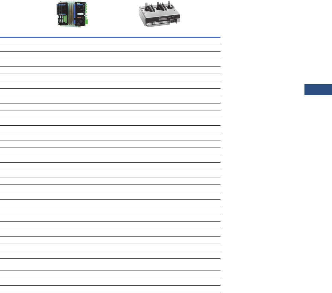
PM3 Monitoring and Metering Module. . . . . . . . . . . . . . . . . . . . . . . . V3-T9-106
Current Transformers (CTs) . . . . . . . . . . . . . . . . . . . . . . . . . . . . . . . . . V3-T9-107
Clamp-On Current Transformers . . . . . . . . . . . . . . . . . . . . . . . . . . . . . V3-T9-116
IQ Flange. . . . . . . . . . . . . . . . . . . . . . . . . . . . . . . . . . . . . . . . . . . . . . . V3-T9-119
Enclosed Meters . . . . . . . . . . . . . . . . . . . . . . . . . . . . . . . . . . . . . . . . . V3-T9-121
9.3 Protective Relays
Product Selection Guide . . . . . . . . . . . . . . . . . . . . . . . . . . . . . . . . . . . V3-T9-143
Digitrip 3000 . . . . . . . . . . . . . . . . . . . . . . . . . . . . . . . . . . . . . . . . . . . . V3-T9-149
EDR-3000 Feeder Protection. . . . . . . . . . . . . . . . . . . . . . . . . . . . . . . . V3-T9-159
EDR-5000 Distribution Protection Relay . . . . . . . . . . . . . . . . . . . . . . . V3-T9-168
FP-5000 Feeder Protection . . . . . . . . . . . . . . . . . . . . . . . . . . . . . . . . . V3-T9-181
MP-3000 Motor Protection . . . . . . . . . . . . . . . . . . . . . . . . . . . . . . . . . V3-T9-189
MP-4000 Motor Protection . . . . . . . . . . . . . . . . . . . . . . . . . . . . . . . . . V3-T9-199
EMR-3000 Motor Protection Relay . . . . . . . . . . . . . . . . . . . . . . . . . . . V3-T9-205
EMR-4000 Motor Protection Relay . . . . . . . . . . . . . . . . . . . . . . . . . . . V3-T9-217
EMR-5000 Motor Protection Relay . . . . . . . . . . . . . . . . . . . . . . . . . . . V3-T9-230
ETR-4000 Transformer Protection Relay . . . . . . . . . . . . . . . . . . . . . . . V3-T9-242
ETR-5000 Transformer Protection Relay . . . . . . . . . . . . . . . . . . . . . . . V3-T9-254
EGR-5000 Generation Protection Relay . . . . . . . . . . . . . . . . . . . . . . . V3-T9-267
Ground Fault Relay . . . . . . . . . . . . . . . . . . . . . . . . . . . . . . . . . . . . . . . V3-T9-280
Universal RTD Module. . . . . . . . . . . . . . . . . . . . . . . . . . . . . . . . . . . . . V3-T9-283
9.4 Connectivity Options
Power Xpert Gateway . . . . . . . . . . . . . . . . . . . . . . . . . . . . . . . . . . . . . V3-T9-287
Power Xpert Ethernet Switches . . . . . . . . . . . . . . . . . . . . . . . . . . . . . V3-T9-296
mMINT . . . . . . . . . . . . . . . . . . . . . . . . . . . . . . . . . . . . . . . . . . . . . . . . V3-T9-300
IPONI. . . . . . . . . . . . . . . . . . . . . . . . . . . . . . . . . . . . . . . . . . . . . . . . . . V3-T9-302
DPONI . . . . . . . . . . . . . . . . . . . . . . . . . . . . . . . . . . . . . . . . . . . . . . . . . V3-T9-303
MPONI . . . . . . . . . . . . . . . . . . . . . . . . . . . . . . . . . . . . . . . . . . . . . . . . V3-T9-304
I/O Devices Digital Input Module (DIM) . . . . . . . . . . . . . . . . . . . . . . . V3-T9-305
Addressable Relay II . . . . . . . . . . . . . . . . . . . . . . . . . . . . . . . . . . . . . . V3-T9-307
Breaker Interface Module II (BIM II) . . . . . . . . . . . . . . . . . . . . . . . . . . V3-T9-309
V3-T9-2 Volume 3—Power Distribution and Control Assemblies CA08100004E—March 2016 www.eaton.com
9
9
9
9
9
9
9
9
9
9
9
9
9
9
9
9
9
9
9
9
9
9
9
9
9
9
9
9
9
9
9.1
Metering Devices, Protective Relays, Software and Connectivity
Energy and Power Monitoring Software
Power Xpert Insight
Contents
Description Page
Power Xpert Insight
Features . . . . . . . . . . . . . . . . . . . . . . . . . . . . . . V3-T9-3
Product Selection . . . . . . . . . . . . . . . . . . . . . . . V3-T9-4
Technical Data and Specifications . . . . . . . . . . . V3-T9-5
An Eaton
Green Solution
Power Xpert Insight
Product Description
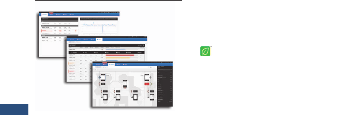
Power Xpert Insight® is a
power and energy monitoring
system that is amazingly
simple—simple to install,
simple to use, simple to add
new devices and simple to
obtain the information
needed to make important
operating decisions every
day. Power Xpert Insight
provides the insight into your
customers’ electrical system
and takes the complexity out
of power and energy
management.
A Web-based software,
Power Xpert Insight is
designed to be quick to install
and configure so that
systems can be up and
running quickly. Developed
after extensive study and
testing with users, the
software allows customers
to view only the device
information that they want
to see, simplify alarm
management, view energy
usage and demand data,
compare and trend data,
and view a one-line
representation of their
electrical system.
Power Xpert Insight provides
the
energy and power
information you
need to:
●Keep the lights on with
real-time, actionable
alarms across desktop
and mobile
●Save money and energy
with easy-to-use and share
energy reports
●Stay up to speed on your
most critical devices with
adjustable dashboards
●Drill into problems quickly
with powerful graphics and
detailed data
●Understand current issues
and plan for future
investments using trends
and visualizations
Volume 3—Power Distribution and Control Assemblies CA08100004E—March 2016 www.eaton.com V3-T9-3
9
9
9
9
9
9
9
9
9
9
9
9
9
9
9
9
9
9
9
9
9
9
9
9
9
9
9
9
9
9
9.1
Metering Devices, Protective Relays, Software and Connectivity
Energy and Power Monitoring Software
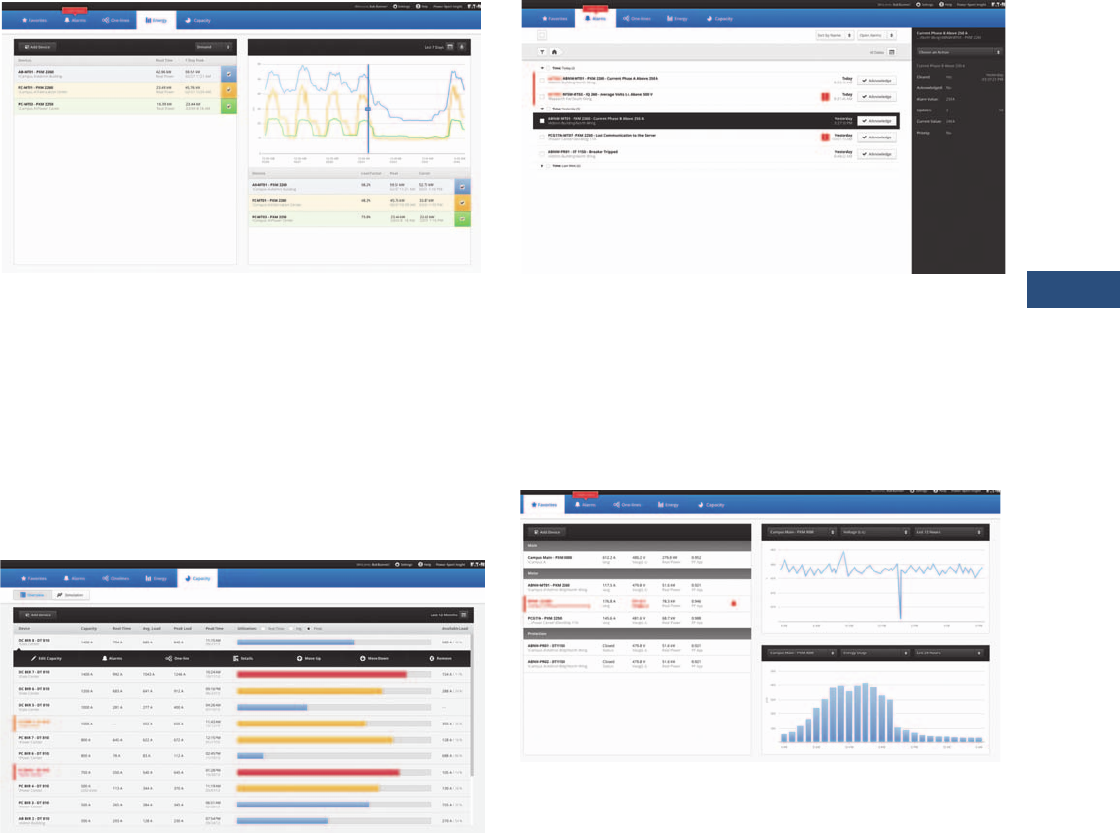
Features
Energy
●View energy usage and demand
●Select the desired devices and time range, 24 hours to a
custom range
●Choose the type of graph that best suits; line or stacked bar
chart
●Move the cursor over the graph to view detailed data
●Export data to a CSV-format file
●Expand to the Trend Viewer for additional information
●Energy usage is automatically summed for the devices shown
in the table
Capacity
●Benchmark capacity usage in real-time to determine tripping
points and avoid downtime
●Custom trigger thresholds for cautionary and critical levels
support all types of electrical environments and changing
needs
●Simulate and trend with line graphics load additions prior to
device installation to avoid tripping and downtime
●Forecast, budget and plan capacity requirements
●Proactively predict overall electrical system performance by
modeling capabilities
Alarms
●View color-coded alarms on one page (Black = Normal,
Red = Alarm, Orange = Loss of Communication)
●Sort alarms by Time, Device or Priority for a specified time
range, view by Alarm Status
●Acknowledge Alarms by individual device or group together
●Open the Alarm Pop Out to view additional data and add notes
●Export alarm history to a CSV-format file
Favorites Dashboard
●Each user can create a unique dashboard to focus on the
devices or systems that they are interested in
●Devices are displayed by device type (Main, Meter, Protection)
and populate the top 4 channels for that device
●Alarm color-coding is automatically propagated across pages
●A quick Trend Graph and Energy Graph are also displayed for a
selected device and channel over a time range up to 24 hours
●Quickly add or remove devices from the Favorites dashboard
V3-T9-4 Volume 3—Power Distribution and Control Assemblies CA08100004E—March 2016 www.eaton.com
9
9
9
9
9
9
9
9
9
9
9
9
9
9
9
9
9
9
9
9
9
9
9
9
9
9
9
9
9
9
9.1
Metering Devices, Protective Relays, Software and Connectivity
Energy and Power Monitoring Software
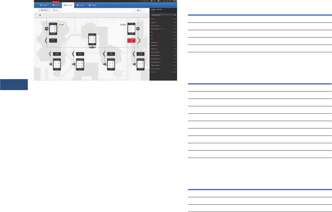
One-lines
●Build an electrical one-line representation of the system with
device widgets and the symbols library
●Drag-and-drop devices, lines, symbols where needed, add
text boxes. Easily updated when devices are removed or
added to service
●The top 4 device channels are automatically populated on the
device widgets and alarm color-coding carries through on the
one-lines
●Upload a unique background image
●Use the Device Tree to set up the one-line structure
Offline Configuration
●Power Xpert Insight provides the ability to completely
configure a system in advance. The more you know about
the final system, the more complete the offline configuration
process will be
●Configure Power Xpert Insight in advance using an Excel®
spreadsheet (template available at Eaton.com/pxi)
●Upload the spreadsheet to an offline Power Xpert Insight
system
●Set up one-line graphics in the offline Power Xpert Insight
system
●Extract the entire system configuration
●Upload the configuration into the target system when ready
and connect when the devices are online
Product Selection
Power Xpert Insight
PXI Device Count Upgrades
Service Packs
Description
Catalog
Number
PXI for up to 10 device connections PXI-A
PXI for up to 25 device connections PXI-B
PXI for up to 50 device connections PXI-C
PXI for up to 100 device connections PXI-D
PXI for up to 200 device connections PXI-E
Description
Catalog
Number
PXI 10 to 25 upgrade PXI-A2B
PXI 10 to 50 upgrade PXI-A2C
PXI 10 to 100 upgrade PXI-A2D
PXI 10 to 200 upgrade PXI-A2E
PXI 25 to 50 upgrade PXI-B2C
PXI 25 to 100 upgrade PXI-B2D
PXI 25 to 200 upgrade PXI-B2E
PXI 50 to 100 upgrade PXI-C2D
PXI 50 to 200 upgrade PXI-C2E
PXI 100 to 200 upgrade PXI-D2E
Description
Catalog
Number
Power Xpert 1-day startup service pack PX-1S
Power Xpert 2-day startup service pack PX-2S
Power Xpert 5-day startup service pack PX-5S

Volume 3—Power Distribution and Control Assemblies CA08100004E—March 2016 www.eaton.com V3-T9-5
9
9
9
9
9
9
9
9
9
9
9
9
9
9
9
9
9
9
9
9
9
9
9
9
9
9
9
9
9
9
9.1
Metering Devices, Protective Relays, Software and Connectivity
Energy and Power Monitoring Software
Technical Data and Specifications
Hardware Requirements
Power Xpert Insight requires a server-class machine with the
following minimum hardware specifications:
Software Requirements
Supported Operating Systems
Note: If you do not have one of the above versions installed, Power Xpert
Insight will install SQL Server 2012 Express with Advanced Services.
Supported Web Browsers
●Microsoft Internet Explorer® (IE) 9, 10 or 11
●Google Chrome™
●Firefox®
●Other browsers (such as Opera and Safari®) that support
Silverlight® may also work, but are not officially supported
by Eaton
Hardware Specification
Processor Quad core
Memory 16 GB
Disk space required for application 100 GB—5 years estimated data storage
Disk space required for database A typical database will grow to 2 GB within a
year. If you have a large number of devices,
reserve additional storage space
Video resolution 1920 by 1080 pixels
Software Specification
Server Windows® Server 2008 R2, Standard and Enterprise, SP1
Windows Sever 2012 Standard and Datacenter
Client Windows 7 Professional, Ultimate or Enterprise, x64, SP1
Windows 8 Professional and Enterprise, x64
Supported versions of Microsoft® SQL Server
SQL Server 2008 R2 Standard (and Standard for Small Business) SP2
SQL Server 2008 R2 Enterprise
SQL Server 2012 Express with Advanced Services, Standard, Enterprise,
Enterprise Core and Business Intelligence
V3-T9-6 Volume 3—Power Distribution and Control Assemblies CA08100004E—March 2016 www.eaton.com
9
9
9
9
9
9
9
9
9
9
9
9
9
9
9
9
9
9
9
9
9
9
9
9
9
9
9
9
9
9
9.2
Metering Devices, Protective Relays, Software and Connectivity
Metering Devices
Metering Products Family
Contents
Description Page
Metering Products Family
Power Xpert Meter 4000/6000/8000 Series . . . . . . V3-T9-15
Power Xpert Meter 2000 Series . . . . . . . . . . . . . . . V3-T9-34
IQ 250/260 Series Electronic Power Meters . . . . . . V3-T9-45
IQ 130/140/150 Series Electronic Power Meters. . . V3-T9-51
IQ 150S/250S Self-Enclosed Electronic Meters . . . V3-T9-56
IQ 35M . . . . . . . . . . . . . . . . . . . . . . . . . . . . . . . . . . V3-T9-61
IQ Analyzer 6400/6600 Series . . . . . . . . . . . . . . . . . V3-T9-64
IQ DP-4000 Series. . . . . . . . . . . . . . . . . . . . . . . . . . V3-T9-72
IQ 230 Meters . . . . . . . . . . . . . . . . . . . . . . . . . . . . . V3-T9-78
Power Xpert Multi-Point Meter . . . . . . . . . . . . . . . . V3-T9-85
IQ Energy Sentinel™ . . . . . . . . . . . . . . . . . . . . . . . . V3-T9-97
PM3 Monitoring and Metering Module. . . . . . . . . . V3-T9-106
Current Transformers (CTs) . . . . . . . . . . . . . . . . . . . V3-T9-107
Clamp-On Current Transformers . . . . . . . . . . . . . . . V3-T9-116
IQ Flange . . . . . . . . . . . . . . . . . . . . . . . . . . . . . . . . . V3-T9-119
Panel Mounting Adapter Kit. . . . . . . . . . . . . . . . . . . V3-T9-120
Enclosed Meters . . . . . . . . . . . . . . . . . . . . . . . . . . . V3-T9-121
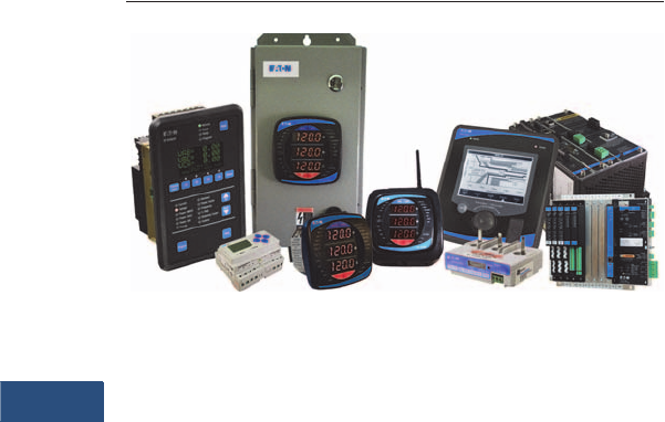
Product Overview
Eaton’s metering products
provide solutions needed
to monitor and manage all
aspects of an electrical
distribution system.
When greater reliability,
increased productivity and
significant cost savings
are called for to remain
competitive in today’s
market, Eaton’s metering
products fit the bill. These
innovative meters and
communications systems,
along with Power
Management software, make
it possible to successfully
take control of the electrical
distribution system.
Power Xpert Meters
Power Xpert Meters are
the benchmark for intelligent
Web-enabled top-quality
metering devices for the
power system. Power Xpert
Meters provide measurement
of the critical elements found
in the power system, whether
that be voltage, power,
current, transients, harmonics
or even time. Power Xpert
Meters provide Web-enabled
communications for use with
the Power Xpert Insight.
All Power Xpert Meters
provide a standard
communications protocol
for easy integration into
other systems.
Features and Benefits
Greater Reliability
Eaton’s metering products
give the ability to receive an
early warning of potential
problems, eliminate
unnecessary trips, isolate
faults to ensure minimum
downtime and shed or
equalize loads while a
problem is being corrected.
Increased Productivity
Equipment downtime
resulting from voltage or
frequency variations can be
very costly to an operation.
Monitoring power quality
with Eaton’s metering
products throughout the
electrical distribution system
provides data to identify,
isolate and correct problems
quickly and efficiently.
Reduced Energy and
Operating Costs
When we think about meters
and power quality, the
common thread throughout
the basket of solutions is
information. Collecting,
monitoring and managing data
from the electrical distribution
system can help reduce costs
for those facilities prepared to
define and analyze present
electrical energy usage levels
and patterns. Data provided by
Eaton’s metering products
comprise the data for verifying
utility bills for energy
management and lowering
operating costs. Deregulation
in some geographical
locations permits energy
users to select a utility
provider and negotiate rate
structures. For large users
with heavy utility bills, this
may be an incentive to verify
the utility bill, identify an
opportunity for savings,
negotiate a better utility rate
and apply the savings directly
to the bottom line. Users are
also empowered to decrease
energy consumption, thereby
lowering peak demand
charges and decreasing
operating costs.
When an Eaton meter is used
with Eaton trip units and
relays incorporating built-in
metering capabilities, the
entire electrical distribution
system can be cost-
effectively managed.
Eaton is an industry
leader offering a complete
integrated solution to oversee
your entire electrical
distribution system. As a
global manufacturer of
low and medium voltage
electrical distribution system
equipment and components,
Eaton is an experienced
innovator of metering
products that incorporate
cutting-edge technology.
These innovations result
from our scientific and
engineering expertise,
physical resources and the
ongoing R&D programs at
our technology centers.
Volume 3—Power Distribution and Control Assemblies CA08100004E—March 2016 www.eaton.com V3-T9-7
9
9
9
9
9
9
9
9
9
9
9
9
9
9
9
9
9
9
9
9
9
9
9
9
9
9
9
9
9
9
9.2
Metering Devices, Protective Relays, Software and Connectivity
Metering Devices
Product Selection Guide
Metering Selection Chart
Notes
1Under typical operating conditions.
2PXM 2260 only.
3PXM 2270 only.
4PXM 2280 only.
5PXM 2290 only.
6IQ 260 only.
7Individual values reported to 85th
harmonic; anti-alias filtering prevents
higher frequencies from distorting
readings (see IEC 61000-4-7).
8PMX 6000 only.
9PXM 8000 only.
jOptional.
kAt computer only.
Device Name
Accessories
See Page V3-T9-116
Power Xpert Meter 4000/6000/8000 Series Power Xpert Meter 2000 Series IQ 250/260 Series
Section Page Number V3-T9-15 V3-T9-34 V3-T9-45
Electrical Parameters
Volts 0.1% of RV + 0.02% FS 0.1% of RV 0.1% of RV
Amperes 0.05% of RV + 0.01% FS 0.1% of RV 0.1% of RV
Current range (% of nominal) 0.005–20A (400%) 0.1–200% 0.1–200%
Watts 0.1% of RV + 0.0025% FS 0.2% of RV 0.2% of RV
VARs 0.1% of RV + 0.0025% FS 0.2% of RV 0.2% of RV
VA 0.1% of RV + 0.0025% FS 0.2% of RV 0.2% of RV
PF-apparent 0.1% 0.2% of RV 0.2% of RV
PF-displacement 0.1% — —
Frequency ±0.01 Hz ±0.03 Hz ±0.03 Hz
THD-voltage 127th 40th 2345 40th 6
THD-current 127th 40th 2345 40th 6
Watthours ±0.2% per ANSI C12.20 0.2 Class 1±0.2% per ANSI C12.20 0.2 Class 1±0.2% per ANSI C12.20 0.2 Class 1
VAR-hours ±0.2% per ANSI C12.20 0.2 Class 1±0.2% per ANSI C12.20 0.2 Class 1±0.2% per ANSI C12.20 0.2 Class 1
VA-hours ±0.2% per ANSI C12.20 0.2 Class 1±0.2% per ANSI C12.20 0.2 Class 1±0.2% per ANSI C12.20 0.2 Class 1
Ampere-demand 0.05% of RV + 0.01% FS ±0.1% per ANSI C12.20 0.2 Class ±0.1% per ANSI C12.20 0.2 Class
Watt-demand ±0.2% per ANSI C12.20 0.2 Class 1±0.2% per ANSI C12.20 0.2 Class 1±0.2% per ANSI C12.20 0.2 Class 1
VAR-demand ±0.2% per ANSI C12.20 0.2 Class 1±0.2% per ANSI C12.20 0.2 Class 1±0.2% per ANSI C12.20 0.2 Class 1
VA-demand ±0.2% per ANSI C12.20 0.2 Class 1±0.2% per ANSI C12.20 0.2 Class 1±0.2% per ANSI C12.20 0.2 Class 1
Revenue accuracy ±0.2% per ANSI C12.20 0.2 Class 1ANSI C12.20 (0.2%) ANSI C12.20 (0.2%)
Individual ampere harmonics 85th 740th 345 —
Individual voltage harmonics 85th 740th 345 —
Interharmonics Yes — —
Minimum and/or Maximum Values
Volts L-L, L-N, N-G, VAUX L-L L-L, L-N L-L, L-N
Current A, B, C, N, G A, B, C, N A, B, C
Power Watt, VAR, VA Watt, VAR, VA Watt, VAR, VA
Power Factor Apparent/displacement Apparent Apparent
Frequency Hertz Hertz Hertz
THD Amperes/volts (L-L, L-N, AUX L-L) Amperes/volts 2345 Amperes/volts 6
Demand values kW, kVAR, kVA, amperes kW, kVAR, kVA, amperes kW, kVAR, kVA, amperes
Trend analysis 2 / 4 8 / 8 9 GB 256 / 512 2 / 768 345 MB 128 KB
j
Event logging 2 / 4 8 / 8 9 GB 100,000 alarms/events with timestamp k
Disturbance recording 2 / 4 8 / 8 9 GB
60 cycles per event
768 MB 45
up to 64 cycles per event 45
—
Legend: PG = Programmable
FS = Full scale
RV = Read value
Auxiliary voltage
(optional) = Provides three additional voltage inputs to the
meter: Va2, Vb2, Vc2.
Interharmonics = Power Xpert Meter 6000/8000 supported.
V3-T9-8 Volume 3—Power Distribution and Control Assemblies CA08100004E—March 2016 www.eaton.com
9
9
9
9
9
9
9
9
9
9
9
9
9
9
9
9
9
9
9
9
9
9
9
9
9
9
9
9
9
9
9.2
Metering Devices, Protective Relays, Software and Connectivity
Metering Devices
Metering Selection Chart, continued
Notes
1PXM 6000 only.
2PXM 8000 only.
3PXM 2260 only.
4PXM 2270 only.
5The auxiliary voltage option adds three additional voltage
input channels to Power Xpert Meters.
6At computer only.
7PXM 2280 only.
8PXM 2290 only.
9Optional
Legend: PG = Programmable
FS = Full scale
RV = Read value
Auxiliary voltage
(optional) = Provides three additional voltage inputs to the
meter: Va2, Vb2, Vc2.
Interharmonics = Power Xpert Meter 6000/8000 supported.
Device Name
Accessories
See Page V3-T9-116
Power Xpert Meter 4000/6000/8000 Series Power Xpert Meter 2000 Series IQ 250/260 Series
Section Page Number V3-T9-15 V3-T9-34 V3-T9-45
Other Features
Storage 2 / 4 1 / 8 2 GB 256 / 512 3 / 768 4 MB Standard 128 KB for logging, up to 8 parameters every 15
minutes for 30 days
PG output relays 5 maximum Optional (2) Form C, 5A or (4) Form A, 120 mA Optional (2) Form C, 5A or (4) Form A, 120 mA
PG analog outputs — Optional (4) 4–20 mA or (4) 0–1 mA Optional (4) 4–20 mA or (4) 0–1 mA
Discrete contact inputs 8 Optional (2) or (4) Optional (2) or (4)
Analog inputs — — —
Synch-input kW utility Via status input Via end of interval pulse with optional digital inputs Via end of interval pulse with optional digital inputs
Auxiliary voltage 5Yes — —
kWh pulse initiator Yes Yes Yes
Waveform display Local/computer 6—
Waveform capture, samples/cycle Yes, 512 (4096 oversampling) Yes, up to 64 7, up to 512 8—
Frequency distribution display — — —
Display type LCD 9Red LED Red LED
Display lines/character Graphic (320 x 240 pixels) 3 lines, 4 characters 3 lines, 4 characters
Display character height 5.5 mm H x 4 mm W 0.56 (14.2) H 0.56 (14.2) H
Communications Serial: Modbus RTU, Modbus ASCII
9 Network: Modbus TCP, Ethernet TCP/IP,
HTTP, SNMP, SMTP, FTP, DNP 3.0
Serial: Modbus RTU, Modbus ASCII, DNP 3.0
Network: Modbus TCP, BACnet/IP, Ethernet TCP/IP,
HTTP, HTTPS, SNMP, SMTP, 78 Waveform FTP
Serial: Modbus RTU, Modbus ASCII, DNP 3.0
Network: Modbus TCP via Power Xpert Gateway
Setup configuration Via Web browser/display Via Web browser/display Via configuration software/display
Dimensions Refer to TD02601007E Refer to TD02601017E Refer to TD02601016E
Operating temperature range –20° to 60°C display unit
–20° to 70°C meter base unit
–20° to 70°C –20° to 70°C
Reference literature TD02601007E TD02601017E TD02601016E

Volume 3—Power Distribution and Control Assemblies CA08100004E—March 2016 www.eaton.com V3-T9-9
9
9
9
9
9
9
9
9
9
9
9
9
9
9
9
9
9
9
9
9
9
9
9
9
9
9
9
9
9
9
9.2
Metering Devices, Protective Relays, Software and Connectivity
Metering Devices
Metering Selection Chart, continued
Notes
1IQ 140 and IQ 150.
2IQ 150 only.
3At computer only.
4Optional.
5IQ 250S only.
Legend: PG = Programmable
FS = Full scale
RV = Read value
Device Name
Accessories
See Page V3-T9-116
IQ 130/140/150 Series IQ 150S/250S Series IQ 35M Series
Section Page Number V3-T9-51 V3-T9-56 V3-T9-61
Electrical Parameters
Volts ±0.25% of RV 0.1% of RV 0.4% +0.015% per °C deviation from 25°C
Amperes ±0.25% of RV 0.1% of RV 0.4% (5–100%), 0.8% (1–5%) +0.015% per °C from 25°C
Current range (% of nominal) 0.1–200% 0.1–200% 1–120%
Watts 0.5% of RV 10.2% of RV 0.5% per ANSI C12.20 and IEC 62053-22 Class 0.5S
VARs 0.5% of RV 10.2% of RV 2.0% per IEC 62053-23 Class 2
VA 0.5% of RV 10.2% of RV Calculated: vector sum of watts and VARs
PF-apparent 0.5% of RV 10.2% of RV Calculated: Watts / VAs
PF-displacement — — —
Frequency ±0.03% Hz 1±0.03 Hz ±0.02 Hz
THD-voltage — — —
THD-current — — —
Watthours ±0.5% per ANSI C12.20 0.5 Class 2±0.2% per ANSI C12.20 0.2 Class 0.5% per ANSI C12.20 and IEC 62053-22 Class 0.5S
Varhours ±0.5% per ANSI C12.20 0.5 Class 2±0.2% per ANSI C12.20 0.2 Class ±2.0% per IEC 62053-23 Class 2
VA-hours ±0.5% per ANSI C12.20 0.5 Class 2±0.2% per ANSI C12.20 0.2 Class —
Ampere-demand ±0.5% per ANSI C12.20 0.5 Class 2±0.1% per ANSI C12.20 0.2 Class —
Watt-demand ±0.5% per ANSI C12.20 0.5 Class 2±0.2% per ANSI C12.20 0.2 Class 0.5% per ANSI C12.20 and IEC 62053-22
Class 0.5S
VAR-demand ±0.5% per ANSI C12.20 0.5 Class 2±0.2% per ANSI C12.20 0.2 Class 2.0% per IEC 62053-23 Class 2
VA-demand ±0.5% per ANSI C12.20 0.5 Class 2±0.2% per ANSI C12.20 0.2 Class Calculated: vector sum of watts and VARs
Revenue accuracy ANSI C12.20 (0.5%) ANSI C12.20 (0.2%) 0.5% per ANSI C12.20 and IEC 62053-22 Class 0.5S
Individual ampere harmonics — — —
Individual voltage harmonics — — —
Interharmonics — — —
Minimum and/or Maximum Values
Volts L-L, L-N L-L, L-N —
Current A, B, C A, B, C —
Power Watt, VAR, VA Watt, VAR, VA —
Power factor Apparent 1Apparent Apparent (low alert)
Frequency Hertz 1Hertz Hertz (out of range alert)
THD Ampere/Volts — —
Demand values kW, kVAR, kVA, amperes 1kW, kVAR, kVA, amperes kW, kVAR, kVA; Maximum kW, kVAR, kVA
Trend analysis 32 MB 5—
Event logging 32 MB 5Logging on demand interval or Modbus command 4
Disturbance recording — — —

V3-T9-10 Volume 3—Power Distribution and Control Assemblies CA08100004E—March 2016 www.eaton.com
9
9
9
9
9
9
9
9
9
9
9
9
9
9
9
9
9
9
9
9
9
9
9
9
9
9
9
9
9
9
9.2
Metering Devices, Protective Relays, Software and Connectivity
Metering Devices
Metering Selection Chart, continued
Notes
1Optional.
2IQ 250S only.
3The auxiliary voltage option adds three additional voltage input channels to
Power Xpert Meters.
Legend: PG = Programmable
FS = Full scale
RV = Read value
Device Name
Accessories
See Page V3-T9-116
IQ 130/140/150 Series IQ 150S/250S Series IQ 35M Series
Section Page Number V3-T9-51 V3-T9-56 V3-T9-61
Other Features
Storage — 2 MB 210 registers (16 bit) by 5760 entries each (115 KB) 1
PG output relays — — —
PG analog outputs — — —
Discrete contact inputs — — 2 pulse inputs with BACnet
Analog inputs — — —
Synch-input kW Utility — — Optional demand synchronization via Modbus
Auxiliary voltage 3—— —
kWh pulse initiator 1Yes Yes
Waveform display — — —
Waveform capture — — —
Frequency distribution display — — —
Display type Red LED Red LED Backlit LCD
Display lines/character 3 lines, 4 characters 3 lines, 4 characters 2 lines by 5 characters ea (full alphanumeric top row)
Display character height 0.56 (14.2) H 0.56 (14.2) H 7.5 mm
Communications Serial: Modbus RTU, Modbus ASCII 1
Network: Modbus TCP 1
Serial: Modbus RTU, Modbus ASCII, DNP 3.0
Network: Modbus TCP, wired or wireless
Serial: Modbus RTU 1, BACnet MS/TP 1
Network: Modbus TCP via Power Xpert Gateway
Setup configuration Via configuration software/display Via configuration software/display Via display/configuration software
Dimensions 4.85 (123.2) H x 4.85 (123.2) W x 4.97 (126.2) D 7.90 (200.7) H x 7.50 (190.5) W x 3.10 (78.7) D 3.60 (91.4) H x 4.20 (106.7) W x 2.30 (58.4) D
Operating temperature range –20 to 70°C –20 to 70°C –20 to 70°C
Reference literature TD02601015E TD02601019E TD02601015E
Volume 3—Power Distribution and Control Assemblies CA08100004E—March 2016 www.eaton.com V3-T9-11
9
9
9
9
9
9
9
9
9
9
9
9
9
9
9
9
9
9
9
9
9
9
9
9
9
9
9
9
9
9
9.2
Metering Devices, Protective Relays, Software and Connectivity
Metering Devices
Metering Selection Chart, continued
Notes
1From 3–300% of FS.
2At unity power factory and 5–300% of FS.
3At a power factor <±0.5 and 5–300% of FS.
4At computer only.
Legend: PG = Programmable
FS = Full scale
RV = Read value
Device Name
Accessories
See Page V3-T9-116
IQ Analyzer 6000 Series IQ DP-4000 Series IQ 230 Series
Section Page Number V3-T9-64 V3-T9-72 V3-T9-78
Electrical Parameters
Volts ±0.2% FS 1±0.3% FS ±0.5% FS
Amperes ±0.2% FS 1±0.3% FS ±0.5% FS
Current range (% of nominal) 3–800% 10–250% 1–200%
Watts 0.4% FS, 6 RV 2±0.6% FS ±1.0% FS
VARs 0.4% FS, 6 RV 3±0.6% FS ±1.0% FS
VA 0.4% FS, 6 RV 2±0.6% FS ±1.0% FS
PF-apparent 0.8% FS 1±1.0% FS ±2.0% FS
PF-displacement 0.8% FS 1±1.0% FS ±2.0% FS
Frequency 0.04% 1 or 0.01 Hz ±0.17% FS ±0.1% Hz
THD-voltage 50th 31st —
THD-current 50th 31st —
Watthours 0.5% RV 2±0.6% FS ±1.0% per ANSI C12
Varhours 1% RV 3±0.6% FS ±1.0% per ANSI C12
VA-hours 0.5% RV 2±0.6% FS ±1.0% per ANSI C12
Ampere-demand ±0.2% FS 1±0.3% ±0.5% per ANSI C12
Watt-demand ±0.4% FS 1±0.6% ±1.0% per ANSI C12
VAR-demand ±0.4% FS 1±0.6% ±1.0% per ANSI C12
VA-demand ±0.4% FS 1±0.6% ±1.0% per ANSI C12
Revenue accuracy ANSI C12.20 (0.5%) — ANSI C12.1 (1%)
Individual ampere harmonics 50th — —
Individual voltage harmonics 50th — —
Interharmonics — — —
Minimum and/or Maximum Values
Volts L-L, L-N L-L, L-N L-L, L-N
Current A, B, C, N, G A, B, C A, B, C
Power Watt, VAR, VA Watt, VAR, VA Watt, VAR, VA
Power factor Apparent/displacement Apparent/displacement Apparent/displacement
Frequency Hertz Hertz Hertz
THD Amperes/volts Amperes/volts —
Demand values All All All
Trend analysis Time/date 2 alarms 4
Event logging 504 events w/timestamp 44
Disturbance recording 10 waveform events — —
V3-T9-12 Volume 3—Power Distribution and Control Assemblies CA08100004E—March 2016 www.eaton.com
9
9
9
9
9
9
9
9
9
9
9
9
9
9
9
9
9
9
9
9
9
9
9
9
9
9
9
9
9
9
9.2
Metering Devices, Protective Relays, Software and Connectivity
Metering Devices
Metering Selection Chart, continued
Notes
1Relays programmable to operate on any measured function.
2Optional.
3An IPONI is required.
4IQ 230M only.
Legend: PG = Programmable
FS = Full scale
RV = Read value
Device Name
Accessories
See Page V3-T9-116
IQ Analyzer 6000 Series IQ DP-4000 Series IQ 230 Series
Section Page Number V3-T9-64 V3-T9-72 V3-T9-78
Other Features
Storage 90 KB 15 parameters —
PG output relays (4) 10A Form C 1(3) 10A Form C 2(2) 100 mA Form A
PG analog outputs (4) 0–10/4–20 mA — —
Discrete contact inputs (3) + 30 Vdc differential (1) kW Demand 2(2) +30 Vdc differential
Analog inputs (1) 0–20/4–20 mA — (1) 4–20 mA
Synch-input kW Utility At device or via communications At device or via communications 2Via communications only
Auxiliary voltage — — —
kWh pulse initiator Yes Yes 2Yes
Waveform display Local 2/computer — —
Waveform capture, samples/cycle Yes, 128 — —
Frequency distribution display Local 2/computer — —
Display type Graphic LCD with LED backlight 7 Segment LED Backlit LCD
Display lines/character 7 lines, 147 characters 1 line, 7 characters 4 lines, 20 characters
Display character height Up to 7 lines 1 line 1.60 (40.6) H x.09 (2.3) W
Communications Serial: INCOM 3
Network: via Power Xpert Gateway 3
Serial: INCOM 3
Network: via Power Xpert Gateway 3
Serial: INCOM, Modbus RTU 4
Network: via Power Xpert Gateway
Setup configuration Via configuration software/display Via configuration software/display Via configuration software/display
Dimensions Refer to TD1702BTE Refer to TD1703ATE Refer to TD1706ATE
Operating temperature range –20° to 70°C –20° to 70°C 0° to 50°C
Reference literature — — —
Volume 3—Power Distribution and Control Assemblies CA08100004E—March 2016 www.eaton.com V3-T9-13
9
9
9
9
9
9
9
9
9
9
9
9
9
9
9
9
9
9
9
9
9
9
9
9
9
9
9
9
9
9
9.2
Metering Devices, Protective Relays, Software and Connectivity
Metering Devices
Metering Selection Chart, continued
Note
1At computer only.
Legend: PG = Programmable
FS = Full scale
RV = Read value
Device Name
Accessories
See Page V3-T9-116
Power Xpert
Multi-Point Meter
IQ Energy
Sentinel
Section Page Number V3-T9-85 V3-T9-97
Electrical Parameters
Volts ±0.2% RV —
Amperes ±0.2% RV —
Current range (% of nominal) — —
Watts ±0.5% RV ±1.0% FS
VARs ±0.5% RV —
VA ±0.5% RV —
PF-apparent ±0.5% RV —
PF-displacement — —
Frequency ±0.1 Hz —
THD-voltage — —
THD-current — —
Watthours ±0.5% per ANSI C12.20 0.5 class ±1.0% FS
VAR-hours ±0.5% per ANSI C12.20 0.5 class —
VA-hours ±0.5% per ANSI C12.20 0.5 class —
Ampere-demand — —
Watt-demand ±0.5% per ANSI C12.20 0.5 class ±1.0% FS
VAR-demand ±0.5% per ANSI C12.20 0.5 class —
VA-demand ±0.5% per ANSI C12.20 0.5 class —
Revenue accuracy ANSI C12.20 (0.5%) —
Individual ampere harmonics — —
Individual voltage harmonics — —
Interharmonics — —
Minimum and/or Maximum Values
Volts L-L, L-N —
Current A, B, C —
Power Watts, VAR, VA —
Power factor Apparent —
Frequency Hertz —
THD — —
Demand values Watts (Delivered & Received), Watts (Q1–Q4), VA (Q1,
Q4), VA (Q2, Q3)
—
Trend analysis Interval data 1
Event logging 20 latest events and historical 1
Disturbance recording — —
V3-T9-14 Volume 3—Power Distribution and Control Assemblies CA08100004E—March 2016 www.eaton.com
9
9
9
9
9
9
9
9
9
9
9
9
9
9
9
9
9
9
9
9
9
9
9
9
9
9
9
9
9
9
9.2
Metering Devices, Protective Relays, Software and Connectivity
Metering Devices
Metering Selection Chart, continued
Note
1Optional.
Legend: PG = Programmable
FS = Full scale
RV = Read value
Device Name
Accessories
See Page V3-T9-116
Power Xpert
Multi-Point Meter
IQ Energy
Sentinel
Section Page Number V3-T9-85 V3-T9-97
Other Features
Storage 256 MB standard, 2 GB optional —
PG output relays 1 standard, 8 each module 1—
Discrete contact inputs 3 standard, 8 each module 1—
Analog inputs — —
Synch-input kW utility Via communications and digital input Via communications only
Auxiliary voltage — —
kWh pulse initiator Aggregate or main-digital output, LED output on meter
modules (accuracy check)
—
Waveform display — —
Waveform capture — —
Frequency distribution display — —
Display type LCD color touchscreen 1—
Display lines/character 6-inch diagonal —
Display character height Graphics —
Communications Serial: Modbus RTU
1 Network: Modbus TCP, BACnet/IP, Ethernet TCP/IP,
HTTP, HTTPS, SNMP, SMTP, SFTP
Serial: INCOM
Network: via Power Xpert Gateway
Setup configuration Via PXMP configuration software Via configuration software
Dimensions Refer to TD150006EN (see Page V3-T9-110) Refer to TD1707TE
Operating temperature range –20° to 70°C –25° to 70°C
Reference literature TD150006EN —
Volume 3—Power Distribution and Control Assemblies CA08100004E—March 2016 www.eaton.com V3-T9-15
9
9
9
9
9
9
9
9
9
9
9
9
9
9
9
9
9
9
9
9
9
9
9
9
9
9
9
9
9
9
9.2
Metering Devices, Protective Relays, Software and Connectivity
Metering Devices
Power Xpert 4000/6000/8000 Series Display and Meter
Contents
Description Page
Metering Products Family. . . . . . . . . . . . . . . . . . . . . V3-T9-6
Power Xpert Meter 4000/6000/8000 Series
Power Xpert Meter 2000 Series . . . . . . . . . . . . . . . . V3-T9-34
IQ 250/260 Series Electronic Power Meters . . . . . . V3-T9-45
IQ 130/140/150 Series Electronic Power Meters . . . V3-T9-51
IQ 150S/250S Self-Enclosed Electronic Meters . . . . V3-T9-56
IQ 35M . . . . . . . . . . . . . . . . . . . . . . . . . . . . . . . . . . . V3-T9-61
IQ Analyzer 6400/6600 Series . . . . . . . . . . . . . . . . . V3-T9-64
IQ DP-4000 Series . . . . . . . . . . . . . . . . . . . . . . . . . . V3-T9-72
IQ 230 Meters . . . . . . . . . . . . . . . . . . . . . . . . . . . . . V3-T9-78
Power Xpert Multi-Point Meter . . . . . . . . . . . . . . . . . V3-T9-85
IQ Energy Sentinel™ . . . . . . . . . . . . . . . . . . . . . . . . V3-T9-97
PM3 Monitoring and Metering Module . . . . . . . . . . V3-T9-106
Current Transformers (CTs). . . . . . . . . . . . . . . . . . . . V3-T9-107
Clamp-On Current Transformers. . . . . . . . . . . . . . . . V3-T9-116
IQ Flange . . . . . . . . . . . . . . . . . . . . . . . . . . . . . . . . . V3-T9-119
Panel Mounting Adapter Kit . . . . . . . . . . . . . . . . . . . V3-T9-120
Enclosed Meters . . . . . . . . . . . . . . . . . . . . . . . . . . . V3-T9-121
An Eaton
Green Solution
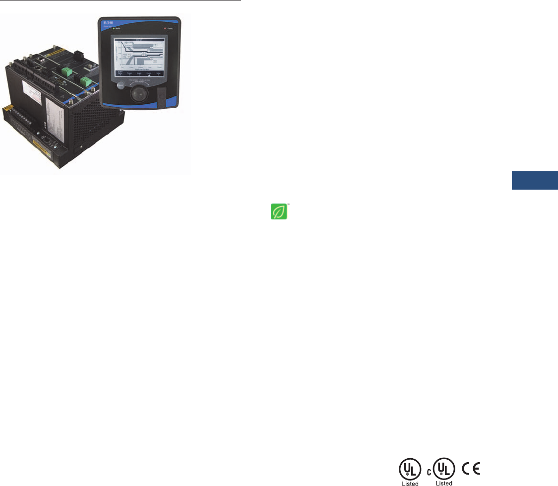
Power Xpert Meter 4000/6000/8000 Series
Product Description
The Power Xpert Meter 4000/
6000/8000 Series monitors
the critical aspects of an
electrical distribution system.
This premier power quality
metering instrument is
simple to use, powerful,
scalable and highly flexible.
The Power Xpert Meter 4000/
6000/8000 offers a new level
of intuitive user interface
design, presenting critical
electrical distribution system
information in simple-to-
navigate and easy-to-
understand information
architecture. The Power
Xpert Meter 4000/6000/8000
graphic display visualizes
the information from up
to 16 meter modules. The
embedded Web server
displays complex power
quality data using standard
Internet browsers and allows
for device configuration from
the browser.
Both the local graphic display
and the embedded Web
server present real time,
historical and event
information in a browser-style
graphical format to help the
user interpret key circuit
information, such as:
●Current loading
●Voltage and power levels
●Power factor
●Energy usage
●I/O status
●Power quality
measurements
●Harmonic plots
●Disturbance and transient
waveforms
●ITIC disturbance summary
screen
The Power Xpert Meter 4000/
6000/8000 graphic display
uses a simple “twist and
click” navigation control dial
to easily navigate the menus
and drill down into increasing
levels of important detail.
A “back” key enhances the
browser-like navigation of the
graphic display.
The Web server provides the
energy and demand readings
required to help manage
the cost of energy. It also
provides critical information
regarding power quality,
such as harmonic distortion,
flicker, crest factor, K-factor
and more.
Note: Features and functionality
may vary depending on the meter
model and options being used.
Review the Features and Benefits
chart on Page V3-T9-20 for
details.
Standards and Certifications
●Safety: EN61010-1,
UL/cUL 61010-1
●Accuracy: IEC/EN60687
0.2 Class, ANSI C12.20
0.2 Class
●EMC: FCC Part 15
Subpart B Class A EN55011
Class A
●Measurement Canada
Approval No. AE-1898
(4000/6000 meters)
●Immunity IEC 61326
●CE Mark

V3-T9-16 Volume 3—Power Distribution and Control Assemblies CA08100004E—March 2016 www.eaton.com
9
9
9
9
9
9
9
9
9
9
9
9
9
9
9
9
9
9
9
9
9
9
9
9
9
9
9
9
9
9
9.2
Metering Devices, Protective Relays, Software and Connectivity
Metering Devices
Application Description
Identify Power Quality
Problems to Help:
●Identify harmonics, sags,
swells and transients
damaging or disrupting
sensitive, mission-critical
IT equipment
●Boost IT equipment’s
service life to the
maximum
●Analyze sequence of
events up to 1 millisecond
time resolution
●Protect motors from
damage
●Preserve the integrity of
processes and batches
●Prevent blown capacitor
bank fuses
●Protect transformers and
conductors from
overheating
Detect and Record High-
Speed Transients to Help:
●Avoid equipment damage
and disruption
●Identify equipment
malfunction
Monitor Circuit Loading
to Help:
●Avoid overloads and
nuisance overload trips
●Maximize equipment
utilization
●Manage emergency
overloads
Manage Energy Utilization
to Help:
●Reduce peak demand
charges and power
factor penalties
●Identify excessive energy
consumption
Metered/Monitored Parameters
Note: See Page V3-T9-20.
●V o l t s : L- L , L- N , A v g . L- L ,
Avg. L-N, N-G
●Phase neutral and
ground currents
●Power: real, reactive
and apparent
●Frequency
●Power factor: apparent
and displacement
●Energy
●Demand
●% THD
●Minimum and maximum
values
●Harmonics
●Flicker
●Individual harmonics
●Interharmonics
●% TDD
●ITIC events plot, duration,
magnitude
●Energy comparisons
●Demand comparisons
●Event calendar
●Event timeline and
sequence
●Number of 9s of availability
●Phasors
●Sequence components
●Crest factor
●K-factor
●PQ Index
Accuracy
●Currents: 0.05% RV
+ 0.025%FS
●Voltage: 0.1% RV
+ 0.025% FS
●Energy and demand
power:
0.2% in accordance
with ANSI C12.20
●Frequency: ±0.01 Hertz
●Power factor:
●0.10% at Unity PF
●0.30% at 0.5 PF
Communications
Multiple communications
ports including:
Standard
●RS-485 remote display port
●RS-485 Modbus RTU
slave port
●RJ-45 10/100Base-T local
configuration port (local
Web server connection)
●HTTP (local), FTP,
COMTRADE
Optional
●Communications
Expansion Card (CEC
●Selectable 100FX or
10/100Base-T Ethernet
network port
●RS-485 Modbus RTU
selectable master/
slave port
●RS-232 Modbus RTU
slave port
For Optional Graphic Display
Note: Display ports provide access
to up to 16 Power Xpert 4000/6000/
8000 Meter modules located on
the display RS-485 network.
●RS-485 meter display
network port
●RJ-45 10/100Base-T for
access to Local Display
Power Xpert network
Communication Protocols
Supported
●Modbus RTU
●Modbus TCP
●Ethernet TCP/IP
●HTML
●NTP (Network Time
Protocol)
●FTP (File Transfer Protocol)
●SMTP (Simple Mail
Transfer Protocol)
●SNMP (Simple Network
Management Protocol)
●COMTRADE (IEEE
C37.111-1999)
●DNP 3.0 over Ethernet
(Distributed Network
Protocol)
Physical Characteristics
Two-Piece Design
●Power Xpert 4000/6000/
8000 Meter modules
●Power Xpert Meter 4000/
6000/8000 Graphic Display
320 x 240 pixel backlight
LCD remote graphics
display (supports up to 16
Power Xpert 4000/6000/
8000 Meter
module
s)
Display/Meter
Mounting Options
●Display remotely mounted
up to 2000 ft (1219m) away
from up to 16 Power Xpert
Meter
modules
●Display and Power Xpert
Meter modules mounted
together on opposite sides
of a panel (15 additional
meter modules can still
be remotely mounted).
Meter Base Unit Characteristics
●NEMA rating: NEMA 1,
IP30
Display Unit Characteristics
●NEMA rating: NEMA 12,
IP42 front of panel rating
Ease of Use—Power Xpert
Meter 4000/6000/8000 Graphic
Display (Option)
The Power Xpert Meter 4000/
6000/8000 display features
a large easy-to-read white
backlit graphic LCD. The
information presented by
the display is organized into
an information architecture
that is easy-to-navigate and
organized for simplicity.
Screen navigation is
accomplished using a
navigation control dial and
a “back” button. The user
simply twists the knob on
the navigation control dial
to move between menu
selections and drill down
links on the screen. When
the selection is highlighted,
pressing the dial makes the
selection. Information is
displayed from a single meter
or an RS-485 daisychain of
up to 16 meters. The display
features a rich set of screens
including real-time data, trend
plots, waveform views and an
ITIC Plot. The graphic display
allows basic device setup and
password protected resets.
An audible alarm is available
to annunciate alarm
conditions.

Volume 3—Power Distribution and Control Assemblies CA08100004E—March 2016 www.eaton.com V3-T9-17
9
9
9
9
9
9
9
9
9
9
9
9
9
9
9
9
9
9
9
9
9
9
9
9
9
9
9
9
9
9
9.2
Metering Devices, Protective Relays, Software and Connectivity
Metering Devices
Power Xpert Meter 4000/6000/
8000 Embedded Web Server
The Power Xpert Meter 4000/
6000/8000 embedded Web
server offers Eaton
customers a new level of
accessibility to the critical
information required to
manage their electrical
distribution system. The Web
server includes real-time
circuit information in both
numeric and graphical visual
formats to help monitor
circuit parameters such as
current loading, voltage and
power levels, power factor,
THD, Flicker and more. The
Web server also provides
energy and demand readings
with graphic usage plots to
help analyze energy usage
patterns. Energy readings
include kWh, kVARh,
delivered and received and
kVAh with time of use and
RTP displays. The interval
energy usage plot includes
the ability to do week-to-
week and month-to-month
energy consumption
graphical comparisons for
benchmarking purposes. The
embedded Web server will
also display in simplified
Chinese if connected to a
computer configured for
Chinese language.
Both the Power Xpert Meter
4000/6000/8000 embedded
Web server and the local
graphic display support
graphical trend charts of key
circuit measurements such
as current, voltage, power
and energy. The trend chart
supports a zoom feature that
allows the user to view data
over a short period of 16
hours up to 4 years. The trend
chart includes zoom in/out
buttons and a horizontal slider
bar control to manage
scrolling forward and backward
through the data. Trend charts
of basic readings include
minimum, maximum and
average readings. Trend
charts of interval by interval
energy data also display
peak demand.
Note: For remote access and
networking capabilities such as
connecting to a LAN/WAN, use
the optional Communications
Expansion Card (CEC).
Sag/Swell/Transient Capture
and Recording
60 cycles of waveform are
oversampled at 4096 samples
per cycle (Power Xpert Meter
4000/6000), filtered through
anti-aliasing and recorded at
512 samples per cycle and
post event data. The Power
Xpert Meter 8000 samples at
a rate of 100,000 samples per
cycle. Embedded Web server
supports viewing of triggered
waveforms one channel at a
time and includes the ability to
zoom and to scroll horizontally
using a slider bar.
The Power Xpert Meter
6000/8000 Series have
preconfigured (600 volts and
below) trigger settings for
sags, swells and transients,
and do not require additional
setup by the user. Waveforms
are stored in non-volatile flash
memory using an industry
standard COMTRADE
format. Waveforms can be
automatically sent out as
COMTRADE attachments to
an e-mail following an event,
or can be retrieved from an
FTP (File Transfer Protocol)
directory structure in
the Power Xpert meter
module’s memory.
Historical Trend Logging
The Power Xpert Meter 4000/
6000/8000 records historical
data for graphical viewing
from the Local display or
the embedded Web server.
Graphical views of historical
data support pan and zoom.
145 standard metering
parameters are logged as
part of the standard meter
functionality including min./
max. and average for each
parameter. The averages are
calculated over the interval
period. The minimum and
maximum readings are based
on 200 ms calculations.
Storage capacity for standard
trend plots includes all of the
following intervals:
●Every 5 minutes for
48 hours (2 days)
●Every 15 minutes for
192 hours (4 days)
●Every hour for 28 days
(4 weeks)
●Every 8 hours for
56 weeks
●Every week for 44 months
Note: Trend plot data can be
easily exported to third-party
applications, such as Microsoft
Excel in csv-file format.
In addition, metered
parameters are automatically
stored on the built-in FTP
Servers, where they can be
easily copied and imported
into third-party applications
for benchmarking and
analysis. Logs on the FTP
Server include the min./max.
and average for 145 standard
metering parameters at
5-minute intervals.
Storage capacity for
trend data:
●6 days of 5-minute
interval trend data
●Capacity=18,144 intervals
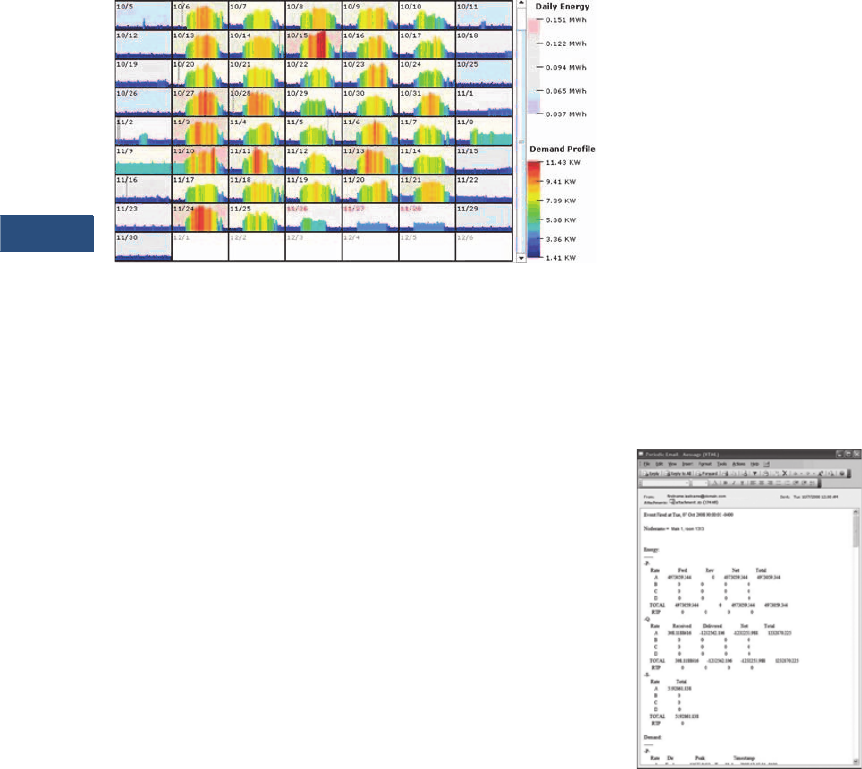
Energy Profile Data
The Power Xpert Meter 4000/
6000/8000 records Real and
Reactive energy forward,
reverse, net and absolute
sum, as well as Apparent
energy (kVAH). Up to 8 status
inputs can be configured as
energy accumulators for
counting KYZ pulse inputs
(option). These readings are
stored over a configurable
interval from 1 to 60 minutes,
as well as in daily and
weekly totals.
With the optional LAN/WAN
Ethernet Communication
Expansion Card (CEC), users
can easily configure the
meters to send periodic
e-mails at user-defined
intervals of energy
consumption and power
demand. E-mails contain
a summary of readings per
rate structures and also have
the actual measurements
attached to the E-mail’s
body as a CSV file in a
ZIP container.
In addition, metered
parameters are automatically
stored on the built-in FTP
Server, where they can be
easily copied and imported
into third-party applications
for benchmarking and
analysis. Logs on the FTP
Server include energy
consumption logs, one
for every month in CSV
file format, trended
measurement logs also
in CSV file format and
waveform captures in
COMTRADE file format.
Storage capacity for energy
profile data:
●62 days of 15 minute
interval energy and pulse
interval data.
●Fixed interval capacity
= 5952 intervals.
Configurable intervals
from 1 to 60 min
●372 days of 1 day
accumulated energy and
pulse interval data
●208 weeks of 1 week
accumulated energy
and pulse interval data
Energy and Demand
Comparisons
Energy and demand usage
patterns can be analyzed with
the month-to-month, week-
to-week comparison chart
built into the meter. Raw
data can be exported with
the “Save Table” option to
other applications, such as
Excel, for further analysis
and graphing.
V3-T9-18 Volume 3—Power Distribution and Control Assemblies CA08100004E—March 2016 www.eaton.com
9
9
9
9
9
9
9
9
9
9
9
9
9
9
9
9
9
9
9
9
9
9
9
9
9
9
9
9
9
9
9.2
Metering Devices, Protective Relays, Software and Connectivity
Metering Devices
Power Xpert Meter Profiler—Free Download
The Power Xpert Meter
Profiler software allows you
to compare “expected”
energy consumption patterns
to present usage and flag
areas of concern. It is also a
predictor. It can predict what
energy consumption would
be expected later in a day.
Event Triggers
The Power Xpert Meter
4000/6000/8000 supports
five types of configurable
event triggers:
●Out of limits (4000/6000/
8000)
●Demand overload (4000/
6000/8000)
●Sub-cycle disturbance
(4000/6000/8000)
●ITIC (6000/8000)
●Fast transient (8000)
These triggers permit pickup,
reset and pickup delay to
be configured by the user.
When a trigger occurs,
actions include Performance
Monitoring (#9’s analysis),
Capturing Waveform, Capture
Parameters, Send Email and
Operate a Relay Output. The
Graphic Display flashes an
LED to annunciate the alarm
condition. An audible alarm is
also available.
Trigger options include:
●Out of limits: over
100 triggers
●Demand overload:
10 triggers
●ITIC: 8 triggers
●Fast transient: dV/dT and
absolute per phase
●Sub-cycle disturbance—
dV/dt and absolute
Event Logging
The optional Power Xpert
Meter 4000/6000/8000
Local graphic display or the
embedded Web server both
allow the user to view a list of
triggered events along with
any captured parameters,
event details and triggered
waveforms. In addition, a
separate event log includes a
variety of activities including
acknowledged triggers, new
min. and max. events, and
system operations such as
resets. The size of the event
log is virtually unlimited based
only on the memory option
selected.
E-mail Notification
With the optional LAN/WAN
Ethernet Communication
Expansion Card (CEC)
attached to the Power Xpert
Meter 4000/6000/8000’s, the
users can easily configure
the meters to send periodic
emails at user-defined
intervals for energy
consumption and power
demand. Emails contain a
summary of readings per
rate structures and also have
the actual measurements
attached to the email’s
body as a CSV file in a ZIP
container. Prompt alarm
emails can also be sent for
any event condition either
standard in the meter or ones
set up by the user based on
thresholds, dV/dt triggers or
IO status changes with the
optional IO Card. Alarm
emails can be configured
to have the COMTRADE
waveform capture attached
to the e-mail’s body.
Periodic Email Message

Volume 3—Power Distribution and Control Assemblies CA08100004E—March 2016 www.eaton.com V3-T9-19
9
9
9
9
9
9
9
9
9
9
9
9
9
9
9
9
9
9
9
9
9
9
9
9
9
9
9
9
9
9
9.2
Metering Devices, Protective Relays, Software and Connectivity
Metering Devices
ITIC Analysis Plot
The Power Xpert Meter
graphic display (option) and
Web server include a graphic
representation of the ITIC plot
(Power Xpert Meter 6000/
8000) with counts of
disturbances and transients
that have occurred. The ITIC
plot organizes events into
8 distinct disturbance zones
corresponding to severity and
a 9th zone for transients. A
pass/fail count is displayed
to indicate how many events
are outside the ITIC limits.
Clicking on any counter in the
ITIC Web page will link the
user to the event view and
display all triggered events
in the selected zone.
This makes it simple to view
disturbance waveforms
associated with the ITIC plot.
A separate ITIC graph is
available to review individual
ITIC events. This graph will
show the user the event
hit position on the graph
and the event duration
and magnitude.
Inputs and Outputs
Power Xpert Meter 4000/
6000/8000 is available with
an optional digital I/O card,
which includes:
●Eight digital inputs—
self sourced 24 Vdc
●Three relay outputs—
5A max. continuous,
240 Vac max., 30 Vdc max.
●Two solid-state outputs—
80 mA max. continuous,
30 Vdc max.
Each of the 8 inputs are
interrupt driven, allowing
for 1 ms accuracy of digital
events time stamps (1 ms
accuracy requires local NTP
TimeServer). Inputs can also
be configured for demand
synch and pulse counting.
Inputs selected for pulse
counting can be scaled.
Interval by interval pulse
recordings are maintained in
profile memory and can be
displayed graphically. Outputs
can be used for KYZ, or alarm
annunciation.
Ratings
●Application to 500 kV,
no PTs to 600V
●CT ratios selectable from
standard 120/600 Vac line
●CT inputs accept 5A
secondary
●Power supply:
●Standard 120/240 Vac
or 110/250 Vdc
Storage Capacity
Power Xpert Meter 4000/6000/8000 Estimated Memory and Storage Capacity with 2/4/8 GB Memory Capacity
Notes
1The typical and server power quality event occurrences are estimates and may vary depending on the electrical environment.
2Memory is not allocated by event category; memory is used first come, first served.
Model Memory Event File Size (KB)
Occurrence Per Month 1Memory Usage (MB) Months of Capacity 2
Typical Severe Typical Severe Typical Severe
PXM 4000 2 GB Subcycle Disturbance 1260 10 60 12.3 73.8 166 28
PXM 6000 4 GB ITIC Event 1260 5 20 6.2 24.6 666 166
Subcycle Disturbance 1260 10 60 12.3 73.8 333 55
ITIC + Subcycle Disturbance Total---> 15 80 18.5 98.4 222 42
PXM 8000 8 GB ITIC Event 1260 5 20 6.2 24.6 1332 333
Subcycle Disturbance 1260 10 60 12.3 73.8 666 111
Transients 2048 3 30 6.0 60.0 1365 137
ITIC + Subcycle Disturbance + Transients Total---> 18 110 24.5 158.4 335 52

V3-T9-20 Volume 3—Power Distribution and Control Assemblies CA08100004E—March 2016 www.eaton.com
9
9
9
9
9
9
9
9
9
9
9
9
9
9
9
9
9
9
9
9
9
9
9
9
9
9
9
9
9
9
9.2
Metering Devices, Protective Relays, Software and Connectivity
Metering Devices
Features and Benefits
Power Xpert Meter 4000
●Harmonics, including
individual harmonics
●Disturbance capture
●Low frequency transient
detection and capture
●Standard power
quality index
Power Xpert Meter 6000
●Interharmonics
●Flicker calculations
●ITIC performance curve
●Event calendar view
●Events timeline view
●Sequence of events
waveform plot
●Enhanced power
quality index
Power Xpert Meter 8000
●Impulsive transient
capture at 6 MHz
●100,000 samples
per cycle
●Premium power
quality index
Power Xpert Meter 4000/6000/8000
Notes
These specifications are subject to change without notice and represent the maximum capabilities of the product with all options installed. This is not a complete feature list. Features and functionality
may vary depending on selected options, firmware version and product model. Please refer to the technical data sheet and User Manual for detailed specifications.
1Delta-Sigma A/D oversampling rate.
Power Xpert Meter
Feature 4000 6000 8000 Benefit
General
Embedded Web server ■■■Use a standard Web browser to monitor and manage the meter over the network, Internet
TOU metering support ■■■Time of usage can be set up to support 4 different schedules
Firmware flash update support ■■■Enables you to flash the meter with the latest firmware updates
Self-learning capability (characterizes “normal” per circuit) ■■■The meter can automatically adjust to the environment and alarm only when
“real” events occur
Power, Energy and Demand
Voltage, current: per phase minimum, maximum, average, trend graph analysis,
export, print
■■■Review voltage and current trends, export, print and analyze parameters right on the meter
or external software
Energy and demand plot comparisons month-to-month, week-to-week ■ ■ ■ Plot two months or two weeks for vivid energy or demand comparison
Power: power factor, apparent, real, reactive, frequency ■■■Review power usage and power factor and avoid potential PF penalties
Energy, demand: forward, reverse, net, sum, tou, profile, previous month
comparison, graph analysis, export, print
■■■Keep track of your energy usage, compare time of usage and usage against previous month,
identify peaks to conserve energy usage
Power Quality Analysis
Statistical analysis (min., max., average) ■■■Review statistical trends, identify past and future problem areas
Sag and swell monitoring, management and recording ■■■Capture electrical sags and swells and analyze the waveforms
Symmetrical Components: Zero, Negative, Positive ■■■Analyze possibly unbalanced three-phase power systems
Low frequency transient detection and capture ■■■Capture lower frequency transient waveforms for retrospective analysis or e-mailing
Sampling rate, maximum samples/cycle 4096 14096 1100,000 Extremely high sampling rate will effectively capture impulsive transients
“Number of Nines” uptime data (e.g., 6 nines = 99.9999%) ■■■Review uptime availability per cent
K-factor ■ ■■Review the ratio of eddy current losses, e.g., when driving nonlinear and linear loads
Crest factor ■ ■■Review the peak-to-average ratio of the waveform
Security
Secure 5 level user access privileges ■■■Define appropriate security access level per user
Communications and I/O
Modbus TCP ■■■Easy integration with standard protocol to power management and other software
Modbus RTU ■■■Integrate meters to existing Modbus networks, daisy chain several (1–16) meters together
HTML ■■■Communicate to the meter over the Internet via standard Web browser
SNMP (simple network management protocol) ■■■Communicate with the meter via Simple Network Protocol; hook to existing NMS system
SMTP (simple mail transfer protocol) ■■■Send e-mail messages via standard Simple Mail Transfer Protocol
FTP (file transfer protocol) ■■■Access, copy, paste, cut waveform capture files on the meter with an FTP Client
NTP (network time protocol) ■■■Network Time Protocol support enables the meter to synchronize time over the network up
to the 1 millisecond resolution
COMTRADE, open IEEE Standard file format for
Waveform capture export
■■■Import waveform captures in standard IEEE (C37.111-1999) COMTRADE file format to third-
party software
DNP 3.0 over Ethernet (Distributed Network Protocol) ■■■Communicate with the meter via DNP 3.0 over Ethernet; hook to existing utility systems

Volume 3—Power Distribution and Control Assemblies CA08100004E—March 2016 www.eaton.com V3-T9-21
9
9
9
9
9
9
9
9
9
9
9
9
9
9
9
9
9
9
9
9
9
9
9
9
9
9
9
9
9
9
9.2
Metering Devices, Protective Relays, Software and Connectivity
Metering Devices
Power Xpert Meter 4000/6000/8000, continued
Notes
These specifications are subject to change without notice and represent the maximum capabilities of the product with all options installed. This is not a complete feature list. Features and functionality
may vary depending on selected options, firmware version and product model. Please refer to the technical data sheet and User Manual for detailed specifications.
1When used with third-party device and I/O option.
Power Xpert Meter
Feature 4000 6000 8000 Benefit
Communications and I/O, continued)
Trend measurements CSV file export ■■■Easily export trend measurements to third-party applications, e.g., Microsoft Excel in
standard CSV file format
I/O (8 digital inputs, 3 relay outputs, 2 solid-state KYZ outputs) ■■■The Power Xpert I/O Card is extremely flexible and can be used in a large variety of
different applications. Digital inputs and relay outputs can be programmed to interact
during various conditions defined by the user. Various third-party devices, such as
alarm, pulse meters, trip units, sensors can be easily integrated to the Power Xpert
Meter. Triggers and events can be tied to the meters standard functions such as e-mail,
logs and trends
Time Synchronization
NTP time synchronization up to 1 millisecond accuracy ■■■Network Time Protocol support enables the meter to synchronize time over the network up
to the 1 millisecond resolution
GPS time synchronization up to 1 millisecond accuracy ■ 1■ 1■ 1The GPS option allows the meter to synchronize time over the GPS satellite positioning
system up to the 1 millisecond resolution
Logs
Trend logging ■■■Log trend information for easy statistical analysis
Load profile ■■■Review the load profile graph to get a better understanding of your electrical load
versus time
Event logging ■■■Log events for retrospective event analysis
Memory and Storage
Standard memory, GB 248Store large amounts of waveform captures and events for historical analysis
Harmonics
Harmonic levels 127 127 127 Provides extremely fast, high resolution D/A conversion
Total harmonic distortion (THD) ■■■Review the total harmonic distortion level directly on the meter
Delta-Sigma D/A conversion technology ■■■Provides extremely fast, high resolution D/A conversion
Harmonics over-sampling (4096 samples per cycle) ■■■Over-sampling enables the usage of Anti-Aliasing technology, increasing accuracy
Anti-alias filtering ■■■Technology to remove out-of-band signal components resulting in more accurate data
Individual harmonics ■ ■■Review individual harmonic levels directly on the meter
Total demand distortion (TDD) ■ ■■Identify harmful harmonics in e.g. lightly loaded variable-speed drive environments where
THD may be high but not relative
Interharmonics ■ ■ Interharmonics allow you to see what is going on between the integer multiples of the
fundamental. Zoom in on the harmonics trend graph and review frequency content every
5 Hz instead of every 60 Hz
Highlights
Sub-cycle disturbance capturing ■■■Capture fast voltage changes/low frequency transient (e.g. capacitor switching transient)
dV/dt triggers for sub-cycle oscillatory transients ■■■Detect and record a large magnitude oscillation transient resulting in equipment damage
Absolute threshold and dV/dt triggering ■■■Detect and record if a surge suppressor is necessary
Power quality index—standard (includes dv/dt count, %TDDi and %THDv) ■ ■■Complex power quality data put into simple graphic format
Power quality index—enhanced (includes Standard Index plus Sag level,
Swell level and Flicker)
■ ■ Complex power quality data put into simple graphic format (includes ITIC events
and flicker calculations)
Flicker calculations ■■Detect and quantify low frequency rms voltage variations causing incandescent
lighting flicker
Automatic trigger setting ■■Trigger thresholds are automatically set according to ITIC (CBEMA) standard, no need to
figure this out by yourself
Automatic event severity analysis ■■Automatically analyze the severity of the event with the ITIC (CBEMA) performance curve
plot, see where the event actually hit

V3-T9-22 Volume 3—Power Distribution and Control Assemblies CA08100004E—March 2016 www.eaton.com
9
9
9
9
9
9
9
9
9
9
9
9
9
9
9
9
9
9
9
9
9
9
9
9
9
9
9
9
9
9
9.2
Metering Devices, Protective Relays, Software and Connectivity
Metering Devices
Power Xpert Meter 4000/6000/8000, continued
Notes
These specifications are subject to change without notice and represent the maximum capabilities of the product with all options installed. This is not a complete feature list. Features and functionality
may vary depending on selected options, firmware version and product model. Please refer to the technical data sheet and User Manual for detailed specifications.
Power Xpert Meter
Feature 4000 6000 8000 Benefit
Highlights, continued
Event severity counters ■■An ITIC (CBEMA) event counter keeps track of the number of all sags, swells and
transients
ITIC (Information Technology Industry Council), previously CBEMA
performance curve
■■ITIC (Information Technology Industry Council), previously CBEMA performance curve for
easy power problem evaluation
Custom ITIC (CBEMA) plot with individual event magnitude and duration ■■Review custom ITIC (CBEMA) plots of individual events showing you the actual
magnitude, duration and hit are in a simple graphical representation
Event calendar view ■ ■ The Events Timeline calendar view provides instant insight to the frequency of power
events and helps detect reoccurring problems
Events timeline view ■ ■ View and understand the sequence of events that have occurred during a period of time
Sequence of events and events plot on waveform ■ ■ Plot color-coded events on a captured waveform to gain insight into the sequence of
events cycle per cycle
Power quality index—premium (at-a-glance “thermometer” view of
power quality)
■ Complex power quality data put into simple graphic format (includes ITIC events and
flicker calculations)
High-Speed Transient Capture and Detection
6 MHz capture of impulsive transients ■Capture impulsive transients by taking 6 samples every millionth of a second
Transient Capture Duration: ~20 ms/6 MHz ~120 ms/1 MHz ■Record and analyze transients during a longer timeframe
Waveform recorded at 100,000 samples per cycle ■High-speed ensures impulsive transients are correctly captured (fast rise time)
Three-phase voltage and neutral-to-ground fast transient capture ■Capture impulsive transients on all 4 channels
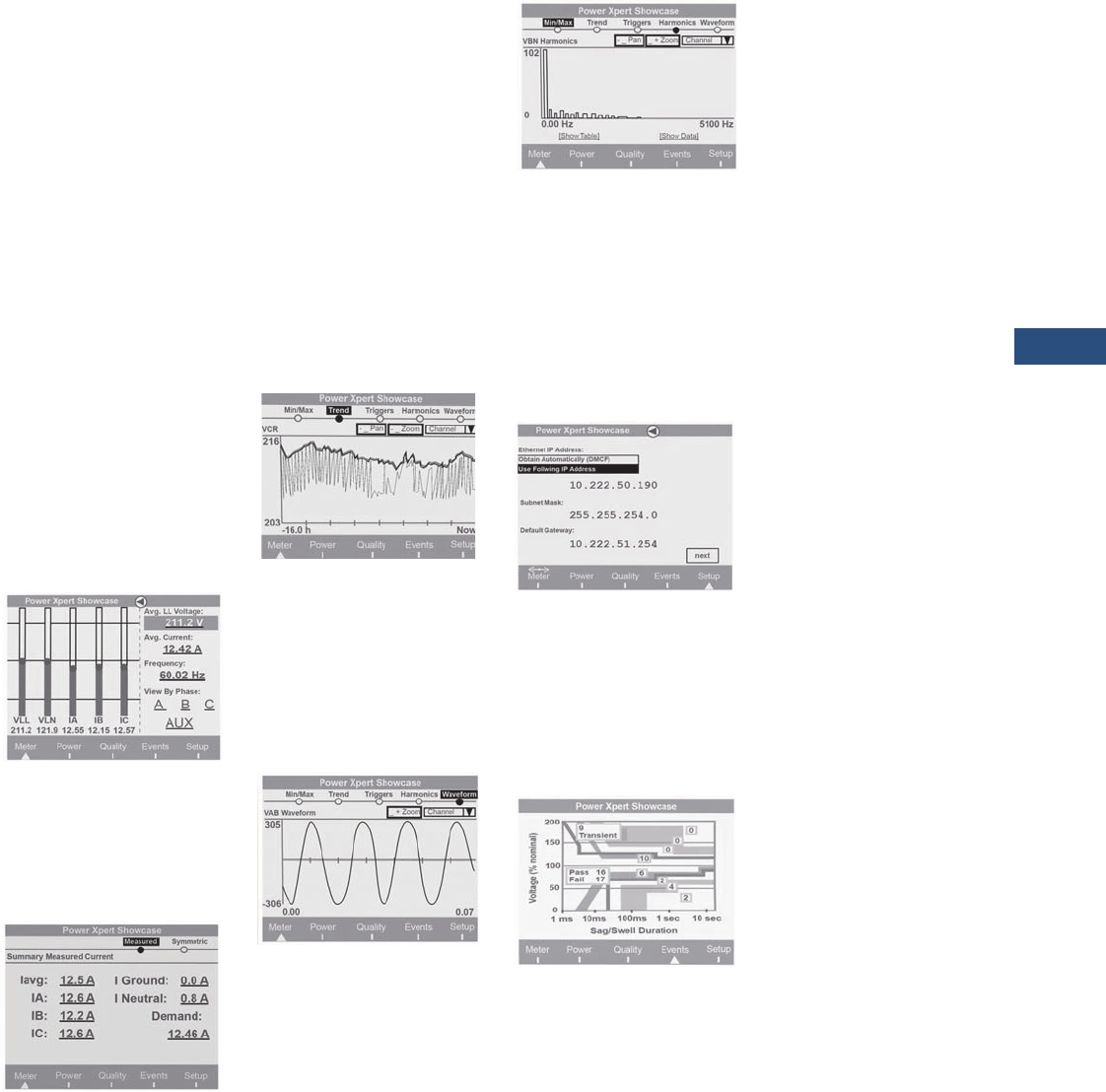
Volume 3—Power Distribution and Control Assemblies CA08100004E—March 2016 www.eaton.com V3-T9-23
9
9
9
9
9
9
9
9
9
9
9
9
9
9
9
9
9
9
9
9
9
9
9
9
9
9
9
9
9
9
9.2
Metering Devices, Protective Relays, Software and Connectivity
Metering Devices
Power Xpert 4000/6000/8000 Graphic Display (Option) Features
A menu-driven graphical
display with information
organized into a user-friendly
information architecture.
The homepage (see below)
offers:
●Graphical level indicator
based on a statistical
analysis for three-phase
line-to-line and line-to-
neutral voltage and per
phase currents to quickly
indicate out of normal
readings
●Large easy-to-read average
L-L voltage average phase
currents and system
frequency can be
highlighted and selected
using the navigation
control dial to drill down
for additional detail
●Menu selections for meter,
power, quality, events and
setup are shown for ease
of navigation into display
for more detail, or basic
device setup
Homepage
Highlighting a field such as
the avg. current value and
pressing the navigation control
dial brings up a detail screen
like the one below.
Current Summary
Highlighting an individual
reading on the detail
summary level screen and
selecting it drills down to a
level including links to min./
max., historical trend plots,
triggers, harmonic spectral
data and waveform viewing.
Selecting the trend plot for
a given parameter displays
a historical graph of the
selected parameter over
the last 16 hours. The zoom
buttons change the time
scale to one of several data
views based on historical
averages with min./max. The
Pan button allows scrolling
within the selected view.
Trend Plot
Waveforms can be displayed
for currents and voltages.
The waveforms can be
viewed on demand for
steady-state conditions.
Triggered waveforms can
also be displayed to view
sag/swell or transient data.
Waveform Viewer
Harmonic Spectrum
The harmonic spectral plot
displays both harmonics and
interharmonics up to the
85th order. A detailed table
also includes individual
magnitudes and angles
of current and voltage
harmonics, as well as a
harmonic power calculation
at each frequency.
Ethernet Settings
Ethernet and other settings
can be input or verified via
the Power Xpert Meter
LCD display.
Note: Some of the other settings
are specific only to the Web
Browser GUI.
ITIC Plot (Power Xpert 6000/8000)
The Power Xpert Meter
classifies disturbances and
summarizes the results
graphically using the ITIC plot.
The number of ITIC sags and
swells are indicated for each
of nine severity levels.
A pass/fail summary is
shown to indicate how many
events are outside the ITIC
pass zone.
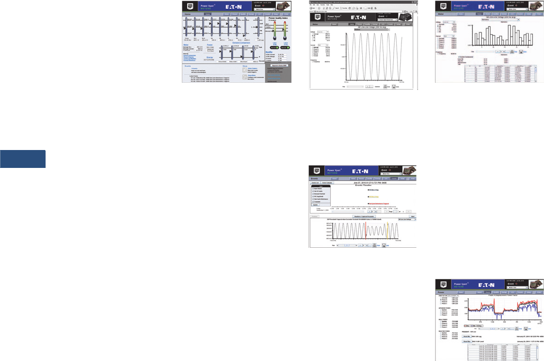
V3-T9-24 Volume 3—Power Distribution and Control Assemblies CA08100004E—March 2016 www.eaton.com
9
9
9
9
9
9
9
9
9
9
9
9
9
9
9
9
9
9
9
9
9
9
9
9
9
9
9
9
9
9
9.2
Metering Devices, Protective Relays, Software and Connectivity
Metering Devices
Power Xpert Graphic Display
(Option) Screens
Meter Top Level Screen
V-LL avg, V-LN avg, IA, IB, IC,
Iavg, freq.
Meter Detail Screens
Per phase detail L-L, L-N,
Symmetrical Comp, Aux.
Channels, Min./Max. with
date/time of occurrence,
Trend Plots, Triggers,
Phasors.
Power Top Level Screen
Three-Phase Power Factor,
kWHr, kWd, Real-Time kW,
kVAR, kVA, Load Profile Link.
Power Detail Screens
Per phase detail, kVA, kVAR,
kW, Min./Max. with date/
time of occurrence, Trend
Plots, Triggers.
Quality Top Level Screen
10 min. and 24 hr. PQIndex,
THDI, THDV, K-factor, Crest
Factor, Flicker Pst,%9’s of
Reliability.
Quality Detail Screens
Per phase detail L-L,
L-N,V aux, Odd, Even,
Interharmonics, Present,
Min/Max, Trend Plots,
Harmonic spectrum plots,
waveform plots.
Events Top Level Screen
Active/Acknowledged Event
list, Trigger List, System Log,
ITIC Curve Link.
Event Detail Screens
Event List, Condition,
Acknowledge Button,
Trigger Date/Time, Trigger
description.
Setup Top Level Screen
View setup, Edit setup,
Login, Logout.
Setup Detail Screens
Quick Setup, Trigger setup,
Detail setting.
Power Xpert 4000/6000/8000 Web Browser Views
Power Xpert 4000/6000/8000 Web
Browser Homepage (Note: 4000 does
not include flicker, ITIC)
Power Xpert Meter 4000/
6000/8000’s embedded
Web server offers Eaton
customers a new level of
accessibility to the critical
information required to
manage the electrical
distribution system. The
embedded Web server
includes real-time circuit
information in both numeric
and graphical formats to help
monitor circuit parameters
such as current loading,
voltage and power levels,
power factor.
The Web server also provides
the energy and demand
readings required to help
manage the cost of energy.
Readings include kWh,
kVARh, delivered and
received and kVAh with
time-of-use and separate
status input controlled energy
accumulation to account for
energy during special times
such as rate alert periods
or stand-by generator times
of operation.
The Web server also includes
critical information regarding
Power Quality such as
harmonic distortion, flicker
(Power Xpert Meter 6000/
8000), crest factor, K-Factor
and more.
Steady-State Waveform
The Web server allows the
user to view waveforms of
the voltage and current to
spot power quality problems
such as notching.
Events Timeline
(Power Xpert 6000/8000)
View and understand the
sequence of events that have
occurred during a period
of time. Plot color-coded
events on captured
waveforms to gain insight
into the sequence of events
from one single cycle to the
next one. This provides the
user an excellent vantage
point to review and compare
multiple events at an
unprecedented resolution.
Harmonic Spectral Plot
The harmonic spectral plot
displays both harmonics and
interharmonics up to the
85th order. A detailed table
also includes individual
magnitudes and angles of
current and voltage
harmonics, as well as a
harmonic power calculation
at each frequency. Even, odd
and total THD are displayed
for diagnostic purposes. In
addition, the Power Xpert
6000/8000 provides
interharmonics, which allow
users to see what is going
on between the integer
multiples of the fundamental.
Historical Trend Plot
Graphical Trending of Data
The Power Xpert Meter 4000/
6000/8000 embedded Web
server supports graphical
trend charts of key circuit
measurements such as
current, voltage, power and
energy. The trend chart
supports a zoom feature
that allows the user to view
data over a short period of
16 hours or a longer period of
48 months. The trend chart
has a horizontal slider bar
control to manage scrolling
forward and backward
through the data. Trend
charts of basic readings
include minimum, maximum
and average readings. Trend
charts of energy data also
display demand values.
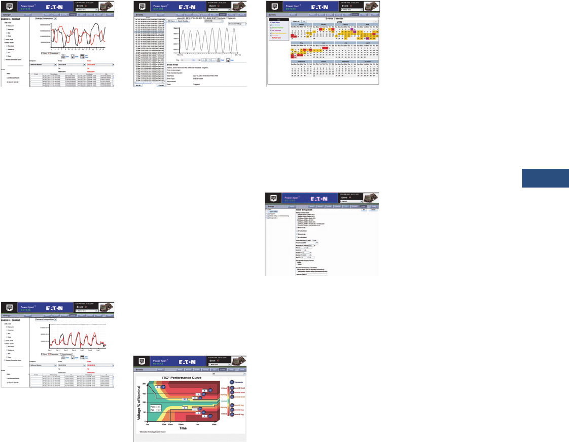
Volume 3—Power Distribution and Control Assemblies CA08100004E—March 2016 www.eaton.com V3-T9-25
9
9
9
9
9
9
9
9
9
9
9
9
9
9
9
9
9
9
9
9
9
9
9
9
9
9
9
9
9
9
9.2
Metering Devices, Protective Relays, Software and Connectivity
Metering Devices
Energy Comparison
Energy usage patterns can be
effortlessly analyzed with the
month-to-month, week-to-
week comparison chart. Raw
data can be easily exported
with the “Save Table” option
to other applications such as
Excel for further analysis or
graphing (firmware version
12.x.x and higher only).
Note: All data logging for
trend plotting is automatically
preconfigured in all of the Power
Xpert Meter 4000/6000/8000
meters. In addition, the 6000
and 8000 Series meters have
sag, swell and transient triggers
built-in according to the ITIC
(CBEMA) standard.
Demand Comparison
Demand comparison
compares power
consumption day-to-day,
month-to-month or week-to-
week. Power Xpert Meters
can set to measure demand
at 1 to 60 minute intervals.
Both sliding and fixed interval
windows are supported for
maximum flexibility.
Disturbance Recording
Sag/Swell Recording
60 cycles of waveform are
recorded at 256 samples per
cycle including 30 cycles of
pre- and post-trigger data.
The Power Xpert Meter 4000/
6000/8000 embedded Web
server supports viewing of
triggered waveforms one
channel at a time including
the ability to zoom and to
scroll horizontally using a
slider bar. Waveforms are
stored in Power Xpert
Meter’s 4000/6000/8000
non-volatile flash memory
using an industry standard
Comtrade format.
Waveforms can be
automatically sent out by
e-mail following an event,
or can be retrieved from an
FTP directory structure in the
meter module’s memory.
ITIC Analysis Plot
(Power Xpert Meter 6000/8000)
The ITIC Web page includes
counters to track the
occurrence of disturbances
and a pass/fail summary.
In addition, selecting any
disturbance counter links to
a detailed event view of the
disturbances in that ITIC
category. Disturbance
waveforms can be viewed
from the browser.
Events Calendar
(Power Xpert 6000/8000)
The Events Timeline calendar
view provides instant insight
to the frequency of power
events and helps detect
reoccurring problems. Color-
coded events can be filtered
to detect specific issues.
Configuration Page
Web Server Device
Configuration
Special software is not
required to configure a Power
Xpert Meter 4000/6000/8000.
The embedded Web server
includes comprehensive
device set-up capability.
Discrete Contact Inputs
The optional PXIO-B
expansion card offers 8 digital
inputs that are useful for a
variety of applications such as:
●Status indication with time
stamping of transitions
(1 ms precision).
●Pulse counting of KYZ or
other utility pulses such
as air, water or gas.
●High-speed triggering of
waveforms based on
events such as breaker
trips or static transfers
●Demand interval timing
taken from a master utility
meter end of interval pulse
Status inputs are self sourced
providing a nominal 24 Vdc
(20–30 Vdc) across the circuit.
Names can be configured for
each input for ease of use.
Relay Outputs
The optional PXIO-B card
includes three 5A form C
relay outputs rated for
240 Vac or 30 Vdc. These
outputs can be used for
applications such as:
●Alarm annunciation
●KYZ pulse output
Alarm outputs can be driven
from triggers based on
metering values. Output
modes include:
●Normal—relay energized
during alarm condition
●Latched—relay energized
by event trigger,
de-energized by
acknowledgement
●Timed—relay energized by
event trigger, maintained
for a programmed interval.
Communications Expansion
Card (CEC)
The optional CEC Card offers
two Ethernet connection
options, 10/100Base-T and
a fiber-optic port that can
be used for the following
applications:
●Monitoring, managing and
configuring the meter
remotely using a standard
Web browser interface like
Microsoft Internet Explorer
●Alarm notifications via
e-mail, SMTP
●Enabling access to the
meter’s FTP server
(energy, trend and
waveform logs)
●Providing Modbus TCP/IP
or RTU communications
to BMS systems
●Providing DNP 3.0 over
Ethernet to utility systems
●Providing SNMP
communications to
NMS systems
●Synchronizing with an
NTP server for 1ms
timestamping resolution
●Asset management
via SNMP to Network
Management Systems
●Updating firmware on
the meter
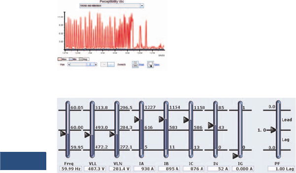
V3-T9-26 Volume 3—Power Distribution and Control Assemblies CA08100004E—March 2016 www.eaton.com
9
9
9
9
9
9
9
9
9
9
9
9
9
9
9
9
9
9
9
9
9
9
9
9
9
9
9
9
9
9
9.2
Metering Devices, Protective Relays, Software and Connectivity
Metering Devices
Flicker (EN61000-4-15; Power Xpert Meter 6000/8000)
Flicker values for
perceptibility, PST and PLT
are calculated based on
EN61000-4-15 guidelines.
Power at a Glance
Easily Upgrade Your Power
Xpert Meter 4000 to a 6000
Eaton understands that our
customers’ needs change
over time. That’s why we’ve
developed meters that can
grow with you. Once a Power
Xpert Meter is purchased,
you have the ability to
upgrade to a Power Xpert
Meter 6000, with no
intervention from Eaton,
when needed. All the
features of the Power Xpert
Meter 4000 that you have
been using and depend on
remain, however, once
updated, all the additional
features of the Power Xpert
Meter 6000 are available. The
self-upgrade is available on
Eaton’s website. You’ll need
a credit card, your Power
Xpert Meter 4000 serial
number and data code (you
will be presented with this
information if you are using
the upgrade link directly from
your Power Xpert Meter)
and your e-mail address.
Once you have completed
the purchase, we will send
you your new license key
information via e-mail that
will allow you to complete
the upgrade.
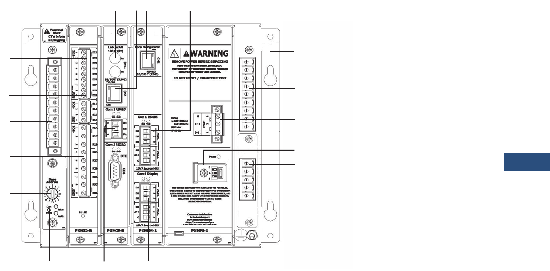
Volume 3—Power Distribution and Control Assemblies CA08100004E—March 2016 www.eaton.com V3-T9-27
9
9
9
9
9
9
9
9
9
9
9
9
9
9
9
9
9
9
9
9
9
9
9
9
9
9
9
9
9
9
9.2
Metering Devices, Protective Relays, Software and Connectivity
Metering Devices
Power Xpert Meter 4000/6000/8000 Module Layout
I/O Card
aDigital inputs 1–8 (option)
bSolid-state outputs 1–2 (option)
cRelay outputs 1–3 (option)
CT and Voltage Connections
dCT input connections
eStandard three-phase voltage phase inputs
fAux. channel voltage inputs (option)
Communication Expansion Card (LAN/WAN Ethernet Networking)
g100FX ST-type Ethernet (multi-mode) (option)
h10/100Base-T Ethernet (option)
iRS-485 (two-wire w/shield)—24V accessory power (com 2)
Standard Features
jLocal RJ-45 config. port (non-networkable Ethernet)
kRS-485 (two-wire w/shield) Modbus RTU (com 1)
lMeter mounting brackets
mSealable mode switch cover
nControl power (100–240 Vac and 110–250 Vdc) (±20%)
oDisplay RS-485 Network port (up to 15 meters)—24V accessory power (com 0)
pRS-232 (Tx Rx) Modbus RTU (com (3) (option)
qMeter base address
rCom Reset Button
a
b
c
d
q
ghj k
e
n
f
m
l
oip
r
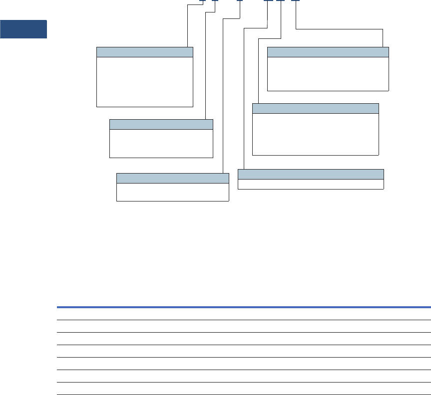
V3-T9-28 Volume 3—Power Distribution and Control Assemblies CA08100004E—March 2016 www.eaton.com
9
9
9
9
9
9
9
9
9
9
9
9
9
9
9
9
9
9
9
9
9
9
9
9
9
9
9
9
9
9
9.2
Metering Devices, Protective Relays, Software and Connectivity
Metering Devices
Catalog Number Selection
To order a Power Xpert
Meter 4000/6000/8000, the
catalog number should be
determined using the chart
shown below. The chart
illustrates how to include the
desired factory options as
part of a catalog number.
Option cards that are
selected at time of order
entry will be installed at the
factory. Option cards are
also field installable for
field upgrades.
If a display is required, it
should be ordered separately.
The multi-meter graphic
display is capable of
displaying data from an
RS-485 daisychain of up to
16 Power Xpert Meter 4000/
6000/8000 modules over a
distance of up to 1000 ft.
Power Xpert Meter modules
include panel mounting
brackets. The multi-meter
graphic display is designed to
mount separately. If back-to-
back meter to display panel
mounting is desired, a
mounting bracket kit is
available (PX-PMBA).
Example 1: PXM8251A1BB
(PXM 8000 Meter, w/ VAUX,
Std. Pwr, Com. Exp. &
I/O Cards)
Example 2: PXM6251A1BA
(PXM 6000 Meter, w/ VAUX,
Std. Pwr, Com. Exp. Card)
Power Xpert Meter 4000/6000/8000
Accessories
Power Xpert Meter 4000/6000/8000
Notes
1These items can be ordered separately or preinstalled in the meter by selecting option B in the model number.
Communication cable (standard Modbus RTU) is not included in the package for meter module connection.
Description
Catalog
Number
Graphic display module PXD-MMG
Communication expansion card for LAN/WAN Ethernet networking: 100FX fiber-optic, 10/100T, RS-485, RS-232 PXMCE-B 1
Digital I/O card: eight digital input, two solid-state output, three relay output PXMIO-B 1
Panel mounting bracket assembly for back-to-back meter to graphic display mounting PX-PMBA
Panel mounting bracket assembly for retrofitting a graphic display to an IQ Analyzer cutout PX-PMBB
Panel mounting bracket assembly for reduced graphic display rear clearance PX-PMBC
Power Xpert Meter 4000 to 6000 license upgrade key PXM-4KUPG
PXM 8 0 5 1 A 1 B B
Model Series
4 = 4000 (Standard
power quality, 2 GB)
6 = 6000 (Enhanced
power quality, 4 GB)
8 = 8000 (Premium PQ
w/ transient capture, 8 GB)
Power Supply Configuration
1 = Standard 100–240 Vac or
110–250 Vdc power supply
Card Slot 1 Configuration
1 = Standard Communications Module with RS-485
Card Slot 2 Configuration
A = No card option
B = Communication expansion card
for LAN/WAN Ethernet
networking w/10/100Base-T,
100F, RS-485, RS-232 ports
Card Slot 3 Configuration
A = No card option
B = I/O option card
(8 digital inputs, 2 solid-state
outputs, 3 relay outputs)
Voltage Input Configuration
0 = Standard (V1, V2, V3, V4)
2 = Standard plus auxiliary
(V6, V7, V8)
Example 1: PXM8251A5BB (PXM 8000 meter, w/ VAUX, std. pwr., com. exp. and I/O cards)
Example 2: PXM6251A6BA (PXM 6000 meter, w/ VAUX, std. pwr., com. exp.card)

Volume 3—Power Distribution and Control Assemblies CA08100004E—March 2016 www.eaton.com V3-T9-29
9
9
9
9
9
9
9
9
9
9
9
9
9
9
9
9
9
9
9
9
9
9
9
9
9
9
9
9
9
9
9.2
Metering Devices, Protective Relays, Software and Connectivity
Metering Devices
Technical Data and Specifications
Environmental Conditions
●Operating temperature:
●Meter: –20 to +70°C
●Display: –20 to +60°C
operating
●Storage temperature:
–40 to +85°C
●Operating humidity:
5% to 95% condensing
●Device weight: 7.1 lbs—
meter 2.1 lbs—display
●Meter and back of
display are pollution
degree 2
●Elevation to 6562 ft
(2000m)
Current Inputs (Each Channel)
●Conversion: 4096 samples
per cycle delta-sigma
converter digitally filtered
down to 512 samples
per cycle
●CT Input: 4096 rms
samples per cycle delta-
sigma converter digitally
filtered down to 512
samples per cycle for
anti-aliasing
●Burden: less than
10 milliohms
●Overload withstand:
500A for 1 second,
non-repeating
●Range: 0.005–20A
continuous
●Accuracy: 0.05% or
reading plus 0.01%
of full scale (from
50 milliamps to 20A)
Voltage Inputs (Each Channel)
●Conversion: 4096 rms
samples per cycle delta-
sigma converter digitally
filtered down to 512
samples per cycle for
anti-aliasing
●PT input: 120V–500,000V
primary
●Input range: 600V L-L,
347 L-N direct connect
●Nominal full scale:
100 0V rms
●Input impedance:
2 megohms
Frequency Range
●47–63 Hz
Harmonic Response
(Voltage, Current)
●127th harmonic
Accuracy
●ANSI C12.20 0.2 Class
●IEC 687 0.2 Class
Discrete Inputs
●Self sourced: 24 Vdc
Relay Output Contacts
●5A maximum, 240 Vac
maximum, 30 Vdc
maximum
●Lifetime: 1,000,000 no
load operations
●100,000 under rated
voltage and load
Solid-State Outputs
●Maximum load:
100 milliamps
●Maximum voltage: 30V
(externally sourced)
Control Power Input
●Input range AC:
100–240 Vac (±20%)
●Frequency range:
47–63 Hz
●Input range DC:
110–250 Vdc ±20%
●Burden 50 VA
●Ride-through: 1–5s
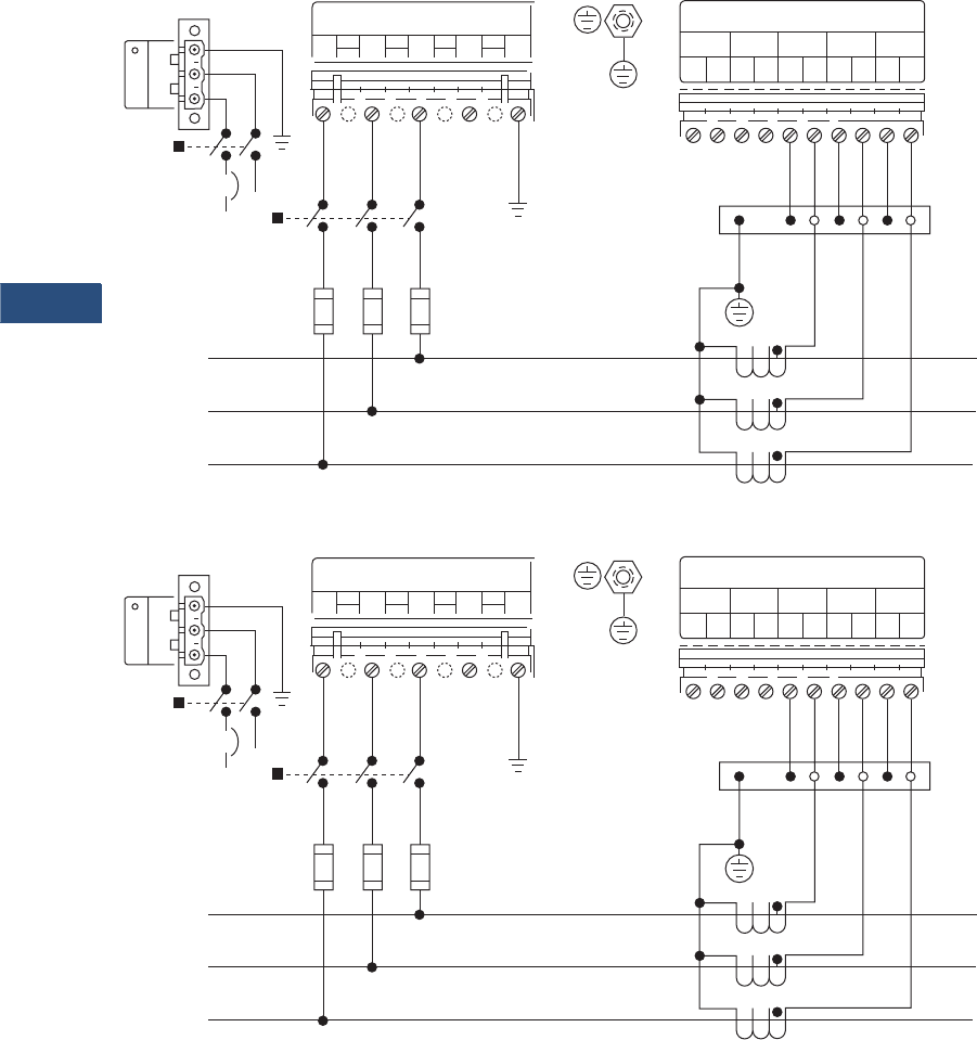
V3-T9-30 Volume 3—Power Distribution and Control Assemblies CA08100004E—March 2016 www.eaton.com
9
9
9
9
9
9
9
9
9
9
9
9
9
9
9
9
9
9
9
9
9
9
9
9
9
9
9
9
9
9
9.2
Metering Devices, Protective Relays, Software and Connectivity
Metering Devices
Wiring Diagrams
Three-Phase, Three-Wire Delta (Up to 600 Volts)
Three-Phase, Three-Wire Delta (Above 600 Volts)
Note
Based upon the voltage rating, you may need a control power transformer for the control power.
Voltage Inputs
V1 V2 V3 V4 VR
Disconnect
Switch
Disconnect
Switch
Breaker
(+) L
(–) N
123
Control
Power
L3
L2
L1
Load
Line
Shorting
Block
Protective
Earth /
Chassis
Ground
Current Inputs
5 4 3 2 1
52 51 42 41 32 31 22 21 12 11
PSI-
Voltage Inputs
V1 V2 V3 V4 VR
Disconnect
Switch
Disconnect
Switch
Breaker
(+) L
(–) N
123
Control
Power
L3
L2
L1
Load
Line
Shorting
Block
Protective
Earth /
Chassis
Ground
Current Inputs
5 4 3 2 1
52 51 42 41 32 31 22 21 12 11
PSI-
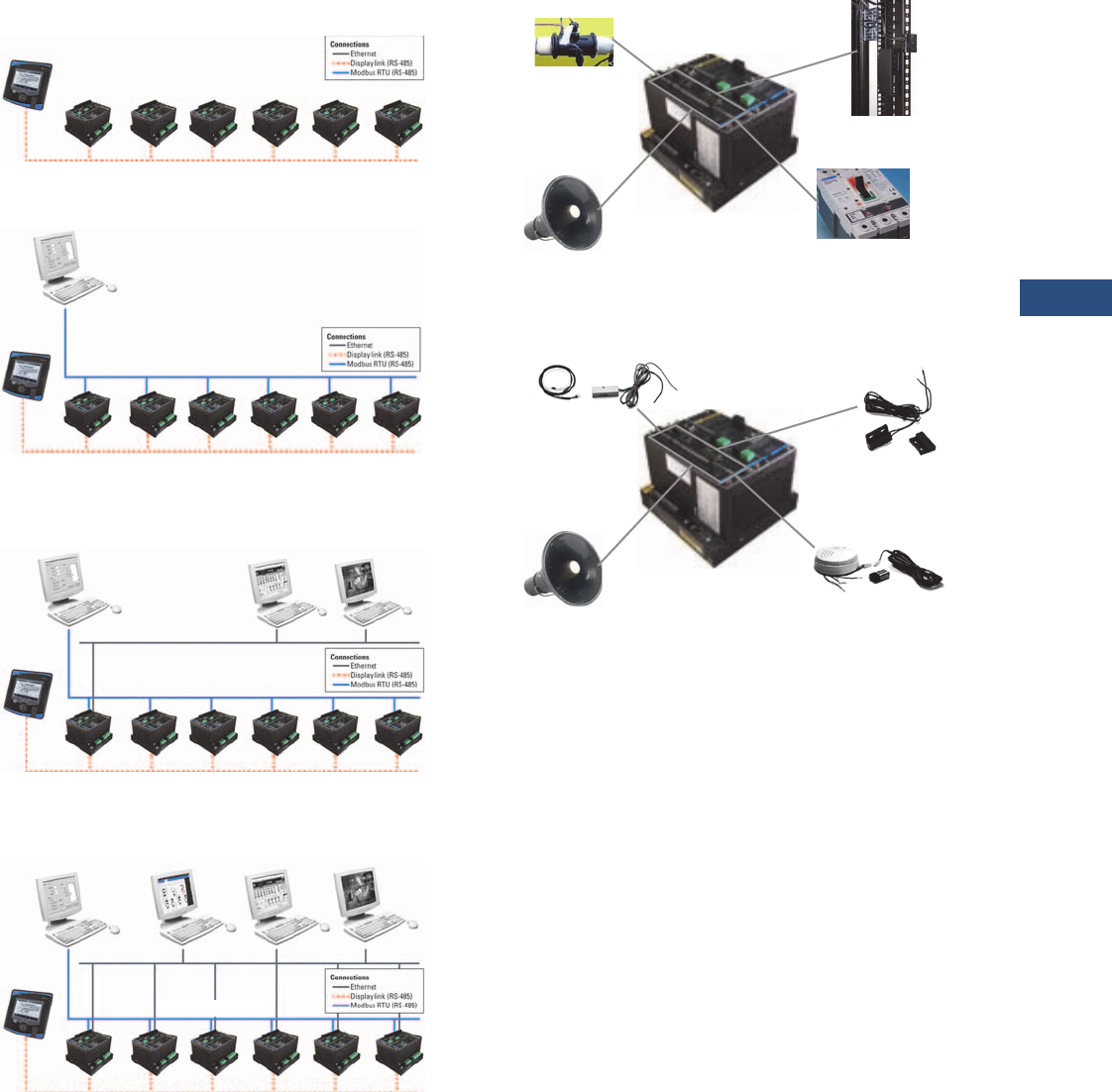
Volume 3—Power Distribution and Control Assemblies CA08100004E—March 2016 www.eaton.com V3-T9-31
9
9
9
9
9
9
9
9
9
9
9
9
9
9
9
9
9
9
9
9
9
9
9
9
9
9
9
9
9
9
9.2
Metering Devices, Protective Relays, Software and Connectivity
Metering Devices
Power Xpert Meters Configuration and Wiring Examples
Display Link
Modbus RTU (RS-485)—Non-Web Enabled
Web Enabled—Browser and Modbus TCP
Web Enabled—Advanced System Functionality
Accessories—I/O Card (Option)
IT Configuration Examples—Accessories—I/O Card (Option
Display Link (RS-485)
Up to 16 Meters can be Daisy-Chained to a Single
Power Xpert Meter LCD Display
…Up to 16
Display Link (RS-485)
Modbus RTU (RS-485)
Modbus RTU (RS-485)
Master
…Up to 16
Display Link (RS-485)
Modbus RTU (RS-485)
Modbus RTU (RS-485)
Master
…Up to 16
Modbus TCP
Master
Web
Browser
Display Link (RS-485)
Modbus RTU (RS-485)
Modbus RTU (RS-485)
Master
Modbus TCP
Master
Web
Browser
Power Xpert
Insight
Alarm
Flow Meter
(Pulse Count)
• Eight Programmable Digital Inputs
• Two Solid-State Programmable Outputs
• Three Relay Programmable Outputs
Trip and Sequence
of Events
Rack Monitoring—
Open Door/Tamper Switch
Smoke Alarm
Alarm
Water Leak and
Vibration Sensors
Rack Monitoring
— Open Door/
Ta m p e r Sw i t c h
• 8 Programmable Digital Inputs
• 2 Solid-State Programmable Outputs
• 3 Relay Programmable Outputs
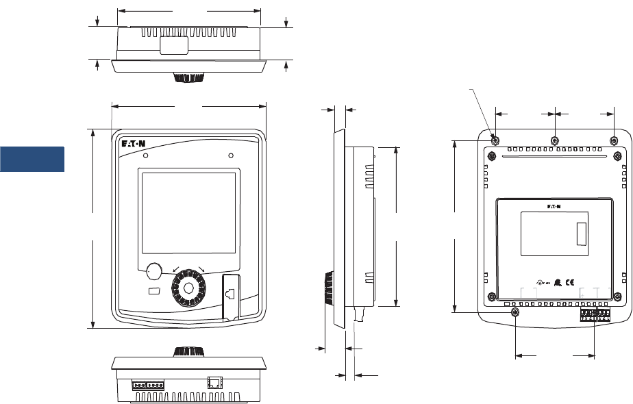
V3-T9-32 Volume 3—Power Distribution and Control Assemblies CA08100004E—March 2016 www.eaton.com
9
9
9
9
9
9
9
9
9
9
9
9
9
9
9
9
9
9
9
9
9
9
9
9
9
9
9
9
9
9
9.2
Metering Devices, Protective Relays, Software and Connectivity
Metering Devices
Dimensions
Approximate Dimensions in Inches (mm)
Power Xpert Meter 4000/6000/8000 Multimeter Graphic Display (PXD-MMG)—Sold Separately,
Supports up to 16 Power Xpert Meter 4000/6000/8000 Modules
CW
10/100 T
Li
nk
T
X
D
R
X
DG3
-
Power
Com 0
3
SH
1
23
4
S
H
C
O24
+
DG2
-
1
2
D
B
D
A
DG1
-
Display Link
24VDC Input
Customer Satisfaction for Techni cal Support
www.EatonElectrical or
htt // E t El t i l
1-800 -809-2772 or 1 -414-
E18555
9
F
ac
t
ory
S
ea
l
e
d
CW
G.O.#: XXXXXXXXXX
Catalog#: PX8054A1CB
Model#: PX8000
Serial#: 000042
Style#: 65D8054G010
Power Supply: 24 VDC (+/ -20%)
SELV, 8W MAX.
MADE
IN
CANADA
Date Code: C050131
Rev: 1
O
per
T
emp: -
20
TO
60°C
4.00 Ref.
(101.6)
3.00 Ref.
(76.2)
3.00 Ref.
(76.2)
1.45
(36.8)
1.50
(38.1)
5X #8 – 32 Thread
Thread Depth 0.31
7.22
(183.5)
7.80
(198.0)
9.02
(229.0)
0.57
(14.5)
7.22
(183.5)
7. 7 6 R e f .
(197.1)
1.04
(26.3)
0.46
(11.6)
Health Events
Push to Select • Hold for Help
BACK
Turn to Highlight
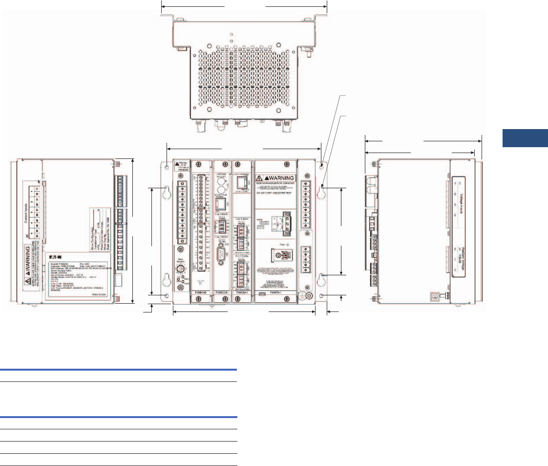
Volume 3—Power Distribution and Control Assemblies CA08100004E—March 2016 www.eaton.com V3-T9-33
9
9
9
9
9
9
9
9
9
9
9
9
9
9
9
9
9
9
9
9
9
9
9
9
9
9
9
9
9
9
9.2
Metering Devices, Protective Relays, Software and Connectivity
Metering Devices
Approximate Dimensions in Inches (mm)
Power Xpert Meter 4000/6000/8000 Module
Meter Base Unit
Display Unit
Note
1Including optional wall mounting brackets.
Width Height Depth
9.56 (242.8) 8.88 (225.6) 6.72 (170.8) 1
Height Width Depth
Projection In Front of Panel Surface
9.02 (229.0) 7.80 (198.1) 1.04 (26.3)
Behind Panel Surface
9.02 (229.0) 7.80 (198.1) 1.45 (36.8)
8.88 (255.6)
8.20 (208.3)
8.32
(211.3)
7.36
(186.9)
0.42 (10.7) 0.34
(8.6)
1.60
(40.6)
5.00
(127.0)
6.72 (208.3)
6.33 (160.8)
4x R0.11
(R2.8)
4x Ø 0.20
(Ø 5.2)
9.56 (242.8)

V3-T9-34 Volume 3—Power Distribution and Control Assemblies CA08100004E—March 2016 www.eaton.com
9
9
9
9
9
9
9
9
9
9
9
9
9
9
9
9
9
9
9
9
9
9
9
9
9
9
9
9
9
9
9.2
Metering Devices, Protective Relays, Software and Connectivity
Metering Devices
Power Xpert Meter 2000 Series
Contents
Description Page
Metering Products Family. . . . . . . . . . . . . . . . . . . . . V3-T9-6
Power Xpert Meter 4000/6000/8000 Series . . . . . . . V3-T9-15
Power Xpert Meter 2000 Series
IQ 250/260 Series Electronic Power Meters. . . . . . . V3-T9-45
IQ 130/140/150 Series Electronic Power Meters . . . V3-T9-51
IQ 150S/250S Self-Enclosed Electronic Meters . . . . V3-T9-56
IQ 35M . . . . . . . . . . . . . . . . . . . . . . . . . . . . . . . . . . . V3-T9-61
IQ Analyzer 6400/6600 Series . . . . . . . . . . . . . . . . . V3-T9-64
IQ DP-4000 Series . . . . . . . . . . . . . . . . . . . . . . . . . . V3-T9-72
IQ 230 Meters . . . . . . . . . . . . . . . . . . . . . . . . . . . . . V3-T9-78
Power Xpert Multi-Point Meter . . . . . . . . . . . . . . . . . V3-T9-85
IQ Energy Sentinel™ . . . . . . . . . . . . . . . . . . . . . . . . V3-T9-97
PM3 Monitoring and Metering Module . . . . . . . . . . V3-T9-106
Current Transformers (CTs). . . . . . . . . . . . . . . . . . . . V3-T9-107
Clamp-On Current Transformers . . . . . . . . . . . . . . . . V3-T9-116
IQ Flange . . . . . . . . . . . . . . . . . . . . . . . . . . . . . . . . . V3-T9-119
Panel Mounting Adapter Kit . . . . . . . . . . . . . . . . . . . V3-T9-120
Enclosed Meters. . . . . . . . . . . . . . . . . . . . . . . . . . . . V3-T9-121
An Eaton
Green Solution
Power Xpert Meter 2000 Series
Product Description
The Power Xpert Meter 2000
Series power quality
instrument monitors the
most critical aspects of an
electrical distribution system.
This premier power quality
metering instrument uses the
latest in advanced technology
to make it simple to use,
powerful, scalable and highly
flexible. The Power Xpert
Meter 2000 offers the
same level of intuitive user
interface design as the Power
Xpert Meter 4000/6000/8000,
presenting critical electrical
distribution system
information in a simple
to navigate and easy-to-
understand information
architecture.
The embedded Web server
displays comprehensive
power quality data using
standard Internet browsers
and allows for device
configuration from the
browser. The embedded
Web server presents real
time, historical and event
information in a browser-style
graphical format to help the
user interpret information
such as current loading,
voltage and power levels,
power factor, energy usage,
I/O status, power quality
measurements, as well
as harmonic plots. The
embedded Web server also
allows for waveform capture
and for visualizing steady-
state harmonic content that is
critical for power quality
analysis.
The Web server provides the
energy and demand readings
required to help manage the
cost of energy.
Application Description
Identify Power Quality Problems
to Help:
●Protect motors from
damage
●Preserve the integrity of
processes and batches
●Prevent blown capacitor
bank fuses
●Protect transformers and
conductors from
overheating
Monitor Circuit Loading
to Help:
●Avoid overloads and
nuisance overload trips
●Maximize equipment
utilization
●Manage emergency
overloads
Manage Energy Utilization
to Help:
●Reduce peak demand
charges and power
factor penalties
●Identify excessive energy
consumption

Volume 3—Power Distribution and Control Assemblies CA08100004E—March 2016 www.eaton.com V3-T9-35
9
9
9
9
9
9
9
9
9
9
9
9
9
9
9
9
9
9
9
9
9
9
9
9
9
9
9
9
9
9
9.2
Metering Devices, Protective Relays, Software and Connectivity
Metering Devices
Features, Benefits and
Functions
Metered/Monitored Parameters
Note: See Table on
Page V3-T9-38.
●V o l t s : L- L , L- N , A v g . L- L ,
Avg. L-N
●Phase and neutral currents
●Power: real, reactive
and apparent
●Frequency
●Power factor: apparent
●Energy: real, forward,
reverse, sum
●Demand: peak with date
and time
●% THD
●Minimum and maximum
values
●Harmonics
●Individual harmonics
●Demand comparisons
●Phasors
Accuracy
Note: Under typical operating
conditions.
●Currents: 0.1% RV
●Voltage: 0.1% RV
●Energy and demand
power:
0.2% in accordance
with ANSI C12.20
●Frequency: ±0.03 Hz
●Power factor: 0.2% RV
Communications
Multiple communications
ports including:
Standard
■RS-485 Modbus RTU
slave port
●10/100Base-T Ethernet
network port
Communication Protocols
Supported
●Modbus RTU
●Modbus TCP
●BACnet/IP
●Ethernet TCP/IP
●HTTP, HTTPS
●NTP (Network Time
Protocol)
●SMTP (Simple Mail
Transfer Protocol)
●SNMP (Simple Network
Management Protocol)
v1, v3
●DNP 3.0
Physical Characteristics
Format
●Power Xpert Meter 2000
with integral display
●Power Xpert Meter 2000
transducer only (no display)
meter
module
●NEMA rating: NEMA 12,
IP42 front of panel rating
Power Xpert 2000 Embedded
Web Server
The Power Xpert Meter 2000
embedded Web server offers
Eaton customers a new level
of accessibility to the critical
information required to
manage their electrical
distribution system. The
Web server includes real-time
information in both numeric
and graphical visual formats
to help monitor parameters
such as current loading,
voltage and power levels,
power factor, THD and more.
The Web server also provides
energy and demand readings
with graphic usage plots to
help analyze energy usage
patterns. Energy readings
include kWh, kVARh, delivered
and received and kVAh
with time.
The Power Xpert Meter 2000
embedded Web server
supports graphical trend charts
of key measurements such as
current, voltage, power and
energy. The trend chart
supports a zoom feature that
allows the user to view data
over predefined ranges from
as little as 16 hours to as much
as 4 years. The trend chart
includes zoom in/out buttons
and a horizontal slider bar
control to manage scrolling
forward and backward through
the data. Trend charts of basic
readings include minimum,
maximum and average
readings. Trend charts of
interval by interval energy data
also display peak demand.
Waveform Display
The Power Xpert Meter 2000
can record waveforms at up to
512 samples per cycle.
Waveform captures are
automatically stored on the
FTP server in the IEEE
standard COMTRADE file
format. This allows users to
view and analyze the
waveforms in any standard
free-of-charge or commercial
COMTRADE file viewer.
Historical Trend Logging
The Power Xpert Meter 2000
records historical data for
graphical viewing from the
embedded Web server.
Graphical views of historical
data support pan and zoom.
Over 100 standard metering
parameters are logged as
part of the standard meter
functionality including min./
max. and average for each
parameter. The averages
are calculated over the
interval period.
Energy Profile Data
The Power Xpert Meter 2000
records Real and Reactive
energy forward, reverse, net
and absolute sum, as well
as apparent energy (kVAH).
These readings are stored
on a fixed 5 minute interval.
Up to 4 status inputs can
be configured as energy
accumulators for counting
KYZ pulse inputs.
Demand Comparisons
Demand usage patterns can
be analyzed with the month-
to-month, week-to-week
comparison chart built into
the meter. Raw data can be
exported as a.csv file with the
“Save Table” option to other
applications for further
analysis and graphing.
Event Triggers
The Power Xpert Meter 2000
has two levels of configurable
event triggers:
●On-board meter limits
(PXM 2260/2270/2280/
2290)
●On-board gateway
card limits
The on-board meter limits
can be set for any measured
parameter, for up to 16 limits.
If either of the 16 limits are
exceeded, an alarm condition
will be present and illuminate
one of the LEDs on the meter
faceplate. The on-board
meter out of limits can also
be used to energize a relay
output, if so equipped.
The on-board gateway limits
can trigger an alarm off of any
measured parameter on any
of the PXM 2000 model
series. These triggers permit
pickup, reset and pickup
delay to be configured by
the user.
Event Logging
The Power Xpert Meter
2000 embedded Web server
allows the user to view a
list of triggered events. In
addition, a separate system
log records system operations
such as resets.
E-mail
The Power Xpert Meter 2000
contains the ability to send
e-mails based on an event
that has been triggered or
cleared along with the option
to send an event or data log
file. The Power Xpert Meter
2000 also has the ability to
send a configurable periodic
e-mail with meter
information.
Inputs and Outputs
Power Xpert Meter 2000 is
available with a standard KYZ
output and optional digital I/O
cards that includes:
●Two relay outputs/two
status inputs
●Four KYZ pulses/four
status inputs
●Four analog outputs
0–1 mA
●Four analog outputs
4–20 mA
Inputs can also be configured
for demand synch and pulse
counting. Inputs selected for
pulse counting can be scaled.
Accumulated pulse recordings
are maintained in profile
memory. Outputs can be
used for alarm annunciation.
Ratings
●Application to any PT ratio,
no PTs required to 600 Vac
●CT ratios to any CT ratio
●CT inputs available as 5 or
1A secondary
●Separate source control
power input:
●90–265 Vac or
100–370 Vdc
●Low voltage 18–60 Vdc
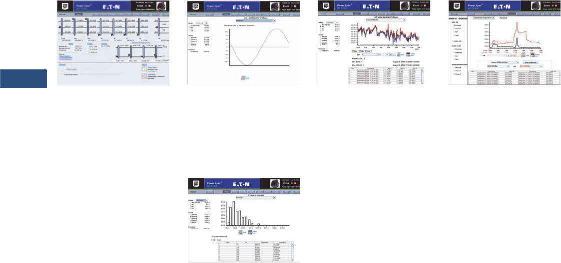
V3-T9-36 Volume 3—Power Distribution and Control Assemblies CA08100004E—March 2016 www.eaton.com
9
9
9
9
9
9
9
9
9
9
9
9
9
9
9
9
9
9
9
9
9
9
9
9
9
9
9
9
9
9
9.2
Metering Devices, Protective Relays, Software and Connectivity
Metering Devices
Displayed Information
●Monitored information is
available locally through the
display, the Web browser
or system power
management software
●True rms values through
40th harmonic
●ANSI C12.20 Class.2%
revenue metering
specification
Power Xpert 2000 Web Browser Views
Power Xpert Meter 2000 Web Browser
Power Xpert Meter 2000’s
embedded Web server offers
Eaton customers a new level
of accessibility to the critical
information required to
manage the electrical
distribution system. The
embedded Web server
includes real time circuit
information in both numeric
and graphical formats to help
monitor parameters such as
current loading, voltage and
power levels and power
factor. The Web server also
provides the energy and
demand readings required to
help manage the cost of
energy. Readings include
kWh, kVARh, delivered and
received and kVAh. The Web
server also includes critical
information regarding power
quality such as harmonic
distortion.
Real-Time Visualization of Harmonic
Content
The Web server offers a
waveform view to visualize
steady-state harmonic
content of the voltage
and current to spot power
quality problems.
Harmonic Spectral Plot
The harmonic spectral plot
displays harmonics up to the
40th order. A detailed table
also includes individual
magnitudes and angles of
current and voltage
harmonics, at each
frequency. Individual and
total THD are displayed for
diagnostic purposes.
Historical Trend Plot
Graphical Trending of Data
The Power Xpert Meter 2000
embedded Web server
supports graphical trend
charts of key circuit
measurements such as
current, voltage, power and
energy. The trend chart
supports a zoom feature
that allows the user to view
data over a short period of
16 hours or a longer period of
48 months. The trend chart
has a horizontal slider bar
control to manage scrolling
forward and backward
through the data. Trend
charts of basic readings
include minimum, maximum
and average readings. Trend
charts of energy data also
display demand values.
Energy Demand Profile
Energy managers can view
load profile data compared
against the peak demand.
The plot allows comparison
of present and past months’
usage.
Web Server Device
Configuration
Special software is not
required to configure a
Power Xpert Meter 2000.
The embedded Web server
includes a comprehensive
device configuration engine.
Discrete Contact Inputs
The optional I/O expansion
cards offers two or four
digital inputs that are useful
for a variety of applications
such as:
●Pulse counting of KYZ or
other utility pulses such as
air, water or gas
●Demand interval timing
taken from a master utility
meter end of interval pulse
Names can be configured for
each input for ease of use.
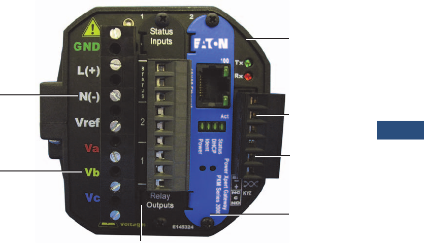
Volume 3—Power Distribution and Control Assemblies CA08100004E—March 2016 www.eaton.com V3-T9-37
9
9
9
9
9
9
9
9
9
9
9
9
9
9
9
9
9
9
9
9
9
9
9
9
9
9
9
9
9
9
9.2
Metering Devices, Protective Relays, Software and Connectivity
Metering Devices
Relay Outputs
The optional I/O card
includes two 5A Form C relay
outputs rated for 240 Vac or
30 Vdc or four Form A solid-
state outputs. These outputs
can be used for applications
such as:
●Alarm annunciation
●KYZ pulse output
Alarm outputs can be driven
from triggers based on
metering values.
Analog Outputs
The optional IO card includes
either four 4–20 mA outputs
or 0–1 mA outputs. These
outputs can be used for
applications such as:
●Input to BMS or PLC
systems for tracking a
measured meter
parameter
Standard Communications Card
The standard communications
card provides one Ethernet
connection and 10/100Base-
T port (copper only) that can
be used for the following
applications:
●Monitoring, managing and
configuring the meter
remotely using a standard
Web browser interface
●Alarm notifications via
email, SMTP
●Providing Modbus TCP/IP,
RTU and BACnet/IP
communications to
BMS systems
●Providing SNMP
communications to
NMS systems
●Synchronizing with an
NTP server
●Asset management
●Updating firmware on
the meter
PXM 2000 Rear View
aPower supply inputs
bSystem voltage inputs
cNEMA 12 gasket
dRS-485
eKYZ out
fMeter gateway card
gI/O slot
a
b
c
d
e
f
g

V3-T9-38 Volume 3—Power Distribution and Control Assemblies CA08100004E—March 2016 www.eaton.com
9
9
9
9
9
9
9
9
9
9
9
9
9
9
9
9
9
9
9
9
9
9
9
9
9
9
9
9
9
9
9.2
Metering Devices, Protective Relays, Software and Connectivity
Metering Devices
Power Xpert Meter 2250
●Measures basic meter
parameters
●256 MB for data logging
●Ethernet
●On-board gateway card
limits/alarms
Power Xpert Meter 2260
Features of PXM 2250 plus:
●Harmonics
●On-board meter hardware
limits to activate optional
relay outputs
●Visual indication of limits
exceeded at meter face
●512 MB for data logging
Power Xpert Meter 2270
Features of PXM 2260 plus:
●Harmonics, including
individual
●Waveform view to visualize
steady-state harmonic
content
●768 MB for data logging
The Power Xpert Meter 2280
Features of PXM 2270 plus:
●Records waveforms at up
to 64 samples per cycles
●Configures the total, pre-
and post-event cycles
Power Xpert Meter 2290
Features of PXM 2280 plus:
●Records waveforms at up
to 512 samples per cycles
Power Xpert Meters 2250/2260/2270/2280/2290
Note
These specifications are subject to change without notice and represent the maximum capabilities of the product with all options installed. This is not a complete feature list. Features and functionality
may vary depending on selected options, firmware version and product model. Please refer to the technical data sheet and User Manual for detailed specifications.
Power Xpert Meter
Feature 2250 2260 2270 2280 2290 Benefit
General
Embedded Web server ■■■■■Use a standard Web browser to monitor and manage the meter over the network
Firmware flash upgrade support ■■■■■Enables you to flash the meter with the latest firmware upgrades
Power, Energy and Demand
Voltage, current: per phase minimum, maximum, average, trend graph
analysis, export, print
■■■■■Review voltage and current trends, export, print and analyze parameters right on the
meter or external software
Demand: forward, reverse, net sum, profile, export, print, plot comparisons
month-to-month, week-to-week
■■■■■Plot two months or two weeks for vivid demand comparison, receive e-mails with
trend logs
Power, apparent, real, reactive, power factor ■■■■■Review power usage and power factor and avoid potential PF penalties
Energy: forward, reverse, net, sum ■■■■■Keep track of your energy usage, identify peaks to conserve energy usage, receive e-mails
with trend logs
Power Quality Analysis
Statistical analysis (min., max., average) ■■■■■Review statistical trends, identify past and future problem areas
Sampling rate, maximum samples/cycle 400 400 400 400 400 High sampling rate resulting in high accuracy
Security
Secure two level user access privileges ■■■■■Define appropriate security access level per user
Communications
Modbus TCP ■■■■■Easy integration with standard protocol to power management and other software
Modbus RTU ■■■■■Integrate meters to existing Modbus networks, daisy chain several (1–32)
meters together
BACnet/IP ■■■■■Easily integrate into existing building management systems without the need for external
protocol adapters
HTTP, HTTPS ■■■■■Communicate to the meter over the Internet via standard Web browser
SNMP (Simple Network Management Protocol) ■■■■■Communicate with the meter via Simple Network Protocol; hook to existing NMS system
SMTP (Simple Mail Transfer Protocol) ■■■■■Send e-mail messages via standard Simple Mail Transfer Protocol
NTP (Network Time Protocol) ■■■■■Network Time Protocol support enables the meter to synchronize time over the network
DNP 3.0 ■■■■■Easy integration with DNP networks (serial)
Trend measurements CSV file export ■■■■■Easily export trend measurements to third-party applications, in standard CSV file format

Volume 3—Power Distribution and Control Assemblies CA08100004E—March 2016 www.eaton.com V3-T9-39
9
9
9
9
9
9
9
9
9
9
9
9
9
9
9
9
9
9
9
9
9
9
9
9
9
9
9
9
9
9
9.2
Metering Devices, Protective Relays, Software and Connectivity
Metering Devices
Power Xpert Meters 2250/2260/2270, continued
Note
These specifications are subject to change without notice and represent the maximum capabilities of the product with all options installed. This is not a complete feature list. Features and functionality
may vary depending on selected options, firmware version and product model. Please refer to the technical data sheet and User Manual for detailed specifications.
Standards and Certifications
●UL/cUL Electrical and
Electronic Measuring and
Test Equipment 22CZ
●Accuracy: IEC/EN60687
0.2 Class, ANSI C12.20
0.2 Class
●ANSI C62.41 Burst
●CE Mark
Power Xpert Meter
Feature 2250 2260 2270 2280 2290 Benefit
Logs
Trend logging ■■■■■Log trend information for easy statistical analysis
Load profile ■■■■■Review the load profile graph to get a better understanding of your electrical load
versus time
Event logging ■■■■■Log events for retrospective event analysis
Memory and Storage
Memory, MB 256 512 768 768 768 Store trend data and events for historical analysis
Harmonics
Harmonic levels 40th 40th 40th 40th Allows you to identify potential harmful harmonics
Total harmonic distortion (THD) ■■■■Review the total harmonic distortion level directly on the meter
Individual harmonics ■■■Provides simple metric for power quality viewable from the embedded Web server
Waveform
Waveform display ■■■A single-cycle waveform view on a PC, through embedded Web server, to visualize steady-
state harmonic content to identify power quality issues
Waveform recording 64 512 Ability to record waveforms up to specified samples/cycle
I/O
I/O (two relay outputs/two status inputs,
four KYZ pulses/four status inputs,
four analog outputs 0–1 mA,
four analog outputs 4–20 mA)
Opt Opt Opt Opt Opt The Power Xpert meter 2000 I/O Cards are extremely flexible and can be used in a large
variety of different applications. Digital inputs and relay outputs can be programmed to
interact during various conditions defined by the user. Various third-party devices, such as
alarms, pulse meters, trip units and sensors, can be easily integrated to the Power Xpert
Meter 2000. Triggers and events can be tied to the meter’s standard functions such as
e-mail, logs and trends. Analog outputs can be programmed to output meter parameters
to BMS or PLC systems
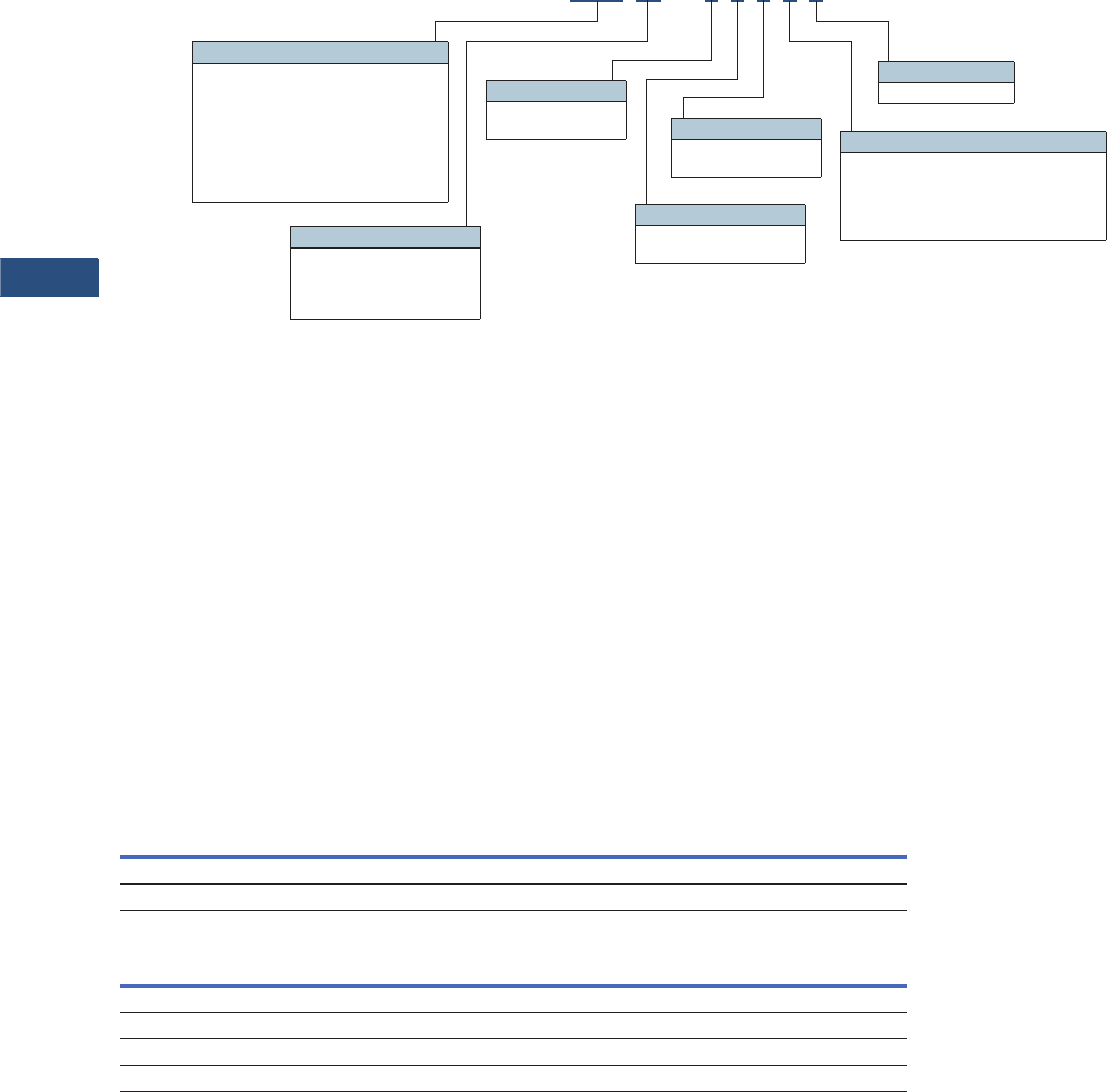
V3-T9-40 Volume 3—Power Distribution and Control Assemblies CA08100004E—March 2016 www.eaton.com
9
9
9
9
9
9
9
9
9
9
9
9
9
9
9
9
9
9
9
9
9
9
9
9
9
9
9
9
9
9
9.2
Metering Devices, Protective Relays, Software and Connectivity
Metering Devices
Catalog Number Selection
Power Xpert Meter 2000
Note
1Refer to Page V3-T9-39 for model-specific features.
To order a Power Xpert Meter
2000, the catalog number
should be determined using
the chart shown above.
The chart illustrates how to
include the desired factory
options as part of a catalog
number. Option cards that are
selected at time of order
entry will be installed at the
factory. Option cards are
also field installable for
future upgrades.
Power Xpert meter modules
include panel mounting
brackets.
Example 1:
PXM2270MA65145 (PXM
2270 Meter/Display 60 Hz, 5A,
90–265 Vac/Vdc W/4AO).
Example 2:
PXM2250MA65105 (PXM
2250 Meter/Display 60 Hz, 5A,
90–265 Vac/Vdc).
Accessories
Power Xpert Meter 2000
Power Xpert Meter 2000 I/O Cards
PXM 2250 M A 6 5 1 0 5
Frequency
5 = 50 Hz system
6 = 60 Hz system
I/O Slot 2
5 = Gateway card
I/O Slot 1
0 = None
1 = 2 Relay outputs/2 status inputs
2 = 4 KYZ pulses/4 status inputs
3 = 4 Analog outputs: 0–1 mA
4 = 4 Analog outputs: 4–20 mA
Model Series 1
2250 = Energy meter
2260 = Power quality meter
2270 = Power quality plus meter
2280 = Power quality plus with up to 64
samples/cycle waveform recording
meter
2290 = Power quality plus with up to 512
samples/cycle recording meter
Example 1:PXM2270MA65145 (PXM 2270 Meter/Display 60 Hz, 5A, 90–265 Vac/Vdc W/4AO)
Example 2:PXM2250MA65105 (PXM 2250 Meter/Display 60 Hz, 5A, 90–265 Vac/Vdc)
Current Input
1 = 1 amp secondary
5 = 5 amp secondary
Power Supply
1 = 90–265 Vac/Vdc
4 = 24–60 Vdc
Meter Type
M= Meter (with integral
display)
T= Transducer only
(no display)
Description Catalog Number
Panel mounting bracket assembly for retrofitting a PXM 2000 to an IQ analyzer/IQ DP4000/IQ data cutout IQ250-PMAK
PXM 2000 Gateway card kit to upgrade an IQ 250/260 to a PXM 2000 PXM2000-GCK
Description Catalog Number
PXM 2000 I/O card—2 relay outputs/2 status inputs IQ250/260-IO1
PXM 2000 I/O card—4 KYZ Pulses/4 status inputs IQ250/260-IO2
PXM 2000 I/O card—4 analog outputs—0–1 mA IQ250/260-IO3
PXM 2000 I/O card—4 analog outputs—4–20 mA IQ250/260-IO4

Volume 3—Power Distribution and Control Assemblies CA08100004E—March 2016 www.eaton.com V3-T9-41
9
9
9
9
9
9
9
9
9
9
9
9
9
9
9
9
9
9
9
9
9
9
9
9
9
9
9
9
9
9
9.2
Metering Devices, Protective Relays, Software and Connectivity
Metering Devices
Technical Data and Specifications
PXM 2250/2260/2270 Electronic Power Meter Technical Information
Current Inputs
●Class 10: 5 amp nominal,
10 amp maximum
●Class 2: 1 amp nominal,
2 amp maximum
●Fault current withstand:
●100 amps for
10 seconds
●300 amps for 3 seconds
●500 amps for 1 second
●Continuous current
withstand: 20 amps for
screw terminated or pass-
through connections
●Programmable current:
full scale to any CT ratio
●Burden: 0.005 VA per
phase maximum at
11 a mp s
●Pickup current: 0.1% of
nominal
●Class 10: 5 mA
●Class 2: 1 mA
●Connections:
●Pass-through wire gauge
dimension: 0.177 inches
(4.5 mm)
●Quick connect: 0.25-inch
(6.35 mm) male tab
Voltage Inputs
●Range:
●Line-to-neutral
20–576 Vac
●Line-to-Line 0–721 Vac
●Programmable voltage
range: full scale to any
PT ratio
●Supported systems:
●Three element wye,
2.5 element wye
●Two element delta, four-
wire delta systems
●Input impedance:
1 megohm/phase.
●Burden: 0.36 VA/phase
maximum at 600V;
0.014 VA at 120V
●Connection: 7-pin
0.400-inch pluggable
terminal block, AWG
#12–26 (0.129–3.31 mm2)
Isolation
●All inputs and outputs are
galvanically isolated to
2500 volts
Environmental Ratings
●Operating temperature:
–20ºC to +70°C
●Storage temperature:
–20ºC to +70°C
●Operating humidity: to
95% RH noncondensing
●Faceplate rating:
●NEMA 12
●Mounting gasket
included
Sensing Method
●Voltage, current: true rms
●Power: sampling at over
400 samples per cycle on
all channels
●Harmonics resolution:
40th order
Update Rate
●Watts, VAR and VA:
100 msec at 60 Hz
●All other parameters:
1 second at 60 Hz
Power Supply
●AC/DC voltage option:
90–265 Vac at 50/60 Hz or
100–370 Vdc, universal AC/
DC supply
●DC voltage option:
18–60 Vdc
●Burden: 10 VA maximum
Serial Communications Format
●Connection type: RS-485
(through back plate)
●Com port baud rate:
9600–57,600 bauds
●Com port address: 01–247
●Data format: 8-bit, no parity
●Protocols: Modbus ASCII,
RTU or DNP 3.0
Network Communications
Format
●Connection type: RJ-45
10/100Base-T Ethernet
network port
●Protocols: Ethernet TCP/IP,
Modbus TCP, BACnet/IP,
HTTP, HTTPS, NTP, SMTP,
SNMP
KYZ Pulse
●Contacts: one Form A
●On resistance, maximum:
35 ohms
●Peak switching voltage:
350 Vdc
●Continuous load current:
120 mA
●Peak load current: 350 mA
(10 ms)
●Off-state leakage current at
350 Vdc: 1 uA
●Opto-isolation: 3750 Vac
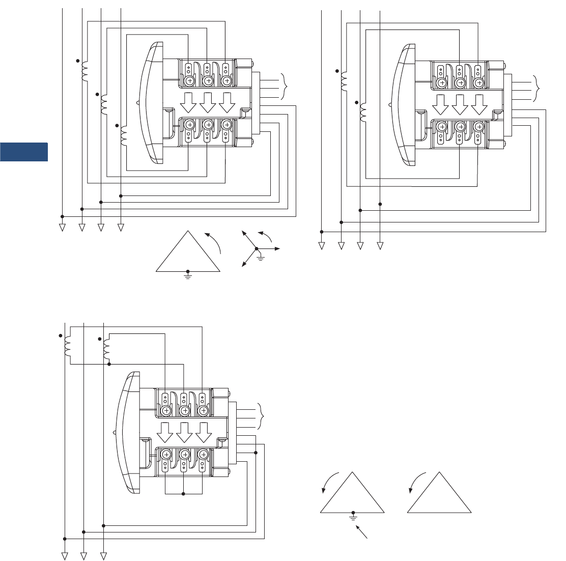
V3-T9-42 Volume 3—Power Distribution and Control Assemblies CA08100004E—March 2016 www.eaton.com
9
9
9
9
9
9
9
9
9
9
9
9
9
9
9
9
9
9
9
9
9
9
9
9
9
9
9
9
9
9
9.2
Metering Devices, Protective Relays, Software and Connectivity
Metering Devices
Wiring Diagrams
Service: Wye or Delta, Four-Wire with No PTs, Two or Three CTs
Service: Delta, Three-Wire with No PTs, 2 CTs
Note: Based upon the voltage rating, you may need a control power transformer for the control power.
GND
L (+)
N (–)
VRef
A
B
C
HI
LO
Ic
HI
LO
Ib
HI
LO
Ia
AB C
AB C
Power
Supply
N
N
GND
L (+)
N (–)
VRef
A
B
x
HI
LO
Ic
HI
LO
Ib
HI
LO
Ia
AB C
AB C
Power
Supply
N
N
C
BA
C
B
A
GND
L (+)
N (–)
VRef
A
B
C
HI
LO
Ic
HI
LO
Ib
HI
LO
Ia
AB C
AB C
Power
Supply
C
BA
or
C
BA
Not Connected to Meter
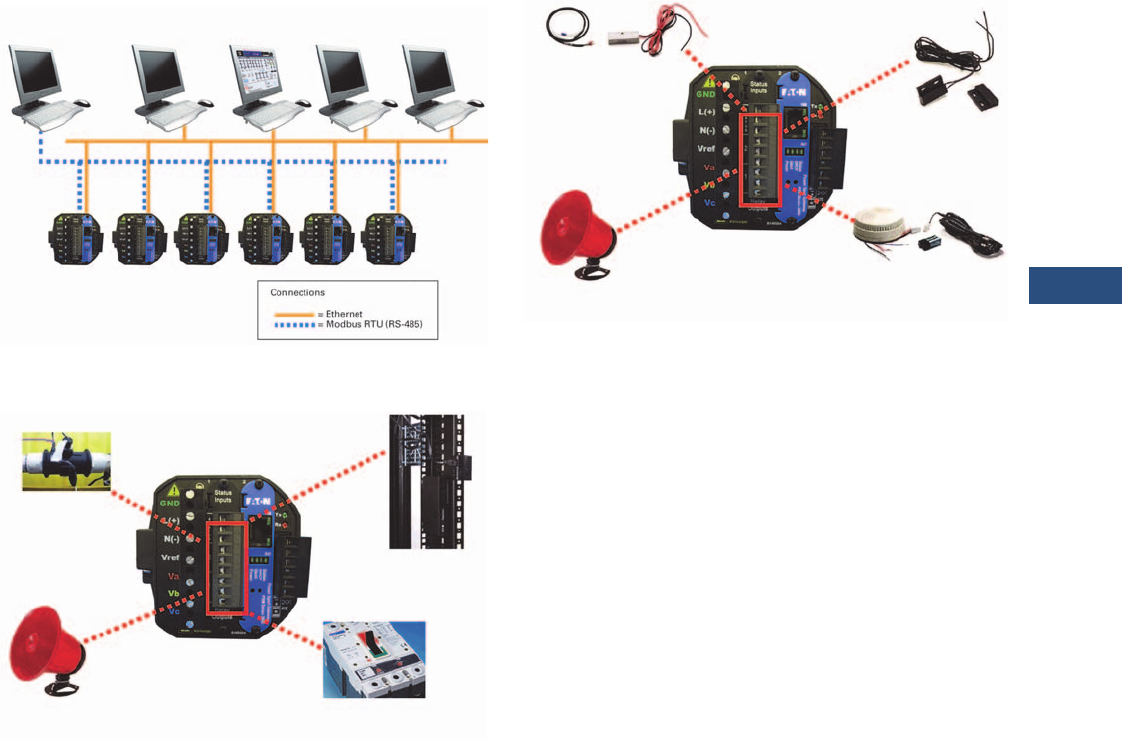
Volume 3—Power Distribution and Control Assemblies CA08100004E—March 2016 www.eaton.com V3-T9-43
9
9
9
9
9
9
9
9
9
9
9
9
9
9
9
9
9
9
9
9
9
9
9
9
9
9
9
9
9
9
9.2
Metering Devices, Protective Relays, Software and Connectivity
Metering Devices
Power Xpert Meters Configuration and Wiring Examples
PXM 2000 Display Front View
Accessories—I/O Cards (Option)
IT Configuration Examples—Accessories—I/O Cards
(Option)
Modbus RTU
(RS-485)
Modbus RTU
(RS-485) Master
Modbus TCP
Master
Web
Browser
Power Xpert
Insight
Building
Automation
System
Alarm
Flow Meter
(Pulse Count)
• Two relay programmable outputs/two programmable inputs
• Four KYZ pulses/four programmable inputs
• Four programmable analog outputs
Trip and Sequence
of Events
Rack Monitoring
— Open Door/
Ta m p e r Sw i t c h
Smoke Alarm
Alarm
Water Leak and
Vibration Sensors
Rack Monitoring
— Open Door/
Ta m p er Sw i t c h
• Two relay programmable outputs/two programmable inputs
• Four KYZ pulses/four programmable inputs
• Four programmable analog outputs
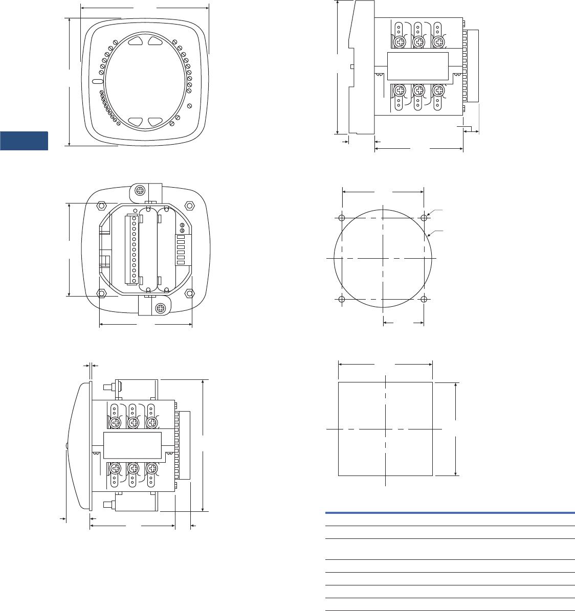
V3-T9-44 Volume 3—Power Distribution and Control Assemblies CA08100004E—March 2016 www.eaton.com
9
9
9
9
9
9
9
9
9
9
9
9
9
9
9
9
9
9
9
9
9
9
9
9
9
9
9
9
9
9
9.2
Metering Devices, Protective Relays, Software and Connectivity
Metering Devices
Dimensions
Approximate Dimensions in Inches (mm)
PXM 2000 Display Front View
PXM 2000 Rear View
PXM 2000 Meter/Display Side View
4.85
(123.2)
4.85
(123.2)
3.54
(89.9)
3.54
(89.9)
5.02
(127.5)
0.95
(24.0) 3.25
(82.6)
0.08
(2.0)
0.77
(19.6)
PXM 2000 Transducer Only Side View
ANSI Mounting Panel Cutout
DIN Mounting Cutout
4.85
(123.2)
0.91
(23.1) 3.25
(82.6)
0.77
(19.6)
4.00
(101.6)
3.38
(85.9)
1.69
(42.9)
4 x .02
(0.5)
3.62
(92.0)
3.62
(92.0)
Description Specifications
Weight 2 lbs (0.9 kg)
Basic unit 5.00 (127.0) H x 4.90 (124.5) W x 5.00 (127.0) L
PXM 2250/2260/2270 Mounts in 3.62-inch (92.0) mm DIN and ANSI C39.1
round cut-outs
Shipping container dimensions 6-inch cube
Tolerance ±0.1 inches (2.54 mm)
Projection in front of panel surface 4.85 (123.2) H x 4.85 (123.2) W x 1.01 (25.6) L
Projection behind panel surface 4.85 (123.2) H x 4.85 (123.2) W x 1.01 (25.6) L

Volume 3—Power Distribution and Control Assemblies CA08100004E—March 2016 www.eaton.com V3-T9-45
9
9
9
9
9
9
9
9
9
9
9
9
9
9
9
9
9
9
9
9
9
9
9
9
9
9
9
9
9
9
9.2
Metering Devices, Protective Relays, Software and Connectivity
Metering Devices
IQ 250 and 260 Electronic Power Meters
Contents
Description Page
Metering Products Family . . . . . . . . . . . . . . . . . . . . V3-T9-6
Power Xpert Meter 4000/6000/8000 Series . . . . . . V3-T9-15
Power Xpert Meter 2000 Series . . . . . . . . . . . . . . . V3-T9-34
IQ 250/260 Series Electronic Power Meters
Standards and Certifications. . . . . . . . . . . . . . . . V3-T9-46
Catalog Number Selection . . . . . . . . . . . . . . . . . V3-T9-47
Accessories . . . . . . . . . . . . . . . . . . . . . . . . . . . . V3-T9-47
Technical Data and Specifications. . . . . . . . . . . . V3-T9-48
Dimensions. . . . . . . . . . . . . . . . . . . . . . . . . . . . . V3-T9-50
IQ 130/140/150 Series Electronic Power Meters . . . V3-T9-51
IQ 150S/250S Self-Enclosed Electronic Meters. . . . V3-T9-56
IQ 35M. . . . . . . . . . . . . . . . . . . . . . . . . . . . . . . . . . . V3-T9-61
IQ Analyzer 6400/6600 Series . . . . . . . . . . . . . . . . . V3-T9-64
IQ DP-4000 Series . . . . . . . . . . . . . . . . . . . . . . . . . . V3-T9-72
IQ 230 Meters . . . . . . . . . . . . . . . . . . . . . . . . . . . . . V3-T9-78
Power Xpert Multi-Point Meter . . . . . . . . . . . . . . . . V3-T9-85
IQ Energy Sentinel™ . . . . . . . . . . . . . . . . . . . . . . . . V3-T9-97
PM3 Monitoring and Metering Module . . . . . . . . . . V3-T9-106
Current Transformers (CTs) . . . . . . . . . . . . . . . . . . . V3-T9-107
Clamp-On Current Transformers . . . . . . . . . . . . . . . V3-T9-116
IQ Flange . . . . . . . . . . . . . . . . . . . . . . . . . . . . . . . . . V3-T9-119
Panel Mounting Adapter Kit . . . . . . . . . . . . . . . . . . . V3-T9-120
Enclosed Meters . . . . . . . . . . . . . . . . . . . . . . . . . . . V3-T9-121
IQ 250/260 Series Electronic Power Meters
Product Description
The IQ 250 and IQ 260
Meters provide capabilities
you would not normally
expect in affordable, ultra-
compact meters, such as fast
sampling rate and accurate
metering for a full range of
power attributes. Providing
the first line of defense
against costly power
problems, Eaton’s IQ 250
and IQ 260 electronic power
meters can perform the work
of an entire wall of legacy
metering equipment using
today’s technology.
When space is at a premium,
yet you need ANSI C12.20
accuracy, the IQ 250/ 260
series fit the bill. These
meters are ideal for electrical
equipment assemblies,
machine control panels,
such as panelboard and
switchboard mains and
feeders, low voltage metal-
enclosed switchgear feeders
and motor control centers.
Requiring far less space than
other meters with similar
functionality, IQ 250/260
series fit into a standard ANSI
or IEC cutout on a panelboard
or other electrical equipment,
and therefore fit easily into
retrofit applications.
Application Description
●Utility and commercial
metering
●Substations, industrial
facilities, p
ower generation
sites and campuses
●Sub-metering
●Load studies and voltage
recording
●Analog meter replacement
Features and Benefits
●Measure and display real-
time information about
critical power parameters
with a sampling rate of 400
samples per cycle
●Monitor power utilization
and quality with ANSI
C12.20 accuracy
(0.2 percent)
●Optional 128 KB for data
logging, which guards
against loss of historical
data
●Verify meter accuracy
with KYZ test pulse self-
certification capabilities
●Standard Modbus RTU
communications
●Available as transducer
only or with display
●Designed to accommodate
upgrades
●Integrate into Eaton’s
Power Xpert architecture
for a holistic system-
level view

V3-T9-46 Volume 3—Power Distribution and Control Assemblies CA08100004E—March 2016 www.eaton.com
9
9
9
9
9
9
9
9
9
9
9
9
9
9
9
9
9
9
9
9
9
9
9
9
9
9
9
9
9
9
9.2
Metering Devices, Protective Relays, Software and Connectivity
Metering Devices
Additional Features
Features of IQ 250 and IQ 260 Electronic Power Meters
Notes
1Digital out with IQ 250 requires external command.
2Requires external power supply.
Standards and Certifications
●IEC 687: 0.2% accuracy
●ANSI C12.20: 0.2% accuracy
●ANSI C62.41: Burst
●UL/cUL: Electrical and
electronic measuring and
test equipment 22CZ
Features IQ 250 IQ 260
Instrumentation
Current, per phase ■■
Current demand ■■
Calculated neutral current ■■
Voltage, per phase (L-L, L-N) ■■
Frequency ■■
Power, Energy and Demand
Real, reactive and apparent power, total and per phase (kW, kVAR, kVA) ■■
Real, reactive and apparent energy, total and per phase (kWh, kVARh, kVAh) ■■
Real, reactive and apparent power demand ■■
Power factor, total and per phase ■■
Min./max. readings, I, V, PF, F, THD (IQ 260), kW, kVAR, kVA ■■
Demand Methods
Block interval (sliding, fixed) ■■
Communications
RS-485 ■■
KYZ output ■■
Modbus RTU ■■
Modbus ASCII ■■
DNP 3.0 ■■
Data Logging
128 KB for data logging Opt. Opt.
I/O
Two digital in /two digital out 1Opt. Opt.
Four digital in/four KYZ out Opt. Opt.
Four analog output (4–20 mA) 2Opt. Opt.
Four analog output (0–1 mA) Opt. Opt.
Power Quality Analysis
Total harmonic distortion (THD) voltage and current per phase ■
Alarming
Set point driven alarm ■
Volume 3—Power Distribution and Control Assemblies CA08100004E—March 2016 www.eaton.com V3-T9-47
9
9
9
9
9
9
9
9
9
9
9
9
9
9
9
9
9
9
9
9
9
9
9
9
9
9
9
9
9
9
9.2
Metering Devices, Protective Relays, Software and Connectivity
Metering Devices
Catalog Number Selection
IQ 250/260 Meter
Accessories
IQ 250/260 Meter
IQ 250/260 Meter I/O Cards
IQ 250 MA65110
Model Series
250 = Energy
260 = Power quality
Frequency
5 = 50 Hz system
6 = 60 Hz system
I/O Slot 2
0 = None
1 = Two relay outputs/
two status inputs
2 = Four KYZ pulses/
four status inputs
3 = Four analog outputs:
0–1 mA
4 = Four analog outputs:
4–20 mA
Power Supply
1 = 90–265 Vac/Vdc
4 = 24–48 Vdc
Current Input
1 = 1 amp secondary
5 = 5 amp secondary
Meter Type
M= Meter (with
integral display)
T= Transducer only
(no display)
I/O Slot 1
0 = None
1 = Two relay outputs/
two status inputs
2 = Four KYZ pulses/
four status inputs
3 = Four analog outputs:
0–1 mA
4 = Four analog outputs:
4–20 mA
Data Logging
A = None
L = Data logging
Description Catalog Number
Panel mounting adapter for retrofitting an IQ 250/260 to an IQ Analyzer/IQ DP-4000/IQ data cutout IQ250-PMAK
PXM 2000 Gateway card kit to upgrade an IQ 250/260 to a PXM 2000 PXM2000-GCK
Description Catalog Number
IQ 250/260 I/O card—2 relay outputs/2 status inputs IQ250/260-IO1
IQ 250/260 I/O card—4 KYZ pulses/4 status inputs IQ250/260-IO2
IQ 250/260 I/O card—4 analog outputs—0–1 mA IQ250/260-IO3
IQ 250/260 I/O card—4 analog outputs—4–20 mA IQ250/260-IO4

V3-T9-48 Volume 3—Power Distribution and Control Assemblies CA08100004E—March 2016 www.eaton.com
9
9
9
9
9
9
9
9
9
9
9
9
9
9
9
9
9
9
9
9
9
9
9
9
9
9
9
9
9
9
9.2
Metering Devices, Protective Relays, Software and Connectivity
Metering Devices
Technical Data and Specifications
IQ 250/260 Electronic Power Meter
Description Specifications
Current Inputs
Class 10 5 amp nominal, 10 amp max.
Class 2 1 amp nominal, 2 amp max.
Fault current withstand
100 amps for:
300 amps for:
500 amps for:
10 seconds
3 seconds
1 second
Continuous current withstand 20 amps for screw terminated or pass-
through connections
Programmable current Full scale to any CT ratio
Burden 0.005 VA per phase max. at 11 amps
Pickup current
Class 10
Class 2
0.1% of nominal
5 mA
1 mA
Connections
Pass-through wire gauge dimension
Quick connect
0.177 inches (4.5 mm)
0.25-inch male tab
Voltage Inputs
Range
Line-to-neutral
Line-to-line
20–576 Vac
0–721 Vac
Programmable voltage range Full scale to any PT ratio
Supported systems 3 element wye, 2.5 element wye,
2 element delta, four-wire delta systems
Input impedance 1 meg ohm/phase
Burden 0.36 VA/phase max. at 600V;
0.014 VA at 120V
Connection 7-pin 0.400-inch pluggable terminal block,
AWG #12–26 (0.129–3.31 mm2)
Isolation
All inputs and outputs are galvanically isolated to 2500 volts.
Environmental Ratings
Operating temperature –20ºC to +70°C
Storage temperature –20ºC to +70°C
Operating humidity To 95% RH noncondensing
Faceplate rating NEMA 12
Water-resistant
Mounting gasket included
Description Specifications
Sensing Method
Voltage, current True rms
Power Sampling at over 400 samples per cycle on
all channels
Harmonics resolution 40th order
Update Rate
Watts, VAR and VA 100 msec at 60 Hz
All other parameters 1 second at 60 Hz
Power Supply
AC/DC voltage option 90–265 Vac at 50/60 Hz or 100–370 Vdc,
universal AC/DC supply
DC voltage option 18–60 Vdc
Burden 10 VA max.
Standard Communications Format
Connection type RS-485 (through back plate)
Com port baud rate 9600–57,600 bauds
Com port address 01–247
Data format 8-bit, no parity
Protocols Modbus ASCII, RTU or DNP 3.0
KYZ Pulse
Contacts 1 Form A
On resistance, max. 35 ohms
Peak switching voltage 350 Vdc
Continuous load current 120 mA
Peak load current 350 mA (10 ms)
Off-state leakage current at 350 Vdc 1 uA
Opto-isolation 3750 Vac
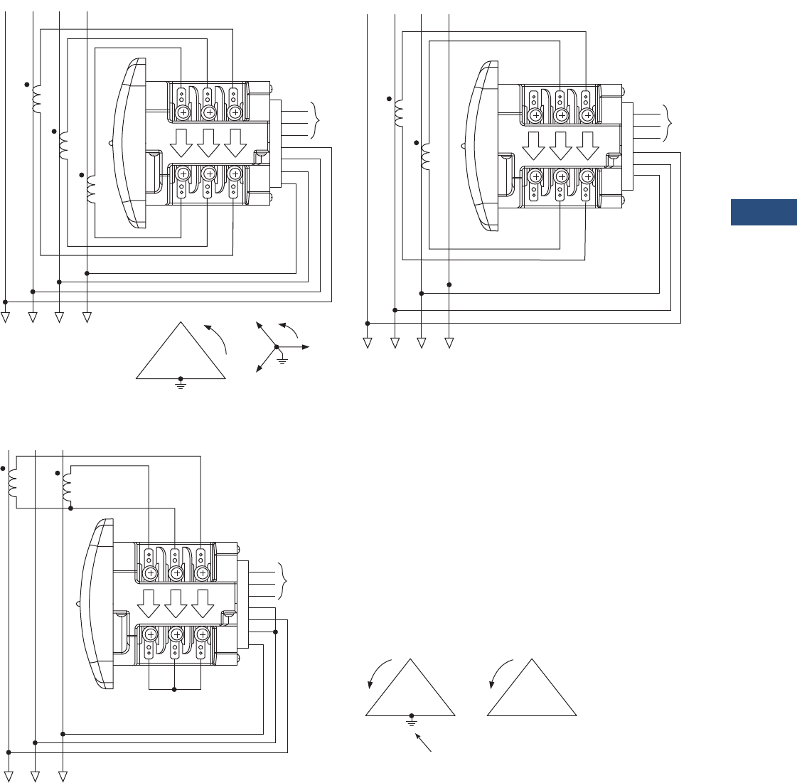
Volume 3—Power Distribution and Control Assemblies CA08100004E—March 2016 www.eaton.com V3-T9-49
9
9
9
9
9
9
9
9
9
9
9
9
9
9
9
9
9
9
9
9
9
9
9
9
9
9
9
9
9
9
9.2
Metering Devices, Protective Relays, Software and Connectivity
Metering Devices
Wiring Diagrams
Service: Wye or Delta, Four-Wire with No PTs, Two or Three CTs
Service: Delta, Three-Wire with No PTs, 2 CTs
Note: Based upon the voltage rating, you may need a control power transformer for the control power.
GND
L (+)
N (–)
VRef
A
B
C
HI
LO
Ic
HI
LO
Ib
HI
LO
Ia
AB C
AB C
Power
Supply
N
N
GND
L (+)
N (–)
VRef
A
B
x
HI
LO
Ic
HI
LO
Ib
HI
LO
Ia
AB C
AB C
Power
Supply
N
N
C
BA
C
B
A
GND
L (+)
N (–)
VRef
A
B
C
HI
LO
Ic
HI
LO
Ib
HI
LO
Ia
AB C
AB C
Power
Supply
C
BA
or
C
BA
Not Connected to Meter
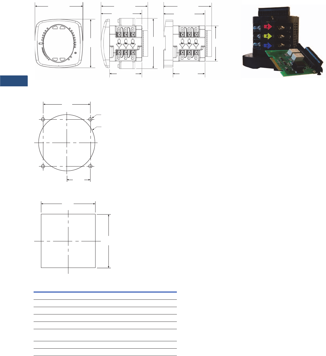
V3-T9-50 Volume 3—Power Distribution and Control Assemblies CA08100004E—March 2016 www.eaton.com
9
9
9
9
9
9
9
9
9
9
9
9
9
9
9
9
9
9
9
9
9
9
9
9
9
9
9
9
9
9
9.2
Metering Devices, Protective Relays, Software and Connectivity
Metering Devices
Dimensions
Approximate Dimensions in Inches (mm)
IQ 250/260 Meter—Face and Side Views
ANSI Mounting Panel Cutout
DIN Mounting Cutout
4.85 (123.2)
4.85
(123.2)
IQ 250/260M Side IQ 250/260T Side
4.97 (126.2)
4.20 (106.7)
5.02
(127.5)
3.25 (82.6) 3.25 (82.6)
3.54
(89.9)
4.93 (125.2)
4.16 (105.7)
IQ 250/260 Face
Expandable I\Q Componentry
4.00
(101.6)
3.38
(85.9)
1.69
(42.9)
4 x .02
(0.5)
3.62
(92.0)
3.62
(92.0)
Description Specifications
Weight 2 lbs (0.9 kg)
Basic unit 5.00 (127.0) H x 4.90 (124.5) W x 5.00 (127.0) L
IQ 250/260 Mounts in 92 mm DIN and ANSI C39.1 round cut-outs
Shipping container dimensions 6-inch cube
Tolerance ±0.1 inches (2.54 mm)
PXM 2250/2260/2270 Mounts in 3.62-inch (92.0) mm DIN and ANSI C39.1
round cut-outs
Projection in front of panel surface 4.85 (123.2) H x 4.85 (123.2) W x 1.01 (25.6) L
Projection behind panel surface 4.85 (123.2) H x 4.85 (123.2) W x 1.01 (25.6) L

Volume 3—Power Distribution and Control Assemblies CA08100004E—March 2016 www.eaton.com V3-T9-51
9
9
9
9
9
9
9
9
9
9
9
9
9
9
9
9
9
9
9
9
9
9
9
9
9
9
9
9
9
9
9.2
Metering Devices, Protective Relays, Software and Connectivity
Metering Devices
IQ 100
Contents
Description Page
Metering Products Family . . . . . . . . . . . . . . . . . . . . V3-T9-6
Power Xpert Meter 4000/6000/8000 Series . . . . . . V3-T9-15
Power Xpert Meter 2000 Series . . . . . . . . . . . . . . . V3-T9-34
IQ 250/260 Series Electronic Power Meters . . . . . . V3-T9-45
IQ 130/140/150 Series Electronic Power Meters
Standards and Certifications. . . . . . . . . . . . . . . . V3-T9-52
Catalog Number Selection . . . . . . . . . . . . . . . . . V3-T9-52
Accessories . . . . . . . . . . . . . . . . . . . . . . . . . . . . V3-T9-52
Technical Data and Specifications. . . . . . . . . . . . V3-T9-53
Dimensions. . . . . . . . . . . . . . . . . . . . . . . . . . . . . V3-T9-55
IQ 150S/250S Self-Enclosed Electronic Meters. . . . V3-T9-56
IQ 35M. . . . . . . . . . . . . . . . . . . . . . . . . . . . . . . . . . . V3-T9-61
IQ Analyzer 6400/6600 Series . . . . . . . . . . . . . . . . . V3-T9-64
IQ DP-4000 Series . . . . . . . . . . . . . . . . . . . . . . . . . . V3-T9-72
IQ 230 Meters . . . . . . . . . . . . . . . . . . . . . . . . . . . . . V3-T9-78
Power Xpert Multi-Point Meter . . . . . . . . . . . . . . . . V3-T9-85
IQ Energy Sentinel™ . . . . . . . . . . . . . . . . . . . . . . . . V3-T9-97
PM3 Monitoring and Metering Module . . . . . . . . . . V3-T9-106
Current Transformers (CTs) . . . . . . . . . . . . . . . . . . . V3-T9-107
Clamp-On Current Transformers . . . . . . . . . . . . . . . V3-T9-116
IQ Flange . . . . . . . . . . . . . . . . . . . . . . . . . . . . . . . . . V3-T9-119
Panel Mounting Adapter Kit . . . . . . . . . . . . . . . . . . . V3-T9-120
Enclosed Meters . . . . . . . . . . . . . . . . . . . . . . . . . . . V3-T9-121
IQ 130/140/150 Series Electronic Power Meters
Product Description
The IQ 100 Meter family
provides capabilities you
would not normally expect in
affordable, compact meters,
such as fast sampling rate
and accurate metering for a
full range of power attributes.
Providing the first line of
defense against costly power
problems, Eaton’s IQ 100
series electronic power
meters can perform the work
of an entire wall of legacy
metering equipment utilizing
today’s technology.
When space is at a premium,
yet you need ANSI C12.20
accuracy, the IQ 100 series fit
the bill. These meters are
ideal for electrical equipment
assemblies, machine control
panels, such as panelboard
and switchboard mains and
feeders, low voltage metal-
enclosed switchgear feeders
and motor control centers.
Requiring far less space than
other meters with similar
functionality, IQ 100 series fit
into a standard ANSI or IEC
cutout on a panelboard or
other electrical equipment,
and therefore fit easily into
retrofit applications.
Application Description
●Utility and commercial
metering
●Substations, industrial
facilities, power generation
sites and campuses
●Sub-metering
●Load studies and voltage
recording
●Analog meter replacement
Features and Benefits
●Measure and display real-
time information about
critical power parameters
with a sampling rate of 400
samples per cycle
●Monitor power utilization
and quality with ANSI
C12.20 accuracy (0.5%)
●Verify meter accuracy with
KYZ test pulse self-
certification capabilities
●Optional Modbus RTU or
TCP communications
●Available as transducer
only or with display
●Designed to accommodate
upgrades
●Integrate into Eaton’s
Power Xpert Architecture
for a holistic system-
level view
V3-T9-52 Volume 3—Power Distribution and Control Assemblies CA08100004E—March 2016 www.eaton.com
9
9
9
9
9
9
9
9
9
9
9
9
9
9
9
9
9
9
9
9
9
9
9
9
9
9
9
9
9
9
9.2
Metering Devices, Protective Relays, Software and Connectivity
Metering Devices
IQ 100 Electronic Power Meters
Standards and Certifications
●IEC 687: 0.5% accuracy
●ANSI C12.20:
0.5% accuracy
●ANSI C62.41: Burst
●CE
●UL/cUL: Electrical and
Electronic Measuring and
Test Equipment 22CZ
Catalog Number Selection
IQ 100 Meter
Accessories
IQ 100 Meter
Features IQ 130 IQ 140 IQ 150
Instrumentation
Current, per phase ■■■
Current demand ■■■
Calculated neutral current ■■■
Voltage, per phase (L-L, L-N) ■■■
Min/max. readings, I, V ■■■
Min./max. readings, I, V, PF, F, W, VAR, VA ■■
Frequency ■■
Power
Real, reactive and apparent power, total (W, VAR, VA) ■■
Power factor, total ■■
Real, reactive and apparent power demand ■■
Demand Methods
Block interval (sliding, fixed) ■■
Energy
Real, reactive and apparent energy, total (Wh, VAR, VAh) ■
Communications
RS-485, Modbus RTU, Modbus ASCII, KYZ output Opt. Opt. Opt.
RJ45, Modbus TCP, KYZ output Opt. Opt. Opt.
Frequency
5 = 50 Hz system
6 = 60 Hz system Communications
0 = None
1 = Modbus RTU and KYZ pulse
2 = Modbus TCP and KYZ output (RJ45)
Model Series
130 = Volts/amps
140 = Power
150 = Energy
Current Input
1 = 1A secondary
5 = 5A secondary
Power Supply
1 = 90–265 Vac/dc
4 = 24–48 Vdc
Meter Type
M= Meter (with integral
display)
T= Transducer only
(no display)
IQ 150 M A 6 5 1 1
Description Catalog Number
Panel Mounting Adapter for retrofitting an IQ 100 to an IQ Analyzer/IQ DP-4000/IQ Data Cutout IQ250-PMAK

Volume 3—Power Distribution and Control Assemblies CA08100004E—March 2016 www.eaton.com V3-T9-53
9
9
9
9
9
9
9
9
9
9
9
9
9
9
9
9
9
9
9
9
9
9
9
9
9
9
9
9
9
9
9.2
Metering Devices, Protective Relays, Software and Connectivity
Metering Devices
Technical Data and Specifications
IQ 100 Electronic Power Meters
Description Specifications
Current Inputs
Class 10 5A nominal, 10A max.
Class 2 1A nominal, 2A max.
Fault current withstand
100A for:
300A for:
500A for:
10 seconds
3 seconds
1 second
Continuous current withstand 20A for screw terminated or pass-through
connections
Programmable current Full scale to any CT ratio
Burden 0.005 VA per phase max. at 11A
Pickup current
Class 10
Class 2
0.1% of nominal
5 mA
1 mA
Connections
Pass-through wire gauge dimension
Quick connect
0.177-inch (4.5 mm)
0.25-inch male tab
Voltage Inputs
Range
Line-to-neutral
Line-to-line
20–416 Vac
20–721 Vac
Programmable voltage range Full scale to any PT ratio
Supported systems 3 element wye, 2.5 element wye,
2 element delta, four-wire delta systems
Input impedance 1 megohm/phase
Burden 0.36 VA/phase max. at 600V;
0.014 VA at 120 volts
Connection 7-pin 0.400-inch pluggable terminal block,
AWG #12–26 (0.129–3.31 mm2)
Isolation
All inputs and outputs are galvanically isolated to 2500 volts.
Environmental Ratings
Operating temperature –20°C to +70°C
Storage temperature –40°C to +85°C
Operating humidity To 95% RH noncondensing
Faceplate rating NEMA 12 water-resistant mounting gasket
included
IQ 100 Electronic Power Meters, continued
Note
These specifications are subject to change without notice and represent the maximum
capabilities of the product with all options installed. This is not a complete feature list. Features
and functionality may vary depending on selected options, firmware version and product model.
Please refer to the technical data sheet and User Manual for detailed specifications.
Description Specifications
Sensing Method
Voltage, current True RMS
Power Sampling at over 400 samples per cycle on all
channels
Update Rate
Watts, VAR and VA 100 msec at 60 Hz
All other parameters 1 second at 60 Hz
Power Supply
AC/DC voltage option 90–265 Vac at 50/60 Hz or
100–370 Vdc, Universal AC/DC supply
DC voltage option 18–60 Vdc
Burden 10 VA max.
Optional Communications Format
Connection type RS-485 or RJ45 (through back plate)
Com port baud rate 9600–57,600 bauds
Com port address 01–247
Data format 8-bit, no parity
Protocols Modbus ASCII, RTU, TCP
Optional KYZ Pulse
Contacts 1 Form A
On resistance, max. 35 ohms
Peak switching voltage 350 Vdc
Continuous load current 350 mA (10 ms)
Off-state leakage current at 350 Vdc 1 uA
Opto-isolation 3750 Vac

V3-T9-54 Volume 3—Power Distribution and Control Assemblies CA08100004E—March 2016 www.eaton.com
9
9
9
9
9
9
9
9
9
9
9
9
9
9
9
9
9
9
9
9
9
9
9
9
9
9
9
9
9
9
9.2
Metering Devices, Protective Relays, Software and Connectivity
Metering Devices
Wiring Diagrams
Service: Wye or Delta, Four-Wire with No PTs, Two or Three CTs
Service: Delta, Three-Wire with No PTs, 2 CTs
Note: Based upon the voltage rating, you may need a control power transformer for the control power.
GND
L (+)
N (–)
VRef
A
B
C
HI
LO
Ic
HI
LO
Ib
HI
LO
Ia
AB C
AB C
Power
Supply
N
N
GND
L (+)
N (–)
VRef
A
B
x
HI
LO
Ic
HI
LO
Ib
HI
LO
Ia
AB C
AB C
Power
Supply
N
N
C
BA
C
B
A
GND
L (+)
N (–)
VRef
A
B
C
HI
LO
Ic
HI
LO
Ib
HI
LO
Ia
AB C
AB C
Power
Supply
C
BA
or
C
BA
Not Connected to Meter
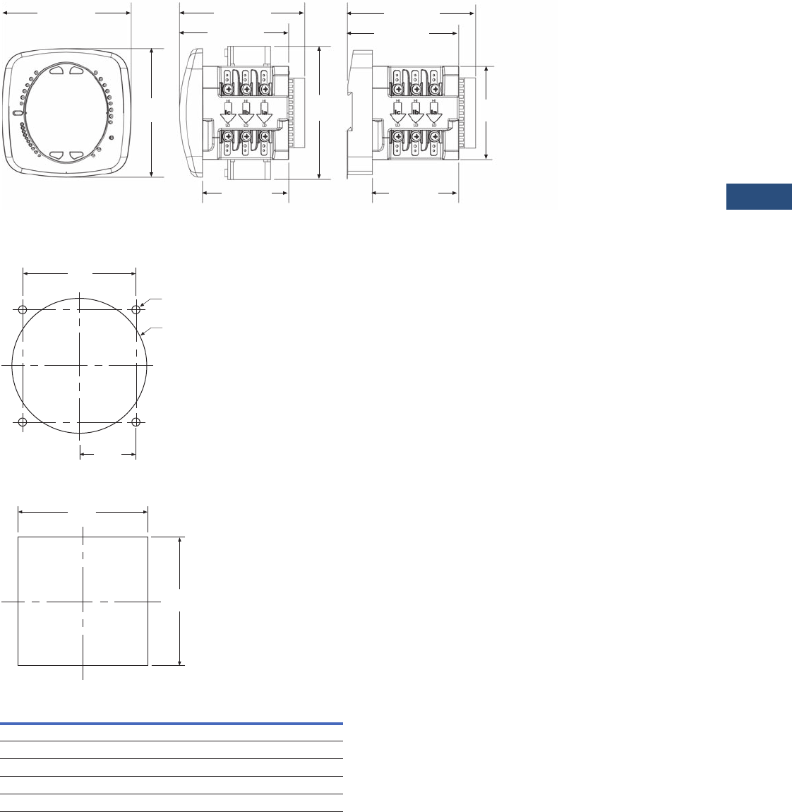
Volume 3—Power Distribution and Control Assemblies CA08100004E—March 2016 www.eaton.com V3-T9-55
9
9
9
9
9
9
9
9
9
9
9
9
9
9
9
9
9
9
9
9
9
9
9
9
9
9
9
9
9
9
9.2
Metering Devices, Protective Relays, Software and Connectivity
Metering Devices
Dimensions
Approximate Dimensions in Inches (mm)
IQ 100 Meter—Face and Side Views
ANSI Mounting Panel Cutout
DIN Mounting Cutout
4.85 (123.2)
4.85
(123.2)
IQ 100 Side IQ 100 Side
4.97 (126.2)
4.20 (106.7)
5.02
(127.5)
3.25 (82.6) 3.25 (82.6)
3.54
(89.9)
4.93 (125.2)
4.16 (105.7)
IQ 100 Face
4.00
(101.6)
3.38
(85.9)
1.69
(42.9)
4 x .02
(0.5)
3.62
(92.0)
3.62
(92.0)
Description Specifications
Weight 2 lbs (0.9 kg)
Basic unit 5.00 (127.0) H x 4.90 (124.5) W x 5.00 (127.0) L
IQ 100 Mounts in 92 mm DIN and ANSI C39.1 round cut-outs
Shipping container dimensions 6-inch cube
Tolerance ±0.1 inches (2.54 mm)
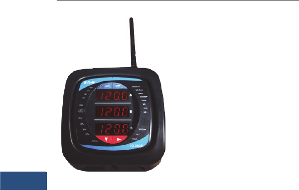
V3-T9-56 Volume 3—Power Distribution and Control Assemblies CA08100004E—March 2016 www.eaton.com
9
9
9
9
9
9
9
9
9
9
9
9
9
9
9
9
9
9
9
9
9
9
9
9
9
9
9
9
9
9
9.2
Metering Devices, Protective Relays, Software and Connectivity
Metering Devices
IQ 150S/250S Self-Enclosed Electronic Meters
Contents
Description Page
Metering Products Family . . . . . . . . . . . . . . . . . . . . V3-T9-6
Power Xpert Meter 4000/6000/8000 Series . . . . . . V3-T9-15
Power Xpert Meter 2000 Series . . . . . . . . . . . . . . . V3-T9-34
IQ 250/260 Series Electronic Power Meters . . . . . . V3-T9-45
IQ 130/140/150 Series Electronic Power Meters. . . V3-T9-51
IQ 150S/250S Self-Enclosed Electronic Meters
Catalog Number Selection . . . . . . . . . . . . . . . . . V3-T9-58
Technical Data and Specifications . . . . . . . . . . . V3-T9-59
Wiring Diagrams. . . . . . . . . . . . . . . . . . . . . . . . . V3-T9-60
Dimensions . . . . . . . . . . . . . . . . . . . . . . . . . . . . V3-T9-60
IQ 35M . . . . . . . . . . . . . . . . . . . . . . . . . . . . . . . . . . V3-T9-61
IQ Analyzer 6400/6600 Series . . . . . . . . . . . . . . . . . V3-T9-64
IQ DP-4000 Series. . . . . . . . . . . . . . . . . . . . . . . . . . V3-T9-72
IQ 230 Meters . . . . . . . . . . . . . . . . . . . . . . . . . . . . . V3-T9-78
Power Xpert Multi-Point Meter . . . . . . . . . . . . . . . . V3-T9-85
IQ Energy Sentinel™ . . . . . . . . . . . . . . . . . . . . . . . . V3-T9-97
PM3 Monitoring and Metering Module. . . . . . . . . . V3-T9-106
Current Transformers (CTs) . . . . . . . . . . . . . . . . . . . V3-T9-107
Clamp-On Current Transformers . . . . . . . . . . . . . . . V3-T9-116
IQ Flange . . . . . . . . . . . . . . . . . . . . . . . . . . . . . . . . . V3-T9-119
Panel Mounting Adapter Kit. . . . . . . . . . . . . . . . . . . V3-T9-120
Enclosed Meters . . . . . . . . . . . . . . . . . . . . . . . . . . . V3-T9-121
IQ 150S/250S Self-Enclosed Electronic Meters
Product Description
With energy costs
skyrocketing, you need the
ability to verify the accuracy
of utility billing and allocation
of energy costs among
business units, different
manufacturing areas or
facilities, and tenants.
Production equipment and IT
systems are vulnerable to
power anomalies; therefore,
you must ensure that power
is always up to specifications.
If your infrastructure is an
established facility, you may
not currently have metering
or may have addressed these
concerns by deploying a
variety of analog gauges and
meters—one for volts, one
for amperes and so on, with
separate meters for each
measurement.
If you’re planning an upgrade
or a new power infrastructure,
no doubt you would like to
capitalize on the latest
technology to improve upon
that cumbersome
architecture and its
patchwork view.
Application Description
●Industrial and commercial
buildings, metering and
submetering
●Government facilities and
military
●Universities and airports
●Load studies and voltage
recording
Features and Benefits
●Self-enclosed, these
meters are an ideal
solution for surface
mounting next to a
selected piece of
equipment for energy
monitoring
●NEMA 12 enclosure with a
large, easy-to-read faceplate,
consistent with other
Eaton meter models,
designed with “knockouts”
for easy installation
●Ethernet communications
option for either wired or
wireless setup, allowing for
additional ease of
installation and integration
into existing networks
●Available data and alarm
recording for historical
records/trending
●Integrate into Eaton’s
Power Xpert® Architecture
for a holistic system-level
view
Wireless and High-End
Capabilities you would not
Expect from a Self-Enclosed,
Compact Meter
Providing the first line of
defense against costly power
problems, Eaton’s IQ 150S/
250S electronic self-enclosed
meters can perform the work
of an entire wall of legacy
metering equipment using
today’s secure wireless
technology. Eaton’s IQ 150S/
250S meters use 24-bit AD
converters that sample at
more than 400 samples per
cycle and meet IEC 687
(0.2% accuracy) and ANSI
C12.20 (0.2% accuracy)
standards. With such high-
performance measurement
capability, these meters can
be confidently used for
primary revenue metering
and submetering applications.
Either model will help you
monitor energy demand,
while the IQ 250S provides
the extra benefit of also
monitoring and recording the
changes in the characteristics
of your power.
Eaton’s IQ 150S/250S
meters provide direct-reading
metered values for the most
critical power aspects, such
as watts, watt demand,
watthours, voltage amperes
(VA), VA-hours, VARs, VAR-
hours and power factor. They
have high sampling speed
and accuracy.
These meters are self-
enclosed in a NEMA 12
enclosure with “knockouts”
on the bottom for
communication and power,
providing for an easy
installation.
Perhaps you don’t have
network drops in all the
right places. The IQ 150S/
250S offers a wireless
communications option.
The transmissions are
encrypted using 128-bit
Wired Equivalent Privacy
(WEP) for security.
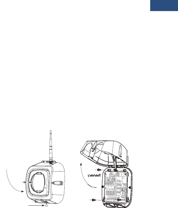
Volume 3—Power Distribution and Control Assemblies CA08100004E—March 2016 www.eaton.com V3-T9-57
9
9
9
9
9
9
9
9
9
9
9
9
9
9
9
9
9
9
9
9
9
9
9
9
9
9
9
9
9
9
9.2
Metering Devices, Protective Relays, Software and Connectivity
Metering Devices
Industry-Standard
Communication Protocols
Standard Modbus RS-485
Communication
Standard communication
includes an RS-485 output
speaking Modbus protocol.
This allows the unit to be
connected to any serial RS-
485 bus using the Modbus
interface. The unit
communicates easily with
most building automation,
Power Xpert Insight or other
software systems. Baud
rates are up to 57.6K baud to
provide fast update times.
Wi-Fi or Land-Based
Ethernet
The unit offers an Ethernet
option—configured either as
an RJ45 or Wi-Fi connection.
The Wi-Fi configuration
allows the 150S/250S to be
used on standard Wi-Fi base
stations. The unit is assigned
an IP address; it communicates
Modbus protocol over
Ethernet TCP/IP. Wireless
Ethernet is reliable and easy
to integrate, making it the
superior solution for mass
meter deployment.
KYZ Pulse
For applications in which a
pulse is needed, the unit also
provides a KYZ output that
pulses proportional to the
amount of energy consumed.
This feature is used for pulse
counting applications into
building management
systems where serial or
Ethernet protocol is not
available.
Verify Energy Bills
The IQ 150S/250S models
provide a traceable watthour
test pulse (used with a
watthour pulse recorder or
totalizer), so you can verify
the accuracy of your meter
and in turn, the accuracy of
billing from your utility
company and to internal
customers.
Integrated with Eaton’s
Power Xpert Architecture
IQ 150S/250S meters
integrate into Eaton’s Power
Xpert Architecture, where
meters, gateways and
monitoring devices
collaborate to create a
unified, centralized view of
the end-to-end power and
facility infrastructure.
When used in this
architecture, either with a
Power Xpert Gateway or
directly via Ethernet, the
meters with the Modbus RTU
option can provide Web-
based graphics of current
power conditions. Simply
connect your meter to a
Power Xpert Gateway to
translate Modbus-based
information from the meter
into HTML-based Web pages
that are accessible from any
standard Web browser. If you
select a model with the
Ethernet option, the meter
can easily be monitored
remotely via Power Xpert
Insight or another third-party
monitoring system. With
access to accurate, real-time
information from IQ 150S/
250S meters, Power Xpert
Architecture can transform
your power system into an
integrated, agile system, and
an easily managed entity
that performs better and
costs less.
Designed for the User
When space is at a premium,
yet you need ANSI C12.20
accuracy, Eaton IQ 150S/
250S meters fit the bill.
These ultra-compact meters
are ideal for surface mounting
next to a selected piece of
equipment for energy
monitoring. Requiring far less
space than other meters with
similar functionality, and
offering a NEMA 12
enclosure and a large, easy-
to-read faceplate, consistent
with other Eaton meter
models, these meters are
designed with “knockouts”
for easy retrofit installation.
Most meters in this class
have small or dark displays
that can be hard to see,
especially from a distance.
Eaton’s IQ 150S/250S meters
have a large, bright red, three-
line LED display, each line
more than a half-inch tall. This
display is very easy to read,
even if the meter is installed at
a height or distance. Using the
keypad and menus on the
local display, users can
display a variety of electrical
system values or program
the meter.
Installation Diagram
IQ 150S/250S Installation
O
Closed
Lockable
Revenue Seal
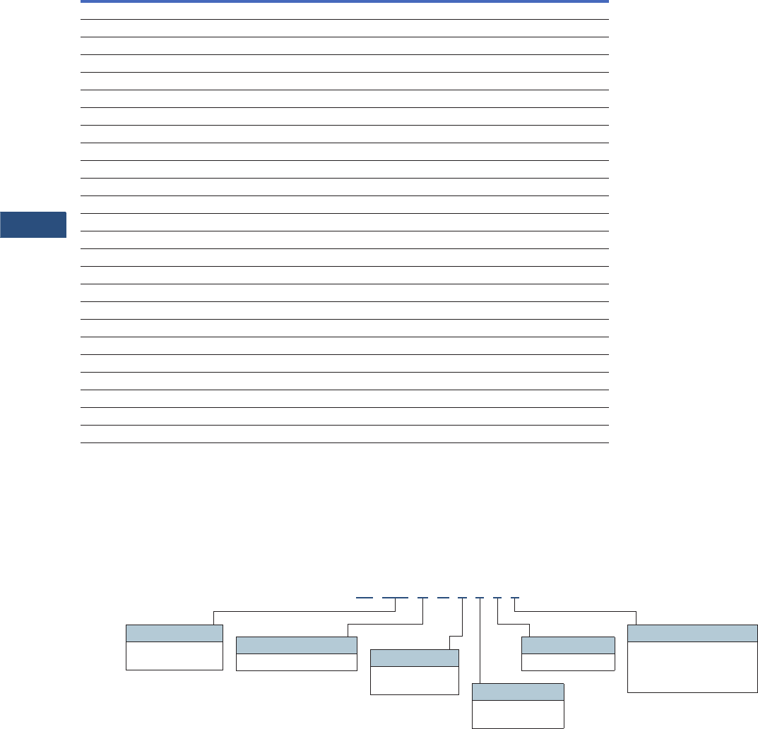
V3-T9-58 Volume 3—Power Distribution and Control Assemblies CA08100004E—March 2016 www.eaton.com
9
9
9
9
9
9
9
9
9
9
9
9
9
9
9
9
9
9
9
9
9
9
9
9
9
9
9
9
9
9
9.2
Metering Devices, Protective Relays, Software and Connectivity
Metering Devices
Features of IQ 150S/250S Electronic Power Meters
Notes
1Per phase only.
2If configured for Ethernet, RS-485 not available.
Catalog Number Selection
IQ 150S/250S Meter
Features IQ 150S IQ 250S
Instrumentation
Current, per phase ■■
Calculated neutral current ■■
Voltage, per phase (L-L, L-N) ■■
Frequency ■■
Minimum/maximum readings, I 1, V 1, PF, F, W, VAR, VA Total Total and per phase
Power
Real, reactive and apparent power (W, VAR, VA) Total Total and per phase
Power factor Average Average and per phase
Demand Methods
Block interval (fixed, sliding) ■■
Current demand ■■
Real, reactive and apparent power demand Total Total and per phase
Energy
Real, reactive and apparent energy (Wh, VARh, VAh) Total Total and per phase
Real and reactive, net and positive and negative (Wh, VARh) Total Total and per phase
I/O
Pulse output ■■
Communications
RS-485, Modbus RTU, DNP 3.0 ■■
RJ45 or 802.11b, Modbus TCP 2Optional Optional
Data Logging
2 MB for data logging ■
Alarming
Set point driven alarm ■
IQ 150 S A 6 5 1 1
Model Series
150 = Energy
250 = Energy plus Frequency
5 = 50 Hz system
6 = 60 Hz system
Power Supply
1 = 90–400 Vac/Vdc
Current Input
1 = 1A secondary
5 = 5A secondary
Meter Type
S = Self-enclosed meter
Communication
1 = Modbus RTU (RS-485)
2 = Modbus RTU (RS-485)
or TCP—(RJ45)
or 802.11b (Wi-Fi)

Volume 3—Power Distribution and Control Assemblies CA08100004E—March 2016 www.eaton.com V3-T9-59
9
9
9
9
9
9
9
9
9
9
9
9
9
9
9
9
9
9
9
9
9
9
9
9
9
9
9
9
9
9
9.2
Metering Devices, Protective Relays, Software and Connectivity
Metering Devices
Technical Data and Specifications
IQ 150S/250S Electronic Meter Technical Information
Note: Specifications are subject to change without notice and represent
the maximum capabilities of the product with all options installed. This is not
a complete feature list. Features and functionality may vary depending on
selected options, firmware version and product model. Please refer to
User Manual for detailed specifications.
Description Specifications
Current Inputs
Class 10 5A nominal, 10A maximum
Class 2 1A nominal, 2A maximum
Fault Current Withstand
20A for:
60A for:
100A for:
10 seconds
3 seconds
1 second
Programmable current Full scale to any CT ratio
Burden 0.005 VA per phase maximum at 11A
Pickup Current
Class 10
Class 2
0.1% of nominal
5 mA
1 mA
Connections
Screw terminal #6–32 screws
Voltage Inputs
Range
Line-to-neutral 20–416 Vac (IQ150S), 20–576 Vac (IQ250S)
Line-to-line 20–721 Vac
Programmable voltage range Full scale to any PT ratio
Supported systems 3 element wye, 2.5 element wye, 2 element delta,
four-wire delta systems
Input impedance 1 megohm/phase
Burden 0.36 VA/phase maximum at 600V; 0.014 VA at 120V
Connection 7-pin, 0.400-inch screw
terminal block, AWG #12–26 (0.129–3.31 mm2)
Isolation
All inputs and outputs are galvanically isolated to 2500V
Environmental Ratings
Operating temperature –20º to +70°C
Storage temperature –20º to +70°C
Operating humidity To 95% RH noncondensing
Faceplate rating NEMA 12
Sensing Method
Voltage, current rms
Power Sampling at over 400 samples per cycle on all
channels
Description Specifications
Update Rate
Watts, VAR and VA 100 msec at 60 Hz
All other parameters 1 second at 60 Hz
Power Supply
AC/DC voltage option 90–400 Vac at 50/60 Hz or
100–370 Vdc, universal AC/DC supply
Burden 16 VA maximum
Standard Serial Communications Format
Connection type RS-485
Communications port baud rate 9600–57,600 Bauds
Communications port address 01–247
Data format 8-bit, no parity
Protocols Modbus ASCII, RTU, DNP 3.0
Optional Ethernet Communications Format
Connection type RJ45 or 802.11b (wireless)
Protocols Modbus TCP
KYZ Pulse
Contacts 1 Form A
On resistance, maximum 35 Ohms
Peak switching voltage 350 Vdc
Continuous load current 120 mA
Peak load current 350 mA (10 ms)
Off-state leakage current at 350 Vdc 1 uA
Opto-isolation 3750 Vac
Dimensions and Shipping
Weight 4 lbs
Basic unit H 7.90 x W 7.50 x D 3.10 inches
Compliance
IEC 687 0.2% accuracy
ANSI C12.20 0.2% accuracy
ANSI C62.41 Burst
ANSI (IEEE) C37.90.1 Surge withstand
UL/cUL Electrical and electronic
measuring and test equipment 22CZ
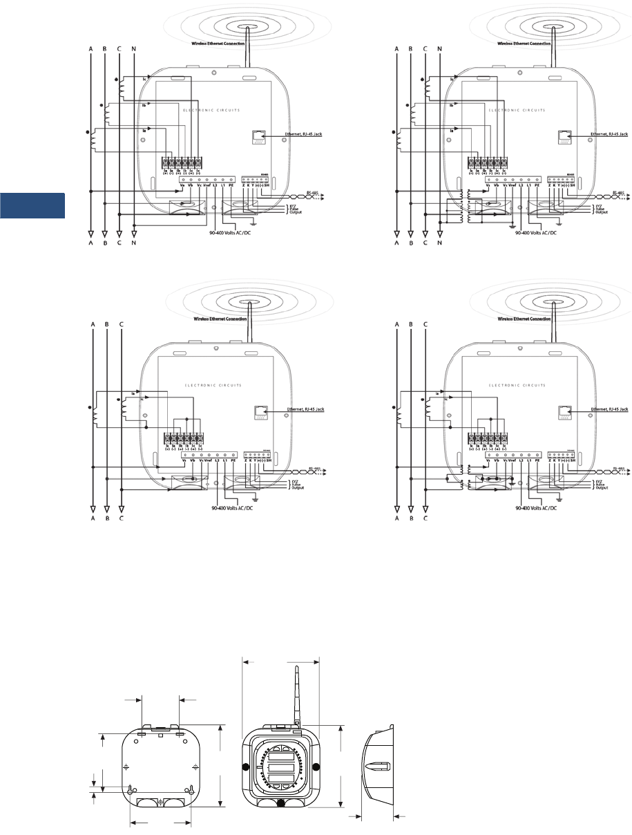
V3-T9-60 Volume 3—Power Distribution and Control Assemblies CA08100004E—March 2016 www.eaton.com
9
9
9
9
9
9
9
9
9
9
9
9
9
9
9
9
9
9
9
9
9
9
9
9
9
9
9
9
9
9
9.2
Metering Devices, Protective Relays, Software and Connectivity
Metering Devices
Wiring Diagrams
IQ 150S/250S Electronic Meter
Dimensions
Approximate Dimensions in Inches (mm)
IQ 150S/250S Electronic Meter
Three-Phase Four-Wire WYE Direct Three-Phase Four-Wire WYE with PTS
Three-Phase Three-Wire DELTA Direct Three-Phase Three-Wire DELTA Direct
3
.1
1
(
79.0
)
7.
90
(
200.7
)
7.
90
(
200.7
)
5
.
60
(
142.2
)
Antenna Len
g
th:
4.40
(
111.8
)
7.
53
(
191.3
)
3
.7
0
(
94.0
)
5
.
95
(
151.1
)
0
.
50
(
12.7
)
Mountin
g
Pl
ate
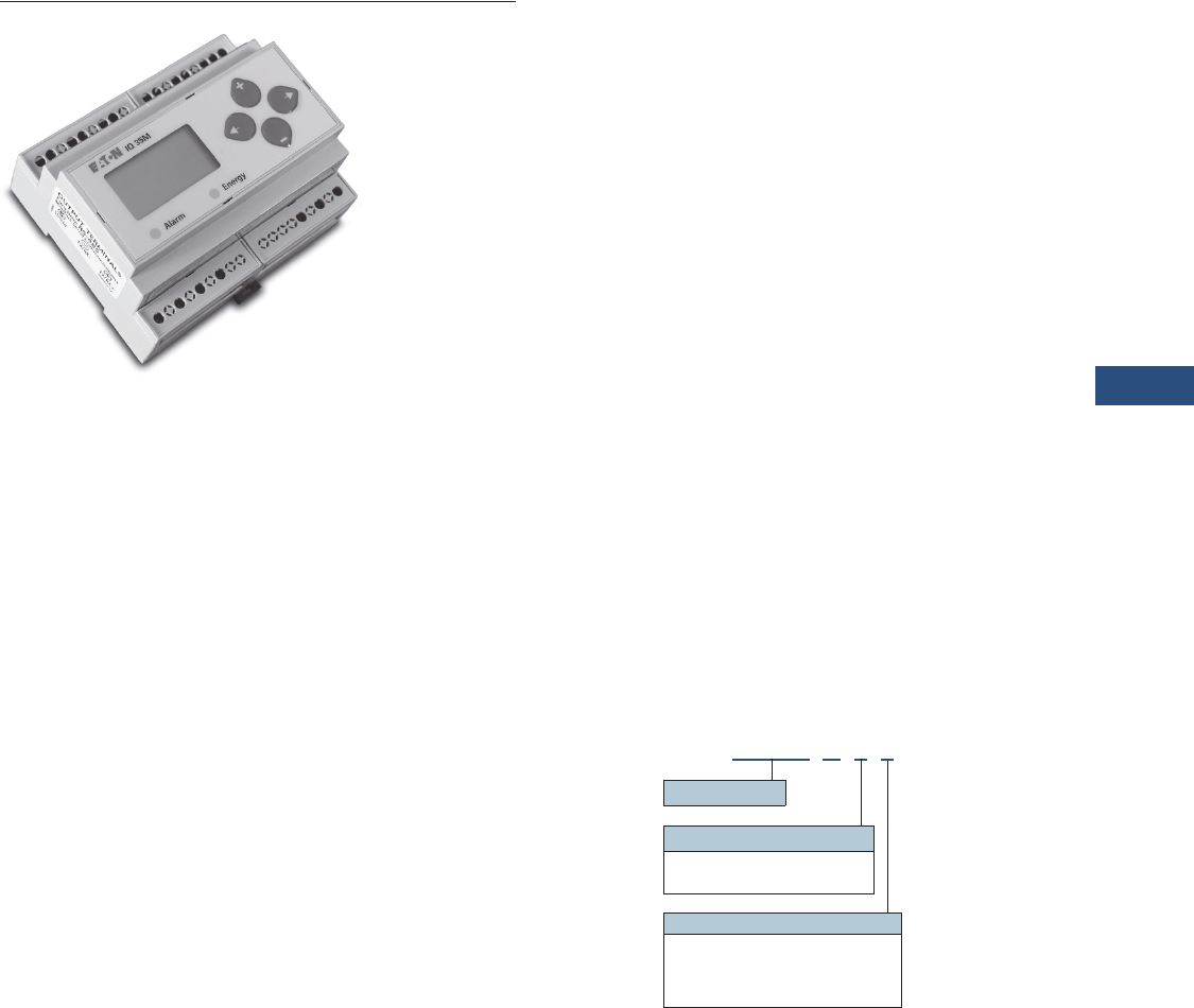
Volume 3—Power Distribution and Control Assemblies CA08100004E—March 2016 www.eaton.com V3-T9-61
9
9
9
9
9
9
9
9
9
9
9
9
9
9
9
9
9
9
9
9
9
9
9
9
9
9
9
9
9
9
9.2
Metering Devices, Protective Relays, Software and Connectivity
Metering Devices
IQ 35M
Contents
Description Page
Metering Products Family. . . . . . . . . . . . . . . . . . . . . V3-T9-6
Power Xpert Meter 4000/6000/8000 Series. . . . . . . V3-T9-15
Power Xpert Meter 2000 Series . . . . . . . . . . . . . . . . V3-T9-34
IQ 250/260 Series Electronic Power Meters . . . . . . V3-T9-45
IQ 130/140/150 Series Electronic Power Meters . . . V3-T9-51
IQ 150S/250S Self-Enclosed Electronic Meters . . . . V3-T9-56
IQ 35M
Product Selection . . . . . . . . . . . . . . . . . . . . . . . . V3-T9-62
Accessories . . . . . . . . . . . . . . . . . . . . . . . . . . . . . V3-T9-62
Technical Data and Specifications . . . . . . . . . . . . V3-T9-62
Dimensions . . . . . . . . . . . . . . . . . . . . . . . . . . . . . V3-T9-63
IQ Analyzer 6400/6600 Series . . . . . . . . . . . . . . . . . V3-T9-64
IQ DP-4000 Series . . . . . . . . . . . . . . . . . . . . . . . . . . V3-T9-72
IQ 230 Meters . . . . . . . . . . . . . . . . . . . . . . . . . . . . . V3-T9-78
Power Xpert Multi-Point Meter . . . . . . . . . . . . . . . . . V3-T9-85
IQ Energy Sentinel™ . . . . . . . . . . . . . . . . . . . . . . . . V3-T9-97
PM3 Monitoring and Metering Module . . . . . . . . . . V3-T9-106
Current Transformers (CTs). . . . . . . . . . . . . . . . . . . . V3-T9-107
Clamp-On Current Transformers. . . . . . . . . . . . . . . . V3-T9-116
IQ Flange . . . . . . . . . . . . . . . . . . . . . . . . . . . . . . . . . V3-T9-119
Panel Mounting Adapter Kit . . . . . . . . . . . . . . . . . . . V3-T9-120
Enclosed Meters . . . . . . . . . . . . . . . . . . . . . . . . . . . V3-T9-121
IQ 35M
Product Description
The Eaton IQ 35M Meter is a
DIN rail meter that combines
exceptional performance and
easy installation to deliver a
cost-effective solution for
energy and power monitoring
applications, as well as sub-
metering applications. Most
models include pulse output,
alarm contact and phase alarms
for true versatility. The BACnet
version offers two digital inputs
for accumulating other meter
pulses in place of the digital
output and alarm contact.
The Modbus output options
offer added flexibility for
configuration and data analysis.
The IQ 35M allows you to:
●Verify energy bills
●Make informed load
shifting and shedding
decisions
●Fairly and accurately
allocate energy costs to
users
●Identify wasteful practices
●Decrease unnecessary
usage
●Produce an energy profile
●Secure the optimum utility
rate structure
Application Description
●Commercial submetering
●Energy management
●Industrial monitoring
●Cost allocation
Features
●
Economical and compact
watthour meter with
demand
●
Backlit LCD display for local
reading
●
Compatible with the Power
Xpert Gateway for remote
monitoring
●
Monitors
●
Voltage, current, power
factor, frequency
●
Power and energy: real,
reactive and apparent
●
Optional data logging
capability
●
Optional serial
communications (Modbus-
RTU or BACnet)
●
Revenue grade, ANSI
C12.20 0.5% accuracy, IEC
62053-22 Class 0.5S
●
Compatible with economical
solid-core and split-core CTs
●
User-enabled password
protection
●
On-board diagnostics
Catalog Number Selection
IQ 35M Meter
IQ35M A 1 1
Meter Series
Energy Type
1= Standard energy
2= Four quadrant energy
Output Option
1= Pulse output only
2= Pulse output + Modbus
3= Pulse output + Modbus + data logging
5= Pulse inputs + BACnet + data logging

V3-T9-62 Volume 3—Power Distribution and Control Assemblies CA08100004E—March 2016 www.eaton.com
9
9
9
9
9
9
9
9
9
9
9
9
9
9
9
9
9
9
9
9
9
9
9
9
9
9
9
9
9
9
9.2
Metering Devices, Protective Relays, Software and Connectivity
Metering Devices
Product Selection
IQ 35M Current Transformers
Accessories
IQ 35M Accessories
Note: Specifications are subject to change without notice and represent
the maximum capabilities of the product with all options installed. This is
not a complete feature list. Features and functionality may vary
depending on selected options, firmware version and product model.
Please refer to User Manual for detailed specifications.
Description
Catalog
Number
Solid Core
IQ35M CT, solid core, 5A:0.33 Vac, 0.30 inch IQ35M-SO-030-5
IQ35M CT, solid core, 20A:0.33 Vac, 0.30 inch IQ35M-SO-030-20
IQ35M CT, solid core, 50A:0.33 Vac, 0.50 inch IQ35M-SO-050-50
IQ35M CT, solid core, 50A:0.33 Vac, 0.75 inch IQ35M-SO-075-50
IQ35M CT, solid core, 100A:0.33 Vac, 1.25 inch IQ35M-SO-125-100
IQ35M CT, solid core, 200A:0.33 Vac, 1.25 inch IQ35M-SO-125-200
IQ35M CT, solid core, 250A:0.33 Vac, 1.25 inch IQ35M-SO-125-250
IQ35M CT, solid core, 300A:0.33 Vac, 1.25 inch IQ35M-SO-125-300
IQ35M CT, solid core, 400A:0.33 Vac, 1.25 inch IQ35M-SO-125-400
Split Core
IQ35M CT, split core, 5A:0.33 Vac, 0.75 inch IQ35M-SP-075-5
IQ35M CT, split core, 30A:0.33 Vac, 0.75 inch IQ35M-SP-075-30
IQ35M CT, split core, 50A:0.33 Vac, 0.75 inch IQ35M-SP-075-50
IQ35M CT, split core, 100A:0.33 Vac, 0.75 inch IQ35M-SP-075-100
IQ35M CT, split core, 200A:0.33 Vac, 0.75 inch IQ35M-SP-075-200
IQ35M CT, split core, 250A:0.33 Vac, 1.25 inch IQ35M-SP-125-250
IQ35M CT, split core, 300A:0.33 Vac, 1.25 inch IQ35M-SP-125-300
IQ35M CT, split core, 400A:0.33 Vac, 1.25 inch IQ35M-SP-125-400
IQ35M CT, split core, 600A:0.33 Vac, 1.25 inch IQ35M-SP-125-600
IQ35M CT, split core, 800A:0.33 Vac, 2.50 inch IQ35M-SP-253-800
IQ35M CT, split core, 1000A:0.33 Vac, 2.50 inch IQ35M-SP-255-1000
IQ35M CT, split core, 1200A:0.33 Vac, 2.50 inch IQ35M-SP-255-1200
IQ35M CT, split core, 1600A:0.33 Vac, 2.50 inch IQ35M-SP-255-1600
IQ35M CT, split core, 2000A:0.33 Vac, 2.50 inch IQ35M-SP-255-2000
IQ35M CT, split core, 2400A:0.33 Vac, 2.50 inch IQ35M-SP-255-2400
Description
Catalog
Number
IQ35M enclosure, NEMA 4X IQ35M-ENC
IQ35M fuse pack, single, 1/2A slow-blow IQ35M-FP1
IQ35M fuse pack, double, 1/2A slow-blow IQ35M-FP2
IQ35M fuse pack, triple, 1/2A slow-blow IQ35M-FP3
IQ35M replacement mounting clips IQ35M-RMC
IQ35M DIN rail IQ35M-DR
IQ35M DIN rail stop clips (10 pack) IQ35M-DRSC
Technical Data and Specifications
●Voltage input
UL: 90V (L-N) to 600V (L-L)
CE: 90V (L-N) to 300V (L-L)
●Current input
Scaling: 5–32,767A
Input range: 0–0.333V or
0–1V (selectable)
●Control power
UL: 90V (L-N) to 600V (L-L)
CE: 90V (L-N) to 300V (L-L)
Accuracy
●Real power and energy
0.5% (ANSI C12.20, IEC 62053-22 Class 0.5S)
Outputs
●IQ35MAx1 thru 3:
Real energy pulse: NO static; alarm contacts: NC static
●IQ35MA11
Reactive energy pulse 30 Vac/Vdc
●IQ35MAx2, IQ35MAx3
RS-485 two-wire Modbus RTU
●IQ35MA15 RS-485 two-wire BACnet MS/TP
Inputs
●IQ35MA15
Two pulse accumulators
Mechanical
●Mounting
DIN rail or 3-point screwmount
Environmental
●Operating temperature range
Meter: –30° to 70°C (–22° to 158°F)
Display: –10° to 50°C (14° to 122°F)
●Storage temperature range
Meter: –40° to 85°C (–40° to 185°F)
Display: –10° to 60°C (14° to 140°F)
●Humidity range
<95% RH noncondensing
Data Outputs
●kW, kWh: Total
●Current: Three-phase average and per phase
●Voltage: Three-phase average, per phase, and line-line and
line-neutral
●Power: Real, reactive and apparent;
Three-phase total and per phase
●Power factor: Three-phase average and per phase
●Frequency
●Power demand: most recent and peak
●Demand configuration: fixed, rolling block and external sync
●Data logging (IQ35MAx3)
10 configurable data buffers;
configurable demand subinterval (when set at a 15-minute
interval, buffers store data for 60 days)
●Data logging (IQ35MA15)
6 configurable data buffers;
configurable demand subinterval (when set at a 15-minute
interval, buffers store data for 60 days)
●Trending requires communication network to retrieve data
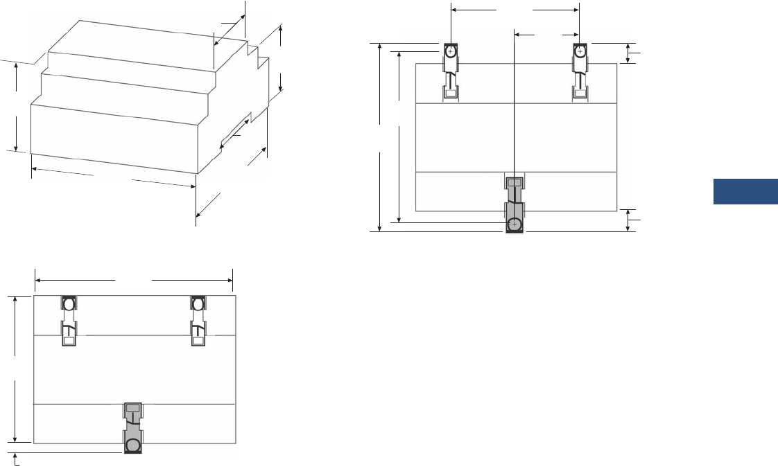
Volume 3—Power Distribution and Control Assemblies CA08100004E—March 2016 www.eaton.com V3-T9-63
9
9
9
9
9
9
9
9
9
9
9
9
9
9
9
9
9
9
9
9
9
9
9
9
9
9
9
9
9
9
9.2
Metering Devices, Protective Relays, Software and Connectivity
Metering Devices
Dimensions
Approximate Dimensions in Inches (mm)
IQ 35M Dimensional Drawing
IQ 35M DIN Mount Configuration
1.80 (45.7)
2.30
(58.4)
4.20
(106.7)
1.50
(38.1)
3.60
(91.4)
1.90
(48.3)
4.20
(106.7)
3.60
(91.4)
0.20
(5.1)
IQ 35M Wall Mount Configuration
2.40
(60.1)
4.30
(109.2)
3.90
(99.1)
1.20
(30.5) 0.30
(7.61)
0.40
(10.2)
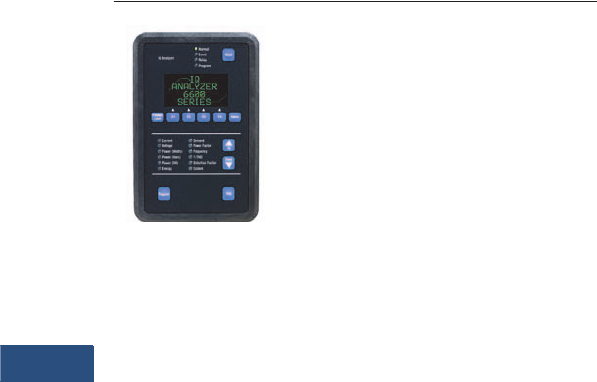
V3-T9-64 Volume 3—Power Distribution and Control Assemblies CA08100004E—March 2016 www.eaton.com
9
9
9
9
9
9
9
9
9
9
9
9
9
9
9
9
9
9
9
9
9
9
9
9
9
9
9
9
9
9
9.2
Metering Devices, Protective Relays, Software and Connectivity
Metering Devices
IQ Analyzer—
Comprehensive Electrical
Distribution Monitoring
IQ Analyzer 6400/6600 Series
Contents
Description Page
Metering Products Family . . . . . . . . . . . . . . . . . . . . V3-T9-6
Power Xpert Meter 4000/6000/8000 Series . . . . . . V3-T9-15
Power Xpert Meter 2000 Series . . . . . . . . . . . . . . . V3-T9-34
IQ 250/260 Series Electronic Power Meters . . . . . . V3-T9-45
IQ 130/140/150 Series Electronic Power Meters. . . V3-T9-51
IQ 150S/250S Self-Enclosed Electronic Meters . . . V3-T9-56
IQ 35M . . . . . . . . . . . . . . . . . . . . . . . . . . . . . . . . . . V3-T9-61
IQ Analyzer 6400/6600 Series
Standards and Certifications . . . . . . . . . . . . . . . V3-T9-67
Product Selection . . . . . . . . . . . . . . . . . . . . . . . . V3-T9-68
Accessories . . . . . . . . . . . . . . . . . . . . . . . . . . . . V3-T9-68
Technical Data and Specifications . . . . . . . . . . . V3-T9-69
Dimensions . . . . . . . . . . . . . . . . . . . . . . . . . . . . V3-T9-70
IQ DP-4000 Series. . . . . . . . . . . . . . . . . . . . . . . . . . V3-T9-72
IQ 230 Meters . . . . . . . . . . . . . . . . . . . . . . . . . . . . . V3-T9-78
Power Xpert Multi-Point Meter . . . . . . . . . . . . . . . . V3-T9-85
IQ Energy Sentinel™ . . . . . . . . . . . . . . . . . . . . . . . . V3-T9-97
PM3 Monitoring and Metering Module. . . . . . . . . . V3-T9-106
Current Transformers (CTs) . . . . . . . . . . . . . . . . . . . V3-T9-107
Clamp-On Current Transformers . . . . . . . . . . . . . . . V3-T9-116
IQ Flange . . . . . . . . . . . . . . . . . . . . . . . . . . . . . . . . . V3-T9-119
Panel Mounting Adapter Kit. . . . . . . . . . . . . . . . . . . V3-T9-120
Enclosed Meters . . . . . . . . . . . . . . . . . . . . . . . . . . . V3-T9-121
IQ Analyzer 6400/6600 Series
Product Description
Eaton’s IQ Analyzer is a
complete solution for users
who want to monitor and
manage all aspects of their
electrical distribution system.
Based on input from
customers and consultants,
it provides extensive
metering, power quality
analysis, remote input
monitoring, control relaying,
analog input/outputs and
communications capability.
Its high performance
metering exceeds ANSI
C12.16 (1%) specification for
revenue meters and meets
ANSI C12.20 Class 0.5%,
provides quality true rms
readings through the 50th
harmonic, accurately
measures nonsinusoidal
waveforms up to a 3.0 crest
factor, and displays even
and odd multiples of the
fundamental current and
voltage through the 50th
harmonic. Both magnitude
and phase angle of the
harmonics are displayed.
The unique operator
interface, which includes a
reverse mode LCD display,
easy to use Meter Menu
screens and detailed Analysis
screens, is designed to allow
a wealth of real-time and
recorded information to be
accessed easily by an
operator. All programming
can be accomplished through
the faceplate or the
communications port. The
comprehensive on-line Help
feature provides useful
information on device
operation, programming and
troubleshooting.
Application Description
●Monitoring of over 150
electrical parameters
●Power quality management
●Energy management
Features, Benefits and Functions
Metered and Monitored
Parameters
●rms sensing
●Phase neutral, and
ground currents
●Volts: L-L, L-N, Avg. L-L,
Avg. L-N, N-G
●Power: real, reactive,
apparent (system and
per phase)
●Frequency
●Power factor: apparent and
displacement (system and
per phase)
●Energy and demand
(forward, reverse, net) real,
reactive apparent at four
different utility rates
●Individual current and
voltage harmonics:
magnitude, phase angle
●% THD: current and
voltage
●Waveform capture
●Minimum and maximum
values
●Event logging/disturbance
recording
●ANSI C12.20 Class 0.5%
revenue metering accuracy,
IEC687 Class 0.5%
●Industry Canada 0.5%
revenue accuracy
Communications
●Optional interface
capability to computer
network for data collection,
storage and/or printout
via Eaton’s Power
Management Software
Physical Characteristics
●Graphical reverse mode
LCD display with LED
backlight
●Up to seven lines of
information
●Membrane faceplate
NEMA 3R and 12 rated

Volume 3—Power Distribution and Control Assemblies CA08100004E—March 2016 www.eaton.com V3-T9-65
9
9
9
9
9
9
9
9
9
9
9
9
9
9
9
9
9
9
9
9
9
9
9
9
9
9
9
9
9
9
9.2
Metering Devices, Protective Relays, Software and Connectivity
Metering Devices
Disturbance Information
With the communications
option and Eaton’s Power
Management Software and
Waveform Display software,
a Waveform Analysis will
construct waveforms of up to
56 cycles of all currents and
voltages (including neutral
and ground) to help
troubleshoot undervoltage/
sag and overvoltage/swell
conditions. (See CBEMA
Trend Logging section.)
By programming a reset
threshold, the duration of the
voltage disturbance can also
be indicated.
The IQ Analyzer 6600 series
with Graphic Waveform
Display offers the ability to
view the captured waveform
right at the device. The 6600
series also offers the ability to
detect and capture sub-cycle
voltage disturbances.
Extensive Harmonic
Distortion Analysis
Current and voltage distortion
data are displayed at the
device and accessible
through the communications
port. This includes % THD,
K-Factor, Crest Factor,
CBEMA factor, and both
magnitudes and phase angles
of all harmonics through the
50th. A snapshot sample
of this information may
be activated by user
commands, discrete inputs
or programmable thresholds
to capture distortion data
during conditions of real
interest. To help eliminate
nuisance alarms, harmonic
distortion information can be
captured and relay outputs
activated when THD exceeds
a programmable percentage
of fundamental or a
programmable magnitude
(e.g., amperes) threshold.
Time-of-Use Metering
The IQ Analyzer offers
the ability to store energy
usage data for time of use
revenue metering. It can
be programmed for any
combination of weekday,
Saturday, Sunday,
22 holidays, 8 seasons,
32 schedules and 10 time
periods per schedule. The IQ
Analyzer will keep track of the
following parameters for four
different utility rates:
●Watthours
●VAR hours
●VA hours
●Current demand
●Watt demand
●VA demand
●VAR demand
Historical Trend Logging
The IQ Analyzer is equipped
with onboard logging
capability, which includes
the ability to log a total of
24 parameters with intervals
ranging from 0.13 seconds
(every eight cycles) to twice
a week (5040 minutes). The
trending function can begin
immediately or can be
triggered upon receipt of a
discrete input into the IQ
Analyzer. Onboard logging
provides a cost-effective
means of distributed data
storage where real-time
communications may not be
feasible or for applications
where data storage
redundancy is desired. Four
trend data logs are stored in
non-volatile memory aboard
the IQ Analyzer and can be
retrieved at the display or
via communications for
viewing using Eaton’s Power
Management Software.
●Up to 24 parameters with
storage capacity for up to
90,000 data points
●Up to 234 days of data
can be stored when
recording a parameter
every 15 minutes
●Trends 1, 2 and 3 can
save data on a discrete
contact input
●Trend 4 can save data
on a power quality or
meter event
●Minimum and maximum
recording (minimum and
maximum three-phase
average current, maximum
IG, minimum and
maximum three-phase
average VLL and VLN,
maximum VNG, maximum
system watts, VARs and
VA, minimum and
maximum apparent and
displacement PF). Using
this feature, minimum
and maximums reached
during each trend interval
are recorded.
CBEMA Trend Logging
The IQ Analyzer can be
configured to store the
necessary data so that the
software can display a sag or
swell voltage event on the
industry standard CBEMA
(now ITIC) curve for
predictive maintenance
and troubleshooting. This
application utilizes the IQ
Analyzer waveform capture
for high-0speed events along
with historical trend logging
for longer term voltage
disturbances. Once this data
is uploaded to a PC running
the Power Management
Software’s Event Viewer
the information is analyzed,
displayed and stored.
Automatic uploading of
CBEMA events can be
selected in the software.
A three-phase event will be
correctly displayed as a single
point on the CBEMA curve.
Event Logging
The IQ Analyzer will store
in non-volatile memory the
time and reason for last 504
events. These events can be
viewed from the graphical
display or accessed via
communications. In addition
to all of the meter events
listed in the Event Conditions
section (Page V3-T9-66), the
following events are entered
into the event log:
Time and date of:
●Alarms
●Meter power up
●All resets
●All setting changes
●Communications
established or lost
Event logging is another
powerful troubleshooting tool
within the IQ Analyzer.
Extensive I/O and
Communications Capability
One analog and three digital
inputs are provided to
interface with sensors and
transducers. Three analog
outputs and four relay
contacts are furnished to
share data with PLCs and
control systems and to
actuate alarms and control
relays. Terminals are captive
clamp type and finger safe.
With the communications
option, the device can be
remotely monitored,
controlled and programmed.
Ratings
●Application to 500 kV,
no PTs to 600 volts
●CT ratios selectable from
5:5A to 10,000:5A
●Standard 120/600 Vac line
●Three-phase power supply
module, 100–600 Vac.
Separate source power
supply module available,
100–240 Vac or
100–250 Vdc
●DC only separate source
power module also
available, 24–48 Vdc
Displayed Information Features
●All information accessible
at device or through
communications port
via Eaton’s Power
Management Software
●Quality true rms readings
through 50th harmonic
●Complies with the
accuracy portion of
ANSI C12.20 Class 0.5%
revenue metering
specification
●Accurate readings for
nonsinusoidal waveforms
with up to 3.0 crest factor
●Screens display auto
ranging units, kilo units,
mega units as needed
●10-digit energy readings
●Displays multiple
parameters at the
same time
●Programmable custom
screens
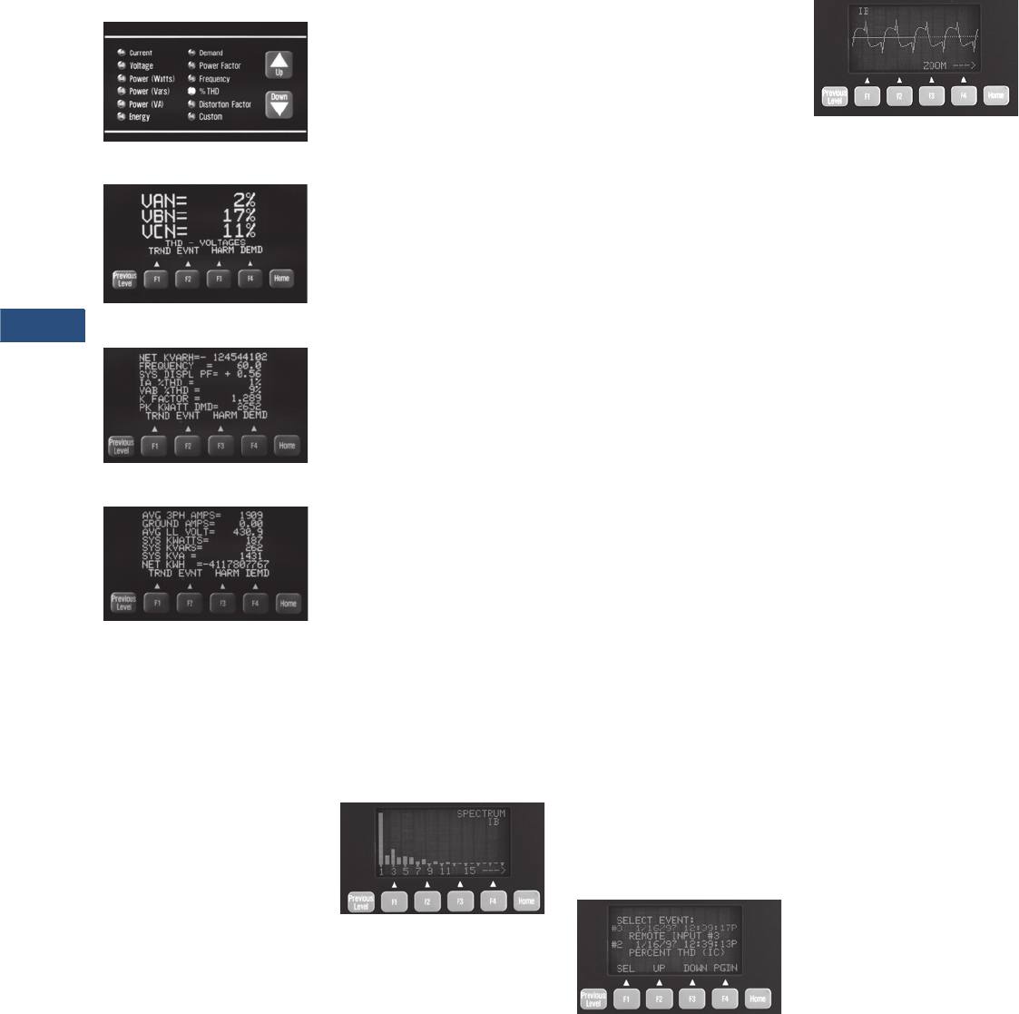
V3-T9-66 Volume 3—Power Distribution and Control Assemblies CA08100004E—March 2016 www.eaton.com
9
9
9
9
9
9
9
9
9
9
9
9
9
9
9
9
9
9
9
9
9
9
9
9
9
9
9
9
9
9
9.2
Metering Devices, Protective Relays, Software and Connectivity
Metering Devices
Meter Menu Screens
Meter Menu
Examples of Meter Menu
Custom Screen
Custom Screen
The IQ Analyzer allows a user
to view commonly used
parameters by scrolling
through its LED indicator
Meter Menu.
Meter Menu Displayed
Information
●Current
●Phases A, B, C, average
●Neutral
●Ground (separate CT)
●Voltage
●Phases A-B, B-C, C-A,
average
●Phases A-N, B-N, C-N,
average
●Neutral-ground
●Power
●Real (watts)
●Reactive (VARs)
●Apparent (VA)
●Phases A, B, C and
system
●Energy (forward, reverse
and net)
●Real (kWh)
●Reactive (kVARh)
●
Apparent (kVAh)—no
reverse or net
●Frequency, time and date
●Demand
●System current
(amperes)
●Systems real power
(kW)
●System reactive power
(kVAR)
●System apparent power
(kVA)
●Power factor (Phases A, B,
C and system)
●Displacement
●Apparent
●%THD current
●Phases A, B, C, N
●%THD voltage
●Phases A-B, B-C, C-A
●Phases A-N, B-N, C-N
●K-factor
●CBEMA (ITIC) derating
factor (displayed as “Z”)
●Crest Factor
●Discrete input and
output status
●Analog input reading
●Custom—user may
program four screens to
show any combination of
seven Meter Menu
parameters per screen
Harmonic Analysis Screens
Harmonic Spectrum Available with
Model 6600
Minimum and Maximum Values
●Current
●Phases A, B, C, N, G
●Voltage
●Phases A-B, B-C, C-A
●Phases A-N, B-N,
C-N, N-G
●Power
●Real (Watts)
●Reactive (VARs)
●Apparent (VA)
●Phases A, B, C and
System
●Power factor
●Apparent and
Displacement (three-
phase and system)
●Frequency
●THD (amperes, volts
and %):
●Current (Phases A, B, C, N)
●Voltage (Phases A-B, B-
C, C-A, A-N, B-N, C-N)
All minimum/maximum
values may be reset via reset
pushbutton on faceplate,
discrete input or
communications command.
Values are updated at least
once every 16 line cycles.
The F3 function key accesses
the Harmonic Analysis
screens. Two cycles of data
sampled at 128 samples/
cycle are simultaneously
recorded for:
●Current
●Phases A, B, C, N, G
●Voltage
●Phases A-B, B-C, C-A
●Phases A-N, B-N, C-N
●Neutral to Ground
Magnitudes (or % of
fundamental) of odd and
even multiples of the
fundamental from 2nd–50th
are displayed. The phase
angle associated with each
multiple of the fundamental
is also displayed.
Event/Alarm Analysis Screens
Example of Event Analysis Screens
Waveform Screen Available with
Model 6600
Pressing the F2 function key
accesses the Event Analysis
screens. These display the
following data for up to ten
event/alarm conditions:
●Description, date and
time of event/alarm with 10
millisecond resolution
●Current, voltages, power
readings, demand
readings, frequency and %
THD at time of event/alarm
●Current and voltage
distortion information
available on Harmonic
Analysis screens
Event data is stored in non-
volatile memory. If a reset
threshold is programmed,
the duration of the event
(e.g., undervoltage) is also
displayed. With Eaton’s
communications option and
software, waveforms and
harmonic profiles may be
displayed on a PC.
Event Conditions
Events may be triggered by
up to seven of any of the
following conditions:
Voltage Disturbances
●Undervoltage/sag—
any VL- L , VL- N (40–100%)
Note: 60% minimum for self-
powered unit.
●Overvoltage/swell—
any VL- L , VL- N (100–750%)

Volume 3—Power Distribution and Control Assemblies CA08100004E—March 2016 www.eaton.com V3-T9-67
9
9
9
9
9
9
9
9
9
9
9
9
9
9
9
9
9
9
9
9
9
9
9
9
9
9
9
9
9
9
9.2
Metering Devices, Protective Relays, Software and Connectivity
Metering Devices
If zero time delay is
programmed, any disturbance
lasting two cycles (less if
magnitude is sufficient to
effect rms readings) will
trigger a voltage disturbance
event/alarm.
●Sub-cycle transient
capture/excess dv/dt on
VA-N, VB-N, VC-N
Note: 6600 series only.
●Sub-cycle voltage
interruption on VA-N,
VB-N, VC-N
Note: 6600 series only.
Maximum Threshold Exceeded
●Currents—phases A, B, C,
Neutral and Ground
●Voltage—Neutral to
Ground
●System Power—Watts,
VA, VARs
●System Power Factor—
Displacement and
Apparent
●Demand
●Currents—Phase A, B, C
and AVG
●System Power—Watts,
VARs, VA
●Frequency
●Percent Total Harmonic
Distortion or Magnitude
Total Harmonic Distortion:
●Currents—Phases A, B,
C, Neutral
●Voltage—VA-N, VB-N,
VC-N, VA-B, VB-C, VC-A
Minimum Threshold Exceeded
●Currents—Phases A, B, C
●System Power—Watts,
Vars, VA
●System Power Factor—
Displacement and
Apparent
●Frequency
Voltage Phase Unbalance
●V o l t a g e L- L , L- N
Current Phase Unbalance
●Current—Phases A, B, C
Discrete Input Energized
●Input 1, 2, 3
●Remote command through
communications port or
front panel
All trigger conditions have
programmable time delays
from 0.1–60 seconds in
0.1 second increments
(except Voltage Disturbances
—programmable from
2–3600 cycles in two-cycle
increments, and Eaton’s
Power Management
Software commands—no
programmable delay).
Demand Recording
Peak Demands are date and
time stamped for:
●Current Phases A, B, C
and Average
●System Power:
●Real (watts)
●Reactive (VARs)
●Apparent (VA)
Input/Output
Extensive input/output
capability is standard on the
IQ Analyzer. In addition to
monitoring three-phase
currents and voltages,
separate inputs
are provided
for both ground and neutral
currents. Voltage of neutral-
to-ground is also monitored to
indicate the presence of
harmonics and potential
downstream grounding
problems. Analog and digital
I/O provide interfaces for
transducers, relays, PLCs
and control systems.
Current Inputs
Five ampere secondary CT
connections for:
●Phases A, B, C
●Ground
●Neutral
●Separate ground and
neutral CT inputs
●
CT range 5:5–10,000: 5
(any integer)
Voltage Inputs
●Phases A, B, C (from
120 Vac–500 kV AC)
●120/240 Vac control power
input standard—not
required with optional line
power module
●Separate ground-to-neutral
voltage reference
●PT range 120:120–
500,000:120 (any integer)
External 120-volt secondary
PTs are required above
600 Vac, optional from
120–600 Vac.
Discrete Contact Inputs
Three dry contact discrete
inputs may be programmed
by the user to:
●Trigger Event Analysis—
the information described
in “Event Analysis
Screens,” including
Harmonic Analysis
information, can be
recorded when external
devices trip or change state
by wiring their auxiliary
contacts into these inputs
●Act as a synch.-pulse
input to synchronize
power demand windows
with utility provided
synch. pulse
●Actuate a relay output
●Reset relay output, peak
demands, Trend Analysis
records and Event
Analysis records
●With communications
option, provide remote
status indication on Eaton’s
communication network
●Status of input contacts is
displayed in the Meter
Menu Custom screen
Relay Output Contacts
Four Form-C (NO/NC)
relay contacts may
be independently
programmed to:
●Act as a kWh, kVARh or
kVAh pulse initiator output
●Actuate on one or more
event conditions—including
discrete input software
commands (through
communications port)
●Reverse sequence alarm
Each relay may be set for
Auto or Manual Reset with
0–30 minute release delay
(one second increments).
Relays are Form-C NO/NC.
Relay(s) programmed to
actuate on undervoltage
also have a programmable
0–30 minute delay on power-
up for transfer applications.
Analog Input and Outputs
One analog input and four
analog outputs may be
configured as 0–20 or
4–20 mA. The analog input is
displayed at the device as a
percentage and is accessible
through the communications
port. The analog input
provides an interface with gas
flow meters, temperature
transducers or other analog
devices.
The analog outputs may be
programmed
to reflect any of
the following:
●Current—Phases A, B, C,
Average, N, G
●Voltage—L-L, L-N, N-G
●Power:
●Real (watts)
●Reactive (VARs)
●Apparent (VA)
●Phases A, B, C and
System
●% THD:
●Current (Phases A, B, C, N)
●Voltage (L-L, L-N)
●Frequency–System
●Power Factor:
●System Displacement PF
●System Apparent PF
Standards and Certifications
●UL listed, File E62791,
NKCR File E185559
(CE versions)
●cUL listed #1010.1 C22.2
●CE mark EN61010-1 (1993)
EN50082-2 (1994)
●Measurement Canada
Electricity Meter AE-0782
●CSA approved
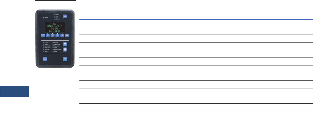
V3-T9-68 Volume 3—Power Distribution and Control Assemblies CA08100004E—March 2016 www.eaton.com
9
9
9
9
9
9
9
9
9
9
9
9
9
9
9
9
9
9
9
9
9
9
9
9
9
9
9
9
9
9
9.2
Metering Devices, Protective Relays, Software and Connectivity
Metering Devices
Product Selection
IQ Analyzer
Accessories
IQ Analyzer Auxiliary
Power Supply
The optional IQ Analyzer
Auxiliary Power Supply allows
set point programming of the
IQ meter while the monitored
line power is turned off and
locked out, thus eliminating
the presence of dangerous
line voltages. The Auxiliary
Power Supply is easy to
install and has been
specifically designed to
connect to the power supply
connector on the IQ meter
and then plug into a standard
electrical wall outlet.
Description
Catalog
Number
IQ Analyzer, separate source power module IQA6410
IQ Analyzer, 24–48 Vdc power module IQA6420
IQ Analyzer, three-phase power module IQA6430
IQ Analyzer, separate source power module with waveform display and sub-cycle voltage disturbance capture IQA6610
IQ Analyzer, 24–48 Vdc power module with waveform display and sub-cycle voltage disturbance capture IQA6620
IQ Analyzer, three-phase power module with waveform display and sub-cycle voltage disturbance capture IQA6630
IQ Flange, to provide extra clearance when mounting IQFLANGE
45-inch (1143.0 mm) extension cable for remote mounting of power module IQA45CABLE
24–48 Vdc separate source power module IQMDCPM
100–240 Vac and 100–250 Vdc separate source power module IQMSSPM
Three-phase, self-powered power module IQM3PPM
INCOM communication module IPONI
RS-485 communication module with Modbus protocol MPONI
IQ Analyzer

Volume 3—Power Distribution and Control Assemblies CA08100004E—March 2016 www.eaton.com V3-T9-69
9
9
9
9
9
9
9
9
9
9
9
9
9
9
9
9
9
9
9
9
9
9
9
9
9
9
9
9
9
9
9.2
Metering Devices, Protective Relays, Software and Connectivity
Metering Devices
Technical Data and Specifications
IQ Analyzer 6400/6600 Series
Fuses
●Self-powered units
with IQMSSPM have
3/4 ampere, 600 volts
Bus Type KTK-R-3/4 fuses
(three required).
●Separate source dual-
voltage units with
IQMSSPM have a single
5 x 20 mm 1/4 ampere fuse
●Separate source DC units
with IQMDCPM do not
have user replaceable
fuses
Environmental Conditions
●Operating temperature:
–20°–70°C
●Storage temperature:
–30°–85°C
●Operating humidity:
5–95% relative humidity
Current Inputs
(Each Channel)
●Conversion: true rms, 32
sample/cycle (all samples
used in all rms calculations)
●CT input: 5 ampere
secondary (any integer
5:5 to10,000:5)
●Burden: 0.05 VA
●Overload withstand:
40 amperes AC continuous,
300 amperes AC 1 second
●Range: 8 x CT continuous
●Accuracy: 0.1% of CT
primary rating, 0.2% of
reading above 150% of
rating, sinusoidal (see
accuracy below for non-
sinusoidal specifications)
●Input impedance:
0.002 ohm
Voltage Inputs
(Each Channel)
●Conversion: True rms, 32
sample/cycle (all samples
used in all rms calculations)
●PT input: direct or any
integer 120:120–
500,000:120
●Range: 30–660 Vac
(separate source and
DC source)
●Nominal full scale:
100–600 Vac
●Burden: 21 VA (self-
powered only)
●Overload withstand:
635 Vac, continuous
700 Vac, 1 second
●Input impedance:
1 megohm
Frequency Range
●20–66 Hz fundamental
(up to 50th harmonic)
Harmonic Response
(Voltages, Currents)
●50th harmonic
Accuracy (in Percent
Full Scale)
Accuracy from 3–300% of Full
Scale and
from –0.5. to 1.00
to 0.5 power factor
●Current and voltage:
±0.20%
●Power, energy and
demand: 0.40%
●Frequency: 0.04%
●Power factor: 0.80%
●THD: 1.00%
Specific Current Accuracies
●±0.20% of full scale to
200% of full scale and
150% crest factor
●±0.20% of full scale to
150% of full scale and
200% crest factor
●±0.20% of full scale to
100% of full scale and
300% crest factor
●±0.40% of reading for
currents to 800% of full
scale
●Power and energy: Start
recording with an average
of 3 mA secondary current
Discrete Inputs
(Dry Contact)
●+30 Vdc differential across
each discrete input pair of
terminals. Minimum pulse
width: 1.6 msec
●Optically isolated inputs
to protect IQ Analyzer
circuitry
Analog Outputs (4)
●0–20 mA/4–20 mA into
maximum 750 ohm load.
Accuracy: 1%
Analog Input (1)
●0–20 mA/4–20 mA into
200 ohm load.
Accuracy: 1%
Relay Output Contacts (4)
●Form C Dry Contact:
10 amperes at 120/240 Vac
(Resistive) 10A at 30 Vdc
(Resistive) 30A make
(50 mS) at 240 Vac/240 Vdc
●Minimum pulse width:
4 cycles (68 mS)
●Withstand rating: 1000 Vac,
1 minute across contacts
5000 Vac (contacts to coil,
1 minute) 10,000 Vac
(contacts to coil, surge
voltage)
Relay Response Time
(Excluding programmed
time delays):
●Two line cycles for Discrete
Input, Eaton’s software
commands
(communications port)
●Four to five line cycles for
Voltage Disturbance,
Voltage Unbalance
●Nine to 10 line cycles for
all others
IQ Analyzer Auxiliary
Power Supply
●Input voltage: 100–250 Vac
●Input frequency: 50/60 Hz
●Output voltage/current:
+24 Vdc at 0–0.45A
●Output ripple: 100 mV
maximum (peak to peak)
●Rated output power:
10.8 watts
●Turn on/turn off overshoot
5% maximum
●Turn on delay: 0.5 second
maximum
●Operating temperature:
0°–40°C
●Storage temperature:
–40°–80°C
Control Power Input
Note
1When directly wired to 480 Vac, IQ Analyzer can ride through a continuous sag that is 20% of rated voltage.
Description Separate Source Self Powered 1DC Source
Input range, AC
Frequency range
110–240 Vac ±10%
45–66 Hz
110–600 Vac ±10%
45–66 Hz
N/A
N/A
Input range, DC
Burden
110–250 Vdc ±10%
21 VA
N/A
21 VA
24–48 Vdc ±20%
21 VA
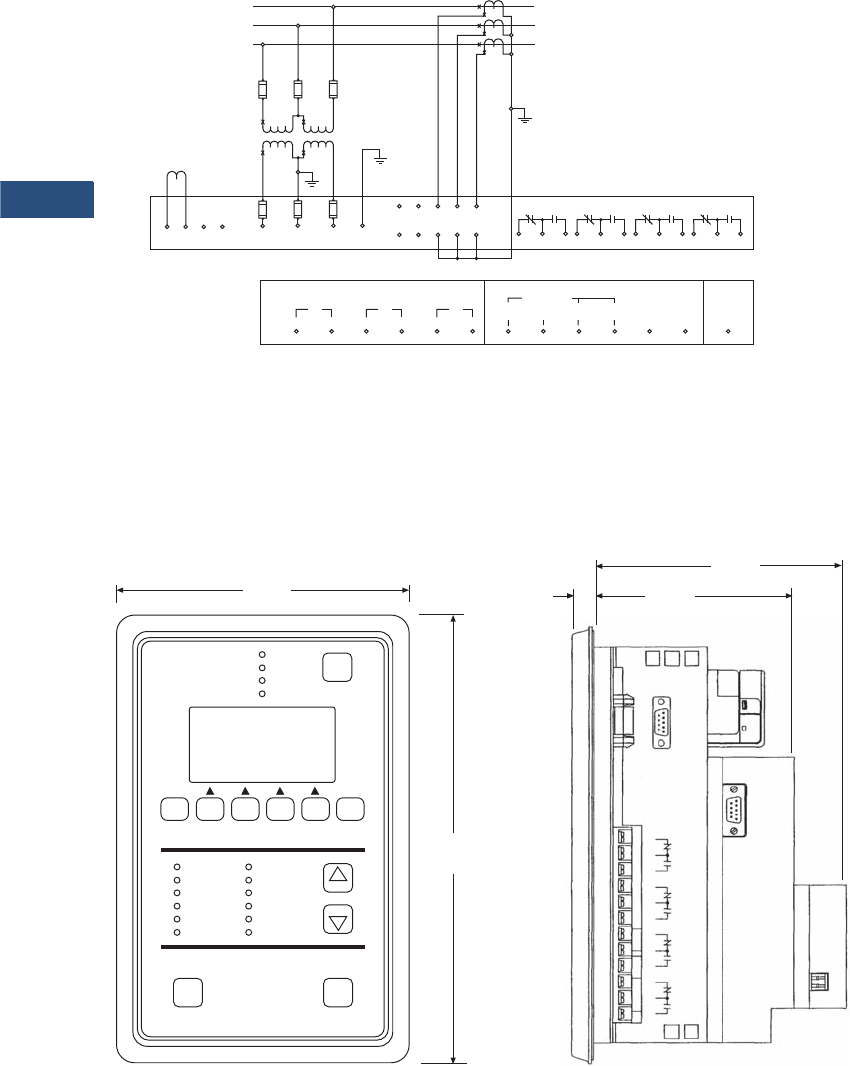
V3-T9-70 Volume 3—Power Distribution and Control Assemblies CA08100004E—March 2016 www.eaton.com
9
9
9
9
9
9
9
9
9
9
9
9
9
9
9
9
9
9
9
9
9
9
9
9
9
9
9
9
9
9
9.2
Metering Devices, Protective Relays, Software and Connectivity
Metering Devices
Wiring Diagram
Field Wiring Connections—Separate Source Power Supply Shown Here
(For Three-Phase Power Supply, No Separate Control Power is Required)
Dimensions
Approximate Dimensions in Inches (mm)
IQ Analyzer 6000 Series
Line
L3
A
B
C
Load
3CT
2CT
1CT
IQ Analyzer
Discrete Contact Inputs Analog I/O
Outputs
123
123
Neutral
Term.
AB C
Control Power
Separate Source Power Supply Module
(See Label for
Vac/dc Connections)
1234
13 14
(+) (-)
15 16
(+) (-)
17 18
(+) (-)
19 20 21 22 23 24 25
H1G
H2G
H1N
H2N
H1C
H2C
H1B
H2B
H1A
H2A
123456789101112
Relay No. 1 Relay No. 2 Relay No. 3 Relay No. 4
GND
Analog
Input Earth
Ground
Fuse
Open Delta
PT Connection
Note: External PTs
Optional Under 600 V
L2
L1
Fuse
4
Three-Phase Three-Wire (Above 600 Volts)
External Potential Transformers and Current Transformers
10.25
(260.4
Progra Help
Down
Up
Reset
RES
Normal
Event
Relay
Program
IQ Analyzer
F1
Previous
Level F2 F3 F4 Home
Current
Voltage
Power (Watts)
Power (Vars)
Power (VA)
Energy
Demand
Power Factor
Frequency
% THD
Distortion Factor
Custom
6.72
(170.7)
5.83
(148.1)
With Communication Module
0.50
(12.7)
Faceplate Without Communication
Module
4.70
(119.4)
J2
POWER
MODULE
RELAY NO. 1 RELAY NO. 2 RELAY NO. 3 RELAY NO. 4
1
2
3
Power Supply
PONI
1
2
3
1
2
3
1
2
3
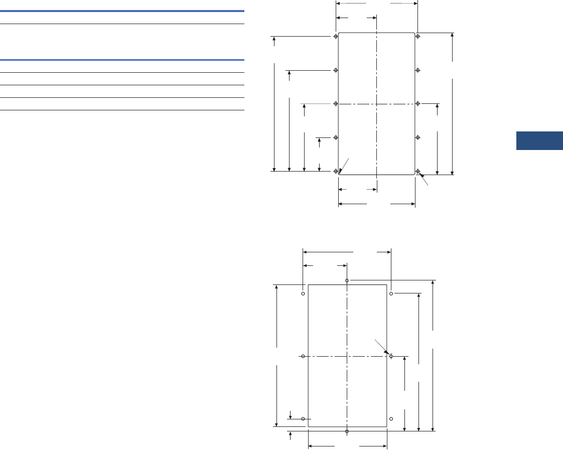
Volume 3—Power Distribution and Control Assemblies CA08100004E—March 2016 www.eaton.com V3-T9-71
9
9
9
9
9
9
9
9
9
9
9
9
9
9
9
9
9
9
9
9
9
9
9
9
9
9
9
9
9
9
9.2
Metering Devices, Protective Relays, Software and Connectivity
Metering Devices
Approximate Dimensions in Inches (mm)
IQ Analyzer Auxiliary Power Supply
IQ Analyzer 6000 Series
Width Height Depth
Shipping Weight
Lbs (kg)
2.40 (61.0) 4.00 (101.6) 1.11 (28.2) 5.8 (3.6)
Height Width Depth
Without PONI
10.25 (260.4) 6.72 (170.7) 4.70 (119.4)
With PONI
10.25 (260.4) 6.72 (170.7) 5.83 (148.1)
Drilling Pattern
Drilling Pattern for Flange Mounting
5.38
(136.7)
9.38
(238.3)
4.69
(119.1)
2.53
(64.3) 5.06
(128.5)
2.23
(56.7)
4.45
(113.0)
6.68
(169.7)
8.90
(226.1)
.06
(1.5) RAD
4 Places
2.69
(68.3)
.218
(5.5) DIA 10 Places
4.06
(103.1)
10.41
(264.4)
8.11
(206.0)
.213
(5.4)
Typ. for 8 11.03
(280.2)
10.09
(256.3)
5.52
(140.2)
.94
(23.9)
7.41
(188.2)
C
L
C
L
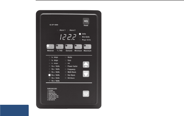
V3-T9-72 Volume 3—Power Distribution and Control Assemblies CA08100004E—March 2016 www.eaton.com
9
9
9
9
9
9
9
9
9
9
9
9
9
9
9
9
9
9
9
9
9
9
9
9
9
9
9
9
9
9
9.2
Metering Devices, Protective Relays, Software and Connectivity
Metering Devices
IQ DP-4000
Contents
Description Page
Metering Products Family. . . . . . . . . . . . . . . . . . . . . V3-T9-6
Power Xpert Meter 4000/6000/8000 Series . . . . . . . V3-T9-15
Power Xpert Meter 2000 Series . . . . . . . . . . . . . . . . V3-T9-34
IQ 250/260 Series Electronic Power Meters. . . . . . . V3-T9-45
IQ 130/140/150 Series Electronic Power Meters . . . V3-T9-51
IQ 150S/250S Self-Enclosed Electronic Meters . . . . V3-T9-56
IQ 35M . . . . . . . . . . . . . . . . . . . . . . . . . . . . . . . . . . . V3-T9-61
IQ Analyzer 6400/6600 Series . . . . . . . . . . . . . . . . . V3-T9-64
IQ DP-4000 Series
Features, Benefits and Functions . . . . . . . . . . . . V3-T9-73
Standards and Certifications . . . . . . . . . . . . . . . . V3-T9-73
Product Selection . . . . . . . . . . . . . . . . . . . . . . . . V3-T9-74
Accessories . . . . . . . . . . . . . . . . . . . . . . . . . . . . . V3-T9-74
Technical Data and Specifications . . . . . . . . . . . . V3-T9-75
Dimensions . . . . . . . . . . . . . . . . . . . . . . . . . . . . . V3-T9-77
IQ 230 Meters . . . . . . . . . . . . . . . . . . . . . . . . . . . . . V3-T9-78
Power Xpert Multi-Point Meter . . . . . . . . . . . . . . . . . V3-T9-85
IQ Energy Sentinel™ . . . . . . . . . . . . . . . . . . . . . . . . V3-T9-97
PM3 Monitoring and Metering Module . . . . . . . . . . V3-T9-106
Current Transformers (CTs). . . . . . . . . . . . . . . . . . . . V3-T9-107
Clamp-On Current Transformers . . . . . . . . . . . . . . . . V3-T9-116
IQ Flange . . . . . . . . . . . . . . . . . . . . . . . . . . . . . . . . . V3-T9-119
Panel Mounting Adapter Kit . . . . . . . . . . . . . . . . . . . V3-T9-120
Enclosed Meters. . . . . . . . . . . . . . . . . . . . . . . . . . . . V3-T9-121
IQ DP-4000 Series
Product Description
Eaton’s IQ DP-4000 is a
microprocessor-based
monitoring and protective
device that provides
complete electrical metering
and system voltage
protection. In one compact,
standard package, the IQ
DP-4000 will provide an
alternative to individually
mounted and wired
conventional meters and
switches. The DP-4000 also
monitors Apparent Power
(VA), Reactive Energy
(VAR-hours), Apparent
Energy (VA-hours) and
percent THD to provide the
user with basic power quality
information. The IQ DP-4000
meets and surpasses
UL/CSA/CE standards.
The IQ DP-4000’s rugged
construction is designed to
withstand harsh conditions
such as temperature
variations, outdoor
applications and industrial
environments. The membrane
faceplate pushbuttons are
easy to use and both the
parameter LED and window
displays are easily visible.
Application Description
●Monitoring of all common
electrical parameters
●Optional protective
alarm functions
Retrofit Opportunities
●Retrofit of existing
electrical distribution
systems with the IQ
DP-4000 for power, quality,
load and energy monitoring
●Mounting flange option
for application where
additional door mounting
space is required; see
Page V3-T9-119

Volume 3—Power Distribution and Control Assemblies CA08100004E—March 2016 www.eaton.com V3-T9-73
9
9
9
9
9
9
9
9
9
9
9
9
9
9
9
9
9
9
9
9
9
9
9
9
9
9
9
9
9
9
9.2
Metering Devices, Protective Relays, Software and Connectivity
Metering Devices
Features, Benefits and Functions
Historical Values
●Present demand current
(per phase) 5, 10, 15, 20,
25, 30, 45 or 60 minute
windows
●Present demand watts,
VARs and VA 5, 10, 15, 20,
25, 30, 45 or 60 minute
windows:
●Sliding or fixed window
for power Sync pulse
input (Model 4100)
Eaton’s PowerNet
broadcast demand sync
●Minimum and maximum
values current (per phase):
●Voltage (per phase,
L- L , L- N )
●Watts, VARs and VA
●Power factor
(displacement and
apparent)
●Frequency
●Peak values:
●Percent THD parameters
●Demand parameters
Protective and Event Alarming
●Undervoltage
●Overvoltage
●Current phase loss
●Voltage phase loss
●Phase reversal
●Phase unbalance
●Optional current and
powerdemand threshold
Metered and Monitored
Parameters
●rms sensing
●Phase currents
●Volts: L-L, L-N
●Power: real, reactive,
apparent
●Energy: real, reactive,
apparent
●Frequency
●Power factor
●% THD: current and
voltage
●Minimum and maximum
values
●Fixed or sliding demand
windows
Communications
●Optional interface
capability to computer
network for data collection,
storage and/or printout
via Eaton’s Power
Management Software
Physical Characteristics
●Large visible LED display
●Membrane Faceplate
NEMA 3R and 12 rated
Alarm and Protective Functions
●Alarm/Protective functions
(all models) include:
●Overvoltage
●Undervoltage
●Current phase loss
●Voltage phase loss
●Phase unbalance
●Phase reversal
●User-programmable alarm
and reset threshold levels
and delay intervals
●Optional current and power
demand threshold
Description of Protection
Functions
Overvoltage
Range 105–140%
(5% increments).
Undervoltage
Range 60–95%
(5% increments).
Phase Unbalance
Deviation between any
two phases percentage of
nominal line voltage preset by
DIP switches. Range 5–40%
(5% increments).
Phase Reversal
Any two phases become
reversed for the selected
delay.
Voltage Phase Loss
Less than 50% of the
nominal line voltage
detected.
Current Phase Loss
Smallest phase current is
less than1/16 of the largest
phase current.
Delay
Allows a delay before an alarm
occurs. (Range 1–20 seconds
in 1 second increments.)
Note: Unit must be powered for
this to occur.
Inputs and Outputs
(4100 Model)
●Three Form C relay outputs
selectable: Trip, Alarm,
kWh pulse initiator
●One synch input for kW
utility demand sync
Standards and Certifications
Listings and Certifications
●UL/cUL/CSA listed
●CE mark EN61010-1,
EN50082-2

V3-T9-74 Volume 3—Power Distribution and Control Assemblies CA08100004E—March 2016 www.eaton.com
9
9
9
9
9
9
9
9
9
9
9
9
9
9
9
9
9
9
9
9
9
9
9
9
9
9
9
9
9
9
9.2
Metering Devices, Protective Relays, Software and Connectivity
Metering Devices
Product Selection
IQ DP-4000
Accessories
IQ DP-4000 I/O Module
For applications where field
modification to add or change
Input/Output (I/O) capability
to the IQ DP-4000 is required,
Eaton offers I/O cards. These
field-installable modules can
be easily inserted into an
existing IQ DP-4000 where
input/output application
needs change.
●Power requirements:
10 VA
●Frequency: 50/60 Hz
●Operating temperature:
25°–70°C
●Operating humidity:
0–95% noncondensing
●Dry contact input: 24 Vdc
differential across input pair
of terminals; minimum
pulse width, 50 mS
Description
Catalog
Number
4 indicates an IQ DP-4000 model
x = 0 indicates no I/O; x = 1 indicates I/O
y = 1 indicates separate source supply, 110–240 Vac and 110–250 Vdc
y = 2 indicates 24–48 Vdc power supply,
y = 3 indicates three-phase power supply, 110–600 Vac
IQDP4XY0
Separate source control power without I/O IQDP4010
Separate source control power without I/O, DC supply IQDP4020
Three-phase power supply without I/O IQDP4030
Separate source control power with three Form C relay output contacts and one sync pulse input IQDP4110
Separate source control power with three Form C relay output contacts and one sync pulse input, DC supply IQDP4120
Three-phase power supply with three Form C relay output contacts and one sync pulse input IQDP4130
2 Form C relay outputs for protective alarming functions, 1 Form C relay output selectable for KYZ pulse output or load shedding,
1 demand sync pulse input
DP4IOMOD
IQ flange, to provide extra clearance when mounting IQFLANGE
45-inch (1143.0 mm) extension cable for remote mounting of power module IQA45CABLE
24–48 Vdc separate source power module IQMDCPM
100–240 Vac and 100–250 Vdc separate source power module IQMSSPM
Three-phase, self-powered power module IQM3PPM
INCOM communication module IPONI
RS-485 communication module with Modbus protocol MPONI
IQ DP-4000

Volume 3—Power Distribution and Control Assemblies CA08100004E—March 2016 www.eaton.com V3-T9-75
9
9
9
9
9
9
9
9
9
9
9
9
9
9
9
9
9
9
9
9
9
9
9
9
9
9
9
9
9
9
9.2
Metering Devices, Protective Relays, Software and Connectivity
Metering Devices
Technical Data and Specifications
Accuracy
●Maintained from 10–250%
of CT primary rating
Current Inputs (Each Channel)
●Nominal full scale current:
5 amperes AC
●Current range for rated
accuracy: 0–15 amperes AC
●Overload withstand:
15 amperes ac continuous
300 amperes AC 1 second
●Burden: 0.003 VA
Voltage Inputs (Each Channel)
●Voltage range (nominal):
90–600 Vac
●Nominal full scale voltage:
120–600 Vac
●Overload withstand:
660 Vac continuous 4 kV
1.2/50 μs
●Burden: three-phase power
module 10 VA
Fuses
Supplied with three-phase
power module only. 3/4
ampere, 600 volt bus type
KTK-R-3/4 (three required).
Contact Rating (Model 4100)
●10 amperes at 120/240 Vac
(resistive)
●10 amperes at 30 Vdc
(resistive)
Compatible with the
Following Systems
●Three-phase, three-wire
●Three-phase, four-wire
Ratings
●Application to 500 kV,
no PTs to 600 volts
●CT ratios selectable from
5:5 A to 12800: 5A
●Standard 120/600 Vac line
three-phase power supply
module. Two separate
source power supply
modules available. One
module from 110– 240 Vac
and 110–250 Vdc; the other
module 24–48 Vdc only
Model 4100 Input and Output
Control Power Input
Displayed Values
Note
All accuracy is measured as a percentage of full scale.
Model Input Output
4000 0 0
4100 1 digital (dry contact) 3 relays
Description Separate Source Self Powered DC Source
Input range, AC
Frequency range
110–240 Vac ±10%
45–66 Hz
110–600 Vac ±10%
45–66 Hz
N/A
N/A
Input range, DC
Burden
110–250 Vac ±10%
10 VA
N/A
10 VA
24–48 Vdc ±20%
10 VA
Description
Displayed Through Eaton’s
PowerNet System Local Display
AC amperes, phases A, B, C ±0.3% ±0.3% ±1 digit
AC voltage, phase A-B, B-C, C-A ±0.3% ±0.3% ±1 digit
Phase A-N, B-N, C-N ±0.3% ±0.3% ±1 digit
Watts ±0.6% ±0.6% ±1 digit
Vars ±0.6% ±0.6% ±1 digit
VA ±0.6% ±0.6% ±1 digit
Watt-hours ±0.6% ±0.6% ±1 digit
VAR-hours ±0.6% ±0.6% ±1 digit
VA-hours ±0.6% ±0.6% ±1 digit
Power factor ±1% ±1%
Frequency ±0.1 Hz ±0.1 Hz
% THD Through 31st harmonic Through 31st harmonic
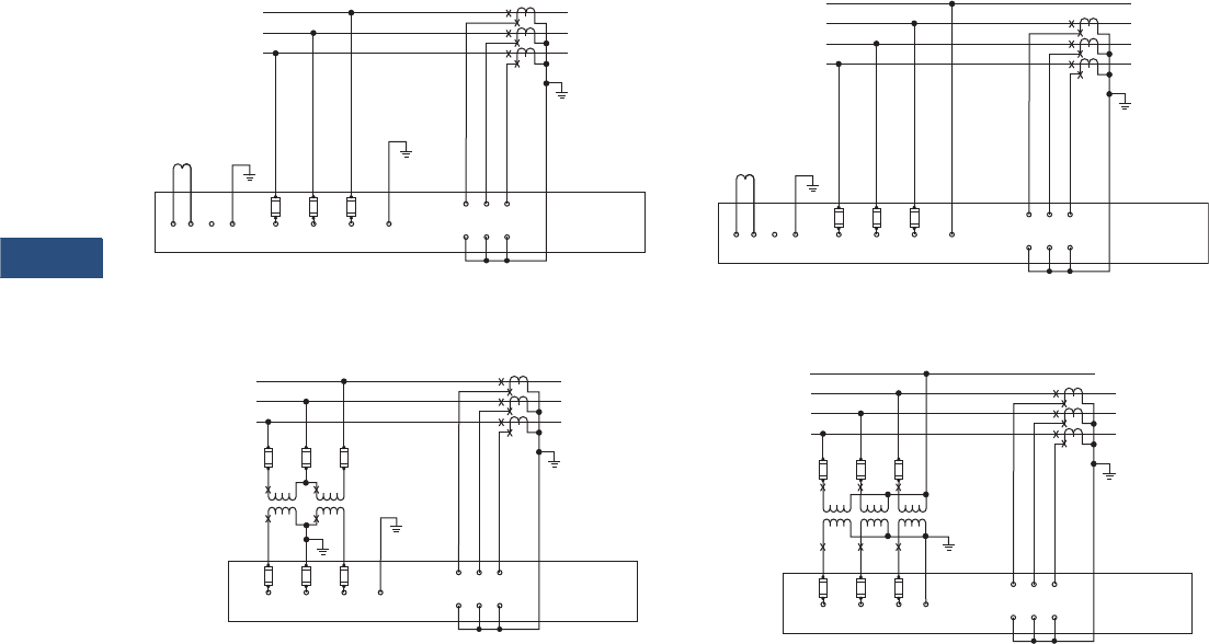
V3-T9-76 Volume 3—Power Distribution and Control Assemblies CA08100004E—March 2016 www.eaton.com
9
9
9
9
9
9
9
9
9
9
9
9
9
9
9
9
9
9
9
9
9
9
9
9
9
9
9
9
9
9
9.2
Metering Devices, Protective Relays, Software and Connectivity
Metering Devices
Wiring Diagrams
Field Wiring Connections
H2C
Line Load
C
B
A
L3
L2
L1
Fuse
ABCNeutral
Ter m .
Open Delta
VT Connection
Self-Powered Power Supply Module
HIC HIB HIA
H2B H2A
IQ DP-4000
1CT
2CT
3CT
Fuse
H2C
Line Load
C
B
A
L3
L2
L1
Fuse
ABC
WYE
Connection
Self-Powered Power Supply Module
HIC HIB HIA
H2B H2A
IQ DP-4000
1CT
2CT
3CT
Fuse
Neutral
Term.
N
H2C
Line Load
C
B
A
L3
L2
L1
Fuse
ABC1234
Separate Source Power Supply Module
HIC HIB HIA
H2B H2A
IQ DP-4000
1CT
2CT
3CT
Neutral
Ter m .
(99 – 275 Vdc)
(99 – 264 Vac)
(24 – 48 Vdc)
Control Power
H2C
Line Load
C
B
A
L3
L2
L1
Fuse
ABC1234 Neutral
Ter m .
(99 – 275 Vdc)
(99 – 264 Vac)
(24 – 48 Vdc)
Control Power
Separate Source Power Supply Module
HIC HIB HIA
H2B H2A
IQ DP-4000
1CT
2CT
3CT
N
Three-Phase Three-Wire (Up to 600 Volts)
Direct Voltage Connection and External Current Transformers
Three-Phase Four-Wire (Up to 600 Volts)
Direct Voltage Connection and External Current Transformers
Three-Phase Three-Wire (Above 600 Volts)
External Voltage Transformers and Current Transformers
Three-Phase Four-Wire (Above 600 Volts)
External Voltage Transformers and Current Transformers
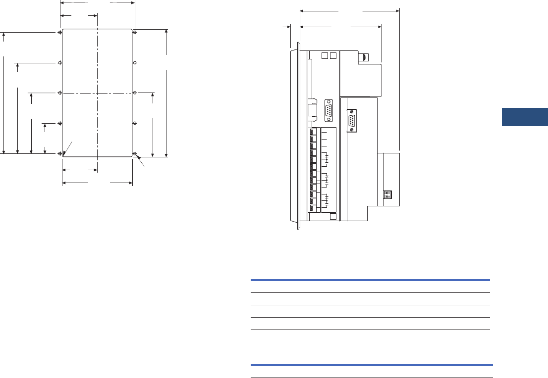
Volume 3—Power Distribution and Control Assemblies CA08100004E—March 2016 www.eaton.com V3-T9-77
9
9
9
9
9
9
9
9
9
9
9
9
9
9
9
9
9
9
9
9
9
9
9
9
9
9
9
9
9
9
9.2
Metering Devices, Protective Relays, Software and Connectivity
Metering Devices
Dimensions
Approximate Dimensions in Inches (mm)
Drilling Pattern
5.38
(136.7)
9.38
(238.3)
4.69
(119.1)
2.53
(64.3) 5.06
(128.5)
2.23
(56.7)
4.45
(113.0)
6.68
(169.7)
8.90
(226.1)
.06
(1.5) RAD
4 Places
2.69
(68.3)
.218
(5.5) DIA 10 Places
IQ DP-4000 Side View
LED Display
IQ DP-4000 Auxiliary Power Supply
Height Width Depth
Shipping Weight
Lbs (kg)
PONI
10.25 (260.4) 6.72 (170.7) 5.40 (137.2) 6.50 (3.0)
Without PONI
9.02 (229.0) 7.80 (198.1) 4.42 (112.3) 12.5 (5.7)
Width Height Depth
2.40 (61.0) 4.00 (101.6) 1.11 (28.2)
1
2
3
4
5
6
7
8
9
10
11
0.50
(12.7)
Faceplate
With Communication Module
5.40
(137.1)
4.42
(112.3)
Power
Module
P3
Without Communication
Module
Power Module
PONI
Sync. 1/2 Hp @ 240 Vac 1/3 Hp @ 120 Vac
GND Pulse Alarm 1 Alarm 2 MWH Pulse
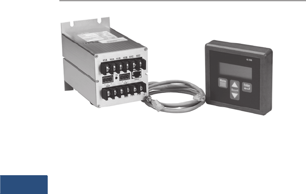
V3-T9-78 Volume 3—Power Distribution and Control Assemblies CA08100004E—March 2016 www.eaton.com
9
9
9
9
9
9
9
9
9
9
9
9
9
9
9
9
9
9
9
9
9
9
9
9
9
9
9
9
9
9
9.2
Metering Devices, Protective Relays, Software and Connectivity
Metering Devices
IQ 230 Digital Meter
Contents
Description Page
Metering Products Family. . . . . . . . . . . . . . . . . . . . . V3-T9-6
Power Xpert Meter 4000/6000/8000 Series . . . . . . . V3-T9-15
Power Xpert Meter 2000 Series . . . . . . . . . . . . . . . . V3-T9-34
IQ 250/260 Series Electronic Power Meters. . . . . . . V3-T9-45
IQ 130/140/150 Series Electronic Power Meters . . . V3-T9-51
IQ 150S/250S Self-Enclosed Electronic Meters . . . . V3-T9-56
IQ 35M . . . . . . . . . . . . . . . . . . . . . . . . . . . . . . . . . . . V3-T9-61
IQ Analyzer 6400/6600 Series . . . . . . . . . . . . . . . . . V3-T9-64
IQ DP-4000 Series . . . . . . . . . . . . . . . . . . . . . . . . . . V3-T9-72
IQ 230 Meters
Features. . . . . . . . . . . . . . . . . . . . . . . . . . . . . . . . V3-T9-79
Standards and Certifications . . . . . . . . . . . . . . . . V3-T9-79
Product Selection . . . . . . . . . . . . . . . . . . . . . . . . V3-T9-80
Technical Data and Specifications . . . . . . . . . . . . V3-T9-81
Dimensions . . . . . . . . . . . . . . . . . . . . . . . . . . . . . V3-T9-84
Power Xpert Multi-Point Meter . . . . . . . . . . . . . . . . . V3-T9-85
IQ Energy Sentinel™ . . . . . . . . . . . . . . . . . . . . . . . . V3-T9-97
PM3 Monitoring and Metering Module . . . . . . . . . . V3-T9-106
Current Transformers (CTs). . . . . . . . . . . . . . . . . . . . V3-T9-107
Clamp-On Current Transformers . . . . . . . . . . . . . . . . V3-T9-116
IQ Flange . . . . . . . . . . . . . . . . . . . . . . . . . . . . . . . . . V3-T9-119
Panel Mounting Adapter Kit . . . . . . . . . . . . . . . . . . . V3-T9-120
Enclosed Meters. . . . . . . . . . . . . . . . . . . . . . . . . . . . V3-T9-121
IQ 230 Meters
Product Description
The IQ 230 is a
microprocessor-
based
metering and monitoring
device. Its compact size and
flexible mounting capabilities
make it suitable for machine
control panels such as
panelboard and switchboard
mains and feeders, low
voltage metal-enclosed
switchgear feeders and
motor control centers. The IQ
230 series meter includes a
base module and a display
module. The IQ 230 base
module has the flexibility to
be directly mounted to the
display or separately panel
mounted. The display is
integrally designed to fit a
standard 1/4 DIN or a
100 mm ANSI cutout for
new retrofit applications.
Application Description
The IQ 230 is ideal for
individual load monitoring
or provides an alternative
to multiple ammeters,
voltmeters, ammeter and
voltmeter switches,
wattmeters, varmeters,
power factor meters,
frequency meters, watthour
and demand meters. ANSI
C12 Class 10 revenue
metering accuracy makes the
IQ 230 ideal for sub-metering
and sub-billing applications.

Volume 3—Power Distribution and Control Assemblies CA08100004E—March 2016 www.eaton.com V3-T9-79
9
9
9
9
9
9
9
9
9
9
9
9
9
9
9
9
9
9
9
9
9
9
9
9
9
9
9
9
9
9
9.2
Metering Devices, Protective Relays, Software and Connectivity
Metering Devices
Features
The IQ 230 can be easily
programmed from the display
keypad, which features a
4 line x 20 character LED
backlit LCD display. This
menu driven device displays a
variety of selectable electrical
system values and may be
programmed for password
protection.
The IQ 230 series includes
two variations all containing
the same display module.
The IQ 230 has built-in
INCOM communications,
KYZ pulse output, digital
inputs, digital outputs and an
analog input. The IQ 230M
includes all the benefits of
the IQ 230 but replaces
INCOM communication with
Modbus®
●Five different mounting
options
●1/4 DIN standard
3.60 inches (91.4 mm) x
3.60 inches (91.4 mm)
cutout that meets global
standards
●One meter style with
multiple mounting
choices—mount on panel,
DIN rail or back of meter
●Autoranging power supply;
one style for any voltage
up to 600 Vac
●Direct connection up to
600 Vac. PTs are not
required
●AC or DC powered
●Polarity sensing for errors
such as improper wiring
or forward and reverse
power flow
●Membrane faceplate
designed and tested to
meet NEMA® 12 and IP52
●Nonvolatile storage of all
set points and recorded
peaks and minimums
●Built-in INCOM or Modbus
communications capability
●Digital and analog I/O
●Utility seal provision
Monitored Values
●Phase currents
●Voltage, L-L, L-N
●System and per-phase
power including watthours,
varhours and VA-hours
●System demand including
watt demand, VA demand
and VAR demand
●Apparent and
displacement power factor
●Frequency
●KYZ pulse output is
available for use with a
watthour pulse recorder
or totalizer
●Recorded minimums and
maximums of most values
Standards and Certifications
●UL and cUL listed
●UL file number E185559
●CSA certified (not ANSI
revenue certified as a
single-phase meter)
●CE mark for applications
where European
compliance is required
●IEC 1010-1 (1990) incl.
amend. 1 and 2 (1995)
●EN61010-1 (1993)
●CSA C22.2 #1010.1 (1992)
●UL 3111
V3-T9-80 Volume 3—Power Distribution and Control Assemblies CA08100004E—March 2016 www.eaton.com
9
9
9
9
9
9
9
9
9
9
9
9
9
9
9
9
9
9
9
9
9
9
9
9
9
9
9
9
9
9
9.2
Metering Devices, Protective Relays, Software and Connectivity
Metering Devices
Product Selection
IQ 230 Meters
Description
Catalog
Number
IQ 230 complete meter
Includes base, display and 14-inch cable with INCOM Communications, KYZ output, digital inputs,
digital outputs, analog input and utility seal provision
IQ230
IQ 230M complete meter
Includes base, display and 14-inch cable with Modbus communications, KYZ output, digital inputs,
digital outputs, analog input and utility seal provision
IQ230M
IQ 230 base module IQ230TRAN
IQ 230M base module IQ230MTRAN
IQ 200D IQ 210/220 display module IQ200D
3-foot (0.9 m) category 5 cable IQ23CABLE
6-foot (1.8 m) category 5 cable IQ26CABLE
10-foot (3.0 m) category 5 cable IQ210CABLE
IQ 230 Meters

Volume 3—Power Distribution and Control Assemblies CA08100004E—March 2016 www.eaton.com V3-T9-81
9
9
9
9
9
9
9
9
9
9
9
9
9
9
9
9
9
9
9
9
9
9
9
9
9
9
9
9
9
9
9.2
Metering Devices, Protective Relays, Software and Connectivity
Metering Devices
Technical Data and Specifications
Compatible with the Following Systems:
●Three-phase, three-wire
●Three-phase, four-wire
●Single-phase, two-wire
●Single-phase, three-wire
Current Input (Each Channel)
●Current range: 2 times
●Nominal full scale current: 5 amperes AC
●Overload withstand:10 amperes AC continuous
150 amperes AC, 1 second
●Input impedance: 0.01 ohms
●Burden: 0.025 VA
Voltage Input (Each Channel)
●Voltage range (nominal): 90–600/347 Vac
●Nominal full scale voltage: 120–600/347 Vac
●Overload withstand: 660 Vac continuous,
800 Vac 1 second
●Input impedance: 2 megohm
CT (Primary) Settings
Select from 256 values ranging from 5–8000 amperes
●PT Primary 256 values with ratios up to 200 kV
Environmental Conditions
Frequency Range
50/60 Hz
Control Power Input
EMC
●Emissions
FCC Part 15 Class A
CISPR 11 (1990)/EN55011 (1991) Group 1 Class A
●Immunity
Electrostatic discharge
EN61000-4-2 (1995)/EN50082-2 (1995)
4 kV contact discharge
8 kV air discharge
Electrical fast transient
EN61000-4-4 (1995)/EN50082-2 (1995)
2 kV power lines
2 kV signal lines
Radiated immunity
EN61000-4-3 (1997)/EN50082-2 (1995)
10V/m
Conducted immunity
EN61000-4-6 (1996)/EN50082-2 (1995)
10V rms
Power frequency magnetic field
EN61000-4-8 (1995)
30 A/m
Metered Values and Accuracies at Full Scale
Communications
INCOM compatible 1200/9600 baud
●(IQ 230 only—does not require IPONI)
Modbus compatible 9600/19200 baud
●(IQ 230M only—does not require PONI)
Input/Output
KYZ solid-state relay output
●96 mA at 240 Vac/300 Vdc
●Digital input 96 mA at 12–48 Vdc
●Digital output 96 mA at 125 Vac/176 Vdc
●Analog input 4–20 mA
Base Display
Operating temperature –20°C to 50°C 0°C to 50°C
Storage temperature –30°C to 85°C –20°C to 60°C
Operating humidity 0.0% to 95% noncondensing —
Maximum relative humidity 80% up to 31°C —
Vac Vdc
IQ 230 100–600 ±10% 48–250 ±10%
Frequency range 50–60 Hz ±10% —
Burden 180 mA 700W
Accuracy
AC ampere Phase A
Phase B
Phase C
±0.5%
AC voltage
Phase A-B
Phase B-C
Phase C-A
Phase A
Phase B
Phase C
±0.5%
Watts ±1.0%
VARs ±1.0%
VA ±1.0%
Watthours ±1.0%
VAR-hours ±1.0%
VA-hours ±1.0%
Power factor ±2.0%
Frequency ±0.1%
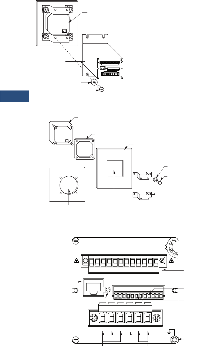
V3-T9-82 Volume 3—Power Distribution and Control Assemblies CA08100004E—March 2016 www.eaton.com
9
9
9
9
9
9
9
9
9
9
9
9
9
9
9
9
9
9
9
9
9
9
9
9
9
9
9
9
9
9
9.2
Metering Devices, Protective Relays, Software and Connectivity
Metering Devices
Mounting the IQ 230 Base Module
to the IQ 230 Display Module
Display Mounting Options
IQ 230 Base Connections
#10 Screw
Lock Washer
IQ 230
Base Module
IQ 230 Display
Module—
Mounted in
a Panel
1
A2
A
H
IN2IN1 A N1
DISPLAY
R
TX
A1
121
IIRRI
NEUVBVA VC PS1 PS2
12122
MOD
2
INCOM
1
PULSE
Y2K Z 321
BAB CC
HHH HH
3.9 Inches (100 mm)
ANSI Cutout
.25 Inches (6.4 mm)
Diameter Cutout
or
Mounting Bracket
Hex Nut
Locking Washer
Panel
Gasket
IQ 230 Display Module
1
A2
A
H
IN2IN1 AN1
DISPLAY
R
A1
121
IIRRI
NEUVBVA VC PS1 PS2
12122
MOD
2
INCOM
1
PULSE
Y2K Z 321
BAB CC
HHH HH
1
A2
A
H
IN2IN1 AN1
DISPLAY
R
TX
A1
121
IIRRI
NEUVBVA VC PS1 PS2
12122
MOD
2
INCOM
1
PULSE
Y2K Z 321
BAB CC
HHH HH
TX
Ground Lug
Connect to
IQ 230 Display
Module
System Current
Transformer Input
IQ 230
Power Supply
Neutral
INCOM™
Transmit LED
INCOM™ Port
System
Voltage Input
K-Y-Z Pulse
Output
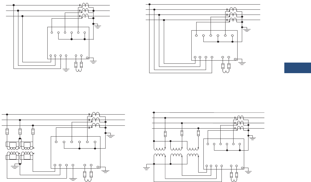
Volume 3—Power Distribution and Control Assemblies CA08100004E—March 2016 www.eaton.com V3-T9-83
9
9
9
9
9
9
9
9
9
9
9
9
9
9
9
9
9
9
9
9
9
9
9
9
9
9
9
9
9
9
9.2
Metering Devices, Protective Relays, Software and Connectivity
Metering Devices
Wiring Diagrams
Typical Field Wiring Connections
H1A H1B H1C
Line
L3
L2
L1
Control Power
PS1 PS2
VA VB VC NEU
H2A H2B H2C
IQ 230
Load
Open
Delta
PT
Connec-
tion
Case
Ground
must be
connected
for proper
operation
Fuse
Fuse
IQ 230
90–600 Vac
48–250 Vdc
H1A H1B H1C
N
L3
L2
L1
Control Power
PS1 PS2
VA VB VC NEU
H2A H2B H2C
IQ 230
Load
Case
Ground
must be
connected
for proper
operation
Fuse
Line
IQ 230
90–600 Vac
48–250 Vdc
H1A H1B H1C
N
L3
L2
L1
Control Power
PS1 PS2
VA VB VC NEU
H2A H2B H2C
IQ 230
Load
Case
Ground
must be
connected
for proper
operation
Fuse
Line
IQ 230
90–600 Vac
48–250 Vdc
WYE
Connection
Three-Phase Three-Wire (up to 600 Volts)
Proper CT polarity is critical to the proper operation of the meter
Three-Phase Three-Wire (above 600 Volts)
Proper CT polarity is critical to the proper operation of the meter
Three-Phase Four-Wire (up to 600 Volts)
(Line Powered) Proper CT polarity is critical to the proper operation of the meter
Three-Phase Four-Wire (above 600 Volts)
Proper CT polarity is critical to the proper operation of the meter
H1A H1B H1C
L3
L2
L1
Control Power
PS1 PS2
VA VB VC NEU
H2A H2B H2C
IQ 230
Load
Case
Ground
must be
connected
for proper
operation
Fuse
Line
IQ 230
90–600 Vac
48–250 Vdc
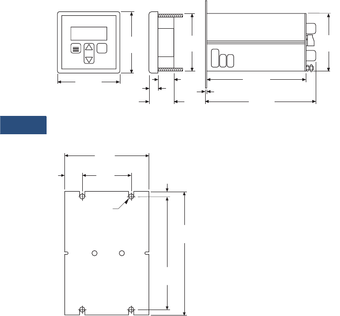
V3-T9-84 Volume 3—Power Distribution and Control Assemblies CA08100004E—March 2016 www.eaton.com
9
9
9
9
9
9
9
9
9
9
9
9
9
9
9
9
9
9
9
9
9
9
9
9
9
9
9
9
9
9
9.2
Metering Devices, Protective Relays, Software and Connectivity
Metering Devices
Dimensions
Approximate Dimensions in Inches (mm)
IQ 230
Mounting Hole Pattern for the IQ 230 Base Module
0.97
(24.6)
1.84
(46.7)
0.50
(12.7) 0.06
(1.5)
4.33
(110.0)
4.33
(110.0)
6.74
(171.2)
6.06
(154)
3.62
(92.0)
IQ 200
Scroll
Menu Enter
3.62
(92.0)
4.55
(115.6)
5.05
(128.3)
2.00
(50.8)
3.55
(90.2)
.78
(19.8)
Slot Size
.125 (3.2) Radius
(4 places)
.25
(6.35)

Volume 3—Power Distribution and Control Assemblies CA08100004E—March 2016 www.eaton.com V3-T9-85
9
9
9
9
9
9
9
9
9
9
9
9
9
9
9
9
9
9
9
9
9
9
9
9
9
9
9
9
9
9
9.2
Metering Devices, Protective Relays, Software and Connectivity
Metering Devices
Power Xpert Multi-Point Meter
Contents
Description Page
Metering Products Family . . . . . . . . . . . . . . . . . . . . V3-T9-6
Power Xpert Meter 4000/6000/8000 Series . . . . . . V3-T9-15
Power Xpert Meter 2000 Series . . . . . . . . . . . . . . . V3-T9-34
IQ 250/260 Series Electronic Power Meters . . . . . . V3-T9-45
IQ 130/140/150 Series Electronic Power Meters . . . V3-T9-51
IQ 150S/250S Self-Enclosed Electronic Meters. . . . V3-T9-56
IQ 35M. . . . . . . . . . . . . . . . . . . . . . . . . . . . . . . . . . . V3-T9-61
IQ Analyzer 6400/6600 Series . . . . . . . . . . . . . . . . . V3-T9-64
IQ DP-4000 Series . . . . . . . . . . . . . . . . . . . . . . . . . . V3-T9-72
IQ 230 Meters . . . . . . . . . . . . . . . . . . . . . . . . . . . . . V3-T9-78
Power Xpert Multi-Point Meter
IQ Energy Sentinel™ . . . . . . . . . . . . . . . . . . . . . . . . V3-T9-97
PM3 Monitoring and Metering Module . . . . . . . . . . V3-T9-106
Current Transformers (CTs) . . . . . . . . . . . . . . . . . . . V3-T9-107
Clamp-On Current Transformers . . . . . . . . . . . . . . . V3-T9-116
IQ Flange . . . . . . . . . . . . . . . . . . . . . . . . . . . . . . . . . V3-T9-119
Panel Mounting Adapter Kit . . . . . . . . . . . . . . . . . . . V3-T9-120
Enclosed Meters . . . . . . . . . . . . . . . . . . . . . . . . . . . V3-T9-121
Power Xpert Multi-Point Meter
Product Overview
Eaton’s Power Xpert™ Multi-
Point Meter is an ANSI
C12.20 revenue class Web-
enabled electronic
submetering device that can
be mounted in panelboards
switchboards or enclosures.
When mounted in a
panelboard or a switchboard,
the Power Xpert Multi-Point
Meter provides customers
with an integrated power
distribution and energy
metering solution that saves
space, reduces installation
labor and lowers total cost.
The Eaton Power Xpert Multi-
Point Meter (PXMP Meter)
offers a highly modular
approach to high-density
metering applications in
electrical power distribution
systems. The PXMP Meter is
compatible with most three-
phase industrial, commercial
and single-phase residential
low voltage electrical power
systems. The PXMP is
equipped with two Modbus®
RTU communication ports for
local display and remote serial
communications. The PXMP
also has optional pulse input
and digital output modules
along with one standard
digital output and three digital
inputs. The PXMP Energy
Portal Module is Web
enabled, making it suitable for
use with Ethernet networks
and modems.
Product Description
The Power Xpert Multi-Point
Meter can measure up to any
of the following number of
circuits:
●Sixty single-phase,
two-wire (single-pole)
●Thirty single-phase,
three-wire (two-pole)
●Twenty three-phase,
four-wire (three-pole)
The circuits listed above can
be mixed provided that the
total number of current
sensors does not exceed 60.
The meter provides current;
voltage; power factor;
demand and active, reactive,
and real power (VA, VAR, kW);
and active, reactive, and real
energy (VA, VAR, kWh)
measurements for each load.
The unit also provides up to
two years at 15-minute
intervals or eight years at one-
hour intervals of demand data
logging storage in non-volatile
memory for up to 60
submeters.
The Power Xpert Multi-Point
Meter can be used with three
different ratings of current
sensors: 100 mA, 10 mA or
333 mV. Switchboard/
panelboard applications will
use the 100 mA current
sensors, which are highly
accurate, self-protecting in the
event of an open circuit
condition under load and are
supplied with an integral plug-
in connector. The PXMP
automatically detects the
rating of the current sensor
that is connected.
The PXMP can also use 10 mA
current sensors that were
previously installed for
IQMESII retrofit applications.
Additionally, the PXMP can
use 333 mV split core current
sensors for retrofit
applications where metering
has not previously existed.
The 10 mA and 333 mV
current sensors are also self-
protecting in the event of an
open circuit condition under
load.

V3-T9-86 Volume 3—Power Distribution and Control Assemblies CA08100004E—March 2016 www.eaton.com
9
9
9
9
9
9
9
9
9
9
9
9
9
9
9
9
9
9
9
9
9
9
9
9
9
9
9
9
9
9
9.2
Metering Devices, Protective Relays, Software and Connectivity
Metering Devices
Application Description
The Power Xpert Multi-Point
Meter is ideally suited to
handle submetering in low
voltage power distribution
equipment applications such
as distribution boards in
multi-tenant buildings,
comprehensive main and
feeder metering in
commercial/industrial
switchboards or medium
voltage distribution
equipment with the use of
voltage and current
transformers.
The Power Xpert Multi-Point
Meter provides a cost-
effective solution for
residential or commercial
metering installations. Typical
installations include:
●High-rise buildings
●Government institutions
●K–12, universities and
campuses
●Office buildings
●Medical facilities
●Apartment and
condominium complexes
●Airports
●Shopping malls
●Industrial sites
●Mixed-use facilities
Features
●Monitors power and
energy for up to 60 current
sensors; space-saving
modular design allows
measurement from 1 to 60
circuits
●Built-in communication
interfaces
●Monitors single-phase and
three-phase loads from 120
to 600 Vac
●Monitors current, voltage,
power factor, frequency,
power and energy
●Stores extensive energy
profile data for each
metering point; can be
used to identify
coincidental peak
demand contribution
●LEDs provide status of unit
communication activity and
verify sensor connections
●Meets rigid ANSI C12.20
accuracy specifications for
revenue meters
●Three standard digital
inputs and eight pulse
inputs per optional module
to monitor WAGES (water,
air, gas, electric, or steam)
●One standard digital output
and eight digital outputs
per optional module for
alarm indication
●Three types of meter
modules to support 10 mA,
100 mA or 333 mV sensors
●Can be directly mounted in
a UL Listed panelboard,
switchboard or enclosure
●256 MB of memory in
meter base for up to two
years of 15-minute interval
data (eight years of one-
hour interval data) for eight
demand values up to
60 submeters
Communication Capabilities
With the Power Xpert Multi-
Point Meter’s built-in
communication capabilities,
remote meter reading and
monitoring functions can be
integrated into both new and
retrofit applications.
●Standard Modbus RTU
●Optional Modbus TCP /
BACnet/IP / SNMP / HTTP /
SMTP / NTP /SFTP
communications
Software Compatibility
The Power Xpert Multi-Point
Meter:
●Can be used as part of
an electrical energy
monitoring and cost
allocation system
●Can be remotely monitored
via onboard Web pages
with Eaton’s optional
Energy Portal Module
●Is compatible with third-
party software platforms
and interface devices
Configuration
●The Power Xpert Multi-
Point Meter is fully
configurable using Power
Xpert Multi-Point
configuration software that
can be down-loaded free
from the Eaton website at
www.eaton.com/meters
●Each Power Xpert Multi-
Point Meter module can be
configured for up to six
metering points in any
combination of single-
phase and three-phase
metering points
corresponding to the
voltage wiring of the meter
base
●Power Xpert Multi-Point
configuration software
simplifies system
commissioning and
startup; PXMP
configuration software
supports both online and
offline configurations
Easy to Install
●UL Listed for mounting
inside panelboards (e.g.,
PRL4), switchboards, and
NEMA 12 enclosures
●Quick connect terminals
for current sensors,
Modbus communications,
and bus voltages make
wiring the unit quick
and easy
Features
Note
1Main only.
Description Main/Aggregate Channel Data Tenant
Instrumentation
Current, per phase ■ 1■—
Voltage, per phase (L-L, L-N) ■■—
Frequency — ■■
Minimum/maximum readings, V Per phase — —
Minimum/maximum readings, W, VAR, VA Total and per phase — —
Minimum/maximum readings, PF, F Total — —
Power
Real, reactive, and apparent power (W, VAR, VA) Total and per phase Total and per phase Total
Power factor — Average Average
Demand
Block interval (fixed, sliding) ■——
Real, reactive and apparent power demand Total and per phase — —
Minimum/maximum readings, PF, W, VAR, VA Total and per phase Total —
Energy
Real, reactive and apparent energy (Wh, VARh, VAh) Total — Total
Real, forward and reverse, and total (Wh) ■—■

Volume 3—Power Distribution and Control Assemblies CA08100004E—March 2016 www.eaton.com V3-T9-87
9
9
9
9
9
9
9
9
9
9
9
9
9
9
9
9
9
9
9
9
9
9
9
9
9
9
9
9
9
9
9.2
Metering Devices, Protective Relays, Software and Connectivity
Metering Devices
Standards and Certifications
Environmental
The PXMP Meter and current sensors must be housed in a
NEMA or UL enclosure that keeps the internal environment
within the PXMP’s environmental specification ranges and
provides suitable fire and mechanical protection in the end
product installation.
●Temperature range: –20 to +70°C (–4 to +158°F)
●Storage temperature range: –40 to 85°C
●Humidity: 5–95% noncondensing environment
●Pollution degree: II
●Elevation: 0 to 9843 ft
(0 to 3000m)
●Housing: IP20
●CE Mark
●EMC EN61326
Emissions Conducted and Radiated
●FCC part 15 Class B
●CISPR 11 Class B
Electromagnetic Immunity
Product Safety
●IEC/EN61010-1
●UL 61010-1 File E185559
●CNL evaluation to CAN/C22.2 No 1010.1.92
Accuracy
●ANSI C12.20—Accuracy Class 0.5% with either CSXXX or
PXMP-CSXXX sensors
●Measurement Canada Approval Pending
Standard Description Level
EN61000-4-2 ESD 3
EN61000-4-3 RF radiated 3
EN61000-4-4 Electrical fast transient 3
EN61000-4-5 Surge 3 1
EN61000-4-6 RF conducted 3
EN61000-4-11 Volt sag/swell/variation —
Product Selection
The Power Xpert Multi-Point Meter, current sensors, and other
accessories can be ordered from Eaton distributors. Refer to the
following catalog numbers when ordering.
Power Xpert Multi-Point Meter Products
Note
Total sensor lead length must not exceed 28 ft (8.5m).
Product Description Catalog Number
Meter Bases and Meter Modules with ABCN Voltage Inputs
PXMP meter base—three-phase with ABCN voltage inputs PXMP-MB
PXMP meter module with six 100 mA inputs
for use with PXMP current sensors
PXMP-MM100MA
PXMP meter module with six 10 mA inputs
for use with IQMESII current sensors
PXMP-MM10MA
PXMP meter module with six 333 mV inputs
for use with 333 mV current sensors
PXMP-MM333MV
Meter Bases and Meter Modules with ABN Voltage Inputs
PXMP meter base—single-phase, three-wire
with ABN voltage inputs
PXMP-MB-AB
PXMP meter module with six 100 mA inputs
for use with PXMP current sensors
PXMP-MM100MA-AB
PXMP meter module with six 10 mA inputs for use with IQMESII
current sensors
PXMP-MM10MA-AB
PXMP meter module with six 333 mV inputs for use with
333 mV current sensors
PXMP-MM333MV-AB
IO Modules
PXMP meter pulse input module with eight inputs PXMP-PIM
PXMP meter digital output module with eight outputs PXMP-DOM
Communication Module
PXMP meter energy portal module PXMP-EPM
Current Sensor Kits
KIT, PXMP CS125 sensor, quantity of 3 PXMP-CS125-3
KIT, PXMP CS250 sensor, quantity of 3 PXMP-CS250-3
KIT, PXMP CS400 sensor, quantity of 3 PXMP-CS400-3
Current Sensor Cable Kits
KIT, PXMP sensor cable, 4 ft (1.2m), quantity of 3 PXMP-SC4-3
KIT, PXMP sensor cable, 6 ft (1.8m), quantity of 3 PXMP-SC6-3
KIT, PXMP sensor cable, 8 ft (2.4m), quantity of 3 PXMP-SC8-3
KIT, PXMP sensor cable, 12 ft (3.7m), quantity of 3 PXMP-SC12-3
Current Sensor Extension Cable Kits
KIT, PXMP sensor extension cable, 8 ft (2.4m), quantity of 3 PXMP-SCE-8-3
KIT, PXMP sensor extension cable, 16 ft (4.9m), quantity of 3 PXMP-SCE-16-3
Interface Modules
PXMP current sensor interface module for 333 mV, kit X 3 PXMP-IM333MV-3

V3-T9-88 Volume 3—Power Distribution and Control Assemblies CA08100004E—March 2016 www.eaton.com
9
9
9
9
9
9
9
9
9
9
9
9
9
9
9
9
9
9
9
9
9
9
9
9
9
9
9
9
9
9
9.2
Metering Devices, Protective Relays, Software and Connectivity
Metering Devices
The Pulse Input Module (PXMP-PIM) can be used to totalize
pulse outputs from water meters, gas meters, steam meters or
even old electrical meters with KZ pulse outputs. The PXMP-PIM
can also be used for status monitoring in applications where
status indication updates of 6 seconds over Modbus satisfies
the application requirement.
Support products for the Power Xpert Multi-Point Meter include
the HMI display, IMPCABLE and power supplies as described in
the table below.
Power Xpert Multi-Point Meter Support Products
Meter Selection
Note
1For applications requiring more than 2000A current sensors, use a CS005 with 5A CT in conjunction with PXMP-MM10MA.
Product Description Catalog Number
Communication cable, 1000 ft (305m), 600V insulation IMPCABLE
PXMP meter display—6-inch color touchscreen (with cable) PXMP-DISP-6
Power supply—single-phase 90–264 Vac, 24 Vdc at 2.5A PSG60E
Power supply—three-phase 360–575 Vac, 24 Vdc at 2.5A PSG60F
Power supply—three-phase 600 Vac, 24 Vdc PSS55D
Meter Base Typical Applications
Meter Module
Three-Phase
Application or
Single-Phase
with ABCN
Single-Phase
Application
with ABN
New Switchboards
PXMP Current
Sensors,
Solid Core,
PXMP-CSXXX, Ampere
Ratings
Retrofit Existing
IQMESII
Sensors,
Solid Core,
CS-XXX,
Ampere Ratings
Enclosed PXMP
333MV
Sensors,
Split Core,
CS-SP-X-XXXX-333MV,
Ampere Ratings
Enclosed PXMP
Interface
Modules
PXMP-MM100MA PXMP-MB — 125, 250, 400 — — —
PXMP-MM333MV PXMP-MB — — — 100, 200, 300, 400, 600, 800, 1000, 1200,
1600, 2000 1
PXMP-IM333MV
PXMP-MM10MA PXMP-MB — — 5, 50, 70, 125, 200, 400 — —
PXMP-MM100MA-AB — PXMP-MB-AB 125, 250, 400 — — —
PXMP-MM333MV-AB — PXMP-MB-AB — — 100, 200, 300, 400, 600, 800, 1000, 1200,
1600, 2000 1
PXMP-IM333MV
PXMP-MM10MA-AB — PXMP-MB-AB — 5, 50, 70, 125, 200, 400 — —

Volume 3—Power Distribution and Control Assemblies CA08100004E—March 2016 www.eaton.com V3-T9-89
9
9
9
9
9
9
9
9
9
9
9
9
9
9
9
9
9
9
9
9
9
9
9
9
9
9
9
9
9
9
9.2
Metering Devices, Protective Relays, Software and Connectivity
Metering Devices
Technical data and Specifications
External Circuit Group Specifications
PXMP-MB (-AB) Meter base
Discrete Output
●Quantity 1—solid-state relay Form A NO Bidirectional FET
●Polarity of external source is not important
●Isolation circuit to ground 2 kV/1 min.
●Maximum external source voltage 28 Vdc
●Line-to-line TVS clamp across switching element at 32 Vdc
●Solid-state relay on resistance 35 ohms maximum
●Maximum load current 80 mA
●Minimum pulse width 20 milliseconds
●Fixed 25 milliseconds for pulse initiator function
●Maximum pulse rate 25 Hz
●Wiring to two-position removable terminal plug
●12–18 AWG (3.31–0.82 mm2), wire ferrules recommended
●T1 (polarity not important)
●T2 (polarity not important)
Discrete Inputs
●Quantity 3, common circuits inputs 1–3
●Group isolation 2 kV
●No input-to-input circuit isolation
●All inputs per module share a common external
24V (±10%) supply
●24V externally sourced between common and inputs
●Design to interface with external dry contact
●Input impedance ~2.2K ohms
●Input current draw ~10 mA per input
●Minimum pulse width 10 milliseconds
●Maximum pulse rate 20 Hz
●Wiring to four-position removable terminal plug
●12–18 AWG (3.31–0.82 mm2), wire ferrules recommended
●T3—Common (connect ext. 24 common here)
●T4—Input 1 (dry contact to 24V hot)
●T5—Input 2 (dry contact to 24V hot)
●T6—Input 3 (dry contact to 24V hot)
COM1 and COM2 RS-485 Serial Ports
●No D+/D– biasing reliance on fail-safe driver and biasing at
Master
●Baud rate configurable between 9600–115K baud (default)
●Use cable designed for RS-485 communications
●Low L:L capacitance
●Impedance of ~100–120 ohms
●Shield—Mylar for high frequency; Braid for low frequency
●Separate common and shield for best noise immunity
●Maximum cable length is 4000 ft (1219.2m) with 32 nodes
at 19.2K baud increased data rates will reduce maximum
cable distance
●2000 ft (609.6m) with 32 total nodes at 115.2K baud
●Isolation 300V to ground due to TVS diode clamps
●Modbus RTU slave protocol, address defined by rotary switch
●Green Rx and Red Tx LEDs per channel
●Data + > Data—during idle marked, logic 1 state
●End of Line Termination resistance should match cable
impedance (typ. 100–120 ohms)
●Four-position removable terminal plug 18–22 AWG (0.82–0.33
mm2) typical, wire ferrules recommended
●COM1
– T7—Shield
– T8—RS-485 common
– T9—Data –
– T10—Data +
●COM2
–T11—Shield
– T12—RS-485 common
– T13—Data –
– T14—Data +
PXMP-MB Power Supply Input
●24 Vdc ±20%
●15W maximum load
●1 kV isolation barrier internal to PXMP-MB
●Externally fuse circuit to protect wire
●Green power OK LED
●Three-position terminal block 16–12 AWG (1.31–3.31 mm2),
wire ferrules recommended
●T15—24 Vdc – (common)
●T16—24 Vdc + (Hot)
●T17—Shield (optional) capacitively referenced to chassis
ground for enhanced EMC performance
Meter Voltage Inputs
●Overvoltage CAT III
●Maximum voltage rating
●480VL:G (corner grounded delta)
●347VL:N
●600VL:L
●Frequency rating 47–63 Hz
●Metering range (temporary transitions)
●30–700VL:N
●30–700VL:L
●Abuse withstand rating 1000V sustained
●High pot withstand rating 2500V/1min
●Input impedance 4M ohms
●Fuse inputs rated to protect wiring to mains. External fuses
●must be installed between the meter voltage terminal and the
mains disconnect switch to the main lines to protect the lines.
600V 1 A BUSS type KTK-R-1 Fast Acting or equivalent fuses
●are recommended.
●Wiring to removable terminal plug 10–18 AWG (5.26–0.82
mm2), wire ferrules recommended
●T18—N (VR)
●T19—C (V3)
●T20—B (V2)
●T21—A (V1)

V3-T9-90 Volume 3—Power Distribution and Control Assemblies CA08100004E—March 2016 www.eaton.com
9
9
9
9
9
9
9
9
9
9
9
9
9
9
9
9
9
9
9
9
9
9
9
9
9
9
9
9
9
9
9.2
Metering Devices, Protective Relays, Software and Connectivity
Metering Devices
PXMP meter modules (PXMP-MMs)
Compatible with all PXMP Meter Base slots 1–10 LED
indicators:
●Health and status green, blink to show activity
●Pulse energy output one red per group of three loads
●Load energy direction red/green pair per load
All variations support six load inputs.
Current sensor connection is one 2 x 2 connector per load.
Compatible with PXMP-SCXX sensor cables, total cable length
to the sensor should not exceed 28 ft (8.5m).
Note that -AB suffix only affects what voltage channels the loads
are paired with for metering purposes.
PXMP-MM10MA supports the CSXXX series of 10 mA
maximum secondary output current transformers.
PXMP-MM100MA supports the PXMP-CSXXX series of 100 mA
maximum secondary output current transformers.
PXMP-MM333MV supports 333 mV maximum secondary
output current transformers with the use of the PXMP-
IM333MV interface module.
PXMP digital output module (PXMP-DOM)
●Compatible with all PXMP-MB slots 1–10
●LED indicators
●Health and status green, blink to show activity
●Output On/Off status one green per output
●Eight individual solid-state relay outputs
●Each circuit rated for 24 Vdc (±20%) with an 80 mA load
maximum
●24 Vdc is externally sourced
●Group isolation to ground 2 kV
●Each circuit has its own separate common, circuit-to-circuit
isolation 120V
●16-position removable terminal plug
●12–18 AWG (3.31–0.82 mm2), wire ferrules recommended
PXMP pulse input modules (PXMP-PIMs)
●Compatible with all PXMP-MB slots 1–10
●LED indicators
●Health and status green, blink to show activity
●Input On/Off status one green per pulse input
●Eight pulse inputs to external dry contacts
●Maximum pulse rate is 20 Hz
●Minimum pulse width is 20 milliseconds
●External circuit groups rated for 24 Vdc (±20%)
●All circuits share the same electrical common
●External supply connects to the module with a two-position
removable terminal plug
●The supply is internally fanned out to all circuits
●Group isolation limited to 300V to ground due to TVS diode
clamp
●Input impedance ~2.2K causing a 10 mA load per input when
energized
●External circuit groups connect with a 16-position removable
terminal plug
●Terminals support 12–18 AWG (3.31–0.82 mm2), wire
ferrules recommended
PXMP energy portal module (PXMP-EPM)
●Only functionally compatible with PXMP-MB slot 10
●LED indicators
●Top health and status green, blink to show activity
●Com. reset button—reset to defaults
●Local IP 192/10
●RJ45 front-facing Ethernet configuration port LEDs
– Link (Tx/Rx blink)
– 10/100 speed
●LED four-stack for bottom LAN/WAN Ethernet port
●Link (Tx/Rx blink)
●10/100 speed
●DHCP/Fixed
●TX active
●Config. Ethernet RJ45 Cat5 STP/UTP
●10Base-T/100Base-Tx
●Auto crossover capability supported
●Java Web browser interface
●Bottom facing LAN/WAN Ethernet port
●RJ45 Cat5 STP/UTP 10Base-T/100Base-Tx
●STP required for full electromagnetic immunity
●Auto crossover capability supported
●Supports Modbus TCP and Java Web browser interface
●Bottom-facing telephone modem interface
●Modem type V92/56K baud
●RJ11 field interface

Volume 3—Power Distribution and Control Assemblies CA08100004E—March 2016 www.eaton.com V3-T9-91
9
9
9
9
9
9
9
9
9
9
9
9
9
9
9
9
9
9
9
9
9
9
9
9
9
9
9
9
9
9
9.2
Metering Devices, Protective Relays, Software and Connectivity
Metering Devices
Power Xpert Multi-Point Meter System—Hardware Specifications
Notes
1DC.
2AC RMS.
Components
Field
Circuit
Power
Source
Rated
Voltage
Rated
Current
Circuit
Impedance Isolation Note 1 Note 2
PXMP-MB
PXMP-MB-AB
Digital output External 24 ±20% 10.080A
maximum
35 ohms
maximum
2.0 kV — —
Digital input External 24 ±20% 10.01A 2.22K 2.0 kV Opto drops supply by 2V Group are electrically common
COM1 RS-485 Internal 5V 1— 50–60 ohms 300V TVS diode clamped to PE —
COM2 RS-485 Internal 5V 1— 50–60 ohms 300V TVS diode clamped to PE —
Power supply
input
External 24 ±20% 10.7A
maximum
N/A 1.0 kV Installation Class II input 15W maximum
Voltage inputs
A (V1)/ B (V2)/
C (V3)/ N (VR)
External
mains
480V L:G 20.12 mA 4M ohms N/A Installation Class III High pot 2500V/1 minimum
347V L:N 20.09 mA 4M ohms N/A Installation Class III High pot 2500V/1 minimum
600V L:L 20.09 mA 4M ohms N/A Installation Class III High pot 2500V/1 minimum
PXMP-MM100MA CT secondary External N/A 100 mA 14.6 ohms N/A 20% over-range See sensor for primary isolation
PXMP-MM10MA CT secondary External N/A 10 mA 67 ohms N/A 20% over-range See sensor for primary isolation
PXMP-MM333MV CT secondary External 0.333V 2N/A 50,000 ohms N/A 20% over-range See sensor for primary isolation
PXMP-DOM Digital output External 24 ±20% 10.080A
maximum
10 ohms
maximum
2 kV group 120V isolation
circuit-to-circuit
Isolation dependent on
external source
PXMP-PIM Pulse input External 24 ±20% 10.01A 2.22K ohms 300V to ground TVS diode clamped to PE;
group isolated, all circuits common
to 24V external source
Note: Opto creates 2.2V drop
sourced by 2.2K ohms; isolation
dependent on external source
PXMP-EPM Ethernet 100 Bt Internal — N/A N/A 1 kV — —
POT modem Internal — N/A N/A — — —
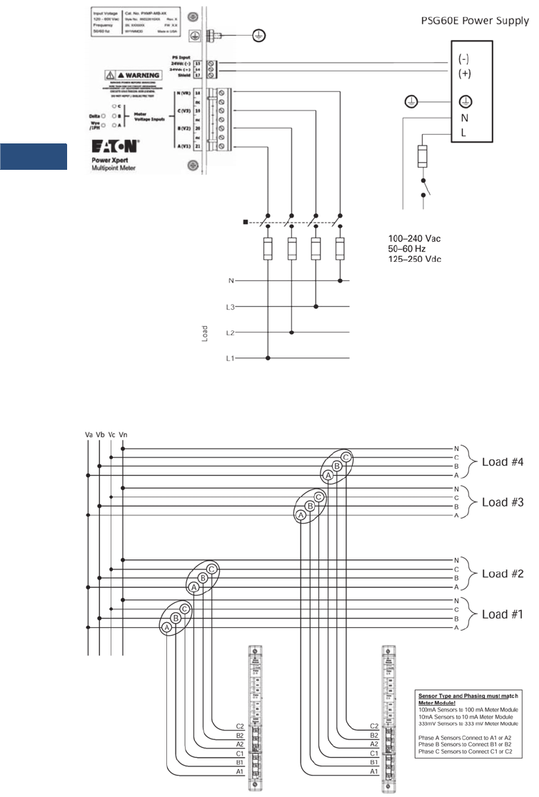
V3-T9-92 Volume 3—Power Distribution and Control Assemblies CA08100004E—March 2016 www.eaton.com
9
9
9
9
9
9
9
9
9
9
9
9
9
9
9
9
9
9
9
9
9
9
9
9
9
9
9
9
9
9
9.2
Metering Devices, Protective Relays, Software and Connectivity
Metering Devices
Wiring Diagrams
Wiring for PXMB-MB
Note: For all voltage connections—fuses should be sized in accordance with best practices to protect the instrumentation wire.
Four-Wire Wye Voltage Connection Inputs
Three-Phase, Four-Wire Service Current Sensor Connections
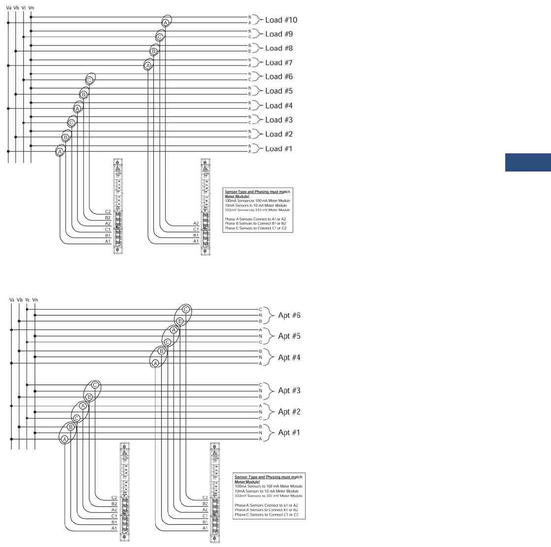
Volume 3—Power Distribution and Control Assemblies CA08100004E—March 2016 www.eaton.com V3-T9-93
9
9
9
9
9
9
9
9
9
9
9
9
9
9
9
9
9
9
9
9
9
9
9
9
9
9
9
9
9
9
9.2
Metering Devices, Protective Relays, Software and Connectivity
Metering Devices
Three-Phase, Four-Wire Service (Ten Single-Phase, Single-Pole) Current Sensor Connections
Network 120/208 Three-Wire Apartment Service Current Sensor Connections
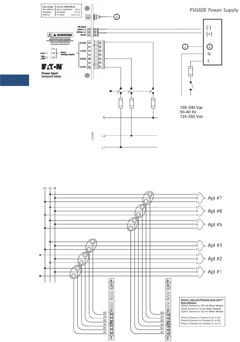
V3-T9-94 Volume 3—Power Distribution and Control Assemblies CA08100004E—March 2016 www.eaton.com
9
9
9
9
9
9
9
9
9
9
9
9
9
9
9
9
9
9
9
9
9
9
9
9
9
9
9
9
9
9
9.2
Metering Devices, Protective Relays, Software and Connectivity
Metering Devices
Wiring for PXMB-MB-AB
Note: For all voltage connections—fuses should be sized in accordance with best practices to protect the instrumentation wire.
Single-Phase, Three-Wire 120/240 Voltage Connection Inputs
120/240 Single-Phase, Three-Wire Service Current Sensor Connections
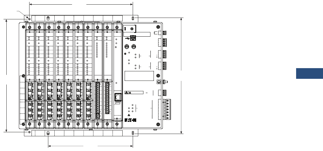
Volume 3—Power Distribution and Control Assemblies CA08100004E—March 2016 www.eaton.com V3-T9-95
9
9
9
9
9
9
9
9
9
9
9
9
9
9
9
9
9
9
9
9
9
9
9
9
9
9
9
9
9
9
9.2
Metering Devices, Protective Relays, Software and Connectivity
Metering Devices
Dimensions
Approximate Dimensions in Inches (mm)
Single Unit—Front View
2 4567891013
2 4567891013
B1
XX
XX
XX
XX
CT
Inputs
A1
RX
TX
RX
TX
7
8
9
10
11
12
13
14
Shield
Common
Shield
Common
A
B
C
15
16
17
18
nc
19
nc
20
nc
21
-Vdc
+Vdc
Shld
N (VR)
C (V3)
B (V2)
A (V1)
PS Input
64
91
0
3
28
7
5
Slave Address
64
3
28
7
5
901
WARNING
REMOVE POWER BEFORE SERVICING
DO NOT HIPOT / DIELECTRIC TEST
MORE THAN ONE LIVE CIRCUIT. SEE DIAGRAM.
CIRCUITS SOUS TENSION. VOIR LE SCHEMA.
AVERTISSEMENT: CET EQUIPEMENT RENFERME PLUSIEURS
Mode
1
2
3
4
5
6
Common
Input 1
Input 2
Input 3
24Vdc Inputs
24Vdc 80mA Output
Delta
Status
Power
Wye
/1PH
Health
Config. Port
Meter
Base
Voltage Inputs
Meter
(Com 2)
RS-485
(Com 1)
RS-485
D
D
D
D
Rating
24Vdc
15W Max
b
Power Xpert
Multipoint Meter
480V~ L:G Max.
347V~ L:N Max.
600V~ L:L Max.
CAT III
Freq. 47-63 Hz
See manual for complete ratings
11.67
(296.4)
10.67
(271.0)
0.20
(5.1)
Cat. No. PXMP-MB-XX
Style No. 66D2261GXX
FW Version X.X
Date Code: WYYMMDD
Rev. X
SN: XXXXXX
Made in USA
Com
Health
Module
Meter
1
-
+A1
100mA
Sensor
Pulse
-
+B1
-
+XX
-
+XX
-
+XX
-
+XX
2
Pulse
Com
Health
Module
Meter
1
-
+A1
100mA
Sensor
Pulse
-
+B1
-
+XX
-
+XX
-
+XX
-
+XX
2
Pulse
Com
Health
Module
Meter
1
-
+A1
100mA
Sensor
Pulse
-
+B1
-
+XX
-
+XX
-
+XX
-
+XX
2
Pulse
Com
Health
Module
Meter
1
-
+A1
100mA
Sensor
Pulse
-
+B1
-
+XX
-
+XX
-
+XX
-
+XX
2
Pulse
Com
Health
Module
Meter
1
-
+A1
100mA
Sensor
Pulse
-
+B1
-
+XX
-
+XX
-
+XX
-
+XX
2
Pulse
Com
Health
Module
Meter
1
-
+A1
100mA
Sensor
Pulse
-
+B1
-
+XX
-
+XX
-
+XX
-
+XX
2
Pulse
Com
Health
Module
Meter
1
-
+A1
100mA
Sensor
Pulse
-
+B1
-
+XX
-
+XX
-
+XX
-
+XX
2
Pulse
Module
Pulse In
PI1
PI2
PI3
PI4
PI5
PI6
PI7
PI8
Com
Health
PI1 PI2
+
-
PI3 PI4 PI5 PI6 PI7 PI8 24V
1 2 3 4 5 6 7 8 9 10111213141516
24Vdc
O1 O2 O3 O4 O5 O6 O7 O8
Module
Output
O1
O2
O3
O4
O5
O6
O7
O8
Com
Health
12345678910111213141516
24Vdc
80mA Max
Status
Health
Com
Reset
Module
Portal
Modem
LAN
Link
10/100
DHCP
TX ST
LAN
Local IP
192/10
10/100
Link
Local
12.00
(304.8)
8.74
(222.0)
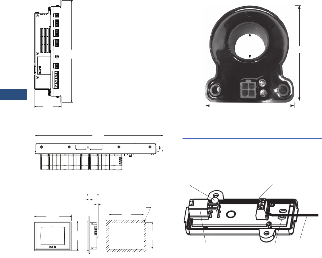
V3-T9-96 Volume 3—Power Distribution and Control Assemblies CA08100004E—March 2016 www.eaton.com
9
9
9
9
9
9
9
9
9
9
9
9
9
9
9
9
9
9
9
9
9
9
9
9
9
9
9
9
9
9
9.2
Metering Devices, Protective Relays, Software and Connectivity
Metering Devices
Single Unit—Side View
Single Unit—Top View
PXMP Color Touchscreen Display
3.27
(83.1)
12.50
(317.5)
Cat. No. PXMP-EPM-X
Serial No. XXXXXX FW X.XX
Technical Support 1-800-809-2772
http://www.Eaton.com
Style No. 66D2250G0X Rev. X
Power Xpert
Multipoint Meter
WYYMMDD
Made in USA
15.63
(397.0)
5.21
(132.4)
Cut-Out Dimensions
6.79
(172.4)
0.12 (3.0) R Typ.
6.10
(0.24)
1.54
(39.0)
0.06~0.12
(1.6~3.0)
Outer
7.25
(184.1)
5.67
(144.1)
Current Sensor Dimensions
Current Sensor Dimensions
Open Interface Module (PXMP-IM333MV)
Sensor H W D
PXMP-CS125 2.66 (67.6) 1.66 (42.1) 0.53 (13.5)
PXMP-CS250 2.96 (75.2) 2.42 (61.5) 1.12 (28.4)
PXMP-CS400 3.64 (92.5) 3.03 (73.2) 1.74 (44.2)
H
W
ID
Terminal Block
Blue Locator LED
PXMP-SCX Cable
Connection Strain Relief
Strap Holes
333 mV
Sensor
Secondary
Leads

Volume 3—Power Distribution and Control Assemblies CA08100004E—March 2016 www.eaton.com V3-T9-97
9
9
9
9
9
9
9
9
9
9
9
9
9
9
9
9
9
9
9
9
9
9
9
9
9
9
9
9
9
9
9.2
Metering Devices, Protective Relays, Software and Connectivity
Metering Devices
IQ Energy Sentinel
Contents
Description Page
Metering Products Family . . . . . . . . . . . . . . . . . . . . V3-T9-6
Power Xpert Meter 4000/6000/8000 Series . . . . . . V3-T9-15
Power Xpert Meter 2000 Series . . . . . . . . . . . . . . . V3-T9-34
IQ 250/260 Series Electronic Power Meters . . . . . . V3-T9-45
IQ 130/140/150 Series Electronic Power Meters . . . V3-T9-51
IQ 150S/250S Self-Enclosed Electronic Meters. . . . V3-T9-56
IQ 35M. . . . . . . . . . . . . . . . . . . . . . . . . . . . . . . . . . . V3-T9-61
IQ Analyzer 6400/6600 Series . . . . . . . . . . . . . . . . . V3-T9-64
IQ DP-4000 Series . . . . . . . . . . . . . . . . . . . . . . . . . . V3-T9-72
IQ 230 Meters . . . . . . . . . . . . . . . . . . . . . . . . . . . . . V3-T9-78
Power Xpert Multi-Point Meter . . . . . . . . . . . . . . . . V3-T9-85
IQ Energy Sentinel™
Application Description . . . . . . . . . . . . . . . . . . . . V3-T9-98
Features . . . . . . . . . . . . . . . . . . . . . . . . . . . . . . . V3-T9-99
Standards and Certifications. . . . . . . . . . . . . . . . V3-T9-100
Product Selection . . . . . . . . . . . . . . . . . . . . . . . . V3-T9-101
Technical Data and Specifications. . . . . . . . . . . . V3-T9-101
Dimensions. . . . . . . . . . . . . . . . . . . . . . . . . . . . . V3-T9-104
PM3 Monitoring and Metering Module . . . . . . . . . . V3-T9-106
Current Transformers (CTs) . . . . . . . . . . . . . . . . . . . V3-T9-107
Clamp-On Current Transformers . . . . . . . . . . . . . . . V3-T9-116
IQ Flange . . . . . . . . . . . . . . . . . . . . . . . . . . . . . . . . . V3-T9-119
Panel Mounting Adapter Kit . . . . . . . . . . . . . . . . . . . V3-T9-120
Enclosed Meters . . . . . . . . . . . . . . . . . . . . . . . . . . . V3-T9-121
IQ Energy Sentinel™
Product Description
IQ Sentinels
IQ Sentinels are
microprocessor-based
submeters, designed to
monitor power and energy.
They represent an alternative
to installing separate
wattmeters, watthour meters
and watt demand meters.
The Energy Sentinel monitors
watts, watthour and watt
demand.
Key advantages include
unmatched savings in
space, lower installation
costs and the capability to
communicate data readings
in a variety of ways.
IQ Sentinels with built-in CTs
and communications have
the added benefit of greater
overall system accuracy.
Conventional metering often
is less accurate since external
CTs and separate transducers
may each have inaccuracies
of 1% or more.
Eaton’s IQ Sentinels provide a
unique cost-effective method
to implement energy
submetering at lower levels
in the distribution system.
The ability to monitor power
distribution systems down to
the machine or process level at
an industrial facility has
become essential to provide
key benefits such as to verify
the accuracy of the utility bill,
identify and track energy usage
to the loads that consume it,
develop a facility energy profile
to establish a baseline, allocate
energy costs to create
accountability, etc.
An optional door-mounted
interface, the Subnetwork
Master Local Display, is
available to display the energy
parameters monitored by the
IQ Sentinels.
Submetering application
examples for the IQ Sentinels
include energy demand
monitoring, product cost
analysis, process machine
tool efficiency and
productivity improvement,
and energy cost allocation or
tenant billing for commercial,
industrial, recreational and
residential facilities.
Note: For customer billing
applications, consult local utility
for metering requirements.
Commercial applications
include energy cost allocation
within convention halls, office
buildings, shopping malls,
hospitals, warehouses and
storage facilities.
Industrial applications include
departmental billing and
process/assembly line energy
cost analysis. IQ Energy
Sentinels may be substituted
for watt transducers when
monitoring machine tool and
equipment performance
within plants.
Recreational facilities include
sports arenas, camping
grounds, trailer parks and
marinas.
The IQ Sentinel may be
applied on three-phase
(three- or four-wire), as well
as single-phase (three-wire)
systems.
IQ Sentinels may be
applied on either 50 or
60 Hz systems.

V3-T9-98 Volume 3—Power Distribution and Control Assemblies CA08100004E—March 2016 www.eaton.com
9
9
9
9
9
9
9
9
9
9
9
9
9
9
9
9
9
9
9
9
9
9
9
9
9
9
9
9
9
9
9.2
Metering Devices, Protective Relays, Software and Connectivity
Metering Devices
Application Description
The IQ Energy Sentinel is
available in three different
package versions: breaker
mounted, universal breaker
with internal CTs, and
universal breaker with
external CTs.
Designed for mounting on
Eaton’s Series C® Circuit
Breakers utilized in Eaton
assemblies such as:
●Pow-R-Line four
panelboards—feeder
circuits
●Pow-R-Line C™
switchboards—feeder
circuits
●Motor control centers and
enclosed control with
circuit breaker
disconnects—starter or
feeder circuits
●Enclosed Motor Control
●Enclosed circuit breakers
●Pow-R-Way III® bus plugs
with circuit breaker
disconnects
Breaker Mount Applications
New Equipment
F-Frame Breaker with IQ Sentinel
Retrofitting
The space-saving design
characteristics of the breaker
mount IQ Energy Sentinels
allow them to be added to
existing Eaton circuit breakers
at any time, often with no
additional space or
modifications required.
Or they may be installed
when upgrading from older
circuit breakers, often with
no additional space or
modifications required.
Universal Mount Applications
Universal Mount with Internal CTs
The universal mount IQ Energy
Sentinel with internal CTs
includes integral 400A CTs and
may be applied on loads up to
400A. The universal mount IQ
Energy Sentinels with internal
CTs may be utilized wherever
breaker mounting is not
feasible or possible.
The universal mount IQ Energy
Sentinel with provisions for
external CTs may be applied on
loads up to 4000A. They are
usually utilized for monitoring
loads larger than 400 amperes,
on power cable sizes larger
than 500 kcmil or on circuits
containing more than one
conductor per phase.
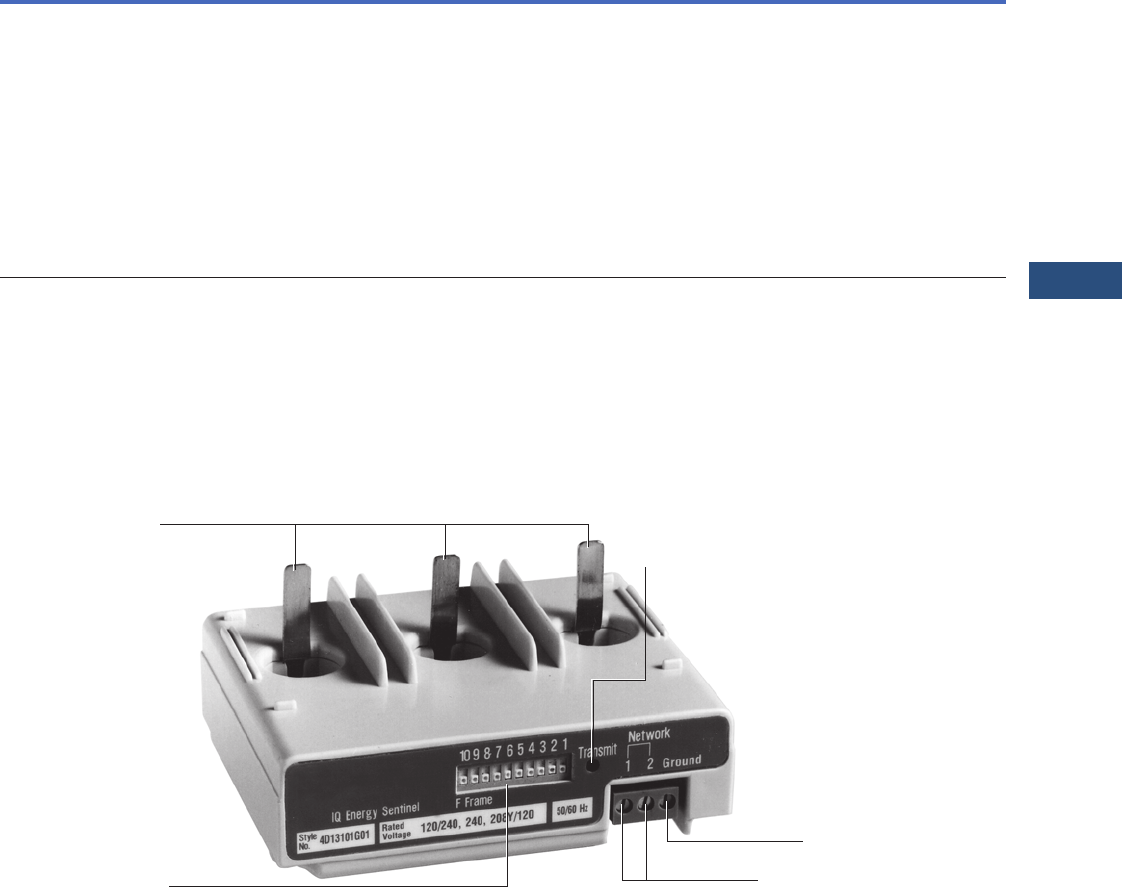
Volume 3—Power Distribution and Control Assemblies CA08100004E—March 2016 www.eaton.com V3-T9-99
9
9
9
9
9
9
9
9
9
9
9
9
9
9
9
9
9
9
9
9
9
9
9
9
9
9
9
9
9
9
9.2
Metering Devices, Protective Relays, Software and Connectivity
Metering Devices
Features
IQ Energy Sentinel Features
.
Eaton’s Breaker Mount
Eaton’s breaker mount
IQ Energy Sentinel installs
in less than 10 minutes on
the load side of an Eaton
F-Frame (150A),
J-Frame (250A), or
K-Frame (400A) circuit
breaker.
Energy Sentinel Features
Features Benefits
■Monitors (accuracy stated full scale)
Kilowatts ±1.0%
Kilowatts demand ±1.0%
Kilowatt Hour ±1.0%
■Built-in CTs version up to 400A or external CTs version up to 4000A
■Breaker, panel or DIN rail mounted
■Powered directly off the line
■Built-in communication capability
Address set by DIP switches
Communication at 9600 baud
Noise immune INCOM protocol
■Choice of operator interfaces
Subnetwork Master Local Display
Breaker Interface Module (BIM)
Power Management Energy Billing software
Power Management Software
■One device replaces multiple meters and/or transducers
■Improved system accuracy
■Savings in product cost
■Savings in space
■Savings in installation cost
■No external power source is needed
■Permits remote monitoring and interconnection with programmable logic controllers
and building management systems. For further information see section on Power
Management Software Systems
■Designed to interface directly with Power Management Software Energy Billing software
■Flexibility—displays what is needed where it is needed
■Power Management Software
DIP Switch
Address
Communications
Connections
Ground/Neutral
Connection
Voltage
Ta n g s Transmit
LED
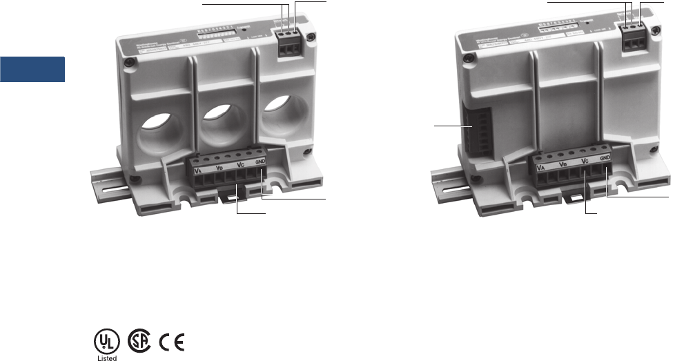
V3-T9-100 Volume 3—Power Distribution and Control Assemblies CA08100004E—March 2016 www.eaton.com
9
9
9
9
9
9
9
9
9
9
9
9
9
9
9
9
9
9
9
9
9
9
9
9
9
9
9
9
9
9
9.2
Metering Devices, Protective Relays, Software and Connectivity
Metering Devices
Universal Mount with
Internal CTs—(UI)
The Universal Mount IQ
Energy Sentinel with internal
CTs may be panel-mounted
or DIN rail mounted on
disconnects or other circuits
up to 400 amperes. A pull-
apart terminal block is
provided on the device for
connection of the system
voltage reference wiring.
The location of the ground/
neutral connection differs on
Breaker Mount IQ Energy
Sentinels from the location of
the ground/neutral
connection on Universal
Mount IQ Sentinels. Incorrect
wiring to the
ground/neutral
and communications
connections may result in
accuracy and communication
errors.
Universal Mount for
External CTs—(UE)
The Universal Mount IQ
Energy Sentinel for external
CTs may be panel-mounted
or DIN rail mounted on
circuits up to 4000 amperes.
A pull-apart terminal block is
provided on the device for
connection of the system
voltage reference wiring as
well as another terminal block
for connection to the user’s
existing 5-ampere secondary
CTs that may range in
standard ratios from 25:5 up
to 4000:5.
Note: If the device will be
disconnected without interruption
of the monitored load, the use of
a CT shorting block is advised.
Energy Sentinel Features
Standards and Certifications
●UL listed, File E64983
●CSA approved, File
LR106359-1
Communications
Connections
Communications
Shield
Connection
Voltage Terminal Block
Ground/Neutral
Connection
Communications
Connections
Communications
Shield
Connection
Voltage Terminal Block
Ground/Neutral
Connection
CT
Te r m i n a l
Block

Volume 3—Power Distribution and Control Assemblies CA08100004E—March 2016 www.eaton.com V3-T9-101
9
9
9
9
9
9
9
9
9
9
9
9
9
9
9
9
9
9
9
9
9
9
9
9
9
9
9
9
9
9
9.2
Metering Devices, Protective Relays, Software and Connectivity
Metering Devices
Product Selection
IQ Energy Sentinels
Technical Data and Specifications
Terminal, Cable and Wiring Guidelines
Description Voltage Rating—Vac
Current Rating
Maximum Amperes
Catalog
Number
For F-Frame breakers 120/240, 240, 208Y/120 150 IQESF208
For F-Frame breakers 220/380, 230/400, 240/415 150 IQESF400
For F-Frame breakers 480, 480Y/277 150 IQESF480
For F-Frame breakers 600, 600Y/347 150 IQESF600
For J-Frame breakers 120/240, 240, 208Y/120 250 IQESJ208
For J-Frame breakers 220/380, 230/400, 240/415 250 IQESJ400
For J-Frame breakers 480, 480Y/277 250 IQESJ480
For J-Frame breakers 600, 600Y/347 250 IQESJ600
For K-Frame breakers 120/240, 240, 208Y/120 400 IQESK208
For K-Frame breakers 220/380, 230/400, 240/415 400 IQESK400
For K-Frame breakers 480, 480Y/277 400 IQESK480
For K-Frame breakers 600, 600Y/347 400 IQESK600
Universal with internal CTs 120/240, 240, 208Y/120 400 IQESUI208
Universal with internal CTs 220/380, 230/400, 240/415 400 IQESUI400
Universal with internal CTs 480, 480Y/277 400 IQESUI480
Universal with internal CTs 600, 600Y/347 400 IQESUI600
Universal for external CTs 120/240, 240, 208Y/120 4000 IQESUE208
Universal for external CTs 220/380, 230/400, 240/415 4000 IQESUE400
Universal for external CTs 480, 480Y/277 4000 IQESUE480
Universal for external CTs 600, 600Y/347 4000 IQESUE600
IQ Energy Sentinels
Sentinel
Eaton’s
Series C Terminal
Wire Size
(Single Conductor)
Wire
Types
F-Frame 624B100G02, G17, G18, G19 #14–1/0, #4–4/0, #4–4/01, #14–1/0 AWG THW, THHN, XHHW
J-Frame T250KB, TA250KB #4–350 kcmil THW, THHN, XHHW
K-Frame T350K, TA350KB #250–500 kcmil THW, THHN, XHHW
Universal Energy Sentinel with internal CTs T350K, TA350KB #250–500 kcmil THW, THHN, XHHW
System Voltage Reference Wiring
Energy Sentinel with internal or external CTs #24–#10 AWG
Current Transformer Wiring
Universal with external CTs #12 AWG (maximum)
Ground Reference Wiring
Energy Sentinel with internal or external CTs #22–#12 AWG (minimum 600 volt rated)
Communications Wiring
Energy Sentinel with internal or external CTs Eaton’s IMPCABLE or Belden 9463 family
F-Frame Eaton’s IMPCABLE or Belden 9463 family
J-Frame Eaton’s IMPCABLE or Belden 9463 family
K-Frame Eaton’s IMPCABLE or Belden 9463 family

V3-T9-102 Volume 3—Power Distribution and Control Assemblies CA08100004E—March 2016 www.eaton.com
9
9
9
9
9
9
9
9
9
9
9
9
9
9
9
9
9
9
9
9
9
9
9
9
9
9
9
9
9
9
9.2
Metering Devices, Protective Relays, Software and Connectivity
Metering Devices
Energy Sentinel
Current Input
Current range: 1% to 125% of current rating
Burden: 1 VA
Voltage Input
Voltage Range: ±20% of voltage rating
Frequency
50 or 60 Hz
Power Factor Range
All (–1 to +1)
Communications
Protocol: INCOM
Speed: 9600 baud
Compatibility: Power Management Software compatible
Environmental Conditions
Operating temperature: –25°C to 70°C 1
(–13°F to 158°F)
Storage temperature: –40°C to 85°C 1
(–40°F to 185°F)
Operating humidity: 5% to 95% relative humidity noncondensing
System Voltage Considerations (Application Note)
The Ground (GND) terminal of the IQ Energy Sentinel should
be connected to the ground bus or other non-current carrying
ground with 600V rated wire to ensure accuracy.
Note
140°C (standard) maximum for Series C circuit breakers.
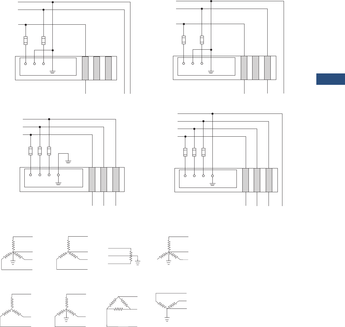
Volume 3—Power Distribution and Control Assemblies CA08100004E—March 2016 www.eaton.com V3-T9-103
9
9
9
9
9
9
9
9
9
9
9
9
9
9
9
9
9
9
9
9
9
9
9
9
9
9
9
9
9
9
9.2
Metering Devices, Protective Relays, Software and Connectivity
Metering Devices
Wiring Diagrams
Field Wiring—IQ Universal Energy Sentinel with Internal CTs
Acceptable System Configurations
IA IB IC
N
L2
L1
Line
Fuses
Reference
Ground
VA VB VC
Load
IQ Universal Energy Sentinel
with Internal CTs
N
L2
L1
Line
Fuses
Reference
Ground
VA VB VC
Load
IQ Universal Energy Sentinel
with Internal CTs
IA IB IC
IA IB IC
L3
L1
Line
Fuses
Reference
Ground
VA VB VC
Load
IQ Universal Energy Sentinel
with Internal CTs
L2
IA IB IC
L3
L1
Line
Fuses
Reference
Ground
VA VB VC
Load
IQ Universal Energy Sentinel
with Internal CTs
L2
N
Single-Phase Three-Wire Two-Phase Three-Wire
Three-Phase Three-Wire Three-Phase Four-Wire
Phase A
Phase C
Phase A
Phase C
Neutral
Three-Phase Star, Four-
Wire, Earthed Neutral.
Three-Phase Star, Four-
Wire, Non-Earthed
Neutral.
Single-Phase, Three-
Wire, Earthed Mid-Point
(Connect to A and C
Phases).
Two-Phase Star, Three-
Wire, Earthed Neutral
(Connect to A and C
Phases).
Three-Phase Star,
Three-Wire
Three-Phase Star,
Three-Wire, Earthed
Neutral Point.
Three-Phase Delta,
Three-Wire
Three-Phase Open
Delta, Four-Wire,
Earthed Junction.
Note: Acceptable for Universal IQ Energy Sentinels only.

V3-T9-104 Volume 3—Power Distribution and Control Assemblies CA08100004E—March 2016 www.eaton.com
9
9
9
9
9
9
9
9
9
9
9
9
9
9
9
9
9
9
9
9
9
9
9
9
9
9
9
9
9
9
9.2
Metering Devices, Protective Relays, Software and Connectivity
Metering Devices
Dimensions
Approximate Dimensions in Inches (mm)
Energy Sentinel
Note
1Acceptable for Universal IQ Energy Sentinels only.
Frame Type D W H CT Window Size 1Hole Clearance
Weight
Lbs (kg)
F 3.20 (81.3) 4.12 (104.6) 1.30 (33.0) 0.59 (15.0) — 0.65 (0.3)
J 4.04 (102.6) 4.12 (104.6) 1.28 (32.5) 0.77 (19.6) — 0.69 (0.3)
K 4.04 (102.6) 5.31 (134.9) 1.25 (31.8) 0.96 (24.4) — 0.87 (0.4)
UI 4.36 (110.7) 5.31 (134.9) 3.00 (76.2) — 1.17 (29.7) 1.10 (0.5)
UE 4.36 (110.7) 5.31 (134.9) 3.00 (76.2) — — 1.10 (0.5)
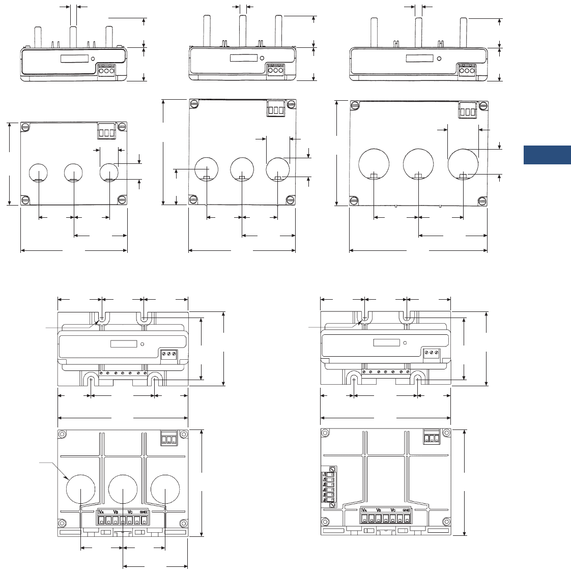
Volume 3—Power Distribution and Control Assemblies CA08100004E—March 2016 www.eaton.com V3-T9-105
9
9
9
9
9
9
9
9
9
9
9
9
9
9
9
9
9
9
9
9
9
9
9
9
9
9
9
9
9
9
9.2
Metering Devices, Protective Relays, Software and Connectivity
Metering Devices
IQ Sentinel
Radius
1.17
(29.7)
Diameter
0.25
(6.4) Typical
0.25
(6.4)Typical
0.25
(6.4) Typical
1.10
(27.9)
1.25
(31.8)
1.25
(31.8)
1.28
(32.5)
0.75
(19.1)
1.30
(33.0)
1.17
(29.7)Typical
1.17
(29.7)Typical
0.96
(24.4)
4.04
(102.6)
1.72
(43.7)
1.72
(43.7)
2.66
(67.5)
5.31
(134.9)
0.77
(19.6)
0.90
(22.9)Typical
1.38
(34.9)
1.38
(34.9)
2.06
(52.3)
4.12
(104.6)
0.59
(15.0)
1.38
(34.9)
4.04
(102.6)
3.20
(81.3)
1.38
(34.9)
1.38
(34.9)
2.06
(52.3)
4.12
(104.6)
1.80
(45.7)
1.71
(43.4)
1.80
(45.7)
0.14
(3.6)
2.50
(63.5)
3.00
(76.2)
2.60
(66.0)
1.36
(34.5)
1.36
(34.5)
5.31
(134.9)
1.72
(43.7)
2.66
(67.5)
4.36
(110.7)
1.72
(43.7)
Radius
1.80
(45.7)
1.71
(43.4)
1.80
(45.7)
0.14
(3.6)
2.50
(63.5)
3.00
(76.2)
2.60
(66.0)
1.36
(34.5)
1.36
(34.5)
5.31
(134.9)
4.36
(110.7)
F-Frame Energy Sentinels J-Frame Energy Sentinels K-Frame Energy Sentinels
Universal with Internal CTs
Energy Sentinels
Universal with External CTs
Energy Sentinels
V3-T9-106 Volume 3—Power Distribution and Control Assemblies CA08100004E—March 2016 www.eaton.com
9
9
9
9
9
9
9
9
9
9
9
9
9
9
9
9
9
9
9
9
9
9
9
9
9
9
9
9
9
9
9.2
Metering Devices, Protective Relays, Software and Connectivity
Metering Devices
Power Monitoring and Metering with Modbus RTU
PM3 Modules
Contents
Description Page
Metering Products Family . . . . . . . . . . . . . . . . . . . . V3-T9-6
Power Xpert Meter 4000/6000/8000 Series . . . . . . V3-T9-15
Power Xpert Meter 2000 Series . . . . . . . . . . . . . . . V3-T9-34
IQ 250/260 Series Electronic Power Meters . . . . . . V3-T9-45
IQ 130/140/150 Series Electronic Power Meters. . . V3-T9-51
IQ 150S/250S Self-Enclosed Electronic Meters . . . V3-T9-56
IQ 35M . . . . . . . . . . . . . . . . . . . . . . . . . . . . . . . . . . V3-T9-61
IQ Analyzer 6400/6600 Series . . . . . . . . . . . . . . . . . V3-T9-64
IQ DP-4000 Series. . . . . . . . . . . . . . . . . . . . . . . . . . V3-T9-72
IQ 230 Meters . . . . . . . . . . . . . . . . . . . . . . . . . . . . . V3-T9-78
Power Xpert Multi-Point Meter . . . . . . . . . . . . . . . . V3-T9-85
IQ Energy Sentinel™ . . . . . . . . . . . . . . . . . . . . . . . . V3-T9-97
PM3 Monitoring and Metering Module
Current Transformers (CTs) . . . . . . . . . . . . . . . . . . . V3-T9-107
Clamp-On Current Transformers . . . . . . . . . . . . . . . V3-T9-116
IQ Flange . . . . . . . . . . . . . . . . . . . . . . . . . . . . . . . . . V3-T9-119
Panel Mounting Adapter Kit. . . . . . . . . . . . . . . . . . . V3-T9-120
Enclosed Meters . . . . . . . . . . . . . . . . . . . . . . . . . . . V3-T9-121
PM3 Monitoring and Metering Module
Product Description
For information on our PM3
product, please refer to
Volume 4, Tab 2.

Volume 3—Power Distribution and Control Assemblies CA08100004E—March 2016 www.eaton.com V3-T9-107
9
9
9
9
9
9
9
9
9
9
9
9
9
9
9
9
9
9
9
9
9
9
9
9
9
9
9
9
9
9
9.2
Metering Devices, Protective Relays, Software and Connectivity
Metering Devices
Current Transformers (CTs)
Contents
Description Page
Metering Products Family . . . . . . . . . . . . . . . . . . . . V3-T9-6
Power Xpert Meter 4000/6000/8000 Series . . . . . . V3-T9-15
Power Xpert Meter 2000 Series . . . . . . . . . . . . . . . V3-T9-34
IQ 250/260 Series Electronic Power Meters . . . . . . V3-T9-45
IQ 130/140/150 Series Electronic Power Meters . . . V3-T9-51
IQ 150S/250S Self-Enclosed Electronic Meters. . . . V3-T9-56
IQ 35M. . . . . . . . . . . . . . . . . . . . . . . . . . . . . . . . . . . V3-T9-61
IQ Analyzer 6400/6600 Series . . . . . . . . . . . . . . . . . V3-T9-64
IQ DP-4000 Series . . . . . . . . . . . . . . . . . . . . . . . . . . V3-T9-72
IQ 230 Meters . . . . . . . . . . . . . . . . . . . . . . . . . . . . . V3-T9-78
Power Xpert Multi-Point Meter . . . . . . . . . . . . . . . . V3-T9-85
IQ Energy Sentinel™ . . . . . . . . . . . . . . . . . . . . . . . . V3-T9-97
PM3 Monitoring and Metering Module . . . . . . . . . . V3-T9-106
Current Transformers (CTs)
Product Selection . . . . . . . . . . . . . . . . . . . . . . . . V3-T9-108
Dimensions. . . . . . . . . . . . . . . . . . . . . . . . . . . . . V3-T9-111
Clamp-On Current Transformers . . . . . . . . . . . . . . . V3-T9-116
IQ Flange . . . . . . . . . . . . . . . . . . . . . . . . . . . . . . . . . V3-T9-119
Panel Mounting Adapter Kit . . . . . . . . . . . . . . . . . . . V3-T9-120
Enclosed Meters . . . . . . . . . . . . . . . . . . . . . . . . . . . V3-T9-121
Current Transformers (CTs)
Product Description
Eaton’s low voltage current
transformers are available in
both solid core and split core
designs. Engineered for
electronic metering
applications, all solid core
designs and selected split
core designs offer ANSI
metering quality accuracy.
The solid core designs also
meet ANSI C57.13 relay
accuracy requirements
including over-ranging
capabilities. The current
transformer offering has a
5 ampere secondary at the
rated primary current.
Split core CTs are specifically
designed to be installed
around primary conductors
without disconnecting wires
or breaking the circuit to be
monitored. These current
transformers are perfect
solutions for energy
management applications
and are manufactured for
installation ease.
Application Description
For new construction and
retrofit applications where
no current transformer exists,
Eaton offers a complete
selection of low voltage
(up to 600V) current
transformers. These current
transformers can be used
in commercial-grade
applications, such as control
panels and panelboards.
Additionally, they can be used
for most industrial metering
and relaying applications in
switchboards, switchgear and
motor control centers. These
CTs are intended for use with
the Power Xpert Meter 2000/
4000/6000/8000, IQ 250/260,
IQ 130/140/150, IQ Analyzer
6400/6600, IQ DP-4000 and
IQ 230 series.

V3-T9-108 Volume 3—Power Distribution and Control Assemblies CA08100004E—March 2016 www.eaton.com
9
9
9
9
9
9
9
9
9
9
9
9
9
9
9
9
9
9
9
9
9
9
9
9
9
9
9
9
9
9
9.2
Metering Devices, Protective Relays, Software and Connectivity
Metering Devices
Product Selection
Solid Core ANSI Metering Accuracy
Note
1 Contact Eaton for further information.
Primary
Current
Rating
ANSI B0.1
Metering Class at 60 Hz
(Accuracy in %)
Window Size
in Inches (mm)
Diameter
Catalog
Number
Mounting Bracket
Catalog
Number
1.25 (31.8) Window
50 1.2 1.25 (31.8) S060-500 1
100 0.6 1.25 (31.8) S060-101 1
150 0.3 1.25 (31.8) S060-151 1
200 0.3 1.25 (31.8) S060-201 1
1.56 (39.6) Window
300 0.3 1.56 (39.6) S050-301 S050BRAC
400 0.3 1.56 (39.6) S050-401 S050BRAC
500 0.3 1.56 (39.6) S050-501 S050BRAC
600 0.3 1.56 (39.6) S050-601 S050BRAC
750 0.3 1.56 (39.6) S050-751 S050BRAC
800 0.3 1.56 (39.6) S050-801 S050BRAC
1000 0.3 1.56 (39.6) S050-102 S050BRAC
1200 0.3 1.56 (39.6) S050-122 S050BRAC
3.25 (82.6) Window
400 0.3 3.25 (82.6) S080-401 S080BRAC
500 0.3 3.25 (82.6) S080-501 S080BRAC
600 0.3 3.25 (82.6) S080-601 S080BRAC
750 0.3 3.25 (82.6) S080-751 S080BRAC
800 0.3 3.25 (82.6) S080-801 S080BRAC
1000 0.3 3.25 (82.6) S080-102 S080BRAC
1200 0.3 3.25 (82.6) S080-122 S080BRAC
4.25 (108.0) Window
500 0.3 4.25 (108.0) S090-501 S090BRAC
600 0.3 4.25 (108.0) S090-601 S090BRAC
750 0.3 4.25 (108.0) S090-751 S090BRAC
800 0.3 4.25 (108.0) S090-801 S090BRAC
1000 0.3 4.25 (108.0) S090-102 S090BRAC
1200 0.3 4.25 (108.0) S090-122 S090BRAC
1500 0.3 4.25 (108.0) S090-152 S090BRAC
1600 0.3 4.25 (108.0) S090-162 S090BRAC
2000 0.3 4.25 (108.0) S090-202 S090BRAC
2500 0.3 4.25 (108.0) S090-252 S090BRAC
3000 0.3 4.25 (108.0) S090-302 S090BRAC
6.31 (160.3) Window
600 0.3 6.31 (160.3) S025-601 S025BRAC
750 0.3 6.31 (160.3) S025-751 S025BRAC
800 0.3 6.31 (160.3) S025-801 S025BRAC
1000 0.3 6.31 (160.3) S025-102 S025BRAC
1200 0.3 6.31 (160.3) S025-122 S025BRAC
1500 0.3 6.31 (160.3) S025-152 S025BRAC
1600 0.3 6.31 (160.3) S025-162 S025BRAC
2000 0.3 6.31 (160.3) S025-202 S025BRAC
2500 0.3 6.31 (160.3) S025-252 S025BRAC
3000 0.3 6.31 (160.3) S025-302 S025BRAC
3500 0.3 6.31 (160.3) S025-352 S025BRAC
4000 0.3 6.31 (160.3) S025-402 S025BRAC
S060
H1
X1
S050
H1
X1
LABEL
S080
H1
X1
LABEL
S090
H1
X10
LABEL
S025
H1
X10
LABEL

Volume 3—Power Distribution and Control Assemblies CA08100004E—March 2016 www.eaton.com V3-T9-109
9
9
9
9
9
9
9
9
9
9
9
9
9
9
9
9
9
9
9
9
9
9
9
9
9
9
9
9
9
9
9.2
Metering Devices, Protective Relays, Software and Connectivity
Metering Devices
Split Core ANSI Metering Accuracy
Primary
Current Rating
ANSI B0.1
Metering Class at 60 Hz
(Accuracy in %)
Window Size
in Inches (mm)
Catalog
Number
Wound and Primary CTs
25 0.3 Wound W190-025
50 0.3 Primary W190-050
2.00 x 5.50 (50.8 x 139.7)
400 2.4 2.00 x 5.50 (50.8 x 139.7) M000-401
500 2.4 2.00 x 5.50 (50.8 x 139.7) M000-501
600 2.4 2.00 x 5.50 (50.8 x 139.7) M000-601
800 1.2 2.00 x 5.50 (50.8 x 139.7) M000-801
1000 1.2 2.00 x 5.50 (50.8 x 139.7) M000-102
1200 0.6 2.00 x 5.50 (50.8 x 139.7) M000-122
1500 0.6 2.00 x 5.50 (50.8 x 139.7) M000-152
1600 0.6 2.00 x 5.50 (50.8 x 139.7) M000-162
2000 0.6 2.00 x 5.50 (50.8 x 139.7) M000-202
4.10 x 7.10 (104.1 x 180.3)
600 4.8 4.10 x 7.10 (104.1 x 180.3) M050-601
750 4.8 4.10 x 7.10 (104.1 x 180.3) M050-751
800 2.4 4.10 x 7.10 (104.1 x 180.3) M050-801
1000 2.4 4.10 x 7.10 (104.1 x 180.3) M050-102
1200 1.2 4.10 x 7.10 (104.1 x 180.3) M050-122
1500 1.2 4.10 x 7.10 (104.1 x 180.3) M050-152
2000 0.6 4.10 x 7.10 (104.1 x 180.3) M050-202
2500 0.6 4.10 x 7.10 (104.1 x 180.3) M050-252
3000 0.6 4.10 x 7.10 (104.1 x 180.3) M050-302
3500 0.6 4.10 x 7.10 (104.1 x 180.3) M050-352
4000 0.3 4.10 x 7.10 (104.1 x 180.3) M050-402
W190
LABEL
H1
X2
X1
M000
H1
X1 X2
This End
Removable
M050
LABEL
This End Removable
H1

V3-T9-110 Volume 3—Power Distribution and Control Assemblies CA08100004E—March 2016 www.eaton.com
9
9
9
9
9
9
9
9
9
9
9
9
9
9
9
9
9
9
9
9
9
9
9
9
9
9
9
9
9
9
9.2
Metering Devices, Protective Relays, Software and Connectivity
Metering Devices
Split Core Current Transformers
Primary
Current Rating
Accuracy
at 60 Hz (in %)
Window Size
in Inches (mm)
Catalog
Number
0.80 x 1.95 (20.3 x 49.5)
100 5.0 0.80 x 1.95 (20.3 x 49.5) M030-101
150 5.0 0.80 x 1.95 (20.3 x 49.5) M030-151
200 4.0 0.80 x 1.95 (20.3 x 49.5) M030-201
300 2.0 0.80 x 1.95 (20.3 x 49.5) M030-301
400 2.0 0.80 x 1.95 (20.3 x 49.5) M030-401
1.42 x 1.53 (36.1 x 38.9)
100 5.0 1.42 x 1.53 (36.1 x 38.9) M040-101
150 4.0 1.42 x 1.53 (36.1 x 38.9) M040-151
200 1.5 1.42 x 1.53 (36.1 x 38.9) M040-201
300 1.5 1.42 x 1.53 (36.1 x 38.9) M040-301
400 1.5 1.42 x 1.53 (36.1 x 38.9) M040-401
2.60 x 2.75 (66.0 x 69.9)
200 1.0 2.60 x 2.75 (66.0 x 69.9) M060-201
300 1.0 2.60 x 2.75 (66.0 x 69.9) M060-301
400 1.0 2.60 x 2.75 (66.0 x 69.9) M060-401
500 1.0 2.60 x 2.75 (66.0 x 69.9) M060-501
600 1.0 2.60 x 2.75 (66.0 x 69.9) M060-601
750 1.0 2.60 x 2.75 (66.0 x 69.9) M060-751
800 1.0 2.60 x 2.75 (66.0 x 69.9) M060-801
1000 1.0 2.60 x 2.75 (66.0 x 69.9) M060-102
1200 1.0 2.60 x 2.75 (66.0 x 69.9) M060-122
2.60 x 6.25 (66.0 x 158.8)
500 1.0 2.60 x 6.25 (66.0 x 158.8) M080-501
600 1.0 2.60 x 6.25 (66.0 x 158.8) M080-601
800 1.0 2.60 x 6.25 (66.0 x 158.8) M080-801
1000 1.0 2.60 x 6.25 (66.0 x 158.8) M080-102
1200 1.0 2.60 x 6.25 (66.0 x 158.8) M080-122
1500 1.0 2.60 x 6.25 (66.0 x 158.8) M080-152
1600 1.0 2.60 x 6.25 (66.0 x 158.8) M080-162
2000 1.0 2.60 x 6.25 (66.0 x 158.8) M080-202
2500 1.0 2.60 x 6.25 (66.0 x 158.8) M080-252
3000 1.0 2.60 x 6.25 (66.0 x 158.8) M080-302
M030
M040
M060
M080
LEBAL
X2
H1
H1
H1
LABEL
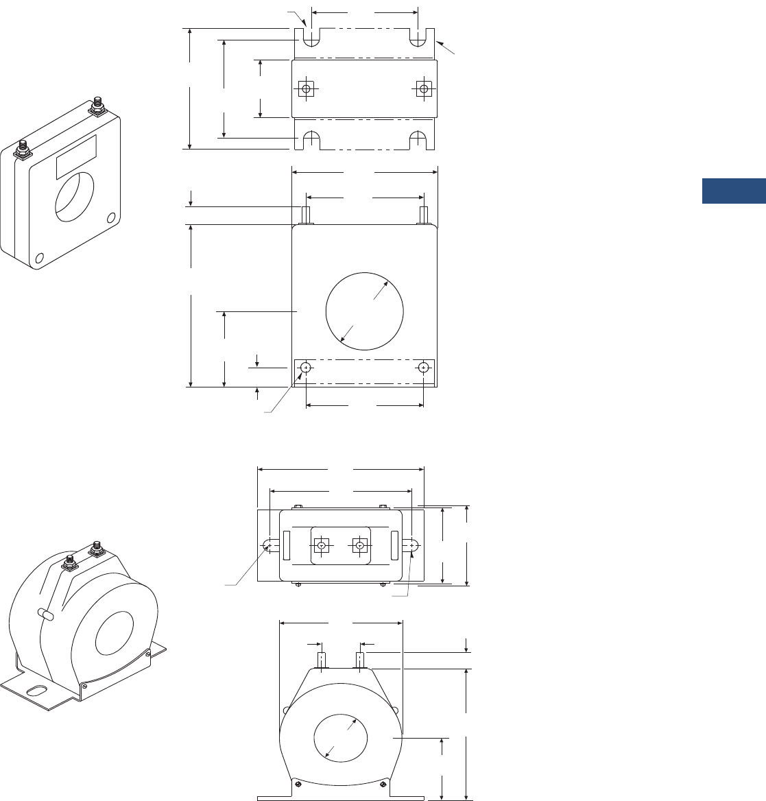
Volume 3—Power Distribution and Control Assemblies CA08100004E—March 2016 www.eaton.com V3-T9-111
9
9
9
9
9
9
9
9
9
9
9
9
9
9
9
9
9
9
9
9
9
9
9
9
9
9
9
9
9
9
9.2
Metering Devices, Protective Relays, Software and Connectivity
Metering Devices
Dimensions
Approximate dimensions in inches (mm)
S050
S060
H1
X1
LABEL
(4) Open Slots 0.22 x 0.34
(5.6 x 8.6)
2.23
(56.6)
1.67
(42.4)
1.10
(27.9)
2.75
(69.9)
3.53
(90.0)
3.00
(76.2)
0.44
(11.2)
3.70
(94.0)
1.88
(47.8)
0.31
(7.9)
2.25
(57.2)
1.56 Dia.
(39.6)
H1
X1
(2) Holes 0.20 (5.1) Diameter
S050BRAC
H1
X1
0.88
(22.4)
3.62
(91.9)
(2) 0.28 x 0.50 Slots
(7.1 x 12.7)
2.88
(73.2)
3.10
(78.7)
4.00
(101.6)
5.25
(133.4)
H1
X1
0.44 (11.2)
4.00
(101.6)
1.95
(49.5)
See Tables
(2) Slots
0.28 x 0.50
(7.1 x 12.7)
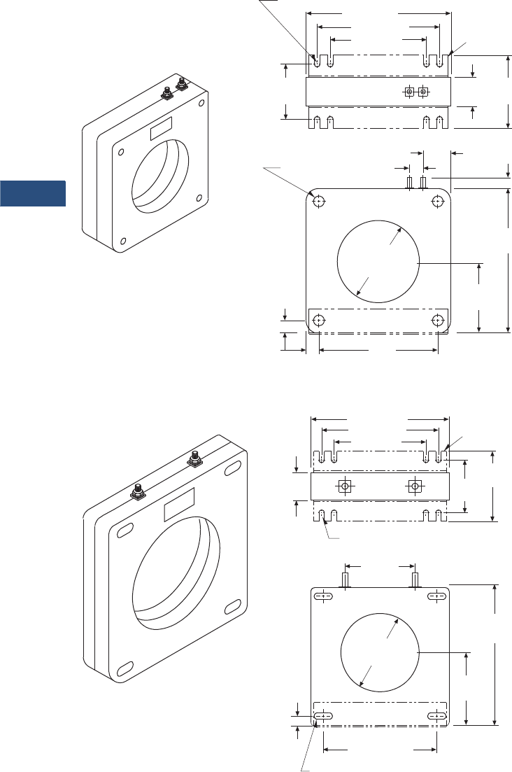
V3-T9-112 Volume 3—Power Distribution and Control Assemblies CA08100004E—March 2016 www.eaton.com
9
9
9
9
9
9
9
9
9
9
9
9
9
9
9
9
9
9
9
9
9
9
9
9
9
9
9
9
9
9
9.2
Metering Devices, Protective Relays, Software and Connectivity
Metering Devices
Approximate dimensions in inches (mm)
S080
S090
(8) Open Slots
0.47 x 0.22 (11.9 x 5.6)
5.73 (145.5)
4.85 (123.2)
3.81 (96.8)
2.19
(55.6)
H1
X1
LABEL
2.91
(73.9)
1.15
(29.2)
0.44
(11.2)
5.73
(145.5)
2.84
(72.1)
4.70
(119.4)
0.51
(13.0)
3.25 (82.6) Dia.
H1
X1
0.42 (10.7) Dia.
(4) Holes 1.09
(27.7)
0.55
(14.0)
S080BRAC
H1
X10
LABEL
5.92 (150.4)
4.85 (123.2)
3.81 (96.8)
1.15
(29.2)
2.91
(73.9)
3.50
(88.9)
6.17
(156.7)
X1
4.25 (108.0) Dia.
H1
0.42
(10.7)
4.86 (123.4)
2.97
(75.4)
(4) 0.28 x 0.63 (7.1 x 16.0) Slots
(8) Open Slots 0.47 x 0.22 (11.9 x 5.6)
2.19
(55.6)
S090BRAC
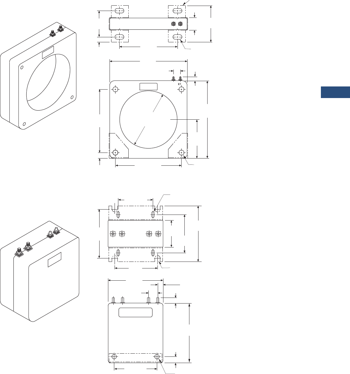
Volume 3—Power Distribution and Control Assemblies CA08100004E—March 2016 www.eaton.com V3-T9-113
9
9
9
9
9
9
9
9
9
9
9
9
9
9
9
9
9
9
9
9
9
9
9
9
9
9
9
9
9
9
9.2
Metering Devices, Protective Relays, Software and Connectivity
Metering Devices
Approximate dimensions in inches (mm)
S025
W190
H1
X10
LABEL
4.10
(104.1)
1.28
(32.5)
6.37
(161.8)
2.98
(75.7)
0.56
(14.2) 8.50
(215.9)
0.75
(19.1)
0.44
(11.2)
8.50
(215.9)
6.31
(160.3)
H1
6.75
(171.5)
4.25
(108.0)
0.88 (22.4) 6.75 (171.5) (4) 0.56 (14.2)
Diameter Holes
(4) Slots 0.44 x 1.00
(11.2 x 25.4)
S025BRAC
H2 X2
0.38
(9.7)
0.50
(12.7)
2.75 (69.9)
(4) Closed Slots
0.21 x 0.50 (5.3 x 12.7)
(4) Open Slots
0.44 x 0.50 (11.2 x 12.7)
3.25
(82.6)
2.19
(55.6)
4.69
(119.1)
4.12
(104.6)
LABEL
3.50
(88.9)
4.50
(114.3)
0.75
(19.1)
0.44
(11.2)
4.88
(124.0)
(2) Mounting Holes
0.38 (9.7) Diameter
3.48 (88.4)
H1 X1
LABEL
H1
H2 X2 X1

V3-T9-114 Volume 3—Power Distribution and Control Assemblies CA08100004E—March 2016 www.eaton.com
9
9
9
9
9
9
9
9
9
9
9
9
9
9
9
9
9
9
9
9
9
9
9
9
9
9
9
9
9
9
9.2
Metering Devices, Protective Relays, Software and Connectivity
Metering Devices
Approximate dimensions in inches (mm)
M000 M050
M030
H1
X1 X2
This End
Removable
2.00
(50.8)
This End
Removable
LABEL
4.25 (108.0)
5.50
(139.7)
H1
X1 X2
3.50 (88.9)
0.38
(9.7)
1.13
(28.7)
(2) 0.19 (4.8) Diameter Holes
7.75
(196.9)
0.75
(19.1)
(4) 0.31 (7.9) Dia. Holes
This End Removable
LABEL
4.10
(104.1)
H1
X1
1.63
(41.4)
0.44
(11.2)
LABEL
X1
This End Removable
H1
7.10
(180.3)
10.00
(254.0)
10.90
(276.9)
6.40
(162.6)
7.30
(185.4)
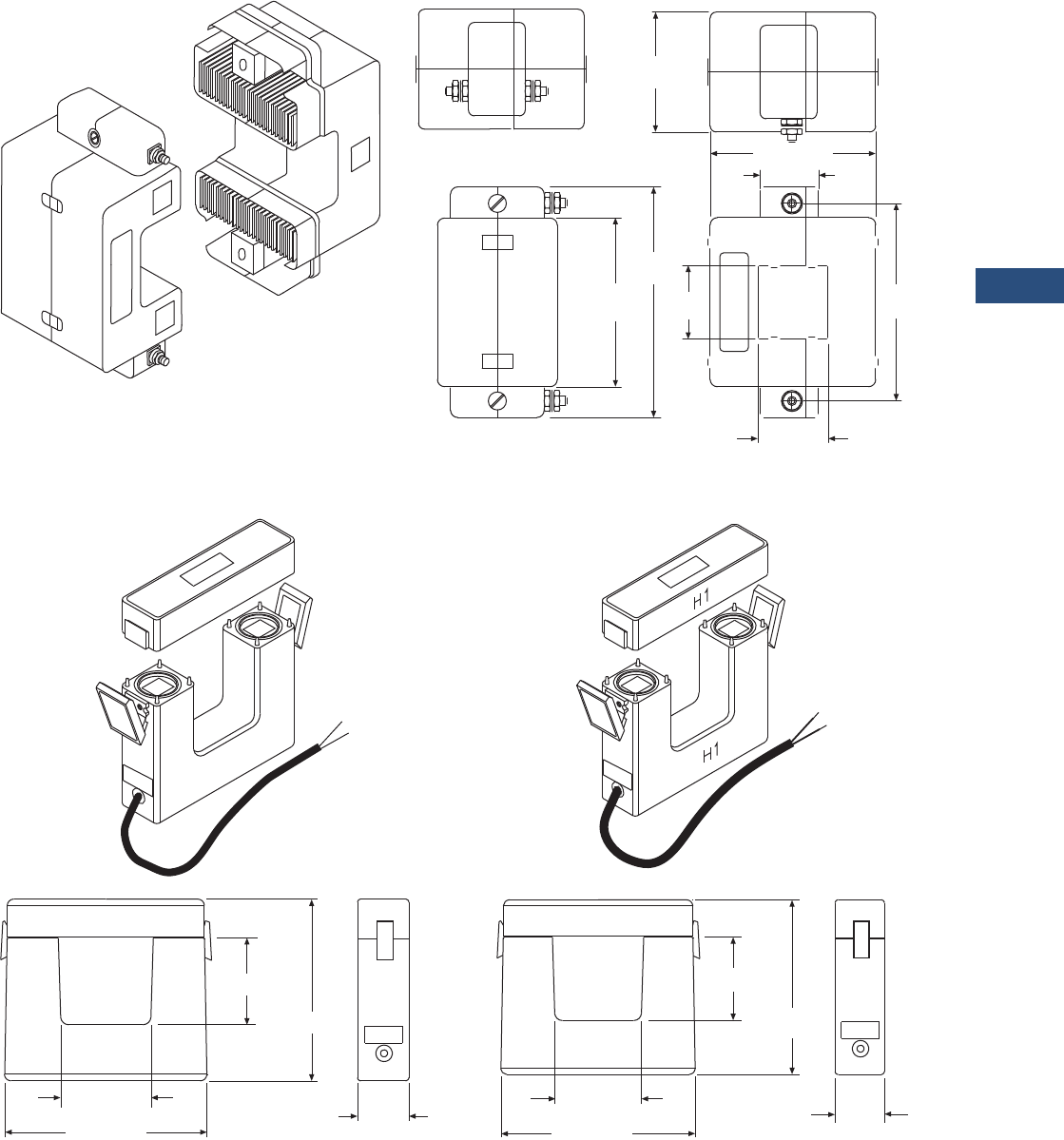
Volume 3—Power Distribution and Control Assemblies CA08100004E—March 2016 www.eaton.com V3-T9-115
9
9
9
9
9
9
9
9
9
9
9
9
9
9
9
9
9
9
9
9
9
9
9
9
9
9
9
9
9
9
9.2
Metering Devices, Protective Relays, Software and Connectivity
Metering Devices
Approximate dimensions in inches (mm)
M040
M060 M080
1.42
(36.1)
1.20
(30.5)
3.38 (85.9)
1.53
(38.9)
4.12
(104.6)
3.52
(89.4)
4.78
(121.4)
2.50
(63.5)
X2
H1
LABEL
X1
Terminal Arrangement for
Ratios 250:5 through 400:5
Terminal Arrangement for
Ratios 100:5 through 200:5
LABEL
X1
X2
H1
H1
H1
H1
H1
2.75 (69.9)
2.70 (68.6)
5.80 (147.3)
1.75
(44.5)
X1 - WHITE
X2 - BLACK
6.05 (153.7)
LABEL
H1
H1
6.25 (158.8)
9.25 (235.0)
2.60 (66.0)
6.05 (153.7)
1.75
(44.5)
X1 - WHITE
X2 - BLACK

V3-T9-116 Volume 3—Power Distribution and Control Assemblies CA08100004E—March 2016 www.eaton.com
9
9
9
9
9
9
9
9
9
9
9
9
9
9
9
9
9
9
9
9
9
9
9
9
9
9
9
9
9
9
9.2
Metering Devices, Protective Relays, Software and Connectivity
Metering Devices
IQ Accessories—Clamp-On CTs
Contents
Description Page
Metering Products Family. . . . . . . . . . . . . . . . . . . . . V3-T9-6
Power Xpert Meter 4000/6000/8000 Series . . . . . . . V3-T9-15
Power Xpert Meter 2000 Series . . . . . . . . . . . . . . . . V3-T9-34
IQ 250/260 Series Electronic Power Meters. . . . . . . V3-T9-45
IQ 130/140/150 Series Electronic Power Meters . . . V3-T9-51
IQ 150S/250S Self-Enclosed Electronic Meters . . . . V3-T9-56
IQ 35M . . . . . . . . . . . . . . . . . . . . . . . . . . . . . . . . . . . V3-T9-61
IQ Analyzer 6400/6600 Series . . . . . . . . . . . . . . . . . V3-T9-64
IQ DP-4000 Series . . . . . . . . . . . . . . . . . . . . . . . . . . V3-T9-72
IQ 230 Meters . . . . . . . . . . . . . . . . . . . . . . . . . . . . . V3-T9-78
Power Xpert Multi-Point Meter . . . . . . . . . . . . . . . . . V3-T9-85
IQ Energy Sentinel™ . . . . . . . . . . . . . . . . . . . . . . . . V3-T9-97
PM3 Monitoring and Metering Module . . . . . . . . . . V3-T9-106
Current Transformers (CTs). . . . . . . . . . . . . . . . . . . . V3-T9-107
Clamp-On Current Transformers
Product Selection . . . . . . . . . . . . . . . . . . . . . . . . V3-T9-117
Technical Data and Specifications . . . . . . . . . . . . V3-T9-117
Dimensions . . . . . . . . . . . . . . . . . . . . . . . . . . . . . V3-T9-118
IQ Flange . . . . . . . . . . . . . . . . . . . . . . . . . . . . . . . . . V3-T9-119
Panel Mounting Adapter Kit . . . . . . . . . . . . . . . . . . . V3-T9-120
Enclosed Meters. . . . . . . . . . . . . . . . . . . . . . . . . . . . V3-T9-121
Clamp-On Current Transformers
Product Description
Eaton’s optional Clamp-on
Current Transformers (CTs)
are designed to be used in
cases where there are no
existing CTs or the existing
CTs cannot be accessed,
these clamp-on CTs can
be used.
These clamp-on CTs are
packaged individually. Most
applications will require at
least three clamp-on CTs,
one for each phase.
Application Description
●There are two models that
cover current ranges from
150 to 1500 amperes
●These clamp-on CTs are
designed to fit around
600 volt insulated cable
and bus bar
Features, Benefits
and Functions
●Each clamp-on CT comes
with a 12-foot (3.7m) cable
and twist lock connector
●All models have a
5 ampere output at
three different primary
current ratings
Standards and Certifications
●Meets IEC 1010-1
Category III
●CE mark for applications
where European
compliance is required

Volume 3—Power Distribution and Control Assemblies CA08100004E—March 2016 www.eaton.com V3-T9-117
9
9
9
9
9
9
9
9
9
9
9
9
9
9
9
9
9
9
9
9
9
9
9
9
9
9
9
9
9
9
9.2
Metering Devices, Protective Relays, Software and Connectivity
Metering Devices
Product Selection
Ordering Information
Current
Ranges
Catalog
Number
150–300–600A IQAPORT0600CT
500–1000–1500A IQAPORT1500CT
150–300–600A
500–1000–1500A
Technical Data and Specifications
●Operating temperature: 14ºF to 122ºF (–10ºC to 50ºC)
●Operating humidity: 5 to 90% maximum noncondensing
●Altitude: 10,000 ft (3048m)
●Environment: indoor use only
●Operating voltage: 600 Vac maximum
●Isolation test: 5.55 kV for 1 minute
●Current over range: 200% for 3 minutes
●Connector: twist-lock
Current Ranges
Each of the two models of clamp-on CTs has three primary
current ranges. The primary current range is selected at the
clamp-on by connecting to the indicated terminals.
150A/300A/600A Clamp-On CT Specifications
●Current ratings:
●150 to 5 amperes
●300 to 5 amperes
●600 to 5 amperes
500A/1000A/1500A Clamp-On CT Specifications
●Current ratings:
●500 to 5 amperes
●1000 to 5 amperes
●1500 to 5 amperes
Electrical Characteristics
Current
Ranges
Load
(Ohms)
Phase Shift
(Degree)
Frequency
Range (3%)
Frequency
Range (–3 db)
150–600A 0.10–1.0 0.5–1.0 40–5000 30–10,000
500–1500A 0.01–4.0 0.5–1.0 40–2000 30–5000
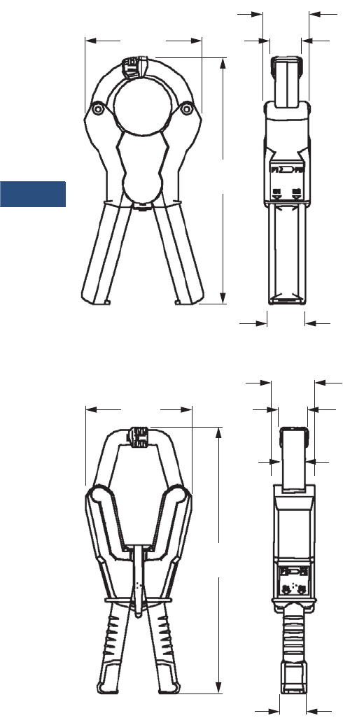
V3-T9-118 Volume 3—Power Distribution and Control Assemblies CA08100004E—March 2016 www.eaton.com
9
9
9
9
9
9
9
9
9
9
9
9
9
9
9
9
9
9
9
9
9
9
9
9
9
9
9
9
9
9
9.2
Metering Devices, Protective Relays, Software and Connectivity
Metering Devices
Dimensions
Approximate Dimensions in Inches (mm)
150A/300A/600A Clamp-On CT
500A/1000A/1500A Clamp-On CT
150A/300A/600A Clamp-On CT
●Maximum cable size:
●2.00 inches (50.8 mm)
●Maximum bus bar size:
●2.00 x 0.47 inches (50.8 x 12.0 mm)
●1.60 x 1.40 inches (40.6 x 35.6 mm)
●Dimensions (without cable):
●4.00 x 8.50 x 1.60 inches (101.6 x 215.9 x 40.6 mm)
●Weight (with cable):
●2.0 lbs (0.9 kg)
500A/1000A/1500A Clamp-On CT
●Maximum cable size:
●2.68 inches (68.1 mm)
●Maximum bus bar size:
●4.84 x 1.40 (122.9 x 35.6 mm)
●4.00 x 1.70 inches (101.6 x 43.2 mm)
●Dimensions (without cable):
●5.20 x 13.20 x 2.00 inches (132.1 x 335.3 x 50.8 mm)
●Weight (with cable):
●6.0 lbs (2.7 kg)
8.50
(215.9)
1.26
(32.0)
4.01
(101.9)
1.58
(40.1)
0.79
(20.1)
8.50
(215.9)
1.30
(33.0)
5.24
(133.1)
2.04
(51.8)
1.40
(35.6)
1.10
(27.9)
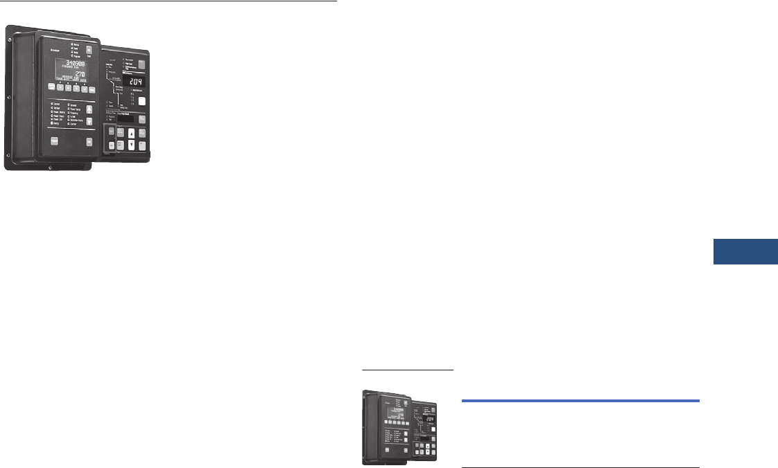
Volume 3—Power Distribution and Control Assemblies CA08100004E—March 2016 www.eaton.com V3-T9-119
9
9
9
9
9
9
9
9
9
9
9
9
9
9
9
9
9
9
9
9
9
9
9
9
9
9
9
9
9
9
9.2
Metering Devices, Protective Relays, Software and Connectivity
Metering Devices
IQ Accessories—IQ Flange
Contents
Description Page
Metering Products Family . . . . . . . . . . . . . . . . . . . . V3-T9-6
Power Xpert Meter 4000/6000/8000 Series . . . . . . V3-T9-15
Power Xpert Meter 2000 Series . . . . . . . . . . . . . . . V3-T9-34
IQ 250/260 Series Electronic Power Meters . . . . . . V3-T9-45
IQ 130/140/150 Series Electronic Power Meters . . . V3-T9-51
IQ 150S/250S Self-Enclosed Electronic Meters. . . . V3-T9-56
IQ 35M. . . . . . . . . . . . . . . . . . . . . . . . . . . . . . . . . . . V3-T9-61
IQ Analyzer 6400/6600 Series . . . . . . . . . . . . . . . . . V3-T9-64
IQ DP-4000 Series . . . . . . . . . . . . . . . . . . . . . . . . . . V3-T9-72
IQ 230 Meters . . . . . . . . . . . . . . . . . . . . . . . . . . . . . V3-T9-78
Power Xpert Multi-Point Meter . . . . . . . . . . . . . . . . V3-T9-85
IQ Energy Sentinel™ . . . . . . . . . . . . . . . . . . . . . . . . V3-T9-97
PM3 Monitoring and Metering Module . . . . . . . . . . V3-T9-106
Current Transformers (CTs) . . . . . . . . . . . . . . . . . . . V3-T9-107
Clamp-On Current Transformers . . . . . . . . . . . . . . . V3-T9-116
IQ Flange
Panel Mounting Adapter Kit . . . . . . . . . . . . . . . . . . . V3-T9-120
Enclosed Meters . . . . . . . . . . . . . . . . . . . . . . . . . . . V3-T9-121
IQ Flange
Product Description
Eaton’s IQ Flange is intended
for use with the IQ Data,
IQ Generator, IQ Data Plus II,
IQ Analyzer and any other
such device sharing the same
mounting dimensions.
The door mounting flange
provides extra depth behind a
panel if there is not enough
clearance to accommodate
the device.
Application Description
Retrofit Applications
For applications where extra
door mounting space is
required, a flange-mounting
unit is available. The IQ
Flange provides an extra
2.5 inches (63.5 mm) of
clearance for the device.
The IQ Flange can be used
with any IQ device with
a 5.38-inch (136.7 mm) x
9.38-inch (238.0 mm) cutout.
Product Selection
IQ Flange
Description Catalog Number
IQ Flange IQFLANGE
IQ Flange
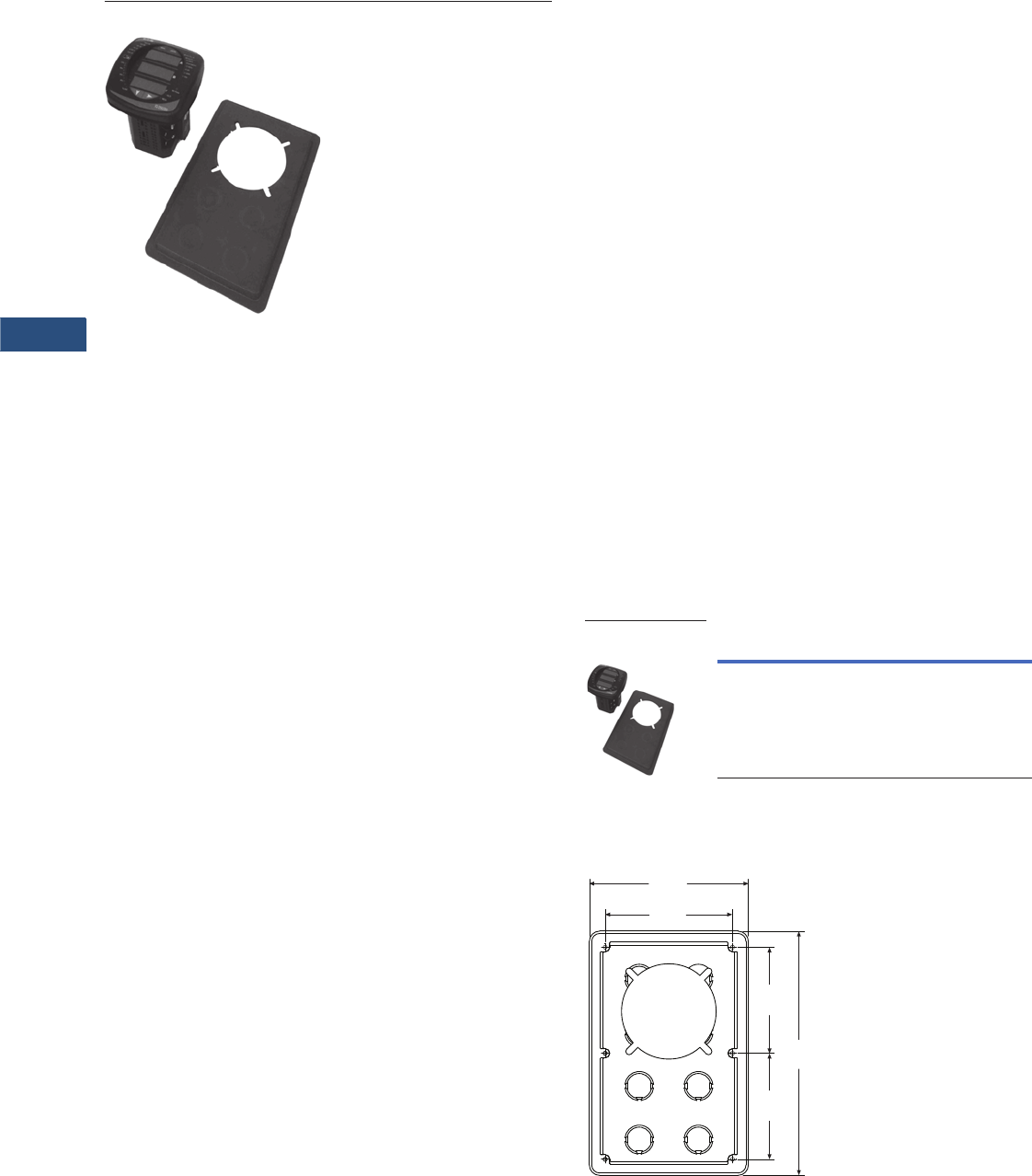
V3-T9-120 Volume 3—Power Distribution and Control Assemblies CA08100004E—March 2016 www.eaton.com
9
9
9
9
9
9
9
9
9
9
9
9
9
9
9
9
9
9
9
9
9
9
9
9
9
9
9
9
9
9
9.2
Metering Devices, Protective Relays, Software and Connectivity
Metering Devices
Panel Mounting Adapter Kit for IQ 100/200 Series and PXM 2000 Meters
Contents
Description Page
Metering Products Family . . . . . . . . . . . . . . . . . . . . V3-T9-6
Power Xpert Meter 4000/6000/8000 Series . . . . . . V3-T9-15
Power Xpert Meter 2000 Series . . . . . . . . . . . . . . . V3-T9-34
IQ 250/260 Series Electronic Power Meters . . . . . . V3-T9-45
IQ 130/140/150 Series Electronic Power Meters. . . V3-T9-51
IQ 150S/250S Self-Enclosed Electronic Meters . . . V3-T9-56
IQ 35M . . . . . . . . . . . . . . . . . . . . . . . . . . . . . . . . . . V3-T9-61
IQ Analyzer 6400/6600 Series . . . . . . . . . . . . . . . . . V3-T9-64
IQ DP-4000 Series. . . . . . . . . . . . . . . . . . . . . . . . . . V3-T9-72
IQ 230 Meters . . . . . . . . . . . . . . . . . . . . . . . . . . . . . V3-T9-78
Power Xpert Multi-Point Meter . . . . . . . . . . . . . . . . V3-T9-85
IQ Energy Sentinel™ . . . . . . . . . . . . . . . . . . . . . . . . V3-T9-97
PM3 Monitoring and Metering Module. . . . . . . . . . V3-T9-106
Current Transformers (CTs) . . . . . . . . . . . . . . . . . . . V3-T9-107
Clamp-On Current Transformers . . . . . . . . . . . . . . . V3-T9-116
IQ Flange . . . . . . . . . . . . . . . . . . . . . . . . . . . . . . . . . V3-T9-119
Panel Mounting Adapter Kit
Enclosed Meters . . . . . . . . . . . . . . . . . . . . . . . . . . . V3-T9-121
Panel Mounting Adapter Kit for IQ 100/200 Series
and PXM 2000 Meters
Product Description
The flange adapter plate can
be installed as follows:
1. Remove the old meter
from the panel or door.
Many IQ metering
products use the typical
IQ drilling pattern shown
at right for mounting
2. Install the flange adapter
plate. Mount it from the
rear using the six screws
provided in the kit. The
flange adapter plate
screw hole pattern
shown at right should
match the typical IQ
drilling pattern. If not,
perform the next step
3. Drill six holes in the panel
or the door to mount the
flange adapter plate.
Follow the typical IQ
drilling pattern. You need
only the top, center and
bottom sets of holes
4. Install the new IQ 100/
200 Series or PXM 2000
meter in the flange
adapter plate. Secure it
from behind with four flat
washers, lock washers
and nuts provided with
the meter
Product Selection
Panel Mounting Adapter Kit
Dimensions
Flange Adapter Plate Screw Hole Pattern
Description Catalog Number
Panel mounting adapter kit
IQ 100/200 and PXM 2000 Series
adapter kit to IQ Analyzer/
IQ DP-4000/IQ Data
IQ250-PMAK
Panel Mounting
Adapter Kit
6.72
(170.7)
5.38
(136.7)
4.45
(113.0)
10.25
(260.4)
4.45
(113.0)

Volume 3—Power Distribution and Control Assemblies CA08100004E—March 2016 www.eaton.com V3-T9-121
9
9
9
9
9
9
9
9
9
9
9
9
9
9
9
9
9
9
9
9
9
9
9
9
9
9
9
9
9
9
9.2
Metering Devices, Protective Relays, Software and Connectivity
Metering Devices
NEMA 12 Single- and Multi-Unit Enclosed Meters
Contents
Description Page
Metering Products Family. . . . . . . . . . . . . . . . . . . . . V3-T9-6
Power Xpert Meter 4000/6000/8000 Series. . . . . . . V3-T9-15
Power Xpert Meter 2000 Series . . . . . . . . . . . . . . . . V3-T9-34
IQ 250/260 Series Electronic Power Meters . . . . . . V3-T9-45
IQ 130/140/150 Series Electronic Power Meters . . . V3-T9-51
IQ 150S/250S Self-Enclosed Electronic Meters . . . . V3-T9-56
IQ 35M . . . . . . . . . . . . . . . . . . . . . . . . . . . . . . . . . . . V3-T9-61
IQ Analyzer 6400/6600 Series . . . . . . . . . . . . . . . . . V3-T9-64
IQ DP-4000 Series . . . . . . . . . . . . . . . . . . . . . . . . . . V3-T9-72
IQ 230 Meters . . . . . . . . . . . . . . . . . . . . . . . . . . . . . V3-T9-78
Power Xpert Multi-Point Meter . . . . . . . . . . . . . . . . . V3-T9-85
IQ Energy Sentinel™ . . . . . . . . . . . . . . . . . . . . . . . . V3-T9-97
PM3 Monitoring and Metering Module . . . . . . . . . . V3-T9-106
Current Transformers (CTs). . . . . . . . . . . . . . . . . . . . V3-T9-107
Clamp-On Current Transformers. . . . . . . . . . . . . . . . V3-T9-116
IQ Flange . . . . . . . . . . . . . . . . . . . . . . . . . . . . . . . . . V3-T9-119
Panel Mounting Adapter Kit . . . . . . . . . . . . . . . . . . . V3-T9-120
Enclosed Meters
Features and Benefits . . . . . . . . . . . . . . . . . . . . . V3-T9-122
Catalog Number Selection. . . . . . . . . . . . . . . . . . V3-T9-124
Product Selection . . . . . . . . . . . . . . . . . . . . . . . . V3-T9-124
Technical Data and Specifications . . . . . . . . . . . . V3-T9-125
Wiring Diagrams . . . . . . . . . . . . . . . . . . . . . . . . . V3-T9-126
Dimensions . . . . . . . . . . . . . . . . . . . . . . . . . . . . . V3-T9-136
Enclosed Meters
Product Description
The Eaton enclosed meter
line provides a complete
energy metering and data
acquisition solution in a single
enclosure. Designed for
Eaton’s IQ 35M, IQ 150, IQ
250/260, and Power Xpert®
2000/4000/6000/8000 and
Multi-Point Meters, Eaton’s
enclosed meter line offers
mounting and installation
flexibility, especially in retrofit
applications where no
metering compartment or
mounting space is available in
the existing electrical
distribution equipment or
where installation time is a
premium. Factory designed
and wired, Eaton’s enclosed
meter line offers savings in
labor and installation costs
because input current and
voltage wiring as well as I/O
wiring is prewired to terminal
blocks inside the enclosure.
The enclosed meter line has
two standard offerings:
single-, prewired unit (specific
IQ 150, IQ 250/260, PXM
2000, PXM 4000/6000/8000
or PXMP) and a multi-unit
(specific IQ 150, IQ 250/260
or IQ 35M models). Because
the multi-unit automatically
includes Eaton’s Power Xpert
Gateway 200E, it facilitates
measurement and verification
of the energy usage on
processes and in buildings.
This provides a convenient
way to monitor energy usage
from multiple points, collect
and log specific energy use
parameters, and display and
generate logs for historical
energy usage reports. Simply
put, Eaton’s multi-unit
enclosed meter solution
helps meet any
measurement and verification
requirement to show energy
efficiency improvements and
results. In addition to the
standard offering, Eaton can
also provide an enclosed
metering solution tailored
around your project needs.
Application Description
Factory designed and wired
to fit various Eaton power and
energy meters at varying
price points, Eaton’s
enclosed meter line offers
savings in labor and
installation costs because
input current and voltage
wiring, as well as I/O wiring,
is prewired to terminal blocks
inside the enclosure.
Standalone, enclosed meters
are ideal for new metering
applications where no
metering existed previously,
for retrofit installations where
energy monitoring is a must
or where ease of installation
is required.
●Health care facilities
●Educational facilities and
campuses
●Industrial facilities
●Commercial facilities
●Government facilities
The multi-unit offering
consolidates energy-related
data available from the
meters in the enclosure, but
also allows for external
meters to be added to the
embedded Power Xpert
Gateway 200E. Through the
Power Xpert Gateway 200E’s
embedded Web server,
information can be presented
in a variety of ways; a
standard Web browser being
the most widely used
method.
The enclosed product is a
standalone solution that is
ideal for many infrastructure
designs. Further, as needs
change and grow, the
enclosed product can be
integrated through Power
Xpert Insight into a broader
solution that encompasses
other intelligent hardware and
can integrate with third-party
network management
systems (NMS) or building
management systems (BMS)
for system-wide monitoring
and reporting of energy
and power.
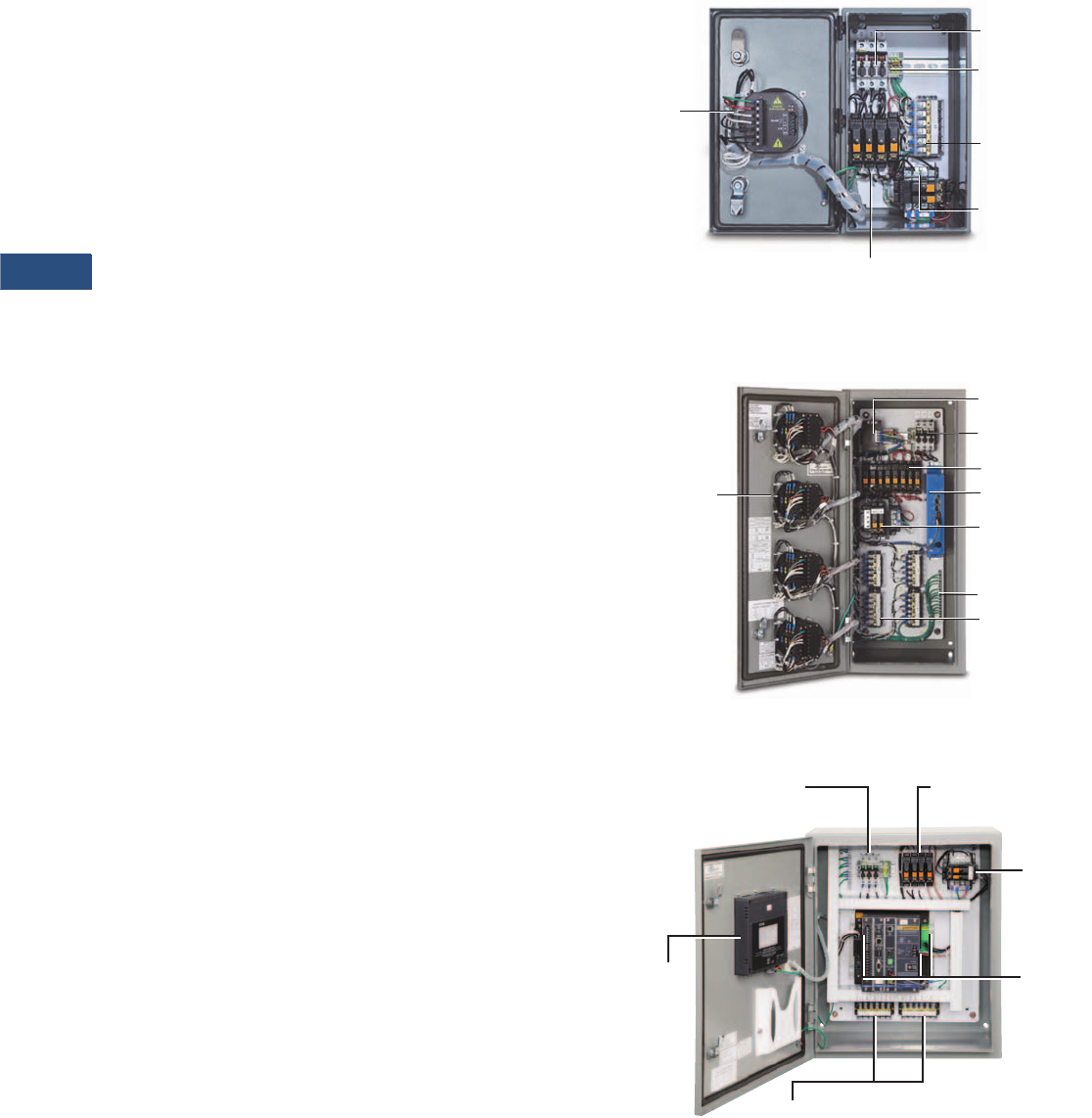
V3-T9-122 Volume 3—Power Distribution and Control Assemblies CA08100004E—March 2016 www.eaton.com
9
9
9
9
9
9
9
9
9
9
9
9
9
9
9
9
9
9
9
9
9
9
9
9
9
9
9
9
9
9
9.2
Metering Devices, Protective Relays, Software and Connectivity
Metering Devices
Features and Benefits
●Saves installation time
and cost
●One part number to order;
no need to worry that any
part has been left out
●Pick the meter or meters
you need as it is designed
to fit various Eaton power
and energy meters, at
varying price points
Factory Wired
Most electrical contractors
are very familiar with wiring
meters. However, it does
take time to place the
disconnect, the CT shorting
blocks, the terminal blocks,
the control power
transformer and so on, and
the associated wiring. It is not
uncommon for errors to be
introduced during the
installation of multiple
meters; it’s just inherent in
wiring. With Eaton’s enclosed
meter line, everything is
wired at the factory—the
shorting block, the terminal
blocks and so on—assuring
that it’s done right. Further, to
ensure safety, Eaton’s
enclosed meter line includes
a primary fusible disconnect
for line voltage, which can be
turned off during meter
maintenance.
For applications with line
voltages above the rated
power supply of the meter,
an optional control power
transformer is supplied in the
enclosure. Control voltage
can also be supplied via a
separate source that is wired
to the field installation
terminal block. CT inputs for
the meter are wired directly
to the shorting terminal
blocks for easy field
installation.
Factory-wired products also
save on installation time and
costs. The meters are flush
mounted on the enclosure
door with all inputs/outputs
factory wired to the terminal
blocks.
A meter subpanel assembly
is also available, which
includes all the internal
components of the single-unit
enclosed meter for the IQ
150/250/260 and PXM 2000
Meters wired and mounted
on a subpanel to be installed
into an existing electrical
structure. It comes with a 48-
inch lead for flexibility in
mounting the meters at
various distances.
NEMA Rated
NEMA 12 enclosure prevents
dust and other materials from
entering the equipment.
Internal gaskets also prevent
air irritants from harming the
vital equipment inside. This
quality enclosure meets most
indoor application needs.
NEMA 3R enclosure is
constructed for either indoor
or outdoor use. It helps to
protect personnel from
access to hazardous parts
and provides a degree of
protection for equipment
inside the enclosure against
ingress of solid foreign
objects (falling dirt), harmful
effects of water (rain, sleet,
snow) and external formation
of ice on the enclosure.
NEMA 4X enclosure provides
the same degree of
protection as the NEMA 3R
with the additional protection
against windblown dust,
splashing and hose-directed
water, and corrosion.
NEMA 12 Front View, Door Open, Prewired and Tested
NEMA 12 Multi-Unit View, Door Open, Prewired and Tested
NEMA 12 Single-Unit Enclosed Meter Inside View,
PXM 4000/6000/8000 Series
Control
Power,
Voltage
and CT
Inputs
Fused
Disconnect
Neutral, Ground
and Input/Output
(not shown)
Ter m i n a l B l o c ks
Prewired Control
Power Transformer
Meter Fusing
CT Shorting
Te r m i n a l
Block
Control power,
voltage, CT and
Communications
Inputs
Gateway Power
Supply
Fused Control
Power Transformer
Fused Disconnect
Meter Fusing
PX Gateway
Ground
CT Shorting Blocks
Display
Fused
Disconnect
Prewired
Control
Power
Transformer
Meter
Control
Power,
Voltage
and CT
Inputs
CT Shorting Terminal Blocks
Meter
Fusing

Volume 3—Power Distribution and Control Assemblies CA08100004E—March 2016 www.eaton.com V3-T9-123
9
9
9
9
9
9
9
9
9
9
9
9
9
9
9
9
9
9
9
9
9
9
9
9
9
9
9
9
9
9
9.2
Metering Devices, Protective Relays, Software and Connectivity
Metering Devices
NEMA 3R Single-Unit Closed and Open, IQ 150/250/260
and PXM 2000 Series
NEMA 4X Single-Unit Closed and Open, IQ 150/250/260
and PXM 2000 Series
Enclosed Power Xpert Multi-Point Meter
PXMP Meter Modules
(not shown—sold separately)
PXMP Meter Base
6-Inch
Color
Touchscreen
Fused
Disconnect
Fuses PXMP
Power
Supply
PXMP
Meter
Base
Connection
s
NEMA 12
Enclosure
(30H x 24W x 12D Inches)
Multi-Unit Enclosed Meter, Inside View of IQ 35M
Prewired Meter Backpan, Single Unit
●Prewired panel to save installation time and cost for retrofits
into existing equipment
●Designed for Eaton’s:
●IQ 100 Meter Series
●IQ 250/260
●Power Xpert Meter 2000 Series
●With or without CPT, depending on voltage
●Order meters separately
Meter
Fusing
Fused
Disconnect
Gateway
Power
Supply
Control Power,
Voltage Current
Sensor and
Communications
Inputs
PX Gateway
Current Sensor
Terminal Strip
Meter
Fusing
48-Inch Meter
Harness
Fused
Disconnec
t
CT Shorting
Block
Optional
CPT
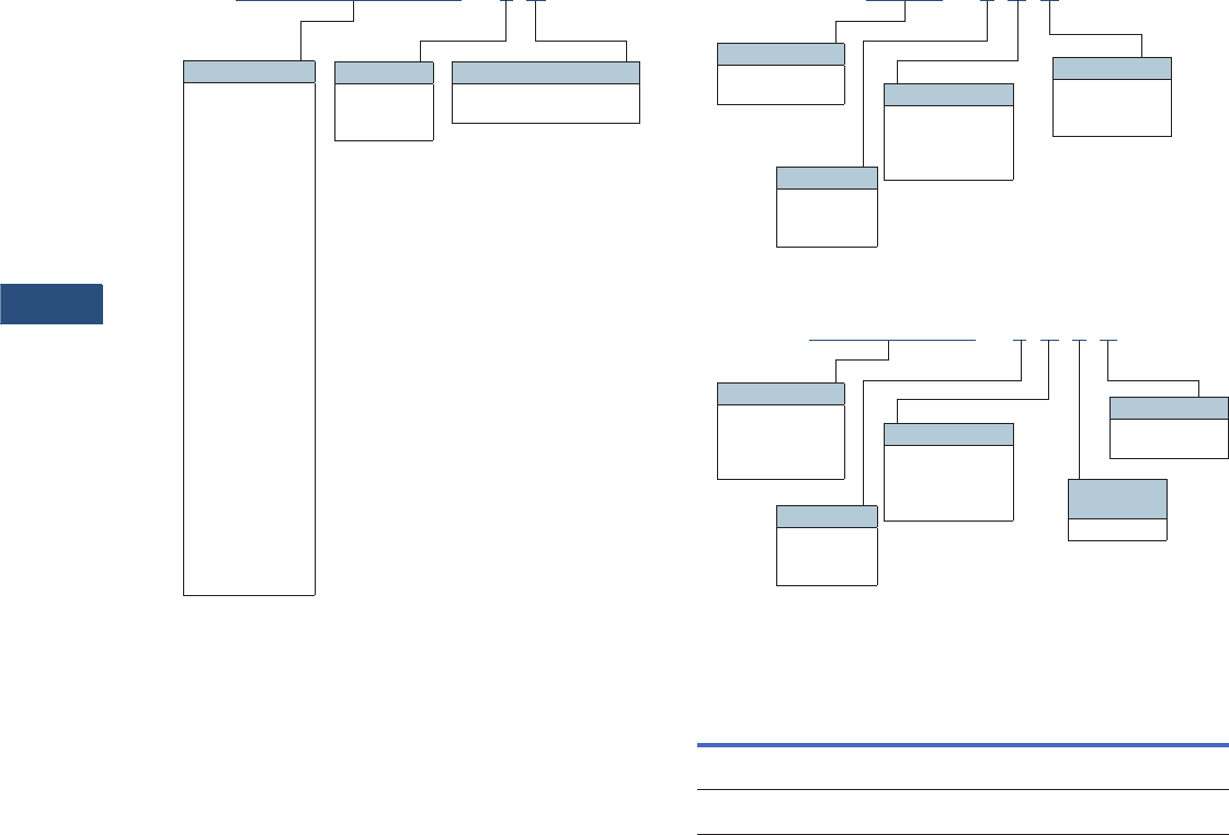
V3-T9-124 Volume 3—Power Distribution and Control Assemblies CA08100004E—March 2016 www.eaton.com
9
9
9
9
9
9
9
9
9
9
9
9
9
9
9
9
9
9
9
9
9
9
9
9
9
9
9
9
9
9
9.2
Metering Devices, Protective Relays, Software and Connectivity
Metering Devices
Catalog Number Selection
Single Unit Enclosed Meter
PXM2250MA65105 -2B
Meter Type
PXM4051A1BA
PXM4051A1BB
PXM6051A1BA
PXM6051A1BB
PXM8051A1BA
PXM8051A1BB
PXM2250MA65105
PXM2250MA65115
PXM2250MA65145
PXM2260MA65105
PXM2260MA65115
PXM2260MA65145
PXM2270MA65105
PXM2270MA65115
PXM2270MA65145
PXM2280MA65105
PXM2280MA65115
PXM2280MA65145
PXM2290MA65105
PXM2290MA65115
PXM2290MA65145
IQ250MA65100
IQ250MA65110
IQ250MA65114
IQ260MA65100
IQ260MA65110
IQ260MA65114
IQ150MA6511
IQ150MA6512
NEMA Rating
2 = NEMA 12
3 = NEMA 3R
4 = NEMA 4X
CPT Option
A= 120/240 Vac (no CPT)
B= 480 Vac (CPT)
Enclosed PXMP Meter
Multi Unit Enclosed Meter
Product Selection
Meter Subpanel Assembly
Notes
1Not available with IQ 35M.
Other meter models available upon request in single- and multi-unit enclosed versions.
Description Catalog Number
Meter subpanel assembly for PXM 2000
and IQ 150/250/260 Meters
PXM2K-MSPA-A
Meter subpanel assembly with CPT for PXM 2000
and IQ 150/250/260 Meters
PXM2K-MSPA-B
PXMP -2B D
Meter Type
PXMP-MB
PXMP-MB-AB
NEMA Rating
2 = NEMA 12
3 = NEMA 3R
4 = NEMA 4X
Display
A= None
D= 6-inch color
touchscreen
CPT Option
A=None
B= 120/240 Vac
C= 480 Vac
D= 600 Vac
IQ150MA6511 -2B 4 C
Meter Type
IQ35MA12
IQ150MA6511
IQ250MA65100
IQ260MA65100
NEMA Rating
2 = NEMA 12 1
3 = NEMA 3R
4 = NEMA 4X
Communications
C= Includes
PXG-200E
CPT Option
A= 120/240 Vac
No CPT
B= 480 Vac
CPT 1
Number of
Meters
4 = 4 meters

Volume 3—Power Distribution and Control Assemblies CA08100004E—March 2016 www.eaton.com V3-T9-125
9
9
9
9
9
9
9
9
9
9
9
9
9
9
9
9
9
9
9
9
9
9
9
9
9
9
9
9
9
9
9.2
Metering Devices, Protective Relays, Software and Connectivity
Metering Devices
Technical Data and Specifications
Enclosed Meters
Note: Specifications are subject to change without notice and represent
the maximum capabilities of the product with all options installed. This is
not a complete feature list. Features and functionality may vary depending
on selected options, firmware version and product model. Please refer to
the technical data sheet and the user manual for detailed specifications.
Description Specification
Enclosure rating NEMA 12, 3R, 4X
Enclosure operating temperature –20°C to +40°C
Note: Temperature range of meter is
–20°C to +70°C. If applied outside, proper
precautions should be taken to avoid exceeding
the maximum and minimum temperature ratings
of the meter.
Dimensions Single unit (IQ 150/250/260 and PXM 2000):
NEMA 12 (8.00W x 16.30H x 10.40D inches),
NEMA 3R/4X (8.00W x 16.30H x 9.60D inches)
Single unit (PXMP):
NEMA 12/3R/4X (24.00W x 30.00H x 12.00D inches)
Single unit (PXM 4000/6000/8000):
NEMA 12 (20.00W x 24.00H x 14.10D inches)
NEMA 3R/4X (20.20W x 24.00H x 13.90D inches)
Multi unit:
NEMA 12 (13.00W x 30.00H x 15.20D inches)
NEMA 3R (13.20W x 30.10H x 14.60D inches)
NEMA 4X (13.00W x 30.00H x 14.00D inches)
Meters Single unit: IQ 150, IQ 250/260, PXM 2000/4000/6000/8000
and PXMP models
Multi unit: IQ 35M, IQ 150 and IQ 250/260
Communications (multi unit only) Power Xpert Gateway
Control voltage 120V–600V (PXMP)—power supply required
Up to 240V (IQ 35M/150/250/260 and PXM 2000/4000/
6000/8000)—no CPT required
Greater than 240V (IQ 150/250/260 and
PXM 2000)—CPT required
Separate source control—no CPT required
Basic model Fusible disconnect—primary voltage
Shorting block(s)—not required for IQ 35M or PXMP
Ground terminal block
Neutral terminal block
Eight-point terminal block(s) for input/output
modules for IQ 250/260 and PXM 2000
Wiring Wired for three-phase, four-wire applications. Three-phase,
three-wire applications—
will need to change the wiring for both the voltage and the
current per the wiring diagram in the meter instruction
manual.
Certifications UL® 508A and cUL®
Source control No separate source control voltage required for applications
below 240 Vac (except PXMP)
Prewired Prewired current transformer, shorting terminal block(s),
neutral, ground, voltage, control
power, fusible disconnect and input/output
terminal block(s)
Latch Padlocking latch provision
Optional features Control power transformer—single unit: 50 VA (IQ150/250/
260) and 150 VA (PXM 4000/6000/8000); multi unit: 250 VA
control power supply for meter where monitored voltage is
480 Vac (IQ150/250/260 and PXM 2000/4000/6000/8000)
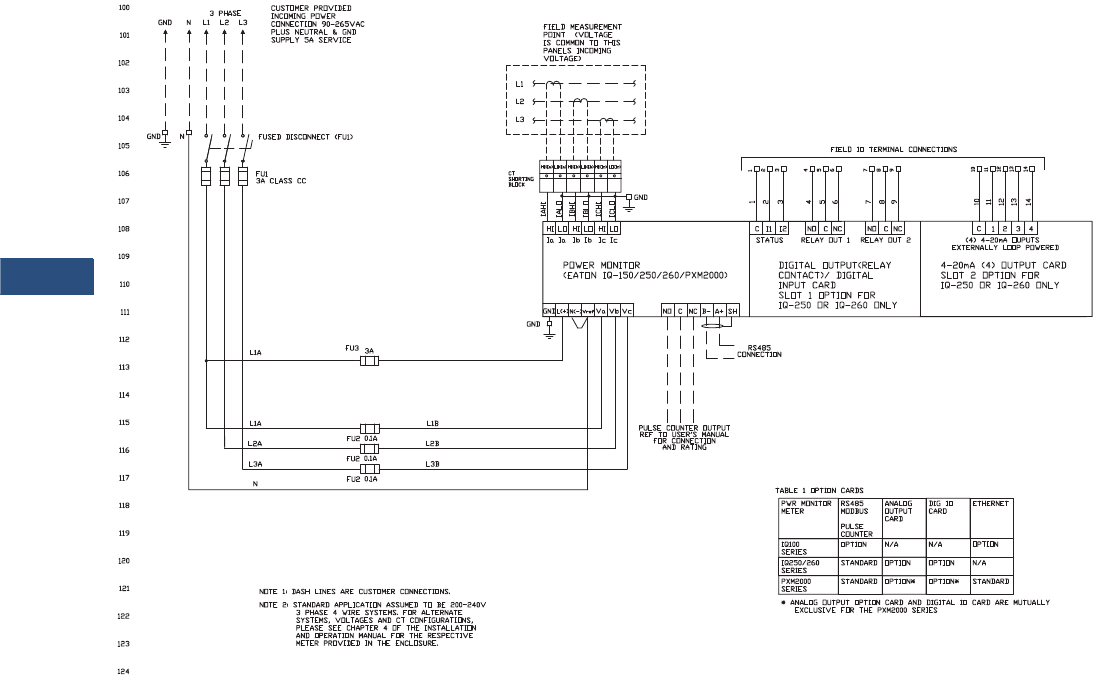
V3-T9-126 Volume 3—Power Distribution and Control Assemblies CA08100004E—March 2016 www.eaton.com
9
9
9
9
9
9
9
9
9
9
9
9
9
9
9
9
9
9
9
9
9
9
9
9
9
9
9
9
9
9
9.2
Metering Devices, Protective Relays, Software and Connectivity
Metering Devices
Wiring Diagrams
Single Unit Enclosure—200/240 Vac 50/60 Hz, Three-Phase, Four-Wire System with IQ 150/250/260 or PXM 2000 Meter
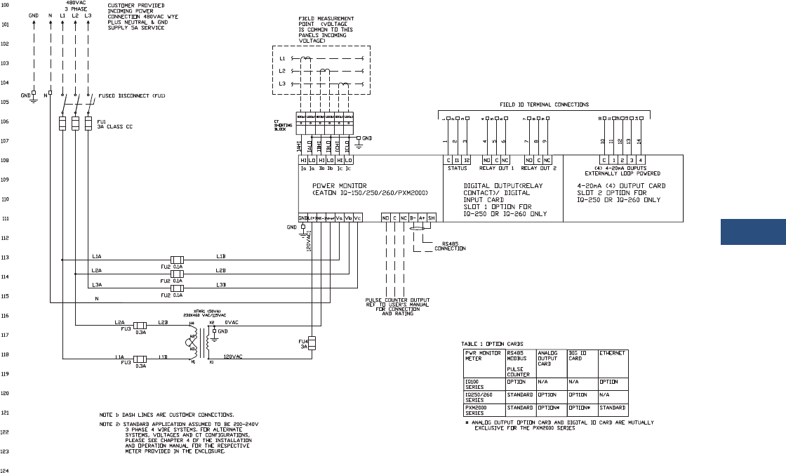
Volume 3—Power Distribution and Control Assemblies CA08100004E—March 2016 www.eaton.com V3-T9-127
9
9
9
9
9
9
9
9
9
9
9
9
9
9
9
9
9
9
9
9
9
9
9
9
9
9
9
9
9
9
9.2
Metering Devices, Protective Relays, Software and Connectivity
Metering Devices
Single Unit Enclosure—480 Vac 50/60 Hz, Three-Phase, Four-Wire System with IQ 150/250/260 or PXM 2000 Meter
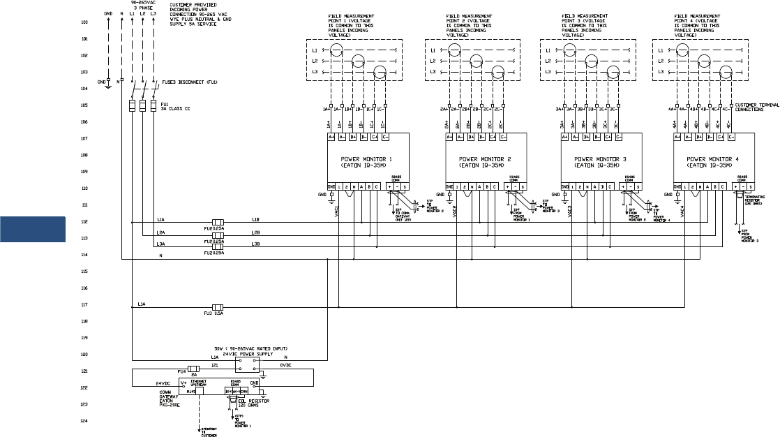
V3-T9-128 Volume 3—Power Distribution and Control Assemblies CA08100004E—March 2016 www.eaton.com
9
9
9
9
9
9
9
9
9
9
9
9
9
9
9
9
9
9
9
9
9
9
9
9
9
9
9
9
9
9
9.2
Metering Devices, Protective Relays, Software and Connectivity
Metering Devices
Multi Unit Enclosure—200–240 Vac 50/60 Hz, Three-Phase, Four-Wire System with IQ 35M Meters
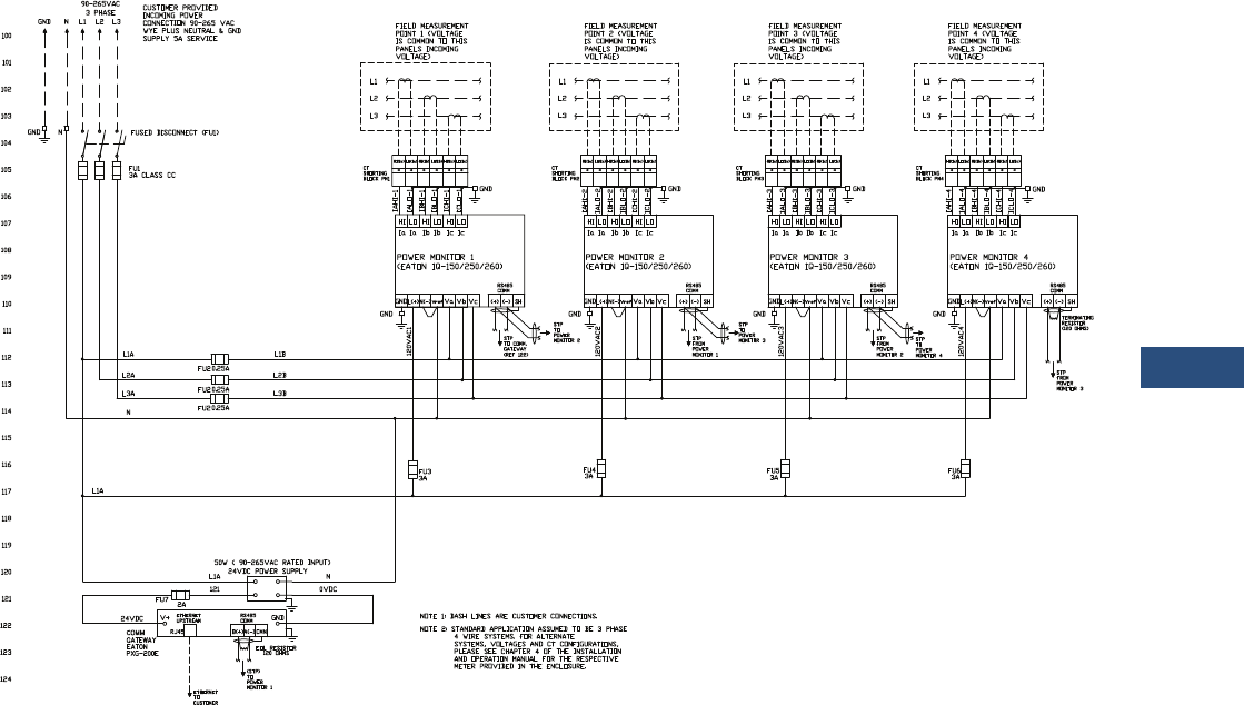
Volume 3—Power Distribution and Control Assemblies CA08100004E—March 2016 www.eaton.com V3-T9-129
9
9
9
9
9
9
9
9
9
9
9
9
9
9
9
9
9
9
9
9
9
9
9
9
9
9
9
9
9
9
9.2
Metering Devices, Protective Relays, Software and Connectivity
Metering Devices
Multi Unit Enclosure—200–240 Vac 50/60 Hz, Three-Phase, Four-Wire System with IQ 150/250/260 Meters
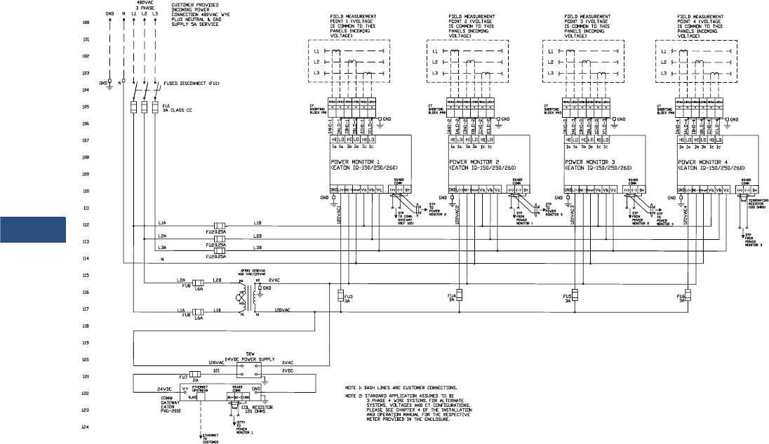
V3-T9-130 Volume 3—Power Distribution and Control Assemblies CA08100004E—March 2016 www.eaton.com
9
9
9
9
9
9
9
9
9
9
9
9
9
9
9
9
9
9
9
9
9
9
9
9
9
9
9
9
9
9
9.2
Metering Devices, Protective Relays, Software and Connectivity
Metering Devices
Multi Unit Enclosure—480 Vac 50/60 Hz, Three-Phase, Four-Wire System with IQ 150/250/260 Meters
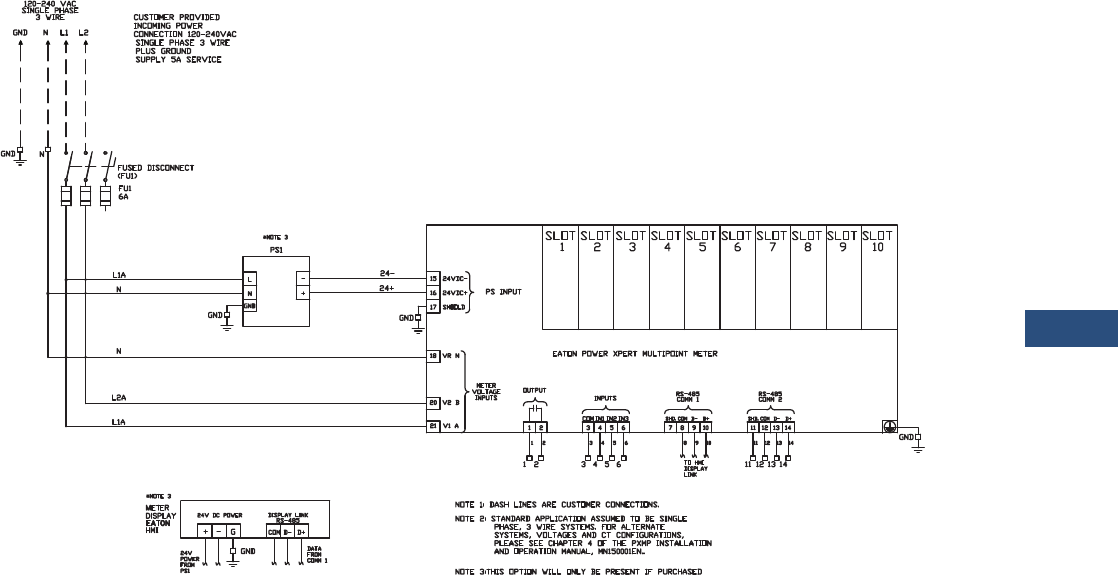
Volume 3—Power Distribution and Control Assemblies CA08100004E—March 2016 www.eaton.com V3-T9-131
9
9
9
9
9
9
9
9
9
9
9
9
9
9
9
9
9
9
9
9
9
9
9
9
9
9
9
9
9
9
9.2
Metering Devices, Protective Relays, Software and Connectivity
Metering Devices
Single Unit Enclosure—120–240 Vac 50/60 Hz, Three-Wire System with PXMP Meter
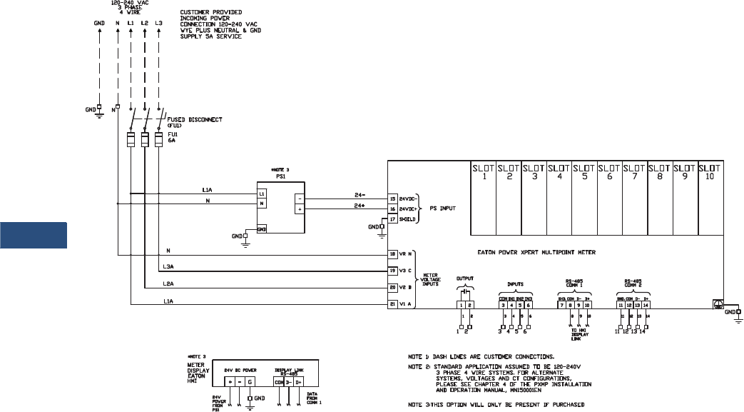
V3-T9-132 Volume 3—Power Distribution and Control Assemblies CA08100004E—March 2016 www.eaton.com
9
9
9
9
9
9
9
9
9
9
9
9
9
9
9
9
9
9
9
9
9
9
9
9
9
9
9
9
9
9
9.2
Metering Devices, Protective Relays, Software and Connectivity
Metering Devices
Single Unit Enclosure—120–240 Vac 50/60 Hz, Three-Phase, Four-Wire Wye System with PXMP Meter
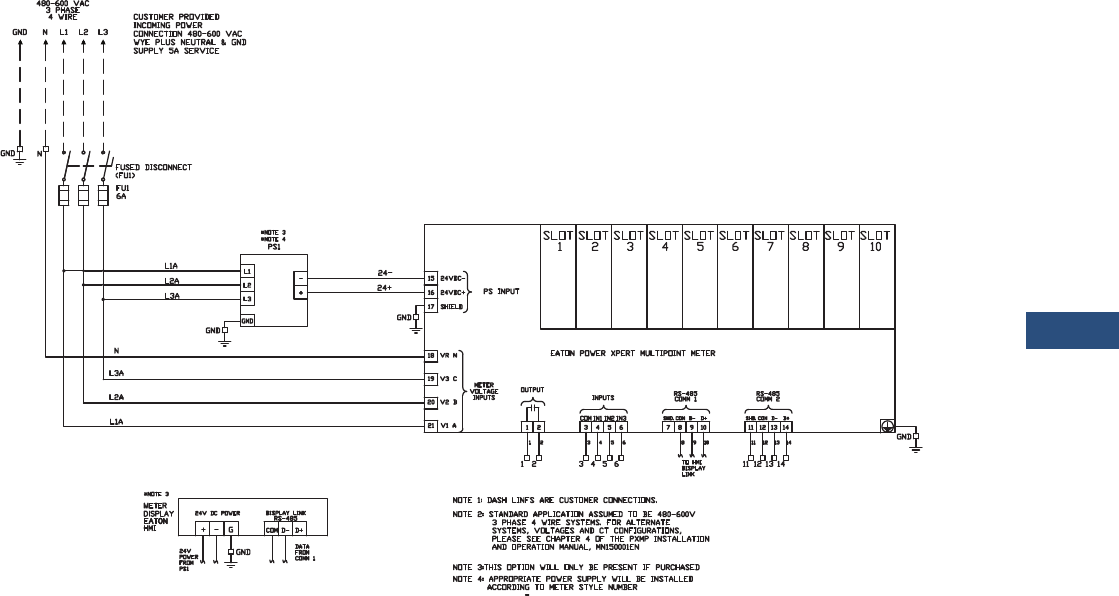
Volume 3—Power Distribution and Control Assemblies CA08100004E—March 2016 www.eaton.com V3-T9-133
9
9
9
9
9
9
9
9
9
9
9
9
9
9
9
9
9
9
9
9
9
9
9
9
9
9
9
9
9
9
9.2
Metering Devices, Protective Relays, Software and Connectivity
Metering Devices
Single Unit Enclosure—480–600 Vac 50/60 Hz, Three-Phase, Four-Wire Wye System with PXMP Meter
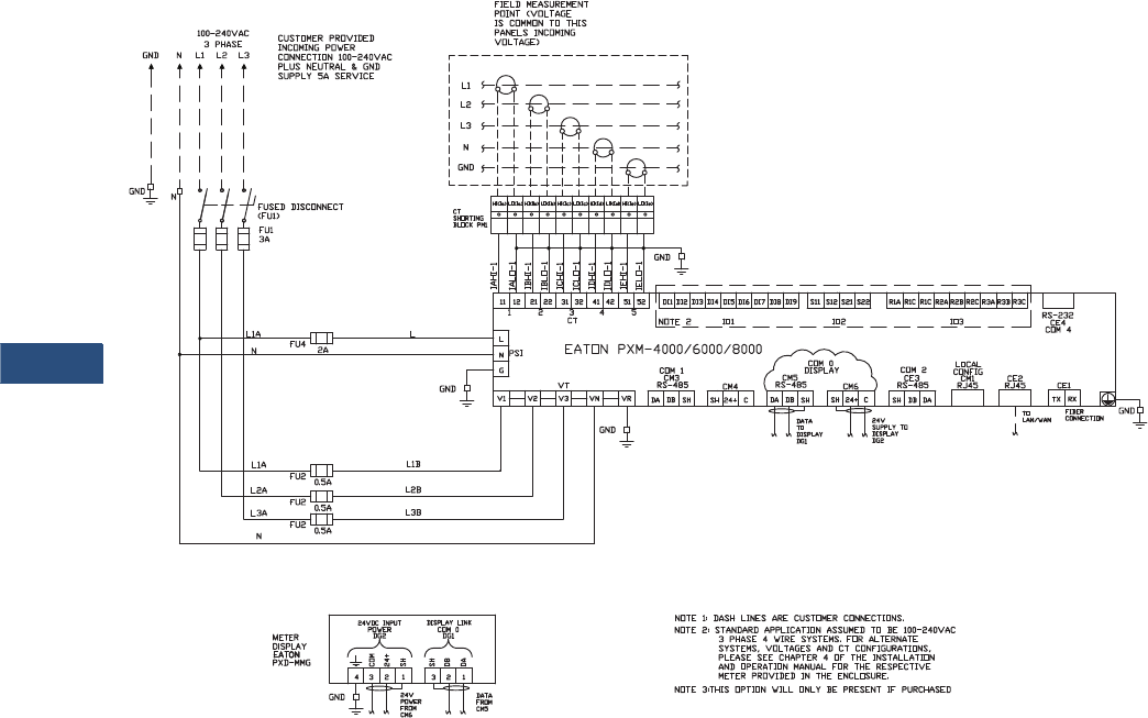
V3-T9-134 Volume 3—Power Distribution and Control Assemblies CA08100004E—March 2016 www.eaton.com
9
9
9
9
9
9
9
9
9
9
9
9
9
9
9
9
9
9
9
9
9
9
9
9
9
9
9
9
9
9
9.2
Metering Devices, Protective Relays, Software and Connectivity
Metering Devices
Single Unit Enclosure—200–240 Vac 50/60 Hz, Three-Phase, Four-Wire System with PXM 4000/6000/8000 Meter
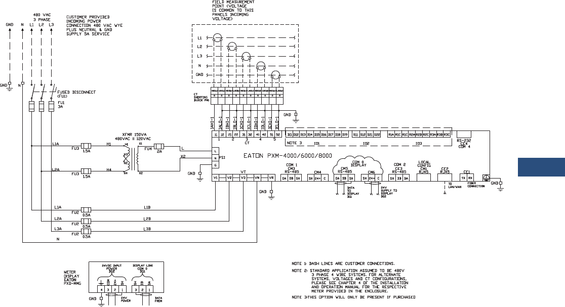
Volume 3—Power Distribution and Control Assemblies CA08100004E—March 2016 www.eaton.com V3-T9-135
9
9
9
9
9
9
9
9
9
9
9
9
9
9
9
9
9
9
9
9
9
9
9
9
9
9
9
9
9
9
9.2
Metering Devices, Protective Relays, Software and Connectivity
Metering Devices
Single Unit Enclosure—480 Vac 50/60 Hz, Three-Phase, Four-Wire System with PXM 4000/6000/8000 Meter
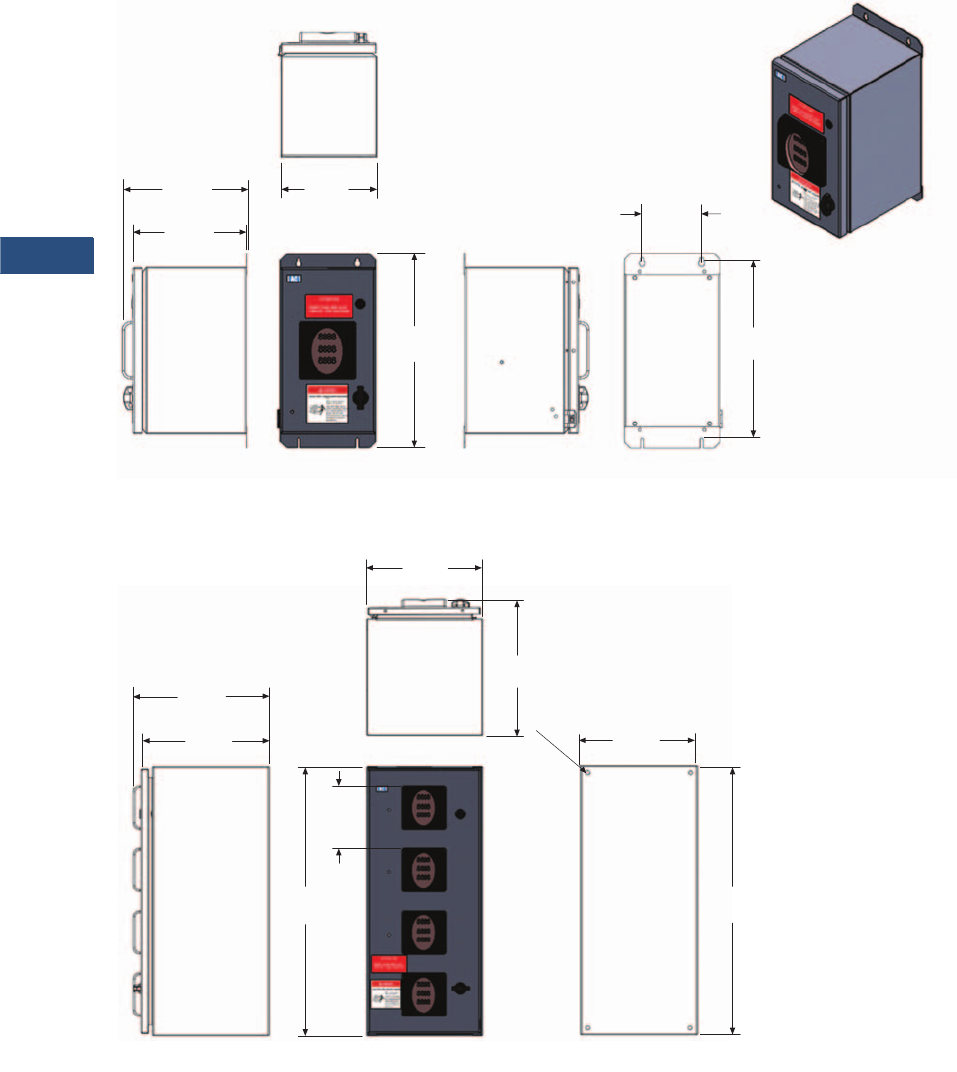
V3-T9-136 Volume 3—Power Distribution and Control Assemblies CA08100004E—March 2016 www.eaton.com
9
9
9
9
9
9
9
9
9
9
9
9
9
9
9
9
9
9
9
9
9
9
9
9
9
9
9
9
9
9
9.2
Metering Devices, Protective Relays, Software and Connectivity
Metering Devices
Dimensions
Approximate Dimensions in Inches (mm)
NEMA 12 Single Unit Enclosure
NEMA 12 Multi Unit Enclosure
Rear View
10.39
(263.9) 5.00
(127.0)
14.99
(380.7)
16.30
(414.0)
9.60
(243.8)
Left Side ViewRight Side View Front View
(203.2)
To p
View
8.00
Rear View
15.19
(385.8)
30.00
(762.0)
28.50
(723.9)
14.07
(357.4)
Right Side View Front View
To p
View
15.19
(385.8)
6.97
(177.0)
Typ.
13.00
(330.2)
11.50
(292.1)
ø0.44
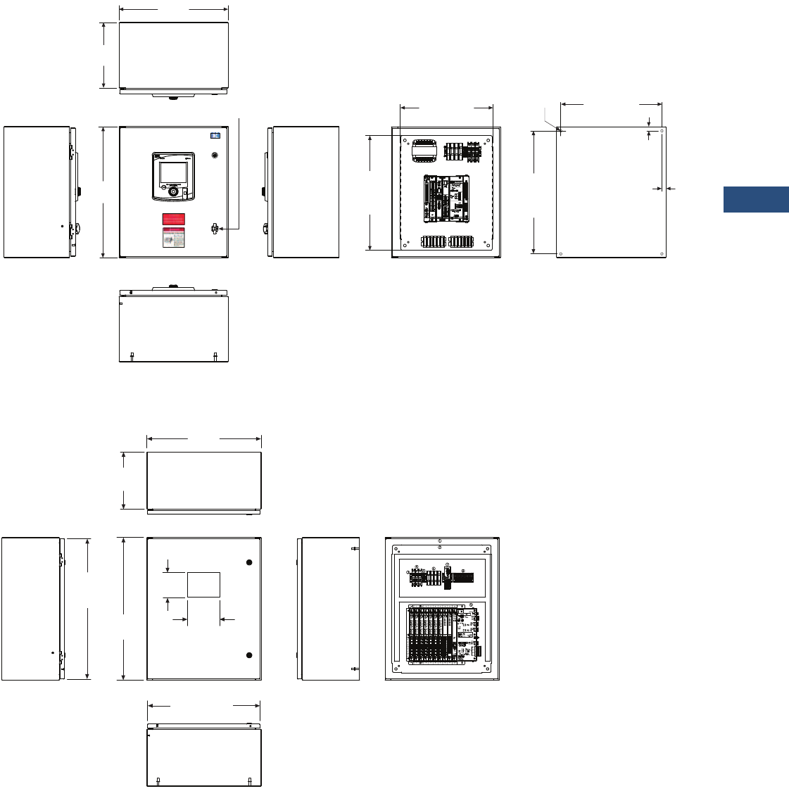
Volume 3—Power Distribution and Control Assemblies CA08100004E—March 2016 www.eaton.com V3-T9-137
9
9
9
9
9
9
9
9
9
9
9
9
9
9
9
9
9
9
9
9
9
9
9
9
9
9
9
9
9
9
9.2
Metering Devices, Protective Relays, Software and Connectivity
Metering Devices
Approximate Dimensions in Inches (mm)
NEMA 12 PXM 4000/6000/8000 Enclosure
NEMA 12 PXMP Enclosure
Top View
20.00
(508.0)
12.00
(304.8)
Left Side View Front View
Bottom View
Right Side View External Rear ViewFront View (Door Removed)
1/4-Turn
Padlocking Latch
22.50
(571.5)
Mounting
Height
18.50 (469.9)
Mounting Width
0.75
(19.1)
0.75
(19.1)
4xø0.44
24.00
(609.6)
21.00
(533.4)
Subpanel
Height
16.94 (430.3)
Subpanel Width
HMI
Cutout
Top View
12.00
(304.8)
Left Side View Front View
Bottom View
Right Side
View
Front View
(Door Removed)
29.50
(749.3)
Door
30.00
(762.0)
24.00
(609.6)
23.63 (600.2)
Door
5.25
(133.4)
6.79
(172.4)
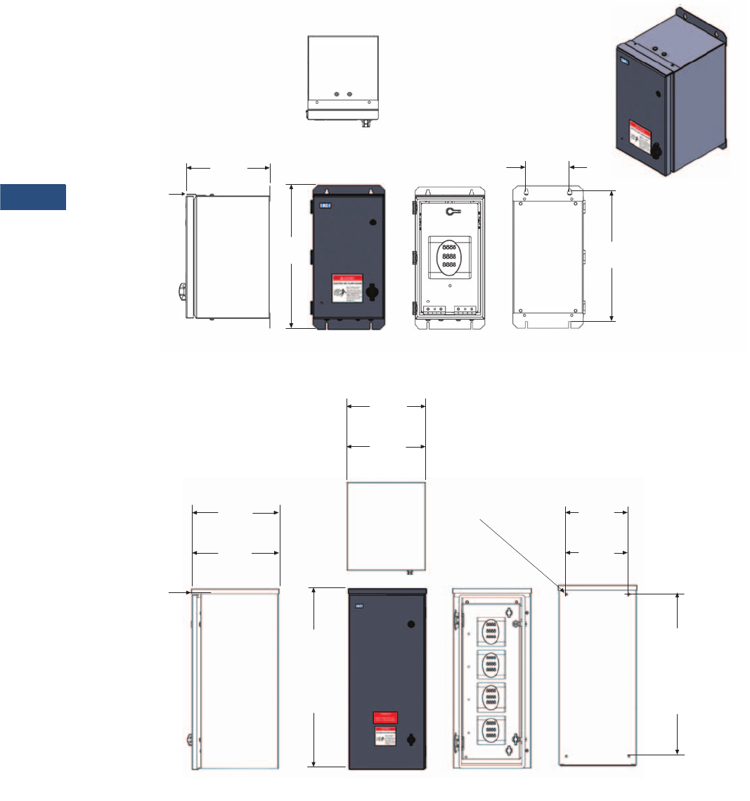
V3-T9-138 Volume 3—Power Distribution and Control Assemblies CA08100004E—March 2016 www.eaton.com
9
9
9
9
9
9
9
9
9
9
9
9
9
9
9
9
9
9
9
9
9
9
9
9
9
9
9
9
9
9
9.2
Metering Devices, Protective Relays, Software and Connectivity
Metering Devices
Approximate Dimensions in Inches (mm)
NEMA 3R/4X Single Unit Enclosure
NEMA 3R/4X Multi Unit Enclosure
Rear View
5.00
(127.0)
14.99
(380.7)
16.30
(414.0)
9.58
(243.3)
Front ViewRight Side View Front View
To p
View
This Drip Cap is
on NEMA 3R Only
Rear View
27.00
(685.8)
(NEMA 3R)
28.50
(723.9)
(NEMA 4X)
Right Side View Front View
ø0.34 (NEMA 3R)
ø0.41 (NEMA 4X)
Front View
(no door)
10.50
(266.7)
(NEMA 3R)
11.50
(292.1)
(NEMA 4X)
30.07
(763.8)
(NEMA 3R)
30.00
(762.0)
(NEMA 4X)
To p
View
This Drip Cap is
on NEMA 3R Only
14.64
(371.9)
(NEMA 3R)
14.03
(356.4)
(NEMA 4X)
13.20
(335.3)
(NEMA 3R)
13.00
(330.2)
(NEMA 4X)
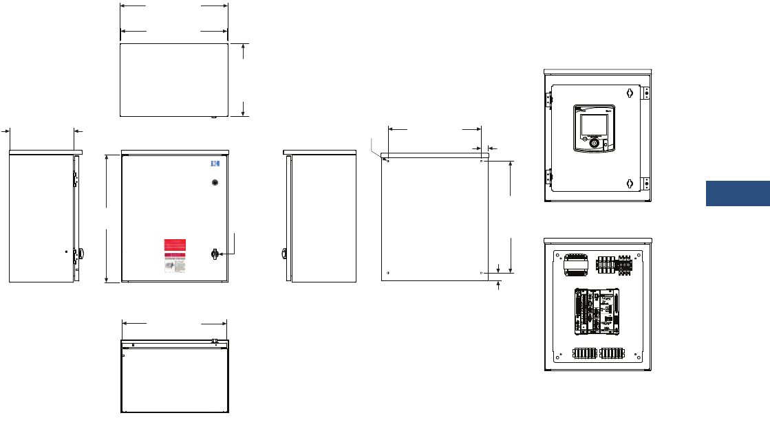
Volume 3—Power Distribution and Control Assemblies CA08100004E—March 2016 www.eaton.com V3-T9-139
9
9
9
9
9
9
9
9
9
9
9
9
9
9
9
9
9
9
9
9
9
9
9
9
9
9
9
9
9
9
9.2
Metering Devices, Protective Relays, Software and Connectivity
Metering Devices
Approximate Dimensions in Inches (mm)
NEMA 3R PXM 4000/6000/8000 Unit Enclosure
Top View
20.20 (513.1)
Top Width
20.00 (508.0)
Enclosure Width
13.70
(348.0)
Top
Depth
Left Side View Front View
Bottom View
Right Side View External Rear View
12.00 (304.8)
Enclosure
Depth
Front View (Door Removed)
Front View (Subpanel Only)
19.63 (498.6)
Door
24.00
(609.6)
1/4-Turn
Padlocking
Latch
21.00
(533.4)
Mounting
Height
4xø0.34 1.25
(31.8)
17.50 (444.5)
Mounting Width
1.50
(38.1)
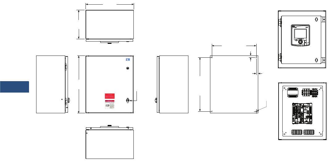
V3-T9-140 Volume 3—Power Distribution and Control Assemblies CA08100004E—March 2016 www.eaton.com
9
9
9
9
9
9
9
9
9
9
9
9
9
9
9
9
9
9
9
9
9
9
9
9
9
9
9
9
9
9
9.2
Metering Devices, Protective Relays, Software and Connectivity
Metering Devices
Approximate Dimensions in Inches (mm)
NEMA 4X PXM 4000/6000/8000 Unit Enclosure
Top View
20.00
(508.0)
12.00
(304.8)
Left Side View Front View
Bottom View
Right Side View External Rear View
Front View (Door Removed)
Front View (Subpanel Only)
24.00
(609.6)
1/4-Turn
Padlocking
Latch
22.50
(571.5)
Mounting
Height
4xø0.44
0.75
(19.1)
18.50 (469.9)
Mounting Width
0.75
(19.1)
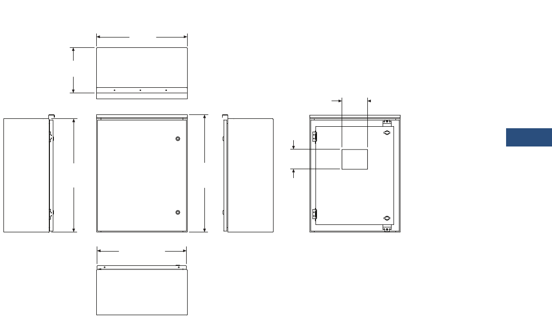
Volume 3—Power Distribution and Control Assemblies CA08100004E—March 2016 www.eaton.com V3-T9-141
9
9
9
9
9
9
9
9
9
9
9
9
9
9
9
9
9
9
9
9
9
9
9
9
9
9
9
9
9
9
9.2
Metering Devices, Protective Relays, Software and Connectivity
Metering Devices
Approximate Dimensions in Inches (mm)
NEMA 3R PXMP Multi Unit Enclosure
Right Side ViewFront ViewLeft Side View
Top View
Bottom View
12.00
(304.8)
24.00
(609.6)
23.63 (600.2)
Door
30.00
(762.0)
Enclosure
30.80
(782.3)
Overall
5.25
(133.4)
6.79
(172.5)
HMI
Cutout
Front View
(Door Removed)
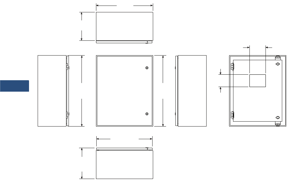
V3-T9-142 Volume 3—Power Distribution and Control Assemblies CA08100004E—March 2016 www.eaton.com
9
9
9
9
9
9
9
9
9
9
9
9
9
9
9
9
9
9
9
9
9
9
9
9
9
9
9
9
9
9
9.2
Metering Devices, Protective Relays, Software and Connectivity
Metering Devices
Approximate Dimensions in Inches (mm)
NEMA 4X PXMP Multi Unit Enclosure
30.00
(762.0)
Enclosure
Front View
(Door Removed)
Right Side ViewFront ViewLeft Side View
Top View
Bottom View
5.25
(133.4)
6.79
(172.5)
HMI
Cutout
12.00
(304.8)
24.00
(609.6)
13.07
(332.0)
Overall
23.63 (600.2)
Door
30.00
(762.0)
Overall

Volume 3—Power Distribution and Control Assemblies CA08100004E—March 2016 www.eaton.com V3-T9-143
9
9
9
9
9
9
9
9
9
9
9
9
9
9
9
9
9
9
9
9
9
9
9
9
9
9
9
9
9
9
9.3
Metering Devices, Protective Relays, Software and Connectivity
Protective Relays
Contents
Description Page
Product Selection Guide
Digitrip 3000 . . . . . . . . . . . . . . . . . . . . . . . . . . . . . V3-T9-149
EDR-3000 Feeder Protection. . . . . . . . . . . . . . . . . V3-T9-159
EDR-5000 Distribution Protection Relay . . . . . . . . V3-T9-168
FP-5000 Feeder Protection . . . . . . . . . . . . . . . . . . V3-T9-181
MP-3000 Motor Protection . . . . . . . . . . . . . . . . . . V3-T9-189
MP-4000 Motor Protection . . . . . . . . . . . . . . . . . . V3-T9-199
EMR-3000 Motor Protection Relay . . . . . . . . . . . . V3-T9-205
EMR-4000 Motor Protection Relay . . . . . . . . . . . . V3-T9-217
EMR-5000 Motor Protection Relay . . . . . . . . . . . . V3-T9-230
ETR-4000 Transformer Protection Relay . . . . . . . . V3-T9-242
ETR-5000 Transformer Protection Relay . . . . . . . . V3-T9-254
EGR-5000 Generation Protection Relay . . . . . . . . V3-T9-267
Ground Fault Relay . . . . . . . . . . . . . . . . . . . . . . . . V3-T9-280
Universal RTD Module . . . . . . . . . . . . . . . . . . . . . V3-T9-283
Product Selection Guide
Protective Relay Selection Chart
Protection Functions
Note
1Directional elements are controlled by reverse, forward, or both directions.
Description
IEEE Device
Number
Feeder Protection Motor Protection
Transformer
Protection
Generator
Protection
DT-3000 EDR-3000 EDR-5000 FP-5000 MP-3000 MP-4000 EMR-3000 EMR-4000 EMR-5000 ETR-4000 ETR-5000 EGR-5000
V3-T9-149 V3-T9-159 V3-T9-168 V3-T9-181 V3-T9-189 V3-T9-199 V3-T9-205 V3-T9-217 V3-T9-230 V3-T9-149 V3-T9-149 V3-T9-267
Phase inst. OC 50 ■■■■■■■■■■■■
Phase TOC 51 ■■■■■■■■■■■■
Ground inst. OC
(measured)
50G ■■■■■■■■■■■■
Ground TOC
(measured)
51G ■■■■■■■■■■■■
Ground inst. OC
(calculated)
50R ■■■ ■■■■■■
Ground TOC
(calculated)
51R ■■■ ■■■■■■
No. of curves
(ANSI/IEC/thermal)
11 11 11 10 11 11 11 11 11 11
Zone selective
interlocking
■■■■ ■■■■■■
Phase directional
control 1
67 ■■ ■■ ■■
Ground directional
control 1
67N ■■ ■■ ■■
Phase voltage
restrained OC
51VR ■■ ■■ ■■
Undervoltage 27 ■■■■■■■
Current unbalance 46 ■■■■■■■■ ■■

V3-T9-144 Volume 3—Power Distribution and Control Assemblies CA08100004E—March 2016 www.eaton.com
9
9
9
9
9
9
9
9
9
9
9
9
9
9
9
9
9
9
9
9
9
9
9
9
9
9
9
9
9
9
9.3
Metering Devices, Protective Relays, Software and Connectivity
Protective Relays
Protection Functions, continued
Note
1When communicating to an external URTD device.
Description
IEEE Device
Number
Feeder Protection Motor Protection
Tran sfor mer
Protection
Generator
Protection
DT-3000 EDR-3000 EDR-5000 FP-5000 MP-3000 MP-4000 EMR-3000 EMR-4000 EMR-5000 ETR-4000 ETR-5000 EGR-5000
V3-T9-149 V3-T9-159 V3-T9-168 V3-T9-181 V3-T9-189 V3-T9-199 V3-T9-205 V3-T9-217 V3-T9-230 V3-T9-149 V3-T9-149 V3-T9-267
Voltage unbalance 47 ■■■■■■■
Power factor 55 ■■■■■ ■
Overvoltage 59 ■■■■■■■
Frequency (over/under) 81 ■■■■■■■
Rate of change of
frequency
81R ■■■■■■■
Vector surge 78V ■■■■■
Forward/reverse power 32 ■■■ ■■ ■■
Forward/reverse VARs 32V ■■■■■
Sync check 25 ■■ ■
Reclosing 79 ■■■
Ground overvoltage 59N ■ ■
Thermal overload 149 ■■■■■■■■
Underload 37 ■■■
Locked rotor 49S/51 ■■■■■
Jam/stall 51R ■■■■■
Incomplete sequence 48 ■■■■■
Number of starts limit ■■■■■
Starts per hour 66 ■■■■■
Time between starts ■■■■■
Long acceleration time ■■■■■
Emergency override ■■■■■
Broken rotor bar
detection
■■
Loss of potential 60LOP ■■ ■■
Current transformer
supervision
■■ ■■■■■■
Cold load pickup ■■■ ■■■■■
Switch on to fault ■■ ■■
Breaker failure 50BF ■■■ ■■■■■■
2nd harmonic restraint ■■
4th harmonic restraint ■■
5th harmonic restraint ■■
Differential 87 ■■■■
Ground differential 87GD ■■■
Trip lock out 86 ■■■■■■■■■■■■
Negative sequence
current
51Q ■■■
External protection ■■ ■■■■■■■■
Overexcitation (Volts/Hz) 24 ■■
Loss of field 40 ■
Low voltage ride-through 27T ■■■
Reactive power and
undervoltage
27Q ■■■
Inadvertent energization 50/27 ■

Volume 3—Power Distribution and Control Assemblies CA08100004E—March 2016 www.eaton.com V3-T9-145
9
9
9
9
9
9
9
9
9
9
9
9
9
9
9
9
9
9
9
9
9
9
9
9
9
9
9
9
9
9
9.3
Metering Devices, Protective Relays, Software and Connectivity
Protective Relays
Control Functions
Description
IEEE Device
Number
Feeder Protection Motor Protection
Transformer
Protection
Generator
Protection
DT-3000 EDR-3000 EDR-5000 FP-5000 MP-3000 MP-4000 EMR-3000 EMR-4000 EMR-5000 ETR-4000 ETR-5000 EGR-5000
V3-T9-149 V3-T9-159 V3-T9-168 V3-T9-181 V3-T9-189 V3-T9-199 V3-T9-205 V3-T9-217 V3-T9-230 V3-T9-149 V3-T9-149 V3-T9-267
Remote open/close ■■■■
Open only Open only ■■■■ ■■
Programmable I/O ■■■■■■■ ■■■ ■■
Digital inputs 1 4 or 8 8 8 2 2 4 8 8 or 16 8 8 8 or 16
Relay outputs 2 3 or 5 10 6 4 4 3 4 8 8 8 8
Supervisory/alarm
output
1111111 111 11
Programmable logic
control
■■■ ■ ■ ■ ■ ■■
Multiple settings
groups
444 4 4 4 4 44
Adaptive parameters ■■ ■ ■ ■ ■ ■■
Reduced voltage
starting
■■■ ■■
Analog outputs 1 1 4 Option
for 2
Option
for 2
Option
for 2
Analog inputs Option
for 2
Option
for 2
Option
for 2

V3-T9-146 Volume 3—Power Distribution and Control Assemblies CA08100004E—March 2016 www.eaton.com
9
9
9
9
9
9
9
9
9
9
9
9
9
9
9
9
9
9
9
9
9
9
9
9
9
9
9
9
9
9
9.3
Metering Devices, Protective Relays, Software and Connectivity
Protective Relays
Metering Functions
Description
IEEE Device
Number
Feeder Protection Motor Protection
Transformer
Protection
Generator
Protection
DT-3000 EDR-3000 EDR-5000 FP-5000 MP-3000 MP-4000 EMR-3000 EMR-4000 EMR-5000 ETR-4000 ETR-5000 EGR-5000
V3-T9-149 V3-T9-159 V3-T9-168 V3-T9-181 V3-T9-189 V3-T9-199 V3-T9-205 V3-T9-217 V3-T9-230 V3-T9-149 V3-T9-149 V3-T9-267
Amperes ■■■■ ■■ ■■■ ■■
Ampere demand ■■■■ ■■ ■■■ ■■
Voltage (L-N and L-L) ■■ ■ ■ ■ ■■
Phase angle ■■■ ■■ ■ ■ ■ ■■
Pos., neg. and zero
sequence
■■■ ■■ ■ ■ ■ ■■
Watts ■■ ■ ■ ■ ■■
Watt demand ■■ ■ ■ ■ ■■
Watthour ■■ ■ ■ ■ ■■
VARs ■■ ■ ■ ■ ■■
VAR demand ■■ ■ ■ ■ ■■
VAR-hour ■■ ■ ■ ■ ■■
VA ■■ ■ ■ ■ ■■
VA Demand ■■ ■ ■ ■ ■■
VA-hour ■■ ■ ■ ■ ■■
Frequency ■■ ■ ■ ■ ■■
Minimum/maximum
recording
■■■ Max. only Max. only ■■■■ ■■
Current unbalance ■■ ■ ■■ ■ ■ ■ ■■
Voltage unbalance ■■■■■■
Power factor ■■ ■ ■ ■ ■■
Sync values ■ ■
Differential currents ■■ ■■
2nd, 4th, 5th harmonic
currents
■■
3rd harmonic voltage ■
THD current ■■■ ■■ ■ ■ ■ ■■
THD voltage ■■ ■ ■ ■ ■■
Volt/Hertz ■■ ■■
Thermal capacity ■■■ ■
Generator hours of
operation
■

Volume 3—Power Distribution and Control Assemblies CA08100004E—March 2016 www.eaton.com V3-T9-147
9
9
9
9
9
9
9
9
9
9
9
9
9
9
9
9
9
9
9
9
9
9
9
9
9
9
9
9
9
9
9.3
Metering Devices, Protective Relays, Software and Connectivity
Protective Relays
Monitoring Functions
Communications
Notes
1When communicating to an external URTD device.
2Option available beginning in late 2015.
Description
IEEE Device
Number
Feeder Protection Motor Protection
Transformer
Protection
Generator
Protection
DT-3000 EDR-3000 EDR-5000 FP-5000 MP-3000 MP-4000 EMR-3000 EMR-4000 EMR-5000 ETR-4000 ETR-5000 EGR-5000
V3-T9-149 V3-T9-159 V3-T9-168 V3-T9-181 V3-T9-189 V3-T9-199 V3-T9-205 V3-T9-217 V3-T9-230 V3-T9-149 V3-T9-149 V3-T9-267
Trip circuit monitor 74 ■■■ ■ ■ ■ ■ ■■
Breaker wear ■■■ ■ ■ ■ ■ ■■
Fault recorder ■■■ ■ ■ ■ ■ ■■
Waveform recorder ■■■ ■ ■ ■ ■ ■■
Sequence of events
recorder
■■■ ■ ■ ■ ■ ■ ■ ■■
Trend recorder (load
profile)
■■■ ■ ■ ■ ■ ■■
Clock ■■■ ■ ■ ■ ■ ■ ■ ■■
Time synchronization ■■ ■ ■ ■ ■ ■■
RTD temperature 1■■■ ■■■ ■■
Hottest RTD 1■■■ ■■■ ■■
Description
IEEE Device
Number
Feeder Protection Motor Protection
Transformer
Protection
Generator
Protection
DT-3000 EDR-3000 EDR-5000 FP-5000 MP-3000 MP-4000 EMR-3000 EMR-4000 EMR-5000 ETR-4000 ETR-5000 EGR-5000
V3-T9-149 V3-T9-159 V3-T9-168 V3-T9-181 V3-T9-189 V3-T9-199 V3-T9-205 V3-T9-217 V3-T9-230 V3-T9-149 V3-T9-149 V3-T9-267
Front access interface
Local human machine
interface
■■■■■■■ ■■■ ■■
RS-232 ■■■ ■ ■ ■ ■ ■■
USB 22 2 2 2 2 22
Rear communication
port interface
RS-485 ■Option Option ■Option Option Option Option Option Option
Ethernet copper (RJ45) Option Option Option Option Option Option Option Option
Fiber optic ST (note) 22 2 2 2 2 22
Fiber optic LC (note) 22 2 2 2 2 22
Protocol
INCOM ■Option Option Option
Modbus-RTU ■Option Option Option Option Option Option Option Option Option Option Option
Modbus-TCP Option Option Option Option Option Option Option Option
IEC 61850 Option Option Option Option Option Option Option Option
DNP 3.0 (note) 22 2 2 2 2 22
PROFIBUS (note) 22 2 2 2 2 22
IRIG-B Option ■■■■■■■
SNTP Option Option Option Option Option Option Option Option

V3-T9-148 Volume 3—Power Distribution and Control Assemblies CA08100004E—March 2016 www.eaton.com
9
9
9
9
9
9
9
9
9
9
9
9
9
9
9
9
9
9
9
9
9
9
9
9
9
9
9
9
9
9
9.3
Metering Devices, Protective Relays, Software and Connectivity
Protective Relays
Construction
Standards
Description
IEEE
Device
Number
Feeder Protection Motor Protection
Transformer
Protection
Generator
Protection
DT-3000 EDR-3000 EDR-5000 FP-5000 MP-3000 MP-4000 EMR-3000 EMR-4000 EMR-5000 ETR-4000 ETR-5000 EGR-5000
V3-T9-149 V3-T9-159 V3-T9-168 V3-T9-181 V3-T9-189V3-T9-199V3-T9-205 V3-T9-217 V3-T9-230 V3-T9-149 V3-T9-149 V3-T9-267
Panel mount
case
■Semi-flush or
projected
Semi-flush or
projected
■■■
Semi-flush or
projected
Semi-flush or
projected
Semi-flush or
projected
Semi-flush or
projected
Semi-flush or
projected
Semi-flush or
projected
Drawout
case
Option Removable
terminals
Removable
terminals
Option Option Option Removable
terminals
Removable
terminals
Removable
terminals
Removable
terminals
Removable
terminals
Removable
terminals
Self-shorting
CT terminals
■■ ■■■■■■
Operating
temperature
range
–30 to +55
°C
–40 to
+60 °C
–40 to
+60 °C
–40 to +60
°C
–20 to
+60 °C
–20 to
+60 °C
–40 to
+60 °C
–40 to
+60 °C
–40 to
+60 °C
–40 to
+60 °C
–40 to
+60 °C
–40 to
+60 °C
Power supply
range (Vac)
120–240
Vac
40–
250 Vac
40–
250 Vac
48–
125 Vdc
90–
264 Vac
90–
264 Vac
40–
250 Vac
40–
250 Vac
40–
250 Vac
40–
250 Vac
40–
250 Vac
40–
250 Vac
Power supply
range (Vdc)
24–250
Vdc
19–
300 Vdc
19–
300 Vdc
48–
125 Vdc
19–
300 Vdc
19–
300 Vdc
19–
300 Vdc
19–
300 Vdc
19–
300 Vdc
19–
300 Vdc
AC current
inputs
■■ ■ ■ ■■■ ■ ■ ■ ■ ■
AC voltage
inputs
■■ ■ ■ ■ ■ ■
Wye VT
configuration
■■ ■ ■ ■ ■ ■
Open delta VT
configuration
■■ ■ ■ ■ ■ ■
Sensitive
ground
50/51G Option Option Option Option Option Option Option Option
Local display /
HMI
■
Backlit LCD
w/8
pushbuttons
Backlit LCD
w/8
pushbuttons
■■■
Backlit LCD
w/8
pushbuttons
Backlit LCD
w/8
pushbuttons
Backlit LCD
w/8
pushbuttons
Backlit LCD
w/8
pushbuttons
Backlit LCD
w/8
pushbuttons
Backlit LCD
w/8
pushbuttons
LEDs (local
targets)
■
Programmable Programmable
■■■
Programmable Programmable Programmable Programmable Programmable Programmable
Description
IEEE Device
Number
Feeder Protection Motor Protection
Transformer
Protection
Generator
Protection
DT-3000 EDR-3000 EDR-5000 FP-5000 MP-3000 MP-4000 EMR-3000 EMR-4000 EMR-5000 ETR-4000 ETR-5000 EGR-5000
V3-T9-149 V3-T9-159 V3-T9-168 V3-T9-181 V3-T9-189 V3-T9-199 V3-T9-205 V3-T9-217 V3-T9-230 V3-T9-149 V3-T9-149 V3-T9-267
ANSI ■ ■■■ ■ ■■ ■ ■ ■ ■■
IEC ■ ■■■ ■ ■ ■ ■ ■ ■ ■■
UL ■ ■■■ ■ ■ ■ ■ ■ ■ ■■
CE DT-3030 only ■■■ ■ ■ ■ ■ ■■
CSA ■ ■■■ ■ ■ ■ ■ ■ ■ ■■
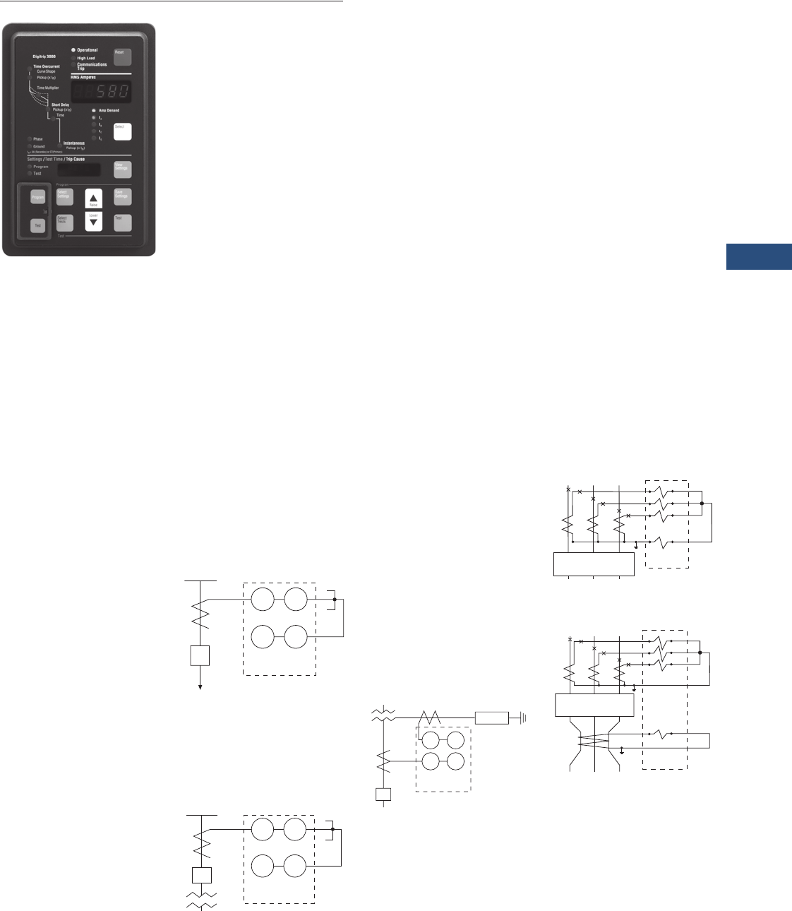
Volume 3—Power Distribution and Control Assemblies CA08100004E—March 2016 www.eaton.com V3-T9-149
9
9
9
9
9
9
9
9
9
9
9
9
9
9
9
9
9
9
9
9
9
9
9
9
9
9
9
9
9
9
9.3
Metering Devices, Protective Relays, Software and Connectivity
Protective Relays
DT-3000
Contents
Description Page
Product Selection Guide . . . . . . . . . . . . . . . . . . . . V3-T9-143
Digitrip 3000
EDR-3000 Feeder Protection. . . . . . . . . . . . . . . . . V3-T9-159
EDR-5000 Distribution Protection Relay . . . . . . . . V3-T9-168
FP-5000 Feeder Protection . . . . . . . . . . . . . . . . . . V3-T9-181
MP-3000 Motor Protection . . . . . . . . . . . . . . . . . . V3-T9-189
MP-4000 Motor Protection . . . . . . . . . . . . . . . . . . V3-T9-199
EMR-3000 Motor Protection Relay . . . . . . . . . . . . V3-T9-205
EMR-4000 Motor Protection Relay . . . . . . . . . . . . V3-T9-217
EMR-5000 Motor Protection Relay . . . . . . . . . . . . V3-T9-230
ETR-4000 Transformer Protection Relay . . . . . . . . V3-T9-242
ETR-5000 Transformer Protection Relay . . . . . . . . V3-T9-254
EGR-5000 Generation Protection Relay . . . . . . . . V3-T9-267
Ground Fault Relay . . . . . . . . . . . . . . . . . . . . . . . . V3-T9-280
Universal RTD Module . . . . . . . . . . . . . . . . . . . . . V3-T9-283
Digitrip 3000
Product Description
●Microprocessor-based,
three-phase and ground
overcurrent relay
●Independent phase and
ground measuring circuits
and operation
●Inverse time (51), short
delay (50, 2) and
instantaneous (50)
protection
●Eleven time overcurrent
characters including ANSI,
IEC and thermal protection
curves
●Phase and ground
ampmeter and peak
demand functions
●INCOM communication
port
●Fixed mount or optional
quick release drawout
case design
●Dual-source power supply
option for AC control
power applications
Application Description
Eaton’s Digitrip 3000
microprocessor-based relay
provides reliable three-phase
and ground overcurrent
protection for all voltage
levels. It can be used for
any application where
instantaneous and/or time
overcurrent protection
is required. It is most
commonly used as primary
feeder circuit protection,
see figure below.
Primary Feeder
Circuit Protection
The Digitrip 3000 may be
applied as the transformer
primary protection or as
backup to the differential
protection, see figure below.
Transformer Overcurrent
Protection
The Digitrip 3000 may be
connected to the secondary
side of a delta-wye grounded
transformer with the ground
element connected to a
separate CT in the neutral
connection of the
transformer. With this
connection, a lower CT ratio
and a pickup setting can
be used to provide more
sensitive ground fault
protection especially for
resistance grounded
systems, see figure below.
Transformer Secondary
Protection with Neutral
CT Connection
The Digitrip 3000 ground
overcurrent element can be
connected in the residual
circuit of the phase CTs as
shown in the top figure or
to a separate ground CT as
shown in last figure.
Residual Ground
Connection
Separate Zero Sequence
Ground CT Connection
50 51
50G 51G
CB
52 Digitrip
3000
Load
50 51
50G 51G
CB
Digitrip
3000
5
0
G
5
1
G
5
0
5
1
Di
g
itrip
3
000
R
esist
or
C
B
a
b
c
GND
Digitrip
3000
CB-52
A1 A2
B1 B2
C1 C2
G1 G2
50N/51N
CB-52
a
b
c
GND
Digitrip
3000
A1 A2
B1 B2
C1 C2
G1 G2
50/51
50G/51G
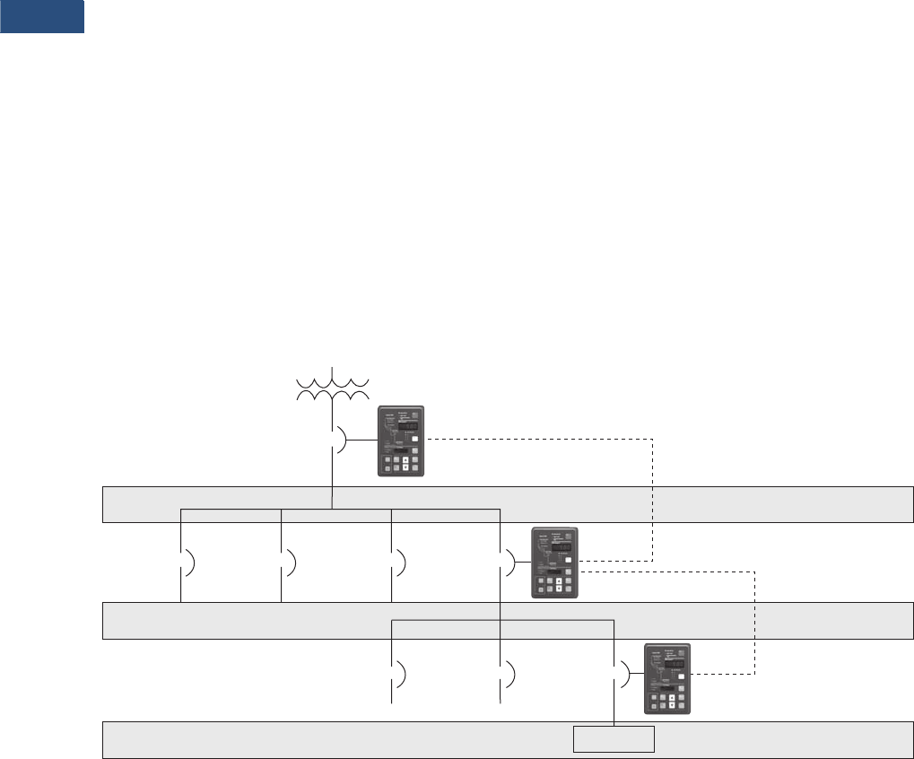
V3-T9-150 Volume 3—Power Distribution and Control Assemblies CA08100004E—March 2016 www.eaton.com
9
9
9
9
9
9
9
9
9
9
9
9
9
9
9
9
9
9
9
9
9
9
9
9
9
9
9
9
9
9
9.3
Metering Devices, Protective Relays, Software and Connectivity
Protective Relays
Zone Selective Interlocking (Phase and Ground)
Note: For the phase time
overcurrent element, the current
sensed by the Digitrip 3000 must
exceed 300% (3 x In) for the zone
selective interlocking to initiate an
immediate trip signal.
Zone Selective interlocking
is a protection function to
minimize equipment damage
resulting from a phase or a
ground fault in an area where
long-time and/or short-time
delay is in use.
When the “Ground Zone
Interlocking” feature is
utilized, an immediate trip
is initiated when the fault
is in the breaker’s zone of
protection, regardless of its
preset time delay. When the
“Phase Zone Interlocking”
feature is utilized, the time
overcurrent and short delay
phase elements work as
follows. The short delay
phase element will initiate an
immediate trip when the fault
is in the breaker’s zone of
protection, regardless of its
preset time delay. For the
time overcurrent phase
element, the current sensed
by the Digitrip 3000 must
exceed 300% (3 x In) for the
zone selective interlocking
to initiate an immediate trip
signal when the fault is in the
breaker’s zone of protection.
Upstream Digitrip 3000
protected breakers are
restrained from tripping
immediately by an
interlocking signal from the
downstream Digitrip 3000
relay. This interlocking signal
requires only a pair of wires
from the downstream breaker
to the upstream breaker.
The Upstream Digitrip 3000
provides time delayed
standard coordinated
tripping when the fault is
located outside the zone
of protection.
In the sample zone
interlocking system shown
below, circuit breakers A, B
and C are equipped with
Digitrip 3000 overcurrent
relays.
Fault Location Zone 3
Note: For the phase time
overcurrent element, the current
sensed by the Digitrip 3000 must
exceed 300% (3 x In) for the zone
selective interlocking to initiate an
immediate trip signal.
If a fault occurs at a point in
Zone 3, the Digitrip 3000 of
Downstream Breaker C
senses the fault and sends
a restraining signal to the
upstream Digitrip 3000 of
Feeder Breaker B.
Having received this signal,
the Digitrip 3000 of Feeder
Breaker B begins timing for
normal final delay tripping. As
a result, only Downstream
Breaker C is tripped.
Fault Location Zone 2
Note: For the phase time
overcurrent element, the current
sensed by the Digitrip 3000 must
exceed 300% (3 x In) for the zone
selective interlocking to initiate an
immediate trip signal.
If a fault occurs at a point in
Zone 2, the Digitrip 3000 of
Feeder Breaker B senses the
fault and sends a restraining
signal to the upstream
Digitrip 3000 of Main
Breaker A.
The Digitrip 3000 of the
Downstream Breaker C does
not see this fault since it is
situated on the downstream
side of the fault.
As a result, the Digitrip 3000
of Downstream Breaker C
does not send a restraining
signal to the Digitrip 3000 of
Feeder Breaker B.
Because there is no
restraining signal from the
Digitrip 3000 of Downstream
Breaker C, the Digitrip 3000 of
Feeder Breaker B identifies
that the fault is in Zone 2
and immediately trips Feeder
Breaker B, regardless of its
time setting.
Fault Location Zone 1
Note: For the phase time
overcurrent element, the current
sensed by the Digitrip 3000 must
exceed 300% (3 x In) for the zone
selective interlocking to initiate an
immediate trip signal.
If a fault occurs in Zone 1, no
restraining signal is received
by the Digitrip of Main
Breaker A. As a result, Main
Breaker A is immediately
tripped by its Digitrip
overcurrent relay, regardless
of its time setting.
Sample Zone Selective Interlocking System
Main
Breaker
“A”
Feeder
Breaker
“B”
Downstream
Breaker
“C”
Interlocking
Wire
LOAD
Zone 1
Zone 2
Zone 3

Volume 3—Power Distribution and Control Assemblies CA08100004E—March 2016 www.eaton.com V3-T9-151
9
9
9
9
9
9
9
9
9
9
9
9
9
9
9
9
9
9
9
9
9
9
9
9
9
9
9
9
9
9
9.3
Metering Devices, Protective Relays, Software and Connectivity
Protective Relays
Features, Benefits and Functions
●Complete current
protection and metering
in a single compact case
reduces panel space, wiring
and cost
●Selectable trip
characteristics simplify
ordering and reduces
inventory
●Optional drawout case
provides easy and quick
removal and replacement
of the relay
●Optional dual-source
power supply provides
reliable protection when
applied with ac control
power, eliminating the
need for batteries or UPS
●Integral ampmeter and
display replaces separate
meter and switch, saving
panel space, wiring and
money
●Zone selective interlocking
improves coordination and
tripping times and can save
money by using in place of
traditional bus differential
●Integral test function and
microprocessor design can
reduce maintenance time
and expense
Standards and Certifications
●UL recognized
●UL 1053 recognized
●ANSI C37.90
●ANSI C37.90.1 (1989)
●ANSI C37.90.2 (1995)
Note: Fixed case versions meet
35 V/m. Drawout case versions
meet 28 V/m.
●IEC 255
●CE (DT3030/3031
version only)

V3-T9-152 Volume 3—Power Distribution and Control Assemblies CA08100004E—March 2016 www.eaton.com
9
9
9
9
9
9
9
9
9
9
9
9
9
9
9
9
9
9
9
9
9
9
9
9
9
9
9
9
9
9
9.3
Metering Devices, Protective Relays, Software and Connectivity
Protective Relays
Product Selection
DT-3000
Options and Accessories
Additional Products by Eaton’s Cutler-Hammer Series
Dual-Source Power
Supply Option
The Digitrip 3000 with Dual-
Source Power Supply (DSPS)
is available in two versions,
DT-3010 and DT-3020. They
include an integral power
supply module that:
●Powers the relay from
nominal 120 Vac, 50/60 Hz
(DT-3010 model) or 240
Vac, 50/60 Hz (DT-3020
model) auxiliary power,
which is normally
connected and available.
●Operates solely from the
main current transformers
(CTs) during a fault if
the normally connected
auxiliary ac voltage is
not available, like an
electromechanical relay
or an electronic “self-
powered” relay
Functional Description
The integral Dual-Source
Power Supply (DSPS)
contains one AC voltage
transformer and three AC
current transformers. The AC
voltage transformer is used to
supply nominal ac control
power to the unit. The current
transformers are used to
power the unit from the line
current. Normally, the unit
will operate from the AC
auxiliary voltage.
Because this voltage is
usually obtained from the
system containing the circuit
that the relay is protecting, a
fault on the protected line
could cause the AC voltage
to drop below an acceptable
operating level. Below
approximately 70 volts for
DT-3010 or 140 volts for
DT-3020, the DSPS switches
over to current powering.
All three current transformer
secondaries are connected in
series to supply this power.
The DSPS will supply enough
power to operate the Digitrip
3000 overcurrent relay in the
tripped state with currents
greater than 1.8 per unit rated
secondary current, or 9 A, in a
single-phase. The DSPS will
operate with three-phase
currents in a tripped state
with currents greater than
1.2 per unit or 6 A rated
secondary current.
Note: There will be no effect
to the DT-3000 relay trip time
accuracy when the Dual-Source
Power Supply switches from
normal ac voltage to fault-
current power.
Burden Data
In normal operating
conditions, the burden is
<0.08 ohms with three-phase
1 A CT current, or 0.2 per
unit, and drops to less than
0.04 ohms at high current
levels. Present CT burden
data in ohms and volt-
amperes, see
Page V3-T9-154
.
In these cases, the burden
shown is the total CT terminal
value, which is the DSPS plus
the relay measuring circuits,
for the indicated operating
condition.
The trip curve on Page V3-
T9-154, right, shows burden
impedance magnitude in
ohms. The two lower curves
are the values with AC power
applied; the upper two are
with CT powering only. For
each of these pairs, one
curve shows the burden
for a single-phase current
(representing a single-phase-
to-ground fault) and the other
for three balanced phases
with normally arrayed
120-degree phase angle
increments. There is no
phase sequence sensitivity.
Page V3-T9-154, trip curve,
upper left, shows the burden
in volt-amperes for the same
four cases.
Digitrip 3000 Optional
Drawout Case
The Digitrip 3000 overcurrent
protective relay is available
in a new drawout case for
quick release, removal and
replacement of the unit
without disruption of the
wiring. The CT circuits are
self-shortening to prevent
damaging voltages from
existing across-the-current
transformer windings. All
voltage inputs, discrete
inputs and contact inputs
are disconnected while
maintaining security against
false tripping.
The terminal blocks feature
a two-stage disconnect
operation. Removal of the
DT-3000 Inner Chassis will
disconnect the trip circuits
and short the CT secondaries
before the unit control power
is disconnected. Upon
insertion of the Inner
Chassis, the control power
connections are made before
the trip circuits are activated.
This feature provides
added security against
false tripping.
Description
Catalog
Number
DT-3000 protective relay DT3000
DT-3000 protective relay Chicago version DT3100
DT-3030 protective relay (24–48 Vdc CE Mark version) DT3030
DT-3000 drawout case protective relay DT3001
DT-3000 Chicago version drawout case protective relay DT3101
DT-3030 drawout case protective relay (24–48 Vdc CE Mark version) DT3031
DT-3000 protective relay with 120 Vac dual-source power supply DT3010
DT-3000 protective relay with 240 Vac dual-source power supply DT3020
DT-3000

Volume 3—Power Distribution and Control Assemblies CA08100004E—March 2016 www.eaton.com V3-T9-153
9
9
9
9
9
9
9
9
9
9
9
9
9
9
9
9
9
9
9
9
9
9
9
9
9
9
9
9
9
9
9.3
Metering Devices, Protective Relays, Software and Connectivity
Protective Relays
Technical Data and Specifications
Current Inputs
●CTs: 5 A secondary
●CT Burden:
●<0.004 ohm at rated
current (5 A)
●<0.1 VA at rated
current (5 A)
●In: 5 A (Secondary) or
CT (Primary)
●Saturation: 30 x In
●CT thermal ratings:
●10 A continuous
●500 A for 1 second
CT (Primary) Settings Available
●Phase and ground:
5/10/25/50/75/100/150/200/
250/300/400/500/600/630/
800/1000/1200/1250/1500/
1600/2000/2400 2500/
3000/3200/4000/5000
Input Voltage DT-3000
●Nominal:
●48–250 Vdc
●120–240 Vac 50/60 Hz
●Operating range:
●28–280 Vdc
●90–254 Vac 50/60 Hz
Power Consumption
Input Voltage Digitrip 3030/
3031
Output Trip Contacts
(Trip OC/Comm., Trip Inst.
and Comm. Close)
●Momentary:
●Make 30 A AC/DC for
0.25 seconds
●Break 0.25 A at 250 Vdc
●
Break 5 A at 120/240 Vac
●Continuous:
●5 A at 120/240 Vac
●5 A at 30 Vdc
●Meets ANSI C37.90,
Paragraph 6.7
Environmental Conditions
●Operating temperature:
–22 ºF to +131 ºF
(–30 ºC to +55 °C)
●Operating humidity:
0–95% relative humidity
(noncondensing)
●Storage temperature:
–40 ºF to +185 ºF
(–40 °C to +70 °C)
Auxiliary Alarm Contacts
●
5 A continuous at
120/240 Vac, 30 Vdc
●5 A break at 120/240 Vac,
30 Vdc
Tests
●Dielectric strength,
current inputs:
●3000 Vac for 1 minute
●Phase-to-phase
●Seismic test: Meets
requirements for UBC® and
California Building Code
Zone 4. ZPA = 3.5
Phase and Ground
Time-Current Curves
●Thermal:
●It (Moderately Inverse)
●I2t (Very Inverse)
●I4t (Extremely lnverse)
●FLAT (Definite Time)
●ANSI (Per ANSI C37.112,
1996):
●Moderately Inverse
●Very Inverse
●Extremely Inverse
●IEC (Per IEC 255-3, 1989):
●IEC-A (Moderately
Inverse)
●IEC-B (Very Inverse)
●IEC-C (Extremely
Inverse)
●IEC-D (Definite Time)
Overcurrent Functions
and Pickup Ranges
Note: Consult factory for
sensitive ground fault.
●Long Delay or Inverse
Time Overcurrent:
●Phase: (0.2–2.2) x In
(29 settings)
●Ground: (0.1–2.0) x In,
None (26 settings)
●Short Delay:
●Phase: (1–11) x In,
None (25 settings)
●Ground: (0.1–11) x In,
None (45 settings)
●Instantaneous:
●Phase: (1–25) x In,
None (30 settings)
●Ground: (0.5–11) x In,
None (33 settings)
Time Delay Settings
●Inverse Time Overcurrent
Time Multiplier:
●Thermal: 0.2–40
(47 settings)
●FLAT: 0.2–2 (21 settings)
●ANSI (all): 0.1–5.0
(50 settings)
●IEC (all): 0.05–1.00
(20 settings)
●Short Delay Time: 0.05–
1.5 seconds (22 settings)
Current Monitoring
Note: Consult factory for
sensitive ground fault.
●True rms sensing: three-
phase and ground
●Display accuracy:
●±1% of Full Scale [ln]
from 0.04 x ln to 1 x In
●±2% of Full Scale [ln]
from 1 x ln to 2 x In
●Ampere demand: Average
demand over 5 minute
sampling window
●High load (with selectable
output): 85% of Inverse
Time Overcurrent setting
Timing Accuracy
●Inverse Time Overcurrent:
±10% at >1.5 x Pickup
●Short Delay Time: ±50 ms
Communications
●
Eaton’s PowerNet
Compatible
●Built-in INCOM
●Data rate is 1200 or
9600 baud
Drawout Case
●Refer to Page V3-T9-157
for Drawout Case
Dimensions
Terminal Block
●Make/Break rating:
●10 A at 240 Vac nominal
●0.25 A at 280 Vdc
maximum
●Terminal wire gauge:
No. 14 to No. 10 AWG
●Screw torque
requirements: 18-inch-
pounds
Reference Information
Cross-Reference
There are several products
that are equivalent to the
Digitrip 3000. The
following
lists the competitor’s name and
equivalent product to the
Digitrip 3000. In general, the
Digitrip 3000 can be used in
place of the competitive
product.
●ABB® MMCO, 51
●Basler Electric® BEI-51
●GE Multilin MDP, 735, 737
●Siemens® 7SJ 511, 7SJ 60
24 48 125 250 120 240
Vdc
10 W
Vdc
10 W
Vdc
10 W
Vdc
10 W
Vac
10 VA
Vac
18 VA
Description DT-3010 DT-3020
Nominal 120 Vac 240 Vac
Operating
Range
70–132 Vac 140–264 Vac
Power
Consumption
15 VA 15 VA
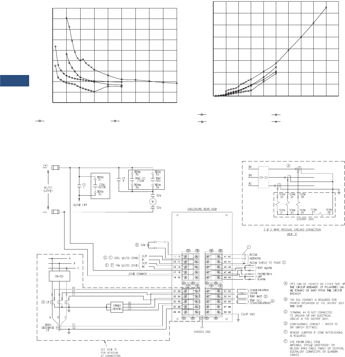
V3-T9-154 Volume 3—Power Distribution and Control Assemblies CA08100004E—March 2016 www.eaton.com
9
9
9
9
9
9
9
9
9
9
9
9
9
9
9
9
9
9
9
9
9
9
9
9
9
9
9
9
9
9
9.3
Metering Devices, Protective Relays, Software and Connectivity
Protective Relays
Trip Curve Charts
Digitrip 3000 With Dual-Source Power Supply
Burden Curves
Digitrip 3000 With Dual-Source Power Supply CT Power
Volt-Ampere Curves
Wiring Diagrams
Digitrip 3001
Typical wiring diagram for the fixed mount version.
CT Burden — Z, Ohms
0
0.02
0.04
0.06
0.08
0.1
0.12
0.14
0.16
0.18
0 5 10 15 20 25 30 35 40 45
CT Current — Amperes
Total Burden, With Vac, 3-Phase I Total Burden, With Vac, 1-Phase I
CT Power in Volt-Amperes
CT Current — Amperes
CT Power in VA, With Vac, 3-Phase I
CT Power in VA, No Vac, 3-Phase I
0
10
20
30
40
50
60
70
80
0 5 10 15 20 25 30 35 40 45 50
CT Power in VA, With Vac, 1-Phase I
CT Power in VA, No Vac, 1-Phase I
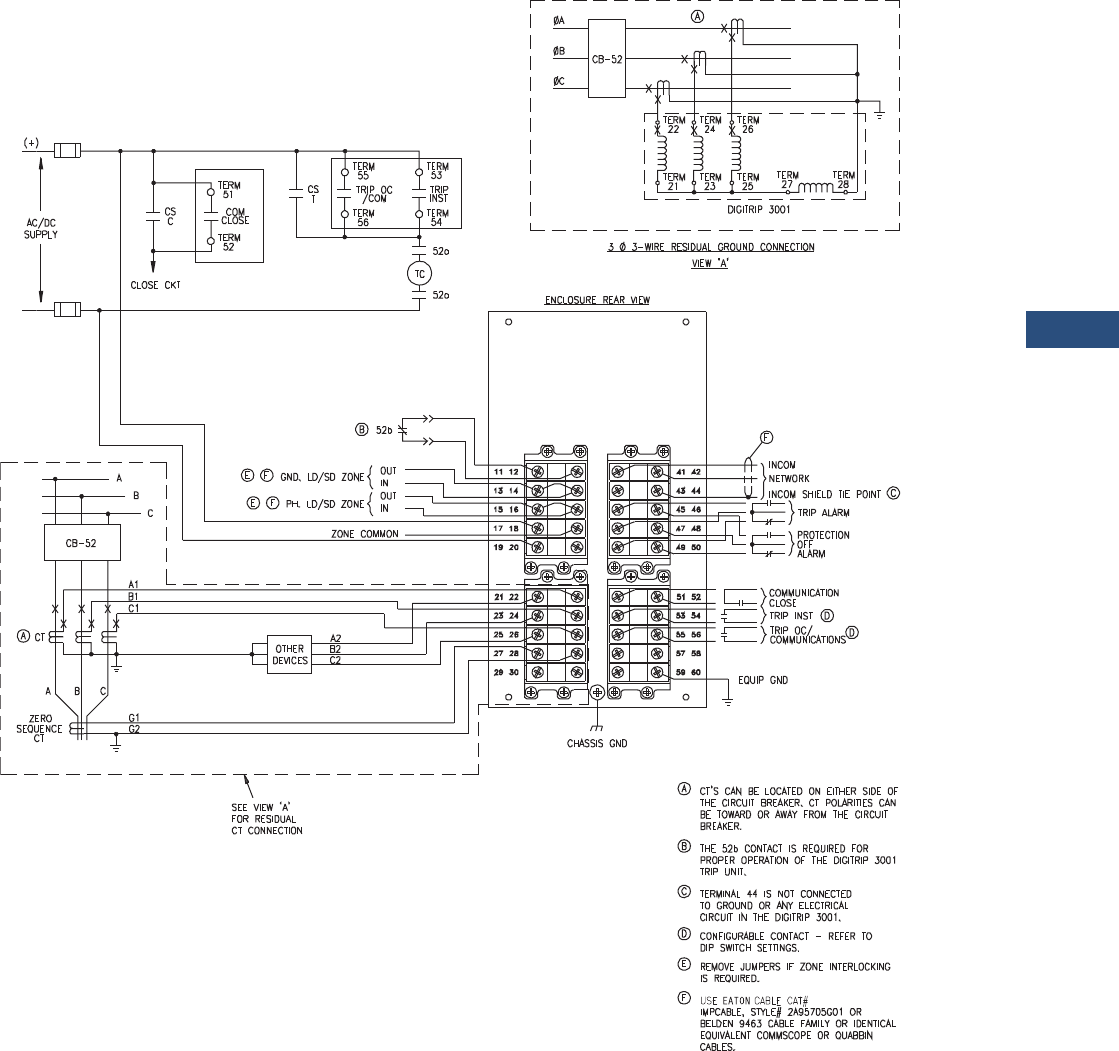
Volume 3—Power Distribution and Control Assemblies CA08100004E—March 2016 www.eaton.com V3-T9-155
9
9
9
9
9
9
9
9
9
9
9
9
9
9
9
9
9
9
9
9
9
9
9
9
9
9
9
9
9
9
9.3
Metering Devices, Protective Relays, Software and Connectivity
Protective Relays
Digitrip 3000 Typical Wiring System
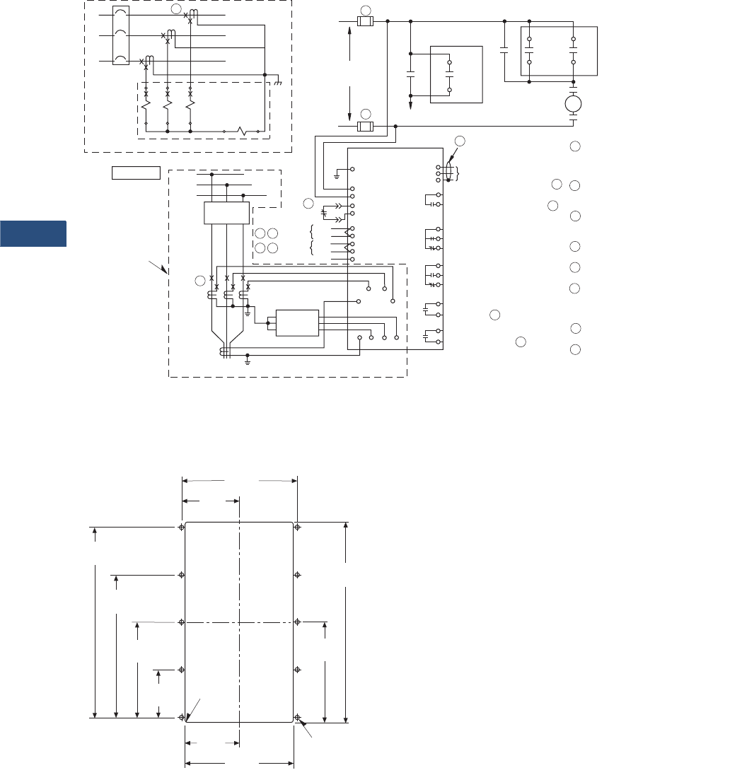
V3-T9-156 Volume 3—Power Distribution and Control Assemblies CA08100004E—March 2016 www.eaton.com
9
9
9
9
9
9
9
9
9
9
9
9
9
9
9
9
9
9
9
9
9
9
9
9
9
9
9
9
9
9
9.3
Metering Devices, Protective Relays, Software and Connectivity
Protective Relays
Digitrip 3000 Typical Wiring Diagram
Dimensions
Approximate Dimensions in Inches (mm)
Drilling Pattern
Note
Panel cutout dimensions for all versions of the Digitrip 3000 relay.
C1
C2
B1
B2
A1
A2 G1 G2
ØC
ØB
ØA A
Digitrip 3000
3-Phase 3-Wire Residual Ground Connection
View ”A“
52
A
B
C
See View ”A“
For Residual
CT Connection
A
CT
ABC
Zero
Sequence
CT
Other
Devices
G2 C2 B2 A2
G1
C1 B1 A1
Ground
Zone
Phase
Zone
Zone Common
E G Out
In
Out
In
11
12
13
14
15
5
6
9
10
4
52b
B
TB1
H
H
AC/DC
Supply
Close CKT
CS
C
TB2
4
TB2
5
Comm.
Close
CS
T
TB2
14
TB2
15
Trip OC
/Comm.
TB2
12
TB2
13
Trip
Inst.
52a
52a
TC
TB2
1
2
3
4
5
6
7
8
9
10
11
F
INCOM
Network
INCOM Shield Tie Point C
Communication
Close or High Load Alarm D
Trip Alarm
Protection
OFF
Alarm
Trip Inst.
or Ground D
Trip OC or Phase/
Communications D
12
13
14
15
A = CTs can be located on either
side of the circuit breaker.
CT polarities can be toward or
away from the circuit breaker.
B = The 52b contact is required for
proper operation of the Digitrip
3000 Protective Relay.
C = TB2 terminal 3 is not connected
to ground or any electrical
circuit in the Digitrip 3000.
D = Congurable contact, refer to DIP
switch settings.
E = Remove jumpers if Zone Interlocking
is required.
F = Use Eaton Cable CAT # IMPCABLE,
Style # 2A95705G01; Belden 9463 cable
family; or equivalent Commscope or
Quabbin cables.
G = Wire spec: 600 V 90ºC,
UL 1039 rated wire.
H = For the DT3030 to be ”CE Compliant,“
the power supply input fuse must be
rated at a maximum of 0.25 amperes.
E G
5.38
(136.7)
9.38
(238.3)
4.69
(119.1)
2.53
(64.3) 5.06
(128.5)
2.23
(56.7)
4.45
(113.0)
6.68
(169.7)
8.90
(226.1)
.06
(1.5) RAD
4 Places
2.69
(68.3)
.218
(5.5) DIA 10 Places
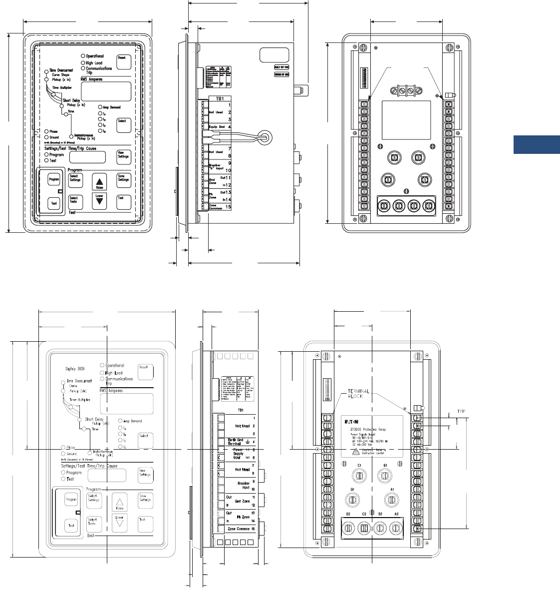
Volume 3—Power Distribution and Control Assemblies CA08100004E—March 2016 www.eaton.com V3-T9-157
9
9
9
9
9
9
9
9
9
9
9
9
9
9
9
9
9
9
9
9
9
9
9
9
9
9
9
9
9
9
9.3
Metering Devices, Protective Relays, Software and Connectivity
Protective Relays
Approximate Dimensions in Inches (mm)
Digitrip 3010/3020
Digitrip 3000
Digitrip 3000
6.72
(170.7)
10.25
260.3)
5.45
(138.4)
6.03
(153.2)
.51
(13.0)
.62
(15.7)
.50
(12.7) 1.05
(26.7) 5.74
(145.8)
3.74
(95.0)
9.31
(236.5)
AC Input
100-120 Vac, 50/60Hz
Digitrip 8010 Protective Relay
with Dual-Source Power Supply
Terminal
Block
S/N000217
P971210
4D13125G01
6.72
(170.7)
2.67
(67.8)
0.39
(9.9)
0.50
(12.7)
0.29
(7.4)
0.62
(15.7)
1.05
(26.7)
1.87
(47.5)
3.74
(95.0)
0.37
(9.4)
3.36
(85.3)
5.12
(130.0)
4.65
(118.1)
5.25
(133.4)
1.48
(37.6)
10.25
(260.4)
9.31
(236.5)
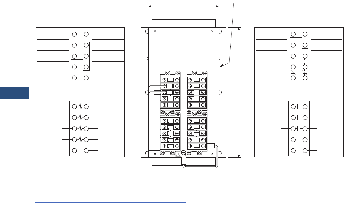
V3-T9-158 Volume 3—Power Distribution and Control Assemblies CA08100004E—March 2016 www.eaton.com
9
9
9
9
9
9
9
9
9
9
9
9
9
9
9
9
9
9
9
9
9
9
9
9
9
9
9
9
9
9
9.3
Metering Devices, Protective Relays, Software and Connectivity
Protective Relays
Approximate Dimensions in Inches (mm)
Rear View of Digitrip 3001 Drawout Outer Case Terminal Layout
Digitrip 3000 Feeder Protection Relay (Fixed Case)
Height Width Depth
Shipping Weight
Lbs (kg)
10.25 (260.4) 6.72 (170.7) 2.96 (75.2) 0.0 (0.0)
Hole for Viewing INCOM
Communications Activity LED.
9.51
(241.6)
11
Breaker “b” Input
13
Gnd Zone Out
15
Ph Zone Out
17
ac/dc Input
(+)
(–)
19
120 – 240 Vac
50/60 HZ
48 – 250 Vdc
21
A2
23
B2
Current Input
25
C2
27
G1
29
Unused
66C2025H01
22
24
26
28
30
A1
B1
C1
G2
Unused
12
14
16
18
20
Breaker “b” Input
Gnd Zone In
Ph Zone In
Zone Common
Unused 12
18
20
11
17
19
42
48
50
41
47
49
4443
4645
56
58
55
57
5251
5453
22
28
30
21
27
29
2423
2625
51
Communication
Close
53
55
57
59
Unused
66C2025H02
52
54
56
58
60
Unused
Trip Inst
or Ground
Trip OC or
Phase /Comm
Communication
Close
Equip Gnd
Unused
Trip Inst
or Ground
Trip OC or
Phase /Comm
41
INCOM
Network
43
45
47
49
42
44
46
48
50
Unused
Trip
Alarn
Protection
Off
Alarm
Shield Tie Point
INCOM
Network
5.23
(132.8)
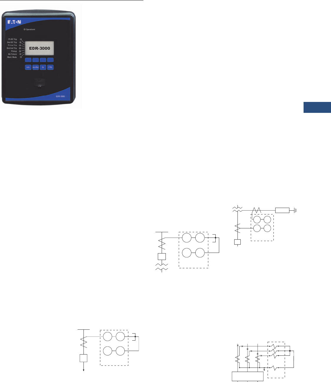
Volume 3—Power Distribution and Control Assemblies CA08100004E—March 2016 www.eaton.com V3-T9-159
9
9
9
9
9
9
9
9
9
9
9
9
9
9
9
9
9
9
9
9
9
9
9
9
9
9
9
9
9
9
9.3
Metering Devices, Protective Relays, Software and Connectivity
Protective Relays
EDR-3000
Contents
Description Page
Product Selection Guide . . . . . . . . . . . . . . . . . . . . V3-T9-143
Digitrip 3000 . . . . . . . . . . . . . . . . . . . . . . . . . . . . . V3-T9-149
EDR-3000 Feeder Protection
EDR-5000 Distribution Protection Relay . . . . . . . . V3-T9-168
FP-5000 Feeder Protection . . . . . . . . . . . . . . . . . . V3-T9-181
MP-3000 Motor Protection . . . . . . . . . . . . . . . . . . V3-T9-189
MP-4000 Motor Protection . . . . . . . . . . . . . . . . . . V3-T9-199
EMR-3000 Motor Protection Relay . . . . . . . . . . . . V3-T9-205
EMR-4000 Motor Protection Relay . . . . . . . . . . . . V3-T9-217
EMR-5000 Motor Protection Relay . . . . . . . . . . . . V3-T9-230
ETR-4000 Transformer Protection Relay . . . . . . . . V3-T9-242
ETR-5000 Transformer Protection Relay . . . . . . . . V3-T9-254
EGR-5000 Generation Protection Relay . . . . . . . . V3-T9-267
Ground Fault Relay . . . . . . . . . . . . . . . . . . . . . . . . V3-T9-280
Universal RTD Module . . . . . . . . . . . . . . . . . . . . . V3-T9-283
EDR-3000 Feeder Protection
Product Description
The EDR-3000 Protective
Relay is a multifunction,
microprocessor-based
overcurrent relay designed
for both ANSI and IEC
applications. It is a panel-
mounted, self-contained unit
that operates from either AC
or DC control power. The
EDR-3000 design provides
true rms and fundamental
sensing of each phase and
ground current. Only one unit
is required for each three-
phase circuit.
Current monitoring and
operator selectable protective
functions are integral to each
relay. The EDR-3000 relay
operates from the 5 A or 1 A
secondary output of standard
current transformers. Current
transformer ratio information
is quickly programmed into
the unit via settings. This
enables the relay to display
metered current in primary
amperes, secondary amperes
or per unit values. The EDR-
3000 features a user-friendly
operations panel to monitor
and program the relay.
Operating parameters and
troubleshooting information
are displayed in the 128 x 64
LCD. In addition, all data and
information can be
communicated to a host
computer equipped
with PowerPort-E™.
A “Communication Trip” and
“Communication Close”
control command can also be
initiated by a host computer
with an authorized access
code for remote breaker
operation.
Application Description
The EDR-3000
microprocessor-based relay
provides reliable three-phase
and ground overcurrent
protection for all voltage
levels. It can be used for
any application where
instantaneous and/or time
overcurrent protection is
required. It is most commonly
used as primary feeder circuit
protection, shown below.
Primary Feeder Circuit
Protection
The EDR-3000 may be
applied as the transformer
primary protection or as
backup to the differential
protection, see below.
Transformer Overcurrent
Protection
The EDR-3000 may be
connected to the secondary
side of a delta-wye grounded
transformer with the ground
element connected to a
separate CT in the neutral
connection of the
transformer. With this
connection, a lower CT
ratio and a pickup setting
can be used to provide
more sensitive ground fault
protection especially for
resistance grounded
systems, shown below.
Transformer Secondary
Protection with Neutral CT
Connection
The EDR-3000 relay has
special provisions for
connection in a Zone
Interlocking scheme that can
be used for bus protection
or to improve protection
coordination in a tight or close
system. Zone Interlocking
is described in following
sections. In addition the
EDR-3000 has multiple
setting groups that can be
used to reduce arc flash
hazard with instantaneous
elements.
Residual Ground Connection
50 51
50G 51G
CB
52 EDR-3000
Load
50 51
50G 51G
CB
EDR-3000
50G 51G
50 51
EDR-3000
Resistor
CB
a
b
c
GND
EDR-3000
CB-52
23
56
89
12 11
50N/51N
50/51
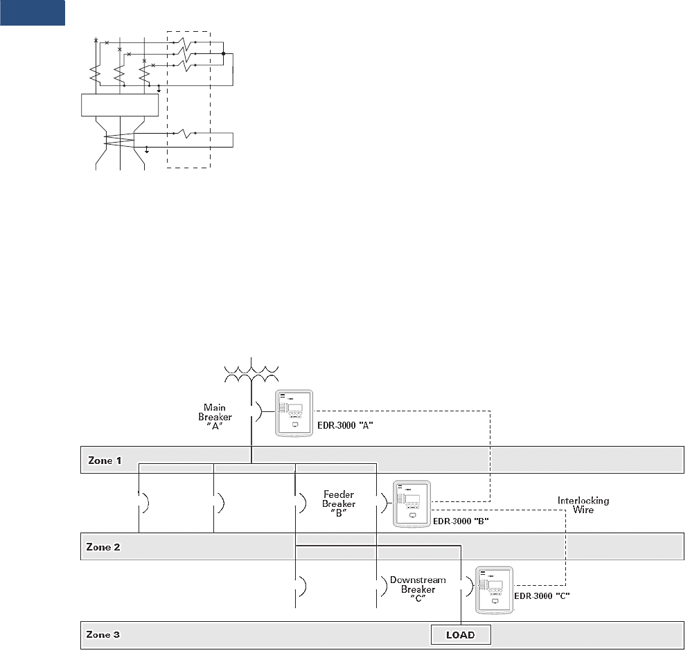
V3-T9-160 Volume 3—Power Distribution and Control Assemblies CA08100004E—March 2016 www.eaton.com
9
9
9
9
9
9
9
9
9
9
9
9
9
9
9
9
9
9
9
9
9
9
9
9
9
9
9
9
9
9
9.3
Metering Devices, Protective Relays, Software and Connectivity
Protective Relays
Overcurrent Protection
The EDR-3000 provides
complete three-phase and
ground protection with
separate elements and
settings. The relay can be
used with CTs from 1 to
50,000 A of primary current
and 1 or 5 A of secondary
current. The CT ratio can be
set independently for phase
and ground, allowing the
ground element to be
connected in either the
residual or the separate
ground CT configuration,
shown on below.
Separate Zero Sequence
Ground CT Connection
Zone Selective Interlocking
(Phase and Ground)
Note: Refer to the Ordering
Information and (Catalog Ordering
Information) for optional features,
see Page V3-T9-162.
Zone Selective interlocking
is a protection function to
minimize equipment damage
resulting from a phase or a
ground fault in an area where
long time and/or short time
delay is in use.
When the “Ground Zone
Interlocking” feature is
utilized, an immediate trip is
initiated when the fault is in
the breaker’s zone of
protection, regardless of its
preset time delay. When the
“Phase Zone Interlocking”
feature is utilized, the time
overcurrent elements work
as follows. The instantaneous
phase element will initiate an
immediate trip when the fault
is in the breaker's zone of
protection, regardless of its
preset time delay. For the
time overcurrent phase
element, the current sensed
by the EDR-3000 must
exceed 1.5 times the pickup
setting for the zone selective
interlocking to initiate an
immediate trip signal when
the fault is in the breaker’s
zone of protection.
Upstream EDR-3000
protected breakers are
restrained from tripping
immediately by an
interlocking signal from the
downstream EDR-3000 relay.
This interlocking signal
requires only a pair of
wires from the downstream
breaker to the upstream
breaker. It provides standard
coordinated tripping when
the fault is located outside
the zone of protection.
In the sample zone
interlocking system shown
below, circuit breakers A,
B and C are equipped with
EDR-3000 overcurrent relays.
Fault Location Zone 3
Note: For the time overcurrent
phase element, the current
sensed by the EDR-3000 must
exceed 1.5 times the pickup
setting for the zone selective
interlocking to initiate an
immediate trip signal when
the fault is in the breaker's zone
of protection.
If a fault occurs at a point
in Zone 3, the EDR-3000
of downstream breaker C
senses the fault and sends
a restraining signal to the
upstream EDR-3000 of
feeder breaker B. Having
received this signal, the
EDR-3000 of feeder breaker
B withholds its trip command.
As a result, only downstream
breaker C is tripped.
Fault Location Zone 2
Note: For the time overcurrent
phase element, the current
sensed by the EDR-3000 must
exceed 1.5 times the pickup
setting for the zone selective
interlocking to initiate an
immediate trip signal when the
fault is in the breaker’s zone
of protection.
If a fault occurs at a point in
Zone 2, the EDR-3000 of
feeder breaker B senses the
fault and sends a restraining
signal to the upstream EDR-
3000 of main breaker A. The
EDR-3000 of the downstream
breaker C does not see this
fault since it is situated on the
downstream side of the fault.
As a result, the EDR-3000 of
downstream breaker C does
not send a restraining signal
to the EDR-3000 of feeder
breaker B. Since it did not
receive a restraining signal
from the EDR-3000 of
downstream breaker C, the
EDR-3000 of feeder breaker
B identifies that the fault is in
Zone 2 and immediately trips
feeder breaker B, regardless
of its time setting.
Fault Location Zone 1
Note: For the time overcurrent
phase element, the current
sensed by the EDR-3000 must
exceed 1.5 times the pickup
setting for the zone selective
interlocking to initiate an
immediate trip signal when the
fault is in the breaker's zone of
protection.
If a fault occurs in Zone 1,
no restraining signal is
received by the Digitrip
of main breaker A. As a
result, main breaker A is
immediately tripped by its
EDR-3000 overcurrent relay,
regardless of its time setting.
Sample Zone Selective Interlocking System
CB-52
a
b
c
GND
EDR-3000
23
56
89
11 12
50/51
50G/51G
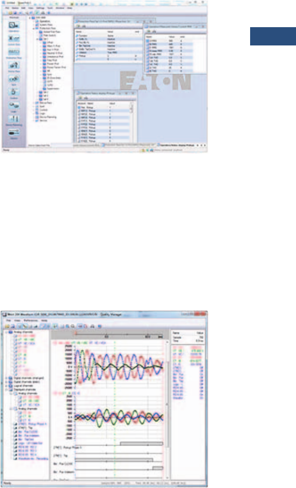
Volume 3—Power Distribution and Control Assemblies CA08100004E—March 2016 www.eaton.com V3-T9-161
9
9
9
9
9
9
9
9
9
9
9
9
9
9
9
9
9
9
9
9
9
9
9
9
9
9
9
9
9
9
9.3
Metering Devices, Protective Relays, Software and Connectivity
Protective Relays
Features, Benefits and Functions
Applications
●Provides reliable three-
phase and ground
overcurrent protection
for all voltage levels
●Primary feeder circuit
protection
●Primary transformer
protection
●Backup to differential
protection
●May be used where
instantaneous and/or time
overcurrent protection is
required
●Ground element capable
of residual, zero sequence
or external source
connections
Protection Functions
●Breaker failure (50BF)
●Phase overcurrent
protection per time-current
curve (51-1, 51-2, 51-3)
●Calculated ground fault
protection per time-current
curve (51R-1, 51R-2)
●Independent measured
ground or neutral fault
protection per time-current
curve (51X-1, 51X-2)
●Phase instantaneous
overcurrent (50-1, 50-2,
50-3)
●Calculated ground or
neutral instantaneous
overcurrent (50R-1, 50R-2)
●Independent measured
ground or neutral
instantaneous overcurrent
(50X-1, 50X-2)
●Curve shapes: ANSI,
IEC, or thermal curves
(11 thermal curves)
●Instantaneous or time
delay reset
●True rms or fundamental
sensing of each phase
and ground current
●Zone selective interlocking
(phase and ground) or
reverse blocking for
bus protection
Note: Refer to the Ordering
Information and Page V3-T9-162
(Catalog Ordering Information)
for optional features.
Metered Values
●rms and fundamental
phase currents
●rms and fundamental
ground currents
●Maximum, minimum
and average rms and
fundamental phase
currents
●Maximum, minimum
and average rms and
fundamental ground
currents
Monitored and Data
Recording Values
●Trip circuit monitoring
Note: Refer to the Ordering
Information and Page V3-T9-162
(Catalog Ordering Information)
for optional features.
●Breaker wear (accumulated
interrupted current)
●Fault data logs (up to
20 events)
●Sequence of event
recorder (1 ms time
stamp, last 300 events)
●Waveform capture
(7200 cycles total)
●Trip Cause displays fault
recorder data on HMI
after fault event
●CT supervision
Control Functions
●Remote open/close
●Programmable I/O
●Programmable LEDs
●Multiple setting groups
(up to four)
Communication Software
●Local HMI
●Front RS-232 port
●Rear RS-485 port
●Protocols
●Modbus RTU
●Modbus TCP (option)
●IEC 61850 (option)
●IRIG-B (option)
●SNTP (option)
PowerPort-E
PowerPort-E is the software
program used to configure
off-line protection setting files
for all E-Series relay models.
PowerPort-E is also used for
viewing measured values of
the relays in real-time,
uploading/downloading
setting files, and retrieving
event log and waveform
records.
Waveform Capture
(Quality Manager)
The EDR-3000 relay provides
oscillographic recording
capabilities. The relay will
record all measured signals
along with the binary signals
of pickup, trip, internal logic,
and contact inputs. The EDR-
3000 can record up to 7200
cycles of data. The number of
records is proportional to the
programmed size of each
record; the maximum size per
record is 600 cycles. The
waveform capture is initiated
by up to 8 different triggers
(i.e., trip/alarm events) or
manually via communications
or the HMI. PowerPort-E
setting software is used to
retrieve the records. Quality
Manager is a separate
software program downloaded
with PowerPort-E used for
analyzing the waveform and
trending files retrieved from
the relay.
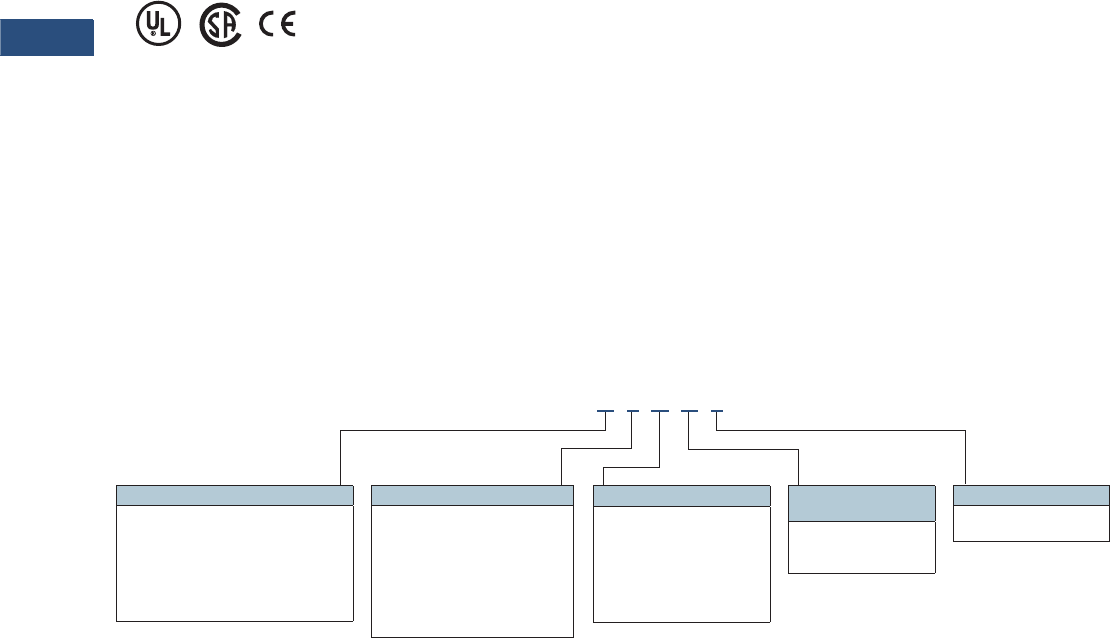
V3-T9-162 Volume 3—Power Distribution and Control Assemblies CA08100004E—March 2016 www.eaton.com
9
9
9
9
9
9
9
9
9
9
9
9
9
9
9
9
9
9
9
9
9
9
9
9
9
9
9
9
9
9
9.3
Metering Devices, Protective Relays, Software and Connectivity
Protective Relays
Standards and Certifications
●Generic standard:
●EN 61000-6-2
●EN 61000-6-3
●Product standard:
●EC 60255-6
●EN 50178
●UL 508 (Industrial Control
Equipment)
●CSA C22.2 No. 14-95
(Industrial Control
Equipment)
●ANSI C37.90
●UL, CSA, CE
Catalog Number Selection
The catalog number
identification chart defines
the electrical characteristics
and operation features
included in the EDR-3000. For
example, if the catalog number
is EDR3000-A0BA1,
the device would have
the following:
EDR-3000
(A)–Four digital inputs,
four output relays
(0)–Phase current 5 A / 1 A,
Ground Current 5 A / 1 A,
Power supply: 19–300 Vdc,
40–250 Vac
(B)–Modbus-RTU (RS-485)
(A)–Without conformal
coating
(1)–Projection panel mount
Relay Removable Terminals
Note
1Beginning in 2016, consult factory for the availability of the following new communication options.
• Protocols: DNP3.0, Profibus
• Interface ports: Fiber optic ST, RS-485 D-SUB, Fiber optic LC
Hardware Option 1
A = 4 digital inputs, 4 outputs,
removable terminals
B = 8 digital inputs, 6 outputs, removable
terminals, trip coil monitor
C = 4 digital inputs, 4 outputs, removable
terminals, zone interlocking
and IRIG-B
Communication Options 1
B= Modbus-RTU
(RS-485)
I= Modbus-RTU (RS-485) and
Modbus-TCP (RJ-45) [only 1
active, software selected]
H= IEC 61850 GOOSE and
MMS (RJ-45)
Conformal Coating
Options
A = None
B = Conformal coated
circuit boards
Mounting Options
0 = Standard mount
1 = Projection panel mount
Hardware Option 2
0 = Phase current 5 A / 1 A, ground
current 5 A / 1 A, power supply
range: 19–300 Vdc,
40–250 Vac
1 = Phase current 5 A / 1 A,sensitive
ground current 0.5 A / 0.1 A,
power supply range: 19–300 Vdc,
40–250 Vac
EDR3000 A 0 B A 1

Volume 3—Power Distribution and Control Assemblies CA08100004E—March 2016 www.eaton.com V3-T9-163
9
9
9
9
9
9
9
9
9
9
9
9
9
9
9
9
9
9
9
9
9
9
9
9
9
9
9
9
9
9
9.3
Metering Devices, Protective Relays, Software and Connectivity
Protective Relays
Technical Data and Specifications
Climatic Environmental
Conditions
●Storage temperature:
–13 °F to 158 °F (–25 °C up
to +70 °C)
●Operating temperature:
–4 °F to 140 °F (–20 °C up
to +60 °C)
●Permissible humidity at
ann. average: <75% rel.
(on 56d up to 95% rel.)
●Permissible Installation
altitude:
●<2000 m (6561.67 ft)
above sea level
●If 4000 m (13,123.35 ft)
altitude apply, a changed
classification of the
operating and test
voltages may be
necessary
Degree of Protection EN 60529
●HMI front panel with
seal: IP54
●Rear side terminals: IP30
Routine Test
●Insulation test according to
IEC 60255-5: All tests to be
carried out against ground
and other input and output
circuits
●Aux. voltage supply, digital
inputs, current measuring
inputs, signal relay outputs:
2.5 kV (eff)/50 Hz
●Voltage measuring inputs:
3.0 kV (eff)/50 Hz
●All wire-bound
communication interfaces:
1. 5 k V D C
Housing
●Material, housing:
aluminum extruded section
●Material, front panel:
aluminum/foil front
●Mounting position:
horizontal (±45° around the
X-axis must be permitted)
Plug-in Connector with
Integrated Short-Circuiter
(Conventional Current Inputs)
●Nominal current:
1 A and 5 A
●Continuous loading
capacity: 4 x In/
continuously
●Overcurrent withstand:
30 x In/10 s
●100 x In/1 s
●250 x In/10 ms
(1 half-wave)
●Screws: M4, captive type
according to VDEW
●Connection cross-sections:
●2 x 2.5 mm2 (2 x AWG
14) with wire end ferrule
●1 x or 2 x 4.0 mm2
(2 x AWG 12) with
ring cable sleeve or
cable sleeve
●1 x or 2 x 6 mm2
(2 x AWG 10) with
ring cable sleeve or
cable sleeve
Voltage Supply
●Aux. voltage: 19–300 Vdc/
40–250 Vac
●Buffer time in case of
supply failure: ≥50 ms
at minimal aux. voltage
communication is
permitted to be interrupted
●Max. permissible making
current:
●18 A peak value for
<0.25 ms
●12 A peak value for
<1 ms
●The voltage supply must
be protected by a fuse of:
●2.5 A time-lag miniature
fuse 5 x 20 mm (approx.
1/5 in x 0.8 in) according
to IEC 60127
●3.5 A time-lag miniature
fuse 6. 3 x 32 mm
(approx. 1/4 in x
1 1/4 in) according
to UL 248-14
Power Consumption
●Power supply range: Power
consumption in idle mode
●Max. power consumption
●19–300 Vdc: 6 W 8.5 W
●40–250 Vac
●For frequencies of
40–70 Hz: 6 W 8.5 W
Real-Time Clock
●Running reserve of the
real-time clock: 1 year min.
Display
●Display type: LCD with
LED background
illumination
●Resolution graphics
display: 128 x 64 pixel
●LED-type: two colored,
red/green
●Number of LEDs, housing
B1: 8
Digital Inputs
●Max. input voltage:
300 Vdc/270 Vac
●Input current: <4 mA
●Reaction time: <20 ms
●Fallback time: <30 ms (safe
state of the digital inputs)
●Four switching thresholds:
Un = 24 Vdc, 48 Vdc,
60 Vdc, 110 Vac/Vdc,
230 Vac/Vdc Un = 24 Vdc
●Switching threshold
1 ON
– Switching threshold 1
OFF
– Min. 19.2 Vdc
– Max. 9.6 Vdc
– Un = 48 V/60 Vdc
●Switching threshold
2 ON
– Switching threshold 2
OFF
– Min. 42.6 Vdc
– Max. 21.3 Vdc
– Un = 110/120 Vac/Vdc
●Switching threshold
3 ON
– Switching threshold 3
OFF
– Min. 88.0 Vdc/
88.0 Vac
– Max. 44.0 Vdc/
44.0 Vac
– Un = 230/240 Vac/Vdc
●Switching threshold
4 ON
– Switching threshold 4
OFF
–Min. 184 Vdc/
184 Vac
– Max. 92 Vdc/92 Vac
●Terminals: screw-type
terminal

V3-T9-164 Volume 3—Power Distribution and Control Assemblies CA08100004E—March 2016 www.eaton.com
9
9
9
9
9
9
9
9
9
9
9
9
9
9
9
9
9
9
9
9
9
9
9
9
9
9
9
9
9
9
9.3
Metering Devices, Protective Relays, Software and Connectivity
Protective Relays
Current and Ground
Current Measurement
●Nominal currents: 1 A / 5 A
●Max. measuring range:
●up to 40 x In (phase
currents)
●up to 25 x In (ground
current standard)
●up to 2.5 x In (ground
current sensitive)
●Continuous loading
capacity: 4 x In/
continuously
●Overcurrent proof:
●30 x In/10 s
●100 x In/1 s
●250 x In/10 ms
(1 half-wave)
●Power consumption:
Phase current inputs
●at In = 1 A S = 0.15 MVA
●at In = 5 A S = 0.15 MVA
●Ground current input
●at In = 1 A S = 0.35 MVA
●at In = 5 A S = 0.35 MVA
●Frequency range: 50 Hz/
60 Hz ±10%
●Terminals: Screw-type
terminals with integrated
short-circuiters (contacts)
Binary Output Relays
●Continuous current:
5 A AC/DC
●Switch-on current:
25 A AC/DC for 4 s
●Max. breaking current:
5 A AC up to 125 Vac
●5 A DC up to 50 V
(resistive)
●0.2A DC at 300 V
●Max. switching voltage:
250 Vac/300 Vdc
●Switching capacity:
2000 VA
●Contact type:
1 changeover contact
●Terminals: Screw-type
terminals
Front Interface RS-232
●Baud rates: 115,200 baud
●Handshake: RTS and CT
●Connection: 9-pole
D-Sub plug
RS-485
●Master/slave: slave
●Connection: 6 screw-
clamping terminals RM
3.5 mm (138 MIL)
(terminating resistors
internal)
Tolerances of the
Real-Time Clock
●Resolution: 1 ms
●Tolerance: <1 minute/
month (+20 °C)
Measuring Accuracy
●Max. measuring range: up
to 40 x In (phase currents)
up to 25 x In (ground
current standard)
●Frequency range: 50 Hz/
60 Hz ± 10%
●Accuracy: Class 0.5
●Amplitude error if I < In:
±0.5% of the rated value
●Amplitude error if I > In:
±0.5% of the measured
value
●Amplitude error if I > 2 In:
±1.0% of the measured
value
●Resolution: 0.01 A
●Harmonics up to 20% 3rd
harmonic ±2% up to 20%
5th harmonic ±2%
●Frequency influence
< ±2%/Hz in the range of
±5 Hz of the parameterized
nominal frequency
●Temperature influence
<±1% within the range
of 0 °C up to +60 °C
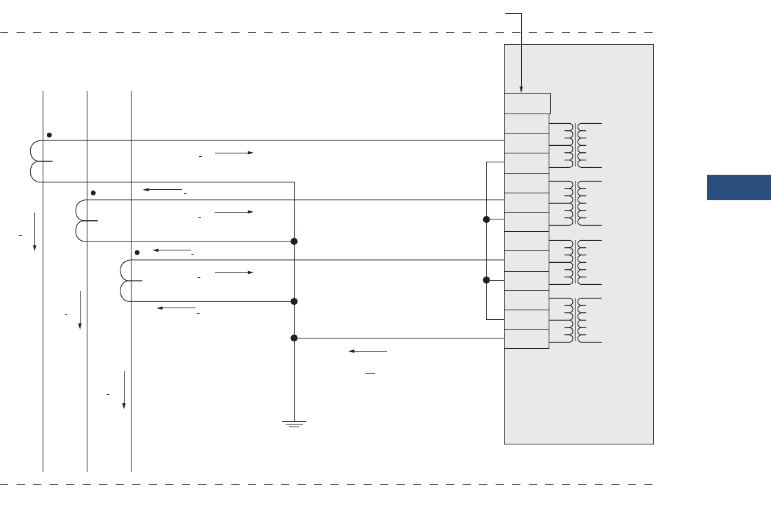
Volume 3—Power Distribution and Control Assemblies CA08100004E—March 2016 www.eaton.com V3-T9-165
9
9
9
9
9
9
9
9
9
9
9
9
9
9
9
9
9
9
9
9
9
9
9
9
9
9
9
9
9
9
9.3
Metering Devices, Protective Relays, Software and Connectivity
Protective Relays
Wiring Diagrams
EDR-3000
Connection Example Clockwise Rotating Field
EDR3000 => Terminal Markings X3.
Three-Phase Current Measurement; Inom Secondary = 5 A
Ground Current Measuring via Residual Connection; IGnom Secondary = 5 A
ABC
IA
IA’
IB’
IB’
IA
IB
IC
IC’
IC’
IX’
X3.
1
2
3
4
5
6
7
8
9
10
11
12
1A
5A
N
1A
5A
N
1A
5A
N
1A
5A
N
1A
1B
1C
1X
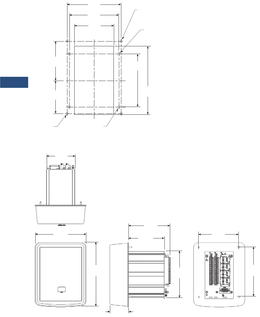
V3-T9-166 Volume 3—Power Distribution and Control Assemblies CA08100004E—March 2016 www.eaton.com
9
9
9
9
9
9
9
9
9
9
9
9
9
9
9
9
9
9
9
9
9
9
9
9
9
9
9
9
9
9
9.3
Metering Devices, Protective Relays, Software and Connectivity
Protective Relays
Dimensions
Approximate Dimensions in Inches (mm)
Drilling Pattern
Projection Mounting
3.94
(100.0)
C
L
4.94
(125.5)
5.38
(136.7)
C
L
Cutout
“B” Holes for
Projection
Panel Mount
“A” Holes for
Standard
Panel Mount
B
A
B
A
B
A
B
A
3.62
(91.8)
3.05
(77.6)
6.30
(160.0)
4.88
(124.0)
4x ø0.19
(ø4.8)
4x ø0.19
(ø4.8)
3.82
(97.0)
6.82
(173.2)
5.38
(136.7)
2.50
(63.5)
4.80
(121.9)
5.56
(141.1)
6.67
(169.4)
8.62
(218.9)
6.14
(156.0)
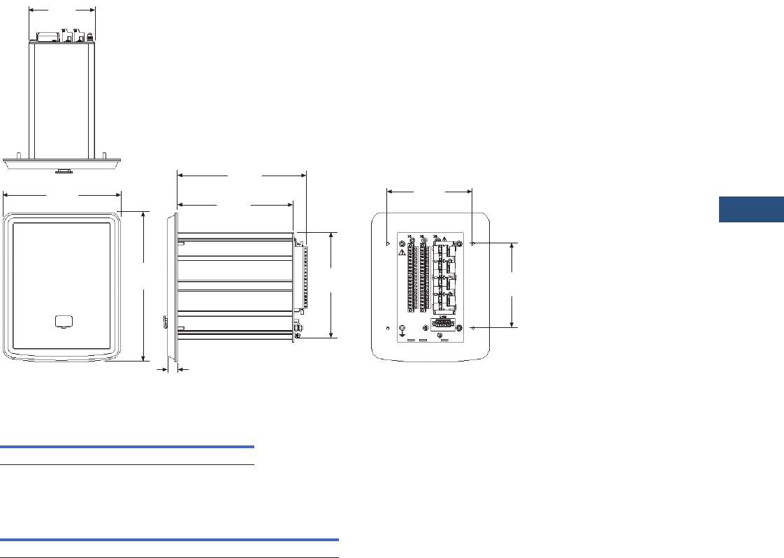
Volume 3—Power Distribution and Control Assemblies CA08100004E—March 2016 www.eaton.com V3-T9-167
9
9
9
9
9
9
9
9
9
9
9
9
9
9
9
9
9
9
9
9
9
9
9
9
9
9
9
9
9
9
9.3
Metering Devices, Protective Relays, Software and Connectivity
Protective Relays
Approximate Dimensions in Inches (mm)
Standard Mounting
EDR-3000
EDR-3000 Housing B1
Notes
1Depth behind panel with projection mounted enclosure.
2Includes terminals.
Width Height Depth
6.82 (173.2) 8.62 (218.9) 7.49 (190.2) 1
Width Height Depth
Shipping Weight
Lbs (kg)
5.57 (141.5) 7.21 (183.0) 8.19 (208.0) 25.3 (2.4)
3.82
(97.0)
6.82
(173.2)
4.94
(125.5)
0.56
(14.2)
6.74
(171.2)
7.49
(190.4)
4.88
(124.0)
8.62
(218.9)
6.14
(156.0)
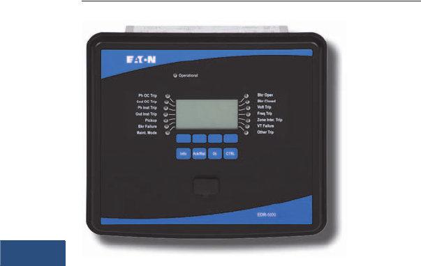
V3-T9-168 Volume 3—Power Distribution and Control Assemblies CA08100004E—March 2016 www.eaton.com
9
9
9
9
9
9
9
9
9
9
9
9
9
9
9
9
9
9
9
9
9
9
9
9
9
9
9
9
9
9
9.3
Metering Devices, Protective Relays, Software and Connectivity
Protective Relays
EDR-5000 Distribution Protection Relay
Contents
Description Page
Product Selection Guide. . . . . . . . . . . . . . . . . . . . . V3-T9-143
Digitrip 3000. . . . . . . . . . . . . . . . . . . . . . . . . . . . . . V3-T9-149
EDR-3000 Feeder Protection . . . . . . . . . . . . . . . . . V3-T9-159
EDR-5000 Distribution Protection Relay
FP-5000 Feeder Protection. . . . . . . . . . . . . . . . . . . V3-T9-181
MP-3000 Motor Protection . . . . . . . . . . . . . . . . . . V3-T9-189
MP-4000 Motor Protection . . . . . . . . . . . . . . . . . . V3-T9-199
EMR-3000 Motor Protection Relay . . . . . . . . . . . . V3-T9-205
EMR-4000 Motor Protection Relay . . . . . . . . . . . . V3-T9-217
EMR-5000 Motor Protection Relay . . . . . . . . . . . . V3-T9-230
ETR-4000 Transformer Protection Relay . . . . . . . . V3-T9-242
ETR-5000 Transformer Protection Relay . . . . . . . . V3-T9-254
EGR-5000 Generation Protection Relay . . . . . . . . . V3-T9-267
Ground Fault Relay . . . . . . . . . . . . . . . . . . . . . . . . . V3-T9-280
Universal RTD Module . . . . . . . . . . . . . . . . . . . . . . V3-T9-283
EDR-5000 Distribution Protection Relay
Product Description
Eaton’s EDR-5000
distribution protection
relay is a multi-functional,
microprocessor-based relay
for feeder circuits of all
voltage levels. It may be used
as a primary protection on
feeders, mains and tie circuit
breaker applications; or as
backup protection for
transformers, high voltage
lines and differential
protection. The relay is most
commonly used on medium
voltage switchgear
applications.
The EDR-5000 distribution
protection relay provides
complete current, voltage,
and frequency protection and
metering in a single, compact
case. The relay has four
current inputs rated for either
5 amperes or 1 ampere and
four voltage inputs. Three of
the voltage inputs are to be
connected to the three-phase
power voltage for voltage
protection and for metering.
They can be connected in
wye-ground or open delta
configuration. The fourth
voltage is for independent
single-phase undervoltage/
overvoltage protection, sync-
check or ground protection
for an ungrounded system.
The maintenance mode
password protected soft key
can be used for arc flash
mitigation to change to an
alternate settings group, set
to have instantaneous
elements only. The multiple
setting groups can also be
changed, via communications
or a digital input.
An integral keypad and
display is provided for direct
user programming and
retrieval of data without the
need of a computer. 14
programmable LEDs provide
quick indication of relay
status.
A front port is provided for
direct computer connection.
An RS-485 communication
port on the back is standard
for local area networking
using Modbus-RTU. An
optional Ethernet port and
protocols are available.
The EDR-5000 distribution
protection relay includes
programmable logic
functions. Logic gates and
timers may be defined and
arranged for customized
applications. Programmable
logic control functions make
the EDR-5000 relay ideally
suited for main-tie-main and
main 1/main 2 transfer
schemes. Flash memory is
used for the programming
and all settings are stored in
nonvolatile memory.
The relay allows for four
preprogrammed setting
groups which can be
activated through software or
contact input.
Flash memory is used for the
programming and all settings
are stored in nonvolatile
memory. The relay allows for
four preprogrammed setting
groups which can be
activated through software,
the display or a contact input.
The EDR-5000 distribution
protection relay has mass
memory for data storage and
a real-time clock with 1 ms
time resolution. The relay will
log 300 sequence of event
records, 20 detailed trip logs,
minimum/maximum values,
load profiles, breaker wear
information and oscillography
data.
The EDR-5000 has eight
programmable binary inputs,
2 normally opened and 8
Form C heavy-duty outputs
and one form C signal alarm
relay. It can be powered from
19 Vdc to 300 Vdc or 40 Vac
to 250 Vac auxiliary power.

Volume 3—Power Distribution and Control Assemblies CA08100004E—March 2016 www.eaton.com V3-T9-169
9
9
9
9
9
9
9
9
9
9
9
9
9
9
9
9
9
9
9
9
9
9
9
9
9
9
9
9
9
9
9.3
Metering Devices, Protective Relays, Software and Connectivity
Protective Relays
Application Description
The Eaton’s EDR-5000
distribution protection relay
has been designed for
maximum user flexibility and
simplicity. The base relay
includes all the standard
current and voltage
protection and metering
functions.
Applications include
distribution feeder protection,
primary or backup protection
for transformers and
generators, utility
interconnections and
transfer schemes.
Features, Benefits and Functions
Directional Overcurrent
Protection
The EDR-5000 distribution
protection relay provides
complete three-phase and
ground directional
overcurrent protection. There
are 8 independent ground
overcurrent elements. The
ground elements “X” use the
independently measured
ground (or neutral) current
from a separate current-
sensing input. The ground
elements “R” uses a
calculated 3Io residual current
obtained from the sum of the
three-phase currents. This
calculated current could be
used for either the neutral or
ground current in a three-
phase, four-wire system.
Each of the phase and ground
overcurrent elements can be
selected to operate based on
fundamental or RMS current.
Phase direction is a function
used to supervise all phase
current elements (50, 51). A
quadrature voltage is
compared to a corresponding
phase current to establish the
direction of the fault. This
function is selectable to
operate in the forward,
reverse or both directions.
Ground direction is used to
supervise ground current
elements and is
accomplished by using
ground, negative sequence or
residual currents supervised
by zero, negative or positive
sequence voltages or ground
current. This function is
selectable to operate in
forward, reverse or both
directions.
Voltage Restrained Overcurrent
Voltage restraint reduces the
overcurrent pickup level
(51P[3]). This modification of
the pickup overcurrent level is
compared to the corresponding
phase input voltage. The
EDR-5000 uses the simple
linear model below to
determine the effective
pickup value.
Sync Check
The sync check function is
provided for double-ended
power source applications.
The sync check monitors
voltage magnitude, phase
angle and slip frequency
between the bus and line.
It also incorporates breaker
close time, dead bus dead
line, dead bus live line and
live bus live line features.
Reverse Power
Reverse power provides
control for power flowing
through a feeder. There are
three elements to be
configured: Operate in
forward or reverse; or, under
or over power conditions.
Reverse power is typically
applied to generator or motor
applications while under
power is generally applied to
load or generation loss.
Reverse VARs
Reverse vars can be used to
detect loss of excitation in
synchronous machines.
There are three elements to
be configured: operate in
forward or reverse; or, under
or over vars conditions.
Inverse-Time Characteristics
There are 11 user-selectable
inverse-time overcurrent
curve characteristics. The
user can select from the
ANSI, IEC or thermal curve
families and can select
instantaneous or time delay
reset characteristics.
Breaker Failure
The EDR-5000 distribution
protection relay includes a
breaker failure (50BF, 62BF)
function that can be initiated
from either an internal or
external trip signal. This is an
independent element that
can be used to operate a
lockout relay or trip an
upstream breaker. The timer
must be longer than the
breaker operating time and
the protective function reset
times.
Voltage Protection
The EDR-5000 distribution
protection relay has four
voltage-input circuits. There is
a three-phase set designated
as Main Voltage (M) and a
single-phase voltage circuit
designated as Auxiliary
Voltage (A). Both include
undervoltage (27) and
overvoltage (59) protection.
The three-phase voltage
protection can be set to
operate on a single-phase,
two out of three phases, or all
three-phase logic. The Main
VTs also provide phase
voltage unbalance/reversal
(47 negative sequence)
protection. Each element has
an independent threshold set
point and adjustable time
delay.
Ground Voltage Protection
In high impedance grounded
systems, ground fault
protection is provided by the
detection of zero sequence
voltage (3Vo) voltage in the
neutral of the transformer by
an overvoltage element (59N)
connected to the secondary
of the distribution grounding
transformer, or in the
secondary of a Wye-Broken
Delta transformer used when
the neutral is not accessible
or in Delta system. In the
EDR-5000 we can measure
this zero sequence voltage
through the 4th voltage input;
the 59N element has to be
desensitized for 3rd harmonic
voltages that can be present
in the system under normal
operation.
Flexible Phase Rotation
The EDR-5000 distribution
protection relay can be
applied on either an A-B-C or
A-C-B phase rotation. A user
setting permits correct
operation and indication of
the actual system
configuration.
Frequency Protection
The EDR-5000 relay provides
6 frequency elements than
can be used to detect under/
over frequency, rate of
change, and a vector surge
(decoupling of two systems)
protection on the Main VT
inputs. Each element has an
independent threshold set
point and adjustable time
delay.

V3-T9-170 Volume 3—Power Distribution and Control Assemblies CA08100004E—March 2016 www.eaton.com
9
9
9
9
9
9
9
9
9
9
9
9
9
9
9
9
9
9
9
9
9
9
9
9
9
9
9
9
9
9
9.3
Metering Devices, Protective Relays, Software and Connectivity
Protective Relays
Autoreclosing Logic
The EDR-5000 provides a 6
shot-recloser scheme.
Autoreclosing is normally
used by the utilities in their
distribution and transmission
lines, but it can be used in
commercial and industrial
applications with long
overhead lines. Nearly 85%
of the faults that occur on
overhead lines are transient in
nature. Tripping of a circuit
breaker normally clears a
transient fault and reclosing
of the circuit breaker restores
power back to the circuit.
Maintenance Mode
The Maintenance Mode can
improve safety by providing a
simple and reliable method to
reduce fault clearing time and
lower incident energy levels
at energized panels. The
Maintenance Mode allows
the user to switch to more
sensitive settings via a
password protected soft key,
communication or via a digital
Input while maintenance
work is being performed at an
energized panel or device.
The more sensitive settings
provide greater security for
maintenance personnel and
helps reduce the possibility of
injury.
Protection Features
●Phase overcurrent
elements:
●Three instantaneous
elements with timers
(50P[1], 50P[2] and
50P[3])
●Three inverse time
overcurrent elements
(51P[1], 51P[2] and
51P[3])
●11 standard curves
●Instantaneous or time
delay reset
●Voltage Restraint (51P[2]
and 51P[3])
●Directional Control (All
Elements)
●Ground overcurrent
elements:
●Two instantaneous
measured elements
with timers (50X[1] and
50X[2])
●Two instantaneous
calculated elements
with timers (50R[1] and
50R[2])
●Two inverse time
overcurrent measured
elements (51X[1] and
51X[2])
●Two inverse time
overcurrent calculated
elements (51R[1] and
51R[2])
●11 standard curves
●Instantaneous or time
delay reset
●Directional control (all
elements)
●Breaker failure (50BF)
●Phase unbalance negative
sequence overcurrent
(46[1], 46[2])
●Phase voltage unbalance
and sequence protection
(47[1], 47[2])
●Main three-phase under/
overvoltage (27M[1],
27M[2], 59M[1], 59M[2])
●Auxiliary single-phase
under/overvoltage (27A[1],
27A[2], 59A[1], 59A[2])
●Ground fault overvoltage
relay (59N[1], 59N[2])
●6 Frequency elements that
can be assigned to: over
frequency, under
frequency, rate of change,
or vector surge (81[1],
81[2], 81[3], 81[4], 81[5],
81[6])
●Apparent and
displacement power factor
(55A[1], 55A[2], 55D[1],
55D[2])
●Forward and Reverse
Watts (32[1], 32[2], 32[3])
●Forward and Reverse VARs
(32V[1], 32V[2], 32V[3])
●Sync check (25)
●Autoreclosing (79)
●Zone interlocking for bus
protection (87B)
●Switch onto fault
protection
●Cold load pickup
Metering Features
●Amperes: Positive,
negative and zero
sequence
●Ampere demand
●Volts: Positive, negative
and zero sequence
●Phase angles
●Volt-amperes and VA
demand
●Watts and kW demand
●kWh (forward, reverse,
net)
●VARs and kVAR demand
●kVARh (lead, leg and net)
●Power factor
●Frequency
●% THD V and I
●Magnitude THD V and I
●Minimum/maximum
recording.
●Sync Values
●Trending (load profile
over time)
Monitoring Features
●Trip coil monitor
●Breaker wear primary and
secondary (accumulated
interrupted current)
●Oscillography (7200 cycles
total)
●Fault data logs (up to 20
events)
●Sequence of events report
(up to 300 events)
●Clock (1 ms time stamping)
●Trip cause displays fault
reorder data on HMI after
fault event
Control Functions
●Breaker open/close
●Remote open/close
●Programmable I/O
●Programmable Logic
●Programmable LEDs
●Multiple setting groups
●Cold load pickup
●CT supervision
Communication Features
●Local HMI
●Password protected
●Addressable
●IRIG-B
●Local communication port:
●RS-232
●Remote communication
port:
●RS-485
●Ethernet RJ-45
●Protocols:
●Modbus-RTU
●Modbus-TCP (optional)
●IEC-61850 (optional)
●Configuration software
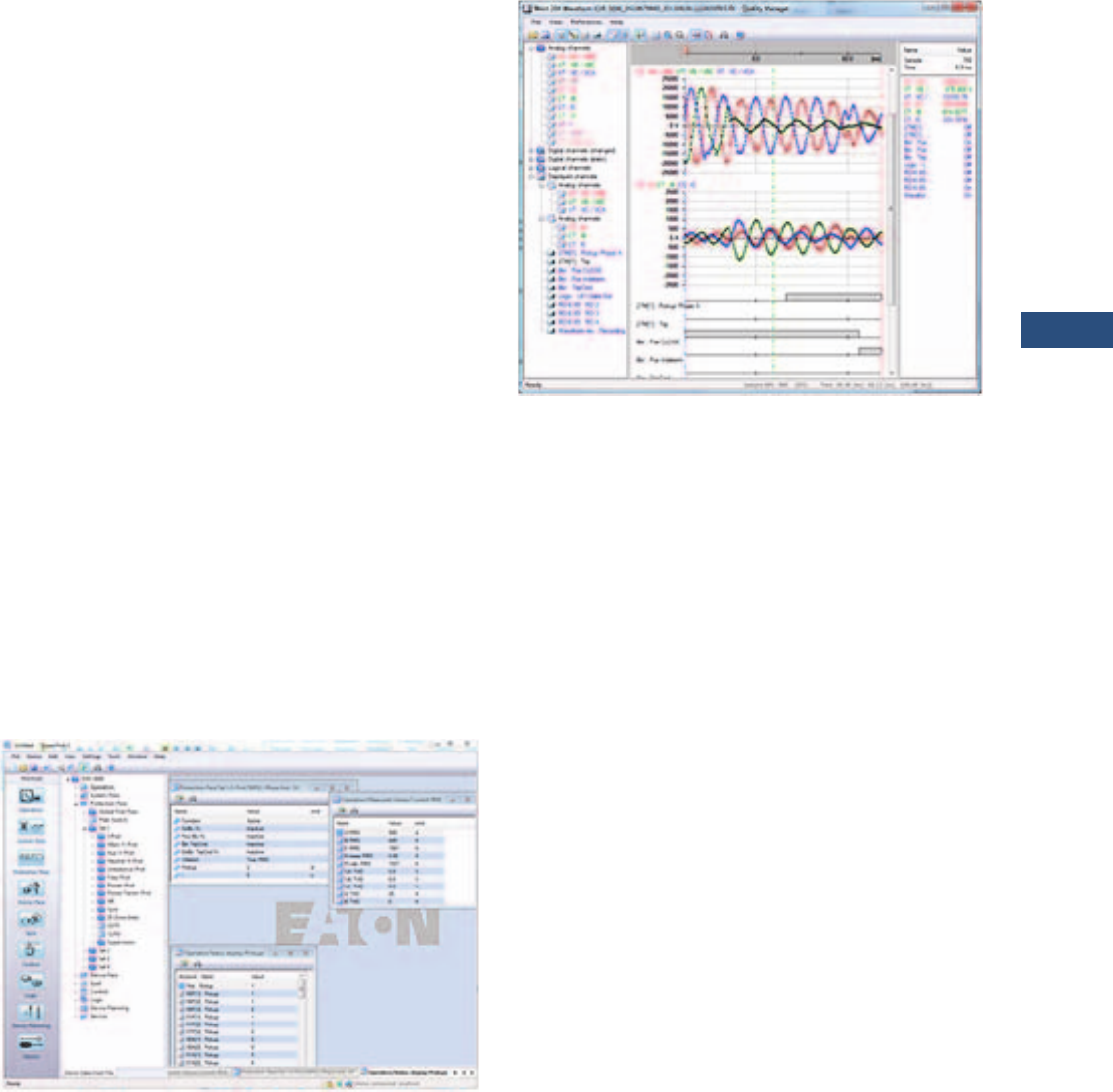
Volume 3—Power Distribution and Control Assemblies CA08100004E—March 2016 www.eaton.com V3-T9-171
9
9
9
9
9
9
9
9
9
9
9
9
9
9
9
9
9
9
9
9
9
9
9
9
9
9
9
9
9
9
9.3
Metering Devices, Protective Relays, Software and Connectivity
Protective Relays
Monitoring and Metering
Sequence of Events Records
The EDR-5000 protection
relay records a maximum of
300 events associated with
the relay. An event is
classified as a change of state
as detected by the relay.
These include relay pickups,
dropouts, trips, contact
closure, alarms, setting
changes and self-diagnostic
failures. Each event is date
and time stamped to a 1 ms
resolution. The events are
stored in a FIFO in
chronological order.
Trip Log
The EDR-5000 protection
relay will store a maximum of
20 trip records in a FIFO trip
log. Each trip record will be
date and time stamped to a 1
ms resolution. The trip log
record will include
information on the type of
fault, protection elements
that operated, fault location
and currents and voltages at
the time of the fault.
PowerPort-E
PowerPort-E is the software
program used to configure
off-line protection setting files
for all E-Series relay models.
PowerPort-E is also used for
viewing measured values of
the relays in real-time,
uploading/downloading
setting files, and retrieving
event log and waveform
records.
Waveform Capture (Quality
Manager)
The EDR-5000 relay provides
oscillographic recording
capabilities. The relay will
record all measured signals
along with the binary signals
of pickup, trip, internal logic
and contact inputs. The EDR-
5000 can record up to 7200
cycles of data. The number of
records is proportional to the
programmed size of each
record; the maximum size per
record is 600 cycles.
The waveform capture is
initiated by up to 8 different
triggers (i.e., trip/alarm
events)
or manually via
communications
or the HMI.
PowerPort-E setting software
is used to retrieve the
records. Quality Manager is a
separate
software program
downloaded
with PowerPort-
E used for analyzing the
waveform and trending files
retrieved from the relay.
PowerPort-E
Waveform Capture (Quality Manager)
Integral User Interface
The front panel user interface
has a 128 x 64 pixel LCD
display with background
illumination for wide angle
viewing in all light conditions.
17 programmable LEDs
provide quick and easy visual
display of power on, mode of
operation, alarm and trip
indication. Soft keys are
provided for operation mode
selection, scrolling through
data and settings. In addition,
the relay settings and test
functions are password
protected.
Load Profiling/Trending
The EDR-5000 relay
automatically records
selected quantities into non-
volatile memory every 5, 10,
15, 30 or 60 minutes,
depending on the trending
report setting.
Programmable I/O
The EDR-5000 distribution
protection relay provides
heavy-duty, triprated, 2
normally open and 8 Form C
contacts. Two isolated inputs
can be used for monitoring
the trip circuit. One Form C
contact is dedicated to the
relay failure alarm function
and is operated in a normally
energized (failsafe) mode.
There are eight user-
configurable discrete inputs
that accept a wet contact and
can operate through a wide
range of power. Each input
and output is user-
programmable for maximum
application flexibility.
Programmable Logic
The EDR-5000 distribution
protection relay provides logic
gates and timers that the
user can customize for
special or unique applications.
Each gate can be assigned a
logic function of either AND,
OR, NAND or NOR. Each
gate can have a maximum of
four input signals and each
input signal can be required
to be a NOT. Input signals can
be external inputs received
via the binary inputs or
internal values associated
with the protection, alarm or
metering set points. Each
gate has a unique output
assignment and designation
that can be used as the input
to another gate. There are 24
independent timers that have
adjustable pickup and dropout
delay settings.

V3-T9-172 Volume 3—Power Distribution and Control Assemblies CA08100004E—March 2016 www.eaton.com
9
9
9
9
9
9
9
9
9
9
9
9
9
9
9
9
9
9
9
9
9
9
9
9
9
9
9
9
9
9
9.3
Metering Devices, Protective Relays, Software and Connectivity
Protective Relays
Standards and Certifications
Design Standards
●Generic Standard:
●EN 61000-6-2
●EN 61000-6-3
●Product Standard:
●IEC 60255-6
●EN 50178
●UL 508 (Industrial
Control Equipment)
●CSA C22.2 No. 14-95
(Industrial Control
Equipment)
●ANSI C37.90
●UL-listed file: e217753
Standards
High Voltage Tests (IEC 60255-6)
●High frequency
interference test:
●IEC 60255-22-1 Class 3
– Within one circuit—
1 kV/2 s
– Circuit to ground—
2.5 kV/2 s
– Circuit to circuit—
2.5 kV/2 s
●Insulation voltage test:
●IEC 60255-5, EN 50178
– All circuits to other
circuits and exposed
conductive parts:
2.5 kV (eff.)/50 Hz,
1 min.
– Except interfaces:
1.5 kV DC, 1 min.
– Voltage measuring
input: 3 kV (eff.)/
50 Hz, 1 min.
●Impulse voltage test:
●IEC 60255-5: 5 kV/0.5J,
1.2/50 μs
EMC Immunity Tests
●Fast transient disturbance
immunity test (burst):
●IEC 60255-22-4: Power
supply, mains inputs—
±4 kV, 2.5 kHz
●IEC 61000-4-4 Class 4:
Other inputs and
outputs—
±2 kV, 5 kHz (coupling
network)
●ANSI C37.90.1: ±4 kV,
2.5 kHz (coupling clamp)
●Surge Immunity Test:
●IEC 61000-4-5 Class 4
– Within one circuit—
2 kV
– Circuit to ground—
4 kV
●Electrical discharge
immunity test:
●IEC 60255-22-2: Air
discharge—8 kV
●IEC 61000-4-2 Class 3:
Contact discharge—6 kV
●Radiated radio frequency
electromagnetic field
immunity test
●IEC 61000-4-3: 26 MHz –
80 MHz—10 V/m
●Class X: 80 MHz–
1 GHz—35 V/m
●ANSI C37.90.2: 1 GHz–
3 GHz—10 V/m
●Immunity to conducted
disturbances induced by
radio frequency fields:
●IEC 61000-4-6 Class 3:
10 V
●Power frequency magnetic
field immunity test:
●IEC 61000-4-8:
Continuous—30 A/m
●Class 4: 3 sec—300 A/m
EMC Emission Tests
●Radio interference
suppression test:
●IEC/CISPR11—
Limit value class B
●Radio interference
radiation test:
●IEC/CISPR11—
Limit value class B
Environmental Tests
Classification
●IEC 60068-1: Climatic—
0/055/56
●IEC 60721-3-1:
●Classification of ambient
conditions (storage)—
1K5/1B1/1C1L/1S1/1M2
but min. –13 °F (–25 °C)
●IEC 60721-3-2:
Classification of ambient
conditions (transportation)
—2K3/2B1/2C1/2S1/2M2
●IEC 60721-3-3:
Classification of ambient
conditions (Stationary use
at weather protected
locations)—3K6/3B1/3C1/
3S1/3M2 but min. 32 °F
(0 °C) and 3K8H for 2 h
Test ad: Cold
●IEC 60068-2-1:
●Temperature—
–4 °F (–20 °C)
●Test duration—16 h
Test Bd: Dry heat
●IEC 60068-2-2:
●Temperature—
131 °F (55 °C)
●Relative humidity—
<50%
●Test duration—72 h
Test cab: Damp heat
(steady state)
●IEC 60068-2-78:
●Temperature—
104 °F (40 °C)
●Relative humidity—93%
●Test duration—56 d
Test Db: Damp heat (cyclic)
●IEC 60068-2-30:
●Temperature—
131 °F (55 °C)
●Relative humidity—95%
●Cycles (12 + 12-hour)—2
Mechanical Tests
Test Fc: Vibration Response Test
●IEC 60068-2-6,
IEC 60255-21-1, Class 1:
●Displacement: (10 Hz–
59 Hz)—0.0014 in
(0.035 mm)
●Acceleration: (59 Hz–
150 Hz)—0.5 gn
●Number of cycles in
each axis: 1
Test Fc: Vibration Endurance
Test
●IEC 60068-2-6,
IEC 60255-21-1, Class 1:
●Acceleration: (10 Hz–
150 Hz)—1.0 gn
●Number of cycles in
each axis: 20
Test Ea: Shock Test
●IEC 60068-2-27,
IEC 60255-21-2, Class 1
●Shock response test:
5 gn, 11 ms, 3 impulses
in each direction
●Shock resistance test:
15 gn, 11 ms, 3 impulses
in each direction
Test Eb: Shock Endurance Test
●IEC 60068-2-29,
IEC 60255-21-2, Class 1
●Shock endurance test:
10 gn, 16 ms, 1000
impulses in each
direction
Test Fe: Earthquake Test
●IEC 60068-3-3, KTA 3503,
IEC 60255-21-3, Class 2
●Single axis earthquake
vibration test:
– 3–7 Hz: Horizontal
0.394 in (10 mm),
1 cycle each axis
– 7–35 Hz Horizontal:
2 gn, 1 cycle each axis

Volume 3—Power Distribution and Control Assemblies CA08100004E—March 2016 www.eaton.com V3-T9-173
9
9
9
9
9
9
9
9
9
9
9
9
9
9
9
9
9
9
9
9
9
9
9
9
9
9
9
9
9
9
9.3
Metering Devices, Protective Relays, Software and Connectivity
Protective Relays
Catalog Number Selection
The catalog number
identification chart defines
the electrical characteristics
and operation features
included in the EDR-5000. For
example, if the catalog number
is EDR-5000A0BA1,
the device would have
the following:
EDR-5000
(A)–8 digital inputs,
11 output relays
(0)–5 A / 1 A phase and
ground CTs, power supply
range:
19–300 Vdc, 40–250 Vac
(B)–Modbus-RTU (RS-485)
(A)–Without conformal
coating
(1)–Projection panel mount
Relay Removable Terminals
Note
1Beginning in 2016, consult factory for the availability of the following new communication options.
• Protocols: DNP3.0, PROFIBUS
• Interface ports: Fiber optic ST, RS-485 D-SUB, fiber optic LC
Hardware Option 1
A = 8 digital inputs, 11 outputs, removable
terminals, zone interlocking
B = 8 digital inputs, 11 outputs, removable
terminals, zone interlocking
and large display
Communication Options 1
B= Modbus-RTU
(RS-485)
I= Modbus-RTU (RS-485) and
Modbus-TCP (RJ-45) [only 1
active, software selected]
H= IEC 61850 GOOSE and
MMS (RJ-45)
Conformal Coating
Options
A = None
B = Conformal coated
circuit boards
Mounting Options
0 = Standard mount
1 = Projection panel mount
Hardware Option 2
0 = Phase current 5 A / 1 A, ground
current 5 A / 1 A, power supply
range: 19–300 Vdc,
40–250 Vac
1 = Phase current 5 A / 1 A, sensitive
ground current 0.5 A /0.1 A,
power supply range: 19–300 Vdc,
40–250 Vac 1
EDR5000 A 0 B A 1

V3-T9-174 Volume 3—Power Distribution and Control Assemblies CA08100004E—March 2016 www.eaton.com
9
9
9
9
9
9
9
9
9
9
9
9
9
9
9
9
9
9
9
9
9
9
9
9
9
9
9
9
9
9
9.3
Metering Devices, Protective Relays, Software and Connectivity
Protective Relays
Technical Data and Specifications
Climatic Environmental
Conditions
●Storage temperature:
–22 °F to 158 °F (–30 °C
to +70 °C)
●Operating temperature:
–4 °F to 140 °F (–20 °C
to +60 °C)
●Permissible humidity at
ann. average: <75% rel.
(on 56d up to 95% rel.)
●Permissible installation
altitude:
●6,561.67 ft (<2000 m)
above sea level
●If 13,123.35 ft (4000 m)
altitude applies, a
changed classification
of the operating and test
voltages may be
necessary
Degree of Protection EN 60529
●HMI front panel with
seal: IP54
●Rear side terminals: IP20
Routine Test
●Insulation test according to
IEC 60255-5: All tests to be
carried out against ground
and other input and output
circuits
●Aux. voltage supply, digital
inputs: 2.5 kV (eff.)/50 Hz
●Current measuring inputs,
signal relay outputs: 2.5 kV
(eff.)/50 Hz
●Voltage measuring inputs:
3.0 kV (eff.)/50 Hz
●All wire-bound
communication interfaces:
1. 5 k V D C
Housing
●Housing B2: Height / Width
7.205 in (183 mm)/ 8.374 in
(212.7 mm)
●Housing Depth (Incl.
Terminals): 8.189 in
(208 mm)
●Material, housing:
Aluminum extruded
section
●Material, front panel:
Aluminum/foil front
●Mounting position:
Horizontal (±45° around
the X-axis must be
permitted)
●Weight: Approx. 9.259 lb
(4.2 kg)
Current and Ground
Current Measurement
●Nominal currents: 1 A / 5 A
●Max. measuring range:
●Up to 40 x In (phase
currents)
●Up to 25 x In (ground
current standard)
●Up to 2.5 x In (ground
current sensitive)
●Continuous loading
capacity: 4 x In/
continuously
●Overcurrent proof:
●30 x In/10 s
●100 x In/1 s
●250 x In/10 ms
(1 half-wave)
●Power consumption:
●Phase current inputs
–At I
n = 1 A
S = 0.15 MVA
–At I
n = 5 A
S = 0.15 MVA
●Ground current input
–At I
n = 1 A
S = 0.35 MVA
–At I
n = 5 A
S = 0.35 MVA
●Frequency range: 50 Hz/
60 Hz ±10%
●Terminals: Screw-type
terminals with integrated
short-circuiters (contacts)
●Connection cross sections:
●1 x or 2 x 2.5 mm² (2 x
AWG 14) with wire end
ferrule
●1 x or 2 x 4.0 mm² (2 x
AWG 12) with ring cable
sleeve or cable sleeve
●1 x or 2 x 6 mm² (2 x
AWG 10) with ring cable
sleeve or cable sleeve
●The current measuring
board´s terminal blocks
may be used as with 2
(double) conductors
AWG 10,12,14
otherwise with single
conductors only
Plug-in Connector with
Integrated Short-Circuiter
(Conventional Current Inputs)
●Nominal current: 1 A and
5 A
●Continuous loading
capacity: 4 x In/
continuously
●Overcurrent withstand:
●30 x In/10 s
●100 x In/1 s
●250 x In/10 ms
(1 half-wave)
●Screws: M4, captive type
acc. to VDEW
●Connection cross sections:
●1 x or 2 x 2.5 mm² (2 x
AWG 14) with wire end
ferrule
●1 x or 2 x 4.0 mm² (2 x
AWG 12) with ring cable
sleeve or cable sleeve
●1 x or 2 x 6 mm² (2 x
AWG 10) with ring cable
sleeve or cable sleeve
●The current measuring
board´s terminal blocks
may be used as with 2
(double) conductors
AWG 10,12,14
otherwise with single
conductors only
Control Power Supply
●Aux. voltage: 24–270 Vdc/
48–230 Vac (–20/+10%)
●Buffer time in case of
supply failure: ≥50 ms
at minimal aux. voltage
interrupted communication
is permitted
●Maximum permissible
making current:
●18 A peak value for
<0.25 ms
●12 A peak value for
<1 ms
●The voltage supply must
be protected by a fuse of:
●2.5 A time-lag miniature
fuse approx. 0.2 x 0.8 in
(5 x 20 mm) according to
IEC 60127
●3.5 A time-lag miniature
fuse approx. 0.25 x
1.25 in (6.3 x 32 mm)
according to UL 248-14
Voltage and Residual Voltage
Measurement
●Nominal voltages: 100 V/
110 V/ 230 V/ 400 V (can be
configured)
●Max. measuring range:
2 x nominal voltage
●Continuous loading
capacity: 2 x nominal
voltage (800 Vac)
●Power consumption:
●at Vn = 100 V
S = 0.1 MVA
●at Vn = 110 V
S = 0.1 MVA
●at Vn = 230 V
S = 0.4 MVA
●at Vn = 400 V
S = 1.0 MVA
●Frequency range: 50 Hz or
60 Hz ±10%
●Terminals: screw-type
terminals
Frequency Measurement
●Nominal frequencies:
50 Hz / 60 Hz
Voltage Supply
●Aux. voltage: 24–270 Vdc/
48–230 Vac (–20/+10%)
●Buffer time in case of
supply failure: ≥50 ms
at minimal aux. voltage
communication is
permitted to be interrupted
●Max. permissible making
current:
●18 A peak value for
<0.25 ms
●12 A peak value for
<1 ms
●The voltage supply must
be protected by a fuse of:
●2.5 A time-lag miniature
fuse 5 x 20 mm (approx.
0.2 in x 0.8 in) according
to IEC 60127
●3.5 A time-lag miniature
fuse 6.3 x 32 mm
(approx. 0.25 in x
1.25 in) according
to UL 248-14

Volume 3—Power Distribution and Control Assemblies CA08100004E—March 2016 www.eaton.com V3-T9-175
9
9
9
9
9
9
9
9
9
9
9
9
9
9
9
9
9
9
9
9
9
9
9
9
9
9
9
9
9
9
9.3
Metering Devices, Protective Relays, Software and Connectivity
Protective Relays
Power Consumption
●Power supply range:
24–270 Vdc
●Power consumption
in idle mode—7 W
●Maximum power
consumption—13 W
●Power supply range:
48–230 Vac (for
frequencies of 40–70 Hz)
●Power consumption
in idle mode—7 VA
●Maximum power
consumption—13 VA
Display
●Display type: LCD with
LED background
illumination
●Resolution graphics
display: 128 x 64 pixel
●LED-type: two colored,
red/green
●Number of LEDs, housing
B2: 15
Front Interface
●Baud rates: 115,200 Baud
●Handshake: RTS and CTS
●Connection: 9-pole
D-sub plug
Real-Time Clock
●Running reserve of the
real-time clock: 1 year min.
Digital Inputs
●Maximum input voltage:
300 Vdc/259 Vac
●Input current: <4 mA
●Reaction time: <20 ms
●Fallback time: <30 ms
(Safe state of the
digital inputs)
●Four switching thresholds:
Un = 24 Vdc, 48 Vdc,
60 Vdc, 110 Vac/Vdc,
230 Vac/Vdc
●Un = 24 Vdc
– Switching threshold
1 ON: Min. 19.2 Vdc
– Switching threshold
1 OFF: Max. 9.6 Vdc
●Un = 48 V / 60 Vdc
– Switching threshold
2 ON: Min. 42.6 Vdc
– Switching threshold
2 OFF: Max. 21.3 Vdc
●Un = 110 / 120 Vac/Vdc
– Switching threshold
3 ON: Min. 88.0 Vdc /
88.0 Vac
– Switching threshold
3 OFF: Max. 44.0 Vdc
/ 44.0 Vac
●Un = 48–60 Vdc
– Switching threshold
4 ON: Min. 184 Vdc /
184 Vac
– Switching threshold
4 OFF: Max. 92 Vdc /
92 Vac
●Terminals: screw-type
terminal
Relay Outputs
●Continuous current:
5 A AC/DC
●Maximum make current:
●25 A AC / 25 A DC up to
30 V for 4s
●30 A/230 Vac according
to ANSI IEEE Std.
C37.90-2005
●30 A/250 Vdc according
to ANSI IEEE Std.
C37.90-2005
●Maximum breaking
current:
●5 A AC up to 250 Vac
●5 A DC up to 30 V
(resistive)
●0.3 A DC at 300 V
●Maximum switching
voltage: 250 Vac/250 Vdc
●Switching capacity:
1250 VA
●Contact type: Form C or
normally open contact
●Terminals: screw-type
terminals
Supervision Contact (SC)
●Continuous current:
5 A AC/DC
●Maximum switch-on
current: 15 A AC / 15 A DC
up to 30 V for 4 s
●Maximum breaking
current:
●5 A Vac up to 250 Vac
●5 A Vdc up to 30 Vdc
●0.4 A at 125 Vdc
●Contact type:
1 Form C contact
●Terminals: screw-type
Time Synchronization IRIG-B00X
●Nominal input voltage: 5 V
●Connection: Screw-type
terminals (twisted pair)
Zone Interlocking
●Zone Out:
●Output voltage (High)
4.75 to 5.25 Vdc
●Output voltage (Low) 0.0
to +0.5 Vdc
●Zone In:
●Nominal input voltage
+5 Vdc
●Max. input voltage
+5.5 Vdc
●Switching threshold ON
min. 4.0 Vdc
●Switching threshold OFF
max. 1.5 Vdc
●Galvanic isolation 2.5 kV
AC (to ground and other IO)
●Connection: Screw-type
terminals (twisted pair)
RS-485
●Master/slave: slave
●Connection: 6 screw-
clamping terminals RM 138
MIL (3.5 mm) (terminating
resistors internal)
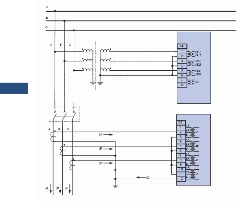
V3-T9-176 Volume 3—Power Distribution and Control Assemblies CA08100004E—March 2016 www.eaton.com
9
9
9
9
9
9
9
9
9
9
9
9
9
9
9
9
9
9
9
9
9
9
9
9
9
9
9
9
9
9
9.3
Metering Devices, Protective Relays, Software and Connectivity
Protective Relays
Wiring Diagrams
Typical AC Connections—Wye VTs, 5 A CTs and Ground Current Measured by Residual Connection
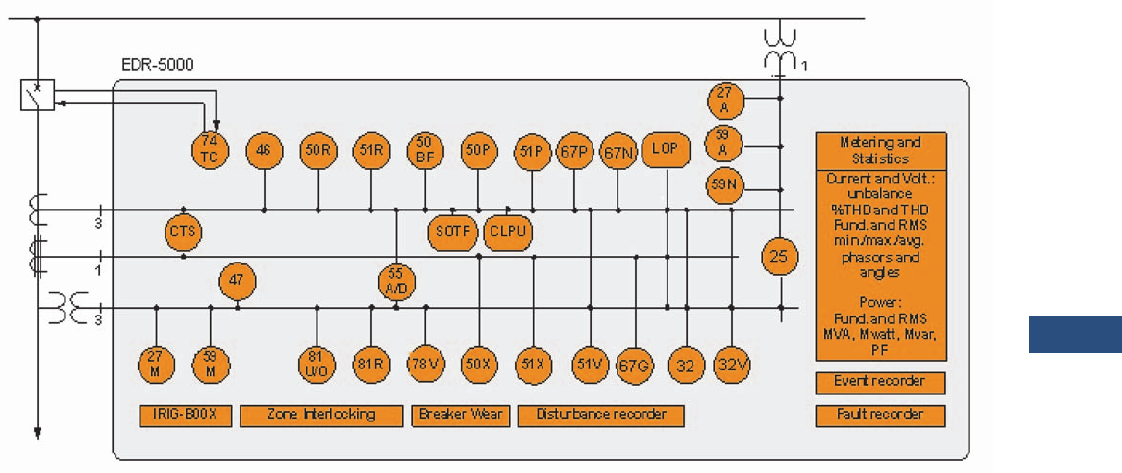
Volume 3—Power Distribution and Control Assemblies CA08100004E—March 2016 www.eaton.com V3-T9-177
9
9
9
9
9
9
9
9
9
9
9
9
9
9
9
9
9
9
9
9
9
9
9
9
9
9
9
9
9
9
9.3
Metering Devices, Protective Relays, Software and Connectivity
Protective Relays
Typical One-Line Diagram
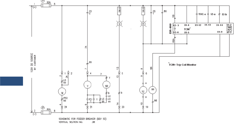
V3-T9-178 Volume 3—Power Distribution and Control Assemblies CA08100004E—March 2016 www.eaton.com
9
9
9
9
9
9
9
9
9
9
9
9
9
9
9
9
9
9
9
9
9
9
9
9
9
9
9
9
9
9
9.3
Metering Devices, Protective Relays, Software and Connectivity
Protective Relays
Ty p i c a l C o n t r o l D i a g r a m
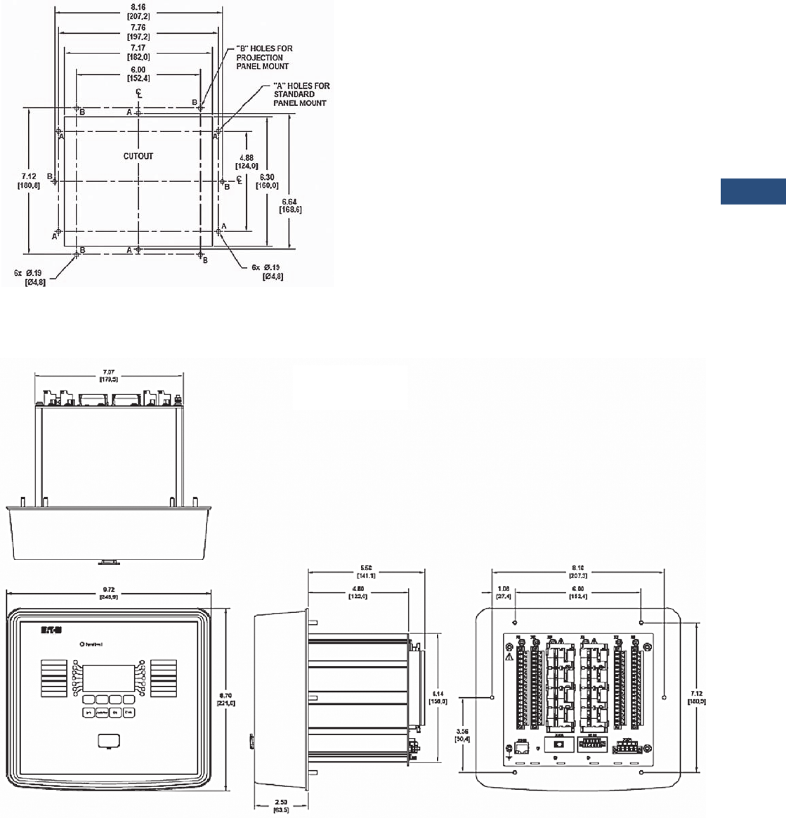
Volume 3—Power Distribution and Control Assemblies CA08100004E—March 2016 www.eaton.com V3-T9-179
9
9
9
9
9
9
9
9
9
9
9
9
9
9
9
9
9
9
9
9
9
9
9
9
9
9
9
9
9
9
9.3
Metering Devices, Protective Relays, Software and Connectivity
Protective Relays
Dimensions
Approximate Dimensions in Inches (mm)
Drilling Plan
Projection Mount Front and Side Views
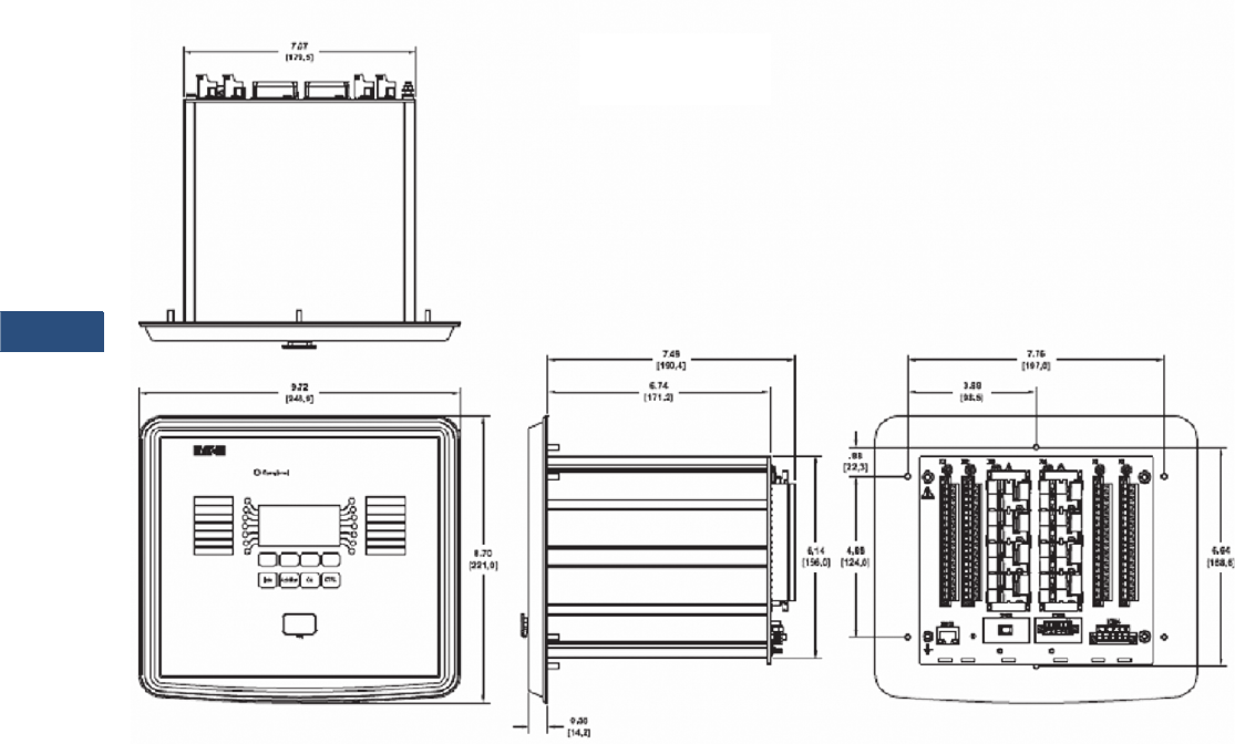
V3-T9-180 Volume 3—Power Distribution and Control Assemblies CA08100004E—March 2016 www.eaton.com
9
9
9
9
9
9
9
9
9
9
9
9
9
9
9
9
9
9
9
9
9
9
9
9
9
9
9
9
9
9
9.3
Metering Devices, Protective Relays, Software and Connectivity
Protective Relays
Approximate Dimensions in Inches (mm)
Standard Mount Front and Side Views

Volume 3—Power Distribution and Control Assemblies CA08100004E—March 2016 www.eaton.com V3-T9-181
9
9
9
9
9
9
9
9
9
9
9
9
9
9
9
9
9
9
9
9
9
9
9
9
9
9
9
9
9
9
9.3
Metering Devices, Protective Relays, Software and Connectivity
Protective Relays
Feeder Protection FP-5000
Contents
Description Page
Product Selection Guide . . . . . . . . . . . . . . . . . . . . V3-T9-143
Digitrip 3000 . . . . . . . . . . . . . . . . . . . . . . . . . . . . . V3-T9-149
EDR-3000 Feeder Protection. . . . . . . . . . . . . . . . . V3-T9-159
EDR-5000 Distribution Protection Relay . . . . . . . . V3-T9-168
FP-5000 Feeder Protection
MP-3000 Motor Protection . . . . . . . . . . . . . . . . . . V3-T9-189
MP-4000 Motor Protection . . . . . . . . . . . . . . . . . . V3-T9-199
EMR-3000 Motor Protection Relay . . . . . . . . . . . . V3-T9-205
EMR-4000 Motor Protection Relay . . . . . . . . . . . . V3-T9-217
EMR-5000 Motor Protection Relay . . . . . . . . . . . . V3-T9-230
ETR-4000 Transformer Protection Relay . . . . . . . . V3-T9-242
ETR-5000 Transformer Protection Relay . . . . . . . . V3-T9-254
EGR-5000 Generation Protection Relay. . . . . . . . . V3-T9-267
Ground Fault Relay . . . . . . . . . . . . . . . . . . . . . . . . V3-T9-280
Universal RTD Module. . . . . . . . . . . . . . . . . . . . . . V3-T9-283
FP-5000 Feeder Protection
Product Description
●Microprocessor-based
protection with monitoring
and control for medium
voltage main and feeder
applications
●Current, voltage, frequency
and power protection for
electric power distribution
systems
●Complete metering of
voltage, currents, power,
energy, minimum/
maximum and
demand functions
●Programmable logic control
functions for main-tie-main
transfer schemes
●Trip logs, event logs and
waveform capture for
better fault analysis and
system restoration
●Data Logger to provide
energy usage profiles for
better planning, utilization
and energy usage
●Compact, drawout
case design
●Multiple settings groups
●ANSI, IEC and thermal
protection curves for
greater flexibility
Application Description
Eaton’s FP-5000 Feeder
Protection relay provides
complete three-phase and
ground overcurrent and
voltage protection plus
metering in a single, compact
drawout case. It may be
used as primary protection
on feeders, mains and tie
circuit breaker applications,
and as backup protection
for transformers, high
voltage lines and differential
protection. The relay is most
commonly used on medium
voltage switchgear
applications.
The FP-5000 takes
full advantage of its
microprocessor technology
providing the user new
freedoms and a wealth of
data-gathering features. The
relay performs self-checking
of all major hardware and
firmware protection elements
to ensure their operation in
the event of a system or
component electrical failure
or fault. Protection functions
are well suited for main and
distribution feeder circuit
applications.
Programmable logic control
functions make the FP-5000
relay ideally suited for main-
tie-main and main 1/main 2
transfer schemes.
The Zone Interlocking feature
can be utilized for bus
protection instead of an
expensive and complicated
bus differential (87B)
scheme. The FP-5000 works
directly with Eaton’s Digitrip
3000 and Digitrip MV relays.
New breaker failure logic
provides faster remote
backup clearing times for
stuck breaker operation.
The multiple settings
groups can be utilized for
arc flash mitigation when
an alternative setting group,
set to have instantaneous
elements only is activated
using a selector switch and
the programmable I/O in the
FP-5000.
The FP-5000 provides trip
and close circuit monitoring
and alarming features. It
continually monitors the
complete trip and close
circuits for continuity and
readiness to trip.
Open and close pushbuttons
are conveniently located on
the front of the relay for local
breaker operation.
Loss-of-vacuum monitoring is
activated when the breaker
is open. Residual current is
monitored and alarmed
if detected.
When an electrical fault
or disturbance occurs, the
FP-5000 begins to store the
following in non-volatile
memory:
●Voltage and current
sampled data
●Calculated values
●
Status of internal protection
functions,
logic, contact
inputs and outputs
Retrieval and viewing of the
data is easy, aiding in the quick
analysis and restoration of your
electric power system.

V3-T9-182 Volume 3—Power Distribution and Control Assemblies CA08100004E—March 2016 www.eaton.com
9
9
9
9
9
9
9
9
9
9
9
9
9
9
9
9
9
9
9
9
9
9
9
9
9
9
9
9
9
9
9.3
Metering Devices, Protective Relays, Software and Connectivity
Protective Relays
Features, Benefits and Functions
When the FP-5000 isn’t
responding to disturbances
in the power system, it’s
providing valuable metering
information at the relay and
remotely. It provides energy
usage and demand reading,
and can alarm when usage
reaches a set value. Power
factor measurements can be
used for cap bank switching
to control kVAR demand.
Onboard data trending can
provide load profiles for up
to 40 days.
The protection functions are
listed below and shown on
Page V3-T9-186.
●Complete protection,
metering and control in a
single compact case to
reduce panel space, wiring
and costs
●Flexible current, voltage
and frequency protection
and programmability to
cover a broad range of
applications while
simplifying relay ordering
and reducing inventory
●Integral test function
reduces maintenance time
and expense
●Relay self-diagnostics and
reporting improves uptime
and troubleshooting
●Breaker trip circuit
monitoring improves the
reliability of the breaker
operation
●Programmable logic control
features that can replace
and eliminate external
auxiliary relays, timers
and wiring
●Zone-selective interlocking
improves coordination and
tripping times and saves
money compared to a
traditional bus differential
scheme
●Trip and event recording
in non-volatile memory
provides detailed
information for analysis and
system restoration
●256 cycles of waveform
capture aids in post fault
analysis
●Front RS-232 port and
PowerPort software
provides local computer
access and a user-friendly,
Windows®-based interface
for relay settings, and
configuration and data
retrieval
●Drawout case design for
quick and easy relay
removal and replacement
●Breaker open/close control
from relay faceplate or
remotely via
communications
●Remote communications
to Eaton’s PowerNet
monitoring system or PC
●Free PowerPort utility
software for local PC
interface to the FP-5000 for
relay settings, monitoring
and control
Phase Overcurrent (Forward,
Reverse or Both)
●Two-stage instantaneous
with timers (50P-1 and
50P-2)
●Two inverse time
overcurrent (51P-1 and
51P-2)
●Directional control
●10 standard curves
●Instantaneous or time
delay reset
●Voltage restrained time
overcurrent (51VR)
●Two independent ground
directional overcurrent
elements, one measured
(IX) and one calculated (IR)
●Two-Stage
instantaneous with
timers (50X-1 and 50X-2)
(50R-1 and 50R-2)
●Inverse time overcurrent
(51X and 51R)
●Ground directional
polarizing (67N) –3vo, Ipol,
negative sequence
●10 standard curves
●Instantaneous or time
delay reset
●Voltage restrained time
overcurrent (51VR)
●Breaker failure (50BF)
●Phase unbalance negative
sequence overcurrent
(46-1, 46-2)
●Phase voltage unbalance
and sequence protection
(47-1, 47-2)
●Main three-phase under/
overvoltage (27M-1,
27M-2, 59M-1, 59M-2)
●Auxiliary single-phase
under/over-voltage (27A-1,
27A-2, 59A-1, 59A-2)
●Under/over frequency
(81U-1, 81U-2, 81O-1,
81O-2)
●Reverse/forward power
(32-1, 32-2)
●Sync check (25)
●Power factor (55)
●Zone interlocking for bus
protection (87B). The
FP-5000 feeder relay
includes a zone selective
interlocking feature that
can be used with other
Eaton devices like the
Digitrip 3000 overcurrent
relay
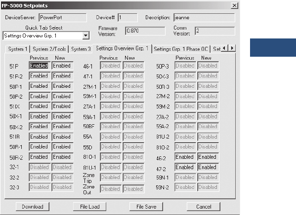
Volume 3—Power Distribution and Control Assemblies CA08100004E—March 2016 www.eaton.com V3-T9-183
9
9
9
9
9
9
9
9
9
9
9
9
9
9
9
9
9
9
9
9
9
9
9
9
9
9
9
9
9
9
9.3
Metering Devices, Protective Relays, Software and Connectivity
Protective Relays
The FP-5000 provides the
following metering functions:
●
Amperes (rms, phasor and
sequence)
●Amperes demand and
peak demand
●Volts (rms, phasor and
sequence)
●VA and VA demand
●Watts and kW demand and
peak demand
●Forward/reverse/net kWh
●VARs and kVAR demand
and peak demand
●Lead/lag/net kVARh
●Power factor
●Frequency
●Voltage and current
●%THD and magnitude THD
●Minimum/maximum
recording with date/
time stamp
●Trending (load profile
over time)
The FP-5000 provides the
following monitoring and data
recording functions that
enhance the security of the
protection system and
provides useful
information
for scheduling maintenance:
●Trip circuit monitoring
●Close circuit monitoring
●Loss-of-vacuum monitoring
●Breaker wear (accumulated
interrupted current)
●Waveform capture
(256 cycles total, up to
16 events)
●Fault data logs (up to
16 events)
●Sequence of events report
(up to 100 events)
●Clock
The FP-5000 provides
standard control functions
plus user-configurable
custom control capabilities.
This logic can be used for
applications such as main-tie-
main transfer schemes.
●Remote open/close
●Programmable I/O
●Programmable logic gates
and timers
●Multiple setting groups
(up to four)
●Bus transfer logic
●Cold load pickup
●Loss of potential
(PT blown fuses)
The FP-5000 supports the
following communication
options:
●Local HMI
●Password protected
●Addressable
●Local communication port
●Remote communication
port:
●FSK
●RS-232
●RS-485
●Protocols:
●INCOM
●Modbus
●Configuration software
Communication Software
Eaton provides two types of
communication software. The
first is PowerPort. It runs on a
PC or laptop for easy access to
a single relay to change set
points or configuration and to
view metered values and
stored data. PowerPort is free
and can be downloaded from
www.eaton.com; search for
‘PowerPort,’ then click the
download search result.
The second package is
PowerNet. PowerNet is a
power management software
package that is designed for
continuous, remote monitoring
of many devices. It provides all
the functionality of PowerPort
plus additional functions such
as billing, trending and
graphics. Contact your local
Eaton representative for more
information on PowerNet
software.
PowerPort and PowerNet Protection Overview Screen
V3-T9-184 Volume 3—Power Distribution and Control Assemblies CA08100004E—March 2016 www.eaton.com
9
9
9
9
9
9
9
9
9
9
9
9
9
9
9
9
9
9
9
9
9
9
9
9
9
9
9
9
9
9
9.3
Metering Devices, Protective Relays, Software and Connectivity
Protective Relays
Standards and Certifications
●Meets ANSI, CE and
CSA standards
Compliance
●UL Recognized,
File # E154862
●UL 1053 (1994) recognized
●ANSI C37.90 (1989)
●EN 55011 (1991)
●EN 61000-6-2 (1999)
Emission Tests
●EN 55011 (1991)—Group 1
Class A (CISPR-11,
Class A)
●FCC 47 CFR Chapter 1—
Part 15 Subpart b Class A
Immunity Tests
●ANSI C37.90.1 (1989)—
Surge Withstand Capability
●ANSI C37.90.2 (1995)—
EMI Immunity to 35V/m
●EN 61000-4-2 (1995)—
ESD Rating of 8 kV
●EN 61000-4-3 (1997)—
Radiated EM Field at
10V/m
●EN 61000-4-4 (1995)—Fast
Transient Burst at 2 kV
●EN 61000-4-5 (1995)—
Surge Immunity Test
●EN 61000-4-6 (1996)—
Conducted RF at 10V/m
●EN 61000-4-11 (1994)—
Voltage Dips and Variations
●EN 61000-4-8—Power
Frequency Magnetic
Field Immunity
Catalog Number Selection
FP-5000 Feeder Protection
Current Range
2 = 5 Amperes
3 = 1 Ampere
Communications Protocol
0 = INCOM
1 = Modbus
FP5 2 00 - 0 1
Control Voltage
0 = 48–125 Vac/Vdc
1 = 100–240 Vac/Vdc
Packaging
0 = Drawout
1 = Fixed case

Volume 3—Power Distribution and Control Assemblies CA08100004E—March 2016 www.eaton.com V3-T9-185
9
9
9
9
9
9
9
9
9
9
9
9
9
9
9
9
9
9
9
9
9
9
9
9
9
9
9
9
9
9
9.3
Metering Devices, Protective Relays, Software and Connectivity
Protective Relays
Technical Data and Specifications
Control Power
●Control voltage:
●48–125 Vac/Vdc
●100–240 Vac/Vdc
●Operating voltage:
●55–264 Vac
●38–300 Vdc
●Interruption ride-through
time: 20 cycle interruption
of nominal ac supply
●
Power consumption: 20 VA
maximum
Current Inputs
●Nominal (In): 1 A or 5 A
●CT rating:
●2 x In continuous
●80 x In for 1 second
●CT burdens:
●< 0.25 VA at 5 A
(nominal)
●< 0.05 VA at 1 A
(nominal)
Voltage Transformer Inputs
●Nominal: 120 Vac
●Operating range:
69–150 Vac
●Burden:
●<0.015 at 120 Vac
●1 megaohm
Metering Accuracy
●Phase current:
●±0.5% or ±0.025 A from
0.02–20 per unit fully
offset current waveform
●Ground current:
●±0.5% of full scale (In)
from 0.02–2.0 per unit
fully offset current
waveform
●Phase voltage: ±0.5% or
±0.2V from 0–160 Vac
●Frequency measurement
accuracy: ±0.02 Hz
●Phase angle: ±1 ºC
●Power metering accuracy:
±1.5%
●
Metering accuracy
temperature range: 32 ºF to
122 ºF (0 ºC to 50 ºC)
●Temperature range: ±5%
for operation below 32 ºF
(0 ºC) and above 122 ºF
(50 ºC)
●Relay outputs:
●2 Form C, NO and NC
●5 Form A, NO only
●Input signal frequency
necessary for accurate
operation:
●60 Hz nominal, 57–63 Hz
(±5%)
●50 Hz nominal, 47–53 Hz
(±5%)
●Clock accuracy:
●Free running ±1 minute/
month at 25 ºC
●Clock automatically
updated by PowerNet
host when present
Protective Functions
Phase and Ground
Overcurrent Protection
●Inverse characteristics:
Mod, Very, Extremely,
IECA, IECB, IECC, It, I2t,
I4t, Flat
●TOC (51) pickup range:
0.1–4.0 per unit in 0.01
steps
●Time multipliers: 0.05–10.0
in 0.01 steps
●IOC (50) pickup range: 0.1–
20.0 per unit in 0.01 steps
●Pickup accuracy: ±1%
(at 0.1–2 per unit)
●Time delay: 0–9999 cycles
in 1 cycle steps
●Time accuracy: ±3% or
±30 ms
●Directional (67, 67N, 67G):
forward, reverse or both
Voltage Unbalance (47)
●Threshold (minimum
voltage) 1–100 volts in
1 volt steps
●% V2/V1: 4–40% in
1% steps
●Time delay: 0–9999 cycles
in 1 cycle steps
Current Unbalance
●Threshold (minimum
current) 0.1–20.0 per unit
in 0.01 steps
●% I2/I1: 4–40% in
1% steps
●Time delay: 0–9999 cycles
in 1 cycle steps
Under/Overvoltage Protection
●Pickup range: 10–150 volts
in 1 volt steps
●Time delay: 0–9999 cycles
in 1 cycle steps
Under/Over Frequency
Protection
●Pickup range: 45–65 Hz in
0.01 Hz steps
●Time delay: 0–9999 cycles
in 1 cycle steps
Breaker Failure Protection
●Pickup range: 0.1–5.0 per
unit in 0.01 steps
●Time delay: 0–9999 cycles
in 1 cycle steps
Power Protection (32)
●Forward/reverse:
over/under
●Pickup accuracy: ±1.0%
●Trip time accuracy:
0 to 12 cycles or 0.1%,
whichever is greater
Sync Check (25)
●Phase angle: 1 to 60 °C
●Slip frequency: 0.1 to 2 Hz
●Voltage differential: 1 to
100 volts
●Breaker close time: 0 to
9999 cycles
Power Factor
●Trigger/reset threshold: 0.5
lag to 0.5 lead in 0.01 steps
●Time delay: 0–1000
seconds in 1 second steps
Discrete Inputs
●Number of contact
inputs: 8
●Rating: 48 Vdc wetting
voltage provided with
internal ground only
Output Contacts
●Number of output
contacts: Five Form A and
two Form C
Rating of Output Contacts
●Momentary:
●Make 30 A AC/DC for
0.25
seconds
●Break 0.25 A at 250 Vdc
(resistive)
●Break 5 A at 120/240
Vac
●Continuous:
●5 A at 120/240 Vac
●5 A at 30 Vdc
Logic and Control Functions
●Six programmable logic
gates for AND, OR, NAND,
NOR operation
●Two latching (flip/flop)
gates
●Six timer gates provide
on/off delays
INCOM Communications
●Baud rate: 9600 fixed
●Maximum distance:
10,000 feet (3048 m)
●Protocol: INCOM
RS-485 Communications,
Rear Panel
●Baud rate: 19.2 K, 9.6 K
●Protocol: Modbus RTU
RS-232 Communications,
Front Panel
●Baud rate: 38.4 K, 19.2 K,
9.6 K
●Connector standard 9-pin
subminiature, three-wire
●Protocol: INCOM
Environmental Ratings
●Operating temperature:
–0 ºF to +140 ºF (–40 ºC to
+60 ºC) Product tested to
+185 ºF (+85 ºC)
●Storage temperature:
–40 ºF to +185 ºF (–40 ºC to
+85 ºC)
●Humidity: 5–95% relative
humidity (noncondensing)
●Altitude: 0–6350 feet
(0–1935 m) above Mean Sea
Level
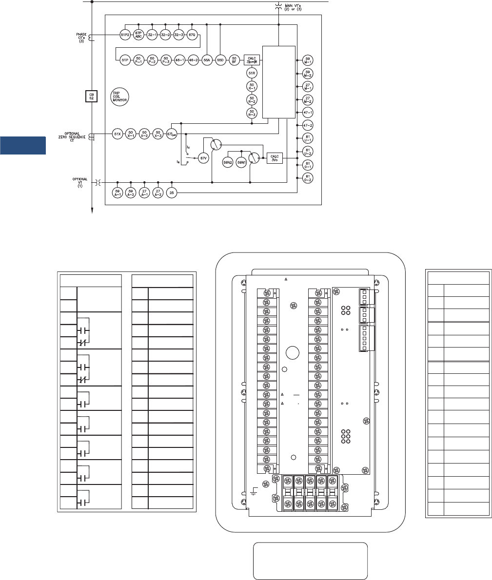
V3-T9-186 Volume 3—Power Distribution and Control Assemblies CA08100004E—March 2016 www.eaton.com
9
9
9
9
9
9
9
9
9
9
9
9
9
9
9
9
9
9
9
9
9
9
9
9
9
9
9
9
9
9
9.3
Metering Devices, Protective Relays, Software and Connectivity
Protective Relays
Wiring Diagrams
FP-5000 One-Line Drawing
FP-5000 Rear View and Terminal Designations
Metering
FP-5000
Load
V, I, F, PF,
W, VARS, VA
Energy
Demand
Min./Max.
% THD
Phasors
Data Logger
Waveform
SER
Fault Records
TB1 TB2
101 Power Supply
Input (+)
102
103
104
105
106
107
108
109
110
111
112
113
114
115
116
117
118
201
202
203
204
205
206
207
208
209
210
211
212
213
214
215
216
217
218 Vg Main
Vx2 Aux
Vx1 Aux
VC(+) Main
VB(+) Main
VA(+) Main
Not Used
Not Used
C In 1
C In 2
C In 3
C In 4
C In Source 1
C In Source 2
C In 5
C In 6
C In 7
C In 8
Trip 1 N.O.
Trip 1 Com.
Trip 2 N.O.
Trip 2 Com.
RLY 3 N.O.
RLY 3 Com.
RLY 4 N.O.
RLY 4 Com.
RLY 5 N.O.
RLY 5 Com.
Alarm Com.
Alarm N.O.
Alarm N.C.
Power Supply
Input (–)
RLY Healthy
Com.
RLY Healthy
N.O.
RLY Healthy
N.C.
A1 B1 C1 X1 N.C. 1
A2 B2 C2 X2 N.C. 2
TB4
118
117
116
115
114
113
112
111
110
109
108
107
106
105
104
103
102
101
218
217
216
215
214
213
212
211
210
209
208
207
206
205
204
203
202
201
Red
White
Factory Connection Only
TB2
TB1 TB3 TB3
J1-1
J1-2
J1-3
J2-1
J2-2
J2-3
J3-1
J3-2
J3-3
J3-4
J3-5 Zone Com.
J5-1 RS485(+)
J5-2 RS485(-)
J5-3 RS485com
J5-4 RS485shield
J4-1
J4-2
J4-3
PowerNet
PowerNet
PowerNet Shield
Accessory Bus
Accessory Bus
Zone In
Accessory Bus
Shield
Zone Out
Zone Com.
Zone Shield
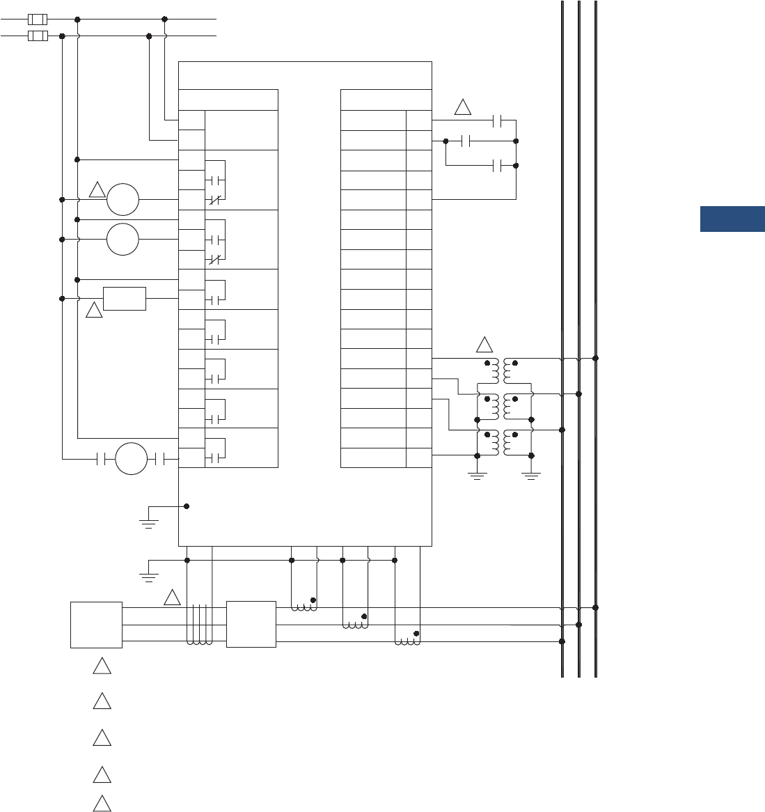
Volume 3—Power Distribution and Control Assemblies CA08100004E—March 2016 www.eaton.com V3-T9-187
9
9
9
9
9
9
9
9
9
9
9
9
9
9
9
9
9
9
9
9
9
9
9
9
9
9
9
9
9
9
9.3
Metering Devices, Protective Relays, Software and Connectivity
Protective Relays
FP-5000 Typical Connection Drawing Using Wye PTs
ac/dc
Power Supply
(+)
(–)
48 – 125 Vac/dc or
100 – 240 Vac/dc
2
3
Breaker
Close
52A 52A
4
Ground
X2 X1
Load 52
A2 A1 B2 B1 C2 C1
5
C B A
C B A
152A
52B
52B TOC
FP-5000
TB1 TB2
101 Power Supply
Input (+)
102
103
104
105
106
107
108
109
110
111
112
113
114
115
116
117
118
201
202
203
204
205
206
207
208
209
210
211
212
213
214
215
216
217
218Vg Main
VX2 Aux
VX1 Aux
VC(+) Main
VB(+) Main
VA(+) Main
Not Used
Not Used
C In 1
C In 2
C In 3
C In 4
C In Source 1
C In Source 2
C In 5
C In 6
C In 7
C In 8
Trip 1 N.O.
Trip 1 Com.
Trip 2 N.O.
Trip 2 Com.
RLY 3 N.O.
RLY 3 Com.
RLY 4 N.O.
RLY 4 Com.
RLY 5 N.O.
RLY 5 Com.
Alarm Com.
Alarm N.O.
Alarm N.C.
Power Supply
Input (–)
RLY Healthy
Com.
RLY Healthy
N.O.
RLY Healthy
N.C.
1For maximum breaker diagnostics use both 52A and 52B contacts.
Some diagnostics are not available if only one of the two is used.
A relay failure alarm should provide immediate attention as circuit
is no longer protected. Relay failure output is normally energized.
FP-5000 can initiate a breaker close via the front panel interface
and/or remote activation through communication or discrete input.
Residual connection may be used in place of zero sequence CT.
Delta or open delta PT connection may be used in place of wye-ground connection.
2
3
4
5
Relay
Failure
Alarm
Breaker
Alarm
52
TC
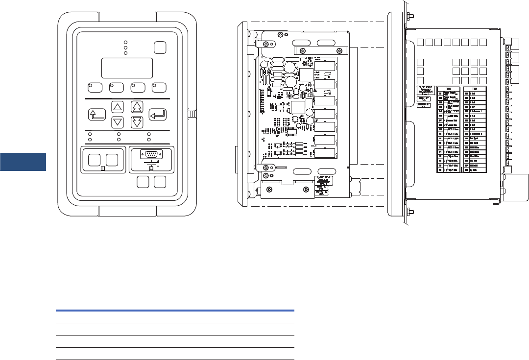
V3-T9-188 Volume 3—Power Distribution and Control Assemblies CA08100004E—March 2016 www.eaton.com
9
9
9
9
9
9
9
9
9
9
9
9
9
9
9
9
9
9
9
9
9
9
9
9
9
9
9
9
9
9
9.3
Metering Devices, Protective Relays, Software and Connectivity
Protective Relays
FP-5000 Front View and Drawout Case Side View
Dimensions
Approximate Dimensions in Inches (mm)
FP-5000 Feeder Protection Relay
Height Width Depth
Shipping Weight
Lbs (kg)
In Front of Panel
11.34 (288.0) 7.72 (196.1) 0.80 (20.3) 12.5 (5.7)
Behind Panel
6.70 (170.2) 5.30 (134.6) 6.90 (175.3) 12.5 (5.7)
Feeder Protection
FP-5000
Operational
Breaker Closed
Breaker Open
Reset
Monitor View Setting Log Status/Control
Enter
Previous
Phase Trip Ground Trip Other Trip
Alarm Pickup Auxiliary
Set Test
Close Open
Breaker

Volume 3—Power Distribution and Control Assemblies CA08100004E—March 2016 www.eaton.com V3-T9-189
9
9
9
9
9
9
9
9
9
9
9
9
9
9
9
9
9
9
9
9
9
9
9
9
9
9
9
9
9
9
9.3
Metering Devices, Protective Relays, Software and Connectivity
Protective Relays
MP-3000
Contents
Description Page
Product Selection Guide . . . . . . . . . . . . . . . . . . . . V3-T9-143
Digitrip 3000 . . . . . . . . . . . . . . . . . . . . . . . . . . . . . V3-T9-149
EDR-3000 Feeder Protection. . . . . . . . . . . . . . . . . V3-T9-159
EDR-5000 Distribution Protection Relay . . . . . . . . V3-T9-168
FP-5000 Feeder Protection . . . . . . . . . . . . . . . . . . V3-T9-181
MP-3000 Motor Protection
MP-4000 Motor Protection . . . . . . . . . . . . . . . . . . V3-T9-199
EMR-3000 Motor Protection Relay . . . . . . . . . . . . V3-T9-205
EMR-4000 Motor Protection Relay . . . . . . . . . . . . V3-T9-217
EMR-5000 Motor Protection Relay . . . . . . . . . . . . V3-T9-230
ETR-4000 Transformer Protection Relay . . . . . . . . V3-T9-242
ETR-5000 Transformer Protection Relay . . . . . . . . V3-T9-254
EGR-5000 Generation Protection Relay. . . . . . . . . V3-T9-267
Ground Fault Relay . . . . . . . . . . . . . . . . . . . . . . . . V3-T9-280
Universal RTD Module. . . . . . . . . . . . . . . . . . . . . . V3-T9-283
MP-3000 Motor Protection
Product Description
●Microprocessor-based,
multi-function motor
protection
●Current only device—
no need to add PTs
●Intel-I-Trip™ overload
protection based on
motor data
●Event recording and
operational logging
●Motor Start Profile™
●Optional Quick Release
Drawout Case
●Used on AMPGARD®
and medium voltage
assemblies
●“Help” menu provides
user operational assistance
Application Description
Eaton’s MP-3000 motor
protection relay is a
multifunctional
microprocessor-based
protective relay for the
protection of three-phase AC
motors. The MP-3000 motor
relay may be applied to any
size motor at any voltage
level. It is most commonly
used on large, medium
voltage three-phase induction
motors. It has also been
widely used on important
low voltage (480 volt)
motor applications and
synchronous motors.
The MP-3000 motor relay is
a current only device that
monitors three-phase and
ground currents. It provides
motor overload, stall, short
circuit, phase unbalance,
single phasing and ground
fault motor protection.
It can also be used to provide
protection for a load jam or
loss of load condition. Please
refer to Page V3-T9-193.
The MP-3000 motor relay
provides start control logic
to protect the motor against
excessive starts or starting
the motor before it has had
sufficient time to cool down.
The MP-3000 motor relay
may be applied to either
across the line starters or
reduced voltage starters. On
reduced voltage starters, the
MP-3000 relay can control the
switch from reduced voltage
to full voltage based on time
and/or motor transition. The
MP-3000 can protect the
starter against failure to
transition to full voltage
through contact feedback and
an incomplete sequence
function.
The MP-3000 motor relay is
generally used on a motor
starter or a breaker used for
a motor load. The MP-3000
motor relay provides the
intelligence to protect and
control the motor against
abnormal operating
conditions. It monitors the
currents from either a 5 A
or 1 A secondary of a CT
circuit. Ground current may
be obtained from either a
ground CT or from the
residual connection of the
phase CTs. It provides a
Form C contact output for
controlling the starter contacts
or breaker operation.

V3-T9-190 Volume 3—Power Distribution and Control Assemblies CA08100004E—March 2016 www.eaton.com
9
9
9
9
9
9
9
9
9
9
9
9
9
9
9
9
9
9
9
9
9
9
9
9
9
9
9
9
9
9
9.3
Metering Devices, Protective Relays, Software and Connectivity
Protective Relays
Features, Benefits and Functions
●Complete motor protection
and control in a single
compact case reduces
panel space requirements
and wiring costs
●Microprocessor design
with self diagnostics
eliminates calibration
and reduces installation,
commissioning and
maintenance
●Programmable stop
2–20% of PCT
●Intel-I-Trip overload
protection develops
customized curve from
manufacturer’s supplied
motor data
●Intel-I-Trip overload
protection provides
adaptive trip characteristics
based on motor
temperature when motor
RTDs are connected
through an optional
URTD module
●Meets UL 1053 ground
fault protection standards
that eliminates the need
for a separate ground relay
saving cost, space, wiring
and time
●Voltage dip/loss ride
through capability reduces
unnecessary trips caused
by poor power quality
●Motor currents,
temperatures and
conditions are monitored
and displayed either locally
or remotely
●Event log provides motor
operating records for the
most recent 20 Trip or
Alarm events with date
and time stamping. This
information can improve
troubleshooting and
reduce downtime
●Log book records the most
recent 100 events such as
motor START/STOP and
set point changes to
provide a log of motor
operation with date and
time stamping
●RTD diagnostics reduces
unnecessary tripping
caused by faulty RTD, RTD
wiring or communications
●Arm/Disarm feature
improves security for
critical motor applications
●Motor Start profile verifies
protection and motor
starting coordination. This
feature can be used to
develop protection settings
on old motors where data
is not available
●Optional communication
module and Eaton’s
software simplifies setting,
configuration, monitoring,
commissioning and data
retrieval either locally or
remotely
●Optional Quick Release
Drawout Case construction
simplifies relay removal
and replacement
The protection functions are
listed below.
●I2t overload protection
(49/51)
●Locked rotor (49S/51)
●Ultimate trip current (51)
●Negative sequence phase
unbalance (46)
●Instantaneous
overcurrent (50)
●Ground fault
protection (50G)
●RTD trip and alarm with
URTD module (49/38)
●Underload trip (37)
●Starts per time (66)
●Jam or stall (51R)
●Auto or manual reset (86)
●Fail-safe or non-fail-safe
trip modes
The metering functions are:
●Motor currents:
●Average current (Iave)
●Individual phase and
ground current in
primary amperes
●Percent of full load
●Percent of phase
unbalance
●RTD temperatures:
●Individual winding
●Motor bearing
●Load
●Auxiliary temperatures
●Motor conditions:
●Percent of I2t thermal
bucket
●Time before start
●Remaining starts
allowed
●Oldest start time
Standards and Certifications
The MP-3000 motor
protection was designed to
meet the industry standards
for protective relays. It is
recognized under UL 1053
Ground Fault Protection
Standard.
●UL recognized
(File No. E154862)
●UL 1053 recognized
●UL 508 recognized
●ANSI C37.90, C37.90.1
●cUL
●CSA

Volume 3—Power Distribution and Control Assemblies CA08100004E—March 2016 www.eaton.com V3-T9-191
9
9
9
9
9
9
9
9
9
9
9
9
9
9
9
9
9
9
9
9
9
9
9
9
9
9
9
9
9
9
9.3
Metering Devices, Protective Relays, Software and Connectivity
Protective Relays
Product Selection
MP-3000
Options and Accessories
Additional Related Products
by Eaton’s Cutler-Hammer®
Series
The MP-3000 is available in
either a fixed mount or Quick
Release Drawout Case. Both
mountings use the same
panel cutout. Page V3-T9-196
shows cutout dimensions.
Page V3-T9-193 shows a
typical fixed mountwiring
diagram for a medium voltage
motor starter application.
Page V3-T9-194 shows the
fixed mount terminal
designation. Page V3-T9-196
shows the drawout case
panel mounting, and shows
the drawout case terminal
designation.
The Universal RTD module
(URTD) is required when the
motor is equipped with RTDs
that you wish to monitor and
use for protection. The URTD
can be mounted near the
motor to reduce RTD wiring
and costs. Page V3-T9-195
shows MP-3000 and URTD
inter-connection wiring.
Please refer to the URTD
information described
elsewhere in this catalog.
The MP-3000 motor
protection is designed to
operate from 120 Vac or
240 Vac auxiliary control
power. The MP-3000 motor
relay can be used with DC
control power with the
addition of the IQDCPS.
The IQDCPS is an inverter
from DC to AC.
Description
Catalog
Number
MP-3000 Drawout, 5 A with RS-232 MP3011
MP-3000 Drawout, INCOM, 5 A with RS-232 MP3012
MP-3000 Drawout, Modbus, 5 A with RS-232 MP3013
MP-3000 Drawout, DeviceNet, 5 A with RS-232 MP3014
MP-3000 Drawout, 1 A with RS-232 MP3111
MP-3000 Drawout, INCOM, 1 A with RS-232 MP3112
MP-3000 Drawout, Modbus, 1 A with RS-232 MP3113
MP-3000 Drawout, DeviceNet, 1 A with RS-232 MP3114
MP-3000 Fixed Case, 5 A with RS-232 MP3010
MP-3000 Fixed Case, INCOM, 5 A with RS-232 MP3010-INCOM
MP-3000 Fixed Case, Modbus, 5 A with RS-232 MP3010MODBUS
MP-3000 Fixed Case, DeviceNet, 5 A with RS-232 MP3010DEVICEN
MP-3000 Fixed Case, 1 A with RS-232 MP3110
MP-3000 Fixed Case, INCOM, 1 A with RS-232 MP3110-INCOM
MP-3000 Fixed Case, Modbus, 1 A with RS-232 MP3110MODBUS
MP-3000 Fixed Case, DeviceNet, 1 A with RS-232 MP3110DEVICEN
MP-3000 Fixed Case, INCOM, 5 A with RS-232, URTD MP3010VPI
MP-3000 Fixed Case, Modbus, 5 A with RS-232, URTD MP3010VPM
MP-3000 Fixed Case, DeviceNet, 5 A with RS-232, URTD MP3010VPD
MP-3000 Fixed Case, INCOM, 1 A with RS-232, URTD MP3110VPI
MP-3000 Fixed Case, Modbus, 1 A with RS-232, URTD MP3110VPM
MP-3000 Fixed Case, DeviceNet, 1 A with RS-232, URTD MP3110VPD
MP-3000

V3-T9-192 Volume 3—Power Distribution and Control Assemblies CA08100004E—March 2016 www.eaton.com
9
9
9
9
9
9
9
9
9
9
9
9
9
9
9
9
9
9
9
9
9
9
9
9
9
9
9
9
9
9
9.3
Metering Devices, Protective Relays, Software and Connectivity
Protective Relays
Technical Data and Specifications
Control Power
●Nominal rating:
●120 Vac or 240 Vac
●+10%, –25%
●Operating range:
●120 Vac: 90 132 Vac
●240 Vac:180 264 Vac
●Frequency: 50 or 60 Hz
●Power use:
●20 VA maximum
●URTD: 6 VA maximum
●IPONI: 1 VA maximum
●Ride-through time:
30 cycles from nominal Vac
Current Inputs
●Nominal (In): 1 A or 5 A
●CT rating:
●2 x In continuous
●50 x In for 1 second
●Burdens:
●< 0.25 VA at 5 A
●< 0.05 VA at 1 A
Metering Accuracy
●Phase current: ±1% of In
(5–100%)
●
Ground current: ±1.5% of I
n
(0–55%)
Discrete Inputs
●Number of inputs: two
programmable
●Ratings:
●1.2 VA at 120 Vac
●Maximum off = 36 Vac
●Minimum on = 86 Vac
Output Contacts
●Number of outputs: four
Form C, programmable
●Momentary:
●Make 30 A AC/DC for
0.25 seconds
●Break 0.25 A at 250 Vdc
(resistive)
●Break 5 A at 120 240 Vac
●Continuous:
●5 A at 120/240 Vac
●5 A at 30 Vdc
Analog Output
●Rating: ± 4–20 mA
programmable
●Maximum load: 1K ohm
●Accuracy: 1%
Motor Overload Protection (I2t)
●Full load amperes:
10–3000 A
●
Locked rotor current:
300–1200% FLA
●Locked rotor time:
1–120 seconds
●Ultimate trip current:
85–150% FLA
●Phase CT ratio:
10–4000 (In
)
●Ground CT ratio:
10–4000 (In
)
●Timing accuracy: ±
2.5% or
±30 ms
for I > 1.1x U.T.C
Trip Setting Range
●Ground fault (GF): Off,
2–55% CT ratio
●GF start time delay:
2–60 cycles
●GF run time delay:
0–60 cycles
●Timer accuracy: ± 20 ms
●Instantaneous O.C.: Off,
300–1600% FLA
●IOC start time delay:
2–60 cycles
●Timer accuracy: ±20 ms
●JAM trip: Off,
100–1200% FLA
●Underload trip: Off,
1–90% FLA
●Phase unbalance trip: Off,
4–40% Ineg/Ipos
●Start delay timers:
●0–120 seconds
(underload and phase
unbalance)
●0–1200 seconds (jam)
●Run delay timers: 0–240
seconds
●Timer accuracy: ±0.5%
+100 ms
Alarm Setting Range
●Ground fault: Off, 2–55%
CT ratio
●Overload I2t: Off,
60–99% I2t
●JAM: Off, 100–1200% FLA
●Underload: Off,
1–90% FLA
●Phase unbalance: Off,
4–40% Ineg/Ipos
●Run delay timers:
0–240 seconds
Start Control Functions
●Starts per time: 1–10 starts
●Time for starts per time:
Off, 1–240 minutes
●Time between starts: Off,
1–240 minutes
●Number of cold starts:
1–5 starts
●Motor transition current:
10–300% FLA
●Time for transition:
0–1200 seconds
●Inc. sequence timer: Off,
1–240 seconds
●Long acceleration timer:
Off, 1–1200 seconds
●Anti-Backspin timer: Off,
1–3600 minutes
RTD Inputs (Requires
URTD module)
●Sensor types:
●10 ohm copper
●100 ohm nickel
●120 ohm nickel
●100 ohm platinum
URTD Module Communications
●Interface:
●Electrical (three-wire)
●Fiber optic (preferred)
●Fiber optic cable: Type
HBFR-ERS or EUS
Clock
●Accuracy: ±1 minute/
month at 77 ºF (25 °C)
IPONI Communications
●Type: two-wire, FSK
●Baud rate: 1200 or
9600 baud
●Protocol: INCOM
●Functions:
●Read/write set points
●Read metered values
●Read trip/alarms
●Read events/history
●View starting profile
MPONI Communications
●Type: 5-wire, 485
●Baud rate: 1200 or
9600 baud
●Protocol: Modbus RTU
●Functions:
●Read/write set points
●Read metered values
●Read trip/alarms
●Read events/history
●View starting profile
DPONI Communications
●Type: J-wire
●Baud rate: 500 k, 250 k,
125 k
●Protocol: DeviceNet
●Functions:
●Read metered values
●Read trip/alarms
Logging
●Log book: 100 events
●Log event: 20 trips and
alarms
●Log start: last four starts
●Start profile: last four starts
(communication only)
●History records: motor,
trips, alarms and total
records
Environmental Conditions
●Operating temperature:
–4 ºF to 140 ºF
(–20 ºC to +60 ºC)
●Storage temperature:
–49 ºF to +185 ºF
(–45 °C to +85 °C)
●Humidity: 0–95%
noncondensing
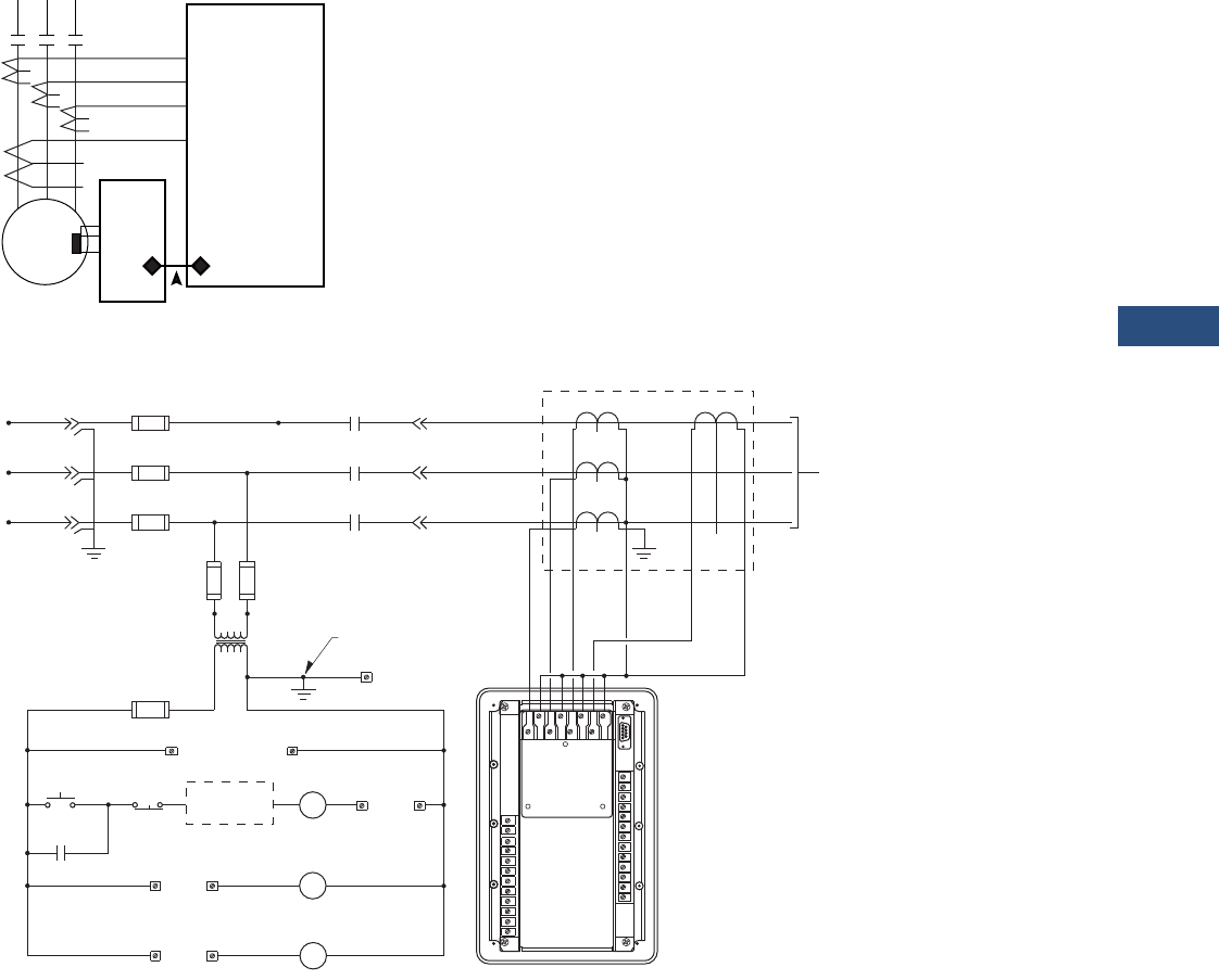
Volume 3—Power Distribution and Control Assemblies CA08100004E—March 2016 www.eaton.com V3-T9-193
9
9
9
9
9
9
9
9
9
9
9
9
9
9
9
9
9
9
9
9
9
9
9
9
9
9
9
9
9
9
9.3
Metering Devices, Protective Relays, Software and Connectivity
Protective Relays
Wiring Diagrams
MP-3000 Motor Relay Protection Functions
MP-3000 Fixed Mount Typical
Motor
MP-3000
Protection Functions
49/51 Overload I2T
49S/51 Locked Rotor
51R Jam/Stall
37 Loss of Load/
Underload
46 Phase Loss/
Unbalance
50 Phase Inst. OC
50G Ground Inst. OC
66 Starts per time
period
URT
11 RTDs
H
1
A
H
2
A
H
1
B
H
2
B
H
1
C
H
2
C
G
1
G
2
MP-3000
Back View
with Jumper
Connection
CPT
Primary
Fuses
Secondary
Fuses 5
Ground
Ground
Non-Current
Carrying Ground
M
M
M
Main
Fuse
L1
L2
L3
L1
L2
L3
A
B
C
Gnd.
T1
T2
T3
X1 X2
CTs
GFCT
To Motor or
Load Device
Under Control
ac Supply
to MP-3000
47
11 12
START STOP
M
Alarm
18 19
Alarm Contacts
Auxiliary Trip Contacts
15 16
Auxiliary
Trip
Trip Contacts
Additional
Control M
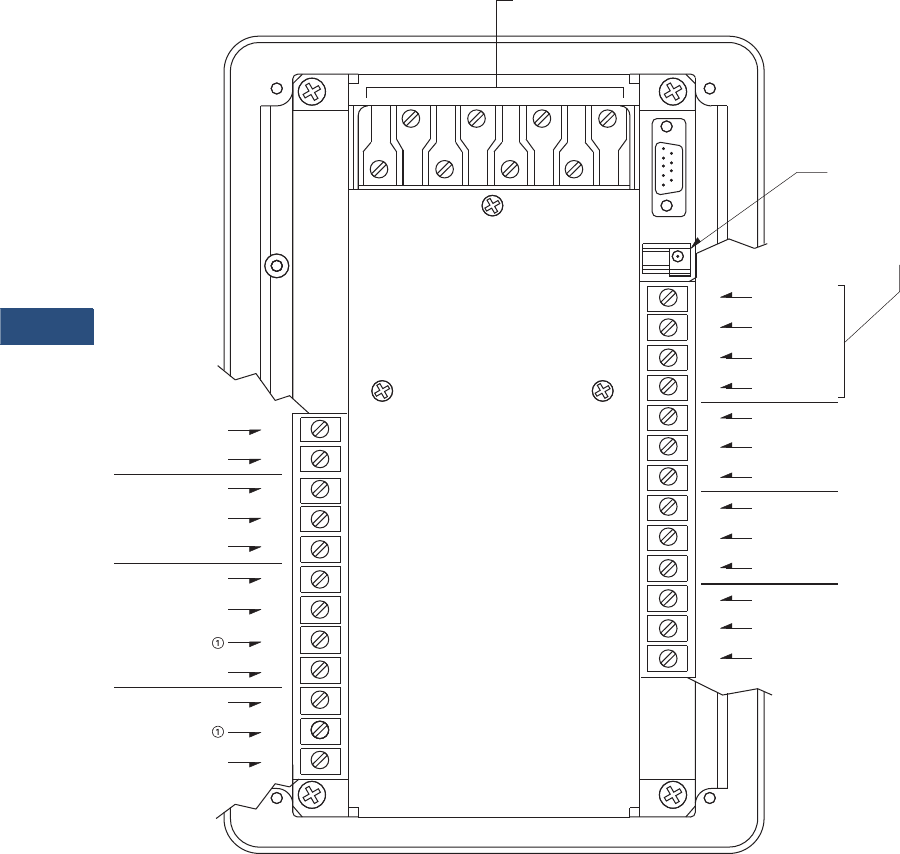
V3-T9-194 Volume 3—Power Distribution and Control Assemblies CA08100004E—March 2016 www.eaton.com
9
9
9
9
9
9
9
9
9
9
9
9
9
9
9
9
9
9
9
9
9
9
9
9
9
9
9
9
9
9
9.3
Metering Devices, Protective Relays, Software and Connectivity
Protective Relays
MP-3000 Terminal Identification
Note
1Caution: Do not connect terminals 6 and 9 together.
+4/20 mA Output
-4/20 mA Output
Aux. 2 N/C
Aux. 2 N/O
Aux. 2 Com.
120 V or 240 V
Earth Ground
iscrete Source
Neutral
Discrete In 1
Discrete Com.
Discrete In 2
Trip Com.
Trip N/C
Trip N/O
Aux.
1 N/C
Aux.
1 N/O
Aux.
1 Com.
Alarm N/C
Strobe
Alarm Com.
Alarm N/O
Data
Common
Shield
URTD Optical Fiber
Communications
(Preferred Method)
or
URTD Wired
Communication
CT Connections
MP-3000
1
2
3
4
5
6
7
8
9
10
25
24
23
22
21
20
19
17
18
16
11
12
13
15
14
H
1
A
H
1
B
H
2
A
H
1
C
H
2
B
H
2
C
G
2
G
1
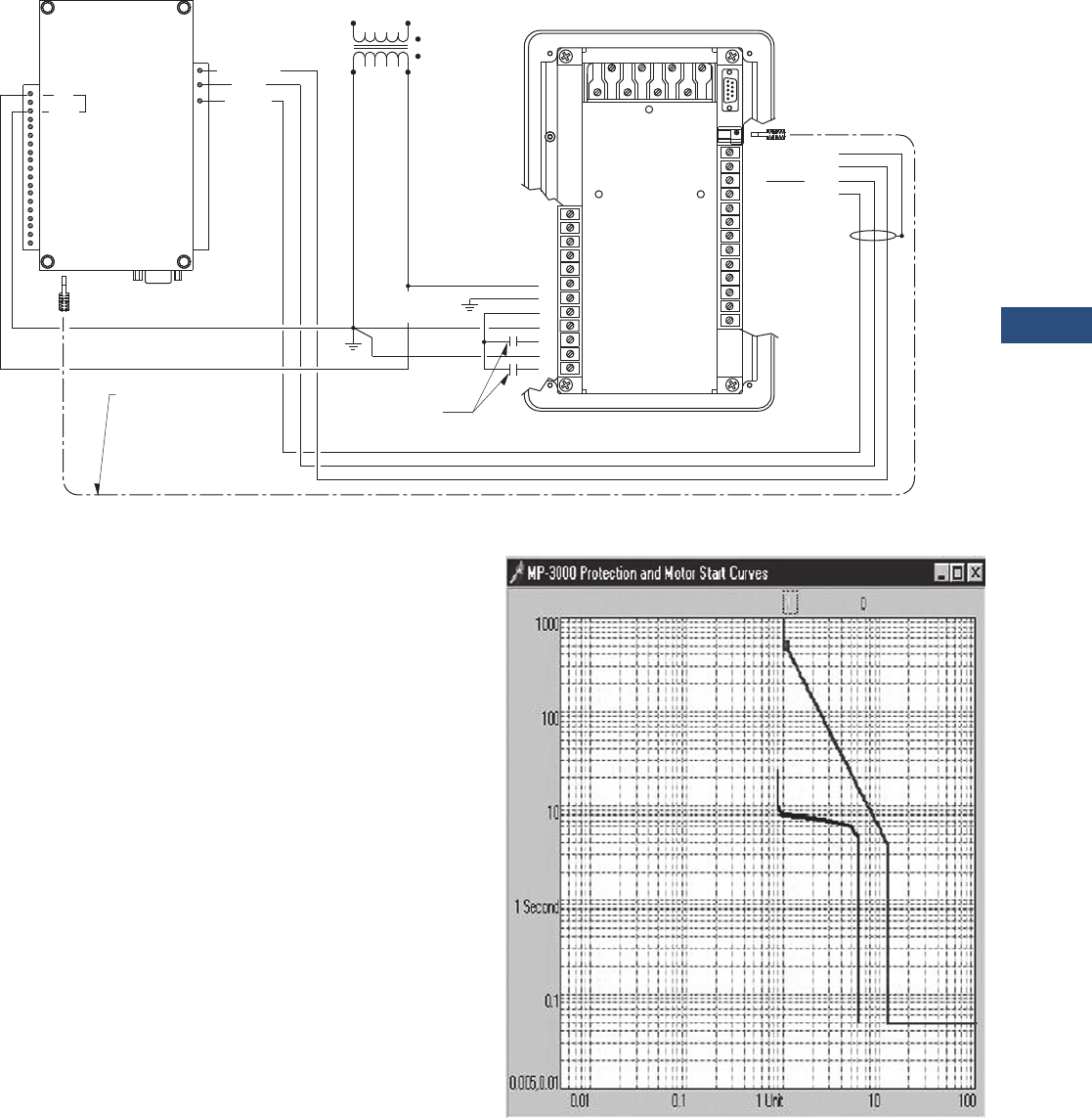
Volume 3—Power Distribution and Control Assemblies CA08100004E—March 2016 www.eaton.com V3-T9-195
9
9
9
9
9
9
9
9
9
9
9
9
9
9
9
9
9
9
9
9
9
9
9
9
9
9
9
9
9
9
9.3
Metering Devices, Protective Relays, Software and Connectivity
Protective Relays
MP-3000 Control and URTD Wiring
Trip Curve Chart
The MP-3000 motor relay
records information on the
most recent four starts. It
records currents, percent of
I2t used, percent unbalance,
RTD temperatures and time
to transition and run. In
addition, a motor start profile
can be downloaded and
displayed using Eaton’s
PowerPort or PowerNet
Software. The starting profile
shows the motor starting
current plotted against the
relay protection curve. This
provides a quick view of the
coordination between the
protection and actual motor
start current.
When communications
are desired, an optional
communication module or
PONI (Product Operated
Network Interface) is
required. The MP-3000 is
compatible with an INCOM
(IPONI), Modbus RTU
(MPONI) or Ethernet (EPONI).
Future communication
modules are planned to
interface with other systems
using other protocols. Please
consult factory for availability
of other communication
options. Page V3-T9-198
shows typical mounting of
MP-3000 with optional PONI
and with URTD module and
PONI.
When the MP-3000 is
supplied in the optional
drawout case, then the
INCOM
(IPONI) is the only
communication option
available. The communication
option must be selected at
the time of order.
AC
ACN 120 Vac J3
Control Power
Transformer
Non-current
Carrying Gnd.
Common
Data
Strobe 120 Vac
Universal
RTD Module
MP-3000
Customer Remote
Input Contacts
or Pushbuttons
Optical Fiber for URTD
Communications
to MP-3000
(Preferred Method)
25
24
2
3
4
5
6
7
8
1
9
10
Shield
Common
Data
Strobe
23
22
21
20
19
17
18
16
11
12
13
15
14
H
1
A
H
1
B
H
2
A
H
1
C
H
2
B
H
2
CG
2
G
1
Motor Starting Profile Time/Current Chart
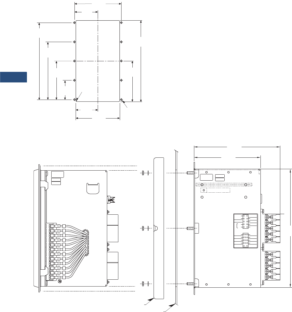
V3-T9-196 Volume 3—Power Distribution and Control Assemblies CA08100004E—March 2016 www.eaton.com
9
9
9
9
9
9
9
9
9
9
9
9
9
9
9
9
9
9
9
9
9
9
9
9
9
9
9
9
9
9
9.3
Metering Devices, Protective Relays, Software and Connectivity
Protective Relays
Dimensions
Approximate Dimensions in Inches (mm)
Panel Cutout Diagram
MP-3000 Drawout Panel Mounting
5.38
(136.7)
9.38
(238.3)
4.69
(119.1)
2.53
(64.3) 5.06
(128.5)
2.23
(56.7)
4.45
(113.0)
6.68
(169.7)
8.90
(226.1)
.06
(1.5) RAD
4 Places
2.69
(68.3)
.218
(5.5) DIA 10 Places
66D2031G01
REV. 1
A980810
S/N123321 BUILT BY
G.K.
TESTED BY
F.C.
66C2020H01
Unused
G1
Unused
H1C
29
27
25
H1A
H1B
23
21
26
28
30
22
24
G2
H2C
H2A
H2B
Discrete In 1
Discrete In 2
Discrete Source
Discrete Com
Unused
Unused
120V
240V
Neut
Auto
Select
VAC
19
or
17
+4/20 Output
-4/20 Output
15
13
11
18
20
12
14
16
11
13
49
17
60
14
19
16
20
18
A980000
66D2029G01
REV. 1
S/N000000
G.K.
F.C.
TESTED BY
BUILT BY
45
47
6.89
(175.0)
5.33
(135.4)
9.51
(241.6)
Inner ChassisOuter Chassis Outer Flange
Mounting Panel
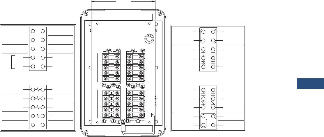
Volume 3—Power Distribution and Control Assemblies CA08100004E—March 2016 www.eaton.com V3-T9-197
9
9
9
9
9
9
9
9
9
9
9
9
9
9
9
9
9
9
9
9
9
9
9
9
9
9
9
9
9
9
9.3
Metering Devices, Protective Relays, Software and Connectivity
Protective Relays
Approximate Dimensions in Inches (mm)
Rear View of MP-3000 Drawout Outer Case
2221
3029
26
2827
25
2423
18
2019
17
14
1615
13
1211
5251
59 60
57
55
58
56
53 54
49
47
50
48
45
43
46
44
41 42
URTD Common
Aux 2
41
43
45
47
Alarm
49
51
53
55
Aux 1
42
44
46
48
50
54
52
56
Trip
57
59 60
58 Shield
66C2020H02
Earth Gnd
Discrete In 1
13
11
Discrete In 2
12
14
H1A
19
15
17
21
Unused
G1
H1B
H1C
66C2020H01
27
23
25
29
20
16
18
22
H2A
G2
26
24
28
H2B
H2C
30
Unused
Discrete Source URTD Shield
URTD DataURTD Strobe
Discrete Com
-4/20 Output
+4/20 Output Unused
Unused
PONI In
Neut
120Vor
240V
VAC
Auto
Select
5.23
(132.8)
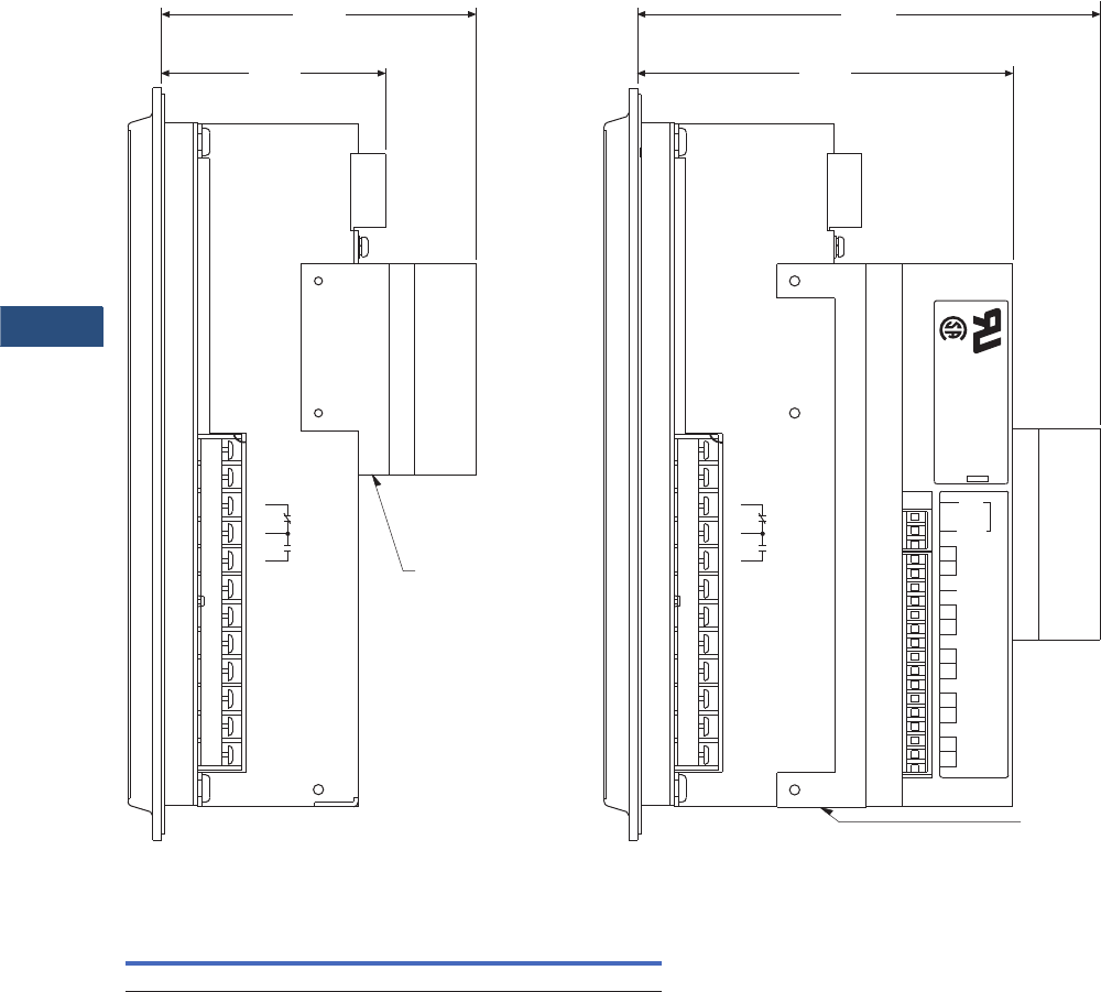
V3-T9-198 Volume 3—Power Distribution and Control Assemblies CA08100004E—March 2016 www.eaton.com
9
9
9
9
9
9
9
9
9
9
9
9
9
9
9
9
9
9
9
9
9
9
9
9
9
9
9
9
9
9
9.3
Metering Devices, Protective Relays, Software and Connectivity
Protective Relays
Approximate Dimensions in Inches (mm)
MP-3000 PONI and URTD Mounting
FP-3000 Feeder Protection Relay
Height Width Depth
Shipping Weight
Lbs (kg)
10.25 (260.4) 6.72 (170.7) 3.70 (94.0) 7.0 (3.2)
ACN
PONI
Mounting
Bracket
MB1
AUX1
120
Vac
ac
MB2
LB1
LB2
GND
J3
27
28
29
30
31
32
33
34
35
20
21
22
23
24
25
26
UNIVERSAL RTD MODULE
STYLE NUMBER 2D78559
1A49102H19
6.26
(159.0)
5.07
(128.8)
®
®
RTD Module
Mounting
Bracket
124
-4/20
OUTPUT
25
+4/20
OUTPUT
AUX 2
7
465
32
DISCRETE
SOURCE
NEUT
EARTH
GROUND
120 V or
240 V
VAC AUTO SELECT
DISCRETE
COMMON
DISCRETE
IN 1
DISCRETE
IN 2
1098
4.25
(108.0)
with PONI
3.01
(76.5)
without PONI
124
-4/20
OUTPUT
25
+4/20
OUTPUT
AUX 2
7
465
32
DISCRETE
SOURCE
NEUT
EARTH
GROUND
120 V or
240 V
VAC AUTO SELECT
DISCRETE
COMMON
DISCRETE
IN 1
DISCRETE
IN 2
1098
with PONI and RTD Module

Volume 3—Power Distribution and Control Assemblies CA08100004E—March 2016 www.eaton.com V3-T9-199
9
9
9
9
9
9
9
9
9
9
9
9
9
9
9
9
9
9
9
9
9
9
9
9
9
9
9
9
9
9
9.3
Metering Devices, Protective Relays, Software and Connectivity
Protective Relays
MP-4000
Contents
Description Page
Product Selection Guide . . . . . . . . . . . . . . . . . . . . V3-T9-143
Digitrip 3000 . . . . . . . . . . . . . . . . . . . . . . . . . . . . . V3-T9-149
EDR-3000 Feeder Protection. . . . . . . . . . . . . . . . . V3-T9-159
EDR-5000 Distribution Protection Relay . . . . . . . . V3-T9-168
FP-5000 Feeder Protection . . . . . . . . . . . . . . . . . . V3-T9-181
MP-3000 Motor Protection . . . . . . . . . . . . . . . . . . V3-T9-189
MP-4000 Motor Protection
EMR-3000 Motor Protection Relay . . . . . . . . . . . . V3-T9-205
EMR-4000 Motor Protection Relay . . . . . . . . . . . . V3-T9-217
EMR-5000 Motor Protection Relay . . . . . . . . . . . . V3-T9-230
ETR-4000 Transformer Protection Relay . . . . . . . . V3-T9-242
ETR-5000 Transformer Protection Relay . . . . . . . . V3-T9-254
EGR-5000 Generation Protection Relay . . . . . . . . V3-T9-267
Ground Fault Relay . . . . . . . . . . . . . . . . . . . . . . . . V3-T9-280
Universal RTD Module . . . . . . . . . . . . . . . . . . . . . V3-T9-283
MP-4000 Motor Protection
Product Description
●Microprocessor-based,
multi-function motor
protection
●Intel-I-Trip overload
protection based on
motor data
●Event recording and
operational logging
●Motor Start Profile
●Optional Quick Release
Drawout Case
●Used on AMPGARD
and medium voltage
assemblies
●“Help” menu provides
user operational assistance
Application Description
Eaton’s MP-4000 motor
protection relay is a
multifunctional
microprocessor-based
protective relay for the
protection of three-phase ac
motors. The MP-4000 motor
relay may be applied to any
size motor at any voltage level.
It is most commonly used on
large, medium voltage three-
phase induction motors. It has
also been widely used on
important low voltage (480
volt) motor applications and
synchronous motors.
The MP-4000 motor relay
monitors three-phase and
ground currents, and three-
phase voltages. It provides
motor overload, stall, short
circuit, phase unbalance, single
phasing over/undervoltage,
underpower, power factor and
ground fault motor protection.
It can also be used to provide
protection for a load jam or loss
of load condition.
The MP-4000 motor relay
provides start control logic
to protect the motor against
excessive starts or starting
the motor before it has had
sufficient time to cool down.
The MP-4000 motor relay may
be applied to either across the
line starters or reduced voltage
starters. On reduced voltage
starters, the MP-4000 relay can
control the switch from
reduced voltage to full voltage
based on time and/or motor
transition. The MP-4000 can
protect the starter against
failure to transition to full
voltage through contact
feedback and an incomplete
sequence function.
The MP-4000 motor relay is
generally used on a motor
starter or a breaker used for
a motor load. The MP-4000
motor relay provides the
intelligence to protect and
control the motor against
abnormal operating conditions.
It monitors the currents from
either a 5 A or 1 A secondary of
a CT circuit. Ground current
may be obtained from either a
ground CT or from the residual
connection of the phase CTs.
It provides a form C contact
output for controlling the
starter contacts or breaker
operation.

V3-T9-200 Volume 3—Power Distribution and Control Assemblies CA08100004E—March 2016 www.eaton.com
9
9
9
9
9
9
9
9
9
9
9
9
9
9
9
9
9
9
9
9
9
9
9
9
9
9
9
9
9
9
9.3
Metering Devices, Protective Relays, Software and Connectivity
Protective Relays
Features, Benefits and Functions
●Complete motor protection
and control in a single
compact case reduces
panel space requirements
and wiring costs
●Microprocessor design
with self diagnostics
eliminates calibration
and reduces installation,
commissioning and
maintenance
●Programmable stop
2–20% of PCT
●Intel-I-Trip overload
protection develops
customized curve from
manufacturer’s supplied
motor data
●Intel-I-Trip overload
protection provides
adaptive trip characteristics
based on motor
temperature when motor
RTDs are connected
through an optional
URTD module
●Meets UL 1053 ground
fault protection standards
that eliminates the need
for a separate ground relay
saving cost, space, wiring
and time
●Voltage dip/loss ride
through capability reduces
unnecessary trips caused
by poor power quality
●Motor currents,
temperatures and
conditions are monitored
and displayed either locally
or remotely
●Event log provides motor
operating records for the
most recent 20 Trip or
Alarm events with date
and time stamping. This
information can improve
troubleshooting and
reduce downtime
●Log book records the most
recent 100 events such as
motor START/STOP and
set point changes to
provide a log of motor
operation with date and
time stamping
●RTD diagnostics reduces
unnecessary tripping
caused by faulty RTD, RTD
wiring or communications
●Arm/Disarm feature
improves security for
critical motor applications
●Motor Start profile verifies
protection and motor
starting coordination. This
feature can be used to
develop protection settings
on old motors where data
is not available
●Optional communication
module and Eaton’s
software simplifies setting,
configuration, monitoring,
commissioning and data
retrieval either locally or
remotely
●Optional Quick Release
Drawout Case construction
simplifies relay removal
and replacement
The protection functions are
listed below:
●I2t overload
protection (49/51)
●Locked rotor (49S/51)
●Ultimate trip current (51)
●Negative sequence phase
unbalance (46)
●Instantaneous
overcurrent (50)
●Ground fault
protection (50G)
●Undervoltage (27)
●Overvoltage (59)
●Under power (32)
●Negative sequence voltage
unbalance (47)
●Power factor (55)
●RTD trip and alarm with
URTD module (49/38)
●Underload trip (37)
●Starts per time (66)
●Jam or stall (51R)
●Auto or manual reset (86)
●Fail-safe or non-fail-safe
trip modes
The metering functions are:
●Metering:
●Average current
●Amperes: magnitude
and angle in primary
values
●Amperes: positive,
negative and zero
sequence
●Average voltage (V ave)
●Voltage: magnitude and
angle
●Voltage: positive,
negative and zero
sequence
●% of full load
●% current unbalance
●% voltage unbalance
●Power, vars and VA
●Power factor
●Frequency
●Energy metering with
time and date stamps
●RTD temperatures:
●Individual winding
●Motor bearing
●Load
●Auxiliary temperatures
●Motor conditions:
●Percent of I2t thermal
bucket
●Time before start
●Remaining starts
allowed
●Oldest start time
Standards and Certifications
The MP-4000 motor
protection was designed to
meet the industry standards
for protective relays. It is
recognized under UL 1053
Ground Fault Protection
Standard.
●UL recognized (File No.
E154862)
●UL 1053 recognized
●UL 508 recognized
●ANSI C37.90, C37.90.1
●cUL
●CSA

Volume 3—Power Distribution and Control Assemblies CA08100004E—March 2016 www.eaton.com V3-T9-201
9
9
9
9
9
9
9
9
9
9
9
9
9
9
9
9
9
9
9
9
9
9
9
9
9
9
9
9
9
9
9.3
Metering Devices, Protective Relays, Software and Connectivity
Protective Relays
Reference Information
Cross-Reference
Westinghouse®/Cutler-Hammer
Eaton’s Cutler-Hammer MP-
3000 motor relay supersedes
the Cutler-Hammer (formerly
Westinghouse) IQ 1000 II
motor relay and can replace
the earlier IQ 1000 motor
relay version sold under the
Westinghouse name. The
MP-3000 motor relay fits in
the same cut out and
provides the protection
functions of these older
models. The MP-3000
relay provides numerous
enhancements and new
features over the superseded
models. The most notable
enhancements are UL 1053
ground fault protection
certified, voltage loss ride
through capability, data
logging, communications
features and the addition of
a clock for date and time
stamping of events.
GE Multilin™
GE Multilin has several
product offerings for motor
protection. The 269 PLUS is
the equivalent model to the
MP-3000 with optional URTD
module. Eaton offers MP-
3000 value packs that include
an MP-3000, PONI, URTD
module and fiber optic cable
at competitive prices.
GE Multilin has both lower
and higher end products.
The MP-3000 can be used in
place of their 239 motor relay.
The MP-3000 offers more
capabilities than the 239 for
a slightly higher price.
GE Multilin 369 and 469
are upgraded end products.
The MP-3000 relay offers
equivalent overload and
current protection functions.
It also provides equivalent
start control functions. Both
the 369 and 469 offer voltage
protection and metering
functions. An Eaton meter
and/or other manufacturers’
protective relays may be
needed to satisfy the
customer’s motor protection
requirements. The 469 adds
differential protection. This
function must be supplied
by others in addition to the
MP-3000 motor relay.
Cross-Reference
Note
1If RTD monitoring required.
New Eaton’s Series Old Cutler-Hammer (Westinghouse) GE Multilin
MP-3000 (URTD module) 1IQ 1000 II, IQ 1000 269, 269+, 239, base 369
MP-4000 (URTD module) 1— 369 with voltage option
MP-4000 + MP-3000 — 469

V3-T9-202 Volume 3—Power Distribution and Control Assemblies CA08100004E—March 2016 www.eaton.com
9
9
9
9
9
9
9
9
9
9
9
9
9
9
9
9
9
9
9
9
9
9
9
9
9
9
9
9
9
9
9.3
Metering Devices, Protective Relays, Software and Connectivity
Protective Relays
Product Selection
MP-4000 Ordering Information
Options and Accessories
Additional Related Products
by Eaton’s Cutler-Hammer Series
The MP-4000 is available in
either a fixed mount or Quick
Release Drawout Case. Both
mountings use the same
panel cutout.
The Universal RTD module
(URTD) is required when the
motor is equipped with RTDs
that you wish to monitor and
use for protection. The URTD
can be mounted near the
motor to reduce RTD wiring
and costs.
The MP-4000 motor protection
is design-ed to operate from
120 Vac or 240 Vac auxiliary
control power. The MP-4000
motor relay can be used with
dc control power with the
addition of the IQDCPS. The
IQDCPS is an inverter from
DC to AC.
Description Catalog Number
MP-4000 drawout, 5 A with RS-232 MP4011
MP-4000 drawout, INCOM, 5 A with RS-232 MP4012
MP-4000 drawout, Modbus, 5 A with RS-232 MP4013
MP-4000 drawout, DeviceNet, 5 A with RS-232 MP4014
MP-4000 drawout, 1 A with RS-232 MP4111
MP-4000 drawout, INCOM, 1 A with RS-232 MP4112
MP-4000 drawout, Modbus, 1 A with RS-232 MP4113
MP-4000 drawout, DeviceNet, 1 A with RS-232 MP4114
MP-4000 fixed case, 5 A with RS-232 MP4010
MP-4000 fixed case, INCOM, 5 A with RS-232 MP4010INCOM
MP-4000 fixed case, Modbus, 5 A with RS-232 MP4010MODBUS
MP-4000 fixed case, DeviceNet, 5 A with RS-232 MP4010DEVICEN
MP-4000 fixed case, 1 A with RS-232 MP4110
MP-4000 fixed case, INCOM, 1 A with RS-232 MP4110INCOM
MP-4000 fixed case, Modbus, 1 A with RS-232 MP4110MODBUS
MP-4000 fixed case, DeviceNet, 1 A with RS-232 MP4110DEVICEN
MP-4000 fixed case, INCOM, 5 A with RS-232, URTD MP4010VPI
MP-4000 fixed case, Modbus, 5 A with RS-232, URTD MP4010VPM
MP-4000 fixed case, DeviceNet, 5 A with RS-232, URTD MP4010VPD
MP-4000 fixed case, INCOM, 1 A with RS-232, URTD MP4110VPI
MP-4000 fixed case, Modbus, 1 A with RS-232, URTD MP4110VPM
MP-4000 fixed case, DeviceNet, 1 A with RS-232, URTD MP4110VPD
MP-4000

Volume 3—Power Distribution and Control Assemblies CA08100004E—March 2016 www.eaton.com V3-T9-203
9
9
9
9
9
9
9
9
9
9
9
9
9
9
9
9
9
9
9
9
9
9
9
9
9
9
9
9
9
9
9.3
Metering Devices, Protective Relays, Software and Connectivity
Protective Relays
Technical Data and Specifications
Control Power
●Nominal rating:
●120 Vac or 240 Vac
●+10%, –25%
●Operating range:
●120 Vac: 90 132 Vac
●240 Vac:180 264 Vac
●Frequency: 50 or 60 Hz
●Power use:
●20 VA maximum
●URTD: 6 VA maximum
●IPONI: 1 VA maximum
●Ride-through time:
30 cycles from nominal Vac
Current Inputs
●Nominal (In): 1 A or 5 A
●CT rating:
●2 x In continuous
●50 x In for 1 second
●Burdens:
●< 0.25 VA at 5 A
●< 0.05 VA at 1 A
Voltage Inputs
●Nominal: 120 Vac
●Operating range: 69 to
150 Vac
●Burden: 2 VA
Metering Accuracy
●Phase current: ±1% of In
(5–100%)
●
Ground current: ±1.5% of I
n
(0–55%)
Discrete Inputs
●Number of inputs: two
programmable
●Ratings:
●1.2 VA at 120 Vac
●Maximum off = 36 Vac
●Minimum on = 86 Vac
Output Contacts
●Number of outputs: four
Form C, programmable.
●Momentary:
●Make 30 A AC/DC for
0.25 seconds
●Break 0.25 A at 250 Vdc
(Resistive)
●Break 5 A at 120 240 Vac
●Continuous:
●5 A at 120/240 Vac
●5 A at 30 Vdc
Analog Output
●Rating: ± 4–20 mA
programmable
●Maximum load: 1K ohm
●Accuracy: 1%
Motor Overload Protection (I2t)
●Full load amperes:
10–3000
●
Locked rotor current:
300–1200% FLA
●Locked rotor time:
1–120 seconds
●Ultimate trip current:
85–150% FLA
●Phase CT ratio:
10–4000 (In
)
●Ground CT ratio:
10–4000 (In
)
●Timing accuracy: ±
2.5% or
±30 ms
for I > 1.1x U.T.C.
Trip Setting Range
●Ground fault (GF): Off,
2–55% CT ratio
●GF start time delay:
2–60 cycles
●GF run time delay:
0–60 cycles
●Timer accuracy: ± 20 ms
●Instantaneous O.C.: Off,
300–1600% FLA
●IOC start time delay:
2–60 cycles
●Timer accuracy: ±20 ms
●JAM trip: Off, 100–
1200% FLA
●Underload trip: Off,
1–90% FLA
●Current unbalance trip:
Off, 4–40% Ineg/Ipos
●Start delay timers:
●0–120 seconds
(underload and phase
unbalance)
●0–1200 seconds (jam)
●Run delay timers:
0–240 seconds
●Timer accuracy: ±0.5%
+100 ms
●Voltage unbalance: Off,
1 to 100 V
●% V2/V1: 4% + 40%
●Voltage unbalance time
delay: 0 to 1200 s
●Under/overvoltage time
delay: Off, 10 to 150 V
●Under/overvoltage time
delay: 0 to 1200 s
●Under/overfrequency:
Off, 15 to 60 Hz
●Under/overfrequency time
delay: 0 to 60 sec
●Power protection: Off,
0.06 to .90 + FLA VT
●Power time delay: 0 to
1200 sec
●Power factor: Off, 0.05 lag
to 0.99 lead
●Power factor time delay:
0 to 60 s
Alarm Setting Range
●Ground fault: Off,
2–55% CT ratio
●Overload I2t: Off,
60–99% I2t
●JAM: Off, 100–1200% FLA
●Underload: Off,
1–90% FLA
●Phase unbalance: Off,
4–40% Ineg/Ipos
●Run delay timers:
0–240 seconds
Start Control Functions
●Starts per time: 1–10 starts
●Time for starts per time:
Off, 1–240 minutes
●Time between starts:
Off, 1–240 minutes
●Number of cold starts:
1–5 starts
●Motor transition current:
10–300% FLA
●Time for transition:
0–1200 seconds
●Inc. sequence timer:
Off, 1–240 seconds
●Long acceleration timer:
Off, 1–1200 seconds
●Anti-Backspin timer:
Off, 1–3600 minutes
RTD Inputs (Requires
URTD module)
●Sensor types:
●10 ohm copper
●100 ohm nickel
●120 ohm nickel
●100 ohm platinum
URTD Module Communications
●Interface:
●Electrical (three-wire)
●Fiber optic (preferred)
●Fiber optic cable: Type
HBFR-ERS or EUS
Clock
●Accuracy: ±1 minute/
month at 77 ºF (25 °C)
PONI Communications
●Type: two-wire, FSK
●Baud rate: 1200 or
9600 baud
●Protocol: INCOM
●Functions:
●Read/write set points
●Read metered values
●Read trip/alarms
●Read events/history
●View starting profile
MPONI Communications
●Type: five-wire, 485
●Baud rate: 1200 or
9600 baud
●Protocol: Modbus RTU
●Functions:
●Read metered values
●Read trip/alarms
DPONI Communications
●Type: J-wire
●Baud rate: 500 k,
250 k, 125 k
●Protocol: DeviceNet
●Functions:
●Read metered values
●Read trip/alarms
Logging
●Log book: 100 events
●Log event: 20 trips
and alarms
●Log start: last four starts
●Start profile: last four starts
(communication only)
●History records: motor,
trips, alarms and total
records
Environmental Conditions
●Operating temperature:
–4 ºF to +140 ºF
(–20 °C to +60 °C)
●Storage temperature:
–49 ºF to +185 ºF
(–45 °C to +85 °C)
●Humidity: 0–95%
noncondensing

V3-T9-204 Volume 3—Power Distribution and Control Assemblies CA08100004E—March 2016 www.eaton.com
9
9
9
9
9
9
9
9
9
9
9
9
9
9
9
9
9
9
9
9
9
9
9
9
9
9
9
9
9
9
9.3
Metering Devices, Protective Relays, Software and Connectivity
Protective Relays
Dimensions
Approximate Dimensions in Inches (mm)
MP-4000 Feeder Protection Relay
Height Width Depth
Shipping Weight
Lbs (kg)
10.25 (260.4) 6.72 (170.7) 3.70 (94.0) 7.0 (3.2)

Volume 3—Power Distribution and Control Assemblies CA08100004E—March 2016 www.eaton.com V3-T9-205
9
9
9
9
9
9
9
9
9
9
9
9
9
9
9
9
9
9
9
9
9
9
9
9
9
9
9
9
9
9
9.3
Metering Devices, Protective Relays, Software and Connectivity
Protective Relays
EMR-3000 Motor Protection Relay
Contents
Description Page
Product Selection Guide . . . . . . . . . . . . . . . . . . . . V3-T9-143
Digitrip 3000 . . . . . . . . . . . . . . . . . . . . . . . . . . . . . V3-T9-149
EDR-3000 Feeder Protection. . . . . . . . . . . . . . . . . V3-T9-159
EDR-5000 Distribution Protection Relay . . . . . . . . V3-T9-168
FP-5000 Feeder Protection . . . . . . . . . . . . . . . . . . V3-T9-181
MP-3000 Motor Protection . . . . . . . . . . . . . . . . . . V3-T9-189
MP-4000 Motor Protection . . . . . . . . . . . . . . . . . . V3-T9-199
EMR-3000 Motor Protection Relay
EMR-4000 Motor Protection Relay . . . . . . . . . . . . V3-T9-217
EMR-5000 Motor Protection Relay . . . . . . . . . . . . V3-T9-230
ETR-4000 Transformer Protection Relay . . . . . . . . V3-T9-242
ETR-5000 Transformer Protection Relay . . . . . . . . V3-T9-254
EGR-5000 Generation Protection Relay . . . . . . . . V3-T9-267
Ground Fault Relay . . . . . . . . . . . . . . . . . . . . . . . . V3-T9-280
Universal RTD Module . . . . . . . . . . . . . . . . . . . . . V3-T9-283
EMR-3000 Motor Protection Relay
Product Description
Eaton’s EMR-3000 motor
protection relay is a
multifunctional
microprocessor- based
protective relay for the
protection of any size motor
at all voltage levels. It is most
commonly applied on
medium voltage or larger
motors. The EMR-3000 relay
is a current only device that
provides complete and
reliable motor protection,
monitoring, and starting
control functions.
The EMR-3000 motor
protection relay has
removable terminal blocks,
and it has Modbus-RTU
communications as standard;
and an optional Ethernet
port for Modbus-TCP
communications. The EMR-
3000 motor protection relay
has three-phase and one
ground current inputs. It can
be used with either a 5 A or 1
A CTs. The ground protection
can be used with either a zero
sequence ground CT or from
the residual connection of the
phase CTs.
The zero sequence ground CT
provides greater ground fault
sensitivity than the residual
connection. The unit is
capable of 60 Hz or 50 Hz
operation.
The maintenance mode
password protected soft key,
can be used for arc flash
mitigation to change to an
alternate settings group, set
to have instantaneous
elements only. The multiple
setting groups can also be
changed, via communications
or a digital input. Flash
memory is used for the
programming and all settings
are stored in nonvolatile
memory.
An integral keypad and
display is provided for direct
user programming and
retrieval of data without the
need of a computer. 14
programmable LEDs provide
quick indication of relay
status.
A front port is provided for
direct computer connection.
An RS-485 communication
port on the back is standard
for local area networking
using Modbus-RTU. An
optional Ethernet port and
protocols are available.
The EMR-3000 motor
protection relay has mass
memory for data storage and
a real-time clock with 1 ms
time resolution. The relay will
log 300 sequence of event
records, 20 detailed trip logs,
minimum/maximum values,
load profiles, the 5 latest start
profiles, motor trending,
breaker wear information and
oscillography data.
The EMR-3000 motor
protection relay has four
discrete inputs and 1 fiber
optic input, 1 Form C, and 2
NO programmable contacts,
1 Form C healthy contact. It
also has an optional 4–20 mA
analog output or zone
interlocking card. The relay
provides maximum user
flexibility to configure the I/O.
All inputs and outputs (except
the healthy output) are user-
programmable. The unit also
counts with a test mode to
force outputs and simulate
currents, to facilitate the
commissioning of the unit.
It can be powered from 19
Vdc to 300 Vdc or 40 Vac to
250 Vac auxiliary power.
Application Description
Eaton’s EMR-3000 motor
protection relay has been
designed for maximum motor
operation and protection. It
permits running the motor
close to its design limits
while protecting it against
excessive heating and
damaging overload
conditions. The EMR-3000
field-proven protection
algorithms were developed
based on motor designs and
operating parameters for
optimum operation and
protection while minimizing
nuisance tripping. The EMR-
3000 motor protection relay
utilizes a patented protection
algorithm and measurement
technique based on proven
positive and negative
(unbalance) sequence current
sampling and true RMS
calculations.
V3-T9-206 Volume 3—Power Distribution and Control Assemblies CA08100004E—March 2016 www.eaton.com
9
9
9
9
9
9
9
9
9
9
9
9
9
9
9
9
9
9
9
9
9
9
9
9
9
9
9
9
9
9
9.3
Metering Devices, Protective Relays, Software and Connectivity
Protective Relays
Features, Benefits and Functions
Protection Features
●Thermal protection (49/51)
●Locked rotor protection
(49S/51)
●Phase overcurrent
elements:
●Two instantaneous
elements with timers
(50P[1], 50P[2] and
50P[3])
●Three inverse time
overcurrent elements
(51P[1], 51P[2] and
51P[3])
●11 standard curves
●Instantaneous or time
delay reset
●Ground overcurrent
elements:
●Two instantaneous
measured elements
with timers (50X[1] and
50X[2])
●Two instantaneous
calculated elements
with timers (50R[1] and
50R[2])
●Two inverse time
overcurrent measured
elements (51X[1] and
51X[2])
●Two inverse time
overcurrent calculated
elements (51R[1] and
51R[2])
●11 standard curves
●Instantaneous or time
delay reset
●Jam or Stall protection
(50J[1], 50J[2])
●Phase unbalance negative
sequence overcurrent
(46[1], 46[2])
●Underload protection
(37[1], 37[2], 37[3])
●Temperature protection
with optional URTD (49/38)
●Stars per hour (66)
●Lockout protection (86)
●Breaker failure (50BF)
●Zone interlocking for bus
protection (87B)
Metering Features
●Amperes: Positive,
negative and zero
sequence
●Ampere demand
●% THD I
●Magnitude THD I
●Minimum/maximum
recording
●Temperature with remote
URTD module
Monitoring Features
●Trip coil monitor
●Breaker wear primary and
secondary (accumulated
interrupted current)
●Oscillography
(7200 cycles total)
●Trip Cause displays fault
recorder data on HMI after
fault event
●Fault data logs
(up to 20 events)
●Sequence of events report
(up to 300 events)
●Trending (load profile
over time)
●Motor history
●Records the last 5 motor
start profiles
●Motor start trending
●CT supervision
●Clock (1 ms time stamping)
Control Functions
●Transition for reduced
voltage starts
●Incomplete sequence
delay
●Permits numbers of cold
starts
●Limits numbers of starts
per hour
●Anti-backspin time delay
●Mechanical load shedding
●Zero speed switch for long
acceleration motors
●Motor stop inputs
●Remote trip input
●Differential trip input
●Emergency override
●Breaker/Contactor open-
close/stop-start
●Remote open-close
(stop-start)
●Programmable I/O
●Programmable LEDs
●Multiple setting groups
Communication Features
●Local HMI
●Password protected
●Addressable
●IRIG-B
●Local communication port.
●RS-232
●Remote communication
port:
●RS-485
●Ethernet port
●Protocols:
●Modbus-RTU
●Modbus-TCP (optional)
●IEC 61850 (optional)
●Configuration software
●PowerPort-E
Monitoring and Metering
Sequence of Events Records
The EMR-3000 protection
relay records a maximum of
300 events associated with
the relay. An event is
classified as a change of state
as detected by the relay.
These include relay pickups,
dropouts, trips, contact
closure, alarms, setting
changes and self-diagnostic
failures. Each event is date
and time stamped to a 1 ms
resolution. The events are
stored in a FIFO in
chronological order.
Trip Log
The EMR-3000 protection
relay will store a maximum of
20 trip records in a FIFO trip
log. Each trip record will be
date and time stamped to a
1 ms resolution. The trip log
record will include
information on the type of
fault, protection elements
that operated, fault location
and currents and voltages at
the time of the fault.

Volume 3—Power Distribution and Control Assemblies CA08100004E—March 2016 www.eaton.com V3-T9-207
9
9
9
9
9
9
9
9
9
9
9
9
9
9
9
9
9
9
9
9
9
9
9
9
9
9
9
9
9
9
9.3
Metering Devices, Protective Relays, Software and Connectivity
Protective Relays
Waveform Capture (Quality Manager)
The EMR-3000 relay provides
oscillographic recording
capabilities. The relay will
record all measured signals
along with the binary signals
of pickup, trip, internal logic,
and contact inputs. The EMR-
3000 can record up to 7200
cycles of data. The number of
records is proportional to the
programmed size of each
record; the maximum size per
record is 600 cycles.
The waveform capture is
initiated by up to 8 different
triggers (i.e., trip/alarm
events) or manually via
communications or the HMI.
PowerPort-E setting software
is used to retrieve the
records. Quality Manager is a
separate software program
downloaded with PowerPort-
E used for analyzing the
waveform and trending files
retrieved from the relay.
Integral User Interface
The front panel user interface
has a 128 x 64 pixel LCD
display with background
illumination for wide angle
viewing in all light conditions.
Seven programmable LEDs
provide quick and easy visual
display of power on, mode of
operation, alarm and trip
indication. Soft keys are
provided for operation mode
selection, scrolling through
data and settings. In addition,
the relay settings and test
functions are password
protected.
Starting Profiles
The EMR-3000 records the
average current versus time
for the last five starting
cycles. This information is
available via the
communications port
through PowerPort-E.
Motor Statistics
For each motor start, the
EMR-300 stores a motor start
report and add this data to the
motor statistics buffer. With
the motor statistics you can
track motor start data for the
past eighteen 30-day periods.
For each 30-day interval, the
relay records the following
information:
●The date the interval began
●The total number of starts
in the interval
●The averages of the
following quantities:
●Motor Start Time
●Start % Rotor Thermal
Capacity Used
●Maximum Start Current
Load Profiling/Trending
The EMR-3000 relay
automatically records
selected quantities into non-
volatile memory every 5, 10,
15, 30 or 60 minutes,
depending on the trending
report setting.
Programmable I/O
The EMR-3000 motor
protection relay provides
heavy-duty, triprated, 2
normally open and 1 Form C
contacts. One isolated inputs
can be used for monitoring
the trip circuit. One Form C
contact is dedicated to the
relay failure alarm function
and is operated in a normally
energized (failsafe) mode.
There are 4 eight user-
configurable discrete inputs
that accept a wet contact and
can operate through a wide
range of power. Each input
and output is user-
programmable for maximum
application flexibility.

V3-T9-208 Volume 3—Power Distribution and Control Assemblies CA08100004E—March 2016 www.eaton.com
9
9
9
9
9
9
9
9
9
9
9
9
9
9
9
9
9
9
9
9
9
9
9
9
9
9
9
9
9
9
9.3
Metering Devices, Protective Relays, Software and Connectivity
Protective Relays
Intel-I-Trip (I2t) Overload
Protection
The EMR-3000 motor relay
features the exclusive Eaton
Intel-I-Trip intelligent overload
protection system. Intel-I-Trip
develops custom overload
curves simply from motor
nameplate data. Intel-I-Trip
protects motors from
potentially damaging overload
and abnormal operating
conditions. The Intel-I-Trip
intelligent overload protection
feature utilizes field proven
measurement techniques and
a patented motor thermal
protection model. The EMR-
3000 motor relay’s unique
measurement technique
samples the current
waveforms 36 times per
cycle, providing accurate
measurements of the
positive and negative
sequence currents. The
negative sequence current
causes a greater heating
effect on the rotor and has a
greater impact on the thermal
model in the relay. Intel-I-Trip
utilizes these measurements
in its motor model to safely
protect the motor against the
heating effects of these
currents.
The motor thermal model is
analogous to a bucket that is
being filled and drained at the
same time. The fill rate is
dependent on the motor
currents and the drain is
based on motor design
principles. The size of the
bucket is equivalent to the
thermal capacity associated
with the mass of the motor.
Intel-I-Trip integrates these
rates and will issue a trip
when the thermal capacity is
filled.
Intel-I-Trip features adaptive
trip characteristics that adjust
the trip times based on
measured motor temperature
when RTDs are used.
Instantaneous Overcurrent
The EMR-3000 motor
protection relay provides an
instantaneous phase
overcurrent function to trip
the motor for high fault
current levels and save the
fuses. This function can be
disabled and has an
adjustable time delay on
starting to avoid nuisance
tripping on inrush.
Phase Unbalance Protection
Motor supply circuits are
often fed through fuses and
can be run with a single-
phase fuse blown, referred to
as single phasing the motor.
The EMR-3000 motor
protection relay measures the
current unbalance and can be
used to alarm or trip the
motor before damage occurs.
Pickup, start and run timers,
and a second element for
alarm purposes are provided.
Ground Fault Protection
A separate measuring circuit
is used to measure ground
current. A ground CT is
recommended for more
sensitive protection against
winding insulation breakdown
to ground. The relay ground
circuit can be connected
residually from the three-
phase CTs. The ground fault
protection has pickup and
time delay set points or can
be disabled.
Jam Protection
The user-selectable Jam
function protects motors that
are running against a sudden
mechanical jam or stall
condition. The common
application is on motors used
on crushers, chippers, or
conveyors. It detects an
increase of motor current to a
level above full load. Pickup,
start, and run timers and a
second element for alarm
purposes are provided.
Underload Protection
The user-selectable
underload function is used to
detect the loss of load on the
motor. Coupling failure is a
common cause for loss of
load. Pickup, start, and run
timers and a second element
for alarm purposes are
provided.
Reduced Voltage Starting
The EMR-3000 motor
protection relay provides a
transition and incomplete
sequence function for
reduced voltage starting. The
user can select to transition
based on the current level
and/or on time.
Antibackspin
The stop function is
programmable from 2–20%.
For certain applications, such
as pumping a fluid up a pipe,
the motor may be driven
backward for a period of time
after it stops. The EMR-3000
relay provides an antibackspin
timer to prevent starting the
motor while it is spinning in
the reverse direction. The
timer begins counting from
the moment a stop is
declared by the relay.
Start Control Timers
Motors typically have limits to
the number of cold starts,
starts per hour period, or time
between starts that are
permitted without damage.
The EMR-3000 motor
protection relay incorporates
these timers to prevent
starting the motor beyond its
capabilities.
Load Shedding
The EMR-3000 motor
protection relay provides a
mechanical load shedding
feature that can be used to
control an upstream process.
The load-shedding function
closes a contact on an
overload condition to control
an upstream process from
adding more load until the
overload condition is gone.
Emergency Override
The EMR-3000 motor
protection relay has a user-
programmable feature that
will let the operator reset the
start inhibitor timers and
thermal overload bucket. This
function is intended for use in
emergency conditions only,
and it may result in motor
damage or failure.
Long Acceleration Motors
Large motors with a high
inertia may experience
starting currents that exceed
the locked rotor current and
time. The EMR-3000 motor
protection relay has logic and
provisions for a zero speed
switch input to differentiate
between a stall and start
condition. If the motor is
spinning, then the relay will
not trip on the normal locked
rotortime allowing the motor
to start.
Remote/Differential Trip
The digital inputs can be
programmed to accept a
contact input from a separate
differential relay or other
device to trip the motor. This
provides local and remote
target information and utilizes
the trip contacts of the EMR-
3000 motor protection relay.
It will also record and log the
motor information at the time
of the trip.
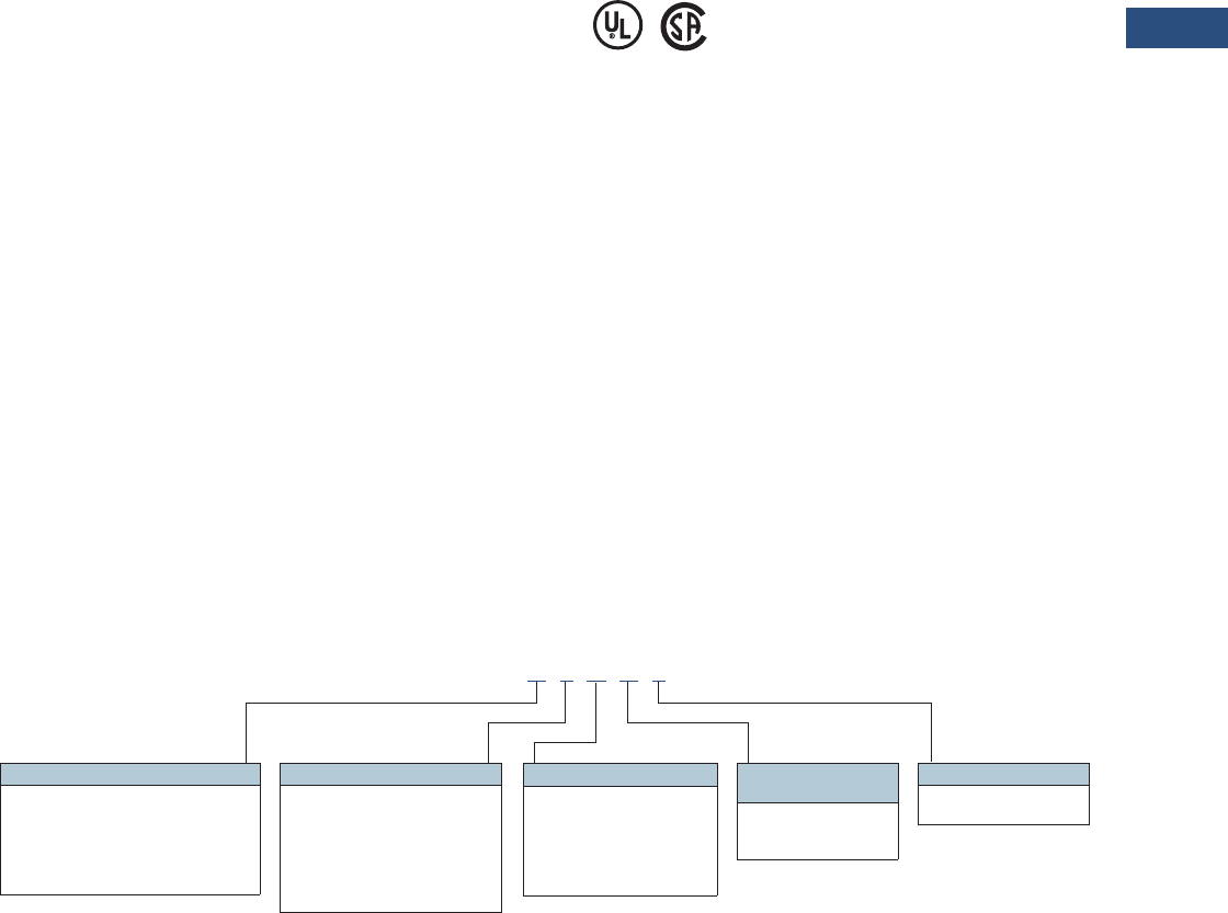
Volume 3—Power Distribution and Control Assemblies CA08100004E—March 2016 www.eaton.com V3-T9-209
9
9
9
9
9
9
9
9
9
9
9
9
9
9
9
9
9
9
9
9
9
9
9
9
9
9
9
9
9
9
9.3
Metering Devices, Protective Relays, Software and Connectivity
Protective Relays
Breaker Failure or Stuck
Contactor
The EMR-3000 motor
protection relay includes a
breaker failure (50BF, 62BF)
function that can be initiated
from either an internal or
external trip signal. This is an
independent element that
can be used to operate a
lockout relay or trip an
upstream breaker. The timer
must be longer than the
breaker operating time and
the protective function reset
times.
Flexible Phase Rotation
The EMR-3000 motor
protection relay can be
applied on either an A-B-C or
A-C-B phase rotation. A user
setting permits correct
operation and indication of
the actual system
configuration.
Maintenance Mode
The Maintenance Mode can
improve safety by providing a
simple and reliable method to
reduce fault clearing time and
lower incident energy levels
at energized panels. The
Maintenance Mode allows
the user to switch to more
sensitive settings via a
password protected soft key,
communication or via a digital
Input while maintenance
work is being performed at an
energized panel or device.
The more sensitive settings
provide greater security for
maintenance personnel and
helps reduce the possibility of
injury.
Standards and Certifications
Design Standards
●Generic Standard:
●EN 61000-6-2
●EN 61000-6-3
●Product Standard:
●IEC 60255-6
●EN 50178
●UL 508 (Industrial
Control Equipment)
●CSA C22.2 No. 14-95
(Industrial Control
Equipment)
●ANSI C37.90
Catalog Number Selection
The catalog number
identification chart defines
the electrical characteristics
and operation features
included in the EMR-3000.
For example, if the catalog
number is EMR-3000A0BA1,
the device would have
the following:
EMR-3000
(A)–Four digital inputs, four
output relays, 1 4–20 mA
analog output, URTD
interface
(0)–5 A / 1 A phase and
ground CTs, power supply
range:
19–300 Vdc, 40–250 Vac
(B)–Modbus-RTU (RS-485)
(A)–Without conformal
coating
(1)–Projection panel mount
Motor Relay Removable Terminals
Note
1Beginning in 2016, consult factory for the availability of the following new communication options.
• Protocols: DNP3.0, Profibus
• Interface ports: Fiber optic ST, RS-485 D-SUB, Fiber optic LC
Hardware Option 1
A = 4 DI, 4 outputs, removable terminals, 1
4–20 mA analog output, URTD
interface, IRIG-B small display
B = 4 DI, 4 outputs, removable terminals,
zone interlocking, URTD interface,
IRIG-B, small display
Communication Options 1
B= Modbus-RTU (RS-485)
I= Modbus-RTU (RS-485) and
Modbus-TCP (RJ-45) [only 1
active, software selected]
H= IEC 61850 GOOSE and
MMS (RJ-45)
Conformal Coating
Options
A = None
B = Conformal coated
circuit boards
Mounting Options
0 = Standard mount
1 = Projection panel mount
Hardware Option 2
0 = Phase current 5 A / 1 A, ground
current 5 A / 1 A, power supply
range: 19–300 Vdc, 40–250 Vac
1 = Phase current 5 A / 1 A sensitive
ground current, 0.5 A / 0.1 A,
power supply range: 19–300 Vdc,
40–250 Vac
EMR3000 A 0 B A 1

V3-T9-210 Volume 3—Power Distribution and Control Assemblies CA08100004E—March 2016 www.eaton.com
9
9
9
9
9
9
9
9
9
9
9
9
9
9
9
9
9
9
9
9
9
9
9
9
9
9
9
9
9
9
9.3
Metering Devices, Protective Relays, Software and Connectivity
Protective Relays
Accessories
Standard Accessories EMR-3000
Notes
1See URTD section for fiber optic cables required to communicate to the EMR-3000.
2Retrofitting mounting plate MP-3000 relay, projection panel mount necessary.
Technical Data and Specifications
Climatic Environmental
Conditions
●Storage Temperature:
–25 °C up to +70 °C (–13 °F
to +158 °F)
●Operating temperature:
–20 °C up to +60 °C (–4 °F
to +140 °F)
●Permissible humidity at
Ann. Average: <75% rel.
(on 56d up to 95% rel.)
●Permissible Installation
Altitude: <2,000 m
(6,561.67 ft) above sea
level.
●If 4,000 m (13,123.35 ft)
altitude applies, a changed
classification of the
operating and test voltages
may be necessary.
Degree of Protection
EN 60529
●HMI front panel with seal:
IP54
●Rear side terminals: IP30
Routine Test
●Insulation test acc. to
IEC 60255-5: All tests to be
carried out against ground
and other input and output
circuits.
●Aux. voltage supply, digital
inputs, current measuring
inputs, signal relay outputs:
2.5 kV (eff.) / 50 Hz
●Voltage measuring inputs:
3.0 kV (eff.) / 50 Hz
●All wire-bound
communication
interfaces: 1.5 kV DC
Housing
●Housing B1: height / width
183 mm (7.205 in)/
141.5 mm (5.571 in)
●Housing depth (incl.
terminals): 208 mm
(8.189 in)
●Material, housing:
aluminum extruded section
●Material, front panel:
aluminum/foil front
●Mounting position:
Horizontal (±45° around
the X-axis must be
permitted)
●Weight EMR-3000 housing
B1: Approx. 2.4 kg
(5.291 lb)
Plug-in Connector with
Integrated Short-Circuiter
(Conventional Current Inputs)
●Nominal current:
1 A and 5 A
●Continuous loading
capacity: 4 x In/
continuously
●Overcurrent withstand:
●30 x In/10 s
●100 x In/1 s
●250 x In/10 ms
(1 half-wave)
●Screws: M4, captive type
acc. to VDEW
●Connection cross sections:
●1 x or 2 x 2.5 mm² (2 x
AWG 14) with wire end
ferrule
●1 x or 2 x 4.0 mm² (2 x
AWG 12) with ring cable
sleeve or cable sleeve
●1 x or 2 x 6 mm² (2 x AWG
10) with ring cable sleeve
or cable sleeve
Voltage Supply
●Aux. voltage: 24–270 Vdc/
48–230 Vac (–20/+10%)
●Buffer time in case of
supply failure: ≥50 ms
at minimal aux. voltage
communication is
permitted to be interrupted
●Max. permissible making
current:
●18 A peak value for
<0.25 ms
●12 A peak value for
<1 ms
●The voltage supply must
be protected by a fuse of:
●2.5 A time-lag miniature
fuse 5 x 20 mm (approx.
1/5 in x 0.8 in) according
to IEC 60127
●3.5 A time-lag miniature
fuse 6. 3 x 32 mm (approx.
1/4 in x 1 1/4 in) according
to UL 248-14
Power Consumption
●Power supply range:
●19–300 Vdc:
6 W idle mode/
8 W max. power
●40–250 Vac:
6 W idle mode/
8 W max. power
(For frequencies of
40–70 Hz)
Real Time Clock
●Running reserve of the real
time clock: 1 year min.
Display
●Display type: LCD with
LED background
illumination
●Resolution—graphics
display: 128 x 64 pixel
●LED Type: two colored: red
/ green
●Number of LEDs,
housing B1: 8
Description
Catalog
Number
UNVL RTD Mod with Modbus-RTU 48–240 Vac/48–250 Vdc URTDII-01 1
UNVL RTD Mod with Modbus-RTU 24–48 Vdc URTDII-02 1
E-SERIES 3000 IQ adapter kit projection mounted 2ER-IQRETROKIT

Volume 3—Power Distribution and Control Assemblies CA08100004E—March 2016 www.eaton.com V3-T9-211
9
9
9
9
9
9
9
9
9
9
9
9
9
9
9
9
9
9
9
9
9
9
9
9
9
9
9
9
9
9
9.3
Metering Devices, Protective Relays, Software and Connectivity
Protective Relays
Digital Inputs
●Max. input voltage:
300 Vdc / 270 Vac
●Input current: <4 mA
●Reaction time: <20 ms
●Fallback time: <30 ms
●(Safe state of the digital
inputs)
●Switching thresholds:
Un = 24 Vdc, 48 Vdc,
60 Vdc, 110 Vac / Vdc,
230 Vac / Vdc
●Un = 24 Vdc
– Switching threshold
1 ON:
– Switching threshold
1 OFF:
– Min. 19.2 Vdc
– Max. 9.6 Vdc
●Un = 48 V / 60 Vdc
– Switching threshold
2 ON:
– Switching threshold
2 OFF:
– Min. 42.6 Vdc
– Max. 21.3 Vdc
●Un = 110 / 120 Vac/Vdc
– Switching threshold
3 ON:
– Switching threshold
3 OFF:
– Min. 88.0 Vdc / 88.0
Vac
– Max. 44.0 Vdc / 44.0
Vac
●Un = 230 / 240 Vac/Vdc
– Switching threshold
4 ON:
– Switching threshold
4 OFF:
– Min. 184 Vdc / 184
Vac
– Max. 92 Vdc / 92 Vac
●Terminals: screw-type
terminal
Current and Ground Current
Measurement
●Nominal currents: 1 A / 5 A
●Max. measuring range:
●Up to 40 x In (phase
currents)
●Up to 25 x In (ground
current standard)
●Up to 2.5 x In (ground
current sensitive)
●Continuous loading
capacity: 4 x In/
continuously
●Overcurrent proof:
●30 x In / 10 s
●100 x In / 1 s
●250 x In / 10 ms
(1 half-wave)
●Power consumption: phase
current inputs
●At In = 1 A burden =
0.15 MVA
●At In = 5 A burden =
0.15 MVA
●Ground current input
●At In = 1 A burden =
0.35 MVA
●At In = 5 A burden =
0.35 MVA
●Frequency range: 50 Hz /
60 Hz ±10%
●Terminals: screw-type
terminals with integrated
short-circuiters (contacts)
Binary Output Relays
●Continuous current:
5 A AC/DC
●Switch-on current:
25 A AC/DC for 4 s
●Max. breaking current:
●5 A AC up to 125 V ac
●5 A DC up to 50 V
(resistive)
●0.2 A DC at 300 V
●Max. Switching Voltage:
250 Vac/300 Vdc
●Switching capacity:
2000 VA
●Contact type: 1 changeover
contact
●Terminals: screw-type
terminals
Front Interface RS-232
●Baud rates: 115200 baud
●Handshake: RTS and CTS
●Connection: 9-pole D-Sub
plug
RS-485
●Master/slave: slave
●Connection: 6 screw-
clamping terminals RM 3.5
mm (138 MIL) (terminating
resistors internal)
Tolerances of the Real
Time Clock
●Resolution: 1 ms
●Tolerance: <1 minute /
month (+20 °C)
Measuring Accuracy
●Max. measuring range: Up
to 40 x In (phase currents)
●Up to 25 x In (ground
current standard)
●Frequency range: 50 Hz /
60 Hz ±10%
●Accuracy: Class 0.5
●Amplitude error if I < 1 In:
±0.5% of the rated value
●Amplitude error if I > In:
±0.5% of the measured
value
●Amplitude error if I > 2 In:
±1.0% of the measured
value
●Resolution: 0.01 A
●Harmonics: Up to 20% 3rd
harmonic ±2% Up to 20%
5th harmonic ±2%
●Frequency influence:
<±2% / Hz in the range of
±5 Hz of the parametrized
nominal frequency
●Temperature influence:
<±1% within the range of
0 °C up to +60 °C
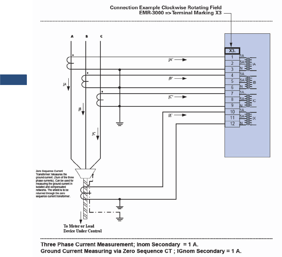
V3-T9-212 Volume 3—Power Distribution and Control Assemblies CA08100004E—March 2016 www.eaton.com
9
9
9
9
9
9
9
9
9
9
9
9
9
9
9
9
9
9
9
9
9
9
9
9
9
9
9
9
9
9
9.3
Metering Devices, Protective Relays, Software and Connectivity
Protective Relays
Wiring Diagrams
Typical AC Connections—1 A CTs and Ground Current Measured by Zero Sequence CT
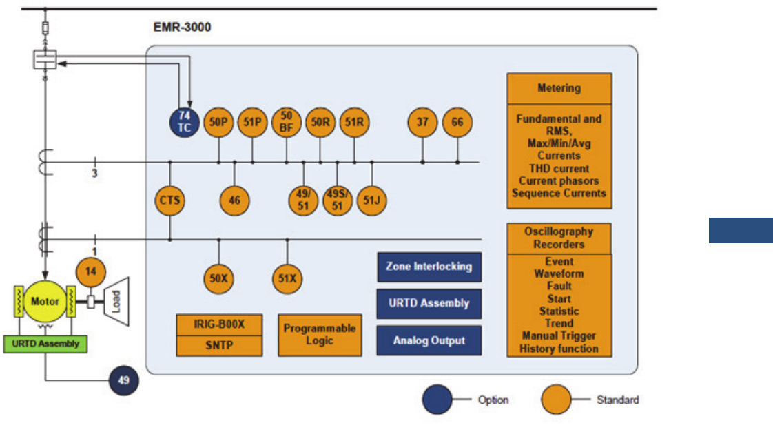
Volume 3—Power Distribution and Control Assemblies CA08100004E—March 2016 www.eaton.com V3-T9-213
9
9
9
9
9
9
9
9
9
9
9
9
9
9
9
9
9
9
9
9
9
9
9
9
9
9
9
9
9
9
9.3
Metering Devices, Protective Relays, Software and Connectivity
Protective Relays
Typical One-Line Diagram
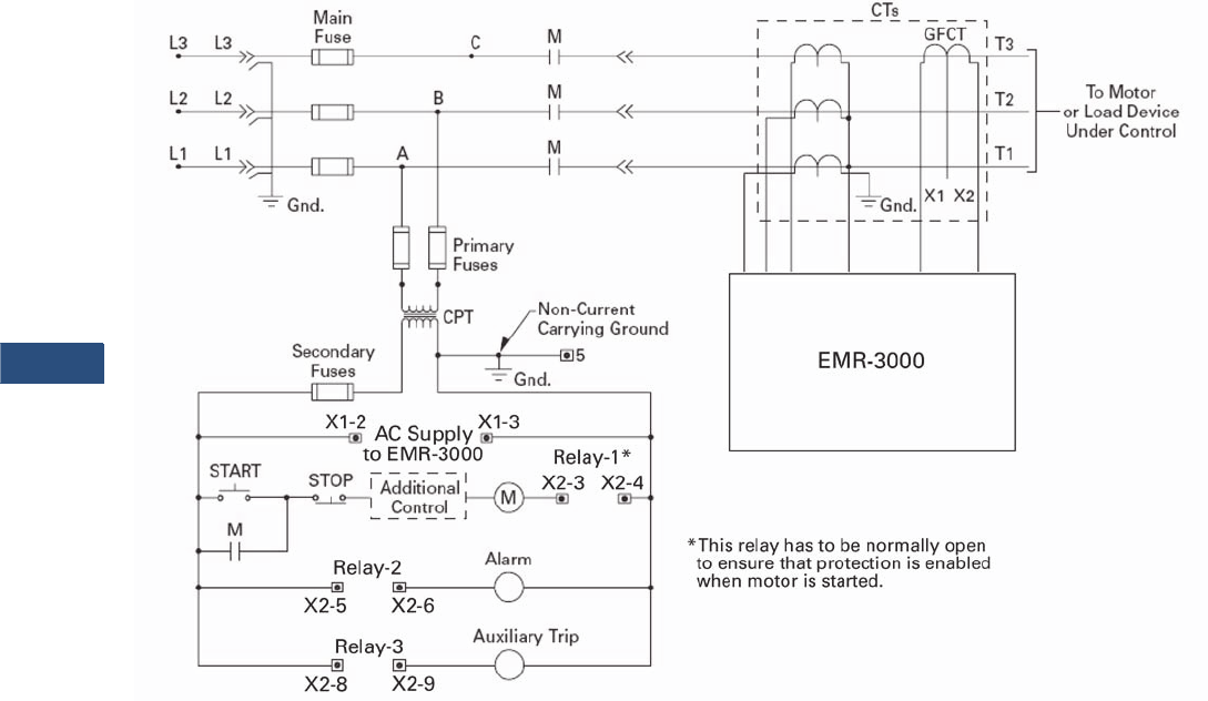
V3-T9-214 Volume 3—Power Distribution and Control Assemblies CA08100004E—March 2016 www.eaton.com
9
9
9
9
9
9
9
9
9
9
9
9
9
9
9
9
9
9
9
9
9
9
9
9
9
9
9
9
9
9
9.3
Metering Devices, Protective Relays, Software and Connectivity
Protective Relays
Ty p i c a l C o n t r o l D i a g r a m
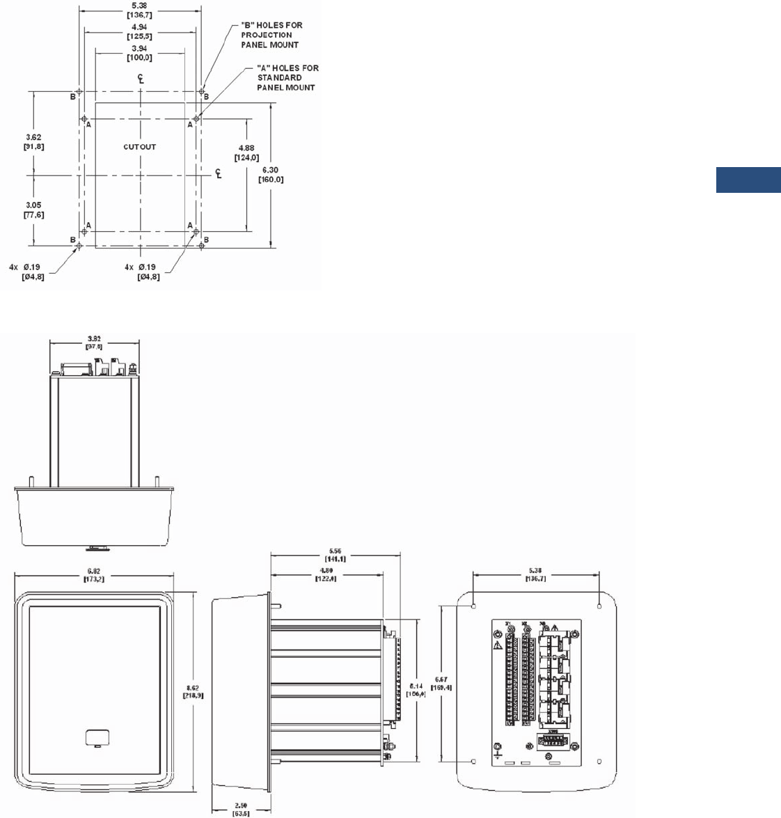
Volume 3—Power Distribution and Control Assemblies CA08100004E—March 2016 www.eaton.com V3-T9-215
9
9
9
9
9
9
9
9
9
9
9
9
9
9
9
9
9
9
9
9
9
9
9
9
9
9
9
9
9
9
9.3
Metering Devices, Protective Relays, Software and Connectivity
Protective Relays
Dimensions
Approximate Dimensions in Inches (mm)
Drilling Plan
Projection Mount Front and Side Views
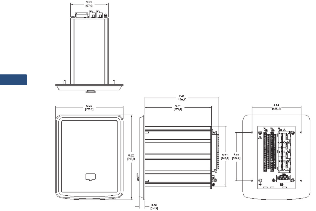
V3-T9-216 Volume 3—Power Distribution and Control Assemblies CA08100004E—March 2016 www.eaton.com
9
9
9
9
9
9
9
9
9
9
9
9
9
9
9
9
9
9
9
9
9
9
9
9
9
9
9
9
9
9
9.3
Metering Devices, Protective Relays, Software and Connectivity
Protective Relays
Approximate Dimensions in Inches (mm)
Standard Mount Front and Side Views

Volume 3—Power Distribution and Control Assemblies CA08100004E—March 2016 www.eaton.com V3-T9-217
9
9
9
9
9
9
9
9
9
9
9
9
9
9
9
9
9
9
9
9
9
9
9
9
9
9
9
9
9
9
9.3
Metering Devices, Protective Relays, Software and Connectivity
Protective Relays
EMR-4000 Motor Protection Relay
Contents
Description Page
Product Selection Guide . . . . . . . . . . . . . . . . . . . . V3-T9-143
Digitrip 3000 . . . . . . . . . . . . . . . . . . . . . . . . . . . . . V3-T9-149
EDR-3000 Feeder Protection. . . . . . . . . . . . . . . . . V3-T9-159
EDR-5000 Distribution Protection Relay . . . . . . . . V3-T9-168
FP-5000 Feeder Protection . . . . . . . . . . . . . . . . . . V3-T9-181
MP-3000 Motor Protection . . . . . . . . . . . . . . . . . . V3-T9-189
MP-4000 Motor Protection . . . . . . . . . . . . . . . . . . V3-T9-199
EMR-3000 Motor Protection Relay . . . . . . . . . . . . V3-T9-205
EMR-4000 Motor Protection Relay
EMR-5000 Motor Protection Relay . . . . . . . . . . . . V3-T9-230
ETR-4000 Transformer Protection Relay . . . . . . . . V3-T9-242
ETR-5000 Transformer Protection Relay . . . . . . . . V3-T9-254
EGR-5000 Generation Protection Relay . . . . . . . . V3-T9-267
Ground Fault Relay . . . . . . . . . . . . . . . . . . . . . . . . V3-T9-280
Universal RTD Module . . . . . . . . . . . . . . . . . . . . . V3-T9-283
EMR-4000 Motor Protection Relay
Product Description
Eaton’s EMR-4000 motor
protection relay is a
multifunctional
microprocessor-based
protective relay for the
protection of any size motor
at all voltage levels. It is most
commonly applied on
medium voltage or larger
motors. The EMR-4000 relay
is a current and voltage
device that provides
complete and reliable motor
protection, monitoring,
diagnostics, metering and
starting control functions.
The EMR-4000 motor
protection relay has
removable terminal blocks,
and it has Modbus-RTU
communications as standard;
and an optional Ethernet port
for Modbus-TCP
communications or
IEC-61850.
The EMR-4000 motor
protection relay provides
complete current, voltage,
and frequency protection in a
single compact case. The
relay has four current inputs
rated for either 5 amperes or
1 ampere and four voltage
inputs. Three of the voltage
inputs are to be connected to
the three-phase power
voltage for voltage protection
and for metering. They can be
connected in wye-ground or
open delta configuration. The
fourth voltage is for
independent single-phase
undervoltage/overvoltage
protection. The unit is capable
of 60 Hz or 50 Hz operation.
The maintenance mode
password protected soft key,
can be used for arc flash
mitigation to change to an
alternate settings group, set
to have instantaneous
elements only. The multiple
setting groups can also be
changed, via communications
or a digital input. Flash
memory is used for the
programming and all settings
are stored in nonvolatile
memory.
An integral keypad and
display is provided for direct
user programming and
retrieval of data without the
need of a computer. 14
programmable LEDs provide
quick indication of relay status.
A front port is provided for
direct computer connection.
An RS-485 communication
port on the back is standard
for local area networking
using Modbus-RTU. An
optional Ethernet port and
protocols are available.
The EMR-4000 motor
protection relay includes
programmable logic
functions. Logic gates and
timers may be defined and
arranged for customized
applications. With the
programmable logic control
functions you can simplify the
complexity of your starting
schemes by eliminating
timers and auxiliary relays.
Flash memory is used for the
programming and all settings
are stored in nonvolatile
memory. The relay allows for
four preprogrammed setting
groups which can be
activated through software or
contact input.
The EMR-4000 motor
protection relay has mass
memory for data storage and
a real-time clock with 1 ms
time resolution.
The relay will log 300
sequence of event records,
20 detailed trip logs,
minimum/maximum values,
load profiles, the 5 latest start
profiles, motor trending,
breaker/contactor wear
information and oscillography
data.
The EMR-4000 motor
protection relay has eight
discrete inputs, 1 fiber optic
input, 2 Form C, and 2 NO
output programmable
contacts, and 1 Form C
healthy contact. It also has
four 4-20 mA analog outputs
and one zone interlocking
card. The relay provides
maximum user flexibility to
configure the I/O. All inputs
and outputs (except the
healthy output) are user-
programmable. The unit also
counts with a test mode to
force outputs and simulate
currents, to facilitate the
commissioning of the unit. It
can be powered from 19 Vdc
to 300 Vdc or 40 Vac to 250
Vac auxiliary power.

V3-T9-218 Volume 3—Power Distribution and Control Assemblies CA08100004E—March 2016 www.eaton.com
9
9
9
9
9
9
9
9
9
9
9
9
9
9
9
9
9
9
9
9
9
9
9
9
9
9
9
9
9
9
9.3
Metering Devices, Protective Relays, Software and Connectivity
Protective Relays
Application Description
Eaton’s EMR-4000 motor
protection relay has been
designed for maximum
motor operation and
protection. It permits running
the motor close to its design
limits while protecting it
against excessive heating
and damaging overload
conditions. The EMR-4000
field proven protection
algorithms were developed
based on motor designs and
operating parameters for
optimum operation and
protection while minimizing
nuisance tripping. The EMR-
4000 motor protection relay
utilizes a patented protection
algorithm and measurement
technique based on proven
positive and negative
(unbalance) sequence
current sampling and true
RMS calculations.
Features, Benefits and Functions
Intel-I-Trip (I2t) Overload
Protection
The EMR-4000 motor relay
features the exclusive Eaton
Intel-I-Trip intelligent overload
protection system. Intel-I-Trip
develops custom overload
curves simply from motor
nameplate data. Intel-I-Trip
protects motors from
potentially damaging overload
and abnormal operating
conditions. The Intel-I-Trip
intelligent overload protection
feature utilizes field proven
measurement techniques and
a patented motor thermal
protection model. The EMR-
4000 motor relay’s unique
measurement technique
samples the current
waveforms 36 times per
cycle, providing accurate
measurements of the
positive and negative
sequence currents. The
negative sequence current
causes a greater heating
effect on the rotor and has a
greater impact on the thermal
model in the relay. Intel-I-Trip
utilizes these measurements
in its motor model to safely
protect the motor against the
heating effects of these
currents.
The motor thermal model is
analogous to a bucket that is
being filled and drained at the
same time. The fill rate is
dependent on the motor
currents and the drain is
based on motor design
principles. The size of the
bucket is equivalent to the
thermal capacity associated
with the mass of the motor.
Intel-I-Trip integrates these
rates and will issue a trip
when the thermal capacity
is filled.
Intel-I-Trip features adaptive
trip characteristics that adjust
the trip times based on
measured motor temperature
when RTDs are used.
Instantaneous Overcurrent
The EMR-4000 motor
protection relay provides an
instantaneous phase
overcurrent function to trip
the motor for high fault
current levels and save the
fuses. This function can be
disabled and has an
adjustable time delay on
starting to avoid nuisance
tripping on inrush.
Phase Unbalance Protection
Motor supply circuits are
often fed through fuses and
can be run with a single-
phase fuse blown, referred to
as single phasing the motor.
The EMR-4000 motor
protection relay measures
the current and voltage
unbalance and either can be
used to alarm or trip the
motor before damage occurs.
The EMR-4000 has 2 voltage
and 2 current unbalance
elements. Pickup, start and
run timers are provided for
each element.
Ground Fault Protection
A separate measuring circuit
is used to measure ground
current. A ground CT is
recommended for more
sensitive protection against
winding insulation breakdown
to ground. The relay ground
circuit can be connected
residually from the three-
phase CTs. The ground fault
protection has pickup and
time delay set points or can
be disabled.
Jam Protection
The user-selectable Jam
function protects motors that
are running against a sudden
mechanical jam or stall
condition. The common
application is on motors used
on crushers, chippers, or
conveyors. It detects an
increase of motor current to a
level above full load. Pickup,
start, and run timers and a
second element for alarm
purposes are provided.
Underload/Underpower
Protection
The user selectable
underload/underpower
function is used to detect the
loss of load on the motor.
Coupling failure is a common
cause for loss of load.
Whenever is possible, it is
better to use underpower to
detect loss of load. Three
power elements and two
underload elements are
provided in the relay for
tripping and alarm purposes.
Pickup, start, and run timers
are provided for each
element.
Frequency Protection
The frequency elements
provide the ability to detect
when the motor is operating
at off-nominal frequencies
that can do damage to the
process or, to signal to
upstream protections or
controls to implement load
shedding actions.
Power Factor Protection
This protection is used in
synchronous motors
applications to detect out-of-
synchronism conditions.
Undervoltage/Overvoltage
Protection
Use the voltage protective
functions to detect abnormal
system voltage conditions
potentially hazardous to the
motor.
Reduced Voltage Starting
The EMR-4000 motor
protection relay provides a
transition and incomplete
sequence function for
reduced voltage starting. The
user can select to transition
based on the current level
and/or on time.

Volume 3—Power Distribution and Control Assemblies CA08100004E—March 2016 www.eaton.com V3-T9-219
9
9
9
9
9
9
9
9
9
9
9
9
9
9
9
9
9
9
9
9
9
9
9
9
9
9
9
9
9
9
9.3
Metering Devices, Protective Relays, Software and Connectivity
Protective Relays
Antibackspin
The stop function is
programmable from 2 to
20%. For certain applications,
such as pumping a fluid up a
pipe, the motor may be
driven backward for a period
of time after it stops. The
EMR-4000 relay provides an
antibackspin timer to prevent
starting the motor while it is
spinning in the reverse
direction. The timer begins
counting from the moment a
stop is declared by the relay.
Start Control Timers
Motors typically have limits to
the number of cold starts,
starts per hour period, or time
between starts that are
permitted without damage.
The EMR-4000 motor
protection relay incorporates
these timers to prevent
starting the motor beyond its
capabilities.
Load Shedding
The EMR-4000 motor
protection relay provides a
mechanical load shedding
feature that can be used to
control an upstream process.
The load-shedding function
closes a contact on an
overload condition to control
an upstream process from
adding more load until the
overload condition is gone.
Emergency Override
The EMR-4000 motor
protection relay has a user-
programmable feature that
will let the operator reset the
start inhibitor timers and
thermal overload bucket. This
function is intended for use in
emergency conditions only,
and it may result in motor
damage or failure.
Long Acceleration Motors
Large motors with a high
inertia may experience
starting currents that exceed
the locked rotor current and
time. The EMR-4000 motor
protection relay has logic and
provisions for a zero speed
switch input to differentiate
between a stall and start
condition. If the motor is
spinning, then the relay will
not trip on the normal locked
rotor time allowing the motor
to start.
Remote/differential Trip
The digital inputs can be
programmed to accept a
contact input from a separate
differential relay or other
device to trip the motor. This
provides local and remote
target information and utilizes
the trip contacts of the EMR-
4000 motor protection relay.
It will also record and log the
motor information at the time
of the trip.
Breaker Failure or Stuck
Contactor
The EMR-4000 motor
protection relay includes a
breaker failure (50BF, 62BF)
function that can be initiated
from either an internal or
external trip signal. This is an
independent element that
can be used to operate a
lockout relay or trip an
upstream breaker. The timer
must be longer than the
breaker operating time and
the protective function reset
times.
Flexible Phase Rotation
The EMR-4000 motor
protection relay can be
applied on either an A-B-C or
A-C-B phase rotation. A user
setting permits correct
operation and indication of
the actual system
configuration.
Maintenance Mode
The Maintenance Mode can
improve safety by providing a
simple and reliable method to
reduce fault clearing time and
lower incident energy levels
at energized panels. The
Maintenance Mode allows
the user to switch to more
sensitive settings via a
password protected soft key,
communication or via a digital
Input while maintenance
work is being performed at an
energized panel or device.
The more sensitive settings
provide greater security for
maintenance personnel and
helps reduce the possibility of
injury.
Diagnostic Features
Broken Rotor Bar
The EMR-4000 provides
advanced motor diagnostics
including a broken rotor bar
detection function. The
broken rotor bar detection is a
condition maintenance
function that continuously
monitors the motor’s health
while in operation. The
advanced Motor Current
Signature Analysis (MCSA)
continuously analyzes the
motor current signature and
based on preset algorithms
will determine when a broken
rotor bar is present in the
motor.
The broken rotor bar function
will provide early detection of
any rotor problems and
advise maintenance
personnel of the impending
issue allowing for predictive
maintenance of the motor
and prevention of
catastrophic motor failures.
By providing early indication
of potential rotor problems,
serious system issues such
as: reduced starting torque,
overloads, torque and speed
oscillation and bearing wear
can be avoided. With the
advanced broken rotor bar
detection system, advanced
warning of impending
problems reduces
catastrophic failures,
maximizing motor life and
system uptime.

V3-T9-220 Volume 3—Power Distribution and Control Assemblies CA08100004E—March 2016 www.eaton.com
9
9
9
9
9
9
9
9
9
9
9
9
9
9
9
9
9
9
9
9
9
9
9
9
9
9
9
9
9
9
9.3
Metering Devices, Protective Relays, Software and Connectivity
Protective Relays
Protection Features
●Thermal protection (49/51)
●Locked rotor protection
(49S/51)
●Phase overcurrent
elements:
●Two instantaneous
elements with timers
(50P[1], 50P[2] and
50P[3])
●Three inverse time
overcurrent elements
(51P[1], 51P[2] and
51P[3])
●11 standard curves
●Instantaneous or time
delay reset
●Ground overcurrent
elements:
●Two instantaneous
measured elements
with timers (50X[1] and
50X[2])
●Two instantaneous
calculated elements
with timers (50R[1] and
50R[2])
●Two inverse time
overcurrent measured
elements (51X[1] and
51X[2])
●Two inverse time
overcurrent calculated
elements (51R[1] and
51R[2])
●11 standard curves
●Instantaneous or time
delay reset
●Jam or Stall protection
(50J[1], 50J[2])
●Phase unbalance negative
sequence overcurrent
(46[1], 46[2])
●Underload protection
(37[1], 37[2])
●Temperature protection
with optional URTD (49/38)
●Stars per hour (66)
●Switch onto fault
protection
●Phase voltage unbalance
and sequence protection
(47[1], 47[2])
●Main three-phase under/
overvoltage (27M[1],
27M[2], 59M[1], 59M[2])
●Auxiliary single-phase
under/overvoltage (27A[1],
27A[2], 59A[1], 59A[2])
●Six frequency elements
that can be assigned to:
over frequency, under
frequency, rate of change,
or vector surge (81[1],
81[2], 81[3], 81[4], 81[5],
81[6])
●Apparent and
displacement power factor
(55A[1], 55A[2], 55D[1],
55D[2])
●Forward and reverse Watts
(32[1], 32[2], 32[3])
●Forward and reverse VARs
(32V[1], 32V[2], 32V[3])
●Lockout protection (86)
●Breaker failure (50BF)
●Zone interlocking for bus
protection (87B)
Metering Features
●Amperes: Positive,
negative and zero
sequence
●Volts: Positive, negative
and zero sequence
●Phase angles
●Volt-amperes and VA
demand
●Watts and kW demand
●kWh (forward, reverse,
net)
●VARs and kVAR demand
●kVARh (lead, leg and net)
●Power factor
●Frequency
●% THD V and I
●Magnitude THD V and I
●Minimum/maximum
recording
●Trending (load profile over
time)
●Minimum/maximum
recording
●Temperature with remote
URTD module
Monitoring Features
●Trip coil monitor
●Breaker wear primary and
secondary (accumulated
interrupted current)
●Oscillography (7200 cycles
total)
●Trip Cause displays fault
recorder data on HMI after
fault event
●Fault data logs (up to 20
events)
●Sequence of events report
(up to 300 events)
●Trending (load profile over
time)
●Motor history
●Records the last 5 motor
start profiles
●Motor start trending
●CT supervision
●VT supervision
●Clock (1 ms time stamping)
Diagnostic Features
●Broken rotor bar
Control Functions
●Transition for reduced
voltage starts
●Incomplete sequence
delay
●Permits numbers of cold
starts
●Limits numbers of starts
per hour
●Anti-backspin time delay
●Mechanical load shedding
●Zero speed switch for long
acceleration motors
●Motor stop inputs
●Remote trip input
●Differential trip input
●Emergency override
●Breaker/contactor open-
close/stop-start
●Remote open-close (stop-
start)
●Programmable I/O
●Programmable LEDs
●Programmable logic
●Multiple setting groups
Communication Features
●Local HMI
●Password protected
●Addressable.
●IRIG-B
●Local communication port.
●RS-232
●Remote communication
port:
●RS-485
●Ethernet port
●Protocols:
●Modbus-RTU (optional)
●Modbus-TCP (optional)
●IEC-61850 (optional)
●Configuration software
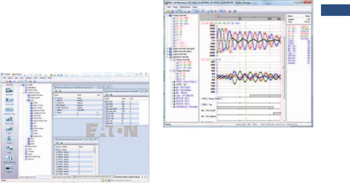
Volume 3—Power Distribution and Control Assemblies CA08100004E—March 2016 www.eaton.com V3-T9-221
9
9
9
9
9
9
9
9
9
9
9
9
9
9
9
9
9
9
9
9
9
9
9
9
9
9
9
9
9
9
9.3
Metering Devices, Protective Relays, Software and Connectivity
Protective Relays
Monitoring and Metering
Sequence of Events Records
The EMR-4000 protection
relay records a maximum of
300 events associated with
the relay. An event is
classified as a change of state
as detected by the relay.
These include relay pickups,
dropouts, trips, contact
closure, alarms, setting
changes and self-diagnostic
failures. Each event is date
and time stamped to a 1 ms
resolution. The events are
stored in a FIFO in
chronological order.
Trip Log
The EMR-4000 protection
relay will store a maximum of
20 trip records in a FIFO trip
log. Each trip record will be
date and time stamped to a 1
ms resolution. The trip log
record will include
information on the type of
fault, protection elements
that operated, fault location
and currents and voltages at
the time of the fault.
PowerPort-E
PowerPort-E is the software
program used to configure
off-line protection setting files
for all E-Series relay models.
PowerPort-E is also used for
viewing measured values of
the relays in real-time,
uploading/downloading
setting files, and retrieving
event log and waveform
records.
Waveform Capture (Quality Manager)
The EMR-4000 relay provides
oscillographic recording
capabilities. The relay will
record all measured signals
along with the binary signals
of pickup, trip, internal logic,
and contact inputs. The EMR-
4000 can record up to 7200
cycles of data. The number of
records is proportional to the
programmed size of each
record; the maximum size per
record is 600 cycles. The
waveform capture is initiated
by up to 8 different triggers
(i.e., trip/alarm events) or
manually via communications
or the HMI. PowerPort-E
setting software is used to
retrieve the records. Quality
Manager is a separate
software program downloaded
with PowerPort-E used for
analyzing the waveform and
trending files retrieved from
the relay.

V3-T9-222 Volume 3—Power Distribution and Control Assemblies CA08100004E—March 2016 www.eaton.com
9
9
9
9
9
9
9
9
9
9
9
9
9
9
9
9
9
9
9
9
9
9
9
9
9
9
9
9
9
9
9.3
Metering Devices, Protective Relays, Software and Connectivity
Protective Relays
Integral User Interface
The front panel user interface
has a 128 x 64 pixel LCD
display with background
illumination for wide angle
viewing in all light conditions.
Seven programmable LEDs
provide quick and easy visual
display of power on, mode of
operation, alarm and trip
indication. Soft keys are
provided for operation mode
selection, scrolling through
data and settings. In addition,
the relay settings and test
functions are password
protected.
Starting Profiles
The EMR-4000 records the
average current versus time
for the last five starting
cycles. This information is
available via the
communications port through
PowerPort-E
Motor Statistics
For each motor start, the
EMR-4000 stores a motor
start report and add this data
to the motor statistics buffer.
With the motor statistics you
can track motor start data for
the past eighteen 30-day
periods. For each 30-day
interval, the relay records the
following information:
●The date the interval began
●The total number of starts
in the interval
●The averages of the
following quantities:
●Motor start time
●Start % rotor thermal
capacity used
●Maximum start current
Load Profiling/Trending
The EMR-4000 relay
automatically records
selected quantities into non-
volatile memory every 5, 10,
15, 30, or 60 minutes,
depending on the trending
report setting.
Programmable I/O
The EMR-4000 motor
protection relay provides
heavy-duty, trip-rated, 2
normally open and 1 Form C
contacts. One isolated inputs
can be used for monitoring
the trip circuit. One Form C
contact is dedicated to the
relay failure alarm function
and is operated in a normally
energized (failsafe) mode.
There are 4 eight user-
configurable discrete inputs
that accept a wet contact and
can operate through a wide
range of power. Each input
and output is user-
programmable for maximum
application flexibility.
Programmable Logic
The EMR-4000 motor
protection relay provides logic
gates and timers that the
user can customize for
special or unique applications.
Each gate can be assigned a
logic function of either AND,
OR, NAND or NOR. Each
gate can have a maximum of
four input signals and each
input signal can be required
to be a NOT. Input signals can
be external inputs received
via the binary inputs or
internal values associated
with the protection, alarm or
metering set points. Each
gate has a unique output
assignment and designation
that can be used as the input
to another gate. There are 80
independent timers that have
adjustable pickup and dropout
delay settings.
Standards and Certifications
Design Standards
●Generic Standard:
●EN 61000-6-2
●EN 61000-6-3
●Product Standard:
●IEC 60255-6
●EN 50178
●UL 508 (Industrial
Control Equipment)
●CSA C22.2 No. 14-95
(Industrial Control
Equipment)
●ANSI C37.90
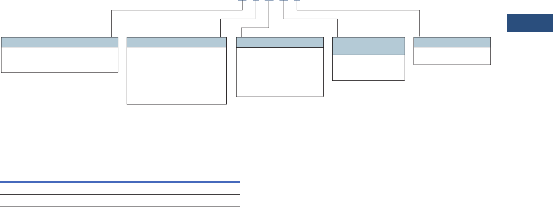
Volume 3—Power Distribution and Control Assemblies CA08100004E—March 2016 www.eaton.com V3-T9-223
9
9
9
9
9
9
9
9
9
9
9
9
9
9
9
9
9
9
9
9
9
9
9
9
9
9
9
9
9
9
9.3
Metering Devices, Protective Relays, Software and Connectivity
Protective Relays
Catalog Number Selection
The catalog number
identification chart defines
the electrical characteristics
and operation features
included in the EMR-3000.
For example, if the catalog
number were EMR-3000A0BA1,
the device would have
the following:
EMR-4000
(A)–Four digital inputs, four
output relays, 1 4-20 mA
analog output, URTD
interface
(0)–5 A / 1 A phase and
ground CTs, power supply
range:
19–300 Vdc, 40–250 Vac
(B)–Modbus-RTU (RS-485)
(A)–Without conformal
coating
(1)–Projection panel mount
Motor Relay Removable Terminals
Accessories
Standard Accessories EMR-4000
Notes
1Beginning in 2016, consult factory for the availability of the following new communication options.
• Protocols: DNP3.0, Profibus
• Interface ports: Fiber optic ST, RS-485 D-SUB, Fiber optic LC
2See URTD section for fiber optic cables required to communicate to the EMR-3000.
Description
Catalog
Number
UNVL RTD Mod with Modbus-RTU 48–240 Vac/48–250 Vdc URTDII-01 2
UNVL RTD Mod with Modbus-RTU 24–48 Vdc URTDII-02 2
Hardware Option 1
A = 8 DI, 5 outputs, 4AO, removable
terminals, zone interlocking, URTD
interface, IRIG-B, small display
Communication Options 1
B= Modbus-RTU (RS-485)
I= Modbus-RTU (RS-485) and
Modbus-TCP (RJ-45) [only 1
active, software selected]
H= IEC 61850 GOOSE and
MMS (RJ-45)
Conformal Coating
Options
A = None
B = Conformal coated
circuit boards
Mounting Options
0 = Standard mount
1 = Projection panel mount
Hardware Option 2
0 = Phase current 5 A / 1 A, ground
current 5 A / 1 A, power supply
range: 19–300 Vdc, 40–250 Vac
1 = Phase current 5 A / 1 A sensitive
ground current, 0.5 A / 0.1 A,
power supply range: 19–300 Vdc,
40–250 Vac
EMR4000 A 0 B A 1

V3-T9-224 Volume 3—Power Distribution and Control Assemblies CA08100004E—March 2016 www.eaton.com
9
9
9
9
9
9
9
9
9
9
9
9
9
9
9
9
9
9
9
9
9
9
9
9
9
9
9
9
9
9
9.3
Metering Devices, Protective Relays, Software and Connectivity
Protective Relays
Technical Data and Specifications
Climatic Environmental
Conditions
●Storage temperature:
–30 °C to +70 °C
(–22 °F to +158 °F)
●Operating temperature:
–20 °C to +60 °C
(–4°F to +140 °F)
●Permissible humidity at
ann. average:<75% rel. (on
56d up to 95% rel.)
●Permissible Installation
Altitude: <2,000 m
(6,561.67 ft) above sea
level
●If 4,000 m (13,123.35 ft)
altitude applies, a
changed classification of
the operating and test
voltages may be
necessary
Degree of Protection EN 60529
●HMI front panel with seal:
IP54
●Rear side terminals: IP20
Routine Test
●Insulation test acc. to
IEC 60255-5: All tests to be
carried out against ground
and other input and output
circuits
●Aux. voltage supply, digital
inputs, current measuring
inputs, signal relay outputs:
2.5 kV (eff.) / 50 Hz
●Voltage measuring Inputs:
3.0 kV (eff.) / 50 Hz
●All wire-bound
communication interfaces:
1. 5 k V D C
Housing
●Housing B2: height / width
183 mm (7.205 in)/
212.7 mm (8.374 in)
●Housing depth (Incl.
Terminals): 208 mm
(8.189 in)
●Material, housing:
aluminum extruded section
●Material, front panel:
aluminum/foil front
●Mounting position:
horizontal (±45° around the
X-axis must be permitted)
●Weight: approx. 4.2 kg
(9.259 lb)
Current and Ground Current
Measurement
●Nominal currents: 1 A / 5 A
●Max. measuring range:
●Up to 40 x In (phase
currents)
●Up to 25 x In (ground
current standard)
●Up to 2.5 x In (ground
current sensitive)
●Continuous loading
capacity: 4 x In/
continuously
●Overcurrent proof:
●30 x In / 10 s
●100 x In / 1 s
●250 x In / 10 ms
(1 half-wave)
●Power consumption:
●Phase current inputs
At In= 1 A S=0.15 MVA
At In= 5 A S=0.15 MVA
●Ground Current Input
At In= 1 A S=0.35 MVA
At In= 5 A S=0.35 MVA
●Frequency range: 50 Hz /
60 Hz ±10%
●Terminals: screw-type
terminals with integrated
short-circuiters (contacts)
●Connection cross sections:
●1 x or 2 x 2.5 mm² (2 x
AWG 14) with wire end
ferrule
●1 x or 2 x 4.0 mm² (2 x
AWG 12) with ring cable
sleeve or cable sleeve
●1 x or 2 x 6 mm² (2 x
AWG 10) with ring cable
sleeve or cable sleeve
●The current measuring
board´s terminal blocks
may be used as with 2
(double) conductors
AWG 10,12,14
otherwise with single
conductors only
Plug-in Connector with
Integrated Short-Circuiter
(Conventional Current Inputs)
●Nominal currents: 1 A / 5 A
●Continuous loading
Capacity: 4 x In /
continuously
●Overcurrent withstand:
●30 x In / 10 s
●100 x In / 1 s
●250 x In / 10 ms
(1 half-wave)
●Screws: M4, captive type
acc. to VDEW
●Connection cross sections:
●1 x or 2 x 2.5 mm² (2 x
AWG 14) with wire end
ferrule
●1 x or 2 x 4.0 mm² (2 x
AWG 12) with ring cable
sleeve or cable sleeve
●1 x or 2 x 6 mm² (2 x
AWG 10) with ring cable
sleeve or cable sleeve
●The current measuring
board´s terminal blocks
may be used as with 2
(double) conductors
AWG 10,12,14
otherwise with single
conductors only
Control Power Supply
●
Aux. voltage: 240–270 Vdc /
48–230 Vac (–20/+10%)
●Buffer time in case of
supply failure: ≥50 ms at
minimal aux. voltage
Interrupted communication
is permitted
●Max. permissible making
current:
●18 A peak value for
<0.25 ms
●12 A peak value for <1
ms
●The voltage supply must
be protected by a fuse of:
●2.5 A time-lag miniature
fuse approx. 1/5 x 0.8 in
(5 x 20 mm) according to
IEC 60127
●3.5 A time-lag miniature
fuse approx. 1/4 x
1 1/4 in (6.3 x 32 mm)
according to UL 248-14
Voltage and Residual Voltage
Measurement
●Nominal voltages:100 V/
110 V/ 230 V/ 400 V (can be
configured)
●Max. measuring range: 2 x
nominal voltage
●Continuous loading
capacity: 2 x nominal
voltage (800 Vac)
●Power Consumption:
●at Vn = 100 V S = 0.1
MVA
●at Vn = 110 V S = 0.1
MVA
●at Vn = 230 V S = 0.4
MVA
●at Vn = 400 V S = 1.0
MVA
●Frequency range: 50 Hz or
60 Hz ±10%
●Terminals: screw-type
terminals
Frequency Measurement
●Nominal Frequencies:
50 Hz / 60 Hz
Voltage Supply
●Aux. Voltage: 24–270 Vdc /
48–230 Vac (–20/+10%)
●Buffer time in case of
supply failure:
●≥50 ms at minimal aux.
voltage
●Interrupted
communication is
permitted.
●Max. permissible making
current:
●18 A peak value for
0.25 ms
●12 A peak value for 1 ms
●The voltage supply must
be protected by a fuse of:
●2.5 A time-lag miniature
fuse approx. 5 x 20 mm
(0.2 x 0.8 in) according
to IEC 60127
●3.5 A time-lag miniature
fuse approx. 6.3 x 32
mm (0.25 x 1.25 in)
according to UL 248-14

Volume 3—Power Distribution and Control Assemblies CA08100004E—March 2016 www.eaton.com V3-T9-225
9
9
9
9
9
9
9
9
9
9
9
9
9
9
9
9
9
9
9
9
9
9
9
9
9
9
9
9
9
9
9.3
Metering Devices, Protective Relays, Software and Connectivity
Protective Relays
Power Consumption
●Power supply range:
24–270 Vdc
●Power consumption
in idle mode—7 W
●Maximum power
consumption—13 W
●Power supply range:
48–230 Vac (for
frequencies of 40–70 Hz)
●Power consumption
in idle mode—7 W
●Maximum power
consumption—13 W
Display
●Display Type: LCD with
LED background
illumination
●Resolution—graphics
display: 128 x 64 pixel
●LED type: two colored:
red/green
●Number of LEDs, housing
B2: 15
Front Interface
●Baud Rates: 115,200 baud
●Handshake: RTS and CTS
●Connection: 9-pole D-Sub
plug
Real Time Clock
●Running reserve of the real
time clock: 1 year min.
Digital Inputs
●Max. input voltage:
300 Vdc / 259 Vac
●Input current: <4 mA
●Reaction time: <20 ms
●Fallback time: <30 ms
●(Safe State of the Digital
Inputs)
●Four switching thresholds:
Un = 24 Vdc, 48 Vdc,
60 Vdc, 110 Vac / Vdc,
230 Vac / Vdc
●Un = 24 Vdc
– Switching threshold
1 ON: Min. 19.2 Vdc
– Switching threshold
1 OFF: Max. 9.6 Vdc
●Un = 48 V / 60 Vdc
– Switching threshold
2 ON: Min. 42.6 Vdc
– Switching threshold
2 OFF: Max. 21.3 Vdc
●Un = 110 / 120 Vac / Vdc
– Switching threshold
3 ON: Min. 88.0 Vdc /
88.0 Vac
– Switching threshold
3 OFF: Max. 44.0 Vdc
/ 44.0 Vac
●Un = 230 / 240 Vac / Vdc
– Switching threshold
4 ON: Min. 184 Vdc /
184 Vac
– Switching threshold
4 OFF: Max. 92 Vdc /
92 Vac
●Terminals: screw-type
terminal
Relay Outputs
●Continuous current:
5 A AC/DC
●Max. make current:
●25 A AC / 25 A DC up to
30 V for 4 s
●30 A / 230 Vac according
to ANSI IEEE Std
C37.90-2005
●30 A / 250 Vdc according
to ANSI IEEE Std
C37.90-2005
●Max. breaking current:
●5 A AC up to 250 Vac
●5 A DC up to 30 V
(resistive)
●0.3 A DC at 300 V
●Max. switching voltage:
250 Vac / 250 Vdc
●Switching capacity:
1250 VA
●Contact Type: Form C or
normally open contact
●Terminals: screw-type
terminals
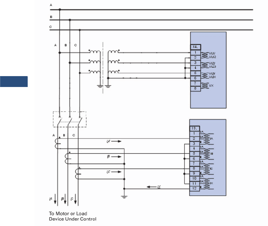
V3-T9-226 Volume 3—Power Distribution and Control Assemblies CA08100004E—March 2016 www.eaton.com
9
9
9
9
9
9
9
9
9
9
9
9
9
9
9
9
9
9
9
9
9
9
9
9
9
9
9
9
9
9
9.3
Metering Devices, Protective Relays, Software and Connectivity
Protective Relays
Wiring Diagrams
Typical AC Connections, Wye VTs 5 A CTs and Ground Current Measured by Residual Connection
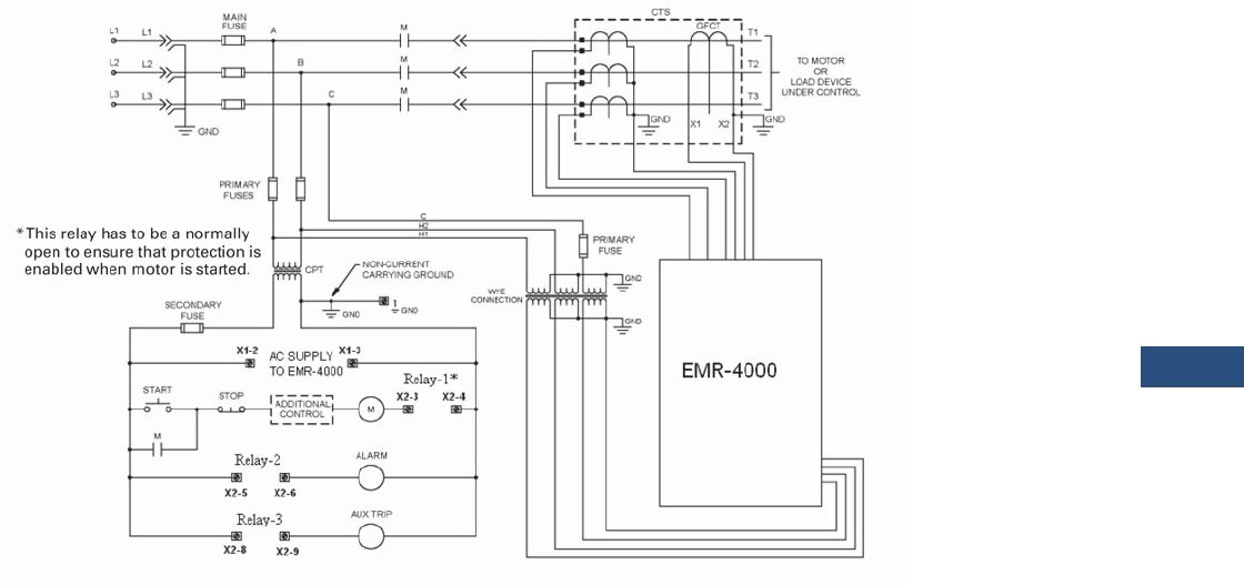
Volume 3—Power Distribution and Control Assemblies CA08100004E—March 2016 www.eaton.com V3-T9-227
9
9
9
9
9
9
9
9
9
9
9
9
9
9
9
9
9
9
9
9
9
9
9
9
9
9
9
9
9
9
9.3
Metering Devices, Protective Relays, Software and Connectivity
Protective Relays
Ty p i c a l C o n t r o l D i a g r a m
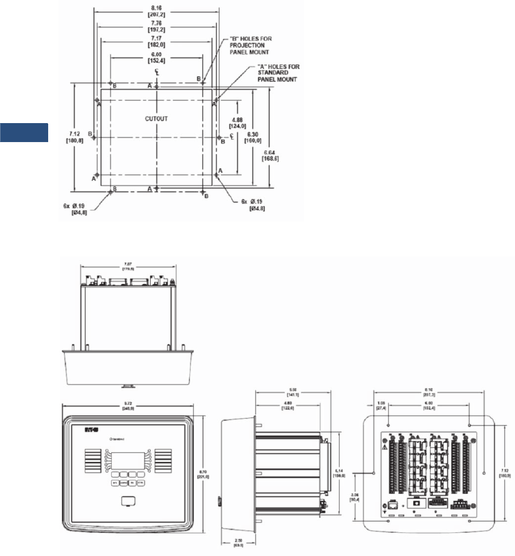
V3-T9-228 Volume 3—Power Distribution and Control Assemblies CA08100004E—March 2016 www.eaton.com
9
9
9
9
9
9
9
9
9
9
9
9
9
9
9
9
9
9
9
9
9
9
9
9
9
9
9
9
9
9
9.3
Metering Devices, Protective Relays, Software and Connectivity
Protective Relays
Dimensions
Approximate Dimensions in Inches (mm)
Drilling Plan
Projection Mount Front and Side Views
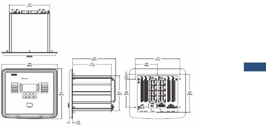
Volume 3—Power Distribution and Control Assemblies CA08100004E—March 2016 www.eaton.com V3-T9-229
9
9
9
9
9
9
9
9
9
9
9
9
9
9
9
9
9
9
9
9
9
9
9
9
9
9
9
9
9
9
9.3
Metering Devices, Protective Relays, Software and Connectivity
Protective Relays
Approximate Dimensions in Inches (mm)
Standard Mount Front and Side Views
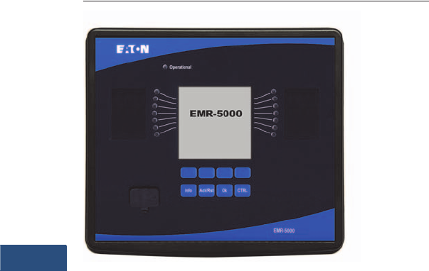
V3-T9-230 Volume 3—Power Distribution and Control Assemblies CA08100004E—March 2016 www.eaton.com
9
9
9
9
9
9
9
9
9
9
9
9
9
9
9
9
9
9
9
9
9
9
9
9
9
9
9
9
9
9
9.3
Metering Devices, Protective Relays, Software and Connectivity
Protective Relays
EMR-5000 Motor Protection Relay
Contents
Description Page
Product Selection Guide. . . . . . . . . . . . . . . . . . . . . V3-T9-143
Digitrip 3000. . . . . . . . . . . . . . . . . . . . . . . . . . . . . . V3-T9-149
EDR-3000 Feeder Protection . . . . . . . . . . . . . . . . . V3-T9-159
EDR-5000 Distribution Protection Relay . . . . . . . . V3-T9-168
FP-5000 Feeder Protection. . . . . . . . . . . . . . . . . . . V3-T9-181
MP-3000 Motor Protection . . . . . . . . . . . . . . . . . . V3-T9-189
MP-4000 Motor Protection . . . . . . . . . . . . . . . . . . V3-T9-199
EMR-3000 Motor Protection Relay . . . . . . . . . . . . V3-T9-205
EMR-4000 Motor Protection Relay . . . . . . . . . . . . V3-T9-217
EMR-5000 Motor Protection Relay
ETR-4000 Transformer Protection Relay . . . . . . . . V3-T9-242
ETR-5000 Transformer Protection Relay . . . . . . . . V3-T9-254
EGR-5000 Generation Protection Relay . . . . . . . . . V3-T9-267
Ground Fault Relay . . . . . . . . . . . . . . . . . . . . . . . . . V3-T9-280
Universal RTD Module . . . . . . . . . . . . . . . . . . . . . . V3-T9-283
EMR-5000 Motor Protection Relay
Product Description
Eaton’s EMR-5000 motor
protection relay is a
multifunctional
microprocessor-based
protective relay for the
protection of any size motor
at all voltage levels. It is most
commonly applied on
medium voltage or larger
motors. The EMR-5000 relay
is a current and voltage
device with built-in differential
protection that provides
complete and reliable motor
protection, monitoring,
diagnostics, metering and
starting control functions.
The EMR-5000 motor
protection relay provides
complete current, voltage,
and frequency protection in
a single compact case. The
relay has eight current inputs
rated for either 5 amperes or
1 ampere and four voltage
inputs. Three of the voltage
inputs are to be connected to
the three-phase power
voltage for voltage protection
and for metering. They can be
connected in wye-ground or
open delta configuration.
The fourth voltage is for
independent single-phase
undervoltage/overvoltage
protection. The unit is capable
of 60 Hz or 50 Hz operation.
The maintenance mode
password protected soft key,
can be used for arc flash
mitigation to change to an
alternate settings group, set
to have instantaneous
elements only. The multiple
setting groups can also be
changed, via communications
or a digital input. Flash
memory is used for the
programming and all settings
are stored in nonvolatile
memory.
An integral keypad and
display is provided for direct
user programming and
retrieval of data without the
need of a computer. Fourteen
programmable LEDs provide
quick indication of relay
status.
A front port is provided for
direct computer connection.
An RS-485 and an Ethernet
ports in the back are optional
for local area networking
using. Optional Modbus-RTU,
Modbus-TCP or IEC-61850
protocols are supported.
The EMR-5000 motor
protection relay includes
programmable logic
functions. Logic gates and
timers may be defined and
arranged for customized
applications. With the
programmable logic control
functions you can simplify the
complexity of your starting
schemes by eliminating
timers and auxiliary relays.
Flash memory is used for the
programming and all settings
are stored in nonvolatile
memory. The relay allows for
four preprogrammed setting
groups that can be activated
through software, manually,
or contact input.
The EMR-5000 motor
protection relay has mass
memory for data storage and
a real-time clock with 1 ms
time resolution. The relay will
log 300 sequence of event
records, 20 detailed trip logs,
minimum/maximum values,
load profiles, the 5 latest start
profiles, motor trending,
breaker/contactor wear
information and waveform
data.
The EMR-5000 has either
eight programmable binary
inputs, two analog inputs,
two analog outputs, or
16 programmable binary
inputs. It has 2NO and six
Form C heavy-duty outputs
and one form C signal alarm
relay. The relay provides
maximum user flexibility to
configure the I/O. All inputs
and outputs (except the
healthy output) are user-
programmable. The unit also
counts with a test mode to
force outputs and simulate
currents, to facilitate the
commissioning of the unit. It
can be powered from 19 Vdc
to 300 Vdc or 40 Vac to
250 Vac auxiliary power.

Volume 3—Power Distribution and Control Assemblies CA08100004E—March 2016 www.eaton.com V3-T9-231
9
9
9
9
9
9
9
9
9
9
9
9
9
9
9
9
9
9
9
9
9
9
9
9
9
9
9
9
9
9
9.3
Metering Devices, Protective Relays, Software and Connectivity
Protective Relays
Application Description
Eaton’s EMR-5000 motor
protection relay has been
designed for maximum motor
operation and protection. It
permits running the motor
close to its design limits
while protecting it against
excessive heating and
damaging overload
conditions. The EMR-5000
field proven protection
algorithms were developed
based on motor designs and
operating parameters for
optimum operation and
protection while minimizing
nuisance tripping. The EMR-
5000 motor protection relay
utilizes a patented protection
algorithm and measurement
technique based on proven
positive and negative
(unbalance) sequence current
sampling and true RMS
calculations.
Intel-I-Trip (I2t) Overload
Protection
The EMR-5000 motor relay
features the exclusive Eaton
Intel-I-Trip intelligent overload
protection system. Intel-I-Trip
develops custom overload
curves simply from motor
nameplate data. Intel-I-Trip
protects motors from
potentially damaging overload
and abnormal operating
conditions. The Intel-I-Trip
intelligent overload protection
feature utilizes field proven
measurement techniques and
a patented motor thermal
protection model. The EMR-
5000 motor relay’s unique
measurement technique
samples the current
waveforms 36 times per
cycle, providing accurate
measurements of the
positive and negative
sequence currents. The
negative sequence current
causes a greater heating
effect on the rotor and has a
greater impact on the thermal
model in the relay. Intel-I-Trip
utilizes these measurements
in its motor model to safely
protect the motor against the
heating effects of these
currents.
The motor thermal model is
analogous to a bucket that is
being filled and drained at the
same time. The fill rate is
dependent on the motor
currents and the drain is
based on motor design
principles. The size of the
bucket is equivalent to the
thermal capacity associated
with the mass of the motor.
Intel-I-Trip integrates these
rates and will issue a trip
when the thermal capacity
is filled.
Intel-I-Trip features adaptive
trip characteristics that adjust
the trip times based on
measured motor temperature
when RTDs are used.
Instantaneous Overcurrent
The EMR-5000 motor
protection relay provides an
instantaneous phase
overcurrent function to trip
the motor for high fault
current levels and save the
fuses. This function can be
disabled and has an
adjustable time delay on
starting to avoid nuisance
tripping on inrush.
Differential Protection
This protection function is
mostly used to protect
induction and synchronous
motors against phase-to-
phase faults. Differential
protection may be considered
the first line of protection for
internal phase to phase or
phase to ground faults. In the
event of such faults, the
quick response of the
differential element may limit
the damage that may have
otherwise occurred to the
motor. While this protection
is recommended in all motors
above 1500 hp, it can be used
in smaller motors depending
primarily in the importance
and the cost of the motor.
Phase Unbalance Protection
Motor supply circuits are
often fed through fuses and
can be run with a single-
phase fuse blown, referred to
as single phasing the motor.
The EMR-5000 motor
protection relay measures the
current and voltage
unbalance and either can be
used to alarm or trip the
motor before damage occurs.
The EMR-5000 has two
voltage and two current
unbalance elements. Pickup,
start and run timers are
provided for each element.
Ground Fault Protection
A separate measuring circuit
is used to measure ground
current. A ground CT is
recommended for more
sensitive protection against
winding insulation breakdown
to ground. The relay ground
circuit can be connected
residually from the three-
phase CTs. The ground fault
protection has pickup and
time delay set points or can
be disabled.
Jam Protection
The user-selectable Jam
function protects motors that
are running against a sudden
mechanical jam or stall
condition. The common
application is on motors used
on crushers, chippers, or
conveyors. It detects an
increase of motor current to a
level above full load. Pickup,
start, and run timers and a
second element for alarm
purposes are provided.
Underload/Underpower
Protection
The user selectable
underload/underpower
function is used to detect the
loss of load on the motor.
Coupling failure is a common
cause for loss of load.
Whenever is possible, it is
better to use underpower to
detect loss of load. Three
power elements and two
underload elements are
provided in the relay for
tripping and alarm purposes.
Pickup, start and run timers
are provided for each
element.
Frequency Protection
The frequency elements
provide the ability to detect
when the motor is operating
at off-nominal frequencies
that can do damage to the
process or, to signal to
upstream protections or
controls to implement load
shedding actions.
Power Factor Protection
This protection is used in
synchronous motors
applications to detect out-of-
synchronism conditions.
Undervoltage/Overvoltage
Protection
Use the voltage protective
functions to detect abnormal
system voltage conditions
potentially hazardous to the
motor.

V3-T9-232 Volume 3—Power Distribution and Control Assemblies CA08100004E—March 2016 www.eaton.com
9
9
9
9
9
9
9
9
9
9
9
9
9
9
9
9
9
9
9
9
9
9
9
9
9
9
9
9
9
9
9.3
Metering Devices, Protective Relays, Software and Connectivity
Protective Relays
Reduced Voltage Starting
The EMR-5000 motor
protection relay provides a
transition and incomplete
sequence function for
reduced voltage starting. The
user can select to transition
based on the current level
and/or on time.
Antibackspin
The stop function is
programmable from 2–20%.
For certain applications, such
as pumping a fluid up a pipe,
the motor may be driven
backward for a period of time
after it stops. The EMR-5000
relay provides an antibackspin
timer to prevent starting the
motor while it is spinning in
the reverse direction. The
timer begins counting from
the moment a stop is
declared by the relay.
Start Control Timers
Motors typically have limits to
the number of cold starts,
starts per hour period, or time
between starts that are
permitted without damage.
The EMR-5000 motor
protection relay incorporates
these timers to prevent
starting the motor beyond its
capabilities.
Load Shedding
The EMR-5000 motor
protection relay provides a
mechanical load shedding
feature that can be used to
control an upstream process.
The load-shedding function
closes a contact on an
overload condition to control
an upstream process from
adding more load until the
overload condition is gone.
Emergency Override
The EMR-5000 motor
protection relay has a user-
programmable feature that
will let the operator reset the
start inhibitor timers and
thermal overload bucket. This
function is intended for use in
emergency conditions only,
and it may result in motor
damage or failure.
Long Acceleration Motors
Large motors with a high
inertia may experience
starting currents that exceed
the locked rotor current and
time. The EMR-5000 motor
protection relay has logic and
provisions for a zero speed
switch input to differentiate
between a stall and start
condition. If the motor is
spinning, then the relay will
not trip on the normal locked
rotor time allowing the motor
to start.
Remote/Differential Trip
The digital inputs can be
programmed to accept a
contact input from a separate
differential relay or other
device to trip the motor. This
provides local and remote
target information and utilizes
the trip contacts of the EMR-
5000 motor protection relay.
It will also record and log the
motor information at the time
of the trip.
Breaker Failure or Stuck
Contactor
The EMR-5000 motor
protection relay includes a
breaker failure (50BF, 62BF)
function that can be initiated
from either an internal or
external trip signal. This is an
independent element that
can be used to operate a
lockout relay or trip an
upstream breaker. The timer
must be longer than the
breaker operating time and
the protective function reset
times.
Flexible Phase Rotation
The EMR-5000 motor
protection relay can be
applied on either an A-B-C or
A-C-B phase rotation. A user
setting permits correct
operation and indication of
the actual system
configuration.
Maintenance Mode
The Maintenance Mode can
improve safety by providing a
simple and reliable method to
reduce fault clearing time and
lower incident energy levels
at energized panels. The
Maintenance Mode allows
the user to switch to more
sensitive settings via a
password protected soft key,
communication or via a digital
Input while maintenance
work is being performed at an
energized panel or device.
The more sensitive settings
provide greater security for
maintenance personnel and
helps reduce the possibility of
injury.

Volume 3—Power Distribution and Control Assemblies CA08100004E—March 2016 www.eaton.com V3-T9-233
9
9
9
9
9
9
9
9
9
9
9
9
9
9
9
9
9
9
9
9
9
9
9
9
9
9
9
9
9
9
9.3
Metering Devices, Protective Relays, Software and Connectivity
Protective Relays
Features, Benefits and Functions
Protection Features
●Motor differential
protection (87M)
●Thermal protection (49/51)
●Locked rotor protection (
49S/51)
●Phase overcurrent
elements:
●Two instantaneous
elements with timers
(50P[1], 50P[2] and
50P[3])
●Three inverse time
overcurrent elements
(51P[1], 51P[2] and
51P[3])
●11 standard curves
●Instantaneous or time
delay reset
●Ground overcurrent
elements:
●Two instantaneous
measured elements
with timers (50X[1] and
50X[2])
●Two instantaneous
calculated elements
with timers (50R[1] and
50R[2])
●Two inverse time
overcurrent measured
elements (51X[1] and
51X[2])
●Two inverse time
overcurrent calculated
elements (51R[1] and
51R[2])
●11 standard curves
●Instantaneous or time
delay reset
●Jam or Stall protection
(50J[1], 50J[2])
●Phase unbalance negative
sequence overcurrent
(46[1], 46[2]))
●Underload protection
(37[1], 37[2])
●Temperature protection
with optional URTD (49/38)
●Stars per hour (66)
●Switch onto fault
protection
●Phase voltage unbalance
and sequence protection
(47[1], 47[2])
●Main three-phase under/
overvoltage (27M[1],
27M[2], 59M[1], 59M[2])
●Auxiliary single-phase
under/overvoltage (27A[1],
27A[2], 59A[1], 59A[2])
●Six frequency elements
that can be assigned to:
over frequency, under
frequency, rate of change,
or vector surge (81[1],
81[2], 81[3], 81[4], 81[5],
81[6])
●Apparent and
displacement power
factor (55A[1], 55A[2],
55D[1], 55D[2])
●Forward and reverse watts
(32[1], 32[2], 32[3])
●Forward and reverse VARs
(32V[1], 32V[2], 32V[3])
●Lockout protection (86)
●Breaker failure (50BF)
●Zone interlocking for bus
protection (87B)
Metering Features
●Amperes: Positive,
negative and zero
sequence
●Volts: Positive, negative
and zero sequence
●Differential current
●Volt-amperes and VA
demand
●Watts and kW demand
●kWh (forward, reverse,
net)
●VARs and kVAR demand
●kVARh (lead, leg and net)
●Power factor
●Frequency
●% THD V and I
●Magnitude THD V and I
●Minimum/maximum
recording
●Trending (load profile over
time)
●Minimum/maximum
recording
●Temperature with remote
URTD module
Monitoring Features
●Trip coil monitor
●Breaker wear primary and
secondary (accumulated
interrupted current)
●Oscillography (7200 cycles
total)
●Trip Cause displays fault
recorder data on HMI after
fault event
●Fault data logs (up to 20
events)
●Sequence of events report
(up to 300 events)
●Trending (load profile over
time)
●Motor history
●Records the last 5 motor
start profiles
●Motor start trending
●CT supervision
●VT supervision
●Clock (1 ms time stamping)
Diagnostic Features
●Broken rotor bar
Control Functions
●Transition for reduced
voltage starts
●Incomplete sequence
delay
●Permits numbers of cold
starts
●Limits numbers of starts
per hour
●Anti-backspin time delay
●Mechanical load shedding
●Zero speed switch for long
acceleration motors
●Motor stop inputs
●Remote trip input
●Emergency override
●Breaker/Contactor open-
close/stop-start
●Remote open-close
(stop-start)
●Programmable I/O
●Programmable LEDs
●Programmable Logic
●Multiple setting groups
Communication Features
●Local HMI
●Password protected
●Addressable
●IRIG-B
●Local communication port:
●RS-232
●Remote communication
port:
●RS-485
●Ethernet port
●Protocols:
●Modbus-RTU (Optional)
●Modbus-TCP (Optional)
●IEC-61850 (Optional)
●Configuration software
Diagnostic Features
Broken Rotor Bar
The EMR-5000 provides
advanced motor diagnostics
including a broken rotor bar
detection function. The
broken rotor bar detection is a
condition maintenance
function that continuously
monitors the motor’s health
while in operation. The
advanced Motor Current
Signature Analysis (MCSA)
continuously analyzes the
motor current signature and
based on preset algorithms
will determine when a broken
rotor bar is present in the
motor.
The broken rotor bar function
will provide early detection of
any rotor problems and
advise maintenance
personnel of the impending
issue allowing for predictive
maintenance of the motor
and prevention of
catastrophic motor failures.
By providing early indication
of potential rotor problems,
serious system issues such
as: reduced starting torque,
overloads, torque and speed
oscillation and bearing wear
can be avoided. With the
advanced broken rotor bar
detection system, advanced
warning of impending
problems reduces
catastrophic failures,
maximizing motor life and
system uptime.
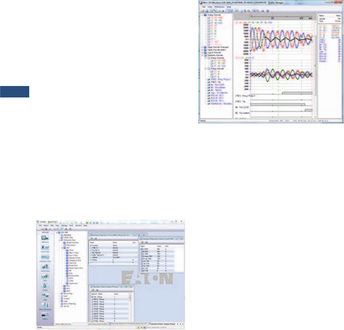
V3-T9-234 Volume 3—Power Distribution and Control Assemblies CA08100004E—March 2016 www.eaton.com
9
9
9
9
9
9
9
9
9
9
9
9
9
9
9
9
9
9
9
9
9
9
9
9
9
9
9
9
9
9
9.3
Metering Devices, Protective Relays, Software and Connectivity
Protective Relays
Monitoring and Metering
Sequence of Events Records
The EMR-5000 protection
relay records a maximum of
300 events associated with
the relay. An event is
classified as a change of state
as detected by the relay.
These include relay pickups,
dropouts, trips, contact
closure, alarms, setting
changes and self-diagnostic
failures. Each event is date
and time stamped to a 1 ms
resolution. The events are
stored in a FIFO in
chronological order.
Trip Log
The EMR-5000 protection
relay will store a maximum of
20 trip records in a FIFO trip
log. Each trip record will be
date and time stamped to a
1 ms resolution. The trip log
record will include
information on the type of
fault, protection elements
that operated, fault location
and currents and voltages at
the time of the fault.
PowerPort-E
PowerPort-E is the software
program used to configure
off-line protection setting files
for all E-Series relay models.
PowerPort-E is also used for
viewing measured values of
the relays in real-time,
uploading/downloading
setting files, and retrieving
event log and waveform
records.
Waveform Capture (Quality
Manager)
The EMR-5000relay provides
oscillographic recording
capabilities. The relay will
record all measured signals
along with the binary signals
of pickup, trip, internal logic,
and contact inputs. The EMR-
5000 can record up to 7200
cycles of data. The number of
records is proportional to the
programmed size of each
record; the maximum size per
record is 600 cycles.
The waveform capture is
initiated by up to 8 different
triggers (i.e., trip/alarm
events)
or manually via
communications
or the HMI.
PowerPort-E setting software
is used to retrieve the
records. Quality Manager is a
separate
software program
downloaded
with PowerPort-
E used for analyzing the
waveform and trending files
retrieved from the relay.
PowerPort-E
Waveform Capture (Quality Manager)
Integral User Interface
The front panel user interface
has a 128 x 64 pixel LCD
display with background
illumination for wide angle
viewing in all light conditions.
Seven programmable LEDs
provide quick and easy visual
display of power on, mode of
operation, alarm and trip
indication. Soft keys are
provided for operation mode
selection, scrolling through
data and settings. In addition,
the relay settings and test
functions are password
protected.
Starting Profiles
The EMR-5000 records the
average current versus time
for the last five starting
cycles. This information
is available via the
communications port
through PowerPort-E.
Motor Statistics
For each motor start, the
EMR-5000 stores a motor
start report and add this data
to the motor statistics buffer.
With the motor statistics you
can track motor start data for
the past eighteen 30-day
periods. For each 30-day
interval, the relay records the
following information:
●The date the interval began
●The total number of starts
in the interval
●The averages of the
following quantities:
●Motor start time
●Start % rotor thermal
capacity used
●Maximum start current
Volume 3—Power Distribution and Control Assemblies CA08100004E—March 2016 www.eaton.com V3-T9-235
9
9
9
9
9
9
9
9
9
9
9
9
9
9
9
9
9
9
9
9
9
9
9
9
9
9
9
9
9
9
9.3
Metering Devices, Protective Relays, Software and Connectivity
Protective Relays
Load Profiling/Trending
The EMR-5000 relay
automatically records
selected quantities into non-
volatile memory every 5, 10,
15, 30, or 60 minutes,
depending on the trending
report setting.
Programmable I/O
The EMR-5000 motor
protection relay provides
heavy-duty, trip-rated, 2
normally open and 1 Form C
contacts. One isolated inputs
can be used for monitoring
the trip circuit. One Form C
contact is dedicated to the
relay failure alarm function
and is operated in a normally
energized (failsafe) mode.
There are 4 eight user-
configurable discrete inputs
that accept a wet contact and
can operate through a wide
range of power. Each input
and output is user-
programmable for maximum
application flexibility.
Programmable Logic
The EMR-5000 motor
protection relay provides logic
gates and timers that the
user can customize for
special or unique applications.
Each gate can be assigned a
logic function of either AND,
OR, NAND or NOR. Each
gate can have a maximum of
four input signals and each
input signal can be required
to be a NOT. Input signals can
be external inputs received
via the binary inputs or
internal values associated
with the protection, alarm or
metering set points. Each
gate has a unique output
assignment and designation
that can be used as the input
to another gate.
Standards and Certifications
Approvals
●UL listed file: E217753
Design Standards
●Generic Standard:
●EN 61000-6-2
●EN 61000-6-3
●Product Standard:
●IEC 60255-6
●EN 50178
●UL 508 (Industrial
Control Equipment)
●CSA C22.2 No. 14-95
(Industrial Control
Equipment)
●ANSI C37.90
Catalog Number Selection
The catalog number
identification chart defines
the electrical characteristics
and operation features
included in the EMR-5000.
For example, if the catalog
number is EMR-5000A0BA,
the device would have
the following:
EMR-5000
(A)–Four digital inputs, four
output relays, 1 4–20 mA
analog output, URTD
interface
(0)–5 A / 1 A phase and
ground CTs, power supply
range: 19–300 Vdc,
40–250 Vac
(B)–Modbus-RTU (RS-485)
(A)–Without conformal
coating
(1)–Projection panel mount
EMR-5000 Eaton Motor Relay
Note
1Beginning in 2016, consult factory for the availability of the following new communication options.
• Protocols: DNP3.0, Profibus
• Interface ports: Fiber optic ST, RS-485 D-SUB, Fiber optic LC
Hardware Option 1
A = 16 DI, 9 outputs, zone interlocking,
URTD interface, IRIG-B, large display
B = 8 DI, 9 outputs, 2 Al + 2AO, zone
interlocking, URTD interface, IRIG-B,
large display
Communication Options 1
B= Modbus-RTU (RS-485)
I= Modbus-RTU (RS-485) and
Modbus-TCP (RJ-45) [only 1
active, software selected]
H= IEC 61850 GOOSE and
MMS (RJ-45)
Conformal Coating
Options
A = None
B = Conformal coated
circuit boards
Mounting Options
0 = Standard mount
1 = Projection panel mount
Hardware Option 2
0 = Phase current 5 A / 1 A, ground
current 5 A / 1 A, power supply
range: 19–300 Vdc, 40–250 Vac
1 = Phase current 5 A / 1 A sensitive
ground current, 0.5 A / 0.1 A,
power supply range: 19–300 Vdc,
40–250 Vac
EMR5000 A 0 B A 1

V3-T9-236 Volume 3—Power Distribution and Control Assemblies CA08100004E—March 2016 www.eaton.com
9
9
9
9
9
9
9
9
9
9
9
9
9
9
9
9
9
9
9
9
9
9
9
9
9
9
9
9
9
9
9.3
Metering Devices, Protective Relays, Software and Connectivity
Protective Relays
Technical Data and Specifications
Climatic Environmental
Conditions
●Storage temperature:
–30 °C to +70 °C (–22 °F to
158 °F)
●Operating temperature:
–20 °C to +60 °C (–4 °F to
140 °F)
●Permissible humidity at
ann. average: <75% rel.
(on 56d up to 95% rel.)
●Permissible installation
altitude:
●<2,000 m (6,561.67 ft)
above sea level
●If 4,000 m (13,123.35 ft)
altitude applies, a
changed classification of
the operating and test
voltages may be
necessary
Degree of Protection EN 60529
●HMI front panel with seal:
IP54
●Rear side terminals: IP20
Routine Test
●Insulation test acc. to
IEC60255-5: All tests to be
carried out against ground
and other input and output
circuits
●Aux. voltage supply, digital
inputs, current measuring
inputs, signal relay outputs:
2.5 kV (eff.) / 50 Hz
●Voltage measuring inputs:
3.0 kV (eff.) / 50 Hz
●All wire-bound
communication interfaces:
1. 5 k V D C
Housing
●Housing B2: height / width
183 mm (7.205 in)/ 212.7
mm (8.374 in)
●Housing depth (incl.
terminals): 208 mm
(8.189 in)
●Material, housing:
aluminum extruded section
●Material, front panel:
aluminum/foil front
●Mounting position:
horizontal (±45° around the
X-axis must be permitted)
●Weight: approx. 4.2 kg
(9.259 lb)
Current and Ground Current
Measurement
Plug-in connector with
integrated short-circuiter
(Conventional current inputs)
Phase and ground current
inputs:
●Nominal currents: 1 A / 5 A
●Max. measuring range:
●Up to 40 x In (phase
currents)
●Up to 25 x In (ground
current standard)
●Capacity: 4 x In/
continuously
●Overcurrent proof:
●30 x In / 10 s
●100 x In / 1 s
●250 x In / 10 ms
(1 half-wave)
●Power consumption:
●Phase current inputs
– At In= 1 A S=0.15
MVA
– At In= 5 A S=0.15
MVA
●Ground current inputs
– At In= 1 A S=0.35
MVA
– At In= 5 A S=0.35
MVA
Sensitive ground current
inputs:
●Nominal currents: 1 A / 5 A
with 50:0:025 core balance
CT
●Max. measuring range: up
to 2.5 x In
●Capacity: 2 x In/
continuously
●Overcurrent proof:
●10 x In / 10 s
●25 x In / 1 s
●100 x In / 10 ms (1 half-
wave)
●Power consumption:
●At In= 1 A S=0.35 MVA
●At In= 5 A S=0.35 MVA
●Frequency range: 50 Hz /
60 Hz ± 10%
●Terminals: screw-type
terminals with integrated
short-circuiters (contacts)
●Screws: M4, captive type
acc. to VDEW
●Connection cross sections:
●1 x or 2 x 2.5 mm2 (2 x
AWG 14) with wire end
ferrule
●1 x or 2 x 4.0 mm2 (2 x
AWG 12) with ring cable
sleeve or cable sleeve
●1 x or 2 x 6 mm2 (2 x
AWG 10) with ring cable
sleeve or cable sleeve
●The current measuring
board’s terminal blocks
may be used as with 2
(double) conductors
AWG 10,12,14
otherwise with single
conductors only
Voltage and Residual Voltage
Measurement
●Nominal voltages: 60–520
V (can be configured)
●Max. measuring range: 2 x
nominal voltage or 800 V
●Continuous loading
capacity: 800 Vac
●Power consumption:
●at Vn= 100 V S=0.1 MVA
●at Vn= 110 V S=0.1 MVA
●
at Vn= 230 V S=0.4 MVA
●at Vn= 400 V S=1.0 MVA
●Nominal voltages:
60–520 V (can be
configured)
●Frequency range: 50 Hz or
60 Hz ± 10%
●Terminals: screw-type
terminals
Frequency Measurement
●Nominal Frequencies:
50 Hz / 60 Hz
Voltage Supply
●Aux. voltage: 24–270 Vdc/
48–230 Vac (–20/+10%)
●Buffer time in case of
supply failure: ≥50 ms
at minimal aux. voltage
communication is
permitted to be interrupted
●Max. permissible making
current:
●18 A peak value for
<0.25 ms
●12 A peak value for
<1 ms
●The voltage supply must
be protected by a fuse of:
●2.5 A time-lag miniature
fuse 5 x 20 mm (approx.
1/5 in x 0.8 in) according
to IEC 60127
●3.5 A time-lag miniature
fuse 6. 3 x 32 mm
(approx. 1/4 in x
1 1/4 in) according
to UL 248-14
Power Consumption
●Power supply range:
24–270 Vdc
●Power consumption
in idle mode—7 W
●Maximum power
consumption—13 W
●Power supply range:
48–230 Vac (for
frequencies of 50–60 Hz)
●Power consumption
in idle mode—7 VA
●Maximum power
consumption—13 VA
Display
●Display type: LCD with
LED background
illumination
●Resolution graphics
display: 128 x 128 pixel
●LED type: two colored,
red/green
●Number of LEDs, housing
B2: 15
Front Interface RS-232
●Baud rates: 115,200 baud
●Handshake: RTS and CTS
●Connection: 9-pole D-Sub
plug
Real-Time Clock
●Running reserve of the
real-time clock: 1 year min

Volume 3—Power Distribution and Control Assemblies CA08100004E—March 2016 www.eaton.com V3-T9-237
9
9
9
9
9
9
9
9
9
9
9
9
9
9
9
9
9
9
9
9
9
9
9
9
9
9
9
9
9
9
9.3
Metering Devices, Protective Relays, Software and Connectivity
Protective Relays
Digital Inputs
●Max. Input voltage:
300 Vdc / 259 Vac
●Input current: <4 mA
●Reaction time: <20 ms
●Drop-out time:
●Shorted inputs: <30 ms
●Open inputs: <90 ms
Relay Output Contacts
●Continuous current:
5 A AC/DC
●Max. make current:
●25 A AC / 25 A DC for
4s
●30 A / 230 Vac according
to ANSI IEEE Std
C37.90-2005
●30 A / 250 Vdc according
to ANSI IEEE Std
C37.90-2005
●Max. breaking current:
●5 A AC up to 240 Vac
●5 A DC up to 30 V
(resistive)
●Continuous current:
5 A AC/DC
●Contact Type: Form C or
normally open contact
●Terminals: screw-type
terminals
Supervision Contact (SC)
●Continuous current:
5 A AC/DC
●Max. switch-on current:
15 A AC / 15 A DC for 4 s
●Max. breaking current:
●5 A AC up to 250 Vac
●5 A DC up to 30 Vdc
(resistive)
●0.25 A at 250 Vdc
(resistive)
●Max. switching voltage:
250 Vac / 250 Vdc
●Switching capacity:
1250 VA
●Contact type: Form C
●Terminals: screw-type
terminals
Analog Outputs
The following technical data
only apply to devices, which
are equipped with analog
outputs. Please refer to the
order code of your device.
The mode of each output can
be individually selected
between current or voltage
output. Shielded cable for the
analog outputs is recommended.
The terminals of the HF
shield should be used, when
connecting the shield to the
ground on both sides of the
cable is not possible. On one
side of the cable the shield
has to be directly connected
to ground. In case of the use
of unshielded twisted pair
cables, the length must not
exceed 10 m. All analog
outputs have a common
potential. Each output has an
own common terminal.
●Current mode
●Range: 0–20 mA
●Max. load resistance:
1 k ohm
●Voltage mode range: 0–10
V maximum output current
20 mA
●Accuracy 0.5% of the
nominal value 20 mA resp.
10 V
●Influence of temperature
to accuracy: <1% (within
the range of 0 °C to +60 °C
(+32 °F to +140 °F)
●Test voltage of outputs
(one group) against other
electrical groups: 2.5 kV
●Test voltage of outputs
(one group) against ground:
1. 0 k V
Time Synchronization IRIG-B00X
●Nominal Input Voltage: 5 V
●Connection: screw-type
terminals (twisted pair)
Zone Interlocking
●Zone Out:
●Output voltage (High):
4.75 to 5.25 Vdc
●Output voltage (Low):
0.0 to +0.5 Vdc
●Zone In:
●Nominal input voltage:
+5 Vdc
●Max. input voltage:
+5.5 Vdc
●Switching threshold ON:
min. 4.0 Vdc
●Switching threshold
OFF: max. 1.5 Vdc
●Galvanic isolation: 2.5 kV
AC (to ground and other IO)
●Connection: screw-type
terminals (twisted pair)
RS-485
●Master/slave: slave
●Connection: 6 screw-
clamping terminals RM 3.5
mm (138 MIL) (terminating
resistors internal)
Fiber Optic
●Master/slave: slave
●Connection: ST-Plug
URTD-Interface
●Connection: versatile link
Boot Phase
After switching on the power
supply, the protection will be
available in approximately 19
seconds. After approximately
165 seconds, the boot phase
is completed (HMI and
communication initialized).
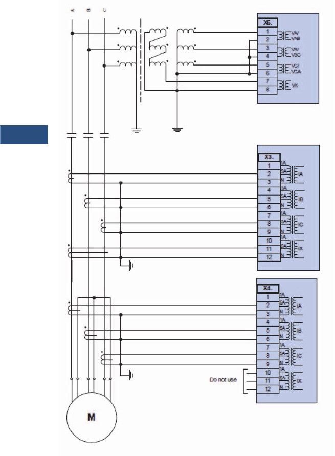
V3-T9-238 Volume 3—Power Distribution and Control Assemblies CA08100004E—March 2016 www.eaton.com
9
9
9
9
9
9
9
9
9
9
9
9
9
9
9
9
9
9
9
9
9
9
9
9
9
9
9
9
9
9
9.3
Metering Devices, Protective Relays, Software and Connectivity
Protective Relays
Wiring Diagrams
Typical AC Connections—Wye (or Delta) VTs, 5 A CTs, Ground Current Measured by 4th Zero Sequence CT,
and 87 Motor Differential
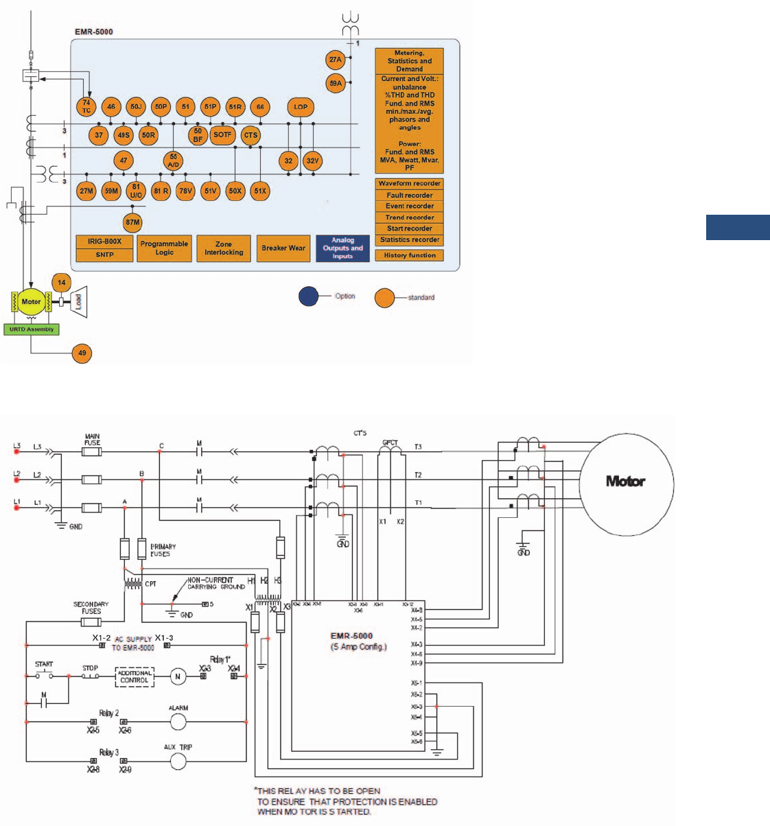
Volume 3—Power Distribution and Control Assemblies CA08100004E—March 2016 www.eaton.com V3-T9-239
9
9
9
9
9
9
9
9
9
9
9
9
9
9
9
9
9
9
9
9
9
9
9
9
9
9
9
9
9
9
9.3
Metering Devices, Protective Relays, Software and Connectivity
Protective Relays
Typical One-Line Diagram
Ty p i c a l C o n t r o l D i a g r a m
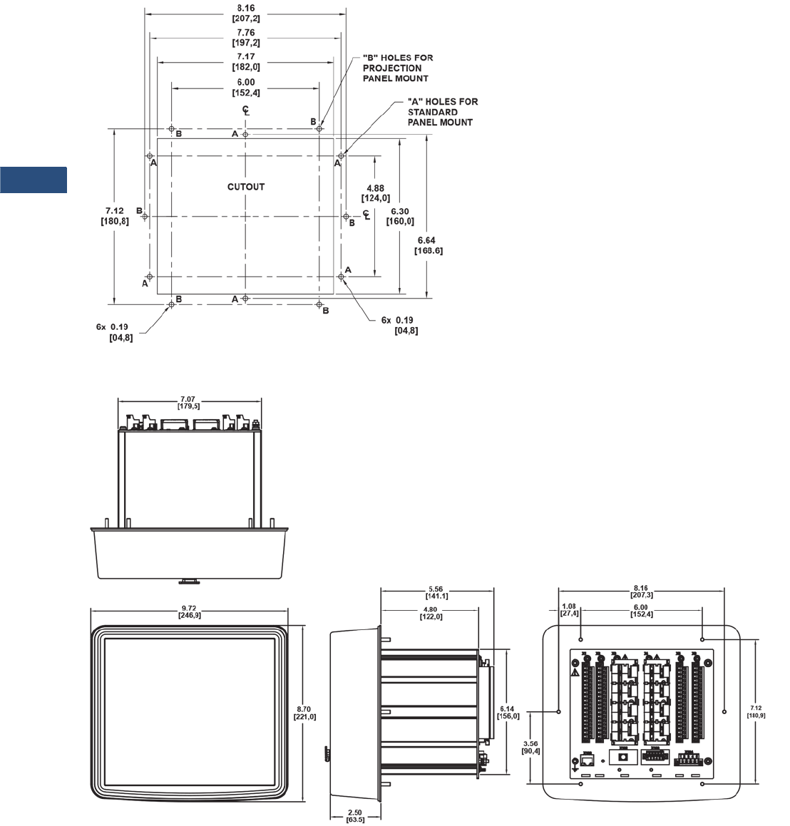
V3-T9-240 Volume 3—Power Distribution and Control Assemblies CA08100004E—March 2016 www.eaton.com
9
9
9
9
9
9
9
9
9
9
9
9
9
9
9
9
9
9
9
9
9
9
9
9
9
9
9
9
9
9
9.3
Metering Devices, Protective Relays, Software and Connectivity
Protective Relays
Dimensions
Approximate Dimensions in Inches (mm)
Drilling Plan
Projection Mount Front and Side Views
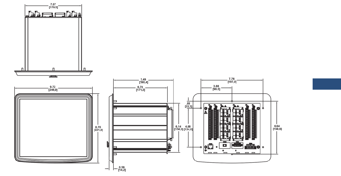
Volume 3—Power Distribution and Control Assemblies CA08100004E—March 2016 www.eaton.com V3-T9-241
9
9
9
9
9
9
9
9
9
9
9
9
9
9
9
9
9
9
9
9
9
9
9
9
9
9
9
9
9
9
9.3
Metering Devices, Protective Relays, Software and Connectivity
Protective Relays
Approximate Dimensions in Inches (mm)
Standard Mount Front and Side Views
V3-T9-242 Volume 3—Power Distribution and Control Assemblies CA08100004E—March 2016 www.eaton.com
9
9
9
9
9
9
9
9
9
9
9
9
9
9
9
9
9
9
9
9
9
9
9
9
9
9
9
9
9
9
9.3
Metering Devices, Protective Relays, Software and Connectivity
Protective Relays
ETR-4000
Contents
Description Page
Product Selection Guide. . . . . . . . . . . . . . . . . . . . . V3-T9-143
Digitrip 3000. . . . . . . . . . . . . . . . . . . . . . . . . . . . . . V3-T9-149
EDR-3000 Feeder Protection . . . . . . . . . . . . . . . . . V3-T9-159
EDR-5000 Distribution Protection Relay . . . . . . . . V3-T9-168
FP-5000 Feeder Protection. . . . . . . . . . . . . . . . . . . V3-T9-181
MP-3000 Motor Protection . . . . . . . . . . . . . . . . . . V3-T9-189
MP-4000 Motor Protection . . . . . . . . . . . . . . . . . . V3-T9-199
EMR-3000 Motor Protection Relay . . . . . . . . . . . . V3-T9-205
EMR-4000 Motor Protection Relay . . . . . . . . . . . . V3-T9-217
EMR-5000 Motor Protection Relay . . . . . . . . . . . . V3-T9-230
ETR-4000 Transformer Protection Relay
ETR-5000 Transformer Protection Relay . . . . . . . . V3-T9-254
EGR-5000 Generation Protection Relay . . . . . . . . . V3-T9-267
Ground Fault Relay . . . . . . . . . . . . . . . . . . . . . . . . . V3-T9-280
Universal RTD Module . . . . . . . . . . . . . . . . . . . . . . V3-T9-283
ETR-4000 Transformer Protection Relay
Product Description
Eaton’s ETR-4000
transformer protection
relay is a multi-functional,
microprocessor-based relay
for two winding transformers
of all voltage levels. The
ETR-4000 provides phase and
ground percentage restrained
differential protection using
a variable dual slope
characteristic with phase,
negative, residual and neutral
overcurrent elements for
backup protection. It can also
be used to provide restrained
differential protection to large
motors and generators.
The ETR-4000 has eight
current inputs rated for either
5 amperes or 1 ampere to
monitor both sides of the
transformers. The CTs can
be connected in wye in both
sides of the transformer;
the relay automatically
compensates for the
connection of the transformer
and CT mismatch errors.
The maintenance mode
password protected soft key,
can be used for arc flash
mitigation to change to an
alternate settings group,
set to have instantaneous
elements only.
An integral keypad and
display is provided for direct
user programming and
retrieval of data without
the need of a computer.
Fourteen programmable
LEDs provide quick indication
of relay status.
A front port is provided for
direct computer connection.
An RS-485 communication
port on the back is standard
for local area networking
using Modbus-RTU. An
optional Ethernet port and
protocols are available.
Flash memory is used for the
programming and all settings
are stored in nonvolatile
memory. The relay allows for
four preprogrammed setting
groups that can be activated
through software, the display
or a contact input.
The ETR-4000 transformer
protection relay has mass
memory for data storage and
a real-time clock with 1 ms
time resolution. The relay will
log 300 sequence of event
records, 20 detailed trip logs,
minimum/maximum values,
load profiles, breaker wear
information and oscillography
data.
The ETR-4000 has eight
programmable binary inputs,
4 normally opened and
4 Form C heavy-duty outputs
and one Form C signal alarm
relay. It can be powered from
19 Vdc to 300 Vdc or 40 Vac
to 250 Vac auxiliary power.

Volume 3—Power Distribution and Control Assemblies CA08100004E—March 2016 www.eaton.com V3-T9-243
9
9
9
9
9
9
9
9
9
9
9
9
9
9
9
9
9
9
9
9
9
9
9
9
9
9
9
9
9
9
9.3
Metering Devices, Protective Relays, Software and Connectivity
Protective Relays
Features, Benefits and Functions
●Flexible phase and ground
differential protection for
two winding transformers,
large motors and
generators
●Complete protection and
control in a single compact
case to reduce panel
space, wiring and costs
●Integral test function
reduces maintenance
time and expense
●Zone selective interlocking
improves coordination and
tripping time, and saves
money compared to a
traditional bus differential
scheme
●Reduce troubleshooting
time and maintenance
costs. Trip and event
recording in non-volatile
memory provides detailed
information for analysis
and system restoration.
6000 cycles of waveform
capture aids in post fault
analysis (viewable using
PowerPort-E software)
●Minimum replacement
time. Removable terminal
blocks ideal for industrial
environments
●Front RS-232 port and
PowerPort-E software
provides local computer
access and user-friendly
Windows-based interface
for relay settings,
configuration and
data retrieval
●Breaker open/close from
relay faceplate or remotely
via communications
●Fast an easy
troubleshooting, improved
maintenance procedures
and increased device
security. Provides detailed
traceability for system
configuration changes
●Relays self-diagnostics and
reporting improves uptime
and troubleshooting
●Breaker trip circuit
monitoring improves the
reliability of the breaker
operation
Features
Protection Features
●Dual-slope percentage
restrained current
differential with
magnetizing inrush and
overexcitation blocking
(87R)
●Unrestrained current
differential (87H)
●Restricted ground fault/
Ground Differential (87GD)
●Phase overcurrent
(elements can be assigned
to either side of the
transformer):
●Four instantaneous
elements with timers
(50P[1], 50P[2], 50P[3]
and 50P[4])
●Four inverse time
overcurrent elements
(51P[1], 51P[2], 51P[3]
and 51P[4])
●11 standard curves
●Inrush Blocking
●Instantaneous or time
delay reset
●Negative sequence phase
overcurrent (elements can
be assigned to either side
of the transformer):
●Two inverse time
overcurrent elements
(51Q[1] and 51Q[2])
●11 standard curves
●Instantaneous or time
delay reset
●Ground overcurrent
(elements can be assigned
to either side of the
transformer):
●Two instantaneous
measured elements
with timers (50X[1]
and 50X[2])
●Two instantaneous
calculated elements
with timers (50R[1]
and 50R[2])
●Two inverse time
overcurrent measured
elements (51X[1]
and 51X[2])
●Two inverse time
overcurrent calculated
elements (51R[1]
and 51R[2])
●11 standard curves
●Instantaneous or time
delay reset
●Two breaker failure
elements (50BF[1]
and 50BF[2])
●Phase transformer
overload protection (49)
●Switch onto fault
protection
●Cold load pickup
●Zone interlocking for bus
protection (87B)
Metering Features
●Amperes: positive,
negative and zero
sequence
●Ampere demand
●Current phase angles
●% THD I
●Magnitude THD I
●Minimum/maximum
recording
●Trending
●RTD Temperatures with
remote URTD
Monitoring Features
●Trip coil monitor for both
primary and secondary
breakers
●Breaker wear primary and
secondary (accumulated
interrupted current)
●Oscillography
(7200 cycles total)
●Fault data logs
(up to 20 events)
●Sequence of events report
(up to 300 events)
●Clock (1 ms time stamping)
●Trip Cause displays fault
recorder data on HMI after
fault event
Control Functions
●Breaker open/close both
breakers
●Remote open/close
●Programmable I/O
●Programmable LEDs
●Multiple setting groups
●Cold load pickup
●CT supervision
Communication Features
●Local HMI
●Password protected
●Addressable
●IRIG-B
●Local communication port
●Remote communication
port:
●RS-232
●RS-485
●Protocols:
●Modbus-RTU
●Modbus-TCP (Optional)
●Configuration software
Protection and
Control Functions
Eaton’s ETR-4000
transformer protection
relay has been designed for
maximum user flexibility and
simplicity. The ETR-4000 is
suitable for application on
small, medium and large two
winding power transformers.
Multiple current inputs are
used to provide primary
protection, control and
back-up protection of
transformers, including
current differential, restricted
ground differential and
overcurrent protection.
Dual-Slope Percent Differential
Protection
The primary protective
element for transformer
protection is the percent
differential element, which
compares the current
entering the primary and
leaving the secondary of the
transformer. The ETR-4000
has built in compensation
for the turns-ratio and the
phase shift of the
transformer, so it's not
necessary to compensate for
the transformer connection
by the connection of the CTs.
The current differential
element looks at the vector
difference between the
current entering and leaving
the zone of protection. If the
difference exceeds a pre-
determined amount, the
element will operate.
The operating characteristic
of the percent differential
element is a dual-slope
characteristic to
accommodate for CT
saturation and CT errors.
Dual-Slope Operating Characteristic
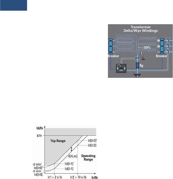
V3-T9-244 Volume 3—Power Distribution and Control Assemblies CA08100004E—March 2016 www.eaton.com
9
9
9
9
9
9
9
9
9
9
9
9
9
9
9
9
9
9
9
9
9
9
9
9
9
9
9
9
9
9
9.3
Metering Devices, Protective Relays, Software and Connectivity
Protective Relays
Harmonic Restraints
There are certain conditions
like energizing one side of the
transformer with the other
side de-energized (inrush
currents) or the paralleling
of two transformers
(sympathetic currents) that
can create false differential
currents. These differential
currents if not recognized can
cause a false trip; in the case
of inrush conditions or
sympathetic currents the
differential current is
characterized by a heavy
content of 2nd and 4th
harmonic currents. The
percentage differential
element is desensitize either
permanently (stationary
conditions) or temporarily
(transient conditions),
whenever the 2nd or 4th
harmonic exceed the value
programmed into the relay.
Another condition that can
create a false differential
current is a sudden change of
voltage or frequency, that can
put the transformer in an
overexcitation state. In this
case there is high content of
5th harmonic currents. The
percentage differential
element is also desensitized
when the 5th harmonic
content exceeds a predefined
value.
Dynamic Rise of the Operating
Characteristic
Unrestrained Differential
An unrestrained differential
element is provided for fast
tripping on heavy internal
faults to limit catastrophic
damage to the transformer
and minimize risks to the
remainder of the power
system.
Restricted Ground Fault
Ground differential protection
is applied to transformers
having impedance grounded
wye windings. It is intended
to provide sensitive ground
fault detection for low
magnitude fault currents,
which would not be detected
by the main percent
differential element.
Restricted Ground Fault
Overcurrent Elements
The ETR-4000 can be used
to provide backup for
transformer and adjacent
power system equipment.
Instantaneous overcurrent
elements can be used for fast
clearing of severe internal or
external (through) faults.
Time overcurrent protection
elements per winding allow
coordinating with the
adjacent protection zones and
acting as a backup protection.
There are 11 user-selectable
inverse-time overcurrent
curve characteristics. The
user can select from the
ANSI, IEC or thermal curve
families and can select
instantaneous or time delay
reset characteristics.
Negative Sequence Overcurrent
Since this element does
not respond to balanced
load or three-phase faults,
the negative-sequence
overcurrent element may
provide the desired
overcurrent protection. This
is particularly applicable to
delta-wye grounded
transformers where only
58% of the secondary p.u.
phase-to-ground fault current
appears in any one primary
phase conductor. Backup
protection can be particularly
difficult when the wye is
impedance grounded. A
negative-sequence element
can be used in the primary
supply to the transformer and
set as sensitively as required
to protect for secondary
phase-to-ground or phase-to-
phase faults. This element
should be set to coordinate
with the low-side phase and
ground relays for phase-to-
ground and phase-to-phase
faults. The negative
sequence element must
also be set higher than the
negative-sequence current
due to unbalanced loads.
Breaker Failure
The ETR-4000 transformer
protection relay includes two
breaker failure (50BF, 62BF)
elements that can be initiated
from either an internal or
external trip signal. These are
independent elements that
can be used to operate a
lockout relay or trip an
upstream breaker. The timer
must be longer than the
breaker operating time and
the protective function
reset times.
Maintenance Mode
The Maintenance Mode can
improve safety by providing a
simple and reliable method to
reduce fault clearing time and
lower incident energy levels
at energized panels. The
Maintenance Mode allows
the user to switch to more
sensitive settings via a
password protected soft
key, communications or
via a digital input while
maintenance work is being
performed at an energized
panel or device. The more
sensitive settings provide
greater security for
maintenance personnel and
helps reduce the possibility
of injury.
Monitoring and Metering
Sequence of Events Records
The ETR-4000 protection
relay records a maximum
of 300 events associated with
the relay. An event is
classified as a change of state
as detected by the relay.
These include relay pickups,
dropouts, trips, contact
closure, alarms, setting
changes and self-diagnostic
failures. Each event is date
and time stamped to a 1 ms
resolution. The events are
stored in a FIFO in
chronological order.
Trip Log
The ETR-4000 protection
relay will store a maximum of
20 trip records in a FIFO trip
log. Each trip record will be
date and time stamped to a
1 ms resolution. The trip
log record will include
information on the type of
fault, protection elements
that operated, fault location
and currents at the time of
the fault.
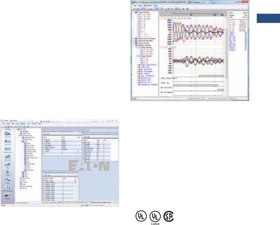
Volume 3—Power Distribution and Control Assemblies CA08100004E—March 2016 www.eaton.com V3-T9-245
9
9
9
9
9
9
9
9
9
9
9
9
9
9
9
9
9
9
9
9
9
9
9
9
9
9
9
9
9
9
9.3
Metering Devices, Protective Relays, Software and Connectivity
Protective Relays
Waveform Capture
The ETR-4000 transformer
protection relay provides
oscillography-recording
capabilities. The relay will
record all measured signals
along with the binary signals
of pickup, trip, logic and
contact closures. The ETR-
4000 relay can record up to
6000 cycles of data. The
number of records is
proportional to the size of
each record; the maximum
size per record is 600 cycles.
The waveform capture is
initiated by up to 8 different
triggers; it can also be
generated manually through
the display or via
communications.
Integral User Interface
The front panel user interface
has a 128 x 64 pixel LCD
display with background
illumination for wide angle
viewing in all light conditions.
Fourteen programmable LEDs
provide quick and easy visual
display of power on, mode
of operation, alarm and trip
indication. Soft keys are
provided for operation mode
selection, scrolling through
data and settings. In addition,
the relay settings and test
functions are password
protected.
Programmable I/O
The ETR-4000 transformer
protection relay provides
heavy-duty, trip-rated, 4
normally open and 4 Form C
contacts. Two isolated inputs
can be used for monitoring
the trip circuits. One Form C
contact is dedicated to the
relay failure alarm function
and is operated in a normally
energized (fail-safe) mode.
There are eight user-
configurable discrete inputs
that accept a wet contact
and can operate through a
wide range of power. Each
input and output is user-
programmable for maximum
application flexibility.
Communication Software
PowerPort-E
PowerPort-E is the software
program used to configure
off-line protection setting files
for all E-Series relay models.
PowerPort-E is also used for
viewing measured values of
the relays in real-time,
uploading/downloading
setting files, and retrieving
event log and waveform
records.
Waveform Capture
(Quality Manager)
The ETR-4000 relay provides
oscillographic recording
capabilities. The relay will
record all measured signals
along with the binary signals
of pickup, trip, internal logic,
and contact inputs. The ETR-
4000 can record up to 7200
cycles of data. The number of
records is proportional to the
programmed size of each
record; the maximum size per
record is 600 cycles. The
waveform capture is initiated
by up to 8 different triggers
(i.e., trip/alarm events) or
manually via communications
or the HMI. PowerPort-E
setting software is used to
retrieve the records. Quality
Manager is a separate
software program downloaded
with PowerPort-E used for
analyzing the waveform and
trending files retrieved from
the relay.
Standards and Certifications
Design Standards
●Generic Standard:
●EN 61000-6-2
●EN 61000-6-3
●Product Standard:
●IEC 60255-6
●EN 50178
●UL 508 (Industrial
Control Equipment)
●CSA C22.2 No. 14-95
(Industrial Control
Equipment)
●ANSI C37.90
●UL listed file: E217753

V3-T9-246 Volume 3—Power Distribution and Control Assemblies CA08100004E—March 2016 www.eaton.com
9
9
9
9
9
9
9
9
9
9
9
9
9
9
9
9
9
9
9
9
9
9
9
9
9
9
9
9
9
9
9.3
Metering Devices, Protective Relays, Software and Connectivity
Protective Relays
Catalog Number Selection
The catalog number
identification chart defines
the electrical characteristics
and operation features
included in the ETR-4000.
For example, if the catalog
number is ETR-3000A0BA1,
the device would have the
following:
ETR-4000
(A)–8 Digital Inputs,
9 Output Relays
(0)–5 A / 1 A phase and
ground CTs, Power Supply
Range: 19-300 Vdc, 40–250
Vac
(B)–Modbus-RTU (RS-485)
(A)–Without Conformal
Coating
(1)–Projection Panel Mount
ETR-4000 Eaton Transformer Protection Relay
Technical Data and Specifications
Climatic Environmental
Conditions
●Storage temperature:
–22 °F to +158 °F (–30 °C
to +70 °C)
●Operating temperature:
–40 °F to +140 °F (–40 °C 2
to +60 °C)
●Permissible humidity at
ann. average: <75% rel.
(on 56d up to 95% rel.)
●Permissible installation
altitude:
●6,561.67 ft (<2000 m)
above sea level
●If 13,123.35 ft (4000 m)
altitude applies, a
changed classification
of the operating and test
voltages may be
necessary
Degree of Protection EN 60529
●HMI front panel with
seal: IP54
●Rear side terminals: IP30
Routine Test
●Insulation test according to
IEC 60255-5: All tests to be
carried out against ground
and other input and output
circuits
●Aux. voltage supply, digital
inputs: 2.5 kV (eff.)/50 Hz
●Current measuring inputs,
signal relay outputs: 2.5 kV
(eff.)/50 Hz
●Voltage measuring inputs:
3.0 kV (eff.)/50 Hz
●All wire-bound
communication interfaces:
1. 5 k V D C
Housing
●Material, housing:
Aluminum extruded
section
●Material, front panel:
Aluminum/foil front
●Mounting position:
Horizontal (±45° around
the X-axis must be
permitted)
Plug-in Connector with
Integrated Short-Circuiter
(Conventional Current Inputs)
●Nominal current: 1 A and
5 A
●Continuous loading
capacity: 4 x In/
continuously
●Overcurrent withstand:
●30 x In/10 s
●100 x In/1 s
●250 x In/10 ms
(1 half-wave)
●Screws: M4, captive type
acc. to VDEW
●Connection cross sections:
●2 x AWG 14 (1 x or 2 x
2.5 mm2) with wire
end ferrule
●2 x AWG 12 (1 x or 2 x
4.0 mm2) with ring cable
sleeve or cable sleeve
●2 x AWG 10 (1 x or 2 x
6 mm2) with ring cable
sleeve or cable sleeve
Control Power Supply
●Aux. voltage: 24–270 Vdc/
48–230 Vac (–20/+10%)
●Buffer time in case of
supply failure: ≥50 ms
at minimal aux. voltage
interrupted communication
is permitted
●Maximum permissible
making current:
●18 A peak value for
<0.25 ms
●12 A peak value for
<1 ms
●The voltage supply must
be protected by a fuse of:
●2.5 A time-lag miniature
fuse approx. 0.2 x 0.8 in
(5 x 20 mm) according to
IEC 60127
●3.5 A time-lag miniature
fuse approx. 0.25 x
1.25 in (6.3 x 32 mm)
according to UL 248-14
Notes
1Beginning in 2016, consult factory for the availability of the following new communication options.
• Protocols: DNP3.0, Profibus
• Interface ports: Fiber optic ST, RS-485 D-SUB, Fiber optic LC
2Display will stop working at –20 °C.
Hardware Option 1
A = 8 DI, 9 outputs, removable terminals,
2 zone interlocking, URTD interface, IRIG-B,
small display
B = 4 DI, 5 outputs, removable terminals,
IRIG-B, small display
C = 8 DI, 5 outputs, removable terminals,
1 zone interlocking, IRIG-B, small display
ETR4000 A 0 B A 1
Communication Options 1
B= Modbus-RTU (RS-485)
I= Modbus-RTU (RS-485) and
Modbus-TCP (RJ-45) [only 1
active, software selected]
H= IEC 61850 GOOSE and
MMS (RJ-45)
Conformal Coating
Options
A = None
B = Conformal coated
circuit boards
Mounting Options
0 = Standard mount
1 = Projection panel mount
Hardware Option 2
0 = Phase current 5 A / 1 A, ground
current 5 A / 1 A, power supply
range: 19–300 Vdc,
40–250 Vac
1 = Phase current 5 A / 1 A
sensitive ground current,
0.5 A / 0.1 A, power supply
range: 19–300 Vdc, 40–250
Vac

Volume 3—Power Distribution and Control Assemblies CA08100004E—March 2016 www.eaton.com V3-T9-247
9
9
9
9
9
9
9
9
9
9
9
9
9
9
9
9
9
9
9
9
9
9
9
9
9
9
9
9
9
9
9.3
Metering Devices, Protective Relays, Software and Connectivity
Protective Relays
Power Consumption
●Power supply range:
19–300 Vdc
●Power consumption
in idle mode—7 W
●Maximum power
consumption—13 W
●Power supply range:
40–250 Vac (for
frequencies of 40–70 Hz)
●Power consumption
in idle mode—7 W
●Maximum power
consumption—13 W
Real-Time Clock
●Running reserve of
the real-time clock:
1 year minimum
Display
●Display type: LCD with
LED background
illumination
●Resolution graphics
display: 128 x 64 pixel
●LED type: Two colored—
red/green
●Number of LEDs, housing
B2: 15
Digital Inputs
●Maximum input voltage:
300 Vdc/270 Vac
●Input current: <4 mA
●Reaction time: <20 ms
●Fallback time: <30 ms
(Safe state of the
digital inputs)
●4 switching thresholds:
Un = 24 Vdc, 48 Vdc,
60 Vdc, 110 Vac/Vdc,
230 Vac/Vdc
●Un = 24 Vdc
– Switching threshold
1 ON: Min. 19.2 Vdc
– Switching threshold
1 OFF: Max. 9.6 Vdc
●Un = 48–60 Vdc
– Switching threshold
2 ON: Min. 42.6 Vdc
– Switching threshold
2 OFF: Max. 21.3 Vdc
●Un = 110/120 Vac/Vdc
– Switching threshold
3 ON: Min. 88.0 Vdc/
88.0 Vac
– Switching threshold
3 OFF: Max. 44.0 Vdc/
44.0 Vac
●Un = 230/240 Vac/Vdc
– Switching threshold
4 ON: Min. 184 Vdc/
184 Vac
– Switching threshold
4 OFF: Max. 92 Vdc/
92 Vac
●Terminals: screw-type
terminal
Current and Ground
Current Measurement
●Nominal currents: 1 A / 5 A
●Max. measuring range:
●Up to 40 x In (phase
currents)
●Up to 25 x In (ground
current standard)
●Up to 2.5 x In (ground
current sensitive)
●Continuous loading
capacity: 4 x In/
continuously
●Overcurrent proof:
●30 x In/10 s
●100 x In/1 s
●250 x In/10 ms
(1 half-wave)
●Power consumption:
●Phase current inputs
–At I
n = 1 A
S = 0.15 MVA
–At I
n = 5 A
S = 0.15 MVA
●Ground current input
–At I
n = 1 A
S = 0.35 MVA
–At I
n = 5 A
S = 0.35 MVA
●Frequency range: 50 Hz/
60 Hz ±10%
●Terminals: Screw-type
terminals with integrated
short-circuiters (contacts)
Relay Outputs
●Continuous current:
5 A AC/DC
●Maximum make current:
●25 A AC/25 A DC up to
30 V for 4s
●30 A/230 Vac according
to ANSI IEEE Std.
C37.90-2005
●30 A/250 Vdc according
to ANSI IEEE Std.
C37.90-2005
●Maximum breaking
current:
●5 A AC up to 125 Vac
●5 A DC up to 30 V
(resistive)
●0.3 A DC at 300 V
●Maximum switching
voltage: 250 Vac/250 Vdc
●Switching capacity:
1250 VA
●Contact type: changeover
contact or normally
open contact
●Terminals: screw-type
terminals
Supervision Contact (SC)
●Continuous current: 5 A at
120/240 Vac or 30 Vdc
●Maximum switch-on
current: 15 A at 120/240
Vac or 30 Vdc (max. 4 s)
●Maximum breaking
current:
●5 A at 120/240 Vac
or 30 Vdc
●0.4 A at 125 Vdc
●Contact type:
1 changeover contact
●Terminals: screw-type
terminals
Time Synchronization IRIG
●Nominal input voltage: 5 V
●Connection: Screw-type
terminals (twisted pair)
Front Interface RS-232
●Baud rates: 115,200 baud
●Handshake: RTS and CTS
●Connection: 9-pole
D-Sub plug
RS-485
●Master/slave: slave
●Connection: 6 screw-
clamping terminals RM 138
MIL (3.5 mm) (terminating
resistors internal)
Zone Interlocking
●Nominal input level: 5 V
●Nominal output level: 5 V
●Connection: Screw-type
terminals (twisted pair)
Standards
High Voltage Tests (IEC 60255-6)
●High frequency
interference test:
●IEC 60255-22-1 Class 3
– Within one circuit—
1 kV/2 s
– Circuit to ground—
2.5 kV/2 s
– Circuit to circuit—
2.5 kV/2 s
●Insulation voltage test:
●IEC 60255-5, EN 50178
– All circuits to other
circuits and exposed
conductive parts:
2.5 kV (eff.)/50 Hz,
1 min.
– Except interfaces:
1.5 kV DC, 1 min.
– Voltage measuring
input: 3 kV (eff.)/
50 Hz, 1 min.
●Impulse voltage test:
●IEC 60255-5: 5 kV/0.5J,
1.2/50 μs

V3-T9-248 Volume 3—Power Distribution and Control Assemblies CA08100004E—March 2016 www.eaton.com
9
9
9
9
9
9
9
9
9
9
9
9
9
9
9
9
9
9
9
9
9
9
9
9
9
9
9
9
9
9
9.3
Metering Devices, Protective Relays, Software and Connectivity
Protective Relays
EMC Immunity Tests
●Fast transient disturbance
immunity test (burst):
●IEC 60255-22-4: Power
supply, mains inputs—
±4 kV, 2.5 kHz
●IEC 61000-4-4 Class 4:
Other inputs and
outputs—
±2 kV, 5 kHz (coupling
network)
●ANSI C37.90.1: ± 4 kV,
2.5 kHz (coupling clamp)
●Surge Immunity Test:
●IEC 61000-4-5 Class 4
– Within one circuit—
2 kV
– Circuit to ground—
4 kV
●Electrical discharge
immunity test:
●IEC 60255-22-2: Air
discharge—8 kV
●IEC 61000-4-2 Class 3:
Contact discharge—6 kV
●Radiated radio frequency
electromagnetic field
immunity test
●IEC 61000-4-3: 26 MHz –
80 MHz—10 V/m
●Class X: 80 MHz–
1 GHz—35 V/m
●ANSI C37.90.2: 1 GHz–
3 GHz—10 V/m
●Immunity to conducted
disturbances induced by
radio frequency fields:
●IEC 61000-4-6 Class 3:
10 V
●Power frequency magnetic
field immunity test:
●IEC 61000-4-8:
Continues—30 A/m
●Class 4: 3 sec—300 A/m
EMC Emission Tests
●Radio interference
suppression test:
●IEC/CISPR11—
Limit value class B
●Radio interference
radiation test:
●IEC/CISPR11—
Limit value class B
Environmental Tests
Classification
●IEC 60068-1: Climatic—
0/055/56
●IEC 60721-3-1:
●Classification of ambient
conditions (storage)—
1K5/1B1/1C1L/1S1/1M2
but min. –13 °F (–25 °C)
●IEC 60721-3-2:
Classification of ambient
conditions (transportation)
—2K3/2B1/2C1/2S1/2M2
●IEC 60721-3-3:
Classification of ambient
conditions (Stationary use
at weather protected
locations)—3K6/3B1/3C1/
3S1/3M2 but min. 32 °F
(0 °C) and 3K8H for 2 h
Test ad: Cold
●IEC 60068-2-1:
●Temperature—
–4 °F (–20 °C)
●Test duration—16 h
Test Bd: Dry heat
●IEC 60068-2-2:
●Temperature—
131 °F (55 °C)
●Relative humidity—
<50%
●Test duration—72 h
Test cab: Damp heat
(steady state)
●IEC 60068-2-78:
●Temperature—
104 °F (40 °C)
●Relative humidity—93%
●Test duration—56d
Test Db: Damp heat (cyclic)
●IEC 60068-2-30:
●Temperature—
131 °F (55 °C)
●Relative humidity—95%
●Cycles (12 + 12-hour)—2
Mechanical Tests
Test Fc: Vibration response test
●IEC 60068-2-6,
IEC 60255-21-1, Class 1:
●Displacement: (10 Hz–
59 Hz)—0.0014 in
(0.035 mm)
●Acceleration: (59 Hz–
150 Hz)—0.5 gn
●Number of cycles in
each axis: 1
Test Fc: Vibration endurance test
●IEC 60068-2-6,
IEC 60255-21-1, Class:
●Acceleration: (10 Hz–
150 Hz)—1.0 gn
●Number of cycles in
each axis: 20
Test Ea: Shock test
●IEC 60068-2-27,
IEC 60255-21-2, Class 1
●Shock response test:
5 gn, 11 ms, 3 impulses
in each direction
●Shock resistance test:
15 gn, 11 ms, 3 impulses
in each direction
Test Eb: Shock endurance test
●IEC 60068-2-29,
IEC 60255-21-2, Class 1
●Shock endurance test:
10 gn, 16 ms, 1000
impulses in each
direction
Test Fe: Earthquake test
●IEC 60068-3-3, KTA 3503,
IEC 60255-21-3, Class 2
●Single axis earthquake
vibration test:
– 3–7 Hz: horizontal
0.394 in (10 mm),
1 cycle each axis
– 7–35 Hz: horizontal:
2 gn, 1 cycle each axis
Tolerances
Tolerances of the Real-
Time Clock
●Resolution: 1 ms
●Tole r a nc e:
●<1 minute/month
(68 °F [+20 °C])
●<±1 ms if synchronized
via IRIG-B
Tolerances of the Measured
Value Acquisition
Phase and ground current
measuring
●Maximum measuring
range:
●Up to 40 x In (phase
currents)
●Up to 25 x In (ground
current standard)
●Up to 2.5 x In (earth
current sensitive)
Note: The precision does not
depend on the nominal value but
is referenced to 100 mA (with In
=1 A) respectively.
500 mA (with In = 5 A)
●Frequency range: 50 Hz /
60 Hz ±10%
●Accuracy: Class 0.5
●Amplitude Error if I < 1 In:
±0.5% of the rated value
●Amplitude Error if I > In:
±0.5% of the measured
value
●Amplitude Error if I > 2 In:
±1.0% of the measured
value
●Resolution: 0.01 A
●Harmonics: Up to 20%
3rd harmonic ±1%
●Up to 20% 5th harmonic
±1%
●Frequency influence:
< ±2% / Hz in the range of
±5 Hz of the parametrized
nominal frequency
●Temperature influence:
< ±1% within the range
of +32 °F to +140 °F
(0 °C to +60 °C)
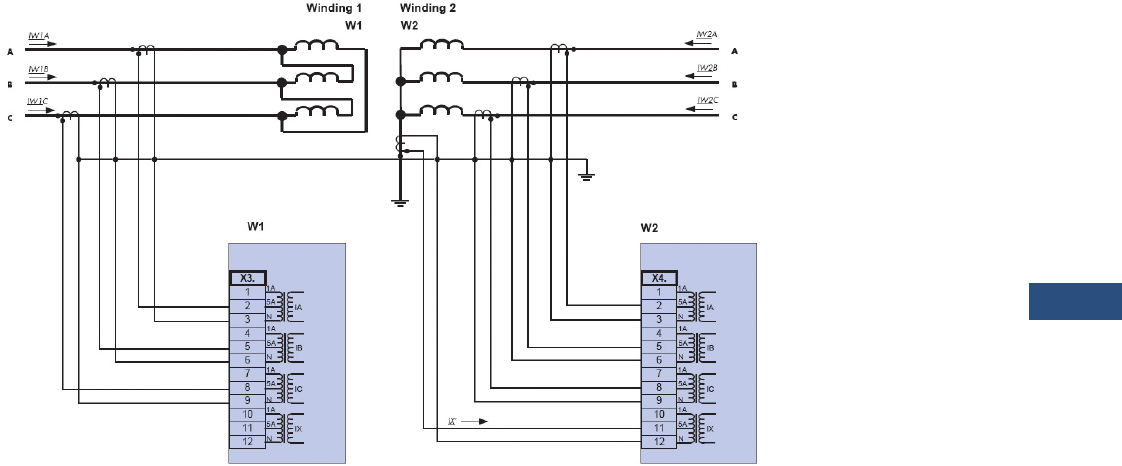
Volume 3—Power Distribution and Control Assemblies CA08100004E—March 2016 www.eaton.com V3-T9-249
9
9
9
9
9
9
9
9
9
9
9
9
9
9
9
9
9
9
9
9
9
9
9
9
9
9
9
9
9
9
9.3
Metering Devices, Protective Relays, Software and Connectivity
Protective Relays
Wiring Diagrams
Typical AC Connections Delta-Wye Transformer with Wye CTs and Neutral CT
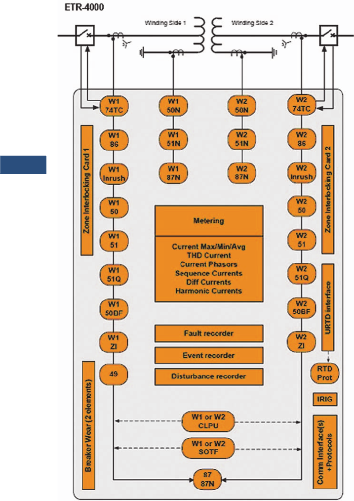
V3-T9-250 Volume 3—Power Distribution and Control Assemblies CA08100004E—March 2016 www.eaton.com
9
9
9
9
9
9
9
9
9
9
9
9
9
9
9
9
9
9
9
9
9
9
9
9
9
9
9
9
9
9
9.3
Metering Devices, Protective Relays, Software and Connectivity
Protective Relays
Typical One-Line Diagram
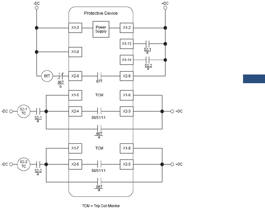
Volume 3—Power Distribution and Control Assemblies CA08100004E—March 2016 www.eaton.com V3-T9-251
9
9
9
9
9
9
9
9
9
9
9
9
9
9
9
9
9
9
9
9
9
9
9
9
9
9
9
9
9
9
9.3
Metering Devices, Protective Relays, Software and Connectivity
Protective Relays
Ty p i c a l C o n t r o l D i a g r a m
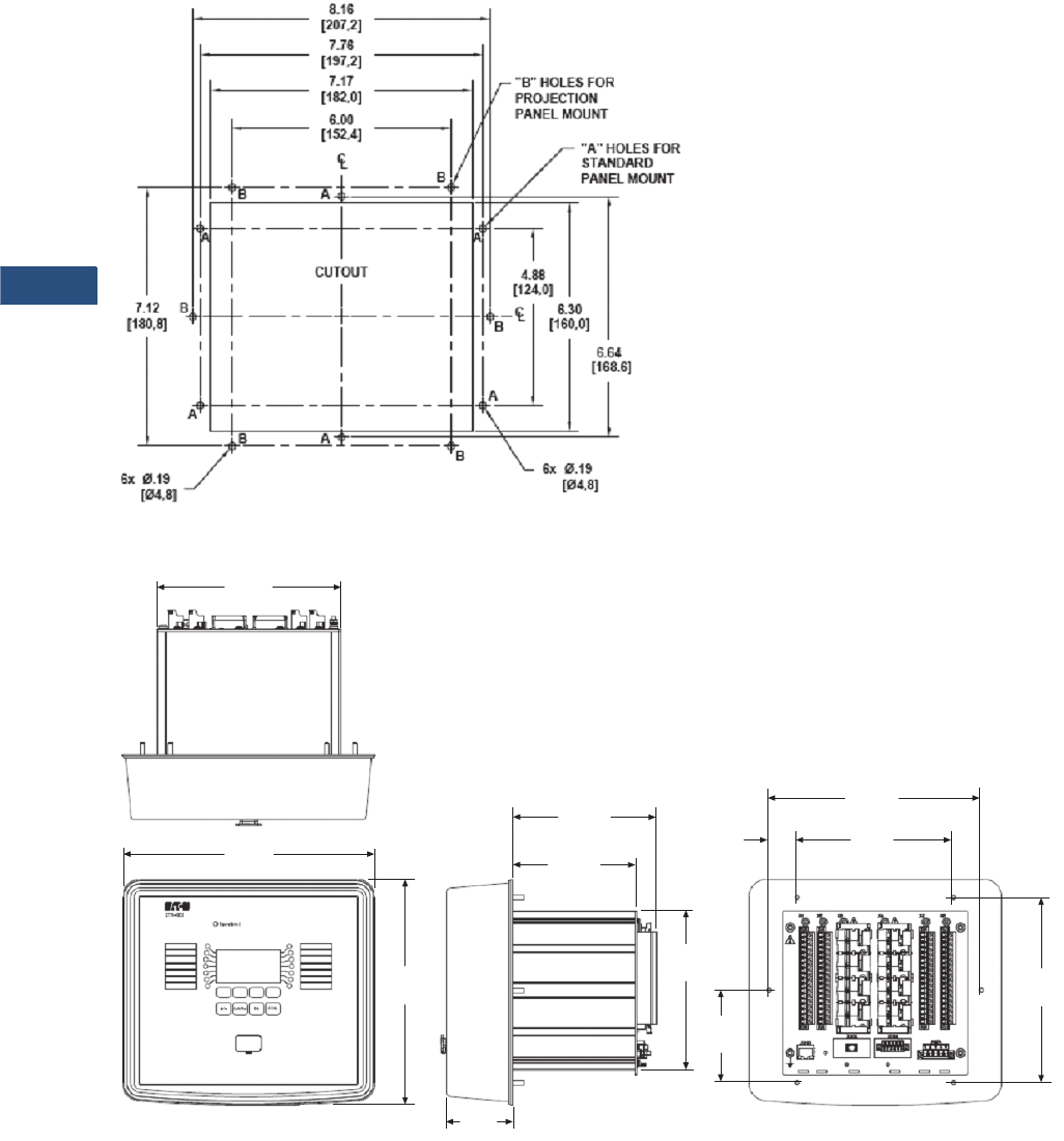
V3-T9-252 Volume 3—Power Distribution and Control Assemblies CA08100004E—March 2016 www.eaton.com
9
9
9
9
9
9
9
9
9
9
9
9
9
9
9
9
9
9
9
9
9
9
9
9
9
9
9
9
9
9
9.3
Metering Devices, Protective Relays, Software and Connectivity
Protective Relays
Dimensions
Approximate Dimensions in Inches (mm)
Drilling Plan
Projection Mount Front and Side Views
7.07
(179.5)
6.00
(152.4)
2.50
(63.5)
4.80
(122.0)
5.56
(141.1)
7. 1 2
(180.8)
8.70
(221.0)
6.14
(156.0)
9.72
(246.9)
8.16
(207.3)
3.56
(90.4)
1.08
(27.4)
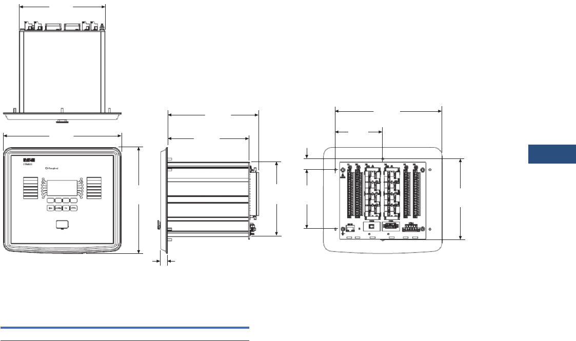
Volume 3—Power Distribution and Control Assemblies CA08100004E—March 2016 www.eaton.com V3-T9-253
9
9
9
9
9
9
9
9
9
9
9
9
9
9
9
9
9
9
9
9
9
9
9
9
9
9
9
9
9
9
9.3
Metering Devices, Protective Relays, Software and Connectivity
Protective Relays
Approximate Dimensions in Inches (mm)
Standard Mount Front and Side Views
ETR-4000 Housing B2
Note
1Includes terminals.
Width Height Depth 1
Shipping Weight
Lbs (kg)
6.81 (173.0) 8.37 (212.7) 8.19 (208.0) 9.3 (4.2)
7.07
(179.5)
3.88
(98.6)
0.56
(14.2)
6.74
(171.2)
7.49
(190.3)
4.94
(125.5)
8.70
(221.0)
6.14
(156.0)
9.72
(246.9)
7.75
(197.0)
4.88
(124.0)
0.88
(22.3)
V3-T9-254 Volume 3—Power Distribution and Control Assemblies CA08100004E—March 2016 www.eaton.com
9
9
9
9
9
9
9
9
9
9
9
9
9
9
9
9
9
9
9
9
9
9
9
9
9
9
9
9
9
9
9.3
Metering Devices, Protective Relays, Software and Connectivity
Protective Relays
ETR-5000 Transformer Protection Relay
Contents
Description Page
Product Selection Guide. . . . . . . . . . . . . . . . . . . . . V3-T9-143
Digitrip 3000. . . . . . . . . . . . . . . . . . . . . . . . . . . . . . V3-T9-149
EDR-3000 Feeder Protection . . . . . . . . . . . . . . . . . V3-T9-159
EDR-5000 Distribution Protection Relay . . . . . . . . V3-T9-168
FP-5000 Feeder Protection. . . . . . . . . . . . . . . . . . . V3-T9-181
MP-3000 Motor Protection . . . . . . . . . . . . . . . . . . V3-T9-189
MP-4000 Motor Protection . . . . . . . . . . . . . . . . . . V3-T9-199
EMR-3000 Motor Protection Relay . . . . . . . . . . . . V3-T9-205
EMR-4000 Motor Protection Relay . . . . . . . . . . . . V3-T9-217
EMR-5000 Motor Protection Relay . . . . . . . . . . . . V3-T9-230
ETR-4000 Transformer Protection Relay . . . . . . . . V3-T9-242
ETR-5000 Transformer Protection Relay
EGR-5000 Generation Protection Relay . . . . . . . . . V3-T9-267
Ground Fault Relay . . . . . . . . . . . . . . . . . . . . . . . . . V3-T9-280
Universal RTD Module . . . . . . . . . . . . . . . . . . . . . . V3-T9-283
ETR-5000 Transformer Protection Relay
Product Description
Eaton’s ETR-5000
transformer protection relay
is a multi-functional,
microprocessor-based relay
for two winding transformers
of all voltage levels. The ETR-
5000 provides phase and
ground percentage restrained
differential protection using a
variable dual slope
characteristic with phase,
residual, and neutral
directional overcurrent
elements for backup
protection. Negative
sequence overcurrent
elements, three phase over/
under voltage, voltage
unbalance, current unbalance,
over/under and rate-of-
change frequency, vector
surge, directional VARs,
directional power, and
overexcitation are standard
functions.
The ETR-5000 transformer
relay provides all required
protection, control,
monitoring and metering for
any size two winding
transformer in a single,
compact case. The relay has
eight current inputs rated for
either 5 amperes or 1 ampere
and four voltage inputs. The
CTs can be connected in wye
in both sides of the
transformer; the relay
automatically compensates
for the connection of the
transformer, and CT
mismatch errors.
Three of the voltage inputs
are to be connected to the
three-phase power voltage
for voltage protection and for
metering. They can be
connected in wye-ground
or open delta configuration.
The fourth voltage is for
independent single-phase
undervoltage/overvoltage
protection.
The maintenance mode
password protected soft key,
can be used for arc flash
mitigation to change to an
alternate settings group, set
to have instantaneous
elements only.
An integral keypad and
display is provided for direct
user programming and
retrieval of data without the
need of a computer. Fourteen
programmable LEDs provide
quick indication of relay
status.
A front port is provided for
direct computer connection.
An RS-485 and an Ethernet
ports in the back are optional
for local area networking
using. Optional Modbus-RTU,
Modbus-TCP, or IEC-61850
protocols are supported.
The ETR-5000 transformer
protection relay includes
programmable logic
functions. Logic gates and
timers may be defined and
arranged for customized
applications. Programmable
logic control functions make
the ETR-5000 very flexible.
Flash memory is used for the
programming and all settings
are stored in nonvolatile
memory.
The ETR-5000 generator
protection relay has mass
memory for data storage and
a real-time clock with 1 ms
time resolution. The relay will
log 300 sequence of event
records, 20 detailed trip logs,
minimum/maximum values,
load profiles, breaker wear
information and waveform
data.
The ETR-5000 has eight
programmable binary inputs,
2 analog inputs, 2 analog
outputs, 1 zone intelorking
card or eight programmable
binary inputs, and 2 zone
interlocking cards. It has 2
normally opened and 6 Form
C heavy-duty outputs and one
Form C signal alarm relay.
The ETR-5000 can be
powered from 19 Vdc to
300 Vdc or 40 Vac to 250 Vac
auxiliary power.
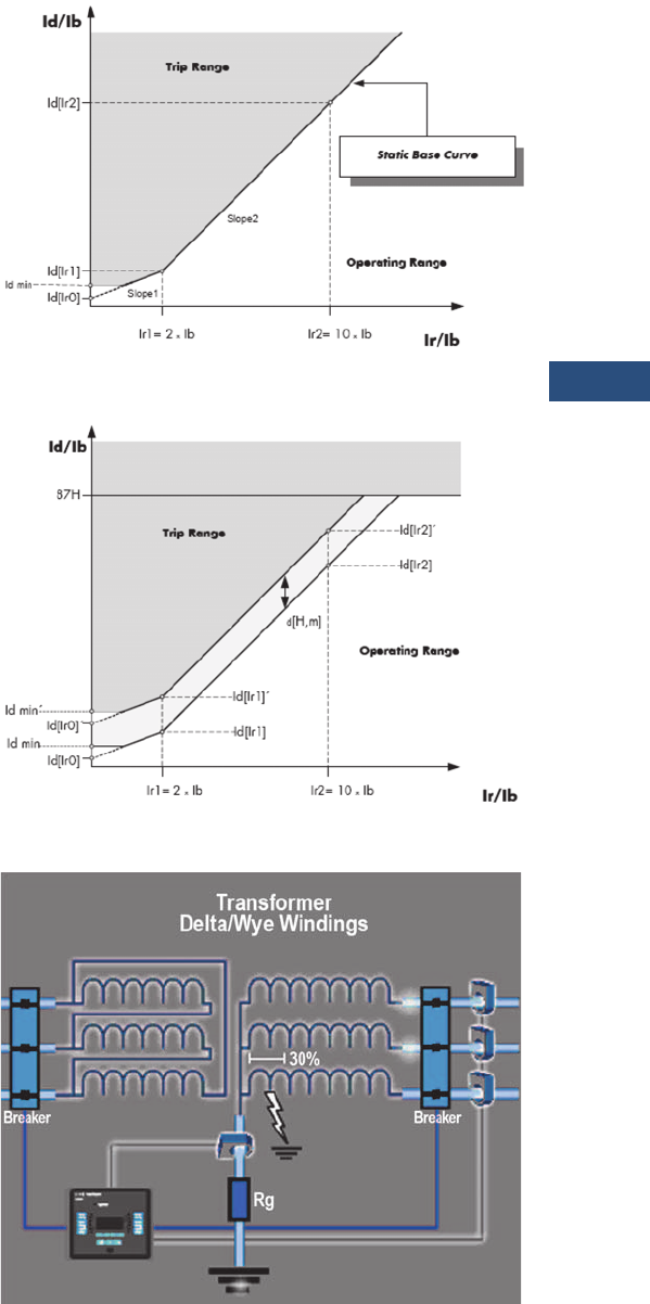
Volume 3—Power Distribution and Control Assemblies CA08100004E—March 2016 www.eaton.com V3-T9-255
9
9
9
9
9
9
9
9
9
9
9
9
9
9
9
9
9
9
9
9
9
9
9
9
9
9
9
9
9
9
9.3
Metering Devices, Protective Relays, Software and Connectivity
Protective Relays
Application Description
Eaton’s ETR-5000
transformer protection relay
has been designed for
maximum user flexibility and
simplicity. The ETR-5000 is
suitable for application on
small, medium, and large two
winding power transformers.
Multiple current inputs are
used to provide primary
protection, control and back-
up protection of transformers,
including current differential,
restricted ground differential,
and overcurrent protection.
Dual-Slope Percent
Differential Protection
The primary protective
element for transformer
protection is the percent
differential element, which
compares the current
entering the primary and
leaving the secondary of the
transformer. The ETR-5000
has built in compensation for
the turns-ratio and the phase
shift of the transformer, so
it’s not necessary to
compensate for the
transformer connection by
the connection of the CTs.
The current differential
element looks at the vector
difference between the
current entering and leaving
the zone of protection. If the
difference exceeds a pre-
determined amount, the
element will operate.
The operating characteristic
of the percent differential
element is a dual-slope
characteristic to
accommodate for CT
saturation and CT errors.
Harmonic Restraints
There are certain conditions
like energizing one side of the
transformer with the other
side de-energized (inrush
currents) or the paralleling of
two transformers
(sympathetic currents) that
can create false differential
currents. These differential
currents if not recognized can
cause a false trip; in the case
of inrush conditions or
sympathetic currents the
differential current is
characterized by a heavy
content of 2nd and 4th
harmonic currents. The
percentage differential
element is desensitize either
permanently (stationary
conditions) or temporarily
(transient conditions),
whenever the 2nd or 4th
harmonic exceed the value
programmed into the relay.
Another condition that can
create a false differential
current is a sudden change of
voltage or frequency, that can
put the transformer in an
overexcitation state. In this
case there is high content of
5th harmonic currents. The
percentage differential
element is also desensitized
when the 5th harmonic
content exceeds a predefined
value.
Unrestrained Differential
An unrestrained differential
element is provided for fast
tripping on heavy internal
faults to limit catastrophic
damage to the transformer
and minimize risks to the
remainder of the power
system.
Restricted Ground Fault
Ground differential protection
is applied to transformers
having impedance grounded
wye windings. It is intended
to provide sensitive ground
fault detection for low
magnitude fault currents,
which would not be detected
by the main percent
differential element.
Dual-Slope Operating Characteristic
Dynamic Rise of the Operating Characteristic.
Restricted Ground Fault

V3-T9-256 Volume 3—Power Distribution and Control Assemblies CA08100004E—March 2016 www.eaton.com
9
9
9
9
9
9
9
9
9
9
9
9
9
9
9
9
9
9
9
9
9
9
9
9
9
9
9
9
9
9
9.3
Metering Devices, Protective Relays, Software and Connectivity
Protective Relays
Directional Overcurrent
Elements
The ETR-5000 can be used to
provide backup for
transformer and adjacent
power system equipment.
Instantaneous overcurrent
elements can be used for fast
clearing of severe internal or
external (through) faults.
Time overcurrent protection
elements per winding allow
coordinating with the
adjacent protection zones and
acting as a backup protection.
There are 11 user-selectable
inverse-time overcurrent
curve characteristics. The
user can select from the
ANSI, IEC or thermal curve
families and can select
instantaneous or time delay
reset characteristics.
Phase direction is a function
used to supervise all phase
current elements (50, 51). A
quadrature voltage is
compared to a corresponding
phase current to establish the
direction of the fault. This
function is selectable to
operate in the forward,
reverse or both directions.
Ground direction is used to
supervise ground current
elements and is
accomplished by using
ground, negative sequence or
residual currents supervised
by zero, negative or positive
sequence voltages or ground
current. This function is
selectable to operate in
forward, reverse or both
directions.
Directional elements are
dependant on the location of
the VTs (primary or secondary
winding) when voltage is
used as the polarizing
quantity.
Negative Sequence Overcurrent
Since this element does not
respond to balanced load or
three-phase faults, the
negative-sequence
overcurrent element may
provide the desired
overcurrent protection. This
is particularly applicable to
delta-wye grounded
transformers where only
58% of the secondary p.u.
phase-to-ground fault current
appears in any one primary
phase conductor. Backup
protection can be particularly
difficult when the wye is
impedance grounded. A
negative-sequence element
can be used in the primary
supply to the transformer and
set as sensitively as required
to protect for secondary
phase-to-ground or phase-to-
phase faults. This element
should be set to coordinate
with the low-side phase and
ground relays for phase-to-
ground and phase-to-phase
faults. The negative
sequence element must also
be set higher than the
negative-sequence current
due to unbalanced loads.
Overexcitation Protection
Transformer overexcitation
occurs when the ratio of
voltage versus frequency is
too high, and the transformer
iron saturates due to high flux
density. High flux density
results in stray flux in
components not designed to
carry it, which in turn causes
overheating and can
potentially damage the
transformer. This protection
is provided through a Volts/
Hertz function with a
programmable inverse time
characteristic.
Voltage Protection
The ETR-5000 transformer
protection relay has four
voltage-input circuits. There is
a three-phase set designated
as Main Voltage (M) and a
single-phase voltage circuit
designated as Auxiliary
Voltage (A). Both include
undervoltage (27) and
overvoltage (59) protection.
The three-phase voltage
protection can be set to
operate on a single-phase, 2
out of 3 phases, or all three-
phase logic. The Main VTs
also provide phase voltage
unbalance/reversal (47
negative sequence)
protection. Each element has
an independent threshold set
point and adjustable time
delay.
Flexible Phase Rotation
The ETR-5000 distribution
protection relay can be
applied on either an A-B-C or
A-C-B phase rotation. A user
setting permits correct
operation and indication of
the actual system
configuration.
Frequency Protection
The ETR-5000 relay provides
six frequency elements than
can be used to detect under/
over frequency, rate of
change, and a vector surge
(decoupling of two systems)
protection on the Main VT
inputs. Each element has an
independent threshold set
point and adjustable time
delay.
Reverse Power
Reverse power provides
control for power flowing
through a feeder. There are
three elements to be
configured: operate in
forward or reverse; or, under
or over power conditions.
Reverse power is typically
applied to generator or motor
applications while under
power is generally applied to
load or generation loss.
Reverse VARs
Reverse VARs can be used to
detect loss of excitation in
synchronous machines.
There are three elements to
be configured: operate in
forward or reverse; or, under
or over vars conditions.
Breaker Failure
The ETR-5000 transformer
protection relay includes two
breaker failure (50BF, 62BF)
elements that can be initiated
from either an internal or
external trip signal. These are
independent elements that
can be used to operate a
lockout relay or trip an
upstream breaker. The timer
must be longer than the
breaker operating time and
the protective function reset
times.
Maintenance Mode
The Maintenance Mode can
improve safety by providing a
simple and reliable method to
reduce fault clearing time and
lower incident energy levels
at energized panels. The
Maintenance Mode allows
the user to switch to more
sensitive settings via a
password protected soft key,
communications or via a
digital input while
maintenance work is being
performed at an energized
panel or device. The more
sensitive settings provide
greater security for
maintenance personnel and
helps reduce the possibility of
injury.

Volume 3—Power Distribution and Control Assemblies CA08100004E—March 2016 www.eaton.com V3-T9-257
9
9
9
9
9
9
9
9
9
9
9
9
9
9
9
9
9
9
9
9
9
9
9
9
9
9
9
9
9
9
9.3
Metering Devices, Protective Relays, Software and Connectivity
Protective Relays
Features, Benefits and Functions
Protection Features
●Dual-slope percentage
restrained current
differential with
magnetizing inrush and
overexcitation blocking
(87R)
●Unrestrained current
differential (87H)
●Restricted ground fault/
Ground Differential (87GD)
●Phase overcurrent
(elements can be assigned
to either side of the
transformer):
●Four instantaneous
elements with timers
(50P[1], 50P[2], 50P[3]
and 50P[4])
●Four inverse time
overcurrent elements
(51P[1], 51P[2], 51P[3]
and 51P[4])
●11 standard curves;
●Inrush blocking
●Instantaneous or time
delay reset
●Voltage restraint (all
elements)
●Directional control (all
elements)
●Negative sequence phase
overcurrent (elements can
be assigned to either side
of the transformer):
●2 inverse time
overcurrent elements
(51Q[1] and 51Q[2])
●11 standard curves
●Instantaneous or time
delay reset
●Ground overcurrent
(elements can be assigned
to either side of the
transformer):
●Two instantaneous
measured elements
with timers
(50X[1] and 50X[2])
●Two instantaneous
calculated elements
with timers
(50R[1] and 50R[2])
●Two inverse time
overcurrent measured
elements
(51X[1] and 51X[2])
●Two inverse time
overcurrent calculated
elements
(51R[1] and 51R[2])
●11 standard curves
●Instantaneous or time
delay reset
●Directional control (all
elements)
●Two breaker failure
elements (50BF[1] and
50BF[2])
●Phase transformer
overload protection (49)
●Phase unbalance negative
sequence overcurrent
(46[1], 46[2]))
●Phase voltage unbalance
and sequence protection
(47[1], 47[2])
●Main three-phase under/
overvoltage (27M[1],
27M[2], 59M[1], 59M[2])
●Auxiliary single-phase
under/overvoltage (27A[1],
27A[2], 59A[1], 59A[2])
●Six frequency elements
that can be assigned to:
over frequency, under
frequency, rate of change,
or vector surge (81[1],
81[2], 81[3], 81[4], 81[5],
81[6])
●Forward and reverse watts
(32[1], 32[2], 32[3]).
●Forward and reverse VARs
(32V[1], 32V[2], 32V[3])
●Overexcitation, volts-per-
Hertz (24[1], 24[2])
●Lockout (86)
●Loss of potential-LOP
●Zone interlocking for bus
protection (87B)
●Switch onto fault
protection
●Cold load pickup
Metering Features
●Phase differential current
●Ground differential current
●Amperes: positive,
negative and zero
sequence
●Ampere demand
●Volts: positive, negative
and zero sequence
●Phase angles
●Volt-amperes and VA
demand
●Watts and kW demand
●kWh (forward, reverse,
net)
●VARs and kVAR demand
●kVARh (lead, leg and net)
●Power factor
●Volts/Hertz
●% THD V and I
●Magnitude THD V and I
●Minimum/maximum
recording
●Trending (load profile over
time)
●Temperature with remote
URTD module
Monitoring Features
●Trip coil monitor for both
primary and secondary
breakers
●Breaker wear primary and
secondary (accumulated
interrupted current)
●Oscillography (7200 cycles
total)
●Trip Cause displays fault
recorder data on HMI after
fault event
●Fault data logs (up to 20
events)
●Sequence of events report
(up to 300 events)
●Clock (1 ms time stamping)
Control Functions
●Breaker open/close both
breakers
●Remote open/close
●Programmable I/O
●Programmable Logic
●Programmable LEDs
●Multiple setting groups
●Cold load pickup
●CT supervision
Communication Features
●Local HMI
●Password protected
●Addressable
●IRIG-B
●Local communication port:
RS-232
●Remote communication
port:
●RS-485
●Ethernet port
●Protocols:
●Modbus-RTU
●Modbus-TCP (optional)
●IEC-61850 (optional)
●Configuration software
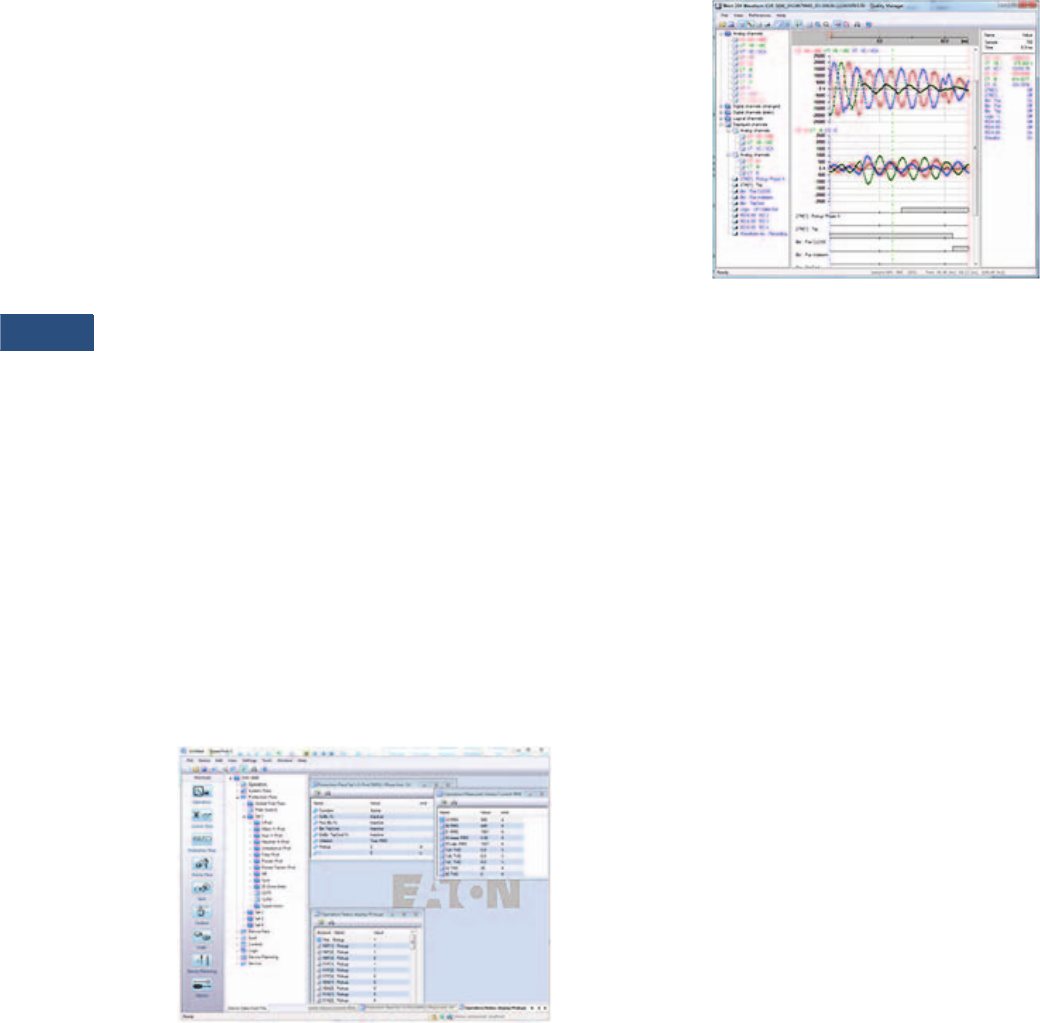
V3-T9-258 Volume 3—Power Distribution and Control Assemblies CA08100004E—March 2016 www.eaton.com
9
9
9
9
9
9
9
9
9
9
9
9
9
9
9
9
9
9
9
9
9
9
9
9
9
9
9
9
9
9
9.3
Metering Devices, Protective Relays, Software and Connectivity
Protective Relays
Monitoring and Metering
Sequence of Events Records
The ETR-5000 protection
relay records a maximum of
300 events associated with
the relay. An event is
classified as a change of state
as detected by the relay.
These include relay pickups,
dropouts, trips, contact
closure, alarms, setting
changes and self-diagnostic
failures. Each event is date
and time stamped to a 1 ms
resolution. The events are
stored in a FIFO in
chronological order.
Trip Log
The ETR-5000 protection
relay will store a maximum of
20 trip records in a FIFO trip
log. Each trip record will be
date and time stamped to a
1 ms resolution. The trip log
record will include
information on the type of
fault, protection elements
that operated, fault location
and currents and voltages at
the time of the fault.
PowerPort-E
PowerPort-E is the software
program used to configure
off-line protection setting files
for all E-Series relay models.
PowerPort-E is also used for
viewing measured values of
the relays in real-time,
uploading/downloading
setting files, and retrieving
event log and waveform
records.
Waveform Capture (Quality
Manager)
The ETR-5000 relay provides
oscillographic recording
capabilities. The relay will
record all measured signals
along with the binary signals
of pickup, trip, internal logic,
and contact inputs. The ETR-
5000 can record up to 7200
cycles of data. The number of
records is proportional to the
programmed size of each
record; the maximum size per
record is 600 cycles.
The waveform capture is
initiated by up to 8 different
triggers (i.e., trip/alarm
events) or manually via
communications or the HMI.
PowerPort-E setting software
is used to retrieve the
records. Quality Manager is a
separate
software program
downloaded
with PowerPort-
E used for analyzing the
waveform and trending files
retrieved from the relay.
PowerPort-E
Waveform Capture (Quality Manager)
Integral User Interface
The front panel user interface
has a 128 x 64 pixel LCD
display with background
illumination for wide angle
viewing in all light conditions.
14 programmable LEDs
provide quick and easy visual
display of power on, mode of
operation, alarm and trip
indication. Soft keys are
provided for operation mode
selection, scrolling through
data and settings. In addition,
the relay settings and test
functions are password
protected.
Load Profiling/Trending
The ETR-5000 relay
automatically records
selected quantities into non-
volatile memory every 5, 10,
15, 30 or 60 minutes,
depending on the trending
report setting.
Programmable I/O
The ETR-5000 transformer
protection relay provides
heavy-duty, trip-rated, 2NO
and 6 Form C contacts. Two
isolated inputs can be used
for monitoring the trip circuit.
One Form C contact is
dedicated to the relay failure
alarm function and is
operated in a normally
energized (failsafe) mode.
There are up to 8 user-
configurable discrete inputs
that accept a wet contact and
can operate through a wide
range of power. Each input
and output is user-
programmable for maximum
application flexibility.
The ETR-5000 also offers two
optional analog inputs and
two optional analog outputs.
The analog inputs are
available for providing
protection. The analog inputs
are field programmable to
measure transducer signals
that operate over a range of 0
to 20 mA, 4 to 20 mA, or 1 to
10V. The two optional analog
outputs can be used for
signaling the value of
measured analog quantities
to external process control
devices such as PLCs. They
can be programmed to
operate over a 0 to 20 mA,
4–20 mA, or 1 to 10 V range.
The analog outputs can be
configured to signal a
representation of most
analog quantities measured
by the ETR-5000 including,
current, voltages and RTD
temperature.
Programmable Logic
The ETR-5000 transformer
protection relay provides logic
gates and timers that the
user can customize for
special or unique applications.
Each gate can be assigned a
logic function of either AND,
OR, NAND or NOR. Each
gate can have a maximum of
four input signals and each
input signal can be required
to be a NOT. Input signals can
be external inputs received
via the binary inputs or
internal values associated
with the protection, alarm or
metering set points. Each
gate has a unique output
assignment and designation
that can be used as the input
to another gate.
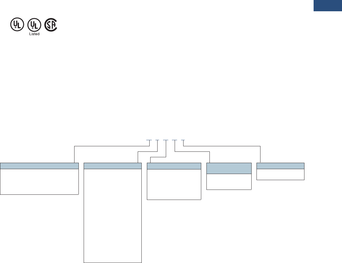
Volume 3—Power Distribution and Control Assemblies CA08100004E—March 2016 www.eaton.com V3-T9-259
9
9
9
9
9
9
9
9
9
9
9
9
9
9
9
9
9
9
9
9
9
9
9
9
9
9
9
9
9
9
9.3
Metering Devices, Protective Relays, Software and Connectivity
Protective Relays
Standards and Certifications
Approvals
●UL listed file: E217753
Design Standards
●Generic Standard:
●EN 61000-6-2
●EN 61000-6-3
●Product Standard:
●IEC 60255-6
●EN 50178
●UL 508 (Industrial
Control Equipment)
●CSA C22.2 No. 14-95
(Industrial Control
Equipment)
●ANSI C37.90
Catalog Number Selection
The catalog number
identification chart defines
the electrical characteristics
and operation features
included in the ETR-5000.
For example, if the catalog
number is ETR-5000B0BA1,
the device would have the
following:
ETR-5000
(A)–8 Digital Inputs,
9 Output Relays
(0)–5 A / 1 A phase and
ground CTs, Power Supply
Range: 19–300 Vdc, 40–250
Vac
(B)–Modbus-RTU (RS-485)
(A)–Without Conformal
Coating
(1)–Projection Panel Mount
ETR-5000 Eaton Transformer Protection Relay
Note
1Beginning in 2016, consult factory for the availability of the following new communication options.
• Protocols: DNP3.0, Profibus
• Interface ports: Fiber optic ST, RS-485 D-SUB, Fiber optic LC
Hardware Option 1
A = 8 DI, 9 outputs, removable terminals,
2 zone interlocking, URTD interface
B = 8 DI, 9 outputs, 2 AI, 2AO, removable
terminals, 1 zone interlocking,
URTD interface
ETR5000 B 0 B A 1
Communication Options 1
B= Modbus-RTU (RS-485)
I= Modbus-RTU (RS-485) and
Modbus-TCP (RJ-45) [only 1
active, software selected]
H= IEC 61850 GOOSE and
MMS (RJ-45)
Conformal Coating
Options
A = None
B = Conformal coated
circuit boards
Mounting Options
0 = Standard mount
1 = Projection panel mount
Hardware Option 2
0 = Phase current 5 A / 1 A, W1/
W2 ground current 5 A / 1 A,
power supply range: 19–300
Vdc, 40–250 Vac
1 = Phase current 5 A / 1 A, W1
sensitive ground current
0.5 A 0.1 A, W2 Ground current
5A/1A, power supply range:
19–300 Vdc, 40–250 Vac
2 = Phase current 5 A / 1 A,
W1 sensitive ground current
0.5 A 0.1 A, W2 Ground current
5A/1A, power supply range:
19–300 Vdc, 40–250 Vac
3 = Phase current 5 A / 1 A,
W1 / W2 sensitive ground
current 0.5 A / 0.1 A, power
supply range: 19–300 Vdc,
40–250 Vac

V3-T9-260 Volume 3—Power Distribution and Control Assemblies CA08100004E—March 2016 www.eaton.com
9
9
9
9
9
9
9
9
9
9
9
9
9
9
9
9
9
9
9
9
9
9
9
9
9
9
9
9
9
9
9.3
Metering Devices, Protective Relays, Software and Connectivity
Protective Relays
Technical Data and Specifications
Climatic Environmental
Conditions
●Storage temperature:
–30 °C to +70 °C
(–22 °F to +158 °F)
●Operating temperature:
–20 °C to +60 °C
(–4 °F to +140 °F)
●Permissible humidity at
ann. average: <75% rel.
(on 56d up to 95% rel.)
●Permissible installation
altitude:
●<2000 m (6,561.67 ft)
above sea level
●If 4000 m (13,123.35 ft)
altitude applies, a
changed classification of
the operating and test
voltages may be
necessary
Degree of Protection EN 60529
●HMI front panel with seal:
IP54
●Rear side terminals: IP30
Routine Test
●Insulation test acc. to
IEC 60255-5: All tests to be
carried out against ground
and other input and output
circuits.
●Aux. voltage supply, digital
inputs: 2.5 kV (eff.) / 50 Hz
●Current measuring inputs,
signal relay outputs:
2.5 kV (eff.) / 50 Hz
●Voltage measuring inputs:
3.0 kV (eff.) / 50 Hz
●All wire-bound
communication interfaces:
1. 5 k V D C
Housing
●Housing B2: height/width:
173 mm (6.811 in / 4 U) /
212.7 mm (8.374 in / 42 hp)
●Housing depth (incl.
terminals):
208 mm (8.189 in)
●Material, housing:
aluminum extruded section
●Material, front panel:
aluminum/foil front
●Mounting position:
horizontal (±45° around the
X-axis must be permitted)
●Weight: ETR-5000 housing
B2: approx. 9.259 lb
(4.2 kg)
Plug-in Connector with
Integrated Short-Circuiter
(Conventional current inputs)
●Nominal current:
1 A and 5 A
●Continuous loading
capacity:
4 x In / continuously
●Overcurrent withstand:
●30 x In / 10 s
●100 x In / 1 s
●250 x In / 10 ms
(1 half-wave)
●Screws: M4, captive type
acc. to VDEW
●Connection cross sections:
●1 x or 2 x 2.5 mm² (2 x
AWG 14) with wire end
ferrule
●1 x or 2 x 4.0 mm² (2 x
AWG 12) with ring cable
sleeve or cable sleeve
●1 x or 2 x 6 mm² (2 x
AWG 10) with ring cable
sleeve or cable sleeve
Control power supply
●Aux. voltage: 24–270 Vdc /
48–230 Vac (–20/+10%)
●Buffer time in case of
supply failure:
●≥50 ms at minimal aux.
voltage
●Interrupted
communication is
permitted
●Max. permissible making
current:
●18 A peak value for
<0.25 ms
●12 A peak value for
<1 ms
●The voltage supply must
be protected by a fuse of:
●2.5 A time-lag miniature
fuse 5 x 20 mm (approx.
1/5 x 0.8 in) according to
IEC 60127
●3.5 A time-lag miniature
fuse 6.3 x 32 mm
(approx. 1/4 x 1 1/4 in)
according to UL 248-14
Power Consumption
●Power supply range:
19–300 Vdc
●Power consumption
in idle mode—7 W
●Maximum power
consumption—13 W
●Power supply range:
40–250 Vac (for
frequencies of 40–70 Hz)
●Power consumption
in idle mode—7 W
●Maximum power
consumption—13 W
Real Time Clock
●Running reserve of the real
time clock: 1 year min.
Display
●Display type: LCD with
LED background
illumination
●Resolution—graphics
display: 128 x 64 pixel
●LED type: two colored:
red/green
●Number of LEDs,
Housing B2: 15
Digital Inputs
●Max. Input Voltage:
300 Vdc / 270 Vac
●Input Current: <4 mA
●Reaction Time: <20 ms
●Fallback Time: <30 ms
(Safe state of the digital
Inputs)
●4 Switching thresholds:
Un = 24 Vdc, 48 Vdc,
60 Vdc, 110 Vac / DC, 230
Vac / DC
●Un = 24 Vdc
– Switching threshold
1 ON: Min. 19.2 Vdc
– Switching threshold
1 OFF: Max. 9.6 Vdc
●Un = 48 V / 60 Vdc
– Switching threshold
2 ON: Min. 42.6 Vdc
– Switching threshold
2 OFF: Max. 21.3 Vdc
●Un = 110 / 120 Vac / Vdc
– Switching threshold
3 ON: Min. 88.0 Vdc /
88.0 Vac
– Switching threshold
3 OFF: Max. 44.0 Vdc
/ 44.0 Vac
●Un = 230 / 240 Vac / dc
– Switching threshold
4 ON: Min. 184 Vdc /
184 Vac
– Switching threshold
4 OFF: Max. 92 Vdc /
92 Vac
●Terminals: screw-type
terminal

Volume 3—Power Distribution and Control Assemblies CA08100004E—March 2016 www.eaton.com V3-T9-261
9
9
9
9
9
9
9
9
9
9
9
9
9
9
9
9
9
9
9
9
9
9
9
9
9
9
9
9
9
9
9.3
Metering Devices, Protective Relays, Software and Connectivity
Protective Relays
Current and Ground Current
Measurement
●Nominal currents: 1 A / 5 A
●Max. measuring range:
●Up to 40 x In (phase
currents)
●Up to 25 x In (ground
current standard)
●Up to 2.5 x In (ground
current sensitive)
●Continuous loading
capacity: 4 x In/
continuously
●Overcurrent proof:
●30 x In / 10 s
●100 x In / 1 s
●250 x In / 10 ms
(1 half-wave)
●Power consumption:
●Phase current inputs
– At In = 1 A burden =
0.15 MVA
– At In = 5 A burden =
0.15 MVA
●Ground current input
– At In = 1 A burden =
0.35 MVA
– At In = 5 A burden =
0.35 MVA
●Frequency range: 50 Hz /
60 Hz ±10%
●Terminals: screw-type
terminals with integrated
short-circuiters (contacts)
Relay Outputs
●Continuous current:
5 A AC/DC
●Maximum make current:
●25 A AC/25 A DC up to
30 V for 4 s
●30 A/230 Vac according
to ANSI IEEE Std.
C37.90-2005
●30 A/250 Vdc according
to ANSI IEEE Std.
C37.90-2005
●Maximum breaking
current:
●5 A AC up to 125 Vac
●5 A DC up to 30 V
(resistive)
●0.3 A DC at 300 V
●Maximum switching
voltage: 250 Vac/250 Vdc
●Switching capacity:
1250 VA
●Contact type: changeover
contact or NO contact
●Terminals: screw-type
terminals
Supervision Contact (SC)
●Continuous current:
5 A at 120/240 Vac or
30 Vdc
●Maximum switch-on
current: 15 A 120/240 Vac
or 30 Vdc (max. 4 s)
●Maximum breaking
current:
●5 A Vac up to 2120/240
Vac
●5 A Vdc up to 30 Vdc
●0.4 A at 125 Vdc
●Contact type:
1 changeover contact
●Terminals: screw-type
terminals
Time Synchronization IRIG
●Nominal input voltage: 5 V
●Connection: screw-type
terminals (twisted pair)
Front Interface RS-232
●Baud rates: 115,200 baud
●Handshake: RTS and CTS
●Connection: 9-pole D-Sub
plug
RS-485
●Master/slave: slave
●Connection: 6 screw-
clamping terminals RM 3.5
mm (138 MIL) (terminating
resistors internal)
Zone Interlocking
●Nominal input level: 5 V
●Nominal output level: 5 V
●Connection: screw-type
terminals (twisted pair)
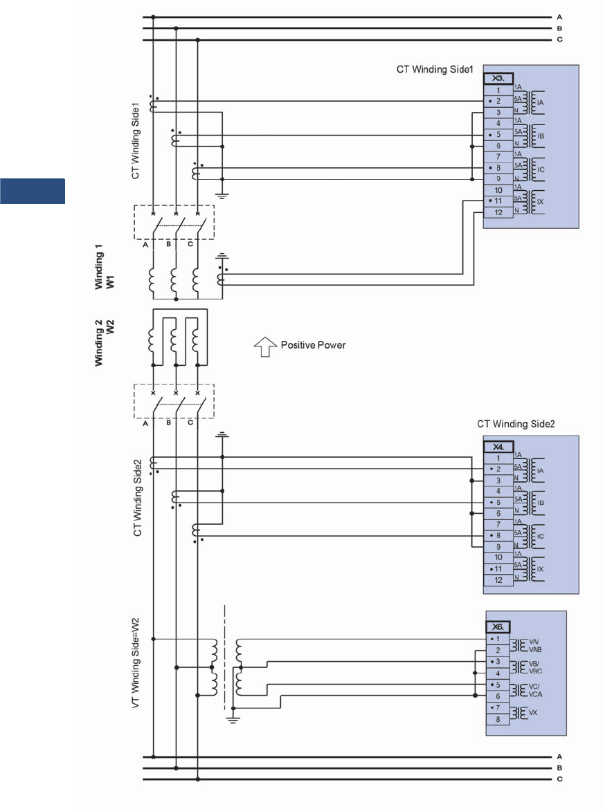
V3-T9-262 Volume 3—Power Distribution and Control Assemblies CA08100004E—March 2016 www.eaton.com
9
9
9
9
9
9
9
9
9
9
9
9
9
9
9
9
9
9
9
9
9
9
9
9
9
9
9
9
9
9
9.3
Metering Devices, Protective Relays, Software and Connectivity
Protective Relays
Wiring Diagrams
Typical AC Connections—Delta-Wye Transformer with CTs for Phase Overcurrent and Differential on Primary Side (W2) and
Secondary Side (W1), Neutral CT for Ground Fault Protection and Open-Delta VT on Primary Side (W2)
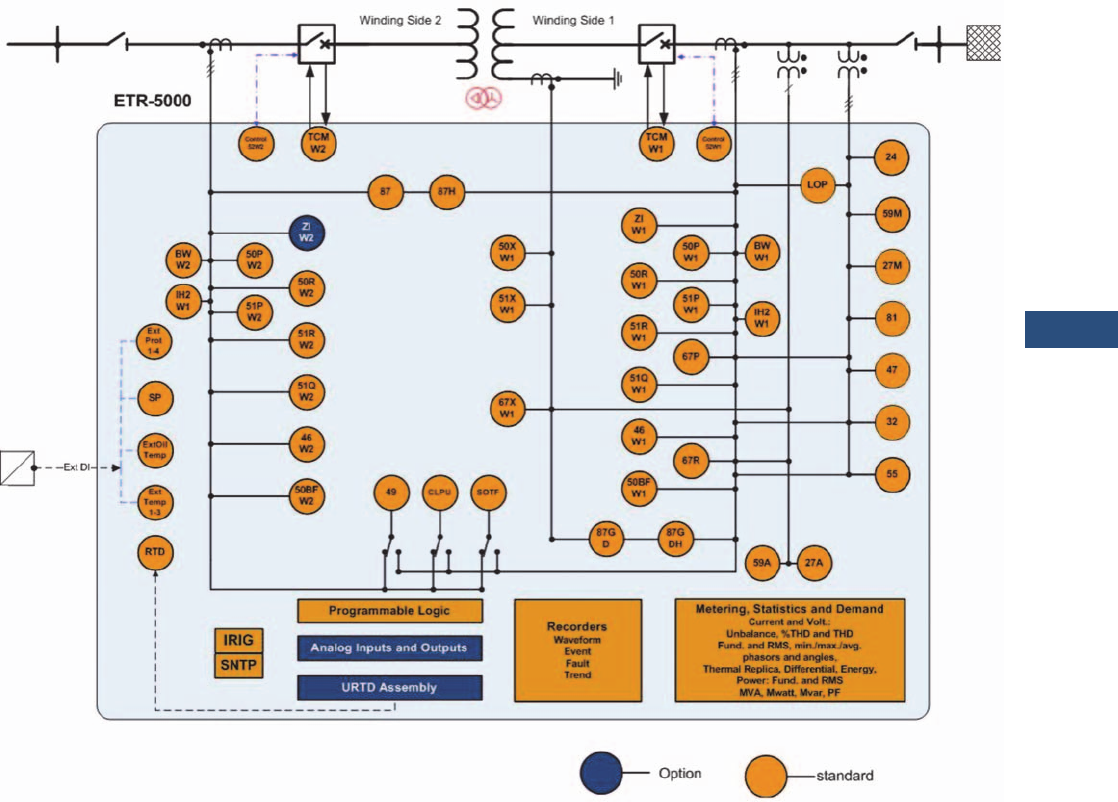
Volume 3—Power Distribution and Control Assemblies CA08100004E—March 2016 www.eaton.com V3-T9-263
9
9
9
9
9
9
9
9
9
9
9
9
9
9
9
9
9
9
9
9
9
9
9
9
9
9
9
9
9
9
9.3
Metering Devices, Protective Relays, Software and Connectivity
Protective Relays
Typical One-Line Diagram
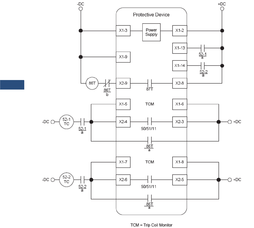
V3-T9-264 Volume 3—Power Distribution and Control Assemblies CA08100004E—March 2016 www.eaton.com
9
9
9
9
9
9
9
9
9
9
9
9
9
9
9
9
9
9
9
9
9
9
9
9
9
9
9
9
9
9
9.3
Metering Devices, Protective Relays, Software and Connectivity
Protective Relays
Ty p i c a l C o n t r o l D i a g r a m
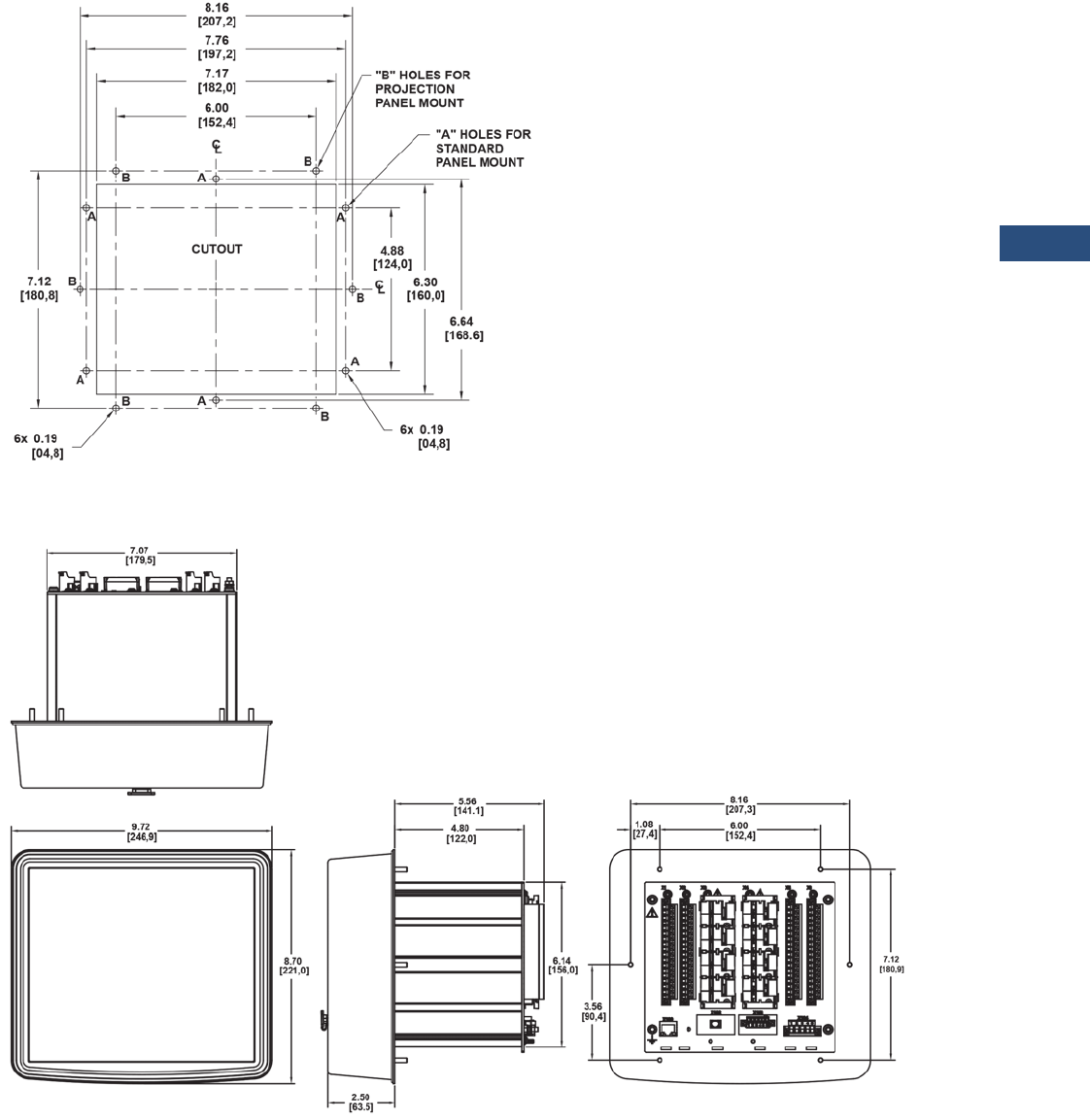
Volume 3—Power Distribution and Control Assemblies CA08100004E—March 2016 www.eaton.com V3-T9-265
9
9
9
9
9
9
9
9
9
9
9
9
9
9
9
9
9
9
9
9
9
9
9
9
9
9
9
9
9
9
9.3
Metering Devices, Protective Relays, Software and Connectivity
Protective Relays
Dimensions
Approximate Dimensions in Inches (mm)
Drilling Plan
Projection Mount Front and Side Views
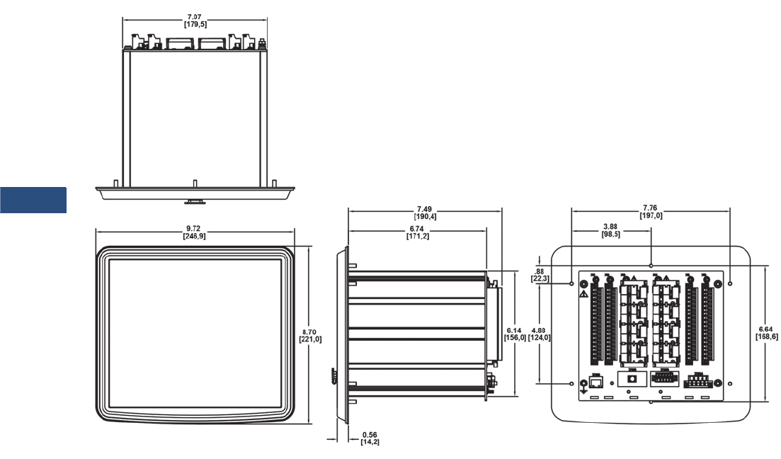
V3-T9-266 Volume 3—Power Distribution and Control Assemblies CA08100004E—March 2016 www.eaton.com
9
9
9
9
9
9
9
9
9
9
9
9
9
9
9
9
9
9
9
9
9
9
9
9
9
9
9
9
9
9
9.3
Metering Devices, Protective Relays, Software and Connectivity
Protective Relays
Approximate Dimensions in Inches (mm)
Standard Mount Front and Side Views

Volume 3—Power Distribution and Control Assemblies CA08100004E—March 2016 www.eaton.com V3-T9-267
9
9
9
9
9
9
9
9
9
9
9
9
9
9
9
9
9
9
9
9
9
9
9
9
9
9
9
9
9
9
9.3
Metering Devices, Protective Relays, Software and Connectivity
Protective Relays
EGR-5000 Generation Protection Relay
Contents
Description Page
Product Selection Guide . . . . . . . . . . . . . . . . . . . . V3-T9-143
Digitrip 3000 . . . . . . . . . . . . . . . . . . . . . . . . . . . . . V3-T9-149
EDR-3000 Feeder Protection. . . . . . . . . . . . . . . . . V3-T9-159
EDR-5000 Distribution Protection Relay . . . . . . . . V3-T9-168
FP-5000 Feeder Protection . . . . . . . . . . . . . . . . . . V3-T9-181
MP-3000 Motor Protection . . . . . . . . . . . . . . . . . . V3-T9-189
MP-4000 Motor Protection . . . . . . . . . . . . . . . . . . V3-T9-199
EMR-3000 Motor Protection Relay . . . . . . . . . . . . V3-T9-205
EMR-4000 Motor Protection Relay . . . . . . . . . . . . V3-T9-217
EMR-5000 Motor Protection Relay . . . . . . . . . . . . V3-T9-230
ETR-4000 Transformer Protection Relay . . . . . . . . V3-T9-242
ETR-5000 Transformer Protection Relay . . . . . . . . V3-T9-254
EGR-5000 Generation Protection Relay
Ground Fault Relay . . . . . . . . . . . . . . . . . . . . . . . . V3-T9-280
Universal RTD Module . . . . . . . . . . . . . . . . . . . . . V3-T9-283
EGR-5000 Generation Protection Relay
Product Description
Eaton’s EGR-5000 generator
protection relay is a multi-
functional, microprocessor-
based relay for any size
generators. It may be used as
a primary or backup
protection in stand by
generators, and cogeneration
applications. The EGR-5000
generator protection relay
provides voltage controlled,
voltage restrained, and
standard directional three
phase overcurrent protection,
as well as directional phase-
residual and independent
ground overcurrent
protection, and breaker
failure. Three phase over/
under voltage, voltage
unbalance, current unbalance,
over/under and rate-of-
change frequency, vector
surge, power factor,
directional VARs, directional
power, loss of excitation,
overexcitation, phase
differential, ground
differential, and synch check
functions are standard
functions.
The EGR-5000 generator
relay provides all required
protection, control,
monitoring and metering for
any size generators in a
single, compact case. The
relay has eight current inputs
rated for either 5 amperes or
1 ampere and four voltage
inputs. Three of the voltage
inputs are to be connected to
the three-phase power
voltage for voltage protection
and for metering. They can be
connected in wye-ground or
open delta configuration. The
fourth voltage is for
independent single-phase
undervoltage/overvoltage
protection, or 100% ground
protection for a high
resistance grounded
generator.
The maintenance mode
password protected soft key,
can be used for arc flash
mitigation to change to an
alternate settings group, set
to have instantaneous
elements only. The multiple
setting groups can also be
changed, via communications
or a digital input.
An integral keypad and
display is provided for direct
user programming and
retrieval of data without the
need of a computer. Fourteen
programmable LEDs provide
quick indication of relay
status.
A front port is provided for
direct computer connection.
An RS-485 and an Ethernet
ports in the back are optional
for local area networking
using. Optional Modbus-RTU,
Modbus-TCP, or IEC-61850
protocols are supported.
The EGR-5000 generator
protection relay includes
programmable logic
functions. Logic gates and
timers may be defined and
arranged for customized
applications. Programmable
logic control functions make
the EGR-5000 very flexible.
Flash memory is used for the
programming and all settings
are stored in nonvolatile
memory.
The EGR-5000 generator
protection relay has mass
memory for data storage and
a real-time clock with 1 ms
time resolution. The relay will
log 300 sequence of event
records, 20 detailed trip logs,
minimum/ maximum values,
load profiles, breaker wear
information and waveform
data.
The EGR-5000 has either
eight programmable binary
inputs, 2 analog inputs, 2
analog outputs, or 16
programmable binary inputs.
It has 2 normally opened and
6 Form C heavy duty outputs
and one Form C signal alarm
relay. The EGR-5000 can be
powered from 19 Vdc to 300
Vdc or 40 Vac to 250 Vac
auxiliary power.

V3-T9-268 Volume 3—Power Distribution and Control Assemblies CA08100004E—March 2016 www.eaton.com
9
9
9
9
9
9
9
9
9
9
9
9
9
9
9
9
9
9
9
9
9
9
9
9
9
9
9
9
9
9
9.3
Metering Devices, Protective Relays, Software and Connectivity
Protective Relays
Application Description
Eaton’s EGR-5000 generator
protection relay has been
designed for maximum user
flexibility and simplicity. The
EGR-5000 provides
comprehensive protection,
metering, and monitoring for
any size synchronous or
induction generators
operating at 50 or 60 Hz.
The base relay includes all
the standard protection
and metering functions.
Protection features found in
the EGR-5000 include:
Phase Differential Protection
This protection provides a
method for rapidly detecting
internal generator phase-to-
phase or phase-to-ground
faults. After the detection of
this fault the generator is
quickly removed from service
to limit the extent of the
damage. The EGR-5000 uses
a dual slope percentage
differential scheme;
advanced CT saturation
algorithms maintain immunity
against external disturbances
and ensures the fault is
internal to the generator
before triggering it to trip.
Ground Differential Protection
In low resistance grounded
generators, ground protection
may be provided by the 87GD
differential, depending on the
fault level and the differential
relay sensitivity. Higher
sensitivity and fast operation
for ground faults may be
obtained by an additional
zero-sequence differential.
Directional Overcurrent
Protection
The EGR-5000 generation
protection relay provides
complete three-phase and
ground directional
overcurrent protection There
are 14 independent ground
overcurrent elements. The
ground elements “X” use the
independently measured
ground (or neutral) current
from a separate current-
sensing input. The ground
elements “R” uses a
calculated 3Io residual current
obtained from the sum of the
three-phase currents. This
calculated current could be
used for either the neutral or
ground current in a three-
phase, four-wire system.
Each of the phase and ground
overcurrent elements can be
selected to operate based on
fundamental or RMS current.
Phase direction is a function
used to supervise all phase
current elements (50, 51).
A quadrature voltage is
compared to a corresponding
phase current to establish the
direction of the fault. This
function is selectable to
operate in the forward,
reverse or both directions.
Ground direction is used to
supervise ground current
elements and is
accomplished by using
ground, negative sequence or
residual currents supervised
by zero, negative or positive
sequence voltages or ground
current. This function is
selectable to operate in
forward, reverse or both
directions.
Voltage Restrained Overcurrent
Voltage restraint reduces the
overcurrent pickup level
(51P[2], 51P[3]), to protect
the distribution system
components against
excessive damage and to
prevent the generator and its
auxiliaries from exceeding
their thermal limitations. This
modification of the pickup
overcurrent level is compared
to the corresponding phase
input voltage. The EGR-5000
uses the simple linear model
below to determine the
effective pickup value.
Sync Check
The sync-check function is
provided for double-ended
power source applications.
The sync-check monitors
voltage magnitude, phase
angle and slip frequency
between the bus and line.
It also incorporates breaker
close time, dead bus dead
line, dead bus live line and
live bus live line features.
Reverse Power
Reverse power provides
control for power flowing
through a generator. There
are three elements to be
configured: operate in
forward or reverse; or, under
or over power conditions.
Reverse power is typically
applied to prevent generator
motoring that can cause
damage to the prime mover;
while under power is
generally applied to load loss
and prevent an overspeed
condition that could damage
the prime mover.
Reverse VARs
Reverse vars can be used to
detect loss of excitation in
synchronous machines.
There are three elements to
be configured: operate in
forward or reverse; or, under
or over vars conditions.
Inverse Time Characteristics
There are 11 user-selectable
inverse-time overcurrent
curve characteristics.
The user can select from the
ANSI, IEC or thermal curve
families and can select
instantaneous or time delay
reset characteristics.
Breaker Failure
The EGR-5000 generator
protection relay includes a
breaker failure (50BF, 62BF)
function that can be initiated
from either an internal or
external trip signal. This is an
independent element that
can be used to operate a
lockout relay or trip an
upstream breaker. The timer
must be longer than the
breaker operating time and
the protective function
reset times.
Voltage Protection
The EGR-5000 generator
protection relay has four
voltage-input circuits. There is
a three-phase set designated
as Main Voltage (M) and a
single-phase voltage circuit
designated as Auxiliary
Voltage (A). Both include
undervoltage (27) and
overvoltage (59) protection.
The three-phase voltage
protection can be set to
operate on a single-phase,
two out of three phases, or all
three-phase logic. The Main
VTs also provide phase
voltage unbalance/reversal
(47 negative sequence)
protection. Each element
has an independent threshold
set point and adjustable
time delay.

Volume 3—Power Distribution and Control Assemblies CA08100004E—March 2016 www.eaton.com V3-T9-269
9
9
9
9
9
9
9
9
9
9
9
9
9
9
9
9
9
9
9
9
9
9
9
9
9
9
9
9
9
9
9.3
Metering Devices, Protective Relays, Software and Connectivity
Protective Relays
100% Ground Stator Protection
In high impedance grounded
generators, ground fault
protection is provided by the
detection of voltage in the
neutral of the generator by an
overvoltage element (59N)
connected to the secondary
of the distribution grounding
transformer, this overvoltage
element has to be
desensitized for 3rd harmonic
voltages normally present in
the generator. Under normal
conditions there is no voltage
across the secondary of the
grounded transformer, when
one of the phases goes to
ground, voltage appears
across the resistor and the
overvoltage element
operates, indicating a ground
conductor. However, the
overvoltage element
technique described above
will protect around 90 percent
to 95 percent of the winding.
The last 5–10 percent is
protected by detecting the
decayed of the 3rd harmonic
voltage using a undervoltage
element (27TN) tuned to the
3rd harmonic voltage. In the
EGR-5000 we can provide
100% stator ground
protection by measuring the
zero sequence voltage
through the 4th voltage input,
and combining the 59N and
27A elements. The 27A
element has to be
programmed to operate for
3rd harmonic zero sequence
voltages.
Flexible Phase Rotation
The EGR-5000 generator
protection relay can be
applied on either an A-B-C or
A-C-B phase rotation. A user
setting permits correct
operation and indication of
the actual system
configuration.
Frequency Protection
Operation of generators at
off-nominal frequencies can
have extremely detrimental
effects on both the generator
itself and the associated
prime mover, in particular
with steam turbine
generators operating below
normal frequency. The EGR-
5000 relay provides six
frequency elements than can
be used to detect under/over
frequency, rate of change,
and a vector surge
(decoupling of two systems)
protection on the Main VT
inputs. Each element has an
independent threshold set
point and adjustable time
delay.
Inadvertent Energization
If a generator is inadvertently
brought on line with the
power system, without being
up to speed and
synchronized, or it is at
standstill when the breaker is
closed severe damage could
occur. The generator will act
as an induction motor and
very high currents will be
induced in the stator and
rotor components, resulting
in rapid overheating and
damage.
Negative Sequence Protection
Negative sequence
overcurrent protection
prevents the generators from
rotor overheating damage.
Unbalanced loads, fault
conditions or open phasing
will produce a negative
sequence current to flow.
The unbalanced currents
induce double system
frequency currents in the
rotor, which quickly causes
rotor overheating. Serious
damage will occur to the
generator if the unbalance is
allowed to persist. The EGR-
5000 provides a negative
sequence definite time
overcurrent element and a
negative sequence timed
over current tripping element
to ensure the generator stays
within it’s short time and
continuous negative
sequence current rated limits.
Overexcitation Protection
Generator overexcitation
occurs when the ratio of
voltage versus frequency is
too high, and the rotor iron
saturates due to high flux
density. High flux density
results in stray flux in
components not designed to
carry it, which in turn causes
overheating and can
potentially damage the
generator. This protection is
provided through a Volts/
Hertz function with a
programmable inverse time
characteristic.
Loss of Excitation
Loss of field protection or
loss of excitation is used to
avoid unstable operation,
potential loss of synchronism,
and possible damage to
synchronous generators.
When a synchronous
generator loses its field, the
generator can continue to
generate power as an
induction generator, provided
that it can obtain its excitation
from the other machines on
the system. During this
condition, the rotor will
quickly overheat due to the
slip frequency currents
induced in it. Loss of
excitation in one machine
could jeopardize the
operation of other machines
beyond their capability, and
also the stability of the entire
system. The EGR-5000
supports the two typical
distance relaying schemes
used for detecting the loss
excitation. The two schemes
differ mainly in that scheme 1
uses a negative offset mho
element and scheme 2 uses
a positive offset mho element
with directional unit
supervision.
Maintenance Mode
The Maintenance Mode can
improve safety by providing a
simple and reliable method to
reduce fault clearing time and
lower incident energy levels
at energized panels. The
Maintenance Mode allows
the user to switch to more
sensitive settings via a
password protected soft key,
communication or via a digital
Input while maintenance
work is being performed at an
energized panel or device.
The more sensitive settings
provide greater security for
maintenance personnel and
helps reduce the possibility of
injury.

V3-T9-270 Volume 3—Power Distribution and Control Assemblies CA08100004E—March 2016 www.eaton.com
9
9
9
9
9
9
9
9
9
9
9
9
9
9
9
9
9
9
9
9
9
9
9
9
9
9
9
9
9
9
9.3
Metering Devices, Protective Relays, Software and Connectivity
Protective Relays
Features, Benefits and Functions
Protection Features
●Dual-slope percentage
restrained phase current
differential (87)
●Unrestrained phase current
differential (87H)
●Restricted ground fault/
Ground Differential (87GD)
●Unrestrained Restricted
ground fault/Ground
Differential (87GDH)
●Thermal protection (49/51)
●Phase overcurrent
elements:
●Three instantaneous
elements with timers
(50P[1], 50P[2] and
50P[3])
●Three inverse time
overcurrent elements
(51P[1], 51P[2] and
51P[3])
●11 standard curves
●Instantaneous or time
delay reset
●Voltage restraint (51P[2]
and 51P[3])
●Directional control (all
elements)
●Ground overcurrent
elements:
●Two instantaneous
measured elements
with timers (50X[1] and
50X[2])
●Two instantaneous
calculated elements
with timers (50R[1] and
50R[2])
●Two inverse time
overcurrent measured
elements (51X[1] and
51X[2])
●Two inverse time
overcurrent calculated
elements (51R[1] and
51R[2])
●11 standard curves
●Instantaneous or time
delay reset
●Directional control (all
elements)
●Breaker failure (50BF)
●Phase unbalance negative
sequence overcurrent
(46[1], 46[2]))
●Phase voltage unbalance
and sequence protection
(47[1], 47[2])
●Main three-phase under/
overvoltage (27M[1],
27M[2], 59M[1], 59M[2])
●Auxiliary single-phase
under/overvoltage (27A[1],
27A[2], 59A[1], 59A[2])
●Ground fault overvoltage
relay (59N[1], 59N[2])
●Six frequency elements
that can be assigned to:
over frequency, under
frequency, rate of change,
or vector surge (81[1],
81[2], 81[3], 81[4], 81[5],
81[6])
●Apparent and
displacement power factor
(55A[1], 55A[2], 55D[1],
55D[2])
●Forward and reverse watts
(32[1], 32[2], 32[3])
●Forward and reverse VARs
(32V[1], 32V[2], 32V[3])
●Overexcitation, volts-per-
hertz (24[1], 24[2])
●64S, 100% stator ground
fault (27TN/ 59N)
●Generator unbalance
(46G[1], 46G[2])
●Loss of excitation
(40[1],40[2])
●Sync check (25)
●Inadvertent energization
(50/27)
●Lockout (86)
●Loss of Potential-LOP
●Zone interlocking for bus
protection (87B)
●Switch onto fault
protection
●Cold load pickup
Metering Features
●Generator hours of
operation
●Phase Differential
Current
●Ground Differential
Current
●Amperes: positive,
negative and zero
sequence
●Ampere demand
●Volts: positive, negative
and zero sequence
●Phase angles
●Volt-amperes and VA
demand
●Watts and kW demand
●
kWh (forward, reverse, net)
●VARs and kVAR demand
●kVARh (lead, leg and net)
●Power factor
●Frequency
●Volts/Hertz
●3rd Harmonic Voltage
●% THD V and I
●Magnitude THD V and I
●Minimum/maximum
recording
●Sync values
●Trending (load profile over
time)
●Temperature with remote
URTD module
Monitoring Features
●Trip coil monitor
●Breaker wear
●Oscillography (7200 cycles
total)
●Trip cause displays fault
recorder data on HMI after
fault event
●Fault data logs (up to 20
events)
●Sequence of events report
(up to 300 events)
●Clock (1 ms time stamping)
Control Functions
●Breaker open/close
●Remote open/close
●Programmable I/O
●Programmable Logic
●Programmable LEDs
●Multiple setting groups
●Cold load pickup
●CT supervision
Communication Features
●Local HMI
●Password protected
●Addressable
●IRIG-B
●Local communication port:
●RS-232
●Remote communication
port:
●RS-485
●Ethernet port
●Protocols:
●Modbus-RTU (optional)
●Modbus-TCP (optional)
●IEC-61850 (optional)
●Configuration software
Monitoring and Metering
Sequence of Events Records
The EGR-5000 generator
protection relay records a
maximum of 300 events
associated with the relay.
An event is classified as a
change of state as detected
by the relay. These include
relay pickups, dropouts, trips,
contact closure, alarms,
setting changes and self-
diagnostic failures. Each
event is date and time
stamped to a 1 ms resolution.
The events are stored in a
FIFO log in chronological
order.
Trip Log
The EGR-5000 protection
relay will store a maximum of
20 trip records in a FIFO trip
log. Each trip record will be
date and time stamped to a 1
ms resolution. The trip log
record will include
information on the type of
fault, protection elements
that operated, fault location
and currents and voltages at
the time of the fault.
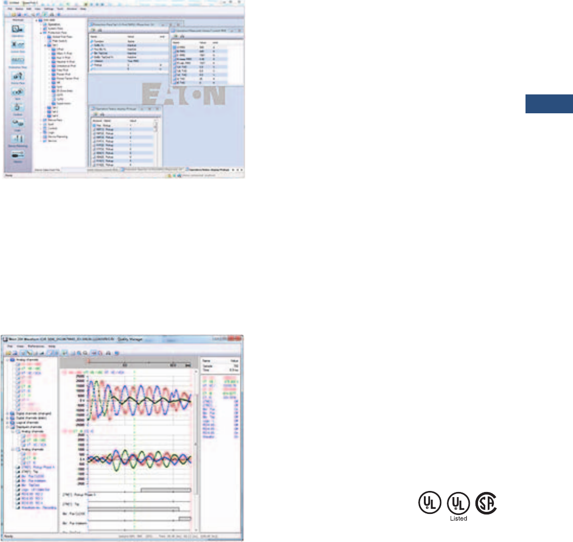
Volume 3—Power Distribution and Control Assemblies CA08100004E—March 2016 www.eaton.com V3-T9-271
9
9
9
9
9
9
9
9
9
9
9
9
9
9
9
9
9
9
9
9
9
9
9
9
9
9
9
9
9
9
9.3
Metering Devices, Protective Relays, Software and Connectivity
Protective Relays
PowerPort-E
PowerPort-E is the software
program used to configure
off-line protection setting files
for all E-Series relay models.
PowerPort-E is also used for
viewing measured values of
the relays in real-time,
uploading/downloading
setting files, and retrieving
event log and waveform
records.
Waveform Capture (Quality Manager)
The EGR-5000 relay provides
oscillographic recording
capabilities. The relay will
record all measured signals
along with the binary signals
of pickup, trip, internal logic,
and contact inputs. The EGR-
5000 can record up to 7200
cycles of data. The number of
records is proportional to the
programmed size of each
record; the maximum size per
record is 600 cycles.
The waveform capture is
initiated by up to 8 different
triggers (i.e., trip/alarm events)
or manually via communications
or the HMI. PowerPort-E setting
software is used to retrieve the
records. Quality Manager is a
separate
software program
downloaded
with PowerPort-E
used for analyzing the
waveform and trending files
retrieved from the relay.
Integral User Interface
The front panel user interface
has a 128 x 64 pixel LCD
display with background
illumination for wide angle
viewing in all light conditions.
17 programmable LEDs
provide quick and easy visual
display of power on, mode of
operation, alarm and trip
indication. Soft keys are
provided for operation mode
selection, scrolling through
data and settings. In addition,
the relay settings and test
functions are password
protected.
Load Profiling/Trending
The EGR-5000 relay
automatically records
selected quantities into non-
volatile memory every 5, 10,
15, 30 or 60 minutes,
depending on the trending
report setting.
Programmable I/O
The EGR-5000 generator
protection relay provides
heavy-duty, triprated, 2NO
and 6 Form C contacts. Two
isolated inputs can be used
for monitoring the trip circuit.
One Form C contact is
dedicated to the relay failure
alarm function and is
operated in a normally
energized (failsafe) mode.
There are up to 16 user-
configurable discrete inputs
that accept a wet contact and
can operate through a wide
range of power. Each input
and output is user-
programmable for maximum
application flexibility.
The EGR-5000 also offers
two optional analog inputs
and two optional analog
outputs. The analog inputs
are available for providing
protection and monitoring of
generator bearing vibration.
The analog inputs are field
programmable to measure
transducer signals that
operate over a range of 0 to
20 mA, 4 to 20 mA, or 1 to
10 V. The two optional analog
outputs can be used for
signaling the value of
measured analog quantities
to external process control
devices such as PLCs.
They can be programmed to
operate over a 0 to 20 mA,
4–20 mA, or 1 to 10 V range.
The analog outputs can be
configured to signal a
representation of most
analog quantities measured
by the EGR-5000 including,
current, voltages, and RTD
temperature.
Programmable Logic
The EGR-5000 generator
protection relay provides logic
gates and timers that the
user can customize for
special or unique applications.
Each gate can be assigned a
logic function of either AND,
OR, NAND or NOR. Each
gate can have a maximum of
four input signals and each
input signal can be required
to be a NOT. Input signals can
be external inputs received
via the binary inputs or
internal values associated
with the protection, alarm or
metering set points. Each
gate has a unique output
assignment and designation
that can be used as the input
to another gate. There are 24
independent timers that have
adjustable pickup and dropout
delay settings.
Standards and Certifications
Approvals
●UL listed file: E217753
Design Standards
●Generic Standard:
●EN 61000-6-2
●EN 61000-6-3
●Product Standard:
●IEC 60255-6
●EN 50178
●UL 508 (Industrial
Control Equipment)
●CSA C22.2 No. 14-95
(Industrial Control
Equipment)
●ANSI C37.90
V3-T9-272 Volume 3—Power Distribution and Control Assemblies CA08100004E—March 2016 www.eaton.com
9
9
9
9
9
9
9
9
9
9
9
9
9
9
9
9
9
9
9
9
9
9
9
9
9
9
9
9
9
9
9.3
Metering Devices, Protective Relays, Software and Connectivity
Protective Relays
Catalog Number Selection
The catalog number
identification chart defines
the electrical characteristics
and operation features
included in the EGR-5000. For
example, if the catalog
number
is EGR-5000A0BA1,
the device would have
the following:
EGR-5000
(A)–16 DI, 9 Outputs,
Removable Terminals, Zone
Interlocking, URTD Interface
(0)–5 A / 1 A Phase and
Ground CTs, Power Supply
Range: 19–300 Vdc, 40–250
Vac
(B)–Modbus-RTU (RS-485)
(A)–Without conformal
coating
(1)–Projection panel mount
EGR-5000 Eaton Motor Relay
Accessories
Standard Accessories EGR-5000
Notes
1Beginning in 2016, consult factory for the availability of the following new communication options.
• Protocols: DNP3.0, Profibus
• Interface ports: Fiber optic ST, RS-485 D-SUB, Fiber optic LC
2See URTD section for fiber optic cables required to communicate to the EGR-5000.
Description
Catalog
Number
UNVL RTD Mod with Modbus-RTU 48–240 Vac/48–250 Vdc URTDII-01 2
UNVL RTD Mod with Modbus-RTU 24–48 Vdc URTDII-02 2
E-Series RS-232 Null Modem Cable 66B2214G01
E-Series USB to RS-232 Converter 66B2214G02
E-Series RS-232 Cable and USB to RS-232 Converter 66B2214G03
Hardware Option 1
A = 16 DI, 9 outputs, removable terminals,
zone interlocking, URTD interface
B = 8 DI, 9 outputs, 2AI, 2AO, removable
terminals, zone interlocking, URTD
interface
Communication Options 1
B= Modbus-RTU (RS-485)
I= Modbus-RTU (RS-485) and
Modbus-TCP (RJ-45) [only 1
active, software selected]
H= IEC 61850 GOOSE and
MMS (RJ-45)
Conformal Coating
Options
A = None
B = Conformal coated
circuit boards
Mounting Options
0 = Standard mount
1 = Projection panel mount
Hardware Option 2
0 = Phase current 5 A / 1 A, ground
current 5 A / 1 A, power supply
range: 19–300 Vdc, 40–250 Vac
1 = Phase current 5 A / 1 A sensitive
ground current, 0.5 A / 0.1 A,
power supply range: 19–300 Vdc,
40–250 Vac
EGR5000 A 0 B A 1

Volume 3—Power Distribution and Control Assemblies CA08100004E—March 2016 www.eaton.com V3-T9-273
9
9
9
9
9
9
9
9
9
9
9
9
9
9
9
9
9
9
9
9
9
9
9
9
9
9
9
9
9
9
9.3
Metering Devices, Protective Relays, Software and Connectivity
Protective Relays
Technical Data and Specifications
Climatic Environmental
Conditions
●Storage temperature:
–30 °C to +70 °C (–22 °F to
+158 °F)
●Operating temperature:
–20 °C to +60 °C (–4 °F to
+140 °F)
●Permissible humidity at
ann. average: <75% rel.
(on 56d up to 95% rel.)
●Permissible installation
altitude:
●<2,000 m (6,561.67 ft)
above sea level
●If 4,000 m (13,123.35 ft)
altitude applies, a
changed classification of
the operating and test
voltages may be
necessary
Degree of Protection EN 60529
●HMI front panel with seal:
IP54
●Rear side terminals: IP20
Routine Test
●Insulation test acc. to
IEC 60255-5: All tests to be
carried out against ground
and other input and output
circuits
●Aux. voltage supply, digital
inputs, current
●Measuring inputs, signal
relay outputs:
– 2.5 kV (eff.) / 50 Hz
●Voltage measuring inputs:
3.0 kV (eff.) / 50 Hz
●All wire-bound
communication interfaces:
1. 5 k V D C
●Insulation test acc to
IEC60255-5: All tests to be
carried out against ground
and other input and output
circuits
Housing
●Housing B2: height / width
183 mm (7.205 in) / 212.7
mm (8.374 in)
●Housing depth (incl.
terminals):
208 mm (8.189 in)
●Material, housing:
aluminum extruded section
●Material, front panel:
aluminum/foil front
●Mounting position:
horizontal (±45° around the
X-axis must be permitted)
●Weight: Approx. 4.2 kg
(9.259 lb)
Current and Ground Current
Measurement
●Nominal currents: 1 A / 5 A
●Max. measuring range:
●Up to 40 x In (phase
currents)
●Up to 25 x In (ground
current standard)
●Up to 2.5 x In (ground
current sensitive)
●Continuous loading
capacity: 4 x In /
continuously
●Overcurrent proof:
●30 x In / 10 s
●100 x In / 1 s
●250 x In / 10 ms
(1 half-wave)
●Power consumption:
●Phase current inputs
– At In = 1 A S = 0.15
MVA
– At In = 5 A S = 0.15
MVA
●Ground current input
– At In = 1 A S = 0.35
MVA
– At In = 5 A S = 0.35
MVA
●Frequency range: 50 Hz /
60 Hz ±10%
●Terminals: screw-type
terminals with integrated
short-circuiters (contacts)
●Connection cross sections:
●1 x or 2 x 2.5 mm² (2 x
AWG 14) with wire end
ferrule
●1 x or 2 x 4.0 mm² (2 x
AWG 12) with ring cable
sleeve or cable sleeve
●1 x or 2 x 6 mm² (2 x
AWG 10) with ring cable
sleeve or cable sleeve
●The current measuring
board´s terminal blocks
may be used as with 2
(double) conductors
AWG 10,12,14
otherwise with single
conductors only
Plug-in Connector with
Integrated Short-Circuiter
(Conventional Current Inputs)
●Nominal Current:
1 A and 5 A
●Continuous loading
capacity: 4 x In /
continuously
●Overcurrent withstand:
●30 x In / 10 s
●100 x In / 1 s
●250 x In / 10 ms
(1 half-wave)
●Screws: M4, captive type
acc. to VDEW
●Connection cross sections:
●1 x or 2 x 2.5 mm² (2 x
AWG 14) with wire end
ferrule
●1 x or 2 x 4.0 mm² (2 x
AWG 12) with ring cable
sleeve or cable sleeve
●1 x or 2 x 6 mm² (2 x
AWG 10) with ring cable
sleeve or cable sleeve
●The current measuring
board´s terminal blocks
may be used as with 2
(double) conductors
AWG 10,12,14
otherwise with single
conductors only
Voltage and Residual Voltage
Measurement
●Nominal voltages: 100 V /
110 V / 230 V / 400 V
(can be configured)
●Max. measuring range: 2 x
nominal voltage
●Continuous loading
capacity: 2 x nominal
voltage (800 Vac)
●Power consumption:
●at Vn = 100 V S = 0.1
MVA
●at Vn = 110 V S = 0.1
MVA
●at Vn = 230 V S = 0.4
MVA
●at Vn = 400 V S = 1.0
MVA
●Frequency range:
50 Hz or 60 Hz ±10%
●Terminals: screw-type
terminals
Frequency Measurement
●Nominal frequencies:
50 Hz / 60 Hz
Voltage Supply
●Aux. voltage: 24–270 Vdc /
48–230 Vac (–20/+10%)
●Buffer time in case of
supply failure:
●≥50 ms at minimal aux.
voltage
●Interrupted
communication is
permitted
●Max. permissible making
current:
●18 A peak value for
<0.25 ms
●12 A peak value for
<1 ms
●The voltage supply must
be protected by a fuse of:
●2.5 A time-lag miniature
fuse 5 x 20 mm (approx.
0.2 x 0.8 in) according to
IEC 60127
●3.5 A time-lag miniature
fuse 6.3 x 32 mm
(approx. 0.25 x 1.25 in)
according to UL 248-14

V3-T9-274 Volume 3—Power Distribution and Control Assemblies CA08100004E—March 2016 www.eaton.com
9
9
9
9
9
9
9
9
9
9
9
9
9
9
9
9
9
9
9
9
9
9
9
9
9
9
9
9
9
9
9.3
Metering Devices, Protective Relays, Software and Connectivity
Protective Relays
Power Consumption
●Power supply range:
24–270 Vdc
●Power consumption
in idle mode—7 W
●Maximum power
consumption—13 W
●Power supply range:
48–230 Vac (for
frequencies of 40–70 Hz)
●Power consumption
in idle mode—7 VA
●Maximum power
consumption—13 VA
Display
●Display type: LCD with
LED background
illumination
●Resolution—graphics
display: 128 x 64 pixel
LED
●LED type: two colored:
red/green
●Number of LEDs, Housing
B2: 15
Front Interface RS-232
●Baud rates: 115,200 baud
●Handshake: RTS and CTS
●Connection: 9-pole D-Sub
plug
Real Time Clock
●Running reserve of the real
time clock: 1 year min.
Digital Inputs
●Max. input voltage:
300 Vdc / 259 Vac
●Input current: <4 mA
●Reaction time: <20 ms
●Fallback time: <30 ms
(Safe state of the
digital inputs)
●Switching thresholds:
Un = 24 Vdc, 48 Vdc,
60 Vdc, 110 Vac / Vdc,
230 Vac / Vdc
●Un = 24 Vdc
– Switching threshold
1 ON: Min. 19.2 Vd
– Switching threshold
1 OFF: Max. 9.6 Vdc
●Un = 48 V / 60 Vdc
– Switching threshold
2 ON: Min. 42.6 Vdc
– Switching threshold
2 OFF: Max. 21.3 Vdc
●Un = 110 / 120 Vac / Vdc
– Switching threshold
3 ON: Min. 88.0 Vdc /
88.0 Vac
– Switching threshold
3 OFF: Max. 44.0 Vdc
/ 44.0 Vac
●Un = 230 / 240 Vac / Vdc
– Switching threshold
4 ON: Min. 184 Vdc /
184 Vac
– Switching threshold
4 OFF: Max. 92 Vdc /
92 Vac
●Terminals: screw-type
terminal
Relay Outputs
●Continuous current:
5 A AC/DC
●Max. make current:
●25 A AC / 25 A DC up to
30 V for 4 s
●30 A / 230 Vac according
to ANSI IEEE Std
C37.90-2005
●30 A / 250 Vdc according
to ANSI IEEE Std
C37.90-2005
●Max. breaking current:
●5 A AC up to 250 Vac
●5 A DC up to 30 V
(resistive)
●0.3 A DC at 300 V
●Max. switching voltage:
250 Vac / 250 Vdc
●Switching capacity:
1250 VA
●Contact type: Form C or
normally open contact
●Terminals: screw-type
terminals
Supervision Contact (SC)
●Continuous current:
5 A AC/DC
●Max. switch-on current:
15 A AC / 15 A DC up to
30 V for 4 s
●Max. breaking current:
●5 A AC up to 250 Vac
●5 A DC up to 30 Vdc
●0.4 A at 125 Vdc
●Contact type: 1 Form C
contact
●Terminals: screw-type
terminals
Time Synchronization IRIG-B00X
●Nominal input voltage: 5 V
●Connection: screw-type
terminals (twisted pair)
Zone interlocking
Note: Only for zone interlock
tripping outputs (zone interlock,
semiconductor output):
5 Vdc, <2 mA for connection to
electronic inputs only.
●Zone Out:
●Output voltage (high)
4.75 to 5.25 Vdc
●Output voltage (low) 0.0
to +0.5 Vdc
●Zone In:
●Nominal input voltage
+5 Vdc
●Max. input voltage +5.5
Vdc
●Switching threshold ON
min. 4.0 Vdc
●Switching threshold OFF
max. 1.5 Vdc
●Galvanic isolation 2.5 kV
AC (to ground and other
IO)
●Connection: screw-type
terminals (twisted pair)
RS-485
●Master/slave: slave
●Connection: six screw-
clamping terminals RM 3.5
mm (138 MIL) (terminating
resistors internal)
Note: The RS-485 interface is
realized via terminals. The
communication cable has to be
shielded. The shielding has to be
fixed at the screw that is marked
with the ground symbol (rear side
of the device).
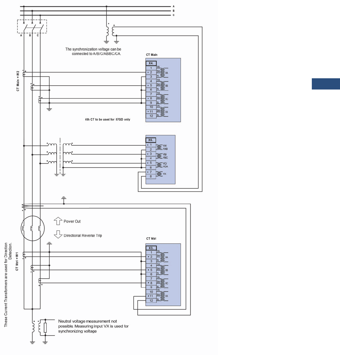
Volume 3—Power Distribution and Control Assemblies CA08100004E—March 2016 www.eaton.com V3-T9-275
9
9
9
9
9
9
9
9
9
9
9
9
9
9
9
9
9
9
9
9
9
9
9
9
9
9
9
9
9
9
9.3
Metering Devices, Protective Relays, Software and Connectivity
Protective Relays
Wiring Diagrams
Typical AC Connections—High Impedance Grounded Generator with Phase Differential Protection, Wye VTs, Zero Sequence
Ground Protection, and Either Synch-check or 100% Stator Ground Fault Protection
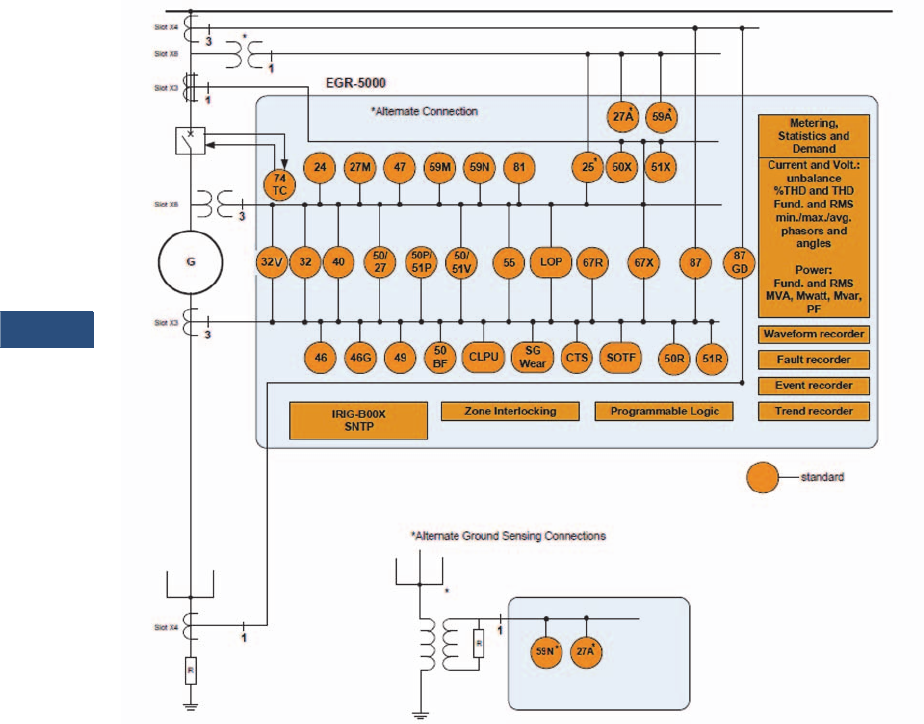
V3-T9-276 Volume 3—Power Distribution and Control Assemblies CA08100004E—March 2016 www.eaton.com
9
9
9
9
9
9
9
9
9
9
9
9
9
9
9
9
9
9
9
9
9
9
9
9
9
9
9
9
9
9
9.3
Metering Devices, Protective Relays, Software and Connectivity
Protective Relays
Typical One-Line Diagram
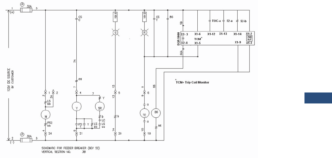
Volume 3—Power Distribution and Control Assemblies CA08100004E—March 2016 www.eaton.com V3-T9-277
9
9
9
9
9
9
9
9
9
9
9
9
9
9
9
9
9
9
9
9
9
9
9
9
9
9
9
9
9
9
9.3
Metering Devices, Protective Relays, Software and Connectivity
Protective Relays
Ty p i c a l C o n t r o l D i a g r a m
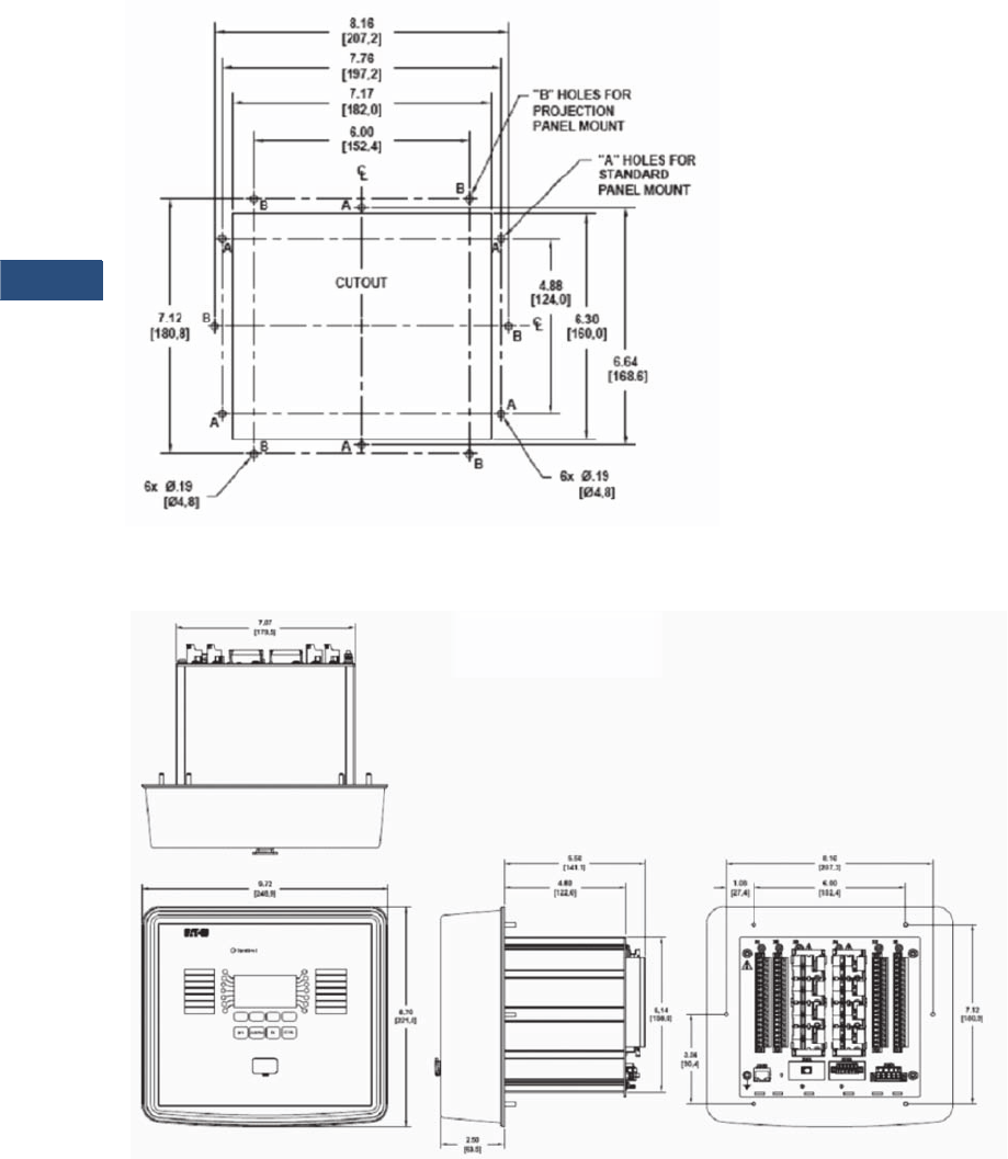
V3-T9-278 Volume 3—Power Distribution and Control Assemblies CA08100004E—March 2016 www.eaton.com
9
9
9
9
9
9
9
9
9
9
9
9
9
9
9
9
9
9
9
9
9
9
9
9
9
9
9
9
9
9
9.3
Metering Devices, Protective Relays, Software and Connectivity
Protective Relays
Dimensions
Approximate Dimensions in Inches (mm)
Drilling Plan
Projection Mount Front and Side Views
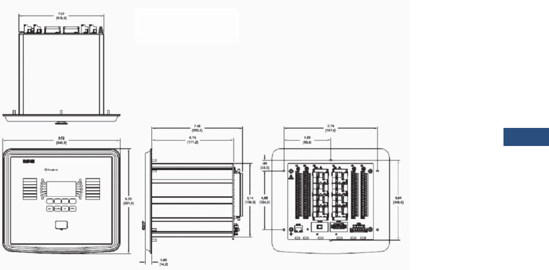
Volume 3—Power Distribution and Control Assemblies CA08100004E—March 2016 www.eaton.com V3-T9-279
9
9
9
9
9
9
9
9
9
9
9
9
9
9
9
9
9
9
9
9
9
9
9
9
9
9
9
9
9
9
9.3
Metering Devices, Protective Relays, Software and Connectivity
Protective Relays
Approximate Dimensions in Inches (mm)
Standard Mount Front and Side Views
V3-T9-280 Volume 3—Power Distribution and Control Assemblies CA08100004E—March 2016 www.eaton.com
9
9
9
9
9
9
9
9
9
9
9
9
9
9
9
9
9
9
9
9
9
9
9
9
9
9
9
9
9
9
9.3
Metering Devices, Protective Relays, Software and Connectivity
Protective Relays
Ground Fault Relay
Contents
Description Page
Product Selection Guide . . . . . . . . . . . . . . . . . . . . V3-T9-143
Digitrip 3000 . . . . . . . . . . . . . . . . . . . . . . . . . . . . . V3-T9-149
EDR-3000 Feeder Protection . . . . . . . . . . . . . . . . V3-T9-159
EDR-5000 Distribution Protection Relay . . . . . . . . V3-T9-168
FP-5000 Feeder Protection . . . . . . . . . . . . . . . . . . V3-T9-181
MP-3000 Motor Protection . . . . . . . . . . . . . . . . . . V3-T9-189
MP-4000 Motor Protection . . . . . . . . . . . . . . . . . . V3-T9-199
EMR-3000 Motor Protection Relay . . . . . . . . . . . . V3-T9-205
EMR-4000 Motor Protection Relay . . . . . . . . . . . . V3-T9-217
EMR-5000 Motor Protection Relay . . . . . . . . . . . . V3-T9-230
ETR-4000 Transformer Protection Relay . . . . . . . . V3-T9-242
ETR-5000 Transformer Protection Relay . . . . . . . . V3-T9-254
EGR-5000 Generation Protection Relay . . . . . . . . V3-T9-267
Ground Fault Relay
Universal RTD Module . . . . . . . . . . . . . . . . . . . . . V3-T9-283
Ground Fault Relay
Product Description
A Type GFR ground fault
protection system, when
properly installed on a
grounded electrical system,
will sense phase-to-ground
fault currents. When the level
of fault current is in excess
of the pre-selected current
pickup and time delay
settings, the GFR relay will
initiate a trip action of a
disconnect device, which will
open the faulted circuit and
clear the fault.
The GFR devices are UL
Class 1 devices designed to
protect electrical equipment
against extensive damage
from arcing ground faults.
A basic Type GFR ground
fault protection system
consists of a ground fault
relay, a ground fault current
sensor and a disconnect
device equipped with a shunt
trip device. This disconnect
device can be a molded case
circuit breaker, a power
circuit breaker, a bolted
pressure switch or other
fusible disconnect device,
suitable for application with
UL Class 1 Ground Fault
Sensing and Relaying
equipment.
Standards and Certifications
Eaton’s GFR ground fault
relays, current sensors, test
panels and accessory devices
are UL listed by Underwriters
Laboratories in accordance
with their standard for
Ground Fault Sensing and
Relaying Equipment, UL 1053,
under File No. E48381.
Note: Relays are also listed with
CSA under File No. 43357.

Volume 3—Power Distribution and Control Assemblies CA08100004E—March 2016 www.eaton.com V3-T9-281
9
9
9
9
9
9
9
9
9
9
9
9
9
9
9
9
9
9
9
9
9
9
9
9
9
9
9
9
9
9
9.3
Metering Devices, Protective Relays, Software and Connectivity
Protective Relays
Product Selection
Each installation requires:
●One relay unit (select trip
ampere as required)
●One current sensor (select
configuration required)
●One circuit breaker or
disconnect device with
shunt trip, or a shunt trip
attachment for mounting
in existing breaker
●Test panel (optional)
GFR Relay
Current Sensor
Note
1 Suitable for either surface or semi-flush mounting.
Ground Fault Pickup Amperes
1–12 5–60 100–1200
GFR Relay
Types
Catalog
Number 1
Catalog
Number 1
Catalog
Number 1
For 120 Volt 50/60 Hz Control
Electrical reset with zone interlocking GFR12EI GFR60EI GFR1200EI
Electrical reset without zone interlocking GFR12E GFR60E GFR1200E
Mechanical reset with zone interlocking GFR12MI GFR60MI GFR1200MI
Mechanical reset without zone interlocking GFR12M GFR60M GFR1200M
For 120 Vdc Control
Mechanical reset without zone interlocking — — GFR1200MD
Description—Window Size in Inches (mm)
Catalog
Number
Used with Relays Rated 1–12 Amperes
5.50 (139.7) inside diameter 1283C45G01
Used with Relays Rated 5–60 Amperes
2.50 (63.5) inside diameter 179C768G01
5.50 (139.7) inside diameter 1256C13G01
7.81 x 11.00 (198.4 x 279.4) rectangular 11257C88G04
3.31 x 24.94 (84.1 x 760.5) rectangular 11257C92G03
Used with Relays Rated 100–1200 Amperes
2.50 (63.5) inside diameter 179C768G02
5.50 (139.7) inside diameter 1256C13G02
8.25 (209.6) inside diameter 179C767G02
7.81 x 11.00 (198.4 x 279.4) rectangular 11257C88G03
9.94 x 16.94 (252.5 x 430.3) rectangular 11257C90G02
9.94 x 23.94 (252.5 x 608.1) rectangular 11257C91G02
15.94 x 19.94 (404.9 x 506.4) rectangular 11257C89G02
3.31 x 24.94 (84.1 x 633.5) rectangular 11257C92G04
6.75 x 29.64 (171.5 x 752.9) rectangular 11255C39G03
GFR Relay

V3-T9-282 Volume 3—Power Distribution and Control Assemblies CA08100004E—March 2016 www.eaton.com
9
9
9
9
9
9
9
9
9
9
9
9
9
9
9
9
9
9
9
9
9
9
9
9
9
9
9
9
9
9
9.3
Metering Devices, Protective Relays, Software and Connectivity
Protective Relays
Options and Accessories
Test Panel (120 Vac)
Used to test the ground fault
system, to give an indication
the relay has tripped the
breaker, and to reset the relay
after tripping. These functions
may be separately mounted
pilot devices.
Note: When a mechanically reset
relay is used with a test panel,
both the relay and test panel
must be reset following either a
simulated ground fault test or
actual ground fault. Not UL listed.
Ground Fault Warning Indicator
This is an accessory item for
use with GFR relays with
interlocking circuitry. At
approximately 30–50% of
the relay pickup setting, the
indicator switches separate
120 Vac control power to a
lamp or relay (not included) to
give an indication of a ground
fault. The indicator is rated
110/120 Vac 50/60 Hz for a
maximum indicator load of
0.5 amperes.
Indicating Ammeter
The optional indicating
ammeter connects to the
sensor terminals through
a momentary contact
pushbutton, and will indicate
(in amperes) any ground fault
current flowing through the
sensor. Kit includes the
ammeter and pushbutton.
Not UL listed.
Shunt Trip Attachments
Use 120 Vac shunt trips.
Face Plate
Recommended when
these relays are semi-flush
mounted, to close the door
cutout opening.
Options
Additional optional equipment
can be added to the protection
system to meet the
requirements of the specifying
engineer, including:
●Ground fault test panel
●Ground fault warning
indicator relay
●Ground fault indicating
ammeter
GFR relays are available with
zone selective interlocking
circuitry to interlock several
relays within the same system.
This allows the relay,
which detects a ground
fault, to instantly clear
the fault by tripping the
disconnect device. The relay
simultaneously sends a signal
to relay units “upstream” from
the fault to time delay or
to block their operation
completely. Current sensors
in various designs provide a
range of “window” sizes to
accommodate standard bus
and cable arrangements.
Shunt trip attachments may be
ordered for field mounting in
Eaton’s molded case circuit
breakers, or may be ordered
factory installed in the breaker.
Optional Test Panel
Ground Fault Warning Indicator
Ammeter Kit
Face Plate
Technical Data and Specifications
GFR Relay
●Ground fault detection ranges:
●1–12 amperes
●5–60 amperes
●100–1200 amperes
●Output contacts:
●240 Vac, 50/60 Hz: 3 amperes
●120 Vac, 50/60 Hz: 6 amperes
●28 Vdc: 3 amperes
●125 Vdc: 0.5 amperes
●Control power requirements:
●
120 V, 50/60 Hz: 0.125 amperes, or
125 Vdc (optional)
Current Sensor
●600 V, 50/60 Hz maximum system voltage
Note
1One end removable for installation.
Instruction Leaflet 15321 available as a PDF at www.eaton.com
(Go to Advanced Search and enter 15321).
Control Test
Catalog
Number
120 volt 50/60 Hz 120 volt 50/60 Hz GFRTP
Description
Catalog
Number
Manual reset 1234C67G01
Self-resetting 1234C67G02
GFR System
Used with
Kit Catalog
Number
1–12 amperes 752B820G01
5–60 amperes 752B820G02
100–1200 amperes 752B820G03
Description
Catalog
Number
Face plate 752B410G01

Volume 3—Power Distribution and Control Assemblies CA08100004E—March 2016 www.eaton.com V3-T9-283
9
9
9
9
9
9
9
9
9
9
9
9
9
9
9
9
9
9
9
9
9
9
9
9
9
9
9
9
9
9
9.3
Metering Devices, Protective Relays, Software and Connectivity
Protective Relays
Universal RTD Module
Contents
Description Page
Product Selection Guide . . . . . . . . . . . . . . . . . . . . V3-T9-143
Digitrip 3000 . . . . . . . . . . . . . . . . . . . . . . . . . . . . . V3-T9-149
EDR-3000 Feeder Protection. . . . . . . . . . . . . . . . . V3-T9-159
EDR-5000 Distribution Protection Relay . . . . . . . . V3-T9-168
FP-5000 Feeder Protection . . . . . . . . . . . . . . . . . . V3-T9-181
MP-3000 Motor Protection . . . . . . . . . . . . . . . . . . V3-T9-189
MP-4000 Motor Protection . . . . . . . . . . . . . . . . . . V3-T9-199
EMR-3000 Motor Protection Relay . . . . . . . . . . . . V3-T9-205
EMR-4000 Motor Protection Relay . . . . . . . . . . . . V3-T9-217
EMR-5000 Motor Protection Relay . . . . . . . . . . . . V3-T9-230
ETR-4000 Transformer Protection Relay . . . . . . . . V3-T9-242
ETR-5000 Transformer Protection Relay . . . . . . . . V3-T9-254
EGR-5000 Generation Protection Relay. . . . . . . . . V3-T9-267
Ground Fault Relay . . . . . . . . . . . . . . . . . . . . . . . . V3-T9-280
Universal RTD Module
Universal RTD Module
Product Description
●Electronic Resistance
Temperature Detector
(RTD) provides motor
temperature interface
for the MP-3000 Motor
Protection Relay
●Monitors up to 11 RTDs
consisting of six motor
windings, two motor
bearings, two load
bearings and one auxiliary
●Works with 10 ohm copper,
100 ohm
platinum, 100 ohm
nickel and 120 ohm
nickel
type RTDs
●Include fiber optic and
electrical communication
interfaces to the MP-3000
Motor Protection Relay
Application Description
URTD can be used with MP-
3000, MP-4000, EMR-3000,
EMR-4000, EMR-5000, ETR-
4000, ETR-5000, and EGR-
5000.
Eaton’s URTD Module is
most commonly used to
provide motor temperature
information to the MP-3000
Motor Protection Relay. The
MP-3000 Motor Protection
uses this information for
monitoring, tripping and
alarming. The MP-3000 Intel-
I-Trip overload algorithm will
adjust its trip characteristics
based on the actual motor
temperature reported by the
URTD Module. This improves
the protection by using an
actual temperature value
instead of the assumed
NEMA Standard Ambient
Temperature.
The URTD Module may be
mounted close to the motor
or at the protective relay.
Both electrical and fiber optic
interface ports are provided
to communicate temperature
information to the MP-3000
relay. The electrical interface
can transmit information
using a three-conductor
shielded cable with a
maximum cable distance of
500 feet (152 m). The fiber
optic link has a maximum
distance of 400 feet (122 m).
The URTD Module may be
used with the IQ-1000 and
IQ-1000 II motor relays. It
may also be applied as a
standalone temperature
monitoring device
communicating, for example,
transformer temperature
information back to a remote
computer or PLC. An optional
PONI (Product Operated
Network Interface) is required
for standalone applications.
Features, Benefits
and Functions
●Universal design works
with any RTD type,
simplifying installation and
operation and reducing
inventory
●Standalone design permits
mounting the module close
to the motor, reducing RTD
wiring costs
●RTD diagnostics detects
faulty RTDs and wiring,
reducing unnecessary
tripping and alarming

V3-T9-284 Volume 3—Power Distribution and Control Assemblies CA08100004E—March 2016 www.eaton.com
9
9
9
9
9
9
9
9
9
9
9
9
9
9
9
9
9
9
9
9
9
9
9
9
9
9
9
9
9
9
9.3
Metering Devices, Protective Relays, Software and Connectivity
Protective Relays
Product Selection
Universal RTD Module
Description
Catalog
Number
Universal RTD Module URTD
48-240 Vac/48-250 Vdc power supply and
Modbus-RTU communications
URTDII-01
24-48 Vdc and Modbus-RTU communications URRDII-02
Universal RTD Module
Options and Accessories
Additional Related Products
from Eaton’s Cutler-Hammer
Series
Eaton provides fiber optic
cables for connecting to the
MP-3000 or IQ-1000 II Motor
Protection Relays.
Fiber Optic Cables:
Technical Data and Specifications
Universal RTD Module
Length
Catalog
Number
1MPF0-1
5MPF0-5
10 MPF0-10
25 MPF0-25
50 MPF0-50
75 MPF0-75
100 MPF0-100
Specifications URTDII-01 URTDII-02
Input power requirements 48–240 Vac / 48–250 Vdc 24–48 Vdc
Frequency 50/60 Hz or DC DC
Power consumption 3.5 W 1 W
Operating temperature –20° to +55 °C (–4° to +131 °F) –20° to +55 °C (–4° to +131 °F)
Storage temperature –40° to +85 °C (–40° to +185° F) –40° to +85 °C (–40° to +185 °F)
Humidity 0 to 95% R.H. noncondensing 0 to 95% R.H. noncondensing
Altitude 2000 m 2000 m
Pollution degree 2 2
Installation category I I
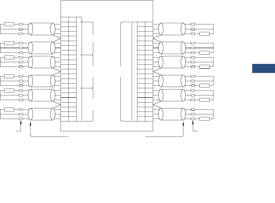
Volume 3—Power Distribution and Control Assemblies CA08100004E—March 2016 www.eaton.com V3-T9-285
9
9
9
9
9
9
9
9
9
9
9
9
9
9
9
9
9
9
9
9
9
9
9
9
9
9
9
9
9
9
9.3
Metering Devices, Protective Relays, Software and Connectivity
Protective Relays
Wiring Diagram
RTD Wiring (Three-Lead Type)
Note
Showing a typical three-lead type RTD wiring connection.
1-
2+
3C
4S
5-
6+
7C
8-
9+
10 C
11 S
12 -
13 +
14 C
15 -
16 +
17 C
18 S
19 -
20 +
21 C
21
20
19
18
17
16
15
14
13
12
11
10
9
8
7
6
5
4
3
2
1
C
+
-
S
C
+
-
C
+
-
S
C
+
-
C
+
-
S
C
+
-
J10B
J2
Auxiliary
Load
Bearings
Motor
Bearings
Motor
Windings
RTD
RTD
RTD
RTD
RTD
RTD
RTD
RTD
RTD
RTD
RTD
RTD
Universal
RTD Module II
Wire
Shield/Drain
Terminals
Motor
USE TAPE TO INSULATE
DO NOT CONNECT CABLE'S SHIELD WIRE AT THIS END!
Terminals
Motor
Wire
Shield/Drain
Wire
Shield/Drain
Wire
Shield/Drain
Wire
Shield/Drain
Wire
Shield/Drain
NC
ote:N
1. Each shielded cable conductor must be connected on the URTDII as shown.
2. Use of three-lead RTDs is recommended.
3. RTDs must not be grounded at the motor, and no common connections between RTDs
should be made at the motor.
4. A suitable earth ground should be connected to J10B-4, J10B-11, J-10B-18, J2-4, J2-11, or
J2-18. It is recommended that a ground connection is made to both sides of the unit.
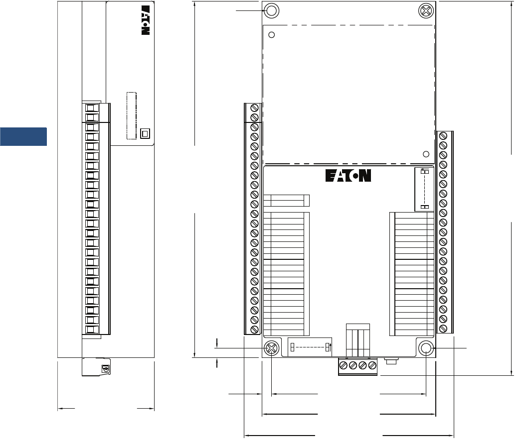
V3-T9-286 Volume 3—Power Distribution and Control Assemblies CA08100004E—March 2016 www.eaton.com
9
9
9
9
9
9
9
9
9
9
9
9
9
9
9
9
9
9
9
9
9
9
9
9
9
9
9
9
9
9
9.3
Metering Devices, Protective Relays, Software and Connectivity
Protective Relays
Dimensions
Approximate Dimensions in Inches (mm)
Universal URTD Module
Note
Showing the URTD Module dimensions and terminal designations.
J2
J10B
RTD7C/MB1C21
RTD7+/MB1+20
RTD7-/MB1-19
Shield18
RTD8C/MB2C17
RTD8+/MB2+16
RTD8-/MB2-15
RTD9C/LB1C14
RTD9+/LB1+13
RTD9-/LB1-12
Shield11
RTD10C/LB2C10
RTD10+/LB2+9
RTD10-/LB2-8
RTD11C/AUX1C7
RTD11+/AUX1+6
RTD11-/AUX1-5
Shield4
RTD12C/AUX2C3
RTD12+/AUX2+
RTD12-/AUX2-
2
1
PWR IN 2
PWR IN 1
2
1
1
2
3
4
5
6
7
8
9
10
11
12
13
14
15
16
17
18
19
20
21
RS-485
MODBUS
FIBER
OPTIC
S2
S1
UNIVERSAL RTD MODULE
URTD-II
B
A
COM
Shield
1234
J11
0N
112
0N
18
J10A
RTD6C/MW6C
RTD6+/MW6+
RTD6-/MW6-
Shield
RTD5C/MW5C
RTD5+/MW5+
RTD5-/MW5-
RTD4C/MW4/C
RTD4+/MW4+
RTD4-/MW4-
Shield
RTD3C/MW3C
RTD3+/MW3+
RTD3-/MW3-
RTD2C/MW2C
RTD2+/MW2+
RTD2-/MW2-
Shield
RTD1C/MW1C
RTD1+/MW1+
RTD1-/MW1-
7.40 [187.96]
.20 [5.08]
3.60 [91.44]
3.20 [81.28].20 [5.08]
7.77
[
197.36
]
Style No.:
Cat No.:
H.W.:
Serial No.:
Universal RTD Module II
66D2235GXX
X.XX
XXXX-MMYY
URTDII-XX
XXXXXXXXXXXXXXXXXX
XXXXXXXXXXXXXXXXXX
F.W.: X.XX
4.35 [110.39]
2.00 [50.80]
MTG
MTG
21
20
19
18
17
16
15
14
13
12
11
10
9
8
7
6
5
4
3
2
1
2
1

Volume 3—Power Distribution and Control Assemblies CA08100004E—March 2016 www.eaton.com V3-T9-287
9
9
9
9
9
9
9
9
9
9
9
9
9
9
9
9
9
9
9
9
9
9
9
9
9
9
9
9
9
9
9.4
Metering Devices, Protective Relays, Software and Connectivity
Connectivity Options
Power Xpert Gateway
Contents
Description Page
Power Xpert Gateway
Product Selection Guide. . . . . . . . . . . . . . . . . . V3-T9-289
Product Description . . . . . . . . . . . . . . . . . . . . . V3-T9-288
Standards and Certifications . . . . . . . . . . . . . . V3-T9-291
Product Selection . . . . . . . . . . . . . . . . . . . . . . . V3-T9-291
Technical Data and Specifications . . . . . . . . . . V3-T9-292
Dimensions . . . . . . . . . . . . . . . . . . . . . . . . . . . V3-T9-295
Power Xpert Ethernet Switches . . . . . . . . . . . . . . V3-T9-296
mMINT . . . . . . . . . . . . . . . . . . . . . . . . . . . . . . . . . V3-T9-300
IPONI. . . . . . . . . . . . . . . . . . . . . . . . . . . . . . . . . . . V3-T9-302
DPONI . . . . . . . . . . . . . . . . . . . . . . . . . . . . . . . . . . V3-T9-303
MPONI . . . . . . . . . . . . . . . . . . . . . . . . . . . . . . . . . V3-T9-304
I/O Devices Digital Input Module (DIM) . . . . . . . . V3-T9-305
Addressable Relay II . . . . . . . . . . . . . . . . . . . . . . . V3-T9-307
Breaker Interface Module II (BIM II) . . . . . . . . . . . V3-T9-309
Power Xpert Gateway
Product Overview
●Open communication
architecture
●Connects to both Eaton
and third-party
electrical equipment;
communicates to
INCOM™ and Modbus®
RTU devices
●Modbus TCP and
BACnet/IP support
facilitates integration
with third-party
monitoring solutions
●Ethernet/Web-based
support uses your
existing network
infrastructure,
reducing costs
●Flexible and expandable
solutions
●Stand-alone or small
systems benefit from
comprehensive, on-
board Web pages; no
additional programming
or software is necessary
for virtually out-of-the-
box, plug-and-play
functionality
●Larger systems, such as
campus installations or
power systems with
remote locations can
view multiple PXGs via
Power Xpert Insight™ or
a third-party monitoring
system
●Existing equipment can
be connected to the
PXG to reap the benefits
of Power Xpert
Architecture at minimal
cost, without the need
to upgrade
●Information at a glance
●Using a standard Web
browser, view the PXG’s
Web interfaces that
include a Network tab,
Alarms tab, individual
device detail pop-outs
and One Line graphics tab
●Comprehensive, well-
organized device Web
pages present
measured parameters
such as current, voltage,
power, energy,
frequency, power factor
and voltage THD, just to
name a few
●Combine with Power
Xpert Insight for viewing
multiple gateways and
other power system
equipment for more
extensive energy
monitoring and capacity
analysis
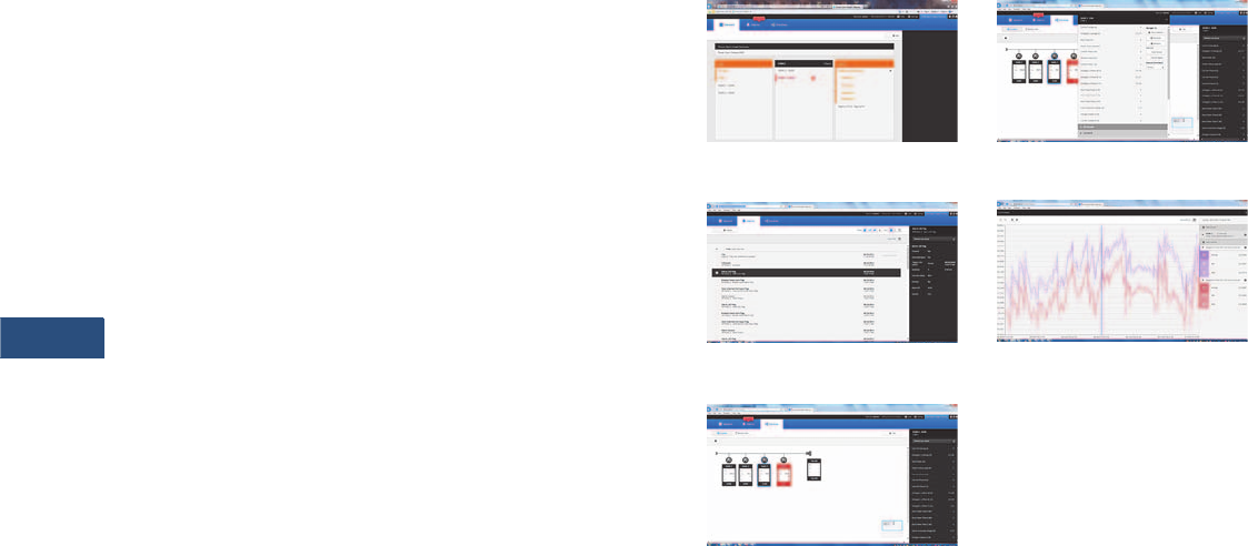
V3-T9-288 Volume 3—Power Distribution and Control Assemblies CA08100004E—March 2016 www.eaton.com
9
9
9
9
9
9
9
9
9
9
9
9
9
9
9
9
9
9
9
9
9
9
9
9
9
9
9
9
9
9
9.4
Metering Devices, Protective Relays, Software and Connectivity
Connectivity Options
Product Description
Through standard on-board
Web pages, Power Xpert
Insight, or third-party
software, Eaton’s Power
Xpert Gateway (PXG) 900
allows you to closely monitor
the performance of your
power and energy efficiency
with easily accessed, real-
time, Web-enabled data.
Eaton’s PXG 900 provides a
central point to connect
devices to an Ethernet
network. The gateway may
be used as a standalone
device to view one system or
location, or it can be easily
integrated into a large, multi-
location system.
The PXG is our configurable
data acquisition solution for
facility equipment like
switchgear, switchboards,
motor control centers, etc.
Power and energy data from
the downstream devices are
time stamped and stored in
non-volatile memory. This
interval data can be stored or
updated to a destination of
the user’s choice through
CSV. Data can also be
accessed through any Web
browser directly on the PXG.
Users can move data into
Power Xpert Insight v. 3.2 or
higher, BMS, BAS, building
dashboards, custom software
applications, or virtually any
Web interface.
Application Description
The Power Xpert® Gateway
900 (PXG 900) has been
designed to be installed in
electrical assemblies or
systems—low and medium
voltage switchgear,
switchboards panelboards,
transfer switches, and motor
control centers to acquire and
consolidate data available
from components such as trip
units, meters, relays, drives
and I/O.
Power Xpert Gateway Screenshots
Network Tab
Alarms Tab
One-Lines Tab
Device Details
Trend Viewer

Volume 3—Power Distribution and Control Assemblies CA08100004E—March 2016 www.eaton.com V3-T9-289
9
9
9
9
9
9
9
9
9
9
9
9
9
9
9
9
9
9
9
9
9
9
9
9
9
9
9
9
9
9
9.4
Metering Devices, Protective Relays, Software and Connectivity
Connectivity Options
Product Selection Guide
Data acquisition and Integration Table for Supported Devices
Supported Devices
Protocol
Family Model
HTTP
(Web
Browser)
Power
Xpert
Insight
Modbus TCP
(BMS and
SCADA)
Pass-through
INCOM
(PowerNet)
SMTP
(Email
Client)
File Export
(CSV File
Format)
File export
(COMTRADE
File Format) BACnet/IP
INCOM
Accessory BIM II ■■■■■■ ■
I/O DIM ■■■■■■ ■
I/O DIM-KYZ ■■■■■■ ■
Meter IQ 220 / IQ 320 ■■■■■■ ■
Meter IQ 230 / IQ 330 ■■■■■■ ■
Meter IQ Analyzer (6000/6200) ■■■■■■ ■
Meter IQ Analyzer (6400/6600) ■■■■■■■■
Meter IQ Data Plus II ■■■■■■ ■
Meter IQ DP-4000 ■■■■■■ ■
Meter IQ Energy Sentinel ■■■■■■ ■
Meter IQ Power Sentinel ■■■■■■ ■
Meter IQMESII ■■■■■■ ■
Meter PM3 ■■■■■■ ■
Protection Digitrip 520MC ■■■■■■ ■
Protection Digitrip 810 ■■■■■■ ■
Protection Digitrip 910 ■■■■■■ ■
Protection Digitrip 1150/DT1150V ■■■■■■■■
Protection Digitrip 3000 ■■■■■■ ■
Protection Digitrip 3200 ■■■■■■ ■
Protection Digitrip MV ■■■■■■ ■
Protection Digitrip OPTIM 550 ■■■■■■ ■
Protection Digitrip OPTIM 750 ■■■■■■ ■
Protection Digitrip OPTIM 1050 ■■■■■■ ■
Protection FP-4000 ■■■■■■■■
Protection FP-5000 ■■■■■■■■
Protection FP-6000 ■■■■■■■■
Protection IQ 500 ■■■■■■ ■
Protection MP-3000 ■■■■■■ ■
Protection MP-4000 ■■■■■■ ■
Protection MPCV Relay ■■■■■■ ■
Protection NRX520I ■■■■■■ ■
Protection NRX1150I ■■■■■■ ■
Protection TC50 ■■■■■■ ■
Protection TC100 ■■■■■■ ■
Protection Universal RTD ■■■■■■ ■
Transfer switch ATC-400 ■■■■■■ ■
Transfer switch ATC-600 ■■■■■■ ■
Transfer switch ATC-800 ■■■■■■ ■

V3-T9-290 Volume 3—Power Distribution and Control Assemblies CA08100004E—March 2016 www.eaton.com
9
9
9
9
9
9
9
9
9
9
9
9
9
9
9
9
9
9
9
9
9
9
9
9
9
9
9
9
9
9
9.4
Metering Devices, Protective Relays, Software and Connectivity
Connectivity Options
Supported Devices, continued
Protocol
Family Model
HTTP
(Web
Browser)
Power
Xpert
Insight
Modbus TCP
(BMS and
SCADA)
Pass-through
INCOM
(PowerNet)
SMTP
(Email
Client)
File Export
(CSV File
Format)
File export
(COMTRADE
File Format) BACnet/IP
Modbus
Drive H-Max ■■■ ■■ ■
Drive M-Max ■■■ ■■ ■
Drive MVX9000 ■■■ ■■ ■
Drive SVX9000 ■■■ ■■ ■
Meter E30/E31A042 1 phase BCM ■■■ ■■ ■
Meter EM19_M ■■■ ■■ ■
Meter ION 7350 ■■■ ■■ ■
Meter ION 7550 ■■■ ■■ ■
Meter ION 7650 ■■■ ■■ ■
Meter IQ 130 ■■■ ■■ ■
Meter IQ 140 ■■■ ■■ ■
Meter IQ 150 ■■■ ■■ ■
Meter IQ 230M / IQ 330M ■■■ ■■ ■
Meter IQ 250 ■■■ ■■ ■
Meter IQ 260 ■■■ ■■ ■
Meter IQ35MA1 ■■■ ■■ ■
Meter IQ35MA2 ■■■ ■■ ■
Meter Nexus 1200 Series ■■■ ■■ ■
Meter PM3_Modbus ■■■ ■■ ■
Meter SQD CM3000 Series ■■■ ■■ ■
Meter SQD CM4000 Series ■■■ ■■ ■
Meter SQD PM700 Series ■■■ ■■ ■
Meter SQD PM800 Series ■■■ ■■ ■
Protection ABB TPU 2000 ■■■ ■■ ■
Protection C440 ■■■ ■■ ■
Protection C441 ■■■ ■■ ■
Protection EDR-3000 ■■■ ■■ ■
Protection EDR-5000 ■■■ ■■ ■
Protection EGR-4000 ■■■ ■■ ■
Protection EGR-5000 ■■■ ■■ ■
Protection EMR-3000 ■■■ ■■ ■
Protection EMR-4000 ■■■ ■■ ■
Protection EMR-5000 ■■■ ■■ ■
Protection ETR-4000 ■■■ ■■ ■
Protection ETR-5000 ■■■ ■■ ■
Protection GE 369 Motor Relay ■■■ ■■ ■
Protection GE 469 Motor Relay ■■■ ■■ ■
Protection InsulGard ■■■ ■■ ■
Protection NRX520M ■■■ ■■ ■
Protection NRX1150M ■■■ ■■ ■
Protection Qualitrol 118 ■■■ ■■ ■
Starter S611 ■■■ ■■ ■
Starter S811 ■■■ ■■ ■
Transfer switch ATC-300 ■■■ ■■ ■
Transfer switch ATC-900 ■■■ ■■ ■
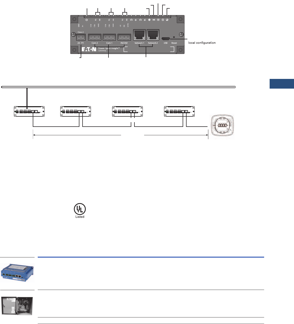
Volume 3—Power Distribution and Control Assemblies CA08100004E—March 2016 www.eaton.com V3-T9-291
9
9
9
9
9
9
9
9
9
9
9
9
9
9
9
9
9
9
9
9
9
9
9
9
9
9
9
9
9
9
9.4
Metering Devices, Protective Relays, Software and Connectivity
Connectivity Options
Power Xpert Gateway 900
PXG Daisy Chain Application
Standards and Certifications
●UL® 508, Standard for
Programmable Controller
Equipment
●FCC, Class A, Part 15,
Subpart B, Sections
15.107b and 15.109b
●EN55022: 1994 Class A,
Information Technology
Equipment
●EN 61000-6-2:2001
Electromagnetic
Compatibility (EMC)
Party 6-2: Immunity for
Industrial Environments
Product Selection
PXG Part Numbers
RS-485
connections
USB connection for
capability
Power Status Web
Bridge
Com2 Com1 INCOM
DHCP
NTP
24 Vdc input power RJ-45 connections with link speed
and activity indicators
Ethernet LAN
LAN Connection
295 ft (90 m)
Cat-5 Patch Cables
PXM2000
Note: In this configuration, if any of the PXG units go offline or lose power, the
communication to the downstream Ethernet devices will lose connection to the LAN.
Description
Style
Number
Catalog
Number
Power Xpert Gateway 900 66D2325G01 PXG900
Enclosed version
Cost-effective solution to add communications to new or existing equipment
that has no physical space to install the PXG in the equipment structure.
NEMA 12 enclosure rating.
Prewired with a PSG60N24RP power supply and terminal blocks for ease of wiring of
incoming power and connected devices.
—PXG900-2A
Power supply—24 Vdc PSG60N24RP-A1 PSG60N24RP
PXG900
PXG900-2A

V3-T9-292 Volume 3—Power Distribution and Control Assemblies CA08100004E—March 2016 www.eaton.com
9
9
9
9
9
9
9
9
9
9
9
9
9
9
9
9
9
9
9
9
9
9
9
9
9
9
9
9
9
9
9.4
Metering Devices, Protective Relays, Software and Connectivity
Connectivity Options
Technical Data and Specifications
PXG part numbers
Memory
●Flash: 2 GB
●RAM: 1 GB
Communication Ports
●Network ports: Two 10/100Base-T RJ-45 connectors
●Serial ports
●Two RS-485 ports for connection to Modbus RTU devices
●One dedicated RS-485 port for INCOM devices
●Configuration port: One USB port
Network Protocols Supported
●Modbus TCP/IP: Supports data access from Modbus TCP
clients
●Web server: Supports data access from Web browsers (HTTP
and HTTPS)
●DHCP: Supports automatic IP address assignments,
if enabled
●NTP: Supports time synchronization via a network time server
for PXG synchronization
●SMTP: Supports mail server for email notification
●BACnet/IP: Supports data access from BACnet clients
Serial Protocols Supported
●INCOM
●Modbus RTU
Web Browsers Recommended
●Internet Explorer versions 10 and 11
●Google Chrome
Power Input
●Input voltage, nominal: 24 Vdc; 0.3 A minimum
●Input voltage range: ±10% nominal
Power Consumption
●8 W maximum
Operating Temperature
●32 to 140 °F (0 to 60 °C)
Ambient Storage Temperature
●–40 to +185 °F (–40 to +85 °C)
Relative Humidity
●5 to 95% noncondensing at 122 °F (50 °C)
Size (H x D x L) in Inches
●2.00 x 4.50 x 6.00
Weight
●1.7 pounds
Description Style Number Catalog Number
Power Xpert Gateway 900 66D2325G01 PXG900
Power supply—24 Vdc PSG60N24RP-A1 PSG60N24RP
Supported Devices and Performance
PXG performance will vary depending upon the number and type
of connected devices. This is driven by the following:
●Each supported device has a distinct number of channels to
report back to the PXG, ranging from as few as 4 to over 900
●The channels are prioritized
●Device protocol, Modbus or INCOM
●Baud rate setting
For this reason, a PXG performance tool has been developed to
assist in understanding the expected performance for a given
application since all systems are unique. This tool can be found
at www.eaton.com/pxg. For a high level performance
comparison, see the table below for three examples.
Note: Features and specifications listed in this document are subject
to change without notice and represent the maximum capabilities of the
product with all options installed. Although every attempt has been made
to ensure the accuracy of information contained within, Eaton makes no
representation about the completeness, correctness, or accuracy and
assumes no responsibility for any errors or omissions. Features and
functionality may vary depending on selected options.
For This Combination of Devices
(All Times in Seconds)
How Long Does It Take
64 INCOM /
32 Modbus
15 INCOM /
15 Modbus 5 INCOM
Between value change in the UI
(INCOM 9600)—Priority 1
21.9 3.7 1.4
Between value change in the UI
(Modbus 57600)—Priority 1
3.5 1.6 —
Between value change in the UI
(INCOM 9600)—Priority 2
44.3 7.4 2.6
Between value change in the UI
(Modbus 57600)—Priority 2
7.0 3.1 —
Modbus server pass-through response time
(57600) (local connection)
0.061 0.059 —
For the UI to show an alarm
(INCOM device)
17.0 3.0 3.0
To boot up (all devices communicating) 399.0 85.0 51.0

Volume 3—Power Distribution and Control Assemblies CA08100004E—March 2016 www.eaton.com V3-T9-293
9
9
9
9
9
9
9
9
9
9
9
9
9
9
9
9
9
9
9
9
9
9
9
9
9
9
9
9
9
9
9.4
Metering Devices, Protective Relays, Software and Connectivity
Connectivity Options
General Wiring Guidelines—RS-485 Network
When communicating over
RS-485 networks to Eaton
products, the following
General Wiring Guidelines
should be used.
Rule 1: Cable Selection—
Twisted Shielded Pair (TSP)
Note: Cables specifically
designed for RS-485 applications
are highly recommended.
The RS-485 bus is a length of
Twisted Shielded Pair (TSP)
that includes a third
conductor (used for the
common wire), a braided
shield accompanied by a drain
wire, and nominal impedance
of 120 ohms.
●Belden Wire and Cable
Company Part Number
3106A or equivalent
Rule 2: Cable Intermixing
Any cable in the Belden
3106A family can be
intermixed with each other
in the Modbus network.
Rule 3: System Topology,
Size and Capacity
●Strict daisy chain must be
adhered to. A strict daisy
chain configuration is one
where the transmission
line connects from one
RS-485 receiver to the
next. The transmission line
appears as one continuous
line to the RS-485 driver
●Maximum 32 devices
●Line termination:
Maximum cable lengths of
4000 feet (1219m); longer
bus lengths will slow the
data rate
Rule 4: Cable Splicing
The prime goal is to create a
secure electrical connection
while minimizing exposure to
electrical transients. Ferrules
are used to dress cable ends.
Most devices have built-in
terminal blocks that can be
used for splicing. Additionally,
terminal blocks should be
utilized when splicing
elsewhere in the gear or
facility to ensure a secure
electrical connection.
Rule 5: Cable Shielding
The cable shielding and outer
jacket should not be stripped
back beyond 1-1/2 inches.
Three-pole terminal blocks
are used to ensure a
continuous metallic shield
ground path. To ensure a
secure electrical connection
when daisy chaining devices
that have built-in two-pole
terminal blocks, mechanically
crimp sleeves onto the two
shield path drain wires.
Rule 6: Cable Grounding
Ground the communication
network at only one point in
the network, preferably by
terminating the drain wire
to ground at the EOL node
(same location as the EOLR).
A solid earth ground is
accomplished by connecting
the shield ground path’s drain
wire to a #14 AWG or larger
multi-stranded wire that has
an impedance path of 1 ohm
or less to a known earth
ground.
Note: The building electrical
ground may not be effective since
it may travel through many
connections and considerable
distances before reaching earth
ground. In such cases, a new
ground path will be required since
the effectiveness of this shield
earth ground connection will
affect the integrity of data
transferred over the cable.
Rule 7: Cable Termination
End of Line Resistors (EOLR)
are necessary to maintain
signal strength and minimize
reflections. EOLR must
match the impedance of the
TSP. Two EOLR are needed
and should be located at both
ends of the RS-485 bus. If
there is only one device
connected to the Modbus
master, it is considered the
last device in the network and
should be terminated with a
120 ohm 1/4 watt terminating
resistor.
Rule 8: Device Addressing
●Each device must have a
unique slave address
●No two devices on the
same RS-485 network can
have the same slave
address
Ethernet Cable Specifications
For complete specifications,
refer to the IEEE 802.3
Ethernet specification.
RS-485 Wiring Guide—Three Terminal Devices
Notes
1Transceiver (XCVR) Common Connected to:
I = Isolated
NI = Non Isolated
E = Earth Ground
2Center terminal on InsulGard (marked with Ground symbol) is for shield splicing only and is electrically floating.
Device Name
A
(– Wire)
B
(+ Wire)
Common
Wire
XCVR
Common 1
Data
Bias
IQ 230M 12 (MOD2) 11 (MOD1) 10 (INCOM 3) I 26V None
IQ 250 (–)
Older Models are Marked
B (–)
(+)
Older Models are Marked
A (–) or A(+)
SH I None
IQ 260 (–)
Older Models are Marked
B (–)
(+)
Older Models are Marked
A (–) or A (+)
SH I None
IQ 330M 12 (MOD2) 11 (MOD1) 10 (INCOM 3) I 26V None
NETLINK 1 (DATA–) 2 (DATA+) 5 (GND) E None
InsulGard 2B A None Floating None
Bushing Gard 2
(InsulGard G3 2)
B A None Floating None
Power Xpert Meter
4000/6000/8000
Data A
750B-S
Data B
750B-S
Shield
(COM)
I 300V 750 Ohm
Switch Sel
Power Xpert Gateway
400//600
A(–) B(+) COM I —

V3-T9-294 Volume 3—Power Distribution and Control Assemblies CA08100004E—March 2016 www.eaton.com
9
9
9
9
9
9
9
9
9
9
9
9
9
9
9
9
9
9
9
9
9
9
9
9
9
9
9
9
9
9
9.4
Metering Devices, Protective Relays, Software and Connectivity
Connectivity Options
INCOM Network
INCOM was specifically
designed with the intention of
delivering a comprehensive
and powerful energy
management solution for
use in electrical distribution
environments while ensuring
affordability, flexibility,
simplicity and noise immunity.
An INCOM network installed
per the following rules will
allow the user to fully realize
all of the above advantages.
(Refer to Eaton document
TD17513 for specific system
layout recommendations
and details.)
Rule 1: Cable Selection—
Twisted Shielded Pair
Approved cable types:
●Any of the cables in the
Belden 9463 family
●Quabbin 6205
●CommScope 9022
●Manhattan Electric M4154
●IMPCABLE—a 600V rated
cable custom designed for
INCOM—
Style # 2A95705G01
Rule 2: Cable Intermixing
Due to impedance
differences between
IMPCABLE and the Belden
9463 family, the main cable
run(s) should be entirely
for the 9463 family OR
IMPCABLE: do not alternate
between these types. The
cable used for taps can be
different from the main run.
Rule 3: System Topology,
Size and Capacity
Supports daisy chain, star
and multi-level network
segment topologies.
Note: Star Segment Topology is
not recommended for new
designs.
See Page V3-T9-295. Surge
protection is required for
FSK networks that leave a
building at the egress/ingress
of the building.
●Supports distances up to
10,000 ft (3048m) per
segment when designed
within the specifications of
this guideline
●Supports up to 1000
devices on a single
network segment
●Supports sub-network
master devices and
associated sub-networks
●Supports 1200 or
9600 baud rate
●Attenuation:
●Total system capacity:
25 dB
●Attenuation per device:
0.01 dB
●Attenuation for approved
wire types, see tables
below
Cable Attenuation
Attenuation at Star
●Definitions:
●Daisy chain: point-to-
point wiring between
devices or clusters of
devices
●Star: single point with a
number of long lines
emanating from it
●Long line: >200-foot
(61m) wire run
●Simple tap: <200-foot
(61m) connection to
cluster of devices
Rule 4: Cable Splicing
The goal is to create a secure
electrical connection while
minimizing exposure to
electrical transients. Ferrules
are used to dress cable ends
in order to avoid problems
associated with frayed and
loose wires. Besides
facilitating cable installation,
subsequent data line
troubleshooting and
downtime are minimized.
Most INCOM devices have
built-in three-pole terminal
blocks for data lines and
shield. For older INCOM
devices that have only two
terminals, shield continuity
must be ensured by other
means. Additional terminal
strips should be utilized when
splicing elsewhere in the
electrical enclosure or facility
to ensure secure electrical
connections. All devices, End
of Line Termination Resistors
and Taps should be wired in
parallel across the cable.
Rule 5: Cable Shielding
The cable shielding and outer
jacket should not be stripped
back beyond 1.5 inches
(38 mm). Terminal blocks are
used at tap points to ensure a
continuous metallic shield
ground path. To ensure a
secure electrical connection
when daisy-chaining INCOM
devices that have built-in
two-pole terminal blocks, use
crimp sleeves to join the two
shield drain wires. The cable
shield ground path for a main
network and sub-network
must not be joined. Each
should have a separate
connection to earth ground
reference.
Rule 6: Cable Grounding
The shield should be
continuous across a network
segment and connected to
the building’s electrical
system grounding electrode
conductor. The 2005 NEC
provides the following
guidance on grounding
communication cables:
1. When a communication
cable enters a building, a
primary protector is required
and must be grounded as
described in Section 800 IV.
Specifically, Paragraphs
800.93 and 800.100 define
grounding requirements for
the primary protector.
2. Grounding systems are
generally covered by Section
250 III. The grounding
electrode conductor is
specifically covered by
Paragraphs 250.62, 250.64,
250.66, 250.68 and 250.70.
3. Bonding requirements
between communication
systems and the power
distribution system is
specified by Paragraph
250.94.
A solid earth ground is
accomplished by connecting
the shield ground path’s drain
wire to a #14 AWG or larger
multi-stranded wire that has
an impedance path of 1 ohm
or less to the building’s
grounding electrode
conductor.
Rule 7: Cable Termination
Each network segment
requires a minimum of two
End of Line Termination
Resistors (EOLTRs). The
EOLTRs maintain signal
strength and minimize
reflections. The EOLTRs
should be 1/2 watt 100 ohm
non-inductive resistors, such
as carbon composition or
metal film. Wire-wound
resistors are not acceptable.
Taps on network segments
should not be terminated.
Some INCOM devices have
the EOLTR permanently
installed and must be located
at the end of a main run.
Other INCOM devices have
an EOLTR that can be
switched to optionally
terminate the network
segment at the device. Care
must be exercised when
installing devices containing
termination resistors
that the switches are set
appropriately. A minimum of
two, up to a maximum of five
EOLTRs must be installed on
each network segment as
dictated by network topology.
Rule 8: Device Address
In order to avoid the
possibility of devices in a
Main Network having the
same addresses as those
in Subnetworks, set Main
Network device addresses
at 100 or higher excluding
addresses 901 to 908.
Cable
Type
Attenuation/
1000 Feet (305m)
IMPCABLE 1.6 dB
Belden 9463 family 2.0 dB
Number of
Long Lines Attenuation
33.5 dB
46 dB
5 8 dB
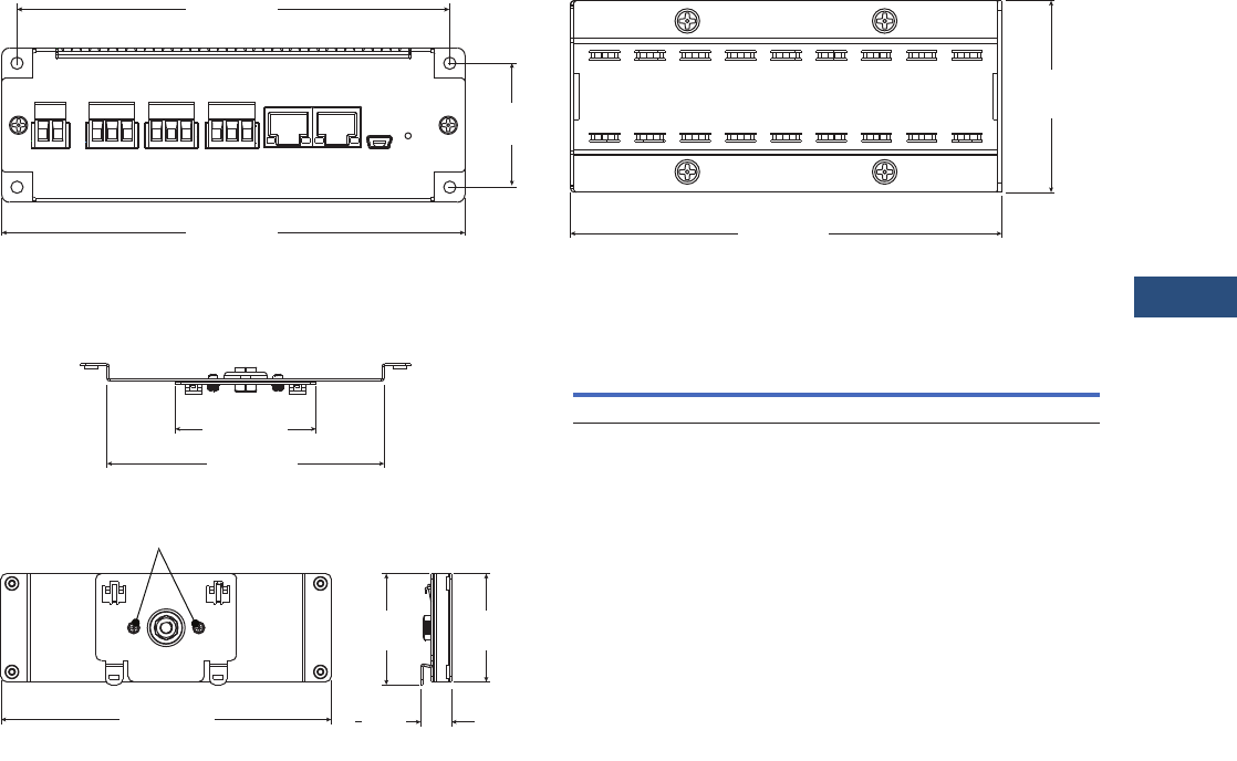
Volume 3—Power Distribution and Control Assemblies CA08100004E—March 2016 www.eaton.com V3-T9-295
9
9
9
9
9
9
9
9
9
9
9
9
9
9
9
9
9
9
9
9
9
9
9
9
9
9
9
9
9
9
9.4
Metering Devices, Protective Relays, Software and Connectivity
Connectivity Options
Dimensions
Approximate Dimensions in Inches (mm)
Power Xpert Gateway 900 with Standard Panel Mounting (Brackets Included)
Power Xpert Gateway 900 with DIN Rail Mounting Power Xpert Gateway 900
6.00 (152.4)
Front View
4.50 (114.3)
Side View
2.00
(50.8)
5.63 (142.8)
1.63
(41.4)
5.04 (128.0)
2.56 (65.0)
Top View
6.00 (152.4)
Front View
Remove and then reattach these
screws to rotate for vertical mounting
1.97
(50.0)
2.02
(51.3)
0.56
(14.2)
Side View
Width Height Depth
Shipping
Weight Lbs (kg)
6.00 (152.4) 2.00 (50.8) 4.50 (114.3) 1.70 (0.8)
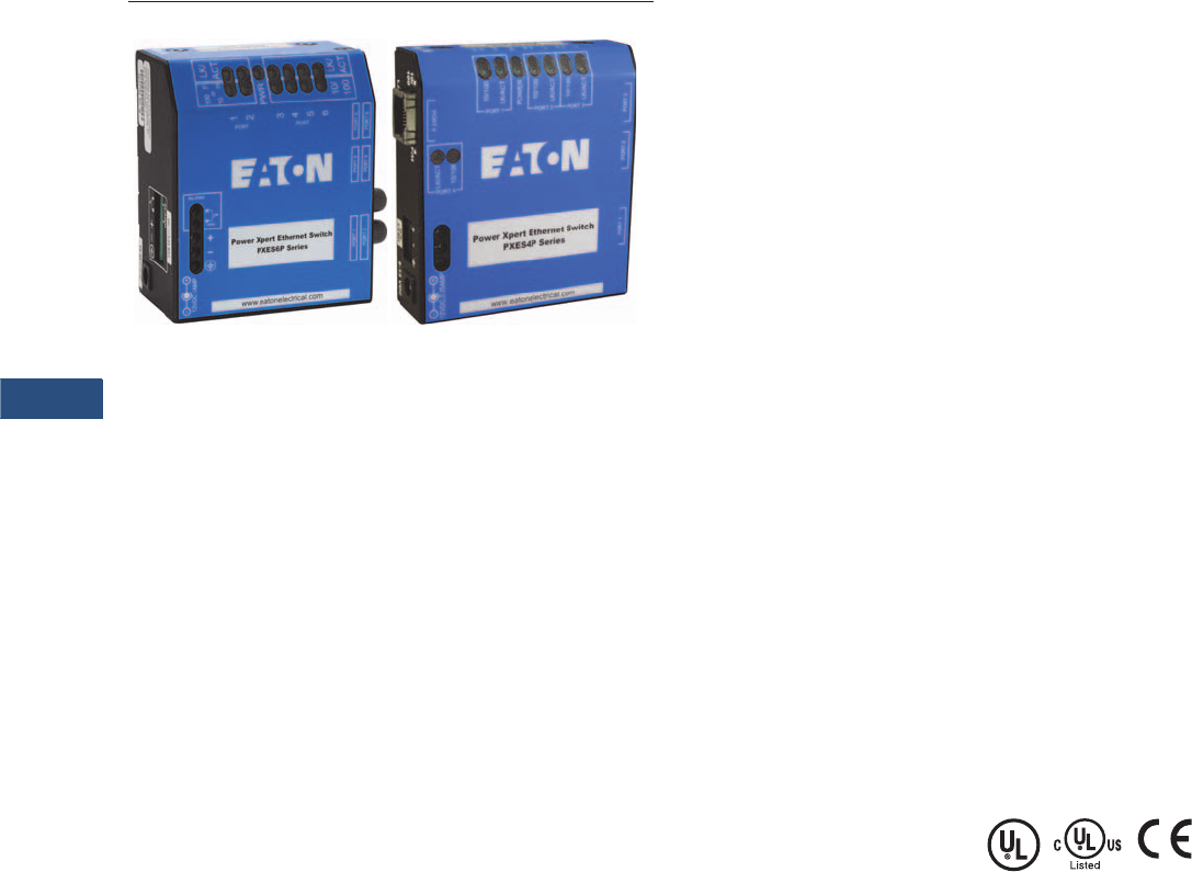
V3-T9-296 Volume 3—Power Distribution and Control Assemblies CA08100004E—March 2016 www.eaton.com
9
9
9
9
9
9
9
9
9
9
9
9
9
9
9
9
9
9
9
9
9
9
9
9
9
9
9
9
9
9
9.4
Metering Devices, Protective Relays, Software and Connectivity
Connectivity Options
Convenient Network Expansion
Power Xpert Ethernet Switches
Contents
Description Page
Power Xpert Gateway. . . . . . . . . . . . . . . . . . . . . . . V3-T9-287
Power Xpert Ethernet Switches
Product Selection . . . . . . . . . . . . . . . . . . . . . . . V3-T9-297
Accessories. . . . . . . . . . . . . . . . . . . . . . . . . . . . V3-T9-297
Technical Data and Specifications . . . . . . . . . . . V3-T9-297
Dimensions . . . . . . . . . . . . . . . . . . . . . . . . . . . . V3-T9-299
mMINT . . . . . . . . . . . . . . . . . . . . . . . . . . . . . . . . . . V3-T9-300
IPONI . . . . . . . . . . . . . . . . . . . . . . . . . . . . . . . . . . . V3-T9-302
DPONI . . . . . . . . . . . . . . . . . . . . . . . . . . . . . . . . . . V3-T9-303
MPONI . . . . . . . . . . . . . . . . . . . . . . . . . . . . . . . . . . V3-T9-304
I/O Devices Digital Input Module (DIM) . . . . . . . . . V3-T9-305
Addressable Relay II . . . . . . . . . . . . . . . . . . . . . . . V3-T9-307
Breaker Interface Module II (BIM II) . . . . . . . . . . . V3-T9-309
Power Xpert Ethernet Switches
Product Description
Eaton’s Power Xpert
Ethernet Switches are ideal
for extending Ethernet
networks via CAT5 wiring
or fiber in harsh, industrial
environments. Built with
high-grade components and
constructed using special
thermal techniques, PXE
Switches can withstand the
unpredictable conditions of
such environments.
Features
●Simultaneous, full-duplex,
high-speed communication
on all ports—no network
performance bottlenecks
●Hardened for factory
floor—ideal for both
industrial or data center
applications
●Unmanaged, plug-and-play
implementation—no
software or additional
hardware required for
configuration
●Seamlessly integrates into
Eaton’s Power Xpert
Architecture—quality
and reliability of Eaton
guaranteed
●Mounting options include
standalone panel-
mounting, DIN rail
mounting, or 19-inch
standard rack mounting
PXES 6-Port Switch—10/100 Mb
with Optional 100 Mb Fiber
This compact switch provides
six Ethernet ports, with
flexible configurations. The
base models have one of
three options:
●Two 100 Mb fiber and
four 10/100 copper ports
●One fiber and five
copper ports
●Six copper ports
PXES 4-Port Switch—10/100 Mb
For smaller applications
requiring fewer connection
points and no fiber, the 4-port
Power Xpert Ethernet Switch
is a versatile option. It
provides edge access
Ethernet ports in a convenient
and compact package.
Standards and Certifications
●UL Listed (UL 60950)
●cUL
●CE
●Emissions meet FCC Part
15, Class A

Volume 3—Power Distribution and Control Assemblies CA08100004E—March 2016 www.eaton.com V3-T9-297
9
9
9
9
9
9
9
9
9
9
9
9
9
9
9
9
9
9
9
9
9
9
9
9
9
9
9
9
9
9
9.4
Metering Devices, Protective Relays, Software and Connectivity
Connectivity Options
Product Selection
Power Xpert Ethernet Switches
Accessories
Power Xpert Ethernet Switches
Technical Data and Specifications
Operating Environment
Network Standards
Power Consumption
Packaging
Mounting
Description
Catalog
Number
4-port Ethernet switch—copper only PXES4P24V
6-port Ethernet switch—copper only PXES6P24V
6-port Ethernet switch—5 copper/1 fiber (ST connector) PXES6P24V1ST
6-port Ethernet switch—4 copper/2 fiber (ST connector) PXES6P24V2ST
Ethernet Switch
Description
Catalog
Number
Power supply (preferred)—100–240 Vac input
DIN rail mount with screw—24 Vdc output terminals
ELC-PS02
Power supply (alternate)—120 Vac input
Wall plug-in type with 6 ft cord—12 Vdc output
PXESPS12V
DIN rail mounting bracket PXESDINRL
19-inch rack mount tray PXESTRAY
Ethernet Switch
Description Specifications
Ambient temperature ratings –25°C to 60°C long-term per independent agency tests (UL), or –40°C to 85°C short-term per IEC type tests
Storage temperature –40° to 185°F (–40°C to 85°C)
Cold start to –20°C
Ambient relative humidity 5%–95% (noncondensing)
Altitude –200 to 50,000 ft (–60 to 15,000m)
MTBF > 15 years
Description
Ethernet IEEE 802.3, IEEE 802.3u; IEEE 802.1p, 100Base-TX, 10Base-T, 100Base-FX
Description
7.0 watts typical—9 watts maximum
Description Specifications
Enclosure Robust sheet metal (steel)
Cooling method Case used as a heat sink
Description Specifications
Metal panel mounting clips Included
DIN rail mounting Optional
19-inch rack mount Optional

V3-T9-298 Volume 3—Power Distribution and Control Assemblies CA08100004E—March 2016 www.eaton.com
9
9
9
9
9
9
9
9
9
9
9
9
9
9
9
9
9
9
9
9
9
9
9
9
9
9
9
9
9
9
9.4
Metering Devices, Protective Relays, Software and Connectivity
Connectivity Options
Copper Ethernet Cable
Wiring Guidelines
The following information can
be used as a guide when
designing an Ethernet system
using Copper Ethernet Cable.
●Cables should not be
routed near equipment that
generates strong electric
or magnetic fields such as
motors, drive controllers,
arc welders and conduit
●Ethernet cable insulation
has a voltage rating of
300 Vac. Use of barriers,
cable trays or high voltage
sheathing with STP
Ethernet cable may be
required in installations
with cables carrying
voltages greater than
300 Vac. This may
also be necessary in
order to comply with
UL requirements. In
installations where the
cable cannot be physically
separated from the power
cables (where a physical
barrier is not practical) fiber
optic cable should be used
●When crossing power
conductors with Ethernet
cable, cross at right angles
●Shielded Twisted Pair (STP)
Ethernet cable should be
specified for use in high
noise environments.
Shielded shrouded
connectors must be used
and the shield must be
connected at both ends of
the wire. The mating plug
must have a shielded
shroud that is terminated
to ground at both ends.
Where there is a possibility
of a difference in ground
potential (common mode)
voltages between the
two terminated ends,
fiber optic cable is
recommended
●When using conduit or a
metal cable tray, each
section of the conduit or
tray must be bonded to
each adjacent section and
the conduit or tray needs
to be bonded to earth
ground. Do not allow the
shields to touch the
conduit or metal tray at
any point
●Only shielded (STP)
Ethernet cables should be
placed into metal conduit.
Some UTP cables may not
function properly when
installed in conduit, as the
metal conduit can affect the
electrical properties of an
unshielded cable. Consult
the cable manufacturer
when installing UTP cables
in conduit
●As a general rule for noise
protection, Ethernet Cable
should maintain a minimum
distance of 3 inches (8 cm)
from electric power
conductors for up to
100 volts and 1 inch (3 cm)
for each additional 100 volts
up to 400 volts. STP cable is
recommended
●For Ethernet cable run
within conduit, but near
conductors with potentially
noisy power conductors
carrying currents of greater
than 20A or voltages
greater than 400V, maintain
the following distances.
STP cable is required.
●Conductors of less than
20A = 3 inches
●Conductors of 20A or
more and up to 100 kVA
= 6 inches
●Conductors greater than
100 kVA = 12 inches
●For Ethernet cable run near
conductors with potentially
noisy power conductors
carrying currents of greater
than 20A or voltages
greater than 400V, maintain
the following distances.
STP cable is recommended
●Conductors of less than
20A = 6 inches
●Conductors of 20A
or more and up to
100 kVA = 12 inches
●Conductors greater than
100 kVA = 24 inches
●Route Ethernet cable at
least 5 feet (1.5m) from
sources of rf/microwave
radiation. STP cable is
required
●Do not cascade more than
four Ethernet repeaters
(router, switch or hub)
within a network segment
●Environmentally sealed
connectors should be
specified for cables used
in outdoor installations
●Avoid pinching the cable
when using cable ties
●Total distance between an
Ethernet Transmitter and
Receiver at the end points
of the network should not
exceed 328 feet (100m)
●Total distance from a patch
panel to a wall jack (using
solid cable) shall not
exceed 295 feet (90m).
Splices are not permitted
●Patch cords used as cross-
connect jumpers in a patch
panel should not exceed
20 feet (6m)
●Patch cords from a wall
jack to the work area PC
(or device) shall not exceed
16 feet (5m)
●Ethernet cable used in
harsh environments
must be selected to
withstand the following
conditions: vibration,
air born contaminants,
chemicals, temperature,
electromagnetic
interference, combustible
atmospheres and local
regulatory standards such
as UL and NEMA
●Ethernet connectors used
in harsh environments
must be robust enough
to withstand vibration,
multiple connection cycles,
temperature changes,
and provide a proper
seal to protect against
moisture, dust/dirt and
chemical attack
●Different cable media
support different
bandwidth capabilities.
When installing cable in a
network, care should be
taken to install the cable
that will fill current network
loading requirements and
future expansion needs. In
general, fiber optic cable
can support the greatest
bandwidth (upward of
25,000 gigabits) and UTP
has the lowest. CAT5e
cabling is designed to
operate a bit rates up to
1000 Mb and CAT6 cable
up to 2000 Mb
●Operating your cable at
maximum speed reduces
the distance between
network segments. Check
with your cable supplier for
specifications regarding
segment distance vs.
speed
●Cable with 5% impedance
mismatch or return
loss of 27 to 32 dB is
recommended. Ethernet
cable impedance can vary
by as much as 15%
(85 to 115 ohms). Average
Ethernet cable with 15%
impedance variation
can have up to 10 dB
additional return loss.
This discontinuity is
referred to as return loss,
since it causes some of the
signal to be reflected back
down the cable instead of
propagating forward. It
is measured in decibels or
ratio of transmitted versus
reflected signal

Volume 3—Power Distribution and Control Assemblies CA08100004E—March 2016 www.eaton.com V3-T9-299
9
9
9
9
9
9
9
9
9
9
9
9
9
9
9
9
9
9
9
9
9
9
9
9
9
9
9
9
9
9
9.4
Metering Devices, Protective Relays, Software and Connectivity
Connectivity Options
Fiber Optic Technology
The use of fiber optics in
telecommunications and wide
area networking has been
common for many years, but
more recently fiber optics
have become increasingly
prevalent in industrial data
communications systems
as well. High data rate
capabilities, noise rejection
and electrical isolation are
just a few of the important
characteristics that make
fiber optic technology ideal
for use in industrial and
commercial systems.
Although often used for point-
to-point connections, fiber
optic links are being used to
extend the distance
limitations of RS-232, RS-422/
485 and Ethernet systems
while ensuring high data rates
and minimizing electrical
interference.
Conventional electrical data
signals are converted into
a modulated light beam,
introduced into the fiber and
transported via a very small
diameter glass or plastic
fiber to a receiver that
converts the light back into
electrical signals.
Optical fibers allow data
signals to propagate through
them by ensuring that the
light signal enters the fiber
at an angle greater than the
critical angle of the interface
between two types of glass.
Optical fiber is actually made
up of three parts. The center
core is composed of very
pure glass. Core dimensions
are usually in the range
of 50 to 125 um for multi-
mode cables and 8-9 um for
single-mode cables. The
surrounding glass, called
cladding, is a slightly less
pure glass. The diameter of
the core and cladding
together is in the range of
125 to 440 um.
Surrounding the cladding is a
protective layer of flexible
silicone called the sheath.
Fiber Optic Cable
Wiring Guidelines
The following information
can be used as a guide
when designing an Ethernet
system using Fiber Optic
Ethernet Cable:
●Select a fiber cable that is
suited for the application,
e.g., outdoor, aerial, duct,
intra-building, risers,
general building and
plenum applications
●Fiber optic cable is useful in
applications where the
environment is combustible,
electrically noisy, the cable
must be bundles with high
voltage wires or where
common mode voltages
may exist between the
earth ground points of the
terminating connectors
●Fiber optic cable is
available in various
operating temperature
ranges. Care should be
taken to match the
temperature rating of the
fiber to the environment it
will be exposed to. The
temperature specification
for fiber may be narrower
than copper cable. Consult
the cable manufacturer for
temperature specifications
of your cable type
●Sealed fiber connectors are
available for use in harsh
environments to prevent
contamination from
entering the connector and
fiber. The type of seal
required will be application
dependant and can vary
from dust- and moisture-
proof to water-tight
●Mixing fiber cable types is
not permitted. The same
core dimensions and mode
must be used within
cable segments
●Care should be taken when
purchasing connectors to
include strain relief, which
reduces mechanical strain
(vibration) within the cable,
as well as the connector.
Strain relief also provides
support to the cable
to ensure proper bend
radius at the connector
●Single-Mode Fiber is
used for long distance
transmission of up to
120 km. Distance may vary
depending on speed and
type of converter used
●Multi-Mode Graded-Index
Fiber Cable is used for
communication over
shorter distances of up
to 2 km
●Fiber cable is composed of
glass and is not well suited
for applications requiring
tight bend radiuses. Cable
radius dimensions vary per
manufacturer. If the
manufacturer does not
provide a bend radius, a
typical rule of thumb is a
radius not less than 15x the
cable diameter
●Fiber cable to connector
terminations can be
performed in the field
using special equipment.
This method is not
recommended
●Tier One testing is
recommended when
diagnosing system
irregularities and should
be performed in all new
installations
●Tier Two testing is
recommended to certify
that a system complies
with standards set forth
by the owner/installer
Dimensions
Packaging
Description Specifications
Dimensions of PXES4P series
Weight of PXES4P series
3.5 in H x 3.0 in W x 1.0 in D (8.9 cm x 7.6 cm x 2.5 cm)
8.6 oz. (243g)
Dimensions of PXES6P series
Weight of PXES6P series
3.6 in H x 3.0 in W x 1.7 in D (9.2 cm x 7.6 cm x 4.3 cm)
13 oz. (370g)
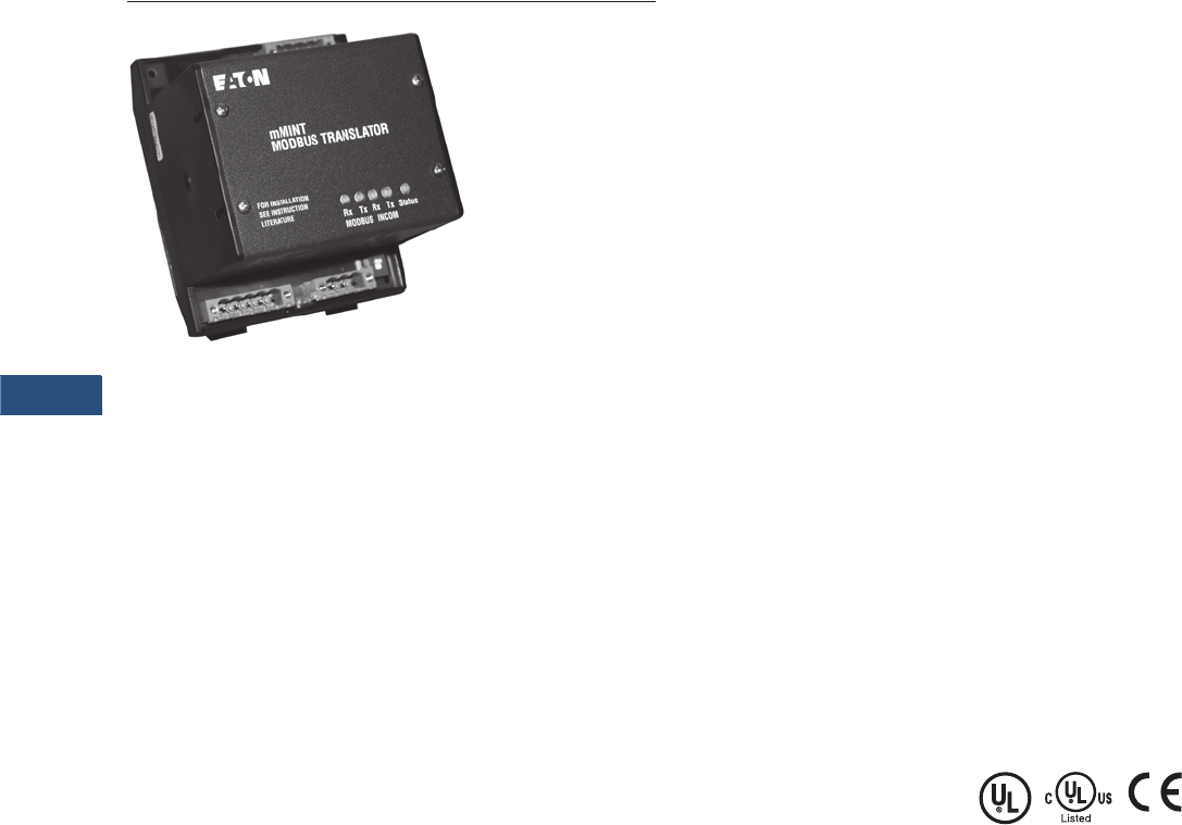
V3-T9-300 Volume 3—Power Distribution and Control Assemblies CA08100004E—March 2016 www.eaton.com
9
9
9
9
9
9
9
9
9
9
9
9
9
9
9
9
9
9
9
9
9
9
9
9
9
9
9
9
9
9
9.4
Metering Devices, Protective Relays, Software and Connectivity
Connectivity Options
mMINT Module
Contents
Description Page
Power Xpert Gateway. . . . . . . . . . . . . . . . . . . . . . . V3-T9-287
Power Xpert Ethernet Switches . . . . . . . . . . . . . . . V3-T9-296
mMINT
Technical Data and Specifications . . . . . . . . . . . V3-T9-301
IPONI . . . . . . . . . . . . . . . . . . . . . . . . . . . . . . . . . . . V3-T9-302
DPONI . . . . . . . . . . . . . . . . . . . . . . . . . . . . . . . . . . V3-T9-303
MPONI . . . . . . . . . . . . . . . . . . . . . . . . . . . . . . . . . . V3-T9-304
I/O Devices Digital Input Module (DIM) . . . . . . . . . V3-T9-305
Addressable Relay II . . . . . . . . . . . . . . . . . . . . . . . V3-T9-307
Breaker Interface Module II (BIM II) . . . . . . . . . . . V3-T9-309
mMINT
Product Description
The mMINT (Modbus Master
INCOM Network Translator)
Module is an Eaton accessory
product that provides
communication between
a Modbus RTU network
and an INCOM (INdustrial
COMmunications) network
(see Page V3-T9-301). This
module is transparent to the
Modbus network. It
communicates to a master on
the Modbus network using
the Modbus RTU (Remote
Terminal Unit) protocol. It
communicates to slave
devices on the INCOM
network using the IMPACC
(Integrated Monitoring,
Protection, And Control
Communication) protocol.
Features
The mMINT module is a
slave device on the Modbus
network and as such requires
a master that will exchange
register objects with the
mMINT module.
●Handles generic pass-
through commands
(Modbus/INCOM/Modbus)
●Capable of passing
Modbus register objects
from Eaton’s existing
products and newer PnP
(Plug-n-Play) products to a
Modbus RTU master
●Data in IEEE Floating Point
format and fixed point
●Modbus RTU
communications data
transfer rates of 1200,
9600 or 19,200 baud with
one start bit, eight data
bits, no parity, and either
one or two stop bits
●Up to 32 products
connected to INCOM
network port (246 unique
addresses maximum)
●Flashing Status LED to
indicate an active module
●LED indicators for INCOM
transmit and receive
communications
exchanges
●LED indicators for Modbus
RS-485 transmit and
receive communications
exchanges
●Input power for the module
from either 120 Vac or 24
to 125 Vdc
●DIN rail mount package
●0ºC to 60ºC ambient
operation
Standards and Certifications
●UL
●CSA
●CE mark
Product Selection
The catalog number of this
product is mMINT.
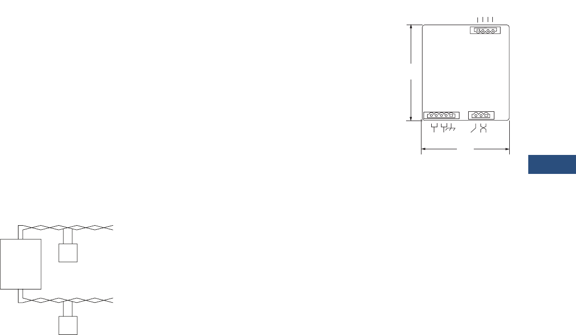
Volume 3—Power Distribution and Control Assemblies CA08100004E—March 2016 www.eaton.com V3-T9-301
9
9
9
9
9
9
9
9
9
9
9
9
9
9
9
9
9
9
9
9
9
9
9
9
9
9
9
9
9
9
9.4
Metering Devices, Protective Relays, Software and Connectivity
Connectivity Options
Technical Data and Specifications
Module Mounting
When mounting the
mMINT, verify that an
11 mm H x 28 mm W
DIN rail is used and that it is
within an enclosed space.
Simplified Wiring Rules
INCOM Network
The following simplified rules
apply to a given system
consisting of a single daisy-
chained main cable link
between master and slave
devices (see below). For
more complex considerations
including star configurations,
please refer to the IMPACC
wiring specification
T.D. 17513.
mMINT in a Communications Network
●Recommended INCOM
cable styles are Belden
9463 or C-H style
2A957805G01
●The maximum system
capacity is 10,000 feet of
communications cable and
32 slave devices on the
INCOM network under
the mMINT
●Non-terminated taps, up to
200 feet in length, off the
main link are permitted,
but add to the total
cable length
●Make sure that there is
twisted-pair wire that is
recommended for IMPACC
network use. Use shielded
twisted-pair wire to
connect each slave to the
INCOM network, daisy-
chain style. The polarity
of the twisted pair is
not important
Modbus RS-485 Network
The following simplified rules
apply to a given system
consisting of a cable link
between master and slave
devices (see below). For
more complex configurations,
please refer to standard
Modbus RTU wiring
specification rules for
the RS-485 network.
●The recommended
Modbus cable has twisted-
pair wires (24 AWG
stranded 7x32 conductors
with PVC insulation) having
an aluminum/mylar foil
shield with drain wire
●The maximum system
capacity is 4000 feet of
communications cable and
247 devices on the
Modbus RTU network
●Make sure that there is
twisted-pair wire that is
recommended for Modbus
RTU network use. Use
shielded twisted-pair wire
to connect each slave to
the Modbus RTU network,
daisy-chain style. The
polarity of the twisted pair
is critically important
mMINT Module Dimensions
Burden
●24 Vac/dc 3 VA
Communications Speed
■INCOM: 1200, 9600 baud
●N2 Bus: 9600 baud
Note: Contact Eaton for
availability and support for the
N2 Gateway.
Modbus RTU Serial Network
(Slave)
Modbus
mMINT
(Master)
Modbus
Master
INCOM Network
INCOM
Slaves
J1 J2
J3
4.25
(108.0)
RS-485
Modbus
3.54
(89.9)
24 – 125 Vdc
120 Vac
Shield INCOM
A B COM SHD
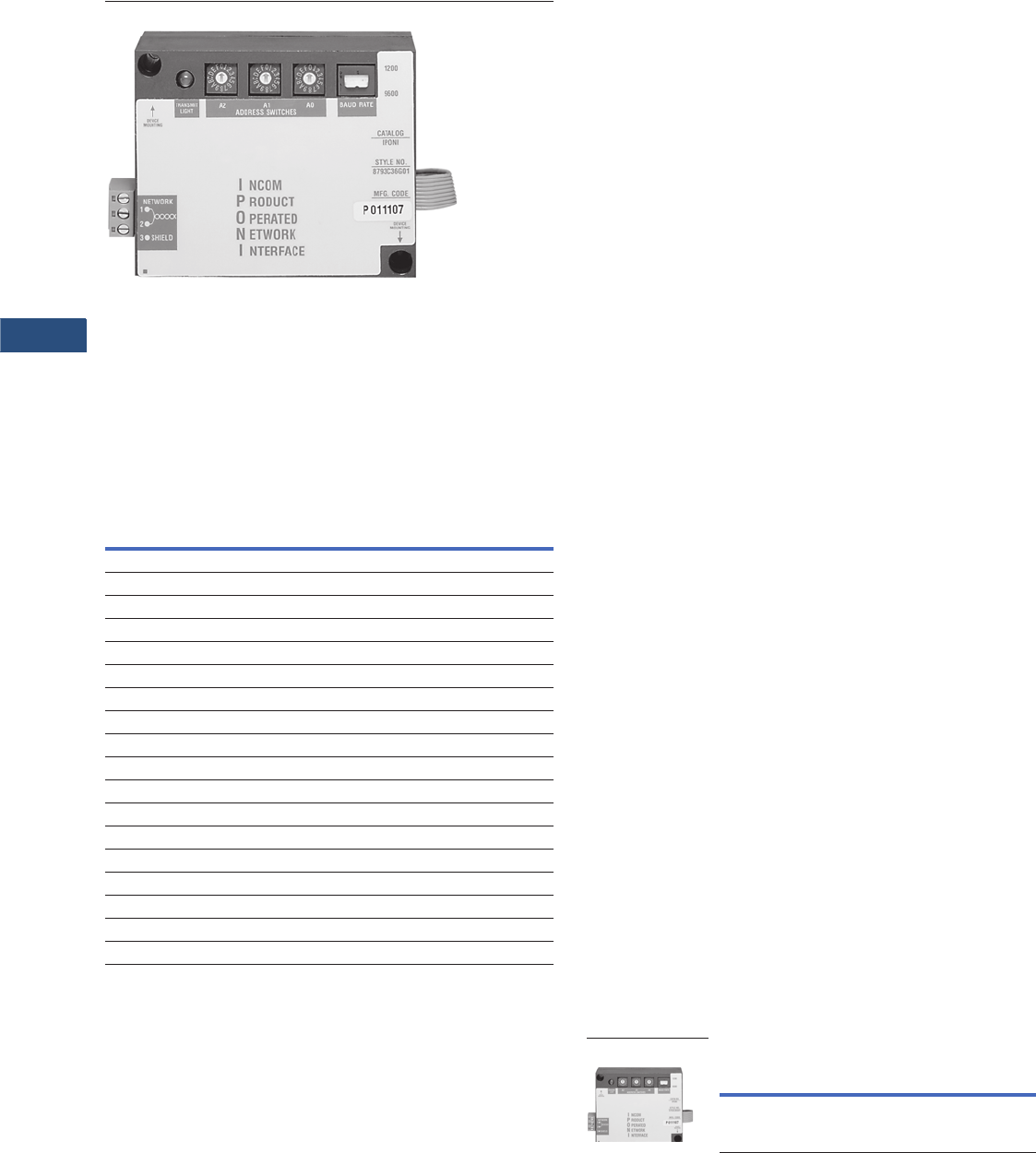
V3-T9-302 Volume 3—Power Distribution and Control Assemblies CA08100004E—March 2016 www.eaton.com
9
9
9
9
9
9
9
9
9
9
9
9
9
9
9
9
9
9
9
9
9
9
9
9
9
9
9
9
9
9
9.4
Metering Devices, Protective Relays, Software and Connectivity
Connectivity Options
IPONI Communication Module
Contents
Description Page
Power Xpert Gateway . . . . . . . . . . . . . . . . . . . . . . V3-T9-287
Power Xpert Ethernet Switches . . . . . . . . . . . . . . V3-T9-296
mMINT . . . . . . . . . . . . . . . . . . . . . . . . . . . . . . . . . V3-T9-300
IPONI
DPONI. . . . . . . . . . . . . . . . . . . . . . . . . . . . . . . . . . V3-T9-303
MPONI . . . . . . . . . . . . . . . . . . . . . . . . . . . . . . . . . V3-T9-304
I/O Devices Digital Input Module (DIM) . . . . . . . . V3-T9-305
Addressable Relay II . . . . . . . . . . . . . . . . . . . . . . . V3-T9-307
Breaker Interface Module II (BIM II). . . . . . . . . . . V3-T9-309
IPONI
Product Selection Guide
IPONI Selection Chart
Description IPONI
INCOM
on Product MPONI
IQ Analyzer ■—■
IQ DP-4000 ■—■
IQ 200 — ■—
IQ Multipoint Energy Submeter II —■—
Energy Sentinel — ■—
Power Sentinel — ■—
IQ Generator ■——
IQ Data ■——
IQ Data Plus II —— —
IQ 500 — — —
IQ Transfer ■——
AEMII ■——
BIM II ■——
CMU ■——
CED ■——
MP-3000 ■—■
Digitrip 3000 — ■—
FP-5000 — ■—
Product Description
The INCOM Product
Operated Network Interface
card, or IPONI card, adds
communication capability to
various Eaton products. Each
IPONI has three 16-digit
address switches to uniquely
identify each device on the
network. IPONIs are
designed to be daisy-chained
throughout a unit substation
or equipment room to a
master device such as a
mMINT, MINTII or Power
Xpert Gateway. From the
master computer, information
is distributed through the
facility’s TCP/IP Ethernet
network. A twisted shielded
pair network connecting
IPONIs may extend up to
10,000 feet (3048m) before
terminating a master device.
The IPONI comes with
mounting hardware and
attaches to the back of its
associated device.
Technical Data and
Specifications
Temperature
●–20°C to 70°C
Humidity
●5%–95% noncondensing
Power
●20–30 Vdc maximum,
50 mA nominal,
100 mA maximum
Speed
●1200 and 9600 baud
Communications
●Three-position removable
terminal block for twisted
shielded pair INCOM
Product Selection
PONI Communication Modules
Description
Catalog
Number
INCOM PONI IPONI
IPONI Card
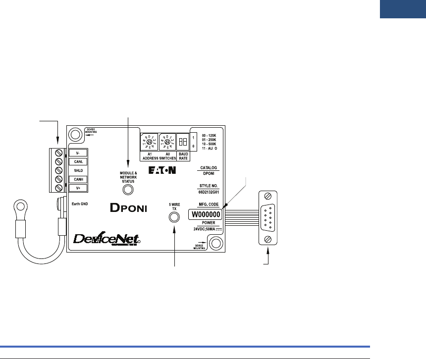
Volume 3—Power Distribution and Control Assemblies CA08100004E—March 2016 www.eaton.com V3-T9-303
9
9
9
9
9
9
9
9
9
9
9
9
9
9
9
9
9
9
9
9
9
9
9
9
9
9
9
9
9
9
9.4
Metering Devices, Protective Relays, Software and Connectivity
Connectivity Options
Contents
Description Page
Power Xpert Gateway . . . . . . . . . . . . . . . . . . . . . . V3-T9-287
Power Xpert Ethernet Switches . . . . . . . . . . . . . . V3-T9-296
mMINT . . . . . . . . . . . . . . . . . . . . . . . . . . . . . . . . . V3-T9-300
IPONI. . . . . . . . . . . . . . . . . . . . . . . . . . . . . . . . . . . V3-T9-302
DPONI
MPONI . . . . . . . . . . . . . . . . . . . . . . . . . . . . . . . . . V3-T9-304
I/O Devices Digital Input Module (DIM) . . . . . . . . V3-T9-305
Addressable Relay II . . . . . . . . . . . . . . . . . . . . . . . V3-T9-307
Breaker Interface Module II (BIM II) . . . . . . . . . . . V3-T9-309
DPONI
Product Description
The DeviceNet Product
Operated Network
Interface (DPONI) enables
communication between a
DeviceNet network master
station and a host device in a
Master/Slave format over a
DeviceNet network. The
DPONI is compatible with the
MP-3000 and the MP-4000.
The DPONI is powered both
by the host product to which
it is attached and by the
DeviceNet network. The
DPONI uses opto-couplers
to isolate the two power
systems.
The DPONI communicates
at 125, 250 or 500 Kbps
selected via a front panel
DIP switch. All products on
the DeviceNet network
must be set at the same
communication rate.
The DPONI has a bi-color
network/module status
LED that functions in
accordance with the
DeviceNet specification.
An additional monocolor
LED flashes while the DPONI
is receiving a message from
the host device.
Features
Eaton’s DPONI
Product Selection
DPONI
Technical Data and Specifications
Temperature
●–20ºC to 70ºC
Humidity
●5%–90% noncondensing
Power
●11–27 Vdc, 40 mA maximum
Speed
●125, 250 or 500 Kbps
Communications
●Standard five-wire
CAN connection
DEVICE
MOUNTING
T
R
DeviceNet
Network
Connection
(5 point plug)
Earth
GND
DeviceNet
Status
Data
Code
INCOM
Status
IQ Host
Device
Connection
Description
Catalog
Number
The DeviceNet Product Operated Network Interface DPONI
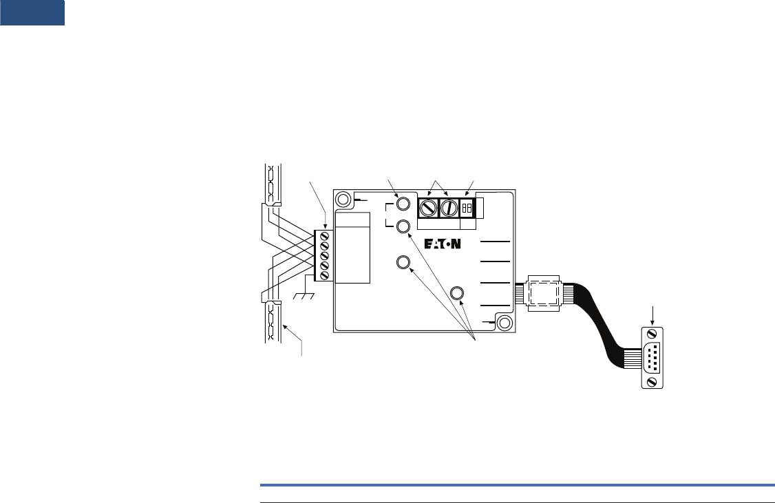
V3-T9-304 Volume 3—Power Distribution and Control Assemblies CA08100004E—March 2016 www.eaton.com
9
9
9
9
9
9
9
9
9
9
9
9
9
9
9
9
9
9
9
9
9
9
9
9
9
9
9
9
9
9
9.4
Metering Devices, Protective Relays, Software and Connectivity
Connectivity Options
Contents
Description Page
Power Xpert Gateway. . . . . . . . . . . . . . . . . . . . . . . V3-T9-287
Power Xpert Ethernet Switches . . . . . . . . . . . . . . . V3-T9-296
mMINT . . . . . . . . . . . . . . . . . . . . . . . . . . . . . . . . . . V3-T9-300
IPONI . . . . . . . . . . . . . . . . . . . . . . . . . . . . . . . . . . . V3-T9-302
DPONI . . . . . . . . . . . . . . . . . . . . . . . . . . . . . . . . . . V3-T9-303
MPONI
I/O Devices Digital Input Module (DIM) . . . . . . . . . V3-T9-305
Addressable Relay II . . . . . . . . . . . . . . . . . . . . . . . V3-T9-307
Breaker Interface Module II (BIM II) . . . . . . . . . . . V3-T9-309
MPONI
Product Description
The MPONI Product Operated
Network Interface card, or
MPONI card, enables Modbus
communication capability to
various Eaton products. Each
MPONI contains two rotary
address switches to uniquely
identify each device on the
network and a baud rate DIP
switch. A 5-pin connector is
provided for wiring to the
RS-485 network. Various
baud rates are available for
networking flexibility, and
onboard LEDs indicate
operation, error and
communication status.
The MPONI is applied where
a device network exists
connected by a dedicated
shielded twisted pair
conductor. Modbus RS-485
allows a single device or
multiple units in a daisy-chain
configuration to communicate
with another local or remote
device and may extend up to
4000 feet (1219m) without a
repeater. The MPONI comes
with mounting hardware and
attaches to the back of its
associated device.
Note: Please see IL for detailed
register support information for
each supported product. Not all
device functionality is supported
with the RS-485 PONI over the
Modbus Protocol.
Features
MPONI
Product Selection
MPONI
Network Connection
(Green Phoenix
Connection)
Recommended
18 gauge twisted pair IMPCABLE or
20 gauge Belden 9463 class
Address
Selector
Switches
Function
Selector
Switch
IQ Host
Device
Connection
LED
STATUS
RX
TX
RS-485
NETWORK
1 = A
2 = G
3 = COMMON
4 = SHIELD
5 = CHASSIS
RS-485
P roduct
O perated
N etwork
I nterface
LED
Description
Catalog
Number
Modbus Product Operated Network Interface Card MPONI
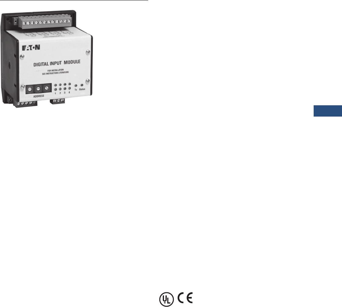
Volume 3—Power Distribution and Control Assemblies CA08100004E—March 2016 www.eaton.com V3-T9-305
9
9
9
9
9
9
9
9
9
9
9
9
9
9
9
9
9
9
9
9
9
9
9
9
9
9
9
9
9
9
9.4
Metering Devices, Protective Relays, Software and Connectivity
Connectivity Options
Digital Input Module (DIM)
Contents
Description Page
Power Xpert Gateway . . . . . . . . . . . . . . . . . . . . . . V3-T9-287
Power Xpert Ethernet Switches . . . . . . . . . . . . . . V3-T9-296
mMINT . . . . . . . . . . . . . . . . . . . . . . . . . . . . . . . . . V3-T9-300
IPONI. . . . . . . . . . . . . . . . . . . . . . . . . . . . . . . . . . . V3-T9-302
DPONI . . . . . . . . . . . . . . . . . . . . . . . . . . . . . . . . . . V3-T9-303
MPONI . . . . . . . . . . . . . . . . . . . . . . . . . . . . . . . . . V3-T9-304
I/O Devices Digital Input Module (DIM)
Product Selection . . . . . . . . . . . . . . . . . . . . . . . V3-T9-306
Technical Data and Specifications . . . . . . . . . . V3-T9-306
Dimensions . . . . . . . . . . . . . . . . . . . . . . . . . . . V3-T9-306
Addressable Relay II . . . . . . . . . . . . . . . . . . . . . . . V3-T9-307
Breaker Interface Module II (BIM II) . . . . . . . . . . . V3-T9-309
I/O Devices Digital Input Module (DIM)
Product Description
Eaton’s Digital Input Module
is a device that interfaces
with up to four standard utility
(electric, gas, water) meters
or monitors eight digital
inputs. It translates KYZ
pulses from meters into a
register count that is
maintained and compiled
within the DIM module in
non-volatile memory. The
pulse count can be accessed
from the DIM module
remotely using Eaton Power
Management Software,
including the Energy Billing
application.
The DIM can also be used to
monitor eight digital inputs
from switch closures.
Features, Benefits and
Functions
●Reads four separate KYZ
equipped utility meters
●Pulse counts stored in non-
volatile memory
●Each channel
independently monitors
KYZ counts, pulse counts,
or digital indications
●Monitors a maximum of
eight individual digital
inputs
●Input channels are isolated
●Isolated 24 Vdc power
is provided on the I/O
connector
●LED indicators on the input
channels indicate when the
unit is counting
●10 LED status indicators,
100 ohm termination DIP
switch, address selector
switches
●DIN rail mounting
Standards and Certifications
●UL 873
●CE mark (48 Vdc operation)
●FCC Part 15, Class A
●IEC 1000-4-x
●CISPR 22, Class A
●IEC 1000-4-2; 1995, Electro
Static Discharge
●IEC 1000-4-3; 1995,
Radiated RF Immunity
●IEC 1000-4-6; 1996,
Conducted RF Immunity
●FCC Part 15 Class A
(10 meters) Radiated
Emissions
●CISPR 22, Class A
(30 meters); 1991,
Radiated Emissions
●CISPR 22, Class A; 1991,
Conducted Emissions
(PowerPort)
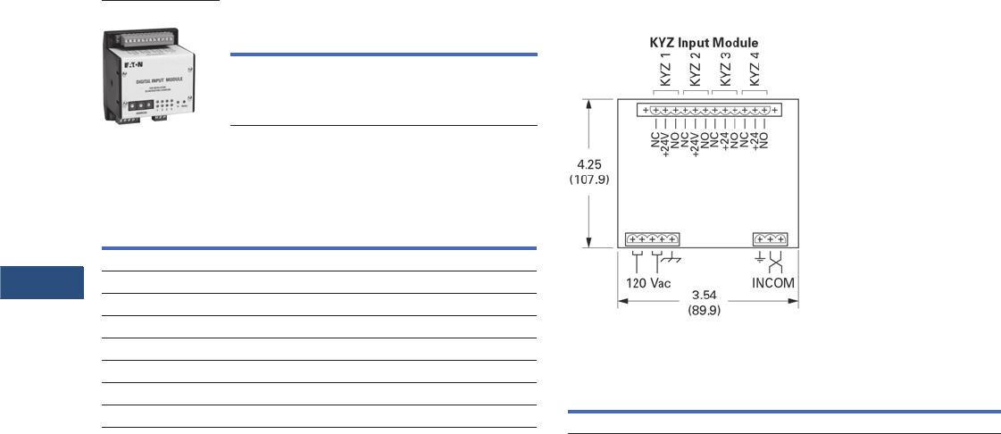
V3-T9-306 Volume 3—Power Distribution and Control Assemblies CA08100004E—March 2016 www.eaton.com
9
9
9
9
9
9
9
9
9
9
9
9
9
9
9
9
9
9
9
9
9
9
9
9
9
9
9
9
9
9
9.4
Metering Devices, Protective Relays, Software and Connectivity
Connectivity Options
Product Selection
Ordering Information
Technical Data and Specifications
Specifications
Frequency Range
●50/60 Hz
Power
●85 to 138 Vac (120 Vac
nominal) 50/60 Hz; 100 mA
●48–128 Vdc (48 Vdc
nominal); 100 mA
●Brownout operation at
50% and 80% of nominal
AC and DC ratings
●Power input is provided
from a limited source,
isolated from the mains
by double isolation
●Power for all inputs is
supplied from an internal,
isolated 24 Vdc power
source
Mounting Information
The DIM module is designed
to be DIN rail mountable.
DIN rail must be 1/3 inches
H x 1-3/8 inches W (8.5 mm
H x 34.9 mm W).
Communications
The DIM is a fully compatible
Power Management Software
communicating device
with built-in INCOM
communications. The DIM
comes complete with a
3-pin connector to receive
the shielded twisted pair
conductor.
All wiring must be complete
as per Instruction Leaflet
TD17513, Wiring
Specification Base Rules.
Description
Catalog
Number
Digital Input Module DIM
DIM
Description Rating
Operating temperature –20°C to 60°C
Storage temperature –20°C to 70°C
Operating Humidity 5 to 90% maximum noncondensing
Altitude 10,000 ft. (3048m)
Environment Indoor use only
Transient overvoltage Category 2
Pollution 1°
Equipment Class 1
Dimensions
Approximate Dimensions in Inches (mm)
KYZ Input Module
KYZ Input Module
Note
1Does include DIN rail.
Width Height Depth
3.54 (89.9) 4.25 (107.9) 3.50 (88.9) 1

Volume 3—Power Distribution and Control Assemblies CA08100004E—March 2016 www.eaton.com V3-T9-307
9
9
9
9
9
9
9
9
9
9
9
9
9
9
9
9
9
9
9
9
9
9
9
9
9
9
9
9
9
9
9.4
Metering Devices, Protective Relays, Software and Connectivity
Connectivity Options
Addressable Relay II
Contents
Description Page
Power Xpert Gateway . . . . . . . . . . . . . . . . . . . . . . V3-T9-287
Power Xpert Ethernet Switches . . . . . . . . . . . . . . V3-T9-296
mMINT . . . . . . . . . . . . . . . . . . . . . . . . . . . . . . . . . V3-T9-300
IPONI. . . . . . . . . . . . . . . . . . . . . . . . . . . . . . . . . . . V3-T9-302
DPONI . . . . . . . . . . . . . . . . . . . . . . . . . . . . . . . . . . V3-T9-303
MPONI . . . . . . . . . . . . . . . . . . . . . . . . . . . . . . . . . V3-T9-304
I/O Devices Digital Input Module (DIM) . . . . . . . . V3-T9-305
Addressable Relay II
Product Selection . . . . . . . . . . . . . . . . . . . . . . . V3-T9-308
Technical Data and Specifications . . . . . . . . . . V3-T9-308
Dimensions . . . . . . . . . . . . . . . . . . . . . . . . . . . V3-T9-308
Breaker Interface Module II (BIM II) . . . . . . . . . . . V3-T9-309
Addressable Relay II
Product Description
The Addressable Relay II is
designed for use where
information or control of non-
communicating devices is
required remotely. The relays
communicate at 9600/1200
baud on the INCOM network.
Devices are assigned a three-
digit address to uniquely
identify them on the daisy-
chained twisted shielded pair
network.
The Addressable Relay II is a
Form C relay on terminals 1, 2
and 3, with output contact
ratings as shown in the
Contact Ratings table. The
Addressable Relay II may be
powered by 48–120 Vac or
48–125 Vdc through
terminals 11 and 12 of the
terminal block. DC polarity is
not significant.
Application Description
●Enables remote control of
non-communication
capable devices on Eaton’s
PowerNet system
●Monitors two digital status
inputs on the PowerNet
system
Features, Benefits and
Functions
Each Addressable Relay II
includes two status indicating
circuits (IN1 and IN2) that can
be used to transmit the
contact status of devices
external to the Addressable
Relay II. Each input is isolated
with its own return. A typical
installation using these report-
back inputs to the Eaton
PowerNet system is shown in
the wiring example. Terminals
4 and 5 connect to the status
input 1 circuit (IN1) and
terminals 6 and 7 connect to
the status input 2 circuit (IN2).
These status indicating
circuits operate with input
voltages of 48–120 Vac or
48–125 Vdc circuits.
The Addressable Relay II
includes a feature called
the “communications
watchdog.” The
communications watchdog
monitors communications
between the Addressable
Relay II and the computer
control station. If
communications are lost, the
communications watchdog
will reset the relay to the de-
energized (OFF) state. The
Addressable Relay II must be
updated every 10 seconds
when the communications
watchdog is enabled or else
communications are
assumed to be lost. The
communications watchdog
is enabled when DIP switch 3
is set to the ON position.
When the communications
watchdog is not enabled, the
relay will remain in the state
set by the last command
issued. See V3-T9-312 for
DIP switch configuration.
Monitored Parameters
●Output relay energized/
de-energized
●Input 1 status
●Input 2 status
●Breaker status open/closed
●
Protective relay status
normal/tripped
Communications
●Built-in INCOM
communications for
monitoring in Eaton’s
PowerNet system
The Addressable Relay II also
includes a feature called
“relay pulse.” The relay pulse
feature sets the Addressable
Relay II to a pulse mode
where the relay is energized
(ON) for 10 seconds and then
is de-energized (OFF). The
relay pulse is enabled when
DIP switch 2 is set to the ON
position and disabled when
DIP switch 2 is set to the OFF
position. If this feature is not
enabled, the relay will remain
in the state set by the last
command.
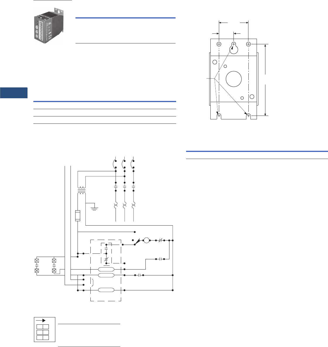
V3-T9-308 Volume 3—Power Distribution and Control Assemblies CA08100004E—March 2016 www.eaton.com
9
9
9
9
9
9
9
9
9
9
9
9
9
9
9
9
9
9
9
9
9
9
9
9
9
9
9
9
9
9
9.4
Metering Devices, Protective Relays, Software and Connectivity
Connectivity Options
Product Selection
Addressable Relay
Technical Data and Specifications
●Power: 48–120 Vac; 48–125 Vdc
●Operating temperature range: 32°–158°F (0°–70°C)
Contact Ratings
Wiring Diagram
DIP Switch Functions
Description
Catalog
Number
Addressable Relay II ARII
Addressable Relay II
Contact
Ratings Make Break
120–240 Vac 4960 VA 828 VA
24–120 Vac 43A 7.2A
30 Vdc 10A 10A
INCOM
Network
Cpt
Power Bus
L1
M1
2
1
3
5
7
12
MA
OL
OL
Auto
Hand
Off
INCOM
Communications
Addressable Relay
6
8
9
11
OL OL OL
T1 T2 T3
M2 M3
L2 L3
FL
M
Communication and
Controlled Output Relay
Power
Input 2
Input 1
M
AUX OL
OFF ON
Baud Rate 9600 1200
Relay Pulse Disabled Enabled
Communications Watchdog
Disabled Enabled
O1 23
N
DOO
Dimensions
Approximate Dimensions in Inches (mm)
Mounting
Addressable Relay
Width Height Depth
1.75 (44.5) 3.00 (76.2) 4.00 (101.6)
Insert (3)
#8 Screws
for
Mounting
Back View
2.82
(71.6)
.50
(12.7)
1.00
(25.4)

Volume 3—Power Distribution and Control Assemblies CA08100004E—March 2016 www.eaton.com V3-T9-309
9
9
9
9
9
9
9
9
9
9
9
9
9
9
9
9
9
9
9
9
9
9
9
9
9
9
9
9
9
9
9.4
Metering Devices, Protective Relays, Software and Connectivity
Connectivity Options
Breaker Interface Module II (BIM II)
Contents
Description Page
Power Xpert Gateway . . . . . . . . . . . . . . . . . . . . . . V3-T9-287
Power Xpert Ethernet Switches . . . . . . . . . . . . . . V3-T9-296
mMINT . . . . . . . . . . . . . . . . . . . . . . . . . . . . . . . . . V3-T9-300
IPONI. . . . . . . . . . . . . . . . . . . . . . . . . . . . . . . . . . . V3-T9-302
DPONI . . . . . . . . . . . . . . . . . . . . . . . . . . . . . . . . . . V3-T9-303
MPONI . . . . . . . . . . . . . . . . . . . . . . . . . . . . . . . . . V3-T9-304
I/O Devices Digital Input Module (DIM) . . . . . . . . V3-T9-305
Addressable Relay II . . . . . . . . . . . . . . . . . . . . . . . V3-T9-307
Breaker Interface Module II (BIM II)
Features, Benefits and Functions . . . . . . . . . . . V3-T9-310
Product Selection . . . . . . . . . . . . . . . . . . . . . . . V3-T9-311
Technical Data and Specifications . . . . . . . . . . V3-T9-311
Breaker Interface Module II (BIM II)
Product Description
Eaton’s Breaker Interface
Module is a panel-mounted
device that displays the
following parameters.
●Phase current
●Energy
●Present demand watts
●Peak demand watts
●Average demand current
●Cause and magnitude
of trip
●Trip history
●% Total Harmonic
Distortion (THD) for
each phase
●% Harmonic Content for
each phase (1st–27th
harmonic)
●Custom circuit description
Note: The Breaker Interface
Module displays only a portion of
the information it receives from
the Digitrip RMS 910, 1150 and
Power Sentinels. The balance of
the information (such as
Waveform Analysis and Power
Factor) can be passed through the
unit to a master computer, where
it can be viewed.
Application Description
●810, 910, 750, 1050, 550,
1150, 520MC, IQ Energy
Sentinels and Power
Sentinels
●Event logging
●Alarming
●High load indication
●Peak exceeded alarm
●Grouping of meters
An operator can use the
Breaker Interface Module to:
●Complete Initial System
Setup:
●Select system
frequency (50/60 Hz)
●Set password
●Configure OPTIM
Protective Settings.
●Select protection
options
●Select alarm levels
●Display Information:
●Metered values
●Trip event information
●Breaker information
●Time-current set points
●Test O P TI M Tr i p U n it
Performance:
●Phase and ground
●Trip/no trip
●Expanded Energy
Monitoring:
●Set addresses for group
energy monitoring
●Group energy readings
●Local and Remote
Indication:
●Remote indication/
alarming
●Breaker status LED
indication
●Expanded
Communications:
●Communicate with:
– OPTIM Trip Units
– Digitrip RMS 810, 910
a n d 115 0 Tri p Un i t s
– IQ Energy Sentinels
and Universal IQ
Energy Sentinels
– A total of 50 devices

V3-T9-310 Volume 3—Power Distribution and Control Assemblies CA08100004E—March 2016 www.eaton.com
9
9
9
9
9
9
9
9
9
9
9
9
9
9
9
9
9
9
9
9
9
9
9
9
9
9
9
9
9
9
9.4
Metering Devices, Protective Relays, Software and Connectivity
Connectivity Options
Features, Benefits and Functions
●Monitors and displays
parameters from any
combination of Digitrip
RMS 810, 910, 1150 and
Digitrip OPTIM Trip Units,
F-/J-/K-Frame Energy
Sentinels, and Universal
Energy Sentinels,
supporting as many as
50 of these devices up to
10,000 feet (3048m) away
●Communicates the
information from these
protective and energy
monitoring devices over
Eaton INCOM network
to a computer or PLC
●Continuously monitors
breakers recording and
time-stamping trip events
along with approximate
fault currents. Events are
logged into non-volatile
RAM
Physical Characteristics
●Graphical, glass plasma
display
●Up to seven lines of
information
●Membrane faceplate
NEMA 3R and 12 rated
Communications
Depending upon the type of
communication protocol used
by the main network, an
appropriate PONI module can
be easily field-mounted to the
back of the Breaker Interface
Module, enabling the unit to
pass the information from its
subnetwork to a remote
master control unit up to
10,000 feet (3048m) away.
No reprogramming of the
unit is required when the
PONI is added.
The Breaker Interface Module
can be mounted directly on
the assembly or at a remote
location and can be used to
access and configure and
display information from
OPTIM Trip Units.
Password Protection
A user-defined password is
included for added security
when changing settings or
performing breaker tests.
Non-Volatile Memory
The programmed functions,
addresses and circuit
descriptions are stored in
non-volatile memory.
External Power
A 24 Vdc supply is required
for the BIM II. (No external
power supply is required for
the PONI Card.) A 120 or
240 Vac supply is required
for the BIMPS.
Rear Access Area
All wiring connections to the
Breaker Interface Module
are made at the chassis’ rear
and include:
●Relay connection for
“alarm” condition, “high
load” condition, “peak
exceed” for device or
group, and watthour pulse
●Initiator
●24 Vdc input—BIM II
●120 or 240 Vac input—
BIMPS
●DIP switches for selecting
an operating mode
●Three-contact connector
with subnetwork
●Connector for PONI
card for remote
communications Local
Display Units

Volume 3—Power Distribution and Control Assemblies CA08100004E—March 2016 www.eaton.com V3-T9-311
9
9
9
9
9
9
9
9
9
9
9
9
9
9
9
9
9
9
9
9
9
9
9
9
9
9
9
9
9
9
9.4
Metering Devices, Protective Relays, Software and Connectivity
Connectivity Options
Product Selection
Breaker Interface Module
Technical Data and Specifications
Power Requirement
●15 VA maximum
Input Voltage
●24 Vdc ±5%—BIM II
●120 or 240 Vac ±10%—
BIMPS
Operating Temperature
●0°C to 70°C
(32°C to 158°F)
Humidity
●5% to 95% R.H.
(noncondensing)
Alarm Contact Ratings
●10A at 277 Vac (resistive)
●10A at 30 Vdc (resistive)
●1/3 hp at 125, 250 Vac
Description
Catalog
Number
Breaker Interface Module BIMII
BIMPSII
Breaker Interface
Module II (BIM II)
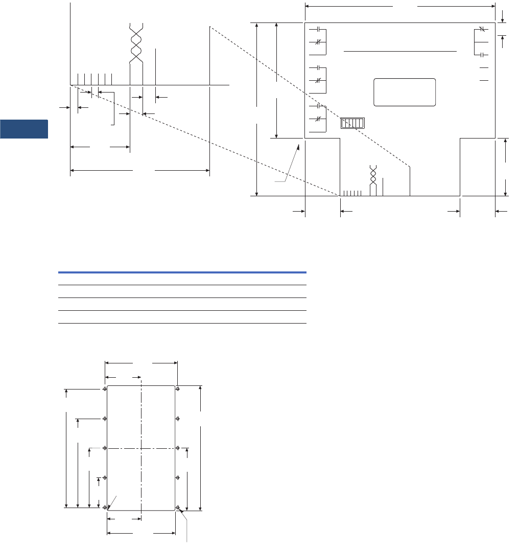
V3-T9-312 Volume 3—Power Distribution and Control Assemblies CA08100004E—March 2016 www.eaton.com
9
9
9
9
9
9
9
9
9
9
9
9
9
9
9
9
9
9
9
9
9
9
9
9
9
9
9
9
9
9
9.4
Metering Devices, Protective Relays, Software and Connectivity
Connectivity Options
Dimensions
Approximate Dimensions in Inches (mm)
Connections and DIP Switch Rear Label Diagram
Breaker Interface Module
Drilling Pattern
Height Width Depth
Without Communications Card
6.72 (170.7) 10.25 (260.4) 2.60 (66.0)
With Communications Card
6.72 (170.7) 10.25 (260.4) 3.85 (97.8)
Typical
5 Places
.10
(2.5)
.11
(2.8)
PONI Power
Learn/Run
Unused
Shield
PONI
Interface
Sub
Network
Unused
Unused
Unused
Expanded View
.87
(22.1)
.19
(4.8)
.19
(4.8)
2.04
(51.8)
Customer Satisfaction
We have established a toll-free
line for problems
Call 1-800-809-2772
9
8
7
6
5
4
3
2
1
Alarm High Load
Peak
Exceeded
Sub
Network
PONI
Interface
Common
24-30 Vac
Ground
Unused
10
11
12
13
14
15
16
17
18
WH Pulse
Initiator
Sync.
Pulse
Impulse
Unused
Run
Unused
Unused
PONI On
Learn
Off Unused
Sub
Network PONI
Interface
Shield
Unused
Learn/Run
Unused
Unused
PONI Power
Unused
H02
CATALOG # BIMPS
STYLE # 7801C61G02
.38
(9.7)
Typical
5.56
(141.2)
1.69
(42.9)
1.03
(26.2)
3.38
(85.9)
5.06
(128.6)
General Layout and Dimensions
1.03
(26.2)
.06
(1.5) RAD
4 Places
2.23
(56.7)
4.45
(113.0)
6.68
(169.7)
8.90
(226.1)
2.53
(64.3)
5.06
(128.5)
2.69
(68.3)
5.38
(136.7)
.218 (5.5) DIA 10 Places
9.38
(238.3)
4.69
(119.1)
