1000334641 Catalog
2016-07-29
: Pdf 1000334641-Catalog 1000334641-Catalog B2 unilog
Open the PDF directly: View PDF ![]() .
.
Page Count: 132 [warning: Documents this large are best viewed by clicking the View PDF Link!]

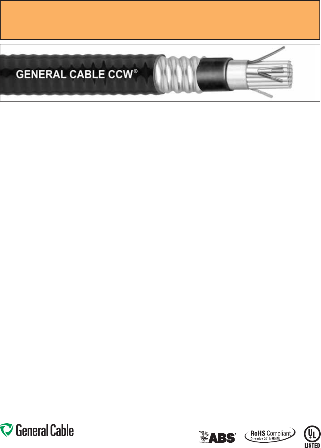
CCW®
Continuously Corrugated
Welded Cable
ARMORED CABLE FOR HAZARDOUS LOCATIONS
OCTOBER 2014
CCW®
Servicing Industrial and
Specialty Applications
This catalog contains in-depth
information on the most
comprehensive line of CCW®
instrumentation, power, control,
and automation Continuously
Corrugated Welded cable
available today. It features the
latest information on products,
along with detailed technical
and specifi cation data in indexed
sections — with an easy-to-use
“spec-on-a-page” format.
The “spec-on-a-page” format was
developed to meet your needs. It
features up-to-the-minute product
information, from applications
and constructions to detailed
technical and specifi cation data.
There’s also a comprehensive
technical section for additional
assistance.
And, of course, if you need any
further data, General Cable’s
Customer Service staff provides
the answers you need quickly
and effi ciently.
All information in this catalog is presented solely
as a guide to product selection and is believed
to be reliable. All printing errors are subject to
correction in subsequent releases of this catalog.
Although General Cable has taken precautions to
ensure the accuracy of the product specifi cations
at the time of publication, the specifi cations of all
products contained herein are subject to change
without notice.
GENERAL CABLE and CCW are registered
trademarks of General Cable Technologies
Corporation.
C-L-X is a trademark of The Okonite Company.
© 2014. General Cable Technologies
Corporation.
Highland Heights, KY 41076
All rights reserved. Printed in USA.
What’s New?
CCW® CABLES FOR ARCTIC CLIMATES
General Cable introduces the addition of Arctic Armor to its
CCW line of products. With unsurpassed performance, CCW
Arctic Armor is impervious to temperature extremes up to
-60ºC, as proven by passing the ASTM D746-04 brittleness
temperature impact test. Arctic Armor is yet another example
of how General Cable continues to deliver to our customers a
product that sets the standard for the refi ning industry and is
a staple in offshore applications.
GLOBAL OIL AND GAS CABLE SOLUTIONS
Uniquely positioned to respond to the evolving needs of the
global oil and gas market, General Cable has the resources,
production processes and dedication to work side-by-side with
customers to design cost-effective solutions that meet exact
specifi cations while providing value-added services.
Global Oil and Gas
CABLE SOLUTIONS
MAY 2014
OFFSHORE & ONSHORE RIG CABLES CATALOG
This catalog provides in-depth information on a comprehensive
range of application-specifi c IEEE cables for upstream offshore
topside and onshore land rig requirements.
APRIL 2014
Offshore & Onshore
RIG Cables
FULL-LINE CATALOG
Instrumentation, Power and Control Cables
This catalog contains in-depth information on the most
comprehensive line of instrumentation, power and control cable
available today. It features the latest information on products,
along with detailed technical and specifi cation data in indexed
sections — with an easy-to-use “spec-on-a-page” format.
Industrial Cable
SERVING INDUSTRIAL, SPECIALTY AND
COMMERCIAL APPLICATIONS

CCW
®
Continuously Corrugated Welded Cable
Participation in the global oil, gas and petrochemical (OGP) market sector is an
important part of General Cable’s long-term energy strategy.
General Cable has positioned itself globally as an “energy company” and
is making major investments in wire and cable products for the energy
infrastructure markets. With oil and gas as a primary driver of energy,
General Cable has listened to customers and analyzed its product offering
based on market input. Consequently, it has rounded out its portfolio of
products on a global scale, adding CCW (Continuously Corrugated Welded
cable), umbilical, and subsea cables to a suite of products used by the
oil, gas and petrochemical industries for power, control, instrumentation,
communications and automation.
The addition of Arctic Armor to the CCW line of product expands the current
OGP product offering, providing existing and new customers with a single
source for their wire and cable needs. Utilizing the same precision-engineered,
state-of-the-art equipment to produce a full line of continuously corrugated
welded cable, General Cable’s CCW Arctic Armor has been engineered
to perform in the north slopes of Alaska and beyond. With unsurpassed
performance, CCW is impervious to temperature extremes up to -60ºC, as
proven by passing the ASTM D746-04 brittleness temperature impact test.
CCW products are used in hazardous locations (in accordance with NEC®
Articles 500-505) requiring cables that are impervious to gas, liquids and
vapors and terminated with explosion-proof glands to electrical equipment.
CCW is a preferred wiring method for the refi ning industry, providing a lower
installed cost over conduit, and is a staple in offshore production platforms,
refi neries, LNG facilities, and petrochemical processing mills. The CCW
product line is ideal for use in the world’s prominent “oil patches” in the U.S.A.,
Indonesia, Mexico, the Caribbean, South America, and the Middle East.
General Cable’s stocking profi le includes a complete line of products from
300 volt instrumentation through 35 kV power cable, allowing General Cable to
participate more broadly in the downstream portion of the OGP market, which
includes refi neries, petrochemical plants, and LNG (liquid natural gas) facilities.
Phone: 888-593-3355
www.generalcable.com
Date of Issue 10/14
Section 1
Table of Contents
CCW
®
Continuously Corrugated Welded Cable for Hazardous Locations
SPECIFICATION NO. PRODUCT DESCRIPTION REVISION DATE
9025 CCW®
Armor Thermocouple Extension, Single Pair, Overall Shield (OS)
UL Type ITC/PLTC, PVC, 105°C, ABS CWCMC Oct. 2014
9050 CCW®
Armor Thermocouple Extension, Pairs, Overall Shield (OS)
UL Type ITC-HL/PLTC, PVC, 105°C, ABS CWCMC Oct. 2014
9075 CCW®
Armor Thermocouple Extension, Pairs, Individual and Overall Shield (IS-OS)
UL Type ITC-HL/PLTC, PVC, 105°C, ABS CWCMC Oct. 2014
9125 CCW®
Armor 300 V Instrumentation, Pairs/Triads, Overall Shield (OS)
UL Type ITC-HL/PLTC, XLPE, 90°C, ABS CWCMC Oct. 2014
9150 CCW®
Armor 300 V Instrumentation, Pairs/Triads, Individual and Overall Shield (IS-OS)
UL Type ITC-HL/PLTC, XLPE, 90°C, ABS CWCMC Oct. 2014
9225 CCW®
Armor 300 V Instrumentation, Pairs/Triads, Overall Shield (OS)
UL Type ITC-HL/PLTC, PVC, 105°C, ABS CWCMC Oct. 2014
9250 CCW®
Armor 300 V Instrumentation, Pairs/Triads, Individual and Overall Shield (IS-OS)
UL Type ITC-HL/PLTC, PVC, 105°C, ABS CWCMC Oct. 2014
9325 CCW®
Armor 600 V Instrumentation, Pairs/Triads, Overall Shield (OS)
UL Type MC-HL, PVC/Nylon, 90°C, ABS CWCMC Oct. 2014
9350 CCW®
Armor 600 V Instrumentation, Pairs/Triads, Individual and Overall Shield (IS-OS)
UL Type MC-HL, PVC/Nylon, 90°C, ABS CWCMC Oct. 2014
9400 CCW®
Arctic
Armor
300 V/600 V Instrumentation, Pairs/Triads, Individual and Overall Shield, UL Type MC-HL
600 V or UL Type ITC-HL, 300 V, XLPE, 90°C, Cable Tray Use, Sunlight-Resistant, Direct Burial
UL Marine Shipboard Cable, ABS CWCMC, Arctic-Grade
Oct. 2014
9500 CCW®
Armor 600 V Control With Grounding Conductor
UL Type MC-HL, CSA Type HL, XLPE, 90°C, ABS CWCMC Oct. 2014
9505 CCW®
Arctic
Armor
600 V Control With Grounding Conductor
UL Type MC-HL, XLPE, 90°C, Cable Tray Use, Sunlight-Resistant
Direct Burial, UL Marine Shipboard Cable, ABS CWCMC, Arctic-Grade
Oct. 2014
9510 CCW®
Armor 600 V Control With Bare Grounding Conductor
UL Type MC-HL, CSA Type HL, XLPE, 90°C, ABS CWCMC Oct. 2014
9525 CCW®
Armor 600 V Control Without Grounding Conductor
UL Type MC, CSA Type HL, XLPE, 90°C, ABS CWCMC Oct. 2014
9600 CCW®
Armor 600 V Power, 3/C VFD and 4/C
UL Type MC-HL, CSA Type HL, XLPE, 90°C, ABS CWCMC Oct. 2014
9605 CCW®
Arctic
Armor
600 V Power, 3/C VFD and 4/C
UL Type MC-HL, XLPE, 90°C, Cable Tray Use, Sunlight-Resistant
Direct Burial, UL Marine Shipboard Cable, ABS CWCMC, Arctic-Grade
Oct. 2014
9615 CCW®
Armor 2000 V Power, 3/C VFD
UL Type MC-HL, XLPE, 90°C, ABS CWCMC Oct. 2014
9625 CCW®
Armor 600 V Composite Power and Control
UL Type MC-HL, XLPE, 90°C, ABS CWCMC Oct. 2014
9650 CCW®
Armor 600 V Composite Power and Control Without Ground
UL Type MC, XLPE, 90°C, ABS CWCMC Oct. 2014
Phone: 888-593-3355
www.generalcable.com
Date of Issue 10/14
Section 1
Table of Contents
CCW
®
Continuously Corrugated Welded Cable for Hazardous Locations
SPECIFICATION NO. PRODUCT DESCRIPTION REVISION DATE
9675 CCW®
Armor 1000 V Power, 3/C VFD
CSA Type RA90, HL, XLPE, 90°C Oct. 2014
9700 CCW®
Armor 2.4 kV Power, Nonshielded, 3/C VFD
UL Type MC-HL or MV-90, EPR, 105°C, ABS CWCMC Jul. 2014
9800 CCW®
Armor 5 kV 133%/8 kV 100% Power, Shielded, 3/C VFD
UL Type MC-HL or MV-105, CSA Type HL, EPR, 105°C, ABS CWCMC Oct. 2014
9805 CCW®
Arctic
Armor
5 kV 133%/8 kV 100% Power, Shielded, 3/C VFD
UL Type MC-HL or MV-105, CSA Type HL, EPR, 105°C, Cable Tray Use, Sunlight-Resistant
Direct Burial, UL Marine Shipboard Cable, ABS CWCMC, Arctic-Grade
Oct. 2014
9815 CCW®
Armor 8 kV 133% Power, Shielded, 3/C VFD
UL Type MC-HL or MV-105, CSA Type HL, EPR, 105°C, ABS CWCMC Oct. 2014
9825 CCW®
Armor 15 kV 100% Power, Shielded, 3/C
UL Type MC-HL or MV-105, CSA Type HL, EPR, 105°C, ABS CWCMC Oct. 2014
9835 CCW®
Armor 15 kV 133% Power, Shielded, 3/C
UL Type MC-HL or MV-105, CSA Type HL, EPR, 105°C, ABS CWCMC Oct. 2014
9840 CCW®
Arctic
Armor
15 kV 133% Power, Shielded, 3/C
UL Type MC-HL or MV-105, CSA Type HL, EPR, 105°C, Cable Tray Use, Sunlight-Resistant
Direct Burial, UL Marine Shipboard Cable, ABS CWCMC, Arctic-Grade
Oct. 2014
9845 CCW®
Armor 25 kV 100% Power, Shielded, 3/C
UL Type MC-HL or MV-105, CSA Type HL, EPR, 105°C, ABS CWCMC Oct. 2014
9855 CCW®
Armor 25 kV 133%/35 kV 100% Power, Shielded, 3/C
UL Type MC-HL or MV-105, CSA Type HL, EPR, 105°C, ABS CWCMC Oct. 2014
9860 CCW®
Arctic
Armor
25 kV 133%/35 kV 100% Power, Shielded, 3/C
UL Type MC-HL or MV-105, CSA Type HL, EPR, 105°C, Cable Tray Use, Sunlight-Resistant
Direct Burial, UL Marine Shipboard Cable, ABS CWCMC, Arctic-Grade
Oct. 2014
9875 CCW®
Armor 35 kV 133% Power, Shielded, 3/C
UL Type MC-HL or MV-105, CSA Type HL, EPR, 105°C, ABS CWCMC Oct. 2014
9880 CCW®
Arctic
Armor
35 kV 133% Power, Shielded, 3/C
UL Type MC-HL or MV-105, CSA Type HL, EPR, 105°C, Cable Tray Use, Sunlight-Resistant
Direct Burial, UL Marine Shipboard Cable, ABS CWCMC, Arctic-Grade
Oct. 2014
9899 CCW®
Arctic
Armor
Fieldbus Cable
Multi-Paired, Individual and Overall Shielded, 18 AWG & 16 AWG
UL Type MC-HL, 600 V, 90°C, Sunlight-Resistant, Direct Burial, Arctic-Grade
Oct. 2014
9899 CCW®
Arctic
Armor
Category 5e Cable
4 Pair, 21 AWG, UL Type ITC-HL, 300 V, 90°C, Cable Tray Use, Sunlight-Resistant
Direct Burial, Arctic-Grade
Oct. 2014
9899 CCW®
Arctic
Armor
PROFIBUS Cable
22 AWG Shielded Pair, UL Type ITC-HL, 300 V, 90°C, Cable Tray Use
Sunlight-Resistant, Direct Burial, Arctic-Grade
Oct. 2014
9900 CCW®
Armor CCW® Armored Cable Tool Kit Jan. 2010

Phone: 888-593-3355
www.generalcable.com
Date of Issue 10/14
Section 2
Table of Contents
Technical Information
SPECIFICATION NO. DESCRIPTION REVISION DATE
Technical Table of Contents Sept. 2014
A001 Metal-Clad CCW® Type MC-HL Wiring System Feb. 2011
A001 CCW® Installation Manual Oct. 2014
A001 CCW® Sheath Removal Instructions Feb. 2011
A010 CCW® Explosion-Proof Gland Cross-Reference Apr. 2010
A015 CCW® Catalog Number Cross-Reference —
Okonite C-L-X® to General Cable CCW®Jan. 2013
A030 Reference Standards Apr. 2010
A055 Checklist for CCW® Specifications Apr. 2010
A100 Common Color Sequence May 2013
A150 Metric Conversion Factors Sept. 2010
A185 AWG (American Wire Gauge) to mm2 (Millimeters Squared) Conversion May 2013
B025 Class B Conductors for General Wiring Mar. 2012
D005 Recommended Reel Handling Practices May 2013
D025 Recommended Cable Handling Practices Oct. 2011
D050 Recommended Cable Storage Practices May 2013
E005 Pre-Installation Instructions Apr. 2010
E050 Installation — Feed-In Setups Apr. 2010
E075 Installation — Conductor Maximum Pulling Tensions Oct. 2012
E100 Installation — Training and Bending Limitations Apr. 2010
E125 Installation — Maximum Sidewall Pressure Oct. 2012
F005 DC “HI-POT” Pre-Test Guidelines for MV Cables Apr. 2010
F025 DC “HI-POT” Testing Guidelines for MV Cables Apr. 2010
F075 Field Electrical “HI-POT” Testing Guidelines Apr. 2010
F130 CCW® Sheath as a Grounding Conductor Dec. 2010
Index Catalog Number Index Sept. 2014
As one of the largest wire and cable companies, General Cable offers its valued customers
the competitive advantages of a global organization while delivering the responsiveness of a small
company. Our culture of continuous improvement consistently provides better quality, better service and better
technology for oil, gas and petrochemical exploration, extraction, production and refining—anywhere in the world.
Upstream Offshore Cable –
Topside Solutions
• IEEE 1580 Type P – MOR® Polyrad®
• UL Type MC-HL ABS CWCMC – CCW®
• UL Type ITC-HL/PLTC ABS CWCMC – CCW®
• Arctic-Armor Grade Automation – CCW®
• IEC 60092-350 – EXZHELLENT® 606 & EXZHELLENT®- 92-3
• Data Comm. & Industrial Automation – COMMODORE®
• Application-Specific Cable Assemblies
Upstream Onshore Cable –
Land Rig and Well Solutions
• IEEE 1580 Type P – MOR® Polyrad®
• UL Type MC-HL – CCW®
• UL Type ITC-HL/PLTC – CCW®
• Arctic-Armor Grade Automation – CCW®
• IEEE 1018 ESP – X-Tract®
• Data Comm. & Industrial Automation – COMMODORE®
• Application-Specific Cable Assemblies
Upstream Offshore Cable –
Subsea Solutions
• Submarine Power –
• Submarine Fiber Optic Cable & Accessories –
• Umbilical Power – , Silec®
• Cable Installations –
Midstream & Downstream
Cable – LNG, Refining and
Petrochemical Solutions
• UL Type MC-HL – CCW®
• UL Type ITC-HL/PLTC – CCW®
• UL Type MC – Duralox®
• TECK90/HVTECK
• UL Type TC-ER – VNTC®, FREP®, ARCTIC-FLEX®
• UL Type MV-105 – Uniblend®, UniShield®
• IEC 60502 – ARMIGRON®, ERVYLEC®
• IEC ANZ – PDIC®
Phone (859) 572-8000 • www.generalcable.com • info@generalcable.com
We’ve Got You Wired
GLOBAL RESOURCES
LOCAL PRESENCE

One Company
Connecting
The World
POWERFUL PRESENCE · PRODUCTS
PERFORMANCE · PEOPLE
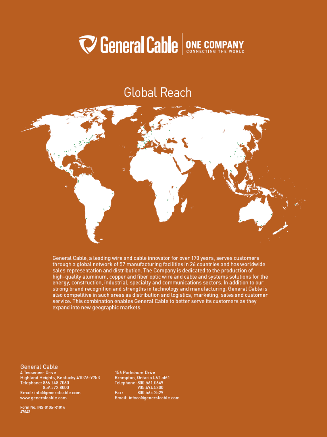
General Cable has been a wire and cable innovator for over
170 years, always dedicated to connecting and powering people’s
lives. Today, with more than 14,500 employees and more than
$6 billion in revenues, we are one of the largest wire and cable
manufacturers in the world.
Our company serves customers through a global network of 57
manufacturing facilities in 26 countries and has worldwide sales
representation and distribution. We are dedicated to the production
of high-quality aluminum, copper and fiber optic wire and cable and
systems solutions for the energy, construction, industrial, specialty
and communications sectors. With a vast portfolio of products to
meet thousands of diverse application requirements, we continue to
invest in research and development in order to maintain and extend
our technology leadership by developing new materials, designing
new products, and creating new solutions to meet tomorrow’s
market challenges.
In addition to our strong brand recognition and strengths in
technology and manufacturing, General Cable is also competitive
in such areas as distribution and logistics, marketing, sales and
customer service. This combination enables us to better serve our
customers globally and as they expand into new geographic markets.
General Cable offers our customers all the
strengths and value of a large company, but our
people give us the agility and responsiveness of
a small one. We service you globally or locally.
Visit our Website at
www.generalcable.com
General Cable believes corporate social responsibility (CSR) is about creating shared value.
That means keeping a dual focus in our business decisions: what is good for us as a company
and what contributes to the greater good of the communities in which we live and work.
Corporate Social Responsibility
CREATING SHARED VALUE
+1.859.572.8000
info@generalcable.com
Visit www.GeneralCableCSR.com
to learn more.
A commitment to achieving industry-leading standards
and responding proactively to environmental global issues.
SAFETY
Working safer by working together
General Cable has one worldwide safety vision and goal –
ZERO & BEYOND
. We measure safety
performance globally, share best practices and implement sound health and safety management
systems. Many of our facilities worldwide are OHSAS 18001 (safety management system) certified.
All North American facilities have implemented an equivalent health and safety management system.
General Cable was a pioneer in obtaining the OHSAS 18001 Certificate for Occupational Health and
Safety Management Systems in Europe and North Africa.
SUSTAINABILITY
Responsible practices in daily operations
As a global leader in the wire and cable industry, General Cable recognizes its role and responsibility
in promoting sustainability. Our strongest business value is continuous improvement in all areas of
our company. Across our many businesses, the quest to introduce new and better products through
continuous improvement in environmental designs reflects our commitment to achieving industry-leading
standards and responding proactively to global environmental issues. General Cable was the first cable
manufacturer to obtain certification for its environmental management system, in accordance with the
ISO 14001 and EMAS Standards.
CITIZENSHIP
A commitment to being good citizens
Being responsible citizens in our communities is of the utmost importance to us. Unequivocal honesty,
integrity, forthrightness and fair dealing have long been part of General Cable’s core values and are
expected globally in all of our business relationships with our customers, employees, suppliers, neighbors
and competitors. Our company leaders and employees strive to make a difference throughout a host of
volunteer activities and financial support, improving the communities in which we live and work.
INNOVATION
Technologies that power and connect the world
General Cable is delivering innovation that matters. We are focusing on R&D expertise
and investing in developing wire and cable solutions that meet the challenges confronting
our customers and the world. In working together and using all the ingenuity and
creativity we have, we will reach the goal of being the preeminent supplier of
wire and cabling solutions in the industry, with both green constructions
and designs for the ever-growing renewable energy market.
Phone: 888-593-3355
www.generalcable.com
SPEC 9025
October, 2014
Overall Jacket:
• Flame-retardant, moisture- and
sunlight-resistant Polyvinyl Chloride
(PVC) per UL Standards 13 and 2250
• ANSI color-coded
• Low temperature performance meets
ASTM D746 brittleness temperature at
or below -40°C
Applications:
• CCW armored Thermocouple
Extension cables provide superior
protection and reliability against
physical damage for use in
instrumentation and process control
applications requiring ITC or PLTC
wiring methods
• For use as Power Limited Tray Cable
on circuits rated 150 V or less and
5 amps or less in Class 2 or Class 3
circuits in accordance with NEC Article
725
• For use as Instrumentation Tray Cable
on circuits rated 150 V or less and
5 amps or less in accordance with
NEC Article 727
• Installed indoors or outdoors, in wet or
dry locations, in a raceway, as aerial
cable on a messenger, in cable trays,
or for direct burial
• Recognized for use on fixed or
floating offshore petroleum facilities
as recommended by the American
Petroleum Institute
Product Construction:
Conductor:
• 16 AWG solid alloy wire per ANSI
MC 96.1
Insulation:
• Flame-retardant Polyvinyl Chloride
(PVC), rated 105°C per UL Standards
13 and 2250
• Color-coded per ANSI
Pair Assembly:
• Insulated conductors are cabled
together with a left-hand lay
Overall Shield:
• Flexfoil
®
aluminum/polyester tape
shield providing 100% coverage
• Stranded tinned copper drain wire,
same size as insulated conductors
Inner Jacket:
• Flame-retardant Polyvinyl Chloride
(PVC) per UL Standards 13 and 2250,
black
• Low temperature performance meets
ASTM D746 brittleness temperature at
or below -40°C
• Nylon rip cord to facilitate jacket
removal
CCW Armor:
• Impervious, continuously welded and
corrugated aluminum alloy sheath per
UL 1569
• CCW armor conductivity meets the
grounding requirements of NEC
Article 250
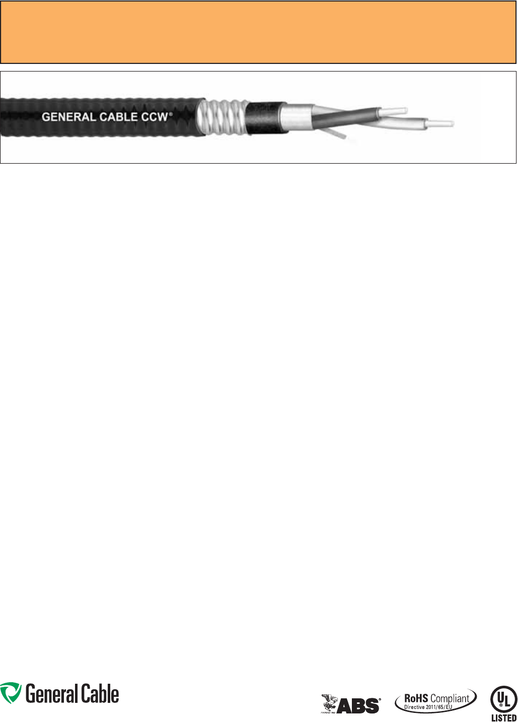
CCW
®
Armored Thermocouple, Single Pair, Overall Shield
UL Type ITC/PLTC, PVC, 105°C, Sunlight-Resistant, Direct Burial
UL Marine Shipboard Cable, ABS CWCMC
Features:
• CCW armor provides superior
mechanical protection and an
impervious barrier to moisture, gas
and liquids
• CCW armor provides EMI shielding
performance
• Meets cold impact at -40°C
Specifications:
Design Adherence:
• UL 13 Power-Limited Circuit Cables
• UL 2250 Instrumentation Tray Cable
• UL 1569 Metal Clad Cables
• UL 1309/CSA C22.2 No. 245 Marine
Shipboard Cable
Flame Tests:
• ICEA T-29-520 (210,000 BTU/hr)
• IEEE 383 (70,000 BTU/hr)
• CSA FT4
• IEEE 1202 (70,000 BTU/hr)
• UL 1581 (70,000 BTU/hr)
• IEC 60332-3 Cat. A
Compliances:
• UL Type PLTC, SUN RES, DIR BUR,
-40°C, UL File # E36118
• UL Type ITC, UL File # E177408
• UL Listed Marine Shipboard, UL File
# E85994
• American Bureau of Shipping (ABS)
Listed for CWCMC
• RoHS Compliant
Phone: 888-593-3355
www.generalcable.com
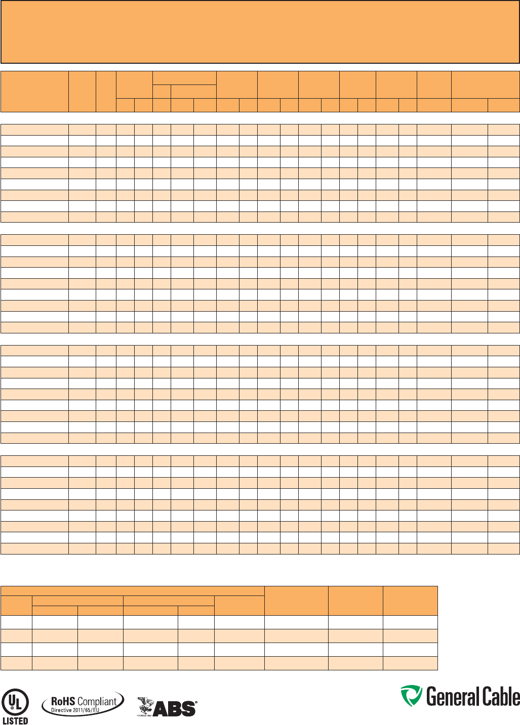
CCW
®
Armored Thermocouple, Single Pair, Overall Shield
UL Type ITC/PLTC, PVC, 105°C, Sunlight-Resistant, Direct Burial
UL Marine Shipboard Cable, ABS CWCMC
SPEC 9025
October, 2014
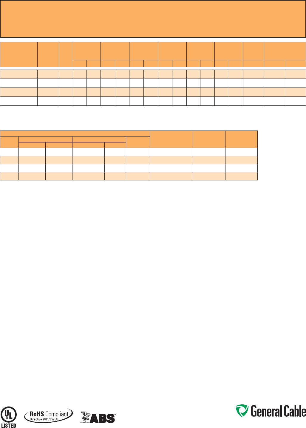
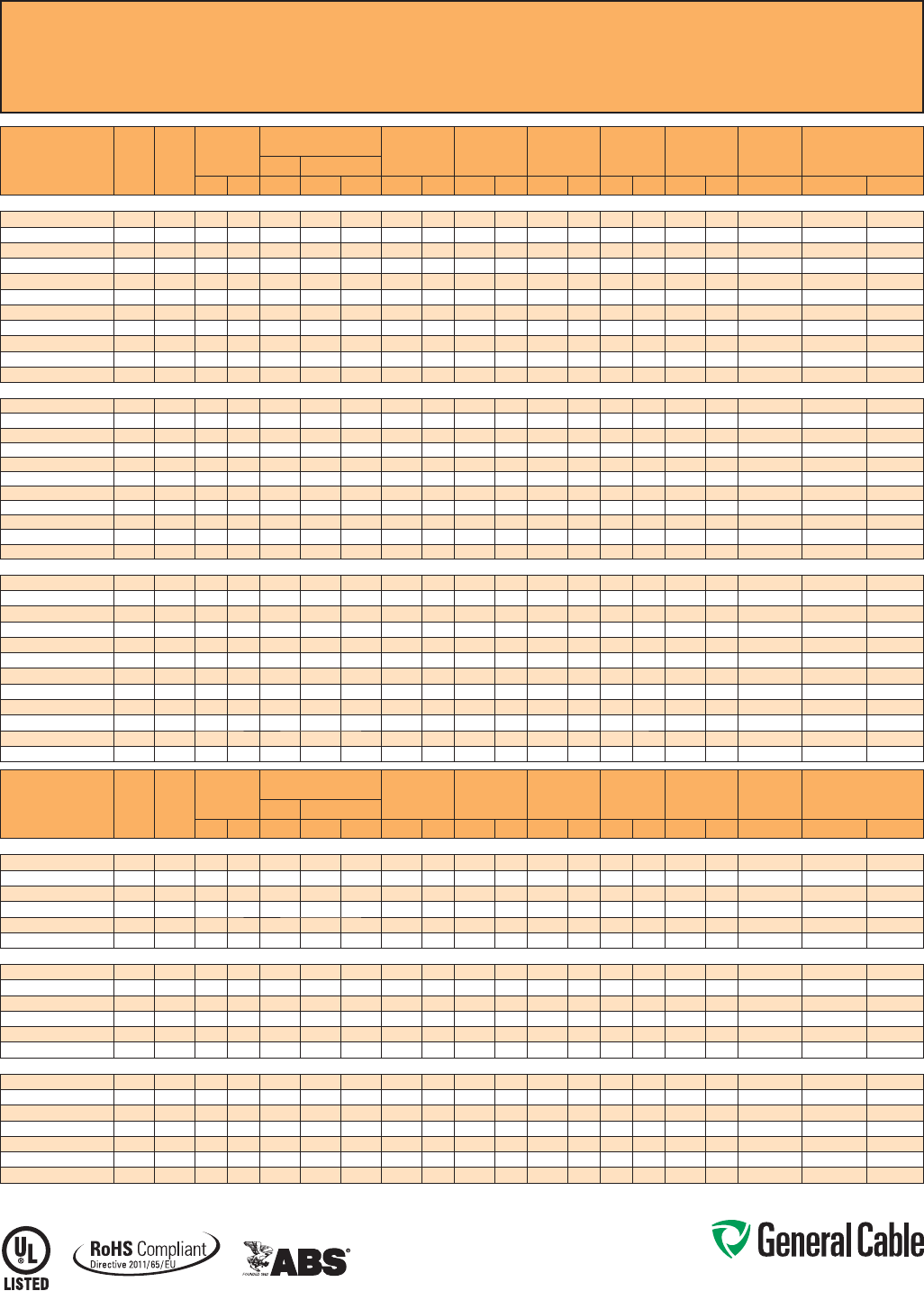
CATALOG
NUMBER
WIRE TYPE/
SIZE
(AWG) NO. OF
PAIRS
INSULATION
THICKNESS INNER JACKET
THICKNESS NOMINAL
CORE O.D. NOMINAL
ARMOR O.D. JACKET
THICKNESS NOMINAL
OVERALL O.D.
CROSS-
SECTIONAL
AREA¹ APPROXIMATE NET
WEIGHT
mils mm mils mm INCHES mm INCHES mm mils mm INCHES mm SQ. IN. LBS/1000 FT kg/1000 m
9025.16010001
EX / 16 1 20 0.51 54 1.37 0.30 7.6 0.47 11.9 50 1.27 0.58 14.7 0.27 160 238
9025.16010002
JX / 16 1 20 0.51 54 1.37 0.30 7.6 0.47 11.9 50 1.27 0.58 14.7 0.27 159 237
9025.16010003
KX / 16 1 20 0.51 54 1.37 0.30 7.6 0.47 11.9 50 1.27 0.58 14.7 0.27 160 238
9025.16010004
TX / 16 1 20 0.51 54 1.37 0.30 7.6 0.47 11.9 50 1.27 0.58 14.7 0.27 161 240
Dimensions and weights are nominal; subject to industry tolerances.
¹ Cross-sectional area for cable tray fill is in accordance with NEC® Section 392.22.
ANSI MC 96.1 CONDUCTOR ALLOY AND COLOR CODE
TEMP. RANGE LIMITS OF ERROR
NOM. LOOP
RESISTANCE PER
100 FT @ 20°C
COND.
TYPE POSITIVE WIRE NEGATIVE WIRE OUTER
JACKETALLOY COLOR ALLOY COLOR
EX
Chromel Purple Constantan Red Purple 0°C To +200°C +/- 1.7°C 27.8 Ohms
JX
Iron White Constantan Red Black 0°C To +200°C +/- 2.2°C 13.9 Ohms
KX
Chromel Yellow Alumel Red Yellow 0°C To +200°C +/- 2.2°C 23.6 Ohms
TX
Copper Blue Constantan Red Blue -60°C To +100°C +/- 1.0°C 12.0 Ohms

Phone: 888-593-3355
www.generalcable.com
Overall Jacket:
• Flame-retardant, moisture- and
sunlight-resistant Polyvinyl Chloride
(PVC) per UL Standards 13 and 2250
• ANSI color-coded
• Low temperature performance meets
ASTM D746 brittleness temperature at
or below -40°C
Applications:
• CCW armored Thermocouple
Extension cables provide superior
protection and reliability against
physical damage for use in
instrumentation and process control
applications requiring ITC-HL or PLTC
wiring methods
• For use as Power Limited Tray Cable
on circuits rated 150 V or less and
5 amps or less in Class 2 or Class 3
circuits in accordance with NEC
Article 725
• For use as Instrumentation Tray Cable
on circuits rated 150 V or less and
5 amps or less in accordance with
NEC Article 727
• Recognized for use in Class I and III,
Divisions 1 and 2; Class II, Division 2;
or Class I, Zones 1 and 2 hazardous
locations per NEC Articles 501, 502,
503 and 505
• Installed indoors or outdoors, in wet or
dry locations, in a raceway, as aerial
cable on a messenger, in cable trays,
or for direct burial
• Recognized for use on fixed or
floating offshore petroleum facilities
as recommended by the American
Petroleum Institute
Features:
• CCW armor provides superior
mechanical protection and an
impervious barrier to moisture, gas
and liquids
• CCW armor provides EMI shielding
performance
• Meets cold impact at -40°C
Specifications:
Design Adherence:
• UL 13 Power-Limited Circuit Cables
• UL 2250 Instrumentation Tray Cable
• UL 1569 Metal Clad Cables
• UL 1309/CSA C22.2 No. 245 Marine
Shipboard Cable
Flame Tests:
• ICEA T-29-520 (210,000 BTU/hr)
• IEEE 383 (70,000 BTU/hr)
• CSA FT4
• IEEE 1202 (70,000 BTU/hr)
• UL 1581 (70,000 BTU/hr)
• IEC 60332-3 Cat. A
Compliances:
• UL Type PLTC, SUN RES, DIR BUR,
-40°C, UL File # E36118
• UL Type ITC-HL, UL File # E177408
• UL Listed Marine Shipboard, UL File
# E85994
• American Bureau of Shipping (ABS)
Listed for CWCMC
• RoHS Compliant
Product Construction:
Conductor:
• 20 AWG solid alloy wire per ANSI MC
96.1
Insulation:
• Flame-retardant Polyvinyl Chloride
(PVC), rated 105°C per UL Standards
13 and 2250
• Color-coded per ANSI with one
conductor in each pair printed
alphanumerically for easy identification
Cable Assembly:
• Individual pairs and communication
wire are cabled together with a left-
hand lay
• Communication wire: 22 AWG solid
bare copper, flame-retardant Polyvinyl
Chloride (PVC), rated 105°C, orange
Overall Shield:
• Flexfoil
®
aluminum/polyester tape
shield providing 100% coverage
• Stranded tinned copper drain wire,
same size as insulated conductors
Inner Jacket:
• Flame-retardant Polyvinyl Chloride
(PVC) per UL Standards 13 and 2250
• ANSI color-coded
• Low temperature performance meets
ASTM D746 brittleness temperature at
or below -40°C
• Nylon rip cord to facilitate jacket
removal
CCW Armor:
• Impervious, continuously welded and
corrugated aluminum alloy sheath per
UL 1569
• CCW armor conductivity meets the
grounding requierments of NEC
Article 250
CCW
®
Armored Thermocouple, Pairs, Overall Shield
UL Type ITC-HL/PLTC, PVC, 105°C, Sunlight-Resistant, Direct Burial
UL Marine Shipboard Cable, ABS CWCMC
SPEC 9050
October, 2014
Phone: 888-593-3355
www.generalcable.com
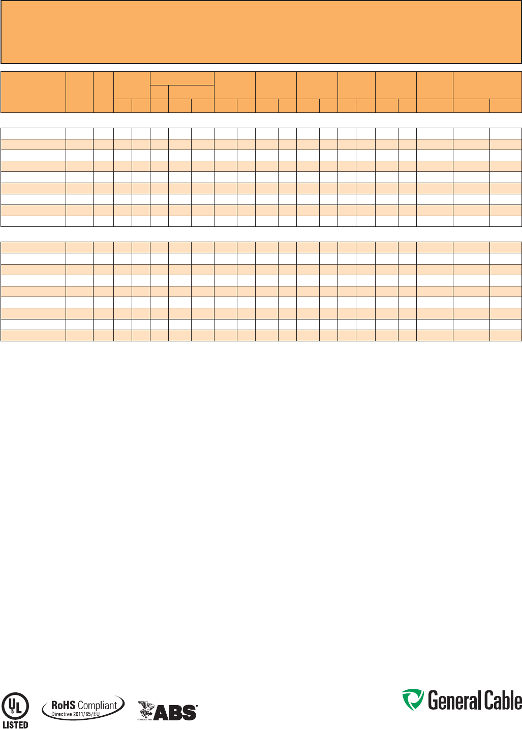
CCW
®
Armored Thermocouple, Pairs, Overall Shield
UL Type ITC-HL/PLTC, PVC, 105°C, Sunlight-Resistant, Direct Burial
UL Marine Shipboard Cable, ABS CWCMC
SPEC 9050
October, 2014
CATALOG
NUMBER
WIRE
TYPE/
SIZE
(AWG)
NO.
OF
PAIRS
INSULATION
THICKNESS
COMMUNICATION WIRE INNER JACKET
THICKNESS NOMINAL
CORE O.D. NOMINAL
ARMOR O.D. JACKET
THICKNESS NOMINAL
OVERALL O.D.
CROSS-
SECTIONAL
AREA¹ APPROXIMATE
NET WEIGHTSIZE INS. THICKNESS
mils mm AWG mils mm mils mm INCHES mm INCHES mm mils mm INCHES mm SQ. IN. LBS/1000 FT kg/1000 m
20 AWG TYPE EX MULTIPLE PAIRS OVERALL SHIELDED THERMOCOUPLE EXTENSION CABLE
9050.20041221 EX / 20 4 20 0.51 22 12 0.30 78 1.98 0.46 11.7 0.65 16.5 50 1.27 0.76 19.3 0.46 255 379
9050.20081221 EX / 20 8 20 0.51 22 12 0.30 78 1.98 0.57 14.5 0.78 19.8 50 1.27 0.89 22.6 0.63 351 522
9050.20101221 EX / 20 10 20 0.51 22 12 0.30 93 2.36 0.69 17.5 0.93 23.6 50 1.27 1.04 26.4 0.86 463 689
9050.20121221 EX / 20 12 20 0.51 22 12 0.30 93 2.36 0.71 18.0 0.95 24.1 50 1.27 1.06 26.9 0.89 490 729
9050.20161221 EX / 20 16 20 0.51 22 12 0.30 93 2.36 0.78 19.8 1.02 25.9 50 1.27 1.13 28.7 1.02 550 818
9050.20201221 EX / 20 20 20 0.51 22 12 0.30 93 2.36 0.85 21.6 1.12 26.4 50 1.27 1.23 31.2 1.20 638 949
9050.20241221 EX / 20 24 20 0.51 22 12 0.30 109 2.77 0.96 24.4 1.27 32.3 50 1.27 1.38 35.1 1.52 783 1,165
9050.20361221 EX / 20 36 20 0.51 22 12 0.30 109 2.77 1.09 27.7 1.44 36.6 50 1.27 1.55 39.4 1.91 1,010 1,503
9050.20501221 EX / 20 50 20 0.51 22 12 0.30 109 2.77 1.26 32.0 1.60 40.6 60 1.52 1.73 43.9 2.38 1,290 1,920
20 AWG TYPE JX MULTIPLE PAIRS OVERALL SHIELDED THERMOCOUPLE EXTENSION CABLE
9050.20041222 JX / 20 4 20 0.51 22 12 0.30 78 1.98 0.46 11.7 0.65 16.5 50 1.27 0.76 19.3 0.46 253 377
9050.20081222 JX / 20 8 20 0.51 22 12 0.30 78 1.98 0.57 14.5 0.78 19.8 50 1.27 0.89 22.6 0.63 348 518
9050.20101222 JX / 20 10 20 0.51 22 12 0.30 93 2.36 0.69 17.5 0.93 23.6 50 1.27 1.04 26.4 0.86 459 683
9050.20121222 JX / 20 12 20 0.51 22 12 0.30 93 2.36 0.71 18.0 0.95 24.1 50 1.27 1.06 26.9 0.89 485 722
9050.20161222 JX / 20 16 20 0.51 22 12 0.30 93 2.36 0.78 19.8 1.02 25.9 50 1.27 1.13 28.7 1.02 549 817
9050.20201222 JX / 20 20 20 0.51 22 12 0.30 93 2.36 0.85 21.6 1.12 26.4 50 1.27 1.23 31.2 1.20 630 938
9050.20241222 JX / 20 24 20 0.51 22 12 0.30 109 2.77 0.96 24.4 1.27 32.3 50 1.27 1.38 35.1 1.52 774 1,152
9050.20361222 JX / 20 36 20 0.51 22 12 0.30 109 2.77 1.09 27.7 1.44 36.6 50 1.27 1.55 39.4 1.91 997 1,484
9050.20501222 JX / 20 50 20 0.51 22 12 0.30 109 2.77 1.26 32.0 1.60 40.6 60 1.52 1.73 43.9 2.38 1,271 1,891
20 AWG TYPE KX MULTIPLE PAIRS OVERALL SHIELDED THERMOCOUPLE EXTENSION CABLE
9050.20041223 KX / 20 4 20 0.51 22 12 0.30 78 1.98 0.46 11.7 0.65 16.5 50 1.27 0.76 19.3 0.46 255 379
9050.20081223 KX / 20 8 20 0.51 22 12 0.30 78 1.98 0.57 14.5 0.78 19.8 50 1.27 0.89 22.6 0.63 351 522
9050.20101223 KX / 20 10 20 0.51 22 12 0.30 93 2.36 0.69 17.5 0.93 23.6 50 1.27 1.04 26.4 0.86 463 689
9050.20121223 KX / 20 12 20 0.51 22 12 0.30 93 2.36 0.71 18.0 0.95 24.1 50 1.27 1.06 26.9 0.89 490 729
9050.20161223 KX / 20 16 20 0.51 22 12 0.30 93 2.36 0.78 19.8 1.02 25.9 50 1.27 1.13 28.7 1.02 549 817
9050.20201223 KX / 20 20 20 0.51 22 12 0.30 93 2.36 0.85 21.6 1.12 26.4 50 1.27 1.23 31.2 1.20 637 948
9050.20241223 KX / 20 24 20 0.51 22 12 0.30 109 2.77 0.96 24.4 1.27 32.3 50 1.27 1.38 35.1 1.52 782 1,164
9050.20361223 KX / 20 36 20 0.51 22 12 0.30 109 2.77 1.09 27.7 1.44 36.6 50 1.27 1.55 39.4 1.91 1,008 1,500
9050.20501223 KX / 20 50 20 0.51 22 12 0.30 109 2.77 1.26 32.0 1.60 40.6 60 1.52 1.73 43.9 2.38 1,287 1,915
20 AWG TYPE TX MULTIPLE PAIRS OVERALL SHIELDED THERMOCOUPLE EXTENSION CABLE
9050.20041224 TX / 20 4 20 0.51 22 12 0.30 78 1.98 0.46 11.7 0.65 16.5 50 1.27 0.76 19.3 0.46 257 382
9050.20081224 TX / 20 8 20 0.51 22 12 0.30 78 1.98 0.57 14.5 0.78 19.8 50 1.27 0.89 22.6 0.63 354 527
9050.20101224 TX / 20 10 20 0.51 22 12 0.30 93 2.36 0.69 17.5 0.93 23.6 50 1.27 1.04 26.4 0.86 467 695
9050.20121224 TX / 20 12 20 0.51 22 12 0.30 93 2.36 0.71 18.0 0.95 24.1 50 1.27 1.06 26.9 0.89 495 737
9050.20161224 TX / 20 16 20 0.51 22 12 0.30 93 2.36 0.78 19.8 1.02 25.9 50 1.27 1.13 28.7 1.02 556 827
9050.20201224 TX / 20 20 20 0.51 22 12 0.30 93 2.36 0.85 21.6 1.12 26.4 50 1.27 1.23 31.2 1.20 646 961
9050.20241224 TX / 20 24 20 0.51 22 12 0.30 109 2.77 0.96 24.4 1.27 32.3 50 1.27 1.38 35.1 1.52 792 1,179
9050.20361224 TX / 20 36 20 0.51 22 12 0.30 109 2.77 1.09 27.7 1.44 36.6 50 1.27 1.55 39.4 1.91 1,023 1,522
9050.20501224 TX / 20 50 20 0.51 22 12 0.30 109 2.77 1.26 32.0 1.60 40.6 60 1.52 1.73 43.9 2.38 1,309 1,948
Dimensions and weights are nominal; subject to industry tolerances.
¹ Cross-sectional area for cable tray fill is in accordance with NEC® Section 392.22.
ANSI MC 96.1 CONDUCTOR ALLOY AND COLOR CODE
TEMP. RANGE LIMITS OF
ERROR
NOM. LOOP
RESISTANCE PER
100 FT @ 20°C
COND.
TYPE POSITIVE WIRE NEGATIVE WIRE OVERALL
JACKET COLORALLOY COLOR ALLOY COLOR
EX Chromel Purple Constantan Red Purple
0°C To +200°C +/- 1.7°C 70.7 Ohms
JX Iron White Constantan Red Black
0°C To +200°C +/- 2.2°C 35.7 Ohms
KX Chromel Yellow Alumel Red Yellow
0°C To +200°C +/- 2.2°C 59.0 Ohms
TX Copper Blue Constantan Red Blue
-60°C To +100°C +/- 1.0°C 29.8 Ohms
Phone: 888-593-3355
www.generalcable.com
CCW Armor:
• Impervious, continuously welded and
corrugated aluminum alloy sheath per
UL 1569
• CCW armor conductivity meets the
grounding requirements of NEC
Article 250
Overall Jacket:
• Flame-retardant, moisture- and
sunlight-resistant Polyvinyl Chloride
(PVC) per UL Standards 13 and 2250
• ANSI color-coded overall jacket
• Low temperature performance meets
ASTM D746 brittleness temperature
at or below -40°C
Applications:
• CCW armored Thermocouple
Extension cables with individually
shielded pairs and an overall shield
provide superior protection and
reliability against physical damage for
use in instrumentation and process
control applications requiring ITC-HL
or PLTC wiring methods where
shielding against both external EMI
and EMI between pairs is required
• For use as Power Limited Tray Cable
on circuits rated 150 V or less and
5 amps or less in Class 2 or Class 3
circuits in accordance with NEC
Article 725
• For use as Instrumentation Tray Cable
on circuits rated 150 V or less and 5
amps or less in accordance with NEC
Article 727
• Recognized for use in Class I and III,
Divisions 1 and 2; Class II, Division 2;
or Class I, Zones 1 and 2 hazardous
locations per NEC Articles 501, 502,
503 and 505
Applications: (cont’d)
• Installed indoors or outdoors, in wet
or dry locations, in a raceway, as
aerial cable on a messenger, in cable
trays, or for direct burial
• Recognized for use on fixed or
floating offshore petroleum facilities
as recommended by the American
Petroleum Institute
Features:
• CCW armor provides superior
mechanical protection and an
impervious barrier to moisture, gas
and liquids
• CCW armor provides EMI shielding
performance
• Meets cold impact at -40°C
Specifications:
Design Adherence:
• UL 13 Power-Limited Circuit Cables
• UL 2250 Instrumentation Tray Cable
• UL 1569 Metal Clad Cables
• UL 1309/CSA C22.2 No. 245 Marine
Shipboard Cable
Flame Tests:
• ICEA T-29-520 (210,000 BTU/hr)
• IEEE 383 (70,000 BTU/hr)
• CSA FT4
• IEEE 1202 (70,000 BTU/hr)
• UL 1581 (70,000 BTU/hr)
• IEC 60332-3 Cat. A
Compliances:
• UL Type PLTC, SUN RES, DIR BUR,
-40°C, UL File #
E36118
• UL Type ITC-HL, UL File # E177408
• UL Listed Marine Shipboard, UL File
# E85994
• American Bureau of Shipping (ABS)
Listed for CWCMC
• RoHS Compliant
Product Construction:
Conductor:
• 20 AWG solid alloy wire per ANSI MC
96.1
Insulation:
• Flame-retardant Polyvinyl Chloride
(PVC), rated 105°C per UL Standards
13 and 2250
• ANSI color-coded insulation, with one
conductor in each pair printed alpha
numerically for easy identification
Shielded Pairs:
• Isolated and individually twisted pairs
with a Flexfoil
®
aluminum/polyester
tape shield providing 100% coverage
• Stranded tinned copper drain wire,
two sizes smaller than insulated
conductors
Cable Assembly:
• Individually shielded pairs and
communication wire are cabled
together with a left-hand lay
• Communication wire: 22 AWG
solid bare copper, flame-retardant
Polyvinyl Chloride (PVC), rated 105°C,
orange
Overall Shield:
• Flexfoil
®
aluminum/polyester tape
shield providing 100% coverage
• Stranded tinned copper drain wire,
same size as insulated conductors
Inner Jacket:
• Flame-retardant Polyvinyl Chloride
(PVC) per UL Standards 13 and 2250
• ANSI color-coded inner jacket
• Low temperature performance meets
ASTM D746 brittleness temperature
at or below -40°C
• Nylon rip cord to facilitate jacket
removal
CCW
®
Armored Thermocouple, Pairs, Individual and Overall Shield
UL Type ITC-HL/PLTC, PVC, 105°C, Sunlight-Resistant, Direct Burial
UL Marine Shipboard Cable, ABS CWCMC
SPEC 9075
October, 2014

Phone: 888-593-3355
www.generalcable.com
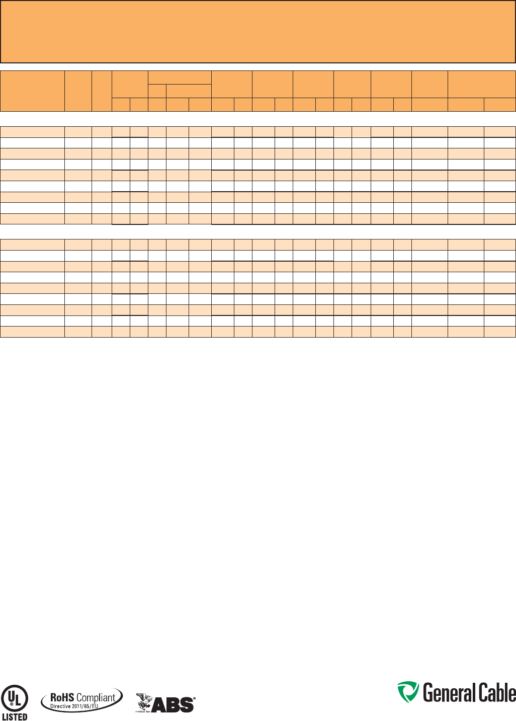
CCW
®
Armored Thermocouple, Pairs, Individual and Overall Shield
UL Type ITC-HL/PLTC, PVC, 105°C, Sunlight-Resistant, Direct Burial
UL Marine Shipboard Cable, ABS CWCMC
SPEC 9075
October, 2014
CATALOG
NUMBER
WIRE
TYPE/
SIZE
(AWG)
NO.
OF
PAIRS
INSULATION
THICKNESS
COMMUNICATION WIRE INNER JACKET
THICKNESS NOMINAL
CORE O.D. NOMINAL
ARMOR O.D. JACKET
THICKNESS NOMINAL
OVERALL O.D.
CROSS-
SECTIONAL
AREA¹ APPROXIMATE
NET WEIGHTSIZE INS. THICKNESS
mils mm AWG mils mm mils mm INCHES mm INCHES mm mils mm INCHES mm SQ. IN. LBS/1000 FT kg/1000 m
20 AWG TYPE EX MULTIPLE PAIRS INDIVIDUAL AND OVERALL SHIELDED THERMOCOUPLE EXTENSION CABLE
9075.20041221 EX / 20 4 20 0.51 22 12 0.30 78 1.98 0.52 13.2 0.72 18.3 50 1.27 0.83 21.1 0.55 297 442
9075.20081221 EX / 20 8 20 0.51 22 12 0.30 78 1.98 0.65 16.5 0.86 21.8 50 1.27 0.97 24.6 0.75 401 597
9075.20101221 EX / 20 10 20 0.51 22 12 0.30 93 2.36 0.78 19.8 1.02 25.9 50 1.27 1.13 28.7 1.02 526 783
9075.20121221 EX / 20 12 20 0.51 22 12 0.30 93 2.36 0.80 20.3 1.07 27.2 50 1.27 1.18 30.0 1.11 587 874
9075.20161221 EX / 20 16 20 0.51 22 12 0.30 93 2.36 0.88 22.4 1.15 29.2 50 1.27 1.26 32.0 1.26 667 993
9075.20201221 EX / 20 20 20 0.51 22 12 0.30 109 2.77 1.00 25.4 1.32 33.5 50 1.27 1.43 36.3 1.63 831 1,237
9075.20241221 EX / 20 24 20 0.51 22 12 0.30 109 2.77 1.10 27.9 1.45 36.8 50 1.27 1.56 39.6 1.94 980 1,458
9075.20361221 EX / 20 36 20 0.51 22 12 0.30 109 2.77 1.24 31.5 1.59 40.4 60 1.52 1.72 43.7 2.35 1,231 1,832
9075.20501221 EX / 20 50 20 0.51 22 12 0.30 124 3.15 1.47 37.3 1.73 43.9 60 1.52 1.86 47.2 2.75 1,580 2,351
20 AWG TYPE JX MULTIPLE PAIRS INDIVIDUAL AND OVERALL SHIELDED THERMOCOUPLE EXTENSION CABLE
9075.20041222 JX / 20 4 20 0.51 22 12 0.30 78 1.98 0.52 13.2 0.72 18.3 50 1.27 0.83 21.1 0.55 295 439
9075.20081222 JX / 20 8 20 0.51 22 12 0.30 78 1.98 0.65 16.5 0.86 21.8 50 1.27 0.97 24.6 0.75 398 592
9075.20101222 JX / 20 10 20 0.51 22 12 0.30 93 2.36 0.78 19.8 1.02 25.9 50 1.27 1.13 28.7 1.02 522 777
9075.20121222 JX / 20 12 20 0.51 22 12 0.30 93 2.36 0.80 20.3 1.07 27.2 50 1.27 1.18 30.0 1.11 582 866
9075.20161222 JX / 20 16 20 0.51 22 12 0.30 93 2.36 0.88 22.4 1.15 29.2 50 1.27 1.26 32.0 1.26 661 984
9075.20201222 JX / 20 20 20 0.51 22 12 0.30 109 2.77 1.00 25.4 1.32 33.5 50 1.27 1.43 36.3 1.63 823 1,225
9075.20241222 JX / 20 24 20 0.51 22 12 0.30 109 2.77 1.10 27.9 1.45 36.8 50 1.27 1.56 39.6 1.94 971 1,445
9075.20361222 JX / 20 36 20 0.51 22 12 0.30 109 2.77 1.24 31.5 1.59 40.4 60 1.52 1.72 43.7 2.35 1,218 1,813
9075.20501222 JX / 20 50 20 0.51 22 12 0.30 124 3.15 1.47 37.3 1.73 43.9 60 1.52 1.86 47.2 2.75 1,561 2,323
20 AWG TYPE KX MULTIPLE PAIRS INDIVIDUAL AND OVERALL SHIELDED THERMOCOUPLE EXTENSION CABLE
9075.20041223 KX / 20 4 20 0.51 22 12 0.30 78 1.98 0.52 13.2 0.72 18.3 50 1.27 0.83 21.1 0.55 297 432
9075.20081223 KX / 20 8 20 0.51 22 12 0.30 78 1.98 0.65 16.5 0.86 21.8 50 1.27 0.97 24.6 0.75 401 597
9075.20101223 KX / 20 10 20 0.51 22 12 0.30 93 2.36 0.78 19.8 1.02 25.9 50 1.27 1.13 28.7 1.02 526 783
9075.20121223 KX / 20 12 20 0.51 22 12 0.30 93 2.36 0.80 20.3 1.07 27.2 50 1.27 1.18 30.0 1.11 587 874
9075.20161223 KX / 20 16 20 0.51 22 12 0.30 93 2.36 0.88 22.4 1.15 29.2 50 1.27 1.26 32.0 1.26 666 991
9075.20201223 KX / 20 20 20 0.51 22 12 0.30 109 2.77 1.00 25.4 1.32 33.5 50 1.27 1.43 36.3 1.63 830 1,235
9075.20241223 KX / 20 24 20 0.51 22 12 0.30 109 2.77 1.10 27.9 1.45 36.8 50 1.27 1.56 39.6 1.94 979 1,457
9075.20361223 KX / 20 36 20 0.51 22 12 0.30 109 2.77 1.24 31.5 1.59 40.4 60 1.52 1.72 43.7 2.35 1,229 1,829
9075.20501223 KX / 20 50 20 0.51 22 12 0.30 124 3.15 1.47 37.3 1.73 43.9 60 1.52 1.86 47.2 2.75 1,577 2,347
20 AWG TYPE TX MULTIPLE PAIRS INDIVIDUAL AND OVERALL SHIELDED THERMOCOUPLE EXTENSION CABLE
9075.20041224 TX / 20 4 20 0.51 22 12 0.30 78 1.98 0.52 13.2 0.72 18.3 50 1.27 0.83 21.1 0.55 299 445
9075.20081224 TX / 20 8 20 0.51 22 12 0.30 78 1.98 0.65 16.5 0.86 21.8 50 1.27 0.97 24.6 0.75 404 601
9075.20101224 TX / 20 10 20 0.51 22 12 0.30 93 2.36 0.78 19.8 1.02 25.9 50 1.27 1.13 28.7 1.02 530 789
9075.20121224 TX / 20 12 20 0.51 22 12 0.30 93 2.36 0.80 20.3 1.07 27.2 50 1.27 1.18 30.0 1.11 592 881
9075.20161224 TX / 20 16 20 0.51 22 12 0.30 93 2.36 0.88 22.4 1.15 29.2 50 1.27 1.26 32.0 1.26 672 1,000
9075.20201224 TX / 20 20 20 0.51 22 12 0.30 109 2.77 1.00 25.4 1.32 33.5 50 1.27 1.43 36.3 1.63 839 1,249
9075.20241224 TX / 20 24 20 0.51 22 12 0.30 109 2.77 1.10 27.9 1.45 36.8 50 1.27 1.56 39.6 1.94 989 1,472
9075.20361224 TX / 20 36 20 0.51 22 12 0.30 109 2.77 1.24 31.5 1.59 40.4 60 1.52 1.72 43.7 2.35 1,243 1,850
9075.20501224 TX / 20 50 20 0.51 22 12 0.30 124 3.15 1.47 37.3 1.73 43.9 60 1.52 1.86 47.2 2.75 1,599 2,380
Dimensions and weights are nominal; subject to industry tolerances.
¹ Cross-sectional area for cable tray fill is in accordance with NEC® Section 392.22.
ANSI MC 96.1 CONDUCTOR ALLOY AND COLOR CODE
TEMP. RANGE LIMITS OF
ERROR
NOM. LOOP
RESISTANCE PER
100 FT @ 20°C
COND.
TYPE POSITIVE WIRE NEGATIVE WIRE OVERALL
JACKET COLORALLOY COLOR ALLOY COLOR
EX Chromel Purple Constantan Red Purple
0°C To +200°C +/- 1.7°C 70.7 Ohms
JX Iron White Constantan Red Black
0°C To +200°C +/- 2.2°C 35.7 Ohms
KX Chromel Yellow Alumel Red Yellow
0°C To +200°C +/- 2.2°C 59.0 Ohms
TX Copper Blue Constantan Red Blue
-60°C To +100°C +/- 1.0°C 29.8 Ohms

Phone: 888-593-3355
www.generalcable.com
CCW Armor:
• Impervious, continuously welded and
corrugated aluminum alloy sheath per
UL 1569
• CCW armor conductivity meets the
grounding requirements of NEC
Article 250
Overall Jacket:
• Flame-retardant, moisture- and
sunlight-resistant Polyvinyl Chloride
(PVC) per UL Standards 13 and 2250,
black
• Low temperature performance meets
ASTM D746 brittleness temperature at
or below -40°C
Applications:
• CCW armored Instrumentation
cables with an overall shield provide
superior protection and reliability
against physical damage for use in
instrumentation and process control
applications requiring ITC-HL or
PLTC wiring methods where shielding
against external EMI is required
• For use as Power Limited Tray Cable
on circuits rated 150 V or less and
5 amps or less in Class 2 or Class 3
circuits in accordance with NEC
Article 725
• For use as Instrumentation Tray Cable
on circuits rated 150 V or less and
5 amps or less in accordance with
NEC Article 727
• Recognized for use in Class I and III,
Divisions 1 and 2; Class II, Division 2;
or Class I, Zones 1 and 2 hazardous
locations per NEC Articles 501, 502,
503 and 505
• Installed indoors or outdoors, in wet or
dry locations, in a raceway, as aerial
cable on a messenger, in cable trays,
or for direct burial
Applications: (cont’d)
• Recognized for use on fixed or
floating offshore petroleum facilities
as recommended by the American
Petroleum Institute
Features:
• CCW armor provides superior
mechanical protection and an
impervious barrier to moisture, gas
and liquids
• CCW armor provides EMI shielding
performance
• Meets cold impact at -40°C
Specifications:
Design Adherence:
• UL 13 Power-Limited Circuit Cables
• UL 2250 Instrumentation Tray Cable
• UL 1569 Metal Clad Cables
• UL 1309 / CSA C22.2 No. 245 Marine
Shipboard Cable
Flame Tests:
• ICEA T-29-520 (210,000 BTU/hr)
• IEEE 383 (70,000 BTU/hr)
• CSA FT4
• IEEE 1202 (70,000 BTU/hr)
• UL 1581 (70,000 BTU/hr)
• IEC 60332-3 Cat. A
Compliances:
• UL Type PLTC, SUN RES, DIR BUR,
-40°C, UL File # E36118
• UL Type ITC-HL, UL File # E177408
• UL Listed Marine Shipboard, UL File #
E85994
• American Bureau of Shipping (ABS)
Listed for CWCMC
• RoHS Compliant
Product Construction:
Conductor:
• Bare annealed copper per ASTM B3
• Class B stranding per ASTM B8
Insulation:
• Cross-Linked Polyethylene (XLPE),
rated 90°C per UL Standards 13 and
2250
• Color-coded per ICEA Method 1:
pairs – black and white; triads – black,
white and red. Each conductor in each
pair or triad is printed alphanumerically
for easy identification
Cable Assembly:
• Individual pairs or triads and
communication wire are cabled
together with a left hand lay
• Communication wire: 20 AWG
solid bare copper, Cross-Linked
Polyethylene (XLPE), rated 90°C,
orange
• Communication wire is not included on
single pair or single triad cables
Overall Shield:
• Flexfoil
®
aluminum/polyester tape
shield providing 100% coverage
• Stranded tinned copper drain wire,
same size as insulated conductors
Inner Jacket:
• Flame-retardant Polyvinyl Chloride
(PVC) per UL Standards 13 and 2250,
black
• Low temperature performance meets
ASTM D746 brittleness temperature at
or below -40°C
• Nylon rip cord to facilitate jacket
removal
CCW
®
Armored Instrumentation, Pairs/Triads, Overall Shield
UL Type ITC-HL/PLTC, XLPE, 300 V, 90°C, Sunlight-Resistant, Direct Burial
UL Marine Shipboard Cable, ABS CWCMC
SPEC 9125
October, 2014
Phone: 888-593-3355
www.generalcable.com
CCW
®
Armored Instrumentation, Pairs/Triads, Overall Shield
UL Type ITC-HL/PLTC, XLPE, 300 V, 90°C, Sunlight-Resistant, Direct Burial
UL Marine Shipboard Cable, ABS CWCMC
SPEC 9125
October, 2014
CATALOG
NUMBER
COND.
SIZE
(AWG)
NO.
OF
PAIRS
INSULATION
THICKNESS
COMMUNICATION WIRE INNER JACKET
THICKNESS NOMINAL
CORE O.D. NOMINAL
ARMOR O.D. JACKET
THICKNESS NOMINAL
OVERALL O.D.
CROSS-
SECTIONAL
AREA¹ APPROXIMATE
NET WEIGHTSIZE INS. THICKNESS
mils mm AWG mils mm mils mm INCHES mm INCHES mm mils mm INCHES mm SQ. IN. LBS/1000 FT kg/1000 m
16 AWG 7W (1.31 mm²) OVERALL SHIELDED PAIRS
9125.16010001*
16 1 30 0.76 — — — 62 1.57 0.38 9.7 0.56 14.2 50 1.27 0.67 17.0 0.36 207 308
9125.16021201
16 2 30 0.76 20 15 0.38 78 1.98 0.56 14.2 0.76 19.3 50 1.27 0.87 22.1 0.60 307 457
9125.16041201
16 4 30 0.76 20 15 0.38 78 1.98 0.64 16.3 0.75 19.1 50 1.27 0.96 24.4 0.73 390 580
9125.16081201
16 8 30 0.76 20 15 0.38 93 2.36 0.85 21.6 1.12 28.4 50 1.27 1.23 31.2 1.20 632 941
9125.16121201
16 12 30 0.76 20 15 0.38 109 2.77 1.05 26.7 1.36 34.5 50 1.27 1.47 37.3 1.72 857 1,275
9125.16161201
16 16 30 0.76 20 15 0.38 109 2.77 1.16 29.5 1.51 38.4 60 1.52 1.64 41.7 2.14 1,081 1,609
9125.16241201
16 24 30 0.76 20 15 0.38 124 3.15 1.44 36.6 1.54 41.7 60 1.52 1.77 45.0 2.49 1,431 2,130
9125.16361201
16 36 30 0.76 20 15 0.38 124 3.15 1.64 41.7 1.96 49.8 60 1.52 2.09 53.1 3.48 1,933 2,877
9125.16501201
16 50 30 0.76 20 15 0.38 140 3.56 1.95 49.5 2.28 57.9 60 1.52 2.41 61.2 4.62 2,550 3,795
16 AWG 7W (1.31 mm²) OVERALL SHIELDED TRIADS
9125.16010002*
16 1 30 0.76 — — — 62 1.57 0.40 10.2 0.59 15.0 50 1.27 0.70 17.8 0.39 235 350
9125.16021202
16 2 30 0.76 20 15 0.38 93 2.36 0.69 17.5 0.93 23.6 50 1.27 1.04 26.4 0.86 441 656
9125.16041202
16 4 30 0.76 20 15 0.38 93 2.36 0.79 20.1 1.06 25.9 50 1.27 1.17 29.7 1.09 569 847
9125.16081202
16 8 30 0.76 20 15 0.38 109 2.77 1.04 26.4 1.35 34.3 50 1.27 1.46 37.1 1.70 859 1,278
9125.16121202
16 12 30 0.76 20 15 0.38 109 2.77 1.25 31.8 1.60 40.6 60 1.52 1.73 43.9 2.38 1,207 1,796
9125.16161202
16 16 30 0.76 20 15 0.38 124 3.15 1.42 36.1 1.64 41.7 60 1.52 1.77 45.0 2.49 1,424 2,119
9125.16241202
16 24 30 0.76 20 15 0.38 140 3.56 1.77 45.0 2.15 54.6 60 1.52 2.28 57.9 4.14 2,103 3,130
9125.16361202
16 36 30 0.76 20 15 0.38 140 3.56 2.01 51.1 2.23 56.6 60 1.52 2.36 59.9 4.43 2,659 3,957
9125.16501202
16 50 30 0.76 20 15 0.38 171 4.34 2.42 61.5 2.75 69.9 75 1.91 2.91 73.9 6.74 3,800 5,655
Dimensions and weights are nominal; subject to industry tolerances.
* Item rated ITC/PLTC.
¹ Cross-sectional area for cable tray fill is in accordance with NEC® Section 392.22.

Phone: 888-593-3355
www.generalcable.com
CCW Armor:
• Impervious, continuously welded and
corrugated aluminum alloy sheath per
UL 1569
• CCW armor conductivity meets the
grounding requirements of NEC
Article 250
Overall Jacket:
• Flame-retardant, moisture- and
sunlight-resistant Polyvinyl Chloride
(PVC) per UL Standards 13 and 2250,
black
• Low temperature performance meets
ASTM D746 brittleness temperature at
or below -40°C
Applications:
• CCW armored Instrumentation cables
with individually shielded pairs or
triads and an overall shield provide
superior protection and reliability
against physical damage for use in
instrumentation and process control
applications requiring ITC-HL or
PLTC wiring methods where shielding
against both external EMI and EMI
between groups is required
• For use as Power Limited Tray Cable
on circuits rated 150 V or less and
5 amps or less in Class 2 or Class 3
circuits in accordance with NEC Article
725
• For use as Instrumentation Tray Cable
on circuits rated 150 V or less and
5 amps or less in accordance with
NEC Article 727
• Recognized for use in Class I and III,
Divisions 1 and 2; Class II, Division 2;
or Class I, Zones 1 and 2 hazardous
locations per NEC Articles 501, 502,
503 and 505
Applications: (cont’d)
• Installed indoors or outdoors, in wet or
dry locations, in a raceway, as aerial
cable on a messenger, in cable trays,
or for direct burial
• Recognized for use on fixed or
floating offshore petroleum facilities
as recommended by the American
Petroleum Institute
Features:
• CCW armor provides superior
mechanical protection and an
impervious barrier to moisture,
gas and liquids
• CCW armor provides EMI shielding
performance
• Meets cold impact at -40°C
Specifications:
Design Adherence:
• UL 13 Power-Limited Circuit Cables
• UL 2250 Instrumentation Tray Cable
• UL 1569 Metal Clad Cables
• UL 1309/CSA C22.2 No. 245 Marine
Shipboard Cable
Flame Tests:
• ICEA T-29-520 (210,000 BTU/hr)
• IEEE 383 (70,000 BTU/hr)
• CSA FT4
• IEEE 1202 (70,000 BTU/hr)
• UL 1581 (70,000 BTU/hr)
• IEC 60332-3 Cat. A
Compliances:
• UL Type PLTC, SUN RES, DIR BUR,
-40°C, UL File # E36118
• UL Type ITC-HL, UL File # E177408
• UL Listed Marine Shipboard, UL File #
E85994
• American Bureau of Shipping (ABS)
Listed for CWCMC
• RoHS Compliant
Product Construction:
Conductor:
• Bare annealed copper per ASTM B3
• Class B stranding per ASTM B8
Insulation:
•
Cross-Linked Polyethylene
(XLPE),
rated 90°C per UL Standards 13 and
2250
• Color-coded per ICEA Method 1:
pairs – black and white; triads – black,
white and red. Each conductor in each
pair or triad is printed alphanumerically
for easy identification
Shielded Pairs/Triads:
• Isolated and individually twisted pairs
or triads with a Flexfoil® aluminum/
polyester tape shield providing 100%
coverage
• Stranded tinned copper drain wire, two
sizes smaller than insulated conductors
Cable Assembly:
• Individually shielded pairs or triads
and communication wire are cabled
together with a left-hand lay
• Communication wire: 20 AWG solid
bare copper, Cross-Linked Polyethylene
(XLPE), rated 90°C, orange
Overall Shield:
• Flexfoil® aluminum/polyester tape shield
providing 100% coverage
• Stranded tinned copper drain wire,
same size as insulated conductors
Inner Jacket:
• Flame-retardant Polyvinyl Chloride
(PVC) per UL Standards 13 and 2250,
black
• Low temperature performance meets
ASTM D746 brittleness temperature at
or below -40°C
• Nylon rip cord to facilitate jacket
removal
CCW
®
Armored Instrumentation, Pairs/Triads, Individual and Overall Shield
UL Type ITC-HL/PLTC, XLPE, 300 V, 90°C, Sunlight-Resistant, Direct Burial
UL Marine Shipboard Cable, ABS CWCMC
SPEC 9150
October, 2014
Phone: 888-593-3355
www.generalcable.com
CCW
®
Armored Instrumentation, Pairs/Triads, Individual and Overall Shield
UL Type ITC-HL/PLTC, XLPE, 300 V, 90°C, Sunlight-Resistant, Direct Burial
UL Marine Shipboard Cable, ABS CWCMC
SPEC 9150
October, 2014
CATALOG
NUMBER
COND.
SIZE
(AWG)
NO.
OF
PAIRS
INSULATION
THICKNESS
COMMUNICATION WIRE INNER JACKET
THICKNESS NOMINAL
CORE O.D. NOMINAL
ARMOR O.D. JACKET
THICKNESS NOMINAL
OVERALL O.D.
CROSS-
SECTIONAL
AREA¹ APPROXIMATE
NET WEIGHTSIZE INS. THICKNESS
mils mm AWG mils mm mils mm INCHES mm INCHES mm mils mm INCHES mm SQ. IN. LBS/1000 FT kg/1000 m
16 AWG 7W (1.31 mm²) INDIVIDUAL AND OVERALL SHIELDED PAIRS
9150.16010001*
16 1 30 0.76 —— — 62 1.57 0.38 9.7 0.56 14.2 50 1.27 0.67 17.0 0.36 207 308
9150.16021201
16 2 30 0.76 20 15 0.38 78 1.98 0.62 15.7 0.83 21.1 50 1.27 0.94 23.9 0.70 351 522
9150.16041201
16 4 30 0.76 20 15 0.38 93 2.36 0.75 19.1 0.99 25.1 50 1.27 1.10 27.9 0.96 509 757
9150.16081201
16 8 30 0.76 20 15 0.38 109 2.77 0.98 24.9 1.29 32.8 50 1.27 1.40 35.6 1.56 798 1,188
9150.16121201
16 12 30 0.76 20 15 0.38 109 2.77 1.17 29.7 1.52 38.6 60 1.52 1.65 41.9 2.17 1,075 1,600
9150.16161201
16 16 15 0.38 20 15 0.38 60 1.52 0.87 22.1 1.11 28.2 50 1.27 1.22 31.0 1.18 665 990
9150.16241201
16 24 30 0.76 20 15 0.38 124 3.15 1.62 41.1 1.92 48.8 60 1.52 2.05 52.1 3.34 1,790 2,664
9150.16361201
16 36 30 0.76 20 15 0.38 140 3.56 1.88 47.8 2.19 55.6 60 1.52 2.31 58.7 4.25 2,405 3,579
9150.16501201
16 50 30 0.76 20 15 0.38 1714.342.2657.42.6266.575 1.912.7870.6 6.15 3,366 5,009
16 AWG 7W (1.31 mm²) INDIVIDUAL AND OVERALL SHIELDED TRIADS
9150.16010002*
16 1 15 0.38 —— — 35 0.89 0.27 6.9 0.49 12.4 50 1.27 0.60 15.2 0.29 158 235
9150.16021202
16 2 30 0.76 20 15 0.38 93 2.36 0.72 18.3 0.96 24.4 50 1.27 1.07 27.2 0.91 461 686
9150.16041202
16 4 30 0.76 20 15 0.38 93 2.36 0.82 20.8 1.09 27.7 50 1.27 1.20 30.5 1.15 605 900
9150.16081202
16 8 30 0.76 20 15 0.38 109 2.77 1.08 27.4 1.43 36.3 50 1.27 1.54 39.1 1.89 992 1,476
9150.16121202
16 12 30 0.76 20 15 0.38 109 2.77 1.29 32.8 1.60 40.6 60 1.52 1.73 43.9 2.38 1,312 1,952
9150.16161202
16 16 15 0.38 20 15 0.38 70 1.78 0.95 24.1 1.24 31.5 50 1.27 1.35 34.3 1.45 965 1,436
9150.16241202
16 24 30 0.76 20 15 0.38 140 3.56 1.83 46.5 2.15 54.6 60 1.52 2.28 57.9 4.14 2,313 3,442
9150.16361202
16 36 30 0.76 20 15 0.38 140 3.56 2.08 52.8 2.45 62.2 60 1.52 2.58 65.5 5.30 3,140 4,673
9150.16501202
16 50 30 0.76 20 15 0.38 171 4.34 2.50 63.5 3.03 77.0 75 1.91 3.19 81.0 8.10 4,270 6,354
Dimensions and weights are nominal; subject to industry tolerances.
* Item rated ITC/PLTC.
¹ Cross-sectional area for cable tray fill is in accordance with NEC® Section 392.22.
Phone: 888-593-3355
www.generalcable.com
Product Construction:
Conductor:
• Bare annealed copper per ASTM B3
• Class B stranding per ASTM B8
Insulation:
• Flame-retardant Polyvinyl Chloride
(PVC), rated 105°C per UL Standards
13 and 2250
• Color-coded per ICEA Method 1:
pairs – black and white; triads – black,
white and red. Each conductor in each
pair or triad is printed alphanumerically
for easy identification
Cable Assembly:
• Individual pairs or triads and
communication wire are cabled
together with a left-hand lay
• Communication wire: 22 AWG solid
bare copper, flame-retardant Polyvinyl
Chloride (PVC), rated 105°C, orange
• Communication wire is not included on
single pair or single triad cables
Overall Shield:
• Flexfoil
®
aluminum/polyester tape
shield providing 100% coverage
• Stranded tinned copper drain wire,
same size as insulated conductors
Inner Jacket:
• Flame-retardant Polyvinyl Chloride
(PVC) per UL Standards 13 and 2250,
black
• Low temperature performance meets
ASTM D746 brittleness temperature at
or below -40°C
• Nylon rip cord to facilitate jacket
removal
CCW Armor:
• Impervious, continuously welded and
corrugated aluminum alloy sheath per
UL 1569
• CCW armor conductivity meets the
grounding requirements of NEC
Article 250
CCW
®
Armored Instrumentation, Pairs/Triads, Overall Shield
UL Type ITC-HL/PLTC, PVC, 300 V, 105°C, Sunlight-Resistant, Direct Burial
UL Marine Shipboard Cable, ABS CWCMC
SPEC 9225
October, 2014
Overall Jacket:
• Flame-retardant, moisture- and
sunlight-resistant Polyvinyl Chloride
(PVC) per UL Standards 13 and 2250,
black
• Low temperature performance meets
ASTM D746 brittleness temperature at
or below -40°C
Applications:
• CCW armored Instrumentation
cables with an overall shield provide
superior protection and reliability
against physical damage for use in
instrumentation and process control
applications requiring ITC-HL or
PLTC wiring methods where shielding
against external EMI is required
• For use as Power Limited Tray Cable
on circuits rated 150 V or less and
5 amps or less in Class 2 or Class 3
circuits in accordance with NEC Article
725
• For use as Instrumentation Tray Cable
on circuits rated 150 V or less and
5 amps or less in accordance with
NEC Article 727
• Recognized for use in Class I and III,
Divisions 1 and 2; Class II, Division 2;
or Class I, Zones 1 and 2 hazardous
locations per NEC Articles 501, 502,
503 and 505
• Installed indoors or outdoors, in wet or
dry locations, in a raceway, as aerial
cable on a messenger, in cable trays,
or for direct burial
• Recognized for use on fixed or
floating offshore petroleum facilities
as recommended by the American
Petroleum Institute
Features:
• CCW armor provides superior
mechanical protection and an
impervious barrier to moisture, gas
and liquids
• CCW armor provides EMI shielding
performance
• Meets cold impact at -40°
Specifications:
Design Adherence:
• UL 13 Power-Limited Circuit Cables
• UL 2250 Instrumentation Tray Cable
• UL 1569 Metal Clad Cables
• UL 1309/CSA C22.2 No. 245 Marine
Shipboard Cable
Flame Tests:
• ICEA T-29-520 (210,000 BTU/hr)
• IEEE 383 (70,000 BTU/hr)
• CSA FT4
• IEEE 1202 (70,000 BTU/hr)
• UL 1581 (70,000 BTU/hr)
• IEC 60332-3 Cat. A
Compliances:
• UL Type PLTC, SUN RES, DIR BUR,
-40°C, UL File # E36118
• UL Type ITC-HL, UL File # E177408
• UL Listed Marine Shipboard, UL File #
E85994
• American Bureau of Shipping (ABS)
Listed for CWCMC
• RoHS Compliant
Phone: 888-593-3355
www.generalcable.com
CCW
®
Armored Instrumentation, Pairs/Triads, Overall Shield
UL Type ITC-HL/PLTC, PVC, 300 V, 105°C, Sunlight-Resistant, Direct Burial
UL Marine Shipboard Cable, ABS CWCMC
SPEC 9225
October, 2014
CATALOG
NUMBER
COND.
SIZE
(AWG)
NO.
OF
PAIRS
INSULATION
THICKNESS COMMUNICATION WIRE INNER JACKET
THICKNESS NOMINAL
CORE O.D. NOMINAL
ARMOR O.D. JACKET
THICKNESS NOMINAL
OVERALL O.D.
CROSS-
SECTIONAL
AREA¹ APPROXIMATE
NET WEIGHTSIZE INS. THICKNESS
mils mm AWG mils mm mils mm INCHES mm INCHES mm mils mm INCHES mm SQ. IN. LBS/1000 FT kg/1000 m
20 AWG 7W (0.52 mm²) OVERALL SHIELDED PAIRS
9225.20021221
20 2 20 0.51 22 12 0.30 62 1.57 0.40 10.2 0.59 15.0 50 1.27 0.70 17.8 0.39 213 317
9225.20041221
20 4 20 0.51 22 12 0.30 78 1.98 0.49 12.4 0.69 17.5 50 1.27 0.80 20.3 0.51 278 414
9225.20061221
20 6 20 0.51 22 12 0.30 78 1.98 0.56 14.2 0.76 19.3 50 1.27 0.87 22.1 0.60 322 479
9225.20081221
20 8 20 0.51 22 12 0.30 78 1.98 0.60 15.2 0.81 20.6 50 1.27 0.92 23.4 0.67 370 551
9225.20101221
20 10 20 0.51 22 12 0.30 93 2.36 0.73 18.5 0.97 24.6 50 1.27 1.08 27.4 0.93 487 725
9225.20121221
20 12 20 0.51 22 12 0.30 93 2.36 0.75 19.1 0.99 25.1 50 1.27 1.10 27.9 0.96 516 768
9225.20161221
20 16 20 0.51 22 12 0.30 93 2.36 0.82 20.8 1.09 25.3 50 1.27 1.20 30.5 1.15 609 906
9225.20201221
20 20 20 0.51 22 12 0.30 93 2.36 0.90 22.9 1.17 29.7 50 1.27 1.28 32.5 1.30 679 1,010
9225.20241221
20 24 20 0.51 22 12 0.30 109 2.77 0.99 25.1 1.30 33.0 50 1.27 1.41 35.8 1.58 834 1,241
9225.20361221
20 36 20 0.51 22 12 0.30 109 2.77 1.15 29.2 1.50 38.1 60 1.52 1.63 41.4 2.11 1,111 1,653
9225.20501221
20 50 20 0.51 22 12 0.30 124 3.15 1.37 34.8 1.64 41.7 60 1.52 1.77 45.0 2.49 1,418 2,110
18 AWG 7W (0.82 mm²) OVERALL SHIELDED PAIRS
9225.18021221
18 2 20 0.51 22 12 0.30 78 1.98 0.46 11.7 0.65 16.5 50 1.27 0.76 19.3 0.46 244 363
9225.18041221
18 4 20 0.51 22 12 0.30 78 1.98 0.52 13.2 0.72 18.3 50 1.27 0.83 21.1 0.55 304 452
9225.18061221
18 6 20 0.51 22 12 0.30 78 1.98 0.60 15.2 0.81 20.6 50 1.27 0.92 23.4 0.67 371 552
9225.18081221
18 8 20 0.51 22 12 0.30 78 1.98 0.65 16.5 0.86 21.8 50 1.27 0.97 24.6 0.75 415 618
9225.18101221
18 10 20 0.51 22 12 0.30 93 2.36 0.78 19.8 1.02 25.9 50 1.27 1.13 28.7 1.02 544 810
9225.18121221
18 12 20 0.51 22 12 0.30 93 2.36 0.80 20.3 1.07 27.2 50 1.27 1.18 30.0 1.11 607 903
9225.18161221
18 16 20 0.51 22 12 0.30 93 2.36 0.88 22.4 1.15 29.2 50 1.27 1.26 32.0 1.26 694 1,033
9225.18201221
18 20 20 0.51 22 12 0.30 109 2.77 1.00 25.4 1.31 33.3 50 1.27 1.42 36.1 1.60 864 1,286
9225.18241221
18 24 20 0.51 22 12 0.30 109 2.77 1.10 27.9 1.45 36.8 50 1.27 1.56 39.6 1.94 1,021 1,519
9225.18361221
18 36 20 0.51 22 12 0.30 109 2.77 1.24 31.5 1.59 40.4 60 1.52 1.72 43.7 2.35 1,292 1,923
9225.18501221
18 50 20 0.51 22 12 0.30 124 3.15 1.48 37.6 1.74 44.2 60 1.52 1.87 47.5 2.78 1,695 2,522
16 AWG 7W (1.31 mm²) OVERALL SHIELDED PAIRS
9225.16010001*
161200.51–––62 1.57 0.34 8.6 0.52 13.2 50 1.27 0.63 16.0 0.32 194 289
9225.16021221
16 2 20 0.51 22 12 0.30 78 1.98 0.50 12.7 0.70 17.8 50 1.27 0.81 20.6 0.52 282 420
9225.16041221
16 4 20 0.51 22 12 0.30 78 1.98 0.57 14.5 0.77 19.6 50 1.27 0.88 22.4 0.62 344 512
9225.16061221
16 6 20 0.51 22 12 0.30 93 2.36 0.70 17.8 0.94 23.9 50 1.27 1.05 26.7 0.88 497 740
9225.16081221
16 8 20 0.51 22 12 0.30 93 2.36 0.75 19.1 0.99 25.1 50 1.27 1.10 27.9 0.96 537 799
9225.16101221
16 10 20 0.51 22 12 0.30 93 2.36 0.86 21.8 1.13 28.7 50 1.27 1.24 31.5 1.22 659 981
9225.16121221
16 12 20 0.51 22 12 0.30 93 2.36 0.88 22.4 1.15 29.2 50 1.27 1.26 32.0 1.26 712 1,060
9225.16161221
16 16 20 0.51 22 12 0.30 109 2.77 1.00 25.4 1.31 33.3 50 1.27 1.42 36.1 1.60 909 1,353
9225.16201221
16 20 20 0.51 22 12 0.30 109 2.77 1.10 27.9 1.45 36.8 50 1.27 1.56 39.6 1.94 1,092 1,625
9225.16241221
16 24 20 0.51 22 12 0.30 109 2.77 1.22 31.0 1.57 39.9 60 1.52 1.70 43.2 2.30 1,250 1,860
9225.16361221
16 36 20 0.51 22 12 0.30 124 3.15 1.41 35.8 1.64 41.7 60 1.52 1.77 45.0 2.49 1,653 2,460
9225.16501221
16 50 20 0.51 22 12 0.30 124 3.15 1.64 41.7 1.96 49.8 60 1.52 2.09 53.1 3.48 2,189 3,258
CATALOG
NUMBER
COND.
SIZE
(AWG)
NO.
OF
TRIADS
INSULATION
THICKNESS COMMUNICATION WIRE INNER JACKET
THICKNESS NOMINAL
CORE O.D. NOMINAL
ARMOR O.D. JACKET
THICKNESS NOMINAL
OVERALL O.D.
CROSS-
SECTIONAL
AREA¹ APPROXIMATE
NET WEIGHT
SIZE INS. THICKNESS
mils mm AWG mils mm mils mm INCHES mm INCHES mm mils mm INCHES mm SQ. IN. LBS/1000 FT kg/1000 m
20 AWG 7W (0.52 mm²) OVERALL SHIELDED TRIADS
9225.20041222
20 4 20 0.51 22 12 0.30
78 1.98 0.56 14.2 0.76 19.3
50 1.27
0.87 22.1 0.60 315 469
9225.20081222
20 8 20 0.51 22 12 0.30
93 2.36 0.73 18.5 0.97 24.6
50 1.27
1.08 27.4 0.93 504 750
9225.20121222
20 12 20 0.51 22 12 0.30
93 2.36 0.87 22.1 1.14 29.0
50 1.27
1.25 31.8 1.24 634 943
9225.20161222
20 16 20 0.51 22 12 0.30
109 2.77 0.99 25.1 1.30 33.0
50 1.27
1.41 35.8 1.58 806 1,199
9225.20241222
20 24 20 0.51 22 12 0.30
109 2.77 1.20 30.5 1.55 39.4
60 1.52
1.63 41.4 2.11 1,100 1,637
9225.20361222
20 36 20 0.51 22 12 0.30
124 3.15 1.39 35.3 1.64 41.7
60 1.52
1.77 45.0 2.49 1,432 2,131
18 AWG 7W (0.82 mm²) OVERALL SHIELDED TRIADS
9225.18041222
18 4 20 0.51 22 12 0.30
78 1.98 0.60 15.2 0.81 20.6
50 1.27
0.92 23.4 0.67 371 552
9225.18081222
18 8 20 0.51 22 12 0.30
93 2.36 0.80 20.3 1.07 27.2
50 1.27
1.18 30.0 1.11 606 902
9225.18121222
18 12 20 0.51 22 12 0.30
109 2.77 0.98 24.9 1.29 32.8
50 1.27
1.40 35.6 1.56 825 1,228
9225.18161222
18 16 20 0.51 22 12 0.30
109 2.77 1.08 27.4 1.43 36.3
50 1.27
1.54 39.1 1.89 1,015 1,510
9225.18241222
18 24 20 0.51 22 12 0.30
109 2.77 1.31 33.3 1.60 40.6
60 1.52
1.73 43.9 2.38 1,354 2,015
9225.18361222
18 36 20 0.51 22 12 0.30
124 3.15 1.52 38.6 1.83 46.5
60 1.52
1.96 49.8 3.06 1,841 2,740
16 AWG 7W (1.31 mm²) OVERALL SHIELDED TRIADS
9225.16010002
161200.51---
62 1.57 0.36 9.1 0.54 13.7
50 1.27
0.65 16.5 0.34 208 310
9225.16041222
16 4 20 0.51 22 12 0.30
93 2.36 0.69 17.5 0.93 23.6
50 1.27
1.04 26.4 0.58 498 741
9225.16081222
16 8 20 0.51 22 12 0.30
93 2.36 0.88 22.4 1.15 29.2
50 1.27
1.26 32.0 1.26 710 1,057
9225.16121222
16 12 20 0.51 22 12 0.30
109 2.77 1.08 27.4 1.43 36.3
50 1.27
1.54 39.1 1.89 1,040 1,548
9225.16161222
16 16 20 0.51 22 12 0.30
109 2.77 1.19 30.2 1.54 39.1
60 1.52
1.67 42.4 2.22 1,243 1,850
9225.16241222
16 24 20 0.51 22 12 0.30
124 3.15 1.49 37.8 1.78 45.2
60 1.52
1.91 48.5 2.90 1,778 2,646
9225.16361222
16 36 20 0.51 22 12 0.30
124 3.15 1.69 42.9 1.96 49.8
60 1.52
2.09 53.1 3.48 2,292 3,411
Dimensions and weights are nominal; subject to industry tolerances.
* Item rated ITC/PLTC.
¹ Cross-sectional area for cable tray fill is in accordance with NEC® Section 392.22.

Phone: 888-593-3355
www.generalcable.com
CCW
®
Armored Instrumentation, Pairs/Triads, Individual and Overall Shield
UL Type ITC-HL/PLTC, PVC, 300 V, 105°C, Sunlight-Resistant, Direct Burial
UL Marine Shipboard Cable, ABS CWCMC
SPEC 9250
October, 2014
CCW Armor:
• Impervious, continuously welded and
corrugated aluminum alloy sheath per
UL 1569
• CCW armor conductivity meets the
grounding requirements of NEC
Article 250
Overall Jacket:
• Flame-retardant, moisture- and
sunlight-resistant Polyvinyl Chloride
(PVC) per UL Standards 13 and 2250,
black
• Low temperature performance meets
ASTM D746 brittleness temperature at
or below -40°C
Applications:
• CCW armored Instrumentation cables
with individually shielded pairs or
triads and an overall shield provide
superior protection and reliability
against physical damage for use in
instrumentation and process control
applications requiring ITC-HL or
PLTC wiring methods where shielding
against both external EMI and EMI
between groups is required
• For use as Power Limited Tray Cable
on circuits rated 150 V or less and
5 amps or less in Class 2 or Class 3
circuits in accordance with NEC Article
725
• For use as Instrumentation Tray Cable
on circuits rated 150 V or less and
5 amps or less in accordance with
NEC Article 727
• Recognized for use in Class I and III,
Divisions 1 and 2; Class II, Division 2;
or Class I, Zones 1 and 2 hazardous
locations per NEC Articles 501, 502,
503 and 505
Applications: (cont’d)
• Installed indoors or outdoors, in wet or
dry locations, in a raceway, as aerial
cable on a messenger, in cable trays,
or for direct burial
• Recognized for use on fixed or
floating offshore petroleum facilities
as recommended by the American
Petroleum Institute
Features:
• CCW armor provides superior
mechanical protection and an
impervious barrier to moisture, gas
and liquids
• CCW armor provides EMI shielding
performance
• Meets cold impact at -40°C
Specifications:
Design Adherence:
• UL 13 Power-Limited Circuit Cables
• UL 2250 Instrumentation Tray Cable
• UL 1569 Metal Clad Cables
• UL 1309/CSA C22.2 No. 245 Marine
Shipboard Cable
Flame Tests:
• ICEA T-29-520 (210,000 BTU/hr)
• IEEE 383 (70,000 BTU/hr)
• CSA FT4
• IEEE 1202 (70,000 BTU/hr)
• UL 1581 (70,000 BTU/hr)
• IEC 60332-3 Cat. A
Compliances:
• UL Type PLTC, SUN RES, DIR BUR,
-40°C, UL File # E36118
• UL Type ITC-HL, UL File # E177408
• UL Listed Marine Shipboard, UL File
# E85994
• American Bureau of Shipping (ABS)
Listed for CWCMC
• RoHS Compliant
Product Construction:
Conductor:
• Bare annealed copper per ASTM B3
• Class B stranding per ASTM B8
Insulation:
• Flame-retardant Polyvinyl Chloride
(PVC), rated 105°C per UL Standards
13 and 2250
• Color-coded per ICEA Method 1:
pairs – black and white; triads – black,
white and red. Each conductor in each
pair or triad is printed alphanumerically
for easy identification
Shielded Pairs/Triads:
• Isolated and individually twisted pairs
or triads with a Flexfoil
®
aluminum/
polyester tape shield providing 100%
coverage
• Stranded tinned copper drain wire,
two sizes smaller than insulated
conductors
Cable Assembly:
• Individually shielded pairs or triads
and communication wire are cabled
together with a left hand lay
• Communication wire: 22 AWG solid
bare copper, flame-retardant Polyvinyl
Chloride (PVC), rated 105°C, orange
Overall Shield:
• Flexfoil
®
aluminum/polyester tape
shield providing 100% coverage
• Stranded tinned copper drain wire,
same size as insulated conductors
Inner Jacket:
• Flame-retardant Polyvinyl Chloride
(PVC) per UL Standards 13 and 2250,
black
• Low temperature performance meets
ASTM D746 brittleness temperature at
or below -40°C
• Nylon rip cord to facilitate jacket
removal
Phone: 888-593-3355
www.generalcable.com
CCW
®
Armored Instrumentation, Pairs/Triads, Individual and Overall Shield
UL Type ITC-HL/PLTC, PVC, 300 V, 105°C, Sunlight-Resistant, Direct Burial
UL Marine Shipboard Cable, ABS CWCMC
SPEC 9250
October, 2014
CATALOG
NUMBER
COND.
SIZE
(AWG)
NO.
OF
PAIRS
INSULATION
THICKNESS COMMUNICATION WIRE INNER JACKET
THICKNESS NOMINAL
CORE O.D. NOMINAL
ARMOR O.D. JACKET
THICKNESS NOMINAL
OVERALL O.D.
CROSS-
SECTIONAL
AREA¹ APPROXIMATE
NET WEIGHTSIZE INS. THICKNESS
mils mm AWG mils mm mils mm INCHES mm INCHES mm mils mm INCHES mm SQ. IN. LBS/1000 FT kg/1000 m
20 AWG 7W (0.52 mm²) INDIVIDUAL AND OVERALL SHIELDED PAIRS
9250.20021221
20 2
20 0.51 22 12 0.30 78 1.98 0.48 12.2 0.68 17.3 50 1.27 0.79 20.1 0.50 260 387
9250.20041221
20 4
20 0.51 22 12 0.30 78 1.98 0.54 13.7 0.74 18.8 50 1.27 0.85 21.6 0.57 308 458
9250.20061221
20 6
20 0.51 22 12 0.30 78 1.98 0.63 16.0 0.84 21.3 50 1.27 0.95 24.1 0.72 376 560
9250.20081221
20 8
20 0.51 22 12 0.30 93 2.36 0.72 18.3 0.96 24.4 50 1.27 1.07 27.2 0.91 490 729
9250.20101221
20 10
20 0.51 22 12 0.30 93 2.36 0.82 20.8 1.09 27.7 50 1.27 1.20 30.5 1.15 576 857
9250.20121221
20 12
20 0.51 22 12 0.30 93 2.36 0.85 21.6 1.12 28.4 50 1.27 1.23 31.2 1.20 615 915
9250.20161221
20 16
20 0.51 22 12 0.30 93 2.36 0.93 23.6 1.24 31.5 50 1.27 1.35 34.3 1.45 753 1,121
9250.20201221
20 20
20 0.51 22 12 0.30 109 2.77 1.05 26.7 1.36 34.5 50 1.27 1.47 37.3 1.72 873 1,299
9250.20241221
20 24
20 0.51 22 12 0.30 109 2.77 1.16 29.5 1.51 38.4 60 1.52 1.64 41.7 2.14 1,062 1,580
9250.20361221
20 36
20 0.51 22 12 0.30 109 2.77 1.31 33.3 1.60 40.6 60 1.52 1.73 43.9 2.38 1,340 1,994
9250.20501221
20 50
20 0.51 22 12 0.30 124 3.15 1.54 39.1 1.83 46.5 60 1.52 1.96 49.8 3.06 1,725 2,567
18 AWG 7W (0.82 mm²) INDIVIDUAL AND OVERALL SHIELDED PAIRS
9250.18021221
18 2
20 0.51 22 12 0.30 78 1.98 0.51 13.0 0.71 18.0 50 1.27 0.82 20.8 0.54 279 415
9250.18041221
18 4
20 0.51 22 12 0.30 78 1.98 0.57 14.5 0.78 19.8 50 1.27 0.89 22.6 0.63 351 522
9250.18061221
18 6
20 0.51 22 12 0.30 93 2.36 0.71 18.0 0.95 24.1 50 1.27 1.06 26.9 0.89 488 726
9250.18081221
18 8
20 0.51 22 12 0.30 93 2.36 0.76 19.3 1.00 25.4 50 1.27 1.11 28.2 0.98 545 811
9250.18101221
18 10
20 0.51 22 12 0.30 93 2.36 0.87 22.1 1.15 29.2 50 1.27 1.26 32.0 1.26 644 958
9250.18121221
18 12
20 0.51 22 12 0.30 93 2.36 0.90 22.9 1.17 29.7 50 1.27 1.28 32.5 1.30 693 1,031
9250.18161221
18 16
20 0.51 22 12 0.30 109 2.77 1.02 25.9 1.33 33.8 50 1.27 1.44 36.6 1.65 885 1,317
9250.18201221
18 20
20 0.51 22 12 0.30 109 2.77 1.12 28.4 1.47 37.3 50 1.27 1.58 40.1 1.99 1,062 1,580
9250.18241221
18 24
20 0.51 22 12 0.30 109 2.77 1.24 31.5 1.59 40.4 60 1.52 1.72 43.7 2.35 1,214 1,807
9250.18361221
18 36
20 0.51 22 12 0.30 124 3.15 1.44 36.6 1.64 41.7 60 1.52 1.77 45.0 2.49 1,592 2,369
9250.18501221
18 50
20 0.51 22 12 0.30 124 3.15 1.68 42.7 1.96 49.8 60 1.52 2.09 53.1 3.48 2,105 3,133
16 AWG 7W (1.31 mm²) INDIVIDUAL AND OVERALL SHIELDED PAIRS
9250.16021221
16 2
20 0.51 22 12 0.30 78 1.98 0.55 14.0 0.75 19.1 50 1.27 0.86 21.8 0.59 309 460
9250.16041221
16 4
20 0.51 22 12 0.30 78 1.98 0.63 16.0 0.84 21.3 50 1.27 0.95 24.1 0.72 403 600
9250.16061221
16 6
20 0.51 22 12 0.30 93 2.36 0.77 19.6 1.01 25.7 50 1.27 1.12 28.4 1.00 563 838
9250.16081221
16 8
20 0.51 22 12 0.30 93 2.36 0.83 21.1 1.10 27.9 50 1.27 1.21 30.7 1.17 665 990
9250.16101221
16 10
20 0.51 22 12 0.30 109 2.77 0.99 25.1 1.30 33.0 50 1.27 1.41 35.8 1.58 842 1,253
9250.16121221
16 12
20 0.51 22 12 0.30 109 2.77 1.02 25.9 1.33 33.8 50 1.27 1.44 36.6 1.65 912 1,357
9250.16161221
16 16
20 0.51 22 12 0.30 109 2.77 1.12 28.4 1.47 37.3 50 1.27 1.58 40.1 1.99 1,127 1,677
9250.16201221
16 20
20 0.51 22 12 0.30 109 2.77 1.24 31.5 1.59 40.4 60 1.52 1.72 43.7 2.35 1,315 1,957
9250.16241221
16 24
20 0.51 22 12 0.30 124 3.15 1.40 35.6 1.64 41.7 60 1.52 1.77 45.0 2.49 1,552 2,310
9250.16361221
16 36
20 0.51 22 12 0.30 124 3.15 1.59 40.4 1.92 48.8 60 1.52 2.05 52.1 3.34 2,086 3,104
9250.16501221
16 50
20 0.51 22 12 0.30 140 3.56 1.89 48.0 2.19 55.6 60 1.52 2.32 58.9 4.28 2,770 4,122
CATALOG
NUMBER
COND.
SIZE
(AWG)
NO.
OF
TRIADS
INSULATION
THICKNESS COMMUNICATION WIRE INNER JACKET
THICKNESS NOMINAL
CORE O.D. NOMINAL
ARMOR O.D. JACKET
THICKNESS NOMINAL
OVERALL O.D.
CROSS-
SECTIONAL
AREA¹ APPROXIMATE
NET WEIGHT
SIZE INS. THICKNESS
mils mm AWG mils mm mils mm INCHES mm INCHES mm mils mm INCHES mm SQ. IN. LBS/1000 FT kg/1000 m
20 AWG 7W (0.52 mm²) INDIVIDUAL AND OVERALL SHIELDED TRIADS
9250.20041222
20 4
20 0.51 22 12 0.30 78 1.98 0.59 15.0 0.80 20.3 50 1.27 0.91 23.1 0.66 358 533
9250.20081222
20 8
20 0.51 22 12 0.30 93 2.36 0.78 19.8 1.02 25.9 50 1.27 1.13 28.7 1.02 557 829
9250.20121222
20 12
20 0.51 22 12 0.30 93 2.36 0.93 23.6 1.24 31.5 50 1.27 1.35 34.3 1.45 761 1,132
9250.20161222
20 16
20 0.51 22 12 0.30 109 2.77 1.05 26.7 1.36 34.5 50 1.27 1.47 37.3 1.72 906 1,348
9250.20241222
20 24
20 0.51 22 12 0.30 109 2.77 1.28 32.5 1.60 40.6 60 1.52 1.73 43.9 2.38 1,287 1,915
9250.20361222
20 36
20 0.51 22 12 0.30 124 3.15 1.48 37.6 1.74 44.2 60 1.52 1.87 47.5 2.78 1,674 2,491
18 AWG 7W (0.82 mm²) INDIVIDUAL AND OVERALL SHIELDED TRIADS
9250.18041222
18 4
20 0.51 22 12 0.30 78 1.98 0.63 16.0 0.84 21.3 50 1.27 0.95 24.1 0.72 396 589
9250.18081222
18 8
20 0.51 22 12 0.30 93 2.36 0.83 21.1 1.10 27.9 50 1.27 1.21 30.7 1.17 658 979
9250.18121222
18 12
20 0.51 22 12 0.30 109 2.77 1.02 25.9 1.33 33.8 50 1.27 1.44 36.6 1.65 903 1,344
9250.18161222
18 16
20 0.51 22 12 0.30 109 2.77 1.12 28.4 1.47 37.3 50 1.27 1.58 40.1 1.99 1,115 1,659
9250.18241222
18 24
20 0.51 22 12 0.30 124 3.15 1.40 35.6 1.67 42.4 60 1.52 1.80 45.7 2.58 1,541 2,293
9250.18361222
18 36
20 0.51 22 12 0.30 124 3.15 1.59 40.4 1.92 48.8 60 1.52 2.05 52.1 3.34 2,062 3,069
16 AWG 7W (1.31 mm²) INDIVIDUAL AND OVERALL SHIELDED TRIADS
9250.16041222
16 4
20 0.51 22 12 0.30 93 2.36 0.72 18.3 0.96 24.4 50 1.27 1.07 27.2 0.58 530 789
9250.16081222
16 8
20 0.51 22 12 0.30 93 2.36 0.91 23.1 1.18 30.0 50 1.27 1.29 32.8 1.32 780 1,161
9250.16121222
16 12
20 0.51 22 12 0.30 109 2.77 1.12 28.4 1.47 37.3 50 1.27 1.58 40.1 1.99 1,144 1,702
9250.16161222
16 16
20 0.51 22 12 0.30 109 2.77 1.24 31.5 1.59 40.4 60 1.52 1.72 43.7 2.35 1,378 2,051
9250.16241222
16 24
20 0.51 22 12 0.30 124 3.15 1.55 39.4 1.83 46.5 60 1.52 1.96 49.8 3.06 1,973 2,936
9250.16361222
16 36
20 0.51 22 12 0.30 140 3.56 1.80 45.7 2.15 54.6 60 1.52 2.28 57.9 4.14 2,729 4,061
Dimensions and weights are nominal; subject to industry tolerances.
¹ Cross-sectional area for cable tray fill is in accordance with NEC® Section 392.22.
Phone: 888-593-3355
www.generalcable.com
Overall Jacket:
• Flame-retardant, moisture- and
sunlight-resistant Polyvinyl Chloride
(PVC) per UL Standard 1569, black
• Low temperature performance meets
ASTM D746 brittleness temperature at
or below -40°C
Applications:
• CCW armored 600 volt instrumentation
cables with an overall shield provide
superior protection and reliability
against physical damage for use in
instrumentation and process control
applications where shielding against
external EMI is required
• For use in Class 1 remote-control and
signal circuits in accordance with NEC
Article 725
• Recognized for use in Class I, II and
III, Divisions 1 and 2; or Class I, Zones
1 and 2 hazardous locations per NEC
Articles 501, 502, 503 and 505
• Installed indoors or outdoors, in wet or
dry locations, in a raceway, as aerial
cable on a messenger, in cable trays,
or for direct burial
• Recognized for use on fixed or
floating offshore petroleum facilities
as recommended by the American
Petroleum Institute
Features:
• CCW armor provides superior
mechanical protection and an
impervious barrier to moisture, gas
and liquids
• CCW armor provides EMI shielding
performance
• Meets cold impact at -40°C
Specifications:
Design Adherence:
• UL 83 Thermoplastic Insulated Wire
and Cables
• UL 1569 Metal Clad Cables
• UL 2225 Cables and Cable Fittings for
Use in Hazardous Locations
• UL 1309/CSA C22.2 No. 245 Marine
Shipboard Cable
Flame Tests:
• ICEA T-29-520 (210,000 BTU/hr)
• IEEE 383 (70,000 BTU/hr)
• CSA FT4
• IEEE 1202 (70,000 BTU/hr)
• UL 1581 (70,000 BTU/hr)
• IEC 60332-3 Cat. A
Compliances:
• UL Type MC-HL, CT USE, SUN RES,
DIR BUR, -40°C, UL File # E90496
• UL Listed Marine Shipboard, UL File
# E85994
• American Bureau of Shipping (ABS)
Listed for CWCMC
• RoHS Compliant
Product Construction:
Conductor:
• Bare annealed copper per ASTM B3
• Class B stranding per ASTM B8
Insulation:
• Flame-retardant Polyvinyl Chloride
(PVC) insulation and nylon covering,
rated 90°C per UL Standard 83
• Color-coded per ICEA Method 1:
pairs – black and white; triads – black,
white and red. Each conductor in each
pair or triad is printed alphanumerically
for easy identification
Cable Assembly:
• Individual pairs or triads are cabled
together with a left-hand lay
Overall Shield:
• Flexfoil® aluminum/polyester tape shield
providing 100% coverage
• Stranded tinned copper drain wire,
same size as insulated conductors
Inner Jacket:
• Flame-retardant Polyvinyl Chloride
(PVC) per UL Standard 1569, black
• Low temperature performance meets
ASTM D746 brittleness temperature at
or below -40°C
• Nylon rip cord to facilitate jacket
removal
CCW Armor:
• Impervious, continuously welded and
corrugated aluminum alloy sheath per
UL Standards 1569 and 2225
• CCW armor conductivity meets the
grounding requirements of NEC
Article 250
CCW
®
Armored Instrumentation, Pairs/Triads, Overall Shield
UL Type MC-HL, PVC/Nylon, 600 V, 90°C, Cable Tray Use, Sunlight-Resistant, Direct Burial
UL Marine Shipboard Cable, ABS CWCMC
SPEC 9325
October, 2014
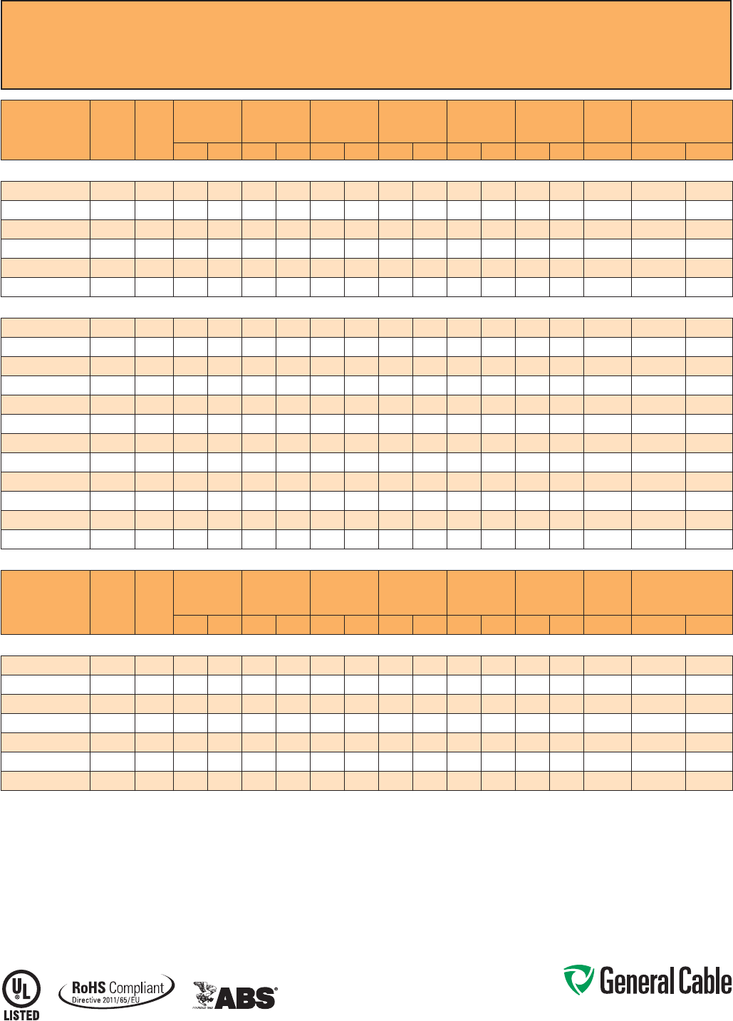
Phone: 888-593-3355
www.generalcable.com
CCW
®
Armored Instrumentation, Pairs/Triads, Overall Shield
UL Type MC-HL, PVC/Nylon, 600 V, 90°C, Cable Tray Use, Sunlight-Resistant, Direct Burial
UL Marine Shipboard Cable, ABS CWCMC
SPEC 9325
October, 2014
CATALOG
NUMBER
COND.
SIZE
(AWG) NO. OF
PAIRS
INSULATION
THICKNESS INNER JACKET
THICKNESS NOMINAL
CORE O.D. NOMINAL
ARMOR O.D. JACKET
THICKNESS NOMINAL
OVERALL O.D.
CROSS-
SECTIONAL
AREA¹ APPROXIMATE
NET WEIGHT
mils mm mils mm INCHES mm INCHES mm mils mm INCHES mm SQ. IN. LBS/1000 FT kg/1000 m
18 AWG 7W (0.82 mm²) OVERALL SHIELDED PAIRS
9325.18020001
18 2 19 0.48 40 1.02 0.41 10.4 0.59 15.0 50 1.27 0.70 17.8 0.39 222 330
9325.18040001
18 4 19 0.48 40 1.02 0.48 12.2 0.65 16.5 50 1.27 0.75 19.1 0.45 268 399
9325.18080001
18 8 19 0.48 50 1.27 0.60 15.2 0.82 20.8 50 1.27 0.92 23.4 0.67 420 625
9325.18120001
18 12 19 0.48 50 1.27 0.78 19.8 1.00 25.4 50 1.27 1.10 27.9 0.96 560 833
9325.18160001
18 16 19 0.48 50 1.27 0.81 20.6 1.12 28.4 50 1.27 1.23 31.2 1.20 706 1,051
9325.18240001
18 24 19 0.48 50 1.27 1.08 27.4 1.39 35.3 50 1.27 1.49 37.8 1.77 969 1,442
16 AWG 7W (1.31 mm²) OVERALL SHIELDED PAIRS
9325.16010001
16 1 19 0.48 60 1.52 0.35 8.9 0.53 13.5 50 1.27 0.64 16.3 0.33 185 275
9325.16020001
16 2 19 0.48 40 1.02 0.38 9.7 0.58 14.7 50 1.27 0.69 17.5 0.38 246 366
9325.16040001
16 4 19 0.48 40 1.02 0.47 11.9 0.71 18.0 50 1.27 0.82 20.8 0.54 333 495
9325.16060001
16 6 19 0.48 50 1.27 0.58 14.7 0.80 20.3 50 1.27 0.91 23.1 0.66 405 603
9325.16080001
16 8 19 0.48 50 1.27 0.66 16.8 0.89 22.6 50 1.27 1.00 25.4 0.80 466 694
9325.16100001
16 10 19 0.48 50 1.27 0.76 19.3 1.02 25.9 50 1.27 1.13 28.7 1.02 556 827
9325.16120001
16 12 19 0.48 50 1.27 0.80 20.3 1.06 26.9 50 1.27 1.17 29.7 1.09 604 899
9325.16160001
16 16 19 0.48 50 1.27 0.87 22.1 1.15 29.2 50 1.27 1.26 32.0 1.26 799 1,189
9325.16200001
16 20 19 0.48 50 1.27 0.98 24.9 1.29 32.8 50 1.27 1.40 35.6 1.56 929 1,383
9325.16240001
16 24 19 0.48 50 1.27 1.08 27.4 1.37 34.8 50 1.27 1.48 37.6 1.74 1,040 1,548
9325.16360001
16 36 19 0.48 50 1.27 1.32 33.5 1.64 41.7 60 1.52 1.78 45.2 2.52 1,445 2,151
9325.16500001
16 50 19 0.48 50 1.27 1.48 37.6 1.83 46.5 60 1.52 1.96 49.8 3.06 1,897 2,823
CATALOG
NUMBER
COND.
SIZE
(AWG) NO. OF
TRIADS
INSULATION
THICKNESS INNER JACKET
THICKNESS NOMINAL
CORE O.D. NOMINAL
ARMOR O.D.
OVERALL
JACKET
THICKNESS NOMINAL
OVERALL O.D.
CROSS-
SECTIONAL
AREA¹ APPROXIMATE
NET WEIGHT
mils mm mils mm INCHES mm INCHES mm mils mm INCHES mm SQ. IN. LBS/1000 FT kg/1000 m
16 AWG 7W (1.31 mm²) OVERALL SHIELDED TRIADS
9325.16010002
16 1 19 0.48 50 1.27 0.35 8.9 0.53 13.5 50 1.27 0.64 16.3 0.33 195 290
9325.16040002
16 4 19 0.48 40 1.02 0.51 13.0 0.71 18.0 50 1.27 0.82 20.8 0.54 407 606
9325.16080002
16 8 19 0.48 50 1.27 0.71 18.0 0.93 23.6 50 1.27 1.04 26.4 0.86 617 918
9325.16120002
16 12 19 0.48 50 1.27 0.85 21.6 1.11 28.2 50 1.27 1.22 31.0 1.18 897 1,334
9325.16160002
16 16 19 0.48 50 1.27 0.93 23.6 1.19 30.2 50 1.27 1.30 33.0 1.34 1,161 1,727
9325.16240002
16 24 19 0.48 50 1.27 1.16 29.5 1.47 37.3 50 1.27 1.58 40.1 1.99 1,581 2,353
9325.16360002
16 36 19 0.48 50 1.27 1.42 36.1 1.74 44.2 60 1.52 1.87 47.5 2.78 2,142 3,188
Dimensions and weights are nominal; subject to industry tolerances.
¹ Cross-sectional area for cable tray fill is in accordance with NEC® Section 392.22.
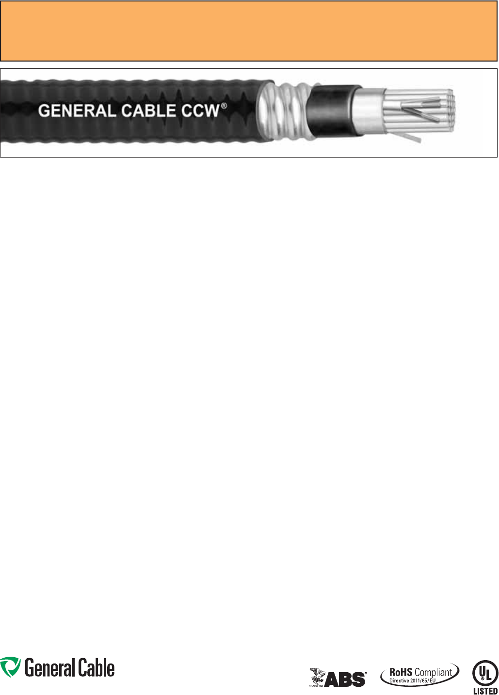
Phone: 888-593-3355
www.generalcable.com
CCW
®
Armored Instrumentation, Pairs/Triads, Individual and Overall Shield
UL Type MC-HL, PVC/Nylon, 600 V, 90°C, Cable Tray Use, Sunlight-Resistant, Direct Burial
UL Marine Shipboard Cable, ABS CWCMC
SPEC 9350
October, 2014
CCW Armor:
• Impervious, continuously welded and
corrugated aluminum alloy sheath per
UL Standards 1569 and 2225
• CCW armor conductivity meets the
grounding requirements of NEC
Article 250
Overall Jacket:
• Flame-retardant, moisture- and
sunlight-resistant Polyvinyl Chloride
(PVC) per UL Standard 1569, black
• Low temperature performance meets
ASTM D746 brittleness temperature at
or below -40°C
Applications:
• CCW armored 600 volt instrumentation
cables with individually shielded pairs
or triads and an overall shield provide
superior protection and reliability
against physical damage for use in
instrumentation and process control
applications where shielding against
both external EMI and EMI between
groups is required
• For use in Class 1 remote-control and
signal circuits in accordance with NEC
Article 725
• Recognized for use in Class I, II and
III, Divisions 1 and 2; or Class I, Zones
1 and 2 hazardous locations per NEC
Articles 501, 502, 503 and 505
• Installed indoors or outdoors, in wet or
dry locations, in a raceway, as aerial
cable on a messenger, in cable trays,
or for direct burial
• Recognized for use on fixed or
floating offshore petroleum facilities
as recommended by the American
Petroleum Institute
Features:
• CCW armor provides superior
mechanical protection and an
impervious barrier to moisture, gas
and liquids
• CCW armor provides EMI shielding
performance
• Meets cold impact at -40°C
Specifications:
Design Adherence:
• UL 83 Thermoplastic Insulated Wire
and Cables
• UL 1569 Metal Clad Cables
• UL 2225 Cables and Cable Fittings for
Use in Hazardous Locations
• UL 1309/CSA C22.2 No. 245 Marine
Shipboard Cable
Flame Tests:
• ICEA T-29-520 (210,000 BTU/hr)
• IEEE 383 (70,000 BTU/hr)
• CSA FT4
• IEEE 1202 (70,000 BTU/hr)
• UL 1581 (70,000 BTU/hr)
• IEC 60332-3 Cat. A
Compliances:
• UL Type MC-HL, CT USE, SUN RES,
DIR BUR, -40°C, UL File # E90496
• UL Listed Marine Shipboard, UL File
# E85994
• American Bureau of Shipping (ABS)
Listed for CWCMC
• RoHS Compliant
Product Construction:
Conductor:
• Bare annealed copper per ASTM B3
• Class B stranding per ASTM B8
Insulation:
• Flame-retardant Polyvinyl Chloride
(PVC) insulation and nylon covering,
rated 90°C per UL Standard 83
• Color-coded per ICEA Method 1:
pairs – black and white; triads – black,
white and red. Each conductor in each
pair or triad is printed alphanumerically
for easy identification
Shielded Pairs/Triads:
• Isolated and individually twisted pairs
or triads with a Flexfoil® aluminum/
polyester tape shield providing 100%
coverage
• Stranded tinned copper drain wire, two
sizes smaller than insulated conductors
Cable Assembly:
• Individually shielded pairs or triads are
cabled together with a left-hand lay
Overall Shield:
• Flexfoil® aluminum/polyester tape shield
providing 100% coverage
• Stranded tinned copper drain wire,
same size as insulated conductors
Inner Jacket:
• Flame-retardant Polyvinyl Chloride
(PVC) per UL Standard 1569, black
• Low temperature performance meets
ASTM D746 brittleness temperature at
or below -40°C
• Nylon rip cord to facilitate jacket
removal
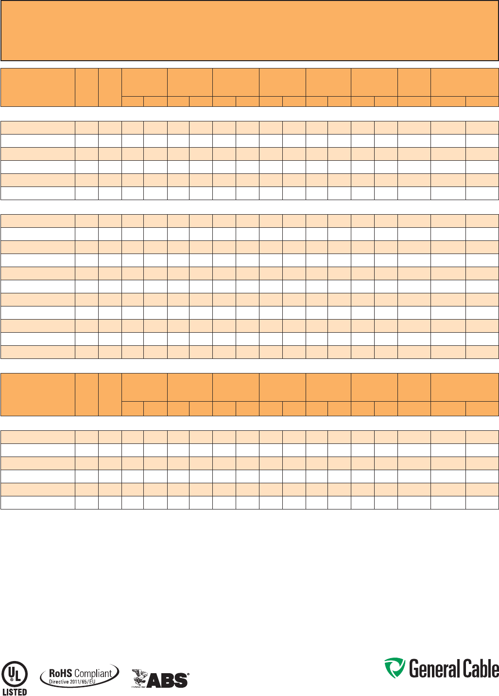
Phone: 888-593-3355
www.generalcable.com
CCW
®
Armored Instrumentation, Pairs/Triads, Individual and Overall Shield
UL Type MC-HL, PVC/Nylon, 600 V, 90°C, Cable Tray Use, Sunlight-Resistant, Direct Burial
UL Marine Shipboard Cable, ABS CWCMC
SPEC 9350
October, 2014
CATALOG
NUMBER
COND.
SIZE
(AWG) NO. OF
PAIRS
INSULATION
THICKNESS INNER JACKET
THICKNESS NOMINAL
CORE O.D. NOMINAL
ARMOR O.D.
OVERALL
JACKET
THICKNESS NOMINAL
OVERALL O.D.
CROSS-
SECTIONAL
AREA¹ APPROXIMATE
NET WEIGHT
mils mm mils mm INCHES mm INCHES mm mils mm INCHES mm SQ. IN. LBS/1000 FT kg/1000 m
18 AWG 7W (0.82 mm²) INDIVIDUAL AND OVERALL SHIELDED PAIRS
9350.18020001
18 2 19 0.48 40 1.02 0.41 10.4 0.59 15.0 50 1.27 0.70 17.8 0.39 225 335
9350.18040001
18 4 19 0.48 40 1.02 0.48 12.2 0.65 16.5 50 1.27 0.75 19.1 0.45 300 446
9350.18080001
18 8 19 0.48 50 1.27 0.60 15.2 0.82 20.8 50 1.27 0.92 23.4 0.67 450 670
9350.18120001
18 12 19 0.48 50 1.27 0.78 19.8 1.00 25.4 50 1.27 1.10 27.9 0.96 580 863
9350.18160001
18 16 19 0.48 50 1.27 0.81 20.6 1.12 28.4 50 1.27 1.23 31.2 1.20 760 1,131
9350.18240001
18 24 19 0.48 50 1.27 1.08 27.4 1.39 35.3 50 1.27 1.49 37.8 1.77 1,050 1,563
16 AWG 7W (1.31 mm²) INDIVIDUAL AND OVERALL SHIELDED PAIRS
9350.16020001
16 2 19 0.48 40 1.02 0.45 11.4 0.67 17.0 50 1.27 0.78 19.8 0.48 239 355
9350.16040001
16 4 19 0.48 50 1.27 0.56 14.2 0.80 20.3 50 1.27 0.91 23.1 0.66 342 509
9350.16060001
16 6 19 0.48 50 1.27 0.66 16.8 0.89 22.6 50 1.27 1.00 25.4 0.80 429 639
9350.16080001
16 8 19 0.48 50 1.27 0.70 17.8 0.93 23.6 50 1.27 1.04 26.4 0.86 502 747
9350.16100001
16 10 19 0.48 50 1.27 0.79 20.1 1.06 26.9 50 1.27 1.17 29.7 1.09 613 912
9350.16120001
16 12 19 0.48 50 1.27 0.85 21.6 1.11 28.2 50 1.27 1.22 31.0 1.18 687 1,023
9350.16160001
16 16 19 0.48 50 1.27 0.98 24.9 1.29 32.8 50 1.27 1.40 35.6 1.56 859 1,278
9350.16200001
16 20 19 0.48 50 1.27 1.06 26.9 1.34 34.0 50 1.27 1.45 36.8 1.67 997 1,483
9350.16240001
16 24 19 0.48 50 1.27 1.12 28.4 1.42 36.1 50 1.27 1.53 38.9 1.86 1,140 1,697
9350.16360001
16 36 19 0.48 50 1.27 1.37 34.8 1.69 42.9 60 1.52 1.82 46.2 2.64 1,618 2,407
9350.16500001
16 50 19 0.48 50 1.27 1.57 39.9 1.92 48.8 60 1.52 2.05 52.1 3.34 2,166 3,224
CATALOG
NUMBER
COND.
SIZE
(AWG) NO. OF
TRIADS
INSULATION
THICKNESS INNER JACKET
THICKNESS NOMINAL
CORE O.D. NOMINAL
ARMOR O.D.
OVERALL
JACKET
THICKNESS NOMINAL
OVERALL O.D.
CROSS-
SECTIONAL
AREA¹ APPROXIMATE
NET WEIGHT
mils mm mils mm INCHES mm INCHES mm mils mm INCHES mm SQ. IN. LBS/1000 FT kg/1000 m
16 AWG 7W (1.31 mm²) INDIVIDUAL AND OVERALL SHIELDED TRIADS
9350.16040002
16 4 19 0.48 50 1.27 0.61 15.5 0.84 21.3 50 1.27 0.95 24.1 0.72 403 600
9350.16080002
16 8 19 0.48 50 1.27 0.82 20.8 1.06 26.9 50 1.27 1.17 29.7 1.09 650 967
9350.16120002
16 12 19 0.48 50 1.27 0.98 24.9 1.24 31.5 50 1.27 1.35 34.3 1.45 853 1,269
9350.16160002
16 16 19 0.48 50 1.27 1.10 27.9 1.37 34.8 50 1.27 1.48 37.6 1.74 1,079 1,606
9350.16240002
16 24 19 0.48 50 1.27 1.33 33.8 1.64 41.7 60 1.52 1.78 45.2 2.52 1,515 2,254
9350.16360002
16 36 19 0.48 50 1.27 1.58 40.1 1.96 49.8 60 1.52 2.09 53.1 3.48 2,184 3,250
Dimensions and weights are nominal; subject to industry tolerances.
¹ Cross-sectional area for cable tray fill is in accordance with NEC® Section 392.22.
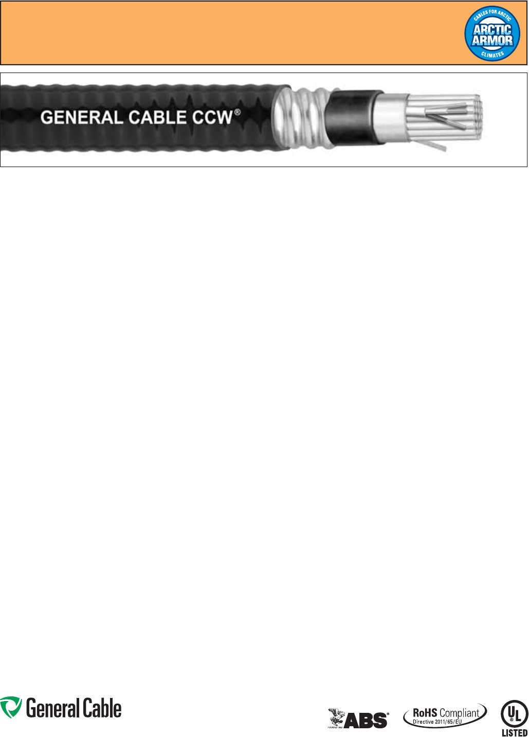
Phone: 888-593-3355
www.generalcable.com
CCW® Armored Instrumentation, Pairs/Triads, Individual and Overall Shield
UL Type MC-HL, 600 V or UL Type ITC-HL, 300 V, XLPE, 90°C, Cable Tray Use
Sunlight-Resistant, Direct Burial, UL Marine Shipboard Cable, ABS CWCMC, Arctic-Grade
SPEC 9400
October, 2014
Product Construction:
Conductor:
• Bare annealed copper per ASTM B3
• Class B stranding per ASTM B8
Insulation:
• Cross-linked Polyethylene (XLPE), rated
90°C per UL Standards 13 and 2250
• Color-coded per ICEA Method 1: pairs
– black and white; triads – black, white
and red. Each conductor in each pair
or triad is printed alphanumerically for
easy identification
Shielded Pair/Triad:
• Isolated and individually twisted pairs or
triads with Flexfoil® aluminum/polyester
tape shield providing 100% coverage
• Stranded tinned copper drain wire, two
sizes smaller than insulated conductors
Cable Assembly:
• Individually shielded pairs or triads are
cabled together with a left-hand lay
Overall Shield:
• Flexifoil® aluminum/polyester tape
shield providing 100% coverage
• Stranded tinned copper drain wire,
same size as insulated conductors
Inner Jacket:
• Flame retardant Polyvinyl Chloride
(PVC) per UL Standard 1569, black
• Low temperature performance meets
ASTM D746 brittleness temperature at
or below -60°C
• Nylon rip cord to facilitate jacket removal
CCW Armor:
• Impervious, continuously welded and
corrugated aluminum alloy sheath per
UL Standards 1569 and 2225
• CCW armor conductivity meets the
grounding requirements of NEC Article 250
Overall Jacket:
• Flame-retardant, moisture- and
sunlight-resistant Polyvinyl Chloride
(PVC) per UL Standard 1569, black
• Low temperature performance meets
ASTM D746 brittleness temperature at
or below -60°C
Applications:
• CCW armored 600 volt instrumentation
cables with individually shielded pairs
or triads and an overall shield provide
superior protection and reliability
against physical damage for use in
instrumentation and process control
applications where shielding against
both external EMI and EMI between
groups is required
• For use in Class 1 remote-control
and signal circuits in accordance with
NEC Article 725
• Recognized for use in Class I, II and III,
Divisions 1 and 2; or Class 1, Zones 1
and 2 hazardous locations per
NEC Articles 501, 502, 503 and 505
• Installed indoors or outdoors, in wet or
dry locations, in a raceway, as aerial
cable on a messenger, in cable trays,
or for direct burial
• Recognized for use on fixed or
floating offshore petroleum facilities
as recommended by the American
Petroleum Institute
Features:
• CCW armor provides superior
mechanical protection and an
impervious barrier to moisture,
gas and liquids
• CCW armor provides EMI shielding
performance
• Meets cold bend at -55°C
Specifications:
Design Adherence:
• UL 1569 Metal Clad Cables
• UL 2225 Cables and Cable Fittings for
Use in Hazardous Locations
• UL 2250 Instrumentation Tray Cable
• UL 1309/CSA C22.2 No. 245 Marine
Shipboard Cable
Flame Tests:
• ICEA T-29-520 (210,000 BTU/hr)
• IEEE 383 (70,000 BTU/hr)
• CSA FT4
• IEEE 1202 (70,000 BTU/hr)
• UL 1581 (70,000 BTU/hr)
• IEC 60332-3 Cat. A
Compliances:
• UL Type MC-HL, CT USE, SUN RES,
DIR BUR, -60°C, UL File # E90496
• UL Type ITC-HL, UL File # E177408
• UL Listed Marine Shipboard, UL File
# E85994
• American Bureau of Shipping (ABS)
Listed for CWCMC
• RoHS Compliant
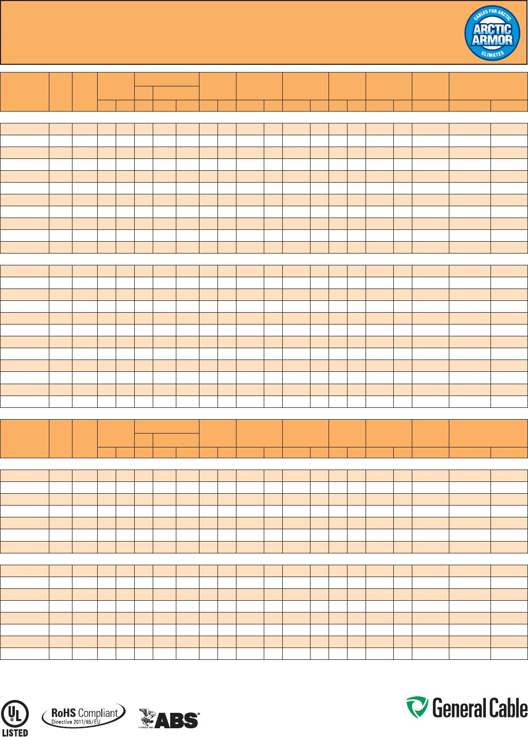
Phone: 888-593-3355
www.generalcable.com
CCW® Armored Instrumentation, Pairs/Triads, Individual and Overall Shield
UL Type MC-HL, 600 V or UL Type ITC-HL, 300 V, XLPE, 90°C, Cable Tray Use
Sunlight-Resistant, Direct Burial, UL Marine Shipboard Cable, ABS CWCMC, Arctic-Grade
SPEC 9400
October, 2014
CATALOG
NUMBER
COND.
SIZE
(AWG) NO. OF
PAIRS
INSULATION
THICKNESS
COMMUNICATION WIRE INNER
JACKET
THICKNESS NOMINAL
CORE O.D. NOMINAL
ARMOR O.D. JACKET
THICKNESS NOMINAL
OVERALL O.D.
CROSS-
SECTIONAL
AREA1APPROXIMATE
NET WEIGHTSIZE INS. THICKNESS
mils mm AWG mils mm mils mm INCHES mm INCHES mm mils mm INCHES mm (SQ. IN.) LBS/1000 FT. kg/1000 m
18 AWG 7W (0.82 mm²) INDIVIDUAL AND OVERALL SHIELDED PAIRS
9400.18020001 18 2 30 0.76 22 12 0.30 78 1.98 0.58 14.6 0.79 19.9 50 1.27 0.89 22.6 0.62 307 457
9400.18040001 18 4 30 0.76 22 12 0.30 93 2.36 0.69 17.4 0.93 23.6 50 1.27 1.04 26.3 0.84 448 667
9400.18060001 18 6 30 0.76 22 12 0.30 93 2.36 0.81 20.4 1.08 27.4 50 1.27 1.19 30.1 1.10 551 820
9400.18080001 18 8 30 0.76 22 12 0.30 93 2.36 0.87 22.1 1.15 29.1 50 1.27 1.25 31.8 1.23 609 906
9400.18100001 18 10 30 0.76 22 12 0.30 109 2.77 1.04 26.4 1.36 34.4 50 1.27 1.46 37.1 1.67 774 1152
9400.18120001 18 12 30 0.76 22 12 0.30 109 2.77 1.07 27.2 1.42 36.1 50 1.27 1.53 38.7 1.83 893 1329
9400.18160001 18 16 30 0.76 22 12 0.30 109 2.77 1.19 30.1 1.54 39.0 60 1.52 1.66 42.2 2.16 1050 1562
9400.18200001 18 20 30 0.76 22 12 0.30 109 2.77 1.31 33.3 1.63 41.3 60 1.52 1.75 44.5 2.41 1234 1836
9400.18240001 18 24 30 0.76 22 12 0.30 124 3.15 1.48 37.6 1.73 43.8 60 1.52 1.85 47.0 2.69 1497 2228
9400.18360001 18 36 30 0.76 22 12 0.30 124 3.15 1.68 42.7 1.92 48.6 60 1.52 2.04 51.8 3.27 1882 2800
9400.18500001 18 50 30 0.76 22 12 0.30 140 3.56 2.00 50.8 2.48 63.0 75 1.91 2.64 67.1 5.47 2739 4076
16 AWG 7W (1.31 mm²) INDIVIDUAL AND OVERALL SHIELDED PAIRS
9400.16010001* 16 1 30 0.76 — — — 62 1.57 0.38 9.5 0.56 14.1 50 1.27 0.66 16.8 0.34 196 292
9400.16020001 16 2 30 0.76 22 12 0.30 78 1.98 0.62 15.6 0.83 21.0 50 1.27 0.93 23.6 0.68 337 501
9400.16040001 16 4 30 0.76 22 12 0.30 93 2.36 0.74 18.8 0.98 24.9 50 1.27 1.09 27.6 0.92 495 737
9400.16060001 16 6 30 0.76 22 12 0.30 93 2.36 0.87 22.1 1.15 29.1 50 1.27 1.25 31.8 1.23 627 933
9400.16080001 16 8 30 0.76 22 12 0.30 109 2.77 0.98 24.8 1.29 32.6 50 1.27 1.39 35.3 1.52 783 1165
9400.16100001 16 10 30 0.76 22 12 0.30 109 2.77 1.13 28.7 1.48 37.6 50 1.27 1.59 40.3 1.97 955 1421
9400.16120001 16 12 30 0.76 22 12 0.30 109 2.77 1.16 29.5 1.51 38.4 60 1.52 1.64 41.5 2.10 1061 1579
9400.16160001 16 16 30 0.76 22 12 0.30 109 2.77 1.29 32.6 1.60 40.6 60 1.52 1.73 43.8 2.34 1274 1896
9400.16200001 16 20 30 0.76 22 12 0.30 124 3.15 1.45 36.8 1.73 43.8 60 1.52 1.85 47.0 2.69 1576 2345
9400.16240001 16 24 30 0.76 22 12 0.30 124 3.15 1.61 40.8 1.92 48.6 60 1.52 2.04 51.8 3.27 1725 2567
9400.16360001 16 36 30 0.76 22 12 0.30 140 3.56 1.87 47.4 2.16 54.9 60 1.52 2.28 57.9 6.38 2436 3625
9400.16500001 16 50 30 0.76 22 12 0.30 171 4.34 2.25 57.0 2.62 66.5 75 1.91 2.78 70.6 6.07 3361 5001
CATALOG
NUMBER
COND.
SIZE
(AWG) NO. OF
TRIADS
INSULATION
THICKNESS
COMMUNICATION WIRE INNER
JACKET
THICKNESS NOMINAL
CORE O.D. NOMINAL
ARMOR O.D. JACKET
THICKNESS NOMINAL
OVERALL O.D.
CROSS-
SECTIONAL
AREA1APPROXIMATE
NET WEIGHTSIZE INS. THICKNESS
mils mm AWG mils mm mils mm INCHES mm INCHES mm mils mm INCHES mm (SQ. IN.) LBS/1000 FT. kg/1000 m
18 AWG 7W (0.82 mm²) INDIVIDUAL AND OVERALL SHIELDED TRIADS
9400.18020002 18 2 30 0.76 22 12 0.30 78 1.98 0.63 15.9 0.84 21.2 50 1.27 0.94 23.9 0.69 337 501
9400.18040002 18 4 30 0.76 22 12 0.30 93 2.36 0.75 19.1 1.00 25.3 50 1.27 1.10 27.9 0.95 495 737
9400.18080002 18 8 30 0.76 22 12 0.30 109 2.77 0.99 25.1 1.30 33.0 50 1.27 1.41 35.7 1.55 785 1168
9400.18120002 18 12 30 0.76 22 12 0.30 109 2.77 1.18 30.0 1.53 38.9 60 1.52 1.67 42.3 2.18 1062 1580
9400.18160002 18 16 30 0.76 22 12 0.30 124 3.15 1.34 33.9 1.64 41.7 60 1.52 1.77 44.8 2.45 1322 1967
9400.18240002 18 24 30 0.76 22 12 0.30 124 3.15 1.64 41.5 1.92 48.6 60 1.52 2.04 51.8 3.27 1806 2687
9400.18360002 18 36 30 0.76 22 12 0.30 140 3.56 1.90 48.3 2.23 56.6 75 1.91 2.39 60.7 4.49 2525 3757
16 AWG 7W (1.31 mm²) INDIVIDUAL AND OVERALL SHIELDED TRIADS
9400.16010002 16 1 30 0.76 — — — 62 1.57 0.40 10.0 0.58 14.6 50 1.27 0.68 17.3 0.36 207 308
9400.16020002 16 2 30 0.76 22 12 0.30 93 2.36 0.71 17.9 0.95 24.1 50 1.27 1.06 26.8 0.87 429 638
9400.16040002 16 4 30 0.76 22 12 0.30 93 2.36 0.81 20.6 1.09 27.6 50 1.27 1.19 30.2 1.11 564 839
9400.16080002 16 8 30 0.76 22 12 0.30 109 2.77 1.07 27.2 1.42 36.1 50 1.27 1.53 38.7 1.83 928 1381
9400.16120002 16 12 30 0.76 22 12 0.30 109 2.77 1.29 32.6 1.60 40.6 60 1.52 1.73 43.8 2.34 1300 1934
9400.16160002 16 16 30 0.76 22 12 0.30 124 3.15 1.46 37.0 1.73 43.8 60 1.52 1.85 47.0 2.69 1654 2461
9400.16240002 16 24 30 0.76 22 12 0.30 140 3.56 1.82 46.2 2.16 54.9 60 1.52 2.29 58.0 4.10 2348 3494
9400.16360002 16 36 30 0.76 22 12 0.30 171 4.34 2.14 54.2 2.45 62.2 75 1.91 2.61 66.3 5.35 3319 4939
Dimensions and weights are nominal; subject to industry tolerances.
* Item rated ITC/PLTC.
¹ Cross-sectional area for cable tray fill is in accordance with NEC® Section 392.22.

Phone: 888-593-3355
www.generalcable.com
SPEC 9500
October, 2014
Applications:
• CCW armored control cables offer
an economical, rugged and reliable
alternative to labor-intensive cable in
conduit wiring methods
• For use in Class I, II and III, Divisions
1 and 2; and Class I, Zones 1 and 2
hazardous locations per NEC Articles
501, 502, 503 and 505
• For use as services, feeders and
branch circuits for power, lighting,
control, and signal circuits in
accordance with NEC Articles 330
and 725
• Installed indoors or outdoors, wet
or dry locations, directly buried,
embedded in concrete, in a raceway,
as aerial cable on a messenger,
in cable trays, or as exposed runs
secured to supports in accordance
with NEC Article 330
• Recognized for use on fixed or
floating offshore petroleum facilities
as recommended by the American
Petroleum Institute
Features:
• CCW armor provides an impervious
barrier to moisture, gas and liquids
• CCW armor provides EMI shielding
performance
• Factory assembled and tested cable
for use as an alternative to cable in
conduit wiring systems
• Meets cold impact at -40°C
• 90˚C continuous operating
temperature, wet or dry
• 130˚C emergency rating
• 250˚C short circuit rating
CCW
®
Armored Control With Grounding Conductor
UL Type MC-HL, CSA Type HL, XLPE, 600 V, 90°C, Cable Tray Use, Sunlight-Resistant
Direct Burial, UL Marine Shipboard Cable, ABS CWCMC
Product Construction:
Conductor:
• Bare annealed copper per ASTM B3
• Compressed Class B stranding per
ASTM B8
Insulation:
• Cross-linked Polyethylene (XLPE)
insulation per ICEA S-73-532 and UL
44, Listed XHHW-2
• Color-coded per ICEA Method 1, Table
E2, full-colored insulation with stripes
• Color-coded per CSA C22.2 No. 123
where applicable
Grounding Conductor:
• Class B stranded bare annealed
copper per ASTM B3 and B8
• Cross-linked Polyethylene (XLPE)
insulation, green
• Sized in accordance with NEC Table
250.122
Cable Assembly:
• Insulated conductors and grounding
wire are cabled together with non-
hygroscopic fillers when required
• A binder tape, when required, is
applied over the cabled core
CCW Armor:
• Impervious, continuously welded and
corrugated aluminum alloy sheath per
UL 1569 and UL 2225
• CCW armor conductivity meets the
grounding requirements of NEC
Article 250
Jacket:
• Flame-retardant, moisture- and
sunlight-resistant Polyvinyl Chloride
(PVC), black
• Low temperature performance meets
ASTM D746 brittleness temperature at
or below -40°C
• Meets CSA Low Acid Gas
requirements
Specifications:
Design Adherence:
• ICEA S-73-532/WC57 Standard for
Control, Thermocouple Extension and
Instrumentation Cables
• UL 44 Rubber Insulated Wires and
Cables
• UL 1569 Metal Clad Cables
• UL 2225 Cables and Cable Fittings for
Use in Hazardous Locations
• UL 1309 Marine Shipboard Cable
• CSA C22.2 No. 123 Metal Sheathed
Cables
• CSA C22.2 No. 174 Cables and Cable
Glands for Use in Hazardous Locations
Flame Tests:
• ICEA T-29-520 (210,000 BTU/hr)
• IEEE 383 (70,000 BTU/hr)
• CSA FT4
• IEEE 1202 (70,000 BTU/hr)
• UL 1581 (70,000 BTU/hr)
• IEC 60332-3 Cat. A
Compliances:
• UL Type MC-HL, XHHW-2, SUN RES,
CT USE, DIR BUR, -40°C, UL File
# E90496
• UL Listed Marine Shipboard, UL File
# E85994
• American Bureau of Shipping (ABS)
Listed for CWCMC
• CSA certified
1
Type RA90, XLPE,
HL, SR, FT4, and -40°C, CSA File
# 7319
• RoHS Compliant
1
Standard cables are also marked CSA Type RA90,
except four (4) conductor cables which require a different
color code, which may be special-ordered.
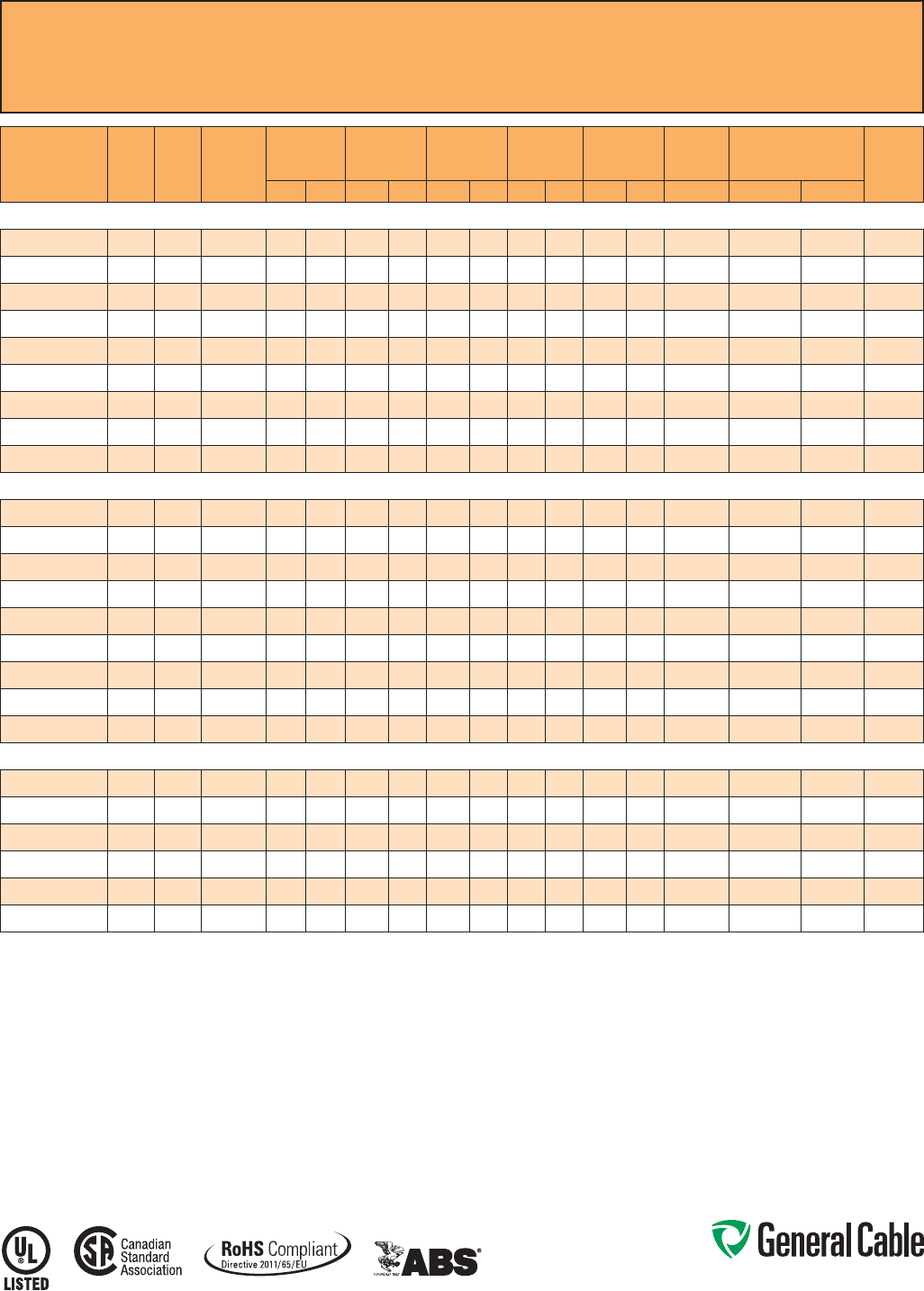
Phone: 888-593-3355
www.generalcable.com
SPEC 9500
October, 2014
CCW
®
Armored Control With Grounding Conductor
UL Type MC-HL, CSA Type HL, XLPE, 600 V, 90°C, Cable Tray Use, Sunlight-Resistant
Direct Burial, UL Marine Shipboard Cable, ABS CWCMC
CATALOG
NUMBER
COND.
SIZE
(AWG) NO. OF
COND.
GREEN
INSULATED
GROUND
(AWG)
INSULATION
THICKNESS NOMINAL
CORE O.D. NOMINAL
ARMOR O.D. JACKET
THICKNESS NOMINAL
OVERALL O.D.
CROSS-
SECTIONAL
AREA¹ APPROXIMATE
NET WEIGHT 90°C
AMPACITY
@ 30°C
AMBIENT²mils mm INCHES mm INCHES mm mils mm INCHES mm SQ. IN. LBS/1000 FT kg/1000 m
14 AWG 7W (2.08 mm²) MULTI-CONDUCTOR CONTROL CABLE WITH GREEN INSULATED GROUNDING CONDUCTOR
9500.01402114
14 2 14 30 0.76 0.30 7.6 0.49 12.4 50 1.27 0.60 15.2 0.29 163 243 15
9500.01403114
14 3 14 30 0.76 0.33 8.4 0.53 13.5 50 1.27 0.64 16.3 0.33 192 286 15
9500.01404114
14 4 14 30 0.76 0.37 9.4 0.58 14.7 50 1.27 0.69 17.5 0.38 222 330 15
9500.01405114
14 5 14 30 0.76 0.39 9.9 0.60 15.2 50 1.27 0.71 18.0 0.40 245 365 15
9500.01406114
14 6 14 30 0.76 0.41 10.4 0.62 15.7 50 1.27 0.73 18.5 0.42 267 397 15
9500.01408114
14 8 14 30 0.76 0.49 12.4 0.71 18.0 50 1.27 0.82 20.8 0.54 321 478 15
9500.01411114
14 11 14 30 0.76 0.57 14.5 0.80 20.3 50 1.27 0.91 23.1 0.66 395 588 12
9500.01418114
14 18 14 30 0.76 0.69 17.5 0.93 23.6 50 1.27 1.04 26.4 0.86 554 824 12
9500.01436114
14 36 14 30 0.76 0.97 24.6 1.24 31.5 50 1.27 1.35 34.3 1.45 948 1,411 10
12 AWG 7W (3.31 mm²) MULTI-CONDUCTOR CONTROL CABLE WITH GREEN INSULATED GROUNDING CONDUCTOR
9500.01202112
12 2 12 30 0.76 0.34 8.6 0.53 13.5 50 1.27 0.64 16.3 0.33 200 298 20
9500.01203112
12 3 12 30 0.76 0.37 9.4 0.58 14.7 50 1.27 0.69 17.5 0.38 239 356 20
9500.01204112
12 4 12 30 0.76 0.45 11.4 0.67 17.0 50 1.27 0.78 19.8 0.48 310 461 20
9500.01205112
12 5 12 30 0.76 0.46 11.7 0.67 17.0 50 1.27 0.78 19.8 0.48 324 482 20
9500.01206112
12 6 12 30 0.76 0.47 11.9 0.67 17.0 50 1.27 0.78 19.8 0.48 338 503 20
9500.01208112
12 8 12 30 0.76 0.56 14.2 0.80 20.3 50 1.27 0.91 23.1 0.66 426 634 20
9500.01211112
12 11 12 30 0.76 0.65 16.5 0.89 22.6 50 1.27 1.00 25.4 0.80 519 772 15
9500.01218112
12 18 12 30 0.76 0.78 19.8 1.02 25.9 50 1.27 1.13 28.7 1.02 739 1,100 15
9500.01236112
12 36 12 30 0.76 1.10 27.9 1.37 34.8 50 1.27 1.48 37.6 1.74 1,302 1,938 12
10 AWG 7W (5.26 mm²) MULTI-CONDUCTOR CONTROL CABLE WITH GREEN INSULATED GROUNDING CONDUCTOR
9500.01002110
10 2 10 30 0.76 0.39 9.9 0.58 14.7 50 1.27 0.69 17.5 0.38 253 377 30
9500.01003110
10 3 10 30 0.76 0.41 10.4 0.62 15.7 50 1.27 0.73 18.5 0.42 303 451 30
9500.01004110
10 4 10 30 0.76 0.45 11.4 0.67 17.0 50 1.27 0.78 19.8 0.48 348 518 30
9500.01006110
10 6 10 30 0.76 0.54 13.7 0.75 19.1 50 1.27 0.86 21.8 0.59 451 671 28
9500.01008110
10 8 10 30 0.76 0.65 16.5 0.89 22.6 50 1.27 1.00 25.4 0.80 568 845 28
9500.01011110
10 11 10 30 0.76 0.75 19.1 0.97 24.6 50 1.27 1.08 27.4 0.93 704 1,048 20
Dimensions and weights are nominal; subject to industry tolerances.
¹ Cross-sectional area for cable tray fill is in accordance with NEC Section 392.22.
² Ampacities in accordance with NEC Article 310 and Table 310.15(B)(16).
Note: Standard cables with up to and including six (6) conductors are also marked CSA Type RA90. All others are special order.
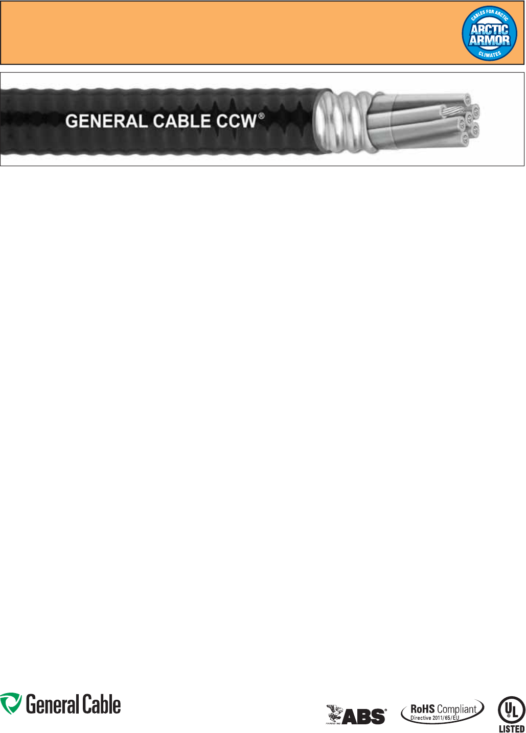
Phone: 888-593-3355
www.generalcable.com
SPEC 9505
October, 2014
CCW
®
Armored Control With Grounding Conductor
UL Type MC-HL, XLPE, 600 V, 90°C, Cable Tray Use, Sunlight-Resistant
Direct Burial, UL Marine Shipboard Cable, ABS CWCMC, Arctic-Grade
Product Construction:
Conductor:
• Bare annealed copper per ASTM B3
• Compressed Class B stranding per
ASTM B8
Insulation:
• Cross-linked Polyethylene (XLPE)
insulation per ICEA S-73-532 and
UL 44, Listed XHHW-2
• Color-coded per ICEA Method 1, Table
E2, full-colored insulation with stripes
• Color-coded per CSA C22.2 No. 123
where applicable
Grounding Conductor:
• Class B stranded bare annealed
copper per ASTM B3 and B8
• Cross-linked Polyethylene (XLPE)
insulation, green
• Sized in accordance with NEC
Table 250.122
Cable Assembly:
• Insulated conductors and grounding
wire are cabled together with
non-hydroscopic fillers when required
• A binder tape, when required, is
applied over the cabled core
CCW Armor:
• Impervious, continuously welded and
corrugated aluminum alloy sheath per
UL Standards 1569 and 2225
• CCW armor conductivity meets
the grounding requirements of
NEC Article 250
Jacket:
• Flame-retardant, moisture- and
sunlight-resistant Polyvinyl Chloride
(PVC), black
• Low temperature performance meets
ASTM D746 brittleness temperature at
or below -60°C
Applications:
• CCW armored control cables offer
an economical, rugged and reliable
alternative to labor-intensive cable in
conduit wiring methods
• For use in Class I, II and III, Divisions
1 and 2; and Class I, Zones 1 and 2
hazardous locations per NEC Articles
501, 502, 503 and 505
• For use as services, feeders and branch
circuits for power, lighting, control, and
signal circuits in accordance with
NEC Articles 330 and 725
• Installed indoors or outdoors, wet
or dry locations, directly buried,
embedded in concrete, in a raceway,
as aerial cable on a messenger,
in cable trays, or as exposed runs
secured to supports in accordance
with NEC Article 330
• Recognized for use on fixed or
floating offshore petroleum facilities
as recommended by the American
Petroleum Institute
Features:
• CCW armor provides an impervious
barrier to moisture, gas and liquids
• CCW armor provides EMI shielding
performance
• Factory assembled and tested cable
for use as an alternate to cable in
conduit wiring systems
• Meets cold bend at -55°C
• 90°C continuous operating
temperature, wet or dry
• 130°C emergency rating
• 250°C short circuit rating
Specifications:
Design Adherence:
• ICEA S-73-532/WC57 Standard for
Control, Thermocouple Extension and
Instrumentation Cables
• UL 44 Rubber Insulated Wires and
Cables
• UL 1569 Metal Clad Cables
• UL 2225 Cables and Cable Fittings for
Use in Hazardous Locations
• UL 1309 Marine Shipboard Cable
• CSA C22.2 No. 123 Metal Sheathed
Cables
• CSA C22.2 No. 174 Cables and Cable
Glands for Use in Hazardous Locations
Flame Tests:
• ICEA T-29-520 (210,000 BTU/hr)
• IEEE 383 (70,000 BTU/hr)
• CSA FT4
• IEEE 1202 (70,000 BTU/hr)
• UL 1581 (70,000 BTU/hr)
• IEC 60332-3 Cat. A
Compliances:
• UL Type MC-HL, XHHW-2, SUN RES,
CT USE, DIR BUR, -40°C, UL File
# E90496
• UL Listed Marine Shipboard, UL File
# E85994
• American Bureau of Shipping (ABS)
Listed for CWCMC
• RoHS Compliant
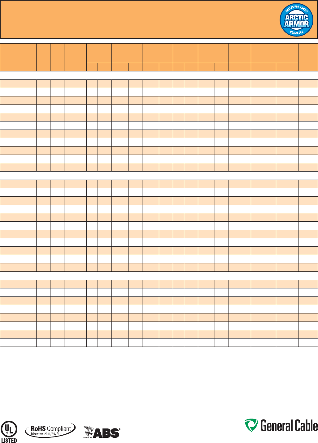
Phone: 888-593-3355
www.generalcable.com
SPEC 9505
October, 2014
CCW
®
Armored Control With Grounding Conductor
UL Type MC-HL, XLPE, 600 V, 90°C, Cable Tray Use, Sunlight-Resistant
Direct Burial, UL Marine Shipboard Cable, ABS CWCMC, Arctic-Grade
CATALOG
NUMBER
COND.
SIZE
(AWG)
NO.
OF
COND.
GREEN
INSULATED
GROUND
(QTY/SIZE)
(AWG)
INSULATION
THICKNESS NOMINAL
CORE O.D. NOMINAL
ARMOR O.D. JACKET
THICKNESS NOMINAL
OVERALL O.D.
CROSS-
SECTIONAL
AREA1APPROXIMATE
NET WEIGHT 90°C
AMPACITY
@ 30°C
AMBIENT²mils mm INCHES mm INCHES mm mils mm INCHES mm SQ. IN. LBS/1000 FT kg/1000 m
14 AWG 7W (2.08 mm²) MULTI-CONDUCTOR CONTROL CABLE WITH GREEN INSULATED GROUNDING CONDUCTOR
9505.01402114
14 2 1-#14 30 0.76 0.30 7.6 0.49 12.4 50 1.27 0.60 15.2 0.29 163 243 15
9505.01403114
14 3 1-#14 30 0.76 0.33 8.4 0.53 13.5 50 1.27 0.64 16.3 0.33 192 286 15
9505.01403114
14 3 3-#18 30 0.76 0.37 9.4 0.55 14.0 50 1.27 0.66 16.8 0.34 218 324 15
9505.01404114
14 4 1-#14 30 0.76 0.37 9.4 0.58 14.7 50 1.27 0.69 17.5 0.38 222 330 15
9505.01404114
14 4 2-#16 30 0.76 0.38 9.7 0.56 14.2 50 1.27 0.67 17.0 0.35 230 343 15
9505.01405114
14 5 1-#14 30 0.76 0.39 9.9 0.60 15.2 50 1.27 0.71 18.0 0.40 245 365 15
9505.01406114
14 6 1-#14 30 0.76 0.41 10.4 0.62 15.7 50 1.27 0.73 18.5 0.42 267 397 15
9505.01408114
14 8 1-#14 30 0.76 0.49 12.4 0.71 18.0 50 1.27 0.82 20.8 0.54 321 478 15
9505.01411114
14 11 1-#14 30 0.76 0.57 14.5 0.80 20.3 50 1.27 0.91 23.1 0.66 395 588 12
9505.01418114
14 18 1-#14 30 0.76 0.69 17.5 0.93 23.6 50 1.27 1.04 26.4 0.86 554 824 12
9505.01436114
14 36 1-#14 30 0.76 0.97 24.6 1.24 31.5 50 1.27 1.35 34.3 1.45 948 1,411 10
12 AWG 7W (3.31 mm²) MULTI-CONDUCTOR CONTROL CABLE WITH GREEN INSULATED GROUNDING CONDUCTOR
9505.01202112
12 2 1-#12 30 0.76 0.34 8.6 0.53 13.5 50 1.27 0.64 16.3 0.33 200 298 20
9505.01203112
12 3 1-#12 30 0.76 0.37 9.4 0.58 14.7 50 1.27 0.69 17.5 0.38 239 356 20
9505.01203112
12 3 3-#16 30 0.76 0.41 10.4 0.60 15.2 50 1.27 0.71 18.0 0.40 270 402 20
9505.01204112
12 4 1-#12 30 0.76 0.45 11.4 0.67 17.0 50 1.27 0.78 19.8 0.48 310 461 20
9505.01204112
12 4 3-#16 30 0.76 0.43 10.9 0.62 15.7 50 1.27 0.73 18.5 0.42 293 436 20
9505.01205112
12 5 1-#12 30 0.76 0.46 11.7 0.67 17.0 50 1.27 0.78 19.8 0.48 324 482 20
9505.01206112
12 6 1-#12 30 0.76 0.47 11.9 0.67 17.0 50 1.27 0.78 19.8 0.48 338 503 20
9505.01208112
12 8 1-#12 30 0.76 0.56 14.2 0.80 20.3 50 1.27 0.91 23.1 0.66 426 634 20
9505.01211112
12 11 1-#12 30 0.76 0.65 16.5 0.89 22.6 50 1.27 1.00 25.4 0.80 519 772 15
9505.01218112
12 18 1-#12 30 0.76 0.78 19.8 1.02 25.9 50 1.27 1.13 28.7 1.02 739 1,100 15
9505.01236112
12 36 1-#12 30 0.76 1.10 27.9 1.37 34.8 50 1.27 1.48 37.6 1.74 1,302 1,938 12
10 AWG 7W (5.26 mm²) MULTI-CONDUCTOR CONTROL CABLE WITH GREEN INSULATED GROUNDING CONDUCTOR
9505.01002110
10 2 1-#10 30 0.76 0.39 9.9 0.58 14.7 50 1.27 0.69 17.5 0.38 253 377 30
9505.01003110
10 3 1-#10 30 0.76 0.41 10.4 0.62 15.7 50 1.27 0.73 18.5 0.42 303 451 30
9505.01003110
10 3 3-#14 30 0.76 0.47 11.9 0.66 16.8 50 1.27 0.77 19.6 0.47 335 499 30
9505.01004110
10 4 1-#10 30 0.76 0.45 11.4 0.67 17.0 50 1.27 0.78 19.8 0.48 348 518 30
9505.01004110
10 4 3-#14 30 0.76 0.49 12.4 0.69 17.5 50 1.27 0.80 20.2 0.50 384 573 30
9505.01006110
10 6 1-#10 30 0.76 0.54 13.7 0.75 19.1 50 1.27 0.86 21.8 0.59 451 671 28
9505.01008110
10 8 1-#10 30 0.76 0.65 16.5 0.89 22.6 50 1.27 1.00 25.4 0.80 568 845 28
9505.01011110
10 11 1-#10 30 0.76 0.75 19.1 0.97 24.6 50 1.27 1.08 27.4 0.93 704 1,048 20
Dimensions and weights are nominal; subject to industry tolerances.
¹ Cross-sectional area for cable tray fill is in accordance with NEC Section 392.22.
² Ampacities in accordance with NEC Article 310 and Table 310.15(B)(16).

Phone: 888-593-3355
www.generalcable.com
SPEC 9510
October, 2014
Applications:
• CCW armored control cables offer
an economical, rugged and reliable
alternative to labor-intensive cable in
conduit wiring methods
• For use in Class I, II and III, Divisions
1 and 2; and Class I, Zones 1 and 2
hazardous locations per NEC Articles
501, 502, 503 and 505
• For use as services, feeders and
branch circuits for power, lighting,
control, and signal circuits in
accordance with NEC Articles 330
and 725
• Installed indoors or outdoors, wet
or dry locations, directly buried,
embedded in concrete, in a raceway,
as aerial cable on a messenger,
in cable trays, or as exposed runs
secured to supports in accordance
with NEC Article 330
• Recognized for use on fixed or
floating offshore petroleum facilities
as recommended by the American
Petroleum Institute
Features:
• CCW armor provides an impervious
barrier to moisture, gas and liquids
• CCW armor provides EMI shielding
performance
• Factory assembled and tested cable
for use as an alternative to cable in
conduit wiring systems
• Meets cold impact at -40°C
• 90˚C continuous operating
temperature, wet or dry
• 130˚C emergency rating
• 250˚C short circuit rating
CCW
®
Armored Control With Bare Grounding Conductor
UL Type MC-HL, CSA Type HL, XLPE, 600 V, 90°C, Cable Tray Use, Sunlight-Resistant
Direct Burial, UL Marine Shipboard Cable, ABS CWCMC
Product Construction:
Conductor:
• Bare annealed copper per ASTM B3
• Compressed Class B stranding per
ASTM B8
Insulation:
• Cross-linked Polyethylene (XLPE)
insulation per ICEA S-73-532 and UL
44, Listed XHHW-2
• Color-coded per ICEA Method 1, Table
E2, full-colored insulation with stripes
• Color-coded per CSA C22.2 No. 123
where applicable
Grounding Conductor:
• Class B stranded bare annealed
copper per ASTM B3 and B8
• Sized in accordance with NEC Table
250.122
Cable Assembly:
• Insulated conductors and grounding
wire are cabled together with non-
hygroscopic fillers when required
• A binder tape, when required, is
applied over the cabled core
CCW Armor:
• Impervious, continuously welded and
corrugated aluminum alloy sheath per
UL 1569 and UL 2225
• CCW armor conductivity meets the
grounding requirements of NEC
Article 250
Jacket:
• Flame-retardant, moisture- and
sunlight-resistant Polyvinyl Chloride
(PVC), black
• Low temperature performance meets
ASTM D746 brittleness temperature at
or below -40°C
• Meets CSA Low Acid Gas
requirements
Specifications:
Design Adherence:
• ICEA S-73-532/WC57 Standard for
Control, Thermocouple Extension and
Instrumentation Cables
• UL 44 Rubber Insulated Wires and
Cables
• UL 1569 Metal Clad Cables
• UL 2225 Cables and Cable Fittings for
Use in Hazardous Locations
• UL 1309 Marine Shipboard Cable
• CSA C22.2 No. 123 Metal Sheathed
Cables
Flame Tests:
• ICEA T-29-520 (210,000 BTU/hr)
• IEEE 383 (70,000 BTU/hr)
• CSA FT4
• IEEE 1202 (70,000 BTU/hr)
• UL 1581 (70,000 BTU/hr)
• IEC 60332-3 Cat. A
Compliances:
• UL Type MC-HL, XHHW-2, SUN RES,
CT USE, DIR BUR, -40°C, UL File
# E90496
• UL Listed Marine Shipboard, UL File
# E85994
• American Bureau of Shipping (ABS)
Listed for CWCMC
• CSA certified
1
Type RA90, XLPE, HL,
SR, FT4, and -40°C, CSA File # 7319
• RoHS Compliant
1
Standard cables are also marked CSA Type RA90,
except four (4) conductor cables which require a different
color code, which may be special-ordered.
Phone: 888-593-3355
www.generalcable.com
SPEC 9510
October, 2014
CATALOG
NUMBER
COND.
SIZE
(AWG) NO. OF
COND.
BARE
INSULATED
GROUND
(AWG)
INSULATION
THICKNESS NOMINAL
CORE O.D. NOMINAL
ARMOR O.D. JACKET
THICKNESS NOMINAL
OVERALL O.D.
CROSS-
SECTIONAL
AREA¹ APPROXIMATE
NET WEIGHT 90°C
AMPACITY
@ 30°C
AMBIENT²mils mm INCHES mm INCHES mm mils mm INCHES mm SQ. IN. LBS/1000 FT kg/1000 m
14 AWG 7W (2.08 mm²) MULTI-CONDUCTOR CONTROL CABLE WITH BARE GROUNDING CONDUCTOR
9510.01404114
14 4 14 30 0.76 0.35 8.8 0.52 13.3 50 1.27 0.63 16.0 0.62 203 302 20
9510.01405114
14 5 14 30 0.76 0.38 9.7 0.53 13.5 50 1.27 0.63 16.0 0.62 224 333 20
9510.01407114
14 7 14 30 0.76 0.43 10.9 0.60 15.2 50 1.27 0.71 18.0 0.79 287 427 17.5
9510.01409114
14 9 14 30 0.76 0.51 13.0 0.75 19.1 50 1.27 0.86 21.8 1.16 368 548 17.5
9510.01412114
14 12 14 30 0.76 0.56 14.2 0.79 20.1 50 1.27 0.89 22.6 1.24 425 632 12.5
9510.01419114
14 19 14 30 0.76 0.67 17.0 0.92 23.4 50 1.27 1.02 25.9 1.63 594 884 12.5
9510.01437114
14 37 14 30 0.76 0.94 23.9 1.22 31.0 50 1.27 1.32 33.5 2.74 1030 1533 10
12 AWG 7W (3.31 mm²) MULTI-CONDUCTOR CONTROL CABLE WITH BARE GROUNDING CONDUCTOR
9510.01204112
12 4 12 30 0.76 0.38 9.7 0.55 14.0 50 1.27 0.65 16.5 0.66 246 366 24
9510.01205112
12 5 12 30 0.76 0.43 10.9 0.61 15.5 50 1.27 0.71 18.0 0.79 302 449 24
9510.01207112
12 7 12 30 0.76 0.49 12.4 0.64 16.3 50 1.27 0.74 18.8 0.86 362 539 21
9510.01209112
12 9 12 30 0.76 0.58 14.7 0.79 20.1 50 1.27 0.90 22.9 1.21 458 682 21
9510.012121112
12 12 12 30 0.76 0.64 16.3 0.83 21.1 50 1.27 0.94 23.9 1.39 545 811 15
10 AWG 7W (5.26 mm²) MULTI-CONDUCTOR CONTROL CABLE WITH BARE GROUNDING CONDUCTOR
9510.01004110
10 4 10 30 0.76 0.46 11.7 0.63 16.0 50 1.27 0.73 18.5 0.84 343 510 32
Dimensions and weights are nominal; subject to industry tolerances.
¹ Cross-sectional area for cable tray fill is in accordance with NEC Section 392.22.
² Ampacities in accordance with NEC Article 310 and Table 310.15(B)(16).
CCW
®
Armored Control With Bare Grounding Conductor
UL Type MC-HL, CSA Type HL, XLPE, 600 V, 90°C, Cable Tray Use, Sunlight-Resistant
Direct Burial, UL Marine Shipboard Cable, ABS CWCMC
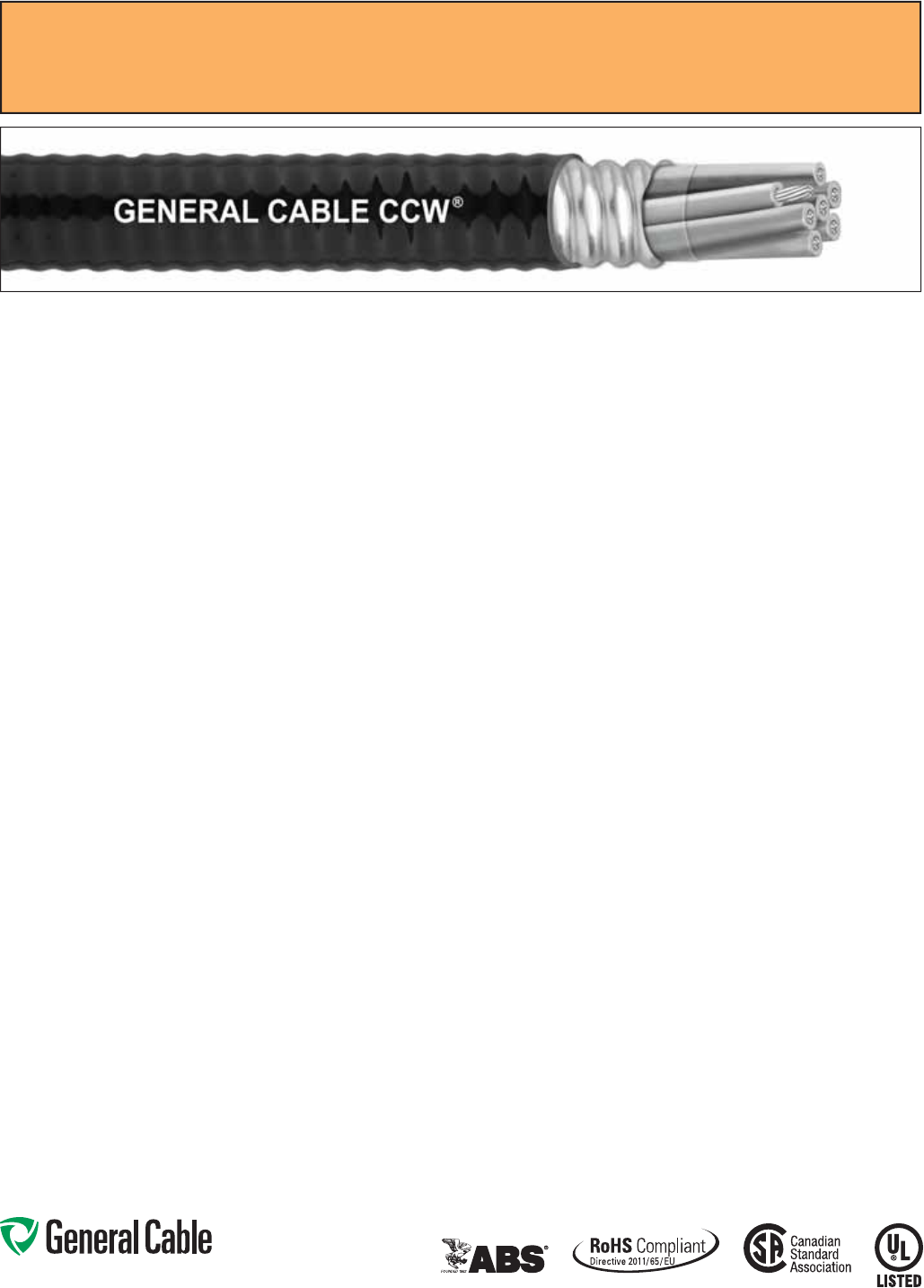
Phone: 888-593-3355
www.generalcable.com
SPEC 9525
October, 2014
Applications:
• CCW armored Control cables offer
an economical, rugged and reliable
alternative to labor-intensive cable in
conduit wiring methods
• For use in Class I and II, Division 2;
Class III, Divisions 1 and 2; and Class
I, Zone 2 hazardous locations per NEC
Articles 501, 502, 503 and 505
• For use as services, feeders and
branch circuits for power, lighting,
control, and signal circuits in
accordance with NEC Articles 330
and 725
• Installed indoors or outdoors, wet
or dry locations, directly buried,
embedded in concrete, in a raceway,
as aerial cable on a messenger,
in cable trays, or as exposed runs
secured to supports in accordance
with NEC Article 330
• Recognized for use on fixed or
floating offshore petroleum facilities
as recommended by the American
Petroleum Institute
Features:
• CCW armor provides an impervious
barrier to moisture, gas and liquids
• CCW armor provides EMI shielding
performance
• Factory assembled and tested cable
for use as an alternative to cable in
conduit wiring systems
• Meets cold impact at -40°C
Features: (cont’d)
• 90˚C continuous operating
temperature, wet or dry
• 130˚C emergency rating
• 250˚C short circuit rating
Specifications:
Design Adherence:
• ICEA S-73-532/WC-57 Standard for
Control, Thermocouple Extension and
Instrumentation Cables
• UL 44 Rubber Insulated Wires and
Cables
• UL 1569 Metal Clad Cables
• UL 1309 Marine Shipboard Cable
• CSA C22.2 No. 123 Metal Sheathed
Cables
Flame Tests:
• ICEA T-29-520 (210,000 BTU/hr)
• IEEE 383 (70,000 BTU/hr)
• CSA FT4
• IEEE 1202 (70,000 BTU/hr)
• UL 1581 (70,000 BTU/hr)
• IEC 60332-3 Cat. A
Compliances:
• UL Type MC, XHHW-2, SUN RES,
CT USE, DIR BUR, -40°C, UL File
# E69797
• UL Listed Marine Shipboard, UL File
# E85994
• American Bureau of Shipping (ABS)
Listed for CWCMC
• CSA certified
1
Type RA90, XLPE, HL,
SR, FT4, and -40°C, CSA File # 7319
• RoHS Compliant
1
Standard cables are also marked CSA Type RA90,
except four (4) conductor cables which require a different
color code, which may be special-ordered.
Product Construction:
Conductor:
• Bare annealed copper per ASTM B3
• Class B stranding per ASTM B8
Insulation:
• Cross-Linked Polyethylene (XLPE)
insulation per ICEA S-73-532 and UL
44, Listed XHHW-2
• Color-coded per ICEA Method 1, Table
E2, full-colored insulation with stripes
• Color-coded per CSA C22.2 No. 123
where applicable
Cable Assembly:
• Insulated conductors are cabled
together with non-hygroscopic fillers
when required
• A binder tape, when required, is
applied over the cabled core
CCW Armor:
• Impervious, continuously welded and
corrugated aluminum alloy sheath per
UL 1569
• CCW armor conductivity meets the
grounding requirements of NEC
Article 250
Jacket:
• Flame-retardant, moisture- and
sunlight-resistant Polyvinyl Chloride
(PVC), black
• Low temperature performance meets
ASTM D746 brittleness temperature at
or below -40°C
• Meets CSA Low Acid Gas
requirements
CCW
®
Armored Control Without Grounding Conductor
UL Type MC, CSA Type HL, XLPE, 600 V, 90°C, Cable Tray Use, Sunlight-Resistant
Direct Burial, UL Marine Shipboard Cable, ABS CWCMC
Phone: 888-593-3355
www.generalcable.com
CCW
®
Armored Control Without Grounding Conductor
UL Type MC, CSA Type HL, XLPE, 600 V, 90°C, Cable Tray Use, Sunlight-Resistant
Direct Burial, UL Marine Shipboard Cable, ABS CWCMC
SPEC 9525
October, 2014
CATALOG
NUMBER
COND.
SIZE
(AWG)
NO.
OF
COND.
INSULATION
THICKNESS NOMINAL
CORE O.D. NOMINAL
ARMOR O.D. JACKET
THICKNESS NOMINAL
OVERALL O.D.
CROSS-
SECTIONAL
AREA¹ APPROXIMATE
NET WEIGHT 90˚C
AMPACITY @
30˚C AMBIENT²
mils mm INCHES mm INCHES mm mils mm INCHES mm (SQ. IN.) LBS/1000 FT kg/1000 m
14 AWG 7W (2.08 mm²) MULTI-CONDUCTOR CONTROL CABLE WITHOUT GROUNDING CONDUCTOR
9525.01402000
14 2 30 0.76 0.28 7.1 0.49 12.4 50 1.27 0.60 15.2 0.29 144 214 15
9525.01403000
14 3 30 0.76 0.30 7.6 0.49 12.4 50 1.27 0.60 15.2 0.29 155 231 15
9525.01404000
14 4 30 0.76 0.33 8.4 0.53 13.5 50 1.27 0.64 16.3 0.33 183 273 15
9525.01405000
14 5 30 0.76 0.37 9.4 0.58 14.7 50 1.27 0.69 17.5 0.38 213 317 15
9525.01407000
14 7 30 0.76 0.41 10.4 0.62 15.7 50 1.27 0.73 18.5 0.42 257 383 15
9525.01409000
14 9 30 0.76 0.50 12.7 0.71 18.0 50 1.27 0.82 20.8 0.54 312 465 15
9525.01412000
14 12 30 0.76 0.57 14.5 0.80 20.3 50 1.27 0.91 23.1 0.66 386 575 12
9525.01419000
14 19 30 0.76 0.69 17.5 0.93 23.6 50 1.27 1.04 26.4 0.86 544 810 12
9525.01437000
14 37 30 0.76 0.96 24.4 1.24 31.5 50 1.27 1.35 34.3 1.45 959 1,427 10
12 AWG 7W (3.31 mm²) MULTI-CONDUCTOR CONTROL CABLE WITHOUT GROUNDING CONDUCTOR
9525.01202000
12 2 30 0.76 0.31 7.9 0.53 13.5 50 1.27 0.64 16.3 0.33 166 247 20
9525.01203000
12 3 30 0.76 0.34 8.6 0.53 13.5 50 1.27 0.64 16.3 0.33 192 285 20
9525.01204000
12 4 30 0.76 0.38 9.7 0.58 14.7 50 1.27 0.69 17.5 0.38 229 341 20
9525.01205000
12 5 30 0.76 0.42 10.7 0.62 15.7 50 1.27 0.73 18.5 0.42 266 395 20
9525.01207000
12 7 30 0.76 0.47 11.9 0.67 17.0 50 1.27 0.78 19.8 0.48 328 489 20
9525.01209000
12 9 30 0.76 0.56 14.2 0.80 20.3 50 1.27 0.91 23.1 0.66 410 611 20
9525.01212000
12 12 30 0.76 0.65 16.5 0.89 22.6 50 1.27 0.99 25.1 0.78 510 759 15
9525.01219000
12 19 30 0.76 0.78 19.8 1.02 25.9 50 1.27 1.13 28.7 1.02 731 1,087 15
9525.01237000
12 37 30 0.76 1.08 27.4 1.37 34.8 50 1.27 1.48 37.6 1.74 1,318 1,962 12
10 AWG 7W (5.26 mm²) MULTI-CONDUCTOR CONTROL CABLE WITHOUT GROUNDING CONDUCTOR
9525.01002000
10 2 30 0.76 0.36 9.1 0.58 14.7 50 1.27 0.69 17.5 0.38 205 305 30
9525.01003000
10 3 30 0.76 0.39 9.9 0.58 14.7 50 1.27 0.69 17.5 0.38 241 359 30
9525.01004000
10 4 30 0.76 0.44 11.2 0.67 17.0 50 1.27 0.78 19.8 0.48 301 448 30
9525.01005000
10 5 30 0.76 0.48 12.2 0.71 18.0 50 1.27 0.82 20.8 0.54 353 525 30
9525.01007000
10 7 30 0.76 0.54 13.7 0.75 19.1 50 1.27 0.86 21.8 0.59 442 658 28
9525.01009000
10 9 30 0.76 0.65 16.5 0.89 22.6 50 1.27 1.00 25.4 0.80 551 820 28
9525.01012000
10 12 30 0.76 0.74 18.8 0.97 24.6 50 1.27 1.08 27.4 0.93 693 1,032 20
Dimensions and weights are nominal; subject to industry tolerances.
¹ Cross-sectional area for cable tray fill is in accordance with NEC® Section 392.22.
² Ampacities in accordance with NEC® Article 310 and Table 310.15(B)(16).
Note: Standard cables with up to and including six (6) conductors are also marked CSA Type RA90. All others are special order.
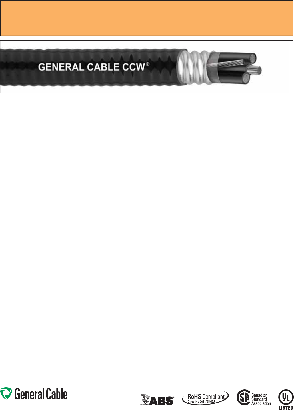
Phone: 888-593-3355
www.generalcable.com
SPEC 9600
October, 2014
Applications:
• Variable Frequency Drives:
3-conductor CCW armored cables
with three (3) symmetrical grounding
wires are the preferred wiring method
for use with AC motors controlled by
pulse-width modulated inverters in
VFD applications
• CCW armored cables offer an
economical, rugged and reliable
alternative to labor-intensive cable in
conduit wiring methods
• For use in Class I, II and III, Divisions
1 and 2; and Class I, Zones 1 and 2
hazardous locations per NEC Articles
501, 502, 503 and 505
• For use as services, feeders and
branch circuits for power, lighting,
control, and signal circuits in
accordance with NEC Articles 330
and 725
• Installed indoors or outdoors, wet
or dry locations, directly buried,
embedded in concrete, in a raceway,
as aerial cable on a messenger,
in cable trays, or as exposed runs
secured to supports in accordance
with NEC Article 330
• Recognized for use on fixed or
floating offshore petroleum facilities
as recommended by the American
Petroleum Institute
Features:
• 3-conductor CCW power cables
with three grounding wires are
recommended for use with pulse-width
modulated AC drives
• CCW armor provides an impervious
barrier to moisture, gas and liquids
• CCW armor provides EMI shielding
performance
• Factory assembled and tested cable
for use as an alternative to cable in
conduit wiring systems
Features: (cont’d)
• Meets cold impact at -40°C
• 90˚C continuous operating
temperature, wet or dry
• 130˚C emergency rating
• 250˚C short circuit rating
Specifications:
Design Adherence:
• ICEA S-95-658/WC70 Standard for
Non-Shielded Power Cable, 2 kV
or Less
• UL 44 Rubber Insulated Wires
and Cables
• UL 1569 Metal Clad Cables
• UL 2225 Cables and Cable Fittings for
Use in Hazardous Locations
• UL 1309 Marine Shipboard Cable
• CSA C22.2 No. 123 Metal Sheathed
Cables
• CSA C22.2 No. 174 Cables and Cable
Glands for Use in Hazardous Locations
Flame Tests:
• ICEA T-29-520 (210,000 BTU/hr)
• IEEE 383 (70,000 BTU/hr)
• CSA FT4
• IEEE 1202 (70,000 BTU/hr)
• UL 1581 (70,000 BTU/hr)
• IEC 60332-3 Cat. A
Compliances:
• UL Type MC-HL, XHHW-2, SUN RES,
CT USE, DIR BUR, -40°C, UL File
# E90496
• UL Listed Marine Shipboard, UL File
# E85994
• American Bureau of Shipping (ABS)
Listed for CWCMC
• CSA certified
1
Type RA90, XLPE,
HL, SR, FT4, and -40°C, CSA File
# 7319
• RoHS Compliant
1
Standard cables are also marked CSA Type RA90,
except four (4) conductor cables which require a different
color code, which may be special-ordered.
Product Construction:
• Bare annealed copper per ASTM B3
• 10 AWG and smaller are Class B
compressed stranding per ASTM B8
• 8 AWG and larger are compact
stranding per ASTM B496
Insulation:
• Cross-linked Polyethylene (XLPE)
insulation per ICEA S-95-658 and UL
44, Listed XHHW-2
• 6 AWG and smaller are color-coded
per ICEA Method 1, Table E2
• 4 AWG and larger are black with
printed numbers per ICEA Method 4
• Color-coded per CSA C22.2 No. 123
where applicable
Grounding Conductor(s):
• Class B stranded bare annealed
copper per ASTM B3 and B8
• Where specified, single or three
split grounding wires are sized in
accordance with NEC Table 250.122
Cable Assembly:
• Insulated conductors and grounding
wire(s) are cabled together with non-
hygroscopic fillers when required
• A binder tape is applied over the
cabled core
CCW Armor:
• Impervious, continuously welded and
corrugated aluminum alloy sheath per
UL 1569 and UL 2225
• CCW armor conductivity meets the
grounding requirements of NEC
Article 250
Jacket:
• Flame-retardant, moisture- and
sunlight-resistant Polyvinyl Chloride
(PVC), black
• Low temperature performance meets
ASTM D746 brittleness temperature at
or below -40°C
• Meets CSA Low Acid Gas
requirements
CCW
®
Armored Power, 3/C VFD and 4/C
UL Type MC-HL, CSA Type HL, XLPE, 600 V, 90°C, Cable Tray Use, Sunlight-Resistant
Direct Burial, UL Marine Shipboard Cable, ABS CWCMC
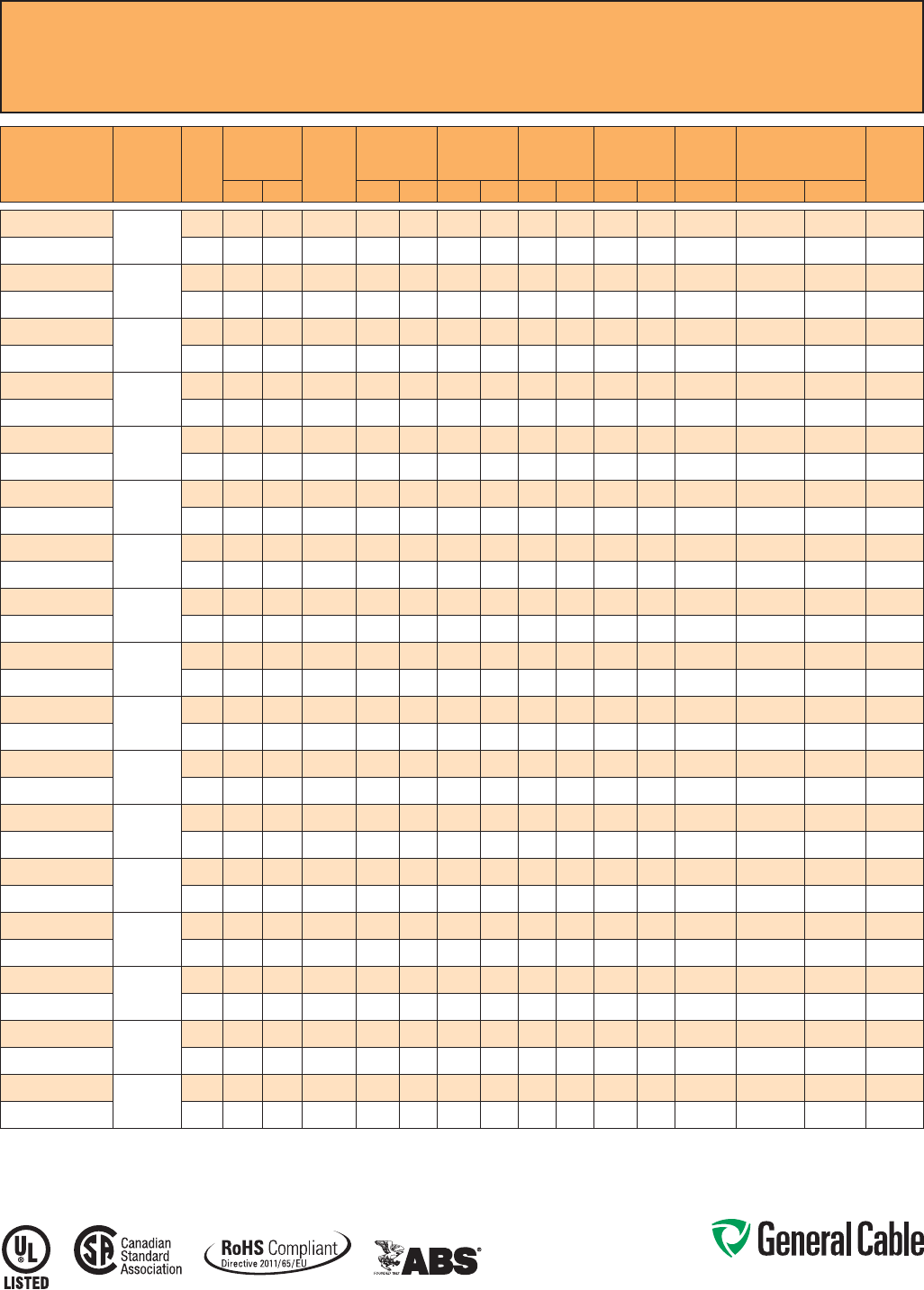
Phone: 888-593-3355
www.generalcable.com
CCW
®
Armored Power, 3/C VFD and 4/C
UL Type MC-HL, CSA Type HL, XLPE, 600 V, 90°C, Cable Tray Use, Sunlight-Resistant
Direct Burial, UL Marine Shipboard Cable, ABS CWCMC
SPEC 9600
October, 2014
CATALOG
NUMBER
COND.
SIZE
(AWG/kcmil) NO. OF
COND.
INSULATION
THICKNESS BARE
GROUND
(AWG)
NOMINAL
CORE O.D. NOMINAL
ARMOR O.D. JACKET
THICKNESS NOMINAL
OVERALL O.D.
CROSS-
SECTIONAL
AREA¹ APPROXIMATE
NET WEIGHT 90°C
AMPACITY
@ 30°C
AMBIENT²mils mm INCHES mm INCHES mm mils mm INCHES mm SQ. IN. LBS/1000 FT kg/1000 m
9600.01403318
14 (7/W)
(2.08 mm²)
3 30 0.76 3 x #18 0.33 8.4 0.53 13.5 50 1.27 0.64 16.3 0.33 163 242 15
9600.01404318
4 30 0.76 3 x #18 0.37 9.4 0.58 14.7 50 1.27 0.69 17.5 0.38 226 336 15
9600.01203316
12 (7/W)
(3.31 mm²)
3 30 0.76 3 x #16 0.37 9.4 0.58 14.7 50 1.27 0.69 17.5 0.38 243 362 20
9600.01204316
4 30 0.76 3 x #16 0.45 11.4 0.67 17.0 50 1.27 0.78 19.8 0.48 291 433 20
9600.01003314
10 (7/W)
(5.26 mm²)
3 30 0.76 3 x #14 0.41 10.4 0.62 15.7 50 1.27 0.73 18.5 0.42 305 454 30
9600.01004314
4 30 0.76 3 x #14 0.45 11.4 0.67 17.0 50 1.27 0.78 19.8 0.48 354 527 30
9600.00803314
8 (7/W)
(8.36 mm²)
3 45 1.14 3 x #14 0.50 12.7 0.71 18.0 50 1.27 0.81 20.6 0.52 392 583 55
9600.00804110
4 45 1.14 1 x #10 0.58 14.7 0.80 20.3 50 1.27 0.90 22.9 0.64 473 704 44
9600.00603312
6 (7/W)
(13.3 mm²)
3 45 1.14 3 x #12 0.58 14.7 0.80 20.3 50 1.27 0.90 22.9 0.64 534 795 75
9600.00604108
4 45 1.14 1 x #8 0.66 16.8 0.89 22.6 50 1.27 0.99 25.1 0.78 641 954 60
9600.00403312
4 (7/W)
(21.2 mm²)
3 45 1.14 3 x #12 0.68 17.3 0.89 22.6 50 1.27 0.99 25.1 0.78 716 1,066 95
9600.00404108
4 45 1.14 1 x #8 0.77 19.6 0.97 24.6 50 1.27 1.08 27.4 0.93 860 1,280 76
9600.00203310
2 (7/W)
(33.6 mm²)
3 45 1.14 3 x #10 0.80 20.3 1.02 25.9 50 1.27 1.13 28.7 1.02 1,013 1,507 130
9600.00204106
4 45 1.14 1 x #6 0.92 23.4 1.15 29.2 50 1.27 1.26 32.0 1.26 1,267 1,885 104
9600.00103310
1 (19/W)
(42.4 mm²)
3 55 1.40 3 x #10 0.92 23.4 1.15 29.2 50 1.27 1.26 32.0 1.26 1,119 1,666 150
9600.00104106
4 55 1.40 1 x #6 1.04 26.4 1.29 32.8 50 1.27 1.40 35.6 1.56 1,526 2,272 120
9600.11003310
1/0 (19/W)
(53.5 mm²)
3 55 1.40 3 x #10 1.00 25.4 1.24 31.5 50 1.27 1.34 34.0 1.43 1,496 2,226 170
9600.11004106
4 55 1.40 1 x #6 1.12 28.4 1.37 34.8 50 1.27 1.48 37.6 1.74 1,862 2,771 136
9600.21003310
2/0 (19/W)
(67.4 mm²)
3 55 1.40 3 x #10 1.09 27.7 1.34 34.0 50 1.27 1.44 36.6 1.65 1,801 2,681 195
9600.21004106
4 55 1.40 1 x #6 1.23 31.2 1.51 38.4 60 1.52 1.64 41.7 2.14 2,351 3,498 156
9600.31003308
3/0 (19/W)
(85.0 mm²)
3 55 1.40 3 x #8 1.21 30.7 1.47 37.3 60 1.52 1.58 40.1 1.99 2,262 3,367 225
9600.31004104
4 55 1.40 1 x #4 1.36 34.5 1.65 41.9 60 1.52 1.78 45.2 2.52 2,921 4,346 180
9600.41003308
4/0 (19/W)
(107 mm²)
3 55 1.40 3 x #8 1.33 33.8 1.60 40.6 60 1.52 1.73 43.9 2.38 2,722 4,051 260
9600.41004104
4 55 1.40 1 x #4 1.49 37.8 1.78 45.2 60 1.52 1.91 48.5 2.90 3,491 5,194 208
9600.25003308
250 (37/W)
(127 mm²)
3 65 1.65 3 x #8 1.48 37.6 1.74 44.2 60 1.52 1.87 47.5 — 3,195 4,755 290
9600.25004104
4 65 1.65 1 x #4 1.64 41.7 1.96 49.8 60 1.52 2.09 53.1 — 4,142 6,164 232
9600.35003307
350 (37/W)
(177 mm²)
3 65 1.65 3 x #7 1.66 42.2 1.96 49.8 60 1.52 2.09 53.1 — 4,284 6,376 350
9600.35004103
4 65 1.65 1 x #3 1.89 48.0 2.19 55.6 75 1.91 2.35 59.7 — 5,536 8,238 280
9600.50003306
500 (37/W)
(253 mm²)
3 65 1.65 3 x #6 1.94 49.3 2.28 57.9 75 1.91 2.44 62.0 — 6,035 8,981 430
9600.50004102
4 65 1.65 1 x #2 2.14 54.4 2.49 63.2 75 1.91 2.65 67.3 — 7,704 11,464 344
9600.75003305
750 (61/W)
(380 mm²)
3 80 2.03 3 x #5 2.37 60.2 2.75 69.9 75 1.91 2.92 74.2 — 8,854 13,176 535
9600.75004101
4 80 2.03 1 x #1 2.61 66.3 3.03 77.0 85 2.16 3.21 81.5 — 11,449 17,037 428
9600.100031110
1000 (61/W)
(507 mm²)
3 80 2.03 1 x #1/0 2.67 67.8 3.11 79.0 85 2.16 3.30 83.8 — 11,611 17,280 615
9600.100041110
4 80 2.03 1 x #1/0 3.07 78.0 3.63 92.2 85 2.16 3.81 96.8 — 15,377 22,883 492
Dimensions and weights are nominal; subject to industry tolerances.
¹ Cross-sectional area for cable tray fill is in accordance with NEC Section 392.22.
² Ampacities in accordance with NEC Article 310 and Table 310.15(B)(16).
Note: Three (3) conductors, 6 AWG and smaller are also marked CSA Type RA90. One (1) AWG and larger are also marked CSA Type RA90.
Phone: 888-593-3355
www.generalcable.com
CCW
®
Armored Power, 3/C VFD and 4/C
UL Type MC-HL, XLPE, 600 V, 90°C, Cable Tray Use, Sunlight-Resistant
Direct Burial, UL Marine Shipboard Cable, ABS CWCMC, Arctic-Grade
SPEC 9605
October, 2014
Product Construction:
Conductor:
• Bare annealed copper per ASTM B3
• 10 AWG and smaller are Class B
compressed stranding per ASTM B8
• 8 AWG and larger are compact
stranding per ASTM B496
Insulation:
• Cross-linked Polyethylene (XLPE)
insulation per ICEA S-95-658 and
UL 44, Listed XHHW-2
• 6 AWG and smaller are color-coded
per ICEA Method 1, Table E2
• 4 AWG and larger are black with
printed numbers per ICEA Method 4
• Color-coded per CSA C22.2 No. 123
where applicable
Grounding Conductor:
• Class B stranded bare annealed
copper per ASTM B3 and B8
• Where specified, single or three
split grounding wires are sized in
accordance with NEC Table 250.122
Cable Assembly:
• Insulated conductors and grounding
wire are cabled together with
non-hydroscopic fillers when required
• A binder tape, when required, is
applied over the cabled core
CCW Armor:
• Impervious, continuously welded and
corrugated aluminum alloy sheath per
UL Standards 1569 and 2225
• CCW armor conductivity meets
the grounding requirements of
NEC Article 250
Jacket:
• Flame-retardant, moisture- and
sunlight-resistant Polyvinyl Chloride
(PVC), black
• Low temperature performance meets
ASTM D746 brittleness temperature at
or below -60°C
Applications:
• Variable Frequency Drives:
3-conductor CCW armored cables
with three (3) symmetrical grounding
wires are the preferred wiring method
for use with AC motors controlled by
pulse-width modulated inverters in
VFD applications
• CCW armored cables offer an
economical, rugged and reliable
alternative to labor-intensive cable in
conduit wiring methods
• For use in Class I, II and III, Divisions
1 and 2; and Class I, Zones 1 and 2
hazardous locations per NEC Articles
501, 502, 503 and 505
• For use as services, feeders and branch
circuits for power, lighting, control, and
signal circuits in accordance with
NEC Articles 330 and 725
• Installed indoors or outdoors, wet
or dry locations, directly buried,
embedded in concrete, in a raceway,
as aerial cable on a messenger,
in cable trays, or as exposed runs
secured to supports in accordance
with NEC Article 330
• Recognized for use on fixed or
floating offshore petroleum facilities
as recommended by the American
Petroleum Institute
Features:
• 3-conductor CCW power cables
with three grounding wires are
recommended for use with pulse-width
modulated AC drives
• CCW armor provides an impervious
barrier to moisture, gas and liquids
• CCW armor provides EMI shielding
performance
• Factory assembled and tested cable
for use as an alternate to cable in
conduit wiring systems
Features: (cont’d)
• Meets cold bend at -55°C
• 90°C continuous operating
temperature, wet or dry
• 130°C emergency rating
• 250°C short circuit rating
Specifications:
Design Adherence:
• ICEA S-95-658/WC70 Standard for
Non-Shielded Power Cable, 2 kV or Less
• UL 44 Rubber Insulated Wires and
Cables
• UL 1569 Metal Clad Cables
• UL 2225 Cables and Cable Fittings for
Use in Hazardous Locations
• UL 1309 Marine Shipboard Cable
• CSA C22.2 No. 123 Metal Sheathed
Cables
• CSA C22.2 No. 174 Cables and Cable
Glands for Use in Hazardous Locations
Flame Tests:
• ICEA T-29-520 (210,000 BTU/hr)
• IEEE 383 (70,000 BTU/hr)
• CSA FT4
• IEEE 1202 (70,000 BTU/hr)
• UL 1581 (70,000 BTU/hr)
• IEC 60332-3 Cat. A
Compliances:
• UL Type MC-HL, XHHW-2, SUN RES,
CT USE, DIR BUR, -40°C, UL File
# E90496
• UL Listed Marine Shipboard, UL File
# E85994
• American Bureau of Shipping (ABS)
Listed for CWCMC
• RoHS Compliant
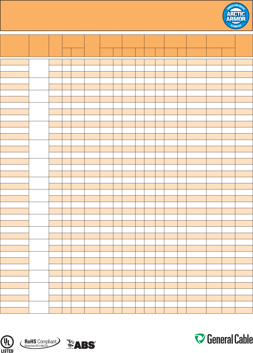
Phone: 888-593-3355
www.generalcable.com
CCW
®
Armored Power, 3/C VFD and 4/C
UL Type MC-HL, XLPE, 600 V, 90°C, Cable Tray Use, Sunlight-Resistant
Direct Burial, UL Marine Shipboard Cable, ABS CWCMC, Arctic-Grade
SPEC 9605
October, 2014
CATALOG
NUMBER COND. SIZE
(AWG/kcmil) NO. OF
COND.
INSULATION
THICKNESS BARE
GROUND
(AWG)
NOMINAL
CORE O.D. NOMINAL
ARMOR O.D. JACKET
THICKNESS
NOMINAL
OVERALL
O.D.
CROSS-
SECTIONAL
AREA1APPROXIMATE
NET WEIGHT 90°C
AMPACITY
@ 30°C
AMBIENT²mils mm INCHES mm INCHES mm mils mm INCHES mm SQ. IN. LBS/1000
FT kg/1000
m
9605.01403318
14 (7/W)
(2.08 mm²)
3 30 0.76 3 x #18 0.33 8.4 0.53 13.5 50 1.27 0.64 16.3 0.33 163 242 15
9605.01404216
4 30 0.76 2 x #16 0.33 8.4 0.51 13.0 50 1.27 0.62 15.7 0.30 221 330 15
9605.01404318
4 30 0.76 3 x #18 0.37 9.4 0.58 14.7 50 1.27 0.69 17.5 0.38 226 336 15
9605.01203316
12 (7/W)
(3.31 mm²) 3 30 0.76 3 x #16 0.37 9.4 0.58 14.7 50 1.27 0.69 17.5 0.38 243 362 20
9605.01204316
4 30 0.76 3 x #16 0.45 11.4 0.67 17.0 50 1.27 0.78 19.8 0.48 291 433 20
9605.01003314
10 (7/W)
(5.26 mm²) 3 30 0.76 3 x #14 0.41 10.4 0.62 15.7 50 1.27 0.73 18.5 0.42 305 454 30
9605.01004314
4 30 0.76 3 x #14 0.45 11.4 0.67 17.0 50 1.27 0.78 19.8 0.48 354 527 30
9605.00803314
8 (7/W)
(8.36 mm²)
3 45 1.14 3 x #14 0.50 12.7 0.71 18.0 50 1.27 0.81 20.6 0.52 392 583 55
9605.00804110
4 45 1.14 1 x #10 0.58 14.7 0.80 20.3 50 1.27 0.90 22.9 0.64 473 704 44
9605.00804212
4 45 1.14 2 x #12 0.57 14.5 0.77 19.6 50 1.27 0.88 22.4 0.61 491 731 44
9605.00603312
6 (7/W)
(13.3 mm²)
3 45 1.14 3 x #12 0.58 14.7 0.80 20.3 50 1.27 0.90 22.9 0.64 534 795 75
9605.00604108
4 45 1.14 1 x #8 0.66 16.8 0.89 22.6 50 1.27 0.99 25.1 0.78 641 954 60
9605.00604210
4 45 1.14 2 x #10 0.66 16.8 0.88 22.4 50 1.27 0.99 25.1 0.78 679 1,012 60
9605.00403312
4 (7/W)
(21.2 mm²)
3 45 1.14 3 x #12 0.68 17.3 0.89 22.6 50 1.27 0.99 25.1 0.78 716 1,066 95
9605.00404108
4 45 1.14 1 x #8 0.77 19.6 0.97 24.6 50 1.27 1.08 27.4 0.93 860 1,280 76
9605.00404210
4 45 1.14 2 x #10 0.76 19.3 1.00 25.4 50 1.27 1.11 28.2 0.97 950 1,415 76
9605.00203310
2 (7/W)
(33.6 mm²)
3 45 1.14 3 x #10 0.80 20.3 1.02 25.9 50 1.27 1.13 28.7 1.02 1,013 1,507 130
9605.00204106
4 45 1.14 1 x #6 0.92 23.4 1.15 29.2 50 1.27 1.26 32.0 1.26 1,267 1,885 104
9605.00204106
4 45 1.14 2 x #8 0.89 22.6 1.16 29.5 50 1.27 1.27 32.3 1.27 1,371 2,043 104
9605.00103310
1 (19/W)
(42.4 mm²) 3 55 1.40 3 x #10 0.92 23.4 1.15 29.2 50 1.27 1.26 32.0 1.26 1,119 1,666 150
9605.00104106
4 55 1.40 1 x #6 1.04 26.4 1.29 32.8 50 1.27 1.40 35.6 1.56 1,526 2,272 120
9605.11003310
1/0 (19/W)
(53.5 mm²) 3 55 1.40 3 x #10 1.00 25.4 1.24 31.5 50 1.27 1.34 34.0 1.43 1,496 2,226 170
9605.11004106
4 55 1.40 1 x #6 1.12 28.4 1.37 34.8 50 1.27 1.48 37.6 1.74 1,862 2,771 136
9605.21003310
2/0 (19/W)
(67.4 mm²) 3 55 1.40 3 x #10 1.09 27.7 1.34 34.0 50 1.27 1.44 36.6 1.65 1,801 2,681 195
9605.21004106
4 55 1.40 1 x #6 1.23 31.2 1.51 38.4 60 1.52 1.64 41.7 2.14 2,351 3,498 156
9605.31003308
3/0 (19/W)
(85.0 mm²) 3 55 1.40 3 x #8 1.21 30.7 1.47 37.3 60 1.52 1.58 40.1 1.99 2,262 3,367 225
9605.31004104
4 55 1.40 1 x #4 1.36 34.5 1.65 41.9 60 1.52 1.78 45.2 2.52 2,921 4,346 180
9605.41003308
4/0 (19/W)
(107 mm²) 3 55 1.40 3 x #8 1.33 33.8 1.60 40.6 60 1.52 1.73 43.9 2.38 2,722 4,051 260
9605.41004104
4 55 1.40 1 x #4 1.49 37.8 1.78 45.2 60 1.52 1.91 48.5 2.87 3,491 5,194 208
9605.25003308
250 (37/W)
(127 mm²) 3 65 1.65 3 x #8 1.48 37.6 1.74 44.2 60 1.52 1.87 47.5 2.75 3,195 4,755 290
9605.25004104
4 65 1.65 1 x #4 1.64 41.7 1.96 49.8 60 1.52 2.09 53.1 3.43 4,142 6,164 232
9605.35003307
350 (37/W)
(177 mm²)
3 65 1.65 3 x #7 1.66 42.2 1.96 49.8 60 1.52 2.09 53.1 3.43 4,284 6,376 350
9605.35003306
3 65 1.65 3 x #6 1.63 41.4 1.95 49.5 60 1.52 2.09 53.1 3.43 4,329 6,443 350
9605.35004103
4 65 1.65 1 x #3 1.89 48.0 2.19 55.6 75 1.91 2.35 59.7 4.34 5,536 8,238 280
9605.50003306
500 (37/W)
(253 mm²) 3 65 1.65 3 x #6 1.94 49.3 2.28 57.9 75 1.91 2.44 62.0 4.68 6,035 8,981 430
9605.50004102
4 65 1.65 1 x #2 2.14 54.4 2.49 63.2 75 1.91 2.65 67.3 5.52 7,704 11,464 344
9605.75003305
750 (61/W)
(380 mm²)
3 80 2.03 3 x #5 2.37 60.2 2.75 69.9 75 1.91 2.92 74.2 6.70 8,854 13,176 535
9605.75003304
3 80 2.03 3 x #4 2.32 58.9 2.71 68.8 75 1.91 2.86 72.6 6.42 8,926 13,293 535
9605.75004101
4 80 2.03 1 x #1 2.61 66.3 3.03 77.0 85 2.16 3.21 81.5 8.09 11,449 17,037 428
9605.100031110
1000 (61/W)
(507 mm²) 3 80 2.03 1 x #1/0 2.67 67.8 3.11 79.0 85 2.16 3.30 83.8 8.55 11,611 17,280 615
9605.100041110
4 80 2.03 1 x #1/0 3.07 78.0 3.63 92.2 85 2.16 3.81 96.8 11.40 15,377 22,883 492
Dimensions and weights are nominal; subject to industry tolerances.
¹ Cross-sectional area for cable tray fill is in accordance with NEC Section 392.22.
² Ampacities in accordance with NEC Article 310 and Table 310.15(B)(16).
Phone: 888-593-3355
www.generalcable.com
SPEC 9615
October, 2014
Applications:
• Variable Frequency Drives:
3-conductor CCW armored cables
with three (3) symmetrical grounding
wires is the preferred wiring method
for use with AC motors controlled by
pulse-width modulated Inverters in
VFD applications
• CCW armored cables offer an
economical, rugged and reliable
alternative to labor-intensive cable in
conduit wiring methods
• For use in Class I, II and III, Divisions
1 and 2; and Class I, Zones 1 and 2
hazardous locations per NEC Articles
501, 502 and 503
• For use as services, feeders and
branch circuits for power, lighting,
control, and signal circuits in
accordance with NEC Articles 330
and 725
• Installed indoors or outdoors, wet
or dry locations, directly buried,
embedded in concrete, in a raceway,
as aerial cable on a messenger,
in cable trays, or as exposed runs
secured to supports in accordance
with NEC Article 330
• Recognized for use on fixed or
floating offshore petroleum facilities
as recommended by the American
Petroleum Institute
Features:
• 90°C, 2000 V rated XLPE insulation
with a dielectric constant less than 3.0
to withstand momentary voltage spikes
common in certain VFD applications
• Three (3) oversized, symmetrical
grounding wires recommended for use
with pulse-width modulated AC drives
• CCW armor provides an impervious
barrier to moisture, gas and liquids
Features: (cont’d)
• CCW armor provides EMI shielding
performance
• Factory assembled and tested cable
for use as an alternative to cable in
conduit wiring systems
• Meets cold impact at -40°C
• 90˚C continuous operating
temperature, wet or dry
• 130˚C emergency rating
• 250˚C short circuit rating
Specifications:
Design Adherence:
• ICEA S-95-658/WC70 Standard
for Non-Shielded Power Cable, 2 kV
or Less
• UL 44 Rubber Insulated Wires and
Cables
• UL 1569 Metal Clad Cables
• UL 2225 Cables and Cable Fittings for
Use in Hazardous Locations
• UL 1309 Marine Shipboard Cable
Flame Tests:
• ICEA T-29-520 (210,000 BTU/hr)
• IEEE 383 (70,000 BTU/hr)
• CSA FT4
• IEEE 1202 (70,000 BTU/hr)
• UL 1581 (70,000 BTU/hr)
• IEC 332-3 Cat. A
Compliances:
• UL Type MC-HL, SUN RES, CT USE,
DIR BUR, -40°C, UL File # E90496
• UL Listed Marine Shipboard, UL File
# E85994
• American Bureau of Shipping (ABS)
Listed for CWCMC
• RoHS Compliant
Product Construction:
Conductor:
• Bare annealed copper per ASTM B3
• 10 AWG and smaller are Class B
compressed stranding per ASTM B8
• 8 AWG and larger are compact
standing per ASTM B496
Insulation:
• Cross-linked Polyethylene (XLPE)
insulation, 2000 V thicknesses per
ICEA S-95-658
• Color-coded black with printed
numbers per ICEA Method 4
Grounding Conductors:
• Class B stranded bare annealed
copper per ASTM B3 and B8
• Three (3) split grounding wires
per specification 9615 exceed the
minimum required in NEC Table
250.122
Cable Assembly:
• Insulated conductors and grounding
wires are cabled together with non-
hygroscopic fillers when required
• A binder tape is applied over the
cabled core
CCW Armor:
• Impervious, continuously welded and
corrugated aluminum alloy sheath per
UL 1569 and UL 2225
• CCW armor conductivity meets the
grounding requirements of NEC
Article 250
Jacket:
• Flame-retardant, moisture- and
sunlight-resistant Polyvinyl Chloride
(PVC) — Black
• Low temperature performance meets
ASTM D746 brittleness temperature at
or below -40°C
CCW
®
Armored Power, 3/C VFD
UL Type MC-HL, XLPE, 2000 V, 90°C, Cable Tray Use, Sunlight-Resistant, Direct Burial
UL Marine Shipboard Cable, ABS CWCMC
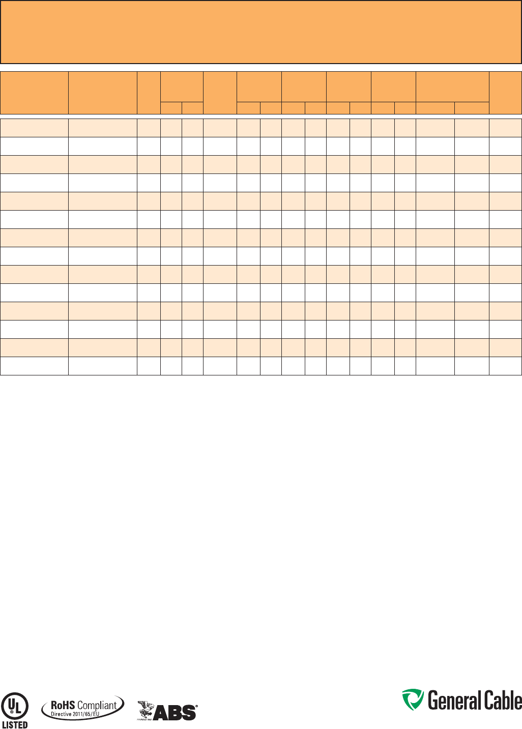
Phone: 888-593-3355
www.generalcable.com
CCW
®
Armored Power, 3/C VFD
UL Type MC-HL, XLPE, 2000 V, 90°C, Cable Tray Use, Sunlight-Resistant, Direct Burial
UL Marine Shipboard Cable, ABS CWCMC
SPEC 9615
October, 2014
CATALOG
NUMBER
COND.
SIZE
(AWG/kcmil) NO. OF
COND.
INSULATION
THICKNESS BARE
GROUND
(AWG)
NOMINAL
CORE O.D. NOMINAL
ARMOR O.D. JACKET
THICKNESS NOMINAL
OVERALL O.D. APPROXIMATE
NET WEIGHT 90°C
AMPACITY
@ 30°C
AMBIENT¹mils mm INCHES mm INCHES mm mils mm INCHES mm LBS/1000 FT kg/1000 m
9615.01403318
14 (7/W) (2.08 mm²)
360 1.52 3 x #18 0.44 11.1 0.62 15.2 50 1.27 0.73 17.9 267 397 15
9615.01203316
12 (7/W) (3.31 mm²)
360 1.52 3 x #16 0.47 11.9 0.66 16.2 50 1.27 0.77 18.9 324 482 20
9615.01003314
10 (7/W) (5.26 mm²)
360 1.52 3 x #14 0.53 13.3 0.73 17.8 50 1.27 0.84 20.5 400 595 30
9615.00803314
8 (7/W) (8.36 mm²)
370 1.78 3 x #14 0.65 16.5 0.86 21.1 50 1.27 0.97 23.8 524 780 55
9615.00603312
6 (7/W) (13.3 mm²)
370 1.78 3 x #12 0.71 18.0 0.96 23.4 50 1.27 1.07 26.1 697 1,037 75
9615.00403312
4 (7/W) (21.2 mm²)
370 1.78 3 x #12 0.81 20.6 1.09 26.6 50 1.27 1.23 30.1 1,000 1,488 95
9615.00203310
2 (7/W) (33.6 mm²)
370 1.78 3 x #10 0.94 23.9 1.25 30.6 50 1.27 1.36 33.3 1,285 1,912 130
9615.00103310
1 (19/W) (42.4 mm²)
390 2.29 3 x #10 1.13 28.7 1.48 36.1 50 1.27 1.59 38.8 1,595 2,374 150
9615.11003310
1/0 (19/W) (53.5 mm²)
390 2.29 3 x #10 1.21 30.6 1.55 38.0 60 1.52 1.68 41.2 1,930 2,872 170
9615.21003306
2/0 (19/W) (67.4 mm²)
390 2.29 3 x #6 1.30 32.9 1.68 41.0 60 1.52 1.81 44.2 2,507 3,731 195
9615.41003304
4/0 (19/W) (107 mm²)
390 2.29 3 x #4 1.53 38.7 1.91 46.7 60 1.52 2.04 49.9 3,590 5,342 260
9615.25003304
250 (37/W) (127 mm²)
3105 2.67 3 x #4 1.71 43.4 2.12 51.8 60 1.52 2.25 55.1 4,150 6,176 290
9615.35003302
350 (37/W) (177 mm²)
3105 2.67 3 x #2 1.93 48.9 2.41 58.9 75 1.91 2.57 62.8 5,214 7,759 350
9615.50003301
500 (37/W) (253 mm²)
3105 2.67 3 x #1 2.20 55.8 2.68 65.5 75 1.91 2.84 69.5 6,977 10,382 430
Dimensions and weights are nominal; subject to industry tolerances.
¹ Ampacities in accordance with NEC Article 310 and Table 310.15(B)(16).
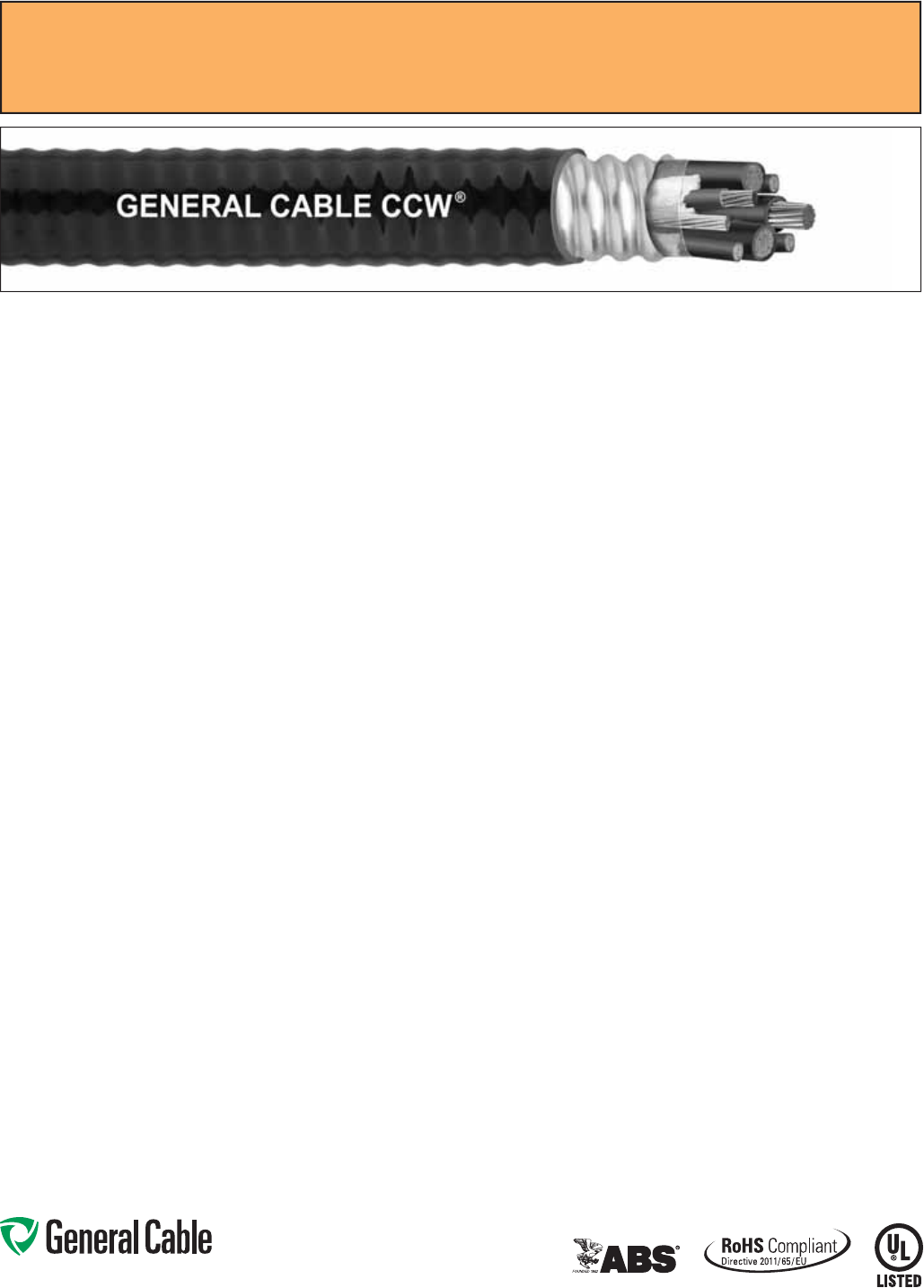
Phone: 888-593-3355
www.generalcable.com
SPEC 9625
October, 2014
CCW
®
Armored Composite Power and Control
UL Type MC-HL, XLPE, 600 V, 90°C, Cable Tray Use, Sunlight-Resistant, Direct Burial
UL Marine Shipboard Cable, ABS CWCMC
Product Construction:
Conductor:
• Bare annealed copper per ASTM B3
• 10 AWG and smaller are Class B
compressed stranding per ASTM B8
• 8 AWG and larger are compact
stranding per ASTM B496
Insulation:
• Cross-linked Polyethylene (XLPE)
insulation per ICEA S-95-658 and UL
44, Listed XHHW-2
• Power conductors 6 AWG and smaller
are color-coded per ICEA Method 1,
Table E2
• Power conductors 4 AWG and larger
are black with printed numbers per
ICEA Method 4
• Control conductors are color-coded
black, red, blue and yellow
Grounding Conductor:
• Class B stranded bare annealed
copper per ASTM B3 and B8
• Sized in accordance with NEC Table
250.122
Cable Assembly:
• Insulated conductors and grounding
wire are cabled together with non-
hygroscopic fillers when required
• A binder tape is applied over the
cabled core
CCW Armor:
• Impervious, continuously welded and
corrugated aluminum alloy sheath per
UL 1569 and UL 2225
• CCW armor conductivity meets the
grounding requirements of NEC
Article 250
Jacket:
• Flame-retardant, moisture- and
sunlight-resistant Polyvinyl Chloride
(PVC), black
• Low temperature performance meets
ASTM D746 brittleness temperature at
or below -40°C
Applications:
• CCW armored Composite Power and
Control cables offer an economical,
rugged and reliable alternative to
labor-intensive cable in conduit wiring
methods
• For use in Class I, II and III, Divisions
1 and 2; and Class I, Zones 1 and 2
hazardous locations per NEC Articles
501, 502, 503 and 505
• For use as services, feeders and
branch circuits for power, lighting,
control, and signal circuits in
accordance with NEC Articles 330
and 725
• Installed indoors or outdoors, wet
or dry locations, directly buried,
embedded in concrete, in a raceway,
as aerial cable on a messenger,
in cable trays, or as exposed runs
secured to supports in accordance
with NEC Article 330
• Recognized for use on fixed or
floating offshore petroleum facilities
as recommended by the American
Petroleum Institute
Features:
• CCW armor provides an impervious
barrier to moisture, gas and liquids
• CCW armor provides EMI shielding
performance
• Factory assembled and tested cable
for use as an alternative to cable in
conduit wiring systems
• Meets cold impact at -40°C
• 90˚C continuous operating
temperature, wet or dry
• 130˚C emergency rating
• 250˚C short circuit rating
Specifications:
Design Adherence:
• ICEA S-95-658/WC70 Standard
for Non-Shielded Power Cables,
2 kV or Less
• UL 44 Rubber Insulated Wires and
Cables
• UL 1569 Metal Clad Cables
• UL 2225 Cables and Cable Fittings for
Use in Hazardous Locations
• UL 1309 Marine Shipboard Cable
Flame Tests:
• ICEA T-29-520 (210,000 BTU/hr)
• IEEE 383 (70,000 BTU/hr)
• CSA FT4
• IEEE 1202 (70,000 BTU/hr)
• UL 1581 (70,000 BTU/hr)
• IEC 60332-3 Cat. A
Compliances:
• UL Type MC-HL, XHHW-2, SUN RES,
CT USE, DIR BUR, -40°C, UL File
# E90496
• UL Listed Marine Shipboard, UL File
# E85994
• American Bureau of Shipping (ABS)
Listed for CWCMC
• RoHS Compliant
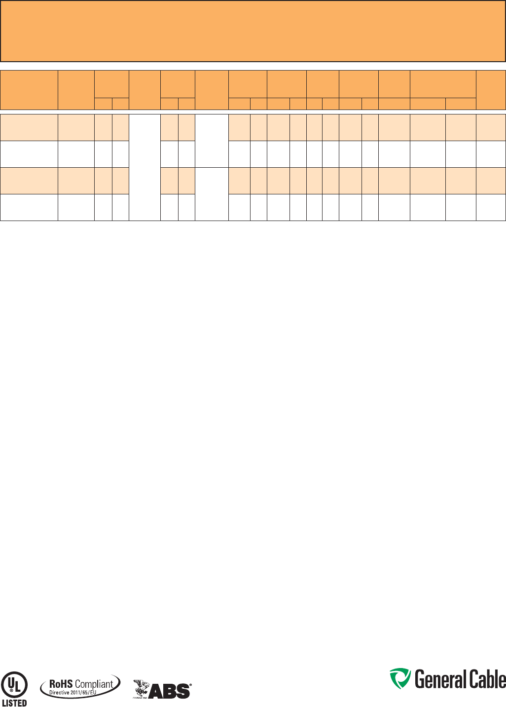
Phone: 888-593-3355
www.generalcable.com
SPEC 9625
October, 2014
CCW
®
Armored Composite Power and Control
UL Type MC-HL, XLPE, 600 V, 90°C, Cable Tray Use, Sunlight-Resistant, Direct Burial
UL Marine Shipboard Cable, ABS CWCMC
CATALOG
NUMBER
POWER
COND. SIZE
(AWG)
POWER
INSULATION
THICKNESS CONTROL
COND.
SIZE
(AWG)
CONTROL
INSULATION
THICKNESS BARE
GROUNDING
(AWG)
NOMINAL
CORE O.D. NOMINAL
ARMOR O.D. JACKET
THICKNESS NOMINAL
OVERALL O.D.
CROSS-
SECTIONAL
AREA¹ APPROXIMATE
NET WEIGHT 90°C
AMPACITY
@ 30°C
AMBIENT²mils mm mils mm INCHES mm INCHES mm mils mm INCHES mm SQ. IN. LBS/1000 FT kg/1000 m
9625.103124110
3x#10 (7/W)
(5.26 mm²)
30 0.76
4 x #12
(7/W)
(3.31 mm²)
30 0.76
10 (7/W)
(5.2 mm²)
0.53 13.5 0.75 19.1 50 1.27 0.86 21.8 0.59 430 640 30
9625.083124110
3x#8 (7/W)
(8.36 mm²)
45 1.14 30 0.76 0.65 16.5 0.89 22.6 50 1.27 0.99 25.1 0.78 535 796 55
9625.063124108
3x#6 (7/W)
(13.3 mm²)
45 1.14 30 0.76
8 (7/W)
(8.36 mm²)
0.69 17.5 0.93 23.6 50 1.27 1.03 26.2 0.84 660 982 75
9625.043124108
3x#4 (7/W)
(21.2 mm²)
45 1.14 30 0.76 0.74 18.8 0.97 24.6 50 1.27 1.08 27.4 0.93 815 1,213 95
Dimensions and weights are nominal; subject to industry tolerances.
¹ Cross-sectional area for cable tray fill is in accordance with NEC Section 392.22.
² Ampacities in accordance with NEC Article 310 and Table 310.15(B)(16).
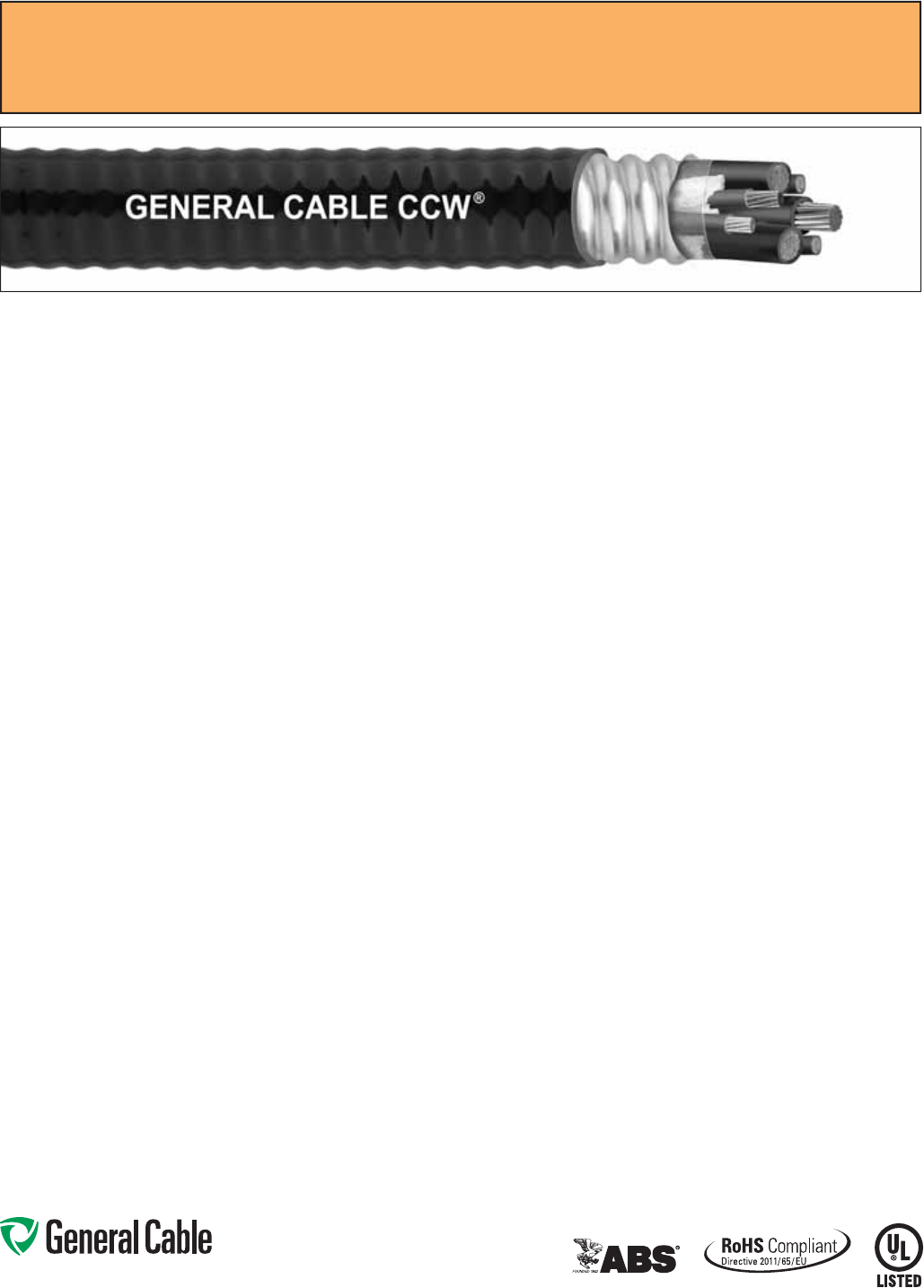
Phone: 888-593-3355
www.generalcable.com
SPEC 9650
October, 2014
CCW
®
Armored Composite Power and Control Without Ground
UL Type MC, XLPE, 600 V, 90°C, Cable Tray Use, Sunlight-Resistant, Direct Burial
UL Marine Shipboard Cable, ABS CWCMC
Product Construction:
Conductor:
• Bare annealed copper per ASTM B3
• Sizes 10 AWG and smaller are Class B
compressed stranding per ASTM B8
• Sizes 8 AWG and larger are compact
stranding per ASTM B496
Insulation:
• Cross-Linked Polyethylene (XLPE)
insulation per ICEA S-95-658 and UL
44, Listed XHHW-2
• Power conductors sizes 6 AWG and
smaller are color-coded per ICEA
Method 1, Table E2
• Power conductors sizes 4 AWG and
larger are black with printed numbers
per ICEA Method 4
• Control conductors are color-coded
black, red, blue and yellow
Cable Assembly:
• Insulated conductors are cabled
together with non-hygroscopic fillers
when required
• A binder tape, when required, is
applied over the cabled core
CCW Armor:
• Impervious, continuously welded and
corrugated aluminum alloy sheath per
UL 1569
• CCW armor conductivity meets the
grounding requirements of NEC
Article 250
Jacket:
• Flame-retardant, moisture- and
sunlight-resistant Polyvinyl Chloride
(PVC), black
• Low temperature performance meets
ASTM D746 brittleness temperature at
or below -40°C
Applications:
• CCW armored Composite Power and
Control cables offer an economical,
rugged and reliable alternative to
labor-intensive cable in conduit wiring
methods
• For use in Class I and II, Division 2;
Class III, Divisions 1 and 2; and Class
I, Zone 2 hazardous locations per NEC
Articles 501, 502, 503 and 505
• For use as services, feeders and
branch circuits for power, lighting,
control, and signal circuits in
accordance with NEC Articles 330
and 725
• Installed indoors or outdoors, wet
or dry locations, directly buried,
embedded in concrete, in a raceway,
as aerial cable on a messenger,
in cable trays, or as exposed runs
secured to supports in accordance
with NEC Article 330
• Recognized for use on fixed or
floating offshore petroleum facilities
as recommended by the American
Petroleum Institute
Features:
• CCW armor provides an impervious
barrier to moisture, gas and liquids
• CCW armor provides EMI shielding
performance
• Factory assembled and tested cable
for use as an alternative to cable in
conduit wiring systems
Features: (cont’d)
• Meets cold impact at -40°C
• 90˚C continuous operating
temperature, wet or dry
• 130˚C emergency rating
• 250˚C short circuit rating
Specifications:
Design Adherence:
• ICEA S-95-658/WC 70 Standard
for Non-Shielded Power Cable, 2 kV
or Less
• UL 44 Rubber Insulated Wires and
Cables
• UL 1569 Metal Clad Cables
• UL 1309 Marine Shipboard Cable
Flame Tests:
• ICEA T-29-520 (210,000 BTU/hr)
• IEEE 383 (70,000 BTU/hr)
• CSA FT4
• IEEE 1202 (70,000 BTU/hr)
• UL 1581 (70,000 BTU/hr)
• IEC 60332-3 Cat. A
Compliances:
• UL Type MC, XHHW-2, SUN RES,
CT USE, DIR BUR, -40°C, UL File #
E69797
• UL Listed Marine Shipboard, UL File #
E85994
• American Bureau of Shipping (ABS)
Listed for CWCMC
• RoHS Compliant
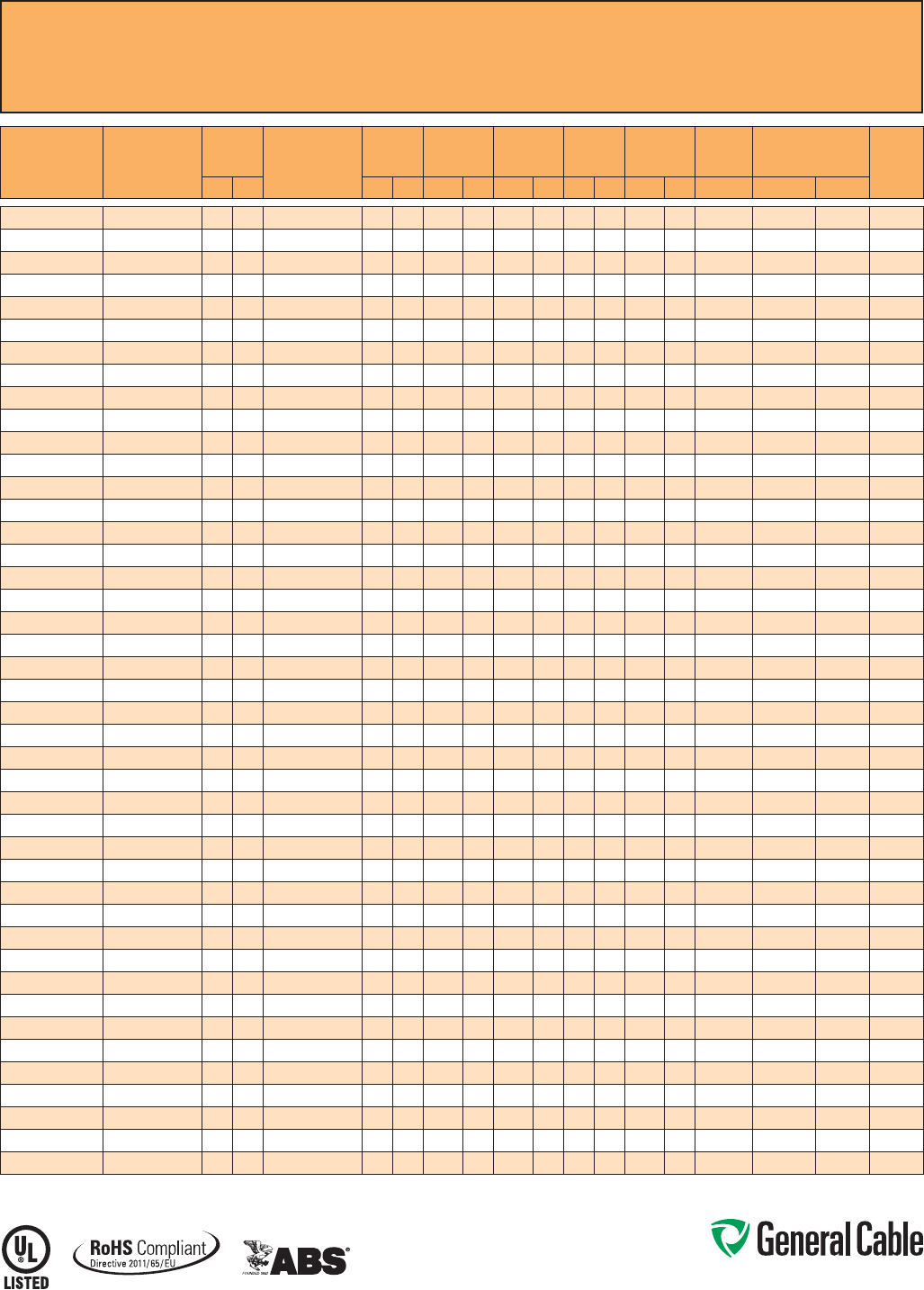
Phone: 888-593-3355
www.generalcable.com
SPEC 9650
October, 2014
CCW
®
Armored Composite Power and Control Without Ground
UL Type MC, XLPE, 600 V, 90°C, Cable Tray Use, Sunlight-Resistant, Direct Burial
UL Marine Shipboard Cable, ABS CWCMC
CATALOG
NUMBER POWER COND. SIZE
(AWG)
POWER
INSULATION
THICKNESS CONTROL COND.
SIZE
(AWG)
CONTROL
INSULATION
THICKNESS NOMINAL
CORE O.D. NOMINAL
ARMOR O.D. JACKET
THICKNESS NOMINAL
OVERALL O.D.
CROSS-
SECTIONAL
AREA¹ APPROXIMATE NET
WEIGHT 90°C
AMPACITY
@ 30°C
AMBIENT²mils mm mils mm INCHES mm INCHES mm mils mm INCHES mm (SQ. IN.) LBS/1000 FT kg/1000 m
9650.123143000
3x#12 (7/W) (3.31 mm²)
30 0.76
3x#14 (7/W) (2.08 mm²)
30 0.76 0.49 12.4 0.71 18.0 50 1.27 0.82 20.8 0.54 307 457 20
9650.123144000
3x#12 (7/W) (3.31 mm²)
30 0.76
4x#14 (7/W) (2.08 mm²)
30 0.76 0.49 12.4 0.71 18.0 50 1.27 0.82 20.8 0.54 323 481 20
9650.124143000
4x#12 (7/W) (3.31 mm²)
30 0.76
3x#14 (7/W) (2.08 mm²)
30 0.76 0.49 12.4 0.71 18.0 50 1.27 0.82 20.8 0.54 365 543 20
9650.124144000
4x#12 (7/W) (3.31 mm²)
30 0.76
4x#14 (7/W) (2.08 mm²)
30 0.76 0.53 13.5 0.75 19.1 50 1.27 0.86 21.8 0.59 388 577 20
9650.103143000
3x#10 (7/W) (5.26 mm²)
30 0.76
3x#14 (7/W) (2.08 mm²)
30 0.76 0.53 13.5 0.75 19.1 50 1.27 0.86 21.8 0.59 384 571 30
9650.103144000
3x#10 (7/W) (5.26 mm²)
30 0.76
4x#14 (7/W) (2.08 mm²)
30 0.76 0.58 14.7 0.80 20.3 50 1.27 0.91 23.1 0.66 392 583 30
9650.103123000
3x#10 (7/W) (5.26 mm²)
30 0.76
3x#12 (7/W) (3.31 mm²)
30 0.76 0.53 13.5 0.75 19.1 50 1.27 0.86 21.8 0.59 410 610 30
9650.104143000
4x#10 (7/W) (5.26 mm²)
30 0.76
3x#14 (7/W) (2.08 mm²)
30 0.76 0.58 14.7 0.80 20.3 50 1.27 0.91 23.1 0.66 412 613 30
9650.104144000
4x#10 (7/W) (5.26 mm²)
30 0.76
4x#14 (7/W) (2.08 mm²)
30 0.76 0.58 14.7 0.80 20.3 50 1.27 0.91 23.1 0.66 428 637 30
9650.104123000
4x#10 (7/W) (5.26 mm²)
30 0.76
3x#12 (7/W) (3.31 mm²)
30 0.76 0.58 14.7 0.80 20.3 50 1.27 0.91 23.1 0.66 436 649 30
9650.104124000
4x#10 (7/W) (5.26 mm²)
30 0.76
4x#12 (7/W) (3.31 mm²)
30 0.76 0.58 14.7 0.80 20.3 50 1.27 0.91 23.1 0.66 460 685 30
9650.083143000
3x#8 (7/W) (8.36 mm²)
45 1.14
3x#14 (7/W) (2.08 mm²)
30 0.76 0.58 14.7 0.80 20.3 50 1.27 0.91 23.1 0.66 424 631 55
9650.083144000
3x#8 (7/W) (8.36 mm²)
45 1.14
4x#14 (7/W) (2.08 mm²)
30 0.76 0.62 15.7 0.84 21.3 50 1.27 0.91 23.1 0.66 455 677 55
9650.083123000
3x#8 (7/W) (8.36 mm²)
45 1.14
3x#12 (7/W) (3.31 mm²)
30 0.76 0.58 14.7 0.80 20.3 50 1.27 0.95 24.1 0.72 455 677 55
9650.083124000
3x#8 (7/W) (8.36 mm²)
45 1.14
4x#12 (7/W) (3.31 mm²)
30 0.76 0.62 15.7 0.84 21.3 50 1.27 0.91 23.1 0.66 495 737 55
9650.084143000
4x#8 (7/W) (8.36 mm²)
45 1.14
3x#14 (7/W) (2.08 mm²)
30 0.76 0.62 15.7 0.84 21.3 50 1.27 0.95 24.1 0.72 505 752 44
9650.084144000
4x#8 (7/W) (8.36 mm²)
45 1.14
4x#14 (7/W) (2.08 mm²)
30 0.76 0.67 17.0 0.89 22.6 50 1.27 1.00 25.4 0.80 530 789 44
9650.084123000
4x#8 (7/W) (8.36 mm²)
45 1.14
3x#12 (7/W) (3.31 mm²)
30 0.76 0.67 17.0 0.89 22.6 50 1.27 1.00 25.4 0.80 535 796 44
9650.084124000
4x#8 (7/W) (8.36 mm²)
45 1.14
4x#12 (7/W) (3.31 mm²)
30 0.76 0.71 18.0 0.93 23.6 50 1.27 1.04 26.4 0.86 576 857 44
9650.063143000
3x#6 (7/W) (13.3 mm²)
45 1.14
3x#14 (7/W) (2.08 mm²)
30 0.76 0.62 15.7 0.84 21.3 50 1.27 0.95 24.1 0.72 525 781 75
9650.063144000
3x#6 (7/W) (13.3 mm²)
45 1.14
4x#14 (7/W) (2.08 mm²)
30 0.76 0.62 15.7 0.84 21.3 50 1.27 0.95 24.1 0.72 545 811 75
9650.063123000
3x#6 (7/W) (13.3 mm²)
45 1.14
3x#12 (7/W) (3.31 mm²)
30 0.76 0.62 15.7 0.84 21.3 50 1.27 0.95 24.1 0.72 556 827 75
9650.063124000
3x#6 (7/W) (13.3 mm²)
45 1.14
4x#12 (7/W) (3.31 mm²)
30 0.76 0.71 18.0 0.93 23.6 50 1.27 1.03 26.2 0.84 606 902 75
9650.064143000
4x#6 (7/W) (13.3 mm²)
45 1.14
3x#14 (7/W) (2.08 mm²)
30 0.76 0.71 18.0 0.93 23.6 50 1.27 1.04 26.4 0.86 657 978 60
9650.064144000
4x#6 (7/W) (13.3 mm²)
45 1.14
4x#14 (7/W) (2.08 mm²)
30 0.76 0.71 18.0 0.93 23.6 50 1.27 1.04 26.4 0.86 667 993 60
9650.064123000
4x#6 (7/W) (13.3 mm²)
45 1.14
3x#12 (7/W) (3.31 mm²)
30 0.76 0.75 19.1 0.97 24.6 50 1.27 1.08 27.4 0.93 687 1,022 60
9650.064124000
4x#6 (7/W) (13.3 mm²)
45 1.14
4x#12 (7/W) (3.31 mm²)
30 0.76 0.75 19.1 0.97 24.6 50 1.27 1.08 27.4 0.93 717 1,067 60
9650.043143000
3x#4 (7/W) (21.2 mm²)
45 1.14
3x#14 (7/W) (2.08 mm²)
30 0.76 0.71 18.0 0.93 23.6 50 1.27 1.04 26.4 0.86 707 1,052 95
9650.043144000
3x#4 (7/W) (21.2 mm²)
45 1.14
4x#14 (7/W) (2.08 mm²)
30 0.76 0.71 18.0 0.93 23.6 50 1.27 1.04 26.4 0.86 727 1,082 95
9650.043123000
3x#4 (7/W) (21.2 mm²)
45 1.14
3x#12 (7/W) (3.31 mm²)
30 0.76 0.71 18.0 0.93 23.6 50 1.27 1.04 26.4 0.86 727 1,082 95
9650.043124000
3x#4 (7/W) (21.2 mm²)
45 1.14
4x#12 (7/W) (3.31 mm²)
30 0.76 0.75 19.1 0.97 24.6 50 1.27 1.08 27.4 0.93 768 1,143 95
9650.044143000
4x#4 (7/W) (21.2 mm²)
45 1.14
3x#14 (7/W) (2.08 mm²)
30 0.76 0.81 20.6 1.06 26.9 50 1.27 1.17 29.7 1.09 899 1,338 76
9650.044144000
4x#4 (7/W) (21.2 mm²)
45 1.14
4x#14 (7/W) (2.08 mm²)
30 0.76 0.81 20.6 1.06 26.9 50 1.27 1.17 29.7 1.09 929 1,383 76
9650.044123000
4x#4 (7/W) (21.2 mm²)
45 1.14
3x#12 (7/W) (3.31 mm²)
30 0.76 0.81 20.6 1.06 26.9 50 1.27 1.17 29.7 1.09 929 1,383 76
9650.044124000
4x#4 (7/W) (21.2 mm²)
45 1.14
4x#12 (7/W) (3.31 mm²)
30 0.76 0.81 20.6 1.06 26.9 50 1.27 1.17 29.7 1.09 960 1,429 76
9650.023143000
3x#2 (7/W) (33.6 mm²)
45 1.14
3x#14 (7/W) (2.08 mm²)
30 0.76 0.81 20.6 1.06 26.9 50 1.27 1.17 29.7 1.09 995 1,481 130
9650.023144000
3x#2 (7/W) (33.6 mm²)
45 1.14
4x#14 (7/W) (2.08 mm²)
30 0.76 0.81 20.6 1.06 26.9 50 1.27 1.17 29.7 1.09 1,010 1,503 130
9650.023123000
3x#2 (7/W) (33.6 mm²)
45 1.14
3x#12 (7/W) (3.31 mm²)
30 0.76 0.81 20.6 1.06 26.9 50 1.27 1.17 29.7 1.09 1,020 1,518 130
9650.023124000
3x#2 (7/W) (33.6 mm²)
45 1.14
4x#12 (7/W) (3.31 mm²)
30 0.76 0.81 20.6 1.06 26.9 50 1.27 1.17 29.7 1.09 1,050 1,563 130
9650.024143000
4x#2 (7/W) (33.6 mm²)
45 1.14
3x#14 (7/W) (2.08 mm²)
30 0.76 0.90 22.9 1.15 29.2 50 1.27 1.26 32.0 1.26 1,242 1,848 104
9650.024144000
4x#2 (7/W) (33.6 mm²)
45 1.14
4x#14 (7/W) (2.08 mm²)
30 0.76 0.90 22.9 1.15 29.2 50 1.27 1.26 32.0 1.26 1,263 1,880 104
9650.024123000
4x#2 (7/W) (33.6 mm²)
45 1.14
3x#12 (7/W) (3.31 mm²)
30 0.76 0.90 22.9 1.15 29.2 50 1.27 1.26 32.0 1.26 1,273 1,894 104
9650.024124000
4x#2 (7/W) (33.6 mm²)
45 1.14
4x#12 (7/W) (3.31 mm²)
30 0.76 0.90 22.9 1.15 29.2 50 1.27 1.26 32.0 1.26 1,293 1,924 104
Dimensions and weights are nominal; subject to industry tolerances.
¹ Cross-sectional area for cable tray fill is in accordance with NEC Section 392.22.
² Ampacities in accordance with NEC Article 310 and Table 310.15(B)(16).
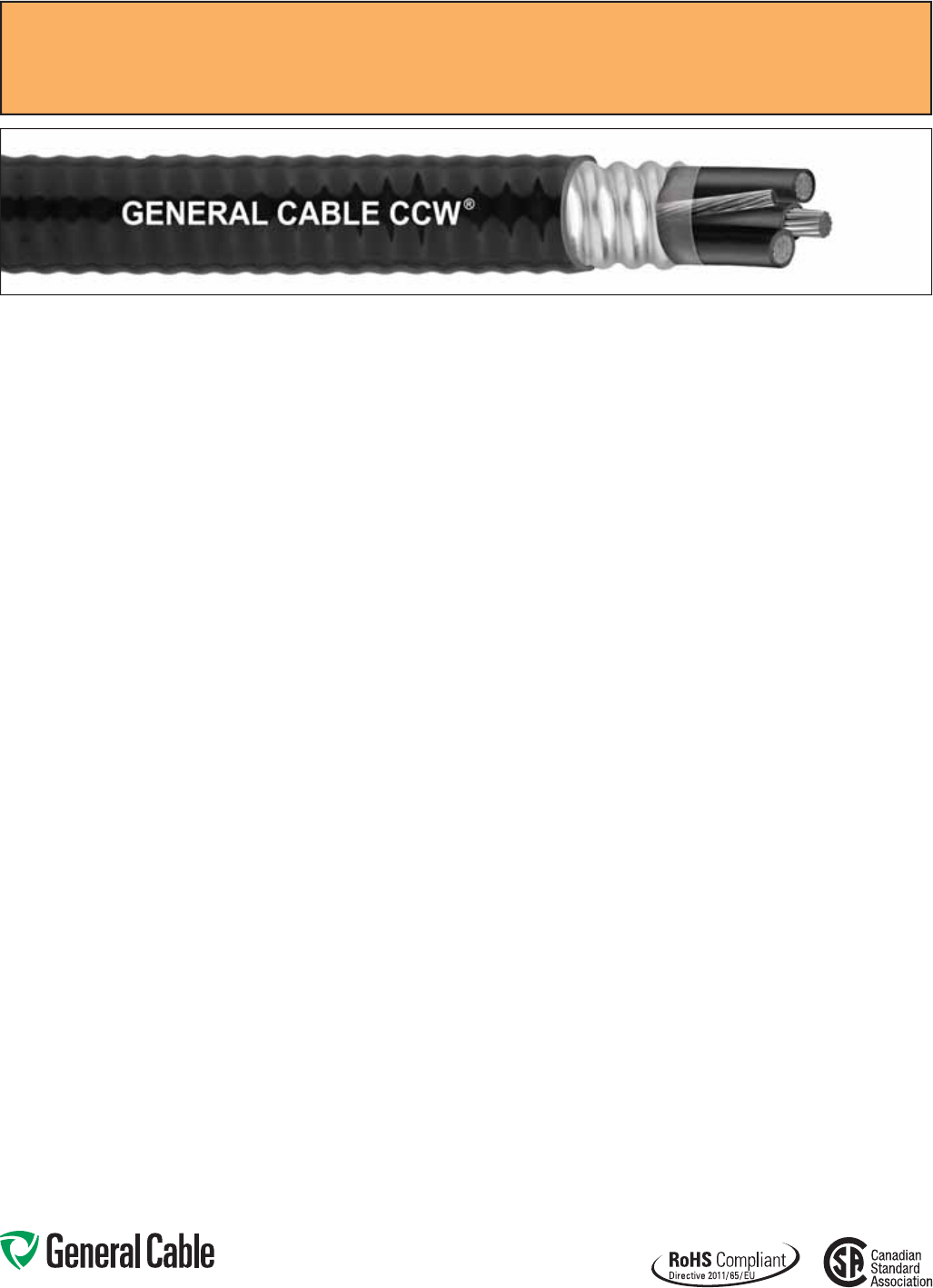
Phone: 888-593-3355
www.generalcable.com
SPEC 9675
October, 2014
CCW
®
Armored Power, 1000 V, 3/C VFD
CSA Type RA90, XLPE, 1000 V, 90°C, Cable Tray Use, Sunlight-Resistant
Direct Burial, FT4, -40°C, AG14, HL
Product Construction:
Conductor:
• Bare annealed copper per ASTM B3
• Sizes 10 AWG and smaller are Class B
compressed stranding per ASTM B8
• Sizes 8 AWG and larger are compact
stranding per ASTM B496
Insulation:
• Cross-linked Polyethylene (XLPE)
insulation rated 1000 Volts, RW90 per
CSA C22.2 No. 38
• Sizes 2 AWG and smaller utilize a
single color insulation: black, red
and blue
• Sizes 1 AWG and larger utilize black
insulation with printed number/color,
1-black, 2-red, 3-blue
Bonding/Grounding Conductors:
• Class B stranded bare annealed
copper per ASTM B3 and B8
• Three (3) symmetrical grounding wires
are sized in accordance with CEC
Table 16
Cable Assembly:
• Three symmetrical grounding wires
are cabled within the interstices of the
phase conductors
• Non-hygroscopic fillers when required
• A binder tape is applied over the
cabled core
CCW Armor:
• Impervious, continuously welded and
corrugated aluminum alloy sheath per
C22.2 No. 123
Jacket:
• Flame-retardant, moisture- and
sunlight-resistant Polyvinyl Chloride
(PVC), black
• Meets CSA Low Gas Emission
requirements, AG14
Applications:
• Variable Frequency Drives:
3-conductor CCW armored cables
with three (3) symmetrical grounding
wires are the preferred wiring method
for use with AC motors controlled by
pulse-width modulated inverters in
VFD applications
• CCW armored cables offer an
economical, rugged and reliable
alternative to labor-intensive cable in
conduit wiring methods
• For use in industrial and commercial
installations including hazardous
locations in accordance with the CEC
• Can be installed in wet or dry
locations, indoors or outdoors, in cable
trays, in a raceway, or direct buried in
accordance with the CEC
Features:
• 90°C, 1000 V wet or dry XLPE
insulation and three (3) symmetrical
grounding wires, recommended
for use with pulse-width modulated
AC drives
• XLPE insulation has a dielectric
constant less than 3.0 to withstand
momentary voltage spikes common
with VFD applications
Features: (cont’d)
• CCW armor provides an impervious
barrier to moisture, gas and liquids
• CCW armor provides EMI shielding
performance
• Factory assembled and tested cable
for use as an alternative to cable in
conduit wiring systems
• Meets cold impact at -40°C
• 90˚C continuous operating
temperature, wet or dry
• 130˚C emergency rating
• 250˚C short circuit rating
Specifications:
Design Adherence:
• CSA C22.2 No. 38 Thermoset-
Insulated Wires and Cables
• CSA C22.2 No. 123 Metal Sheathed
Cables
• CSA C22.2 No. 174 Cables and Cable
Glands for Use in Hazardous Locations
Flame Tests:
• CSA FT4
• ICEA T-29-520 (210,000 BTU/hr)
• IEEE 383 (70,000 BTU/hr)
• IEEE 1202 (70,000 BTU/hr)
Compliances:
• CSA Certified Type RA90, XLPE,
HL, SR, FT4, AG14 and -40°C,
CSA File # 7319
• RoHS Compliant
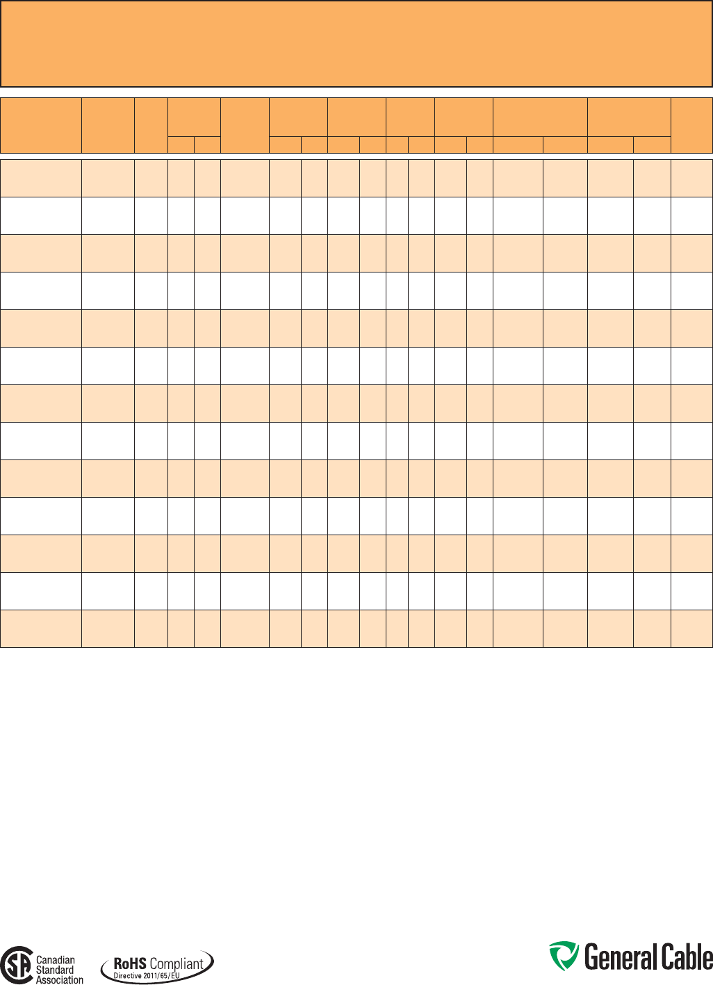
Phone: 888-593-3355
www.generalcable.com
SPEC 9675
October, 2014
CCW
®
Armored Power, 1000 V, 3/C VFD
CSA Type RA90, XLPE, 1000 V, 90°C, Cable Tray Use, Sunlight-Resistant
Direct Burial, FT4, -40°C, AG14, HL
CATALOG
NUMBER
COND.
SIZE
(AWG/kcmil) NO. OF
COND.
INSULATION
THICKNESS BARE
GROUND
COND.
(AWG)
NOMINAL
CORE O.D. NOMINAL
ARMOR O.D. JACKET
THICKNESS NOMINAL
OVERALL O.D. APPROXIMATE NET
WEIGHT MIN. BEND RADIUS ¹ 90°C
AMPACITY
@ 30°C
AMBIENT²mils mm INCHES mm INCHES mm mils mm INCHES mm LBS/1000 FT kg/1000 m INCHES mm
9675.01203318 12 (7/W)
(3.31 mm²)
3 45 1.14 3 x #18 0.40 10.2 0.60 15.3 50 1.27 0.70 17.8 249 370 7.0 178 30
9675.01003316 10 (7/W)
(5.26 mm²)
3 45 1.14 3 x #16 0.45 11.5 0.63 16.1 50 1.27 0.73 18.6 299 445 7.3 185 40
9675.00803314 8 (7/W)
(8.36 mm²)
3 45 1.14 3 x #14 0.50 12.7 0.76 19.2 50 1.27 0.86 21.9 417 620 8.6 218 55
9675.00603312 6 (7/W)
(13.3 mm²)
3 60 1.52 3 x #12 0.64 16.3 0.91 23.2 50 1.27 1.02 26.0 601 895 12.2 311 75
9675.00403312 4 (7/W)
(21.2 mm²)
3 60 1.52 3 x #12 0.74 18.7 0.98 24.8 50 1.27 1.08 27.4 763 1,135 12.9 329 95
9675.00203310 2 (7/W)
(33.6 mm²)
3 60 1.52 3 x #10 0.86 21.8 1.18 29.9 50 1.27 1.28 32.5 1,122 1,670 15.4 390 130
9675.00103310 1 (19/W)
(42.4 mm²)
3 80 2.03 3 x #10 1.01 25.7 1.36 34.6 50 1.27 1.46 37.1 1,404 2,090 17.5 445 145
9675.11003310 1/0 (19/W)
(53.5 mm²)
3 80 2.03 3 x #10 1.09 27.8 1.42 36.0 50 1.27 1.52 38.6 1,623 2,415 18.2 462 170
9675.21003310 2/0 (19/W)
(67.4 mm²)
3 80 2.03 3 x #10 1.18 30.0 1.56 39.6 50 1.27 1.66 42.2 2,043 3,040 20.0 506 195
9675.41003308 4/0 (19/W)
(107 mm²)
3 80 2.03 3 x #8 1.40 35.5 1.75 44.4 50 1.27 1.85 47.0 2,950 4,390 22.2 564 260
9675.25003308 250 (37/W)
(127 mm²)
3 90 2.29 3 x #8 1.49 37.8 1.90 48.2 50 1.27 2.01 51.1 3,380 5,030 24.1 612 290
9675.35003308 350 (37/W)
(177 mm²)
3 90 2.29 3 x #8 1.74 44.3 2.22 56.4 50 1.27 2.33 59.2 4,465 6,645 27.9 710 350
9675.50003306 500 (37/W)
(253 mm²)
3 90 2.29 3 x #6 2.00 50.9 2.48 63.0 50 1.27 2.59 65.8 6,152 9,155 31.0 789 430
Dimensions and weights are nominal; subject to industry tolerances.
¹ Minimum bend radius per Canadian Electrical Code, Part I, Section 12-712.
² Ampacity per Table #2, Canadian Electical Code.
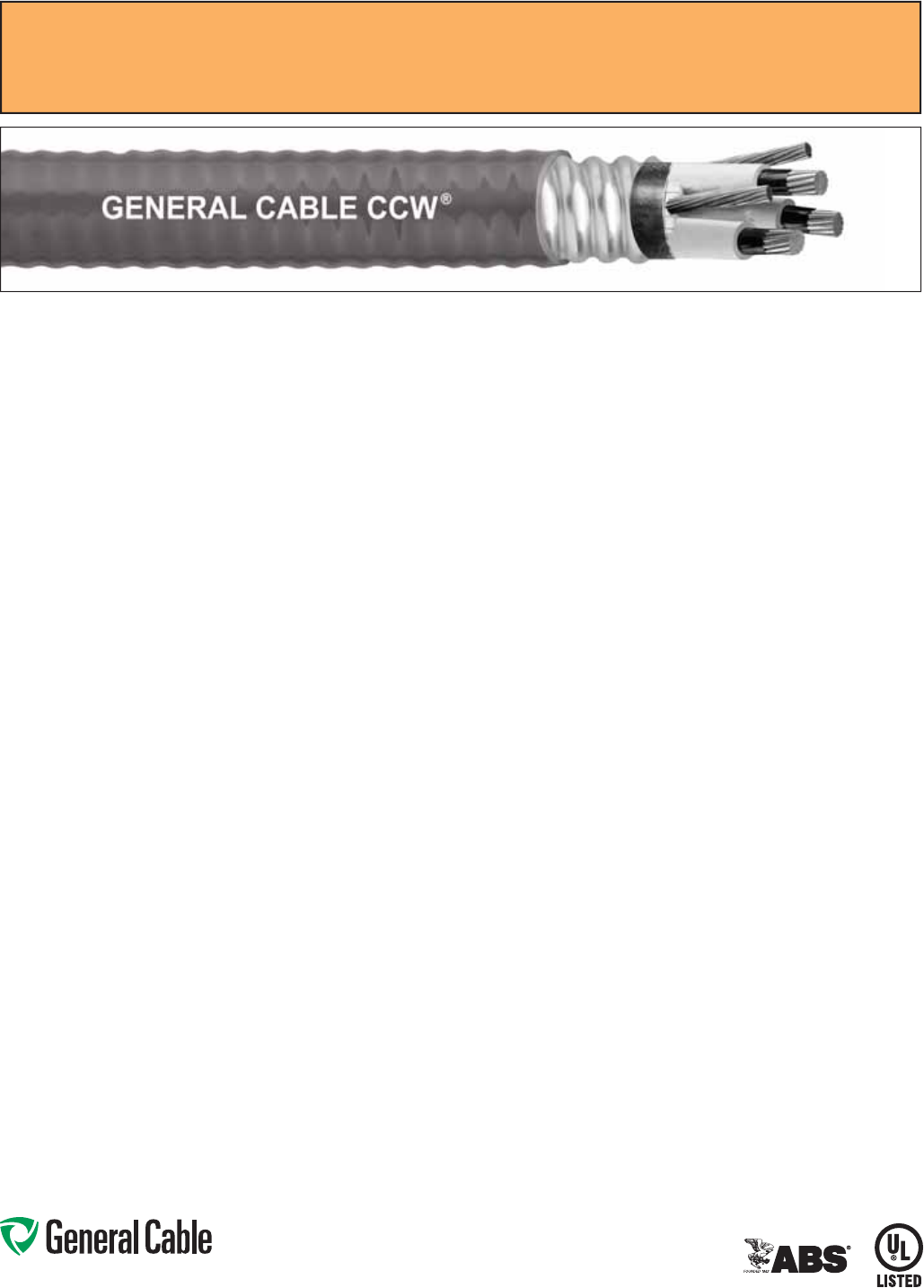
Phone: 888-593-3355
www.generalcable.com
Applications:
• Variable Frequency Drives:
3-conductor CCW armored cables
with three (3) symmetrical grounding
wires are the preferred wiring method
for use with AC motors controlled by
pulse-width modulated inverters in
VFD applications
• CCW armored medium-voltage
power cables offer an economical,
rugged and reliable alternative to
labor-intensive cable in conduit wiring
methods
• For use on feeders and branch circuits
in industrial power distribution systems
per NEC Articles 328 and 330
• For use in Class I, II and III, Divisions
1 and 2; and Class I, Zones 1 and 2
hazardous locations per NEC Articles
501, 502, 503 and 505
• Installed on metal racks, troughs, in
raceways, in cable trays or secured
to supports spaced not more than six
feet apart
• Installed in both exposed and
concealed work, wet or dry locations,
directly buried or embedded in
concrete
• Recognized for use on fixed or
floating offshore petroleum facilities
as recommended by the American
Petroleum Institute
Features:
• CCW armor provides an impervious
barrier to moisture, gas and liquids
and meets the grounding requirements
of UL 1072 and the NEC
• Factory assembled and tested cable
for use as an alternative to cable in
conduit wiring systems
Features: (cont’d)
• General Cable’s EPR insulation system
has outstanding corona resistance and
high dielectric strength, and it provides
electrical stability under stress
• Cable meets cold impact at -40°C
• 90˚C continuous operating
temperature, wet or dry
• 140˚C emergency rating
• 250˚C short circuit rating
Specifications:
Design Adherence:
• ICEA S-96-659/WC71 Standard for
Nonshielded Cables Rated 2001 –
5000 Volts
• UL 1072 Medium-Voltage Power
Cables
• UL 1569 Metal Clad Cables
• UL 2225 Cables and Cable Fittings for
Use in Hazardous Locations
• UL 1309 Marine Shipboard Cable
Flame Tests:
• ICEA T-29-520 (210,000 BTU/hr)
• IEEE 383 (70,000 BTU/hr)
• CSA FT4
• IEEE 1202 (70,000 BTU/hr)
• UL 1072
• IEC 60332-3 Category A
Compliances:
• UL Type MV-90 or MC-HL, SUN RES,
CT USE, DIR BUR, -40°C, FT4, UL File
# E90501
• UL Listed Marine Shipboard, UL File #
E85994
• American Bureau of Shipping (ABS)
Listed for CWCMC
Product Construction:
Conductor:
• Bare annealed copper per ASTM B3
• Compact stranding per ASTM B496
Extruded Strand Shield (ESS):
• Extruded thermoset semi-conductor
stress control layer over conductor per
ICEA S-96-659 and UL 1072
Insulation:
• 90 mils Ethylene Propylene Rubber
(EPR) insulation per ICEA S-96-659
and UL 1072
• Insulation is printed 1-black, 2-red and
3-blue for phase identification
Grounding Conductors:
• Three (3) split Class B stranded
bare annealed copper grounding
conductors
• Sized in accordance with UL 1072 and
NEC Table 250.122
Cable Assembly:
• Insulated and grounding conductors
are cabled together with non-
hygroscopic fillers when required
• Binder tape is applied over the cabled
core
CCW Armor:
• Impervious, continuously welded and
corrugated aluminum alloy sheath per
UL 1072 and UL 1569
• CCW armor conductivity meets
the grounding requirements of NEC
Article 250
Jacket:
• Flame-retardant, moisture- and
sunlight-resistant Polyvinyl Chloride
(PVC), yellow
• Low temperature performance meets
ASTM D746 brittleness temperature at
or below -40°C
CCW
®
Armored Power, 2.4 kV, Nonshielded, 3/C VFD
UL Type MC-HL or MV-90, EPR, 105°C, Cable Tray Use, Sunlight-Resistant
Direct Burial, ABS CWCMC
SPEC 9700
July, 2014
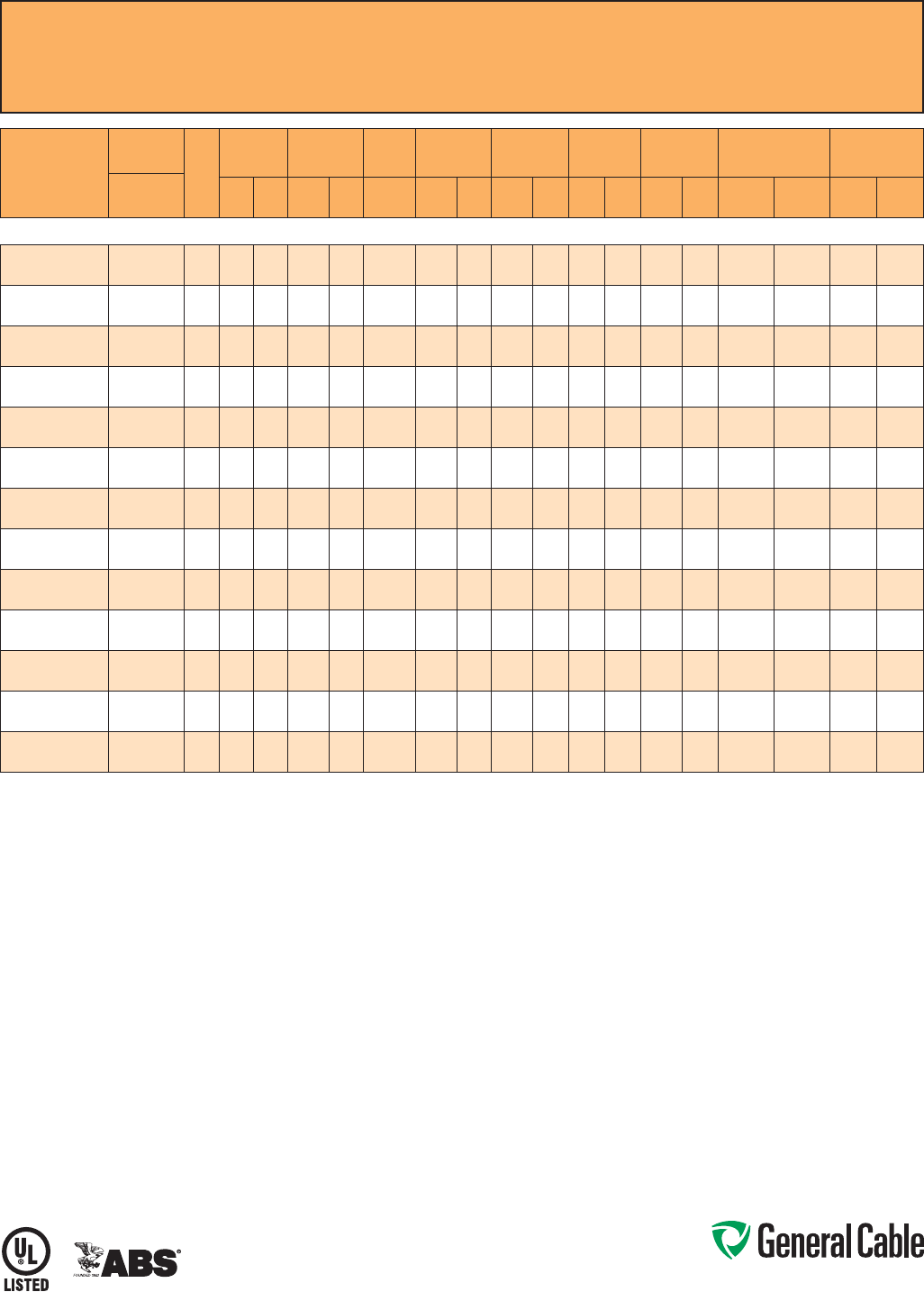
Phone: 888-593-3355
www.generalcable.com
CCW
®
Armored Power, 2.4 kV, Nonshielded, 3/C VFD
UL Type MC-HL or MV-90, EPR, 105°C, Cable Tray Use, Sunlight-Resistant
Direct Burial, ABS CWCMC
SPEC 9700
July, 2014
CATALOG
NUMBER
COND.
SIZE NO.
OF
COND.
INSULATION
THICKNESS
NOMINAL O.D.
OVER
INSULATION BARE
GROUND NOMINAL
CORE O.D. NOMINAL
ARMOR O.D. JACKET
THICKNESS NOMINAL
OVERALL O.D. APPROXIMAT
NET WEIGHT AMPACITY
AWG (kcmil) mils mm INCHES mm AWG INCHES mm INCHES mm mils mm INCHES mm LBS/1000
FT kg/1000
mIN AIR¹
DIRECT
BURIAL²
3/C WITH GROUND MC-HL OR MV-90, 90 MILS EPR, 2.4 kV, YELLOW JACKET
9700.00803312 8 (7/W)
(8.36 mm²)
3 90 2.3 0.36 9.1 3 x #12 0.77 19.6 0.97 24.6 50 1.27 1.08 27.4 570 848 59 85
9700.00603310 6 (7/W)
(13.3 mm²)
3 90 2.3 0.38 9.6 3 x #10 0.85 21.6 1.06 26.9 50 1.27 1.17 29.7 745 1,109 79 105
9700.00403310 4 (7/W)
(21.2 mm²)
3 90 2.3 0.43 10.8 3 x #10 0.97 24.6 1.19 30.2 50 1.27 1.30 33.0 965 1,436 105 135
9700.00203310 2 (7/W)
(33.6 mm²)
3 90 2.3 0.48 12.1 3 x #10 1.10 27.9 1.34 34.0 50 1.27 1.45 36.8 1,275 1,897 140 180
9700.00103308 1 (19/W)
(42.4 mm²)
3 90 2.3 0.52 13.1 3 x #8 1.16 29.5 1.42 36.1 50 1.27 1.53 38.9 1,525 2,269 160 200
9700.11003308 1/0 (19/W)
(53.5 mm²)
3 90 2.3 0.55 13.9 3 x #8 1.23 31.2 1.51 38.4 60 1.52 1.65 41.9 1,840 2,738 185 230
9700.21003308 2/0 (19/W)
(67.4 mm²)
3 90 2.3 0.59 14.9 3 x #8 1.33 33.8 1.60 40.6 60 1.52 1.73 43.9 2,165 3,222 215 260
9700.41003307 4/0 (19/W)
(107 mm²)
3 90 2.3 0.69 17.4 3 x #7 1.53 38.9 1.83 46.5 60 1.52 1.96 49.8 3,080 4,584 285 335
9700.25003307 250 (37/W)
(127 mm²)
3 90 2.3 0.74 18.7 3 x #7 1.64 41.7 1.96 49.8 60 1.52 2.09 53.1 3,475 5,171 320 365
9700.35003306 350 (37/W)
(177 mm²)
3 90 2.3 0.83 21.0 3 x #6 1.86 47.2 2.19 55.6 60 1.52 2.32 58.9 4,710 7,009 395 440
9700.50003305 500 (37/W)
(253 mm²)
3 90 2.3 0.95 24.0 3 x #5 2.10 53.3 2.45 62.2 75 1.91 2.61 66.3 6,410 9,539 485 530
9700.75003304 750 (61/W)
(380 mm²)
3 90 2.3 1.12 28.3 3 x #4 2.51 63.8 2.93 74.4 75 1.91 3.10 78.7 9,225 13,728 615 650
9700.10003304 1000 (61/W)
(507 mm²)
3 90 2.3 1.27 32.2 3 x #4 2.90 73.7 3.41 86.6 80 2.03 3.59 91.2 12,080 17,977 705 730
Dimensions and weights are nominal, subject to industry tolerances.
¹ In-air ampacities are per NEC Table 310.60(C)(71) for three insulated copper conductors rated 90°C, cabled with an overall covering and isolated in air at 40°C ambient temperature.
² Direct burial ampacities are per NEC Table 310.60(C)(83) for three insulated copper conductors rated 90°C, cabled within an overall covering and directly buried in earth at 20°C
ambient earth temperature.

Phone: 888-593-3355
www.generalcable.com
Jacket:
• Flame-retardant, moisture- and
sunlight-resistant Polyvinyl Chloride
(PVC), yellow
• Low temperature performance meets
ASTM D746 brittleness temperature at
or below -40°C
Applications:
• Variable Frequency Drives:
3-conductor CCW armored cables
with three (3) symmetrical grounding
wires are the preferred wiring method
for use with AC motors controlled by
pulse-width modulated inverters in
VFD applications
• CCW armored medium-voltage
power cables offer an economical,
rugged and reliable alternative to
labor-intensive cable in conduit wiring
methods
• For use on feeders and branch circuits
in industrial power distribution systems
per NEC Articles 328 and 330
• For use in Class I, II and III, Divisions
1 and 2; and Class I, Zones 1 and 2
hazardous locations per NEC Articles
501, 502, 503 and 505
• Installed on metal racks, troughs, in
raceways, in cable trays or secured
to supports spaced not more than six
feet apart
• Installed in both exposed and
concealed work, wet or dry locations,
directly buried or embedded in
concrete
• Recognized for use on fixed or
floating offshore petroleum facilities
as recommended by the American
Petroleum Institute
Features:
• CCW armor provides an impervious
barrier to moisture, gas and liquids
and meets the grounding requirements
of UL 1072 and the NEC
Features: (cont’d)
• Triple Extrusion: The strand shield,
EPR insulation and insulation shield
are all extruded in one operation
• General Cable’s EPR insulation system
has outstanding corona resistance and
high dielectric strength, and it provides
electrical stability under stress
• Cable meets cold impact at -40°C
• 105˚C continuous operating
temperature, wet or dry
• 140˚C emergency rating
• 250˚C short circuit rating
Specifications:
Design Adherence:
• ICEA S-93-639/WC74, 5-46 kV
Shielded Power Cable
• AEIC CS8 Specification for Shielded
Power Cable, 5-46 kV
• UL 1072 Medium-Voltage Power
Cables
• UL 1569 Metal Clad Cables
• UL 2225 Cables and Cable Fittings for
Use in Hazardous Locations
• UL 1309 Marine Shipboard Cable
• CSA 68.10
Flame Tests:
• ICEA T-29-520 (210,000 BTU/hr)
• IEEE 383 (70,000 BTU/hr)
• CSA FT4
• IEEE 1202 (70,000 BTU/hr)
• UL 1072
• IEC 60332-3 Category A
Compliances:
• UL Type MV-105 or MC-HL, SUN RES,
CT USE, DIR BUR, -40°C, FT4, UL File
# E90501
• UL Listed Marine Shipboard, UL File #
E85994
• CSA Type HL, SR, FT4, -40°C, CSA
File # 27161
• American Bureau of Shipping (ABS)
Listed for CWCMC
Product Construction:
Conductor:
• Bare annealed copper per ASTM B3
• Compact stranding per ASTM B496
Extruded Strand Shield (ESS):
• Extruded thermoset semi-conductor
stress control layer over the conductor
per ICEA S-93-639 and UL 1072
Insulation:
• 115 mils Ethylene Propylene Rubber
(EPR) insulation per ICEA S-93-639
and UL 1072
Extruded Insulation Shield (EIS):
• Thermoset semi-conducting polymeric
layer, free stripping from the insulation
per ICEA S-93-639 and UL 1072
Shield:
• 5 mil annealed bare copper tape with
25% overlap
Phase Identification:
• Color-coded polymeric identification
tape laid under the shield — black, red
and blue
Grounding Conductors:
• Three (3) split Class B stranded
bare annealed copper grounding
conductors
• Sized in accordance with UL 1072 and
NEC Article 250
Cable Assembly:
• Insulated and grounding conductors are
cabled together with non-hygroscopic
fillers when required
• Binder tape is applied over the cabled
core
CCW Armor:
• Impervious, continuously welded and
corrugated aluminum alloy sheath per
UL 1072 and UL 1569
• CCW armor conductivity meets
the grounding requirements of NEC
Article 250
CCW
®
Armored Power, 5 kV 133%/8 kV 100%, Shielded, 3/C VFD
UL Type MC-HL or MV-105, CSA Type HL, EPR, 105°C, Cable Tray Use, Sunlight-Resistant
Direct Burial, ABS CWCMC
SPEC 9800
October, 2014
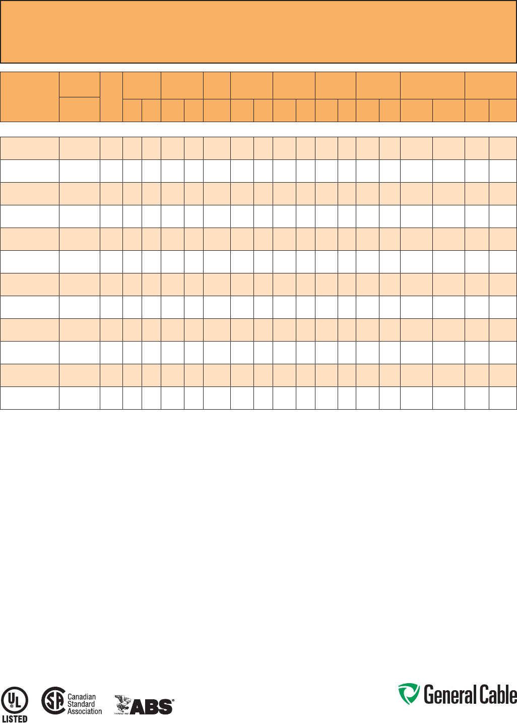
Phone: 888-593-3355
www.generalcable.com
CCW
®
Armored Power, 5 kV 133%/8 kV 100%, Shielded, 3/C VFD
UL Type MC-HL or MV-105, CSA Type HL, EPR, 105°C, Cable Tray Use, Sunlight-Resistant
Direct Burial, ABS CWCMC
SPEC 9800
October, 2014
CATALOG
NUMBER
COND.
SIZE
NO. OF
COND.
INSULATION
THICKNESS
NOMINAL O.D.
OVER
INSULATION BARE
GROUND NOMINAL
CORE O.D. NOMINAL
ARMOR O.D. JACKET
THICKNESS NOMINAL
OVERALL O.D. APPROXIMATE
NET WEIGHT 5 kV³
AMPACITY
AWG (kcmil) mils mm INCHES mm AWG INCHES mm INCHES mm mils mm INCHES mm LBS/1000
FT kg/1000
mIN AIR¹
DIRECT
BURIAL²
3/C WITH GROUND MC-HL OR MV-105, 115 MILS EPR, 5 kV 133% AND 8 kV 100% INSULATION LEVEL
9800.00603310 6 (7/W)
(13.3 mm²) 3 115 2.9 0.43 10.9 3 x #10 1.15 29.2 1.37 34.8 50 1.27 1.48 37.6 1,121 1,668 88 115
9800.00403310 4 (7/W)
(21.2 mm²) 3 115 2.9 0.48 12.2 3 x #10 1.24 31.5 1.51 38.4 60 1.52 1.65 41.9 1,418 2,110 115 150
9800.00203310 2 (7/W)
(33.6 mm²) 3 115 2.9 0.53 13.5 3 x #10 1.37 34.8 1.64 41.7 60 1.52 1.78 45.2 1,731 2,576 154 190
9800.00103308 1 (19/W)
(42.4 mm²) 3 115 2.9 0.57 14.5 3 x #8 1.47 37.3 1.69 42.9 60 1.52 1.82 46.2 1,978 2,944 180 215
9800.11003308 1/0 (19/W)
(53.5 mm²) 3 115 2.9 0.60 15.2 3 x #8 1.56 39.6 1.78 45.2 60 1.52 1.91 48.5 2,259 3,362 205 245
9800.21003308 2/0 (19/W)
(67.4 mm²) 3 115 2.9 0.64 16.3 3 x #8 1.61 40.9 1.92 48.8 60 1.52 2.05 52.1 2,626 3,908 240 280
9800.41003307 4/0 (19/W)
(107 mm²) 3 115 2.9 0.74 18.8 3 x #7 1.82 46.2 2.15 54.6 60 1.52 2.28 57.9 3,650 5,432 320 360
9800.25003306 250 (37/W)
(127 mm²) 3 115 2.9 0.80 20.3 3 x #6 2.01 51.1 2.23 56.6 60 1.52 2.36 59.9 4,060 6,042 355 395
9800.35003306 350 (37/W)
(177 mm²) 3 115 2.9 0.89 22.6 3 x #6 2.10 53.3 2.45 62.2 75 1.91 2.61 66.3 5,045 7,508 440 475
9800.50003305 500 (37/W)
(253 mm²) 3 115 2.9 1.01 25.7 3 x #5 2.39 60.7 2.75 69.9 75 1.91 2.92 74.2 7,137 10,621 545 570
9800.75003304 750 (61/W)
(380 mm²) 3 115 2.9 1.19 30.2 3 x #4 3.07 78.0 3.32 84.3 85 2.16 3.50 88.9 10,268 15,280 685 700
9800.10003304 1000 (61/W)
(507 mm²) 3 115 2.9 1.34 34.0 3 x #4 3.43 87.1 3.76 95.5 85 2.16 3.94 100.1 13,051 19,422 790 785
Dimensions and weights are nominal; subject to industry tolerances.
¹ In-air ampacities are per NEC Table 310.60(C)(71) for three insulated copper conductors rated 105°C, cabled with an overall covering and isolated in air at 40°C ambient temperature.
² Direct burial ampacities are per NEC Table 310.60(C)(83) for three insulated copper conductors rated 105°C, cabled within an overall covering and directly buried in earth at 20°C
ambient earth temperature.
³ For 8 kV ampacities, refer to NEC Tables 310.60(C)(71) and 310.60(C)(83) for cables listed 5001-35,000 volts.

Phone: 888-593-3355
www.generalcable.com
CCW
®
Armored Power, 5 kV 133%/8 kV 100%, Shielded, 3/C VFD
UL Type MC-HL or MV-105, CSA Type HL, EPR, 105°C, Cable Tray Use
Sunlight-Resistant, Direct Burial, UL Marine Shipboard Cable, ABS CWCMC, Arctic-Grade
SPEC 9805
October, 2014
Product Construction:
Conductor:
• Bare annealed copper per ASTM B3
• Compact stranding per ASTM B496
Extruded Strand Shield (ESS):
• Extruded thermoset semi-conductor
stress control layer over the conductor
per ICEA S-93-639 and UL 1072
Insulation:
• 115 mils Ethylene Propylene Rubber
(EPR) insulation per ICEA S-93-639
and UL 1072
Extruded Insulation Shield (EIS):
• Thermoset semi-conducting polymeric
layer, free stripping from the insulation
per ICEA S-93-639 and UL 1072
Shield:
• 5 mil annealed bare copper tape with
25% overlap
Phase Identification:
• Color-coded polymeric identification
tape laid under the shield – black, red
and blue
Grounding Conductors:
• Three (2) split Class B stranded bare
annealed copper grounding conductors
• Sized in accordance with UL 1072 and
NEC Article 250
Cable Assembly:
• Insulated and grounding conductors are
cabled together with non-hydroscopic
fillers when required
• Binder tape is applied over the
cabled core
CCW Armor:
• Impervious, continuously welded and
corrugated aluminum alloy sheath per
UL Standards 1569 and 2225
• CCW armor conductivity meets the
grounding requirements of NEC
Article 250
Jacket:
• Flame-retardant, moisture- and
sunlight-resistant Polyvinyl Chloride
(PVC), black
• Low temperature performance meets
ASTM D746 brittleness temperature at
or below -60°C
Applications:
• Variable Frequency Drives:
3-conductor CCW armored cables
with three (3) symmetrical grounding
wires are the preferred wiring method
for use with AC motors controlled by
pulse-width modulated inverters in
VFD applications
• CCW armored medium-voltage power
cables offer an economical, rugged and
reliable alternative to labor-intensive
cable in conduit wiring methods
• For use on feeders and branch circuits
for power distribution systems per
NEC Articles 328 and 330
• For use in Class I, II and III, Divisions
1 and 2; and Class I, Zones 1 and 2
hazardous locations per NEC Articles
501, 502, 503 and 505
• Installed on metal racks, troughs, in
raceways, in cable trays or secured to
supports spaced not more than
six feet apart
• Installed in both exposed and
concealed work, wet or dry locations,
directly buried or embedded in
concrete
• Recognized for use on fixed or
floating offshore petroleum facilities
as recommended by the American
Petroleum Institute
Features:
• CCW armor provides an impervious
barrier to moisture, gas and liquids
and meets grounding requirements of
UL 1072 and the NEC
Features: (cont’d)
• Triple Extrusion: The strand shield,
EPR insulation and insulation shield
are all extruded in one operation
• General Cable’s EPR insulation system
has outstanding corona resistance and
high dielectric strength, and it provides
electrical stability under stress
• Meets cold bend at -55°C
• 105°C continuous operating
temperature, wet or dry
• 140°C emergency rating
• 250°C short circuit rating
Specifications:
Design Adherence:
• ICEA S-93-639/WC74, 5-46 kV
Shielded Power Cables
• AEIC CS8 Specification for Shielded
Power Cable, 5 – 46 kV
• UL 1072 Medium-Voltage Power Cables
• UL 1569 Metal Clad Cables
• UL 2225 Cables and Cable Fittings for
Use in Hazardous Locations
• UL 1309 Marine Shipboard Cable
• CSA C68.10
Flame Tests:
• ICEA T-29-520 (210,000 BTU/hr)
• IEEE 383 (70,000 BTU/hr)
• CSA FT4
• IEEE 1202 (70,000 BTU/hr)
• UL 1581 (70,000 BTU/hr)
• IEC 60332-3 Cat. A
Compliances:
• UL Type MV-105 or UL Type MC-HL,
SUN RES, CT USE, DIR BUR, -40°C,
FT4, UL File # E90501
• UL Listed Marine Shipboard, UL File
# E85994
• CSA Type HL, SR, FT4, -40˚C,
CSA File # 27161
• American Bureau of Shipping (ABS)
Listed for CWCMC

Phone: 888-593-3355
www.generalcable.com
CCW
®
Armored Power, 5 kV 133%/8 kV 100%, Shielded, 3/C VFD
UL Type MC-HL or MV-105, CSA Type HL, EPR, 105°C, Cable Tray Use
Sunlight-Resistant, Direct Burial, UL Marine Shipboard Cable, ABS CWCMC, Arctic-Grade
SPEC 9805
October, 2014
CATALOG
NUMBER COND. SIZE
(AWG/kcmil)
NO.
OF
COND.
INSULATION
THICKNESS
NOMINAL
O.D. OVER
INSULATION BARE
GROUND
(AWG)
NOMINAL
CORE O.D. NOMINAL
ARMOR O.D. JACKET
THICKNESS NOMINAL
OVERALL O.D. APPROXIMATE
NET WEIGHT 5 kV³ AMPACITY
mils mm INCHES mm INCHES mm INCHES mm mils mm INCHES mm LBS/1000
FT kg/1000
mIN AIR¹
DIRECT
BURIAL²
3/C WITH GROUND MC-HL OR MV-105, 115 MILS EPR, 5 kV 133% AND 8 kV 100% INSULATION LEVEL
9805.00603310 6 (7/W)
(13.3 mm²) 3 115 2.9 0.43 10.9 3 x #10 1.15 29.2 1.37 34.8 50 1.27 1.48 37.6 1,121 1,668 88 115
9805.00403310 4 (7/W)
(21.2 mm²) 3 115 2.9 0.48 12.2 3 x #10 1.24 31.5 1.51 38.4 60 1.52 1.65 41.9 1,418 2,110 115 150
9805.00203310 2 (7/W)
(33.6 mm²) 3 115 2.9 0.53 13.5 3 x #10 1.37 34.8 1.64 41.7 60 1.52 1.78 45.2 1,731 2,576 154 190
9805.00103308 1 (19/W)
(42.4 mm²) 3 115 2.9 0.57 14.5 3 x #8 1.47 37.3 1.69 42.9 60 1.52 1.82 46.2 1,978 2,944 180 215
9805.11003308 1/0 (19/W)
(53.5 mm²) 3 115 2.9 0.60 15.2 3 x #8 1.56 39.6 1.78 45.2 60 1.52 1.91 48.5 2,259 3,362 205 245
9805.21003308 2/0 (19/W)
(67.4 mm²) 3 115 2.9 0.64 16.3 3 x #8 1.61 40.9 1.92 48.8 60 1.52 2.05 52.1 2,626 3,908 240 280
9805.41003307 4/0 (19/W)
(107 mm²) 3 115 2.9 0.74 18.8 3 x #7 1.82 46.2 2.15 54.6 60 1.52 2.28 57.9 3,650 5,432 320 360
9805.25003306 250 (37/W)
(127 mm²) 3 115 2.9 0.80 20.3 3 x #6 2.01 51.1 2.23 56.6 60 1.52 2.36 59.9 4,060 6,042 355 395
9805.35003306 350 (37/W)
(177 mm²) 3 115 2.9 0.89 22.6 3 x #6 2.10 53.3 2.45 62.2 75 1.91 2.61 66.3 5,045 7,508 440 475
9805.50003305 500 (37/W)
(253 mm²) 3 115 2.9 1.01 25.7 3 x #5 2.39 60.7 2.75 69.9 75 1.91 2.92 74.2 7,137 10,621 545 570
9805.75003304 750 (61/W)
(380 mm²) 3 115 2.9 1.19 30.2 3 x #4 3.07 78.0 3.32 84.3 85 2.16 3.50 88.9 10,268 15,280 685 700
9805.10003304 1000 (61/W)
(507 mm²) 3 115 2.9 1.34 34.0 3 x #4 3.43 87.1 3.76 95.5 85 2.16 3.94 100.1 13,051 19,422 790 785
Dimensions and weights are nominal; subject to industry tolerances.
¹ In-air ampacities are per NEC Table 310.60(C)(71) for three insulated copper conductors rated 105°C, cabled with an overall covering and isolated in air at 40°C ambient temperature.
² Direct burial ampacities are per NEC Table 310.60(C)(83) for three insulated copper conductors rated 105°C, cabled within an overall covering and directly buried in earth at 20°C
ambient earth temperature.
³ For 8 kV ampacities, refer to NEC Tables 310.60(C)(71) and 310.60(C)(83) for cables listed 5,001-35,000 volts.

Phone: 888-593-3355
www.generalcable.com
Jacket:
• Flame-retardant, moisture- and
sunlight-resistant Polyvinyl Chloride
(PVC), yellow
• Low temperature performance meets
ASTM D746 brittleness temperature at
or below -40°C
Applications:
• Variable Frequency Drives:
3-conductor CCW armored cables
with three (3) symmetrical grounding
wires are the preferred wiring method
for use with AC motors controlled by
pulse-width modulated inverters in
VFD applications
• CCW armored medium-voltage
power cables offer an economical,
rugged and reliable alternative to
labor-intensive cable in conduit wiring
methods
• For use on feeders and branch circuits
in industrial power distribution systems
per NEC Articles 328 and 330
• For use in Class I, II and III, Divisions
1 and 2; and Class I, Zones 1 and 2
hazardous locations per NEC Articles
501, 502, 503 and 505
• Installed on metal racks, troughs, in
raceways, in cable trays or secured
to supports spaced not more than six
feet apart
• Installed in both exposed and
concealed work, wet or dry locations,
directly buried or embedded in
concrete
• Recognized for use on fixed or
floating offshore petroleum facilities
as recommended by the American
Petroleum Institute
Features:
• CCW armor provides an impervious
barrier to moisture, gas and liquids
and meets the grounding requirements
of UL 1072 and the NEC
Features: (cont’d)
• Triple Extrusion: The strand shield,
EPR insulation and insulation shield
are all extruded in one operation
• General Cable’s EPR insulation system
has outstanding corona resistance and
high dielectric strength, and it provides
electrical stability under stress
• Cable meets cold impact at -40°C
• 105˚C continuous operating
temperature, wet or dry
• 140˚C emergency rating
• 250˚C short circuit rating
Specifications:
Design Adherence:
• ICEA S-93-639/WC74, 5-46 kV
Shielded Power Cable
• AEIC CS8 Specification for Shielded
Power Cable, 5-46 kV
• UL 1072 Medium-Voltage Power
Cables
• UL 1569 Metal Clad Cables
• UL 2225 Cables and Cable Fittings for
Use in Hazardous Locations
• UL 1309 Marine Shipboard Cable
• CSA 68.10
Flame Tests:
• ICEA T-29-520 (210,000 BTU/hr)
• IEEE 383 (70,000 BTU/hr)
• CSA FT4
• IEEE 1202 (70,000 BTU/hr)
• UL 1072
• IEC 60332-3 Category A
Compliances:
• UL Type MV-105 or MC-HL, SUN RES,
CT USE, DIR BUR, -40°C, FT4, UL File
# E90501
• UL Listed Marine Shipboard, UL File #
E85994
• CSA Type HL, SR, FT4, -40°C, CSA
File # 27161
• American Bureau of Shipping (ABS)
Listed for CWCMC
Product Construction:
Conductor:
• Bare annealed copper per ASTM B3
• Compact stranding per ASTM B496
Extruded Strand Shield (ESS):
• Extruded thermoset semi-conductor
stress control layer over the conductor
per ICEA S-93-639 and UL 1072
Insulation:
• 140 mils Ethylene Propylene Rubber
(EPR) insulation per ICEA S-93-639
and UL 1072
Extruded Insulation Shield (EIS):
• Thermoset semi-conducting polymeric
layer, free stripping from the insulation
per ICEA S-93-639 and UL 1072
Shield:
• 5 mil annealed bare copper tape with
25% overlap
Phase Identification:
• Color-coded polymeric identification
tape laid under the shield - black, red
and blue
Grounding Conductors:
• Three (3) split Class B stranded
bare annealed copper grounding
conductors
• Sized in accordance with UL 1072 and
NEC Article 250
Cable Assembly:
• Insulated and grounding conductors
are cabled together with non-
hygroscopic fillers when required
• Binder tape is applied over the cabled
core
CCW Armor:
• Impervious, continuously welded and
corrugated aluminum alloy sheath per
UL 1072 and UL 1569
• CCW armor conductivity meets the
grounding requirements of the NEC
CCW
®
Armored Power, 8 kV 133%, Shielded, 3/C VFD
UL Type MC-HL or MV-105, CSA Type HL, EPR, 105°C, Cable Tray Use, Sunlight-Resistant
Direct Burial, ABS CWCMC
SPEC 9815
October, 2014
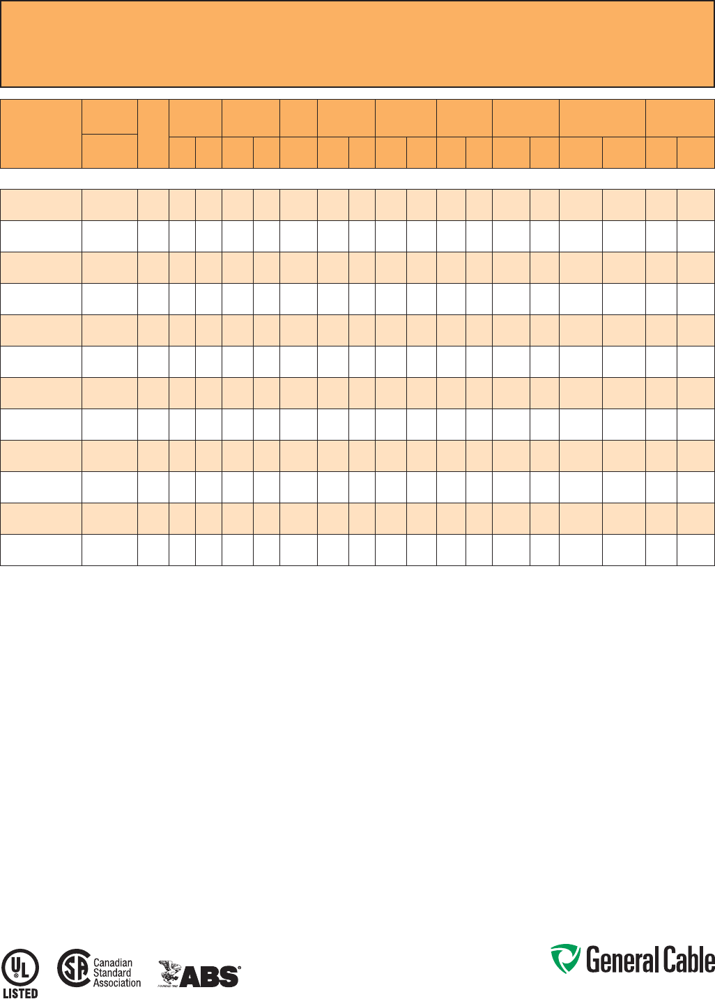
Phone: 888-593-3355
www.generalcable.com
CCW
®
Armored Power, 8 kV 133%, Shielded, 3/C VFD
UL Type MC-HL or MV-105, CSA Type HL, EPR, 105°C, Cable Tray Use, Sunlight-Resistant
Direct Burial, ABS CWCMC
SPEC 9815
October, 2014
CATALOG
NUMBER
COND.
SIZE
NO. OF
COND.
INSULATION
THICKNESS
NOMINAL O.D.
OVER
INSULATION BARE
GROUND NOMINAL
CORE O.D. NOMINAL
ARMOR O.D. JACKET
THICKNESS NOMINAL
OVERALL O.D. APPROXIMATE
NET WEIGHT AMPACITY
AWG (kcmil) mils mm INCHES mm AWG INCHES mm INCHES mm mils mm INCHES mm LBS/1000
FT kg/1000
mIN AIR¹
DIRECT
BURIAL²
3/C WITH GROUND MC-HL OR MV-105, 140 MILS EPR, 8 kV 133% INSULATION LEVEL
9815.00603310 6 (7/W)
(13.3 mm²) 3 140 3.6 0.48 12.2 3 x #10 1.20 30.5 1.60 40.6 60 1.52 1.73 43.9 1,350 2,009 105 120
9815.00403310 4 (7/W)
(21.2 mm²) 3 140 3.6 0.53 13.5 3 x #10 1.29 32.8 1.70 43.2 60 1.52 1.83 46.5 1,600 2,381 135 155
9815.00203310 2 (7/W)
(33.6 mm²) 3 140 3.6 0.58 14.7 3 x #10 1.42 36.1 1.85 47.0 60 1.52 1.98 50.3 2,000 2,976 185 200
9815.00103308 1 (19/W)
(42.4 mm²) 3 140 3.6 0.62 15.7 3 x #8 1.52 38.6 1.93 49.0 60 1.52 2.06 52.3 2,275 3,386 210 225
9815.11003308 1/0 (19/W)
(53.5 mm²) 3 140 3.6 0.65 16.5 3 x #8 1.61 40.9 2.03 51.6 60 1.52 2.16 54.9 2,600 3,869 240 255
9815.21003308 2/0 (19/W)
(67.4 mm²) 3 140 3.6 0.69 17.5 3 x #8 1.66 42.2 2.14 54.4 60 1.52 2.27 57.7 2,950 4,390 275 290
9815.41003307 4/0 (19/W)
(107 mm²) 3 140 3.6 0.79 20.1 3 x #7 1.87 47.5 2.40 61.0 75 1.91 2.56 65.0 4,025 5,990 360 375
9815.25003306 250 (37/W)
(127 mm²) 3 140 3.6 0.85 21.6 3 x #6 2.06 52.3 2.59 65.8 75 1.91 2.75 69.9 4,600 6,846 400 410
9815.35003306 350 (37/W)
(177 mm²) 3 140 3.6 0.94 23.9 3 x #6 2.15 54.6 2.85 72.4 75 1.91 3.01 76.5 5,800 8,631 490 495
9815.50003305 500 (37/W)
(253 mm²) 3 140 3.6 1.06 26.9 3 x #5 2.44 62.0 3.19 81.0 85 2.16 3.37 85.6 7,800 11,608 600 590
9815.75003304 750 (61/W)
(380 mm²) 3 140 3.6 1.26 32.0 3 x #4 3.19 81.0 3.68 93.5 85 2.16 3.86 98.0 10,750 15,998 745 720
9815.10003304 1000 (61/W)
(507 mm²) 3 140 3.6 1.42 36.1 3 x #4 3.48 88.4 3.98 101.1 85 2.16 4.16 105.7 13,550 20,165 860 810
Dimensions and weights are nominal; subject to industry tolerances.
¹ In-air ampacities are per NEC Table 310.60(C)(71) for three insulated copper conductors rated 105°C, cabled with an overall covering and isolated in air at 40°C ambient temperature.
² Direct burial ampacities are per NEC Table 310.60(C)(83) for three insulated copper conductors rated 105°C, cabled within an overall covering and directly buried in earth at 20°C
ambient earth temperature.

Phone: 888-593-3355
www.generalcable.com
Jacket:
• Flame-retardant, moisture- and
sunlight-resistant Polyvinyl Chloride
(PVC), red
• Low temperature performance meets
ASTM D746 brittleness temperature at
or below -40°C
Applications:
• CCW armored medium-voltage
power cables offer an economical,
rugged and reliable alternative to
labor-intensive cable in conduit wiring
methods
• For use on feeders and branch circuits
in industrial power distribution systems
per NEC Articles 328 and 330
• For use in Class I, II and III, Divisions
1 and 2; and Class I, Zones 1 and 2
hazardous locations per NEC Articles
501, 502, 503 and 505
• Installed on metal racks, troughs, in
raceways, in cable trays or secured
to supports spaced not more than six
feet apart
• Installed in both exposed and
concealed work, wet or dry locations,
directly buried or embedded in
concrete
• Recognized for use on fixed or
floating offshore petroleum facilities
as recommended by the American
Petroleum Institute
Features:
• CCW armor provides an impervious
barrier to moisture, gas and liquids
and meets the grounding requirements
of UL 1072 and the NEC
• Triple Extrusion: The strand shield,
EPR insulation and insulation shield
are all extruded in one operation
Features: (cont’d)
• General Cable’s EPR insulation system
has outstanding corona resistance and
high dielectric strength, and it provides
electrical stability under stress
• Cable meets cold impact at -40°C
• 105˚C continuous operating
temperature, wet or dry
• 140˚C emergency rating
• 250˚C short circuit rating
Specifications:
Design Adherence:
• ICEA S-93-639/WC74, 5-46 kV
Shielded Power Cable
• AEIC CS8 Specification for Shielded
Power Cable, 5-46 kV
• UL 1072 Medium-Voltage Power
Cables
• UL 1569 Metal Clad Cables
• UL 2225 Cables and Cable Fittings for
Use in Hazardous Locations
• UL 1309 Marine Shipboard Cable
• CSA 68.10
Flame Tests:
• ICEA T-29-520 (210,000 BTU/hr)
• IEEE 383 (70,000 BTU/hr)
• CSA FT4
• IEEE 1202 (70,000 BTU/hr)
• UL 1072
• IEC 60332-3 Category A
Compliances:
• UL Type MV-105 or MC-HL, SUN RES,
CT USE, DIR BUR, -40°C, FT4, UL File
# E90501
• UL Listed Marine Shipboard, UL File #
E85994
• CSA Type HL, SR, FT4, -40°C, CSA
File # 27161
• American Bureau of Shipping (ABS)
Listed for CWCMC
Product Construction:
Conductor:
• Bare annealed copper per ASTM B3
• Compact stranding per ASTM B496
Extruded Strand Shield (ESS):
• Extruded thermoset semi-conductor
stress control layer over the conductor
per ICEA S-93-639 and UL 1072
Insulation:
• 175 mils Ethylene Propylene Rubber
(EPR) insulation per ICEA S-93-639
and UL 1072
Extruded Insulation Shield (EIS):
• Thermoset semi-conducting polymeric
layer, free stripping from the insulation
per ICEA S-93-639 and UL 1072
Shield:
• 5 mil annealed bare copper tape with
25% overlap
Phase Identification:
• Color-coded polymeric identification
tape laid under the shield - black, red
and blue
Grounding Conductor:
• Class B stranded bare annealed
copper grounding conductor
• Sized in accordance with UL 1072 and
NEC Article 250
Cable Assembly:
• Insulated and grounding conductors
are cabled together with non-
hygroscopic fillers when required
• Binder tape is applied over the cabled
core
CCW Armor:
• Impervious, continuously welded and
corrugated aluminum alloy sheath per
UL 1072 and UL 1569
• CCW armor conductivity meets the
grounding requirements of the NEC
CCW
®
Armored Power, 15 kV 100%, Shielded, 3/C
UL Type MC-HL or MV-105, CSA Type HL, EPR, 105°C, Cable Tray Use, Sunlight-Resistant
Direct Burial, ABS CWCMC
SPEC 9825
October, 2014
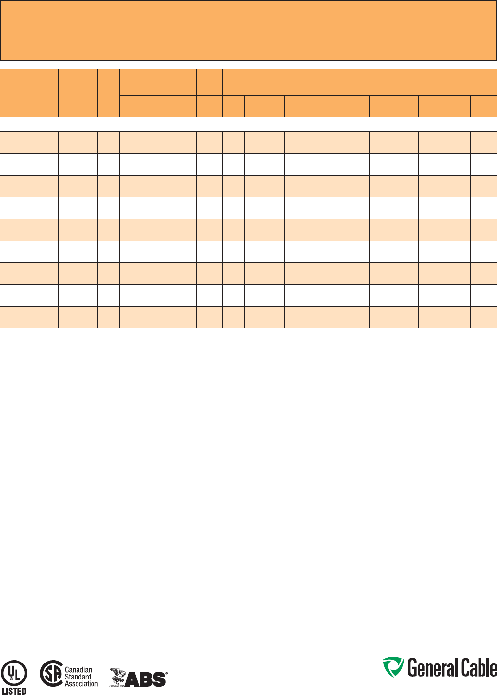
Phone: 888-593-3355
www.generalcable.com
SPEC 9825
October, 2014
CCW
®
Armored Power, 15 kV 100%, Shielded, 3/C
UL Type MC-HL or MV-105, CSA Type HL, EPR, 105°C, Cable Tray Use, Sunlight-Resistant
Direct Burial, ABS CWCMC
CATALOG
NUMBER
COND.
SIZE
NO. OF
COND.
INSULATION
THICKNESS
NOMINAL O.D.
OVER
INSULATION BARE
GROUND NOMINAL
CORE O.D. NOMINAL
ARMOR O.D. JACKET
THICKNESS NOMINAL
OVERALL O.D. APPROXIMATE
NET WEIGHT AMPACITY
AWG (kcmil) mils mm INCHES mm AWG INCHES mm INCHES mm mils mm INCHES mm LBS/1000
FT kg/1000
mIN AIR¹
DIRECT
BURIAL²
3/C WITH GROUND MC-HL OR MV-105, 175 MILS EPR, 15 kV 100% INSULATION LEVEL
9825.00203106 2 (7/W)
(33.6 mm²)
3 175 4.4 0.65 16.5 6 1.61 40.9 1.96 49.8 60 1.52 2.05 52.1 2,077 3,091 185 200
9825.00103104 1 (19/W)
(42.4 mm²)
3 175 4.4 0.69 17.5 4 1.68 42.7 2.01 51.1 60 1.52 2.15 54.6 2,469 3,674 210 225
9825.11003104 1/0 (19/W)
(53.5 mm²)
3 175 4.4 0.72 18.3 4 1.78 45.2 2.10 53.3 60 1.52 2.24 56.9 2,760 4,107 240 255
9825.21003104 2/0 (19/W)
(67.4 mm²)
3 175 4.4 0.76 19.3 4 1.88 47.8 2.19 55.6 60 1.52 2.36 59.9 3,130 4,658 275 290
9825.41003103 4/0 (19/W)
(107 mm²)
3 175 4.4 0.86 21.8 3 2.09 53.1 2.45 62.2 75 1.91 2.61 66.3 4,290 6,384 360 375
9825.25003102 250 (37/W)
(127 mm²)
3 175 4.4 0.92 23.4 2 2.19 55.6 2.58 65.5 75 1.91 2.74 69.6 4,775 7,106 400 410
9825.35003102 350 (37/W)
(177 mm²)
3 175 4.4 1.01 25.7 2 2.45 62.2 2.85 72.4 75 1.91 3.01 76.5 6,132 9,125 490 495
9825.50003101 500 (37/W)
(253 mm²)
3 175 4.4 1.13 28.7 1 2.71 68.8 3.16 80.3 85 2.16 3.34 84.8 8,052 11,983 600 590
9825.750031110 750 (61/W)
(380 mm²)
3 175 4.4 1.31 33.3 1/0 3.12 79.2 3.67 93.2 85 2.16 3.85 97.8 11,098 16,516 745 720
Dimensions and weights are nominal; subject to industry tolerances.
¹ Ampacities in air are per NEC Table 310.60(C)(71) for an insulated three-conductor copper cable isolated in air with 105°C rated conductors at a 40°C ambient temperature.
² Direct burial ampacities are per NEC Table 310.60(C)(83) for three insulated copper conductors cabled within an overall covering, directly buried in earth with 105°C rated conductors
at 20°C ambient earth temperature.
Phone: 888-593-3355
www.generalcable.com
Jacket:
• Flame-retardant, moisture- and
sunlight-resistant Polyvinyl Chloride
(PVC), red
• Low temperature performance meets
ASTM D746 brittleness temperature at
or below -40°C
Applications:
• CCW armored medium-voltage
power cables offer an economical,
rugged and reliable alternative to
labor-intensive cable in conduit wiring
methods
• For use on feeders and branch circuits
in industrial power distribution systems
per NEC Articles 328 and 330
• For use in Class I, II and III, Divisions
1 and 2; and Class I, Zones 1 and 2
hazardous locations per NEC Articles
501, 502, 503 and 505
• Installed on metal racks, troughs, in
raceways, in cable trays or secured
to supports spaced not more than six
feet apart
• Installed in both exposed and
concealed work, wet or dry locations,
directly buried or embedded in
concrete
• Recognized for use on fixed or
floating offshore petroleum facilities
as recommended by the American
Petroleum Institute
Features:
• CCW armor provides an impervious
barrier to moisture, gas and liquids
and meets the grounding requirements
of UL 1072 and the NEC
• Triple Extrusion: The strand shield,
EPR insulation and insulation shield
are all extruded in one operation
Features: (cont’d)
• General Cable’s EPR insulation system
has outstanding corona resistance and
high dielectric strength, and it provides
electrical stability under stress
• Cable meets cold impact at -40°C
• 105˚C continuous operating
temperature, wet or dry
• 140˚C emergency rating
• 250˚C short circuit rating
Specifications:
Design Adherence:
• ICEA S-93-639/WC74, 5-46 kV
Shielded Power Cable
• AEIC CS8 Specification for Shielded
Power Cable, 5-46 kV
• UL 1072 Medium-Voltage Power
Cables
• UL 1569 Metal Clad Cables
• UL 2225 Cables and Cable Fittings for
Use in Hazardous Locations
• UL 1309 Marine Shipboard Cable
• CSA 68.10
Flame Tests:
• ICEA T-29-520 (210,000 BTU/hr)
• IEEE 383 (70,000 BTU/hr)
• CSA FT4
• IEEE 1202 (70,000 BTU/hr)
• UL 1072
• IEC 60332-3 Category A
Compliances:
• UL Type MV-105 or MC-HL, SUN RES,
CT USE, DIR BUR, -40°C, FT4, UL File
# E90501
• UL Listed Marine Shipboard, UL File #
E85994
• CSA Type HL, SR, FT4, -40°C, CSA
File # 27161
• American Bureau of Shipping (ABS)
Listed for CWCMC
Product Construction:
Conductor:
• Bare annealed copper per ASTM B3
• Compact stranding per ASTM B496
Extruded Strand Shield (ESS):
• Extruded thermoset semi-conductor
stress control layer over the conductor
per ICEA S-93-639 and UL 1072
Insulation:
• 220 mils Ethylene Propylene Rubber
(EPR) insulation per ICEA S-93-639
and UL 1072
Extruded Insulation Shield (EIS):
• Thermoset semi-conducting polymeric
layer, free stripping from the insulation
per ICEA S-93-639 and UL 1072
Shield:
• 5 mil annealed bare copper tape with
25% overlap
Phase Identification:
• Color-coded polymeric identification
tape laid under the shield - black, red
and blue
Grounding Conductor:
• Class B stranded bare annealed
copper grounding conductor
• Sized in accordance with UL 1072 and
NEC Article 250
Cable Assembly:
• Insulated and grounding conductors
are cabled together with non-
hygroscopic fillers when required
• Binder tape is applied over the cabled
core
CCW Armor:
• Impervious, continuously welded and
corrugated aluminum alloy sheath per
UL 1072 and UL 1569
• CCW armor conductivity meets the
grounding requirements of the NEC
CCW
®
Armored Power, 15 kV 133%, Shielded, 3/C
UL Type MC-HL or MV-105, CSA Type HL, EPR, 105°C, Cable Tray Use, Sunlight-Resistant
Direct Burial, ABS CWCMC
SPEC 9835
October, 2014
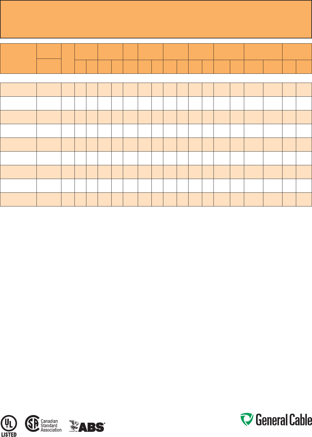
Phone: 888-593-3355
www.generalcable.com
CCW
®
Armored Power, 15 kV 133%, Shielded, 3/C
UL Type MC-HL or MV-105, CSA Type HL, EPR, 105°C, Cable Tray Use, Sunlight-Resistant
Direct Burial, ABS CWCMC
SPEC 9835
October, 2014
CATALOG
NUMBER
COND.
SIZE
NO. OF
COND.
INSULATION
THICKNESS
NOMINAL O.D.
OVER
INSULATION BARE
GROUND NOMINAL
CORE O.D. NOMINAL
ARMOR O.D. JACKET
THICKNESS NOMINAL
OVERALL O.D. APPROXIMATE
NET WEIGHT AMPACITY
AWG (kcmil) mils mm INCHES mm AWG INCHES mm INCHES mm mils mm INCHES mm LBS/1000
FT kg/1000
mIN AIR¹
DIRECT
BURIAL²
3/C WITH GROUND MC-HL OR MV-105, 220 MILS EPR, 15 kV 133% INSULATION LEVEL
9835.00203106 2 (7/W)
(33.6 mm²)
3 220 5.6 0.76 19.3 6 1.82 46.2 2.15 54.6 60 1.52 2.28 57.9 2,473 3,680 185 200
9835.00103104 1 (19/W)
(42.4 mm²)
3 220 5.6 0.79 20.1 4 1.88 47.8 2.23 56.6 60 1.52 2.36 59.9 2,811 4,183 210 225
9835.11003104 1/0 (19/W)
(53.5 mm²)
3 220 5.6 0.83 21.1 4 1.96 49.8 2.32 58.9 75 1.91 2.48 63.0 3,190 4,747 240 255
9835.21003104 2/0 (19/W)
(67.4 mm²)
3 220 5.6 0.87 22.1 4 2.06 52.3 2.40 61.0 75 1.91 2.56 65.0 3,630 5,402 275 290
9835.41003103 4/0 (19/W)
(107 mm²)
3 220 5.6 0.97 24.6 3 2.26 57.4 2.62 66.5 75 1.91 2.79 70.9 4,435 6,600 360 345
9835.25003102 250 (37/W)
(127 mm²)
3 220 5.6 1.03 26.2 2 2.36 59.9 2.75 69.9 75 1.91 2.92 74.2 5,086 7,569 400 410
9835.35003102 350 (37/W)
(177 mm²)
3 220 5.6 1.12 28.4 2 2.61 66.3 3.03 77.0 85 2.16 3.21 81.5 6,445 9,591 490 495
9835.50003101 500 (37/W)
(253 mm²)
3 220 5.6 1.24 31.5 1 2.86 72.6 3.32 84.3 85 2.16 3.50 88.9 8,376 12,465 600 590
9835.750031110 750 (61/W)
(380 mm²)
3 220 5.6 1.41 35.8 1/0 3.25 82.6 3.80 96.5 85 2.16 3.98 101.1 11,431 17,011 745 720
Dimensions and weights are nominal; subject to industry tolerances.
¹ Ampacities in air are per NEC Table 310.60(C)(71) for an insulated three-conductor copper cable isolated in air with 105°C rated conductors at a 40°C ambient temperature.
² Direct burial ampacities are per NEC Table 310.60(C)(83) for three insulated copper conductors cabled within an overall covering, directly buried in earth with 105°C rated conductors
at 20°C ambient earth temperature.

Phone: 888-593-3355
www.generalcable.com
CCW
®
Armored Power, 15 kV 133%, Shielded, 3/C
UL Type MC-HL or MV-105, CSA Type HL, EPR, 105°C, Cable Tray Use
Sunlight-Resistant, Direct Burial, UL Marine Shipboard Cable, ABS CWCMC, Arctic-Grade
SPEC 9840
October, 2014
Product Construction:
Conductor:
• Bare annealed copper per ASTM B3
• Compact stranding per ASTM B496
Extruded Strand Shield (ESS):
• Extruded thermoset semi-conductor
stress control layer over the conductor
per ICEA S-93-639 and UL 1072
Insulation:
• 220 mils Ethylene Propylene Rubber
(EPR) insulation per ICEA S-93-639
and UL 1072
Extruded Insulation Shield (EIS):
• Thermoset semi-conducting polymeric
layer, free stripping from the insulation
per ICEA S-93-639 and UL 1072
Shield:
• 5 mil annealed bare copper tape with
25% overlap
Phase Identification:
• Color-coded polymeric identification
tape laid under the shield – black, red
and blue
Grounding Conductors:
• Class B stranded bare annealed
copper grounding conductor
• Sized in accordance with UL 1072
and NEC Article 250
Cable Assembly:
• Insulated and grounding conductors are
cabled together with non-hydroscopic
fillers when required
• Binder tape is applied over the cabled
core
CCW Armor:
• Impervious, continuously welded and
corrugated aluminum alloy sheath per
UL Standards 1569 and 2225
• CCW armor conductivity meets
the grounding requirements of
NEC Article 250
Jacket:
• Flame-retardant, moisture- and
sunlight-resistant Polyvinyl Chloride
(PVC), black
• Low temperature performance meets
ASTM D746 brittleness temperature at
or below -60°C
Applications:
• CCW armored medium-voltage power
cables offer an economical, rugged and
reliable alternative to labor-intensive
cable in conduit wiring methods
• For use on feeders and branch circuits
for power distribution systems per
NEC Articles 328 and 330
• For use in Class I, II and III, Divisions
1 and 2; and Class I, Zones 1 and 2
hazardous locations per NEC Articles
501, 502, 503 and 505
• Installed on metal racks, troughs, in
raceways, in cable trays or secured to
supports spaced not more than
six feet apart
• Installed in both exposed and concealed
work, wet or dry locations, directly buried
or embedded in concrete
• Recognized for use on fixed or
floating offshore petroleum facilities
as recommended by the American
Petroleum Institute
Features:
• CCW armor provides an impervious
barrier to moisture, gas and liquids
and meets grounding requirements of
UL 1072 and the NEC
• Triple Extrusion: The strand shield,
EPR insulation and insulation shield
are all extruded in one operation
• General Cable’s EPR insulation system
has outstanding corona resistance and
high dielectric strength, and it provides
electrical stability under stress
Features: (cont’d)
• Meets cold bend at -55°C
• 105°C continuous operating
temperature, wet or dry
• 140°C emergency rating
• 250°C short circuit rating
Specifications:
Design Adherence:
• CEA S-93-639/WC74, 5-46 kV
Shielded Power Cables
• AEIC CS8 Specification for Shielded
Power Cable, 5 – 46 kV
• UL 1072 Medium-Voltage Power Cables
• UL 1569 Metal Clad Cables
• UL 2225 Cables and Cable Fittings for
Use in Hazardous Locations
• UL 1309 Marine Shipboard Cable
Flame Tests:
• ICEA T-29-520 (210,000 BTU/hr)
• IEEE 383 (70,000 BTU/hr)
• CSA FT4
• IEEE 1202 (70,000 BTU/hr)
• UL 1581 (70,000 BTU/hr)
• IEC 60332-3 Cat. A
Compliances:
• UL Type MV-105 or UL Type MC-HL,
SUN RES, CT USE, DIR BUR, -40°C,
FT4, UL File # E90501
• UL Listed Marine Shipboard, UL File
# E85994
• CSA Type HL, SR, FT4, -40°C, CSA
File # 27161
• American Bureau of Shipping (ABS)
Listed for CWCMC
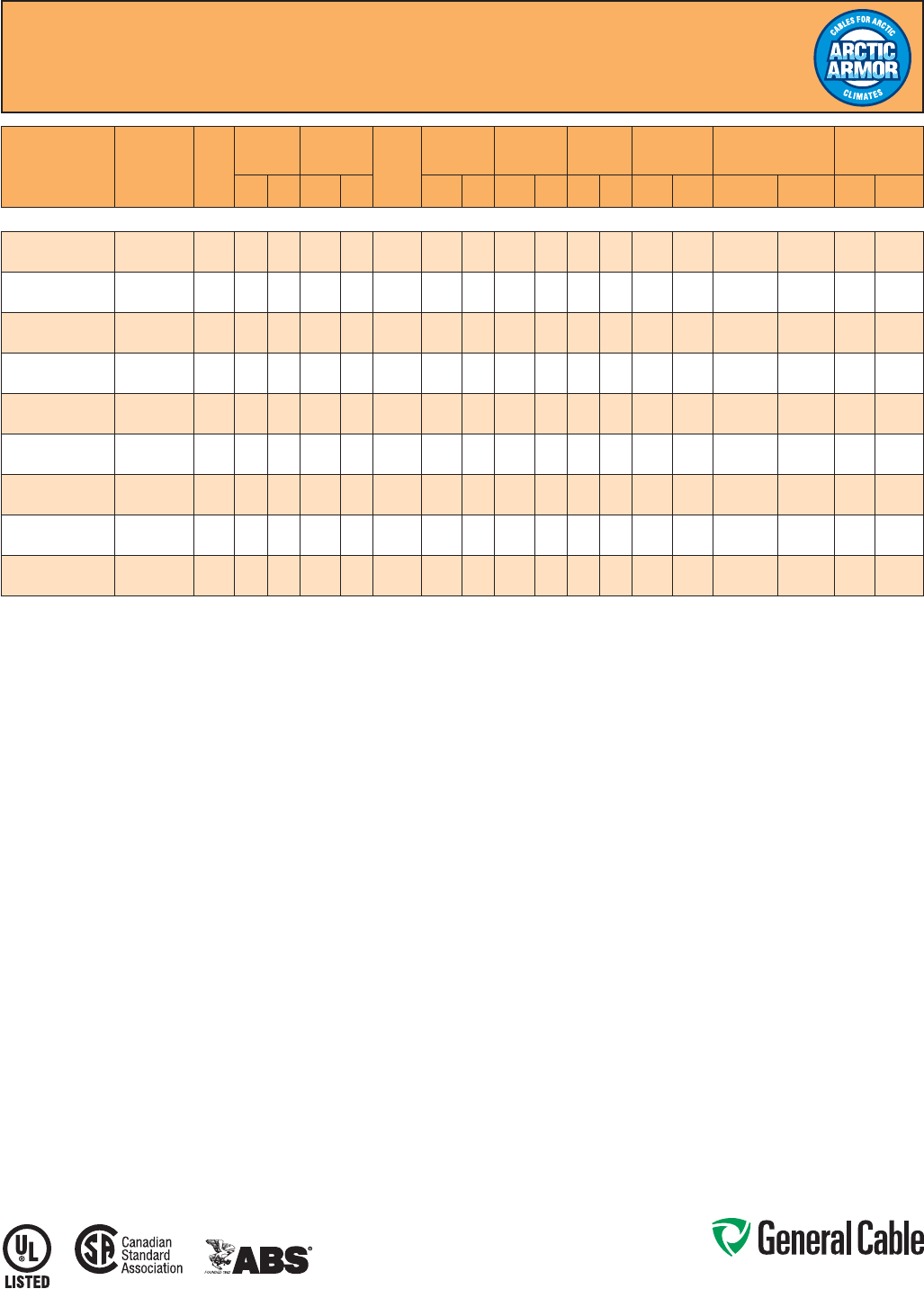
Phone: 888-593-3355
www.generalcable.com
CCW
®
Armored Power, 15 kV 133%, Shielded, 3/C
UL Type MC-HL or MV-105, CSA Type HL, EPR, 105°C, Cable Tray Use
Sunlight-Resistant, Direct Burial, UL Marine Shipboard Cable, ABS CWCMC, Arctic-Grade
SPEC 9840
October, 2014
CATALOG
NUMBER COND. SIZE
(AWG/kcmil)
NO.
OF
COND.
INSULATION
THICKNESS
NOMINAL O.D.
OVER
INSULATION BARE
GROUND
(AWG)
NOMINAL
CORE O.D. NOMINAL
ARMOR O.D. JACKET
THICKNESS NOMINAL
OVERALL O.D. APPROXIMATE
NET WEIGHT AMPACITY
mils mm INCHES mm INCHES mm INCHES mm mils mm INCHES mm LBS/1000 FT kg/1000 m IN AIR¹ DIRECT
BURIAL²
3/C WITH GROUND MC-HL OR MV-105, 220 MILS EPR, 15 kV 133% INSULATION LEVEL
9840.00203106 2 (7/W)
(33.6 mm²) 3 220 5.6 0.76 19.3 6 1.82 46.2 2.15 54.6 60 1.52 2.28 57.9 2,473 3,680 185 200
9840.00103104 1 (19/W)
(42.4 mm²) 3 220 5.6 0.79 20.1 4 1.88 47.8 2.23 56.6 60 1.52 2.36 59.9 2,811 4,183 210 225
9840.11003104 1/0 (19/W)
(53.5 mm²) 3 220 5.6 0.83 21.1 4 1.96 49.8 2.32 58.9 75 1.91 2.48 63.0 3,190 4,747 240 255
9840.21003104 2/0 (19/W)
(67.4 mm²) 3 220 5.6 0.87 22.1 4 2.06 52.3 2.40 61.0 75 1.91 2.56 65.0 3,630 5,402 275 290
9840.41003103 4/0 (19/W)
(107 mm²) 3 220 5.6 0.97 24.6 3 2.26 57.4 2.62 66.5 75 1.91 2.79 70.9 4,435 6,600 360 345
9840.25003102 250 (37/W)
(127 mm²) 3 220 5.6 1.03 26.2 2 2.36 59.9 2.75 69.9 75 1.91 2.92 74.2 5,086 7,569 400 410
9840.35003102 350 (37/W)
(177 mm²) 3 220 5.6 1.12 28.4 2 2.61 66.3 3.03 77.0 85 2.16 3.21 81.5 6,445 9,591 490 495
9840.50003101 500 (37/W)
(253 mm²) 3 220 5.6 1.24 31.5 1 2.86 72.6 3.32 84.3 85 2.16 3.50 88.9 8,376 12,465 600 590
9840.750031110 750 (61/W)
(380 mm²) 3 220 5.6 1.41 35.8 1/0 3.25 82.6 3.80 96.5 85 2.16 3.98 101.1 11,431 17,011 745 720
Dimensions and weights are nominal; subject to industry tolerances.
¹ Ampacities in air are per NEC Table 310.60(C)(71) for an insulated three-conductor copper cable isolated in air with 105°C rated conductors at a 40°C ambient temperature.
² Direct burial ampacities are per NEC Table 310.60(C)(83) for three insulated copper conductors cabled within an overall covering, directly buried in earth with 105°C rated
conductors at 20°C ambient earth temperature.

Phone: 888-593-3355
www.generalcable.com
Jacket:
• Flame-retardant, moisture- and
sunlight-resistant Polyvinyl Chloride
(PVC) per UL 1072, orange
• Low temperature performance meets
ASTM D746 brittleness temperature at
or below -40°C
Applications:
• CCW armored medium-voltage
power cables offer an economical,
rugged and reliable alternative to
labor-intensive cable in conduit wiring
methods
• For use on feeders and branch circuits
in industrial power distribution systems
per NEC Articles 328 and 330
• For use in Class I, II and III, Divisions
1 and 2; and Class I, Zones 1 and 2
hazardous locations per NEC Articles
501, 502, 503 and 505
• Installed on metal racks, troughs, in
raceways, in cable trays or secured
to supports spaced not more than six
feet apart
• Installed in both exposed and
concealed work, wet or dry locations,
directly buried or embedded in
concrete
• Recognized for use on fixed or
floating offshore petroleum facilities
as recommended by the American
Petroleum Institute
Features:
• CCW armor provides an impervious
barrier to moisture, gas and liquids
and meets the grounding requirements
of UL 1072 and the NEC
• Triple Extrusion: The strand shield,
EPR insulation and insulation shield
are all extruded in one operation
Features: (cont’d)
• General Cable’s EPR insulation system
has outstanding corona resistance and
high dielectric strength, and it provides
electrical stability under stress
• Cable meets cold impact at -40°C
• 105˚C continuous operating
temperature, wet or dry
• 140˚C emergency rating
• 250˚C short circuit rating
Specifications:
Design Adherence:
• ICEA S-93-639/WC74, 5-46 kV
Shielded Power Cable
• AEIC CS8 Specification for Shielded
Power Cable, 5-46 kV
• UL 1072 Medium-Voltage Power
Cables
• UL 1569 Metal Clad Cables
• UL 2225 Cables and Cable Fittings for
Use in Hazardous Locations
• UL 1309 Marine Shipboard Cable
• CSA 68.10
Flame Tests:
• ICEA T-29-520 (210,000 BTU/hr)
• IEEE 383 (70,000 BTU/hr)
• CSA FT4
• IEEE 1202 (70,000 BTU/hr)
• UL 1072
• IEC 60332-3 Category A
Compliances:
• UL Type MV-105 or MC-HL, SUN RES,
CT USE, DIR BUR, -40°C, FT4, UL File
# E90501
• UL Listed Marine Shipboard, UL File #
E85994
• CSA Type HL, SR, FT4, -40°C, CSA
File # 27161
• American Bureau of Shipping (ABS)
Listed for CWCMC
Product Construction:
Conductor:
• Bare annealed copper per ASTM B3
• Compact stranding per ASTM B496
Extruded Strand Shield (ESS):
• Extruded thermoset semi-conductor
stress control layer over the conductor
per ICEA S-93-639 and UL 1072
Insulation:
• 260 mils Ethylene Propylene Rubber
(EPR) insulation per ICEA S-93-639
and UL 1072
Extruded Insulation Shield (EIS):
• Thermoset semi-conducting polymeric
layer, free stripping from the insulation
per ICEA S-93-639 and UL 1072
Shield:
• 5 mil annealed bare copper tape with
25% overlap
Phase Identification:
• Color-coded polymeric identification
tape laid under the shield - black, red
and blue
Grounding Conductor:
• Class B stranded bare annealed
copper grounding conductor
• Sized in accordance with UL 1072 and
NEC Article 250
Cable Assembly:
• Insulated and grounding conductors
are cabled together with non-
hygroscopic fillers when required
• Binder tape is applied over the cabled
core
CCW Armor:
• Impervious, continuously welded and
corrugated aluminum alloy sheath per
UL 1072 and UL 1569
• CCW armor conductivity meets the
grounding requirements of the NEC
CCW
®
Armored Power, 25 kV 100%, Shielded, 3/C
UL Type MC-HL or MV-105, CSA Type HL, EPR, 105°C, Cable Tray Use, Sunlight-Resistant
Direct Burial, ABS CWCMC
SPEC 9845
October, 2014
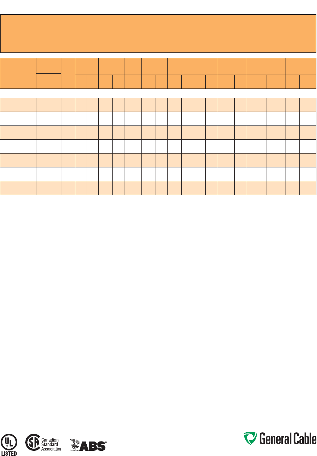
Phone: 888-593-3355
www.generalcable.com
CCW
®
Armored Power, 25 kV 100%, Shielded, 3/C
UL Type MC-HL or MV-105, CSA Type HL, EPR, 105°C, Cable Tray Use, Sunlight-Resistant
Direct Burial, ABS CWCMC
SPEC 9845
October, 2014
CATALOG
NUMBER
COND.
SIZE
NO. OF
COND.
INSULATION
THICKNESS
NOMINAL O.D.
OVER
INSULATION BARE
GROUND NOMINAL
CORE O.D. NOMINAL
ARMOR O.D. JACKET
THICKNESS NOMINAL
OVERALL O.D. APPROXIMATE
NET WEIGHT AMPACITY
AWG (kcmil) mils mm INCHES mm AWG INCHES mm INCHES mm mils mm INCHES mm LBS/1000
FT kg/1000
mIN AIR¹
DIRECT
BURIAL²
3/C WITH GROUND MC-HL OR MV-105, 260 MILS EPR, 25 kV 100% INSULATION LEVEL
9845.00103104
1 (19/W)
(42.4 mm²)
3 260 6.6 0.87 22.1 4 2.07 52.6 2.45 62.2 75 1.91 2.61 66.3 3,189 4,746 210 225
9845.11003104
1/0 (19/W)
(53.5 mm²)
3 260 6.6 0.90 22.9 4 2.15 54.6 2.53 64.3 75 1.91 2.69 68.3 3,536 5,262 240 255
9845.21003104
2/0 (19/W)
(67.4 mm²)
3 260 6.6 0.94 23.9 4 2.24 56.9 2.62 66.5 75 1.91 2.79 70.9 3,939 5,862 275 290
9845.41003103
4/0 (19/W)
(107 mm²)
3 260 6.6 1.04 26.4 3 2.51 63.8 2.93 74.4 75 1.91 3.10 78.7 5,122 7,622 360 345
9845.25003102
250 (37/W)
(127 mm²)
3 260 6.6 1.10 27.9 2 2.61 66.3 3.07 78.0 85 2.16 3.25 82.6 5,819 8,660 400 410
9845.35003102
350 (37/W)
(177 mm²)
3 260 6.6 1.19 30.2 2 2.82 71.6 3.32 84.3 85 2.16 3.50 88.9 7,115 10,588 490 495
9845.50003101
500 (37/W)
(253 mm²)
3 260 6.6 1.31 33.3 1 3.08 78.2 3.62 91.9 85 2.16 3.81 96.8 9,125 13,579 600 590
Dimensions and weights are nominal; subject to industry tolerances.
¹ In-air ampacities are per NEC Table 310.60(C)(71) for three insulated copper conductors rated 105°C, cabled with an overall covering and isolated in air at 40°C ambient temperature.
² Direct burial ampacities are per NEC Table 310.60(C)(83) for three insulated copper conductors rated 105°C, cabled within an overall covering and directly buried in earth at 20°C
ambient earth temperature.

Phone: 888-593-3355
www.generalcable.com
Jacket:
• Flame-retardant, moisture- and
sunlight-resistant Polyvinyl Chloride
(PVC) per UL 1072, orange
• Low temperature performance meets
ASTM D746 brittleness temperature at
or below -40°C
Applications:
• CCW armored medium-voltage
power cables offer an economical,
rugged and reliable alternative to
labor-intensive cable in conduit wiring
methods
• For use on feeders and branch circuits
in industrial power distribution systems
per NEC Articles 328 and 330
• For use in Class I, II and III, Divisions
1 and 2; and Class I, Zones 1 and 2
hazardous locations per NEC Articles
501, 502, 503 and 505
• Installed on metal racks, troughs, in
raceways, in cable trays or secured
to supports spaced not more than six
feet apart
• Installed in both exposed and
concealed work, wet or dry locations,
directly buried or embedded in
concrete
• Recognized for use on fixed or
floating offshore petroleum facilities
as recommended by the American
Petroleum Institute
Features:
• CCW armor provides an impervious
barrier to moisture, gas and liquids
and meets the grounding requirements
of UL 1072 and the NEC
• Triple Extrusion: The strand shield,
EPR insulation and insulation shield
are all extruded in one operation
Features: (cont’d)
• General Cable’s EPR insulation system
has outstanding corona resistance and
high dielectric strength, and it provides
electrical stability under stress
• Cable meets cold impact at -40°C
• 105˚C continuous operating
temperature, wet or dry
• 140˚C emergency rating
• 250˚C short circuit rating
Specifications:
Design Adherence:
• ICEA S-93-639/WC74, 5-46 kV
Shielded Power Cable
• AEIC CS8 Specification for Shielded
Power Cable, 5-46 kV
• UL 1072 Medium-Voltage Power
Cables
• UL 1569 Metal Clad Cables
• UL 2225 Cables and Cable Fittings for
Use in Hazardous Locations
• UL 1309 Marine Shipboard Cable
• CSA 68.10
Flame Tests:
• ICEA T-29-520 (210,000 BTU/hr)
• IEEE 383 (70,000 BTU/hr)
• CSA FT4
• IEEE 1202 (70,000 BTU/hr)
• UL 1072
• IEC 60332-3 Category A
Compliances:
• UL Type MV-105 or MC-HL, SUN RES,
CT USE, DIR BUR, -40°C, FT4, UL File
# E90501
• UL Listed Marine Shipboard, UL File #
E85994
• CSA Type HL, SR, FT4, -40°C, CSA
File # 27161
• American Bureau of Shipping (ABS)
Listed for CWCMC
Product Construction:
Conductor:
• Bare annealed copper per ASTM B3
• Compact stranding per ASTM B496
Extruded Strand Shield (ESS):
• Extruded thermoset semi-conductor
stress control layer over the conductor
per ICEA S-93-639 and UL 1072
Insulation:
• 345 mils Ethylene Propylene Rubber
(EPR) insulation per ICEA S-93-639
and UL 1072
Extruded Insulation Shield (EIS):
• Thermoset semi-conducting polymeric
layer, free stripping from the insulation
per ICEA S-93-639 and UL 1072
Shield:
• 5 mil annealed bare copper tape with
25% overlap
Phase Identification:
• Color-coded polymeric identification
tape laid under the shield - black, red
and blue
Grounding Conductor:
• Class B stranded bare annealed
copper grounding conductor
• Sized in accordance with UL 1072 and
NEC Article 250
Cable Assembly:
• Insulated and grounding conductors
are cabled together with non-
hygroscopic fillers when required
• Binder tape is applied over the cabled
core
CCW Armor:
• Impervious, continuously welded and
corrugated aluminum alloy sheath per
UL 1072 and UL 1569
• CCW armor conductivity meets the
grounding requirements of the NEC
CCW
®
Armored Power, 25 kV 133%/35 kV 100%, Shielded, 3/C
UL Type MC-HL or MV-105, CSA Type HL, EPR, 105°C, Cable Tray Use, Sunlight-Resistant
Direct Burial, ABS CWCMC
SPEC 9855
October, 2014
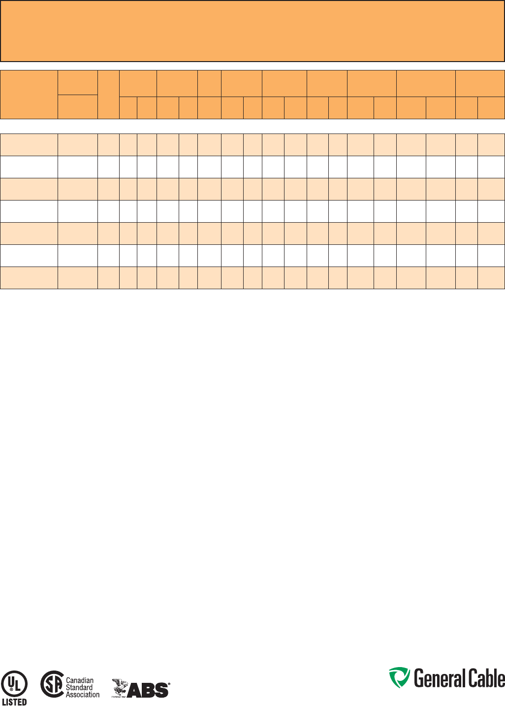
Phone: 888-593-3355
www.generalcable.com
CCW
®
Armored Power, 25 kV 133%/35 kV 100%, Shielded, 3/C
UL Type MC-HL or MV-105, CSA Type HL, EPR, 105°C, Cable Tray Use, Sunlight-Resistant
Direct Burial, ABS CWCMC
SPEC 9855
October, 2014
CATALOG
NUMBER
COND.
SIZE
NO. OF
COND.
INSULATION
THICKNESS
NOMINAL O.D.
OVER
INSULATION BARE
GROUND NOMINAL
CORE O.D. NOMINAL
ARMOR O.D. JACKET
THICKNESS NOMINAL
OVERALL O.D. APPROXIMATE
NET WEIGHT AMPACITY
AWG (kcmil) mils mm INCHES mm AWG INCHES mm INCHES mm mils mm INCHES mm LBS/1000
FT kg/1000
mIN AIR¹
DIRECT
BURIAL²
3/C WITH GROUND MC-HL OR MV-105, 345 MILS EPR, 25 kV 133% AND 35 kV 100% INSULATION LEVEL³
9855.00103104
1 (19/W)
(42.4 mm²)
3 345 8.8 1.04 26.4 4 2.48 63.0 2.89 73.4 75 1.91 3.05 77.5 4,100 6,101 210 225
9855.11003104
1/0 (19/W)
(53.5 mm²)
3 345 8.8 1.07 27.2 4 2.56 65.0 2.98 75.7 75 1.91 3.14 79.8 4,500 6,697 240 255
9855.21003104
2/0 (19/W)
(67.4 mm²)
3 345 8.8 1.11 28.2 4 2.65 67.3 3.11 79.0 85 2.16 3.30 83.8 4,950 7,366 275 290
9855.41003103
4/0 (19/W)
(107 mm²)
3 345 8.8 1.22 31.0 3 2.88 73.2 3.41 86.6 85 2.16 3.60 91.4 6,200 9,227 360 345
9855.25003103
250 (37/W)
(127 mm²)
3 345 8.8 1.27 32.3 3 2.97 75.4 3.63 92.2 85 2.16 3.81 96.8 6,800 10,119 400 410
9855.35003102
350 (37/W)
(177 mm²)
3 345 8.8 1.36 34.5 2 3.20 81.3 3.76 95.5 85 2.16 3.94 100.1 8,000 11,905 490 495
9855.50003101
500 (37/W)
(253 mm²)
3 345 8.8 1.48 37.6 1 3.45 87.6 4.10 104.1 85 2.16 4.23 107.4 10,150 15,105 600 590
Dimensions and weights are nominal; subject to industry tolerances.
¹ In-air ampacities are per NEC Table 310.60(C)(71) for three insulated copper conductors rated 105°C, cabled with an overall covering and isolated in air at 40°C ambient temperature.
² Direct burial ampacities are per NEC Table 310.60(C)(83) for three insulated copper conductors rated 105°C, cabled within an overall covering and directly buried in earth at 20°C
ambient earth temperature.
³ Catalog number 9855.00103104, 1 AWG, 3 conductor is only listed 25 kV 133% insulation level in accordance with UL 1072.

Phone: 888-593-3355
www.generalcable.com
CCW
®
Armored Power, 25 kV 133%/35 kV 100%, Shielded, 3/C
UL Type MC-HL or MV-105, CSA Type HL, EPR, 105°C, Cable Tray Use
Sunlight-Resistant, Direct Burial, UL Marine Shipboard Cable, ABS CWCMC, Arctic-Grade
SPEC 9860
October, 2014
Product Construction:
Conductor:
• Bare annealed copper per ASTM B3
• Compact stranding per ASTM B496
Extruded Strand Shield (ESS):
• Extruded thermoset semi-conductor
stress control layer over the conductor
per ICEA S-93-639 and UL 1072
Insulation:
• 345 mils Ethylene Propylene Rubber
(EPR) insulation per ICEA S-93-639
and UL 1072
Extruded Insulation Shield (EIS):
• Thermoset semi-conducting polymeric
layer, free stripping from the insulation
per ICEA S-93-639 and UL 1072
Shield:
• 5 mil annealed bare copper tape with
25% overlap
Phase Identification:
• Color-coded polymeric identification
tape laid under the shield – black, red
and blue
Grounding Conductors:
• Class B stranded bare annealed
copper grounding conductor
• Sized in accordance with UL 1072 and
NEC Article 250
Cable Assembly:
• Insulated and grounding conductors are
cabled together with non-hydroscopic
fillers when required
• Binder tape is applied over the cabled
core
CCW Armor:
• Impervious, continuously welded and
corrugated aluminum alloy sheath per
UL Standards 1569 and 2225
• CCW armor conductivity meets
the grounding requirements of
NEC Article 250
Jacket:
• Flame-retardant, moisture- and
sunlight-resistant Polyvinyl Chloride
(PVC), black
• Low temperature performance meets
ASTM D746 brittleness temperature at
or below -60°C
Applications:
• CCW armored medium-voltage power
cables offer an economical, rugged and
reliable alternative to labor-intensive
cable in conduit wiring methods
• For use on feeders and branch circuits
for power distribution systems per
NEC Articles 328 and 330
• For use in Class I, II and III, Divisions
1 and 2; and Class I, Zones 1 and 2
hazardous locations per NEC Articles
501, 502, 503 and 505
• Installed on metal racks, troughs, in
raceways, in cable trays or secured to
supports spaced not more than
six feet apart
• Installed in both exposed and concealed
work, wet or dry locations, directly buried
or embedded in concrete
• Recognized for use on fixed or
floating offshore petroleum facilities
as recommended by the American
Petroleum Institute
Features:
• CCW armor provides an impervious
barrier to moisture, gas and liquids
and meets grounding requirements of
UL 1072 and the NEC
• Triple Extrusion: The strand shield,
EPR insulation and insulation shield
are all extruded in one operation
• General Cable’s EPR insulation system
has outstanding corona resistance and
high dielectric strength, and it provides
electrical stability under stress
Features: (cont’d)
• Meets cold bend at -55°C
• 105°C continuous operating
temperature, wet or dry
• 140°C emergency rating
• 250°C short circuit rating
Specifications:
Design Adherence:
• ICEA S-93-639/WC74, 5-46 kV
Shielded Power Cables
• AEIC CS8 Specification for Shielded
Power Cable, 5 – 46 kV
• UL 1072 Medium-Voltage Power Cables
• UL 1569 Metal Clad Cables
• UL 2225 Cables and Cable Fittings for
Use in Hazardous Locations
• UL 1309 Marine Shipboard Cable
Flame Tests:
• ICEA T-29-520 (210,000 BTU/hr)
• IEEE 383 (70,000 BTU/hr)
• CSA FT4
• IEEE 1202 (70,000 BTU/hr)
• UL 1581 (70,000 BTU/hr)
• IEC 60332-3 Cat. A
Compliances:
• UL Type MV-105 or UL Type MC-HL,
SUN RES, CT USE, DIR BUR, -40°C,
FT4, UL File # E90501
• UL Listed Marine Shipboard, UL File
# E85994
• CSA Type HL, SR, FT4, -40°C, CSA
File # 27161
• American Bureau of Shipping (ABS)
Listed for CWCMC

Phone: 888-593-3355
www.generalcable.com
CCW
®
Armored Power, 25 kV 133%/35 kV 100%, Shielded, 3/C
UL Type MC-HL or MV-105, CSA Type HL, EPR, 105°C, Cable Tray Use
Sunlight-Resistant, Direct Burial, UL Marine Shipboard Cable, ABS CWCMC, Arctic-Grade
SPEC 9860
October, 2014
CATALOG
NUMBER COND. SIZE
(AWG/kcmil) NO. OF
COND.
INSULATION
THICKNESS
NOMINAL O.D.
OVER
INSULATION BARE
GROUND
(AWG)
NOMINAL
CORE O.D. NOMINAL
ARMOR O.D. JACKET
THICKNESS NOMINAL
OVERALL O.D. APPROXIMATE
NET WEIGHT AMPACITY
mils mm INCHES mm INCHES mm INCHES mm mils mm INCHES mm LBS/1000
FT kg/1000
mIN AIR¹
DIRECT
BURIAL²
3/C WITH GROUND MC-HL OR MV-105, 345 MILS EPR, 25 kV 133% AND 35 kV 100% INSULATION LEVEL3
9860.00103104
1 (19/W)
(42.4 mm²) 3 345 8.8 1.04 26.4 4 2.48 63.0 2.89 73.4 75 1.91 3.05 77.5 4,100 6,101 210 225
9860.11003104
1/0 (19/W)
(53.5 mm²) 3 345 8.8 1.07 27.2 4 2.56 65.0 2.98 75.7 75 1.91 3.14 79.8 4,500 6,697 240 255
9860.21003104
2/0 (19/W)
(67.4 mm²) 3 345 8.8 1.11 28.2 4 2.65 67.3 3.11 79.0 85 2.16 3.30 83.8 4,950 7,366 275 290
9860.41003103
4/0 (19/W)
(107 mm²) 3 345 8.8 1.22 31.0 3 2.88 73.2 3.41 86.6 85 2.16 3.60 91.4 6,200 9,227 360 345
9860.25003102
250 (37/W)
(127 mm²) 3 345 8.8 1.27 32.3 3 2.97 75.4 3.63 92.2 85 2.16 3.81 96.8 6,800 10,119 400 410
9860.35003102
350 (37/W)
(177 mm²) 3 345 8.8 1.36 34.5 2 3.20 81.3 3.76 95.5 85 2.16 3.94 100.1 8,000 11,905 490 495
9860.50003101
500 (37/W)
(253 mm²) 3 345 8.8 1.48 37.6 1 3.45 87.6 4.10 104.1 85 2.16 4.23 107.4 10,150 15,105 600 590
Dimensions and weights are nominal; subject to industry tolerances.
¹ In-air ampacities are per NEC Table 310.60(C)(71) for three insulated copper conductors rated 105°C, cabled with an overall covering and isolated in air at 40°C ambient temperature.
² Direct burial ampacities are per NEC Table 310.60(C)(83) for three insulated copper conductors rated 105°C, cabled within an overall covering and directly buried in earth at 20°C ambient
earth temperature.
³ Catalog number 9855.00103104, 1 AWG, 3 conductor is only listed 25 kV 133% insulation level in accordance with UL 1072.

Phone: 888-593-3355
www.generalcable.com
Jacket:
• Flame-retardant, moisture- and
sunlight-resistant Polyvinyl Chloride
(PVC) per UL 1072, orange
• Low temperature performance meets
ASTM D746 brittleness temperature at
or below -40°C
Applications:
• CCW armored medium-voltage
power cables offer an economical,
rugged and reliable alternative to
labor-intensive cable in conduit wiring
methods
• For use on feeders and branch circuits
in industrial power distribution systems
per NEC Articles 328 and 330
• For use in Class I, II and III, Divisions
1 and 2; and Class I, Zones 1 and 2
hazardous locations per NEC Articles
501, 502, 503 and 505
• Installed on metal racks, troughs, in
raceways, in cable trays or secured
to supports spaced not more than six
feet apart
• Installed in both exposed and
concealed work, wet or dry locations,
directly buried or embedded in
concrete
• Recognized for use on fixed or
floating offshore petroleum facilities
as recommended by the American
Petroleum Institute
Features:
• CCW armor provides an impervious
barrier to moisture, gas and liquids
and meets the grounding requirements
of UL 1072 and the NEC
• Triple Extrusion: The strand shield,
EPR insulation and insulation shield
are all extruded in one operation
Features: (cont’d)
• General Cable’s EPR insulation system
has outstanding corona resistance and
high dielectric strength, and it provides
electrical stability under stress
• Cable meets cold impact at -40°C
• 105˚C continuous operating
temperature, wet or dry
• 140˚C emergency rating
• 250˚C short circuit rating
Specifications:
Design Adherence:
• ICEA S-93-639/WC74, 5-46 kV
Shielded Power Cable
• AEIC CS8 Specification for Shielded
Power Cable, 5-46 kV
• UL 1072 Medium-Voltage Power
Cables
• UL 1569 Metal Clad Cables
• UL 2225 Cables and Cable Fittings for
Use in Hazardous Locations
• UL 1309 Marine Shipboard Cable
• CSA 68.10
Flame Tests:
• ICEA T-29-520 (210,000 BTU/hr)
• IEEE 383 (70,000 BTU/hr)
• CSA FT4
• IEEE 1202 (70,000 BTU/hr)
• UL 1072
• IEC 60332-3 Category A
Compliances:
• UL Type MV-105 or MC-HL, SUN RES,
CT USE, DIR BUR, -40°C, FT4, UL File
# E90501
• UL Listed Marine Shipboard, UL File #
E85994
• CSA Type HL, SR, FT4, -40°C, CSA
File # 27161
• American Bureau of Shipping (ABS)
Listed for CWCMC
Product Construction:
Conductor:
• Bare annealed copper per ASTM B3
• Compact stranding per ASTM B496
Extruded Strand Shield (ESS):
• Extruded thermoset semi-conductor
stress control layer over the conductor
per ICEA S-93-639 and UL 1072
Insulation:
• 420 mils Ethylene Propylene Rubber
(EPR) insulation per ICEA S-93-639
and UL 1072
Extruded Insulation Shield (EIS):
• Thermoset semi-conducting polymeric
layer, free stripping from the insulation
per ICEA S-93-639 and UL 1072
Shield:
• 5 mil annealed bare copper tape with
25% overlap
Phase Identification:
• Color-coded polymeric identification
tape laid under the shield - black, red
and blue
Grounding Conductor:
• Class B stranded bare annealed
copper grounding conductor
• Sized in accordance with UL 1072 and
NEC Article 250
Cable Assembly:
• Insulated and grounding conductors
are cabled together with non-
hygroscopic fillers when required
• Binder tape is applied over the cabled
core
CCW Armor:
• Impervious, continuously welded and
corrugated aluminum alloy sheath per
UL 1072 and UL 1569
• CCW armor conductivity meets the
grounding requirements of the NEC
CCW
®
Armored Power, 35 kV 133%, Shielded, 3/C
UL Type MC-HL or MV-105, CSA Type HL, EPR, 105°C, Cable Tray Use, Sunlight-Resistant
Direct Burial, ABS CWCMC
SPEC 9875
October, 2014
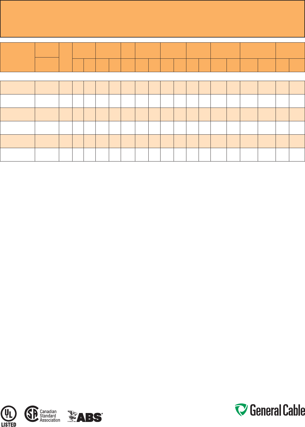
Phone: 888-593-3355
www.generalcable.com
CCW
®
Armored Power, 35 kV 133%, Shielded, 3/C
UL Type MC-HL or MV-105, CSA Type HL, EPR, 105°C, Cable Tray Use, Sunlight-Resistant
Direct Burial, ABS CWCMC
SPEC 9875
October, 2014
CATALOG
NUMBER
COND.
SIZE
NO. OF
COND.
INSULATION
THICKNESS
NOMINAL O.D.
OVER
INSULATION BARE
GROUND NOMINAL
CORE O.D. NOMINAL
ARMOR O.D. JACKET
THICKNESS NOMINAL
OVERALL O.D. APPROXIMATE
NET WEIGHT AMPACITY
AWG (kcmil) mils mm INCHES mm AWG INCHES mm INCHES mm mils mm INCHES mm LBS/1000
FT kg/1000
mIN AIR¹
DIRECT
BURIAL²
3/C WITH GROUND MC-HL OR MV-105, 420 MILS EPR, 35 kV 133% INSULATION LEVEL
9875.11003104
1/0 (19/W)
(53.5 mm²)
3 420 10.7 1.24 31.5 4 2.91 73.9 3.41 86.6 85 2.16 3.59 91.2 5,300 7,887 240 255
9875.21003104
2/0 (19/W)
(67.4 mm²)
3 420 10.7 1.27 32.3 4 3.02 76.7 3.63 92.2 85 2.16 3.81 96.8 6,000 8,929 275 290
9875.41003103
4/0 (19/W)
(107 mm²)
3 420 10.7 1.38 35.1 3 3.23 82.0 3.80 96.5 85 2.16 3.98 101.1 7,100 10,566 360 345
9875.25003103
250 (37/W)
(127 mm²)
3 420 10.7 1.43 36.3 3 3.40 86.4 3.98 101.1 85 2.16 4.16 105.7 8,100 12,054 400 410
9875.35003102
350 (37/W)
(177 mm²)
3 420 10.7 1.52 38.6 2 3.51 89.2 4.10 104.1 85 2.16 4.29 109.0 9,000 13,393 490 495
9875.50003101
500 (37/W)
(253 mm²)
3 420 10.7 1.64 41.7 1 3.81 96.8 4.45 113.0 85 2.16 4.63 117.6 11,100 16,519 600 590
Dimensions and weights are nominal; subject to industry tolerances.
¹ In-air ampacities are per NEC Table 310.60(C)(71) for three insulated copper conductors rated 105°C, cabled with an overall covering and isolated in air at 40°C ambient temperature.
² Direct burial ampacities are per NEC Table 310.60(C)(83) for three insulated copper conductors rated 105°C, cabled within an overall covering and directly buried in earth at 20°C
ambient earth temperature.
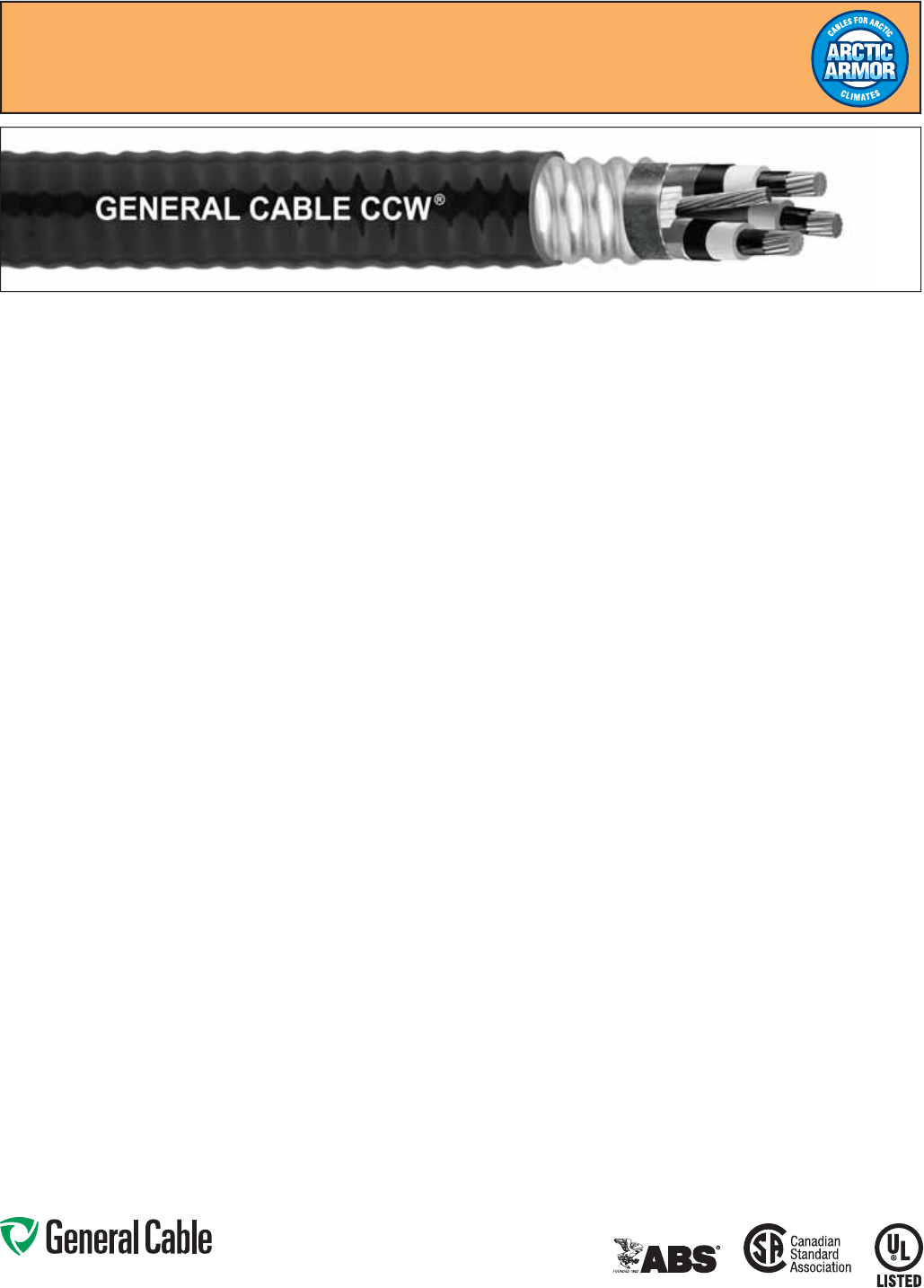
Phone: 888-593-3355
www.generalcable.com
CCW
®
Armored Power, 35 kV 133%, Shielded, 3/C
UL Type MC-HL or MV-105, CSA Type HL, EPR, 105°C, Cable Tray Use
Sunlight-Resistant, Direct Burial, UL Marine Shipboard Cable, ABS CWCMC, Arctic-Grade
SPEC 9880
October, 2014
Product Construction:
Conductor:
• Bare annealed copper per ASTM B3
• Compact stranding per ASTM B496
Extruded Strand Shield (ESS):
• Extruded thermoset semi-conductor
stress control layer over the conductor
per ICEA S-93-639 and UL 1072
Insulation:
• 420 mils Ethylene Propylene Rubber
(EPR) insulation per ICEA S-93-639
and UL 1072
Extruded Insulation Shield (EIS):
• Thermoset semi-conducting polymeric
layer, free stripping from the insulation
per ICEA S-93-639 and UL 1072
Shield:
• 5 mil annealed bare copper tape with
25% overlap
Phase Identification:
• Color-coded polymeric identification
tape laid under the shield – black, red
and blue
Grounding Conductors:
• Class B stranded bare annealed
copper grounding conductor
• Sized in accordance with UL 1072 and
NEC Article 250
Cable Assembly:
• Insulated and grounding conductors are
cabled together with non-hydroscopic
fillers when required
• Binder tape is applied over the cabled
core
CCW Armor:
• Impervious, continuously welded and
corrugated aluminum alloy sheath per
UL Standards 1569 and 2225
• CCW armor conductivity meets
the grounding requirements of
NEC Article 250
Jacket:
• Flame-retardant, moisture- and
sunlight-resistant Polyvinyl Chloride
(PVC), black
• Low temperature performance meets
ASTM D746 brittleness temperature at
or below -60°C
Applications:
• CCW armored medium-voltage power
cables offer an economical, rugged and
reliable alternative to labor-intensive
cable in conduit wiring methods
• For use on feeders and branch circuits
for power distribution systems per
NEC Articles 328 and 330
• For use in Class I, II and III, Divisions
1 and 2; and Class I, Zones 1 and 2
hazardous locations per NEC Articles
501, 502, 503 and 505
• Installed on metal racks, troughs, in
raceways, in cable trays or secured
to supports spaced not more than six
feet apart
• Installed in both exposed and concealed
work, wet or dry locations, directly buried
or embedded in concrete
• Recognized for use on fixed or
floating offshore petroleum facilities
as recommended by the American
Petroleum Institute
Features:
• CCW armor provides an impervious
barrier to moisture, gas and liquids
and meets grounding requirements of
UL 1072 and the NEC
• Triple Extrusion: The strand shield,
EPR insulation and insulation shield
are all extruded in one operation
• General Cable’s EPR insulation system
has outstanding corona resistance and
high dielectric strength, and it provides
electrical stability under stress
Features: (cont’d)
• Meets cold bend at -55°C
• 105°C continuous operating
temperature, wet or dry
• 140°C emergency rating
• 250°C short circuit rating
Specifications:
Design Adherence:
• ICEA S-93-639/WC74, 5-46 kV
Shielded Power Cables
• AEIC CS8 Specification for Shielded
Power Cable, 5 – 46 kV
• UL 1072 Medium-Voltage Power Cables
• UL 1569 Metal Clad Cables
• UL 2225 Cables and Cable Fittings for
Use in Hazardous Locations
• UL 1309 Marine Shipboard Cable
Flame Tests:
• ICEA T-29-520 (210,000 BTU/hr)
• IEEE 383 (70,000 BTU/hr)
• CSA FT4
• IEEE 1202 (70,000 BTU/hr)
• UL 1581 (70,000 BTU/hr)
• IEC 60332-3 Cat. A
Compliances:
• UL Type MV-105 or UL Type MC-HL,
SUN RES, CT USE, DIR BUR, -40°C,
FT4, UL File # E90501
• UL Listed Marine Shipboard, UL File
# E85994
• CSA Type HL, SR, FT4, -40°C, CSA
File # 27161
• American Bureau of Shipping (ABS)
Listed for CWCMC
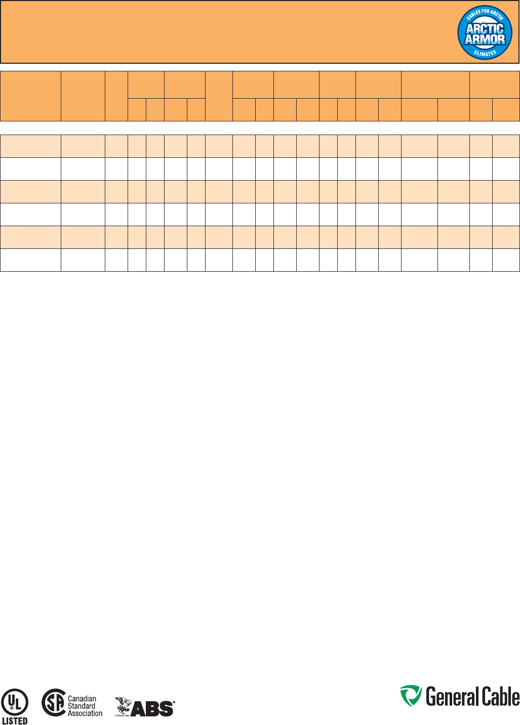
Phone: 888-593-3355
www.generalcable.com
CCW
®
Armored Power, 35 kV 133%, Shielded, 3/C
UL Type MC-HL or MV-105, CSA Type HL, EPR, 105°C, Cable Tray Use
Sunlight-Resistant, Direct Burial, UL Marine Shipboard Cable, ABS CWCMC, Arctic-Grade
SPEC 9880
October, 2014
CATALOG
NUMBER COND. SIZE
(AWG/kcmil)
NO.
OF
COND.
INSULATION
THICKNESS
NOMINAL O.D.
OVER
INSULATION BARE
GROUND
(AWG)
NOMINAL
CORE O.D. NOMINAL
ARMOR O.D. JACKET
THICKNESS NOMINAL
OVERALL O.D. APPROXIMATE
NET WEIGHT AMPACITY
mils mm INCHES mm INCHES mm INCHES mm mils mm INCHES mm LBS/1000 FT kg/1000 m IN AIR¹ DIRECT
BURIAL²
3/C WITH GROUND MC-HL OR MV-105, 420 MILS EPR, 35 kV 133% INSULATION LEVEL
9880.11003104 1/0 (19/W)
(53.5 mm²) 3 420 10.7 1.24 31.5 4 2.91 73.9 3.41 86.6 85 2.16 3.59 91.2 5,300 7,887 240 255
9880.21003104 2/0 (19/W)
(67.4 mm²) 3 420 10.7 1.27 32.3 4 3.02 76.7 3.63 92.2 85 2.16 3.81 96.8 6,000 8,929 275 290
9880.41003103 4/0 (19/W)
(107 mm²) 3 420 10.7 1.38 35.1 3 3.23 82.0 3.80 96.5 85 2.16 3.98 101.1 7,100 10,566 360 345
9880.25003102 250 (37/W)
(127 mm²) 3 420 10.7 1.43 36.3 3 3.40 86.4 3.98 101.1 85 2.16 4.16 105.7 8,100 12,054 400 410
9880.35003102 350 (37/W)
(177 mm²) 3 420 10.7 1.52 38.6 2 3.51 89.2 4.10 104.1 85 2.16 4.29 109.0 9,000 13,393 490 495
9880.50003101 500 (37/W)
(253 mm²) 3 420 10.7 1.64 41.7 1 3.81 96.8 4.45 113.0 85 2.16 4.63 117.6 11,100 16,519 600 590
Dimensions and weights are nominal; subject to industry tolerances.
¹ In-air ampacities are per NEC Table 310.60(C)(71) for three insulated copper conductors rated 105°C, cabled with an overall covering and isolated in air at 40°C ambient temperature.
² Direct burial ampacities are per NEC Table 310.60(C)(83) for three insulated copper conductors rated 105°C, cabled within an overall covering and directly buried in earth at 20°C ambient earth temperature.
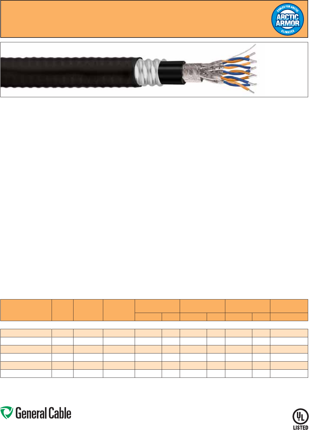
Phone: 888-593-3355
www.generalcable.com
SPEC 9899
October, 2014
CCW
®
Arctic Armor Fieldbus Cable
Multi-Paired, Individual and Overall Shielded, 18 AWG & 16 AWG
UL Type MC-HL, 600 V, 90°C, Sunlight-Resistant, Direct Burial, Arctic-Grade
CCW Armor:
• Impervious, continuously welded and
corrugated aluminum alloy sheath per
UL 1569 and UL 2225
• CCW armor conductivity meets
the grounding requirements of
NEC Article 250
Outer Jacket:
• Flame-retardant, moisture- and
sunlight-resistant arctic-grade
Polyvinyl Chloride (PVC), black
Applications:
• Recognized for use in Class I, II, and
III, Divisions 1 and 2; or Class I, Zones
1 and 2 hazardous locations per NEC
Articles 501, 502, 503 and 505
• Installed indoors or outdoors, in wet or
dry locations, in a raceway, as aerial
cable on a messenger, in cable trays,
or for direct burial
Features:
• 100 Ohm impedance (± 10 ohms)
• CCW armor provides an impervious
barrier to moisture, gas and liquids
• Meets cold bend at -55°C
• Insulation passes ASTM D746-04
brittleness temperature impact test
at -73°C
Features: (cont’d)
• Insulation passes MIL-C-13777 cold
bend test @ -65°C
• Arctic-grade PVC inner sheath and outer
jacket passes ASTM D746-04 brittleness
temperature impact test at -60°C
Specifications:
Fieldbus Standards:
• Registered with Fieldbus Foundation
• Meets Fieldbus Foundation FF-844
Specification, marked as Type A H1
Fieldbus cable
• Meets ISA 50.02 Part 2 Fieldbus
standard for use in industrial control
systems
• Meets IEC 61158-2 requirements for
industrial Fieldbus cable
Compliances:
• UL Listed, NEC Type MC-HL, 600 V,
SUN RES, DIR BUR, -40°C
Flame Tests:
• CSA FT4
• IEEE 1202
Product Construction:
Conductor:
• 18 and 16 AWG fully annealed
stranded tinned copper per ASTM B33
• Class B stranding per ASTM B8
Insulation:
• Cross-linked Polyethylene (XLPE)
Pairs:
• Two conductors twisted together with
left-hand lay (LHL)
• Each pair has 1 blue and 1 orange
conductor. One conductor in each pair
is printed alphanumerically for easy
identification
Individually Shielded Pairs:
• Aluminum/Polyester tape with 25%
overlap, 100% coverage (aluminum
side out)
Drain:
• Stranded tinned copper drain wire
Overall Shield:
• Aluminum/Polyester tape with
25% overlap, 100% coverage
(aluminum side in)
Inner Sheath:
• Arctic-grade Polyvinyl Chloride (PVC),
black
CATALOG
NUMBER NO. OF
PAIRS COND. SIZE
(AWG) SHIELDS
NOMINAL
CORE O.D. NOMINAL
ARMOR O.D. NOMINAL
OVERALL O.D. APPROXIMATE
NET WEIGHT
INCHES mm INCHES mm INCHES mm LBS/1000 FT
18 AWG AND 16 AWG INDIVIDUAL AND OVERALL SHIELDED PAIRS
9899.FB01801120 118 SP
0.27 6.73 0.53 13.46 0.64 16.13 178
9899.FB01802120 218SP/OS
0.48 12.07 0.79 20.07 0.90 22.73 305
9899.FB01804120 418SP/OS
0.57 14.48 0.89 22.48 0.99 25.02 349
9899.FB01601118 116 SP
0.29 7.37 0.56 14.10 0.66 16.76 191
9899.FB01602118 216SP/OS
0.52 13.21 0.84 21.21 0.94 23.88 338
9899.FB01604118 416SP/OS
0.62 15.75 0.97 24.64 1.08 27.31 440
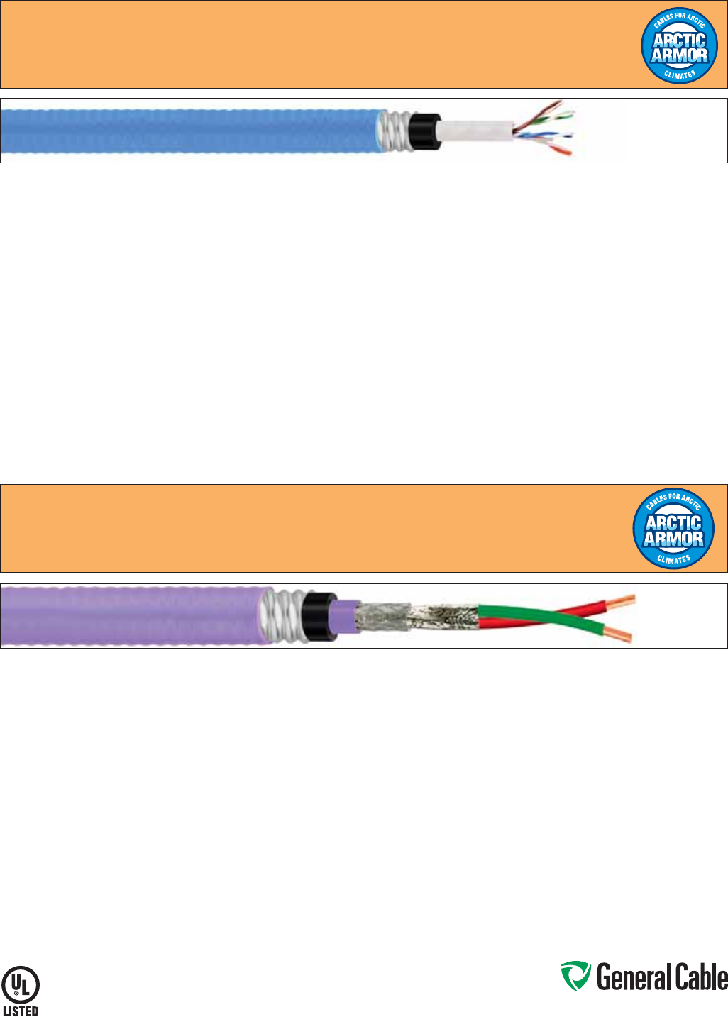
Phone: 888-593-3355
www.generalcable.com
SPEC 9899
October, 2014
CCW
®
Arctic Armor Category 5e Cable
4 Pair, 21 AWG, UL Type ITC-HL, 300 V, 90°C, Cable Tray Use
Sunlight-Resistant, Direct Burial, Arctic-Grade
CCW Armor:
• Impervious, continuously welded and
corrugated aluminum alloy sheath per
UL 1569 and UL 2225
• CCW armor conductivity meets the
grounding requirements of NEC Article 250
Outer Jacket:
• Flame-retardant, moisture- and sunlight-
resistant arctic-grade Polyvinyl Chloride
(PVC), purple. O.D.: 0.940”
Applications:
• High speed PROFIBUS DP communication
for use in factory automation systems
• Recognized for use in Class I and III,
Divisions 1 and 2; Class II, Division 2; or
Class I, Zones 1 and 2 hazardous locations
per NEC Articles 501, 502, 503 and 505
Features:
• 150 Ohm impedance (± 15 ohms)
• CCW armor provides an impervious barrier
to moisture, gas and liquids
• Meets cold bend at -55°C
CCW Armor:
• Impervious, continuously welded and
corrugated aluminum alloy sheath per
UL 1569 and UL 2225
• CCW armor conductivity meets the grounding
requirements of NEC Article 250
Outer Jacket:
• Flame-retardant, moisture- and sunlight-
resistant arctic-grade Polyvinyl Chloride
(PVC), light blue. O.D.: .930”
Applications:
• For high speed data transmission. Tested to
100 MHz
• CID1 applications
• Recognized for use in Class I and III,
Divisions 1 and 2; Class II, Division 2; or
Class I, Zones 1 and 2 hazardous locations
per NEC Articles 501, 502, 503 and 505
• Installed indoors or outdoors, in wet or dry
locations, in a raceway, as aerial cable on a
messenger, in cable trays, or for direct burial
Features: (cont’d)
• Insulation passes ASTM D746-04 brittleness
temperature impact test at -73°C
• Arctic-grade PVC inner sheath and outer
jacket passes ASTM D746-04 brittleness
temperature impact test at -60°C
Specifications:
PROFIBUS Specifications:
• Electrical characteristics in accordance with
PROFIBUS DP specifications
Compliances:
• UL Listed, NEC Type ITC-HL, 300 V, CT USE,
SUN RES, DIR BUR, -40°C
Flame Tests:
• CSA FT4
• IEEE 1202
Catalog Number
• 9899.PB02201000
Features:
• CCW armor provides an impervious barrier
to moisture, gas and liquids
• Meets cold bend at -55°C
• Insulation and inner jacket passes ASTM
D746-04 brittleness temperature impact
test at -73°C
• Arctic-grade PVC inner sheath and outer
jacket passes ASTM D746-04 brittleness
temperature impact test at -60°C
Specifications:
Compliances
• TIA/EIA-568-B.2 Category 5e
• UL Listed, NEC Type ITC-HL, 300 V, CT
USE, SUN RES, DIR BUR, -40°C
Flame Tests
• CSA FT4
• IEEE 1202
Catalog Number
• 9899.CT02104000
Product Construction:
Conductor:
• 22 AWG solid bare copper per ASTM B3:
O.D.: 0.025”
Insulation:
• Fluoropolymer: O.D.: 0.106”
Pair:
• Two conductors twisted together with left-
hand lay (LHL)
• Color Code: C1: Red C2: Green
Inner Shield:
• Aluminum/Polyester tape with 25% overlap,
100% coverage (aluminum side out)
Overall Shield:
• 34 AWG tinned copper braid, 65% min.
coverage
Inner Jacket:
• Fluoropolymer, purple. O.D.: 0.270”
Inner Sheath:
• Arctic-grade Polyvinyl Chloride (PVC),
black. O.D.: 0.610”
Product Construction:
Conductor:
• 4 pair, 21 AWG solid bare annealed copper
per ASTM B3: O.D.: .029”
Insulation:
• Fluoropolymer: O.D.: .047”
Pairs:
• Two conductors twisted together with
left-hand lay (LHL)
• Color Code:
P1: White/Blue, Blue
P3: White/Green, Green
P2: White/Orange, Orange
P4: White/Brown, Brown
Inner Jacket:
• Fluoropolymer: O.D.: .215”
Inner Sheath:
• Arctic-grade Polyvinyl Chloride (PVC),
black. O.D.: .590”
CCW
®
Arctic Armor PROFIBUS Cable
22 AWG Shielded Pair, UL Type ITC-HL, 300 V, 90°C, Cable Tray Use
Sunlight-Resistant, Direct Burial, Arctic-Grade
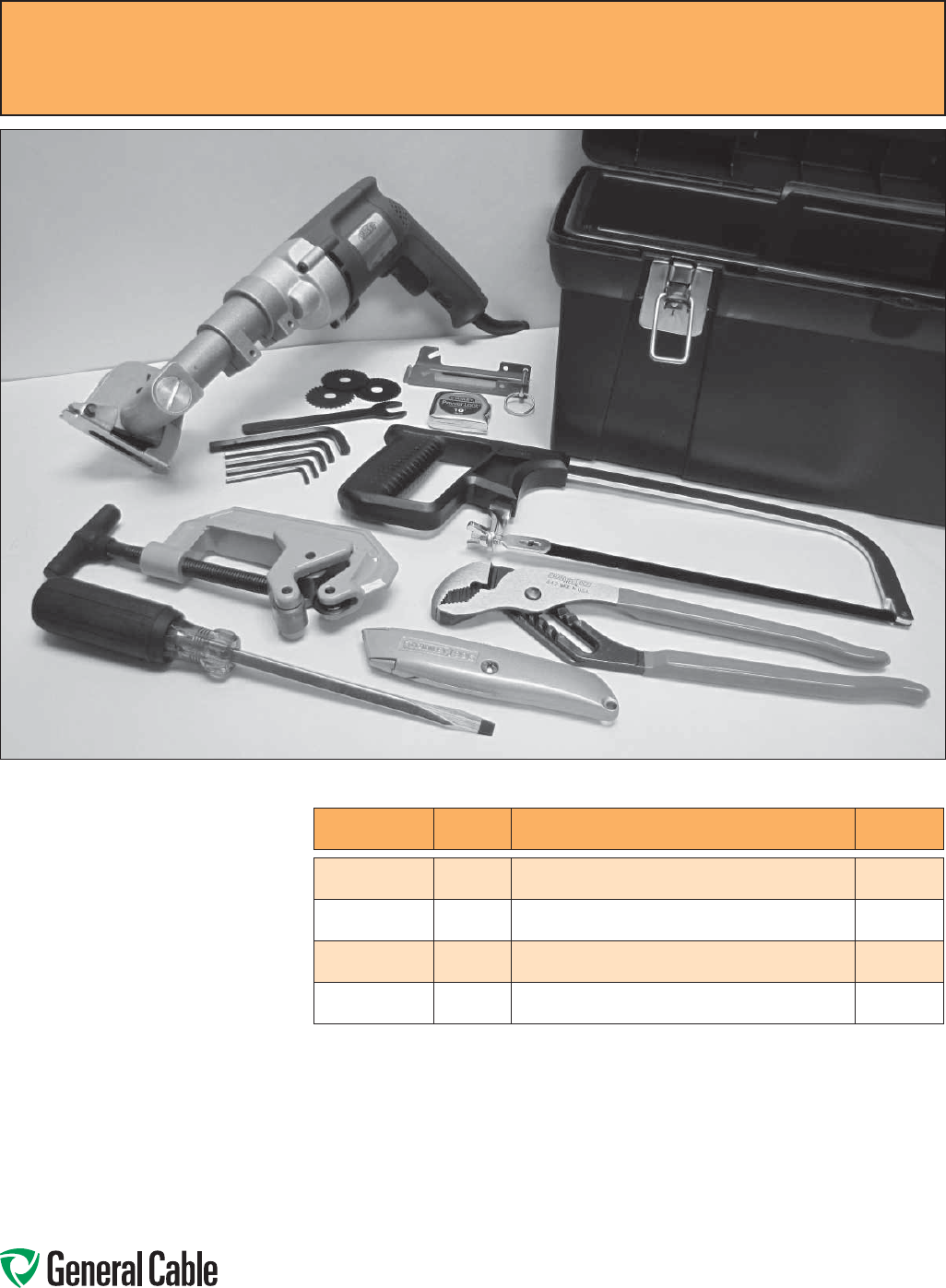
Phone: 888-593-3355
www.generalcable.com
CCW
®
Armored Cable Tool Kit
For Removal of CCW Armor Sheath
Including Accessories
SPEC 9900
January, 2010
Tool Kit Contents:
• 1 ea. Kett-Tool Metal Clad Cable Saw
• 12 pcs. 2" / 44 teeth Cutting Blades
• Cable Saw Spindle and Allen Wrenches
• 1 ea. MC Cable Guide
• 1 ea. Tubing and Pipe Cutter
• 1 ea. 12" V-Jaw Channel-Lock Pliers
• 1 ea. 10" Hacksaw Frame
• 3 ea. 10" / 24 teeth/in. Hacksaw Blades
• 1 ea. 10 ft. Tape Measure
• 1 ea. Utility Knife with Blades
• 1 ea. 5/16" Screwdriver
• 1 ea. Tool Box
CATALOG NUMBER QUANTITY DESCRIPTION APPROXIMATE
WEIGHT
9900.KS226
1CCW TOOL KIT WITH 120 V AC,
60Hz ELECTRIC CUTTING SAW 22.0 LBS
9900.PS526
1CCW TOOL KIT WITH 90PSI
PNEUMATIC CUTTING SAW 20.0 LBS
9900.15744
12", 44T REPLACEMENT CUTTING BLADES
(12 BLADES PER PACK) 1.0 LBS
9900.27901
1 MC CABLE GUIDE 0.5 LBS

Phone: 888-593-3355
www.generalcable.com
Table of Contents
Technical Information
Technical
October, 2014
SPECIFICATION NO. DESCRIPTION REVISION DATE
Technical Table of Contents Oct. 2014
A001 Metal-Clad CCW® Type MC-HL Wiring System Feb. 2011
A001 CCW® Installation Manual Oct. 2014
A001 CCW® Sheath Removal Instructions Feb. 2011
A010 CCW® Explosion-Proof Gland Cross-Reference Apr. 2010
A015 CCW® Catalog Number Cross-Reference —
Okonite C-L-X® to General Cable CCW®Jan. 2013
A030 Reference Standards Apr. 2010
A055 Checklist for CCW® Specifications Apr. 2010
A100 Common Color Sequence May 2013
A150 Metric Conversion Factors Sept. 2010
A185 AWG (American Wire Gauge) to mm2 (Millimeters Squared) Conversion May 2013
B025 Class B Conductors for General Wiring Mar. 2012
D005 Recommended Reel Handling Practices May 2013
D025 Recommended Cable Handling Practices Oct. 2011
D050 Recommended Cable Storage Practices May 2013
E005 Pre-Installation Instructions Apr. 2010
E050 Installation — Feed-In Setups Apr. 2010
E075 Installation — Conductor Maximum Pulling Tensions Oct. 2012
E100 Installation — Training and Bending Limitations Apr. 2010
E125 Installation — Maximum Sidewall Pressure Oct. 2012
F005 DC “HI-POT” Pre-Test Guidelines for MV Cables Apr. 2010
F025 DC “HI-POT” Testing Guidelines for MV Cables Apr. 2010
F075 Field Electrical “HI-POT” Testing Guidelines Apr. 2010
F130 CCW® Sheath as a Grounding Conductor Dec. 2010
Index Catalog Number Index Sept. 2014
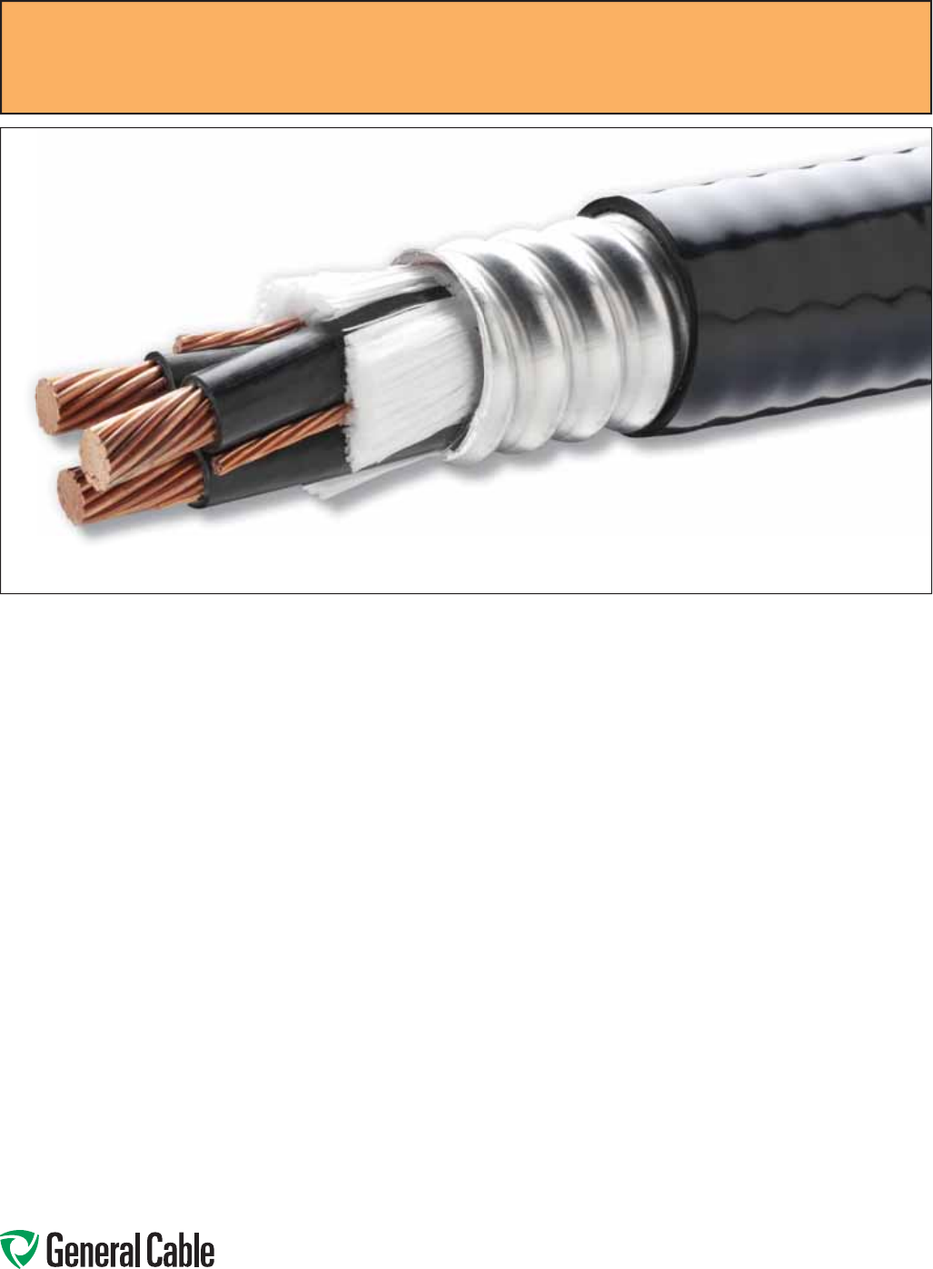
Phone: 888-593-3355
www.generalcable.com
CCW® is General Cable’s trade name for the continuously corrugated,
welded, aluminum-sheathed wiring system. CCW provides a unique
cable system within a sealed metallic sheath that provides complete
protection to the conductors from all external environments. CCW is
offered in a complete line of power, control, signal, and instrumentation
cables.
The Most Versatile Wiring Method Available
Ideal for Hazardous (Classified) Locations
Provides Best Performance for PWM Circuits
Metal-Clad CCW
®
Type MC-HL Wiring System
SPEC A001
February, 2011
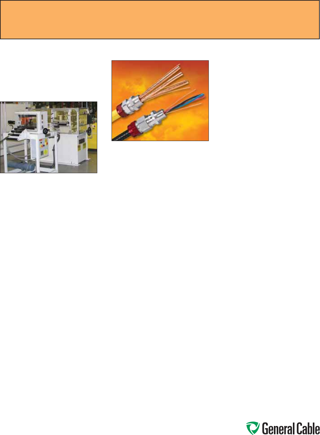
Phone: 888-593-3355
www.generalcable.com
Introduction
CCW provides a unique wiring system
that is unparalleled in versatility for
practically every installation condition
or requirement.
CCW Is A Self-Contained Wiring
System
The CCW wiring system consists
of conductors or a cable enclosed
in a raceway consisting of a strong,
pliable aluminum metallic sheath that
is continuously welded to provide
a completely enclosed gas/vapor-
tight metallic sheath that is then
corrugated. Corrugating the aluminum
sheath provides greater crush and
impact resistance for mechanical
protection of the conductors and
increases the pliability of the cable
during installation. The standard
corrugated aluminum sheath used
on all CCW cables complies with
the more severe crush and impact
requirements of UL 2225 for HL
cables permitted in hazardous
locations. CCW Type MC Metal-Clad
Cable has been installed in some of
the most demanding applications for
over 40 years and has become an
industry standard for industrial and
commercial applications.
CCW Has Almost-Universal
Applications
CCW Type MC
CCW is available in low- and medium-
voltage power, control, signal, and
instrumentation cables. As CCW is
rated MC-HL, it can be used in any
Type MC application, as it complies
with UL 1569, Metal-Clad Aluminum
Cable.
CCW has been recognized by the
National Electrical Code® (NEC®) for
more than 40 years, and the permitted
uses of CCW in the NEC have been
signifi cantly expanded over the years,
as users have recognized the unique
advantages of this factory-assembled
wiring system and inspectors have
observed and recognized the trouble-
free performance of CCW in all the
uses permitted.
NEC Article 330 is the primary article
for CCW Metal-Clad Type MC Cable.
In accordance with this Article, CCW
rated from 600 V to 35 kV is permitted
to be used in the applications shown
below; the additional references
included refer to the 2014 NEC.
• For services, feeders, and branch
circuits
• For power, lighting, control, and
signaling circuits
• As exposed runs “ER” (formerly
open wiring) or concealed
• Indoors or outdoors
• In cable tray, where identifi ed for
such use – see 392.10, 392.20(A),
(B) and (C)
• As aerial cable on Messenger-
Supported Wiring or installed
outside of buildings or structures –
see 225.10, 396.10, and 396.12
• In any raceway
• In hazardous (classifi ed) locations
Class I, Division 1
[511.7, 513.7, 515.7, and 516.7]
Class I, Division 2
[501.10(B)(1) and (5)]
Class I, Zone 2
[505.15(C)(1)(b)]
Class II, Division 2
[502.10(B)(3) and (6)]
Class III, Divisions 1 and 2
[503.10(A) and (B)]
Intrinsically Safe Circuits
[504.20]
Zone 22
[506.15(C)(3) and (6)]
[Not included in UL 2225]
• Special Occupancies – see Articles
517 through 552
• As Service-Entrance Cable – see
230.43
• In wet and dry locations – since the
metallic covering is impervious to
moisture, the insulated conductors
under the metallic sheath are
listed for use in wet locations, and
a corrosion-resistant protective
nonmetallic jacket is provided over
the metallic sheath
• To be direct buried or encased
in concrete, since CCW has a
corrosion-resistant protective
nonmetallic jacket over the metallic
sheath – see 300.5 or 300.50, as
appropriate
• As single-conductors when all the
phase conductors and, where used,
the neutral conductor are grouped
together to minimize induced
voltage on the sheath – see 300.20
Unless otherwise stated, all references refer to the 2014 NEC
®
.
SPEC A001
October, 2014
CCW
®
Installation Manual

Phone: 888-593-3355
www.generalcable.com
CCW Type MC-HL
CCW Type MC-HL contains separate
equipment grounding conductor(s)
sized in accordance with 250.122 in
all constructions, in addition to the
standard gas/vapor-tight continuously
corrugated metallic sheath and overall
jacket of suitable polymeric materials
and complies with UL 2225, Standard
for Cables and Cable Fittings For Use
In Hazardous (Classifi ed) Locations.
UL 2225 also includes additional
requirements that the cable comply with
a -40°C low temperature impact test,
more severe room temperature crush
and impact tests, and a more severe
vertical tray fl ame test.
When installed with termination
fi ttings listed for the application, CCW
MC-HL may be used in industrial
establishments with restricted public
access, where the conditions of
maintenance and supervision ensure
that only qualifi ed persons service the
installation. In addition to all the uses
permitted for CCW Type MC, CCW Type
MC-HL is also permitted to be installed
in the following hazardous (classifi ed)
locations:
Class I, Division 1
[501.10(A)(1)(c)]
Class I, Zone 1
[505.15(B)(1)(b)]
Class II, Division 1
[502.10(A)(1)
and
(3)]
Zones 20 and 21
[506.15(A)(3) and (B)(1)]
[Not included in UL 2225]
CCW Type MV or MC
CCW Type MV or MC contains
conductors rated 105°C and is available
from 2400 V to 35 kV. The cable
complies with both UL 1569, Metal-
Clad Aluminum Cable, and UL 1072,
Medium-Voltage Power Cables, and is
listed and marked as Type MV or MC.
The cable is permitted to be used in
accordance with 328.10 and 330.10 and
installed in the same applications as
CCW Type MC.
CCW Remote-Control, Signaling,
and Power-Limited Cables
CCW Type MC and CCW Type MC-
HL are permitted to be used on 600 V
Class 1 power-limited circuits, Class 1
remote-control and signaling circuits,
and the supply side of Class 2 or Class
3 power sources in the applications
and locations shown above for the
applicable cable type, subject to any
limitations specifi ed in Part II of Article
725, also see 725.127.
Type MC cable is permitted to be
installed in compliance with Parts II
and III of Article 725 and 770.133 as
applicable and in accordance with
330.10(B)(1) through (B)(4).
CCW Type ITC-HL
CCW Instrumentation Tray Cable Type
ITC-HL is permitted to be installed in
accordance with Article 501.10(A)(1)(d)
in Class l, Zone 1 or Division 1 locations.
All constructions are manufactured
with the standard gas/vapor tight
continuously corrugated metallic sheath
and covered with a jacket of suitable
polymeric material. CCW Type ITC-HL
cable complies with UL 2225, Standard
for Cables and Cable Fittings For Use
In Hazardous (Classifi ed) Locations.
The CCW sheath provides equipment
grounding through the sheath. UL 2225
also includes additional requirements
that the cable comply with the -40°C
low temperature impact test, more
severe room temperature crush and
impact tests, and a more severe vertical
tray fl ame test.
In addition to all the applications
permitted for CCW Type ITC, CCW Type
ITC-HL is also permitted in the following
additional hazardous (classifi ed)
locations:
Class I, Division 1
[501.10(A)(1)(d)]
Class I, Zone 1
[505.15(B)(1)(c)]
CCW Type ITC-HL/PLTC
(Instrumentation Tray Cable/
Power-Limited Tray Cable)
CCW Type ITC-HL/PLTC is permitted
in 727.4 to be used as ITC cable on
instrumentation and control circuits
operating at 150 volts or less and
5 amperes or less in industrial
establishments where the conditions of
maintenance and supervision ensure
that only qualifi ed persons service the
installation:
• In cable trays
• In raceways
• In the following hazardous (classifi ed)
locations:
Class I, Division 2
[501.10(B)(1), (3) and (4)]
Class I, Zone 2
[505.15(C)(1)(c) and (d)]
Class II, Division 2
[502.10(B)(1), (4) and (5)]
Intrinsically Safe Circuits
[504.20]
Zone 22
[506.15(C)(4) and (5)]
[Not included in UL 2225]
Commercial garages
[511.7]
• As aerial cable on a messenger
• Direct buried
• Under raised fl oors in rooms contain-
ing industrial process control equip-
ment and rack rooms
• Under raised fl oors in information
technology equipment rooms – see
Table 645.5.
Refer to Article 727 for complete wiring
methods, installation requirements, and
listing requirements for CCW Type ITC-
HL cables.
Unless otherwise stated, all references refer to the 2014 NEC
®
.
SPEC A001
October, 2014
CCW
®
Installation Manual

Phone: 888-593-3355
www.generalcable.com
CCW Type ITC-HL/PLTC is permitted
in 725.133 to be used as PLTC cable
on Class 2 and Class 3 remote-control,
signaling, and power-limited circuits:
• As exposed runs “ER”
• In cable trays
• In raceways
• In the following hazardous (classifi ed)
locations:
Class I, Zone 2
[505.15(C)(1)(d)]
Class II, Division 2
[502.10(B)(1)
and
(4)]
Intrinsically Safe Circuits
[504.20]
Zone 22
[506.15(C)(4)]
[Not included in UL 2225]
Commercial garages
[511.7]
• As aerial cable on a messenger
• Direct buried
• Under raised fl oors in information
technology equipment rooms
–
see
Table 645.5
Refer to Parts III and IV of NEC 725 for
complete wiring methods, installation
requirements, and listing requirements
for CCW Type PLTC cables.
CCW Is The Perfect Cable For
PWM Variable Frequency Drive
Cables
As a function of its construction,
CCW has been recognized for its
ability to reduce the amount of stray
harmonic currents generated by Pulse
Width Modulated (PWM) variable
frequency drives. Through the use of
split ground confi gurations and the
overall shield with CCW’s corrugated,
continuously welded aluminum
sheath, this cable design is one of
the preferred choices of the world’s
manufacturers of drives and motors
to reduce EMI, RFI, and destructive
harmonic currents. CCW cables provide
high attenuation shielding for control,
signal, and instrumentation circuits and
a symmetrical low impedance path to
ground. The CCW sheath effectively
reduces crosstalk, common mode
currents, motor frame voltage, and
injected ground currents. These are all
important considerations for PWM ac
drive applications.
CCW Offshore And Shipboard
Cables Certified By ABS
CCW cables are certifi ed by the
American Bureau of Shipping (ABS) as
cables listed as CWCMC. This listing
means that CCW cables may be used
in MODUs (Mobile Offshore Drilling
Units), Fixed Production Platforms,
Floating Production Platforms, and
FPSOs (Floating Production, Storage
and Offl oading) requiring MC or MC-
HL (Hazardous Locations). These
cable constructions meet UL 1309,
Standards For Marine Shipboard Cable
and UL 2225, Standard For Cables and
Cable Fittings For Use In Hazardous
(Classifi ed) Locations.
CCW Is An Economical Factory
Assembled Wiring System
CCW is a factory-assembled wiring
system that eliminates the cost of
installing raceways and the possibility
of damaging the insulated conductors
during installation in raceways or cable
trays. Since CCW is manufactured in
long, continuous lengths and supplied
on reels, scrap is signifi cantly reduced.
Since CCW Type MC cables are
approved for exposed runs, they offer a
very economical wiring system. A cable
tray or other supports can be used
when there are multiple cables in the
same run, and then individual cables
can branch off as exposed runs from
the tray or support to the termination, as
required, without any change or splices
in the cable.
CCW Is Easy To Install
CCW can be installed using normal
installation equipment and established
installation techniques. It is pliable and
can be easily installed in long lengths
in cable trays, on ladders or other
supports. As with any wiring method,
care should be taken not to exceed the
maximum pulling tension, minimum
bending radius, or maximum sidewall
pressure. A complete cable installation
manual for all cables and conductors is
available from General Cable.
The minimum bending radius for a
multiconductor cable is seven times
(7x) the external diameter of the metallic
sheath.
CCW cable is easily terminated,
and sheath removal instructions are
included in this catalog. Termination
kits and splicing kits are available from
numerous manufacturers.
CCW Provides Environmental
Protection
The welded and corrugated metallic
sheath on CCW is impervious to vapors,
gases or liquids and provides a clean,
dry environment for the conductors.
This permits the conductors to be
rated at 90°C up to 2400 V and 105°C
for medium-voltage cables in both wet
and dry installations. The standard
jacket over the CCW sheath is low-
temperature, sunlight-resistant Polyvinyl
Chloride (PVC). Other jacketed or
unjacketed cables are available for
specifi c installation or environmental
conditions. Consult your General Cable
representative for further details.
Unless otherwise stated, all references refer to the 2014 NEC
®
.
SPEC A001
October, 2014
CCW
®
Installation Manual

Phone: 888-593-3355
www.generalcable.com
CCW Cables Provide Excellent
Flame Resistance
CCW cables, with or without a PVC
jacket, comply with all current fl ame
test standards, including UL 1569,
IEEE 1202, IEEE 383, CSA FT4, ICEA
T-29-520 (210,000 BTU/hr) and IEC
60332.3 Cat A.
CCW Sheath Permitted As An
Equipment Grounding Conductor
The sheath on CCW is actually a hollow
aluminum tube that provides a cross-
sectional area that meets or exceeds
the equipment grounding conductor
requirements specifi ed in 250.122 in all
constructions. Spec F125 provides the
equivalent conductor size for each CCW
aluminum sheath diameter.
Even though the metallic sheath
provides an equipment grounding
conductor that equals or exceeds the
NEC requirements, an additional copper
equipment grounding conductor is
provided in all constructions listed MC-
HL to comply with the user’s preference
not to rely completely on the metallic
sheath for grounding power cables.
The additional equipment grounding
conductor provides an added benefi t
of being able to parallel two standard
power cables and still comply with the
grounding requirements of 250.122(F).
In many cases, three standard power
cables can be run in parallel, but you
should check with the manufacturer for
this type of installation.
CCW Sheath Recognized As A
Voltage Separation Barrier
The CCW aluminum sheath is recognized
as a solid fixed barrier when used on
Type MV or MC cables installed in cable
tray with cables rated 600 volts or less in
accordance with 392.20(B).
Installation
Some specifi c guidelines for installing
CCW cables are listed below.
• When pulling CCW cables into
position, the pulling tension must
be on the conductors rather than
the aluminum sheath. The pulling
eyes/bolts or basket grip should
be attached to the conductors and
the metallic sheath fastened to the
insulated conductors or the pulling
rope to prevent movement of the
conductors within the CCW sheath.
If movement of the conductors within
the CCW sheath is noted at the start
of a pull, one method to stop the
movement is to drive three or four
nails about 2 in. apart through the
CCW sheath into each copper power
conductor.
• The minimum bending radius of seven
times (7x) the external diameter of
the metallic sheath for nonshielded
multiconductor cables must be
maintained during pulling. Roller
assemblies must provide a smooth,
regular bending radius for the cable.
Using smaller rollers can damage the
aluminum sheath and the cable.
• Sidewall pressure should not exceed
500 lbs/ft of radius to avoid fl attening
the CCW sheath or damaging the
conductors.
• Anti-short bushings are not required
on CCW Type MC cables. The listed
termination fi ttings are designed
such that the throat of the fi tting is
constructed to permit the conductors
to pass through but not permit the
cut end of the sheath to contact the
insulated conductors.
• Termination kits and splicing
kits are available from numerous
manufacturers.
Refer to the General Cable Installation
Manual for Power and Control
Cables for more detailed installation
instructions. For special installations,
such as long vertical risers, contact
General Cable for engineering
assistance.
CCW Installation Tips
While it is rarely done, CCW can be
installed in a raceway. One application
is when a run of CCW Type MC is
installed in a non-hazardous or Class I,
Division 2 hazardous location and one
end of the cable is to be terminated in a
Class I, Division 1 hazardous location.
The CCW cable may be pulled into a
raceway approved for use in Class I,
Division 1 hazardous locations, provided
the sealing requirements at the Division
1 and 2 boundaries are met. This
provides a lower cost total cable run
and eliminates splicing of the CCW at
the Division boundary. Another instance
would be to install the CCW in a raceway
to provide additional mechanical
protection to prevent physical damage to
the cable.
On very long runs, the higher ampacity
permitted for 90°C conductors may be
utilized for the CCW cable and 10-foot
lengths of a larger conductor that
complies with the ampacity limitations
required for the 60°C or 75°C termination
rating, to be spliced onto the cable
conductors at the termination. The 10
feet of the larger conductor will act as
a heat sink and ensure that the rated
temperature of the termination is not
exceeded while permitting smaller 90°C
rated conductors to be used for the
majority of the run. The same installation
technique can also be used for 105°C
conductors in CCW Type MV or MC
cable.
CCW cable terminated directly on
busbars is permitted to use the 90°C or
105°C ampacity, as applicable.
In long vertical runs as exposed run or
in cable tray, CCW cables containing
conductors 4 AWG and larger can
comply with Table 300.19(A) by having
horizontal offsets at the required
distances. For installation assistance on
cables smaller than 4 AWG installed in
long vertical runs, contact General Cable
Engineering.
Unless otherwise stated, all references refer to the 2014 NEC
®
.
CCW
®
Installation Manual
SPEC A001
October, 2014

Phone: 888-593-3355
www.generalcable.com
SPEC A001
February, 2011
The following procedures provide
a simple, safe means of removing
the non-metallic jacket and the
corrugated, continuously welded
(CCW) aluminum sheath from
Type MC cable for terminating
or splicing without damaging
the insulated conductors. These
procedures are not recommended
for use on TECK 90, HVTECK or
interlocked armor MC.
Tool Kit:
• Kett-Tool Metal-Clad Cable Saw
• 2"/44 teeth Cutting Blades
• Cable Saw Spindle and Allen
Wrenches
• MC Cable Guide
• Tubing and Pipe Cutter
• 12" V-Jaw Channel-Lock Pliers
• 10" Hacksaw Frame
• 10"/24 teeth/in. Hacksaw Blades
• 10 ft. Tape Measure
• Utility Knife with Blades
• 5/16" Screwdriver
• Tool Box
Safe working practices should
be observed, including safety
glasses and adequate work
gloves. Cable installers should
be properly trained in cable
termination procedures.
Step 1:
Using the utility knife, remove the jacket to expose the required length of
unarmored cable within the enclosure.
Step 2:
Refer to the instructions of the gland manufacturer for the length of aluminum sheath
required to be exposed beyond the jacket for fi tting the glands to the sheath. Mark
the sheath at the nearest crown (high point). This is the Cutting Point.
Installation Note 1:
Work Prior to Removing Sheath
Measure twice, cut once. Ensure that
the pull of cable, in addition to the
termination used, and the amount
of cable required are adequate for
the installation. Make sure that you
have the correct size and style glands
to properly marry the cable to the
equipment.
CCW
®
Sheath Removal Instructions
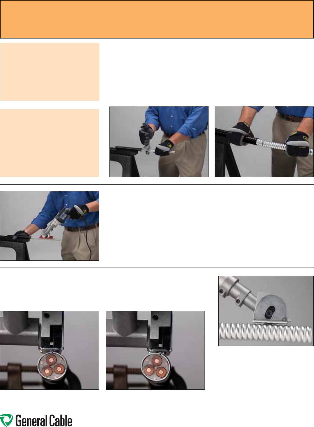
Phone: 888-593-3355
www.generalcable.com
For Small-Diameter CCW® Cable
(diameter of sheath less than or equal to 1.625")
Step 3:
Using a hacksaw blade or tubing cutter, score the CCW aluminum sheath around
the entire sheath at the Cutting Point. Gripping the cable with a hand on either
side of the Cutting Point, flex the cable until the metal opens. Carefully remove
the freed armored sheath from the end of the cable, being careful not to score or
damage the cabled core.
Step 4:
For CCW cables with an inner jacket
or tight-fitting sheath, it may be
necessary to use the Kett-Tool Metal-
Clad Cable Saw with the optional red
cable guide. Attach the cable guide
to the Kett Cable Saw and secure
the cable.
Step 5:
Now that your cross-cut is complete,
sheath removal via the Kett-Tool
Metal-Clad Cable Saw must be done
longitudinally down the cable sheath.
Depth of the saw blade and use of
the guides are critical to the proper
cutting operation. Do not cut through
the entire sheath, as damage to the
core is likely. It is suggested that the
saw depth be adjusted so that 80-
95% of the metal in the valley (low
point) of the CCW® sheath is cut.
Installation Note 2:
Review Sheath Outside
Diameters
For diameters less than or equal to
1.625", use Steps 3-9.
For diameters greater than 1.625",
use Steps 10-15.
Step 6:
When setting up to cut CCW cable, the cable saw blade must be placed to cut
perpendicular to the cable along the cable. See below:
CORRECT NOT CORRECT
Installation Note 3:
Using the Kett Model KS-226
Cable Saw
When using the cable saw, it is
important to read and understand
the manufacturer’s instructions and
to be familiar with the Kett Cable
Saw cutting equipment prior to
operating.
CCW
®
Sheath Removal Instructions
SPEC A001
February, 2011
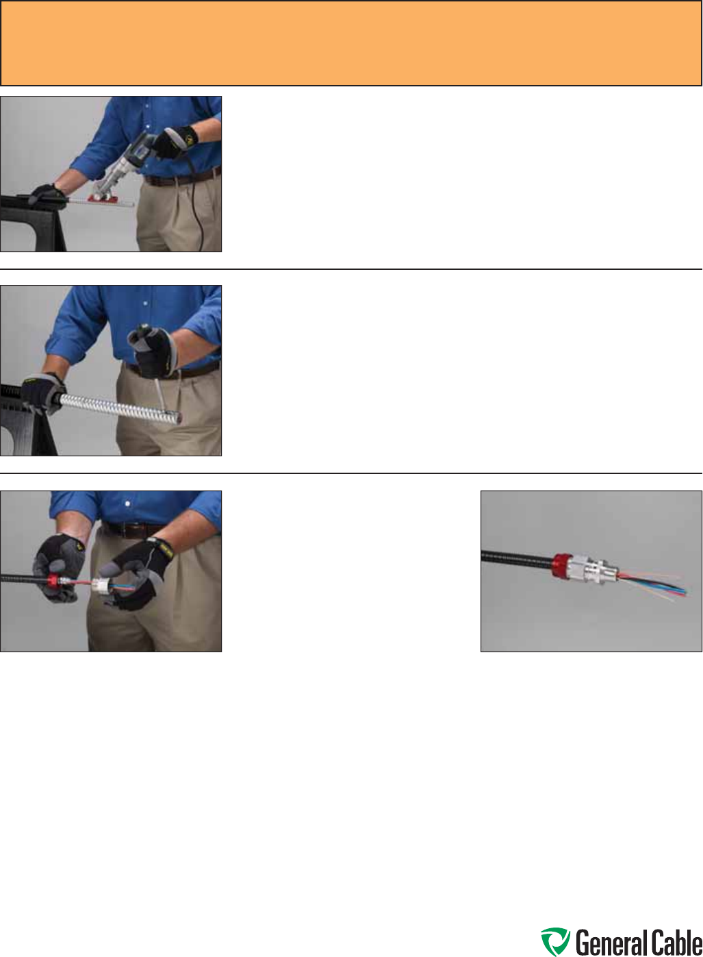
Phone: 888-593-3355
www.generalcable.com
CCW
®
Sheath Removal Instructions
SPEC A001
February, 2011
Step 7:
With downward pressure being applied to the Kett Cable Saw, make a longitudinal
cut down the length of the sheath to be stripped (from the cut end) to the end
you hacksawed earlier. Do not attempt to use the cable saw to plunge cut, as this
could result in injury.
Step 8:
Insert the wide fl at-head screwdriver into the cut at the free end and twist. This
will cause the remaining metal in the valleys to break. Repeat until the sheath
completely separates from the core.
Step 9:
Remove the cable fillers and marker
tape from the cabled core, separating
the conductors and the equipment
grounding conductor(s) for ease in
termination. Install the appropriate
gland suited to the application per the
manufacturer’s instructions. The cable
is now ready to be terminated into the
enclosure.
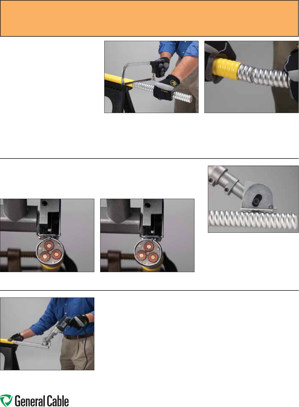
Phone: 888-593-3355
www.generalcable.com
Step 11:
Now that your cross-cut is complete, sheath removal via the Kett-Tool Metal-Clad
Cable Saw must be done longitudinally down the cable sheath.
For Large-Diameter CCW®
Cable (diameter of sheath
greater than 1.625")
Step 10:
Using a hacksaw with the appropriate
blade for cutting metal, cut through
the crown (high point) of the CCW
sheath at your marked Cutting Point
to connect the valley (low point) of the
CCW sheath.
Once this cut is made, mark the sheath
around the balance of the cable,
making additional cuts for a completed
circle. If you cannot complete the
circle entirely through cutting, then flex
the cable end until the metal separates
as shown at the far right.
Depth of the saw blade and use of
the guides are critical to the proper
cutting operation. Do not cut through
the entire sheath, as damage to the
core is likely. It is suggested that
the saw depth be adjusted so that
80-95% of the metal in the valley (low
point) of the CCW® sheath is cut.
Step 12:
When setting up to cut CCW cable, the cable saw blade must be placed to cut
perpendicular to the cable along the cable. See below:
CORRECT NOT CORRECT
CCW
®
Sheath Removal Instructions
SPEC A001
February, 2011
Step 13:
With downward pressure being applied to the Kett Cable Saw, make a longitudinal
cut down the length of the sheath to be stripped (from the cut end) to the end
you hacksawed earlier. Do not attempt to use the cable saw to plunge cut, as this
could result in injury.
At this point, you should have a completed cut with noticeable connections in the
valleys of the sheath.
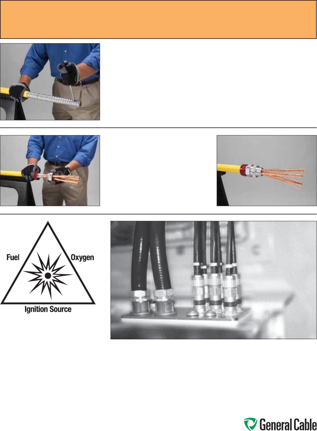
Phone: 888-593-3355
www.generalcable.com
CCW
®
Sheath Removal Instructions
SPEC A001
February, 2011
Step 14:
Insert the wide fl at-head screwdriver into the cut at the free end and twist. This
will cause the remaining metal in the valleys to break. Repeat until the sheath
completely separates from the core.
Step 15:
Remove the cable fillers and marker
tape from the cabled core, separating
the conductors and grounds/shields
for ease in termination. Install the
appropriate fitting/gland suited to the
application per the manufacturer’s
instructions. The cable is now ready
to be terminated into the enclosure.
Areas with a high propensity for
ignitable environments, including
presence of liquids, gases or dust.
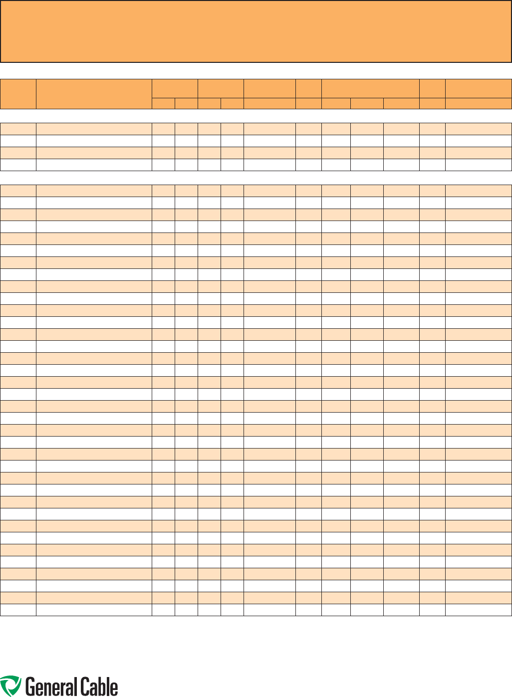
Phone: 888-593-3355
www.generalcable.com
CCW
®
Explosion-Proof Gland Cross-Reference
SPEC A010
April, 2010
Thermocouple Extension
CCW
CATALOG
NUMBER PRODUCT DETAIL
NOMINAL ARMOR
O.D. NOMINAL
OVERALL O.D. CROUSE-HINDS HAWKE APPLETON (TMCX)
*end stop removed Thomas &
Betts Hubbell/Killark
INCHES mm INCHES mm TMCX Series 711 Series Aluminum NP Brass Stainless Steel Spin-On X CMCXA
CCW® ARMORED THERMOCOUPLE EXTENSION, SINGLE PAIR, OVERALL SHIELD
9025.16010001 16 AWG TYPE EX 0.45 11.4 0.56 14.2 TMCX165 A TMCX050SA* TMCX050SNB* TMCX050SSS* 4-075-010 CMCXAA050
9025.16010002 16 AWG TYPE JX 0.45 11.4 0.56 14.2 TMCX165 A TMCX050SA* TMCX050SNB* TMCX050SSS* 4-075-010 CMCXAA050
9025.16010003 16 AWG TYPE KX 0.45 11.4 0.56 14.2 TMCX165 A TMCX050SA* TMCX050SNB* TMCX050SSS* 4-075-010 CMCXAA050
9025.16010004 16 AWG TYPE TX 0.45 11.4 0.56 14.2 TMCX165 A TMCX050SA* TMCX050SNB* TMCX050SSS* 4-075-010 CMCXAA050
CCW® ARMORED THERMOCOUPLE EXTENSION, PAIRS, OVERALL SHIELD
9050.20041221 20 AWG TYPE EX 4 PAIRS 0.58 14.7 0.69 17.5 TMCX165 A or B TMCX050A* TMCX050NB* TMCX050SS* 4-075-020 CMCXAA050 or CMCXAB075
9050.20041222 20 AWG TYPE JX 4 PAIRS 0.58 14.7 0.69 17.5 TMCX165 A or B TMCX050A* TMCX050NB* TMCX050SS* 4-075-020 CMCXAA050 or CMCXAB075
9050.20041223 20 AWG TYPE KX 4 PAIRS 0.58 14.7 0.69 17.5 TMCX165 A or B TMCX050A* TMCX050NB* TMCX050SS* 4-075-020 CMCXAA050 or CMCXAB075
9050.20041224 20 AWG TYPE TX 4 PAIRS 0.58 14.7 0.69 17.5 TMCX165 A or B TMCX050A* TMCX050NB* TMCX050SS* 4-075-020 CMCXAA050 or CMCXAB075
9050.20081221 20 AWG TYPE EX 8 PAIRS 0.71 18.0 0.82 20.8 TMCX285 B TMCX075A TMCX075NB TMCX075SS 4-075-040 CMCXAB075
9050.20081222 20 AWG TYPE JX 8 PAIRS 0.71 18.0 0.82 20.8 TMCX285 B TMCX075A TMCX075NB TMCX075SS 4-075-040 CMCXAB075
9050.20081223 20 AWG TYPE KX 8 PAIRS 0.71 18.0 0.82 20.8 TMCX285 B TMCX075A TMCX075NB TMCX075SS 4-075-040 CMCXAB075
9050.20081224 20 AWG TYPE TX 8 PAIRS 0.71 18.0 0.82 20.8 TMCX285 B TMCX075A TMCX075NB TMCX075SS 4-075-040 CMCXAB075
9050.20101221 20 AWG TYPE EX 10 PAIRS 0.75 19.1 0.86 21.8 TMCX285 B TMCX075A TMCX075NB TMCX075SS 4-100-050 CMCXAB075
9050.20101222 20 AWG TYPE JX 10 PAIRS 0.75 19.1 0.86 21.8 TMCX285 B TMCX075A TMCX075NB TMCX075SS 4-100-050 CMCXAB075
9050.20101223 20 AWG TYPE KX 10 PAIRS 0.75 19.1 0.86 21.8 TMCX285 B TMCX075A TMCX075NB TMCX075SS 4-100-050 CMCXAB075
9050.20101224 20 AWG TYPE TX 10 PAIRS 0.75 19.1 0.86 21.8 TMCX285 B TMCX075A TMCX075NB TMCX075SS 4-100-050 CMCXAB075
9050.20121221 20 AWG TYPE EX 12 PAIRS 0.80 20.3 0.91 23.1 TMCX285 or TMCX3112 B TMCX075A* TMCX075NB* TMCX075SS* 4-100-050 CMCXAB075
9050.20121222 20 AWG TYPE JX 12 PAIRS 0.80 20.3 0.91 23.1 TMCX285 or TMCX3112 B TMCX075A* TMCX075NB* TMCX075SS* 4-100-050 CMCXAB075
9050.20121223 20 AWG TYPE KX 12 PAIRS 0.80 20.3 0.91 23.1 TMCX285 or TMCX3112 B TMCX075A* TMCX075NB* TMCX075SS* 4-100-050 CMCXAB075
9050.20121224 20 AWG TYPE TX 12 PAIRS 0.80 20.3 0.91 23.1 TMCX285 or TMCX3112 B TMCX075A* TMCX075NB* TMCX075SS* 4-100-050 CMCXAB075
9050.20161221 20 AWG TYPE EX 16 PAIRS 0.84 21.3 0.95 24.1 TMCX285 or TMCX3112 B TMCX100A TMCX100NB TMCX100SS 4-100-070 CMCXAB075
9050.20161222 20 AWG TYPE JX 16 PAIRS 0.84 21.3 0.95 24.1 TMCX285 or TMCX3112 B TMCX100A TMCX100NB TMCX100SS 4-100-070 CMCXAB075
9050.20161223 20 AWG TYPE KX 16 PAIRS 0.84 21.3 0.95 24.1 TMCX285 or TMCX3112 B TMCX100A TMCX100NB TMCX100SS 4-100-070 CMCXAB075
9050.20161224 20 AWG TYPE TX 16 PAIRS 0.84 21.3 0.95 24.1 TMCX285 or TMCX3112 B TMCX100A TMCX100NB TMCX100SS 4-100-070 CMCXAB075
9050.20201221 20 AWG TYPE EX 20 PAIRS 0.97 24.6 1.08 27.4 TMCX3112 C TMCX100A TMCX100NB TMCX100SS 4-100-080 CMCXAB075 or CMCXAC100
9050.20201222 20 AWG TYPE JX 20 PAIRS 0.97 24.6 1.08 27.4 TMCX3112 C TMCX100A TMCX100NB TMCX100SS 4-100-080 CMCXAB075 or CMCXAC100
9050.20201223 20 AWG TYPE KX 20 PAIRS 0.97 24.6 1.08 27.4 TMCX3112 C TMCX100A TMCX100NB TMCX100SS 4-100-080 CMCXAB075 or CMCXAC100
9050.20201224 20 AWG TYPE TX 20 PAIRS 0.97 24.6 1.08 27.4 TMCX3112 C TMCX100A TMCX100NB TMCX100SS 4-100-080 CMCXAB075 or CMCXAC100
9050.20241221 20 AWG TYPE EX 24 PAIRS 1.02 25.9 1.13 28.7 TMCX3112 C TMCX100A* TMCX100NB* TMCX100SS* 4-100-080 CMCXAC100
9050.20241222 20 AWG TYPE JX 24 PAIRS 1.02 25.9 1.13 28.7 TMCX3112 C TMCX100A* TMCX100NB* TMCX100SS* 4-100-080 CMCXAC100
9050.20241223 20 AWG TYPE KX 24 PAIRS 1.02 25.9 1.13 28.7 TMCX3112 C TMCX100A* TMCX100NB* TMCX100SS* 4-100-080 CMCXAC100
9050.20241224 20 AWG TYPE TX 24 PAIRS 1.02 25.9 1.13 28.7 TMCX3112 C TMCX100A* TMCX100NB* TMCX100SS* 4-100-080 CMCXAC100
9050.20361221 20 AWG TYPE EX 36 PAIRS 1.19 30.2 1.30 33.0 TMCX4140 C or C2 TMCX125A TMCX125NB TMCX125SS 4-125-110 CMCXAC100 or CMCXAC2125
9050.20361222 20 AWG TYPE JX 36 PAIRS 1.19 30.2 1.30 33.0 TMCX4140 C or C2 TMCX125A TMCX125NB TMCX125SS 4-125-110 CMCXAC100 or CMCXAC2125
9050.20361223 20 AWG TYPE KX 36 PAIRS 1.19 30.2 1.30 33.0 TMCX4140 C or C2 TMCX125A TMCX125NB TMCX125SS 4-125-110 CMCXAC100 or CMCXAC2125
9050.20361224 20 AWG TYPE TX 36 PAIRS 1.19 30.2 1.30 33.0 TMCX4140 C or C2 TMCX125A TMCX125NB TMCX125SS 4-125-110 CMCXAC100 or CMCXAC2125
9050.20501221 20 AWG TYPE EX 50 PAIRS 1.34 34.0 1.45 36.8 TMCX4140 or TMCX5161 C2 TMCX150A TMCX150NB TMCX150SS 4-150-130 CMCXAC2125
9050.20501222 20 AWG TYPE JX 50 PAIRS 1.34 34.0 1.45 36.8 TMCX4140 or TMCX5161 C2 TMCX150A TMCX150NB TMCX150SS 4-150-130 CMCXAC2125
9050.20501223 20 AWG TYPE KX 50 PAIRS 1.34 34.0 1.45 36.8 TMCX4140 or TMCX5161 C2 TMCX150A TMCX150NB TMCX150SS 4-150-130 CMCXAC2125
9050.20501224 20 AWG TYPE TX 50 PAIRS 1.34 34.0 1.45 36.8 TMCX4140 or TMCX5161 C2 TMCX150A TMCX150NB TMCX150SS 4-150-130 CMCXAC2125
All information in this cross-reference is presented solely as a guide to product selection and is believed to be reliable. All printing errors are subject to correction in subsequent
releases of this catalog. Although General Cable has taken precautions to ensure the accuracy of the product cross-reference at the time of publication, the specifications of all
products contained herein are subject to change by gland manufacturers without notice.
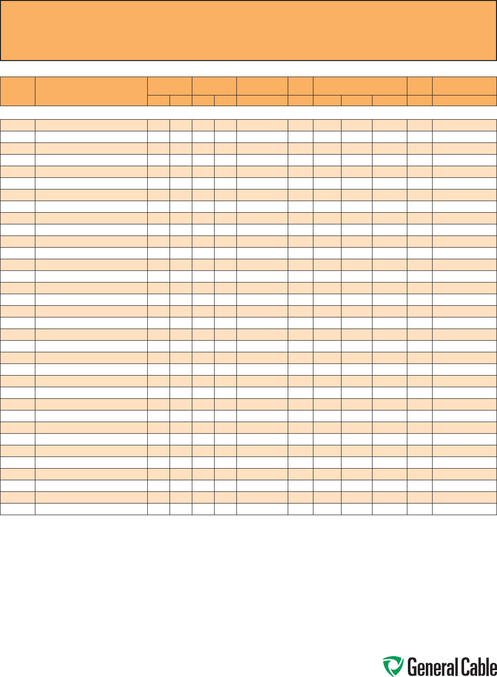
Phone: 888-593-3355
www.generalcable.com
CCW
®
Explosion-Proof Gland Cross-Reference
SPEC A010
April, 2010
Thermocouple Extension
CCW
CATALOG
NUMBER PRODUCT DETAIL
NOMINAL ARMOR
O.D. NOMINAL
OVERALL O.D. CROUSE-HINDS HAWKE APPLETON (TMCX)
*end stop removed Thomas &
Betts Hubbell/Killark
INCHES mm INCHES mm TMCX Series 711 Series Aluminum NP Brass Stainless Steel Spin-On X CMCXA
CCW® ARMORED THERMOCOUPLE EXTENSION, PAIRS, INDIVIDUAL AND OVERALL SHIELD
9075.20041221 20 AWG TYPE EX 4 PAIRS 0.62 15.7 0.73 18.5 TMCX165 or TMCX285 A or B TMCX075A TMCX075NB TMCX075SS 4-075-030 CMCXAA050 or CMCXAB075
9075.20041222 20 AWG TYPE JX 4 PAIRS 0.62 15.7 0.73 18.5 TMCX165 or TMCX285 A or B TMCX075A TMCX075NB TMCX075SS 4-075-030 CMCXAA050 or CMCXAB075
9075.20041223 20 AWG TYPE KX 4 PAIRS 0.62 15.7 0.73 18.5 TMCX165 or TMCX285 A or B TMCX075A TMCX075NB TMCX075SS 4-075-030 CMCXAA050 or CMCXAB075
9075.20041224 20 AWG TYPE TX 4 PAIRS 0.62 15.7 0.73 18.5 TMCX165 or TMCX285 A or B TMCX075A TMCX075NB TMCX075SS 4-075-030 CMCXAA050 or CMCXAB075
9075.20081221 20 AWG TYPE EX 8 PAIRS 0.75 19.1 0.86 21.8 TMCX285 B TMCX075A TMCX075NB TMCX075SS 4-100-050 CMCXAB075
9075.20081222 20 AWG TYPE JX 8 PAIRS 0.75 19.1 0.86 21.8 TMCX285 B TMCX075A TMCX075NB TMCX075SS 4-100-050 CMCXAB075
9075.20081223 20 AWG TYPE KX 8 PAIRS 0.75 19.1 0.86 21.8 TMCX285 B TMCX075A TMCX075NB TMCX075SS 4-100-050 CMCXAB075
9075.20081224 20 AWG TYPE TX 8 PAIRS 0.75 19.1 0.86 21.8 TMCX285 B TMCX075A TMCX075NB TMCX075SS 4-100-050 CMCXAB075
9075.20101221 20 AWG TYPE EX 10 PAIRS 0.80 20.3 0.91 23.1 TMCX285 or TMCX3112 B TMCX075A* TMCX075NB* TMCX075SS* 4-100-050 CMCXAB075
9075.20101222 20 AWG TYPE JX 10 PAIRS 0.80 20.3 0.91 23.1 TMCX285 or TMCX3112 B TMCX075A* TMCX075NB* TMCX075SS* 4-100-050 CMCXAB075
9075.20101223 20 AWG TYPE KX 10 PAIRS 0.80 20.3 0.91 23.1 TMCX285 or TMCX3112 B TMCX075A* TMCX075NB* TMCX075SS* 4-100-050 CMCXAB075
9075.20121222 20 AWG TYPE JX 12 PAIRS 0.84 21.3 0.95 24.1 TMCX285 or TMCX3112 B TMCX100A TMCX100NB TMCX100SS 4-100-070 CMCXAB075
9075.20121223 20 AWG TYPE KX 12 PAIRS 0.84 21.3 0.95 24.1 TMCX285 or TMCX3112 B TMCX100A TMCX100NB TMCX100SS 4-100-070 CMCXAB075
9075.20121224 20 AWG TYPE TX 12 PAIRS 0.84 21.3 0.95 24.1 TMCX285 or TMCX3112 B TMCX100A TMCX100NB TMCX100SS 4-100-070 CMCXAB075
9075.20161221 20 AWG TYPE EX 16 PAIRS 0.97 24.6 1.08 27.4 TMCX3112 C TMCX100A TMCX100NB TMCX100SS 4-100-080 CMCXAB075 or CMCXAC100
9075.20161222 20 AWG TYPE JX 16 PAIRS 0.97 24.6 1.08 27.4 TMCX3112 C TMCX100A TMCX100NB TMCX100SS 4-100-080 CMCXAB075 or CMCXAC100
9075.20161223 20 AWG TYPE KX 16 PAIRS 0.97 24.6 1.08 27.4 TMCX3112 C TMCX100A TMCX100NB TMCX100SS 4-100-080 CMCXAB075 or CMCXAC100
9075.20161224 20 AWG TYPE TX 16 PAIRS 0.97 24.6 1.08 27.4 TMCX3112 C TMCX100A TMCX100NB TMCX100SS 4-100-080 CMCXAB075 or CMCXAC100
9075.20201221 20 AWG TYPE EX 20 PAIRS 1.06 26.9 1.17 29.7 TMCX3112 C TMCX100A* TMCX100NB* TMCX100SS* 4-125-090 CMCXAC100
9075.20201222 20 AWG TYPE JX 20 PAIRS 1.06 26.9 1.17 29.7 TMCX3112 C TMCX100A* TMCX100NB* TMCX100SS* 4-125-090 CMCXAC100
9075.20201223 20 AWG TYPE KX 20 PAIRS 1.06 26.9 1.17 29.7 TMCX3112 C TMCX100A* TMCX100NB* TMCX100SS* 4-125-090 CMCXAC100
9075.20201224 20 AWG TYPE TX 20 PAIRS 1.06 26.9 1.17 29.7 TMCX3112 C TMCX100A* TMCX100NB* TMCX100SS* 4-125-090 CMCXAC100
9075.20241221 20 AWG TYPE EX 24 PAIRS 1.15 29.2 1.26 32.0 TMCX4140 C TMCX125A TMCX125NB TMCX125SS 4-125-100 CMCXAC100
9075.20241222 20 AWG TYPE JX 24 PAIRS 1.15 29.2 1.26 32.0 TMCX4140 C TMCX125A TMCX125NB TMCX125SS 4-125-100 CMCXAC100
9075.20241223 20 AWG TYPE KX 24 PAIRS 1.15 29.2 1.26 32.0 TMCX4140 C TMCX125A TMCX125NB TMCX125SS 4-125-100 CMCXAC100
9075.20241224 20 AWG TYPE TX 24 PAIRS 1.15 29.2 1.26 32.0 TMCX4140 C TMCX125A TMCX125NB TMCX125SS 4-125-100 CMCXAC100
9075.20361221 20 AWG TYPE EX 36 PAIRS 1.34 34.0 1.45 36.8 TMCX4140 or TMCX5161 C2 TMCX150A TMCX150NB TMCX150SS 4-150-130 CMCXAC2125
9075.20361222 20 AWG TYPE JX 36 PAIRS 1.34 34.0 1.45 36.8 TMCX4140 or TMCX5161 C2 TMCX150A TMCX150NB TMCX150SS 4-150-130 CMCXAC2125
9075.20361223 20 AWG TYPE KX 36 PAIRS 1.34 34.0 1.45 36.8 TMCX4140 or TMCX5161 C2 TMCX150A TMCX150NB TMCX150SS 4-150-130 CMCXAC2125
9075.20361224 20 AWG TYPE TX 36 PAIRS 1.34 34.0 1.45 36.8 TMCX4140 or TMCX5161 C2 TMCX150A TMCX150NB TMCX150SS 4-150-130 CMCXAC2125
9075.20501221 20 AWG TYPE EX 50 PAIRS 1.47 37.3 1.58 40.1 TMCX5161 C2 or D TMCX150A* TMCX150NB* TMCX150SS* 4-150-140 CMCXAC2125 or CMCXAD200
9075.20501222 20 AWG TYPE JX 50 PAIRS 1.47 37.3 1.58 40.1 TMCX5161 C2 or D TMCX150A* TMCX150NB* TMCX150SS* 4-150-140 CMCXAC2125 or CMCXAD200
9075.20501223 20 AWG TYPE KX 50 PAIRS 1.47 37.3 1.58 40.1 TMCX5161 C2 or D TMCX150A* TMCX150NB* TMCX150SS* 4-150-140 CMCXAC2125 or CMCXAD200
9075.20501224 20 AWG TYPE TX 50 PAIRS 1.47 37.3 1.58 40.1 TMCX5161 C2 or D TMCX150A* TMCX150NB* TMCX150SS* 4-150-140 CMCXAC2125 or CMCXAD200
All information in this cross-reference is presented solely as a guide to product selection and is believed to be reliable. All printing errors are subject to correction in subsequent
releases of this catalog. Although General Cable has taken precautions to ensure the accuracy of the product cross-reference at the time of publication, the specifications of all
products contained herein are subject to change by gland manufacturers without notice.
Phone: 888-593-3355
www.generalcable.com
CCW
®
Explosion-Proof Gland Cross-Reference
SPEC A010
April, 2010
Instrumentation - 300 V
CCW
CATALOG
NUMBER PRODUCT DETAIL
NOMINAL ARMOR
O.D. NOMINAL
OVERALL O.D. CROUSE-HINDS HAWKE APPLETON (TMCX)
*end stop removed Thomas &
Betts Hubbell/Killark
INCHES mm INCHES mm TMCX Series 711 Series Aluminum NP Brass Stainless Steel Spin-On X CMCXA
CCW® ARMORED INSTRUMENTATION, PAIRS/TRIADS, OVERALL SHIELD
9125.16010001 16 AWG 7W (1.31 mm²) 1 PAIR 0.43 10.9 0.54 13.7 - A TMCX050SA* TMCX050SNB* TMCX050SSS* 4-075-008 CMCXAA050
9125.16010002 16 AWG 7W (1.31 mm²) 1 TRIAD 0.49 12.4 0.60 15.2 TMCX165 A or B TMCX050SA* TMCX050SNB* TMCX050SSS* 4-075-010 CMCXAA050 or CMCXAB075
9125.16021201 16 AWG 7W (1.31 mm²) 2 PAIRS 0.58 14.7 0.69 17.5 TMCX165 A or B TMCX050A* TMCX050NB* TMCX050SS* 4-075-020 CMCXAA050 or CMCXAB075
9125.16021202 16 AWG 7W (1.31 mm²) 2 TRIADS 0.62 15.7 0.73 18.5 TMCX165 or TMCX285 A or B TMCX075A TMCX075NB TMCX075SS 4-075-030 CMCXAA050 or CMCXAB075
9125.16041201 16 AWG 7W (1.31 mm²) 4 PAIRS 0.71 18.0 0.82 20.8 TMCX285 B TMCX075A TMCX075NB TMCX075SS 4-075-040 CMCXAB075
9125.16041202 16 AWG 7W (1.31 mm²) 4 TRIADS 0.75 19.1 0.86 21.8 TMCX285 B TMCX075A TMCX075NB TMCX075SS 4-100-050 CMCXAB075
9125.16081201 16 AWG 7W (1.31 mm²) 8 PAIRS 0.89 22.6 1.00 25.4 TMCX3112 B or C TMCX100A TMCX100NB TMCX100SS 4-100-070 CMCXAB075 or CMCXAC100
9125.16081202 16 AWG 7W (1.31 mm²) 8 TRIADS 0.93 23.6 1.04 26.4 TMCX3112 B or C TMCX100A TMCX100NB TMCX100SS 4-100-070 CMCXAB075 or CMCXAC100
9125.16121201 16 AWG 7W (1.31 mm²) 12 PAIRS 1.02 25.9 1.13 28.7 TMCX3112 C TMCX100A* TMCX100NB* TMCX100SS* 4-100-080 CMCXAC100
9125.16121202 16 AWG 7W (1.31 mm²) 12 TRIADS 1.06 26.9 1.17 29.7 TMCX3112 C TMCX100A* TMCX100NB* TMCX100SS* 4-125-090 CMCXAC100
9125.16161201 16 AWG 7W (1.31 mm²) 16 PAIRS 1.11 28.2 1.22 31.0 TMCX3112 or TMCX4140 C TMCX125A TMCX125NB TMCX125SS 4-125-100 CMCXAC100
9125.16161202 16 AWG 7W (1.31 mm²) 16 TRIADS 1.24 31.5 1.35 34.3 TMCX4140 C2 TMCX125A* TMCX125NB* TMCX125SS* 4-125-110 CMCXAC2125
9125.16241201 16 AWG 7W (1.31 mm²) 24 PAIRS 1.34 34.0 1.45 36.8 TMCX4140 or TMCX5161 C2 TMCX150A TMCX150NB TMCX150SS 4-150-130 CMCXAC2125
9125.16241202 16 AWG 7W (1.31 mm²) 24 TRIADS 1.42 36.1 1.53 38.9 TMCX5161 C2 or D TMCX150A TMCX150NB TMCX150SS 4-150-140 CMCXAC2125 or CMCXAD200
9125.16361201 16 AWG 7W (1.31 mm²) 36 PAIRS 1.56 39.6 1.69 42.9 TMCX5161 C2 or D TMCX200SA TMCX200SNB TMCX200SSS 4-150-150 CMCXAC2125 or CMCXAD200
9125.16361202 16 AWG 7W (1.31 mm²) 36 TRIADS 1.64 41.7 1.78 45.2 TMCX6206 D TMCX200SA TMCX200SNB TMCX200SSS 4-200-160 CMCXAD200
9125.16501201 16 AWG 7W (1.31 mm²) 50 PAIRS 1.83 46.5 1.96 49.8 TMCX6206 D or E TMCX200A TMCX200NB TMCX200SS 4-200-180 CMCXAD200 or CMCXAE250
9125.16501202 16 AWG 7W (1.31 mm²) 50 TRIADS 1.92 48.8 2.05 52.1 TMCX6206 D or E TMCX200A TMCX200NB TMCX200SS 4-200-190 CMCXAD200 or CMCXAE250
CCW® ARMORED INSTRUMENTATION, PAIRS/TRIADS, INDIVIDUAL AND OVERALL SHIELD
9150.16021201 16 AWG 7W (1.31 mm²) 2 PAIRS 0.67 17.0 0.78 19.8 TMCX285 B TMCX075A TMCX075NB TMCX075SS 4-075-040 CMCXAB075
9150.16021202 16 AWG 7W (1.31 mm²) 2 TRIADS 0.71 18.0 0.82 20.8 TMCX285 B TMCX075A TMCX075NB TMCX075SS 4-075-040 CMCXAB075
9150.16041201 16 AWG 7W (1.31 mm²) 4 PAIRS 0.75 19.1 0.86 21.8 TMCX285 B TMCX075A TMCX075NB TMCX075SS 4-100-050 CMCXAB075
9150.16041202 16 AWG 7W (1.31 mm²) 4 TRIADS 0.84 21.3 0.95 24.1 TMCX285 or TMCX3112 B TMCX100A TMCX100NB TMCX100SS 4-100-070 CMCXAB075
9150.16081201 16 AWG 7W (1.31 mm²) 8 PAIRS 0.93 23.6 1.04 26.4 TMCX3112 B or C TMCX100A TMCX100NB TMCX100SS 4-100-070 CMCXAB075 or CMCXAC100
9150.16081202 16 AWG 7W (1.31 mm²) 8 TRIADS 1.06 26.9 1.17 29.7 TMCX3112 C TMCX100A* TMCX100NB* TMCX100SS* 4-125-090 CMCXAC100
9150.16121201 16 AWG 7W (1.31 mm²) 12 PAIRS 1.06 26.9 1.17 29.7 TMCX3112 C TMCX100A* TMCX100NB* TMCX100SS* 4-125-090 CMCXAC100
9150.16121202 16 AWG 7W (1.31 mm²) 12 TRIADS 1.24 31.5 1.35 34.3 TMCX4140 C2 TMCX125A* TMCX125NB* TMCX125SS* 4-125-110 CMCXAC2125
9150.16241201 16 AWG 7W (1.31 mm²) 24 PAIRS 1.42 36.1 1.53 38.9 TMCX5161 C2 or D TMCX150A TMCX150NB TMCX150SS 4-150-140 CMCXAC2125 or CMCXAD200
9150.16241202 16 AWG 7W (1.31 mm²) 24 TRIADS 1.60 40.6 1.73 43.9 TMCX5161 or TMCX6206 D TMCX200SA TMCX200SNB TMCX200SSS 4-200-160 CMCXAD200
9150.16361201 16 AWG 7W (1.31 mm²) 36 PAIRS 1.64 41.7 1.78 45.2 TMCX6206 D TMCX200SA TMCX200SNB TMCX200SSS 4-200-160 CMCXAD200
9150.16361202 16 AWG 7W (1.31 mm²) 36 TRIADS 1.87 47.5 2.00 50.8 TMCX6206 D or E TMCX200A TMCX200NB TMCX200SS 4-200-190 CMCXAD200 or CMCXAE250
9150.16501201 16 AWG 7W (1.31 mm²) 50 PAIRS 1.96 49.8 2.09 53.1 TMCX6206 or TMCX7247 D or E TMCX200A* TMCX200NB* TMCX200SS* 4-250-200 CMCXAD200 or CMCXAE250
9150.16501202 16 AWG 7W (1.31 mm²) 50 TRIADS 2.19 55.6 2.32 58.9 TMCX7247 E TMCX250SA* TMCX250SNB* TMCX250SSS* 4-250-220 CMCXAE250
CCW® ARMORED INSTRUMENTATION, PAIRS/TRIADS, OVERALL SHIELD
9225.16010001 16 AWG 7W (1.31 mm²) 1 PAIR 0.43 10.9 0.54 13.7 - A TMCX050SA* TMCX050SNB* TMCX050SSS* 4-075-008 CMCXAA050
9225.16010002 16 AWG 7W (1.31 mm²) 1 TRIAD 0.43 10.9 0.54 13.7 - A TMCX050SA* TMCX050SNB* TMCX050SSS* 4-075-008 CMCXAA050
9225.16021221 16 AWG 7W (1.31 mm²) 2 PAIRS 0.58 14.7 0.69 17.5 TMCX165 A or B TMCX050A* TMCX050NB* TMCX050SS* 4-075-020 CMCXAA050 or CMCXAB075
9225.16041221 16 AWG 7W (1.31 mm²) 4 PAIRS 0.71 18.0 0.82 20.8 TMCX285 B TMCX075A TMCX075NB TMCX075SS 4-075-040 CMCXAB075
9225.16041222 16 AWG 7W (1.31 mm²) 4 TRIADS 0.75 19.1 0.86 21.8 TMCX285 B TMCX075A TMCX075NB TMCX075SS 4-100-050 CMCXAB075
9225.16061221 16 AWG 7W (1.31 mm²) 6 PAIRS 0.80 20.3 0.91 23.1 TMCX285 or TMCX3112 B TMCX075A* TMCX075NB* TMCX075SS* 4-100-050 CMCXAB075
9225.16081221 16 AWG 7W (1.31 mm²) 8 PAIRS 0.84 21.3 0.95 24.1 TMCX285 or TMCX3112 B TMCX100A TMCX100NB TMCX100SS 4-100-070 CMCXAB075
9225.16081222 16 AWG 7W (1.31 mm²) 8 TRIADS 0.89 22.6 1.00 25.4 TMCX3112 B or C TMCX100A TMCX100NB TMCX100SS 4-100-070 CMCXAB075 or CMCXAC100
9225.16101221 16 AWG 7W (1.31 mm²) 10 PAIRS 0.93 23.6 1.04 26.4 TMCX3112 B or C TMCX100A TMCX100NB TMCX100SS 4-100-070 CMCXAB075 or CMCXAC100
9225.16121221 16 AWG 7W (1.31 mm²) 12 PAIRS 0.97 24.6 1.08 27.4 TMCX3112 C TMCX100A TMCX100NB TMCX100SS 4-100-080 CMCXAB075 or CMCXAC100
9225.16121222 16 AWG 7W (1.31 mm²) 12 TRIADS 1.06 26.9 1.17 29.7 TMCX3112 C TMCX100A* TMCX100NB* TMCX100SS* 4-125-090 CMCXAC100
9225.16161221 16 AWG 7W (1.31 mm²) 16 PAIRS 1.11 28.2 1.22 31.0 TMCX3112 or TMCX4140 C TMCX125A TMCX125NB TMCX125SS 4-125-100 CMCXAC100
9225.16161222 16 AWG 7W (1.31 mm²) 16 TRIADS 1.19 30.2 1.30 33.0 TMCX4140 C or C2 TMCX125A TMCX125NB TMCX125SS 4-125-110 CMCXAC100 or CMCXAC2125
All information in this cross-reference is presented solely as a guide to product selection and is believed to be reliable. All printing
errors are subject to correction in subsequent releases of this catalog. Although General Cable has taken precautions to ensure the
accuracy of the product cross-reference at the time of publication, the specifications of all products contained herein are subject to
change by gland manufacturers without notice.
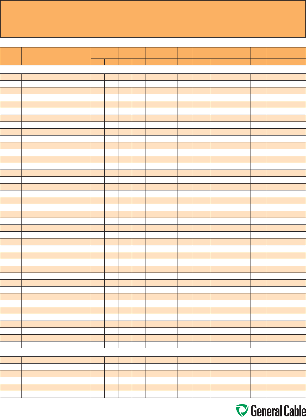
Phone: 888-593-3355
www.generalcable.com
CCW
®
Explosion-Proof Gland Cross-Reference
SPEC A010
April, 2010
Instrumentation - 300 V
CCW
CATALOG
NUMBER PRODUCT DETAIL
NOMINAL ARMOR
O.D. NOMINAL
OVERALL O.D. CROUSE-HINDS HAWKE APPLETON (TMCX)
*end stop removed Thomas &
Betts Hubbell/Killark
INCHES mm INCHES mm TMCX Series 711 Series Aluminum NP Brass Stainless Steel Spin-On X CMCXA
CCW® ARMORED INSTRUMENTATION, PAIRS/TRIADS, OVERALL SHIELD (cont’d)
9225.16201221 16 AWG 7W (1.31 mm²) 20 PAIRS 1.24 31.5 1.35 34.3 TMCX4140 C2 TMCX125A* TMCX125NB* TMCX125SS* 4-125-110 CMCXAC2125
9225.16241221 16 AWG 7W (1.31 mm²) 24 PAIRS 1.34 34.0 1.45 36.8 TMCX4140 or TMCX5161 C2 TMCX150A TMCX150NB TMCX150SS 4-150-130 CMCXAC2125
9225.16241222 16 AWG 7W (1.31 mm²) 24 TRIADS 1.42 36.1 1.53 38.9 TMCX5161 C2 or D TMCX150A TMCX150NB TMCX150SS 4-150-140 CMCXAC2125 or CMCXAD200
9225.16361221 16 AWG 7W (1.31 mm²) 36 PAIRS 1.51 38.4 1.65 41.9 TMCX5161 C2 or D TMCX200SA TMCX200SNB TMCX200SSS 4-150-150 CMCXAC2125 or CMCXAD200
9225.16361222 16 AWG 7W (1.31 mm²) 36 TRIADS 1.60 40.6 1.73 43.9 TMCX5161 or TMCX6206 D TMCX200SA TMCX200SNB TMCX200SSS 4-200-160 CMCXAD200
9225.16501221 16 AWG 7W (1.31 mm²) 50 PAIRS 1.64 41.7 1.78 45.2 TMCX6206 D TMCX200SA TMCX200SNB TMCX200SSS 4-200-160 CMCXAD200
9225.18021221 18 AWG 7W (0.82 mm²) 2 PAIRS 0.58 14.7 0.69 17.5 TMCX165 A or B TMCX050A* TMCX050NB* TMCX050SS* 4-075-020 CMCXAA050 or CMCXAB075
9225.18041221 18 AWG 7W (0.82 mm²) 2 PAIRS 0.67 17.0 0.78 19.8 TMCX285 B TMCX075A TMCX075NB TMCX075SS 4-075-040 CMCXAB075
9225.18041222 18 AWG 7W (0.82 mm²) 2 TRIADS 0.71 18.0 0.82 20.8 TMCX285 B TMCX075A TMCX075NB TMCX075SS 4-075-040 CMCXAB075
9225.18061221 18 AWG 7W (0.82 mm²) 6 PAIRS 0.71 18.0 0.82 20.8 TMCX285 B TMCX075A TMCX075NB TMCX075SS 4-075-040 CMCXAB075
9225.18081221 18 AWG 7W (0.82 mm²) 8 PAIRS 0.80 20.3 0.91 23.1 TMCX285 or TMCX3112 B TMCX075A* TMCX075NB* TMCX075SS* 4-100-050 CMCXAB075
9225.18081222 18 AWG 7W (0.82 mm²) 8 TRIADS 0.80 20.3 0.91 23.1 TMCX285 or TMCX3112 B TMCX075A* TMCX075NB* TMCX075SS* 4-100-050 CMCXAB075
9225.18101221 18 AWG 7W (0.82 mm²) 10 PAIRS 0.89 22.6 1.00 25.4 TMCX3112 B or C TMCX100A TMCX100NB TMCX100SS 4-100-070 CMCXAB075 or CMCXAC100
9225.18121221 18 AWG 7W (0.82 mm²) 12 PAIRS 0.93 23.6 1.04 26.4 TMCX3112 B or C TMCX100A TMCX100NB TMCX100SS 4-100-070 CMCXAB075 or CMCXAC100
9225.18121222 18 AWG 7W (0.82 mm²) 12 TRAIDS 0.97 24.6 1.08 27.4 TMCX3112 C TMCX100A TMCX100NB TMCX100SS 4-100-080 CMCXAB075 or CMCXAC100
9225.18161221 18 AWG 7W (0.82 mm²) 16 PAIRS 1.02 25.9 1.13 28.7 TMCX3112 C TMCX100A* TMCX100NB* TMCX100SS* 4-100-080 CMCXAC100
9225.18161222 18 AWG 7W (0.82 mm²) 16 TRIADS 1.06 26.9 1.17 29.7 TMCX3112 C TMCX100A* TMCX100NB* TMCX100SS* 4-125-090 CMCXAC100
9225.18201221 18 AWG 7W (0.82 mm²) 20 PAIRS 1.06 26.9 1.17 29.7 TMCX3112 C TMCX100A* TMCX100NB* TMCX100SS* 4-125-090 CMCXAC100
9225.18241221 18 AWG 7W (0.82 mm²) 24 PAIRS 1.11 28.2 1.22 31.0 TMCX3112 or TMCX4140 C TMCX125A TMCX125NB TMCX125SS 4-125-100 CMCXAC100
9225.18241222 18 AWG 7W (0.82 mm²) 24 TRIADS 1.24 31.5 1.35 34.3 TMCX4140 C2 TMCX125A* TMCX125NB* TMCX125SS* 4-125-110 CMCXAC2125
9225.18361221 18 AWG 7W (0.82 mm²) 36 PAIRS 1.29 32.8 1.40 35.6 TMCX4140 or TMCX5161 C2 TMCX125A* TMCX125NB* TMCX125SS* 4-125-120 CMCXAC2125
9225.18361222 18 AWG 7W (0.82 mm²) 36 TRIADS 1.34 34.0 1.45 36.8 TMCX4140 or TMCX5161 C2 TMCX150A TMCX150NB TMCX150SS 4-150-130 CMCXAC2125
9225.18501221 18 AWG 7W (0.82 mm²) 50 PAIRS 1.47 37.3 1.58 40.1 TMCX5161 C2 or D TMCX150A* TMCX150NB* TMCX150SS* 4-150-140 CMCXAC2125 or CMCXAD200
9225.20021221 20 AWG 7W (0.52 mm²) 2 PAIRS 0.58 14.7 0.69 17.5 TMCX165 A or B TMCX050A* TMCX050NB* TMCX050SS* 4-075-020 CMCXAA050 or CMCXAB075
9225.20041221 20 AWG 7W (0.52 mm²) 4 PAIRS 0.62 15.7 0.73 18.5 TMCX165 or TMCX285 A or B TMCX075A TMCX075NB TMCX075SS 4-075-030 CMCXAA050 or CMCXAB075
9225.20041222 20 AWG 7W (0.52 mm²) 4 TRIADS 0.67 17.0 0.78 19.8 TMCX285 B TMCX075A TMCX075NB TMCX075SS 4-075-040 CMCXAB075
9225.20061221 20 AWG 7W (0.52 mm²) 6 PAIRS 0.67 17.0 0.78 19.8 TMCX285 B TMCX075A TMCX075NB TMCX075SS 4-075-040 CMCXAB075
9225.20081221 20 AWG 7W (0.52 mm²) 8 PAIRS 0.71 18.0 0.82 20.8 TMCX285 B TMCX075A TMCX075NB TMCX075SS 4-075-040 CMCXAB075
9225.20081222 20 AWG 7W (0.52 mm²) 8 TRIADS 0.75 19.1 0.86 21.8 TMCX285 B TMCX075A TMCX075NB TMCX075SS 4-100-050 CMCXAB075
9225.20101221 20 AWG 7W (0.52 mm²) 10 PAIRS 0.75 19.1 0.86 21.8 TMCX285 B TMCX075A TMCX075NB TMCX075SS 4-100-050 CMCXAB075
9225.20121221 20 AWG 7W (0.52 mm²) 12 PAIRS 0.80 20.3 0.91 23.1 TMCX285 or TMCX3112 B TMCX075A* TMCX075NB* TMCX075SS* 4-100-050 CMCXAB075
9225.20121222 20 AWG 7W (0.52 mm²) 12 TRIADS 0.84 21.3 0.95 24.1 TMCX285 or TMCX3112 B TMCX100A TMCX100NB TMCX100SS 4-100-070 CMCXAB075
9225.20161221 20 AWG 7W (0.52 mm²) 16 PAIRS 0.89 22.6 1.00 25.4 TMCX3112 B or C TMCX100A TMCX100NB TMCX100SS 4-100-070 CMCXAB075 or CMCXAC100
9225.20161222 20 AWG 7W (0.52 mm²) 16 TRIADS 0.93 23.6 1.04 26.4 TMCX3112 B or C TMCX100A TMCX100NB TMCX100SS 4-100-070 CMCXAB075 or CMCXAC100
9225.20201221 20 AWG 7W (0.52 mm²) 20 PAIRS 0.97 24.6 1.08 27.4 TMCX3112 C TMCX100A TMCX100NB TMCX100SS 4-100-080 CMCXAB075 or CMCXAC100
9225.20241221 20 AWG 7W (0.52 mm²) 24 PAIRS 1.06 26.9 1.17 29.7 TMCX3112 C TMCX100A* TMCX100NB* TMCX100SS* 4-125-090 CMCXAC100
9225.20241222 20 AWG 7W (0.52 mm²) 24 TRIADS 1.11 28.2 1.22 31.0 TMCX3112 or TMCX4140 C TMCX125A TMCX125NB TMCX125SS 4-125-100 CMCXAC100
9225.20361221 20 AWG 7W (0.52 mm²) 36 PAIRS 1.24 31.5 1.35 34.3 TMCX4140 C2 TMCX125A* TMCX125NB* TMCX125SS* 4-125-110 CMCXAC2125
9225.20361222 20 AWG 7W (0.52 mm²) 36 TRIADS 1.29 32.8 1.40 35.6 TMCX4140 or TMCX5161 C2 TMCX125A* TMCX125NB* TMCX125SS* 4-125-120 CMCXAC2125
9225.20501221 20 AWG 7W (0.52 mm²) 50 PAIRS 1.34 34.0 1.45 36.8 TMCX4140 or TMCX5161 C2 TMCX150A TMCX150NB TMCX150SS 4-150-130 CMCXAC2125
CCW® ARMORED INSTRUMENTATION, PAIRS/TRIADS, INDIVIDUAL AND OVERALL SHIELD
9250.16021221 16 AWG 7W (1.31 mm²) 2 PAIRS 0.67 17.0 0.78 19.8 TMCX285 B TMCX075A TMCX075NB TMCX075SS 4-075-040 CMCXAB075
9250.16041221 16 AWG 7W (1.31 mm²) 4 PAIRS 0.71 18.0 0.82 20.8 TMCX285 B TMCX075A TMCX075NB TMCX075SS 4-075-040 CMCXAB075
9250.16041222 16 AWG 7W (1.31 mm²) 4 TRIADS 0.80 20.3 0.91 23.1 TMCX285 or TMCX3112 B TMCX075A* TMCX075NB* TMCX075SS* 4-100-050 CMCXAB075
9250.16061221 16 AWG 7W (1.31 mm²) 6 PAIRS 0.84 21.3 0.95 24.1 TMCX285 or TMCX3112 B TMCX100A TMCX100NB TMCX100SS 4-100-070 CMCXAB075
9250.16081221 16 AWG 7W (1.31 mm²) 8 PAIRS 0.93 23.6 1.04 26.4 TMCX3112 B or C TMCX100A TMCX100NB TMCX100SS 4-100-070 CMCXAB075 or CMCXAC100
9250.16081222 16 AWG 7W (1.31 mm²) 8 TRIADS 1.02 25.9 1.13 28.7 TMCX3112 C TMCX100A* TMCX100NB* TMCX100SS* 4-100-080 CMCXAC100
All information in this cross-reference is presented solely as a guide to product selection and is believed to be reliable. All printing
errors are subject to correction in subsequent releases of this catalog. Although General Cable has taken precautions to ensure the
accuracy of the product cross-reference at the time of publication, the specifications of all products contained herein are subject to
change by gland manufacturers without notice.
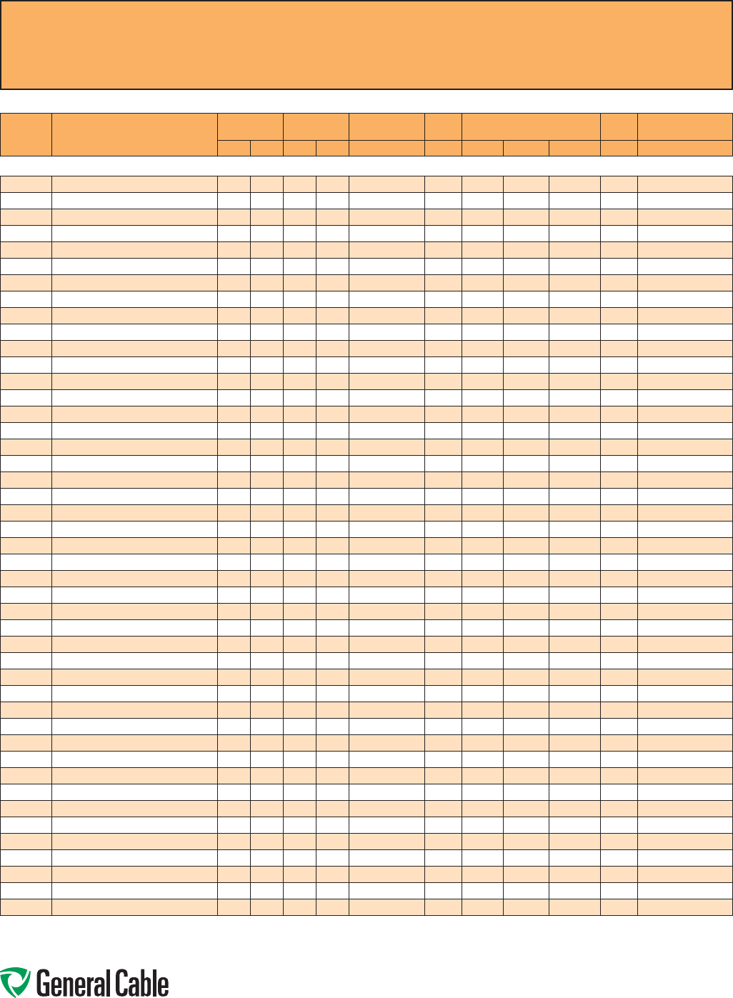
Phone: 888-593-3355
www.generalcable.com
CCW
®
Explosion-Proof Gland Cross-Reference
SPEC A010
April, 2010
Instrumentation - 300 V
CCW
CATALOG
NUMBER PRODUCT DETAIL
NOMINAL ARMOR
O.D. NOMINAL
OVERALL O.D. CROUSE-HINDS HAWKE APPLETON (TMCX)
*end stop removed Thomas &
Betts Hubbell/Killark
INCHES mm INCHES mm TMCX Series 711 Series Aluminum NP Brass Stainless Steel Spin-On X CMCXA
CCW® ARMORED INSTRUMENTATION, PAIRS/TRIADS, INDIVIDUAL AND OVERALL SHIELD (cont’d)
9250.16101221 16 AWG 7W (1.31 mm²) 10 PAIRS 1.02 25.9 1.13 28.7 TMCX3112 C TMCX100A* TMCX100NB* TMCX100SS* 4-100-080 CMCXAC100
9250.16121221 16 AWG 7W (1.31 mm²) 12 PAIRS 1.06 26.9 1.17 29.7 TMCX3112 C TMCX100A* TMCX100NB* TMCX100SS* 4-125-090 CMCXAC100
9250.16121222 16 AWG 7W (1.31 mm²) 12 TRIADS 1.19 30.2 1.30 33.0 TMCX4140 C or C2 TMCX125A TMCX125NB TMCX125SS 4-125-110 CMCXAC100 or CMCXAC2125
9250.16161221 16 AWG 7W (1.31 mm²) 16 PAIRS 1.24 31.5 1.35 34.3 TMCX4140 C2 TMCX125A* TMCX125NB* TMCX125SS* 4-125-110 CMCXAC2125
9250.16161222 16 AWG 7W (1.31 mm²) 16 TRIADS 1.34 34.0 1.45 36.8 TMCX4140 or TMCX5161 C2 TMCX150A TMCX150NB TMCX150SS 4-150-130 CMCXAC2125
9250.16201221 16 AWG 7W (1.31 mm²) 20 PAIRS 1.34 34.0 1.45 36.8 TMCX4140 or TMCX5161 C2 TMCX150A TMCX150NB TMCX150SS 4-150-130 CMCXAC2125
9250.16241221 16 AWG 7W (1.31 mm²) 24 PAIRS 1.37 34.8 1.48 37.6 TMCX4140 or TMCX5161 C2 or D TMCX150A TMCX150NB TMCX150SS 4-150-130 CMCXAC2125 or CMCXAD200
9250.16241222 16 AWG 7W (1.31 mm²) 24 TRIADS 1.60 40.6 1.73 43.9 TMCX5161 or TMCX6206 D TMCX200SA TMCX200SNB TMCX200SSS 4-200-160 CMCXAD200
9250.16361221 16 AWG 7W (1.31 mm²) 36 PAIRS 1.60 40.6 1.73 43.9 TMCX5161 or TMCX6206 D TMCX200SA TMCX200SNB TMCX200SSS 4-200-160 CMCXAD200
9250.16361222 16 AWG 7W (1.31 mm²) 36 TRIADS 1.83 46.5 1.96 49.8 TMCX6206 D or E TMCX200A TMCX200NB TMCX200SS 4-200-180 CMCXAD200 or CMCXAE250
9250.16501221 16 AWG 7W (1.31 mm²) 50 PAIRS 1.87 47.5 2.00 50.8 TMCX6206 D or E TMCX200A TMCX200NB TMCX200SS 4-200-190 CMCXAD200 or CMCXAE250
9250.18021221 18 AWG 7W (0.82 mm²) 2 PAIRS 0.58 14.7 0.69 17.5 TMCX165 A or B TMCX050A* TMCX050NB* TMCX050SS* 4-075-020 CMCXAA050 or CMCXAB075
9250.18041221 18 AWG 7W (0.82 mm²) 4 PAIRS 0.71 18.0 0.82 20.8 TMCX285 B TMCX075A TMCX075NB TMCX075SS 4-075-040 CMCXAB075
9250.18041222 18 AWG 7W (0.82 mm²) 4 TRIADS 0.75 19.1 0.86 21.8 TMCX285 B TMCX075A TMCX075NB TMCX075SS 4-100-050 CMCXAB075
9250.18061221 18 AWG 7W (0.82 mm²) 6 PAIRS 0.75 19.1 0.86 21.8 TMCX285 B TMCX075A TMCX075NB TMCX075SS 4-100-050 CMCXAB075
9250.18081221 18 AWG 7W (0.82 mm²) 8 PAIRS 0.80 20.3 0.92 23.4 TMCX285 or TMCX3112 B TMCX075A* TMCX075NB* TMCX075SS* 4-100-050 CMCXAB075
9250.18081222 18 AWG 7W (0.82 mm²) 8 TRIADS 0.93 23.6 1.04 26.4 TMCX3112 B or C TMCX100A TMCX100NB TMCX100SS 4-100-070 CMCXAB075 or CMCXAC100
9250.18101221 18 AWG 7W (0.82 mm²) 10 PAIRS 0.89 22.6 1.00 25.4 TMCX3112 B or C TMCX100A TMCX100NB TMCX100SS 4-100-070 CMCXAB075 or CMCXAC100
9250.18121221 18 AWG 7W (0.82 mm²) 12 PAIRS 0.93 23.6 1.04 26.4 TMCX3112 B or C TMCX100A TMCX100NB TMCX100SS 4-100-070 CMCXAB075 or CMCXAC100
9250.18121222 18 AWG 7W (0.82 mm²) 12 TRIADS 1.06 26.9 1.17 29.7 TMCX3112 C TMCX100A* TMCX100NB* TMCX100SS* 4-125-090 CMCXAC100
9250.18161221 18 AWG 7W (0.82 mm²) 16 PAIRS 1.06 26.9 1.17 29.7 TMCX3112 C TMCX100A* TMCX100NB* TMCX100SS* 4-125-090 CMCXAC100
9250.18161222 18 AWG 7W (0.82 mm²) 16 TRIADS 1.15 29.2 1.26 32.0 TMCX4140 C TMCX125A TMCX125NB TMCX125SS 4-125-100 CMCXAC100
9250.18201221 18 AWG 7W (0.82 mm²) 20 PAIRS 1.15 29.2 1.26 32.0 TMCX4140 C TMCX125A TMCX125NB TMCX125SS 4-125-100 CMCXAC100
9250.18241221 18 AWG 7W (0.82 mm²) 24 PAIRS 1.24 31.5 1.35 34.3 TMCX4140 C2 TMCX125A* TMCX125NB* TMCX125SS* 4-125-110 CMCXAC2125
9250.18241222 18 AWG 7W (0.82 mm²) 24 TRIADS 1.34 34.0 1.45 36.8 TMCX4140 or TMCX5161 C2 TMCX150A TMCX150NB TMCX150SS 4-150-130 CMCXAC2125
9250.18361221 18 AWG 7W (0.82 mm²) 36 PAIRS 1.47 37.3 1.58 40.1 TMCX5161 C2 or D TMCX150A* TMCX150NB* TMCX150SS* 4-150-140 CMCXAC2125 or CMCXAD200
9250.18361222 18 AWG 7W (0.82 mm²) 36 TRIADS 1.60 40.6 1.73 43.9 TMCX5161 or TMCX6206 D TMCX200SA TMCX200SNB TMCX200SSS 4-200-160 CMCXAD200
9250.18501221 18 AWG 7W (0.82 mm²) 50 PAIRS 1.69 42.9 1.82 46.2 TMCX6206 D TMCX200SA* TMCX200SNB* TMCX200SSS* 4-200-170 CMCXAD200
9250.20021221 20 AWG 7W (0.52 mm²) 2 PAIRS 0.58 14.7 0.69 17.5 TMCX165 A or B TMCX050A* TMCX050NB* TMCX050SS* 4-075-020 CMCXAA050 or CMCXAB075
9250.20041221 20 AWG 7W (0.52 mm²) 4 PAIRS 0.62 15.7 0.73 18.5 TMCX165 or TMCX285 A or B TMCX075A TMCX075NB TMCX075SS 4-075-030 CMCXAA050 or CMCXAB075
9250.20041222 20 AWG 7W (0.52 mm²) 4 TRIADS 0.67 17.0 0.78 19.8 TMCX285 B TMCX075A TMCX075NB TMCX075SS 4-075-040 CMCXAB075
9250.20061221 20 AWG 7W (0.52 mm²) 6 PAIRS 0.71 18.0 0.82 20.8 TMCX285 B TMCX075A TMCX075NB TMCX075SS 4-075-040 CMCXAB075
9250.20081221 20 AWG 7W (0.52 mm²) 8 PAIRS 0.75 19.1 0.86 21.8 TMCX285 B TMCX075A TMCX075NB TMCX075SS 4-100-050 CMCXAB075
9250.20081222 20 AWG 7W (0.52 mm²) 8 TRIADS 0.80 20.3 0.91 23.1 TMCX285 or TMCX3112 B TMCX075A* TMCX075NB* TMCX075SS* 4-100-050 CMCXAB075
9250.20101221 20 AWG 7W (0.52 mm²) 10 PAIRS 0.80 20.3 0.91 23.1 TMCX285 or TMCX3112 B TMCX075A* TMCX075NB* TMCX075SS* 4-100-050 CMCXAB075
9250.20121221 20 AWG 7W (0.52 mm²) 12 PAIRS 0.84 21.3 0.95 24.1 TMCX285 or TMCX3112 B TMCX100A TMCX100NB TMCX100SS 4-100-070 CMCXAB075
9250.20121222 20 AWG 7W (0.52 mm²) 12 TRIADS 0.89 22.6 1.00 25.4 TMCX3112 B or C TMCX100A TMCX100NB TMCX100SS 4-100-070 CMCXAB075 or CMCXAC100
9250.20161221 20 AWG 7W (0.52 mm²) 16 PAIRS 0.97 24.6 1.08 27.4 TMCX3112 C TMCX100A TMCX100NB TMCX100SS 4-100-080 CMCXAB075 or CMCXAC100
9250.20161222 20 AWG 7W (0.52 mm²) 16 TRIADS 1.02 25.9 1.13 28.7 TMCX3112 C TMCX100A* TMCX100NB* TMCX100SS* 4-100-080 CMCXAC100
9250.20201221 20 AWG 7W (0.52 mm²) 20 PAIRS 1.06 26.9 1.17 29.7 TMCX3112 C TMCX100A* TMCX100NB* TMCX100SS* 4-125-090 CMCXAC100
9250.20241221 20 AWG 7W (0.52 mm²) 24 PAIRS 1.15 29.2 1.26 32.0 TMCX4140 C TMCX125A TMCX125NB TMCX125SS 4-125-100 CMCXAC100
9250.20241222 20 AWG 7W (0.52 mm²) 24 TRIADS 1.24 31.5 1.35 34.3 TMCX4140 C2 TMCX125A* TMCX125NB* TMCX125SS* 4-125-110 CMCXAC2125
9250.20361221 20 AWG 7W (0.52 mm²) 36 PAIRS 1.34 34.0 1.45 36.8 TMCX4140 or TMCX5161 C2 TMCX150A TMCX150NB TMCX150SS 4-150-130 CMCXAC2125
9250.20361222 20 AWG 7W (0.52 mm²) 36 TRIADS 1.42 36.1 1.53 38.9 TMCX5161 C2 or D TMCX150A TMCX150NB TMCX150SS 4-150-140 CMCXAC2125 or CMCXAD200
9250.20501221 20 AWG 7W (0.52 mm²) 50 PAIRS 1.51 38.4 1.65 41.9 TMCX5161 C2 or D TMCX200SA TMCX200SNB TMCX200SSS 4-150-150 CMCXAC2125 or CMCXAD200
All information in this cross-reference is presented solely as a guide to product selection and is believed to be reliable. All printing errors are subject to correction in subsequent
releases of this catalog. Although General Cable has taken precautions to ensure the accuracy of the product cross-reference at the time of publication, the specifications of all
products contained herein are subject to change by gland manufacturers without notice.
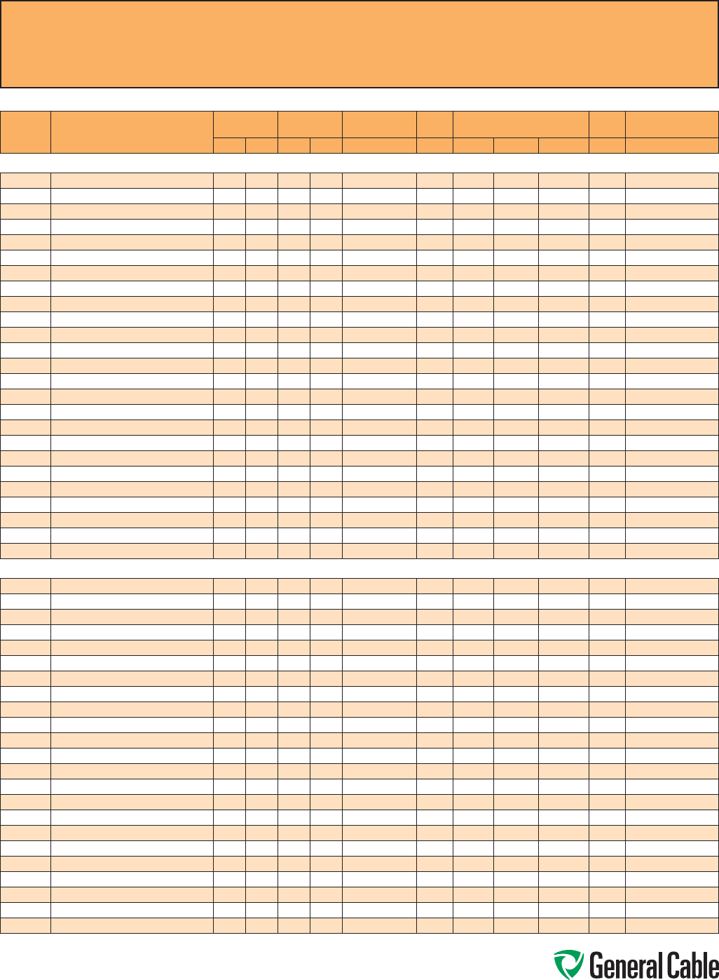
Phone: 888-593-3355
www.generalcable.com
CCW
®
Explosion-Proof Gland Cross-Reference
SPEC A010
April, 2010
Instrumentation - 600 V
CCW
CATALOG
NUMBER PRODUCT DETAIL
NOMINAL ARMOR
O.D. NOMINAL
OVERALL O.D. CROUSE-HINDS HAWKE APPLETON (TMCX)
*end stop removed Thomas &
Betts Hubbell/Killark
INCHES mm INCHES mm TMCX Series 711 Series Aluminum NP Brass Stainless Steel Spin-On X CMCXA
CCW® ARMORED INSTRUMENTATION, PAIRS/TRIADS, OVERALL SHIELD
9325.16010001 16 AWG 7W (1.31 mm²) 1 PAIR 0.53 13.5 0.64 16.3 TMCX165 A or B TMCX050A* TMCX050NB* TMCX050SS* 4-075-020 CMCXAA050 or CMCXAB075
9325.16010002 16 AWG 7W (1.31 mm²) 1 TRIAD 0.53 13.5 0.64 16.3 TMCX165 A or B TMCX050A* TMCX050NB* TMCX050SS* 4-075-020 CMCXAA050 or CMCXAB075
9325.16020001 16 AWG 7W (1.31 mm²) 2 PAIRS 0.58 14.7 0.69 17.5 TMCX165 A or B TMCX050A* TMCX050NB* TMCX050SS* 4-075-020 CMCXAA050 or CMCXAB075
9325.16040001 16 AWG 7W (1.31 mm²) 4 PAIRS 0.71 18.0 0.82 20.8 TMCX285 B TMCX075A TMCX075NB TMCX075SS 4-075-040 CMCXAB075
9325.16040002 16 AWG 7W (1.31 mm²) 4 TRIADS 0.71 18.0 0.82 20.8 TMCX285 B TMCX075A TMCX075NB TMCX075SS 4-075-040 CMCXAB075
9325.16060001 16 AWG 7W (1.31 mm²) 6 PAIRS 0.80 20.3 0.91 23.1 TMCX285 or TMCX3112 B TMCX075A* TMCX075NB* TMCX075SS* 4-100-050 CMCXAB075
9325.16080001 16 AWG 7W (1.31 mm²) 8 PAIRS 0.89 22.6 1.00 25.4 TMCX3112 B or C TMCX100A TMCX100NB TMCX100SS 4-100-070 CMCXAB075 or CMCXAC100
9325.16080002 16 AWG 7W (1.31 mm²) 8 TRIADS 0.93 23.6 1.04 26.4 TMCX3112 B or C TMCX100A TMCX100NB TMCX100SS 4-100-070 CMCXAB075 or CMCXAC100
9325.16100001 16 AWG 7W (1.31 mm²) 10 PAIRS 1.02 25.9 1.13 28.7 TMCX3112 C TMCX100A* TMCX100NB* TMCX100SS* 4-100-080 CMCXAC100
9325.16120001 16 AWG 7W (1.31 mm²) 12 PAIRS 1.06 26.9 1.17 29.7 TMCX3112 C TMCX100A* TMCX100NB* TMCX100SS* 4-125-090 CMCXAC100
9325.16120002 16 AWG 7W (1.31 mm²) 12 TRIADS 1.11 28.2 1.22 31.0 TMCX3112 or TMCX4140 C TMCX125A TMCX125NB TMCX125SS 4-125-100 CMCXAC100
9325.16160001 16 AWG 7W (1.31 mm²) 16 PAIRS 1.15 29.2 1.26 32.0 TMCX4140 C TMCX125A TMCX125NB TMCX125SS 4-125-100 CMCXAC100
9325.16160002 16 AWG 7W (1.31 mm²) 16 TRIADS 1.19 30.2 1.30 33.0 TMCX4140 C or C2 TMCX125A TMCX125NB TMCX125SS 4-125-110 CMCXAC100 or CMCXAC2125
9325.16200001 16 AWG 7W (1.31 mm²) 20 PAIRS 1.29 32.8 1.40 35.6 TMCX4140 or TMCX5161 C2 TMCX125A* TMCX125NB* TMCX125SS* 4-125-120 CMCXAC2125
9325.16240001 16 AWG 7W (1.31 mm²) 24 PAIRS 1.37 34.8 1.48 37.6 TMCX4140 or TMCX5161 C2 or D TMCX150A TMCX150NB TMCX150SS 4-150-130 CMCXAC2125 or CMCXAD200
9325.16240002 16 AWG 7W (1.31 mm²) 24 TRIADS 1.47 37.3 1.58 40.1 TMCX5161 C2 or D TMCX150A* TMCX150NB* TMCX150SS* 4-150-140 CMCXAC2125 or CMCXAD200
9325.16360001 16 AWG 7W (1.31 mm²) 36 PAIRS 1.64 41.7 1.78 45.2 TMCX6206 D TMCX200SA TMCX200SNB TMCX200SSS 4-200-160 CMCXAD200
9325.16360002 16 AWG 7W (1.31 mm²) 36 TRIADS 1.74 44.2 1.87 47.5 TMCX6206 D TMCX200SA* TMCX200SNB* TMCX200SSS* 4-200-170 CMCXAD200
9325.16500001 16 AWG 7W (1.31 mm²) 50 PAIRS 1.83 46.5 1.96 49.8 TMCX6206 D or E TMCX200A TMCX200NB TMCX200SS 4-200-180 CMCXAD200 or CMCXAE250
9325.18020001 18 AWG 7W (0.82 mm²) 2 PAIRS 0.59 15.0 0.70 17.8 TMCX165 A or B TMCX075A TMCX075NB TMCX075SS 4-075-030 CMCXAA050 or CMCXAB075
9325.18040001 18 AWG 7W (0.82 mm²) 4 PAIRS 0.65 16.5 0.75 19.1 TMCX165 or TMCX285 B TMCX075A TMCX075NB TMCX075SS 4-075-030 CMCXAB075
9325.18080001 18 AWG 7W (0.82 mm²) 8 PAIRS 0.82 20.8 0.92 23.4 TMCX285 or TMCX3112 B TMCX100A TMCX100NB TMCX100SS 4-100-070 CMCXAB075
9325.18120001 18 AWG 7W (0.82 mm²) 12 PAIRS 1.00 25.4 1.10 27.9 TMCX3112 C TMCX100A* TMCX100NB* TMCX100SS* 4-100-080 CMCXAC100
9325.18160001 18 AWG 7W (0.82 mm²) 16 PAIRS 1.12 28.4 1.23 31.2 TMCX3112 or TMCX4140 C TMCX125A TMCX125NB TMCX125SS 4-125-100 CMCXAC100
9325.18240001 18 AWG 7W (0.82 mm²) 24 PAIRS 1.39 35.3 1.49 37.8 TMCX4140 or TMCX5161 C2 or D TMCX150A TMCX150NB TMCX150SS 4-150-130 CMCXAC2125 or CMCXAD200
CCW® ARMORED INSTRUMENTATION, PAIRS/TRIADS, INDIVIDUAL AND OVERALL SHIELD
9350.16020001 16 AWG 7W (1.31 mm²) 2 PAIRS 0.67 17.0 0.78 19.8 TMCX285 B TMCX075A TMCX075NB TMCX075SS 4-075-040 CMCXAB075
9350.16040001 16 AWG 7W (1.31 mm²) 4 PAIRS 0.80 20.3 0.91 23.1 TMCX285 or TMCX3112 B TMCX075A* TMCX075NB* TMCX075SS* 4-100-050 CMCXAB075
9350.16040002 16 AWG 7W (1.31 mm²) 4 TRIADS 0.84 21.3 0.95 24.1 TMCX285 or TMCX3112 B TMCX100A TMCX100NB TMCX100SS 4-100-070 CMCXAB075
9350.16060001 16 AWG 7W (1.31 mm²) 6 PAIRS 0.89 22.6 1.00 25.4 TMCX3112 B or C TMCX100A TMCX100NB TMCX100SS 4-100-070 CMCXAB075 or CMCXAC100
9350.16080001 16 AWG 7W (1.31 mm²) 8 PAIRS 0.93 23.6 1.04 26.4 TMCX3112 B or C TMCX100A TMCX100NB TMCX100SS 4-100-070 CMCXAB075 or CMCXAC100
9350.16080002 16 AWG 7W (1.31 mm²) 8 TRIADS 1.06 26.9 1.17 29.7 TMCX3112 C TMCX100A* TMCX100NB* TMCX100SS* 4-125-090 CMCXAC100
9350.16100001 16 AWG 7W (1.31 mm²) 10 PAIRS 1.06 26.9 1.17 29.7 TMCX3112 C TMCX100A* TMCX100NB* TMCX100SS* 4-125-090 CMCXAC100
9350.16120001 16 AWG 7W (1.31 mm²) 12 PAIRS 1.11 28.2 1.22 31.0 TMCX3112 or TMCX4140 C TMCX125A TMCX125NB TMCX125SS 4-125-100 CMCXAC100
9350.16120002 16 AWG 7W (1.31 mm²) 12 TRIADS 1.24 31.5 1.35 34.3 TMCX4140 C2 TMCX125A* TMCX125NB* TMCX125SS* 4-125-110 CMCXAC2125
9350.16160001 16 AWG 7W (1.31 mm²) 16 PAIRS 1.29 32.8 1.40 35.6 TMCX4140 or TMCX5161 C2 TMCX125A* TMCX125NB* TMCX125SS* 4-125-120 CMCXAC2125
9350.16160002 16 AWG 7W (1.31 mm²) 16 TRIADS 1.37 34.8 1.48 37.6 TMCX4140 or TMCX5161 C2 or D TMCX150A TMCX150NB TMCX150SS 4-150-130 CMCXAC2125 or CMCXAD200
9350.16200001 16 AWG 7W (1.31 mm²) 20 PAIRS 1.34 34.0 1.45 36.8 TMCX4140 or TMCX5161 C2 TMCX150A TMCX150NB TMCX150SS 4-150-130 CMCXAC2125
9350.16240001 16 AWG 7W (1.31 mm²) 24 PAIRS 1.42 36.1 1.53 38.9 TMCX5161 C2 or D TMCX150A TMCX150NB TMCX150SS 4-150-140 CMCXAC2125 or CMCXAD200
9350.16240002 16 AWG 7W (1.31 mm²) 24 TRIADS 1.64 41.7 1.78 45.2 TMCX6206 D TMCX200SA TMCX200SNB TMCX200SSS 4-200-160 CMCXAD200
9350.16360001 16 AWG 7W (1.31 mm²) 36 PAIRS 1.69 42.9 1.82 46.2 TMCX6206 D TMCX200SA* TMCX200SNB* TMCX200SSS* 4-200-170 CMCXAD200
9350.16360002 16 AWG 7W (1.31 mm²) 36 TRIADS 1.96 49.8 2.09 53.1 TMCX6206 or TMCX7247 D or E TMCX200A* TMCX200NB* TMCX200SS* 4-250-200 CMCXAD200 or CMCXAE250
9350.16500001 16 AWG 7W (1.31 mm²) 50 PAIRS 1.92 48.8 2.05 52.1 TMCX6206 D or E TMCX200A TMCX200NB TMCX200SS 4-200-190 CMCXAD200 or CMCXAE250
9350.18020001 18 AWG 7W (0.82 mm²) 2 PAIRS 0.59 15.0 0.70 17.8 TMCX165 A or B TMCX075A TMCX075NB TMCX075SS 4-075-030 CMCXAA050 or CMCXAB075
9350.18040001 18 AWG 7W (0.82 mm²) 4 PAIRS 0.65 16.5 0.75 19.1 TMCX165 or TMCX285 B TMCX075A TMCX075NB TMCX075SS 4-075-030 CMCXAB075
9350.18080001 18 AWG 7W (0.82 mm²) 8 PAIRS 0.82 20.8 0.92 23.4 TMCX285 or TMCX3112 B TMCX100A TMCX100NB TMCX100SS 4-100-070 CMCXAB075
9350.18120001 18 AWG 7W (0.82 mm²) 12 PAIRS 1.00 25.4 1.10 27.9 TMCX3112 C TMCX100A* TMCX100NB* TMCX100SS* 4-100-080 CMCXAC100
9350.18160001 18 AWG 7W (0.82 mm²) 16 PAIRS 1.12 28.4 1.23 31.2 TMCX3112 or TMCX4140 C TMCX125A TMCX125NB TMCX125SS 4-125-100 CMCXAC100
9350.18240001 18 AWG 7W (0.82 mm²) 24 PAIRS 1.39 35.3 1.49 37.8 TMCX4140 or TMCX5161 C2 or D TMCX150A TMCX150NB TMCX150SS 4-150-130 CMCXAC2125 or CMCXAD200
All information in this cross-reference is presented solely as a guide to product selection and is believed to be reliable. All printing
errors are subject to correction in subsequent releases of this catalog. Although General Cable has taken precautions to ensure the
accuracy of the product cross-reference at the time of publication, the specifications of all products contained herein are subject to
change by gland manufacturers without notice.
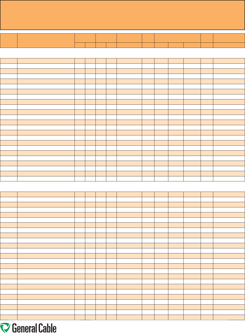
Phone: 888-593-3355
www.generalcable.com
CCW
®
Explosion-Proof Gland Cross-Reference
SPEC A010
April, 2010
CCW
CATALOG
NUMBER PRODUCT DETAIL
NOMINAL ARMOR
O.D. NOMINAL
OVERALL O.D. CROUSE-HINDS HAWKE APPLETON (TMCX)
*end stop removed Thomas &
Betts Hubbell/Killark
INCHES mm INCHES mm TMCX Series 711 Series Aluminum NP Brass Stainless Steel Spin-On X CMCXA
Control - 600 V CCW® ARMORED CONTROL WITH GREEN INSULATED GROUNDING CONDUCTOR
9500.01002110 10 AWG 7W (5.26 mm²) 2/C W/10 AWG GROUND 0.58 14.7 0.69 17.5 TMCX165 A or B TMCX050A* TMCX050NB* TMCX050SS* 4-075-020 CMCXAA050 or CMCXAB075
9500.01003110 10 AWG 7W (5.26 mm²) 3/C W/10 AWG GROUND 0.62 15.7 0.73 18.5 TMCX165 or TMCX285 A or B TMCX075A TMCX075NB TMCX075SS 4-075-030 CMCXAA050 or CMCXAB075
9500.01004110 10 AWG 7W (5.26 mm²) 4/C W/10 AWG GROUND 0.67 17.0 0.78 19.8 TMCX285 B TMCX075A TMCX075NB TMCX075SS 4-075-040 CMCXAB075
9500.01006110 10 AWG 7W (5.26 mm²) 6/C W/10 AWG GROUND 0.75 19.1 0.86 21.8 TMCX285 B TMCX075A TMCX075NB TMCX075SS 4-100-050 CMCXAB075
9500.01008110 10 AWG 7W (5.26 mm²) 8/C W/10 AWG GROUND 0.89 22.6 1.00 25.4 TMCX3112 B or C TMCX100A TMCX100NB TMCX100SS 4-100-070 CMCXAB075 or CMCXAC100
9500.01011110 10 AWG 7W (5.26 mm²) 11/C W/10 AWG GROUND 0.97 24.6 1.08 27.4 TMCX3112 C TMCX100A TMCX100NB TMCX100SS 4-100-080 CMCXAB075 or CMCXAC100
9500.01202112 12 AWG 7W (3.31 mm²) 2/C W/12 AWG GROUND 0.53 13.5 0.64 16.3 TMCX165 A or B TMCX050A* TMCX050NB* TMCX050SS* 4-075-020 CMCXAA050 or CMCXAB075
9500.01203112 12 AWG 7W (3.31 mm²) 3/C W/12 AWG GROUND 0.58 14.7 0.69 17.5 TMCX165 A or B TMCX050A* TMCX050NB* TMCX050SS* 4-075-020 CMCXAA050 or CMCXAB075
9500.01204112 12 AWG 7W (3.31 mm²) 4/C W/12 AWG GROUND 0.67 17.0 0.78 19.8 TMCX285 B TMCX075A TMCX075NB TMCX075SS 4-075-040 CMCXAB075
9500.01205112 12 AWG 7W (3.31 mm²) 5/C W/12 AWG GROUND 0.67 17.0 0.78 19.8 TMCX285 B TMCX075A TMCX075NB TMCX075SS 4-075-040 CMCXAB075
9500.01206112 12 AWG 7W (3.31 mm²) 6/C W/12 AWG GROUND 0.67 17.0 0.78 19.8 TMCX285 B TMCX075A TMCX075NB TMCX075SS 4-075-040 CMCXAB075
9500.01208112 12 AWG 7W (3.31 mm²) 8/C W/12 AWG GROUND 0.80 20.3 0.91 23.1 TMCX285 or TMCX3112 B TMCX075A* TMCX075NB* TMCX075SS* 4-100-050 CMCXAB075
9500.01211112 12 AWG 7W (3.31 mm²) 11/C W/12 AWG GROUND 0.89 22.6 1.00 25.4 TMCX3112 B or C TMCX100A TMCX100NB TMCX100SS 4-100-070 CMCXAB075 or CMCXAC100
9500.01218112 12 AWG 7W (3.31 mm²) 18/C W/12 AWG GROUND 1.02 25.9 1.13 28.7 TMCX3112 C TMCX100A* TMCX100NB* TMCX100SS* 4-100-080 CMCXAC100
9500.01236112 12 AWG 7W (3.31 mm²) 36/C W/12 AWG GROUND 1.37 34.8 1.48 37.6 TMCX4140 or TMCX5161 C2 or D TMCX150A TMCX150NB TMCX150SS 4-150-130 CMCXAC2125 or CMCXAD200
9500.01402114 14 AWG 7W (2.08 mm²) 2/C W/14 AWG GROUND 0.49 12.4 0.60 15.2 TMCX165 A or B TMCX050SA* TMCX050SNB* TMCX050SSS* 4-075-010 CMCXAA050 or CMCXAB075
9500.01403114 14 AWG 7W (2.08 mm²) 3/C W/14 AWG GROUND 0.53 13.5 0.64 16.3 TMCX165 A or B TMCX050A* TMCX050NB* TMCX050SS* 4-075-020 CMCXAA050 or CMCXAB075
9500.01404114 14 AWG 7W (2.08 mm²) 4/C W/14 AWG GROUND 0.58 14.7 0.69 17.5 TMCX165 A or B TMCX050A* TMCX050NB* TMCX050SS* 4-075-020 CMCXAA050 or CMCXAB075
9500.01405114 14 AWG 7W (2.08 mm²) 5/C W/14 AWG GROUND 0.60 15.2 0.71 18.0 TMCX165 or TMCX285 A or B TMCX075A TMCX075NB TMCX075SS 4-075-030 CMCXAA050 or CMCXAB075
9500.01406114 14 AWG 7W (2.08 mm²) 6/C W/14 AWG GROUND 0.62 15.7 0.73 18.5 TMCX165 or TMCX285 A or B TMCX075A TMCX075NB TMCX075SS 4-075-030 CMCXAA050 or CMCXAB075
9500.01408114 14 AWG 7W (2.08 mm²) 8/C W/14 AWG GROUND 0.71 18.0 0.82 20.8 TMCX285 B TMCX075A TMCX075NB TMCX075SS 4-075-040 CMCXAB075
9500.01411114 14 AWG 7W (2.08 mm²) 11/C W/14 AWG GROUND 0.80 20.3 0.91 23.1 TMCX285 or TMCX3112 B TMCX075A* TMCX075NB* TMCX075SS* 4-100-050 CMCXAB075
9500.01418114 14 AWG 7W (2.08 mm²) 18/C W/14 AWG GROUND 0.93 23.6 1.04 26.4 TMCX3112 B or C TMCX100A TMCX100NB TMCX100SS 4-100-070 CMCXAB075 or CMCXAC100
9500.01436114 14 AWG 7W (2.08 mm²) 36/C W/14 AWG GROUND 1.24 31.5 1.35 34.3 TMCX4140 C2 TMCX125A* TMCX125NB* TMCX125SS* 4-125-110 CMCXAC2125
Control (Non-HL) - 600 V CCW® ARMORED CONTROL WITHOUT GROUNDING CONDUCTOR
9525.01002000 10 AWG 7W (5.26 mm²) 2/C 0.58 14.7 0.69 17.5 TMCX165 A or B TMCX050A* TMCX050NB* TMCX050SS* 4-075-020 CMCXAA050 or CMCXAB075
9525.01003000 10 AWG 7W (5.26 mm²) 3/C 0.58 14.7 0.69 17.5 TMCX165 A or B TMCX050A* TMCX050NB* TMCX050SS* 4-075-020 CMCXAA050 or CMCXAB075
9525.01004000 10 AWG 7W (5.26 mm²) 4/C 0.67 17.0 0.78 19.8 TMCX285 B TMCX075A TMCX075NB TMCX075SS 4-075-040 CMCXAB075
9525.01005000 10 AWG 7W (5.26 mm²) 5/C 0.71 18.0 0.82 20.8 TMCX285 B TMCX075A TMCX075NB TMCX075SS 4-075-040 CMCXAB075
9525.01007000 10 AWG 7W (5.26 mm²) 7/C 0.75 19.1 0.86 21.8 TMCX285 B TMCX075A TMCX075NB TMCX075SS 4-100-050 CMCXAB075
9525.01009000 10 AWG 7W (5.26 mm²) 9/C 0.89 22.6 1.00 25.4 TMCX3112 B or C TMCX100A TMCX100NB TMCX100SS 4-100-070 CMCXAB075 or CMCXAC100
9525.01012000 10 AWG 7W (5.26 mm²) 12/C 0.97 24.6 1.08 27.4 TMCX3112 C TMCX100A TMCX100NB TMCX100SS 4-100-080 CMCXAB075 or CMCXAC100
9525.01202000 12 AWG 7W (3.31 mm²) 2/C 0.53 13.5 0.64 16.3 TMCX165 A or B TMCX050A* TMCX050NB* TMCX050SS* 4-075-020 CMCXAA050 or CMCXAB075
9525.01203000 12 AWG 7W (3.31 mm²) 3/C 0.53 13.5 0.64 16.3 TMCX165 A or B TMCX050A* TMCX050NB* TMCX050SS* 4-075-020 CMCXAA050 or CMCXAB075
9525.01204000 12 AWG 7W (3.31 mm²) 4/C 0.58 14.7 0.69 17.5 TMCX165 A or B TMCX050A* TMCX050NB* TMCX050SS* 4-075-020 CMCXAA050 or CMCXAB075
9525.01205000 12 AWG 7W (3.31 mm²) 5/C 0.62 15.7 0.73 18.5 TMCX165 or TMCX285 A or B TMCX075A TMCX075NB TMCX075SS 4-075-030 CMCXAA050 or CMCXAB075
9525.01207000 12 AWG 7W (3.31 mm²) 7/C 0.67 17.0 0.78 19.8 TMCX285 B TMCX075A TMCX075NB TMCX075SS 4-075-040 CMCXAB075
9525.01209000 12 AWG 7W (3.31 mm²) 9/C 0.80 20.3 0.91 23.1 TMCX285 or TMCX3112 B TMCX075A* TMCX075NB* TMCX075SS* 4-100-050 CMCXAB075
9525.01212000 12 AWG 7W (3.31 mm²) 12/C 0.89 22.6 0.99 25.1 TMCX3112 B or C TMCX100A TMCX100NB TMCX100SS 4-100-070 CMCXAB075 or CMCXAC100
9525.01219000 12 AWG 7W (3.31 mm²) 19/C 1.02 25.9 1.13 28.7 TMCX3112 C TMCX100A* TMCX100NB* TMCX100SS* 4-100-080 CMCXAC100
9525.01237000 12 AWG 7W (3.31 mm²) 37/C 1.37 34.8 1.48 37.6 TMCX4140 or TMCX5161 C2 or D TMCX150A TMCX150NB TMCX150SS 4-150-130 CMCXAC2125 or CMCXAD200
9525.01402000 14 AWG 7W (2.08 mm²) 2/C 0.49 12.4 0.60 15.2 TMCX165 A or B TMCX050SA* TMCX050SNB* TMCX050SSS* 4-075-010 CMCXAA050 or CMCXAB075
9525.01403000 14 AWG 7W (2.08 mm²) 3/C 0.49 12.4 0.60 15.2 TMCX165 A or B TMCX050SA* TMCX050SNB* TMCX050SSS* 4-075-010 CMCXAA050 or CMCXAB075
9525.01404000 14 AWG 7W (2.08 mm²) 4/C 0.53 13.5 0.64 16.3 TMCX165 A or B TMCX050A* TMCX050NB* TMCX050SS* 4-075-020 CMCXAA050 or CMCXAB075
9525.01405000 14 AWG 7W (2.08 mm²) 5/C 0.58 14.7 0.69 17.5 TMCX165 A or B TMCX050A* TMCX050NB* TMCX050SS* 4-075-020 CMCXAA050 or CMCXAB075
9525.01407000 14 AWG 7W (2.08 mm²) 7/C 0.62 15.7 0.73 18.5 TMCX165 or TMCX285 A or B TMCX075A TMCX075NB TMCX075SS 4-075-030 CMCXAA050 or CMCXAB075
9525.01409000 14 AWG 7W (2.08 mm²) 9/C 0.71 18.0 0.82 20.8 TMCX285 B TMCX075A TMCX075NB TMCX075SS 4-075-040 CMCXAB075
9525.01412000 14 AWG 7W (2.08 mm²) 12/C 0.80 20.3 0.91 23.1 TMCX285 or TMCX3112 B TMCX075A* TMCX075NB* TMCX075SS* 4-100-050 CMCXAB075
9525.01419000 14 AWG 7W (2.08 mm²) 19/C 0.93 23.6 1.04 26.4 TMCX3112 B or C TMCX100A TMCX100NB TMCX100SS 4-100-070 CMCXAB075 or CMCXAC100
9525.01437000 14 AWG 7W (2.08 mm²) 37/C 1.24 31.5 1.35 34.3 TMCX4140 C2 TMCX125A* TMCX125NB* TMCX125SS* 4-125-110 CMCXAC2125
All information in this cross-reference is presented solely as a guide to product selection and is believed to be reliable. All printing
errors are subject to correction in subsequent releases of this catalog. Although General Cable has taken precautions to ensure the
accuracy of the product cross-reference at the time of publication, the specifications of all products contained herein are subject to
change by gland manufacturers without notice.
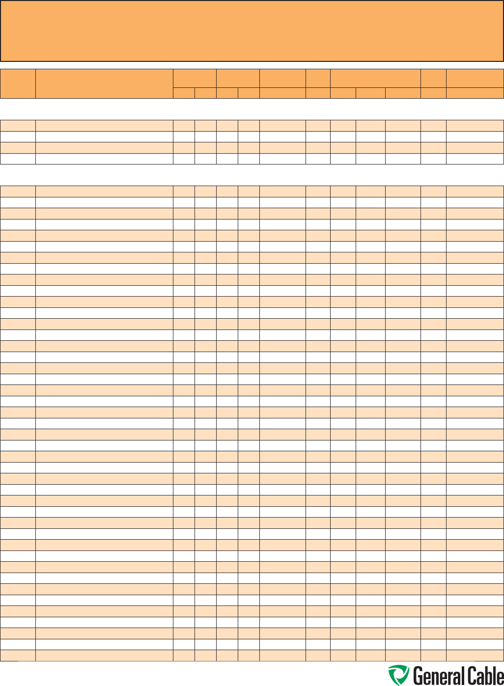
Phone: 888-593-3355
www.generalcable.com
CCW
®
Explosion-Proof Gland Cross-Reference
SPEC A010
April, 2010
CCW
CATALOG
NUMBER PRODUCT DETAIL
NOMINAL ARMOR
O.D. NOMINAL
OVERALL O.D. CROUSE-HINDS HAWKE APPLETON (TMCX)
*end stop removed Thomas &
Betts Hubbell/Killark
INCHES mm INCHES mm TMCX Series 711 Series Aluminum NP Brass Stainless Steel Spin-On X CMCXA
Composite Power & Control - 600 V CCW® ARMORED COMPOSITE POWER AND CONTROL WITH BARE GROUND
9625.043124108 4 AWG 7W (21.2 mm²) 3/C W/12 AWG 4/C CONTROL & 8 AWG GROUND 0.97 24.6 1.08 27.4 TMCX3112 C TMCX100A TMCX100NB TMCX100SS 4-100-080 CMCXAB075 or CMCXAC100
9625.063124108 6 AWG 7W (13.3 mm²) 3/C W/12 AWG 4/C CONTROL & 8 AWG GROUND 0.93 23.6 1.03 26.2 TMCX3112 B or C TMCX100A TMCX100NB TMCX100SS 4-100-070 CMCXAB075 or CMCXAC100
9625.083124110 8 AWG 7W (8.36 mm²) 3/C W/12 AWG 4/C CONTROL & 10 AWG GROUND 0.89 22.6 0.99 25.1 TMCX3112 B or C TMCX100A TMCX100NB TMCX100SS 4-100-070 CMCXAB075 or CMCXAC100
9625.103124110
10 AWG 7W (5.26 mm²) 3/C W/12 AWG 4/C CONTROL & 10 AWG GROUND
0.75 19.1 0.86 21.8 TMCX285 B TMCX075A TMCX075NB TMCX075SS 4-100-050 CMCXAB075
Composite Power & Control (Non-HL) - 600 V CCW® ARMORED COMPOSITE POWER AND CONTROL WITHOUT GROUND
9650.023123000 2 AWG 7W (33.6 mm²) 3/C W/12 AWG 3/C CONTROL 1.06 26.9 1.17 29.7 TMCX3112 C TMCX100A* TMCX100NB* TMCX100SS* 4-125-090 CMCXAC100
9650.023124000 2 AWG 7W (33.6 mm²) 3/C W/12 AWG 4/C CONTROL 1.06 26.9 1.17 29.7 TMCX3112 C TMCX100A* TMCX100NB* TMCX100SS* 4-125-090 CMCXAC100
9650.023143000 2 AWG 7W (33.6 mm²) 3/C W/14 AWG 3/C CONTROL 1.06 26.9 1.17 29.7 TMCX3112 C TMCX100A* TMCX100NB* TMCX100SS* 4-125-090 CMCXAC100
9650.023144000 2 AWG 7W (33.6 mm²) 3/C W/14 AWG 4/C CONTROL 1.06 26.9 1.17 29.7 TMCX3112 C TMCX100A* TMCX100NB* TMCX100SS* 4-125-090 CMCXAC100
9650.024123000 2 AWG 7W (33.6 mm²) 4/C W/12 AWG 3/C CONTROL 1.15 29.2 1.26 32.0 TMCX4140 C TMCX125A TMCX125NB TMCX125SS 4-125-100 CMCXAC100
9650.024124000 2 AWG 7W (33.6 mm²) 4/C W/12 AWG 4/C CONTROL 1.15 29.2 1.26 32.0 TMCX4140 C TMCX125A TMCX125NB TMCX125SS 4-125-100 CMCXAC100
9650.024143000 2 AWG 7W (33.6 mm²) 4/C W/14 AWG 3/C CONTROL 1.15 29.2 1.26 32.0 TMCX4140 C TMCX125A TMCX125NB TMCX125SS 4-125-100 CMCXAC100
9650.024144000 2 AWG 7W (33.6 mm²) 4/C W/14 AWG 4/C CONTROL 1.15 29.2 1.26 32.0 TMCX4140 C TMCX125A TMCX125NB TMCX125SS 4-125-100 CMCXAC100
9650.043123000 4 AWG 7W (21.2 mm²) 3/C W/12 AWG 3/C CONTROL 0.93 23.6 1.04 26.4 TMCX3112 B or C TMCX100A TMCX100NB TMCX100SS 4-100-070 CMCXAB075 or CMCXAC100
9650.043124000 4 AWG 7W (21.2 mm²) 3/C W/12 AWG 4/C CONTROL 0.97 24.6 1.08 27.4 TMCX3112 C TMCX100A TMCX100NB TMCX100SS 4-100-080 CMCXAB075 or CMCXAC100
9650.043143000 4 AWG 7W (21.2 mm²) 3/C W/14 AWG 3/C CONTROL 0.93 23.6 1.04 26.4 TMCX3112 B or C TMCX100A TMCX100NB TMCX100SS 4-100-070 CMCXAB075 or CMCXAC100
9650.043144000 4 AWG 7W (21.2 mm²) 3/C W/14 AWG 4/C CONTROL 0.93 23.6 1.04 26.4 TMCX3112 B or C TMCX100A TMCX100NB TMCX100SS 4-100-070 CMCXAB075 or CMCXAC100
9650.044123000 4 AWG 7W (21.2 mm²) 4/C W/12 AWG 3/C CONTROL 1.06 26.9 1.17 29.7 TMCX3112 C TMCX100A* TMCX100NB* TMCX100SS* 4-125-090 CMCXAC100
9650.044124000 4 AWG 7W (21.2 mm²) 4/C W/12 AWG 4/C CONTROL 1.06 26.9 1.17 29.7 TMCX3112 C TMCX100A* TMCX100NB* TMCX100SS* 4-125-090 CMCXAC100
9650.044143000 4 AWG 7W (21.2 mm²) 4/C W/14 AWG 3/C CONTROL 1.06 26.9 1.17 29.7 TMCX3112 C TMCX100A* TMCX100NB* TMCX100SS* 4-125-090 CMCXAC100
9650.044144000 4 AWG 7W (21.2 mm²) 4/C W/14 AWG 4/C CONTROL 1.06 26.9 1.17 29.7 TMCX3112 C TMCX100A* TMCX100NB* TMCX100SS* 4-125-090 CMCXAC100
9650.063123000 6 AWG 7W (13.3 mm²) 3/C W/12 AWG 3/C CONTROL 0.84 21.3 0.95 24.1 TMCX285 or TMCX3112 B TMCX100A TMCX100NB TMCX100SS 4-100-070 CMCXAB075
9650.063124000 6 AWG 7W (13.3 mm²) 3/C W/12 AWG 4/C CONTROL 0.93 23.6 1.03 26.2 TMCX3112 B or C TMCX100A TMCX100NB TMCX100SS 4-100-070 CMCXAB075 or CMCXAC100
9650.063143000 6 AWG 7W (13.3 mm²) 3/C W/14 AWG 3/C CONTROL 0.84 21.3 0.95 24.1 TMCX285 or TMCX3112 B TMCX100A TMCX100NB TMCX100SS 4-100-070 CMCXAB075
9650.063144000 6 AWG 7W (13.3 mm²) 3/C W/14 AWG 4/C CONTROL 0.84 21.3 0.95 24.1 TMCX285 or TMCX3112 B TMCX100A TMCX100NB TMCX100SS 4-100-070 CMCXAB075
9650.064123000 6 AWG 7W (13.3 mm²) 4/C W/12 AWG 3/C CONTROL 0.97 24.6 1.08 27.4 TMCX3112 C TMCX100A TMCX100NB TMCX100SS 4-100-080 CMCXAB075 or CMCXAC100
9650.064124000 6 AWG 7W (13.3 mm²) 4/C W/12 AWG 4/C CONTROL 0.97 24.6 1.08 27.4 TMCX3112 C TMCX100A TMCX100NB TMCX100SS 4-100-080 CMCXAB075 or CMCXAC100
9650.064143000 6 AWG 7W (13.3 mm²) 4/C W/14 AWG 3/C CONTROL 0.93 23.6 1.04 26.4 TMCX3112 B or C TMCX100A TMCX100NB TMCX100SS 4-100-070 CMCXAB075 or CMCXAC100
9650.064144000 6 AWG 7W (13.3 mm²) 4/C W/14 AWG 4/C CONTROL 0.93 23.6 1.04 26.4 TMCX3112 B or C TMCX100A TMCX100NB TMCX100SS 4-100-070 CMCXAB075 or CMCXAC100
9650.083123000 8 AWG 7W (8.36 mm²) 3/C W/12 AWG 3/C CONTROL 0.80 20.3 0.95 24.1 TMCX285 or TMCX3112 B TMCX075A* TMCX075NB* TMCX075SS* 4-100-050 CMCXAB075
9650.083124000 8 AWG 7W (8.36 mm²) 3/C W/12 AWG 4/C CONTROL 0.84 21.3 0.91 23.1 TMCX285 or TMCX3112 B TMCX100A TMCX100NB TMCX100SS 4-100-070 CMCXAB075
9650.083143000 8 AWG 7W (8.36 mm²) 3/C W/14 AWG 3/C CONTROL 0.80 20.3 0.91 23.1 TMCX285 or TMCX3112 B TMCX075A* TMCX075NB* TMCX075SS* 4-100-050 CMCXAB075
9650.083144000 8 AWG 7W (8.36 mm²) 3/C W/14 AWG 4/C CONTROL 0.84 21.3 0.91 23.1 TMCX285 or TMCX3112 B TMCX100A TMCX100NB TMCX100SS 4-100-070 CMCXAB075
9650.084123000 8 AWG 7W (8.36 mm²) 4/C W/12 AWG 3/C CONTROL 0.89 22.6 1.00 25.4 TMCX3112 B or C TMCX100A TMCX100NB TMCX100SS 4-100-070 CMCXAB075 or CMCXAC100
9650.084124000 8 AWG 7W (8.36 mm²) 4/C W/12 AWG 4/C CONTROL 0.93 23.6 1.04 26.4 TMCX3112 B or C TMCX100A TMCX100NB TMCX100SS 4-100-070 CMCXAB075 or CMCXAC100
9650.084143000 8 AWG 7W (8.36 mm²) 4/C W/14 AWG 3/C CONTROL 0.84 21.3 0.95 24.1 TMCX285 or TMCX3112 B TMCX100A TMCX100NB TMCX100SS 4-100-070 CMCXAB075
9650.084144000 8 AWG 7W (8.36 mm²) 4/C W/14 AWG 4/C CONTROL 0.89 22.6 1.00 25.4 TMCX3112 B or C TMCX100A TMCX100NB TMCX100SS 4-100-070 CMCXAB075 or CMCXAC100
9650.103123000 10 AWG 7W (5.26 mm²) 3/C W/12 AWG 3/C CONTROL 0.75 19.1 0.86 21.8 TMCX285 B TMCX075A TMCX075NB TMCX075SS 4-100-050 CMCXAB075
9650.103143000 10 AWG 7W (5.26 mm²) 3/C W/14 AWG 3/C CONTROL 0.75 19.1 0.86 21.8 TMCX285 B TMCX075A TMCX075NB TMCX075SS 4-100-050 CMCXAB075
9650.103144000 10 AWG 7W (5.26 mm²) 3/C W/14 AWG 4/C CONTROL 0.80 20.3 0.91 23.1 TMCX285 or TMCX3112 B TMCX075A* TMCX075NB* TMCX075SS* 4-100-050 CMCXAB075
9650.104123000 10 AWG 7W (5.26 mm²) 4/C W/12 AWG 3/C CONTROL 0.80 20.3 0.91 23.1 TMCX285 or TMCX3112 B TMCX075A* TMCX075NB* TMCX075SS* 4-100-050 CMCXAB075
9650.104124000 10 AWG 7W (5.26 mm²) 4/C W/12 AWG 4/C CONTROL 0.80 20.3 0.91 23.1 TMCX285 or TMCX3112 B TMCX075A* TMCX075NB* TMCX075SS* 4-100-050 CMCXAB075
9650.104143000 10 AWG 7W (5.26 mm²) 4/C W/14 AWG 3/C CONTROL 0.80 20.3 0.91 23.1 TMCX285 or TMCX3112 B TMCX075A* TMCX075NB* TMCX075SS* 4-100-050 CMCXAB075
9650.104144000 10 AWG 7W (5.26 mm²) 4/C W/14 AWG 4/C CONTROL 0.80 20.3 0.91 23.1 TMCX285 or TMCX3112 B TMCX075A* TMCX075NB* TMCX075SS* 4-100-050 CMCXAB075
9650.123143000 12 AWG 7W (3.31 mm²) 3/C W/14 AWG 3/C CONTROL 0.71 18.0 0.82 20.8 TMCX285 B TMCX075A TMCX075NB TMCX075SS 4-075-040 CMCXAB075
9650.123144000 12 AWG 7W (3.31 mm²) 3/C W/14 AWG 4/C CONTROL 0.71 18.0 0.82 20.8 TMCX285 B TMCX075A TMCX075NB TMCX075SS 4-075-040 CMCXAB075
9650.124143000 12 AWG 7W (3.31 mm²) 4/C W/14 AWG 3/C CONTROL 0.71 18.0 0.82 20.8 TMCX285 B TMCX075A TMCX075NB TMCX075SS 4-075-040 CMCXAB075
9650.124144000 12 AWG 7W (3.31 mm²) 4/C W/14 AWG 4/C CONTROL 0.75 19.1 0.86 21.8 TMCX285 B TMCX075A TMCX075NB TMCX075SS 4-100-050 CMCXAB075
All information in this cross-reference is presented solely as a guide to product selection and is believed to be reliable. All printing
errors are subject to correction in subsequent releases of this catalog. Although General Cable has taken precautions to ensure the
accuracy of the product cross-reference at the time of publication, the specifications of all products contained herein are subject to
change by gland manufacturers without notice.
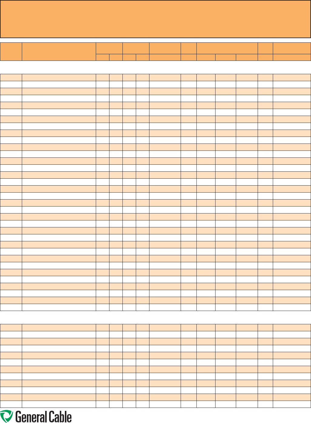
Phone: 888-593-3355
www.generalcable.com
CCW
®
Explosion-Proof Gland Cross-Reference
SPEC A010
April, 2010
CCW
CATALOG
NUMBER PRODUCT DETAIL
NOMINAL ARMOR
O.D. NOMINAL
OVERALL O.D. CROUSE-HINDS HAWKE APPLETON (TMCX)
*end stop removed Thomas &
Betts Hubbell/Killark
INCHES mm INCHES mm TMCX Series 711 Series Aluminum NP Brass Stainless Steel Spin-On X CMCXA
Power - 600 V CCW® ARMORED POWER, 3/C VFD AND 4/C WITH BARE GROUND
9600.00103310 1 AWG 19W (42.4 mm²) 3/C VFD W/10 AWG 3/C GROUND 1.15 29.2 1.26 32.0 TMCX4140 C TMCX125A TMCX125NB TMCX125SS 4-125-100 CMCXAC100
9600.00104106 1 AWG 19W (42.4 mm²) 4/C W/6 AWG 1/C GROUND 1.29 32.8 1.40 35.6 TMCX4140 or TMCX5161 C2 TMCX125A* TMCX125NB* TMCX125SS* 4-125-120 CMCXAC2125
9600.00203310 2 AWG 7W (33.6 mm²) 3/C VFD W/10 AWG 3/C GROUND 1.02 25.9 1.13 28.7 TMCX3112 C TMCX100A* TMCX100NB* TMCX100SS* 4-100-080 CMCXAC100
9600.00204106 2 AWG 7W (33.6 mm²) 4/C W/6 AWG 1/C GROUND 1.15 29.2 1.26 32.0 TMCX4140 C TMCX125A TMCX125NB TMCX125SS 4-125-100 CMCXAC100
9600.00403312 4 AWG 7W (21.2 mm²) 3/C VFD W/12 AWG 3/C GROUND 0.89 22.6 0.99 25.1 TMCX3112 B or C TMCX100A TMCX100NB TMCX100SS 4-100-070 CMCXAB075 or CMCXAC100
9600.00404108 4 AWG 7W (21.2 mm²) 4/C W/8 AWG 1/C GROUND 0.97 24.6 1.08 27.4 TMCX3112 C TMCX100A TMCX100NB TMCX100SS 4-100-080 CMCXAB075 or CMCXAC100
9600.00603312 6 AWG 7W (13.3 mm²) 3/C VFD W/12 AWG 3/C GROUND 0.80 20.3 0.90 22.9 TMCX285 or TMCX3112 B TMCX075A* TMCX075NB* TMCX075SS* 4-100-050 CMCXAB075
9600.00604108 6 AWG 7W (13.3 mm²) 4/C W/8 AWG 1/C GROUND 0.89 22.6 0.99 25.1 TMCX3112 B or C TMCX100A TMCX100NB TMCX100SS 4-100-070 CMCXAB075 or CMCXAC100
9600.00803314 8 AWG 7W (8.36 mm²) 3/C VFD W/14 AWG 3/C GROUND 0.71 18.0 0.81 20.6 TMCX285 B TMCX075A TMCX075NB TMCX075SS 4-075-040 CMCXAB075
9600.00804110 8 AWG 7W (8.36 mm²) 4/C W/10 AWG 1/C GROUND 0.80 20.3 0.90 22.9 TMCX285 or TMCX3112 B TMCX075A* TMCX075NB* TMCX075SS* 4-100-050 CMCXAB075
9600.01003314 10 AWG 7W (5.26 mm²) 3/C VFD W/14 AWG 3/C GROUND 0.62 15.7 0.73 18.5 TMCX165 or TMCX285 A or B TMCX075A TMCX075NB TMCX075SS 4-075-030 CMCXAA050 or CMCXAB075
9600.01004314 10 AWG 7W (5.26 mm²) 4/C W/14 AWG 3/C GROUND 0.67 17.0 0.78 19.8 TMCX285 B TMCX075A TMCX075NB TMCX075SS 4-075-040 CMCXAB075
9600.01203316 12 AWG 7W (3.31 mm²) 3/C VFD W/16 AWG 3/C GROUND 0.58 14.7 0.69 17.5 TMCX165 A or B TMCX050A* TMCX050NB* TMCX050SS* 4-075-020 CMCXAA050 or CMCXAB075
9600.01204316 12 AWG 7W (3.31 mm²) 4/C W/16 AWG 3/C GROUND 0.67 17.0 0.78 19.8 TMCX285 B TMCX075A TMCX075NB TMCX075SS 4-075-040 CMCXAB075
9600.01403318 14 AWG 7W (2.08 mm²) 3/C VFD W/18 AWG 3/C GROUND 0.53 13.5 0.64 16.3 TMCX165 A or B TMCX050A* TMCX050NB* TMCX050SS* 4-075-020 CMCXAA050 or CMCXAB075
9600.01404318 14 AWG 7W (2.08 mm²) 4/C W/18 AWG 3/C GROUND 0.58 14.7 0.69 17.5 TMCX165 A or B TMCX050A* TMCX050NB* TMCX050SS* 4-075-020 CMCXAA050 or CMCXAB075
9600.100031110
1000 KCMIL 61W (507 mm²) 3/C VFD W/1/0 AWG 1/C GROUND
1.24 31.5 1.34 34.0 TMCX4140 C2 TMCX125A* TMCX125NB* TMCX125SS* 4-125-110 CMCXAC2125
9600.100041110 1000 KCMIL 61W (507 mm²) 4/C W/1/0 AWG 1/C GROUND 1.37 34.8 1.48 37.6 TMCX4140 or TMCX5161 C2 or D TMCX150A TMCX150NB TMCX150SS 4-150-130 CMCXAC2125 or CMCXAD200
9600.11003310 1/0 AWG 19W (53.5 mm²) 3/C VFD W/10 AWG 3/C GROUND 1.34 34.0 1.44 36.6 TMCX4140 or TMCX5161 C2 TMCX150A TMCX150NB TMCX150SS 4-150-130 CMCXAC2125
9600.11004106 1/0 AWG 19W (53.5 mm²) 4/C W/6 AWG 1/C GROUND 1.51 38.4 1.64 41.7 TMCX5161 C2 or D TMCX200SA TMCX200SNB TMCX200SSS 4-150-150 CMCXAC2125 or CMCXAD200
9600.21003310 2/0 AWG 19W (67.4 mm²) 3/C VFD W/10 AWG 3/C GROUND 1.74 44.2 1.87 47.5 TMCX6206 D TMCX200SA* TMCX200SNB* TMCX200SSS* 4-200-170 CMCXAD200
9600.21004106 2/0 AWG 19W (67.4 mm²) 4/C W/6 AWG 1/C GROUND 1.96 49.8 2.09 53.1 TMCX6206 or TMCX7247 D or E TMCX200A* TMCX200NB* TMCX200SS* 4-250-200 CMCXAD200 or CMCXAE250
9600.25003308 250 KCMIL 37W (127 mm²) 3/C VFD W/8 AWG 3/C GROUND 1.47 37.3 1.59 40.4 TMCX5161 C2 or D TMCX150A* TMCX150NB* TMCX150SS* 4-150-140 CMCXAC2125 or CMCXAD200
9600.25004104 250KCMIL 37W (127 mm²) 4/C W/4 AWG 1/C GROUND 1.65 41.9 1.78 45.2 TMCX6206 D TMCX200SA TMCX200SNB TMCX200SSS 4-200-160 CMCXAD200
9600.31003308 3/0 AWG 19W (85 mm²) 3/C VFD W/8 AWG 3/C GROUND 1.96 49.8 2.09 53.1 TMCX6206 or TMCX7247 D or E TMCX200A* TMCX200NB* TMCX200SS* 4-250-200 CMCXAD200 or CMCXAE250
9600.31004104 3/0 AWG 19W (85 mm²) 4/C W/4 AWG 1/C GROUND 2.19 55.6 2.35 59.7 TMCX7247 E TMCX250SA* TMCX250SNB* TMCX250SSS* 4-250-220 CMCXAE250
9600.35003307 350 KCMIL 37W (177 mm²) 3/C VFD W/7 AWG 3/C GROUND 1.60 40.6 1.73 43.9 TMCX5161 or TMCX6206 D TMCX200SA TMCX200SNB TMCX200SSS 4-200-160 CMCXAD200
9600.35004103 350 KCMIL 37W (177 mm²) 4/C W/3 AWG 1/C GROUND 1.78 45.2 1.91 48.5 TMCX6206 D or E TMCX200A TMCX200NB TMCX200SS 4-200-180 CMCXAD200 or CMCXAE250
9600.41003308 4/0 AWG 19W (107 mm²) 3/C VFD W/8 AWG 3/C GROUND 2.28 57.9 2.44 62.0 TMCX7247 E TMCX250A TMCX250NB TMCX250SS 4-250-230 CMCXAE250
9600.41004104 4/0 AWG 19W (107 mm²) 4/C W/4 AWG 1/C GROUND 2.49 63.2 2.65 67.3 TMCX8302 E or F TMCX250A* TMCX250NB* TMCX250SS* 4-300-240 CMCXAE250 or CMCXAF300
9600.50003306 500 KCMIL 37W (253 mm²) 3/C VFD W/6 AWG 3/C GROUND 2.75 69.9 2.92 74.2 TMCX8302 F TMCX300A TMCX300NB TMCX300SS 4-300-260 CMCXAF300
9600.50004102 500 KCMIL 37W (253 mm²) 4C W/2 AWG 1/C GROUND 3.03 77.0 3.21 81.5 TMCX9352 H TMCX350A TMCX350NB TMCX350SS — CMCXAH350
9600.75003305 750 KCMIL 61W (380 mm²) 3/C VFD W/5 AWG 3/C GROUND 3.11 79.0 3.30 83.8 TMCX9352 H TMCX350A TMCX350NB TMCX350SS 4-350-290 CMCXAH350
9600.75004101 750 KCMIL 61W (380 mm²) 4/C W/1 AWG 1/C GROUND 3.63 92.2 3.81 96.8 TMCX10402 — TMCX402400* — — 4-400-330 —
Power - 1000 V CCW® ARMORED POWER, 1000 V, 3/C VFD WITH BARE GROUND
9675.00103310 1 AWG 19W (42.4 mm²) 3/C VFD W/10 AWG 3/C GROUND 1.36 34.6 1.46 37.1 TMCX4140 or TMCX5161 C2 TMCX150A TMCX150NB TMCX150SS 4-150-130 CMCXAC2125
9675.00203310 2 AWG 7W (33.6 mm²) 3/C VFD W/10 AWG 3/C GROUND 1.18 29.9 1.28 32.5 TMCX4140 C or C2 TMCX125A TMCX125NB TMCX125SS 4-125-100 CMCXAC100 or CMCXAC2125
9675.00403312 4 AWG 7W (21.2 mm²) 3/C VFD W/12 AWG 3/C GROUND 0.98 24.8 1.08 27.4 TMCX3112 C TMCX100A* TMCX100NB* TMCX100SS* 4-100-080 CMCXAC100
9675.00603312 6 AWG 7W (13.3 mm²) 3/C VFD W/12 AWG 3/C GROUND 0.91 23.2 1.02 26.0 TMCX3112 B or C TMCX100A TMCX100NB TMCX100SS 4-100-070 CMCXAB075 or CMCXAC100
9675.00803314 8 AWG 7W (8.36 mm²) 3/C VFD W/14 AWG 3/C GROUND 0.76 19.2 0.86 21.9 TMCX285 B TMCX075A* TMCX075NB* TMCX075SS* 4-100-050 CMCXAB075
9675.01003316 10 AWG 7W (5.26 mm²) 3/C VFD W/16 AWG 3/C GROUND 0.63 16.1 0.73 18.6 TMCX165 or TMCX285 A or B TMCX075A TMCX075NB TMCX075SS 4-075-030 CMCXAA050 or CMCXAB075
9675.01203318 12 AWG 7W (3.31 mm²) 3/C VFD W/18 AWG 3/C GROUND 0.60 15.3 0.70 17.8 TMCX165 or TMCX285 A or B TMCX075A TMCX075NB TMCX075SS 4-075-030 CMCXAA050 or CMCXAB075
9675.11003310 1/0 AWG 19W (53.5 mm²) 3/C VFD W/10 AWG 3/C GROUND 1.42 36.0 1.52 38.6 TMCX5161 C2 or D TMCX150A TMCX150NB TMCX150SS 4-150-140 CMCXAC2125 or CMCXAD200
9675.21003310 2/0 AWG 19W (67.4 mm²) 3/C VFD W/10 AWG 3/C GROUND 1.56 39.6 1.66 42.2 TMCX5161 C2 or D TMCX200SA TMCX200SNB TMCX200SSS 4-150-150 CMCXAC2125 or CMCXAD200
9675.25003308 250 KCMIL 37W (127 mm²) 3/C VFD W/8 AWG 3/C GROUND 1.90 48.2 2.01 51.1 TMCX6206 D or E TMCX200A TMCX200NB TMCX200SS 4-200-190CMCXAD200 or CMCXAE250
9675.41003308 4/0 AWG 19W (107 mm²) 3/C VFD W/8 AWG 3/C GROUND 1.75 44.4 1.85 47.0 TMCX6206 D TMCX200SA* TMCX200SNB* TMCX200SSS* 4-200-170 CMCXAD200
9675.50003306 500 KCMIL 37W (253 mm²) 3/C VFD W/6 AWG 3/C GROUND 2.48 63.0 2.59 65.8 TMCX7247 or TMCX8302 E or F TMCX250A* TMCX250NB* TMCX250SS* 4-300-240 CMCXAE250 or CMCXAF300
All information in this cross-reference is presented solely as a guide to product selection and is believed to be reliable. All printing
errors are subject to correction in subsequent releases of this catalog. Although General Cable has taken precautions to ensure the
accuracy of the product cross-reference at the time of publication, the specifications of all products contained herein are subject to
change by gland manufacturers without notice.
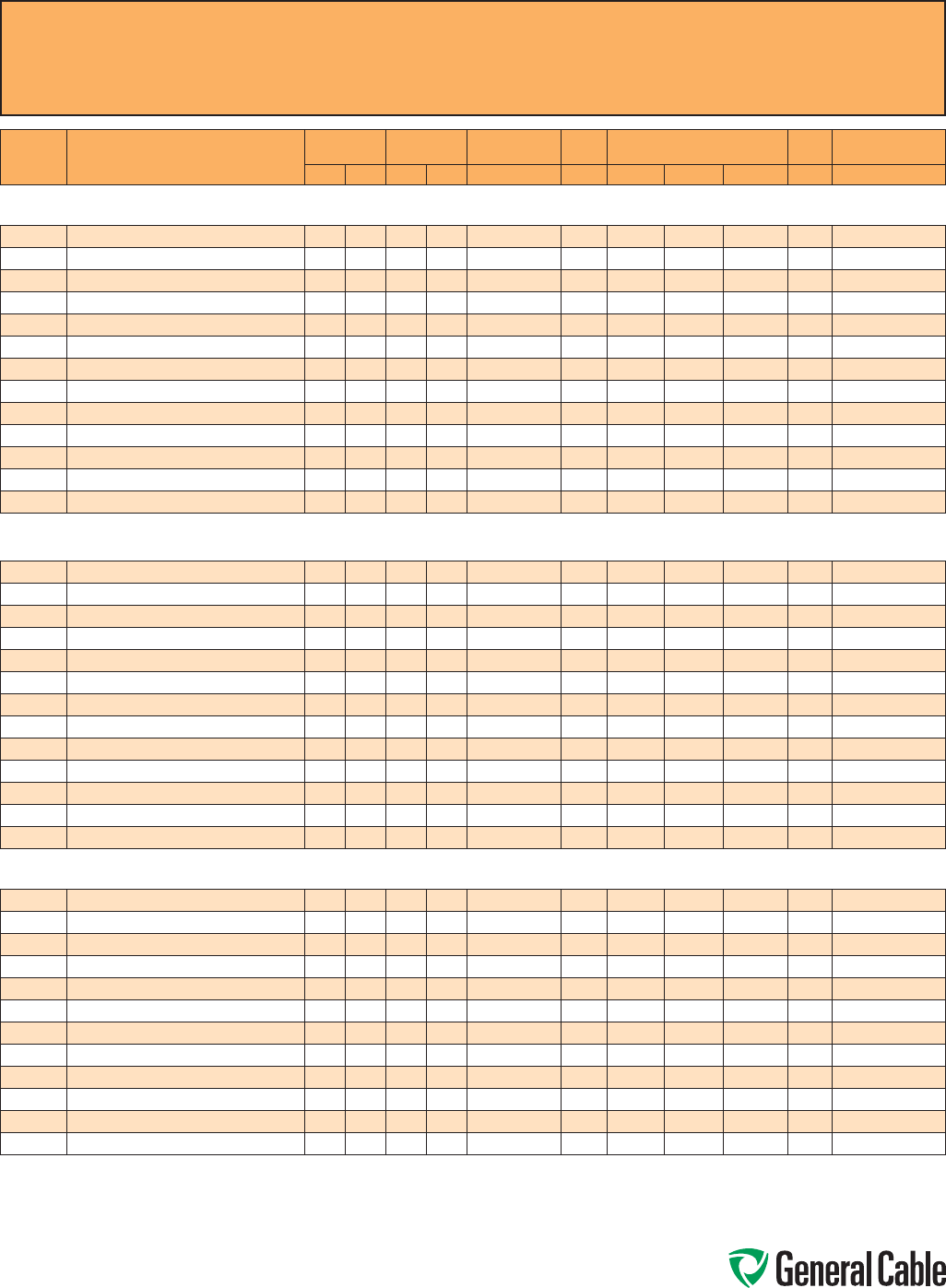
Phone: 888-593-3355
www.generalcable.com
CCW
®
Explosion-Proof Gland Cross-Reference
SPEC A010
April, 2010
CCW
CATALOG
NUMBER PRODUCT DETAIL
NOMINAL ARMOR
O.D. NOMINAL
OVERALL O.D. CROUSE-HINDS HAWKE APPLETON (TMCX)
*end stop removed Thomas &
Betts Hubbell/Killark
INCHES mm INCHES mm TMCX Series 711 Series Aluminum NP Brass Stainless Steel Spin-On X CMCXA
Power - 2.4 kV CCW® ARMORED POWER, 2.4 kV, NONSHIELDED, 3/C VFD WITH BARE GROUND OR MV-90 W/90 MILS INSULATION
9700.00103308 1 AWG 19W (42.4 mm²) 3/C MC-HL W/8 AWG 3/C GROUND 1.42 36.1 1.53 38.9 TMCX5161 C2 or D TMCX150A TMCX150NB TMCX150SS 4-150-140 CMCXAC2125 or CMCXAD200
9700.00203310 2 AWG 7W (33.6 mm²) 3/C MC-HL W/10 AWG 3/C GROUND 1.34 34.0 1.45 36.8 TMCX4140 or TMCX5161 C2 TMCX150A TMCX150NB TMCX150SS 4-150-130 CMCXAC2125
9700.00403310 4 AWG 7W (21.2 mm²) 3/C MC-HL W/10 AWG 3/C GROUND 1.19 30.2 1.30 33.0 TMCX4140 C or C2 TMCX125A TMCX125NB TMCX125SS 4-125-110 CMCXAC100 or CMCXAC2125
9700.00603310 6 AWG 7W (13.3 mm²) 3/C MC-HL W/10 AWG 3/C GROUND 1.06 26.9 1.17 29.7 TMCX3112 C TMCX100A* TMCX100NB* TMCX100SS* 4-125-090 CMCXAC100
9700.00803312 8 AWG 7W (8.36 mm²) 3/C MC-HL W/12 AWG 3/C GROUND 0.97 24.6 1.08 27.4 TMCX3112 C TMCX100A TMCX100NB TMCX100SS 4-100-080 CMCXAB075 or CMCXAC100
9700.10003304 1000 KCMIL 61W (507 mm²) 3/C MC-HL W/4 AWG 3/C GROUND 3.41 86.6 3.59 91.2 TMCX9352 H TMCX350A* TMCX350NB* TMCX350SS* 4-350-310 CMCXAH350
9700.11003308 1/0 AWG 19W (53.5 mm²) 3/C MC-HL W/8 AWG 3/C GROUND 1.51 38.4 1.65 41.9 TMCX5161 C2 or D TMCX200SA TMCX200SNB TMCX200SSS 4-150-150 CMCXAC2125 or CMCXAD200
9700.21003308 2/0 AWG 19W (67.4 mm²) 3/C MC-HL W/8 AWG 3/C GROUND 1.60 40.6 1.73 43.9 TMCX5161 or TMCX6206 D TMCX200SA TMCX200SNB TMCX200SSS 4-200-160 CMCXAD200
9700.25003307 250 KCMIL 37W (127 mm²) 3/C MC-HL W/7 AWG 3/C GROUND 1.96 49.8 2.09 53.1 TMCX6206 or TMCX7247 D or E TMCX200A* TMCX200NB* TMCX200SS* 4-250-200 CMCXAD200 or CMCXAE250
9700.35003306 350 KCMIL 37W (177 mm²) 3/C MC-HL W/6 AWG 3/C GROUND 2.19 55.6 2.32 58.9 TMCX7247 E TMCX250SA* TMCX250SNB* TMCX250SSS* 4-250-220 CMCXAE250
9700.41003307 4/0 AWG 19W (107 mm²) 3/C MC-HL W/7 AWG 3/C GROUND 1.83 46.5 1.96 49.8 TMCX6206 D or E TMCX200A TMCX200NB TMCX200SS 4-200-180 CMCXAD200 or CMCXAE250
9700.50003305 500 KCMIL 37W (253 mm²) 3/C MC-HL W/5 AWG 3/C GROUND 2.45 62.2 2.61 66.3 TMCX7247 or TMCX8302 E or F TMCX250A* TMCX250NB* TMCX250SS* 4-300-240 CMCXAE250 or CMCXAF300
9700.75003304 750 KCMIL 37W (380 mm²) 3/C MC-HL W/4 AWG 3/C GROUND 2.93 74.4 3.10 78.7 TMCX8302 F or H TMCX350A TMCX350NB TMCX350SS — CMCXAF300 or CMCXAH350
Power 5 kV (133%) / 8 kV (100%)
CCW® ARMORED POWER, 5 kV 133%/8 kV 100%, SHIELDED, 3/C VFD WITH BARE GROUND OR MV-105 W/115 MILS INSULATION
9800.00103308 1 AWG 19W (42.4 mm²) 3/C MC-HL W/8 AWG 3/C GROUND 1.69 42.9 1.82 46.2 TMCX6206 D TMCX200SA* TMCX200SNB* TMCX200SSS* 4-200-170 CMCXAD200
9800.00203310 2 AWG 7W (33.6 mm²) 3/C MC-HL W/10 AWG 3/C GROUND 1.64 41.7 1.78 45.2 TMCX6206 D TMCX200SA TMCX200SNB TMCX200SSS 4-200-160 CMCXAD200
9800.00403310 4 AWG 7W (21.2 mm²) 3/C MC-HL W/10 AWG 3/C GROUND 1.51 38.4 1.65 41.9 TMCX5161 C2 or D TMCX200SA TMCX200SNB TMCX200SSS 4-150-150 CMCXAC2125 or CMCXAD200
9800.00603310 6 AWG 7W (13.3 mm²) 3/C MC-HL W/10 AWG 3/C GROUND 1.37 34.8 1.48 37.6 TMCX4140 or TMCX5161 C2 or D TMCX150A TMCX150NB TMCX150SS 4-150-130 CMCXAC2125 or CMCXAD200
9800.00803312 8 AWG 7W (8.36 mm²) 3/C MC-HL W/12 AWG 3/C GROUND 1.34 34.0 1.45 36.8 TMCX4140 or TMCX5161 C2 TMCX150A TMCX150NB TMCX150SS 4-150-130 CMCXAC2125
9800.10003304 1000 KCMIL 61W (507 mm²) 3/C MC-HL W/4 AWG 3/C GROUND 3.76 95.5 3.94 100.1 TMCX10402 — TMCX402400* — — 4-400-330 —
9800.11003308 1/0 AWG 19W (53.5 mm²) 3/C MC-HL W/8 AWG 3/C GROUND 1.78 45.2 1.91 48.5 TMCX6206 D or E TMCX200A TMCX200NB TMCX200SS 4-200-180 CMCXAD200 or CMCXAE250
9800.21003308 2/0 AWG 19W (67.4 mm²) 3/C MC-HL W/8 AWG 3/C GROUND 1.92 48.8 2.05 52.1 TMCX6206 D or E TMCX200A TMCX200NB TMCX200SS 4-200-190 CMCXAD200 or CMCXAE250
9800.25003307 250 KCMIL 37W (127 mm²) 3/C MC-HL W/7 AWG 3/C GROUND 2.23 56.6 2.36 59.9 TMCX7247 E TMCX250SA* TMCX250SNB* TMCX250SSS* 4-250-220 CMCXAE250
9800.35003306 350 KCMIL 37W (177 mm²) 3/C MC-HL W/6 AWG 3/C GROUND 2.45 62.2 2.61 66.3 TMCX7247 or TMCX8302 E or F TMCX250A* TMCX250NB* TMCX250SS* 4-300-240 CMCXAE250 or CMCXAF300
9800.41003307 4/0 AWG 19W (107 mm²) 3/C MC-HL W/7 AWG 3/C GROUND 2.15 54.6 2.28 57.9 TMCX7247 E TMCX250SA TMCX250SNB TMCX250SSS 4-250-210 CMCXAE250
9800.50003305 500 KCMIL 37W (253 mm²) 3/C MC-HL W/5 AWG 3/C GROUND 2.75 69.9 2.92 74.2 TMCX8302 F TMCX300A TMCX300NB TMCX300SS 4-300-260 CMCXAF300
9800.75003304 750 KCMIL 61W (380 mm²) 3/C MC-HL W/4 AWG 3/C GROUND 3.32 84.3 3.50 88.9 TMCX9352 H TMCX350A* TMCX350NB* TMCX350SS* — CMCXAH350
Power - 8 kV (133%) CCW® ARMORED POWER, 8 kV 133%, SHIELDED, 3/C VFD WITH BARE GROUND OR MV-105 W/140 MILS INSULATION
9815.00103308 1 AWG 19W (42.4 mm²) 3/C MC-HL W/8 AWG 3/C GROUND 1.93 49.0 2.06 52.3 TMCX6206 or TMCX7247 D or E TMCX200A TMCX200NB TMCX200SS 4-200-190 CMCXAD200 or CMCXAE250
9815.00203310 2 AWG 7W (33.6 mm²) 3/C MC-HL W/10 AWG 3/C GROUND 1.85 47.0 1.98 50.3 TMCX6206 D or E TMCX200A TMCX200NB TMCX200SS 4-200-190CMCXAD200 or CMCXAE250
9815.00403310 4 AWG 7W (21.2 mm²) 3/C MC-HL W/10 AWG 3/C GROUND 1.70 43.2 1.83 46.5 TMCX6206 D TMCX200SA* TMCX200SNB* TMCX200SSS* 4-200-170 CMCXAD200
9815.00603310 6 AWG 7W (13.3 mm²) 3/C MC-HL W/10 AWG 3/C GROUND 1.60 40.6 1.73 43.9 TMCX5161 or TMCX6206 D TMCX200SA TMCX200SNB TMCX200SSS 4-200-160 CMCXAD200
9815.10003304
1000 KCMIL 61W (507 mm²) 3/C MC-HL W/4 AWG 3/C GROUND
3.98 101.1 4.16 105.7 TMCX10402 — TMCX402400* — — 4-400-350 —
9815.11003308 1/0 AWG 19W (53.5 mm²) 3/C MC-HL W/8 AWG 3/C GROUND 2.03 51.6 2.16 54.9 TMCX6206 or TMCX7247 E TMCX200A* TMCX200NB* TMCX200SS* 4-250-200 CMCXAE250
9815.21003308 2/0 AWG 19W (67.4 mm²) 3/C MC-HL W/8 AWG 3/C GROUND 2.14 54.4 2.27 57.7 TMCX7247 E TMCX250SA TMCX250SNB TMCX250SSS 4-250-210CMCXAE250
9815.25003307 250 KCMIL 37W (127 mm²) 3/C MC-HL W/7 AWG 3/C GROUND 2.59 65.8 2.75 69.9 TMCX8302 F TMCX300A TMCX300NB TMCX300SS 4-300-250 CMCXAF300
9815.35003306 350 KCMIL 37W (177 mm²) 3/C MC-HL W/6 AWG 3/C GROUND 2.85 72.4 3.01 76.5 TMCX8302 F TMCX300A* TMCX300NB* TMCX300SS* — CMCXAF300
9815.41003307 4/0 AWG 19W (107 mm²) 3/C MC-HL W/7 AWG 3/C GROUND 2.40 61.0 2.56 65.0 TMCX7247 E or F TMCX250A TMCX250NB TMCX250SS 4-300-240 CMCXAE250 or CMCXAF300
9815.50003305 500 KCMIL 37W (253 mm²) 3/C MC-HL W/5 AWG 3/C GROUND 3.19 81.0 3.37 85.6 TMCX9352 H TMCX350A TMCX350NB TMCX350SS 4-350-300 CMCXAH350
9815.75003304 750 KCMIL 61W (380 mm²) 3/C MC-HL W/4 AWG 3/C GROUND 3.68 93.5 3.86 98.0 TMCX10402 — TMCX402400* — — 4-400-330 —
All information in this cross-reference is presented solely as a guide to product selection and is believed to be reliable. All printing errors are subject to correction in subsequent
releases of this catalog. Although General Cable has taken precautions to ensure the accuracy of the product cross-reference at the time of publication, the specifications of all
products contained herein are subject to change by gland manufacturers without notice.
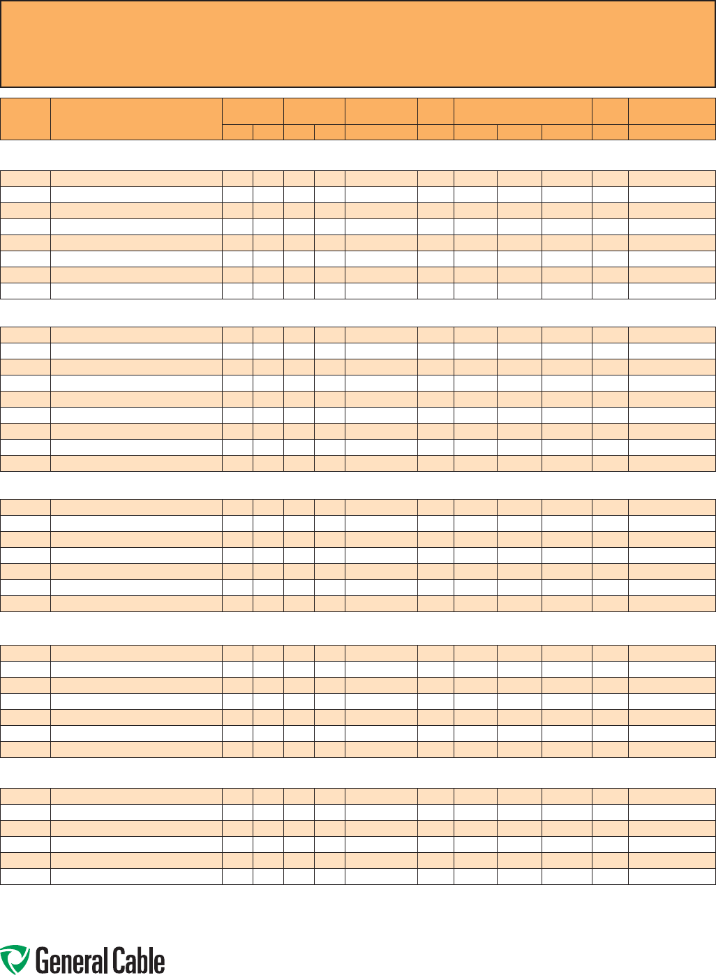
Phone: 888-593-3355
www.generalcable.com
CCW
®
Explosion-Proof Gland Cross-Reference
SPEC A010
April, 2010
CCW
CATALOG
NUMBER PRODUCT DETAIL
NOMINAL ARMOR
O.D. NOMINAL
OVERALL O.D. CROUSE-HINDS HAWKE APPLETON (TMCX)
*end stop removed Thomas &
Betts Hubbell/Killark
INCHES mm INCHES mm TMCX Series 711 Series Aluminum NP Brass Stainless Steel Spin-On X CMCXA
Power - 15 kV (100%) CCW® ARMORED POWER, 15 kV 100%, SHIELDED, 3/C WITH BARE GROUND OR MV-105 175 MILS INSULATION
9825.00103104 1 AWG 19W (42.4 mm²) 3/C MC-HL W/4 AWG GROUND 2.01 51.1 2.15 54.6 TMCX6206 or TMCX7247 E TMCX200A* TMCX200NB* TMCX200SS* 4-250-200 CMCXAE250
9825.00203106 2 AWG 7W (33.6 mm²) 3/C MC-HL W/6 AWG GROUND 1.96 49.8 2.05 52.1 TMCX6206 or TMCX7247 D or E TMCX200A* TMCX200NB* TMCX200SS* 4-250-200 CMCXAD200 or CMCXAE250
9825.11003104 1/0 AWG 19W (53.5 mm²) 3/C MC-HL W/4 AWG GROUND 2.10 53.3 2.24 56.9 TMCX7247 E TMCX250SA TMCX250SNB TMCX250SSS 4-250-210 CMCXAE250
9825.21003104 2/0 AWG 19W (67.4 mm²) 3/C MC-HL W/4 AWG GROUND 2.19 55.6 2.36 59.9 TMCX7247 E TMCX250SA* TMCX250SNB* TMCX250SSS* 4-250-220 CMCXAE250
9825.25003103 250 KCMIL 37W (127 mm²) 3/C MC-HL W/3 AWG GROUND 2.58 65.5 2.74 69.6 TMCX8302 F TMCX300A TMCX300NB TMCX300SS 4-300-250 CMCXAF300
9825.35003102 350 KCMIL 37W (177 mm²) 3/C MC-HL W/2 AWG GROUND 2.85 72.4 3.01 76.5 TMCX8302 F TMCX300A* TMCX300NB* TMCX300SS* — CMCXAF300
9825.41003103 4/0 AWG 19W (107 mm²) 3/C MC-HL W/3 AWG GROUND 2.45 62.2 2.61 66.3 TMCX7247 or TMCX8302 E or F TMCX250A* TMCX250NB* TMCX250SS* 4-300-240 CMCXAE250 or CMCXAF300
9825.50003101 500 KCMIL 37W (253 mm²) 3/C MC-HL W/1 AWG GROUND 3.16 80.3 3.34 84.8 TMCX9352 H TMCX350A TMCX350NB TMCX350SS 4-350-290 CMCXAH350
Power - 15 kV (133%) CCW® ARMORED POWER, 15 kV 133%, SHIELDED, 3/C WITH BARE GROUND OR MV-105 220 MILS INSULATION
9835.00103104 1 AWG 19W (42.4 mm²) 3/C MC-HL W/4 AWG GROUND 2.23 56.6 2.36 59.9 TMCX7247 E TMCX250SA* TMCX250SNB* TMCX250SSS* 4-250-220 CMCXAE250
9835.00203106 2 AWG 7W (33.6 mm²) 3/C MC-HL W/6 AWG GROUND 2.15 54.6 2.28 57.9 TMCX7247 E TMCX250SA TMCX250SNB TMCX250SSS 4-250-210 CMCXAE250
9835.11003104 1/0 AWG 19W (53.5 mm²) 3/C MC-HL W/4 AWG GROUND 2.32 58.9 2.48 63.0 TMCX7247 E or F TMCX250A TMCX250NB TMCX250SS 4-250-230 CMCXAE250 or CMCXAF300
9835.21003104 2/0 AWG 19W (67.4 mm²) 3/C MC-HL W/4 AWG GROUND 2.40 61.0 2.56 65.0 TMCX7247 E or F TMCX250A TMCX250NB TMCX250SS 4-300-240 CMCXAE250 or CMCXAF300
9835.25003103 250 KCMIL 37W (127 mm²) 3/C MC-HL W/3 AWG GROUND 2.75 69.9 2.92 74.2 TMCX8302 F TMCX300A TMCX300NB TMCX300SS 4-300-260 CMCXAF300
9835.35003102 350 KCMIL 37W (177 mm²) 3/C MC-HL W/2 AWG GROUND 3.03 77.0 3.21 81.5 TMCX9352 H TMCX350A TMCX350NB TMCX350SS — CMCXAH350
9835.41003103 4/0 AWG 19W (107 mm²) 3/C MC-HL W/3 AWG GROUND 2.62 66.5 2.79 70.9 TMCX8302 F TMCX300A TMCX300NB TMCX300SS 4-300-250 CMCXAF300
9835.50003101 500 KCMIL 37W (253 mm²) 3/C MC-HL W/1 AWG GROUND 3.32 84.3 3.50 88.9 TMCX9352 H TMCX350A* TMCX350NB* TMCX350SS* — CMCXAH350
9835.750031110 750 KCMIL 61W (380 mm²) 3/C MC-HL W/1/0 AWG GROUND 3.80 96.5 3.98 101.1 TMCX10402 — TMCX402400* — — — —
Power - 25 kV (100%) CCW® ARMORED POWER, 25 kV 100%, SHIELDED, 3/C WITH BARE GROUND OR MV-105 260 MILS INSULATION
9845.00103104 1 AWG 19W (42.4 mm²) 3/C MC-HL W/4 AWG GROUND 2.45 62.2 2.61 66.3 TMCX7247 or TMCX8302 E or F TMCX250A* TMCX250NB* TMCX250SS* 4-300-240 CMCXAE250 or CMCXAF300
9845.11003104 1/0 AWG 19W (53.5 mm²) 3/C MC-HL W/4 AWG GROUND 2.53 64.3 2.69 68.3 TMCX8302 E or F TMCX250A* TMCX250NB* TMCX250SS* 4-300-250 CMCXAE250 or CMCXAF300
9845.21003104 2/0 AWG 19W (67.4 mm²) 3/C MC-HL W/4 AWG GROUND 2.62 66.5 2.79 70.9 TMCX8302 F TMCX300A TMCX300NB TMCX300SS 4-300-250 CMCXAF300
9845.25003103 250 KCMIL 37W (127 mm²) 3/C MC-HL W/3 AWG GROUND 3.07 78.0 3.25 82.6 TMCX9352 H TMCX350A TMCX350NB TMCX350SS 4-350-290 CMCXAH350
9845.35003102 350 KCMIL 37W (177 mm²) 3/C MC-HL W/2 AWG GROUND 3.32 84.3 3.50 88.9 TMCX9352 H TMCX350A* TMCX350NB* TMCX350SS* — CMCXAH350
9845.41003103 4/0 AWG 19W (107 mm²) 3/C MC-HL W/3 AWG GROUND 2.93 74.4 3.10 78.7 TMCX8302 F or H TMCX350A TMCX350NB TMCX350SS — CMCXAF300 or CMCXAH350
9845.50003101 500 KCMIL 37W (253 mm²) 3/C MC-HL W/1 AWG GROUND 3.62 91.9 3.81 96.8 TMCX10402 — TMCX402400* — — 4-400-330 —
Power 25 kV (133%)/35 kV (100%)
CCW® ARMORED POWER, 25 kV 133%/35 kV 100%, SHIELDED, 3/C WITH BARE GROUND OR MV-105 345 MILS INSULATION
9855.00103104 1 AWG 19W (42.4 mm²) 3/C MC-HL W/4 AWG GROUND 2.89 73.4 3.05 77.5 TMCX8302 F TMCX300A* TMCX300NB* TMCX300SS* — CMCXAF300
9855.11003104 1/0 AWG 19W (53.5 mm²) 3/C MC-HL W/4 AWG GROUND 2.98 75.7 3.14 79.8 TMCX8302 or TMCX9352 F or H TMCX350A TMCX350NB TMCX350SS — CMCXAF300 or CMCXAH350
9855.21003104 2/0 AWG 19W (67.4 mm²) 3/C MC-HL W/4 AWG GROUND 3.11 79.0 3.30 83.8 TMCX9352 H TMCX350A TMCX350NB TMCX350SS 4-350-290 CMCXAH350
9855.25003103 250 KCMIL 37W (127 mm²) 3/C MC-HL W/3 AWG GROUND 3.63 92.2 3.81 96.8 TMCX10402 — TMCX402400* — — 4-400-330 -—
9855.35003102 350 KCMIL 37W (177 mm²) 3/C MC-HL W/2 AWG GROUND 3.76 95.5 3.94 100.1 TMCX10402 — TMCX402400* — — 4-400-330 —
9855.41003103 4/0 AWG 19W (107 mm²) 3/C MC-HL W/3 AWG GROUND 3.41 86.6 3.60 91.4 TMCX9352 H TMCX350A* TMCX350NB* TMCX350SS* 4-350-310 CMCXAH350
9855.50003101 500 KCMIL 37W (253 mm²) 3/C MC-HL W/1 AWG GROUND 4.10 104.1 4.23 107.4 — — — — — — —
Power 35 kV (133%) CCW® ARMORED POWER, 35 kV 133%, SHIELDED, 3/C WITH BARE GROUND OR MV-105 420 MILS INSULATION
9875.11003104 1/0 AWG 19W (53.5 mm²) 3/C MC-HL W/4 AWG GROUND 3.41 86.6 3.59 91.2 TMCX9352 H TMCX350A* TMCX350NB* TMCX350SS* 4-350-310 CMCXAH350
9875.21003104 2/0 AWG 19W (67.4 mm²) 3/C MC-HL W/4 AWG GROUND 3.63 92.2 3.81 96.8 TMCX10402 — TMCX402400* — — 4-400-330 —
9875.25003103 250 KCMIL 37W (127 mm²) 3/C MC-HL W/3 AWG GROUND 3.98 101.1 4.16 105.7 TMCX10402 — TMCX402400* — — 4-400-350 —
9875.35003102 350 KCMIL 37W (177 mm²) 3/C MC-HL W/2 AWG GROUND 4.10 104.1 4.29 109.0 — — — — — —- —
9875.41003103 4/0 AWG 19W (107 mm²) 3/C MC-HL W/3 AWG GROUND 3.80 96.5 3.98 101.1 TMCX10402 — TMCX402400* — — — —
9875.50003101 500 KCMIL 37W (253 mm²) 3/C MC-HL W/1 AWG GROUND 4.45 113.0 4.63 117.6 — — — — — — —
All information in this cross-reference is presented solely as a guide to product selection and is believed to be reliable. All printing errors are subject to correction in subsequent
releases of this catalog. Although General Cable has taken precautions to ensure the accuracy of the product cross-reference at the time of publication, the specifications of all
products contained herein are subject to change by gland manufacturers without notice.

Phone: 888-593-3355
www.generalcable.com
CCW
®
Catalog Number Cross-Reference –
Okonite C-L-X
®
to General Cable CCW
®
SPEC A015
January, 2013
Okonite C-L-X®
Catalog Number General Cable CCW®
Catalog Number Okonite C-L-X®
Catalog Number General Cable CCW®
Catalog Number Okonite C-L-X®
Catalog Number General Cable CCW®
Catalog Number
546-31-3002 9525.01402000 546-31-3927 9650.123144000 561-15-3304 9250.18041222
546-31-3003 9525.01403000 546-31-3950 9650.124143000 561-15-3308 9250.18081222
546-31-3004 9525.01404000 546-31-3956 9650.104143000 561-15-3312 9250.18121222
546-31-3005 9525.01405000 546-31-3958 9650.104124000 561-15-3316 9250.18161222
546-31-3007 9525.01407000 546-31-3983 9650.123143000 561-15-3324 9250.18241222
546-31-3009 9525.01409000 546-31-3984 9625.103124110 561-15-3336 9250.18361222
546-31-3012 9525.01412000 546-31-3987 9650.104144000 561-15-3404 9250.16041222
546-31-3019 9525.01419000 546-31-3988 9650.104123000 561-15-3408 9250.16081222
546-31-3037 9525.01437000 546-31-3990 9650.103123000 561-15-3412 9250.16121222
546-31-3082 9525.01202000 546-31-3992 9650.103144000 561-15-3416 9250.16161222
546-31-3083 9525.01203000 561-10-3202 9250.20021221 561-15-3424 9250.16241222
546-31-3084 9525.01204000 561-10-3204 9250.20041221 561-15-3436 9250.16361222
546-31-3085 9525.01205000 561-10-3206 9250.20061221 561-60-3402 9350.16020001
546-31-3087 9525.01207000 561-10-3208 9250.20081221 561-60-3404 9350.16040001
546-31-3089 9525.01209000 561-10-3210 9250.20101221 561-60-3406 9350.16060001
546-31-3092 9525.01212000 561-10-3212 9250.20121221 561-60-3408 9350.16080001
546-31-3099 9525.01219000 561-10-3216 9250.20161221 561-60-3410 9350.16100001
546-31-3117 9525.01237000 561-10-3220 9250.20201221 561-60-3412 9350.16120001
546-31-3162 9525.01002000 561-10-3224 9250.20241221 561-60-3416 9350.16160001
546-31-3163 9525.01003000 561-10-3236 9250.20361221 561-60-3420 9350.16200001
546-31-3164 9525.01004000 561-10-3250 9250.20501221 561-60-3424 9350.16240001
546-31-3165 9525.01005000 561-10-3302 9250.18021221 561-60-3436 9350.16360001
546-31-3167 9525.01007000 561-10-3304 9250.18041221 561-60-3450 9350.16500001
546-31-3169 9525.01009000 561-10-3306 9250.18061221 561-65-3404 9350.16040002
546-31-3172 9525.01012000 561-10-3308 9250.18081221 561-65-3408 9350.16080002
546-31-3402 9500.01402114 561-10-3310 9250.18101221 561-65-3412 9350.16120002
546-31-3403 9600.01403318 561-10-3312 9250.18121221 561-65-3416 9350.16160002
546-31-3404 9600.01404318 561-10-3316 9250.18161221 561-65-3424 9350.16240002
546-31-3406 9500.01406114 561-10-3320 9250.18201221 561-65-3436 9350.16360002
546-31-3408 9500.01408114 561-10-3324 9250.18241221 564-10-3202 9225.20021221
546-31-3411 9500.01411114 561-10-3336 9250.18361221 564-10-3204 9225.20041221
546-31-3418 9500.01418114 561-10-3350 9250.18501221 564-10-3206 9225.20061221
546-31-3436 9500.01436114 561-10-3402 9250.16021221 564-10-3208 9225.20081221
546-31-3452 9500.01202112 561-10-3404 9250.16041221 564-10-3210 9225.20101221
546-31-3453 9600.01203316 561-10-3406 9250.16061221 564-10-3212 9225.20121221
546-31-3454 9600.01204316 561-10-3408 9250.16081221 564-10-3216 9225.20161221
546-31-3456 9500.01206112 561-10-3410 9250.16101221 564-10-3220 9225.20201221
546-31-3458 9500.01208112 561-10-3412 9250.16121221 564-10-3224 9225.20241221
546-31-3461 9500.01211112 561-10-3416 9250.16161221 564-10-3236 9225.20361221
546-31-3468 9500.01218112 561-10-3420 9250.16201221 564-10-3250 9225.20501221
546-31-3486 9500.01236112 561-10-3424 9250.16241221 564-10-3302 9225.18021221
546-31-3502 9500.01002110 561-10-3436 9250.16361221 564-10-3304 9225.18041221
546-31-3503 9600.01003314 561-10-3450 9250.16501221 564-10-3306 9225.18061221
546-31-3504 9600.01004314 561-15-3204 9250.20041222 564-10-3308 9225.18081221
546-31-3506 9500.01006110 561-15-3208 9250.20081222 564-10-3310 9225.18101221
546-31-3508 9500.01008110 561-15-3212 9250.20121222 564-10-3312 9225.18121221
546-31-3511 9500.01011110 561-15-3216 9250.20161222 564-10-3316 9225.18161221
546-31-3758 9650.103143000 561-15-3224 9250.20241222 564-10-3320 9225.18201221
546-31-3925 9650.124144000 561-15-3236 9250.20361222 564-10-3324 9225.18241221
All information in this cross-reference is presented solely as a guide to product selection and is believed to be reliable. All printing
errors are subject to correction in subsequent releases of this catalog. Although General Cable has taken precautions to ensure the
accuracy of the product cross-reference at the time of publication, the specifications of all products contained herein are subject to
change by gland manufacturers without notice.
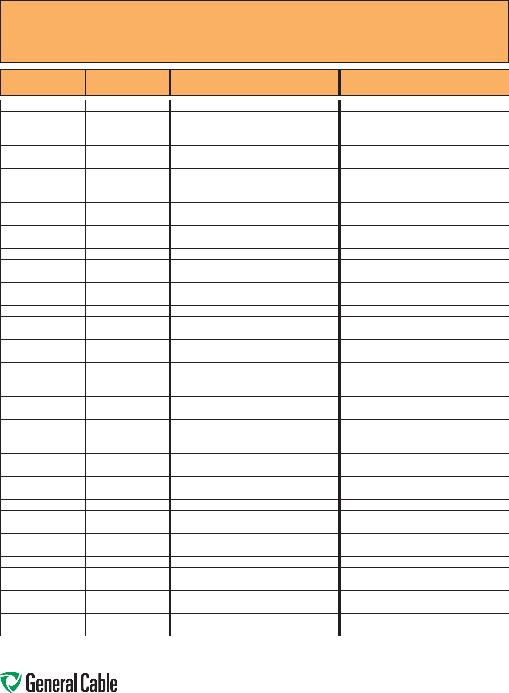
Phone: 888-593-3355
www.generalcable.com
CCW
®
Catalog Number Cross-Reference –
Okonite C-L-X
®
to General Cable CCW
®
SPEC A015
January, 2013
Okonite C-L-X®
Catalog Number General Cable CCW®
Catalog Number Okonite C-L-X®
Catalog Number General Cable CCW®
Catalog Number Okonite C-L-X®
Catalog Number General Cable CCW®
Catalog Number
564-10-3336 9225.18361221 564-65-3408 9325.16080002 571-21-3244 9700.50003305
564-10-3350 9225.18501221 564-65-3412 9325.16120002 571-21-3248 9700.75003304
564-10-3401 9225.16010001 564-65-3416 9325.16160002 571-21-3252 9700.10003304
564-10-3402 9225.16021221 564-65-3424 9325.16240002 571-22-3696 9800.00603310
564-10-3404 9225.16041221 564-65-3436 9325.16360002 571-22-3698 9800.00403310
564-10-3406 9225.16061221 567-86-3402 9150.16021201 571-22-3706 9800.00203310
564-10-3408 9225.16081221 567-86-3404 9150.16041201 571-22-3708 9800.00103308
564-10-3410 9225.16101221 567-86-3408 9150.16081201 571-22-3710 9800.11003308
564-10-3412 9225.16121221 567-86-3412 9150.16121201 571-22-3717 9800.21003308
564-10-3416 9225.16161221 567-86-3424 9150.16241201 571-22-3725 9800.41003307
564-10-3420 9225.16201221 567-86-3436 9150.16361201 571-22-3727 9800.25003307
564-10-3424 9225.16241221 567-86-3450 9150.16501201 571-22-3748 9800.75003304
564-10-3436 9225.16361221 567-87-3402 9150.16021202 571-22-3751 9800.10003304
564-10-3450 9225.16501221 567-87-3404 9150.16041202 571-22-3838 9800.35003306
564-15-3204 9225.20041222 567-87-3408 9150.16081202 571-22-3846 9800.50003305
564-15-3208 9225.20081222 567-87-3412 9150.16121202 571-23-3204 9825.00203106
564-15-3212 9225.20121222 567-87-3424 9150.16241202 571-23-3208 9825.00103104
564-15-3216 9225.20161222 567-87-3436 9150.16361202 571-23-3212 9825.11003104
564-15-3224 9225.20241222 567-87-3450 9150.16501202 571-23-3216 9825.21003104
564-15-3236 9225.20361222 567-93-3801 9125.16010001 571-23-3224 9825.41003103
564-15-3304 9225.18041222 567-93-3802 9125.16021201 571-23-3228 9825.25003103
564-15-3308 9225.18081222 567-93-3804 9125.16041201 571-23-3236 9825.35003102
564-15-3312 9225.18121222 567-93-3808 9125.16081201 571-23-3244 9825.50003101
564-15-3316 9225.18161222 567-93-3812 9125.16121201 571-23-3504 9835.00203106
564-15-3324 9225.18241222 567-93-3816 9125.16161201 571-23-3508 9835.00103104
564-15-3336 9225.18361222 567-93-3824 9125.16241201 571-23-3512 9835.11003104
564-15-3401 9225.16010002 567-93-3836 9125.16361201 571-23-3516 9835.21003104
564-15-3404 9225.16041222 567-93-3850 9125.16501201 571-23-3524 9835.41003103
564-15-3408 9225.16081222 567-94-3801 9125.16010002 571-23-3528 9835.25003103
564-15-3412 9225.16121222 567-94-3802 9125.16021202 571-23-3536 9835.35003102
564-15-3416 9225.16161222 567-94-3804 9125.16041202 571-23-3544 9835.50003101
564-15-3424 9225.16241222 567-94-3808 9125.16081202 571-23-3548 9835.750031110
564-15-3436 9225.16361222 567-94-3812 9125.16121202 571-23-3758 9845.00103104
564-60-3401 9325.16010001 567-94-3816 9125.16161202 571-23-3762 9845.11003104
564-60-3402 9325.16020001 567-94-3824 9125.16241202 571-23-3766 9845.21003104
564-60-3404 9325.16040001 567-94-3836 9125.16361202 571-23-3774 9845.41003103
564-60-3406 9325.16060001 567-94-3850 9125.16501202 571-23-3778 9845.25003103
564-60-3408 9325.16080001 571-21-3193 9700.00803312 571-23-3786 9845.35003102
564-60-3410 9325.16100001 571-21-3196 9700.00603310 571-23-3794 9845.50003101
564-60-3412 9325.16120001 571-21-3200 9700.00403310 571-23-3808 9855.00103104
564-60-3416 9325.16160001 571-21-3204 9700.00203310 571-23-3812 9855.11003104
564-60-3420 9325.16200001 571-21-3208 9700.00103308 571-23-3816 9855.21003104
564-60-3424 9325.16240001 571-21-3212 9700.11003308 571-23-3824 9855.41003103
564-60-3436 9325.16360001 571-21-3217 9700.21003308 571-23-3826 9855.25003103
564-60-3450 9325.16500001 571-21-3224 9700.41003307 571-23-3836 9855.35003102
564-65-3401 9325.16010002 571-21-3228 9700.25003307 571-23-3844 9855.50003101
564-65-3404 9325.16040002 571-21-3236 9700.35003306 571-23-3852 9875.11003104
All information in this cross-reference is presented solely as a guide to product selection and is believed to be reliable. All printing errors are subject to correction in subsequent
releases of this catalog. Although General Cable has taken precautions to ensure the accuracy of the product cross-reference at the time of publication, the specifications of all
products contained herein are subject to change by gland manufacturers without notice.

Phone: 888-593-3355
www.generalcable.com
CCW
®
Catalog Number Cross-Reference –
Okonite C-L-X
®
to General Cable CCW
®
SPEC A015
January, 2013
Okonite C-L-X®
Catalog Number General Cable CCW®
Catalog Number Okonite C-L-X®
Catalog Number General Cable CCW®
Catalog Number Okonite C-L-X®
Catalog Number General Cable CCW®
Catalog Number
571-23-3856 9875.21003104 571-31-3670 9650.044123000 584-10-4216 9075.20161224
571-23-3864 9875.41003103 571-31-3671 9650.043123000 584-10-4220 9075.20201224
571-23-3876 9875.35003102 571-31-3672 9650.044124000 584-10-4224 9075.20241224
571-23-3884 9875.50003101 571-31-3673 9650.063123000 584-10-4236 9075.20361224
571-31-3190 9600.00803314 571-31-3674 9650.023144000 584-10-4250 9075.20501224
571-31-3191 9600.00603312 571-31-3675 9650.023123000 584-20-1204 9050.20041221
571-31-3192 9650.083143000 571-31-3677 9625.043124108 584-20-1208 9050.20081221
571-31-3195 9650.063143000 571-31-3680 9650.084124000 584-20-1210 9050.20101221
571-31-3200 9600.00403312 571-31-3682 9650.084143000 584-20-1212 9050.20121221
571-31-3203 9650.023143000 571-31-3683 9650.084123000 584-20-1216 9050.20161221
571-31-3204 9600.00203310 571-31-3684 9650.064144000 584-20-1220 9050.20201221
571-31-3208 9600.00103310 571-31-3685 9650.064123000 584-20-1224 9050.20241221
571-31-3213 9600.11003310 571-31-3688 9650.044143000 584-20-1236 9050.20361221
571-31-3216 9600.21003310 571-31-3960 9650.084144000 584-20-1250 9050.20501221
571-31-3224 9600.41003308 571-31-3965 9650.064124000 584-20-1401 9025.16010001
571-31-3228 9600.25003308 571-31-3968 9650.064143000 584-20-2204 9050.20041222
571-31-3236 9600.35003307 571-31-3970 9650.043144000 584-20-2208 9050.20081222
571-31-3244 9600.50003306 571-31-3974 9650.043124000 584-20-2210 9050.20101222
571-31-3248 9600.75003305 584-10-1204 9075.20041221 584-20-2212 9050.20121222
571-31-3252 9600.100031110 584-10-1208 9075.20081221 584-20-2216 9050.20161222
571-31-3263 9600.00804110 584-10-1210 9075.20101221 584-20-2220 9050.20201222
571-31-3270 9600.00604108 584-10-1216 9075.20161221 584-20-2224 9050.20241222
571-31-3272 9600.00404108 584-10-1220 9075.20201221 584-20-2236 9050.20361222
571-31-3276 9600.00204106 584-10-1224 9075.20241221 584-20-2250 9050.20501222
571-31-3280 9600.00104106 584-10-1236 9075.20361221 584-20-2401 9025.16010002
571-31-3285 9600.11004106 584-10-1250 9075.20501221 584-20-3204 9050.20041223
571-31-3289 9600.21004106 584-10-2204 9075.20041222 584-20-3208 9050.20081223
571-31-3296 9600.41004104 584-10-2208 9075.20081222 584-20-3210 9050.20101223
571-31-3300 9600.25004104 584-10-2210 9075.20101222 584-20-3212 9050.20121223
571-31-3308 9600.35004103 584-10-2212 9075.20121222 584-20-3216 9050.20161223
571-31-3316 9600.50004102 584-10-2216 9075.20161222 584-20-3220 9050.20201223
571-31-3320 9600.75004101 584-10-2220 9075.20201222 584-20-3224 9050.20241223
571-31-3324 9600.100041110 584-10-2224 9075.20241222 584-20-3236 9050.20361223
571-31-3505 9650.023124000 584-10-2236 9075.20361222 584-20-3250 9050.20501223
571-31-3506 9650.024143000 584-10-2250 9075.20501222 584-20-3401 9025.16010003
571-31-3507 9650.024144000 584-10-3204 9075.20041223 584-20-4204 9050.20041224
571-31-3508 9650.024123000 584-10-3208 9075.20081223 584-20-4208 9050.20081224
571-31-3509 9650.024124000 584-10-3210 9075.20101223 584-20-4210 9050.20101224
571-31-3655 9650.043143000 584-10-3212 9075.20121223 584-20-4212 9050.20121224
571-31-3657 9625.083124110 584-10-3216 9075.20161223 584-20-4216 9050.20161224
571-31-3661 9650.083144000 584-10-3220 9075.20201223 584-20-4220 9050.20201224
571-31-3664 9650.083123000 584-10-3224 9075.20241223 584-20-4224 9050.20241224
571-31-3665 9650.083124000 584-10-3236 9075.20361223 584-20-4236 9050.20361224
571-31-3666 9650.063144000 584-10-3250 9075.20501223 584-20-4250 9050.20501224
571-31-3667 9625.063124108 584-10-4204 9075.20041224 584-20-4401 9025.16010004
571-31-3668 9650.063124000 584-10-4208 9075.20081224
571-31-3669 9650.044144000 584-10-4212 9075.20121224
All information in this cross-reference is presented solely as a guide to product selection and is believed to be reliable. All printing errors are subject to correction in subsequent
releases of this catalog. Although General Cable has taken precautions to ensure the accuracy of the product cross-reference at the time of publication, the specifications of all
products contained herein are subject to change by gland manufacturers without notice.

Phone: 888-593-3355
www.generalcable.com
Reference Standards
SPEC A030
April, 2010
AEIC CS5: Specifications for
Thermoplastic and Crosslinked
Polyethylene Insulated Shielded Power
Cables Rated 5 Through 69 kV
AEIC CS6: Specifications for Ethylene
Propylene Rubber Insulated Shielded
Power Cables Rated 5 Through 69 kV
AEIC CS8: Specification for Extended
Dielectric, Shielded Power Cables Rated 5
through 46 kV
ANSI C2: National Electrical Safety Code
ANSI MC96.1: Thermocouple Extension
Wire Calibration
ASTM B 3: Standard Specification for Soft
or Annealed Copper Wire
ASTM B 8: Standard Specification
for Concentric-Lay Stranded Copper
Conductors, Hard, Medium-Hard or Soft
ASTM B 33: Standard Specification for
Tinned Soft or Annealed Copper Wire for
Electrical Purposes
ASTM B 105: Standard Specification
for Hard-Drawn Copper Alloy Wires for
Electrical Conductors
ASTM B 172: Standard Specification for
Rope-Lay-Stranded Copper Conductors
Having Bunch-Stranded Members, for
Electrical Conductors
ASTM B 173: Standard Specification for
Rope-Lay-Stranded Copper Conductors
Having Concentric-Stranded Members, for
Electrical Conductors
ASTM B 174: Standard Specification for
Bunch-Stranded Copper Conductors for
Electrical Conductors
ASTM B 189: Standard Specification for
Lead-Coated and Lead-Alloy-Coated Soft
Copper Wire for Electrical Purposes
ASTM B 193: Standard Test Method for
Resistivity of Electrical Conductor Materials
ASTM B 226: Standard Specification for
Cored, Annular, Concentric-Lay-Stranded
Copper Conductors
ASTM B 246: Standard Specification for
Tinned Hard-Drawn and Medium-Hard-
Drawn Copper Wire for Electrical Purposes
ASTM B 258: Standard Specification
for Standard Nominal Diameters and
Cross-Sectional Areas of AWG Sizes of
Solid Round Wires Used as Electrical
Conductors
ASTM B 263: Standard Test Method for
Determination of Cross-Sectional Area of
Stranded Conductors
ASTM B 298: Standard Specification for
Silver-Coated Soft or Annealed Copper
Wire
ASTM B 324: Standard Specification for
Nickel-Coated Soft or Annealed Copper
Wire
ASTM B 355: Standard Specification for
Nickel-Coated Soft or Annealed Copper
Wire
ASTM B 496: Standard Specification for
Compact Round Concentric-Lay-Stranded
Copper Conductors
ASTM B 738: Standard Specification for
Fine-Wire Bunch-Stranded and Rope-Lay
Bunch Stranded Copper Conductors for
Use as Electrical Conductors
ASTM B 784: Standard Specification for
Modified Concentric-Lay-Stranded Copper
Conductors for Use in Insulated Electrical
Cables
ASTM B 785: Standard Specification for
Compact Round Modified Concentric-Lay-
Stranded Copper Conductors for Use in
Insulated Electrical Cables
ASTM D 149: Standard Test Method
for Dielectric Break down Voltage and
Dielectric Strength of Solid Electrical
Insulating Materials at Commercial Power
Frequencies
ASTM D 470: Method of Testing
Crosslinked Insula tions and Jackets for
Wire and Cable
ASTM D 866: Specification for Styrene-
Butadiene (SBR) Synthetic Rubber Jacket
for Wire and Cable
ASTM D 1047: Specification for Polyvinyl
Chloride (PVC) Jacket for Wire and Cable
ASTM D 1351: Specification for
Polyethylene Insulation for Wire and Cable
ASTM D 1352: Specification for Ozone-
Resisting Butyl Rubber Insulation for Wire
and Cable
ASTM D 1523: Method for Synthetic
Rubber Insulation for Wire and Cable, 90°
Operation
ASTM D 1679: Specification for Synthetic
Rubber Heat and Moisture-Resisting
Insulation for Wire and Cable, 75°C
Operation
ASTM D 2219: Specification for Polyvinyl
Chloride (PVC) Insulation for Wire and
Cable, 60° Operation
ASTM D 2220: Specification for Polyvinyl
Chloride (PVC) Insulation for Wire and
Cable, 75° Operation
ASTM D 2308: Specification for
Polyethylene Jacket for Electrical Insulated
Wire and Cable
ASTM D 2526: Specification for Ozone-
Resisting Silicone Rubber Insulation for
Wire and Cable
ASTM D 2655: Specification for Crosslinked
Polyethylene Insulation for Wire and Cable
Rated 0 to 2000V
ASTM D 2656: Specification for Crosslinked
Polyethylene Insulation for Wire and Cable
Rated 2001 to 35000V
ASTM D 2768: Specification for General-
Purpose Ethylene-Propylene Rubber Jacket
for Wire and Cable
ASTM D 2770: Specification for Ozone-
Resisting Ethylene-Propylene Rubber
Integral Insulation and Jacket for Wire and
Cable
ASTM D 2802: Specification for Ozone-
Resistant Ethylene-Propylene Rubber
Insulation for Wire and Cable
ASTM D 3004: Specification for Extruded
Thermo set ting and Thermoplastic Semi-
Conduct ing Conductor and Insulation
Shields
ASTM D 3554: Specification for Track-
Resistant Black Thermoplastic High Density
Poly ethylene Insulation for Wire and Cable
ASTM D 3555: Specification for Track-
Resistant Black Crosslinked Thermosetting
Poly ethylene Insulation for Wire and Cable
ASTM D 4244: Specification for General-
Purpose, Heavy-Duty and Extra-Heavy
Duty Acrylonitrile-Butadiene/ Polyvinyl
Chloride (NBR/PVC) Jackets for Wire and
Cable

Phone: 888-593-3355
www.generalcable.com
Reference Standards
SPEC A030
April, 2010
ASTM D 4245: Specification for Ozone-
Resistant Thermoplastic Elastomer
Insulation for Wire and Cable, 90°C Dry -
75°C Wet Operation
ASTM D 4246: Specification for Ozone-
Resistant Thermoplastic Elastomer
Insulation for Wire and Cable, 90°C
Operation
ASTM D 4313: Specification for General
Purpose Heavy-Duty and Extra-Heavy-
Duty Crosslinked Chlorinated Poly ethylene
Jackets for Wire and Cable
ASTM D 4363: Specification for
Thermoplastic Chlorinated Polyethylene
Jacket for Wire and Cable
ASTM D 4496: Test Method of DC
Resistance or Conductance of Moderately
Conductive Materials
CAN/CSA C22.2 No. 211: Standard for
Cord Sets and Power-Supply Cords
CAN/CSA C22.2 No. 48: Standard for
Nonmetallic Sheathed Cable
CAN/CSA C22.2 No. 49: Standard for
Flexible Cords and Cables
CAN/CSA C22.2 No. 51: Standard for
Armored Cable
CAN/CSA C22.2 No. 96: Standard for
Portable Power Cables
CAN/CSA C22.2 No. 131: Standard for
Type TECK 90 Cable
CAN/CSA C22.2 No. 239: Standard for
Control and Instrumentation Cables
CAN/CSA C22.2 No. 241: IEEE Standard
for Cable Joints for Use with Extruded
Dielectric Cable Rated 5,000V Through
46,000V, and Cable Joints for Use with
Laminated Dielectric Cable Rated 2,500V
Through 500,000V (Adopted IEEE 404-
1986)
CAN/CSA C49.1: Standard for Round
Wire, Concentric Lay, Overhead Electrical
Conductors
CAN/CSA C68.3: Standard for Shielded
and Concentric Neutral Power Cables
Rated 5-46 kV
CSA C22.1: Canadian Electrical Code,
Part 1, Safety Standard for Electrical
Installations
CSA C22.2 No. 0.3: Standard for Test
Methods for Electrical Wires and Cables
CSA C22.2 No. 16: Standard for Insulated
Conductors for Power-Operated Electronic
Devices
CSA C22.2 No. 35: Standard for Extra-
Low-Voltage Control Circuit Cables, Low-
Energy Control Cable, and Extra-Low-
Voltage Control Cable
CSA C22.2 No. 38: Standard for
Thermoset Insulated Wires and Cables
CSA C22.2 No. 75: Standard for
Thermoplastic-Insulated Wires and Cables
CSA C22.2 No. 123: Standard for
Aluminum Sheathed Cables
CSA C22.2 No. 127: Standard for
Equipment Wires
CSA C22.2 No. 138: Standard for Heat
Tracing Cable and Cable Sets for Use in
Hazardous Locations
CSA C22.2 No. 174: Standard for Cables
and Cable Glands for Use in Hazardous
Locations
CSA C22.2 No. 188: Standard for Splicing
Wire and Cable Connectors
CSA C22.2 No. 198.2: Standard for
Underground Cable Splicing Kits
CSA C22.2 No. 230: Standard for Tray
Cable
CSA/CAN3 C22.3 No. 7: Standard for
Underground Systems
CSA M421: Standard for Use of Electricity
in Mines
ICEA P-32-382: ICEA Standards
Publication for Short Circuit
Characteristics of Insulated Cable
ICEA P-45-482: ICEA Standards
Publication for Short-Circuit Performance
of Metallic Shields and Sheaths of
Insulated Cable
ICEA P-53-426: ICEA/NEMA Standards
Publication for Ampacities, Including Effect
of Shield Losses for Single-Conductor
Solid-Dielectric Power Cable 15 kV
through 69 kV (NEMA WC 50)
ICEA P-54-440: ICEA/NEMA Standards
Publication for Ampacities of Cables in
Open-Top Cable Trays (NEMA WC 51)
ANSI/ICEA S-70-547: ICEA/ANSI
Standards Publication for Weather-
Resistant Polyolefin-Covered Wire
and Cable
ICEA S-73-532: ICEA/NEMA/ANSI Standards
Publi ca tion for Control Cables (NEMA WC 57)
ICEA S-75-381: ICEA/NEMA/ANSI
Standards Publication for Portable and
Power Feeder Cables for Use in Mines and
Similar Applications (NEMA WC 58)
ICEA S-82-552: ICEA/NEMA Standards
Publication for Instru mentation Cables and
Thermocouple Wire (NEMA WC 55)
ICEA-S-93-639: ICEA/NEMA Standard for
Shielded Power Cables Rated 5-46 kV for
the Distribution of Electrical Energy (NEMA
WC 74)
ICEA S-95-658: ICEA/NEMA Standard
for Non-shielded Power Cables Rated
2000 Volts or Less for the Distribution of
Electrical Energy (NEMA WC 70)
ICEA S-96-659: ICEA/NEMA Standard for
Non-shielded Cables Rated 2001-5000
Volts for use in the Distribution of Electrical
Energy (NEMA WC 71)
ICEA T-22-294: ICEA Standard Test
Procedures for Extended Time-Testing of
Wire and Cable Insulations for Service in
Wet Locations
ICEA T-25-425: ICEA Guide for
Establishing Stability of Volume Resistivity
for Conducting Polymeric Components of
Power Cables
ICEA T-26-465: ICEA/NEMA Guide for
Frequency of Sampling Extruded Dielectric
Power, Control, Instru mentation and Port-
able Cables for Test (NEMA WC 54)
ICEA T-27-581: ICEA/NEMA Standard Test
Methods for Extruded Dielectric Power,
Control, Instrumentation and Portable
Cables (NEMA WC 53)
ANSI/ICEA T-28-562: ICEA Standard Test
Method for Measurement of Hot Creep of
Polymeric Insulations
ICEA T-29-520: ICEA Standard for Vertical
Tray Flame Tests at 210,000 BTU
ICEA T-30-520: ICEA Standard for Vertical
Tray Flame Tests at 70,000 BTU

Phone: 888-593-3355
www.generalcable.com
Reference Standards
SPEC A030
April, 2010
ICEA T-31-610: ICEA Standard for Water
Penetration Resistance Test, Sealed
Conductor
IEC 92-3: International Electrotechnical
Commission Electrical Installation in
Ships – Part 3 Cables (Constructions,
Testing and Installations)
IEEE 45: IEEE Recommended Practice for
Electric Installations on Shipboard
IEEE 48: IEEE Standard Test Procedures
and Requirements for High-Voltage Alter -
nating Current Cable Terminations
IEEE 100: IEEE Standard Dictionary of
Electrical and Electronics Terms
IEEE 141: IEEE Recommended Practice
for Electric Power Distribution for Industrial
Plants (“IEEE Red Book”)
IEEE 142: IEEE Recommended
Practice for Grounding of Industrial and
Commercial Power Systems (“IEEE
Green Book”)
IEEE 241: IEEE Recommended Practice
for Electric Power Systems in Com mercial
Buildings (“IEEE Gray Book”)
IEEE 242: IEEE Recommended Practice
for Protection and Coordination of
Industrial and Commercial Power Systems
(“IEEE Buff Book”)
IEEE 323: IEEE Standard for Qualifying
Class 1E Equipment for Nuclear Power
Generating Stations
IEEE 383: IEEE Standard for Type Test of
Class 1E Electric Cables, Field Splices and
Connections for Nuclear Power Generating
Stations
IEEE 400: IEEE Guide for Making High-
Direct-Voltage Tests on PowerCable
Systems in the Field
IEEE 404: IEEE Standard for Cable Joints
for Use with Extruded Dielectric Cable
Rated 5,000V Through 46,000V, and Cable
Joints for Use with Laminated Dielectric
Cable Rated 2,500V Through 500,000V
(Adopted as a National Standard of
Canada, CAN/CSA-C22.2 No. 241)
IEEE 446: IEEE Recommended Practice
for Emergency and Standby Power
Systems for Industrial and Commercial
Applications (“IEEE Orange Book”)
IEEE 493: IEEE Recommended Practice
for the Design of Reliable Industrial
and Commercial Power Systems
(“IEEE Gold Book”)
IEEE 525: IEEE Guide for the Design
and Install ation of Cable Systems in
Substations
IEEE 575: IEEE Guide for the Application
of Sheath-Bonding Methods for Single-
Conductor Cables and the Calcula tion of
Induced Voltages and Currents in Cable
Sheaths
IEEE 576: IEEE Recommended Practice
for Installation, Termination, and Testing
of Insulated Power Cable as Used in the
Petroleum and Chemical Industry
IEEE 602: IEEE Recommended Practice
for Electric Systems in Health Care
Facilities (“IEEE White Book”)
IEEE 635: IEEE Guide for Selection and
Design of Aluminum Sheaths for Power
Cables
IEEE 789: IEEE Standard Performance
Requirements for Communications and
Control Cables for Application in High
Voltage Environments
IEEE 816: IEEE Guide for Determining the
Smoke Generation of Solid Materials Used
for Insulations and Coverings of Electric
Wire and Cable
IEEE 1017: IEEE Recommended Practice
for Field Testing Electric Submersible
Pump Cable
IEEE 1018: IEEE Recommended Practice
for Specifying Electric Submersible Pump
Cable – Ethylene-Propylene Rubber
Insulation
IEEE 1019: IEEE Recommended Practice
for Specifying Electric Submersible Pump
Cable – Polypropylene Insulation
IEEE 1202: IEEE Standard for Flame
Testing of Cables for Use in Cable Tray in
Indus trial and Commercial Occupancies
IEEE/ICEA S-135: Power Cable
Ampacities
NEMA WC 3: Rubber-Insulated Wire
and Cable for the Transmission and
Distribution of Electrical Energy (ICEA
S-19-81)
NEMA WC 5: Thermoplastic-Insulated
Wire and Cable for the Transmission and
Distribution of Electrical Energy (ICEA
S-61-402)
NEMA WC 7: Cross-Linked-
Thermosetting-Polyethylene-Insulated
Wire and Cable for the Transmission and
Distribution of Electrical Energy (ICEA
S-66-524)
NEMA WC 8: Ethylene-Propylene-
Rubber-Insulated Wire and Cable for the
Transmission and Distribution of Electrical
Energy (ICEA S-68-516)
NEMA WC 26: Wire and Cable Packaging
NEMA WC 50: Ampacities, Including
Effect of Shield Losses for Single-
Conductor Solid Dielectric Power Cable
15 kV through 69 kV (ICEA P-53-426)
NEMA WC 51: Ampacities of Cables in
Open-Top Cable Trays (ICEA P-54-440)
NEMA WC 52: High Temperature and
Electronic Insulated Wire-Impulse
Dielectric Testing
NEMA WC 53: Standard Test Methods for
Extruded Dielectric Power, Control, Instru-
menta tion, and Portable Cables (ICEA
T-27-581)
NEMA WC 54: Guide for Frequency of
Sampling Extruded Dielectric Power,
Control, Instrumentation, and Portable
Cables for Test (ICEA T-26-465)
NEMA WC 55: Instrumentation Cables
and Thermocouple Wire (ICEA S-82-552)
NEMA WC 57: Standard for Control Cables
(ICEA S-73-532)
NEMA WC 58: Standard for Portable and
Power Feeder Cables for Use in Mines and
Similar Applications (ICEA-S-75-381)

Phone: 888-593-3355
www.generalcable.com
Reference Standards
SPEC A030
April, 2010
NEMA WC 61: Transfer Impedance Testing
NEMA WC 62: Repeated Spark/Impulse
Dielectric Testing
NEMA WC 70: Standard for Non-shielded
Power Cables Rated 2000 Volts or Less for
the Distribution of Electrical Energy (ICEA
S-95-658)
NEMA WC 71: Standard for Non-shielded
Cables Rated 2001-5000 Volts for Use in
the Distribution of Electrical Energy (ICEA
S-96-659)
NEMA WC 74: Standard for Shielded
Power Cables Rated 5-46 kV for the
Distribution of Electrical Energy (ICEA
S-93-639)
NFPA 70: National Electrical Code
NFPA 70HB: National Electrical Code
Handbook
NFPA 262: Test for Fire and Smoke
Characteristics of Wires and Cables
UL 4: Standard for Armored Cable
UL 13: Standard for Power-Limited Circuit
Cables
UL 44: Standard for Rubber-Insulated Wires
and Cables
UL 62: Standard for Flexible Cord and
Fixture Wire
UL 83: Standard for Thermoplastic-
Insulated Wires and Cables
UL 486A: Standard for Wire Connectors
and Soldering Lugs for Use With Copper
Conductors
UL 486B: Standard for Wire Connectors
and Soldering Lugs for Use With Aluminum
Conductors
UL 486C: Standard for Splicing Wire
Connectors
UL 486D: Standard for Insulated Wire
Connectors for Use With Underground
Conductors
UL 486E: Standard for Equipment Wiring
Terminals for Use With Aluminum and/or
Copper Conductors
UL 493: Standard for Thermoplastic-
Insulated Underground Feeder and Branch-
Circuit Cables
UL 1072: Standard for Medium-Voltage
Power Cables
UL 1084: Standard for Hoistway Cables
UL 1277: Standard for Electrical Power
and Control Tray Cables With Optional
Optical Fiber Members
UL 1309: Standard for Marine Shipboard
Cable
UL 1424: Standard for Cables for Power-
Limited Fire-Protective-Signaling Circuits
UL 1569: Standard for Metal-Clad Cables
UL 1581: Reference Standard for Electrical
Wires, Cables and Flexible Cords
UL 1685: Standard for Vertical-Tray Fire-
Propagation and Smoke-Release Test for
Electrical and Optical-Fiber Cables
UL 1807: Standard for Fire Resistant
Cable Coating Materials
UL 2029: Standard for Gas/Vapor-Blocked
Cable Classified for Use in Class 1
Hazardous (Classified) Locations
UL 2225: Cable and Cable Fittings for Use
in Hazardous Locations
UL 2250: Instrumentation Tray Cable
UL 2556: Wire and Cable Test Methods
UL Type ITC-HL: Listing for
Instrumentation Cable Used in Hazardous
Locations
UL Type PLTC: Listing for Power-Limited
Tray Cables
WC: See NEMA listing

Phone: 888-593-3355
www.generalcable.com
Instrumentation & Control Cable
Voltage Rating
___ 300 V
___ 600 V
___ Number of Conductor
Conductor Type-Copper
___ AWG
___ Bare
___ Tinned
___ Thermocouple
___ EX
___ JX
___ KX
___ TX
___ Solid
___ Stranded
___ Class B, concentric
___ Flexible
Insulation
___ PVC
___ XLPE
Identification Method
___ Color code
___ Numbering
Grounding Conductor
___ Size
___ Bare
___ Tinned
___ Insulated
Aluminum Mylar Shields
___ Individual (IS)
___ Overall (OS)
___ Individual/Overall (IOS)
CCW® Armor
___ PLTC-HL
___ ITC-HL
___ MC
___ MC-HL
Jacket
___ PVC
___ Other
Power Cable
Voltage rating
___ 600 V
___ 2400 V (2.4 kV)
___ 5 kV
___ 8 kV
___ 15 kV
___ 25 kV
___ 35 kV
Cable Assembly
___ Cabled VFD (split grounds)
___ Multi-conductor (one ground)
___ Other (special)
Conductor Size
___ AWG
___ kcmil
Conductor Type
___ Copper
___ Bare
___ Tinned
___ Aluminum
Stranding
___ Class B, compact
___ Class B, concentric
___ Other
Extruded Conductor Shielding
(Medium Voltage only)
Insulation
___ EPR
___ XLPE
Insulation Level
(Medium Voltage only)
___ 100%
___ 133%
Extruded Insulation Shielding
(Medium Voltage only)
Metallic Shield
___ Helically applied copper tape
___ Other
Grounding Conductors
___ Bare
___ Insulated
___ Quantity
___ Size
Sheath
___ Continuously Corrugated Welded
armor (MC-HL)
___ Interlocked armor
___ MC
___ TECK
___ Lead
___ Non-metallic
___ Other
Jacket
___ CPE
___ LSZH/XLPO
___ PVC
___ Other
Jacket Color
___ Other than standard
Temperature rating
___ 90°C
___ 105°C
General Checklist
Standards
___ AEIC
___ ABS
___ CSA
___ ICEA
___ IEEE
___ UL
___ Other
Testing Procedures
___ AEIC
___ ABS
___ CSA
___ ICEA
___ IEEE
___ UL
___ Other
Special Requirements
___ Cold bend/Cold impact
___ Direct burial
___ Flame-retardant
___ Oil-resistant
___ Sunlight-resistant
___ Other
Documentation
___ Certificates of Compliance (CofC)
___ Certified Test Reports (CTR)
___ Drawings
___ Warranties
___ Other
Shipping Details
___ Cut lengths
___ Lagging
___ Returnable reels
___ Other
Identification Requirements
___ Cable
___ Circuit
___ Reel
Note: This checklist must be accompanied by exact system details about the
environment and electrical characteristics.
Checklist for CCW
®
Specifications
Guideline for Specifying MC-HL Constructions for Class I –
Divisions 1, 2 for Zones 1, 2 Installations
SPEC A055
April, 2010
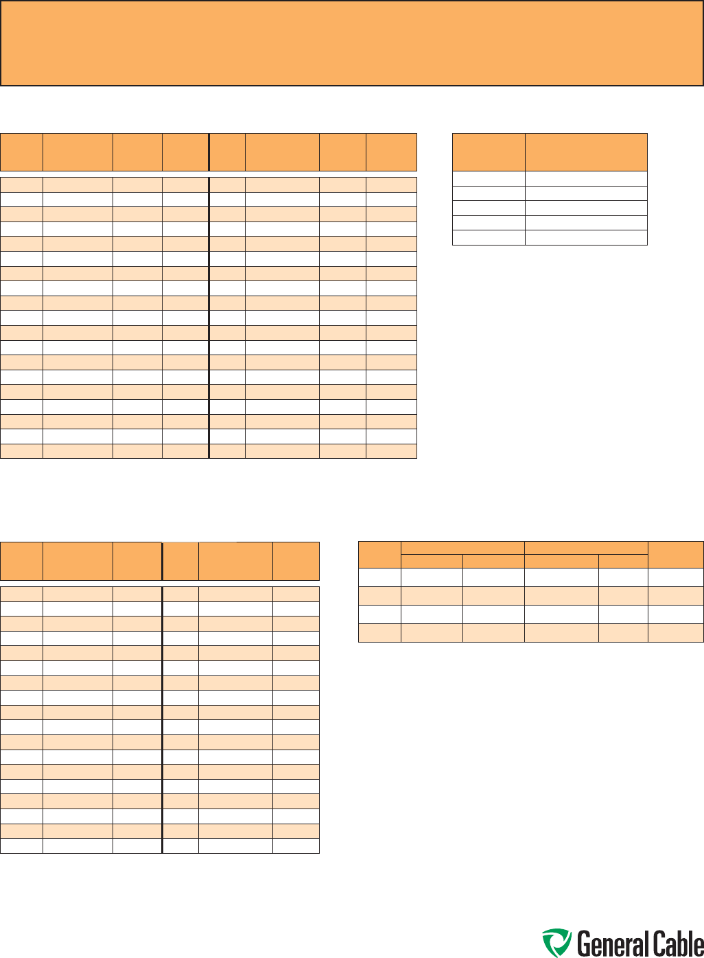
Phone: 888-593-3355
www.generalcable.com
SPEC A100
May, 2013
Common Color Sequence
Method 1 -
Table E1 Color Sequence
COND.
NO. BACKGROUND
OR BASE
COLOR
FIRST
TRACER
COLOR
SECOND
TRACER
COLOR
COND.
NO. BACKGROUND
OR BASE
COLOR
FIRST
TRACER
COLOR
SECOND
TRACER
COLOR
1
Black - -
20
Red Green -
2
White - -
21
Orange Green -
3
Red - -
22
Black White Red
4
Green - -
23
White Black Red
5
Orange - -
24
Red Black White
6
Blue - -
25
Green Black White
7
White Black -
26
Orange Black White
8
Red Black -
27
Blue Black White
9
Green Black -
28
Black Red Green
10
Orange Black -
29
White Red Green
11
Blue Black -
30
Red Black Green
12
Black White -
31
Green Black Orange
13
Red White -
32
Orange Black Green
14
Green White -
33
Blue White Orange
15
Blue White -
34
Black White Orange
16
Black Red -
35
White Red Orange
17
White Red -
36
Orange White Blue
18
Orange Red -
37
White Red Blue
19
Blue Red -
Pair cables are Black, White and numbered. Triad cables are Black, White, Red and numbered.
Method 1 -
Table E2 Color Sequence
COND.
NO. BACKGROUND
OR BASE
COLOR
TRACER
COLOR COND.
NO. BACKGROUND
OR BASE
COLOR
TRACER
COLOR
1
Black -
19
Orange Blue
2
Red -
20
Yellow Blue
3
Blue -
21
Brown Blue
4
Orange -
22
Black Orange
5
Yellow -
23
Red Orange
6
Brown -
24
Blue Orange
7
Red Black
25
Yellow Orange
8
Blue Black
26
Brown Orange
9
Orange Black
27
Black Yellow
10
Yellow Black
28
Red Yellow
11
Brown Black
29
Blue Yellow
12
Black Red
30
Orange Yellow
13
Blue Red
31
Brown Yellow
14
Orange Red
32
Black Brown
15
Yellow Red
33
Red Brown
16
Brown Red
34
Blue Brown
17
Black Blue
35
Orange Brown
18
Red Blue
36
Yellow Brown
Pair cables are Black, Red and numbered. Triad cables are Black, Red, Blue and numbered.
Colors repeat after 36 conductors. There are no Green or White conductors or stripes.
Method 4 -
All Conductors Black
COND. CONDUCTOR PRINTING
1st
“1-One”
2nd
“2-Two”
3rd
“3-Three”
4th
“4-Four”
5th
“5-Five”
ANSI MC 96.1 Conductor Alloy and Color Code
COND.
TYPE POSITIVE WIRE NEGATIVE WIRE OUTER
JACKETALLOY COLOR ALLOY COLOR
EX
Chromel Purple Constantan Red Purple
JX
Iron White Constantan Red Black
KX
Chromel Yellow Alumel Red Yellow
TX
Copper Blue Constantan Red Blue

Phone: 888-593-3355
www.generalcable.com
To Convert From To Multiply By
Inches Millimeters 25.4
Millimeters Inches 0.03937
Inches Centimeters 2.54
Centimeters Inches 0.3937
Length
Feet Meters 0.3048
Meters Feet 3.2808
Kilofeet (1000 feet) Kilometers 0.3048
Kilometers Kilofeet (1000 feet) 3.2808
Square Inches Square Millimeters 645.16
Square Millimeters Square Inches 0.00155
Square Inches Square Centimeters 6.4516
Square Centimeters Square Inches 0.155
Area Square Inches Circular Mils 1,273,240
Circular Mils Square Inches 7.854 x 10⁻⁷
Circular Mils Square Millimeters 5.066 x 10⁴
Square Millimeters Circular Mils 1973.51
Square Feet Square Meters 0.0929
Square Meters Square Feet 10.764
Pounds Kilograms 0.4536
Kilograms Pounds 2.2046
Weight
Pound/Kilofeet Kilograms/Kilometer 1.4882
Kilograms/Kilometer Pounds/Kilofeet 0.6720
Ohms/Kilofeet Ohms/Kilometer 3.2808
Ohms/Kilometer Ohms/Kilofeet 0.3048
Microfarads/Kilofeet Microfarads/Kilometer 3.2808
Electrical Microfarads/Kilometer Microfarads/Kilofeet 0.3048
Insulation Resistance:
Megohms—Kilofeet Megohms—Kilometer 0.3048
Megohms—Kilometer Megohms—Kilofeet 3.2808
Pounds/Square Inch Kilo Pascal* 6.895
Mechanical Kilo Pascal* Pounds/Square Inch 0.1432
Pounds (force) Newtons 4.448
* 1 Pascal = 1 Newton/square meters
Metric Conversion Factors
SPEC A150
September, 2010
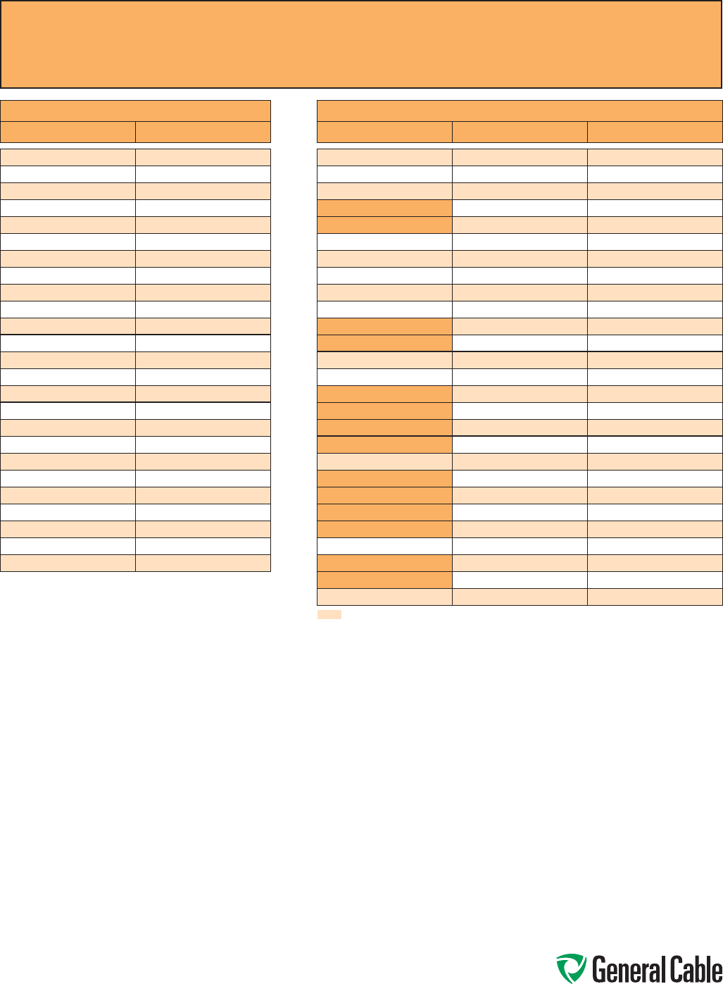
Phone: 888-593-3355
www.generalcable.com
AWG (American Wire Gauge) to mm2 (Millimeters Squared) Conversion
SPEC A185
May, 2013
AWG to mm² CONVERSION TABLE
AWG/kcmil [mm²]*
20 0.52
18 0.82
16 1.31
14 2.08
12 3.31
10 5.26
8 8.36
6 13.3
4 21.2
2 33.6
1 42.4
1/0 53.5
2/0 67.4
3/0 85.0
4/0 107
250 127
300 152
350 177
400 203
450 228
500 253
600 304
750 380
800 405
1000 507
* Equivalent mm2 cross-sectional area
mm² to AWG CONVERSION TABLE
mm² [mm²] * AWG/kcmil
0.5 0.52 20
0.75 0.82 18
1.5 1.31 16
2.5 2.08 14
2.5 3.31 12
4 3.31 12
6 5.26 10
10 8.36 8
16 13.3 6
25 21.2 4
35 33.6 2
35 42.4 1
50 53.5 1/0
70 67.4 2/0
95 85.0 3/0
95 107 4/0
120 107 4/0
120 127 250
150 152 300
185 177 350
185 203 400
240 228 450
240 253 500
300 304 600
400 380 750
400 405 800
500 507 1000
Multiple AWG choices — consult responsible engineer for required ampacity
* Equivalent mm2 cross-sectional area
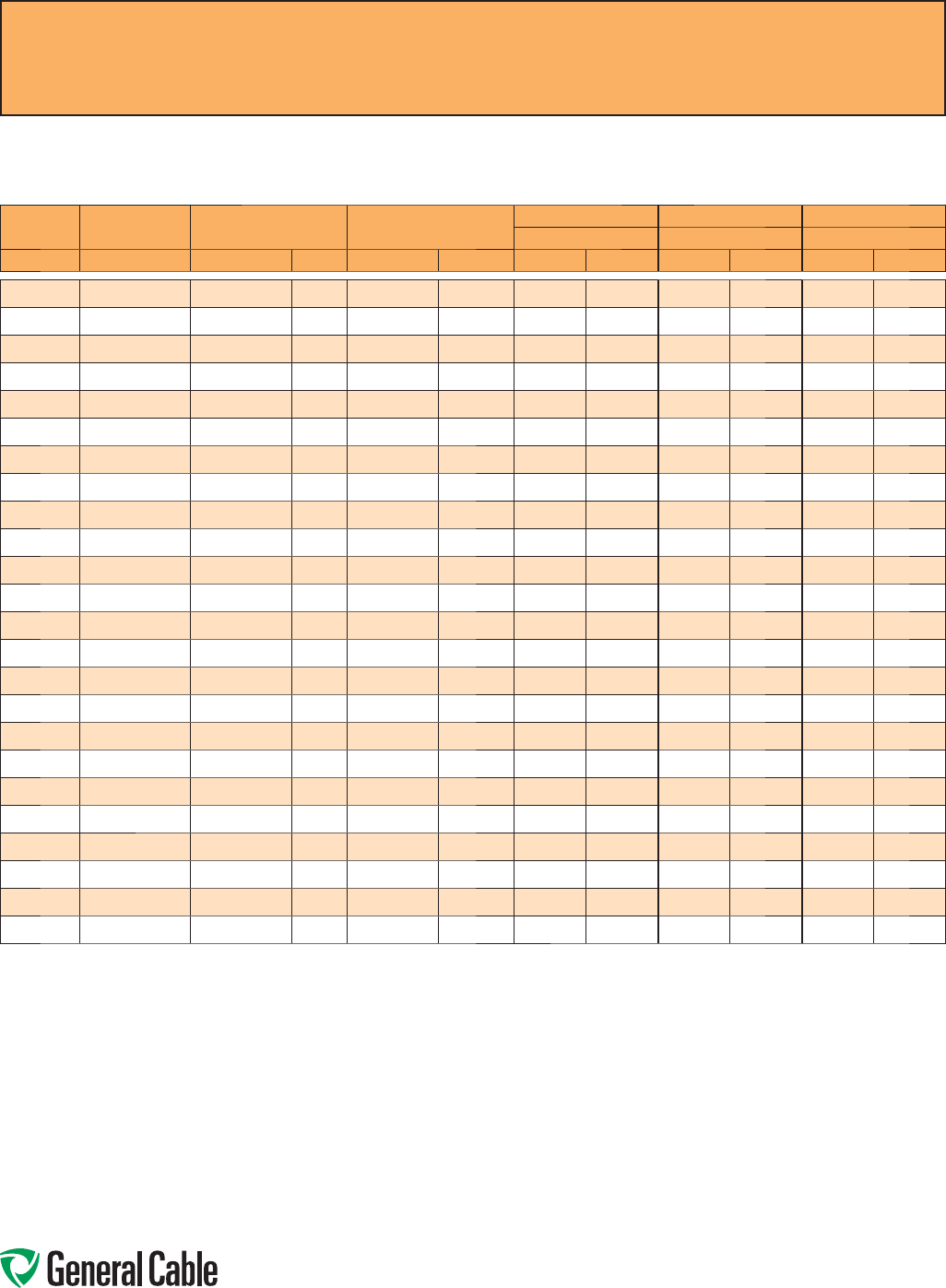
Phone: 888-593-3355
www.generalcable.com
Copper Conductor
ASTM CLASS B
COND. SIZE STRANDING NOMINAL AREA NOMINAL WEIGHT CONCENTRIC COMPRESSED COMPACT
NOMINAL O.D. NOMINAL O.D. NOMINAL O.D.
AWG/kcmil INCHES CIRCULAR MILS mm² LBS/1000 FT¹ kg/km INCHES mm INCHES mm INCHES mm
22 7/.0096 640 0.32 1.99 2.96 0.029 0.74 — — — —
20 7/.0121 1,020 0.52 3.15 4.69 0.036 0.91 — — — —
18 7/.0152 1,620 0.82 5.10 7.59 0.046 1.17 — — — —
16 7/.0192 2,580 1.31 7.74 11.52 0.058 1.47 — — — —
14 7/.0242 4,110 2.08 12.70 18.90 0.073 1.84 0.071 1.80 — —
12 7/.0305 6,530 3.31 20.20 30.10 0.092 2.32 0.089 2.26 — —
10 7/.0385 10,380 5.26 32.10 47.80 0.116 2.95 0.113 2.87 — —
8 7/.0486 16,510 8.36 51 75.90 0.146 3.71 0.142 3.60 0.134 3.40
6 7/.0612 26,240 13.30 81.10 120.70 0.184 4.67 0.178 4.53 0.169 4.29
4 7/.0772 41,740 21.20 129 192 0.232 5.89 0.225 5.72 0.213 5.41
2 7/.0974 66,360 33.60 205 305.10 0.292 7.42 0.283 7.19 0.268 6.81
1 19/.0664 83,690 42.40 258 383.90 0.332 8.43 0.322 8.18 0.299 7.59
1/0 19/.0745 105,600 53.50 326 485.10 0.373 9.47 0.362 9.19 0.336 8.53
2/0 19/.0837 133,100 67.40 411 611.60 0.419 10.64 0.406 10.32 0.376 9.55
3/0 19/.0940 167,800 85 518 770.90 0.470 11.94 0.456 11.58 0.423 10.74
4/0 19/.1055 211,600 107 653 971.80 0.528 13.41 0.512 13.01 0.475 12.07
250 37/.0822 250,000 127 772 1148.90 0.575 14.61 0.558 14.17 0.520 13.21
300 37/.0900 300,000 152 926 1378 0.630 16.00 0.611 15.52 0.570 14.48
350 37/.0973 350,000 177 1,081 1609 0.681 17.30 0.661 16.78 0.616 15.65
400 37/.1040 400,000 203 1,235 1838 0.728 18.49 0.706 17.94 0.659 16.74
500 37/.1162 500,000 253 1,544 2298 0.813 20.65 0.789 20.03 0.736 18.69
600 61/.0992 600,000 304 1,883 2802 0.893 22.68 0.866 22.00 0.813 20.65
750 61/.1109 750,000 380 2,316 3447 0.998 25.35 0.968 24.59 0.908 23.06
1000 61/.1280 1,000,000 507 3,088 4595 1.152 29.26 1.117 28.38 1.060 26.92
Dimensions and weights are nominal; subject to industry tolerances.
¹ Nominal conductor weights are applicable for Concentric Class B and Compressed Stranding per ASTM B8.
Class B Conductors for General Wiring
SPEC B025
March, 2012
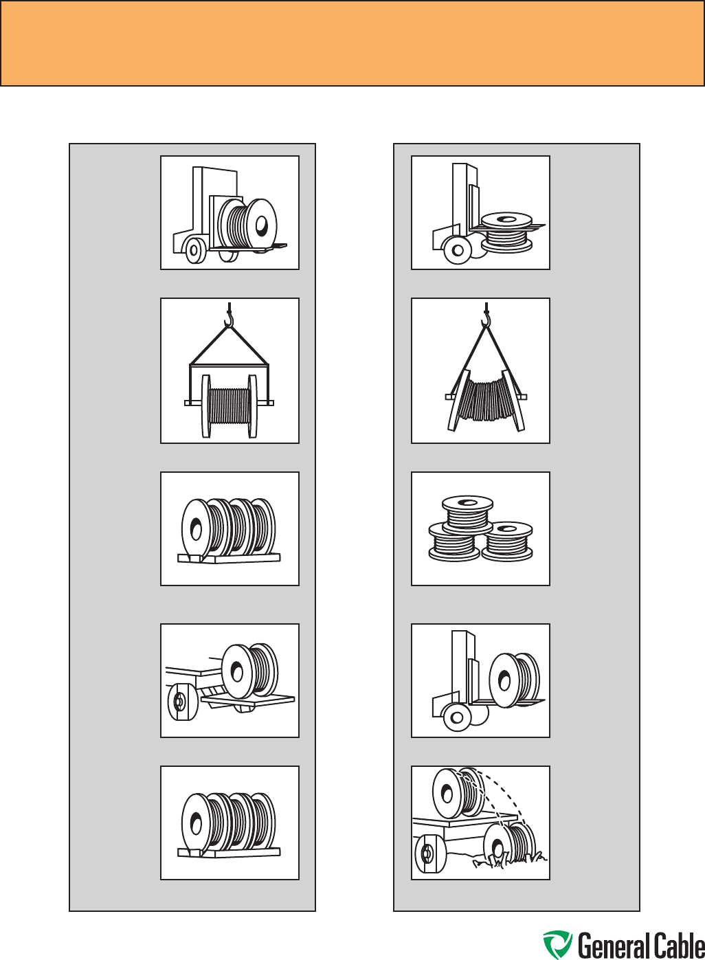
Phone: 888-593-3355
www.generalcable.com
How to Handle Cable Reels
Recommended Reel Handling Practices
SPEC D005
May, 2013
Do not lift by top flange. Cable or reel
will be damaged.
Use a spreader bar to prevent bending
the reel flanges and mashing the cable.
Upended heavy reels will often arrive
damaged. Refuse or receive subject to
inspection for hidden damage.
Never allow forks to touch cable surface
or reel wrap.
Never drop reels.
NO
Cradle both reel flanges between forks.
Reels can be hoisted with a shaft
extended through both flanges.
Lower reels from truck using hydraulic
gate, hoist or fork lift. LOWER CAREFULLY.
Always load with flanges on edge and
chock and block securely.
Always load with flanges on edge and
chock and block securely.
YES
Phone: 888-593-3355
www.generalcable.com
Recommended Cable Handling Practices
SPEC D025
October, 2011
Unloading and Moving of Reels:
Cable reels are never shipped upended (flat side down). Cable reels that arrive in this manner should be rejected
or received only after a thorough inspection for damage.
See “Recommended Reel Handling Practices” page.
Upon receipt, a cable’s protective covering and/or lagging should be inspected for evidence of damage during
shipment. If evidence of damage is found, a report should immediately be made to the carrier.
Under no circumstances should reels be dropped from the delivering vehicle to the ground.
Unloading and reel handling should be accomplished so that the equipment used does not contact the cable
surface, and in the case of protective wrap, that the equipment does not contact the protective wrap.
If unloading and reel handling is accomplished by crane, either a cradle supporting the reel flanges or a shaft
through the arbor hole should be used. If a fork lift is utilized, the forks must lift the reel at 90˚ to the flanges
and the forks must be long enough to make complete lifting contact with both flanges. Under no circumstances
should the forks come into contact with the cable surface or the protective wraps.
When a reel of cable is rolled from one point to another, care must be taken to see that there are no objects on
the surface area which could contact or damage the cable surface or protective wrap.
If an inclined ramp is used for unloading, the ramp must be wide enough to contact both flanges completely.
The stopping of the reels at the bottom shall be accomplished by using the reel flanges and not the surface of
the cable.
Minimum Drum Diameters for Packaging Cables
Type of Cable Minimum Drum Diameter as a
Multiple of Outside
Diameter of Cable
1. Single and multiple conductor cable - unshielded 0-2000 V 10
2. Single and multiple conductor cable - unshielded 2400 V 12
3. Single and multiple conductor cable - wire shield (UniShield®)
5-35 kV 12
4. Single and multiple conductor cable - helically applied tape shield
(Uniblend®) 5-35 kV 14
5. Single and multiple conductor cable - longitudinally applied flat
tape shield (Type TC) 20
6.
Single and multiple conductor cable - Interlocked Armor (Duralox®)
600 V-35 kV 14
7. Triplexed single conductors cabled together. The circumscribing
overall diameter* shall be multiplied by the factor in 1 - 6 and then
by the reduction factor.
.75
*Single conductor times 2.155 times
NEMA WC26 EEMAC201-2007 Binational Wire and Cable Packaging Standard

Phone: 888-593-3355
www.generalcable.com
Storage and Storage Maintenance:
Finished cables have no established shelf-life. Moisture and atmospheric conditions can cause exposed
conductors to oxidize and discolor. Uncovered/unsheltered cable will degrade due to exposure to direct sunlight
and/or the elements. If the cables are protected, there should be no degradation of the insulation.
In general, any cable for use indoors should be stored indoors. Any cable suitable for installation outdoors is
suitable for storage outdoors. Cables stored outdoors should have the ends sealed to prevent moisture ingress
into the cable and should be used within two years or less.
Cables should be stored in a sheltered area. The cable conductor should not be exposed to water.
Cables with a cold temperature marking, e.g. –10˚C, –25˚C, or –40˚C, may be stored outdoors. Cables without a
cold temperature marking must be stored indoors.
Cable reels must remain in the upright position. Cable reels must not be stored on their sides. Reels must not be
stacked.
Cable reels should be stored with the protective covering or lagging in place. If a length of cable has been cut
from the reel, the cable end should be immediately resealed to prevent the entrance of moisture. If a part length
is returned to storage, the reel’s protective covering should be restored.
Wooden reels should be stored off the ground to prevent rotting. Reels should be stored on a flat, hard surface
so that flanges do not sink into the earth. The weight of the reel and cable must be carried at all times by the reel
flanges.
Cable reels and lagging must not be stored for an extended time period sitting in direct contact with water or
dampness. Timbers or metal supports must be placed under the reel flanges to provide elevated storage of the
reels away from the direct contact with water or damp soil.
Reels should be stored in an area where construction equipment, falling or flying objects or other materials will
not contact the cable.
Cable should be stored in an area where chemicals or petroleum products will not be spilled or sprayed on the
cable.
Cable should be stored in an area away from open fires or sources of high heat.
If the reels are relocated, they should be handled as suggested in the “Recommended Reel Handling Practices”
section, and inspection made on each reel during the relocation.
If the cables are stored in a secure area and not exposed to the effects of the weather, an annual inspection
should be satisfactory.
Where the reels are exposed to the weather, a bimonthly inspection should be performed to observe any sign of
deterioration.
If the reels are exposed in a non-secure area, policing of the area at frequent intervals may be required
depending on circumstances.
Records of delivery date, manufacturer, installation date, any extenuating circumstances, along with all test
reports, should be kept on file.
Recommended Cable Storage Practices
SPEC D050
May, 2013

Phone: 888-593-3355
www.generalcable.com
Overview
To ensure safety during cable installation
and reliability once the cable is installed,
you should confirm the following prior to
installation:
• The cable selected is proper for your
application
• The cable has not been damaged in
transit or storage
Review all applicable state and national codes
to verify that the cable chosen is appropriate
for the job. Also, consult your local building
authority.
Next, you must identify any existing cable
damage and prevent any further damage
from occurring. This is done through proper
cable inspection, handling and storage.
Cable Inspection
Inspect every cable reel for damage before
accepting the shipment. Be particularly alert
for cable damage if:
• A reel is laying flat on its side
• Several reels are stacked
• Other freight is stacked on a reel
• Nails have been driven into reel flanges to
secure shipping blocks
• A reel flange is damaged
• A cable covering is removed, stained or
damaged
• A cable end seal is removed or
damaged
• A reel has been dropped
(hidden damage likely)
Cabling Handling
Remove all nails and staples from the reel
flanges before moving a reel, and avoid all
objects that could crush, gouge or impact
the cable when moving. NEVER use the
cable as a means to move a reel.
When unreeling, observe recommended
bending radii, use swivels to prevent
twisting and avoid overruns.
Pre-Installation
Pre-Installation Instructions
SPEC E005
April, 2010
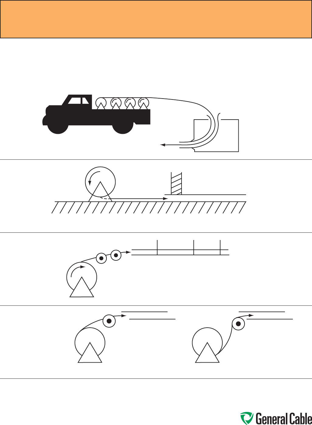
Phone: 888-593-3355
www.generalcable.com
The following diagrams illustrate various cable feed-in setups:
Cable Feed-In Setups
The feed-in setup should unreel the
cable with a natural curvature
(Figure 1) as opposed to a reverse
“S” curvature (Figure 2).
Reels on truck
Apply lube here
Guide-in tube
Setup for duct close to floor
Setup for overhead, into tray
IMPROPER
Figure 2
PROPER
Figure 1
Installation—Feed-In Setups
SPEC E050
April, 2010
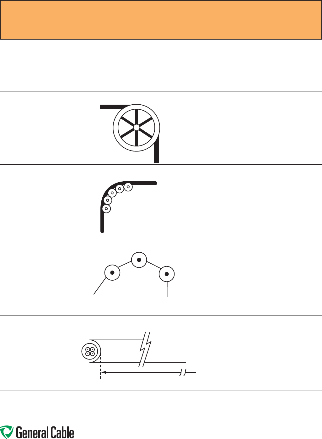
Phone: 888-593-3355
www.generalcable.com
Remember to use the radius of the
surface over which the cable is bent,
not the outside flange diameter of
the pulley. A “10 inch” cable sheave
typically has a 10 inch outside flange
diameter with a 6 inch inside diameter
that provides an inside (bending)
radius of 3 inches.
Single sheaves should only be
used for GUIDING cables. Arrange
multiple blocks to maintain bending
radii whenever cable changes
direction or elevation.
For pulling around bends,
use conveyor sheave
assemblies of the
appropriate radius series.
The pulleys must be positioned to ensure that
the effective curvature is smooth and changes
direction or elevation evenly at each pulley.
Never allow a polygon curvature to occur
(Figure 3).
The fit of a pulley around the cable is also
important when pulling heavy weights
(i.e. pulleys at the top of a vertical drop).
Cable Feed-In Setups (continued)
Single Sheave
Sheave Assembly
NEVER ALLOW
Figure 3
Radius
Installation—Feed-In Setups
SPEC E050
April, 2010
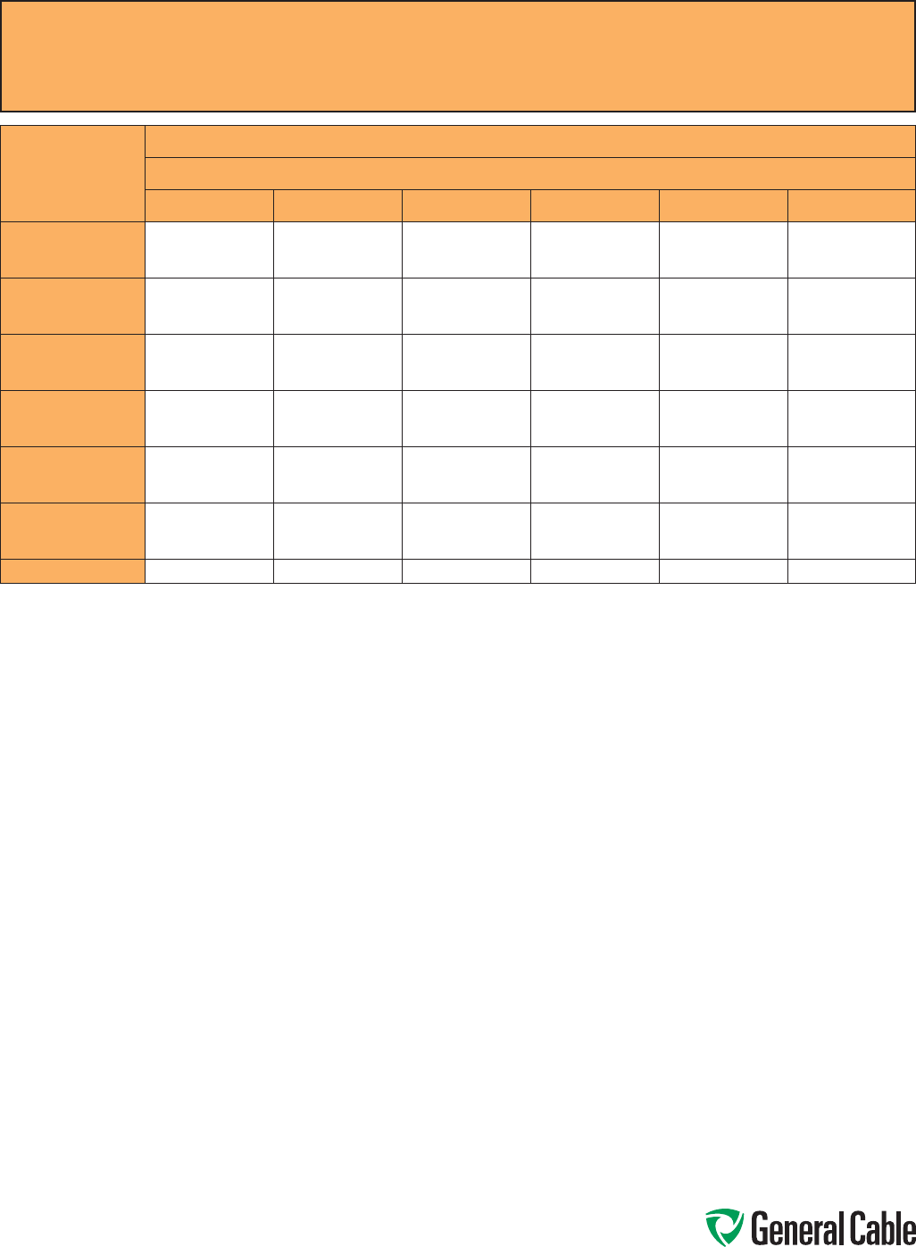
Phone: 888-593-3355
www.generalcable.com
Installation—Conductor Maximum Pulling Tensions
Multiconductor Cables Having Equal-Sized Conductors;
In Parallel or as Multiplexed Assemblies
SPEC E075
October, 2012
AWG/kcmil
MAXIMUM ALLOWABLE PULLING TENSION (LBS)
NUMBER OF CONDUCTORS
123456
18
16
14
13
20
33
26
40
66
39
60
99
41
65
105
52
81
132
62
97
158
12
10
8
52
83
132
104
166
264
157
249
396
167
266
423
209
332
528
251
399
634
6
4
2
210
334
531
420
668
1062
630
1002
1593
672
1069
1699
840
1336
2124
1008
1603
2548
1
1/0
2/0
670
845
1065
1339
1690
2130
2009
2534
3194
2142
2703
3407
2678
3379
4259
3214
4055
5111
3/0
4/0
250
1342
1693
2000
2685
3386
4000
4027
5078
6000
4296
5417
6400
5370
6771
8000
6444
8125
9600
350
500
750
2800
4000
6000
5600
8000
10000
8400
10000
10000
8960
10000
10000
10000
10000
10000
10000
10000
10000
1000 8000 10000 10000 10000 10000 10000
The maximum allowable pulling tensions are for direct attachment to the conductor.
T = 0.008 x cmil x n, if n ≤ 3
T = 0.008 x cmil x n x 0.8, if n > 3
When more than two conductors are pulled in parallel in an installation containing bends, the maximum allowable pulling tension is limited
to the two conductor column, regardless of the number of conductors that are being pulled.
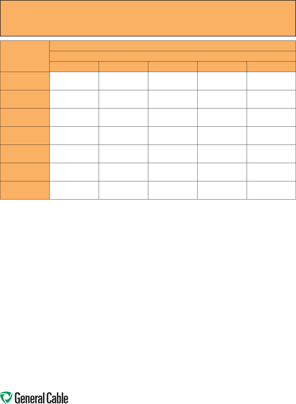
Phone: 888-593-3355
www.generalcable.com
Installation—Conductor Maximum Pulling Tensions
Multiconductor Cables Having Equal-Sized Conductors, Without Subassemblies
SPEC E075
October, 2012
NUMBER OF
CONDUCTORS
MAXIMUM ALLOWABLE PULLING TENSION (LBS)
CONDUCTOR SIZE (AWG/kcmil)
18 16 14 12 10
2
3
4
26
39
41
40
60
65
66
99
105
104
157
167
166
249
266
5
6
7
52
62
73
81
97
113
132
158
184
209
251
293
332
399
465
8
9
10
83
93
104
129
145
161
210
237
263
334
376
418
531
598
664
12
14
15
124
145
156
194
226
242
316
368
395
502
585
627
797
930
996
16
18
19
166
187
197
258
290
306
421
473
500
669
752
794
1000
1000
1000
20
22
24
207
228
249
323
355
387
526
549
631
836
919
1000
1000
1000
1000
25
30
37
259
311
383
403
484
596
658
789
974
1000
1000
1000
1000
1000
1000
The maximum allowable pulling tensions are for multi-conductor cables pulled into a raceway or cable tray using a basket grip or similar
device secured directly to the cable jacket.It is recommended that a combination of basket grips and pulling eyes be used whenever possible.
T = 0.008 x cmil x n, if n ≤ 3
T = 0.008 x cmil x n x 0.8, if n > 3
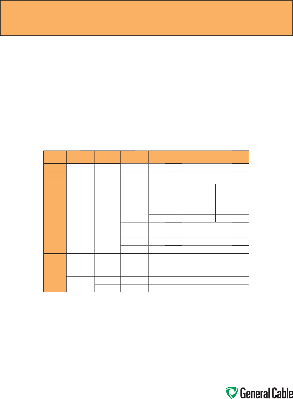
Phone: 888-593-3355
www.generalcable.com
Overview
Training is the positioning of cable when
it is not under tension. Bending is the
positioning of cable when it is under
tension. When installing cable, the object
is to limit the mechanical forces so that
the cable’s physical and electrical
characteristics are maintained for the
expected service life. Bends in conductors,
multi-conductor cables or assemblies of
conductors shall be made so that the cable
will not be damaged.
Physical Limitations Training and Bending
A nonshielded cable can tolerate a sharper
bend than a shielded cable. This is
especially true for cables having helically
applied metallic shielding tapes which,
when bent too sharply, can separate or
buckle and cut into the insulation.
Remember that offsets are bends.
The problem is compounded by the fact
that most tapes are under jackets that
conceal such damage. The extruded
polymers used for insulation shields have
suffi cient conductivity and coverage
initially to pass acceptance testing, then
fail prematurely due to corona at the
shield/insulation interface.
Minimum Bending Radius in Accordance with National Electric Code
Voltage Conductors Shielding Cable Types Minimum Bending Radius as a Multiple
of Conductor/Assembly Diameter
600 V Single Nonshielded All 5X
601-
2000 V All 8X
600 V
or
2000 V
Multi-
conductor
or
Multiplexed
Nonshielded TC or TC-ER 1 in. (25 mm)
or less Over 1 in. to 2 in.
(>25 mm to 50
mm) Over 2 in.
(>50 mm)
4X 5X 6X
MC37X
Shielded All 12X
TC or TC-ER 12X
MC 12X/7X1
Over
2000 V
Single Nonshielded MV 8X
MC37X
Shielded MC and MV 12X2
Multi-
conductor or
Multiplexed
Nonshielded MC and MV 8X
Shielded MC and MV 12X/7X1,2
1 12 times the diameter of an individual shielded conductor or 7 times the overall cable diameter, whichever is greater.
2 Since UniShield® is a unique construction, there are no applicable values for the bending radius in the NEC. However,
General Cable recommends 8 times for single conductors, and for multiplexed or multi-conductor cables, it is 8 times
the diameter of the individual conductors or 5 times the overall diameter, whichever is greater, in accordance with
ANSI/ICEA S-93-639 5-46 kV Shielded Power Cable for Use in the Transmission and Distribution of Electric Energy.
3 Per 330.24B Interlocked-Type Armor or Continuously Corrugated Metallic Sheath.
Installation—Training and Bending Limitations
SPEC E100
April, 2010
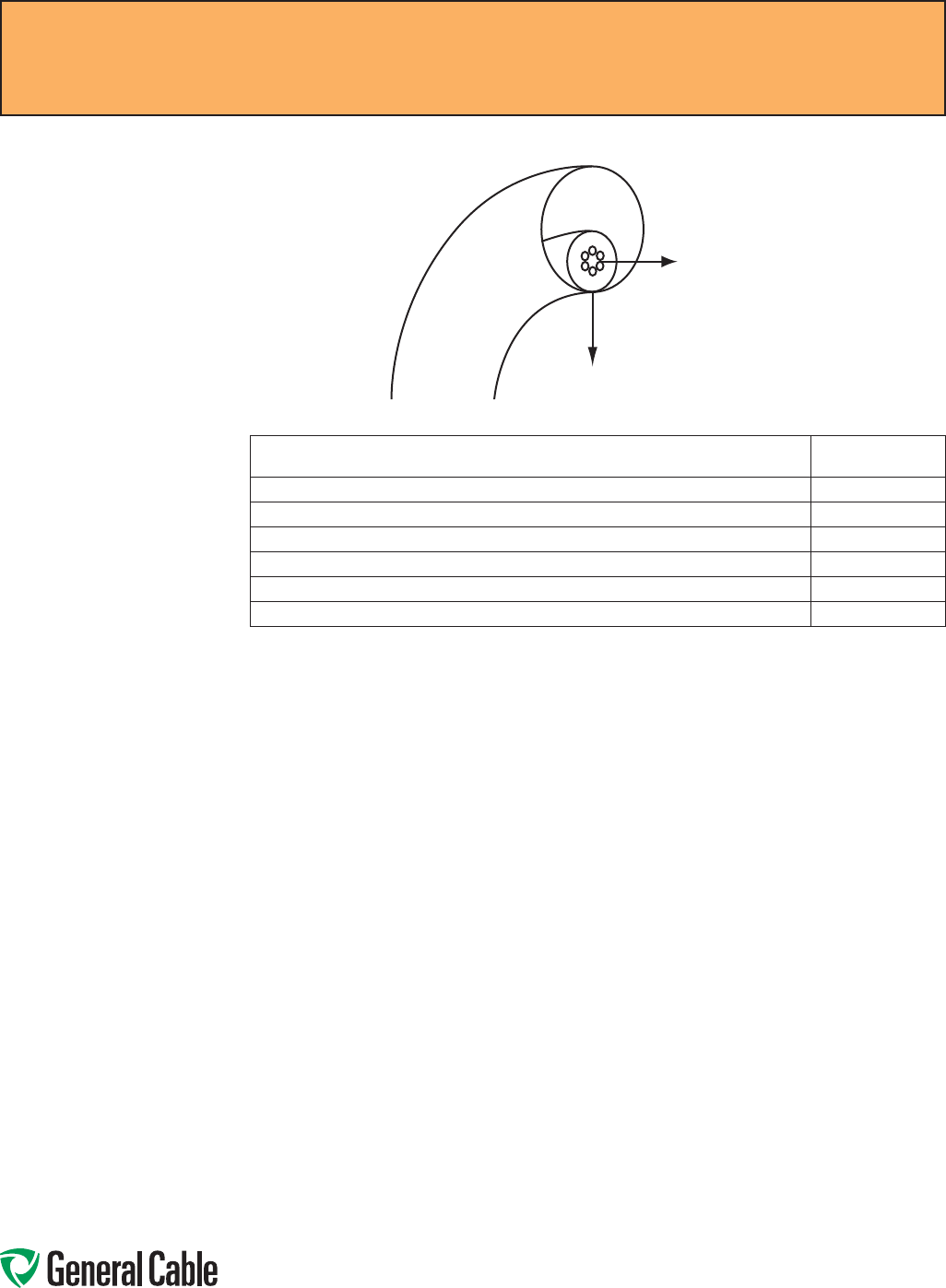
Phone: 888-593-3355
www.generalcable.com
Installation—Maximum Sidewall Pressure
SPEC E125
October, 2012
Overview
Sidewall bearing pressure (SWBP), or sidewall
loading, is the radial force exerted on a cable being
pulled around a conduit bend or sheave. Excessive
SWBP can crush a cable and is, therefore, one of
the most restrictive factors in installations having
bends and requiring high pulling tensions. SWBP is
reduced by increasing the radius of bends.
The maximum tension that can safely be applied
to the cable during installation can be calculated
using the maximum SWBP for the cable and the
radius of the bend it is traversing.
For example, a cable having a maximum SWBP of
300 lb/ft that is being pulled around a bend having
a radius of 2 feet should have no more than 300
lbs/ft x 2 ft or 600 lbs tension applied to it as the
cable exits the bend.
*Yellow 77 not recommended for use with UniShield® cables.
For LSZH jacketed cable, consult with pulling compound manufacturers.
Other wire pulling compounds may be suitable for use with General Cable constructions. Contact the wire pulling compound manufacturer regarding the
suitability of their products with specifi c General Cable products.
General Cable’s Approval List of Cable Pulling Lubricants
The following manufacturers, who are listed in the 2006 UL Electrical Construction Equipment Directory, provide wire pulling compounds intended for
use as lubricants in installing electrical conductors in raceways. These manufacturers have had some of their products evaluated by Underwriters
Laboratories (UL) to determine their compatibility with conductor insulation and coverings.
Since it is not feasible to test every possible combination of cable material with every wire pulling compound, the installer should check with the pulling
compound manufacturer or the cable manufacturer to determine compatibility between specifi c cable materials and the pulling compound.
The Listing Mark for these products includes the UL symbol, together with the word “LISTED,” a control number and the product name “Wire Pulling
Compound.” Refer to the latest edition of the UL Electrical Construction Equipment Directory for the current listing of manufacturers of wire pulling
compounds and their control numbers.
J. C. Whitlam Mfg. Co.
Klein Tools Inc.
Madison Electric Products Inc.
Rainbow Technology Corp.
Rectorseal
Thomas & Betts Corp.
3M Company
American Bentonite International Inc.
American Polywater Corp.
Arnco Corp.
Dura-Line Corp.
Greenlee Textron
Ideal Industries Inc.*
CABLE TYPE SWBP (LBS/FT)
300 V Nonshielded, 300 V and 600 V Shielded Control & Instrumentation 500
600 V Nonshielded Control & Instrumentation 500
600 V and 2400 V Nonshielded Power 1000
5 kV-35 kV Shielded Power 1000
Interlocked Armored Cable (all voltage) 300
CCW® MC-HL Armored Cable 500
Sidewall Load
Tension

Phone: 888-593-3355
www.generalcable.com
The test voltage should be increased in steps of 10 kV, or minimum of 5 steps. The duration at each step should
be long enough for the current to reach a steady value (1 minute suggested). The test current will momentarily
increase for each voltage increment due to charging of the capacitance and the dielectric absorption characteris-
tics of the insulation. Stabilized current should be recorded at each step.
The maximum test voltage should be maintained for 15 minutes (new cable, shielded) / 5 minutes (non-shielded).
Leakage current should be recorded each minute after the maximum test voltage has been reached.
Increase of leakage current at any step point may be an indication of a cable insulation problem. Failure of the
cable or cable accessories may result unless the voltage is rapidly reduced.
Otherwise, the leakage current should stabilize after about 5 minutes. Leakage current is essentially a function of
the construction and length of cable but it can be influenced by the test conditions (wind and humidity) as well as
the test apparatus (leads).
Typical leakage currents in the order of 100 – 150 microamperes or higher are not unusual. A defective installation
is identified by increasing leakage current with time, at a fixed DC voltage.
All testing should be performed by qualified personnel taking all appropriate safety precautions.
DC “HI-POT” Pre-Test Guidelines for MV Cables
SPEC F005
April, 2010
Phone: 888-593-3355
www.generalcable.com
DC High Potential (HI-POT) Testing of Medium-Voltage Power Cable
Overview
This procedure is intended to provide
general guidelines for high potential
DC testing of power cables.
All tests made after cable installation
and during the guarantee period
shall be made in accordance with
applicable specifications.
All safety precautions must be
observed during testing at
high voltage.
Read and understand and follow the
Operator’s Manual for the particular
test set being used!
Test Equipment
Direct current test equipment
is available commercially with a
wide range of voltages. Accessory
equipment necessary to safely
conduct high voltage tests—such as
safety barriers, rubber gloves and
nonconducting hard hats—must be
used; consult appropriate
safety officer.
Test Procedures
See IEEE Standard 400 Article 5
Direct Voltage Testing. Acceptable
procedures, although varying slightly
in technique, have more or less been
standardized as either a “withstand
test” or a “time-leaking current test.”
Before performing any DC
over potential tests:
• All equipment must be
disconnected from the cable
circuit, i.e., taps, motors, circuit
breakers, surge arrestors, etc.
This will preclude damage to such
equipment and will prevent test
interruptions due to flashovers
and/or trip-outs resulting from
excessive
leakage current.
• Establish adequate clearance
between the circuit test ends and
any grounded object, and to other
equipment not under test (about
2.5 feet).
• Ground all circuit conductors not
under test with all cable shields
including nearby equipment.
• Consult termination manufacturers
for maximum test voltage
recommendations and
time limitations.
The direct current test voltage may
be applied either continuously or in
predetermined steps to the maximum
value in accordance with applicable
specifications.
• Continuous Method – Apply
test voltage at an approximate
rise rate of 1 kV per second or
75% of the rated current output
of the equipment, whichever is
less. Some equipment will take
longer to reach the maximum test
voltage because of the amount of
charging current.
• Step Method – Apply test voltage
slowly in 5 to 7 increments of
equal value to the maximum
specified. Allow sufficient time at
each stop for the leakage current
to stabilize.
HI-POT TESTING PROCEDURES
Normally this requires only a few
seconds unless cable circuits of high
capacitance are involved.
Record leakage current at each step.
Maintain the test voltage at
the prescribed value for the
time designated in applicable
specifications. The following times
are usually considered adequate: at
the end of the test period, set the
test set voltage control to zero, allow
the residual voltage on the circuit to
decay, then ground the conductor just
tested.
CAUTION
It should be recognized that DC
charges on cable can build up to
potentially dangerous levels if grounds
are removed too quickly. Maintain
solid grounds after the test on the
cable for at least 4 times the duration
of the test. On exceptionally long
cable lengths, it may be necessary
to increase the grounding time.
It is advantageous to maintain
these grounds longer and while
reconnecting circuit components.
• Acceptance Testing – After
installation and before the cable
is placed in regular service, the
specified test voltage shall be
applied for 15 consecutive
minutes.
• Proof Testing – At any time during
the period of guarantee, the cable
circuit may be removed from
service and tested at a reduced
voltage (normally 65 percent of the
original acceptance value) for 5
consecutive minutes.
• Record the leakage current at one
minute intervals for the duration of
the test time involved.
DC “HI-POT” Testing Guidelines for MV Cables
SPEC F025
April, 2010

Phone: 888-593-3355
www.generalcable.com
DC High Potential (HI-POT) Testing of Medium-Voltage Power Cable
Comments
The significance of conducting DC
high-voltage tests on nonshielded,
nonmetallic-sheathed cable is
dependent upon the environment
in which it is installed because the
characteristics of the return circuits
are unknown. The environment must
be carefully considered or test results
may not be significant. In fact, these
tests can result in damage to the
cable insulation.
Humidity, condensation and actual
precipitation on the surface of a
cable termination can increase the
leakage current by several orders of
magnitude. Humidity also increases
the corona current, which indication is
included in the total leakage current.
Wind prevents the accumulation of
space charges at all bare energized
terminals.
This results in an increase of
corona. It is most desirable to
reduce or eliminate corona current
at the bare metal extremities of
cable or terminations. This may be
accomplished by covering these areas
with plastic envelopes, plastic or glass
containers, plastic wrap or suitable
electrical putty.
Routine periodic DC maintenance
testing of cable for the evaluation of
the insulation strength is not a common
practice. Some power cable users
have adopted a program of testing
circuits during planned outages,
preferring possible breakdowns during
testing rather than experiencing a
service outage. It is nearly impossible
to recommend test voltage values for
those maintenance tests with the history
of the cable circuit. An arbitrary test
voltage level could break down a cable
circuit that would otherwise render long
trouble-free service at normal operating
AC voltage.
The main usefulness of DC high-voltage
testing is to detect conducting particles
left on the creepage surface during
splicing or termination.
Test equipment should be supplied
from a stable, constant voltage
source. Do not use the same source
that is supplying arc welders or
other equipment causing line voltage
fluctuations. The output voltage of the
test set must be filtered and regulated.
Consider using a portable, motor-driven
alter nator to energize the test set.
The gradual decrease or non-increase of
leakage current with respect to time at
maximum test voltage is the acceptance
criteria for DC HI-POT testing.
Testing Problems
Extra Leakage Current:
• Failure to guard against corona
• Failure to clean insulation surface
• Failure to keep cable ends dry
• Failure to provide adequate
clearance to ground
• Improper shield termination
Erratic Readings:
• Fluctuating voltage to test set
• Improper test leads
Environmental Influences:
• High relative humidity
• Dampness, dew, fog
• Wind, snow
Results vs. Cable Life
To date there is no basis for
correlation between DC test
results and cable life expectancy.
DC “HI-POT” Testing Guidelines for MV Cables
SPEC F025
April, 2010
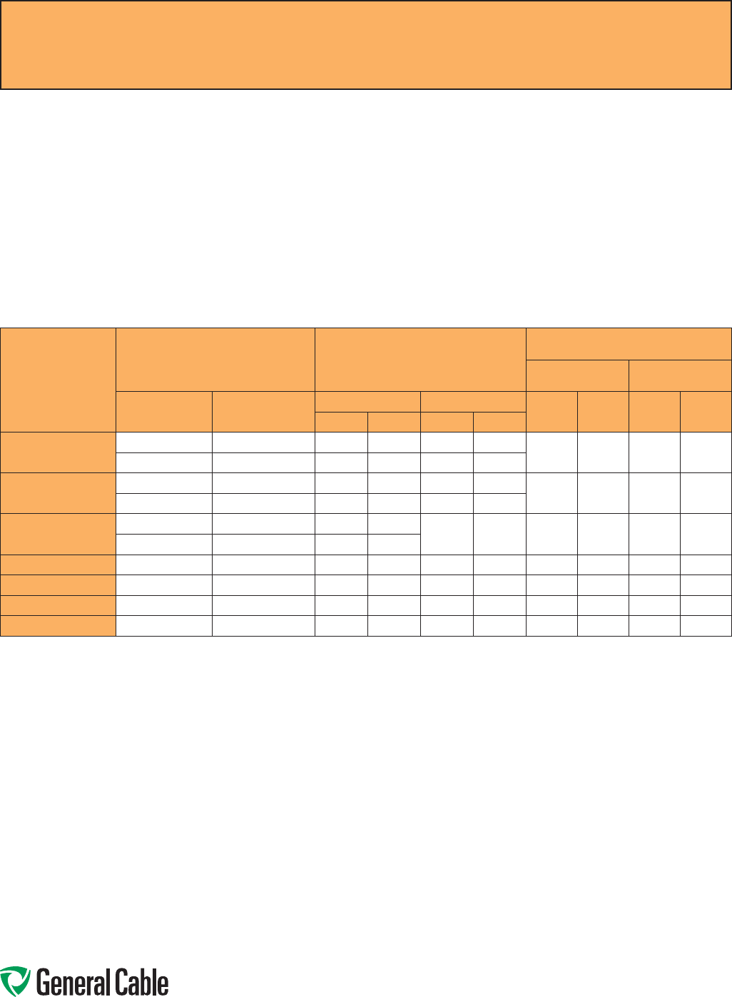
Phone: 888-593-3355
www.generalcable.com
Acceptance Testing
Acceptance testing is performed to detect any defects in cable insulation and terminations which may have resulted from poor
workmanship or mechanical damage. This proof test confirms the integrity of the insulation and accessories before the cable is
placed into service.
After installation and before the cable is placed in regular service, the test voltages specified in the ICEA S-97-682 Table should
be applied for 15 consecutive minutes. Record the leakage current at one minute intervals for the duration of the test.
ICEA DC Field Test Voltages
ICEA S-97-682 Utility Shielded Power Cables Rated 5,000-46,000 Volts
Rated
Voltage Phase-
to-Phase (kV)
Conductor Size Nominal Insulation Thickness
(Insulation Level)
Maximum DC Field
Test Voltages (kV)
During or After
Installation First 5 Years
AWG/kcmil mm2100% 133% 100% 133% 100% 133%
mils mm mils mm
58 - 1000 8.4 - 507 90 2.29 115 2.92 28 36 9 11
> 1000 > 507 140 3.56 140 3.56
86 - 1000 13.3 - 507 115 2.92 140 3.56 36 44 11 14
> 1000 > 507 175 4.45 175 4.45
15 2 - 1000 33.6 - 507 175 4.45 220 5.59 56 64 18 20
> 1000 > 507 220 5.59
25 1 - 2000 42.4 - 1013 260 6.60 320 8.13 80 96 25 30
28 1 - 2000 42.4 - 1013 280 7.11 345 8.76 84 100 26 31
35 1/0 - 2000 53.5 - 1013 345 8.76 420 10.7 100 124 31 39
46 4/0 - 2000 107.2 - 1013 445 11.3 580 14.7 132 172 41 54
DC test voltages are applied to discover gross problems such as improperly installed accessories or mechanical damage. DC testing is not expected to reveal deterioration due
to aging in service. There is some evidence that DC testing of aged cross-linked polyethylene cables can lead to early cable failures. Information on this subject is available in EPRI
project report TR-101245, “Effect of DC Testing in Extruding Cross-Linked Polyethylene Insulated Cables.
Dimensions and weights are nominal; subject to industry tolerances.
Field Electrical “HI-POT” Testing Guidelines
SPEC F075
April, 2010

Phone: 888-593-3355
www.generalcable.com
CCW®
DIAMETER
INCHES
ALUMINUM
CROSS-
SECTIONAL
AREA kcmil
EQUIVALENT
ALUMINUM
CONDUCTOR
CCW® 10 CYCLE
FAULT
CAPABILITY*
(kA)
0.49 26.39 6 2.84
0.53 30.79 6 3.32
0.58 33.46 5 3.60
0.62 35.19 5 3.79
0.67 39.58 5 4.27
0.71 43.98 4 4.74
0.75 47.50 4 5.11
0.80 51.89 4 5.59
0.84 55.42 3 5.97
0.89 58.94 3 6.35
0.93 61.58 3 6.64
0.97 65.97 3 7.11
1.02 66.85 2 7.21
1.06 69.49 3 7.49
1.11 94.56 1 10.19
1.15 98.96 1 10.67
1.19 101.16 1 10.90
1.24 104.46 1 11.26
1.29 108.86 1/0 11.73
1.34 123.75 1/0 13.33
1.37 132.32 1/0 14.26
1.42 136.00 2/0 14.66
1.47 142.13 2/0 15.32
1.51 145.80 2/0 15.71
1.60 174.26 3/0 18.75
1.64 179.67 3/0 19.36
1.69 185.07 3/0 19.95
*Short Circuit Capacity based on ICEA P-45-482
CCW®
DIAMETER
INCHES
ALUMINUM
CROSS-
SECTIONAL
AREA kcmil
EQUIVALENT
ALUMINUM
CONDUCTOR
CCW® 10 CYCLE
FAULT
CAPABILITY*
(kA)
1.75 206.72 3/0 22.28
1.85 209.67 3/0 22.60
1.90 220.01 4/0 23.71
1.96 233.29 4/0 25.14
2.03 257.96 250 27.80
2.15 291.60 250 31.43
2.28 310.83 300 33.50
2.32 314.03 300 33.85
2.40 355.94 350 38.36
2.45 362.85 350 39.11
2.53 371.49 350 40.04
2.58 378.40 350 40.78
2.62 387.04 350 41.72
2.75 407.78 400 43.94
2.85 454.12 400 48.94
2.98 474.51 400 51.15
3.03 483.77 400 52.14
3.11 491.19 400 52.94
3.16 502.31 500 54.14
3.32 530.11 500 57.13
3.41 537.53 500 57.93
3.63 559.77 550 60.33
3.67 578.30 550 62.32
3.80 598.69 550 64.53
3.98 630.20 600 67.92
4.10 650.59 650 70.12
CCW
®
Sheath as a Grounding Conductor
SPEC F130
December, 2010

Phone: 888-593-3355
www.generalcable.com
CATALOG SPEC
NUMBER NUMBER CATALOG SPEC
NUMBER NUMBER CATALOG SPEC
NUMBER NUMBER CATALOG SPEC
NUMBER NUMBER
Catalog Number Index
Index
November, 2014
9025.16010001 ...........9025
9025.16010002 ...........9025
9025.16010003 ...........9025
9025.16010004 ...........9025
9050.20041221 ...........9050
9050.20041222 ...........9050
9050.20041223 ...........9050
9050.20041224 ...........9050
9050.20081221 ...........9050
9050.20081222 ...........9050
9050.20081223 ...........9050
9050.20081224 ...........9050
9050.20101221 ...........9050
9050.20101222 ...........9050
9050.20101223 ...........9050
9050.20101224 ...........9050
9050.20121221 ...........9050
9050.20121222 ...........9050
9050.20121223 ...........9050
9050.20121224 ...........9050
9050.20161221 ...........9050
9050.20161222 ...........9050
9050.20161223 ...........9050
9050.20161224 ...........9050
9050.20201221 ...........9050
9050.20201222 ...........9050
9050.20201223 ...........9050
9050.20201224 ...........9050
9050.20241221 ...........9050
9050.20241222 ...........9050
9050.20241223 ...........9050
9050.20241224 ...........9050
9050.20361221 ...........9050
9050.20361222 ...........9050
9050.20361223 ...........9050
9050.20361224 ...........9050
9050.20501221 ...........9050
9050.20501222 ...........9050
9050.20501223 ...........9050
9050.20501224 ...........9050
9075.20041221 ...........9075
9075.20041222 ...........9075
9075.20041223 ...........9075
9075.20041224 ...........9075
9075.20081221 ...........9075
9075.20081222 ...........9075
9075.20081223 ...........9075
9075.20081224 ...........9075
9075.20101221 ...........9075
9075.20101222 ...........9075
9075.20101223 ...........9075
9075.20101224 ...........9075
9075.20121221 ...........9075
9075.20121222 ...........9075
9075.20121223 ...........9075
9075.20121224 ...........9075
9075.20161221 ...........9075
9075.20161222 ...........9075
9075.20161223 ...........9075
9075.20161224 ...........9075
9075.20201221 ...........9075
9075.20201222 ...........9075
9075.20201223 ...........9075
9075.20201224 ...........9075
9075.20241221 ...........9075
9075.20241222 ...........9075
9075.20241223 ...........9075
9075.20241224 ...........9075
9075.20361221 ...........9075
9075.20361222 ...........9075
9075.20361223 ...........9075
9075.20361224 ...........9075
9075.20501221 ...........9075
9075.20501222 ...........9075
9075.20501223 ...........9075
9075.20501224 ...........9075
9125.16010001 ...........9125
9125.16010002 ...........9125
9125.16021201 ...........9125
9125.16021202 ...........9125
9125.16041201 ...........9125
9125.16041202 ...........9125
9125.16081201 ...........9125
9125.16081202 ...........9125
9125.16121201 ...........9125
9125.16121202 ...........9125
9125.16161201 ...........9125
9125.16161202 ...........9125
9125.16241201 ...........9125
9125.16241202 ...........9125
9125.16361201 ...........9125
9125.16361202 ...........9125
9125.16501201 ...........9125
9125.16501202 ...........9125
9150.16010001 ...........9150
9150.16010002 ...........9150
9150.16021201 ...........9150
9150.16021202 ...........9150
9150.16041201 ...........9150
9150.16041202 ...........9150
9150.16081201 ...........9150
9150.16081202 ...........9150
9150.16121201 ...........9150
9150.16121202 ...........9150
9150.16161201 ...........9150
9150.16161202 ...........9150
9150.16241201 ...........9150
9150.16241202 ...........9150
9150.16361201 ...........9150
9150.16361202 ...........9150
9150.16501201 ...........9150
9150.16501202 ...........9150
9225.16010001 ...........9225
9225.16010002 ...........9225
9225.16021221 ...........9225
9225.16041221 ...........9225
9225.16041222 ...........9225
9225.16061221 ...........9225
9225.16081221 ...........9225
9225.16081222 ...........9225
9225.16101221 ...........9225
9225.16121221 ...........9225
9225.16121222 ...........9225
9225.16161221 ...........9225
9225.16161222 ...........9225
9225.16201221 ...........9225
9225.16241221 ...........9225
9225.16241222 ...........9225
9225.16361221 ...........9225
9225.16361222 ...........9225
9225.16501221 ...........9225
9225.18021221 ...........9225
9225.18041221 ...........9225
9225.18041222 ...........9225
9225.18061221 ...........9225
9225.18081221 ...........9225
9225.18081222 ...........9225
9225.18101221 ...........9225
9225.18121221 ...........9225
9225.18121222 ...........9225
9225.18161221 ...........9225
9225.18161222 ...........9225
9225.18201221 ...........9225
9225.18241221 ...........9225
9225.18241222 ...........9225
9225.18361221 ...........9225
9225.18361222 ...........9225
9225.18501221 ...........9225
9225.20021221 ...........9225
9225.20041221 ...........9225
9225.20041222 ...........9225
9225.20061221 ...........9225
9225.20081221 ...........9225
9225.20081222 ...........9225
9225.20101221 ...........9225
9225.20121221 ...........9225
9225.20121222 ...........9225
9225.20161221 ...........9225
9225.20161222 ...........9225
9225.20201221 ...........9225
9225.20241221 ...........9225
9225.20241222 ...........9225
9225.20361221 ...........9225
9225.20361222 ...........9225
9225.20501221 ...........9225
9250.16021221 ...........9250
9250.16041221 ...........9250
9250.16041222 ...........9250
9250.16061221 ...........9250
9250.16081221 ...........9250
9250.16081222 ...........9250
9250.16101221 ...........9250
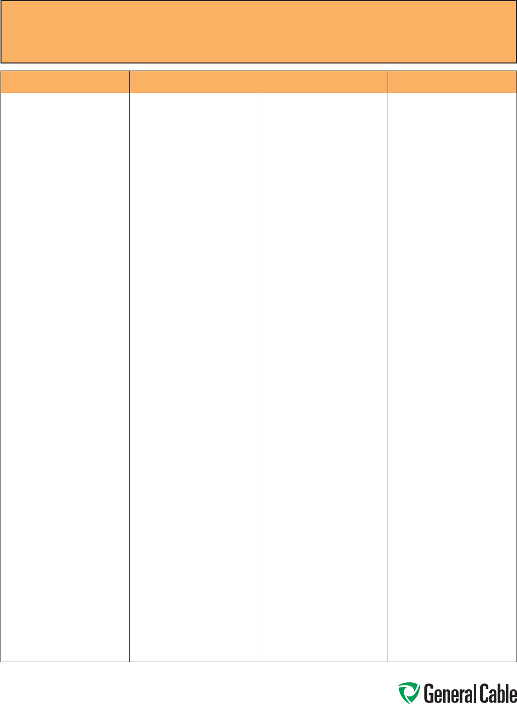
Phone: 888-593-3355
www.generalcable.com
CATALOG SPEC
NUMBER NUMBER CATALOG SPEC
NUMBER NUMBER CATALOG SPEC
NUMBER NUMBER CATALOG SPEC
NUMBER NUMBER
Catalog Number Index
Index
November, 2014
9250.16121221 ...........9250
9250.16121222 ...........9250
9250.16161221 ...........9250
9250.16161222 ...........9250
9250.16201221 ...........9250
9250.16241221 ...........9250
9250.16241222 ...........9250
9250.16361221 ...........9250
9250.16361222 ...........9250
9250.16501221 ...........9250
9250.18021221 ...........9250
9250.18041221 ...........9250
9250.18041222 ...........9250
9250.18061221 ...........9250
9250.18081221 ...........9250
9250.18081222 ...........9250
9250.18101221 ...........9250
9250.18121221 ...........9250
9250.18121222 ...........9250
9250.18161221 ...........9250
9250.18161222 ...........9250
9250.18201221 ...........9250
9250.18241221 ...........9250
9250.18241222 ...........9250
9250.18361221 ...........9250
9250.18361222 ...........9250
9250.18501221 ...........9250
9250.20021221 ...........9250
9250.20041221 ...........9250
9250.20041222 ...........9250
9250.20061221 ...........9250
9250.20081221 ...........9250
9250.20081222 ...........9250
9250.20101221 ...........9250
9250.20121221 ...........9250
9250.20121222 ...........9250
9250.20161221 ...........9250
9250.20161222 ...........9250
9250.20201221 ...........9250
9250.20241221 ...........9250
9250.20241222 ...........9250
9250.20361221 ...........9250
9250.20361222 ...........9250
9250.20501221 ...........9250
9325.16010001 ...........9325
9325.16010002 ...........9325
9325.16020001 ...........9325
9325.16040001 ...........9325
9325.16040002 ...........9325
9325.16060001 ...........9325
9325.16080001 ...........9325
9325.16080002 ...........9325
9325.16100001 ...........9325
9325.16120001 ...........9325
9325.16120002 ...........9325
9325.16160001 ...........9325
9325.16160002 ...........9325
9325.16200001 ...........9325
9325.16240001 ...........9325
9325.16240002 ...........9325
9325.16360001 ...........9325
9325.16360002 ...........9325
9325.16500001 ...........9325
9325.18020001 ...........9325
9325.18040001 ...........9325
9325.18080001 ...........9325
9325.18120001 ...........9325
9325.18160001 ...........9325
9325.18240001 ...........9325
9350.16020001 ...........9350
9350.16040001 ...........9350
9350.16040002 ...........9350
9350.16060001 ...........9350
9350.16080001 ...........9350
9350.16080002 ...........9350
9350.16100001 ...........9350
9350.16120001 ...........9350
9350.16120002 ...........9350
9350.16160001 ...........9350
9350.16160002 ...........9350
9350.16200001 ...........9350
9350.16240001 ...........9350
9350.16240002 ...........9350
9350.16360001 ...........9350
9350.16360002 ...........9350
9350.16500001 ...........9350
9350.18020001 ...........9350
9350.18040001 ...........9350
9350.18080001 ...........9350
9350.18120001 ...........9350
9350.18160001 ...........9350
9350.18240001 ...........9350
9400.16010001 ...........9400
9400.16010002 ...........9400
9400.16020001 ...........9400
9400.16020002 ...........9400
9400.16040001 ...........9400
9400.16040002 ...........9400
9400.16060001 ...........9400
9400.16080001 ...........9400
9400.16080002 ...........9400
9400.16100001 ...........9400
9400.16120001 ...........9400
9400.16120002 ...........9400
9400.16160001 ...........9400
9400.16160002 ...........9400
9400.16200001 ...........9400
9400.16240001 ...........9400
9400.16240002 ...........9400
9400.16360001 ...........9400
9400.16360002 ...........9400
9400.16500001 ...........9400
9400.18020001 ...........9400
9400.18020002 ...........9400
9400.18040001 ...........9400
9400.18040002 ...........9400
9400.18060001 ...........9400
9400.18080001 ...........9400
9400.18080002 ...........9400
9400.18100001 ...........9400
9400.18120001 ...........9400
9400.18120002 ...........9400
9400.18160001 ...........9400
9400.18160002 ...........9400
9400.18200001 ...........9400
9400.18240001 ...........9400
9400.18240002 ...........9400
9400.18360001 ...........9400
9400.18360002 ...........9400
9400.18500001 ...........9400
9500.01002110 ...........9500
9500.01003110 ...........9500
9500.01004110 ...........9500
9500.01006110 ...........9500
9500.01008110 ...........9500
9500.01011110 ...........9500
9500.01202112 ...........9500
9500.01203112 ...........9500
9500.01204112 ...........9500
9500.01205112 ...........9500
9500.01206112 ...........9500
9500.01208112 ...........9500
9500.01211112 ...........9500
9500.01218112 ...........9500
9500.01236112 ...........9500
9500.01402114 ...........9500
9500.01403114 ...........9500
9500.01404114 ...........9500
9500.01405114 ...........9500
9500.01406114 ...........9500
9500.01408114 ...........9500
9500.01411114 ...........9500
9500.01418114 ...........9500
9500.01436114 ...........9500
9505.01002110 ...........9505
9505.01003110 ...........9505
9505.01004110 ...........9505
9505.01006110 ...........9505
9505.01008110 ...........9505
9505.01011110 ...........9505
9505.01202112 ...........9505
9505.01203112 ...........9505
9505.01204112 ...........9505
9505.01205112 ...........9505
9505.01206112 ...........9505
9505.01208112 ...........9505
9505.01211112 ...........9505
9505.01218112 ...........9505
9505.01236112 ...........9505
9505.01402114 ...........9505
9505.01403114 ...........9505
9505.01404114 ...........9505
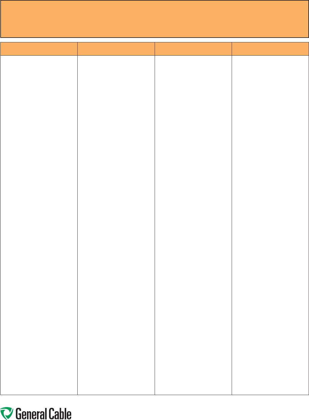
Phone: 888-593-3355
www.generalcable.com
CATALOG SPEC
NUMBER NUMBER CATALOG SPEC
NUMBER NUMBER CATALOG SPEC
NUMBER NUMBER CATALOG SPEC
NUMBER NUMBER
Catalog Number Index
Index
November, 2014
9505.01405114 ...........9505
9505.01406114 ...........9505
9505.01408114 ...........9505
9505.01411114 ...........9505
9505.01418114 ...........9505
9505.01436114 ...........9505
9510.01004110 ...........9510
9510.01204112 ...........9510
9510.01205112 ...........9510
9510.01207112 ...........9510
9510.01209112 ...........9510
9510.01404114 ...........9510
9510.01405114 ...........9510
9510.01407114 ...........9510
9510.01409114 ...........9510
9510.01412114 ...........9510
9510.01419114 ...........9510
9510.01437114 ...........9510
9510.012121112 .........9510
9525.01002000 ...........9525
9525.01003000 ...........9525
9525.01004000 ...........9525
9525.01005000 ...........9525
9525.01007000 ...........9525
9525.01009000 ...........9525
9525.01012000 ...........9525
9525.01202000 ...........9525
9525.01203000 ...........9525
9525.01204000 ...........9525
9525.01205000 ...........9525
9525.01207000 ...........9525
9525.01209000 ...........9525
9525.01212000 ...........9525
9525.01219000 ...........9525
9525.01237000 ...........9525
9525.01402000 ...........9525
9525.01403000 ...........9525
9525.01404000 ...........9525
9525.01405000 ...........9525
9525.01407000 ...........9525
9525.01409000 ...........9525
9525.01412000 ...........9525
9525.01419000 ...........9525
9525.01437000 ...........9525
9600.00103310 ...........9600
9600.00104106 ...........9600
9600.00203310 ...........9600
9600.00204106 ...........9600
9600.00403312 ...........9600
9600.00404108 ...........9600
9600.00603312 ...........9600
9600.00604108 ...........9600
9600.00803314 ...........9600
9600.00804110 ...........9600
9600.01003314 ...........9600
9600.01004314 ...........9600
9600.01203316 ...........9600
9600.01204316 ...........9600
9600.01403318 ...........9600
9600.01404318 ...........9600
9600.11003310 ...........9600
9600.11004106 ...........9600
9600.21003310 ...........9600
9600.21004106 ...........9600
9600.25003308 ...........9600
9600.25004104 ...........9600
9600.31003308 ...........9600
9600.31004104 ...........9600
9600.35003307 ...........9600
9600.35004103 ...........9600
9600.41003308 ...........9600
9600.41004104 ...........9600
9600.50003306 ...........9600
9600.50004102 ...........9600
9600.75003305 ...........9600
9600.75004101 ...........9600
9600.100031110 .........9600
9600.100041110 .........9600
9605.00103310 ...........9605
9605.00104106 ...........9605
9605.00203310 ...........9605
9605.00204106 ...........9605
9605.00403312 ...........9605
9605.00404108 ...........9605
9605.00404210 ...........9605
9605.00603312 ...........9605
9605.00604108 ...........9605
9605.00604210 ...........9605
9605.00803314 ...........9605
9605.00804110 ...........9605
9605.00804212 ...........9605
9605.01003314 ...........9605
9605.01004314 ...........9605
9605.01203316 ...........9605
9605.01204316 ...........9605
9605.01403318 ...........9605
9605.01404216 ...........9605
9605.01404318 ...........9605
9605.11003310 ...........9605
9605.11004106 ...........9605
9605.21003310 ...........9605
9605.21004106 ...........9605
9605.25003308 ...........9605
9605.25004104 ...........9605
9605.31003308 ...........9605
9605.31004104 ...........9605
9605.35003306 ...........9605
9605.35003307 ...........9605
9605.35004103 ...........9605
9605.41003308 ...........9605
9605.41004104 ...........9605
9605.50003306 ...........9605
9605.50004102 ...........9605
9605.75003304 ...........9605
9605.75003305 ...........9605
9605.75004101 ...........9605
9605.100031110 .........9605
9605.100041110 .........9605
9615.00103310 ...........9615
9615.00203310 ...........9615
9615.00403312 ...........9615
9615.00603312 ...........9615
9615.00803314 ...........9615
9615.01003314 ...........9615
9615.01203316 ...........9615
9615.01403318 ...........9615
9615.11003310 ...........9615
9615.21003306 ...........9615
9615.25003304 ...........9615
9615.35003302 ...........9615
9615.41003304 ...........9615
9615.50003301 ...........9615
9625.043124108 .........9625
9625.063124108 .........9625
9625.083124110 .........9625
9625.103124110 .........9625
9650.023123000 .........9650
9650.023124000 .........9650
9650.023143000 .........9650
9650.023144000 .........9650
9650.024123000 .........9650
9650.024124000 .........9650
9650.024143000 .........9650
9650.024144000 .........9650
9650.043123000 .........9650
9650.043124000 .........9650
9650.043143000 .........9650
9650.043144000 .........9650
9650.044123000 .........9650
9650.044124000 .........9650
9650.044143000 .........9650
9650.044144000 .........9650
9650.063123000 .........9650
9650.063124000 .........9650
9650.063143000 .........9650
9650.063144000 .........9650
9650.064123000 .........9650
9650.064124000 .........9650
9650.064143000 .........9650
9650.064144000 .........9650
9650.083123000 .........9650
9650.083124000 .........9650
9650.083143000 .........9650
9650.083144000 .........9650
9650.084123000 .........9650
9650.084124000 .........9650
9650.084143000 .........9650
9650.084144000 .........9650
9650.103123000 .........9650
9650.103143000 .........9650
9650.103144000 .........9650
9650.104123000 .........9650

Phone: 888-593-3355
www.generalcable.com
CATALOG SPEC
NUMBER NUMBER CATALOG SPEC
NUMBER NUMBER CATALOG SPEC
NUMBER NUMBER CATALOG SPEC
NUMBER NUMBER
Catalog Number Index
Index
November, 2014
9650.104124000 .........9650
9650.104143000 .........9650
9650.104144000 .........9650
9650.123143000 .........9650
9650.123144000 .........9650
9650.124143000 .........9650
9650.124144000 .........9650
9675.00103310 ...........9675
9675.00203310 ...........9675
9675.00403312 ...........9675
9675.00603312 ...........9675
9675.00803314 ...........9675
9675.01003316 ...........9675
9675.01203318 ...........9675
9675.11003310 ...........9675
9675.21003310 ...........9675
9675.25003308 ...........9675
9675.35001308 ...........9675
9675.41003308 ...........9675
9675.50003306 ...........9675
9700.00103308 ...........9700
9700.00203310 ...........9700
9700.00403310 ...........9700
9700.00603310 ...........9700
9700.00803312 ...........9700
9700.10003304 ...........9700
9700.11003308 ...........9700
9700.21003308 ...........9700
9700.25003307 ...........9700
9700.35003306 ...........9700
9700.41003307 ...........9700
9700.50003305 ...........9700
9700.75003304 ...........9700
9800.00103308 ...........9800
9800.00203310 ...........9800
9800.00403310 ...........9800
9800.00603310 ...........9800
9800.10003304 ...........9800
9800.11003308 ...........9800
9800.21003308 ...........9800
9800.25003307 ...........9800
9800.35003306 ...........9800
9800.41003307 ...........9800
9800.50003305 ...........9800
9800.75003304 ...........9800
9805.00103308 ...........9805
9805.00203310 ...........9805
9805.00403310 ...........9805
9805.00603310 ...........9805
9805.10003304 ...........9805
9805.11003308 ...........9805
9805.21003308 ...........9805
9805.25003306 ...........9805
9805.35003306 ...........9805
9805.41003307 ...........9805
9805.50003305 ...........9805
9805.75003304 ...........9805
9815.00103308 ...........9815
9815.00203310 ...........9815
9815.00403310 ...........9815
9815.00603310 ...........9815
9815.10003304 ...........9815
9815.11003308 ...........9815
9815.21003308 ...........9815
9815.25003307 ...........9815
9815.35003306 ...........9815
9815.41003307 ...........9815
9815.50003305 ...........9815
9815.75003304 ...........9815
9825.00103104 ...........9825
9825.00203106 ...........9825
9825.11003104 ...........9825
9825.21003104 ...........9825
9825.25003103 ...........9825
9825.35003102 ...........9825
9825.41003103 ...........9825
9825.50003101 ...........9825
9825.750031110 .........9825
9835.00103104 ...........9835
9835.00203106 ...........9835
9835.11003104 ...........9835
9835.21003104 ...........9835
9835.25003103 ...........9835
9835.35003102 ...........9835
9835.41003103 ...........9835
9835.50003101 ...........9835
9835.750031110 .........9835
9840.00103104 ...........9840
9840.00203106 ...........9840
9840.11003104 ...........9840
9840.21003104 ...........9840
9840.25003102 ...........9840
9840.35003102 ...........9840
9840.41003103 ...........9840
9840.50003101 ...........9840
9840.750031110 .........9840
9845.00103104 ...........9845
9845.11003104 ...........9845
9845.21003104 ...........9845
9845.25003103 ...........9845
9845.35003102 ...........9845
9845.41003103 ...........9845
9845.50003101 ...........9845
9855.00103104 ...........9855
9855.11003104 ...........9855
9855.21003104 ...........9855
9855.25003103 ...........9855
9855.35003102 ...........9855
9855.41003103 ...........9855
9855.50003101 ...........9855
9860.00103104 ...........9860
9860.11003104 ...........9860
9860.21003104 ...........9860
9860.25003102 ...........9860
9860.35003102 ...........9860
9860.41003103 ...........9860
9860.50003101 ...........9860
9875.11003104 ...........9875
9875.21003104 ...........9875
9875.25003103 ...........9875
9875.35003102 ...........9875
9875.41003103 ...........9875
9875.50003101 ...........9875
9880.11003104 ...........9880
9880.21003104 ...........9880
9880.25003102 ...........9880
9880.35003102 ...........9880
9880.41003103 ...........9880
9880.50003101 ...........9880
9899.FB01601118 ......9899
9899.FB01602118 ......9899
9899.FB01604118 ......9899
9899.FB01801120 ......9899
9899.FB01802120 ......9899
9899.FB01804120 ......9899
9900.15744 .................9900
9900.27901 .................9900
9900.KS226 ................9900
9900.PS526 ................9900

Phone: 888-593-3355
www.generalcable.com
Notes

Phone: 888-593-3355
www.generalcable.com
Notes