Ii ADFE 16A 13050r2 WEB Installation Directions
2016-09-04
: Pdf 1000335542-Installationsheet 1000335542-InstallationSheet B4 unilog
Open the PDF directly: View PDF ![]() .
.
Page Count: 10
ADFE-16A
Three-Wire Fluorescent
Multi-way Architectural Dimmer
Installation Instructions
SPECIFICATIONS
Voltage ............................................................... 120VAC, 60Hz
Maximum Load Rating ........................................................ 16A
Minimum Load Rating ...................................................... 0.33A
Narrow Dimmer:
Load (Multi-way) ....................................................Fluorescent
For use with specifi c Lutron Hi-Lume, Hi-Lume 3D,
Compact SE, and Eco-10 dimming ballasts
Environment ..................................................... Indoor use only
Operating Temperature ............................0-25°C (32-77°F)
Humidity ...................................... 93% RH, non-condensing
Electrical Supply Wire Requirement:
Minimum temperature rating ..........................75°C (167°F)
Tools Needed ................ Insulated Screwdriver, Wire Strippers
Santa Clara, CA 95050
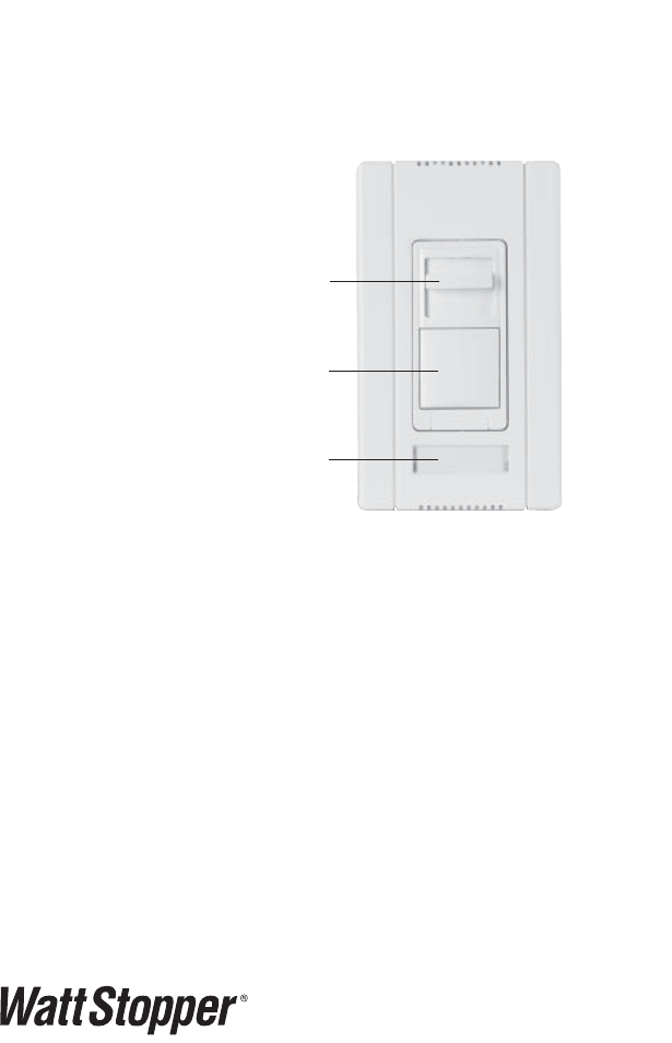
Dimming slider
On/Off switch
Label slot
Visit our website for FAQs: www.wattstopper.com
DESCRIPTION AND OPERATION
The ADFE-16A Fluorescent Architectural Dimmer is designed to replace a
standard light switch or dimmer. To dim the connected load move the slider
down; to brighten the connected load move the slider up. Press the top of the
ON/OFF button to turn the connected load ON. Press the bottom until it clicks
to turn OFF. The load will turn back ON to the preset light level.
Caution:
- Use only with dimming ballasts shown on the “List of Compatible
Ballasts” on the other side of this page.
- To reduce the risk of overheating and possible damage to other
equipment, do not install to control a receptacle, a motor-operated
applicance, or a transformer-supplied appliance.
Important Notes
1. Only one dimmer can be used in a 3-way circuit.
2. It is normal for the dimmer to feel warm to the touch during operation.
3. Protect the dimmer from dust and dirt when painting or spackling.
4. Check new installations for short circuits prior to installing the dimmer.
- Disconnect power to the circuit by removing the fuse or turning the circuit
breakers OFF.
- Install a switch instead of the dimmer. Turn the switch to the ON position.
- Restore power to the circuit. If the circuit breaker trips, a short is
present.
- Operate the switch. If the light fails to turn ON and OFF with the switch,
the wiring may be incorrect.
- Correct wiring if necessary and retest.
- Install the dimmer only after the light operates properly with the switch.
5. To ensure full lamp life and optimum dimmer performance, the lamp
must be operated at full intensity for 100 hours prior to dimming. Refer to
individual lamp manufacturers for more information.
Derating
No derating is required for multigang installations.
Call 800.879.8585 for Technical Support
INSTALLATION AND WIRING
WARNING
Disconnect power to the wall switch box by turning OFF
the circuit breaker or removing the fuse from the
circuit before installing the ADFE-16A, replacing
lamps, or doing any electrical work.
1. Prepare the switch box
After the power is turned OFF at the circuit
breaker box, remove the existing wall plate
and mounting screws. Pull the old switch out
from the wall box.
2. Identify the type of circuit
You may connect the ADFE-16A to a single
pole or multi-way circuit. If you are unable
to clearly identify some or all of the wires
mentioned in this manual, you should consult
with a qualifi ed electrician.
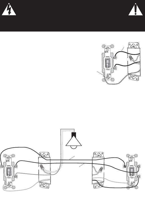
In a 3-way circuit (Fig. 2) two traveler wires connect to both switches. Another
wire provides power from the circuit box to one of the switches. A wire
connects from one switch to the load. A ground wire may also be connected to
a ground terminal on the old switches.
Ground
HOT (power from
circuit box)
LOAD
(power
to lamp)
NEUTRAL
Fig 1: Typical Single Pole
Switch Wiring
NEUTRAL
GROUND
LOAD/Common
(power to lamp)
NEUTRAL
GROUND
HOT/Common
(power from circuit box)
TRAVELER
TRAVELER
Lamp/load
MASTER SWITCH
AUXILIARY SWITCH
Fig. 2: Typical 3-Way Switch Wiring
PATENTS PENDING
MADE IN CHINA
WARRANTY VOID IF CASE OPENED
TURN OFF POWER
3-WAY
NEUTRAL
120VAC 60Hz
BLUE
HOT
GROUND
GREEN
BLUE
TIE
OFF
TO ADDITIONAL
BALLASTS
WHITE
RED
YELLOW
DIMMING
BALLAST
BLACK
ORANGE
WHITE
BLACK
ORANGE
WHITE
DIMMING
BALLAST
Fig. 4: Single Pole Wiring
Caution – For your safety: Connecting a proper ground wire to the dimmer
provides protection against electrical shock in the event of certain fault
conditions. If a proper ground is not available, consult with a qualifi ed
electrician before continuing installation.
3. Prepare the Wires
Tag the wires currently connected to the existing switch
so that they can be identifi ed later. Disconnect the wires.
Make sure the insulation is stripped off of the wires to
expose their copper cores to the length indicated by the
“Strip Gage” in Fig. 3 (approx. ½ inch).
4. Wire the dimmer
Connect the wires to the fl ying leads on the ADFE-16A dimmer(s) as
indicated in either step 4a or 4b.
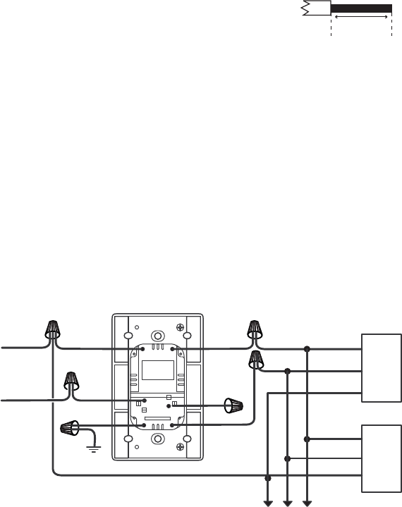
4a. Single Pole Circuit: Wiring one ADFE-16A (Fig. 4)
• Connect the green or non-insulated (copper) GROUND wire from the circuit
to the green wire on the dimmer.
• Connect the power wire from the circuit (HOT) to the blue wire on
the dimmer.
• Connect the neutral wire to the white wire on the dimmer.
• Connect the black wire on the ballast to the red wire on the dimmer.
• Connect the orange wire (dimmed hot) on the ballast to the yellow wire on
the dimmer.
• The remaining blue wire is not used in a single pole circuit.
Strip Gage
1/2"
12.7 mm
Fig. 3 : #12 or
#14 AWG
Visit our website for FAQs: www.wattstopper.com
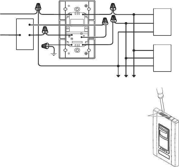
4b. 3-way wiring (Fig. 5)
• Note: Only one dimmer can be used in a 3-way circuit.
• Note: The dimmer must be wired on the load side. The 3-way switch must be
wired on the line side.
Warning: If the dimmer is wired in any other confi guration, the air gap will be
lost and risk of shock or electrocution will exist when servicing the lamp.
• Connect the green or non-insulated (copper) GROUND wire from the circuit
to the green wire on the dimmer.
• Connect one of the blue wires on the dimmer to the switch.
• Connect the remaining blue wire to the switch.
• Connect the neutral wire to the white wire on the dimmer.
• Connect the black wire on the ballast to the red wire on the dimmer.
• Connect the orange wire (dimmed hot) on the ballast to the yellow wire on
the dimmer.
PATENTS PENDING
MADE IN CHINA
WARRANTY VOID IF CASE OPENED
TURN OFF POWER
3-WAY
3-WAY
SWITCH
GROUND
GREEN
HOT BLUE BLUE
NEUTRAL WHITE
TO ADDITIONAL
BALLASTS
RED
YELLOW
DIMMING
BALLAST
BLACK
ORANGE
WHITE
BLACK
ORANGE
WHITE
DIMMING
BALLAST
Fig. 5: Multi-way Wiring
Call 800.879.8585 for Technical Support
5. Remove the center part of the wallplate by placing
a small fl at head screwdriver into one of the four
slots located at the top and bottom of the wallplate.
Gently twist a half turn until the plate pops off.
6. For single gang installations, put all the new
switches into their wall boxes. Position the dimmer
with the slider above the ON/OFF button. Use the
captive screws on the mounting strap to secure the
switches to their wall boxes. Continue to step 7.
For multi-gang installations, select the appropriate
mounting confi guration and install into the wallbox
as explained in the multi-gang installation sections.
Slots
Fig. 6: Remove
Wallplate
Visit our website for FAQs: www.wattstopper.com
7. Restore power to the circuit. Turn ON the breaker or replace the fuse.
8. Attach the cover plates.
MULTIGANG INSTALLATION FINS ARE NOT REMOVED
Multiple controls can be installed in a common wallbox or a series of inter-
connected wallboxes. When ganging any combination of narrow and wide controls,
place all narrow controls on one end and all wide controls on the other end.
Note: A 3-gang installation of narrow dimmers is shown in Fig. 9. Follow the same
steps for any combination of narrow and wide dimmers.
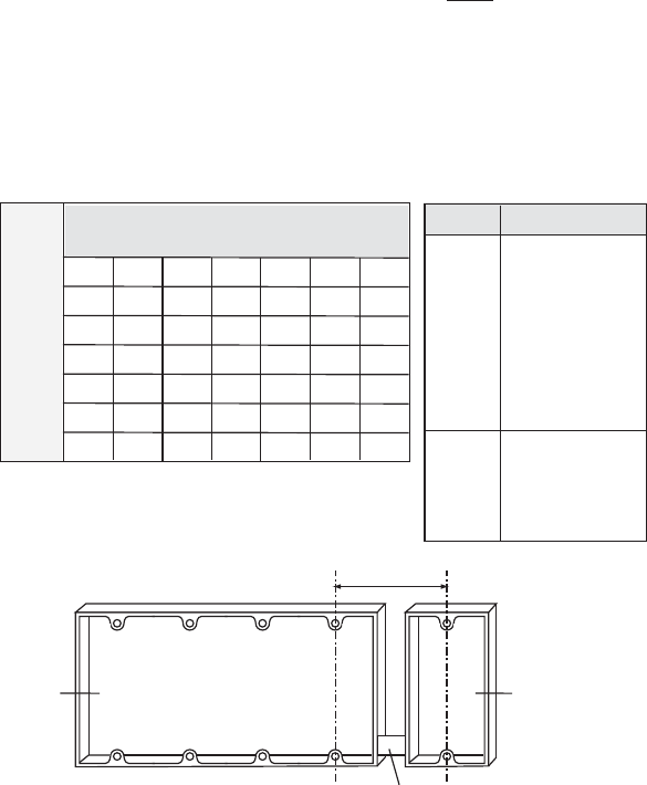
1. Select the correct wall box size from the Table below.
Narrow Dimmers
Wide Dimmers
0
1
2
3
4
5
6
0
0
1
4
6
9
11
14
5
7
9
11
14
16
—
—
4
4+1*
8
10
12
15
—
—
3
4
6
8
11
13
16
—
2
1+1*
5
7
9
12
14
—
1
1
3
5
8
10
13
15
6
7+1*
11
13
15
—
—
—
* Wall box requirements for
ganging an even number
of narrow dimmers.
4-gang
wall box
1-gang
wall box
Chase nipple
2.712
Fig. 7: 4 + 1 Set Up
Model #
Narrow ADMLV-703
AD-1103
ADFM-8A
ADFE-16A
ADFE277-10A
ADF120277
ADFC-6A
Wide ADMLV-1603
AD-2003
ADFM-16A
ADFM277-10A
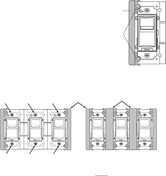
2. Remove End Caps between adjacent dimmers
(2 screws for each End Cap). Keep these
screws.
3. With the slider positioned above the ON/OFF
button, install the dimmer in the wall box
using the captive screws that are
attached to the strap.
4. Attach the large couplers between the
dimmers with the screws that were removed
in step 2.
5. Tighten the captive screws, insert the label
per instructions in the Wallplate Labeling section, attach
the wallplate, and restore power to the circuit.
MULTIGANG INSTALLATION FINS ARE REMOVED
Multiple controls can be installed in a common wallbox or a series of inter-
connected wallboxes. When ganging any combination of narrow and wide controls,
place all narrow controls on one end and all wide controls on the other end.
Note: A 3-gang installation of narrow dimmers is shown in Fig.11. Follow the
same steps for any combination of narrow and wide dimmers. Before removing
fi ns take into consideration derating requirements.
TOP TOP TOP
Captive
Screws
TOP TOP TOP
Large Couplers
End Caps
Fig. 9: Install Dimmers and Attach Couplers
TOP
Remove screws
and set aside.
End Cap
Fig. 8: Remove
End Cap
Call 800.879.8585 for Technical Support
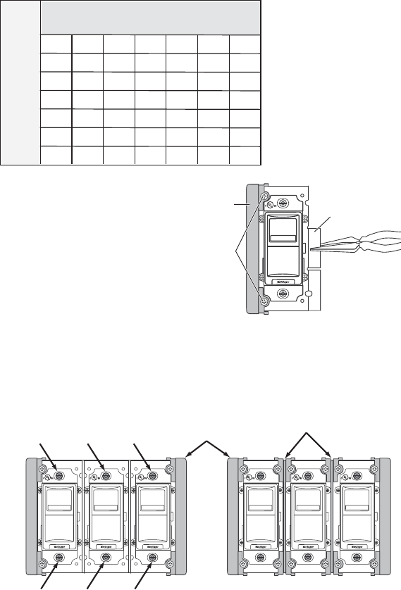
1. Select the correct box size from the table below.
2. Remove the end cap (2
screws for each end cap)
and break the fi ns between
adjacent dimmers.
3. With the slider positioned
above the ON/OFF button,
install the dimmer in the
wallbox using the captive
screws attached to the strap.
4. Attach the small couplers between
the dimmers with the screws that
were removed in step 2.
5. Tighten the captive screws, insert the label per instructions in the Wallplate
Labeling section, attach the wallplate, and restore power to the circuit.
TOP
Break ns
using pliers
Remove screws
and set aside.
End Cap
Fig. 10: Remove End Cap and fi ns
TOP TOP TOP
Captive
Screws
TOP TOP TOP
Small Couplers
End Caps
Fig. 11: Install Dimmers and Attach Small Couplers
Narrow Dimmers
Wide Dimmers
0
1
2
3
4
5
6
0
0
1
3
5
7
9
11
5
5
7
8
10
12
14
16
4
4
6
7
9
11
13
15
3
3
5
6
8
10
12
14
2
2
4
5
7
9
11
13
1
1
3
4
6
8
10
12
6
6
8
9
11
13
15
17
WALLPLATE LABELING
The wallplates contain a label holding slot. A 0.33” x 1.5” label can be printed
from an Avery® standard template: Divider tab inserts 8-Tabs or equivalent.
Install the label following these steps:
1. Disconnect power to the circuit
by removing the fuse or turning
the circuit breakers OFF.
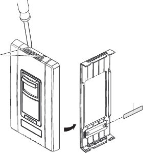
2. Remove the wallplate by placing
a small fl at head screwdriver
into one of the four slots located
at the top and bottom of the
wallplate. Gently twist a half
turn until the plate pops off.
3. Slide the label in from the back
side of the wallplate.
Slots
INSERT LABEL HERE
Label
Fig. 12: Insert Label
SETUP
No adjustments are required. The minimum light level is calibrated at the
factory and does not normally require adjustment. If the lamp drops out or
fl ickers at the minimum dimming level, there may be an installation error.
TROUBLESHOOTING
Lights are flickering
• Lamp has a bad connection.
• Check wire connection to make sure they are secured fi rmly.
• There may be a circuit wiring issue. You should always use a separate
neutral wire for the circuit connected to the dimmer. If two 120V hots
from the breaker box share the same neutral and one of them has a very
large load, it could cause a voltage drop on the other hot. This can cause
fl ickering.
Light does not turn ON
• Check to see if the circuit breaker or fuse has tripped.
• Check to see if the lamp is burned out.
Visit our website for FAQs: www.wattstopper.com
WARRANTY INFORMATION
WattStopper warranties its products to be free of defects in materials
and workmanship for a period of five (5) years. There are no obligations
or liabilities on the part of WattStopper for consequential damages
arising out of, or in connection with, the use or performance of this
product or other indirect damages with respect to loss of property,
revenue or profit, or cost of removal, installation or reinstallation.
Please
Recycle
2800 De La Cruz Boulevard, Santa Clara, CA 95050
Technical Support: 800.879.8585 • www.wattstopper.com
13050r2 7/2010
E3-T514C-120-1, E3-T514C-120-2,
E3-T521C-120-1, E3-T521C-120-2,
ECO-T528-120-1, ECO-T528-120-2,
ECO-T524-120-1, ECO-T524-120-2,
ECO-T5H39-120-1, ECO-T5H39-120-2,
ECO-T554-120-1, ECO-T554-120-2,
ECO-T539-120-1, ECO-T539-120-2,
ECO-T539-120-3, ECO-T540-120-1,
ECO-T540-120-2, ECO-T540-120-3,
ECO-T550-120-1, ECO-T550-120-2,
ECO-T817-120-1, ECO-T817-120-2,
ECO-T817-120-3, ECO-T825-120-1,
ECO-T825-120-2, ECO-T832-120-1-L,
ECO-T832-120-1-T, ECO-T832-120-2-L,
ECO-T832-120-2-T, ECO-T832-120-3
HL3-T426-120-1-S, HL3-T432-120-1-S
FDB-T524-120-1, FDB-T524-120-2,
FDB-T539-120-1, FDB-T539-120-2,
FDB-T554-120-1, FDB-T554-120-2,
FDB-2427-120-1, FDB-2427-120-2,
FDB-2427-120-3, FDB-3627-120-1,
FDB-3627-120-2, FDB-3627-120-3.
FDB-4827-120-1, FDB-4827-120-2,
FDB-4827-120-3, FDB-6027-120-1,
FDB-6027-120-2, FDB-7280-120-1,
FDB-8480-120-1, FDB-9680-120-1,
H3DT832CUNV110, H3DT832CUNV117,
H3DT832CUNV210, H3DT832CUNV217
FDB-T418-120-1-S, FDB-T418-120-2-S,
FDB-T426-120-1-S, FDB-T426-120-2-S,
FDB-T432-120-1-S, FDB-T432-120-2-S,
FDB-T442-120-1-S, FDB-T442-120-2-S,
FDB-1643-120-1, FDB-1643-120-2,
FDB-1643-120-3, FDB-2227-120-1,
FDB-2227-120-2, FDB-2227-120-3,
FDB-2243-120-3, FDB-2243-120-2
1% - Hi-Lume, Hi-Lume 3D 10% - Eco-10
5% - Compact SE
List of Compatible Ballasts
Ballast Manufacturer: Luton
