Installation Directions
2016-08-16
: Pdf 1000346913-Installationsheet 1000346913-InstallationSheet B3 unilog
Open the PDF directly: View PDF ![]() .
.
Page Count: 3

PHOENIX CONTACT PHOENIX CONTACT
Crimping
recess
Digital display
Battery holder,
Battery type
CR2025 3 VOLT
"MODE" button
"ON/OFF" button
Adjustment knob for
accuracies of feed
depth of 0.01 mm
End stop
Locator, 12-section
Clamping screw for
locking the crimping
dimensions
Operating Instructions RC-Z2514
(Order No. 1614590)
4-arbor crimping pliers for
machined contacts with digital
display and wear monitoring Gauge introduced
Gauge dimensions
displayed
"MODE" button
"ON/OFF" button
Adjustment knob for
setting the arbors to
the gauge dimension
Operating Instructions RC-Z2514 • 2015-11-03 Operating Instructions RC-Z2514 • 2015-11-03
General
The RC-Z2514 4-arbor crimping pliers are for crimping the machined crimp contacts in the list below. The pliers may
only be used if they are in technically perfect working order and are only to be used for the purpose described in the
operating instructions. With this crimping tool, the user is able to check the pliers at intervals he denes himself, and
can calibrate them, if necessary. To increase the process reliability for the user, the pliers have wear monitoring. This
lets the user know when the tool wear has exceeded a dened range.
The settings of the crimping pliers have been calculated based on the
withdrawal forces stated in DIN EN 60352-2 and by using a reference
conductor. Depending on the conductor used, the required
settings of the crimping pliers can dier from the values stated.
Procedure
• Switching on/o: The device is switched on/o by pressing the
"ON/OFF" button.
• Mode function: The "MODE" button is used to select the display
functions in mm or in inches, or the selector positions from 1 – 8 in
acc. with MIL 22520. Use the enclosed gauge to press the "MODE"
button as often as necessary to select the desired display:
Setting the crimping parameters / crimping operation
• Please refer to the enclosed setting matrix for the crimp arbor and
locator settings for the contact to be crimped.
• Loosen the clamping screw (condition when delivered).
• The crimping dimensions (crimping depth of the crimp arbors) are
set by turning the adjustment knob until the digital display shows the
required value. Please note that a larger crimping dimension must
always be selected than that to be set, e.g. select 1.2 mm and adjust
down to crimping dimension 1.0 mm.
• Depth settings clockwise reduce the crimping dimensions, while
counter-clockwise increases the crimping dimensions.
• Lock the crimping dimension setting using the clamping screw.
• Lift the locator at the side and turn to set it to the position dened in
the setting matrix. Insert the crimp contact as far as it will go into the
recess provided. The locator moves the crimp contact to the exact
position.
• Insert the prepared cable as far as it will go into the crimp contact in
the pliers and close the pliers tightly until the trigger block is unlocked.
Open the pliers and remove the crimped contact.
Do not crimp on the gauge or other similar objects to avoid
damage to the pliers. Avoid crimping solid materials (e.g. steel)
having a hardness greater than 35 HRC.
Standard display
in mm
Display in
inches
Display of comparable selector
positions in acc. with MIL
Changing the battery
The service life of the battery for the digital display is approximately one year, depending on how often it is used. To
change the battery (type CR2025, 3 VOLT), the battery holder is pulled out so that the battery can be removed and
exchanged. Before inserting the battery, make sure you set the pliers to the stop at the lower setting point.
How to further proceed is described in the section "Calibrating the reference value". Dispose of used batteries at
approved recycling centers.
Calibrating the pliers
The crimping pliers may only be calibrated by authorized skilled
personnel, since improper calibration can lead to incorrect
crimping.
• Adjust the crimp arbors to a setting dimension of 1 mm: Using the
adjustment knob, set the crimp arbors so that the enclosed gauge
can move between the crimp arbors without play. Please note that a
larger gauge dimension must always be selected than that to be set,
e.g. select 1.2 mm and adjust down to gauge dimension 1.0 mm.
• Keep the "ON/OFF" button pressed and press the "MODE" button
using the gauge. Keep the "MODE" pressed for at least 5 seconds.
Release the "MODE" button after 5 seconds and then the "ON/OFF"
button.
• The digital display automatically jumps to the gauge value 1.0 mm.
The pliers are adjusted and ready for the crimping parameters to be
set.
Wear monitoring
Every tool is subject to wear, even when used as intended. This wear is tolerable within certain limits and is
compensated during each calibration. Press the "Mode" button for 10 seconds (range: 8 to 15 s) to call up the current
tool status and to display the numerical output on the pliers. The following values are output consecutively:
• Serial number – current wear value – position value of the lower stop of the unworn pliers (xed value, specic to
pliers) – number of previous calibrations carried out.
The mechanical stop at the lower setting point serves as a reference value for calculating the current wear value.
The value is permanently stored in the tool memory and cannot be changed. Every time the battery is changed,
calibration must be carried out using this reference value. To do this, follow this procedure:
Calibrating the reference value
• For preparation, the battery must be removed.
• Open the pliers.
• Turn the adjustment knob to the stop at the lower setting point (turn counter-clockwise;
see gure) and leave it there.
• Insert battery; "CAL" appears on the display to prompt you to calibrate.
• Adjust the pliers with the gauge (see also section "Calibrating the pliers").
• Keep the "ON/OFF" button pressed and press the "MODE" button using the gauge.
Keep the "MODE" pressed for at least 5 seconds. Release the "MODE" button after 5
seconds and then the "ON/OFF" button.
• The digital display automatically jumps to the gauge value 1.0 mm.
• The pliers are adjusted and ready for the crimping parameters to be set.
Troubleshooting
The 4-arbor crimping pliers reach their wear limit after about 50 thousand crimping
cycles. When this limit has been exceeded, the error message "E1" is output to the
display. Here, when pressed, the display cyclically switches between the set crimp value and the message "E1", and
then shows "E1" permanently.
Maintenance and repair
Unauthorized changes to or unintended use of the manual crimping pliers excludes the liability of the manufacturer for
any damage resulting from this. The manual crimping pliers must be clean and in good order before starting work. Any
residue from the crimping process must be removed from the crimping jaws and locator. The joints must be lubricated
regularly with a light machine oil and protected against dirt. Please ensure that all bolts are secured with circlips.
Repairs to the 4-arbor crimping pliers may only be carried out by the manufacturer of the pliers.
Displayed Cause Solution
E1
After changing the battery, the pliers were not turned to
the lower setting point using the adjustment knob.
See the section "Calibrating the
reference value"
Wear limit of tool reached Contact manufacturer
14795 (Page 1 / 3)
PHOENIX CONTACT GmbH & Co. KG
D-32823 Blomberg, Germany
Tel. +49(0)5235-300
Fax +49(0)5235-310799
www.phoenixcontact.com
info@phoenixcontact.com
PHOENIX CONTACT PHOENIX CONTACTOperating Instructions RC-Z2514 • 2015-11-03 Operating Instructions RC-Z2514 • 2015-11-03
14795 (Page 2 / 3)
Type Plug-in Ø [mm] Cross Total Conductor Stripping Setting parameters
Contact Pin Socket [mm²] length insert Ø length Locator Crimp arbor setting
[mm] [mm] [mm] [mm]
HC-11P2000 1 0.08 14.8 0.6 4 1 0.65
HC-11P2000 1 0.14 14.8 0.6 4 1 0.67
HC-11P2000 1 0.22 14.8 0.6 4 1 0.69
HC-11S2000 1 0.08 14.3 0.6 4 2 0.65
HC-11S2000 1 0.14 14.3 0.6 4 2 0.67
HC-11S2000 1 0.22 14.3 0.6 4 2 0.69
HC-12P2000 1 0.14 14.8 1.1 4 10.63
HC-12P2000 1 0.22 14.8 1.1 4 1 0.65
HC-12P2000 1 0.38 14.8 1.1 4 1 0.67
HC-12P2000 1 0.56 14.8 1.1 4 1 0.69
HC-12S2000 1 0.14 14.3 1.1 4 20.63
HC-12S2000 1 0.22 14.3 1.1 4 2 0.65
HC-12S2000 1 0.38 14.3 1.1 4 2 0.67
HC-12S2000 1 0.56 14.3 1.1 4 2 0.69
HC-1KP2000 1 0.50 14.8 1.5 4 1 0.75
HC-1KP2000 10.75 14.8 1.5 4 1 0.80
HC-1KP2000 1 1.00 14.8 1.5 4 1 1.00
HC-1KS2000 1 0.50 14.3 1.5 4 2 0.75
HC-1KS2000 10.75 14.3 1.5 4 2 0.80
HC-1KS2000 1 1.00 14.3 1.5 4 2 1.00
RC-11P2000 1 0.08 14.8 0.6 4 1 0.65
RC-11P2000 1 0.14 14.8 0.6 4 1 0.67
RC-11P2000 1 0.22 14.8 0.6 4 1 0.69
RC-11S2000 1 0.08 14.3 0.6 4 2 0.65
RC-11S2000 1 0.14 14.3 0.6 4 2 0.67
RC-11S2000 1 0.22 14.3 0.6 4 2 0.69
RC-12P2000 1 0.14 14.8 1.1 4 10.63
RC-12P2000 1 0.22 14.8 1.1 4 1 0.65
RC-12P2000 1 0.38 14.8 1.1 4 1 0.67
RC-12P2000 1 0.56 14.8 1.1 4 1 0.69
RC-12S2000 1 0.14 14.3 1.1 4 20.63
RC-12S2000 1 0.22 14.3 1.1 4 2 0.65
RC-12S2000 1 0.38 14.3 1.1 4 2 0.67
RC-12S2000 1 0.56 14.3 1.1 4 2 0.69
RC-1BP2000 10.75 14.8 1.7 41 0.85
RC-1BP2000 1 1.00 14.8 1.7 41 0.90
RC-1BS2000 10.75 14.3 1.7 42 0.85
RC-1BS2000 1 1.00 14.3 1.7 42 0.90
RC-1KP2000 1 0.50 14.8 1.5 4 1 0.75
RC-1KP2000 10.75 14.8 1.5 4 1 0.80
RC-1KP2000 1 1.00 14.8 1.5 4 1 1.00
RC-1KS2000 1 0.50 14.3 1.5 4 2 0.75
RC-1KS2000 10.75 14.3 1.5 4 2 0.80
RC-1KS2000 1 1.00 14.3 1.5 4 2 1.00
RC-43P2000 1 0.14 21.4 0.9 6 30.62
RC-43P2000 1 0.22 21.4 0.9 6 30.65
RC-43P2000 1 0.38 21.4 0.9 6 30.67
RC-46P2000 1 0.14 21.4 1.1 6 30.65
RC-46P2000 1 0.25 21.4 1.1 6 30.67
RC-46P2000 1 0.35 21.4 1.1 6 30.69
RC-46P2000 1 0.50 21.4 1.1 6 30.71
RC-47P2000 10.75 21.4 1.7 630.85
RC-47P2000 1 1.00 21.4 1.7 630.88
RC-4DP2000 1 0.50 21.4 1.4 6 30.85
RC-4DP2000 10.75 21.4 1.4 6 30.88
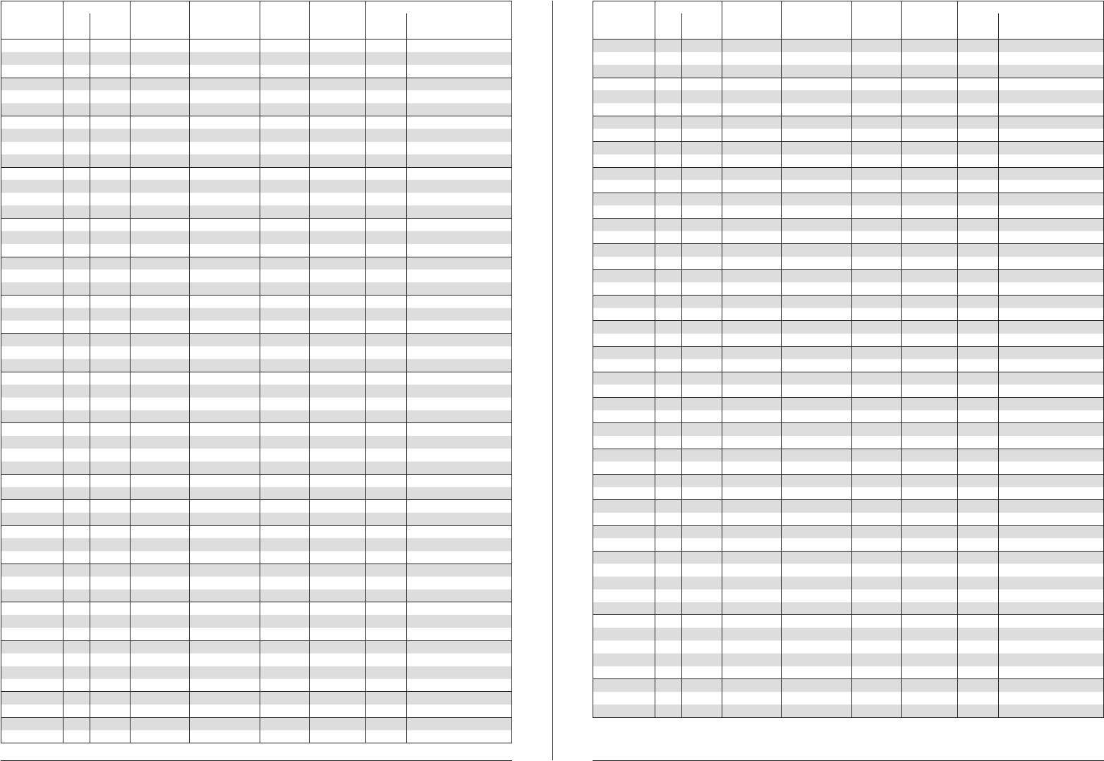
Settings chart for crimp contacts 4-arbor crimping pliers Order No. RC-Z2514 Settings chart for crimp contacts 4-arbor crimping pliers Order No. RC-Z2514
Type Plug-in Ø [mm] Cross Total Conductor Stripping Setting parameters
Contact Pin Socket [mm²] length insert Ø length Locator Crimp arbor setting
[mm] [mm] [mm] [mm]
RC-58P2000 1 0.50 14.8 1.5 4 1 0.75
RC-58P2000 10.75 14.8 1.5 4 1 0.80
RC-58P2000 1 1.00 14.8 1.5 4 1 1.00
RC-58S2000 1 0.50 14.3 1.5 4 2 0.75
RC-58S2000 10.75 14.3 1.5 4 2 0.80
RC-58S2000 1 1.00 14.3 1.5 4 2 1.00
RC-59P2000 20.75 14.8 1.7 44 0.85
RC-59P2000 2 1.00 14.8 1.7 44 0.88
RC-59S2000 20.75 14.3 1.7 45 0.85
RC-59S2000 2 1.00 14.3 1.7 45 0.88
RC-5AP2000 2 1.50 14.8 2.4 4 4 0.85
RC-5AP2000 2 2.50 14.8 2.4 4 4 1.05
RC-5AS2000 2 1.50 14.3 2.4 4 5 0.92
RC-5AS2000 2 2.50 14.3 2.4 4 51.03
RC-5CP2000 2 1.00 14.8 2.0 4 4 1.00
RC-5CP2000 2 1.50 14.8 2.0 4 4 1.07
RC-5CS2000 2 1.00 14.3 2.0 4 5 0.97
RC-5CS2000 2 1.50 14.3 2.0 4 5 1.02
RC-5NP2000 2 1.00 16.3 2.0 4 9 1.00
RC-5NP2000 2 1.50 16.3 2.0 4 9 1.07
RC-5PP2000 2 1.50 16.3 2.4 4 9 0.85
RC-5PP2000 2 2.50 16.3 2.4 4 9 1.05
RC-5QP2000 20.75 16.3 1.7 49 0.85
RC-5QP2000 2 1.00 16.3 1.7 49 0.88
RC-5SP2000 2 0.50 14.8 1.4 4 50.93
RC-5SP2000 20.75 14.8 1.4 4 5 0.96
RC-5SS2000 2 0.50 14.3 1.4 4 5 0.86
RC-5SS2000 20.75 14.3 1.4 4 5 0.88
RC-67P2000 10.75 24.3 1.7 66 0.85
RC-67P2000 1 1.00 24.3 1.7 66 0.88
RC-67S2000 10.75 16.5 1.7 67 0.85
RC-67S2000 1 1.00 16.5 1.7 67 0.88
RC-6EP2000 1.5 0.75 24.3 1.7 68 0.85
RC-6EP2000 1.5 1.00 24.3 1.7 68 0.88
RC-6ES2000 1.5 0.75 16.6 1.7 69 0.85
RC-6ES2000 1.5 1.00 16.6 1.7 69 0.88
RC-6FP2000 1.5 0.75 26 1.7 69 0.85
RC-6FP2000 1.5 1.00 26 1.7 69 0.88
RC-6FS2000 1.5 0.75 16.6 1.7 69 0.85
RC-6FS2000 1.5 1.00 16.6 1.7 69 0.88
RC-6KP2000 1 0.14 24.3 1.25 6 6 0.60
RC-6KP2000 1 0.25 24.3 1.25 6 6 0.70
RC-6KP2000 1 0.34 24.3 1.25 6 6 0.75
RC-6KP2000 1 0.50 24.3 1.25 6 6 0.80
RC-6KP2000 10.75 24.3 1.25 6 60.83
RC-6KS2000 1 0.14 16.5 1.25 6 7 0.60
RC-6KS2000 1 0.25 16.5 1.25 6 7 0.70
RC-6KS2000 1 0.34 16.5 1.25 6 7 0.75
RC-6KS2000 1 0.50 16.5 1.25 6 7 0.80
RC-6KS2000 10.75 16.5 1.25 6 70.83
RC-6LP2000 1 0.25 24.3 1.1 6 6 0.72
RC-6LP2000 1 0.38 24.3 1.1 6 6 0.75
RC-6LP2000 1 0.50 24.3 1.1 6 6 0.77
Depending on the conductor used, the crimping pliers settings required may dier from the values given in
the settings chart.
PHOENIX CONTACT PHOENIX CONTACTOperating Instructions RC-Z2514 • 2015-11-03 Operating Instructions RC-Z2514 • 2015-11-03
14795 (Page 3 / 3)
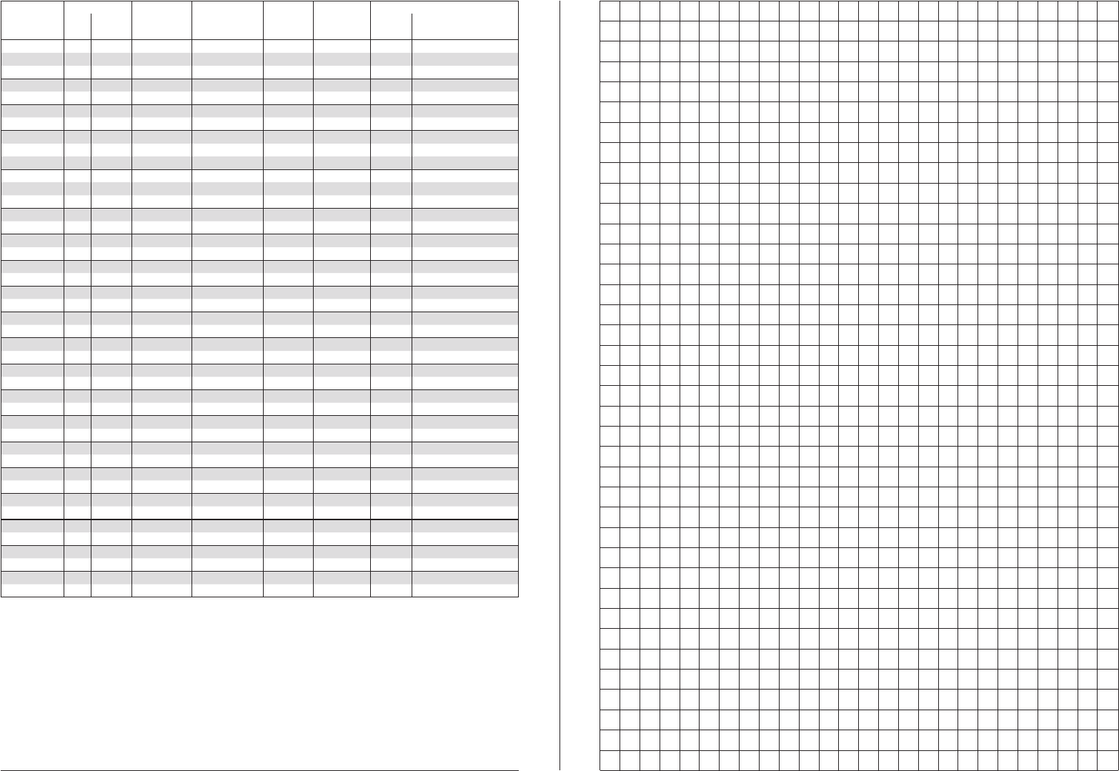
Settings chart for crimp contacts 4-arbor crimping pliers Order No. RC-Z2514
Depending on the conductor used, the crimping pliers settings required may dier from the values given in
the settings chart.
Type Plug-in Ø [mm] Cross Total Conductor Stripping Setting parameters
Contact Pin Socket [mm²] length insert Ø length Locator Crimp arbor setting
[mm] [mm] [mm] [mm]
RC-6LS2000 1 0.25 16.5 1.1 6 7 0.72
RC-6LS2000 1 0.38 16.5 1.1 6 7 0.75
RC-6LS2000 1 0.50 16.5 1.1 6 7 0.77
RC-6MP2000 10.75 25.8 1.7 69 0.85
RC-6MP2000 1 1.00 25.8 1.7 69 0.88
RC-6MS2000 10.75 16.5 1.7 67 0.85
RC-6MS2000 1 1.00 16.5 1.7 67 0.88
RC-6RP2000 1 0.08 24.3 0.6 6 6 0.69
RC-6RP2000 1 0.14 24.3 0.6 6 6 0.74
RC-6RP2000 1 0.22 24.3 0.6 6 6 0.78
RC-6RS2000 1 0.08 16.5 0.6 6 7 0.69
RC-6RS2000 1 0.14 16.5 0.6 6 7 0.74
RC-6RS2000 1 0.22 16.5 0.6 6 7 0.78
SC-79P2000 20.75 27 1.7 610 1.00
SC-79P2000 2 1.00 27 1.7 610 1.03
SC-7AP2000 2 2.00 27 2.7 610 1.10
SC-7AP2000 2 2.50 27 2.7 610 1.20
SC-7CP2000 2 1.00 27 2.0 6 10 0.90
SC-7CP2000 2 1.50 27 2.0 6 10 1.00
SC-7GP2000 2 1.50 27 2.2 6 10 1.00
SC-7GP2000 2 2.00 27 2.2 6 10 1.10
SC-7SP2000 2 0.50 27 1.4 6 10 0.80
SC-7SP2000 20.75 27 1.4 6 10 0.83
SC-7UP2000 2 0.50 27 1.4 6 10 0.80
SC-7UP2000 20.75 27 1.4 6 10 0.83
SC-7VP2000 2 2.00 27 2.7 610 1.10
SC-7VP2000 2 2.50 27 2.7 610 1.20
SC-7XP2000 2 1.00 27 2.0 6 10 1.05
SC-7XP2000 2 1.50 27 2.0 6 10 1.10
SI-7JS2000 2 2.00 16.5 2.4 6 10 1.10
SI-7JS2000 2 2.50 16.5 2.4 6 10 1.25
SI-7UP2000 2 0.50 29 1.4 6 12 0.73
SI-7UP2000 20.75 29 1.4 6 12 0.76
SI-7US2000 2 0.50 16.5 1.4 6 11 0.73
SI-7US2000 20.75 16.5 1.4 6 11 0.76
SI-7WP2000 20.75 29 1.7 612 0.85
SI-7WP2000 2 1.00 29 1.7 612 0.88
SI-7WS2000 20.75 16.5 1.7 611 0.85
SI-7WS2000 2 1.00 16.5 1.7 611 0.89
SI-7XP2000 2 1.00 29 2.0 6 12 1.05
SI-7XP2000 2 1.50 29 2.0 6 12 1.10
SI-7XS2000 2 1.00 16.5 2.0 6 11 0.90
SI-7XS2000 2 1.50 16.5 2.0 6 11 0.95
