1000347612 Catalog
1000295564-Catalog 1000295564-Catalog 1000295564-Catalog B5 unilog cesco-content
2016-09-04
: Pdf 1000347612-Catalog 1000347612-Catalog B4 unilog
Open the PDF directly: View PDF ![]() .
.
Page Count: 130 [warning: Documents this large are best viewed by clicking the View PDF Link!]
- General contents
- 1 - Altivar 61 variable speed drives
- 2 - Altivar 61 Plus variable speed drives
- 3 - Product reference index
Catalogue
April 2014
Variable speed drives
Altivar 61 and Altivar 61 Plus
for asynchronous motors
from 0.75 kW/1 HP to 2400 kW
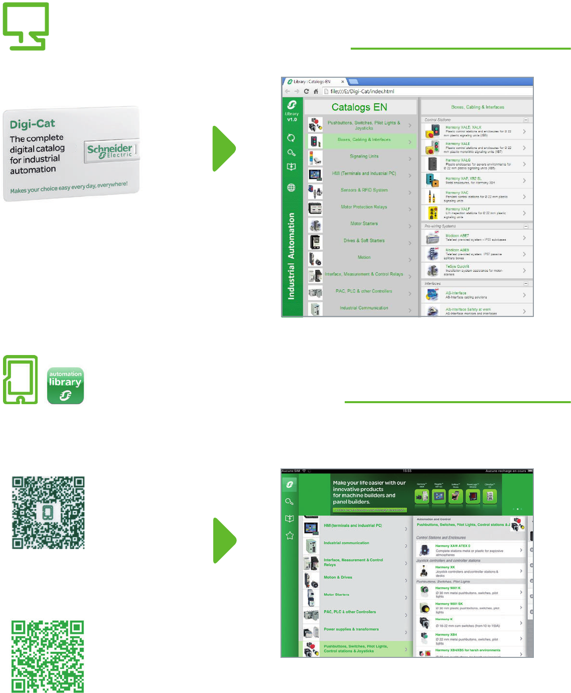
Digi-Cat, a handy USB key for PC
Contact your local representative to get your own Digi-Cat
How can you fit a 6000-page catalog in your pocket ?
Schneider Electric provides you with the complete set of industrial automation catalogs all on a handy
USB key for PC or in an application for tablets
e-Library, the app for tablets
>Convenient to carry
>Always up-to-date
>Environmentally friendly
>Easy-to-share format
>Go to the App Store and search for e-Library
>or scan the QR code
If you have an iPad®:
>Go to the Google Play StoreTM and search for eLibrary
>or scan the QR code
If you have an Android tablet:

1
General contents
Altivar 61 variable speed drives . . . . . . . . . . . .
Altivar 61 Plus variable speed drives . . . . . . .
Index of references ........................
2
1
3
5
6
7
8
9
10
2
1
3
5
6
7
8
9
10

21/0
2
1
3
4
5
6
7
8
9
10
2
1
3
4
5
6
7
8
9
10

3
Contents
IP 20 variable speed drive selection guide . . . . . . . . . . . . . . . . . . . . . . . . page 1/2
IP 54 or IP 55 variable speed drive selection guide . . . . . . . . . . . . . . . . . page 1/4
Altivar 61 Plus variable speed drive selection guide . . . . . . . . . . . . . . . page 1/6
b Presentation ...........................................................................................page 1/8
b Altivar 61 variable speed drives .........................................................page 1/16
v 200…240 V power supply, IP 20 ............................................................ page 1/16
v 380…480 V power supply ...................................................................... page 1/17
- IP 20 ................................................................................................. page 1/17
- IP20, water-cooled............................................................................ page 1/18
- IP 54 ................................................................................................. page 1/19
- IP 54, with Vario switch disconnector ................................................ page 1/20
v 500…600 V power supply, IP 20 ............................................................ page 1/21
v 500…690 V power supply ...................................................................... page 1/21
- IP 20 ................................................................................................. page 1/21
- IP 20, water-cooled ........................................................................... page 1/22
v Variants.................................................................................................. page 1/23
v Accessories .......................................................................................... page 1/25
v Dialogue and conguration tools ............................................................ page 1/31
b Drive/option combinations .................................................................page 1/34
b Options ................................................................................................page 1/46
v Encoder interface cards ........................................................................ page 1/46
v I/O expansion cards ............................................................................... page 1/47
v Multi-pump card ..................................................................................... page 1/48
v Controller inside programmable card ..................................................... page 1/50
v Communication buses and networks ..................................................... page 1/54
v Resistance braking units ........................................................................ page 1/60
v Braking resistors .................................................................................... page 1/61
v Reduction of current harmonics ............................................................. page 1/64
- DC chokes ........................................................................................ page 1/64
- line chokes........................................................................................ page 1/66
- passive lters .................................................................................... page 1/69
- Active Front End ............................................................................... page 1/76
v Additional EMC input lters .................................................................... page 1/80
v Output lters .......................................................................................... page 1/82
- motor chokes .................................................................................... page 1/83
- sinus lters........................................................................................ page 1/86
b Motor starters ......................................................................................page 1/88
1 - Altivar 61 variable speed drives
1/1
2
1
3
4
5
6
7
8
9
10
2
1
3
4
5
6
7
8
9
10
2
1
3
4
5
6
7
8
9
10
2
1
3
4
5
6
7
8
9
10
2
1
3
4
5
6
7
8
9
10
2
1
3
4
5
6
7
8
9
10
1/2 1/21/2 1/3
Selection guide IP 20 or IP 21 variable speed drives
for asynchronous and
synchronous motors
Type of machine Simple machines Pumps and fans
(building (HVAC)) (1) Pumps and fans
(industrial) Complex machines
Power range for 50…60 Hz (kW/HP) line supply 0.18…4/0.25...5 0.18…15/0.25...20 0.75…75/1...100 0.37…800/0.5...900 0.37…630/0.5...700
Single-phase 100…120 V (kW/HP) 0.18…0.75/0.25...1 – – – –
Single-phase 200…240 V (kW/HP) 0.18…2.2/0.25...3 0.18…2.2/0.25...3 – 0.37…5.5/0.5...7.5 0.37…5.5/0.5...7.5
Three-phase 200…230 V (kW/HP) – – – – –
Three-phase 200…240 V (kW/HP) 0.18…4/0.25...5 0.18…15/0.25...20 0.75…30/1...40 0.75…90/1...125 0.37…75/0.5...100
Three-phase 380…480 V (kW/HP) – – 0.75…75/1...100 0.75…630/1...900 0.75…500/1...700
Three-phase 380…500 V (kW/HP) – 0.37…7.5/0.5...10 – – –
Three-phase 500…600 V (kW/HP) – – – 2.2…7.5/3...10 1.5…7.5/2...10
Three-phase 525…600 V (kW/HP) – 0.75…15/1...20 – – –
Three-phase 500…690 V (kW/HP) – – – 2.2…800/3...800 1.5…630/2...700
Degree of protection IP 20 IP 21 IP 20
Type of cooling (2) Heatsink or base plate Heatsink Heatsink or water-cooled system Heatsink, base plate or water-cooled system
Drive Output frequency 0.1…400 Hz 0.1…500 Hz 0.5…200 Hz 0.1…500 Hz for the entire range
0.1…599 Hz up to 37 kW/50 HP at 200…240 V a and 380…480 V a 0.1…500 Hz for the entire range
0.1…599 Hz up to 37 kW/50 HP at 200…240 V a and 380…480 V a
Type of control Asynchronous
motor Standard (voltage/frequency)
Performance (sensorless ux
vector control)
Pump/fan (Kn2 quadratic ratio)
Standard (voltage/frequency)
Performance (sensorless ux
vector control)
Energy saving ratio
Sensorless ux vector control
Voltage/frequency ratio
(2 points)
Energy saving ratio
Sensorless ux vector control
Voltage/frequency ratio (2 or 5 points)
Energy saving ratio
Flux vector control with or without sensor
Voltage/frequency ratio (2 or 5 points)
ENA System
Synchronous motor – Vector control without speed feedback Vector control with or without speed feedback
Transient overtorque 150…170% of the nominal
motor torque 170…200% of the nominal
motor torque 120% of the nominal motor
torque 120% of the nominal motor torque for 60 seconds 220% of the nominal motor torque for 2 seconds
170% for 60 seconds
Functions
Number of functions 40 50 50 > 100 > 150
Number of preset speeds 8 16 7 8 16
Number of I/O Analog inputs 1 3 2 2…4 2…4
Logic inputs 4 6 3 6…20 6…20
Analog outputs 1 1 1 1…3 1…3
Logic outputs 1 – – 0…8 0…8
Relay outputs 1 2 2 2…4 2…4
Communication Integrated Modbus Modbus and CANopen Modbus, METASYS N2,
APOGEE FLN, BACnet Modbus and CANopen
Available as an option – CANopen Daisy Chain,
DeviceNet, PROFIBUS DP,
Modbus TCP, Fipio
LonWorks Modbus TCP Daisy Chain, Modbus/Uni-Telway, EtherNet/IP (RSTP),
DeviceNet, PROFIBUS DP V0 and V1, InterBus, CC-LInk, LonWorks,
METASYS N2, APOGEE FLN, BACnet, Pronet, EtherCAT,
POWERLINK
Modbus TCP Daisy Chain, Modbus/Uni-Telway, EtherNet/IP (RSTP), DeviceNet,
PROFIBUS DP V0 and V1, InterBus, CC-LInk, Pronet, EtherCAT, POWERLINK
Cards (available as an option) – I/O extension cards, “Controller Inside” programmable card, multi-pump
cards, encoder interface cards Interface cards for incremental, resolver, SinCos, SinCos Hiperface®, EnDat® or SSI
encoders, I/O extension cards, Controller Inside programmable card
Dialogue tools IP 54 or IP 65 remote terminal IP 54 or IP 65 remote terminal
IP 54 remote graphic display
terminal
IP 54 or IP 65 remote graphic
display terminal IP 54 or IP 65 remote graphic display terminal
Conguration
tools Setup software SoMove PCSoft for ATV 212 SoMove
Conguration tools Simple Loader, Multi-Loader Multi-Loader Simple Loader, Multi-Loader
Standards and certications IEC 61800-5-1
IEC 61800-3 (environments 1 and 2, categories C1 to C3, cat. C1 with option for ATV 212) IEC 61800-5-1
IEC 61800-3 (environments 1 and 2, categories C1 to C3), IEC 61000-4-2/4-3/4-4/4-5/4-6/4-11
e, UL, CSA, C-Tick, NOM,
GOST
e, UL, CSA, DNV, C-Tick,
NOM, GOST
EN 55011: Group 1, class A
and class B with option card.
e, UL, CSA, C-Tick, NOM
e, UL, CSA, DNV, C-Tick, NOM, GOST
References ATV 12 ATV 312 ATV 212 ATV 61 ATV 71
Catalogues “Altivar 12 variable speed
drives” “Altivar 312 variable speed
drives” “Altivar 212 variable speed
drives” page 1/16 “Altivar 71 variable speed drives”
(1) Heating, Ventilation and Air Conditioning (2) The type of cooling depends on the model. Please consult pages 1/16 to 1/22.
2
1
3
4
5
6
7
8
9
10
2
1
3
4
5
6
7
8
9
10
2
1
3
4
5
6
7
8
9
10
2
1
3
4
5
6
7
8
9
10
1/4 1/41/4 1/5
Type of machine Simple machines Pumps and fans
(building (HVAC)) (1) Pumps and fans
(industrial) Complex machines
Power range for 50…60 Hz (kW/HP) line supply 0.18…15/0.25...20 0.75…75/1...100 0.75…90/1...125 0.75…75/1...100
Single-phase 200…240 V (kW/HP) 0.18…2.2/0.25...3 – –
Three-phase 380…480 V (kW/HP) – 0.75…75/1...100 0.75…90/1...125 0.75…75/1...100
Three-phase 380…500 V (kW/HP) 0.37…15/0.5...20 – –
Degree of protection IP 55 IP 55 IP 54
Variants Enclosure user-denable up to 4 kW/5 HP:
Vario switch disconnector, LEDs, selector
switch, potentiometer
– – Equipped with a Vario switch
disconnector – Equipped with a Vario switch
disconnector
Drive Output frequency 0.1…500 Hz 0.1…200 Hz 0.1…599 Hz from 0.75 to 45 kW/1...60 HP
0.1…500 Hz from 55…90 kW/75...125 HP 0.1…599 Hz from 0.75 to 37 kW/1...50 HP
0.1…500 Hz from 45 to 75 kW/60...100 HP
Type of control Asynchronous motor Sensorless ux vector control
Voltage/frequency ratio Sensorless ux vector control
Voltage/frequency ratio (2 points)
Energy saving ratio
Sensorless ux vector control
Voltage/frequency ratio (2 or 5 points)
Energy saving ratio
Sensorless ux vector control
Voltage/frequency ratio (2 or 5 points)
ENA System
Synchronous motor – – Vector control without speed feedback Vector control with or without speed feedback
Transient overtorque 170…200% of the nominal motor torque 120% of the nominal motor torque for
60 seconds 110% of the nominal motor torque for 60 seconds 220% of the nominal motor torque for 2 seconds
170% for 60 seconds
Functions
Number of functions 50 50 >100 >150
Number of preset speeds 16 7 8 16
Number of I/O Analog inputs 3 2 2…4 2…4
Logic inputs 6 3 6…20 6…20
Analog outputs 1 1 1…3 1…3
Logic outputs – – 0…8 0…8
Relay outputs 2 2 2…4 2…4
Communication Integrated Modbus and CANopen Modbus, METASYS N2, APOGEE FLN,
BACnet Modbus and CANopen
Available as an option Modbus TCP, Fipio, PROFIBUS DP,
DeviceNet LonWorks Modbus TCP Daisy Chain, Modbus/Uni-Telway, EtherNet/IP (RSTP),
DeviceNet, PROFIBUS DP V0 and V1, InterBus, CC-LInk, LonWorks,
METASYS N2, APOGEE FLN, BACnet, Pronet, EtherCAT, POWERLINK
Modbus TCP Daisy Chain, Modbus/Uni-Telway, EtherNet/IP (RSTP),
DeviceNet, PROFIBUS DP V0 and V1, InterBus, CC-LInk, Pronet, EtherCAT,
POWERLINK
Cards (available as an option) – – I/O extension cards, “Controller Inside” programmable card, multi-pump cards,
encoder interface cards Interface cards for incremental, resolver, SinCos, SinCos Hiperface®, EnDat®
or SSI encoders, I/O extension cards, Controller Inside programmable card
Dialogue tools IP 65 remote terminal IP 54 or IP 65 remote graphic display
terminal IP 54 or IP 65 remote graphic display terminal
Conguration
tools Setup software SoMove PCSoft for ATV 212 drive SoMove
Conguration tool Simple Loader Multi-Loader Simple Loader, Multi-Loader
Standards and certications IEC 61800-5-1, IEC 61800-3 (environments 1 and 2, categories C1 to C3) IEC 61800-5-1, IEC 61800-3 (environments 1 and 2, categories C1 to C3), IEC 61000-4-2/4-3/4-4/4-5/4-6/4-11
e, UL, CSA, C-Tick, GOST e, UL, CSA, DNV, C-Tick, NOM, GOST
References ATV 31C ATV 212W ATV 61W ATV 61E5 ATV 71W ATV 71E5
Catalogues “Altivar 31C variable speed drives” “Altivar 212 variable speed drives” pages 1/19 and 1/20 “Altivar 71 variable speed drives”
(1) Heating, Ventilation and Air Conditioning
Selection guide IP 54 or IP 55 variable speed drives
for asynchronous and
synchronous motors
1/6 32
Type of machine Pumps and fans
(industrial) Complex machines
(industrial and infrastructure)
Power range for 50…60 Hz (kW/HP) line supply 90…630/125...900 90…800/125...900 630…2400/800...2500 90…500/125...700 90…630/125...700 500…2000/550...2100
Three-phase 380…415 V (kW) 90...630 90...630 630...1400 90…500 90…500 500…1300
Three-phase 480 V (HP) 125...900 125...900 900...2000 125...700 125...700 550...1800
Three-phase 500 V (kW) – 90...630 630...1800 – 90…500 500…1500
Three-phase 600 V (HP) –125...800 800...2500 –125...700 700...2100
Three-phase 690 V (kW) – 110...800 800...2400 – 110…630 630…2000
Main characteristics With enhanced protection With enhanced protection
and integrated cooling
circuit
With enhanced protection With enhanced protection and integrated cooling
circuit
Variants Ready to use Standard offer
Modular with integrated options
User-denable on request
Ready to use Standard offer
Modular with integrated options
User-denable on request
Low Harmonic – Yes, only for ATV 61 Plus - LH – Yes, for power regeneration to the mains supply, only for ATV 71 Plus - LH
Drive Output frequency 0.1...500 Hz 0.1…500 Hz
Type of control Asynchronous
motor Sensorless ux vector control
Voltage/frequency ratio 2 or 5 points
Energy saving ratio
Flux vector control with or without sensor
Voltage/frequency ratio (2 or 5 points)
ENA System
Synchronous motor Flux vector control without speed feedback Vector control with or without speed feedback
Transient overtorque 120% of the nominal motor torque for 60 seconds 220% of the nominal motor torque for 2 seconds
170% of the nominal motor torque for 60 seconds
Communication Embedded Modbus and CANopen Modbus and CANopen
As an option Modbus TCP, Modbus/Uni-Telway, EtherNet/IP, DeviceNet, PROFIBUS DP V0 and V1,
InterBus, CC-LInk
LonWorks, METASYS N2, APOGEE FLN, BACnet
Modbus TCP, Modbus/Uni-Telway, EtherNet/IP, DeviceNet, PROFIBUS DP V0 and V1, InterBus, CC-LInk
Cards (available as an option) “Controller Inside” programmable card
Multi-pump cards “Controller Inside” programmable card
Degree of protection IP 54 with separate air ows,
ATV61ES5 IP 23 compact version,
ATV61EXC2
IP 54 compact version,
ATV61EXC5
IP 54 with separate air ows,
ATV61EXS5
With integrated air-cooled
circuit:
IP 23: ATV61EXA2
IP 54: ATV61EXA5
With external water-cooled
system: IP 55, on request
IP 54 with separate air ows, ATV71ES5 IP 23 compact version, ATV71EXC2
IP 54 compact version, ATV71EXC5
IP 54 with separate air ows, ATV71EXS5
IP 23, with integrated air-cooled circuit, ATV71EXA2
IP 54, with integrated air-cooled circuit, ATV71EXA5
IP 55, with external water-cooled system (on
request)
Type of drive ATV 61 Plus ATV 61 Plus / ATV 61 Plus - LH ATV 71 Plus ATV 71 Plus / ATV 71 Plus - LH
Catalogues page 2/2 "Altivar 71 and Altivar 71 Plus variable speed drives"
Selection guide Variable speed drives
Altivar 61 Plus and Altivar 71 Plus
Integrated solutions
1/6 1/7
1 1
2 2
3 3
4 4
5 5
6 6
7 7
8 8
9 9
10 10
2
1
3
4
5
6
7
8
9
10
2
1
3
4
5
6
7
8
9
10
1/81/8
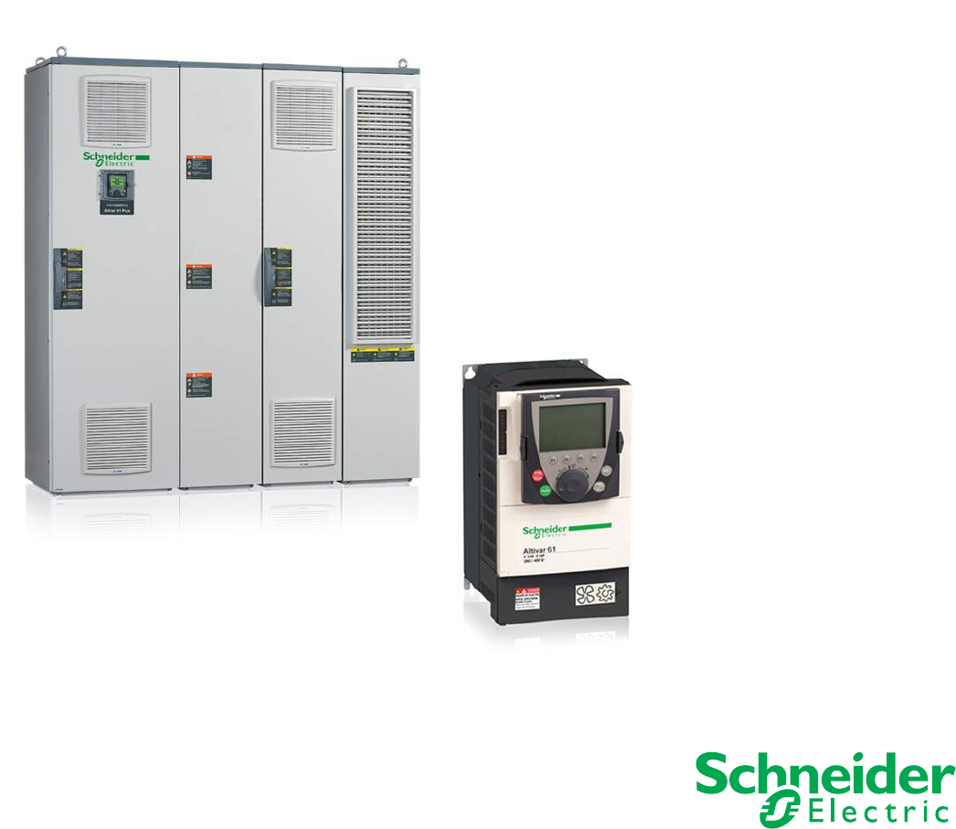
Presentation
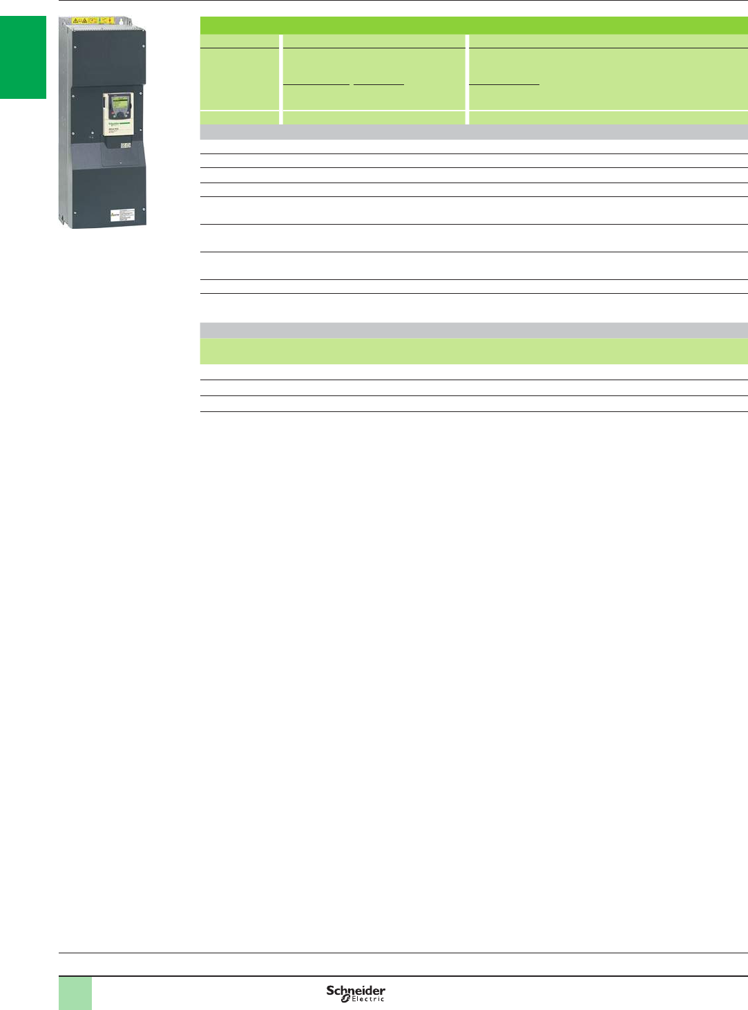
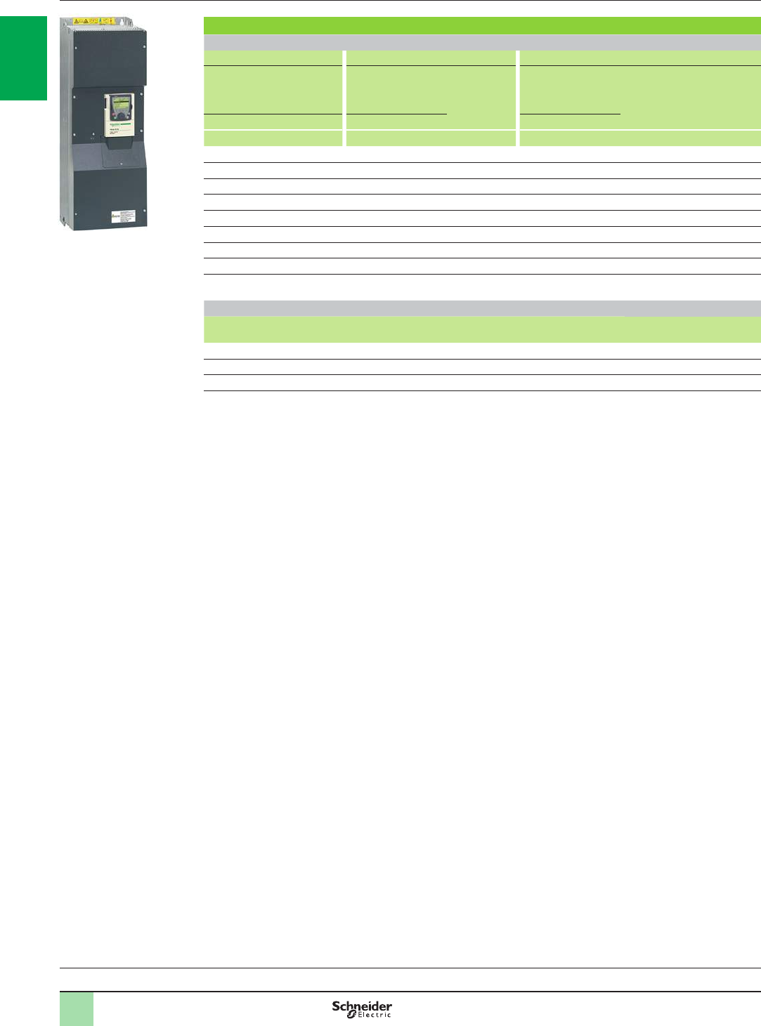
The Altivar 61 drive is a frequency inverter for 0.75 kW/1 HP to 2400 kW three-phase
synchronous and asynchronous motors.
It has been designed for common uid management applications in industrial and
commercial buildings and infrastructures.
The Altivar 61 can increase the performance of equipment and reduce operating
costs in buildings by optimizing energy consumption whilst improving user comfort.
Environmentally-friendly and energy-saving
The drive is designed to be environmentally-friendly:
bEnergy saving with a reduction in energy consumption of 70 % for ventilation
applications and 50 % for pumping applications
bReduction of uid losses in distribution networks
bUse of 80 % recyclable materials - the Altivar 61 drive conforms to environmental
standard ISO 14040 which denes a critical analysis of the product's impact on the
environment
An environmental report is available for the Altivar 61 drive on our website
www.schneider-electric.com.
Compliance with international standards and certications
The Altivar 61 drive has been developed to meet the requirements of directives
regarding the protection of the environment (RoHS, REACH, WEEE, etc.) as well as
those of European Directives to obtain the e mark.
The entire range is UL, CSA, DNV, C-Tick, NOM and GOST certied and conforms
to international standards relating to electrical industrial control equipment
IEC/EN 61800-2 and IEC/EN 61800-5-1.
The need for electromagnetic compatibility was taken into account at the outset
when designing the drive. The entire range conforms to international standard
IEC/EN 61800-3.
The Altivar 61 drive complies with the requirements of safety standards for
applications in explosive atmospheres (ATEX). Please refer to the ATEX guide
which is available on our website www.schneider-electric.com.
An extensive range
The Altivar 61 range offers numerous variants to meet the requirements of
applications in a wide variety of elds and in very harsh environments.
With these variants, the Altivar 61 range offers ready-to-use or modular solutions
that can adapt to your needs.
Its numerous and comprehensive options enable it to be adapted and incorporated
into electrical installations, sophisticated control systems, infrastructures and
building management systems. They also create signicant energy savings and
reduce line interference.
A specic option, the Active Front End, enables the Altivar 61 to be used in
installations where particularly low harmonic levels are required. It also allows
the Altivar 61 drive to operate on unstable line supplies.
Presentation Variable speed drives
Altivar 61
Variable speed drives:
page 1/16 Variants:
page 1/23 Accessories:
page 1/25 Options:
page 1/46 Drive/option combinations:
page 1/34
ATV61HC31N4,
ATV61HD22M3X, ATV61HU22N4
ATV61EXS5ppppp
PF095305 PF095495
ATV61W075N4,
ATV61W075N4C
2
1
3
4
5
6
7
8
9
10
2
1
3
4
5
6
7
8
9
10
1/91/9
A wide range of applications
The Altivar 61 drive incorporates advanced functions for optimum efciency in the
majority of applications in the industrial or commercial buildings sector:
b Ventilation
b Air conditioning
b Air purication, smoke extraction
b Fluid management
b Pumping and booster stations
b Irrigation stations
b Off-shore drilling rigs
b Etc.
Advanced functions
The Altivar 61 drive meets stringent requirements due to its numerous integrated
application functions, while helping ensure the reliability of equipment with its
protection and safety functions.
Functions designed specically for pump and fan applications
b Energy saving ratio, 2 or 5 point quadratic ratio
b Automatic catching a spinning load with speed detection
b Adaptation of current limiting according to speed
b Noise and resonance suppression due to the possibility of adjusting the switching
frequency during operation up to 16 kHz depending on the rating and the possibility
of making frequency skips
b Preset speeds
b Integrated PID regulator with preset PID references and automatic/manual
(Auto/Man.) mode
b Electricity and service hours meter
b Fluid absence detection, zero ow and limited ow detection
b Sleep function, wake-up function
b Customer settings with display of physical measurements (bar, I/s, °C, etc.)
Protection functions
b Motor and drive thermal protection, PTC thermal probe management
b Protection against overloads and overcurrents in continuous operation
b Machine mechanical protection via skip frequency function, output phase rotation
b
Protection of the installation by means of underload, overload and zero ow detection
b Protection via management of multiple faults and congurable alarms
Safety functions
b Machine safety via the integrated Power Removal function
This function stops the motor and helps preventing accidental restarts; it complies
with machine safety standard ISO 1389-1, category 3 and the standard for functional
safety IEC/EN 61508, SIL2 capability (safety control-signalling applied to processes
and systems).
This safety function means that the drive can be installed as part of the safety
system for an Electrical/Electronic/Programmable Electronic control system relating
to the safety of a machine or industrial process.
b Means of the forced operation function with congurable fault inhibiting, direction
of operation and references help ensure installation safety.
Presentation (continued) Variable speed drives
Altivar 61
PF095309
Water treatment application
Variable speed drives:
page 1/16 Variants:
page 1/23 Accessories:
page 1/25 Options:
page 1/46 Drive/option combinations:
page 1/34
Air purication application
PF108971
Air treatment application
PF095308
2
1
3
4
5
6
7
8
9
10
2
1
3
4
5
6
7
8
9
10
1/101/10
2
1
2
537174
Extended functions using option cards
An open-ended offer to adapt to your applications
The Altivar 61 and Altivar 61 Plus offers cover motor power ratings from 0.75 kW/
1 HP to 2400 kW with several types of power supply:
Three-phase power supply Motor power Reference
200...240 V 0.75 kW…90 kW/
1 HP...125 HP ATV61HpppM3
ATV61HpppM3X
380...415 V 55 kW…630 kW/
75 HP...900 HP ATV61EXCppppN4H
90 kW…630 kW/
125 HP...900 HP ATV61ES5pppN4
ATV61EXS5pppN4
ATV61EXCppppN4
630 kW…1400 kW ATV61EXAppppN4
380...480 V 0.75 kW…630 kW/
1 HP...900 HP ATV61HpppN4
0.75 kW…90 kW/
1 HP...125 HP ATV61WpppN4
ATV61WpppN4C
110 kW…630 kW/
150 HP...900 HP ATV61QpppN4
500 V 90 kW…630 kW/
125 HP...800 HP ATV61EXS5pppN
ATV61EXCppppN
630 kW…1800 kW ATV61EXAppppN
500...600 V 1.5 kW…15 kW/
2 HP...20 HP ATV61HpppS6X
500...690 V 2.2 kW…800 kW/
3 HP...800 HP ATV61HpppY
110 kW…630 kW/
150 HP...800 HP ATV61QpppY
690 V 110 kW…800 kW/
125 HP...800 HP ATV61EXCppppY
ATV61EXS5pppY
800 kW…2400 kW ATV61EXAppppY
ATV61EXAppppYH
Altivar 61 drives with 200…240 V three-phase supply voltage can also be used with
motor power ratings from 0.37 kW/0.5 HP to 5.5 kW/7.5 HP single-phase, if the
motor is derated.
Flexibility in control systems and building management systems
The Altivar 61 drive 1 has numerous logic and analog inputs and outputs that can be
congured to adapt better to applications.
Its functions can be extended by using I/O expansion cards 2 (see page 1/47).
It includes the Modbus and CANopen protocols as standard to enhance the
performance of your control systems.
It is open to other control system architectures for industry and and integrates easily
into building management systems (HVAC) using communication option cards 2
(see page 1/54).
Most communication protocols for use in industry (Modbus TCP, Ethernet/IP, Modbus/
Uni-Telway, PROFIBUS DP V0 or V1, DeviceNet, InterBus, CC-LInk and Ethernet
POWERLINK) or in building management (LonWorks, METASYS N2, APOGEE FLN,
BACnet) are available.
It can be open to a distributed architecture by using a Controller Inside
programmable card 2 which allows the drive to be adapted to specic applications,
quickly and in an open-ended manner, by decentralizing the control system
functions (programming in IEC 61131-3 compliant languages) (see pages 1/50 to
1/53).
It can also be used to manage several pumps using multi-pump cards 2 (see
pages 1/48 and 1/49).
The Controller Inside and multi-pump cards have their own I/O and can manage the
drive's I/O as well as those of the I/O expansion cards. They can also use drive
parameters such as speed, current, torque, etc.
The Altivar 61 drive can also take an encoder interface card to increase the safety of
the application (see page 1/46).
Note: The Altivar 61 can accommodate a maximum of two option cards simultaneously; please
refer to the summary table of possible combinations to nd out which options are available for
each drive (see pages 1/34 to 1/45).
Presentation (continued) Variable speed drives
Altivar 61
Variable speed drives:
page 1/16 Variants:
page 1/23 Accessories:
page 1/25 Options:
page 1/46 Drive/option combinations:
page 1/34
2
1
3
4
5
6
7
8
9
10
2
1
3
4
5
6
7
8
9
10
1/111/11
An open-ended offer to adapt to your applications (continued)
Electromagnetic compatibility (EMC)
The need for electromagnetic compatibility was taken into account at the outset
when designing the drive.
The incorporation of EMC lters in ATV61HpppM3, ATV61ppppN4 and
ATV61ppppY drives and the observance of requirements in respect of EMC
simplies installation and provides economical means of helping ensuring that
equipment meets e marking requirements.
ATV61WpppN4C drives have integrated EMC lters, which make them compliant with
the requirements of EN 55011 (class B group 1) and IEC/EN 61800-3 (category C1)
standards.
ATV61HpppM3X, ATV61HpppS6X and ATV61Qppppp drives have been designed
without an EMC lter. Filters are available as an option and can be installed by the
customer to reduce the level of emissions (see page 1/78).
A wide range of options
A large number of external options can be combined with the Altivar 61:
b Braking units and resistors (see pages 1/60 to 1/63)
b DC chokes, line chokes and passive lters (see pages 1/64 to 1/75) and the Active
Front End option for reducing current harmonics (see pages 1/76 to 1/79)
b Additional EMC input lters for reducing conducted emissions on the line (see
pages 1/80 and 1/81)
b Motor chokes and sinus lters for long cable runs or to remove the need for
shielding (see pages 1/83 to 1/87)
Mounting options
The Altivar 61 drive can be mounted in a variety of ways to adapt to the various
needs of an installation.
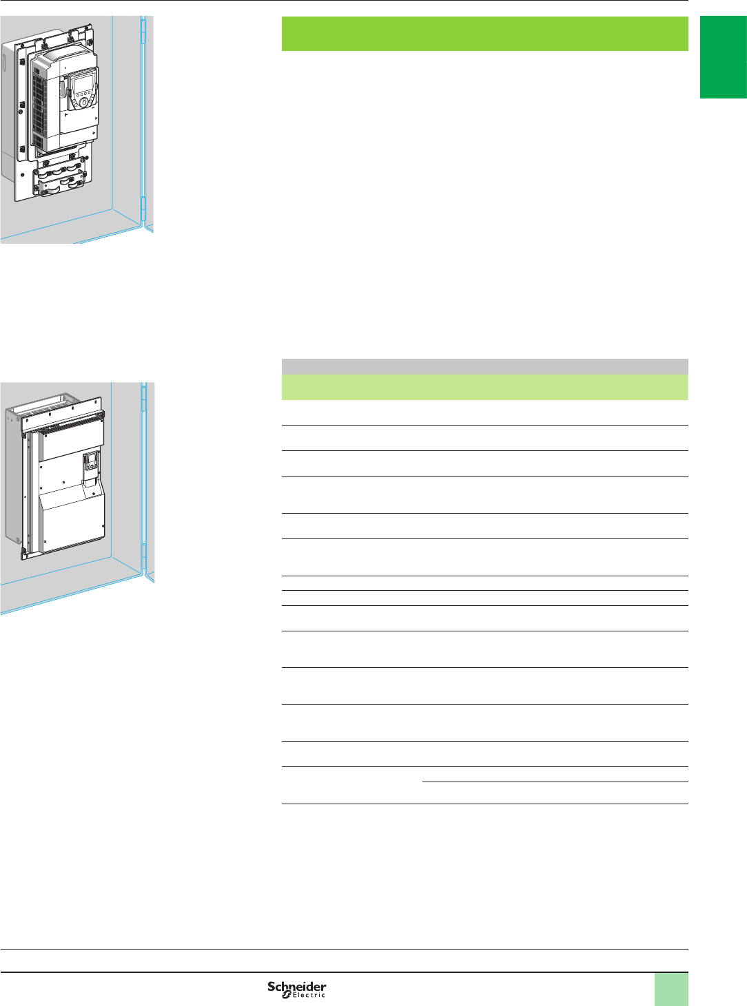
Mounting without an enclosure
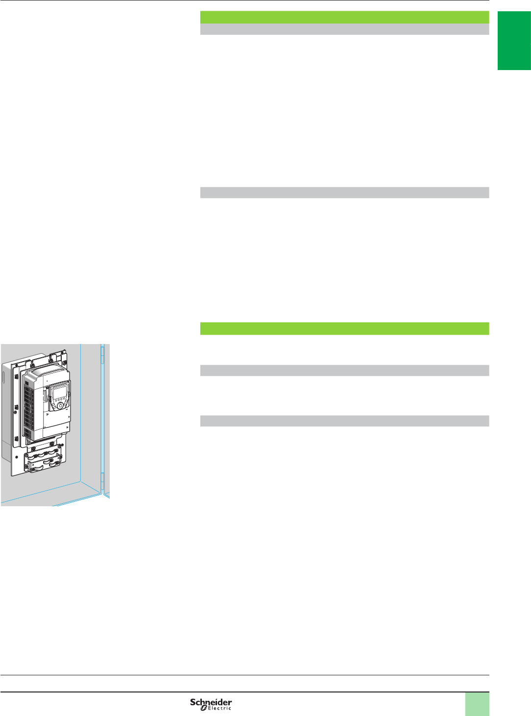
The Altivar 61 drive can be mounted directly on a wall without having to be installed
inside an enclosure. UL Type 1 conformity can be achieved by using kit VW3A92pp,
or IP 21 or IP 31 conformity with kit VW3A91pp (see pages 1/26 and 1/27).
Flush-mounting in dust and damp proof enclosure
The Altivar 61 drive has been designed to reduce the size of enclosures (oor-standing,
wall-mounted, etc.).
Flush-mounting kit VW3A95pp makes it possible to mount the power section outside
the enclosure and limit the temperature rise inside the enclosure (see page 1/25).
This variant also allows side-by-side mounting, if operating conditions require it.
Presentation (continued) Variable speed drives
Altivar 61
Variable speed drives:
page 1/16 Variants:
page 1/23 Accessories:
page 1/25 Options:
page 1/46 Drive/option combinations:
page 1/34
537172
ATV61HU75N4 ush-mounted

2
1
3
4
5
6
7
8
9
10
2
1
3
4
5
6
7
8
9
10
1/121/12
Solutions for many environments
The offer includes numerous variants which make it possible to further broaden the
Altivar 61 drive's range of applications.
It is designed to meet the requirements of each application as closely as possible,
and offers ready-to-use or modular solutions.
Reinforced version variant
This reinforced version variant enables the Altivar 61 drive to be used for
applications in difcult ambient pollution conditions (see page 1/23).
Variant with Vario switch disconnector
IP 54 Altivar 61 drives can be supplied equipped with a Vario switch disconnector.
This ready-equipped offer, ATV61E5pppN4, is specially designed for applications
that require an accessible drive as close as possible to the motor (such as in uid,
waste water and air treatment applications).
It covers motor power ratings from 0.75 kW/1 HP to 90 kW/125 HP (see page 1/20).
Variant for medium voltage motors
This variant enables the Altivar 61 drive to be used for applications involving medium
voltage motors (see page 1/24).
Variant for industrial environments and infrastructure
To facilitate set-up in industrial environments and infrastructure contexts (such as
tunnels, subways, smoke extraction and pumping), an enclosed drive solution is
available, enhanced by a wide range of options.
Altivar 61 Plus drive in IP 23 or IP 54 ready-assembled, compact oor-standing enclosure
This enclosed drive solution (ATV61EXCppppp) provides IP 23 or IP 54 protection. It
is supplied ready-assembled and ready to connect. A common air circuit provides
enclosure ventilation.
In addition to a standard version, a modular version is available with a choice of
options to suit the requirements of your installation.
The offer covers a range of drives from 90 kW/125 HP to 800 kW/800 HP (see page
2/12).
Variant for applications requiring a very low harmonic level
Altivar 61 Plus drive with harmonic ltering in “Ready to use” IP 23 or IP 54
oor-standing enclosure
This enclosed product has been designed to offer, in a compact “ready-to-use”
version, a range of drives designed to meet the requirements of applications
requiring very low harmonic distortion factors (THDI y 5 %).
This enclosed drive solution provides, depending on the model, degree of protection
IP 23 (ATV61EXC2pppN4H and ATV61EXA2ppYH) or IP 54 (ATV61EXC5pppN4H
and ATV61EXA5ppYH).
In addition to a standard version, a modular version is available with a choice of
options to suit the requirements of your installation.
The offer covers a range of drives from 55 kW/75 HP to 2400 kW (see pages 2/6 and
2/7).
Presentation (continued) Variable speed drives
Altivar 61
PF095310
Altivar 61 drive equipped with
a Vario switch disconnector
Variable speed drives:
page 1/16 Variants:
page 1/23 Accessories:
page 1/25 Options:
page 1/46 Drive/option combinations:
page 1/34
Altivar 61 Plus variant with harmonic ltering
in “ready to use” IP 23 or IP 54 oor-standing enclosure

2
1
3
4
5
6
7
8
9
10
2
1
3
4
5
6
7
8
9
10
1/131/13
Solutions for many environments (continued)
Variant for environments requiring greater ruggedness
Water-cooled Altivar 61 drive
With their internal water-cooled system, Altivar 61Q (ATV61QpppN4 and
ATV61QpppY) drives represent the optimum solution for applications in which
rugged versions are essential.
The integrated water-cooled system circuit can dissipate heat at its source and
hence offers optimum integration of the whole electrical control system. Evacuation
of thermal losses by this system also avoids the need to install an expensive air
conditioning system.
The Altivar 61Q offer is also well suited to frequent start-up applications.
It covers motor power ratings between 110 kW/150 HP and 630 kW/900 HP (see
pages 1/18 and 1/22).
These variants offer enclosed drive solutions with cooling systems specially
designed to allow the Altivar 61 drive to operate in difcult environmental conditions.
Variants for harsh and highly polluted environments
These variants offer enclosed drive solutions with cooling systems specially
designed to allow the Altivar 61 drive to operate in difcult environmental conditions.
Pre-equipped IP 54 kit
This straightforward and cost-effective solution, which is available by quoting a
single reference, provides you with the mechanical components you need to create
an IP 54 certied oor-standing enclosure (VW3A9541…VW3A9551) (see page
2/2).
The cooling systems enable the equipment to be installed in a variety of difcult
environments (1 or 3 air circuits, depending on the model).
The overall dimensions, reduced to a minimum, allow assembly in extremely
conned spaces.
The kit is available for IP 20 Altivar 61 drives from 110 kW/150 HP to 630 kW/900 HP
(see page 2/2).
Altivar 61 Plus drive in “ready-to-use” IP 54 oor-standing enclosure
This enclosed drive solution (ATV61ES5pppN4) provides IP 54 protection. It is
supplied ready-assembled and ready to connect. Two separate cooling circuits help
ensure optimum enclosure ventilation.
The offer covers a range of drives from 90 kW/125 HP to 630 kW/900 HP (see page
2/4).
Altivar 61 Plus drive in IP 23 or IP 54 oor-standing enclosure with separate air ows
These oor-standing enclosures are designed to operate in harsh and highly
polluted environments, by using two separate cooling circuits, one for the control
section and one for the power section, to optimize enclosure ventilation.
Depending on the model, they provide IP 54 protection (ATV61EXS5pppp) and
IP 23 or IP 54 (ATV61EXAppppp).
It includes a standard version, a modular version via the addition of numerous
options and a fully customizable version to suit your requirements.
The offer covers a range of drives from 90 kW/125 HP to 630 kW/900 HP
(ATV61EXS5pppp) and 630 kW to 2400 kW (ATV61EXAppppp) (see page 2/8).
PF107559
Pre-equipped IP 54 kit
Altivar 61 Plus variant
in an IP 23 or IP 54 enclosure with separate air ows
PF095307
Presentation (continued) Variable speed drives
Altivar 61
Variable speed drives:
page 1/16 Variants:
page 1/23 Accessories:
page 1/25 Options:
page 1/46 Drive/option combinations:
page 1/34
Altivar 61 Plus variant
in “ready to use” IP 54 oor-standing enclosure
PF095305
2
1
3
4
5
6
7
8
9
10
2
1
3
4
5
6
7
8
9
10
1/141/14
Dialogue and conguration tools
Remote graphic display terminal
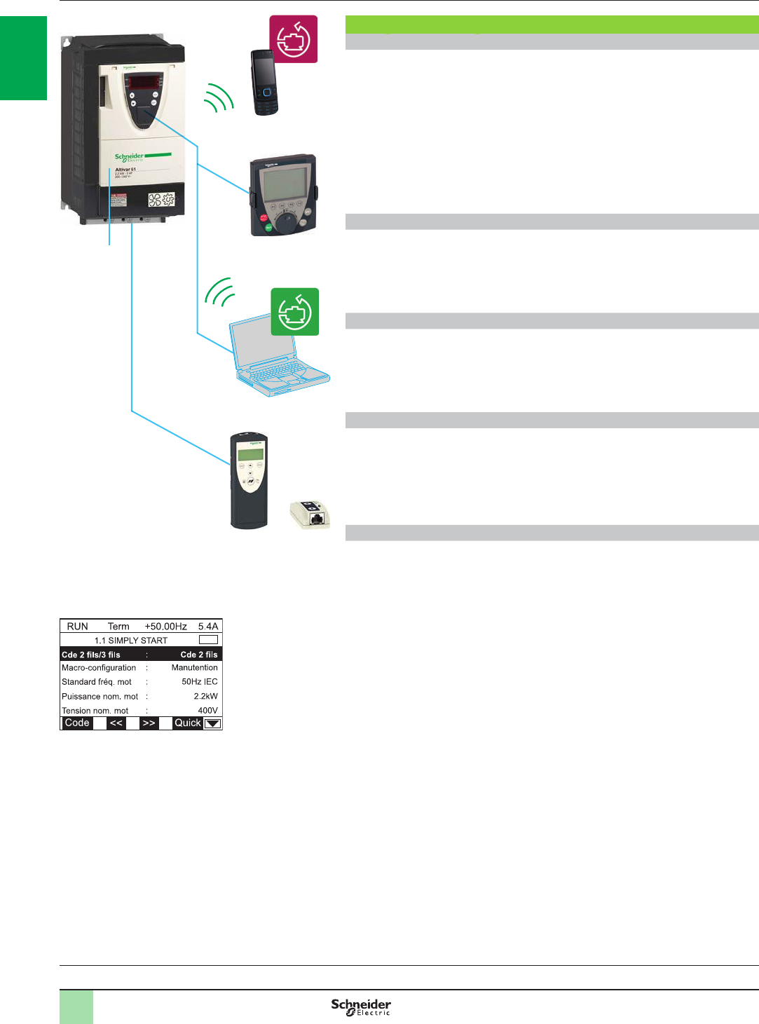
The Altivar 61 drive 1 is supplied with a remote graphic display terminal 3.
This terminal provides a user-friendly interface with fast and easy access, on-line
help screens, text in the user's language (8 languages factory-installed, plus others
available via ash memory). It can be customized for the user or the machine.
The advanced functions on the display unit allow easy access to the more complex
conguration, setup or maintenance functions.
It can be located remotely on an enclosure door with IP 54 or IP 65 degree of
protection on IP 20 drives, or built-in on IP 54 drives.
See page 1/33.
SoMove Mobile Software
SoMove Mobile software 2 is particularly suitable for maintenance operations.
It can be used to edit the drive parameters from a mobile phone, save congurations,
import them from a PC and export them to a PC via a Bluetooth® wireless
connection.
See page 1/33.
SoMove setup software
SoMove setup software for PC 4 is used to congure, adjust and debug the Altivar 61
drive with the Oscilloscope function, as well as for drive maintenance, in the same
way as for other Schneider Electric drives and starters.
See page 1/33.
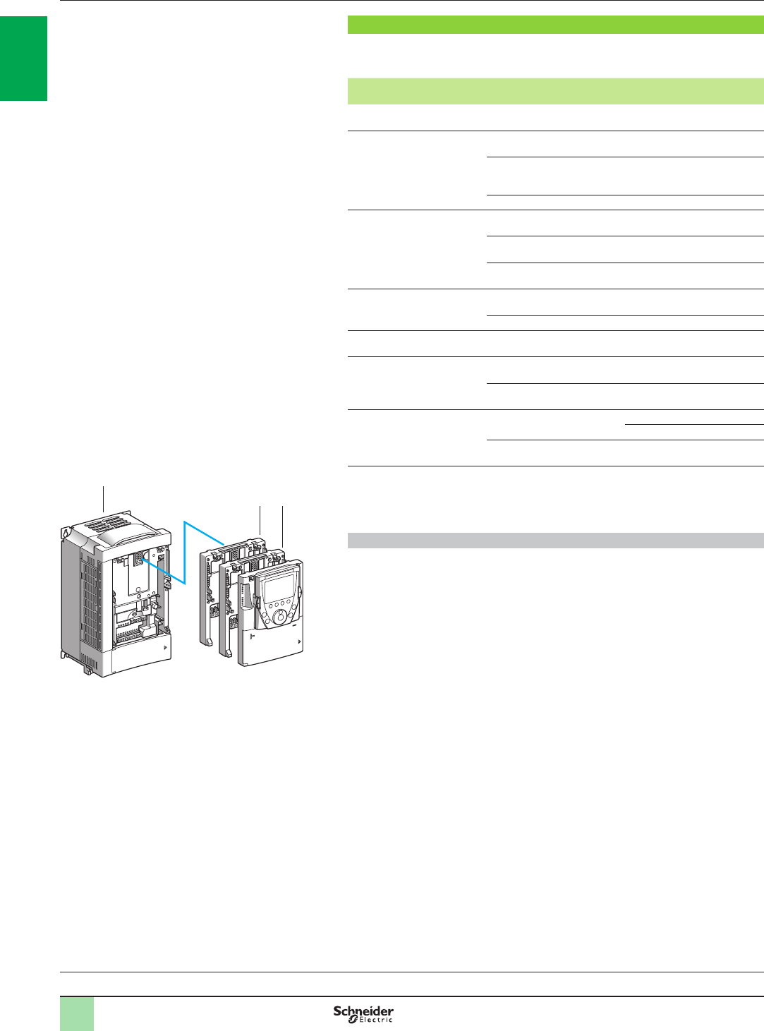
Simple Loader and Multi-Loader conguration tools
The Simple Loader tool 6 enables the conguration from one powered-up drive to be
duplicated on another powered-up drive.
The Multi-Loader tool 5 enables congurations from a PC or drive to be copied and
duplicated on another drive; Altivar 61 drives must be powered up.
See page 1/33.
Quick programming tools
With its macro-congurations and its Simply Start menu, the Altivar 61 drive gets
applications up and running immediately.
Macro-conguration
The Altivar 61 drive offers quick and easy programming using macro-congurations
corresponding to different applications or uses: start-stop, pumping and ventilation,
general use, connection to communication networks, PID regulator.
Each of these congurations is still fully modiable.
Simply Start menu
The Simply Start menu can be used to help ensure that the application is working
correctly, maximize motor performance and help ensure motor protection.
The architecture, the hierarchical parameter structure and the direct access functions
serve to make programming quick and easy, even for the more complex functions.
Presentation (continued) Variable speed drives
Altivar 61
Variable speed drives:
page 1/16 Variants:
page 1/23 Accessories:
page 1/25 Options:
page 1/46 Drive/option combinations:
page 1/34
4
or
Dialogue and conguration tools for Altivar 61 drive
5
6
or
3
1
2
Simply Start menu
537166

2
1
3
4
5
6
7
8
9
10
2
1
3
4
5
6
7
8
9
10
1/151/15
Integrated functions for maintenance, monitoring and
diagnostics
The Altivar 61 has numerous built-in maintenance, monitoring and diagnostic
functions.
The option of powering the control part separately enables communication to be
maintained (monitoring, diagnostics) even if there is no power supply to the power
part.
Example of functions:
b Drive test functions with diagnostic screen on the remote graphic display terminal
b I/O maps
b Communication maps for the different ports
b Oscilloscope function that can be viewed using the SoMove setup software
b Management of the drive installed base via microprocessors with ash memory
b Remote use of these functions by connecting the drive to a modem via the
Modbus port
b Identication of the drive's component parts as well as the software versions
b Fault logs with display of the value of up to 16 variables on occurrence of a fault
b Downloading languages to the terminal via ash memory
b Storage of a 5-line, 24-character message in the drive
Presentation (continued) Variable speed drives
Altivar 61
Variable speed drives:
page 1/16 Variants:
page 1/23 Accessories:
page 1/25 Options:
page 1/46 Drive/option combinations:
page 1/34
Built-in function: fault log
537165
1/16
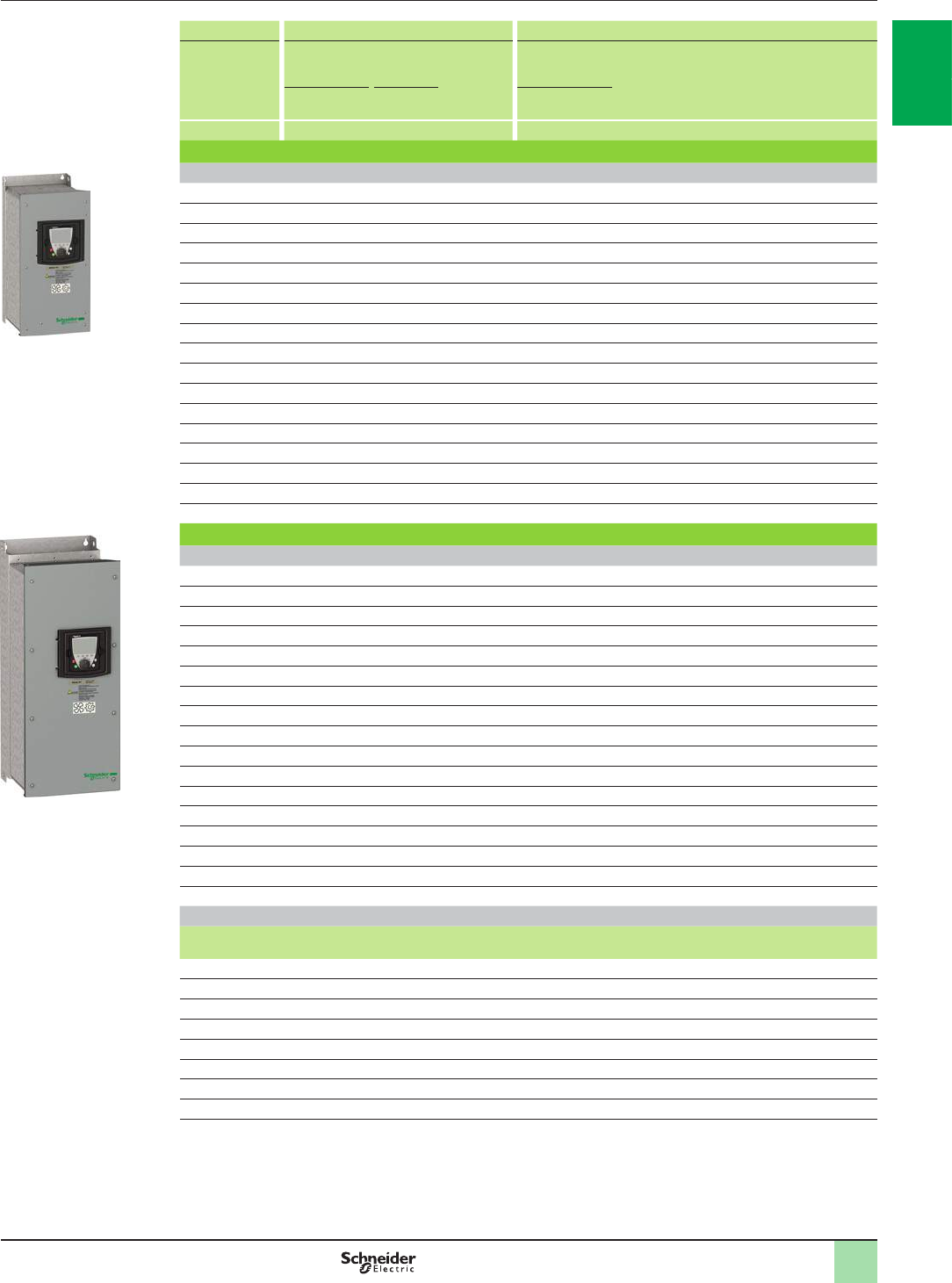
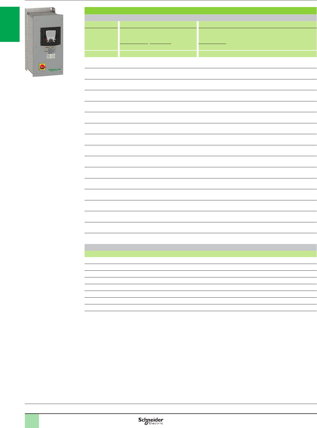
Variable speed drives
Altivar 61
Supply voltage 200...240 V 50/60 Hz
References
1
IP 20 drives
Motor Line supply Altivar 61
Power
indicated on
rating plate (1)
Line current
(2) Apparent
power Max.
prospective
line Isc
Maximum
continuous
current (1)
Max. transient
current
for 60 s
Reference Weight
200 V 240 V 240 V 230 V
kW HP A A kVA kA A A kg
Single-phase supply voltage: 200…240 V 50/60 Hz
0.37 0.5 6.9 5.8 1.4 5 3 3.6 ATV61H075M3 3.000
0.75 112 9.9 2.4 5 4.8 5.7 ATV61HU15M3 3.000
1.5 218.2 15.7 3.7 5 8 9.6 ATV61HU22M3 4.000
2.2 325.9 22.1 5.3 5 11 13.2 ATV61HU30M3 4.000
3 – 25.9 22 5.3 5 13.7 16.4 ATV61HU40M3 (3) 4.000
4534.9 29.9 7 5 17.5 21 ATV61HU55M3 (3) 5.500
5.5 7.5 47.3 40.1 9.5 22 27.5 33 ATV61HU75M3 (3) 7.000
Three-phase supply voltage: 200…240 V 50/60 Hz
0.75 16.1 5.3 2.2 5 4.8 5.7 ATV61H075M3 3.000
1.5 211.3 9.6 4 5 8 9.6 ATV61HU15M3 3.000
2.2 315 12.8 5.3 5 11 13.2 ATV61HU22M3 4.000
3 – 19.3 16.4 6.8 5 13.7 16.4 ATV61HU30M3 4.000
4525.8 22.9 9.5 5 17.5 21 ATV61HU40M3 4.000
5.5 7.5 35 30.8 12.8 22 27.5 33 ATV61HU55M3 5.500
7.5 10 45 39.4 16.4 22 33 39.6 ATV61HU75M3 7.000
11 15 53.3 45.8 19 22 54 64.8 ATV61HD11M3X (4) 22.000
15 20 71.7 61.6 25.6 22 66 79.2 ATV61HD15M3X (4) 22.000
18.5 25 77 69 28.7 22 75 90 ATV61HD18M3X (4) 30.000
22 30 88 80 33.3 22 88 105.6 ATV61HD22M3X (4) 30.000
30 40 124 110 45.7 22 120 144 ATV61HD30M3X (4) 37.000
37 50 141 127 52.8 22 144 172.8 ATV61HD37M3X (4) 37.000
45 60 167 147 61.1 22 176 211.2 ATV61HD45M3X (4) 37.000
55 75 200 173 71.9 35 221 265.2 ATV61HD55M3X (4) 84.000
75 100 271 232 96.4 35 285 342 ATV61HD75M3X (4) 84.000
90 125 336 288 119.7 35 359 431 ATV61HD90M3X (4) 106.000
Dimensions (overall)
Drives W x H x D
mm
ATV61H075M3, HU15M3 130 x 230 x 175
ATV61HU22M3…HU40M3 155 x 260 x 187
ATV61HU55M3 175 x 295 x 187
ATV61HU75M3 210 x 295 x 213
ATV61HD11M3X, HD15M3X 230 x 400 x 213
ATV61HD18M3X, HD22M3X 240 x 420 x 236
ATV61HD30M3X…HD45M3X 320 x 550 x 266
ATV61HD55M3X, HD75M3X 320 x 920 x 377
ATV61HD90M3X 360 x 1022 x 377
(1) These values are given for a nominal switching frequency of 12 kHz up to ATV61HD45M3X or 2.5 kHz
for ATV61HD55M3X…HD90M3X drives for use in continuous operation.
The switching frequency is adjustable from 1…16 kHz up to ATV61HD45M3X, from 2.5…12 kHz for ATV61HD55M3X and
from 2.5…8 kHz for ATV61HD75M3X, HD90M3X.
Above 2.5 or 12 kHz, depending on the rating, the drive will reduce the switching frequency automatically in the event of an
excessive temperature rise. For continuous operation above the nominal switching frequency, derate the nominal drive
current, see derating curves on our website www.schneider-electric.com.
(2) Typical value for the indicated motor power and for the maximum prospective line Isc.
(3) A line choke must be used (see page 1/67).
(4) Drive supplied without EMC lter. EMC lters are available as an option (see page 1/81).
Note: Consult the summary tables of possible drive, option and accessory combinations (see pages 1/34, 1/35, 1/44 and 1/45).
PF107573
ATV61H075M3
PF107574
ATV61HU22M3Z
PF107581
ATV61HD22M3X
Variants:
page 1/23 Accessories:
page 1/25 Dialogue:
page 1/31 Drive/option combinations:
page 1/34
2
1
3
4
5
6
7
8
9
10
2
1
3
4
5
6
7
8
9
10
1/17
References (continued)
1
Variable speed drives
Altivar 61
Supply voltage 380...480 V 50/60 Hz
ATV61HU22N4
PF107483
PF107575
ATV61HU40N4Z
PF107586
ATV61HC31N4
IP 20 drives with integrated category C2 or C3 EMC lter
Motor Line supply Altivar 61
Power
indicated on
rating plate (1)
Line current
(2) Apparent
power Max.
prospective
line Isc
Maximum
continuous
current (1)
Max. transient
current
for 60 s
Reference Weight
380 V 480 V 380 V 380 V
(IEC) 460 V
(NEC)
kW HP A A kVA kA A A kg
Three-phase supply voltage: 380…480 V 50/60 Hz
0.75 13.7 3 2.4 5 2.3 2.1 2.7 ATV61H075N4 3.000
1.5 25.8 5.3 3.8 5 4.1 3.4 4.9 ATV61HU15N4 3.000
2.2 38.2 7.1 5.4 5 5.8 4.8 6.9 ATV61HU22N4 3.000
3–10.7 9 7 5 7.8 6.2 9.3 ATV61HU30N4 4.000
4514.1 11.5 9.3 5 10.5 7.6 12.6 ATV61HU40N4 4.000
5.5 7.5 20.3 17 13.4 22 14.3 11 17.1 ATV61HU55N4 5.500
7.5 10 27 22.2 17.8 22 17.6 14 21.1 ATV61HU75N4 5.500
11 15 36.6 30 24.1 22 27.7 21 33.2 ATV61HD11N4 7.000
15 20 48 39 31.6 22 33 27 39.6 ATV61HD15N4 22.000
18.5 25 45.5 37.5 29.9 22 41 34 49.2 ATV61HD18N4 22.000
22 30 50 42 32.9 22 48 40 57.6 ATV61HD22N4 30.000
30 40 66 56 43.4 22 66 52 79.2 ATV61HD30N4 37.000
37 50 84 69 55.3 22 79 65 94.8 ATV61HD37N4 37.000
45 60 104 85 68.5 22 94 77 112.8 ATV61HD45N4 44.000
55 75 120 101 79 22 116 96 139.2 ATV61HD55N4 44.000
75 100 167 137 109.9 22 160 124 192 ATV61HD75N4 44.000
90 125 166 143 109.3 35 179 179 214.8 ATV61HD90N4 84.000
110 150 202 168 133 35 215 215 258 ATV61HC11N4 84.000
132 200 239 224 157.3 35 259 259 310.8 ATV61HC13N4 106.000
160 250 289 275 190.2 50 314 314 376.8 ATV61HC16N4 116.000
200 300 357 331 235 50 427 427 512.4 ATV61HC22N4 163.000
220 350 396 383 260.6 50
250 400 444 435 292.2 50 481 481 577.2 ATV61HC25N4 207.000
280 450 494 494 325.1 50 616 616 739.2 ATV61HC31N4 207.000
315 500 555 544 365.3 50
355 –637 597 419.3 50 759 759 910.8 ATV61HC40N4 320.000
400 600 709 644 466.6 50
500 700 876 760 576.6 50 941 941 1129.2 ATV61HC50N4 330.000
560 800 978 858 643.6 50 1188 1188 1425.6 ATV61HC63N4 435.000
630 900 1091 964 718 50
Dimensions (overall)
Drives W x H x D
mm
ATV61H075N4…HU22N4 130 x 230 x 175
ATV61HU30N4, HU40N4 155 x 260 x 187
ATV61HU55N4, HU75N4 175 x 295 x 187
ATV61HD11N4 210 x 295 x 213
ATV61HD15N4, HD18N4 230 x 400 x 213
ATV61HD22N4 240 x 420 x 236
ATV61HD30N4, HD37N4 240 x 550 x 266
ATV61HD45N4…HD75N4 320 x 630 x 290
ATV61HD90N4, HC11N4 320 x 920 x 377
ATV61HC13N4 360 x 1022 x 377
ATV61HC16N4 340 x 1190 x 377
ATV61HC22N4 440 x 1190 x 377
ATV61HC25N4, HC31N4 595 x 1190 x 377
ATV61HC40N4, HC50N4 890 x 1390 x 377
ATV61HC63N4 1120 x 1390 x 377
(1) These values are given for a nominal switching frequency of 12 kHz up to ATV61HD75N4, 4 kHz
for ATV 61HD90N4 or 2.5 kHz for ATV61HC11N4…HC63N4 drives for use in continuous operation.
The switching frequency is adjustable from 1…16 kHz up to ATV61HD75N4 and from 2…8 kHz
for ATV61HD90N4…ATV61HC63N4.
Above 2.5, 4 or 12 kHz, depending on the rating, the drive will reduce the switching frequency automatically in the event of an
excessive temperature rise. For continuous operation above the nominal switching frequency, derate the nominal drive current
(see derating curves on our website www.schneider-electric.com).
(2) Typical value for the indicated motor power and for the maximum prospective line Isc.
Note: Consult the summary tables of possible drive, option and accessory combinations (see pages 1/36, 1/37, 1/44 and 1/45).
2
1
3
4
5
6
7
8
9
10
2
1
3
4
5
6
7
8
9
10
1/18
Variable speed drives
Altivar 61
Supply voltage 380...480 V 50/60 Hz
References (continued)
PF110500
ATV61QC11N4
Variants:
page 1/23 Accessories:
page 1/25 Dialogue:
page 1/31 Drive/option combinations:
page 1/34
Water-cooled IP 20 drives
Motor Line supply Altivar 61
Power
indicated on
rating plate (1)
Line current
(2) Apparent
power Max.
prospective
line Isc
Maximum
continuous
current (1)
Max. transient
current
for 60 s
Reference Weight
380 V 480 V 380 V 380 V
(IEC) 460 V
(NEC)
kW HP A A kVA kA A A kg
Three-phase supply voltage: 380…480 V 50/60 Hz
110 150 202 168 133 35 215 215 258 ATV61QC11N4 80.000
132 200 239 224 157.3 35 259 259 310.8 ATV61QC13N4 80.000
160 250 289 275 190.2 50 314 314 376.8 ATV61QC16N4 80.000
200 300 357 331 235 50 387 387 464 ATV61QC20N4 140.000
220 350 396 383 260.6 50 481 481 577.2 ATV61QC25N4 140.000
250 400 444 435 292.2 50
280 450 494 494 325.1 50 616 616 739.2 ATV61QC31N4 140.000
315 500 555 544 365.3 50
355 –637 597 419.3 50 759 759 910.8 ATV61QC40N4 300.000
400 600 709 644 466.6 50
500 700 876 760 576.6 50 941 941 1129.2 ATV61QC50N4 300.000
560 800 978 858 643.6 50 1188 1188 1425.6 ATV61QC63N4 300.000
630 900 1091 964 718 50
Dimensions (overall)
Drive W x H x D
mm
ATV61QC11N4…QC16N4 330 x 950 x 377
ATV61QC20N4…QC31N4 585 x 950 x 377
ATV61QC40N4…QC63N4 1110 x 1150 x 377
(1) These values are given for a nominal switching frequency of 2.5 kHz, for use in continuous operation.
The switching frequency is adjustable from 2.5…8 kHz.
Above 2.5 kHz, the drive will reduce the switching frequency automatically in the event of excessive temperature rise. For
continuous operation above the nominal switching frequency, derate the nominal drive current (see derating curves on our
website www.schneider-electric.com).
(2) Typical value for the indicated motor power and for the maximum prospective line Isc.
Note: Consult the summary tables of possible drive, option and accessory combinations (see pages 1/36, 1/37, 1/44 and 1/45).
2
1
3
4
5
6
7
8
9
10
2
1
3
4
5
6
7
8
9
10
1/19
Motor Line supply Altivar 61
Power
indicated on
rating plate (1)
Line current
(2) Apparent
power Max.
prospective
line Isc
Maximum
continuous
current (1)
Max. transient
current
for 60 s
Reference Weight
380 V 480 V 380 V 380 V
(IEC) 460 V
(NEC)
kW HP A A kVA kA A A kg
IP 54 drives with integrated category C2 EMC lter
Three-phase supply voltage: 380…480 V 50/60 Hz
0.75 11.8 1.5 1.2 5 2.3 2.1 2.5 ATV61W075N4 13.000
1.5 23.5 3 2.3 5 4.1 3.4 4.5 ATV61WU15N4 13.000
2.2 35 4.1 3.3 5 5.1 4.8 5.6 ATV61WU22N4 13.000
3–6.7 5.6 4.4 5 7.2 6.2 7.9 ATV61WU30N4 14.000
458.8 7.4 5.8 5 9.1 7.6 10 ATV61WU40N4 16.000
5.5 7.5 11.4 9.2 7.5 22 12 11 13.2 ATV61WU55N4 16.000
7.5 10 15.8 13.3 10.4 22 16 14 17.6 ATV61WU75N4 22.000
11 15 21.9 17.8 14.4 22 22.5 21 24.7 ATV61WD11N4 22.000
15 20 30.5 25.8 20 22 30.5 27 33.5 ATV61WD15N4 28.000
18.5 25 37.5 32.3 24.7 22 37 34 40.7 ATV61WD18N4 36.000
22 30 43.6 36.6 28.7 22 43.5 40 47.8 ATV61WD22N4 36.000
30 40 56.7 46.2 37.3 22 58.5 52 64.3 ATV61WD30N4 51.000
37 50 69.5 56.8 45.7 22 71.5 65 78.6 ATV61WD37N4 64.000
45 60 85.1 69.6 56 22 85 77 93.5 ATV61WD45N4 65.000
55 75 104.8 87 69 35 103 96 113.3 ATV61WD55N4 92.000
75 100 140.3 113.8 92.3 35 137 124 150.7 ATV61WD75N4 92.000
90 125 171.8 140.9 113 35 163 156 179.3 ATV61WD90N4 92.000
IP 54 drives with integrated category C1 EMC lter
Three-phase supply voltage: 380…480 V 50/60 Hz
0.75 11.8 1.5 1.2 5 2.3 2.1 2.5 ATV61W075N4C 19.000
1.5 23.5 3 2.3 5 4.1 3.4 4.5 ATV61WU15N4C 19.000
2.2 35 4.1 3.3 5 5.1 4.8 5.6 ATV61WU22N4C 20.000
3–6.7 5.6 4.4 5 7.2 6.2 7.9 ATV61WU30N4C 20.000
458.8 7.4 5.8 5 9.1 7.6 10 ATV61WU40N4C 23.000
5.5 7.5 11.4 9.2 7.5 22 12 11 13.2 ATV61WU55N4C 23.000
7.5 10 15.8 13.3 10.4 22 16 14 17.6 ATV61WU75N4C 32.000
11 15 21.9 17.8 14.4 22 22.5 21 24.7 ATV61WD11N4C 32.000
15 20 30.5 25.8 20 22 30.5 27 33.5 ATV61WD15N4C 40.000
18.5 25 37.5 32.3 24.7 22 37 34 40.7 ATV61WD18N4C 51.000
22 30 43.6 36.6 28.7 22 43.5 40 47.8 ATV61WD22N4C 50.000
30 40 56.7 46.2 37.3 22 58.5 52 64.3 ATV61WD30N4C 68.000
37 50 69.5 56.8 45.7 22 71.5 65 78.6 ATV61WD37N4C 85.000
45 60 85.1 69.6 56 22 85 77 93.5 ATV61WD45N4C 85.000
55 75 104.8 87 69 35 103 96 113.3 ATV61WD55N4C 119.000
75 100 140.3 113.8 92.3 35 137 124 150.7 ATV61WD75N4C 119.000
90 125 171.8 140.9 113 35 163 156 179.3 ATV61WD90N4C 119.000
Dimensions (overall)
Drives W x H x D
mm
ATV61W075N4 (C)…WU30N4 (C) 240 x 490 x 272
ATV61WU40N4 (C), WU55N4 (C) 240 x 490 x 286
ATV61WU75N4 (C), WD11N4 (C) 260 x 525 x 286
ATV61WD15N4 (C) 295 x 560 x 315
ATV61WD18N4 (C), WD22N4 (C) 315 x 665 x 315
ATV61WD30N4 (C) 285 x 720 x 315
ATV61WD37N4 (C), WD45N4 (C) 285 x 880 x 343
ATV61WD55N4 (C)…WD90N4 (C) 362 x 1000 x 364
(1) These values are given for a nominal switching frequency of 8 kHz up to ATV61WD15N4 or ATV61WD15N4C, or 4 kHz
for ATV61WD18N4…WD90N4 or ATV61WD18N4C…WD90N4C drives for use in continuous operation.
The switching frequency is adjustable from 2…16 kHz for all ratings.
Above 4 or 8 kHz, depending on the rating, the drive will reduce the switching frequency automatically in the event of an excessive
temperature rise. For continuous operation above the nominal switching frequency, derate the nominal drive current (see derating curves
on our website www.schneider-electric.com).
(2) Typical value for the indicated motor power and for the maximum prospective line Isc.
Note: Consult the summary tables of possible drive, option and accessory combinations (see pages 1/38, 1/39, 1/44 and 1/45).
Variable speed drives
Altivar 61
Supply voltage 380...480 V 50/60 Hz
References (continued)
1
PF107495
ATV61W075N4
ATV61WD30N4
PF107493
2
1
3
4
5
6
7
8
9
10
2
1
3
4
5
6
7
8
9
10
1/20
IP 54 drives with integrated Vario switch disconnector and category C2 EMC lter
Three-phase supply voltage: 380…480 V 50/60 Hz
Motor Line supply Altivar 61
Power
indicated on
rating plate (1)
Line current
(2) Apparent
power Max.
prospective
line Isc
Maximum
continuous
current In (1)
Max.
transient
current
for 60 s
Reference Weight
380 V 460 V380 V 480 V 380 V
kW HP A A kVA kA A A A kg
0.75 11.8 1.5 1.2 5 2.3 2.1 2.5 ATV61E5075N4 16.400
1.5 23.5 3 2.3 5 4.1 3.4 4.5 ATV61E5U15N4 16.400
2.2 35 4.1 3.3 5 5.1 4.8 5.6 ATV61E5U22N4 16.400
3–6.7 5.6 4.4 5 7.2 6.2 7.9 ATV61E5U30N4 16.400
458.8 7.4 5.8 5 9.1 7.6 10 ATV61E5U40N4 18.400
5.5 7.5 11.4 9.2 7.5 22 12 11 13.2 ATV61E5U55N4 18.400
7.5 10 15.8 13.3 10.4 22 16 14 17.6 ATV61E5U75N4 22.700
11 15 21.9 17.8 14.4 22 22.5 21 24.7 ATV61E5D11N4 22.700
15 20 30.5 25.8 20 22 30.5 27 33.5 ATV61E5D15N4 36.700
18.5 25 37.5 32.3 24.7 22 37 34 40.7 ATV61E5D18N4 45.400
22 30 43.6 36.6 28.7 22 43.5 40 47.8 ATV61E5D22N4 45.400
30 40 56.7 46.2 37.3 22 58.5 52 64.3 ATV61E5D30N4 52.800
37 50 69.5 56.8 45.7 22 71.5 65 78.6 ATV61E5D37N4 65.800
45 60 85.1 69.6 56 22 85 77 93.5 ATV61E5D45N4 65.800
55 75 104.8 87 69 35 103 96 113.3 ATV61E5D55N4 84.400
75 100 140.3 113.8 92.3 35 137 124 150.7 ATV61E5D75N4 84.400
90 125 171.8 140.9 113 35 163 156 179.3 ATV61E5D90N4 84.400
Dimensions (overall)
Drives W x H x D
ATV61E5075N4…U30N4 240 x 490 x 296
ATV61E5U40N4, U55N4 240 x 490 x 310
ATV61E5U75N4, D11N4 260 x 525 x 310
ATV61E5D15N4 295 x 560 x 339
ATV61E5D18N4, D22N4 315 x 665 x 340
ATV61E5D30N4 285 x 720 x 335
ATV61E5D37N4, D45N4 285 x 880 x 383
ATV61E5D55N4…D90N4 362 x 1000 x 404
(1) These values are given for a nominal switching frequency of 8 kHz up to ATV61E5D15N4 or 4 kHz
for ATV61E5D18N4...E5D90N4 drives for use in continuous operation.
The switching frequency is adjustable from 2…16 kHz for all ratings.
Above 4 or 8 kHz, depending on the rating, the drive will reduce the switching frequency automatically in the event of an
excessive temperature rise. For continuous operation above the nominal switching frequency, derate the nominal drive current
(see derating curves on our website www.schneider-electric.com).
(2) Typical value for the indicated motor power and for the maximum prospective line Isc.
ATV61E5D11N4
PF095313
References (continued) Variable speed drives
Altivar 61
Supply voltage 380...480 V 50/60 Hz
Variants:
page 1/23 Accessories:
page 1/25 Dialogue:
page 1/31 Drive/option combinations:
page 1/34
2
1
3
4
5
6
7
8
9
10
2
1
3
4
5
6
7
8
9
10

1/21
Variable speed drives
Altivar 61
Supply voltage 500...690 V 50/60 Hz
References (continued)
1
IP 20 drives
Motor Line supply Altivar 61
Power
indicated on rating plate (1) Line current
(2) Max.
prospective
line Isc
Maximum
continuous
current
(1) (3)
Reference Weight
500 V 575 V 500 V 600 V 500 V 575 V
kW HP A A kA A A kg
Three-phase supply voltage: 500…600 V 50/60 Hz
2.2 37.6 6.7 22 4.5 3.9 ATV61HU22S6X 7.500
3–9.9 10 22 5.8 –ATV61HU30S6X 7.500
4512.5 10.9 22 7.5 6.1 ATV61HU40S6X 7.500
5.5 7.5 16.4 14.2 22 10 9 ATV61HU55S6X 7.500
7.5 10 21.4 18.4 22 13.5 11 ATV61HU75S6X 7.500
IP 20 drives with integrated category C3 EMC lter
Three-phase supply voltage: 500…690 V 50/60 Hz
Motor Line supply Altivar 61
Power
indicated on rating plate (1) Line current
(2) Max.
prospective
line Isc
Maximum
continuous
current
(1) (3)
Reference (4) Weight
500 V 575 V 690 V 500 V 600 V 690 V 500 V 575 V 690 V
kW HP kW A A A kA A A A kg
2.2 33 5.2 4.4 5.2 22 4.5 3.9 4.5 ATV61HU30Y 30.000
3–4 6.8 –6.6 22 5.8 –5.5 ATV61HU40Y 30.000
455.5 8.6 7.2 8.6 22 7.5 6.1 7.5 ATV61HU55Y 30.000
5.5 7.5 7.5 11.2 9.5 11.2 22 10 9 10 ATV61HU75Y 30.000
7.5 10 11 14.6 12.3 15.5 22 13.5 11 13.5 ATV61HD11Y 30.000
11 15 15 19.8 16.7 20.2 22 18.5 17 18.5 ATV61HD15Y 30.000
15 20 18.5 24.6 20.7 24 22 24 22 24 ATV61HD18Y 30.000
18.5 25 22 29 24 27 22 29 27 27 ATV61HD22Y 30.000
22 30 30 33 28 34 22 35 32 35 ATV61HD30Y 30.000
30 40 37 48 41 47 22 47 41 43 ATV61HD37Y 68.000
37 50 45 62 51 55 22 59 52 54 ATV61HD45Y 68.000
45 60 55 68 57 63 22 68 62 62 ATV61HD55Y 68.000
55 75 75 79 67.0 82 22 85 77 84 ATV61HD75Y 68.000
75 100 90 109 92 101 22 110 99 104 ATV61HD90Y 68.000
90 125 110 128 113 117 22 136 125 125 ATV61HC11Y (4) 102.000
110 150 132 153 133 137 28 165 144 150 ATV61HC13Y (4) 102.000
132 –160 182 158.9 163 28 200 –180 ATV61HC16Y (4) 102.000
160 200 200 218 197 199 35 240 192 220 ATV61HC20Y (4) 102.000
200 250 250 277 250 257 35 312 242 290 ATV61HC25Y (4) 181.000
250 350 315 342 311 317 35 390 336 355 ATV61HC31Y (4) 181.000
315 450 400 426 390 394 35 462 412 420 ATV61HC40Y (4) 181.000
400 550 500 547 494 505 35 590 528 543 ATV61HC50Y (4) 383.000
500 700 630 673 613 616 42 740 672 675 ATV61HC63Y (4) 383.000
630 800 800 847 771 775 42 900 768 840 ATV61HC80Y (4) 383.000
Dimensions (overall)
Drives W x H x D
mm
ATV61HU22S6X…HU75S6X 210 x 295 x 213
ATV61HU30Y…HD30Y 240 x 420 x 236
ATV61HD37Y…HD90Y 320 x 630 x 290
ATV61HC11Y…HC20Y 340 x 1190 x 377
ATV61HC25Y…HC40Y 595 x 1190 x 377
ATV61HC50Y…HC80Y 1120 x 1390 x 377
(1) These values are given for a nominal switching frequency of 4 kHz for ATV61HUppS6X and for ATV61HU30Y… HD30Y or
2.5 kHz for ATV61HD37Y…HC80Y drives for use in continuous operation. The switching frequency is adjustable from
2.5…6 kHz for ATV61HUppS6X and for ATV61HU30Y… HD30Y and from 2.5…4.9 kHz for ATV61HD37Y…HC80Y drives.
Above 2.5 kHz or 4 kHz, depending on the rating, the drive will reduce the switching frequency automatically in the event of an
excessive temperature rise. For continuous operation above the nominal switching frequency, derate the nominal drive current
(see derating curves on our website www.schneider-electric.com).
(2) Typical value for the indicated motor power and for the maximum prospective line Isc.
(3) The maximum transient current for 60 seconds is equal to 120% of the maximum continuous current.
(4) Line choke mandatory for ATV61HC11Y…HC80Y drives, unless a special transformer is used (12-pulse) or when using the
“387” variant for medium voltage motors (see page 1/24). The line choke must be ordered separately (see page 1/68).
Note: Consult the summary tables of possible drive, option and accessory combinations (see pages 1/40 to 1/45).
PF107532 PF107586
ATV61HC31Y
+
VW3A4572 (line choke
mandatory) (4)
PF107581
ATV61HU30S6X
PF107583
ATV61HD45Y
2
1
3
4
5
6
7
8
9
10
2
1
3
4
5
6
7
8
9
10
1/22
References (continued) Variable speed drives
Altivar 61
Supply voltage 500...690 V 50/60 Hz
Water-cooled IP 20 drives
Three-phase supply voltage: 500…690 V 50/60 Hz
Motor Line supply Altivar 61
Power
indicated on rating plate (1) Line current
(2) Max.
prospective
line Isc
Maximum
continuous
current
(1) (3)
Reference (4) Weight
500 V 575 V 690 V 500 V 600 V 690 V 500 V 575 V 690 V
kW HP kW A A A kA A A A kg
110 150 132 153 133 137 28 165 144 150 ATV61QC13Y 80.000
132 –160 182 158.9 163 28 200 –180 ATV61QC16Y 80.000
160 200 200 218 197 199 35 240 192 220 ATV61QC20Y 80.000
200 250 250 277 250 257 35 312 242 290 ATV61QC25Y 140.000
250 350 315 342 311 317 35 390 336 355 ATV61QC31Y 140.000
315 450 400 426 390 394 35 462 412 420 ATV61QC40Y 140.000
400 550 500 547 494 505 35 590 528 543 ATV61QC50Y 300.000
500 700 630 673 613 616 42 740 672 675 ATV61QC63Y 300.000
630 800 800 847 771 775 42 900 768 840 ATV61QC80Y 300.000
Dimensions (overall)
Drives W x H x D
mm
ATV61QC13Y…QC20Y 330 x 950 x 377
ATV61QC25Y…QC40Y 585 x 950 x 377
ATV61QC50Y…QC80Y 1110 x 1150 x 377
(1) These values are given for a nominal switching frequency of 2.5 kHz, for use in continuous operation.
The switching frequency is adjustable from 2.5…4.9 kHz.
Above 2.5 kHz, depending on the rating, the drive will reduce the switching frequency automatically in the event of an
excessive temperature rise. For continuous operation above the nominal switching frequency, derate the nominal drive current
(see derating curves on our website www.schneider-electric.com).
(2) Typical value for the indicated motor power and for the maximum prospective line Isc.
(3) The maximum transient current for 60 seconds is equal to 120% of the maximum continuous current.
(4) A line choke must be used (see page 1/68).
Note: Consult the summary tables of possible drive, option and accessory combinations (see pages 1/42 to 1/45).
ATV61QC13Y
PF110500
Variants:
page 1/23 Accessories:
page 1/25 Dialogue:
page 1/31 Drive/option combinations:
page 1/34
2
1
3
4
5
6
7
8
9
10
2
1
3
4
5
6
7
8
9
10

1/23
Variable speed drive with additional power supply
When the power consumption of the option cards exceeds 200 mA, ATV61WpppN4
drives can be supplied with an additional 24 V c power supply, which allows
additional consumption of 250 mA.
In this case, add A24 at the end of the reference. For example, ATV61W075N4
becomes ATV61W075N4A24.
Variable speed drive in a reinforced version
This variant enables variable speed drives to operate in difcult ambient pollution
conditions and complies with standard IEC60721-3-3 class 3C2.
ATV61HD55M3X…HD90M3X, ATV61HD90N4…HC63N4, ATV61HpppY and
ATV61WpppN4A24 drives are supplied as standard in a reinforced version.
To order ATV61H075M3…HU75M3 and ATV61H075N4…HD75N4 variable speed
drives in a reinforced version, add S337 at the end of the reference.
For example, ATV61H075M3 becomes ATV61H075M3S337.
To order ATV61HD11M3X…HD45M3X drives in this version, add 337 at the end of
the reference.
For example, ATV61HD11M3X becomes ATV61HD11M3X337.
In the reinforced version, the variable speed drive is always supplied with a remote
graphic display terminal.
Variable speed drive with integrated terminal
All drives come with a remote graphic display terminal and an integrated terminal as
standard.
ATV61H075M3…HD45M3X and ATV61H075N4…HD75N4 drives can be ordered
without a remote graphic display terminal. They will then have the integrated
terminal only.
In this case, add Z at the end of the reference.
For example, ATV61H075M3 becomes ATV61H075M3Z.
Variable speed drive without DC choke
ATV61HD90N4…HC63N4 drives are supplied with a DC choke as standard.
They can be ordered without a DC choke for connections to the DC bus or when
using a line choke (see page 1/67), by adding D at the end of the reference.
For example, ATV61HD90N4 becomes ATV61HD90N4D.
Variable speed drive with EMC plate conforming to NEMA type
12 standard
ATV61WpppN4 drives are supplied as standard with a European version EMC
plate.
To order drives with an EMC plate conforming to NEMA type 12 standard, add U at
the end of the reference. This plate is supplied without a drill hole.
For example, ATV61W075N4 becomes ATV61W075N4U.
Note:
- ATV61H075M3…HD45M3X, ATV61H075N4…HD75N4, ATV61HpppS6X, ATV61WpppN4C
and ATV61HU30Y…HD90Y drives are supplied as standard with a European version plate for
EMC mounting.
- ATV61HD55M3X…HD90M3X, ATV61HD90N4…HC63N4 and ATV61HC11Y…HC80Y drives
are supplied as standard without a plate for EMC mounting. Depending on the reference, the
European version EMC plate is included in the UL Type 1 or IP 31 kit (see pages 1/26 and
1/27).
Variable speed drives
Altivar 61
Variants
Presentation,
references
Variable speed drives:
page 1/16 Accessories:
page 1/25 Dialogue:
page 1/31 Drive/option combinations:
page 1/34
2
1
3
4
5
6
7
8
9
10
2
1
3
4
5
6
7
8
9
10

1/24
Low voltage drive for medium voltage motors
This variant is an optimized solution for a medium voltage installation since it allows
a low voltage drive to be used to control a medium voltage motor, thus offering a
signicant reduction in costs.
Debugging and maintenance are also simpler and therefore less expensive.
This variant is particularly suitable for pump and fan installations requiring low
starting torque and/or long cable runs, such as submersible pumps, etc.
The drive is supplied by a medium voltage/low voltage step-down transformer and
controls the motor via a sinus lter and a low voltage/medium voltage step-up
transformer.
M1
3
L1
L2
L3
Medium
voltage
line
supply
MV/LV
step-down
transformer
Altivar 61
low voltage
drive Sinus lter
LV/MV
step-up
transformer
Medium
voltage
motor
This variant allows use of a low voltage drive covering motor ratings from
110 kW/150 HP to 800 kW/800 HP for a medium voltage line supply between
700 V and 6600 V.
To order ATV61HC11N4D…HC63N4D and ATV61HC11Y…HC80Y drives in this
variant, add 387 at the end of the reference.
For example, ATV61HC11N4D becomes ATV61HC11N4D387.
The sinus lter must be ordered separately (see page 1/87).
To determine the size of the drive and the step-up/step-down transformers, please
contact our Customer Care Centre.
Variable speed drives
Altivar 61
Variants
Presentation,
references (continued)
Variable speed drives:
page 1/16 Accessories:
page 1/25 Dialogue:
page 1/31 Drive/option combinations:
page 1/34
2
1
3
4
5
6
7
8
9
10
2
1
3
4
5
6
7
8
9
10
1/25
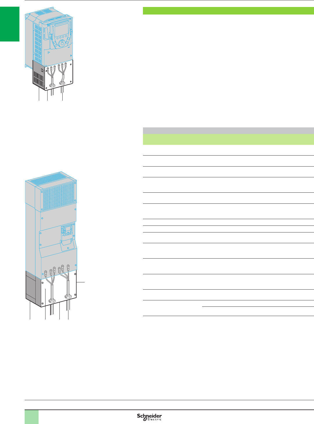
Kit for ush-mounting in a dust and damp proof enclosure
(for ATV61Hppppp drives)
This kit is used to mount the power section of the drive outside the enclosure. This
solution considerably reduces dissipated losses in the enclosure (1).
It is available for ATV61HpppM3, ATV61HpppM3X, ATV61H075N4…HC31N4,
ATV61HpppS6X, ATV61HD90N4D…HC31N4D and ATV61HU30Y…HC40Y drives.
With this type of mounting, the maximum internal temperature in the enclosure can
then reach 60°C without it being necessary to derate the drive current.
Between 50°C and 60°C, a control card fan kit must be used
for ATV61HD22N4…HD75N4 and ATV61HU30Y…HD90Y drives to prevent hot
spots (see page 1/28).
The back of the enclosure must be drilled and cut out for this type of mounting.
The kit includes:
b A metal frame of the right size for the drive rating
b Corner pieces
b Seals
b A fan support. This is used to re-position the fans so that they can be accessed
from the front of the enclosure
b Mounting hardware
b A manual
References
For drives Reference Weight
kg
ATV61H075M3, HU15M3
ATV61H075N4…HU22N4 VW3A9501 2.700
ATV61HU22M3…HU40M3
ATV61HU30N4, HU40N4 VW3A9502 3.100
ATV61HU55M3
ATV61HU55N4, HU75N4 VW3A9503 3.700
ATV61HU75M3
ATV61HD11N4
ATV61HU22S6X…HU75S6X
VW3A9504 4.600
ATV61HD11M3X, HD15M3X
ATV61HD15N4, HD18N4 VW3A9505 4.900
ATV61HD18M3X, HD22M3X
ATV61HD22N4
ATV61HU30Y…HD30Y
VW3A9506 3.900
ATV61HD30N4, HD37N4 VW3A9507 4.200
ATV61HD30M3X…HD45M3X VW3A9508 4.900
ATV61HD45N4…HD75N4
ATV61HD37Y…HD90Y VW3A9509 5.200
ATV61HD55M3X, HD75M3X
ATV61HD90N4, HC11N4 (2)
ATV61HD90N4D, HC11N4D
VW3A9510 5.100
ATV61HD90M3X
ATV61HC13N4 (2)
ATV61HC13N4D
VW3A9511 3.600
ATV61HC16N4 (2)
ATV61HC16N4D
ATV61HC11Y…HC20Y (3)
VW3A9512 4.300
ATV61HC22N4 (2)
ATV61HC22N4D VW3A9513 4.700
ATV61HC25N4, HC31N4 (2)
ATV61HC25N4D, HC31N4D
ATV61HC25Y…HC40Y (3)
Without braking unit VW3A9514 4.700
With braking unit VW3A9515 4.700
(1) Power dissipated in the enclosure for dust and damp proof ush-mounting: please consult
our website www.schneider-electric.com.
(2) Drives supplied as standard with a DC choke: when mounting, cut out and drill the enclosure
for the choke.
(3) Drives supplied as standard with a transformer for the fan: when mounting, cut out and drill
the enclosure for the transformer.
ATV61HC31N4D ush-mounted
537179
ATV61HU75N4 ush-mounted
537178
Presentation,
references Variable speed drives
Altivar 61
Accessories
Variable speed drives:
page 1/16 Variants:
page 1/23 Dialogue:
page 1/31 Drive/option combinations:
page 1/34
2
1
3
4
5
6
7
8
9
10
2
1
3
4
5
6
7
8
9
10
1/26
UL Type 1 conformity kit (for mounting outside the enclosure)
When the drive is mounted directly on a wall outside the enclosure, this kit can be
used to ensure UL Type 1 conformity when connecting the cables with a tube.
The shielding is connected inside the kit.
For ATV61HpppM3, ATV61HD11M3X…HD45M3X, ATV61H075N4…HD75N4,
ATV61HpppS6X and ATV61HU30Y…HD90Y drives, the kit includes:
b All the mechanical ttings 1 including a pre-cut plate 2 for connecting the tubes 3
b Mounting hardware
b A manual
For ATV61HD55M3X…HD90M3X, ATV61HD90N4…HC31N4,
ATV61HD90N4D…HC31N4D and ATV61HC11Y…HC40Y drives, the kit includes:
b An IP 54 casing 4 used to maintain the IP 54 degree of protection for the power
section
b An EMC plate 5
b A UL Type 1 cover 7
b A pre-drilled plate 6 for connecting the tubes 3
b Mounting hardware
b A manual
References
For drives Reference Weight
kg
ATV61H075M3, HU15M3
ATV61H075N4…HU22N4 VW3A9201 1.300
ATV61HU22M3…HU40M3
ATV61HU30N4, HU40N4 VW3A9202 1.500
ATV61HU55M3
ATV61HU55N4, HU75N4 VW3A9203 1.800
ATV61HU75M3
ATV61HD11N4
ATV61HU22S6X…U75S6X
VW3A9204 2.000
ATV61HD11M3X, HD15M3X
ATV61HD15N4, HD18N4 VW3A9205 2.800
ATV61HD18M3X, HD22M3X
ATV61HD22N4
ATV61HU30Y…HD30Y
VW3A9206 4.000
ATV61HD30N4, HD37N4 VW3A9207 5.000
ATV61HD30M3X…HD45M3X VW3A9217 7.000
ATV61HD45N4…HD75N4
ATV61HD37Y…HD90Y VW3A9208 7.000
ATV61HD55M3X, HD75M3X
ATV61HD90N4, HC11N4 (1)
ATV61HD90N4D, HC11N4D (2)
VW3A9209 9.400
ATV61HD90M3X
ATV61HC13N4 (1)
ATV61HC13N4D (2)
VW3A9210 11.800
ATV61HC16N4 (1)
ATV61HC16N4D (2)
ATV61HC11Y…HC20Y (3)
VW3A9211 11.600
ATV61HC22N4 (1)
ATV61HC22N4D (2) VW3A9212 14.600
ATV61HC25N4, HC31N4 (1)
ATV61HC25N4, HC31N4D (2)
ATV61HC25Y…HC40Y (3)
Without braking unit VW3A9213 19.500
With braking unit VW3A9214 19.500
(1) Drives supplied as standard with a DC choke.
(2) Drives supplied as standard without DC choke.
(3) Drives supplied as standard with a transformer for the fan.
Variable speed drives
Altivar 61
Accessories
Presentation,
references (continued)
4 5 36
7
UL Type 1 conformity kits
537182
1 2 3
537184
Variable speed drives:
page 1/16 Variants:
page 1/23 Dialogue:
page 1/31 Drive/option combinations:
page 1/34
2
1
3
4
5
6
7
8
9
10
2
1
3
4
5
6
7
8
9
10
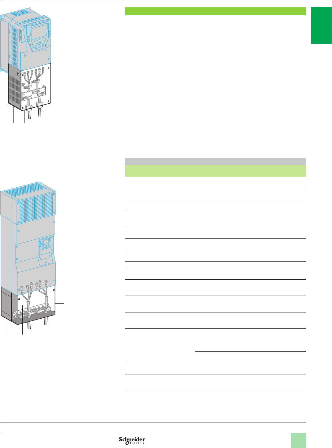
1/27
Variable speed drives
Altivar 61
Accessories
Presentation,
references (continued)
IP 21 or IP 31 conformity kit (for mounting outside the enclosure)
When the drive is mounted directly on a wall outside the enclosure, this kit can be
used to ensure IP 21 or IP 31 degree of protection when connecting the cables with a
cable gland.
The shielding is connected inside the kit.
For ATV61HpppM3, ATV61HD11M3X…HD45M3X, ATV61H075N4…HD75N4,
ATV61HpppS6X and ATV61HU30Y…HD90Y drives, the kit conforms to IP 21
degree of protection and includes:
b All the mechanical parts 1 including a drilled plate 2 for attaching the cable
glands 3
b Mounting hardware
b A manual
For ATV61HD55M3X…HD90M3X, ATV61HD90N4…HC63N4,
ATV61HD90N4D…HC63N4D and ATV61HC11Y…HC80Y drives, the kit conforms
to IP 31 degree of protection.
and includes:
b An IP 54 casing 4 used to maintain the IP 54 degree of protection for the power
section
b An EMC plate with cable clips 5
b An IP 31 cover 6
b Mounting hardware
b A manual
References
For drives Degree of
protection Reference Weight
kg
ATV61H075M3, HU15M3
ATV61H075N4…HU22N4 IP 21 VW3A9101 1.300
ATV61HU22M3…HU40M3
ATV61HU30N4, HU40N4 IP 21 VW3A9102 1.500
ATV61HU55M3
ATV61HU55N4, HU75N4 IP 21 VW3A9103 1.800
ATV61HU75M3
ATV61HD11N4
ATV61HU22S6X…ATV61HU75S6X
IP 21 VW3A9104 2.000
ATV61HD11M3X, HD15M3X
ATV61HD15N4, HD18N4 IP 21 VW3A9105 2.800
ATV61HD18M3X, HD22M3X
ATV61HD22N4
ATV61HU30Y…HD30Y
IP 21 VW3A9106 4.000
ATV61HD30N4, HD37N4 IP 21 VW3A9107 5.000
ATV61HD30M3X…HD45M3X IP 21 VW3A9117 7.000
ATV61HD45N4…HD75N4
ATV61HD37Y…HD90Y IP 21 VW3A9108 7.000
ATV61HD55M3X, HD75M3X
ATV61HD90N4, HC11N4 (1)
ATV61HD90N4D, HC11N4D (2)
IP 31 VW3A9109 9.400
ATV61HD90M3X
ATV61HC13N4 (1)
ATV61HC13N4D (2)
IP 31 VW3A9110 11.800
ATV61HC16N4 (1)
ATV61HC16N4D (2)
ATV61HC11Y…HC20Y (3)
IP 31 VW3A9111 11.600
ATV61HC22N4 (1)
ATV61HC22N4D (2) IP 31 VW3A9112 14.600
ATV61HC25N4, HC31N4 (1)
ATV61HC25N4, HC31N4D (2)
ATV61HC25Y…HC40Y (3)
Without braking
unit IP 31 VW3A9113 19.500
With braking
unit IP 31 VW3A9114 19.500
ATV61HC40N4, HC50N4 (1)
ATV61HC40N4D, HC50N4D (2) IP 31 VW3A9115 25.000
ATV61HC63N4 (1)
ATV61HC63N4D (2)
ATV61HC50Y…HC80Y (3)
IP 31 VW3A9116 35.000
(1) Drives supplied as standard with a DC choke.
(2) Drives supplied as standard without DC choke.
(3) Drives supplied as standard with a transformer for the fan.
4 5
6
IP 31 conformity kit
537181
1 2 3
537180
IP 21 conformity kit
Variable speed drives:
page 1/16 Variants:
page 1/23 Dialogue:
page 1/31 Drive/option combinations:
page 1/34
2
1
3
4
5
6
7
8
9
10
2
1
3
4
5
6
7
8
9
10
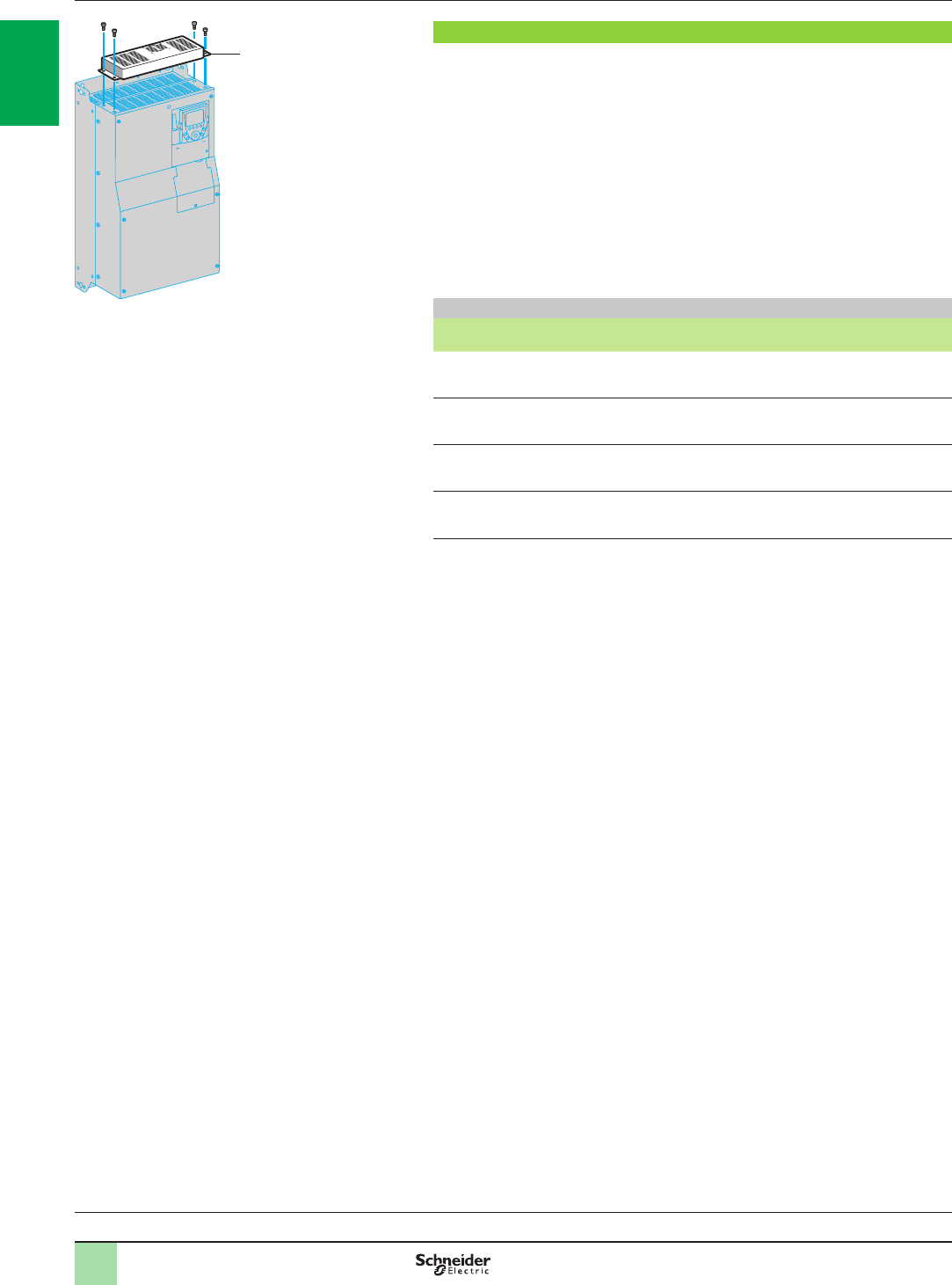
1/28
Control card fan kit
This kit is required for ATV61HD18M3X…HD45M3X, ATV61HD22N4…HD75N4 and
ATV61HU30Y…HD90Y drives.
It enables the drive to operate at an ambient temperature of 50°C to 60°C, for
example if it is mounted in an IP 54 enclosure. The circulation of air around the
electronic cards prevents the formation of hot spots.
To ascertain the derating to be applied to the drive nominal current, consult the
curves on our website www.schneider-electric.com.
The kit 1 is mounted on the upper part of the drive. It is powered by the drive.
It comprises:
b A fan subassembly
b Mounting hardware
b A manual
References
For drives Reference Weight
kg
ATV61HD18M3X, HD22M3X
ATV61HD22N4
ATV61HU30Y…HD30Y
VW3A9404 0.700
ATV61HD30N4, HD37N4 VW3A9405 0.700
ATV61HD30M3X…HD45M3X VW3A9406 0.800
ATV61HD45N4…HD75N4
ATV61HD37Y…HD90Y VW3A9407 0.900
1
DF537175
Control card fan kit
Presentation,
references (continued) Variable speed drives
Altivar 61
Accessories
Variable speed drives:
page 1/16 Variants:
page 1/23 Dialogue:
page 1/31 Drive/option combinations:
page 1/34
2
1
3
4
5
6
7
8
9
10
2
1
3
4
5
6
7
8
9
10
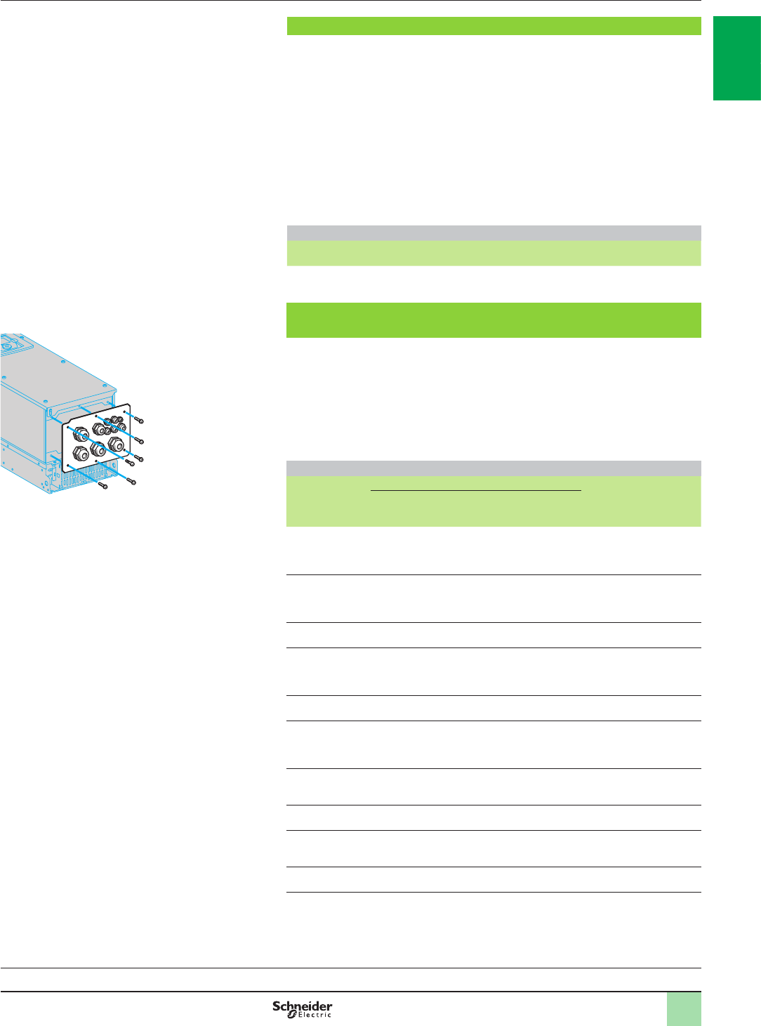
1/29
Adaptor for 115 V a logic inputs
This adaptor is used to connect 115 V a logic signals to the logic inputs on the drive
or an I/O expansion card.
7 logic inputs with capacitive impedance at 60 Hz of 0.22 µF are available for
connecting the logic signals:
b Maximum current: 200 mA
b Response time: 5 ms to change from state 0 to state 1, 20 ms to change from state
1 to state 0
b Logic state 0 for a voltage below 20 V, logic state 1 for a voltage between 70 V and
132 V
The power supply must be provided by a 115 V a external supply (min. 70 V,
max. 132 V).
Reference
Description Reference Weight
kg
Adaptor for 115 V a logic inputs VW3A3101 –
Ready-assembled IP 54 base plate (for ATV61WpppN4 and
ATV61WpppN4C drives)
This plate can be used to increase the number of cable connections supported by the
drive as standard from 3 to 11.
It is supplied with:
b A metal cable gland for the motor cable
b A special plastic cable gland for the network cable
b Plastic cable glands for connection of the control cable or options such as
communication cards, etc.
References
For drive Type of cable gland Reference Weight
kg
Metal Plastic Plastic for
network
cable
ATV61W075N4 …
WU55N4
ATV61W075N4C
…WU55N4C
1 (ISO 25) 1 (ISO 12), 4 (ISO 16)
3 (ISO 20), 1 (ISO 25) 1 (ISO 32) VW3A9901 1.300
ATV61WU75N4,
WD11N4
ATV61WU75N4C,
WD11N4C
1 (ISO 25) 1 (ISO 12), 4 (ISO 16)
3 (ISO 20), 1 (ISO 25) 1 (ISO 32) VW3A9902 1.300
ATV61WD15N4
ATV61WD15N4C 1 (ISO 32) 1 (ISO 12), 4 (ISO 16)
1 (ISO 20), 3 (ISO 32) 1 (ISO 32) VW3A9903 1.300
ATV61WD18N4,
WD22N4
ATV61WD18N4C,
WD22N4C
1 (ISO 32) 1 (ISO 12), 4 (ISO 16)
1 (ISO 20), 3 (ISO 32) 1 (ISO 32) VW3A9904 1.300
ATV61WD30N4
ATV61WD30N4C 1 (ISO 40) 1 (ISO 12), 4 (ISO 16)
1 (ISO 20), 3 (ISO 40) 1 (ISO 32) VW3A9905 1.300
ATV61WD37N4,
WD45N4
ATV61WD37N4C,
WD45N4C
1 (ISO 40) 1 (ISO 12), 4 (ISO 16)
1 (ISO 20), 3 (ISO 50) 1 (ISO 32) VW3A9906 1.300
ATV61WD55N4,
WD75N4 1 (ISO 50) 1 (ISO 12), 4 (ISO 16)
1 (ISO 20), 1 (ISO 50)
1 (ISO 63)
1 (ISO 32) VW3A9907 1.500
ATV61WD90N4 1 (ISO 50) 1 (ISO 12), 4 (ISO 16)
1 (ISO 20), 2 (ISO 63) 1 (ISO 32) VW3A9908 1.500
ATV61WD55N4C,
WD75N4C 1 (ISO 50) 1 (ISO 12), 4 (ISO 16)
1 (ISO 20), 1 (ISO 50)
2 (ISO 63)
1 (ISO 32) VW3A9909 1.500
ATV61WD90N4C 1 (ISO 50) 1 (ISO 12), 4 (ISO 16)
1 (ISO 20), 3 (ISO 63) 1 (ISO 32) VW3A9910 1.500
Ready-assembled IP 54 base plate
DF537183
Presentation,
references (continued) Variable speed drives
Altivar 61
Accessories
Variable speed drives:
page 1/16 Variants:
page 1/23 Dialogue:
page 1/31 Drive/option combinations:
page 1/34
2
1
3
4
5
6
7
8
9
10
2
1
3
4
5
6
7
8
9
10
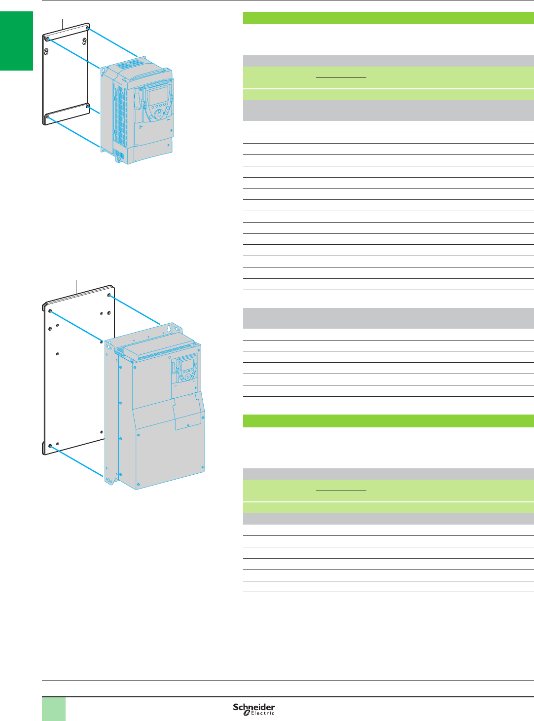
1/30
Substitution kit for Altivar 38 drives
This kit 1 is used to install an Altivar 61 drive in place of an Altivar 38 drive using the
same xing holes. It includes the mechanical adaptors required for mounting.
References
Old drive Motor Replaced by Reference Weight
Power
kW HP kg
Replacing an Altivar 38 drive with an integrated EMC lter
Three-phase supply voltage: 380…480 V 50/60 Hz
ATV38HU18N4 0.75 1ATV61H075N4 VW3A9302 –
ATV38HU29N4 1.5 2ATV61HU15N4 VW3A9302 –
ATV38HU41N4 2.2 3ATV61HU22N4 VW3A9302 –
ATV38HU54N4 3 –ATV61HU30N4 VW3A9304 –
ATV38HU72N4 4 5ATV61HU40N4 VW3A9304 –
ATV38HU90N4 5.5 7.5 ATV61HU55N4 VW3A9305 –
ATV38HD12N4 7.5 10 ATV61HU75N4 VW3A9306 –
ATV38HD16N4 11 15 ATV61HD11N4 VW3A9307 –
ATV38HD23N4 15 20 ATV61HD15N4 VW3A9308 –
ATV38HD25N4 18.5 25 ATV61HD18N4 VW3A9309 –
ATV38HD28N4 22 30 ATV61HD22N4 VW3A9310 –
ATV38HD33N4 30 40 ATV61HD30N4 VW3A9310 –
ATV38HD46N4 37 50 ATV61HD37N4 VW3A9312 –
ATV38HD54N4 45 60 ATV61HD45N4 VW3A9312 –
ATV38HD64N4 55 75 ATV61HD55N4 VW3A9312 –
ATV38HD79N4 75 100 ATV61HD75N4 VW3A9312 –
Replacing an Altivar 38 drive without integrated EMC lter
Three-phase supply voltage: 380…480 V 50/60 Hz
ATV38HD25N4X 18.5 25 ATV61HD18N4 VW3A9309 –
ATV38HD28N4X 22 30 ATV61HD22N4 VW3A9310 –
ATV38HD33N4X 30 40 ATV61HD30N4 VW3A9310 –
ATV38HD46N4X 37 50 ATV61HD37N4 VW3A9312 –
ATV38HD54N4X 45 60 ATV61HD45N4 VW3A9312 –
ATV38HD64N4X 55 75 ATV61HD55N4 VW3A9312 –
ATV38HD79N4X 75 100 ATV61HD75N4 VW3A9312 –
Substitution kit for Altivar 58 drives
This kit 1 is used to install an Altivar 61 drive in place of an Altivar 58 drive for variable
torque applications, using the same xing holes.
It includes the mechanical adaptors required for mounting.
References
Old drive Motor Replaced by Reference Weight
Power
kW HP kg
Three-phase supply voltage: 500 V 50/60 Hz
ATV58HD28N4 22 30 ATV61HD30Y VW3A9310 –
ATV58HD33N4 30 40 ATV61HD37Y VW3A9312 –
ATV58HD46N4 37 50 ATV61HD45Y VW3A9312 –
ATV58HD54N4 45 60 ATV61HD55Y VW3A9312 –
ATV58HD64N4 55 75 ATV61HD75Y VW3A9312 –
ATV58HD79N4 75 100 ATV61HD90Y VW3A9312 –
1
VW3A9304
537177
1
VW3A9312
537176
Presentation,
references (continued) Variable speed drives
Altivar 61
Accessories
Variable speed drives:
page 1/16 Variants:
page 1/23 Dialogue:
page 1/31 Drive/option combinations:
page 1/34
2
1
3
4
5
6
7
8
9
10
2
1
3
4
5
6
7
8
9
10

1/31
Presentation,
references Variable speed drives
Altivar 61
Option: dialogue
Remote graphic display terminal
(this display terminal can be supplied with the drive or ordered separately)
This display terminal is attached to the front of the drive. It includes the integrated
graphic terminal for drives ordered without a graphic display terminal (see page
1/23).
It can be:
bUsed remotely in conjunction with the appropriate accessories (see below)
b Connected to several drives using multidrop link components (see page 1/32)
It is used to:
bControl, adjust and congure the drive
bDisplay the current values (motor, input/output values, etc.)
b Save and download congurations; 4 conguration les can be saved.
The maximum operating temperature of the terminal is 60°C and it has IP 54
protection.
Description
1 Graphic display unit:
- 8 lines, 240 x 160 pixels
- large digits that can be read from 5 m away
- bar chart display
2 Assignable function keys F1, F2, F3, F4:
- dialogue functions: direct access, help screens, navigation
- application functions: Local/Remote, preset speed
3 STOP/RESET key: local control of motor stopping/fault clearing
4 RUN key: local control of motor operation
5 Navigation button:
- Press: saves the current value (ENT)
- Turn ±: increases or decreases the value, or goes to the next or previous line
6 FWD/REV key: reverses the motor direction of rotation
7 ESC key: aborts a value, a parameter, or a menu to return to the previous
selection
Note: Keys 3, 4 and 6 can be used to control the drive directly.
Reference
Description Item no. Reference Weight
kg
Remote graphic display terminal
1VW3A1101 0.180
Remote graphic display terminal accessories
The following accessories are available:
b A remote mounting kit 2 for mounting on an enclosure door with IP 54 degree of
protection, and includes:
vAll the mechanical ttings
vMounting hardware
b A transparent door 3 which attaches to the remote mounting mechanism to
achieve IP 65 degree of protection
b A preassembled cordset 4 with two RJ45 connectors for connecting the graphic
display terminal to the Altivar 61 drive (1, 3, 5 or 10 metres long)
b A female/female RJ45 adaptor 5 for connecting the graphic display terminal
VW3A1101 to the remote-mounting cordset VW3A1104Rppp
References
Description Item no. Length
mDegree of
protection Reference Weight
kg
Remote mounting kit
Order with remote-
mounting cordset
VW3A1104Rppp
2– IP 54 VW3A1102 0.150
Door
for remote mounting kit 3– IP 65 VW3A1103 0.040
Preassembled remote-
mounting cordsets
with 2 RJ45 connectors
41–VW3A1104R10 0.050
43–VW3A1104R30 0.150
45–VW3A1104R50 0.250
410 – VW3A1104R100 0.500
Female/female RJ45
adaptor 5––VW3A1105 0.010
1
4
2
3
5
1
4
Remote mounting accessories for the graphic display
terminal
Remote graphic display terminal
PF600255
1
2
3
4
7
6
5
2
1
3
4
5
6
7
8
9
10
2
1
3
4
5
6
7
8
9
10

1/32
References (continued) Variable speed drives
Altivar 61
Option: dialogue
Multidrop connection accessories
These accessories enable a graphic display terminal to be connected to several
drives via a multidrop link. This multidrop link is connected to the Modbus terminal
port on the front of the drive.
Connection accessories
Description Item no. Order in
multiples of Unit
reference Weight
kg
Modbus splitter box
10 RJ45 connectors and
1 screw terminal block
1–LU9GC3 0.500
Modbus
T-junction
boxes
With integrated cable
(0.3 m) 2–VW3A8306TF03 –
With integrated cable
(1 m) 2–VW3A8306TF10 –
Modbus line
terminator For
RJ45
connector
R = 120 W,
C = 1 nf
32VW3A8306RC 0.010
Remote
mounting kit For graphic display
terminal VW3A1101 4–VW3A1102 0.150
Cordsets (preassembled with 2 RJ45 connectors)
Used for Item no. Length
mReference Weight
kg
Remote operation of the Altivar 61 and
the graphic display terminal VW3A1101 51VW3A1104R10 0.050
3VW3A1104R30 0.150
5VW3A1104R50 0.250
10 VW3A1104R100 0.500
Modbus serial link 60.3 VW3A8306R03 0.025
1VW3A8306R10 0.060
3VW3A8306R30 0.130
1
66
5 52
22 3
2
6
2
2
3
4
Example of connection via multidrop link
VW3A1102
ATV61
ATV61
Variable speed drives:
page 1/16 Variants:
page 1/23 Accessories:
page 1/25 Drive/option combinations:
page 1/34
2
1
3
4
5
6
7
8
9
10
2
1
3
4
5
6
7
8
9
10
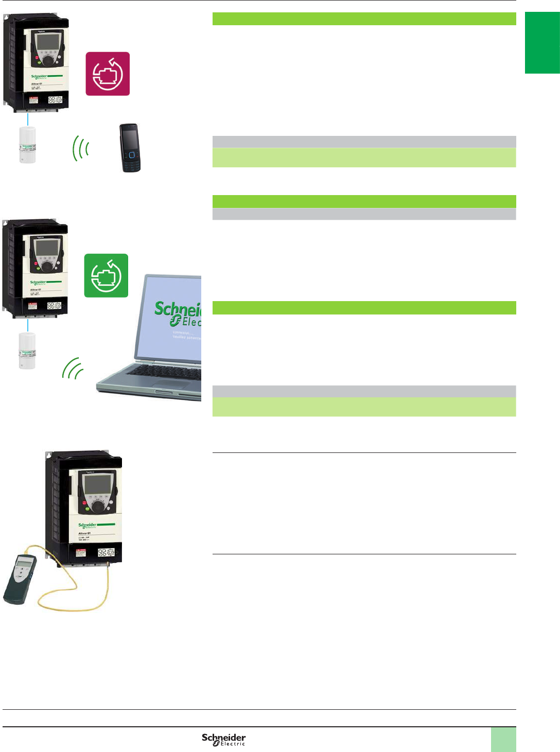
1/33
Presentation,
references Variable speed drives
Altivar 61
Option: conguration tools
SoMove Mobile software for mobile phones (1)
SoMove Mobile software converts any compatible mobile phone (1) into a remote
graphic display terminal, offering an identical Human-Machine Interface.
Particularly suitable for on-site or remote maintenance operations, SoMove Mobile
software can be used to print out and save congurations, import them from a PC
and export them to a PC or a drive equipped with the Modbus-Bluetooth® adaptor
(TCSW AAC13FB) via the Bluetooth® wireless link.
The SoMove Mobile software and drive conguration les can be downloaded from
our website www.schneider-electric.com.
References
Description For drives Reference Weight
kg
SoMove Mobile software
for mobile phones (1) ATV61pppppp ––
SoMove setup software
Presentation
SoMove setup software for PC is used to congure, adjust and debug using the
Oscilloscope function, as well as for maintenance, like all Schneider Electric drives
and starters.
The software communicates via Bluetooth® wireless link with the drive which is
equipped with the Modbus-Bluetooth® adaptor (TCSW AAC13FB).
It is compatible with Altivar 61 drives from software version 1.6 upwards.
Simple Loader and Multi-Loader conguration tools
The Simple Loader tool enables one powered-up drive's conguration to be
duplicated on another powered-up drive. It is connected to the drive's RJ45
communication port.
The Multi-Loader tool enables a number of congurations from a PC or drive to be
copied and duplicated on another drive; the Altivar 61 drives must be powered up.
References
Description For drives Reference Weight
kg
Simple Loader conguration tool
Supplied with a preassembled cordset with
2 RJ45 connectors
ATV61pppppp VW3A8120 –
Multi-Loader conguration tool
Supplied with:
- 1 preassembled cordset with 2 RJ45
connectors
- 1 preassembled cordset with a USB type A
connector and a USB Mini-B type connector
- 1 SD memory card
- 1 female/female RJ45 adaptor
- 4 AA/LR6 1.5 V batteries
- 1 anti-shock protection
- 1 carrying handle
ATV61pppppp VW3A8121 –
(1) SoMove Mobile software requires a mobile phone with minimum features; please consult our
website www.schneider-electric.com.
SoMove setup software with Modbus-Bluetooth® adaptor
for PC
Conguration with SoMove Mobile software for
mobile phones via Bluetooth®
Conguration with the Multi-Loader tool connected to the
Altivar 61 drive
PF100231C
Variable speed drives:
page 1/16 Variants:
page 1/23 Accessories:
page 1/25 Drive/option combinations:
page 1/34
2
1
3
4
5
6
7
8
9
10
2
1
3
4
5
6
7
8
9
10
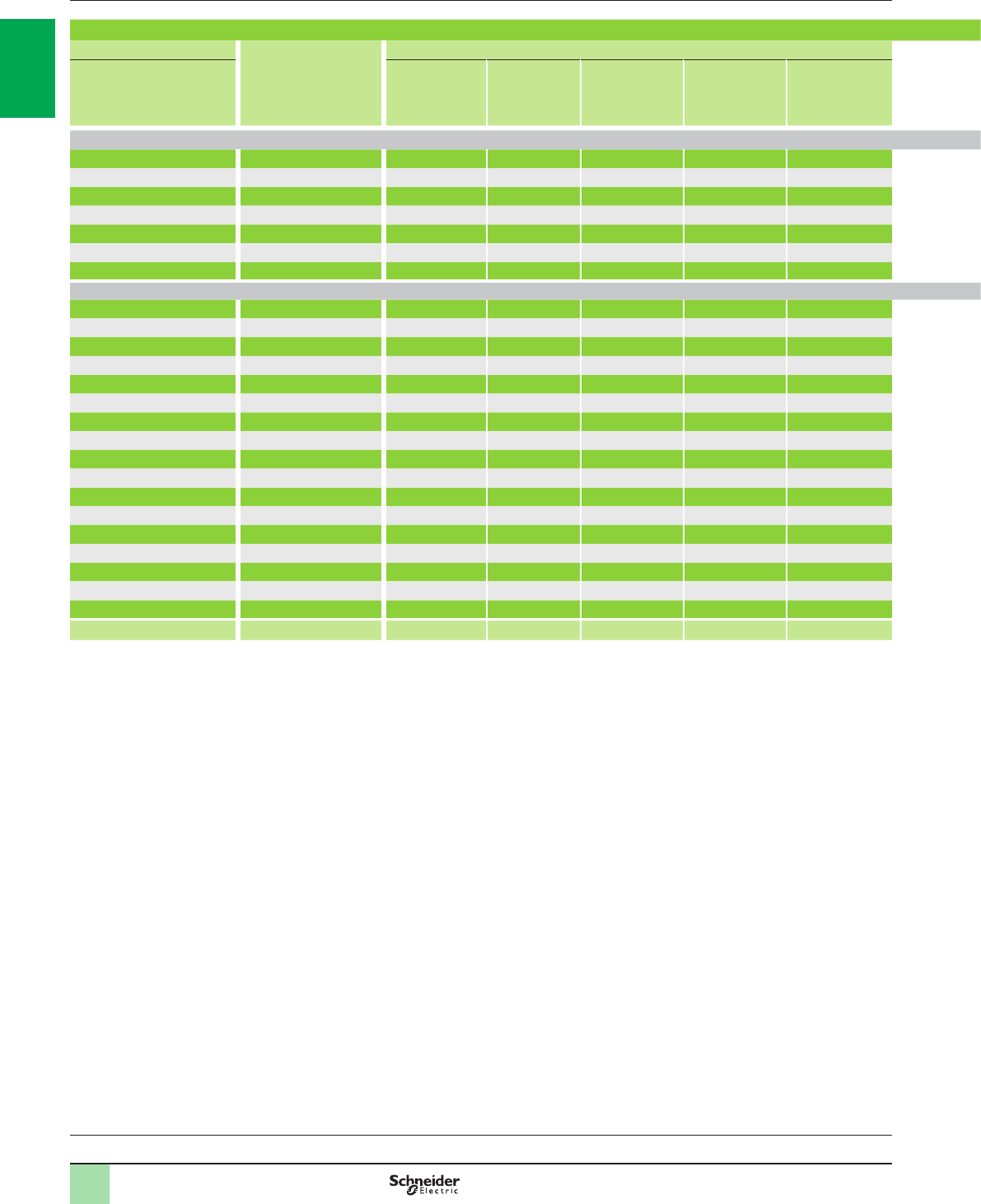
1/34
Combinations
1
Table showing possible combinations of ATV61HpppM3 and ATV61pppM3X drive options
Motor Drive Options
kW HP
DC
choke Line
choke Additional
EMC input lter
Motor choke IP 20 kit for
motor choke
Sinus lter Braking resistor Flush-mounting kit
(inside dust and
damp proof
enclosure)
UL Type 1
conformity kit
(outside enclosure)
IP 21 or IP 31
conformity kit
(outside enclosure)
Control card fan kit
Single-phase supply voltage: 200…240 V 50/60 Hz
0.37 0.5 ATV61H075M3 VW3A4503 – VW3A4401 VW3A5101 – VW3A5201 VW3A7701 VW3A9501 VW3A9201 VW3A9101 –
0.75 1ATV61HU15M3 VW3A4505 – VW3A4401 VW3A5101 – VW3A5201 VW3A7702 VW3A9501 VW3A9201 VW3A9101 –
1.5 2ATV61HU22M3 VW3A4506 – VW3A4402 VW3A5101 – VW3A5202 VW3A7702 VW3A9502 VW3A9202 VW3A9102 –
2.2 3ATV61HU30M3 VW3A4507 – VW3A4402 VW3A5102, 103 – VW3A5202 VW3A7703 VW3A9502 VW3A9202 VW3A9102 –
3–ATV61HU40M3 VW3A4508 VW3A58501 VW3A4402 VW3A5102, 103 – VW3A5203 VW3A7703 VW3A9502 VW3A9202 VW3A9102 –
45ATV61HU55M3 VW3A4508 VW3A58502 VW3A4403 VW3A5102, 103 – VW3A5203 VW3A7704 VW3A9503 VW3A9203 VW3A9103 –
5.5 7.5 ATV61HU75M3 VW3A4509 VW3A58502 VW3A4404 VW3A5102, 103 – VW3A5203 VW3A7704 VW3A9504 VW3A9204 VW3A9104 –
Three-phase supply voltage: 200…240 V 50/60 Hz
0.75 1ATV61H075M3 VW3A4503 VW3A4551 VW3A4401 VW3A5101 – VW3A5201 VW3A7701 VW3A9501 VW3A9201 VW3A9101 –
1.5 2ATV61HU15M3 VW3A4505 VW3A4552 VW3A4401 VW3A5101 – VW3A5201 VW3A7702 VW3A9501 VW3A9201 VW3A9101 –
2.2 3ATV61HU22M3 VW3A4506 VW3A4552 VW3A4402 VW3A5101 – VW3A5202 VW3A7702 VW3A9502 VW3A9202 VW3A9102 –
3–ATV61HU30M3 VW3A4507 VW3A4553 VW3A4402 VW3A5102, 103 – VW3A5202 VW3A7703 VW3A9502 VW3A9202 VW3A9102 –
45ATV61HU40M3 VW3A4508 VW3A4554 VW3A4402 VW3A5102, 103 – VW3A5203 VW3A7703 VW3A9502 VW3A9202 VW3A9102 –
5.5 7.5 ATV61HU55M3 VW3A4508 VW3A4554 VW3A4403 VW3A5102, 103 – VW3A5203 VW3A7704 VW3A9503 VW3A9203 VW3A9103 –
7.5 10 ATV61HU75M3 VW3A4509 VW3A4555 VW3A4404 VW3A5102, 103 – VW3A5203 VW3A7704 VW3A9504 VW3A9204 VW3A9104 –
11 15 ATV61HD11M3X VW3A4510 VW3A4555 VW3A4405 VW3A5103 – VW3A5204 VW3A7705 VW3A9505 VW3A9205 VW3A9105 –
15 20 ATV61HD15M3X VW3A4510 VW3A4556 VW3A4405 VW3A5103 – VW3A5204 VW3A7706 VW3A9505 VW3A9205 VW3A9105 –
18.5 25 ATV61HD18M3X VW3A4511 VW3A4557 VW3A4406 VW3A5103 – VW3A5205 VW3A7707 VW3A9506 VW3A9206 VW3A9106 VW3A9404
22 30 ATV61HD22M3X VW3A4511 VW3A4557 VW3A4406 VW3A5103 – VW3A5205 VW3A7707 VW3A9506 VW3A9206 VW3A9106 VW3A9404
30 40 ATV61HD30M3X VW3A4512 VW3A4557 VW3A4408 VW3A5104 VW3A9612 VW3A5206 VW3A7708 VW3A9508 VW3A9217 VW3A9117 VW3A9406
37 50 ATV61HD37M3X VW3A4512 VW3A4557 VW3A4408 VW3A5104 VW3A9612 VW3A5206 VW3A7709 VW3A9508 VW3A9217 VW3A9117 VW3A9406
45 60 ATV61HD45M3X VW3A4512 VW3A4557 VW3A4408 VW3A5104 VW3A9612 VW3A5206 VW3A7709 VW3A9508 VW3A9217 VW3A9117 VW3A9406
55 75 ATV61HD55M3X – VW3A4559 VW3A4410 VW3A5105 VW3A9612 VW3A5208 VW3A7713 VW3A9510 VW3A9209 VW3A9109 –
75 100 ATV61HD75M3X – VW3A4568 VW3A4410 VW3A5105 VW3A9612 VW3A5208 VW3A7713 VW3A9510 VW3A9209 VW3A9109 –
90 125 ATV61HD90M3X – VW3A4569 VW3A4411 VW3A5106 VW3A9613 VW3A5209 VW3A7714 VW3A9511 VW3A9210 VW3A9110 –
Page 1/16 1/65 1/67 1/83 1/84 1/85 1/87 1/61 1/25 1/26 1/27 1/28
Note: The quantity of certain required options varies according to the drive used. For more information, refer to pages 1/63 to 1/75.
Variable speed drives
Altivar 61
200…240 V 50/60 Hz supply voltage
Variable speed drives:
page 1/16 Variants:
page 1/23 Accessories:
page 1/25 Options:
page 1/46
2
1
3
4
5
6
7
8
9
10
2
1
3
4
5
6
7
8
9
10
1/35
Table showing possible combinations of ATV61HpppM3 and ATV61pppM3X drive options
Motor Drive Options
kW HP
DC
choke Line
choke Additional
EMC input lter
Motor choke IP 20 kit for
motor choke
Sinus lter Braking resistor Flush-mounting kit
(inside dust and
damp proof
enclosure)
UL Type 1
conformity kit
(outside enclosure)
IP 21 or IP 31
conformity kit
(outside enclosure)
Control card fan kit
Single-phase supply voltage: 200…240 V 50/60 Hz
0.37 0.5 ATV61H075M3 VW3A4503 – VW3A4401 VW3A5101 – VW3A5201 VW3A7701 VW3A9501 VW3A9201 VW3A9101 –
0.75 1ATV61HU15M3 VW3A4505 – VW3A4401 VW3A5101 – VW3A5201 VW3A7702 VW3A9501 VW3A9201 VW3A9101 –
1.5 2ATV61HU22M3 VW3A4506 – VW3A4402 VW3A5101 – VW3A5202 VW3A7702 VW3A9502 VW3A9202 VW3A9102 –
2.2 3ATV61HU30M3 VW3A4507 – VW3A4402 VW3A5102, 103 – VW3A5202 VW3A7703 VW3A9502 VW3A9202 VW3A9102 –
3–ATV61HU40M3 VW3A4508 VW3A58501 VW3A4402 VW3A5102, 103 – VW3A5203 VW3A7703 VW3A9502 VW3A9202 VW3A9102 –
45ATV61HU55M3 VW3A4508 VW3A58502 VW3A4403 VW3A5102, 103 – VW3A5203 VW3A7704 VW3A9503 VW3A9203 VW3A9103 –
5.5 7.5 ATV61HU75M3 VW3A4509 VW3A58502 VW3A4404 VW3A5102, 103 – VW3A5203 VW3A7704 VW3A9504 VW3A9204 VW3A9104 –
Three-phase supply voltage: 200…240 V 50/60 Hz
0.75 1ATV61H075M3 VW3A4503 VW3A4551 VW3A4401 VW3A5101 – VW3A5201 VW3A7701 VW3A9501 VW3A9201 VW3A9101 –
1.5 2ATV61HU15M3 VW3A4505 VW3A4552 VW3A4401 VW3A5101 – VW3A5201 VW3A7702 VW3A9501 VW3A9201 VW3A9101 –
2.2 3ATV61HU22M3 VW3A4506 VW3A4552 VW3A4402 VW3A5101 – VW3A5202 VW3A7702 VW3A9502 VW3A9202 VW3A9102 –
3–ATV61HU30M3 VW3A4507 VW3A4553 VW3A4402 VW3A5102, 103 – VW3A5202 VW3A7703 VW3A9502 VW3A9202 VW3A9102 –
45ATV61HU40M3 VW3A4508 VW3A4554 VW3A4402 VW3A5102, 103 – VW3A5203 VW3A7703 VW3A9502 VW3A9202 VW3A9102 –
5.5 7.5 ATV61HU55M3 VW3A4508 VW3A4554 VW3A4403 VW3A5102, 103 – VW3A5203 VW3A7704 VW3A9503 VW3A9203 VW3A9103 –
7.5 10 ATV61HU75M3 VW3A4509 VW3A4555 VW3A4404 VW3A5102, 103 – VW3A5203 VW3A7704 VW3A9504 VW3A9204 VW3A9104 –
11 15 ATV61HD11M3X VW3A4510 VW3A4555 VW3A4405 VW3A5103 – VW3A5204 VW3A7705 VW3A9505 VW3A9205 VW3A9105 –
15 20 ATV61HD15M3X VW3A4510 VW3A4556 VW3A4405 VW3A5103 – VW3A5204 VW3A7706 VW3A9505 VW3A9205 VW3A9105 –
18.5 25 ATV61HD18M3X VW3A4511 VW3A4557 VW3A4406 VW3A5103 – VW3A5205 VW3A7707 VW3A9506 VW3A9206 VW3A9106 VW3A9404
22 30 ATV61HD22M3X VW3A4511 VW3A4557 VW3A4406 VW3A5103 – VW3A5205 VW3A7707 VW3A9506 VW3A9206 VW3A9106 VW3A9404
30 40 ATV61HD30M3X VW3A4512 VW3A4557 VW3A4408 VW3A5104 VW3A9612 VW3A5206 VW3A7708 VW3A9508 VW3A9217 VW3A9117 VW3A9406
37 50 ATV61HD37M3X VW3A4512 VW3A4557 VW3A4408 VW3A5104 VW3A9612 VW3A5206 VW3A7709 VW3A9508 VW3A9217 VW3A9117 VW3A9406
45 60 ATV61HD45M3X VW3A4512 VW3A4557 VW3A4408 VW3A5104 VW3A9612 VW3A5206 VW3A7709 VW3A9508 VW3A9217 VW3A9117 VW3A9406
55 75 ATV61HD55M3X – VW3A4559 VW3A4410 VW3A5105 VW3A9612 VW3A5208 VW3A7713 VW3A9510 VW3A9209 VW3A9109 –
75 100 ATV61HD75M3X – VW3A4568 VW3A4410 VW3A5105 VW3A9612 VW3A5208 VW3A7713 VW3A9510 VW3A9209 VW3A9109 –
90 125 ATV61HD90M3X – VW3A4569 VW3A4411 VW3A5106 VW3A9613 VW3A5209 VW3A7714 VW3A9511 VW3A9210 VW3A9110 –
Page 1/16 1/65 1/67 1/83 1/84 1/85 1/87 1/61 1/25 1/26 1/27 1/28
Note: The quantity of certain required options varies according to the drive used. For more information, refer to pages 1/63 to 1/75.
1
2
1
3
4
5
6
7
8
9
10
2
1
3
4
5
6
7
8
9
10

1/36
Combinations (continued)
1
Variable speed drives
Altivar 61
380…480 V 50/60 Hz supply voltage
Table showing possible combinations of ATV61HpppN4 drive options
Motor Drive Options
kW HP
DC choke Line choke 50 Hz passive lters 60 Hz passive lters Additional
EMC input
lter
Motor choke IP 20 kit
for motor
choke
Resistance
braking
unit
Braking
resistor Sinus
lter
Flush-
mounting kit
(4)
UL Type 1
conformity
kit (5)
IP 21 or IP 31
conformity
kit (5)
Control
card fan
kit
THDI 16% THDI 10% THDI 5% THDI 16% THDI 10% THDI 5%
Three-phase supply voltage: 380…480 V 50/60 Hz
0.75 1ATV61H075N4 VW3A4501 VW3A4551 VW3A46101 VW3A46120 – VW3A46139 VW3A46158 – VW3A4401 VW3A5101, 102, 103 – – VW3A7701 VW3A5201 VW3A9501 VW3A9201 VW3A9101 –
1.5 2ATV61HU15N4 VW3A4502 VW3A4551 VW3A46101 VW3A46120 – VW3A46139 VW3A46158 – VW3A4401 VW3A5101, 102, 103 – – VW3A7701 VW3A5201 VW3A9501 VW3A9201 VW3A9101 –
2.2 3ATV61HU22N4 VW3A4503 VW3A4552 VW3A46101 VW3A46120 – VW3A46139 VW3A46158 – VW3A4401 VW3A5101, 102, 103 – – VW3A7701 VW3A5201 VW3A9501 VW3A9201 VW3A9101 –
3–ATV61HU30N4 VW3A4503 VW3A4552 VW3A46101 VW3A46120 – VW3A46139 VW3A46158 – VW3A4402 VW3A5101, 102, 103 – – VW3A7701 VW3A5201 VW3A9502 VW3A9202 VW3A9102 –
45ATV61HU40N4 VW3A4504 VW3A4552 VW3A46102 VW3A46121 – VW3A46140 VW3A46159 – VW3A4402 VW3A5101, 102, 103 – – VW3A7701 VW3A5201 VW3A9502 VW3A9202 VW3A9102 –
5.5 7.5 ATV61HU55N4 VW3A4505 VW3A4553 VW3A46102 VW3A46121 – VW3A46140 VW3A46159 – VW3A4403 VW3A5102, 103, 104 VW3A9612 – VW3A7702 VW3A5202 VW3A9503 VW3A9203 VW3A9103 –
7.5 10 ATV61HU75N4 VW3A4506 VW3A4553 VW3A46103 VW3A46122 – VW3A46141 VW3A46160 – VW3A4403 VW3A5102. 103, 104 VW3A9612 – VW3A7702 VW3A5203 VW3A9503 VW3A9203 VW3A9103 –
11 15 ATV61HD11N4 VW3A4507 VW3A4554 VW3A46104 VW3A46123 – VW3A46142 VW3A46161 – VW3A4404 VW3A5102, 103, 104 VW3A9612 – VW3A7703 VW3A5203 VW3A9504 VW3A9204 VW3A9104 –
15 20 ATV61HD15N4 VW3A4508 VW3A4554 VW3A46105 VW3A46124 – VW3A46143 VW3A46162 – VW3A4405 VW3A5102, 103, 104 VW3A9612 – VW3A7703 VW3A5203 VW3A9505 VW3A9205 VW3A9105 –
18.5 25 ATV61HD18N4 VW3A4508 VW3A4555 VW3A46106 VW3A46125 – VW3A46144 VW3A46163 – VW3A4405 VW3A5102, 103, 104 VW3A9612 – VW3A7704 VW3A5204 VW3A9505 VW3A9205 VW3A9105 –
22 30 ATV61HD22N4 VW3A4510 VW3A4555 VW3A46107 VW3A46126 – VW3A46145 VW3A46164 – VW3A4406 VW3A5103, 104 VW3A9612 – VW3A7704 VW3A5204 VW3A9506 VW3A9206 VW3A9106 VW3A9404
30 40 ATV61HD30N4 VW3A4510 VW3A4556 VW3A46108 VW3A46127 – VW3A46146 VW3A46165 – VW3A4407 VW3A5103, 104 VW3A9612 – VW3A7704 VW3A5204 VW3A9507 VW3A9207 VW3A9107 VW3A9405
37 50 ATV61HD37N4 VW3A4510 VW3A4556 VW3A46109 VW3A46128 – VW3A46147 VW3A46166 – VW3A4407 VW3A5103, 104 VW3A9612 – VW3A7705 VW3A5205 VW3A9507 VW3A9207 VW3A9107 VW3A9405
45 60 ATV61HD45N4 VW3A4511 VW3A4556 VW3A46110 VW3A46129 – VW3A46148 VW3A46167 – VW3A4408 VW3A5104 VW3A9612 – VW3A7707 VW3A5205 VW3A9509 VW3A9208 VW3A9108 VW3A9407
55 75 ATV61HD55N4 VW3A4511 VW3A4556 VW3A46111 VW3A46130 – VW3A46149 VW3A46168 – VW3A4408 VW3A5104 VW3A9612 – VW3A7707 VW3A5206 VW3A9509 VW3A9208 VW3A9108 VW3A9407
75 100 ATV61HD75N4 VW3A4511 VW3A4557 VW3A46112 VW3A46131 – VW3A46150 VW3A46169 – VW3A4408 VW3A5104 VW3A9612 – VW3A7707 VW3A5206 VW3A9509 VW3A9208 VW3A9108 VW3A9407
90 125 ATV61HD90N4 – VW3A4558 (1) – VW3A46112 VW3A46131 – VW3A46151 VW3A46170 VW3A4410 VW3A5104 VW3A9612 – VW3A7710 VW3A5207 VW3A9510 VW3A9209 VW3A9109 –
110 150 ATV61HC11N4 – VW3A4559 (1) – VW3A46113 VW3A46132 – VW3A46152 VW3A46171 VW3A4410 VW3A5105 VW3A9612 – VW3A7710 VW3A5207 VW3A9510 VW3A9209 VW3A9109 –
132 200 ATV61HC13N4 – VW3A4560 (1) – VW3A46114 VW3A46133 – VW3A46153 VW3A46172 VW3A4410 VW3A5105 VW3A9612 – VW3A7711 VW3A5208 VW3A9511 VW3A9210 VW3A9110 –
160 250 ATV61HC16N4 – VW3A4568 (1) – VW3A46116 VW3A46135 – VW3A46153 VW3A46172 VW3A4410 VW3A5106 VW3A9613 – VW3A7711 VW3A5208 VW3A9512 VW3A9211 VW3A9111 –
200 300 ATV61HC22N4 – VW3A4561 (1) – VW3A46118 VW3A46137 – VW3A46155 VW3A46174 VW3A4411 VW3A5106 VW3A9613 – VW3A7712 VW3A5209 VW3A9513 VW3A9212 VW3A9112 –
220 350 ATV61HC22N4 – VW3A4569 (1) – VW3A46118 VW3A46137 – VW3A46155 VW3A46174 VW3A4411 VW3A5106 VW3A9613 – VW3A7712 VW3A5209 VW3A9513 VW3A9212 VW3A9112 –
250 400 ATV61HC25N4 – VW3A4569 (1) – VW3A46119 VW3A46138 – VW3A46157 VW3A46176 VW3A4411 VW3A5107 VW3A9613 VW3A7101 VW3A7715 VW3A5210 VW3A9514, 515 VW3A9213, 214 VW3A9113, 114 –
280 450 ATV61HC31N4 – VW3A4564 (1) – VW3A46115 VW3A46134 – VW3A46157 VW3A46176 VW3A4411 VW3A5107 VW3A9613 VW3A7101 VW3A7716 VW3A5210 VW3A9514, 515 VW3A9213, 214 VW3A9113, 114 –
315 500 ATV61HC31N4 – VW3A4564 (1) – VW3A46116 VW3A46135 – VW3A46153 VW3A46172 VW3A4411 VW3A5107 VW3A9613 VW3A7101 VW3A7716 VW3A5210 VW3A9514, 515 VW3A9213, 214 VW3A9113, 114 –
355 –ATV61HC40N4 – VW3A4565 (1) – VW3A46116 VW3A46135 – VW3A46154 VW3A46173 VW3A4412 VW3A5107 VW3A9613 VW3A7102 VW3A7717 VW3A5210 – – VW3A9115 –
400 600 ATV61HC40N4 – VW3A4565 (1) – VW3A46117 VW3A46136 – VW3A46154 VW3A46173 VW3A4412 VW3A5108 VW3A9613 VW3A7102 VW3A7717 VW3A5211 – – VW3A9115 –
500 700 ATV61HC50N4 – VW3A4569 (1) – VW3A46119 VW3A46138 – VW3A46156 VW3A46175 VW3A4412 VW3A5108 VW3A9613 VW3A7102 VW3A7717 VW3A5211 – – VW3A9115 –
560 800 ATV61HC63N4 – VW3A4564 (1) – VW3A46117 VW3A46136 – VW3A46157 VW3A46176 VW3A4413 VW3A5108 VW3A9613 VW3A7102 VW3A7718 VW3A5211 – – VW3A9116 –
630 900 ATV61HC63N4 – VW3A4564 (1) – VW3A46118 VW3A46137 – VW3A46155 VW3A46174 VW3A4413 VW3A5108 VW3A9613 VW3A7102 VW3A7718 VW3A5211 – – VW3A9116 –
Page 1/17 1/65 1/67 1/70 1/70 1/72 1/73 1/73 1/75 1/81 1/84 1/85 1/60 1/62 1/87 1/25 1/26 1/27 1/28
Table showing possible combinations of ATV61QCppN4 drive options
Motor Drive Options
kW HP
DC choke Line choke 50 Hz passive lters 60 Hz passive lters Additional
EMC input
lter
Motor choke IP 20 kit
for motor
choke
Resistance
braking
unit
Braking
resistor Sinus
lter
Flush-
mounting kit
(2)
UL Type 1
conformity
kit (3)
IP 21 or IP 31
conformity
kit (3)
Control
card fan
kit
THDI 16% THDI 10% THDI 5% THDI 16% THDI 10% THDI 5%
Three-phase supply voltage: 380…480 V 50/60 Hz
110 150 ATV61QC11N4 – VW3A4559 (1) – VW3A46113 VW3A46132 – VW3A46152 VW3A46171 VW3A4410 VW3A5104 VW3A9612 – VW3A7710 VW3A5207 – – – –
132 200 ATV61QC13N4 – VW3A4560 (1) – VW3A46114 VW3A46133 – VW3A46153 VW3A46172 VW3A4410 VW3A5105 VW3A9612 – VW3A7711 VW3A5208 – – – –
160 250 ATV61QC16N4 – VW3A4568 (1) – VW3A46116 VW3A46135 – VW3A46153 VW3A46172 VW3A4410 VW3A5105 VW3A9612 – VW3A7711 VW3A5208 – – – –
200 300 ATV61QC20N4 – VW3A4561 (1) – VW3A46118 VW3A46137 – VW3A46155 VW3A46174 VW3A4411 VW3A5106 VW3A9613 VW3A7101 VW3A7712 VW3A5209 – – – –
220 350 ATV61QC25N4 – VW3A4569 (1) – VW3A46118 VW3A46137 – VW3A46155 VW3A46174 VW3A4411 VW3A5106 VW3A9613 VW3A7101 VW3A7712 VW3A5209 – – – –
250 400 ATV61QC25N4 – VW3A4569 (1) – VW3A46119 VW3A46138 – VW3A46157 VW3A46176 VW3A4411 VW3A5106 VW3A9613 VW3A7101 VW3A7715 VW3A5210 – – – –
280 450 ATV61QC31N4 – VW3A4564 (1) – VW3A46115 VW3A46134 – VW3A46157 VW3A46176 VW3A4411 VW3A5107 VW3A9613 VW3A7101 VW3A7716 VW3A5210 – – – –
315 500 ATV61QC31N4 – VW3A4564 (1) – VW3A46116 VW3A46135 – VW3A46153 VW3A46172 VW3A4411 VW3A5107 VW3A9613 VW3A7101 VW3A7716 VW3A5210 – – – –
355 –ATV61QC40N4 – VW3A4561 (1) – VW3A46116 VW3A46135 – VW3A46154 VW3A46173 VW3A4412 VW3A5107 VW3A9613 VW3A7102 VW3A7717 VW3A5210 – – – –
400 600 ATV61QC40N4 – VW3A4561 (1) – VW3A46117 VW3A46136 – VW3A46154 VW3A46173 VW3A4412 VW3A5107 VW3A9613 VW3A7102 VW3A7717 VW3A5211 – – – –
500 700 ATV61QC50N4 – VW3A4563 (1) – VW3A46119 VW3A46138 – VW3A46156 VW3A46175 VW3A4412 VW3A5108 VW3A9613 VW3A7102 VW3A7717 VW3A5211 – – – –
560 800 ATV61QC63N4 – VW3A4573 (1) – VW3A46117 VW3A46136 – VW3A46157 VW3A46176 VW3A4413 VW3A5108 VW3A9613 VW3A7102 VW3A7718 VW3A5211 – – – –
630 900 ATV61QC63N4 – VW3A4573 (1) – VW3A46118 VW3A46137 – VW3A46155 VW3A46174 VW3A4413 VW3A5108 VW3A9613 VW3A7102 VW3A7718 VW3A5211 – – – –
Page 1/18 –1/67 –1/70 1/72 –1/73 1/75 1/81 1/84 1/85 1/60 1/62 1/87 – – – –
(1) For drives with a power rating of 90 kW or more without an integrated DC choke, a line choke must be used. This is the case for ATV61HD90N4D to
ATV61HC63N4D drives (see page 1/23) and for ATV61QCppN4 drives.
ATV61HD90N4D to ATV61HC63N4D drives are variants without an integrated DC choke of ATV61HD90N4 to ATV61HC63N4 drives.
(2) In dust and damp proof enclosure.
(3) Outside enclosure.
Note: The quantity of certain required options varies according to the drive used. For more information, refer to pages 1/63 to 1/75.
2
1
3
4
5
6
7
8
9
10
2
1
3
4
5
6
7
8
9
10
1/37
Table showing possible combinations of ATV61HpppN4 drive options
Motor Drive Options
kW HP
DC choke Line choke 50 Hz passive lters 60 Hz passive lters Additional
EMC input
lter
Motor choke IP 20 kit
for motor
choke
Resistance
braking
unit
Braking
resistor Sinus
lter
Flush-
mounting kit
(4)
UL Type 1
conformity
kit (5)
IP 21 or IP 31
conformity
kit (5)
Control
card fan
kit
THDI 16% THDI 10% THDI 5% THDI 16% THDI 10% THDI 5%
Three-phase supply voltage: 380…480 V 50/60 Hz
0.75 1ATV61H075N4 VW3A4501 VW3A4551 VW3A46101 VW3A46120 – VW3A46139 VW3A46158 – VW3A4401 VW3A5101, 102, 103 – – VW3A7701 VW3A5201 VW3A9501 VW3A9201 VW3A9101 –
1.5 2ATV61HU15N4 VW3A4502 VW3A4551 VW3A46101 VW3A46120 – VW3A46139 VW3A46158 – VW3A4401 VW3A5101, 102, 103 – – VW3A7701 VW3A5201 VW3A9501 VW3A9201 VW3A9101 –
2.2 3ATV61HU22N4 VW3A4503 VW3A4552 VW3A46101 VW3A46120 – VW3A46139 VW3A46158 – VW3A4401 VW3A5101, 102, 103 – – VW3A7701 VW3A5201 VW3A9501 VW3A9201 VW3A9101 –
3–ATV61HU30N4 VW3A4503 VW3A4552 VW3A46101 VW3A46120 – VW3A46139 VW3A46158 – VW3A4402 VW3A5101, 102, 103 – – VW3A7701 VW3A5201 VW3A9502 VW3A9202 VW3A9102 –
45ATV61HU40N4 VW3A4504 VW3A4552 VW3A46102 VW3A46121 – VW3A46140 VW3A46159 – VW3A4402 VW3A5101, 102, 103 – – VW3A7701 VW3A5201 VW3A9502 VW3A9202 VW3A9102 –
5.5 7.5 ATV61HU55N4 VW3A4505 VW3A4553 VW3A46102 VW3A46121 – VW3A46140 VW3A46159 – VW3A4403 VW3A5102, 103, 104 VW3A9612 – VW3A7702 VW3A5202 VW3A9503 VW3A9203 VW3A9103 –
7.5 10 ATV61HU75N4 VW3A4506 VW3A4553 VW3A46103 VW3A46122 – VW3A46141 VW3A46160 – VW3A4403 VW3A5102. 103, 104 VW3A9612 – VW3A7702 VW3A5203 VW3A9503 VW3A9203 VW3A9103 –
11 15 ATV61HD11N4 VW3A4507 VW3A4554 VW3A46104 VW3A46123 – VW3A46142 VW3A46161 – VW3A4404 VW3A5102, 103, 104 VW3A9612 – VW3A7703 VW3A5203 VW3A9504 VW3A9204 VW3A9104 –
15 20 ATV61HD15N4 VW3A4508 VW3A4554 VW3A46105 VW3A46124 – VW3A46143 VW3A46162 – VW3A4405 VW3A5102, 103, 104 VW3A9612 – VW3A7703 VW3A5203 VW3A9505 VW3A9205 VW3A9105 –
18.5 25 ATV61HD18N4 VW3A4508 VW3A4555 VW3A46106 VW3A46125 – VW3A46144 VW3A46163 – VW3A4405 VW3A5102, 103, 104 VW3A9612 – VW3A7704 VW3A5204 VW3A9505 VW3A9205 VW3A9105 –
22 30 ATV61HD22N4 VW3A4510 VW3A4555 VW3A46107 VW3A46126 – VW3A46145 VW3A46164 – VW3A4406 VW3A5103, 104 VW3A9612 – VW3A7704 VW3A5204 VW3A9506 VW3A9206 VW3A9106 VW3A9404
30 40 ATV61HD30N4 VW3A4510 VW3A4556 VW3A46108 VW3A46127 – VW3A46146 VW3A46165 – VW3A4407 VW3A5103, 104 VW3A9612 – VW3A7704 VW3A5204 VW3A9507 VW3A9207 VW3A9107 VW3A9405
37 50 ATV61HD37N4 VW3A4510 VW3A4556 VW3A46109 VW3A46128 – VW3A46147 VW3A46166 – VW3A4407 VW3A5103, 104 VW3A9612 – VW3A7705 VW3A5205 VW3A9507 VW3A9207 VW3A9107 VW3A9405
45 60 ATV61HD45N4 VW3A4511 VW3A4556 VW3A46110 VW3A46129 – VW3A46148 VW3A46167 – VW3A4408 VW3A5104 VW3A9612 – VW3A7707 VW3A5205 VW3A9509 VW3A9208 VW3A9108 VW3A9407
55 75 ATV61HD55N4 VW3A4511 VW3A4556 VW3A46111 VW3A46130 – VW3A46149 VW3A46168 – VW3A4408 VW3A5104 VW3A9612 – VW3A7707 VW3A5206 VW3A9509 VW3A9208 VW3A9108 VW3A9407
75 100 ATV61HD75N4 VW3A4511 VW3A4557 VW3A46112 VW3A46131 – VW3A46150 VW3A46169 – VW3A4408 VW3A5104 VW3A9612 – VW3A7707 VW3A5206 VW3A9509 VW3A9208 VW3A9108 VW3A9407
90 125 ATV61HD90N4 – VW3A4558 (1) – VW3A46112 VW3A46131 – VW3A46151 VW3A46170 VW3A4410 VW3A5104 VW3A9612 – VW3A7710 VW3A5207 VW3A9510 VW3A9209 VW3A9109 –
110 150 ATV61HC11N4 – VW3A4559 (1) – VW3A46113 VW3A46132 – VW3A46152 VW3A46171 VW3A4410 VW3A5105 VW3A9612 – VW3A7710 VW3A5207 VW3A9510 VW3A9209 VW3A9109 –
132 200 ATV61HC13N4 – VW3A4560 (1) – VW3A46114 VW3A46133 – VW3A46153 VW3A46172 VW3A4410 VW3A5105 VW3A9612 – VW3A7711 VW3A5208 VW3A9511 VW3A9210 VW3A9110 –
160 250 ATV61HC16N4 – VW3A4568 (1) – VW3A46116 VW3A46135 – VW3A46153 VW3A46172 VW3A4410 VW3A5106 VW3A9613 – VW3A7711 VW3A5208 VW3A9512 VW3A9211 VW3A9111 –
200 300 ATV61HC22N4 – VW3A4561 (1) – VW3A46118 VW3A46137 – VW3A46155 VW3A46174 VW3A4411 VW3A5106 VW3A9613 – VW3A7712 VW3A5209 VW3A9513 VW3A9212 VW3A9112 –
220 350 ATV61HC22N4 – VW3A4569 (1) – VW3A46118 VW3A46137 – VW3A46155 VW3A46174 VW3A4411 VW3A5106 VW3A9613 – VW3A7712 VW3A5209 VW3A9513 VW3A9212 VW3A9112 –
250 400 ATV61HC25N4 – VW3A4569 (1) – VW3A46119 VW3A46138 – VW3A46157 VW3A46176 VW3A4411 VW3A5107 VW3A9613 VW3A7101 VW3A7715 VW3A5210 VW3A9514, 515 VW3A9213, 214 VW3A9113, 114 –
280 450 ATV61HC31N4 – VW3A4564 (1) – VW3A46115 VW3A46134 – VW3A46157 VW3A46176 VW3A4411 VW3A5107 VW3A9613 VW3A7101 VW3A7716 VW3A5210 VW3A9514, 515 VW3A9213, 214 VW3A9113, 114 –
315 500 ATV61HC31N4 – VW3A4564 (1) – VW3A46116 VW3A46135 – VW3A46153 VW3A46172 VW3A4411 VW3A5107 VW3A9613 VW3A7101 VW3A7716 VW3A5210 VW3A9514, 515 VW3A9213, 214 VW3A9113, 114 –
355 –ATV61HC40N4 – VW3A4565 (1) – VW3A46116 VW3A46135 – VW3A46154 VW3A46173 VW3A4412 VW3A5107 VW3A9613 VW3A7102 VW3A7717 VW3A5210 – – VW3A9115 –
400 600 ATV61HC40N4 – VW3A4565 (1) – VW3A46117 VW3A46136 – VW3A46154 VW3A46173 VW3A4412 VW3A5108 VW3A9613 VW3A7102 VW3A7717 VW3A5211 – – VW3A9115 –
500 700 ATV61HC50N4 – VW3A4569 (1) – VW3A46119 VW3A46138 – VW3A46156 VW3A46175 VW3A4412 VW3A5108 VW3A9613 VW3A7102 VW3A7717 VW3A5211 – – VW3A9115 –
560 800 ATV61HC63N4 – VW3A4564 (1) – VW3A46117 VW3A46136 – VW3A46157 VW3A46176 VW3A4413 VW3A5108 VW3A9613 VW3A7102 VW3A7718 VW3A5211 – – VW3A9116 –
630 900 ATV61HC63N4 – VW3A4564 (1) – VW3A46118 VW3A46137 – VW3A46155 VW3A46174 VW3A4413 VW3A5108 VW3A9613 VW3A7102 VW3A7718 VW3A5211 – – VW3A9116 –
Page 1/17 1/65 1/67 1/70 1/70 1/72 1/73 1/73 1/75 1/81 1/84 1/85 1/60 1/62 1/87 1/25 1/26 1/27 1/28
Table showing possible combinations of ATV61QCppN4 drive options
Motor Drive Options
kW HP
DC choke Line choke 50 Hz passive lters 60 Hz passive lters Additional
EMC input
lter
Motor choke IP 20 kit
for motor
choke
Resistance
braking
unit
Braking
resistor Sinus
lter
Flush-
mounting kit
(2)
UL Type 1
conformity
kit (3)
IP 21 or IP 31
conformity
kit (3)
Control
card fan
kit
THDI 16% THDI 10% THDI 5% THDI 16% THDI 10% THDI 5%
Three-phase supply voltage: 380…480 V 50/60 Hz
110 150 ATV61QC11N4 – VW3A4559 (1) – VW3A46113 VW3A46132 – VW3A46152 VW3A46171 VW3A4410 VW3A5104 VW3A9612 – VW3A7710 VW3A5207 – – – –
132 200 ATV61QC13N4 – VW3A4560 (1) – VW3A46114 VW3A46133 – VW3A46153 VW3A46172 VW3A4410 VW3A5105 VW3A9612 – VW3A7711 VW3A5208 – – – –
160 250 ATV61QC16N4 – VW3A4568 (1) – VW3A46116 VW3A46135 – VW3A46153 VW3A46172 VW3A4410 VW3A5105 VW3A9612 – VW3A7711 VW3A5208 – – – –
200 300 ATV61QC20N4 – VW3A4561 (1) – VW3A46118 VW3A46137 – VW3A46155 VW3A46174 VW3A4411 VW3A5106 VW3A9613 VW3A7101 VW3A7712 VW3A5209 – – – –
220 350 ATV61QC25N4 – VW3A4569 (1) – VW3A46118 VW3A46137 – VW3A46155 VW3A46174 VW3A4411 VW3A5106 VW3A9613 VW3A7101 VW3A7712 VW3A5209 – – – –
250 400 ATV61QC25N4 – VW3A4569 (1) – VW3A46119 VW3A46138 – VW3A46157 VW3A46176 VW3A4411 VW3A5106 VW3A9613 VW3A7101 VW3A7715 VW3A5210 – – – –
280 450 ATV61QC31N4 – VW3A4564 (1) – VW3A46115 VW3A46134 – VW3A46157 VW3A46176 VW3A4411 VW3A5107 VW3A9613 VW3A7101 VW3A7716 VW3A5210 – – – –
315 500 ATV61QC31N4 – VW3A4564 (1) – VW3A46116 VW3A46135 – VW3A46153 VW3A46172 VW3A4411 VW3A5107 VW3A9613 VW3A7101 VW3A7716 VW3A5210 – – – –
355 –ATV61QC40N4 – VW3A4561 (1) – VW3A46116 VW3A46135 – VW3A46154 VW3A46173 VW3A4412 VW3A5107 VW3A9613 VW3A7102 VW3A7717 VW3A5210 – – – –
400 600 ATV61QC40N4 – VW3A4561 (1) – VW3A46117 VW3A46136 – VW3A46154 VW3A46173 VW3A4412 VW3A5107 VW3A9613 VW3A7102 VW3A7717 VW3A5211 – – – –
500 700 ATV61QC50N4 – VW3A4563 (1) – VW3A46119 VW3A46138 – VW3A46156 VW3A46175 VW3A4412 VW3A5108 VW3A9613 VW3A7102 VW3A7717 VW3A5211 – – – –
560 800 ATV61QC63N4 – VW3A4573 (1) – VW3A46117 VW3A46136 – VW3A46157 VW3A46176 VW3A4413 VW3A5108 VW3A9613 VW3A7102 VW3A7718 VW3A5211 – – – –
630 900 ATV61QC63N4 – VW3A4573 (1) – VW3A46118 VW3A46137 – VW3A46155 VW3A46174 VW3A4413 VW3A5108 VW3A9613 VW3A7102 VW3A7718 VW3A5211 – – – –
Page 1/18 –1/67 –1/70 1/72 –1/73 1/75 1/81 1/84 1/85 1/60 1/62 1/87 – – – –
(1) For drives with a power rating of 90 kW or more without an integrated DC choke, a line choke must be used. This is the case for ATV61HD90N4D to
ATV61HC63N4D drives (see page 1/23) and for ATV61QCppN4 drives.
ATV61HD90N4D to ATV61HC63N4D drives are variants without an integrated DC choke of ATV61HD90N4 to ATV61HC63N4 drives.
(2) In dust and damp proof enclosure.
(3) Outside enclosure.
2
1
3
4
5
6
7
8
9
10
2
1
3
4
5
6
7
8
9
10
1/38
Variable speed drives
Altivar 61
380…480 V 50/60 Hz supply voltage
Combinations (continued)
1
Variable speed drives:
page 1/16 Variants:
page 1/23 Accessories:
page 1/25 Options:
page 1/46
Table showing possible combinations of ATV61WpppN4 and ATV61WpppN4C drive options
Motor Drive Options
kW HP
Line choke 50 Hz passive lters 60 Hz passive lters Motor choke Braking resistor Ready-assembled IP 54 base
plate IP 20 kit for motor choke Sinus lter
THDI 10% THDI 5% THDI 10% THDI 5%
Three-phase supply voltage: 380…480 V 50/60 Hz
0.75 1ATV61W075N4
ATV61W075N4C VW3A4551 VW3A46101 VW3A46120 VW3A46139 VW3A46158 VW3A5101, 102, 103 VW3A7701 VW3A9901 – VW3A5201
1.5 2ATV61WU15N4
ATV61WU15N4C VW3A4551 VW3A46101 VW3A46120 VW3A46139 VW3A46158 VW3A5101, 102, 103 VW3A7701 VW3A9901 – VW3A5201
2.2 3ATV61WU22N4
ATV61WU22N4C VW3A4552 VW3A46101 VW3A46120 VW3A46139 VW3A46158 VW3A5101, 102, 103 VW3A7701 VW3A9901 – VW3A5201
3–ATV61WU30N4
ATV61WU30N4C VW3A4552 VW3A46101 VW3A46120 VW3A46139 VW3A46158 VW3A5101, 102, 103 VW3A7701 VW3A9901 – VW3A5201
45ATV61WU40N4
ATV61WU40N4C VW3A4552 VW3A46102 VW3A46121 VW3A46140 VW3A46159 VW3A5101, 102, 103 VW3A7701 VW3A9901 – VW3A5201
5.5 7.5 ATV61WU55N4
ATV61WU55N4C VW3A4553 VW3A46102 VW3A46121 VW3A46140 VW3A46159 VW3A5102, 103, 104 VW3A7701 VW3A9901 VW3A9612 VW3A5202
7.5 10 ATV61WU75N4
ATV61WU75N4C VW3A4553 VW3A46103 VW3A46122 VW3A46141 VW3A46160 VW3A5102, 103, 104 VW3A7702 VW3A9902 VW3A9612 VW3A5203
11 15 ATV61WD11N4
ATV61WD11N4C VW3A4554 VW3A46104 VW3A46123 VW3A46142 VW3A46161 VW3A5102, 103, 104 VW3A7702 VW3A9902 VW3A9612 VW3A5203
15 20 ATV61WD15N4
ATV61WD15N4C VW3A4554 VW3A46105 VW3A46124 VW3A46143 VW3A46162 VW3A5102, 103, 104 VW3A7703 VW3A9903 VW3A9612 VW3A5203
18.5 25 ATV61WD18N4
ATV61WD18N4C VW3A4555 VW3A46106 VW3A46125 VW3A46144 VW3A46163 VW3A5102, 103, 104 VW3A7703 VW3A9904 VW3A9612 VW3A5204
22 30 ATV61WD22N4
ATV61WD22N4C VW3A4555 VW3A46107 VW3A46126 VW3A46145 VW3A46164 VW3A5103, 104 VW3A7704 VW3A9904 VW3A9612 VW3A5204
30 40 ATV61WD30N4
ATV61WD30N4C VW3A4556 VW3A46108 VW3A46127 VW3A46146 VW3A46165 VW3A5103, 104 VW3A7704 VW3A9905 VW3A9612 VW3A5204
37 50 ATV61WD37N4
ATV61WD37N4C VW3A4556 VW3A46109 VW3A46128 VW3A46147 VW3A46166 VW3A5103, 104 VW3A7704 VW3A9906 VW3A9612 VW3A5205
45 60 ATV61WD45N4
ATV61WD45N4C VW3A4556 VW3A46110 VW3A46129 VW3A46148 VW3A46167 VW3A5104 VW3A7705 VW3A9906 VW3A9612 VW3A5205
55 75 ATV61WD55N4 VW3A4556 VW3A46111 VW3A46130 VW3A46149 VW3A46168 VW3A5104 VW3A7706 VW3A9907 VW3A9612 VW3A5206
55 75 ATV61WD55N4C VW3A4556 VW3A46111 VW3A46130 VW3A46149 VW3A46168 VW3A5104 VW3A7706 VW3A9909 VW3A9612 VW3A5206
75 100 ATV61WD75N4 VW3A4557 VW3A46112 VW3A46131 VW3A46150 VW3A46169 VW3A5104 VW3A7706 VW3A9907 VW3A9612 VW3A5206
75 100 ATV61WD75N4C VW3A4557 VW3A46112 VW3A46131 VW3A46150 VW3A46169 VW3A5104 VW3A7706 VW3A9909 VW3A9612 VW3A5206
90 125 ATV61WD90N4 VW3A4558 VW3A46112 VW3A46131 VW3A46151 VW3A46170 VW3A5104 VW3A7706 VW3A9908 VW3A9612 VW3A5207
90 125 ATV61WD90N4C VW3A4558 VW3A46112 VW3A46131 VW3A46151 VW3A46170 VW3A5104 VW3A7706 VW3A9910 VW3A9612 VW3A5207
Page 1/19 1/67 1/70 1/72 1/73 1/75 1/84 1/62 1/29 1/85 1/87
Note: The quantity of certain required options varies according to the drive used. For more information, refer to pages 1/63 to 1/75.
2
1
3
4
5
6
7
8
9
10
2
1
3
4
5
6
7
8
9
10
1/39
1
Variable speed drives:
page 1/16 Variants:
page 1/23 Accessories:
page 1/25 Options:
page 1/46
Table showing possible combinations of ATV61WpppN4 and ATV61WpppN4C drive options
Motor Drive Options
kW HP
Line choke 50 Hz passive lters 60 Hz passive lters Motor choke Braking resistor Ready-assembled IP 54 base
plate IP 20 kit for motor choke Sinus lter
THDI 10% THDI 5% THDI 10% THDI 5%
Three-phase supply voltage: 380…480 V 50/60 Hz
0.75 1ATV61W075N4
ATV61W075N4C VW3A4551 VW3A46101 VW3A46120 VW3A46139 VW3A46158 VW3A5101, 102, 103 VW3A7701 VW3A9901 – VW3A5201
1.5 2ATV61WU15N4
ATV61WU15N4C VW3A4551 VW3A46101 VW3A46120 VW3A46139 VW3A46158 VW3A5101, 102, 103 VW3A7701 VW3A9901 – VW3A5201
2.2 3ATV61WU22N4
ATV61WU22N4C VW3A4552 VW3A46101 VW3A46120 VW3A46139 VW3A46158 VW3A5101, 102, 103 VW3A7701 VW3A9901 – VW3A5201
3–ATV61WU30N4
ATV61WU30N4C VW3A4552 VW3A46101 VW3A46120 VW3A46139 VW3A46158 VW3A5101, 102, 103 VW3A7701 VW3A9901 – VW3A5201
45ATV61WU40N4
ATV61WU40N4C VW3A4552 VW3A46102 VW3A46121 VW3A46140 VW3A46159 VW3A5101, 102, 103 VW3A7701 VW3A9901 – VW3A5201
5.5 7.5 ATV61WU55N4
ATV61WU55N4C VW3A4553 VW3A46102 VW3A46121 VW3A46140 VW3A46159 VW3A5102, 103, 104 VW3A7701 VW3A9901 VW3A9612 VW3A5202
7.5 10 ATV61WU75N4
ATV61WU75N4C VW3A4553 VW3A46103 VW3A46122 VW3A46141 VW3A46160 VW3A5102, 103, 104 VW3A7702 VW3A9902 VW3A9612 VW3A5203
11 15 ATV61WD11N4
ATV61WD11N4C VW3A4554 VW3A46104 VW3A46123 VW3A46142 VW3A46161 VW3A5102, 103, 104 VW3A7702 VW3A9902 VW3A9612 VW3A5203
15 20 ATV61WD15N4
ATV61WD15N4C VW3A4554 VW3A46105 VW3A46124 VW3A46143 VW3A46162 VW3A5102, 103, 104 VW3A7703 VW3A9903 VW3A9612 VW3A5203
18.5 25 ATV61WD18N4
ATV61WD18N4C VW3A4555 VW3A46106 VW3A46125 VW3A46144 VW3A46163 VW3A5102, 103, 104 VW3A7703 VW3A9904 VW3A9612 VW3A5204
22 30 ATV61WD22N4
ATV61WD22N4C VW3A4555 VW3A46107 VW3A46126 VW3A46145 VW3A46164 VW3A5103, 104 VW3A7704 VW3A9904 VW3A9612 VW3A5204
30 40 ATV61WD30N4
ATV61WD30N4C VW3A4556 VW3A46108 VW3A46127 VW3A46146 VW3A46165 VW3A5103, 104 VW3A7704 VW3A9905 VW3A9612 VW3A5204
37 50 ATV61WD37N4
ATV61WD37N4C VW3A4556 VW3A46109 VW3A46128 VW3A46147 VW3A46166 VW3A5103, 104 VW3A7704 VW3A9906 VW3A9612 VW3A5205
45 60 ATV61WD45N4
ATV61WD45N4C VW3A4556 VW3A46110 VW3A46129 VW3A46148 VW3A46167 VW3A5104 VW3A7705 VW3A9906 VW3A9612 VW3A5205
55 75 ATV61WD55N4 VW3A4556 VW3A46111 VW3A46130 VW3A46149 VW3A46168 VW3A5104 VW3A7706 VW3A9907 VW3A9612 VW3A5206
55 75 ATV61WD55N4C VW3A4556 VW3A46111 VW3A46130 VW3A46149 VW3A46168 VW3A5104 VW3A7706 VW3A9909 VW3A9612 VW3A5206
75 100 ATV61WD75N4 VW3A4557 VW3A46112 VW3A46131 VW3A46150 VW3A46169 VW3A5104 VW3A7706 VW3A9907 VW3A9612 VW3A5206
75 100 ATV61WD75N4C VW3A4557 VW3A46112 VW3A46131 VW3A46150 VW3A46169 VW3A5104 VW3A7706 VW3A9909 VW3A9612 VW3A5206
90 125 ATV61WD90N4 VW3A4558 VW3A46112 VW3A46131 VW3A46151 VW3A46170 VW3A5104 VW3A7706 VW3A9908 VW3A9612 VW3A5207
90 125 ATV61WD90N4C VW3A4558 VW3A46112 VW3A46131 VW3A46151 VW3A46170 VW3A5104 VW3A7706 VW3A9910 VW3A9612 VW3A5207
Page 1/19 1/67 1/70 1/72 1/73 1/75 1/84 1/62 1/29 1/85 1/87
Note: The quantity of certain required options varies according to the drive used. For more information, refer to pages 1/63 to 1/75.
2
1
3
4
5
6
7
8
9
10
2
1
3
4
5
6
7
8
9
10
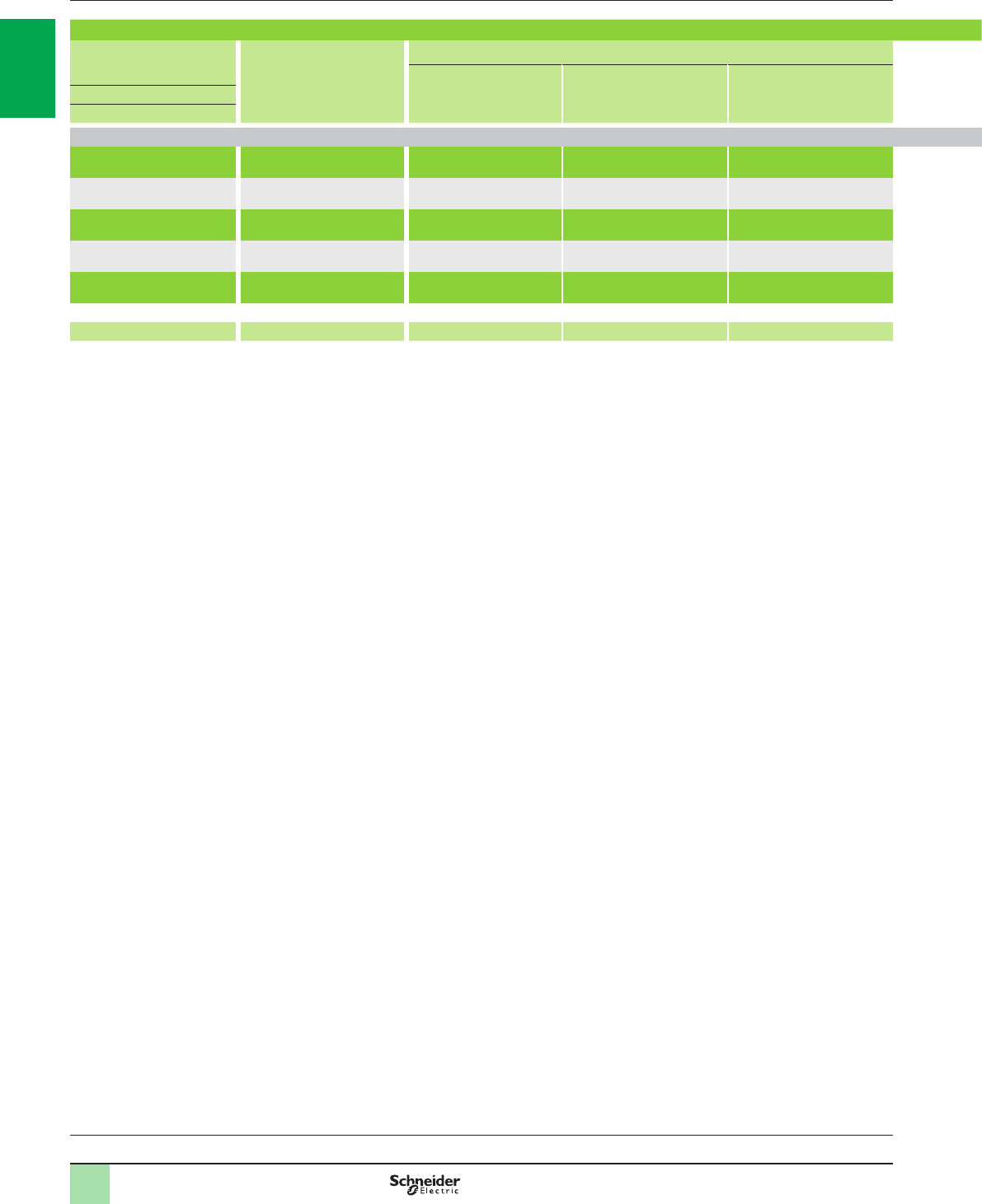
1/40
Combinations (continued) Variable speed drives
Altivar 61
500...690 V 50/60 Hz supply voltage
Variable speed drives:
page 1/16 Variants:
page 1/23 Accessories:
page 1/25 Options:
page 1/46
Table showing possible combinations of ATV61HpppS6X drive options
Motor Drive Options
Line choke Motor choke Braking resistor Flush-mounting kit
(inside dust and damp proof enclosure) UL Type 1 conformity kit
(outside enclosure) IP 21 or IP 31 conformity kit
(outside enclosure)
500 V 575 V
kW HP
Three-phase supply voltage: 500…600 V 50/60 Hz
2.2 3ATV61HU22S6X VW3A4551 VW3A5102, 103, 104 VW3A7702 VW3A9504 VW3A9204 VW3A9104
3–ATV61HU30S6X VW3A4552 VW3A5102, 103, 104 VW3A7702 VW3A9504 VW3A9204 VW3A9104
45ATV61HU40S6X VW3A4552 VW3A5102, 103, 104 VW3A7702 VW3A9504 VW3A9204 VW3A9104
5.5 7.5 ATV61HU55S6X VW3A4552 VW3A5102, 103, 104 VW3A7702 VW3A9504 VW3A9204 VW3A9104
7.5 10 ATV61HU75S6X VW3A4553 VW3A5102, 103, 104 VW3A7702 VW3A9504 VW3A9204 VW3A9104
Page 1/21 1/68 1/84 1/63 1/25 1/26 1/27
Note: The quantity of certain required options varies according to the drive used. For more information, refer to pages 1/63 to 1/75.
2
1
3
4
5
6
7
8
9
10
2
1
3
4
5
6
7
8
9
10
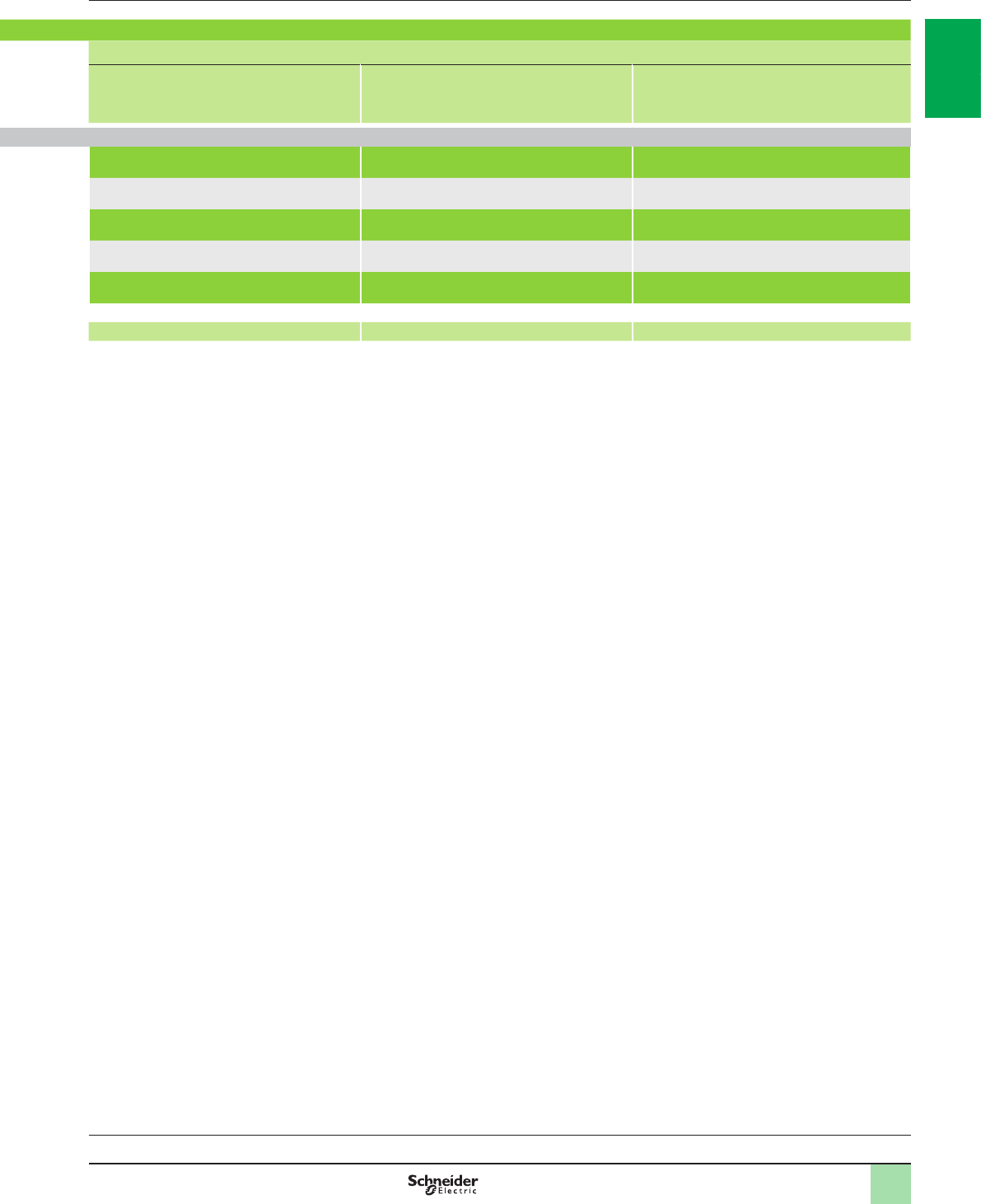
1/41
Variable speed drives:
page 1/16 Variants:
page 1/23 Accessories:
page 1/25 Options:
page 1/46
Table showing possible combinations of ATV61HpppS6X drive options
Motor Drive Options
Line choke Motor choke Braking resistor Flush-mounting kit
(inside dust and damp proof enclosure) UL Type 1 conformity kit
(outside enclosure) IP 21 or IP 31 conformity kit
(outside enclosure)
500 V 575 V
kW HP
Three-phase supply voltage: 500…600 V 50/60 Hz
2.2 3ATV61HU22S6X VW3A4551 VW3A5102, 103, 104 VW3A7702 VW3A9504 VW3A9204 VW3A9104
3–ATV61HU30S6X VW3A4552 VW3A5102, 103, 104 VW3A7702 VW3A9504 VW3A9204 VW3A9104
45ATV61HU40S6X VW3A4552 VW3A5102, 103, 104 VW3A7702 VW3A9504 VW3A9204 VW3A9104
5.5 7.5 ATV61HU55S6X VW3A4552 VW3A5102, 103, 104 VW3A7702 VW3A9504 VW3A9204 VW3A9104
7.5 10 ATV61HU75S6X VW3A4553 VW3A5102, 103, 104 VW3A7702 VW3A9504 VW3A9204 VW3A9104
Page 1/21 1/68 1/84 1/63 1/25 1/26 1/27
Note: The quantity of certain required options varies according to the drive used. For more information, refer to pages 1/63 to 1/75.
2
1
3
4
5
6
7
8
9
10
2
1
3
4
5
6
7
8
9
10
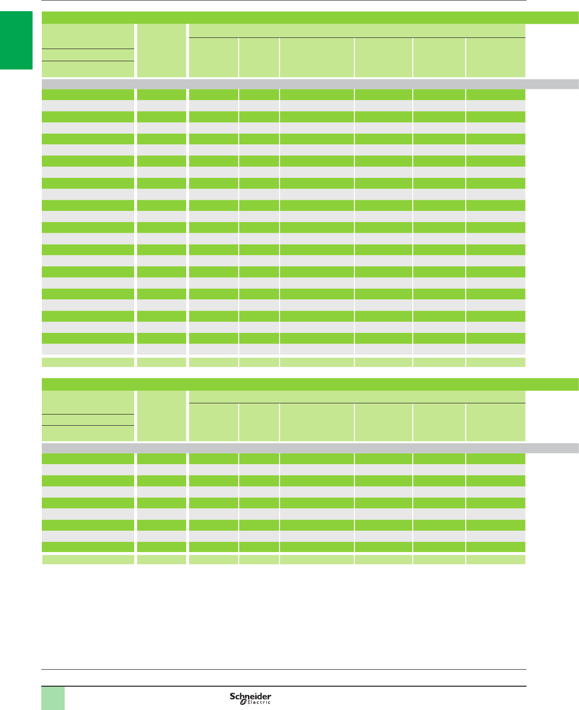
1/42
Combinations (continued) Variable speed drives
Altivar 61
500...690 V 50/60 Hz supply voltage
Variable speed drives:
page 1/16 Variants:
page 1/23 Accessories:
page 1/25 Options:
page 1/46
Table showing possible combinations of ATV61HpppY drive options
Motor Drive Options
Line choke Sinus
lter
Motor choke IP 20 kit for
motor choke Resistance
braking unit Braking
resistor Flush-mounting kit
(inside dust and damp proof
enclosure)
UL Type 1 conformity kit
(outside enclosure) IP 21 or IP 31
conformity kit (outside
enclosure)
Control card fan kit
500 V 575 V 690 V
kW HP kW
Three-phase supply voltage: 500…690 V 50/60 Hz
2.2 33ATV61HU30Y VW3A4551 – VW3A5102, 103, 104 VW3A9612 – VW3A7701 VW3A9506 VW3A9206 VW3A9106 VW3A9404
3–4ATV61HU40Y VW3A4552 – VW3A5102, 103, 104 VW3A9612 – VW3A7701 VW3A9506 VW3A9206 VW3A9106 VW3A9404
455.5 ATV61HU55Y VW3A4552 – VW3A5102, 103, 104 VW3A9612 – VW3A7701 VW3A9506 VW3A9206 VW3A9106 VW3A9404
5.5 7.5 7.5 ATV61HU75Y VW3A4552 – VW3A5102, 103, 104 VW3A9612 – VW3A7701 VW3A9506 VW3A9206 VW3A9106 VW3A9404
7.5 10 11 ATV61HD11Y VW3A4553 – VW3A5102, 103, 104 VW3A9612 – VW3A7702 VW3A9506 VW3A9206 VW3A9106 VW3A9404
11 15 15 ATV61HD15Y VW3A4553 – VW3A5103, 104 VW3A9612 – VW3A7702 VW3A9506 VW3A9206 VW3A9106 VW3A9404
15 20 18.5 ATV61HD18Y VW3A4554 – VW3A5103, 104 VW3A9612 – VW3A7703 VW3A9506 VW3A9206 VW3A9106 VW3A9404
18.5 25 22 ATV61HD22Y VW3A4554 – VW3A5103, 104 VW3A9612 – VW3A7703 VW3A9506 VW3A9206 VW3A9106 VW3A9404
22 30 30 ATV61HD30Y VW3A4555 – VW3A5103, 104 VW3A9612 – VW3A7704 VW3A9506 VW3A9206 VW3A9106 VW3A9404
30 40 37 ATV61HD37Y VW3A4555 – VW3A5104 VW3A9612 – VW3A7704 VW3A9509 VW3A9208 VW3A9108 VW3A9407
37 50 45 ATV61HD45Y VW3A4555 – VW3A5104 VW3A9612 – VW3A7704 VW3A9509 VW3A9208 VW3A9108 VW3A9407
45 60 55 ATV61HD55Y VW3A4556 – VW3A5104 VW3A9612 – VW3A7705 VW3A9509 VW3A9208 VW3A9108 VW3A9407
55 75 75 ATV61HD75Y VW3A4556 – VW3A5104 VW3A9612 – VW3A7705 VW3A9509 VW3A9208 VW3A9108 VW3A9407
75 100 90 ATV61HD90Y VW3A4556 – VW3A5104 VW3A9612 – VW3A7707 VW3A9509 VW3A9208 VW3A9108 VW3A9407
90 125 110 ATV61HC11Y VW3A4570 VW3A5212 VW3A5104 VW3A9612 – VW3A7806 VW3A9512 VW3A9211 VW3A9111 –
110 150 132 ATV61HC13Y VW3A4570 VW3A5212 VW3A5104 VW3A9612 – VW3A7806 VW3A9512 VW3A9211 VW3A9111 –
132 –160 ATV61HC16Y VW3A4571 VW3A5212 VW3A5104 VW3A9612 – VW3A7805 VW3A9512 VW3A9211 VW3A9111 –
160 200 200 ATV61HC20Y VW3A4571 VW3A5212 VW3A5105 VW3A9612 – VW3A7805 VW3A9512 VW3A9211 VW3A9111 –
200 250 250 ATV61HC25Y VW3A4560 VW3A5213 VW3A5105 VW3A9612 VW3A7103 VW3A7806 VW3A9514, 515 VW3A9213, 214 VW3A9113, 114 –
250 350 315 ATV61HC31Y VW3A4572 VW3A5213 VW3A5106 VW3A9613 VW3A7103 VW3A7716 VW3A9514, 515 VW3A9213, 214 VW3A9113, 114 –
315 450 400 ATV61HC40Y VW3A4572 VW3A5213 VW3A5106 VW3A9613 VW3A7103 VW3A7814 VW3A9514, 515 VW3A9213, 214 VW3A9113, 114 –
400 550 500 ATV61HC50Y VW3A4568 VW3A5214 VW3A5107 VW3A9613 VW3A7104 VW3A7717 – – VW3A9116 –
500 700 630 ATV61HC63Y VW3A4572 VW3A5214 VW3A5107 VW3A9613 VW3A7104 VW3A7718 – – VW3A9116 –
630 800 800 ATV61HC80Y VW3A4572 VW3A5214 VW3A5108 VW3A9613 VW3A7104 VW3A7816 – – VW3A9116 –
Page 1/21 1/68 1/87 1/84 1/85 1/60 1/63 1/25 1/26 1/27 1/30
Table showing possible combinations of ATV61QpppY drive options
Motor Drive Options
Line choke
(1 to 2 per
drive)
Sinus
lter
Motor choke IP 20 kit for
motor choke Resistance
braking unit Braking
resistor
(1 to 2 per
drive)
Flush-mounting kit
(inside dust and damp proof
enclosure)
UL Type 1 conformity kit
(outside enclosure) IP 21 or IP 31
conformity kit (outside
enclosure)
Control card fan kit
500 V 575 V 690 V
kW HP kW
Three-phase supply voltage: 500…690 V 50/60 Hz
110 150 132 ATV61QC13Y VW3A4570 – VW3A5104 VW3A9612 – VW3A7806 – – – –
132 –160 ATV61QC16Y VW3A4571 – VW3A5105 VW3A9612 – VW3A7805 – – – –
160 200 200 ATV61QC20Y VW3A4571 – VW3A5105 VW3A9612 – VW3A7805 – – – –
200 250 250 ATV61QC25Y VW3A4560 – VW3A5106 VW3A9612 VW3A7103 VW3A7806 – – – –
250 350 315 ATV61QC31Y VW3A4572 – VW3A5106 VW3A9612 VW3A7103 VW3A7716 – – – –
315 450 400 ATV61QC40Y VW3A4572 – VW3A5107 VW3A9613 VW3A7103 VW3A7814 – – – –
400 550 500 ATV61QC50Y VW3A4568 – VW3A5107 VW3A9613 VW3A7104 VW3A7717 – – – –
500 700 630 ATV61QC63Y VW3A4572 – VW3A5108 VW3A9613 VW3A7104 VW3A7718 – – – –
630 800 800 ATV61QC80Y VW3A4572 – VW3A5108 VW3A9613 VW3A7104 VW3A7816 – – – –
Page 1/22 1/68 –1/84 1/85 1/60 1/63 – – – –
Note: The quantity of certain required options varies according to the drive used. For more information, refer to pages 1/63 to 1/75.
2
1
3
4
5
6
7
8
9
10
2
1
3
4
5
6
7
8
9
10
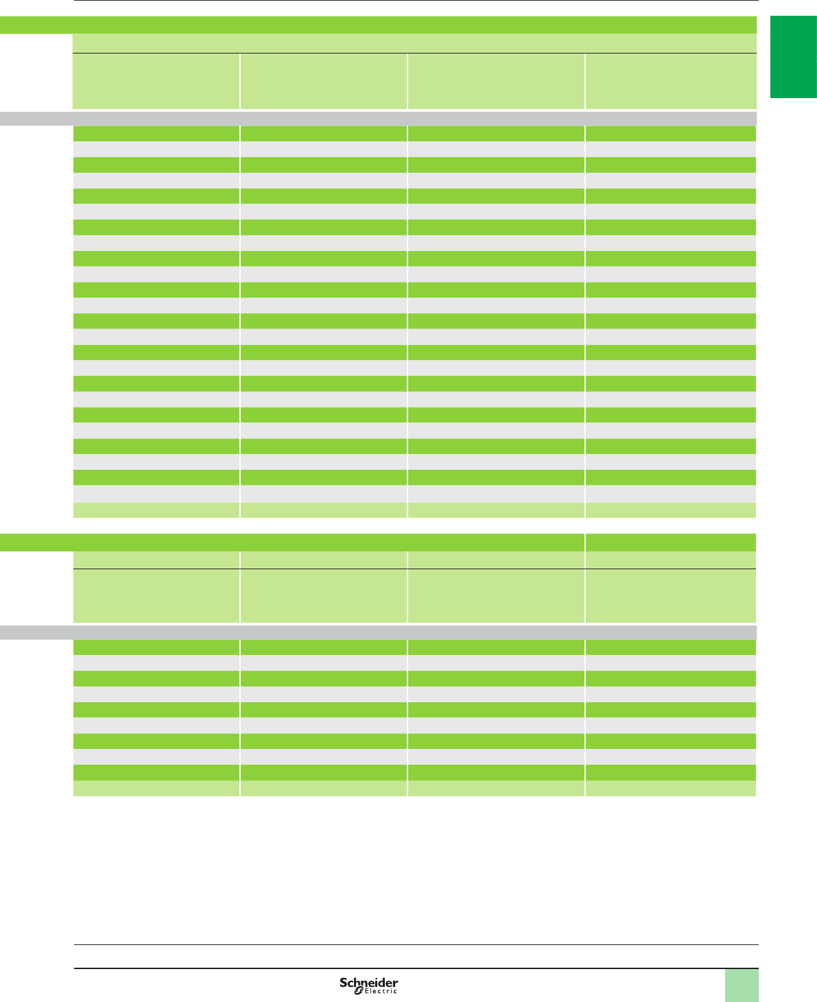
1/43
Table showing possible combinations of ATV61HpppY drive options
Motor Drive Options
Line choke Sinus
lter
Motor choke IP 20 kit for
motor choke Resistance
braking unit Braking
resistor Flush-mounting kit
(inside dust and damp proof
enclosure)
UL Type 1 conformity kit
(outside enclosure) IP 21 or IP 31
conformity kit (outside
enclosure)
Control card fan kit
500 V 575 V 690 V
kW HP kW
Three-phase supply voltage: 500…690 V 50/60 Hz
2.2 33ATV61HU30Y VW3A4551 – VW3A5102, 103, 104 VW3A9612 – VW3A7701 VW3A9506 VW3A9206 VW3A9106 VW3A9404
3–4ATV61HU40Y VW3A4552 – VW3A5102, 103, 104 VW3A9612 – VW3A7701 VW3A9506 VW3A9206 VW3A9106 VW3A9404
455.5 ATV61HU55Y VW3A4552 – VW3A5102, 103, 104 VW3A9612 – VW3A7701 VW3A9506 VW3A9206 VW3A9106 VW3A9404
5.5 7.5 7.5 ATV61HU75Y VW3A4552 – VW3A5102, 103, 104 VW3A9612 – VW3A7701 VW3A9506 VW3A9206 VW3A9106 VW3A9404
7.5 10 11 ATV61HD11Y VW3A4553 – VW3A5102, 103, 104 VW3A9612 – VW3A7702 VW3A9506 VW3A9206 VW3A9106 VW3A9404
11 15 15 ATV61HD15Y VW3A4553 – VW3A5103, 104 VW3A9612 – VW3A7702 VW3A9506 VW3A9206 VW3A9106 VW3A9404
15 20 18.5 ATV61HD18Y VW3A4554 – VW3A5103, 104 VW3A9612 – VW3A7703 VW3A9506 VW3A9206 VW3A9106 VW3A9404
18.5 25 22 ATV61HD22Y VW3A4554 – VW3A5103, 104 VW3A9612 – VW3A7703 VW3A9506 VW3A9206 VW3A9106 VW3A9404
22 30 30 ATV61HD30Y VW3A4555 – VW3A5103, 104 VW3A9612 – VW3A7704 VW3A9506 VW3A9206 VW3A9106 VW3A9404
30 40 37 ATV61HD37Y VW3A4555 – VW3A5104 VW3A9612 – VW3A7704 VW3A9509 VW3A9208 VW3A9108 VW3A9407
37 50 45 ATV61HD45Y VW3A4555 – VW3A5104 VW3A9612 – VW3A7704 VW3A9509 VW3A9208 VW3A9108 VW3A9407
45 60 55 ATV61HD55Y VW3A4556 – VW3A5104 VW3A9612 – VW3A7705 VW3A9509 VW3A9208 VW3A9108 VW3A9407
55 75 75 ATV61HD75Y VW3A4556 – VW3A5104 VW3A9612 – VW3A7705 VW3A9509 VW3A9208 VW3A9108 VW3A9407
75 100 90 ATV61HD90Y VW3A4556 – VW3A5104 VW3A9612 – VW3A7707 VW3A9509 VW3A9208 VW3A9108 VW3A9407
90 125 110 ATV61HC11Y VW3A4570 VW3A5212 VW3A5104 VW3A9612 – VW3A7806 VW3A9512 VW3A9211 VW3A9111 –
110 150 132 ATV61HC13Y VW3A4570 VW3A5212 VW3A5104 VW3A9612 – VW3A7806 VW3A9512 VW3A9211 VW3A9111 –
132 –160 ATV61HC16Y VW3A4571 VW3A5212 VW3A5104 VW3A9612 – VW3A7805 VW3A9512 VW3A9211 VW3A9111 –
160 200 200 ATV61HC20Y VW3A4571 VW3A5212 VW3A5105 VW3A9612 – VW3A7805 VW3A9512 VW3A9211 VW3A9111 –
200 250 250 ATV61HC25Y VW3A4560 VW3A5213 VW3A5105 VW3A9612 VW3A7103 VW3A7806 VW3A9514, 515 VW3A9213, 214 VW3A9113, 114 –
250 350 315 ATV61HC31Y VW3A4572 VW3A5213 VW3A5106 VW3A9613 VW3A7103 VW3A7716 VW3A9514, 515 VW3A9213, 214 VW3A9113, 114 –
315 450 400 ATV61HC40Y VW3A4572 VW3A5213 VW3A5106 VW3A9613 VW3A7103 VW3A7814 VW3A9514, 515 VW3A9213, 214 VW3A9113, 114 –
400 550 500 ATV61HC50Y VW3A4568 VW3A5214 VW3A5107 VW3A9613 VW3A7104 VW3A7717 – – VW3A9116 –
500 700 630 ATV61HC63Y VW3A4572 VW3A5214 VW3A5107 VW3A9613 VW3A7104 VW3A7718 – – VW3A9116 –
630 800 800 ATV61HC80Y VW3A4572 VW3A5214 VW3A5108 VW3A9613 VW3A7104 VW3A7816 – – VW3A9116 –
Page 1/21 1/68 1/87 1/84 1/85 1/60 1/63 1/25 1/26 1/27 1/30
Table showing possible combinations of ATV61QpppY drive options
Motor Drive Options
Line choke
(1 to 2 per
drive)
Sinus
lter
Motor choke IP 20 kit for
motor choke Resistance
braking unit Braking
resistor
(1 to 2 per
drive)
Flush-mounting kit
(inside dust and damp proof
enclosure)
UL Type 1 conformity kit
(outside enclosure) IP 21 or IP 31
conformity kit (outside
enclosure)
Control card fan kit
500 V 575 V 690 V
kW HP kW
Three-phase supply voltage: 500…690 V 50/60 Hz
110 150 132 ATV61QC13Y VW3A4570 – VW3A5104 VW3A9612 – VW3A7806 – – – –
132 –160 ATV61QC16Y VW3A4571 – VW3A5105 VW3A9612 – VW3A7805 – – – –
160 200 200 ATV61QC20Y VW3A4571 – VW3A5105 VW3A9612 – VW3A7805 – – – –
200 250 250 ATV61QC25Y VW3A4560 – VW3A5106 VW3A9612 VW3A7103 VW3A7806 – – – –
250 350 315 ATV61QC31Y VW3A4572 – VW3A5106 VW3A9612 VW3A7103 VW3A7716 – – – –
315 450 400 ATV61QC40Y VW3A4572 – VW3A5107 VW3A9613 VW3A7103 VW3A7814 – – – –
400 550 500 ATV61QC50Y VW3A4568 – VW3A5107 VW3A9613 VW3A7104 VW3A7717 – – – –
500 700 630 ATV61QC63Y VW3A4572 – VW3A5108 VW3A9613 VW3A7104 VW3A7718 – – – –
630 800 800 ATV61QC80Y VW3A4572 – VW3A5108 VW3A9613 VW3A7104 VW3A7816 – – – –
Page 1/22 1/68 –1/84 1/85 1/60 1/63 – – – –
Note: The quantity of certain required options varies according to the drive used. For more information, refer to pages 1/63 to 1/75.
Variable speed drives:
page 1/16 Variants:
page 1/23 Accessories:
page 1/25 Options:
page 1/46
2
1
3
4
5
6
7
8
9
10
2
1
3
4
5
6
7
8
9
10

1/44
Combinations (continued) Variable speed drives
Altivar 61
List of options common to Altivar 61 drives
Description Reference Page
Logic input adaptor
Adaptor for 115 V a logic inputs VW3A3101 1/29
HMI terminal
Remote graphic display terminal VW3A1101 1/31
Encoder interface cards (1)
With RS 422 compatible differential outputs VW3A3401 1/46
With open collector outputs VW3A3403, 404 1/46
With push-pull outputs VW3A3405…407 1/46
I/O expansion cards (1)
Logic VW3A3201 1/47
Extended VW3A3202 1/47
Multi-pump cards (1)
Multi-pump card VW3A3502 1/49
Water solution multi-pump card VW3A3503 1/49
Programmable card (1)
Controller Inside programmable card VW3A3501 1/53
SoMove setup software
SoMove setup software Available on our website www.schneider-electric.com
List of communication cards (1)
Description Reference Page
Modbus TCP Daisy Chain VW3A3310D 1/58
EtherNet/IP VW3A3316 1/58
EtherNet/IP (RSTP) VW3A3320 1/58
DeviceNet VW3A3309 1/58
InterBus VW3A3304 1/58
CC-LInk VW3A3317 1/58
Modbus/Uni-Telway VW3A3303 1/58
PROFIBUS DP V0 VW3A3307 1/59
PROFIBUS DP V1 VW3A3307S371 1/59
LonWorks VW3A3312 1/59
METASYS N2 VW3A3313 1/59
APOGEE FLN VW3A3314 1/59
BACnet VW3A3319 1/59
Pronet VW3A3327 1/59
EtherCAT VW3A3326 1/59
Ethernet POWERLINK VW3A3321 1/59
(1) For card compatibility table, see opposite.
Variable speed drives:
page 1/16 Variants:
page 1/23 Accessories:
page 1/25 Options:
page 1/46
2
1
3
4
5
6
7
8
9
10
2
1
3
4
5
6
7
8
9
10

1/45
Combinations (continued) Variable speed drives
Altivar 61
Card compatibility table (1)
Type of card Encoder
interface
VW3A340p
Logic I/O
VW3A3201 Extended I/O
VW3A3202 Multi-pump
VW3A3502, 503 Programmable
Controller inside
VW3A3501
Communication
VW3A33pp
Encoder interface
VW3A340p
Logic I/O
VW3A3201
Extended I/O
VW3A3202
Multi-pump
VW3A3502, 503
Programmable Controller inside
VW3A3501
Communication
VW3A33pp
Combination possible
Combination not possible
(1) Maximum combination involving two types of card is 2.
Variable speed drives:
page 1/16 Variants:
page 1/23 Accessories:
page 1/25 Options:
page 1/46
2
1
3
4
5
6
7
8
9
10
2
1
3
4
5
6
7
8
9
10
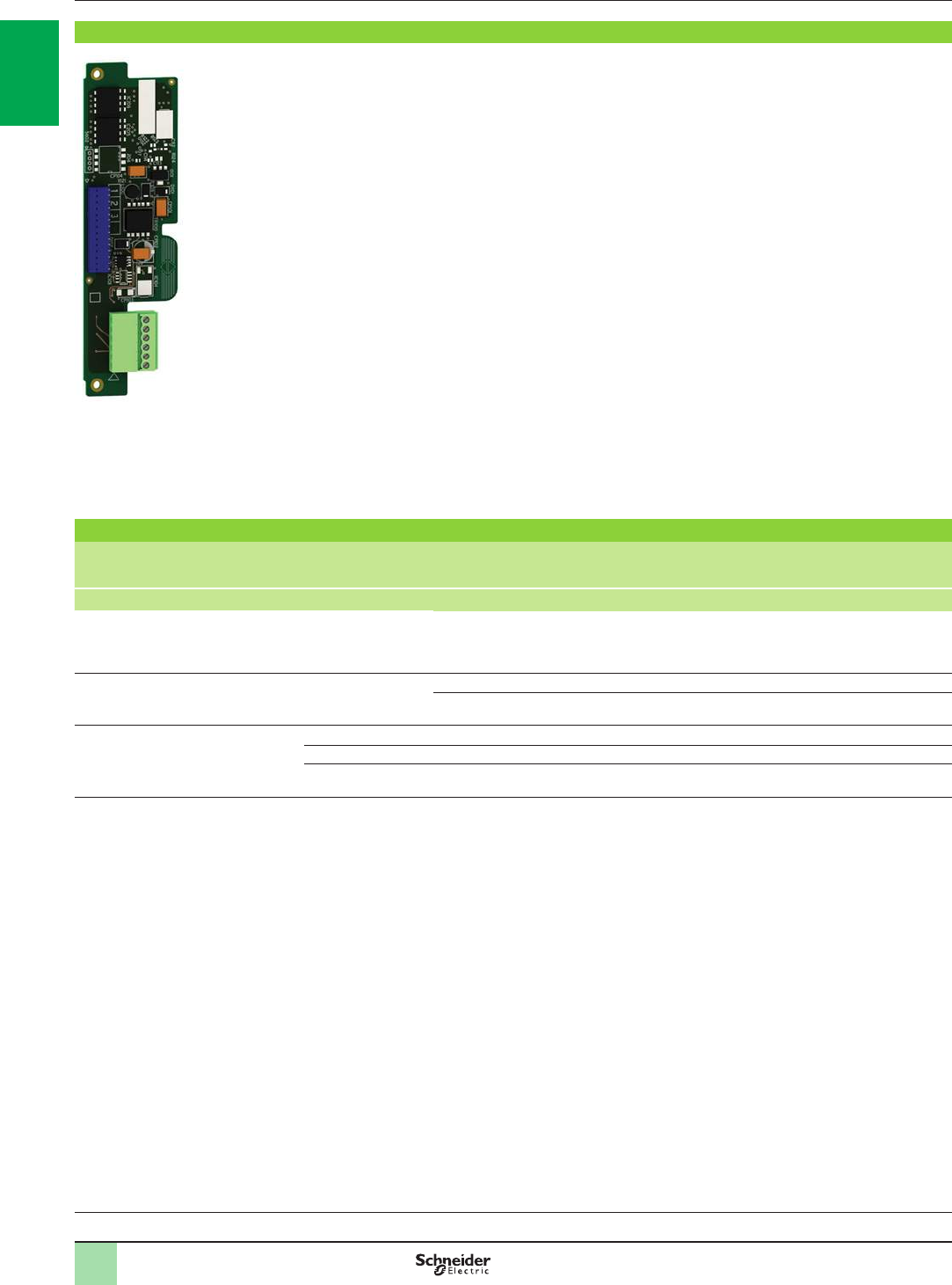
1/46
Variable speed drives
Altivar 61
Option: Encoder interface cards
Presentation,
references
Presentation
Encoder interface cards are used for machine safety, irrespective of the control type:
b�Overspeed detection
b�Load slip detection
Three types of card are available depending on the encoder technology:
b�RS 422 compatible differential outputs
b�Open collector outputs (NPN)
b�Push-pull outputs
The Altivar 61 variable speed drive can only take one encoder interface card. Please
refer to the card compatibility table on page 1/45.
The interface encoder card is inserted in a dedicated slot.
It is protected against short circuits and overloads.
References
Description Used with
encoder
(1)
Voltage Maximum
current Maximum
cable
length
Maximum
operating
frequency
Reference Weight
V mA m kHz kg
Encoder interface card with RS422
compatible differential outputs XCC1pppppppX
XCC1pppppppR
XCC1pppppppRN
5 200 50 300 VW3A3401 0.200
Encoder interface cards with
open collector outputs – 12 175 500 300 VW3A3403 0.200
15 175 500 300 VW3A3404 0.200
Encoder interface cards with
push-pull outputs XCC1pppppppY 12 175 500 300 VW3A3405 0.200
XCC1pppppppK 15 175 500 300 VW3A3406 0.200
XCC1pppppppKN 24 100 500 300 VW3A3407 0.200
(1) To determine the complete encoder reference, please refer to the “Detection for automation solutions - OsiSense” catalogue or our website
www.schneider-electric.com.
Drive/option combinations:
pages 1/34 to 1/45
PF121623
VW3A3401 encoder interface card
2
1
3
4
5
6
7
8
9
10
2
1
3
4
5
6
7
8
9
10
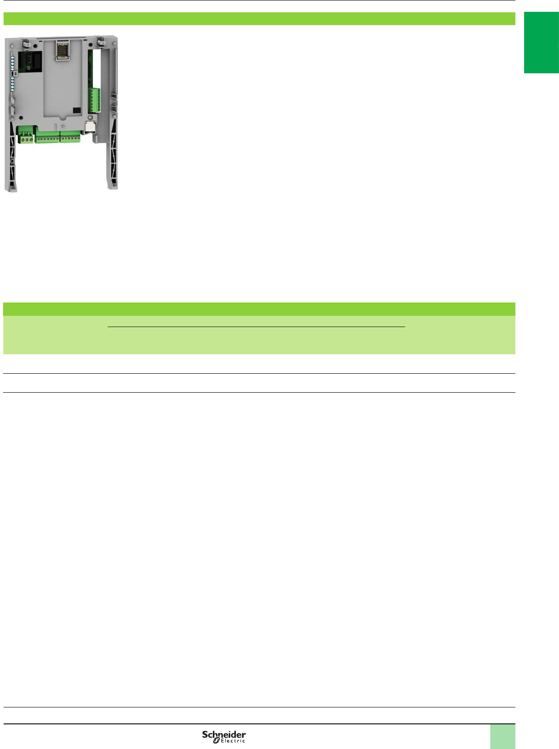
1/47
Presentation,
references
1
Variable speed drives
Altivar 61
Option: I/O expansion cards
Presentation
Altivar 61 variable speed drives can be adapted for more complex or extensive
applications by installing I/O expansion cards.
Two models are available:
b Card with logic I/O featuring:
v 1 relay logic output (“C/O” contact)
v 4 x 24 V c positive or negative logic inputs
v 2 x 24 V c positive or negative logic open collector outputs
v 1 input for 6 PTC probes (1)
b Card with extended I/O featuring:
v 1 differential current analog input 0...20 mA
v 1 software-congurable voltage (c 0...10 V) or current (0...20 mA) analog input
v 2 software-congurable voltage (± 10 V c, 0...10 V) or current (0...20 mA) analog
outputs
v 1 relay logic output
v 4 x 24 V c positive logic (Source) or negative logic (Sink) inputs
v 2 x 24 V c positive or negative logic open collector outputs
v 1 input for 6 PTC probes
v 1 frequency control input
The Altivar 61 variable speed drive can only take one I/O expansion card with the
same reference.
Please refer to the card compatibility table on page 1/45.
References
Designation Type of I/O Reference Weight
kg
Logic
input Logic
output Analog
input Analog
output Input for
PTC probes
(1)
Frequency
control input
Logic I/O card 4 3 – – 1 – VW3A3201 0.300
Extended I/O card 4 3 2 2 1 1 VW3A3202 0.300
(1) This PTC probe input must never be used to protect an ATEX motor in applications in explosive atmospheres. Please refer to the ATEX guide which is available
on our website www.schneider-electric.com.
VW3A3202 extended I/O card
PF121620
Drive/option combinations:
pages 1/34 to 1/45
2
1
3
4
5
6
7
8
9
10
2
1
3
4
5
6
7
8
9
10
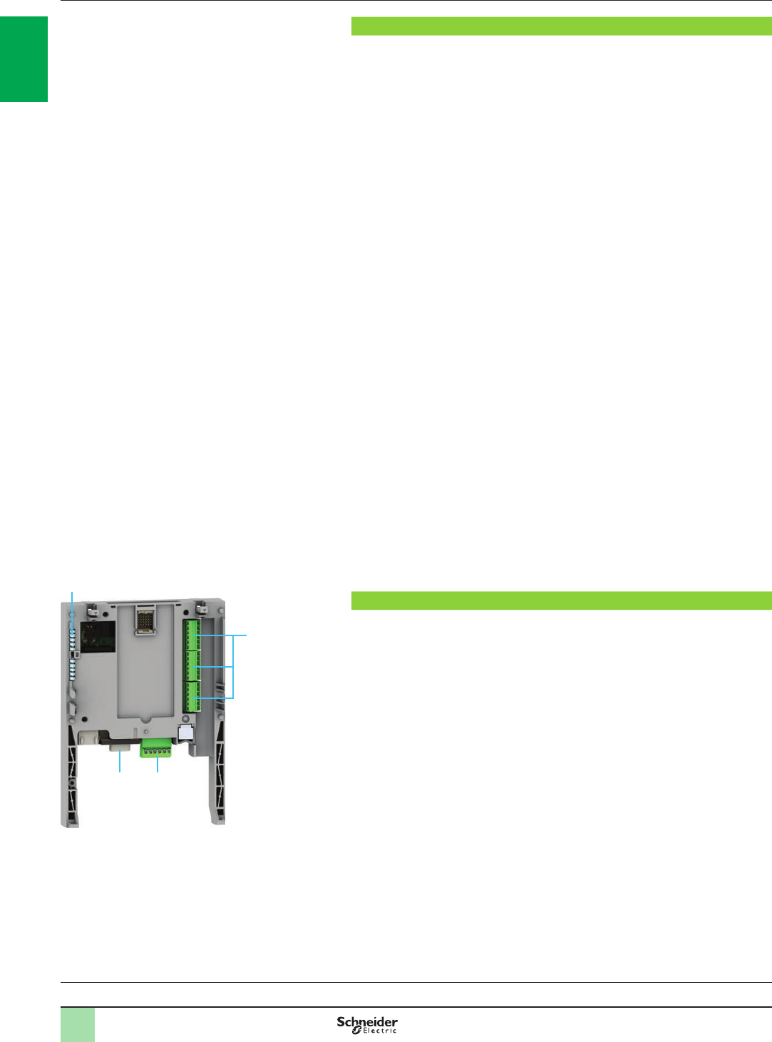
1/48
Presentation
The Altivar 61 drive provides an automation solution that is ideal for the requirements
of water treatment:
b It incorporates all the application functions for managing your pumps, such as
sleep, wake-up, zero ow detection, uid absence detection, underload or overload
detection and PID regulator.
b It is used to adjust the operating point of pumps using control proles.
b It protects your pumps:
motor thermal protection, PTC management, low speed detection and time delay
Multi-pump cards can adapt drive operation to the specic requirements of the
installation.
They reduce costs and increase the service life of equipment by intelligently
managing the operating time of each pump.
Various predened congurable applications are sold by Schneider Electric and
its partners.
In order to protect our know-how, it is not possible to transfer the program from the
card to a PC.
A single multi-pump card can be installed in the Altivar 61. It can be combined with
another option card (I/O expansion or communication). Please refer to the card
compatibility table on page 1/45.
Each multi-pump card consists of:
b 10 x 24 V c logic inputs, 2 of which can be used for 2 counters or 4 of which can
be used for 2 incremental encoders
b 2 x 0…20 mA current analog inputs, impedance 250 W
b 6 x 24 V c positive logic (Source) open collector outputs
b 2 x 0…20 mA current analog outputs, impedance 500 W
b A master port for the CANopen machine bus
If the power consumption does not exceed 200 mA, this card can be powered by
ATV61Hppppp drives. Otherwise, an external 24 V c power supply must be used.
ATV61WpppN4A24 drives incorporate a 24 V c power supply, allowing additional
consumption of 250 mA.
Note: It is recommended that an OsiSense XM electronic pressure sensor, type XML F or
XML G, is added to the installation. Please consult our “Detection for automation solutions -
OsiSense” catalogue or our website www.schneider-electric.com.
Description
1 9-way male SUB-D connector for connection to the CANopen machine bus
2 Connector with removable screw terminals, 6 contacts at intervals of 3.81 for the
24 V c power supply and 4 logic inputs
3 3 connectors with removable screw terminals, 6 contacts at intervals of 3.81 for
6 logic inputs, 6 logic outputs, 2 analog inputs, 2 analog outputs and 2 commons
4 5 LEDs:
b 1 to indicate the presence of the 24 V c power supply
b 1 to indicate a program execution fault
b 2 to indicate the CANopen machine bus communication status
b 1 controlled by the application program
Variable speed drives
Altivar 61
Option: Multi-pump cards
Presentation,
description
Drive/option combinations:
pages 1/34 to 1/45
3
1 2
4
PF095312
2
1
3
4
5
6
7
8
9
10
2
1
3
4
5
6
7
8
9
10
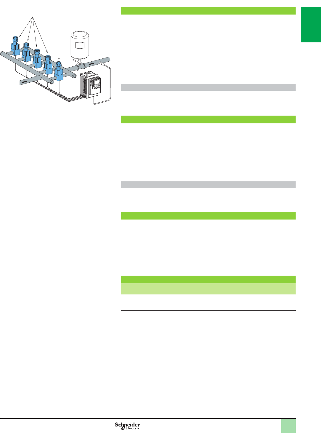
1/49
VW3A3502 multi-pump card
The VW3A3502 multi-pump card ensures compatibility of pump applications
developed for an Altivar 38 drive with an Altivar 61, without reprogramming.
With this card, a complete pumping installation (up to 5 pumps) can be controlled
with a single drive, providing constant pressure.
It incorporates the following operating modes:
b Single or multiple variable
b Single or multiple variable with changeover of auxiliary pumps
b Single or multiple variable with limitation of operating time between pumps
These last two operating modes can be combined.
Applications
It is specially designed for applications such as:
b Constant pressure water distribution and pumping systems
b Booster stations
VW3A3503 Water solution multi-pump card
The VW3A3503 multi-pump card is not compatible with pump applications
developed for an Altivar 38 drive.
With this card, a complete pumping installation (up to 4 pumps) can be controlled
with a single drive, providing constant pressure.
It incorporates the single variable function as well as the Jockey management
function which is primarily used to manage booster or priming pumps. It also
compensates for losses in installations.
Applications
It is specially designed for applications such as:
b Irrigation stations
b Sprinkling stations
Continuity of service for your installation
If a pump is faulty (information on the LIx logic input) it is not taken into account and
the start and stop conditions are provided by the other pumps.
Each pump can:
b Display the operating time
b Reset the counter
b Save the operating times
Each card also incorporates an OFF mode, used during maintenance operations.
References
Description Reference Weight
kg
Multi-pump card Equipped with one
9-way male SUB-D connector VW3A3502 0.320
Water solution
multi-pump card Equipped with one
9-way male SUB-D connector VW3A3503 0.320
Variable speed drives
Altivar 61
Option: Multi-pump cards
Description (continued),
references
Drive/option combinations:
pages 1/34 to 1/45
Example conguration of a pumping system with the
VW3A3502 multi-pump card
Variable speed
pump
Fixed speed
auxiliary pumps
2
1
3
4
5
6
7
8
9
10
2
1
3
4
5
6
7
8
9
10
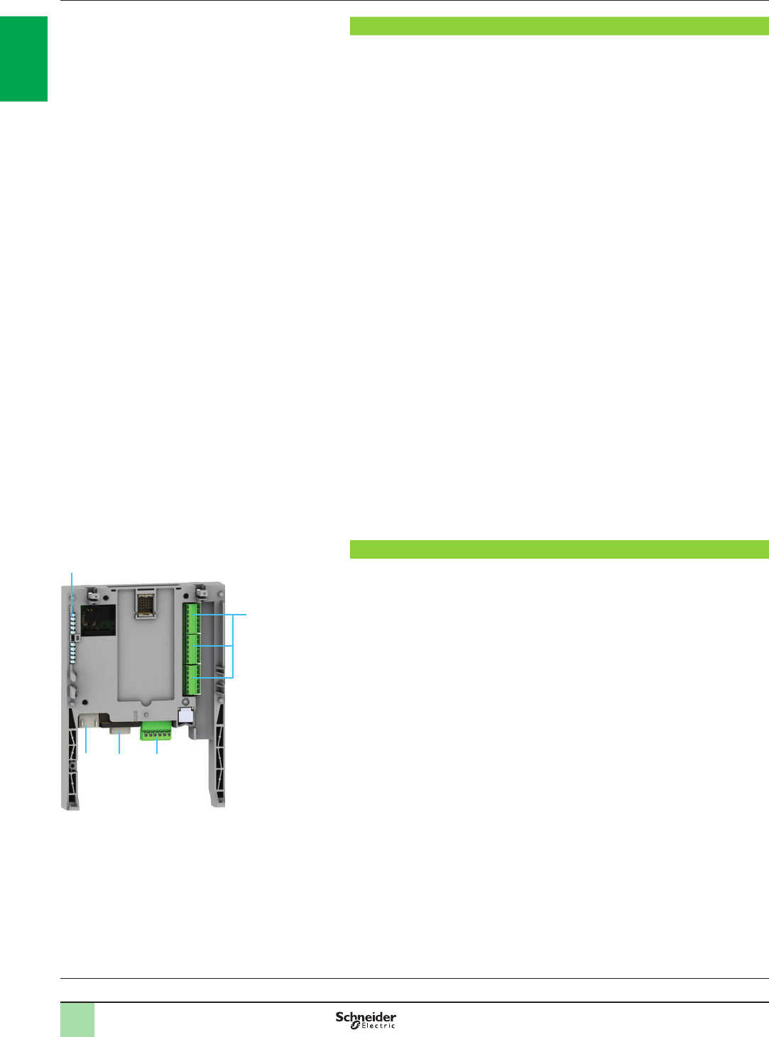
1/50
Presentation
The Controller Inside programmable card is used to adapt the variable speed drive to
specic applications by integrating control system functions.
Various predened congurable applications are sold by Schneider Electric and its
partners.
The PS 1131 software workshop is used for programming and debugging new
applications, quickly and in an open-ended manner in accordance with standard
IEC 61131-3.
It is not possible to transfer the program from the card to the PC, therefore know-how
is protected.
A single Controller Inside programmable card can be installed in the Altivar 61 drive.
It can be combined with another option card (I/O expansion or communication).
Please refer to the card compatibility table on page 1/45.
The Controller Inside programmable card features:
b 10 x 24 V c logic inputs, 2 of which can be used for 2 counters or 4 of which can
be used for 1 incremental encoder and/or 3 counters
b 2 x 0…20 mA current analog inputs, impedance 500 W
b 6 x 24 V c positive logic (Source) open collector outputs
b 2 x 0…20 mA current analog inputs, impedance 500 W
b A master port for the CANopen machine bus, for controlling other drives and
communication with I/O modules and sensors
b A PC port for programming using the PS 1131 software workshop
If the power consumption does not exceed 200 mA, the Controller Inside
programmable card can be powered by Altivar 61 drives. Otherwise, an external
24 V c power supply must be used.
ATV61WpppN4A24 drives incorporate a 24 V c power supply, allowing additional
consumption of 250 mA.
The Controller Inside programmable card can also use:
b The drive I/O
b The I/O expansion card I/O
b The encoder interface card points counter
b The drive parameters (speed, current, torque, etc.)
Description
1 RJ45 connector for connecting the PS1131 software workshop via an RS 485
serial link
Connection to the PC is via a cable and RS 232/RS 485 converter included in the
PC serial port connection kit, VW3 A8 106.
2 9-way male SUB-D connector for connection to the CANopen machine bus
3 Connector with removable screw terminals, 6 contacts at intervals of 3.81 for the
24 V c power supply and 4 logic inputs
4 3 connectors with removable screw terminals, 6 contacts at intervals of 3.81 for
6 logic inputs, 6 logic outputs, 2 analog inputs, 2 analog outputs and 2 commons
5 5 LEDs:
b 1 to indicate the presence of the 24 V c power supply
b 1 to indicate a program execution fault
b 2 to indicate the CANopen machine bus communication status
b 1 controlled by the application program
Variable speed drives
Altivar 61
Option: Controller Inside programmable card
Presentation,
description
Drive/option combinations:
pages 1/34 to 1/45
12 3
5
4
PF095312
2
1
3
4
5
6
7
8
9
10
2
1
3
4
5
6
7
8
9
10
1/51
Dialogue
Human-machine dialogue with the application programmed in the Controller Inside
programmable card is possible using:
b The Altivar 61 graphic display terminal: the graphic terminal has a menu dedicated
to the Controller Inside programmable card. This menu can be customized by the
program depending on the application.
b A Magelis industrial HMI terminal, connected to:
- The drive's Modbus port
- The Modbus TCP network, if the drive is equipped with a Modbus TCP
communication card
Any industrial HMI terminal which supports the Modbus protocol can be used to
display and modify the Controller Inside programmable card parameters.
Master CANopen communication
The master CANopen port on the Controller Inside programmable card can be used
to extend the I/O capacity and to control other CANopen slave devices.
Communication with a PLC
An Altivar 61 drive equipped with a Controller Inside programmable card integrates
easily into complex architectures.
Regardless of which bus, network or serial link is being used (Modbus TCP, Modbus/
Uni-Telway, PROFIBUS DP, InterBus, etc.), the PLC can communicate with the
Controller Inside programmable card and the drive.
The periodic variables can still be congured as required.
Clock
A clock backed up by a lithium battery makes it possible to keep a log of events.
When the Controller Inside programmable card is installed in the drive, drive faults
are automatically time and date-stamped without any special programming.
(1) Please refer to the “Modicon M340 Automation Platform” catalogue.
Sensors
Magelis XBT
ATV61
Modbus
serial link
Independent machine with multiwire system
ATV312 ATV312 Advantys STB
distributed I/O FTB 1CN
ATV61
CANopen machine bus
Independent machine with CANopen bus
Magelis XBT
Sensors ATV312 FTB1CN
Modbus TCP network
Modicon M340 (1)
ATV61ATV61
Magelis XBT
Modular machine with Modbus TCP network
Variable speed drives
Altivar 61
Option: Controller Inside programmable card
Presentation (continued)
XCC
encoder
XCC
encoder
Drive/option combinations:
pages 1/34 to 1/45
2
1
3
4
5
6
7
8
9
10
2
1
3
4
5
6
7
8
9
10
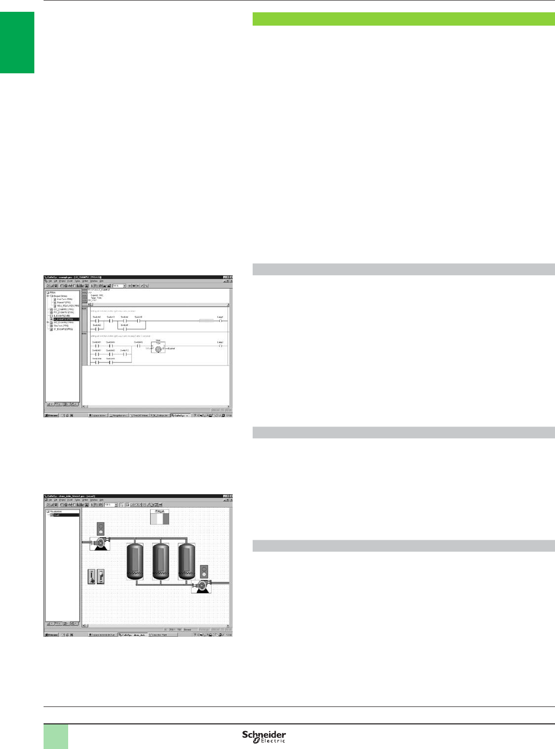
1/52
PS 1131 software workshop
The PS 1131 software workshop conforms to international standard IEC/EN 61131-3
and includes all the functions for programming and setting up the Controller Inside
programmable card.
It includes the CANopen congurator.
It is designed for Microsoft Windows® 98, Microsoft Windows® NT 4.0, Microsoft
Windows® Millennium, Microsoft Windows® 2000 Professional and Microsoft
Windows® XP operating systems.
It benets from the user-friendly interface associated with these operating systems:
b Pop-up menus
b Function blocks
b Online help
The PS 1131 software workshop is available in both English and German.
The programming and debugging tools can be accessed via the application
browser. This provides the user with an overview of the program and quick access
to all the application components:
b Program editor
b Function blocks editor
b Variables editor
b Animation tables editor
b Runtime screens editor
Modular structured programming
The PS 1131 software workshop is used to structure an application into function
modules consisting of sections (program code), animation tables and runtime
screens.
Each program section has a name and is programmed in one of six available
languages:
b Ladder Diagram (LD)
b Structured Text (ST)
b Grafcet (SFC)
b Instruction List (IL)
b Function Block Diagram (FBD)
b Continuous Flow Chart (CFC)
To protect know-how or prevent any accidental modication, each section can be
write-protected or read/write-protected.
Function blocks
The PS 1131 software workshop features pre-programmed function blocks which
make up the standard library.
Exchanges with the drive are performed by a function block available in the standard
library.
The software workshop also offers users the option of creating their own function
blocks and thus creating a user library.
The user library is also a means of protecting the know-how contained in the
algorithms, as it is possible to lock access to the user function blocks program.
Debugging tools
The PS 1131 software workshop offers a complete set of tools for debugging the
application:
bProgram execution for debugging (step-by-step execution, execution of a single
cycle, etc.)
bRealtime animation of the program with automatic display of the variables
b Animation tables editor with the option of saving them
b Oscilloscope (monitoring up to 20 variables)
b Application runtime screens editor (graphic objects, messages, screen
backgrounds, etc.)
b Simulation function for testing the program without using the drive
Ladder language programming example
Variable speed drives
Altivar 61
Option: Controller Inside programmable card
Presentation (continued)
Example runtime screen
Drive/option combinations:
pages 1/34 to 1/45
2
1
3
4
5
6
7
8
9
10
2
1
3
4
5
6
7
8
9
10
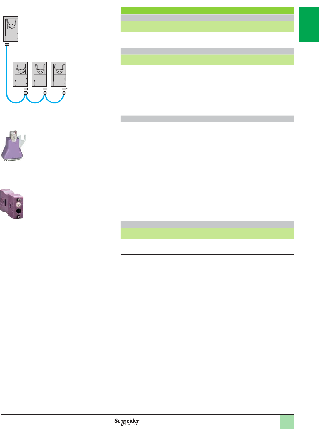
1/53
References
Card
Description Reference Weight
kg
Controller Inside programmable card
equipped with one 9-way male SUB-D connector VW3A3501 0.320
Connection accessories
Description Item no. Length
mWeight
kg
CANopen adaptor for mounting
on the RJ45 socket in the drive
control terminals.
The adaptor provides a 9-way male
SUB-D connector conforming to the
CANopen standard (CIA DRP 303-1)
1–VW3CANA71 –
CANopen connector
9-way female SUB-D with line
terminator (can be disabled)
2–TSXCANKCDF180T –
Cables
CANopen cables
Standard cable, e marking.
Low smoke zero halogen.
Flame retardant (IEC 60332-1).
350 TSXCANCA50 4.930
100 TSXCANCA100 8.800
300 TSXCANCA300 24.560
CANopen cables
UL certied, e marking.
Flame retardant
(IEC 60332-2).
350 TSXCANCB50 3.580
100 TSXCANCB100 7.840
300 TSXCANCB300 21.870
CANopen cables
Cable for harsh environments (1) or
mobile installations, e marking.
Low smoke zero halogen. Flame
retardant (IEC 60332-1).
350 TSXCANCD50 3.510
100 TSXCANCD100 7.770
300 TSXCANCD300 21.700
PS 1131 software workshop
Description Reference Weight
kg
PS 1131 software workshop
supplied on CD-ROM (2) –
PC serial port connection kit
including various accessories such as:
b One 3 m cable with two RJ45 connectors
b One RS 232/RS 485 converter with one 9-way female
SUB-D connector and one RJ45 connector
VW3A8106 0.350
(1) Harsh environments:
- Resistance to hydrocarbons, industrial oils, detergents, solder splashes
- Relative humidity up to 100%
- Saline atmosphere
- Signicant temperature variations
- Operating temperature between - 10°C and + 70°C
(2) The product reference is provided during the Controller Inside programmable card training
course. Consult your Customer Care Centre.
1
2
2
3
Master/slave application
ATV61 (master drive)
+ VW3A3501 card
537199
CANopen machine bus
ATV61 (slave drives)
VW3CANA71
PF121625
Variable speed drives
Altivar 61
Option: Controller Inside programmable card
References
TSXCANKCDF180T
PF105504
Drive/option combinations:
pages 1/34 to 1/45
2
1
3
4
5
6
7
8
9
10
2
1
3
4
5
6
7
8
9
10
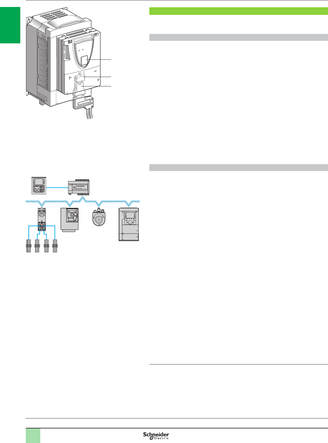
1/54
Presentation
Presentation
The Altivar 61 drive has been designed to meet all the conguration requirements
encountered within the context of networked industrial installations.
Integrated communication protocols
It includes Modbus and CANopen communication protocols as standard.
Two integrated communication ports enable direct access to the Modbus protocol:
b One RJ45 Modbus terminal port 1 located on the drive front panel, which is used
to connect a Human Machine Interface or one of the following conguration tools:
v Remote graphic display terminal
v Magelis industrial HMI terminal
v SoMove setup software
v Simple Loader and Multi-Loader conguration tools
b One RJ45 Modbus network port 2 located on the drive's control terminals
This is assigned to control and signalling by a PLC or by another type of controller.
It can also be used to connect a terminal or the SoMove setup software.
The CANopen protocol can be accessed from the Modbus network port 2 via the
CANopen adaptor 3. In this case, terminal port 1 must be used to access the Modbus
protocol.
The characteristics of the communication ports for Modbus and CANopen protocols
are available on our website www.schneider-electric.com.
Optional communication cards
By adding one of the communication cards available as options, the Altivar 61 drive
can also be connected to other communication networks and buses used in various
application areas, such as industry and building management (HVAC) (1).
Communication cards for industrial applications:
bModbus TCP Daisy Chain
bModbus/Uni-Telway (this card provides access to additional functions, which
complement those of the integrated ports (Modbus ASCII and 4-wire RS 485))
bEthernet/IP
bDeviceNet
bPROFIBUS DP V0 and V1
bInterBus
bCC-LInk
bEthernet POWERLINK
Communication cards for building applications (HVAC):
bLonWorks
bMETASYS N2
bAPOGEE FLN
bBACnet
The option of powering the control part separately enables communication to be
maintained (monitoring, diagnostics) even if there is no power supply to the power
part.
The main communication functions of Altivar 38 drives are compatible with the
Altivar 61 drive (2):
bConnection
bCommunication services
bDrive behaviour (prole)
bControl and monitoring parameters
bStandard adjustment parameters
(1) Heating, Ventilation and Air Conditioning.
(2) Please refer to the ATV38/ATV61 Substitution Guide supplied on the documentation
CD-ROM.
Variable speed drives
Altivar 61
Communication buses and networks
Example conguration on CANopen machine bus
Sensors
M238 logic controller
Magelis XBT
ATV312
Osicoder
encoder
ATV61
600267
Drive/option combinations:
pages 1/34 to 1/45
1
2
3
537201
Integrated communication for Modbus and CANopen protocols
2
1
3
4
5
6
7
8
9
10
2
1
3
4
5
6
7
8
9
10

1/55
Presentation (continued) Variable speed drives
Altivar 61
Communication buses and networks
Drive/option combinations:
pages 1/34 to 1/45
Functions
All drive functions can be accessed via the network:
bConguration
bAdjustment
bControl
bMonitoring
The Altivar 61 drive's advanced functions provide excellent interfacing exibility. They enable the different control
sources (I/O, communication networks, communication cards and HMI terminal) to be assigned to control
functions that satisfy the requirements of numerous, extremely complex applications.
Network conguration is simplied through the provision of conguration software (congurator for SyCon®
networks, etc.).
For the integrated Modbus and CANopen ports and for communication cards for industrial applications, the
Altivar 61 drive can be controlled:
bAccording to the CiA 402 prole
bAccording to the I/O prole where control is as simple and adaptable as control via the I/O terminals
The DeviceNet card also supports CIP AC Drive and Allen-Bradley drive proles; PROFIBUS DP V0 and V1 cards
also support the PROFIdrive prole.
Communication is monitored according to the specic criteria for each protocol. However, regardless of the
protocol, it is possible to congure the drive reaction to a communication fault:
bFreewheel stop, stop on ramp, fast stop or braked stop
bMaintain last command received
bFallback position at a predened speed
bIgnore the fault
A command from the CANopen machine bus is processed with the same priority as one of the drive terminal
inputs. This results in excellent response times on the network port via the CANopen adaptor.
2
1
3
4
5
6
7
8
9
10
2
1
3
4
5
6
7
8
9
10
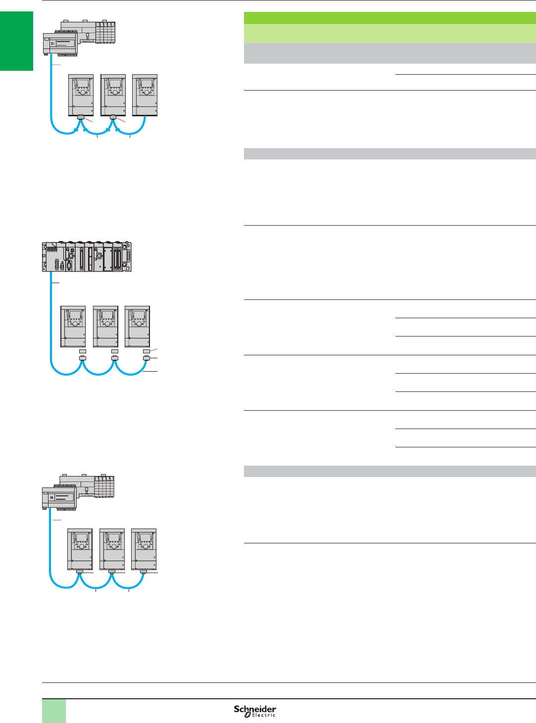
1/56
CANopen machine bus
Description Item no. Length
mReference Weight
kg
Connection via RJ45 connector (optimized solution for daisy chain connection to
the CANopen machine bus)
CANopen cordsets
equipped with 2 RJ45 connectors 10.3 VW3CANCARR03 0.050
1VW3CANCARR1 0.500
Daisy chain tap
equipped with:
b2 RJ45 connectors for connecting
the CANopen bus in a daisy chain
b1 cordset equipped with an RJ45
connector for connecting the drive
20.3 TCSCTN023F13M03 –
Connection via SUB-D connector
CANopen adaptor for mounting
on the RJ45 port on the drive
control terminals.
The adaptor provides a 9-way
male SUB-D connector
conforming to the CANopen
standard (CIA DRP 303-1).
3–VW3CANA71 –
CANopen connector (4)
9-way female SUB-D
with line terminator
(can be disabled).
180° cable outlet for
2 CANopen cables.
CAN-H, CAN-L, CAN-GND
connection.
4–VW3CANKCDF180T –
CANopen cables (1) (2)
Standard cable, e marking
Low smoke zero halogen
Flame retardant (IEC 60332-1)
550 TSXCANCA50 4.930
100 TSXCANCA100 8.800
300 TSXCANCA300 24.560
CANopen cables (1) (2)
UL certied, e marking
Flame retardant
(IEC 60332-2)
550 TSXCANCB50 3.580
100 TSXCANCB100 7.840
300 TSXCANCB300 21.870
CANopen cables (1) (2)
Cable for harsh environments (5)
or mobile installations, e marking
Low smoke zero halogen
Flame retardant (IEC 60332-1)
550 TSXCANCD50 3.510
100 TSXCANCD100 7.770
300 TSXCANCD300 21.700
Connection via terminals
Daisy chain tap
equipped with:
b2 spring terminal blocks for
connecting the CANopen bus
in a daisy chain
b1 cordset equipped with an RJ45
connector for connecting the drive
60.6 TCSCTN026M16M –
(1) Please refer to the “Modicon M238 Logic Controller” and “M258 Logic Controller” catalogues.
(2) Cable dependent on the type of controller or PLC.
(3) Please refer to the “Modicon M340 Automation Platform” catalogue.
(4) For ATV61HpppM3, ATV61HD11M3X, HD15M3X, ATV61H075N4…HD18N4 and
ATV61HpppY drives, this connector can be replaced by the TSXCANKCDF180T connector.
(5) Harsh environments:
- Resistance to hydrocarbons, industrial oils, detergents, solder splashes
- Relative humidity up to 100%
- Saline atmosphere
- Significant temperature variations
- Operating temperature between - 10°C and + 70°C.
References Variable speed drives
Altivar 61
Communication buses and networks
CANopen machine bus
(2)
1
2
3
M340 PLC (3)
DF600353
Example CANopen diagram with SUB-D connector
ATV61
Drive/option combinations:
pages 1/34 to 1/45
1 1
22
Optimized solution for daisy chain connection to the
CANopen machine bus
Modicon M238/Modicon M258 (1)
DF600690
ATV61
(2)
Modicon M238/Modicon M258 (1)
5 5
6 6 6
ATV61
Example CANopen diagram with daisy chain tap
DF516101
(2)
2
1
3
4
5
6
7
8
9
10
2
1
3
4
5
6
7
8
9
10
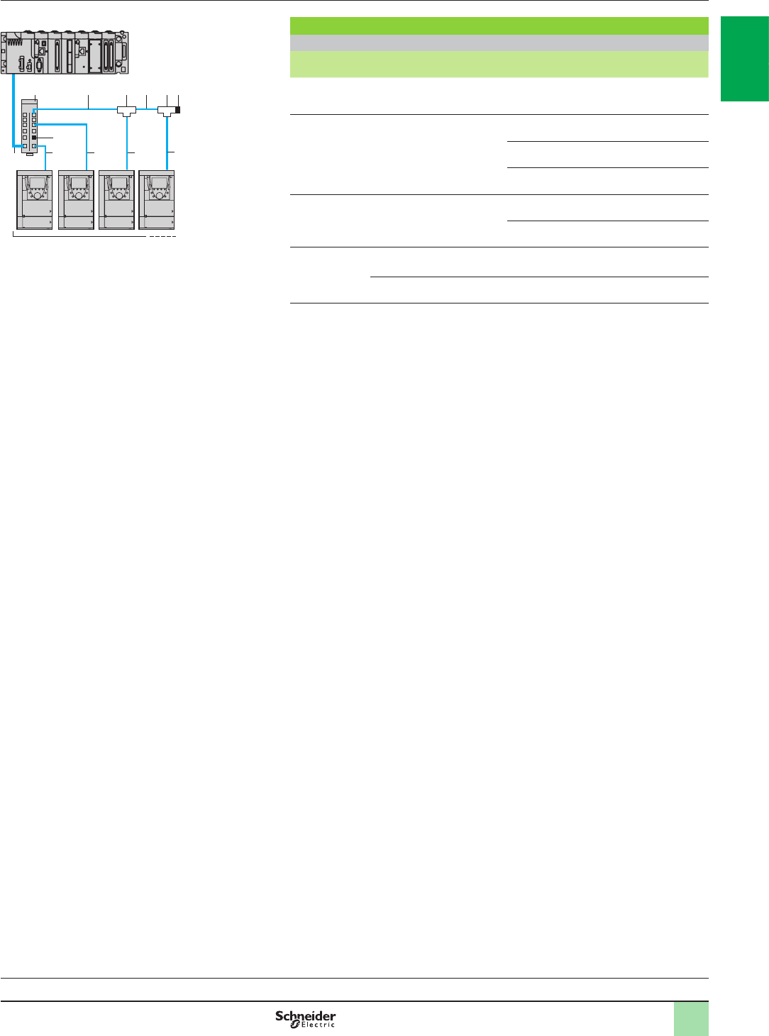
1/57
Modbus serial link
Connection accessories
Description Item no. Length
mUnit
reference Weight
kg
Modbus splitter box
10 RJ45 connectors and 1 screw
terminal block
1–LU9GC3 0.500
Cordsets for
Modbus serial link
equipped with 2 RJ45 connectors
20.3 VW3A8306R03 0.025
1VW3A8306R10 0.060
3VW3A8306R30 0.130
Modbus T-junction boxes
(with integrated cable) 30.3 VW3A8306TF03 0.190
1VW3A8306TF10 0.210
Line
terminators
for RJ45
connector (3)
R = 120 W
C = 1 nf
4–VW3A8306RC 0.010
R = 150 W4–VW3A8306R 0.010
1) Please refer to the “Modicon M340 Automation platform” catalogue.
(2) Cable depending on the type of controller or PLC.
(3) Order in lots of 2.
References (continued) Variable speed drives
Altivar 61
Communication buses and networks
Modbus serial link
4
22
(2)
21 23 3 4
3 3
Example Modbus diagram with connection via splitter
box and RJ45 connectors
DF600354
M340 PLC (1)
ATV61
Drive/option combinations:
pages 1/34 to 1/45
2
1
3
4
5
6
7
8
9
10
2
1
3
4
5
6
7
8
9
10
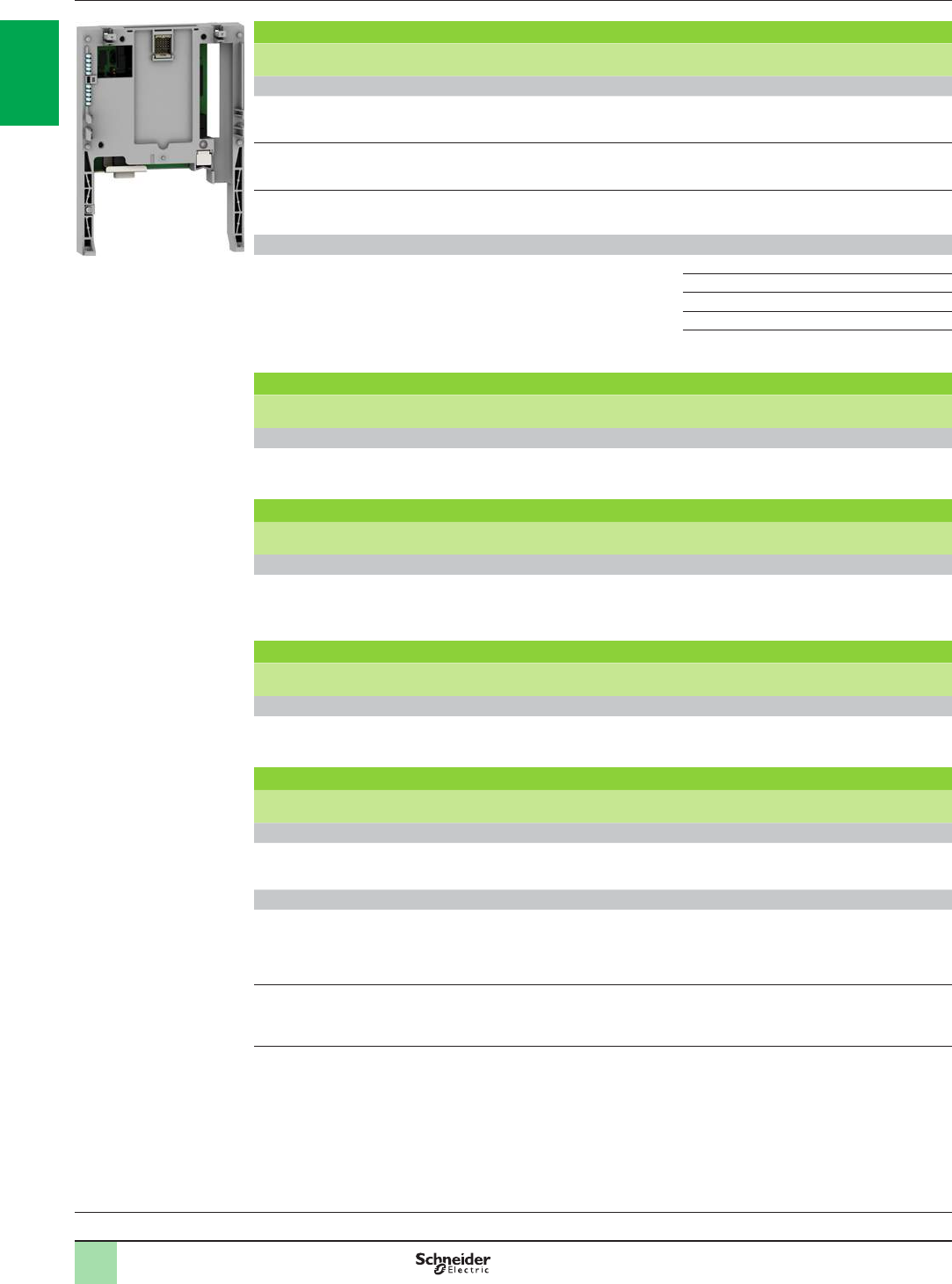
1/58
References (continued) Variable speed drives
Altivar 61
Communication buses and networks
Drive/option combinations:
pages 1/34 to 1/45
Modbus TCP Daisy Chain and EtherNet/IP network (1) (2)
Description Length
mReference Weight
kg
Communication cards
Modbus TCP Daisy Chain Equipped with 2 RJ45 connectors
Modbus TCP 10/100 Mbps class C20 –VW3A3310D 0.300
EtherNet/IP Equipped with 2 RJ45 connectors – VW3A3316 0.300
EtherNet/IP (RSTP) Equipped with 2 RJ45 connectors – VW3A3320 (3) 0.300
ConneXium Modbus TCP (VW3A3310D) or EtherNet/IP (VW3A3316 and VW3A3320) cordsets
Straight shielded
twisted pair cordsets Equipped with 2 RJ45 connectors
To be connected on a hub or on a switch 2490NTW00002 –
5490NTW00005 –
12 490NTW00012 –
40 490NTW00040 –
80 490NTW00080 –
DeviceNet bus (1) (2)
Description Reference Weight
kg
Communication card
DeviceNet Equipped with a 5-way removable screw
terminal block VW3A3309 0.300
InterBus bus (1) (2)
Description Reference Weight
kg
Communication card
InterBus Equipped with one 9-way male SUB-D connector
and one 9-way female SUB-D connector
To be connected using cordset 170MCIppp00 (4)
VW3A3304 0.300
CC-LInK bus (1) (2)
Description Reference Weight
kg
Communication card
CC-Link Equipped with a 5-way removable screw
terminal block VW3A3317 0.300
Modbus/Uni-Telway network (1) (2)
Description Length
mReference Weight
kg
Communication card
Modbus/Uni-Telway Equipped with a 9-way female SUB-D
connector –VW3A3303 0.300
Connection accessories for Modbus/Uni-Telway card (VW3A3303)
Subscriber socket Equipped with two 15-way female SUB-D
connectors and two screw terminal blocks.
For 2-channel junction box, trunk cable
extension and line terminator
–TSXSCA62 0.570
Cordset
for TSXSCA62
subscriber socket
Equipped with two 9 and 15-way male
SUB-D connectors 3VW3A83062 0.150
(1) The Altivar 61 drive can only take one communication card. See the summary tables of possible drive, option and accessory
combinations on pages 1/34 to 1/45.
(2) User manuals can be downloaded from our website www.schneider-electric.com. For the DeviceNet card, the description files
in gsd, eds or xif format can also be downloaded from our website www.schneider-electric.com..
(3) For a v5.8ie36#6 and above software version.
(4) Please refer to the “Automation Platform Modicon Premium and Unity - PL7 Software” catalogue
PF121621
Communication card
2
1
3
4
5
6
7
8
9
10
2
1
3
4
5
6
7
8
9
10

1/59
Drive/option combinations:
pages 1/34 to 1/45
PROFIBUS DP V0/V1 (1) (2)
Description Length
mReference Weight
kg
Communication cards
PROFIBUS DP V0 Equipped with a 9-way female SUB-D
connector –VW3A3307 0.300
PROFIBUS DP V1 Equipped with a 9-way female SUB-D
connector –VW3A3307S371 0.300
Connection accessories for PROFIBUS DP V0 (VW3A3307) or V1 (VW3A3307S371) card
Connectors:
9-way male SUB-D (3) For middle of line – 490NAD91104 –
For end of line – 490NAD91103 –
Cable
for 490NAD911pp connector (3) 100 TSXPBSCA100 –
400 TSXPBSCA100 –
LonWorks bus (1) (2)
Description Reference Weight
kg
Communication card
LonWorks Equipped with a 3-way removable screw
terminal block VW3A3312 0.300
METASYS N2 bus (1) (2)
Communication card
METASYS N2 Equipped with a 4-way removable screw
terminal block VW3A3318 0.300
APOGEE FLN bus (1) (2)
Communication card
APOGEE FLN Equipped with a 4-way removable screw
terminal block VW3A3314 0.300
BACnet bus (1) (2)
Communication card
BACnet Equipped with a 4-way removable screw
terminal block VW3A3319 0.300
Pronet bus (1) (2)
Description Length
mReference Weight
kg
Communication card
Pronet Equipped with 2 RJ45 connectors – VW3A3327 (4) 0.290
EtherCAT bus (1) (2)
Description Length
mReference Weight
kg
Communication card
EtherCAT bus Equipped with 2 RJ45 connectors – VW3A3326 (4) 0.270
Ethernet POWERLINK (1) (2)
Description Length
mReference Weight
kg
Communication card
POWERLINK Equipped with 2 RJ45 connectors – VW3A3321 0.350
(1) The Altivar 61 drive can only take one communication card. See the summary tables of possible drive, option and accessory
combinations on pages 1/34 to 1/45.
(2) User manuals can be downloaded from our website www.schneider-electric.com.
For the PROFIBUS DP and LonWorks cards, the description files in gsd, eds or xif format can also be downloaded from our
website www.schneider-electric.com.
(3) Please refer to the “Automation Platform Modicon Premium and Unity - PL7 Software” catalogue.
(4) For a v5.8ie36#6 and above software version.
References (continued) Variable speed drives
Altivar 61
Communication buses and networks
2
1
3
4
5
6
7
8
9
10
2
1
3
4
5
6
7
8
9
10
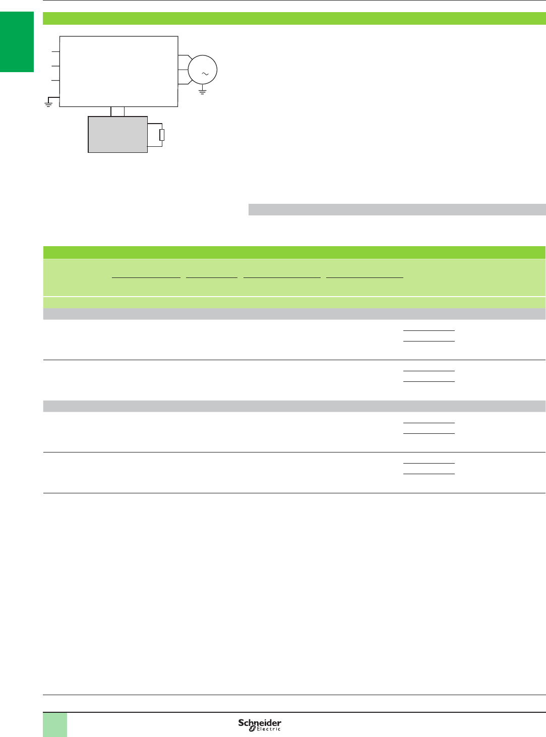
1/60
Variable speed drives
Altivar 61
Option: resistance braking units
Presentation,
references
Presentation
Resistance braking allows Altivar 61 drives to operate while braking to a standstill or
during “generator” operation, by dissipating the energy in the braking resistor.
ATV61HpppM3, ATV61HpppM3X, ATV61H075N4…HC22N4, ATV61WpppN4,
ATV61WpppN4C, ATV61HpppS6X and ATV61HU30Y…HC20Y drives have a
built-in dynamic brake transistor.
For ATV61HC25N4…HC63N4 and ATV61HC25Y…HC80Y drives, a braking unit
must be used. This is controlled by the drive:
b For ATV61HC25N4 and HC31N4 drives, the braking unit is mounted directly on
the left-hand side of the drive
b For ATV61HC40N4...HC63N4 and ATV61HC25Y…HC80Y drives, the braking
unit is an external module
Braking units provide IP 20 protection. Thermal protection is provided by an
integrated temperature probe.
Application
High-inertia machines.
References
For drives Power Losses Cable
(drive-braking unit) Cable
(braking unit-esistors) Percentage of
conduction
time
Reference Weight
Conti-
nuous Maximum At continuous
power Cross-
section Maximum
length Cross-
section Maximum
length
kW kW W mm² m mm² m % kg
Supply voltage: 380…480 V 50/60 Hz
ATV61HC25N4,
HC31N4
ATV61QC20N4…
QC31N4
200 420 550 – –
Internal connections 2 x 95 50 5% at 420 kW VW3A7101 30.000
15% at 320 kW
50% at 250 kW
ATV61HC40N4…
HC63N4
ATV61QC40N4…
QC63N4
400 750 1050 2 x 150 1 2 x 150 50 5% at 750 kW VW3A7102 80.000
15% at 550 kW
50% at 440 kW
Supply voltage: 500…690 V 50/60 Hz
ATV61HC25Y…
HC40Y
ATV61QC25Y…
QC40Y
300 450 650 1 50 5% at 450 kW VW3A7103 80.000
15% at 400 kW
50% at 350 kW
ATV61HC50Y…
HC80Y
ATV61QC50Y…
QC80Y
400 900 1150 1 50 5% at 900 kW VW3A7104 80.000
15% at 600 kW
50% at 500 kW
Note: To increase the braking power, several braking resistors can be mounted in parallel on the same braking unit. In this case, do not forget to take the minimum
resistance value to be associated with the braking unit into account, that is:
b 1.05 ohm for the VW3A7101 braking unit
b 0.7 ohm for the VW3A7102 braking unit
b 2 ohms for the VW3A7103 braking unit
b 1 ohm for the VW3A7104 braking unit
Variable speed drives:
page 1/16 Drive/option combinations:
page 1/34
M1
3
L1
L2
L3
Braking unit Braking
resistor
ATV61HC25N4…HC63N4
ATV61HC25Y…HC80Y
600293
2
1
3
4
5
6
7
8
9
10
2
1
3
4
5
6
7
8
9
10
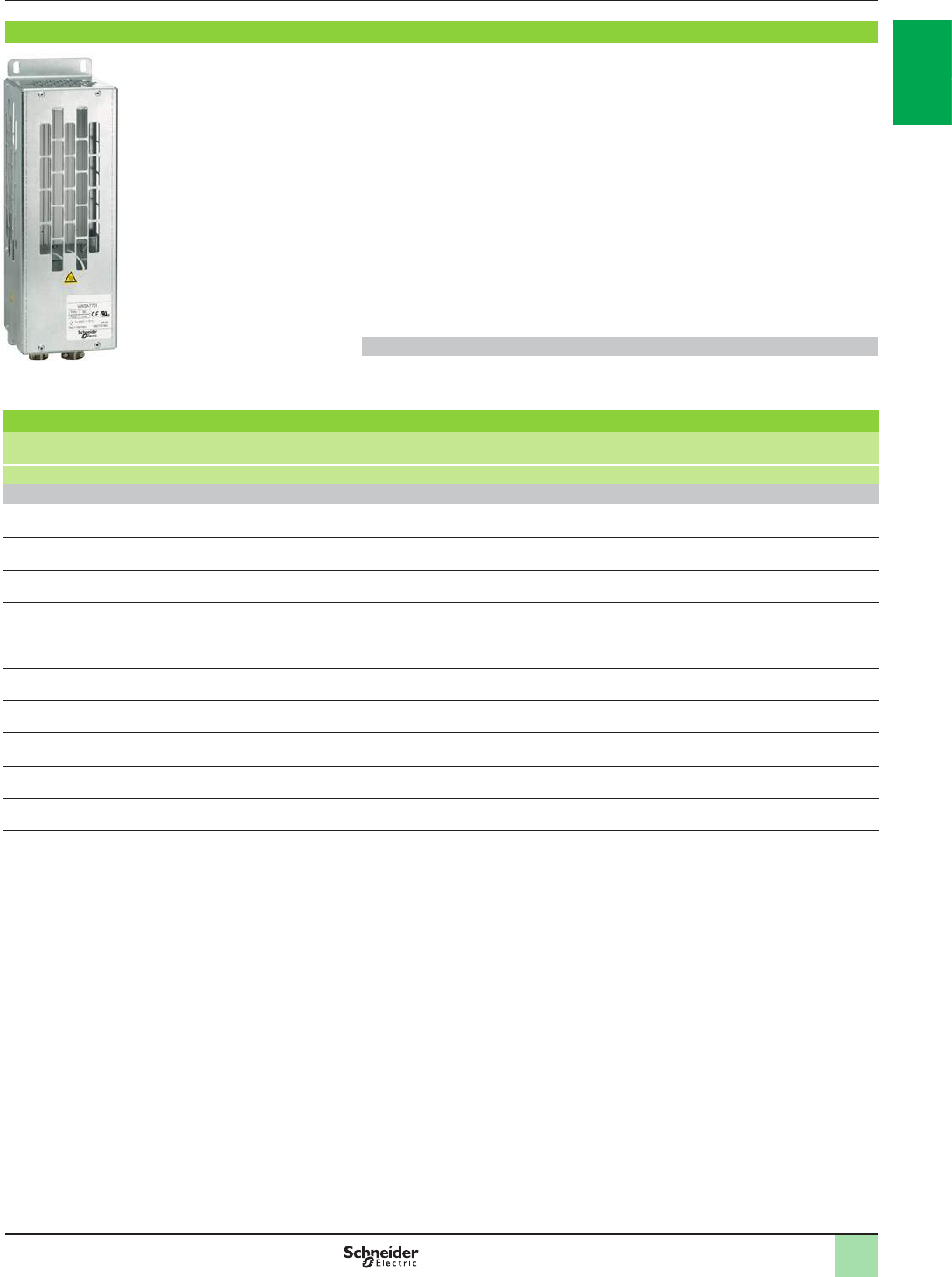
1/61
Variable speed drives
Altivar 61
Option: braking resistors
Presentation,
references
1
Presentation
Braking resistors allow Altivar 61 drives to operate while braking to a standstill, by
dissipating the braking energy.
They enable maximum transient braking torque.
Braking resistors are designed to be mounted on the outside of the enclosure, but
should not inhibit natural cooling. Air inlets and outlets must not be obstructed in any
way. The air must be free of dust, corrosive gas and condensation.
Two resistor models are available, depending on the drive rating:
b With IP 20 casing and thermal protection provided by temperature-controlled
switch or by the drive (VW3A7701…709)
b With IP 23 casing and thermal protection provided by thermal overload relay
(VW3A771p and 8pp)
The internal circuits of Altivar 61 drives rated 200 kW or less have a built-in dynamic
brake transistor.
Application
Inertia machines.
Braking resistors
For drives Degree of protection
of the resistor Ohmic value at 20°C Average power
available at 50°C (1) Reference Weight
ΩkW kg
Supply voltage: 200…240 V 50/60 Hz
ATV61H075M3 IP 20 100 0.05 VW3A7701 1.900
ATV61HU15M3, HU22M3 IP 20 60 0.1 VW3A7702 2.400
ATV61HU30M3, HU40M3 IP 20 28 0.2 VW3A7703 3.500
ATV61HU55M3, HU75M3 IP 20 15 1 VW3A7704 11.000
ATV61HD11M3X IP 20 10 1 VW3A7705 11.000
ATV61HD15M3X IP 20 8 1 VW3A7706 11.000
ATV61HD18M3X, HD22M3X IP 20 5 1.3 VW3A7707 11.000
ATV61HD30M3X IP 20 4 1 VW3A7708 11.000
ATV61HD37M3X, HD45M3X IP 20 2.5 1 VW3A7709 11.000
ATV61HD55M3X, HD75M3X IP 23 1.8 15.3 VW3A7713 50.000
ATV61HD90M3X IP 23 1.4 20.9 VW3A7714 63.000
(1) Load factor for resistors: the value of the average power that can be dissipated at 50°C from the resistor into the casing is determined for a load factor during
braking that corresponds to the majority of normal applications:
For VW3A7701…709:
- 2 s braking with a 0.6 Tn braking torque for a 40 s cycle
- 0.8 s braking with a 1.5 Tn braking torque for a 40 s cycle
For VW3A7713 and 714:
- 10 s braking with a 2 Tn braking torque for a 30 s cycle
VW3A7701
PF105659
Variable speed drives:
page 1/16 Drive/option combinations:
page 1/34
2
1
3
4
5
6
7
8
9
10
2
1
3
4
5
6
7
8
9
10
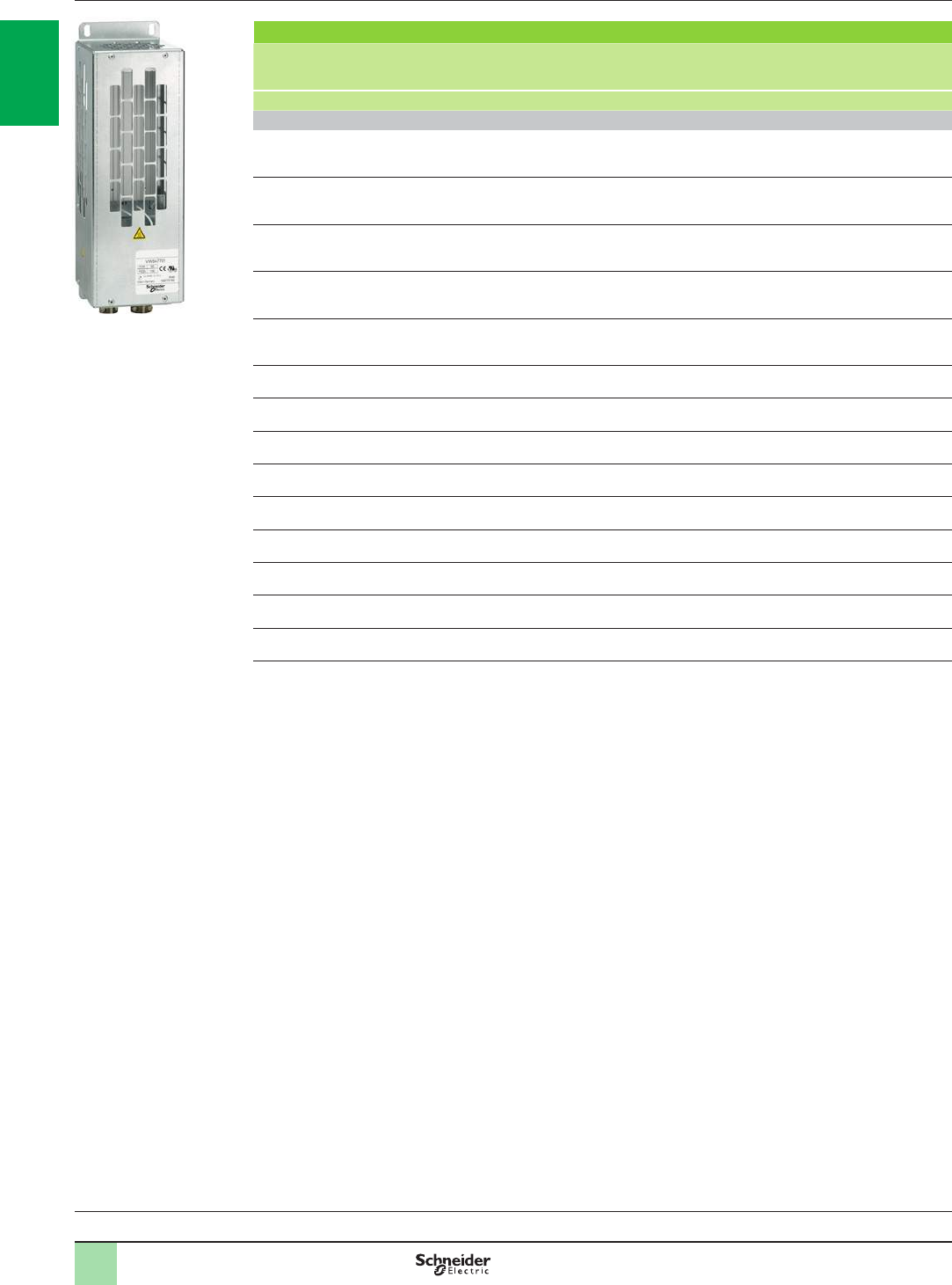
1/62
Variable speed drives
Altivar 61
Option: braking resistors
References (continued)
Braking resistors (continued)
For drives Degree of
protection of
the resistor
Ohmic value
at 20°C Average power
available
at 50°C (1)
Reference Weight
ΩkW kg
Supply voltage: 380…480 V 50/60 Hz
ATV61H075N4…HU40N4
ATV61W075N4…WU55N4
ATV61W075N4C…WU55N4C
IP 20 100 0.05 VW3A7701 1.900
ATV61HU55N4, HU75N4
ATV61WU75N4, WD11N4
ATV61WU75N4C, WD11N4C
IP 20 60 0.1 VW3A7702 2.400
ATV61HD11N4, HD15N4
ATV61WD15N4, WD18N4
ATV61WD15N4C, WD18N4C
IP 20 28 0.2 VW3A7703 3.500
ATV61HD18N4…HD30N4
ATV61WD22N4…WD37N4
ATV61WD22N4C…WD37N4C
IP 20 15 1 VW3A7704 11.000
ATV61HD37N4
ATV61WD45N4
ATV61WD45N4C
IP 20 10 1 VW3A7705 11.000
ATV61WD55N4, WD90N4
ATV61WD55N4C, WD90N4C IP 20 8 1 VW3A7706 11.000
ATV61HD45N4, HD75N4 IP 20 5 1.3 VW3A7707 11.000
ATV61HD90N4, HC11N4
ATV61QC11N4 IP 23 2.75 25 VW3A7710 80.000
ATV61HC13N4, HC16N4
ATV61QC13N4, QC16N4 IP 23 2.1 37 VW3A7711 86.000
ATV61HC22N4
ATV61QC20N4 IP 23 2.1 44 VW3A7712 104.000
ATV61HC25N4
ATV61QC25N4 IP 23 1.05 56 VW3A7715 136.000
ATV61HC31N4
ATV61QC31N4 IP 23 1.05 75 VW3A7716 172.000
ATV61HC40N4, HC50N4
ATV61QC40N4, QC50N4 IP 23 0.7 112 VW3A7717 266.000
ATV61HC63N4
ATV61QC63N4 IP 23 0.7 150 VW3A7718 350.000
(1) Load factor for resistors: the value of the average power that can be dissipated at 50°C from the resistor into the casing is
determined for a load factor during braking that corresponds to the majority of normal applications:
For VW3A7701…707:
- 2 s braking with a 0.6 Tn braking torque for a 40 s cycle
- 0.8 s braking with a 1.5 Tn braking torque for a 40 s cycle
For VW3A7710…712 and 715…718:
- 10 s braking with a 2 Tn braking torque for a 30 s cycle
Variable speed drives:
page 1/16 Drive/option combinations:
page 1/34
VW3A7701
PF105659
2
1
3
4
5
6
7
8
9
10
2
1
3
4
5
6
7
8
9
10

1/63
Variable speed drives
Altivar 61
Option: braking resistors
References (continued)
1
Braking resistors (continued)
For drives Degree of
protection of
the resistor
Ohmic
value
at 20°C
Average
power
available
at 50°C (1)
Quantity
required
per
drive
Reference Weight
ΩkW kg
Supply voltage: 500…600 V 50/60 Hz
ATV61HU22S6X…HU75S6X IP 20 60 0.1 1 VW3A7702 2.400
Supply voltage: 500…690 V 50/60 Hz
ATV61HU30Y…HU75Y IP 20 100 0.05 1 VW3A7701 1.900
ATV61HD11Y, HD15Y IP 20 60 0.1 1 VW3A7702 2.400
ATV61HD18Y, HD22Y IP 20 28 0.2 1 VW3A7703 3.500
ATV61HD30Y…HD45Y IP 20 15 1 1 VW3A7704 11.000
ATV61HD55Y, HD75Y IP 20 10 1 1 VW3A7705 11.000
ATV61HD90Y IP 20 5 1.3 1 VW3A7707 11.000
ATV61HC11Y, HC13Y
ATV61QC13Y IP 23 4.2 62 1 VW3A7806 126.000
ATV61HC16Y, HC20Y
ATV61QC16Y, QC20Y IP 23 8.1 44 2 VW3A7805 (2) 92.000
ATV61HC25Y
ATV61QC25Y IP 23 4.2 62 2 VW3A7806 (2) 126.000
ATV61HC31Y
ATV61QC31Y IP 23 1.05 75 2 VW3A7716 (3) 172.000
ATV61HC40Y
ATV61QC40Y IP 23 1.05 112 2 VW3A7814 (3) 280.000
ATV61HC50Y
ATV61QC50Y IP 23 0.7 112 2 VW3A7717 (3) 266.000
ATV61HC63Y
ATV61QC63Y IP 23 0.7 150 2 VW3A7718 (3) 350.000
ATV61HC80Y
ATV61QC80Y IP 23 0.7 225 2 VW3A7816 (3) 543.000
(1) Load factor for resistors: the value of the average power that can be dissipated at 50°C from the resistor into the casing is
determined for a load factor during braking that corresponds to the majority of normal applications.
For VW3A7701…705 and 707:
- 2 s braking with a 0.6 Tn braking torque for a 40 s cycle
- 0.8 s braking with a 1.5 Tn braking torque for a 40 s cycle
For VW3A7716…718:
- 10 s braking with a 2 Tn braking torque for a 30 s cycle
For VW3A7805 and 806:
- 100 s braking with a 1 Tn braking torque for a 200 s cycle
- 20 s braking with a 1.6 Tn braking torque for a 200 s cycle
For VW3A7814 and 816:
- 10 s braking with a 2 Tn braking torque for a 240 s cycle
- 110 s braking with a 1.25 Tn braking torque for a 240 s cycle
(2) The two braking resistors must be connected in parallel. The dimensions of all the components must be taken into account as
well as the required space of 300 mm to be left between each resistor (see our website www.schneider-electric.com).
(3) The two braking resistors must be connected in series. The dimensions of all the components must be taken into account as
well as the required space of 300 mm to be left between each resistor (see our website www.schneider-electric.com).
Variable speed drives:
page 1/16 Drive/option combinations:
page 1/34
2
1
3
4
5
6
7
8
9
10
2
1
3
4
5
6
7
8
9
10
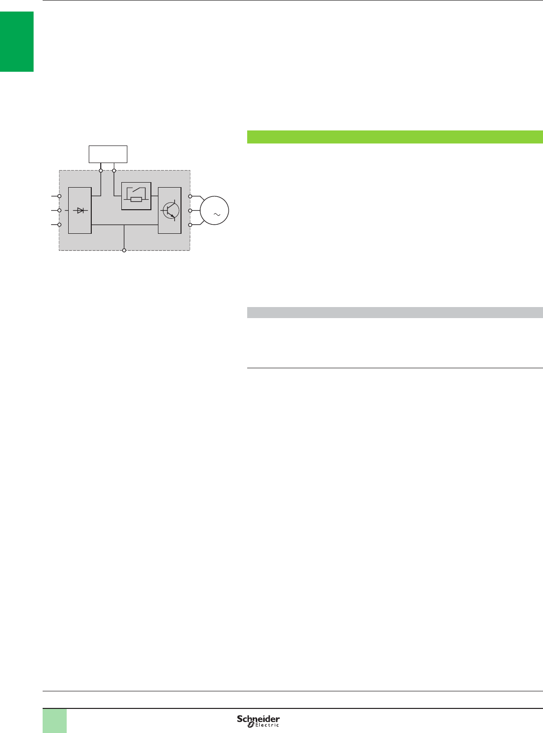
1/64
Variable speed drives
Altivar 61: reduction of current harmonics
Option: DC chokes
Presentation
1
Depending on the line supply, the main solutions for reducing current harmonics are
as follows:
bDC chokes (1) (see below)
bLine chokes (1) (see page 1/66)
b16% and 10% passive lters (1) (see page 1/69)
bUse of passive lters with a DC choke (see pages 1/70 to 1/75).
These ve solutions can be used on the same installation (1).
It is always easier and less expensive to deal with current harmonics at installation
level as a whole rather than at the level of each individual unit, particularly when
using passive lters.
DC choke
DC chokes are used to reduce current harmonics in order to comply with standard
IEC 61000-3-12 for drives in which the line current is more than 16 A and less than
75 A.
Using a DC choke with the drive complies with standard IEC 61000-3-12 provided
that the RSCE u 120 at the point of connection to the public power supply.
It is the responsibility of the installer or the user to ensure that the device is
connected correctly to a connection point with an RSCE u 120.
The DC choke is connected to the drive power terminals.
The DC choke is supplied as standard with ATV61HD55M3X…HD90M3X and
ATV61HD90N4…HC63N4 drives, and integrated in ATV61WpppN4 and
ATV61WpppN4C drives.
It provides IP 20 degree of protection.
Applications
Reduction of current harmonics.
Reduction of the THDI to 5% or 10% when used with passive lters (see pages 1/70
to 1/75).
Maintaining the motor torque in relation to the line inductance.
(1) For ATV61HpppS6X and ATV61HU30Y…HD90Y drives, only line chokes are recommended.
They are mandatory for ATV61HC11Y…HC80Y drives (see page 1/66).
M1
3
L1
L2
L3
PO
PA/+
PC/–
ATV61HpppM3
ATV61HpppM3X
ATV61HpppN4
DC
choke
537327
Variable speed drives:
page 1/16 Drive/option combinations:
page 1/34
2
1
3
4
5
6
7
8
9
10
2
1
3
4
5
6
7
8
9
10

1/65
Variable speed drives
Altivar 61: reduction of current harmonics
Option: DC chokes
References
1
References (1)
For drives Inductance
value Nominal
current Losses THDI
(2) Reference Weight
mH A W kg
Three-phase supply voltage: 200…240 V 50/60 Hz
ATV61H075M3 6.8 8 22.5 41.27 VW3A4503 1.700
ATV61HU15M3 3.2 14.3 32 42.4 VW3A4505 2.200
ATV61HU22M3 2.2 19.2 33 43.33 VW3A4506 2.500
ATV61HU30M3 1.6 27.4 43 43.22 VW3A4507 3.000
ATV61HU40M3 1.2 44 61 43.91 VW3A4508 4.300
ATV61HU55M3 1.2 44 61 38
ATV61HU75M3 0.7 36 30.5 43.96 VW3A4509 2.500
ATV61HD11M3X 0.52 84.5 77 38.14 VW3A4510 6.400
ATV61HD15M3X 0.52 84.5 77 35
ATV61HD18M3X 0.22 171.2 86 38.5 VW3A4511 17.850
ATV61HD22M3X 0.22 171.2 86 36.62
ATV61HD30M3X 0.09 195 73 43.51 VW3A4512 10.000
ATV61HD37M3X 0.09 195 73 39.24
ATV61HD45M3X 0.09 195 73 35.7
Three-phase supply voltage: 380…480 V 50/60 Hz
ATV61H075N4 18 2.25 7.7 44.95 VW3A4501 0.650
ATV61HU15N4 10 4.3 11 45.48 VW3A4502 1.000
ATV61HU22N4 6.8 8 22.5 45 VW3A4503 1.700
ATV61HU30N4 6.8 8 22.5 40.08
ATV61HU40N4 3.9 10.7 27 44.72 VW3A4504 1.650
ATV61HU55N4 3.2 14.3 32 45.19 VW3A4505 2.200
ATV61HU75N4 2.2 19.2 33 42.25 VW3A4506 2.500
ATV61HD11N4 1.6 27.4 43 43.1 VW3A4507 3.000
ATV61HD15N4 1.2 44 57.5 43.06 VW3A4508 4.300
ATV61HD18N4 1.2 44 57.5 35.23
ATV61HD22N4 0.52 84.5 98.3 40.4 VW3A4510 6.400
ATV61HD30N4 0.52 84.5 98.3 36.99
ATV61HD37N4 0.52 84.5 98.3 35.13
ATV61HD45N4 0.22 171.2 128 45.59 VW3A4511 17.850
ATV61HD55N4 0.22 171.2 128 39.29
ATV61HD75N4 0.22 171.2 128 36.2
(1) The DC choke is supplied as standard with ATV61HD55M3X…HD90M3X and ATV61HD90N4…HC63N4 drives.
It is integrated in ATV61WpppN4 and ATV61WpppN4C drives.
(2) Total current harmonic distortion in accordance with IEC 61000-3-12.
Variable speed drives:
page 1/16 Drive/option combinations:
page 1/34
2
1
3
4
5
6
7
8
9
10
2
1
3
4
5
6
7
8
9
10

1/66
Variable speed drives
Altivar 61: reduction of current harmonics
Option: line chokes
Line chokes
Line chokes are used to provide improved protection against overvoltages on the
line supply and to reduce harmonic distortion of the current produced by the drive.
The recommended chokes limit the line current.
They have been developed in line with standard IEC 61800-5-1 (VDE 0160 level 1
high-energy overvoltages on the line supply).
The choke values are dened for a phase-to-phase voltage drop of between 3% and
5% of the nominal supply voltage. Values higher than this will cause loss of torque.
Line chokes are mandatory for:
b ATV61HU40M3…HU75M3 drives powered by a 200…240 V 50/60 Hz single-
phase supply voltage
b ATV61HD90N4D...HC63N4D and ATV61QCppN4 drives powered by
a 380…480 V 50/60 Hz three-phase supply voltage
b ATV61HC11Y…HC80Y drives
bATV61QC13Y…QC80Y drives
Their use is recommended for ATV61HpppS6X and ATV61HU30Y…HD90Y drives.
They can also be used with:
b ATV61HpppM3 drives powered by a 200…240 V 50/60 Hz three-phase voltage,
ATV61HpppM3X and ATV61ppppN4 drives
b ATV61pppY drives in order to reach a total current distortion factor complying with
standard IEC 61000-3-12
Note: ATV61HD90N4…HC63N4 drives, supplied as standard with a DC choke, can be ordered
without a choke by adding the letter D at the end of the reference (see page 1/23).
Chokes must be installed upstream of the drive.
Applications
The use of line chokes is recommended in particular under the following
circumstances:
b�Close connection of several drives in parallel
b�Line supply with signicant disturbance from other equipment (interference,
overvoltages)
b�Line supply with voltage imbalance between phases that is more than 1.8% of the
nominal voltage
b�Drive supplied by a line with very low impedance (in the vicinity of power
transformers 10 times more powerful than the drive rating)
b�Installation of a large number of frequency inverters on the same line
b�Reduction of overloads on the cos j correction capacitors,
if the installation includes a power factor correction unit
Presentation
1
600292
M1
3
Altivar 61
L1
L2
L3
Line choke
Variable speed drives:
page 1/16 Drive/option combinations:
page 1/34
2
1
3
4
5
6
7
8
9
10
2
1
3
4
5
6
7
8
9
10

1/67
Variable speed drives
Altivar 61: reduction of current harmonics
Option: line chokes
References
References
For drives Line
supply
Isc
Line choke Quantity
required
per drive
Reference Weight
Inductance
value Nominal
current Saturation
current Losses
kA mH A A W kg
Single-phase supply voltage: 200…240 V 50/60 Hz
ATV61HU40M3 (1) 5 2 25 – 45 1 VW3A58501 3.500
ATV61HU55M3 (1) 5 1 45 – 50 1 VW3A58502 3.500
ATV61HU75M3 (1) 22 1 45 – 50 1 VW3A58502 3.500
Three-phase supply voltage: 200…240 V 50/60 Hz
ATV61H075M3 5 10 4 – 45 1 VW3A4551 1.500
ATV61HU15M3, HU22M3 5 4 10 – 65 1 VW3A4552 3.000
ATV61HU30M3 5 2 17 – 75 1 VW3A4553 3.500
ATV61HU40M3 5 1 31 – 90 1 VW3A4554 6.000
ATV61HU55M3 22 1 31 – 90 1 VW3A4554 6.000
ATV61HU75M3, HD11M3X 22 0.5 60 – 94 1 VW3A4555 11.000
ATV61HD15M3X 22 0.3 107 – 260 1 VW3A4556 16.000
ATV61HD18M3X…HD45M3X 22 0.15 230 – 400 1 VW3A4557 45.000
ATV61HD55M3X 35 0.12 222 346 278
1VW3A4559
35.000
ATV61HD75M3X 35 0.085 300 474 315
1VW3A4568
46.000
ATV61HD90M3X 35 0.06 450 574 335 1
VW3A4569
70.000
Three-phase supply voltage: 380…480 V 50/60 Hz
ATV61H075N4, HU15N4
ATV61W075N4, WU15N4
ATV61W075N4C, WU15N4C
5 10 4 – 45 1 VW3A4551 1.500
ATV61HU22N4…HU40N4
ATV61WU22N4…WU40N4
ATV61WU22N4C…WU40N4C
5 4 10 – 65 1 VW3A4552 3.000
ATV61HU55N4, HU75N4
ATV61WU55N4, WU75N4
ATV61WU55N4C, WU75N4C
22 2 17 – 75 1 VW3A4553 3.500
ATV61HD11N4, HD15N4
ATV61WD11N4, WD15N4
ATV61WD11N4C, WD15N4C
22 1 31 – 90 1 VW3A4554 6.000
ATV61HD18N4, HD22N4
ATV61WD18N4, WD22N4
ATV61WD18N4C, WD22N4C
22 0.5 60 – 94 1 VW3A4555 11.000
ATV61HD30N4…HD55N4
ATV61WD30N4…WD55N4
ATV61WD30N4C…WD55N4C
22 0.3 107 – 260 1 VW3A4556 16.000
ATV61HD75N4
ATV61WD75N4
ATV61WD75N4C
22 0.15 230 – 400 1 VW3A4557 45.000
ATV61HD90N4D
(1)
ATV61WD90N4
ATV61WD90N4C
35 0.155 184 370 220 1
VW3A4558
31.000
ATV61HC11N4D
(1)
ATV61QC11N4
(1)
35 0.12 222 445 278 1
VW3A4559
35.000
ATV61HC13N4D
(1)
ATV61QC13N4
(1)
35 0.098 264 530 245 1
VW3A4560
43.000
ATV61HC16N4D
(1)
ATV61QC16N4
(1)
50 0.085 300 570 315 1
VW3A4568
46.000
ATV61HC22N4D
(1)
ATV61QC20N4
(1)
50 0.066 344 685 258 1
VW3A4561
47.000
ATV61HC22N4D
(1)
ATV61HC25N4D
(1)
ATV61QC25N4
(1)
50 0.06 450 850 335 1
VW3A4569
70.000
ATV61HC31N4D
(1)
ATV61QC31N4
(1)
50 0.038 613 1150 307 1
VW3A4564
73.000
ATV61HC40N4D
(1)
50 0.032 720 1352 428 1
VW3A4565
82.000
ATV61QC40N4
(1)
50 0.066 344 685 258 2
VW3A4561
47.000
ATV61HC50N4D
(1)
50 0.06 450 850 335 2
VW3A4569
70.000
ATV61QC50N4
(1)
50 0.038 509 855 278 2
VW3A4563 59.000
ATV61HC63N4D
(1)
50 0.038 613 1150 307 2
VW3A4564
73.000
ATV61QC63N4
(1)
50 0.026 590 1180 320 2
VW3A4573 60.000
(1) Use of a line choke is mandatory (see table of combinations on page 1/36).
2
1
3
4
5
6
7
8
9
10
2
1
3
4
5
6
7
8
9
10
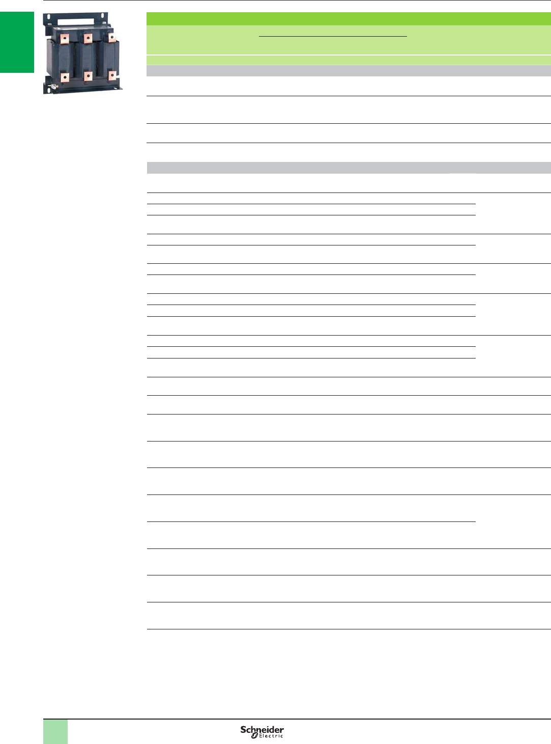
1/68
Variable speed drives
Altivar 61: reduction of current harmonics
Option: line chokes
References (continued)
References (continued)
For drives Line
supply
Isc
Line choke Quantity
required
per drive
THDI
(1) Reference Weight
Inductance
value Nominal
current Saturation
current Losses
kA mH A A W kg
Three-phase supply voltage: 500…600 V 50/60 Hz
ATV61HU22S6X (2) 22 10 4 – 45 1 39.6 VW3A4551 1.500
ATV61HU30S6X,
HU40S6X (2) 22 4 10 – 65 1 48.1 VW3A4552 3.000
ATV61HU55S6X (2) 22 4 10 – 65 1 41.6 VW3A4552 3.000
ATV61HU75S6X (2) 22 2 17 – 75 1 52.3 VW3A4553 3.500
Three-phase supply voltage: 500…690 V 50/60 Hz
ATV61HU30Y (2) 22 10 4 – 45 1 38.03 VW3A4551 1.500
ATV61HU40Y (2) 22 4 10 – 65 2 36.95 VW3A4552 3.000
ATV61HU55Y (2) 22 4 10 – 65 1 47.09
ATV61HU75Y (2) 22 4 10 – 65 1 37.36
ATV61HD11Y (2) 22 2 17 – 75 1 41.81 VW3A4553 3.500
ATV61HD15Y (2) 22 2 17 – 75 1 35.75
ATV61HD18Y (2) 22 1 31 – 90 1 38.44 VW3A4554 6.000
ATV61HD22Y (2) 22 1 31 – 90 1 35.31
ATV61HD30Y (2) 22 0.5 60 – 94 1 37.61 VW3A4555 11.000
ATV61HD37Y (2) 22 0.5 60 – 94 1 39.39
ATV61HD45Y (2) 22 0.5 60 – 94 1 36.07
ATV61HD55Y (2) 22 0.3 107 – 260 1 37.38 VW3A4556 16.000
ATV61HD75Y (2) 22 0.3 107 – 260 1 37.39
ATV61HD90Y (2) 22 0.3 107 – 260 1 33.24
ATV61HC11Y (3) 28 0.22 160 320 220 1 43.31 VW3A4570 28.000
ATV61HC13Y (3)
ATV61QC13Y 28 0.22 160 320 220 1 39.73 VW3A4570 28.000
ATV61HC16Y (3)
ATV61QC16Y (3) 28 0.23 230 405 330 1 36.5 VW3A4571 79.000
ATV61HC20Y (3)
ATV61QC20Y (3) 35 0.23 230 405 330 1 47.13 VW3A4571 79.000
ATV61HC25Y (3)
ATV61QC25Y (3) 35 0.098 264 530 245 1 41.91 VW3A4560 35.000
ATV61HC31Y (3)
ATV61QC31Y (3) 35 0.1 450 770 495 1 37.61 VW3A4572 90.000
ATV61HC40Y (3)
ATV61QC40Y (3) 35 0.1 450 770 495 1 44.78
ATV61HC50Y (3)
ATV61QC50Y (3) 35 0.085 300 570 315 2 38.08 VW3A4568 46.000
ATV61HC63Y (3)
ATV61QC63Y (3) 35 0.1 450 770 495 2 35.42 VW3A4572 90.000
ATV61HC80Y (3)
ATV61QC80Y (3) 42 0.1 450 770 495 2 32.04 VW3A4572 90.000
(1) Total current harmonic distortion in accordance with IEC 61000-3-12. The values are given for a 600 V 60 Hz three-phase
supply voltage.
(2) Use of a line choke is recommended.
(3) Use of a line choke is mandatory.
VW3A4572
PF107532
2
1
3
4
5
6
7
8
9
10
2
1
3
4
5
6
7
8
9
10
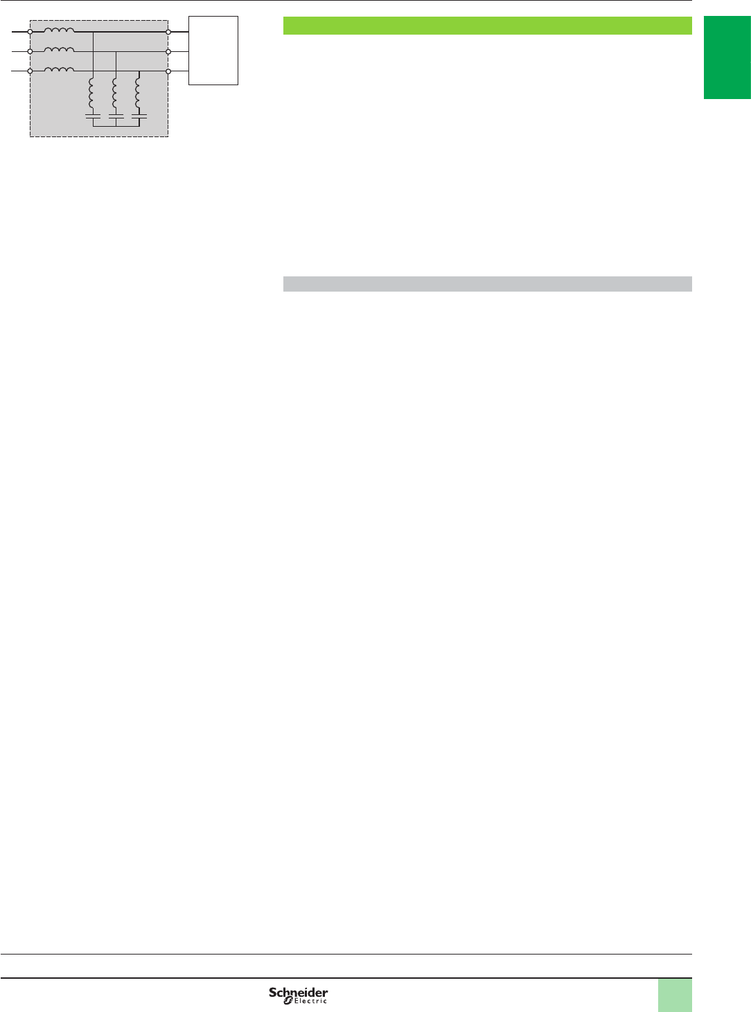
1/69
Variable speed drives
Altivar 61: reduction of current harmonics
Option: passive lters
Presentation
Passive lters
Passive lters are used to reduce current harmonics with total harmonic distortion
factors (THDI) of less than 16%, 10% or 5%.
In some cases, several passive lters (2 to 3) can be used on the same drive.
These performance levels can be improved and the harmonic distortion reduced to
less than 10% or 5% if a DC choke is used with a 16% or 10% passive lter. See
pages 1/64 to 1/65.
The reactive power increases at no load or low load. To eliminate this reactive power,
the lter capacitors can be disconnected via the drive (see the diagrams on our
website www.schneider-electric.com or refer to the Programming Manual).
The passive lters provide IP 20 protection.
The associations are given for ATV61ppppN4 and ATV61WpppN4C drives. For
ATV61HpppM3, ATV61HpppY and ATV61HpppS6X, please contact our Customer
Care Centre.
Applications
Reduction of current harmonics in order to use drives in the rst environment
(restricted distribution, for domestic use, sale conditional on the competence of the
user and the distributor in terms of reduction of current harmonics).
ATV61ppppN4
ATV61WpppN4C
L1
L2
L3
Passive lter
537329
Variable speed drives:
page 1/16 Drive/option combinations:
page 1/34
2
1
3
4
5
6
7
8
9
10
2
1
3
4
5
6
7
8
9
10
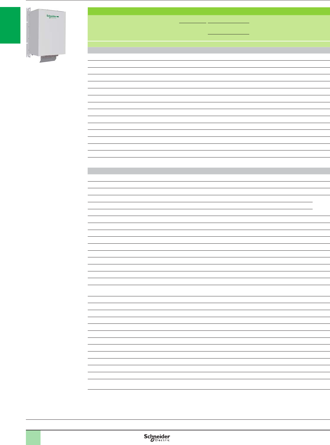
1/70
References Variable speed drives
Altivar 61: reduction of current harmonics
Option: 50 Hz passive lters
Passive lters: 400 V 50 Hz three-phase power supply
Motor rating For ATV61
drives Line supply Filter Quantity
required
per drive
Reference Weight
Line current Nominal current
Input Output
kW HP A A kg
THDI 16% with ATV61H075N4…HD75N4 drives (1)
0.75 1H075N4 2.5 6 6.2 1 VW3A46101 10.000
1.5 2HU15N4 3.6 6 6.2 1 VW3A46101 10.000
2.2 3HU22N4 5 6 6.2 1 VW3A46101 10.000
3–HU30N4 6 6 6.2 1 VW3A46101 10.000
45HU40N4 7.8 10 10.4 1 VW3A46102 13.500
5.5 7.5 HU55N4 10 10 10.4 1 VW3A46102 13.500
7.5 10 HU75N4 14 14 14.5 1 VW3A46103 16.300
11 15 HD11N4 19 22 23.0 1 VW3A46104 22.000
15 20 HD15N4 26 29 30.0 1 VW3A46105 25.000
18.5 25 HD18N4 32 35 36.5 1 VW3A46106 37.000
22 30 HD22N4 38 43 44.5 1 VW3A46107 39.000
30 40 HD30N4 52 58 60.0 1 VW3A46108 44.000
37 50 HD37N4 63 72 75.0 1 VW3A46109 56.000
45 60 HD45N4 77 86 89.5 1 VW3A46110 62.000
55 75 HD55N4 91 101 105.0 1 VW3A46111 74.000
75 100 HD75N4 126 144 150.0 1 VW3A46112 85.000
THDI 10% with ATV61W075N4...WD90N4C, ATV61HD90N4 and ATV61HC/QC11N4...HC/QC63N4 drives
0.75 1W075N4, W075N4C 2.5 6 6.2 1 VW3A46101 10.000
1.5 2WU15N4, WU15N4C 3.6 6 6.2 1 VW3A46101 10.000
2.2 3WU22N4, WU22N4C 5 6 6.2 1 VW3A46101 10.000
3–WU30N4, WU30N4C 6 6 6.2 1 VW3A46101 10.000
45WU40N4, WU40N4C 7.8 10 10.4 1 VW3A46102 13.500
5.5 7.5 WU55N4, WU55N4C 10 10 10.4 1 VW3A46102 13.500
7.5 10 WU75N4, WU75N4C 14 14 14.5 1 VW3A46103 16.300
11 15 WD11N4, WD11N4C 19 22 23 1 VW3A46104 22.000
15 20 WD15N4, WD15N4C 26 29 30 1 VW3A46105 25.000
18.5 25 WD18N4, WD18N4C 32 35 36.5 1 VW3A46106 37.000
22 30 WD22N4, WD22N4C 38 43 44.5 1 VW3A46107 39.000
30 40 WD30N4, WD30N4C 52 58 60 1 VW3A46108 44.000
37 50 WD37N4, WD37N4C 63 72 75 1 VW3A46109 56.000
45 60 WD45N4, WD45N4C 77 86 89.5 1 VW3A46110 62.000
55 75 WD55N4, WD55N4C 91 101 105 1 VW3A46111 74.000
75 100 WD75N4, WD75N4C 126 144 150 1 VW3A46112 85.000
90 125 HD90N4
WD90N4, WD90N4C 149 144 150 1 VW3A46112 85.000
110 150 HC11N4, QC11N4 182 180 187 1 VW3A46113 102.000
132 200 HC13N4, QC13N4 218 217 225 1 VW3A46114 119.000
160 250 HC16N4, QC16N4 287 304 316 1 VW3A46116 142.000
200 300 HC22N4, QC20N4
353.5 380 395
1VW3A46118 185.000
220 350 HC22N4, QC25N4
364 380 395
1VW3A46118 185.000
250 400 HC25N4, QC25N4
415 433 450
1VW3A46119 203.000
280 450 HC31N4, QC31N4
485 252 262
2VW3A46115 119.000
315 500 HC31N4, QC31N4
543 304 316
2VW3A46116 142.000
355 –HC40N4, QC40N4
588 304 316
2VW3A46116 142.000
400 600 HC40N4, QC40N4
664 325 338
2VW3A46117 142.000
500 700 HC50N4, QC50N4
840 433 450
2VW3A46119 203.000
560 800 HC63N4, QC63N4
978 325 338
3VW3A46117 142.000
630 900 HC63N4, QC63N4
1091 380 395
3VW3A46118 185.000
(1) By adding a DC choke (see page 1/64) to ATV61H075N4…HD75N4 drives, a total current harmonic distortion (THDI) ≤ 10% is
obtained.
This DC choke is supplied as standard with ATV61HD90N4 and ATV61pC11N4 … pC63N4 drives. These reduced current
harmonics are achieved as long as the total voltage harmonic distortion (THDU) is < 2%, the short-circuit ratio (RSCE) is
> 66%, and only for the nominal current of the passive lter.
Variable speed drives:
page 1/16 Drive/option combinations:
page 1/34
VW3A46106
PF140347
2
1
3
4
5
6
7
8
9
10
2
1
3
4
5
6
7
8
9
10

1/71
Variable speed drives
Altivar 61: reduction of current harmonics
Option: 50 Hz passive lters
References (continued)
Passive lters: 400 V 50 Hz three-phase power supply (continued)
Motor rating For ATV61
drives Line supply Filter Quantity
required
per drive
Reference Weight
Line current Nominal current
Input Output
kW HP A A kg
THDI 10% with ATV61H075N4…HD75N4 drives (1)
0.75 1H075N4 2.5 6 6.2 1 VW3A46120 18.000
1.5 2HU15N4 3.6 6 6.2 1 VW3A46120 18.000
2.2 3HU22N4 5 6 6.2 1 VW3A46120 18.000
3–HU30N4 6 6 6.2 1 VW3A46120 18.000
45HU40N4 7.8 10 10.4 1 VW3A46121 20.000
5.5 7.5 HU55N4 10 10 10.4 1 VW3A46121 30.000
7.5 10 HU75N4
14 14
14.5 1 VW3A46122 20.000
11 15 HD11N4
19 22
23 1 VW3A46123 30.000
15 20 HD15N4
26 29
30 1 VW3A46124 34.000
18.5 25 HD18N4
32 35
36.5 1 VW3A46125 52.000
22 30 HD22N4
38 43
44.5 1 VW3A46126 75.000
30 40 HD30N4
52 58
60 1 VW3A46127 82.000
37 50 HD37N4
63 72
75 1 VW3A46128 96.000
45 60 HD45N4
77 86
89.5 1 VW3A46129 104.000
55 75 HD55N4
91 101
105 1 VW3A46130 130.000
75 100 HD75N4
126 144
150 1 VW3A46131 126.000
(1) By adding a DC choke (see page 1/64) to ATV61H075N4…HD75N4 drives, a total current harmonic distortion (THDI) ≤ 5% is
obtained.
These reduced current harmonics are achieved as long as the total voltage harmonic distortion (THDU) is < 2%, the short-
circuit ratio (RSCE) is > 66%, and only for the nominal current of the passive lter.
Variable speed drives:
page 1/16 Drive/option combinations:
page 1/34
2
1
3
4
5
6
7
8
9
10
2
1
3
4
5
6
7
8
9
10

1/72
Variable speed drives
Altivar 61: reduction of current harmonics
Option: 50 Hz passive lters
Passive lters: 400 V 50 Hz three-phase power supply (continued)
Motor rating For ATV61
drives Line supply Filter Quantity
required
per drive
Reference Weight
Line current Nominal current
Input Output
kW HP A A kg
THDI 5% with ATV61W075N4...WD90N4C, ATV61HD90N4 and ATV61HC/QC11N4...HC/QC63N4 drives
0.75 1W075N4, W075N4C 2.5 6 6.2 1 VW3A46120 18.000
1.5 2WU15N4, WU15N4C 3.6 6 6.2 1 VW3A46120 18.000
2.2 3WU22N4, WU22N4C 5 6 6.2 1 VW3A46120 18.000
3–WU30N4, WU30N4C 6 6 6.2 1 VW3A46120 18.000
45WU40N4, WU40N4C 7.8 10 10.4 1 VW3A46121 18.000
5.5 7.5 WU55N4, WU55N4C 10 10 10.4 1 VW3A46121 18.000
7.5 10 WU40N4, WU40N4C 14 14 14.5 1 VW3A46122 20.000
11 15 WU55N4, WU55N4C 19 22 23 1 VW3A46123 30.000
15 20 WD15N4, WD15N4C 26 29 30 1 VW3A46124 34.000
18.5 25 WD18N4, WD18N4C 32 35 36.5 1 VW3A46125 52.000
22 30 WD22N4, WD22N4C 38 43 44.5 1 VW3A46126 75.000
30 40 WD30N4, WD30N4C 52 58 60 1 VW3A46127 82.000
37 50 WD37N4, WD37N4C 63 72 75 1 VW3A46128 96.000
45 60 WD45N4, WD45N4C 77 86 89.5 1 VW3A46129 104.000
55 75 WD55N4, WD55N4C 91 101 105.04 1 VW3A46130 130.000
75 100 WD75N4, WD75N4C 126 144 150 1 VW3A46131 126.000
90 125 HD90N4
WD90N4, WD90N4C 149 144 150 1 VW3A46131 126.000
110 150 HC11N4, QC11N4 182 180 187 1 VW3A46132 135.000
132 200 HC13N4, QC13N4 218 217 225 1 VW3A46133 171.000
160 250 HC16N4, QC16N4 287 304 316 1 VW3A46135 221.000
200 300 HC22N4, QC20N4
353.5 380 395
1VW3A46137 265.000
220 350 HC22N4, QC25N4
364 395
1VW3A46137 265.000
250 400 HC25N4, QC25N4
415 433 450
1VW3A46138 272.000
280 450 HC31N4, QC31N4
485 252 262
2VW3A46134 206.000
315 500 HC31N4, QC31N4
543 304 316
2VW3A46135 221.000
355 –HC40N4, QC40N4
588 316
2VW3A46135 221.000
400 600 HC40N4, QC40N4
664 325 338
2VW3A46136 230.000
500 700 HC50N4, QC50N4
840 433 450
2VW3A46138 272.000
560 800 HC63N4, QC63N4
918 325 338
3VW3A46136 230.000
630 900 HC63N4, QC63N4
1091 380 395
3VW3A46137 265.000
References (continued)
1
Variable speed drives:
page 1/16 Drive/option combinations:
page 1/34
2
1
3
4
5
6
7
8
9
10
2
1
3
4
5
6
7
8
9
10
1/73
Variable speed drives:
page 1/16 Drive/option combinations:
page 1/34
Variable speed drives
Altivar 61: reduction of current harmonics
Option: 60 Hz passive lters
References (continued)
1
Passive lters: 400 V 60 Hz three-phase power supply
Motor rating For ATV61
drives Line supply Filter Quantity
required
per drive
Reference Weight
Line current Nominal current
Input Output
kW HP A A kg
THDI 16% with ATV61H075N4…HD75N4 drives (1)
0.75 1H075N4 2.5 6 6.2 1 VW3A46139 10.000
1.5 2HU15N4 3 6 6.2 1 VW3A46139 10.000
2.2 3HU22N4 5 6 6.2 1 VW3A46139 10.000
3–HU30N4 6 6 6.2 1 VW3A46139 10.000
45HU40N4 7 10 10.4 1 VW3A46140 13.500
5.5 7.5 HU55N4 10 10 10.4 1 VW3A46140 13.500
7.5 10 HU75N4 13 14 14.5 1 VW3A46141 16.300
11 15 HD11N4 19 19 19.5 1 VW3A46142 22.000
15 20 HD15N4 24 25 26 1 VW3A46143 23.000
18.5 25 HD18N4 32 31 32 1 VW3A46144 33.000
22 30 HD22N4 35 36 37.5 1 VW3A46145 37.000
30 40 HD30N4 46 48 50 1 VW3A46146 38.000
37 50 HD37N4 58.7 60 62.5 1 VW3A46147 43.000
45 60 HD45N4 68 73 76 1 VW3A46148 55.000
55 75 HD55N4 82.6 95 99 1 VW3A46149 62.000
75 100 HD75N4 108 118 122.5 1 VW3A46150 74.000
THDI 10% with ATV61W075N4...WD90N4C, ATV61HD90N4 and ATV61HC/QC11N4...HC/QC63N4 drives
0.75 1W075N4, W075N4C 2.5 6 6.2 1 VW3A46139 10.000
1.5 2WU15N4, WU15N4C 3 6.2 1 VW3A46139 10.000
2.2 3WU22N4, WU22N4C 5 6.2 1 VW3A46139 10.000
3–WU30N4, WU30N4C 6 6.2 1 VW3A46139 10.000
45WU40N4, WU40N4C 7 10 10.4 1 VW3A46140 13.500
5.5 7.5 WU55N4, WU55N4C 10 10.4 1 VW3A46140 13.500
7.5 10 WU75N4, WU75N4C 13 14 14.5 1 VW3A46141 16.300
11 15 WD11N4, WD11N4C 19 19 19.5 1 VW3A46142 22.000
15 20 WD15N4, WD15N4C 24 25 26 1 VW3A46143 25.000
18.5 25 WD18N4, WD18N4C 32 31 32 1 VW3A46144 37.000
22 30 WD22N4, WD22N4C 35 36 37.5 1 VW3A46145 39.000
30 40 WD30N4, WD30N4C 46 48 50 1 VW3A46146 44.000
37 50 WD37N4, WD37N4C 58.7 60 62.5 1 VW3A46147 56.000
45 60 WD45N4, WD45N4C 68 73 76 1 VW3A46148 62.000
55 75 WD55N4, WD55N4C 82.6 95 99 1 VW3A46149 74.000
75 100 WD75N4, WD75N4C 108 118 122.5 1 VW3A46150 85.000
90 125 HD90N4,
WD90N4 WD90N4C 134 154 160 1 VW3A46151 85.000
110 150 HC11N4, QC11N4 163 183 190 1 VW3A46152 102.000
132 200 HC13N4, QC13N4 192 231 240 1 VW3A46153 119.000
160 250 HC16N4, QC16N4 235 231 240 1 VW3A46153 142.000
200 300 HC22N4, QC20N4
300 355 369
1VW3A46155 185.000
220 350 HC22N4, QC25N4
330 369
1VW3A46155 185.000
250 400 HC25N4, QC25N4
400 436 450
2VW3A46157 203.000
280 450 HC31N4, QC31N4
440 436 450
2VW3A46157 119.000
315 500 HC31N4, QC31N4
470 231 240
2VW3A46153 136.000
355 –HC40N4, QC40N4
530
291
302.5
2VW3A46154 136.000
400 600 HC40N4, QC40N4
590 291 302.5
2VW3A46154 142.000
500 700 HC50N4, QC50N4
730 380 395
3VW3A46156 203.000
560 800 HC63N4, QC63N4
858 436 450
3VW3A46157 142.000
630 900 HC63N4, QC63N4
964 355 369
3VW3A46155 185.000
(1) By adding a DC choke (see page 1/64) to ATV61H075N4…HD75N4 drives, a total current harmonic distortion (THDI) ≤ 10% is
obtained.
This DC choke is supplied as standard with ATV61HD90N4 and ATV61pC11N4 … pC63N4 drives. These reduced current
harmonics are achieved as long as the total voltage harmonic distortion (THDU) is < 2%, the short-circuit ratio (RSCE) is
> 66%, and only for the nominal current of the passive lter.
2
1
3
4
5
6
7
8
9
10
2
1
3
4
5
6
7
8
9
10

1/74
Variable speed drives
Altivar 61: reduction of current harmonics
Option: 60 Hz passive lters
References (continued)
1
Passive lters: 400 V 60 Hz three-phase power supply (continued)
Motor rating For ATV61
drives Line supply Filter Quantity
required
per drive
Reference Weight
Line current Nominal current
Input Output
kW HP A A kg
THDI 10% with ATV61H075N4…HD75N4 drives (1)
0.75 1H075N4 2.5 6 6.2 1 VW3A46158 18.000
1.5 2HU15N4 3 6 6.2 1 VW3A46158 18.000
2.2 3HU22N4 4.2 6 6.2 1 VW3A46158 18.000
3–HU30N4 6 6 6.2 1 VW3A46158 18.000
45HU40N4 7 10 10.4 1 VW3A46159 18.000
5.5 7.5 HU55N4 10 10 10.4 1 VW3A46159 18.000
7.5 10 HU75N4
13 14
14.5 1 VW3A46160 20.000
11 15 HD11N4
19 19
19.5 1 VW3A46161 30.000
15 20 HD15N4
24 25
26 1 VW3A46162 34.000
18.5 25 HD18N4
32 31
32 1 VW3A46163 52.000
22 30 HD22N4
35 36
37.5 1 VW3A46164 53.000
30 40 HD30N4
44 48
50 1 VW3A46165 57.000
37 50 HD37N4
58.7 60
62.5 1 VW3A46166 75.000
45 60 HD45N4
68 73
76 1 VW3A46167 97.000
55 75 HD55N4
82.6 95
99 1 VW3A46168 104.000
75 100 HD75N4
108 118
122.5 1 VW3A46169 106.000
(1) By adding a DC choke (see page 1/64) to ATV61H075N4…HD75N4 drives, a total current harmonic distortion (THDI) ≤ 5% is
obtained.
These reduced current harmonics are achieved as long as the total voltage harmonic distortion (THDU) is < 2%, the
short-circuit ratio (RSCE) is > 66%, and only for the nominal current of the passive lter.
Variable speed drives:
page 1/16 Drive/option combinations:
page 1/34
2
1
3
4
5
6
7
8
9
10
2
1
3
4
5
6
7
8
9
10

1/75
Variable speed drives
Altivar 61: reduction of current harmonics
Option: 60 Hz passive lters
Passive lters: 400 V 60 Hz three-phase power supply (continued)
Motor rating For ATV61
drives Line supply Filter Quantity
required
per drive
Reference Weight
Line current Nominal current
Input Output
kW HP A A kg
THDI 5% with ATV61W075N4...WD90N4C, ATV61HD90N4 and ATV61HC/QC11N4...HC/QC63N4 drives
0.75 1W075N4, W075N4C 2.5 6 6.2 1 VW3A46158 18.000
1.5 2WU15N4, WU15N4C 3 6 6.2 1 VW3A46158 18.000
2.2 3WU22N4, WU22N4C 5 6 6.2 1 VW3A46158 18.000
3–WU30N4, WU30N4C 6 6 6.2 1 VW3A46158 18.000
45WU40N4, WU40N4C 7 10 10.4 1 VW3A46159 18.000
5.5 7.5 WU55N4, WU55N4C 10 10 10.4 1 VW3A46159 18.000
7.5 10 WU40N4, WU40N4C 13 14 14.5 1 VW3A46160 20.000
11 15 WU55N4, WU55N4C 19 19 19.5 1 VW3A46161 30.000
15 20 WD15N4, WD15N4C 24 25 26 1 VW3A46162 34.000
18.5 25 WD18N4, WD18N4C 32 31 32 1 VW3A46163 52.000
22 30 WD22N4, WD22N4C 35 36 37.5 1 VW3A46164 53.000
30 40 WD30N4, WD30N4C 44 48 50 1 VW3A46165 57.000
37 50 WD37N4, WD37N4C 58.7 60 62.5 1 VW3A46166 75.000
45 60 WD45N4, WD45N4C 68 73 76 1 VW3A46167 97.000
55 75 WD55N4, WD55N4C 82.6 95 99 1 VW3A46168 104.000
75 100 WD75N4, WD75N4C 108 118 122.5 1 VW3A46169 106.000
90 125 HD90N4
WD90N4, WD90N4C 134 154 160 1 VW3A46170 126.000
110 150 HC11N4, QC11N4 163 183 190 1 VW3A46171 135.000
132 200 HC13N4, QC13N4 192 231 240 1 VW3A46172 170.000
160 250 HC16N4, QC16N4 235 231 302.5 1 VW3A46172 170.000
200 300 HC22N4, QC20N4
300.5 355 369
1VW3A46174 229.000
220 350 HC22N4, QC25N4
330 355 369
1VW3A46174 229.000
250 400 HC25N4, QC25N4
400 436 450
1VW3A46176 270.000
280 450 HC31N4, QC31N4
440 436 450
2VW3A46176 270.000
315 500 HC31N4, QC31N4
470 231 240
2VW3A46172 170.000
355 –HC40N4, QC40N4
530 291 316
2VW3A46173 206.000
400 600 HC40N4, QC40N4
590 291 316
2VW3A46173 206.000
500 700 HC50N4, QC50N4
730 380 395
2VW3A46175 265.000
560 800 HC63N4, QC63N4
858 436 450
2VW3A46176 270.000
630 900 HC63N4, QC63N4
964 355 369
3VW3A46174 229.000
References (continued)
1
Variable speed drives:
page 1/16 Drive/option combinations:
page 1/34
2
1
3
4
5
6
7
8
9
10
2
1
3
4
5
6
7
8
9
10
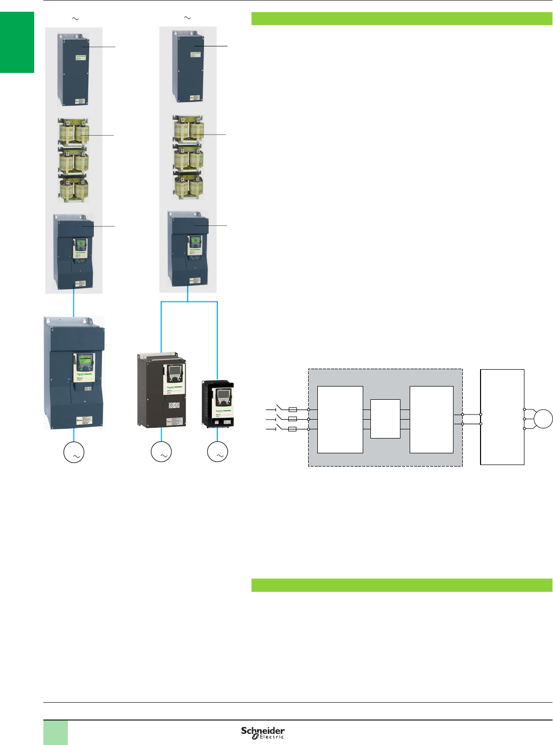
1/76
Presentation Variable speed drives
Altivar 61: reduction of current harmonics
Option: Active Front End
Presentation
The Active Front End allows the Altivar 61 drive to be used in applications requiring a
particularly low harmonic level (THDI < 4%).
It complies with standard IEEE 519-1992.
It is available for a range of drives between 0.75 kW and 800 kW with three types of
50/60 Hz power supply:
380…440 V three-phase
480 V three-phase
500…690 V three-phase
It has been developed to comply with European directives and to obtain e marking.
Apart from the possibility of signicantly reducing the level of harmonics, this
technology offers several benets:
- Increased application dynamics
- Operation on unstable line supplies
- Amplication of the input voltage
- Reduced EMC emissions
The Active Front End consists of a set of three modules installed upstream of the
drive between the line supply and the motor.
It is made up of the following elements:
A line lter module (LFM) 1, used at the input, incorporating:
A charging circuit
A line contactor
An EMC lter
A line lter choke (LFC) 2, consisting of three single-phase chokes, connected
between the line lter module (LFM) and the active infeed converter (AIC)
An active infeed converter (AIC) 3
The Active Front End allows the Altivar 61 drive to be powered via the common DC
bus, while limiting the total current distortion factor (THDI) to less than 4%.
It can also supply direct current to several drives of different power ratings, operating
in parallel, should the installation require this.
The Active Front End offers IP 00 protection. The ambient air temperature during
operation must be between - 10°C and + 45°C (without derating, + 60°C with
derating).
It is imperative that the protection of the Active Front End on the line supply side is
supplemented by fuses for semi-conductors (to protect against short-circuits or a
system failure).
The DC bus output only requires fuse protection if Active Front End modules are
used in parallel.
Applications
Applications requiring a very low harmonic level
Applications with high inertia and strong dynamics
Applications on unstable line supplies
Variable speed drives:
page 1/16 Drive/option combinations:
page 1/34
3
M1
3
Active Front End
+
ATV61HC11N4D
3
2
1
Active Front End
Active Front End
+
ATV61HD22N4 + ATV61HU22N4
3
2
1
M1
3
3
M1
3
Active Front End
M
3a
3 aLFM LFC AIC
AFE (Active Front End)
cAltivar 61
drive
2
1
3
4
5
6
7
8
9
10
2
1
3
4
5
6
7
8
9
10

1/77
References Variable speed drives
Altivar 61: reduction of current harmonics
Option: Active Front End
References
For drives Motor Line supply DC bus Active Front
End
(1) (2)
Quantity
per
drive
Reference Weight
Power indicated
on rating plate Nominal line
current Maximum
current Continuous
power
400 V 400 V
kW A A kW kg
Three-phase supply voltage: 380…440 V 50/60 Hz
ATV61H075N4…
HD90N4 0.75…90 160 185 120 AIC 1VW3A7250 60.000
LFC 1 VW3A7265 54.000
LFM 1 VW3A7260 60.000
ATV61HC11N4D 110 160 185 120 AIC 1VW3A7250 60.000
LFC 1 VW3A7265 54.000
LFM 1 VW3A7260 60.000
ATV61HC13N4D 132 200 220 143 AIC 1VW3A7251 74.000
LFC 1 VW3A7266 69.000
LFM 1 VW3A7261 80.000
ATV61HC16N4D
...HC22N4D 220 348 366 238 AIC 1VW3A7253 110.000
LFC 1 VW3A7267 132.000
LFM 1 VW3A7262 125.000
ATV61HC25N4D 250 395 412 268 AIC 1VW3A7254 140.000
LFC 1 VW3A7267 132.000
LFM 1 VW3A7262 125.000
ATV61HC31N4D 315 495 517 336 AIC 1VW3A7255 140.000
LFC 1 VW3A7267 132.000
LFM 1 VW3A7262 125.000
ATV61HC40N4D 400 628 654 425 AIC 1VW3A7256 215.000
LFC 2 VW3A7267 132.000
LFM 2 VW3A7262 125.000
ATV61HC50N4D 500 780 815 530 AIC 1VW3A7257 225.000
LFC 2 VW3A7267 132.000
LFM 2 VW3A7262 125.000
ATV61HC63N4D 630 980 1023 665 AIC 1VW3A7258 300.000
LFC 2 VW3A7267 132.000
LFM 2 VW3A7262 125.000
Dimensions (overall)
Active infeed converter (AIC) W x H x D
mm
VW3A7250 310 x 680 x 377
VW3A7251 350 x 782 x 377
VW3A7253 430 x 950 x 377
VW3A7254 585 x 950 x 377
VW3A7255 585 x 950 x 377
VW3A7256 880 x 1150 x 377
VW3A7257 880 x 1150 x 377
VW3A7258 1110 x 1150 x 377
Line lter choke (LFC) W x H x D
mm
VW3A7265 835 x 210 x 185
VW3A7266 835 x 295 x 195
VW3A7267 1270 x 360 x 255
Line lter module (LFM) W x H x D
mm
VW3A7260 240 x 630 x 377
VW3A7261 290 x 730 x 377
VW3A7262 290 x 1100 x 377
(1) For more information about the Active Front End, please refer to the programming manual or visit our website www.schneider-electric.com.
(2) AIC = active infeed converter; LFC = line lter choke; LFM = line lter module.
2
1
3
4
5
6
7
8
9
10
2
1
3
4
5
6
7
8
9
10

1/78
References (continued) Variable speed drives
Altivar 61: reduction of current harmonics
Option: Active Front End
References
For drives Motor Line supply DC bus Active Front
End
(1) (2)
Quantity
per
drive
Reference Weight
Power indicated
on rating plate Nominal line
current Maximum
current Continuous
power
480 V 480 V
HP A A kW kg
Three-phase supply voltage: 480 V 50/60 Hz
ATV61H075N4…
HD90N4 1…125 160 185 120 AIC 1 VW3A7250 60.000
LFC 1 VW3A7265 54.000
LFM 1 VW3A7260 60.000
ATV61HC11N4D 150 160 185 120 AIC 1 VW3A7250 60.000
LFC 1 VW3A7265 54.000
LFM 1 VW3A7260 60.000
ATV61HC13N4D 200 200 220 143 AIC 1 VW3A7251 74.000
LFC 1 VW3A7266 69.000
LFM 1 VW3A7261 80.000
ATV61HC16N4D...
HC22N4D 350 348 366 238 AIC 1 VW3A7283 110.000
LFC 1 VW3A7267 132.000
LFM 1 VW3A7262 125.000
ATV61HC25N4D 400 395 412 268 AIC 1 VW3A7254 140.000
LFC 1 VW3A7267 132.000
LFM 1 VW3A7262 125.000
ATV61HC31N4D 500 495 517 336 AIC 1 VW3A7255 140.000
LFC 1 VW3A7267 132.000
LFM 1 VW3A7262 125.000
ATV61HC40N4D 600 628 654 425 AIC 1 VW3A7286 215.000
LFC 2 VW3A7267 132.000
LFM 2 VW3A7262 125.000
ATV61HC50N4D 700 780 815 530 AIC 1 VW3A7287 225.000
LFC 2 VW3A7267 132.000
LFM 2 VW3A7262 125.000
ATV61HC63N4D 900 980 1023 665 AIC 1 VW3A7258 300.000
LFC 2 VW3A7267 132.000
LFM 2 VW3A7262 125.000
Dimensions (overall)
Active infeed converter (AIC) W x H x D
mm
VW3A7250 310 x 680 x 377
VW3A7251 350 x 782 x 377
VW3A7283 585 x 950 x 377
VW3A7254 585 x 950 x 377
VW3A7255 585 x 950 x 377
VW3A7286 1110 x 1150 x 377
VW3A7287 1110 x 1150 x 377
VW3A7258 1110 x 1150 x 377
Line lter choke (LFC) W x H x D
mm
VW3A7265 835 x 210 x 185
VW3A7266 835 x 295 x 195
VW3A7267 1270 x 360 x 255
Line lter module (LFM) W x H x D
mm
VW3A7260 240 x 630 x 377
VW3A7261 290 x 730 x 377
VW3A7262 290 x 1100 x 377
(1) For more information about the Active Front End, please refer to the programming manual or visit our website www.schneider-electric.com.
(2) AIC = active infeed converter; LFC = line lter choke; LFM = line lter module.
2
1
3
4
5
6
7
8
9
10
2
1
3
4
5
6
7
8
9
10

1/79
References (continued) Variable speed drives
Altivar 61: reduction of current harmonics
Option: Active Front End
References
For drives Motor Line supply DC bus Active Front
End
(1) (2)
Quantity
per drive Reference Weight
Power indicated
on rating plate Maximum
nominal line
current
Maximum
current Continuous
power
500 V…690 V 500 V 600 V 690 V
kW A A kW kW kW kg
Three-phase supply voltage: 500…690 V 50/60 Hz
ATV61HC11Y (3) 110 120 130 102 123 142 AIC 1 VW3A7270 110.000
LFC 1 VW3A7268 99.000
LFM 1 VW3A7263 80.000
ATV61HC13Y (3) 132 120 130 102 123 142 AIC 1 VW3A7270 110.000
LFC 1 VW3A7268 99.000
LFM 1 VW3A7263 80.000
ATV61HC16Y (3) 160 150 156 127 153 172 AIC 1 VW3A7271 110.000
LFC 1 VW3A7268 99.000
LFM 1 VW3A7263 80.000
ATV61HC20Y (3) 200 185 195 157 188 215 AIC 1 VW3A7272 110.000
LFC 1 VW3A7268 99.000
LFM 1 VW3A7263 80.000
ATV61HC25Y (3) 250 228 244 193 230 268 AIC 1 VW3A7273 190.000
LFC 1 VW3A7269 210.000
LFM 1 VW3A7264 125.000
ATV61HC31Y (3) 315 285 305 242 290 335 AIC 1 VW3A7274 190.000
LFC 1 VW3A7269 210.000
LFM 1 VW3A7264 125.000
ATV61HC40Y (3) 400 360 386 305 365 424 AIC 1 VW3A7275 190.000
LFC 1 VW3A7269 210.000
LFM 1 VW3A7264 125.000
ATV61HC50Y (4) 500 450 481 382 460 528 AIC 1 VW3A7276 400.000
LFC 2 VW3A7269 210.000
LFM 2 VW3A7264 125.000
ATV61HC63Y (4) 630 563 604 478 575 663 AIC 1 VW3A7277 400.000
LFC 2 VW3A7269 210.000
LFM 2 VW3A7264 125.000
ATV61HC80Y (4) 800 715 765 607 730 842 AIC 1 VW3A7278 400.000
LFC 2 VW3A7269 210.000
LFM 2 VW3A7264 125.000
Dimensions(overall)
Active infeed converter (AIC) W x H x D
mm
VW3A7270 330 x 1190 x 377
VW3A7271 330 x 1190 x 377
VW3A7272 330 x 1190 x 377
VW3A7273 585 x 1190 x 377
VW3A7274 585 x 1190 x 377
VW3A7275 585 x 1190 x 377
VW3A7276 1110 x 1390 x 377
VW3A7277 1110 x 1390 x 377
VW3A7278 1110 x 1390 x 377
Line lter choke (LFC) W x H x D
mm
VW3A7268 835 x 295 x 210
VW3A7269 985 x 540 x 250
Line lter module (LFM) W x H x D
mm
VW3A7263 290 x 730 x 377
VW3A7264 290 x 1100 x 397
(1) For more information about the Active Front End, please refer to the programming manual or visit our website www.schneider-electric.com.
(2) AIC = active infeed converter; LFC = line lter choke; LFM = line lter module.
(3) Requires a 6 V fan wiring option, reference VW3A7280. For more information, please visit our website www.schneider-electric.com.
(4) Requires two 6 V fan wiring options, reference VW3A7280. For more information, please visit our website www.schneider-electric.com.
Variable speed drives:
page 1/16 Drive/option combinations:
page 1/34
2
1
3
4
5
6
7
8
9
10
2
1
3
4
5
6
7
8
9
10
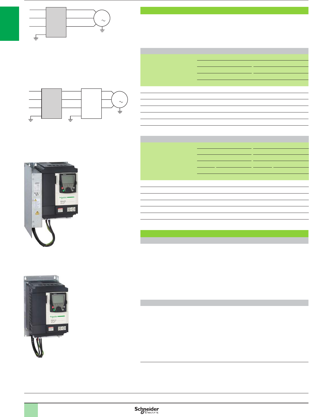
1/80
Integrated EMC lters
Altivar 61 drives, except for the ATV61HpppM3X, have built-in radio interference
lters to meet the EMC standard for variable speed electrical power drive “products”
IEC/EN 61800-3, edition 2, category C2 or C3 in environment 1 or 2 and to comply
with the European Electromagnetic Compatibility Directive (EMC).
IP 20 drives
Drives Maximum length of shielded cable (1) according to
EN 55011 class A Gr1 EN 55011 class A Gr2
IEC/EN 61800-3 cat. C2 IEC/EN 61800-3 cat. C3
LF (2) (3) HF (2) (3) LF (2) (3) HF (2) (3)
m m m m
ATV61H075M3…HU22M3 10 5 – –
ATV61HU30M3…HU75M3 – – 10 5
ATV61H075N4…HU40N4 10 5 – –
ATV61HU55N4…HD15N4 – – 10 5
ATV61HD18N4…HC63N4 – – 50 25
ATV61HU30Y…HD90Y – – 25 25
ATV61HC11Y…HC80Y – – 50 25
IP 54 drives
Drives Maximum length of shielded cable (1) according to
EN 55011 class A Gr1 EN 55011 class B Gr1
IEC/EN 61800-3 cat. C2 IEC/EN 61800-3 cat. C1
LF (2) HF (2) LF (2) HF (2)
2 kHz 8 kHz 16 kHz 2 kHz 8 kHz 16 kHz
mm m m m m
ATV61WpppN4 80 50 50 – – –
ATV61W075N4C…WU40N4C – – – 20 20 20
ATV61WU40N4C, WU55N4C – – – 50 50 50
ATV61WU75N4C, WD11N4C – – – 20 20 20
ATV61WD15N4C…WD22N4C – – – 50 50 50
ATV61WD30N4C…WD45N4C – – – 20 50 20
ATV61WD55N4C…WD90N4C – – – 20 20 20
Additional EMC input lters
Applications
When used with ATV61HpppM3, HpppM3X and ATV61HpppN4 drives, additional
EMC input lters can be used to meet more stringent requirements and are designed
to reduce conducted emissions on the line supply below the limits of standards
EN 55011 group 1, class A or B and IEC/EN 61800-3 category C1 or C2.
For ATV61H075M3…HD45M3X and ATV61H075N4…HD75N4 drives, the additional
EMC lters can be mounted beside or under the device. They act as a support for the
drives and are attached to them via tapped holes.
For ATV61HD55M3X…HD90M3X and ATV61HD90N4…HC63N4, the additional
EMC lters can only be mounted beside the drive.
Use according to the type of line supply
These additional lters can only be used on TN (neutral connection) and TT (earthed
neutral) type systems.
Standard IEC/EN 61800-3, appendix D2.1, states that on IT systems (isolated or
impedance earthed neutral), lters can cause permanent insulation monitors to
operate in a random manner.
If a machine has to be installed on an IT system, one solution is to insert an isolation
transformer and connect the machine locally on a TN or TT system.
(1) If motors are connected in parallel, it is the total cable length that should be taken into
account.
(2) LF: low switching frequency. HF: high switching frequency.
(3) See note (5) on the next page.
Variable speed drives
Altivar 61: EMC lters
Integrated lters and optional additional lters
Presentation
1
Altivar 61 drive with integrated EMC lter
M1
3
L1
L2
L3
ATV61HpppM3
ATV61ppppN4
ATV61HpppY
ATV61WpppN4C
with integrated lter
600291
Altivar 61 drive with additional EMC lter
M1
3
L1
L2
L3
Additional
EMC lter
ATV61HpppM3
ATV61HpppM3X
ATV61HpppN4
600290
Variable speed drives:
page 1/16 Drive/option combinations:
page 1/34
PF100229
Mounting the EMC lter beside the Altivar 61 drive
PF100227
Mounting the EMC lter under the Altivar 61 drive
2
1
3
4
5
6
7
8
9
10
2
1
3
4
5
6
7
8
9
10
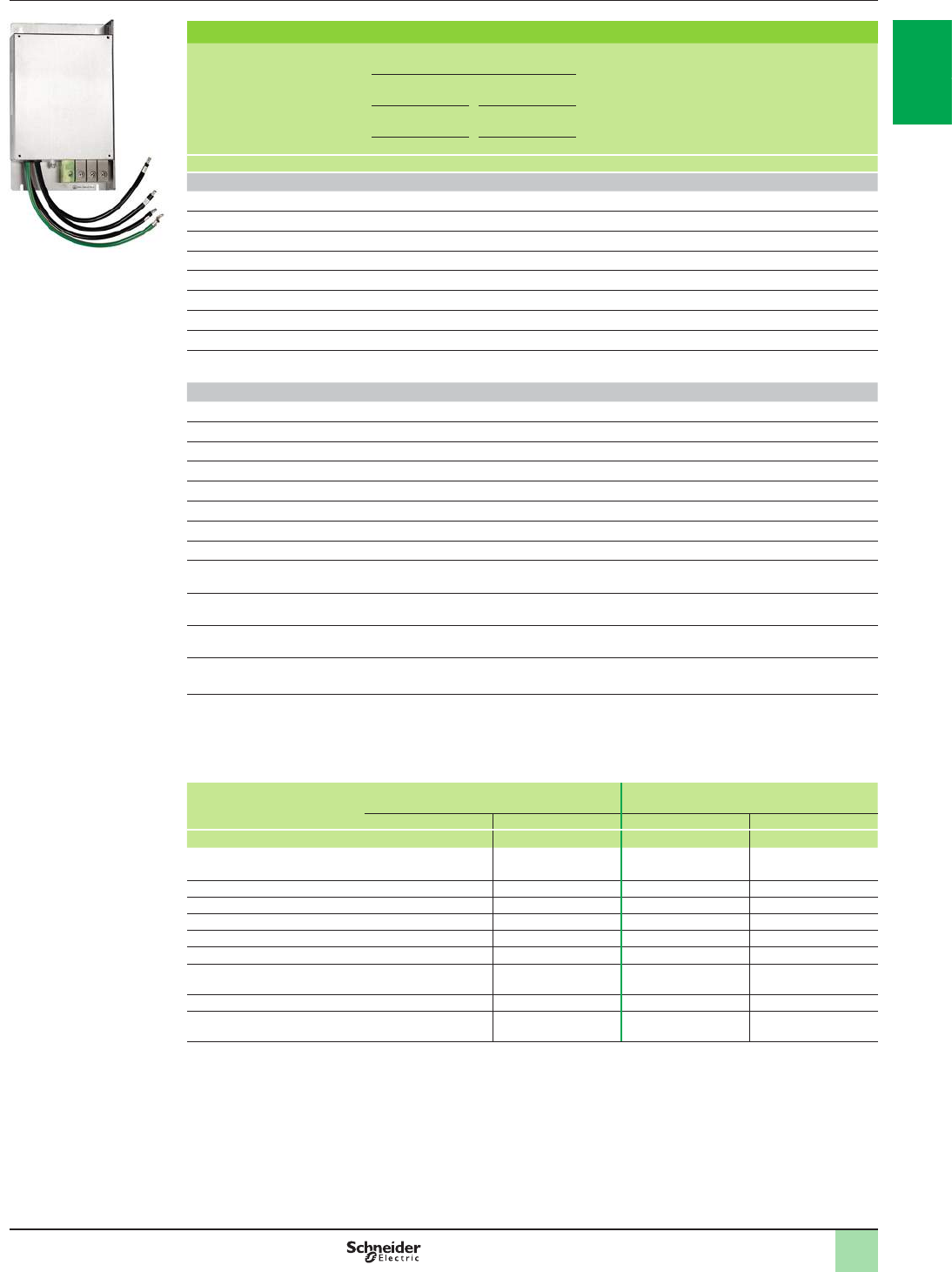
1/81
Additional EMC input lters for ATV61HpppM3, HpppM3X and HpppN4 drives
Drives Maximum length of shielded
cable (1) In
(2) If
(3) Losses
(4) Reference Weight
EN 55011
class A Gr1 EN 55011
class B Gr1
IEC/EN 61800-3
category C2 IEC/EN 61800-3
category C1
LF (5) HF (5) LF (5) HF (5)
m m m m A mA W kg
Three-phase supply voltage: 200…240 V 50/60 Hz
ATV61H075M3, HU15M3 100 50 50 20 12 4 10 VW3A4401 2.200
ATV61HU22M3…HU40M3 100 50 50 20 26 4.4 18 VW3A4402 4.000
ATV61HU55M3 100 50 50 20 35 3 24 VW3A4403 5.800
ATV61HU75M3 100 50 50 20 46 10 19 VW3A4404 7.000
ATV61HD11M3X, HD15M3X 200 100 50 25 72 33 34 VW3A4405 12.000
ATV61HD18M3X, HD22M3X 200 100 50 25 90 33 34 VW3A4406 15.000
ATV61HD30M3X...HD45M3X 200 100 50 25 180 80 58 VW3A4408 40.000
ATV61HD55M3X, HD75M3X 100 50 50 25 273 285 60 VW3A4410 22.000
ATV61HD90M3X 100 50 50 25 336 500 125 VW3A4411 22.000
Three-phase supply voltage: 380…480 V 50/60 Hz
ATV61H075N4…HU22N4 100 50 50 20 12 7 5 VW3A4401 2.200
ATV61HU30N4, HU40N 100 50 50 20 26 8 6 VW3A4402 4.000
ATV61HU55N4, HU75N4 100 50 50 20 35 7 14 VW3A4403 5.800
ATV61HD11N4 100 50 50 20 46 14 13 VW3A4404 7.000
ATV61HD15N4 (6), HD18N4 300 200 100 100 72 60 14 VW3A4405 12.000
ATV61HD22N4 300 200 100 100 90 60 11 VW3A4406 15.000
ATV61HD30N4, HD37N4 300 200 100 100 92 60 30 VW3A4407 17.000
ATV61HD45N4…HD75N4 300 200 100 100 180 140 58 VW3A4408 40.000
ATV61HD90N4…HC16N4
ATV61QC11N4…QC16N4 300 150 50 25 273 500 60 VW3A4410 22.000
ATV61HC22N4…HC31N4
ATV61QC20N4…QC31N4 300 150 50 25 546 500 125 VW3A4411 25.000
ATV61HC40N4, HC50N4
ATV61QC40N4, QC50N4 300 150 50 25 728 500 210 VW3A4412 25.000
ATV61HC63N4
ATV61QC63N4 300 150 50 25 1456 200 380 VW3A4413 34.000
(1) The maximum lengths are given as examples only, as they vary depending on the stray capacitance of the motors and the
cables used. If motors are connected in parallel, it is the total cable length that should be taken into account.
(2) Nominal lter current.
(3) Maximum earth leakage current at 230 V and at 400 V 50 Hz on a TT system.
(4) Via heat dissipation.
(5) LF: low switching frequency. HF: high switching frequency. These frequencies depend on the drive rating:
For drives Switching frequency with integrated EMC
lter
Switching frequency with additional EMC
lter
LF HF LF HF
kHz kHz kHz kHz
ATV61HpppM3
ATV61H075N4…HD11N4 4 4.1…16 4 4.1…16
ATV61HD15N4…HD30N4 4 4.1…16 3.5...4 4.1…12
ATV61HD11M3X, HD15M3X – – 3.5...4 4.1…12
ATV61HD18M3X...HD45M3X – – 2…2.5 2.6…12
ATV61HD37N4...HD75N4 2…2.5 2.6…12 2…2.5 2.6…12
ATV61HD55M3X...HD90M3X – – 2.5…4 4.1…8
ATV61HD90N4...HC63N4
ATV61QC11N4…QC63N4 2…4 4.1…8 2…4 4.1…8
ATV61HU30Y…HD30Y 2.5…4 4.1…6 – –
ATV61HD37Y…HC80Y 2.5 2.6…4.9 – –
(6) It is possible to use a special lter VW3A4409 with a leakage current If (3) of 14 mA which enables a maximum motor cable
length of 100 m.
References Variable speed drives
Altivar 61: EMC lters
Option: additional input lters
VW3A44pp
PF095117
2
1
3
4
5
6
7
8
9
10
2
1
3
4
5
6
7
8
9
10
1/82
The Altivar 61 drive includes as standard a software function used to limit
overvoltages at the motor terminals.
Depending on the cable lengths or the type of application, it may be necessary to use
output lters:
b�Motor chokes used to limit the dv/dt
b�Sinus lters that are particularly effective for long cable runs or to reduce
electromagnetic motor noise
Cable length (1) 0…10 m 10…30 m 30…50 m 50…100 m 100…150 m 150…250 m 250…300 m 300…400 m 400…600 m
Shielded cable
ATV61HpppM3
ATV61H075N4…HD15N4
ATV61W075N4…WD15N4
ATV61W075N4C…WD15N4C
Software function (2) Motor choke –
ATV61HpppM3X
ATV61HD18N4…HC63N4
ATV61WD18N4…WD90N4
ATV61WD18N4C…WD90N4C
Software function (2) Motor choke –
ATV61HU22S6X…HU75S6X Software function (2) Motor choke 2 motor
chokes in
series
–
ATV61HU30Y…HD11Y Software
function (2) Motor choke –
ATV61HD15Y…HD30Y Motor choke 2 motor
chokes in
series
–
ATV61HD37Y…HD90Y Motor choke 2 motor
chokes in
series
–
ATV61HC11Y…HC80Y Sinus lter
Unshielded cable
ATV61H075M3, HU15M3
ATV61H075N4...HU22N4
ATV61W075N4…WU22N4
ATV61W075N4C…WU22N4C
Software function (2) Motor choke or sinus lter –
ATV61HU22M3, HU30M3
ATV61HU30N4…HU55N4
ATV61WU30N4…WU55N4
ATV61WU30N4C…WU55N4C
Software function (2) Motor choke Sinus lter
ATV61HU40M3…HU75M3
ATV61HU75N4…HD15N4
ATV61WU75N4…WD15N4
ATV61WU75N4C…WD15N4C
Software function (2) Motor choke Sinus lter (300…1000 m)
ATV61HD11M3X…HD45M3X
ATV61HD18N4…HD75N4
ATV61WD18N4…WD90N4
ATV61WD18N4C…WD90N4C
Software function (2) Motor choke Sinus lter (300…1000 m)
ATV61HD55M3X…HD90M3X
ATV61HD90N4…HC63N4 Software function (2) Motor choke 2 motor chokes in
series
ATV61HU22S6X…HU75S6X Software function (2) Motor choke 2 motor chokes in
series –
ATV61HU30Y…HD11Y (3) Software function
(2) Motor choke
(above 20 m) 2 motor
chokes
in series
–
ATV61HD15Y…HD30Y (3) Software function
(2) Motor choke
(above 20 m) 2 motor
chokes in
series
–
ATV61HD37Y…HD90Y (3) Software function
(2) Motor choke
(above 20 m) 2 motor
chokes in
series
–
ATV61HC11Y…HC80Y Software function (2) Motor choke 2 motor chokes in series Sinus lter
(1)�The cable length varies depending on the combination of variable speed drive/motor choke or sinus lter (see pages 1/84, 1/85 and 1/87).
For an application with several motors connected in parallel, the cable length must include all cabling.
Recommended cable types:
b Shielded cables: “GORSE” cable, type GUOSTV-LS/LH; “PROTOFLEX” cable, type EMV2YSL CY
b Unshielded cables: “GORSE” cable, type H07 RN-F4GXX; “BELDEN” cable, type 2950X
(2)�The software function limits the overvoltage at the motor terminals to twice the DC bus voltage.
For any application with braking cycles, the DC bus voltage rises to more than the supply voltage multiplied by 2.
You must check the electrical characteristics of the motor before using this function.
(3) Sinus lters can be used with ATV61HUppY and ATV61HDppY drives. For more information, please contact our Customer Care Centre.
Variable speed drives
Altivar 61: output lters
Presentation
Variable speed drives:
page 1/16 Drive/option combinations:
page 1/34
2
1
3
4
5
6
7
8
9
10
2
1
3
4
5
6
7
8
9
10
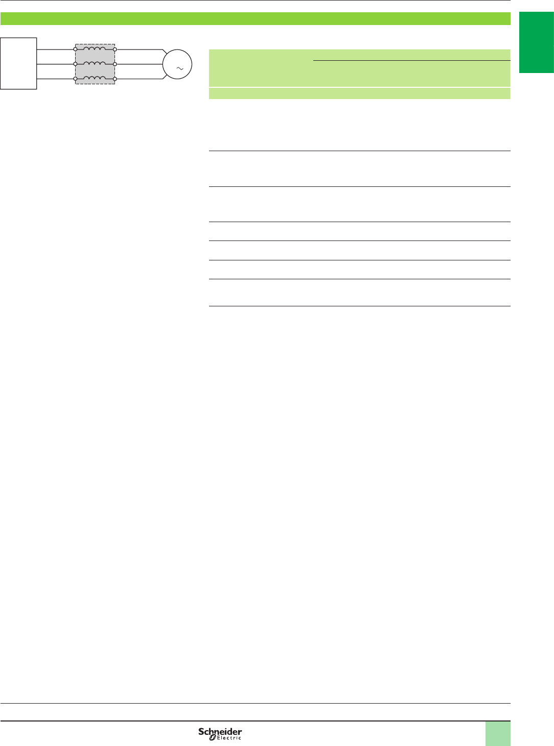
1/83
Variable speed drives
Altivar 61: output lters
Option: motor chokes
Presentation
Motor chokes
Altivar 61 drives have been developed to operate with the following maximum motor
cable lengths:
For drives Maximum length of motor cable
For a maximum
switching
frequency
Shielded cable Unshielded cable
kHz m m
ATV61HpppM3
ATV61HD11M3X, HD15M3X
ATV61H075N4…HD18N4
ATV61W075N4…WD18N4
ATV61W075N4C…WD18N4C
4 50 100
ATV61HD18M3X…HD90M3X
ATV61HD37N4…HC63N4
ATV61QC11N4…QC63N4
2.5 100 200
ATV61HD22N4, HD30N4
ATV61WD22N4…WD90N4
ATV61WD22N4C…WD90N4C
4 100 200
ATV61HpppS6X 4 30 50
ATV61HU30Y…HD30Y 4 10 20
ATV61HD37Y…HD90Y 2.5 10 20
ATV61HC11Y…HC80Y
ATV61QC13Y…QC80Y 2.5 15 30
Motor chokes allow operation with motor cables which are longer than these
maximum lengths and/or limit the dv/dt at the motor terminals to:
b500 V/ms for 400 V three-phase line supplies
b750 V/ms for 500 V three-phase line supplies
b1000 V/ms for 500 V three-phase line supplies
They are also used to:
b�Limit overvoltages at the motor terminals to:
v 1000 V at 400 V a (rms value)
v 1300 V at 500 V a (rms value)
v 1600 V at 690 V a (rms value)
b�Filter interference caused by opening of a contactor placed between the lter and
the motor
b�Reduce the motor earth leakage current
Choke performance is ensured by not exceeding the cable lengths given on pages
1/84 and 1/85. For an application with several motors connected in parallel, the
cable length must include all cabling. If a cable longer than that recommended is
used, the motor chokes may overheat.
537298
M1
3
Altivar 61
Motor choke
Variable speed drives:
page 1/16 Drive/option combinations:
page 1/34
2
1
3
4
5
6
7
8
9
10
2
1
3
4
5
6
7
8
9
10
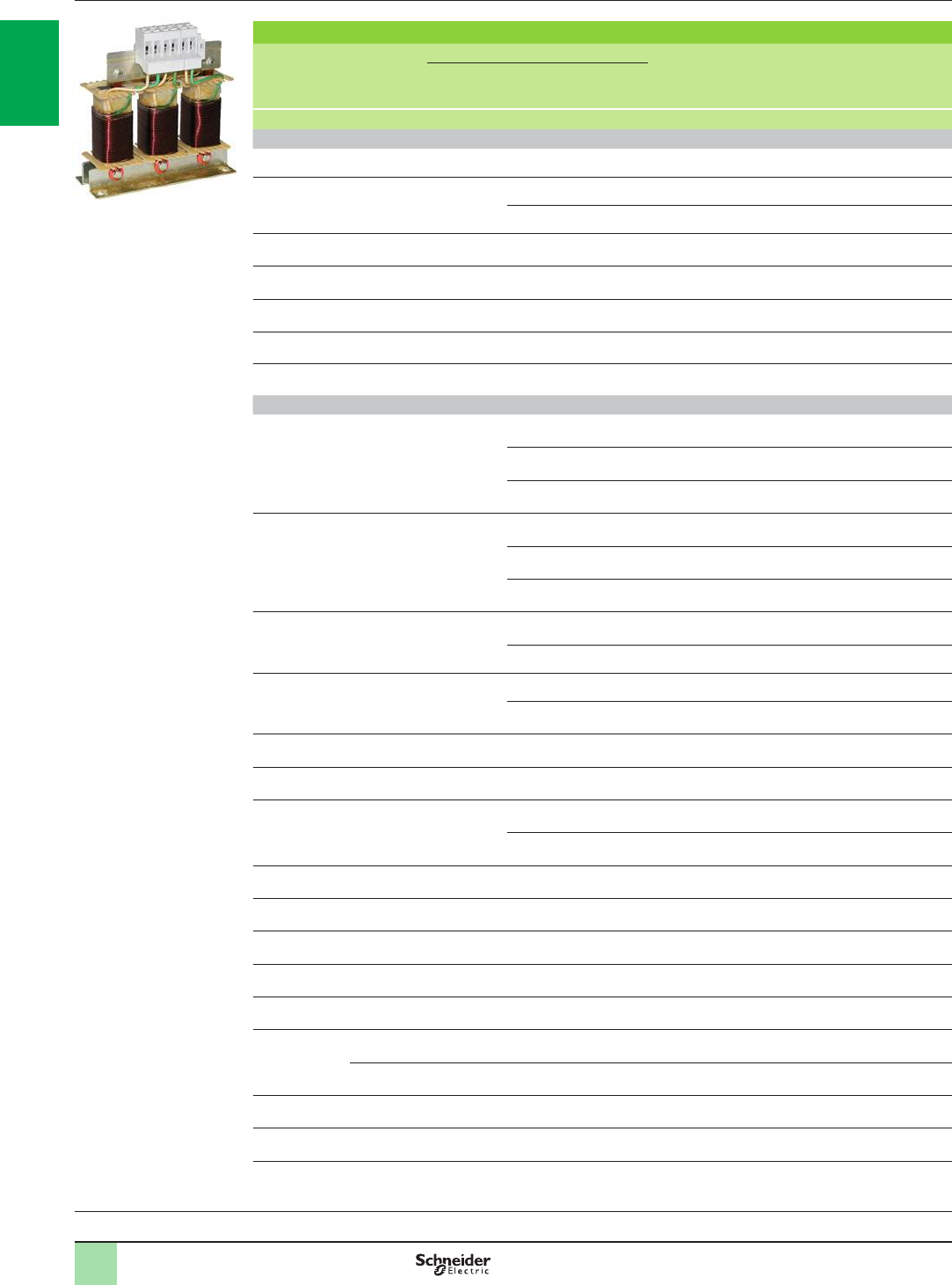
1/84
Variable speed drives
Altivar 61: output lters
Option: motor chokes
References
Motor chokes
For drives Maximum length of motor cable Losses Nominal
current Order
in
multiples
of
Unit
reference Weight
Maximum
switching
frequency
Shielded Unshielded
kHz m m W A kg
Three-phase supply voltage: 200…240 V 50/60 Hz
ATV61H075M3…HU22M3 4 150 300 150 12 –VW3A5101 5.500
ATV61HU30M3…HU75M3 4 200 260 250 48 –VW3A5102 8.000
300 300 350 90 –VW3A5103 10.000
ATV61HD11M3X, HD15M3X 4 150 300 350 90 –VW3A5103 10.000
ATV61HD18M3X, HD22M3X 2.5 150 300 350 90 –VW3A5103 10.000
ATV61HD30M3X…HD45M3X 2.5 150 300 430 215 3VW3A5104 15.500
ATV61HD55M3X, HD75M3X 2.5 150 300 475 314 3VW3A5105 32.000
ATV61HD90M3X 2.5 250 300 530 481 3VW3A5106 58.000
Three-phase supply voltage: 380…480 V 50/60 Hz
ATV61H075N4…HU40N4
ATV61W075N4…WU40N4
ATV61W075N4C…WU40N4C
4 75 90 150 12 –VW3A5101 5.500
85 95 250 48 –VW3A5102 8.000
160 200 350 90 –VW3A5103 10.000
ATV61HU55N4…HD18N4
ATV61WU55N4…WD18N4
ATV61WU55N4C…WD18N4C
4 85 95 250 48 –VW3A5102 8.000
160 200 350 90 –VW3A5103 10.000
200 300 430 215 3VW3A5104 15.500
ATV61HD22N4, HD30N4
ATV61WD22N4, WD30N4
ATV61WD22N4C, WD30N4C
4 140 170 350 90 –VW3A5103 10.000
150 300 430 215 3VW3A5104 15.500
ATV61WD37N4
ATV61WD37N4C 4 97 166 350 90 –VW3A5103 10.000
200 300 430 215 3VW3A5104 15.500
ATV61WD45N4…WD75N4
ATV61WD45N4C…WD75N4C 4 150 300 430 215 3VW3A5104 15.500
ATV61WD90N4
ATV61WD90N4C 4 200 300 430 215 3VW3A5104 15.500
ATV61HD37N4 2.5 97 166 350 90 –VW3A5103 10.000
200 300 430 215 3VW3A5104 15.500
ATV61HD45N4…HD75N4 2.5 150 300 430 215 3VW3A5104 15.500
ATV61HD90N4
ATV61QC11N4 2.5 200 300 430 215 3VW3A5104 15.500
ATV61HC11N4, HC13N4
ATV61QC13N4, QC16N4 2.5 150 250 475 314 3VW3A5105 32.000
ATV61HC16N4, HC22N4
ATV61QC20N4, QC25N4 2.5 250 300 530 481 3VW3A5106 58.000
ATV61HC25N4, HC31N4
ATV61QC31N4 2.5 200 250 598 759 3VW3A5107 93.000
ATV61HC40N4 Motor
P 355 kW 2.5 200 250 598 759 3VW3A5107 93.000
Motor
P 400 kW 2.5 250 300 682 1188 3VW3A5108 120.000
ATV61QC40N4 2.5 200 250 598 759 3VW3A5107 93.000
ATV61HC50N4, HC63N4
ATV61QC50N4, QC63N4 2.5 250 300 682 1188 3VW3A5108 120.000
PF121624
VW3A5101
Variable speed drives:
page 1/16 Drive/option combinations:
page 1/34
2
1
3
4
5
6
7
8
9
10
2
1
3
4
5
6
7
8
9
10
1/85
Variable speed drives
Altivar 61: output lters
Option: motor chokes
References (continued)
Motor chokes (continued)
For drives Maximum length of motor cable Losses Nominal
current Order
in
multiples
of
Unit
reference Weight
Maximum
switching
frequency
Shielded Unshielded
kHz m m W A kg
Three-phase supply voltage: 500…600 V 50/60 Hz (1)
ATV61HU22S6X…
HU75S6X 4 50 100 250 48 –VW3A5102 8.000
75 150 350 90 –VW3A5103 10.000
150 250 700 90 –2 x VW3A5103 20.000
150 250 430 215 3VW3A5104 15.500
250 400 860 215 32 x VW3A5104 31.000
Three-phase supply voltage: 500…690 V 50/60 Hz (2)
ATV61HU30Y…HD11Y 4 45 70 250 48 –VW3A5102 8.000
65 100 350 90 –VW3A5103 10.000
100 150 700 90 –2 x VW3A5103 20.000
100 150 430 215 3VW3A5104 15.500
ATV61HD15Y…HD30Y 4 65 100 350 90 –VW3A5103 10.000
100 150 700 90 –2 x VW3A5103 20.000
100 150 430 215 3VW3A5104 15.500
150 250 860 215 32 x VW3A5104 31.000
ATV61HD37Y…HD90Y 2.5 150 250 430 215 3VW3A5104 15.500
250 300 860 215 32 x VW3A5104 31.000
ATV61HC11Y… HC16Y
ATV61QC13Y 2.5 150 250 430 215 3VW3A5104 15.500
250 400 860 215 32 x VW3A5104 31.000
ATV61HC20Y, HC25Y
ATV61QC16Y, QC20Y 2.5 150 250 475 314 3VW3A5105 32.000
250 400 950 314 32 x VW3A5105 64.000
ATV61HC31Y, HC40Y
ATV61QC25Y, QC31Y 2.5 150 250 530 481 3VW3A5106 58.000
250 400 1060 481 32 x VW3A5106 116.000
ATV61HC50Y, HC63Y
ATV61QC40Y, QC50Y 2.5 150 250 598 759 3VW3A5107 93.000
250 400 1196 759 32 x VW3A5107 186.000
ATV61HC80Y
ATV61QC63Y, QC80Y 2.5 150 250 682 1188 3VW3A5108 120.000
250 400 1364 1188 32 x VW3A5108 240.000
IP 20 protection kits
Description For motor chokes Reference Weight
kg
Mechanical kit including
an IP 20 cover and
cable clips
VW3A9612 –
VW3A9613 –
(1) Maximum length given for a 600 V 60 Hz three-phase supply voltage.
(2) Maximum length given for a 690 V 50 Hz three-phase supply voltage.
Variable speed drives:
page 1/16 Drive/option combinations:
page 1/34
2
1
3
4
5
6
7
8
9
10
2
1
3
4
5
6
7
8
9
10

1/86
Variable speed drives
Altivar 61: output lters
Option: sinus lters
Presentation
Sinus lters
Sinus lters allow Altivar 61 drives to operate with long motor cables or signicant
motor noise reduction.
For ATV61HpppM3, ATV61HD11M3X...HD45M3X, ATV61H075N4…HD75N4,
ATV61W075N4…WD90N4 and ATV61W075N4C…WD90N4C and
ATV61HC11Y...HC80Y drives, they also allow the use of unshielded cables while still
complying with the standards relating to radiated EMC emissions (EN 55011 class A
Gr1 and IEC/EN 61800-3 category C2).
Sinus lters only operate with a voltage/frequency drive ratio.
Sinus lters are never compatible with the voltage sensorless ux vector control
prole.
Applications
For ATV61HpppM3, ATV61HD11M3X...HD45M3X, ATV61H075N4...HD75N4 and
ATV61HC11Y...HC80Y drives, applications requiring:
b�Long cable runs
b�Mechanical restrictions preventing the use of shielded cables
b�An intermediate transformer between the drive and the motor
b�A reduction in motor noise
b�Motors connected in parallel
For ATV61HD55M3X...HD90M3X, ATV61HD90N4...HC63N4 and
ATV61HC11Y...HC80Y drives, applications requiring:
b�An intermediate transformer between the drive and the motor
b�A reduction in electromagnetic motor noise
When using a step-up voltage transformer for a motor current above 1000 V, use of a
sinus lter is strongly recommended.
Sinus lters can be used with ATV61HUppY and ATV61HDppY drives. For more
information, please contact our Customer Care Centre.
Variable speed drives:
page 1/16 Drive/option combinations:
page 1/34
2
1
3
4
5
6
7
8
9
10
2
1
3
4
5
6
7
8
9
10

1/87
Variable speed drives
Altivar 61: output lters
Option: sinus lters
References
Sinus lters
For drives Nominal
current Losses
at 100 Hz Reference Weight
A W kg
Three-phase supply voltage: 200...240 V 50/60 Hz
ATV61H075M3, HU15M3 (1) 11 50 VW3A5201 8.000
ATV61HU22M3, HU30M3 16 70 VW3A5202 11.000
ATV61HU40M3... HU75M3 33 120 VW3A5203 22.000
ATV61HD11M3X, HD15M3X 66 180 VW3A5204 45.000
ATV61HD18M3X, HD22M3X 95 250 VW3A5205 60.000
ATV61HD30M3X... HD45M3X 180 400 VW3A5206 120.000
ATV61HD55M3X, HD75M3X 300 1360 VW3A5208 165.000
ATV61HD90M3X 400 1900 VW3A5209 190.000
Three-phase supply voltage: 380...480 V 50/60 Hz
ATV61H075N4...HU40N4 (1)
ATV61W075N4...WU40N4
ATV61W075N4C...WU40N4C
11 50 VW3A5212 8.000
ATV61HU55N4
ATV61WU55N4
ATV61WU55N4C
16 70 VW3A5213 11.000
ATV61HU75N4...HD15N4
ATV61WU75N4...WD15N4
ATV61WU75N4C...WD15N4C
33 120 VW3A5214 22.000
ATV61HD18N4...HD30N4
ATV61WD18N4...WD30N4
ATV61WD18N4C...WD30N4C
66 180 VW3A5212 45.000
ATV61HD37N4, HD45N4
ATV61WD37N4, WD45N4
ATV61WD37N4C, WD45N4C
95 250 VW3A5213 60.000
ATV61HD55N4, HD75N4
ATV61WD55N4, WD75N4
ATV61WD55N4C, WD75N4C
180 400 VW3A5214 120.000
ATV61HD90N4, HC11N4
ATV61WD90N4
ATV61WD90N4C
ATV61QC11N4
200 945 VW3A5212 130.000
ATV61HC13N4, HC16N4
ATV61QC13N4, QC16N4 300 1360 VW3A5213 165.000
ATV61HC22N4
ATV61QC20N4 400 1900 VW3A5214 190.000
ATV61HC25N4
ATV61QC25N4 600 2370 VW3A5212 260.000
ATV61HC31N4
ATV61QC31N4 600 2370 VW3A5213 260.000
ATV61HC40N4
ATV61QC40N4 Motor P 355 kW/
- HP
600 2370 VW3A5214 260.000
Motor P 400 kW/
600 HP 1200 5150 VW3A5212 600.000
ATV61HC50N4
ATV61QC50N4 1200 5150 VW3A5213 600.000
ATV61HC63N4
ATV61QC63N4 1200 5150 VW3A5214 600.000
Three-phase supply voltage: 500...690 V 50/60 Hz
ATV61HC11Y...HC20Y 240 1500 VW3A5212 210.000
ATV61HC25Y...HC40Y 460 2800 VW3A5213 300.000
ATV61HC50Y...HC80Y 900 4810 VW3A5214 400.000
(1)�For ATV61H075M3, HU15M3, ATV61H075N4 and HU15N4 drives, it is advisable to use a lower power motor with a sinus lter.
Variable speed drives:
page 1/16 Drive/option combinations:
page 1/34
2
1
3
4
5
6
7
8
9
10
2
1
3
4
5
6
7
8
9
10
1/88
Applications
Circuit-breaker/contactor/drive combinations can be used to ensure continuous service of the installation with
optimum safety.
The type of circuit-breaker/contactor coordination selected can reduce maintenance costs in the event of a motor
short-circuit by minimizing the time required to make the necessary repairs and the cost of replacement
equipment. The suggested combinations provide type 1 or type 2 coordination depending on the drive rating.
Type 2 coordination: A motor short-circuit will not damage the device or affect its settings. The motor starter
should be able to operate once the electrical fault has been removed. The electrical isolation provided by the
circuit-breaker will not be affected by the short-circuit. Welding of the contactor contacts is permissible if they can
be separated easily.
Type 1 coordination: The electrical isolation provided by the circuit-breaker will not be affected by the incident
and no other elements apart from the contactor are damaged as a result of the motor short-circuit.
The drive controls the motor, provides protection against short-circuits between the drive and the motor and
protects the motor cable against overloads. Overload protection is provided by the drive's motor thermal
protection. If this protection is removed, external thermal protection must be provided. Before restarting the
installation, the cause of the trip must be removed.
Motor starters for IP 20 drives
Motor Drive Circuit-breaker Line contactor
Power (1) Reference Reference (2) Rating Irm Reference (3) (4)
kW HP A A
Single-phase supply voltage: 200…240 V 50/60 Hz. Type 2 coordination
0.37 0.5 ATV61H075M3 GV2L14 10 – LC1D09pp
0.75 1ATV61HU15M3 GV2L16 14 – LC1D18pp
1.5 2ATV61HU22M3 GV2L20 18 – LC1D25pp
2.2 3ATV61HU30M3 GV2L32 32 – LC1D32pp
3–ATV61HU40M3
(5) GV2L32 32 – LC1D32pp
45ATV61HU55M3
(5) GV3L40 40 – LC1D40App
5.5 7.5 ATV61HU75M3
(5) GV3L50 50 – LC1D50App
Single-phase supply voltage: 200…240 V 50/60 Hz. Type 1 coordination
0.37 0.5 ATV61H075M3 GV2L14 10 – LC1D09pp
0.75 1ATV61HU15M3 GV2L16 14 – LC1D09pp
1.5 2ATV61HU22M3 GV2L20 18 – LC1D09pp
2.2 3ATV61HU30M3 GV2L32 32 – LC1D18pp
3–ATV61HU40M3
(5) GV2L32 32 – LC1D18pp
45ATV61HU55M3
(5) GV3L40 40 300 LC1D32pp
5.5 7.5 ATV61HU75M3
(5) GV3L50 50 300 LC1D38pp
(1) Standard power ratings for 230 V 50/60 Hz 4-pole motors.
The values expressed in HP conform to the NEC (National Electrical Code).
(2) Breaking capacity of circuit-breakers according to standard IEC 60947-2:
Circuit-breaker Icu (kA) for 240 V
GV2L14, GV2L16 130
GV2L20, GV2L32
GV3L40, GV3L50 50
(3) Composition of contactors:
LC1D09 to LC1D50A: 3 poles + 1 N/O auxiliary contact and 1 N/C auxiliary contact.
(4) Replace pp with the control circuit voltage reference indicated in the table below:
Volts a24 48 110 220 230 240
LC1Dpp 50 Hz B5 E5 F5 M5 P5 U5
60 Hz B6 E6 F6 M6 – U6
50/60 Hz B7 E7 F7 M7 P7 U7
For other voltages available between 24 V and 660 V, or a DC control circuit, please contact our Customer Care Centre.
(5) A line choke must be added (see page 1/66).
+
+
Combinations for
customer assembly Variable speed drives
Altivar 61
Motor starters: 200…240 V supply voltage
GV2L20
+
LC1D25pp
+
ATV61HU22M3
PF107483SE DF526153 DF526131
Variable speed drives:
page 1/16 Options:
page 1/46 Drive/option combinations:
page 1/34
2
1
3
4
5
6
7
8
9
10
2
1
3
4
5
6
7
8
9
10
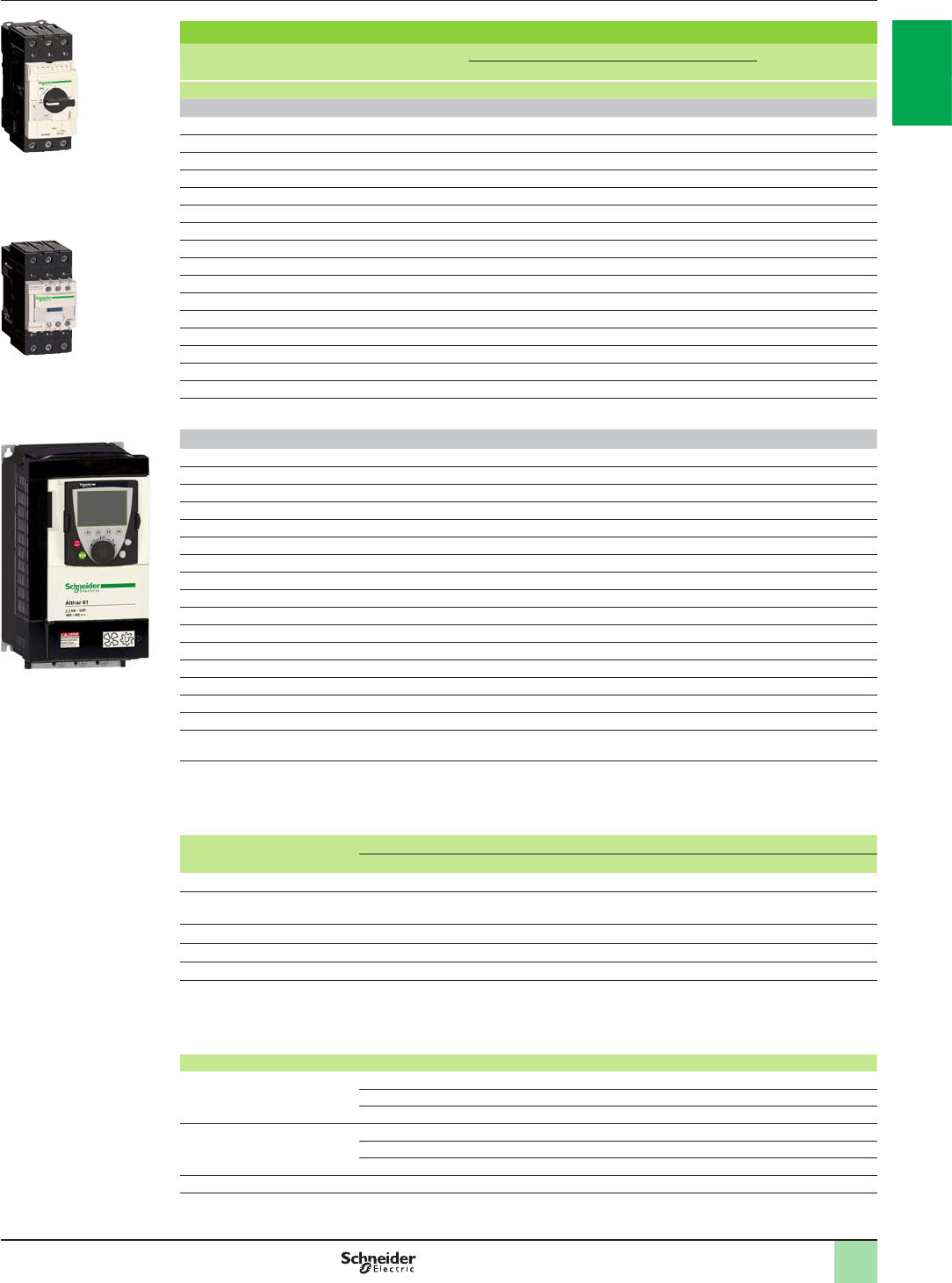
1/89
Combinations for
customer assembly
(continued)
Variable speed drives
Altivar 61
Motor starters: 200…240 V supply voltage
Motor starters for IP 20 drives
Motor Drive Circuit-breaker Line contactor
Power (1) Reference Reference (2) Rating Irm Reference (3) (4)
kW HP A A
Three-phase supply voltage: 200…240 V 50/60 Hz. Type 2 coordination
0.75 1ATV61H075M3 GV2L10 6.3 – LC1D09pp
1.5 2ATV61HU15M3 GV2L16 14 – LC1D18pp
2.2 3ATV61HU22M3 GV2L20 18 – LC1D18pp
3–ATV61HU30M3 GV2L22 25 – LC1D25pp
45ATV61HU40M3 GV2L32 32 – LC1D25pp
5.5 7.5 ATV61HU55M3 GV3L40 40 – LC1D40App
7.5 10 ATV61HU75M3 GV3L50 50 – LC1D50App
11 15 ATV61HD11M3X GV3L65 65 – LC1D65App
15 20 ATV61HD15M3X NS80HMA80 80 480 LC1D80pp
18.5 25 ATV61HD18M3X NS80HMA80 80 480 LC1D80pp
22 30 ATV61HD22M3X NSX100pMA100 100 600 LC1D95pp
30 40 ATV61HD30M3X NSX160pMA150 150 1350 LC1D150pp
37 50 ATV61HD37M3X NSX160pMA150 150 1350 LC1D150pp
45 60 ATV61HD45M3X NSX250pMA220 220 1980 LC1F185pp
55 75 ATV61HD55M3X NSX250pMA220 220 1980 LC1F225pp
75 100 ATV61HD75M3X NSX400p Micrologic 1.3M 320 1920 LC1F265pp
90 125 ATV61HD90M3X NSX630p Micrologic 1.3M 500 3000 LC1F330pp
Three-phase supply voltage: 200…240 V 50/60 Hz. Type 1 coordination
0.75 1ATV61H075M3 GV2L10 6.3 – LC1D09pp
1.5 2ATV61HU15M3 GV2L16 14 – LC1D09pp
2.2 3ATV61HU22M3 GV2L20 18 – LC1D09pp
3–ATV61HU30M3 GV2L22 25 – LC1D18pp
45ATV61HU40M3 GV2L32 32 – LC1D18pp
5.5 7.5 ATV61HU55M3 GV3L40 40 – LC1D25pp
7.5 10 ATV61HU75M3 GV3L50 50 – LC1D32pp
11 15 ATV61HD11M3X GV3L65 65 – LC1D40App
15 20 ATV61HD15M3X NS80HMA80 80 480 LC1D50App
18.5 25 ATV61HD18M3X NS80HMA80 80 480 LC1D50App
22 30 ATV61HD22M3X NSX100pMA100 100 600 LC1D80pp
30 40 ATV61HD30M3X NSX160pMA150 150 1350 LC1D95pp
37 50 ATV61HD37M3X NSX160pMA150 150 1350 LC1D115pp
45 60 ATV61HD45M3X NSX250pMA220 220 1980 LC1D115pp
55 75 ATV61HD55M3X NSX250pMA220 220 1980 LC1D115pp
75 100 ATV61HD75M3X NSX400p Micrologic 1.3M 320 1920 LC1F185pp
90 125 ATV61HD90M3X NSX630p Micrologic 1.3M 500 3000 LC1F265pp
(1) Standard power ratings for 230 V 50/60 Hz 4-pole motors.
The values expressed in HP conform to the NEC (National Electrical Code).
(2) For references to be completed, replace the dot with the letter corresponding to the circuit-breaker breaking performance
(B, F, N, H, S or L).
Breaking capacity of circuit-breakers according to standard IEC 60947-2:
Circuit-breaker Icu (kA) for 240 V
B F N H S L
GV2L10 130 – – – – – –
GV2L16…L32
GV3L40…L65 50 – – – – – –
NS80HMA 100 – – – – – –
NSX100pMA…NSX250pMA – 40 85 90 100 120 150
NSX400p, NSX630p– – 40 85 100 120 150
(3) Composition of contactors:
LC1D09 to LC1D150: 3 poles + 1 N/O auxiliary contact and 1 N/C auxiliary contact.
LC1F185 to LC1F330: 3 poles. To add auxiliary contacts or other accessories, please refer to the “Motor-starter solutions -
Control and protection components” catalogue.
(4) Replace pp with the control circuit voltage reference indicated in the table below:
Volts a24 48 110 220 230 240
LC1D09…D150 50 Hz B5 E5 F5 M5 P5 U5
60 Hz B6 E6 F6 M6 – U6
50/60 Hz B7 E7 F7 M7 P7 U7
LC1F185, F225 50 Hz (LX1 coil) B5 E5 F5 M5 P5 U5
60 Hz (LX1 coil) – E6 F6 M6 – U6
40…400 Hz (LX9 coil) – E7 F7 M7 P7 U7
LC1F265, LC1F330 40…400 Hz (LX1 coil) B7 E7 F7 M7 P7 U7
For other voltages available between 24 V and 660 V, or a DC control circuit, please contact our Customer Care Centre.
+
DF526156PF107483SE
GV3L40
+
LC1D40App
+
ATV61HU55M3
+
PDF107941
2
1
3
4
5
6
7
8
9
10
2
1
3
4
5
6
7
8
9
10

1/90
Motor starters for IP 20 drives
Motor Drive Circuit-breaker Line contactor
Power (1) Reference Reference (2) Rating Irm Reference (4) (5)
kW HP A A
Three-phase supply voltage: 380…415 V 50/60 Hz. Type 2 coordination
0.75 1ATV61H075N4 GV2L08 4–LC1D09pp
1.5 2ATV61HU15N4 GV2L10 6.3 – LC1D09pp
2.2 3ATV61HU22N4 GV2L14 10 – LC1D25pp
3–ATV61HU30N4 GV2L16 14 – LC1D25pp
45ATV61HU40N4 GV2L16 14 – LC1D25pp
5.5 7.5 ATV61HU55N4 GV2L22 25 – LC1D25pp
7.5 10 ATV61HU75N4 GV3L32 32 – LC1D40App
11 15 ATV61HD11N4 GV3L40 40 – LC1D50App
15 20 ATV61HD15N4 GV3L50 50 – LC1D65App
18.5 25 ATV61HD18N4 GV3L50 50 – LC1D65App
22 30 ATV61HD22N4 GV3L65 65 – LC1D65App
30 40 ATV61HD30N4 NS80HMA80 80 480 LC1D80pp
37 50 ATV61HD37N4 NSX100pMA100 100 600 LC1D95pp
45 60 ATV61HD45N4 NSX160pMA150 150 1350 LC1D115pp
55 75 ATV61HD55N4 NSX160pMA150 150 1350 LC1D150pp
75 100 ATV61HD75N4 NSX250pMA220 220 1980 LC1F185pp
90 125 ATV61HD90N4 NSX250pMA220 220 1980 LC1F185pp
110 150 ATV61HC11N4 NSX250pMA220 220 1980 LC1F225pp
132 200 ATV61HC13N4 NSX400p Micrologic 1.3M 320 1920 LC1F265pp
160 250 ATV61HC16N4 NSX400p Micrologic 1.3M 320 1920 LC1F330pp
200 300 ATV61HC22N4 NSX630p Micrologic 1.3M 500 3000 LC1F400pp
220 350 ATV61HC22N4 NSX630p Micrologic 1.3M 500 3000 LC1F400pp
250 400 ATV61HC25N4 NSX630p Micrologic 1.3M 500 3000 LC1F500pp
280 450 ATV61HC31N4 NSX630p Micrologic 1.3M 500 3000 LC1F500pp
315 500 ATV61HC31N4 NS800L Micrologic 2 or 5 (LR OFF) 800 1600 LC1F630pp
355 – ATV61HC40N4 NS800L Micrologic 2 or 5 (LR OFF) 800 1600 LC1F630pp
400 600 ATV61HC40N4 NS800L Micrologic 2 or 5 (LR OFF) 800 1600 LC1F800pp
500 700 ATV61HC50N4
NS1000L Micrologic 2 or 5 (LR OFF)
1000 2000 LC1BLpp
560 800 ATV61HC63N4
NS1000L Micrologic 2 or 5 (LR OFF)
1000 2000 LC1BMpp
(1) Standard power ratings for 400 V 50/60 Hz 4-pole motors.
The values expressed in HP conform to the NEC (National Electrical Code).
(2) For references to be completed, replace the dot with the letter corresponding to the circuit-breaker breaking performance
(B, F, N, H, S or L).
Breaking capacity of circuit-breakers according to standard IEC 60947-2:
Circuit-breaker Icu (kA) for 400 V
B F N H S L
GV2L08…L16 (3) 130 – – – – – –
GV2L16 (3), GV2L22
GV3L32…L65 50 – – – – – –
NS80HMA 70 – – – – – –
NSX100pMA…NSX250pMA – 25 36 50 70 100 150
NSX400p, NSX630p– – 36 50 70 100 150
NS800L Micrologic 2 or 5
NS1000L Micrologic 2 or 5 – – – – – – 150
(3) GV2L16: Icu of 130 when combined with an ATV61HU30N4, Icu of 50 when combined with an ATV61HU40N4.
(4) Composition of contactors:
LC1D09 to LC1D150: 3 poles + 1 N/O auxiliary contact and 1 N/C auxiliary contact.
LC1Fppp, LC1BL and LC1BM: 3 poles. To add auxiliary contacts or other accessories, please refer to the “Motor-starter
solutions - Control and protection components” catalogue.
(5) Replace pp with the control circuit voltage reference indicated in the table below:
Volts a24 48 110 220 230 240
LC1D09…D150 50 Hz B5 E5 F5 M5 P5 U5
60 Hz B6 E6 F6 M6 – U6
50/60 Hz B7 E7 F7 M7 P7 U7
LC1F185, F225 50 Hz (LX1 coil) B5 E5 F5 M5 P5 U5
60 Hz (LX1 coil) – E6 F6 M6 – U6
40…400 Hz (LX9 coil) – E7 F7 M7 P7 U7
LC1F265, F330 40…400 Hz (LX1 coil) B7 E7 F7 M7 P7 U7
LC1F400…F800 40…400 Hz (LX1 coil) – E7 F7 M7 P7 U7
LC1BL, LC1BM 50…400 Hz (WB1 coil) – – F M P U
For other voltages available between 24 V and 660 V, or a DC control circuit, please contact our Customer Care Centre.
Combinations for
customer assembly
(continued)
Variable speed drives
Altivar 61
Motor starters: 380…415 V supply voltage
NSX160pMA150
+
LC1D115pp
+
ATV61HD45N4
PF107583SE
+
DPF526158
+
PF095316
2
1
3
4
5
6
7
8
9
10
2
1
3
4
5
6
7
8
9
10
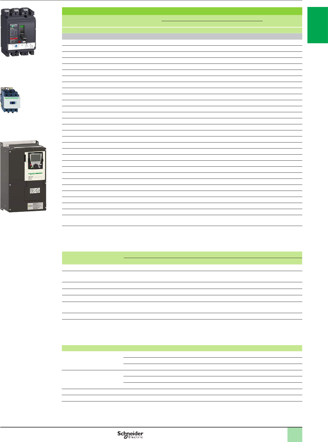
1/91
Motor starters for IP 20 drives
Motor Drive Circuit-breaker Line contactor
Power (1) Reference Reference (2) Rating Irm Reference (3) (4)
kW HP A A
Three-phase supply voltage: 380…415 V 50/60 Hz. Type 1 coordination
0.75 1ATV61H075N4 GV2L08 4–LC1D09pp
1.5 2ATV61HU15N4 GV2L10 6.3 – LC1D09pp
2.2 3ATV61HU22N4 GV2L14 10 – LC1D09pp
3–ATV61HU30N4 GV2L16 14 – LC1D09pp
45ATV61HU40N4 GV2L16 14 – LC1D18pp
5.5 7.5 ATV61HU55N4 GV2L22 25 – LC1D25pp
7.5 10 ATV61HU75N4 GV3L32 32 – LC1D40App
11 15 ATV61HD11N4 GV3L40 40 – LC1D40App
15 20 ATV61HD15N4 GV3L50 50 – LC1D50App
18.5 25 ATV61HD18N4 GV3L50 50 – LC1D50App
22 30 ATV61HD22N4 GV3L65 65 – LC1D65App
30 40 ATV61HD30N4 NS80HMA80 80 480 LC1D65App
37 50 ATV61HD37N4 NSX100pMA100 100 600 LC1D95pp
45 60 ATV61HD45N4 NSX160pMA150 150 1350 LC1D115pp
55 75 ATV61HD55N4 NSX160pMA150 150 1350 LC1D115pp
75 100 ATV61HD75N4 NSX250pMA220 220 1980 LC1F185pp
90 125 ATV61HD90N4 NSX250pMA220 220 1980 LC1F185pp
110 150 ATV61HC11N4 NSX250pMA220 220 1980 LC1F225pp
132 200 ATV61HC13N4 NSX400p Micrologic 1.3M 320 1920 LC1F265pp
160 250 ATV61HC16N4 NSX400p Micrologic 1.3M 320 1920 LC1F330pp
200 300 ATV61HC22N4 NSX630p Micrologic 1.3M 500 3000 LC1F400pp
220 350 ATV61HC22N4 NSX630p Micrologic 1.3M 500 3000 LC1F400pp
250 400 ATV61HC25N4 NSX630p Micrologic 1.3M 500 3000 LC1F500pp
280 450 ATV61HC31N4 NSX630p Micrologic 1.3M 500 3000 LC1F500pp
315 500 ATV61HC31N4 NS800L Micrologic 2 or 5 (LR OFF) 800 1600 LC1F630pp
355 – ATV61HC40N4 NS800L Micrologic 2 or 5 (LR OFF) 800 1600 LC1F630pp
400 600 ATV61HC40N4 NS800L Micrologic 2 or 5 (LR OFF) 800 1600 LC1F630pp
500 700 ATV61HC50N4 NS1000L Micrologic 2 or 5 (LR OFF) 1000 2000 LC1F630pp
560 800 ATV61HC63N4 NS1000L Micrologic 2 or 5 (LR OFF) 1000 2000 LC1F630pp
630 900 ATV61HC63N4 NS1250 Micrologic 2 or 5 (LR OFF) 1000 2000 LC1F630pp
(1) Standard power ratings for 400 V 50/60 Hz 4-pole motors.
The values expressed in HP conform to the NEC (National Electrical Code).
(2) For references to be completed, replace the dot with the letter corresponding to the circuit-breaker breaking performance
(B, F, N, H, S or L).
Breaking capacity of circuit-breakers according to standard IEC 60947-2:
Circuit-breaker Icu (kA) for 400 V
B F N H S L
GV2L08…L14 130 – – – – – –
GV2L16, GV2L22
GV3L32…L65 50 – – – – – –
NS80HMA 70 – – – – – –
NSX100pMA…NSX250pMA – 25 36 50 65 100 150
NSX400p, NSX630p– – 36 50 65 100 150
NS800L Micrologic 2 or 5
NS1000L Micrologic 2 or 5 – – – – – – 150
NS1250 Micrologic 2 or 5 – – – 50 65 – –
(3) Composition of contactors:
LC1D09 to LC1D115: 3 poles + 1 N/O auxiliary contact and 1 N/C auxiliary contact.
LC1F185 to F630: 3 poles. To add auxiliary contacts or other accessories, please refer to the “Motor-starter solutions - Control
and protection components” catalogue.
(4) Replace pp with the control circuit voltage reference indicated in the table below:
Volts a24 48 110 220 230 240
LC1D09…D115 50 Hz B5 E5 F5 M5 P5 U5
60 Hz B6 E6 F6 M6 – U6
50/60 Hz B7 E7 F7 M7 P7 U7
LC1F185, F225 50 Hz (LX1 coil) B5 E5 F5 M5 P5 U5
60 Hz (LX1 coil) – E6 F6 M6 – U6
40…400 Hz (LX9 coil) – E7 F7 M7 P7 U7
LC1F265, F330 40…400 Hz (LX1 coil) B7 E7 F7 M7 P7 U7
LC1F400…F630 40…400 Hz (LX1 coil) – E7 F7 M7 P7 U7
For other voltages available between 24 V and 660 V, or a DC control circuit, please contact our Customer Care Centre.
Combinations for
customer assembly
(continued)
Variable speed drives
Altivar 61
Motor starters: 380…415 V supply voltage
PF5107581SE
NSX100pMA100
+
LC1D95pp
+
ATV61HD37N4
+
DF526157
+
PF5095316
2
1
3
4
5
6
7
8
9
10
2
1
3
4
5
6
7
8
9
10
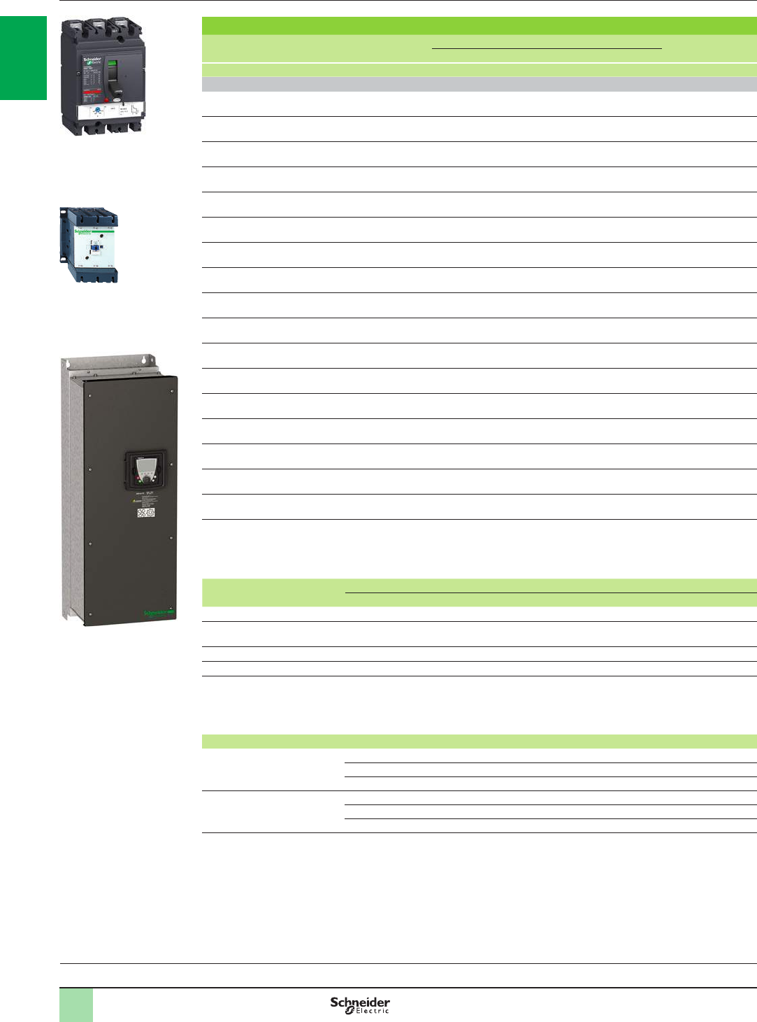
1/92
Motor starters for IP 54 drives
Motor Drive Circuit-breaker Line contactor
Power (1) Reference Reference (2) Rating Irm Reference (3) (4)
kW HP A A
Three-phase supply voltage: 380…415 V 50/60 Hz. Type 2 coordination
0.75 1ATV61W075N4
ATV61W075N4C GV2L07 2.5 – LC1D09pp
1.5 2ATV61WU15N4
ATV61WU15N4C GV2L08 4–LC1D09pp
2.2 3ATV61WU22N4
ATV61WU22N4C GV2L10 6.3 – LC1D09pp
3–ATV61WU30N4
ATV61WU30N4C GV2L14 10 – LC1D25pp
45ATV61WU40N4
ATV61WU40N4C GV2L14 10 – LC1D25pp
5.5 7.5 ATV61WU55N4
ATV61WU55N4C GV2L16 14 – LC1D25pp
7.5 10 ATV61WU75N4
ATV61WU75N4C GV3L32 32 – LC1D40App
11 15 ATV61WD11N4
ATV61WD11N4C GV3L40 40 – LC1D40App
15 20 ATV61WD15N4
ATV61WD15N4C GV3L50 50 – LC1D50App
18.5 25 ATV61WD18N4
ATV61WD18N4C GV3L50 50 – LC1D50App
22 30 ATV61WD22N4
ATV61WD22N4C GV3L65 65 – LC1D65App
30 40 ATV61WD30N4
ATV61WD30N4C NS80HMA80 80 480 LC1D80pp
37 50 ATV61WD37N4
ATV61WD37N4C NS80HMA80 80 480 LC1D80pp
45 60 ATV61WD45N4
ATV61WD45N4C NSX100pMA100 100 600 LC1D95pp
55 75 ATV61WD55N4
ATV61WD55N4C NSX160pMA150 150 1350 LC1D115pp
75 100 ATV61WD75N4
ATV61WD75N4C NSX160pMA150 150 1350 LC1D150pp
90 125 ATV61WD90N4
ATV61WD90N4C NSX250pMA220 220 1980 LC1F185pp
(1) Standard power ratings for 400 V 50/60 Hz 4-pole motors.
The values expressed in HP conform to the NEC (National Electrical Code).
(2) For references to be completed, replace the dot with the letter corresponding to the circuit-breaker breaking performance
(B, F, N, H, S or L).
Breaking capacity of circuit-breakers according to standard IEC 60947-2:
Circuit-breaker Icu (kA) for 400 V
B F N H S L
GV2L07…L14 130 – – – – – –
GV2L16
GV3L32…L65 50 – – – – – –
NS80HMA 70 – – – – – –
NSX100pMA …250pMA – 25 36 50 70 100 150
(3) Composition of contactors:
LC1D09 to LC1D150: 3 poles + 1 N/O auxiliary contact and 1 N/C auxiliary contact.
LC1F185: 3 poles. To add auxiliary contacts or other accessories, please refer to the “Motor-starter solutions - Control and
protection components” catalogue.
(4) Replace pp with the control circuit voltage reference given in the table below:
Volts a24 48 110 220 230 240
LC1D09…D150 50 Hz B5 E5 F5 M5 P5 U5
60 Hz B6 E6 F6 M6 – U6
50/60 Hz B7 E7 F7 M7 P7 U7
LC1F185 50 Hz (LX1 coil) B5 E5 F5 M5 P5 U5
60 Hz (LX1 coil) – E6 F6 M6 – U6
40…400 Hz (LX9 coil) – E7 F7 M7 P7 U7
For other voltages available between 24 V and 660 V, or a DC control circuit, please contact our Customer Care Centre.
Combinations for
customer assembly
(continued)
Variable speed drives
Altivar 61
Motor starters: 380…415 V supply voltage
PF095317
+
DPF526158
+
PF107492SE
NSX160pMA150
+
LC1D115pp
+
ATV61WD55N4
Variable speed drives:
page 1/16 Options:
page 1/46 Drive/option combinations:
page 1/34
2
1
3
4
5
6
7
8
9
10
2
1
3
4
5
6
7
8
9
10
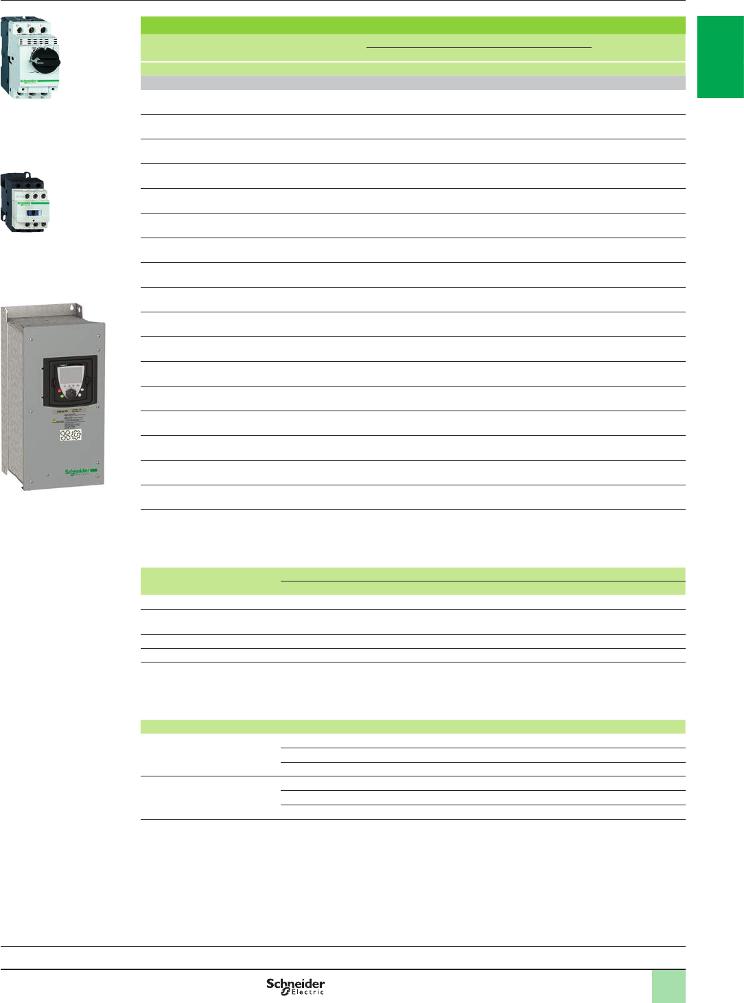
1/93
Motor starters for IP 54 drives
Motor Drive Circuit-breaker Line contactor
Power (1) Reference Reference (2) Rating Irm Reference (3) (4)
kW HP A A
Three-phase supply voltage: 380…415 V 50/60 Hz. Type 1 coordination
0.75 1ATV61W075N4
ATV61W075N4C GV2L07 2.5 – LC1D09pp
1.5 2ATV61WU15N4
ATV61WU15N4C GV2L08 4–LC1D09pp
2.2 3ATV61WU22N4
ATV61WU22N4C GV2L10 6.3 – LC1D09pp
3–ATV61WU30N4
ATV61WU30N4C GV2L14 10 – LC1D09pp
45ATV61WU40N4
ATV61WU40N4C GV2L14 10 – LC1D18pp
5.5 7.5 ATV61WU55N4
ATV61WU55N4C GV2L16 14 – LC1D18pp
7.5 10 ATV61WU75N4
ATV61WU75N4C GV3L32 32 – LC1D25pp
11 15 ATV61WD11N4
ATV61WD11N4C GV3L40 40 – LC1D40App
15 20 ATV61WD15N4
ATV61WD15N4C GV3L50 40 – LC1D50App
18.5 25 ATV61WD18N4
ATV61WD18N4C GV3L50 50 – LC1D50App
22 30 ATV61WD22N4
ATV61WD22N4C GV3L65 65 – LC1D65App
30 40 ATV61WD30N4
ATV61WD30N4C NS80HMA80 80 480 LC1D65App
37 50 ATV61WD37N4
ATV61WD37N4C NS80HMA80 80 480 LC1D80pp
45 60 ATV61WD45N4
ATV61WD45N4C NSX100pMA100 100 600 LC1D80pp
55 75 ATV61WD55N4
ATV61WD55N4C NSX160pMA150 150 1350 LC1D115pp
75 100 ATV61WD75N4
ATV61WD75N4C NSX160pMA150 150 1350 LC1D150pp
90 125 ATV61WD90N4
ATV61WD90N4C NSX250pMA220 220 1980 LC1F185pp
(1) Standard power ratings for 400 V 50/60 Hz 4-pole motors.
The values expressed in HP conform to the NEC (National Electrical Code).
(2) For references to be completed, replace the dot with the letter corresponding to the circuit-breaker breaking performance
(B, F, N, H, S or L).
Breaking capacity of circuit-breakers according to standard IEC 60947-2:
Circuit-breaker Icu (kA) for 400 V
B F N H S L
GV2L07…L14 130 – – – – – –
GV2L16
GV3L32…L65 50 – – – – – –
NS80HMA 70 – – – – – –
NSX100pMA… NSX250pMA – 25 36 50 70 100 150
(3) Composition of contactors:
LC1D09 to LC1D150: 3 poles + 1 N/O auxiliary contact and 1 N/C auxiliary contact.
LC1F185: 3 poles. To add auxiliary contacts or other accessories, please refer to the “Motor-starter solutions - Control and
protection components” catalogue.
Replace pp with the control circuit voltage reference indicated in the table below:
Volts a24 48 110 220 230 240
LC1D09…D150 50 Hz B5 E5 F5 M5 P5 U5
60 Hz B6 E6 F6 M6 – U6
50/60 Hz B7 E7 F7 M7 P7 U7
LC1F185 50 Hz (LX1 coil) B5 E5 F5 M5 P5 U5
60 Hz (LX1 coil) – E6 F6 M6 – U6
40…400 Hz (LX9 coil) – E7 F7 M7 P7 U7
For other voltages available between 24 V and 660 V, or a DC control circuit, please contact our Customer Care Centre.
Combinations for
customer assembly
(continued)
Variable speed drives
Altivar 61
Motor starters: 380…415 V supply voltage
+
DF526131
+
DF526150PF107495SE
GV2L07
+
LC1D09pp
+
ATV61W075N4
Variable speed drives:
page 1/16 Options:
page 1/46 Drive/option combinations:
page 1/34
2
1
3
4
5
6
7
8
9
10
2
1
3
4
5
6
7
8
9
10
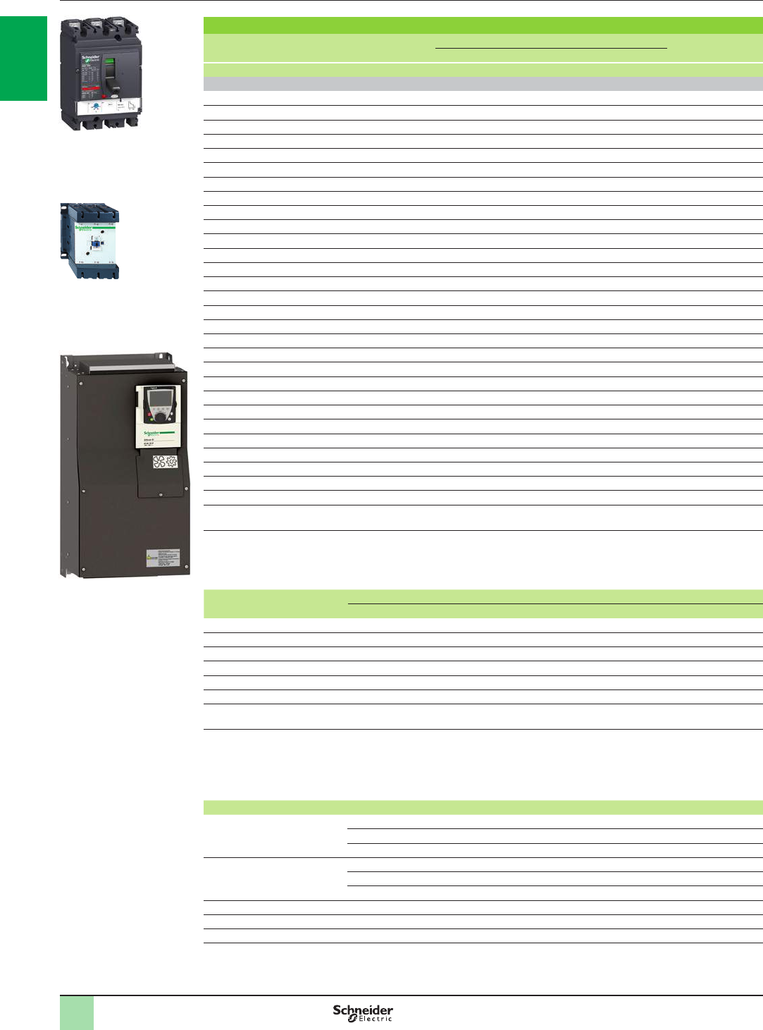
1/94
Motor starters for IP 20 drives
Motor Drive Circuit-breaker Line contactor
Power (1) Reference Reference (2) Rating Irm Reference (4) (5)
kW HP A A
Three-phase supply voltage: 440…480 V 50/60 Hz. Type 2 coordination
0.75 1ATV61H075N4 GV2L08 4 – LC1D25pp
1.5 2ATV61HU15N4 GV2L10 6.3 – LC1D25pp
2.2 3ATV61HU22N4 GV2L14 10 – LC1D25pp
3–ATV61HU30N4 GV2L14 10 – LC1D25pp
45ATV61HU40N4 GV2L16 14 – LC1D25pp
5.5 7.5 ATV61HU55N4 GV2L20 18 – LC1D25pp
7.5 10 ATV61HU75N4 GV3L25 25 – LC1D32pp
11 15 ATV61HD11N4 GV3L32 32 – LC1D40App
15 20 ATV61HD15N4 GV3L50 50 – LC1D50App
18.5 25 ATV61HD18N4 GV3L50 50 – LC1D50App
22 30 ATV61HD22N4 GV3L50 50 – LC1D65App
30 40 ATV61HD30N4 GV3L65 65 – LC1D65App
37 50 ATV61HD37N4 NS80HMA80 80 480 LC1D80pp
45 60 ATV61HD45N4 NSX100pMA100 100 600 LC1D115pp
55 75 ATV61HD55N4 NSX160pMA150 150 1350 LC1D115pp
75 100 ATV61HD75N4 NSX250pMA220 220 1980 LC1F185pp
90 125 ATV61HD90N4 NSX250pMA220 220 1980 LC1F185pp
110 150 ATV61HC11N4 NSX250pMA220 220 1980 LC1F185pp
132 200 ATV61HC13N4 NSX250pMA220 220 1980 LC1F265pp
160 250 ATV61HC16N4 NSX400p Micrologic 1.3M 320 1920 LC1F265pp
200 300 ATV61HC22N4 NSX630p Micrologic 1.3M 500 3000 LC1F400pp
220 350 ATV61HC22N4 NSX630p Micrologic 1.3M 500 3000 LC1F400pp
250 400 ATV61HC25N4 NSX630p Micrologic 1.3M 500 3000 LC1F500pp
280 450 ATV61HC31N4 NSX630p Micrologic 1.3M 500 3000 LC1F500pp
315 500 ATV61HC31N4 NS800L Micrologic 2 or 5 (LR OFF) 800 1600 LC1F630pp
355 –ATV61HC40N4 NS800L Micrologic 2 or 5 (LR OFF) 800 1600 LC1F630pp
400 600 ATV61HC40N4 NS800L Micrologic 2 or 5 (LR OFF) 800 1600 LC1F780pp
500 700 ATV61HC50N4
NS1000L Micrologic 2 or 5 (LR OFF)
1000 2000 LC1F780pp
560 800 ATV61HC63N4
NS1000L Micrologic 2 or 5 (LR OFF)
1000 2000 LC1F780pp
630 900 ATV61HC63N4
NS1000L Micrologic 2 or 5 (LR OFF)
1000 2000 LC1F780pp
(1) Standard power ratings for 400 V 50/60 Hz 4-pole motors.
The values expressed in HP conform to the NEC (National Electrical Code).
(2) For references to be completed, replace the dot with the letter corresponding to the circuit-breaker breaking performance
(B, F, N, H, S or L).
Breaking capacity of circuit-breakers according to standard IEC 60947-2:
Circuit-breaker Icu (kA) for 440 V
B F N H S L
GV2L08…GV2L14 (3) 130 – – – – – –
GV2L14 (3)…L20 20 – – – – – –
GV3L25…L65 50 – – – – – –
NS80HMA 65 – – – – – –
NSX100pMA… NSX250pMA – 20 35 50 65 90 130
NSX400pMA…NSX630pMA – – 30 42 65 90 130
NS800L Micrologic 2 or 5
NS1000L Micrologic 2 or 5 – – – – – – 130
(3) GV2L14: Icu of 130 when combined with an ATV61HU22N4, Icu of 20 when combined with an ATV61HU30N4.
(4) Composition of contactors:
LC1D25 to LC1D115: 3 poles + 1 N/O auxiliary contact and 1 N/C auxiliary contact.
LC1F185 to LC1F780: 3 poles. To add auxiliary contacts or other accessories, please refer to the “Motor-starter solutions -
Control and protection components” catalogue.
(5) Replace pp with the control circuit voltage reference given in the table below:
Volts a24 48 110 220 230 240
LC1D25…D115 50 Hz B5 E5 F5 M5 P5 U5
60 Hz B6 E6 F6 M6 – U6
50/60 Hz B7 E7 F7 M7 P7 U7
LC1F185 50 Hz (LX1 coil) B5 E5 F5 M5 P5 U5
60 Hz (LX1 coil) – E6 F6 M6 – U6
40…400 Hz (LX9 coil) – E7 F7 M7 P7 U7
LC1F265 40…400 Hz (LX1 coil) B7 E7 F7 M7 P7 U7
LC1F400…F630 40…400 Hz (LX1 coil) – E7 F7 M7 P7 U7
LC1F780 40…400 Hz (LX1 coil) – – F7 M7 P7 U7
For other voltages available between 24 V and 660 V, or a DC control circuit, please contact our Customer Care Centre.
Combinations for
customer assembly
(continued)
Variable speed drives
Altivar 61
Motor starters: 440…480 V supply voltage
NSX100pMA150
+
LC1D115pp
+
ATV61HD45N4
PF107583SE
+
PF095316DPF526158
+
2
1
3
4
5
6
7
8
9
10
2
1
3
4
5
6
7
8
9
10
1/95
Motor starters for IP 20 drives
Motor Drive Circuit-breaker Line contactor
Power (1) Reference Reference (2) Rating Irm Reference (4) (5)
kW HP A A
Three-phase supply voltage: 440…480 V 50/60 Hz. Type 1 coordination
0.75 1ATV61H075N4 GV2L08 4–LC1D09pp
1.5 2ATV61HU15N4 GV2L10 6.3 – LC1D09pp
2.2 3ATV61HU22N4 GV2L14 10 – LC1D09pp
3–ATV61HU30N4 GV2L14 10 – LC1D09pp
45ATV61HU40N4 GV2L16 14 – LC1D09pp
5.5 7.5 ATV61HU55N4 GV2L20 18 – LC1D09pp
7.5 10 ATV61HU75N4 GV3L25 25 – LC1D25pp
11 15 ATV61HD11N4 GV3L32 32 – LC1D32pp
15 20 ATV61HD15N4 GV3L50 50 – LC1D40App
18.5 25 ATV61HD18N4 GV3L50 50 – LC1D40App
22 30 ATV61HD22N4 GV3L50 50 – LC1D50App
30 40 ATV61HD30N4 GV3L65 65 – LC1D65App
37 50 ATV61HD37N4 NS80HMA80 80 480 LC1D80pp
45 60 ATV61HD45N4 NSX100pMA100 100 600 LC1D95pp
55 75 ATV61HD55N4 NSX160pMA150 150 1350 LC1D115pp
75 100 ATV61HD75N4 NSX250pMA220 220 1980 LC1D115pp
90 125 ATV61HD90N4 NSX250pMA220 220 1980 LC1D150pp
110 150 ATV61HC11N4 NSX250pMA220 220 1980 LC1D150pp
132 200 ATV61HC13N4 NSX250pMA220 220 1980 LC1F225pp
160 250 ATV61HC16N4 NSX400p Micrologic 1.3M 320 1920 LC1F225pp
200 300 ATV61HC22N4 NSX630p Micrologic 1.3M 500 3000 LC1F330pp
220 350 ATV61HC22N4 NSX630p Micrologic 1.3M 500 3000 LC1F330pp
250 400 ATV61HC25N4 NSX630p Micrologic 1.3M 500 3000 LC1F400pp
280 450 ATV61HC31N4 NSX630p Micrologic 1.3M 500 3000 LC1F500pp
315 500 ATV61HC31N4 NS800L Micrologic 2 or 5 (LR OFF) 800 1600 LC1F500pp
355 –ATV61HC40N4 NS800L Micrologic 2 or 5 (LR OFF) 800 1600 LC1F630pp
400 600 ATV61HC40N4 NS800L Micrologic 2 or 5 (LR OFF) 800 1600 LC1F630pp
500 700 ATV61HC50N4 NS1000L Micrologic 2 or 5 (LR OFF) 800 1600 LC1F630pp
560 800 ATV61HC63N4 NS1000L Micrologic 2 or 5 (LR OFF) 1000 2000 LC1F630pp
630 900 ATV61HC63N4 NS1000L Micrologic 2 or 5 (LR OFF) 1000 2000 LC1F630pp
(1) Standard power ratings for 400 V 50/60 Hz 4-pole motors.
The values expressed in HP conform to the NEC (National Electrical Code).
(2) For references to be completed, replace the dot with the letter corresponding to the circuit-breaker breaking performance
(B, F, N, H, S or L).
Breaking capacity of circuit-breakers according to standard IEC 60947-2:
Circuit-breaker Icu (kA) for 440 V
B F N H S L
GV2L08…L14 (3) 130 – – – – – –
GV2L14 (3)…L20 20 – – – – – –
GV3L25…L65 50 – – – – – –
NS80HMA 65 – – – – – –
NSX100pMA … NSX250pMA – 20 35 50 65 90 130
NSX400p, NSX630p– – 30 42 65 90 130
NS800L Micrologic 2 or 5
NS1000L Micrologic 2 or 5 – – – – – – 130
(3) GV2L14: Icu of 130 when combined with an ATV61HU22N4, Icu of 20 when combined with an ATV61HU30N4.
(4) Composition of contactors:
LC1D09 to LC1D150: 3 poles + 1 N/O auxiliary contact and 1 N/C auxiliary contact.
LC1F225 to LC1F630: 3 poles. To add auxiliary contacts or other accessories, please refer to the “Motor-starter solutions -
Control and protection components” catalogue.
(5) Replace pp with the control circuit voltage reference given in the table below:
Volts a24 48 110 220 230 240
LC1D09…D150 50 Hz B5 E5 F5 M5 P5 U5
60 Hz B6 E6 F6 M6 – U6
50/60 Hz B7 E7 F7 M7 P7 U7
LC1F265, LC1F330 40…400 Hz (LX1 coil) B7 E7 F7 M7 P7 U7
LC1F400…F630 40…400 Hz (LX1 coil) – E7 F7 M7 P7 U7
For other voltages available between 24 V and 660 V, or a DC control circuit, please contact our Customer Care Centre.
Combinations for
customer assembly
(continued)
Variable speed drives
Altivar 61
Motor starters: 440…480 V supply voltage
NSX160pMA150
+
LC1D115pp
+
ATV61HD55N4
PF107583SE
+
DPF526158
+
PF095316
Variable speed drives:
page 1/16 Options:
page 1/46 Drive/option combinations:
page 1/34
2
1
3
4
5
6
7
8
9
10
2
1
3
4
5
6
7
8
9
10

1/96
Motor starters for IP 54 drives
Motor Drive Circuit-breaker Line contactor
Power (1) Reference Reference (2) Rating Irm Reference (4) (5)
kW HP A A
Three-phase supply voltage: 440…480 V 50/60 Hz. Type 2 coordination
0.75 1ATV61W075N4
ATV61W075N4C GV2L07 2.5 – LC1D09pp
1.5 2ATV61WU15N4
ATV61WU15N4C GV2L08 4–LC1D09pp
2.2 3ATV61WU22N4
ATV61WU22N4C GV2L10 6.3 – LC1D09pp
3–ATV61WU30N4
ATV61WU30N4C GV2L10 6.3 – LC1D09pp
45ATV61WU40N4
ATV61WU40N4C GV2L14 10 – LC1D25pp
5.5 7.5 ATV61WU55N4
ATV61WU55N4C GV2L14 10 – LC1D25pp
7.5 10 ATV61WU75N4
ATV61WU75N4C GV3L32 32 – LC1D40App
11 15 ATV61WD11N4
ATV61WD11N4C GV3L40 40 – LC1D40App
15 20 ATV61WD15N4
ATV61WD15N4C GV3L50 50 – LC1D50App
18.5 25 ATV61WD18N4
ATV61WD18N4C GV3L50 50 – LC1D50App
22 30 ATV61WD22N4
ATV61WD22N4C GV3L65 65 – LC1D65App
30 40 ATV61WD30N4
ATV61WD30N4C NS80HMA50 50 300 LC1D80pp
37 50 ATV61WD37N4
ATV61WD37N4C NS80HMA80 80 480 LC1D80pp
45 60 ATV61WD45N4
ATV61WD45N4C NS80HMA80 80 480 LC1D80pp
55 75 ATV61WD55N4
ATV61WD55N4C NSX100pMA100 100 600 LC1D115pp
75 100 ATV61WD75N4
ATV61WD75N4C NSX160pMA150 150 1350 LC1D150pp
90 125 ATV61WD90N4
ATV61WD90N4C NSX250pMA220 220 1980 LC1F185pp
(1) Standard power ratings for 400 V 50/60 Hz 4-pole motors.
The values expressed in HP conform to the NEC (National Electrical Code).
(2) For references to be completed, replace the dot with the letter corresponding to the circuit-breaker breaking performance
(B, F, N, H, S or L).
Breaking capacity of circuit-breakers according to standard IEC 60947-2:
Circuit-breaker Icu (kA) for 440 V
B F N H S L
GV2L07…L14 (3) 130 – – – – – –
GV2L14 (3)
GV3L32…L65 50 – – – – – –
NS80HMA 70 – – – – – –
NSX100pMA… NSX250pMA – 20 35 50 65 90 130
(3) GV2L14: Icu of 130 when combined with an ATV61WU40N4, Icu of 50 when combined with an ATV61WU55N4.
(4) Composition of contactors:
LC1D09 to LC1D150: 3 poles + 1 N/O auxiliary contact and 1 N/C auxiliary contact.
LC1F185: 3 poles. To add auxiliary contacts or other accessories, please refer to the “Motor-starter solutions - Control and
protection components” catalogue.
(5) Replace pp with the control circuit voltage reference given in the table below:
Volts a24 48 110 220 230 240
LC1D09…D150 50 Hz B5 E5 F5 M5 P5 U5
60 Hz B6 E6 F6 M6 – U6
50/60 Hz B7 E7 F7 M7 P7 U7
LC1F185 50 Hz (LX1 coil) B5 E5 F5 M5 P5 U5
60 Hz (LX1 coil) – E6 F6 M6 – U6
40…400 Hz (LX9 coil) – E7 F7 M7 P7 U7
For other voltages available between 24 V and 660 V, or a DC control circuit, please contact our Customer Care Centre.
Combinations for
customer assembly
(continued)
Variable speed drives
Altivar 61
Motor starters: 440…480 V supply voltage
+
DF526158
+
PF095316PF107492SE
NSX100pMA150
+
LC1D115pp
+
ATV61WD55N4
Variable speed drives:
page 1/16 Options:
page 1/46 Drive/option combinations:
page 1/34
2
1
3
4
5
6
7
8
9
10
2
1
3
4
5
6
7
8
9
10
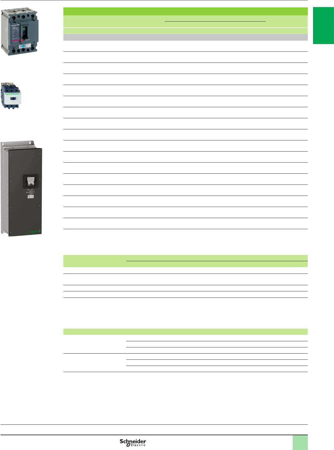
1/97
Motor starters for IP 54 drives
Motor Drive Circuit-breaker Line contactor
Power (1) Reference Reference (2) Rating Irm Reference (4) (5)
kW HP A A
Three-phase supply voltage: 440…480 V 50/60 Hz. Type 1 coordination
0.75 1ATV61W075N4
ATV61W075N4C GV2L07 2.5 – LC1D09pp
1.5 2ATV61WU15N4
ATV61WU15N4C GV2L08 4 – LC1D09pp
2.2 3ATV61WU22N4
ATV61WU22N4C GV2L10 6.3 – LC1D09pp
3–ATV61WU30N4
ATV61WU30N4C GV2L10 6.3 – LC1D09pp
45ATV61WU40N4
ATV61WU40N4C GV2L14 10 – LC1D18pp
5.5 7.5 ATV61WU55N4
ATV61WU55N4C GV2L14 10 – LC1D18pp
7.5 10 ATV61WU75N4
ATV61WU75N4C GV3L32 32 – LC1D25pp
11 15 ATV61WD11N4
ATV61WD11N4C GV3L40 40 – LC1D40App
15 20 ATV61WD15N4
ATV61WD15N4C GV3L50 50 – LC1D50App
18.5 25 ATV61WD18N4
ATV61WD18N4C GV3L50 50 – LC1D50App
22 30 ATV61WD22N4
ATV61WD22N4C GV3L65 65 – LC1D65App
30 40 ATV61WD30N4
ATV61WD30N4C NS80HMA50 50 300 LC1D65App
37 50 ATV61WD37N4
ATV61WD37N4C NS80HMA80 80 480 LC1D65App
45 60 ATV61WD45N4
ATV61WD45N4C NS80HMA80 80 480 LC1D80pp
55 75 ATV61WD55N4
ATV61WD55N4C NSX100pMA100 100 600 LC1D115pp
75 100 ATV61WD75N4
ATV61WD75N4C NSX160pMA150 150 1350 LC1D150pp
90 125 ATV61WD90N4
ATV61WD90N4C NSX250pMA220 220 1980 LC1F185pp
(1) Standard power ratings for 400 V 50/60 Hz 4-pole motors.
The values expressed in HP conform to the NEC (National Electrical Code).
(2) For references to be completed, replace the dot with the letter corresponding to the circuit-breaker breaking performance
(B, F, N, H, S or L).
Breaking capacity of circuit-breakers according to standard IEC 60947-2:
Circuit-breaker Icu (kA) for 440 V
B F N H S L
GV2L07…L14 (3) 130 – – – – – –
GV2L14 (3)
GV3L32…L65 50 – – – – – –
NS80HMA 70 – – – – – –
NSX100pMA… NSX250pMA – 20 35 50 65 90 130
(3) GV2L14: Icu of 130 when combined with an ATV61WU40N4 (C) and Icu of 50 when combined with an ATV61WU55N4 (C).
(4) Composition of contactors:
LC1D09 to LC1D150: 3 poles + 1 N/O auxiliary contact and 1 N/C auxiliary contact.
LC1F185: 3 poles. To add auxiliary contacts or other accessories, please refer to the “Motor-starter solutions - Control and
protection components” catalogue.
(5) Replace pp with the control circuit voltage reference given in the table below:
Volts a24 48 110 220 230 240
LC1D09…D150 50 Hz B5 E5 F5 M5 P5 U5
60 Hz B6 E6 F6 M6 – U6
50/60 Hz B7 E7 F7 M7 P7 U7
LC1F185 50 Hz (LX1 coil) B5 E5 F5 M5 P5 U5
60 Hz (LX1 coil) – E6 F6 M6 – U6
40…400 Hz (LX9 coil) – E7 F7 M7 P7 U7
For other voltages available between 24 V and 660 V, or a DC control circuit, please contact our Customer Care Centre.
Combinations for
customer assembly
(continued)
Variable speed drives
Altivar 61
Motor starters: 440…480 V supply voltage
NS80HMA80
+
LC1D80pp
+
ATV61WD45N4
PF107492SE
+
DF526157
+
PB101591_SE
Variable speed drives:
page 1/16 Options:
page 1/46 Drive/option combinations:
page 1/34
2
1
3
4
5
6
7
8
9
10
2
1
3
4
5
6
7
8
9
10
1/98
Motor starters for IP 20 drives
Motor Drive Circuit-breaker Line contactor
Power (1) Reference Reference (2) Rating Irm Reference (3) (4)
kW A A
Three-phase supply voltage: 690 V 50/60 Hz. Type 2 coordination
3ATV61HU30Y GV2L10 6.3 – LC1D25pp
4ATV61HU40Y GV2L14 10 – LC1D25pp
5.5 ATV61HU55Y GV2L14 10 – LC1D25pp
7.5 ATV61HU75Y GV2L16 14 – LC1D25pp
11 ATV61HD11Y GV2L20 18 – LC1D40App
15 ATV61HD15Y GV2L22 25 – LC1D40App
18.5 ATV61HD18Y GV3L25 25 – LC1D40App
22 ATV61HD22Y GV3L32 32 – LC1D65App
30 ATV61HD30Y GV3L40 40 – LC1D80pp
37 ATV61HD37Y GV3L50 50 – LC1D80pp
45 ATV61HD45Y GV3L65 65 – LC1D115pp
55 ATV61HD55Y NS100LMA100 100 1100 LC1D115pp
75 ATV61HD75Y NS100LMA100 100 1100 LC1D115pp
90 ATV61HD90Y NS400LMA320 320 2880 LC1F265pp
110 ATV61HC11Y NS400LMA320 320 2880 LC1F265pp
132 ATV61HC13Y NS400LMA320 320 2880 LC1F265pp
160 ATV61HC16Y NS400LMA320 320 2880 LC1F265pp
200 ATV61HC20Y NS400LMA320 320 2880 LC1F330pp
250 ATV61HC25Y NS630bLB Micrologic 2 or 5 (LR OFF) 630 2880 LC1F630pp
315 ATV61HC31Y NS630bLB Micrologic 2 or 5 (LR OFF) 630 4500 LC1F630pp
400 ATV61HC40Y NS630bLB Micrologic 2 or 5 (LR OFF) 630 4500 LC1F630pp
500 ATV61HC50Y NS630bLB Micrologic 2 or 5 (LR OFF) 630 4500 LC1F630pp
630 ATV61HC63Y NS800LB Micrologic 2 or 5 (LR OFF) 800 5670 LC1F780pp
(1) Standard power ratings for 690 V 50 Hz 4-pole motors.
(2) Breaking capacity of circuit-breakers according to standard IEC 60947-2:
Circuit-breaker Icu (kA) for 690 V
GV2L10…L22
GV3L25, GV3L32 4
GV3L40…L65 5
NSpppLMA
NS630bLB Micrologic 2 or 5
NS800LB Micrologic 2 or 5
75
(3) Composition of contactors:
LC1D25 to LC1D115: 3 poles + 1 N/O auxiliary contact and 1 N/C auxiliary contact.
LC1F265 to LC1F780: 3 poles. To add auxiliary contacts or other accessories, please refer to the “Motor-starter solutions -
Control and protection components” catalogue.
(4) Replace pp with the control circuit voltage reference given in the table below:
Volts a24 48 110 220 230 240
LC1D25…D115 50 Hz B5 E5 F5 M5 P5 U5
60 Hz B6 E6 F6 M6 – U6
50/60 Hz B7 E7 F7 M7 P7 U7
LC1F265, LC1F330 40…400 Hz (LX1 coil) B7 E7 F7 M7 P7 U7
LC1F630 40…400 Hz (LX1 coil) – E7 F7 M7 P7 U7
LC1F780 40…400 Hz (LX1 coil) – – F7 M7 P7 U7
For other voltages available between 24 V and 660 V, or a DC control circuit, please contact our Customer Care Centre.
Combinations for
customer assembly
(continued)
Variable speed drives
Altivar 61
Motor starters: 690 V supply voltage
DF526131
+
+
DF526156
GV2L20
+
LC1D40App
+
ATV61HD11Y
PF107582SE
Variable speed drives:
page 1/16 Options:
page 1/46 Drive/option combinations:
page 1/34
2
1
3
4
5
6
7
8
9
10
2
1
3
4
5
6
7
8
9
10
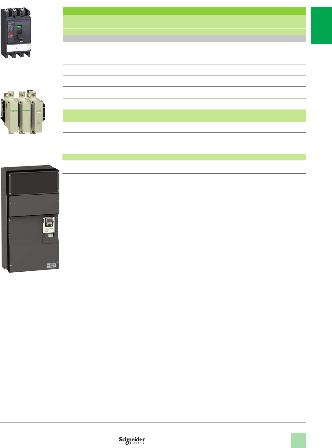
1/99
Motor starters for IP 20 drives
Motor Drive Circuit-breaker Line contactor
Power (1) Reference Reference (2) Rating Irm Reference (3) (4)
kW A A
Three-phase supply voltage: 690 V 50/60 Hz. Type 1 coordination
250 ATV61HC25Y NS630bLB Micrologic 2 or 5
(LR OFF) 630 – LC1F400pp
315 ATV61HC31Y NS630bLB Micrologic 2 or 5
(LR OFF) 630 – LC1F500pp
400 ATV61HC40Y NS630bLB Micrologic 2 or 5
(LR OFF) 630 – LC1F630pp
500 ATV61HC50Y NS630bLB Micrologic 2 or 5
(LR OFF) 630 – LC1BL33pp
630 ATV61HC63Y NS800LB Micrologic 5
(LR OFF) 800 – LC1BL34pp
(1) Standard power ratings for 690 V 50 Hz 4-pole motors.
(2) Breaking capacity of circuit-breakers according to standard IEC 60947-2:
Circuit-breaker Icu (kA) for 690 V
NS630bLB Micrologic 2 or 5
NS800LB Micrologic 5 75
(3) Composition of contactors:
LC1F400 to LC1F630, LC1BL3p: 3 poles. To add auxiliary contacts or other accessories, please refer to the “Motor-starter
solutions - Control and protection components” catalogue.
(4) Replace pp with the control circuit voltage reference given in the table below:
Volts a24 48 110 220 230 240
LC1Fppp 40…400 Hz (LX1 coil) – E7 F7 M7 P7 U7
LC1BLpp 50…400 Hz (WB1 coil) – – F M D U
For other voltages available between 24 V and 660 V, or a DC control circuit, please contact our Customer Care Centre.
Combinations for
customer assembly
(continued)
Variable speed drives
Altivar 61
Motor starters: 690 V supply voltage
PF103273
+
NSX630LMA500
+
LC1F400pp
+
ATV61HC25Y
PF107586SE
+
DF526089
Variable speed drives:
page 1/16 Options:
page 1/46 Drive/option combinations:
page 1/34
2
1
3
4
5
6
7
8
9
10
2
1
3
4
5
6
7
8
9
10

22/0
2
1
3
4
5
6
7
8
9
10
2
1
3
4
5
6
7
8
9
10

3
Contents
b Altivar 61 Plus variable speed drives ...................................................page 2/2
v Pre-equipped IP 54 oor-standing enclosure kit ...................................... page 2/2
v “Ready to use” IP 54 oor-standing enclosure ......................................... page 2/4
v “Ready to use” IP 23 or IP 54 oor-standing enclosure with
harmonic ltering ..................................................................................... page 2/6
v IP 23 or IP 54 oor-standing enclosure with separate air ows................. page 2/8
v IP 23 or IP 54 oor-standing enclosure (compact version) ..................... page 2/12
v Options .................................................................................................. page 2/16
b Product reference index ........................................................................page 3/0
2 - Altivar 61 Plus
variable speed drives
2/1
2
1
3
4
5
6
7
8
9
10
2
1
3
4
5
6
7
8
9
10
2/2
Presentation
The pre-equipped kit solution is used to create an IP 54 certied oor-standing
enclosure for 110 kW to 630 kW IP 20 Altivar 61 variable speed drives for a
380…480 V three-phase supply voltage.
This kit has been designed to:
bReduce the setup time with:
vSimplied assembly
vOptimized thermal and mechanical dimensioning
The cooling systems used enable the equipment to be installed in difcult and dusty
environments.
The temperature must not exceed + 45°C outside the enclosure or + 50°C inside the
enclosure; the temperature is monitored by a thermostat which can shut down the
equipment if these limits are exceeded.
Cooling systems
There are two types of cooling, depending on the model:
bVW3A9541 and VW3A9542 enclosure kits with a single air circuit for the power
section:
vAir inlet via the plinth 1
vAir outlet on the enclosure roof 2
bVW3A9543…548 enclosure kits with three separate air circuits:
vOne for the power section:
- Air inlet via the plinth 1
- Air outlet on the enclosure roof 2
vTwo for the control section with cooling system using an air/air exchanger:
- External air circuit 3 for cooling the heat exchanger 5
- Internal air circuit 4 cooled by the heat exchanger 5
This system makes it possible to isolate the air circulating in the power section from
the control section, thereby helping ensure better protection against the entry of
contaminants (in hostile and dusty environments).
Options
There are two additional 600 and 800 mm empty enclosure kits VW3A955p for
adding accessories or options.
The additional empty enclosure kit must be installed on the left side of the
pre-equipped IP 54 enclosure kit. In this case, the left-hand panel of the pre-equipped
IP 54 enclosure kit is mounted on the left side of the additional empty enclosure kit,
which is supplied without side panels.
Presentation Variable speed drives
Altivar 61
Pre-equipped IP 54 oor-standing enclosure kit
1
2
Cooling system with a single air circuit
DF600349
1
2
3
3
4
4
5
Cooling system with three separate air circuits
DF600350
IP 54 oor-standing enclosure kit
PF107555SE
2
1
3
4
5
6
7
8
9
10
2
1
3
4
5
6
7
8
9
10
2/3
Description
The kit consists of:
bAir/air heat exchanger (except for enclosure kits VW3A9541 or VW3A9542) 1
bIP 65 graphic display terminal remote mounting kit 2
bHandle with a pushbutton-operated opening mechanism 3
bDocument holder 4
bPlinth 5
bLower air duct 6
bEMC plate 7
bDrive support rack 8
bRoof extension 9
bUpper air duct
b24 V c 600 mA supplementary power supply
bFixing accessories, seals
bTechnical documentation containing parts lists, electrical diagrams and mechanical assembly drawings
References
Description For use with Dimensions Reference Weight
W x H x D kg
Pre-equipped IP 54 oor-standing
enclosure kit ATV61HC11N4 (1)
ATV61HD90N4 (1) 600 x 2362 x 642 VW3A9541 220.000
ATV61HC13N4 (1) 600 x 2362 x 642 VW3A9542 220.000
ATV61HC16N4 (1) 600 x 2362 x 642 VW3A9543 252.000
ATV61HC22N4 (1) 600 x 2362 x 642 VW3A9544 252.000
ATV61HC25N4 (1) without braking unit
ATV61HC31N4 (1) without braking unit 800 x 2362 x 642 VW3A9545
300.000
ATV61HC25N4 (1) with braking unit VW3A7101 (2)
ATV61HC31N4 (1) with braking unit VW3A7101 (2) 800 x 2362 x 642 VW3A9546 300.000
ATV61HC40N4 (1) without braking unit
ATV61HC50N4 (1) without braking unit 1000 x 2362 x 642 VW3A9547 360.000
ATV61HC63N4 (1) without braking unit 1200 x 2362 x 642 VW3A9548 470.000
VW3A7102 braking unit 600 x 2362 x 642 VW3A9549 (3) 252.000
Additional empty enclosure kit 600 mm Options and accessories (4) 600 x 2209 x 642 VW3A9550 200.000
Additional empty enclosure kit 800 mm Options and accessories (4) 800 x 2209 x 642 VW3A9551 210.000
(1) Drive to be ordered separately (see page 1/17).
(2) Braking unit for drives ATV61HC25N4, HC31N4, to be ordered separately (see page 1/60).
(3) Enclosure kit VW3A9549 is designed to take braking unit VW3A7102 for high-power drives ATV61HC40N4…HC63N4; it is mounted on the left of enclosure kit
VW3A9547 or VW3A9548. The braking unit must be ordered separately (see page 1/60).
(4) For any additional information, please contact our Customer Care Centre.
Description,
references Variable speed drives
Altivar 61
Pre-equipped IP 54 oor-standing enclosure kit
1
2
3
5
9
8
7
6
4
2
1
3
4
5
6
7
8
9
10
2
1
3
4
5
6
7
8
9
10
2/4
Presentation Variable speed drives
Altivar 61 Plus
“Ready to use” IP 54 oor-standing enclosure
Presentation
Altivar 61 variable speed drives can also be supplied in a “ready to use” IP 54
certied oor-standing enclosure, which makes it possible to achieve an IP 54
degree of protection for IP 20 Altivar 61 drives.
The range has been designed to offer a simple and economical “ready to
use”solution, with setup time reduced to a minimum. The enclosures are supplied
ready-assembled and ready to connect, making wiring fast and easy.
This standardized version enables the equipment to be made available very quickly.
It covers motor power ratings from 90 kW to 630 kW for a 380…415 V three-phase
supply.
Cooling system
The cooling system used helps ensure optimum ventilation of the equipment, even
in difcult and dusty environments.
Cooling is provided by two separate air circuits:
vOne for the power section:
- Air entry via an intake grille on the plinth 1
- Air outlet via a metal cover with protection against water splashes on the
enclosure roof 3
vOne for the control section:
- Air entry via an intake grille with fan (tted with a lter) on the enclosure door 4
- Air outlet through a lter 5
The incoming air temperature must be 0…+ 40°C.
The temperature is monitored by a thermostat which can shut down the equipment.
“Ready to use” IP 54 oor-standing enclosure
PF095305
3
52
4
1
DF600351
Cooling system with two separate air circuits
Variable speed drives:
page 1/16 Options:
page 1/46 Drive/option combinations:
page 1/34
2
1
3
4
5
6
7
8
9
10
2
1
3
4
5
6
7
8
9
10
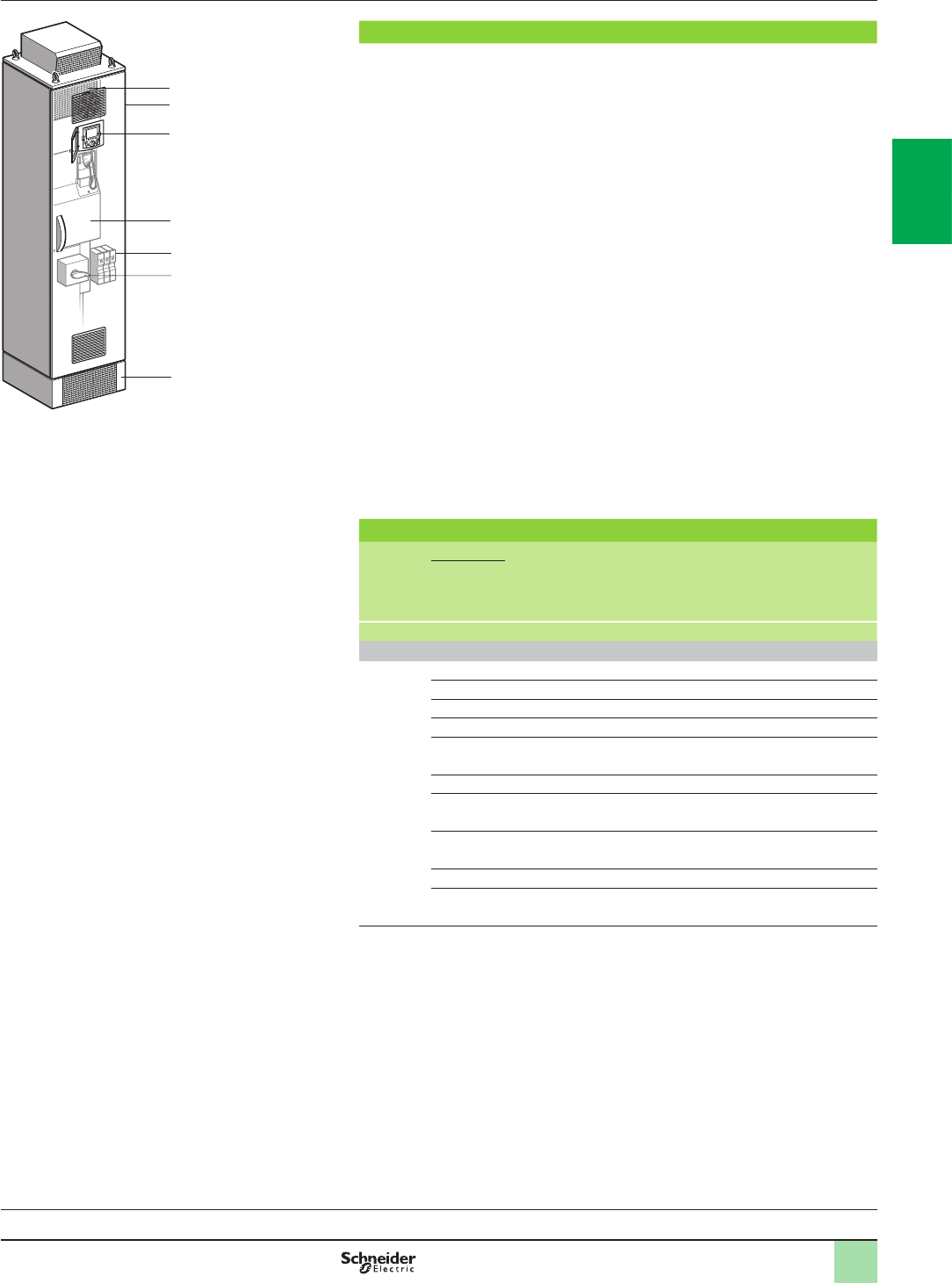
2/5
Description,
references Variable speed drives
Altivar 61 Plus
“Ready to use” IP 54 oor-standing enclosure
Description
The offer comprises:
bA wired, ready-assembled Sarel “Spacial SF” enclosure 1
bA drive on heatsink ATV61HD90N4…HC63N4 3
bAn IP 65 remote mounting kit for graphic display terminal 2
bA DC choke 4
bMotor terminals 5
bA magnetic circuit-breaker 6
bA plinth 7
References
Degree of
protection Motor With drive Dimensions Reference Weight
Power
indicated
on rating
plate (1)
kW W x H x D kg
Three-phase supply voltage 380…415 V 50/60 Hz (2)
IP 54 90 ATV61HD90N4 600 x 2362 x 642 ATV61ES5D90N4 300.000
110 ATV61HC11N4 600 x 2362 x 642 ATV61ES5C11N4 300.000
132 ATV61HC13N4 600 x 2362 x 642 ATV61ES5C13N4 300.000
160 ATV61HC16N4 600 x 2362 x 642 ATV61ES5C16N4 320.000
200 ATV61HC22N4 600 x 2362 x 642 ATV61ES5C22N4 330.000
220
250 ATV61HC25N4 800 x 2362 x 642 ATV61ES5C25N4 440.000
280 ATV61HC31N4 800 x 2362 x 642 ATV61ES5C31N4 440.000
315
355 ATV61HC40N4 1400 x 2362 x 642 ATV61ES5C40N4 700.000
400
500 ATV61HC50N4 1400 x 2362 x 642 ATV61ES5C50N4 720.000
560 ATV61HC63N4 1600 x 2362 x 642 ATV61ES5C63N4 850.000
630
(1) These values are given for a nominal switching frequency of 4 kHz for ATV61HD90N4 or
2.5 kHz for ATV61HC11N4…HC63N4 drives for use in continuous operation.
The switching frequency is adjustable from 2…8 kHz forATV61HD90N4…ATV61HC63N4
drives.
Above 2.5, 4 or 12 kHz, depending on the rating, the drive will reduce the switching
frequency automatically in the event of an excessive temperature rise. For continuous
operation above the nominal switching frequency, derate the nominal drive current, see
derating curves on our website www.schneider-electric.com.
(2) The maximum prospective line Isc is of 50 kA. These values are given for use with upstream
fuses (see the characteristics on our website www.schneider-electric.com).
1
2
3
5
6
7
4
DF537139
Variable speed drives:
page 1/16 Options:
page 1/46 Drive/option combinations:
page 1/34
2
1
3
4
5
6
7
8
9
10
2
1
3
4
5
6
7
8
9
10
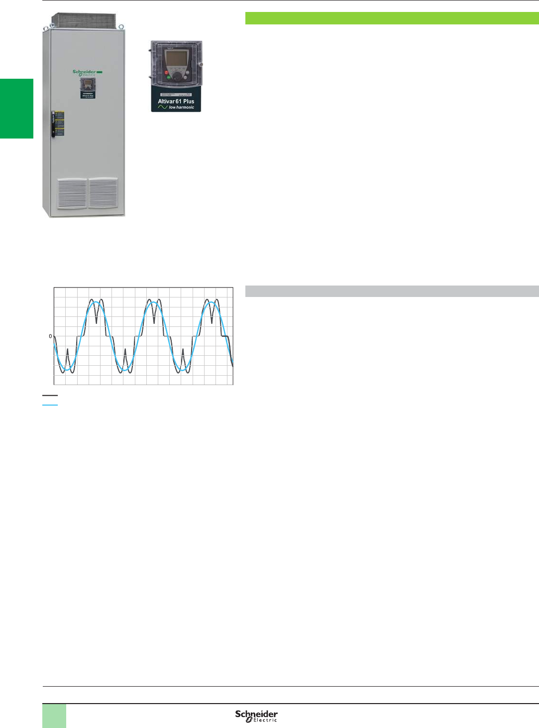
2/6
Variable speed drives
Altivar 61 Plus - LH
“Ready to use” IP 23 or IP 54 oor-standing enclosure
with harmonic ltering
Presentation
Presentation
The Altivar 61 Plus - LH (Low Harmonic) offer has been designed with harmonic
ltering to suit applications requiring a very low harmonic level (THDI y 5 %).
They comply with the conditions imposed by standard IEEE 519 - 1992.
Altivar 61 Plus - LH drives are supplied in an IP 23 or IP 54 certied oor-standing
enclosure, which makes it possible to achieve an IP 23 or IP 54 degree of protection
for IP 20 Altivar 61 drives.
The enclosures are supplied ready-assembled and ready to connect, thus offering a
simple and economical “ready to use” solution which keeps setup time to a
minimum. Wiring is fast and easy, the setup parameters are factory-set.
Thanks to this “ready to use” solution the standard offer is available very quickly.
The standard offer is supplemented by a wide selection of options depending on the
drive rating (see pages 2/18 to 2/23).
The offer covers motor power ratings from 55 kW to 630 kW for a 380…415 V,
50/60 Hz three-phase supply voltage and from 800 kW to 2400 kW for a 690 V,
50/60 Hz three-phase supply voltage.
The incoming air temperature must be between 0 and + 40°C.
The internal temperature is monitored by a thermostat which can shut down the
equipment.
Harmonic ltering
The harmonic ltering system is used to keep the harmonic level to less than 5 %.
Its design optimizes motor efciency and reduces energy consumption by
signicantly decreasing harmonic distortions.
It also offers the following advantages:
b Maximum motor power maintained in the event of a weak line supply by boosted
DC voltage
bPower factor (cos Phi ~ 1) independent of load or of return energy
b Reduction in drive electromagnetic emissions in accordance with standard
IEC/EN 61800-3 category C3 due to the integrated lter
b Congurable energy recovery onto the line supply, for example for an installation
with diesel generator
bLine supply short-circuits tolerated up to 100 kA
Variable speed drives:
page 1/16 Options:
page 1/46 Drive/option combinations:
page 1/34
Harmonic level without harmonic ltering (THDI ~ 48 %)
Harmonic level with harmonic ltering (THDI y 5 %)
DF600774
A rms
“Ready to use” IP 23 or IP 54 oor-standing enclosure with
harmonic ltering
2
1
3
4
5
6
7
8
9
10
2
1
3
4
5
6
7
8
9
10
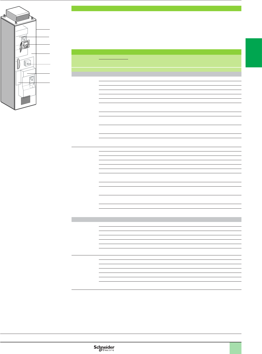
2/7
Variable speed drives
Altivar 61 Plus - LH
“Ready to use” IP 23 or IP 54 oor-standing enclosure
with harmonic ltering
Description,
references
Description
The offer comprises:
bA wired, ready-assembled Sarel “Spacial SF” enclosure 1
bA built-in drive based on ATV61 technology (1) 2
bAn IP 65 remote mounting kit for graphic display terminal 3
bAn active infeed converter 4
bFilter components including EMC lter 5
bA switch, fast-acting fuses and motor terminals 6
bA slot for optional motor choke 7
References
Degree of
protection Motor With drive Dimensions Reference Weight
Power indicated
on rating plate (2)
kW W x H x D kg
Three-phase supply voltage 380…415 V 50/60 Hz (3)
IP 23 55 ATV61HD55N4 400 x 2157 x 642 ATV61EXC2D55N4H 370.000
75 ATV61HD75N4 600 x 2157 x 642 ATV61EXC2D75N4H 465.000
90 ATV61HD90N4 600 x 2157 x 642 ATV61EXC2D90N4H 465.000
110 ATV61HC11N4 600 x 2157 x 642 ATV61EXC2C11N4H 480.000
132 ATV61HC13N4 800 x 2157 x 642 ATV61EXC2C13N4H 605.000
160 ATV61HC16N4 800 x 2157 x 642 ATV61EXC2C16N4H 610.000
200 ATV61HC22N4 1200 x 2157 x 642 ATV61EXC2C22N4H 820.000
220
250 ATV61HC25N4 1600 x 2157 x 642 ATV61EXC2C25N4H 980.000
280 ATV61HC31N4 1600 x 2157 x 642 ATV61EXC2C31N4H 980.000
315
355 ATV61HC40N4 2000 x 2157 x 642 ATV61EXC2C40N4H 1455.000
400
500 ATV61HC50N4 2000 x 2157 x 642 ATV61EXC2C50N4H 1455.000
560 ATV61HC63N4 2400 x 2157 x 642 ATV61EXC2C63N4H 1755.000
630
IP 54 55 ATV61HD55N4 400 x 2237 x 642 ATV61EXC5D55N4H 370.000
75 ATV61HD75N4 600 x 2237 x 642 ATV61EXC5D75N4H 465.000
90 ATV61HD90N4 600 x 2237 x 642 ATV61EXC5D90N4H 465.000
110 ATV61HC11N4 600 x 2237 x 642 ATV61EXC5C11N4H 480.000
132 ATV61HC13N4 800 x 2237 x 642 ATV61EXC5C13N4H 600.000
160 ATV61HC16N4 800 x 2237 x 642 ATV61EXC5C16N4H 605.000
200 ATV61HC22N4 1200 x 2237 x 642 ATV61EXC5C22N4H 810.000
220
250 ATV61HC25N4 1600 x 2237 x 642 ATV61EXC5C25N4H 995.000
280 ATV61HC31N4 1600 x 2237 x 642 ATV61EXC5C31N4H 995.000
315
355 ATV61HC40N4 2000 x 2237 x 642 ATV61EXC5C40N4H 1470.000
400
500 ATV61HC50N4 2000 x 2237 x 642 ATV61EXC5C50N4H 1480.000
560 ATV61HC63N4 2400 x 2237 x 642 ATV61EXC5C63N4H 1770.000
630
Three-phase supply voltage 690 V 50/60 Hz (3)
IP 23 800 ATV61EC80Y (1) 3800 x 2237 x 642 ATV61EXA2C80YH 2940.000
1000 ATV61EM10Y (1) 3800 x 2237 x 642 ATV61EXA2M10YH 2940.000
1200 ATV61EM12Y (1) 3800 x 2237 x 642 ATV61EXA2M12YH 2940.000
1500 ATV61EM15Y (1) 7400 x 2237 x 642 ATV61EXA2M15YH 6060.000
1800 ATV61EM18Y (1) 7400 x 2237 x 642 ATV61EXA2M18YH 6060.000
2100 ATV61EM21Y (1) 7400 x 2237 x 642 ATV61EXA2M21YH 6060.000
2400 ATV61EM24Y (1) 7400 x 2237 x 642 ATV61EXA2M24YH 6060.000
IP 54 800 ATV61EC80Y (1) 3800 x 2237 x 642 ATV61EXA5C80YH 2940.000
1000 ATV61EM10Y (1) 3800 x 2237 x 642 ATV61EXA5M10YH 2940.000
1200 ATV61EM12Y (1) 3800 x 2237 x 642 ATV61EXA5M12YH 2940.000
1500 ATV61EM15Y (1) 7400 x 2237 x 642 ATV61EXA5M15YH 6060.000
1800 ATV61EM18Y (1) 7400 x 2237 x 642 ATV61EXA5M18YH 6060.000
2100 ATV61EM21Y (1) 7400 x 2237 x 642 ATV61EXA5M21YH 6060.000
2400 ATV61EM24Y (1) 7400 x 2237 x 642 ATV61EXA5M24YH 6060.000
(1) Reference of the drive mounted in the enclosure; this reference cannot be ordered on its own.
(2) These values are given for a nominal switching frequency of 12 kHz up to ATV61HD75N4, 4 kHz for
ATV61HD90N4 or 2.5 kHz for ATV61HC11N4…HC63N4 drives for use in continuous operation.
The switching frequency is adjustable from 1…16 kHz up to ATV61HD75N4 and from 2…8 kHz for
ATV61HD90N4…ATV61HC63N4 drives.
Above 2.5, 4 or 12 kHz, depending on the rating, the drive will reduce the switching frequency automatically in
the event of an excessive temperature rise. For continuous operation above the nominal switching frequency,
derate the nominal drive current, see derating curves on our website www.schneider-electric.com.
(3) The maximum prospective line Isc if of 100 kA. These values are given for use with a circuit-breaker, which is
available as an option, or fuses placed upstream (see the characteristics on our website
www.schneider-electric.com).
Variable speed drives:
page 1/16 Options:
page 1/46 Drive/option combinations:
page 1/34
DF60775
1
2
3
6
5
4
72
1
3
4
5
6
7
8
9
10
2
1
3
4
5
6
7
8
9
10
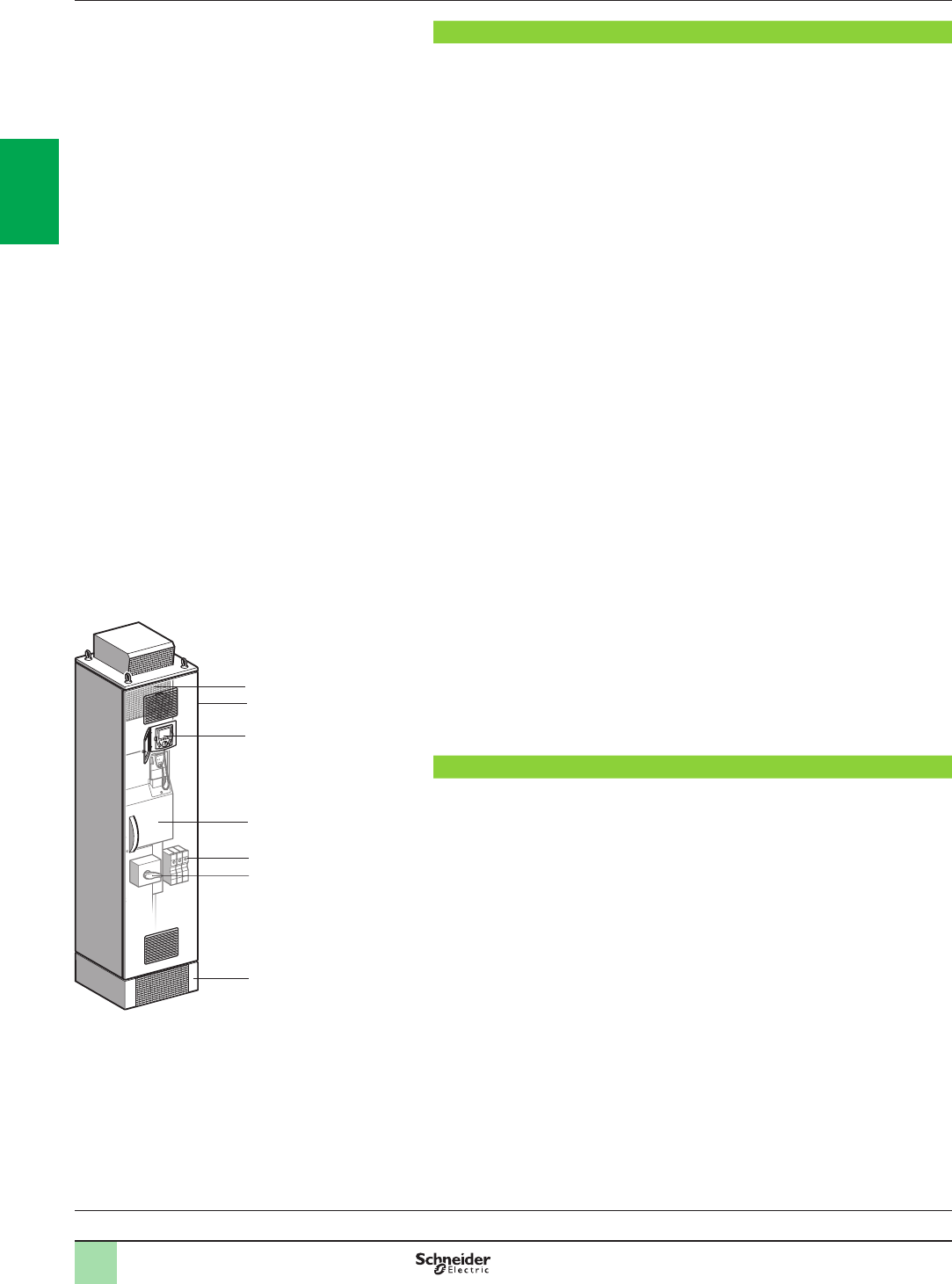
2/8
Variable speed drives
Altivar 61 Plus
IP 23 or IP 54 oor-standing enclosure
with separate air ows
Presentation
Presentation
The Altivar 61 Plus offer with separate air ows has been designed to meet
requirements for harsh and highly polluted environments (such as in tunnels,
subways, smoke extraction and pumping applications, etc.).
Altivar 61 variable speed drives are supplied in an IP 23 or IP 54 ready-assembled
oor-standing enclosure to facilitate their installation and setup, while helping
ensure optimum ventilation.
The enclosures are supplied ready to connect.
The offer comprises two versions:
bThe ATV61EXS5ppppp version consists of a single enclosure providing IP 54
protection.
It covers motor power ratings from 90 kW to 800 kW with three types of power supply:
v380…415 V three-phase, 90 kW to 630 kW (ATV61EXS5pppN4)
v500 V three-phase, 90 kW to 630 kW (ATV61EXS5pppN)
v690 V three-phase, 110 kW to 800 kW (ATV61EXS5pppY)
Two separate cooling circuits for the control section and the power section help
ensure optimum enclosure ventilation.
bThe ATV61EXApppppp version consists of a set of 4 or more enclosures providing
IP 23 or IP 54 protection, depending on the model.
It covers motor power ratings from 630 kW to 2400 kW with three types of power supply:
v380…415 V three-phase, 630 kW to 1400 kW (ATV61EXAppppN4)
v500 V three-phase, 630 kW to 1800 kW (ATV61EXAppppN)
v690 V three-phase, 800 kW to 2400 kW (ATV61EXAppppY)
Two separate cooling circuits, one for the control section and one for the power
section, also help ensure enclosure ventilation.
In addition, a water circuit is integrated in the power enclosure to help ensure
excellent cooling for power electronics.
The incoming air temperature must be between 0°C and + 40°C (- 10°C and + 40°C
with enclosure heater) and may reach + 50°C with derating (class 3K3 according to
IEC/EN 60721-3-3).
The internal temperature is monitored by a thermostat which can shut down the
equipment.
The entire range includes the choice of:
bA standard offer
bA modular offer, in which a wide selection of options can be incorporated
depending on the drive rating
The standard ATV61EXS5ppppp offer
This consists of:
bA wired, ready-assembled Sarel “Spacial SF” enclosure 1
bA drive on heatsink ATV61HD90N4…HC63N4 or
ATV61HC11Y…ATV61HC80Y 3
bAn IP 65 remote mounting kit for graphic display terminal 2
bA DC choke 4 (ATV61EXS5pppN4) or a line choke in an additional enclosure
(ATV61EXS5pppN and ATV61EXS5pppY)
bMotor terminals 5
bA switch and fast-acting fuses 6
bA plinth 7
See pages 2/10 and 2/11.
1
2
3
5
6
7
4
DF600355
Standard ATV61EXS5ppppp offer
Variable speed drives:
page 1/16 Options:
page 1/46 Drive/option combinations:
page 1/34
2
1
3
4
5
6
7
8
9
10
2
1
3
4
5
6
7
8
9
10
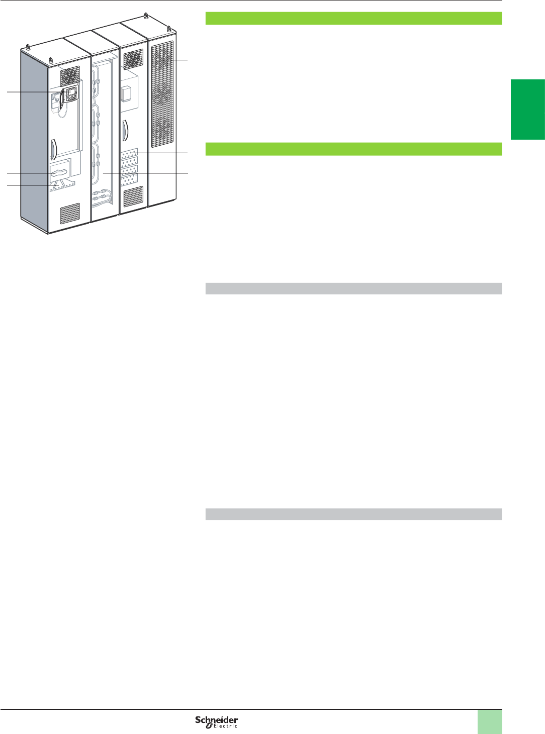
2/9
Variable speed drives
Altivar 61 Plus
IP 23 or IP 54 oor-standing enclosure
with separate air ows
Presentation (continued)
The standard ATV61EXApppppp offer
The ATV61EXApppppp offer is supplied in wired, ready-assembled Sarel “Spacial
SF” enclosures.
Conguration example for a standard ATV61EXApppppp offer:
bAn enclosure for the power supply with an IP 65 remote mounting kit for graphic
display terminal 1, a switch 2, terminals 3 and fast-acting fuses
bAn enclosure for the power section cooled by an integrated water circuit 4
bAn enclosure with motor connection terminals 5
bAn enclosure for the power section cooling circuit with heat exchanger and fans 6
See pages 2/10 and 2/11.
Modular offer
This consists of:
bThe standard separate air ow offer ATV61EXS5ppppp or ATV61EXApppppp
bOne or more options (see pages 2/16 to 2/23)
As well as these specic options, the options available for Altivar 61 drives can be
used, at the same rating, with the enclosed drives offer (see the summary tables of
possible drive, option and accessory combinations on pages 1/36, 1/37 and 1/42 to
1/45).
For any conguration other than those shown on pages 2/16 to 2/23, please contact
our Customer Care Centre.
Common options
These options can be integrated, whatever the enclosure model, without any need
for modications to the enclosure:
bAdaptor for 115 V a logic inputs
bEncoder interface cards
bI/O expansion cards
bMultipump cards and “Controller Inside” programmable card
bModbus TCP Daisy Chain, EtherNet/IP, DeviceNet, InterBus, CC-Link, Modbus/
Uni-Telway, PROFIBUS DP V0 or V1, LonWorks, METASYS N2, APOGEE FLN,
BACnet communication cards
b“Preventa type AC” or “Preventa type ATE” fault relay
bPTC relays, PT100 relays
bMotor heater
bAdditional 24 V c power supply
bEnclosure lighting
bEmergency stop button
bKey switch (Local/Remote)
bPower supply circuit for external fan
See pages 2/16 and 2/17. For other options, please contact our Customer Care
Centre.
Options dependent on the drive rating
These options depend on the drive rating. Some may lead to modication of the size
of the enclosure:
bBraking unit
bIsolating handle for switch
bCircuit-breaker
bLine contactor
bControl transformer
bAmmeter
bEnclosure heater
bMotor choke
bSinus lter
bAir conditioning
See pages 2/18 to 2/23. For other options, please contact our Customer Care Centre.
5
2
3
1
6
4
DF504397
Standard ATV61EXAppppp offer
2
1
3
4
5
6
7
8
9
10
2
1
3
4
5
6
7
8
9
10
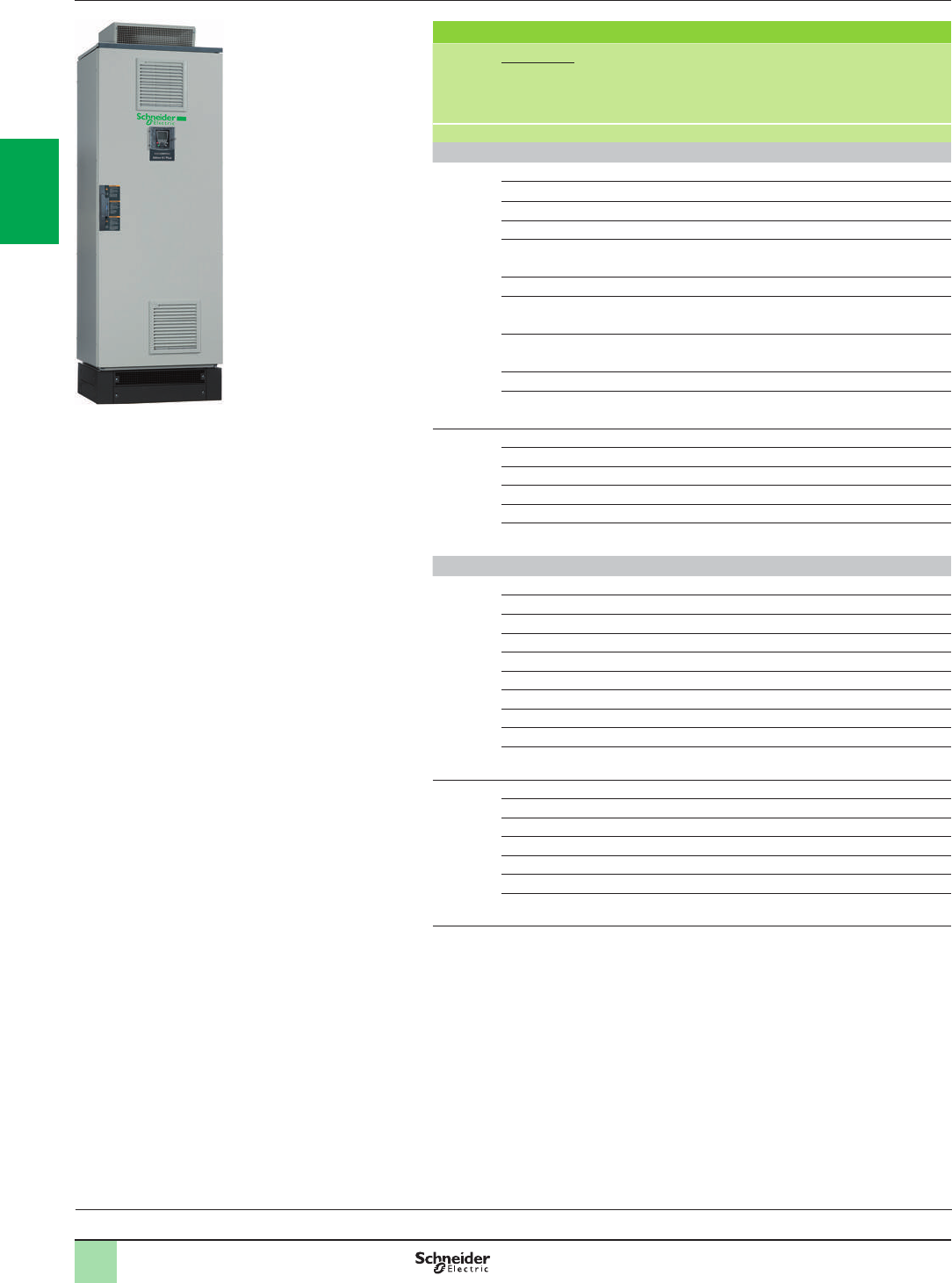
2/10
References Variable speed drives
Altivar 61 Plus
IP 23 or IP 54 oor-standing enclosure
with separate air ows
IP 23 or IP 54 oor-standing enclosure with separate air ows
Degree of
protection Motor With drive Dimensions Reference (1) Weight
Power
indicated
on rating
plate (2)
kW W x H x D kg
Three-phase supply voltage 380…415 V 50/60 Hz
IP 54 (4) 90 ATV61HD90N4 600 x 2362 x 642 ATV61EXS5D90N4 310.000
110 ATV61HC11N4 600 x 2362 x 642 ATV61EXS5C11N4 310.000
132 ATV61HC13N4 600 x 2362 x 642 ATV61EXS5C13N4 335.000
160 ATV61HC16N4 600 x 2362 x 642 ATV61EXS5C16N4 345.000
200 ATV61HC22N4 600 x 2362 x 642 ATV61EXS5C22N4 395.000
220
250 ATV61HC25N4 800 x 2362 x 642 ATV61EXS5C25N4 480.000
280 ATV61HC31N4 800 x 2362 x 642 ATV61EXS5C31N4 480.000
315
355 ATV61HC40N4 1000 x 2362 x 642 ATV61EXS5C40N4 745.000
400
500 ATV61HC50N4 1000 x 2362 x 642 ATV61EXS5C50N4 765.000
560 ATV61HC63N4 1200 x 2362 x 642 ATV61EXS5C63N4 900.000
630
IP 23 or
IP 54 (5) 630 ATV61EC63N4 (3) 1800 x 2009 x 642 ATV61EXApC63N4 950.000
710 ATV61EC71N4 (3) 1800 x 2009 x 642 ATV61EXApC71N4 950.000
900 ATV61EC90N4 (3) 3400 x 2009 x 642 ATV61EXApC90N4 1825.000
1100 ATV61EM11N4 (3) 3400 x 2009 x 642 ATV61EXApM11N4 1825.000
1300 ATV61EM13N4 (3) 3400 x 2009 x 642 ATV61EXApM13N4 1825.000
1400 ATV61EM14N4 (3) 3400 x 2009 x 642 ATV61EXApM14N4 1825.000
Three-phase supply voltage 500 V 50/60 Hz
IP 54 (4) 90 ATV61HC11Y 600 x 2362 x 642 ATV61EXS5D90N 446.000
110 ATV61HC13Y 600 x 2362 x 642 ATV61EXS5C11N 446.000
132 ATV61HC16Y 600 x 2362 x 642 ATV61EXS5C13N 497.000
160 ATV61HC20Y 600 x 2362 x 642 ATV61EXS5C16N 497.000
200 ATV61HC25Y 800 x 2362 x 642 ATV61EXS5C20N 573.000
250 ATV61HC31Y 800 x 2362 x 642 ATV61EXS5C25N 623.000
315 ATV61HC40Y 800 x 2362 x 642 ATV61EXS5C31N 623.000
400 ATV61HC50Y 1200 x 2362 x 642 ATV61EXS5C40N 912.000
500 ATV61HC63Y 1200 x 2362 x 642 ATV61EXS5C50N 1000.000
630 ATV61HC80Y 1200 x 2362 x 642 ATV61EXS5C63N 1000.000
IP 23 or
IP 54 (5) 630 ATV61EC80Y (3) 1800 x 2009 x 642 ATV61EXApC63N 950.000
800 ATV61EM10Y (3) 1800 x 2009 x 642 ATV61EXApC80N 950.000
900 ATV61EM12Y (3) 1800 x 2009 x 642 ATV61EXApC90N 950.000
1100 ATV61EM15Y (3) 3400 x 2009 x 642 ATV61EXApM11N 1825.000
1300 ATV61EM18Y (3) 3400 x 2009 x 642 ATV61EXApM13N 1825.000
1500 ATV61EM21Y (3) 3400 x 2009 x 642 ATV61EXApM15N 1825.000
1800 ATV61EM24Y (3) 3400 x 2009 x 642 ATV61EXApM18N 1825.000
(1) To obtain the complete enclosure reference, replace the p with a 2 for IP 23 protection or a 5
for IP 54 protection.
Example for IP 23 protection: ATV61EXApC63N4 becomes ATV61EXA2C63N4.
(2) These values are given for a nominal switching frequency from 2.5…4.9 kHz for
ATV61HD90N4 ...HC63N4 and ATV61HC11Y…HC80Y drives. Above 2.5 kHz, 4 kHz or
12 kHz, depending on the rating, the drive will reduce the switching frequency automatically in
the event of an excessive temperature rise. The switching frequency is adjustable from
2…8 kHz for ATV61HD90N4…ATV61HC63N4 drives.
For continuous operation above the nominal switching frequency, derate the nominal drive
current, see derating curves on our website www.schneider-electric.com.
(3) Reference of the drive mounted in the enclosure; this reference cannot be ordered on its own.
(4) The maximum prospective line Isc is of 50 kA.These values are given for use with upstream
fuses (see the characteristics on our website www.schneider-electric.com).
(5) The maximum prospective line Isc is of 100 kA.These values are given for use with upstream
fuses (see the characteristics on our website www.schneider-electric.com).
PF095305
ATV61EXS5ppppp
Variable speed drives:
page 1/16 Options:
page 1/46 Drive/option combinations:
page 1/34
2
1
3
4
5
6
7
8
9
10
2
1
3
4
5
6
7
8
9
10
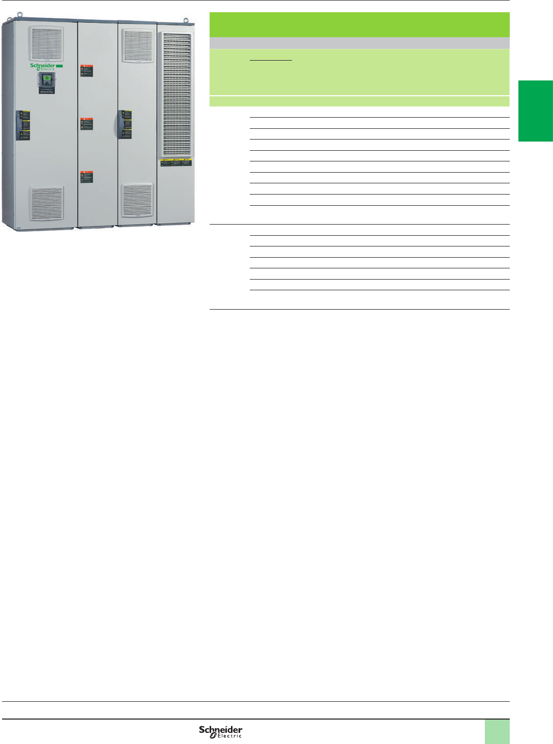
2/11
IP 23 or IP 54 oor-standing enclosure with separate air ows
(continued)
Three-phase supply voltage 690 V 50/60 Hz
Degree of
protection Motor With drive Dimensions Reference (1) Weight
Power
indicated
on rating
plate (2)
kW W x H x D kg
IP 54 (3) 110 ATV61HC11Y 600 x 2362 x 642 ATV61EXS5C11Y 446.000
132 ATV61HC13Y 600 x 2362 x 642 ATV61EXS5C13Y 446.000
160 ATV61HC16Y 600 x 2362 x 642 ATV61EXS5C16Y 497.000
200 ATV61HC20Y 600 x 2362 x 642 ATV61EXS5C20Y 497.000
250 ATV61HC25Y 800 x 2362 x 642 ATV61EXS5C25Y 573.000
315 ATV61HC31Y 800 x 2362 x 642 ATV61EXS5C31Y 623.000
400 ATV61HC40Y 800 x 2362 x 642 ATV61EXS5C40Y 623.000
500 ATV61HC50Y 1200 x 2362 x 642 ATV61EXS5C50Y 912.000
630 ATV61HC63Y 1200 x 2362 x 642 ATV61EXS5C63Y 1000.000
800 ATV61HC80Y 1200 x 2362 x 642 ATV61EXS5C80Y 1000.000
IP 54 or
IP 23 (4) 800 ATV61EC80Y (5) 1800 x 2009 x 642 ATV61EXApC80Y 950.000
1000 ATV61EM10Y (5) 1800 x 2009 x 642 ATV61EXApM10Y 950.000
1200 ATV61EM12Y (5) 1800 x 2009 x 642 ATV61EXApM12Y 950.000
1500 ATV61EM15Y (5) 3400 x 2009 x 642 ATV61EXApM15Y 1825.000
1800 ATV61EM18Y (5) 3400 x 2009 x 642 ATV61EXApM18Y 1825.000
2100 ATV61EM21Y (5) 3400 x 2009 x 642 ATV61EXApM21Y 1825.000
2400 ATV61EM24Y (5) 3400 x 2009 x 642 ATV61EXApM24Y 1825.000
(1) To obtain the complete enclosure reference, replace the p with a 2 for IP 23 protection or a 5
for IP 54 protection.
Example for IP 23 protection: ATV61EXApC63N4 becomes ATV61EXA2C63N4.
(2) These values are given for a nominal switching frequency from 2.5…4.9 kHz for
ATV61HC11Y…HC80Y drives. Above 2.5 kHz or 4 kHz, depending on the rating, the drive
will reduce the switching frequency automatically in the event of an excessive temperature rise.
For continuous operation above the nominal switching frequency, derate the nominal drive
current, see derating curves on our website www.schneider-electric.com.
(3) The maximum prospective line Isc is of 50 kA.These values are given for use with upstream
fuses (see the characteristics on our website www.schneider-electric.com).
(4) The maximum prospective line Isc is of 100 kA.These values are given for use with upstream
fuses (see the characteristics on our website www.schneider-electric.com).
(5) Reference of the drive mounted in the enclosure; this reference cannot be ordered on its own.
References (continued) Variable speed drives
Altivar 61 Plus
IP 23 or IP 54 oor-standing enclosure
with separate air ows
Variable speed drives:
page 1/16 Options:
page 1/46 Drive/option combinations:
page 1/34
PF095306
ATV61EXAppppp
2
1
3
4
5
6
7
8
9
10
2
1
3
4
5
6
7
8
9
10
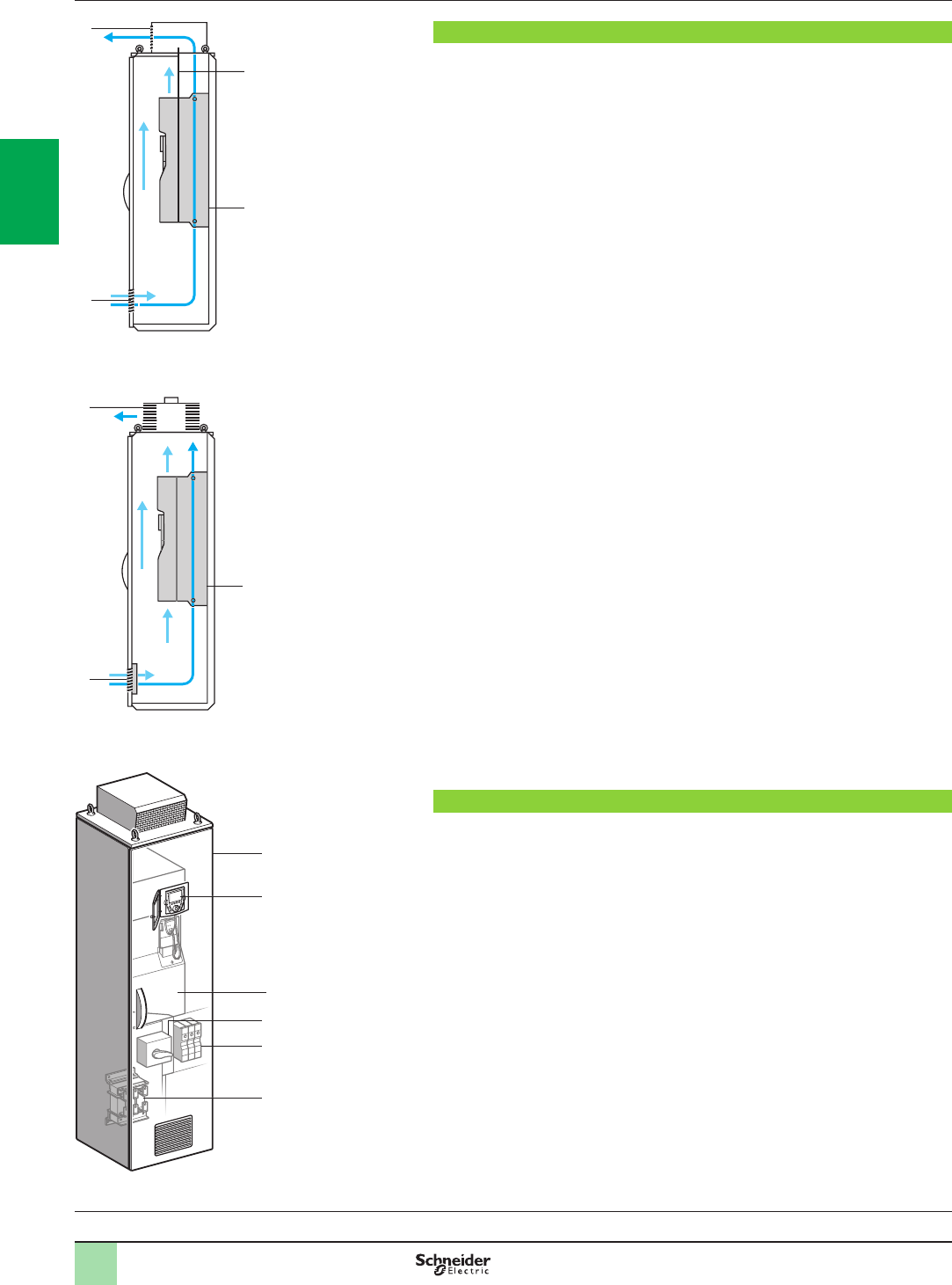
2/12
Presentation Variable speed drives
Altivar 61 Plus
IP 23 or IP 54 oor-standing enclosure compact version
1
2
3
4
6
5
DF537031
The standard ATV61EXCpppppp offer
IP 23 cooling circuit
DF600362
1
4
3
2
IP 54 cooling circuit
DF600363
1
3
2
Variable speed drives:
page 1/16 Options:
page 1/46 Drive/option combinations:
page 1/34
Presentation
The ATV61EXCpppppp offer consists of a compact oor-standing enclosure
providing IP 23 or IP 54 protection for industrial environments and infrastructures
(tunnels, subways, smoke extraction and pumping, etc.).
Altivar 61 variable speed drives are supplied in an IP 23 or IP 54 ready-assembled
enclosure to facilitate installation and setup and, in particular, to help ensure
optimum ventilation.
The enclosure is supplied ready to connect.
One common air circuit provides enclosure ventilation, cooling the power section
and the control section. A fan 2 integrated in the drive provides ventilation for the
power section.
bIP 23 air circuit:
vAir intake 1 is via a grille on the lower part of the enclosure door.
vAir outlet 4 is via a metal cover with protection against water splashes on the
enclosure roof.
vA separating plate 3 helps preventing internal turbulence.
bIP 54 air circuit:
vThe grille 1 on the lower part of the door is tted with a protective lter.
vThe air outlet 3 on the enclosure roof is tted with a fan with lter.
The incoming air temperature must be between 0°C and 40°C (- 10°C and 40°C
with enclosure heater) and may reach + 50°C with derating (class 3K3 according to
IEC/EN 60721-3-3).
The internal temperature is monitored by a thermostat which can shut down the
equipment.
The ATV61EXCpppppp offer covers motor power ratings from 90 kW to
800 kW with three types of power supply:
b380…415 V three-phase, 90 kW to 630 kW (ATV61EXCppppN4)
b500 V three-phase, 90 kW to 630 kW (ATV61EXCppppN)
b690 V three-phase, 110 kW to 800 kW (ATV61EXCppppY)
It includes the choice of:
bA standard compact offer
bA modular offer, in which a wide selection of options can be incorporated depending
on the drive rating
The standard compact offer
This consists of:
bA wired, ready-assembled Sarel “Spacial SF” enclosure 1
bA drive on heatsink ATV61HD90N4D…HC63N4D or
ATV61HC11Y…HC80Y 3
bAn IP 65 remote mounting kit for graphic display terminal 2
bA switch and fast-acting fuses 4
bMotor terminals 5
bA line choke 6
See pages 2/14 and 2/15.
2
1
3
4
5
6
7
8
9
10
2
1
3
4
5
6
7
8
9
10

2/13
Modular offer
This consists of:
bThe standard compact offer
bOne or more options (see pages 2/16 to 2/23)
As well as these specic options, the options available for Altivar 61 drives can be
used, at the same rating, with the enclosed drives offer (see the summary tables of
possible drive, option and accessory combinations on pages 1/36, 1/37 and 1/42 to
1/45).
For any conguration other than those shown on pages 2/16 to 2/23, please contact
our Customer Care Centre.
Common options
These options can be integrated, whatever the enclosure model, without any need
for modications to the enclosure:
bAdaptor for 115 V a logic inputs
bEncoder interface cards
bI/O expansion cards
bMultipump cards and “Controller Inside” programmable card
bModbus TCP, EtherNet/IP, DeviceNet, InterBus, CC-Link, Modbus/Uni-Telway,
PROFIBUS DP V0 or V1, LonWorks, METASYS N2, APOGEE FLN, BACnet
communication cards
b“Preventa type AC” or “Preventa type ATE” fault relay
bPTC relays, PT100 relays
bMotor heater
bAdditional 24 V c power supply
bEmergency stop button
bEnclosure lighting
bKey switch (Local/Remote)
bPower supply circuit for external fan
See pages 2/16 and 2/17. For other options, please contact our Customer Care
Centre.
Options dependent on the drive rating
These options depend on the drive rating. Some may lead to modication of the size
of the enclosure:
bBraking unit
bIsolating handle for switch
bCircuit-breaker
bLine contactor
bControl transformer
bAmmeter
bEnclosure heater
bMotor choke
bSinus lter
bPlinth
See pages 2/18 to 2/23. For other options, please contact our Customer Care
Centre.
Presentation (continued) Variable speed drives
Altivar 61 Plus
IP 23 or IP 54 oor-standing enclosure compact version
Variable speed drives:
page 1/16 Options:
page 1/46 Drive/option combinations:
page 1/34
2
1
3
4
5
6
7
8
9
10
2
1
3
4
5
6
7
8
9
10
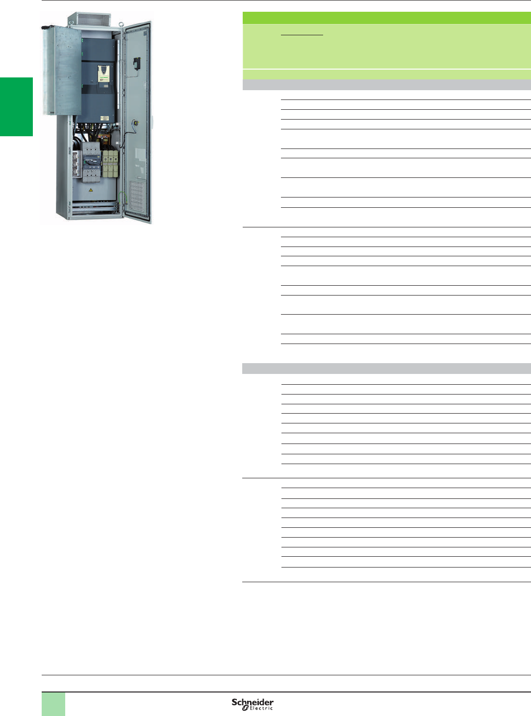
2/14
References Variable speed drives
Altivar 61 Plus
IP 23 or IP 54 oor-standing enclosure compact version
IP 23 or IP 54 oor-standing enclosure compact version
Degree of
protection Motor With drive Dimensions Reference Weight
Power
indicated on
rating plate
(1)
kW W x H x D kg
Three-phase supply voltage 380…415 V 50/60 Hz (2)
IP 23 90 ATV61HD90N4D 600 x 2162 x 642 ATV61EXC2D90N4 315.000
110 ATV61HC11N4D 600 x 2162 x 642 ATV61EXC2C11N4 315.000
132 ATV61HC13N4D 600 x 2162 x 642 ATV61EXC2C13N4 335.000
160 ATV61HC16N4D 600 x 2162 x 642 ATV61EXC2C16N4 350.000
200 ATV61HC22N4D 800 x 2162 x 642 ATV61EXC2C22N4 380.000
220
250 ATV61HC25N4D 800 x 2162 x 642 ATV61EXC2C25N4 485.000
280 ATV61HC31N4D 800 x 2162 x 642 ATV61EXC2C31N4 485.000
315
355 ATV61HC40N4D 1200 x 2162 x 642 ATV61EXC2C40N4 640.000
400
500 ATV61HC50N4D 1200 x 2162 x 642 ATV61EXC2C50N4 680.000
560 ATV61HC63N4D 1200 x 2162 x 642 ATV61EXC2C63N4 805.000
630
IP 54 90 ATV61HD90N4D 600 x 2262 x 642 ATV61EXC5D90N4 325.000
110 ATV61HC11N4D 600 x 2262 x 642 ATV61EXC5C11N4 325.000
132 ATV61HC13N4D 600 x 2262 x 642 ATV61EXC5C13N4 345.000
160 ATV61HC16N4D 600 x 2262 x 642 ATV61EXC5C16N4 360.000
200 ATV61HC22N4D 800 x 2262 x 642 ATV61EXC5C22N4 385.000
220
250 ATV61HC25N4D 800 x 2262 x 642 ATV61EXC5C25N4 485.000
280 ATV61HC31N4D 800 x 2262 x 642 ATV61EXC5C31N4 485.000
315
355 ATV61HC40N4D 1200 x 2262 x 642 ATV61EXC5C40N4 660.000
400
500 ATV61HC50N4D 1200 x 2262 x 642 ATV61EXC5C50N4 700.000
560 ATV61HC63N4D 1200 x 2262 x 642 ATV61EXC5C63N4 835.000
630
Three-phase supply voltage 500 V 50/60 Hz (2)
IP 23 90 ATV61HC11Y 600 x 2162 x 642 ATV61EXC2D90N 361.000
110 ATV61HC13Y 600 x 2162 x 642 ATV61EXC2C11N 361.000
132 ATV61HC16Y 600 x 2162 x 642 ATV61EXC2C13N 412.000
160 ATV61HC20Y 600 x 2162 x 642 ATV61EXC2C16N 412.000
200 ATV61HC25Y 800 x 2162 x 642 ATV61EXC2C20N 503.000
250 ATV61HC31Y 800 x 2162 x 642 ATV61EXC2C25N 553.000
315 ATV61HC40Y 800 x 2162 x 642 ATV61EXC2C31N 553.000
400 ATV61HC50Y 1200 x 2162 x 642 ATV61EXC2C40N 828.000
500 ATV61HC63Y 1200 x 2162 x 642 ATV61EXC2C50N 916.000
630 ATV61HC80Y 1200 x 2162 x 642 ATV61EXC2C63N 916.000
IP 54 90 ATV61HC11Y 600 x 2262 x 642 ATV61EXC5D90N 371.000
110 ATV61HC13Y 600 x 2262 x 642 ATV61EXC5C11N 371.000
132 ATV61HC16Y 600 x 2262 x 642 ATV61EXC5C13N 422.000
160 ATV61HC20Y 600 x 2262 x 642 ATV61EXC5C16N 422.000
200 ATV61HC25Y 800 x 2262 x 642 ATV61EXC5C20N 503.000
250 ATV61HC31Y 800 x 2262 x 642 ATV61EXC5C25N 553.000
315 ATV61HC40Y 800 x 2262 x 642 ATV61EXC5C31N 553.000
400 ATV61HC50Y 1200 x 2262 x 642 ATV61EXC5C40N 858.000
500 ATV61HC63Y 1200 x 2262 x 642 ATV61EXC5C50N 946.000
630 ATV61HC80Y 1200 x 2262 x 642 ATV61EXC5C63N 946.000
(1) These values are given for a nominal switching frequency 4 kHz for ATV61HD90N4D or 2.5
kHz for ATV61HC11N4D…HC63N4D drives or of 2.5 kHz for ATV61HC11Y…HC80Y drives
for use in continuous operation.
The switching frequency is adjustable from 2…8 kHz for ATV61HD90N4D…ATV61HC63N4D
drives and from 2.5…4.9 kHz for ATV61HC11Y…HC80Y drives. Above 2.5 or 4 kHz
depending on the rating, the drive will reduce the switching frequency automatically in the
event of an excessive temperature rise. For continuous operation above the nominal
switching frequency, derate the nominal drive current, see derating curves on our website
www.schneider-electric.com.
(2) The maximum prospective line Isc is of 100 kA. These values are given for use with upstream
fuses (see the characteristics on our website www.schneider-electric.com).
ATV61EXC2ppppp
PF095307
Variable speed drives:
page 1/16 Options:
page 1/46 Drive/option combinations:
page 1/34
2
1
3
4
5
6
7
8
9
10
2
1
3
4
5
6
7
8
9
10

2/15
References (continued) Variable speed drives
Altivar 61 Plus
IP 23 or IP 54 oor-standing enclosure compact version
IP 23 or IP 54 oor-standing enclosure compact version
(continued)
Degree of
protection Motor With drive Dimensions Reference Weight
Power
indicated
on rating
plate (1)
kW W x H x D kg
Three-phase supply voltage 690 V 50/60 Hz (2)
IP 23 110 ATV61HC11Y 600 x 2162 x 642 ATV61EXC2C11Y 361.000
132 ATV61HC13Y 600 x 2162 x 642 ATV61EXC2C13Y 361.000
160 ATV61HC16Y 600 x 2162 x 642 ATV61EXC2C16Y 412.000
200 ATV61HC20Y 600 x 2162 x 642 ATV61EXC2C20Y 412.000
250 ATV61HC25Y 800 x 2162 x 642 ATV61EXC2C25Y 503.000
315 ATV61HC31Y 800 x 2162 x 642 ATV61EXC2C31Y 553.000
400 ATV61HC40Y 800 x 2162 x 642 ATV61EXC2C40Y 553.000
500 ATV61HC50Y 1200 x 2162 x 642 ATV61EXC2C50Y 828.000
630 ATV61HC63Y 1200 x 2162 x 642 ATV61EXC2C63Y 916.000
800 ATV61HC80Y 1200 x 2162 x 642 ATV61EXC2C80Y 916.000
IP 54 110 ATV61HC11Y 600 x 2262 x 642 ATV61EXC5C11Y 371.000
132 ATV61HC13Y 600 x 2262 x 642 ATV61EXC5C13Y 371.000
160 ATV61HC16Y 600 x 2262 x 642 ATV61EXC5C16Y 422.000
200 ATV61HC20Y 600 x 2262 x 642 ATV61EXC5C20Y 422.000
250 ATV61HC25Y 800 x 2262 x 642 ATV61EXC5C25Y 503.000
315 ATV61HC31Y 800 x 2262 x 642 ATV61EXC5C31Y 553.000
400 ATV61HC40Y 800 x 2262 x 642 ATV61EXC5C40Y 553.000
500 ATV61HC50Y 1200 x 2262 x 642 ATV61EXC5C50Y 858.000
630 ATV61HC63Y 1200 x 2262 x 642 ATV61EXC5C63Y 946.000
800 ATV61HC80Y 1200 x 2262 x 642 ATV61EXC5C80Y 946.000
(1) These values are given for a nominal switching frequency of 2.5 kHz for
ATV61HC11Y…HC80Y for use in continuous operation.
The switching frequency is adjustable from 2.5…4.9 kHz for ATV61HC11Y…HC80Y drives.
Above 2.5 kHz or 4 kHz, depending on the rating, the drive will reduce the switching
frequency automatically in the event of an excessive temperature rise. For continuous
operation above the nominal switching frequency, derate the nominal drive current, see
derating curves on our website www.schneider-electric.com
(2) The maximum prospective line Isc is of 100 kA. These values are given for use with upstream
fuses (see the characteristics on our website www.schneider-electric.com).
Variable speed drives:
page 1/16 Options:
page 1/46 Drive/option combinations:
page 1/34
2
1
3
4
5
6
7
8
9
10
2
1
3
4
5
6
7
8
9
10

2/16
References Variable speed drives
Altivar 61 Plus
Floor-standing enclosure with separate air ows or
compact version
Common options
Common options without modication of the enclosure (1)
Description Reference Weight
kg
Adaptor for 115 V a logic inputs VW3A3E101 (2) 0.200
Encoder interface cards with RS 422, 5 V compatible differential outputs VW3A3E401 (3) 0.200
Encoder interface card with 12 V open collector outputs VW3A3E403 (3) 0.200
Encoder interface card with 15 V open collector outputs VW3A3E404 (3) 0.200
Encoder interface card with 12 V push-pull outputs VW3A3E405 (3) 0.200
Encoder interface card with 15 V push-pull outputs VW3A3E406 (3) 0.200
Encoder interface card with 24 V push-pull outputs VW3A3E407 (3) 0.200
Logic I/O expansion card VW3A3E201 (4) 0.320
Extended I/O expansion card VW3A3E202 (4) 0.300
Multi-pump card VW3A3E502 (5) (6) 0.320
“Water solution” multi-pump card VW3A3E503 (5) (6) 0.320
“Controller Inside” programmable card VW3A3E501 (6) (7) 0.300
Modbus TCP Daisy Chain communication card VW3A3E310D (8) 0.300
EtherNet/IP communication card VW3A3E316 (8) 0.300
DeviceNet communication card VW3A3E309 (8) 0.300
InterBus communication card VW3A3E304 (8) 0.300
CC-Link communication card VW3A3E317 (8) 0.320
Modbus Plus communication card VW3A3E302 (8) 0.300
Modbus/Uni-Telway communication card VW3A3E303 (8) 0.300
PROFIBUS DP V0 communication card VW3A3E307 (8) 0.300
PROFIBUS DP V1 communication card VW3A3E307S371 (8) 0.300
LonWorks communication card VW3A3E312 (8) 0.300
METASYS N2 communication card VW3A3E313 (8) 0.300
APOGEE FLN communication card VW3A3E314 (8) 0.300
BACnet communication card VW3A3E319 (8) 0.300
(1) For any other conguration, please contact our Customer Care Centre.
(2) The characteristics of the VW3A3E101 adaptor are identical to those of the VW3A3101 adaptor (see page 1/29 or consult our
website www.schneider-electric.com).
(3) The characteristics of the VW3A3E401 and 403…407 encoder interface cards are identical to those of the VW3A3401 and
403...407 encoder interface cards (see page 1/46 or consult our website www.schneider-electric.com).
(4) The characteristics of the VW3A3E201 and VW3A3E202 I/O expansion cards are identical to those of the VW3A3201 and
VW3A3202 expansion cards (see page 1/47 or consult our website www.schneider-electric.com).
(5) The characteristics of the VW3A3E502 and VW3A3E503 I/O multi-pump cards are identical to those of the VW3A3502 and
VW3A3 03 multi-pump cards (see pages 1/48 and 1/49) or consult our website www.schneider-electric.com).
(6) If the power consumption does not exceed 200 mA, this card can be powered by the drive. For a power consumption in excess of
200 mA, the additional 24 V c power supply option, reference VW3AE1401, should be ordered separately (see page 2/17).
(7) The characteristics of the VW3A3E501 Controller Inside programmable card are identical to those of the VW3A3501
Controller Inside programmable card (see pages 1/50 to 1/53 or consult our website www.schneider-electric.com).
(8) The characteristics of the VW3A3E302…319 communication cards are identical to those of the VW3A3302…319 communication
cards (see page 1/54 to 1/59 or consult our website www.schneider-electric.com).
Variable speed drives:
page 1/16 Options:
page 1/46 Drive/option combinations:
page 1/34
2
1
3
4
5
6
7
8
9
10
2
1
3
4
5
6
7
8
9
10

2/17
References (continued) Variable speed drives
Altivar 61 Plus
Floor-standing enclosure with separate air ows or
compact version
Common options
Common options without modication of the enclosure (continued) (1)
Description Reference Weight
kg
Remote control terminals X12 VW3AE1201 0.700
Remote option card terminals X13 (2)
for I/O expansion cards VW3A3E201 and 202 VW3AE1202 0.900
External 230 V a supply terminals VW3AE1301 0.100
Additional 24 V c power supply, nominal current 2 A (3) (4) VW3AE1401 2.200
External 24 V c supply terminals VW3AE1402 0.100
Emergency stop button VW3AE1501 0.100
“Preventa type AC” fault relay (5) VW3AE1502 0.100
“Preventa type ATE” fault relay (5) VW3AE1503 0.100
Enclosure lighting (4) VW3AE1601 1.500
Key switch (Local/Remote) VW3AE1801 0.200
Additional electrical input isolation (5) VW3AE1901 0.100
Additional electrical output isolation (5) VW3AE1902 0.100
PTC relay (4) VW3AE2001 0.100
PTC relay with PTB (ATEX) certication (4) (6) VW3AE2002 0.100
PT100 relay (5)
for motor winding VW3AE2003 0.300
PT100 relay (5)
for motor bearings VW3AE2004 0.300
PT100 relay (5)
for line supply transformer VW3AE2005 0.300
Motor heater 200 W, 230 V (4) VW3AE2101 0.200
Power supply circuit with protection (4)
for 1000 W external fan VW3AE2102 0.200
Relay for logic output (5) VW3AE2201 0.100
Voltmeter
three-phase supply voltage 380…415 V VW3AE2301 0.400
Voltmeter
three-phase supply voltage 500 V VW3AE2302 0.400
Voltmeter
three-phase supply voltage 690 V VW3AE2303 0.400
Fan interruption (4) VW3AE2901 0.100
Modied colors for Australia VW3AE3001 0.100
Insulation monitoring device on an IT system (4) VW3AE2601 5.000
Selector for IT system VW3AE2701 –
(1) For any other conguration, please contact our Customer Care Centre.
(2) The X13 terminals, reference VW3AE1202, include the X12 terminals, reference VW3AE1201.
(3) Essential if the power consumption of the option cards exceeds 200 mA.
(4) This option requires a 230 V a supply, reference VW3AE1301.
(5) This option requires a 24 V c supply voltage, reference VW3AE1401.
(6) ATEX: Please refer to the ATEX guide which is available on our website www.schneider-electric.com.
Variable speed drives:
page 1/16 Options:
page 1/46 Drive/option combinations:
page 1/34
2
1
3
4
5
6
7
8
9
10
2
1
3
4
5
6
7
8
9
10

2/18
References (continued) Variable speed drives
Altivar 61 Plus
Floor-standing enclosure with separate air ows or
compact version
Options dependent on the drive rating
Options dependent on the drive rating (1)
Three-phase supply voltage 380…415 V 50/60 Hz
Description For ATV 61 enclosure Reference Weight
kg
Resistance braking unit EXCpC25N4, C31N4
EXS5C25N4, C31N4 VW3A7E101 (3) 31.000
EXCpC40N4…C63N4 VW3AE1003 (2) 190.000
EXS5C40N4…C63N4 VW3A7E102 (3) 205.000
Isolating handle for switch EXCpD55N4H VW3AE0190 0.500
EXCpD90N4...C13N4
EXCpD75N4H…C11N4H
EXS5D90N4...C13N4
VW3AE0103 1.000
EXCpC16N4...C31N4
EXCpC13N4H…C31N4H
EXS5C16N4...C31N4
VW3AE0104 2.000
EXCpC40N4...C63N4
EXCpC40N4H...C63N4H
EXS5C40N4…C63N4
EXApC63N4…M14N4
VW3AE0105 2.000
Circuit-breaker (4) EXCpD90N4...C11N4
EXS5D90N4...C11N4 VW3AE0142 –
EXCpC13N4
EXS5C13N4 VW3AE0143 –
EXCpC16N4
EXS5C16N4 VW3AE0146 1.400
EXCpC22N4
EXS5C22N4 VW3AE0147 1.400
EXCpC25N4
EXS5C25N4 VW3AE0148 1.400
EXCpC31N4
EXS5C31N4 VW3AE0110 9.400
EXCpC40N4
EXS5C40N4 VW3AE0151 –
EXCpC50N4
EXS5C50N4 VW3AE0169 –
EXCpC63N4
EXS5C63N4
EXApC63N4, C71N4
VW3AE0170 –
EXApC90N4 VW3AE0171 –
EXApM11N4 VW3AE0172 –
EXApM13N4, M14N4 VW3AE0173 –
EXCpD75N4H VW3AE0141 0.500
EXCpD90N4H…C11N4H VW3AE0142 –
EXCpC13N4H, C16N4H VW3AE0146 1.400
EXCpC22N4H, C25N4H VW3AE0147 1.400
EXCpC31N4H VW3AE0148 1.400
EXCpC40N4H, C50N4H VW3AE0151 –
EXCpC63N4H VW3AE0169 –
Door handle for circuit-breaker EXCpD90N4...C11N4
EXCpD75N4H...C11N4H
EXS5D90N4...C11N4
VW3AE0114 1.000
EXCpC13N4...C25N4
EXC●C13N4H…C31N4H
EXS5C13N4...C25N4
VW3AE0115 2.000
EXCpC31N4...C63N4
EXC●C40N4H...C63N4H
EXS5C31N4...C63N4
EXApC63N4, C71N4
VW3AE0116 2.000
(1) For any other conguration, please contact our Customer Care Centre.
(2) This option depends on the drive rating and may lead to modication of the size of the enclosure. Please refer to the dimensions on our website
www.schneider-electric.com.
(3) The characteristics of the VW3A7E101 and VW3A7E102 braking units are identical to those of the VW3A7101 and VW3A7102 braking units
(see page 1/60 or consult our website www.schneider-electric.com).
(4) The circuit-breaker replaces the switch in the standard offer.
Variable speed drives:
page 1/16 Options:
page 1/46 Drive/option combinations:
page 1/34
2
1
3
4
5
6
7
8
9
10
2
1
3
4
5
6
7
8
9
10

2/19
Options dependent on the drive rating (continued) (1)
Three-phase supply voltage 380…415 V 50/60 Hz (continued)
Description For ATV 61 enclosure Reference Weight
kg
Line contactor (2) EXCpD90N4
EXS5D90N4 VW3AE0206 7.000
EXCpC11N4
EXS5C11N4 VW3AE0207 7.000
EXCpC13N4
EXS5C13N4 VW3AE0218 10.000
EXCpC16N4
EXS5C16N4 VW3AE0208 11.000
EXCpC22N4 VW3AE0209 12.000
EXS5C22N4...C31N4 VW3AE0216 10.000
EXCpC25N4 VW3AE0210 14.000
EXCpC31N4, C40N4
EXS5C40N4 VW3AE0211 21.000
EXCpC50N4
EXS5C50N4 VW3AE0213 28.000
EXCpC63N4
EXS5C63N4 VW3AE0214 42.000
EXApC63N4, C71N4 (3) VW3AE0227 42.000
EXApC90N4...M14N4 VW3AE0224 84.000
Switch for 12-pulse input EXApC63N4, C71N4 VW3AE2416 –
EXApC90N4 VW3AE2418 –
EXApM11N4 VW3AE2419 –
EXApM13N4, M14N4 VW3AE2420 –
Line choke EXApC63N4, C71N14 VW3AE2501 132.000
EXApC90N4 VW3AE2502 (4) 202.000
EXApM11N4…M14N14 VW3AE2503 (4) 264.000
500 VA a control transformer, 230 V a output EXCpD90N4…C22N4
EXS5D90N4…C22N4 VW3AE0302 8.000
800 VA a control transformer, 230 V a output EXCpC25N4…C63N4
EXS5C25N4…C63N4 VW3AE0303 11.000
Ammeter EXCpD90N4
EXC●D75N4H, D90N4H
EXS5D90N4
VW3AE0404 0.200
EXCpC11N4…C16N4
EXC●C11N4H…C16N4H
EXS5C11N4…C16N4
VW3AE0406 0.200
EXCpC22N4, C25N4
EXC●C22N4H…C31N4H
EXS5C22N4, C25N4
VW3AE0426 0.200
EXCpC31N4, C40N4
EXC●C40N4H...C50N4H
EXS5C31N4, C40N4
VW3AE0409 0.200
EXCpC50N4
EXC●C63N4H
EXS5C50N4
VW3AE0427 0.200
EXCpC63N4
EXS5C63N4 VW3AE0411 0.200
EXApC63N4, C71N4 VW3AE0411 (5)
VW3AE0421 (6) 0.200
EXApC90N4 VW3AE0413 (5)
VW3AE0421 (6) 0.200
EXApM11N4 VW3AE0414 (5)
VW3AE0429 (6) 0.200
EXApM13N4, M14N4 VW3AE0415 (5)
VW3AE0423 (6) 0.200
(1) For any other conguration, please contact our Customer Care Centre.
(2) This option requires a 230 V a supply, reference VW3AE1301.
(3) If a line contactor and choke are used, order reference VW3AE0225 (50.000 kg) (see note 3).
(4) These options depend on the drive rating and may lead to modication of the size of the enclosure. Please refer to the dimensions on our website
www.schneider-electric.com.
(5) For 6-pulse mounting.
(6) For 12-pulse mounting.
References (continued) Variable speed drives
Altivar 61 Plus
Floor-standing enclosure with separate air ows or
compact version
Options dependent on the drive rating
Variable speed drives:
page 1/16 Options:
page 1/46 Drive/option combinations:
page 1/34
2
1
3
4
5
6
7
8
9
10
2
1
3
4
5
6
7
8
9
10

2/20
References (continued) Variable speed drives
Altivar 61 Plus
Floor-standing enclosure with separate air ows or
compact version
Options dependent on the drive rating
Options dependent on the drive rating (continued) (1)
Three-phase supply voltage 380…415 V 50/60 Hz (continued)
Description For ATV 61 enclosure Reference Weight
kg
Enclosure heater (2) EXCpD90N4…C31N4
EXCpD75N4H…C31N4H
EXS5D90N4…C31N4
VW3AE0501 0.500
EXCpC40N4…C63N4
EXCpC40N4H…C63N4H
EXS5C40N4…C63N4
EXApC63N4, C71N4
VW3AE0502 1.000
EXApC90N4…M14N4 VW3AE0503 1.500
EXApM15YH…M24YH VW3AE0504 2.000
Motor choke EXCpD90N4
EXCpD55N4H…D90N4H VW3AE0603 17.000
EXS5D90N4 VW3AE0615 37.000
EXCpC11N4, C13N4
EXCpC11N4H, C13N4H VW3AE0604 35.000
EXS5C11N4 VW3AE0616 55.000
EXS5C13N4 VW3AE0617 55.000
EXCpC16N4, C22N4
EXCpC16N4H, C22N4H VW3AE0605 64.000
EXS5C16N4 VW3AE0618 (3) 154.000
EXS5C22N4 VW3AE0619 (3) 157.000
EXCpC25N4, C31N4
EXCpC25N4H, C31N4H VW3AE0606 102.000
EXS5C25N4, C31N4 VW3AE0621 (3) 192.000
EXC2C40N4
EXC●C40N4H
VW3AE0608 (3) 222.000
EXC5C40N4 VW3AE0612 (3) 222.000
EXS5C40N4 VW3AE0623 (3) 222.000
EXC2C50N4
EXC●C50N4H
VW3AE0609 (3) 228.000
EXC5C50N4 VW3AE0613 (3) 228.000
EXS5C50N4 VW3AE0624 (3) 228.000
EXC2C63N4
EXC●C63N4H
VW3AE0610 (3) 234.000
EXC5C63N4 VW3AE0614 (3) 234.000
EXS5C63N4 VW3AE0625 (3) 234.000
EXApC63N4, C71N4 VW3AE0635 132.000
EXApC90N4…M14N4 VW3AE0636 264.000
Sinus lter (3) (4) EXC2D90N4, C11N4 VW3AE0641 318.000
EXC5D90N4, C11N4 VW3AE0653 348.000
EXS5D90N4, C11N4 VW3AE0665 318.000
EXC2C13N4 VW3AE0643 357.000
EXC5C13N4 VW3AE0655 357.000
EXS5C13N4 VW3AE0667 357.000
EXC2C16N4 VW3AE0644 365.000
EXC5C16N4 VW3AE0656 365.000
EXS5C16N4 VW3AE0668 365.000
EXC2C22N4 VW3AE0646 384.000
EXC5C22N4 VW3AE0658 384.000
EXS5C22N4 VW3AE0670 384.000
EXC2C25N4, C31N4 VW3AE0648 434.000
EXC5C25N4, C31N4 VW3AE0660 434.000
EXS5C25N4, C31N4 VW3AE0672 434.000
EXC2C40N4 VW3AE0650 870.000
EXC5C40N4 VW3AE0662 870.000
EXS5C40N4 VW3AE0674 870.000
EXC2C50N4 VW3AE0651 870.000
EXC5C50N4 VW3AE0663 900.000
EXS5C50N4 VW3AE0675 900.000
EXC2C63N4 VW3AE0652 900.000
EXC5C63N4 VW3AE0664 930.000
EXS5C63N4 VW3AE0676 930.000
(1) For any other conguration, please contact our Customer Care Centre.
(2) This option requires a 230 V a supply, reference VW3AE1301.
(3) These options depend on the drive rating and may lead to modication of the size of the enclosure. Please refer to the dimensions on our website
www.schneider-electric.com.
(4) The sinus lter option is not compatible with the motor choke option.
Variable speed drives:
page 1/16 Options:
page 1/46 Drive/option combinations:
page 1/34
2
1
3
4
5
6
7
8
9
10
2
1
3
4
5
6
7
8
9
10

2/21
Options dependent on the drive rating (continued) (1)
Three-phase supply voltage 380…415 V 50/60 Hz (continued)
Description For ATV 61 enclosure Reference Weight
kg
200 mm plinth Without motor choke EXCpD55N4H VW3AE0807 9.000
EXCpD90N4…C22N4
EXCpD75N4H…C11N4H VW3AE0801 11.000
EXCpC25N4, C31N4
EXCpC13N4H, C16N4H VW3AE0802 13.000
EXCpC22N4H VW3AE0827 22.000
EXCpC25N4H, C31N4H VW3AE0828 26.000
EXCpC40N4, C50N4 VW3AE0803 15.000
EXCpC40N4H, C50N4H VW3AE0829 30.000
EXCpC63N4 VW3AE0804 17.000
EXCpC63N4H VW3AE0830 34.000
EXApC63N4, C71N4 VW3AE0820 (2) 38.000
EXApC90N4…M14N4 VW3AE0822 69.000
With motor choke EXCpD55N4H VW3AE0807 9.000
EXCpD90N4…C22N4
EXCpD75N4H…C11N4H VW3AE0801 11.000
EXCpC25N4, C31N4
EXC●C13N4H, C16N4H
VW3AE0802 13.000
EXCpC22N4H VW3AE0827 22.000
EXCpC25N4H, C31N4H VW3AE0828 26.000
EXCpC40N4, C50N4 VW3AE0805 24.000
EXCpC40N4H, C50N4H VW3AE0831 39.000
EXCpC63N4 VW3AE0806 26.000
EXCpC63N4H VW3AE0832 43.000
EXApC63N4, C71N4 VW3AE0820 (2) 38.000
EXApC90N4…M14N4 VW3AE0822 69.000
With line choke EXApC63N4, C71N4 VW3AE0820 (2) 38.000
EXApC90N4…M14N4 VW3AE0824 78.000
Plinth for braking unit EXCpC40N4…C63N4 VW3AE0810 9.000
Plinth for sinus lter EXCpD90N4…C31N4 VW3AE0816 11.000
EXCpC40N4...C63N4 VW3AE0817 13.000
(1) For any other conguration, please contact our Customer Care Centre.
(2) If a line choke and a line contactor are used, order reference VW3AE0821 (40.000 kg).
References (continued) Variable speed drives
Altivar 61 Plus
Floor-standing enclosure with separate air ows or
compact version
Options dependent on the drive rating
Variable speed drives:
page 1/16 Options:
page 1/46 Drive/option combinations:
page 1/34
2
1
3
4
5
6
7
8
9
10
2
1
3
4
5
6
7
8
9
10

2/22
Options dependent on the drive rating (continued) (1)
Three-phase supply voltage 500 V and 690 V 50/60 Hz
Description For ATV 61 enclosure Reference Weight
kg
500 V 690 V
Resistance braking unit EXCpC20N…C31N EXCpC25Y…C40Y VW3AE1004 (2) 190.000
EXS5C20N…C31N EXS5C25Y…C40Y VW3A7E103 (2) (3) 205.000
EXCpC40N…C63N EXCpC50Y…C80Y VW3AE1005 (2) 190.000
EXS5C40N…C63N EXS5C50Y…C80Y VW3A7E104 (2) (3) 205.000
Isolating handle for switch EXCpD90N…C16N
EXS5D90N…C16N EXCpC11Y…C20Y
EXS5C11Y…C20Y VW3AE0103 1.000
EXCpC20N…C31N
EXS5C20N…C31N EXCpC25Y…C40Y
EXS5C25Y…C40Y VW3AE0104 2.000
EXCpC40N…C63N
EXS5C40N…C63N
EXApC63N…M18N
EXCpC50Y…C80Y
EXS5C50Y…C80Y
EXApC80Y…M24Y
EXApC80YH...M24YH
VW3AE0105 2.000
Circuit-breaker (4) EXCpD90N, EXS5D90N – VW3AE0141 –
EXCpC11N, EXCpC13N
EXS5C11N, EXS5C13N –VW3AE0142 –
EXCpC16N
EXS5C16N EXCpC11Y, C20Y
EXS5C11Y, C20Y VW3AE0143 4.000
EXCpC20N, EXS5C20N – VW3AE0146 1.400
EXCpC25N
EXS5C25N EXCpC25Y…C40Y
EXS5C25Y…C40Y VW3AE0147 1.400
EXCpC31N, EXS5C31N – VW3AE0148 1.400
EXCpC40N
EXS5C40N EXCpC50Y, C63Y
EXS5C50Y, C63Y VW3AE0150 –
EXCpC50N
EXS5C50N EXCpC80Y
EXS5C80Y VW3AE0151 –
EXCpC63N, EXS5C63N – VW3AE0152 –
EXApC63N EXApC80Y
EXApC80YH VW3AE0169 –
EXApC80N, C90N EXApM10Y, M12Y
EXApM10YH, M12YH VW3AE0170 –
EXApM11N EXApM15Y
EXApM15YH VW3AE0171 –
EXApM13N EXApM18Y
EXApM18YH VW3AE0172 –
EXApM15N, M18N EXApM21Y, M24Y
EXApM21YH, M24YH VW3AE0173 –
Door handle for circuit-breaker EXCpC11N, C13N
EXS5C11N, C13N –VW3AE0114 1.000
EXCpC16N…C31N
EXS5C16N…C31N EXCpC11Y…C40Y
EXS5C11Y…C40Y VW3AE0115 2.000
EXCpC40N…C63N
EXS5C40N…C63N
EXApC63N…C90N
EXCpC50Y, C63Y
EXS5C50Y, C63Y
EXApC80Y…M12Y
EXApC80YH...M12YH
VW3AE0116 2.000
Line contactor (5) EXCpD90N, EXS5D90N – VW3AE0205 4.000
EXCpC11N, EXS5C11N – VW3AE0206 7.000
EXCpC13N
EXS5C13N EXCpC11Y…C16Y
EXS5C11Y…C16Y VW3AE0218 10.000
– EXCpC20Y, EXS5C20Y VW3AE0208 11.000
EXCpC16N...C20N
EXS5C16N...C20N EXCpC25Y, EXS5C25Y VW3AE0209 12.000
EXCpC25N, C31N
EXS5C25N, C31N EXCpC31Y
EXS5C31Y VW3AE0210 14.000
– EXCpC40Y, EXS5C40Y VW3AE0211 21.000
EXCpC40N, EXS5C40N EXCpC50Y, EXS5C50Y VW3AE0212 24.000
EXCpC50N, C63N
EXS5C50N, C63N EXCpC63Y, C80Y
EXS5C20Y, C80Y VW3AE0213 28.000
EXApC63N…C90N EXApC80Y…M12Y VW3AE0227 (6) 42.000
EXApM11N…M18N EXApM15Y…M24Y VW3AE0226 84.000
Switch for 12-pulse input EXApC63N EXApC80Y VW3AE2415 –
EXApC80N, C90N EXApM10Y, M12Y VW3AE2416 –
EXApM11N EXApM15Y VW3AE2418 –
EXApM13N EXApM18Y VW3AE2419 –
EXApM15N, M18N EXApM21Y, M24Y VW3AE2420 –
(1) For any other conguration, please contact our Customer Care Centre.
(2) These options depend on the drive rating and may lead to modication of the size of the enclosure. Please refer to the dimensions on our website
www.schneider-electric.com.
(3) The characteristics of the VW3A7E103 and VW3A7E104 braking units are identical to those of the VW3A7103 and VW3A7104 braking units
(see page 1/60 or consult our website www.schneider-electric.com).
(4) The circuit-breaker replaces the switch in the standard offer.
(5) This option requires a 230 V a supply, reference VW3AE1301.
(6) If a line contactor and choke are used, order reference VW3AE0225 (50.000 kg) (see note 2).
References (continued) Variable speed drives
Altivar 61 Plus
Floor-standing enclosure with separate air ows or
compact version
Options dependent on the drive rating
2
1
3
4
5
6
7
8
9
10
2
1
3
4
5
6
7
8
9
10
2/23
Options dependent on the drive rating (continued) (1)
Three-phase supply voltage 500 V and 690 V 50/60 Hz (continued)
Description For ATV 61 enclosure Reference Weight
kg
500 V 690 V
Line choke EXApC63N EXApC80Y VW3AE2504 154.000
EXApC80N EXApM10Y VW3AE2505 121.000
EXApC90N EXApM12Y VW3AE2506 136.000
EXApM11N EXApM15Y VW3AE2507 (2) 308.000
EXApM13N, M15N EXApM18Y, M21Y VW3AE2508 (2) 242.000
EXApM18N EXApM24Y VW3AE2509 (2) 273.000
Ammeter EXCpD90N, C11N
EXS5D90N, C11N EXCpC11Y… C16Y
EXS5C11Y… C16Y VW3AE0404 0.200
EXCpC13N…C20N
EXS5C13N…C20N EXCpC20Y… C31Y
EXS5C20Y… C31Y VW3AE0406 0.200
EXCpC25N, C31N
EXS5C25N, C31N EXCpC40Y
EXS5C40Y VW3AE0426 0.200
EXCpC40N, C50N
EXS5C40N,C50N EXCpC50Y…C80Y
EXS5C50Y…C80Y
EXApC80YH
VW3AE0409 0.200
EXCpC63N
EXS5C63N EXApM10YH VW3AE0427 0.200
EXApC63N – VW3AE0427 (3)
VW3AE0428 (4) 0.200
– EXApC80Y VW3AE0409 (3)
VW3AE0428 (4) 0.200
EXApC80N, C90N EXApM10Y, M12Y, M12YH VW3AE0411 (3)
VW3AE0421 (4) 0.200
EXApM11N EXApM15Y, M15YH…M18YH VW3AE0413 (3)
VW3AE0421 (4) 0.200
EXApM13N, M15N EXApM18Y, M21Y, M21YH VW3AE0414 (3)
VW3AE0429 (4) 0.200
EXApM18N EXApM18Y, M24YH VW3AE0415 (3)
VW3AE0423 (4) 0.200
Enclosure heater (5) EXCpD90N…C31N
EXS5D90N…C31N EXCpC11Y…C40Y VW3AE0501 0.500
EXCpC40N…C63N
EXS5C40N…C63N
EXApC63N…C90N
EXCpC50Y…C80Y
EXApC80Y…M12Y VW3AE0502 1.000
EXApM11N…M18N EXApM15Y…M24Y VW3AE0503 1.500
Motor choke EXCpD90N, C11N
EXS5D90N, C11N EXCpC11Y, C13Y
EXS5C11Y, C13Y VW3AE0603 17.000
EXCpC13N, C16N
EXS5C13N, C16N EXCpC16Y, C20Y
EXS5C16Y, C20Y VW3AE0604 35.000
EXCpC20N, C25N
EXS5C20N, C25N EXCpC25Y, C31Y
EXS5C25Y, C31Y VW3AE0605 64.000
EXCpC31N
EXS5C31N EXCpC40Y
EXS5C40Y VW3AE0606 102.000
EXC2C40N EXC2C50Y VW3AE0626 (2) 192.000
EXC5C40N EXC5C50Y VW3AE0628 (2) 192.000
EXS5C40N EXS5C50Y VW3AE0630 (2) 197.000
EXC2C50N, C63N EXC2C63Y, C80Y VW3AE0627 (2) 234.000
EXC5C50N, C63N EXC5C63Y, C80Y VW3AE0629 (2) 234.000
EXS5C50N, C63N EXS5C63Y, C80Y VW3AE0631 (2) 234.000
EXApC63N…C90N EXApC80Y…M12Y
EXApC80YH...M12YH VW3AE0635 132.000
EXApM11N…M18N EXApM15Y…M24Y
EXApM15YH...M24YH VW3AE0636 264.000
200 mm plinth Without option EXCpD90N…C16N EXCpC11Y…C20Y VW3AE0801 11.000
EXCpC20N…C31N EXCpC25Y…C40Y VW3AE0802 13.000
EXCpC40N…C63N EXCpC50Y…C80Y VW3AE0804 17.000
EXApC63N…C90N EXApC80Y…M12Y VW3AE0820 (6) 38.000
– EXApC80YH...M12YH VW3AE0835 –
EXApM11N…M18N EXApM15Y…M24Y VW3AE0822 69.000
– EXApM15YH...M24YH VW3AE0836 –
With motor choke EXCpD90N…C16N EXCpC11Y…C20Y VW3AE0801 11.000
EXCpC20N…C31N EXCpC25Y…C45Y VW3AE0802 13.000
EXCpC40N…C63N EXCpC50Y…C80Y VW3AE0806 26.000
EXApC63N…C90N EXApC80Y…M12Y VW3AE0820 (6) 38.000
EXApM11N…M18N EXApM15Y…M24Y VW3AE0822 69.000
With line choke EXApC63N…C90N EXApC80Y…M12Y VW3AE0820 (6) 38.000
EXApM11N…M18N EXApM15Y…M24Y VW3AE0824 78.000
Plinth for braking unit EXCpC20N…C63N EXCpC25Y…C80Y VW3AE0810 9.000
(1) For any other conguration, please contact our Customer Care Centre.
(2) These options may lead to modication of the size of the enclosure. Please refer to the dimensions on our website www.schneider-electric.com.
(3) For 6-pulse mounting.
(4) For 12-pulse mounting (not available for ATV61EXAppppYH).
(5) This option requires a 230 V a supply, reference VW3AE1301.
(6) If a line contactor and choke are used, order reference VW3AE0821 (40.000 kg).
References (continued) Variable speed drives
Altivar 61 Plus
Floor-standing enclosure with separate air ows or
compact version
Options dependent on the drive rating
2
1
3
4
5
6
7
8
9
10
2
1
3
4
5
6
7
8
9
10
2
1
3
4
6
7
8
9
10
2
1
3
4
6
7
8
9
10
24
4
490NAD91103 1/59
490NAD91104 1/59
490NTW00002 1/58
490NTW00005
1/58
490NTW00012 1/58
490NTW00040 1/58
490NTW00080 1/58
A
ATV61E5075N4 1/20
ATV61E5D11N4 1/20
ATV61E5D15N4 1/20
ATV61E5D18N4
1/20
ATV61E5D22N4
1/20
ATV61E5D30N4 1/20
ATV61E5D37N4 1/20
ATV61E5D45N4 1/20
ATV61E5D55N4
1/20
ATV61E5D75N4 1/20
ATV61E5D90N4 1/20
ATV61E5U15N4 1/20
ATV61E5U22N4
1/20
ATV61E5U30N4 1/20
ATV61E5U40N4 1/20
ATV61E5U55N4 1/20
ATV61E5U75N4 1/20
ATV61ES5C11N4
2/5
ATV61ES5C13N4 2/5
ATV61ES5C16N4 2/5
ATV61ES5C22N4 2/5
ATV61ES5C25N4
2/5
ATV61ES5C31N4 2/5
ATV61ES5C40N4 2/5
ATV61ES5C50N4 2/5
ATV61ES5C63N4
2/5
ATV61ES5D90N4
2/5
ATV61EXApC63N 2/10
ATV61EXApC63N4 2/10
ATV61EXApC71N4 2/10
ATV61EXA
p
C80N
2/10
ATV61EXApC80Y 2/11
ATV61EXApC90N 2/10
ATV61EXApC90N4 2/10
ATV61EXA
p
M10Y
2/11
ATV61EXApM11N 2/10
ATV61EXApM11N4 2/10
ATV61EXApM12Y 2/11
ATV61EXA
p
M13N
2/10
ATV61EXA
p
M13N4
2/10
ATV61EXApM14N4 2/10
ATV61EXApM15N 2/10
ATV61EXApM15Y 2/11
ATV61EXA
p
M18N
2/10
ATV61EXApM18Y 2/11
ATV61EXApM21Y 2/11
ATV61EXApM24Y 2/11
ATV61EXA2C80YH
2/7
ATV61EXA2M10YH 2/7
ATV61EXA2M12YH 2/7
ATV61EXA2M15YH 2/7
ATV61EXA2M18YH 2/7
ATV61EXA2M21YH
2/7
ATV61EXA2M24YH 2/7
ATV61EXA5C80YH 2/7
ATV61EXA5M10YH 2/7
ATV61EXA5M12YH 2/7
ATV61EXA5M15YH 2/7
ATV61EXA5M18YH 2/7
ATV61EXA5M21YH 2/7
ATV61EXA5M24YH 2/7
ATV61EXC2C11N 2/14
ATV61EXC2C11N4 2/14
ATV61EXC2C11N4H 2/7
ATV61EXC2C11Y 2/15
ATV61EXC2C13N 2/14
ATV61EXC2C13N4 2/14
ATV61EXC2C13N4H
2/7
ATV61EXC2C13Y 2/15
ATV61EXC2C16N 2/14
ATV61EXC2C16N4 2/14
ATV61EXC2C16N4H 2/7
ATV61EXC2C16Y 2/15
ATV61EXC2C20N 2/14
ATV61EXC2C20Y 2/15
ATV61EXC2C22N4 2/14
ATV61EXC2C22N4H 2/7
ATV61EXC2C25N 2/14
ATV61EXC2C25N4
2/14
ATV61EXC2C25N4H 2/7
ATV61EXC2C25Y 2/15
ATV61EXC2C31N 2/14
ATV61EXC2C31N4 2/14
ATV61EXC2C31N4H 2/7
ATV61EXC2C31Y 2/15
ATV61EXC2C40N 2/14
ATV61EXC2C40N4 2/14
ATV61EXC2C40N4H 2/7
ATV61EXC2C40Y 2/15
ATV61EXC2C50N 2/14
ATV61EXC2C50N4 2/14
ATV61EXC2C50N4H 2/7
ATV61EXC2C50Y 2/15
ATV61EXC2C63N 2/14
ATV61EXC2C63N4 2/14
ATV61EXC2C63N4H 2/7
ATV61EXC2C63Y 2/15
ATV61EXC2C80Y 2/15
ATV61EXC2D55N4H 2/7
ATV61EXC2D75N4H 2/7
ATV61EXC2D90N 2/14
ATV61EXC2D90N4 2/14
ATV61EXC2D90N4H 2/7
ATV61EXC5C11N 2/14
ATV61EXC5C11N4 2/14
ATV61EXC5C11N4H 2/7
ATV61EXC5C11Y 2/15
ATV61EXC5C13N 2/14
ATV61EXC5C13N4 2/14
ATV61EXC5C13N4H 2/7
ATV61EXC5C13Y
2/15
ATV61EXC5C16N 2/14
ATV61EXC5C16N4 2/14
ATV61EXC5C16N4H 2/7
ATV61EXC5C16Y 2/15
ATV61EXC5C20N 2/14
ATV61EXC5C20Y 2/15
ATV61EXC5C22N4 2/14
ATV61EXC5C22N4H 2/7
ATV61EXC5C25N 2/14
ATV61EXC5C25N4 2/14
ATV61EXC5C25N4H 2/7
ATV61EXC5C25Y 2/15
ATV61EXC5C31N 2/14
ATV61EXC5C31N4 2/14
ATV61EXC5C31N4H 2/7
ATV61EXC5C31Y 2/15
ATV61EXC5C40N 2/14
ATV61EXC5C40N4 2/14
ATV61EXC5C40N4H 2/7
ATV61EXC5C40Y
2/15
ATV61EXC5C50N 2/14
ATV61EXC5C50N4 2/14
ATV61EXC5C50N4H 2/7
ATV61EXC5C50Y 2/15
ATV61EXC5C63N 2/14
ATV61EXC5C63N4 2/14
ATV61EXC5C63N4H 2/7
ATV61EXC5C63Y 2/15
ATV61EXC5C80Y 2/15
ATV61EXC5D55N4H 2/7
ATV61EXC5D75N4H
2/7
ATV61EXC5D90N 2/14
ATV61EXC5D90N4 2/14
ATV61EXC5D90N4H 2/7
ATV61EXS5C11N 2/10
ATV61EXS5C11N4 2/10
ATV61EXS5C11Y 2/11
ATV61EXS5C13N 2/10
ATV61EXS5C13N4 2/10
ATV61EXS5C13Y 2/11
ATV61EXS5C16N 2/10
ATV61EXS5C16N4 2/10
ATV61EXS5C16Y 2/11
ATV61EXS5C20N 2/10
ATV61EXS5C20Y 2/11
ATV61EXS5C22N4 2/10
ATV61EXS5C25N 2/10
ATV61EXS5C25N4 2/10
ATV61EXS5C25Y 2/11
ATV61EXS5C31N 2/10
ATV61EXS5C31N4 2/10
ATV61EXS5C31Y 2/11
ATV61EXS5C40N 2/10
ATV61EXS5C40N4 2/10
ATV61EXS5C40Y 2/11
ATV61EXS5C50N 2/10
ATV61EXS5C50N4 2/10
ATV61EXS5C50Y 2/11
ATV61EXS5C63N 2/10
ATV61EXS5C63N4 2/10
ATV61EXS5C63Y 2/11
ATV61EXS5C80Y 2/11
ATV61EXS5D90N
2/10
ATV61EXS5D90N4 2/10
ATV61H075M3 1/16
ATV61H075N4 1/17
ATV61HC11N4 1/17
ATV61HC11Y 1/21
ATV61HC13N4 1/17
ATV61HC13Y 1/21
ATV61HC16N4 1/17
ATV61HC16Y 1/21
ATV61HC20Y 1/21
ATV61HC22N4 1/17
ATV61HC25N4 1/17
ATV61HC25Y 1/21
ATV61HC31N4 1/17
ATV61HC31Y 1/21
ATV61HC40N4 1/17
ATV61HC40Y 1/21
ATV61HC50N4 1/17
ATV61HC50Y 1/21
ATV61HC63N4
1/17
ATV61HC63Y 1/21
ATV61HC80Y 1/21
ATV61HD11M3X 1/16
ATV61HD11N4 1/17
ATV61HD11Y 1/21
ATV61HD15M3X 1/16
ATV61HD15N4 1/17
ATV61HD15Y 1/21
ATV61HD18M3X 1/16
ATV61HD18N4 1/17
ATV61HD18Y
1/21
ATV61HD22M3X 1/16
ATV61HD22N4 1/17
ATV61HD22Y 1/21
ATV61HD30M3X 1/16
ATV61HD30N4 1/17
ATV61HD30Y 1/21
ATV61HD37M3X 1/16
ATV61HD37N4 1/17
ATV61HD37Y 1/21
ATV61HD45M3X 1/16
ATV61HD45N4 1/17
ATV61HD45Y 1/21
ATV61HD55M3X 1/16
ATV61HD55N4 1/17
ATV61HD55Y 1/21
ATV61HD75M3X 1/16
ATV61HD75N4 1/17
ATV61HD75Y 1/21
ATV61HD90M3X 1/16
ATV61HD90N4 1/17
ATV61HD90Y 1/21
ATV61HU15M3 1/16
ATV61HU15N4 1/17
ATV61HU22M3 1/16
ATV61HU22N4 1/17
ATV61HU22S6X 1/21
ATV61HU30M3 1/16
ATV61HU30N4 1/17
ATV61HU30S6X 1/21
ATV61HU30Y 1/21
ATV61HU40M3 1/16
ATV61HU40N4
1/17
ATV61HU40S6X 1/21
ATV61HU40Y 1/21
ATV61HU55M3 1/16
ATV61HU55N4 1/17
ATV61HU55S6X 1/21
ATV61HU55Y 1/21
ATV61HU75M3 1/16
ATV61HU75N4 1/17
ATV61HU75S6X 1/21
ATV61HU75Y 1/21
ATV61QC11N4 1/18
ATV61QC13N4 1/18
ATV61QC13Y 1/22
ATV61QC16N4 1/18
ATV61QC16Y 1/22
ATV61QC20N4 1/18
ATV61QC20Y 1/22
ATV61QC25N4 1/18
ATV61QC25Y 1/22
ATV61QC31N4 1/18
ATV61QC31Y 1/22
ATV61QC40N4 1/18
ATV61QC40Y 1/22
ATV61QC50N4 1/18
ATV61QC50Y 1/22
ATV61QC63N4 1/18
ATV61QC63Y 1/22
ATV61QC80Y 1/22
ATV61W075N4 1/19
ATV61W075N4C 1/19
ATV61WD11N4 1/19
ATV61WD11N4C 1/19
ATV61WD15N4 1/19
ATV61WD15N4C 1/19
ATV61WD18N4 1/19
ATV61WD18N4C 1/19
ATV61WD22N4 1/19
ATV61WD22N4C 1/19
ATV61WD30N4 1/19
ATV61WD30N4C 1/19
ATV61WD37N4 1/19
ATV61WD37N4C 1/19
ATV61WD45N4 1/19
ATV61WD45N4C 1/19
ATV61WD55N4 1/19
ATV61WD55N4C 1/19
ATV61WD75N4 1/19
ATV61WD75N4C 1/19
ATV61WD90N4 1/19
ATV61WD90N4C 1/19
ATV61WU15N4 1/19
ATV61WU15N4C 1/19
ATV61WU22N4 1/19
ATV61WU22N4C 1/19
ATV61WU30N4 1/19
ATV61WU30N4C 1/19
ATV61WU40N4 1/19
ATV61WU40N4C 1/19
ATV61WU55N4 1/19
ATV61WU55N4C 1/19
ATV61WU75N4 1/19
ATV61WU75N4C 1/19
L
LU9GC3
1/32
1/57
T
TCSCTN023F13M03 1/56
TCSCTN026M16M 1/56
Index Product reference index
3/0
2
1
3
4
6
7
8
9
10
2
1
3
4
6
7
8
9
10
25
TSXCANCA100
1/53
1/56
TSXCANCA300
1/53
1/56
TSXCANCA50
1/53
1/56
TSXCANCB100
1/53
1/56
TSXCANCB300
1/53
1/56
TSXCANCB50
1/53
1/56
TSXCANCD100
1/53
1/56
TSXCANCD50 1/53
TSXCANCD300
1/53
1/56
TSXCANCD50 1/56
TSXCANKCDF180T 1/53
TSXPBSCA100 1/59
TSXPBSCA400 1/59
TSXSCA62 1/58
V
VW3A1101 1/31
VW3A1102
1/31
1/32
VW3A1103 1/31
VW3A1104R10
1/31
1/32
VW3A1104R100
1/31
1/32
VW3A1104R30
1/31
1/32
VW3A1104R50
1/31
1/32
VW3A1105 1/31
VW3A3101 1/29
VW3A3201 1/47
VW3A3202 1/47
VW3A3303 1/58
VW3A3304 1/58
VW3A3307 1/59
VW3A3307S371 1/59
VW3A3309 1/58
VW3A3310D 1/58
VW3A3312
1/59
VW3A3314 1/59
VW3A3316 1/58
VW3A3317 1/58
VW3A3318 1/59
VW3A3319 1/59
VW3A3320 1/58
VW3A3321 1/59
VW3A3326 1/59
VW3A3327 1/59
VW3A3401 1/46
VW3A3403 1/46
VW3A3404 1/46
VW3A3405 1/46
VW3A3406 1/46
VW3A3407 1/46
VW3A3501 1/53
VW3A3502 1/49
VW3A3503 1/49
VW3A3E101 2/16
VW3A3E201 2/16
VW3A3E202 2/16
VW3A3E302 2/16
VW3A3E303 2/16
VW3A3E304 2/16
VW3A3E307 2/16
VW3A3E307S371 2/16
VW3A3E309 2/16
VW3A3E310D 2/16
VW3A3E312 2/16
VW3A3E313 2/16
VW3A3E314 2/16
VW3A3E316 2/16
VW3A3E317 2/16
VW3A3E319 2/16
VW3A3E401 2/16
VW3A3E403 2/16
VW3A3E404 2/16
VW3A3E405 2/16
VW3A3E406 2/16
VW3A3E407 2/16
VW3A3E501 2/16
VW3A3E502 2/16
VW3A3E503
2/16
VW3A4401 1/81
VW3A4402 1/81
VW3A4403 1/81
VW3A4404 1/81
VW3A4405 1/81
VW3A4406 1/81
VW3A4407 1/81
VW3A4408 1/81
VW3A4410 1/81
VW3A4411 1/81
VW3A4412 1/81
VW3A4413 1/81
VW3A4501 1/65
VW3A4502 1/65
VW3A4503 1/65
VW3A4504 1/65
VW3A4505 1/65
VW3A4506 1/65
VW3A4507 1/65
VW3A4508 1/65
VW3A4509 1/65
VW3A4510 1/65
VW3A4511 1/65
VW3A4512 1/65
VW3A4551
1/67
1/68
VW3A4552
1/67
1/68
VW3A4553
1/67
1/68
VW3A4554
1/67
1/68
VW3A4555
1/67
1/68
VW3A4556
1/67
1/68
VW3A4557 1/67
VW3A4558 1/67
VW3A4559
1/67
VW3A4560
1/67
1/68
VW3A4561
1/67
VW3A4563 1/67
VW3A4564 1/67
VW3A4565 1/67
VW3A4568
1/67
1/68
VW3A4569 1/67
VW3A4570 1/68
VW3A4571 1/68
VW3A4572 1/68
VW3A4573 1/67
VW3A46101 1/70
VW3A46102 1/70
VW3A46103 1/70
VW3A46104 1/70
VW3A46105 1/70
VW3A46106 1/70
VW3A46107 1/70
VW3A46108 1/70
VW3A46109 1/70
VW3A46110 1/70
VW3A46111 1/70
VW3A46112 1/70
VW3A46113 1/70
VW3A46114 1/70
VW3A46115
1/70
VW3A46116 1/70
VW3A46117 1/70
VW3A46118 1/70
VW3A46119 1/70
VW3A46120
1/71
1/72
VW3A46121
1/71
1/72
VW3A46122
1/71
1/72
VW3A46123
1/71
1/72
VW3A46124
1/71
1/72
VW3A46125
1/71
1/72
VW3A46126
1/71
1/72
VW3A46127
1/71
1/72
VW3A46128
1/71
1/72
VW3A46129
1/71
1/72
VW3A46130
1/71
1/72
VW3A46131
1/71
1/72
VW3A46132 1/72
VW3A46133 1/72
VW3A46134 1/72
VW3A46135 1/72
VW3A46136 1/72
VW3A46137 1/72
VW3A46138 1/72
VW3A46139 1/73
VW3A46140
1/73
VW3A46141 1/73
VW3A46142 1/73
VW3A46143 1/73
VW3A46144 1/73
VW3A46145 1/73
VW3A46146 1/73
VW3A46147 1/73
VW3A46148 1/73
VW3A46149 1/73
VW3A46150 1/73
VW3A46151 1/73
VW3A46152 1/73
VW3A46153 1/73
VW3A46154 1/73
VW3A46155 1/73
VW3A46156 1/73
VW3A46157
1/73
VW3A46158
1/74
1/75
VW3A46159
1/74
1/75
VW3A46160
1/74
1/75
VW3A46161
1/74
1/75
VW3A46162
1/74
1/75
VW3A46163
1/74
1/75
VW3A46164
1/74
1/75
VW3A46165
1/74
1/75
VW3A46166
1/74
1/75
VW3A46167
1/74
1/75
VW3A46168
1/74
1/75
VW3A46169
1/74
1/75
VW3A46170
1/75
VW3A46171 1/75
VW3A46172 1/75
VW3A46173 1/75
VW3A46174
1/75
VW3A46175 1/75
VW3A46176 1/75
VW3A5101 1/84
VW3A5102
1/84
1/85
VW3A5103
1/84
1/85
VW3A5104
1/84
1/85
VW3A5105
1/84
1/85
VW3A5106
1/84
1/85
VW3A5107
1/84
1/85
VW3A5108
1/84
1/85
VW3A5201 1/87
VW3A5202 1/87
VW3A5203
1/87
VW3A5204
1/87
VW3A5205 1/87
VW3A5206 1/87
VW3A5207 1/87
VW3A5208
1/87
VW3A5209 1/87
VW3A5210 1/87
VW3A5211 1/87
VW3A5212
1/87
VW3A5213 1/87
VW3A5214 1/87
VW3A58501 1/67
VW3A58502
1/67
VW3A7101
1/60
VW3A7102 1/60
VW3A7103 1/60
VW3A7104 1/60
VW3A7250
1/77
1/78
VW3A7251
1/77
1/78
VW3A7253 1/77
VW3A7254
1/77
1/78
VW3A7255
1/77
1/78
VW3A7256 1/77
VW3A7257 1/77
VW3A7258
1/77
1/78
VW3A7260
1/77
1/78
VW3A7261
1/77
1/78
VW3A7262
1/77
1/78
VW3A7263 1/79
VW3A7264 1/79
VW3A7265
1/77
1/78
VW3A7266
1/77
1/78
VW3A7267
1/77
1/78
VW3A7268
1/79
VW3A7269
1/79
VW3A7270 1/79
VW3A7271 1/79
VW3A7272 1/79
VW3A7273
1/79
VW3A7274 1/79
VW3A7275 1/79
VW3A7276 1/79
VW3A7277
1/79
VW3A7278 1/79
VW3A7283 1/78
VW3A7286 1/78
VW3A7287
1/78
VW3A7701
1/61
1/62
1/63
VW3A7702
1/61
1/62
1/63
VW3A7703
1/61
1/62
1/63
VW3A7704
1/61
1/62
1/63
VW3A7705
1/61
1/62
1/63
VW3A7706
1/61
1/62
VW3A7707
1/61
1/62
1/63
VW3A7708 1/61
VW3A7709
1/61
VW3A7710
1/62
VW3A7711 1/62
VW3A7712 1/62
VW3A7713 1/61
VW3A7714
1/61
VW3A7715 1/62
VW3A7716 1/62
VW3A7716 1/63
VW3A7717
1/62
VW3A7717
1/63
VW3A7718 1/62
VW3A7718 1/63
VW3A7805 1/63
VW3A7806
1/63
VW3A7806 1/63
Index (continued) Product reference index
3/1

2
1
3
4
6
7
8
9
10
2
1
3
4
6
7
8
9
10
26
VW3A7814 1/63
VW3A7816 1/63
VW3A7E101 2/18
VW3A7E102 2/18
VW3A7E103 2/22
VW3A7E104 2/22
VW3A8106 1/53
VW3A8120 1/33
VW3A8121 1/33
VW3A83062 1/58
VW3A8306R 1/57
VW3A8306R03
1/32
1/57
VW3A8306R10
1/32
1/57
VW3A8306R30
1/32
1/57
VW3A8306RC
1/32
1/57
VW3A8306TF03
1/32
1/57
VW3A8306TF10
1/32
1/57
VW3A9101 1/27
VW3A9102 1/27
VW3A9103 1/27
VW3A9104 1/27
VW3A9105 1/27
VW3A9106 1/27
VW3A9107 1/27
VW3A9108 1/27
VW3A9109 1/27
VW3A9110 1/27
VW3A9111 1/27
VW3A9112 1/27
VW3A9113 1/27
VW3A9114 1/27
VW3A9115
1/27
VW3A9116 1/27
VW3A9117 1/27
VW3A9201 1/26
VW3A9202 1/26
VW3A9203 1/26
VW3A9204 1/26
VW3A9205 1/26
VW3A9206 1/26
VW3A9207 1/26
VW3A9208 1/26
VW3A9209 1/26
VW3A9210 1/26
VW3A9211
1/26
VW3A9212 1/26
VW3A9213 1/26
VW3A9214 1/26
VW3A9217 1/26
VW3A9302 1/30
VW3A9304 1/30
VW3A9305 1/30
VW3A9306 1/30
VW3A9307 1/30
VW3A9308 1/30
VW3A9309 1/30
VW3A9310 1/30
VW3A9312 1/30
VW3A9404 1/28
VW3A9405 1/28
VW3A9406 1/28
VW3A9407 1/28
VW3A9501 1/25
VW3A9502
1/25
VW3A9503 1/25
VW3A9504 1/25
VW3A9505 1/25
VW3A9506
1/25
VW3A9507
1/25
VW3A9508 1/25
VW3A9509 1/25
VW3A9510 1/25
VW3A9511
1/25
VW3A9512 1/25
VW3A9513 1/25
VW3A9514 1/25
VW3A9515
1/25
VW3A9541 2/3
VW3A9542 2/3
VW3A9543 2/3
VW3A9544
2/3
VW3A9545
2/3
VW3A9546 2/3
VW3A9547 2/3
VW3A9548 2/3
VW3A9549
2/3
VW3A9550 2/3
VW3A9551 2/3
VW3A9612 1/85
VW3A9613
1/85
VW3A9901 1/29
VW3A9902 1/29
VW3A9903 1/29
VW3A9904
1/29
VW3A9905
1/29
VW3A9906 1/29
VW3A9907 1/29
VW3A9908 1/29
VW3A9909
1/29
VW3A9910 1/29
VW3AE0103
2/18
2/22
VW3AE0104
2/18
2/22
VW3AE0105
2/18
2/22
VW3AE0110 2/18
VW3AE0114
2/18
2/22
VW3AE0115
2/18
2/22
VW3AE0116
2/18
2/22
VW3AE0141
2/18
2/22
VW3AE0142
2/18
2/22
VW3AE0143
2/18
2/22
VW3AE0146
2/18
2/22
VW3AE0147
2/18
2/22
VW3AE0148
2/18
2/22
VW3AE0150 2/22
VW3AE0151
2/18
2/22
VW3AE0152 2/22
VW3AE0169
2/18
2/22
VW3AE0170
2/18
2/22
VW3AE0171
2/18
2/22
VW3AE0172
2/18
2/22
VW3AE0173
2/18
2/22
VW3AE0190 2/18
VW3AE0205 2/22
VW3AE0206
2/19
2/22
VW3AE0207 2/19
VW3AE0208
2/19
2/22
VW3AE0209
2/19
2/22
VW3AE0210
2/19
2/22
VW3AE0211
2/19
2/22
VW3AE0212 2/22
VW3AE0213
2/19
2/22
VW3AE0214 2/19
VW3AE0216 2/19
VW3AE0218
2/19
2/22
VW3AE0224 2/19
VW3AE0226 2/22
VW3AE0227
2/19
2/22
VW3AE0302 2/19
VW3AE0303 2/19
VW3AE0404
2/19
2/23
VW3AE0406
2/19
2/23
VW3AE0409
2/19
2/23
VW3AE0411
2/19
2/23
VW3AE0413
2/19
2/23
VW3AE0414
2/19
2/23
VW3AE0415
2/19
2/23
VW3AE0421
2/19
2/23
VW3AE0423
2/19
2/23
VW3AE0426
2/19
2/23
VW3AE0427
2/19
2/23
VW3AE0428 2/23
VW3AE0429
2/19
2/23
VW3AE0501
2/20
2/23
VW3AE0502
2/20
2/23
VW3AE0503
2/20
2/23
VW3AE0504 2/20
VW3AE0603
2/20
2/23
VW3AE0604
2/20
2/23
VW3AE0605
2/20
2/23
VW3AE0606
2/20
2/23
VW3AE0608 2/20
VW3AE0609 2/20
VW3AE0610 2/20
VW3AE0612 2/20
VW3AE0613 2/20
VW3AE0614 2/20
VW3AE0615 2/20
VW3AE0616 2/20
VW3AE0617 2/20
VW3AE0618 2/20
VW3AE0619 2/20
VW3AE0621 2/20
VW3AE0623 2/20
VW3AE0624 2/20
VW3AE0625 2/20
VW3AE0626 2/23
VW3AE0627 2/23
VW3AE0628 2/23
VW3AE0629 2/23
VW3AE0630 2/23
VW3AE0631 2/23
VW3AE0635
2/20
2/23
VW3AE0636
2/20
2/23
VW3AE0641 2/20
VW3AE0643 2/20
VW3AE0644 2/20
VW3AE0646 2/20
VW3AE0648 2/20
VW3AE0650 2/20
VW3AE0651 2/20
VW3AE0652 2/20
VW3AE0653 2/20
VW3AE0655 2/20
VW3AE0656 2/20
VW3AE0658 2/20
VW3AE0660 2/20
VW3AE0662 2/20
VW3AE0663 2/20
VW3AE0664 2/20
VW3AE0665 2/20
VW3AE0667 2/20
VW3AE0668 2/20
VW3AE0670 2/20
VW3AE0672 2/20
VW3AE0674 2/20
VW3AE0675 2/20
VW3AE0676 2/20
VW3AE0801
2/21
2/23
VW3AE0802
2/21
2/23
VW3AE0803 2/21
VW3AE0804
2/21
2/23
VW3AE0805 2/21
VW3AE0806
2/21
2/23
VW3AE0807 2/21
VW3AE0810
2/21
2/23
VW3AE0816 2/21
VW3AE0817 2/21
VW3AE0820
2/21
2/23
VW3AE0822
2/21
2/23
VW3AE0824
2/21
2/23
VW3AE0827 2/21
VW3AE0828 2/21
VW3AE0829 2/21
VW3AE0830 2/21
VW3AE0831 2/21
VW3AE0832 2/21
VW3AE0835
2/23
VW3AE0836 2/23
VW3AE1003 2/18
VW3AE1004 2/22
VW3AE1005
2/22
VW3AE1201
2/17
VW3AE1202 2/17
VW3AE1301 2/17
VW3AE1401 2/17
VW3AE1402
2/17
VW3AE1501 2/17
VW3AE1502 2/17
VW3AE1503 2/17
VW3AE1601
2/17
VW3AE1801 2/17
VW3AE1901 2/17
VW3AE1902 2/17
VW3AE2001
2/17
VW3AE2002
2/17
VW3AE2003 2/17
VW3AE2004 2/17
VW3AE2005 2/17
VW3AE2101
2/17
VW3AE2102 2/17
VW3AE2201 2/17
VW3AE2301 2/17
VW3AE2302
2/17
VW3AE2303 2/17
VW3AE2415 2/22
VW3AE2416
2/19
2/22
VW3AE2418
2/19
2/22
VW3AE2419
2/19
2/22
VW3AE2420
2/19
2/22
VW3AE2501 2/19
VW3AE2502 2/19
VW3AE2503 2/19
VW3AE2504
2/23
VW3AE2505 2/23
VW3AE2506 2/23
VW3AE2507 2/23
VW3AE2508
2/23
VW3AE2509 2/23
VW3AE2601 2/17
VW3AE2701 2/17
VW3AE2901
2/17
VW3AE3001
2/17
VW3CANA71
1/53
1/56
VW3CANCARR03 1/56
VW3CANCARR1 1/56
VW3CANKCDF180T 1/56
Index (continued) Product reference index
3/2
April 2014
DIA2ED2140406EN
The information provided in this documentation contains general descriptions and/or technical
characteristics of the performance of the products contained herein. This documentation is not
intended as a substitute for and is not to be used for determining suitability or reliability of these
products for specic user applications. It is the duty of any such user or integrator to perform the
appropriate and complete risk analysis, evaluation and testing of the products with respect to the
relevant specic application or use thereof. Neither Schneider Electric nor any of its afliates or
subsidiaries shall be responsible or liable for misuse of the information contained herein.
Design: Schneider Electric
Photos: Schneider Electric
Printed by:
Head Ofce
35, rue Joseph Monier
F-92500 Rueil-Malmaison
France
www.schneider-electric.comSchneider Electric Industries SAS

Schneider Electric Variable speed drives Altivar 61 and Altivar 61 Plus
14
