05_Tesys EN_contactors 1000354090 Catalog
2016-06-25
: Pdf 1000354090-Catalog 1000354090-Catalog B1 unilog
Open the PDF directly: View PDF ![]() .
.
Page Count: 292 [warning: Documents this large are best viewed by clicking the View PDF Link!]

B7/1
Control
relays
Control relays
TeSys SK, K, D
Relays – TeSys SK, K - For control of TeSys K contactor coils and other devices
Type of product Pages
Mini relay - 2 contacts, simultaneous action
TeSys SK, SKE
B7/2
Relays - 4 contacts, simultaneous action
TeSys K B7/4
Auxiliary contact blocks, accessories B7/6
Relays – TeSys D - For control of TeSys D contactor coils and other devices
Relays and auxiliary contact blocks
5 contacts, simultaneous action
TeSys D
B7/8
Accessories B7/10
TeSys
Control and
Protection
Components
Chapter
B7
Technical Data for Designers B7/13
PCPB07S10-EN Version : 1.0 21 novembre 2014 3:21 PM

B7/2
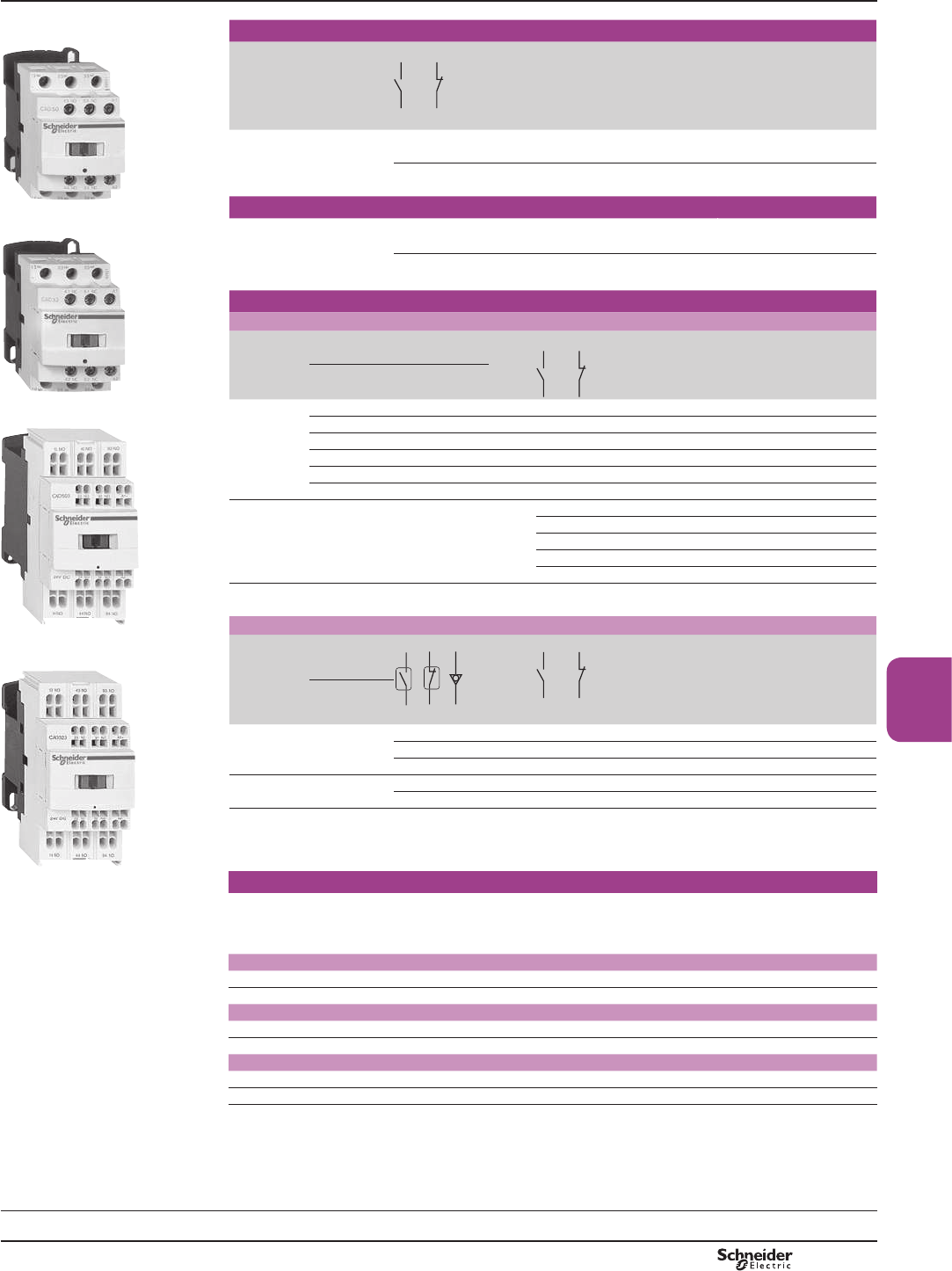
TeSys SK
References
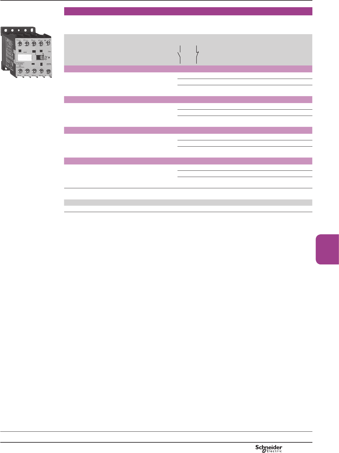
Mini-control relays
b Width of mini-control relays 27 mm.
b Mounting on 35 mm 7 rail.
b Connection by connectors.
Control circuit supply Auxiliary contacts Basic reference,
to be completed
by adding the
voltage code (1)
a.c. supply 2 – CA2SK20pp
1 1 CA2SK11pp
d.c. supply 2 – CA3SK20pp
1 1 CA3SK11pp
Mini-control relay with alternating contacts
This mini-control relay with alternating contacts (see function diagram page B7/17) makes it possible to
automatically split the operating time between 2 circuits of a redundant system.
By regularly energising the “safety circuits”, this device makes it possible to ensure that they are operating
correctly.
b Width of mini-control relay 45 mm.
b Fixing by Ø4 screws.
b Connection by connectors.
b &DQQRWEH¿WWHGZLWKIURQWPRXQWHGDX[LOLDU\FRQWDFWEORFN
b &DQQRWEH¿WWHGZLWKFRLOVXSSUHVVRUPRGXOH
Control circuit supply Auxiliary contacts Basic reference,
to be completed
by adding the
voltage code (1)
a.c. supply 2 – CA2SKE20pp
(1) 6WDQGDUGFRQWUROFLUFXLWYROWDJHVIRURWKHUYROWDJHVSOHDVHFRQVXOW\RXU5HJLRQDO6DOHV2I¿FH
Mini-control relays CA2 SK and CA2 SKE
Volts a
50/60 Hz
24 48 110 120 220 230 240 380 400
Code B7 E7 F7 G7 M7 P7 U7 Q7 V7
Mini-control relays CA3 SK
Volts c12 24 36 48 72
Code JD BD CD ED SD
Control relays
Mini-control relays
TeSys CA2 SK and CA3 SK
Mini-control relay TeSys CA2 SKE with alternating
contacts
CA2 SK20pp
PF526254.tif
CA2 SKE20pp
PF526255.tif
Characteristics:
pages B7/14 and
B7/15
Dimensions:
page
B7/16
Schemes:
page
B7/17
PCPB07P10-EN
Version : 1.0 14 novembre 2014 9:00 AM

B7/3
Control
relays
TeSys SK
References
Instantaneous auxiliary contact blocks
Clip-on front mounting
For use on
control relays
Maximum number
of blocks
per contactor
Composition Reference
CA2SK20 1 2 – LA1SK20
– 2 LA1SK02
1 1 LA1SK11
Suppressor modules
Connection without need for tools by clipping onto right-hand side of contactor
For use on
control relays
Type For
voltages
Sold
in lots of
Unit
reference
CA2SK and CA3SK Varistor
(1)
a and c 24 V…48 V 10 LA4SKE1E
a and c 110 V…250 V 10 LA4SKE1U
Diode
(2)
c 24 V…250 V 10 LA4SKC1U
(1) Protection provided by limiting the transient voltage to 2 Uc max.
Maximum reduction of transient voltage peaks.
6OLJKWLQFUHDVHLQGURSRXWWLPHWRWLPHVWKHQRUPDOWLPH
(2) No overvoltage or oscillating frequency.
6OLJKWLQFUHDVHLQGURSRXWWLPHWRWLPHVWKHQRUPDOWLPH
Control relays
Mini-control relays
TeSys CA2 SK and CA3 SK
Instantaneous auxiliary contacts and
coil suppressor modules
Characteristics:
pages B7/14 and
B7/15
Dimensions:
page
B7/16
Schemes:
page
B7/17
LA1 SK11
PF526256.tif
LA4 SKp1p
PF526257.tif
PCPB07P10-EN Version : 1.0 14 novembre 2014 9:00 AM

B7/4
References
Control relays for a.c. control circuit
b Mounting on 35 mm 7UDLORUVFUHZ¿[LQJ
b Screws in the open “ready-to-tighten” position.
Control circuit
Consumption
Auxiliary
contacts
Basic reference,
to be completed by adding
the voltage code (1)
Screw clamp connections
4.5 VA 4 – CA2KN40pp
3 1 CA2KN31pp
2 2 CA2KN22pp
Spring terminal connections
4.5 VA 4 – CA2KN403pp
3 1 CA2KN313pp
2 2 CA2KN223pp
Faston connectors, 1 x 6.35 or 2 x 2.8
4.5 VA 4 – CA2KN407pp
3 1 CA2KN317pp
2 2 CA2KN227pp
Solder pins for printed circuit boards
4.5 VA 4 – CA2KN405pp
3 1 CA2KN315pp
2 2 CA2KN225pp
Control relays for d.c. control circuit
b Mounting on 35 mm 7UDLORUVFUHZ¿[LQJ
b Screws in the open “ready-to-tighten” position.
Screw clamp connections
3 W 4 – CA3KN40pp
3 1 CA3KN31pp
2 2 CA3KN22pp
Spring terminal connections
3 W 4 – CA3KN403pp
3 1 CA3KN313pp
2 2 CA3KN223pp
Faston connectors, 1 x 6.35 or 2 x 2.8
3 W 4 – CA3KN407pp
3 1 CA3KN317pp
2 2 CA3KN227pp
Solder pins for printed circuit boards
3 W 4 – CA3KN405pp
3 1 CA3KN315pp
2 2 CA3KN225pp
(1)6WDQGDUGFRQWUROFLUFXLWYROWDJHVIRURWKHUYROWDJHVSOHDVHFRQVXOW\RXU5HJLRQDO6DOHV2I¿FH
Control relays CA2 K (0.8...1.15 Uc) 8F
Volts a 12 20 24(2) 36 42 48 110 115 127 220/ 230 230/ 380/ 400 400/ 440 500 660/
50/60 Hz 230 240 400 415 690
Code J7 Z7 B7 C7 D7 E7 F7 FE7 FC7 M7 P7 U7 Q7 V7 N7 R7 S7 Y7
Up to and including 240 V, coil with integral suppression device available: add 2 to the code required. Example: J72
Control relays CA3 K (0.8...1.15 Uc)
Volts c12 20 24(2) 36 48 60 72 100 110 125 200 220 230 240 250
Code JD ZD BD CD ED ND SD KD FD GD LD MD MPD MUD UD
Coil with integral suppression device available: add 3 to the code required. Example: JD3.
(2) When connecting an electronic sensor or timer in series with the coil of the control relay, select a 20 V coil (a code Z7,
cFRGH='VRDVWRFRPSHQVDWHIRUWKHLQFXUUHGYROWDJHGURS
Control relays
TeSys K control relays
For a.c. or d.c. control circuit
TeSys K
Characteristics:
pages B7/18 and
B7/19
Dimensions:
page
B7/20
Schemes:
page
B7/21
CA2 KN40pp
PF526247.tif
CA2 KN403pp
PF526248.tif
CA3 KN407pp
PF526249.tif
PCPB07P10-EN
Version : 1.0 14 novembre 2014 9:00 AM
B7/5
Control
relays
References
Low consumption control relays
(d.c. control circuit)
b Mounting on 35 mm 7UDLORUVFUHZ¿[LQJ
b Screws in the open “ready-to-tighten” position.
Control circuit
Consumption
Auxiliary
contacts
Basic reference,
to be completed
by adding the
voltage code (1)
Screw clamp connections
1.8 W 4 – CA4KN40pp
3 1 CA4KN31pp
2 2 CA4KN22pp
Spring terminal connections
1.8 W 4 – CA4KN403pp
3 1 CA4KN313pp
2 2 CA4KN223pp
Faston connectors, 1 x 6.35 or 2 x 2.8
1.8 W 4 – CA4KN407pp
3 1 CA4KN317pp
2 2 CA4KN227pp
Solder pins for printed circuit boards
1.8 W 4 – CA4KN405pp
3 1 CA4KN315pp
2 2 CA4KN225pp
(1)6WDQGDUGFRQWUROFLUFXLWYROWDJHVIRURWKHUYROWDJHVSOHDVHFRQVXOW\RXU5HJLRQDO6DOHV2I¿FH
Control relays CA4 K (Wide range coil: 0.7...1.3 Uc)
Volts c12 20 24 48 72 110 120
Code JW3 ZW3 BW3 EW3 SW3 FW3 GW3
Control relays
TeSys K control relays
For d.c. control circuit
TeSys K
Characteristics:
pages B7/18 and
B7/19
Dimensions:
page
B7/20
Schemes:
page
B7/21
CA4 KN40ppp
PF526250.tif
PCPB07P10-EN Version : 1.0 14 novembre 2014 9:00 AM
B7/6
References
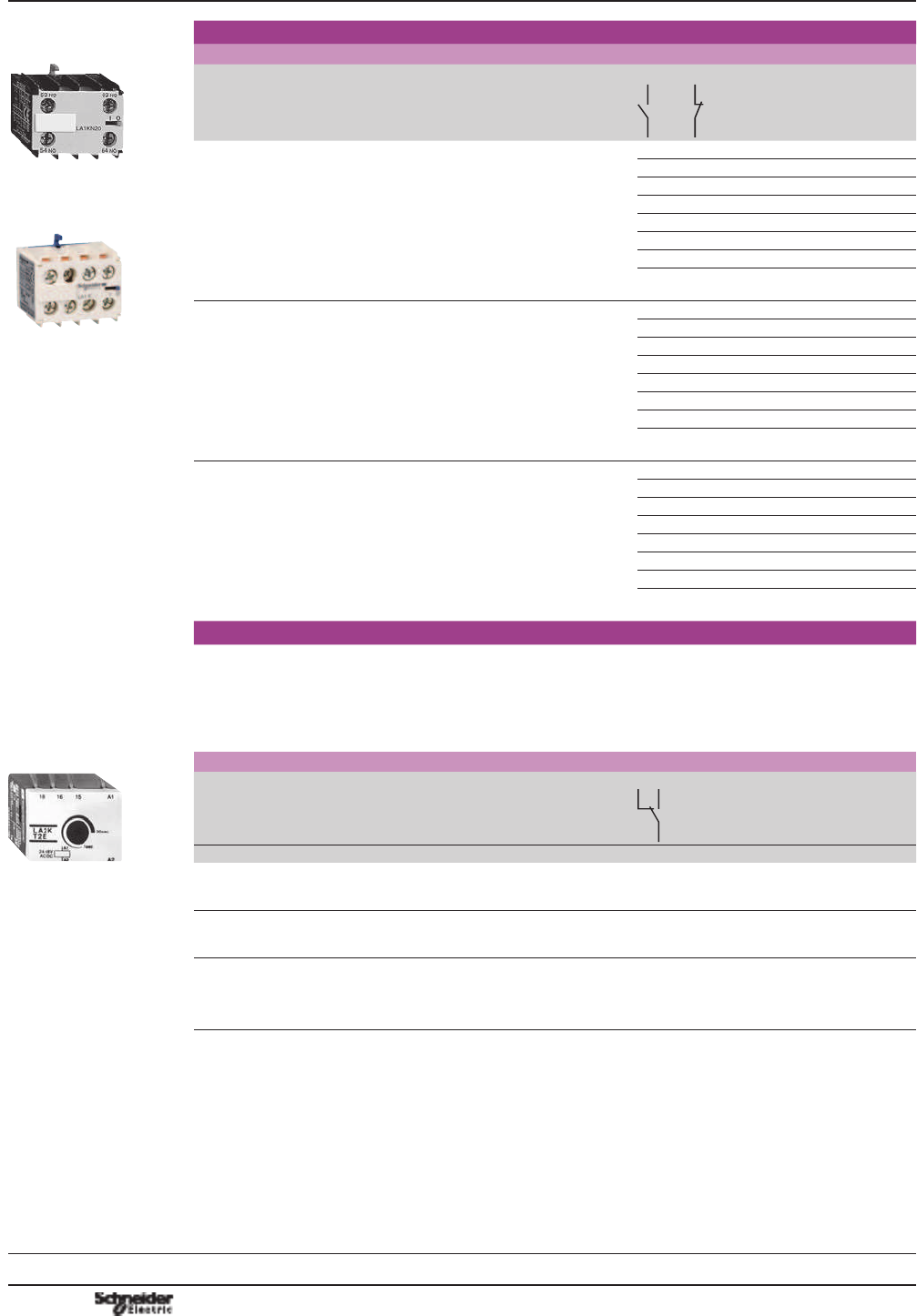
Instantaneous auxiliary contact blocks
Clip-on front mounting, 1 per control relay
Connection Composition Reference
Screw clamp terminals 2 – LA1KN20
– 2 LA1KN02
1 1 LA1KN11
4 – LA1KN40 (1)
3 1 LA1KN31 (1)
2 2 LA1KN22 (1)
1 3 LA1KN13 (1)
– 4 LA1KN04 (1)
Spring terminals 2 – LA1KN203
– 2 LA1KN023
1 1 LA1KN113
4 – LA1KN403 (1)
3 1 LA1KN313 (1)
2 2 LA1KN223 (1)
1 3 LA1KN133 (1)
– 4 LA1KN043 (1)
Faston connectors
1 x 6.35 or 2 x 2.8
2 – LA1KN207
– 2 LA1KN027
1 1 LA1KN117
4 – LA1KN407 (1)
3 1 LA1KN317 (1)
2 2 LA1KN227 (1)
1 3 LA1KN137 (1)
– 4 LA1KN047 (1)
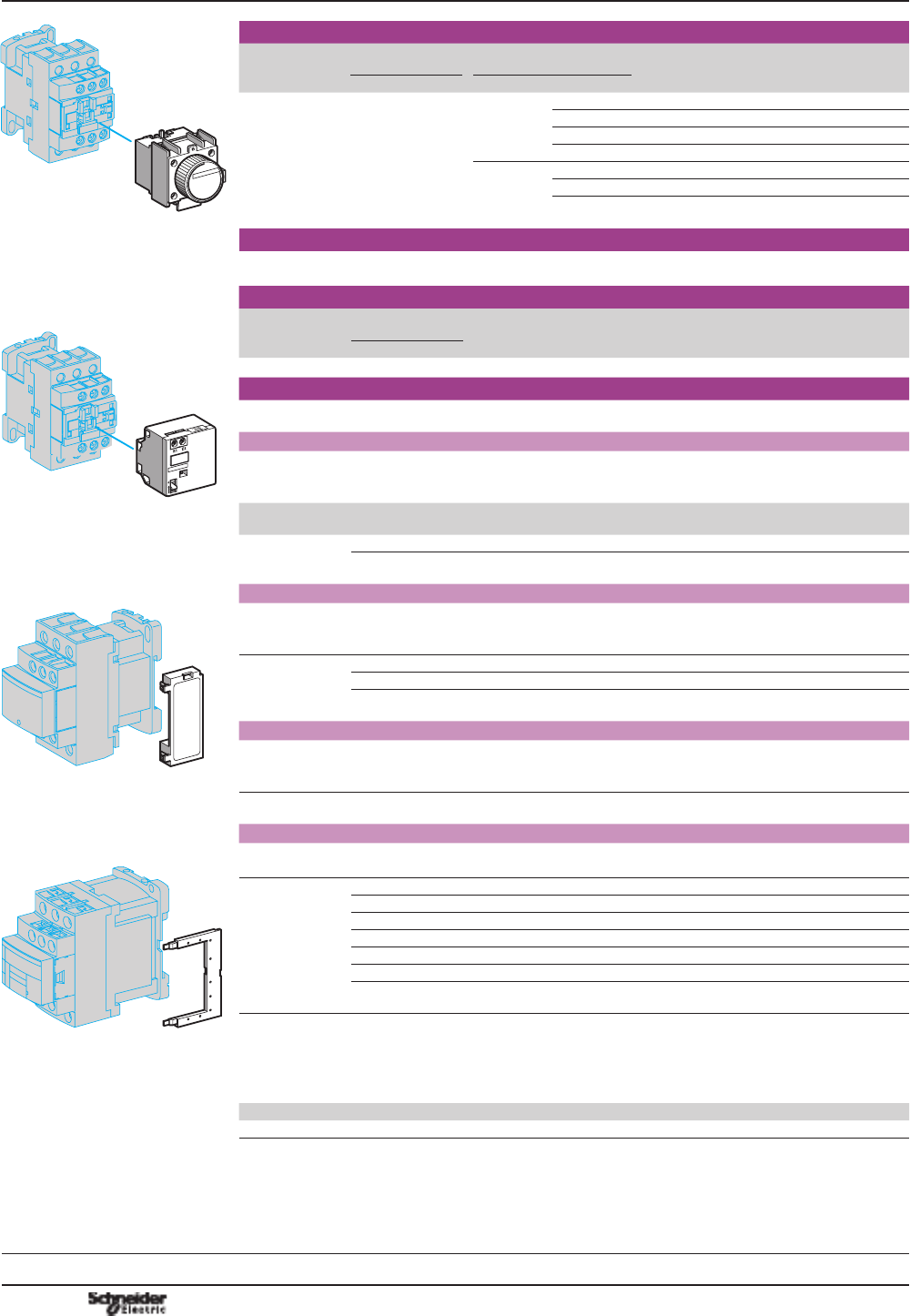
Electronic time delay contact blocks
b Relay output with common point changeover contact, a or c 240 V, 2 A maximum
b Control voltage 0.85...1.1 Uc
b Maximum switching capacity 250 VA or 150 W
b Operating temperature -10...+ 60 °C
b Reset time: 1.5 s during the time delay period 0.5 s after the time delay period
Clip-on front mounting, 1 per control relay
Voltage Type Timing
range
Composition Reference
V s
a or c 24...48 On-delay 1...30 1 LA2KT2E
a 110...240 On-delay 1...30 1 LA2KT2U
Other versions Electronic timers type RE4.
3OHDVHFRQVXOW\RXU5HJLRQDO6DOHV2I¿FH
(1) Block of 4 contacts for use on CA2 K and CA3 K.
Control relays
TeSys K control relays
Instantaneous and time delay auxiliary contact
blocks
TeSys K
Characteristics :
page
B7/19
Dimensions :
page
B7/20
Schemes :
page
B7/21
LA1 KN20
PF526251.tif
LA1 Kppp
PB111986.eps
LA2 KT2p
PF526253.tif
PCPB07P10-EN
Version : 1.0 14 novembre 2014 9:00 AM
B7/7
Control
relays
References
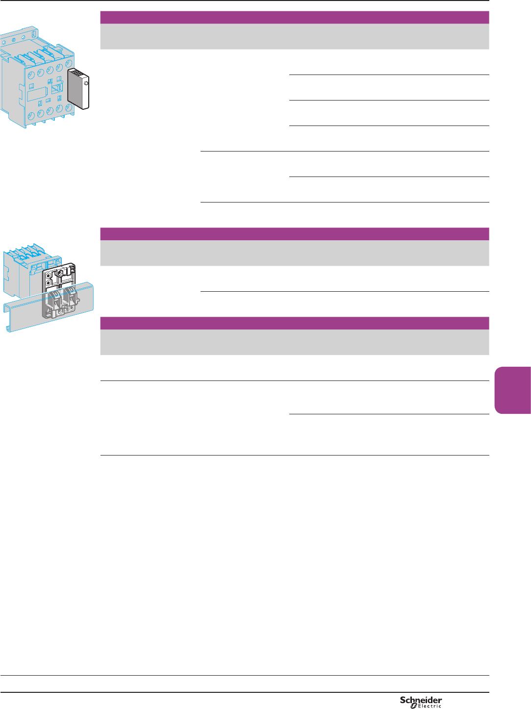
Suppressor modules incorporating LED indicator
Mounting
and connection
Type For
voltages
Sold in
lots of
Unit
reference
Clips onto front of relay
with locating device.
No tools required.
Varistor (1) a and c
12...24 V
5LA4KE1B
a and c
32...48 V
5LA4KE1E
a and c
50...129 V
5LA4KE1FC
a and c
130...250 V
5LA4KE1UG
Diode + Zener diode (2) c
12...24 V 5LA4KC1B
c
32...48 V 5LA4KC1E
RC (3) a
220...250 V 5LA4KA1U
Mounting accessories
Description Application Sold in
lots of
Unit
reference
Mounting plates On 1 4 rail Clip-on 1 LA9D973
On 2 4 rails 110/120 mm
¿[LQJFHQWUHV
10
DX1AP25
Marking accessories
Description Application Sold in
lots of
Unit
reference
Marker holder &OLSRQ¿[LQJRQIURQWIDFH –100 LA9D90
Clip-in markers 4 maximum per relay Strips of 10
identical
numbers 0 to 9
25 AB1Rp (4)
Strips of 10
identical capital
letters A to Z
25 AB1Gp (4)
(1) Protection provided by limiting the transient voltage to 2 Uc max.
Maximum reduction of transient voltage peaks.
6OLJKWLQFUHDVHLQGURSRXWWLPHWRWLPHVWKHQRUPDOWLPH
(2) No overvoltage or oscillating frequency.
Polarised component.
6OLJKWLQFUHDVHLQGURSRXWWLPHWRWLPHVWKHQRUPDOWLPH
(3) Protection by limiting the transient voltage to 3 Uc max. and limitation of the oscillating
frequency.
6OLJKWLQFUHDVHLQGURSRXWWLPHWRWLPHVWKHQRUPDOWLPH
(4) Complete the reference by replacing the dot with the required character.
Control relays
TeSys K control relays
Mounting and marking accessories
TeSys K
Dimensions :
page
B7/20
LA4 Kppp
DF533635.eps
LA9 D973
DF533636.eps
PCPB07P10-EN Version : 1.0 14 novembre 2014 9:00 AM
B7/8
See page opposite for mounting possibilities
according to control relay type and rating
DF526461.eps
PCPB07P10-EN
Version : 1.0 14 novembre 2014 9:00 AM
B7/9
Control
relays
TeSys control relays 7
TeSys D control relays and add-on blocks
Control circuit: a.c., d.c. or low consumption
Control relays for connection by screw clamp terminals
Type Number of
contacts
Composition Basic reference, to be
completed by adding the
control voltage code (1)
Instantaneous 5 5 – CAD50pp (3)
3 2 CAD32pp (3)
Control relays for connection by spring terminals
Instantaneous 5 5 – CAD503pp
3 2 CAD323pp
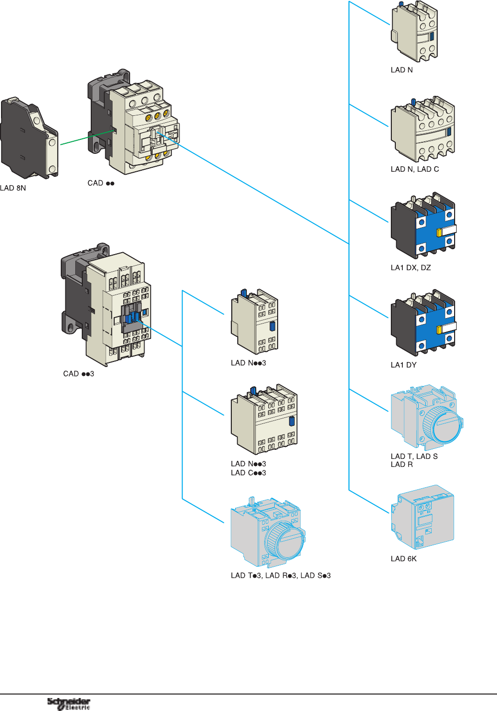
Instantaneous auxiliary contact blocks for connection by screw clamp terminals
For use in normal operating environments
Number of
contacts
Maximum number per relay Composition Reference
Clip-on mounting
front side
2 1 – 1 1 LADN11
– 1 on LH side 1 1 LAD8N11 (6)
1 – 2 – LADN20
– 1 on LH side 2 – LAD8N20 (6)
1 – – 2 LADN02
– 1 on LH side – 2 LAD8N02 (6)
4 (4) 1 – 2 2 LADN22
1 3 LADN13
4 – LADN40
– 4 LADN04
3 1 LADN31
4 (4) 1 – 2 2 LADC22
Including 1 N/O and 1 N/C make before break.
With dust and damp protected contacts, for use in particularly harsh industrial environments
Number of
contacts
Maximum
number per
relay
Composition Reference
Front
mounting
protected (5) not protected
2 1 2 – – – – LA1DX20
– 2 – – – LA1DX02
2 – 2 – – LA1DY20
4 (4) 1 2 – – 2 – LA1DZ40
2 – – 1 1 LA1DZ31
Instantaneous auxiliary contact blocks for connection by spring terminals
This type of connection is not possible for contact blocks LAD 8 and blocks with dust and damp protected contacts.
For all other instantaneous auxiliary contact blocks, add the digit 3 to the end of the references selected above.
Example: LAD N11 becomes LAD N113.
(1)6WDQGDUGFRQWUROFLUFXLWYROWDJHVIRURWKHUYROWDJHVSOHDVHFRQVXOW\RXU5HJLRQDO6DOHV2I¿FH
a.c. supply
Volts a24 42 48 110 115 220 230 240 380 400 415 440
50/60 Hz B7 D7 E7 F7 FE7 M7 P7 U7 Q7 V7 N7 R7
d.c. supplyFRLOVZLWKLQWHJUDOVXSSUHVVLRQGHYLFH¿WWHGDVVWDQGDUG
Volts c12 24 36 48 60 72 110 125 220 250 440
U from 0.7 to 1.25 Uc JD BD CD ED ND SD FD GD MD UD RD
Low consumptionFRLOVZLWKLQWHJUDOVXSSUHVVLRQGHYLFH¿WWHGDVVWDQGDUG
Volts c5 12 20 24 48 110 220 250
Code AL JL ZL BL EL FL ML UL
(2)/&ORZFRQVXPSWLRQ
(3) To order control relays with connection by lugs, add the digit 6 to the end of the selected reference.
Example: CAD50pp becomes CAD506pp.
(4) Blocks with 4 auxiliary contacts cannot be used on low consumption control relays.
(5)3URGXFW¿WWHGZLWKHDUWKVFUHHQFRQWLQXLW\WHUPLQDOV
(6) These contact blocks cannot be used on low consumption control relays.
References
7
TeSys D
Characteristics:
pages
B7/22 and
B7/25
Dimensions:
page
B7/26
Schemes:
page
B7/27
CAD 50pp
PF526456.tif
CAD 32pp
PF526457.tif
CAD 503pp
PF526458.tif
CAD 323pp
PF526460.tif
PCPB07P10-EN Version : 1.0 14 novembre 2014 9:00 AM
B7/10
TeSys control relays
TeSys D control relays
Add-on blocks
LAD T
810533.eps
Time delay auxiliary contact blocks for connection by screw clamp terminals (1)
Number
and type of
contacts
Maximum number
per relay
Time delay Reference
Front mounting Type Range
1 N/C and 1 N/O 1 On-delay 0.1…3 s (2) LADT0
0.1…30 s LADT2
10…180 s LADT4
1…30 s (3) LADS2
Off-delay 0.1…3 s (2) LADR0
0.1…30 s LADR2
(Sealing cover: see page
B8/21
) 10…180 s LADR4
Time delay auxiliary contact blocks for connection by spring terminals
Add the digit 3 to the references selected above. Example: LAD T0 becomes LAD T03.
Mechanical latch blocks (4)
Unlatching
control
Maximum number
per relay
Basic reference
to be completed
(5)
Front mounting
Manual or electric 1LAD6K10p
Suppressor modules
These modules clip onto the top of the control relay and the electrical connection is instantly made. Fitting of an input
module is still possible.
RC circuits (Resistor-Capacitor)
b Effective protection for circuits highly sensitive to “high frequency” interference.
b Voltage limited to 3 Uc maximum and oscillating frequency limited to 400 Hz maximum.
b Slight time delay on drop-out (1.2 to 2 times the normal time).
For
mounting on
Operational
voltage
Reference
CAD aa 24…48 V LAD4RCE
a 110…240 V LAD4RCU
Varistors (peak limiting)
b Protection provided by limiting the transient voltage value to 2Uc maximum.
b Maximum reduction of transient voltage peaks.
b Slight time delay on drop-out (1.1 to 1.5 times the normal time).
CAD a a 24…48 V LAD4VE
a 50…127 V LAD4VG
a 110…250 V LAD4VU
Freewheel diode
b No overvoltage or oscillating frequency.
b Increase in drop-out time (6 to 10 times the normal time).
b Polarised component.
CAD c c 24…250 V LAD4DDL
Bidirectional peak limiting diode (6)
b Protection provided by limiting the transient overvoltage value to 2Uc maximum.
b Maximum reduction of transient voltage peaks.
CAD a a 24 V LAD4TB
a 72 V LAD4TS
CAD c c 24 V LAD4TBDL
c 72 V LAD4TSDL
c 125 V LAD4TGDL
c 250 V LAD4TUDL
c 600 V LAD4TXDL
(1) These contact blocks cannot be used on low consumption control relays.
(2) With extended scale from 0.1 to 0.6 s.
(3) With switching time of 40 ms ±15 ms between opening of the N/C contact and closing of the N/O contact.
(4) Power should not be simultaneously applied or maintained to the mechanical latching block of the CAD N. The duration of
the control signal to the mechanical latching block and the CAD N should be u 100 ms.
(5)6WDQGDUGFRQWUROFLUFXLWYROWDJHVIRURWKHUYROWDJHVSOHDVHFRQVXOW\RXU5HJLRQDO6DOHV2I¿FH
Volts a and c24 32/36 42/48 60/72 100 110/127 220/240 256/277 380/415
Code B C E EN K F M U Q
(6) CAD pp cDQGORZFRQVXPSWLRQFRQWUROUHOD\VDUH¿WWHGZLWKDEXLOWLQELGLUHFWLRQDOSHDNOLPLWLQJGLRGHVXSSUHVVRUDV
standard. On control relays produced after 15th July 2004, this diode is removable. It can therefore be replaced by the
user (see references LAD4Tppp DERYH,WFDQDOVREHUHSODFHGE\DIUHHZKHHOGLRGHLAD 4DDL . If a d.c. or
low consumption control replay is used without suppression, the standard suppressor should be replaced with a
blanking plug LAD9DL.
References
TeSys D
Characteristics:
pages
B7/22 and
B7/25
Illustrations:
page
B7/8
Dimensions:
page
B7/26
Schemes:
page
B7/27
LAD 6K10
810531.eps
LAD 4pp
DF510384.epsDF503726.eps
LAD 4pp
PCPB07P10-EN
Version : 1.0 14 novembre 2014 9:00 AM

B7/11
Control
relays
TeSys control relays
TeSys D control relays
Accessories and spare parts
Accessories (to be ordered separately)
Description For
mounting on
Sold in
lots of
Unit reference
For marking
Sheet of 64 blank legends,
self-adhesive, 8 x 33 mm
CAD, LAD (4 contacts) 10 LAD21
Sheet of 112 blank legends,
self-adhesive, 8 x 12 mm
LAD (2 contacts),
LAD T
LAD22
Strips of blank, self-adhesive
legends for printing by plotter
(4 sets of 5 strips)
All products 35 LAD24
“SIS Label” labelling
software for legends LAD 21
and LAD 22, supplied on
CD-Rom
Multi-language version:
English, French, German,
Italian, Spanish
1XBY2U
Legend holder, snap-in,
8 x 18 mm
LC1 D09...38
LC1DT20...40
LADN (4 contacts)
LAD T, LAD R
100 LAD90
For protection
Sealing cover LAD T, LAD R 1LA9D901
Safety cover preventing
access to the moving
contact carrier
CAD LAD9ET1
1
Red cover
(for safety chain indication)
CAD 1LAD9ET1S
Spare parts: coils
6SHFL¿FDWLRQV
b Average consumption at 20 °C:
- inrush (cos M = 0.75) 50/60 Hz: 70 VA at 50 Hz,
- sealed (cos M = 0.3) 50/60 Hz: 8 VA at 60 Hz,
b Operating range (T
<
60 °C): 0.85 to 1.1 Uc
Control circuit
voltage Uc
Average resistance
at 20 °C ±10 %
Inductance of
closed circuit
Reference (1)
50/60 Hz
V V H
LAD 9ET1
810536.eps
12 6.3 0.26 LXD1J7
21 (2) 5.6 0.24 LXD1Z7
24 6.19 0.26 LXD1B7
32 12.3 0.48 LXD1C7
36 – – LXD1CC7
42 19.15 0.77 LXD1D7
48 25 1 LXD1E7
60 – – LXD1EE7
100 – – LXD1K7
LXD 1
810537.eps
110 130 5.5 LXD1F7
115 – – LXD1FE7
120 159 6.7 LXD1G7
127 192.5 7.5 LXD1FC7
200 – – LXD1L7
208 417 16 LXD1LE7
220/230 539 22 LXD1M7 (3)
230 595 21 LXD1P7
230/240 645 25 LXD1U7 (4)
277 781 30 LXD1W7
380/400 1580 60 LXD1Q7
400 1810 64 LXD1V7
415 1938 74 LXD1N7
440 2242 79 LXD1R7
480 2300 85 LXD1T7
500 2499 – LXD1S7
575 3294 – LXD1SC7
600 3600 135 LXD1X7
690 5600 190 LXD1Y7
(1) The last 2 digits in the reference represent the voltage code.
(2)9ROWDJHIRUVSHFLDOFRLOV¿WWHGLQFRQWUROUHOD\VZLWKVHULDOWLPHUPRGXOHZLWK9VXSSO\
(3)7KLVFRLOFDQEHXVHGRQ9DW+]
(4)7KLVFRLOFDQEHXVHGRQ9DW+]DQGRQ9RQO\DW+]
References
TeSys D
Characteristics:
pages
B7/22 and
B7/25
Dimensions:
page
B7/26
Schemes:
page
B7/27
/$'
810535.eps
PCPB07P10-EN Version : 1.0 20 novembre 2014 9:06 AM

B7/12 PCPB07P10-EN
Version : 1.0 14 novembre 2014 9:00 AM

B7/13
Control
relays
Technical
Data for
Designers
TeSys GS
Contents
TeSys SK:
> characteristics ..............................B7/14 and B7/15
> dimensions ...............................................................B7/16
> schemes .....................................................................B7/17
TeSys K:
> characteristics ..............................B7/18 and B7/19
> dimensions ...............................................................B7/20
> schemes .....................................................................B7/21
TeSys D:
> characteristics ..................................B7/22 to B7/25
> dimensions ...............................................................B7/26
> schemes .....................................................................B7/27
PCPB07T10-EN
Version : 1.0 14 novembre 2014 9:00 AM
B7/14
TeSys SK
Environment
Rated insulation voltage (Ui) Conforming to IEC 60947,
VDE 0110 gr C, BS 5424,
CSA 22-2 n° 14, UL 508
V690
Conforming to standards IEC 60947, NF C 63-110, VDE 0660, BS 5424
3URGXFWFHUWL¿FDWLRQV UL, CSA
Protective treatment Conforming to IEC 60068
(DIN 50015)
“TC” (Klimafest, Climateproof)
Degree of protection Conforming to VDE 0106 3URWHFWLRQDJDLQVWGLUHFW¿QJHUFRQWDFW
Ambient air temperature
around the device
Storage °C -50…+70
Operation °C -20…+50
Maximum operating altitude Without derating m2000
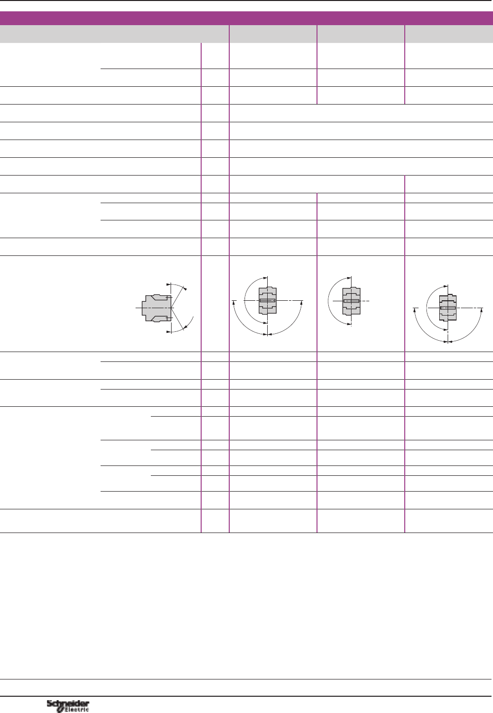
Operating position Vertical axis Horizontal axis
DF511028.eps
DF511029.eps
Without derating Without derating
Connection by connectors Min. Max.
Solid cable mm
2
1 x 1.5 or 2 x 1.5 1 x 6 or 2 x 4
Flexible cable without cable end mm
2
1 x 0.5 or 2 x 0.35 1 x 6 or 2 x 2.5
Flexible cable with cable end mm
2
1 x 0.35 or 2 x 0.35 1 x 6 or 2 x 1.5
Tightening torque Pozidriv n° 1 head N.m 0.8
Terminal referencing Conforming to standards
EN 50005 and EN 50011
Up to 4 contacts
Control circuit characteristics
Control relay CA2 SK CA2 SKE CA3 SK
Rated control circuit voltage (Uc) Va 24…400 c 12…72
Control voltage limits
(y 50 °C)
For operation 0.85…1.1 Uc 0.85…1.1 Uc
For drop-out u 0.20 Uc u 0.10 Uc
Average consumption
at 20 °C and at Uc
Inrush 16 VA 23 VA 2.2 W
Sealed 4.2 VA 4.9 VA 2.2 W
Heat dissipation W1.4 1.5 2.2
Operating time
at 20 °C and at Uc
Between coil energisation and
opening of the N/C contacts ms 8…16 10…18
closing of the N/O contacts ms 7…14 8…12
Between coil de-energisation and
opening of the N/O contacts ms 6…8 4…6
closing of the N/C contacts ms 8…10 6…8
Maximum operating rate In operating cycles per hour 1200 1200
Mechanical durability at Uc
in millions of operating cycles
50/60 Hz coil 10 –
Standard c coil – 10
Characteristics Control relays
Mini-control relays TeSys CAp SK and
CA2 SKE
References:
pages B7/2 and
B7/3
Dimensions:
page B7/16
Schemes:
page
B7/17

PCPB07T10-EN Version : 1.0 14 novembre 2014 9:00 AM B7/15
Control
relays
B7/15
TeSys SK
Characteristics
Auxiliary contact characteristics of mini-control relays and instantaneous contact blocks
Rated operational voltage
(Ue)
VUp to 690
Rated insulation voltage (Ui) Conforming to IEC 96047,
BS 5424, VDE 0110 group C,
CSA C 22-2 n° 14
V690
Conventional rated
thermal current (Ith)
For ambient temperature
y 55 °C
A10
Frequency of the operational current Hz Up to 400
Short-circuit protection Conforming to IEC 60947
and VDE 0660, gl fuse
A10
Operational power of contacts conforming to IEC 60947
a.c. supply, category AC-15 d.c. supply, category DC-13
Electrical durability (valid for up to 3600
operating cycles/hour) on an inductive load
such as the coil of an electromagnet: making
current (cos M 0.7) = 10 times the power
broken (cos M 0.4).
Electrical durability (valid for up to 1200
operating cycles/hour) on an inductive load
such as the coil of an electromagnet, without
economy resistor, the time constant
increasing with the load.
V 24 48 110/
127
220/
230
380/
400
440 V 24 48 110 220 440
1 million operating cycles VA 48 96 240 440 800 880 W120 80 60 52 51
3 million operating cycles VA 17 34 86 158 288 317 W55 38 30 28 26
10 million operating cycles VA 7 14 36 66 120 132 W15 11 9 8 7
Occasional making capacity VA 1000 2050 5000 10000 14000 13 000 W720 600 400 300 230
Control relays
Mini-control relays TeSys CAp SK and
CA2 SKE
References:
pages B7/2 and
B7/3
Dimensions:
page B7/16
Schemes:
page
B7/17
PCPB07T10-EN
Version : 1.0 14 novembre 2014 9:00 AM
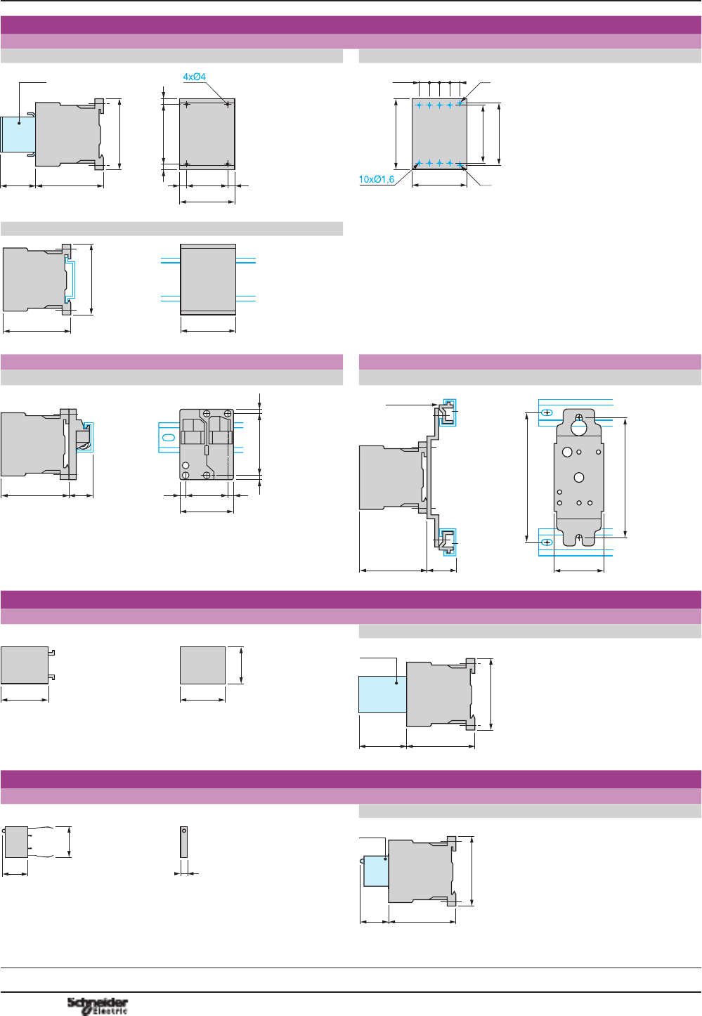
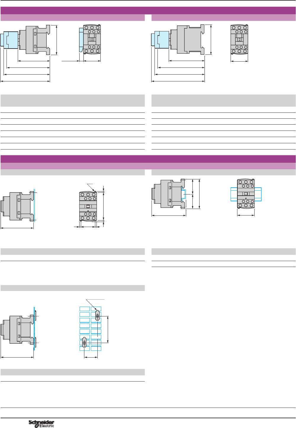
B7/16
Dimensions
Mini-control relays
CA2 SK and CA3 SK
3,5LA4 SK
55,5
56
27
DF533668.eps
56
2755,5
84,55
3,5LA1 SK (1)
DF533669.eps
(1) Only on CA2 SK20.
Mounting
Mini-control relays
CA2 SK and CA3 SK
On mounting rail AM1 DP200 or AM1 DE200 (7 35 mm)
56
55,5
27
DF533670.eps
Dimensions
CA2 SKE
4
68 45
58
DF533671.eps
Mounting
CA2 SKE
On panel On mounting rail AM1 DP200 or AM1 DE200 (7 35 mm)
34-35
48-50
DF533672.eps
4568
58
DF533673.eps
Dimensions, mounting Control relays
Mini-control relays TeSys CAp SK and
CA2 SKE
References:
pages B7/2 and
B7/3
Characteristics:
pages B7/14 and
B7/15
Schemes:
page
B7/17
TeSys SK
PCPB07T10-EN Version : 1.0 14 novembre 2014 9:00 AM B7/17
Control
relays
B7/17
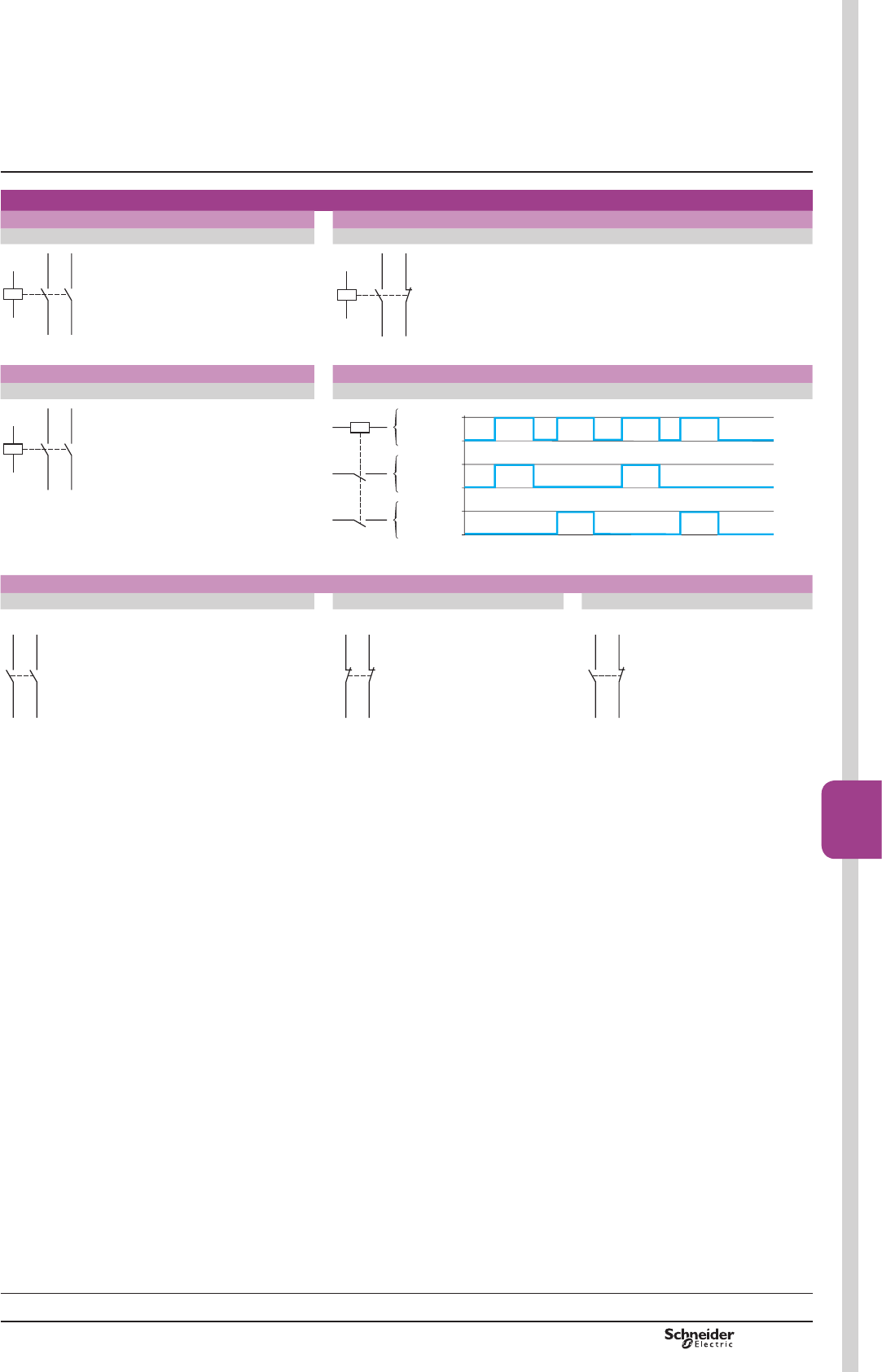
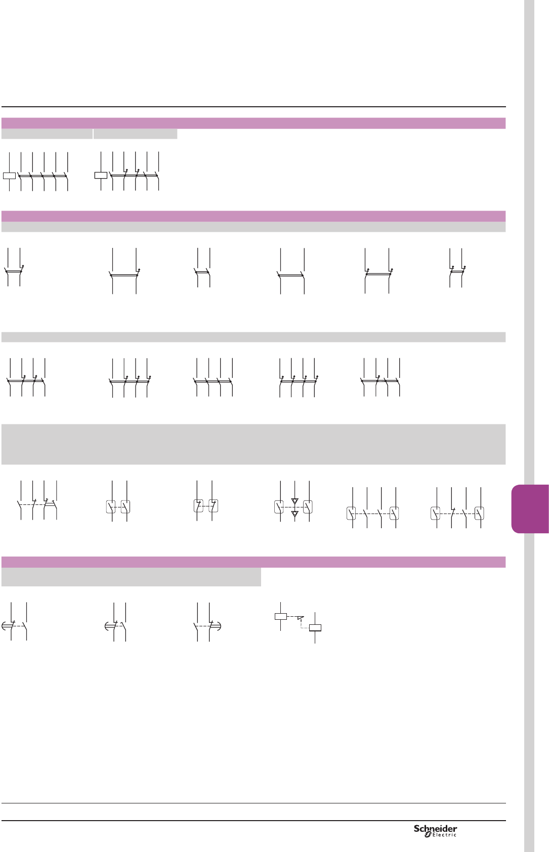
Schemes
CA2 SK20, CA3 SK20 CA2 SK11, CA3 SK11
2 N/O 1 N/O + 1 N/C
A1
13/NO
14
A2
23/NO
24
DF533674.eps
A1
13/NO
14
A2
21/NO
22
DF533675.eps
CA2 SKE CA2 SKE
2 N/O Function diagram
A1
13/NO
14
A2
23/NO
24
DF533676.eps
A2A1
1413
2423
De-energised
Close
Open
Close
Open
Energised
DF533677.eps
Instantaneous auxiliary contacts
2 N/O 2 N/C 1 N/O + 1 N/C
LA1 SK20 LA1 SK02 LA1 SK11
33/NO34
44 43/NO
DF533678.eps
31/NC32
42 41/NC
DF533679.eps
33/NO34
42 41/NC
DF533680.eps
Schemes Control relays
Mini-control relays TeSys CAp SK and
CA2 SKE
TeSys SK
References:
pages B7/2 and
B7/3
Characteristics:
pages B7/14 and
B7/15
Dimensions:
page
B7/16

PCPB07T10-EN
Version : 1.0 14 novembre 2014 9:00 AM
B7/18
Characteristics
Environment
Conforming to standards IEC 60947, NF C 63-140, VDE 0660, BS 5424
3URGXFWFHUWL¿FDWLRQV UL, CSA
Operating positions Vertical axis
DF533629.eps
Horizontal axis
DF511026.eps
DF533630.eps
Without derating Without derating Possible positions for
CA2 K only, with derating,
please consult your
5HJLRQDO6DOHV2I¿FH
Connection Min. Max. Max. to IEC 60947
Screw clamp connections Solid cable mm21 x 1.5 2 x 4 1 x 4 + 1 x 2.5
Flexible cable without cable end mm
2
1 x 0.75 2 x 4 2 x 2.5
Flexible cable with cable end mm
2
1 x 0.34 1 x 1.5 + 1 x 2.5 1 x 1.5 + 1 x 2.5
Spring terminals Solid cable mm
2
1 x 0.75 1 x 1.5 2 x 1.5
Flexible cable without cable end mm
2
1 x 0.75 1 x 1.5 2 x 1.5
Faston connectors Clip mm 2 x 2.8 or 1 x 6.35
Solder pins for
printed circuit board
With locating device between
power and control circuits
4 mm x 35 microns
Tightening torque Philips head n° 2 and Ø6 N.m 0.8…1.3
Terminal referencing Conforming to standards
EN 50005 and EN 50011
Up to 8 contacts
Protective treatment Conf. to IEC 60068 (DIN 50016) “TC” (Klimafest, Climateproof)
Degree of protection Conforming to VDE 0106 3URWHFWLRQDJDLQVWGLUHFW¿QJHUFRQWDFW
(devices with screw clamp terminals or pins for printed circuit board)
Ambient air temperature
around the device
Storage °C -50...+80
Operation °C -25...+50
Maximum operating altitude Without derating m2000
Vibration resistance Control relay open 2 gn
5...300 Hz Control relay closed 4 gn
Flame resistance Conforming to UL 94 Self-extinguishing material V1
Conforming to NF F 16-101
and 16-102
Conforming to requirement 2
Shock resistance
(1/2 sine wave, 11 ms)
Control relay open 10 gn
Control relay closed 15 gn
Safety separation of circuits Conforming to VDE 0106
and IEC 60536
SELV (Safety Extra Low Voltage), up to 400 V
Control circuit characteristics
Control relay type CA2 K CA3 K CA4 K
Rated control circuit voltage (Uc) Va 12...690 c 12...250 c 12...120
Control voltage limits
(y 50 °C) single voltage coil
For operation 0.8...1.15 Uc 0.8...1.15 Uc 0.7...1.3 Uc
For drop-out y 0.2 Uc y 0.1 Uc y 0.1 Uc
Mechanical durability at Uc
In millions of operating cycles
50/60 Hz coil 10 – –
Standard c coil – 20 –
Wide range,
low consumption c coil
– – 30
Maximum operating rate In operating cycles per hour 10 000 10 000 6000
Average consumption
at 20 °C and at Uc
Inrush 30 VA 3 W 1.8 W
Sealed 4.5 VA 3 W 1.8 W
Heat dissipation W1.3 3 1.8
Operating time
at 20 °C and at Uc
Between coil energisation and
opening of the N/C contacts ms 5...15 25...35 25...35
closing of the N/O contacts ms 10...20 30...40 30...40
Between coil de-energisation and
opening of the N/O contacts ms 10...20 10 10...20
closing of the N/C contacts ms 15...25 15 15...25
Maximum immunity to microbreaks ms 2 2 2
Control relays
TeSys K control relays
TeSys K
References:
pages B7/4 to B7/7
Dimensions:
page B7/20
Schemes:
page B7/21
PCPB07T10-EN Version : 1.0 14 novembre 2014 9:00 AM B7/19
Control
relays
B7/19
Characteristics
Contact characteristics of control relays and instantaneous contact blocks
Number of auxiliary contacts On CAp K 4
On LA1 K 2 or 4 for CA2 K and CA3 K, 2 for CA4 K
Rated operational voltage (Ue) Up to V 690
Rated insulation voltage (Ui) Conforming to BS 5424 V 690
Conforming to IEC 60947 V 690
Conforming to VDE 0110 group C V 750
Conforming to CSA C 22-2 n° 14 V 600
Conventional thermal current
(Ith)
For ambient temperature y50 °C A 10
Frequency of the operational current Hz Up to 400
Minimum switching capacity U min (DIN 19 240) V 17
I min mA 5
Short-circuit protection Conforming to IEC 60947
and VDE 0660, gG fuse
A10
Rated making capacity Conforming to IEC 60947
I rms A 110
Short-time rating Permissible for
1 s A80
500 ms A90
100 ms A110
Insulation resistance M: > 10
Non-overlap distance CAp K and LA1 K: linked
contacts conforming to INRS,
%,$DQG&1$VSHFL¿FDWLRQV
mm 0.5 (see schemes page B7/21)
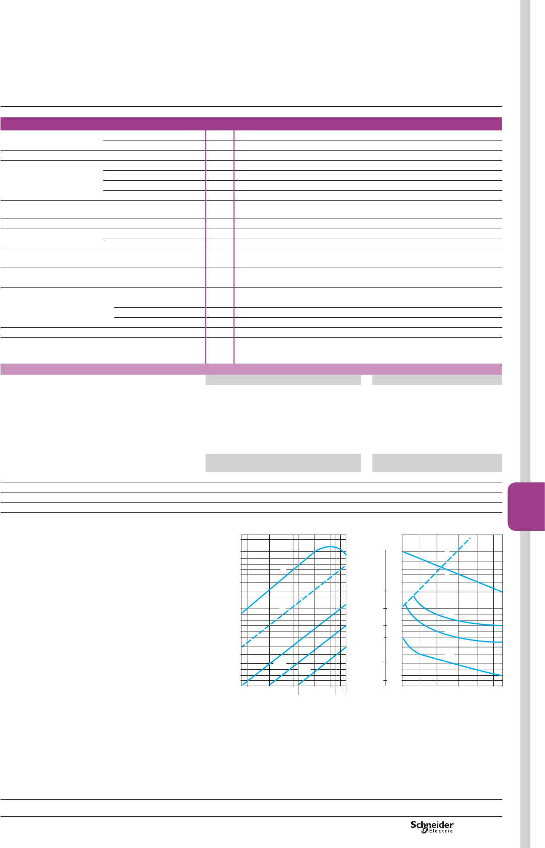
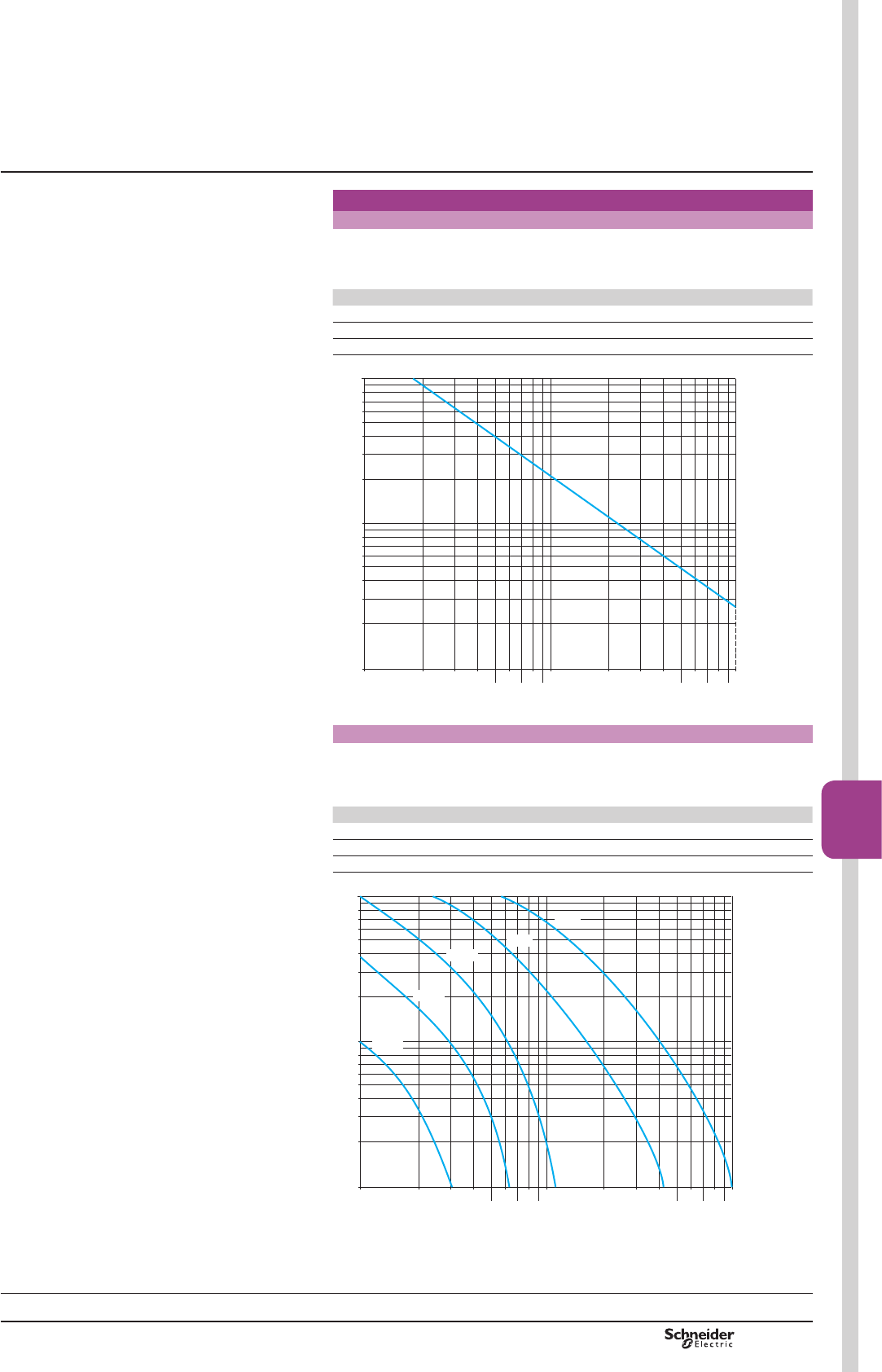
Operational power of contacts conforming to IEC 60947
a.c. supply, category AC-15 d.c. supply, category DC-13
Electrical durability (valid for up to 3600
operating cycles/hour) on an inductive load
such as the coil of an electromagnet:
making current (cos M 0.7) = 10 times the
power broken (cos M 0.4)
Electrical durability (valid for up to
1200 operating cycles/hour) on an
inductive load such as the coil of an
electromagnet, without economy
resistor, the time constant increasing
with the load.
V 24 48 110/
127
220/
230
380/
400
440 600/
690
V 24 48 110 220 440 600
1 million operating cycles VA 48 96 240 440 800 880 1200 W120 80 60 52 51 50
3 million operating cycles VA 17 34 86 158 288 317 500 W55 38 30 28 26 25
10 million operating cycles VA 7 14 36 66 120 132 200 W15 11 9 8 7 6
Occasional making capacity VA 1000 2050 5000 10000 14000 13000 9000 W720 600 400 300 230 200
1 Breaking limit of contacts valid for:
b maximum of 50 operating cycles at 10 s intervals
(power broken = making current x cos M 0.7).
2 Electrical durability of contacts for:
b 1 million operating cycles (2a)
b 3 million operating cycles (2b)
b 10 million operating cycles (2c).
3 Breaking limit of contacts valid for:
b maximum of 20 operating cycles at 10 s intervals with
current passing for 0.5 s per operating cycle.
4 Thermal limit
10 000
5000
3000
2000
1000
800
600
500
400
300
200
100
80
60
24 48 110 220
440 690 V
120
380
500
40
16 000
8000
6000
4000
2c
2b
4
1
2a
Power broken in VA
DF523305.eps
1000
700
500
300
200
100
80
60
50
40
30
20
10
8
6
12 24 48 110 220 440 600 V
250
200
140
100
50
20
2c
2a
3
4
2b
Power broken in W
Time constant
in ms
DF510561.eps
Control relays
TeSys K control relays
TeSys K
References:
pages B7/4 to B7/7
Dimensions:
page B7/20
Schemes:
page B7/21
PCPB07T10-EN
Version : 1.0 14 novembre 2014 9:00 AM
B7/20
Dimensions,
mounting
Control relays
CA2 K, CA3 K, CA4 K
On panel On printed circuit board
5735
LA1 K
58
50= =
35
45
==
DF533637.eps
50
53
45
58
8,65 = = = A1
A2
DF533638.eps
On mounting rail AM1 DP200 or AM1 DE200 (7 35 mm)
57
58
45
DF533639.eps
LA9 D973 DX1 AP25
On asymmetrical rail with clip-on mounting plates On asymmetrical rail with clip-on mounting plates
57 21
45
35= =
50 55
DF533640.eps
110
45
120
57
57 27
DZ5 ME5
DF533641.eps
Electronic time delay contact blocks
LA2 KT
On control relay
38
38
27
DF533642.eps
57
LA2 KT
58
38
DF533644.eps
Suppressor modules
LA4 K
On control relay
6
25
22
DF533643.eps
5722
58
LA4 K
DF533645.eps
Control relays
TeSys K control relays
TeSys K
References:
pages B7/4 to B7/7
Characteristics:
pages B7/18 and B7/19
Schemes:
page B7/21
PCPB07T10-EN Version : 1.0 14 novembre 2014 9:00 AM B7/21
Control
relays
B7/21
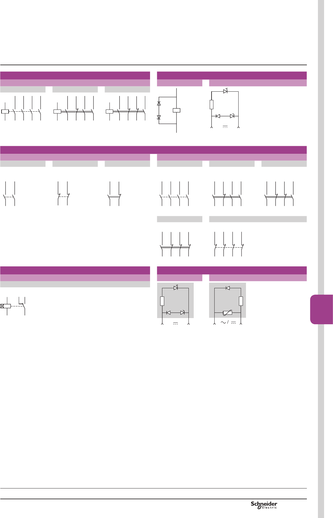
Schemes
Control relays With integral suppression device
CA2 K, CA3 K, CA4 K CA3 K CA4 K
4 N/O 3 N/O + 1 N/C 2 N/O + 2 N/C
+A1
–
A2
DF533649.eps
_
+ A1 A2
DF533650.eps
A1
A2
14
24
34
13/NO
23/NO
33/NO
43/NO
44
DF533646.eps
A1
A2
13/NO
14
21/NC
22
33/NO
34
43/NO
44
DF533647.eps
A1
A2
13/NO
14
21/NC
22
31/NC
32
43/NO
44
DF533648.eps
Instantaneous auxiliary contact blocks LA1 K
For CA2 K, CA3 K, CA4 K For CA2 K, CA3 K
2 N/O 2 N/C 1 N/O + 1 N/C 4 N/O 3 N/O + 1 N/C 2 N/O + 2 N/C
LA1 KN20,
LA1 KN207
LA1 KN02,
LA1 KN027
LA1 KN11,
LA1 KN117
LA1 KN40,
LA1 KN407
LA1 KN31,
LA1 KN317
LA1 KN22,
LA1 KN227
53/NO
54
63/NO
64
DF533651.eps
61/NC
62
51/NC
52
DF533652.eps
61/NC
62
53/NO
54
DF533653.eps
54
64
74
53/NO
63/NO
73/NO
83/NO
84
DF533654.eps
62
74
53/NO
54
61/NC
73/NO
83/NO
84
DF533655.eps
53/NO
54
61/NC
62
71/NC
72
83/NO
84
DF533656.eps
1 N/O + 3 N/C 4 N/C
LA1 KN13, LA1 KN137 LA1 KN04, LA1 KN047
54
62
72
82
53/NO
61/NC
71/NC
81/NC
DF533657.eps
51/NC
52
61/NC
62
71/NC
72
81/NC
82
DF533658.eps
Electronic time delay contact blocks LA2 KT Suppressor modules
For CA2 K, CA3 K, CA4 K LA4 KC LA4 KE
1 C/O
+_
DF533660.eps
DF533661.eps
LA2 KT2
A1A2
18
15
16
DF533659.eps
Control relays
TeSys K control relays
TeSys K
References:
pages B7/4 to B7/7
Characteristics:
pages B7/18 and B7/19
Dimensions:
page B7/20
PCPB07T10-EN
Version : 1.0 14 novembre 2014 9:00 AM
B7/22
TeSys control relays 7
TeSys D control relays
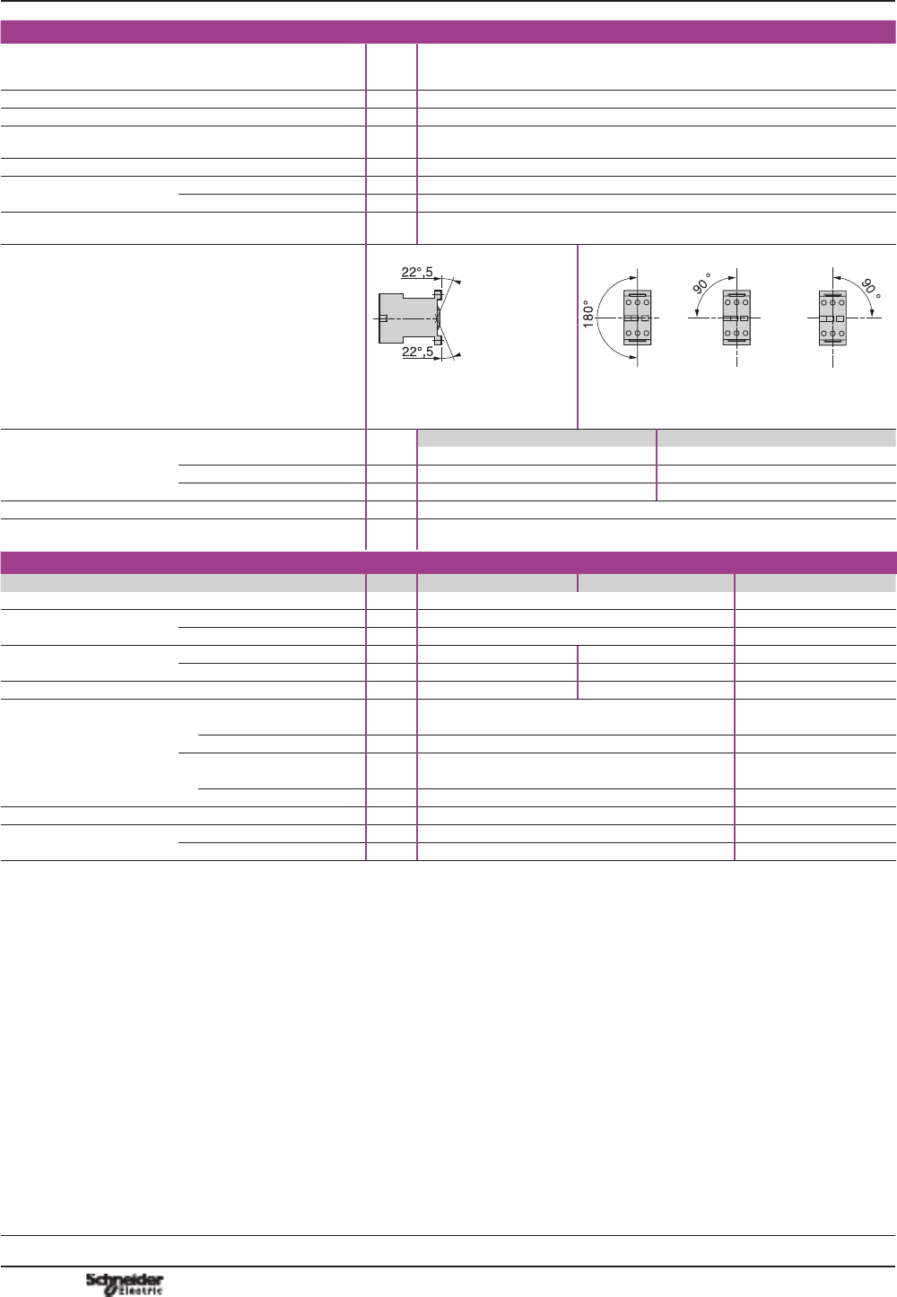
Environment
Control relay type CAD aCAD cCAD
low consumption
Rated insulation voltage (Ui) Conforming to IEC 60947-5-1
Overvoltage category III and
degree of pollution 3
V690 690 690
Conforming to UL, CSA V600 600 600
Rated impulse withstand
voltage (Uimp)
Conforming to IEC 60947 kV 6 6 6
Separation of
electrical circuits
Conforming to IEC 60536
and VDE 0106
Reinforced insulation up to 400 V
Conforming to standards IEC 60947-5-1, N-F C 63-140, VDE 0660, BS 4794,
EN 60947-5
3URGXFWFHUWL¿FDWLRQV UL, CSA
Protective treatment Conforming to IEC 60068 “TH”
Degree of protection Conforming to VDE 0106 )URQWIDFHSURWHFWHGDJDLQVWGLUHFW¿QJHUFRQWDFW,3; Protection against direct
¿QJHUFRQWDFW
Ambient air temperature
around the device
Storage °C-60…+80 -60…+80 -60…+80
Operation, conforming to
IEC 60255 (0.8…1.1 UC)
°C-5…+60 -5…+60 -5…+60
For operation at Uc °C-40…+70 -40…+70 -40…+70
Maximum operating altitude Without derating m3000 3000 3000
Operating positions Without derating
in the following positions
30°
30°
DF510764.eps
DF510765.eps
90°
90°
180°
180°
DF510766.eps
1
8
0
°
9
0
°
9
0
°
DF510767.eps
Shock resistance (1)
half sine wave for 11ms
Control relay open 10 gn 10 gn 10 gn
Control relay closed 15 gn 15 gn 15 gn
Vibration resistance (1)
5…300 Hz
Control relay open 2 gn 2 gn 2 gn
Control relay closed 4 gn 4 gn 4 gn
Screw clamp connections Flexible
conductor
without cable
end
1 conductor mm
2
1…4 1…4 1…4
2 conductors mm
2
1…4 1…4 1…4
Flexible
conductor with
cable end
1 conductor mm
2
1…4 1…4 1…4
2 conductors mm
2
1…2.5 1…2.5 1…2.5
Solid conductor
without cable
end
1 conductor mm
2
1…4 1…4 1…4
2 conductors mm
2
1…4 1…4 1…4
Tightening torque N.m 1.7 1.7 1.7
Spring terminal connections RUÀH[LEOHRUULJLGFRQGXFWRUV
without cable end
mm
2
1…2.5 1…2.5 1…2.5
(1) In the least favourable direction, without change of contact state, with coil supplied at Uc.
Characteristics
7
TeSys D
References:
pages B7/9 to B7/11
Dimensions:
page B7/26
Schemes:
page B7/27
PCPB07T10-EN Version : 1.0 14 novembre 2014 9:00 AM B7/23
Control
relays
B7/23
TeSys control relays 7
TeSys D control relays
Control circuit characteristics
Control relay type CAD aCAD cCAD
low consumption
Rated control circuit voltage (Uc) V12…690 12…440 c 5…72
Control voltage limits
Operation With coil 50/60 Hz 0.8…1.1 Uc at 50 Hz – –
0.85…1.1 Uc at 60 Hz – –
With standard coil,
wide range
– 0.7…1.25 Uc 0.7…1.25 Uc
Drop-out 0.3…0.6 Uc 0.1…0.25 Uc 0.1…0.25 Uc
Average consumption
at 20 °C and at Uc
a 50/60 Hz (at 50 Hz) VA Inrush: 70 – –
sealed: 8 – –
With standard coil W– Inrush or sealed: 5.4 Inrush or sealed: 2.4
Operating time
(at rated control circuit voltage
and at 20 °C)
Between coil energisation
and
- opening of the N/C contacts
ms 4…19 55 ± 15 % 67 ± 15 %
- closing of the N/O contacts ms 12…22 63 ± 15 % 77 ± 15 %
Between coil de-energisation
and
- opening of the N/O contacts
ms 4…12 20 ± 20 % 27 ± 20 %
- closing of the N/C contacts ms 6…17 25 ± 20 % 35 ± 20 %
Short supply failure Maximum duration without
affecting hold-in of the device
ms 2 2 2
Maximum operating rate In operating cycles
per second
3 3 3
Mechanical durability
In millions of operating cycles
With coil 50/60 Hz
(at 50 Hz)
30 – –
With standard coil c
wide range
– 30 30
Time constant L/R ms – 28 40
Characteristics
TeSys D
References:
pages B7/9 to B7/11
Dimensions:
page B7/26
Schemes:
page B7/27
PCPB07T10-EN
Version : 1.0 14 novembre 2014 9:00 AM
B7/24
TeSys control relays 7
TeSys D control relays
Characteristics of instantaneous contacts incorporated in the control relay
Number of contacts 5
Rated operational voltage
(Ue)
Up to V690
Rated insulation voltage
(Ui)
Conforming to IEC 60947-5-1 V690
Conforming to UL, CSA V600
Conventional
thermal current (Ith)
For ambient temperature d60 °C A10
Frequency of the
operational current
Hz 25...400
Minimum switching capacity U min V17
I min mA 5
Short-circuit protection Conforming to IEC 60947-5-1 gG fuse: 10 A
Rated making capacity Conforming to
IEC 60947-5-1
I rms a 140, c 250
Short-time rating Permissible for 1 s A100
500 ms A120
100 ms A140
Insulation resistance M: > 10
Non-overlap time Guaranteed between
N/C and N/O contacts
ms 1.5 (on energisation and on de-energisation)
Tightening torque Philips head n° 2 and Ø6 N.m 1.2
Non-overlap distance Linked contacts in association with auxiliary contacts LAD N
Mechanically linked contacts Conforming to IEC 60947-5-1 The 3 N/O contacts and the 2 N/C contacts of CAD N32 are linked mechanically by one
mobile contact carrier.
Characteristics
7
TeSys D
References:
pages B7/9 to B7/11
Dimensions:
page B7/26
Schemes:
page B7/27
PCPB07T10-EN Version : 1.0 14 novembre 2014 9:00 AM B7/25
Control
relays
B7/25
TeSys control relays 7
TeSys D control relays
Rated operational power of contacts
(conforming to IEC 60947-5-1)
a.c. supply, categories AC-14 and AC-15
Electrical durability (valid for up to 3600 operating cycles/hour) on an inductive load such
as the coil of an electromagnet:
making current (cos M 0.7) = 10 times the power broken (cos M 0.4).
V 24 48 115 230 400 440 600
1 million operating cycles VA 60 120 280 560 960 1050 1440
3 million operating cycles VA 16 32 80 160 280 300 420
10 million operating cycles VA 4 8 20 40 70 80 100
d.c. supply, category DC-13
Electrical durability (valid for up to 1200 operating cycles/hour) on an inductive load
such as the coil of an electromagnet, without economy resistor, the time constant
increasing with the power.
V 24 48 125 250 440
1 million operating cycles W120 90 75 68 61
3 million operating cycles W70 50 38 33 28
10 million operating cycles W25 18 14 12 10
Characteristics
7
0,1 0,2 0,3 0,4
0,5
0,6
0,7
0,8
0,9
1 2 3 4
5
6
7
8
9
10
0,1
0,2
0,3
0,4
0,6
0,5
0,8
0,7
7
1
2
3
5
4
6
8
10
Millions of operating cycles
Current broken in A
DF510762.eps
0,1 0,2 0,3 0,4
0,5
0,6
0,7
0,8
0,9
1 2 3 4
5
6
7
8
9
10
0,1
0,2
0,3
0,4
0,6
0,5
0,8
0,7
7
1
2
3
5
4
6
8
10
440 V
48 V
250 V
125 V
24 V
Millions of operating cycles
Current broken in A
DF510763.eps
TeSys D
References:
pages B7/9 to B7/11
Dimensions:
page B7/26
Schemes:
page B7/27
PCPB07T10-EN
Version : 1.0 14 novembre 2014 9:00 AM
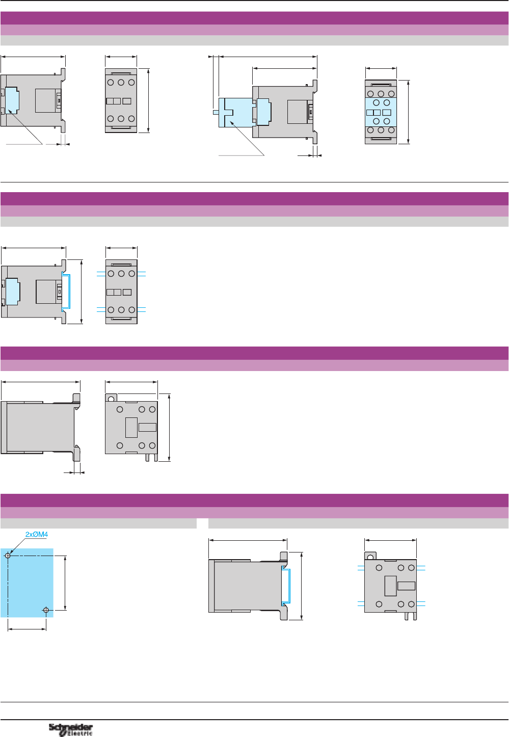
B7/26
TeSys control relays 0
TeSys D control relays and add-on blocks
Dimensions
CAD aCAD c or LC (low consumption)
45
12,5
(LAD8)
b
c
c1
c2
c3
DF511080.eps
b
c
c1
c2
c3
45
DF511081.eps
CAD 32
50
323
503
CAD 32
50
323
503
b 77 99 b 77 99
c without cover or add-on blocks 84 84 c without cover or add-on blocks 93 93
with cover, without add-on blocks 86 86 with cover, without add-on blocks 95 95
c1 with LAD N or C (2 or 4 contacts) 117 117 c1 with LAD N or C (2 or 4 contacts) 126 126
c2 with LAD 6K10 129 129 c2 with LAD 6K10 138 138
c3 with LAD T, R, S 137 137 c3 with LAD T, R, S 146 146
with LAD T, R, S and sealing cover 141 141 with LAD T, R, S and sealing cover 150 150
Mounting
CAD
Panel mounted Mounted on rail AM1 DP200 or DE200
60/70 ==
35 ==
(1)
c
DF511082.eps
78
=
=
45
c
810711.eps
CAD aCAD c or LC CAD aCAD c or LC
c with cover 86 95 c (AM1 DP200) (2) 88 97
c (AM1 DP200) (2) 96 105
(1) 2 elongated holes 4.5 x 9. (2) With cover.
Mounted on plate AM1 P
c
35
60/70
AF1 EA4
DF523319.eps
CAD aCAD c or LC
c with cover 86 95
Dimensions,
mounting
TeSys D
References:
pages B7/9 to B7/11
Illustration:
page B7/8
Characteristics:
pages B7/22 and B7/25
Schemes:
page B7/27
PCPB07T10-EN Version : 1.0 14 novembre 2014 9:00 AM B7/27
Control
relays
B7/27
TeSys control relays 0
TeSys D control relays and add-on blocks
Instantaneous auxiliary contacts
5 N/O 3 N/O + 2 N/C
CAD 50 CAD 32
A1
A2
03/NO
04
13/NO
14
23/NO
24
33/NO
34
43/NO
44
A1
A2
03/NO
04
13/NO
14
31/NC
32
21/NC
22
43/NO
44
127324.eps
Instantaneous auxiliary contact blocks
1 N/O + 1 N/C 2 N/O 2 N/C
LAD N11 LAD 8N11 (1) LAD N20 LAD 8N20 (1) LAD 8N02 LAD N02
53/NO
54
61/NC
62
127325.eps
153/NO
154
161/NC
162
(184)
(183)
(172)
(171)
127326.eps
53/NO
54
63/NO
64
127327.eps
153/NO
154
163/NC
164
(184)
(183)
(174)
(173)
127328.eps
161/NC
162
(172)
(171)
151/NC
152
(182)
(181)
127329.eps
51/NC
52
61/NC
62
127330.eps
(1) 7KH¿JXUHVLQEUDFNHWVDUHIRUWKHGHYLFHPRXQWHGRQWKH5+VLGHRIWKHFRQWUROUHOD\
2 N/O + 2F N/C 1 N/O + 3 N/C 4 N/O 4 N/C 3 N/O + 1 N/C
LAD N22 LAD N13 LAD N40 LAD N04 LAD N31
53/NO
54
61/NC
62
71/NC
72
83/NO
84
127331.eps
53/NO
54
61/NC
62
71/NC
72
81/NC
82
127332.eps
53/NO
54
63/NO
64
73/NO
74
83/NO
84
127333.eps
71/NC
72
81/NC
82
51/NC
52
61/NC
62
127334.eps
53/NO
54
61/NC
62
73/NO
74
83/NO
84
127335.eps
2 N/O + 2 N/C including
1 N/O + 1 N/C
make before break
With dust and damp protected contacts
2 N/O protected 2 N/C protected 2 N/O protected (2) 2 N/O protected +
2 N/O non protected
2 N/O protected +
1 N/O + 1 N/C
non protected
LAD C22 LA1 DX20 LA1 DX02 LA1 DY20 LA1 DZ40 LA1 DZ31
53/NO
54
61/NC
62
87/NO
88
75/NC
76
127336.eps
53/NO54
63/NO64
810727.eps
52 51/NC
62 61/NC
810734.eps
53/NO54
63/NO64
810726.eps
(2)3URGXFW¿WWHGZLWKHDUWKVFUHHQFRQWLQXLW\WHUPLQDOV
Time delay auxiliary contact blocks Mechanical latch blocks
On-delay 1 N/O + 1 N/C Off-delay
1 N/O + 1 N/C
LAD T LAD S LAD R LAD 6K10
55/NC56
67/NO
68
810716.eps
55/NC56
67/NO68
810719.eps
57/NO
58
65/NC66
810721.eps
E2
E1
A2 A1
810732.eps
53/NO54
83/NO84
63/NO
64
73/NO
74
62 61/NC
53/NO54
83/NO84
73/NO
74
Schemes
TeSys D
References:
pages B7/9 to B7/11
Illustration:
page B7/8
Characteristics:
pages B7/22 and B7/25
Dimensions:
page B7/26

PCPB07T10-EN
Version : 1.0 14 novembre 2014 9:00 AM
B7/28
B8/1
Contactors
Contactors
TeSys SK, K, D, SKGC, GC, GY, GF
Contactors – TeSys D
Contactors with standard coils From 9 to 150 A
B8/2
Contactors with low consumption coils From 9 to 65 AB8/3
Contactors conforming to UL and CSA From 25 to 160 AB8/8
Reversing pre-assembled contactors From 9 to 150 AB8/9
Contactors for capacitor banks switching From 12.5 to 60 kVAR B8/13
Auxiliary contact blocks – accessories – spare coils B8/14
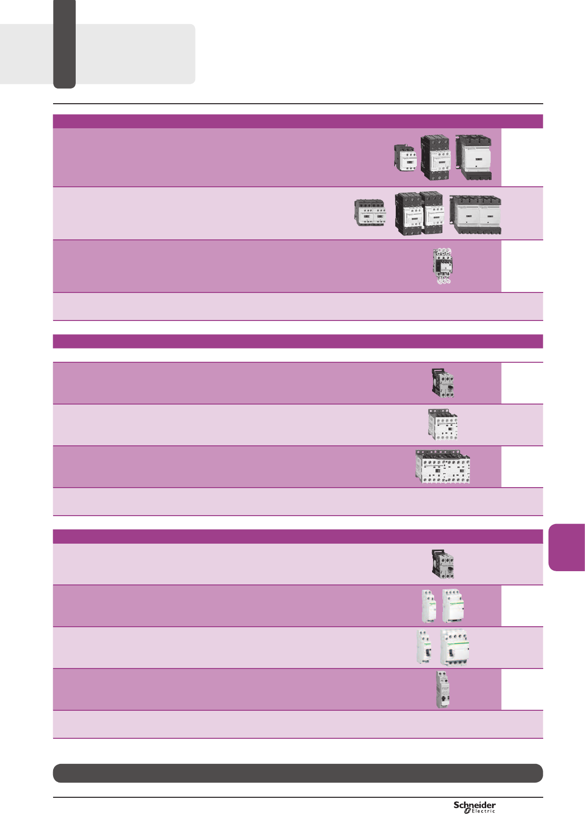
Mini contactors – TeSys SK, K
Type of product Range Pages
Mini contactors
TeSys SK Up to 6 AB8/29
Mini contactors
TeSys K From 6 to 16 AB8/31
Reversing pre-assembled mini contactors
TeSys K From 6 to 16 AB8/35
Auxiliary contact blocks - accessories B8/41
Contactors for use in modular enclosures / Din rail
Mini contactors
TeSys SKGC Up to 20 A B8/44
Modular contactors
TeSys GC From 16 to 100 AB8/46
Dual tariff contactors
TeSys GY 16, 25, 40 or 100 AB8/47
Impulse relay
TeSys GF Up to 16 A B8/48
Auxiliary contact blocks - accessories
TeSys GC, GY B8/49
TeSys
Control and
Protection
Components
Chapter
B8
Technical Data for Designers B8/51
PCPB08S10-EN Version : 1.0 19 novembre 2014 10:37 AM
B8/2
TeSys D
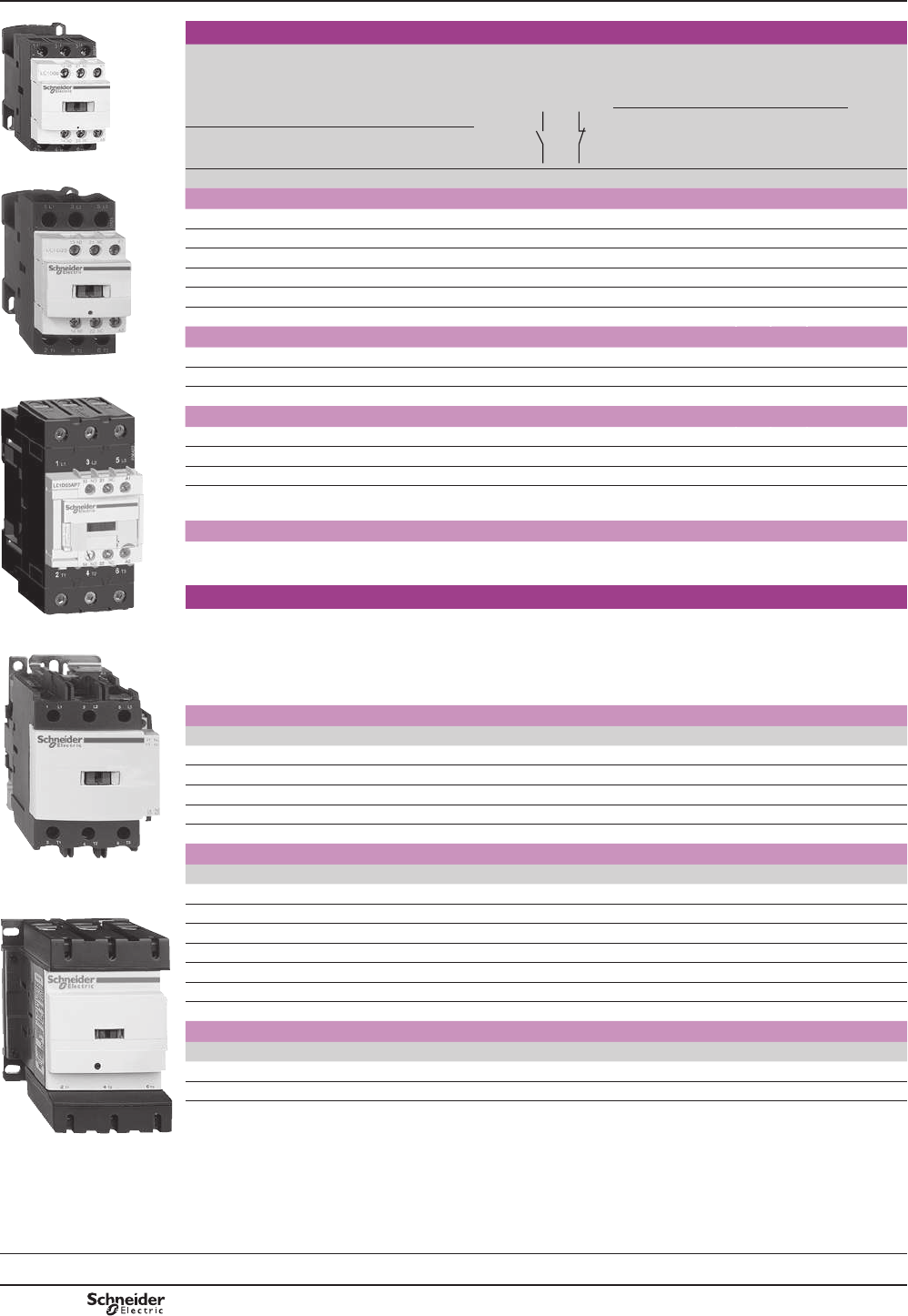
References TeSys contactors
TeSys D contactors for motor control
up to 75 kW at 400 V, in category AC-3
For connection by screw clamp terminals and lugs
Selection:
pages A5/23 to A5/47
Characteristics:
pages B8/53 to B8/58
Dimensions:
pages B8/65 to B8/68
Schemes:
pages B8/69 and B8/70
LC1 D09pp
PF526216R.eps
LC1 D25pp
PF526217R.eps
LC1 D65App
PF526218R.eps
LC1 D95pp
PF526219R.eps
LC1 D115pp
PF526220-34-MR.eps
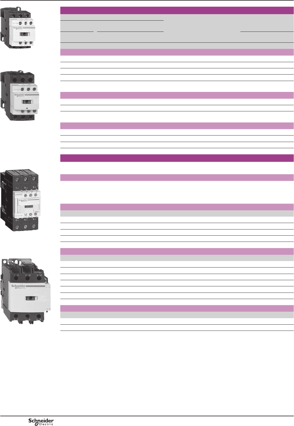
3-pole contactors
Standard power ratings of 3-phase motors
50-60 Hz in category AC-3
(T y 60 °C)
Rated
opera-
tional
current
in AC-3
440 V
up to
Instan-
taneous
auxiliary
contacts
Basic reference,
to be completed by adding
the control voltage code (2)
Weight
(3)
Fixing (1)
220 V
230 V
380 V
400 V
415 V 440 V 500 V 660 V
690 V
1000 V
kW kW kW kW kW kW kW A kg
Connection by screw clamp terminals
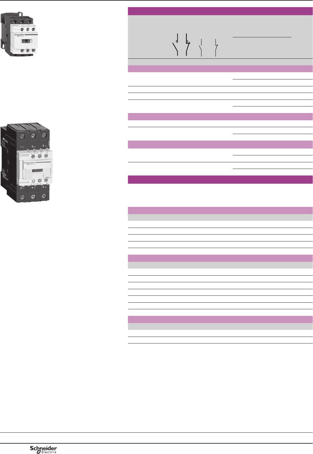
2.2 4 4 4 5.5 5.5 – 9 1 1 LC1D09pp 0.320
3 5.5 5.5 5.5 7.5 7.5 – 12 1 1 LC1D12pp 0.325
4 7.5 9 9 10 10 – 18 1 1 LC1D18pp 0.330
5.5 11 11 11 15 15 – 25 1 1 LC1D25pp 0.370
7.5 15 15 15 18.5 18.5 – 32 1 1 LC1D32pp 0.375
9 18.5 18.5 18.5 18.5 18.5 – 38 1 1 LC1D38pp 0.380
Power connections by EverLink® BTR screw connectors (4) and control by spring terminals
11 18.5 22 22 22 30 – 40 1 1 LC1D40App (5) 0.850
15 22 25 30 30 33 – 50 1 1 LC1D50App (5) 0.855
18.5 30 37 37 37 37 – 65 1 1 LC1D65App (5) 0.860
Connection by screw clamp terminals or connectors
22 37 45 45 55 45 45 80 1 1 LC1D80pp 1.590
25 45 45 45 55 45 45 95 1 1 LC1D95pp 1.610
30 55 59 59 75 80 65 115 1 1 LC1D115pp 2.500
40 75 80 80 90 100 75 150 1 1 LC1D150pp 2.500
Connection by lugs or bars
,QWKHUHIHUHQFHVVHOHFWHGDERYHLQVHUWD¿JXUH6 before the voltage code.
Example: LC1 D09pp becomes LC1 D096pp.
Separate components
Auxiliary contact blocks and add-on modules: see pages B8/15 to B8/21.
(1) LC1 D09 to D65A: clip-on mounting on 35 mm 5UDLO$0'3RUVFUHZ¿[LQJ
LC1 D80 to D95 a: clip-on mounting on 35 mm 5 rail AM1 DP or 75 mm 5UDLO$0'/RUVFUHZ¿[LQJ
LC1 D80 to D95 c: clip-on mounting on 75 mm 5UDLO$0'/RUVFUHZ¿[LQJ
/&'DQG'FOLSRQPRXQWLQJRQ[PP5UDLOV$0'3RUVFUHZ¿[LQJ
(2)6WDQGDUGFRQWUROFLUFXLWYROWDJHVIRURWKHUYROWDJHVSOHDVHFRQVXOW\RXU5HJLRQDO6DOHV2I¿FH
a.c. supply
Volts 24 42 48 110 115 220 230 240 380 400 415 440 500
LC1 D09…D150 'DQG'FRLOVZLWKEXLOWLQVXSSUHVVLRQDVVWDQGDUGE\ELGLUHFWLRQDOSHDNOLPLWLQJGLRGH
50/60 Hz B7 D7 E7 F7 FE7 M7 P7 U7 Q7 V7 N7 R7 S7
LC1 D80…D115
50 Hz B5 D5 E5 F5 FE5 M5 P5 U5 Q5 V5 N5 R5 S5
60 Hz B6 – E6 F6 – M6 – U6 Q6 – – R6 –
d.c. supply
Volts 12 24 36 48 60 72 110 125 220 250 440
LC1 D09…D65A FRLOVZLWKLQWHJUDOVXSSUHVVLRQGHYLFH¿WWHGDVVWDQGDUG
U 0.75…1.25 Uc JD BD CD ED ND SD FD GD MD UD RD
LC1 D80…D95
U 0.85…1.1 Uc JD BD CD ED ND SD FD GD MD UD RD
U 0.75…1.2 Uc JW BW CW EW – SW FW – MW – –
LC1 D115 and D150 FRLOVZLWKLQWHJUDOVXSSUHVVLRQGHYLFH¿WWHGDVVWDQGDUG
U 0.75…1.2 Uc – BD – ED ND SD FD GD MD UD RD
Low consumption
Volts c 5 12 20 24 48 110 220 250
LC1 D09...D38 FRLOVZLWKLQWHJUDOVXSSUHVVLRQGHYLFH¿WWHGDVVWDQGDUG
U 0.8…1.25 Uc AL JL ZL BL EL FL ML UL
)RURWKHUYROWDJHVEHWZHHQDQG9VHHSDJHV%WR%
(3)7KHZHLJKWVLQGLFDWHGDUHIRUFRQWDFWRUVZLWKDFFRQWUROFLUFXLW)RUGFRUORZFRQVXPSWLRQFRQWUROFLUFXLWDGGNJIURP
LC1 D09 to D38NJIURPLC1 D40A to D65A DQGNJIRULC1 D80 and D95
(4)%75VFUHZVKH[DJRQVRFNHWKHDG,QDFFRUGDQFHZLWKORFDOHOHFWULFDOZLULQJUHJXODWLRQVDVL]HLQVXODWHG$OOHQNH\PXVWEH
used (reference LAD ALLEN4, see page B8/21
(5))RUORZFRQVXPSWLRQNLWLA4 DBLVHHSDJH%
PCPB08P20-EN
Version : 1.0 19 novembre 2014 10:37 AM

B8/3
Contactors
TeSys D
PF526221R.eps
3-pole contactors
Standard power ratings of 3-phase motors
50-60 Hz in category AC-3
(T y 60 °C)
Rated
operational
current in
AC-3 440 V
up to
Instan-
taneous
auxiliary
contacts
Basic reference,
to be completed by adding
the control voltage code (2)
Fixing (1)
220 V
230 V
380 V
400 V
415 V 440 V 500 V 660 V
690 V
1000 V
kW kW kW kW kW kW kW A
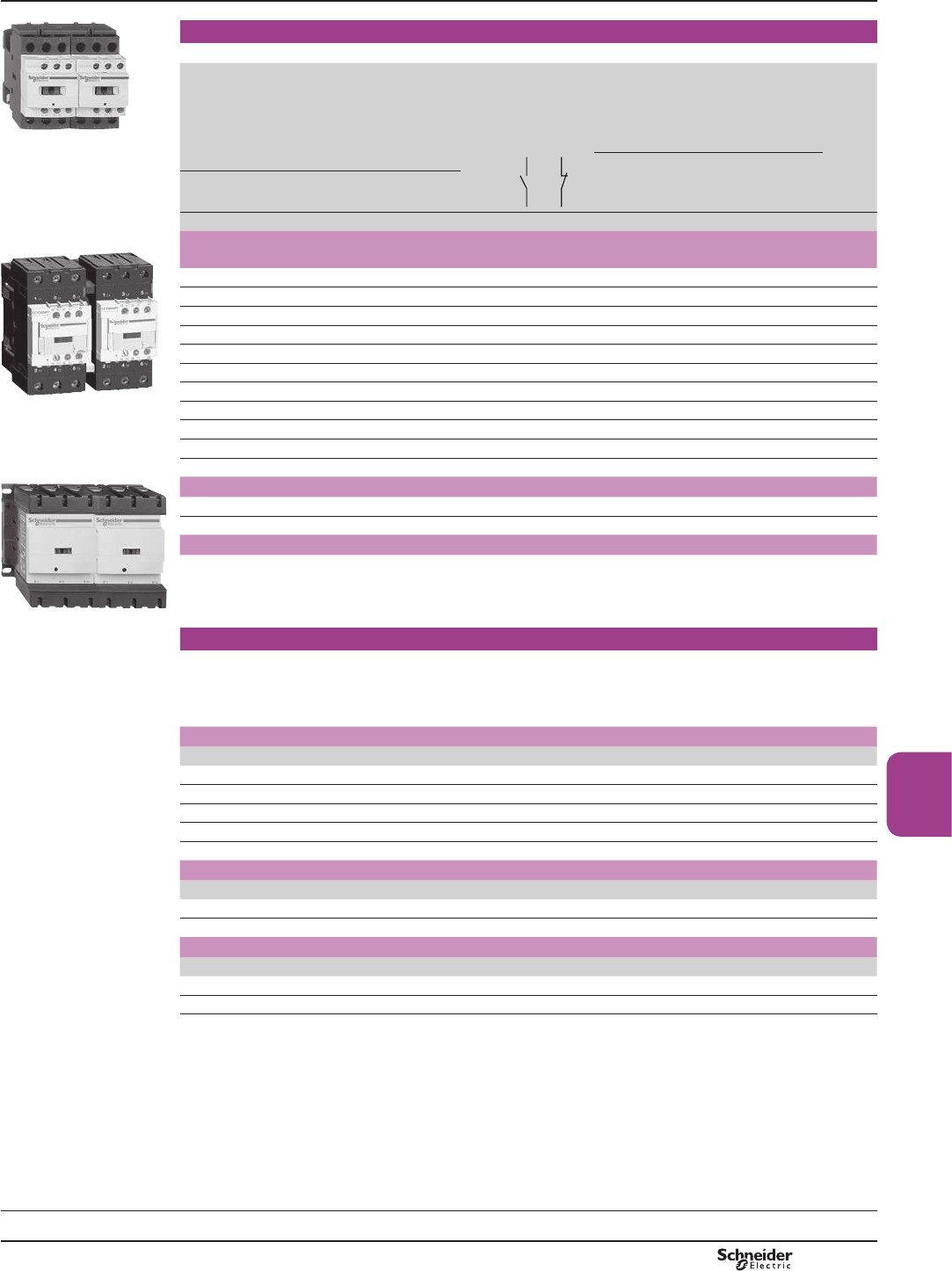
Power and control connections by spring terminals
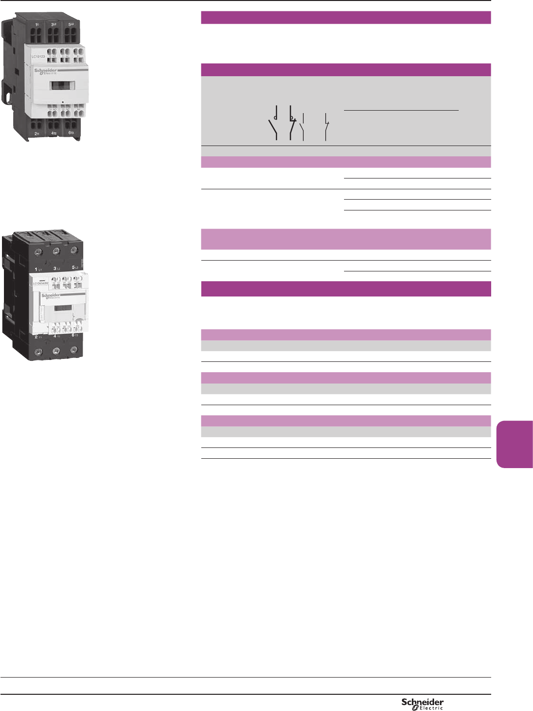
LC1 D123pp 2.2 4 4 4 5.5 5.5 9 1 1 LC1D093pp
3 5.5 5.5 5.5 7.5 7.5 12 1 1 LC1D123pp
4 7.5 9 9 10 10 18 1 1 LC1D183pp
5.5 11 11 11 15 15 25 1 1 LC1D253pp
PF526222R.eps
7.5 15 15 15 18.5 18.5 32 (4) 1 1 LC1D323pp
Power connections by EverLink® BTR screw connectors (5) and control by spring terminals
11 18.5 22 22 22 30 40 1 1 LC1D40A3pp (6)
15 22 25 30 30 33 50 1 1 LC1D50A3pp (6)
18.5 30 37 37 37 37 65 1 1 LC1D65A3pp (6)
Connection by Faston connectors
7KHVHFRQWDFWRUVDUH¿WWHGZLWK)DVWRQFRQQHFWRUV[PPRQWKHSRZHUSROHVDQG[PPRQWKH
FRLODQGDX[LOLDU\WHUPLQDOV
)RUFRQWDFWRUV/&'DQG/&'RQO\UHSODFHWKH¿JXUH3 with a 9 in the references selected above.
Example: LC1 D093pp becomes LC1 D099pp.
LC1 D65A3pp Separate components
Auxiliary contact blocks and add-on modules: see pages B8/15 to B8/21.
(1) LC1 D09 to D32: clip-on mounting on 35 mm 5UDLO$0'3RUVFUHZ¿[LQJ
(2)6WDQGDUGFRQWUROFLUFXLWYROWDJHVIRURWKHUYROWDJHVSOHDVHFRQVXOW\RXU5HJLRQDO6DOHV2I¿FH
a.c. supply
Volts 24 42 48 110 115 220 230 240 380 400 415 440
LC1 D09…D65A
50/60 Hz B7 D7 E7 F7 FE7 M7 P7 U7 Q7 V7 N7 R7
d.c. supply
Volts 12 24 36 48 60 72 110 125 220 250 440
LC1 D09…D65A FRLOVZLWKEXLOWLQVXSSUHVVLRQDVVWDQGDUGE\ELGLUHFWLRQDOSHDNOLPLWLQJGLRGH
U 0.75…1.25 Uc JD BD CD ED ND SD FD GD MD UD RD
Low consumption
Volts c 5 12 20 24 48 110 220 250
LC1 D09...D32 FRLOVZLWKLQWHJUDOVXSSUHVVLRQGHYLFH¿WWHGDVVWDQGDUG
U 0.8…1.25 Uc AL JL ZL BL EL FL ML UL
)RURWKHUYROWDJHVEHWZHHQDQG9VHHSDJHV%WR%
(3)7KHZHLJKWVLQGLFDWHGDUHIRUFRQWDFWRUVZLWKDFFRQWUROFLUFXLW
)RUGFRUORZFRQVXPSWLRQFRQWUROFLUFXLWDGGNJIURPLC1 D09 to D32 DQGNJIURPLC1 D40A to D65A
(4)0XVWEHZLUHGZLWK[PP2FDEOHVLQSDUDOOHORQWKHXSVWUHDPVLGH2QWKHGRZQVWUHDPVLGHRXWJRLQJWHUPLQDOEORFN
LAD 331PD\EHXVHG4XLFN¿WWHFKQRORJ\VHHSDJH%:KHQZLUHGZLWKDVLQJOHFDEOHWKHSURGXFWLVOLPLWHGWR$
N:9PRWRUV
(5)%75VFUHZVKH[DJRQVRFNHWKHDG,QDFFRUGDQFHZLWKORFDOHOHFWULFDOZLULQJUHJXODWLRQVDVL]HLQVXODWHG$OOHQNH\PXVWEH
used (reference LAD ALLEN4, see page B8/21
(6))RUORZFRQVXPSWLRQNLWLA4 DBLVHHSDJH%
TeSys contactors
TeSys D contactors for motor control
up to 30 kW at 400 V, in category AC-3
For connection by spring terminals
Selection:
pages A5/23 to A5/47
Characteristics:
pages B8/53 to B8/58
Dimensions:
pages B8/65 to B8/68
Schemes:
pages B8/69 and B8/70
References
PCPB08P20-EN Version : 1.0 19 novembre 2014 10:37 AM
B8/4
PF526230R.eps
3-pole contactors
Non inductive
loads maximum
current
(T y 60 °C)
utilisation category
AC-1
Number
of poles
Instan-
taneous
auxiliary
contacts
Basic reference,
to be completed by adding
the control voltage code (1)
Weight
(3)
Fixing (2)
LC1 D09pp A kg
Connection by screw clamp terminals
25 3 1 1 LC1D09pp 0.320
or LC1D12pp 0.325
32 3 1 1 LC1D18pp 0.330
40 3 1 1 LC1D25pp 0.370
50 3 1 1 LC1D32pp 0.375
or LC1D38pp 0.380
Connection by EverLink®, BTR screw connectors (4)
PF526231R.eps
60 3 1 1 LC1D40App (7) 0.850
80 3 1 1 LC1D50App (7) 0.855
or LC1D65App (5)(7) 0.860
Connection by screw clamp terminals or connectors
125 3 1 1 LC1D80pp 1.590
or LC1D95pp (5) 1.610
200 3 1 1 LC1D115pp 2.500
or LC1D150pp (6) 2.500
3-pole contactors for connection by lugs
,QWKHUHIHUHQFHVVHOHFWHGDERYHLQVHUWD¿JXUH6 before the voltage code.
Example: LC1 D09pp becomes LC1 D096pp.
(1) Standard control circuit voltages (for other voltages, please consult your Regional Sales
2I¿FH
LC1 D65App a.c. supply
Volts 24 42 48 110 115 220 230 240 380 400 415 440 500
LC1 D09...D150 FRLOV'DQG'¿WWHGZLWKLQWHJUDOVXSSUHVVLRQGHYLFHDVVWDQGDUG
50/60 Hz B7 D7 E7 F7 FE7 M7 P7 U7 Q7 V7 N7 R7 –
LC1 D80...D150
50 Hz B5 D5 E5 F5 FE5 M5 P5 U5 Q5 V5 N5 R5 S5
60 Hz B6 – E6 F6 – M6 – U6 Q6 – – R6 –
d.c. supply
Volts 12 24 36 48 60 72 110 125 220 250 440
LC1 D09...D65A FRLOVZLWKLQWHJUDOVXSSUHVVLRQGHYLFH¿WWHGDVVWDQGDUG
U 0.7…1.25 Uc JD BD CD ED ND SD FD GD MD UD RD
LC1 or LP1 D80 and D95
U 0.85…1.1 Uc JD BD CD ED ND SD FD GD MD UD RD
U 0.75…1.2 Uc JW BW CW EW – SW FW – MW – –
LC1 D115 and D150 FRLOVZLWKLQWHJUDOVXSSUHVVLRQGHYLFH¿WWHGDVVWDQGDUG
U 0.75…1.2 Uc – BD – ED ND SD FD GD MD UD RD
Low consumption
Volts c 5 12 20 24 48 110 220 250
LC1 D09...D38 FRLOVZLWKLQWHJUDOVXSSUHVVLRQGHYLFH¿WWHGDVVWDQGDUG
U 0.8…1.25 Uc AL JL ZL BL EL FL ML UL
)RURWKHUYROWDJHVEHWZHHQDQG9VHHSDJHV%WR%
(2) LC1 D09 to D65A: clip-on mounting on 35 mm 5 rail AM1 DP RUVFUHZ¿[LQJ
LC1 D80 and D95 a: clip-on mounting on 35 mm 5 rail AM1 DP or 75 mm 5 rail AM1 DL
RUVFUHZ¿[LQJ
LC1 or LP1 D80 to D95 c: clip-on mounting on 75 mm 5 rail AM1 DLRUVFUHZ¿[LQJ
LC1 D115 and D150FOLSRQPRXQWLQJRQ[PP5 rails AM1 DPRUVFUHZ¿[LQJ
(3)7KHZHLJKWVLQGLFDWHGDUHIRUFRQWDFWRUVZLWKDFFRQWUROFLUFXLW)RUGFRUORZFRQVXPSWLRQ
FRQWUROFLUFXLWDGGNJIURPLC1 D09 to D38NJIURPLC1 D40A to D65A and
NJIRULC1 D80 and D95
(4)%75VFUHZVKH[DJRQVRFNHWKHDG,QDFFRUGDQFHZLWKORFDOHOHFWULFDOZLULQJUHJXODWLRQV
DVL]HLQVXODWHG$OOHQNH\PXVWEHXVHGUHIHUHQFHLAD ALLEN4VHHSDJH%
(5)6HOHFWLRQDFFRUGLQJWRWKHQXPEHURIRSHUDWLQJF\FOHVVHH$&FXUYHSDJH$
(6)$ZLWK[PP2 FDEOHVFRQQHFWHGLQSDUDOOHO
(7))RUORZFRQVXPSWLRQNLWLA4 DBLVHHSDJH%
References TeSys contactors
TeSys D, 3-pole contactors
For control in category AC-1, from 25 to 200 A
Selection:
pages A5/23 to A5/47
Characteristics:
pages B8/53 to B8/58
Dimensions:
pages B8/65 to B8/68
Schemes:
pages B8/69 and B8/70
TeSys D
PCPB08P20-EN
Version : 1.0 19 novembre 2014 10:37 AM
B8/5
Contactors
PF526232R.eps
3-pole contactors for connection by Faston connectors
7KHVHFRQWDFWRUVDUH¿WWHGZLWK)DVWRQFRQQHFWRUV[PPRQWKHSRZHU
poles and 1 x 6.35 mm on the coil terminals. For contactors LC1 D09 and LC1 D12
RQO\LQWKHUHIHUHQFHVVHOHFWHGIURPWKHSUHYLRXVSDJHLQVHUWD¿JXUH9 before the
voltage code. Example: LC1 D09pp becomes LC1 D099pp.
3-pole contactors
Non inductive
loads maximum
current
(T y 60 °C)
utilisation
category AC-1
Number
of poles
Instan-
taneous
auxiliary
contacts
Basic reference,
to be completed by adding
the control voltage code (1)
Weight
(3)
Fixing (2)
LC1 D123pp A kg
Connection by spring terminals
16 3 1 1 LC1D093pp (4) 0.320
or LC1D123pp (4) 0.325
25 3 1 1 LC1D183pp (5) 0.335
or LC1D253pp (6) 0.325
or LC1D323pp (6) 0.325
PF526233R.eps
LC1 D65A3pp
Power connections by EverLink® BTR screw connectors (7) and control by
spring terminals
60 3 1 1 LC1D40A3pp (9) 0.850
80 3 1 1 LC1D50A3pp (8) (9) 0.855
or LC1D65A3pp (8) (9) 0.860
Separate components
Auxiliary contact blocks and add-on modules: see pages B8/15 to B8/21.
(1) Standard control circuit voltages (for other voltages, please consult your Regional Sales
2I¿FH
a.c. supply
Volts 24 42 48 110 115 220 230 240 380 400 415 440 500
LC1 D09...D65A
50/60 Hz B7 D7 E7 F7 FE7 M7 P7 U7 Q7 V7 N7 R7 S7
d.c. supply
Volts 12 24 36 48 60 72 110 125 220 250 440
LC1 D09...D65A FRLOVZLWKLQWHJUDOVXSSUHVVLRQGHYLFH¿WWHGDVVWDQGDUG
U 0.75…1.25 Uc JD BD CD ED ND SD FD GD MD UD RD
Low consumption
Volts c 5 12 20 24 48 110 220 250
LC1 D09...D38 FRLOVZLWKLQWHJUDOVXSSUHVVLRQGHYLFH¿WWHGDVVWDQGDUG
U 0.8…1.25 Uc AL JL ZL BL EL FL ML UL
)RURWKHUYROWDJHVEHWZHHQDQG9VHHSDJHV%WR%
(2) LC1 D09 to D65A: clip-on mounting on 35 mm 5 rail AM1 DP RUVFUHZ¿[LQJ
(3)7KHZHLJKWVLQGLFDWHGDUHIRUFRQWDFWRUVZLWKDFFRQWUROFLUFXLW)RUGFRUORZFRQVXPSWLRQ
FRQWUROFLUFXLWDGGNJIURPLC1 D09 to D38DQGNJIURPLC1 D40A to D65A
(4)$ZLWK[PP2 FDEOHVFRQQHFWHGLQSDUDOOHO
(5)$ZLWK[PP2 FDEOHVFRQQHFWHGLQSDUDOOHO
(6)$ZLWK[PP2 FDEOHVFRQQHFWHGLQSDUDOOHO
(7)%75VFUHZVKH[DJRQVRFNHWKHDG,QDFFRUGDQFHZLWKORFDOHOHFWULFDOZLULQJUHJXODWLRQV
DVL]HLQVXODWHG$OOHQNH\PXVWEHXVHGUHIHUHQFHLAD ALLEN4VHHSDJH%
(8)6HOHFWLRQDFFRUGLQJWRWKHQXPEHURIRSHUDWLQJF\FOHVVHH$&FXUYHSDJH$
(9))RUORZFRQVXPSWLRQNLWLA4 DBLVHHSDJH%
Selection:
pages A5/23 to A5/47
Characteristics:
pages B8/53 to B8/58
Dimensions:
pages B8/65 to B8/68
Schemes:
pages B8/69 and B8/70
References TeSys contactors
TeSys D, 3-pole contactors
For control in category AC-1, from 25 to 200 A
TeSys D
PCPB08P20-EN Version : 1.0 19 novembre 2014 10:37 AM
B8/6
PF526227R.eps
4-pole contactors for connection by screw clamp terminals or connectors
Non inductive loads
maximum current
(T y 60 °C)
utilisation category
AC-1
Number
of poles
Instantaneous
auxiliary
contacts
Basic reference,
to be completed by adding
the control voltage code (1)
Weight
(3)
Fixing (2)
A kg
Connection by screw clamp terminals
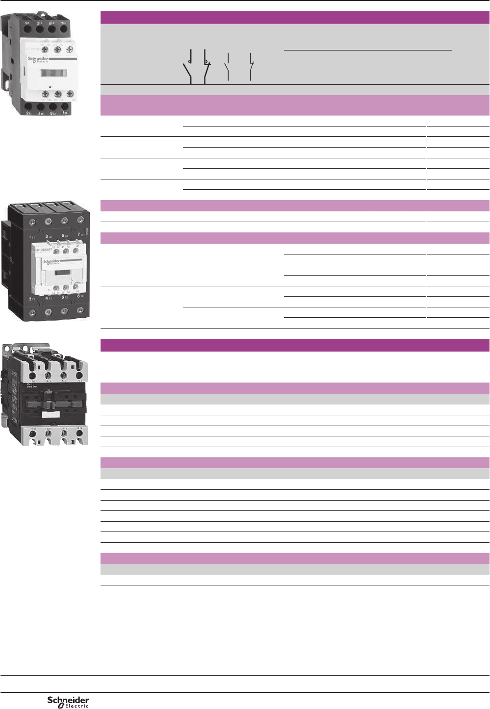
LC1 DT20pp 20 4 – 1 1 LC1DT20pp 0.365
2 2 1 1 LC1D098pp 0.365
25 4 – 1 1 LC1DT25pp 0.365
2 2 1 1 LC1D128pp 0.365
32 4 – 1 1 LC1DT32pp 0.425
2 2 1 1 LC1D188pp 0.425
40 4 – 1 1 LC1DT40pp 0.425
2 2 1 1 LC1D258pp 0.425
PF526228R.eps
Connection by EverLink®, BTR screw connectors
60 4 – 1 1 LC1DT60App 1.090
80 4 – 1 1 LC1DT80App 1.150
Connection by screw clamp terminals or connectors
60 2 2 – – LC1D40008pp 1.440
or LP1D40008pp 2.210
80 2 2 – – LC1D65008pp 1.450
or LP1D65008pp 2.220
125 4 – – – LC1D80004pp 1.760
or LP1D80004pp 2.685
2 2 – – LC1D80008pp 1.840
or LP1D80008pp 2.910
LC1 DT80App 200 4 – – – LC1D115004pp 2.860
PF526229R.eps
LC1 D65008pp
4-pole contactors for connection by lugs or bars
,QWKHUHIHUHQFHVVHOHFWHGDERYHLQVHUWD¿JXUHEHIRUHWKHYROWDJHFRGH
Example: LC1 DT20pp becomes LC1 DT206pp.
(1) 6WDQGDUGFRQWUROFLUFXLWYROWDJHVIRURWKHUYROWDJHVSOHDVHFRQVXOW\RXU5HJLRQDO6DOHV2I¿FH
a.c. supply
Volts 24 42 48 110 115 220 230 240 380 400 415 440 500
LC1 D09...D150 and LC1 DT20...DT80A FRLOV'DQG'¿WWHGZLWKLQWHJUDOVXSSUHVVLRQGHYLFHDVVWDQGDUG
50/60 Hz B7 D7 E7 F7 FE7 M7 P7 U7 Q7 V7 N7 R7 –
LC1 D80...D115
50 Hz B5 D5 E5 F5 FE5 M5 P5 U5 Q5 V5 N5 R5 S5
60 Hz B6 – E6 F6 – M6 – U6 Q6 – – R6 –
d.c. supply
Volts 12 24 36 48 60 72 110 125 220 250 440
LC1 D09...D65A and LC1 DT20...DT80A FRLOVZLWKLQWHJUDOVXSSUHVVLRQGHYLFH¿WWHGDVVWDQGDUG
U 0.7…1.25 Uc JD BD CD ED ND SD FD GD MD UD RD
LC1 or LP1D40...D80
U 0.85…1.1 Uc JD BD CD ED ND SD FD GD MD UD RD
U 0.75…1.2 Uc JW BW CW EW – SW FW – MW – –
LC1 D115 FRLOVZLWKLQWHJUDOVXSSUHVVLRQGHYLFH¿WWHGDVVWDQGDUG
U 0.75…1.2 Uc – BD – ED ND SD FD GD MD UD RD
Low consumption
Volts c 5 12 20 24 48 110 220 250
LC1 D09...D38 and LC1 DT20...DT40 FRLOVZLWKLQWHJUDOVXSSUHVVLRQGHYLFH¿WWHGDVVWDQGDUG
U 0.8…1.25 Uc AL JL ZL BL EL FL ML UL
)RURWKHUYROWDJHVEHWZHHQDQG9VHHSDJHV%WR%
(2) LC1 D09 to D38 and LC1 DT20 to DT80A: clip-on mounting on 35 mm 5 rail AM1 DP RUVFUHZ¿[LQJ
LC1 D80 a: clip-on mounting on 35 mm 5 rail AM1 DP or 75 mm 5 rail AM1 DLRUVFUHZ¿[LQJ
LC1 or LP1 D80 c: clip-on mounting on 75 mm 5 rail AM1 DLRUVFUHZ¿[LQJ
LC1 D115 and D150FOLSRQPRXQWLQJRQ[PP5 rails AM1 DPRUVFUHZ¿[LQJ
(3)7KHZHLJKWVLQGLFDWHGDUHIRUFRQWDFWRUVZLWKDFFRQWUROFLUFXLW)RUGFRUORZFRQVXPSWLRQFRQWUROFLUFXLWDGGNJIURP
LC1 D09 to D38NJIURPLC1 DT60A and D80ADQGNJIRULC1 D80
References TeSys contactors
TeSys D, 4-pole contactors
For control in category AC-1, 25 to 200 A
TeSys D
Selection:
pages A5/23 to A5/47
Characteristics:
pages B8/53 to B8/58
Dimensions:
pages B8/65 to B8/68
Schemes:
pages B8/69 and B8/70
PCPB08P20-EN
Version : 1.0 19 novembre 2014 10:37 AM
B8/7
Contactors
4-pole contactors
Non inductive
loads maximum
current
(T y 60 °C)
utilisation
category AC-1
Number
of poles
Instan-
taneous
auxiliary
contacts
Basic reference,
to be completed by
adding the voltage code (1)
Weight
(3)
Fixing (2)
A kg
Connection by spring terminals
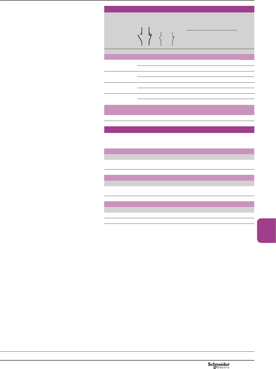
20 4 – 1 1 LC1DT203pp 0.380
2 2 1 1 LC1D0983pp 0.380
25 4 – 1 1 LC1DT253pp 0.380
2 2 1 1 LC1D1283pp 0.380
32 4 – 1 1 LC1DT323pp 0.425
2 2 1 1 LC1D1883pp 0.425
40 4 – 1 1 LC1DT403pp 0.425
2 2 1 1 LC1D2583pp 0.425
Connection by EverLink®, BTR screw connectors and control circuit by
spring terminals
60 4 – 1 1 LC1DT60A3pp 1.090
80 4 – 1 1 LC1DT80A3pp 1.150
Separate components
Auxiliary contact blocks and add-on modules: see pages B8/15 to B8/21.
(1) Standard control circuit voltages (for other voltages, please consult your Regional Sales
2I¿FH
a.c. supply
Volts 24 42 48 110 115 220 230 240 380 400 415 440 500
LC1 D09...D25 and LC1 DT20...DT80A FRLOVZLWKLQWHJUDOVXSSUHVVLRQGHYLFH¿WWHGDV
VWDQGDUG
50/60 Hz B7 D7 E7 F7 FE7 M7 P7 U7 Q7 V7 N7 R7 –
d.c. supply
Volts 12 24 36 48 60 72 110 125 220 250 440
LC1 D09...D25 and LC1 DT20...DT80A FRLOVZLWKLQWHJUDOVXSSUHVVLRQGHYLFH¿WWHGDV
VWDQGDUG
U 0.7…1.25 Uc JD BD CD ED ND SD FD GD MD UD RD
Low consumption
Volts c 5 12 20 24 48 110 220 250
LC1 D09...D25 and LC1 DT20...DT40 FRLOVZLWKLQWHJUDOVXSSUHVVLRQGHYLFH¿WWHGDVVWDQGDUG
U 0.8…1.25 Uc AL JL ZL BL EL FL ML UL
)RURWKHUYROWDJHVEHWZHHQDQG9VHHSDJHV%WR%
(2) LC1 D09 to D38 and LC1 DT20 to DT80A: clip-on mounting on 35 mm 5 rail AM1DP or
VFUHZ¿[LQJ
(3)7KHZHLJKWVLQGLFDWHGDUHIRUFRQWDFWRUVZLWKDFFRQWUROFLUFXLW)RUGFRUORZFRQVXPSWLRQ
FRQWUROFLUFXLWDGGNJIURPLC1 D09 to D38NJIRULC1 DT60A and DT80A
References TeSys contactors
TeSys D, 4-pole contactors
For control in category AC-1, 25 to 200 A
TeSys D
Selection:
pages A5/23 to A5/47
Characteristics:
pages B8/53 to B8/58
Dimensions:
pages B8/65 to B8/68
Schemes:
pages B8/69 and B8/70
PCPB08P20-EN Version : 1.0 19 novembre 2014 10:37 AM
B8/8
DF526168R.eps
Contactors
Standard power ratings of motors 50/60 Hz Associated cable
type 75 °C-Cu
Continuous
current
Type of contactor required
Basic reference,
to be completed (1)
Single-phase
1 Ø
3-phase
3 Ø
115 V 230 V
240 V
200 V
208 V
230 V
240 V
460 V
480 V
575 V
600 V
Fixing, connection (2)
HP HP HP HP HP HP A
LC1 D09pp Connection by screw clamp terminals
1/3 1 2 2 5 7.5 AWG 18 - 10 25 LC1D09pp
0.5 2 3 3 7.5 10 AWG 18 - 10 25 LC1D12pp
DF526169R.eps
1 3 5 5 10 15 AWG 18 - 8 32 LC1D18pp
2 3 7.5 7.5 15 20 AWG 14 - 6 40 LC1D25pp
2 5 10 10 20 25 AWG 14 - 6 50 LC1D32pp
Power connections by EverLink® BTR screw connectors (4) and control by spring terminals
3 5 10 10 30 30 AWG 16 - 2 60 LC1D40App
3 7.5 15 15 40 40 AWG 16 - 2 70 LC1D50App
5 10 20 20 40 50 AWG 16 - 2 80 LC1D65App
LC1 D25pp Connection by screw clamp terminals or connectors
7.5 15 25 30 60 60 AWG 10 - 2 110 LC1D80pp
7.5 15 25 30 60 60 AWG 10 - 2 110 LC1D95pp
– – 30 40 75 100 AWG 2/0 160 LC1D115pp
– – 40 50 100 125 AWG 3/0 160 LC1D150pp
DF526170R.eps
Applications with High-Fault Short-Circuit ratings
)RUFRQWDFWRUV/&'$WR/&'$WKH+LJK)DXOW6KRUW&LUFXLWUDWLQJVDUHN$DW9DQGN$
at 600 V.
Application example
For a 15 HP-230 V motor
6HOHFWDFRQWDFWRUW\SHLC1 D50A.
,QIRUPDWLRQWKHFRQWDFWRUUDWLQJVHOHFWHGFRUUHVSRQGVWR³VL]H´WKHDVVRFLDWHGFDEOHLVW\SH$:*&&X
(1)6WDQGDUGFRQWUROFLUFXLWYROWDJHVIRURWKHUYROWDJHVSOHDVHFRQVXOW\RXU5HJLRQDO6DOHV2I¿FH
a.c. supply
Volts 24 42 48 110 115 120 208 220 230 240 380 400 415 440 480 500
LC1 D09…D150 'DQG'FRLOVZLWKLQWHJUDOVXSSUHVVLRQGHYLFH¿WWHGDVVWDQGDUG
50/60 Hz B7 D7 E7 F7 FE7 G7 LE7 M7 P7 U7 Q7 V7 N7 R7 T7 S7
LC1 D80…D115
50 Hz B5 D5 E5 F5 FE5 G5 – M5 P5 U5 Q5 V5 N5 R5 – S5
60 Hz B6 – E6 F6 – G6 L6 M6 – U6 Q6 – – R6 T6 –
d.c. supply
Volts 12 24 36 48 60 72 110 125 220 250 440
LC1 D09…D65A FRLOVZLWKLQWHJUDOVXSSUHVVLRQGHYLFH¿WWHGDVVWDQGDUG
U 0.7…1.25 Uc JD BD CD ED ND SD FD GD MD UD RD
LC1 D80 and D95
U 0.85…1.1 Uc JD BD CD ED ND SD FD GD MD UD RD
U 0.75…1.2 Uc JW BW CW EW – SW FW – MW – –
LC1 D115 and D150 FRLOVZLWKLQWHJUDOVXSSUHVVLRQGHYLFH¿WWHGDVVWDQGDUG
U 0.75…1.2 Uc – BD – ED ND SD FD GD MD UD RD
Low consumption
Volts c5 12 20 24 48 72 110 220 250
LC1 D09…D38 FRLOVZLWKLQWHJUDOVXSSUHVVLRQGHYLFH¿WWHGDVVWDQGDUG
U 0.7…1.25 Uc AL JL ZL BL EL SL FL ML UL
(2) LC1 D09 to D65A: clip-on mounting on 35 mm 6 rail AM1 DPRUVFUHZ¿[LQJ
LC1 D80 and LC1 D95:
clip-on mounting on 35 mm 6 rail AM1 DP or 75 mm 6 rail AM1 DLRUVFUHZ¿[LQJ
LC1 D115 and D150FOLSRQPRXQWLQJRQ[PP6 rails AM1 DPRUVFUHZ¿[LQJ
LC1 D65App
DF526171R.eps
LC1 D95pp
Reference TeSys contactors
For the North American market,
Conforming to UL and CSA standards
25 to 160 A
TeSys D
PCPB08P20-EN
Version : 1.0 19 novembre 2014 10:37 AM
B8/9
Contactors
DF526172R.eps
LC2 D12pp
3-pole reversing contactors for connection by screw clamp terminals
Pre-wired power connections.
Standard power ratings of 3-phase motors
50-60 Hz in category AC-3
(T y 60 °C)
Rated
opera-
tional
current
in AC-3
440 V
up to
Instan-
taneous
auxiliary
contacts
per
contactor
Contactors supplied with coil
Basic reference, to be completed by
adding the control voltage code (2)
Weight
(3)
Fixing (1)
220 V
230 V
380 V
400 V
415 V 440 V 500 V 660 V
690 V
1000 V
kW kW kW kW kW kW kW A kg
DF526173R.eps
With mechanical interlock, without electrical interlocking, for connection by screw clamp terminals
or connectors
2.2 4 4 4 5.5 5.5 – 9 1 1 LC2D09pp (4) 0.687
3 5.5 5.5 5.5 7.5 7.5 – 12 1 1 LC2D12pp (4) 0.697
4 7.5 9 9 10 10 – 18 1 1 LC2D18pp (4) 0.707
5.5 11 11 11 15 15 – 25 1 1 LC2D25pp (4) 0.787
7.5 15 15 15 18.5 18.5 – 32 1 1 LC2D32pp (4) 0.797
9 18.5 18.5 18.5 18.5 18.5 – 38 1 1 LC2D38pp (4) 0.807
11 18.5 22 22 22 30 – 40 1 1 LC2D40App (5) 1.870
LC2 D65App 15 22 25 30 30 33 – 50 1 1 LC2D50App (5) 1.880
18.5 30 37 37 37 37 – 65 1 1 LC2D65App (5) 1.890
22 37 45 45 55 45 – 80 1 1 LC2D80pp 3.200
25 45 45 45 55 45 – 95 1 1 LC2D95pp 3.200
DF526175R.eps
LC2 D115pp
With mechanical interlock and electrical interlocking, for connection by screw clamp terminals or connectors
30 55 59 59 75 80 65 115 1 1 LC2D115pp 6.350
40 75 80 80 90 100 75 150 1 1 LC2D150pp 6.400
Connection by lugs or bars
For reversing contactors LC2 D09 to LC2 D38, LC2 D115 and LC2 D150, in the references selected above,
LQVHUWD¿JXUH6 before the voltage code. Example: LC2 D09pp becomes LC2 D096pp.
7REXLOGDWR$UHYHUVLQJFRQWDFWRUIRUFRQQHFWLRQE\OXJVRUGHUFRQWDFWRUVLC1 DppA6 and
PHFKDQLFDOLQWHUORFNLAD 4CMVHHSDJH%
Component parts
Auxiliary contact blocks and add-on modules: see pages B8/15 to B8/21.
(1) LC2 D09 to D65A: clip-on mounting on 35 mm 5 rail AM1 DPRUVFUHZ¿[LQJ
LC2 D80 and D95: clip-on mounting on 35 mm 5 rail AM1 DP or 75 mm 5 rail AM1 DLRUVFUHZ¿[LQJ
LC2 D115 and D150: clip-on mounting on 35 mm 5 rail AM1 DPRUVFUHZ¿[LQJ
(2)6WDQGDUGFRQWUROFLUFXLWYROWDJHVIRURWKHUYROWDJHVEHWZHHQDQG9SOHDVHFRQVXOW\RXU5HJLRQDO6DOHV2I¿FH
a.c. supply
Volts 24 42 48 110 115 220 230 240 380 400 415 440 500
LC2 D09…D150 'DQG'FRLOVZLWKLQWHJUDOVXSSUHVVLRQGHYLFH¿WWHGDVVWDQGDUG
50/60 Hz B7 D7 E7 F7 FE7 M7 P7 U7 Q7 V7 N7 R7 S7
LC2 D80…D115
50 Hz B5 D5 E5 F5 FE5 M5 P5 U5 Q5 V5 N5 R5 S5
60 Hz B6 – E6 F6 – M6 – U6 Q6 – – R6 –
d.c.supply
Volts 12 24 36 48 60 72 110 125 220 250 440
LC2 D09…D65A FRLOVZLWKLQWHJUDOVXSSUHVVLRQGHYLFH¿WWHGDVVWDQGDUG
U 0.75…1.25 Uc JD BD CD ED ND SD FD GD MD UD RD
Low consumption
Volts c 5 12 20 24 48 110 220 250
LC2 D09...D38 FRLOVZLWKLQWHJUDOVXSSUHVVLRQGHYLFH¿WWHGDVVWDQGDUG
U 0.8…1.25 Uc AL JL ZL BL EL FL ML UL
)RURWKHUYROWDJHVEHWZHHQDQG9VHHSDJHV%WR%
(3)7KHZHLJKWVLQGLFDWHGDUHIRUFRQWDFWRUVZLWKDFFRQWUROFLUFXLW)RUGFRUORZFRQVXPSWLRQFRQWUROFLUFXLWDGGNJIRU
LC2 D09 to D38NJIRULC1 D40A to D65A
(4))RUUHYHUVLQJFRQWDFWRUVZLWKHOHFWULFDOLQWHUORFNLQJSUHZLUHGDWWKHIDFWRU\DGGVXI¿[VWRWKHUHIHUHQFHVVHOHFWHGDERYH
([DPSOHLC2 D09P7 becomes LC2 D09P7V
(5))RUORZFRQVXPSWLRQNLWLA4 DBLVHHSDJH%
Note:ZKHQDVVHPEOLQJDUHYHUVLQJFRQWDFWRULWLVJRRGSUDFWLFHWRLQFRUSRUDWHDPVWLPHGHOD\
References TeSys contactors
TeSys D, 3-pole reversing contactors for motor
control up to 75 kW at 400 V,
in category AC-3
Horizontally mounted, pre-assembled
Selection:
pages A5/23 to A5/47
Characteristics:
pages B8/53 to B8/58
Dimensions:
pages B8/71 and B8/72
Schemes:
pages B8/73 and B8/74
TeSys D
PCPB08P20-EN Version : 1.0 19 novembre 2014 10:37 AM
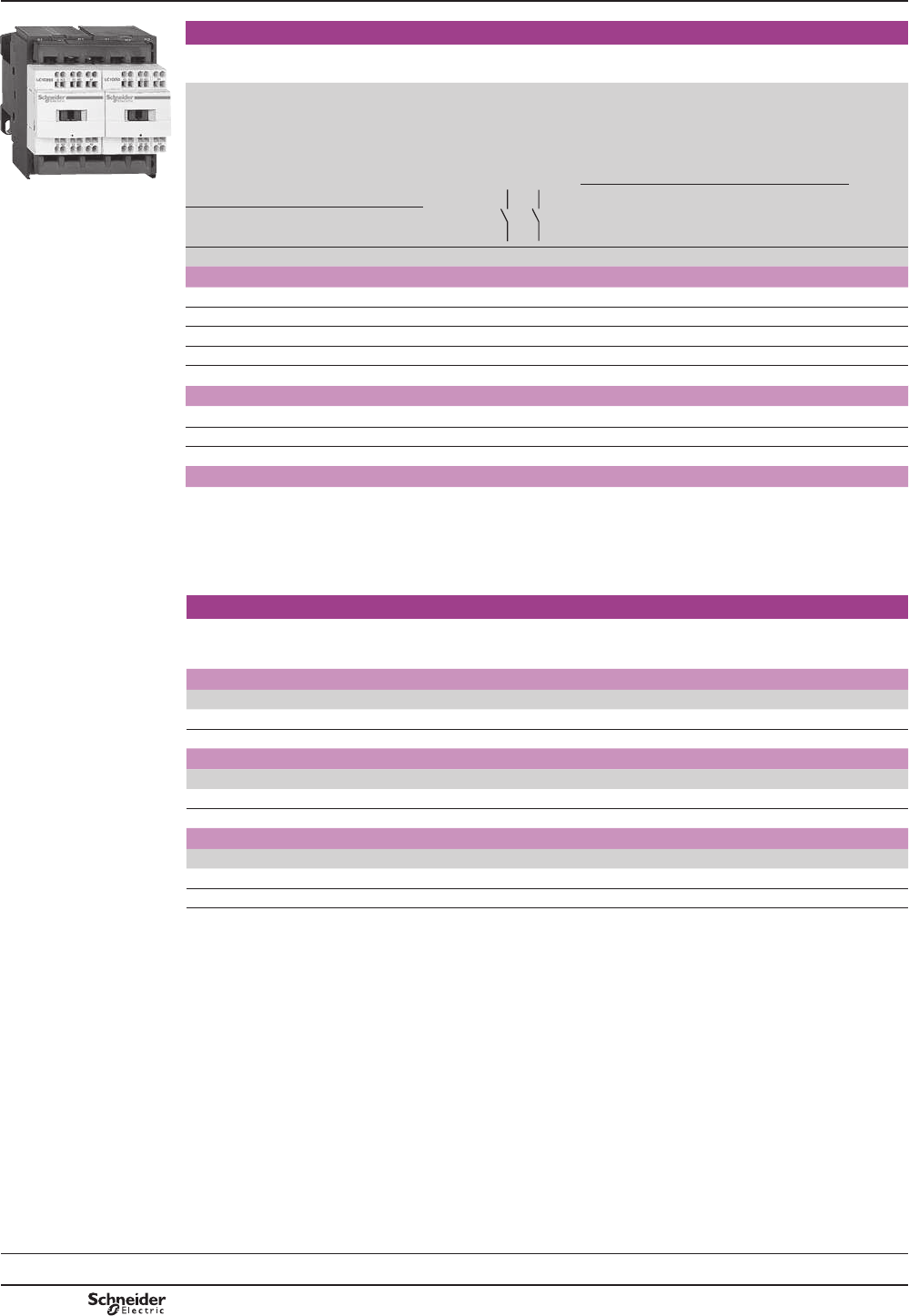
B8/10
TeSys contactors
TeSys D, 3-pole reversing contactors for motor
control up to 15 kW at 400 V, in category AC-3
Horizontally mounted, pre-assembled
Selection:
pages A5/23 to A5/47
Characteristics:
pages B8/53 to B8/58
Dimensions:
pages B8/71 and B8/72
Schemes:
pages B8/73 and B8/74
DF526174R.eps
3-pole reversing contactors, for connection by spring terminals
Pre-wired power connections.
0HFKDQLFDOLQWHUORFNZLWKRXWHOHFWULFDOLQWHUORFNLQJ
Standard power ratings
of 3-phase motors 50-60 Hz
in category AC-3
(T y 60 °C)
Rated
opera-
tional
current
in AC-3
440 V
up to
Instan-
taneous
auxiliary
contacts
per
contactor
Contactors supplied with coil
Basic reference,
to be completed by
adding the voltage code (2)
Weight
(3)
LC2 D123pp
Fixing (1)
220 V
230 V
380 V
400 V
415 V 440 V 500 V 660 V
690 V
kW kW kW kW kW kW A kg
For connection by spring terminals
2.2 4 4 4 5.5 5.5 9 1 1 LC2D093pp 0.687
3 5.5 5.5 5.5 7.5 7.5 12 1 1 LC2D123pp 0.697
4 7.5 9 9 10 10 18 1 1 LC2D183pp 0.707
5.5 11 11 11 15 15 25 1 1 LC2D253pp 0.787
7.5 15 15 15 18.5 18.5 32 (4) 1 1 LC2D323pp 0.797
Power connection by EverLink
®
, BTR screw connectors
(5)
and control by spring terminals
11 18.5 22 22 22 30 40 1 1 LC2D40A3pp
(6) 1.870
15 22 25 30 30 33 50 1 1 LC2D50A3pp (6) 1.880
18.5 30 37 37 37 37 65 1 1 LC2D65A3pp (6) 1.890
For connection by Faston connectors
All power connections are to be made by the customer.
7KHVHFRQWDFWRUVDUH¿WWHGZLWK)DVWRQFRQQHFWRUV[PPRQWKHSRZHUSROHVDQG[PPRQWKH
coil terminals.
)RUUHYHUVLQJFRQWDFWRUV/&'DQG/&'RQO\LQWKHUHIHUHQFHVVHOHFWHGDERYHUHSODFHWKH¿JXUH3
EHIRUHWKHYROWDJHFRGHZLWKD¿JXUH9.
Example: LC2 D093pp becomes LC2 D099pp.
Component parts
Auxiliary contact blocks and add-on modules: see pages B8/15 to B8/21.
(1) LC2 D09 to D32: clip-on mounting on 35 mm 5 rail AM1 DPRUVFUHZ¿[LQJ
(2)6WDQGDUGFRQWUROFLUFXLWYROWDJHVIRURWKHUYROWDJHVSOHDVHFRQVXOW\RXU5HJLRQDO6DOHV2I¿FH
a.c. supply
Volts 24 42 48 110 115 220 230 240 380 400 415 440 500
LC2 D09…D65A
50/60 Hz B7 D7 E7 F7 FE7 M7 P7 U7 Q7 V7 N7 R7 S7
d.c. supply
Volts 12 24 36 48 60 72 110 125 220 250 440
LC2 D09…D65A FRLOVZLWKLQWHJUDOVXSSUHVVLRQGHYLFH¿WWHGDVVWDQGDUG
U 0.75…1.25 Uc JD BD CD ED ND SD FD GD MD UD RD
Low consumption
Volts c 5 12 20 24 48 110 220 250
LC2 D09...D38 FRLOVZLWKLQWHJUDOVXSSUHVVLRQGHYLFH¿WWHGDVVWDQGDUG
U 0.8…1.25 Uc AL JL ZL BL EL FL ML UL
)RURWKHUYROWDJHVEHWZHHQDQG9VHHSDJHV%WR%
(3)7KHZHLJKWVLQGLFDWHGDUHIRUUHYHUVLQJFRQWDFWRUVZLWKDFFRQWUROFLUFXLW)RUGFRUORZFRQVXPSWLRQFRQWUROFLUFXLWDGG
NJIRULC2 D09 to D38NJIRULC1 D40A to D65A
(4)0XVWEHZLUHGZLWK[PP2FDEOHVLQSDUDOOHORQWKHXSVWUHDPVLGH2QWKHGRZQVWUHDPVLGHRXWJRLQJWHUPLQDOEORFN
LAD 331PD\EHXVHG4XLFN¿WWHFKQRORJ\VHHSDJH%:KHQZLUHGZLWKDVLQJOHFDEOHWKHSURGXFWLVOLPLWHGWR$
N:9PRWRUV
(5)%75VFUHZVKH[DJRQVRFNHWKHDG,QDFFRUGDQFHZLWKORFDOHOHFWULFDOZLULQJUHJXODWLRQVDVL]HLQVXODWHG$OOHQNH\PXVWEH
used (reference LAD ALLEN4, see page B8/21
(6))RUORZFRQVXPSWLRQNLWLA4 DBLVHHSDJH%
Reference
TeSys D
PCPB08P20-EN
Version : 1.0 19 novembre 2014 10:37 AM
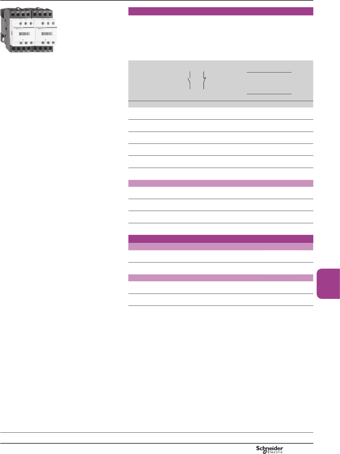
B8/11
Contactors
PF526176R.eps
LC2 DT20pp
Pre-assembled. Pre-wired power connections
For connection by screw clamp terminals or connectors
/&'7WR/&'7PHFKDQLFDOLQWHUORFNZLWKRXWHOHFWULFDOLQWHUORFNLQJ
/&'RUGHUVHSDUDWHO\DX[LOLDU\FRQWDFWEORFNV/$'1p1 to obtain
HOHFWULFDOLQWHUORFNLQJEHWZHHQWKHFRQWDFWRUVVHHSDJH%
)RUHOHFWULFDOLQWHUORFNLQJLQFRUSRUDWHGLQWKHPHFKDQLFDOLQWHUORFNSOHDVHFRQVXOW
\RXU5HJLRQDO6DOHV2I¿FH
/&'PHFKDQLFDOLQWHUORFNZLWKLQWHJUDOSUHZLUHGHOHFWULFDOLQWHUORFNLQJ
Utilisation category AC-1
Non-inductive loads
Maximum rated
operational current
(T y 60 °C)
Instantaneous auxiliary
contacts per contactor
Contactors supplied
with coil
Weight
Basic reference, to
be completed
by adding the
voltage code (1)
Fixing (2)
A kg
20 1 1 LC2DT20pp 0.730
25 1 1 LC2DT25pp 0.730
32 1 1 LC2DT32pp 0.850
40 1 1 LC2DT40pp 0.850
125 – – LC2D80004pp 3.200
200 – – LC2D115004pp 7.400
For connection by lugs or bars
20 1 1 LC2DT206pp 0.730
25 1 1 LC2DT256pp 0.730
32 1 1 LC2DT326pp 0.850
40 1 1 LC2DT406pp 0.850
For customer assembly
For connection by screw clamp terminals or connectors
60 1 1 LC1DT60App (3) –
80 1 1 LC1DT80App (3) –
For connection by lugs or bars
60 1 1 LC1DT60A6pp (3) –
80 1 1 LC1DT80A6pp (3) –
Auxiliary contact blocks and add-on modules: see pages B8/15 to B8/21.
Note: when assembling changeover contactor pairs, it is good practice to incorporate a 50 ms
WLPHGHOD\
(1) See note (1)RQQH[WSDJH
(2) LC2 DT20 to LC2 DT80: clip-on mounting on 35 mm 5 rail AM1 DPRUVFUHZ¿[LQJ
LC2 D80: clip-on mounting on 35 mm 5 rail AM1 DP or 75 mm 5 rail AM1 DL or screw
¿[LQJ
LC2 D115FOLSRQPRXQWLQJRQ[PP5 rails AM1 DPRUVFUHZ¿[LQJ
(3))RUWKHVHRSHUDWLRQDOFXUUHQWVRUGHULGHQWLFDOFRQWDFWRUVDQGDPHFKDQLFDOLQWHUORFN
LAD 4CMVHHSDJH%
References TeSys contactors
TeSys D, 4-pole changeover contactor
pairs for control in category AC-1,
20 to 200 A
Selection:
pages A5/23 to A5/47
Characteristics:
pages B8/53 to B8/58
Dimensions:
pages B8/71 and B8/72
Schemes:
pages B8/73 and B8/74
TeSys D
PCPB08P20-EN Version : 1.0 19 novembre 2014 10:37 AM
B8/12
Pre-assembled. Pre-wired power connections
For connection by spring terminals.
Utilisation category AC-1
Non-inductive loads
Maximum rated
operational current
(T y 60 °C)
Instantaneous auxiliary
contacts per contactor
Contactors
supplied with coil
Basic reference, to
be completed by
adding the control
voltage code (1)
Fixing (2)
A
20 1 1 LC2DT203pp
For customer assembly
Power connection by EverLink
®
, BTR screw connectors
(3)
and control
by spring terminals
60 1 1 LC1DT60A3pp (4)
80 1 1 LC1DT80A3pp (4)
Separate components
Auxiliary contact blocks and add-on modules: see pages B8/15 to B8/21.
(1) Standard control circuit voltages (for other voltages, please consult your Regional Sales
2I¿FH
a.c. supply
Volts 24 42 48 110 115 220 230 240 380 400 415 440 500
LC2 DT20…DT40, LC1 DT60…DT80
50/60 Hz B7 D7 E7 F7 FE7 M7 P7 U7 Q7 V7 N7 R7 –
LC2 D80004…D115004
50 Hz B5 D5 E5 F5 FE5 M5 P5 U5 Q5 V5 N5 R5 S5
60 Hz B6 – E6 F6 – M6 – U6 Q6 – – R6 –
d.c. supply
Volts 12 24 36 48 60 72 110 125 220 250 440
LC2 DT20…DT40, LC1 DT60…DT80 FRLOVZLWKLQWHJUDOVXSSUHVVLRQGHYLFH¿WWHGDVVWDQGDUG
U 0.7…1.25 Uc JD BD CD ED ND SD FD GD MD UD RD
Low consumption
Volts c 5 12 20 24 48 110 220 250
LC2 DT20...DT40 FRLOVZLWKLQWHJUDOVXSSUHVVLRQGHYLFH¿WWHGDVVWDQGDUG
U 0.8…1.25 Uc AL JL ZL BL EL FL ML UL
)RURWKHUYROWDJHVEHWZHHQDQG9VHHSDJHV%WR%
(2) Clip-on mounting on 35 mm 5 rail AM1 DPRUVFUHZ¿[LQJ
(3)%75VFUHZVKH[DJRQVRFNHWKHDG,QDFFRUGDQFHZLWKORFDOHOHFWULFDOZLULQJUHJXODWLRQV
DVL]HLQVXODWHG$OOHQNH\PXVWEHXVHGUHIHUHQFHLAD ALLEN4VHHSDJH%
(4))RUWKHVHRSHUDWLRQDOFXUUHQWVRUGHULGHQWLFDOFRQWDFWRUVDQGDPHFKDQLFDOLQWHUORFN
LAD 4CMVHHSDJH%
TeSys contactors
TeSys D, 4-pole changeover contactor
pairs for control in category AC-1, 20 A
Reference
TeSys D
Selection:
pages A5/23 to A5/47
Characteristics:
pages B8/53 to B8/58
Dimensions:
pages B8/71 and B8/72
Schemes:
pages B8/73 and B8/74
PCPB08P20-EN
Version : 1.0 19 novembre 2014 10:37 AM
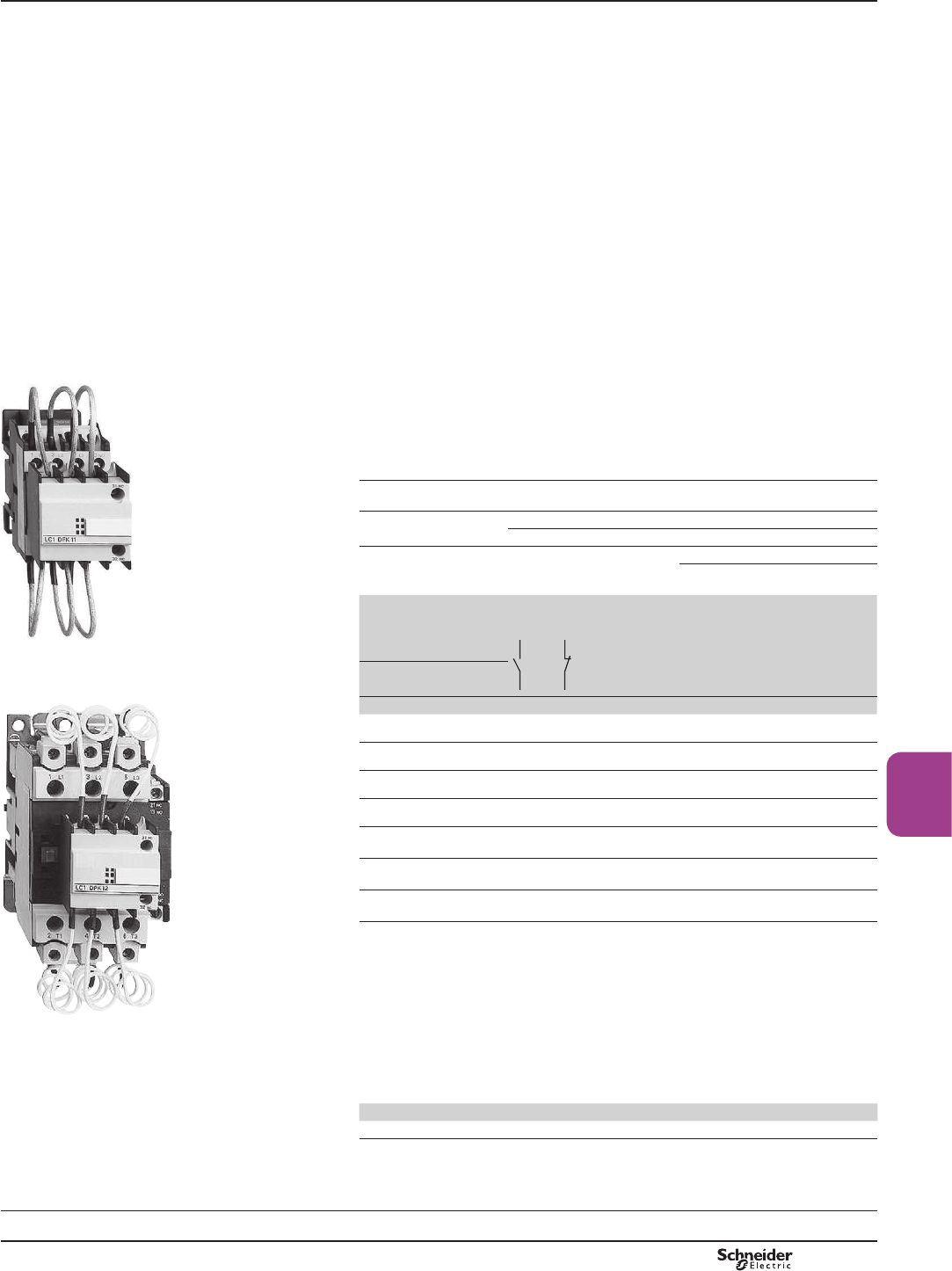
B8/13
Contactors
TeSys contactors
For switching 3-phase capacitor banks,
used for power factor correction
'LUHFWFRQQHFWLRQZLWKRXWFKRNHLQGXFWRUV
PF511555.eps
Special contactors
Special contactors LC1 DpK are designed for switching 3-phase, single or
PXOWLSOHVWHSFDSDFLWRUEDQNVXSWRVWHSV2YHUVWHSVLWLVUHFRPPDQGHG
WRXVHFKRNHVLQRUGHUWROLPLWWKHLQUXVKFXUUHQWDQGWKXVLPSURYHWKHOLIHWLPH
of the installation. The contactors are conform to standards IEC 60070 and 60831,
UL and CSA.
Contactor applications
6SHFL¿FDWLRQ
&RQWDFWRUV¿WWHGZLWKDEORFNRIHDUO\PDNHSROHVDQGGDPSLQJUHVLVWRUVOLPLWLQJ
WKHYDOXHRIWKHFXUUHQWRQFORVLQJWR,QPD[
7KLVFXUUHQWOLPLWDWLRQLQFUHDVHVWKHOLIHRIDOOWKHFRPSRQHQWVRIWKHLQVWDOODWLRQ
LQSDUWLFXODUWKDWRIWKHIXVHVDQGFDSDFLWRUV
7KHSDWHQWHGGHVLJQRIWKHDGGRQEORFNQHQVXUHVVDIHW\DQGORQJOLIH
of the installation.
Operating conditions
7KHUHLVQRQHHGWRXVHFKRNHLQGXFWRUVIRUHLWKHUVLQJOHRUPXOWLSOHVWHSFDSDFLWRU
EDQNV6KRUWFLUFXLWSURWHFWLRQPXVWEHSURYLGHGE\J,W\SHIXVHVUDWHGDW«
In.
Maximum operational power
The power values given in the selection table below are for the following
operating conditions:
3URVSHFWLYHSHDNFXUUHQW
at switch-on
LC1 DpK 200 In
0D[LPXPRSHUDWLQJUDWH LC1 DFK, DGK, DLK, DMK, DPK RSHUDWLQJF\FOHVKRXU
LC1 DTK, DWK RSHUDWLQJF\FOHVKRXU
(OHFWULFDOGXUDELOLW\DW
nominal load
All contactor ratings 400 V RSHUDWLQJF\FOHV
690 V RSHUDWLQJF\FOHV
Operational power
at 50/60 Hz (1)
Ty 55 °C (2)
Instantaneous
auxiliary
contacts
Tightening
torque on
cable end
Basic reference,
to be completed
by adding
the voltage code (3)
Weight
LC1 DFK11pp
220 V 400 V 660 V
240 V 440 V 690 V
PF511556.eps
kVAR kVAR kVAR N/O N/C N.m kg
6.7 12.5 18 1 2 1.7
LC1DFK
pp 0.430
8.5 16.7 24 1 2 1.7
LC1DGK
pp 0.450
10 20 30 1 2 2.5
LC1DLK
pp 0.600
15 25 36 1 2 2.5
LC1DMK
pp 0.630
20 33.3 48 1 2 5
LC1DPK
pp 1.300
25 40 58 1 2 5
LC1DTK
pp 1.300
40 60 92 1 2 9
LC1DWK12
pp 1.650
Switching of multiple-step capacitor banks ZLWKHTXDORUGLIIHUHQWSRZHUUDWLQJV
The correct contactor for each step is selected from the above table, according to the power
rating of the step to be switched.
Example: N9$5VWHSFDSDFLWRUEDQN7HPSHUDWXUH&DQG8 9RU9
2QHN9$5VWHSFRQWDFWRU/&'0.RQHN9$5VWHSFRQWDFWRU/&'*.
DQGRQHN9$5VWHSFRQWDFWRU/&').
LC1 DPK12pp (1)2SHUDWLRQDOSRZHURIWKHFRQWDFWRUDFFRUGLQJWRWKHVFKHPHRQWKHSDJHRSSRVLWH
(2)7KHDYHUDJHWHPSHUDWXUHRYHUDKRXUSHULRGLQDFFRUGDQFHZLWKVWDQGDUGV,(&
DQGLV&
(3) Standard control circuit voltages (the delivery time is variable, please consult your Regional
6DOHV2I¿FH
Volts 24 48 120 220 230 240 380 400 415 440
50/60 Hz B7 E7 G7 M7 P7 U7 Q7 V7 N7 R7
References
TeSys D
Dimensions, schemes:
page B8/75
PCPB08P20-EN Version : 1.0 19 novembre 2014 10:37 AM
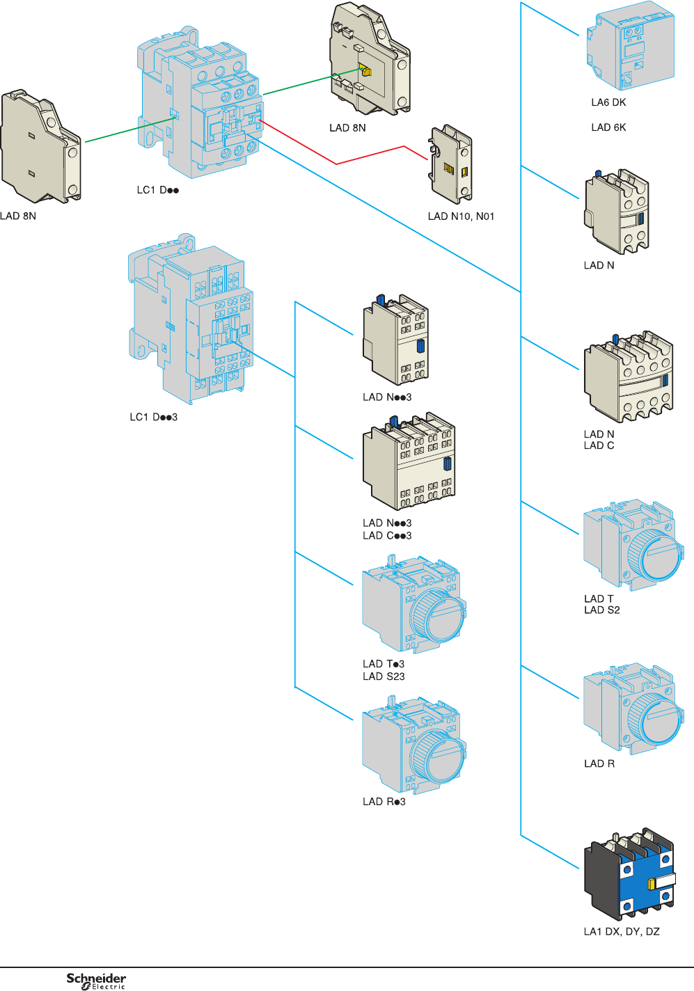
B8/14
DB127250.eps
6HHSDJHRSSRVLWHIRUPRXQWLQJSRVVLELOLWLHV
DFFRUGLQJWRWKHFRQWDFWRUW\SH
or
PCPB08P20-EN
Version : 1.0 19 novembre 2014 10:37 AM
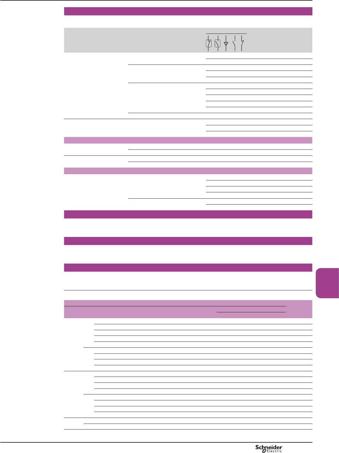
B8/15
Contactors
Instantaneous auxiliary contact blocks for connection by screw clamp terminals
For use in normal operating environments
,QRUGHUWRPRXQWDQ/$'1RQDQ/&'WR'DVHWRIVKLPVPXVWEHRUGHUHGVHSDUDWHO\VHHSDJH%
Clip-on mounting
(1)
Number of
contacts per block
Composition Reference
Front 1 – – – 1 – LADN10
– – – – 1 LADN01
2 – – – 1 1 LADN11
– – – 2 – LADN20
– – – – 2 LADN02
4 – – – 2 2 LADN22
– – – 1 3 LADN13
– – – 4 – LADN40
– – – – 4 LADN04
– – – 3 1 LADN31
LQFO121&PDNHEHIRUHEUHDN – – – 2 2 LADC22
Side
FRQWDFWEORFNVFRPSDWLEOHZLWK
$&FRLOFRQWDFWRUVRQO\
2 – – – 1 1 LAD8N11
– – – 2 – LAD8N20
– – – – 2 LAD8N02
For terminal referencing conforming to EN 50012
Front on 3P contactors and
4P contactors 20 to 80 A
2 – – – 1 1 LADN11G
4 – – – 2 2 LADN22G
Front on 4P contactors
125 to 200 A
2 – – – 1 1 LADN11P
4 – – – 2 2 LADN22P
With dust and damp protected contacts, for use in particularly harsh industrial environments
Front 2 – 2 – – – LA1DX20
1 1 – – – LA1DX11
2 – – – – LA1DX02
– 2 2 – – LA1DY20 (2)
4 – 2 – 2 – LA1DZ40
– 2 – 1 1 LA1DZ31
Instantaneous auxiliary contact blocks for connection by lugs
7KLVW\SHRIFRQQHFWLRQLVQRWSRVVLEOHIRUEORFNVZLWKFRQWDFWRUEORFNVZLWKGXVWDQGGDPSSURWHFWHG
FRQWDFWV)RUDOORWKHULQVWDQWDQHRXVDX[LOLDU\FRQWDFWEORFNVDGGWKH¿JXUH6 to the end of the references
selected above. Example: LAD N11 becomes LAD N116.
Instantaneous auxiliary contact blocks for connection by spring terminals
7KLVW\SHRIFRQQHFWLRQLVQRWSRVVLEOHIRU/$'/$'1ZLWKFRQWDFWRUEORFNVZLWKGXVWDQGGDPSSURWHFWHG
FRQWDFWV)RUDOORWKHUFRQWDFWEORFNVDGGWKH¿JXUH3 to the end of the references selected above.
Example: LAD N11 becomes LAD N113.
Instantaneous auxiliary contact blocks for connection by Faston connectors
7KLVW\SHRIFRQQHFWLRQLVQRWSRVVLEOHIRU/$'/$'1ZLWKFRQWDFWRUEORFNVZLWKGXVWDQGGDPSSURWHFWHG
FRQWDFWV)RUDOORWKHUFRQWDFWEORFNVDGGWKH¿JXUH9 to the end of the references selected above.
Example: LAD N11 becomes LAD N119.
(1)0D[LPXPQXPEHURIDX[LOLDU\FRQWDFWVWKDWFDQEH¿WWHG
Contactors Instantaneous auxiliary contacts Time delay
Front
mounted
Type Number of poles and size Side mounted Front mounted
1 contact 2 contacts 4 contacts
a3P LC1 D09…D38 1 on LH side and – 1 or 1 or 1
LC1 D40A…D65A 1 on LH or 1 on RH side and – 1 or 1 or 1
/&'DQG'+] 1 on each side or 2 and 1 or 1 or 1
/&'DQG'RU+] 1 on each side and 2 and 1 or 1 or 1
LC1 D115 and D150 1 on LH side and – 1 or 1 or 1
4P LC1 DT20…DT40 1 on LH side and – 1 or 1 or 1
LC1 DT60A and DT80A 1 on LH or 1 on RH side and – 1 or 1 or 1
LC1 D40008, D65008 and D80 1 on each side or 1 or 1 or 1 or 1
LC1 D115 1 on each side and 1 or 1 or 1 or 1
c3P LC1 D09…D38 – – 1 or 1 or 1
LC1 D40A…D65A – – 1 or 1 or 1
LC1 D80 and D95 – 1 or 1 or 1 or 1
LC1 D115 and D150 1 on LH side and – 1 or 1 or 1
4P LC1 DT20…DT40 – – 1 or 1 or 1
LC1 DT60A and DT80A – – 1 or 1 or 1
LC1 D40008, D65008 and D80 – 2 and 1 or 1 or 1
LC1 D115 1 on each side – and 1 or 1 or 1
BC (3) 3P LC1 D09…D38 – – 1 – –
4P LC1 DT20…DT40 – – 1 – –
(2) 'HYLFH¿WWHGZLWKHDUWKVFUHHQFRQWLQXLW\WHUPLQDOV
(3)/&ORZFRQVXPSWLRQ
References TeSys contactors
TeSys D contactors and reversing
contactors
Instantaneous auxiliary contact blocks
PCPB08P20-EN Version : 1.0 19 novembre 2014 10:37 AM
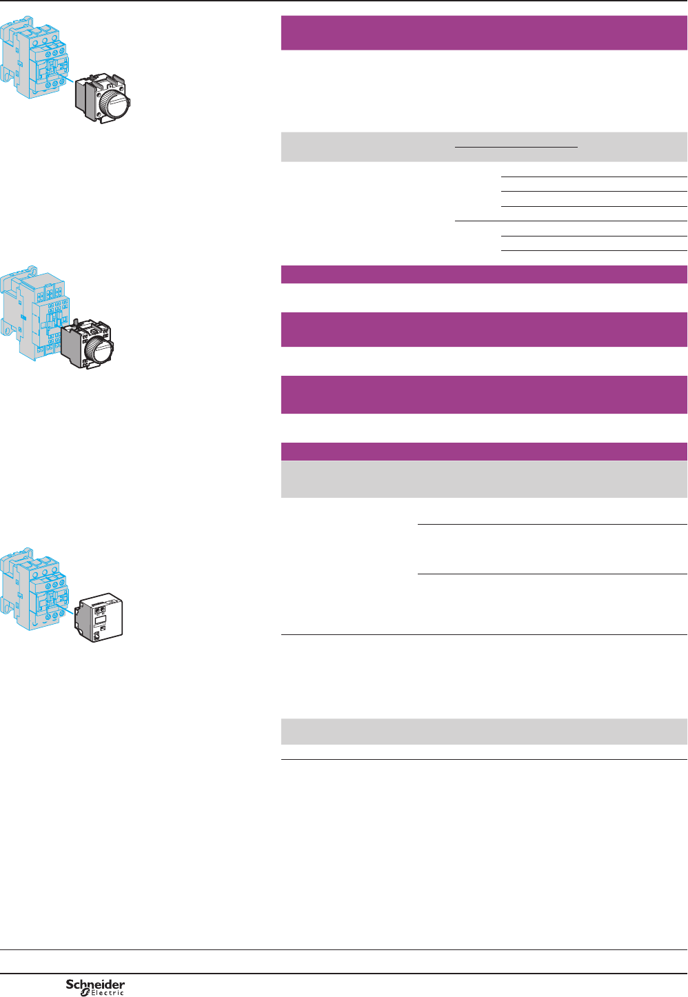
B8/16
DF537783.eps
Time delay auxiliary contact blocks for connection by screw
clamp terminals
0D[LPXPQXPEHURIDX[LOLDU\FRQWDFWEORFNVWKDWFDQEH¿WWHGSHUFRQWDFWRUVHH
page B8/15.
6HDOLQJFRYHUWREHRUGHUHGVHSDUDWHO\VHHSDJH%
LAD T0 and LAD R0: with extended scale from 0.1 to 0.6 s.
LAD S2: with switching time of 40 ms ± 15 ms between opening of the N/C contact
DQGFORVLQJRIWKH12FRQWDFW
LAD TpClip-on mounting Number
of contacts
Time delay Reference
Type Setting range
Front 121& 2QGHOD\ 0.1…3 s LADT0
0.1…30 s LADT2
10…180 s LADT4
1…30 s LADS2
2IIGHOD\ 0.1…3 s LADR0
0.1…30 s LADR2
10…180 s LADR4
DF537785.eps
Time delay auxiliary contact blocks for connection by lugs
$GGWKH¿JXUH6 to the end of the references selected above. Example: LAD T0
becomes LAD T06.
Time delay auxiliary contact blocks for connection by spring
terminals
$GGWKH¿JXUH3 to the end of the references selected above. Example: LAD T0
becomes LAD T03.
LAD Tp3Time delay auxiliary contact blocks for connection by Faston
connectors
$GGWKH¿JXUH9 to the end of the references selected above. Example: LAD T0
becomes LAD T09.
Mechanical latch blocks (1)
Clip-on
mounting
Unlatching
control
For use on
contactor
Basic reference,
to be completed by adding
the control voltage code (2)
Front 0DQXDORU
electric
LC1 D09…D38 (a or c(3)
LC1 DT20…DT40 (a or c
LAD6K10p
LC1 D40A…D65A
(3 P a or c
LC1 DT60A and DT80A
(4 P a or c
LAD6K10p
LC1 D80…D150 (3 P a
LC1 D80 and D115 (3 P c
LC1 D80 (4 P a
LC1 D80 and D115 (4 P a
LP1 D80 and LC1 D115 (4 P c
LA6DK20p
(1)7KHPHFKDQLFDOODWFKEORFNPXVWQRWEHSRZHUHGXSDWWKHVDPHWLPHDVWKHFRQWDFWRU
7KHGXUDWLRQRIWKHFRQWUROVLJQDOIRUWKHPHFKDQLFDOODWFKEORFNDQGWKHFRQWDFWRUVKRXOGEH
uPVIRUDFRQWDFWRURSHUDWLQJRQDQDFVXSSO\
uPVIRUDFRQWDFWRURSHUDWLQJRQDGFVXSSO\
0D[LPXPLPSXOVHGXUDWLRQIRUWKH/$'.p PHFKDQLFDOODWFKEORFNVHFRQGV
(2) Standard control circuit voltages (for other voltages, please consult your Regional Sales
2I¿FH
DF537784.eps
LAD 6K10p
Volts 50/60 Hz,
c24 32/36 42/48 60/72 100 110/127 220/240 256/277 380/415
Code B C E EN K F M U Q
(3) The DC, low consumption contactors ( coil code p/DUHQRWFRPSDWLEOHZLWKWKHPHFKDQLFDO
ODWFKEORFNV/$'.p
References
Characteristics:
pages B8/59 to B8/61
Dimensions:
pages B8/65 to B8/68
Schemes:
pages B8/69 and B8/70
TeSys contactors
TeSys D contactors and reversing
contactors
Time delay auxiliary contact blocks
Mechanical latch blocks
TeSys D
PCPB08P20-EN
Version : 1.0 19 novembre 2014 10:37 AM
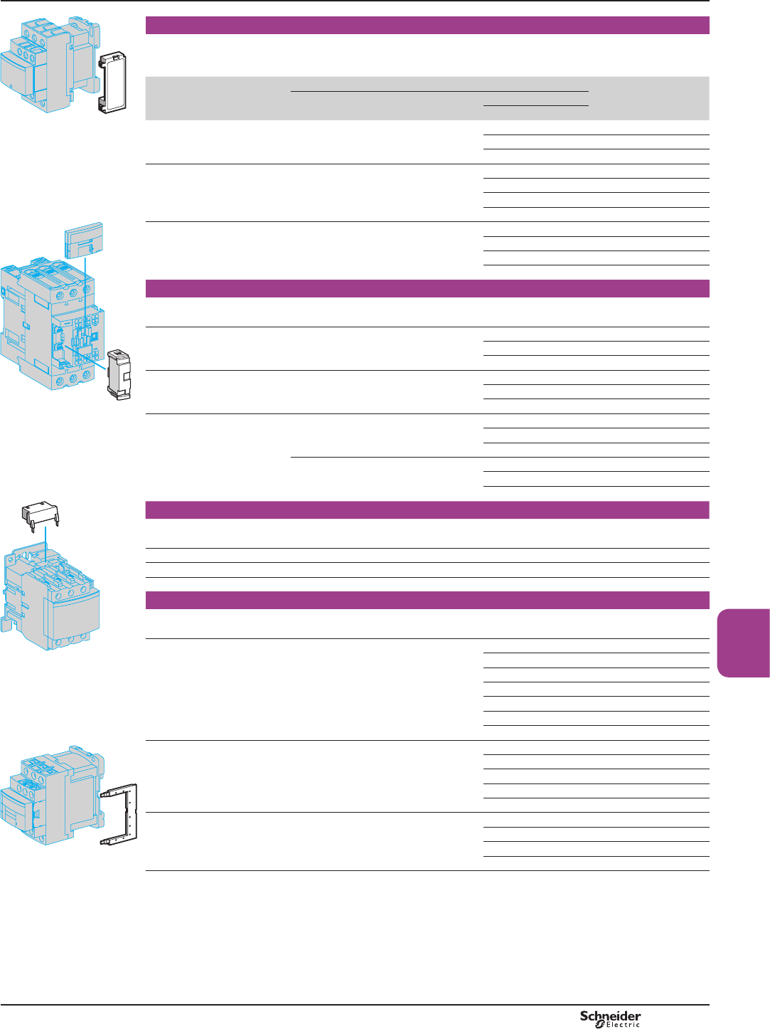
B8/17
Contactors
DF537787.eps
RC circuits (Resistor-Capacitor)
(IIHFWLYHSURWHFWLRQIRUFLUFXLWVKLJKO\VHQVLWLYHWRKLJKIUHTXHQF\LQWHUIHUHQFH)RUXVHRQO\LQFDVHVZKHUH
WKHYROWDJHLVYLUWXDOO\VLQXVRLGDOLHOHVVWKDQWRWDOKDUPRQLFGLVWRUWLRQ9ROWDJHOLPLWHGWR8FPD[DQG
RVFLOODWLQJIUHTXHQF\OLPLWHGWR+]PD[6OLJKWLQFUHDVHLQGURSRXWWLPHWRWLPHVWKHQRUPDOWLPH
Mounting For use with contactor (1) Reference
Rating Type
V aV c
/$'pp &OLSRQVLGHPRXQWLQJ(3) '«'3
DT20…DT40
24…48 – LAD4RCE
50…127 – LAD4RCG
110…250 – LAD4RCU
&OLSRQIURQWPRXQWLQJ (3) '$«'$3
'7$«'7$3
24…48 – LAD4RC3E
50…127 – LAD4RC3G
110…240 – LAD4RC3U
380…415 – LAD4RC3N
DF537788.eps
6FUHZ¿[LQJ (4) '«'3
'«'3
24…48 – LA4DA2E
50…127 – LA4DA2G
110…240 – LA4DA2U
380…415 – LA4DA2N
Varistors (peak limiting)
3URWHFWLRQSURYLGHGE\OLPLWLQJWKHWUDQVLHQWYROWDJHWR8FPD[0D[LPXPUHGXFWLRQRIWUDQVLHQWYROWDJH
SHDNV6OLJKWLQFUHDVHLQGURSRXWWLPHWRWLPHVWKHQRUPDOWLPH
&OLSRQVLGHPRXQWLQJ(3) '«'3
DT20…DT40
24…48 – LAD4VE
50…127 – LAD4VG
110…250 – LAD4VU
&OLSRQIURQWPRXQWLQJ (3) '$«'$3
'7$«'7$3
24…48 24…48 LAD4V3E
50…127 50…127 LAD4V3G
110…250 110…250 LAD4V3U
6FUHZ¿[LQJ (4) '«'3
'«'3
24…48 – LA4DE2E
50…127 – LA4DE2G
110…250 – LA4DE2U
'«'3
'3
– 24…48 LA4DE3E
– 50…127 LA4DE3G
– 110…250 LA4DE3U
/$'5&p/$'9p,
/$''8/$'7p
DF537789.eps
Flywheel diodes
1RRYHUYROWDJHRURVFLOODWLQJIUHTXHQF\,QFUHDVHLQGURSRXWWLPHWRWLPHVWKHQRUPDOWLPH
Polarised component.
&OLSRQVLGHPRXQWLQJ(5) '«'3'7«'7 – 24…250 LAD4DDL
&OLSRQIURQWPRXQWLQJ (5) '$«'$3'7$«'7$3 – 24…250 LAD4D3U
6FUHZ¿[LQJ(4) 'DQG'3'«'3 – 24…250 LA4DC3U
Bidirectional peak limiting diodes
3URWHFWLRQSURYLGHGE\OLPLWLQJWKHWUDQVLHQWYROWDJHWR8FPD[
0D[LPXPUHGXFWLRQRIWUDQVLHQWYROWDJHSHDNV
&OLSRQVLGHPRXQWLQJ(3) (5) '«'3
'7«'73(2)
24 – LAD4TB
– 24 LAD4TBDL
72 – LAD4TS
– 72 LAD4TSDL
– 125 LAD4TGDL
– 250 LAD4TUDL
– 600 LAD4TXDL
&OLSRQIURQWPRXQWLQJ (3) '$«'$3
'7$«'7$3 (2)
12…24 12…24 LAD4T3B
25…72 25…72 LAD4T3S
73…125 73…125 LAD4T3G
126…250 126…250 LAD4T3U
251…440 251…440 LAD4T3R
6FUHZ¿[LQJ (4) '«'3
'«'3
12…24 12…24 LA4DB2B
25…72 25…72 LA4DB2S
– 24 LA4DB3B
– 72 LA4DB3S
(1) )RUVDWLVIDFWRU\SURWHFWLRQDVXSSUHVVRUPRGXOHPXVWEH¿WWHGDFURVVWKHFRLORIHDFKFRQWDFWRU
(2) )URP'WR'$DQGIURP/&'7WR'7$GFDQGORZFRQVXPSWLRQSROHFRQWDFWRUVDUH¿WWHGZLWKDEXLOWLQ
ELGLUHFWLRQDOSHDNOLPLWLQJGLRGHVXSSUHVVRUDVVWDQGDUG7KLVELGLUHFWLRQDOSHDNOLPLWLQJGLRGHLVUHPRYDEOHDQGFDQWKHUHIRUH
EHUHSODFHGE\WKHXVHU6HHUHIHUHQFHDERYH,IDGFRUORZFRQVXPSWLRQFRQWDFWRULVXVHGZLWKRXWVXSSUHVVLRQWKH
VWDQGDUGVXSSUHVVRUVKRXOGEHUHSODFHGZLWKDEODQNLQJSOXJUHIHUHQFHLAD 9DLIRU/&'WR'DQG/&'7WR'7
reference LAD 9DL3IRU/&'$WR'$DQG/&'7$WR'7$
(3) &OLSSLQJRQPDNHVWKHHOHFWULFDOFRQQHFWLRQ7KHRYHUDOOVL]HRIWKHFRQWDFWRUUHPDLQVXQFKDQJHG
(4)0RXQWLQJDWWKHWRSRIWKHFRQWDFWRURQFRLOWHUPLQDOV$DQG$
(5),QRUGHUWRLQVWDOOWKHVHDFFHVVRULHVWKHH[LVWLQJVXSSUHVVLRQGHYLFHPXVW¿UVWEHUHPRYHG
/$'pp
DF537790.eps
/$'''/RU/$'7pDL
TeSys contactors
TeSys D contactors and reversing
contactors
Suppressor modules
TeSys D
References
PCPB08P20-EN Version : 1.0 19 novembre 2014 10:37 AM

B8/18
6HHSDJHRSSRVLWHIRUPRXQWLQJSRVVLELOLWLHV
DFFRUGLQJWRWKHFRQWDFWRUW\SH
DB127251.eps
PCPB08P20-EN
Version : 1.0 19 novembre 2014 10:37 AM
B8/19
Contactors
Electronic serial timer modules (1)
bSROHFRQWDFWRUV/&'WR'PRXQWHGXVLQJDGDSWHU/$'%%
WREHRUGHUHGVHSDUDWHO\VHHEHORZ
bSROHFRQWDFWRUV/&'$WR'$PRXQWHGXVLQJDGDSWHU/$'%%
WREHRUGHUHGVHSDUDWHO\VHHEHORZ
b3-pole contactors LC1 D80 to D150 and 4-pole contactors LC1 D40 to D115:
PRXQWHGGLUHFWO\DFURVVWHUPLQDOV$DQG$RIWKHFRQWDFWRU
On-delay type
Operational voltage aTime delay Reference
24…250 V 100…250 V
/&'«'$3 /&'«'3 0.1…2 s LA4DT0U
1.5…30 s LA4DT2U
25…500 s LA4DT4U
Interface modules
bSROHFRQWDFWRUV/&'WR'PRXQWHGXVLQJDGDSWHU/$'%%
WREHRUGHUHGVHSDUDWHO\VHHEHORZ
bSROHFRQWDFWRUV/&'$WR'$PRXQWHGXVLQJDGDSWHU/$'%%
WREHRUGHUHGVHSDUDWHO\VHHEHORZ
Relay interface
Operational voltage aSupply
voltage E1-E2 (c)
Reference
24…250 V
/&'«'3 24 V LA4DFB
Relay interface with "AUTO-I" manual override switch (output forced “ON”),
solid state type
Operational voltage aSupply
voltage
E1-E2 (c)
Reference
24…250 V 100…250 V
/&'«'$3 /&'«'3 24 V LA4DWB
Low consumption kit
For use on
contactors
Composition Reference
LC1 D40A…D65A
3(2)
Kit comprising:
bDUHWUR¿WFRLO/$'%%
bDUHOD\LQWHUIDFHPRGXOH/$')%
LA4DBL
5HWUR¿WFRLOIRUSROHFRQWDFWRU
For adapting existing wiring to a new product
For use on
contactors
Reference
LC1 D09…D38 :LWKRXWFRLOVXSSUHVVLRQ LAD4BB
:LWKFRLOVXSSUHVVLRQ a 24…48 V LAD4BBVE
a 50…127 V LAD4BBVG
a 110…250 V LAD4BBVU
LC1 D40A…65A :LWKRXWFRLOVXSSUHVVLRQ LAD4BB3
(1))RU9RSHUDWLRQWKHFRQWDFWRUPXVWEH¿WWHGZLWKD9FRLOFRGH=
6HHSDJHV%WR%
(2) 7KHNLWLVFRPSDWLEOHZLWKD coil voltage of a9WRa9%WR8DQGc9WRc
9%'WR8'
References
Characteristics:
pages B8/62 to B8/64
Dimensions:
pages B8/65 to B8/68
Schemes:
pages B8/69 and B8/70
TeSys contactors
TeSys D contactors and
reversing contactors
Accessories
TeSys D
PCPB08P20-EN Version : 1.0 19 novembre 2014 10:37 AM
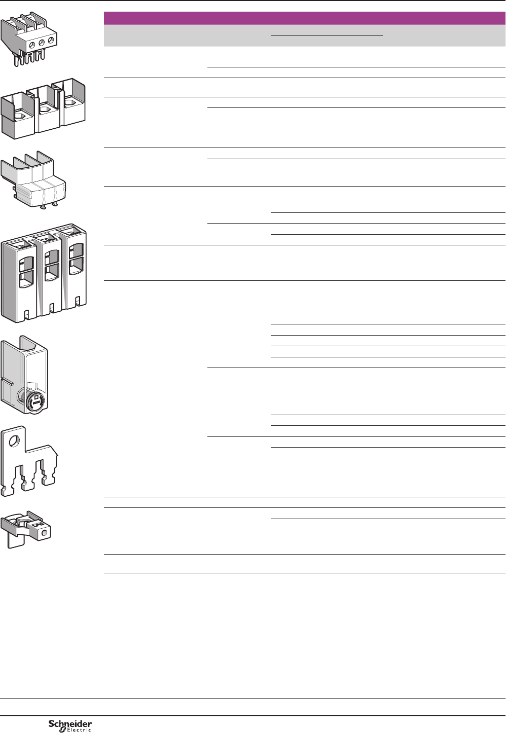
B8/20
DF537792.eps
Accessories for main pole and control connections
Description For use with contactors LC1 Sold in
lots of
Unit
reference
a c
Connectors for cable, size
FRQQHFWRU
4-pole 10 mm2DT20, DT25 DT20, DT25 1LAD92560
LA9 D3260 3-pole 25 mm2D09…D38 D09…D38 1LA9D3260
DB127252.eps
LA9 D11550p
(YHU/LQN®
WHUPLQDOEORFN
3-pole D40A…D65A D40A…D65A 1LAD96560
Connectors for cables
FRQQHFWRUV
3-pole 120 mm2D115, D150 D115, D150 1LA9D115603
4-pole 120 mm2D115 D115 1LA9D115604
DF537794.eps
Connectors for
OXJW\SHWHUPLQDOV
FRQQHFWRUV
3-pole D1156, D1506 D1156, D1506 1LA9D115503
4-pole D1156 D1156 1LA9D115504
Protective covers
for connectors for
OXJW\SHWHUPLQDOV
3-pole D40A6…D65A6 D40A6…D65A6 1LAD96570
LAD 96570 D1156, D1506 D1156, D1506 1LA9D115703 (1)
DF537795.eps
4-pole D60A6…D80A6 D60A6…D80A6 1LAD96580
D1156, D1506 D1156, D1506 1LA9D115704
,3FRYHUVIRUOXJW\SH
WHUPLQDOVIRUPRXQWLQJZLWK
FLUFXLWEUHDNHUV*93pp6
and GV3 Lpp
3 poles D40A6…D65A6 D40A6…D65A6 1LAD96575
/LQNVIRU
parallel connection of
2 poles D09…D38 D09…D38 10 LA9D2561
LA9 D11560p'7'73 '7'73 10 LA9D1261
DF537796.eps
'7'73 '7'73 10 LAD96061
D40A…D65A D40A…D65A 1LAD9P32
D80, D95 D80 2LA9D80961
3 poles D09…D38 D09…D38 10 LAD9P3 (2)
LA9 D11570pD40A…D65A D40A…D65A 1LAD9P33
DF537797.eps
D80, D95 D80, D95 1LA9D80962
4 poles DT20, DT25 DT20, DT25 2LA9D1263
D80, D95 D80 2LA9D80963
LA9 D80962 Staggered coil connection – D80 10 LA9D09966
DF537798.eps
&RQWUROFLUFXLWWDNHRII
from main pole
D80, D95 D80, D95 10 LA9D8067
D115, D150 D115, D150 10 LA9D11567
LA9 D11567 Spreaders
for increasing the pole pitch to 45 mm
D115, D150 D115, D150 3GV7AC03
(1))RUSROHFRQWDFWRUVVHWRIFRYHUVIRUSROHFRQWDFWRUVVHWRIFRYHUV
(2) 6HSDUDWHFRQQHFWLQJEDUIRUFRQQHFWLQJSROHVLQSDUDOOHO
References
Dimensions:
pages B8/65 to B8/68
Schemes:
pages B8/69 and B8/70
TeSys contactors
TeSys D contactors and
reversing contactors
Accessories
TeSys D
PCPB08P20-EN
Version : 1.0 19 novembre 2014 10:37 AM
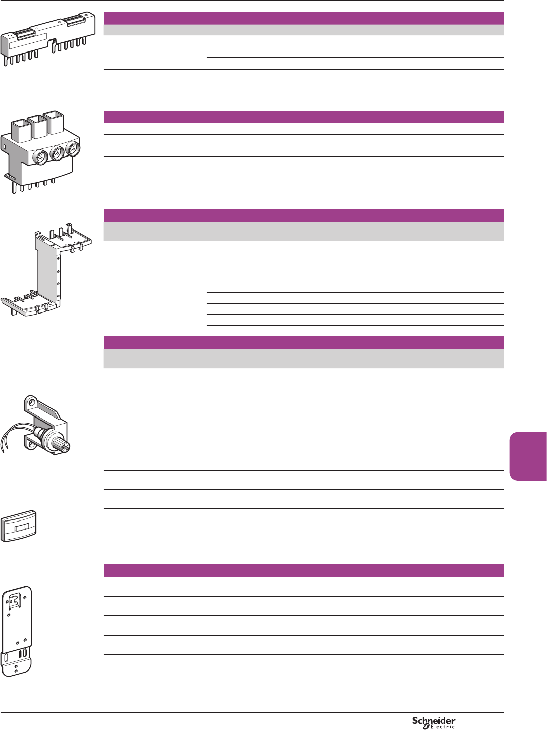
B8/21
Contactors
DF537799.eps
Sets of contacts and arc chambers
Description For contactor Reference
Sets of contacts 3-pole LC1 D115 LA5D1158031
LC1 D150 LA5D150803
4-pole LC1 D115004 LA5D115804
GV2 G245 Arc chambers 3-pole LC1 D115 LA5D11550
LC1 D150 LA5D15050
4-pole LC1 D115004 LA5D115450
DF510994.eps
Power connection accessories
Terminal block For supply to one or more GV2 G busbar sets GV1G09
Set of 63 A busbars
for parallelling of contactors
2 contactors LC1 D09…D18 or D25…D38 GV2G245
4 contactors LC1 D09…D18 or D25…D38 GV2G445
Set of 115 A busbars
for parallelling of contactors
2 contactors LC1 D40A…D65A GV3G264
3 contactors LC1 D40A…D65A GV3G364 (1)
Set of S-shape busbars For circuit breakers GV3 Ppp and GV3 Lpp
and contactors LC1 D40A…D65A
GV3S
GV1 G09
Protection accessories
Description Use Sold in
lots of
Reference
Miniature control
circuit fuse holder
5 x 20 with 4 A-250 V fuse 1LA9D941
Sealing cover For LAD T, LAD R 1LA9D901
Safety cover
preventing access to
the moving contact carrier
LC1 D09…D65A and DT20…DT80A 1LAD9ET1
Red cover (for safety chain indication) 1LAD9ET1S
LC1 D80 and D95 1LAD9ET3
Red cover (for safety chain indication) 1LAD9ET3S
LC1 D115 and D150 1LAD9ET4
Red cover (for safety chain indication) 1LAD9ET4S
DF510995.eps
Marking accessories
Description Use Sold in
lots of
Unit
reference
Sheet of 64 blank legends,
self-adhesive, 8 x 33 mm (2)
Contactors (except 4P)
LC1 D80…D115,
LAD N (4 contacts), LA6 DK
10 LAD21
Sheet of 112 blank legends,
self-adhesive, 8 x 12 mm (2)
LAD N (2 contacts),
LAD T, LAD R, LRD
10 LAD22
Sheet of 64 blank legends
for marking using plotter
or 8 x 33 mm engraver
Contactors (except 4P)
LC1 D80…D115,
LAD (4 contacts), LA6 DK
10 LAD23
Sheet of 440 blank legends
for marking using plotter
or 8 x 12 mm engraver
All products 35 LAD24
Marker holder
snap-in, 8 x 22 mm
4-pole contactors,
LC1 D80...D115, LA6 DK
100 LA9D92
Marker holder
snap-in, 8 x 18 mm
LC1 D09...D65A, LC1 DT20...DT80A,
LAD N (4 contacts), LAD T, LAD R
100 LAD90
Bag of 300 blank legends
self-adhesive, 7 x 21 mm
On holder LA9 D92 1LA9D93
“SIS Label”
labelling software
supplied on CD-Rom
Multi-language version:
English, French, German, Italian,
Spanish
1XBY2U
GV3 S
DF537802.eps
LA9 D941
DF537803.eps
LAD 9ETp
Mounting accessories
5HWUR¿WSODWH
IRUVFUHZ¿[LQJ
For replacement of LC1 D40 to D65
with LC1 D40A to D65A
1LAD7X3
Mounting plate For replacement of LC1 F115 or
F150 with LC1 D115 or D150
1LA9D730
Set of shims )RU¿WWLQJVLGHPRXQWLQJEORFNV
LAD 8N on LC1 D80 and D95
1LA9D511
Size 4 Allen key, insulated,
1000 V
For use on contactors
LC1 D40A to LC1 D150
5LADALLEN4
(1) With this set of busbars, any one contactor can be supplied directly by its EverLink® double cage power terminal block.
The other two contactors are supplied by the busbar set. The 115 A limitation is therefore applied to these two contactors.
Example: 1 LC1 D65A supplied directly + 1 contactor LC1 D65A and 1 contactor LC1 D50 A supplied via the busbar set =
115 A. This combination is compatible with busbar set GV3 G364.
(2) 7KHVHOHJHQGVDUHIRUVWLFNLQJRQWRWKHVDIHW\FRYHURIWKHFRQWDFWRUVRUDGGRQEORFNLI¿WWHG
DF537804.eps
LAD 7X3
References TeSys contactors
TeSys D contactors and
reversing contactors
Accessories
TeSys D
PCPB08P20-EN Version : 1.0 20 novembre 2014 9:17 AM
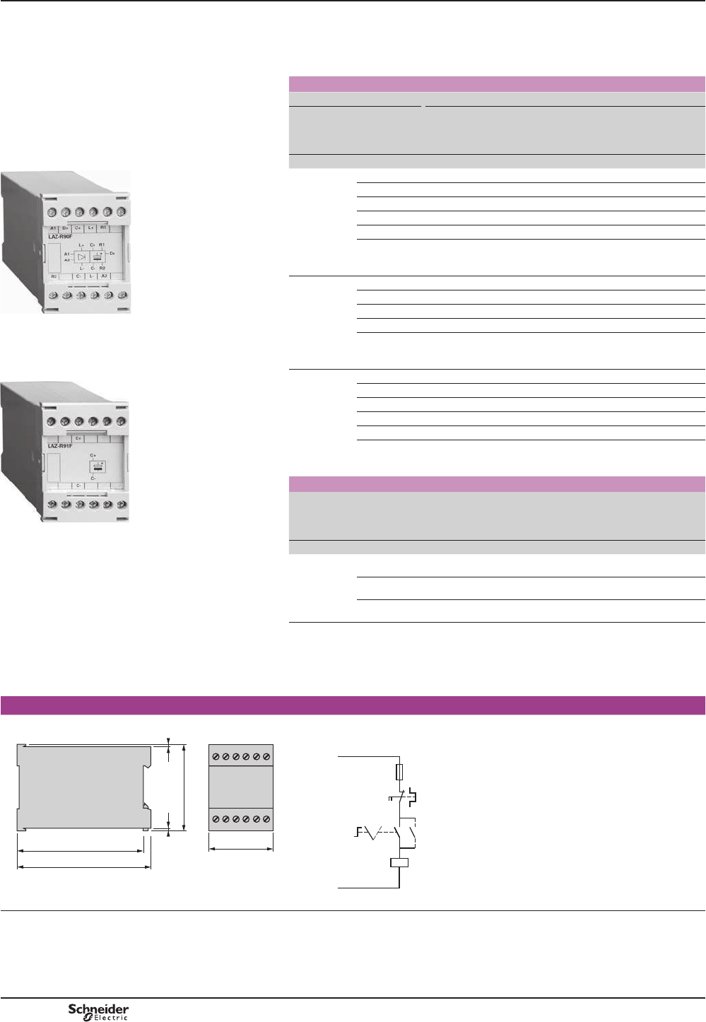
B8/22
TeSys contactors
Capacitive delayed opening devices
For TeSys D contactors
References
These devices prevent inadvertent opening of a contactor in the event of a brief volt
GURSRUPRPHQWDU\VXSSO\IDLOXUH
Control circuit: d.c. supply
For use with contactor Corresponding delayed opening device
Type (1) Contactor
reference
to be
completed (2)
Supply voltage
50/60 Hz
Non-
adjustable
delay time (Tr)
Reference
V s
LC1 D09,
LC1 D12,
LC1 D18,
LC1 D25,
LC1 D32
or
LC1 D38
LC1 DppPD 110…115 1.5…5 LAZR90F
LC1 DppQD 120…127 2.5…5 LAZR90F
LC1 DppTD 220 4…8 LAZR90M
LC1 DppVD 240 5…10 LAZR90M
LC1 DppWD 380 4…8 LAZR90Q
LC1 DppXD
415…440 5.5…13 LAZR90Q
LC1 D40,
LC1 D50
or
LC1 D65
LC1 DppPD 110…115 0.5…1 LAZR90F
LC1 DppQD 120…127 0.5…1.5 LAZR90F
LC1 DppTD 220…240 1…2.5 LAZR90M
LC1 DppWD 380 1…2.5 LAZR90Q
LC1 DppXD
415…440 1…3 LAZR90Q
LC1 D80 LC1 DppPD 110…120 0.4…1 LAZR90F
LC1 DppQD 120…127 0.5…1 LAZR90F
LC1 DppTD 220 0.5…2 LAZR90M
LC1 DppVD 240 1…2.5 LAZR90M
LC1 DppWD 380 1…2 LAZR90Q
LC1 DppXD
415…440 1…2.5 LAZR90Q
Add-on blocks for delayed opening devices
Application For use with
delayed
opening
device
Operational
voltage
Non-
adjustable
delay time
Reference
V s
To
GRXEOH
WKHGHOD\
time
LAZ R90F 110…127 Tr x 2 LAZR91F
LAZ R90M 220…240 Tr x 2 LAZR91M
LAZ R90Q 380…440 Tr x 2 LAZR91Q
(1) These contactors can be supplied as standard for this application or can be adapted by
UHSODFLQJWKHFRLOH[FHSWIRUFRQWDFWRUV/& D09pppp to LC1 D38pppp on which the coil
LVQRWUHSODFHDEOH
(2)5HIHUHQFHWREHFRPSOHWHGVHHSDJH%
Dimensions Schemes
LAZ R9pp
55
108
114
77
33
DF521519.eps
LAZ R9pp /&'
F1
A1
A2
0 1
D +
(LAZ R)
L –
(LAZ R)
DF511512.eps
Other versions
'HOD\HGRSHQLQJGHYLFHVIRUXVHZLWKRWKHUW\SHVRIFRQWDFWRU3OHDVHFRQVXOW\RXU
5HJLRQDO6DOHV2I¿FH
References
/$= R90F
PF511116-32-MR.eps
/$= R91F
PF511117-32-MR.eps
TeSys D
PCPB08P20-EN
Version : 1.0 19 novembre 2014 10:37 AM
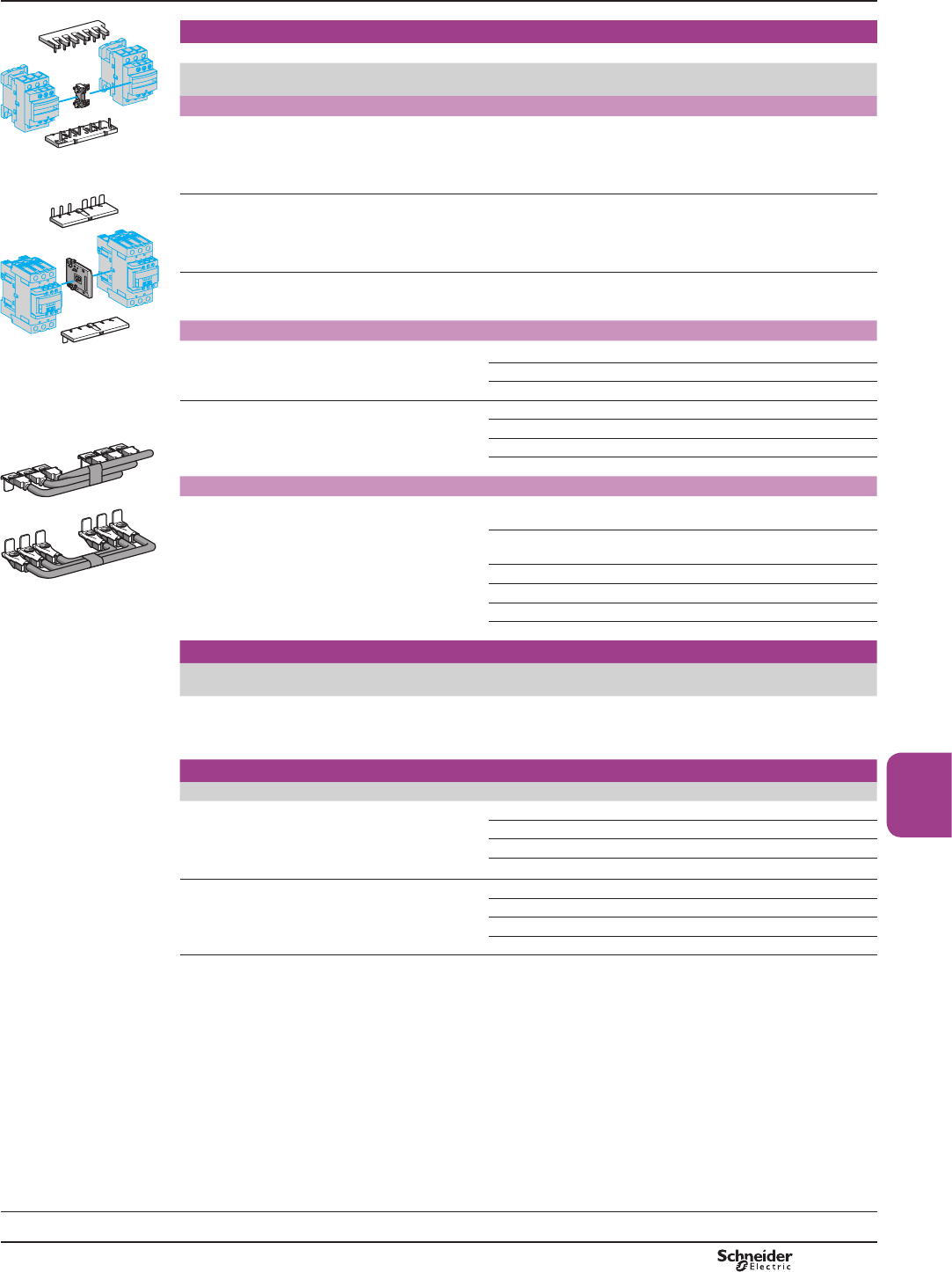
B8/23
Contactors
DF537729.eps
LAD 9R1
For 3-pole reversing contactors for motor control
&RQWDFWRUVZLWKVFUHZFODPSWHUPLQDOVRUFRQQHFWRUV+RUL]RQWDOO\PRXQWHGDVVHPEOHGE\FXVWRPHU
Description For contactors (1)
LGHQWLFDOFRQWDFWRUV
Reference
Kits for assembly of reversing contactors
Kit comprising:
bDPHFKDQLFDOLQWHUORFNLAD 9V2
ZLWKHOHFWULFDOLQWHUORFNLQJLAD 9V1
bDVHWRISRZHUFRQQHFWLRQV/$'9SDUDOOHO
and LAD 9V6UHYHUVLQJ
LC1 D09 to D38 LAD9R1V
DF537730.eps
LAD 9R3
Kit comprising:
bDPHFKDQLFDOLQWHUORFNLAD 9V2
ZLWKRXWHOHFWULFDOLQWHUORFNLQJ
ba set of power connections LAD 9V5SDUDOOHO
and LAD 9V6UHYHUVLQJ
LC1 D09 to D38 LAD9R1
Kit comprising:
bDPHFKDQLFDOLQWHUORFNLAD 4CM
ba set of power connections LA9 D65A69.
LC1 D40A to D65A LAD9R3
Mechanical interlocks
0HFKDQLFDOLQWHUORFNZLWK
LQWHJUDOHOHFWULFDOLQWHUORFNLQJ
LC1 D80 and D95 (aLA9D4002
LC1 D80 and D95 (cLA9D8002
LC1 D115 and D150 LA9D11502
0HFKDQLFDOLQWHUORFNZLWKRXW
LQWHJUDOHOHFWULFDOLQWHUORFNLQJ
LC1 D09 to D38 LAD9V2
LC1 D40A to D65A LAD4CM
DF537731.eps
LC1 D80 and D95 (aLA9D50978
LC1 D80 and D95 (cLA9D80978
Sets of power connections
Comprising:
ba set of parallel bars
ba set of reverser bars.
LC1 D09 to D38 with screw
clamp terminals or connectors
LAD9V5 LAD9V6
LC1 D09…D32 with
spring terminal connections
LAD9V12 LAD9V13 (2)
LC1 D40A to D65A LA9D65A69
LA9 D8069 LC1 D80 and D95 (aLA9D8069
LC1 D80 and D95 (cLA9D8069
LC1 D115 and D150 LA9D11569
For low-speed/high-speed starter
Description For contactors with
connection type
Reference
&RQQHFWLRQNLWHQDEOLQJ
reversing of low and high speed directions
XVLQJDUHYHUVLQJFRQWDFWRUDQGD121&
main pole contactor
Screw clamps or connectors LAD9PVGV
For star-delta starter
Description For contactors Reference
0RXQWLQJNLWFRPSULVLQJ
bWLPHGHOD\FRQWDFWEORFNLAD S2 (LC1 D09…D80
bSRZHUFLUFXLWFRQQHFWLRQVLC1 D09…D80
bKDUGZDUHUHTXLUHGIRU¿[LQJWKHFRQWDFWRUV
RQWRWKHPRXQWLQJSODWHLC1 D80
LC1 D09 and D12 LAD91217
LC1 D18 to D32 LAD93217
LC1 D40A and D50A LAD9SD3
LC1 D80 LA9D8017
(TXLSPHQWPRXQWLQJSODWHV LC1 D09, D12 and D18 LA9D12974
LC1 D32 LA9D32974
LC1 D40A and D50A –
LC1 D80 LA9D80973
(1)7RRUGHUWKHFRQWDFWRUVVHHSDJHV%DQG%
(2) To assemble a reversing contactor with spring terminal connections, the following components must be ordered:
PHFKDQLFDOLQWHUORFNLAD 9V2,
XSVWUHDPSRZHUFRQQHFWLRQNLWDQGGRZQVWUHDPSRZHUFRQQHFWLRQNLW
8SVWUHDPSRZHUFRQQHFWLRQNLWLAD 9V10LQVWDOOHGLQWKH4XLFN¿WV\VWHPZLWKSRZHUFRQQHFWLRQPRGXOHLAD 34
,IPRGXOHLAD 34 is not used, replace LAD 9V10 with LAD 9V12
'RZQVWUHDPSRZHUFRQQHFWLRQNLWLAD 9V11LQVWDOOHGLQWKH4XLFN¿WV\VWHPZLWKRXWJRLQJWHUPLQDOEORFNLAD 331
,ILAD 331 is not used, replace LAD 9V11 with LAD 9V13
References TeSys contactors
Component parts for assembling
reversing contactors for motor control,
low-speed/high-speed starters
and star-delta starters
Selection:
pages A5/23 to A5/47
Characteristics:
pages B8/53 to B8/58
Dimensions:
pages B8/71 and B8/72
Schemes:
pages B8/73 and B8/74
TeSys D
PCPB08P20-EN Version : 1.0 19 novembre 2014 10:37 AM
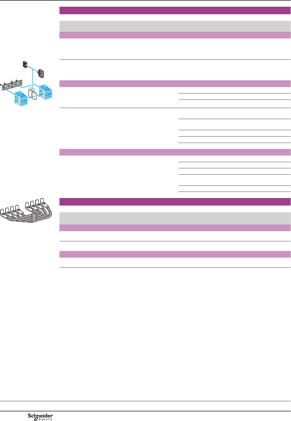
B8/24
For 4-pole changeover contactor pairs (3-phase distribution + neutral)
&RQWDFWRUVZLWKVFUHZFODPSWHUPLQDOVRUFRQQHFWRUV+RUL]RQWDOO\PRXQWHGDVVHPEOHGE\FXVWRPHU
Description For contactors (1)
LGHQWLFDOFRQWDFWRUV
Reference
Kits for assembly of changeover contactor pairs
Kit comprising:
bDPHFKDQLFDOLQWHUORFN/$'9
ZLWKHOHFWULFDOLQWHUORFNLQJ/$'9
bDVHWRISRZHUFRQQHFWLRQVFKDQJHRYHU/$'9
LC1 DT20 to DT40 with
screw clamps or connectors
LADT9R1V
DF537733.eps
Kit comprising:
bDPHFKDQLFDOLQWHUORFN/$'9
ZLWKRXWHOHFWULFDOLQWHUORFNLQJ
bDVHWRISRZHUFRQQHFWLRQVFKDQJHRYHU/$'9
LC1 DT20 to DT40 with
screw clamps or connectors
LADT9R1
Mechanical interlocks
With integral
HOHFWULFDOLQWHUORFNLQJ
LC1 D80004 LA9D4002
LP1 D80004 LA9D8002
LC1 D115004 LA9D11502
LA9 D50978 :LWKRXWLQWHJUDO
HOHFWULFDOLQWHUORFNLQJ
LC1 DT20 to DT40 with
screw clamps or connectors
LAD9V2 (2)
LC1 DT203 to DT403
with spring terminals
LAD9V2 (2)
LC1 DT60A and DT80A LAD4CM
LC1 D80004 LA9D50978
LP1 D80004 LA9D80978
Sets of power connections
Comprising a set of parallel bars LC1 D80004 LA9D8070
LP1 D80004 LA9D8070
LC1 D115004 LA9D11570
LC1 DT203 to DT403
with spring terminals
LAD9V9
LC1 D80004 LA9D8070 (2)
LP1 D80004 LA9D8070 (2)
DF537735.eps
For 3-pole changeover contactor pairs
&RQWDFWRUVZLWKVFUHZFODPSWHUPLQDOVRUFRQQHFWRUV+RUL]RQWDOO\PRXQWHGDVVHPEOHGE\FXVWRPHU
Description For contactors (1)
LGHQWLFDOFRQWDFWRUV
Reference
LA9 D8070 Mechanical interlocks
:LWKRXWLQWHJUDOHOHFWULFDOLQWHUORFNLQJ LC1 D40A…D65A LAD9R3S
:LWKLQWHJUDOHOHFWULFDOLQWHUORFNLQJ LC1 D115 and D150 LA9D11502
Sets of power connections
Comprising a set of parallel bars LC1 D115 and D150 LA9D11571
(1)7RRUGHUWKHFRQWDFWRUVVHHSDJHV%DQG%
(2)2UGHUFRQWDFWEORFNVLAD Np1WREXLOGWKHHOHFWULFDOLQWHUORFNVHHSDJH%
References TeSys contactors
Component parts for assembling
changeover contactor pairs
TeSys D
Selection:
pages A5/23 to A5/47
Characteristics:
pages B8/53 to B8/58
Dimensions:
pages B8/71 and B8/72
Schemes:
pages B8/73 and B8/74
PCPB08P20-EN
Version : 1.0 19 novembre 2014 10:37 AM
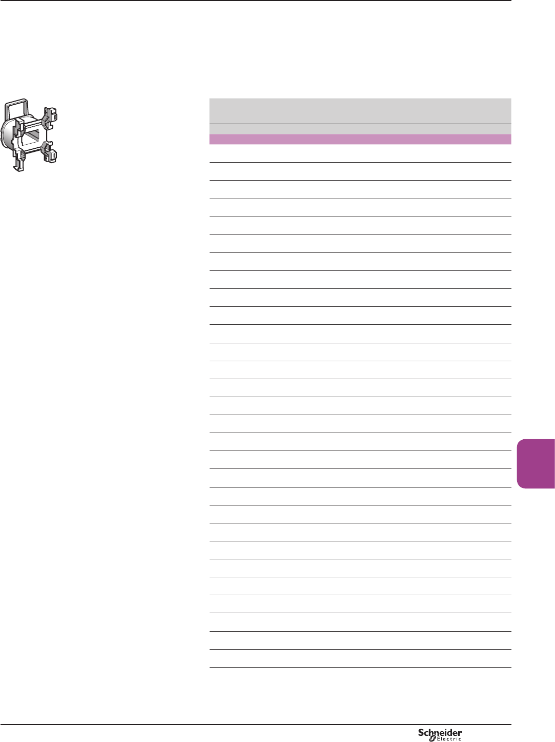
B8/25
Contactors
References
For a contactors LC1 D09...D38
and LC1 DT20…DT40
6SHFL¿FDWLRQV
$YHUDJHFRQVXPSWLRQDW&
bLQUXVKFRVM 9$
bsealed (cos M +]9$+]9$
2SHUDWLQJUDQJHT y&+]«8F+]«8F
DF537496.eps
LXD 1pp
Control circuit
voltage
Uc
Average resistance
at 20 °C ±10 %
Inductance of
closed circuit
Reference (1)
V:H
50/60 Hz
12 1.33 0.05 LXD1J7
21 (2) 4.17 0.17 LXD1Z7
24 5.37 0.22 LXD1B7
32 10.1 0.39 LXD1C7
36 12.8 0.49 LXD1CC7
42 17 0.67 LXD1D7
48 21.7 0.87 LXD1E7
60 34.6 1.4 LXD1EE7
100 100.4 3.8 LXD1K7
110 124.1 4.6 LXD1F7
115 129.8 5 LXD1FE7
120 150.6 5.4 LXD1G7
127 158.5 6.1 LXD1FC7
200 410.7 15 LXD1L7
208 430.4 16 LXD1LE7
220 515.4 18 LXD1M7 (3)
230 538.6 20 LXD1P7
240 562.3 22 LXD1U7
277 800.7 29 LXD1W7
380 1551 55 LXD1Q7 (4)
400 1633 60 LXD1V7
415 1694 65 LXD1N7
440 1993 73 LXD1R7
480 2398 87 LXD1T7
500 2499 95 LXD1S7
575 3294 125 LXD1SC7
600 3810 136 LXD1X7
660 4656 165 LXD1YC7
690 5020 180 LXD1Y7
(1)7KHODVWGLJLWVLQWKHUHIHUHQFHUHSUHVHQWWKHYROWDJHFRGH
(2)9ROWDJHIRUVSHFLDOFRLOV¿WWHGLQFRQWDFWRUVZLWKVHULDOWLPHUPRGXOHVZLWK9VXSSO\
(3) Suitable for use on 230 V+],QWKLVFDVHDSSO\DFRHI¿FLHQWRIWRWKHPHFKDQLFDO
GXUDELOLW\RIWKHFRQWDFWRUVHHSDJH%DQG%
(4) Suitable for use on 400 V+],QWKLVFDVHDSSO\DFRHI¿FLHQWRIWRWKHPHFKDQLFDO
GXUDELOLW\RIWKHFRQWDFWRUVHHSDJH%DQG%
TeSys contactors
a.c. coils for TeSys D, 3 or 4-pole
contactors
TeSys D
PCPB08P20-EN Version : 1.0 19 novembre 2014 10:37 AM
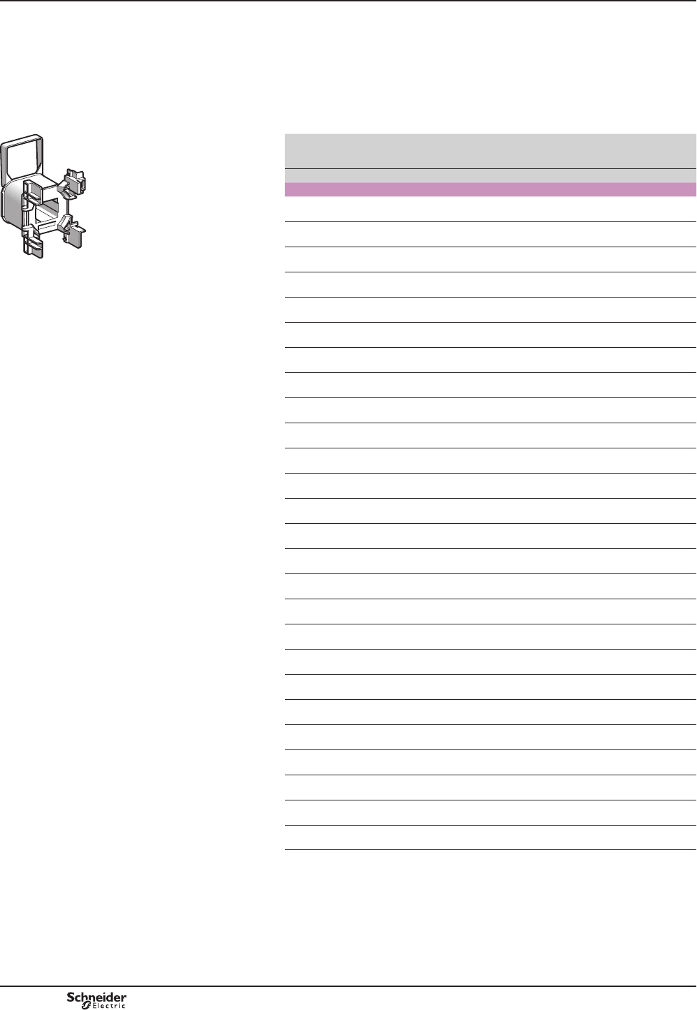
B8/26
For a contactors LC1 D40A…D65A, LC1 DT60A
and LC1 DT80A
6SHFL¿FDWLRQV
$YHUDJHFRQVXPSWLRQDW&
bLQUXVKFRVM 9$
bsealed (cos M +]9$+]9$
2SHUDWLQJUDQJHT y&+]«8F+]«8F
DF503984.eps
LXD 3pp
Control circuit
voltage
Uc
Average resistance
at 20 °C ±10%
Inductance of
closed circuit
Reference (1)
V:H
50/60 Hz
12 0.49 0.03 LXD3J5 (2)
24 1.98 0.12 LXD3B7
32 3.76 0.22 LXD3C7
42 6.18 0.37 LXD3D7
48 7.97 0.48 LXD3E7
100 37.63 2.07 LXD3K7
110 42.28 2.50 LXD3F7
115 48.76 2.74 LXD3FE7
120 37.63 2.07 LXD3G7
127 60.29 3.34 LXD3FC7
200 149 8.27 LXD3L7
208 105 6.22 LXD3LE7
220 182 10 LXD3M7 (3)
230 192 10.9 LXD3P7
240 202 11.9 LXD3U7
277 193 11 LXD3W7
380 512 29.9 LXD3Q7 (4)
400 607 33.1 LXD3V7
415 635 35.6 LXD3N7
440 682 40.1 LXD3R7
480 607 33.1 LXD3T7
500 878 51.7 LXD3S7
575 1238 68.4 LXD3SC7
600 1304 74.5 LXD3X7
660 1593 90.1 LXD3YC7
690 1683 98.5 LXD3Y7
(1)7KHODVWGLJLWVLQWKHUHIHUHQFHUHSUHVHQWWKHYROWDJHFRGH
(2)7KLVFRLOFDQRQO\EHXVHGRQ+]
(3) Suitable for use on 230 V+],QWKLVFDVHDSSO\DFRHI¿FLHQWRIWRWKHPHFKDQLFDO
GXUDELOLW\RIWKHFRQWDFWRUVHHSDJH%DQG%
(4) Suitable for use on 400 V+],QWKLVFDVHDSSO\DFRHI¿FLHQWRIWRWKHPHFKDQLFDO
GXUDELOLW\RIWKHFRQWDFWRUVHHSDJH%DQG%
References TeSys contactors
a.c. coils for TeSys D, 3 or 4-pole
contactors
TeSys D
PCPB08P20-EN
Version : 1.0 19 novembre 2014 10:37 AM
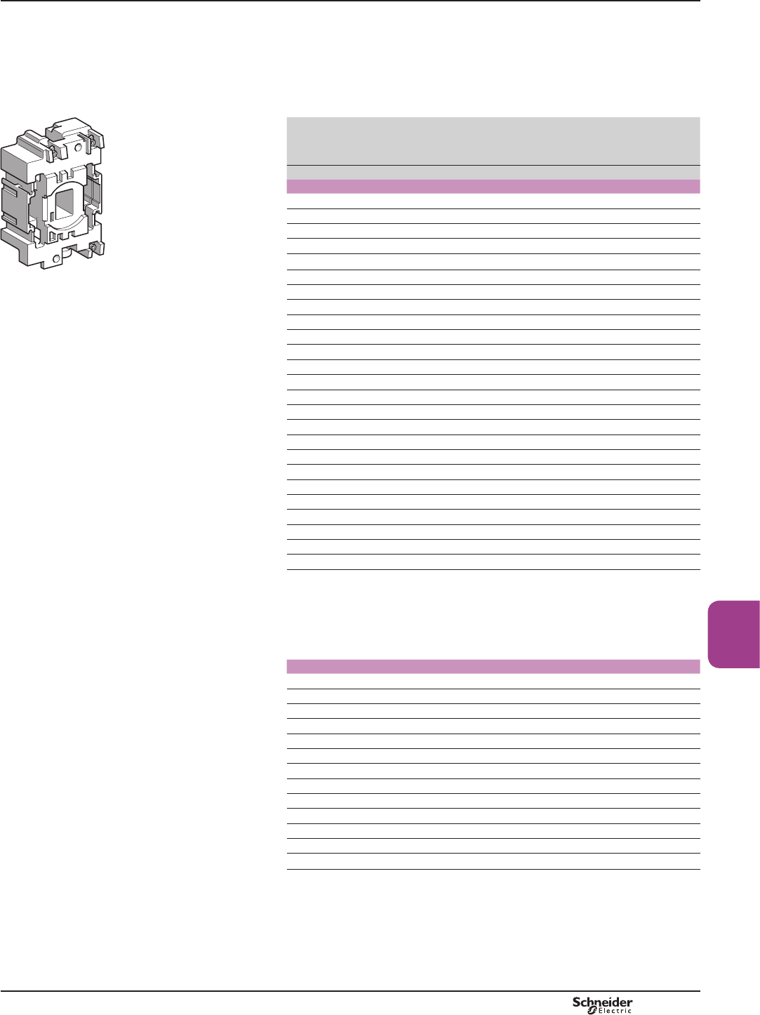
B8/27
Contactors
References
For 3 or 4-pole contactors LC1D40, D50, D65, D80, D95
6SHFL¿FDWLRQV
$YHUDJHFRQVXPSWLRQDW&
b LQUXVKFRVM +]9$+]9$
b sealed (cos M +]9$+]9$
2SHUDWLQJUDQJHT y&«8F
DF537497.eps
Control
circuit
voltage
Uc
Average
resistance
at 20°C
±10 %
Inductance
of closed
circuit
Reference
(1)
Average
resistance
at 20 °C
±10 %
Inductance
of closed
circuit
Reference
(1)
V:H:H
50 Hz 60 Hz
24 1.4 0.09 LX1D6B5 1.05 0.06 LX1D6B6
32 2.6 0.16 LX1D6C5 – – –
42 4.4 0.27 LX1D6D5 – – –
48 5.5 0.35 LX1D6E5 4.2 0.23 LX1D6E6
110 31 1.9 LX1D6F5 22 1.2 LX1D6F6
LX1 D6pp 115 31 1.9 LX1D6FE5 – – –
120 – – – 28 1.5 LX1D6G6
127 41 2.4 LX1D6G5 – – –
208 – – – 86 4.3 LX1D6L6
220 – – – 98 4.8 LX1D6M6
220/230 127 7.5 LX1D6M5 – – –
230 133 8.1 LX1D6P5 – – –
240 152 8.7 LX1D6U5 120 5.7 LX1D6U6
256 166 10 LX1D6W5 – – –
277 – – – 157 8 LX1D6W6
380 – – – 300 14 LX1D6Q6
380/400 381 22 LX1D6Q5 – – –
400 411 25 LX1D6V5 – – –
415 463 26 LX1D6N5 – – –
440 513 30 LX1D6R5 392 19 LX1D6R6
480 – – – 480 23 LX1D6T6
500 668 38 LX1D6S5 – – –
575 – – – 675 33 LX1D6S6
600 – – – 775 36 LX1D6X6
660 1220 67 LX1D6Y5 – – –
6SHFL¿FDWLRQV
$YHUDJHFRQVXPSWLRQDW&
bLQUXVKFRVM +]9$DW+]
bsealed (cosM +]9$DW+]
2SHUDWLQJUDQJHT y&«8F
50/60 Hz
24 – – – 1.22 0.08 LX1D6B7
42 – – – 3.5 0.25 LX1D6D7
48 – – – 5 0.32 LX1D6E7
110 – – – 26 1.7 LX1D6F7
115 – – – – – LX1D6FE7
120 – – – 32 2 LX1D6G7
220/230 (2) – – – 102 6.7 LX1D6M7
230 – – – 115 7.7 LX1D6P7
230/240 (3) – – – 131 8.3 LX1D6U7
380/400 (4) – – – 310 20 LX1D6Q7
400 – – – 349 23 LX1D6V7
415 – – – 390 24 LX1D6N7
440 – – – 410 27 LX1D6R7
(1)7KHODVWGLJLWVLQWKHUHIHUHQFHUHSUHVHQWWKHYROWDJHFRGH
(2) For use on 230 V+]DSSO\DFRHI¿FLHQWRIWRWKHPHFKDQLFDOGXUDELOLW\RIWKH
FRQWDFWRUVHHSDJH%DQG%7KLVFRLOFDQEHXVHGRQ9DW+]
(3)7KLVFRLOFDQEHXVHGRQ9DW+]DQGRQ9RQO\DW+]
(4) For use on 400 V+]DSSO\DFRHI¿FLHQWRIWRWKHPHFKDQLFDOGXUDELOLW\RIWKH
FRQWDFWRUVHHSDJH%DQG%
TeSys contactors
a.c. coils for TeSys D, 3 or 4-pole
contactors
TeSys D
PCPB08P20-EN Version : 1.0 19 novembre 2014 10:37 AM
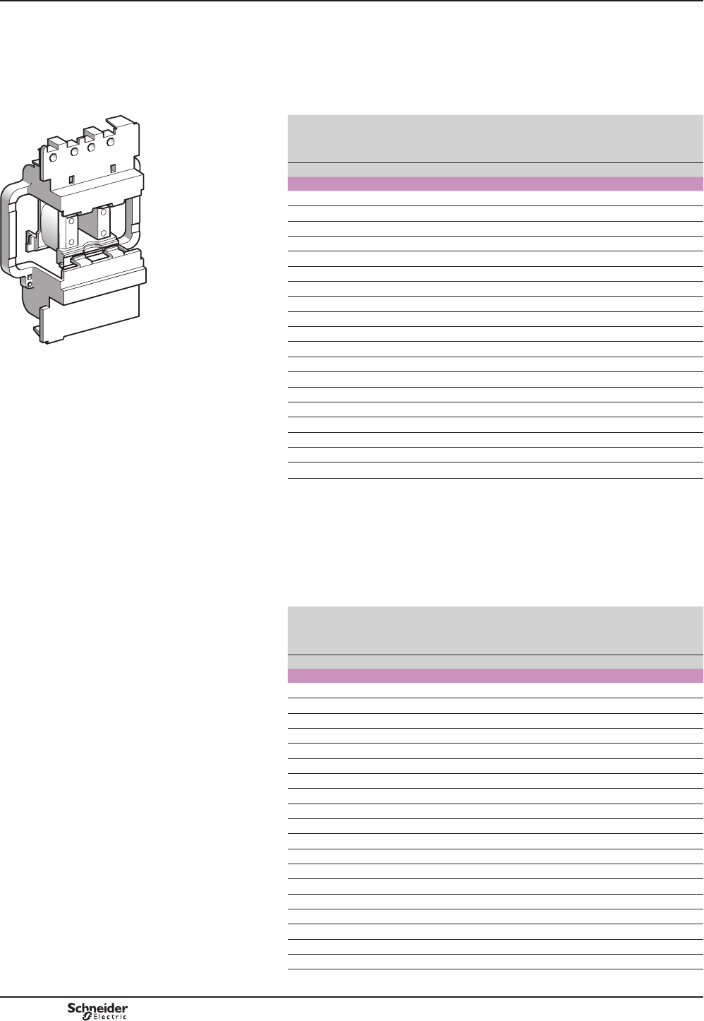
B8/28
References TeSys contactors
a.c. coils for TeSys D, 3 or 4-pole
contactors
For 3 or 4-pole contactors LC1 D115
6SHFL¿FDWLRQV
$YHUDJHFRQVXPSWLRQDW&
b LQUXVKFRVM RU+] 9$
b sealed (cos M RU +]9$
2SHUDWLQJUDQJHT y&«8F
DF537502.eps
LX1 D8pp
Control
circuit
voltage
Uc
Average
resistance
at 20 °C
±10 %
Inductance
of closed
circuit
Reference
(1)
Average
resistance
at 20 °C
±10 %
Inductance
of closed
circuit
Reference
(1)
V:H:H
50 Hz 60 Hz
24 1.24 0.09 LX1D8B5 0.87 0.07 LX1D8B6
32 2.14 0.17 LX1D8C5 – – –
42 3.91 0.28 LX1D8D5 – – –
48 4.51 0.36 LX1D8E5 3.91 0.28 LX1D8E6
110 26.53 2.00 LX1D8F5 19.97 1.45 LX1D8F6
115 26.53 2.00 LX1D8FE5 – – –
120 – – – 24.02 1.70 LX1D8G6
127 32.75 2.44 LX1D8FC5 – – –
208 – – – 67.92 5.06 LX1D8L6
220 104.77 7.65 LX1D8M5 79.61 5.69 LX1D8M6
230 104.77 8.29 LX1D8P5 – – –
240 125.25 8.89 LX1D8U5 97.04 6.75 LX1D8U6
277 – – – 125.75 8.89 LX1D8W6
380 338.51 22.26 LX1D8Q5 243.07 17.04 LX1D8Q6
400 368.43 25.55 LX1D8V5 – – –
415 368.43 27.65 LX1D8N5 – – –
440 441.56 30.34 LX1D8R5 338.51 22.26 LX1D8R6
480 – – – 368.43 25.55 LX1D8T6
500 566.62 38.12 LX1D8S5 – – –
For 3 or 4-pole contactors LC1 D115, LC1 D150
6SHFL¿FDWLRQV
$YHUDJHFRQVXPSWLRQDW&
bLQUXVKFRVM WR9$
bsealed: cosM WR9$
2SHUDWLQJUDQJHT y&«8F
&RLOVZLWKLQWHJUDOVXSSUHVVLRQGHYLFH¿WWHGDVVWDQGDUGFODVV%
Control
circuit
voltage
Uc
Average
resistance
at 20 °C
±10 %
Inductance
of closed
circuit
Reference
(1)
Average
resistance
at 20 °C
±10 %
Inductance
of closed
circuit
Reference
(1)
V:H:H
50/60 Hz
24 – – – 147 3.03 LX1D8B7
32 – – – 301 8.28 LX1D8C7
42 – – – 498 13.32 LX1D8D7
48 – – – 1061 24.19 LX1D8E7
110 – – – 4377 109.69 LX1D8F7
115 – – – 4377 109.69 LX1D8FE7
120 – – – 4377 109.69 LX1D8G7
127 – – – 6586 152.65 LX1D8FC7
208 – – – 10 895 260.15 LX1D8LE7
220 – – – 9895 210.72 LX1D8M7
230 – – – 9895 210.72 LX1D8P7
240 – – – 9895 210.72 LX1D8U7
277 – – – 21 988 533.17 LX1D8UE7
380 – – – 21 011 482.42 LX1D8Q7
400 – – – 21 011 482.42 LX1D8V7
415 – – – 21 011 482.42 LX1D8N7
440 – – – 21 501 507.47 LX1D8R7
480 – – – 32 249 938.41 LX1D8T7
500 – – – 32 249 938.41 LX1D8S7
(1)7KHODVWGLJLWVLQWKHUHIHUHQFHUHSUHVHQWWKHYROWDJHFRGH
TeSys D
PCPB08P20-EN
Version : 1.0 19 novembre 2014 10:37 AM
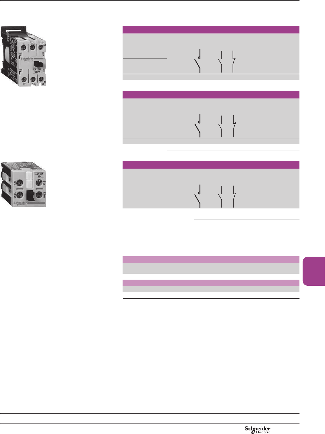
B8/29
Contactors
TeSys SK
TeSys contactors
Mini-contactors TeSys LC1 SK
and LP1 SK
bWidth of contactor 27 mm.
b0RXQWLQJRQPP7 rail.
bScrew clamp terminals.
PF511131R.eps
LC1 SK06
Mini-contactors for motor in category AC-3
Standard power
ratings of
3-phase motors
50/60 Hz in category
AC-3 (1)
Rated
operational
voltage in
AC-3
up to 400 V
Number of
poles
Instantaneous
auxiliary
contacts
Basic
reference.
Complete with
code indicating
control circuit
voltage (2)
220 V
230 V
380 V
415 V
660 V
690 V
kW kW kW A
1.1 2.2 2.2 6 2 – – LC1SK0600pp
Mini-contactors for motor in category AC-1
Non inductive loads
maximum current
(T y 55 °C)
utilisation category
AC-1
Control
circuit
supply
Number of
poles
Instantaneous
auxiliary
contacts
Basic
reference.
Complete with
code indicating
control circuit
voltage (2)
A
PF511132R.eps
12 a.c. 2 – –
LC1SK0600
pp
d.c. 2 – –
LP1SK0600
pp
Add-on block with 1 power pole (for 3-phase circuits)
For use on contactor Number of
poles
Instantaneous
auxiliary
contacts
Reference
LA1 SK10 LC1 SK06
FOLSRQIURQWPRXQWLQJ
1 1 – LA1SK10
1 – 1 LA1SK01
Note: $X[LOLDU\FRQWDFWEORFNVDQGFRLOVXSSUHVVRUPRGXOHVHHQH[WSDJH
(1) For use in AC-3 category and 3-phase circuits, an LA1 SKppDX[LOLDU\FRQWDFWEORFNVKRXOG
EHRUGHUHGVHSDUDWHO\IRUPRXQWLQJRQWKHFRQWDFWRU
(2) Standard control circuit voltages (variable delivery times, please consult your Regional Sales
2I¿FH
Mini-contactors LC1 SK
Volts a
50/60 Hz
24 48 110 120 220 230 240 380 400
Code B7 E7 F7 G7 M7 P7 U7 Q7 V7
Mini-contactors LP1 SK
Volts c12 24 36 48 72
Code JD BD CD ED SD
References
Characteristics:
pages B8/76 to B8/79
Dimensions, schemes:
page B8/80
PCPB08P10-EN Version : 1.0 19 novembre 2014 10:37 AM
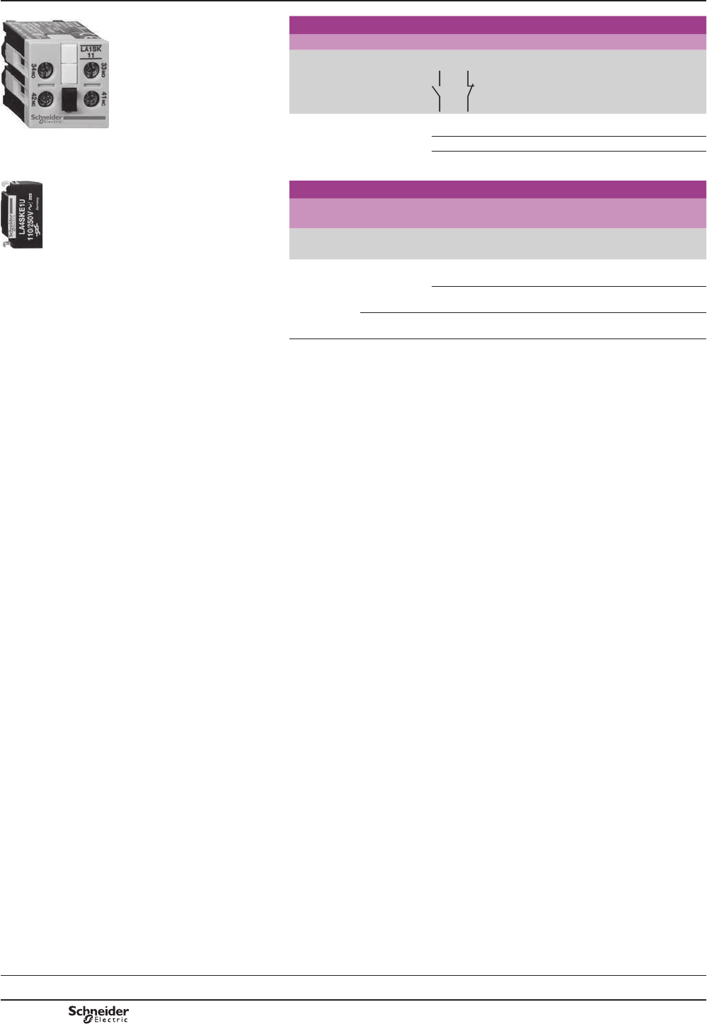
B8/30
TeSys SK
TeSys contactors
Mini-contactors TeSys LC1 SK and LP1 SK
Instantaneous auxiliary contacts and coil
suppressor modules
PF511133R.eps
Instantaneous auxiliary contact blocks
Clip-on front mounting
For use on
contactor
Maximum
number of
blocks per
contactor
Composition Reference
LC1 SK06 1 2 – LA1SK20
LA1 SK11 – 2 LA1SK02
1 1 LA1SK11
PF511134R.eps
/$6.p1p
Coil suppressor modules
&OLSRQ¿[LQJDQGHOHFWULFDOFRQQHFWLRQRQULJKWKDQGVLGHZLWKRXWXVH
of tools
For use on
contactors
Type For voltages Sold in lots of Unit reference
LC1 SK06
and LP1 SK06
Varistor (1) a and c
24 V…48 V
10 LA4SKE1E
a and c
110 V…250 V
10 LA4SKE1U
Diode (2) c
24 V…250 V
10 LA4SKC1U
(1)3URWHFWLRQSURYLGHGE\OLPLWLQJWKHWUDQVLHQWYROWDJHWR8FPD[0D[LPXPUHGXFWLRQRI
WUDQVLHQWYROWDJHSHDNV6OLJKWLQFUHDVHLQGURSRXWWLPHWRWLPHVWKHQRUPDOWLPH
(2)1RRYHUYROWDJHRURVFLOODWLQJIUHTXHQF\
6OLJKWLQFUHDVHLQGURSRXWWLPHWRWLPHVWKHQRUPDOWLPH
References
Characteristics:
pages B8/76 to B8/79
Dimensions, schemes:
page B8/80
PCPB08P10-EN
Version : 1.0 19 novembre 2014 10:37 AM

B8/31
Contactors
TeSys contactors
Contactors for motor control,
6 to 16 A in category AC-3 and
6 to 12 A in category AC-4
Control circuit: a.c.
PF511137R.eps
LC1 K0910pp
&RQWDFWRUVHOHFWLRQDFFRUGLQJWRXWLOLVDWLRQFDWHJRU\VHHSDJHV$WR$DQG$WR$
0RXQWLQJRQPP7UDLORUVFUHZ¿[LQJ
6FUHZVLQWKHRSHQ³UHDG\WRWLJKWHQ´SRVLWLRQ
$GGRQDX[LOLDU\FRQWDFWEORFNVDQGDFFHVVRULHVVHHSDJHV%WR%
3-pole contactors for standard applications
Standard power ratings of
3-phase motors 50-60 Hz
in category AC-3
Rated operational
current in
category AC-3
440 V
up to
Instan-
taneous
auxiliary
contacts
Basic reference,
to be completed by
adding the voltage code
(1) (2)
220 V
230 V
380 V
415 V
440/500 V
660/690 V
kW kW kW A
PF511138R.eps
LC1 K09103pp
Screw clamp connections
1.5 2.2 3 61 - LC1K0610pp
- 1 LC1K0601pp
2.2 4 4 91 - LC1K0910pp
- 1 LC1K0901pp
3 5.5 ! 12 1 - LC1K1210pp
- 1 LC1K1201pp
4 7.5 ! 16 1 - LC1K1610pp
- 1 LC1K1601pp
Spring terminal connections
)RUWR$UDWLQJVRQO\LQWKHUHIHUHQFHVVHOHFWHGDERYHLQVHUWD¿JXUH3 before the voltage code.
Example: LC1 K0610pp becomes LC1 K06103pp.
PF511139R.eps
Faston connectors, 1 x 6.35 or 2 x 2.8
)RUWR$UDWLQJVLQWKHUHIHUHQFHVVHOHFWHGDERYHLQVHUWD¿JXUH7 before the voltage code.
Example: LC1 K0610pp becomes LC1 K06107pp.
Solder pins for printed circuit boards
)RUWR$UDWLQJVLQWKHUHIHUHQFHVVHOHFWHGDERYHLQVHUWD¿JXUH5 before the voltage code.
Example: LC1 K0610pp becomes LC1 K06105pp.
3-pole silent contactors
5HFRPPHQGHGIRUXVHLQDUHDVVHQVLWLYHWRQRLVHKLJKLQWHUIHUHQFHPDLQVVXSSOLHVHWF
&RLOZLWKUHFWL¿HULQFRUSRUDWHGVXSSUHVVRU¿WWHGDVVWDQGDUG
Screw clamp connections
1.5 2.2 3 61 - LC7K0610pp
- 1 LC7K0601pp
2.2 4 4 91 - LC7K0910pp
- 1 LC7K0901pp
3 5.5 ! 12 1 - LC7K1210pp
- 1 LC7K1201pp
Faston connectors, 1 x 6.35 or 2 x 2.8
,QWKHUHIHUHQFHVVHOHFWHGDERYHLQVHUWD¿JXUH7 before the voltage code.
Example: LC7 K0610pp becomes LC7 K06107pp.
Solder pins for printed circuit boards
,QWKHUHIHUHQFHVVHOHFWHGDERYHLQVHUWD¿JXUH5 before the voltage code.
Example: LC7 K0610pp becomes LC7 K06105pp.
(1) 6WDQGDUGFRQWUROFLUFXLWYROWDJHVIRURWKHUYROWDJHVSOHDVHFRQVXOW\RXU5HJLRQDO6DOHV2I¿FH
a.c. supply
Contactors LC1 K «8F«8F
Volts 12 20 24 (2) 36 42 48 110 115 120 127 200/208 220/230 230 230/240
50/60 Hz J7 Z7 B7 C7 D7 E7 F7 FE7 G7 FC7 L7 M7 P7 8
Volts 256 277 380/400 400 400/415 440 480 500 575 600 660/690
50/60 Hz W7 UE7 Q7 – V7 N7 R7 T7 S7 SC7 X7 Y7 – –
8SWRDQGLQFOXGLQJ9FRLOZLWKLQWHJUDOVXSSUHVVLRQGHYLFHDYDLODEOHDGG2WRWKHFRGHUHTXLUHG([DPSOHJ72.
Contactors LC7 K «8F
Volts 24 42 48 110 115 220 230/240
50/60 Hz B7 D7 E7 F7 FE7 M7 U7
(2))RUPDLQVVXSSOLHVZLWKDKLJKOHYHORILQWHUIHUHQFHYROWDJHVXUJH!9XVHDVXSSUHVVRUPRGXOH/$.()&«9
RU/$.(8*«9VHHSDJH%
LC1 K09107pp
PF511140R.eps
LC1 K09105pp
PF511141R.eps
LC7 K0910pp
References
TeSys K
Selection:
pages A5/23 and A5/27
Characteristics:
pages B8/81 to B8/84
Dimensions:
page B8/85
Schemes:
page B8/86
PCPB08P10-EN Version : 1.0 19 novembre 2014 10:37 AM
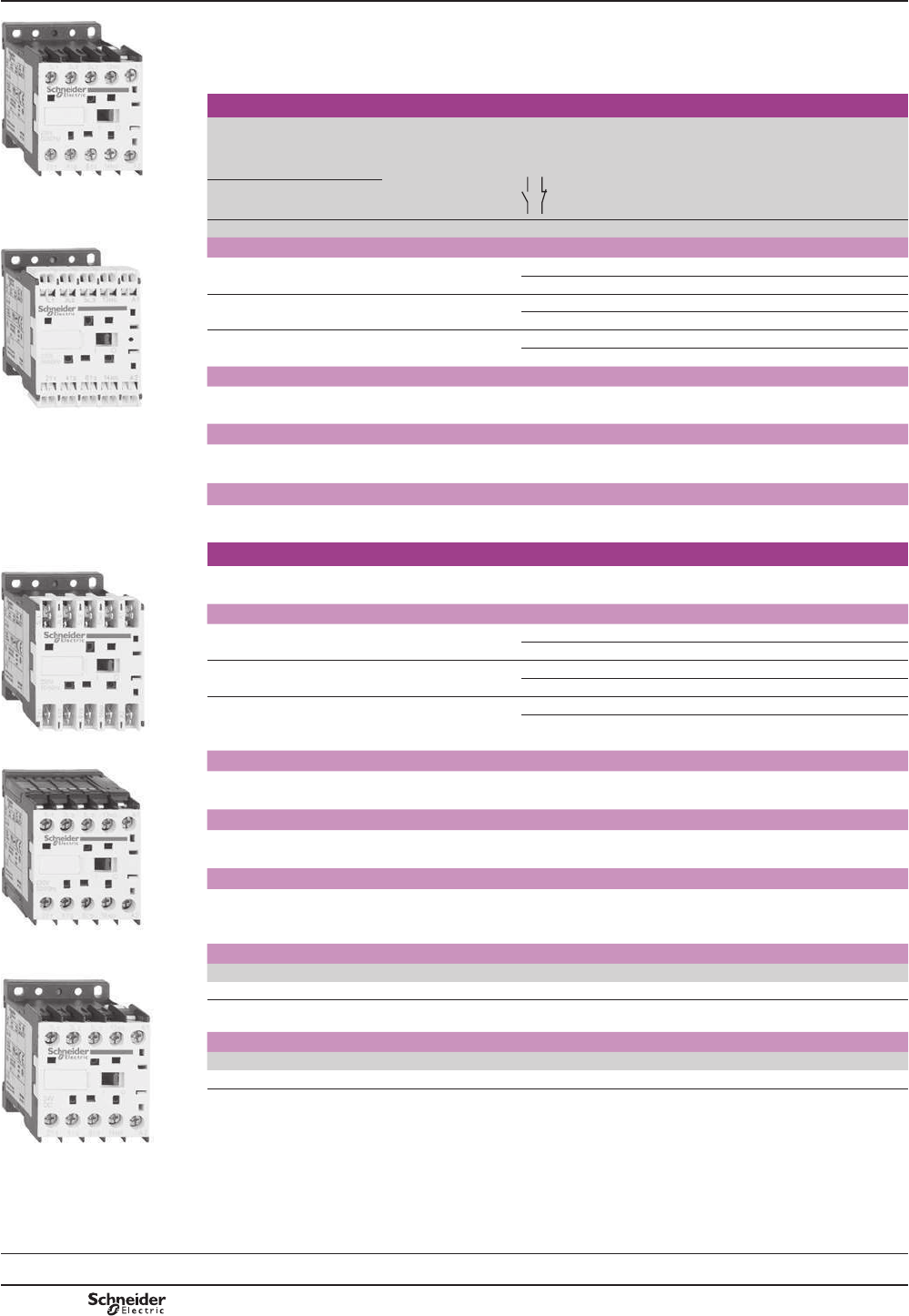
B8/32
TeSys contactors
Contactors for motor control,
6 to 12 A in categories AC-3 and AC-4
Control circuit: d.c. or low consumption
PF511137R.eps
&RQWDFWRUVHOHFWLRQDFFRUGLQJWRXWLOLVDWLRQFDWHJRU\VHHSDJHV$WR$DQG$WR$
0RXQWLQJRQPP7UDLORUVFUHZ¿[LQJ
6FUHZVLQWKHRSHQ³UHDG\WRWLJKWHQ´SRVLWLRQ
$GGRQDX[LOLDU\FRQWDFWEORFNVDQGDFFHVVRULHVVHHSDJHV%WR%
3-pole contactors, d.c. supply
Standard power ratings of
3-phase motors 50-60 Hz
in category AC-3
Rated operational
current in
category AC-3
440 V
up to
Instan-
taneous
auxiliary
contacts
Basic reference,
to be completed by
adding the voltage code
(1) (2)
LP1 K0910pp 220 V
230 V
380 V
415 V
440/500 V
660/690 V
kW kW kW A
PF511138R.eps
Screw clamp connections
1.5 2.2 3 61 – LP1K0610pp
– 1 LP1K0601pp
2.2 4 4 91 – LP1K0910pp
– 1 LP1K0901pp
3 5.5 ! 12 1 – LP1K1210pp
– 1 LP1K1201pp
Spring terminal connections
,QWKHUHIHUHQFHVVHOHFWHGDERYHLQVHUWD¿JXUH3 before the voltage code.
Example: LP1 K0610pp becomes LP1 K06103pp.
LP1 K09103pp Faston connectors, 1 x 6.35 or 2 x 2.8
,QWKHUHIHUHQFHVVHOHFWHGDERYHLQVHUWD¿JXUH7 before the voltage code.
Example: LP1 K0610pp becomes LP1 K06107pp.
Solder pins for printed circuit boards
,QWKHUHIHUHQFHVVHOHFWHGDERYHLQVHUWD¿JXUH5 before the voltage code.
Example: LP1 K0610pp becomes LP1 K06105pp.
3-pole low consumption contactors
PF511139R.eps
LP1 K09107pp
&RPSDWLEOHZLWKSURJUDPPDEOHFRQWUROOHURXWSXWV
:LGHUDQJHFRLO«8FVXSSUHVVRU¿WWHGDVVWDQGDUGFRQVXPSWLRQ:
Screw clamp connections
1.5 2.2 3 61 – LP4K0610pp
– 1 LP4K0601pp
2.2 4 4 91 – LP4K0910pp
– 1 LP4K0901pp
3 5.5 ! 12 1 – LP4K1210pp
– 1 LP4K1201pp
PF511140R.eps
Spring terminal connections
,QWKHUHIHUHQFHVVHOHFWHGDERYHLQVHUWD¿JXUH3 before the voltage code.
Example: LP4 K0610pp becomes LP4 K06103pp.
Faston connectors, 1 x 6.35 or 2 x 2.8
,QWKHUHIHUHQFHVVHOHFWHGDERYHLQVHUWD¿JXUH7 before the voltage code.
Example: LP4 K0610pp becomes LP4 K06107pp.
Solder pins for printed circuit boards
,QWKHUHIHUHQFHVVHOHFWHGDERYHLQVHUWD¿JXUH5 before the voltage code.
Example: LP4 K0610pp becomes LP4 K06105pp.
(1) 6WDQGDUGFRQWUROFLUFXLWYROWDJHVIRURWKHUYROWDJHVSOHDVHFRQVXOW\RXU5HJLRQDO6DOHV2I¿FH
LP1 K09105pp d.c. supply FRQWDFWRUV/3.8F
Volts 12 20 24 (2) 36 48 60 72 100 110 125 155 174 200 220 230 240 250
Code JD ZD BD CD ED ND SD KD FD GD PD QD LD MD MPD MUD UD
&RLOZLWKLQWHJUDOVXSSUHVVLRQGHYLFHDYDLODEOHDGG3WRWKHFRGHUHTXLUHG([DPSOHJD3
Low consumption (contactors LP4 K: 0.78F
Volts 12 20 24 48 72 110 120
Code JW3 ZW3 BW3 EW3 SW3 FW3 GW3
(2) For LP1 K only, when connecting an electronic sensor or timer in series with the contactor coil, select a 20 V coil
(aFRQWUROFLUFXLWYROWDJHFRGH=c FRQWUROFLUFXLWYROWDJHFRGH='VRDVWRFRPSHQVDWHIRUWKHLQFXUUHGYROWDJHGURS
PF511141R.eps
/3.pp
References
TeSys K
Selection:
pages A5/23 and A5/27
Characteristics:
pages B8/81 to B8/84
Dimensions:
page B8/85
Schemes:
page B8/86
PCPB08P10-EN
Version : 1.0 19 novembre 2014 10:37 AM
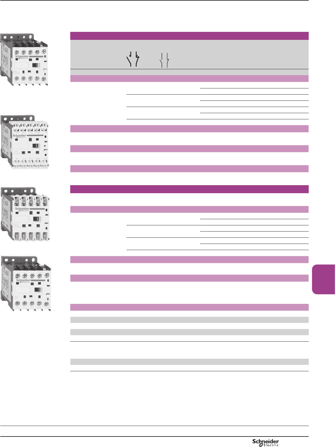
B8/33
Contactors
TeSys contactors
Contactors for control
in category AC-1, 20 A
Control circuit: a.c.
&RQWDFWRUVHOHFWLRQDFFRUGLQJWRXWLOLVDWLRQFDWHJRU\VHHSDJHV$DQG$
0RXQWLQJRQPP7UDLORUVFUHZ¿[LQJ
6FUHZVLQWKHRSHQ³UHDG\WRWLJKWHQ´SRVLWLRQ
$GGRQDX[LOLDU\FRQWDFWEORFNVDQGDFFHVVRULHVVHHSDJHVB8/40 to B8/43.
PF511137R.eps
/&.pp
3 or 4-pole contactors for standard applications (1)
Non-inductive loads
Category AC-1
Maximum current
atT y 50 °C
Number
of poles
Instantaneous
auxiliary contacts
Basic reference,
to be completed by adding
the voltage code (2) (3)
A
Screw clamp connections
20 3 – 1 – LC1K0910pp
or LC1K1210pp
3 – – 1 LC1K0901pp
or LC1K1201pp
4 – – – LC1K09004pp
PF511138R.eps
or LC1K12004pp
2 2 – – LC1K09008pp
Spring terminal connections
,QWKHUHIHUHQFHVVHOHFWHGDERYHLQVHUWD¿JXUH3 before the voltage code.
Example: LC1 K0910pp becomes LC1 K09103pp.
Faston connectors, 1 x 6.35 or 2 x 2.8
,QWKHUHIHUHQFHVVHOHFWHGDERYHLQVHUWD¿JXUH7 before the voltage code.
Example: LC1 K0910pp becomes LC1 K09107pp.
Solder pins for printed circuit boards
LC1 K09103pp ,QWKHUHIHUHQFHVVHOHFWHGDERYHLQVHUWD¿JXUH5 before the voltage code.
Example: LC1 K0910pp becomes LC1 K09105pp.
PF511139R.eps
LC1 K09107pp
3 or 4-pole silent contactors (1)
5HFRPPHQGHGIRUXVHLQDUHDVVHQVLWLYHWRQRLVHKLJKLQWHUIHUHQFHPDLQVVXSSOLHVHWF
&RLOZLWKUHFWL¿HULQFRUSRUDWHGVXSSUHVVRU¿WWHGDVVWDQGDUG
Screw clamp connections
20 3 – 1 – LC7K0910pp
or LC7K1210pp
3 – – 1 LC7K0901pp
or LC7K1201pp
4 – – – LC7K09004pp
or LC7K12004pp
2 2 – – LC7K09008pp
Faston connectors, 1 x 6.35 or 2 x 2.8
,QWKHUHIHUHQFHVVHOHFWHGDERYHLQVHUWD¿JXUH7 before the voltage code.
Example: LC7 K0910pp becomes LC7 K09107pp.
Solder pins for printed circuit boards
,QWKHUHIHUHQFHVVHOHFWHGDERYHLQVHUWD¿JXUH5 before the voltage code.
Example: LC7 K0910pp becomes LC7 K09105pp.
(1)6HOHFWLRQEHWZHHQDQG$UDWLQJVDFFRUGLQJWRQXPEHURIRSHUDWLQJF\FOHVVHH$&FXUYHRQSDJH$
(2)6WDQGDUGFRQWUROFLUFXLWYROWDJHVIRURWKHUYROWDJHVSOHDVHFRQVXOW\RXU5HJLRQDO6DOHV2I¿FH
PF511141R.eps
a.c. supply
Contactors LC1 K «8F«8F
Volts 12 20 24 (3) 36 42 48 110 115 120 127 200/208 220/230 230 230/240
50/60 Hz J7 Z7 B7 C7 D7 E7 F7 FE7 G7 FC7 L7 M7 P7 8
Volts 256 277 380/400 400 400/415 440 480 500 575 600 660/690
50/60 Hz W7 UE7 Q7 V7 N7 R7 T7 S7 SC7 X7 Y7
8SWRDQGLQFOXGLQJ9FRLOZLWKLQWHJUDOVXSSUHVVLRQGHYLFHDYDLODEOHDGG2WRWKHFRGHUHTXLUHG([DPSOHJ72.
Contactors LC7 K «8F
Volts 24 42 48 110 115 220 230/240
50/60 Hz B7 D7 E7 F7 FE7 M7 U7
(3))RUPDLQVVXSSOLHVZLWKDKLJKOHYHORILQWHUIHUHQFHYROWDJHVXUJH!9XVHDVXSSUHVVRUPRGXOH/$.()&«9
RU/$.(8*«9VHHSDJH%
/&.pp
References
TeSys K
Selection:
pages A5/28 and A5/29
Characteristics:
pages B8/81 to B8/84
Dimensions:
page B8/85
Schemes:
page B8/86
PCPB08P10-EN Version : 1.0 19 novembre 2014 10:37 AM
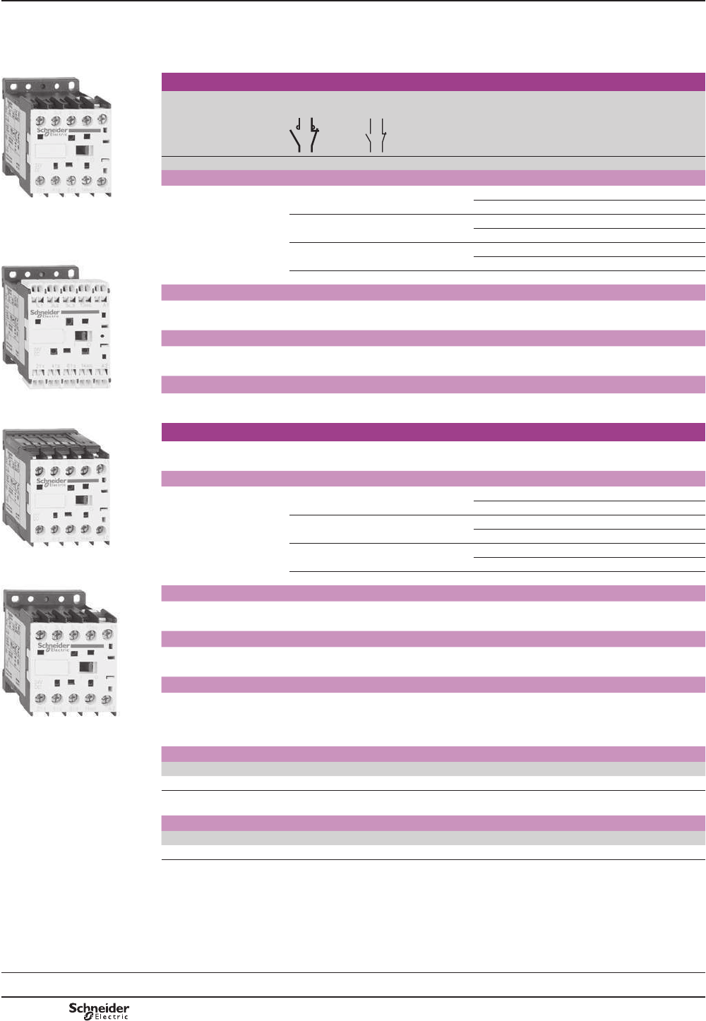
B8/34
TeSys contactors
Contactors for control
in category AC-1, 20 A
Control circuit: d.c. or low consumption
&RQWDFWRUVHOHFWLRQDFFRUGLQJWRXWLOLVDWLRQFDWHJRU\VHHSDJHV$DQG$
0RXQWLQJRQPP7UDLORUVFUHZ¿[LQJ
6FUHZVLQWKHRSHQ³UHDG\WRWLJKWHQ´SRVLWLRQ
$GGRQDX[LOLDU\FRQWDFWEORFNVDQGDFFHVVRULHVVHHSDJHVB8/40 to B8/43.
PF511142R.eps
3 and 4-pole contactors, d.c. supply (1)
Non-inductive loads
Category AC-1
Maximum current at
T y 50 °C
Number
of poles
Instantaneous
auxiliary contacts
Basic reference,
to be completed by adding
the voltage code (2) (3)
A
Screw clamp connections
20 3 – 1 – LP1K0910pp
/&.pp or LP1K1210pp
3 – – 1 LP1K0901pp
or LP1K1201pp
4 – – – LP1K09004pp
PF511143R.eps
or LP1K12004pp
2 2 – – LP1K09008pp
Spring terminal connections
,QWKHUHIHUHQFHVVHOHFWHGDERYHLQVHUWD¿JXUH3 before the voltage code.
Example: LP1 K0910pp becomes LP1 K09103pp.
Faston connectors, 1 x 6.35 or 2 x 2.8
,QWKHUHIHUHQFHVVHOHFWHGDERYHLQVHUWD¿JXUH7 before the voltage code.
Example: LP1 K0910pp becomes LP1 K09107pp.
Solder pins for printed circuit boards
LC1 K09103pp ,QWKHUHIHUHQFHVVHOHFWHGDERYHLQVHUWD¿JXUH5 before the voltage code.
Example: LP1 K0910pp becomes LP1 K09105pp.
PF511144R.eps
3 or 4-pole low consumption contactors (1)
&RPSDWLEOHZLWKSURJUDPPDEOHFRQWUROOHURXWSXWV
:LGHUDQJHFRLO«8FVXSSUHVVRU¿WWHGDVVWDQGDUGFRQVXPSWLRQ:
Screw clamp connections
20 3 – 1 – LP4K0910ppp
or LP4K1210ppp
3 – – 1 LP4K0901ppp
or LP4K1201ppp
4 – – – LP4K09004ppp
LC1 K09105pp or LP4K12004ppp
2 2 – – LP4K09008ppp
PF511141R.eps
/&.pp
Spring terminal connections
,QWKHUHIHUHQFHVVHOHFWHGDERYHLQVHUWD¿JXUH3 before the voltage code.
Example: LP4 K0910pp becomes LP4 K09103pp.
Faston connectors, 1 x 6.35 or 2 x 2.8
,QWKHUHIHUHQFHVVHOHFWHGDERYHLQVHUWD¿JXUH7 before the voltage code.
Example: LP4 K0910pp becomes LP4 K09107pp.
Solder pins for printed circuit boards
,QWKHUHIHUHQFHVVHOHFWHGDERYHLQVHUWD¿JXUH5 before the voltage code.
Example: LP4 K0910pp becomes LP4 K09105pp.
(1)6HOHFWLRQEHWZHHQDQG$UDWLQJVDFFRUGLQJWRQXPEHURIRSHUDWLQJF\FOHVVHH$&FXUYHRQSDJH$
(2)6WDQGDUGFRQWUROFLUFXLWYROWDJHVIRURWKHUYROWDJHVSOHDVHFRQVXOW\RXU5HJLRQDO6DOHV2I¿FH
d.c. supply (contactors LP1 K: 0.8...8F
Volts c12 20 24 (3) 36 48 60 72 100 110 125 155 174 200 220 230 240 250
Code JD ZD BD CD ED ND SD KD FD GD PD QD LD MD MPD MUD UD
&RLOZLWKLQWHJUDOVXSSUHVVLRQGHYLFHDYDLODEOHDGG3WRWKHFRGHUHTXLUHG([DPSOHJD3.
Low consumption (contactors LP4 K: 0.7...8F
Volts c12 20 24 48 72 110 120
Code JW3 ZW3 BW3 EW3 SW3 FW3 GW3
(3) For LP1 K only, when connecting an electronic sensor or timer in series with the contactor coil, select a 20 V coil (a control
FLUFXLWYROWDJHFRGH=c FRQWUROFLUFXLWYROWDJHFRGH='VRDVWRFRPSHQVDWHIRUWKHLQFXUUHGYROWDJHGURS
References
TeSys K
Selection:
pages A5/28 and A5/29
Characteristics:
pages B8/81 to B8/84
Dimensions:
page B8/85
Schemes:
page B8/86
PCPB08P10-EN
Version : 1.0 19 novembre 2014 10:37 AM

B8/35
Contactors
5HYHUVLQJFRQWDFWRUVHOHFWLRQDFFRUGLQJWRXWLOLVDWLRQFDWHJRU\VHHSDJHVA5/23 to A5/27 and A5/30 to A5/33.
,QWHJUDOPHFKDQLFDOLQWHUORFN
,WLVHVVHQWLDOWROLQNWKHFRQWDFWVRIWKHHOHFWULFDOLQWHUORFN
3UHZLUHGSRZHUFLUFXLWFRQQHFWLRQVDVVWDQGDUGRQVFUHZFODPSYHUVLRQV
0RXQWLQJRQPP7UDLORUVFUHZ¿[LQJ6FUHZVLQWKHRSHQ³UHDG\WRWLJKWHQ´SRVLWLRQ
$GGRQDX[LOLDU\FRQWDFWEORFNVDQGDFFHVVRULHVVHHSDJHVB8/40 to B8/43.
PF511147R.eps
3-pole reversing contactors for standard applications
Standard power ratings
of 3-phase motors 50/60 Hz
in category AC-3
Rated
operational
current in
category AC-3
440 V
up to
Instan-
taneous
auxiliary
contacts per
contactor
Basic reference,
to be completed by adding
the voltage code (1) (2)
220 V
230 V
380 V
415 V
440/500 V
660/690 V
LC2 K0910pp kW kW kW A
Screw clamp connections
PF511148R.eps
1.5 2.2 3 61 – LC2K0610pp
– 1 LC2K0601pp
2.2 4 4 91 – LC2K0910pp
– 1 LC2K0901pp
3 5.5 ! 12 1 – LC2K1210pp
– 1 LC2K1201pp
4 7.5 ! 16 1 – LC2K1610pp
– 1 LC2K1601pp
LC2 K09105pp Spring terminal connections
)RUWR$UDWLQJVRQO\LQWKHUHIHUHQFHVVHOHFWHGDERYHLQVHUWD¿JXUH3 before the voltage code.
Example: LC2 K0610pp becomes LC2 K06103pp.
Faston connectors, 1 x 6.35 or 2 x 2.8
)RUWR$UDWLQJVLQWKHUHIHUHQFHVVHOHFWHGDERYHLQVHUWD¿JXUH7 before the voltage code.
Example: LC2 K0610pp becomes LC2 K06107pp.
Solder pins for printed circuit boards
)RUWR$UDWLQJVLQWKHUHIHUHQFHVVHOHFWHGDERYHLQVHUWD¿JXUH5 before the voltage code.
Example: LC2 K0610pp becomes LC2 K06105pp.
3-pole silent reversing contactors
5HFRPPHQGHGIRUXVHLQDUHDVVHQVLWLYHWRQRLVHKLJKLQWHUIHUHQFHPDLQVVXSSOLHVHWF
&RLOZLWKUHFWL¿HULQFRUSRUDWHGVXSSUHVVRU¿WWHGDVVWDQGDUG
Screw clamp connections
1.5 2.2 3 61 – LC8K0610pp
– 1 LC8K0601pp
2.2 4 4 91 – LC8K0910pp
– 1 LC8K0901pp
3 5.5 ! 12 1 – LC8K1210pp
– 1 LC8K1201pp
Faston connectors, 1 x 6.35 or 2 x 2.8
,QWKHUHIHUHQFHVVHOHFWHGDERYHLQVHUWD¿JXUH7 before the voltage code.
Example: LC8 K0610pp becomes LC8 K06107pp.
Solder pins for printed circuit boards
,QWKHUHIHUHQFHVVHOHFWHGDERYHLQVHUWD¿JXUH5 before the voltage code.
Example: LC8 K0610pp becomes LC8 K06105pp.
(1)6WDQGDUGFRQWUROFLUFXLWYROWDJHVIRURWKHUYROWDJHVSOHDVHFRQVXOW\RXU5HJLRQDO6DOHV2I¿FH
a.c. supply
Reversing contactors LC2 K «8F«8F
Volts 12 20 24 (2) 36 42 48 110 115 120 127 200/208 220/230 230 230/240
50/60 Hz J7 Z7 B7 C7 D7 E7 F7 FE7 G7 FC7 L7 M7 P7 U7
Volts 256 277 380/400 400 400/415 440 480 500 575 600 660/690
50/60 Hz W7 UE7 Q7 V7 N7 R7 T7 S7 SC7 X7 Y7
8SWRDQGLQFOXGLQJ9FRLOZLWKLQWHJUDOVXSSUHVVLRQGHYLFHDYDLODEOHDGG2WRWKHFRGHUHTXLUHG([DPSOHJ72.
Reversing contactors LC8 K «8F
Volts 24 42 48 110 115 220 230/240
50/60 Hz B7 D7 E7 F7 FE7 M7 U7
(2))RUPDLQVVXSSOLHVZLWKDKLJKOHYHORILQWHUIHUHQFHYROWDJHVXUJH!9XVHDVXSSUHVVRUPRGXOH/$.()&«9
RU/$.(8*«9VHHSDJH%
TeSys contactors
Reversing contactors for motor control,
6 to 16 A in category AC-3 and
6 to 12 A in category AC-4
Control circuit: a.c.
References
TeSys K
Selection:
pages A5/23 and A5/33
Characteristics:
pages B8/81 to B8/84
Dimensions:
page B8/85
Schemes:
page B8/86
PCPB08P10-EN Version : 1.0 19 novembre 2014 10:37 AM

B8/36
5HYHUVLQJFRQWDFWRUVHOHFWLRQDFFRUGLQJWRXWLOLVDWLRQFDWHJRU\VHHSDJHVA5/23 to A5/27 and A5/30 to A5/33.
,QWHJUDOPHFKDQLFDOLQWHUORFN
,WLVHVVHQWLDOWROLQNWKHFRQWDFWVRIWKHHOHFWULFDOLQWHUORFN
3UHZLUHGSRZHUFLUFXLWFRQQHFWLRQVDVVWDQGDUGRQVFUHZFODPSYHUVLRQV
0RXQWLQJRQPP7UDLORUVFUHZ¿[LQJ
6FUHZVLQWKHRSHQ³UHDG\WRWLJKWHQ´SRVLWLRQ
$GGRQDX[LOLDU\FRQWDFWEORFNVDQGDFFHVVRULHVVHHSDJHVB8/40 to B8/43.
3-pole reversing contactors, d.c. supply
Standard power ratings
of 3-phase motors 50-60 Hz
in category AC-3
Rated
operational
current in
category AC-3
440 V
up to
Instan-
taneous
auxiliary
contacts per
contactor
Basic reference,
to be completed by adding
the voltage code (1) (2)
220 V 380 V 440/500 V
230 V 415 V 660/690 V
kW kW kW A
Screw clamp connections
1.5 2.2 3 6 1 – LP2K0610pp
– 1 LP2K0601pp
2.2 4 4 9 1 – LP2K0910pp
– 1 LP2K0901pp
3 5.5 ! 12 1 – LP2K1210pp
– 1 LP2K1201pp
Spring terminal connections
,QWKHUHIHUHQFHVVHOHFWHGDERYHLQVHUWD¿JXUH3 before the voltage code.
Example: LP2 K0610pp becomes LP2 K06103pp.
Faston connectors, 1 x 6.35 or 2 x 2.8
,QWKHUHIHUHQFHVVHOHFWHGDERYHLQVHUWD¿JXUH7 before the voltage code.
Example: LC2 K0610pp becomes LC2 K06107pp.
Solder pins for printed circuit boards
)RUWR$UDWLQJVLQWKHUHIHUHQFHVVHOHFWHGDERYHLQVHUWD¿JXUH5 before the voltage code.
Example: LC2 K0610pp becomes LC2 K06105pp.
3-pole low consumption reversing contactors
&RPSDWLEOHZLWKSURJUDPPDEOHFRQWUROOHURXWSXWV
:LGHUDQJHFRLO«8FVXSSUHVVRU¿WWHGDVVWDQGDUGFRQVXPSWLRQ:
Screw clamp connections
1.5 2.2 3 6 1 – LP5K0610pp
– 1 LP5K0601pp
2.2 4 4 9 1 – LP5K0910pp
– 1 LP5K0901pp
3 5.5 ! 12 1 – LP5K1210pp
– 1 LP5K1201pp
Spring terminal connections
,QWKHUHIHUHQFHVVHOHFWHGDERYHLQVHUWD¿JXUH3 before the voltage code.
Example: LP5 K0610pp becomes LP5 K06103pp.
Faston connectors, 1 x 6.35 or 2 x 2.8
,QWKHUHIHUHQFHVVHOHFWHGDERYHLQVHUWD¿JXUH7 before the voltage code.
Example: LP5 K0610pp becomes LP5 K06107pp.
Solder pins for printed circuit boards
,QWKHUHIHUHQFHVVHOHFWHGDERYHLQVHUWD¿JXUH5 before the voltage code.
Example: LP5 K0610pp becomes LP5 K06105pp.
(1)6WDQGDUGFRQWUROFLUFXLWYROWDJHVIRURWKHUYROWDJHVSOHDVHFRQVXOW\RXU5HJLRQDO6DOHV2I¿FH
d.c. supply
Reversing contactors LP2 K «8F
Volts 12 20 24 (2) 36 48 60 72 100 110 125 155 174 200 220 230 240 250
Code JD ZD BD CD ED ND SD KD FD GD PD QD LD MD MPD MUD UD
&RLOZLWKLQWHJUDOVXSSUHVVLRQGHYLFHDYDLODEOHDGG3WRWKHFRGHUHTXLUHG([DPSOHJD3.
Low consumption
Reversing contactors LP5 K «8F
Volts 12 20 24 48 72 110 120
Code JW3 ZW3 BW3 EW3 SW3 FW3 GW3
(2) For LP2 K only, when connecting an electronic sensor or timer in series with the contactor coil, select a 20 V coil (a control
FLUFXLWYROWDJHFRGH=cFRQWUROFLUFXLWYROWDJHFRGH='VRDVWRFRPSHQVDWHIRUWKHLQFXUUHGYROWDJHGURS
TeSys contactors
Reversing contactors for motor control,
6 to 12 A in categories AC-3 and AC-4
Control circuit: d.c. or low consumption
References
TeSys K
Selection:
pages A5/23 and A5/33
Characteristics:
pages B8/81 to B8/84
Dimensions:
page B8/85
Schemes:
page B8/86
PCPB08P10-EN
Version : 1.0 19 novembre 2014 10:37 AM
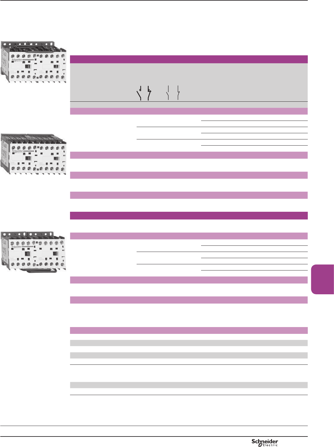
B8/37
Contactors
PF511150R.eps
Warning: reversing contactors LC2 K0910pp and LC2 K0901pp are pre-wired for reverse motor
operation as standard.
5HYHUVLQJFRQWDFWRUVHOHFWLRQDFFRUGLQJWRXWLOLVDWLRQFDWHJRU\VHHSDJHV$DQG$
,QWHJUDOPHFKDQLFDOLQWHUORFN
It is essential to link the contacts of the electrical interlock.
0RXQWLQJRQPP7UDLORUVFUHZ¿[LQJ
6FUHZVLQWKHRSHQ³UHDG\WRWLJKWHQ´SRVLWLRQ
$GGRQDX[LOLDU\FRQWDFWEORFNVDQGDFFHVVRULHVVHHSDJHVB8/40 to B8/43.
3 or 4-pole reversing contactors for standard applications (1)
Non-inductive loads
Category AC-1
Maximum current
atT y 50 °C
Number
of poles
Instantaneous
auxiliary
contacts per
contactor
Basic reference,
to be completed by adding
the voltage code (2) (3)
LC2 K0910pp
A
Screw clamp connections
20 3 – 1 – LC2K0910pp
or LC2K1210pp
3 – – 1 LC2K0901pp
PF511151R.eps
or LC2K1201pp
4 – – – LC2K09004pp
or LC2K12004pp
Spring terminal connections
,QWKHUHIHUHQFHVVHOHFWHGDERYHLQVHUWD¿JXUH3 before the voltage code.
Example: LC2 K0910pp becomes LC2 K09103pp.
Faston connectors, 1 x 6.35 or 2 x 2.8
LC2 K09105pp ,QWKHUHIHUHQFHVVHOHFWHGDERYHLQVHUWD¿JXUH7 before the voltage code.
Example: LC2 K0910pp becomes LC2 K09107pp.
Solder pins for printed circuit boards
,QWKHUHIHUHQFHVVHOHFWHGDERYHLQVHUWD¿JXUH5 before the voltage code.
Example: LC2 K0910pp becomes LC2 K09105pp.
PF511152R.eps
3 or 4-pole silent reversing contactors (1)
5HFRPPHQGHGIRUXVHLQDUHDVVHQVLWLYHWRQRLVHKLJKLQWHUIHUHQFHPDLQVVXSSOLHVHWF
&RLOZLWKUHFWL¿HULQFRUSRUDWHGVXSSUHVVRU¿WWHGDVVWDQGDUG
Screw clamp connections
20 3 – 1 – LC8K0910pp
or LC8K1210pp
3 – – 1 LC8K0901pp
or LC8K1201pp
4 – – – LC8K09004pp
or LC8K12004pp
/&.pp Faston connectors, 1 x 6.35 or 2 x 2.8
,QWKHUHIHUHQFHVVHOHFWHGDERYHLQVHUWD¿JXUH7 before the voltage code.
Example: LC8 K0910pp becomes LC8 K09107pp.
Solder pins for printed circuit boards
,QWKHUHIHUHQFHVVHOHFWHGDERYHLQVHUWD¿JXUH5 before the voltage code.
Example: LC8 K0910pp becomes LC8 K09105pp.
(1)6HOHFWLRQEHWZHHQDQG$UDWLQJVDFFRUGLQJWRQXPEHURIRSHUDWLQJF\FOHVVHH$&FXUYHRQSDJH$
(2)6WDQGDUGFRQWUROFLUFXLWYROWDJHVIRURWKHUYROWDJHVSOHDVHFRQVXOW\RXU5HJLRQDO6DOHV2I¿FH
a.c. supply
Reversing contactors LC2 K «8F«8F
Volts 12 20 24 (3) 36 42 48 110 115 120 127 200/208 220/230 230 230/240
50/60 Hz J7 Z7 B7 C7 D7 E7 F7 FE7 G7 FC7 L7 M7 P7 8
Volts 256 277 380/400 400 400/415 440 480 500 575 600 660/690
50/60 Hz W7 UE7 Q7 V7 N7 R7 T7 S7 SC7 X7 Y7
8SWRDQGLQFOXGLQJ9FRLOZLWKLQWHJUDOVXSSUHVVLRQGHYLFHDYDLODEOHDGG2WRWKHFRGHUHTXLUHG([DPSOHJ72.
Reversing contactors LC8 K «8F
Volts 24 42 48 110 115 220 230/240
50/60 Hz B7 D7 E7 F7 FE7 M7 U7
(3))RUPDLQVVXSSOLHVZLWKDKLJKOHYHORILQWHUIHUHQFHYROWDJHVXUJH!9XVHDVXSSUHVVRUPRGXOH/$.()&«9
RU/$.(8*«9VHHSDJH%
TeSys contactors
Reversing contactors for control
in category AC-1, 20 A
Control circuit: a.c.
References
TeSys K
Selection:
pages A5/28 and A5/29
Characteristics:
pages B8/81 to B8/84
Dimensions:
page B8/85
Schemes:
page B8/86
PCPB08P10-EN Version : 1.0 19 novembre 2014 10:37 AM
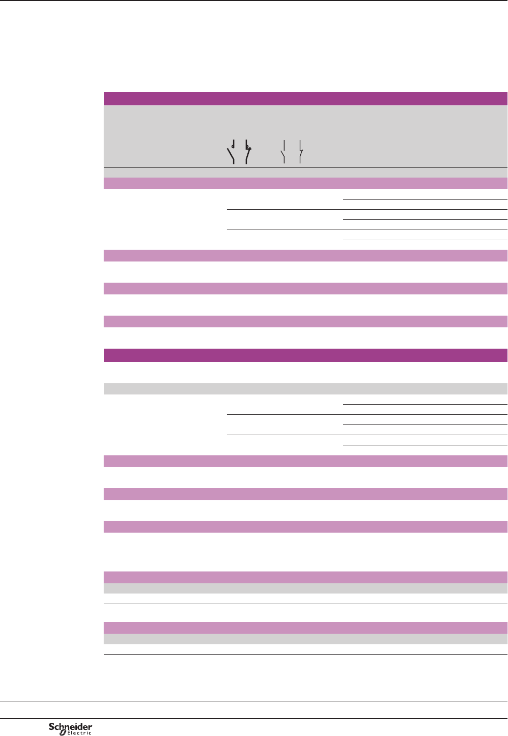
B8/38
Warning: reversing contactors LP2 K0910pp and LP2 K0901pp are pre-wired for reverse motor operation
as standard.
5HYHUVLQJFRQWDFWRUVHOHFWLRQDFFRUGLQJWRXWLOLVDWLRQFDWHJRU\VHHSDJHV$DQG$
,QWHJUDOPHFKDQLFDOLQWHUORFN
It is essential to link the contacts of the electrical interlock.
0RXQWLQJRQPP7UDLORUVFUHZ¿[LQJ
6FUHZVLQWKHRSHQ³UHDG\WRWLJKWHQ´SRVLWLRQ
$GGRQDX[LOLDU\FRQWDFWEORFNVDQGDFFHVVRULHVVHHSDJHVB8/40 to B8/43.
3 or 4-pole reversing contactors, d.c. supply (1)
Non-inductive loads
Category AC-1
Maximum current
atT y 50 °C
Number
of poles
Instantaneous
auxiliary
contacts per
contactor
Basic reference,
to be completed by adding
the voltage code (2) (3)
A
Screw clamp connections
20 3 – 1 – LP2K0910pp
or LP2K1210pp
3 – – 1 LP2K0901pp
or LP2K1201pp
4 – – – LP2K09004pp
or LP2K12004pp
Spring terminal connections
,QWKHUHIHUHQFHVVHOHFWHGDERYHLQVHUWD¿JXUH3 before the voltage code.
Example: LP2 K0910pp becomes LP2 K09103pp.
Faston connectors, 1 x 6.35 or 2 x 2.8
,QWKHUHIHUHQFHVVHOHFWHGDERYHLQVHUWD¿JXUH7 before the voltage code.
Example: LP2 K0910pp becomes LP2 K09107pp.
Solder pins for printed circuit boards
,QWKHUHIHUHQFHVVHOHFWHGDERYHLQVHUWD¿JXUH5 before the voltage code.
Example: LP2 K0910pp becomes LP2 K09105pp.
3 or 4-pole low consumption reversing contactors (1)
&RPSDWLEOHZLWKSURJUDPPDEOHFRQWUROOHURXWSXWV
:LGHUDQJHFRLO«8FVXSSUHVVRU¿WWHGDVVWDQGDUGFRQVXPSWLRQ:
Screw clamp connections
20 3 – 1 – LP5K0910ppp
or LP5K1210ppp
3 – – 1 LP5K0901ppp
or LP5K1201ppp
4 – – – LP5K09004ppp
or LP5K12004ppp
Spring terminal connections
,QWKHUHIHUHQFHVVHOHFWHGDERYHLQVHUWD¿JXUH3 before the voltage code.
Example: LP5 K0910pp becomes LP5 K09103pp.
Faston connectors, 1 x 6.35 or 2 x 2.8
,QWKHUHIHUHQFHVVHOHFWHGDERYHLQVHUWD¿JXUH7 before the voltage code.
Example: LP5 K0910pp becomes LP5 K09107pp.
Solder pins for printed circuit boards
,QWKHUHIHUHQFHVVHOHFWHGDERYHLQVHUWD¿JXUH5 before the voltage code.
Example: LP5 K0910pp becomes LP5 K09105pp.
(1)6HOHFWLRQEHWZHHQDQG$UDWLQJVDFFRUGLQJWRQXPEHURIRSHUDWLQJF\FOHVVHH$&FXUYHRQSDJH$
(2)6WDQGDUGFRQWUROFLUFXLWYROWDJHVIRURWKHUYROWDJHVSOHDVHFRQVXOW\RXU5HJLRQDO6DOHV2I¿FH
d.c. supply (reversing contactors LP2 K: 0.8}8F
Volts c12 20 24 (3) 36 48 60 72 100 110 125 155 174 200 220 230 240 250
Code JD ZD BD CD ED ND SD KD FD GD PD QD LD MD MPD MUD UD
&RLOZLWKLQWHJUDOVXSSUHVVLRQGHYLFHDYDLODEOHDGG3WRWKHFRGHUHTXLUHG([DPSOHJD3.
Low consumption (reversing contactors LP5 K: 0.7}8F
Volts c12 20 24 48 72 110 120
Code JW3 ZW3 BW3 EW3 SW3 FW3 GW3
(3) For LP2 K only, when connecting an electronic sensor or timer in series with the contactor coil, select a 20 V coil (a control
FLUFXLWYROWDJHFRGH=c FRQWUROFLUFXLWYROWDJHFRGH='VRDVWRFRPSHQVDWHIRUWKHLQFXUUHGYROWDJHGURS
TeSys contactors
Reversing contactors for control
in category AC-1, 20 A
Control circuit: d.c. or low consumption
References
TeSys K
Selection:
pages A5/28 and A5/29
Characteristics:
pages B8/81 to B8/84
Dimensions:
page B8/85
Schemes:
page B8/86
PCPB08P10-EN
Version : 1.0 19 novembre 2014 10:37 AM

B8/39
Contactors
PCPB08P10-EN Version : 1.0 19 novembre 2014 10:37 AM
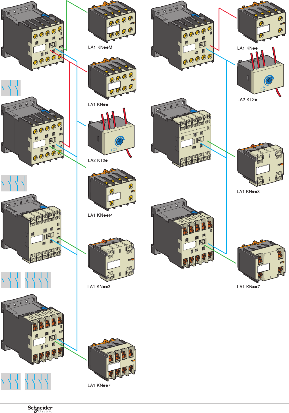
B8/40
LC1, LC7, LP1 K
LC1, LC7, LP1 K
LC1, LC7, LP1 K
LC1, LP1 K
LP4
LP4
LP4
DB404209.eps
PCPB08P10-EN
Version : 1.0 19 novembre 2014 10:37 AM
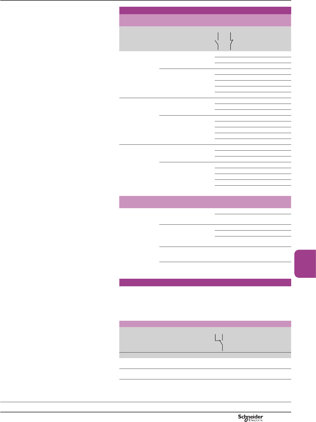
B8/41
Contactors
TeSys contactors
TeSys K contactors and reversing
contactors
Auxiliary contact blocks
Instantaneous auxiliary contact blocks
Recommended for standard applications. Clip-on front mounting, 1 block per
contactor
Connection For use on contactors Composition
Reference
Screw clamp
terminals
$OOSURGXFWVZLWKVFUHZFODPS
terminals
2 – LA1KN20
– 2 LA1KN02
1 1 LA1KN11
$OOSURGXFWVZLWKVFUHZFODPS
terminals except low
FRQVXPSWLRQ
4 – LA1KN40
3 1 LA1KN31
2 2 LA1KN22
1 3 LA1KN13
– 4 LA1KN04
Spring terminals $OOSURGXFWVZLWKVSULQJ
terminals
2 – LA1KN203
– 2 LA1KN023
1 1 LA1KN113
$OOSURGXFWVZLWKVSULQJ
terminals except low
FRQVXPSWLRQ
4 – LA1KN403
3 1 LA1KN313
2 2 LA1KN223
1 3 LA1KN133
– 4 LA1KN043
Faston connectors,
1 x 6.35 or 2 x 2.8
$OOSURGXFWVZLWK)DVWRQ
connectors
2 – LA1KN207
– 2 LA1KN027
1 1 LA1KN117
$OOSURGXFWVZLWK)DVWRQ
connectors except low
FRQVXPSWLRQ
4 – LA1KN407
3 1 LA1KN317
2 2 LA1KN227
1 3 LA1KN137
– 4 LA1KN047
With terminal referencing to standard EN 50012. Clip-on front mounting,
1 block per contactor
Screw clamp
terminals with
referencing
conforming to
standard EN 50012
$OOSROH12SURGXFWVZLWK
screw clamp terminals
except LP4 and LP5 K12
– 2 LA1KN02M
1 1 LA1KN11M
$OOSROH12SURGXFWVZLWK
screw clamp terminals except
LP4 or LP5 K06, K09 and K12
3 1 LA1KN31M
2 2 LA1KN22M
1 3 LA1KN13M
$OOSROHSURGXFWVZLWKVFUHZ
clamp terminals except LP4 or
LP5 K12
1 1 LA1KN11P
$OOSROHSURGXFWVZLWKVFUHZ
clamp terminals except LP4
or LP5 K09 and K12
2 2 LA1KN22P
Electronic time delay auxiliary contact blocks
5HOD\RXWSXWZLWKFRPPRQSRLQWFKDQJHRYHUFRQWDFWa or c 240 V, 2 A
PD[LPXP
Control voltage 0.85…1.1 Uc.
0D[LPXPVZLWFKLQJFDSDFLW\9$RU:
2SHUDWLQJWHPSHUDWXUH«&
5HVHWWLPHVGXULQJWKHWLPHGHOD\SHULRGVDIWHUWKHWLPHGHOD\SHULRG
Clip-on front mounting, 1 block per contactor
Voltage Type Timing range Composition Reference
V s
a or c
24…48
2QGHOD\ 1…30 1 LA2KT2E
a 110…240 2QGHOD\ 1…30 1 LA2KT2U
References
TeSys K
Characteristics:
page B8/84
Dimensions:
pages B8/85 and B8/87
Schemes:
pages B8/86 and B8/88
PCPB08P10-EN Version : 1.0 19 novembre 2014 10:37 AM
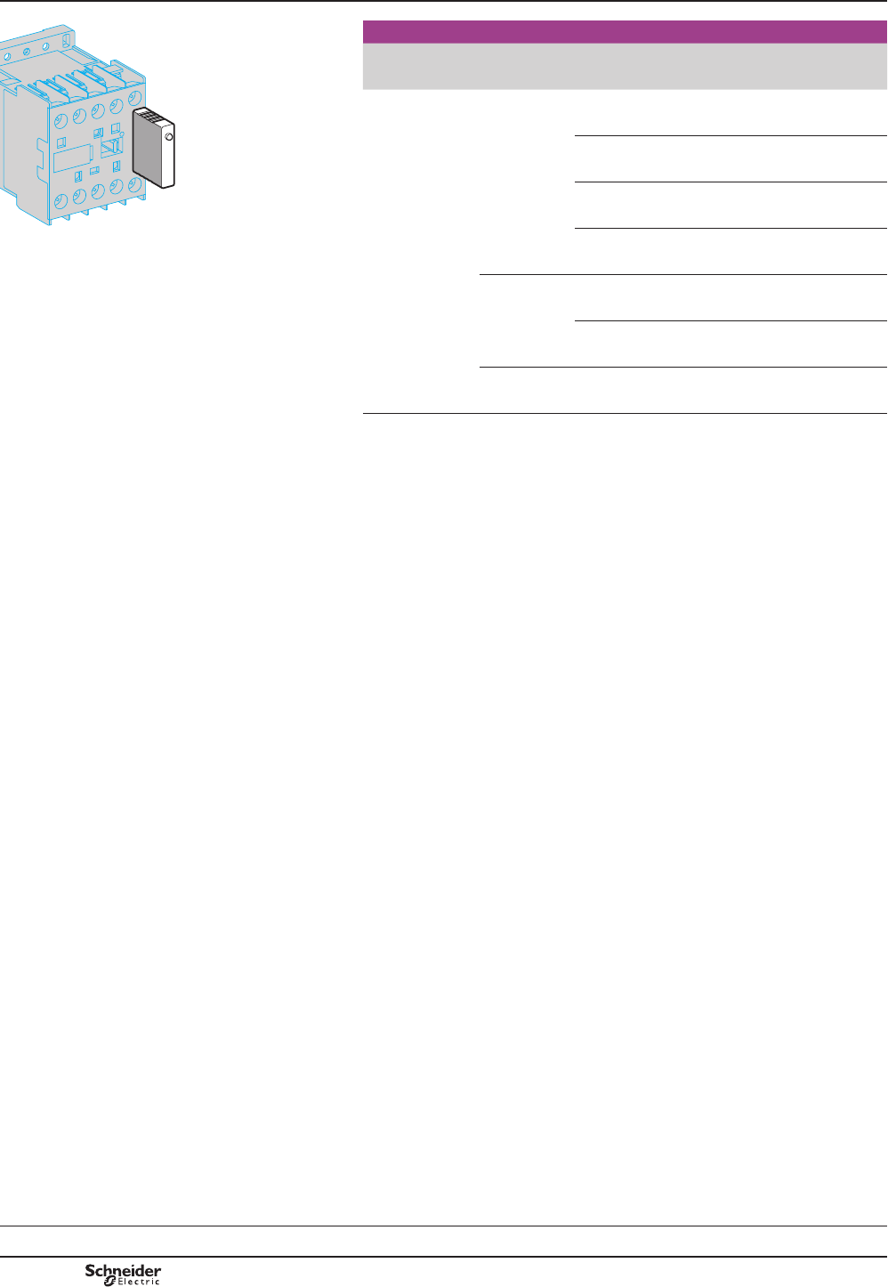
B8/42
DF565018.eps
/$.ppp
References
Mounting
and connection
Type For voltages Sold in
lots of
Unit
reference
&OLSRQ¿[LQJRQWKH
front of contactors
LC1 and LP1, with
locating device.
1RWRROVUHTXLUHG
Varistor (1) a and c 12…24 V 5LA4KE1B
a and c 32…48 V 5LA4KE1E
a and c 50…129 V 5LA4KE1FC
a and c 130…250 V 5LA4KE1UG
'LRGH=HQHU
diode (2)
c 12…24 V 5LA4KC1B
c 32…48 V 5LA4KC1E
RC (3) a 110…250 V 5LA4KA1U
(1)3URWHFWLRQSURYLGHGE\OLPLWLQJWKHWUDQVLHQWYROWDJHWR8FPD[
0D[LPXPUHGXFWLRQRIWUDQVLHQWYROWDJHSHDNV
6OLJKWLQFUHDVHLQGURSRXWWLPHWRWLPHVWKHQRUPDOWLPH
(2)1RRYHUYROWDJHRURVFLOODWLQJIUHTXHQF\
3RODULVHGFRPSRQHQW
6OLJKWLQFUHDVHLQGURSRXWWLPHWRWLPHVWKHQRUPDOWLPH
(3)3URWHFWLRQE\OLPLWLQJWKHWUDQVLHQWYROWDJHWR8FPD[DQGOLPLWDWLRQRIWKHRVFLOODWLQJ
IUHTXHQF\
6OLJKWLQFUHDVHLQGURSRXWWLPHWRWLPHVWKHQRUPDOWLPH
References TeSys contactors
TeSys K contactors and reversing
contactors
Suppressor modules incorporating
LED indicator
TeSys K
Characteristics:
page B8/84
Dimensions:
pages B8/85 and B8/87
Schemes:
pages B8/86 and B8/88
PCPB08P10-EN
Version : 1.0 19 novembre 2014 10:37 AM
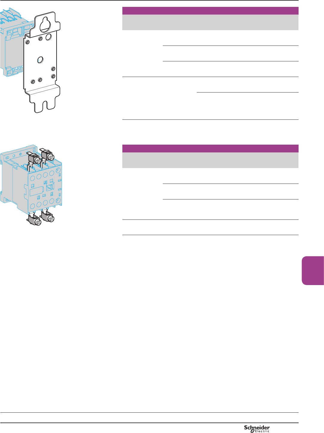
B8/43
Contactors
DF565019.eps
DX1 AP25
Mounting and marking accessories
Description Application Sold in
lots of
Unit
reference
0RXQWLQJSODWHV (1) )RU¿[LQJRQ
1 4 rail
Clip-on 1LA9D973
)RU¿[LQJRQ
2 4 rails
110/120 mm
¿[LQJFHQWUHV
10 DX1AP25
0DUNHUKROGHU Clip-on 2QWRIURQWRI
contactor
100 LA9D90
&OLSLQPDUNHUV PD[LPXP
per contactor
Strips of 10
LGHQWLFDOQXPEHUV
0…9
25 AB1Rp (2)
Strips of 10
identical letters
A…Z
25 AB1Gp (2)
DF565020.eps
LA9 E01
Connection accessories
Description Application Sold in
lots of
Unit
preference
3DUDOOHOLQJOLQNV For 2 poles With screw
clamps
4LA9E01
For 4 poles With screw
clamps
2LA9E02
Set of 6
power connections
For 3-pole
reversing
contactors
for motor control
For contactors
with screw clamp
terminals
100 LA9K0969
Set of 4
power connections
For 4-pole
changeover
contactor pairs
For contactors
with screw clamp
terminals
100 LA9K0970
(1)2UGHUPRXQWLQJSODWHIRU¿[LQJDFRQWDFWRUDQGPRXQWLQJSODWHVIRU¿[LQJDUHYHUVLQJ
FRQWDFWRU
(2)&RPSOHWHWKHUHIHUHQFHE\UHSODFLQJWKHGRWZLWKWKHUHTXLUHGFKDUDFWHU
TeSys contactors
TeSys K contactors and reversing
contactors
Accessories
References
TeSys K
Characteristics:
page B8/84
Dimensions:
pages B8/85 and B8/87
Schemes:
pages B8/86 and B8/88
PCPB08P10-EN Version : 1.0 19 novembre 2014 10:37 AM
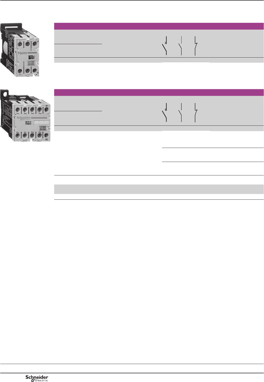
B8/44
TeSys SKGC
TeSys contactors
Mini-contactors TeSys LC1 SKGC,
for use in modular panels
b0RXQWLQJRQPP7UDLORU¿[LQJE\IRXUVFUHZVH[FHSWIRU/&6.*&
b&RQQHFWLRQE\FRQQHFWRUV
b0LQLFRQWDFWRU¿WWHGZLWKWUDQVSDUHQWVHDODEOHSURWHFWLYHFRYHUWRSUHYHQWIURQWIDFHDFFHVV
PF511135R.eps
LC1 SKGC200
Mini-contactors, width 27 mm
Standard power ratings
of 3-phase motors
50/60 Hz in category AC-3
Rated
operational
current
in AC-3
up to
400 V
Non inductive
loads
category AC-1
maximum
current
Ty 50 °C
No. of poles Basic reference,
to be completed
by adding the
voltage code (1)
220 V
230 V
380 V
415 V
660 V
690 V
kW kW kW A A
– – – 5 20 2 – – LC1SKGC200pp
PF511136R.eps
Mini-contactors, width 45 mm
Standard power ratings
of 3-phase motors
50/60 Hz in category AC-3
Rated
operational
current
in AC-3
up to
400 V
Non inductive
loads
category AC-1
maximum
current
Ty 50 °C
No. of poles Basic reference,
to be completed
by adding the
voltage code (1)
220 V
230 V
380 V
415 V
660 V
690 V
kW kW kW A A
1.1 4 4 9 20 3 1 – LC1SKGC310pp
/&6.*& 3 – 1 LC1SKGC301pp
4 – – LC1SKGC400pp
(1)6WDQGDUGFRQWUROFLUFXLWYROWDJHVIRURWKHUYROWDJHVSOHDVHFRQVXOW\RXU5HJLRQDO6DOHV2I¿FH
Volts a
50/60 Hz
24 48 110 120 220 230 240 380 400
Code B7 E7 F7 G7 M7 P7 U7 Q7 V7
References
Characteristics:
pages B8/89 to B8/92
Dimensions, schemes:
page B8/93
PCPB08P30-EN
Version : 1.0 19 novembre 2014 10:37 AM

B8/45
Contactors
TeSys SKGC
TeSys contactors
Mini-contactors TeSys LC1 SKGC,
for use in modular panels
Suppressor modules
PF511134R.eps
/$6.p1p
Suppressor modules
Connection without need for tools by clipping onto right-hand side of contactor
For use on
contactors
Type For voltages Sold in
lots of
Unit
reference
LC1SKGC Varistor (1) a and c 24…48 V 10 LA4SKE1E
a and c
110…250 V
10 LA4SKE1U
Diode (2) c 24…250 V 10 LA4SKC1U
(1)3URWHFWLRQSURYLGHGE\OLPLWLQJWKHWUDQVLHQWYROWDJHWR8FPD[
0D[LPXPUHGXFWLRQRIWUDQVLHQWYROWDJHSHDNV
6OLJKWLQFUHDVHLQGURSRXWWLPHWRWLPHVWKHQRUPDOWLPH
(2)1RRYHUYROWDJHRURVFLOODWLQJIUHTXHQF\
6OLJKWLQFUHDVHLQGURSRXWWLPHWRWLPHVWKHQRUPDOWLPH
References
Characteristics:
pages B8/89 to B8/92
Dimensions, schemes:
page B8/93
PCPB08P30-EN Version : 1.0 19 novembre 2014 10:37 AM

B8/46
References Modular equipment
Standard contactors TeSys GC
Selection:
pages B8/96 to B8/99
Characteristics:
pages B8/100 and
B8/101
Dimensions, schemes:
pages B8/102 and
B8/103
Standard contactors, TeSys GC
No. of
poles
Number of
17.5 mm
modules
Commercial reference
50 Hz coil - different voltages
Sold
in lots
of
12 24 48 110 220/240
V V V V V
Maximum current rating category AC-7a - 16 A
1 – 1 GC1610J5 GC1610B5 GC1610E5 GC1610F5 GC1610M5 g12
1 1 1 GC1611J5 GC1611B5 –GC1611F5 GC1611M5 g12
2 – 1 GC1620J5 GC1620B5 GC1620E5 GC1620F5 gGC1620M5 g12
2 2 2 –GC1622B5 GC1622E5 GC1622F5 gGC1622M5 6
3 – 2 – – – – GC1630B5
GC1630M5 g6
4 – 2 –GC1640B5 –GC1640F5 GC1640M5 g6
Maximum current rating category AC-7a - 25 A
– 2 1 –GC2502B5 GC2502E5 gGC2502M5 g12
– 4 2 –GC2504B5 GC2504E5 gGC2504M5 g6
1 – 1 –GC2510B5 – – GC2510M5 g12
1 1 1 –GC2511B5 –GC2511F5 GC2511M5 g12
2 – 1 GC2520J5 GC2520B5 GC2520E5 GC2520F5 gGC2520M5 g12
2 2 2 –GC2522B5 GC2522E5 GC2522F5 GC2522M5 g6
3 – 2 –GC2530B5 –GC2530F5 GC2530M5 g6
3 2 1 – – – – GC2531M5 6
4 – 2 GC2540J5 GC2540B5 GC2540E5 GC2540F5 gGC2540M5 g6
Maximum current rating category AC-7a - 40 A
– 2 2 –GC4002B5 – – GC4002M5 g6
– 4 3 –GC4004B5 –GC4004F5 gGC4004M5 4
1 1 2 –GC4011B5 – – GC4011M5 g6
2 – 2 –GC4020B5 –GC4020F5 gGC4020M5 g6
2 2 3 – – – – GC4022M5 4
3 – 3 –GC4030B5 –GC4030F5 GC4030M5 g4
4 – 3 –GC4040B5 GC4040E5 GC4040F5 gGC4040M5 g4
Maximum current rating category AC-7a - 63 A
– 2 2 – – – – GC6302M5 6
– 4 3 – GC6304B5 – – GC6304M5 4
1 1 2 – – – – GC6311M5 6
2 – 2 – – – – GC6320M5 6
2 2 3 – – – GC6322F5 GC6322M5 4
3 – 3 –GC6330B5 –GC6330F5 GC6330M5 g4
4 – 3 GC6340B5 GC6340E5 GC6340F5 gGC6340M5 g4
Maximum current rating category AC-7a - 100 A
2 – 3 – – – – GC10020M5 4
4 – 6 –GC10040B5 – – GC10040M5 g2
g IRU+]FRLOUHSODFHODVW¿JXUHE\
GC 2520
PB113075_12.eps
*&
PB113078_18.eps
GC 10020
PB113079_24.eps
TeSys GC
PCPB08P30-EN
Version : 1.0 19 novembre 2014 10:37 AM
B8/47
Contactors
References Modular equipment
TeSys GY "dual tariff" contactors
TeSys GY "dual tariff" contactors
No. of
poles
Number of
17.5 mm
modules
Commercial reference
50 Hz coil - different voltages
Sold
in lots
of
12 24 48 110 220/240
V V V V V
Maximum current rating category AC-7a - 16 A
2 – 1 –GY1620B5 –GY1620M5 12
4 – 2 – – – – GY1640M5 6
Maximum current rating category AC-7a - 25 A
2 – 1 –GY2520B5 – – GY2520M5 g12
3 – 2 – – – – GY2530M5 6
4 – 2 –GY2540B5 – – GY2540M5 6
Maximum current rating category AC-7a - 40 A
2 – 2 – – – – GY4020M5 6
3 – 3 – – – – GY4030M5 4
4 – 3 –GY4040B5 – – GY4040M5 4
Maximum current rating category AC-7a - 63 A
2 – 2 – – – – GY6320M5 6
4 – 3 –GY6340B5 – – GY6340M5 4
g IRU+]FRLOUHSODFHODVW¿JXUHE\
GY 2520M5
PB113083_13.eps
*<0
PB113087_26.eps
TeSys GY
PCPB08P30-EN Version : 1.0 19 novembre 2014 10:37 AM
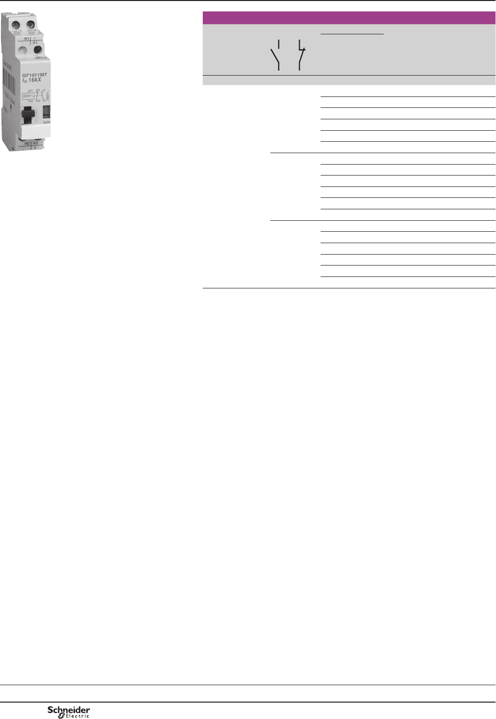
B8/48
References
PF526284R.eps
GF 1611M7
TeSys GF impulse relays
Maximum current
rating category
AC-1
Composition Coil voltages Sold in
lots of
Unit
reference
a 50/60
Hz
c
A V V
16 1 – 12 6 12 GF1610J7
24 12 12 GF1610B7
48 24 12 GF1610E7
110 48 12 GF1610F7
220 – 12 GF1610M7
230/240 110 12 GF1610U7
2 – 12 6 12 GF1620J7
24 12 12 GF1620B7
48 24 12 GF1620E7
110 48 12 GF1620F7
220 – 12 GF1620M7
230/240 110 12 GF1620U7
1 1 12 6 12 GF1611J7
24 12 12 GF1611B7
48 24 12 GF1611E7
110 48 12 GF1611F7
220 – 12 GF1611M7
230/240 110 12 GF1611U7
Modular equipment
TeSys GF impulse relays
Presentation:
page B8/110
Selection:
page B8/111
Characteristics:
pages B8/112 and B8/113
Dimensions, schemes:
page B8/114
TeSys GF
PCPB08P30-EN
Version : 1.0 19 novembre 2014 10:37 AM

B8/49
Contactors
References
PB113093_13.eps
GAP 23
Instantaneous auxiliary contact blocks
Number of contacts Number of poles Reference
2 1 1 – GAC0521
– 2 – GAC0531
– – 1 GAC0511
PB104483-40.eps
GAC 5
Accessories
Description For use on
contactor
Number
of
modules
Operational
voltage
in V
Sold in
lots of
Unit
reference
&RLOVXSSUHVVLRQ
EORFNVFRPSULVLQJ
5&FLUFXLWV
– 1 12…48 1GAP21
110…240 1GAP23
PB104486_34.eps
A9A15922
Ventilation 1/2
PRGXOHFOLSV
onto 5 rail
– 1/2 – 10 GAC5
Set of screw shields
(10 top parts
ERWWRPSDUWV
40 or 63 A
2 contacts
2 – 1A9A15922
40 or 63 A
3 or 4
contacts
3 – 1A9A15923
PB104487_49.eps
A9A15923
Modular equipment
TeSys GC, GY accessories
TeSys GC, GY
PCPB08P30-EN Version : 1.0 19 novembre 2014 10:37 AM

B8/50 PCPB08P30-EN
Version : 1.0 19 novembre 2014 10:37 AM

B8/51
Contactors
Technical
Data for
Designers
TeSys D, SK, K, SKGC, GC, GY, GF
TeSys D:
> characteristics .............. B8/53 to B8/64
> dimensions ..................... B8/65 to B8/75
TeSys SK:
> characteristics .............. B8/76 to B8/79
> dimensions ........................................... B8/80
TeSys K:
> characteristics .............. B8/81 to B8/84
> dimensions ..................... B8/85 to B8/88
TeSys SKGC:
> characteristics .............. B8/89 to B8/92
> dimensions ........................................... B8/93
TeSys GC:
> characteristics ........... B8/94 to B8/101
> dimensions ...........B8/102 and B8/103
TeSys GY:
> characteristics ........B8/104 to B8/107
> dimensions ...........B8/108 and B8/109
TeSys GF:
> characteristics ........B8/110 to B8/113
> dimensions ........................................ B8/114
Standard IEC tests - Contactors
conforming to UL/CSA .................... B8/115
Contents
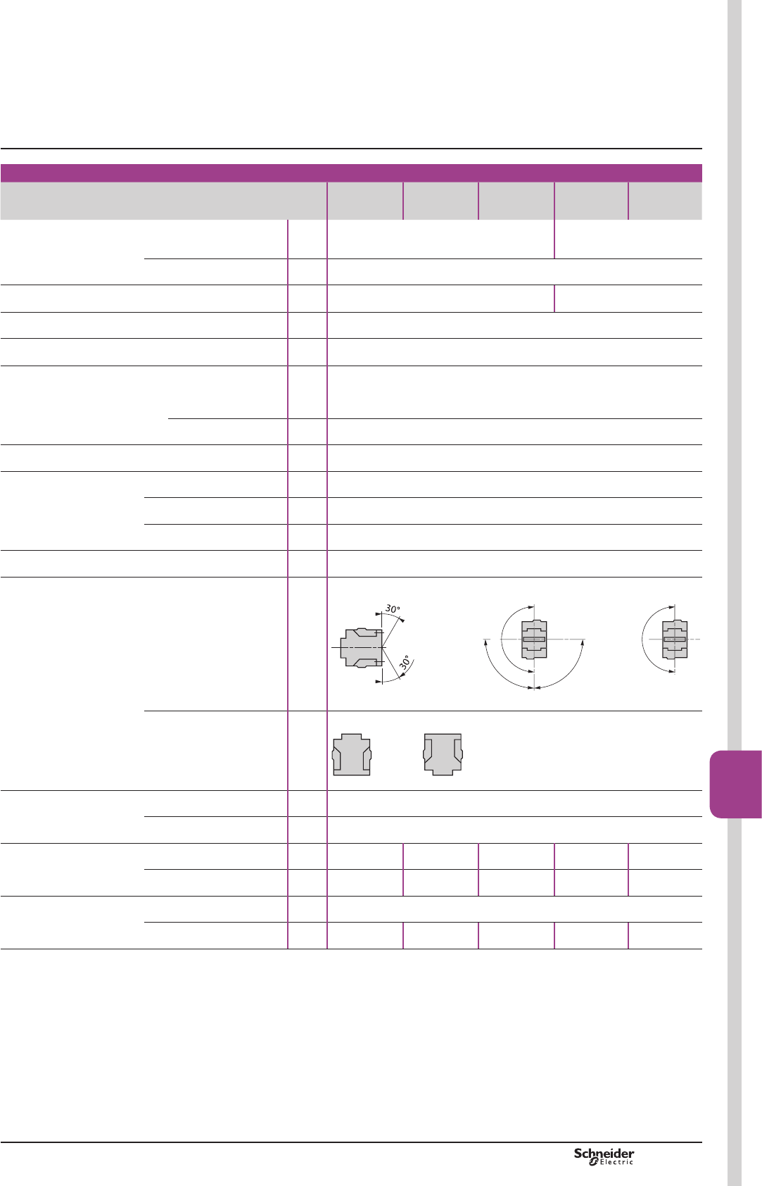
PCPB08T20-EN Version : 1.0 19 novembre 2014 10:37 AM B8/53
Contactors
B8/53
TeSys D
Environment
Contactor type LC1 D09…D18
DT20 and
DT25
D25…D38
DT32 and
DT40
D40A…D65A
DT60A and
DT80A
D80…D95 D115 and
D150
5DWHGLQVXODWLRQYROWDJH8L Conforming to IEC 60947-4-1,
RYHUYROWDJHFDWHJRU\,,,
GHJUHHRISROOXWLRQ
V690 1000
Conforming to UL, CSA V600
5DWHGLPSXOVH
ZLWKVWDQGYROWDJH8LPS
Conforming to IEC 60947 kV 6 8
Conforming to standards ,(&(1,(&(18/&6$&Q
3URGXFWFHUWL¿FDWLRQV UL, CSA (1)&&&*267
*/'195,1$%9/526
Degree of protection (2)
IURQWIDFH
Conforming to IEC 60529
3RZHUFLUFXLWFRQQHFWLRQV 3URWHFWLRQDJDLQVWGLUHFW¿QJHUFRQWDFW,3
Coil connection 3URWHFWLRQDJDLQVWGLUHFW¿QJHUFRQWDFW,3
Protective treatment Conforming to IEC 60068-2-30 “TH”
$PELHQWDLUWHPSHUDWXUHDURXQG
the device
Storage °C «
2SHUDWLRQ °C «
Permissible °C «IRURSHUDWLRQDW8F
0D[LPXPRSHUDWLQJDOWLWXGH :LWKRXWGHUDWLQJ m3000
2SHUDWLQJSRVLWLRQV (3) :LWKRXWGHUDWLQJ
in the following positions
a/c a c
DF510743.eps
90
°
90
°
180
°
DF537812.eps
180
°
DF537813.eps
Positions that are
not permissible
For c contactors LC1 D09 to LC1 D65A.
DF537814.eps
DF537815.eps
Flame resistance Conforming to UL 94 V1
Conforming to IEC 60695-2-1 °C 850
6KRFNUHVLVWDQFH (4)
VLQHZDYH PV
Contactor open 10 gn 8 gn 10 gn 8 gn 6 gn
Contactor closed 15 gn 15 gn 15 gn 10 gn 15 gn
Vibration resistance (4)
5…300 Hz
Contactor open 2 gn
Contactor closed 4 gn 4 gn 4 gn 3 gn 4 gn
(1) &RQWDFWRU/&'ZLWKGFFRLOLVQRW8/&6$FHUWL¿HG
(2) 3URWHFWLRQSURYLGHGIRUWKHFDEOLQJFVDVLQGLFDWHGRQWKHQH[WSDJHDQGIRUFRQQHFWLRQE\FDEOH)RUOXJW\SHDGGDSURWHFWLYHFRYHU
(3) :KHQPRXQWLQJRQDYHUWLFDOUDLOXVHDVWRS
(4) :LWKRXWPRGLI\LQJWKHFRQWDFWVWDWHVLQWKHPRVWXQIDYRXUDEOHGLUHFWLRQFRLOHQHUJLVHGDW8H
Characteristics TeSys contactors
TeSys D contactors
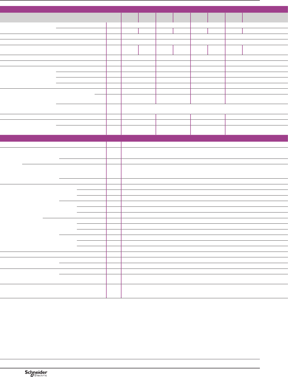
PCPB08T20-EN
Version : 1.0 19 novembre 2014 10:37 AM
B8/54
Pole characteristics
Contactor type LC1 D09
3
DT20
D098
D12
3
DT25
D128
D18
3
DT32
D188
D25
3
DT40
D258
5DWHGRSHUDWLRQDOFXUUHQW,H
(Ue y9
In AC-3, T y& A9 12 18 25
In AC-1, T y& A25 (1) 20 25 (1) 25 32 (1) 32 40 (1) 40
5DWHGRSHUDWLRQDOYROWDJH8H Up to V690 690 690 690
)UHTXHQF\OLPLWV 2IWKHRSHUDWLRQDOFXUUHQW Hz 25…400 25…400 25…400 25…400
Conventional thermal
FXUUHQW,WK
T y& A25 (1) 20 25 (1) 25 32 (1) 32 40 (1) 40
5DWHGPDNLQJFDSDFLW\9 Conforming to IEC 60947 A250 250 300 450
5DWHGEUHDNLQJFDSDFLW\9 Conforming to IEC 60947 A250 250 300 450
Permissible short time rating
1RFXUUHQWÀRZLQJIRUSUHFHGLQJ
PLQXWHVZLWKT y&
For 1 s A210 210 240 380
For 10 s A105 105 145 240
For 1 min A61 61 84 120
For 10 min A30 30 40 50
)XVHSURWHFWLRQ
DJDLQVWVKRUWFLUFXLWV
(U y9
:LWKRXWWKHUPDO
RYHUORDGUHOD\
J*IXVH
W\SH A25 40 50 63
W\SH A20 25 35 40
:LWKWKHUPDORYHUORDGUHOD\ A6HHSDJHV%DQG%IRUD0RUJ*IXVHUDWLQJV
FRUUHVSRQGLQJWRWKHDVVRFLDWHGWKHUPDORYHUORDGUHOD\
6HHSDJHV%DQG%IRUD0RUJ*IXVHUDWLQJVFRUUHVSRQGLQJWRWKHDVVRFLDWHGWKHUPDORYHUORDGUHOD\
Average impedance per pole At Ith and 50 Hz m:2.5 2.5 2.5 2
Power dissipation per pole for the
DERYHRSHUDWLRQDOFXUUHQWV
AC-3 W0.20 0.36 0.8 1.25
AC-1 W1.56 1.56 2.5 3.2
Control circuit characteristics, a.c. supply
5DWHGFRQWUROFLUFXLWYROWDJH8F 50/60 Hz V12…690
Control voltage limits
«8FDW&
50 or 60 Hz coils 2SHUDWLRQ –
'URSRXW –
«8FDW& «8FDW&
50/60 Hz coils 2SHUDWLRQ 0.8…1.1 Uc on 50 Hz and
0.85…1.1 Uc on 60 Hz
DW&
DW&
«8FRQ+]DW&
DW&
DW&
'URSRXW «8FDW&
«8FDW& «8FDW& «8FDW& «8FDW&
$YHUDJHFRQVXPSWLRQ
DW&DQGDW8F
a 50 Hz ,QUXVK 50 Hz coil VA –
Cos M0.75
50/60 Hz coil VA 70
Sealed 50 Hz coil VA –
Cos M0.3
50/60 Hz coil VA 7
a 60 Hz ,QUXVK 60 Hz coil VA –
Cos M0.75
50/60 Hz coil VA 70
Sealed 60 Hz coil VA –
Cos M0.3
50/60 Hz coil VA 7.5
Heat dissipation 50/60 Hz W2…3
2SHUDWLQJWLPH(2) &ORVLQJ& ms 12…22
2SHQLQJ2 ms 4…19
0HFKDQLFDOGXUDELOLW\
LQPLOOLRQVRIRSHUDWLQJF\FOHV
50 or 60 Hz coil –
50/60 Hz coil on 50 Hz 15
0D[LPXPRSHUDWLQJUDWH
DWDPELHQWWHPSHUDWXUHy&
,QRSHUDWLQJF\FOHVSHUKRXU 3600
(1) Versions with spring terminal connections:
16 A for LC1 D093 and LC1 D123$SRVVLEOHZLWK[PP2LQSDUDOOHO
25 A for LC1 D183 to LC1 D323 (32 A possible for LC1 D183FRQQHFWHGZLWK[PP2FDEOHVLQSDUDOOHO$SRVVLEOHIRULC1 D253 and LC1 D323 connected
ZLWK[PP2LQSDUDOOHO
(2) 7KHFORVLQJWLPH&LVPHDVXUHGIURPWKHPRPHQWWKHFRLOVXSSO\LVVZLWFKHGRQWRFORVXUHRIWKHPDLQSROHV7KHRSHQLQJWLPH2LVPHDVXUHGIURPWKH
PRPHQWWKHFRLOVXSSO\LVVZLWFKHGRIIWRWKHPRPHQWWKHPDLQSROHVVHSDUDWH
Characteristics
Selection:
pages A5/23 to A5/47
References:
pages B8/2 to B8/7
Dimensions:
pages B8/65 to B8/68
Schemes:
pages B8/69 and B8/70
TeSys contactors
TeSys D contactors
TeSys D
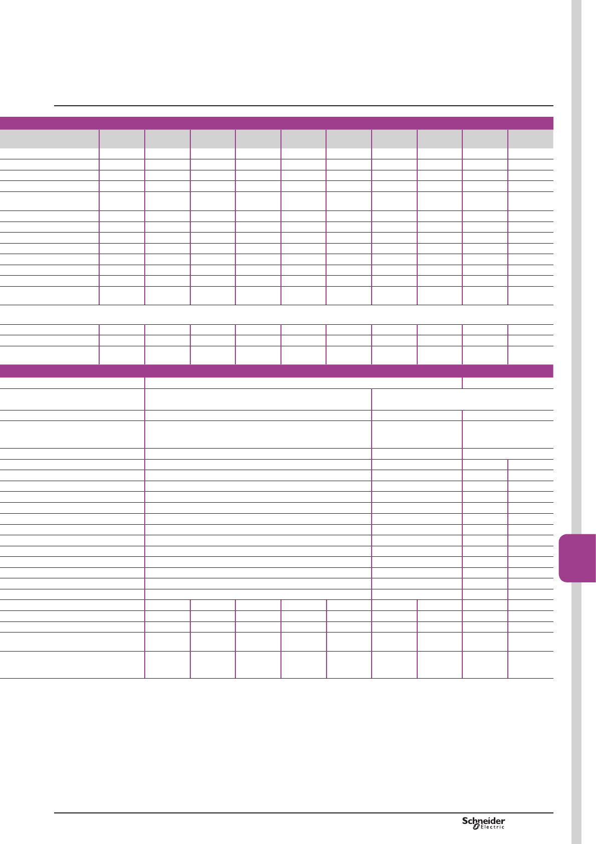
PCPB08T20-EN Version : 1.0 19 novembre 2014 10:37 AM B8/55
Contactors
B8/55
3 3 3 3
D32 D38 D40A DT60A D50A D65A DT80A D80 D95 D115 D150
5DWHGRSHUDWLRQDOFXUUHQW,H
9
T&
32 38 40 – 50 65 – 80 95 115 150
T&
50 (1) 50 60 60 80 80 80 125 125 200 200
5DWHGRSHUDWLRQDOYROWDJH8H
690 690 690 690 690 690 690 1000 1000 1000 1000
)UHTXHQF\OLPLWV 2IWKHRSHUDWLRQDOFXUUHQW
25…400 25…400 25…400 25…400 25…400 25…400 25…400 25…400 25…400 25…400 25…400
FXUUHQW,WK
T&
50 50 60 60 80 80 80 125 125 200 200
5DWHGPDNLQJFDSDFLW\9
550 550 800 800 900 1000 1000 1100 1100 1260 1660
5DWHGEUHDNLQJFDSDFLW\9
550 550 800 800 900 1000 1000 1100 1100 1100 1400
1RFXUUHQWÀRZLQJIRUSUHFHGLQJ
PLQXWHVZLWKT&
430 430 720 720 810 900 900 990 1100 1100 1400
260 310 320 320 400 520 520 640 800 950 1200
138 150 165 165 208 260 260 320 400 550 580
60 60 72 72 84 110 110 135 135 250 250
)XVHSURWHFWLRQ
DJDLQVWVKRUWFLUFXLWV
9
:LWKRXWWKHUPDO
RYHUORDGUHOD\
J*IXVH
W\SH
63 63 80 80 100 125 125 200 200 250 315
W\SH
63 63 80 80 100 125 125 160 160 200 250
:LWKWKHUPDORYHUORDGUHOD\ 6HHSDJHV%DQG%IRUD0RUJ*IXVHUDWLQJV
FRUUHVSRQGLQJWRWKHDVVRFLDWHGWKHUPDORYHUORDGUHOD\
6HHSDJHV%DQG%IRUD0RUJ*IXVHUDWLQJVFRUUHVSRQGLQJWRWKHDVVRFLDWHGWKHUPDORYHUORDGUHOD\
:
2 2 1.5 1.6 1.5 1.5 1.6 0.8 0.8 0.6 0.6
DERYHRSHUDWLRQDOFXUUHQWV
2 3 2.4 – 3.7 6.3 – 5.1 7.2 7.9 13.5
5 5 5.4 5.8 9.6 9.6 10.2 12.5 12.5 24 24
5DWHGFRQWUROFLUFXLWYROWDJH8F
12…690 12…690 24…500
– – «8FDW&
2SHUDWLRQ
'URSRXW
– – «8FDW& «8FDW&
2SHUDWLRQ
DW&
0.8…1.1 Uc on 50 Hz and
0.85…1.1 Uc on 60 Hz
DW&
0.8…1.1 Uc on 50 Hz and
«8FRQ+]DW&
0.8…1.1 Uc on 50 Hz and
0.85…1.1 Uc on 60 Hz
DW&
0.8…1.15 Uc on 50/60 Hz
DW&
'URSRXW «8FDW&
«8FDW& «8FDW& «8FDW& «8FDW&
$YHUDJHFRQVXPSWLRQ
DW&DQGDW8F
,QUXVK
– – 200 300 –
M
0.75 0.75 0.75 0.8 0.9
70 160 245 280…350 280…350
– – 20 22 –
M
0.3 0.3 0.3 0.3 0.9
7 15 26 2…18 2…18
,QUXVK
– – 220 300 –
M
0.75 0.75 0.75 0.8 0.9
70 140 245 280…350 280…350
– – 22 22 –
M
0.3 0.3 0.3 0.3 0.9
7.5 13 26 2…18 2…18
2…3 4…5 6…10 3…8 3…4.5
2SHUDWLQJWLPH &ORVLQJ&
12…22 12…26 12…26 12…26 12…26 12…26 20…35 20…35 20…50 20…35
2SHQLQJ2
4…19 4…19 4…19 4…19 4…19 4…19 6…20 6…20 6…20 40…75
0HFKDQLFDOGXUDELOLW\
LQPLOOLRQVRIRSHUDWLQJF\FOHV
– – – – – – 10 10 8 –
15 6 6 6 6 6 4 4 8 8
0D[LPXPRSHUDWLQJUDWH
DWDPELHQWWHPSHUDWXUH &
,QRSHUDWLQJF\FOHVSHUKRXU
3600 3600 3600 3600 3600 3600 3600 3600 2400 1200
$SRVVLEOHZLWK[PP LQSDUDOOHO
FRQQHFWHGZLWK[PP FDEOHVLQSDUDOOHO$SRVVLEOHIRU
ZLWK[PP LQSDUDOOHO
7KHFORVLQJWLPH&LVPHDVXUHGIURPWKHPRPHQWWKHFRLOVXSSO\LVVZLWFKHGRQWRFORVXUHRIWKHPDLQSROHV7KHRSHQLQJWLPH2LVPHDVXUHGIURPWKH
PRPHQWWKHFRLOVXSSO\LVVZLWFKHGRIIWRWKHPRPHQWWKHPDLQSROHVVHSDUDWH
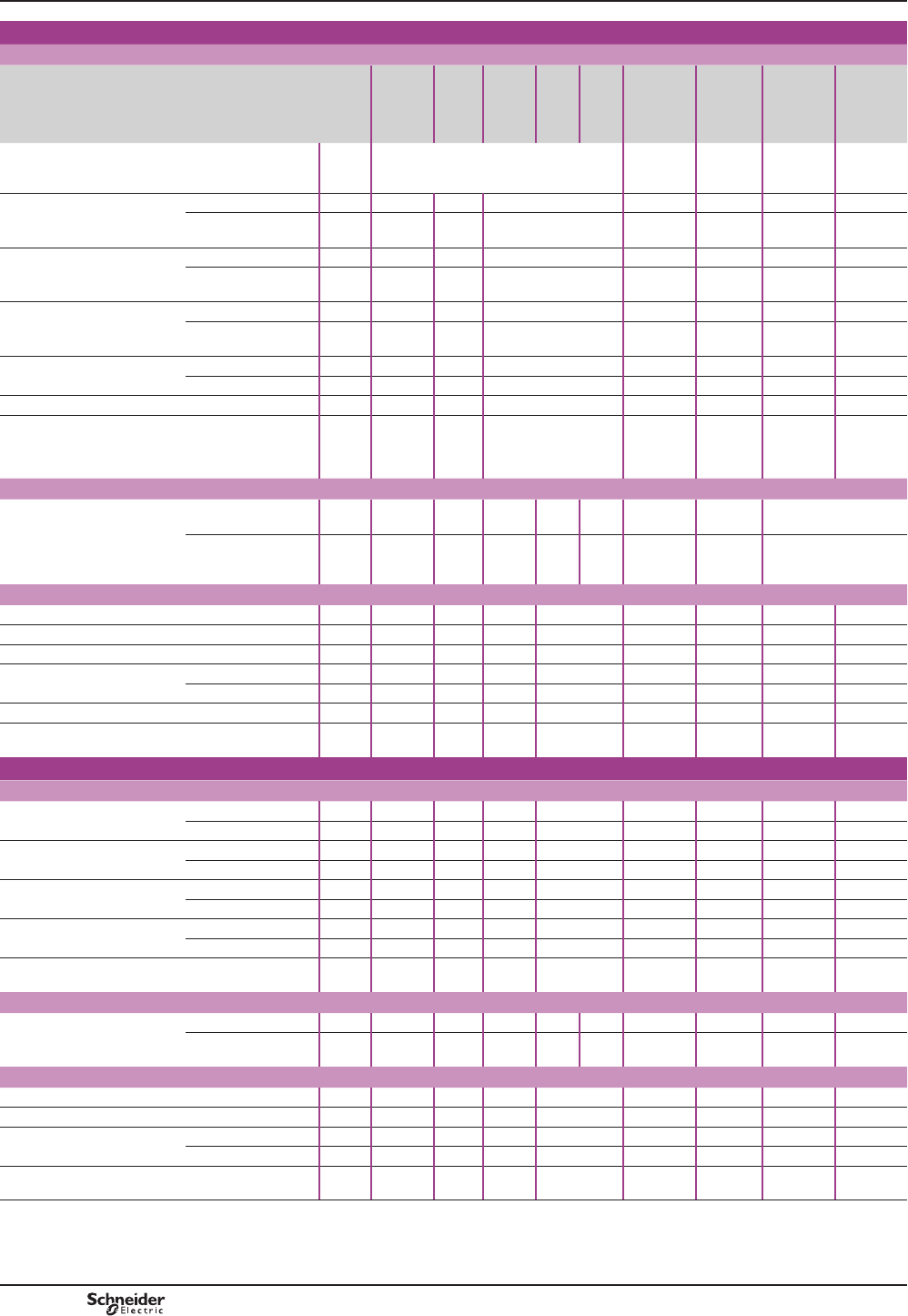
PCPB08T20-EN
Version : 1.0 19 novembre 2014 10:37 AM
B8/56
TeSys D
Power circuit connections
Screw clamp terminal connections
Contactor type LC1 D09
and D12
DT20
and DT25
D18
3
D25
3
D32 D38 D18 and
D25 3
DT32 and
DT40
D40A to
D65A
DT60A
and
DT80A (1)
D80
and D95
D115
and D150
Tightening Screw clamp terminals
Connector
LQSXWV
Screw
clamp
terminals
Connector
LQSXW
Connector
LQSXWV
Flexible cable
ZLWKRXWFDEOHHQG
FRQGXFWRU mm21…4 1.5…6 2.5…10 2.5…10 1…35 4…50 10…120
FRQGXFWRUV mm21…4 1.5…6 2.5…10 2.5…10 1…25
and 1…35
4…25 10…120
«
Flexible cable
with cable end
FRQGXFWRU mm21…4 1…6 1…10 2.5…10 1…35 4…50 10…120
FRQGXFWRUV mm21…2.5 1…4 1.5…6 2.5…10 1…25
and 1…35
4…16 10…120
«
Solid cable
ZLWKRXWFDEOHHQG
FRQGXFWRU mm21…4 1.5…6 1.5…10 2.5…16 1…35 4…50 10…120
FRQGXFWRUV mm21…4 1.5…6 2.5…10 2.5…16 1…25
and 1…35
6…25 10…120
«
Screwdriver Philips 1 1 1 1 – – –
Flat screwdriver Ø Ø6 Ø6 Ø6 Ø6 – Ø6…Ø8 –
+H[DJRQDONH\ – – – – 4 4 4
7LJKWHQLQJWRUTXH N.m 1.7 1.7 2.5 1.8 5:
y 25 mm2
8: 35 mm2
9 12
Spring terminal connections (2)
Flexible cable
ZLWKRXWFDEOHHQG
FRQGXFWRU mm22.5
'7
4 4 4 – 10 – –
FRQGXFWRUV mm22.5
(except
'7
4 4 4 – – – –
Connection by bars or lugs
Bar c.s.a. – – – – – – 3 x 16 5 x 25
/XJH[WHUQDO mm 8 8 10 10 8 16.5 17 25
Ø of screw mm M3.5 M3.5 M4 M4 M3.5 M6 M6 M8
Screwdriver Philips 1 1 1 1 1 – – –
Flat screwdriver Ø Ø6 Ø6 Ø6 Ø6 Ø6 – Ø8 –
.H\IRUKH[DJRQDOKHDGHGVFUHZ – – – – – 10 10 13
7LJKWHQLQJWRUTXH N.m 1.7 1.7 2.5 2.5 1.8 6 9 12
Control circuit connections
Connection by cable (tightening via screw clamps)
Flexible cable
ZLWKRXWFDEOHHQG
FRQGXFWRU mm21…4 1…4 1…4 1…4 1…4 1…4 1…4 1…2.5
FRQGXFWRUV mm21…4 1…4 1…4 1…4 1…4 1…4 1…4 1…2.5
Flexible cable
with cable end
FRQGXFWRU mm21…4 1…4 1…4 1…4 1…4 1…4 1…2.5 1…2.5
FRQGXFWRUV mm21…2.5 1…2.5 1…2.5 1…2.5 1…2.5 1…2.5 1…2.5 1…2.5
Solid cable
ZLWKRXWFDEOHHQG
FRQGXFWRU mm21…4 1…4 1…4 1…4 1…4 1…4 1…4 1…2.5
FRQGXFWRUV mm21…4 1…4 1…4 1…4 1…4 1…4 1…4 1…2.5
Screwdriver Philips 1 1 1 1 1 1 1 1
Flat screwdriver Ø Ø6 Ø6 Ø6 Ø6 Ø6 Ø6 Ø6 Ø6
7LJKWHQLQJWRUTXH N.m 1.7 1.7 1.7 1.7 1.7 1.7 1.7 1.2
Spring terminal connections (2)
Flexible cable
ZLWKRXWFDEOHHQG
FRQGXFWRU mm22.5 2.5 2.5 2.5 – 2.5 0.75…2.5 – –
FRQGXFWRUV mm22.5 2.5 2.5 2.5 – 2.5 0.75…2.5 – –
Connection by bars or lugs
/XJH[WHUQDO mm 8 8 8 8 8 8 8 8
Ø of screw mm M3.5 M3.5 M3.5 M3.5 M3.5 M3.5 M3.5 M3.5
Screwdriver Philips 1 1 1 1 1 1 1 1
Flat screwdriver Ø Ø6 Ø6 Ø6 Ø6 Ø6 Ø6 Ø6 Ø6
7LJKWHQLQJWRUTXH N.m 1.7 1.7 1.7 1.7 1.7 1.7 1.7 1.2
(1)%75VFUHZVKH[DJRQVRFNHWKHDG,QDFFRUGDQFHZLWKORFDOHOHFWULFDOZLULQJUHJXODWLRQVDVL]HLQVXODWHG$OOHQNH\PXVWEHXVHGUHIHUHQFHLAD ALLEN4,
VHHSDJH%
(2),IFDEOHHQGVDUHXVHGFKRRVHWKHQH[WVL]HGRZQH[DPSOHIRUPP2XVHPP2DQGVTXDUHFULPSWKHFDEOHHQGVXVLQJDVSHFLDOWRRO
Characteristics TeSys contactors
TeSys D contactors
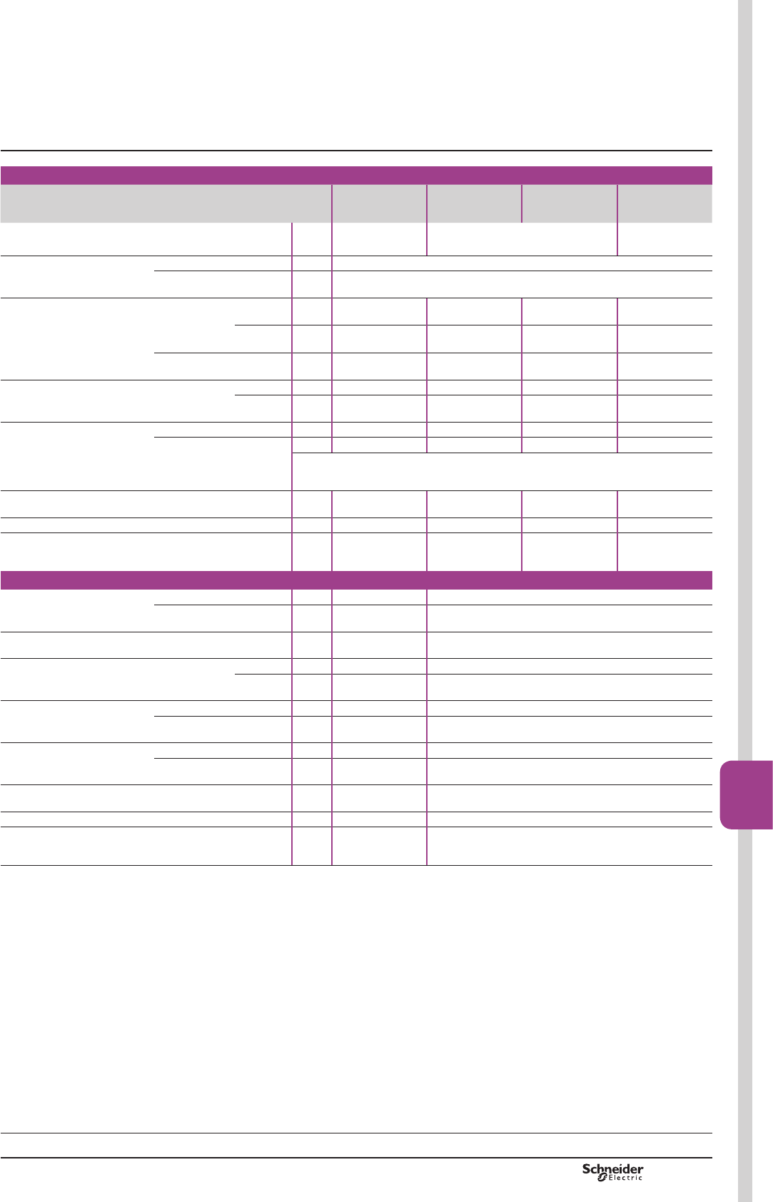
PCPB08T20-EN Version : 1.0 19 novembre 2014 10:37 AM B8/57
Contactors
B8/57
d.c. control circuit characteristics
Contactor type LC1 D09…D38
LC1 DT20…DT40
LC1 D40A…D65A
LC1 DT60A and
DT80A
LC1 or LP1 D80
LC1 D95
LC1 D115 and
LC1 D150
5DWHGFRQWUROFLUFXLWYROWDJH8F cV12…440 12…440 24…440
5DWHGLQVXODWLRQYROWDJH Conforming to IEC 60947-1 V690
Conforming to UL, CSA V600
Control voltage limits 2SHUDWLRQ Standard
coil
0.7…1.25 Uc
DW&
0.75…1.25 Uc
DW&
0.85…1.1 Uc
DW&
0.75…1.2 Uc
DW&
Wide range
coil
– – 0.75…1.2 Uc
DW&
–
'URSRXW 0.1…0.25 Uc
DW&
0.1…0.3 Uc
DW&
0.1…0.3 Uc
DW&
0.15…0.4 Uc
DW&
$YHUDJHFRQVXPSWLRQ
DW&DQGDW8F
c,QUXVK W5.4 19 22 270…365
Sealed W5.4 7.4 22 2.4…5.1
2SHUDWLQJWLPH (1)
average at Uc
Closing & ms 95…130 20…35
2SHQLQJ ³2´ ms 20…35 40…75
Note:7KHDUFLQJWLPHGHSHQGVRQWKHFLUFXLWVZLWFKHGE\WKHSROHV)RUDOOQRUPDOSKDVH
DSSOLFDWLRQVWKHDUFLQJWLPHLVOHVVWKDQPV7KHORDGLVLVRODWHGIURPWKHVXSSO\DIWHUDWLPH
HTXDOWRWKHVXPRIWKHRSHQLQJWLPHDQGWKHDUFLQJWLPH
7LPHFRQVWDQW/5 ms 28 34 75 25
0HFKDQLFDOGXUDELOLW\DW8F ,QPLOOLRQVRIRSHUDWLQJF\FOHV 30 10 10 8
0D[LPXPRSHUDWLQJUDWH
DWDPELHQWWHPSHUDWXUHy&
,QRSHUDWLQJF\FOHVSHUKRXU 3600 3600 3600 1200
Low consumption control circuit characteristics
5DWHGLQVXODWLRQYROWDJH Conforming to IEC 60947-1 V690 –
Conforming to UL, CSA V600 –
0D[LPXPYROWDJH 2IWKHFRQWUROFLUFXLWRQcV250 –
$YHUDJHFRQVXPSWLRQ
GFDW&DQGDW8F
Wide range coil
«8F
,QUXVK W2.4 –
Sealed W2.4 –
2SHUDWLQJWLPH (1)
DW8FDQGDW&
Closing & ms –
2SHQLQJ ³2´ ms –
Voltage limits (T y&
RIWKHFRQWUROFLUFXLW
2SHUDWLRQ 0.8 to 1.25 Uc –
'URSRXW 0.1…0.3 Uc –
7LPHFRQVWDQW/5 ms 40 –
0HFKDQLFDOGXUDELOLW\ ,QPLOOLRQVRIRSHUDWLQJF\FOHV 30 –
0D[LPXPRSHUDWLQJUDWH
DWDPELHQWWHPSHUDWXUHy&
,QRSHUDWLQJF\FOHVSHUKRXU 3600 –
(1) 7KHRSHUDWLQJWLPHVGHSHQGRQWKHW\SHRIFRQWDFWRUHOHFWURPDJQHWDQGLWVFRQWUROPRGH
7KHFORVLQJWLPH&LVPHDVXUHGIURPWKHPRPHQWWKHFRLOVXSSO\LVVZLWFKHGRQWRLQLWLDOFRQWDFWRIWKHPDLQSROHV
7KHRSHQLQJWLPH2LVPHDVXUHGIURPWKHPRPHQWWKHFRLOVXSSO\LVVZLWFKHGRIIWRWKHPRPHQWWKHPDLQSROHVVHSDUDWH
Characteristics TeSys contactors
TeSys D contactors
TeSys D
Selection:
pages A5/23 to A5/47
References:
pages B8/2 to B8/7
Dimensions:
pages B8/65 to B8/68
Schemes:
pages B8/69 and B8/70
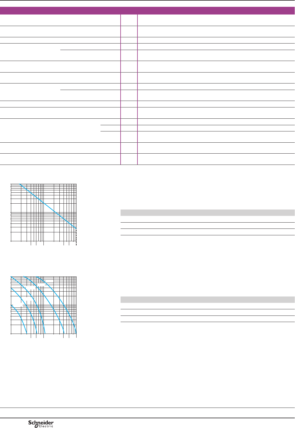
PCPB08T20-EN
Version : 1.0 19 novembre 2014 10:37 AM
B8/58
Characteristics of auxiliary contacts incorporated in the contactor
0HFKDQLFDOO\OLQNHGFRQWDFWV Conforming to IEC 60947-5-1 (DFKFRQWDFWRUKDV12DQG1&FRQWDFWVPHFKDQLFDOO\OLQNHGRQWKHVDPH
movable contact holder
Mirror contact Conforming to IEC 60947-4-1 The N/C contact on each contactor represents the state of the power contacts
DQGFDQEHFRQQHFWHGWRD35(9(17$VDIHW\PRGXOH
5DWHGRSHUDWLRQDOYROWDJH8H Up to V690
5DWHGLQVXODWLRQYROWDJH8L Conforming to IEC 60947-1 V690
Conforming to UL, CSA V600
&RQYHQWLRQDOWKHUPDOFXUUHQW
,WK
)RUDPELHQWWHPSHUDWXUH
y&
A10
)UHTXHQF\RIWKHRSHUDWLRQDOFXUUHQW Hz 25…400
0LQLPXPVZLWFKLQJFDSDFLW\
O –8
U min V17
I min mA 5
6KRUWFLUFXLWSURWHFWLRQ Conforming to IEC 60947-5-1 J*IXVH$
5DWHGPDNLQJFDSDFLW\ Conforming to IEC 60947-5-1,
I rms
Aa: 140, c: 250
Short-time rating Permissible for 1 s A100
500 ms A120
100 ms A140
,QVXODWLRQUHVLVWDQFH M:> 10
Non-overlap time *XDUDQWHHGEHWZHHQ
1&DQG12FRQWDFWV
ms RQHQHUJLVDWLRQDQGRQGHHQHUJLVDWLRQ
0,1
0,2 0,3 0,5
0,4 0,6
0,8
1
2 3
4
5
6
8
10
0,1
0,2
0,3
0,4
0,6
0,8
1
2
3
4
6
8
10
0LOOLRQVRIRSUDWLQJF\FOHV
&XUUHQWEURNHQLQ$
DF537816.eps
Operational power of contacts conforming to IEC 60947-5-1
a.c. supply, categories AC-14 and AC-15
(OHFWULFDOGXUDELOLW\YDOLGIRUXSWRRSHUDWLQJF\FOHVKRXURQDQLQGXFWLYH
ORDGVXFKDVWKHFRLORIDQHOHFWURPDJQHWPDNLQJFXUUHQWFRVM WLPHV
WKHSRZHUEURNHQFRVM
Operating cycles V 24 48 115 230 400 440 600
1 million VA 60 120 280 560 960 1050 1440
3 million VA 16 32 80 160 280 300 420
10 million VA 4 8 20 40 70 80 100
AC-15
0,1
0,2 0,3 0,5
0,4 0,6
0,8
1
2 3
4
5
6
8
10
0,1
0,2
0,3
0,4
0,6
0,8
1
2
3
4
6
8
10
440 V
48 V
250 V
125 V
24 V
&XUUHQWEURNHQLQ$
0LOOLRQVRIRSUDWLQJF\FOHV
DF537817.eps
d.c. supply, category DC-13
(OHFWULFDOGXUDELOLW\YDOLGIRUXSWRRSHUDWLQJF\FOHVKRXURQDQLQGXFWLYHORDG
VXFKDVWKHFRLORIDQHOHFWURPDJQHWZLWKRXWHFRQRP\UHVLVWRUWKHWLPHFRQVWDQW
increasing with the load.
Operating cycles V 24 48 125 250 440
1 million W96 76 76 76 44
3 million W48 38 38 32 –
10 million W14 12 12 – –
DC-13
Selection:
pages A5/23 to A5/47
References:
pages B8/2 to B8/7
Dimensions:
pages B8/65 to B8/68
Schemes:
pages B8/69 and B8/70
Characteristics TeSys contactors
TeSys D contactors
TeSys D
PCPB08T20-EN Version : 1.0 19 novembre 2014 10:37 AM B8/59
Contactors
B8/59
Environment
Contact block type LAD N or LAD C LAD T and LAD S LAD R LAD 8
Conforming to standards IEC 60947-5-1, NF C 63-140, VDE 0660, BS 4794, EN 60947-5-1
3URGXFWFHUWL¿FDWLRQV UL, CSA
Protective treatment Conforming to IEC 60068 “TH”
Degree of protection Conforming to VDE 0106 3URWHFWLRQDJDLQVWGLUHFW¿QJHUFRQWDFW,3;
$PELHQWDLUWHPSHUDWXUH
DURXQGWKHGHYLFH
Storage °C «
2SHUDWLRQ °C «
Permissible for operation at Uc °C «
0D[LPXPRSHUDWLQJDOWLWXGH :LWKRXWGHUDWLQJ m3000
&RQQHFWLRQE\FDEOH 3KLOOLSVQDQGPP
Flexible or solid cable
ZLWKRUZLWKRXWFDEOHHQG
mm2Min: 1 x 1; max: 2 x 2.5
Spring terminal connections Flexible or solid cable
ZLWKRXWFDEOHHQG
mm2Max: 2 x 2.5
Instantaneous and time delay contact characteristics
1XPEHURIFRQWDFWV 1, 2 or 4 2 2 2
Rated operational voltage
8H
Up to V690
5DWHGLQVXODWLRQYROWDJH
8L
Conforming to IEC 60947-5-1 V690
Conforming to UL, CSA V600
Conventional thermal
FXUUHQW,WK
)RUDPELHQWWHPSHUDWXUH
y&
A10
)UHTXHQF\RIWKHRSHUDWLRQDOFXUUHQW Hz 25…400
0LQLPXPVZLWFKLQJFDSDFLW\ U min V17
I min mA 5
6KRUWFLUFXLWSURWHFWLRQ Conforming to IEC 60947-5-1
DQG9'(J*IXVH
A10
5DWHGPDNLQJFDSDFLW\ Conforming to
IEC 60947-5-1
I rms Aa: 140; c: 250
Short-time rating Permissible for 1 s A100
500 ms A120
100 ms A140
,QVXODWLRQUHVLVWDQFH M:> 10
Non-overlap time *XDUDQWHHGEHWZHHQ
1&DQG12FRQWDFWV
ms RQHQHUJLVDWLRQDQGRQGHHQHUJLVDWLRQ
2YHUODSWLPH *XDUDQWHHGEHWZHHQ1&DQG
12FRQWDFWVRQ/$'&
ms 1.5 – – –
7LPHGHOD\
/$'75DQG6FRQWDFWEORFNV
$FFXUDF\RQO\YDOLGIRU
setting range indicated
on the front face
$PELHQWDLUWHPSHUDWXUH
for operation
°C –« « –
5HSHDWDFFXUDF\ – –
'ULIWXSWRPLOOLRQ
RSHUDWLQJF\FOHV
– –
Drift depending on
DPELHQWDLUWHPSHUDWXUH
–SHU& SHU& –
0HFKDQLFDOGXUDELOLW\ ,QPLOOLRQVRIRSHUDWLQJF\FOHV 30 5 5 30
2SHUDWLRQDOSRZHU
of contacts
See page B8/61
Characteristics
References:
pages B8/15 and B8/16
Dimensions:
pages B8/65 and B8/66
Schemes:
pages B8/69 and B8/70
TeSys contactors
Auxiliary contact blocks without dust
and damp protected contacts for
TeSys D contactors
TeSys D
PCPB08T20-EN
Version : 1.0 19 novembre 2014 10:37 AM
B8/60
Environment
Contact block type LA1 DX LA1 DZ LA1 DY
Protected Non protected
Conforming to standards IEC 60947-5-1, VDE 0660
3URGXFWFHUWL¿FDWLRQV UL, CSA
Protective treatment Conforming to IEC 60068 “TH”
Degree of protection Conforming to VDE 0106 3URWHFWLRQDJDLQVWGLUHFW¿QJHUFRQWDFW,3;
$PELHQWDLUWHPSHUDWXUH Storage and operation °C «
Cabling 3KLOOLSVQDQGPP
)OH[LEOHRUVROLGFRQGXFWRU
ZLWKRUZLWKRXWFDEOHHQG
mm2Min: 1 x 1; max: 2 x 2.5
1XPEHURIFRQWDFWV 2 2 2 2
Contact characteristics
Rated operational voltage
8H
Up to V50 50 690 24
5DWHGLQVXODWLRQYROWDJH
8L
Conforming to IEC 60947-5-1 V250 250 690 250
Conforming to UL, CSA V– – 600 –
&RQYHQWLRQDOWKHUPDOFXUUHQW
,WK
)RUDPELHQWWHPSHUDWXUH
y&
A– – 10 –
0D[LPXPRSHUDWLRQDOFXUUHQW
,H
mA 500 500 – 50
)UHTXHQF\RIWKHRSHUDWLRQDOFXUUHQW Hz – – 25…400 –
0LQLPXPVZLWFKLQJFDSDFLW\ U min V3 3 17 3
I min mA 0.3 0.3 5 0.3
6KRUWFLUFXLWSURWHFWLRQ Conforming to IEC 609475-1
J*IXVH
A– – 10 –
5DWHGPDNLQJFDSDFLW\ Conforming to
IEC 609475-1
I rms A– – a:140; c: 250 –
Short-time rating Permissible for 1 s A– – 100 –
500 ms A– – 120 –
100 ms A– – 140 –
,QVXODWLRQUHVLVWDQFH M:> 10 > 10 > 10 > 10
0HFKDQLFDOGXUDELOLW\ ,QPLOOLRQVRIRSHUDWLQJF\FOHV 5 5 30 5
0DWHULDOVDQGWHFKQRORJ\
XVHGIRUGXVWDQGGDPSSURWHFWHGFRQWDFWV
Silver - Single
EUHDN
Silver - Single
EUHDN
–*ROG6LQJOHEUHDN
with crossed bars
References:
pages B8/15 and B8/16
Dimensions:
pages B8/65 and B8/66
Schemes:
pages B8/69 and B8/70
TeSys D
Characteristics TeSys contactors
Auxiliary contact blocks without dust
and damp protected contacts for
TeSys D contactors
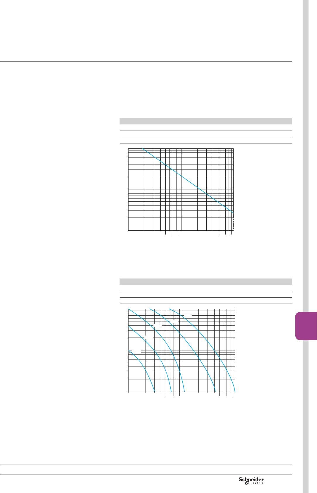
PCPB08T20-EN Version : 1.0 19 novembre 2014 10:37 AM B8/61
Contactors
B8/61
Rated operational power of contacts
(conforming to IEC 60947-5-1)
a.c. supply, categories AC-14 and AC-15
(OHFWULFDOGXUDELOLW\YDOLGIRUXSWRRSHUDWLQJF\FOHVKRXURQDQLQGXFWLYH
ORDGVXFKDVWKHFRLORIDQHOHFWURPDJQHWPDNLQJFXUUHQWFRVM WLPHV
WKHSRZHUEURNHQFRVM
Operating cycles V 24 48 115 230 400 440 600
1 million VA 60 120 280 560 960 1050 1440
3 million VA 16 32 80 160 280 300 420
10 million VA 4 8 20 40 70 80 100
0,1 0,2 0,3 0,4
0,5
0,6
0,7
0,8
0,9
1 2 3 4
5
6
7
8
9
10
0,1
0,2
0,3
0,4
0,6
0,5
0,8
0,7
7
1
2
3
5
4
6
8
10
&XUUHQWEURNHQLQ$
0LOOLRQVRIRSHUDWLQJF\FOHV
DF510631.eps
d.c. supply, category DC-13
(OHFWULFDOGXUDELOLW\YDOLGIRUXSWRRSHUDWLQJF\FOHVKRXURQDQLQGXFWLYH
ORDGVXFKDVWKHFRLORIDQHOHFWURPDJQHWZLWKRXWHFRQRP\UHVLVWRUWKHWLPH
constant increasing with the load.
Ooperating cycles V 24 48 125 250 440
1 million W 120 90 75 68 61
3 million W 70 50 38 33 28
10 million W 25 18 14 12 10
0,1 0,2 0,3 0,4
0,5
0,6
0,7
0,8
0,9
1 2 3 4
5
6
7
8
9
10
0,1
0,2
0,3
0,4
0,6
0,5
0,8
0,7
7
1
2
3
5
4
6
8
10
440 V
48 V
250 V
125 V
24 V
&XUUHQWEURNHQLQ$
0LOOLRQVRIRSHUDWLQJF\FOHV
DF510632.eps
Characteristics
References:
pages B8/15 and B8/16
Dimensions:
pages B8/65 and B8/66
Schemes:
pages B8/69 and B8/70
TeSys contactors
Auxiliary contact blocks with dust
and damp protected contacts
for TeSys D contactors
TeSys D
PCPB08T20-EN
Version : 1.0 19 novembre 2014 10:37 AM
B8/62
Environment
Conforming to standards IEC 60947-5-1
3URGXFWFHUWL¿FDWLRQV UL, CSA
Protective treatment Conforming to IEC 60068 “TH”
Degree of protection Conforming to VDE 0106 3URWHFWLRQDJDLQVWGLUHFW¿QJHUFRQWDFW,3;
$PELHQWDLUWHPSHUDWXUH
DURXQGWKHGHYLFH
Storage °C «
2SHUDWLRQ °C «
Permissible for operation at Uc °C «
Suppressor modules
Module type LA4 DA, LAD 4RC,
LAD 4RC3
LA4 DB, LAD 4T,
LAD 4T3
LA4 DC, LAD 4D3 LA4 DE, LAD 4V,
LAD 4V3
7\SHRISURWHFWLRQ 5&FLUFXLW Bidirectional
SHDNOLPLWLQJGLRGH
Diode Varistor
5DWHGFRQWUROFLUFXLWYROWDJH8F Va 24…415 a or c 24…440 c 12…250 a or c 24…250
0D[LPXPSHDNYROWDJH 3 Uc 2 Uc Uc 2 Uc
1DWXUDO5&IUHTXHQF\ 24/48 V Hz 400 – – –
50/127 V Hz 200 – – –
110/240 V Hz 100 – – –
380/415 V Hz 150 – – –
Mechanical latch blocks (1)
Mechanical latch block type LAD 6K10 LA6 DK20
)RUXVHRQFRQWDFWRU LC1 D09…D65A
DT20…DT80A
LC1 D80…D150
LP1 D80 and LC1 D115
3URGXFWFHUWL¿FDWLRQV UL, CSA UL, CSA
5DWHGLQVXODWLRQYROWDJH Conforming to IEC 60947-5-1 V690 690
5DWHGFRQWUROFLUFXLWYROWDJH a 50/60 Hz and cV24…415 24…415
3RZHUUHTXLUHG )RUXQODWFKLQJ aVA 25 25
cW30 30
0D[LPXPRSHUDWLQJUDWH ,QRSHUDWLQJF\FOHVKRXU 1200 1200
2QORDGIDFWRU
0HFKDQLFDOGXUDELOLW\DW8F ,QPLOOLRQVRIRSHUDWLQJF\FOHV 0.5 0.5
(1)8QODWFKLQJFDQEHPDQXDOO\RSHUDWHGRUHOHFWULFDOO\FRQWUROOHGSXOVHG
The LA6 DK or LAD 6K latch coil and the LC1 DRSHUDWLQJFRLOPXVWQRWEHHQHUJLVHGVLPXOWDQHRXVO\
The duration of the LA6 DK or LAD 6K and LC1 D control signals must be uPV
References:
pages B8/15 and B8/16
Dimensions:
pages B8/65 and B8/66
Schemes:
pages B8/69 and B8/70
TeSys contactors
Control modules, coil suppressor
modules and mechanical latch blocks
for TeSys D contactors
TeSys D
Characteristics
PCPB08T20-EN Version : 1.0 19 novembre 2014 10:37 AM B8/63
Contactors
B8/63
Environment
Module type LA4 DT 2QGHOD\
Conforming to standards IEC 60255-5
3URGXFWFHUWL¿FDWLRQV UL, CSA
Protective treatment Conforming to IEC 60068 “TH”
Degree of protection Conforming to VDE 0106 3URWHFWLRQDJDLQVWGLUHFW¿QJHUFRQWDFW,3;
$PELHQWDLUWHPSHUDWXUH
DURXQGWKHGHYLFH
Storage °C «
2SHUDWLRQ °C «
For operation at Uc °C «
5DWHGLQVXODWLRQYROWDJH8L Conforming to IEC 60947-1 V250
Cabling 3KLOOLSVQDQGPP
)OH[LEOHRUVROLGFRQGXFWRU
ZLWKRUZLWKRXWFDEOHHQG
mm2Min: 1 x 1; max: 2 x 2.5
Control circuit characteristics
%XLOWLQSURWHFWLRQ 2IWKHLQSXW %\YDULVWRU
&RQWDFWRUFRLOVXSSUHVVLRQ %\YDULVWRU
5DWHGFRQWUROFLUFXLWYROWDJH8F Va or c: 24…250
Permissible variation 0.8…1.1 Uc
7\SHRIFRQWURO %\PHFKDQLFDOFRQWDFWRQO\
Timing characteristics
Timing ranges s0.1…2; 1.5…30; 25…500
5HSHDWDFFXUDF\ «& PVPLQLPXP
Reset time 'XULQJWLPHGHOD\SHULRG ms 150
$IWHUWLPHGHOD\SHULRG ms 50
,PPXQLW\WRPLFUREUHDNV 'XULQJWLPHGHOD\SHULRG ms 10
$IWHUWLPHGHOD\SHULRG ms 2
0LQLPXPFRQWUROSXOVHGXUDWLRQ ms –
7LPHGHOD\VLJQDOOLQJ %\/(' ,OOXPLQDWHVGXULQJWLPHGHOD\SHULRG
Switching characteristics (solid state type)
0D[LPXPSRZHUGLVVLSDWHG W2
/HDNDJHFXUUHQW mA < 5
5HVLGXDOYROWDJH V3.3
2YHUYROWDJHSURWHFWLRQ N9MRXOH
(OHFWULFDOGXUDELOLW\ ,QPLOOLRQVRIRSHUDWLQJF\FOHV 30
Function diagram
Electronic on-delay timer LA4 DT
0
1
0
1
t
8VXSSO\$$
7LPHGHOD\RXWSXW
Contactor coil
Red LED
810389.eps
Characteristics TeSys contactors
Electronic serial timer module
for TeSys D contactors
References:
page B8/19
Dimensions:
pages B8/65 and B8/66
Schemes:
pages B8/69 and B8/70
TeSys D

PCPB08T20-EN
Version : 1.0 19 novembre 2014 10:37 AM
B8/64
Environment
Conforming to standards IEC 60255-5
3URGXFWFHUWL¿FDWLRQV UL, CSA
Protective treatment Conforming to IEC 60068 “TH”
Degree of protection Conforming to VDE 0106 3URWHFWLRQDJDLQVWGLUHFW¿QJHUFRQWDFW,3;
$PELHQWDLUWHPSHUDWXUH
DURXQGWKHGHYLFH
Storage °C «
2SHUDWLRQ °C «
Permissible for operation at Uc °C «
Other characteristics
Module type LA4 DFB
:LWKUHOD\
LA4 DWB
Solid state
&RQYHQWLRQDOWKHUPDOFXUUHQW
,WK
)RUDPELHQWWHPSHUDWXUH
y&
A8
5DWHGLQVXODWLRQYROWDJH Conforming to IEC 60947-5-1 V250
Rated operational voltage Conforming to IEC 60947-5-1 V250
,QGLFDWLRQRILQSXWVWDWH %\LQWHJUDO/('ZKLFKLOOXPLQDWHVZKHQWKHFRQWDFWRUFRLOLVHQHUJLVHG
,QSXWVLJQDOV &RQWUROYROWDJH(( Vc 24 c 24
Permissible variation V17…30 5…30
&XUUHQWFRQVXPSWLRQDW& mA 25 8.5 for 5 V
15 for 24 V
6WDWH³´JXDUDQWHHGIRU UV< 2.4 < 2.4
ImA < 2 < 2
6WDWH³´JXDUDQWHHGIRU UV17 5
%XLOWLQSURWHFWLRQ $JDLQVWUHYHUVHGSRODULW\ %\GLRGH %\GLRGH
2IWKHLQSXW %\GLRGH %\GLRGH
(OHFWULFDOGXUDELOLW\
at 220 A/240 V
,QPLOOLRQVRIRSHUDWLQJF\FOHV 10 20
0D[LPXPLPPXQLW\WRPLFUREUHDNV ms 4 1
Power dissipated $W& W0.6 0.4
'LUHFWPRXQWLQJ
on contactor
With coil a 24…250 V LC1 D80…D150 –
a 100…250 V – LC1 D80…D115
a 380…415 V – –
0RXQWLQJZLWK
cabling adapter
LAD 4BB
With coil a 24…250 V LC1 D09…D38,
LC1 DT20…DT40
LC1 D09…D38,
LC1 DT20…DT40
a 380…415 V – –
0RXQWLQJZLWK
cabling adapter
LAD 4BB3
With coil a 24…250 V LC1 D40A…D65A LC1 D40A…D65A
a 380…415 V LC1 D40A…D65A LC1 D40A…D65A
Total operating time at Uc
RIWKHFRQWDFWRU
7KHRSHUDWLQJWLPHVGHSHQGRQWKHW\SHRIFRQWDFWRUHOHFWURPDJQHWDQGLWVFRQWUROPRGH
7KHFORVLQJWLPH&LVPHDVXUHGIURPWKHPRPHQWWKHFRLOVXSSO\LVVZLWFKHGRQWRLQLWLDO
FRQWDFWRIWKHPDLQSROHV7KHRSHQLQJWLPH2LVPHDVXUHGIURPWKHPRPHQWWKHFRLOVXSSO\
is switched off to the moment the main poles separate.
LC1 D09…D38,
LC1 DT20…DT40
LC1 D40A…D65A LC1 D80 and D95
With LA4 DFB & ms 20…30 28…34 28…43
³2´ ms 16…24 20…24 18…32
Cabling 3KLOOLSVQDQGPP
Flexible or solid cable
ZLWKRUZLWKRXWFDEOHHQG
mm2Min: 1 x 1; max: 2 x 2.5
References:
page B8/19
Dimensions:
pages B8/65 and B8/66
Schemes:
pages B8/69 and B8/70
TeSys contactors
Interface modules
for TeSys D contactors
TeSys D
Characteristics

PCPB08T20-EN Version : 1.0 19 novembre 2014 10:37 AM B8/65
Contactors
B8/65
LC1 D09…D18 SROH LC1 D25…D38 SROHLC1 DT20…DT40 SROH
(LAD 8) (LAD 8) (1)
b
c
10
c1
c2
c3
45 12,512,5
b1
44
LA4
DF510934.eps
(LAD 8)
b
45 12,5
(LAD 8)
(1)
12,5
b1
44
LA4
c
10
c1
c2
c3
0LQLPXPHOHFWULFDOFOHDUDQFH
DF565145.eps
LC1 D09…D18 D093…
D123
D099…
D129
D25…
D38
D183…
D323
D098, D128,
DT20 and DT25
DT203 and
DT253
DT32 and
DT40
D188, D258,
DT323 and DT403
bZLWKRXWDGGRQEORFNV 77 99 80 85 99 85 99 91 105
b1 with LAD 4BB 94 107 95,5 98 107 98 – – –
with LA4 Dp2 110 (1) 123 (1) 111.5 (1) 114 (1) 123 (1) 114 – – –
with LA4 DF, DT 119 (1) 132 (1) 120.5 (1) 123 (1) 132 (1) 129 – – –
with LA4 DW, DL 126 (1) 139 (1) 127.5 (1) 130 (1) 139 (1) 190 – – –
cZLWKRXWFRYHURUDGGRQEORFNV 84 84 84 90 90 90 90 97 97
ZLWKFRYHUZLWKRXWDGGRQEORFNV 86 86 86 92 92 92 92 99 99
c1 ZLWK/$'1RU&RUFRQWDFWV 117 117 117 123 123 123 123 131 131
c2 with LA6 DK10, LAD 6K10 129 129 129 135 135 135 135 143 143
c3 with LAD T, R, S 137 137 137 143 143 143 143 151 151
with LAD T, R, S and sealing cover 141 141 141 147 147 147 147 155 155
(1),QFOXGLQJ/$'%%
LC1 D40A…D65ASROHLC1 DT60A…DT80A SROH LC1 D80 and D95 SROHLC1 D80004 and
D80008 SROHD40008 and D65008SROH
LAD 4BB3
117
122
a
(LAD 8N) (LAD 8N)
12,5
c1
c2
c3
LA4 DpB
LA4 DpB
LAD 4BB3
b1
12
c
12,5
Min. electrical clearance
DF569184.eps
12,5
(LAD 8) (LAD 8)
127
b1
a 12,5
4432
LA4
c12
c1
c2
c3
0LQLPXPHOHFWULFDOFOHDUDQFH
DF565147.eps
LC1 D40A…D65A DT60A…DT80A D40008 D80 D95, D65008 D80004 D80008
a 55 70 85 85 85 96 96
b1 with LA4 Dp2 – – 135 135 135 135 135
with LA4 DB3 or LAD 4BB3 136 – – 135 – – –
with LA4 DF, DT 157 – 142 142 142 142 142
with LA4 DM, DW, DL 166 – 150 150 150 150 150
cZLWKRXWFRYHURUDGGRQEORFNV 118 118 125 125 125 125 140
ZLWKFRYHUZLWKRXWDGGRQEORFNV 120 120 – 130 130 – –
c1 ZLWK/$'1FRQWDFW – – 139 150 150 150 150
ZLWK/$'1RU&RUFRQWDFWV 150 150 147 158 158 158 158
c2 with LAD 6K10 or LA6 DK 163 163 159 170 170 170 170
c3 with LAD T, R, S 171 171 167 178 178 178 178
with LAD T, R, S and sealing cover 175 175 171 182 182 182 182
LC1 D115 and D150 SROHLC1 D115004 SROH
LC1 D115, D150 D115004 D1150046
158
ca
c1
c2
c3
b1
LAD 8
LA4
10
Min. electrical clearance
DF569186.eps
a 120 150 155
b1 with LA4 DA2 174 174 174
with LA4 DF, DT 185 185 185
with LA4 DM, DL 188 188 188
with LA4 DW 188 188 188
cZLWKRXWFRYHURUDGGRQEORFNV 132 132 115
ZLWKFRYHUZLWKRXWDGGRQEORFNV 136 – –
c1 ZLWK/$'1RU&RUFRQWDFWV 150 150 150
c2 with LA6 DK20 155 155 155
c3 with LAD T, R, S 168 168 168
with LAD T, R, S and sealing cover 172 172 172
0LQLPXPHOHFWULFDOFOHDUDQFH
TeSys contactors
TeSys D contactors
Control circuit: a.c.
Dimensions
TeSys D

PCPB08T20-EN
Version : 1.0 19 novembre 2014 10:37 AM
B8/66
LC1 D09…D18 SROH LC1 D25…D38 SROH
b
c10
c1
c2
c3
45
0LQLPXPHOHFWULFDOFOHDUDQFH
DF565149.eps
c
b
10
c1
c2
c3
45
0LQLPXPHOHFWULFDOFOHDUDQFH
DF565150.eps
LC1 D09…D18 D093…D123 D099…D129 D25…D38 D183…D323
b 77 99 80 85 99
cZLWKRXWFRYHURUDGGRQEORFNV 93 93 93 99 99
ZLWKFRYHUZLWKRXWDGGRQEORFNV 95 95 95 101 101
c1 ZLWK/$'1RU&RUFRQWDFWV 126 126 126 132 132
c2 with LA6 DK10 138 138 138 144 144
c3 with LAD T, R, S 146 146 146 152 152
with LAD T, R, S and sealing cover 150 150 150 156 156
LC1 DT20…DT40 SROH
c
b
10
c1
c2
c3
45
0LQLPXPHOHFWULFDOFOHDUDQFH
DF565151.eps
LC1 DT20 and DT25
D098 and D128
DT203 and DT253
D0983 and D1283
DT32 and DT40
D188…D258
DT323 and DT403
D1883 and D2583
b 85 99 91 105
c with cover 99 99 107 107
c1 ZLWK/$'1RU&RUFRQWDFWV 123 123 131 131
c2 with LA6 DK10 135 135 143 143
c3 with LAD T, R, S 143 143 151 151
with LAD T, R, S and sealing cover 147 147 155 155
LC1 D40A…D65ASROHLC1 DT60A…DT80A SROH LC1 D80 and D95 SROHLP1 D80004, LP1 D80008 SROH
LP1 D40008 and D65008 SROH
LAD 4BB3
117
122
a
(LAD 8N) (LAD 8N)
12,5
c1
c2
c3
LA4 DpB
LA4 DpB
LAD 4BB3
b1
12
c
12,5
DF569184.eps
a
c12
c1
c2
c3
127
Min. electrical clearance
DF510661.eps
LC1 D40A
… D65A
LC1
DT60A…DT80A
LP1 D40008
and D65008
LC1
D80 and D95
LP1 D80004 LP1 D80008
a 55 72 85 85 96 96
b1 with LAD 4BB3 136 136 – – – –
with LA4 DF, DT 157 157 – – – –
cZLWKRXWFRYHURUDGGRQEORFNV 118 118 182 181 181 196
ZLWKFRYHUZLWKRXWDGGRQEORFNV 120 120 – 186 – –
c1 ZLWK/$'1FRQWDFW – – 196 204 204 204
ZLWK/$'1RU&RUFRQWDFWV 150 150 202 210 210 210
c2 with LA6 DK10 163 163 213 221 221 221
c3 with LAD T, R, S 171 171 221 229 229 229
with LAD T, R, S and sealing cover 175 175 225 233 233 233
LC1 D115ppp and LC1 D150ppp with c coil: see page B8/65.
Min. electrical clearance
TeSys contactors
TeSys D contactors
Control circuit: d.c. or low consumption
TeSys D
Dimensions
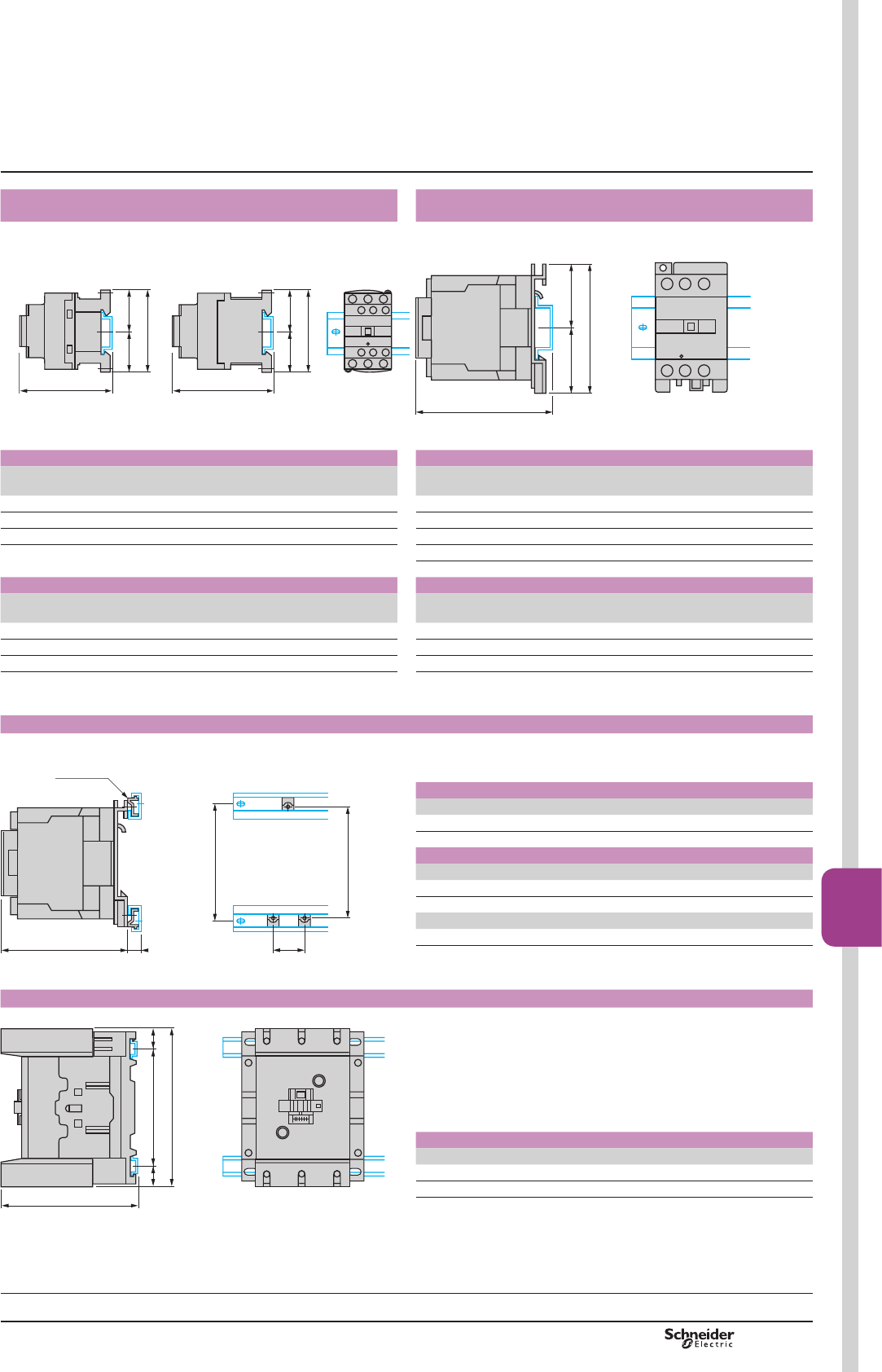
PCPB08T20-EN Version : 1.0 19 novembre 2014 10:37 AM B8/67
Contactors
B8/67
TeSys contactors
TeSys D contactors
Mounting
LC1 D09…D38, DT20…DT40 LC1 D40A…D65A, LC1 DT60A and DT80A, LC1 D80 and D95,
LC1 D40008 and D65008
On mounting rail AM1 DP200, DR200 or AM1 DE200 ZLGWKPP
c
=
b
=
c
=
b
=
810610.eps
On mounting rail AM1 DL200 or DL201ZLGWKPP(2)
On mounting rail AM1 EDppp or AM1 DE200 (width 35 mm
==
c
b
DF511013.eps
Control circuit: a.c. Control circuit: a.c.
LC1 D09…
D18
D25…
D38
DT20
and DT25
DT32
and DT40
LC1 D40A…D65A
DT60A…DT80A
D80
and D95
D40008
and D65008
b 77 85 85 100 b 122 127 127
c$0'3RU'5(1) 88 94 94 109 c $0'/(1) – 147 143
c$0'((1) 96 102 102 117 c $0'/(1) – 137 133
c (AM1 EDpppRU'((1) 128 137 133
Control circuit: d.c. Control circuit: d.c.
LC1 D09…
D18
D25…
D38
DT20
and DT25
DT32
and DT40
LC1 D40A…D65A
DT60A…DT80A
D80
and D95
D40008
and D65008
b 77 85 94 109 c $0'/(1) – 205 200
c$0'3RU'5(1) 97 103 103 118 c $0'/(1) – 195 190
c$0'( (1) 105 110 111 1236 c (AM1 EDppp RU'((1) 128 128 190
(1):LWKVDIHW\FRYHU (1):LWKVDIHW\FRYHU
(2) ([FHSWIRU/&'$«'$/&'7$DQG'7$
LC1 D80 and D95, LP1 D80
On 2 mounting rails DZ5 MB on 120 mm centres
110
120
40
c 15
DZ5 ME5
DF565154.eps
Control circuit: a.c.
LC1 D80 and D95
c with cover 130
Control circuit: d.c.
LC1 D80 and D95
c with cover 186
LP1 D80
c 181
LC1 D115, D150
On 2 mounting rails DZ5 MB on 120 mm centres
100 ==
158
c
810611.eps
Control circuit: a.c. or d.c.
LC1 D115 and D150 D1156 and D1506
c$0'3RU'5 134.5 117.5
c (AM1 DE200 or EDppp142.5 125.5
TeSys D
Selection:
pages A5/23 to A5/47
Characteristics:
pages B8/53 to B8/58
References:
pages B8/2 to B8/5
Schemes:
pages B8/69 to B8/70
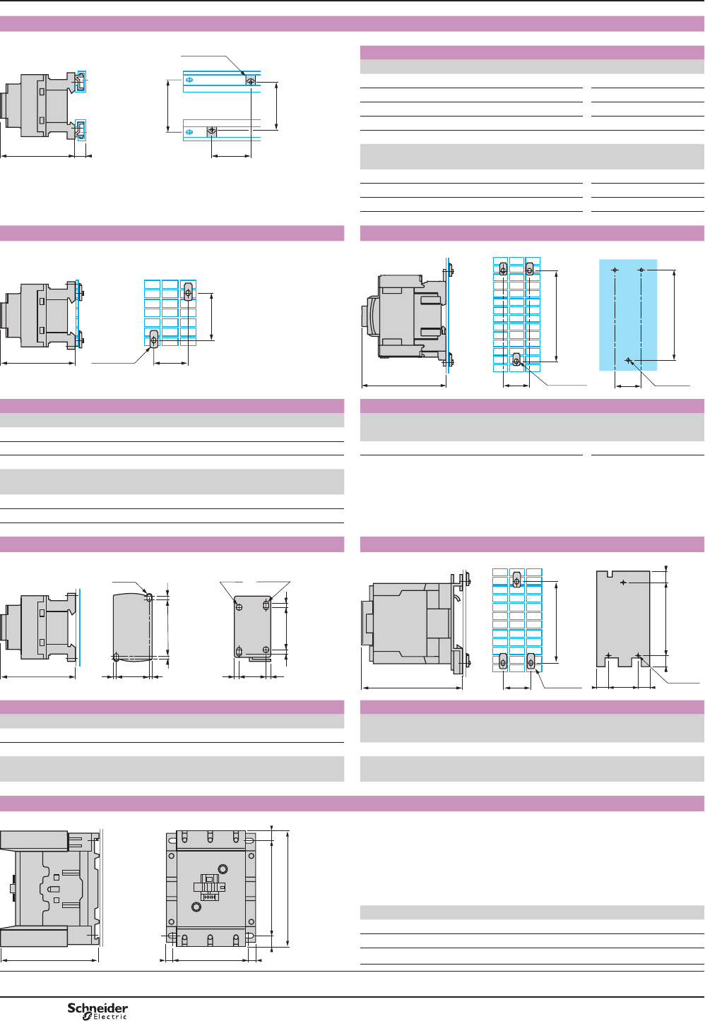
PCPB08T20-EN
Version : 1.0 19 novembre 2014 10:37 AM
B8/68
LC1 D09…D38 and LC1 DT20…DT40
On 2 mounting rails DZ5 MB
c
15
H
H1
DZ5 ME8
G
DF510718.eps
Control circuit: a.c. d.c.
LC1 D09…D18 D25…D38 D09…D18 D25…D38
c with cover 86 92 95 101
G 35 35 35 35
H 60 60 70 70
H1 70 70 70 70
4-pole contactors
LC1 DT20
and DT25
DT32
and DT40
DT20
and DT25
DT32
and DT40
c 92 100 101 109
G 35 35 35 35
H 60 60 70 70
H1 70 70 70 70
LC1 D09…D38 and LC1 DT20…DT40 LC1 D40A…D65A, LC1 DT60A…DT80A
On pre-slotted mounting plate AM1 PA, PB, PC
H
AF1 EA4 Gc
DF510439.eps
On pre-slotted mounting plate AM1 PA, PB, PC and panel mounted
128
37,5 AF1 EA4
c
3xØ6,5
128
37,5
DB402218.eps
Control circuit: a.c d.c Control circuit: a.c d.c.
LC1 D09…D18 D25…D38 D09…D18 D25…D38 LC1 D40A…65A ,
DT60A…DT80A
D40A…65A ,
DT60A…DT80A
c with cover 86 92 95 101
G 35 35 35 35 c with cover 120 120
H 60/70 60/70 70 70
LC1 DT20
and DT25
DT32
and DT40
DT20
and DT25
DT32
and DT40
c with cover 80 93 118 132
G 35 35 35 35
H 60 60 70 70
LC1 D09…D38, LC1 DT20…DT40 LC1 D80 and D95, LC1 D40008 and D65008, LP1 D80
Panel mounted On pre-slotted mounting plate AM1 PA, PB, PC and panel mounted
AF1 EA6
40
110
c
40= =
100/110= =
3xØ6,5
DF511562.eps
50
2xM4
= =
60/70
==
35= =35= =
2xØ4,5
2xM4
c
DF565155.eps
Control circuit: a.c d.c Control circuit: a.c d.c.
LC1 D09…D18 D25…D38 D09…D18 D25…D38 LC1 D80 and D95, D80 and D95
c with cover 86 92 95 101 D40008 and D65008 D40008 and D65008
4-pole contactors c with cover 130 186
LC1 DT20
and DT25
DT32
and DT40
DT20
and DT25
DT32
and DT40
LP1 – – D80
c with cover 90 98 90 98 c ZLWKRXWFRYHU – – 181
LC1 D115, D150
Panel mounted
130 ==
158
cG= =
DF565389.eps
LC1 D115 D1156 D150 D1506
c 132 115 132 115
G (3-pole) 96/110 96/110 96/110 96/110
G (4-pole) 130/144 130/144 – –
Selection:
pages A5/23 to A5/47
Characteristics:
pages B8/53 to B8/58
References:
pages B8/2 to B8/5
Schemes:
pages B8/69 to B8/70
TeSys D
TeSys contactors
TeSys D contactors
Mounting
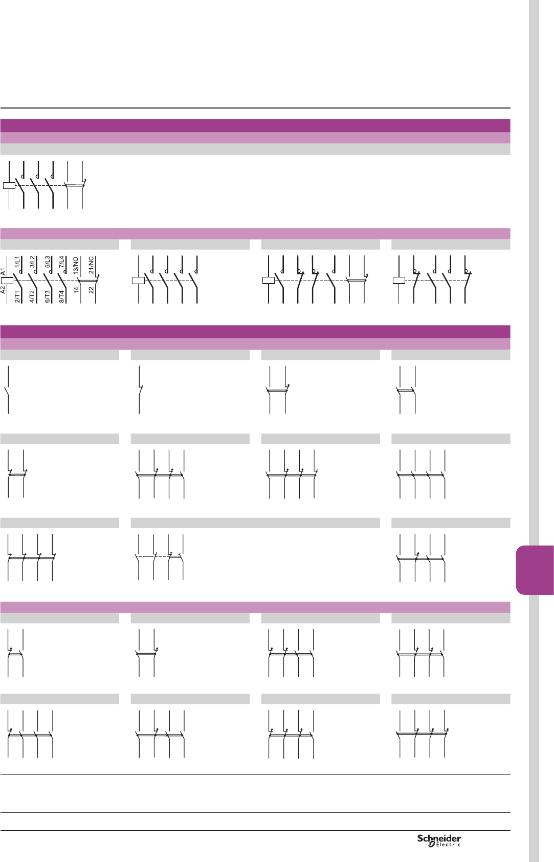
PCPB08T20-EN Version : 1.0 19 novembre 2014 10:37 AM B8/69
Contactors
B8/69
Schemes
Contactors
3-pole contactors 5HIHUHQFHVSDJHV%WR%
LC1 D09 to D150
A1
A2
13/NO
14
1/L1
2/T1
3/L2
5/L3
22 21/NC
4/T2
6/T3
127266.eps
4-pole contactors 5HIHUHQFHVSDJHV%DQG%
LC1 DT20 to DT80A LC1 D115004 LC1 D098 to D258 LC1 and LP1 D40008 to D80008
127267.eps
A1
A2
1/L1
2/T1
3/L2
4/T2
5/L3
6/T3
7/L4
8/T4
127268.eps
A1
A2
1
2
R1
R2
R3
R4
3
4
13/NO
14
22
21/N
C
127269.eps
A1
A2
R1
R2
R3
R4
1
2
3
4
127270.eps
Front mounting add-on contact blocks
Instantaneous auxiliary contacts 5HIHUHQFHVSDJH%
1 N/O LAD N10 (1) 1 N/C LAD N01 (1) 1 N/O + 1 N/C LAD N11 2 N/O LAD N20
44 43/NO
(94)
(93)
DF510935.eps
42 41/NC
(91) (92)
810623.eps
53/NO
54
62 61/NC
127271.eps
63/NO
64
53/NO
54
127307.eps
2 N/C LAD N02 2 N/O + 2 N/C LAD N22 1 N/O + 3 N/C LAD N13 4 N/O LAD N40
52 51/NC
62
61/NC
127272.eps
72
71/NC
62 61/NC
83/NO
84
53/NO
54
127273.eps
72
71/NC
62 61/NC
53/NO
54
82 81/NC
127274.eps
83/NO
84
73/NO
74
63/NO
64
53/NO
54
127275.eps
4 N/C LAD N04 2 N/O + 2 N/C including 1 N/O + 1 N/C make before break LAD C22 3 N/O + 1 N/C LAD N31
52 51/NC
62 61/NC
72 71/NC
82 81/NC
127260.eps
53/NO
54
61/NC
62
87/NO
88
75/NC
76
127261.eps
62
61/NC
83/NO
84
73/NO
74
53/NO
54
127308.eps
Instantaneous auxiliary contacts conforming to standard EN 50012 5HIHUHQFHVSDJH%
1 N/O + 1 N/C LAD N11G 1 N/O + 1 N/C LAD N11P 2 N/O + 2 N/C LAD N22G 2 N/O + 2 N/C LAD N22P
32 31/NC
43/NO
44
127309.eps
22
21/NC
13/NO
14
127310.eps
32 31/NC
42 41/NC
63/NO
64
53/NO
54
127311.eps
32
31/NC
22 21/NC
43/NO
44
13/NO
14
127312.eps
3 N/O + 1 N/C LAD N31G 3 N/O + 1 N/C LADN31P 1 N/O + 3 N/C LAD N13G 1 N/O + 3 N/C LAD N13P
32 31/NC
43/NO
44
63/NO
64
53/NO
54
127313.eps
22
21/NC
33/NO
34
13/NO
14
43/NO
44
127314.eps
42
41/NC
32 31/NC
52 51/NC
63/NO
64
127315.eps
32
31/NC
22 21/NC
13/NO
14
42 41/NC
127316.eps
(1),WHPVLQEUDFNHWVUHIHUWREORFNVPRXQWHGRQULJKWKDQGVLGHRIFRQWDFWRU
TeSys contactors
TeSys D contactors
TeSys D
Selection:
pages A5/23 to A5/47
Characteristics:
pages B8/53 to B8/58
References:
pages B8/2 to B8/19
Dimensions:
pages B8/65 and B8/66

PCPB08T20-EN
Version : 1.0 19 novembre 2014 10:37 AM
B8/70
Selection:
pages A5/23 to A5/47
Characteristics:
pages B8/53 to B8/58
References:
pages B8/2 to B8/19
Dimensions:
pages B8/65 and B8/66
Front mounting add-on contact blocks
Dust and damp protected instantaneous auxiliary contacts 5HIHUHQFHVSDJH%
2 N/O (24-50 V)
LA1 DX20
2 N/C (24-50 V)
LA1 DX02
2 N/O (5-24 V)
LA1 DY20
2 N/O protected (24-50 V)
2 N/O standard LA1 DZ40
2 N/O protected (24-50 V)
+ 1 N/O + 1 N/C standard LA1 DZ31
DF510649.eps
DF510650.eps
DF510651.eps
53/NO54
83/NO84
63/NO
64
73/NO
74
810646.eps
62 61/NC
53/NO54
83/NO84
73/NO
74
810644.eps
Time delay auxiliary contacts 5HIHUHQFHVSDJH%
On-delay 1 N/O + 1 N/C
LAD T
Off-delay 1 N/O + 1 N/C
LAD R
On-delay 1 N/C + 1 N/O break before make LAD S
55/NC56
67/NO
68
810647.eps
66 65/NC
57/NO
58
810650.eps
810648.eps
67/NO68
55/NC56
Mechanical latch blocks (References: page B8/16
LAD 6K10 and LA6 DK20
A1
A2
E1
E2
810639.eps
Side mounting add-on contact blocks
Instantaneous auxiliary contacts 5HIHUHQFHVSDJH%
1 N/O + 1 N/C LAD 8N11 (1) 2 N/O LAD 8N20 (1) 2 N/O LAD 8N02 (1)
162 161/NC
(171) (172)
153/NO
154
(183) (184)
810651.eps
153/NO
154
(184)
(183)
163/NO
164
(174)
(173)
810652.eps
262 261/NC
(271) (272)
251/NC
252
(281) (282)
DF510484.eps
(1),WHPVLQEUDFNHWVUHIHUWREORFNVPRXQWHGRQULJKWKDQGVLGHRIFRQWDFWRU
Electronic serial timer modules
On-delay LA4 DTpU
DF510646.eps
Interface modules
Relay output Solid state
LA4 DFB LA4 DWB
DF510647.eps
DF510648.eps
References: page B8/85.
TeSys D
Schemes TeSys contactors
TeSys D contactors
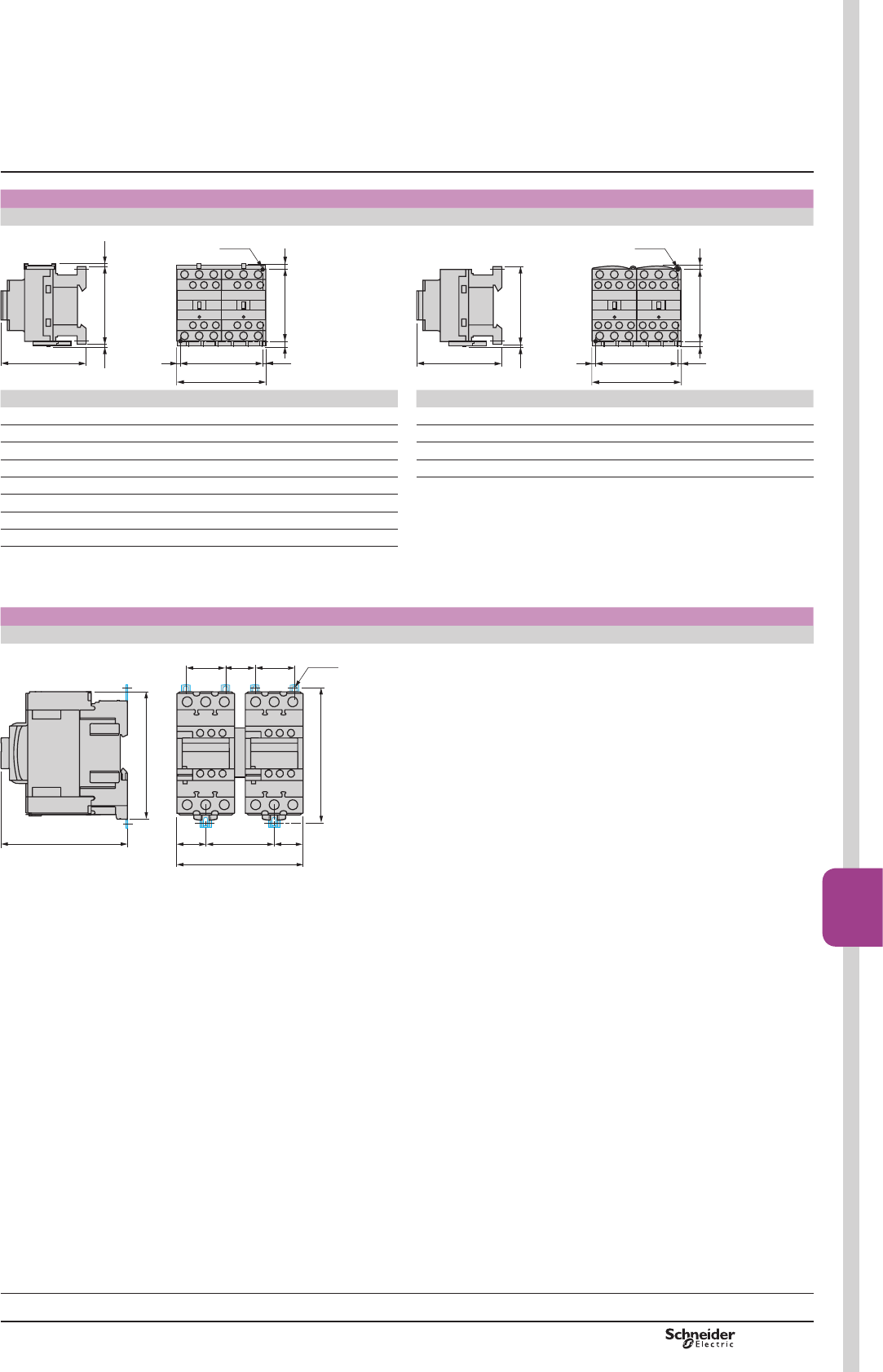
PCPB08T20-EN Version : 1.0 19 novembre 2014 10:37 AM B8/71
Contactors
B8/71
Dimensions TeSys contactors
TeSys D reversing contactors
LC2 D09 to D38 LC2 DT20 to DT40
2 x LC1 D09 to D38 2 x LC1 DT20 to DT40
2xM4
G
a
==
60/70 ==
c
b e1
e2
DF568948.eps
2xM4
G
a
==
60/70 ==
c
b
e2
DF568949.eps
LC2 or 2 x LC1 a b c (1) e1 e2 GLC2 or 2 x LC1 a b c G
D09 to D18 a90 77 86 4 1.5 80 DT20 and DT25 a90 85 92 80
D093 to D123 a90 99 86 – – 80 DT32 and DT40 a90 91 99 80
D09 to D18 c90 77 95 4 1.5 80 DT20 and DT25 c90 85 102 80
D093 to D123 c90 99 95 – – 80 DT32 and DT40 c90 91 109 80
D25 to D38 a90 85 92 9 5 80 FHLQFOXGLQJFDEOLQJ
D183 to D383 a90 99 92 – – 80
D25 to D32 c90 85 101 9 5 80
D183 to D383 c90 99 101 – – 80
HDQGHLQFOXGLQJFDEOLQJ
(1):LWKVDIHW\FRYHUZLWKRXWDGGRQEORFN
LC2 D40A to D65A
2 x LC1 D40A to D65A
DF568945.eps
122
128
120
119
6418,7 18,7
26,537,5 37,5
6xM4
Selection:
pages A5/23 to A5/47
Characteristics:
pages B8/53 to B8/58
References:
pages B8/2 to B8/19, B8/23 and B8/24
Schemes:
pages B8/73 to B8/74
TeSys D
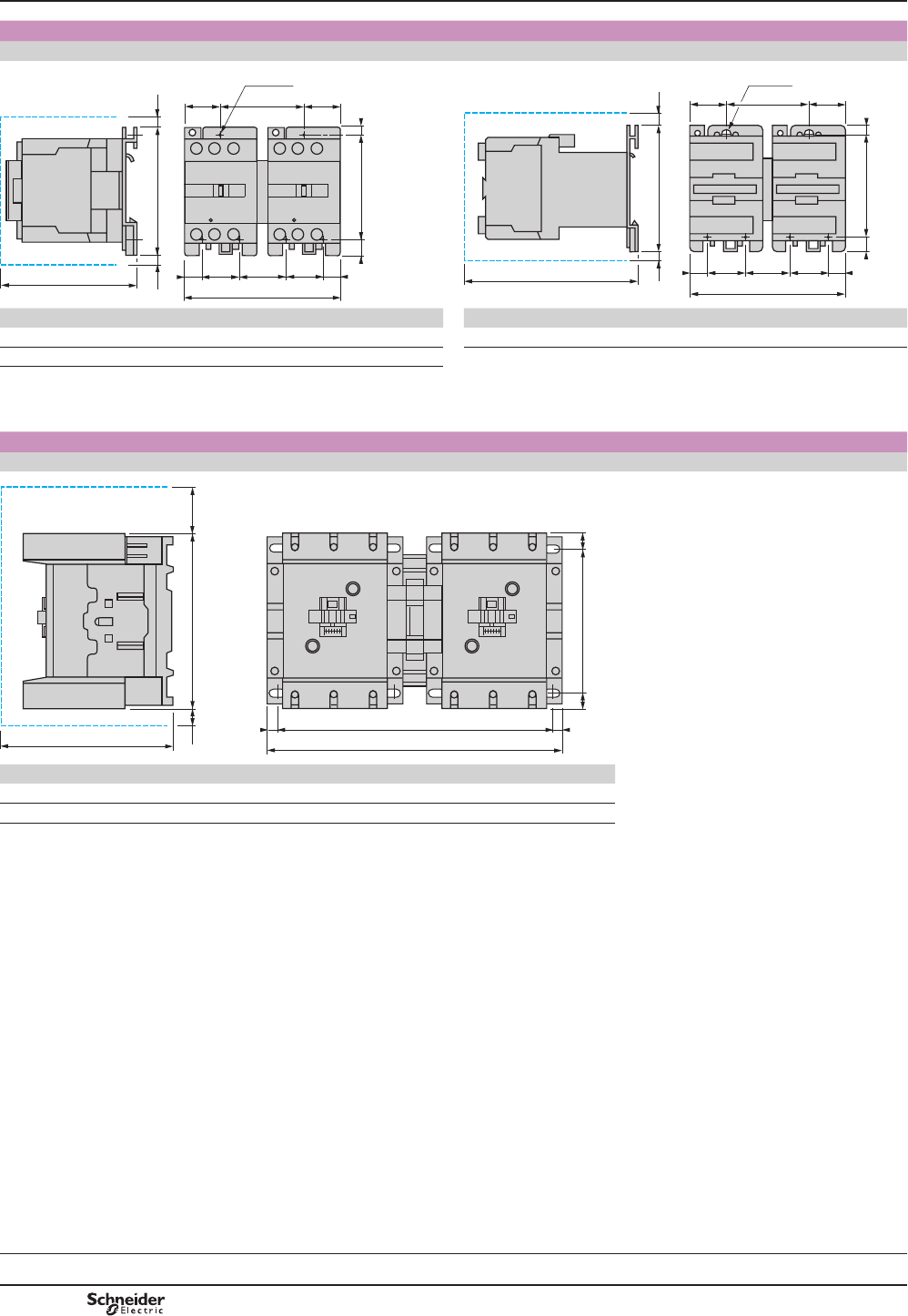
PCPB08T20-EN
Version : 1.0 19 novembre 2014 10:37 AM
B8/72
LC2 D80 and D95
2 x LC1 D80 and D95 a2 x LC1 D80 and D95 c
c
b e1e2
G1= =
6xØ6,5
40
a
= =G 40
100/110 8
13
DF568950.eps
c
b e1e2
G1= =
6xØ6,5
40
a
= =G 40
100/110 813
DF568951.eps
LC2 or 2 x LC1 a b c e1 e2 G G1 2 x LC1 a b c e1 e2 G G1
D80 and D95 a182 127 158 13 – 57 96 D80 and D95 207 127 215 13 20 96 111
D80004 a207 127 158 – 20 71 111 FHDQGHLQFOXGLQJFDEOLQJ
FHDQGHLQFOXGLQJFDEOLQJ
LC2 D115 and D150
2 x LC1 D115 and D150
158 e1e2
c
G
a
= =
130 ==
DF568952.eps
LC2 or 2 x LC1 a c e1 e2 G
D115 and D150 266 148 56 18 242/256
D115004 334 148 – 60 310/324
FHDQGHLQFOXGLQJFDEOLQJ
Dimensions TeSys contactors
TeSys D reversing contactors
TeSys D
Selection:
pages A5/23 to A5/47
Characteristics:
pages B8/53 to B8/58
References:
pages B8/2 to B8/19, B8/23 and B8/24
Schemes:
pages B8/73 to B8/74
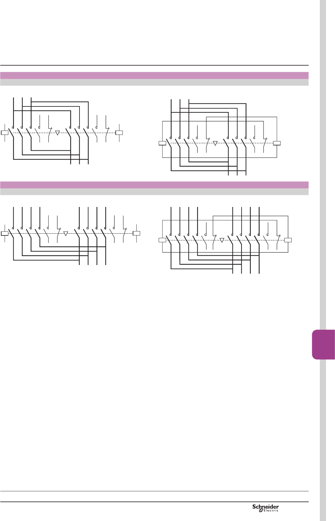
PCPB08T20-EN Version : 1.0 19 novembre 2014 10:37 AM B8/73
Contactors
B8/73
Schemes TeSys contactors
TeSys D reversing contactors
Reversing contactors for motor control
LC2 D09…D150 LAD 9R1V
+RUL]RQWDOO\PRXQWHG :LWKLQWHJUDOHOHFWULFDOLQWHUORFNLQJ
14
A1
A2
1
2
3
4
5
6
L1
L2
L3
1
2
3
4
5
6
U
V
W
13/NO
14 13/NO
A1
A2
22 21/NC
22 21/NC
DF568953.eps
14
A1
A2
1
2
3
4
5
6
L1
L2
L3
1
2
3
4
5
6
U
V
W
13/NO
14 13/NO
A1
A2
22 21/NC
22 21/NC
DF568946.eps
Changeover contactor pairs
LC2 DT20…DT40 LAD T9R1V
+RUL]RQWDOO\PRXQWHG :LWKLQWHJUDOHOHFWULFDOLQWHUORFNLQJ
A1
A2
1
2
3
4
5
6
1/L1
1/L2
1/L3
1
2
3
4
7
8
L1
L2
N
5
6
L3
7
8
1N
2/L1
2/L2
2/L3
2N
14 13/NO
22 21/NC
14 13/NO
A1
A2
22 21/NC
DF568954.eps
1
2
3
4
5
6
1/L1
1/L2
1/L3
1
2
3
4
7
8
L1
L2
N
5
6
L3
7
8
1N
2/L1
2/L2
2/L3
2N
14
A1
A2
13/NO
14 13/NO
A1
A2
22 21/NC
22 21/NC
DF568955.eps
Selection:
pages A5/23 to A5/47
Characteristics:
pages B8/53 to B8/58
References:
pages B8/2 to B8/19, B8/23 and B8/24
Dimensions:
pages B8/71 to B8/72
TeSys D
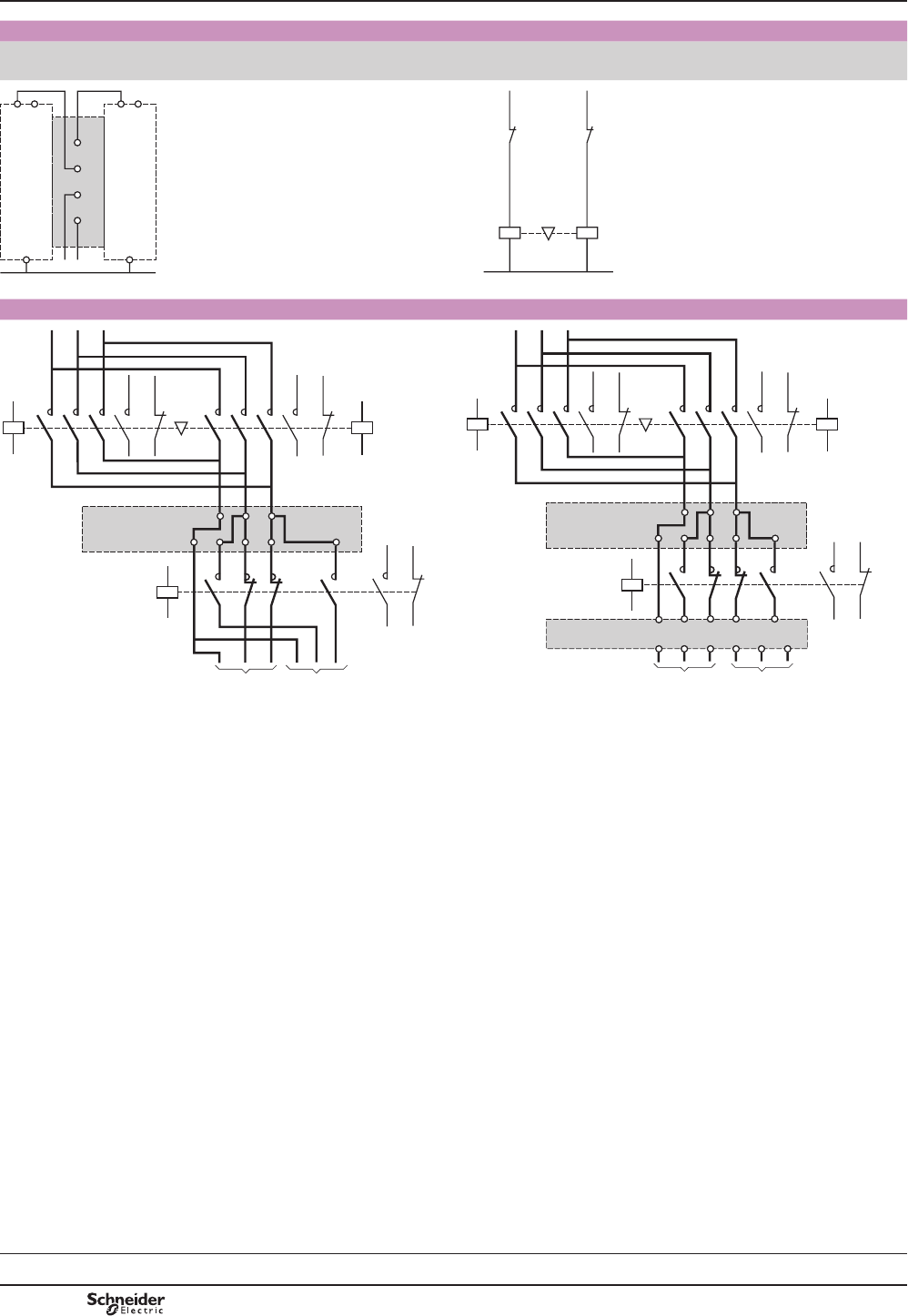
PCPB08T20-EN
Version : 1.0 19 novembre 2014 10:37 AM
B8/74
(OHFWULFDOLQWHUORFNLQJRIUHYHUVLQJFRQWDFWRUV¿WWHGZLWK
Mechanical interlock with integral electrical contacts Mechanical interlock without integral electrical contacts
LA9 D4002, LA9 D8002 and LA9 D11502 LAD 9V2, LAD 4CM, LA9 D50978 and LA9 D80978
01
02
01
02
A1
A2 A2
A1
A2
A2
– KM2– KM1
DF568956.eps
A1
A2
– KM1
– KM2
A1
A2
– KM2
– KM1
DF568957.eps
Low speed - High speed cabling kit, screw clamp terminals Low speed - High speed cabling kit, spring terminals
14
A1
A2
1
2
3
4
5
6
1
2
3
4
L1
L2
L3
1
2
3
4
5
6
U
V
W
13/NO
14 13/NO
A1
A2
A1
A2
22 21/NC
22 21/NC
14 13
22 21
PV GV
R1R2
R3R4
LAD 9PV/GV
DF568958.eps
14
A1
A2
1
2
3
4
5
6
1
2
3
4
L1
L2
L3
1
2
3
4
5
6
U
V
W
13/NO
14 13/NO
A1
A2
A1
A2
22 21/NC
22 21/NC
PV GV
R1R2
R3R4
LAD 3PV/GV
U1
V1
W1
U2
V2
W2
LAD 3PV/GV10
14 13
22
21
DF568959.eps
TeSys D
Schemes TeSys contactors
TeSys D reversing contactors
Selection:
pages A5/23 to A5/47
Characteristics:
pages B8/53 to B8/58
References:
pages B8/2 to B8/19, B8/23 and B8/24
Dimensions:
pages B8/71 to B8/72
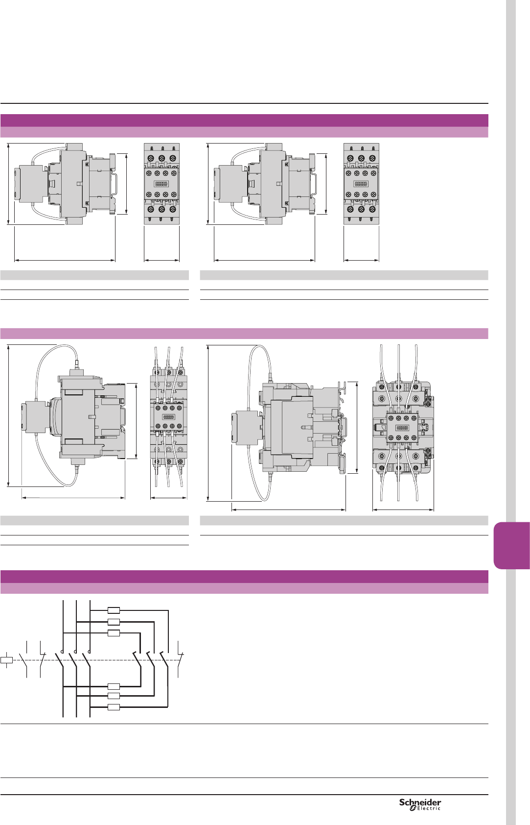
PCPB08T20-EN Version : 1.0 19 novembre 2014 10:37 AM B8/75
Contactors
B8/75
TeSys contactors
For switching 3-phase capacitor banks,
used for power factor correction
Dimensions
LC1 DFK, DGK LC1 DLK, DMK
45121
77
91
DB402404R.eps
45127
77
103
DB402405R.eps
LC1 7\SHRI¿[LQJ LC1 7\SHRI¿[LQJ
DFK LC1 D18 See pages B8/67 and B8/68 DLK LC1 D25 See pages B8/67 and B8/68
DGK LC1 D18 See pages B8/67 and B8/68 DMK LC1 D32 See pages B8/67 and B8/68
LC1 DPK, DTK LC1 DWK
156
113
166
55
DB402406.eps
180
127
154 85
DB402407.eps
LC1 7\SHRI¿[LQJ LC1 7\SHRI¿[LQJ
DPK LC1 D40A See pages B8/67 and B8/68 DWK LC1 D80 See pages B8/67 and B8/68
DTK LC1 D65A See pages B8/67 and B8/68
Schemes
LC1 DpK
21
NC
13
NO
22
31
NC
3214
1/L1
3/L2
5/L3
2/T1
4/T2
6/T3
A1
A2
- R
- R
DB402403.eps
5 3UHZLUHGUHVLVWRUFRQQHFWLRQV
Dimensions,
schemes
TeSys D
References:
page B8/13
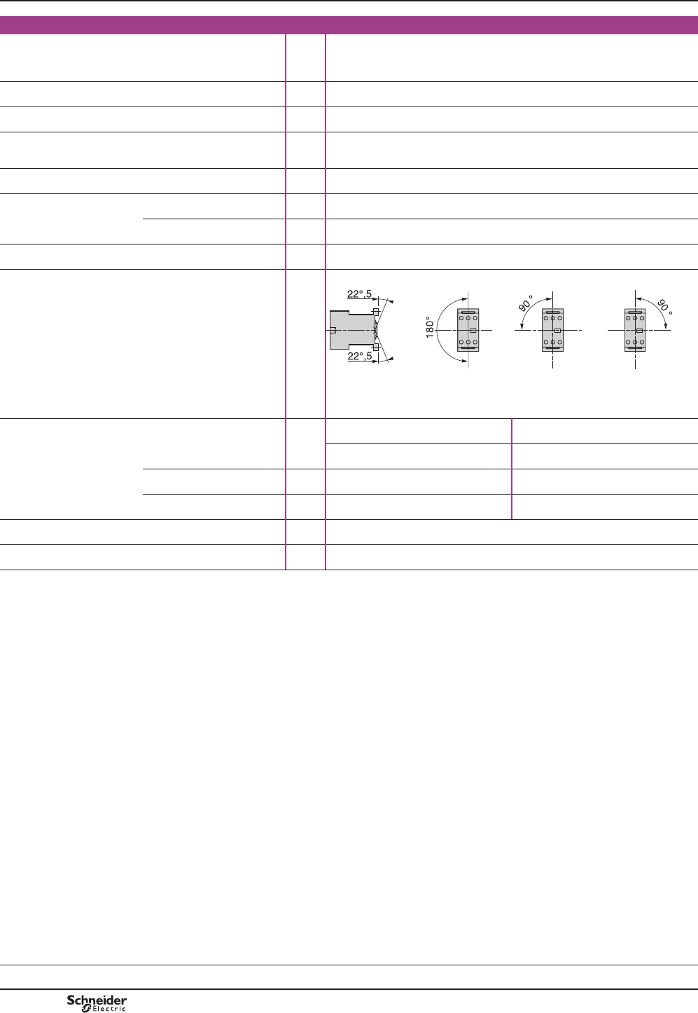
B8/76
TeSys contactors
Mini-contactors TeSys LC1 SK
and LP1 SK
Environment
5DWHGLQVXODWLRQYROWDJH
8L
Conforming to 60947,
VDE 0110 gr C,BS 5424,
&6$Q8/
V690
Conforming to standards IEC 60947, NF C 63-110, VDE 0660, BS 5424
Approvals UL, CSA
Protective treatment Conforming to IEC 60068
',1
³7&´.OLPDIHVW&OLPDWHSURRI
Degree of protection Conforming to VDE 0106 3URWHFWLRQDJDLQVWGLUHFW¿QJHUFRQWDFW
$PELHQWDLUWHPSHUDWXUHDURXQG
the device
Storage °C «
2SHUDWLRQ °C «
0D[LPXPRSHUDWLQJDOWLWXGH :LWKRXWGHUDWLQJ m2000
2SHUDWLQJSRVLWLRQ Vertical axis Horizontal axis
DF511520.eps
:LWKRXWGHUDWLQJ :LWKRXWGHUDWLQJ
Cabling,
screw clamp terminals
Min Max
6ROLGFRQGXFWRU mm2 1 x 1.5 or 2 x 1.5 1 x 6 or 2 x 4
)OH[LEOHFDEOHZLWKRXWFDEOHHQG mm2 1 x 0.5 or 2 x 0.35 1 x 6 or 2 x 2.5
Flexible cable with cable end mm2 1 x 0.35 or 2 x 0.35 1 x 6 or 2 x 1.5
7LJKWHQLQJWRUTXH 3R]LGULYQKHDG N.m 0.8
Terminal referencing Conforming to standards En 50005
Characteristics
TeSys SK
References:
pages B8/29 and B8/30
Dimensions:
page B8/80
Schemes:
page B8/80
PCPB08T10-EN
Version : 1.0 19 novembre 2014 10:37 AM
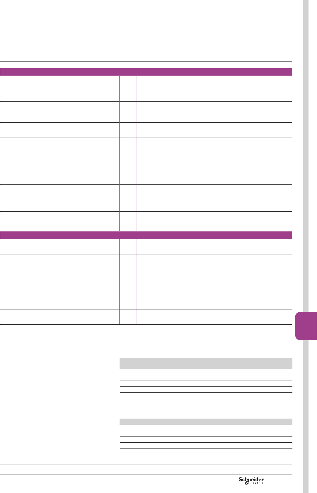
B8/77
Contactors
B8/77
Pole characteristics
&RQYHQWLRQDOWKHUPDOFXUUHQW
,WK
)RUDPELHQWWHPSHUDWXUH
y &
A12
5DWHGRSHUDWLRQDOIUHTXHQF\ Hz 50/60
)UHTXHQF\OLPLWVRIWKH
RSHUDWLRQDOFXUUHQW
Hz Up to 400
Rated operational voltage
8H
V690
5DWHGPDNLQJFDSDFLW\ I rms conforming to
NF C 63-110 and IEC 60947
A66
5DWHGEUHDNLQJFDSDFLW\
(for Ue y9
Conforming to NF C 63-110
DQG,(&,UPV
A52
Short time rating In free air for a time “t”
from cold state (T y&
A50
6KRUWFLUFXLWSURWHFWLRQ JOIXVH8y 440 V A16
Average impedance per pole At Ith and 50 Hz m:4
0D[LPXPUDWHGRSHUDWLRQDOFXUUHQW
)RUDWHPSHUDWXUH
y&
AC-3 (1)
(Ue y9
A6
AC-1 A12
8WLOLVDWLRQLQFDWHJRU\$&
UHVLVWLYHFLUFXLWVKHDWLQJ
lighting
(Ue y9
,QFUHDVHLQRSHUDWLRQDOFXUUHQW
E\SDUDOOHOLQJRISROHV
A20
Auxiliary contact characteristics of add-on blocks
Rated operational voltage
8H
Up to V
690
5DWHGLQVXODWLRQYROWDJH
8L
Conforming to IEC 60947,
BS 5424,
9'(JURXS&
&6$&Q
V690
&RQYHQWLRQDOWKHUPDOFXUUHQW
,WK
)RUDPELDQWWHPSHUDWXUH
y&
A10
)UHTXHQF\RIRSHUDWLRQDOFXUUHQW Hz Up to 400
6KRUWFLUFXLWSURWHFWLRQ Conforming to IEC 60947 and
9'(JOIXVH
A10
Operational power of contacts conforming to IEC 60947
a.c. supply, category AC-15
(OHFWULFDOGXUDELOLW\YDOLGXSWRRSHUDWLQJF\FOHVSHUKRXURQDQLQGXFWLYHORDG
VXFKDVWKHFRLORIDQHOHFWURPDJQHWPDNLQJFXUUHQWFRVM WLPHVWKH
EUHDNLQJFXUUHQWFRVM
V 24 48
110/
127
220/
230
380/
400 440
PLOOLRQRSHUDWLQJF\FOHV VA 48 96 240 440 800 880
PLOOLRQRSHUDWLQJF\FOHV VA 17 34 86 158 288 317
PLOOLRQRSHUDWLQJF\FOHV VA 7 14 36 66 120 132
2FFDVLRQDOPDNLQJFDSDFLW\ VA 1000 2050 5000 10000 14000 13000
d.c. supply, category DC-13
(OHFWULFDOGXUDELOLW\YDOLGXSWRRSHUDWLQJF\FOHVSHUKRXURQDQLQGXFWLYH
ORDGVXFKDVWKHFRLORIDQHOHFWURPDJQHWZLWKRXWHFRQRP\UHVLVWRUWKHWLPH
constant increasing with the load.
V 24 48 110 220 440 440
PLOOLRQRSHUDWLQJF\FOHV W120 80 60 52 51 880
PLOOLRQRSHUDWLQJF\FOHV W55 38 30 28 26 317
PLOOLRQRSHUDWLQJF\FOHV W15 11 9 8 7 132
2FFDVLRQDOPDNLQJFDSDFLW\ W720 600 400 300 230 13000
(1))RU/&FRQWDFWRUV
TeSys contactors
Mini-contactors TeSys LC1 SK
and LP1 SK
Characteristics
TeSys SK
References:
pages B8/29 and B8/30
Dimensions:
page B8/80
Schemes:
page B8/80
PCPB08T10-EN Version : 1.0 19 novembre 2014 10:37 AM

B8/78
TeSys contactors
Mini-contactors TeSys LC1 SK
and LP1 SK
Control circuit characteristics
Type LC1 SK06 LP1 SK06
5DWHGFRQWUROFLUFXLWYROWDJH8F Va 24…400 c 12…72
Control voltage limits
(T y&
For operation 0.85…1.1 Uc 0.85…1.1 Uc
)RUGURSRXW u 0.20 Uc u 0.10 Uc
$YHUDJHFRLOFRQVXPSWLRQ
DW&DQGDW8F
,QUXVK 16 VA 2.2 W
Sealed 4.2 VA 2.2 W
Heat dissipation W1.4 2.2
2SHUDWLQJWLPHDW&DQGDW8F
Between coil
energisation and
opening of the N/C contacts ms 8…16 10…18
FORVLQJRIWKH12FRQWDFWV ms 7…14 8…12
Between coil
de-energisation and
RSHQLQJRIWKH12FRQWDFWV ms 6…8 4…6
closing of the N/C contacts ms 8…10 6…8
0D[LPXPRSHUDWLQJUDWH ,QRSHUDWLQJF\FOHVSHUKRXU 1200 1200
0HFKDQLFDOGXUDELOLW\DW8F
,QPLOOLRQVRIRSHUDWLQJF\FOHV
50/60 Hz coil 10 –
c coil – 10
Characteristics
TeSys SK
References:
pages B8/29 and B8/30
Dimensions:
page B8/80
Schemes:
page B8/80
PCPB08T10-EN
Version : 1.0 19 novembre 2014 10:37 AM
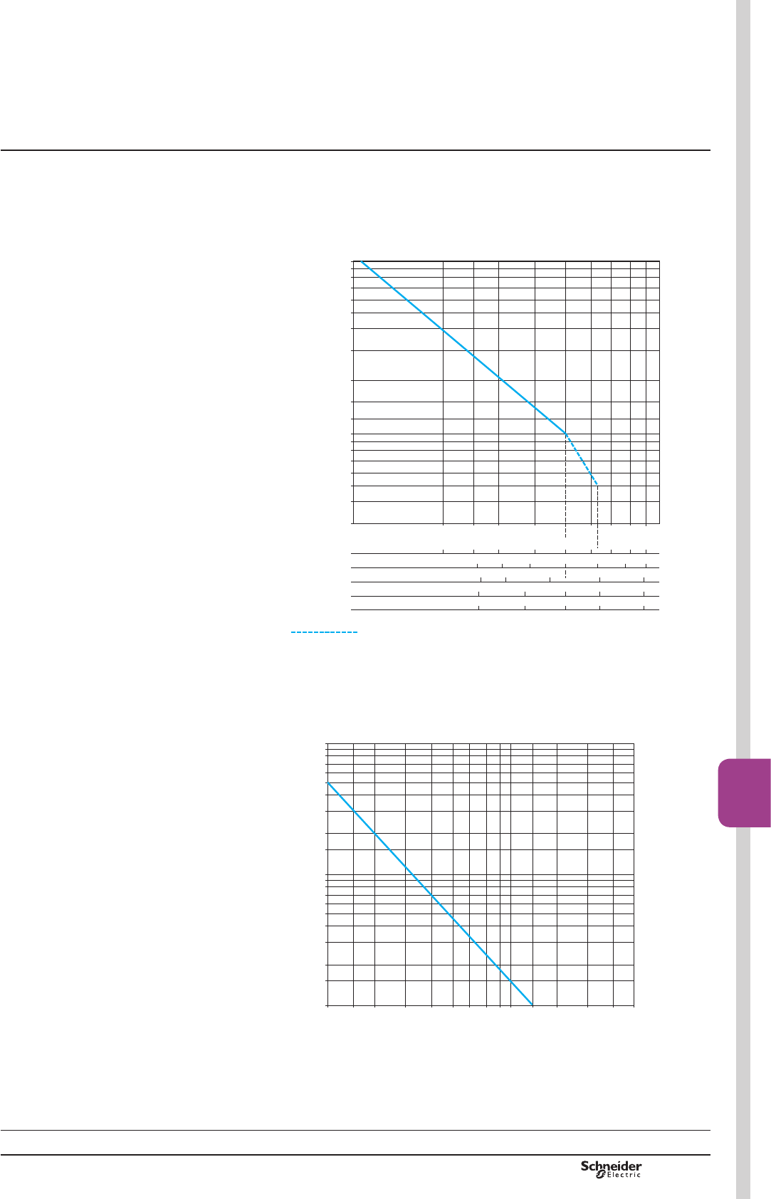
B8/79
Contactors
B8/79
TeSys contactors
Mini-contactors TeSys LC1 SK
and LP1 SK
Use in category AC-3 (Ue y 440 V)
&RQWURORISKDVHDV\QFKURQRXVVTXLUUHOFDJHPRWRUVZLWKEUHDNLQJZKLOVW
UXQQLQJ
7KHFXUUHQWEURNHQ,FLQFDWHJRU\$&LVHTXDOWRWKHUDWHGRSHUDWLRQDOFXUUHQW
,HRIWKHPRWRU
812712.eps
10
8
9
7
6
5
4
3
2
1,5
1,2
1
0,8
0,9
0,7
0,6
0,5
0,4
0,3
220/380/415 V 2 3 4 5 6 7 8
9 A
2,5
500 V 2 3 4 5 6 7
A
2,5
220/230 V
kW
380/400 V 1,1 1,5 2,2 3 4 kW
1,1 1,5 2,2 3 4
415 V
0,75 1,1 1,5 2,2
kW
0,55
&XUUHQWEURNHQLQ$
RQO\XSWR9
0LOOLRQVRIRSHUDWLQJF\FOHV
Use in category AC-1 (Ue y 440 V)
&RQWURORIUHVLVWLYHFLUFXLWVFRVM u
7KHFXUUHQWEURNHQ,FLQFDWHJRU\$&LVHTXDOWRWKHFXUUHQW,HQRUPDOO\GUDZQ
E\WKHORDG
0LOOLRQVRIRSHUDWLQJF\FOHV
&XUUHQWEURNHQLQ$
2 3 4 5 6 7 8 9 10 1512 20 30 402,5
10
8
7
6
5
4
3
2
1,5
1
0,8
0,7
0,6
0,5
0,4
0,3
0,2
0,15
0,1
812711.eps
Contactor selection guide
according to required
electrical durability
TeSys SK
References:
pages B8/29 and B8/30
Dimensions:
page B8/80
Schemes:
page B8/80
PCPB08T10-EN Version : 1.0 19 novembre 2014 10:37 AM
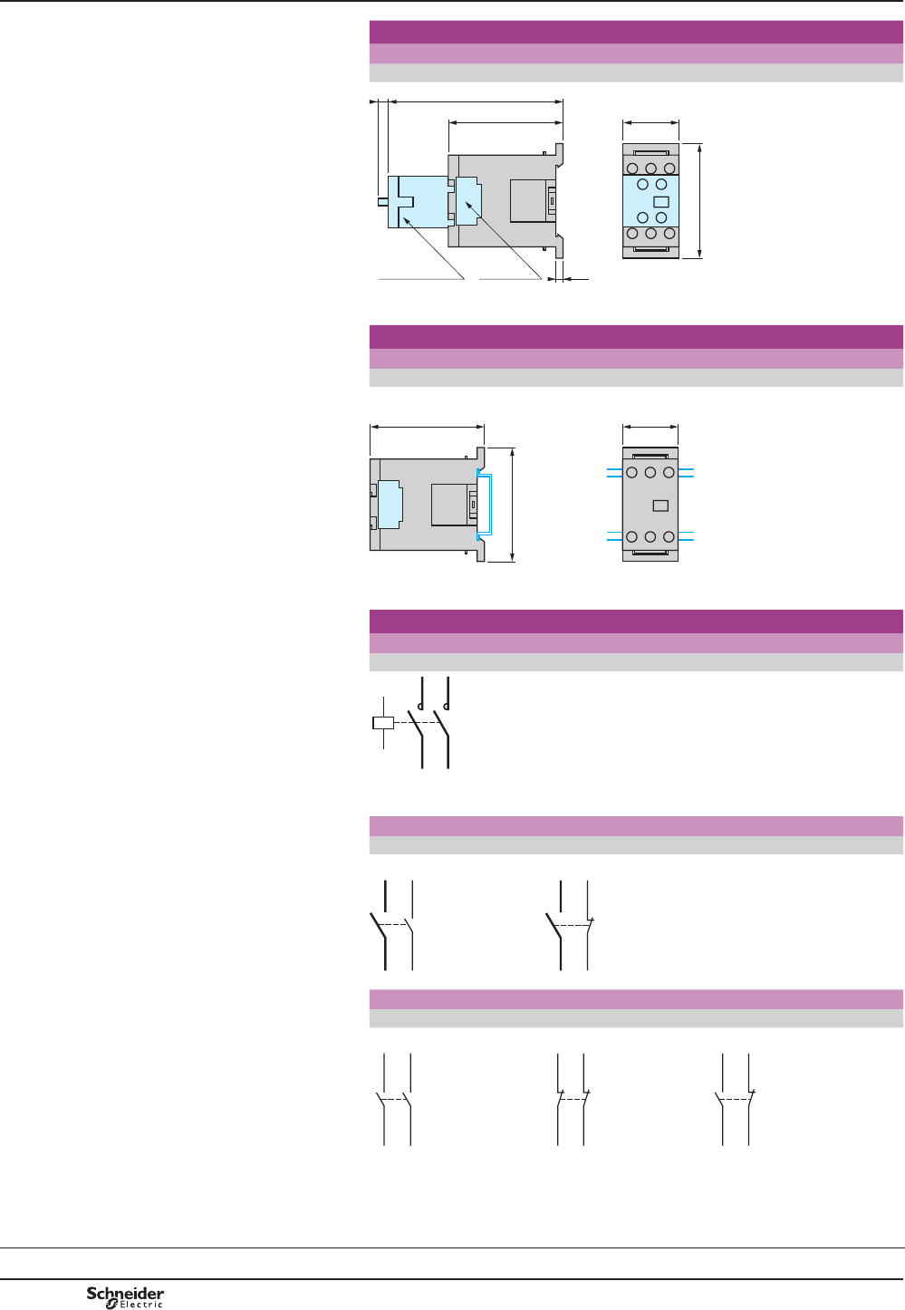
B8/80
TeSys contactors
Mini-contactors TeSys LC1 SK
and LP1 SK
Dimensions
Mini-contactors
LC1 and LP1 SK06
56
2755,5
84,55
3,5LA1 SK
(1)
LA4 SK
DF522582.eps
(1)2QO\RQ/&6.
Mounting
Mini-contactors
LC1 and LP1 SK06
On mounting rail AM1 DP200 or AM1 DE200 (7 35 mm)
27
56
55,5
DF522583.eps
Schemes
2-pole mini-contactors
LC1 and LP1 SK06
A1
1/L1
A2
T1/2
T2/4 3/L2
812724.eps
Add-on power pole block
1 pole + 1 “N/O” aux. 1 pole + 1 “N/C” aux.
LA1 SK10 LA1 SK01
5/L3
T3/6
13/NO
14
812727.eps
5/L3
T3/6
21/NC
22
812728.eps
Instantaneous auxiliary contacts
2 “N/O” 2 “N/C” 1 “N/O” + 1 “N/C”
LA1 SK20 LA1 SK02 LA1 SK11
33/NO34
44 43/NO
812725.eps
31/NC32
42 41/NC
812726.eps
33/NO34
42 41/NC
812729.eps
Dimensions,
mounting,
schemes
Characteristics:
pages B8/76 to B8/79
References:
pages B8/29 and B8/30
TeSys SK
PCPB08T10-EN
Version : 1.0 19 novembre 2014 10:37 AM
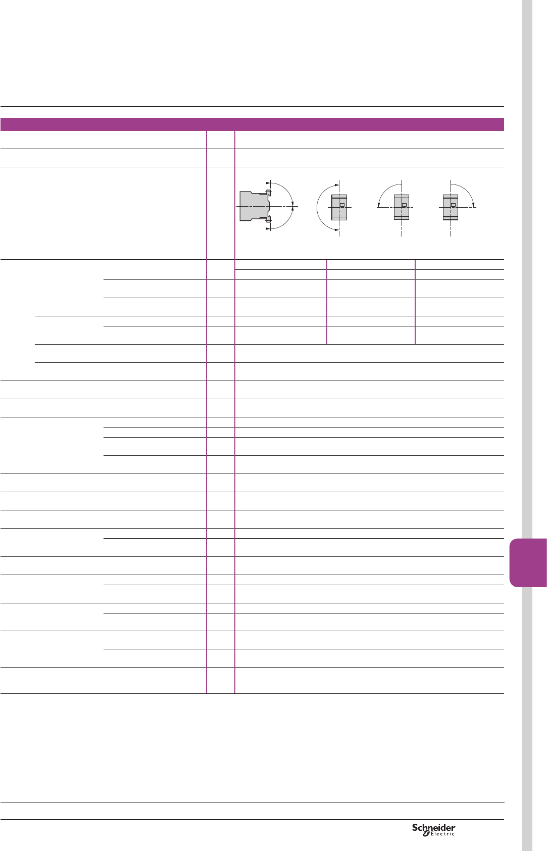
B8/81
Contactors
B8/81
TeSys contactors
TeSys K contactors and reversing
contactors
Environment characteristics
Conforming to standards IEC 60947, NF C 63-110, VDE 0660, BS 5424
3URGXFWFHUWL¿FDWLRQV LCp and LPp K06 to K12 UL, CSA
2SHUDWLQJSRVLWLRQV Vertical axis Horizontal axis
90°
90°
DF511522.eps
180°
DF511523.eps
90˚
90˚
DF564970.eps
:LWKRXWGHUDWLQJ :LWKRXWGHUDWLQJ Possible positions for LCp KRQO\
&RQWDFWRUSXOOLQYROWDJH8F
Connection Min. Max. Max. to IEC 60947
Screw clamp
terminals
6ROLGFRQGXFWRU mm21 x 1.5 2 x 4 [[
)OH[LEOHFRQGXFWRU
ZLWKRXWFDEOHHQG
mm21 x 0.75 2 x 4 2 x 2.5
)OH[LEOHFRQGXFWRU
with cable end
mm21 x 0.34 [[ [[
Spring terminals 6ROLGFRQGXFWRU mm21 x 0.75 1 x 1.5 2 x 1.5
)OH[LEOHFRQGXFWRU
ZLWKRXWFDEOHHQG
mm21 x 0.75 1 x 1.5 2 x 1.5
Faston connectors Clip mm 2 x 2.8 or 1 x 6.35
Solder pins for
SULQWHGFLUFXLWERDUG
With locating device between
SRZHUDQGFRQWUROFLUFXLWV
4 mm x 35 microns
7LJKWHQLQJWRUTXH 3KLOLSVKHDGQDQG N.m 0.8
Terminal referencing Conforming to standards
EN 50005 and EN 50012
Up to 5 contacts, depending on model
5DWHGLQVXODWLRQYROWDJH
8L
Conforming to IEC 60947 V690
Conforming to VDE 0110 gr C V750
Conforming to BS 5424,
NF C 20-040
V690
&RQIRUPLQJWR&6$Q
UL 508
V600
5DWHGLPSXOVHZLWKVWDQGYROWDJH8LPS kV 8
Protective treatment Conforming to IEC 60068
',1
³7&´.OLPDIHVW&OLPDWHSURRI
Degree of protection Conforming to VDE 0106 3URWHFWLRQDJDLQVWGLUHFW¿QJHUFRQWDFW
$PELHQWDLUWHPSHUDWXUHDURXQG
the device
Storage °C «
2SHUDWLRQ °C «
0D[LPXPRSHUDWLQJDOWLWXGH :LWKRXWGHUDWLQJ m2000
Vibration resistance
5 ... 300 Hz
Contactor open 2 gn
Contactor closed 4 gn
Flame resistance Conforming to UL 94 6HOIH[WLQJXLVKLQJPDWHULDOV9
Conforming to NF F 16-101
and 16-102
&RQIRUPLQJWRUHTXLUHPHQW
6KRFNUHVLVWDQFH
VLQHZDYHPV
Contactor open 2Q;D[LVJQ
2Q<DQG=D[HVJQ
Contactor closed 2Q;D[LVJQ
2Q<DQG=D[HVJQ
6DIHVHSDUDWLRQRIFLUFXLWV Conforming to VDE 0106
and IEC 60536
6(/96DIHW\([WUD/RZ9ROWDJHXSWR9
Characteristics
References:
pages B8/31 to B8/38
Dimensions:
pages B8/85 and B8/87
Schemes:
pages B8/86 and B8/88
TeSys K
PCPB08T10-EN Version : 1.0 19 novembre 2014 10:37 AM
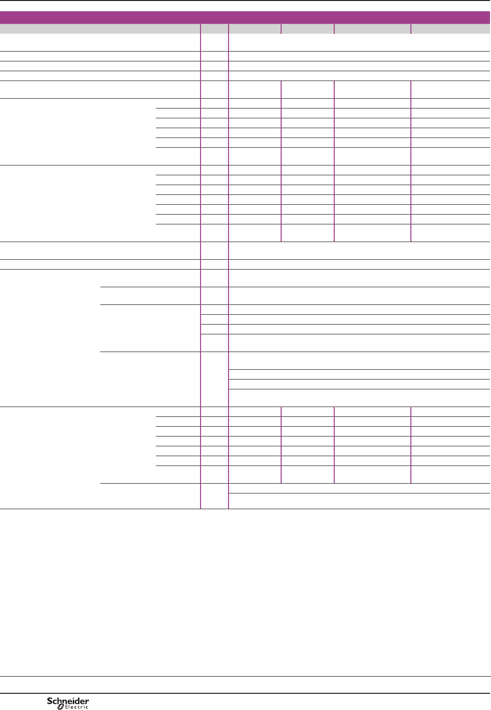
B8/82
Pole characteristics
Type LCp or LPp K06 K09 K12 K16
Conventional thermal
FXUUHQW,WK
)RUDPELHQWWHPSHUDWXUH
y &
A20
5DWHGRSHUDWLRQDOIUHTXHQF\ Hz 50/60
)UHTXHQF\OLPLWVRIWKHRSHUDWLRQDOFXUUHQW Hz Up to 400
5DWHGRSHUDWLRQDOYROWDJH8H V690
5DWHGPDNLQJFDSDFLW\ I rms conforming to
NF C 63 110 and IEC 60947
A110 110 144 160
5DWHGEUHDNLQJFDSDFLW\ I rms conforming
to NF C 63 110
and IEC 60947
220/230 V A110 110 – –
380/400 V A110 110 – –
415 V A110 110 – –
440 V A110 110 110 110
500 V A80 80 80 80
660/690 V A70 70 70 70
Permissible short
time rating
In free air for a
time “t” from cold
state (T y&
1 s A90 90 115 115
5 s A85 85 105 105
10 s A80 80 100 100
30 s A60 60 75 75
1 min A45 45 55 55
3 min A40 40 50 50
u 15 min A20 20 25 25
6KRUWFLUFXLWSURWHFWLRQ J*IXVH8y440 V
D0IXVHVHHSDJH
A25
Average impedance per pole At Ith and 50 Hz m:3
8VHLQFDWHJRU\$&
UHVLVWLYHFLUFXLWVKHDWLQJ
lighting (Ue y9
0D[LPXPUDWHGRSHUDWLRQDO
FXUUHQWIRUDWHPSHUDWXUHy&
A20
0D[LPXPUDWHGRSHUDWLRQDO
FXUUHQWIRUDWHPSHUDWXUHy&
AIRU8HRQO\
5DWHGRSHUDWLRQDOFXUUHQWOLPLWV
in relation to the on-load factor
DQGRSHUDWLQJIUHTXHQF\
2QORDGIDFWRU
ARSHUDWLQJF\FOHVKRXU 13 15 18
ARSHUDWLQJF\FOHVKRXU 15 18 19
ARSHUDWLQJF\FOHVKRXU 19 20 20
Increase in rated operational
FXUUHQWE\SDUDOOHOLQJRISROHV
$SSO\WKHIROORZLQJFRHI¿FLHQWVWRWKHDERYHFXUUHQWVWKHVHFRHI¿FLHQWVWDNHLQWR
DFFRXQWDQRIWHQXQEDODQFHGGLVWULEXWLRQRIFXUUHQWEHWZHHQWKHSROHV
SROHVLQSDUDOOHO.
SROHVLQSDUDOOHO.
SROHVLQSDUDOOHO.
8VHLQFDWHJRU\$&
VTXLUUHOFDJHPRWRUV
2SHUDWLRQDO
power according
to the voltage.
Voltage 50 or
60 Hz
115 V single-ph. kW 0.37 0.55 – –
220 V single-ph. kW 0.75 1.1 – –
220/230 V 3-ph. kW 1.5 2.2 3 4
380/415 V 3-ph. kW 2.2 4 5.5 7.5
440/480 V 3-ph. kW 3 4
500/600 V 3-ph. kW 3 4 4 4
660/690 V 3-ph. kW 3 4 4 4
0D[LPXPRSHUDWLQJUDWH
LQRSHUDWLQJF\FOHVKRXULQ
UHODWLRQWRRIUDWHGSRZHU
2SF\FOHVK 600 900 1200
Power
References:
pages B8/31 to B8/38
Dimensions:
pages B8/85 and B8/87
Schemes:
pages B8/86 and B8/88
TeSys contactors
TeSys K contactors and reversing
contactors
Characteristics
TeSys K
PCPB08T10-EN
Version : 1.0 19 novembre 2014 10:37 AM
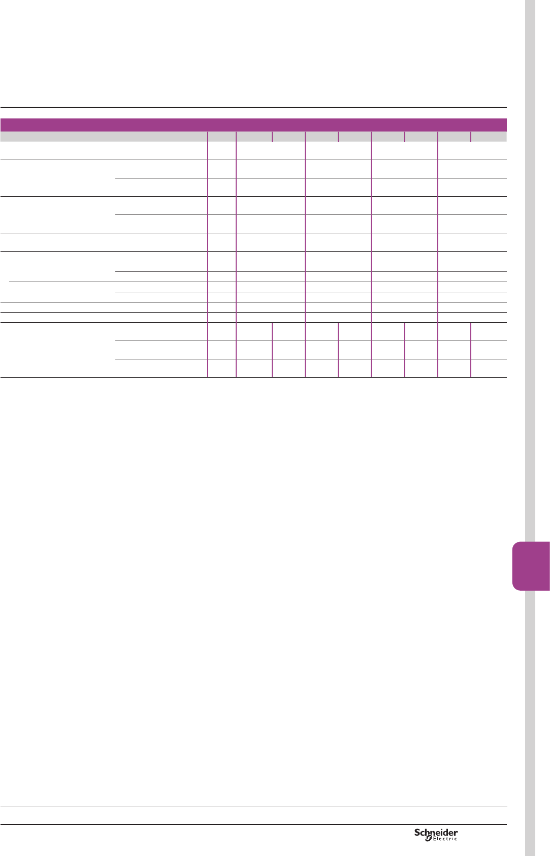
B8/83
Contactors
B8/83
TeSys contactors
TeSys K contactors and reversing
contactors
Control circuit characteristics
Type LC1 LC2 LC7 LC8 LP1 LP2 LP4 LP5
5DWHGFRQWUROFLUFXLWYROWDJH8F V a 12…690 (1) a 24…240 (1) c 12…250 (1) c 12…120
Control voltage limits (y&
single voltage coil
2SHUDWLRQ 0.8…1.15 Uc (2) 0.85…1.1 Uc 0.8…1.15 Uc 0.7…1.30 Uc
'URSRXW u 0.20 Uc u 0.10 Uc u 0.10 Uc u 0.10 Uc
$YHUDJHFRQVXPSWLRQ
DW&DQGDW8F
,QUXVK 30 VA 3 VA 3 W 1.8 W
Sealed 4.5 VA 3 VA 3 W 1.8 W
Heat dissipation W1.3 3 3 1.8
2SHUDWLQJWLPHDW&DQGDW8F
Between coil energisation and: - opening of the N/C contacts ms 5…15 25…35 25…35 25…35
- FORVLQJRIWKH12FRQWDFWV ms 10…20 30…40 30…40 30…40
Between coil de-energisation and: - RSHQLQJRIWKH12FRQWDFWV ms 10…20 30 10 10…20
- closing of the N/C contacts ms 15…25 40 15 15…25
0D[LPXPLPPXQLW\WRPLFUREUHDNV ms 2 2 2 2
0D[LPXPRSHUDWLQJUDWH ,QRSHUDWLQJF\FOHVSHUKRXU 3600 3600 3600 3600
0HFKDQLFDOGXUDELOLW\DW8F
,QPLOOLRQVRIRSHUDWLQJF\FOHV
50/60 Hz coil 10 5 10 5 – – – –
c coil – – – – 10 5 – –
Wide range coil,
/RZFRQVXPSWLRQ
– – – – – – 30 5
(1))RUPDLQVVXSSOLHVZLWKDKLJKOHYHORILQWHUIHUHQFHYROWDJHVXUJH!9XVHDVXSSUHVVRUPRGXOH/$.()&«9RU/$.(8*«9
see page
%
(2)/&.«8F
Characteristics
References:
pages B8/31 to B8/38
Dimensions:
pages B8/85 and B8/87
Schemes:
pages B8/86 and B8/88
TeSys K
PCPB08T10-EN Version : 1.0 19 novembre 2014 10:37 AM
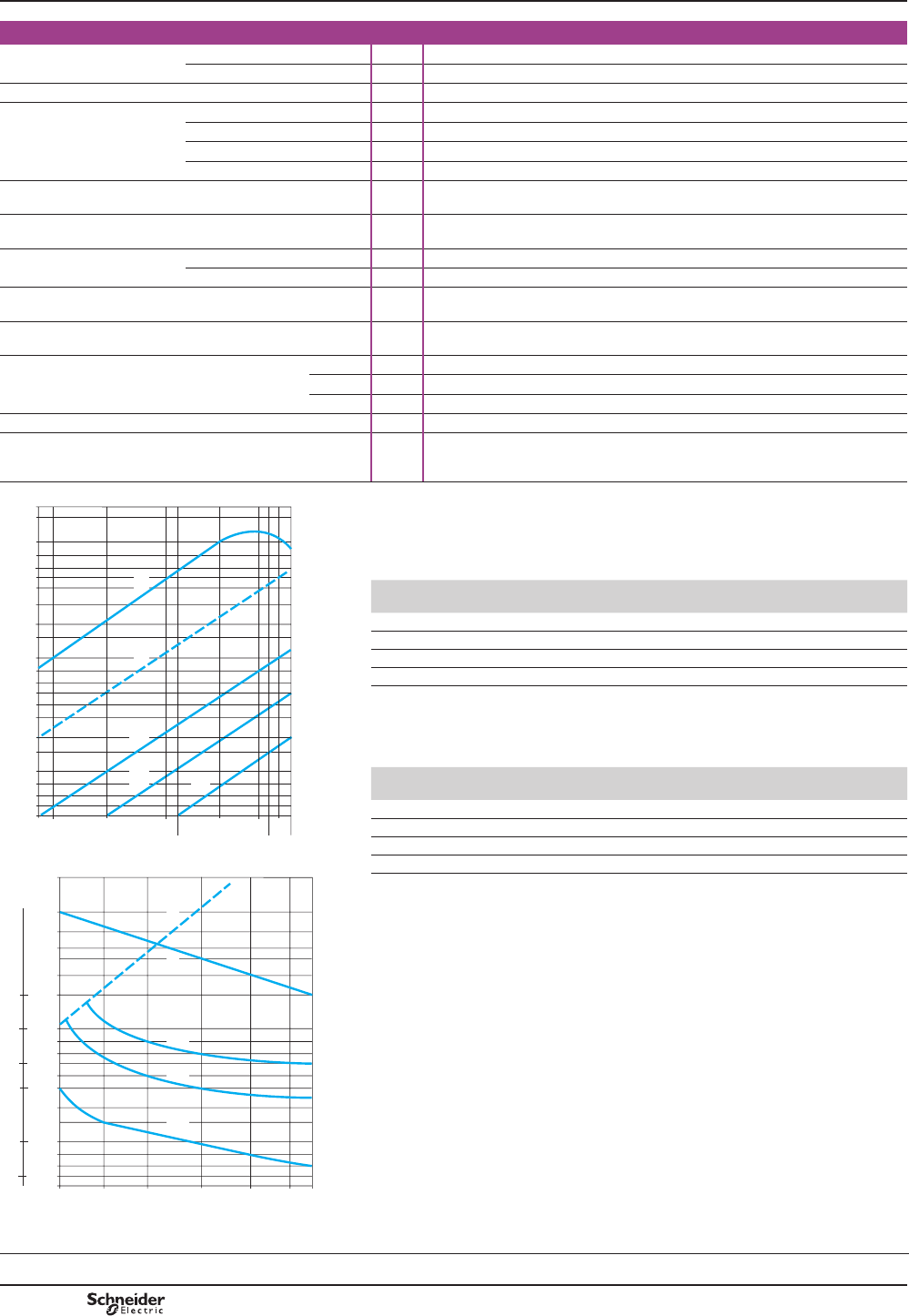
B8/84
Auxiliary contact characteristics of contactors and instantaneous contact blocks
1XPEHURIDX[LOLDU\FRQWDFWV 2Q/&p K or LPp K 3-pole 1
2Q/$. 2 or 4
5DWHGRSHUDWLRQDOYROWDJH8H Up to V690
5DWHGLQVXODWLRQYROWDJH8L Conforming to BS 5424 V690
Conforming to IEC 60947 V690
&RQIRUPLQJWR9'(JURXS& V750
&RQIRUPLQJWR&6$&Q V600
Conventional
WKHUPDOFXUUHQW,WK
)RUDPELHQWWHPSHUDWXUHy& A10
)UHTXHQF\RIWKH
RSHUDWLRQDOFXUUHQW
Hz Up to 400
0LQLPXPVZLWFKLQJ
FDSDFLW\
8PLQ',1 V17
I min mA 5
6KRUWFLUFXLWSURWHFWLRQ Conforming to IEC 60947
DQG9'(J*IXVH
A10
5DWHGPDNLQJFDSDFLW\ Conforming to
IEC 60947
I rms A110
Short-time rating Permissible for 1 s A80
500 ms A90
100 ms A110
,QVXODWLRQUHVLVWDQFH M:> 10
Non-overlap distance /$.OLQNHGFRQWDFWV
conforming to INRS, BIA
DQG&1$VSHFL¿FDWLRQV
mm VHHVFKHPHVSDJHV%DQG%
3RZHUEURNHQLQ9$ Operational power of contacts conforming to IEC 60947
a.c. supply, category AC-15
(OHFWULFDOGXUDELOLW\YDOLGIRUXSWRRSHUDWLQJF\FOHVKRXURQDQLQGXFWLYH
ORDGVXFKDVWKHFRLORIDQHOHFWURPDJQHWPDNLQJFXUUHQWFRVM WLPHV
WKHSRZHUEURNHQFRVM
10 000
5000
3000
2000
1000
800
600
500
400
300
200
100
80
60
24 48 110 220
440 690 V
120
380 500
40
16 000
8000
6000
4000
2c
2b
4
1
2a
DF564971.eps
Operating cycles
V
24
48
110/
127
220/
230
380/
400
440
600/
690
PLOOLRQRSHUDWLQJF\FOHV VA 48 96 240 440 800 880 1200
PLOOLRQRSHUDWLQJF\FOHV VA 17 34 86 158 288 317 500
PLOOLRQRSHUDWLQJF\FOHV VA 7 14 36 66 120 132 200
2FFDVLRQDOPDNLQJFDSDFLW\ VA 1000 2050 5000 10000 14000 13000 9000
d.c. supply, category DC-13
(OHFWULFDOGXUDELOLW\YDOLGIRUXSWRRSHUDWLQJF\FOHVKRXURQDQLQGXFWLYH
ORDGVXFKDVWKHFRLORIDQHOHFWURPDJQHWZLWKRXWHFRQRP\UHVLVWRUWKHWLPH
constant increasing with the load.
Operating cycles
V
24
48
110
220
440
600
PLOOLRQRSHUDWLQJF\FOHV W120 80 60 52 51 50
PLOOLRQRSHUDWLQJF\FOHV W55 38 30 28 26 25
PLOOLRQRSHUDWLQJF\FOHV W15 11 9 8 7 6
2FFDVLRQDOPDNLQJFDSDFLW\ W720 600 400 300 230 200
3RZHUEURNHQLQ:
1000
700
500
300
200
100
80
60
50
40
30
20
10
8
6
12 24 48 110 220 440 600 V
250
200
140
100
50
20
2c
2b
2a
3
4
DF564972.eps
1.%UHDNLQJOLPLWRIFRQWDFWVYDOLGIRU
bPD[LPXPRIRSHUDWLQJF\FOHVDWVLQWHUYDOVSRZHUEURNHQ PDNLQJ
FXUUHQW[FRVM
2.(OHFWULFDOGXUDELOLW\RIFRQWDFWVIRU
bPLOOLRQRSHUDWLQJF\FOHV2a
bPLOOLRQRSHUDWLQJF\FOHV2b
b PLOOLRQRSHUDWLQJF\FOHV2c
3.%UHDNLQJOLPLWRIFRQWDFWVYDOLGIRU
b PD[LPXPRIRSHUDWLQJF\FOHVDWVLQWHUYDOVZLWKFXUUHQWSDVVLQJIRUV
SHURSHUDWLQJF\FOH
4. Thermal limit.
References:
pages B8/31 to B8/38
Dimensions:
pages B8/85 and B8/87
Schemes:
pages B8/86 and B8/88
TeSys contactors
TeSys K contactors and reversing
contactors
Characteristics
TeSys K
PCPB08T10-EN
Version : 1.0 19 novembre 2014 10:37 AM
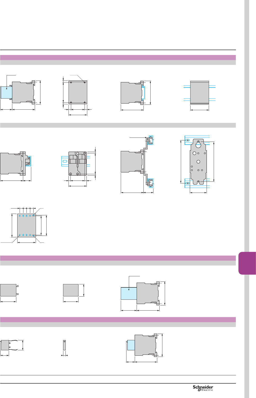
B8/85
Contactors
B8/85
TeSys contactors
TeSys K contactors
Contactors
LC1 K, LC7 K, LP1 K, LP4 K
2QSDQHO 2QPRXQWLQJUDLO$0'3RU$0'(7PP
5735
LA1 K
58
50= =
35
45
==
4xØ4
DF565021.eps
57
58
45
DF565023.eps
LA9 D973 DX1 AP25
2QRQHDV\PPHWULFDOUDLO'=0%ZLWKFOLSRQPRXQWLQJSODWHV
45
35
= =
50 55
57 21
DF565022.eps
110
45
120
57 27
DZ5 ME5
DF565024.eps
2QSULQWHGFLUFXLWERDUG
50
53
45
58
8,65 = = =
10xØ1,6
A1
A2
DF565025.eps
Electronic time delay contact blocks
LA2 KT
38 38
27
810294.eps
2QFRQWDFWRU
57
LA2 KT
58
38
DF565026.eps
Suppressor modules
LA4 Kp
2QFRQWDFWRU/&.RU/3.
6
25
22
5722
58
810295.eps
Dimensions,
mounting
TeSys K
Characteristics:
pages B8/81 to B8/84
References:
pages B8/31 to B8/34
Schemes:
page B8/86
PCPB08T10-EN Version : 1.0 19 novembre 2014 10:37 AM

B8/86
TeSys contactors
TeSys K reversing contactors
3-pole contactors With integral suppression device
LC7 K LP4 K
312
A1
A2
1/L1
T1/2
3/L2
T2/4
5/L3
T3/6
7/L4
T4/8
127355.eps
31&
22 21/NC
A1
A2
1/L1
T1/2
3/L2
T2/4
5/L3
T3/6
127356.eps
A1
A2
810332.eps
+A1
–A2
810348.eps
4-pole contactors With integral suppression device
LC7 K LP4 K
4 P
A1
A2
1/L1
T1/2
3/L2
T2/4
5/L3
T3/6
7/L4
T4/8
127357.eps
31231&
R1
R2
A1
A2
1
2
3
4
R3
R4
127358.eps
A1
A2
810332.eps
+A1
–A2
810348.eps
Instantaneous auxiliary contacts LA1 K
LA1 KN20, KN207, KN203 LA1 KN02, KN027, KN023 LA1 KN11, KN117, KN113
12 2 N/C 121&
53/NO
54
63/NO
64
127359.eps
61/NC
62
51/NC
52
127360.eps
61/NC
62
53/NO
54
810337.eps
LA1 KN40, KN407, KN403 LA1 KN31, KN317, KN313 LA1 KN22, KN227, KN223 LA1 KN13, KN137, KN133 LA1 KN04, KN047, KN043
12 121& 121& 121& 4 N/C
54
64
74
53/NO
63/NO
73/NO
83/NO
84
127361.eps
62
74
53/NO
54
61/NC
73/NO
83/NO
84
810342.eps
53/NO
54
61/NC
62
71/NC
72
83/NO
84
810341.eps
54
62
72
82
53/NO
61/NC
71/NC
81/NC
810340.eps
51/NC
52
61/NC
62
71/NC
72
81/NC
82
127362.eps
Terminal referencing conforming to standard EN 50012
LA1 KN02M LA1 KN11M LA1 KN31M LA1 KN22M LA1 KN13M
2 N/C 121& 121& 121& 121&
31/NC
32
21/NC
22
127363.eps
22
34
21/NC
33/NO
DF565032.eps
33/NO
34
21/NC
22
43/NO
44
53/NO
54
DF565033.eps
21/NC
22
43/NO
44
53/NO
54
31/NC
32
DF565034.eps
21/NC
22
53/NO
54
31/NC
32
41/NC
42
DF565035.eps
LA1 KN11P LA1 KN22P
121& 121&
21/NC
22
13/NO
14
DF565036.eps
22
13/NO
14
21/NC
31/NC
32
43/NO
44
DF565037.eps
Electronic time delay contact blocks Suppressor modules
LA2 KT LA4 KC LA4 KE
&2
A1A2
18
15
16
810345.eps
+–
DB404433.eps
DB404434.eps
Schemes
TeSys K
Characteristics:
pages B8/81 to B8/84
References:
pages B8/31 to B8/34
Dimensions:
page B8/85
PCPB08T10-EN
Version : 1.0 19 novembre 2014 10:37 AM
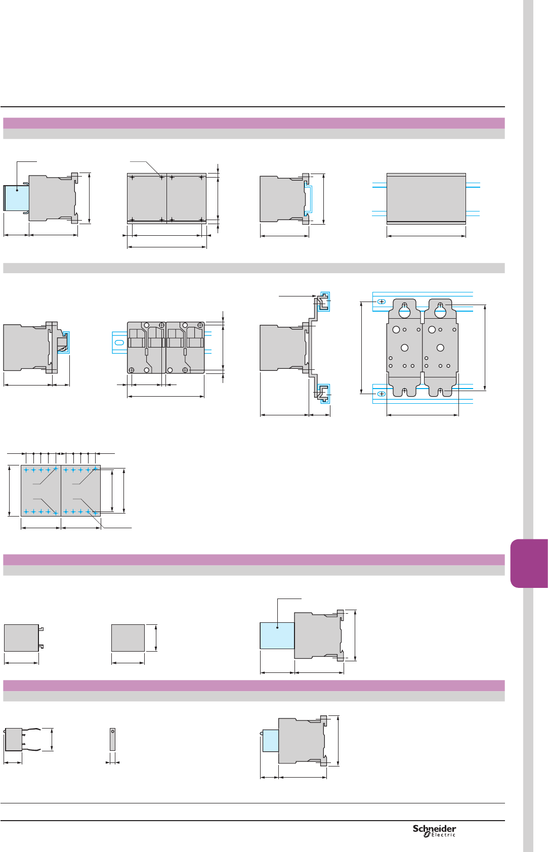
B8/87
Contactors
B8/87
TeSys contactors
TeSys K reversing contactors
Reversing contactors
LC2 K, LC8 K, LP2 K, LP5 K
2QSDQHO 2QPRXQWLQJUDLO$0'3RU$0'(7PP
5735
LA1 K
58
50= =
90
80
8xØ4
==
DF565038.eps
57
58
90
DF565040.eps
2 x LA9 D973 2 x DX1 AP25
2QRQHDV\PPHWULFDOPRXQWLQJUDLO'=0%ZLWKFOLSRQPRXQWLQJSODWHV/$'RURQPRXQWLQJSODWHV';$3
90
35= =
50 55
57 21
DF565039.eps
57 27
DZ5 ME5
90
110
120
DF565041.eps
2QSULQWHGFLUFXLWERDUGIRUUHYHUVLQJFRQWDFWRUVRUFRQWDFWRUVPRXQWHGVLGHE\VLGH
45
58
8,65 = = =
20xØ1,6
A1
A2
50
45
8,65===
53
A1
A2
DF565042.eps
Electronic time delay contact blocks
LA2 KT
2QUHYHUVLQJFRQWDFWRUV
38
38
27
DF565044.eps
57
LA2 KT
58
38
DF565043.eps
Suppressor modules
LA4 Kp
2QUHYHUVLQJFRQWDFWRUV/&.RU/3.
6
25
22
DF565045.eps
5722
58
DF565046.eps
Dimensions,
mounting
TeSys K
Characteristics:
pages B8/81 to B8/84
References:
pages B8/35 to B8/38
Schemes:
page B8/88
PCPB08T10-EN Version : 1.0 19 novembre 2014 10:37 AM
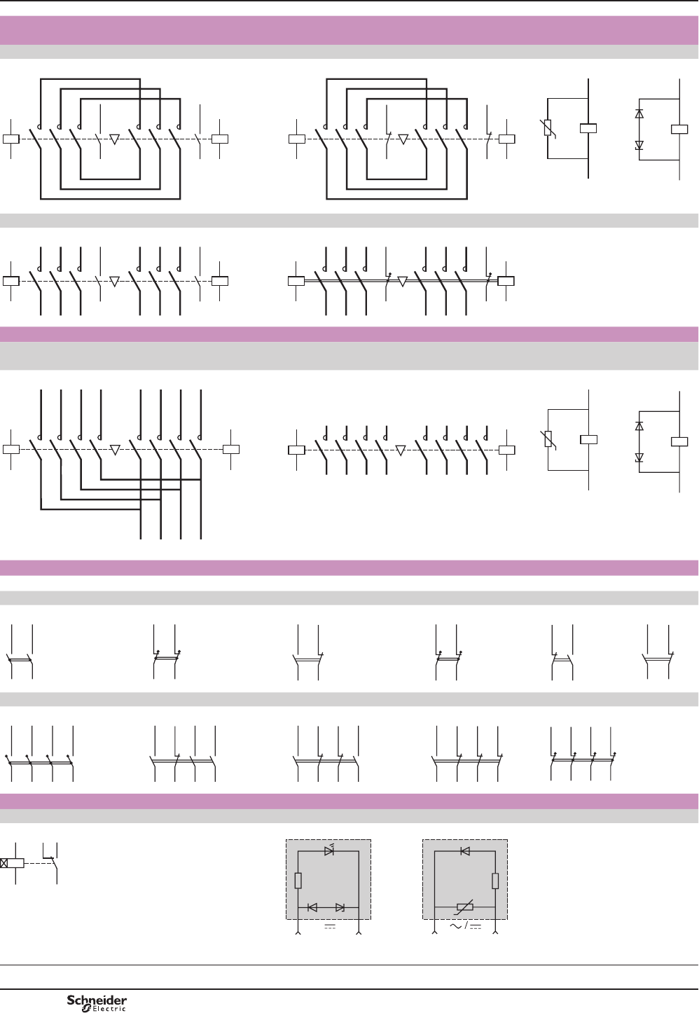
B8/88
TeSys contactors
TeSys K reversing contactors
3-pole reversing contactors With integral suppression
device
With screw clamp connections LC8 K LP5 K
312 31&
13/NO
14
A1
A2
1/L1
T1/2
3/L2
T2/4
5/L3
T3/6
13/NO
14
A1
A2
1/L1
T1/2
3/L2
T2/4
5/L3
T3/6
810331.eps
21/NC
22
A1
A2
1/L1
T1/2
3/L2
T2/4
5/L3
T3/6
21/NC
22
A1
A2
1/L1
T1/2
3/L2
T2/4
5/L3
T3/6
810330.eps
A1
A2
810332.eps
+A1
–
A2
810348.eps
With Faston connectors or solder pins (printed circuit board)
312 31&
13/NO
14
A1
A2
1/L1
T1/2
3/L2
T2/4
5/L3
T3/6
13/NO
14
A1
A2
1/L1
T1/2
3/L2
T2/4
5/L3
T3/6
810333.eps
21/NC
22
A1
A2
1/L1
T1/2
3/L2
T2/4
5/L3
T3/6
21/NC
22
A1
A2
1/L1
T1/2
3/L2
T2/4
5/L3
T3/6
127365.eps
4-pole reversing contactors Integral suppression device
With screw clamp connections With Faston connectors or solder pins (printed
circuit board)
LC8 K LP5 K
4 P 4 P
A1
A2
1
2
3
4
5
6
A1
A2
1
2
3
4
5
6
1/L1
1/L2
1/L3
2/L1
2/L2
2/L3
L1
L2
L3
7
81N
7
82N
N
810335.eps
A1
A2
1
2
3
4
5
6
A1
A2
1
2
3
4
7
8
7
8
5
6
DF565047.eps
A1
A2
810332.eps
+A1
–
A2
810348.eps
Instantaneous auxiliary contacts LA1 K
Terminal referencing conforming to standard EN 50012
LA1 KN20, KN207, KN203 LA1 KN02, KN027, KN023 LA1 KN11, KN117, KN113 LA KN02M LA1 KN11M LA1 KN11P
12 2 N/C 121& 2 N/C 121& 121&
53/NO
54
63/NO
64
127366.eps
61/NC
62
51/NC
52
127367.eps
61/NC
62
53/NO
54
810337.eps
31/NC
32
21/NC
22
127370.eps
22
34
21/NC
33/NO
810350.eps
21/NC
22
13/NO
14
810351.eps
LA1 KN40, KN407, KN403 LA1 KN31, KN317, KN313 LA1 KN22, KN227, KN223 LA KN13, KN137, KN133 LA1 KN04, KN047, KN043
12 121& 121& 121& 4 N/C
54
64
74
53/NO
63/NO
73/NO
83/NO
84
127368.eps
62
74
53/NO
54
61/NC
73/NO
83/NO
84
810342.eps
53/NO
54
61/NC
62
71/NC
72
83/NO
84
810341.eps
54
62
72
82
53/NO
61/NC
71/NC
81/NC
810340.eps
51/NC
52
61/NC
62
71/NC
72
81/NC
82
127369.eps
Electronic time delay contact blocks Suppressor modules
LA2 KT LA4 KC LA4 KE
&2
A1A2
18
15
16
810345.eps
+–
810346.eps
810347.eps
Schemes
TeSys K
Characteristics:
pages B8/81 to B8/84
References:
pages B8/35 to B8/38
Dimensions:
page B8/87
PCPB08T10-EN
Version : 1.0 19 novembre 2014 10:37 AM
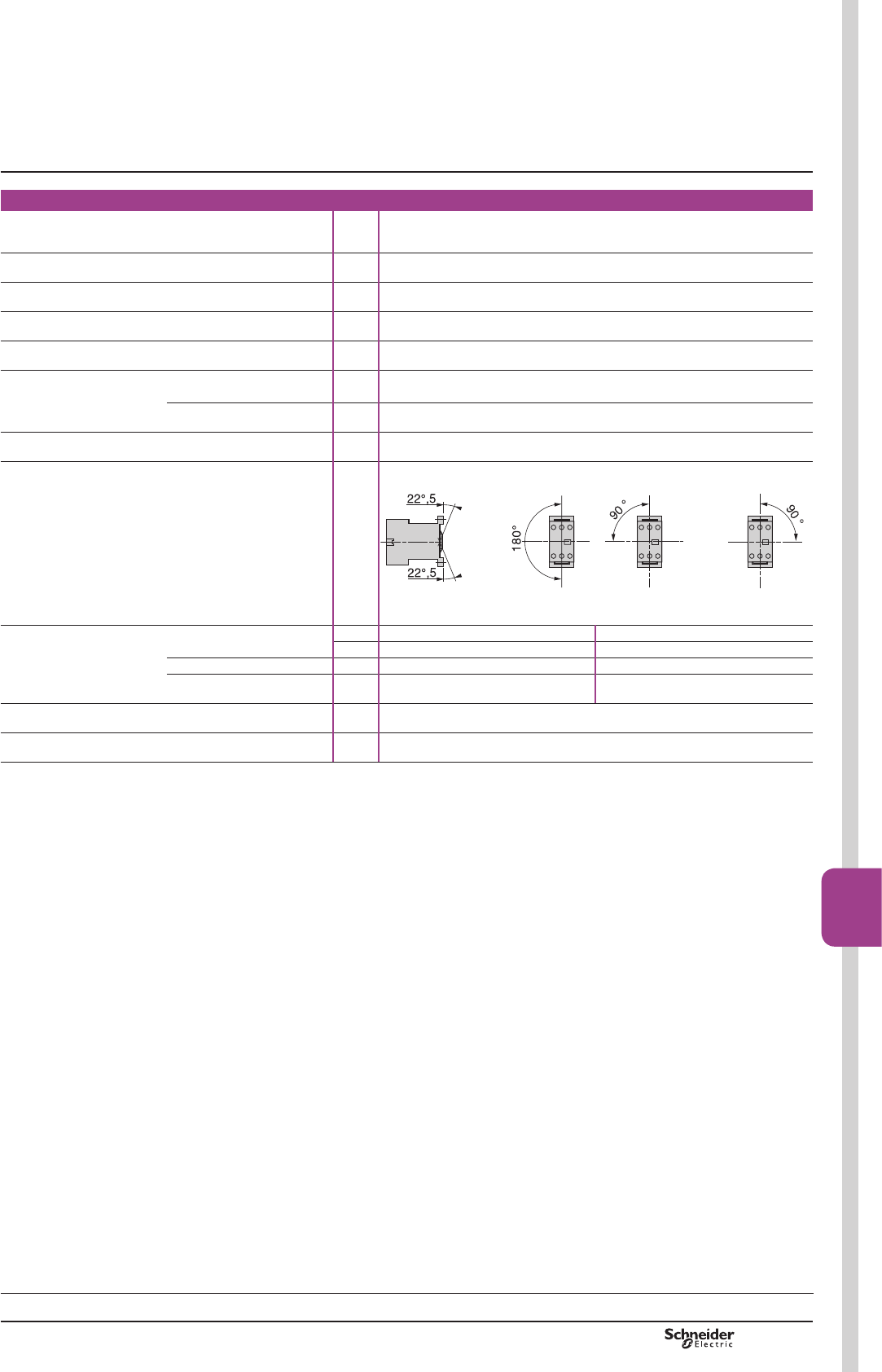
B8/89
Contactors
B8/89
TeSys SKGC
TeSys contactors
Mini-contactors TeSys LC1SKGC,
for use in modular panels
Environment
5DWHGLQVXODWLRQ
YROWDJH8L
Conforming to IEC 60947,
VDE 0110 gr C, BS 5424,
&6$Q8/
V 690
Conforming to standards IEC 60947, NF C 63-110, VDE 0660, BS 5424
3URGXFWFHUWL¿FDWLRQV UL, CSA
Protective treatment Conforming to IEC 60068
',1
³7&´.OLPDIHVW&OLPDWHSURRI
Degree of protection Conforming to VDE 0106 3URWHFWLRQDJDLQVWGLUHFW¿QJHUFRQWDFW
$PELHQWDLUWHPSHUDWXUHDURXQGWKHGHYLFH
Storage °C «
2SHUDWLRQ °C «
0D[LPXPRSHUDWLQJDOWLWXGH :LWKRXWGHUDWLQJ m 2000
2SHUDWLQJSRVLWLRQ Vertical axis Horizontal axis
DF532749.eps
DF532750.eps
:LWKRXWGHUDWLQJ :LWKRXWGHUDWLQJ
Cabling, connectors Min. Max.
6ROLGFRQGXFWRU mm21 x 1.5 or 2 x 1.5 1 x 6 or 2 x 4
)OH[LEOHFDEOHZLWKRXWFDEOHHQG mm21 x 0.5 or 2 x 0.35 1 x 6 or 2 x 2.5
Flexible cable with cable end mm21 x 0.35 or 2 x 0.35 1 x 6 or 2 x 1.5
7LJKWHQLQJWRUTXH 3R]LGULYQKHDG N.m 0.8
Terminal referencing Conforming to standards EN 50005
Characteristics
References:
pages B8/44 and B8/45
Dimensions, schemes:
page B8/93
PCPB08T30-EN Version : 1.0 19 novembre 2014 10:37 AM
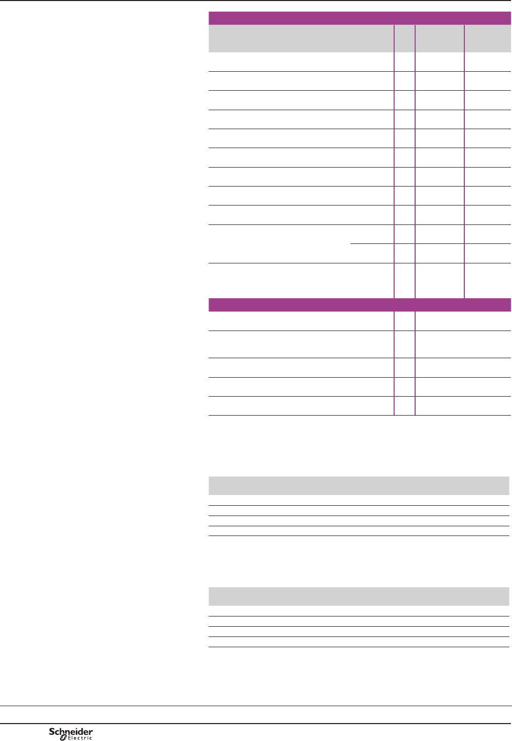
B8/90
Pole characteristics
Mini-contactor type LC1 SKGC2 LC1 SKGC3
and
LC1 SKGC4
Conventional
WKHUPDOFXUUHQW,WK
)RUDPELHQWWHPSHUDWXUH
y&
A 20 20
5DWHGRSHUDWLRQDOIUHTXHQF\ Hz 50/60
)UHTXHQF\OLPLWRIWKHRSHUDWLRQDOFXUUHQW Hz XSWR
Rated operational voltage
8H
V 690
5DWHGPDNLQJFDSDFLW\ I rms conforming to
NF C 63-110 and IEC 60947
A 50 85
5DWHGEUHDNLQJFDSDFLW\
(for Ue y9
Conforming to NF C 63-110
DQG,(&,UPV
A 40 68
Permissible
short time rating
In free air for a time “t”
from cold state (T y&
A 40 60
6KRUWFLUFXLWSURWHFWLRQ JOIXVH8y 440 V A 20 20
Average impedance
per pole
At Ith and 50 Hz m: 4 4
0D[LPXPUDWHG
RSHUDWLRQDOFXUUHQW
)RUWHPSHUDWXUH
y&
AC-3
(Ue y9
A 5 9
AC-1 A 20 20
8VHLQFDWHJRU\$&
UHVLVWLYHFLUFXLWVKHDWLQJ
lighting
(Ue y9
Increase in rated operational
FXUUHQWE\SDUDOOHOLQJRISROHV
A32 32
Auxiliary contact characteristics of mini-contactors
Rated operational voltage
8H
Up to V 690
5DWHGLQVXODWLRQ
YROWDJH8L
Conforming to IEC 60947,
%69'(JURXS&
&6$&Q
V
690
Conventional
WKHUPDOFXUUHQW,WK
)RUDPELHQWWHPSHUDWXUH
y&
A 10
)UHTXHQF\RIWKHRSHUDWLRQDOFXUUHQW Hz Up to 400
6KRUWFLUFXLWSURWHFWLRQ Conforming to IEC 60947
DQG9'(JOIXVH
A 10
Operational power of contacts conforming to IEC 60947
a.c. supply, category AC-15
(OHFWULFDOGXUDELOLW\YDOLGIRUXSWRRSHUDWLQJF\FOHVKRXURQDQLQGXFWLYH
ORDGVXFKDVWKHFRLORIDQHOHFWURPDJQHWPDNLQJFXUUHQWFRVM WLPHV
WKHSRZHUEURNHQFRVM
V 24 48 110/
127
220/
230
380/
400
440
PLOOLRQRSHUDWLQJF\FOHV VA 48 96 240 440 800 880
PLOOLRQRSHUDWLQJF\FOHV VA 17 34 86 158 288 317
PLOOLRQRSHUDWLQJF\FOHV VA 7 14 36 66 120 132
2FFDVLRQDOPDNLQJFDSDFLW\ VA 1000 2050 5000 10000 14000 13000
d.c. supply, category DC-13
(OHFWULFDOGXUDELOLW\YDOLGIRUXSWRRSHUDWLQJF\FOHVKRXURQDQLQGXFWLYH
ORDGVXFKDVWKHFRLORIDQHOHFWURPDJQHWZLWKRXWHFRQRP\UHVLVWRUWKHWLPH
constant increasing with the load.
V 24 48 110 220 440 440
PLOOLRQRSHUDWLQJF\FOHV W120 80 60 52 51 880
PLOOLRQRSHUDWLQJF\FOHV W55 38 30 28 26 317
PLOOLRQRSHUDWLQJF\FOHV W15 11 9 8 7 132
2FFDVLRQDOPDNLQJFDSDFLW\ W720 600 400 300 230 13000
TeSys contactors
Mini-contactors TeSys LC1SKGC,
for use in modular panels
Characteristics
References:
pages B8/44 and B8/45
Dimensions, schemes:
page B8/93
TeSys SKGC
PCPB08T30-EN
Version : 1.0 19 novembre 2014 10:37 AM
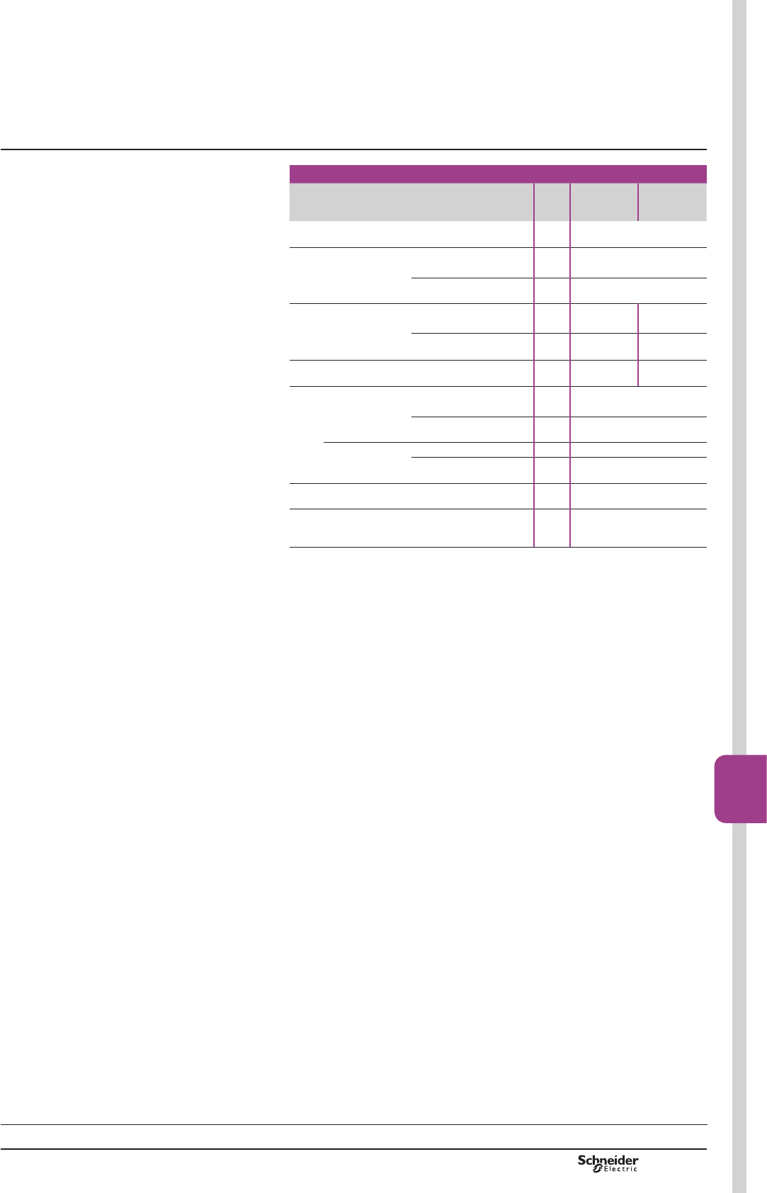
B8/91
Contactors
B8/91
TeSys contactors
Mini-contactors TeSys LC1SKGC,
for use in modular panels
Control circuit characteristics
Mini-contactor type LC1 SKGC2 LC1 SKGC3
and LC1
SKGC4
5DWHGFRQWUROFLUFXLWYROWDJH8F V a 24…400
Control voltage limits
(T y& 2SHUDWLRQ 0.85…1.1 Uc
)RUGURSRXW u 0.20 Uc
$YHUDJHFRLOFRQVXPSWLRQDW&DQGDW8F
,QUXVK VA 16 23
Sealed VA 4.2 4.9
Heat dissipation W 1.4 1.5
2SHUDWLQJWLPHDW&DQGDW8F
Between coil
energisation and
opening of the N/C contacts ms 8…16
FORVLQJRIWKH12FRQWDFWV ms 7…14
Between coil
de-energisation
and
RSHQLQJRIWKH12FRQWDFWV ms 6…8
closing of the N/C contacts ms 8…10
0D[LPXPRSHUDWLQJUDWH ,QRSHUDWLQJF\FOHVSHUKRXU 1200
0HFKDQLFDOGXUDELOLW\DW8F
in millions of operating
F\FOHV
50/60 Hz coil 10
Characteristics
References:
pages B8/44 and B8/45
Dimensions, schemes:
page B8/93
TeSys SKGC
PCPB08T30-EN Version : 1.0 19 novembre 2014 10:37 AM
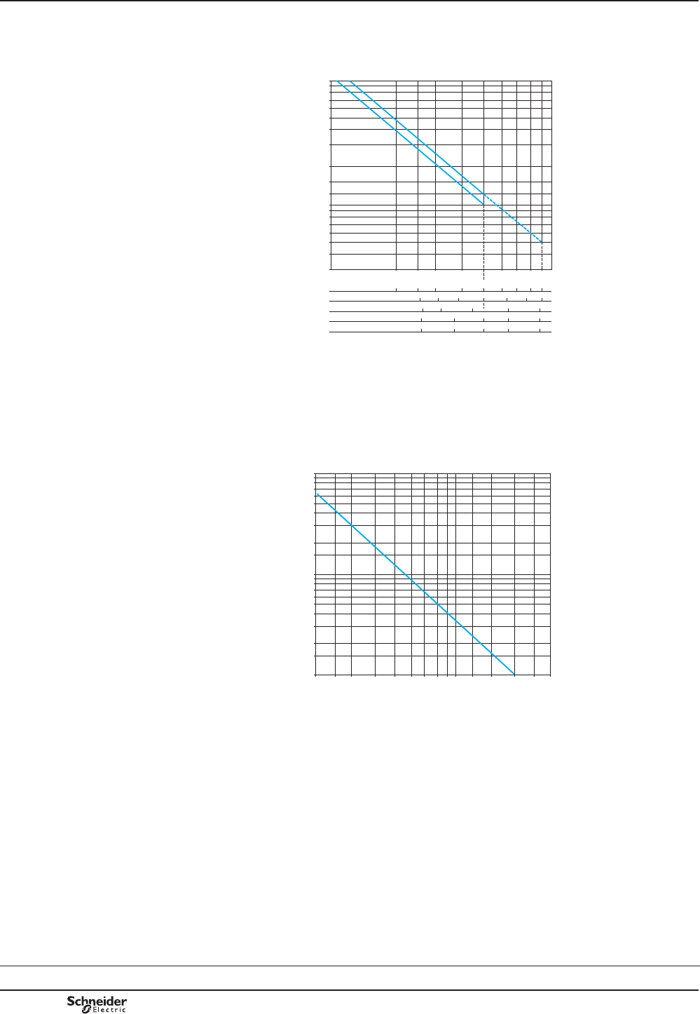
B8/92
TeSys contactors
Mini-contactors TeSys LC1SKGC,
for use in modular panels
Use in category AC-3 (Ue y 440 V)
&RQWURORISKDVHDV\QFKURQRXVVTXLUUHOFDJHPRWRUVZLWKEUHDNLQJZKLOVWUXQQLQJ
7KHFXUUHQWEURNHQ,FLQFDWHJRU\$&LVHTXDOWRWKHUDWHGRSHUDWLRQDOFXUUHQWRI
the motor.
812732.eps
10
8
9
7
6
5
4
3
2
21
1,5
1,2
1
0,8
0,9
0,7
0,6
0,5
0,4
0,3
220/380/415 V 2 3 4 5 6 7 8
9 A
2,5
500 V 2 3 4 5 6 7 A
2,5
220/230 V kW
380/400 V 1,1 1,5 2,2 3 4 kW
1,1 1,5 2,2 3 4
415 V
0,75 1,1 1,5 2,2
kW
0,55
&XUUHQWEURNHQLQ$
0LOOLRQVRIRSHUDWLQJF\FOHV
1. LC1 SKGC2
2. LC1 SKGC3 and SKGC4
- - - - - RQO\XSWR9
Use in category AC-1 (Ue y 440 V)
&RQWURORIUHVLVWLYHFLUFXLWVFRVM u
7KHFXUUHQWEURNHQ,FLQFDWHJRU\$&LVHTXDOWRWKHFXUUHQW,HQRUPDOO\GUDZQ
E\WKHORDG
812731.eps
2 3 4 5 6 7 8 9 10 1512 20 30 402,5
10
8
7
6
5
4
3
2
1,5
1
0,8
0,7
0,6
0,5
0,4
0,3
0,2
0,15
0,1
0LOOLRQVRIRSHUDWLQJF\FOHV
&XUUHQWEURNHQLQ$
Contactor selection according
to required electrical durability
References:
pages B8/44 and B8/45
Dimensions, schemes:
page B8/93
TeSys SKGC
PCPB08T30-EN
Version : 1.0 19 novembre 2014 10:37 AM
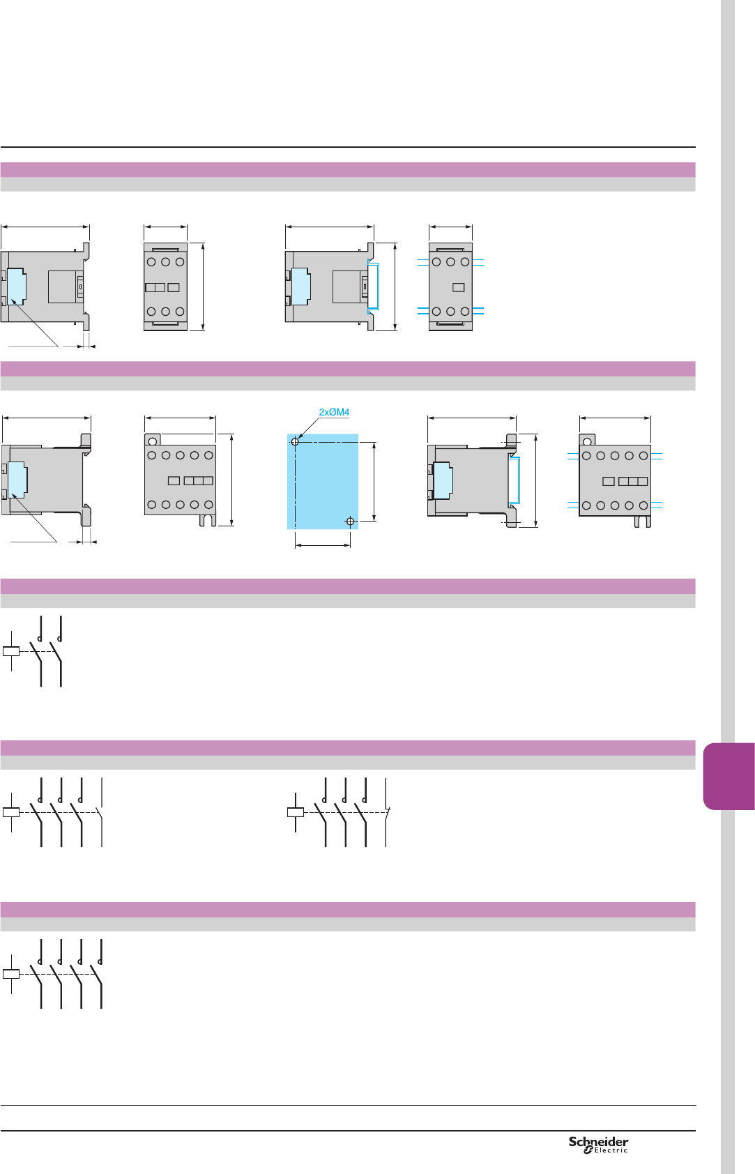
B8/93
Contactors
B8/93
TeSys contactors
Mini-contactors TeSys LC1SKGC,
for use in modular panels
Dimensions Mounting
Mini-contactors LC1 SKGC2 On mounting rail AM1 DP200 or AM1 DE200 (7 35 mm)
3,5LA4 SK
55,5
56
27
DF532769.eps
27
56
55,5
DF532770.eps
Dimensions Mounting
Mini-contactors LC1 SKGC3 and SKGC4 On panel On mounting rail AM1 DP200 or AM1 DE200 (7 35 mm)
4LA4 SK
56 45
58
34-35
48-50
DF532771.eps
4556
58
DF532772.eps
2-pole mini-contactors
LC1 SKGC2
A1
1/L1
A2
T1/2
T2/4 3/L2
812745.eps
3-pole mini-contactors
LC1 SKGC310 LC1 SKGC301
A1
13/NO
14
1/L1
3/L2
5/L3
A2
T1/2
T2/4
T3/6
812746.eps
A1
21/NC
22
1/L1
3/L2
5/L3
A2
T1/2
T2/4
T3/6
812747.eps
4-pole mini-contactors
LC1 SKGC400
A1
1/L1
3/L2
5/L3
A2
T1/2
T2/4
T3/6
7/L4T4/8
812748.eps
Dimensions,
mounting,
schemes
References:
pages B8/44 and B8/45
Characteristics:
pages B8/89 to B8/92
TeSys SKGC
PCPB08T30-EN Version : 1.0 19 novembre 2014 10:37 AM

B8/94
Presentation,
standards Modular equipment
Standard contactors TeSys GC
PB113076_13.eps
Presentation
7H6\V*&FRQWDFWRUVDUHGHVLJQHGIRUXVHLQPRGXODUSDQHOVDQGHQFORVXUHV
7KHVHFRQWDFWRUVIHDWXUH
b Easy installation:
v TXLFNFOLSRQ¿[LQJDQGORFNLQJRQWRPPRPHJDUDLO
v HDV\FRQQHFWLRQE\PHDQVRIUHDG\WRWLJKWHQFDSWLYHSR]LGULYHVFUHZWHUPLQDOV
b Compact size:
$OOXQLWVKDYHDFRPPRQGHSWKRIPPDQGZLGWKLQPRGXOHVRIPP
ZLGWKRIRQHPRGXOHPP
b User safety:
v XVHRIPDWHULDOVFRQIRUPLQJWRVWULFWHVW¿UHVDIHW\VWDQGDUGV
v OLYHSDUWVSURWHFWHGDJDLQVWGLUHFW¿QJHUFRQWDFW
v FRPSOHWHO\VDIHRSHUDWLRQ
v state indication on front panel.
Standards
7KLVUDQJHRIPRGXODUFRQWDFWRUVKDVEHHQGHVLJQHGWDNLQJLQWRDFFRXQWWKH
UHTXLUHPHQWVRILQWHUQDWLRQDOVWDQGDUG,(&
7KLVVWDQGDUGLVVSHFL¿FWR³(OHFWURPDJQHWLFFRQWDFWRUVIRUGRPHVWLFDQGVLPLODU
XVH´
,WKDVYHU\VWULFWUHTXLUHPHQWVPHHWLQJWKHH[SHFWDWLRQVRIXVHUVZLWKUHJDUGWRWKH
VDIHW\RIHTXLSPHQWDQGSHUVRQVLQ³SUHPLVHVDQGDUHDVDFFHVVLEOHWRWKHSXEOLF´
&RQIRUPLW\ZLWKWKLVVWDQGDUGPDNHVLWSRVVLEOHWRREWDLQWKHIROORZLQJTXDOLW\ODEHOV
ZLWKRXWWKHQHHGIRUDGGLWLRQDOWHVWV1)86(9'(&(%(&HWF
Applications
7H6\V*&PRGXODUFRQWDFWRUVDUHGHVLJQHGIRUVZLWFKLQJDOOVLQJOHSKDVHSKDVH
RUSKDVHORDGVXSWR$
Power switching
7KHVHFRQWDFWRUVKDYHPXOWLSOHDSSOLFDWLRQVLQLQGXVWULDODJULFXOWXUDODQG
FRPPHUFLDOSUHPLVHVKRVSLWDOVDQGWKHKRPHLHZKHUHYHUVZLWFKLQJRIDVSHFL¿F
VXSSO\LVUHTXLUHG
b lighting
b heating
b ventilation
b PRWRULVHGVKXWWHUVRUJDWHV
GC 25
Selection:
pages B8/96 to B8/99
Characteristics:
pages B8/100 and
B8/101
References:
page B8/46
Dimensions, schemes:
pages B8/102 and
B8/103
TeSys GC
PCPB08T30-EN
Version : 1.0 19 novembre 2014 10:37 AM
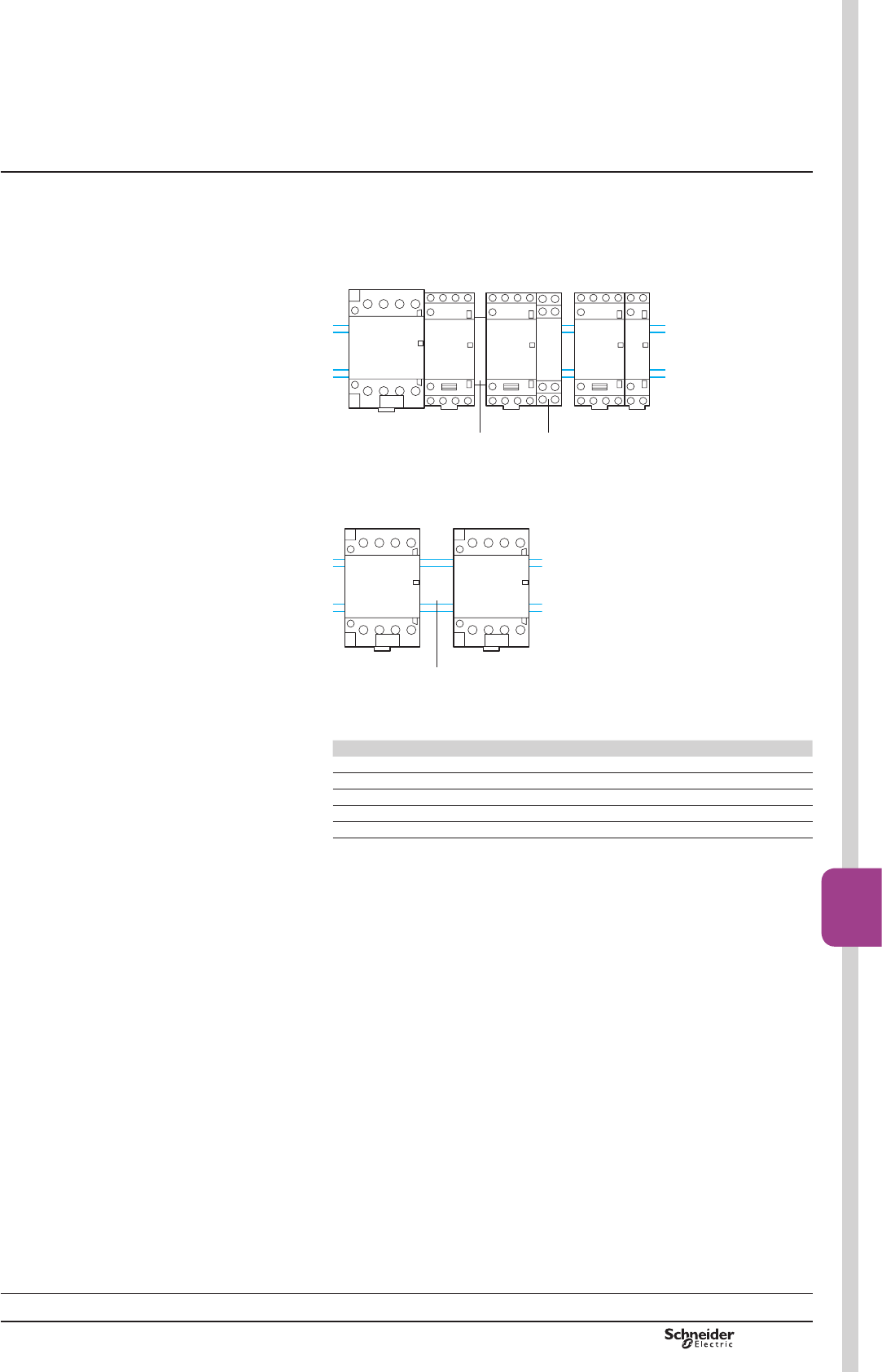
B8/95
Contactors
B8/95
Setting-up
precautions Modular equipment
Standard contactors TeSys GC
Setting-up precautions
7KHFRQWDFWRUFRQWUROVPXVWEHERXQFHIUHH,IQRWFRQQHFWDFRLOVXSSUHVVLRQ
EORFN1*$3RUDFURVVWKHFRLOWHUPLQDOV\9
:KHQVHYHUDOFRQWDFWRUVZKLFKRSHUDWHDWWKHVDPHWLPHDUHPRXQWHGVLGHE\VLGH
D*$&YHQWLODWLRQPRGXOH2 PXVWEH¿WWHGHYHU\FRQWDFWRUV
1
2
DB417050.eps
,WLVDGYLVDEOHWRPRXQWHOHFWURQLFXQLWVDWWKHERWWRPRIWKHPRGXODUSDQHODQGWR
VHSDUDWHWKHPIURPHOHFWURPHFKDQLFDOXQLWVE\DVSDFH3HTXDOWRRQHPRGXOHRUE\
YHQWLODWLRQPRGXOHV*$&
3
DB417051.eps
'HUDWLQJRIFRQWDFWRUVPRXQWHGLQDPRGXODUHQFORVXUHLIWKHWHPSHUDWXUHZLWKLQWKH
HQFORVXUHLV!&
Contactor rating 40 °C 50 °C 60 °C (1)
16 A 16 A 14 A 13 A
25 A 25 A 22 A 20 A
40 A 40 A 36 A 32 A
63 A 63 A 57 A 50 A
100 A 100 A 87 A 80 A
(1) 9HQWLODWLRQPRGXOHPXVWEH¿WWHG
Selection:
pages B8/96 to B8/99
Characteristics:
pages B8/100 and
B8/101
References:
page B8/46
Dimensions, schemes:
pages B8/102 and
B8/103
TeSys GC
PCPB08T30-EN Version : 1.0 19 novembre 2014 10:37 AM
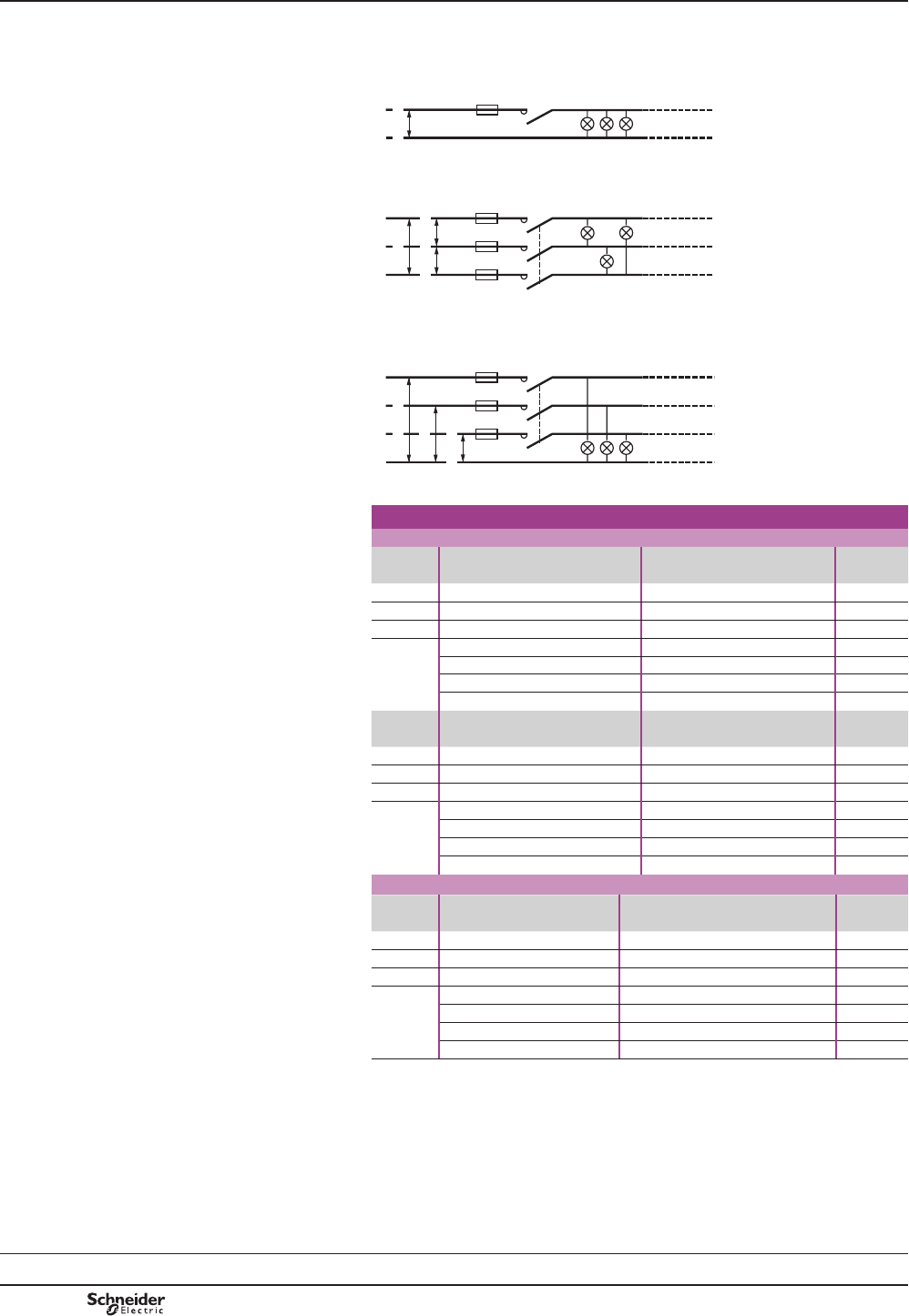
B8/96
Contactor selection for
lighting circuits Modular equipment
Modular contactors
Characteristics:
pages B8/100 and
B8/101
References:
page B8/46
Dimensions, schemes:
pages B8/102 and
B8/103
Lighting (Maximum number of lamps depending on the power
of each unit) Presentation of installations according to type of supply
b6LQJOHSKDVHFLUFXLW9
230V
L1
N
811982.eps
bSKDVHFLUFXLW9
L3
L1
L2
230V
230V 230V
811983.eps
7KHPD[LPXPQXPEHURI
lamps which can be
operated per phase is
HTXDOWRWKHQXPEHURI
lamps in the “single phase
9´WDEOHGLYLGHGE\3.
bSKDVHFLUFXLW9ZLWKQHXWUDO
230V
L3
N
230V
L1
L2
230V
811984.eps
7KHPD[LPXPQXPEHURI
lamps which can be
operated per phase is
HTXDOWRWKHWRWDOQXPEHURI
lamps in the “single-phase
230 V” table.
Contactor rating for a single-phase 230 V circuit (single-pole)
Fluorescent lamps with starter
Single
¿WWLQJ
Non corrected With parallel correction Contactor
rating
3: 20 40 50 80 110 20 40 58 80 110 –
IB$ 0.39 0.43 0.70 0.80 1.2 0.19 0.29 0.46 0.57 0.79 –
&) – – – – – 5 5 7 7 16 –
0D[LPXP
QXPEHU
of lamps
22 20 13 10 7 15 15 10 10 5 16 A
30 28 17 15 10 20 20 15 15 7 25 A
70 60 35 30 20 40 40 30 30 14 40 A
100 90 56 48 32 60 60 43 43 20 63 A
Twin
¿WWLQJ
Non corrected With series correction Contactor
rating
3: 2 x 18 2 x 36 2 x 58 2 x 80 2 x 140 2 x 18 2 x 36 2 x 58 2 x 80 2 x 140 –
IB$ 0.44 0.82 1.34 1.64 2.2 0.26 0.48 0.78 0.96 1.3 –
&) – – – – – 3.5 4.5 7 9 18 –
0D[LPXP
QXPEHU
of lamps
20 11 7 5 4 30 17 10 9 6 16 A
30 16 10 8 6 46 25 16 13 10 25 A
50 26 16 13 10 80 43 27 22 16 40 A
75 42 25 21 16 123 67 42 34 25 63 A
High pressure mercury vapour lamps
Non corrected With parallel correction Contactor
rating
3: 50 80 125 250 400 700 50 80 125 250 400 700 1000 –
IB$ 0.6 0.8 1.15 2.15 3.25 5.4 0.35 0.50 0.7 1.5 2.4 4 5.7 –
&) – – – – – – 7 8 10 18 25 40 60 –
0D[LPXP
QXPEHU
of lamps
15 10 8 4 2 1 10 9 9 4 3 2 – 16 A
20 15 10 6 4 2 15 13 10 6 4 2 1 25 A
34 27 20 10 6 4 28 25 20 11 8 5 3 40 A
53 40 28 15 10 6 43 38 30 17 12 7 5 63 A
IBYDOXHRIFXUUHQWGUDZQE\HDFKODPSDWLWVUDWHGYROWDJH
CXQLWFDSDFLWDQFHIRUHDFKODPS
IB and C correspond to values normally quoted by lamp manufacturers
TeSys GC
PCPB08T30-EN
Version : 1.0 19 novembre 2014 10:37 AM
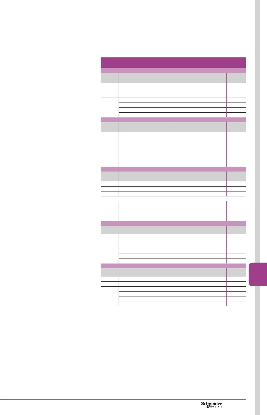
B8/97
Contactors
B8/97
Contactor rating for a single-phase 230 V circuit
(single-pole) (continued)
Low pressure sodium vapour lamps
Non corrected With parallel correction Contactor
rating
3: 18 35 55 90 135 180 18 35 55 90 135 180 –
IB$ 0.35 1.4 1.4 2.1 3.1 3.1 0.35 0.6 0.6 0.9 0.9 0.9 –
&) –– – – – – 520 20 26 45 40 –
0D[LPXP
QXPEHU
of lamps
18 4 5 3 2 2 14 3 3 2 1 1 16 A
34 9 9 6 4 4 21 5 5 4 2 2 25 A
57 14 14 9 6 6 40 10 10 8 4 5 40 A
91 24 24 19 10 10 60 15 15 11 6 7 63 A
High pressure sodium vapour lamps
Non corrected With parallel correction Contactor
rating
3: 70 150 250 400 1000 70 150 250 400 1000 –
IB$ 11.8 3 4.4 10.3 0.6 0.7 1.5 2.5 6 –
&) –– – – – 12 20 32 45 100 –
0D[LPXP
QXPEHU
of lamps
84 2 1 – 66 2 2 1 16 A
12 7 4 3 1 99 3 4 2 25 A
20 13 8 5 2 18 18 6 8 4 40 A
32 18 11 8 3 25 25 9 12 6 63 A
Metal iodine or halogen vapour lamps
Non corrected With parallel correction Contactor
rating
3: 35 70 150 250 400 1000 39 70 150 250 400 1000 2000 –
IB$ 0.3 0.5 1 1.5 2.5 6 0.3 0.5 1 1.5 2.5 6 5.5 –
&) –– – – – – 612 20 32 45 85 60 –
0D[LPXP
QXPEHU
of lamps
27 16 8 5 3 1 12 6 4 3 2 – 1 16 A
40 24 12 8 5 2 18 9 6 4 3 1 2 25 A
68 42 20 14 8 4 31 16 10 7 5 3 3 40 A
106 64 32 21 13 5 50 25 15 10 7 4 5 63 A
Incandescent and halogen lamps
Contactor
rating
3: 60 75 100 150 200 300 500 1000 –
IB$ 0.26 0.32 0.44 0.65 0.87 1.3 2.17 4.4 –
0D[LPXP
QXPEHU
of lamps
30 25 19 12 10 7 4216 A
45 38 28 18 14 10 6325 A
85 70 50 35 26 18 10 640 A
125 100 73 50 37 25 15 863 A
Halogen lamps used with transformer
Contactor
rating
3: 60 80 105 150 –
IB$ 0.26 0.35 0.45 0.65 –
0D[LPXP
of lamps
98 6 4 16 A
14 12 9 6 25 A
27 23 18 13 40 A
40 35 27 19 63 A
IB:YDOXHRIFXUUHQWGUDZQE\HDFKODPSDWLWVUDWHGYROWDJH
CXQLWFDSDFLWDQFHIRUHDFKODPS
IB and C correspond to values normally quoted by lamp manufacturers
Characteristics:
pages B8/100 and
B8/101
References:
page B8/46
Dimensions, schemes:
pages B8/102 and
B8/103
Contactor selection for
lighting circuits Modular equipment
Modular contactors
TeSys GC
PCPB08T30-EN Version : 1.0 19 novembre 2014 10:37 AM
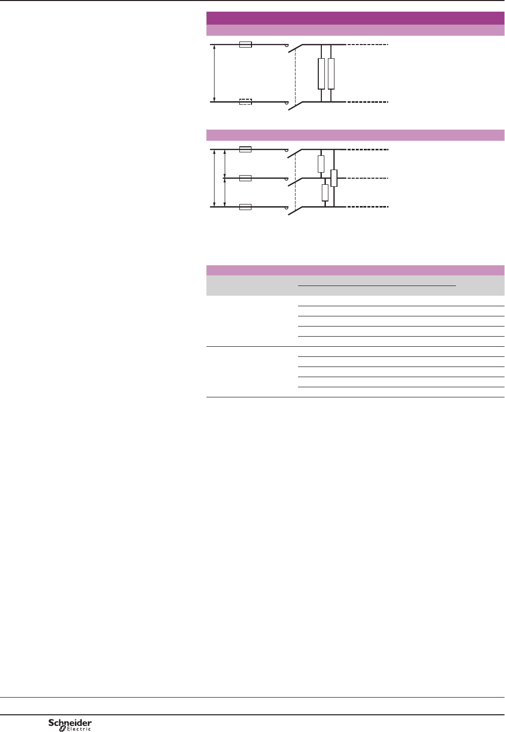
B8/98
Contactor selection for
heating circuits
Heating (AC-7a)
Single-phase, 2-pole switching
U
811985.eps
3-phase switching
U
U U
811986.eps
+HDWLQJE\UHVLVWLYHHOHPHQWVRUE\LQIUDUHGUDGLDWRUVFRQYHFWRUVRUUDGLDWRUV
KHDWLQJGXFWVLQGXVWULDOIXUQDFHV7KHFXUUHQWSHDNEHWZHHQWKHKRWDQGFROGVWDWHV
PXVWQRWH[FHHGWR,QDWWKHPRPHQWRIVZLWFKRQ
Contactor selection according to power and required electrical life
Electrical durability
LQRSHUDWLQJF\FOHV
Maximum power (kW) Contactor
rating
100 x 103150 x 103200 x 103500 x 103106
Single-phase switching
230 V
SROH
3.5 3 2.2 1 0.8 16 A
5.4 4.6 3.5 1.6 1.2 25 A
8.6 7.4 5.6 2.6 1.9 40 A
13.6 11.6 8.8 4 3 63 A
21.6 18.4 14 6.4 4.8 100 A
3-phase switching
400 V
SROH
10 9 6.5 3.2 2.2 16 A
16 14 10 5 3.5 25 A
26 22 17 7.5 6 40 A
41 35 26.5 12 9 63 A
64.8 55.2 42 19.2 14.4 100 A
Modular equipment
Modular contactors
Characteristics:
pages B8/100 and
B8/101
References:
page B8/46
Dimensions, schemes:
pages B8/102 and
B8/103
TeSys GC
PCPB08T30-EN
Version : 1.0 19 novembre 2014 10:37 AM
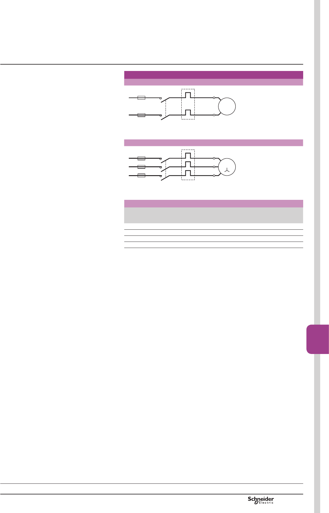
B8/99
Contactors
B8/99
Contactor selection for
motor control
Motor control (AC-7b)
Single-phase circuit, 230 V
U
V
M
L1
L2
811987.eps
3-phase circuit, 400 V
U
W
M
V
L1
L2
L3
811988.eps
Contactor selection according to maximum power in kW
230 V single-phase
capacitor motor
SROH
400 V 3-phase motor Contactor
rating
,WK
0.55 2.2 16 A
1.1 4 25 A
2.2 7.5 40 A
4 11 63 A
Characteristics:
pages B8/100 and
B8/101
References:
page B8/46
Dimensions, schemes:
pages B8/102 and
B8/103
Modular equipment
Modular contactors
TeSys GC
PCPB08T30-EN Version : 1.0 19 novembre 2014 10:37 AM
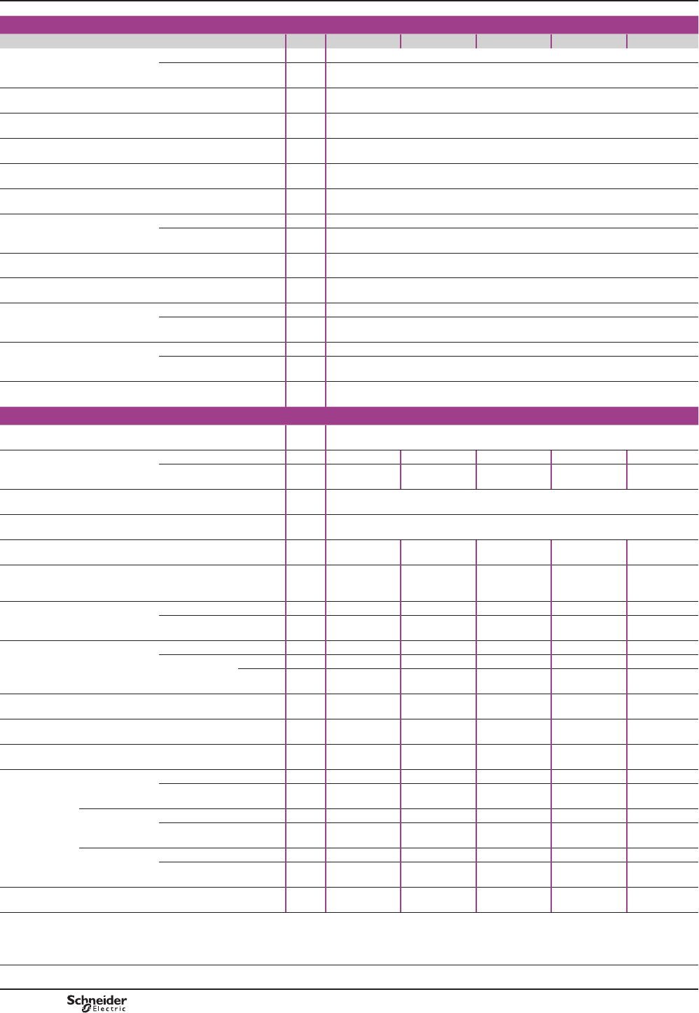
B8/100
Characteristics
Environment
Contactor type GC16 GC25 GC40 GC63 GC100
5DWHGLQVXODWLRQYROWDJH
8L
Conforming to IEC 61095 V500
Conforming to VDE 0110 V500
5DWHGLPSXOVHZLWKVWDQGYROWDJH
8LPS
kV LQHQFORVXUH
Conforming to standards ,(&9'(DQG,(&IRUDX[LOLDU\FRQWDFWV
3URGXFWFHUWL¿FDWLRQV NF- USE, VDE, CEBEC, ÖVE
Degree of protection Conforming to VDE 0106 3URWHFWLRQDJDLQVWGLUHFW¿QJHUFRQWDFW,3RSHQ,3LQHQFORVXUH
Protective treatment Standard version “TC”
$PELHQWDLUWHPSHUDWXUH
DURXQGWKHGHYLFH
Storage °C «
2SHUDWLRQ °C ««8F
0D[LPXPRSHUDWLQJDOWLWXGH :LWKRXWGHUDWLQJ m3000
2SHUDWLQJSRVLWLRQV :LWKRXWGHUDWLQJ LQUHODWLRQWRQRUPDOYHUWLFDOPRXQWLQJSODQH
6KRFNUHVLVWDQFH
VLQHZDYH PV
Contactor open 10 gn
Contactor closed 15 gn
Vibration resistance
5…300 Hz
Contactor open 2 gn
Contactor closed 3 gn
Flame resistance Conforming to IEC 61095
Pole characteristics
1XPEHURISROHV 2, 3 or 4
5DWHGRSHUDWLRQDOFXUUHQW,H
(Ue y9
,Q$&DKHDWLQJ A16 25 40 63 100
,Q$&EPRWRUFRQWURO A5 8.5 15 25 –
Rated operational voltage
8H
Up to VWZRSROHFRQWDFWRUVWKUHHDQGIRXUSROHFRQWDFWRUV
)UHTXHQF\OLPLWV 2IWKHRSHUDWLQJFXUUHQW Hz 400
&RQYHQWLRQDOWKHUPDOFXUUHQW
OWK T y& A16 25 40 63 100
5DWHGEUHDNLQJDQGPDNLQJFDSDFLW\ Conforming to IEC 61095
$&E
I rms 400 V 3-phase
A40 68 120 200 –
Permissible short time rating
QRFXUUHQWÀRZLQJIRUSUHFHGLQJ
PLQXWHVZLWKT y&
For 10 s A128 200 320 504 800
For 30 s A40 62 100 157 250
6KRUWFLUFXLWSURWHFWLRQ
E\IXVHRUFLUFXLWEUHDNHU
U y 440 V
JOIXVH A16 25 40 63 100
&LUFXLWEUHDNHU,2t
DWN$UPV
SURVSHFWLYH
230 V A2s5000 10000 16000 18000 –
400 V A2s9000 14000 17500 20000 –
(OHFWULFDOGXUDELOLW\LQRSHUDWLQJ
F\FOHV
AC-7a, AC-7b 100000 100000 100000 100000 30000
Average impedance per pole At lth and 50 Hz m:2.5 2.5 2 2 1
Power dissipated per pole For the above
RSHUDWLRQDOFXUUHQWV
W0.65 1.6 3.2 8 10
0D[LPXPFDEOLQJ
c.s.a.
Flexible cable
ZLWKRXWFDEOHHQG
FRQGXFWRU mm26 6 25 25 35
FRQGXFWRUV mm24 4 16 16 –
Flexible cable
with cable end
FRQGXFWRU mm26 6 16 16 35
FRQGXFWRUV mm21.5 1.5 4 4 –
Solid cable
ZLWKRXWFDEOHHQG
FRQGXFWRU mm26 6 25 25 35
FRQGXFWRUV mm24 4 6 6 10
7LJKWHQLQJWRUTXH 3RZHUFLUFXLWFRQQHFWLRQV N.m 0.8 0.8 3.5 3.5 3.5
Modular equipment
TeSys GC standard contactors
Selection:
pages B8/96 to B8/99
References:
page B8/46
Dimensions, schemes:
pages B8/102 and
B8/103
TeSys GC
PCPB08T30-EN
Version : 1.0 19 novembre 2014 10:37 AM
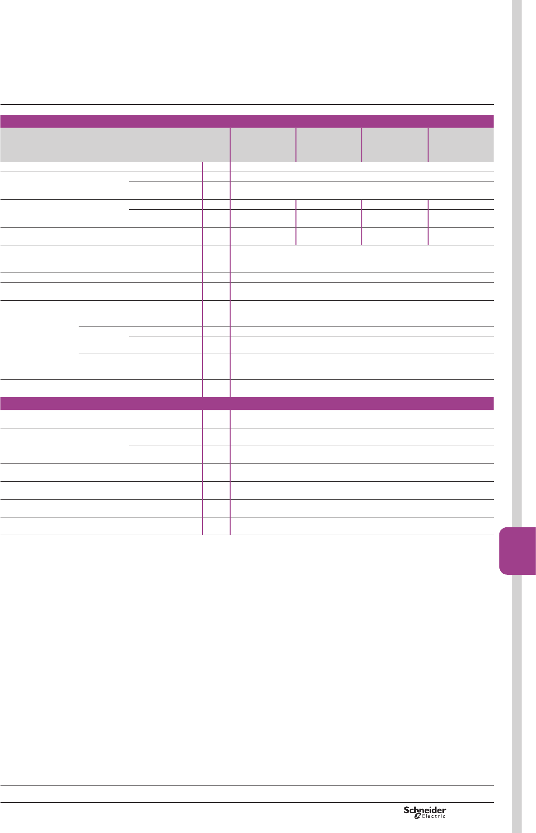
B8/101
Contactors
B8/101
Control circuit characteristics
Contactor type GC16, GC25
single or 2-pole
GC16, GC25
3 or 4-pole
GC40, GC63
2-pole
GC40, GC63
3 or 4-pole
GC100
2-pole
GC100
4-pole
5DWHGFRQWUROFLUFXLWYROWDJH8F 50 or 60 Hz V«9IRURWKHUYROWDJHVSOHDVHFRQVXOW\RXU5HJLRQDO6DOHV2I¿FH
Control voltage limits
(T y&
50 Hz coils 2SHUDWLRQDO 0.85…1.1 Uc
'URSRXW 0.2…0.75 Uc
Average coil
FRQVXPSWLRQ
DW&DQGDW8F
a 50 Hz ,QUXVK VA 15 34 53 106
Sealed VA 3.8 4.6 6.5 13
0D[LPXPKHDWGLVVLSDWLRQ 50/60 Hz W1.3 1.6 2.1 4.2
2SHUDWLQJWLPH Closing “C” ms 10…30
2SHQLQJ³2´ ms 10…25
0HFKDQLFDOGXUDELOLW\ ,QRSHUDWLQJF\FOHV 106
0D[LPXPRSHUDWLQJUDWH
DWDPELHQWWHPSHUDWXUHy&
,QRSHUDWLQJF\FOHVSHU
KRXU
300
0D[LPXP
cabling c.s.a.
Flexible cable
ZLWKRXWFDEOH
end
RUFRQGXFWRUV mm22.5
Flexible cable
with cable end
FRQGXFWRU mm22.5
FRQGXFWRUV mm21.5
Solid cable
ZLWKRXW
cable end
RUFRQGXFWRUV mm21.5
7LJKWHQLQJWRUTXH N.m 0.8
Instantaneous auxiliary contact characteristics
5DWHGRSHUDWLRQDOYROWDJH8H Up to V250
5DWHGLQVXODWLRQYROWDJH8L Conforming to
IEC 60947-5
V500
Conforming to
VDE 0110
V500
&RQYHQWLRQDOWKHUPDOFXUUHQW,WK For ambient Ty& A5
0HFKDQLFDOGXUDELOLW\ 2SHUDWLQJF\FOHV 106
0D[LPXPFDEOLQJFVD Flexible or
VROLGFRQGXFWRU
mm22.5
7LJKWHQLQJWRUTXH N.m 0.8
Selection:
pages B8/96 to B8/99
References:
page B8/46
Dimensions, schemes:
pages B8/102 and
B8/103
Characteristics Modular equipment
TeSys GC standard contactors
TeSys GC
PCPB08T30-EN Version : 1.0 19 novembre 2014 10:37 AM
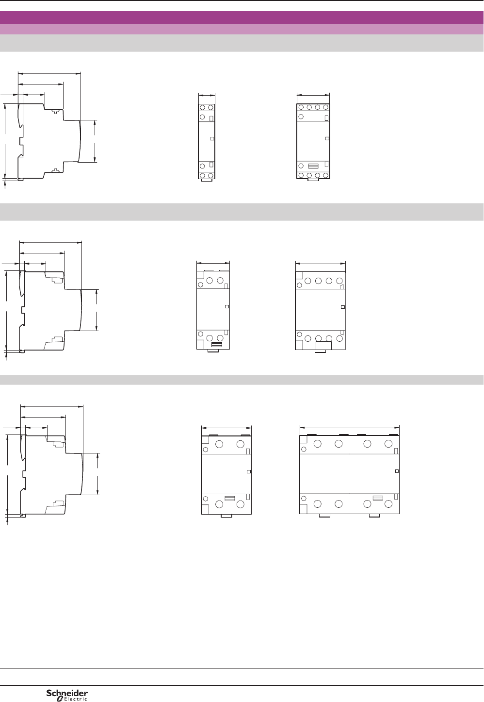
B8/102
Dimensions
Dimensions
Contactors
Common side view GC 1610, 1611, 1620
GC 2502, 2510, 2511, 2520
GC 1622, 1640
GC 2504, 2522, 2530, 2540
PRGXOH PRGXOHV
23.5
5.5
2.5
49
68
81 45
18 36
DB417023.eps
Common side view GC 4002, 4011, 4020
GC 6302, 6311, 6320
GC 4004, 4022, 4030, 4040
GC 6304, 6322, 6330, 6340
PRGXOHV PRGXOHV
54
36
23.5
5.5
2.5
49
68
85 45
DB417024.eps
Common side view GC 10020 GC 10040
PRGXOHV PRGXOHV
54 108
23.5
5.5
2.5
49
68
85 45
DB417025.eps
Modular equipment
TeSys GC standard contactors
Selection:
pages B8/96 to B8/99
Characteristics:
pages B8/100 and
B8/101
References:
page B8/46
Dimensions, schemes:
pages B8/102 and
B8/103
TeSys GC
PCPB08T30-EN
Version : 1.0 19 novembre 2014 10:37 AM
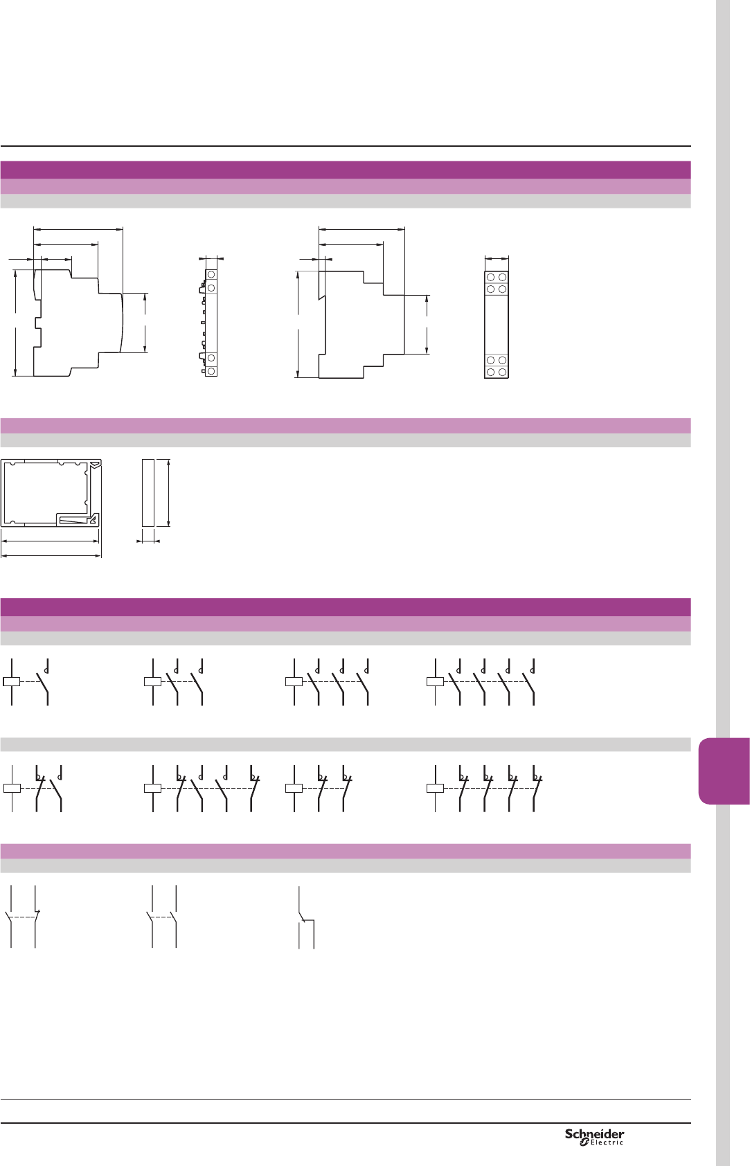
B8/103
Contactors
B8/103
Dimensions,
schemes
Dimensions
Auxiliary contacts Coil suppression blocks
GAC 0511, 0531 and 0521 GAP 21 and 23
81
23.5
5.5
49
68
45
9
DB417026.eps
18
81 45
5
44
60
DB417027.eps
Clip-on ventilation 1/2 module
GAC 5
865
67
44
DF533726.eps
Schemes
Contactors
GC pp10 GC pp20 GC pp30 GC pp40
A1
A2
12
DF533729.eps
A1
A2
34
12
DF533730.eps
A1
A2
34
12
56
DF533731.eps
A1
A2
34
12
56
78
DF533732.eps
GC pp11 GC pp22 GC pp02 GC pp04
R1
R2
A1
A2
12
DF533733.eps
A1
A2
12
34
R1
R2
R3
R4
DF533734.eps
R1
R2
A1
A2
R3
R4
DF533735.eps
A1
A2
R1
R2
R7
R8
R3
R4
R5
R6
DF533736.eps
Auxiliary contacts
GAC 0521 GAC 0531 GAC 0511
22 21/NC
13/NO14
DF533737.eps
24 23/NO
13/NO14
DF533738.eps
14/NO 13/NO
12
DF533739.eps
Modular equipment
TeSys GC standard contactors
Selection:
pages B8/96 to B8/99
Characteristics:
pages B8/100 and
B8/101
References:
page B8/46
Dimensions, schemes:
pages B8/102 and
B8/103
TeSys GC
PCPB08T30-EN Version : 1.0 19 novembre 2014 10:37 AM
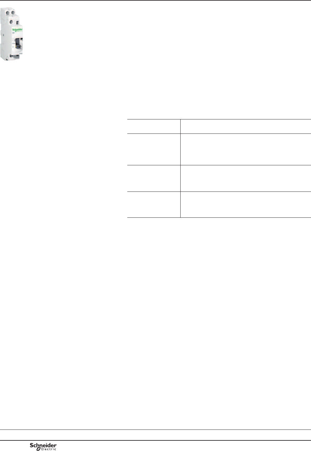
B8/104
Presentation
standards
PB113083_13.eps
Presentation
7H6\V*<GXDOWDULIIFRQWDFWRUVDUHGHVLJQHGIRUXVHLQPRGXODUSDQHOVDQG
HQFORVXUHV
7KHVHFRQWDFWRUVIHDWXUH
b Easy installation:
v TXLFNFOLSRQ¿[LQJDQGORFNLQJRQWRPPRPHJDUDLO
v HDV\FRQQHFWLRQE\PHDQVRIUHDG\WRWLJKWHQFDSWLYHSR]LGULYHVFUHZWHUPLQDOV
b Compact size
$OOXQLWVKDYHDFRPPRQGHSWKRIPPDQGZLGWKLQPRGXOHVRIPPZLGWKRI
RQHPRGXOHPP
b User safety:
v XVHRIPDWHULDOVFRQIRUPLQJWRVWULFWHVW¿UHVDIHW\VWDQGDUGV
v OLYHSDUWVSURWHFWHGDJDLQVWGLUHFW¿QJHUFRQWDFW
v FRPSOHWHO\VDIHRSHUDWLRQ
v state indication on front panel.
'XDOWDULIIFRQWDFWRUVDUHGHVLJQHGIRUXVHZLWK(OHFWULFLW\6XSSO\$XWKRULW\GXDO
tariffs.
7KH\KDYHDSRVLWLRQVHOHFWRUVZLWFKRQWKHIURQWSDQHO
GY 25
"Stop" (O) For switching off the load, e.g. for prolonged periods of
absence.
"Off peak"
Automatic start (A)
7KHFRQWDFWRUVZLWFKHVDXWRPDWLFDOO\GXULQJRIISHDN
KRXUVDVVHWE\WKH6XSSO\$XWKRULW\
UHPRWHFRQWURODQGWKXV
VXSSOLHVWKHORDGZDVKLQJPDFKLQHGLVKZDVKHUFRQYHFWRU
KHDWHUZDWHUKHDWHUGXULQJWKLVSHULRGDW
DQHFRQRP\UDWH
WRWKHXVHU
"Peak time"
Manual start (I)
,QWKLVSRVLWLRQWKHFRQWDFWRUVXSSOLHVWKHORDGWRFDWHUIRU
DGGLWLRQDOUHTXLUHPHQWVIRUKRWZDWHUKHDWLQJHWFEXWDW
WKHVWDQGDUGUDWH7KHFRQWDFWRUUHWXUQVDXWRPDWLFDOO\WR
WKHRIISHDNSRVLWLRQDWWKHVWDUWRIWKHRIISHDNSHULRG
"P
eak time"
Manual override
with lock
)DFLOLW\IRUVHWWLQJWKHFRQWDFWRUWRFRQWLQXRXVPDQXDO
RSHUDWLRQLJQRULQJWKHDXWRPDWLRQV\VWHPDQGWKH6XSSO\
$XWKRULW\FRQWUROVHWWLQJDQGORFNLQJLVDFKLHYHGE\PHDQV
RIDWRROZLWKPDQXDOUHWXUQWRWKH$872SRVLWLRQ
Standards
7KLVUDQJHRIPRGXODUFRQWDFWRUVKDVEHHQGHVLJQHGWDNLQJLQWRDFFRXQWWKH
UHTXLUHPHQWVRILQWHUQDWLRQDOVWDQGDUG,(&
7KLVVWDQGDUGLVVSHFL¿FWR(OHFWURPDJQHWLFFRQWDFWRUVIRUGRPHVWLFDQGVLPLODU
XVH
,WKDVYHU\VWULFWUHTXLUHPHQWVPHHWLQJWKHH[SHFWDWLRQVRIXVHUVZLWKUHJDUGWRWKH
VDIHW\RIHTXLSPHQWDQGSHUVRQVLQSUHPLVHVDQGDUHDVDFFHVVLEOHWRWKHSXEOLF
&RQIRUPLW\ZLWKWKLVVWDQGDUGPDNHVLWSRVVLEOHWRREWDLQWKHIROORZLQJTXDOLW\ODEHOV
ZLWKRXWWKHQHHGIRUDGGLWLRQDOWHVWV1)86(9'(&(%(&HWF
Applications
'XDOWDULIIPRGXODUFRQWDFWRUVDUHGHVLJQHGIRUVZLWFKLQJDOOVLQJOHSKDVHSKDVH
RUSKDVHORDGVXSWR $
Power switching
7H6\V*<FRQWDFWRUVKDYHPXOWLSOHDSSOLFDWLRQVLQLQGXVWULDODJULFXOWXUDODQG
FRPPHUFLDOSUHPLVHVKRVSLWDOVDQGWKHKRPHLHZKHUHYHUVZLWFKLQJRIDVSHFL¿F
VXSSO\LVUHTXLUHG
b lighting,
b heating, ventilation,
b PRWRULVHGVKXWWHUVRUJDWHV
Modular equipment
TeSys GY "dual tariff" contactors
Selection:
pages B8/96 to B8/99
Characteristics:
pages B8/106 and
B8/107
References:
page B8/47
Dimensions and schemes:
pages B8/108 and
B8/109
TeSys GY
PCPB08T30-EN
Version : 1.0 19 novembre 2014 10:37 AM
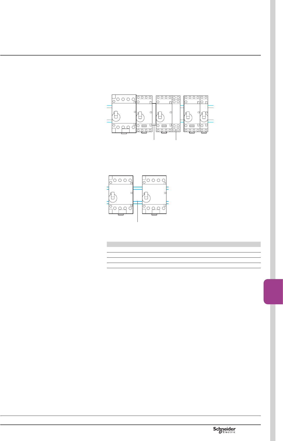
B8/105
Contactors
B8/105
Setting-up
precautions
Setting-up precautions
7KHFRQWDFWRUFRQWUROVPXVWEHERXQFHIUHH,IQRWFRQQHFWDFRLOVXSSUHVVLRQEORFN
1*$3RUDFURVVWKHFRLOWHUPLQDOVy 250 V.
:KHQVHYHUDOFRQWDFWRUVZKLFKRSHUDWHDWWKHVDPHWLPHDUHPRXQWHGVLGHE\VLGH
D*$&YHQWLODWLRQPRGXOH2 PXVWEH¿WWHGHYHU\FRQWDFWRUV
1
2
DB417052.eps
,WLVDGYLVDEOHWRPRXQWHOHFWURQLFXQLWVDWWKHERWWRPRIWKHPRGXODUSDQHODQGWR
VHSDUDWHWKHPIURPHOHFWURPHFKDQLFDOXQLWVE\DVSDFHHTXDOWRRQHPRGXOH3RUE\
YHQWLODWLRQPRGXOHV*$&
3
DB417053.eps
'HUDWLQJRIFRQWDFWRUVPRXQWHGLQDPRGXODUHQFORVXUHLIWKHWHPSHUDWXUHZLWKLQ
WKHHQFORVXUHLV!&
Contactor rating 40 °C 50 °C 60 °C (1)
16 A 16 A 14 A 13 A
25 A 25 A 22 A 20 A
40 A 40 A 36 A 32 A
63 A 63 A 57 A 50 A
(1) 9HQWLODWLRQPRGXOHPXVWEH¿WWHG
Modular equipment
TeSys GY "dual tariff" contactors
Selection:
pages B8/96 to B8/99
Characteristics:
pages B8/106 and
B8/107
References:
page B8/47
Dimensions and schemes:
pages B8/108 and
B8/109
TeSys GY
PCPB08T30-EN Version : 1.0 19 novembre 2014 10:37 AM
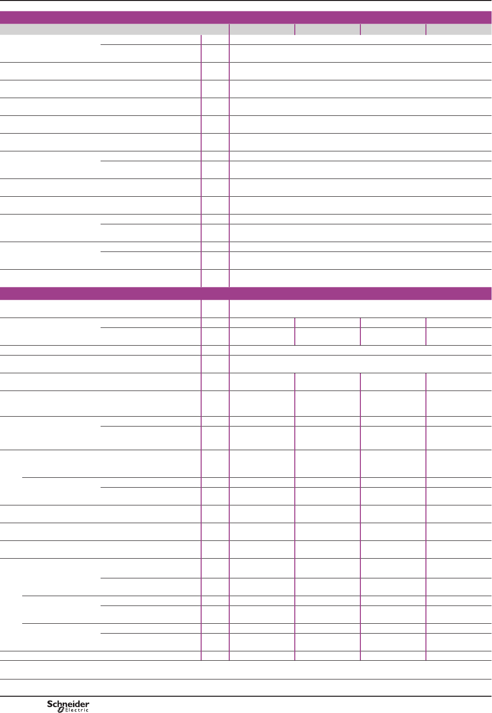
B8/106
Characteristics
Environment
Type GY 16 GY 25 GY 40 GY 63
5DWHGLQVXODWLRQYROWDJH8L Conforming to IEC 61095 V500
Conforming to VDE 0110 V500
5DWHGLPSXOVHZLWKVWDQGYROWDJH8LPS kV LQHQFORVXUH
Conforming to standards ,(&9'(DQG,(&IRUDX[LOLDU\FRQWDFWV
3URGXFWFHUWL¿FDWLRQV NF-USE, VDE, CEBEC, ÖVE
Degree of protection Conforming to VDE 0106 3URWHFWLRQDJDLQVWGLUHFW¿QJHUFRQWDFW,3RSHQ,3LQHQFORVXUH
Protective treatment Standard version 7&
$PELHQWDLUWHPSHUDWXUHDURXQG
the device
Storage °C «
2SHUDWLRQ °C ««8F
0D[LPXPRSHUDWLQJDOWLWXGH :LWKRXWGHUDWLQJ m3000
2SHUDWLQJSRVLWLRQV :LWKRXWGHUDWLQJ LQUHODWLRQWRQRUPDOYHUWLFDOPRXQWLQJSODQH
6KRFNUHVLVWDQFH
VLQHZDYH PV
Contactor open 10 gn
Contactor closed 15 gn
Vibration resistance
5…300 Hz
Contactor open 2 gn
Contactor closed 3 gn
Flame resistance Conforming to IEC 61095
Pole characteristics
1XPEHURISROHV 2, 3 or 4
5DWHGRSHUDWLRQDOFXUUHQW,H
(Ue y9
,Q$&DKHDWLQJ A16 25 40 63
,Q$&EPRWRUFRQWURO A5 8.5 15 25
5DWHGRSHUDWLRQDOYROWDJH8H Up to V250 - 2-pole contactors, 415 - 3 and 4-pole contactors
)UHTXHQF\OLPLWV 2IWKHRSHUDWLQJFXUUHQW Hz 400
Conventional
WKHUPDOFXUUHQWOWK
T y& A16 25 40 63
5DWHGEUHDNLQJ
DQGPDNLQJFDSDFLW\
Conforming to IEC 61095
$&E
I rms 400 V 3-phase
A40 68 120 200
Short time rating
ZLWKQRFXUUHQWÀRZIRUWKH
SUHYLRXVSUHYLRXVPLQXWHV
with T y&
For 10 s A128 200 320 504
For 30 s A40 62 100 157
6KRUWFLUFXLWSURWHFWLRQE\IXVHRUFLUFXLWEUHDNHU
U y 440 V
JOIXVH A16 25 40 63
&LUFXLWEUHDNHU,2t
DWN$UPVSURVSHFWLYH
230V A2s5000 10000 16000 18000
400V A2s9000 14000 17500 20000
(OHFWULFDOGXUDELOLW\LQRSHUDWLQJ
F\FOHV
AC-7a, AC-7b 100000 100000 100000 100000
Average impedance per pole At lth and 50 Hz m:2.5 2.5 2 2
Power dissipated per pole For the above operational
FXUUHQWV
W0.65 1.6 3.2 8
0D[LPXPFDEOLQJFVD
Flexible cable
ZLWKRXWFDEOHHQG
FRQGXFWRU mm26 6 25 25
FRQGXFWRUV mm24 4 16 16
Flexible cable
with cable end
FRQGXFWRU mm26 6 16 16
FRQGXFWRUV mm21.5 1.5 4 4
Solid cable
ZLWKRXWFDEOHHQG
FRQGXFWRU mm26 6 25 25
FRQGXFWRUV mm24 4 6 6
7LJKWHQLQJWRUTXH 3RZHUFLUFXLWFRQQHFWLRQV N.m 0.8 0.8 3.5 3.5
Modular equipment
TeSys GY "dual tariff" contactors
Selection:
pages B8/96 to B8/99
References:
page B8/47
Dimensions and schemes:
pages B8/108 and
B8/109
TeSys GY
PCPB08T30-EN
Version : 1.0 19 novembre 2014 10:37 AM
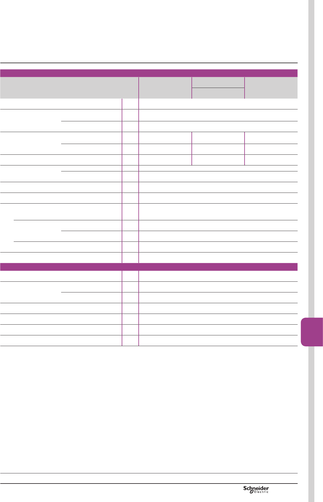
B8/107
Contactors
B8/107
Control circuit characteristics
Type GY 16, GY 25
single or 2-pole
GY 16, GY 25
3 or 4-pole
GY 40, GY 63
3 or 4-pole
GY 40, GY 63
2-pole
Rated control
FLUFXLWYROWDJH8F
50 or 60 Hz V«9IRURWKHUYROWDJHVSOHDVHFRQVXOW\RXU5HJLRQDO6DOHV2I¿FH
Control voltage limits (T y&
50 Hz coils 2SHUDWLRQDO 0.85…1.1 Uc
'URSRXW 0.2…0.75 Uc
$YHUDJHFRQVXPSWLRQDW&DQGDW8F
a 50 Hz ,QUXVK VA 15 34 53
Sealed VA 3.8 4.6 6.5
Heat dissipation 50/60 Hz W1.3 1.6 2.1
2SHUDWLQJWLPH &ORVLQJ& ms 10 ... 30
2SHQLQJ2 ms 10 ... 25
0HFKDQLFDOGXUDELOLW\ ,QRSHUDWLQJF\FOHV 106
0D[LPXPRSHUDWLQJUDWH
DWDPELHQWWHPSHUDWXUHy&
,QRSHUDWLQJF\FOHVSHUKRXU 300
0D[LPXPFDEOLQJFVD
Flexible cable
ZLWKRXWFDEOHHQG
RUFRQGXFWRUV mm22.5
Flexible cable
with cable end
FRQGXFWRU mm22.5
FRQGXFWRUV mm21.5
Solid cable
ZLWKRXWFDEOHHQG
RUFRQGXFWRUV mm21.5
7LJKWHQLQJWRUTXH N.m 0.8
Instantaneous auxiliary contact characteristics
Rated operational
YROWDJH8H
Up to V250
5DWHGLQVXODWLRQYROWDJH8L Conforming to IEC 60947-5 V500
Conforming to VDE 0110 V500
Conventional
WKHUPDOFXUUHQW,WK
For ambient Ty& A5
0HFKDQLFDOGXUDELOLW\ ,QRSHUDWLQJF\FOHV 106
0D[LPXPFDEOLQJFVD )OH[LEOHRUVROLGFRQGXFWRU mm2 2.5
7LJKWHQLQJWRUTXH N.m 0.8
Selection:
pages B8/96 to B8/99
References:
page B8/47
Dimensions and schemes:
pages B8/108 and
B8/109
TeSys GY
Characteristics Modular equipment
TeSys GY "dual tariff" contactors
PCPB08T30-EN Version : 1.0 19 novembre 2014 10:37 AM
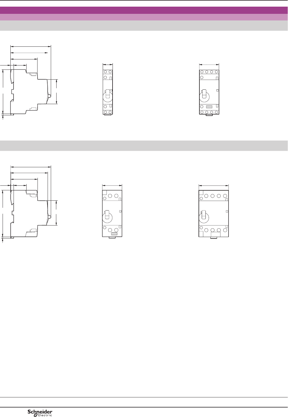
B8/108
Dimensions
Dimensions
"Dual tariff" contactors
Common side view GY 1620
GY 2520
GY 2530, 2540
PRGXOH PRGXOHV
23.5
5.5
49
68
73
2.5
81 45
18 36
DB417046.eps
Common side view GY 4020
GY 6320
GY 4030, 4040
GY 6330, 6340
PRGXOHV PRGXOHV
73
23.5
5.5
2.5
49
68
85 45
36 54
DB417047.eps
Modular equipment
TeSys GY "dual tariff" contactors
Selection:
pages B8/96 to B8/99
Characteristics:
pages B8/106 and
B8/107
References:
page B8/47
Dimensions and schemes:
pages B8/108 and
B8/109
TeSys GY
PCPB08T30-EN
Version : 1.0 19 novembre 2014 10:37 AM
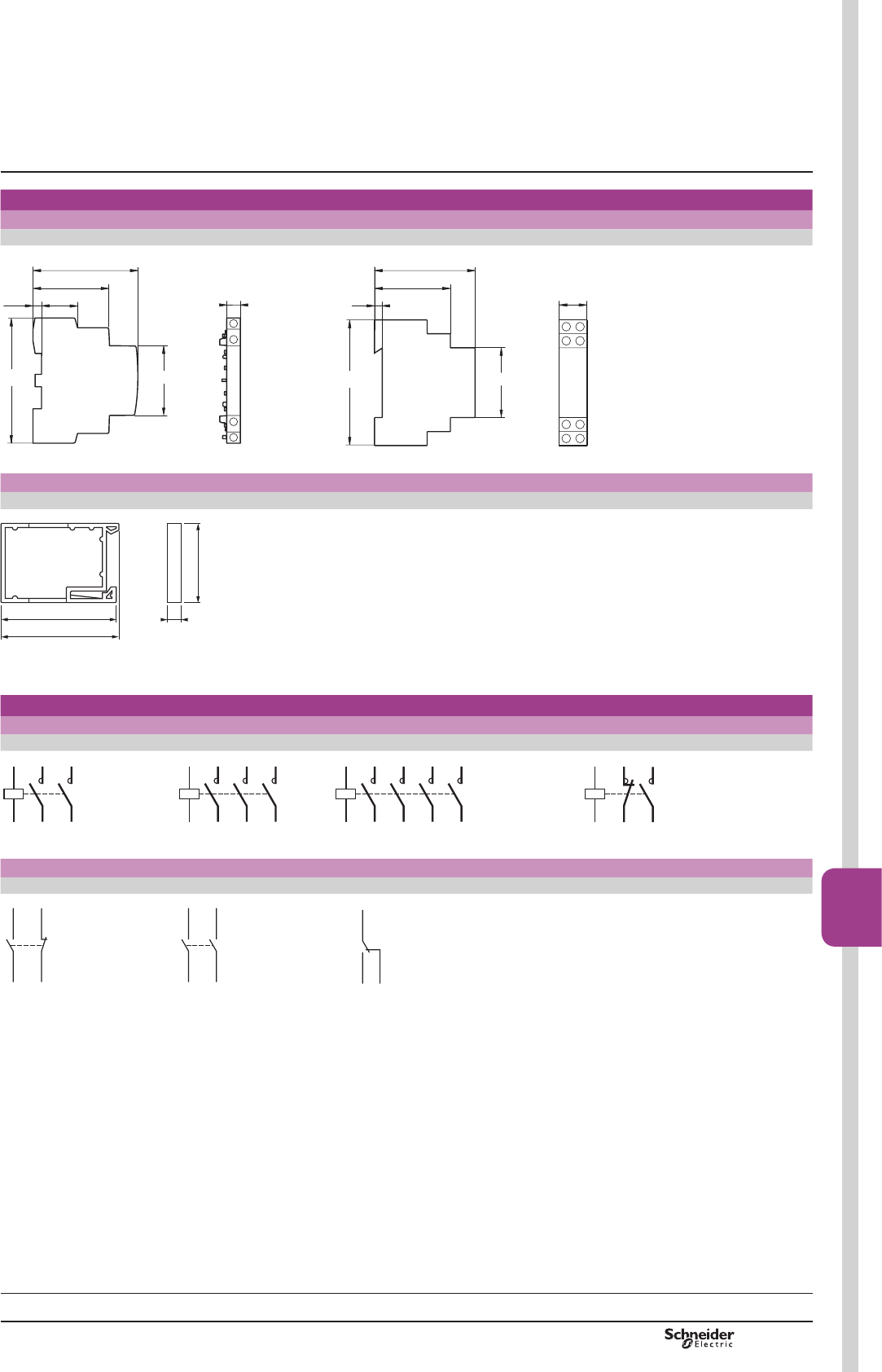
B8/109
Contactors
B8/109
Dimensions,
schemes
Dimensions
Auxiliary contacts Coil suppression block
GAC 0511, 0531 and 0521 GAP 21 and 23
81
23.5
5.5
49
68
45
9
DB417048.eps
81 45
18
5
44
60
DB417049.eps
Clip-on ventilation 1/2 module
GAC 5
865
67
44
DF533726.eps
Schemes
Contactors
GY pp20 GY pp30 GY pp40 GY pp11
A1
A2
34
12
812037.eps
A1
A2
34
12
56
812038.eps
A1
A2
34
12
56
78
812039.eps
R1
R2
A1
A2
12
812040.eps
Auxiliary contacts
GAC 0521 GAC 0531 GAC 0511
22 21/NC
13/NO14
812041.eps
24 23/NO
13/NO14
812042.eps
14/NO 13/NO
12
812046.eps
Modular equipment
TeSys GY "dual tariff" contactors
Selection:
pages B8/96 to B8/99
Characteristics:
pages B8/106 and
B8/107
References:
page B8/47
Dimensions and schemes:
pages B8/108 and
B8/109
TeSys GY
PCPB08T30-EN Version : 1.0 19 novembre 2014 10:37 AM

B8/110
PF526284R.eps
Presentation
7H6\V*)LPSXOVHUHOD\VDUHGHVLJQHGIRUXVHLQPRGXODUHQFORVXUHV
7KH\IHDWXUH
b Easy installation:
v TXLFNFOLSRQ¿[LQJDQGORFNLQJRQWRPPRPHJDUDLO
v HDV\FRQQHFWLRQE\PHDQVRIUHDG\WRWLJKWHQFDSWLYHSR]LGULYHVFUHZWHUPLQDOV
b Compact size
Units have a common depth of 60 mm and width of 18 mm.
b User safety:
v OLYHSDUWVSURWHFWHGDJDLQVWGLUHFW¿QJHUFRQWDFW
v FRPSOHWHO\VDIHRSHUDWLRQ
v state indication on front panel.
Standards
7KLVUDQJHRIPRGXODULPSXOVHUHOD\VKDVEHHQGHVLJQHGWDNLQJLQWRDFFRXQWWKH
UHTXLUHPHQWVRILQWHUQDWLRQDOVWDQGDUG,(&
7KLVVWDQGDUGLVVSHFL¿FWR³,PSXOVHUHOD\V´
&RQIRUPLW\ZLWKWKLVVWDQGDUGPDNHVLWSRVVLEOHWRREWDLQWKHIROORZLQJTXDOLW\ODEHOV
ZLWKRXWWKHQHHGIRUDGGLWLRQDOWHVWV1)86(9'(&(%(&HWF
Functions
0RGXODULPSXOVHUHOD\VDUHGHVLJQHGIRURSHQLQJDQGFORVLQJRIFLUFXLWVZKLFKDUH
UHPRWHO\FRQWUROOHGE\LPSXOVHV7KHSRVLWLRQLVPHFKDQLFDOO\PDLQWDLQHG
7KHVHLPSXOVHUHOD\VDUHXVHGLQOLJKWLQJFLUFXLWVZKHQWKHUHDUHPRUHWKDQWZR
switching points.
Power switching
7H6\V*)LPSXOVHUHOD\VKDYHPXOWLSOHDSSOLFDWLRQVLQLQGXVWULDODJULFXOWXUDODQG
FRPPHUFLDOSUHPLVHVKRVSLWDOVDQGWKHKRPHLHZKHUHYHUVZLWFKLQJRIDVSHFL¿F
OLJKWLQJVXSSO\LVUHTXLUHG
GF 1611M7
Modular equipment
TeSys GF impulse relays
Presentation
Characteristics:
pages B8/112 and B8/113
References:
page B8/48
Dimensions, schemes:
page B8/114
TeSys GF
PCPB08T30-EN
Version : 1.0 19 novembre 2014 10:37 AM

B8/111
Contactors
B8/111
Lighting circuits
Fluorescent lamps with starter
6LQJOH¿WWLQJ Non corrected With parallel correction
Power in W 18 36 58 18 36 58
1XPEHURIODPSV 70 35 21 50 25 16
7ZLQ¿WWLQJ With series correction
Power in W 2 x 18 2 x 36 2 x 58
1XPEHURIODPSV 56 28 17
,QFDQGHVFHQWODPSV¿ODPHQWODPSV
Power in W 40 60 75 100 200
1XPEHURIODPSV 40 25 20 16 8
Incandescent lamps: halogen lamps
Power in W 300 500 1000 1500
1XPEHURIODPSV 5 3 1 1
Incandescent lamps: very low voltage halogen lamps
Power in W 20 50 75 100
1XPEHURIODPSV 70 28 19 4
Low pressure sodium vapour lamps
Non corrected
Power in W 55 90 135 180
1XPEHURIODPSV 24 15 10 7
High pressure sodium vapour lamps
Non corrected
Power in W 250 400 1000
1XPEHURIODPSV 531
Heating circuits
Single-phase 230 V, 2-pole
3RZHULQN: 3.6
Modular equipment
TeSys GF impulse relays
Selection for lighting
and heating circuits
Characteristics:
pages B8/112 and B8/113
References:
page B8/48
Dimensions, schemes:
page B8/114
TeSys GF
PCPB08T30-EN Version : 1.0 19 novembre 2014 10:37 AM
B8/112
Characteristics
Environment
5DWHGLQVXODWLRQYROWDJH8L Conforming to
IEC 60947-1-5
V400
Conforming to
VDE 0110
V400
5DWHGLPSXOVHZLWKVWDQGYROWDJH8LPS kV LQHQFORVXUH
Conforming to standards IEC 60669-1 and 60669-2, NF C 61-112
3URGXFWFHUWL¿FDWLRQV NF-USE, CEBEC, ASE, KEMA, N, S, D, FI, VDE
Degree of protection Conforming to
VDE 0106
3URWHFWLRQDJDLQVWGLUHFW¿QJHUFRQWDFW,3RSHQ,3LQHQFORVXUH
Protective treatment Standard version “TC”
$PELHQWDLUWHPSHUDWXUH
DURXQGWKHGHYLFH
Storage °C «
2SHUDWLRQ °C «
0D[LPXPRSHUDWLQJDOWLWXGH :LWKRXWGHUDWLQJ m2000
2SHUDWLQJSRVLWLRQV :LWKRXWGHUDWLQJ LQUHODWLRQWRQRUPDOYHUWLFDOPRXQWLQJSODQH
6KRFNUHVLVWDQFH
VLQHZDYH PV
,PSXOVHUHOD\RSHQ 3OHDVHFRQVXOW\RXU5HJLRQDO6DOHV2I¿FH
,PSXOVHUHOD\FORVHG 3OHDVHFRQVXOW\RXU5HJLRQDO6DOHV2I¿FH
Vibration resistance
5…300 Hz
,PSXOVHUHOD\RSHQ 4 gn
,PSXOVHUHOD\FORVHG 4 gn
Pole characteristics
1XPEHURISROHV 1 or 2
5DWHGRSHUDWLRQDOFXUUHQW,H
(Ue y9
,Q$&DKHDWLQJ A16
Rated operational voltage V250
&RQYHQWLRQDOWKHUPDOFXUUHQWOWK T y& A16
Permissible short time rating
QRFXUUHQWÀRZLQJIRUSUHFHGLQJ
PLQXWHVZLWKT y&
For 1 s A320
For 10 s A96
For 30 s A48
6KRUWFLUFXLWSURWHFWLRQ
E\IXVHRUFLUFXLWEUHDNHU
JOIXVH A16
&LUFXLWEUHDNHU,2t (at
N$UPVSURVSHFWLYH
A2s5000
Average impedance per pole At lth and 50 Hz m:4
Power dissipated per pole W1
0D[LPXP
cabling
c.s.a.
Min. Max.
Flexible cable
ZLWKRXWFDEOHHQG
FRQGXFWRU mm20.5 6
FRQGXFWRUV mm20.5 4
Flexible cable
with cable end
FRQGXFWRU mm20.5 6
FRQGXFWRUV mm20.5 4
Solid cable
ZLWKRXWFDEOHHQG
FRQGXFWRU mm20.5 6
FRQGXFWRUV mm20.5 4
7LJKWHQLQJWRUTXH 3RZHUFLUFXLW
connections
N.m 0.8
Modular equipment
TeSys GF impulse relays
Presentation:
page B8/110
Selection:
page B8/111
References:
page B8/48
Dimensions, schemes:
page B8/114
TeSys GF
PCPB08T30-EN
Version : 1.0 19 novembre 2014 10:37 AM
B8/113
Contactors
B8/113
Control circuit characteristics
5DWHGFRQWUROFLUFXLWYROWDJH8F V«9IRURWKHUYROWDJHVSOHDVHFRQVXOW\RXU5HJLRQDO6DOHV2I¿FH
Control voltage limits
(T&
2SHUDWLQJWKUHVKROG
GXDOIUHTXHQF\+]
V0.85…1.1 Uc
$YHUDJHFRQVXPSWLRQ
DW&DQGDW8F
,QUXVKDW+] VA 19
2SHUDWLQJWLPH Closing “C” ms 70
2SHQLQJ³2´ ms 70
0LQLPXPLPSXOVHWLPH ms 70
0HFKDQLFDOGXUDELOLW\ 106RSHUDWLQJF\FOHV
(OHFWULFDOGXUDELOLW\
AC-21 RSHUDWLQJF\FOHV
AC-22 RSHUDWLQJF\FOHV
0D[LPXPRSHUDWLQJUDWH 2SHUDWLQJF\FOHV
SHUKRXU
900
0D[LPXP
cabling c.s.a.
Flexible cable
ZLWKRXWFDEOHHQG
RUFRQGXFWRUV mm22.5
Flexible cable
with cable end
FRQGXFWRU mm22.5
FRQGXFWRUV mm21.5
Solid cable
ZLWKRXWFDEOHHQG
RUFRQGXFWRUV mm21.5
7LJKWHQLQJWRUTXH N.m 0.8
Presentation:
page B8/110
Selection:
page B8/111
References:
page B8/48
Dimensions, schemes:
page B8/114
TeSys GF
Characteristics Modular equipment
TeSys GF impulse relays
PCPB08T30-EN Version : 1.0 19 novembre 2014 10:37 AM

B8/114
Dimensions,
schemes
Dimensions
GF 1610, GF 1611, GF 1620
18
64
60
44
5,5
81
45
DF534007.eps
Schemes
GF 1610 GF 1611 GF 1620
A1
A2
12
DF534008.eps
R1
R2
A1
A2
12
DF534009.eps
A1
A2
34
12
DF534010.eps
Modular equipment
TeSys GF impulse relays
Presentation:
page B8/110
Selection:
page B8/111
Characteristics:
pages B8/112 and B8/113
References:
page B8/48
TeSys GF
PCPB08T30-EN
Version : 1.0 19 novembre 2014 10:37 AM
B8/115
Contactors
B8/115
Technical information
Tests according to standard utilisation
categories conforming to IEC 60947-4-1
and 5-1
Contactors
Electrical durability:
making and breaking conditions
Occasional duty:
making and breaking conditions
a.c. supply
Typical
applications
Utilisation
category
Making Breaking Making Breaking
I U cos MI U cos MI U cos MI U cos M
Resistors,
QRQLQGXFWLYH
RUVOLJKWO\LQGXFWLYHORDGV
AC-1 Ie Ue 0.95 Ie Ue 0.95 1.5 Ie 1.05 Ue 0.8 1.5 Ie 1.05 Ue 0.8
Motors
Slip ring motors:
VWDUWLQJEUHDNLQJ
AC-2 2.5 Ie Ue 0.65 2.5 Ie Ue 0.65 4 Ie 1.05 Ue 0.65 4 Ie 1.05 Ue 0.65
6TXLUUHOFDJHPRWRUV
VWDUWLQJEUHDNLQJZKLOVW
PRWRUUXQQLQJ
AC-3
Ie y (1) 6 Ie Ue 0.65 1 Ie 0.17 Ue 0.65 10 Ie 1.05 Ue 0.45 8 Ie 1.05 Ue 0.45
Ie > (2) 6 Ie Ue 0.35 1 Ie 0.17 Ue 0.35 10 Ie 1.05 Ue 0.35 8 Ie 1.05 Ue 0.35
6TXLUUHOFDJHPRWRUV
starting,
reversing,
inching
AC-4
Ie y (1) 6 Ie Ue 0.65 6 Ie Ue 0.65 12 Ie 1.05 Ue 0.45 10 Ie 1.05 Ue 0.45
Ie > (2) 6 Ie Ue 0.35 6 Ie Ue 0.35 12 Ie 1.05 Ue 0.35 10 Ie 1.05 Ue 0.35
d.c. supply.c. supply
Typical
applications
Utilisation
category
Making Breaking Making Breaking
I U L/R PV I U L/R PV I U L/R PV I U L/R PV
Resistors,
QRQLQGXFWLYH
RUVOLJKWO\LQGXFWLYHORDGV
DC-1 Ie Ue 1 Ie Ue 1 1.5 Ie 1.05 Ue 1 1.5 Ie 1.05 Ue 1
6KXQWZRXQGPRWRUV
starting,
reversing,
inching
DC-3 2.5 Ie Ue 2 2.5 Ie Ue 2 4 Ie 1.05 Ue 2.5 4 Ie 1.05 Ue 2.5
6HULHVZRXQGPRWRUV
starting,
reversing,
inching
DC-5 2.5 Ie Ue 7.5 2.5 Ie Ue 7.5 4 Ie 1.05 Ue 15 4 Ie 1.05 Ue 15
Control relays and auxiliary contacts
Electrical durability:
making and breaking conditions
Occasional duty:
making and breaking conditions
a.c. supply
Typical
applications
Utilisation
category
Making Breaking Making Breaking
I U cos MI U cos MI U cos MI U cos M
Electromagnets
y 72 VA AC-14 - - - - - - 6 Ie 1.1 Ue 0.7 6 Ie 1.1 Ue 0.7
> 72 VA AC-15 10 Ie Ue 0.7 Ie Ue 0.4 10 Ie 1.1 Ue 0.3 10 Ie 1.1 Ue 0.3
d.c. supply
Typical
applications
Utilisation
category
Making Breaking Making Breaking
I U L/R PV I U L/R PV I U L/R PV I U L/R PV
Electromagnets DC-13 Ie Ue 6 P (3) Ie Ue 6 P (3) 1.1 Ie 1.1 Ue 6 P (3) 1.1 Ie 1.1 Ue 6 P (3)
(1),Hy$IRUHOHFWULFDOGXUDELOLW\,Hy $IRURFFDVLRQDOGXW\
(2),H!$IRUHOHFWULFDOGXUDELOLW\,H!$IRURFFDVLRQDOGXW\
(3)7KHYDOXH3LQZDWWVLVEDVHGRQSUDFWLFDOREVHUYDWLRQVDQGLVFRQVLGHUHGWRUHSUHVHQWWKHPDMRULW\RIGFPDJQHWLFORDGVXSWRWKHPD[LPXPOLPLWRI
3 :LH3 PV /5
$ERYHWKLVWKHORDGVDUHPDGHXSRIVPDOOHUORDGVLQSDUDOOHO7KHYDOXHPVLVWKHUHIRUHDPD[LPXPOLPLWZKDWHYHUWKHYDOXHRIFXUUHQWGUDZQ
General
TeSys SK, K, D, GC, GY, GF
PCPB08T30-EN Version : 1.0 19 novembre 2014 10:37 AM
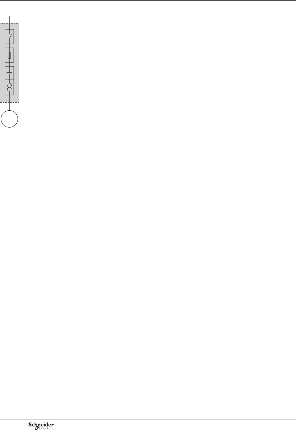
B8/116
Starters for the North American market
,QUHFHQW\HDUVWKH1RUWK$PHULFDQPDUNHWKDVVWDUWHGWRKDUPRQLVH8/&6$DQG
$1&(VWDQGDUGVDVZHOODVWKHLQGXVWULDOLQVWDOODWLRQFRGHVSURYLGHGE\QDWLRQDO
UHJXODWLRQV1(&IRUWKH8QLWHG6WDWHV&(&IRU&DQDGDDQG0(&IRU0H[LFR(1)
0DMRULPSURYHPHQWVFDUULHGRXWE\WKH&DQHQD(2) are aimed at harmonising
SURGXFWUHTXLUHPHQWVEDVHGRQ,(&(3) standards.
+RZHYHUWKH1RUWK$PHULFDQFRGHVXVHVSHFL¿FWHUPLQRORJ\IRUGH¿QLQJWKH
IXQFWLRQVRIDVWDUWHU
7KHVHIXQFWLRQVFDQEHIXO¿OOHGE\VWDQGDUG,(&SURGXFWVDFFRPSDQLHGE\
DSSURSULDWHFHUWL¿FDWLRQV
Combination Starters
&RPELQDWLRQ6WDUWHUVDUHWKHPRVWFRPPRQW\SHRISDFNDJHGPRWRUVWDUWHU7KH\
DUHFDOOHG&RPELQDWLRQEHFDXVHRIWKHLUVWUXFWXUHDQGWKHLUFRPELQHGIXQFWLRQV
7KH¿JXUHRSSRVLWHVKRZVWKHIRXUFRPELQHGIXQFWLRQVWKDWFRQVWLWXWHDFRPSOHWH
PRWRUVWDUWHUFLUFXLWGH¿QHGDVD³0RWRUEUDQFKFLUFXLW´E\WKH1(&861DWLRQDO
(OHFWULF&RGHLQDUWLFOH6WDQGDUG8/FXUUHQWO\JLYHVGLIIHUHQWW\SHVRI
FRPELQDWLRQVWDUWHUWKDWPHHWWKHUHTXLUHPHQWVRID0RWRUEUDQFKFLUFXLW
Type E, called “self-protected combination starter´FRYHUVDOOWKHVHIXQFWLRQV
DQGFDQEHFRQWUROOHGPDQXDOO\WKHUPDOPDJQHWLFFLUFXLWEUHDNHURUUHPRWHO\
VWDUWHUFRQWUROOHU7\SH(VWDUWHUVZLWKVWDQGIDXOWVZLWKLQWKHLUGHFODUHGQRPLQDO
UDWLQJZLWKRXWVXVWDLQLQJGDPDJHDIWHUZKLFKWKH\FDQEHSXWEDFNLQWRVHUYLFH,Q
DGGLWLRQWKH\FDQZLWKVWDQGPRUHVHYHUHVKRUWFLUFXLWDQGGXUDELOLW\SHUIRUPDQFH
WHVWVZLWKRXWZHOGLQJRUH[FHVVLYHZHDURIWKHFRQWDFWWLSV
Type F, called “Combination motor starter´FRQVLVWVRIDW\SH(PDQXDOVWDUWHU
WKHUPDOPDJQHWLFFLUFXLWEUHDNHUFRPELQHGZLWKDFRQWDFWRU
7KHVHVWDUWHUVDUHHYDOXDWHGE\PHDQVRIEDVLFVKRUWFLUFXLWWHVWVEXWDUHQRW
considered as “self-protected”.
)RUWKLVFRPELQDWLRQWKHW\SH(VWDUWHUPXVWEHPDUNHG³&RPELQDWLRQ0RWRU
&RQWUROOHUZKHQXVHGZLWK´IROORZHGE\WKHUHIHUHQFHRIWKHORDGVLGHFRQWDFWRU
Presentation TeSys contactors
For the North American market
Conforming to UL and CSA
10RWRU'LVFRQQHFW'LVFRQQHFWVZLWFK
20RWRU%UDQFK&LUFXLW3URWHFWLRQ
6KRUWFLUFXLWSURWHFWLRQ
30RWRU&RQWUROOHU&RQWDFWRU
40RWRU2YHUORDG3URWHFWLRQ7KHUPDORYHUORDGUHOD\
1
2
3
4
M
DF537742.eps
(1) UL8QGHUZULWHUV/DERUDWRULHVCSA: Canadian Standards Association, ACNE: Association
RI6WDQGDUGL]DWLRQDQG&HUWL¿FDWLRQNEC: National Electric Code, CEC: Canadian Electrical
Code, MEC0H[LFDQ(OHFWULFDO&RGH
(2) Canena&RXQFLOIRU+DUPRQL]DWLRQRI(OHFWURWHFKQLFDO6WDQGDUGL]DWLRQRI1RUWK$PHULFD
(3) IEC,QWHUQDWLRQDO(OHFWURWHFKQLFDO&RPPLVVLRQ
TeSys SK, K, D, GC, GY, GF
PCPB08T30-EN
Version : 1.0 19 novembre 2014 10:37 AM

B8/117
Contactors
B8/117
Control panels
7RKHOSXVHUVSURSHUO\FRRUGLQDWHWKHLUPRWRUFRQWUROHTXLSPHQWZLWKWKHLU
GLVWULEXWLRQV\VWHPLQWKHHYHQWRIDIDXOWDUWLFOHRIWKH1(&UHTXLUHV
SDQHOEXLOGHUVWROLVWWKHVKRUWFLUFXLWZLWKVWDQGUDWLQJRIWKHLUPRWRUFRQWUROSDQHOV
$FFRUGLQJWRVWDQGDUG8/$PDQXIDFWXUHUVPXVWXVHWKHVKRUWFLUFXLWZLWKVWDQG
YDOXHRIWKHORZHVWUDWHGGHYLFHDVWKHQRPLQDOZLWKVWDQGUDWLQJRIWKHSDQHO
XQOHVVWKHGHYLFHVKDYHEHHQWHVWHGWRJHWKHUIRUDKLJKHUFRRUGLQDWHGUDWLQJ
7KHPLQLPXP³short-circuit current rating´6&&5RQPRWRUFRQWUROFRPSRQHQWV
for horsepower ratings of 50 hp or below is 5000 A.
Using a type E or type F combination starter eliminates the coordination problems
RIXVLQJLQGLYLGXDOFRPSRQHQWVIRUWKH³PRWRUEUDQFKFLUFXLWSURWHFWLRQ´³PRWRU
FRQWUROOHU´DQG³PRWRURYHUORDGSURWHFWLRQ´IXQFWLRQV
7KHSDQHOEXLOGHUXVHVWKHGHFODUHGVKRUWFLUFXLWFXUUHQWUDWLQJIRUWKHFRPELQDWLRQ
VWDUWHU7KLVYDOXHLVJHQHUDOO\KLJKHUWKDQ$
7KLVPDNHVLWHDVLHUWROLVWWKHVKRUWFLUFXLWFXUUHQWUDWLQJVDQGWRFKHFNWKH
FRPSDWLELOLW\RID8/$PRWRUFRQWUROSDQHOZLWKLQDJLYHQGLVWULEXWLRQV\VWHP
Presentation TeSys contactors
For the North American market
Conforming to UL and CSA
TeSys SK, K, D, GC, GY, GF
Group protection
$UWLFOHRIWKH1(&DOORZVDVLQJOHVKRUWFLUFXLWSURWHFWLRQGHYLFHWREHXVHG
IRUPRUHWKDQRQHPRWRUFLUFXLWLIWKHFRPSRQHQWVXVHGDUHPDUNHGDQGOLVWHGIRU
VXFKXVH
&RPSRQHQWVVXLWDEOHIRUXVHLQJURXSSURWHFWLRQNQRZQDV³motor group
installations´FDQEHPDUNHGLQRQHRIWKHIROORZLQJWZRZD\V
Case n° 1
7KHFRQWDFWRUDQGWKHPRWRURYHUORDGUHOD\DUHERWKOLVWHGDVVXLWDEOHIRUJURXS
installation.
$QLQYHUVHWLPHFLUFXLWEUHDNHUFDQEHXVHGDVWKHVKRUWFLUFXLWSURWHFWLRQGHYLFHLI
LWLVDOVROLVWHGDVVXLWDEOHIRUJURXSLQVWDOODWLRQ
7KHSDQHOEXLOGHUPXVWWKHUHIRUHPDNHVXUHWKDWWKHVKRUWFLUFXLWSURWHFWLRQGHYLFH
VHOHFWHGIXVHVRULQYHUVHWLPHFLUFXLWEUHDNHUGRHVQRWH[FHHGWKHYDOXHDOORZHG
E\DUWLFOHIRUWKHVPDOOHVWRYHUORDGUHOD\XVHGLQWKHFLUFXLW
2QFHWKHVHFRQGLWLRQVKDYHEHHQPHWWKHSDQHOEXLOGHUFDQUHGXFHWKHVL]HRI
WKHFRQGXFWRUFRQQHFWLQJWKHVKRUWFLUFXLWSURWHFWLRQGHYLFHWRWKHLQGLYLGXDOPRWRU
FRQWDFWRURYHUORDGUHOD\WRRQHWKLUGRIWKHVL]HRIWKHXSVWUHDPFLUFXLWFRQGXFWRU
VXSSO\LQJWKHSURWHFWLRQGHYLFH
7KHSDQHOEXLOGHUPXVWOLPLWWKHOHQJWKRIWKHPRWRUVWDUWHUFRQGXFWRUFRQQHFWLQJ
WKHVKRUWFLUFXLWSURWHFWLRQGHYLFHWRWKHPRWRUFRQWDFWRURYHUORDGUHOD\WRD
PD[LPXPRIPIHHW
Case n° 2
7KHPRWRUFRQWDFWRUDQGRYHUORDGUHOD\DUHOLVWHGDVVXLWDEOHIRU³tap conductor
protection´LQJURXSLQVWDOODWLRQV
7KLVFDWHJRU\DOORZVWKHSDQHOGHVLJQHUWRUHGXFHWKHVL]HRIWKHFRQGXFWRU
FRQQHFWLQJWKHVKRUWFLUFXLWSURWHFWLRQGHYLFHWRWKHLQGLYLGXDOPRWRU
FRQWDFWRURYHUORDGUHOD\WRRQHWHQWKRIWKHVL]HRIWKHXSVWUHDPFLUFXLWFRQGXFWRU
VXSSO\LQJWKHSURWHFWLRQGHYLFH
7KHGHVLJQHUPXVWOLPLWWKHOHQJWKRIWKLVFRQGXFWRUWRDPD[LPXPRIP
IHHW
,QERWKFDVHVWKHVXSSO\FLUFXLWVPXVWQRWEHOHVVWKDQRIWKHFRQQHFWHG
PRWRU)/$)XOO/RDG$PSVUDWLQJ
)RUSDQHOEXLOGHUVXVLQJtype FFRPELQDWLRQVWDUWHUVLQJURXSLQVWDOODWLRQV
VLPSOL¿HVJURXSPRWRUFRQVLGHUDWLRQV
(DFKVWDUWHULVDIXOO\FRRUGLQDWHGPRWRUEUDQFKFLUFXLW
7KHSDQHOEXLOGHUIROORZVWKHVDPH1(&UHTXLUHPHQWVIRUVL]LQJWKHVXSSO\
FRQGXFWRUVDVWKRVHUHTXLUHGIRUVLQJOHPRWRUEUDQFKFLUFXLWV
7KHVL]HRIWKHVXSSO\FRQGXFWRUVFDQEHUHGXFHGLQDFFRUGDQFHZLWKWKH
VSHFL¿FDWLRQVRIDUWLFOH
7KLVDOORZVWKHVDPHÀH[LELOLW\LQFRQGXFWRUVL]LQJDVWKDWRIIHUHGLQDUWLFOH
'ZLWKRXWDUHTXLUHPHQWWRFKHFNWKHVKRUWFLUFXLWSURWHFWLRQUDWLQJPDUNHGRQ
WKHFRPSRQHQWVDQGWKHRYHUORDGUHOD\OLPLW
$8/$SDQHOGRHVQRWQHHGDVKRUWFLUFXLWSURWHFWLRQGHYLFHZKHQHDFK
motor starter installed is a type F.
7KHXSVWUHDPVKRUWFLUFXLWSURWHFWLRQGHYLFHVXSSO\LQJWKHVWDUWHUSURWHFWVWKH
SDQHO7KHSDQHOEXLOGHURQO\KDVWRFRQVLGHUWKHSDQHOHQFORVXUHGLVFRQQHFW
UHTXLUHPHQWVVSHFL¿HGE\WKH1(&RUORFDOFRGHV
PCPB08T30-EN Version : 1.0 19 novembre 2014 10:37 AM
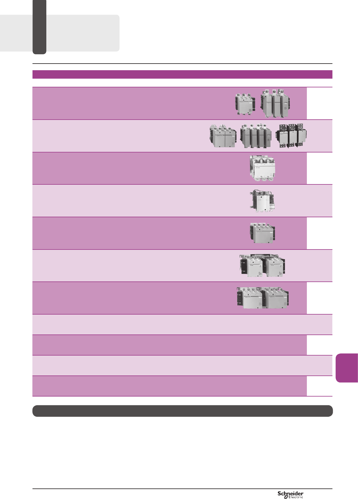
B9/1
High power
contactors
High power contactors
TeSys F
Contactors – TeSys F, V, FG, CR1F
Type of product Range Pages
Contactors for AC-3 applications
TeSys F From 115 to 800 A
B9/2
Contactors for AC-1 applications
TeSys F From 115 to 2100 AB9/3
Vacuum contactors– 1500 V
TeSys V
From 160 to 610 A - AC-3
From 160 to 630 A - AC-1 B9/4
Shockproof contactors
TeSys FG From 150 to 630 AB9/6
Magnetic latching contactors
TeSys CR1F From 150 to 630 AB9/7
Reversing pre-assembled contactors
for AC-3 applications
TeSys F
From 115 to 265 AB9/8
Changeover pre-assembled contactor pairs
for AC-1 applications
TeSys F
From 200 to 350 AB9/9
Auxiliary contact blocks Accessories – spare parts - capacitive devices
TeSys F B9/11
Coils
TeSys F B9/17
Accessories, coils for shockproof and magnetic latching contactors
TeSys FG, TeSys CR1F B9/27
Accessories for reversing and changeover contactor assemblies
TeSys LA9F B9/36
TeSys
Control and
Protection
Components
Chapter
B9
Technical Data for Designers B9/45
PCPB09S10-EN Version : 1.0 18 novembre 2014 12:55 PM
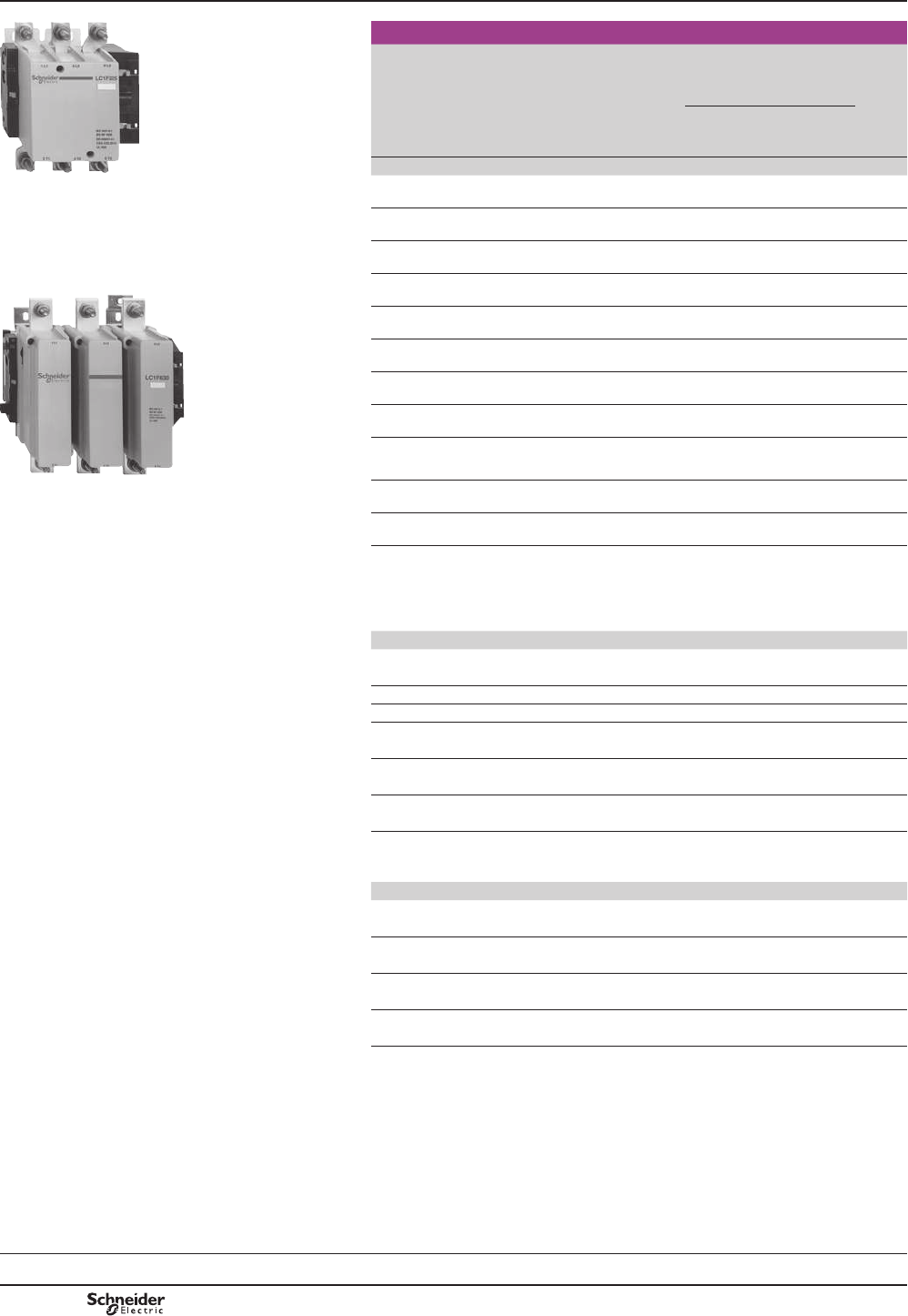
B9/2
References
DF526091R.eps
3-pole contactors
Standard power ratings
of 3-phase motors
50-60 Hz in category AC-3
Rated
opera-
tional
current
in AC-3
Basic reference,
to be completed by
adding the voltage code
(2)
Weight
6FUHZ¿[LQJ
cabling (1)
220 V
230 V
380 V
400 V
415 V
440 V
500 V
660 V
690 V
1000 V
440 V
up to
kW kW kW kW kW kW kW A kg
LC1 F225 30 55 59 59 75 80 65 115 LC1F115pp 3.430
40 75 80 80 90 100 65 150 LC1F150pp 3.430
55 90 100 100 110 110 100 185 LC1F185pp 4.650
DF526092R.eps
63 110 110 110 129 129 100 225 LC1F225pp 4.750
75 132 140 140 160 160 147 265 LC1F265pp 7.440
100 160 180 200 200 220 160 330 LC1F330pp 8.600
110 200 220 250 257 280 185 400 LC1F400pp 9.100
147 250 280 295 355 335 335 500 LC1F500pp 11.350
200 335 375 400 400 450 450 630 LC1F630pp 18.600
LC1 F630 220 400 425 425 450 475 450 780 LC1F780pp 39.500
250 450 450 450 450 475 450 800 LC1F800pp 18.750
Note: auxiliary contact blocks, modules and accessories: see pages B9/10 to B9/27.
(1)3RZHUWHUPLQDOVFDQEHSURWHFWHGDJDLQVWGLUHFW¿QJHUFRQWDFWE\WKHDGGLWLRQRIVKURXGV
to be ordered separately, except on contactors LC1 F780 (see page B9/14).
(2)6WDQGDUGFRQWUROFLUFXLWYROWDJHVIRURWKHUYROWDJHVSOHDVHFRQVXOW\RXU5HJLRQDO6DOHV
2I¿FH
Volts a24 48 110 115 120 208 220 230 240 380 400 415 440
LC1 F115…F225
50 Hz (coil LX1) B5 E5 F5 FE5 – – M5 P5 U5 Q5 V5 N5 –
60 Hz (coil LX1) – E6 F6 – G6 L6 M6 – U6 Q6 – – R6
40}400 Hz (coil LX9) – E7 F7 FE7 G7 L7 M7 P7 U7 Q7 V7 N7 R7
LC1 F265…F330
40}400 Hz (coil LX1) B7 E7 F7 FE7 G7 L7 M7 P7 U7 Q7 V7 N7 R7
LC1 F400…F630
40}400 Hz (coil LX1) – E7 F7 FE7 G7 (3) L7 M7 P7 U7 Q7 V7 N7 R7
LC1 F780
40}400 Hz (coil LX1) – – F7 FE7 F7 L7 M7 P7 U7 Q7 V7 N7 R7
LC1 F800
40}400 Hz (coil LX4) (4) – – FW FW FW – MW MW MW QW QW QW –
Volts c24 48 110 125 220 230 250 400 440
LC1 F115…F330
(coil LX4 F) BD ED FD GD MD MD UD – RD
LC1 F400…F630
(coil LX4 F) – ED FD GD MD – UD – RD
LC1 F780
(coil LX4 F) – – FD GD MD – UD – RD
LC1 F800
(coil LX4 F) – – FW FW MW MW – QW –
(3))IRULC1F630.
(4) Coil LX4 F8ppUHFWL¿HU'57(pp.
TeSys contactors
TeSys F contactors for motor control in
utilisation category AC-3 (115 to 800 A)
Control circuit: a.c. or d.c.
Selection:
pages B10/50 to B10/73
References:
pages B9/2 and B9/3
Dimensions:
pages B9/54 to B9/56
Schemes:
page B9/61
TeSys F
PCPB09P10-EN
Version : 1.0 18 novembre 2014 12:55 PM
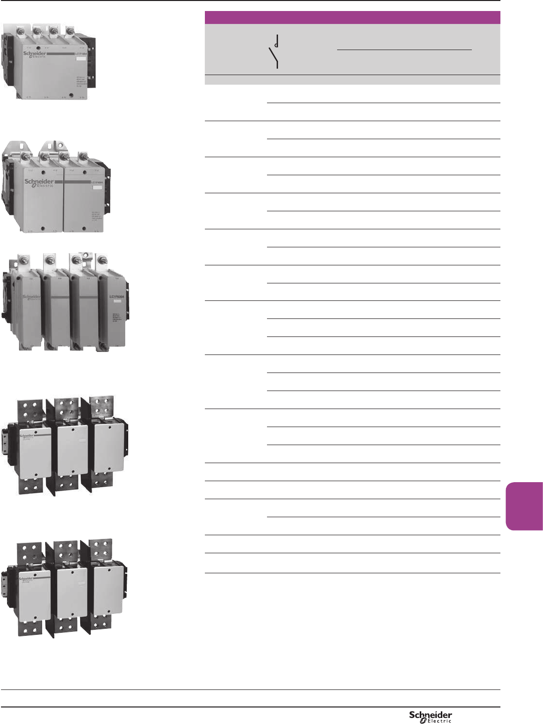
B9/3
High power
contactors
DF526093R.eps
2, 3 or 4-pole contactors
0D[LPXP
current
in AC-1
(T y 40 °C)
Number of poles Basic reference,
to be completed by
adding the voltage code (2)
Weight
6FUHZ¿[LQJ
cabling (1)
A kg
200 3 LC1F115pp 3.430
LC1 F1854 4 LC1F1154pp 3.830
250 3 LC1F150pp 3.430
DF526094R.eps
LC1 F4004
4 LC1F1504pp 3.830
275 3 LC1F185pp 4.650
4 LC1F1854pp 5.450
315 3 LC1F225pp 4.750
4 LC1F2254pp 5.550
350 3 LC1F265pp 7.440
DF526095R.eps
4 LC1F2654pp 8.540
400 3 LC1F330pp 8.600
4 LC1F3304pp 9.500
500 2 LC1F4002pp 8.000
3 LC1F400pp 9.100
4 LC1F4004pp 10.200
LC1 F6304 700 2 LC1F5002pp 9.750
3 LC1F500pp 11.350
DF526096R.eps
4 LC1F5004pp 12.950
1000 2 LC1F6302pp 15.500
3 LC1F630pp 18.600
4 LC1F6304pp 21.500
1260 3 LC1F1250pp 19.000
1400 3 LC1F1400pp 29.000
LC1 F1700 1600 3 LC1F780pp 39.500
4 LC1F7804pp 48.000
DF526097R.eps
1700 3 LC1F1700pp 30.000
2100 (3) 3 LC1F2100pp 31.000
Note: auxiliary contact blocks, modules and accessories: see pages B9/10 to B9/27.
(1)3RZHUWHUPLQDOVFDQEHSURWHFWHGDJDLQVWGLUHFW¿QJHUFRQWDFWE\WKHDGGLWLRQRIVKURXGV
to be ordered separately (except LC1 F780, LC1 F1250, LC1 F1400, LC1 F1700
and LC1 F2100VHHSDJH³7H6\VFRQWDFWRUV´SDJH%
(2) Standard control circuit voltages, see previous page.
(3):LWKVHWRIULJKWDQJOHGFRQQHFWRUVLA9 F2100VHHSDJH5HIHUHQFHVSDJH%
LC1 F2100
References TeSys contactors
TeSys F contactors for motor control in
utilisation category AC-3 (115 to 2100 A)
Control circuit: a.c. or d.c.
Selection:
pages B10/50 to B10/73
References:
pages B9/2 and B9/3
Dimensions:
pages B9/54 to B9/56
Schemes:
page B9/61
TeSys F
PCPB09P10-EN Version : 1.0 18 novembre 2014 12:55 PM
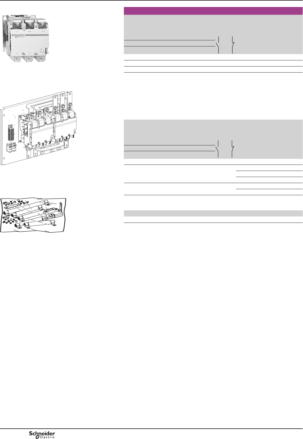
B9/4
TeSys V
Vacuum contactors
Standard power ratings
50/60 Hz
in category AC-3
Rated
operational
current
Ie
Instan-
taneous
DX[LOLDU\
contacts
Control
circuit
voltage
(50/60 Hz)
Basic
reference (1)
Weight
230 V 400 V 525 V 690 V 1000 V AC-3 AC-1
kW kW kW kW kW A A kg
45 75 110 150 200 160 160 2 1 (1) LC1V160pp 3.800
90 160 220 280 400 320 320 1 1 (1) LC1V320pp 10.500
160 300 400 560 800 610 630 1 1 (1) LC1V610pp 13.000
Reversing vacuum contactors
The reversing contactor range comprises :
b for 160 A rating, a kit with set of power connections allowing assembly
of the starter
b for 320 and 610 A ratings, a complete starter, ready for use.
Standard power ratings
50/60 Hz
in category AC-3
Rated
operational
current
Ie
Instan-
taneous
DX[LOLDU\
contacts
Control
circuit
voltage
(50/60 Hz)
Basic
reference (1)
Weight
230 V 400 V 525 V 690 V 1000 V AC-3 AC-1
kW kW kW kW kW A A kg
45 75 110 150 200 160 160 2 1 – LA9V974 (2) 1.200
90 160 220 280 400 320 320 1 1 110-120 V LC2V320FE7 30
220-240 V LC2V320P7 30
380-415 V LC2V320V7 30
160 300 400 560 800 610 630 1 1 110-120 V LC2V610FE7 36
220-240 V LC2V610P7 36
(1)%DVLFUHIHUHQFHDGGFRGHLQGLFDWLQJFRQWUROFLUFXLWYROWDJH
Standard control circuit voltages:
Volts 50/60 Hz 110…120 220…240 380…415 440…480 550…600
Item FE7 P7 V7 R7 X7
(2).LWFRQWDLQLQJDPHFKDQLFDOLQWHUORFNDVHWRISRZHUFRQQHFWLRQVDQGD¿[LQJSODWH
7REXLOGDFRPSOHWHUHYHUVLQJFRQWDFWRURUGHUFRQWDFWRUV/&9pp separately.
TeSys contactors
3-pole vacuum contactors
and reversing contactors
Power and control circuits a.c. supply
References
/&9
PF526336R.eps
g
f
3 L2 5 L3
1 L1
4 T2 6 T3
ON / I
OFF / 0
2 T1
LC1V610
3 L2 5 L3
1 L1
4 T2 6 T3
ON / I
OFF / 0
2 T1
LC1V610
KM1 KM2
L1 L2 L3
/&9
510227.eps
/$9
510213.eps
PCPB09P10-EN
Version : 1.0 18 novembre 2014 12:55 PM
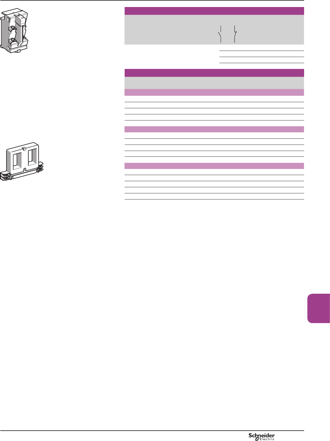
B9/5
High power
contactors
TeSys V
,QVWDQWDQHRXVDX[LOLDU\FRQWDFWEORFNV(1)
Number of contacts 0D[LPXPQXPEHURI
blocks per contactor
$X[LOLDU\
contacts
Reference
2 4 1 1 LA1VN11
– 2 LA1VN02
2 – LA1VN20
1 1 LA1VN11X (2)
50/60 Hz coils
Rated voltage Voltage code Reference
V
For contactors LC1 V160
110…120 FE7 LX1V160FE7
220…240 P7 LX1V160P7
380…415 V7 LX1V160V7
440…480 R7 LX1V160R7
550…600 X7 LX1V160X7
For contactors LC1 V320
110…120 FE7 LX1V320FE7
220…240 P7 LX1V320P7
380…415 V7 LX1V320V7
440…480 R7 LX1V320R7
550…600 X7 LX1V320X7
For contactors LC1 V610
110…120 FE7 LX1V610FE7
220…240 P7 LX1V610P7
380…415 V7 LX1V610V7
440…480 R7 LX1V610R7
550…600 X7 LX1V610X7
(1)/&9DX[LOLDU\FRQWDFWEORFNVPRXQWHGDWWKHWRSRIWKHFRQWDFWRUZLWKQRFKDQJH
WRWKHRYHUDOOGLPHQVLRQV
/&9RU/&9DX[LOLDU\FRQWDFWEORFNVPRXQWHGRQWKH5+DQG/+VLGH
RIWKHFRQWDFWRUZLWKQRFKDQJHWRWKHRYHUDOOGLPHQVLRQV
(2))RU/&91&FRQWDFWIRUWKHFRLO12FRQWDFW
/$91
500308_1.eps
/;9pp
500310.eps
TeSys contactors
3-pole vacuum contactors
and reversing contactors
Power and control circuits a.c. supply
References
PCPB09P10-EN Version : 1.0 18 novembre 2014 12:55 PM
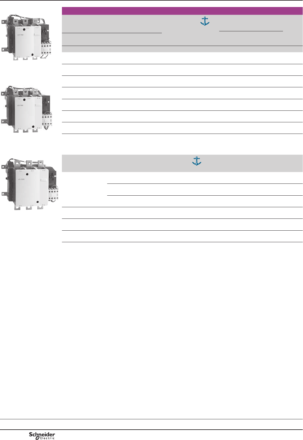
B9/6
3-pole shockproof contactors
Standard power ratings of 3-phase motors
50-60 Hz in category AC-3
Rated
operational
current in
cat. AC-3,
440 V/AC-1
up to
(1)
'&1
UHI
Basic reference,
to be completed by
adding the voltage code (3)
Weight
6FUHZ¿[LQJ
cabling (2)
220 V
230 V
380 V
400 V 415 V 440 V 500 V
660 V
690 V 1000 V
kW kW kW kW kW kW kW A kg
40 75 80 80 90 100 65 150/250 CR182 LC1FG150pp 3.430
55 90 100 100 110 110 100 185/275 CR242 LC1FG185pp 4.650
75 132 140 140 160 160 147 265/350 CR302 LC1FG265pp 7.440
110 200 220 250 257 280 185 400/500 CR432 LC1FG400pp 9.100
147 250 280 295 355 335 335 500/700 CR582 LC1FG500pp 11.350
200 335 375 400 400 450 450 630/1000 CR852 LC1FG630pp 18.600
Note:WKHVHFRQWDFWRUVKDYHLQVWDQWDQHRXVDX[LOLDU\FRQWDFWEORFNVZLWK12FRQWDFWV1&FRQWDFWDQGRQHFRLOPDLQWDLQLQJ
contact.
(1)'HYLFHVDSSURYHGE\WKH'&1)UHQFKQDYDOVKLS\DUGGHSDUWPHQWDQGDXWKRULVHGIRURQERDUGXVH
(2)3RZHUWHUPLQDOVFDQLIUHTXLUHGEHSURWHFWHGDJDLQVWGLUHFW¿QJHUFRQWDFWE\WKHDGGLWLRQRIVKURXGVWREHRUGHUHG
separately.
(3)6WDQGDUGFRQWUROFLUFXLWYROWDJHVIRURWKHUYROWDJHVSOHDVHFRQVXOW\RXU5HJLRQDO6DOHV2I¿FH
Volt a48 110 115
(1)
120 208 220 230 240 380 400 415 440
LC1 FG 150…FG185 50 Hz (coil LX1) E5 F5 F5 – – M5 P5 U5 Q5 V5 N5 –
60 Hz (coil LX1) E6 F6 – – L6 M6 – U6 Q6 – – R6
50/60 Hz (coil LX9) E7 F7 F7 G6 L7 M7 P7 U7 Q7 V7 N7 R7
LC1 FG265 40…400 Hz (coil LX1) E7 F7 F7 G7 L7 M7 P7 U7 Q7 V7 N7 R7
LC1 FG400…FG500 40…400 Hz (coil LX1) – F7 F7 G7 L7 M7 P7 U7 Q7 V7 N7 R7
LC1 FG630 40…400 Hz (coil LX1) – F7 F7 F7 L7 M7 P7 U7 Q7 V7 N7 R7
References TeSys contactors
3-pole shockproof contactors LC1 FG
For control of motors and distribution circuits
Control circuit: a.c.
Presentation :
pages B9/68 and B9/69
Selection :
pages B9/70 to B9/75
Characteristics :
pages B9/76 to B9/83
Dimensions, schemes :
pages B9/84 and B9/85
LC1 FG150
PF526281R.eps
LC1 FG185
PF526282R.eps
LC1 FG265
PF526283R.eps
TeSys FG
PCPB09P10-EN
Version : 1.0 18 novembre 2014 12:55 PM
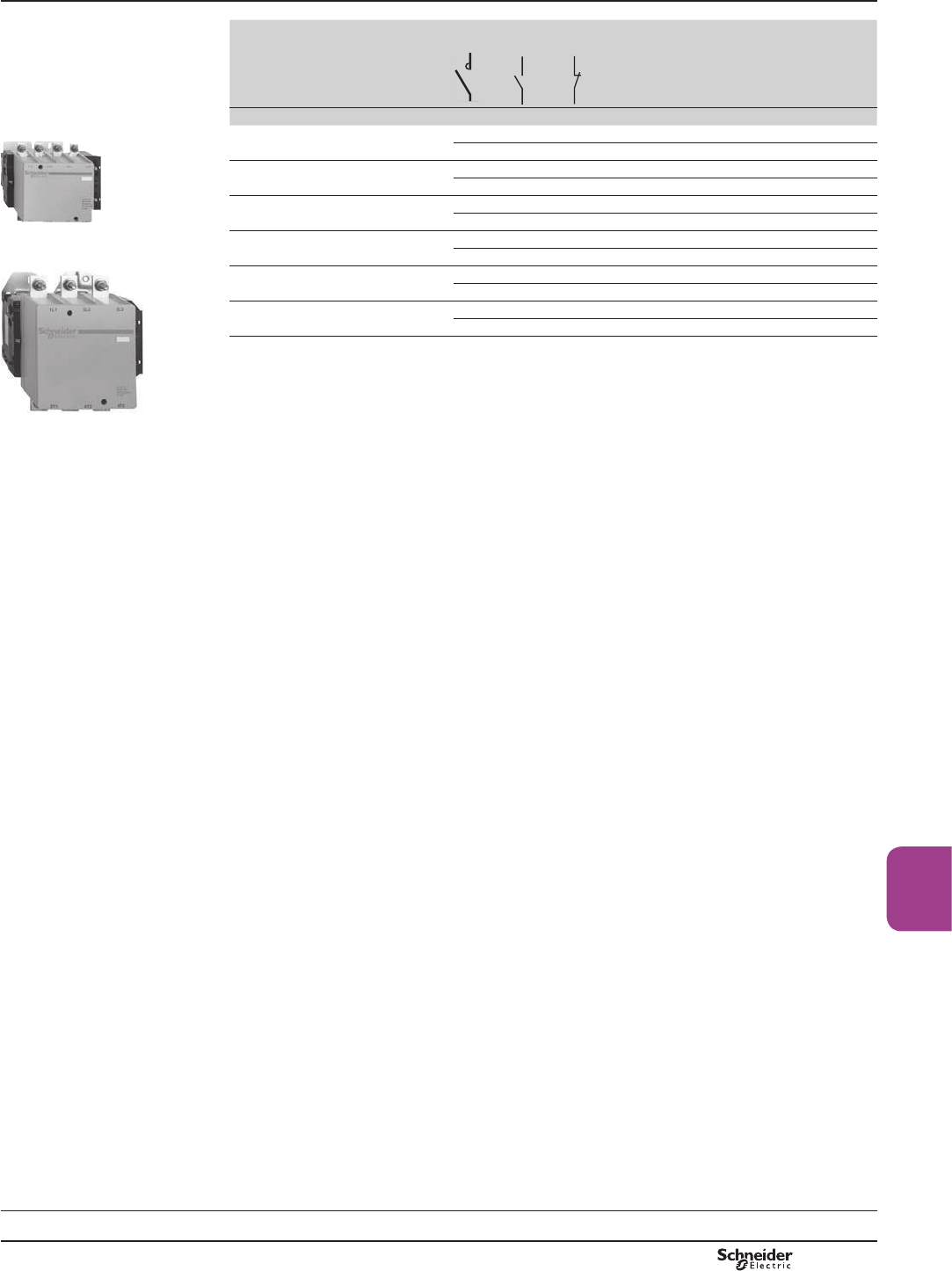
B9/7
High power
contactors
0D[LPXPWKHUPDO
current in category
AC-1
40 °C
Rated
operational
current in
category AC-3
9PD[
Number
of poles
Instantaneous
DX[LOLDU\FRQWDFWV
Basic reference,
to be completed by
adding the voltage code (1)
Weight
PF526337R.eps
A A kg
250 150 3 – – CR1F150pp 3.500
4 – – CR1F1504pp 3.800
275 185 3 – – CR1F185pp 4.600
4 – – CR1F1854pp 5.400
350 265 3 – – CR1F265pp 7.400
4 – – CR1F2654pp 8.500
&5) 500 400 3 – – CR1F400pp 9.100
4 – – CR1F4004pp 10.200
PF526338R.eps
&5)
700 500 3 – – CR1F500pp 11.300
4 – – CR1F5004pp 12.900
1000 630 3 – – CR1F630pp 18.600
4 – – CR1F6304pp 21.500
(1) Standard control circuit voltages: see page opposite.
TeSys contactors
Magnetic latching contactors
Control circuit: a.c. or d.c. supply
References
Selection:
pages B9/86 to B9/91
Characteristics:
pages B9/92 to B9/95
Dimensions:
pages B9/96 to B9/99
TeSys CR1F
PCPB09P10-EN Version : 1.0 18 novembre 2014 12:55 PM
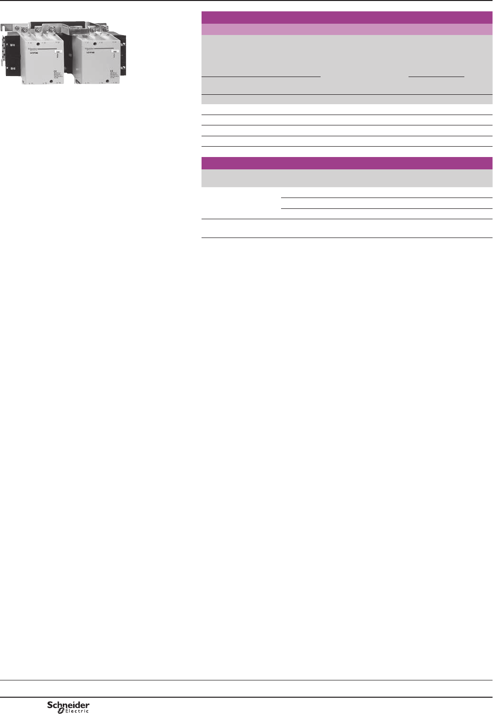
B9/8
TeSys contactors
TeSys F reversing contactors for motor
control in utilisation category AC-3
(115 to 265 A), pre-assembled
Control circuit: a.c. or d.c.
DB402428.eps
3-pole reversing contactors (horizontally mounted) (1)
Pre-wired power connections
Standard power ratings
of 3-phase motors
50/60 Hz in category AC-3
Opera-
tional
current
in AC-3
0D[LPXP
opera-
tional
voltage
Contactors
supplied
without coil (2)
Complete
reference
Weight
220 V
230 V
380 V
400 V 415 V 440 V 500 V
660 V
690 V 1000 V
440 V
up to
)L[LQJFDEOLQJ(3)
LC2 F115 kW kW kW kW kW kW kW A V kg
30 55 59 59 75 80 65 115 1000 LC2F115 7.560
40 75 80 80 90 100 65 150 1000 LC2F150 7.560
55 90 100 100 110 110 100 185 1000 LC2F185 10.100
63 110 110 110 129 129 100 225 1000 LC2F225 14.200
75 132 140 140 160 160 147 265 1000 LC2F265 16.480
Accessories (to be ordered separately)
Description For reversing
contactors
Quantity
required
Reference
Power terminal protection
shrouds
LC2 F115 2 LA9F701
LC2 F150, F185 2 LA9F702
LC2 F225, F265 2 LA9F703
Auxiliary contact blocks
and add-on modules
– – See pages B9/10
to B9/14
(1))LWWHGZLWKDPHFKDQLFDOLQWHUORFNZLWKRXWHOHFWULFDOLQWHUORFNLQJ2UGHUVHSDUDWHO\DX[LOLDU\
contact blocks LADNp1WRREWDLQHOHFWULFDOLQWHUORFNLQJEHWZHHQWKHFRQWDFWRUV
see page B9/11. For accessories, see pages B9/12 to B9/14.
(2) Coils to be ordered separately:
DFVXSSO\VHHSDJHV%WR%
GFVXSSO\VHHSDJHV%DQG%
(3)6FUHZ¿[LQJ
3RZHUWHUPLQDOVFDQEHSURWHFWHGDJDLQVWGLUHFW¿QJHUFRQWDFWE\WKHDGGLWLRQRIVKURXGV
to be ordered separately, see above.
References
Selection:
pages B10/50 to B10/73
Dimensions:
pages B9/100 to B9/102
Schemes:
page B9/103
TeSys F
PCPB09P10-EN
Version : 1.0 18 novembre 2014 12:55 PM
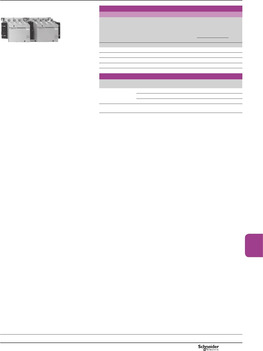
B9/9
High power
contactors
4-pole changeover contactor pairs (horizontally mounted) (1)
Pre-wired power connections
DF526098R.eps
Utilisation category AC-1
Non inductive loads
0D[LPXPRSHUDWLRQDOFXUUHQW
T < 40 °C
0D[LPXP
operational
voltage
Contactors
supplied without
coil (2)
Complete
reference
Weight
)L[LQJFDEOLQJ (3)
A V kg
LC2 F1854 200 1000 LC2F1154 8.860
250 1000 LC2F1504 8.860
275 1000 LC2F1854 12.100
315 1000 LC2F2254 15.200
350 1000 LC2F2654 19.480
Accessories (to be ordered separately)
Description For changeover
pairs
Quantity
required
Reference
Power terminal
protection shrouds
LC2 F1154 2 LA9F706
LC2 F1504, F1854 2 LA9F707
LC2 F2254, F2654 2 LA9F708
Auxiliary contact blocks
and add-on modules
– – See pages B9/10
to B9/14
(1))LWWHGZLWKDPHFKDQLFDOLQWHUORFNZLWKRXWHOHFWULFDOLQWHUORFNLQJ2UGHUVHSDUDWHO\DX[LOLDU\
contact blocks LAD Np1WRREWDLQHOHFWULFDOLQWHUORFNLQJEHWZHHQWKHFRQWDFWRUV
see page B9/11. For accessories, see pages B9/12 to B9/14.
(2) Coils to be ordered separately:
DFVXSSO\VHHSDJHV%WR%
GFVXSSO\VHHSDJHV%DQG%
(3)6FUHZ¿[LQJ
3RZHUWHUPLQDOVFDQEHSURWHFWHGDJDLQVWGLUHFW¿QJHUFRQWDFWE\WKHDGGLWLRQRIVKURXGV
to be ordered separately, see above.
TeSys contactors
TeSys F changeover contactors for motor
control in utilisation category AC-1
(200 to 350 A), pre-assembled
Control circuit: a.c. or d.c.
References
Selection:
pages B10/50 to B10/73
Dimensions:
pages B9/100 to B9/102
Schemes:
page B9/103
TeSys F
PCPB09P10-EN Version : 1.0 18 novembre 2014 12:55 PM
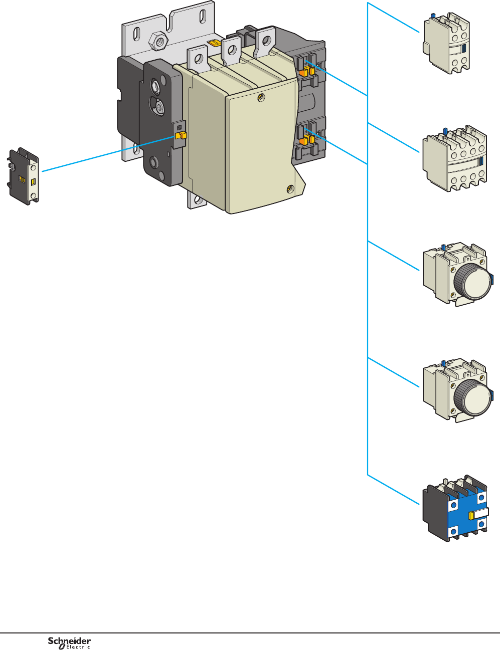
B9/10
LAD R
LAD T, LAD S
LC1 F
LAD N10, N01
LAD N
LAD N, LAD C
LA1 DX, DY, DZ
DB404210.eps
PCPB09P20-EN
Version : 1.0 18 novembre 2014 12:55 PM
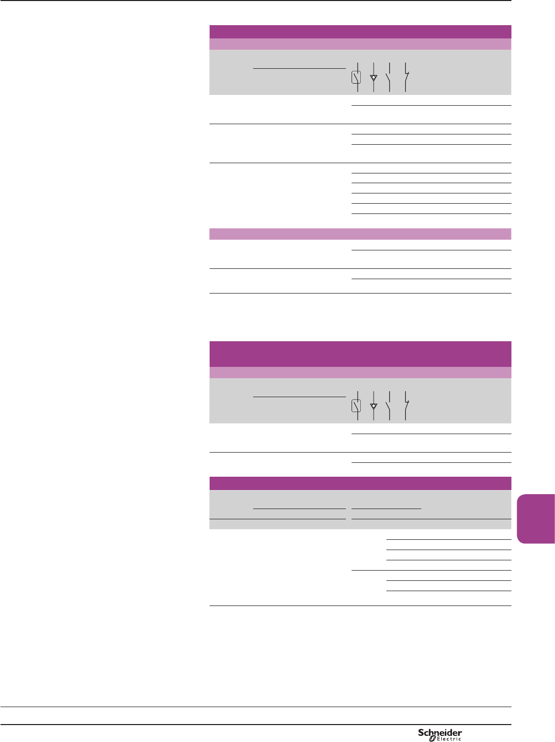
B9/11
High power
contactors
References
,QVWDQWDQHRXVDX[LOLDU\FRQWDFWEORFNV
For use in normal operating environments
Number
of
contacts
0D[LPXPQXPEHU
of blocks per contactor
Composition
Reference
Clip-on mounting
1 1 – – 1 – LADN10
– – – 1 LADN01
2 2 – – 1 1 LADN11
– – 2 – LADN20
– – – 2 LADN02
4 2 – – 2 2 LADN22
– – 1 3 LADN13
– – 4 – LADN40
– – – 4 LADN04
– – 3 1 LADN31
– – 2 2 (1) LADC22
With terminal referencing conforming to EN 50012
2 2 – – 1 1 LADN11P
– – 1 1 LADN11G
4 2 – – 2 2 LADN22P
– – 2 2 LADN22G
,QVWDQWDQHRXVDX[LOLDU\FRQWDFWEORFNVIRUFRQQHFWLRQE\OXJV
This type of connection is not possible for blocks with 1 contact or blocks with dust and damp
SURWHFWHGFRQWDFWV)RUDOORWKHULQVWDQWDQHRXVDX[LOLDU\FRQWDFWEORFNVDGGWKH¿JXUH6
to the end of the references selected above. Example: LAD N11 becomes LAD N116.
,QVWDQWDQHRXVDX[LOLDU\FRQWDFWEORFNVZLWKGXVWDQGGDPS
protected contacts
Recommended for use in particularly harsh industrial environments
Number
of
contacts
0D[LPXPQXPEHURI
blocks per contactor
Composition Reference
Clip-on mounting
2 2 2 – – – LA1DX20
2 2 (2) – – LA1DY20
4 2 2 – 2 – LA1DZ40
2 – 1 1 LA1DZ31
7LPHGHOD\DX[LOLDU\FRQWDFWEORFNV
Number
of
contacts
0D[LPXPQXPEHURI
blocks per contactor
Time delay Reference
Clip-on mounting Type Range
s
1 N/O
+
1 N/C
2 On-delay 0.1}3 (3) LADT0
0.1}30 LADT2
10}180 LADT4
1}30 (4) LADS2
Off-delay 0.1}3 (3 ) LADR0
0.1}30 LADR2
10}180 LADR4
(1),QFOXGLQJ121&PDNHEHIRUHEUHDN
(2)'HYLFH¿WWHGZLWKHDUWKVFUHHQFRQWLQXLW\WHUPLQDOV
(3):LWKH[WHQGHGVFDOHIURPWRV
(4):LWKVZLWFKLQJWLPHRIPVPVEHWZHHQRSHQLQJRIWKH1&FRQWDFWDQGFORVLQJ
RIWKH12FRQWDFW
TeSys contactors
TeSys F contactors
Auxiliary contact blocks
Presentation:
page B9/10
Schemes:
page B9/61
TeSys F
PCPB09P20-EN Version : 1.0 18 novembre 2014 12:55 PM

B9/12
References
813089.eps
/$' /$)ppp
Suppressor blocks
RC circuits (resistor-capacitor)
bEffective protection for circuits highly sensitive to "high frequency" interference.
For use only in cases where the voltage is virtually sinusoidal, i.e. less than 5 %
total harmonic distortion.
bVoltage limited to 3 Uc max. and oscillating frequency limited to 400 Hz max.
bSlight increase in drop-out time (1.1 to 1.3 times the normal time).
Mounting Uc Reference
Clip-on mounting on all ratings
and all a.c. coils.
a24}48 V LA4FRCE
50}110 V LA4FRCF
127}240 V LA4FRCP
265}415 V LA4FRCV
Suppressor block bracket LA9D09981
Varistors (peak limiting)
b Protection provided by limiting the transient voltage to 2 Uc max.
b Maximum reduction of transient voltage peaks.
Clip-on mounting on all ratings
and all coils.
a or c24}48 V LA4FVE
50}110 V LA4FVF
127}240 V LA4FVP
813087.eps
265}415 V LA4FVV
Diodes
b No overvoltage or oscillating frequencies.
b Increase in drop-out time (3 to 4 times the normal time).
b Polarised component.
Clip-on mounting on all ratings
and all d.c. coils.
c24}48 V LA4FDE
55}110 V LA4FDF
125}250 V LA4FDP
280}440 V LA4FDV
Bidirectional peak limiting diodes (transil)
b Protection provided by limiting the transient voltage to between 2 and 2.5 times
Uc max.
b Maximum reduction of transient voltage peaks.
LA9 Fp602 Clip-on mounting on all ratings
and all coils.
a or c24}48 V LA4FTE
50}110 V LA4FTF
127}240 V LA4FTP
265}415 V LA4FTV
813088.eps
Connection accessories
For use on 4-pole contactors Set of 4 links Weight
Set reference kg
Links for parallel connection of poles (in pairs)
LC1 F1154 LA9FF602 0.200
LC1 F1504, F1854 LA9FG602 0.350
LA9 Fp601 LC1 F2254, F2654, F3304, F4004 LA9FH602 1.000
LC1 F5004 LA9FK602 1.750
LC1 F6304 LA9FL602 3.000
Links for “star” connection of 3 poles
LC1 F115 LA9FF601 0.035
LC1 F150, F185 LA9FG601 0.050
813090.eps
LC1 F225, F265, F330, F400 LA9FH601 0.120
LC1 F500 LA9FK601 0.180
LC1 F630, F800 LA9FL601 0.550
Control circuit voltage take-off from power terminals
'=)$ For use with contactors Mounted on
bolt size
Sold in
lots of
Unit
reference
LC1 F115 M6 10 DZ3FA3
LC1 F150, F185 M8 10 DZ3GA3
LC1 F225…F500 M10 10 DZ3HA3
LC1 F630, F800 M12 10 DZ3JA3
TeSys contactors
TeSys F contactors
Suppressor blocks
Dimensions:
pages B9/57 and B9/58
TeSys F
PCPB09P20-EN
Version : 1.0 18 novembre 2014 12:55 PM

B9/13
High power
contactors
813091.eps
Right-angled connectors
For contactors or thermal overload relays
For use with With connector plates Set of 3 connectors
Contactors Thermal overload
relays (1)
Set reference Weight
Width Type kg
LA9 Fp981 LC1 F115 LR9 F5p67, LR9 F67 15 mm Rear LA9FF981 0.060
Side LA9FF979 0.240
Large
surface area
LA9FF980 0.150
813093.eps
LC1 F150,
F185
LR9 F5p69, F5p71,
LR9 F69, F71
20 mm Rear LA9FG981 0.080
Side LA9FG979 0.350
Large
surface area
LA9FG980 0.200
LC1 F225,
F265, F330,
F400
LR9 F7p75,LR9 F75 25 mm Rear LA9FJ981 0.430
Side LA9FJ979 0.750
LA9 Fp979 Large
surface area
LA9FJ980 0.490
LC1 F500 LR9 F7p79, F7p81,
LR9 F79, F81
30 mm Rear LA9FK981 0.480
DF510487.eps
Side LA9FK979 0.920
Large
surface area
LA9FK980 0.800
LC1 F630,
F800
LR9 F7p81,LR9 F81 40 mm Rear LA9FL981 1.210
Side LA9FL979 2.570
Large
surface area
LA9FL980 3.190
For use with With connector
plates
Set of 6 connectors
Contactors Set reference Weight
LA9 FL980 Width Type kg
LC1 F1250 60 mm Rear LA9F1250 5.480
DB402137.eps
LC1 F1400,
F1700, F2100
60 mm Rear LA9F2100 9.550
Connection accessories
For reversing contactors or "star-delta" contactors combined with a thermal
overload relay
For use with Width of
connector plates
Set of 3 busbars
Contactors Thermal overload
relays (1)
Set reference
LC1 F115 LR9 F5p57, F5p63
LR9 F5p67, F5p69
LR9 F69, F71
15 mm LA7F401
LC1 F150
and F185
LR9 F5p57, F5p63 20 mm LA7F402
LA9 F1250 LC1 F185 LR9 F5p71,
LR9 F71
25 mm LA7F407
LC1 F225
and F265
LR9 F5p71,
LR9 F71
25 mm LA7F403
DF569547.eps
LR9 F7p75, F7p79
LR9 F75, F79
25 mm LA7F404
LC1 F330
and F400
LR9 F7p75, F7p79
LR9 F75, F79
25 mm LA7F404
LC1 F400 LR9 F7p81,LR9 F81 25 mm LA7F404
LC1 F500 LR9 F7p75, F7p79
LR9 F7p81
LR9 F75, F79, F81
30 mm LA7F405
LC1 F630,
F800
LR9 F7p81,
LR9 F81
40 mm LA7F406
(1))RUSURWHFWLRQUHOD\VFODVVUHSODFHWKHpZLWKDDQGIRUFODVVUHSODFHWKHpZLWKD
LA9 F2100
TeSys contactors
TeSys F contactors
Accessories
References
Dimensions:
pages B9/57 and B9/58
TeSys F
PCPB09P20-EN Version : 1.0 18 novembre 2014 12:55 PM
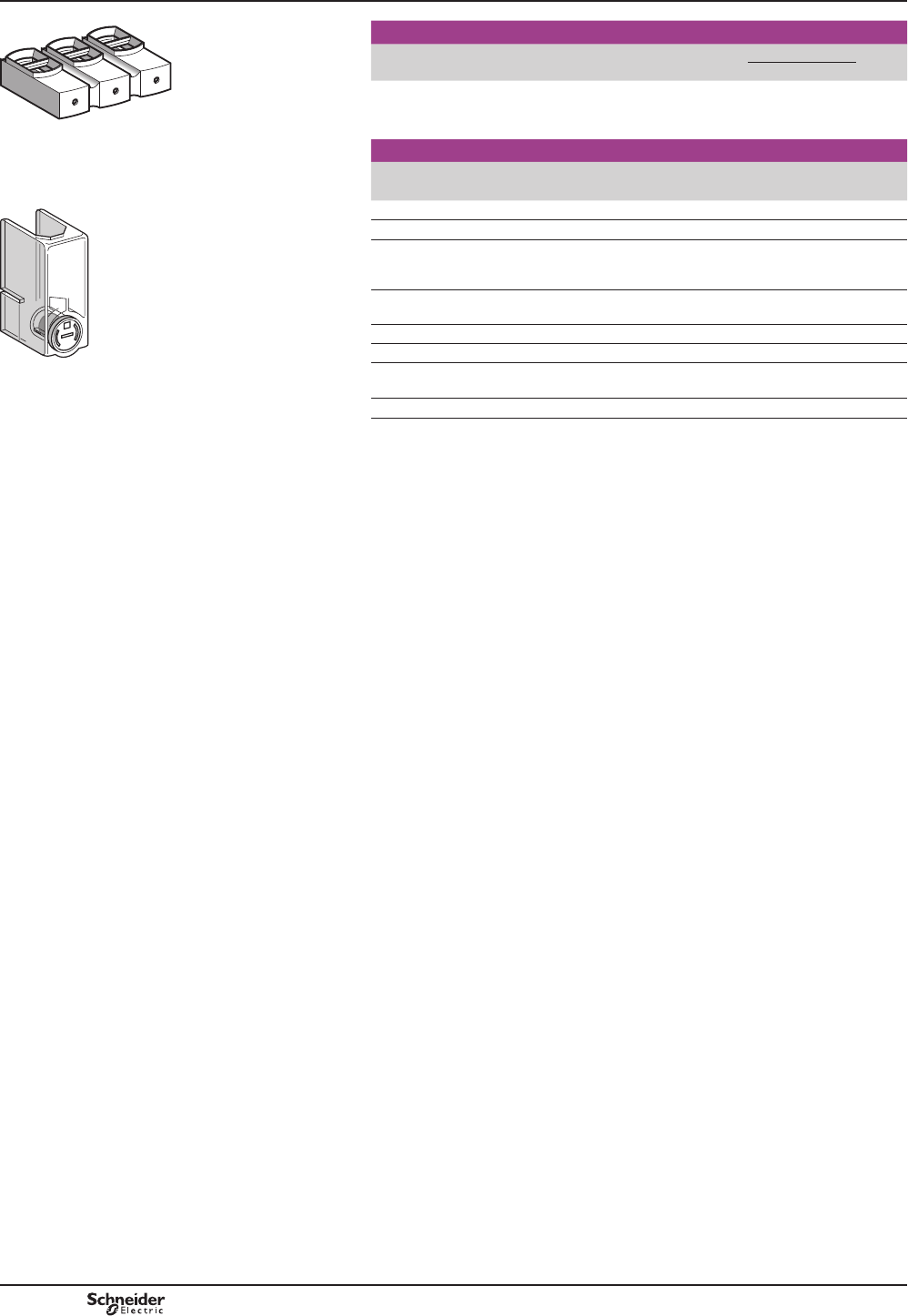
B9/14
References
813094.eps
LA9 F103
Insulated terminal blocks
For use on
3-pole contactors
Connection Tightening
tool
Set of 2 blocks
Set reference
LC1 F115, F150, F185 1 x 16}150 mm2
or
2 x 16}95 mm2
4 mm
hexagonal
socket key
LA9F103
Power terminal protection shrouds
For use on
2, 3 and 4-pole contactors
Number of
shrouds per set
Set reference
813095.eps
LC1 F115 6 LA9F701
LC1 F150, F185 6 LA9F702
LC1 F225, F265, F330,
F400 and F4002
F500 and F5002
6LA9F703
LC1 F630, F6302 and
F800
6LA9F704
LC1 F1154 8 LA9F706
LC1 F1504 and F1854 8 LA9F707
LA9 F701 LC1 F2254, F2654,
F3304, F4004, F5004
8LA9F708
LC1 F6304 8 LA9F709
TeSys contactors
TeSys F contactors
Accessories
TeSys F
PCPB09P20-EN
Version : 1.0 18 novembre 2014 12:55 PM
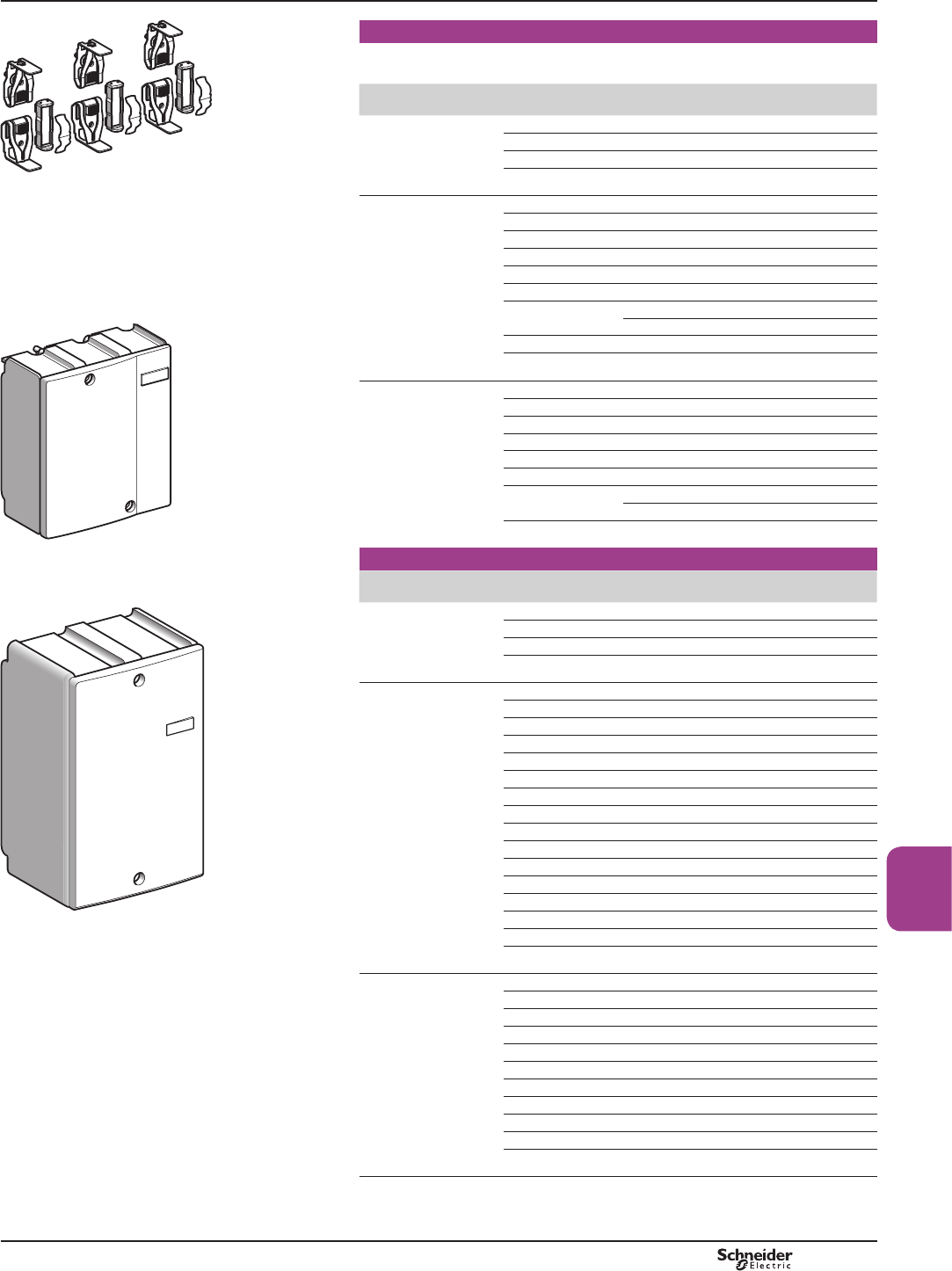
B9/15
High power
contactors
813096.eps
Sets of contacts
3HUSROH¿[HGFRQWDFWVPRYLQJFRQWDFWGHÀHFWRUVEDFNSODWHFODPSLQJ
screws and washers.
For contactor Type Replacement
for
Reference Weight
kg
2-pole LC1 F4002 2 poles LA5F400802 1.350
LC1 F5002 2 poles LA5F500802 1.950
LC1 F6302 2 poles LA5F630802 4.700
LC1 F6302S011 2 poles LA5F630802S011 4.800
LA5 FG431 3-pole LC1 F115. F150 3 poles LA5FF431 0.270
LC1 F185. F225 3 poles LA5FG431 0.350
LC1 F265 3 poles LA5FH431 0.660
LC1 F330. F400 3 poles LA5F400803 2.000
LC1 F500 3 poles LA5F500803 2.950
LC1 F630 3 poles LA5F630803 6.100
LC1 F780 1 pole LA5F780801 (1) 4.700
DF569555.eps
3 poles LA5F780803 13.200
LC1 F800 3 poles LA5F800803 6.100
LC1 F630S011 3 poles LA5F630803S011 6.200
4-pole LC1 F1504. F1154 4 poles LA5FF441 0.360
LC1 F1854. F2254 4 poles LA5FG441 0.465
LC1 F2654 4 poles LA5FH441 0.880
LC1 F3304. F4004 4 poles LA5F400804 2.700
LC1 F5004 4 poles LA5F500804 3.900
LC1 F6304 4 poles LA5F630804 8.150
LC1 F7804 1 pole LA5F780801 (1) 4.700
4 poles LA5F780804 17.300
LC1 F6304S011 4 poles LA5F630804S011 8.400
LA5 F40050 Arc chambers
For contactor Type Replacement
for
Reference Weight
kg
DF569556.eps
2-pole LC1 F4002 2 poles LA5F400250 0.870
LC1 F5002 2 poles LA5F500250 1.250
LC1 F6302 2 poles LA5F630250 2.100
LC1 F6302S011 2 poles LA5F630250 2.100
3-pole LC1 F115 3 poles LA5F11550 0.490
LC1 F150 3 poles LA5F15050 0.490
LC1 F185 3 poles LA5F18550 0.670
LC1 F225 3 poles LA5F22550 0.670
LC1 F265 3 poles LA5F26550 0.920
LC1 F330 3 poles LA5F33050 1.300
LC1 F400 3 poles LA5F40050 1.300
LC1 F500 3 poles LA5F50050 1.850
LC1 F630 3 poles LA5F63050 3.150
LC1 F780 1 pole LA5F780150 (1) 2.100
LC1 F800 3 poles LA5F80050 3.150
LC1 F630S011 3 poles LA5F63050 3.150
LC1 F1250 3 poles LA5F125050 3.150
LC1 F1400 6 poles LA5F140050 (2) 3.750
LA5 F210050 LC1 F1700 6 poles LA5F170050 (2) 3.750
LC1 F2100 6 poles LA5F210050 (2) 3.750
4-pole LC1 F1154 4 poles LA5F115450 0.660
LC1 F1504 4 poles LA5F150450 0.660
LC1 F1854 4 poles LA5F185450 0.910
LC1 F2254 4 poles LA5F225450 1.000
LC1 F2654 4 poles LA5F265450 1.220
LC1 F3304 4 poles LA5F330450 1.740
LC1 F4004 4 poles LA5F400450 (3) 1.740
LC1 F5004 4 poles LA5F500450 (3) 2.500
LC1 F6304 4 poles LA5F630450 (4) 4.200
LC1 F7804 1 pole LA5F780150 (1) 2.100
LC1 F6304S011 4 poles LA5F630450 4.200
(1) Comprising 2 identical items per pole.
(2)&RPSULVLQJWKUHHSROHDUFFKDPEHUV
(3)&RPSULVLQJWZRSROHDUFFKDPEHUV
(4)&RPSULVLQJVLQJOHSROHDUFFKDPEHUV
TeSys contactors
TeSys F contactors
Accessories
References
TeSys F
PCPB09P20-EN Version : 1.0 18 novembre 2014 12:55 PM
B9/16
TeSys contactors
Capacitive delayed opening devices
For TeSys F contactors
References
These devices prevent inadvertent opening of a contactor in the event of a brief volt
drop or momentary supply failure.
Control circuit : d.c. supply
For use with contactor Corresponding delayed opening device
Type With coil Supply
voltage
50/60 Hz
Non-
adjustable
delay time (Tr)
Reference
V s
LC1 F115
or
LC1 F150
LX4 FF110 110 2…5 LAZR90F
LX4 FF125 127 2…5 LAZR90F
LX4 FF220 220 2…5 LAZR90M
LX4 FF250 240 2…5 LAZR90M
LX4 FF375 380…415 2…5 LAZR90Q
LX4 FF440 440 2…5 LAZR90Q
LC1 F185
or
LC1 F225
LX4 FG110 110 2…5 LAZR90F
LX4 FG125 127 2…5 LAZR90F
LX4 FG220 220 2…5 LAZR90M
LX4 FG250 240 2…5 LAZR90M
LX4 FG375 380…415 2…5 LAZR90Q
LX4 FG440 440 2…5 LAZR90Q
LC1 F265
or
LC1 F330
LX4 FH110 110 2…5 LAZR90F
LX4 FH125 127 2…5 LAZR90F
LX4 FH220 220 2…5 LAZR90M
LX4 FH250 240 2…5 LAZR90M
LX4 FH375 380…415 2…5 LAZR90Q
LX4 FH440 440 2…5 LAZR90Q
LC1 F400 LX4 FJ110 110 1…2 LAZR90F
LX4 FJ125 127 1…2 LAZR90F
LX4 FJ220 220 1…2 LAZR90M
LX4 FJ250 240 1…2 LAZR90M
LX4 FJ375 380 1…2 LAZR90Q
LX4 FJ400 415 1…2 LAZR90Q
LX4 FJ440 440 1…2 LAZR90Q
LC1 F500 LX4 FK110 110 1…2 LAZR90F
LX4 FK125 127 1…2 LAZR90F
LX4 FK220 220 1…2 LAZR90M
LX4 FK250 240 1…2 LAZR90M
LX4 FK375 380 1…2 LAZR90Q
LX4 FK400 415 1…2 LAZR90Q
LX4 FK440 440 1…2 LAZR90Q
LC1 F630 LX4 FL110 110 1…2 LAZR90F
LX4 FL125 127 1…2 LAZR90F
LX4 FL220 220 1…2 LAZR90M
LX4 FL250 240 1…2 LAZR90M
LX4 FL375 380 1…2 LAZR90Q
LX4 FL400 415 1…2 LAZR90Q
LX4 FL440 440 1…2 LAZR90Q
Add-on blocks for delayed opening devices
Application For use with
delayed
opening device
Operational
voltage
Non-
adjustable
delay time
Reference
V s
To
double
the delay
time
LAZ R90F 110…127 Tr x 2 LAZR91F
LAZ R90M 220…240 Tr x 2 LAZR91M
LAZ R90Q 380…440 Tr x 2 LAZR91Q
Other versions
Delayed opening devices for use with other types of contactor. Please consult your
5HJLRQDO6DOHV2I¿FH
References
/$= 5)
PF511116-32-MR.eps
TeSys F
PCPB09P20-EN
Version : 1.0 18 novembre 2014 12:55 PM
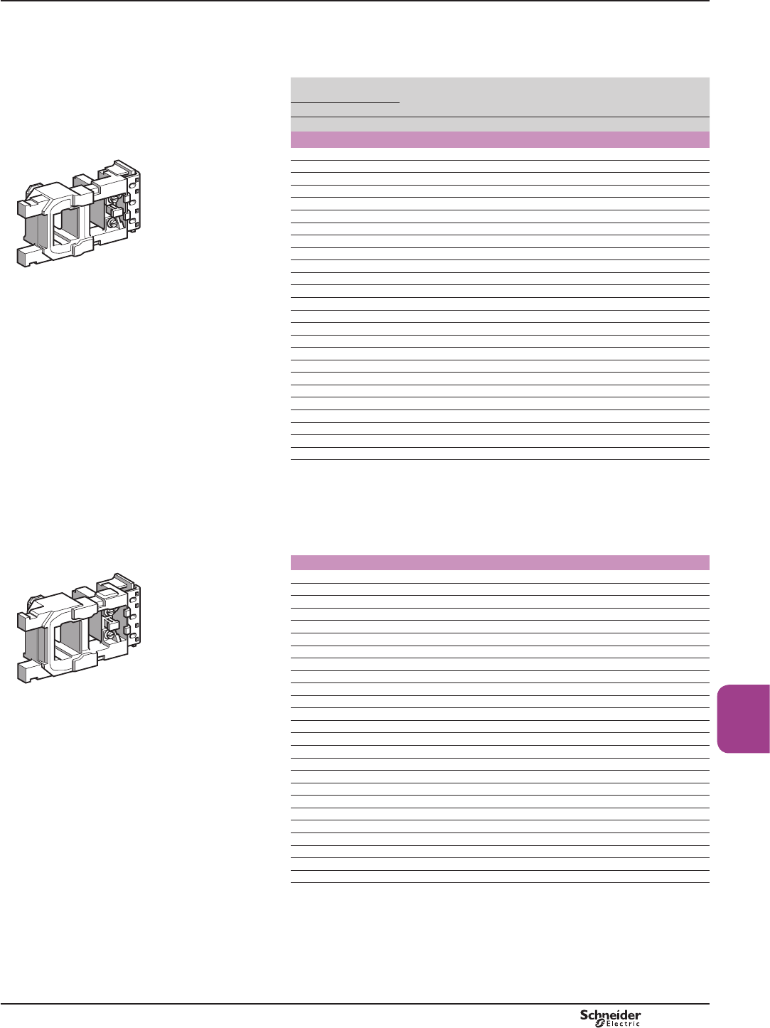
B9/17
High power
contactors
References
References
Maximum ambient air temperature: 55 °C. Above this, use an LX9 F coil,
see page B9/22.
Operating cycles/hour (Ty 55 °C): y2400.
Control circuit
voltage
Average
resistance at
20 °C ±10 %
Inductance
of closed
circuit
Voltage
code
Reference
Uc - 50 Hz Uc - 60 Hz
V V :H
For contactors LC1 F115 and LC1 F150
24 – 0.27 0.04 B5 LX1FF024
42 – 0.94 0.13 D5 LX1FF042
– 48 0.78 0.11 E6 LX1FF040
48 – 1.17 0.16 E5 LX1FF048
– 110 4.55 0.59 F6 LX1FF092
– 120 4.77 0.64 G6 LX1FF095
110 – 6.38 0.86 F5 LX1FF110
115 – 6.38 0.86 FE5 LX1FF110
127/132 – 9.14 1.15 G5 LX1FF127
– 200/208 14.5 1.87 L6 LX1FF162
– 220 18.4 2.38 M6 LX1FF184
– 240 18.9 2.5 U6 LX1FF187
220 265/277 28.1 3.44 M5 LX1FF220
230 – 28.1 3.44 P5 LX1FF220
240 – 31.1 4.1 U5 LX1FF240
– 380 57.2 7.05 Q6 LX1FF316
– 440 72.6 9.21 R6 LX1FF360
380 460/480 86.9 10.3 Q5 LX1FF380
400 – 86.9 10.3 V5 LX1FF380
415 – 95.1 12 N5 LX1FF415
500 – 141 17 S5 LX1FF500
– 660 172 20.3 Y6 LX1FF550
660/690 – 254 28.9 Y5 LX1FF660
– 1000 414 48.9 – LX1FF850
1000 – 610 68.5 – LX1FF1000
6SHFL¿FDtions
Average consumption at 20 °C:
binrush 50 Hz: 550 VA; 60 Hz: 660 VA
bsealed 50 Hz: 45 VA; 60 Hz: 55 VA, cos M= 0.3.
Heat dissipation: 12…16 W.
Operating time at Uc: closing = 23…35 ms, opening = 5…15 ms.
For contactors LC1 F185 and LC1 F225
24 – 0.18 0.03 B5 LX1FG024
42 – 0.57 0.09 – LX1FG042
– 48 0.47 0.08 E6 LX1FG040
48 – 0.71 0.12 E5 LX1FG048
– 110 2.74 0.44 F6 LX1FG092
– 115/120 2.87 0.49 G6 LX1FG095
110 – 4.18 0.65 F5 LX1FG110
115 – 4.18 0.65 FE5 LX1FG110
127/132 – 5.35 0.86 G5 LX1FG127
– 200/208 8.8 1.41 L6 LX1FG162
– 220 11.1 1.8 M6 LX1FG184
– 240 11.4 1.87 U6 LX1FG187
220 265/277 16.5 2.59 M5 LX1FG220
230 – 16.5 2.59 P5 LX1FG220
240 – 20.1 3.09 U5 LX1FG240
– 380 34 5.32 Q6 LX1FG316
– 440 43.5 6.94 R6 LX1FG360
380 460/480 51.3 7.75 Q5 LX1FG380
400 – 51.3 7.75 V5 LX1FG380
415 – 62.3 9.06 N5 LX1FG415
500 – 82.7 12.8 S5 LX1FG500
– 660 103 15.3 Y6 LX1FG550
660/690 – 154 21.8 Y5 LX1FG660
– 1000 249 36.6 – LX1FG850
1000 – 370 51.6 – LX1FG1000
6SHFL¿FDtions
Average consumption at 20 °C:
binrush 50 Hz: 805 VA; 60 Hz: 970 VA
bsealed 50 Hz: 55 VA; 60 Hz: 66 VA, cos M= 0.3.
Heat dissipation: 18…24 W.
Operating time at Uc: closing = 20…35 ms, opening = 7…15 ms.
TeSys contactors
TeSys F contactors
a.c. 50/60 Hz supply coils
LX1 FFppp
813181.eps
LX1 FGppp
813182.eps
TeSys F
PCPB09P20-EN Version : 1.0 18 novembre 2014 12:55 PM
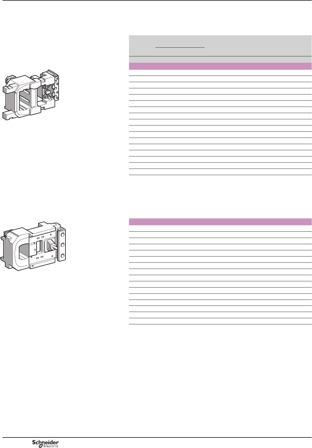
B9/18
References
Low sealed consumption.
Operate on networks with harmonic numbers y 7.
Operating cycles/hour (T y 55 °C): y 2400.
Control
circuit
voltage
Uc
Average resistance
at 20 °C ±10 %
Inductance
of closed
circuit
Voltage
code
Reference
Inrush Sealed
V: : H
For contactors LC1 F265 and LC1 F330
24 0.8 20 (1) B7 LX1FH0242
48 2.96 67 (1) E7 LX1FH0482
110 18.7 440 (1) F7 LX1FH1102
115 18.7 440 (1) FE7 LX1FH1102
120/127 22.9 536 (1) G7 LX1FH1272
200/208 58.4 1366 (1) L7 LX1FH2002
220 70.6 1578 (1) M7 LX1FH2202
230 70.6 1578 (1) P7 LX1FH2202
240 87.94 1968 (1) U7 LX1FH2402
277 113 2444 (1) W7 LX1FH2772
380 217 4631 (1) Q7 LX1FH3802
400 217 4631 (1) V7 LX1FH3802
415 217 4631 (1) N7 LX1FH3802
440 265 6731 (1) R7 LX1FH4402
480/500 329 8543 (1) S7 LX1FH5002
600/660 296 10245 (1) X7 LX1FH6002
1000 696 25880 (1) –LX1FH10002
6SHFL¿FDWLRQV
Average consumption at 20 °C for 50 or 60 Hz and cos M = 0.9:
binrush: 600…700 VA
bsealed: 8…10 VA.
Heat dissipation: 8 W.
Operating time at Uc: closing = 40…65 ms, opening = 100…170 ms.
For contactor LC1 F400
48 1.6 29.5 0.18 E7 LX1FJ048
110/120 9.8 230 1.35 F7 LX1FJ110
115 9.8 230 1.35 FE7 LX1FJ110
120/127 12.8 280 1.75 G7 LX1FJ127
200/208 30 815 4.1 L7 LX1FJ200
220 37 1030 5.1 M7 LX1FJ220
230 37 1030 5.1 P7 LX1FJ220
240 47.5 1320 6.4 U7 LX1FJ240
265/277 61 1700 8.1 W7 LX1FJ280
380 120 3310 15.8 Q7 LX1FJ380
400 120 3310 15.8 V7 LX1FJ380
415 145 4070 19.4 N7 LX1FJ415
440 145 4070 19.4 R7 LX1FJ415
500 190 4980 25.5 S7 LX1FJ500
550/600 243 6310 27.4 X7 LX1FJ600
1000 720 19420 84.6 – LX1FJ1000
6SHFL¿FDWLRQV
Average consumption at 20 °C for 50 or 60 Hz and cosM = 0.9:
b inrush: 1000…1150 VA
b sealed: 12…18 VA.
Heat dissipation: 14 W.
Operating time at Uc: closing = 40…75 ms, opening = 100…170 ms.
(1)3OHDVHFRQVXOW\RXU5HJLRQDO6DOHV2I¿FH
TeSys contactors
TeSys F contactors
a.c. 40 to 400 Hz supply coils
/;)+ppp2
813183.eps
LX1 FJppp
813184.eps
References
TeSys F
PCPB09P20-EN
Version : 1.0 18 novembre 2014 12:55 PM
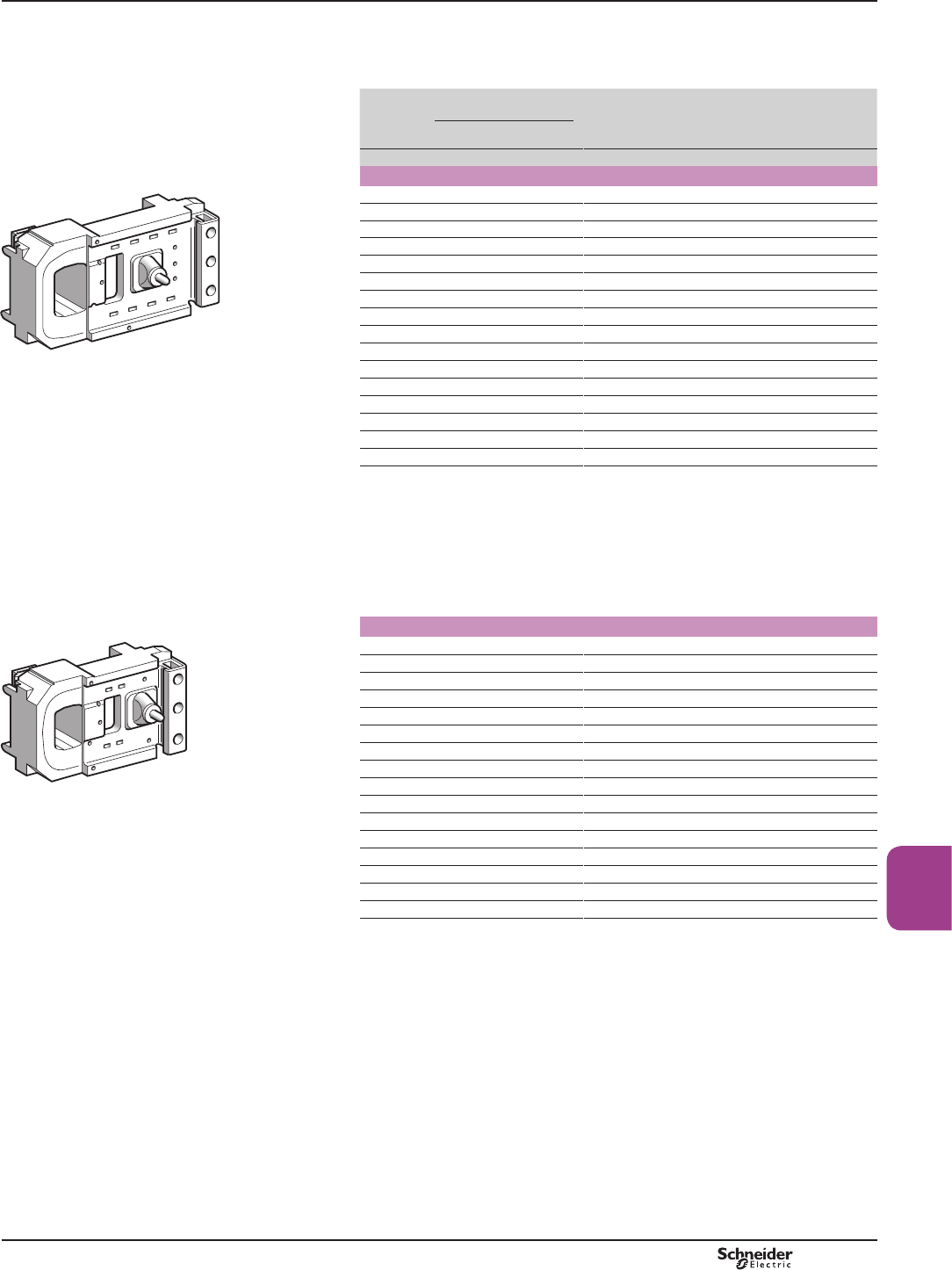
B9/19
High power
contactors
References
References
Low sealed consumption.
Operate on networks with harmonic numbers y 7.
Control
circuit
voltage
Uc
Average resistance
at 20 °C ±10 %
Inductance
of closed
circuit
Voltage
code
Reference Weight
Inrush Sealed
V: : H kg
For contactor LC1 F500
48 1.9 33.5 0.19 E7 LX1FK048 1.150
110/120 9.55 260 1.25 F7 LX1FK110 1.150
115 9.55 260 1.25 FE7 LX1FK110 1.150
120/127 11.5 315 1.5 G7 LX1FK127 1.150
200/208 29 735 3.75 L7 LX1FK200 1.150
220 35.5 915 4.55 M7 LX1FK220 1.150
230 35.5 915 4.55 P7 LX1FK220 1.150
240 44.5 1160 5.75 U7 LX1FK240 1.150
265/277 56.5 1490 7.3 W7 LX1FK280 1.150
380 112 2980 14.7 Q7 LX1FK380 1.150
400 112 2980 14.7 V7 LX1FK380 1.150
415 143 3730 18.4 N7 LX1FK415 1.150
440 143 3730 18.4 R7 LX1FK415 1.150
500 172 4590 22.8 S7 LX1FK500 1.150
550/600 232 5660 23.9 X7 LX1FK600 1.150
1000 679 16960 72 – LX1FK1000 1.150
6SHFL¿FDWLRQV
Average consumption at 20 °C for 50 or 60 Hz, cosM = 0.9:
binrush: 1050…1150 VA,
bsealed: 16…20 VA.
Operating cycles/hour (T y 55 °C): y 2400.
Heat dissipation: 18 W.
Operating time at Uc: closing = 40…75 ms, opening = 100…170 ms.
For contactor LC1 F630 and LC1 F1250
48 1.1 17.1 0.09 E7 LX1FL048 (1) 1.500
110/120 6.45 165 1.85 F7 LX1FL110 1.500
115 6.45 165 1.85 FE7 LX1FL110 1.500
127 8.1 205 1.05 G7 LX1FL127 1.500
200/208 20.5 605 2.65 L7 LX1FL200 1.500
220 25.5 730 3.35 M7 LX1FL220 1.500
230 25.5 730 3.35 P7 LX1FL220 1.500
240 25.5 730 3.35 U7 LX1FL220 1.500
265/277 31 900 4.1 W7 LX1FL260 1.500
380 78 2360 10.5 Q7 LX1FL380 1.500
400 78 2360 10.5 V7 LX1FL380 1.500
415 96 2960 13 N7 LX1FL415 1.500
440 96 2960 13 R7 LX1FL415 1.500
500 120 3660 16.5 S7 LX1FL500 1.500
550/600 155 4560 19.5 X7 LX1FL600 1.500
1000 474 12880 56.2 – LX1FL1000 (1) 1.500
(1),QFRPSDWLEOHZLWK/&)
6SHFL¿FDWLRQV
Average consumption at 20 °C for 50 or 60 Hz, cosM = 0.9:
binrush: 1500…1730 VA,
bsealed: 20…25 VA.
Operating cycles/hour (Ty 55 °C): 1200.
Heat dissipation: 20 W.
Operating time at Uc: closing = 40…80 ms, opening = 100…200 ms.
TeSys contactors
TeSys F contactors
a.c. 40 to 400 Hz supply coils
LX1 FKppp
813186.eps
LX1 FLppp
813187.eps
TeSys F
PCPB09P20-EN Version : 1.0 18 novembre 2014 12:55 PM
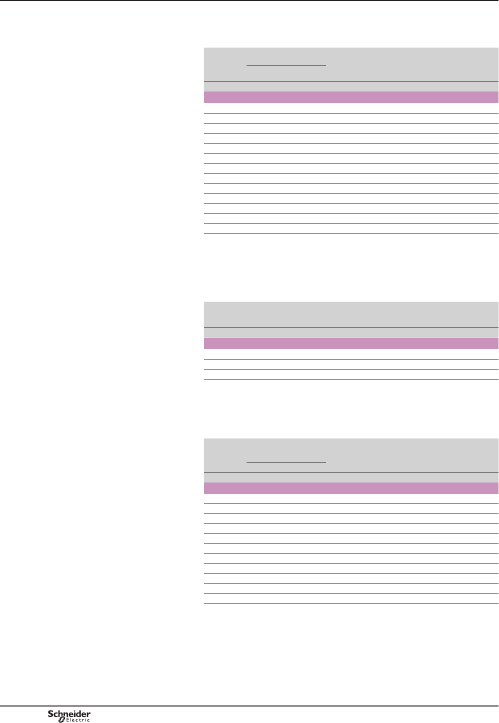
B9/20
References
Low sealed consumption.
Operate on networks with harmonic numbers y 7.
Control
circuit
voltage
Uc
Average resistance
at 20 °C ±10 %
Inductance
of closed
circuit
Voltage
code
Reference Weight
Inrush Sealed
V: : H kg
For contactor LC1 F780
110/120 4.95 (2) 230 (2) 0.21 F7 LX1FX110 (1) 3.000
115 4.95 (2) 230 (2) 0.21 FE7 LX1FX110 (1) 3.000
127 6.1 (2) 280 (2) 0.26 G7 LX1FX127 (1) 3.000
200/208 15.5 (2) 750 (2) 0.66 L7 LX1FX200 (1) 3.000
220 19.5 (2) 920 (2) 0.82 M7 LX1FX220 (1) 3.000
230 19.5 (2) 920 (2) 0.82 P7 LX1FX220 (1) 3.000
240 19.5 (2) 920 (2) 0.82 U7 LX1FX220 (1) 3.000
265/277 29.8 (2) 1330 (2) 1.25 W7 LX1FX280 (1) 3.000
380 60.9 (2) 2780 (2) 2.3 Q7 LX1FX380 (1) 3.000
400 60.9 (2) 2780 (2) 2.3 V7 LX1FX380 (1) 3.000
415/480 74.3 (2) 3340 (2) 2.8 N7 LX1FX415 (1) 3.000
440 74.3 (2) 3340 (2) 2.8 R7 LX1FX415 (1) 3.000
500 92 (2) 4180 (2) 3.5 S7 LX1FX500 (1) 3.000
6SHFL¿FDWLRQV
Average consumption at 20 °C for 50 or 60 Hz, cos M = 0.9:
binrush: 1900…2300 VA, sealed: 44…55 VA.
Operating cycles/hour (Ty 55 °C): 600.
Heat dissipation: 2 x 22 W.
Operating time at Uc: closing = 40…80 ms, opening = 130…230 ms.
Control circuit
voltage
Uc
Voltage
code
5HFWL¿HU
Reference (3)
Coil
Reference
Weight
V kg
For contactor LC1 F800
110/127 FE7 DR5TE4U LX4F8FW 1.650
220/240 P7 DR5TE4U LX4F8MW 1.650
380/440 V7 DR5TE4S LX4F8QW 1.650
6SHFL¿FDWLRQV
Operating cycles/hour (Ty 55 °C): 600.
Average consumption at 20 °C for 50 or 60 Hz, cos M = 0.8:
binrush: 1700 VA, sealed: 12 VA.
Operating time at Uc: closing = 60…80 ms, opening = 160…180 ms.
Control
circuit
voltage
Uc
Average resistance
at 20 °C ±10 %
Inductance
of closed
circuit
Voltage
code
Reference Weight
Inrush Sealed
V: : H kg
For contactors LC1 F1400, LC1 F1700 and LC1 F2100
110 5.92 106 0.72 F7 LX1FK065 (4) 1.150
120 5.92 106 0.72 G7 LX1FK070 (4) 1.150
220 9.55 260 1.25 M7 LX1FK110 (4) 1.150
230 9.55 260 1.25 P7 LX1FK110 (4) 1.150
240 11.5 315 1.50 U7 LX1FK127 (4) 1.150
277 16.5 420 2.25 W7 LX1FK140 (4) 1.150
380 29 735 3.75 Q7 LX1FK200 (4) 1.150
400 29 735 3.75 V7 LX1FK200 (4) 1.150
415 35.5 915 4.55 N7 LX1FK220 (4) 1.150
440 35.5 915 4.55 R7 LX1FK220 (4) 1.150
500 44.5 1160 5.75 S7 LX1FK240 (4) 1.150
6SHFL¿FDWLRQV
Average consumption at 20 °C for 50 or 60 Hz, cos M = 0.9:
binrush: 1600…2400 VA, sealed: 29…37 VA.
Operating cycles/hour (Ty 55 °C): 600.
Heat dissipation: 2 x 18 W.
Operating time at Uc: closing = 40…75 ms, opening = 100…170 ms.
(1)5HIHUHQFHRIVHWRILGHQWLFDOFRLOVWREHFRQQHFWHGLQVHULHV
(2)9DOXHIRUWKHFRLOVLQVHULHV
(3)5HFWL¿HUWREHRUGHUHGVHSDUDWHO\NJ
(4)2UGHUFRLOVDQGFRQQHFWWKHPLQVHULHV
References TeSys contactors
TeSys F contactors
a.c. 40 to 400 Hz supply coils
TeSys F
PCPB09P20-EN
Version : 1.0 18 novembre 2014 12:55 PM
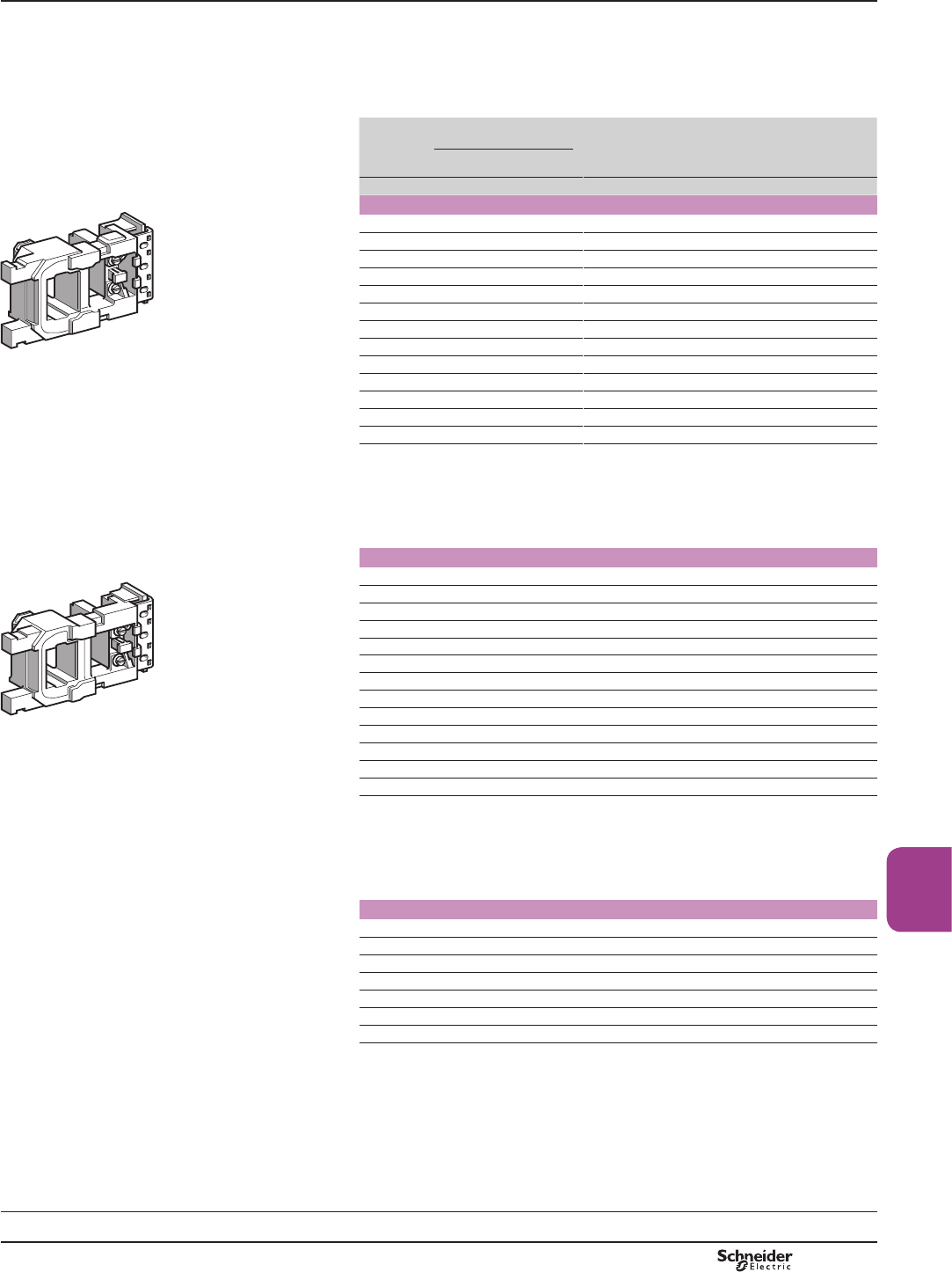
B9/21
High power
contactors
References
References
Low sealed consumption.
High tolerance to inrush voltage drops.
Immune to micro-breaks (mains supply or contact chain).
Operate on networks with harmonic numbers y 7.
Control
circuit
voltage
Uc
Average resistance
at 20 °C ±10 %
Inductance
of closed
circuit
Voltage
code
Reference Weight
Inrush Sealed
V: : H
For contactors LC1 F115 and LC1 F150
48 3.03 80.2 0.3 E7 LX9FF048
110 14.8 579 2.08 F7 LX9FF110
115 14.8 579 2.08 FE7 LX9FF110
120/127 19 746 2.65 G7 LX9FF127
208 45 1788 5.95 L7 LX9FF200
220 59.4 2190 7.7 M7 LX9FF220
230 59.4 2190 7.7 P7 LX9FF220
240 73.5 2750 9.68 U7 LX9FF240
380 173 6540 23 Q7 LX9FF380
400 173 6540 23 V7 LX9FF380
415 218 8460 30 N7 LX9FF415
440 218 8460 30 R7 LX9FF415
500 262 10300 36 S7 LX9FF500
6SHFL¿FDWLRQV
Average consumption at 20 °C: inrush: 690…855 VA, sealed: 6.6…8.1 VA.
Heat dissipation: 5.9…7.2 W.
Operating cycles/hour (Ty 55 °C): < 2400.
Operating time at Uc: closing = 35 ms, opening = 130 ms.
For contactors LC1 F185 and LC1 F225
48 2.2 60 0.23 E7 LX9FG048
110 10.4 411 1.46 F7 LX9FG110
115 10.4 411 1.46 FE7 LX9FG110
120/127 13 520 1.85 G7 LX9FG127
208 33 1339 4.9 L7 LX9FG200
220 42.1 1680 5.84 M7 LX9FG220
230 42.1 1680 5.84 P7 LX9FG220
240 50.6 2060 7.22 U7 LX9FG240
380 128 4730 16.4 Q7 LX9FG380
400 128 4730 16.4 V7 LX9FG380
415 157 5930 20.6 N7 LX9FG415
440 157 5930 20.6 R7 LX9FG415
500 194 7550 26.3 S7 LX9FG500
6SHFL¿FDWLRQV
Average consumption at 20 °C: inrush: 950…1180 VA, sealed: 8.9…10.9 VA.
Heat dissipation: 8…9.8 W.
Operating cycles/hour (Ty 55 °C): < 2400.
Operating time at Uc: closing = 35 ms, opening = 130 ms.
For contactors LC1 F265 and LC1 F330
48 2.96 72 (2) – LX9FH0482
110/115 18.7 415 (2) – LX9FH1102
120/127 22.9 156 (2) – LX9FH1272
220/230 71.6 1621 (2) – LX9FH2202
240 88 1968 (2) – LX9FH2402
380/415 222 5075 (2) – LX9FH3802
500 345 7990 (2) – LX9FH5002
6SHFL¿FDWLRQV
Average consumption at 20 °C: inrush: 560…660 VA, sealed: 8…10 VA.
Heat dissipation: 8.4…10.4 W.
Operating cycles/hour (Ty 55 °C): < 3600.
Operating time at Uc: closing = 45 ms, opening = 25 ms.
(1)$SSOLFDWLRQH[DPSOHVKRLVWLQJLQFKLQJKLJKRSHUDWLQJUDWHV0DLQ6WDQGE\XQVWDEOHPDLQV
VXSSOLHV7KHVHFRLOVDUHSDUWLFXODUO\VXLWHGIRUXVHDWKLJKHURSHUDWLQJWHPSHUDWXUHV
PRXQWLQJLQQRQYHQWLODWHGFRPSDUWPHQWVHQFORVXUHVHWF
(2)3OHDVHFRQVXOW\RXU5HJLRQDO6DOHV2I¿FH
TeSys contactors
TeSys F contactors
a.c. 40 to 400 Hz supply coils for specific
applications (1)
LX9 FFppp
813188.eps
LX9 FGppp
813189.eps
Schemes:
page 9/60
TeSys F
PCPB09P20-EN Version : 1.0 18 novembre 2014 12:55 PM
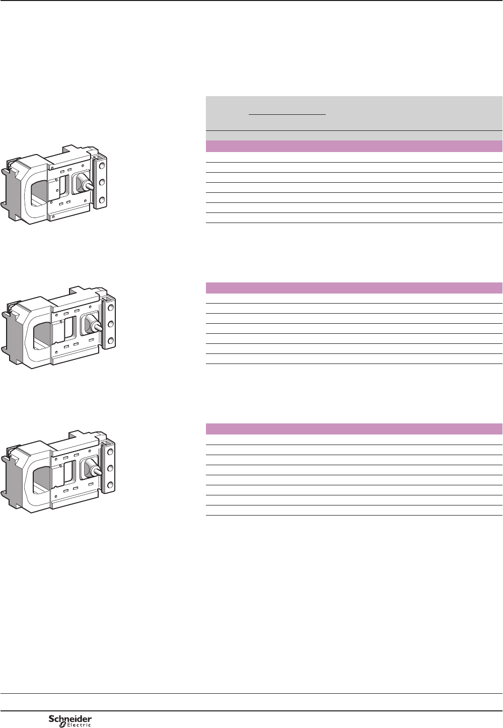
B9/22
References
Coils with short operating times (at Uc):
bN/O: 60 ms
bN/C: 50 ms (a side); 20 ms (c side).
Coils with high operating rates (T y 70 °C):
b3600 operating cycles/hour
b1800 for LC1 F630.
Coils with low inrush consumption.
Control
circuit
voltage
Uc
Average resistance
at 20 °C ±10 %
Inductance
of closed
circuit
5HFWL¿HU
Reference
(1)
Coil Reference Weight
Inrush Sealed
V: : H kg
For contactor LC1 F400
48 4.03 43 0.22 DR5TF4V LX9FJ917 0.970
110 25.7 246 1.3 DR5TE4U LX9FJ925 0.970
127 32.3 302 1.7 DR5TE4U LX9FJ926 0.970
220/230 99.5 919 5 DR5TE4U LX9FJ931 0.970
380/415 311 3011 15 DR5TE4S LX9FJ936 0.970
440 386 3690 19 DR5TE4S LX9FJ937 0.970
500 478 4380 23 DR5TE4S LX9FJ938 0.970
6SHFL¿FDWLRQV
Average consumption:
binrush: 500 VA
bsealed: 23 VA.
Heat dissipation: 11.4…13.9 W.
For contactor LC1 F500
48 3.73 30.7 0.18 DR5TF4V LX9FK917 1.080
110 24 204 1.1 DR5TE4U LX9FK925 1.080
127 29.8 250 1.4 DR5TE4U LX9FK926 1.080
220/230 89.9 770 4 DR5TE4U LX9FK931 1.080
380/415 274 2075 12 DR5TE4S LX9FK936 1.080
440 361 3060 16 DR5TE4S LX9FK937 1.080
500 448 3750 19 DR5TE4S LX9FK938 1.080
6SHFL¿FDWLRQV
Average consumption:
binrush: 550 VA
bsealed: 31 VA.
Heat dissipation: 15…18.3 W.
For contactor LC1 F630
48 2.81 20.8 0.17 DR5TF4V LX9FL917 1.450
110 13.5 114 0.77 DR5TE4U LX9FL924 1.450
127 20.8 167 1.2 DR5TE4U LX9FL926 1.450
220 52 425 2.9 DR5TE4U LX9FL930 1.450
220/240 64.5 518 3.6 DR5TE4U LX9FL931 1.450
380/400 163 1360 8.8 DR5TE4S LX9FL935 1.450
415/440 204 1670 11 DR5TE4S LX9FL936 1.450
500 312 2510 17 DR5TE4S LX9FL938 1.450
6SHFL¿FDWLRQV
Average consumption:
binrush: 830 VA
bsealed: 47 VA.
Heat dissipation: 22.8…27.8 W.
(1)5HFWL¿HUWREHRUGHUHGVHSDUDWHO\NJ
LX9 FJppp
813190.eps
LX9 FKppp
813191.eps
LX9 FLppp
813191.eps
References TeSys contactors
TeSys F contactors
a.c. 40 to 400 Hz supply coils for specific
applications (1)
Schemes:
page 9/60
TeSys F
PCPB09P20-EN
Version : 1.0 18 novembre 2014 12:55 PM
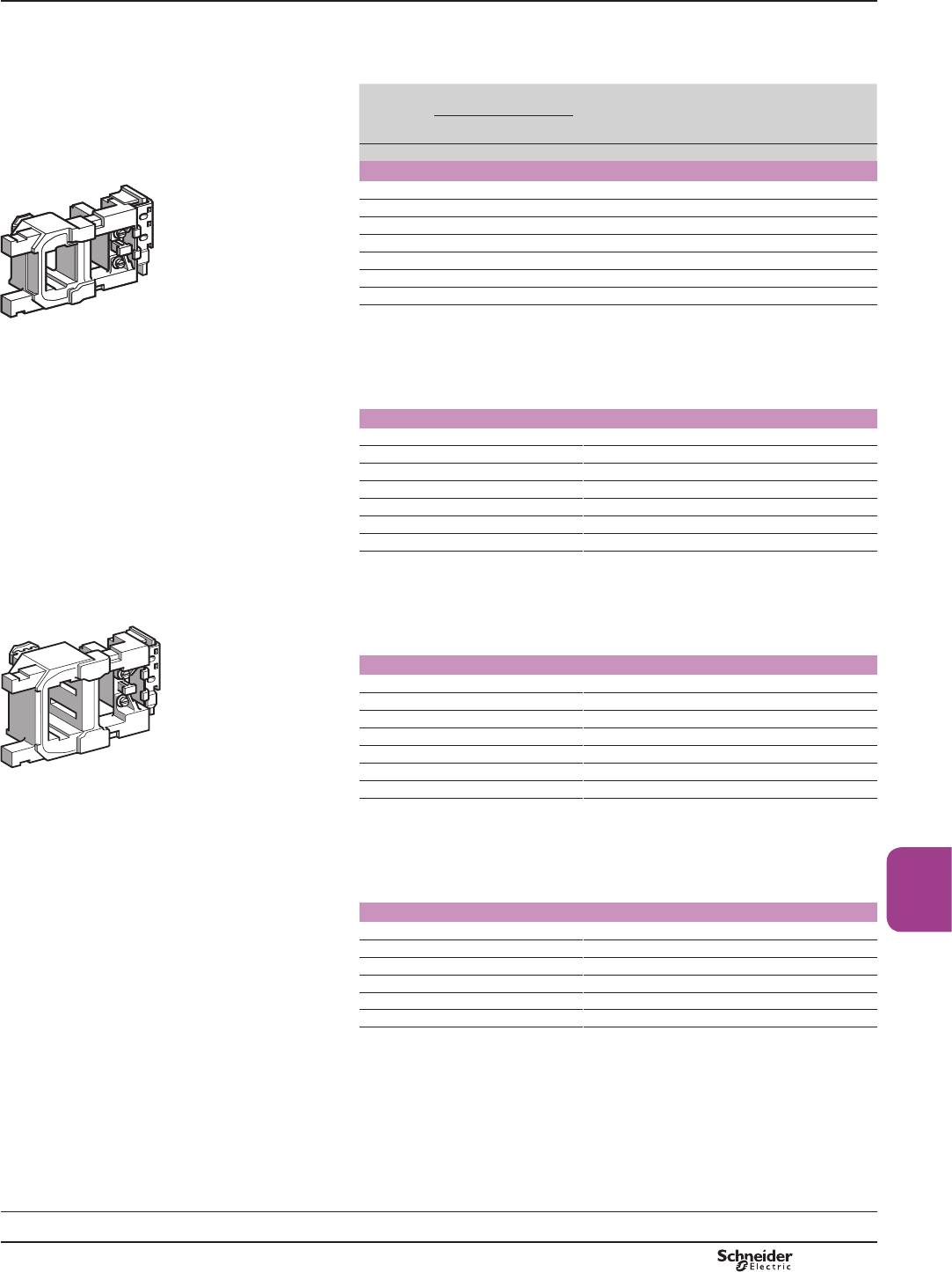
B9/23
High power
contactors
References
References
Low sealed consumption.
Operating cycles/hour (Ty 55 °C): y 2400.
Control
circuit
voltage
Uc
Average resistance
at 20 °C ±10 %
Inductance
of closed
circuit
Voltage
code
Reference
Inrush Sealed
V: : H
For contactors LC1 F115 and LC1 F150
24 1.12 177 11 BD LX4FF024
48 4.52 715 42.7 ED LX4FF048
110 21.7 2940 179 FD LX4FF110
125 26.8 3560 223 GD LX4FF125
220/230 84 11100 704 MD LX4FF220
250 105 13000 868 UD LX4FF250
440/460 301 48200 4000 RD LX4FF440
6SHFL¿FDWLRQV
Average consumption:
binrush: 543…665 W,
bsealed: 3.94…4.83 W.
Operating time at Uc: closing = 30…40 ms, opening = 30…50 ms.
For contactors LC1 F185 and LC1 F225
24 0.79 169 14.9 BD LX4FG024
48 3.2 662 55.3 ED LX4FG048
110 14.9 2810 241 FD LX4FG110
125 19 3320 289 GD LX4FG125
220/230 57.7 10200 890 MD LX4FG220
250 76 12400 1140 UD LX4FG250
440/460 223 39700 4210 RD LX4FG440
6SHFL¿FDWLRQV
Average consumption:
binrush: 737…902 W,
bsealed: 4.13…5.07 W.
Operating time at Uc: closing = 30…40 ms, opening = 30…50 ms.
For contactors LC1 F265 and LC1 F330
24 0.9 192 26.3 BD LX4FH024
48 3.49 707 92.9 ED LX4FH048
110 16.8 3180 424 FD LX4FH110
125 20.8 3840 530 GD LX4FH125
220/230 65.7 11500 1590 MD LX4FH220
250 84 13900 1910 UD LX4FH250
440/460 255 44000 7570 RD LX4FH440
6SHFL¿FDWLRQV
Average consumption:
binrush: 655…803 W,
bsealed: 3.68…4.53 W.
Operating time at Uc: closing = 40…50 ms, opening = 40…65 ms.
For contactor LC1 F400
48 2.5 558 56 ED LX4FJ048
110 12.7 2660 270 FD LX4FJ110
125 15.8 3130 330 GD LX4FJ125
220 47 8820 910 MD LX4FJ220
250 61 10500 1200 UD LX4FJ250
440 236 33750 4435 RD LX4FJ440
6SHFL¿FDWLRQV
Average consumption:
binrush: 920…1140 W,
bsealed: 4…7.5 W.
Operating time at Uc: closing = 50…60 ms, opening = 45…60 ms.
TeSys contactors
TeSys F contactors
d.c. supply coils
LX4 FFppp
813193.eps
/;)+ppp
813192.eps
Schemes:
page 9/60
TeSys F
PCPB09P20-EN Version : 1.0 18 novembre 2014 12:55 PM
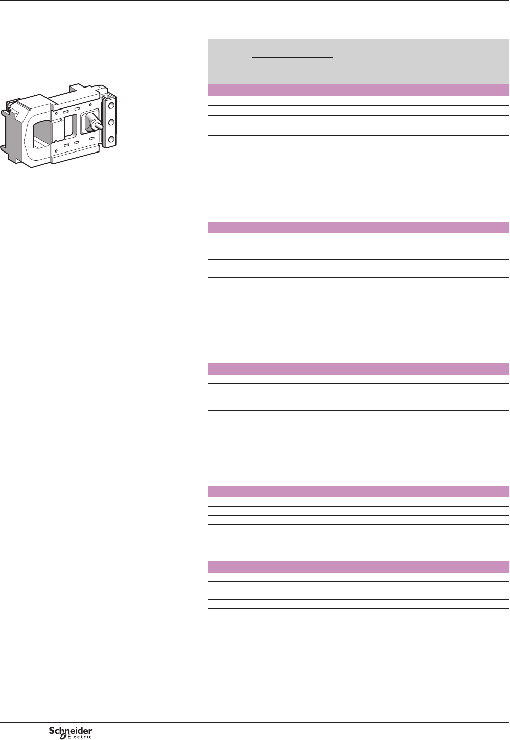
B9/24
References
Low sealed consumption.
Control
circuit
voltage
Uc
Average resistance
at 20 °C ±10 %
Inductance
of closed
circuit
Voltage
code
Reference Weight
Inrush Sealed
V: : H kg
For contactor LC1 F500
48 2.35 515 67 ED LX4FK048 1.080
110 11.5 2450 280 FD LX4FK110 1.080
125 15 2930 400 GD LX4FK125 1.080
220 44 8150 1080 MD LX4FK220 1.080
250 56 9650 1350 UD LX4FK250 1.080
440 225 31300 5270 RD LX4FK440 1.080
6SHFL¿FDWLRQV
Average consumption:
binrush: 990…1220 W,
bsealed: 4.54…8 W.
Operating cycles/hour (Ty 55 °C): 2400.
Operating time at Uc: closing = 50…60 ms, opening = 45…60 ms.
For contactor LC1 F630 and LC1 F1250
48 1.7 353 40.5 ED LX4FL048 1.450
110 8.1 1680 180 FD LX4FL110 1.450
125 10 2110 230 GD LX4FL125 (1) 1.450
220 31 5160 650 MD LX4FL220 1.450
250 38 6080 815 UD LX4FL250 1.450
440 152 23120 2910 RD LX4FL440 (1) 1.450
(1),QFRPSDWLEOHZLWK/&)
6SHFL¿FDWLRQV
Average consumption:
binrush: 1420…1920 W,
bsealed: 6.5…12.5 W.
Operating cycles/hour (Ty 55 °C): 1200.
Operating time at Uc: closing = 60…70 ms, opening = 40…50 ms.
For contactor LC1 F780
110 6.1 (2) 280 (3) 0.26 FD LX4FX110 (2) 3.000
125 7.7 (2) 410 (3) 0.33 GD LX4FX125 (2) 3.000
220 24.6 (2) 1100 (3) 1 MD LX4FX220 (2) 3.000
250 29.8 (2) 1330 (3) 1.25 UD LX4FX250 (2) 3.000
440 92 (2) 4180 (3) 3.5 RD LX4FX440 (2) 3.000
6SHFL¿FDWLRQV
Average consumption:
binrush: 1960…2420 W
bsealed: 42…52 W.
Operating cycles/hour (Ty 55 °C): 600.
Operating time at Uc: closing = 70…80 ms, opening = 100…130 ms.
For contactor LC1 F800
110/120 – – – FW LX4F8FW 1.650
220/240 – – – MW LX4F8MW 1.650
380/400 – – – QW LX4F8QW 1.650
6SHFL¿FDWLRQV
Heat dissipation: 25 W.
Operating time at Uc: closing = 60…80 ms, opening = 40…50 ms.
For contactors LC1 F1400, LC1 F1700 and LC1 F2100
110 2.94 734 98 FD LX4FK055 (4) 1.080
125 3.73 916 122 GD LX4FK065 (4) 1.080
220 11.5 2450 280 MD LX4FK110 (4) 1.080
250 15 2930 400 UD LX4FK125 (4) 1.080
440 44 8150 1080 RD LX4FK220 (4) 1.080
6SHFL¿FDWLRQV
Average consumption:
binrush: 2000…2200 W,
bsealed: 8…10 W.
Operating cycles/hour (Ty 55 °C): 600.
Operating time at Uc: closing = 50…60 ms, opening = 45…60 ms.
(2)5HIHUHQFHRIVHWRILGHQWLFDOFRLOVWREHFRQQHFWHGLQVHULHV
(3)9DOXHIRUWKHFRLOVLQVHULHV
(4)2UGHUFRLOVDQGFRQQHFWWKHPLQVHULHV
LX4 FKppp
813194.eps
References TeSys contactors
TeSys F contactors
d.c. supply coils
Schemes:
page 9/60
TeSys F
PCPB09P20-EN
Version : 1.0 18 novembre 2014 12:55 PM
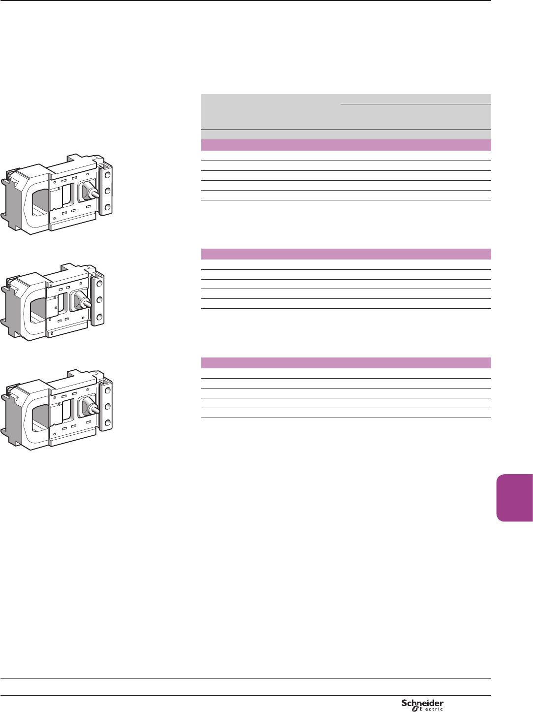
B9/25
High power
contactors
References
References
Coils with short operating times (at Uc):
bN/O: 60 ms
bN/C: 20 ms.
Coils with high operating rates (T y 70 °C):
b3600 operating cycles/hour
b1800 for LC1 F630.
Coils with low inrush consumption.
Control
circuit
voltage
Uc
Average
resistance
at 20 °C ±10 %
Induc-
tance of
closed
circuit
Resistor (1) Coil
Qty
required
Reference Reference Weight
Inrush Sealed
V: : H kg
For contactor LC1 F400
48 5.11 99 0.27 1 DR2SC0047 LX9FJ918 0.970
110 32.3 632 1.7 1 DR2SC0330 LX9FJ926 0.970
125 39.4 760 2 1 DR2SC0390 LX9FJ927 0.970
220 123 2320 6.1 1 DR2SC1200 LX9FJ932 0.970
440/460 478 9080 23 1 DR2SC4700 LX9FJ938 0.970
6SHFL¿FDWLRQV
Average consumption:
binrush: 430 W
bsealed: 22 W.
For contactor LC1 F500
48 4.67 76.7 0.22 1 DR2SC0039 LX9FK918 1.080
110 29.8 470 1.4 1 DR2SC0220 LX9FK926 1.080
125 37.4 637 1.7 1 DR2SC0330 LX9FK927 1.080
220 115 1935 5.1 1 DR2SC1000 LX9FK932 1.080
440/460 448 7050 19 1 DR2SC3300 LX9FK938 1.080
6SHFL¿FDWLRQV
Average consumption:
binrush: 470 W
bsealed: 29 W.
For contactor LC1 F630
48 3.43 52.9 0.20 2 DR2SC0047 LX9FL918 1.450
110 17.2 272 0.98 2 DR2SC0270 LX9FL925 1.450
125 20.8 333 1.2 2 DR2SC0330 LX9FL926 1.450
220 64.5 1018 3.6 2 DR2SC1000 LX9FL931 1.450
440/460 260 4010 14 2 DR2SC3900 LX9FL937 1.450
6SHFL¿FDWLRQV
Average consumption:
binrush: 733 W
bsealed: 48 W.
(1)5HVLVWRUWREHRUGHUHGVHSDUDWHO\ZHLJKWRIUHVLVWRUNJ
TeSys contactors
TeSys F contactors
d.c. supply coils for specific applications
LX9 FJppp
813194.eps
LX9 FKppp
813196.eps
LX9 FLppp
813195.eps
Schemes:
page 9/60
TeSys F
PCPB09P20-EN Version : 1.0 18 novembre 2014 12:55 PM
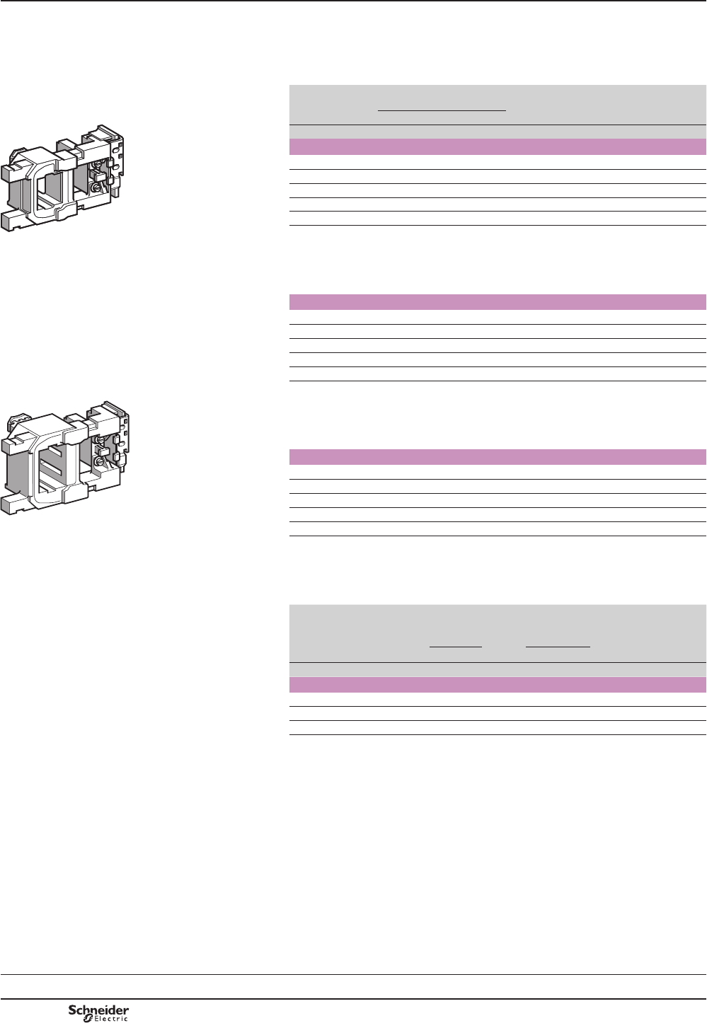
B9/26
References
References
Wide range coils: 0.7…1.25 Uc.
Operating cycles/hour: y 60 (1).
Ambient temperature (operation): -55 to + 70 °C.
Control
circuit voltage
Uc
Average resistance
at 20 °C ±10 %
Inductance
of closed
circuit
Reference
Inrush Sealed
V: : H
For contactors LC1 F115 and LC1 F150
24 0.71 120 7.4 LX4FF020
48 2.86 392 27 LX4FF040
72 7.05 1055 66 LX4FF060
110 13.2 1970 121 LX4FF090
125 16.9 2340 149 LX4FF100
6SHFL¿FDWLRQV
Average consumption:
binrush: 415…1300 W
bsealed: 3…9 W.
For contactors LC1 F185 and LC1 F225
24 0.52 112 9.3 LX4FG020
48 2 359 34.4 LX4FG040
72 5.07 984 85 LX4FG060
110 9.66 1840 157 LX4FG090
125 12 2230 196 LX4FG100
6SHFL¿FDWLRQV
Average consumption:
binrush: 580…1820 W
bsealed: 3.1…9.5 W.
For contactors LC1 F265 and LC1 F330
24 0.58 129 17.3 LX4FH020
48 2.19 400 59.5 LX4FH040
72 5.58 1110 149 LX4FH060
110 11 2120 287 LX4FH090
125 13.8 2520 353 LX4FH100
6SHFL¿FDWLRQV
Average consumption:
binrush: 515…1600 W
bsealed: 2.7…8.5 W.
Opera-
tional
voltage
Average
resistance
at 20 °C
±10 %
Induc-
tance
of
closed
circuit
Coil Economy resistor
Resistors in //
Reference
of the assembly (2)
Reference No. :Reference
V:H
For contactor LC1 F400
24 1.05 0.049 LX2 FJW11 3 56 DR2 SC0056 LX5FJW11
48 4.8 0.22 LX2 FJW18 3 220 DR2 SC0220 LX5FJW18
72 9.6 0.44 LX2 FJW21 3 470 DR2 SC0470 LX5FJW21
6SHFL¿FDWLRQV
Average consumption:
binrush: 290…860 W
bsealed: 16…47 W.
(1)7KHPHFKDQLFDOGXUDELOLW\RIWKHFRQWDFWRULVOLPLWHGWRPLOOLRQRSHUDWLQJF\FOHV
(2)7KHVHWFRPSULVHVFRLOLX2 FJ and 3 resistors DR2 SC.
TeSys contactors
TeSys F contactors
Wide range d.c. supply coils for specific
applications
LX4 FFppp
813198.eps
/;)+ppp
813197.eps
Schemes:
page 9/60
TeSys F
PCPB09P20-EN
Version : 1.0 18 novembre 2014 12:55 PM
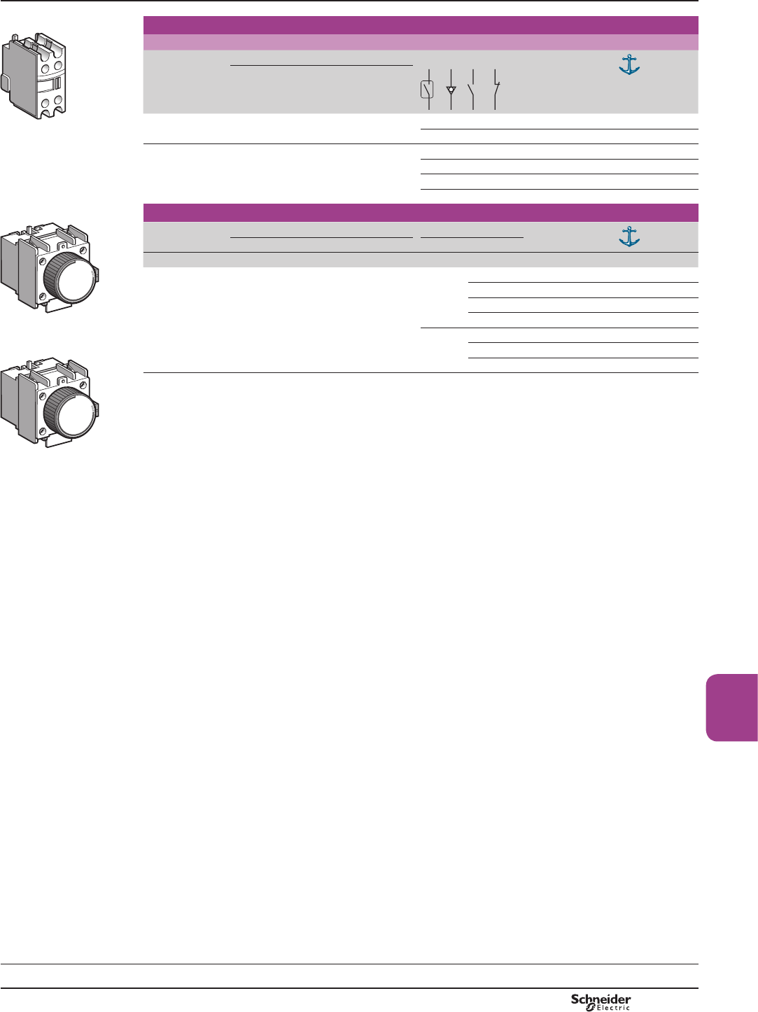
B9/27
High power
contactors
TeSys contactors
Auxiliary contact blocks for
3-pole shockproof contactors LC1 FG
,QVWDQWDQHRXVDX[LOLDU\FRQWDFWEORFNV
For use in normal operating environments
Number of
contacts
0D[QXPEHURIEORFNVSHUFRQWDFWRU Composition Reference
Clip-on mounting
1 1 – – 1 – LADN10 (1)
– – – 1 LADN01 (1)
41 – – 2 2 LADN22 (1)
– – 4 – LADN40 (1)
– – – 4 LADN04 (1)
– – 3 1 LADN31 (1)
7LPHGHOD\DX[LOLDU\FRQWDFWEORFNV
Number of
contacts
0D[QXPEHURIEORFNVSHUFRQWDFWRU Time delay Reference
Clip-on mounting Type Range
s
1 N/O
+
1 N/C
1 On-delay 0.1…3 (2) LADT0
0.1…30 LADT2 (1)
10…180 LADT4
1…30 (3) LADS2
Off-delay 0.1…3 (2) LADR0
0.1…30 LADR2 (1)
10…180 LADR4
(1)'HYLFHDSSURYHGE\WKH'&1)UHQFKQDYDOVKLS\DUGGHSDUWPHQWDQGDXWKRULVHGIRURQERDUGXVH
(2):LWKH[WHQGHGVFDOHIURPWRV
(3):LWKVZLWFKLQJWLPHRIPVPVEHWZHHQRSHQLQJRIWKH1&FRQWDFWDQGFORVLQJRIWKH12FRQWDFW
Characteristics:
pages B9/82 and B9/83
Schemes:
page B9/85
/$'1pp
DF537317.eps
/$'7p
DF537318.eps
/$'5p
DF537319.eps
References
TeSys F
PCPB09P20-EN Version : 1.0 18 novembre 2014 12:55 PM
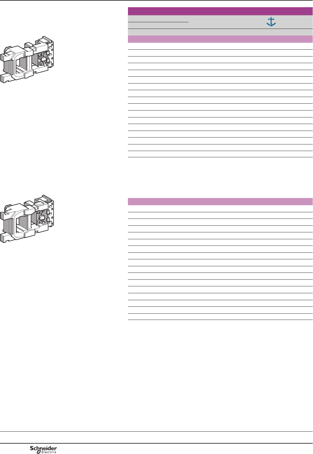
B9/28
References TeSys contactors
Coils for 3-pole shockproof
contactors LC1 FG
Spare or replacement parts
a.c. supply 50/60 Hz
References
Control circuit voltage Uc Voltage
code
Coil
reference
50 Hz 60 Hz
V V
Coils for contactors LC1 FG150
– 48 E6 LX1FF040
48 – E5 LX1FF048
– 110 F6 LX1FF092
– 115/120 G6 LX1FF095 (1)
110/115 – F5 LX1FF110
120 – FE5 LX1FF120
– 208 L6 LX1FF170
– 320 M6 LX1FF184
– 230/240 U6 LX1FF187
208 – LE5 LX1FF200
220/230 – M5 LX1FF220
240 – U5 LX1FF240
– 380 Q6 LX1FF316
– 415 N6 LX1FF340
– 440 R6 LX1FF360
380 – Q5 LX1FF380
415/440 – N5 LX1FF415
6SHFL¿FDWLRQV
Average consumption at 20 °C:
binrush 50 Hz: 550 VA; 60 Hz: 660 VA
bsealed 50 Hz: 45 VA; 60 Hz: 55 VA, cos M = 0.32.
Operating cycles/hour (T = 55 °C): 2400.
Coils for contactors LC1 FG185
– 48 E6 LX1FG040
48 – E5 LX1FG048
– 110 F6 LX1FG092
– 115/120 G6 LX1FG095 (1)
110/115 – F5 LX1FG110
120 – FE5 LX1FG120
– 208 L6 LX1FG170
– 320 M6 LX1FG184
– 230/240 U6 LX1FG187
208 – LE5 LX1FG200
220/230 – M5 LX1FG220
240 – U5 LX1FG240
– 380 Q6 LX1FG316
– 415 N6 LX1FG340
– 440 R6 LX1FG360
380 – Q5 LX1FG380
415/440 – N5 LX1FG415
6SHFL¿FDWLRQV
Average consumption at 20 °C:
binrush 50 Hz: 805 VA; 60 Hz: 970 VA
bsealed 50 Hz: 55 VA; 60 Hz: 66 VA, cos M = 0.34.
Operating cycles/hour (T = 55 °C): 2400.
(1)'HYLFHDSSURYHGE\WKH'&1)UHQFKQDYDOVKLS\DUGGHSDUWPHQWDQGDXWKRULVHGIRU
RQERDUGXVH
Schemes:
page B9/85
LX1 FFppp
DF537299.eps
LX1 FGppp
DF537300.eps
TeSys F
PCPB09P20-EN
Version : 1.0 18 novembre 2014 12:55 PM

B9/29
High power
contactors
References
Control circuit voltage Uc
50 and 60 Hz
Voltage
code
Coil
reference
Weight
V kg
Coils for contactors LC1 FG265
110/120 F7 LX1FH1102 (1) 0.740
208 L7 LX1FH2002 0.740
220/230 M7 LX1FH2202 0.740
240 U7 LX1FH2402 0.740
380/415 Q7 LX1FH3802 0.740
6SHFL¿FDWLRQV
Average consumption at 20 °C:
binrush 50 or 60 Hz: 600 to 700 VA
bsealed 50 or 60 Hz: 8 to 10 VA, cos M = 0.9.
Operating cycles/hour (T = 55 °C): 2400.
Coils for contactors LC1 FG400
110/120 F7 LX1FJ110 (1) 1.000
208 L7 LX1FJ200 1.000
220/230 M7 LX1FJ220 1.000
230/240 U7 LX1FJ240 1.000
380/400 Q7 LX1FJ380 1.000
415/440 N7 LX1FJ415 1.000
6SHFL¿FDWLRQV
Average consumption at 20 °C:
binrush 50 or 60 Hz: 1000 to 1150 VA
bsealed 50 or 60 Hz: 12 to 18 VA, cos M = 0.9.
Operating cycles/hour (T = 55 °C): 2400.
Coils for contactors LC1 FG500
110/120 F7 LX1FK110 (1) 1.150
208 L7 LX1FK200 1.150
220/230 M7 LX1FK220 1.150
230/240 U7 LX1FK240 1.150
380/400 Q7 LX1FK380 1.150
415/440 N7 LX1FK415 1.150
6SHFL¿FDWLRQV
Average consumption at 20 °C:
binrush 50 or 60 Hz: 1050 to 1150 VA
bsealed 50 or 60 Hz: 16 to 20 VA, cos M = 0.9.
Operating cycles/hour (T = 55 °C): 2400.
Coils for contactors LC1 FG630
110/120 F7 LX1FL110 (1) 1.500
208 L7 LX1FL200 1.500
220/230 M7 LX1FL220 1.500
380/400 Q7 LX1FL380 1.500
415/440 N7 LX1FL415 1.500
6SHFL¿FDWLRQV
Average consumption at 20 °C:
binrush 50 or 60 Hz: 1500 to 1730 VA
bsealed 50 or 60 Hz: 20 to 25 VA, cos M = 0.9.
Operating cycles/hour (T = 55 °C): 1200.
(1) 'HYLFHDSSURYHGE\WKH'&1)UHQFKQDYDOVKLS\DUGGHSDUWPHQWDQGDXWKRULVHGIRU
RQERDUGXVH
Schemes:
page B9/85
/;)+ppp
DF537301.eps
LX1 FJppp
DF537302.eps
LX1 FKppp
DF537303.eps
LX1 FLppp
DF537304.eps
References TeSys contactors
Coils for 3-pole shockproof
contactors LC1 FG
Spare or replacement parts
a.c. supply 50/60 Hz
TeSys F
PCPB09P20-EN Version : 1.0 18 novembre 2014 12:55 PM
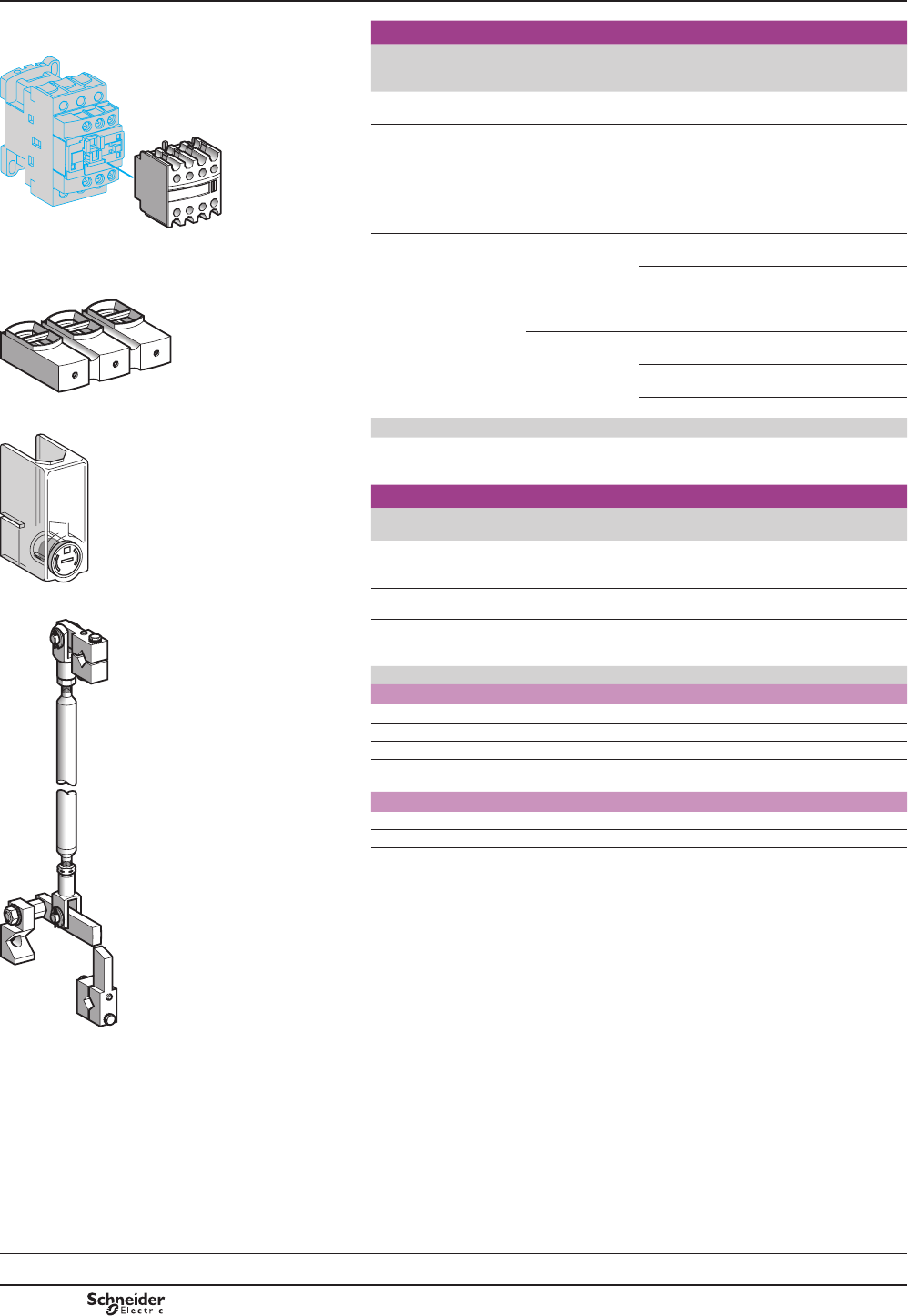
B9/30
Accessories for contactors CR1 F
500377_1.eps
Description Number of
contacts or
shrouds
For use on Reference
Instantaneous
auxiliary contacts
(1) CR1 F LADN (1)
Time delay
auxiliary contacts
(1) CR1 F LADp (1)
Contact blocks with
protected terminals
for 3-pole contactors
(for mounting on contactors
with closed arc chamber)
Set of 2 blocks CR1 F150 and
CR1 F185
LA9F103
/$'1 Power terminal protection
shrouds
Set of 6 shrouds
for 3-pole
contactors
CR1 F150 and
CR1 F185
LA9F702
CR1 F265 to
CR1 F500
LA9F703
501616_1.eps
CR1 F630 LA9F704
Set of 8 shrouds
for 4-pole
contactors
CR1 F1504 and
CR1 F1854
LA9F707
CR1 F2654 to
CR1 F5004
LA9F708
LA9 F103 CR1 F6304 LA9F709
501617_1.eps
Description Application Reference
Mechanical interlock
and power connections
For assembly of
reversing contactors and
changeover contactor pairs
See pages B9/31
and B9/32
Accessories for contactors CR1 B
Description Application Reference Weight
kg
Mechanical interlock
with mounting
accessories (3)
For vertical assembly of
reversing contactors and
changeover contactor pairs
EZ2LB0601 1.560
LA9 F70pKit containing 2
bar mounting brackets
For mounting on
120 or 150 mm centres
LA9B103 1.620
501618_1.eps
(1))RUPD[LPXPQXPEHUSHUFRQWDFWRUDQGFRPSOHWHUHIHUHQFHVHHSDJH%
(2) 6WDQGDUGFRQWUROFLUFXLWYROWDJHVIRURWKHUYROWDJHVSOHDVHFRQVXOW\RXU5HJLRQDO6DOHV
2I¿FH
Volts 48 110 125 127 220 230 240 250 380 400 415 440 500
For contactors CR1 F
a 50/60 Hz E7 F7 – G7 M7 M7 U7 – Q7 Q7 N7 – –
a 400 Hz E7 F7 – G7 M7 M7 – – – – – – –
cE7 F7 – G7 M7 M7 – – – – – – –
c low
consumption
EZ7 FZ7 – GZ7 MZ7 – – – – – – – –
For contactors CR1 B
a 50…400 Hz – F –G M M U – Q V N R S
c– FD GD – MD – UD UCD – – – RD SD
(3) 3RVLWLYHPHFKDQLFDOLQWHUORFNLQJEHWZHHQYHUWLFDOO\PRXQWHGFRQWDFWRUVRILGHQWLFDO
RUGLIIHUHQWUDWLQJV&RQQHFWLQJURGVDQGFUDQNVDVVHPEOHGRQULJKWKDQGVLGHVFUDQNSLQV
RQWKHSROHVLGH
9HUWLFDO¿[LQJFHQWUHGLVWDQFHEHWZHHQWKHWZRFRQWDFWRUVPP
(=/%
TeSys contactors
Magnetic latching contactors
Accessories
Selection:
pages B9/86 to B9/91
Characteristics:
pages B9/30 to B9/35
Dimensions:
pages B9/96 to B9/99
References
TeSys FG, TeSys CR1F
PCPB09P20-EN
Version : 1.0 18 novembre 2014 12:55 PM

B9/31
High power
contactors
Horizontally mounted
Mechanical interlocks Sets of power connections
Reversers assembled
using 2 contactors of
identical rating, type:
CR1 F150
CR1 F185
CR1 F265
CR1 F400
CR1 F500
CR1 F630
LA9 Fp970
Reversing contactors
LA9 Fp976
3 or 4-pole changeover contactor pairs
LA9 Fp977 or LA9 Fp982
501598_1.eps
A1
E1
A2
A1
A2
E1
1
2
3
4
5
6
1
2
3
4
5
6
L1
L2
L3
U
V
W
DF510478.eps
A1
E1
A2
A1
A2
E1
1
2
3
4
5
6
3
4
5
6
7
8
1N
1/L3
1/L2
L2
1
2
L1
7
81/L1
2/L1
2/L2
2/L3
2N
L3
N
DF510477.eps
DF534040.eps
501602_1.eps
Vertically mounted
Mechanical interlocks
Reversers assembled
using 2 contactors of
identical rating, type:
CR1 F150
CR1 F185
CR1 F265
CR1 F400
CR1 F500
CR1 F630
LA9 FF4F
LA9 FG4G
Assembly A LA9 FH4H
LA9 FJ4J
LA9 FK4K
LA9 FL4L
Assembly C
501603_1.eps
501604_1.eps
Reversers assembled
using 2 contactors of
different ratings, type:
CR1 F150
CR1 F185
CR1 F265
CR1 F400
CR1 F500
CR1 F630
LA9 FG4F Assembly A LA9 FH4F
LA9 FJ4F
LA9 FK4F
LA9 FL4F
LA9 FH4G
LA9 FJ4G
LA9 FK4G
LA9 FL4G
Assembly B LA9 FJ4H
LA9 FK4H
LA9 FL4H
LA9 FK4J
LA9 FL4J
LA9 FK4K
Assembly C
501606_1.eps
501605_1.eps
501607_1.eps
Reversers assembled
using 3 contactors of
identical or different ratings
LA9 Fp4p4p
Warning: the contactor ratings
must be in decreasing size from
top to bottom.
501608_1.eps
F150
F185
F265
F400
F500
F630
F150 F185 F265 F400 F500 F630
F185
F265
F400
F150
F500
F630
CR1 F500
CR1 F265
CR1 F185
A
B
C
DF565952.eps
TeSys contactors
Magnetic latching contactors
Components for assembling reversing contactors
and changeover contactor pairs CR1 F
Horizontally or vertically mounted
Mounting
TeSys FG, TeSys CR1F
PCPB09P20-EN Version : 1.0 18 novembre 2014 12:55 PM

B9/32
Reversers assembled using 2 contactors of identical rating
Contactor type Set of power connections Mechanical interlock
3-pole
Reference
4-pole
Reference
Weight
kg
Kit reference Weight
kg
For assembly of 3-pole reversing contactors
for motor control (1)
Horizontally mounted
CR1 F150 LA9FF976 – 0.600 LA9FF970 0.060
CR1 F185 LA9FG976 – 0.780 LA9FG970 0.060
CR1 F265 LA9FH976 – 1.500 LA9FJ970 0.140
CR1 F400 LA9FJ976 – 2.100 LA9FJ970 0.140
CR1 F500 LA9FK976 – 2.350 LA9FJ970 0.140
CR1 F630 LA9FL976 – 3.800 LA9FL970 0.150
Vertically mounted
CR1 F150 (2) – – LA9FF4F 0.345
CR1 F185 (2) – – LA9FG4G 0.350
CR1 F265 (2) – – LA9FH4H 1.060
CR1 F400 (2) – – LA9FJ4J 1.200
CR1 F500 (2) – – LA9FK4K 1.200
CR1 F630 (2) – – LA9FL4L 1.220
For assembly of 4-pole changeover contactor pairs Horizontally mounted
CR1 F1504 LA9FF982 LA9FF977 0.460 LA9FF970 0.060
CR1 F1854 LA9FG982 LA9FG977 0.610 LA9FG970 0.060
CR1 F2654 LA9FH982 LA9FH977 1.200 LA9FJ970 0.140
CR1 F4004 LA9FJ982 LA9FJ977 1.800 LA9FJ970 0.140
CR1 F5004 LA9FK982 LA9FK977 2.300 LA9FJ970 0.140
CR1 F6304 LA9FL982 LA9FL977 3.400 LA9FL970 0.150
Vertically mounted
CR1 F1504 (2) – – LA9FF4F 0.345
CR1 F1854 (2) – – LA9FG4G 0.350
CR1 F2654 (2) – – LA9FH4H 1.060
CR1 F4004 (2) – – LA9FJ4J 1.200
CR1 F5004 (2) – – LA9FK4K 1.200
CR1 F6304 (2) – – LA9FL4L 1.220
Reversers assembled using 2 contactors of different ratings
Contactor type Mechanical interlock
At bottom At top Kit reference Weight
kg
For assembly of 3 or 4-pole changeover contactor pairs Vertically mounted (3)
CR1 F150 or F1504 CR1 F185 or F1854 LA9FG4F 0.350
CR1 F265 or F2654 LA9FH4F 0.870
CR1 F400 or F4004 LA9FJ4F 0.930
CR1 F500 or F5004 LA9FK4F 0.940
CR1 F630 or F6304 LA9FL4F 0.940
CR1 F185 or F1854 CR1 F265 or F2654 LA9FH4G 0.860
CR1 F400 or F4004 LA9FJ4G 0.940
CR1 F500 or F5004 LA9FK4G 0.940
CR1 F630 or F6304 LA9FL4G 0.950
CR1 F265 or F2654 CR1 F400 or F4004 LA9FJ4H 1.130
CR1 F500 or F5004 LA9FK4H 1.130
CR1 F630 or F6304 LA9FL4H 1.140
CR1 F400 or F4004 CR1 F500 or F5004 LA9FK4J 1.200
CR1 F630 or F6304 LA9FL4J 1.210
CR1 F500 or F5004 CR1 F630 or F6304 LA9FL4K 1.210
For assembly of 3 or 4-pole reversing contactors Using 3 contactors (vertically mounted)
of identical or different ratings
Mechanical interlock
Kit reference (4)
The contactor ratings must be in decreasing size
from top to bottom.
LA9Fp4p4p
(1)$SROHUHYHUVLQJFRQWDFWRUIRUPRWRUFRQWUROFDQEHFRQYHUWHGLQWRDSROHFKDQJHRYHU
FRQWDFWRUSDLUE\UHPRYLQJWKHXSSHUFRQQHFWLQJOLQNV
(2)$OOSRZHUFRQQHFWLRQVDUHWREHPDGHE\WKHFXVWRPHU
(3):LWKLGHQWLFDORUGLIIHUHQWQXPEHURISROHV3RZHUFRQQHFWLRQVWREHPDGHE\WKHFXVWRPHU
(4)&RPSOHWHWKHUHIHUHQFHE\UHSODFLQJWKH¿UVWGRWZLWKWKHFRGHIRUWKHXSSHUFRQWDFWRUWKH
VHFRQGGRWZLWKWKHFRGHIRUWKHPLGGOHFRQWDFWRUDQGWKHWKLUGGRWZLWKWKHFRGHIRUWKHERWWRP
contactor.
Contactors CR1 F150 CR1 F185 CR1 F265 CR1 F400 CR1 F500 CR1 F630
Code F G H J K L
([DPSOH: mechanical interlock for reversing contactor made up of 3 different contactors:
CR1 F500 top, CR1 F26 middle and CR1 F185 bottom: LA9 FK4H4G.
TeSys contactors
Magnetic latching contactors
Components for assembling reversing
contactors and changeover contactor pairs
CR1 F
References
Illustrations:
page B9/31
Dimensions:
pages B9/96 to B9/99
TeSys FG, TeSys CR1F
PCPB09P20-EN
Version : 1.0 18 novembre 2014 12:55 PM

B9/33
High power
contactors
References
501478_1.eps
Description For contactor Reference Weight
kg
Complete sets
of contacts
for 3 or 4 poles (1)
3-pole CR1 F150 LA5FF431 0.270
CR1 F185 LA5FG431 0.350
CR1 F265 LA5FH431 0.660
CR1 F400 LA5F400803 0.660
LA5 FG431 CR1 F500 LA5F500803 0.660
CR1 F630 LA5F630803 0.660
4-pole CR1 F1504 LA5FF441 0.360
CR1 F1854 LA5FG441 0.465
CR1 F2654 LA5FH441 0.880
CR1 F4004 LA5F400804 0.465
CR1 F5004 LA5F500804 0.465
CR1 F6304 LA5F630804 0.465
501479_1.eps
Arc chambers 3-pole CR1 F150 LA5F15050 0.490
CR1 F185 LA5F18550 0.670
CR1 F265 LA5F26550 0.920
CR1 F400 LA5F40050 1.300
CR1 F500 LA5F50050 1.850
CR1 F630 LA5F63050 3.150
4-pole CR1 F1504 LA5F150450 0.660
CR1 F1854 LA5F185450 0.910
CR1 F2654 LA5F265450 1.220
LA5 F40050 CR1 F4004 LA5F400450 1.740
CR1 F5004 LA5F500450 2.500
CR1 F6304 LA5F630450 4.200
(1)6HWFRQWDLQLQJWKHIROORZLQJSHUSROH¿[HGFRQWDFWVPRYLQJFRQWDFWGHÀHFWRUV
EDFNSODWHFODPSLQJVFUHZVDQGZDVKHUV
References TeSys contactors
Magnetic latching contactors
Accessories and replacement parts for
contactors CR1 F
TeSys FG, TeSys CR1F
PCPB09P20-EN Version : 1.0 18 novembre 2014 12:55 PM

B9/34
Standard coils
Usual voltages Resistance of winding
at T = 20 °C
Reference Voltage
code
Weight
50…400 Hz
or c50 Hz, 60 Hz Latching Unlatching
V V : : kg
For contactors CR1 F150
501470_1.eps
48 – 1.98 230.8 LX0FF005 E7 0.440
110 – 9.35 1453 LX0FF006 F7 0.440
127 – 11.61 1788 LX0FF007 G7 0.440
208 – 23.50 4098 LX0FF020 L7 0.440
220/230 – 37.55 5139 LX0FF008 M7 0.440
– 240 45.16 6544 LX0FF009 U7 0.440
– 380/400 114.10 12 447 LX0FF010 Q7 0.440
– 415 139.50 16 717 LX0FF011 N7 0.440
For contactors CR1 F185
48 – 1.42 220 LX0FG005 E7 0.560
LX0 FF009 110 – 6.92 1339 LX0FG006 F7 0.560
127 – 8.45 1676 LX0FG007 G7 0.560
208 – 21.30 3169 LX0FG020 L7 0.560
220/230 – 26.27 4729 LX0FG008 M7 0.560
– 240 32.95 4729 LX0FG009 U7 0.560
– 380/400 82.29 11 885 LX0FG010 Q7 0.560
– 415 102.30 14 305 LX0FG011 N7 0.560
For contactors CR1 F265
501471_1.eps
48 – 1.34 183.4 LX0FH005 E7 0.780
110 – 6.90 1031 LX0FH006 F7 0.780
127 – 8.56 1325 LX0FH007 G7 0.780
208 – 20.20 2654 LX0FH020 L7 0.780
220/230 – 25.77 4090 LX0FH008 M7 0.780
– 240 33.03 5002 LX0FH009 U7 0.780
– 380/400 78.39 11 803 LX0FH010 Q7 0.780
– 415 102.9 15 006 LX0FH011 N7 0.780
For contactors CR1 F400
48 – 1.32 90.5 LX0FJ005 E7 1.120
110 – 8.09 813 LX0FJ006 F7 1.120
127 – 9.79 1027 LX0FJ007 G7 1.120
208 – 24.40 2643 LX0FJ020 L7 1.120
/;)+ 220/230 – 30.14 3309 LX0FJ008 M7 1.120
– 240 37.02 4074 LX0FJ009 U7 1.120
– 380/400 94.80 9380 LX0FJ010 Q7 1.120
– 415 121.10 11 763 LX0FJ011 N7 1.120
For contactors CR1 F500
48 – 1.57 166 LX0FK005 E7 1.220
110 – 7.53 916 LX0FK006 F7 1.220
127 – 9.56 1159 LX0FK007 G7 1.220
208 – 23.60 2981 LX0FK020 L7 1.220
220/230 – 28.81 3733 LX0FK008 M7 1.220
– 240 35.67 4595 LX0FK009 U7 1.220
– 380/400 89.56 10 570 LX0FK010 Q7 1.220
– 415 112.06 13 256 LX0FK011 N7 1.220
For contactors CR1 F630
48 – 0.87 204 LX0FL005 E7 1.460
110 – 5.20 1423 LX0FL006 F7 1.460
127 – 6.45 1830 LX0FL007 G7 1.460
208 – 20.20 2961 LX0FL020 L7 1.460
220/230 – 25.36 4603 LX0FL008 M7 1.460
– 240 25.36 5658 LX0FL009 U7 1.460
– 380/400 60.95 10 676 LX0FL010 Q7 1.460
– 415 77.97 13 003 LX0FL011 N7 1.460
TeSys contactors
Magnetic latching contactors
Coils for contactors CR1 F
References
TeSys FG, TeSys CR1F
PCPB09P20-EN
Version : 1.0 18 novembre 2014 12:55 PM
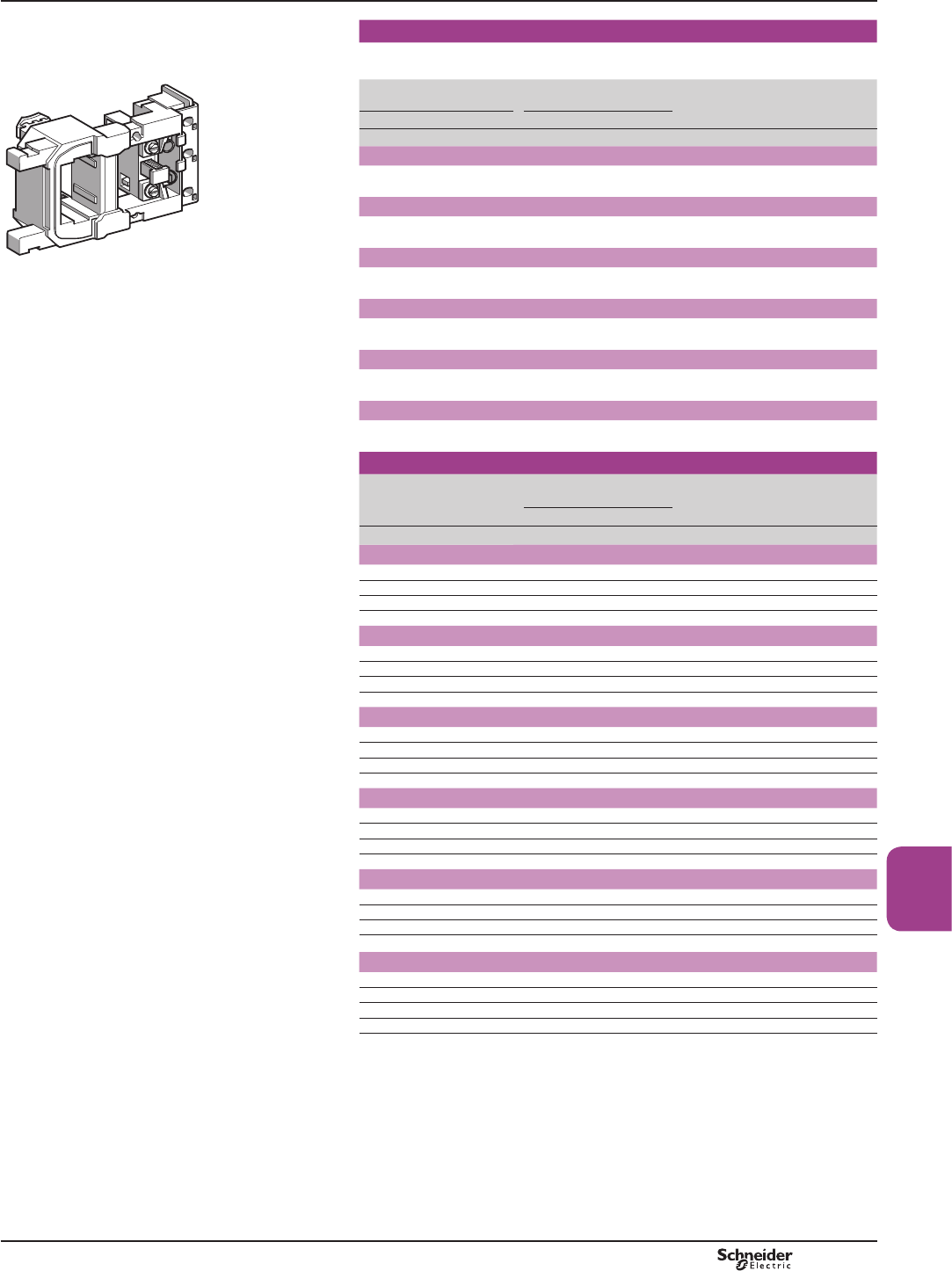
B9/35
High power
contactors
Special coils
Coils with two windings with common point, allowing the use of two separate power
sources for latching and unlatching.
501472_1.eps
Coil voltages at 50 Hz,
60 Hz, 400 Hz or cResistance of winding
at T= 20 °C
Reference Voltage
code
Weight
Latching Unlatching Latching Unlatching
V V : : kg
For contactors CR1 F150
220 24 29.5 39.5 LX0FF224 MB7 0.440
For contactors CR1 F185
220 24 26.5 19 LX0FG224 MB7 0.560
For contactors CR1 F265
LX0 FF030 220 24 26 29.5 LX0FH224 MB7 0.780
For contactors CR1 F400
220 24 30 23 LX0FJ224 MB7 1.120
For contactors CR1 F500
220 24 29 26 LX0FK224 MB7 1.220
For contactors CR1 F630
220 24 26 41 LX0FL224 MB7 1.460
Coils with low inrush consumption
Usual voltages
cResistance of winding
at T = 20 °C
Reference Voltage
code
Weight
Latching Unlatching
V: : kg
For contactors CR1 F150
48 4.56 140.56 LX0FF055 EZ7 0.440
110 22.37 706.44 LX0FF056 FZ7 0.440
127 35.54 1086.36 LX0FF057 GZ7 0.440
220 89.85 3342.51 LX0FF058 MZ7 0.440
For contactors CR1 F185
48 5.19 106.54 LX0FG055 EZ7 0.570
110 25.50 536.26 LX0FG056 FZ7 0.570
127 32.75 732.64 LX0FG057 GZ7 0.570
220 102.44 2378.62 LX0FG058 MZ7 0.570
For contactors CR1 F265
48 5.19 74.26 LX0FH055 EZ7 0.800
110 25 364.61 LX0FH056 FZ7 0.800
127 30.98 458.45 LX0FH057 GZ7 0.800
220 97.89 1344.46 LX0FH058 MZ7 0.800
For contactors CR1 F400
48 5.05 36.36 LX0FJ055 EZ7 1.150
110 25.39 171.49 LX0FJ056 FZ7 1.150
127 31.86 221.20 LX0FJ057 GZ7 1.150
220 98.19 648.79 LX0FJ058 MZ7 1.150
For contactors CR1 F500
48 4.42 41 LX0FK055 EZ7 1.270
110 22.74 193.36 LX0FK056 FZ7 1.270
127 28.25 313.60 LX0FK057 GZ7 1.270
220 85.12 918.68 LX0FK058 MZ7 1.270
For contactors CR1 F630
48 3.94 59.17 LX0FL055 EZ7 1.500
110 19.36 365.33 LX0FL056 FZ7 1.500
127 25.39 452.27 LX0FL057 GZ7 1.500
220 74.44 1071.43 LX0FL058 MZ7 1.500
TeSys contactors
Magnetic latching contactors
Coils for contactors CR1 F
References
TeSys FG, TeSys CR1F
PCPB09P20-EN Version : 1.0 18 novembre 2014 12:55 PM

B9/36
TeSys LA9F
TeSys contactors
TeSys F reversing contactors and changeover
contactor pairs
Components for assembling 3-pole reversing
contactors and changeover contactor pairs,
for customer assembly
Horizontally mounted Mechanical interlocks Sets of power connections
Reversers assembled using
2 contactors of identical rating,
type :
Reversing contactors 3-pole changeover contactor
pairs (1)
LA9 Fp970 (2) LA9 Fppp76 (2)
A1
A1
A2
A2
1
2
3
4
5
6
1
2
3
4
5
6
L1
L2
L3
U
V
W
813151.eps
LA9 Fppp82 (2)
A2
A2
A1
A1
1
2
3
4
5
6
3
4
5
6
1/L3
1/L2
1/L1
L2
1
2
L1 2/L1
2/L2
2/L3
L3
813152.eps
LC1 F115
LC1 F150
813153.eps
LC1 F185
LC1 F225
LC1 F265
LC1 F330
LC1 F400
LC1 F500
LC1 F630
813155.eps
813154.eps
LC1 F800
Vertically mounted Mechanical interlocks
Reversers assembled using
2 contactors of identical rating,
type :
LC1 F115
LC1 F150
LC1 F185
LC1 F225
LC1 F265
LC1 F330
LC1 F400
LC1 F500
LC1 F630
LC1 F800
Reversers assembled using
2 contactors of different ratings,
see page B9/38
LA9 FF4F
LA9 FG4G
813158.eps
LA9 FH4H
LA9 FJ4J
LA9 FK4K
LA9 FL4L
LC1 F780 LA9 FX970
813157.eps
(1))RUSROHFKDQJHRYHUFRQWDFWRUSDLUVVHHSDJHV%DQG%
(2)&RPSOHWHUHIHUHQFHVVHHSDJH%
Combinations
813156.eps
PCPB09P30-EN
Version : 1.0 18 novembre 2014 12:55 PM
B9/37
TeSys LA9F
High power
contactors
TeSys contactors
TeSys F reversing contactors and changeover
contactor pairs
Control circuit: a.c. or d.c.
Reversers assembled using 2 contactors of identical rating
Contactor type (1) Set of power connections Mechanical interlock
Reference Weight
kg
Kit reference Weight
kg
For assembly of 3-pole reversing contactors for motor control
Horizontally mounted
LC1 F115 LA9FF976 0.600 LA9FF970 0.060
LC1 F150 LA9F15076 0.600 LA9FF970 0.060
LC1 F185 LA9FG976 0.780 LA9FG970 0.060
LC1 F225 LA9F22576 1.500 LA9FG970 0.060
LC1 F265 LA9FH976 1.500 LA9FJ970 0.140
LC1 F330 LA9FJ976 2.100 LA9FJ970 0.140
LC1 F400 LA9FJ976 2.100 LA9FJ970 0.140
LC1 F500 LA9FK976 2.350 LA9FJ970 0.140
LC1 F630 or F800 LA9FL976 3.800 LA9FL970 0.150
Vertically mounted
LC1 F115 or F150 (2) –LA9FF4F 0.345
LC1 F185 (2) –LA9FG4G 0.350
LC1 F225 (2) –LA9FG4G 0.350
LC1 F265 or F330 (2) –LA9FH4H 1.060
LC1 F400 (2) –LA9FJ4J 1.200
LC1 F500 (2) –LA9FK4K 1.200
LC1 F630 or F800 (2) –LA9FL4L 1.220
LC1 F780 (3) –LA9FX970 (3) 6.100
For assembly of 3-pole changeover contactor pairs (4)
Horizontally mounted
LC1 F115 LA9FF982 0.460 LA9FF970 0.060
LC1 F150 LA9F15082 0.460 LA9FF970 0.060
LC1 F185 LA9FG982 0.610 LA9FG970 0.060
LC1 F225 LA9F22582 1.200 LA9FG970 0.060
LC1 F265 LA9FH982 1.200 LA9FJ970 0.140
LC1 F330 LA9FJ982 1.800 LA9FJ970 0.140
LC1 F400 LA9FJ982 1.800 LA9FJ970 0.140
LC1 F500 LA9FK982 2.300 LA9FJ970 0.140
LC1 F630 or F800 LA9FL982 3.400 LA9FL970 0.150
Vertically mounted
LC1 F115 or F150 (2) –LA9FF4F 0.345
LC1 F185 (2) –LA9FG4G 0.350
LC1 F225 (2) –LA9FG4G 0.350
LC1 F265 or F330 (2) –LA9FH4H 1.060
LC1 F400 (2) –LA9FJ4J 1.200
LC1 F500 (2) –LA9FK4K 1.200
LC1 F630 or F800 (2) –LA9FL4L 1.220
LC1 F780 (3) –LA9FX970 (3) 7.800
(1)7RRUGHUWKHFRQWDFWRUVVHHSDJHV%DQG%)RUWKHDX[LOLDU\FRQWDFWEORFNV
LAD Np1UHTXLUHGWRREWDLQHOHFWULFDOLQWHUORFNLQJEHWZHHQWKHFRQWDFWRUVVHHSDJH%
For accessories, see pages B9/12 to B9/14.
(2):LWKWKHH[FHSWLRQRIFRQWDFWRUVLC1 F780DOOSRZHUFRQQHFWLRQVDUHWREHPDGHE\WKH
customer.
(3)'RXEOHPHFKDQLFDOLQWHUORFNPHFKDQLVPZLWKLQWHUORFNFRQQHFWLQJURGVDQGSRZHU
connecting links.
(4))RUDVVHPEO\RISROHFKDQJHRYHUFRQWDFWRUSDLUVVHHSDJHV%DQG%.
Combinations
Selection :
pages B10/50 to B10/73
Dimensions:
pages B9/100 to B9/102
Schemes:
page B9/103
PCPB09P30-EN Version : 1.0 18 novembre 2014 12:55 PM

B9/38
TeSys LA9F
TeSys contactors
TeSys F changeover contactor pairs
Components for assembling 3 and 4-pole
changeover contactor pairs, for customer
assembly
Horizontally mounted Mechanical interlocks Sets of power connections
Contactor pairs assembled using
2 contactors of identical rating,
type :
LC1 F1154
LC1 F1504
LC1 F1854
LC1 F2254
LC1 F2654
LC1 F3304
LC1 F4004
LC1 F5004
LC1 F6304
4-pole changeover contactor pairs (1)
LA9 Fp970 LA9 Fppp77
813167.eps
813168.eps
A1
A2
A1
A2
1
2
3
4
5
6
3
4
5
6
7
8
1N
1/L3
1/L2
L2
1
2
L1
7
81/L1
2/L1
2/L2
2/L3
2N
L3
N
813166.eps
Vertically mounted Mechanical interlocks
Contactor pairs assembled using
2 contactors of identical rating,
type :
LC1 F1154
LC1 F1504
LC1 F1854
LC1 F2254
LC1 F2654
LC1 F3304
LC1 F4004
LC1 F5004
LC1 F6304
Assembly A Assembly B Assembly C
LA9 FF4F
LA9 FG4G
813160.eps
LA9 FH4H
LA9 FJ4J
LA9 FK4K
LA9 FL4L
813159.eps
LA9 FX971
813161.eps
Contactor pairs assembled using
2 contactors of different ratings,
type :
LC1 F115 or F1154
LC1 F150 or F1504
LC1 F185 or F1854
LC1 F225 or F2254
LC1 F265 or F2654
LC1 F330 or F3304
LC1 F400 or F4004
LC1 F500 or F5004
LC1 F630 or F6304
LC1 F800
Assembly A Assembly B Assembly C
LA9 FG4F
813163.eps
LA9 FH4F, LA9 FH4G
LA9 FJ4F, LA9 FJ4G
LA9 FK4F, LA9 FK4G
LA9 FL4F, LA9 FL4G
813165.eps
LA9 FJ4H
LA9 FK4H, LA9 FK4J
LA9 FL4H, LA9 FL4J and LA9 FL4K
813162.eps
Contactor pairs assembled using
3 contactors of identical or
different ratings, type :
LA9 Fp4p4p : see pages B9/40 and B9/41.
813164.eps
LC1 F115 or F1154
LC1 F150 or F1504
LC1 F185 or F1854
LC1 F225 or F2254
LC1 F265 or F2654
LC1 F330 or F3304
LC1 F400 or F4004
LC1 F500 or F5004
LC1 F630 or F6304
LC1 F800
Important: the contactor ratings must be in decreasing size from top
to bottom.
(1))RUSROHFKDQJHRYHUFRQWDFWRUSDLUVVHHSDJHV%DQG%
Combinations
PCPB09P30-EN
Version : 1.0 18 novembre 2014 12:55 PM
B9/39
TeSys LA9F
High power
contactors
Contactor pairs assembled using 2 contactors of identical rating
For assembly of 4-pole changeover contactor pairs (1)
Contactor type
(2)
Set of power connections Mechanical interlock
Reference Weight
kg
Kit reference Weight
kg
Horizontally mounted
LC1 F1154 LA9FF977 0.460 LA9FF970 0.060
LC1 F1504 LA9F15077 0.460 LA9FF970 0.060
LC1 F1854 LA9FG977 0.610 LA9FG970 0.060
LC1 F2254 LA9F22577 1.200 LA9FG970 0.060
LC1 F2654 LA9FH977 1.200 LA9FJ970 0.140
LC1 F3304 LA9FJ977 1.800 LA9FJ970 0.140
LC1 F4004 LA9FJ977 1.800 LA9FJ970 0.140
LC1 F5004 LA9FK977 2.300 LA9FJ970 0.140
LC1 F6304 LA9FL977 3.400 LA9FL970 0.150
Vertically mounted
LC1 F1154 or F1504 (3) –LA9FF4F 0.345
LC1 F1854 (3) –LA9FG4G 0.350
LC1 F2254 (3) –LA9FG4G 0.350
LC1 F2654 or F3304 (3) –LA9FH4H 1.060
LC1 F4004 (3) –LA9FJ4J 1.200
LC1 F5004 (3) –LA9FK4K 1.200
LC1 F6304 (3) –LA9FL4L 1.220
LC1 F7804 (4) –LA9FX971 (4) 7.800
Contactor pairs assembled using 2 contactors of different ratings
For assembly of 3 or 4-pole changeover contactor pairs
Contactor type (1) Mechanical interlock
At bottom At top Kit reference Weight
kg
Vertically mounted
LC1 F115 or F1154
or
LC1 F150 or F1504
LC1 F185 or F1854 LA9FG4F 0.350
LC1 F225 or F2254 LA9FG4F 0.350
LC1 F265 or F2654 LA9FH4F 0.870
LC1 F330 or F3304 LA9FH4F 0.870
LC1 F400 or F4004 LA9FJ4F 0.930
LC1 F500 or F5004 LA9FK4F 0.940
LC1 F630, F6304 or F800 LA9FL4F 0.940
LC1 F185 or F1854
or
LC1 F225 or F2254
LC1 F265 or F2654 LA9FH4G 0.860
LC1 F330 or F3304 LA9FH4G 0.860
LC1 F400 or F4004 LA9FJ4G 0.940
LC1 F500 or F5004 LA9FK4G 0.940
LC1 F630, F6304 or F800 LA9FL4G 0.950
LC1 F265 or F2654
or
LC1 F330 or F3304
LC1 F400 or F4004 LA9FJ4H 1.130
LC1 F500 or F5004 LA9FK4H 1.130
LC1 F630, F6304 or F800 LA9FL4H 1.140
LC1 F400 or F4004 LC1 F500 or F5004 LA9FK4J 1.200
LC1 F630 or F6304 or F800 LA9FL4J 1.210
LC1 F500 or F5004 LC1 F630 or F6304 or F800 LA9FL4K 1.210
For assembly of reversers using 3 contactors, vertically mounted
See pages B9/40 and B9/41.
(1))RUDVVHPEO\RISROHFKDQJHRYHUFRQWDFWRUSDLUVVHHSDJHV%DQG%
(2)7RRUGHUWKHFRQWDFWRUVVHHSDJHV%DQG%)RUWKHDX[LOLDU\FRQWDFWEORFNV
LAD Np1UHTXLUHGWRREWDLQHOHFWULFDOLQWHUORFNLQJEHWZHHQWKHFRQWDFWRUVVHHSDJH%
For accessories, see pages B9/12 to B9/14.
(3)$OOSRZHUFRQQHFWLRQVDUHWREHPDGHE\WKHFXVWRPHU
(4)'RXEOHPHFKDQLFDOLQWHUORFNPHFKDQLVPZLWKLQWHUORFNFRQQHFWLQJURGVDQGSRZHU
connecting links.
TeSys contactors
TeSys F changeover contactor pairs
Components for assembling 3 and 4-pole
changeover contactor pairs, for customer
assembly
Combinations
Selection :
pages B10/50 to B10/73
Dimensions:
pages B9/100 to B9/102
Schemes:
page B9/103
PCPB09P30-EN Version : 1.0 18 novembre 2014 12:55 PM
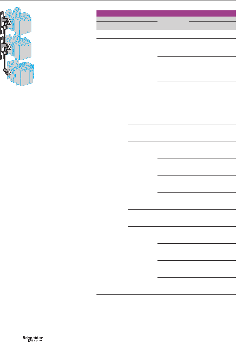
B9/40
TeSys LA9F
TeSys contactors
TeSys F contactors
Accessories for assembly of reversing contactors
and changeover contactor pairs using 3 contactors,
vertically mounted - for customer assembly
813215.eps
Closing of one of the 3 contactors prevents closing of the other 2.
Mechanical interlock kits
Contactor type (1) Mechanical interlock (2)
Top Middle Bottom Kit reference (3) Weight
kg
LC1 F115, F150,
F1154 or F1504
LC1 F115, F150,
F1154 or F1504
LC1 F115, F150,
F1154 or F1504
LA9FF4F4F 0.554
LC1 F185, F225,
F1854 or F2254
LC1 F115, F150,
F1154 or F1504
LC1 F115, F150,
F1154 or F1504
LA9FG4F4F 0.559
LC1 F185, F225,
F1854 or F2254
LC1 F115, F150,
F1154 or F1504
LA9FG4G4F 0.559
LC1 F185, F225,
F1854 or F2254
LA9FG4G4G 0.562
LC1 F265, F330,
F2654 or F3304
LC1 F115, F150,
F1154 or F1504
LC1 F115, F150,
F1154 or F1504
LA9FH4F4F 1.350
LC1 F185, F225,
F1854 or F2254
LC1 F115, F150,
F1154 or F1504
LA9FH4G4F 1.375
LC1 F185, F225,
F1854 or F2254
LA9FH4G4G 1.375
LA9 Fp4p4pLC1 F265, F330,
F2654 or F3304
LC1 F115, F150,
F1154 or F1504
LA9FH4H4F 1.524
LC1 F185, F225,
F1854 or F2254
LA9FH4H4G 1.527
LC1 F265, F330,
F2654 or F3304
LA9FH4H4H 1.684
LC1 F400, F4002
or F4004
LC1 F115, F150,
F1154 or F1504
LC1 F115, F150,
F1154 or F1504
LA9FJ4F4F 1.421
LC1 F185, F225,
F1854 or F2254
LC1 F115, F150,
F1154 or F1504
LA9FJ4G4F 1.424
LC1 F185, F225,
F1854 or F2254
LA9FJ4G4G 1.428
LC1 F265, F330,
F2654 or F3304
LC1 F115, F150,
F1154 or F1504
LA9FJ4H4F 1.595
LC1 F185, F225,
F1854 or F2254
LA9FJ4H4G 1.598
LC1 F265, F330,
F2654 or F3304
LA9FJ4H4H 1.755
LC1 F400, F4002
or F4004
LC1 F115, F150,
F1154 or F1504
LA9FJ4J4F 1.666
LC1 F185, F225,
F1854 or F2254
LA9FJ4J4G 1.669
LC1 F265, F330,
F2654 or F3304
LA9FJ4J4H 1.829
LC1-F400, F4002
or F4004
LA9FJ4J4J 1.890
LC1 F500, F5002
or F5004
(continued on page
B9/41)
LC1 F115, F150,
F1154 or F1504
LC1 F115, F150,
F1154 or F1504
LA9FK4F4F 1.421
LC1 F185, F225,
F1854 or F2254
LC1 F115, F150,
F1154 or F1504
LA9FK4G4F 1.424
LC1 F185, F225,
F1854 or F2254
LA9FK4G4G 1.428
LC1 F265, F330,
F2654 or F3304
LC1 F115, F150,
F1154 or F1504
LA9FK4H4F 1.595
LC1 F185, F225,
F1854 or F2254
LA9FK4H4G 1.598
LC1 F265, F330,
F2654 or F3304
LA9FK4H4H 1.755
LC1 F400, F4002
or F4004
LC1 F115, F150,
F1154 or F1504
LA9FK4J4F 1.666
LC1 F185, F225,
F2654 or F3304
LA9FK4J4G 1.669
LC1 F265, F330,
F2654 or F3304
LA9FK4J4H 1.829
LC1 F400, F4002
or F4004
LA9FK4J4J 1.896
LC1 F500, F5002
or F5004
LC1 F115, F150,
F1154 or F1504
LA9FK4K4F 1.666
(1)7RRUGHUWKHFRQWDFWRUVVHHSDJHV%DQG%)RUDX[LOLDU\FRQWDFWEORFNVLAD N02
XVHGIRUHOHFWULFDOORFNLQJVHHSDJH%)RUDFFHVVRULHVVHHSDJHV%WR%
(2)0LQLPXPGLVWDQFHVEHWZHHQFRQWDFWRUVVHHSDJH%
(3)7KHNLWFRQWDLQVWKHOHYHUDUPVWKH[PPURGVDQGDOOSDUWVUHTXLUHGIRUDVVHPEO\
References
Selection:
pages B10/50 to B10/73
PCPB09P30-EN
Version : 1.0 18 novembre 2014 12:55 PM
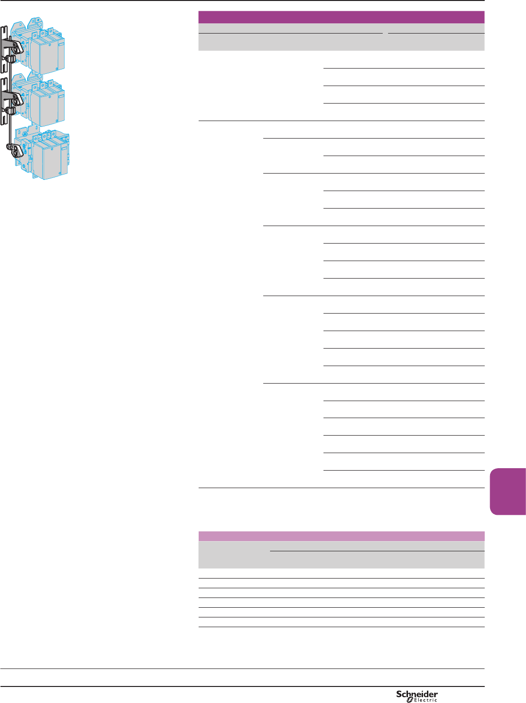
B9/41
TeSys LA9F
High power
contactors
813216.eps
LA9 Fp4p4p
Mechanical interlock kits (continued)
Contactor type (1) Mechanical interlock (2)
Top Middle Bottom Kit reference (3) Weight
kg
LC1 F500, F5002
or F5004
(continued)
LC1 F500, F5002
or F5004
LC1 F185, F225,
F1854 or F2254
LA9FK4K4G 1.669
LC1 F265, F330,
F2654 or F3304
LA9FK4K4H 1.825
LC1 F400, F4002
or F4004
LA9FK4K4J 1.896
LC1-F500, F5002
or F5004
LA9FK4K4K 1.896
LC1 F630, F800,
F6302 or F6304
LC1 F115, F150,
F1154 or F1504
LC1 F115, F150,
F1154 or F1504
LA9FL4F4F 1.428
LC1 F185, F225,
F1854 or F2254
LC1 F115, F150,
F1154 or F1504
LA9FL4G4F 1.431
LC1 F185, F225,
F1854 or F2254
LA9FL4G4G 1.436
LC1 F265, F330,
F2654 or F3304
LC1 F115, F150,
F1154 or F1504
LA9FL4H4F 1.602
LC1 F185, F225,
F1854 or F2254
LA9FL4H4G 1.606
LC1 F265, F330,
F2654 or F3304
LA9FL4H4H 1.751
LC1 F400, F4002
or F4004
LC1 F115, F150,
F1154 or F1504
LA9FL4J4F 1.673
LC1 F185, F225,
F1854 or F2254
LA9FL4J4G 1.676
LC1 F265, F330,
F2654 or F3304
LA9FL4J4H 1.832
LC1 F400, F4002
or F4004
LA9FL4J4J 1.903
LC1-F500, F5002
or F5004
LC1 F115, F150,
F1154 or F1504
LA9FK4K4F 1.666
LC1 F185, F225,
F1854 or F2254
LA9FK4K4G 1.669
LC1 F265, F330,
F2654 or F3304
LA9FK4K4H 1.825
LC1 F400, F4002
or F4004
LA9FK4K4J 1.896
LC1-F500, F5002
or F5004
LA9FK4K4K 1.896
LC1 F630, F800,
F6302 or F6304
LC1 F115, F150,
F1154 or F1504
LA9FL4L4F 1.680
LC1 F185, F225,
F1854 or F2254
LA9FL4L4G 1.683
LC1 F265, F330,
F2654 or F3304
LA9FL4L4H 1.910
LC1 F400, F4002
or F4004
LA9FL4L4J 1.896
LC1 F500, F5002
or F5004
LA9FL4L4K 1.896
LC1 F630, F800,
F6302, or F6304
LA9FL4L4L 1.920
(1)7RRUGHUWKHFRQWDFWRUVVHHSDJHV%DQG%)RUDX[LOLDU\FRQWDFWEORFNVLAD N02
XVHGIRUHOHFWULFDOORFNLQJVHHSDJH%)RUDFFHVVRULHVVHHSDJHV%WR%
(2)0LQLPXPGLVWDQFHVEHWZHHQFRQWDFWRUV
7KLVLVWKHGLVWDQFHLQPPEHWZHHQWKHFHQWUHVRIWZRDGMDFHQWFRQWDFWRUVEHWZHHQWKHWRSDQG
PLGGOHFRQWDFWRUVRUEHWZHHQWKHPLGGOHDQGERWWRPFRQWDFWRUV
Contactor
Bottom or top Middle
LC1 F115
or F150
LC1 F185
or F225
LC1 F265
or F330
LC1 F400 LC1 F500 LC1 F630
or F800
LC1 F115 or F150 200 210 240 250 270 320
LC1 F185 or F225 210 220 250 250 270 330
LC1 F265 or F330 240 250 250 260 280 350
LC1 F400 250 250 260 260 280 320
LC1 F500 270 270 280 280 300 340
LC1 F630 or F800 320 330 350 320 340 380
(3)7KHNLWFRQWDLQVWKHOHYHUDUPVWKH[PPURGVDQGDOOSDUWVUHTXLUHGIRUDVVHPEO\
Selection:
pages B10/50 to B10/73
TeSys contactors
TeSys F contactors
Accessories for assembly of reversing contactors
and changeover contactor pairs using 3 contactors,
vertically mounted - for customer assembly
References
PCPB09P30-EN Version : 1.0 18 novembre 2014 12:55 PM
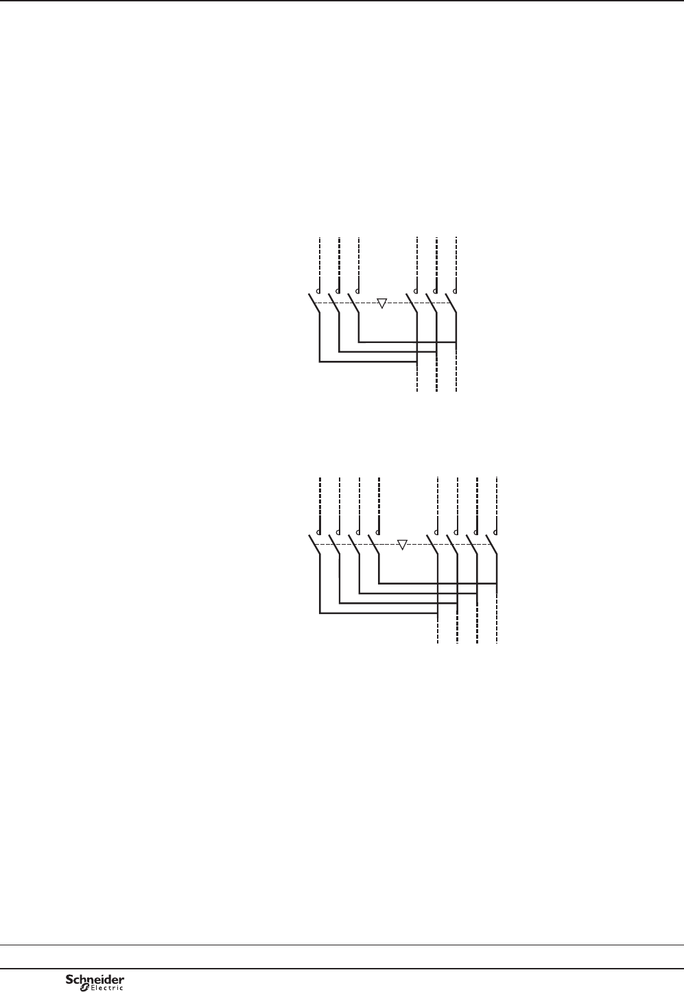
B9/42
TeSys LA9F
TeSys contactors
High power changeover contactor pairs
for distribution
Control circuit: a.c. or d.c.
General
A changeover contactor pair ensures continuity of operation of an installation
and energy management.
It switches between:
b a power supply source M (main) which normally supplies the installation
b and a power supply source S (standby) which may be an incoming line from
an additional network or a generating set.
The supply sources may be 3-phase or 3-phase + neutral.
Supply - 3-phase
– KM1 – KM2
2
4
6
1/1L1
3/1L2
5/1L3
1/2L1
3/2L2
5/2L3
2
4
6
U/L1
V/L2
W/L3
Main Standby
Application
813220.eps
Supply 3-phase + neutral
2
4
6
2
4
8
U/L1
V/L2
N
6W/L3
87/1N
1/2L1
3/2L2
5/2L3
7/2N
– KM1 – KM2
1/1L1
3/1L2
5/1L3
StandbyMain
Application
813219.eps
The 2 contactors must be mechanically and electrically interlocked to prevent any
paralleling, even transitory, of the two supplies.
General
Dimensions:
pages B9/104 and B9/105
Schemes:
page B9/105
PCPB09P30-EN
Version : 1.0 18 novembre 2014 12:55 PM
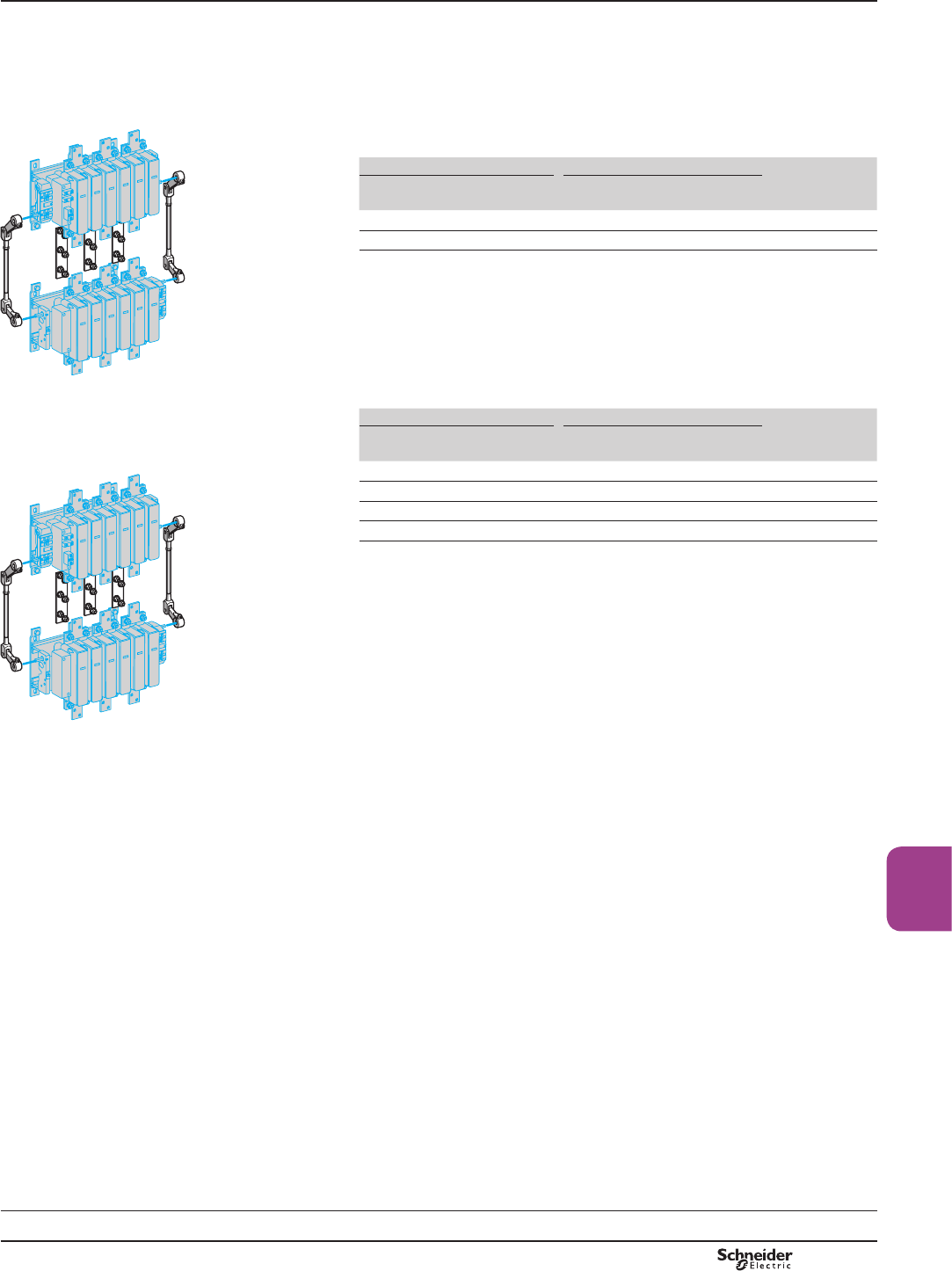
B9/43
TeSys LA9F
High power
contactors
TeSys contactors
High power changeover contactor pairs
for distribution
Control circuit: a.c. or d.c.
Changeover contactor pairs for customer
assembly: 3-phase
Vertically mounted.
Maximum operational voltage: 1000 V.
Utilisation category: AC-1.
Maximum temperature in the vicinity of the devices: 40 °C.
0D[LPXPRSHUDWLRQDOFXUUHQW Contactors (1) Mechanical
interlock (2)
Main Standby Main Standby
3-phase 3-phase Reference Reference Reference
1600 A 1000 A LC1F780 LC1F6309 LA9FX970
1600 A 1600 A LC1F780 LC1F780 LA9FX970
Changeover contactor pairs for customer
assembly: 3-phase + neutral
Vertically mounted.
Maximum operational voltage: 1000 V.
Utilisation category: AC-1.
Maximum temperature in the vicinity of the devices: 40 °C.
0D[LPXPRSHUDWLRQDOFXUUHQW Contactors (1) Mechanical
interlock (2)
Main Standby Main Standby
3-phase + N 3-phase + N Reference Reference Reference
1600 A + 1000 A 1000 A + 1000 A LC1F78041 LC1F63049 LA9FX970 (3)
1600 A + 1000 A 1600 A + 1000 A LC1F78041 LC1F78040 LA9FX970 (3)
1600 A + 1600 A 1000 A + 1000 A LC1F7804 LC1F63049 LA9FX971
1600 A + 1600 A 1600 A + 1600 A LC1F7804 LC1F7804 LA9FX971
(1) Coils to be ordered separately, see pages B9/17 to B9/26.
(2)'RXEOHPHFKDQLFDOLQWHUORFNPHFKDQLVPZLWKLQWHUORFNFRQQHFWLQJURGVDQGSRZHU
FRQQHFWLQJOLQNV7RRUGHUWKHWKHDX[LOLDU\FRQWDFWEORFNVLAD Np1UHTXLUHGWRREWDLQ
HOHFWULFDOLQWHUORFNLQJEHWZHHQWKHFRQWDFWRUVVHHSDJH%
(3)1HXWUDOFRQQHFWLQJOLQNQRWVXSSOLHGWREHRUGHUHGVHSDUDWHO\
References
LA9 FX970
813221.eps
LA9 FX971
813221.eps
Dimensions:
pages B9/104 and B9/105
Schemes:
page B9/105
PCPB09P30-EN Version : 1.0 18 novembre 2014 12:55 PM

B9/44 PCPB09P30-EN
Version : 1.0 18 novembre 2014 12:55 PM

B9/45
High power
contactors
Technical
Data for
Designers
TeSys F
Contents
TeSys F contactors:
> characteristics ...................... B9/46 to B9/53
> dimensions ............................. B9/54 to B9/59
> schemes ................................ B9/60 and B9/61
TeSys VëYacuum contactors:
> selection
and characteristics ......... B9/62 and B9/63
> dimensions ......................... B9/64 and B9/65
> schemes ....................................B9/64 to B9/67
TeSys FG shockproof contactors:
> presentation
and selection ..........................B9/68 to B9/75
> characteristics ....................... B9/76 to B9/83
> dimensions
and schemes ...................... B9/84 and B9/85
TeSys CR1F magnetic
latching
contactors
:
> selection .................................... B9/86 to B9/91
> characteristics ....................... B9/92 to B9/95
> dimensions .............................. B9/96 to B9/99
TeSys F - reversing contactors:
> dimensions ........................B9/100 to B9/102
> schemes .......................................................B9/103
TeSys F - high power changeover
contactor pairs for distribution:
> dimensions ....................B9/104 and B9/105
> schemes .......................................................B9/105
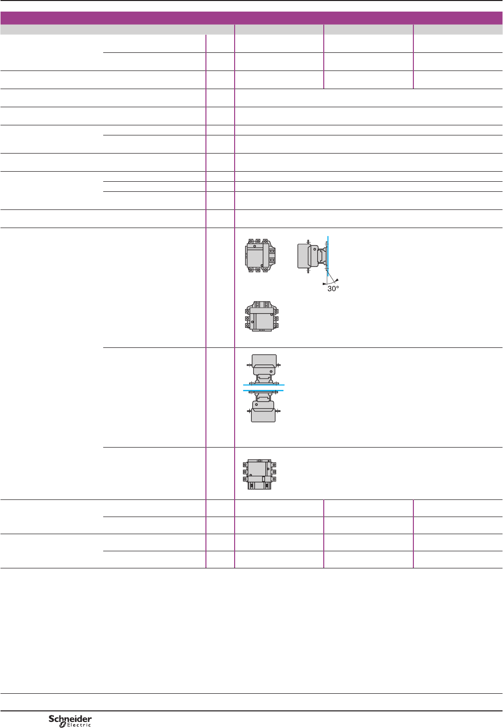
TeSys F
Characteristics TeSys contactors
TeSys F contactors (115 to 2100 A)
Control circuit: a.c. or d.c.
Environment
Contactor type LC1 F115 LC1 F150 LC1 F185
Rated insulation voltage (Ui) Conforming to IEC 60947-4-1 V1000 1000 1000
Conforming to VDE 0110 gr C V1500 1500 1500
Rated impulse withstand
voltage (Uimp)
Coil not connected to the
power circuit
kV 888
Conforming to standards EN 60947-1, EN 60947-4-1, IEC 60947-1, IEC 60947-4-1, JEM 1038
3URGXFWFHUWL¿FDWLRQV CSA, UL, BV, GL, DNV, RINA, RMROS, LROS, CCC
Degree of protection Conforming to IEC 60529 IP 2X front face with shrouds LA9 F
Conforming to VDE 0106 )URQWIDFHSURWHFWHGDJDLQVWGLUHFW¿QJHUFRQWDFWZLWKVKURXGV/$)
Protective treatment Standard version “TH”
Ambient air temperature around
the device
Storage °C -60…+80
Operation °C -5…+55
Permissible at Uc (1) °C -40…+70
Maximum operating altitude Without derating m3000
Operating positions Without derating
With derating
$SSO\WKHIROORZLQJGHUDWLQJFRHI¿FLHQWVRQWKHSXOOLQ
voltage, 0.9 on the drop-out voltage and 0.8 on the operational
current in AC-1.
$SSO\WKHIROORZLQJGHUDWLQJFRHI¿FLHQWVRQWKHSXOOLQ
voltage, 1.1 on the drop-out voltage and 0.8 on the operational
current in AC-1.
In either case: neither the making and breaking capacities nor the electrical and
mechanical durabilities can be assured.
Not to be used
Shock resistance (2)
1/2 sine wave = 11 ms
Contactor open 9 gn 9 gn 7 gn
Contactor closed 15 gn 15 gn 15 gn
Vibration resistance (2)
5…300 Hz
Contactor open 2 gn 2 gn 2 gn
Contactor closed 6 gn 6 gn 5 gn
(1),QWKHVHFRQGLWLRQVLWLVUHFRPPHQGHGWKDW/;)FRLOVEHXVHGIRUFRQWDFWRUVL]HV)
to F225.
(2),QWKHOHDVWIDYRXUDEOHGLUHFWLRQZLWKRXWFKDQJHRIFRQWDFWVWDWHFRLODW8F:KHUHKLJKHU
UHVLVWDQFHWRPHFKDQLFDOVKRFNLVUHTXLUHGVHOHFWVKRFNSURRIFRQWDFWRUV3OHDVHFRQVXOW
\RXU5HJLRQDO6DOHV2I¿FH
(not to be used for LC1 F780, F1700 and F2100)
813073.eps
813074.eps
813075.eps813076.eps813077.eps813078.eps
Selection:
pages B10/50 to B10/73
References:
pages B9/2 and B9/3
Dimensions:
pages B9/54 to B9/56
Schemes:
page B9/61
PCPB09T10-EN
Version : 1.0 18 novembre 2014 12:55 PM
B9/46
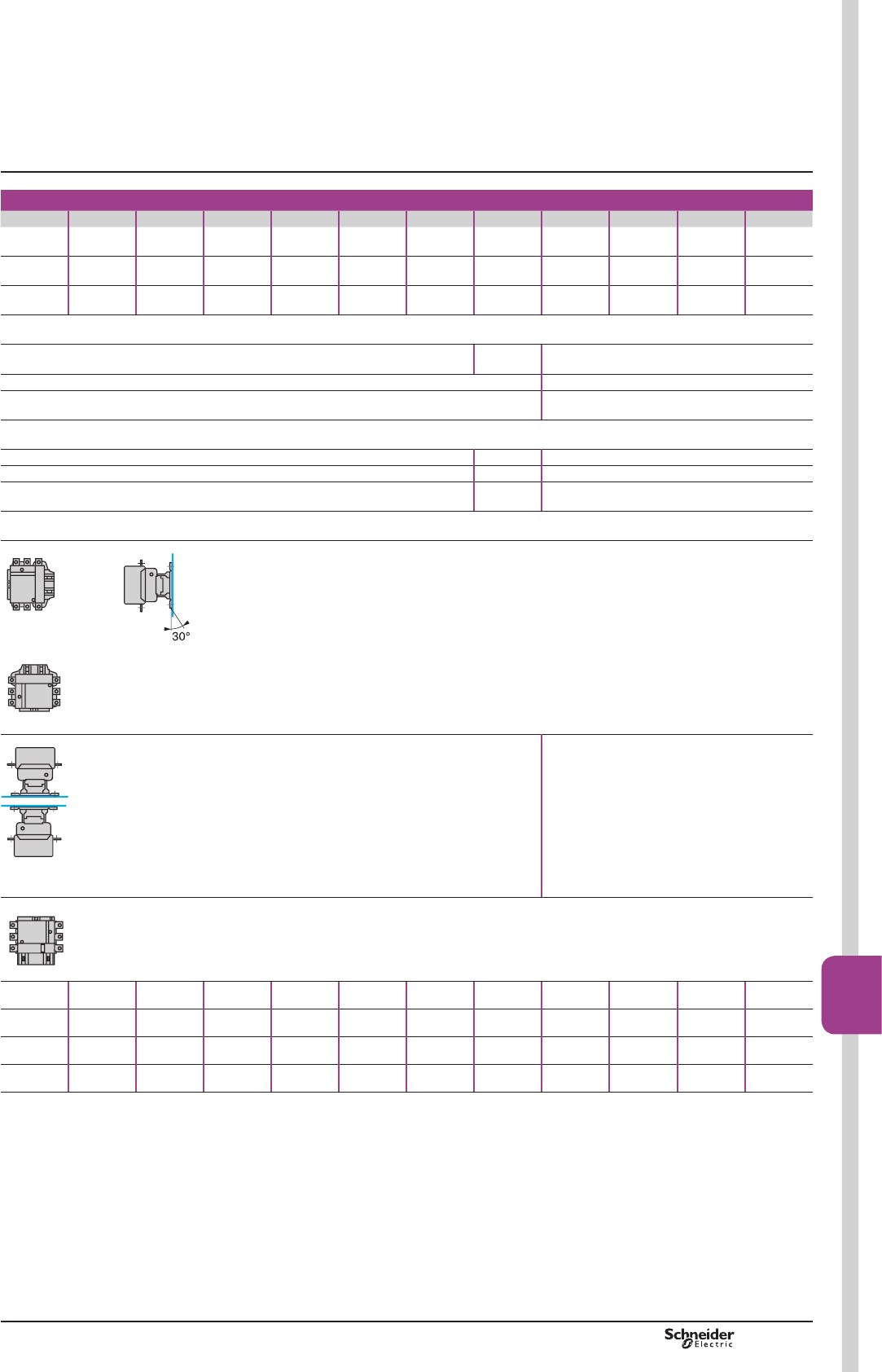
TeSys F
LC1 F225 LC1 F265 LC1 F330 LC1 F400 LC1 F500 LC1 F630 LC1 F780 LC1 F800 LC1 F1250 LC1 F1400 LC1 F1700 LC1 F2100
1000 1000 1000 1000 1000 1000 1000 1000 1000 1000 1000 1000
1500 1500 1500 1500 1500 1500 1500 1500 1500 1500 1500 1500
8 88888888888
EN 60947-1, EN 60947-4-1, IEC 60947-1, IEC 60947-4-1, JEM 1038
CSA, UL, BV, GL, DNV, RINA, RMROS, LROS, CCC UL, CSA,
GL, LROS
CSA, CCC, ETL-UL
IP 20 front face with shrouds LA9 F –
)URQWIDFHSURWHFWHGDJDLQVWGLUHFW¿QJHUFRQWDFWZLWKVKURXGV/$) –
“TH”
-60…+80 -60…+80 -60…+80
-5…+55 -5…+55 -5…+40
-40…+70 -5…+55 -40…+60
3000
$SSO\WKHIROORZLQJGHUDWLQJFRHI¿FLHQWVRQWKHSXOOLQYROWDJH
on the drop-out voltage and 0.8 on the operational current in AC-1.
$SSO\WKHIROORZLQJGHUDWLQJFRHI¿FLHQWVRQWKHSXOOLQYROWDJH
on the drop-out voltage and 0.8 on the operational current in AC-1.
In either case: neither the making and breaking capacities nor the electrical
and mechanical durabilities can be assured.
Not to be used
7 gn 6 gn 6 gn 6 gn 9 gn 6 gn 5 gn 6 gn 6 gn 6 gn 6 gn 6 gn
15 gn 15 gn 15 gn 15 gn 15 gn 15 gn 15 gn 15 gn 15 gn 15 gn 15 gn 15 gn
2 gn 2 gn 2 gn 1.5 gn 2 gn 2 gn 2.5 gn 2 gn 2 gn 2 gn 2 gn 2 gn
5 gn 5 gn 5 gn 5 gn 4 gn 4 gn 5.5 gn 4 gn 4 gn 4 gn 4 gn 4 gn
(not to be used for LC1 F780, F1400, F1700 and F2100)
813073.eps813075.eps
813074.eps
813076.eps
813077.eps813078.eps
Characteristics TeSys contactors
TeSys F contactors (115 to 2100 A)
Control circuit: a.c. or d.c.
PCPB09T10-EN Version : 1.0 18 novembre 2014 12:55 PM
B9/47
High power
contactors
B9/47
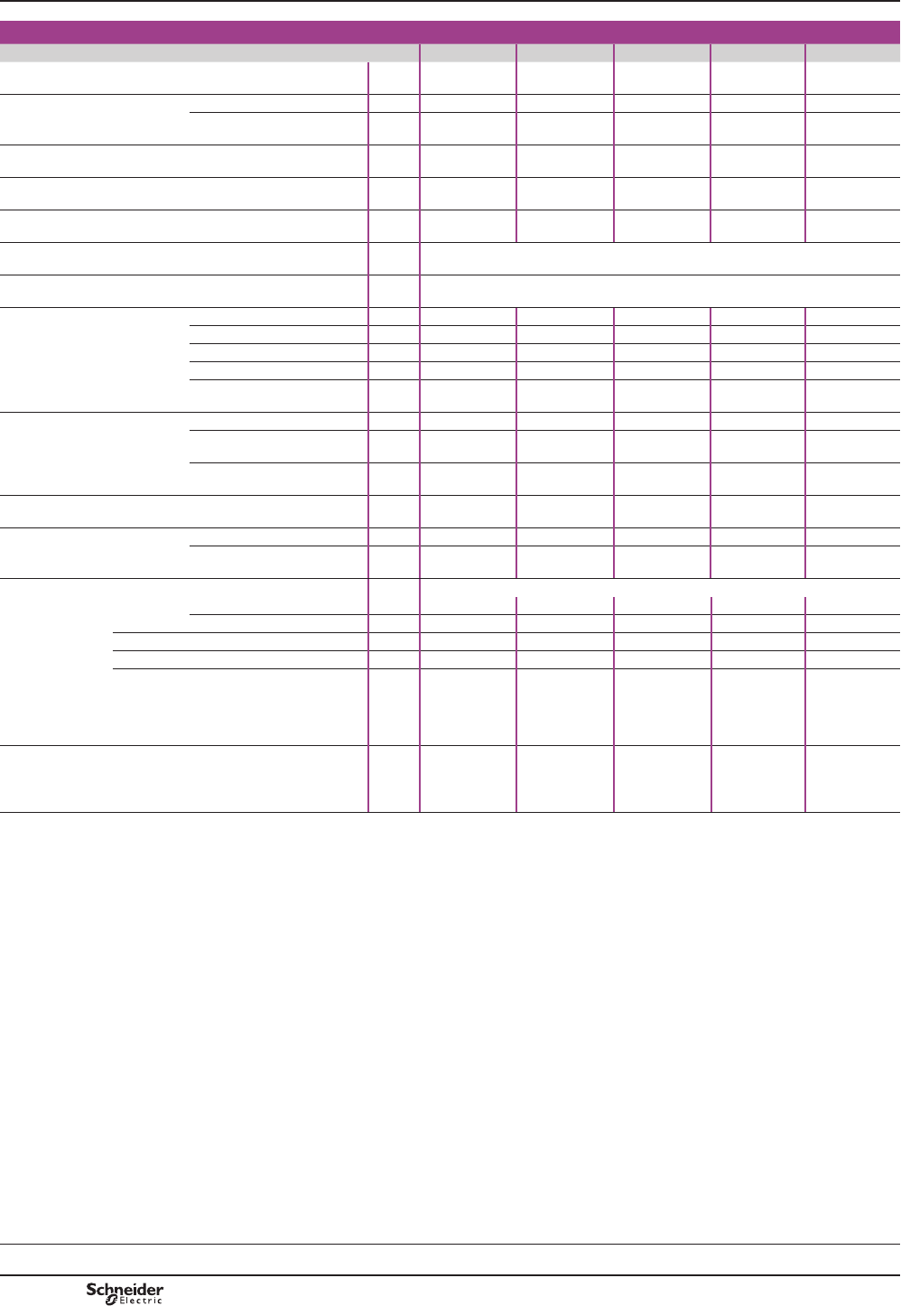
TeSys F
Characteristics
Pole characteristics
Contactor type LC1 F115 LC1 F150 LC1 F185 LC1 F225 LC1 F265
Number of poles 3 or 4 3 or 4 3 or 4 3 or 4 3 or 4
Rated operational current (le)
(Ue y 440 V) In AC-3, T y 55 °C A115 150 185 225 265
In AC-1, T y 40 °C A200 250 275 315 350
Rated operational voltage
(Ue)
Up to V1000 1000 1000 1000 1000
Frequency limits Of the operational current (1) Hz 162/3…200 162/3…200 162/3…200 162/3…200 162/3…200
Conventional thermal current T y 40 °C A200 250 275 315 350
Rated making capacity I rms conforming to
IEC 60947-4-1
AMaking current: 10 x I in AC-3 or 12 x I in AC-4
Rated breaking capacity I rms conforming to
IEC 60947-4-1
AMaking and breaking current: 8 x I in AC-3 or 10 x I in AC-4
Maximum permissible current
1RFXUUHQWÀRZLQJIRUSUHYLRXV
60 minutes, at T y 40 °C
For 10 s A1100 1200 1500 1800 2200
For 30 s A640 700 920 1000 1230
For 1 min A520 600 740 850 950
For 3 min A400 450 500 560 620
For 10 min A320 350 400 440 480
Short-circuit protection
by fuses
U y 440 V
Motor circuit (type aM) A125 160 200 250 315
With thermal overload relay
(type gG)
A200 200 315 315 500
gG fuses A200 250 315 315 400
Average impedance per pole At lth and 50 Hz m:0.37 0.35 0.33 0.32 0.3
Power dissipation per pole
for the above
operational currents
AC-3 W5 8 12 16 21
AC-1 W15 22 25 32 37
Connection Maximum c.s.a.
Bar Number of bars 2 2 2 2 2
Bar mm 20 x 3 25 x 3 25 x 3 32 x 4 32 x 4
Cable with lug mm295 120 150 185 240
Cable with connector mm295 120 150 185 240
Bolt diameter mm Ø6 Ø8 Ø8 Ø10 Ø10
Tightening torque Power circuit connections N.m 10 18 18 35 35
(1)6LQHZDYHZLWKRXWLQWHUIHUHQFH$ERYHWKHVHYDOXHVSOHDVHFRQVXOW\RXU5HJLRQDO6DOHV
2I¿FH
(2):LWKVHWRIULJKWDQJOHGFRQQHFWRUVLA9 F2100 (see page B9/13).
(3)3DUDOOHOLQJRISROHVPXVWEHFDUULHGRXWRQO\LQDFFRUGDQFHZLWKWKHIXVHPDQXIDFWXUHUV
recommendations.
TeSys contactors
TeSys F contactors (115 to 2100 A)
Control circuit: a.c. or d.c.
Selection:
pages B10/50 to B10/73
References:
pages B9/2 and B9/3
Dimensions:
pages B9/54 to B9/56
Schemes:
page B9/61
PCPB09T10-EN
Version : 1.0 18 novembre 2014 12:55 PM
B9/48
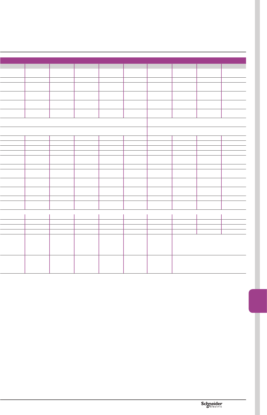
TeSys F
LC1 F330 LC1 F400 LC1 F500 LC1 F630 LC1 F780 LC1 F800 LC1 F1250 LC1 F1400 LC1 F1700 LC1 F2100
3 or 4 2, 3 or 4 2, 3 or 4 2, 3 or 4 3 or 4 3 3 3 3 3
330 400 500 630 780 800 - - - -
400 500 700 1000 1600 1000 1260 1400 1700 2100 (2)
1000 1000 1000 1000 1000 1000 1000 1000 1000 1000
162/3…200 162/3…200 162/3…200 162/3…200 162/3…200 162/3…200 162/3…200 162/3…200 162/3…200 162/3…200
400 500 700 1000 1600 1000 1260 1400 1700 2100 (2)
Making current: 10 x I in AC-3 or 12 x I in AC-4 Making current: 1.5 x I in AC-1
Making and breaking current: 8 x I in AC-3 or 10 x I in AC-4 Making and breaking current: 1.5 x I in AC-1
2650 3600 4200 5050 6250 5500 8000 8000 10000 10000
1800 2400 3200 4400 5600 4600 5200 6000 7500 7500
1300 1700 2400 3400 4600 3600 4000 4500 5500 5500
900 1200 1500 2200 3000 2600 3000 4000 4200 4200
750 1000 1200 1600 2200 1700 2000 2600 3000 3000
400 400 500 630 800 800 – – – –
500 630 800 800 1000 1000 – – – –
500 500 800 1000 2 x 800 (3) 1000 1000 2 x 800 (3) 2 x 800 (3) 2 x 1000 (3)
0.28 0.26 0.18 0.12 0.10 0.12 0.12 0.10 0.10 0.10
31 42 45 48 60 77 – – – –
44 65 88 120 250 120 120 150 200 200
Maximum c.s.a.
2 2 2 2 2 2 2 2 3 4
30 x 5 30 x 5 40 x 5 60 x 5 100 x 5 60 x 5 100 x 5 100 x 5 100 x 5 100 x 5
240 2 x 150 2 x 240 – – – – – – –
– – – – – – – – – –
Ø10 Ø10 Ø10 Ø12 2 x Ø12 Ø12 3 x Ø12
Ø11.5 with set
of right-angled
connectors
LA9 F1250)
4 x Ø12 (Ø11.5 with set of right-angled
connectors LA9 F2100)
35 35 35 58 58 58 58 35 with set
of right-angled
connectors
LA9 F1250)
58 35 with set of right-angled
connectors LA9 F2100)
Characteristics TeSys contactors
TeSys F contactors (115 to 2100 A)
Control circuit: a.c. or d.c.
PCPB09T10-EN Version : 1.0 18 novembre 2014 12:55 PM
B9/49
High power
contactors
B9/49
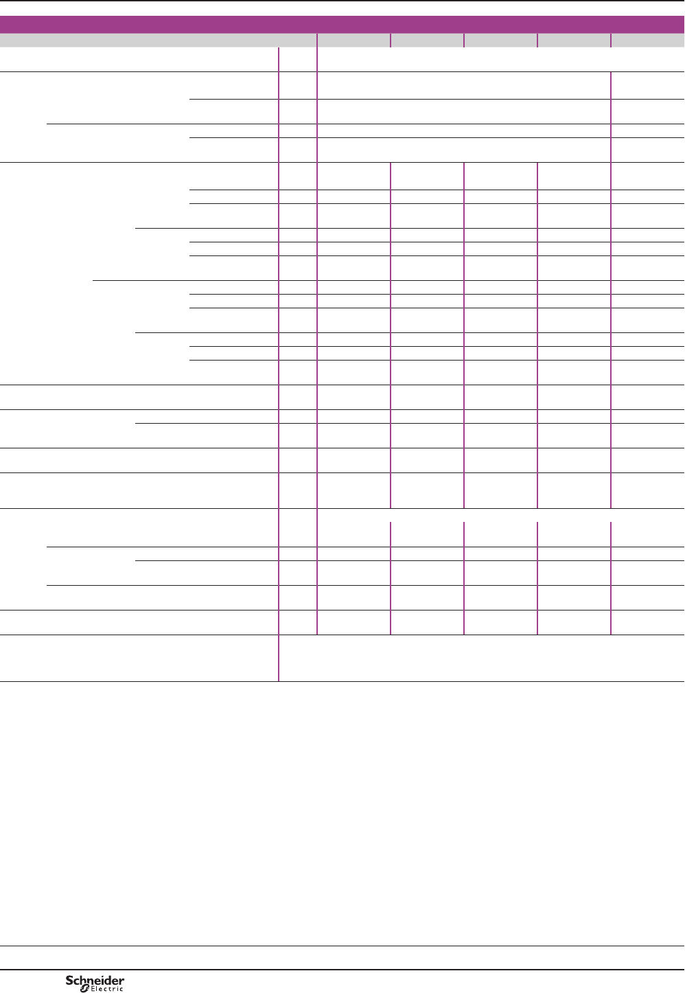
TeSys F
Characteristics
Control circuit characteristics with LX1 or LX9 coil
Contactor type LC1 F115 LC1 F150 LC1 F185 LC1 F225 LC1 F265
Rated control circuit voltage (Uc) 50 or 60 Hz V24…1000
Control voltage limits (Ty 55 °C) Operation 0.85…1.1 Uc –
50 or 60 Hz coils
Drop-out 0.35…0.55 Uc –
40…400 Hz coils Operation –0.85…1.1 Uc
Drop-out –0.35…0.55 Uc
Average consumption at 20 °C and at Uc
a 50 Hz Inrush 50 Hz coil VA 550 550 805 805 –
40…400 Hz coil VA – – – – 650
CosM 0.3 0.3 0.3 0.3 0.9
Sealed 50 Hz coil VA 45 45 55 55 –
40…400 Hz coil VA – – – – 10
Cos M0.3 0.3 0.3 0.3 0.9
a 60 Hz Inrush 60 Hz coil VA 660 660 970 970 –
40…400 Hz coil VA – – – – 650
Cos M0.3 0.3 0.3 0.3 0.9
Sealed 60 Hz coil VA 55 55 66 66 –
40…400 Hz coil VA – – – – 10
Cos M0.3 0.3 0.3 0.3 0.9
Heat dissipation W12…16 12…16 18…24 18…24 8
Operating time (1) Closing "C" ms 23…35 23…35 20…35 20…35 40…65
Opening "O" ms 5…15 5…15 7…15 7…15 100…170
Mechanical durability at Uc In millions of operating cycles 10 10 10 10 10
Maximum operating rate
at ambient temperature
y 55 °C
In operating cycles per hour 2400 2400 2400 2400 2400
Connection Min/max c.s.a.
Flexible cable
without cable end
1 or 2 conductors mm21/4 1/4 1/4 1/4 1/4
Flexible cable
with cable end
1 conductor mm21/4 1/4 1/4 1/4 1/4
2 conductors mm21/2.5 1/2.5 1/2.5 1/2.5 1/2.5
Solid cable
without cable end
1 or 2 conductors mm21/4 1/4 1/4 1/4 1/4
Tightening torque N.m 1.2 1.2 1.2 1.2 1.2
Mechanical latching 0HFKDQLFDOODWFKEORFNV/$'.PXVWQRWEH¿WWHGRQ/&)FRQWDFWRUV
For similar type of operation, use magnetic latching contactors CR1 F.
See pages B9/30 to B9/35.
(1)7KHFORVLQJWLPH&LVPHDVXUHGIURPWKHPRPHQWWKHFRLOVXSSO\LVVZLWFKHGRQWRLQLWLDO
FRQWDFWRIWKHPDLQSROHV7KHRSHQLQJWLPH2LVPHDVXUHGIURPWKHPRPHQWWKHFRLOVXSSO\
LVVZLWFKHGRIIWRWKHPRPHQWWKHPDLQSROHVVHSDUDWH
(2)&RQWUROFLUFXLWFKDUDFWHULVWLFVZLWK/;FRLO
TeSys contactors
TeSys F contactors (115 to 2100 A)
Control circuit: a.c.
Selection:
pages B10/50 to B10/73
References:
pages B9/2 and B9/3
Dimensions:
pages B9/54 to B9/56
Schemes:
page B9/61
PCPB09T10-EN
Version : 1.0 18 novembre 2014 12:55 PM
B9/50

TeSys F
LC1 F330 LC1 F400 LC1 F500 LC1 F630 LC1 F780 LC1 F800 LC1 F1250 LC1 F1400 LC1 F1700 LC1 F2100
24…1000 48…1000 48…1000 110…500 110…400 110...600 110...500 (2) 110…500 (2) 110…500 (2)
–
–
0.85…1.1 Uc 0.85…1.1 Uc 0.85…1.1 Uc 0.85…1.1 Uc 0.85…1.1 Uc 0.85…1.1 Uc 0.85…1.1 Uc 0.85…1.1 Uc 0.85…1.1 Uc
0.35…0.55 Uc 0.3…0.5 Uc 0.25…0.5 Uc 0.2…0.4 Uc 0.3…0.5 Uc 0.25...0.5 Uc 0.3…0.5 Uc 0.3…0.5 Uc 0.3…0.5 Uc
– – – – – – – – – –
650 1075 1100 1650 2100 1700 1650 2200 2200 2200
0.9 0.9 0.9 0.9 0.9 0.9 0.9 0.9 0.9 0.9
– – – – – – – – – –
10 15 18 22 50 12 22 36 36 36
0.9 0.9 0.9 0.9 0.9 –0.9 0.9 0.9 0.9
– – – – – – – – – –
650 1075 1100 1650 2100 1700 1650 2200 2200 2200
0.9 0.9 0.9 0.9 0.9 0.9 0.9 0.9 0.9 0.9
– – – – – – – – – –
10 15 18 22 50 12 22 36 36 36
0.9 0.9 0.9 0.9 0.9 –0.9 0.9 0.9 0.9
8 14 18 20 2 x 22 25 20 2 x 18 2 x 18 2 x 18
40…65 40…75 40…75 40…80 40…80 60…80 40…80 40…75 40…75 40…75
100…170 100…170 100…170 100…200 130…230 150…180 100...200 100...170 100…170 100…170
10 10 10 5 5 5 1 0.5 0.5 0.5
2400 2400 2400 1200 600 600 1200 600 600 600
Min/max c.s.a.
1/4 1/4 1/4 1/4 1/4 1/4 1/4 1/4 1/4 1/4
1/4 1/4 1/4 1/4 1/4 1/4 1/4 1/4 1/4 1/4
1/2.5 1/2.5 1/2.5 1/2.5 1/2.5 1/2.5 1/2.5 1/2.5 1/2.5 1/2.5
1/4 1/4 1/4 1/4 1/4 1/4 1/4 1/4 1/4 1/4
1.2 1.2 1.2 1.2 1.2 1.2 1.2 1.2 1.2 1.2
0HFKDQLFDOODWFKEORFNV/$'.PXVWQRWEH¿WWHGRQ/&)FRQWDFWRUV
For similar type of operation, use magnetic latching contactors CR1 F.
See pages B9/30 to B9/35.
Characteristics TeSys contactors
TeSys F contactors (115 to 2100 A)
Control circuit: a.c.
PCPB09T10-EN Version : 1.0 18 novembre 2014 12:55 PM
B9/51
High power
contactors
B9/51
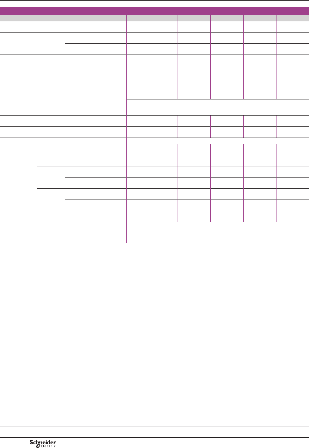
TeSys F
Characteristics
Control circuit characteristics with LX4 coil
Contactor type LC1 F115 LC1 F150 LC1 F185 LC1 F225 LC1 F265
Rated control circuit voltage (Uc) cV24…460 24…460 24…460 24…460 24…460
Control voltage limits
(T y 55 °C)
Operation 0.85…1.1 Uc 0.85…1.1 Uc 0.85…1.1 Uc 0.85…1.1 Uc 0.85…1.1 Uc
Drop-out 0.15…0.2 Uc 0.15…0.2 Uc 0.15…0.2 Uc 0.15…0.2 Uc 0.15…0.2 Uc
Average consumption
at 20 °C and at Uc
cInrush W560 560 800 800 750
Sealed W4.5 4.5 5 55
Average operating time
at Uc (1)
Closing "C" ms 30…40 30…40 30…40 30…40 40…50
Opening "O" ms 30…50 30…50 30…50 30…50 40…65
Note:WKHDUFLQJWLPHGHSHQGVRQWKHFLUFXLWVZLWFKHGE\WKHSROHV)RUDOOQRUPDOSKDVH
DSSOLFDWLRQVWKHDUFLQJWLPHLVOHVVWKDQPV7KHORDGLVLVRODWHGIURPWKHVXSSO\DIWHUDWLPH
HTXDOWRWKHVXPRIWKHRSHQLQJWLPHDQGWKHDUFLQJWLPH
Mechanical durability at Uc In millions of operating cycles 10 10 10 10 10
Maximum operating rate at
ambient temperature y 55 °C
In operating cycles per hour 2400 2400 2400 2400 2400
Cabling Min/max c.s.a.
Flexible cable
without cable
end
1 conductor mm21/4 1/4 1/4 1/4 1/4
2 conductors mm21/4 1/4 1/4 1/4 1/4
Flexible cable
with cable
end
1 conductor mm21/4 1/4 1/4 1/4 1/4
2 conductors mm21/2.5 1/2.5 1/2.5 1/2.5 1/2.5
Solid cable
without cable
end
1 conductor mm21/4 1/4 1/4 1/4 1/4
2 conductors mm21/4 1/4 1/4 1/4 1/4
Tightening torque N.m 1.2 1.2 1.2 1.2 1.2
Mechanical latching 0HFKDQLFDOODWFKEORFNV/$'.PXVWQRWEH¿WWHGRQ/&)FRQWDFWRUV
For similar type of operation, use magnetic latching contactors CR1 F.
See pages B9/30 to B9/35.
(1)7KHRSHUDWLQJWLPHVGHSHQGRQWKHW\SHRIFRQWDFWRUHOHFWURPDJQHWDQGLWVFRQWUROPRGH
7KHFORVLQJWLPH&LVPHDVXUHGIURPWKHPRPHQWWKHFRLOVXSSO\LVVZLWFKHGRQWRLQLWLDO
FRQWDFWRIWKHPDLQSROHV7KHRSHQLQJWLPH2LVPHDVXUHGIURPWKHPRPHQWWKHFRLOVXSSO\
LVVZLWFKHGRIIWRWKHPRPHQWWKHPDLQSROHVVHSDUDWH
TeSys contactors
TeSys F contactors (115 to 2100 A)
Control circuit: d.c
Selection:
pages B10/50 to B10/73
References:
pages B9/2 and B9/3
Dimensions:
pages B9/54 to B9/56
Schemes:
page B9/61
PCPB09T10-EN
Version : 1.0 18 novembre 2014 12:55 PM
B9/52
TeSys F
LC1 F330 LC1 F400 LC1 F500 LC1 F630 LC1 F780 LC1 F800 LC1 F1250 LC1 F1400 LC1 F1700 LC1 F2100
24…460 48…440 48…440 48…440 110…440 110…400 48…250 110…440 110…440 110…440
0.85…1.1 Uc 0.85…1.1 Uc 0.85…1.1 Uc 0.85…1.1 Uc 0.85…1.1 Uc 0.85…1.1 Uc 0.85…1.1 Uc 0.85…1.1 Uc 0.85…1.1 Uc 0.85…1.1 Uc
0.15…0.2 Uc 0.2…0.35 Uc 0.2…0.35 Uc 0.2…0.35 Uc 0.2…0.4 Uc 0.3…0.5 Uc 0.2…0.35 Uc 0.2…0.35 Uc 0.2…0.35 Uc 0.2…0.35 Uc
750 1000 1100 1600 2 x 1000 1900 1600 2100 2100 2100
5 6 6 9 2 x 21 12 9 10 10 10
40…50 50…60 50…60 60…70 70…80 60…80 60…70 50…60 50…60 50…60
40…65 45…60 45…60 40…50 100…130 40…50 40…50 45…60 45…60 45…60
Note: WKHDUFLQJWLPHGHSHQGVRQWKHFLUFXLWVZLWFKHGE\WKHSROHV)RUDOOQRUPDOSKDVHDSSOLFDWLRQVWKHDUFLQJWLPHLVOHVVWKDQPV7KHORDGLVLVRODWHGIURP
WKHVXSSO\DIWHUDWLPHHTXDOWRWKHVXPRIWKHRSHQLQJWLPHDQGWKHDUFLQJWLPH
10 10 10 5 5 5 1 0.5 0.5 0.5
2400 2400 2400 1200 600 600 1200 600 600 600
Min/max c.s.a.
1/4 1/4 1/4 1/4 1/4 1/4 1/4 1/4 1/4 1/4
1/4 1/4 1/4 1/4 1/4 1/4 1/4 1/4 1/4 1/4
1/4 1/4 1/4 1/4 1/4 1/4 1/4 1/4 1/4 1/4
1/2.5 1/2.5 1/2.5 1/2.5 1/2.5 1/2.5 1/2.5 1/2.5 1/2.5 1/2.5
1/4 1/4 1/4 1/4 1/4 1/4 1/4 1/4 1/4 1/4
1/4 1/4 1/4 1/4 1/4 1/4 1/4 1/4 1/4 1/4
1.2 1.2 1.2 1.2 1.2 1.2 1.2 1.2 1.2 1.2
0HFKDQLFDOODWFKEORFNV/$'.PXVWQRWEH¿WWHGRQ/&)FRQWDFWRUV
For similar type of operation, use magnetic latching contactors CR1 F.
See pages B9/30 to B9/35.
Characteristics TeSys contactors
TeSys F contactors (115 to 2100 A)
Control circuit: d.c
PCPB09T10-EN Version : 1.0 18 novembre 2014 12:55 PM
B9/53
High power
contactors
B9/53
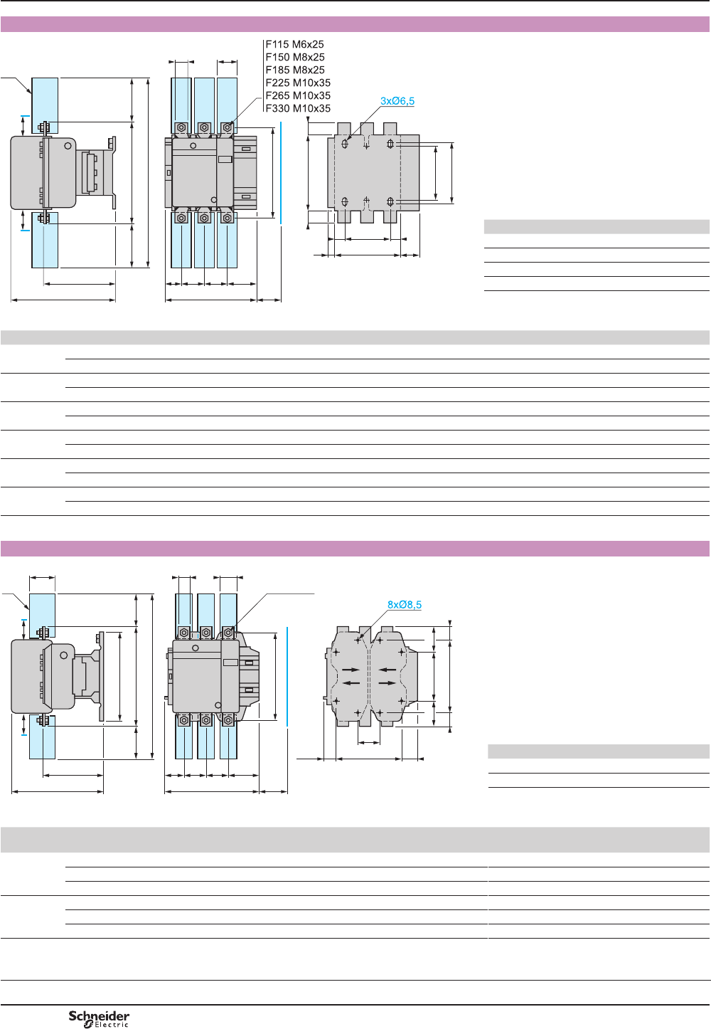
TeSys F
Dimensions
LC1 F115 to F330
J
J1
b1 ==
G1
GZ
= =
Y
L
c
= b =
b2
X1X1
S1
Q
a
P P Q1
f
M
S
(1)
DF568677.eps
X1 (mm) = Minimum electrical clearance according
to operating voltage and breaking capacity.
LC1 200...500 V 600…1000 V
F115, F150 10 15
F185 10 15
F225, F265 10 15
F330 10 15
(1)3RZHUWHUPLQDOSURWHFWLRQVKURXG
(see page B9/14).
LC1 a b b1 b2 c f G G1 J J1 L M P Q Q1 S S1 Y Z
F115 3P 163.5 162 137 265 171 131 106 80 106 120 107 147 37 29.5 60 20 26 44 13.5
4P 200.5 162 137 265 171 131 143 80 106 120 107 147 37 29.5 60 20 26 44 13.5
F150 3P 163.5 170 137 301 171 131 106 80 106 120 107 150 40 26 57.5 20 34 44 13.5
4P 200.5 170 137 301 171 131 143 80 106 120 107 150 40 26 55.5 20 34 44 13.5
F185 3P 168.5 174 137 305 181 130 111 80 106 120 113.5 154 40 29 59.5 20 34 44 13.5
4P 208.5 174 137 305 181 130 151 80 106 120 113.5 154 40 29 59.5 20 34 44 13.5
F225 3P 168.5 197 137 364 181 130 111 80 106 120 113.5 172 48 21 51.5 25 44.5 44 13.5
4P 208.5 197 137 364 181 130 151 80 106 120 113.5 172 48 17 47.5 25 44.5 44 13.5
F265 3P 201.5 203 145 375 213 147 142 96 106 120 141 178 48 39 66.5 25 44.5 38 21.5
4P 244.5 203 145 375 213 147 190 96 106 120 141 178 48 34 66.5 25 44.5 38 21.5
F330 3P 213 206 145 375 219 147 154.5 96 106 120 145 181 48 43 74 25 44.5 38 20.5
4P 261 206 145 375 219 147 202.5 96 106 120 145 181 48 43 74 25 44.5 38 20.5
f = minimum distance required for coil removal.
LC1 F400 and F500
G
G123,5 J
120 ==
180 ==
L
c
=b =
b2
209
56
X1X1
Q1
a
PQ P
f
M
44,5S
6xM10x35
(1)
DF568678.eps
X1 (mm) = Minimum electrical clearance according
to operating voltage and breaking capacity.
LC1 200…500 V 600…1000 V
F400 15 20
F500 15 20
(1)3RZHUWHUPLQDOSURWHFWLRQVKURXG
(see page B9/14).
LC1 a b b2 c f G
supplied
G
min.
G
max.
G1
supplied
G1
min
G1
max.
JL M P Q Q1 S
F400 2P 213 206 375 219 146 80 66 102 170 156 192 19.5 145 181 48 69 96 25
3P 213 206 375 219 146 80 66 102 170 156 192 19.5 145 181 48 43 74 25
4P 261 206 375 219 146 80 66 150 170 156 240 67.5 145 181 48 43 74 25
F500 2P 233 238 400 232 150 80 66 120 170 156 210 39.5 146 208 55 76 102 30
3P 233 238 400 232 150 80 66 120 170 156 210 39.5 146 208 55 46 77 30
4P 288 238 400 232 150 140 66 175 230 156 265 34.5 146 208 55 46 77 30
f = minimum distance required for coil removal.
TeSys contactors
TeSys F contactors
Selection:
pages B10/50 to B10/73
Characteristics:
pages B9/46 to B9/53
References:
pages B9/2 to B9/9
Schemes:
page B9/61
PCPB09T10-EN
Version : 1.0 18 novembre 2014 12:55 PM
B9/54

TeSys F
LC1 F630 and F800
Q1
a
8080Q
264
181 (2)
6440
6xM12x45
155
= 304 =
197
255
280
X1
464
72
X1
(1)
DF568679.eps
185= =
J1G60,5
DB402356.eps
X1 (mm) = Minimum electrical clearance according to operating
voltage and breaking capacity.
LC1 a G
supplied
G
min.
G
PD[
J1 Q Q1 Voltage 200}500 V 690}1000 V 200}690 V 1000 V
F630 2P 309 180 100 195 68.5 102 127 LC1 F630 20 30 – –
F630, F800 3P 309 180 100 195 68.5 60 89 LC1 F800 – – 10 20
F630 4P 389 240 150 275 68.5 60 89 (1) 3RZHUWHUPLQDOSURWHFWLRQVKURXGVHHSDJH%
(2)0LQLPXPGLVWDQFHUHTXLUHGIRUFRLOUHPRYDO
LC1 F780
191
183
(1)
191160 160
183
(1)
60 12xM12x45 26= =
348
400
22 26
3P=702, 4P=862
X1X1
= 280 =
434
165
255
DF568681.eps
X1 (mm) = Minimum electrical clearance according to operating
voltage and breaking capacity.
Voltage 200}500 V 690}1000 V
(1)0LQLPXPGLVWDQFHUHTXLUHGIRUFRLOUHPRYDO X1 (mm) 30 35
)L[LQJFHQWUHVRI/&) )L[LQJFHQWUHVRI/&)
10224090 190 240
185127 127
DB402357.eps
13224090 240
185127 127
DB402358.eps
Dimensions TeSys contactors
TeSys F contactors
Selection:
pages B10/50 to B10/73
Characteristics:
pages B9/46 to B9/53
References:
pages B9/2 to B9/9
Schemes:
page B9/61
PCPB09T10-EN Version : 1.0 18 novembre 2014 12:55 PM B9/55
High power
contactors
B9/55
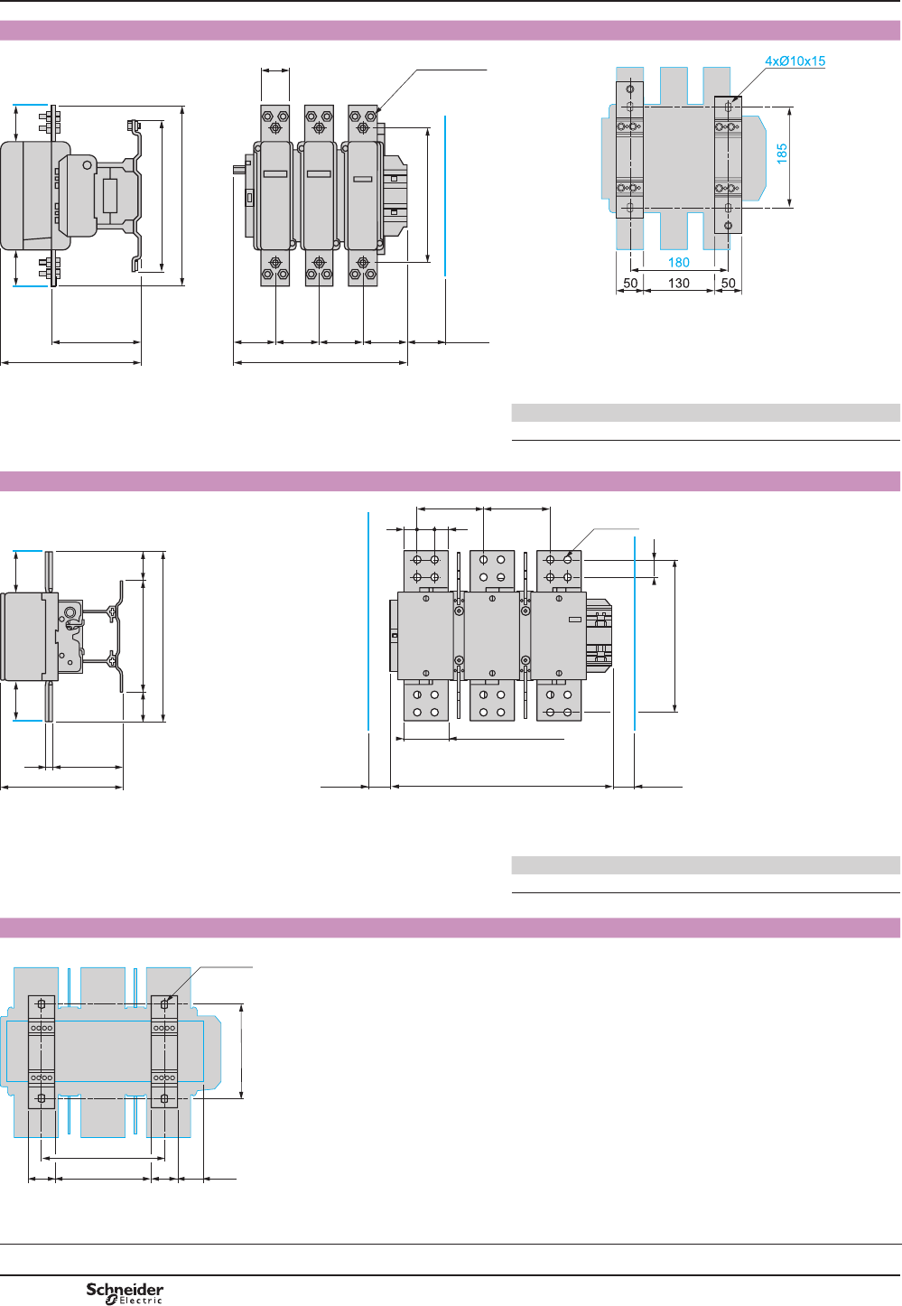
TeSys F
TeSys contactors
TeSys F contactors
Dimensions
LC1 F1250
89
309
808060
264
181 (1)
50 18xM12x50
153.5
338
255
280
X1X1
DB402351.eps
DB402352.eps
(1) 0LQLPXPGLVWDQFHUHTXLUHGIRUFRLOUHPRYDO X1 (mm) = Minimum electrical clearance according to operating
voltage and breaking capacity.
Voltage 200}500 V 690}1000 V
X1 (mm) 20 30
LC1 F1400, LC1 F1700 and LC1 F2100
24xØ14
=
= =
210 =
332
137,314
238,6
34
34
129,7 129,7
438
LC1 F1700 : 84,9
LC1 F2100 : 91
298
200
(1)
200
(1)
X1
X1
DB402359.eps
X1 (mm) = Minimum electrical clearance according to operating
voltage and breaking capacity.
Voltage 200}500 V 690}1000 V
(1)0LQLPXPGLVWDQFHUHTXLUHGIRUFRLOUHPRYDO X1 (mm) 90 100
)L[LQJFHQWUHVRI/&))DQG
190
240
50 50 49,5
185
4xØ5x15
DF568727.eps
Selection:
pages B10/50 to B10/73
Characteristics:
pages B9/46 to B9/53
References:
pages B9/2 to B9/9
Schemes:
page B9/61
PCPB09T10-EN
Version : 1.0 18 novembre 2014 12:55 PM
B9/56
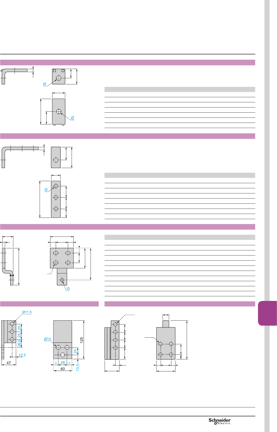
TeSys F
TeSys contactors
TeSys F contactors
Accessories
Right-angled connectors LA9 Fp981 (set of 3) for rear connection
c
G
b1
a
H
b
DF568684.eps
LA9 FF981 FG981 FJ981 FK981 FL981
a 15 20 25 30 40
b 18 23 29 35 48
b1 3 3 4 5 8
c 42 45 55 52 86
G 24 26 32.5 26 45
H 10.5 13 16.5 20 28
Ø 6.5 9 11 11 13
Right-angled connectors LA9 Fp979 (set of 3) for side connection
b1
H
b
c
G1 G G
a
DF568685.eps
LA9 FF979 FG979 FJ979 FK979 FL979
a 15 20 25 30 40
b 54 58 63.5 68 117
b1 5 5 6 6 10
c 80 92 120 120 130
G 24 28 37 37 37.5
G1 20 22 29 29 35
H 36 39 41 42 76
Ø 6.5 9 11 11 13
Right-angled connectors LA9 Fp980 with large surface area (set of 3)
(1)
H1
a
= G =
c
c1
b
H
b1
H2
DF568686.eps
LA9 FF980 FG980 FJ980 FK980 FL980
a 35 40 50 60 100
b 70.5 82.5 98.5 114 154
b1 40 45 55 65 85
c 29 29 33 33 43
c1 3 3 5 5 10
G 18 20 25 29 53
H 18 20 22 26 40
H1 10 12 14 17 20
H2 60.5 72.5 84.5 97 132
Ø 6.5 9 11 11 13
(1) Ø7 x 10 Ø9 x 12 Ø11 x 14 Ø12.5 x 15 Ø12.5 x 15
Right-angled connectors LA9 F1250 (set of 6) Right-angled connectors LA9 F2100 (set of 6) for rear connection
DB402101.EPS
==
16
125
3413
60
47
34
Ø11.5
252538 25
Ø11.5 20
DB402136.eps
Dimensions
References:
page B9/13
PCPB09T10-EN Version : 1.0 18 novembre 2014 12:55 PM B9/57
High power
contactors
B9/57
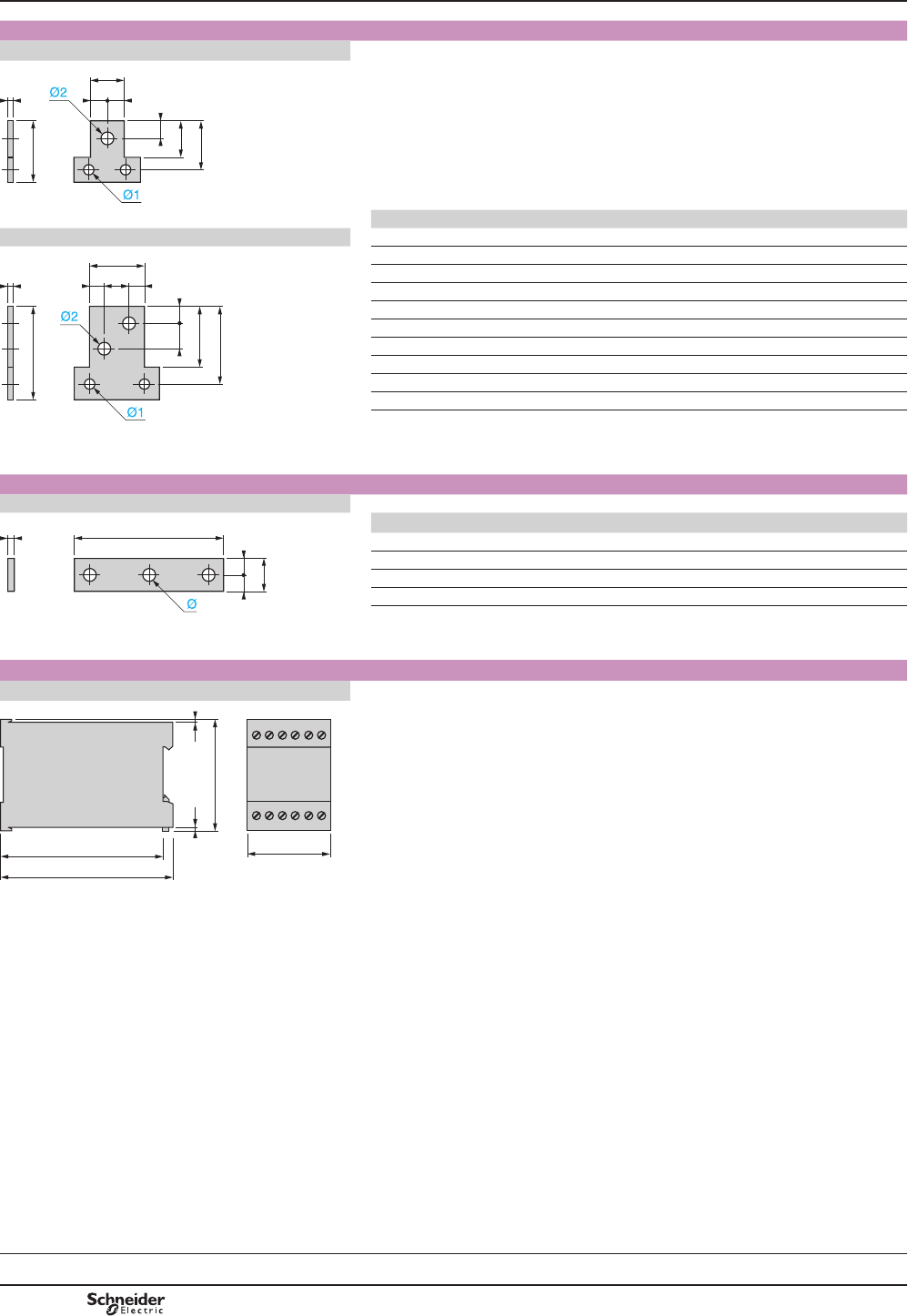
TeSys F
TeSys contactors
TeSys F contactors
Accessories
Dimensions
Paralleling links (set of 4)
LA9 FF602, FG602, FH602
a
=
b
=
H1
b1
H
c
DF568687.eps
LA9 FF602 FG602 FH602 FK602 FL602
LA9 FK602, FL602 a 25 30 40 50 60
a
=
b
=
H1
b1
H
cG
H2
DF568688.eps
b 45 55 60 85 100
b1 30 35 40 55 65
c 4 5 8 10 10
G – – – 22 26
H 37.5 45 52.5 70 85
H1 12.5 15 15 14 17
H2 – – – 22 26
Ø1 6.5 9 11 11 13
Ø2 11 11 13 11 14
Links for "star" connection of 3 poles
LA9 Fp601
b
==
ca
DF568689.eps
LA9 FF601 FG601 FH601 FK601 FL601
a 69 100 121 140 200
b 15 20 20 30 40
c 3 3 5 5 8
Ø 6.5 x 8.5 8.5 x 10.5 10.5 x 13 11 13
Capacitive delayed opening devices for TeSys F contactors
LAZ R9pp
55
108
114
77
33
DF521519.eps
References:
page B9/13
PCPB09T10-EN
Version : 1.0 18 novembre 2014 12:55 PM
B9/58
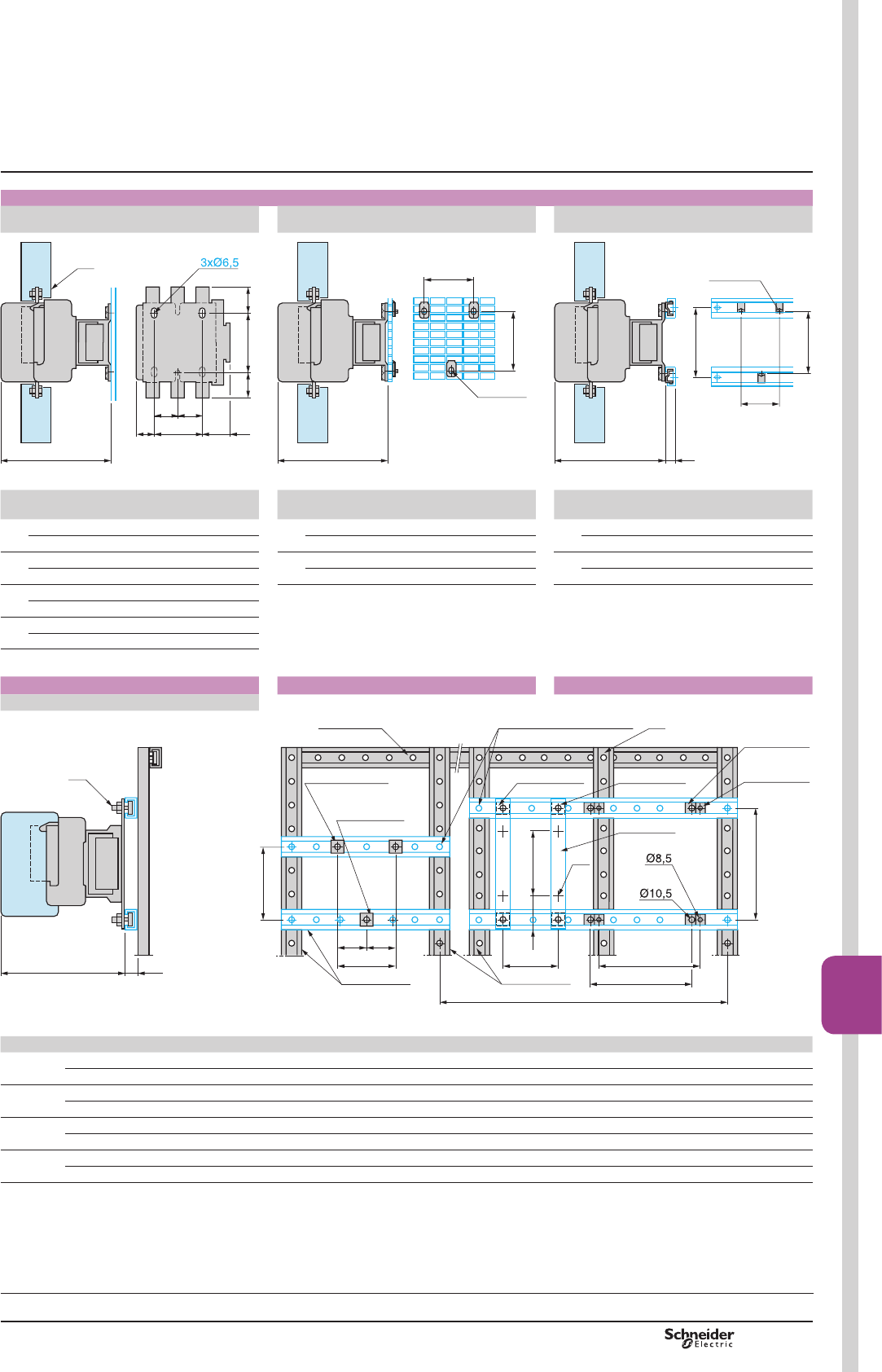
TeSys F
TeSys contactors
TeSys F contactors
Accessories
Mounting
LC1 F115 to F330
On panel On pre-slotted mounting plate AM1 PA, PB,
PC
On rails DZ5 MB on 120 mm centres
c
J G
=
J1
= 110
=
=
(1)
DF568690.eps
c
AF1 EA6
110
G
DF568691.eps
DZ5 MF5
c
G
110
120
15
DF568692.eps
LC1 F115
F150
F185
F225
F265 F330 LC1 F115
F150
F185
F225
F265 F330 LC1 F115
F150
F185
F225
F265 F330
c (2) 3P 171 181 213 219 c (2) 3P 171 181 213 219 c (2) 3P 171 181 213 219
4P 171 181 213 219 4P 171 181 213 219 4P 171 181 213 219
G 3P 80 80 96 96 G 3P 80 80 96 96 G 3P 80 80 96 96
4P 80 80 96 96 4P 80 80 96 96 4P 80 80 96 96
J 3P 26.5 29 44.5 44.5
4P 45 49 68.5 68.5
J1 3P 57 59.5 61.5 61.5
4P 75.5 79.5 85.5 85.5
LC1 F LC1 F115 to F330 LC1 F400 to F800
On 2 notched rails AM1 ECppp
c 25
(3)
120
AM1 EC200 AF1 CD081 + AF1 VC820
AM1 EC200
AF1 CD061+
AF1 VA618
AF1 CD061 AF1 VA618
M6
LA9 F100
AF1 CD101+
AF1 VC10
AF1 CD081+
AF1 VC820
M6
AM1 EC200
11035
180
G
= =
G
AF1 VA618
M6
G1
G2
G3
(4)
DF568693.eps
LC1 F115, F150 F185, F225 F265 F330 F400 F500 F630 F780 F800
c 3P 165 (5) 176 207 213 219 232 255 255 255
4P 165 (5) 176 207 213 219 232 255 255 –
G (M6) 3P 80 80 96 96 – – – – –
4P 80 80 96 96 – – – – –
G1 (8.5) 3P – – – – 80 80 – – –
4P – – – – 80 140 – – –
G2 (10.5) 3P – – – – – – 180 See page B9/55 180
4P – – – – – – 240 See page B9/55 –
(1)3RZHUWHUPLQDOSURWHFWLRQVKURXGVHHSDJH%
(2) See X1 (minimum electrical clearance) pages B9/54 and B9/55.
(3)$)&'pppDQG$)9$ppp.
(4)7KLV$0(&XSULJKWLVUHTXLUHGZKHQ*RU*LVJUHDWHUWKDQPPSOHDVHFRQVXOW\RXU5HJLRQDO6DOHV2I¿FH
(5) PPZLWKWLPHGHOD\EORFNRQ/&)
Selection:
pages B10/50 to B10/73
Characteristics:
pages B9/46 to B9/53
References:
pages B9/2 to B9/9
Schemes:
page B9/61
PCPB09T10-EN Version : 1.0 18 novembre 2014 12:55 PM
B9/59
High power
contactors
B9/59
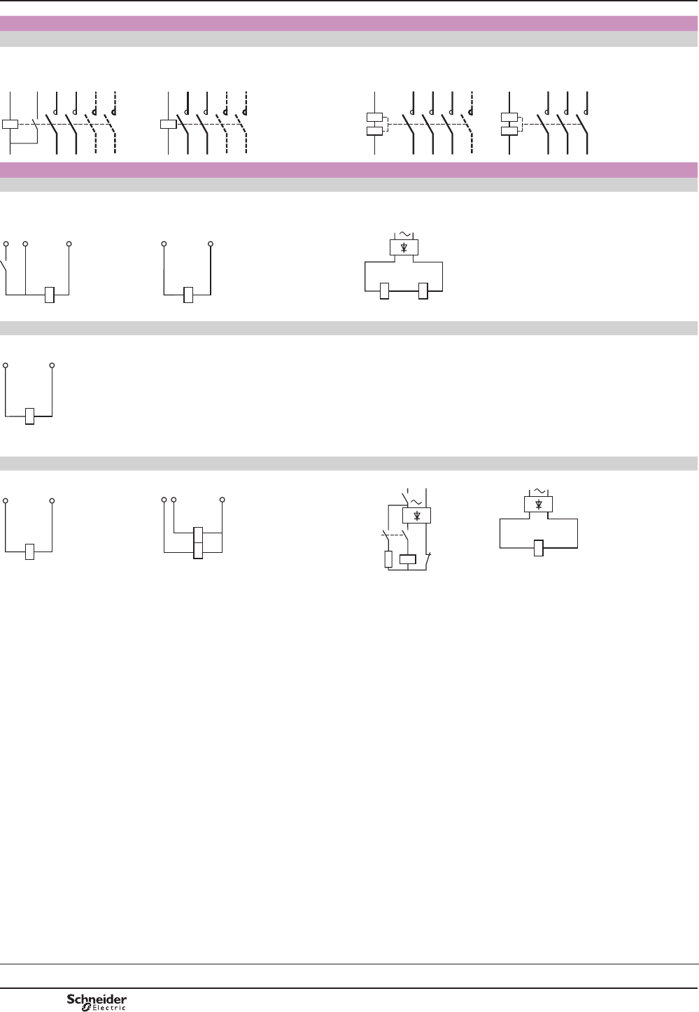
TeSys F
TeSys contactors
TeSys F contactors
Schemes
Contactors
2, 3 and 4-pole contactors
LC1 F115 to F630 , F1250
(coil LX1 F a)
LC1 F115 to F630 , F1250 (coil LX4 F c)
LC1 F115 to F265 (coil LX9 F a)
LC1 F800 (coil LX8 F a/ c)
LC1 F780 a or cLC1 F1400 a or c
LC1 F1700 a or c
LC1 F2100 a or c
A2
03
04
1/L1
T1/2
3/L2
T2/4
5/L3
T3/6
7/L4
T4/8
A1
DF568694.eps
A2
A1
1/L1
T1/2
3/L2
T2/4
5/L3
T3/6
7/L4
T4/8
DF568695.eps
1/L1
T1/2
3/L2
T2/4
5/L3
T3/6
7/L4
T4/8
A2
A1
DF568696.eps
1/L1
T1/2
3/L2
T2/4
5/L3
T3/6
A2
A1
DF511516.eps
Coils
Standard a coils
LX1 FF, FG, FJ…FL
LX1 FH0422…FH3802
LX1 FH0202…FH0362
LX1 FH4402…FH10002
LX1 F8p
LX1 FX
5HFWL¿HUVXSSOLHGDQG¿[HGRQWKHFRQWDFWRU
A2A1
A2A103
DF568719.eps
A2A1
A2A1
DF568720.eps
A2A1 A2A1
+
–
DF568721.eps
Standard c coils
LX4 FF, FG, FH, FJ, FK, FL, FX (1), LX4 F8p
A2A1
A2A1
DF568722.eps
(1) 2 coils in series.
Special a coils
LX9 FF, FG LX9 FHppp2 LX9 FJ, FK, FL LX4 F8p
A2A1
A2A1
DF568723.eps
B1 A2/B2
A1
DF568724.eps
A2
A1
+
–
01
(1)
(2)
DF568725.eps
A2A1
+
DF568726.eps
(1) Breaking on a side.
'URSRXWWLPHPV
(2) Breaking on c side.
'URSRXWWLPHPV
Selection:
pages B10/50 to B10/73
Characteristics:
pages B9/46 to B9/53
References:
pages B9/2 to B9/9
Dimensions:
pages B9/54 to B9/56
PCPB09T10-EN
Version : 1.0 18 novembre 2014 12:55 PM
B9/60
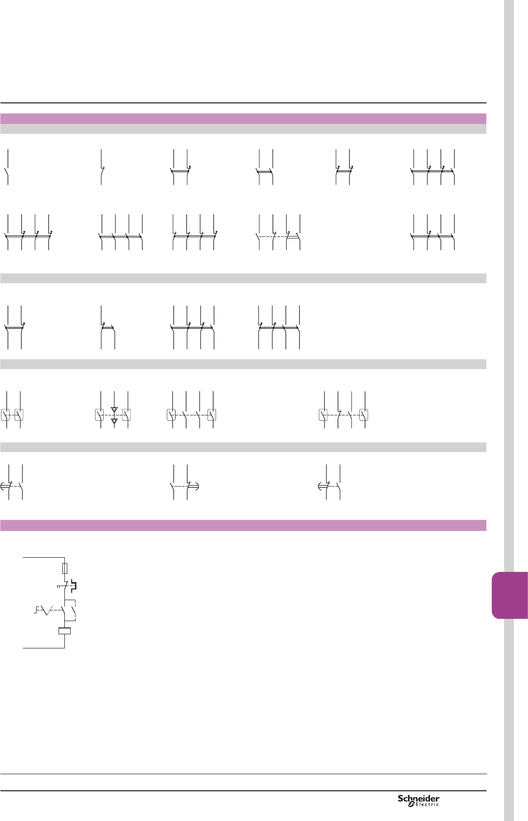
TeSys F
Add-on blocks
,QVWDQWDQHRXVDX[LOLDU\FRQWDFWV
1 N/O LAD N10 (1) 1 N/C LAD N01 (1) 1 N/O + 1 N/C LAD N11 2 N/O LAD N20 2 N/C LAD N02 2 N/O + 2 N/C LAD N22
43/NO
44
(94)
(93)
DF568697.eps
(92)
(91)
42 41/NC
DF568698.eps
62 61/NC
53/NO
54
127338.eps
53/NO
54
63/NO
64
127339.eps
62 61/NC
51/NC52
127340.eps
72 71/NC
62 51/NC
53/NO
54
83/NO
84
127341.eps
1 N/O + 3 N/C LAD N13 4 N/O LAD N40 4 N/C LAD N04 2 N/O + 2 N/C (2) LAD C22 3 N/O + 1 N/C LAD N31
72 71/NC
62 61/NC
53/NO
54
82 81/NC
127342.eps
53/NO
54
63/NO
64
73/NO
74
83/NO
84
127343.eps
72 71/NC
62 61/NC
82 81/NC
52 51/NC
127344.eps
76 75/NC
62 61/NC
53/NO
54
87/NO
88
127345.eps
62 61/NC
53/NO
54
84 83/NO
73/NO
74
127346.eps
(1),WHPVLQEUDFNHWV6HH³7H6\V'FRQWDFWRUV´ (2)121&PDNHEHIRUHEUHDN
,QVWDQWDQHRXVDX[LOLDU\FRQWDFWVZLWKWHUPLQDOUHIHUHQFLQJFRQIRUPLQJWRVWDQGDUG(1(References: pages B9/10 and B9/11)
1 N/O + 1 N/C 1 N/O + 1 N/C 2 N/O + 2 N/C 2 N/O + 2 N/C
LAD N11P LAD N11G LAD N22P LAD N22G
22 21/NC
13/NO
14
127347.eps
32 31/NC
43/NO
44
127348.eps
22 21/NC
32 31/NC
13/NO
14
43/NO
44
127349.eps
32
31/NC
42 41/NC
63/NO
64
53/NO
54
127350.eps
'XVWDQGGDPSSURWHFWHGLQVWDQWDQHRXVDX[LOLDU\FRQWDFWV
2 N/O (24-50 V) 2 N/O (5-24 V) 2 N/O protected (24-50 V) + 2 N/O standard 2 N/O protected (24-50 V) + 1 N/O + 1 N/C standard
LA1 DX20 LA1 DY20 LA1 DZ40 LA1 DZ31
53/NO54
63/NO64
DF568712.eps
53/NO54
63/NO64
DF568713.eps
53/NO54
83/NO84
63/NO
64
73/NO
74
DF568714.eps
62 61/NC
53/NO54
83/NO84
73/NO
74
DF568715.eps
7LPHGHOD\DX[LOLDU\FRQWDFWV
On-delay 1 N/O +1 N/C LAD TpOff-delay 1 N/O + 1 N/C LAD RpOn-delay 1 N/C + 1 N/O break before make LAD Sp
55/N56
67/NO
68
DF568716.eps
66 65/NC
57/NO
58
DF568717.eps
55/NC
67/NO
68
DF568718.eps
Capacitive delayed opening devices for TeSys F contactors
LAZ R9pp + LC1 F
F1
A1
A2
0 1
L
+
(LAZ R)
L
–
(LAZ R)
DF511513.eps
Selection:
pages B10/50 to B10/73
Characteristics:
pages B9/46 to B9/53
References:
pages B9/2 to B9/9
TeSys contactors
TeSys F contactors
Schemes
PCPB09T10-EN Version : 1.0 18 novembre 2014 12:55 PM
B9/61
High power
contactors
B9/61
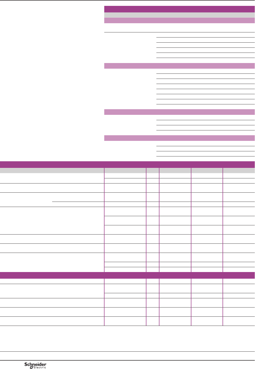
TeSys V
Selection
Contactor size LC1 V160 LC1 V320 LC1 V610
For utilisation category AC-3
Maximum operational
current in AC-3
A160 320 610
Rated operational
power P
(standard power ratings
of motors)
230 V kW 45 90 160
400 V kW 75 160 300
525 V kW 110 220 400
690 V kW 150 280 560
1000 V kW 200 400 800
1500 V kW 280 600 930
For 3-phase motors conforming to CSA standards
Rated operational
power P
(standard power ratings
of 3-phase CSA motors)
200 V hp 50 100 150
240 V hp 60 125 200
380 V hp 100 200 300
480 V hp 125 250 400
600 V hp 150 300 500
800 V hp 200 400 700
1000 V hp 250 500 1000
1500 V hp 400 800 1300
For switching 3-phase capacitors
Rated operational
power P
240 V kVAR 47 94 176
480 V kVAR 95 190 356
600 V kVAR 100 200 400
1500 V kVAR 250 500 1000
For switching the primaries of 3-phase transformers (LV/LV)
Rated operational
power P
208 V kVA 20 41 81
240 V kVA 23 47 94
480 V kVA 47 94 188
600 V kVA 59 117 234
Environment characteristics
Contactor type LC1 V160 LC1 V320 LC1 V610
Shock resistance
(1/2 sine wave = 11 ms)
Contacts closed 10 gn 10 gn 10 gn
Contacts open 10 gn 10 gn 10 gn
Vibration resistance
10…500 Hz
2 gn
2 gn
2 gn
Operating altitude
Above sea level
Maximum
m
3600
3600
3600
Below sea level Minimum m2500 4500 4500
Ambient air temperature
around the device
Storage
°C
-40…+80
-40…+80
-40…+80
Operation
0.8… 1.1 Uc
°C -5…+55 -5…+55 -5…+55
Permissible for
operation at Uc
°C -10…+75 -10…+75 -10…+75
Degree of protection
Conforming to IEC 60529
IP 00
IP 00
IP 00
Operating position
Any
Any
Any
Cabling
Cable c.s.a.
mm2
70
185
2 x 185
Key for hex. screws mm Allen 4 20 20
Tightening torque N.m 14 39 39
Control circuit characteristics
Rated insulation voltage (Ui) To earth V2000 2000 2000
Consumption
Inrush
VA
300
600
1700
Sealed VA 30 20 28
Permissible control circuit voltage
0.8…1.1 Uc
0.8…1.1 Uc
0.8…1.1 Uc
Closing time (1)
ms
18...22
24...32
24...32
Opening time (1)
ms
95...115
95...115
95...115
(1)7KHFORVLQJWLPH&LVPHDVXUHGIURPWKHPRPHQWWKHFRLOVXSSO\LVVZLWFKHGRQWRLQLWLDO
FRQWDFWRIWKHPDLQSROHV7KHRSHQLQJWLPH2LVPHDVXUHGIURPWKHPRPHQWWKHFRLOVXSSO\
LVVZLWFKHGRIIWRWKHPRPHQWWKHPDLQSROHVVHSDUDWH
TeSys contactors
3-pole vacuum contactors
and reversing contactors
Selection,
characteristics
References:
page B9/4
Dimensions:
page B9/64
Schemes:
page B9/64
PCPB09T20-EN
Version : 1.0 18 novembre 2014 12:55 PM
B9/62
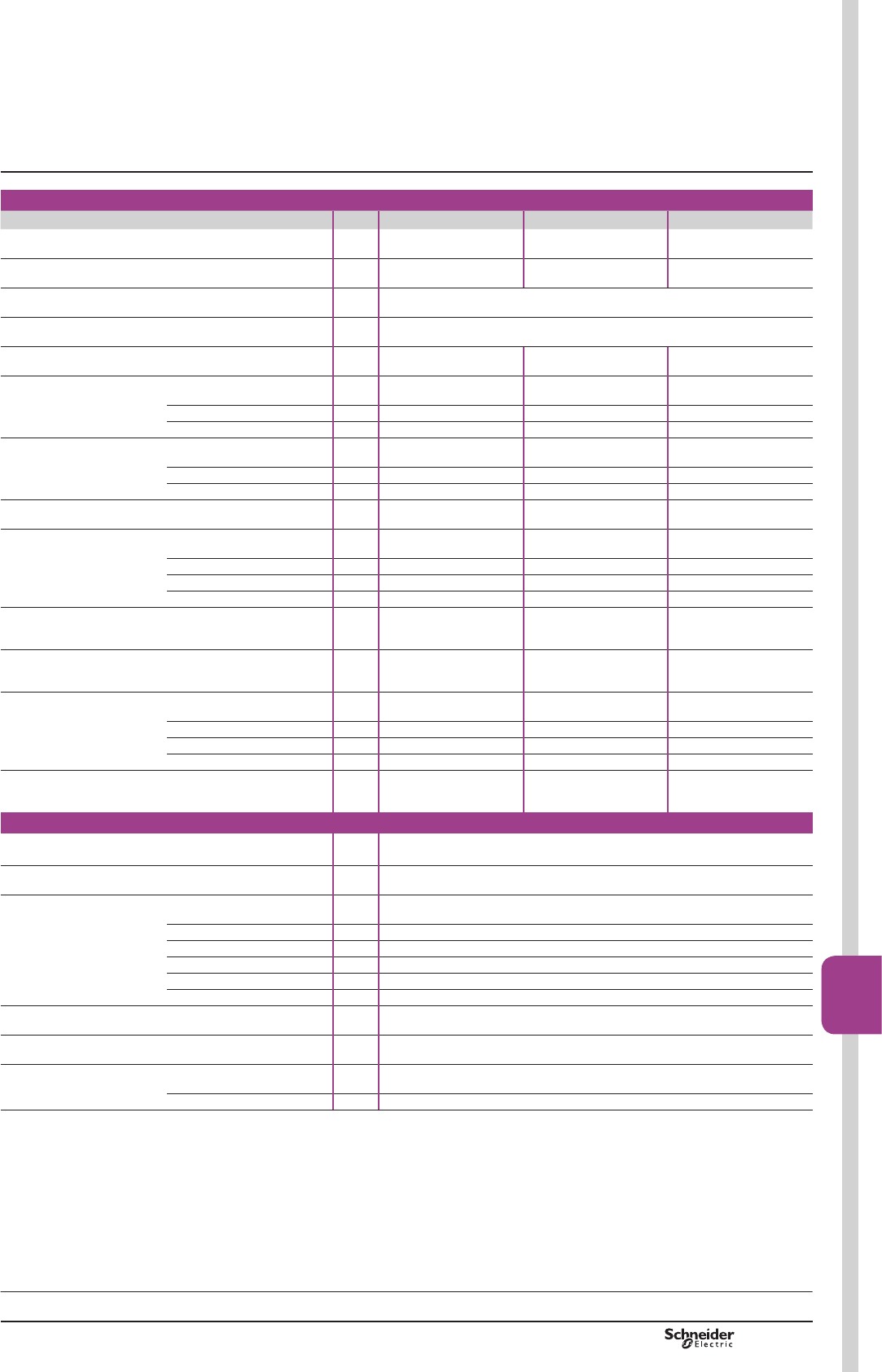
TeSys V
Main pole characteristics
Contactor type LC1 V160 LC1 V320 LC1 V610
Rated insulation voltage (Ui)
V
1500
1500
1500
Rated impulse withstand voltage (Uimp)
kV
8
8
8
Conforming to standards
EN 60947-4-1 - IEC 60947-4-1
Approvals
CSA
Conventional rated thermal current (Ith)
A
160
320
630
Rated operational current (Ie)
T y 40 °C AC-1
A
160
320
630
T y 55 °C AC-3 A160 320 610
T y 55 °C AC-4 A130 270 540
Electrical durability
in millions of operating cycles
(400 V at I max)
AC-1
1.2
1
1
AC-3 1.6 1.5 1.5
AC-4 0.18 0.15 0.12
Mechanical durability
In millions of operating cycles
5
2.5
2
Maximum operating rate
in operating cycles
per hour
Mechanical
1200
1200
1200
AC-1 900 900 900
AC-3 900 900 900
AC-4 450 450 450
Maximum making capacity
(lrms)
Ue = 1500 V To IEC 60947
A
1900
3800
7300
Maximum breaking capacity
(lrms)
Ue = 1500 V To IEC 60947
A
1600
3200
6100
Maximum
permissible current
For 1 s
A
2400
4500
9000
For 2 s A2000 3750 7580
For 10 s A1600 3200 6100
For 30 s A960 1920 3600
Short-circuit protection
at Ie in cat. AC-3 max.
aM fuse
A
160
400
630
$X[LOLDU\FRQWDFWFKDUDFWHULVWLFV
Rated insulation voltage (Ui)
V
690
Conventional rated thermal current (Ith)
A
10
Rated operational current (Ie)
AC-15, 230 V
A
0.78
AC-15, 400 V A0.45
AC-15, 500 V A0.35
DC-13, 24 V A1.1
DC-13, 110 V A0.24
DC-13, 220 V A0.12
Cabling
Cable c.s.a.
mm2
2.5
Short-circuit protection
gG fuse
A
10
Operating time (1)
(at 100 % of Uc)
"C"
ms
±5
"O" ms ±5
(1)2SHUDWLQJWLPHLQUHODWLRQWRWKHPDLQFRQWDFWV
Selection:
page B9/62
References:
page B9/4
Dimensions:
page B9/64
Schemes:
page B9/64
TeSys contactors
3-pole vacuum contactors
and reversing contactors
Selection,
characteristics
PCPB09T20-EN Version : 1.0 18 novembre 2014 12:55 PM B9/63
High power
contactors
B9/63
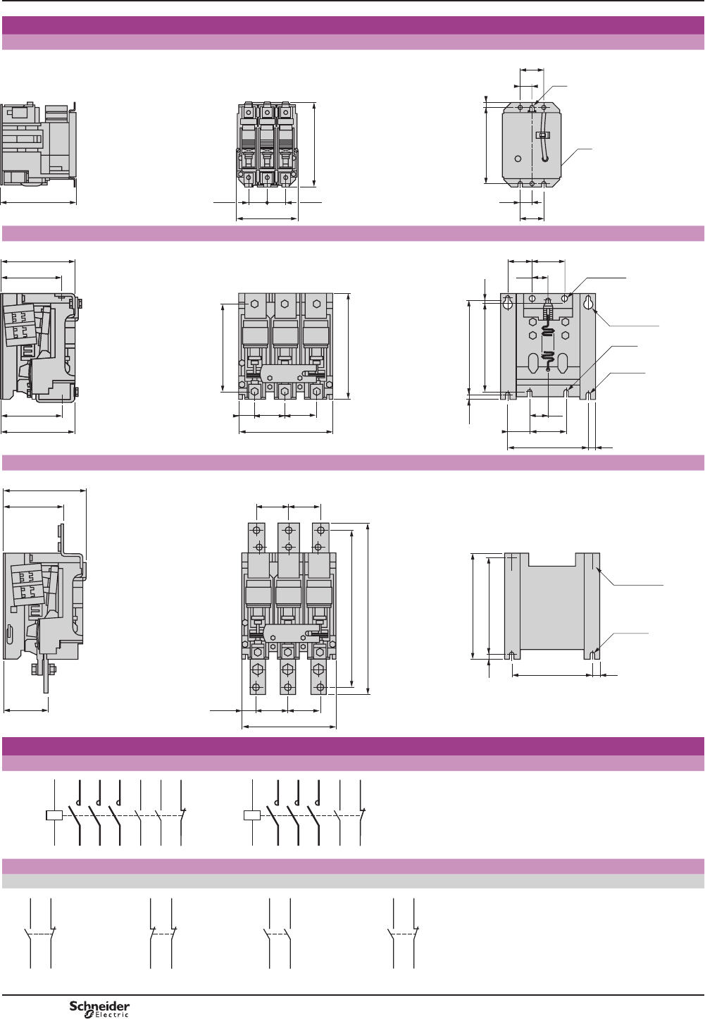
TeSys V
Dimensions, mounting
LC1 V160
151 36,5
123
36,5
168
24
48
24
48
Ø7
Ø7
152 9
500311.eps
LC1 V320
35
159
130
156
133
63,5
201
63,5
222
37
185
38
76
170
70
2xØ8
2xØ8,5x19
2039,5
191 3,5
48
15
2xØ8,5
50
2xØ10,5
500312.eps
LC1 V610
95
178
127
172
2xØ8,5x19
203
222
9,5
15
2xØ8,5
68
201
68
356
328
32,5
68 68
500313.eps
Schemes
LC1 V160 LC1 V320, V610
$X[LOLDU\FRQWDFWEORFNV
LA1 VN11 1 N/O & 1 N/C LA1 VN02 2 N/C LA1 VN20 2 N/O LA1 VN11X 1 N/O
TeSys contactors
3-pole vacuum contactors
Dimensions,
mounting,
schemes
1/L12/T1
A1
03/NO
13/NO
A2
04
14
3/L24/T2
5/L36/T3
21/NC
22
500314.eps
1/L12/T1
A1
13/NO
A2
14
3/L24/T2
5/L36/T3
21/NC
22
500315.eps
14
22
13/NO
21/NC
500316.eps
52
62
51/NC
61/NC
500317.eps
34
44
33/NO
43/NO
500318.eps
04 03/NO
NC
coil
500521.eps
PCPB09T20-EN
Version : 1.0 18 novembre 2014 12:55 PM
B9/64

TeSys V
Dimensions, mounting
/$9[/&9
48 81,8 48
88,9
152,4 11,18
53
177,8
215
254
151
562320.eps
LC2 V320
418
446
22
168 63
16
107
108 63 48
616
96 41
54
356 ==
463
559
241
63
54
104
DF536047.eps
LC2 V610
41
16
432
105
117
356 =
=
463
69 69
112
559
165
199
112
68
T1 T2 T3
L2L1 L3
68
616
562322.eps
TeSys reversing contactors
3-pole reversing vacuum contactors
Dimensions,
mounting
Selection:
page B9/62
Characteristics:
pages B9/62 and B9/63
References:
page B9/4
PCPB09T20-EN Version : 1.0 18 novembre 2014 12:55 PM B9/65
High power
contactors
B9/65

TeSys V
Schemes
/$9[/&9
1
3
5
2
4
6
1
3
5
2
4
6
U
V
W
KM1
1/L1
3/L2
5/L3
A1A2
KM2
A1A2
562323.eps
LC2 V320
1
3
5
2
4
6
1
3
5
2
4
6
U
V
W
KM1
1/L1
3/L2
5/L3
A1A2
KM2
A1A2
6
78
9
- KM1
- KM1
- KM2
A1A2
3
45
- KM2- KM1 - KM2
- KM2
- KM1
A2A1
– F1
(1)
Start Start
Stop
562324.eps
(1)'RWWHGOLQHLQGLFDWHVZLULQJWREHLQVWDOOHGE\WKHFXVWRPHU
Schemes TeSys reversing contactors
3-pole reversing vacuum contactors
Selection:
page B9/62
Characteristics:
pages B9/62 and B9/63
References:
page B9/4
PCPB09T20-EN
Version : 1.0 18 novembre 2014 12:55 PM
B9/66

TeSys V
Schemes
LC2 V610
1
3
5
2
4
6
1
3
5
2
4
6
U
V
W
KM1
A1A2
KM2
A1A2
6
78
9
- KM1
- KM1
- KM1
- KM1
- KM2
A1A2
3
45
- KM2
- KM2
- KM2
- KM1
A2A1
– F1
(1)
- KM2
1/L1
3/L2
5/L3
Start Start
Stop
562325.eps
(1)'RWWHGOLQHLQGLFDWHVZLULQJWREHLQVWDOOHGE\WKHFXVWRPHU
Selection:
page B9/62
Characteristics:
pages B9/62 and B9/63
References:
page B9/4
Schemes TeSys reversing contactors
3-pole reversing vacuum contactors
PCPB09T20-EN Version : 1.0 18 novembre 2014 12:55 PM B9/67
High power
contactors
B9/67
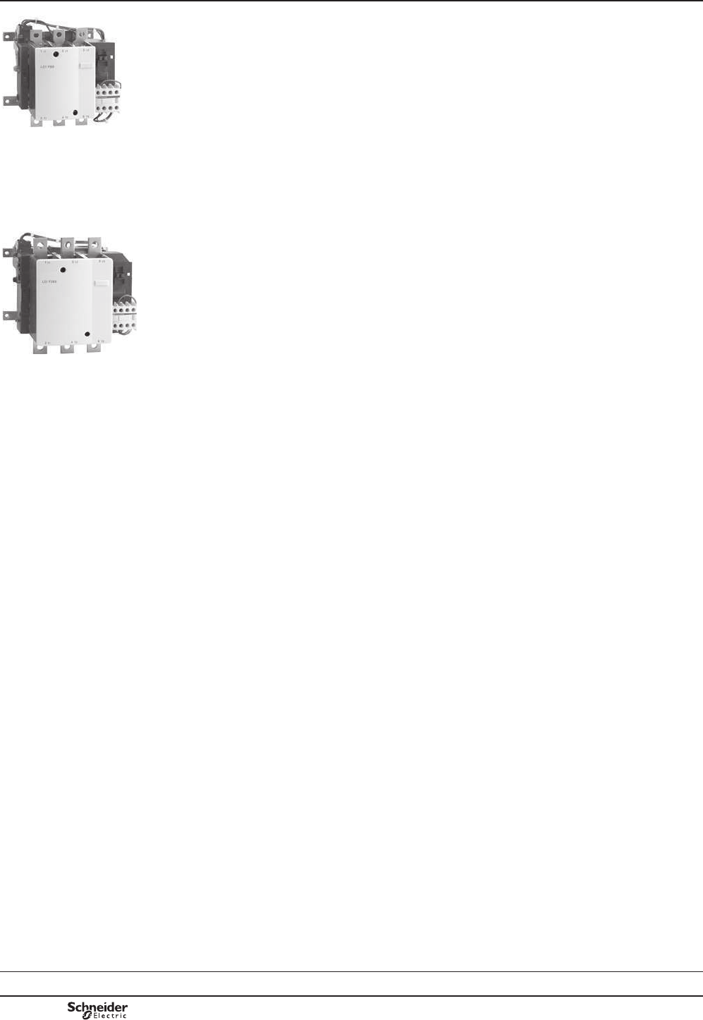
TeSys F
Presentation TeSys contactors
3-pole shockproof contactors LC1 FG
Presentation
In an environment subject to severe mechanical shocks, unwanted closing
of a contactor's poles and the serious consequences of this, is not permissible.
Shockproof contactors LC1 FG150 to FG630 are equipped with an auxiliary
electromechanical device which ensures that the contactor is mechanically locked
in the “open” position when it’s main electromagnet is not energised.
If the contactor is subjected to mechanical impact, from back to front or from front
to back, accidental closing of the poles is then impossible.
In addition, accidental opening of the poles (when the contactor is in the “on”
SRVLWLRQLVYLUWXDOO\LPSRVVLEOHGXHWRWKHVLJQL¿FDQWSXOOLQIRUFHFKDUDFWHULVWLF
of these contactors.
Applications
bMarine: on-board equipment, windlasses, capstans, winches, etc…
bMilitary equipment : land, sea, launching silos.
bHeavy mechanical handling systems: travelling cranes, cranes, gantries.
bConveying and handling: lifts, hoists, conveyors.
bEquipment for power stations.
bDistribution boards.
LC1 FG150
PF537334
LC1 FG265
PF537336
Selection:
pages B9/70 to B9/75
Characteristics:
pages B9/76 to B9/83
References:
page B9/6
Dimensions, schemes:
pages B9/84 and B9/85
PCPB09T20-EN
Version : 1.0 18 novembre 2014 12:55 PM
B9/68
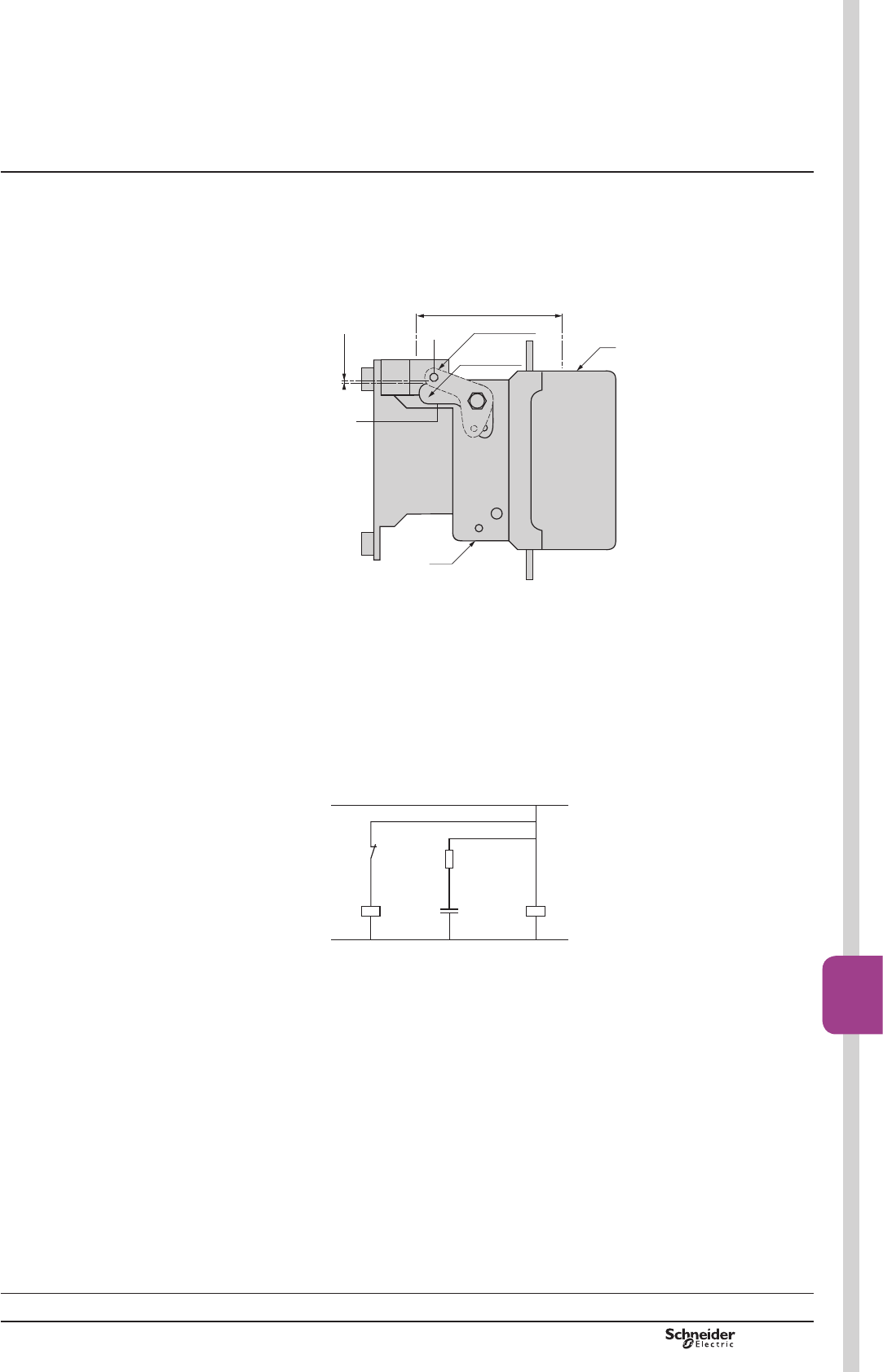
TeSys F
Description of shockproof device
Shockproof contactors LC1 FGppp are equipped with:
ba lever 1 that is rotated by the core of the contactor’s electromagnet.
ban auxiliary electromagnet (EV) for the locking function.
ban RC circuit (Resistor-Capacitor) to limit overvoltage.
0,3…0,6
KM1
2
1
EV
Direction of impact
ON KM1
OFF KM1
BACK FRONT
DF537257.eps
Operation
bIn the ‘off’ position (contactor open and not energised) the core 2
of the electromagnet (EV) locks the lever 1 and therefore the contactor.
bThe coils (KM1) and (EV) are energised simultaneously, the core 2 releases
the lever 1 and allows the contactor to close.
bDe-energisation of the locking electromagnet (EV) is achieved by an auxiliary
contact within the contactor.
The core 2 rests freely in lever 1.
bOn de-energisation of coil KM1, the moving contact drops out.
Core 2, under spring pressure, once again locks lever 1.
– KM1
A1A2
22 21C2 C1
– KM1
a
a
EV
DF537258.eps
Selection:
pages B9/70 to B9/75
Characteristics:
pages B9/76 to B9/83
References:
page B9/6
Dimensions, schemes:
pages B9/84 and B9/85
Presentation TeSys contactors
3-pole shockproof contactors LC1 FG
PCPB09T20-EN Version : 1.0 18 novembre 2014 12:55 PM B9/69
High power
contactors
B9/69

TeSys F
PCPB09T20-EN
Version : 1.0 18 novembre 2014 12:55 PM
B9/70
Use in category AC-3 (Ue y 440 V)
Operational current and power (T y 55 °C)
Contactors LC1 FG150 LC1 FG185 LC1 FG265 LC1 FG400 LC1 FG500 LC1 FG630
Operational current A150 185 265 400 500 630
Operational power
Standard power ratings
of motors)
220/230 V kW 40 55 75 110 147 200
KS 54 75 100 150 200 270
380/400 V kW 75 90 132 200 250 335
KS 100 185 180 270 340 450
415 V kW 80 100 140 220 280 375
KS 110 136 180 300 380 500
440 V kW 80 100 140 250 295 400
KS 110 136 190 340 400 545
500 V kW 90 110 160 257 355 400
KS 125 150 220 350 480 545
660/690 V kW 100 110 160 280 335 450
KS 136 150 220 380 450 600
1000 V kW 65 100 147 185 335 450
KS 85 136 200 250 450 610
0D[LPXPRSHUDWLQJUDWH (operating cycles/hour) (1)
On-load factor Operational
power
LC1 FG150 LC1 FG185 LC1 FG265 LC1 FG400 LC1 FG500 LC1 FG630
y 85 % P 750 750 750 500 500 500
y 85 % 0.5 P 2000 2000 2000 1200 1200 1200
y 25 % P 1200 1200 1200 1200 1200 1200
(1) 'HSHQGLQJRQWKHRSHUDWLRQDOSRZHUDQGWKHRQORDGIDFWRUT y 55 °C).
Electrical durability in utilisation category AC-3 (Ue y 440 V)
20 40 7030 50 60 80 100 200 300 400 500 600 800
0,4
0,6
0,8
1
2
4
6
8
10
LC1 FG150
LC1 FG265
LC1 FG185
LC1 FG400
1000
LC1 FG500
LC1 FG630
Millions of operating cycles
Current broken in Amperes
DF537320.eps
Control of 3-phase asynchronous squirrel cage motors with breaking whilst running.
The current broken (Ie) in category AC-3 is equal to the rated operational current of the motor.
([DPSOH
Asynchronous motor with P = 55 kW - Ue = 380 V - Ie = 105 A
4 million operating cycles required.
The above selection curves show the contactor rating needed: LC1 FG265.
Selection TeSys contactors
3-pole shockproof contactors LC1 FG
a.c. supply
According to the utilisation category and
required electrical durability
Presentation:
pages B9/68 and B9/69
Characteristics:
pages B9/76 to B9/83
References:
page B9/6
Dimensions, schemes:
pages B9/84 and B9/85

TeSys F
PCPB09T20-EN Version : 1.0 18 novembre 2014 12:55 PM B9/71
High power
contactors
B9/71
Use in category AC-1 (Ue y 440 V)
Contactors LC1 FG150 LC1 FG185 LC1 FG265 LC1 FG400 LC1 FG500 LC1 FG630
Connection Cable C.s.a. mm2120 150 240 – – –
Bar Number – – – 2 2 2
C.s.a. mm – – – 30 x 5 40 x 5 60 x 5
Maximum operating rate
in operating cycles/hour
600 600 600 600 600 600
Operational current AC-1 y 40 °C A250 270 350 500 700 1000
y 55 °C A220 240 300 430 580 850
y 70 °C (1) A170 180 250 340 500 700
(1)2QO\IRURSHUDWLRQZLWKFRLOVXSSOLHGDW8F
Increase in operational current by parallel connection of poles
DF537322.eps
DF537323.eps
Apply the following multiplying factors to the current values given
above.
The factors take into account the often unbalanced current
distribution between the 2 poles:
b2 poles in parallel: K = 1.6
b3 poles in parallel: K = 2.25
b4 poles in parallel: K = 2.8.
Recommended connection scheme to equalise the currents in each
pole (see opposite).
Electrical durability in utilisation category AC-1 (Ue y 440 V)
Millions of operating cycles
Current broken in Amperes
20 40 7030 50 60 80 100 200 300 400
270 350
500 600 800
0,4
0,2
0,1
0,6
0,8
1
2
4
6
8
10
LC1 FG150
LC1 FG265
LC1 FG185
LC1 FG400
1000 2000
LC1 FG500
LC1 FG630
DF537321.eps
([DPSOH
Control of resistive circuits (cos M u 0.95).
The current broken (Ic) in category AC-1 is equal to the current (Ie) normally drawn by the load.
Ue = 220 V - Ic = Ie = 300 A - T = 40 °C.
1 million operating cycles required.
The above selection curves show the contactor rating needed: LC1 FG400.
Presentation:
pages B9/68 and B9/69
Characteristics:
pages B9/76 to B9/83
References:
page B9/6
Dimensions, schemes:
pages B9/84 and B9/85
Selection TeSys contactors
3-pole shockproof contactors LC1 FG
a.c. supply
According to the utilisation category and
required electrical durability
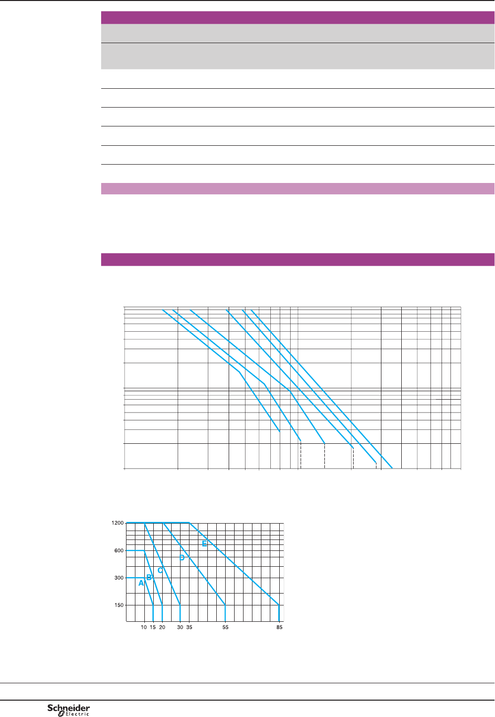
TeSys F
PCPB09T20-EN
Version : 1.0 18 novembre 2014 12:55 PM
B9/72
Selection TeSys contactors
3-pole shockproof contactors LC1 FG
a.c. supply
According to the utilisation category and
required electrical durability
Thermal limits in utilisation categories AC-2/AC-4
Contactors LC1
FG150
LC1
FG185
LC1
FG265
LC1
FG400
LC1
FG500
LC1
FG630
Thermal limit
zone
Operating cycles/hour (1)
and on-load factor
0D[LPXPFXUUHQWEURNHQDFFRUGLQJWRWKHGXW\
requirements
(thermal limit, ambient temperature y 55 °C)
A From 150 and 15 %
to 300 and 10 %
310 380 560 780 1100 1400
B From 150 and 20 %
to 600 and 10 %
280 350 500 700 950 1250
C From 150 and 30 %
to 1200 and 10 %
240 300 400 600 750 950
D From 150 and 55 %
to 2400 and 10 %
190 240 320 450 600 720
E From 150 and 85 %
to 3600 and 10 %
145 170 230 350 500 660
(1)'RQRWH[FHHGWKHPD[LPXPOLPLWIRUWKHPHFKDQLFDORSHUDWLQJF\FOHV
Counter current braking (plugging)
The current varies from the maximum plug-braking current to the rated motor current.
The current made must be compatible with the making and breaking capacities of the contactor.
In most cases, breaking occurs at a current value close to the locked rotor current and contactor selection can
therefore be made using the criteria for utilisation categories AC-2 and AC-4.
Electrical durability in utilisation categories AC-2/AC-4 (Ue y 440 V)
Millions of operating cycles
Current broken in Amperes
200 400300 500 600 800 1000 2000 3000 5000 7000
0,04
0,02
0,01
0,06
0,08
0,1
0,2
0,4
0,6
0,8
1
LC1 FG150
LC1 FG265
LC1 FG185
LC1 FG400
9000100
LC1 FG500
LC1 FG630
DF537324.eps
([DPSOH&RQWDFWRUVHOHFWLRQ
Operating cycles/hour
On-load factor as %
DF537325.eps
For an on-load factor of 10 % at 400
operating cycles per hour, the curve on the
left indicates zone B. If the current broken
is 600 A, the above table leads to selection
of an LC1 FG400 contactor. Referring to the
electrical durability curves, it can be seen
that the contactor will be able to perform 350
000 operating cycles. Where a higher value
of electrical durability is required, 1 million
operating cycles for example, an LC1 FG630
contactor would be recommended.
Presentation:
pages B9/68 and B9/69
Characteristics:
pages B9/76 to B9/83
References:
page B9/6
Dimensions, schemes:
pages B9/84 and B9/85

TeSys F
PCPB09T20-EN Version : 1.0 18 novembre 2014 12:55 PM B9/73
High power
contactors
B9/73
TeSys contactors
For switching 3-phase capacitor banks,
used for power factor correction
Switching the primaries of 3-phase
transformers (LV/LV)
Switching 3-phase capacitors
Capacitors, together with the circuits to which they are connected, form oscillatory
circuits which can, at the moment of switch-on, give rise to high transient currents
(> 180 In) at high frequencies (1 to 15 kHz).
The contactors are used for direct switching. The values of peak current at switch-on
must not exceed the values indicated below.
An inductor or an early break resistor may be inserted in each of the three phases
supplying the capacitors to reduce the peak current, if necessary. This must be done
when switching multiple step capacitor banks.
Inductance values are determined according to the selected operating temperature:
please refer to our “Motor starter solutions - Control and protection components”
catalogue.
In addition, in accordance with standards IEC 60070, NF C 54 100, VDE 0560, the
switching contactor must be able to withstand a continuous current of 1.43 times the
rated current of the capacitor bank step being switched. The rated operational
powers given in table the below take this overload into account.
Short-circuit protection is normally provided by g1 fuses rated at 1.3 to 1.6 In.
0D[LPXPRSHUDWLRQDOSRZHURIFRQWDFWRUV
Maximum operating rate: 120 operating cycles/hour.
Electrical durability at maximum load: 100 000 operations.
With choke inductors connected, where necessary.
Operational power at 50/60 Hz 0D[LPXP
peak
current
Contactor
to be used
T y 40 °C T y 55 °C
220 V
240 V
400 V
440 V
600 V
660 V
220 V
240 V
400 V
440 V
600 V
660 V
kvar kvar kvar kvar kvar kvar A
60 100 135 40 85 90 3200 LC1FG150
70 125 160 50 100 100 3500 LC1FG185
90 160 225 75 125 125 5000 LC1FG265
125 220 300 100 160 200 8000 LC1FG400
180 300 400 125 220 300 10 000 LC1FG500
250 400 600 190 350 500 12 000 LC1FG630
Switching the primaries of 3-phase transformers
(LV/LV)
When a transformer is switched on, there is generally an initial current surge which
can reach 20 to 40 times the rated current for the power ratings shown below.
This current reaches its peak value almost instantaneously and then decreases in
a largely exponential manner, quickly dropping back down to its steady state value.
Contactor selection
Operating rate less than 120 operating cycles/hour.
Maximum operational voltages: 1000 V 50/60 Hz.
The value of the peak magnetising current must be lower than the values
indicated below.
Maximum ambient temperature: 55 °C.
Contactor LC1 FG150 LC1 FG185 LC1 FG265 LC1 FG400 LC1 FG500 LC1 FG630
Maximum permissible
current peak at switch-on
A1700 2800 3500 5500 6800 9000
Maximum operational power (1) 220 V kVA 25 40 50 75 100 140
380 V kVA 50 75 90 130 170 225
415/440 V kVA 55 80 100 140 190 250
500 V kVA 65 95 110 170 225 280
660 V kVA 80 120 140 200 270 315
1000 V kVA 100 150 200 250 375 470
(1)0D[LPXPRSHUDWLRQDOSRZHUFRUUHVSRQGLQJWRDFXUUHQWSHDNDWVZLWFKRQRI,Q
Selection
Presentation:
pages B9/68 and B9/69
Characteristics:
pages B9/76 to B9/83
References:
page B9/6
Dimensions, schemes:
pages B9/84 and B9/85
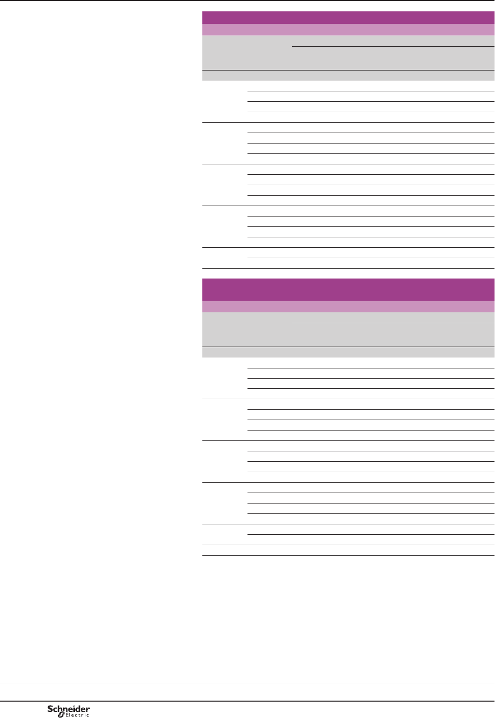
TeSys F
PCPB09T20-EN
Version : 1.0 18 novembre 2014 12:55 PM
B9/74
Selection TeSys contactors
3-pole shockproof contactors LC1 FG
d.c. supply
Selection guide for utilisation categories
DC-1 to DC-5
Use in category DC-1 (resistive loads; time constant L/R y 1 ms)
Rated operational current Ie
Operational
voltage (Ue)
Number of
poles
to be wired
in series
Contactors
LC1
FG150
LC1
FG185
LC1
FG265
LC1
FG400
LC1
FG500
LC1
FG630
V A A A A A A
24 1 160 220 300 400 600 850
2 160 220 300 400 600 850
3 160 220 300 400 600 850
4 160 220 300 400 600 850
48/75 1 160 220 300 400 600 850
2 160 220 300 400 600 850
3 160 220 300 400 600 850
4 160 220 300 400 600 850
125 1 – – – – – –
2 130 170 300 400 550 850
3 130 170 300 400 600 850
4 130 170 300 400 600 850
225 1 – – – – – –
2 100 150 250 350 450 700
3 130 170 300 400 600 850
4 130 170 300 400 600 850
300 3 100 150 250 350 450 700
4 130 170 300 400 600 850
460 4 100 150 250 350 450 700
Use in category DC-2 to DC-5
(inductive loads; time constant L/R y 15 ms)
Rated operational current Ie
Operational
voltage (Ue)
Number of
poles
to be wired
in series
Contactors
LC1
FG150
LC1
FG185
LC1
FG265
LC1
FG400
LC1
FG500
LC1
FG630
V A A A A A A
24 1 140 180 280 350 550 850
2 140 180 280 350 550 850
3 140 180 280 350 550 850
4 140 180 280 350 550 850
48/75 1 140 180 280 350 550 850
2 140 180 280 350 550 850
3 140 180 280 350 550 850
4 140 180 280 350 550 850
125 1 – – – – – –
2 100 140 250 350 550 850
3 120 160 280 350 550 850
4 120 160 280 350 550 850
225 1 – – – – – –
2 80 100 200 280 450 700
3 100 140 250 350 550 850
4 120 160 280 350 550 850
300 3 80 100 200 280 450 700
4 120 160 280 350 550 850
460 4 80 100 200 280 450 700
Presentation:
pages B9/68 and B9/69
Characteristics:
pages B9/76 to B9/83
References:
page B9/6
Dimensions, schemes:
pages B9/84 and B9/85
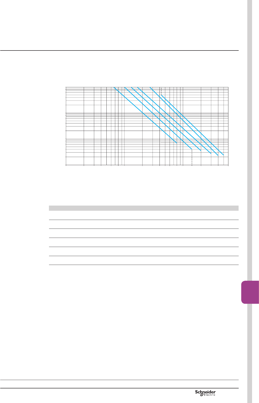
TeSys F
PCPB09T20-EN Version : 1.0 18 novembre 2014 12:55 PM B9/75
High power
contactors
B9/75
Electrical durability
Utilisation categories DC-1 to DC-5
Millions of operating cycles
Current broken in Amperes
1 3 8 202 4 6 10 30 40 50 60 80 100 140 200
0,08
0,02
0,01
0,6
0,8
1
2
4
6
8
10
LC1 FG150
LC1 FG265
LC1 FG185
LC1 FG400
300 400 600
LC1 FG500
LC1 FG630
0,1
0,04
0,06
0,2
0,4
DF537326.eps
Determining the electrical durability
The electrical durability can be read directly from the curve above, having previously calculated the power
broken Pc. The following table gives, for each utilisation category, the value of Pc according to the operational
current Ie and the operational voltage Ue.
Utilisation categories Pc (Power broken)
DC-1 Non-inductive loads Pc = Ue x Ie
DC-2 Shunt motors, breaking whilst running Pc = 0.1 Ue x Ie
DC-3 Shunt motors, reversing Pc = Ue x 2.5 Ie
DC-4 Series wound motors, breaking whilst
running
Pc = 0.3 Ue x Ie
DC-5 Series wound motors, reversing Pc = Ue x 2.5 Ie
Counter current braking (plugging) Pc = 1.5 Ue x 1.5 Ie
([DPSOH
Series wound motor, breaking whilst motor running, category DC-4.
P = 50 kW, Ue = 200 V, Ie = 250 A.
Select contactor LC1 FG265 with 3 poles in series.
The power broken is: Pc = 0.3 Ue x Ie = 0.3 x 200 x 250 = 15 kW.
The electrical durability read from the curve is 8 million operating cycles.
0D[LPXPRSHUDWLQJUDWH
The following operating rate used at Ie must not be exceeded: 120 operating cycles/hour.
Use of poles in parallel
The electrical durability is equal to the number of operating cycles performed by a pole, multiplied by the
QXPEHURISROHVLQSDUDOOHOPXOWLSOLHGE\DFRHI¿FLHQWRI
Selection TeSys contactors
3-pole shockproof contactors LC1 FG
d.c. supply
Selection guide for utilisation categories
DC-1 to DC-5
Presentation:
pages B9/68 and B9/69
Characteristics:
pages B9/76 to B9/83
References:
page B9/6
Dimensions, schemes:
pages B9/84 and B9/85
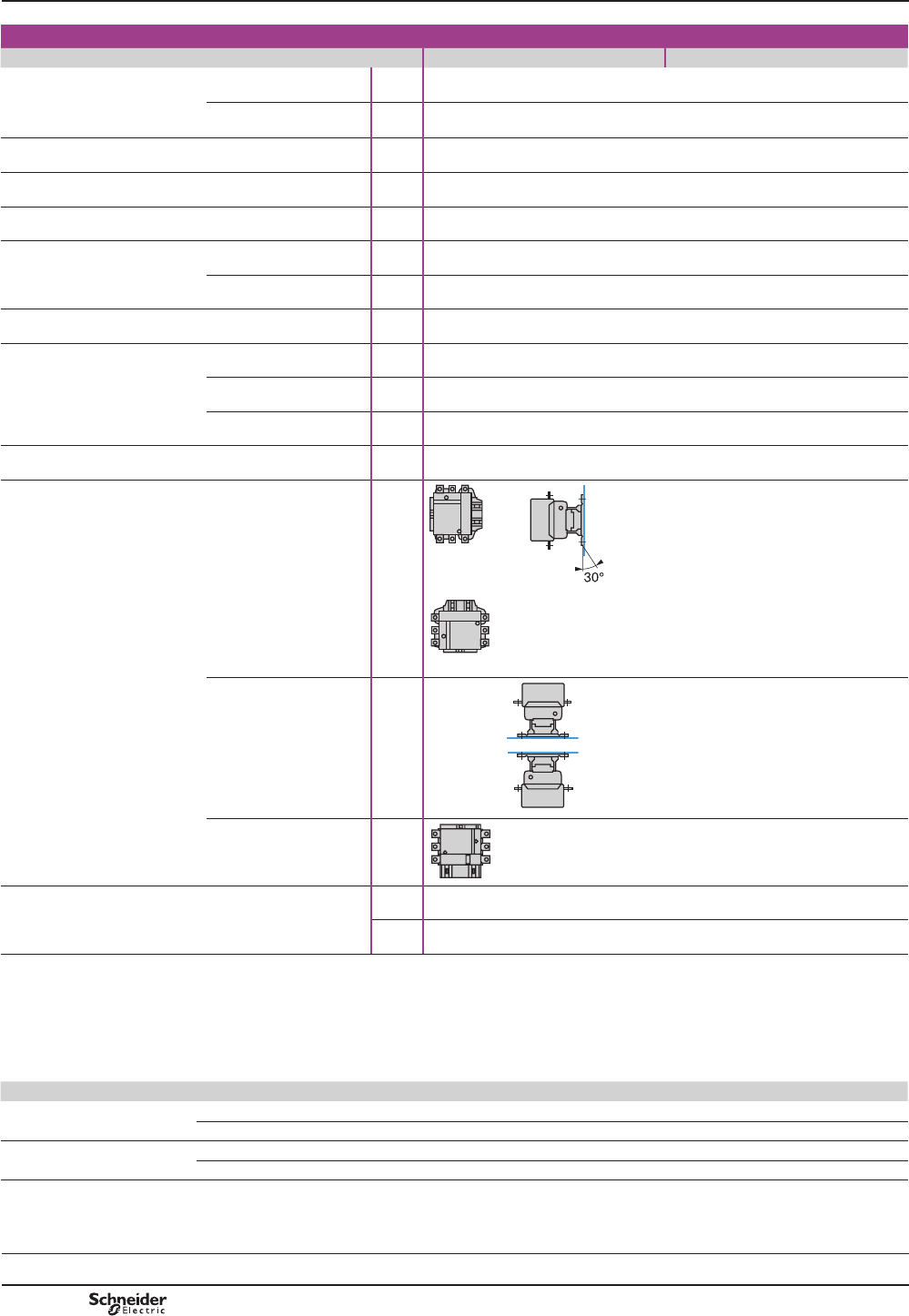
TeSys F
PCPB09T20-EN
Version : 1.0 18 novembre 2014 12:55 PM
B9/76
Characteristics TeSys contactors
3-pole shockproof contactors LC1 FG
Control circuit: a.c.
Environment
Contactor type LC1 FG150 LC1 FG185
Rated insulation voltage (Ui)
Conforming to
IEC 60947-4-1
V1000
Conforming to
VDE 0110 gr C
V1500
Rated impulse
withstand voltage (Uimp)
Coil not connected
to the power circuit
kV 8
Conforming to standards EN 60947-1, EN 60947-4-1, IEC 60947-1, IEC 60947-4-1
3URGXFWFHUWL¿FDWLRQV N.A.T.O.
Degree of protection Conforming to IEC 60529 IP 20 front face with shrouds LA9 F
Conforming to VDE 0106 )URQWIDFHSURWHFWHGDJDLQVWGLUHFW¿QJHUFRQWDFWZLWKVKURXGV/$)
Protective treatment Standard version “TH”
Ambient air temperature
around the device
Storage °C -60…+80
Operation °C -5…+55
Permissible at Uc (1) °C -40…+70
Maximum operating altitude Without derating m3000
Operating positions Without derating
DF537261.eps
DF537262.eps
DF537263.eps
With derating (3) )L[LQJ$
DF537264.eps
)L[LQJ%
DF537265.eps
Not to be used
DF537266.eps
Shock resistance (2) 12 g, 50 ms on the three axes: X, Y, Z
15 g, 11 ms on the three axes: X, Y, Z
(1),QWKHVHFRQGLWLRQVLWLVUHFRPPHQGHGWKDWFRLOV/;)EHXVHGIRUFRQWDFWRUVL]HVFG150 to FG265.
(2),QWKHOHDVWIDYRXUDEOHGLUHFWLRQZLWKRXWFKDQJHRIFRQWDFWVWDWHFRLODW8F
(3)+RUL]RQWDO¿[LQJ
WKHRSHUDWLRQDOFXUUHQW$&LVHTXLYDOHQWWRRIWKHYDOXHLQGLFDWHGLQWKHFDWDORJXH
EUHDNLQJDQGPDNLQJFDSDFLWLHVQRWJXDUDQWHHG
PHFKDQLFDODQGHOHFWULFDOGXUDELOLWLHVQRWJXDUDQWHHG
Derating of pull-in and drop-out voltage
Contactors LC1 FG150 FG185 FG265 FG400 FG500 FG630
Fixing A Pull-in 75 % 75 % 75 % 80 % 80 % 80 %
Drop-out 105 % 105 % 105 % 110 % 110 % 110 %
Fixing B Pull-in 115 % 115 % 115 % 120 % 120 % 120 %
Drop-out 90 % 90 % 90 % 95 % 95 % 95 %
Presentation:
pages B9/68 and B9/69
Selection:
pages B9/70 to B9/75
References:
page B9/6
Dimensions, schemes:
pages B9/84 and B9/85
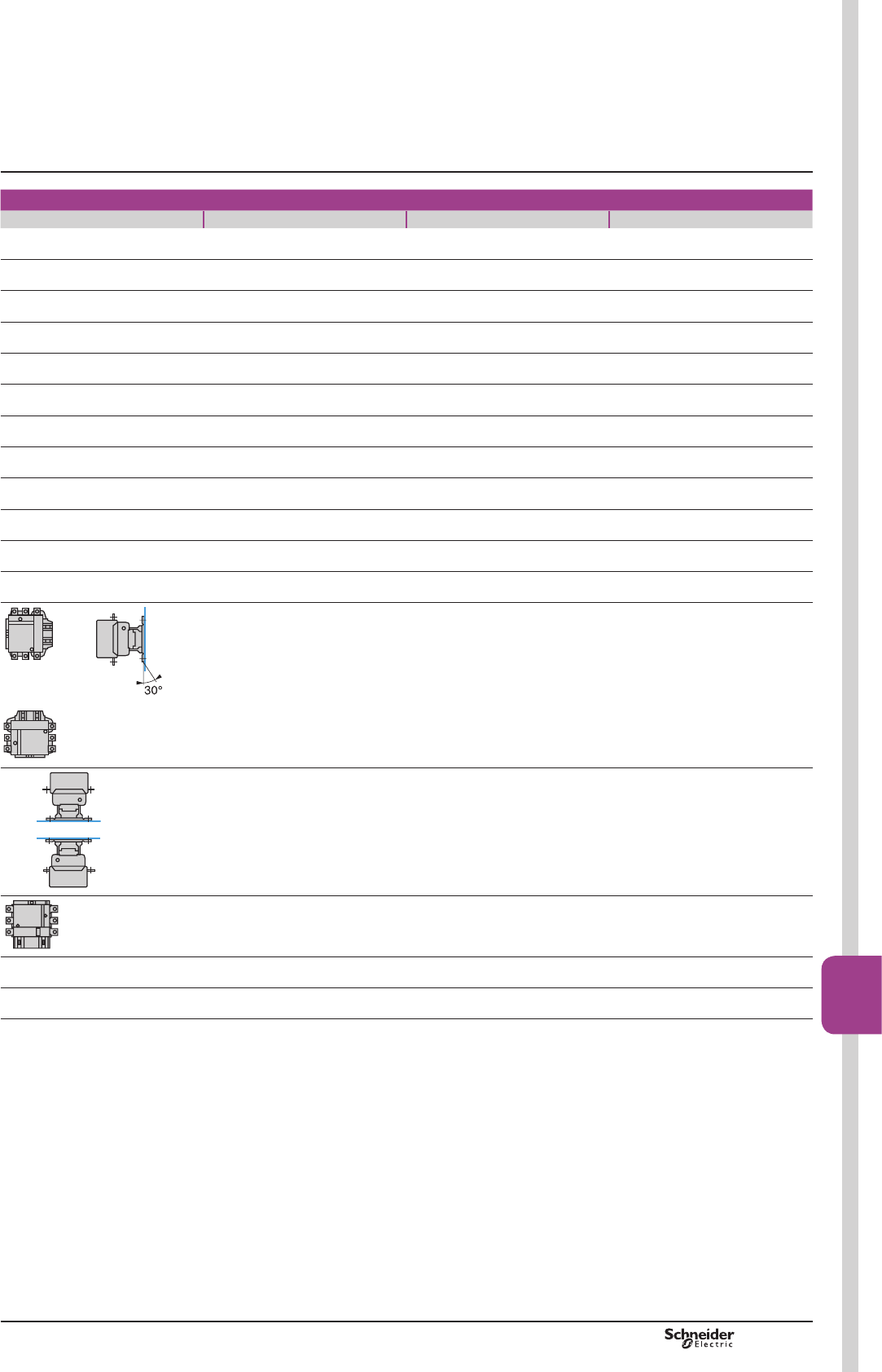
TeSys F
PCPB09T20-EN Version : 1.0 18 novembre 2014 12:55 PM B9/77
High power
contactors
B9/77
LC1 FG265 LC1 FG400 LC1 FG500 LC1 FG630
1000
1500
8
EN 60947-1, EN 60947-4-1, IEC 60947-1, IEC 60947-4-1
N.A.T.O.
IP 20 front face with shrouds LA9 F
)URQWIDFHSURWHFWHGDJDLQVWGLUHFW¿QJHUFRQWDFWZLWKVKURXGV/$)
“TH”
-60…+80
-5…+55
-40…+70
3000
DF537261.eps
DF537262.eps
DF537263.eps
A
DF537264.eps
B
DF537265.eps
DF537266.eps
12 g, 50 ms on the three axes: X, Y, Z
15 g, 11 ms on the three axes: X, Y, Z
Characteristics TeSys contactors
3-pole shockproof contactors LC1 FG
Control circuit: a.c.
TeSys F
PCPB09T20-EN
Version : 1.0 18 novembre 2014 12:55 PM
B9/78
Characteristics TeSys contactors
3-pole shockproof contactors LC1 FG
Control circuit: a.c.
Pole characteristics
Contactor type LC1 FG150 LC1 FG185
Number of poles 3 3
Rated operational current (Ie)
(Ue y 440 V)
In AC-3,
șy 55 °C
T y 70 °C A150/150 185/180
In AC-1,
șy 55 °C
T y 70 °C A220/170 240/180
Rated operational voltage (Ue) Up to V1000 1000
Frequency limits Of the operational current
(1)
Hz 25 to 200 25 to 200
Conventional thermal current șy 40 °C 250 275
Rated making capacity I rms conforming to
IEC 60947-4-1
AMaking current: 10 x I in AC-3
Rated breaking capacity I rms conforming to
IEC 60947-4-1
AMaking and breaking current: 8 x I in cat. AC-3
Permissible short time rating
1RFXUUHQWÀRZLQJIRUSUHFHGLQJ
PLQXWHVZLWKșy 40 °C
For 1.5 or 10 s A1200 1500
For 30 s A700 920
For 1 mn A600 740
For 3 mn A450 500
For 10 mn A350 400
Fuse protection
against short-circuits
(U y 440 V)
Motor circuit (type aM) A160 200
With thermal overload relay
(type gG)
A200 315
gG fuses A250 315
Average impedance per pole At Ith and 50 Hz m:0.35 0.33
Power dissipation per pole
for the above operational currents
AC-3 W8 12
AC-1 W22 25
Cabling
Minimum c.s.a.
Bar No. of bars 2 2
Bar mm 25 x 3 25 x 3
Cable with lug mm2120 150
Cable with connector mm2120 150
Bolt diameter mm Ø8 Ø8
Tightening torque Power circuit connections N.m 18 18
(1)6LQHZDYHZLWKRXWLQWHUIHUHQFH$ERYHWKHVHYDOXHVSOHDVHFRQVXOW\RXU5HJLRQDO6DOHV2I¿FH
Presentation:
pages B9/68 and B9/69
Selection:
pages B9/70 to B9/75
References:
page B9/6
Dimensions, schemes:
pages B9/84 and B9/85
TeSys F
PCPB09T20-EN Version : 1.0 18 novembre 2014 12:55 PM B9/79
High power
contactors
B9/79
LC1 FG265 LC1 FG400 LC1 FG500 LC1 FG630
3 3 3 3
265/250 400/340 500/500 630/630
300/250 430/340 580/500 850/700
1000 1000 1000 1000
25 to 200 25 to 200 25 to 200 25 to 200
350 500 700 1000
Making current: 10 x I in AC-3
Making and breaking current: 8 x I in AC-3
2200 3600 4200 5050
1230 2400 3200 4400
950 1700 2400 3400
620 1200 1500 2200
480 1000 1200 1600
315 400 500 630
500 630 800 800
400 500 800 1000
0.3 0.26 0.18 0.12
21 42 45 48
37 65 88 120
2 2 2 2
32 x 4 30 x 5 40 x 5 60 x 5
240 2 x 150 2 x 240 –
240 – – –
Ø10 Ø10 Ø10 Ø12
35 35 35 58
Characteristics TeSys contactors
3-pole shockproof contactors LC1 FG
Control circuit: a.c.

TeSys F
PCPB09T20-EN
Version : 1.0 18 novembre 2014 12:55 PM
B9/80
Characteristics TeSys contactors
3-pole shockproof contactors LC1 FG
Control circuit: a.c.
Control circuit characteristics with LX1 coil
Contactor type LC1 FG150 LC1 FG185
Rated control
circuit voltage (Uc)
50 or 60 Hz V48…440
Control voltage
limits
șy 55 °C)
50 or 60 Hz
coils
Operation 0.85…1.1 Uc
Drop-out 0.35…0.55 Uc
40…400 Hz
coils
Operation –
Drop-out –
Average consumption
at 20 °C and at Uc
a 50 Hz Inrush 50 Hz coil VA 550 805
40…400 Hz
coil
VA – –
Cos M0.3 0.3
Sealed 50 Hz coil VA 45 55
40…400 Hz
coil
VA – –
Cos M0.3 0.3
a 60 Hz Inrush 60 Hz coil VA 660 970
40…400 Hz
coil
VA – –
Cos M0.3 0.3
Sealed 60 Hz coil VA 55 66
40…400 Hz
coil
VA – –
Cos M0.3 0.3
Heat dissipation W12…16 18…24
Operating time (1) Closing "C" ms 23…35 20…35
Opening "O" ms 5…15 7…15
Mechanical durability at Uc In millions of
operating cycles
10 10
Maximum operating rate
at ambient temperature y 55 °C
In operating cycles
per hour
2400 2400
Cabling
Min/max c.s.a.
Flexible cable
without cable end
1 or 2
conductors
mm21/4 1/4
Flexible cable
with cable end
1 conductor mm21/4 1/4
2 conductors
mm21/2.5 1/2.5
Solid cable
without cable end
1 or 2
conductors
mm21/4 1/4
Tightening torque N.m 1.2 1.2
Characteristics of the locking electromagnet (shockproof device)
Contactor type LC1 FG150 LC1 FG185
Control circuit voltage 50/60 Hz V48…440 48…440
Inrush consumption VA 100 100
Maximum energisation time at Uc ms 20 20
Maximum operating rate In operating cycles
per hour
2400 2400
Mechanical durability at Uc In millions of
operating cycles
1 x 1061 x 106
(1)7KHFORVLQJWLPH&LVPHDVXUHGIURPWKHPRPHQWWKHFRLOVXSSO\LVVZLWFKHGRQWRLQLWLDOFRQWDFWRIWKHPDLQSROHV
7KHRSHQLQJWLPH2LVPHDVXUHGIURPWKHPRPHQWWKHFRLOVXSSO\LVVZLWFKHGRIIWRWKHPRPHQWWKHPDLQSROHVVHSDUDWH
Presentation:
pages B9/68 and B9/69
Selection:
pages B9/70 to B9/75
References:
page B9/6
Dimensions, schemes:
pages B9/84 and B9/85
TeSys F
PCPB09T20-EN Version : 1.0 18 novembre 2014 12:55 PM B9/81
High power
contactors
B9/81
LC1 FG265 LC1 FG400 LC1 FG500 LC1 FG630
48…440 110…440 110…440 110…440
– – – –
– – – –
0.85…1.1 Uc 0.85…1.1 Uc 0.85…1.1 Uc 0.85…1.1 Uc
0.35…0.55 Uc 0.3…0.5 Uc 0.3…0.5 Uc 0.25…0.5 Uc
– – – –
650 1075 1100 1650
0.9 0.9 0.9 0.9
– – – –
10 15 18 22
0.9 0.9 0.9 0.9
– – – –
650 1075 1100 1650
0.9 0.9 0.9 0.9
– – – –
10 15 18 22
0.9 0.9 0.9 0.9
8 14 18 20
40…65 40…75 40…75 40…80
100…170 100…170 100…170 100…200
10 10 10 10
2400 2400 2400 1200
1/4 1/4 1/4 1/4
1/4 1/4 1/4 1/4
1/2.5 1/2.5 1/2.5 1/2.5
1/4 1/4 1/4 1/4
1.2 1.2 1.2 1.2
LC1 FG265 LC1 FG400 LC1 FG500 LC1 FG630
48…440 110…440 110…440 110…440
100 100 100 100
20 20 20 20
2400 2400 2400 1200
1 x 1061 x 1061 x 1061 x 106
Characteristics TeSys contactors
3-pole shockproof contactors LC1 FG
Control circuit: a.c.
TeSys F
PCPB09T20-EN
Version : 1.0 18 novembre 2014 12:55 PM
B9/82
Environment
Contact block type LAD N LAD T and LAD S LAD R
Conforming to standards IEC 60947-5-1, NF C 63-140, VDE 0660, BS 4794, EN 60947-5-1
3URGXFWFHUWL¿FDWLRQV UL, CSA
Protective treatment Conforming to IEC 60068 “TH”
Degree of protection Conforming to VDE 0106 3URWHFWLRQDJDLQVWGLUHFW¿QJHUFRQWDFW,3;
Ambient air temperature
around the device
Storage °C -60…+80
Operation °C -5…+60
Permissible for operation at Uc °C -40…+70
Maximum
operating altitude
Without derating m3000
Cabling Phillips n° 2 and Ø6 mm. Flexible or
solid cable with or without cable end
mm2Min: 1 x 1; max: 2 x 2.5
Instantaneous and time delay contact characteristics
Contact block type LAD N LAD T and LAD S LAD R
Number of contacts 1 or 4 2 2
Rated operational voltage
(Ue)
Up to V660
Rated insulation
voltage (Ui)
Conforming to IEC 60947-5-1 V690
Conforming to UL, CSA V600
Conventional thermal
current (Ith)
For ambient temperature y 60 °C A10
Frequency of the operational current Hz 25…400
Minimum
switching capacity
U min V17
I min mA 5
Short-circuit protection Conforming to IEC 60947-5-1 and
VDE 0660.
gG fuse
A10
Rated making capacity Conforming to IEC 60947-5-1, I rms Aa 140; c 250
Short-time rating Permissible for 1 s A100
500 ms A120
100 ms A140
Insulation resistance M:> 10
Non-overlap time Guaranteed between
N/C and N/O contacts
ms 1.5 (on energisation and on de-energisation)
Time delay
(LADT, R and S
contact blocks)
Accuracy only valid for
setting range indicated
on the front face
Ambient air temperature for operation °C – -40…+70 -40…+70
Repeat accuracy – ±2 % ±2 %
Drift up to 0.5 million operating cycles – +15 % +15 %
Drift depending on ambient air
temperature
– 0.25 % per °C 0.25 % per °C
Mechanical durability In millions of operating cycles 30 5 5
Rated operational
power of contacts
Conforming to
IEC 60947-5-1
V 24 48 110/127 220/230 380/400 440 600
1 million operating cycles VA 150 300 400 480 500 500 500
3 million operating cycles VA 80 170 250 290 320 320 320
10 million operating cycles VA 30 65 90 120 130 130 130
Occasional making capacity VA 1200 2600 7000 13 000 15 000 13 000 9000
Characteristics TeSys contactors
Auxiliary contact blocks
for 3-pole shockproof contactors LC1 FG
References:
page B9/27
Schemes:
page B9/85
TeSys F
PCPB09T20-EN Version : 1.0 18 novembre 2014 12:55 PM B9/83
High power
contactors
B9/83
Environment
Module type LAD T (On-delay) LAD R (Off-delay)
Conforming to standards IEC 60255-5
3URGXFWFHUWL¿FDWLRQV UL, CSA
Protective treatment Conforming to IEC 60068 “TH”
Degree of protection Conforming to VDE 0106 3URWHFWLRQDJDLQVWGLUHFW¿QJHUFRQWDFW,3;
Ambient air
temperature around
the device
Storage °C -40…+80
Operation °C -25…+55
For operation at Uc °C -25…+70
Rated insulation
voltage (Ui)
Conforming to IEC 60947-1 V250
Cabling Phillips n° 2 and Ø6 mm. Flexible or
solid cable with or without cable end
mm2Min: 1 x 1; max: 2 x 2.5
Control circuit characteristics
Module type LAD T (On-delay) LAD R (Off-delay)
Built-in protection Of the input By varistor By varistor
Contactor coil suppression By varistor By bidirectional peak limiting diode
Rated control circuit voltage (Uc) Va or c 24…250 a 24…250
Permissible variation 0.8…1.1 Uc 0.8…1.1 Uc
Control type By mechanical contact only By mechanical contact only
connecting cable < 10 m
Time delay characteristics
Module type LAD T (On-delay) LAD R (Off-delay)
Timing ranges s0.1…2 ; 1.5…30 ; 25…500 0.1…2 ; 1.5…30 ; 25…500
Repeat accuracy 0…40 °C ±3 % (10 ms minimum) ±3 % (10 ms minimum)
Reset time During time delay period ms 150 225
After time delay period ms 50 –
Immunity to
microbreaks
During time delay period ms 10 20
After time delay period ms 2 –
Minimum impulse duration ms – 40
Time delay signalling By LED Illuminates during time delay period Illuminates during time delay period
Switching characteristics (solid state type)
Module type LAD T (On-delay) LAD R (Off-delay)
Maximum power dissipated W2 3.5
Leakage current mA < 5 < 5
Residual voltage V3.3 3.3
Overvoltage protection 3 kV; 0.5 joule 3 kV; 0.5 joule
Electrical durability In millions of operating cycles 30 30
Operating diagrams
Electronic On-delay timer LAD T Electronic Off-delay timer LAD R
0
1
0
1
t
U supply
(A1 - A2)
Time delay output
Contactor coil
Red LED
DF537275.eps
Control
(A2 - B2)
Time delay output
Contactor coil
Red LED
U supply
(A1 - A2)
0
1
0
1
t
0
1
40 ms
DF537276.eps
References:
page B9/27
Schemes:
page B9/85
Characteristics TeSys contactors
Auxiliary contact blocks
for 3-pole shockproof contactors LC1 FG

TeSys F
Dimensions TeSys contactors
3-pole shockproof contactors LC1 FG
Dimensions
LC1 FG150, FG185 and FG265
J
J1
b1 ==
G1
GZ
= =
Y
L
c
= b =
b2
X1X1
S1
Q
a
P P Q1
f
M
S
FG150 M8x25
F1G85 M8x25
FG265 M10x35
(1)
DF537282.eps
X1 (mm) = Minimum electrical clearance according
to operating voltage and breaking capacity.
LC1 200…500 V 600…1000 V
FG150 10 15
FG185 10 15
FG265 10 15
(1)3RZHUWHUPLQDOSURWHFWLRQVKURXG
(see page B9/14).
LC1 a b b1 b2 c f G G1 J J1 L M P Q Q1 S S1 Y Z
FG150 181 170 137 301 180 131 106 80 106 120 116 150 40 26 57.5 20 34 44 13.5
FG185 183.5 174 137 305 190 130 111 80 106 120 122.5 154 40 29 59.5 20 34 44 13.5
FG265 217.5 203 145 375 222 147 142 96 106 120 150 178 48 39 66.5 25 44.5 38 21.5
f = minimum distance required for coil removal.
LC1 FG400 and FG500
G
G123,5 J
120 ==
180 ==
L
c
= b =
b2
209
56
X1X1
Q1
a
PQ P
f
M
44,5S
6xM10x35
(1)
DF537283.eps
X1 (mm) = Minimum electrical clearance according
to operating voltage and breaking capacity.
LC1 200…500 V 600…1000 V
FG400 15 20
FG500 15 20
(1)3RZHUWHUPLQDOSURWHFWLRQVKURXG
(see page B9/14).
LC1 a b b2 c f G
supplied
G
min.
G
PD[
G1
supplied
G1
min.
G1
PD[
JL M P Q Q1 S
FG400 237 206 375 234 146 80 66 102 223 156 192 19.5 160 181 48 75 74 25
FG500 257 238 400 247 150 80 66 120 223 156 210 39.5 181 208 55 78 77 30
f = minimum distance required for coil removal.
Presentation:
pages B9/68 and B9/69
Selection:
pages B9/70 to B9/75
Characteristics:
pages B9/76 to B9/83
References:
page B9/6
PCPB09T30-EN
Version : 1.0 18 novembre 2014 12:55 PM
B9/84
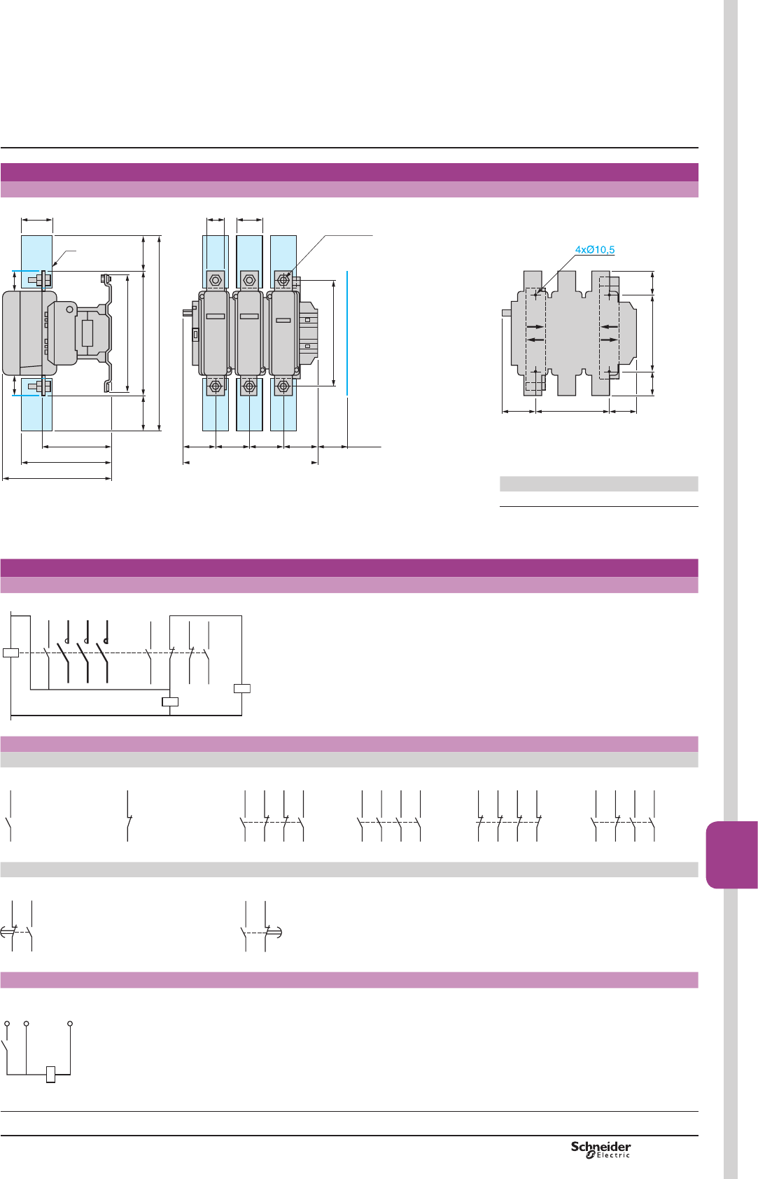
TeSys F
Dimensions, schemes
Dimensions
LC1 FG630
89
321
808079
264
180 (2)
6440
6xM12x45
155
= 304 =
197
255
280
X1
464
72
X1
(1)
DF537284.eps
180= =
68,528260,5
DF537285.eps
X1 (mm) = Minimum electrical clearance
according to operating voltage and breaking
capacity.
LC1 200…500 V 690…1000 V
FG630 20 30
(1)3RZHUWHUPLQDOSURWHFWLRQVKURXGVHHSDJH%
(2)0LQLPXPGLVWDQFHUHTXLUHGIRUFRLOUHPRYDO
Schemes
Contactors LC1-FG150 to FG630
A2
03
04
1/L1
T1/2
3/L2
T2/4
5/L3
T3/6
A1
22 21/NC
32 31/NC
13/NO
14
43/NO
44
C1
C2
a a
Un y 240 V
d 50-60 Hz max
DF537286.eps
Add-on blocks
,QVWDQWDQHRXVDX[LOLDU\FRQWDFWV
1 N/O LAD N10 1 N/C LAD N01 2 N/O + 2 N/C LAD N22 4 N/O LAD N40 4 N/C LAD N04 3 N/O + 1 N/C LAD N31
43/NO
44
(94)
(93)
DF537287.eps
(92)
(91)
42 41/NC
DF537288.eps
72 71/NC
62 51/NC
53/NO
54
83/NO
84
DF537289.eps
53/NO
54
63/NO
64
73/NO
74
83/NO
84
DF537290.eps
72 71/NC
62 61/NC
82 81/NC
52 51/NC
DF537291.eps
62 61/NC
53/NO
54
84 83/NO
73/NO
74
DF537292.eps
7LPHGHOD\DX[LOLDU\FRQWDFWV
On-delay 1 N/O + 1 N/C LAD TpOff-delay 1 N/O + 1 N/C LAD Rp
55/N56
67/NO
68
DF537293.eps
66 65/NC
57/NO
58
DF537294.eps
Coils a
LX1 FF, FG, FH, FJ, FK and FL
A2A1
A2A103
DF537295.eps
Presentation:
pages B9/68 and B9/69
Selection:
pages B9/70 to B9/75
Characteristics:
pages B9/76 to B9/83
References:
pages B9/6, B9/28 and B9/29
TeSys contactors
3-pole shockproof contactors LC1 FG
PCPB09T30-EN Version : 1.0 18 novembre 2014 12:55 PM B9/85
High power
contactors
B9/85

TeSys F
General
Magnetic latching contactors
0DJQHWLFODWFKLQJFRQWDFWRUVRIERWKEORFNDQGEDUPRXQWHGW\SHVDUH¿WWHGZLWKD
special electromagnet which enables them to remain in the “On” position when the
coil is no longer energised.
Applications
The special properties of magnetic latching contactors make them suitable for a large
number of applications.
Properties
b Retention of the sequence memory in automatic control equipment in the event of
loss of control voltage.
b Energy saving, since the source of supply to the coil does not need to supply
current when the contactor is latched in the closed state.
b Change of state from “Closed” to “Open” by current signal through the coil.
b Unaffected by mains interference.
b Utilisation of contactors beyond their breaking capacity, as operations are
performed off-load.
b Contactors are silent in the latched position.
Applications
b 5H¿QHULHVSRZHUVWDWLRQVH[FLWDWLRQFLUFXLWV
b Contactors remaining in the closed state for long periods.
([DPSOHVUH¿QHULHVSRZHUVXSSOLHVORZYROWDJHGLVWULEXWLRQ
b Selective opening control.
b No unwanted opening and closing of the main power poles.
b Current carrying at voltages up to 1000 Volts.
Operation of the electromagnet
CR1 F block contactors
&5)PDJQHWLFODWFKLQJFRQWDFWRUVDUH¿WWHGZLWKDGRXEOHFRLOZLWKWHUPLQDOV
comprising a latching winding and an unlatching winding. The 2 windings have
a common point which can necessitate special wiring precautions when the latching
supply is separate from the unlatching supply.
The power supplies may be a.c. or d.c. For d.c. operation, the polarities indicated
must be complied with.
Operating precautions:
b the 2 windings must not be supplied simultaneously
b a winding must not be supplied continuously
b supply to the coils must be via pulsed contacts.
Manual opening:
if the control voltage is not present, the contactor can be unlatched manually.
CR1 B bar mounted contactors
&5%PDJQHWLFODWFKLQJFRQWDFWRUVDUH¿WWHGZLWKDVLQJOHFRLOVXSSOLHGZLWKGFRU
ZLWKDFWKURXJKDUHFWL¿HU
/DWFKLQJLVREWDLQHGE\GLUHFWVXSSO\RIWKHFRLOLQRQHGLUHFWLRQRIFXUUHQWÀRZ
Unlatching is obtained by a reverse current, adjusted by resistors.
Mechanical latching contactors
LC1 D block contactors
For applications using smaller contactor sizes than those described on page B9/78, it
is possible to obtain the same function by the addition of a mechanical latch block
type LA6 DK, which can be mounted on LC1 D contactors (see page B9/78).
TeSys contactors
Magnetic latching contactors
Selection:
pages B9/87 to B9/91
Characteristics:
pages B9/92 to B9/95
References:
pages B9/7, B9/30 to B9/35
Dimensions:
pages B9/96 to B9/99
PCPB09T30-EN
Version : 1.0 18 novembre 2014 12:55 PM
B9/86

TeSys F
Selection
Continuous or intermittent duty up to 30 operating cycles/hour
Motor (1) 3-pole
contactor
3-pole differential
thermal overload relay
3 fuses
Type
220 V
230 V
380 V
400 V
415 V 440 V
(2) Reference Setting
range
aM BS-88
P In P In P In P In Reference Rating
kW HP A kW HP A kW HP A kW HP A A A A
25 35 85 –––––––––CR1F150 LR9F5367 60…100 100 125
30
33
40
45
103
113
51
55
70
75
98
105
55
–
75
–
100
–
59 80 97 CR1F150 LR9F5369 90…150 100 160
–
–
–
–
–
–
59
63
80
85
112
117
59
63
80
85
105
115
63
–
85
–
109
–
CR1F150 LR9F5369 90…150 125 160
37
40
50
54
126
134
75
–
100
–
138
–
75
–
100
–
135
–
75
80
100
110
125
131
CR1F150 LR9F5369 90…150 160 200
45 60 150 80 110 147 80 110 138 90 125 146 CR1F185 LR9F5369 90…150 160 200
51
55
70
75
170
182
90
–
125
–
170
–
90
100
125
136
165
182
100
–
136
–
162
–
CR1F185 LR9F5371 132…220 200 250
59
63
80
85
195
203
100
110
138
150
188
205
110
–
150
–
200
–
110
129
150
175
178
209
CR1F265 LR9F5371 132…220 250 315
75
–
100
–
240
–
129
132
175
180
242
245
129
132
175
180
230
240
132
–
180
–
215
–
CR1F265 LR9F7375 200…330 250 315
––––––140 190 250 140 190 227 CR1F265 LR9F7375 200…330 315 400
80
–
–
110
–
–
260
–
–
140
147
150
190
200
205
260
273
280
147
150
160
200
205
220
260
270
280
147
150
160
200
205
220
236
246
256
CR1F400 LR9F7375 200…330 315 400
90
–
125
–
295
–
160
–
220
–
300
–
–––180
185
245
250
289
295
CR1F400 LR9F7375 200…330 315 400
100
110
136
150
325
356
180
185
245
250
333
342
180
185
245
250
320
325
200
220
270
300
321
353
CR1F400 LR9F7379 300…500 400 500
–––200 270 370 200
220
270
300
340
385
250
–
340
–
401
–
CR1F400 LR9F7379 300…500 400 500
129 175 420 220 300 408 –––257 350 412 CR1F500 LR9F7379 300…500 500 630
132
140
180
190
425
450
250
–
340
–
460
–
250
257
340
350
425
450
280
–
380
–
450
–
CR1F500 LR9F7381 380…630 500 630
147 200 472 ––––––295 400 473 CR1F500 LR9F7381 380…630 500 630
–––257
–
350
–
475
–
280
295
380
400
475
500
300
–
410
–
481
–
CR1F630 LR9F7381 380…630 500 630
150
160
205
220
483
520
280
295
380
400
510
546
300
315
410
430
510
535
315
335
430
450
505
518
CR1F630 LR9F7381 380…630 630 800
180
185
245
250
578
595
300
315
410
430
565
584
335
355
450
480
550
580
355
375
480
500
549
575
CR1F630 LR9F7381 380…630 630 800
200 270 626 335 450 620 375 500 610 400 454 611 CR1F630 LR9F7381 380…630 800 1000
220 g700 355
375
400
–
g
g
g
635
670
710
–
400
425
445
450
g
g
g
g
650
690
730
740
425
445
450
475
g
g
g
g
650
680
690
730
CR1BL33 500…800 800 1000
250 g800 425 g760 475 g780 500 g780 CR1BM33 500…800 800 1000
257
280
295
300
315
g
g
g
g
g
826
900
948
980
990
445
450
475
500
530
g
g
g
g
g
790
800
850
900
950
500
530
560
600
g
g
g
g
820
870
920
978
530
560
600
630
g
g
g
g
825
870
920
965
CR1BM33 630…1000 1000 1250
(1)7KHUDWLQJVDUHIRUVWDQGDUG99RU9PRWRUV7KHRYHUORDGUHOD\VVKRXOGSUHIHUDEO\EHVHWWRWKHPRWRUIXOOORDGFXUUHQWVKRZQRQ
WKHPRWRUUDWLQJSODWH)RURWKHUSRZHUUDWLQJVVHOHFWWKHRYHUORDGUHOD\ZLWKWKHDSSURSULDWHUDQJHWKHDVVRFLDWHGFRQWDFWRUDQGIXVHVPXVWKDYHUDWLQJVHTXDOWR
RULPPHGLDWHO\JUHDWHUWKDQ,Q
(2)5HIHUHQFHWREHFRPSOHWHGVHHSDJH%
g There are no standard power ratings for these motors.
TeSys contactors
Magnetic latching contactors
Selection guide for direct on-line starting
of squirrel cage motors
Characteristics:
pages B9/92 to B9/95
References:
pages B9/7, B9/30 to B9/35
Dimensions:
pages B9/96 to B9/99
PCPB09T30-EN Version : 1.0 18 novembre 2014 12:55 PM
B9/87
High power
contactors
B9/87

TeSys F
Selection
Rated operational current in AC-3 (T y 55 °C)
Contactor size CR1
F150
CR1
F185
CR1
F265
CR1
F400
CR1
F500
CR1
F630
CR1
BL
CR1
BM
CR1
BP
CR1
BR
440 V A150 185 265 400 500 630 750 1000 1500 1800
500 V A135 175 245 385 500 540 750 900 1200 1500
660/690 V A130 140 230 365 435 470 700 800 900 1100
1000 V A47 73 95 135 270 330 400 400 500 600
Rated operational power (standard motor power ratings)
220…240 V kW 40 55 75 110 147 200 220 280 425 500
HP 54 75 100 150 200 270 300 380 580 680
380…400 V kW 75 90 132 200 250 335 400 500 750 900
HP 100 185 180 270 340 450 545 680 1000 1220
415 V kW 80 100 140 220 280 375 425 530 800 900
HP 110 136 180 300 380 500 580 720 1100 1220
440 V kW 80 100 140 250 295 400 450 560 800 900
HP 110 136 190 340 400 545 610 760 1100 1220
500 V kW 90 110 160 257 355 400 500 600 750 900
HP 125 150 220 350 480 545 680 810 1000 1220
660/690 V kW 100 110 160 280 335 450 560 670 750 900
HP – – – – – 610 760 910 1000 1220
1000 V kW 65 100 147 185 335 450 530 530 670 750
HP – 136 200 250 – 610 720 720 910 1000
Maximum operating rate in operating cycles/hour, at rated operational power with
an on-load factor = 85 %: 750 for CR1 F150 to F265, 500 for CR1 F400 to F630 and
120 for CR1 B.
TeSys contactors
Magnetic latching contactors
Selection guide for utilisation category AC-3
Characteristics:
pages B9/92 to B9/95
References:
pages B9/7, B9/30 to B9/35
Dimensions:
pages B9/96 to B9/99
PCPB09T30-EN
Version : 1.0 18 novembre 2014 12:55 PM
B9/88
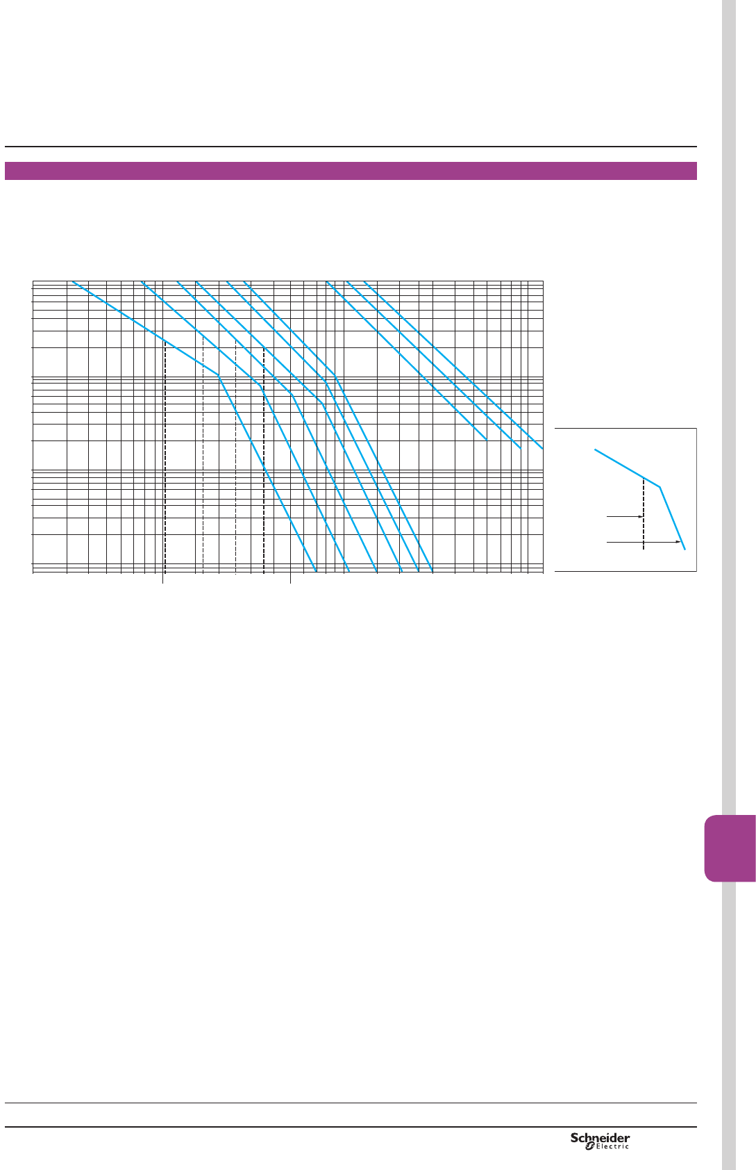
TeSys F
Selection
Use in category AC-3 (Ue y 440 V) (1) (Ty 55 °C)
The current (Ic) in AC-3 is equal to the rated operational current (Ie) drawn by the
motor.
AC-3 AC-2
AC–4
20 30 40 50 60 70 8090
100
150 200 300 400
500
600 800 1000 1500 2000 3000 4000 6000 8000 10 000
0,008
0,001
0,002
0,004
0,006
0,008
0,01
0,02
0,04
0,06
0,08
0,1
0,2
0,4
0,6
0,8
1
CR1 F150
CR1 F185
CR1 F265
CR1 F400
CR1 F500
CR1 F630
CR1 BL, BM
CR1 BP
CR1 BR
Millions of
operating
cycles
Current broken in A
DF565949.eps
TeSys contactors
Magnetic latching contactors
Selection according to required electrical
durability
([DPSOH
Asynchronous motor with P = 50 kW, Ue = 380 V, Ie = 100 A, Ic = Ie = 100 A, or
asynchronous motor with P = 55 kW, Ue = 415 V, Ie = 100 A, Ic = Ie = 100 A.
600000 operating cycles required.
The above selection curves show the contactor rating needed, CR1 F185.
(1))RU9PXOWLSO\WKHQXPEHURIRSHUDWLQJF\FOHVE\
Current
breaking
limits
In categories
Characteristics:
pages B9/92 to B9/95
References:
pages B9/7, B9/30 to B9/35
Dimensions:
pages B9/96 to B9/99
PCPB09T30-EN Version : 1.0 18 novembre 2014 12:55 PM B9/89
High power
contactors
B9/89

TeSys F
Selection
0D[LPXPRSHUDWLRQDOFXUUHQW(on-load factor u 0.95)
0D[LPXPRSHUDWLQJUDWHRSHUDWLQJF\FOHVKRXU
Contactor size CR1
F150
CR1
F185
CR1
F265
CR1
F400
CR1
F500
CR1
F630
CR1
BL
CR1
BM
CR1
BP
CR1
BR
Cable c.s.a. mm2120 150 185 – – – – – – –
Number of bars – – – 2 2 2 2 2 3 4
Bar c.s.a. mm – – – 30 x 5 40 x 5 60 x 5 50 x 5 80 x 5 100 x 5 100 x 5
Operational current
in category AC-1
at ambient temperature
y 40 °C A250 275 350 500 700 1000 800 1250 2000 2750
y 55 °C A250 275 300 430 580 850 700 1100 1750 2400
y 70 °C A170 180 250 340 500 700 600 900 1500 2000
Increase in operational current by parallel connection of poles
$SSO\WKHIROORZLQJFRHI¿FLHQWVWRWKHDERYHFXUUHQWVWKHVHFRHI¿FLHQWVWDNHLQWR
account an often unbalanced distribution of current between the poles:
b 2 poles in parallel: K = 1.6
b 3 poles in parallel: K = 2.25
b 4 poles in parallel: K = 2.8.
Electrical durability (Ue y 440 V) (1)
0,01
8060 100 250
275
400
350 500
600
700
800 1000
1250
2000
2750
4000
0,02
0,04
0,06
0,08
0,1
0,2
0,4
0,6
0,8
1
CR1 F150
CR1 F185
CR1 F265
CR1 F400
CR1 F500
CR1 F630
CR1 BL, BM
CR1 BP
CR1 BR
Millions of
operating
cycles
Current broken in A
DF565951.eps
([DPSOH
Ue = 220 V - Ie = 200 A - T = 40 °C - Ic = Ie = 200 A
600000 operating cycles required.
The above selection curves show the contactor rating needed, CR1 F400.
(1) )RU9PXOWLSO\WKHQXPEHURIRSHUDWLQJF\FOHVE\
TeSys contactors
Magnetic latching contactors
Selection guide for utilisation category AC-1
and according to required electrical durability
Characteristics:
pages B9/92 to B9/95
References:
pages B9/7, B9/30 to B9/35
Dimensions:
pages B9/96 to B9/99
PCPB09T30-EN
Version : 1.0 18 novembre 2014 12:55 PM
B9/90

TeSys F
Selection
Operating conditions
Maximum ambient temperature: 55 °C.
Maximum operational voltage: 1000 V, 50…60 Hz.
When a transformer is switched on, there is generally an initial current surge which
reaches its peak value almost instantaneously and then decreases in a largely
exponential manner to quickly reach its steady state value.
The value of this current depends on:
b the characteristics of the magnetic circuit and of the windings (cross sectional area
of the core, rated inductance, number of turns, size of the windings, ...)
b the performance of the magnetic laminations used (residual induction and
saturation inductance),
b the magnetic state of the circuit and the instantaneous value of the a.c. mains
voltage at the moment of switch-on.
The peak current at the moment of switch-on can reach 20 to 40 times the rated
current for the various kVA power ratings in the tables below. This value is
independent of the “no-load” or “on-load” state of the transformer.
The peak magnetising current of the transformer must be lower than the values given
in the tables below.
TeSys contactors
Magnetic latching contactors
Selection guide for switching the primaries
of 3-phase transformers
Contactor selection
0D[LPXPRSHUDWLQJUDWHRSHUDWLQJF\FOHVKRXU
Contactor size CR1
F150
CR1
F185
CR1
F265
CR1
F400
CR1
F500
CR1
F630
CR1
BL
CR1
BM
CR1
BP
CR1
BR
Maximum permissible
current peak at switch-on
A1700 2800 3500 5500 6800 9000 18 000 18 000 24 000 30 000
Maximum
operational power (1)
220…230 V kVA 25 40 50 75 100 140 230 230 300 380
380…400 V kVA 50 75 90 130 170 225 400 400 530 660
415…440 V kVA 55 80 100 140 190 250 450 450 560 700
500 V kVA 65 95 110 170 225 280 480 480 600 750
660 V kVA 80 120 140 200 270 315 600 600 800 950
1000 V kVA 100 150 200 250 375 470 700 700 1000 1200
(1)0D[LPXPRSHUDWLRQDOSRZHUFRUUHVSRQGLQJWRDFXUUHQWSHDNDWVZLWFKRQRI,Q
Characteristics:
pages B9/92 to B9/95
References:
pages B9/7, B9/30 to B9/35
Dimensions:
pages B9/96 to B9/99
PCPB09T30-EN Version : 1.0 18 novembre 2014 12:55 PM
B9/91
High power
contactors
B9/91
TeSys F
Environment
Contactor type CR1 F150 CR1 F185 CR1 F265
Rated insulation voltage (Ui) Conforming to IEC 60158-1,
BS 775, 60947-4
V1000 1000 1000
Conforming to VDE 0110 grC V1500 1500 1500
Protective treatment Standard version “TH”
Special version –
Ambient air temperature
around the device
Storage °C -60…+80
For operation at Uc °C -15…+70
Maximum operating altitude Without derating m3000
Operating positions Without derating ±5 °
Pole characteristics
Number of poles 3 or 4 3 or 4 3 or 4
Rated operational current (Ie)
(Ue y 440 V)
In AC-3, T y 40 °C A150 185 265
In AC-1, T y 40 °C A250 275 350
In AC-4, T y 40 °C A138 170 245
Rated operational voltage (Ue) Up to V1000 1000 1000
Frequency limits
(sine wave)
Of the opeational current Hz 25…200 25…200 25…200
Rated making capacity I rms A1700 2100 2940
Rated breaking capacity I rms 220…440 V A1500 1800 2450
500 V A1200 1600 2200
660/690 V A1100 1200 1700
1000 V A450 600 800
Permissible short time rating
from cold state, with no current
ÀRZLQJIRUSUHYLRXVPLQXWHV
at T y 40 °C
For 1 s A1200 1500 2200
For 5 s A1200 1500 2200
For 10 s A1200 1500 2200
For 30 s A700 920 1230
For 1 min A600 740 950
For 3 min A450 500 620
For 10 min A350 400 480
Short-circuit protection by fuses
T y 440 V
Motor circuit AC-3 (type aM) A160 200 315
AC-1 circuit (type gG, BS 88) A250 315 400
Average impedance per pole At lth and 50 Hz m:0.45 0.36 0.32
Power dissipated per pole
for the above operational currents
AC-3 W6 12 22
AC-1 W18 26 39
Connection Number of conductors 1 1 1
Cable with lugs mm2120 150 240
Cable with connector mm2120 150 240
Number of bars 2 2 2
Bar c.s.a. mm 25 x 3 25 x 3 32 x 4
Bolt diameter Ø8 Ø8 Ø10
Tightening torque N.m 18 18 35
TeSys contactors
Magnetic latching contactors
Characteristics
Selection:
pages B9/87 to B9/91
References:
pages B9/7, B9/30 to B9/35
Dimensions:
pages B9/96 to B9/99
PCPB09T30-EN
Version : 1.0 18 novembre 2014 12:55 PM
B9/92
TeSys F
CR1 F400 CR1 F500 CR1 F630 CR1 BL CR1 BM CR1 BP CR1 BR
1000 1000 1000 1000 1000 1000 1000
1500 1500 1500 1500 1500 1500 1500
“TH” “TC”
– “TH”
-60…+80 -60…+80
-15…+70 -15…+60
3000 3000
±5 ° in relation to normal vertical mounting plane ±5 ° in relation to normal vertical mounting plane
3 or 4 3 or 4 3 or 4 1, 2, 3 or 4 1, 2, 3 or 4 1, 2, 3 or 4 1, 2, 3 or 4
400 500 630 750 1000 1500 1800
500 700 1000 800 1250 2000 2750
370 460 560 700 800 1250 1500
1000 1000 1000 1000 1000 1000 1000
25…200 25…200 25…200 50…60 50…60 50…60 50…60
4500 5000 6740 10 000 10 000 15 000 18 000
4000 5000 6300 10 000 10 000 15 000 18 000
3500 4500 5400 9000 9000 12 000 15 000
3000 3560 4600 8000 8000 9000 11 000
1200 2500 3200 4000 4000 5000 6000
3600 4200 5050 9600 9600 12 000 15 000
3600 4200 5050 9600 9600 12 000 15 000
3600 4200 5050 7000 8000 9600 12 000
2400 3200 4400 4800 5200 6400 8000
1700 2400 3400 3500 3800 5200 6300
1200 1500 2200 2100 2400 3600 4400
1000 1200 1600 1200 1800 2800 3600
400 500 630 800 1200 800 x 2 (1) 1000 x 2 (1)
500 800 1000 800 1200 1000 x 2 (1) 1200 x 2 (1)
0.28 0.18 0.12 0.18 0.18 0.13 0.09
45 45 48 88 180 290 360
70 88 120 115 280 520 680
2 2 – – – – –
150 240 – – – – –
– – – – – – –
2 2 2 2 2 3 4
30 x 5 40 x 5 60 x 5 50 x 5 80 x 5 100 x 5 100 x 10
Ø10 Ø10 Ø12 4 x Ø8 4 x Ø10 4 x Ø10 4 x Ø10
35 35 58 21 35 35 35
(1)3DUDOOHOLQJRISROHVPXVWEHFDUULHGRXWRQO\LQDFFRUGDQFHZLWKWKHIXVHPDQXIDFWXUHU¶VUHFRPPHQGDWLRQV
TeSys contactors
Magnetic latching contactors
Characteristics
PCPB09T30-EN Version : 1.0 18 novembre 2014 12:55 PM
B9/93
High power
contactors
B9/93
TeSys F
Control circuit characteristics
Contactor type CR1 F150 CR1 F185 CR1 F265
Rated control
circuit voltage (Uc)
a 50 or 60 Hz V48…415
a 400 Hz V48…220
cV48…220
c low consumption V48…220
Control voltage limits
a and cLatching 0.85…1.1 Uc
Unlatching 0.85…1.1 Uc
Maximum operating rate
at ambient temperature y 40 °C
In operating cycles per hour 120
Mechanical durability In millions of operating cycles 1
Average consumption Latching 1-pole VA – – –
50/60 Hz 2-pole VA – – –
3-pole VA 1100 1600 1650
4-pole VA 100 1600 1650
Unlatching 1-pole VA – – –
2-pole VA –––
3-pole VA 7.3 8 9
4-pole VA 7.3 8 9
400 Hz and cLatching 1-pole VA –––
2-pole VA – – –
3-pole VA 1260 1750 1800
4-pole VA 1260 1750 1800
Unlatching 1-pole VA – – –
2-pole VA – – –
3-pole VA 10 11 12
4-pole VA 10 11 12
c low
consumption
Latching 3/4-pole W500 500 500
Unlatching 3/4-pole W15 20 40
Average operating time
at Uc (1)
Latching ms 35…40 35…40 45…50
Unlatching ms 50…100 50…100 50…100
(1)7KHFORVLQJWLPHLVPHDVXUHGIURPWKHPRPHQWWKHFORVLQJFRLOLVHQHUJLVHGWRLQLWLDOFRQWDFWRIWKHPDLQSROHV7KHRSHQLQJWLPHLVPHDVXUHGIURPWKHPRPHQW
WKHRSHQLQJFRLOLVHQHUJLVHGWRWKHPRPHQWWKHPDLQSROHVVHSDUDWH
Note: WKHDUFLQJWLPHGHSHQGVRQWKHFLUFXLWVZLWFKHGE\WKHPDLQSROHV)RUSKDVHDSSOLFDWLRQVWKHDUFLQJWLPHLVXVXDOO\OHVVWKDQPV7KHORDGLVLVRODWHG
IURPWKHVXSSO\DIWHUDWLPHHTXDOWRWKHVXPRIWKHRSHQLQJWLPHDQGWKHDUFLQJWLPH
$X[LOLDU\FRQWDFWFKDUDFWHULVWLFV
Type of contacts LAD N for contactors CR1 F
Conventional thermal current A10
Rated insulation voltage
(Ui)
Conforming to IEC 60947-5-1 V690
Connection Flexible or solid conductor
with or without cable end
mm21 x 1 min; 2 x 2.5 max
Operational power of contacts
LAD N for contactors CR1 F
a.c. supply d.c. supply
Electrical durability (valid for up to 3600
operating cycles/hour) on an inductive load
such as the coil of an electromagnet: making
current (cos M 0.7) = 10 times the power
broken (cos M0.4).
Electrical durability (valid for up to 1200
operating cycles/hour) on an inductive load
such as the coil of an electromagnet, without
economy resistor, the time constant
increasing with the load.
V 48 115 230 400 600 V 48 125 250 440
1 million operating cycles VA 120 280 560 960 1440 W90 75 68 61
Occasional making capacity VA 2600 7000 13 000 15 000 9000 W700 400 260 220
TeSys contactors
Magnetic latching contactors
Characteristics
Selection:
pages B9/87 to B9/91
References:
pages B9/7, B9/30 to B9/35
Dimensions:
pages B9/96 to B9/99
PCPB09T30-EN
Version : 1.0 18 novembre 2014 12:55 PM
B9/94
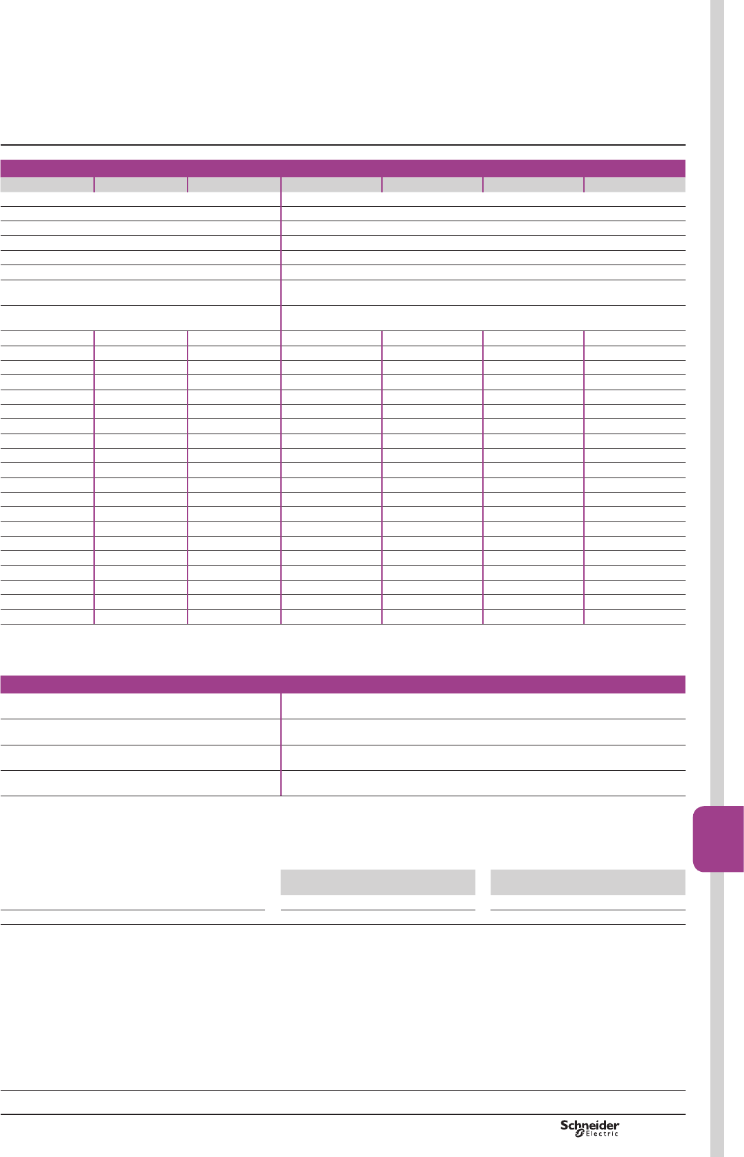
TeSys F
CR1 F400 CR1 F500 CR1 F630 CR1 BL CR1 BM CR1 BP CR1 BR
48…415 110…500
48…220 110…500
48…220 110…500
48…220 –
0.85…1.1 Uc 0.85…1.1 Uc
0.85…1.1 Uc 0.85…1.1 Uc
120 120
1 1
– – – 650 650 650 650
– – – 1100 1100 1100 1100
1450 1650 2100 1650 1650 1650 1650
1450 1650 2100 1850 1850 1850 1850
– – – 110 110 110 110
– – – 125 125 125 125
12 9.5 8 165 165 165 165
12 9.5 8 175 175 175 175
– – – 600 600 600 600
– – – 1000 1000 1000 1000
1600 1800 2300 1500 1500 1500 1500
1600 1800 2300 1700 1700 1700 1700
– – – 100 100 100 100
– – – 115 115 115 115
16 13 11 150 150 150 150
16 13 11 160 160 160 160
500 550 620 – – – –
70 60 45 – – – –
40…75 40…80 40…80 100…150 100…150 100…150 100…150
50…100 50…100 50…100 20…40 20…40 20…40 20…40
(1)7KHFORVLQJWLPHLVPHDVXUHGIURPWKHPRPHQWWKHFORVLQJFRLOLVHQHUJLVHGWRLQLWLDOFRQWDFWRIWKHPDLQSROHV7KHRSHQLQJWLPHLVPHDVXUHGIURPWKHPRPHQW
WKHRSHQLQJFRLOLVHQHUJLVHGWRWKHPRPHQWWKHPDLQSROHVVHSDUDWH
Note: WKHDUFLQJWLPHGHSHQGVRQWKHFLUFXLWVZLWFKHGE\WKHPDLQSROHV)RUSKDVHDSSOLFDWLRQVWKHDUFLQJWLPHLVXVXDOO\OHVVWKDQPV7KHORDGLVLVRODWHG
IURPWKHVXSSO\DIWHUDWLPHHTXDOWRWKHVXPRIWKHRSHQLQJWLPHDQGWKHDUFLQJWLPH
LAD N for contactors CR1 F ZC4 GM for contactors CR1 B
10 20
690 660
1 x 1 min; 2 x 2.5 max 2 min; 4 max
Operational power of contacts
ZC4 GM for contactors CR1 B
a.c. supply d.c. supply
Electrical durability (valid for up to 2400
operating cycles/hour) on an inductive load
such as the coil of an electromagnet: making
current (cos M 0.7) = 10 times the power
broken (cos M0.4).
Electrical durability (valid for up to 1200
operating cycles/hour) on an inductive load
such as the coil of an electromagnet, without
economy resistor, the time constant
increasing with the load.
V 110
127
220 380 415
440
500 V 110 120 440 500
1 million operating cycles VA 2000 4000 4000 4000 3500 W250 250 230 200
Occasional making capacity VA 14000 23000 35000 45000 35000 W1600 800 400 360
TeSys contactors
Magnetic latching contactors
Characteristics
Selection:
pages B9/87 to B9/91
References:
pages B9/7, B9/30 to B9/35
Dimensions:
pages B9/96 to B9/99
PCPB09T30-EN Version : 1.0 18 novembre 2014 12:55 PM
B9/95
High power
contactors
B9/95
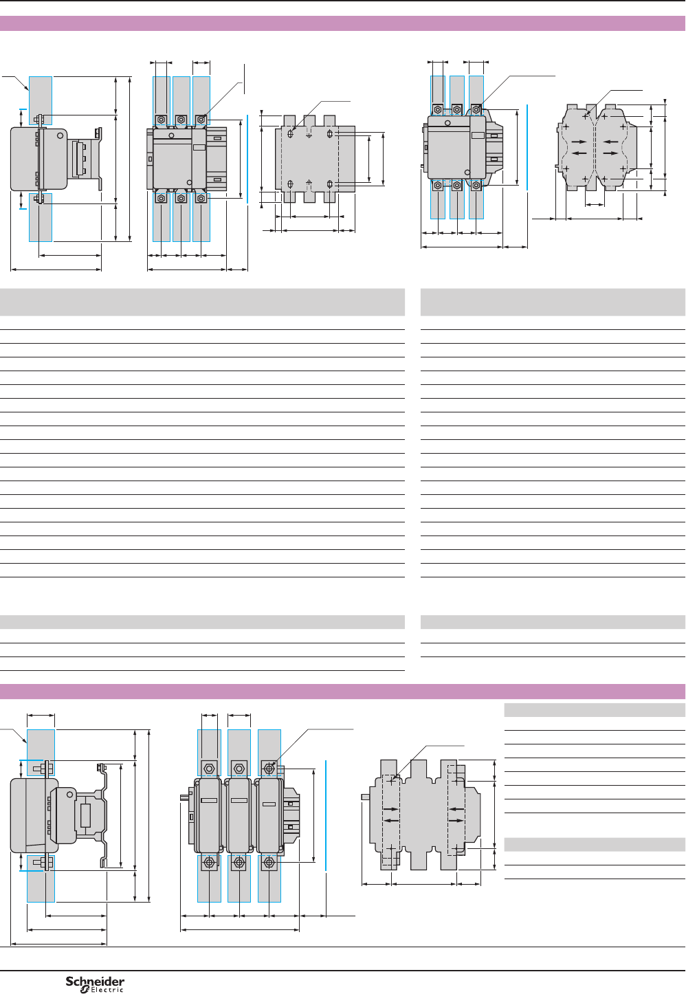
TeSys F
CR1 F150 to F500
Common side view CR1 F150, F185, F265 CR1 F400, F500
J
J1
b1 ==
G1
G
Z
= =
Y
3xØ6,5
L
c
(1)
= b =
b2
X1X1
S1
Q
a
P P Q1
f
M
SF150 M8x25
F185 M8x25
F265 M10x35
DF565953.eps
Q1
a
PQ P
f
M
44,5
S
6xM10x35
G
G123,5 J
120 ==
180 ==
8xØ8,5
501379_1.eps
CR1 F150 F185 F265 CR1 F400 F500
3P 4P 3P 4P 3P 4P 3P 4P 3P 4P
a 163.5 201.5 168.5 208.5 201.5 244.5 a 213 261 233 288
b 170 170 174 174 203 203 G min. 66 66 66 66
b1 137 137 137 137 145 145 b 206 206 238 238
b2 301 301 305 305 370 370 b2 375 375 400 400
c 171 171 181 181 213 213 c 219 219 232 232
f 131 131 130 130 147 147 f 146 146 150 150
G 106 143 111 151 142 190 G supplied 80 80 80 140
G1 80 80 80 80 96 96 G max. 102 150 120 175
J 106 106 106 106 106 106 G1 supplied 170 170 170 230
J1 120 120 120 120 120 120 G1 min. 156 156 156 156
L 107 107 113.5 113.5 141 141 G1 max. 192 240 210 265
M 150 150 154 154 178 178 J 12 60 32 27
P 40 40 40 40 48 48 L 145 145 146 146
Q 26 26 29 29 39 34 M 181 181 208 208
Q1 57.5 55.5 59.5 59.5 66.5 66.5 P 48 48 55 55
S 20 20 20 20 25 25 Q 43 43 47 47
S1 27 27 34 34 38 38 Q1 74 74 77 77
Y 44 44 38.5 30.5 30.5 21.5 S 25 25 30 30
Z 13.5 13.5 13.5 13.5 15.5 15.5
f = minimum distance required for coil removal. f = minimum distance required for coil removal.
X1: Minimum electrical clearance according to operational voltage and breaking capacity. X1: Minimum electrical clearance according to operational
voltage and breaking capacity.
Voltage in V 200…500 660…1000 Voltage in V 200…500 660…1000
CR1 F150 10 15 CR1 F400 15 20
CR1 F185 10 15 CR1 F500 15 20
CR1 F265 10 15
(1) 3RZHUWHUPLQDOSURWHFWLRQVKURXGVHHSDJH%
CR1 F630
155
= 304 =
(1)
197
255
280
X1
464
72
X1
Q18080Q
264
181
(2)
6440
6xM12x45
a
DF565954.eps
180= =
J1G60,5
4xØ10,5
CR1 F630 3P 4P
a 309 389
G supplied 180 240
G min. 100 150
G max. 195 275
J1 61 81
Q 60 60
Q1 89 89
X1: Min. electrical clearance according to
operational voltage and breaking capacity.
Voltage in V X1
200…500 20
690…1000 30
(1)3RZHUWHUPLQDOSURWHFWLRQVKURXG
(2)0LQLPXPGLVWDQFHUHTXLUHGIRUFRLO
removal.
TeSys contactors
Magnetic latching contactors CR1 F
Dimensions
Selection:
pages B9/87 to B9/91
Characteristics:
pages B9/92 to B9/95
References:
pages B9/7, B9/30 to B9/35
PCPB09T30-EN
Version : 1.0 18 novembre 2014 12:55 PM
B9/96
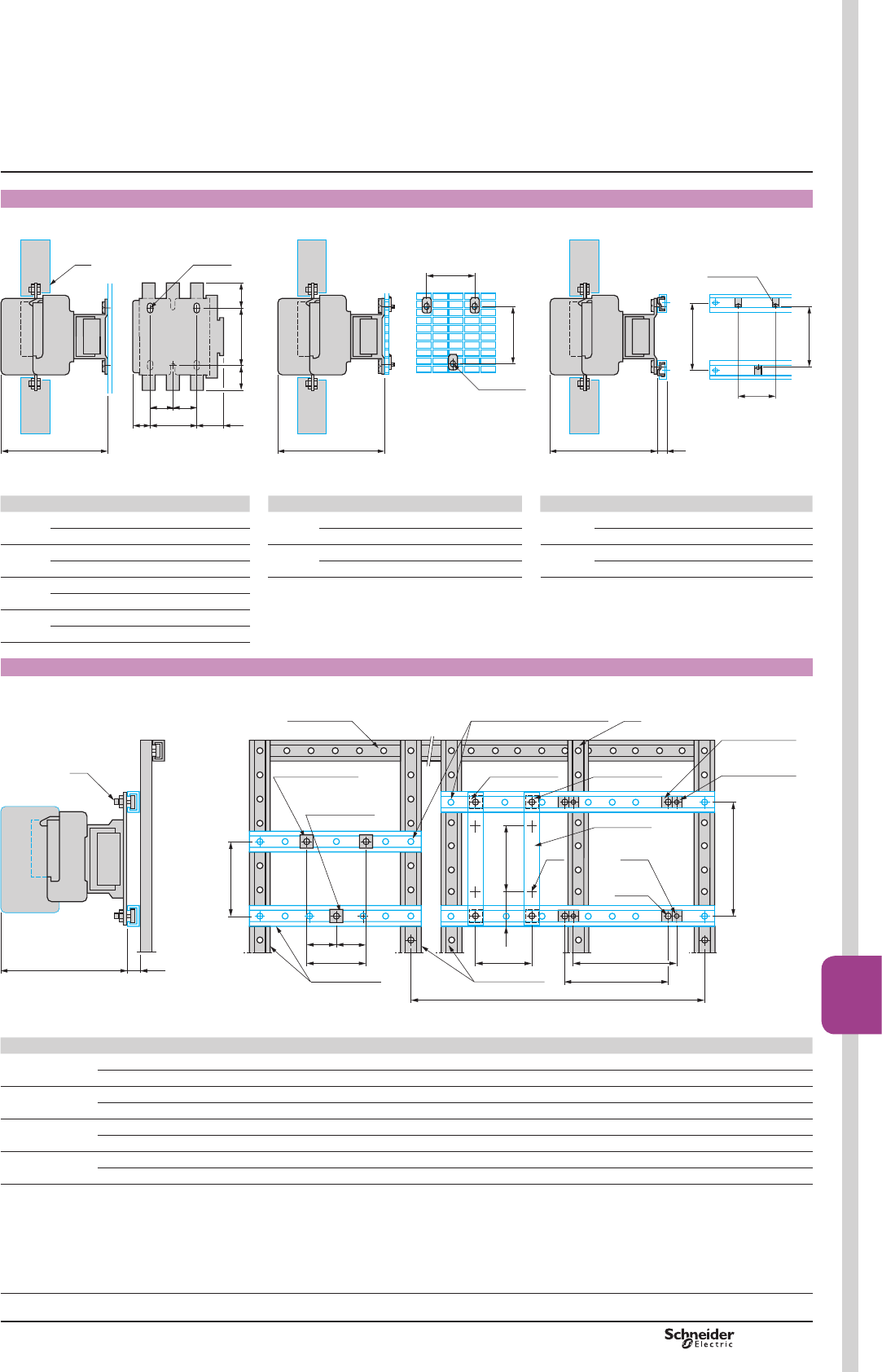
TeSys F
CR1 F150…F265
Panel mounted On pre-slotted mounting plate AM1 PA, PB, PC On rails DZ5 MB on 120 mm centres
3xØ6,5
c
J G
=
J1
= 110
=
=
(1)
DF565955.eps
c
AF1 EA6
110
G
DF565956.eps
DZ5 MF5
c
G
110
120
15
DF510481.eps
CR1 F150 F185 F265 CR1 F150 F185 F265 CR1 F150 F185 F265
c 3P 171 181 213 c 3P 171 181 213 c 3P 171 181 213
4P 171 181 213 4P 171 181 213 4P 171 181 213
G 3P 80 80 96 G 3P 80 80 96 G 3P 80 80 96
4P 80 80 96 4P 80 80 96 4P 80 80 96
J 3P 26.5 29 44.5
4P 45 49 68.5
J1 3P 57 59.5 61.5
4P 75.5 79.5 85.5
(1) 3RZHUWHUPLQDOSURWHFWLRQVKURXGVHHSDJH%
CR1 F150…F650
On 2 notched uprights AM1 ECppp
c 25
(1)
120
(2)
Ø10,5
AM1 EC200 AF1 CD081 + AF1 VC820
AM1 EC200
AF1 CD061+
AF1 VA618
AF1 CD061 AF1 VA618
M6
LA9 F100
AF1 CD101+
AF1 VC10
AF1 CD081+
AF1 VC820
Ø8,5M6
AM1 EC200
11035
180
G
= =
G
AF1 VA618
M6
G1
G2
G3
DF565958.eps
CR1 F150 F185 F265 F400 F500 F630
c 3P 171 181 213 213 226 250
4P 171 181 213 213 226 250
G (M6) 3P 80 80 96 – – –
4P 80 80 96 – – –
G1 (Ø 8.5) 3P – – – 80 80 –
4P – – – 80 140 –
G2 (Ø 10.5) 3P – – – – – 180
4P – – – – – 240
(1)$)&'pppRU$)9$ppp.
(2)7KLV$0(&XSULJKWLVUHTXLUHGZKHQ*RU*LVJUHDWHUWKDQPPSOHDVHFRQVXOW\RXU5HJLRQDO6DOHV2I¿FH
Mounting
Selection:
pages B9/87 to B9/91
Characteristics:
pages B9/92 to B9/95
References:
pages B9/7, B9/30 to B9/35
TeSys contactors
Magnetic latching contactors CR1 F
PCPB09T30-EN Version : 1.0 18 novembre 2014 12:55 PM
B9/97
High power
contactors
B9/97
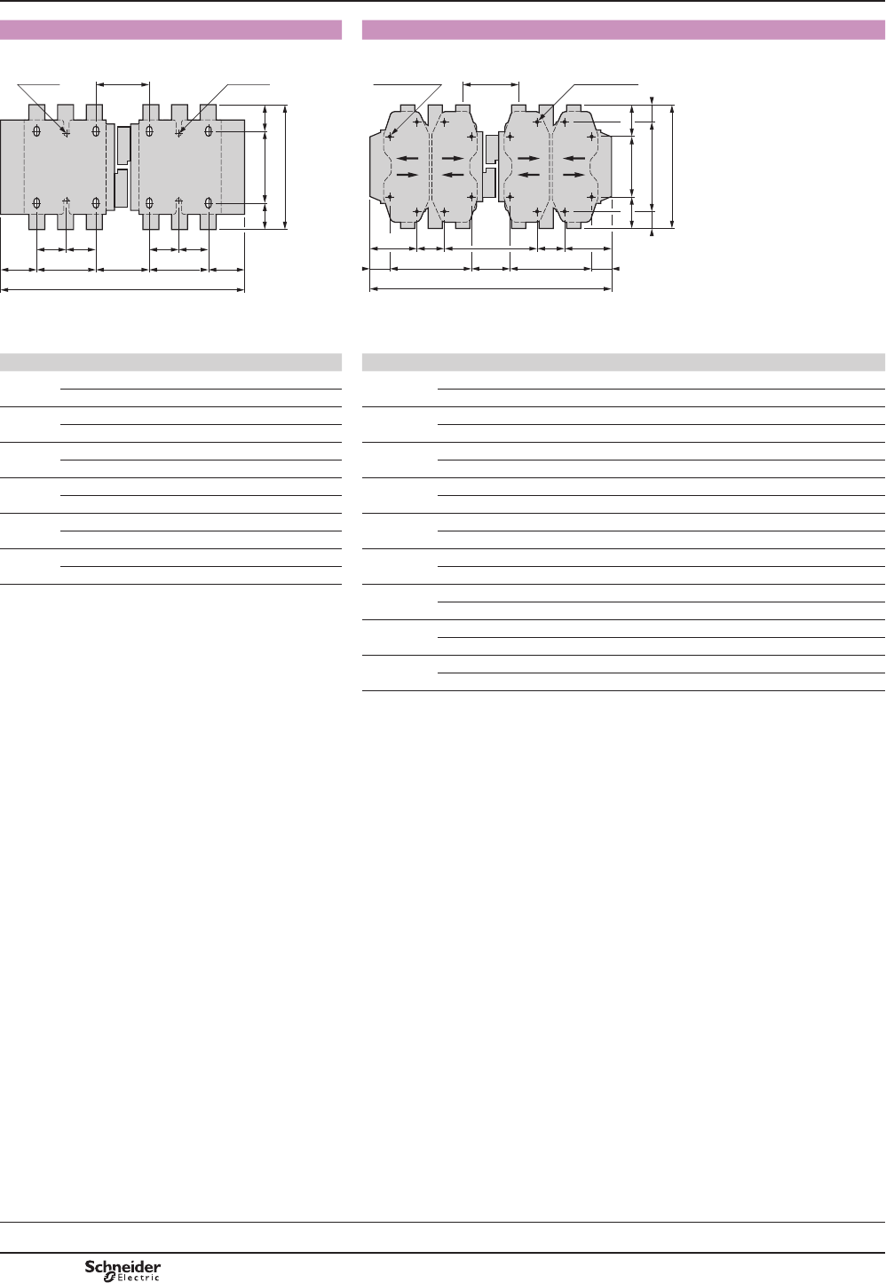
TeSys F
5HYHUVLQJFRQWDFWRUV[&5)«) 5HYHUVLQJFRQWDFWRUV[&5)«)
Horizontally mounted
110/120 ==
=
G1 J1
3xØ6,5
==
G1
=
J1 J
3xØ6,5
a
b
P1
501385_1.eps
G
G1 J3
120
(2)
==
180 ==
8xØ8,5
(1)
b
GJ1 J1
J2
J
G1J3
8xØ8,5
(1)
P1
a
DF565959.eps
2 x CR1 F150 F185 F265 2 x CR1 F400 F500 F630
a 3P 345 357 425 a 3P 446 485 636
4P 422 437 521 4P 542 595 796
b 3P 170 174 203 b 3P 206 238 304
4P 170 174 203 4P 206 238 304
G1 3P 80 80 96 G 3P 80 80 180
4P 80 80 96 4P 80 140 240
J 3P 71 78 109 G1 3P 170 170 –
4P 111 118 157 4P 170 230 –
J1 3P 57 59.5 61.5 J 3P 157 156 139
4P 75.5 79.5 85.5 4P 157 156 139
P1 3P 71 78 100 J1 3P 64.5 84.5 68.5
4P 71 78 100 4P 112.5 79.5 68.5
J2 3P 67 66 –
4P 67 66 –
J3 3P 19.5 39.5 –
4P 67.5 34.5 –
P1 3P 107 112 137
4P 107 112 137
(1) ([FHSW)[
(2) ([FHSW)
TeSys contactors
Magnetic latching contactors CR1 F
Mounting
Selection:
pages B9/87 to B9/91
Characteristics:
pages B9/92 to B9/95
References:
pages B9/7, B9/30 to B9/35
PCPB09T30-EN
Version : 1.0 18 novembre 2014 12:55 PM
B9/98
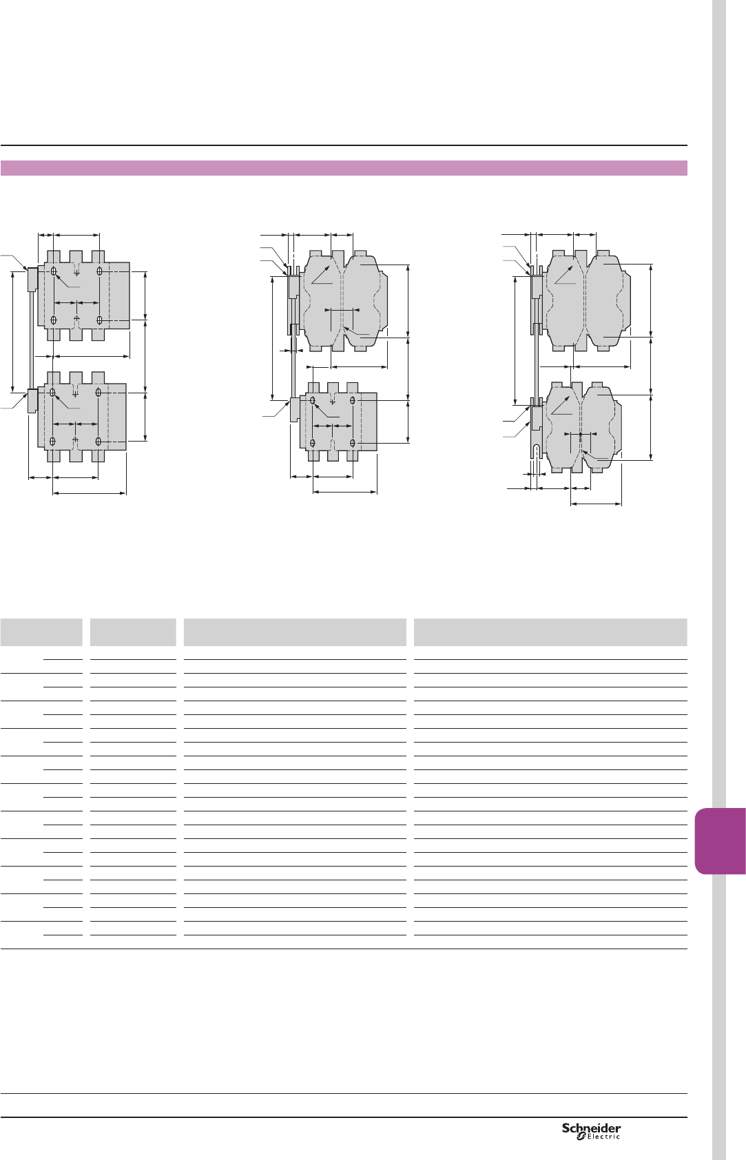
TeSys F
Reversing contactors
Vertically mounted with mechanical interlock LA9 Fppp.
2 contactors CR1 F of identical or different ratings (CR1 F150…F630), see pages B9/81 and B9/81.
Assembly A Assembly B Assembly C
F330
F265
H1 120
}
F400
F500
F630 180
}
F330
F265 120
}
F400
F500
F630 180
}
J1G3(2)
(6)
G2G4
J2
12,5
9
= =
(4)
(6)
G1G512,5
H
(1)
(5)
(1)
(5)
= =
F330
F265
180 H1 120
}
F400
F500
F630 180
}
G1G512,5
J1G3(2)
80J4
(3)
= =
(6)
(4)
H
(1)
(1)
9
(5)
J2
120120 H1
80J4
J2
J1G3
(2)
= =
(3)
= =
(3)
80J3
H
(1)
(1)
DF565960.eps
(1)0HFKDQLFDOLQWHUORFNVKDIW
(2))RUDVVHPEO\RIFRQWDFWRUVRIGLIIHUHQWUDWLQJVRQO\
(3)[PPIRU&5)«)
(4) [PPIRU&5)
(5) 0HFKDQLFDOLQWHUORFNJXLGHEUDFNHW
(6)[PPIRU&5))RU[PP
Assembly type A B C
LA9 F F4F G4F G4G H4F J4F K4F L4F H4G J4G K4G L4G H4H J4H K4H L4H J4J K4J L4J K4K L4K L4L
G1 3P – – – 96 80 80 180 96 80 80 180 96 80 80 180 80 80 180 80 180 180
4P – – – 96 80 140 240 96 80 140 240 96 80 140 240 80 140 240 140 240 240
G2 3P – – – – – – – – – – – 96 96 96 96 80 80 80 80 80 180
4P – – – – – – – – – – – 96 96 96 96 80 80 80 140 140 240
G3 3P 0 3 0 21 45 45 35 19 42 42 33 0 23 23 14 0 0 9 (7) 0 9 (7) 0
4P 0 4 0 27 26 26 17 23 22 22 13 0 0 0 9 (7) 0 0 9 (7) 0 9 (7) 0
G4 3P – – – – – – – – – – – 60 60 60 60 83 83 83 83 83 74
4P – – – – – – – – – – – 83 83 83 83 83 83 83 83 83 74
G5 3P – – – 60 83 83 74 60 83 83 74 60 83 83 74 83 83 74 83 74 74
4P – – – 83 83 83 74 83 83 83 74 83 83 83 74 83 83 74 83 74 74
H min. 200 210 220 240 250 270 310 250 250 270 310 250 260 280 330 260 280 325 300 345 380
max. 310 300 310 380 380 380 380 380 380 380 380 380 380 380 380 380 380 380 380 380 380
H1 min. 80 90 100 110 80 100 140 120 90 110 150 130 110 130 170 60 100 140 120 160 200
max. 190 180 190 250 210 210 210 250 220 220 220 260 230 230 220 200 200 195 200 195 200
J1 3P 133 134 134 149.5 137 157 241 149.5 137 157 241 149.5 137 157 24 137 157 241 157 244 241
4P 145 146 146 164.5 185 212 321 164.5 185 212 321 164.5 185 212 321 185 212 321 212 321 321
J2 3P 133 133 134 183 133 183 133 134 134 134 134 142.5 149.5 149.5 149.5 137 137 137 157 157 241
4P 145 145 146 145 145 145 145 146 146 146 146 164.5 164.5 164.5 164.5 185 185 185 212 212 312
J3 3P 48.5 53 53 – – – – – – – – – – – – – – – – – –
4P 67 73 73 – – – – – – – – – – – – – – – – – –
J4 3P 48.5 54 53 48.5 48.5 48.5 48.5 53 53 53 53 – – – – – – – – – –
4P 67 69 73 67 67 67 67 73 73 73 73 – – – – – – – – – –
(7) ,QWKLVFDVH*LVJUHDWHUWKDQ*
TeSys contactors
Magnetic latching contactors CR1 F
Mounting
Selection:
pages B9/87 to B9/91
Characteristics:
pages B9/92 to B9/95
References:
pages B9/7, B9/30 to B9/35
PCPB09T30-EN Version : 1.0 18 novembre 2014 12:55 PM
B9/99
High power
contactors
B9/99
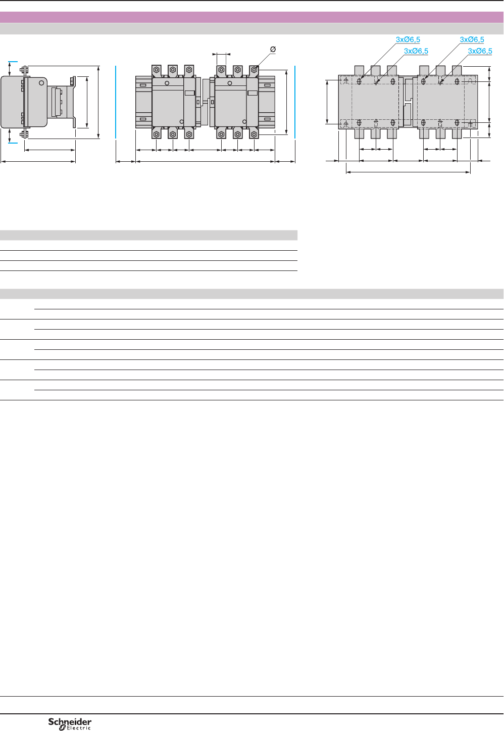
TeSys F
Pre-assembled
LC2 F115 to F265 UHYHUVHUVXSSOLHGRQEDUVZKLFKFDQEHXVHGIRU¿[LQJWKHGHYLFH
110/120 ==
=
G1 J1
120
==
G1
a2
=
J1 J
L
c
b
b1
X1X1
P1
a
P P Q1
f
M
S
f
P PQ1
813169.eps
f - Minimum distance required for coil removal. %DU¿[LQJFHQWUHV
Vertical: 120 mm
Horizontal: a2 see table
X1 (mm) = Minimum electrical clearance according to operating voltage and breaking capacity.
LC1 200…500 V 660…1000 V
F115, F150 10 15
F185 10 15
F225, F265 10 15
LC2 a a2 b b1 c G1 J J1 L M P P1 Q1 S f Ø
F115 3P 345 317 162 137 171 80 71 57 107 147 37 77 60 20 131 M6
4P 419 378 162 137 171 80 108 75.5 107 147 37 77 60 20 131 M6
F150 3P 345 317 170 137 171 80 71 57 107 150 40 71 57 20 131 M8
4P 422 381 170 137 171 80 111 75.5 107 150 40 71 55.5 20 131 M8
F185 3P 357 326 174 137 181 80 78 59.5 113.5 154 40 78 59.5 20 130 M8
4P 437 390 174 137 181 80 118 79.5 113.5 154 40 78 59.5 20 130 M8
F225 3P 357 326 197 137 181 80 78 59.5 113.5 172 48 62 51.5 25 130 M10
4P 437 390 197 137 181 80 118 79.5 113.5 172 48 54 47.5 25 130 M10
F265 3P 425 386 203 145 213 96 109 61.5 141 178 48 100 66.5 25 147 M10
4P 521 464 203 145 213 96 157 85.5 141 178 48 100 66.5 25 147 M10
Dimensions TeSys contactors
TeSys F reversing contactors and
changeover contactor pairs
Horizontally mounted
Selection:
pages A5/23 to A5/47
References:
pages B9/36 to B9/41
Schemes:
page B9/103
PCPB09T30-EN
Version : 1.0 18 novembre 2014 12:55 PM
B9/100
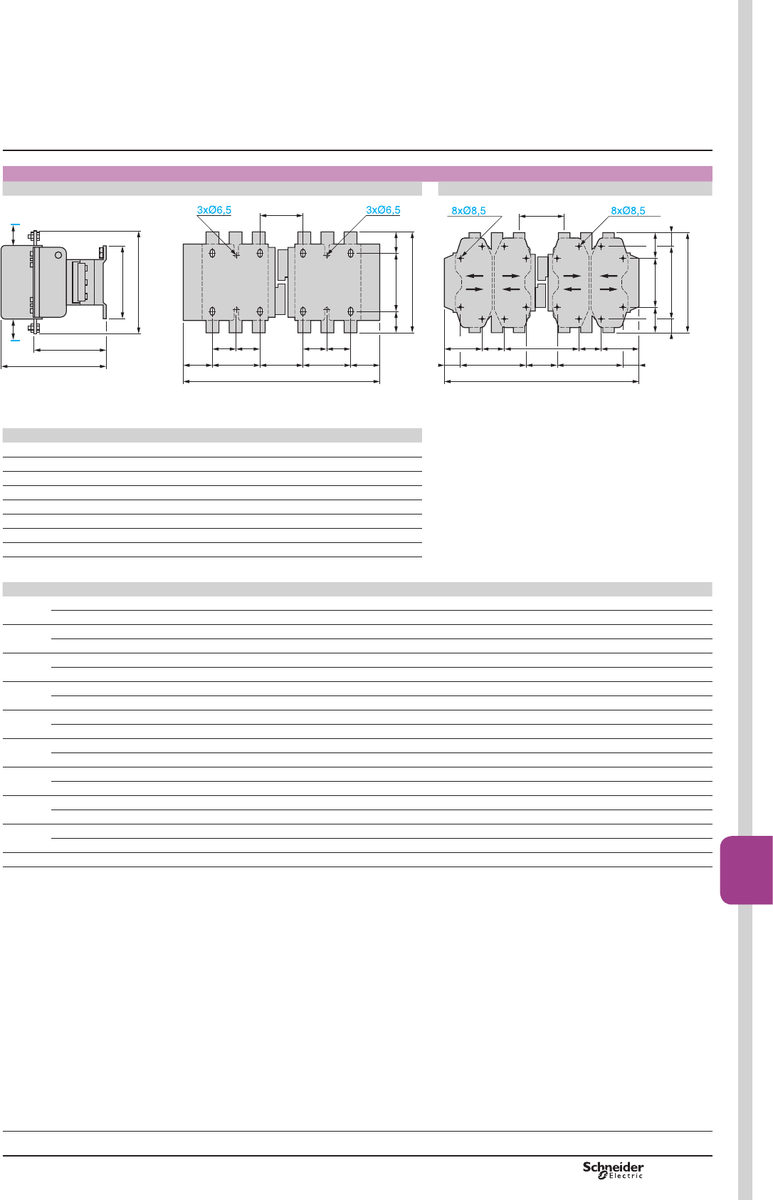
TeSys F
For customer assembly, ¿[LQJUHFRPPHQGHGRQ$0(&XSULJKWVSOHDVHFRQVXOW\RXU5HJLRQDO6DOHV2I¿FH
2 x LC1 F115 to F330 2 x LC1 F400, F500, F630, F800
110/120 ==
=
G1 J1
==
G1
=
J1 J
a
b
P1
L
c
b
b1
X1X1
DF564917.eps
G
G1 J3
120 (2) ==
180 ==
b
GJ1 J1
J2
J
G1J3
P1
a
(1)
(1)
DF510422.eps
X1 (mm) = Minimum electrical clearance according to operating voltage and breaking capacity.
LC1 200…500 V 660…1000 V 200…690 V 1000 V
F115, F150 10 15 – –
F185 10 15 – –
F225, F265 10 15 – –
F330 10 15 – –
F400 15 20 – –
F500 15 20 – –
F630 20 30 – –
F800 – – 10 20
2 x LC1 a b b1 c G G1 J J1 J2 J3 L P1
F115 3P 345 162 137 171 – 80 71 57 – – 107 77
4P 419 162 137 171 – 80 108 75.5 – – 107 77
F150 3P 345 170 137 171 – 80 71 57 – – 107 71
4P 422 170 137 171 – 80 111 75.5 – – 107 71
F185 3P 357 174 137 181 – 80 78 59.5 – – 113.5 78
4P 437 174 137 181 – 80 118 79.5 – – 113.5 78
F225 3P 357 197 137 181 – 80 78 59.5 – – 113.5 62
4P 437 197 137 181 – 80 118 79.5 – – 113.5 54
F265 3P 425 203 145 213 – 96 109 61.5 – – 141 100
4P 521 203 145 213 – 96 157 85.5 – – 141 100
F330 3P 447 206 145 219 – 96 124 65.5 – – 145 107
4P 543 206 145 219 – 96 172 89.5 – – 145 107
F400 3P 446 206 209 219 80 170 157 64.5 67 19.5 145 107
4P 542 206 209 219 80 170 157 112.5 67 67.5 145 107
F500 3P 485 238 209 232 80 170 156 84.5 66 39.5 146 112
4P 595 238 209 232 140 230 156 79.5 66 34.5 146 112
F630 3P 636 304 280 255 180 – 139 68.5 – – 155 137
4P 796 304 280 255 240 – 139 88.5 – – 155 137
F800 3P 636 304 280 255 180 – 139 68.5 – – 155 137
(1)([FHSW/&)DQG)[
(2)([FHSW/&)DQG)
For other dimensions: see pages B9/54 and B9/55.
Dimensions TeSys contactors
TeSys F reversing contactors and
changeover contactor pairs
Horizontally mounted
Selection:
pages A5/23 to A5/47
References:
pages B9/36 to B9/41
Schemes:
page B9/103
PCPB09T30-EN Version : 1.0 18 novembre 2014 12:55 PM
B9/101
High power
contactors
B9/101

TeSys F
For customer assembly, with mechanical interlock (MI) LA9 F¿[LQJUHFRPPHQGHGRQ$0(&XSULJKWVSOHDVHFRQVXOW\RXU5HJLRQDO6DOHV
2I¿FH[LC1 identical or different ratings (LC1 F115 to F630 and F800). See pages B9/36 to B9/39.
Assembly A Assembly B Assembly C
120120 H1
80J4
J2
J1G3
(2)
= =
(3)
= =
(3)
80J3
H
(1)
(1)
DF564919.eps
= =
F330
F265
120 H1 120
}
F400
F500
F630
F800
180
G1G512,5
J1G3
(2)
80J4
(3)
= =
(6)
(4)
H
(1)
(1)
9
(5)
J2
DF564920.eps
F330
F265
H1 120
}
F400
F500
F630
F800
180
F330
F265 120
}
F400
F500
F630
F800
180
J1G3
(2)
(6)
G2G4
J2
12,5
9
= =
(4)
(6)
G1G512,5
H
(1)
(5)
(1)
(5)
DF564921.eps
(1)0HFKDQLFDOLQWHUORFNVKDIW
(2))RUDVVHPEO\RIFRQWDFWRUVRIGLIIHUHQWUDWLQJVRQO\
(3)[IRU/&)WR)
(4)[IRU/&)
(5)0HFKDQLFDOLQWHUORFNJXLGHEUDFNHW
(6)[IRU/&))RU
[IRU/&)DQG)
Assembly A (7) Mechanical interlock reference Assembly B (7)Mechanical interlock reference
G3 3P G3 4P H min. +PD[ H1 min.H1 PD[J1 3P J1 4P G1 3P G1 4P G3 3P G3 4P G5 3P G5 4P H min. +PD[
LA9 FF4F 0 0 200 310 80 190 137 155.5 LA9 FH4F 96 96 21 27 60 83 240 380
LA9 FG4F 3 4 210 300 90 180 139.5 159.5 LA9 FJ4F 80 80 45 26 83 83 250 380
LA9 FG4G 0 0 220 310 100 190 139.5 159.5 LA9 FK4F 80 140 45 26 83 83 270 380
J2 3P J2 4P J3 3P J3 4P J4 3P J4 4P LA9 FL4F 180 240 35 17 74 74 310 380
LA9 FF4F 137 155.5 48.5 67 48.5 67 LA9 FH4G 96 96 19 23 60 83 250 380
LA9 FG4F 137 155.5 53 73 54 69 LA9 FJ4G 80 80 42 22 83 83 250 380
LA9 FG4G 139.5 159.5 53 73 53 73 LA9 FK4G 80 140 42 22 83 83 270 380
)RUFXVWRPHUDVVHPEO\¿[LQJUHFRPPHQGHGRQ$0(&XSULJKWV
SOHDVHFRQVXOW\RXU5HJLRQDO6DOHV2I¿FH
2 x LC1 F780
;DQG¿[LQJVVHHSDJH%
LA9 FL4G 180 240 33 13 74 74 310 380
H1 min.H1 PD[J1 3P J1 4P J2 3P J2 4P J4 3P J4 4P
LA9 FH4F 110 250 157.5 181.5 137 155.5 48.5 67
LA9 FJ4F 80 210 144.5 192.5 137 155.5 48.5 67
LA9 FK4F 100 210 164.5 219.5 137 155.5 48.5 67
LA9 FL4F 140 210 248.5 328.5 137 155.5 48.5 67
LA9 FH4G 120 250 157.5 181.5 139.5 159.5 53 73
LA9 FJ4G 90 220 144.5 192.5 139.5 159.5 53 73
LA9 FK4G 110 220 164.5 219.5 139.5 159.5 53 73
LA9 FL4G 150 220 248.5 328.5 139.5 159.5 53 73
Assembly C (7)
G1 3P G1 4P G2 3P G2 4P G3 3P G3 4P G4 3P G4 4P G5 3P G5 4P
LA9 FH4H 96 96 96 96 0 0 60 83 60 83
LA9 FJ4H 80 80 96 96 23 0 60 83 83 83
LA9 FK4H 80 140 96 96 23 0 60 83 83 83
LA9 FL4H 180 240 96 96 14 9 (8) 60 83 74 74
LA9 FJ4J 80 80 80 80 0 0 83 83 83 83
LA9 FK4J 80 140 80 80 0 0 83 83 83 83
LA9 FL4J 180 240 80 80 9 (8) 9 (8) 83 83 74 74
LA9 FK4K 80 140 80 140 0 0 83 83 83 83
LA9 FL4K 180 240 80 140 9 (8) 9 (8) 83 83 74 74
LA9 FL4L 180 240 180 240 0 0 74 74 74 74
H min. +PD[ H1 min.H1 PD[J1 3P J1 4P J2 3P J2 4P
LA9 FH4H 250 380 130 260 157.5 181.5 157.5 181.5
LA9 FJ4H 260 380 110 230 144.5 192.5 157.5 181.5
LA9 FK4H 280 380 130 230 164.5 219.5 157.5 181.5
LA9 FL4H 330 380 170 220 248.5 328.5 157.5 181.5
LA9 FJ4J 260 380 60 200 144.5 192.5 144.5 192.5
LA9 FK4J 280 380 100 200 164.5 219.5 144.5 192.5
LA9 FL4J 325 380 140 195 248.5 329.5 144.5 192.5
LA9 FK4K 300 380 120 200 164.5 329.5 164.5 219.5
(7)2QO\3IRU)
(8),QWKLVFDVH*LVJUHDWHUWKDQ*
LA9 FL4K 345 380 160 195 248.5 328.5 164.5 219.5
LA9 FL4L 380 380 200 200 248.5 328.5 248.5 328.5
Dimensions TeSys contactors
TeSys F reversing contactors and
changeover contactor pairs
Vertically mounted
250
X1
=180= 180 420
1034
191 160 160 191
702(LC1 F780), 862(LC1 F7804)
X1
DF564918.eps
Selection:
pages A5/23 to A5/47
References:
pages B9/36 to B9/41
Schemes:
page B9/103
PCPB09T30-EN
Version : 1.0 18 novembre 2014 12:55 PM
B9/102
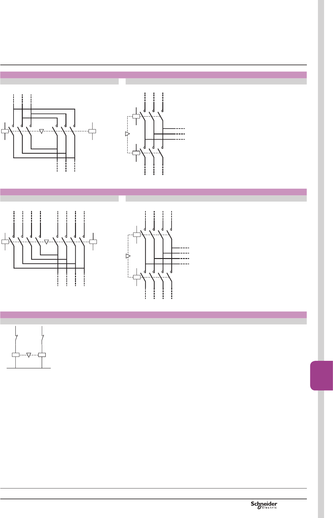
TeSys F
Reversing contactors for motor control LC2 F
2 x LC1 F 2 x LC1 F
Horizontally mounted
A1
A2
1
2
3
4
5
6
L1
L2
L3
1
2
3
4
5
6
U
V
W
A1
A2
813177.eps
Vertically mounted
A1
A2
1
2
3
4
5
6
1/L1
1/L2
1/L3
A1
A2
1
2
3
4
5
6
L3
L2
L1
2/L1
2/L2
2/L3
813178.eps
Changeover contactor pairs for distribution LC2 F
2 x LC1 F 2 x LC1 F
Horizontally mounted
A1
A2
1
2
3
4
5
6
1N
1/L3
1/L2
1
2
3
4
7
8
L1
L2
N
A1
A2
5
6
L3
7
81/L1
2/L1
2/L2
2/L3
2N
813179.eps
Vertically mounted
A1
A2
1
2
3
4
5
6
1/L1
1/L2
1/L3
A1
A2
1
2
3
4
5
6
N
L3
L2
L1
7
81N7
8
2/L1
2/L2
2/L3
2N
813180.eps
(OHFWULFDOLQWHUORFNLQJRIUHYHUVHUV¿WWHGZLWKPHFKDQLFDOLQWHUORFNZLWKRXWLQWHJUDOHOHFWULFDOFRQWDFWV
LA9 F
A1
A2
– KM2
– KM1
A1
A2
– KM1
– KM2
813176.eps
Schemes TeSys contactors
TeSys F reversing contactors and
changeover contactor pairs
Selection:
pages A5/23 to A5/47
References:
pages B9/36 to B9/41
Dimensions:
pages B9/100 to B9/102
PCPB09T30-EN Version : 1.0 18 novembre 2014 12:55 PM B9/103
High power
contactors
B9/103
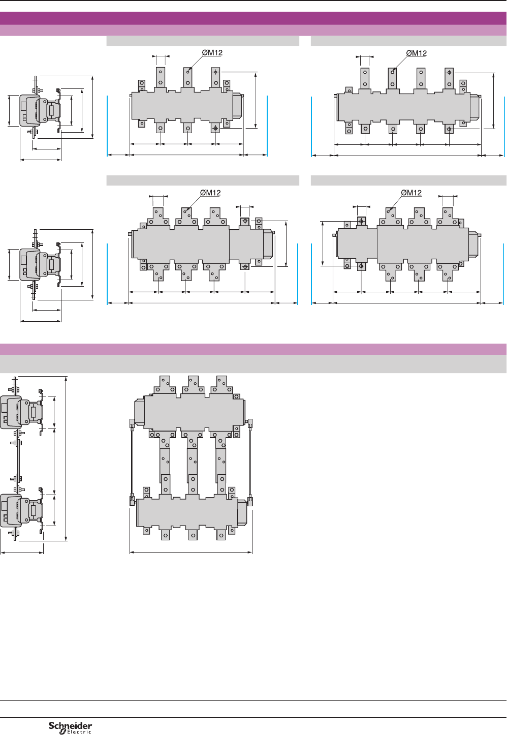
TeSys F
TeSys contactors 5
High power changeover contactor pairs
for distribution
Dimensions
Contactors used to assemble high power changeover contactor pairs LC1 F780: see page
B9/43
LC1 F6309 LC1 F63049
Common side view
165
202
250
180/190
280
348
DF564830.eps
204 160 160 178
183 183702
306
40
(1)
(1)
DF511519.eps
306
40
204 160 160 160 178
183
(1)
183
(1)
862
DF564832.eps
LC1 F78040 LC1 F78041
Common side view
180/190
280
434
202
165
250
DF564833.eps
60
40
264
191 160 160 173 178
183
(1)
183
(1)
862
DF564834.eps
264
178 173 160 160 191
183
(1)
183
(1)
862
60
40
DF564835.eps
(1)0LQLPXPGLVWDQFHUHTXLUHGIRUUHPRYDORIHDFKFRLO
3-phase changeover contactor pairs
LC1 F780 + LC1 F780 + LA9 FX970: see page
B9/43
LC1 F780 + LC1 F6309 + LA9 FX970
180180 420
969
250 702
DF564836.eps
Dimensions
5
References:
page B9/43
PCPB09T30-EN
Version : 1.0 18 novembre 2014 12:55 PM
B9/104
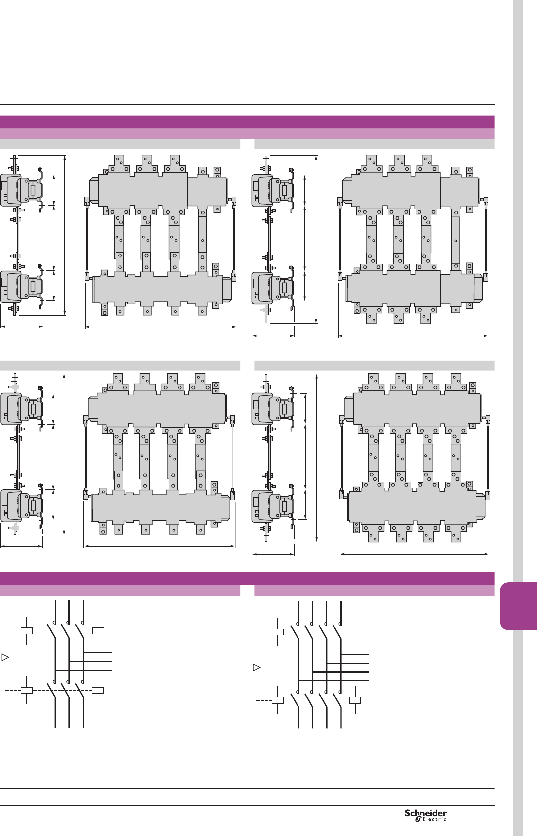
TeSys F
Dimensions
3-phase + neutral changeover contactor pairs
LC1 F78041 + LC1 F63049 + LA9 FX970 LC1 F78041 + LC1 F78040 + LA9 FX970
180180 420
969
250 862
DF564837.eps
180180 420
1034
250 862
DF564838.eps
LC1 F7804 + LC1 F63049 + LA9 FX971 LC1 F7804 + LC1 F7804 + LA9 FX971
180180 420
969
250 862
DF564839.eps
180180 420
1034
250 862
DF564840.eps
Schemes
3-phase changeover contactor pairs 3-phase + neutral changeover contactor pairs
A1
A2
1
2
3
4
5
6
1/L1
1/L2
1/L3
A1
A2
A1
A2
1
2
3
4
5
6
L3
L2
L1
2/L1
2/L2
2/L3
A1
A2
813226.eps
A1
A2
A1
A2
1
2
3
4
5
6
1/L1
1/L2
1/L3
A1
A2
A1
A2
1
2
3
4
5
6
N
L3
L2
L1
7
81N7
8
2/L1
2/L2
2/L3
2N
813231.eps
Dimensions,
schemes
5
References:
page B9/43
TeSys contactors 5
High power changeover contactor pairs
for distribution
PCPB09T30-EN Version : 1.0 18 novembre 2014 12:55 PM B9/105
High power
contactors
B9/105

PCPB09T30-EN
Version : 1.0 18 novembre 2014 12:55 PM
B9/106

B10/1
Bar
mounted
contactors
Bar mounted
contactors
TeSys B
Pre defined composition contactors – TeSys B
Type of product Range Pages
High performance & power - 1000 V
TeSys LC1B
From 750 to 1800 A - AC-3
From 800 to 2750 A - AC-1
B10/2
Magnetic latching - 1000 V
TeSys CR1B
From 750 to 1800 A - AC-3
From 800 to 2750 A - AC-1 B10/10
For control of DC excitation circuit of
synchronous motors - 1200 V DC
TeSys CRXB, CVXB, CWXB
From 80 to 2750 A - DC B10/13
Variable composition contactors – TeSys B
Standard - 690 V
TeSys CV1B
Composition to be defined by customer
From 80 to 700 A - AC-3
From 80 to 1000 A - AC-1 B10/16
High performance - 1000 V
TeSys CV3B
Composition to be defined by customer
From 80 to 1800 A - AC-3
From 80 to 2750 A - AC-1 B10/17
Variable composition contactors - ordering process B10/18
All details and composition list in the TeSys B dedicated catalogue
Low Voltage
TeSys B
contactors
Catalogue
Variable composition contactors, new design
Catalogue ref:
DIAED2070702EN
Free
download
on the web
On request – TeSys B
For induction heating applications - 3000 V
TeSys B From 80 to 16300 A - AC-1 On request
TeSys
Control and
Protection
Components
Chapter
B10
Technical Data for Designers B10/23
PCPB10S10-EN Version : 1.0 13 novembre 2014 3:13 PM
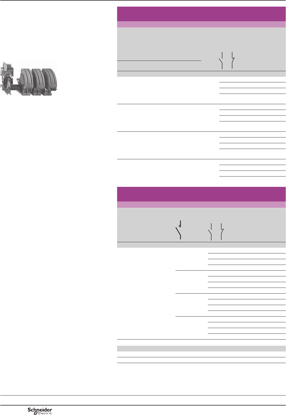
B10/2
TeSys B
TeSys contactors
TeSys LC1B contactors
Contactors for motor control in category AC-3,
from 750 to 1800 A (a or c )
3-pole contactors
Standard power ratings
of 3-phase motors 50-60 Hz
in category AC-3
Rated
opera-
tional
current
in AC-3
440V
up to
Instan-
taneous
auxiliary
contacts
Basic
reference,
to be
completed by
adding the
voltage code
(1)
Weight
220 V
230 V
380 V
400 V 415 V 440 V 500 V
660 V
690 V 1000 V
kW kW kW kW kW kW kW A kg
220 400 425 450 500 560 530 750 2 2 LC1BL33p22 58.000
3 1 LC1BL33p31 58.000
1 3 LC1BL33p13 58.000
4 – LC1BL33p40 58.000
280 500 530 560 600 670 530 1000 2 2 LC1BM33p22 57.000
3 1 LC1BM33p31 57.000
1 3 LC1BM33p13 57.000
4 – LC1BM33p40 57.000
425 750 800 800 700 750 670 1500 2 2 LC1BP33p22 94.000
3 1 LC1BP33p31 94.000
1 3 LC1BP33p13 94.000
4 – LC1BP33p40 94.000
500 900 900 900 900 900 750 1800 2 2 LC1BR33p22 129.000
3 1 LC1BR33p31 129.000
1 3 LC1BR33p13 129.000
4 – LC1BR33p40 129.000
Contactors for control in category AC-1, from 800 to 2750 A
(a or c )
Single, 2, 3 or 4-pole contactors
Maximum
operational
current
in AC-1
(T y 40 °C)
Number
of poles
Instantaneous
auxiliary
contacts
Basic reference,
to be completed
by adding the
voltage code
(1)
Weight
A kg
800 1 2 2 LC1BL31p22 32.000
3 1 LC1BL31p31 32.000
1 3 LC1BL31p13 32.000
4 – LC1BL31p40 32.000
2 2 2 LC1BL32p22 45.000
3 1 LC1BL32p31 45.000
1 3 LC1BL32p13 45.000
4 – LC1BL32p40 45.000
3 2 2 LC1BL33p22 58.000
3 1 LC1BL33p31 58.000
1 3 LC1BL33p13 58.000
4 – LC1BL33p40 58.000
4 2 2 LC1BL34p22 72.000
3 1 LC1BL34p31 72.000
1 3 LC1BL34p13 72.000
4 – LC1BL34p40 72.000
(1)6WDQGDUGFRQWUROFLUFXLWYROWDJHVIRURWKHUYROWDJHVSOHDVHFRQVXOW\RXU5HJLRQDO6DOHV2I¿FH
Volts 48 110 120 125 127 220 230 240 380 400 415 440 500
a 50…400 Hz – F K – G M P U Q V N R S
cED FD – GD – MD – UD – – – RD SD
For voltages other than those indicated above, replace the p in the reference with the the
RSHUDWLRQDOYROWDJH¿JXUHVDQGWKHW\SHRIFXUUHQWOHWWHUVAC for a.c. supply and DC for
GFVXSSO\([DPSOH9GFWKHUHIHUHQFHEHFRPHV/&%3082DC
)RUFRLOFKDUDFWHULVWLFVVHHSDJHV%WR%
References
/&%3
DF522612R.eps
Selection:
pages A5/23 to A5/47
Characteristics:
pages B10/24 and B10/25
Dimensions and schemes:
pages B10/26 and B10/27
PCPB10P10-EN
Version : 1.0 13 novembre 2014 3:14 PM
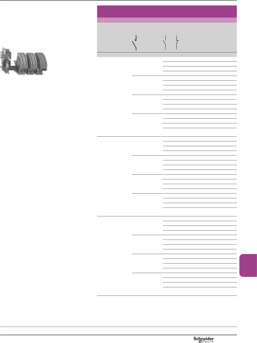
B10/3
TeSys B
Bar
mounted
contactors
Contactors for control in category AC-1,
from 800 to 2750 A (a or c )
Single, 2, 3 or 4-pole contactors
Maximum
operational
current in AC-1
(T y 40 °C)
Number
of poles
Instantaneous
auxiliary
contacts
Basic reference,
to be completed by
adding the voltage
code
(1)
Weight
A kg
1250 1 2 2 LC1BM31p22 31.000
3 1 LC1BM31p31 31.000
1 3 LC1BM31p13 31.000
4 – LC1BM31p40 31.000
2 2 2 LC1BM32p22 44.000
3 1 LC1BM32p31 44.000
1 3 LC1BM32p13 44.000
4 – LC1BM32p40 44.000
3 2 2 LC1BM33p22 57.000
3 1 LC1BM33p31 57.000
1 3 LC1BM33p13 57.000
4 – LC1BM33p40 57.000
4 2 2 LC1BM34p22 71.000
3 1 LC1BM34p31 71.000
1 3 LC1BM34p13 71.000
4 – LC1BM34p40 71.000
2000 1 2 2 LC1BP31p22 41.000
3 1 LC1BP31p31 41.000
1 3 LC1BP31p13 41.000
4 – LC1BP31p40 41.000
2 2 2 LC1BP32p22 65.000
3 1 LC1BP32p31 65.000
1 3 LC1BP32p13 65.000
4 – LC1BP32p40 65.000
3 2 2 LC1BP33p22 94.000
3 1 LC1BP33p31 94.000
1 3 LC1BP33p13 94.000
4 – LC1BP33p40 94.000
4 2 2 LC1BP34p22 120.000
3 1 LC1BP34p31 120.000
1 3 LC1BP34p13 120.000
4 – LC1BP34p40 120.000
2750 1 2 2 LC1BR31p22 52.000
3 1 LC1BR31p31 52.000
1 3 LC1BR31p13 52.000
4 – LC1BR31p40 52.000
2 2 2 LC1BR32p22 85.000
3 1 LC1BR32p31 85.000
1 3 LC1BR32p13 85.000
4 – LC1BR32p40 85.000
3 2 2 LC1BR33p22 129.000
3 1 LC1BR33p31 129.000
1 3 LC1BR33p13 129.000
4 – LC1BR33p40 129.000
4 2 2 LC1BR34p22 160.000
3 1 LC1BR34p31 160.000
1 3 LC1BR34p13 160.000
4 – LC1BR34p40 160.000
(1) See previous page.
/&%3
DF522612R.eps
TeSys contactors
TeSys LC1B contactors
References
Selection:
pages A5/23 to A5/47
Characteristics:
pages B10/24 and B10/25
Dimensions and schemes:
pages B10/26 and B10/27
PCPB10P10-EN Version : 1.0 13 novembre 2014 3:14 PM
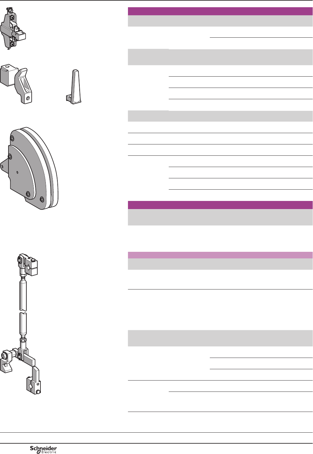
B10/4
TeSys B
TeSys contactors
TeSys LC1 B contactors
Accessories and spare parts
Spare parts
Description For contactor Composition Reference Weight
kg
Instantaneous
auxiliary contact
blocks
LC1 B 1 N/O ZC4GM1 0.030
1 N/C ZC4GM2 0.030
Description For contactor Number of sets
required per
contactor pole
Set reference Weight
kg
Set of contacts
(1 moving contact,
¿[HGFRQWDFW
LC1 BL 1 PA1LB80 0.420
LC1 BM 1 PA1LB80 0.420
LC1 BP 2 PA1LB80 0.420
LC1 BR 3 PA1LB80 0.420
Description For contactor Reference Weight
kg
Moving contact only
IRU¿QJHU
LC1 B PA1LB75 0.220
Fixed contact only
IRU¿QJHU
LC1 B PA1LB76 0.200
Blow-out horn only
IRU¿QJHU
LC1 B PA1LB89 0.120
Arc chamber
(for 1 contactor pole)
LC1 BL PA1LB50 3.700
LC1 BM PA1LB50 3.700
LC1 BP PA1PB50 6.200
LC1 BR PA1RB50 8.500
Mounting accessories
Description For contactor Sold in
lots of
Unit
reference
Weight
kg
Bar support bracket
for mounting on 120
or 150 mm centres
LC1 BL to BR 2LA9B103 1.620
Assembly of two vertically mounted contactors by the customer
Description For contactor Reference Weight
kg
Mechanical interlock
and locking device
components
LC1 B EZ2LB0601 1.280
6SHFL¿FDWLRQV
b Positive mechanical interlock between two vertically mounted contactors of the
same or different ratings.
b Connecting rod with cranks mounted on the right-hand, pole side.
b 9HUWLFDO¿[LQJFHQWUHVRIWKHWZRFRQWDFWRUVPP
Description 6SHFL¿FDWLRQ Height
mm
Sold in
lots of
Unit
reference
Weight
kg
Notched mounting
rails used as
uprights and as
equipment support
2 mm steel,
with zinc chromate
treatment
1650 4AM1EC165 2.460
1850 4AM1EC185 2.760
2000 4AM1EC200 2.980
1/4 turn sliding
clip nut and
corresponding
screw for assembly
of rails AM1 EC
M8 – 10 AF1CD081 0.020
M8 x 18 – 10 AF1VC820 0.024
References
=&*0
813307.eps
3$/%
3$/%3$/%
813308.eps
3$/%
813309.eps
3$/%
813306.eps
(=/%
813305.eps
Selection:
pages A5/23 to A5/47
Characteristics:
pages B10/24 and B10/25
Dimensions and schemes:
pages B10/26 and B10/27
PCPB10P10-EN
Version : 1.0 13 novembre 2014 3:14 PM
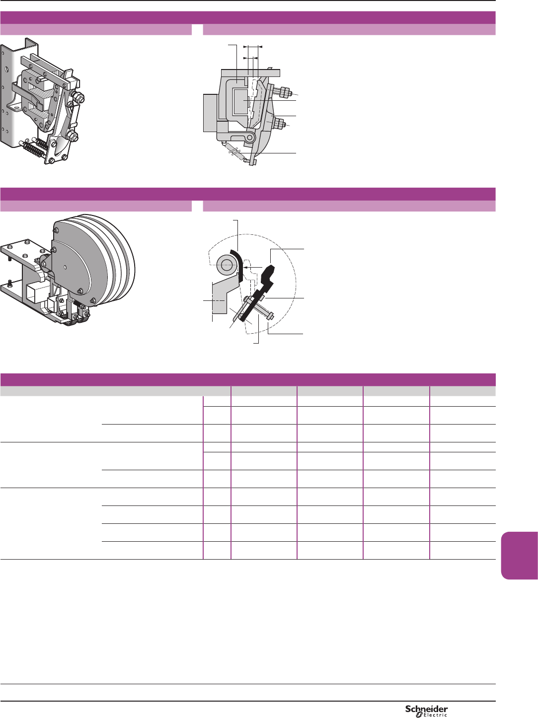
B10/5
TeSys B
Bar
mounted
contactors
TeSys contactors
TeSys LC1 B contactors
Electromagnet
Electromagnet EB5 KB50 Adjustment of pick-up travel and pull-in travel
813310.eps
E
e
Moving
circuit
Coil
Return
spring
Moving
circuit
813312.eps
Poles
Complete pole N/O pole
813311.eps
F
Fixed
contact
Moving contact
Opening gap adjustment
Adjustment of
application force
Pole
spring
813313.eps
c or a supply adjustment characteristics with economy resistor DQGUHFWL¿HURQa)
Contactor type LC1 BL LC1 BM LC1 BP LC1 BR
Electromagnet EB5 KB50 EB5 KB50 EB5 KB50 EB5 KB50
Pick-up travel (E)mm 30 30 30 30
Pull-in travel (e)mm 10 10 10 10
Coil WB1KBppp WB1KBppp WB1KBppp WB1KBppp
Pull-in voltage V0.75 Uc 0.75 Uc 0.75 Uc 0.75 Uc
Drop-out voltage V0.3…0.5 Uc 0.3…0.5 Uc 0.3…0.5 Uc 0.3…0.5 Uc
N/O pole
Adjustment of
application force (F)
on the contact per pole
according to contactor
composition
1-pole daN 30 30 30 (1) 30 (2)
2-pole daN 30 30 30 (1) 30 (2)
3-pole daN 30 30 30 (1) 30 (2)
4-pole daN 30 30 30 (1) 30 (2)
(1)(DFKSROHKDVFRQWDFWVWKHIRUFHPXVWEHDSSOLHGHYHQO\WRHDFKRIWKHVHFRQWDFWV
(2)(DFKSROHKDVFRQWDFWVWKHIRUFHPXVWEHDSSOLHGHYHQO\WRHDFKRIWKHVHFRQWDFWV
Adjustment
characteristics
Selection:
pages A5/23 to A5/47
References:
pages B10/2 to B10/4
Dimensions and schemes:
pages B10/26 and B10/27
PCPB10P10-EN Version : 1.0 13 novembre 2014 3:14 PM
B10/6
TeSys B
TeSys contactors
TeSys LC1 B contactors
Replacement coils and accessories
for single-pole contactors
References
The same coils are used for c or a contactor control supply.
b For d.c. operation, the following must be associated with the coil:
v 1 economy resistor arrangement (resistors + 1 or 2 auxiliary contact(s)
or 1 contactor).
b For 50 to 400 Hz a.c. operation, the following must be associated with the coil:
v LQGLYLGXDOUHFWL¿HUWREHZLUHG
v 1 economy resistor arrangement (resistors + auxiliary contact(s) or 1 contactor)
ZLUHGLQWRWKHUHFWL¿HGFXUUHQWVLGH
Operating range
min-max (1)
Coil Economy resistor 5HFWL¿HU
(for a only)
Coil Weight
d.c. a.c. Resis-
tance
at
20 °C
±10 %
I
inrush
±10 %
at Un
max
Resistor Contact Reference Reference
Unit
reference
Total
resis-
tance
Qty Reference
V V :A:kg
47-51 – 5.1 10.3 DR2SC0270 270 1 ZC4GM2 –WB1KB155 1.120
52-56 – 5.9 9.5 DR2SC0330 330 1 ZC4GM2 –WB1KB132 1.120
57-64 – 7.3 8.9 DR2SC0390 390 1 ZC4GM2 –WB1KB123 1.120
65-68 – 9.5 7.1 DR2SC0560 560 1 ZC4GM2 –WB1KB133 1.120
69-79 – 11.6 6.9 DR2SC0680 680 1 ZC4GM2 –WB1KB121 1.120
80-87 – 16.2 5.3 DR2SC0820 820 1 ZC4GM2 –WB1KB130 1.120
88-94 – 19.9 4.7 DR2SC1000 1000 1 ZC4GM2 –WB1KB140 1.120
95-108 110-125 25.5 4.3 DR2SC1200 1200 1 ZC4GM2 DR5TE1U WB1KB134 1.120
109-136 126-155 33.1 4.2 DR2SC1800 1800 1 ZC4GM2 DR5TE1U WB1KB124 1.120
137-151 156-173 50.9 3 DR2SC2700 2700 2 ZC4GM2 DR5TE1U WB1KB122 1.120
152-166 174-191 61.36 2.7 DR2SC3300 3300 2 ZC4GM2 DR5TE1U WB1KB135 1.120
167-189 192-216 78.4 2.4 DR2SC3900 3900 2 ZC4GM2 DR5TE1U WB1KB136 1.120
190-221 217-256 94.8 2.3 DR2SC4700 4700 2 ZC4GM2 DR5TE1U WB1KB139 1.120
222-243 257-280 123.9 1.9 DR2SC6800 6800 1 LC1DT20LDS135 DR5TE1U WB1KB125 1.120
244-267 281-307 159.9 1.7 DR2SC8200 4700
+ 3300
1LC1DT20LDS135 DR5TE1S WB1KB137 1.120
268-318 308-365 199.6 1.6 DR2SC1001 5600
+ 4700
1LC1DT20UDS135 DR5TE1S WB1KB126 1.120
319-405 366-463 247.4 1.6 DR2SC1201 6800
+ 5600
1LC1DT20TDS135 DR5TE1S WB1KB138 1.120
406-446 464-500 382 1.1 (2) DR2SC1001 20 000 1 LC1DT20VDS135 DR5TE1S WB1KB127 1.120
447-500 – 506.7 1 (3) DR2SC1201 24 000 1 LC1DT20RDS135 –WB1KB128 1.120
6SHFL¿FDWLRQV
b Average coil consumption (low sealed consumption):
v d.c.: inrush 380…520 W, sealed 0.15…0.20 W
v DFZLWKUHFWL¿HULQUXVK«9$VHDOHG«9$
b Time constant when sealed 25 ms
b Economy resistor consumption: 7…10 W
b Operating cycles/hour at T y 55 °C: y 120
b Mechanical durability at Uc: 1.2 million operating cycles
b With a.c. operation: good resistance to voltage drop on inrush, non susceptibility
to micro-breaks, mains harmonics: level y 7.
(1))RUVXSSO\YROWDJHVRIOHVVWKDQ9EHZDUHRIYROWDJHGURSVFDXVHGE\WKHLQUXVKFXUUHQW
(2)UHVLVWRUVLQVHULHV[:.
(3)UHVLVWRUVLQVHULHV[:.
References
:%.%ppp
DF522634.eps
PCPB10P10-EN
Version : 1.0 13 novembre 2014 3:14 PM
B10/7
TeSys B
Bar
mounted
contactors
References
:%.%ppp
DF522634.eps
References
The same coils are used for c or a contactor control supply.
b For d.c. operation, the following must be associated with the coil:
v 1 economy resistor arrangement (resistors + 1 or 2 auxiliary contact(s)
or 1 contactor).
b For 50 to 400 Hz a.c. operation, the following must be associated with the coil:
v LQGLYLGXDOUHFWL¿HUWREHZLUHG
v 1 economy resistor arrangement (resistors + auxiliary contact(s) or 1 contactor)
ZLUHGLQWRWKHUHFWL¿HGFXUUHQWVLGH
Operating range
min-max (1)
Coil Economy resistor 5HFWL¿HU
(for a only)
Coil Weight
d.c. a.c. Resis-
tance
at
20 °C
± 10 %
I
inrush
± 10 %
at Un
max
Resistors (2 in series) Contact Reference Reference
Unit
reference
Total
resis-
tance
Qty Reference
V V :A:kg
48-51 – 3.22 15.8 DR2SC0068 2 x 68 1 ZC4GM2 –WB1KB141 1.120
52-56 – 4.04 13.8 DR2SC0082
DR2SC0100
82 + 100 1 ZC4GM2 –WB1KB142 1.120
57-62 – 4.96 12.5 DR2SC0100
DR2SC0120
100
+ 120
1ZC4GM2 –WB1KB155 1.120
63-68 – 5.86 11.6 DR2SC0120 2 x 120 1 ZC4GM2 –WB1KB132 1.120
69-79 – 7.2 11 DR2SC0150 2 x 150 1 ZC4GM2 –WB1KB123 1.120
80-85 – 9.6 8.8 DR2SC0180
DR2SC0220
180
+ 220
1ZC4GM2 –WB1KB133 1.120
86-98 99-113 11.4 8.6 DR2SC0220
DR2SC0270
220
+ 270
1ZC4GM2 –WB1KB121 1.120
99-108 114-125 16.3 6.6 DR2SC0330 2 x 330 1 ZC4GM2 DR5TE1U WB1KB130 1.120
109-119 126-136 19.7 6 DR2SC0390 2 x 390 1 ZC4GM2 DR5TE1U WB1KB140 1.120
120-136 137-156 25.2 5.4 DR2SC0470 2 x 470 2 ZC4GM2 DR5TE1U WB1KB134 1.120
137-173 157-196 32.5 5.3 DR2SC0680 2 x 680 2 ZC4GM2 DR5TE1U WB1KB124 1.120
174-191 197-216 49.7 3.8 DR2SC1000 2 x 1000 2 ZC4GM2 DR5TE1U WB1KB122 1.120
192-210 217-238 61 3.4 DR2SC1200 2 x 1200 2 ZC4GM2 DR5TE1U WB1KB135 1.120
211-238 239-272 77.2 3 DR2SC1500
DR2SC1800
1500
+ 1800
2ZC4GM2 DR5TE1U WB1KB136 1.120
239-279 273-318 94 3 DR2SC1800
DR2SC2200
1800
+ 2200
1LP1DT20LDS135 DR5TE1S WB1KB139 1.120
280-310 319-359 128 2.4 DR2SC2700 2 x 2700 1 LP1DT20UDS135 DR5TE1S WB1KB125 1.120
311-341 360-387 160 2.1 DR2SC3300 2 x 3300 1 LP1DT20TDS135 DR5TE1S WB1KB137 1.120
342-399 388-452 197 2 DR2SC3900 2 x 3900 1 LP1DT20TDS135 DR5TE1S WB1KB126 1.120
400-500 453-500 257 1.9 DR2SC4700
DR2SC5600
4700
+ 5600
1LP1DT20VDS135 DR5TE1S WB1KB138 1.120
6SHFL¿FDWLRQV
b Average coil consumption (low sealed consumption):
v d.c.: inrush 600…800 W, sealed 0.35…0.5 W
v DFZLWKUHFWL¿HULQUXVK«9$VHDOHG«9$
b Time constant when sealed 25 ms.
b Economy resistor consumption: 15…20 W.
b Operating cycles/hour at T y 55 °C: y 120.
b Mechanical durability at Uc: 1.2 million operating cycles.
b With a.c. operation: good resistance to voltage drop on inrush, non susceptibility
to micro-breaks, mains harmonics: level y 7.
(1))RUVXSSO\YROWDJHVRIOHVVWKDQ9EHZDUHRIYROWDJHGURSVFDXVHGE\WKHLQUXVKFXUUHQW
TeSys contactors
TeSys LC1 B contactors
Replacement coils and accessories
for 2-pole contactors
PCPB10P10-EN Version : 1.0 13 novembre 2014 3:14 PM
B10/8
TeSys B
References TeSys contactors
TeSys LC1 B contactors
Replacement coils and accessories
for 3-pole contactors
References
The same coils are used for c or a contactor control supply.
b For d.c. operation, the following must be associated with the coil:
v 1 economy resistor arrangement (resistors + 1 or 2 auxiliary contact(s)
or 1 contactor).
b For 50 to 400 Hz a.c. operation, the following must be associated with the coil:
v LQGLYLGXDOUHFWL¿HUWREHZLUHG
v 1 economy resistor arrangement (resistors + auxiliary contact(s) or 1 contactor)
ZLUHGLQWRWKHUHFWL¿HGFXUUHQWVLGH
Operating range
min-max (1)
Coil Economy resistor 5HFWL¿HU
(for a only)
Coil Weight
d.c. a.c. Resis-
tance
at
20 °C
±10 %
I
inrush
±10 %
at Un
max
Resistors (2 in
parallel or in series)
Contact Reference Reference
Unit
reference
Total
resis-
tance
Qty Reference
V V :A:kg
47-50 – 1.85 27 DR2SC0150 2x150// 1 ZC4GM2 –WB1KB154 1.120
51-55 – 2.35 23.5 DR2SC0180 2x180// 1 ZC4GM2 –WB1KB153 1.120
56-60 – 3.22 18.5 DR2SC0220 2x220// 1 ZC4GM2 –WB1KB141 1.120
61-66 – 4.04 16 DR2SC0270 2X270// 1 ZC4GM2 –WB1KB142 1.120
67-72 – 4.96 14.5 DR2SC0330 2x330// 1 ZC4GM2 –WB1KB155 1.120
73-79 – 5.86 13.5 DR2SC0100 2x100 1 ZC4GM2 –WB1KB132 1.120
80-92 – 7.2 12.8 DR2SC0120 2x120 1 ZC4GM2 –WB1KB123 1.120
93-98 108-113 9.6 10.2 DR2SC0150
DR2SC0180
150
+ 180
1ZC4GM2 DR5TE1U WB1KB133 1.120
99-114 114-132 11.4 10 DR2SC0180
DR2SC0220
180
+ 220
1ZC4GM2 DR5TE1U WB1KB121 1.120
115-126 133-145 16.3 7.7 DR2SC0270 2x270 2 ZC4GM2 DR5TE1U WB1KB130 1.120
127-139 146-160 11.7 7 DR2SC0330 2x330 2 ZC4GM2 DR5TE1U WB1KB140 1.120
140-159 161-181 25.2 6.3 DR2SC0390
DR2SC0470
390
+ 470
2ZC4GM2 DR5TE1U WB1KB134 1.120
160-201 182-228 32.2 6.2 DR2SC0560 2x560 2 ZC4GM2 DR5TE1U WB1KB124 1.120
202-222 229-255 49.7 4.5 DR2SC0820 2x820 2 ZC4GM2 DR5TE1U WB1KB122 1.120
223-246 256-282 61 4 DR2SC1000 2x1000 1 LC1DT20LDS135 DR5TE1S WB1KB135 1.120
247-277 283-316 77.2 3.6 DR2SC1200 2x1200 1 LC1DT20LDS135 DR5TE1S WB1KB136 1.120
278-327 317-372 94 3.5 DR2SC1500 2x1500 1 LC1DT20UDS135 DR5TE1S WB1KB139 1.120
328-360 373-408 128 2.8 DR2SC1500 3x1500 1 LC1DT20TDS135 DR5TE1S WB1KB125 1.120
361-399 409-452 160 2.5 DR2SC1800 3x1800 1 LC1DT20VDS135 DR5TE1S WB1KB137 1.120
400-469 453-500 197 2.4 DR2SC2200 3x2200 1 LC1DT20VDS135 DR5TE1S WB1KB126 1.120
470-500 – 257 1.9 DR2SC2700 3x2700 1 LC1DT20RDS135 –WB1KB138 1.120
6SHFL¿FDWLRQV
b Average coil consumption (low sealed consumption):
v d.c.: inrush 900…1100 W, sealed 0.7…1 W
v DFZLWKUHFWL¿HULQUXVK«9$VHDOHG«9$
b Time constant when sealed 25 ms.
b Economy resistor consumption: 24…30 W.
b Operating cycles/hour at T y 55 °C: y 120.
b Mechanical durability at Uc: 1.2 million operating cycles.
b With a.c. operation: good resistance to voltage drop on inrush, non susceptibility
to micro-breaks, mains harmonics: level y 7.
(1))RUVXSSO\YROWDJHVRIOHVVWKDQ9EHZDUHRIYROWDJHGURSVFDXVHGE\WKHLQUXVKFXUUHQW
:%.%ppp
DF522634.eps
PCPB10P10-EN
Version : 1.0 13 novembre 2014 3:14 PM
B10/9
TeSys B
Bar
mounted
contactors
References TeSys contactors
TeSys LC1 B contactors
Replacement coils and accessories
for 4-pole contactors
References
The same coils are used for c or a contactor control supply.
b For d.c. operation, the following must be associated with the coil:
v 1 economy resistor arrangement (resistors + 1 or 2 auxiliary contact(s)
or 1 contactor).
b For 50 to 400 Hz a.c. operation, the following must be associated with the coil:
v LQGLYLGXDOUHFWL¿HUWREHZLUHG
v 1 economy resistor arrangement (resistors + auxiliary contact(s) or 1 contactor)
ZLUHGLQWRWKHUHFWL¿HGFXUUHQWVLGH
Operating range
min-max (1)
Coil Economy resistor 5HFWL¿HU
(for a only)
Coil Weight
d.c. a.c. Resis-
tance
at
20 °C
± 10 %
I
inrush
± 10 %
at Un
max
Resistors (3 in series) Contact Reference Reference
Reference
unit
Total
resis-
tance
Qty Reference
V V :A:kg
57-61 – 2.35 26 DR2SC0027 3x27 1 ZC4GM2 –WB1KB153 1.120
62-67 – 3.22 21 DR2SC0033 3x33 1 ZC4GM2 –WB1KB141 1.120
68-73 – 4.04 18 DR2SC0039 3x39 1 ZC4GM2 –WB1KB142 1.120
74-81 – 4.96 16.3 DR2SC0047 3x47 1 ZC4GM2 –WB1KB155 1.120
82-89 – 5.86 15 DR2SC0056 3x56 1 ZC4GM2 –WB1KB132 1.120
90-102 105-119 7.2 14 DR2SC0068 3x68 1 ZC4GM2 DR5TE1U WB1KB123 1.120
103-111 120-128 9.6 11.5 DR2SC0100 3x100 2 ZC4GM2 DR5TE1U WB1KB133 1.120
112-129 129-148 11.4 11.3 DR2SC0100 3x100 2 ZC4GM2 DR5TE1U WB1KB121 1.120
130-143 149-163 16.3 8.7 DR2SC0150 3x150 2 ZC4GM2 DR5TE1U WB1KB130 1.120
144-157 164-179 19.7 8 DR2SC0180 3x180 2 ZC4GM2 DR5TE1U WB1KB140 1.120
158-180 180-204 25.2 7.1 DR2SC0220 3x220 2 ZC4GM2 DR5TE1U WB1KB134 1.120
181-226 205-259 32.5 6.9 DR2SC0330 3x330 2 ZC4GM2 DR5TE1U WB1KB124 1.120
227-251 260-288 49.7 5 DR2SC0470 3x470 1 LC1DT20LDS135 DR5TE1S WB1KB122 1.120
252-278 289-317 61 4.5 DR2SC0560 3x560 1 LC1DT20UDS135 DR5TE1S WB1KB135 1.120
279-313 318-356 77.2 4 DR2SC0680 3x680 1 LC1DT20UDS135 DR5TE1S WB1KB136 1.120
314-368 357-418 94 3.9 DR2SC0820 3x820 1 LC1DT20TDS135 DR5TE1S WB1KB139 1.120
369-408 419-462 128 3.2 DR2SC1200 3x1200 1 LC1DT20VDS135 DR5TE1S WB1KB125 1.120
409-448 463-500 160 2.8 DR2SC1500 3x1500 1 LC1DT20VDS135 DR5TE1S WB1KB137 1.120
449-500 – 197 2.5 DR2SC1800 3x1800 1 LC1DT20RDS135 –WB1KB126 1.120
6SHFL¿FDWLRQV
b Average coil consumption (low sealed consumption):
v d.c.: inrush 1100…1400 W, sealed 1.2…1.6 W
v DFZLWKUHFWL¿HULQUXVK«9$VHDOHG«9$
b Time constant when sealed 25 ms
b Economy resistor consumption: 35…45 W
b Operating cycles/hour at T y 55 °C: y 120
b Mechanical durability at Uc: 1.2 million operating cycles
b With a.c. operation: good resistance to voltage drop on inrush, non susceptibility
to micro-breaks, mains harmonics: level y 7.
(1))RUVXSSO\YROWDJHVRIOHVVWKDQ9EHZDUHRIYROWDJHGURSVFDXVHGE\WKHLQUXVKFXUUHQW
:%.%ppp
DF522634.eps
PCPB10P10-EN Version : 1.0 13 novembre 2014 3:14 PM
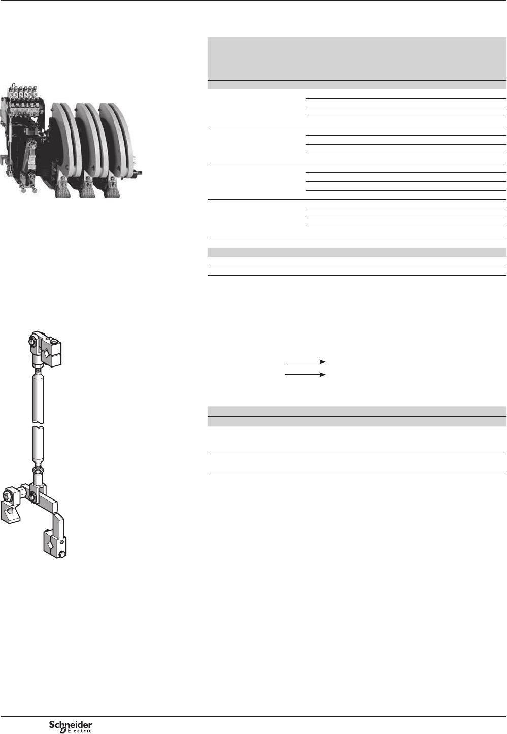
B10/10
TeSys B
CR1 B
Magnetic latching contactors
References
DB116198.eps
&5%/
Accessories for contactors CR1 B
Control circuit: a.c. or d.c. supply
Maximum
thermal
current in
category
AC-1
Rated
operational
current in
category
AC-3
Composition Number of
Instantaneous
auxiliary
contacts
Basic reference,
to be completed
by adding the
voltage code (1)
Weight
A A N/C N/O kg
800 750 1 pole 2 1 CR1BL31p21 (2) 32.000
2 poles 2 1 CR1BL32p21 (2) 45.000
3 poles 2 1 CR1BL33p21 (2) 58.000
4 poles 2 1 CR1BL34p21 (2) 72.000
1250 1000 1 pole 2 1 CR1BM31p21 (2) 31.000
2 poles 2 1 CR1BM32p21 (2) 44.000
3 poles 2 1 CR1BM33p21 (2) 57.000
4 poles 2 1 CR1BM34p21 (2) 71.000
2000 1500 1 pole 2 1 CR1BP31p21 (2) 41.000
2 poles 2 1 CR1BP32p21 (2) 65.000
3 poles 2 1 CR1BP33p21 (2) 94.000
4 poles 2 1 CR1BP34p21 (2) 120.000
2750 1800 1 pole 2 1 CR1BR31p21 (2) 52.000
2 poles 2 1 CR1BR32p21 (2) 85.000
3 poles 2 1 CR1BR33p21 (2) 129.000
4 poles 2 1 CR1BR34p21 (2) 160.000
(1) 6WDQGDUGFRQWUROFLUFXLWYROWDJHV
Volts 110 125 127 200 220 240 250 380 412 440 500
a 50-400 Hz F - G L M U - Q N R S
cFD GD - - MD UD UCD - - RD SD
)RURWKHUYROWDJHVVHHWDEOHVRIUHIHUHQFHVFRLOVSDJH%RUFRQVXOWXV
(2) 2WKHUFRQ¿JXUDWLRQVVHHEHORZ
2WKHUFRQ¿JXUDWLRQVIRU&5%
)RURWKHUFRQ¿JXUDWLRQVRIDX[LOLDU\FRQWDFWVUHSODFHWKHQXPEHU
³12´³1&´E\WKHUHIHUHQFHRIWKHFKRVHQFRQ¿JXUDWLRQ
Example: LC1 BP33p30.
1 “N/O” + 2 “N/C” 12
3 “N/O” 30
Accessories for contactors CR1 B
Description Application Reference Weight
kg
Mechanical interlock (3)
with mounting
accessories
For vertical assembly of
reversing contactors and CR1 B
changeover contactor pairs
EZ2LB0601 1.560
Kit containing 2
bar mounting brackets
LA9B103 1.620
Spare parts see page B10/12.
Note:WKHSURWHFWLRQFRLOFRQWUROFLUFXLWDJDLQVWVKRUWFLUFXLWVPXVWEHSHUIRUPHGE\DIXVH
FRRUGLQDWHGZLWKWKHFDEOHVHFWLRQXVHGPPIRUFRSSHU$IXVHPD[LPXP%6RUJ
(3)3RVLWLYHPHFKDQLFDOLQWHUORFNLQJEHWZHHQYHUWLFDOO\PRXQWHGFRQWDFWRUVRILGHQWLFDORU
GLIIHUHQWUDWLQJV&RQQHFWLQJURGVDQGFUDQNVDVVHPEOHGRQULJKWKDQGVLGHVFUDQNSLQVRQ
the pole side.
9HUWLFDO¿[LQJFHQWUHGLVWDQFHEHWZHHQWKHWZRFRQWDFWRUVPP
DB116217.eps
PCPB10P20-EN
Version : 1.0 6 novembre 2014 11:04 AM

B10/11
TeSys B
Bar
mounted
contactors
CR1 B
Magnetic latching contactors
References
DF522634.eps
:%.%ppp
Coils for CR1 B contactors
Usual voltage Coils Spare parts
c a
50 - 400 Hz
Resistance
(T = 20 °C)
Reference Additional
resistors (1)
Cut-out contact 5HFWL¿HU
for a
R1 R2 Number Type
V V ȍ ȍ ȍ
For CR1 Bp31 1 pole
- 110/120 19.7 WB1KB140 68 47 2 ZC4GM2 or ZC4GM8 DR5TE1U
110 / 125 - 25.2 WB1KB134 68 68 2 ZC4GM2 or ZC4GM8 -
- 220/240 77.2 WB1KB136 220 180 2 ZC4GM2 or ZC4GM8 DR5TE1U
220 - 94 WB1KB139 270 220 2 ZC4GM2 or ZC4GM8 -
250 - 128 WB1KB125 330 270 3 ZC4GM2 or ZC4GM8 -
- 380/400 197 WB1KB126 470 470 3 ZC4GM2 or ZC4GM8 DR5TE1S
- 415/440 257 WB1KB138 1000 470 3 ZC4GM2 or ZC4GM8 DR5TE1S
For CR1 Bp32 2 poles
- 110 9.6 WB1KB133 10 33 1 PR4FB0011 DR5TE1U
110 120/127 11.4 WB1KB121 47 39 1 PR4FB0010 DR5TE1U
125 - 19.7 WB1KB140 100 47 1 PR4FB0009 -
- 220 32.5 WB1KB124 120 120 1 PR4FB0007 DR5TE1U
220 240 49.7 WB1KB122 220 150 1 PR4FB0007 DR5TE1U
250 - 77.2 WB1KB136 330 220 1 PR4FB0006 -
- 380/400 128 WB1KB125 470 470 1 PR4FB0005 DR5TE1S
- 415/440 160 WB1KB137 680 560 1 PR4FB0004 DR5TE1S
For CR1 Bp33 3 poles
- 110 7.2 WB1KB123 39 27 1 PR4FB0012 DR5TE1U
110 120/127 9.6 WB1KB133 47 39 1 PR4FB0011 DR5TE1U
125 - 11.4 WB1KB121 56 47 1 PR4FB0010 -
220 240 32.5 WB1KB124 180 120 1 PR4FB0008 DR5TE1U
250 - 61 WB1KB135 270 270 1 PR4FB0006 -
- 380/400 94 WB1KB139 470 390 1 PR4FB0005 DR5TE1S
- 415/440 128 WB1KB125 680 470 1 PR4FB0004 DR5TE1S
For CR1 Bp34 4 poles
- 110 5.8 WB1KB132 33 27 1 PR4FB0014 DR5TE1U
110 120/127 7.2 WB1KB123 47 33 1 PR4FB0012 DR5TE1U
125 - 11.4 WB1KB121 56 45 1 PR4FB0010 -
- 220 25.2 WB1KB134 150 120 1 PR4FB0008 DR5TE1U
- 240 32.5 WB1KB124 180 150 1 PR4FB0007 DR5TE1U
250 - 49.7 WB1KB122 270 220 1 PR4FB0007 -
- 380 77.2 WB1KB136 390 390 1 PR4FB0006 DR5TE1S
- 400/440 94 WB1KB139 560 470 1 PR4FB0005 DR5TE1S
(1) )RUKRWDQGKXPLGFRQGLWLRQV³7+WUHDWPHQW´WKHUHIHUHQFHVRIWKHFRLOVDUHVXSSOHPHQWHGE\WKHOHWWHUV³7+´
([DPSOHWB1 KB 135TH.
5HIHUHQFHRIUHVLVWDQFH DR2 SC0010IRURKPVDQG
DR2 SC0470IRURKPV
:HLJKWRIWKHYDULRXVHOHPHQWV
bFRLO:%.%ppp NJ
bFRQWDFW=&*0p NJ
bVZLWFK35)%pp NJ
bUHFWL¿HU'567(Op NJ
bUHVLVWDQFH'56&ppp NJ
PCPB10P20-EN Version : 1.0 6 novembre 2014 11:04 AM
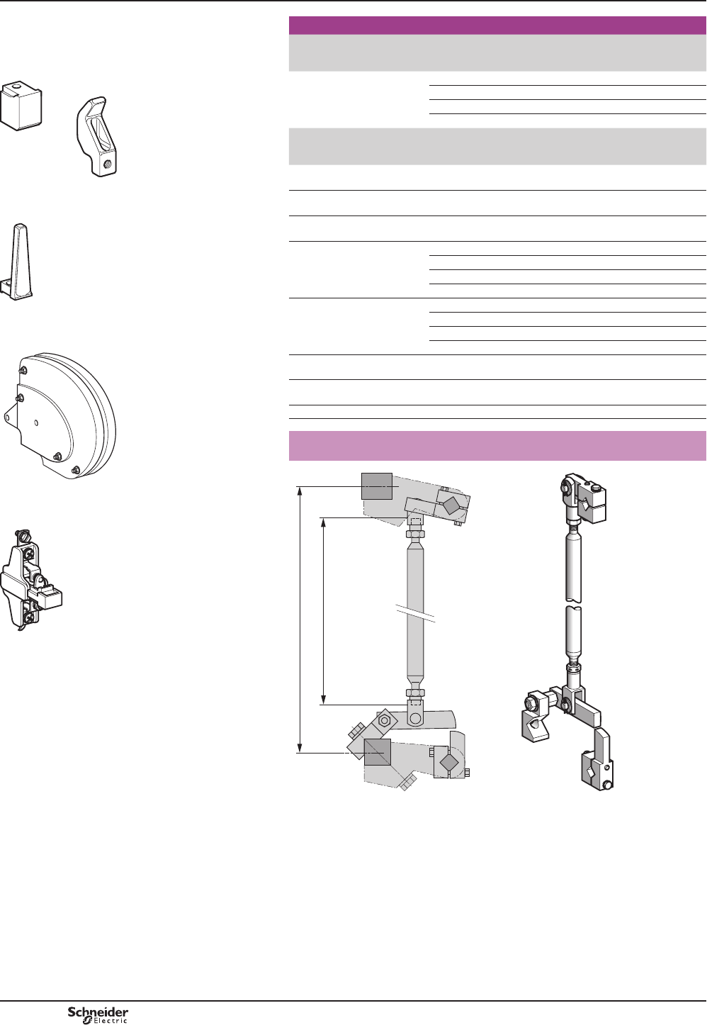
B10/12
TeSys B
Separate components and spare
Description For
contactors
Number of
sets required
per pole
Reference Weight
kg
Sets of contacts
(1 moving contact,
¿[HGFRQWDFW
CR1BL 1PA1LB80 0.420
CR1BM 1PA1LB80 0.420
CR1BP 2PA1LB80 0.420
CR1BR 3PA1LB80 0.420
Description For
contactors
Composition Reference Weight
kg
Moving contact only
IRURQH¿QJHU
CR1B PA1LB75 0.220
Fixed contact only
IRURQH¿QJHU
CR1B PA1LB76 0.200
Blow-out horn only
IRU¿QJHU
CR1B PA1LB89 0.120
Arc chambers
(for a single pole)
CR1BL PA1LB50 3.700
CR1BM PA1LB50 3.700
CR1BP PA1PB50 6.200
CR1BR PA1RB50 8.500
Auxiliary
contact blocks
CR1B 1 contact N/C ZC4GM1 0.030
CR1B 1 contact N/O ZC4GM2 0.030
CR1B 1 contact N/C ZC4GM9 0.030
CR1B 1 contact N/O ZC4GM8 0.030
Switch pole
for automatic cut-out coil
CR1B PR4FB00pp (1) 0.600
6HWRIPRYLQJDQG¿[HG
contacts for switch pole
CR1B PV1FA80 0.035
Arc chamber for switch pole CR1B PN1FB50 0.220
Mechanical interlock for the realization of reversing superposed contactors
ref. EZ2-LB0601
A = (E–112) 488
E = 600
DB403714.eps
DB116217.eps
(1)5HIHUHQFHWREHFRPSOHWHGVHHSDJH%
References
Spare parts CR1 B
Magnetic latching contactors
DB403717.eps
3$/%
3$/%3$/%
DB403717.eps
DB403716.eps
3$/%
DB403715.eps
3$/%
DB403718.eps
=&*0
PCPB10P20-EN
Version : 1.0 6 novembre 2014 11:04 AM
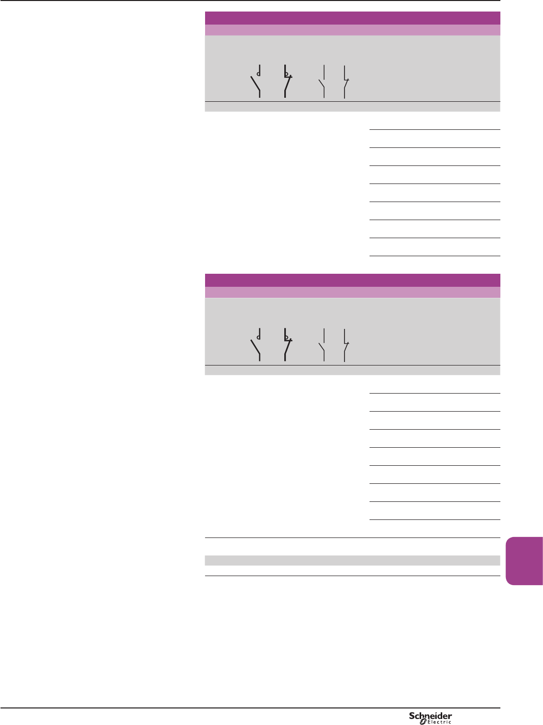
B10/13
TeSys B
Bar
mounted
contactors
Magnetic latching contactors
Control circuit: dc
Operational
voltage
Number
of pole
N/O
Number
of pole
N/C
Instantaneous
auxiliary
contacts
Rated
operational
current
Basic reference to
be completed by
adding the voltage
(1)
Weight
c V A kg
850 2 1 6 2 80 CRXBF21pp 6.280
170 CRXBG21pp 10.890
250 CRXBH21pp 15.000
470 CRXBJ21pp 21.700
630 CRXBK21pp 38.150
800 CRXBL21pp 58.000
1250 CRXBM21pp 58.000
2000 CRXBP21pp 81.000
2750 CRXBR21pp 114.000
Contactors with standard electromagnets
Control circuit: dc with economy resistor
Operational
voltage
Number
of pole
N/O
Number
of pole
N/C
Instantaneous
auxiliary
contacts
Rated
operational
current
Basic reference to
be completed by
adding the voltage
(1)
Weight
c V A kg
850 2 1 6 2 80 CVXBF21pp 6.280
170 CVXBG21pp 10.890
250 CVXBH21pp 15.000
470 CVXBJ21pp 21.700
630 CVXBK21pp 38.150
800 CVXBL21pp 58.000
1250 CVXBM21pp 58.000
2000 CVXBP21pp 81.000
2750 CVXBR21pp 114.000
(1) Standard control circuit voltages (for other voltages, please consult your Regional Sales
2I¿FH
Volts 110 125 250
cFD GD UD
CRX B and CVX B for switching
the excitation circuits of
synchronous machines
Selection guide
PCPB10P20-EN Version : 1.0 6 novembre 2014 11:04 AM

B10/14
TeSys B
Contactors description
CRX and CVX B contactors comprise:
b 2 N/O poles with magnetic blow-out (80…2750 A at c 850 V).
b 1 N/C pole without blow-out (80…630 A).
b 1 electromagnet with d.c. supply
v either magnetic latching (CRX Bp21pp)
v or with economy resistor (CVX Bp21pp).
b 2 instantaneous auxiliary contact heads (6 N/O contacts + 2 N/C contacts).
b 1 mounting bar, 1 rotary drive shaft.
The following can be added:
b 1 or 2 blocks of 4 instantaneous auxiliary contacts LAD Npp, without increasing
the overall size of the contactor.
b or 1 time delay block LAD Tp or LAD Rp.
Note: LWLVQRWSRVVLEOHWR¿WDPHFKDQLFDOODWFKEORFN/$'.pp on these contactors.
Characteristics
Sizes of contactors CRX B and CVX B F G H J K L M P R
N/O Pole
Rated current Ty40 °C A 80 170 250 470 630 800 1250 2000 2750
Maximum operating voltage
d.c.
2 pole series V850
Rated insulation voltage
According to IEC 60664-1
d.c. V1000
Making capacity d.c. A 1400 2900 3500 5200 6500 14 000 14 000 21 000 25 000
Breaking capacity d.c. L/R = 15 ms A 500 1000 1200 1200 1500 3200 4400 7200 10 000
Overlap time with the N/C pole
ms 2
N/C Pole
Rated current Ty40 °C A80 200 300 470 630 630 630 630 630
Making capacity d.c. A1600 3200 4000 5200 6500 6500 6500 6500 6500
Breaking capacity d.c. L/R = 15 ms A0
Permissible current For 10 seconds A480 960 1400 2700 3600 3600 3600 3600 3600
Characteristics CRX B and CVX B for switching
the excitation circuits of
synchronous machines
PCPB10P20-EN
Version : 1.0 6 novembre 2014 11:04 AM

B10/15
TeSys B
Bar
mounted
contactors
Spare parts
Sets of contacts for CRX contactors
Description Number of sets
required per
contactor pole
CRX B
and CVX B
contactor sizes
Reference Weight
kg
¿[HGFRQWDFW
+
1 moving contact
1 F PA2FB80 0.070
1 G PA2GB80 0.160
1 H PA2HB80 0.220
1 J PN1JB80 0.320
1 K PN1KB80 0.440
1 L PA1LB80 0.420
1 M PA1LB80 0.420
2 P PA1LB80 0.420
3 R PA1LB80 0.420
Arc chamber only
Description Number of sets
required per
contactor pole
CRX B
and CVX B
contactor sizes
Reference Weight
kg
Arc chamber 1 F PA2FB50 0.070
GPA2GB50 0.160
HPA2HB50 0.220
JPN3JB50 0.320
KPN3KB50 0.440
LPA1LB50 0.420
MPA1LB50 0.420
PPA1PB52 0.840
RPA1RB52 1.260
31-%
DF567072.eps
31/%
501480_1.eps
31.%
DF567073.eps
References
Spare parts CRX B and CVX B for switching
the excitation circuits of
synchronous machines
PCPB10P20-EN Version : 1.0 6 novembre 2014 11:04 AM
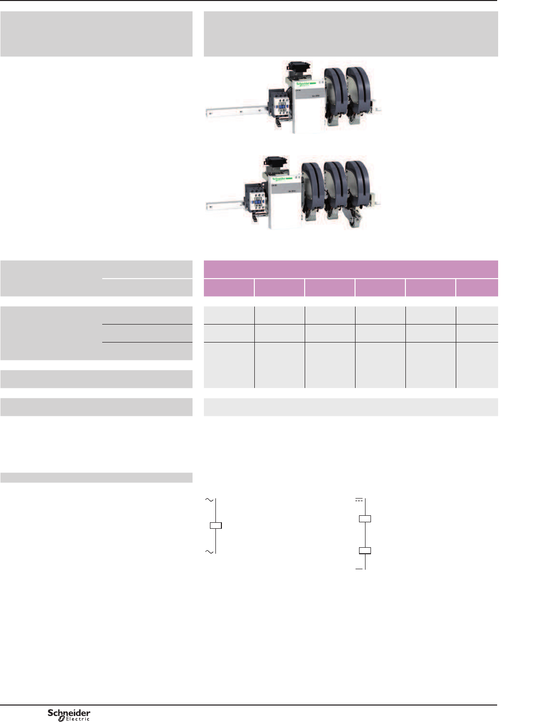
B10/16
TeSys B
Panorama
Applications b Motor switching in categories AC-3.
b Resistive load switching: heating, etc.
b Distribution circuit switching: line contactor.
b Supply changeover switching: circuit coupling etc.
b Transformer, capacitor, lighting switching.
PB110868.epsPB110869.eps
Contactors Type CV1 B
Size F G H J K L
Rated operational current AC-3 80 A 170 A 250 A 350 A 460 A 700 A
AC-4/DC-5 72 A/– 145 A/– 205 A/– 290/470 A (1) 380/630 A (1) 584/1000 A
(1)
AC-1 80 A 200 A 300 A 470 A 630 A 1000 A
Rated operational voltage 690 V a690 V a690 V a690 V a690 V a690 V a
$YDLODEOHZLWKFRQ¿JXUDWLRQW\SHFRPPDQG A - B - C - D
$YDLODEOHFRQWUROFLUFXLWFRQ¿JXUDWLRQ Type A Type B
a.c. supply a d.c. supply c
A1A2
501346_1.eps
A1A2 A1A2
501347_1.eps
(1):LWK31SROHV
Variable composition standard
and high performance
contactors
PCPB10P20-EN
Version : 1.0 6 novembre 2014 11:04 AM
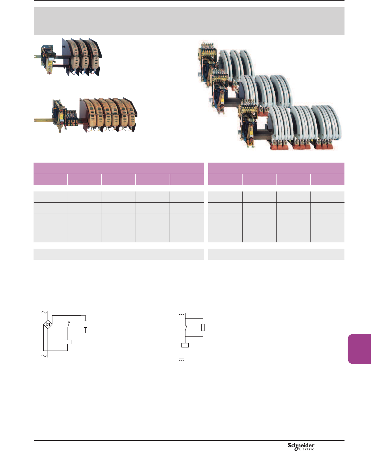
B10/17
TeSys B
Bar
mounted
contactors
501354_1.eps
b Motor switching in categories AC-4, DC-5.
b Inductive circuit switching.
b High voltage d.c. switching: crane electromagnets, railway locomotives.
b Load switching at high operating rates.
501352_1.eps501353_1.eps
CV3 B CV3 B and LC1 B
F G H J K L M P R
80 A 200 A 250 A 320 A 460 A 800 A 1000 A 1500 A 1800 A
80/80 A 170/200 A 208/300 A 250/320 A 380/500 A 720/800 A 830/1000 A 1200/1800 A 1500/2500 A
80A 200 A 300 A 320 A 500 A 800 A 1250 A 2000 A 2750 A
1000 V a1000 V a1000 V a1000 V a1000 V a1000 V a1000 V a1000 V a1000 V a
A - B - C - D C - D
(B: special conditions - contact us)
Type C Type D
a.c. supply via economy resistor d.c. supply via economy resistor
Rr
– KM
A1A2
– KM
501348_1R.eps
Rr
– KM
A1A2
– KM
501349_1R.eps
Panorama Variable composition standard
and high performance
contactors
PCPB10P20-EN Version : 1.0 6 novembre 2014 11:04 AM

Selection
7RGH¿QHDFRQWDFWRU
7KHFULWHULDUHTXLUHGWRGH¿QHWKHFRPSRVLWLRQRIDFRQWDFWRUDUH
b the number of N/O and N/C power poles
b the current and power supply voltage
(note: on a d.c. supply, the time constant
L
R
----
of the load must be known in order to
GH¿QHWKHQXPEHURISROHVWREHZLUHGLQVHULHVWREUHDNWKHDUF
b the control circuit voltage
b the number of auxiliary contacts.
To order a contactor
Three possibilities are offered:
b contactor selectable by code combinations:
vXVHWKHFRQ¿JXUDWLRQVRIWZDUH “bar contactor soft-customer.xls” to download on:
www.schneider-electric.com.
vuse the symbol combination table, on the next page.
b Contactor not selectable by code combinations use the symbol combination table
or the software, use the order form on catalogue DIA2070702EN.
To order a contactor manually
contactor selectable by code combinations
b Use the symbol combination table on the next page.
b Check the operational currents possible in the selection restrictions table, below.
b Check the maximum number of poles in the selection table, below.
Choice of operational current (Ie) for contactors selectable
by code combinations
Contactor type CV1 BF
CV3 BF
CV1 BG
CV3 BG
CV1 BH
CV3 BH
CV1 BJ
CV3 BJ
CV1 BK
CV3 BK
CV1 BL
Rated
operational
current (1)
11 A E – – – – –
13 A M – – – – –
20 A N – – – – –
40 A P – – – – –
50 A Q Q – – – –
80 A F – – – – –
125 A – R R – – –
200 A – G G – – –
250 A – – – S – –
300 A – – H – – –
(1) 2WKHUUDWLQJFRQWDFWXV
Guide to selection of poles for code combinations
Maximum potential of pole contactors, new design (size F to H)
)RUDQRWKHUFRPELQDWLRQSOHDVHFRQWDFWXV
Pole N/O Pole N/C
0 1
1 0
1 1
2 0
2 1
3 0
4 0
Contactors CV1 B or CV3 B:
number of standard auxiliary contacts: 3 N/O +2 N/C + additive Tesys D.
Examples
b Switching of single-phase capacitor: 400 V - 80 A - 1 N/O main pole. 220 V / 50 Hz.
control circuit voltage, 3 N/O and 2 N/C auxiliary contacts.
Reference: CV1 BF1F0ZM5A.
b Switching of d.c. heating circuits: 800 V - 150 A - 2 N/O main poles - 48 V c.
control circuit, instantaneous auxiliary contact 1 N/O + 1 on-delay.
Reference: CV3 BG2G0ZEDA + LADT 0, 2 or 4.
Other versions
To obtain a composition with more main poles or with more than 4 auxiliary contacts,
please use order form CF 452, on catalogue DIA2070702EN..
Variable composition contactors
Ordering process
Order form
B10/18
TeSys B
PCPB10P20-EN
Version : 1.0 6 novembre 2014 11:04 AM

Reference to be constituted (see examples page B10/18)
Type of contactor related to application
a 690 V, c 220 V/pole CV1 B
a 1000 V, c 440 V/pole CV3 B
Contactor size AC-1/AC-3
CV1: 80/80 A CV3: 80/80 A F g
CV1: 200/170 A CV3: 200/200 A G g
CV1: 300/250 A CV3: 300/285 A H g
Number of poles
N/O poles 1 N/O 1
2 N/O 2
3 N/O 3
4 N/O 4
N/C poles 1 N/C 1
No main poles 0 Z 0 Z
Operational current (determines the blow-out coil size)
11 A E E
13 A M M
20 A N N
40 A P P
50 A Q Q
80 A F F
125 A R R
200 A G G
250 A S S
300 A H H
Without breaking Z Z
Control circuit voltage
24 V B
48 V E
110 V F
120 V K
127 V G
208 V L
220 V M
230 V P
240 V U
380 V Q
400 V V
Operating frequency
50 Hz 5
60 Hz 6
+]UHFWL¿HUHFRQRP\UHVLVWRU 7
cD
c + economy resistor R
Auxiliary contacts /$%1DGGLWLYHV¿WWHGDVVWDQGDUG
Instantanés 3 N/O + 2 N/C A
7RFKHFNZKHWKHUWKHV\PEROFRPELQDWLRQVDUHSRVVLEOHUHIHUWRWKHVHOHFWLRQLQIRUPDWLRQDQGJXLGHRQSDJHV%DQG%
,ILQGRXEW¿OORXWRUGHUIRUP&)VHHFDWDORJXH',$(1
g 1HZGHVLJQFDQXVHDQ\DGGLWLYHVLQWKHUDQJHRIFRQWDFWRUV7H6\V'H[FHSW/$'.DQG/$'./$'1
Important information for use by Schneider Electric
To place an order in SAP GRC switch-LOGOS
Example: Order the contactor CRXBKZ1GD
b enter in the Reference product "CRXBK"
bLQWKH¿HOG7HFKQLFDOWH[WVSHFLI\&5;%.Z1GD".
Variable composition contactors
CV1B / CV3B - 80 to 300 A
Symbol combination table
Order form
B10/19
TeSys B
Bar
mounted
contactors
PCPB10P20-EN Version : 1.0 6 novembre 2014 11:04 AM
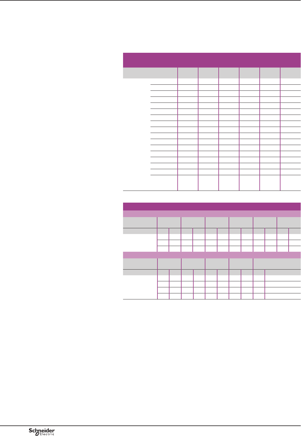
Selection (see page B10/18)
To order a contactor manually
contactor selectable by code combinations
b Use the symbol combination table on page B10/21.
b Check the operational currents possible in the selection restrictions table, below.
b Check the maximum number of poles in the selection table, below.
Choice of operational current (Ie) for contactors selectable
by code combinations
Contactor type CV1 BF
CV3 BF
CV1 BG
CV3 BG
CV1 BH
CV3 BH
CV1 BJ
CV3 BJ
CV1 BK
CV3 BK
CV1 BL
Rated
operational
current (1)
11 A E – – – – –
13 A M – – – – –
20 A N–––––
40 A P – – – – –
50 A Q Q – – – –
80 A F – – – – –
125 A – R R – – –
200 A – G G – – –
250 A – – – S – –
300 A – – H – – –
320 A – – – T – –
400 A – – – – U –
470 A – – – J – –
500 A – – – – V –
630 A – – – – K K
1000 A – – – – – L
0
Sans
VRXIÀDJH
ZZZZZZ
(1)2WKHUUDWLQJFRQWDFWXV
Guide to selection of code combinations
CV1 B contactors: maximum number of power poles
Contactor type CV1 BF CV1 BG CV1 BH CV1 BJ CV1 BK CV1 BL
Pole type N/O N/C N/O N/C N/O N/C N/O N/C N/O N/C N/O N/C
Number of poles 5 0 4 0 4 0 4 0 4 0 2 (1) 0
0 2 0 2 0 2 0 2 0 2 0 1 (2)
2 1 2 1 2 1 2 1 2 1 – –
CV3 B contactors: maximum number of power poles
Contactor type CV3 BF CV3 BG CV3 BH CV3 BJ CV3 BK
Pole type N/O N/C N/O N/C N/O N/C N/O N/C N/O N/C
Number of poles 5 0 4 0 4 0 2 0 2 0
020202––––
1212––––––
312121––––
CV1 B or CV3 B contactors:
Maximum number of auxiliary contacts: 4 + 1 time delay if necessary
Selection restrictions, according to coil type:
(1)SROHZLWKHFRQRP\UHVLVWRU
(2)SROHZLWKHFRQRP\UHVLVWRU
Variable composition contactors
CV1 B - 80 to 1000 A
CV3 B - 80 to 500 A
Order form
B10/20
TeSys B
PCPB10P20-EN
Version : 1.0 6 novembre 2014 11:04 AM
Reference to be constituted (see examples page B10/20)
Type of contactor related to application
a 690 V, c 220 V/pole CV1 B
a 1000 V, c 440 V/pole CV3 B
Contactor size AC-1/AC-3
CV1: 80/80 A CV3: 80/80 A F
CV1: 200/170 A CV3: 200/200 A G
CV1: 300/250 A CV3: 300/285 A H
CV1: 470/350 A CV3: 320/320 A J
CV1: 630/460 A CV3: 500/460 A K
CV1: 1000/700 A L
Number of poles
N/O poles 1 N/O 1
2 N/O 2
3 N/O 3
4 N/O 4
5 N/O 5
N/C poles 1 N/C 1
2 N/C 2
3 N/C 3
No main poles 0 Z 0 Z
Operational current (determines the blow-out coil size)
11 A E E
13 A M M
20 A N N
40 A P P
50 A Q Q
80 A F F
125 A R R
200 A G G
250 A S S
300 A H H
320 A T T
400 A U U
470 A J J
500 A V V
630 A K K
1000 A L L
Without breaking Z Z
Control circuit voltage
24 V B
48 V E
110 V F
120 V K
127 V G
208 V L
220 V M
230 V P
240 V U
380 V Q
400 V V
415 V N
440 V R
480 V T
500 V S
600 V X
Operating frequency
50 Hz 5
60 Hz 6
+]UHFWL¿HUHFRQRP\UHVLVWRU 7
cD
c + economy resistor R
Auxiliary contacts (type ZC4 GM)
N/O instantaneous 1 N/O 1
2 N/O 2
3 N/O 3
4 N/O 4
N/C instantaneous 1 N/C 1
2 N/C 2
3 N/C 3
4 N/C 4
No instantaneous auxiliary contacts 0 0
On-delay 1 N/O + 1 N/C on-delay J
Off-delay 1 N/O + 1 N/C off-delay N
7RFKHFNZKHWKHUWKHV\PEROFRPELQDWLRQVDUHSRVVLEOHUHIHUWRWKHVHOHFWLRQLQIRUPDWLRQDQGJXLGHRQSDJHV%DQG%
,ILQGRXEW¿OORXWRUGHUIRUP&)RQFDWDORJXH',$(1
Variable composition contactors
CV1 B - 80 to 1000 A
CV3 B - 80 to 500 A
Symbol combination table
Order form
B10/21
TeSys B
Bar
mounted
contactors
PCPB10P20-EN Version : 1.0 6 novembre 2014 11:04 AM

B10/22 PCPB10P20-EN
Version : 1.0 6 novembre 2014 11:04 AM

B10/23
Bar
mounted
contactors
Technical
Data for
Designers
TeSys B and V
TeSys LC1B:
> characteristics .... B10/24 and B10/25
> dimensions ........................................ B10/26
> schemes .............................................. B10/27
TeSys CR1B:
> presentation ...................................... B10/28
> selection .................B10/29 and B10/30
> characteristics ....B10/31 and B10/32
> dimensions ........................................ B10/33
> schemes .............................................. B10/34
TeSys CRXB, CVXB:
> presentation ...................................... B10/35
> dimensions ........................................ B10/36
TeSys CV1B, CV3B:
> presentation .............B10/37 to B10/40
Contents

TeSys B
TeSys contactors
TeSys LC1 B contactors
Environment
Contactor type LC1 BL LC1 BM LC1 BP LC1 BR
Rated insulation voltage (Ui) Conforming to
IEC 60158-1/IEC 60947-4
V1000 1000 1000 1000
Conforming to VDE 0110 gr C V1500 1500 1500 1500
Conforming to standards IEC 60947-4, EN 60947-4
3URGXFWFHUWL¿FDWLRQV CSA
Ambient air temperature around
the device
(for operation at Uc)
Storage °C -60…+80
Operation °C -5…+55
Permissible °C -30…+70
Maximum operating altitude Without derating m2000
Operating positions Without derating ±23° occasional, in relation to normal vertical mounting plane
Pole characteristics
Number of poles 1, 2, 3 or 4 1, 2, 3 or 4 1, 2, 3 or 4 1, 2, 3 or 4
Rated operational current (Ie)
(Ue y 440 V)
In AC-3, T y 55 °C A750 1000 1500 1800
In AC-1, T y 40 °C A800 1250 2000 2750
Rated operational voltage (Ue) Up to V1000
Frequency limits
(sine wave)
Without derating Hz 50/60
'HUDWLQJFRHI¿FLHQW 100 Hz: 0.9 - 150 Hz: 0.8 - 250 Hz: 0.7 - 400 Hz: 0.5
Maximum thermal current (Ith) Ty 40 °C A800 1250 2000 2750
Rated making capacity I rms conforming to
IEC 60158-1 and 60947-4
A8000 9000 12000 15000
Rated breaking capacity I rms
conforming to
IEC 60158-1
and 60947-4
up to 440 V A8000 9000 12000 15000
500 V A7000 8000 12000 14000
660-690 V A6000 7000 9000 11000
1000 V A4000 4000 5000 6000
Permissible short time rating
From cold state, with no current
ÀRZLQJIRUSUHYLRXVPLQXWHV
at T y 40 °C
For 1 s A9600 9600 12000 15000
For 5 s A9600 9600 12000 15000
For 10 s A7000 8000 9600 12000
For 30 s A4800 5200 6400 8000
For 1 min. A3500 3800 5200 6300
For 3 min. A2100 2400 3600 4400
For 10 min. A1200 1800 2800 3600
Short-circuit protection
by fuses
U y 440 V
Motor circuit (type aM) A800 1200 2 x 800 (1) 2 x 1000 (1)
With thermal overload relay
(type gl)
A1000 1500 2 x 1000 (1) 2 x 1200 (1)
gl fuses A800 1200 2 x 1000 (1) 2 x 1200 (1)
Average impedance per pole At Ith and 50 Hz m:0.18 0.18 0.13 0.09
Power dissipated per pole AC-3 W115 180 290 290
AC-1 W115 280 520 680
Connection Number of bars 2 2 3 4
Bar mm 50 x 5 80 x 5 100 x5 100 x 5
Bolt diameter mm 4 x Ø8 4 x Ø10 4 x Ø10 4 x Ø10
Tightening torque Power circuit connections N.m 18 35 35 35
(1))XVHVPXVWQRWEHFRQQHFWHGLQSDUDOOHOXQOHVVVSHFL¿HGE\WKHPDQXIDFWXUHU
Characteristics
Selection:
pages A5/23 to A5/47
References:
pages B10/2 to B10/4
Dimensions and schemes:
pages B10/26 and B10/27
PCPB10T10-EN
Version : 1.0 13 novembre 2014 3:13 PM
B10/24
TeSys B
Control circuit characteristics
Contactor type LC1 BL LC1 BM LC1 BP LC1 BR
Rated control voltage 50/60 Hz V110…500 110…500 110…500 110…500
c 1,2 or 3-pole contactors V48…500 48…500 48…500 48…500
c 4-pole contactors V48…500 48…500 48…500 60…500
Voltage limits Operation V0.85…1.1 Uc 0.85…1.1 Uc 0.85…1.1 Uc 0.85…1.1 Ucw
Drop-out V0.30…0.50 Uc 0.30…0.50 Uc 0.35…0.50 Uc 0.40…0.50 Uc
Maximum consumption
(coil + economy resistor)
aNumber of
poles: 1
VA Inrush: 620 - sealed: 10
Number of
poles: 2
VA Inrush: 1000 - sealed: 20
Number of
poles: 3
VA Inrush: 1300 - sealed: 31
Number of
poles: 4
VA Inrush: 1600 - sealed: 47
c
(1) Number of
poles: 1
WInrush: 520 - sealed: 10
Number of
poles: 2
WInrush: 800 - sealed: 20
Number of
poles: 3
WInrush: 1100 - sealed: 31
Number of
poles: 4
WInrush: 1400 - sealed: 47
Operating time (2)
average at Uc
(in milliseconds)
“C” ms 100…150 100…150 100…150 100…150
“O” breaking on a side ms 50…100 50…100 50…100 50…100
“O” breaking on c side ms 20…40 20…40 20…40 20…40
Mechanical durability (at Uc) In millions of operating cycles 1.2 1.2 1.2 1.2
Maximum operating rate in
mechanical operating cycles
Ambient temperature y 55 °C Op.
cycs/h
120 120 120 120
Characteristics of instantaneous auxiliary contacts ZC4 GMp
Rated thermal current A20
Rated insulation voltage Conforming to IEC 60947-1 V660
Conforming to VDE, group C V750
Short-circuit protection
gl type cartridge fuses
Conforming to
IEC 60947-1 and VDE 0660
A20
Operational power a supply c supply
V110/127 220 380 415/440 500 110 220 440 500
1 million operating cycles VA/W 2000 4000 4000 4000 3500 250 250 230 200
Making and breaking capacity VA/W 14000 23000 35000 45000 35000 1600 800 400 360
Cabling With cable end mm21 or 2 x 4 mm2 conductors
Without cable end mm21 or 2 x 6 mm2 conductors
(1)7KHLQUXVKDQGVHDOHGSRZHUYDOXHVRIGFHOHFWURPDJQHWVRIWHQUHTXLUHWKHXVHRIDQ
LQWHUPHGLDWHUHOD\IRUFRQWURO
(2)7KHFORVLQJWLPH³&´LVPHDVXUHGIURPWKHPRPHQWWKHFRLOVXSSO\LVVZLWFKHGRQWRLQLWLDO
FRQWDFWRIWKHPDLQSROHV7KHRSHQLQJWLPH³2´LVPHDVXUHGIURPWKHPRPHQWWKHFRLOVXSSO\
LVVZLWFKHGRIIWRWKHPRPHQWWKHPDLQSROHVVHSDUDWH
Selection:
pages A5/23 to A5/47
References:
pages B10/2 to B10/4
Dimensions and schemes:
pages B10/26 and B10/27
TeSys contactors
TeSys LC1 B contactors
Characteristics
PCPB10T10-EN Version : 1.0 13 novembre 2014 3:13 PM
B10/25
Bar
mounted
contactors
B10/25
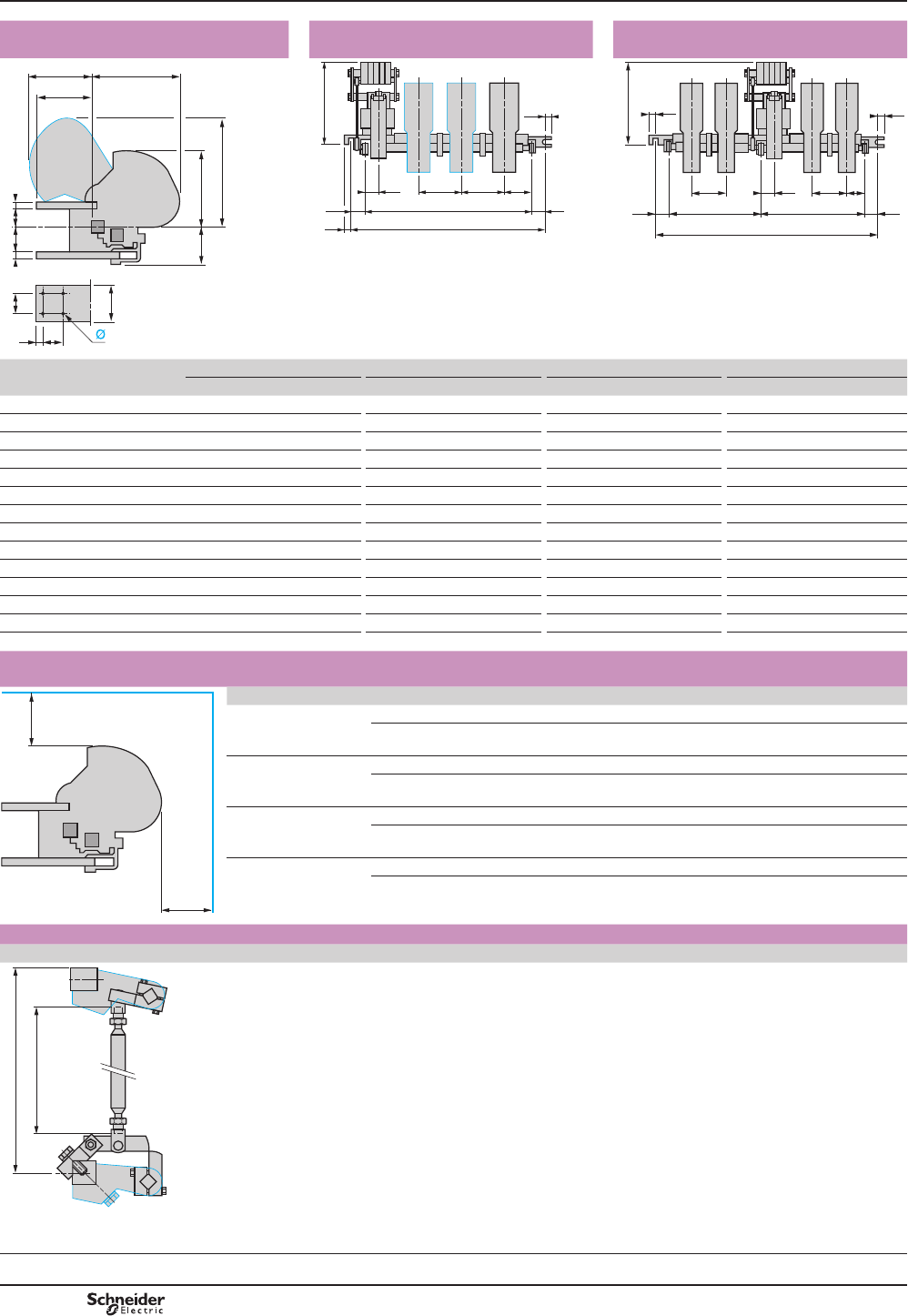
TeSys B
TeSys contactors
TeSys LC1 B contactors
Single, 2, 3 or 4-pole contactors LC1 B
Common side view
Single, 2 or 3-pole contactors
LC1 Bp31, Bp32 or Bp33
4-pole contactors LC1 Bp34
DF522613.eps
a
TS
T
260
R
290185
N
85c b c
365
44
330
P P Q1
30
15
30
M
L
15
DF522614.eps
330
P
30
15
30M1
L
P Q151
M2
15
DF522615.eps
LC1 BL LC1 BM LC1 BP LC1 BR
Number of poles 1 2 3 4 1 2 3 4 1 2 3 4 1 2 3 4
a 50 50 50 50 63 63 63 63 100 100 100 100 125 125 125 125
b 59 59 59 59 55 55 55 55 55 55 55 55 50 50 50 50
c 16 16 16 16 20 20 20 20 20 20 20 20 25 25 25 25
L 345 445 540 760 345 445 540 760 385 540 760 1065 445 635 885 1065
M 285 385 480 – 285 385 480 – 325 480 700 – 385 575 825 –
M1 – – – 308 – – – 308 – – – 455 – – – 455
M2 – – – 392 – – – 392 – – – 550 – – – 550
N 121 121 121 121 125 125 125 125 125 125 125 125 130 130 130 130
P 100 100 100 100 100 100 100 100 150 150 150 150 195 195 195 195
Q1 100 100 100 100 100 100 100 100 110 110 110 110 130 130 130 130
R 122 122 122 122 157 157 157 157 173 173 173 173 173 173 173 173
S 10 10 10 10 17 17 17 17 20 20 20 20 20 20 20 20
T 30 30 30 30 30 30 30 30 60 60 60 60 60 60 60 60
Ø 9 9 9 9 11 11 11 11 11 11 11 11 11 11 11 11
Electrical safety clearance
Values X1 and X2 are given for a breaking capacity of 10 In (a 3-phase supply).
X2
X1
DF522616.eps
a 3-phase voltage LC1 BL LC1 BM LC1 BP LC1 BR
380/440 V X1 100 100 150 200
X2 150 150 200 250
500 V X1 100 100 150 200
X2 150 150 220 250
660/690 V X1 150 150 200 200
X2 200 200 250 250
1000 V X1 200 200 200 250
X2 250 250 250 300
Mechanical interlock for assembling vertically mounted reversing contactors
EZ2 LB0601
A = (E–112) 488
E = 600
DF522617.eps
Dimensions
Selection:
pages A5/23 to A5/47
References:
pages B10/2 to B10/4
Schemes:
page B10/27
PCPB10T10-EN
Version : 1.0 13 novembre 2014 3:13 PM
B10/26
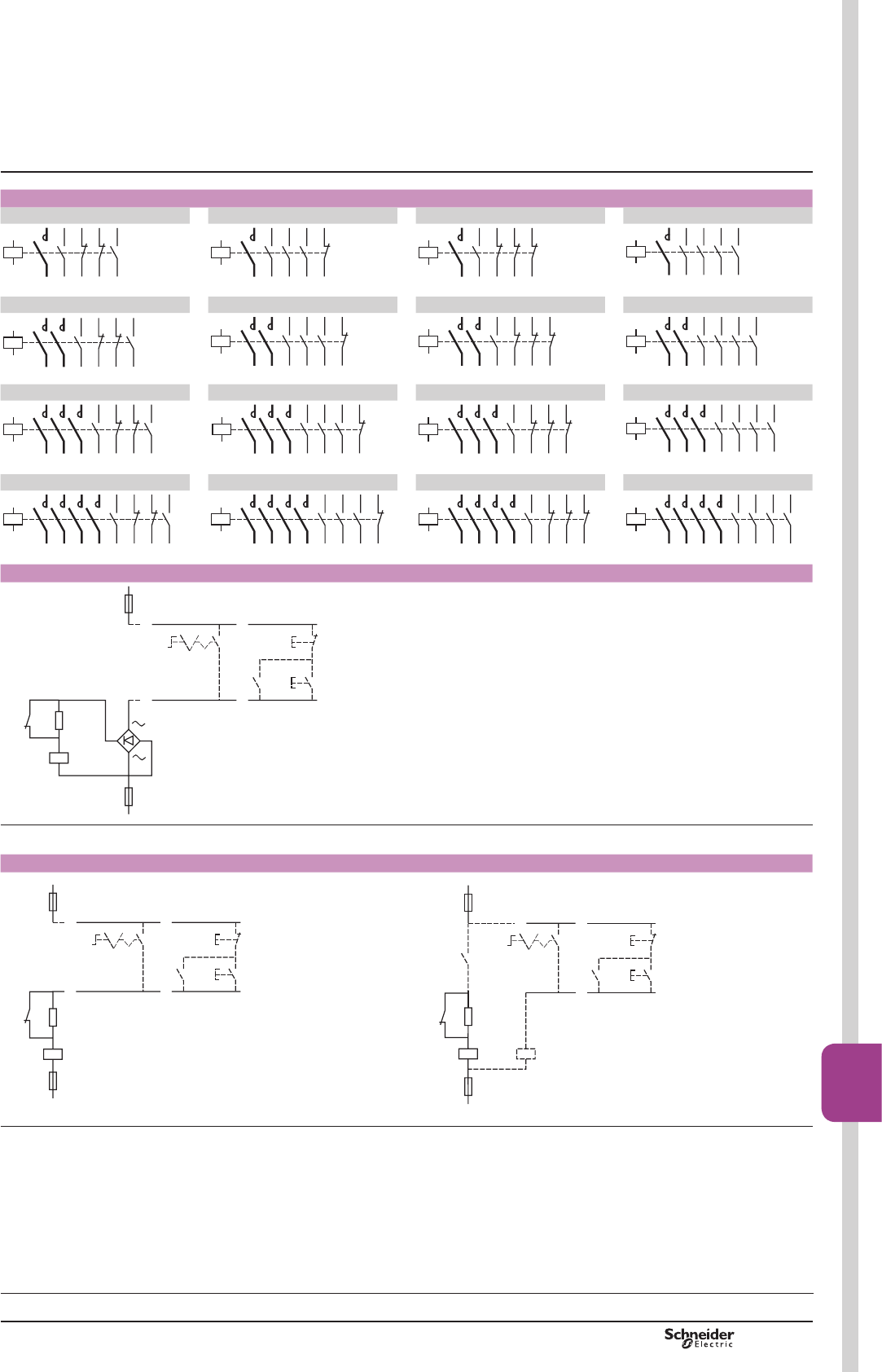
TeSys B
TeSys LC1 B contactors
LC1 Bp31p22 LC1 Bp31p31 LC1 Bp31p13 LC1 Bp31p40
A1A2
DF522618.eps
A1A2
DF522619.eps
A1A2
DF522620.eps
A1A2
DF522621.eps
LC1 Bp32p22 LC1 Bp32p31 LC1 Bp32p13 LC1 Bp32p40
A1A2
DF522622.eps
A1A2
DF522623.eps
A1A2
DF522624.eps
A1A2
DF522625.eps
LC1 Bp33p22 LC1 Bp33p31 LC1 Bp33p13 LC1 Bp33p40
A1A2
DF522626.eps
A1A2
DF522627.eps
A1A2
DF522628.eps
A1A2
DF522629.eps
LC1 Bp34p22 LC1 Bp34p31 LC1 Bp34p13 LC1 Bp34p40
A1A2
DF522630.eps
A1A2
DF522631.eps
A1A2
DF522632.eps
A1A2
DF522633.eps
a.c. control circuit
– S3
– R
– KM
– S1
– S2– KM
+
–
– KM
2-wire
control
3-wire
control
813321.eps
Dotted lines show optional wiring and external items required.
d.c. control circuit
– S3
– R
– KM
–
– S1
– S2– KM
– KM
+
2-wire
control
3-wire
control
813323.eps
– S3
– R
– KA
– KM – KA
– S1
– S2– KM
– KM
–
+
2-wire
control
3-wire
control
813322.eps
Note: LWLVHVVHQWLDOWRFKHFNWKDWWKHFRQWUROFLUFXLWFRQWDFWVKDYHUDWLQJVFRPSDWLEOHZLWKWKHYROWDJHDQGSRZHUFRQVXPSWLRQRIWKHRSHUDWLQJFRLORIWKHFRQWDFWRU,I
QRWDQLQWHUPHGLDWH³.$´UHOD\PXVWEH¿WWHGDQGZLUHGDVVKRZQ
Dotted lines show optional wiring and external items required.
Selection:
pages A5/23 to A5/47
References:
pages B10/2 to B10/4
Dimensions:
page B10/26
TeSys contactors
TeSys LC1 B contactors
Schemes
PCPB10T10-EN Version : 1.0 13 novembre 2014 3:13 PM
B10/27
Bar
mounted
contactors
B10/27

TeSys B
Magnetic latching contactors
7KHPDJQHWLFODWFKLQJFRQWDFWRUVDUHHTXLSSHGZLWKDVSHFL¿FHOHFWURPDJQHW
allowing them to maintain position “ON” although the coil is fed by any current.
Use
7KHVSHFL¿FSURSHUWLHVRIPDJQHWLFODWFKLQJFRQWDFWRUVPDNHWKHPVXLWDEOHIRUPDQ\
uses:
Properties Use
Memory retention of the sequence in automatic
equipment, in the event of loss of the control
voltage.
5H¿QHULHVSRZHUSODQWVH[FLWDWLRQFLUFXLWV
Energy saving, as no current is drained when
the contactor is activated.
Contactor staying activated for long periods.
([DPSOHVUH¿QHULHVDOLPHQWDWLRQHQHUJ\
ST distribution.
Change of state “Work” / “Rest”
by current pulse sent to the coil.
Selective opening control.
Insensitivity to main perturbations. No unexpected opening or closing of
power poles
Use of contactors beyond breaking capacity
as they are activated off-load.
Passer diverter, for use with 1000 V
Silent contactor when locked in ON position
Electro-magnet operation of the CR1 B contactors
The CR1 B magnetic latching contactors are equipped with a single coil, supplied with
GLUHFWFXUUHQWRUDOWHUQDWLQJFXUUHQWWKURXJKDUHFWL¿HU
The latching is obtained by direct feeding of the coil with a current in a given direction.
The unlatching is produced by a current of opposite direction, adjusted by resistors.
Range
b The magnetic latching contactors are available from 80 to 630 A (Size F to K).
b The characteristics of N/O and N/C poles are identical to those of CV1 and CV3 B
(Size F to K).
b For other characteristics and mounting dimensions, please contact us.
b For ratings of 800 to 2750 A, see next page.
CR1 B
Magnetic latching contactors
Presentation
PCPB10T10-EN
Version : 1.0 13 novembre 2014 3:13 PM
B10/28
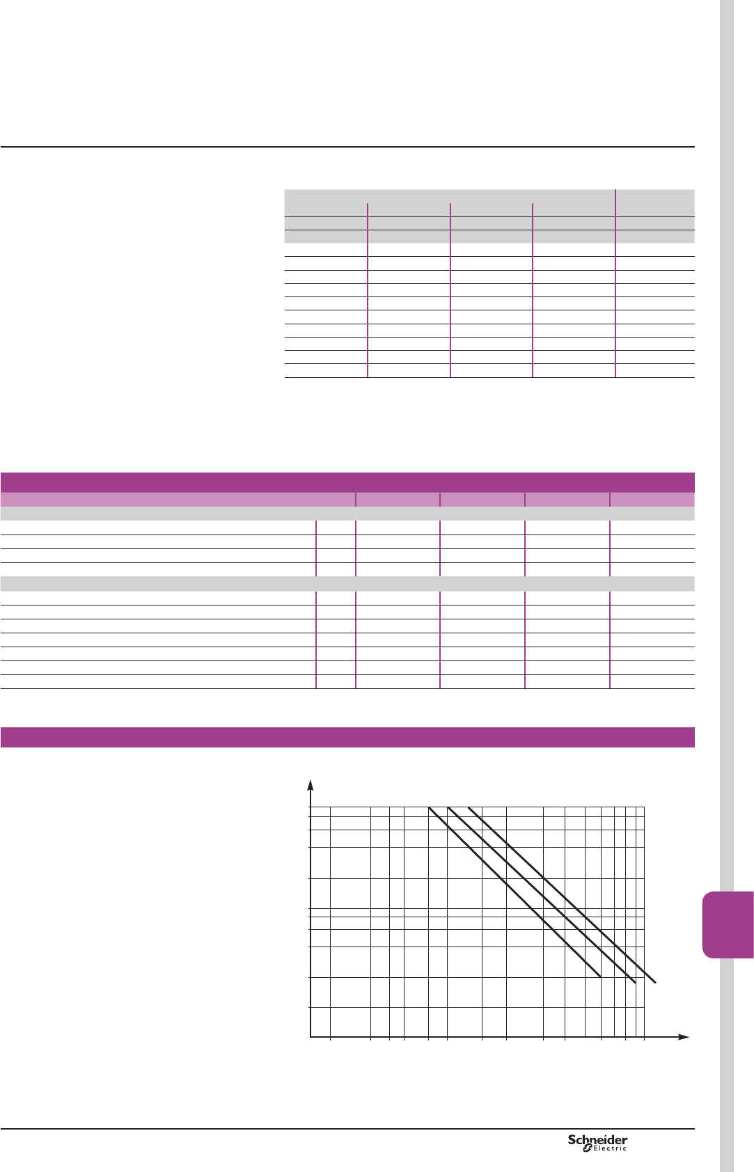
TeSys B
CR1 B
Magnetic latching contactors
Selection guide
Direct starting of squirrel cage motors
In continuous or intermittent service up to 30 operating cycles per hour.
Motor (1) 3-poles
contactor
220 / 230 V 380 / 400 V 415 V 440 V
P In P In P In P In Size (2)
kW A kW A kW A kW A
220 700 355 635 400 650 425 650 CR1-BL33
- - 375 670 425 690 445 680 CR1-BL33
- - 400 710 445 730 450 690 CR1-BL33
- - - - 450 740 475 730 CR1-BL33
250 800 425 760 475 780 500 780 CR1-BM33
257 826 445 790 500 820 530 825 CR1-BM33
280 900 450 800 530 870 560 870 CR1-BM33
295 948 475 850 560 920 600 920 CR1-BM33
300 980 500 900 600 978 630 965 CR1-BM33
315 990 530 950 - - - - CR1-BM33
(1)7KHUDWLQJVDUHIRUVWDQGDUG99RU9PRWRUV7KHRYHUORDG
UHOD\VVKRXOGSUHIHUDEO\EHVHWWRWKHPRWRUIXOOORDGFXUUHQWVKRZQRQWKHPRWRUUDWLQJSODWH
)RURWKHUSRZHUUDWLQJVVHOHFWWKHRYHUORDGUHOD\ZLWKWKHDSSURSULDWHUDQJHWKHDVVRFLDWHG
FRQWDFWRUDQGIXVHVPXVWKDYHUDWLQJVHTXDOWRRULPPHGLDWHO\JUHDWHUWKDQ,Q
(2)5HIHUHQFHWREHFRPSOHWHGRQSDJH%
Selection guide for utilisation category and electrical durability
a.c.: category AC-3
CR1 B contactor rating L M P R
Rated operational current (T y 55 °C)
440 V A750 1000 1500 1800
500 V A750 900 1200 1500
660 V A700 800 900 1100
1000 V A400 400 500 600
Operational power (T y 55 °C) (normalized motor power)
220 / 230 V kW 220 280 425 500
380 / 400 V kW 400 500 750 900
415 V kW 425 530 800 900
440 V kW 450 560 800 900
500 V kW 500 600 750 900
660 V kW 560 670 750 900
1000 V kW 530 530 670 750
Maximum operating rate of 120 operating cycles/hour, at rated operational power
with an on-load factor y 85 %.
Electrical durability in category AC-3 (Ue y 440 V)
For 660 V, multiply the number
of operating cycles by 0.8.
200 300 400 4000 6000 8000 10000
CR1-BL/BM
CR1-BP
CR1-BR
Current
broken
(A)
30002000500 600 800 1000 1500
0.01
0.02
0.04
0.06
0.08
0.6
0.1
0.2
0.4
0.8
1
Millions of operating cycles
DB413427.eps
PCPB10T10-EN Version : 1.0 13 novembre 2014 3:13 PM
B10/29
Bar
mounted
contactors
B10/29
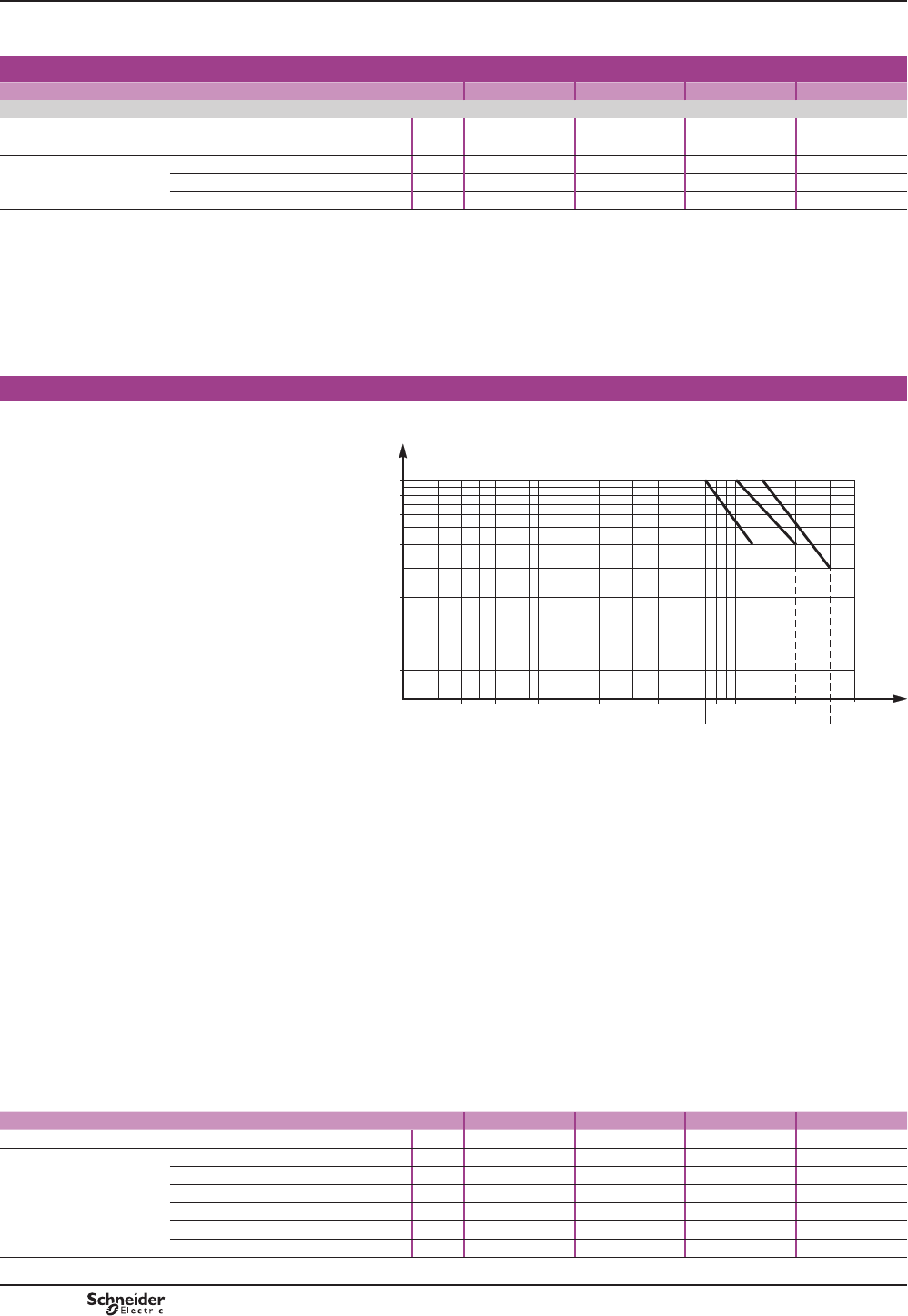
TeSys B
CR1 B
Magnetic latching contactors
Selection guide
Selection guide for utilisation category and electrical durability
Resistive circuits - power factor u 0.95.
a.c.: category AC-3
CR1 B contactor rating L M P R
Maximum operational current (T y 55 °C)
Number of bars 2 2 3 4
Cabling c.s.a. mm250 x 5 80 x 5 100 x 5 100 x 5
Rated operationnal current
in category AC-1
at ambient air temperature
y 40 °C A800 1250 3000 2750
y 55 °C A700 1100 1750 2400
y 70 °C A600 900 1500 2000
Increase in rated operational current by paralleling of poles
$SSO\WKHIROORZLQJFRHI¿FLHQWVWRWKHDERYHFXUUHQWV
b2 poles in parallel: K = 1.60
b3 poles in parallel: K = 2.25
b4 poles in parallel: K = 2.8.
7KHVHFRHI¿FLHQWVWDNHLQWRDFFRXQWDQRIWHQXQEDODQFHGGLVWULEXWLRQRIFXUUHQW
between the poles.
Maximum operating rate in operating cycles 120/hour.
Electrical durability in category AC-1 (Ue y 440 V)
For 660 V, multiply the number
of operating cycles by 0.8.
20 40 60 80 100 4000
CR1-BL/BM
CR1-BP
CR1-BR
Current
broken
(A)
2000200 400 600
700 1250 2750
800
0.08
0.1
0.2
0.4
0.6
0.8
1
Millions of operating cycles
1000
DB413428.eps
Switching the primaries of 3-phase transformers
Conditions of use
bMaximum operational voltage: 1000 V 50/60 Hz.
bMaximum ambient temperature: 55 °C.
At power up, there is usually a suden inrush current. It reaches almost instantly its
peak value and then decreases so approximately exponentially to its rapid steady
state value.
The value depends on:
b characteristics of the magnetic circuit and the windings (section of kernel design
¿HOGQXPEHURIWXUQVGLPHQVLRQVRIWKHFRLOV
b characteristics of magnetic metal sheets used (residual induction and saturation
induction)
b of the magnetic state of the circuit and the instantaneous value of the alternating
voltage of the network at the time of activation.
When a transformer is switched on, there is generally an initial current surge which
can reach 20 to 40 times the rated current for the power ratings shown below.
This current reaches its peak value almost instantaneously and then decreases in
a largely exponential manner, quickly dropping back down to its steady state value.
CR1 B contactor rating L M P R
Prospective peak current at switch-on A18000 18000 24000 30000
Maximum operational
power (1)
220 / 230 V kVA 230 230 300 380
380 400 V kVA 400 400 530 660
415 / 440 V kVA 450 450 560 700
500 V kVA 480 480 600 750
660 V kVA 600 600 800 950
1000 V kVA 700 700 1000 1200
(1)0D[LPXPRSHUDWLRQDOSRZHUFRUUHVSRQGLQJWRDFXUUHQWSHDNDWVZLWFKRQRI,Q
PCPB10T10-EN
Version : 1.0 13 novembre 2014 3:13 PM
B10/30
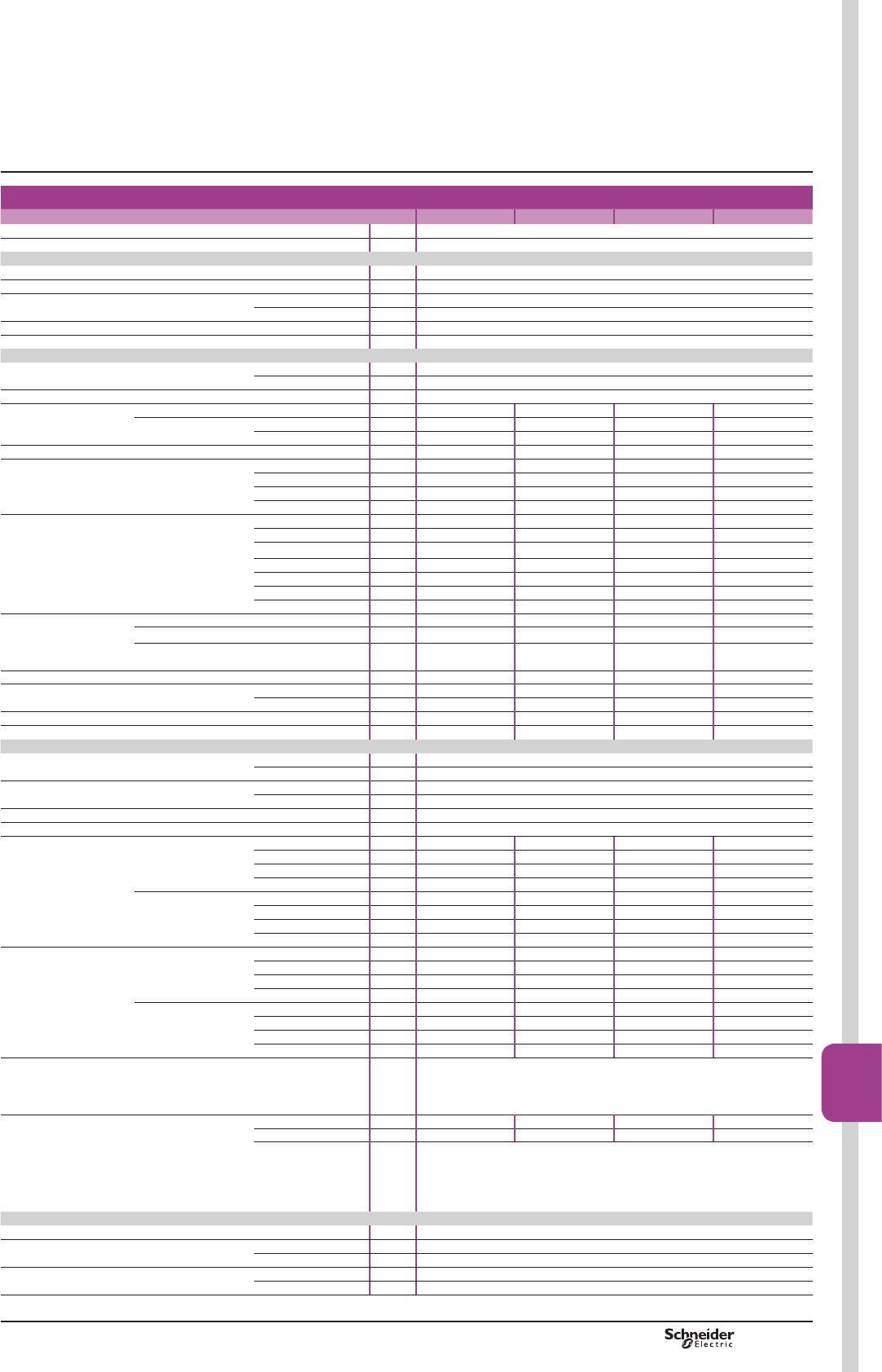
TeSys B
Characteristics CR1 B
Magnetic latching contactors
a.c or d.c. control circuit
Characteristics
CR1 B contactor rating L M P R
Number of poles 1, 2, 3 or 4
Rated operational voltage V1000
Environment
Terminal protection cover against accidental contact Without
Protective treatment TC
Ambient air temperature storage °C -60 ... +80
operation °C -15 ... +60
Maximum operating altitude m 3000
Maximum inclination ± 30° occasional, in relation to normal vertical mounting plane
Pole characteristics
Rated operational voltage conforming to BS 775 and IEC 158-1 V1000
VDE 0110 grC V1500
Frequency limits by operational current Hz 50-60
Operational current Distribution (T y 40 °C) AC-1 A800 1250 2000 2750
Motor
(T y 40 °C, U y 440 V) AC-3 A750 1000 1500 1800
AC-4 A750 1000 1500 1800
Rated making capacity I rms conforming to IEC 158-1 A10000 10000 15000 18000
Rated breaking capacity
conforming to IEC 158-1
220 - 380 - 415 - 440 V A10000 10000 15000 18000
500 V A9000 9000 12000 15000
660 V A8000 8000 9000 11000
1000 V A4000 4000 5000 6000
Permissible short time rating
From cold state, with no current
ÀRZLQJIRUSUHYLRXVPLQXWHV
at Ty 40 °C
for 1 s A9600 9600 12000 15000
for 5 s A9600 9600 12000 15000
for 10 s A7000 8000 9600 12000
for 30 s A4800 5200 6400 8000
for 1 min A3500 3800 5200 6300
for 3 min A2100 2400 3600 4400
for 10 min A1200 1800 2800 3600
Short-circuit protection
by fuses (max. rating)
Distribution type g1 - BS 88 A800 1200 1000 x 2 (1) 1200 x 2 (1)
Motor circuit type aM A800 1200 800 x 2 (1) 1000 x 2 (1)
With thermal
overload relay
type g1 - BS 88 A1000 1500 1000 x 2 (1) 1200 x 2 (1)
Average impedance per pole m:0.18 0.18 0.13 0.09
Power dissipated per pole AC-1 W115 280 520 680
AC-3 W88 180 290 360
Number of bars 2 2 3 4
Bar mm 50 x 5 80 x 5 100 x 5 100 x 10
Control circuit characteristics
Rated control voltage 50/60 Hz V110 to 500
400 Hz and cV110 to 500
Voltage limits a and clatching Un 0.85 to 1.1
unlatching Un 0.85 to 1.1
Maximum operating rate in mechanical operating cycles (at T y 40 °C) man./h 120
Mechanical durability man. 1 million
Average
consumption
at 50/60 Hz
Latching 1 pole VA 650 650 650 650
2 poles VA 1100 1100 1100 1100
3 poles VA 1650 1650 1650 1650
4 poles VA 1850 1850 1850 1850
Unlatching 1 pole VA 110 110 110 110
2 poles VA 125 125 125 125
3 poles VA 165 165 165 165
4 poles VA 175 175 175 175
Average
consumption
at 400 Hz and c
Latching 1 pole VA 600 600 600 600
2 poles VA 1000 1000 1000 1000
3 poles VA 1500 1500 1500 1500
4 poles VA 1700 1700 1700 1700
Unlatching 1 pole VA 100 100 100 100
2 poles VA 115 115 115 115
3 poles VA 150 150 150 150
4 poles VA 160 160 160 160
Average operating time at nominal voltage The closing time “C” is measured from the moment the coil supply is switched
on to initial contact of the main poles. The opening time “O” is measured
from the moment the coil supply is switched off to the moment the main poles
separate.
Operating in a.c. or d.c. Latching ms 100 - 150 100 - 150 100 - 150 100 - 150
Unlatching ms 20 - 40 20 - 40 20 - 40 20 - 40
Note:WKHDUFLQJWLPHGHSHQGVRQWKHFLUFXLWVZLWFKHGE\WKHPDLQSROHV
)RUSKDVHDSSOLFDWLRQVWKHDUFLQJWLPHLVXVXDOO\OHVVWKDQPV
7KHORDGLVLVRODWHGIURPWKHVXSSO\DIWHUDWLPHHTXDOWRWKHVXPRIWKH
RSHQLQJWLPHDQGWKHDUFLQJWLPH
Characteristics of instantaneous auxiliary contacts (type ZC4 GM for CR1 B contactors)
Rated thermal current A20
Rated insulation voltage conforming to IEC 337-1 660
VDE 0110 grC 750
Cabling Number of bars 2
Bar c.s.a. mm24
(1) 3DUDOOHOFDEOLQJPXVWEHGRQHRQO\DFFRUGLQJWKHLQVWUXFWLRQVRIWKHIXVHVPDQXIDFWXUHU
PCPB10T10-EN Version : 1.0 13 novembre 2014 3:13 PM
B10/31
Bar
mounted
contactors
B10/31

TeSys B
Characteristics CR1 B
Magnetic latching contactors
Adjustment characteristics for control circuit
CR1 B contactor rating L M P R
Electromagnet Ref. ET1-KB50
Air gap of the magnetic circuit mm 5/100
Pick-up travel (E) mm 30
Pull-in travel (e) mm 10
N° of the return spring of the moving part 1 x 292 (1 pole contactors)
2 x 292 (2 poles, 3 poles, 4 poles contactors)
Type of coil WB1-KB
Pull-in cold voltage (T = 20 °C) Un 0.75
Drop-out voltage Un 0.30 to 0.50
Adjustment of
application force (F)
on the contact per pole
according to contactor composition
Number of springs 1 pole 201 201 201 155
2 poles 201 201 201 155
3 poles 201 201 201 155
4 poles 201 201 201 155
Application force (F)
to contact per pole
1 pole daN 30 30 30 (1) 30 (2)
2 poles daN 30 30 30 (1) 30 (2)
3 poles daN 30 30 30 (1) 30 (2)
4 poles daN 30 30 30 (1) 30 (2)
Switch pole setting Opening gap (b.), electro-magnet closed mm 2 ±0.5
Beginning of opening, during closing
action (F)
mm 12 to 14
Application force (F) daN 0.900
(1)(DFKSROHKDVFRQWDFWVWKHIRUFHPXVWEHDSSOLHGHYHQO\WRHDFKRIWKHVHFRQWDFWV
(2)(DFKSROHKDVFRQWDFWVWKHIRUFHPXVWEHDSSOLHGHYHQO\WRHDFKRIWKHVHFRQWDFWV
Electromagnet ET1-KB50
Fixed
electromagnet
Coil
Armature
Return
spring
DB413429.eps
N/O pole N/C pole
DF511216.eps
DF511217.eps
Characteristics
Characteristics of instantaneous auxiliary contacts (type ZC4 GM for CR1 B contactors)
Operational power in a.c. V110/127 220 380 415/440 500
1 million operating cycles VA 2000 4000 4000 4000 3500
occasional making capacity VA 14000 23000 35000 45000 35000
Electrical durability (valid for up to 2400 operating cycles/hour) on an
inductive load such as the coil of an electromagnet: making current (cos M
0.7) = 10 times the power broken (cos M 0.4).
Operational power in d.c. V110 220 440 500
1 million operating cycles VA 250 250 230 200
occasional making capacity VA 1600 800 400 360
Electrical durability (valid for up to 1200 operating cycles/hour) on an
inductive load such as the coil of an electromagnet, without economy resistor,
the time constant increasing with the load.
Fixed contact
Moving contact
Opening gap
adjustment
Adjustment of
application force (F)
Pole spring
Fixed
contact
Moving
contact
Opening gap
adjustment
Adjustment
of application
force (F)
Pole
spring
PCPB10T10-EN
Version : 1.0 13 novembre 2014 3:13 PM
B10/32
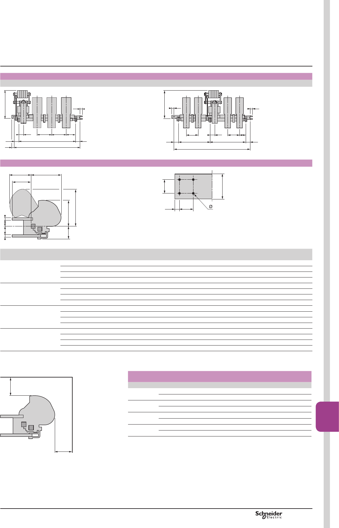
TeSys B
Front face view
Single, 2 or 3-pole contactors 4-pole contactors
44
330
P P Q1
30
15
30
M
L
15
DB116208.eps
330
P
30
15
30M1
L
P Q151
M2
15
DB116209.eps
Common side view Drilling plan of busbars connections
260
R
290185
N
85c b c
365
DB116211.eps
a
TS
T
DB116210.eps
Diameter of screw: 12 mm.
Type Rating
(A)
Number
of poles
L M M1 M2 b c ø a T S R N P Q1
CR1 BL 800 1 345 285 - - 59 16 9 50 30 10 122 121 100 100
2 445 385 - - 59 16 9 50 30 10 122 121 100 100
3 540 480 - - 59 16 9 50 30 10 122 121 100 100
4 760 - 308 392 59 16 9 50 30 10 122 121 100 100
CR1 BM 1250 1 345 285 - - 55 20 11 63 30 17 157 125 100 100
2 445 385 - - 55 20 11 63 30 17 157 125 100 100
3 540 480 - - 55 20 11 63 30 17 157 125 100 100
4 760 - 308 392 55 20 11 63 30 17 157 125 100 100
CR1 BP 2000 1 385 325 - - 55 20 11 100 60 20 173 125 150 110
2 540 480 - - 55 20 11 100 60 20 173 125 150 110
3 760 700 - - 55 20 11 100 60 20 173 125 150 110
4 1065 - 455 550 55 20 11 100 60 20 173 125 150 110
CR1 BR 2750 1 445 385 - - 55 20 11 125 60 20 173 130 195 123
2 635 575 - - 55 20 11 125 60 20 173 130 195 123
3 885 825 - - 55 20 11 125 60 20 173 130 195 123
4 1065 - 455 550 55 20 11 125 60 20 173 130 195 123
Minimum electrical clearance
Values X1 and X2 are given for a breaking capacity of 10 In (a 3-phase supply).
Rating of
contactor CR1 B L M P R
a 3-phase voltage
380/440 V X1 100 100 150 200
X2 150 150 200 250
500 V X1 100 100 150 200
X2 150 150 220 250
660 V X1 150 150 200 200
X2 200 200 250 250
1000 V X1 200 200 200 250
X2 250 250 250 300
Dimensions CR1 B
Magnetic latching contactors
X2
X1
DB116212.eps
PCPB10T10-EN Version : 1.0 13 novembre 2014 3:13 PM B10/33
Bar
mounted
contactors
B10/33
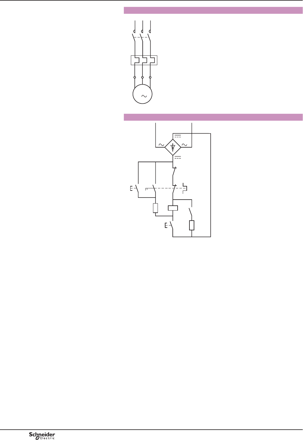
TeSys B
Control circuit
schemes CR1 B
Magnetic latching contactors
Contactor CR1 B with overload relay
L1
1 3 5
2
F1
KM1
4 6
1 3
3
5
2 4 6
U V
M
W
L2 L3
DB403766.eps
Contactor CR1 B
KM1
KM1 : 1 KM1 : 5
1
2
95
96
97
98
13
14
13
14
R1
A1
A2
S2 F1
S1 R2
DB403767.eps
6ODWFKLQJSXVKEXWWRQ
6XQODWFKLQJSXVKEXWWRQ
PCPB10T10-EN
Version : 1.0 13 novembre 2014 3:13 PM
B10/34
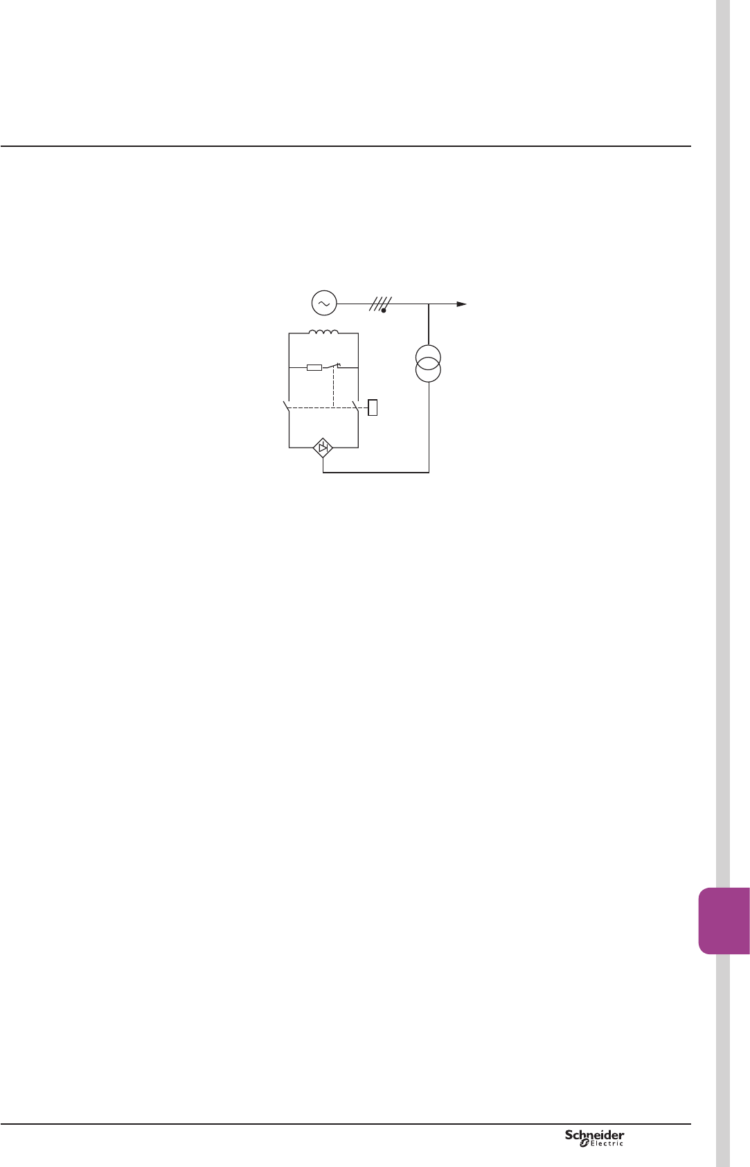
TeSys B
Presentation
Variable composition contactors CRX B and CVX B are designed for switching the
excitation circuits of synchronous machines, in particular electrical power station
generators, for operational currents from 80 to 2750 A.
Example: Static excitation generator.
Basic scheme
1 Excitation contactor
2 Thyristor bridge
3 Discharge resistor Rd
4 Excitation winding
Operating principle
7KHYROWDJHGHOLYHUHGE\WKHJHQHUDWRULVUHODWHGWRWKHFXUUHQWÀRZLQJWKURXJKWKH
excitation winding 4.
Start-up phase
b The contactor 1 closes, off load.
b An adjustable auxiliary power supply generates current in the excitation winding 4
to allow power-up of the generator.
b :KHQWKHYROWDJHGHOLYHUHGE\WKHJHQHUDWRULVVXI¿FLHQWWRVXSSO\WKHH[FLWDWLRQ
winding 4 via a thyristor bridge 2, the auxiliary supply is switched off.
Stop phase
When a stop instruction is received, the thyristor bridge 2 operates for a few seconds
as an inverter, then the excitation contactor 1 opens.
The function of the N/C pole is to discharge residual electromagnetic energy from the
excitation winding 4 via the discharge resistor Rd 3.
Under normal operating conditions, breaking is therefore easy, especially as the
N/O poles and the N/C pole are make before break.
However, in the event of a problem, the contactor must be able to break.
Note: 7KH1&SROHZKLFKLVXVHGIRUPDFKLQHGHH[FLWDWLRQKDVQRDUFFKDPEHUV
,WVEUHDNLQJFDSDFLW\LVQLO5HHQHUJLVDWLRQRIWKHFRQWDFWRUPXVWWKHUHIRUHEHDYRLGHGGXULQJ
WKHGHH[FLWDWLRQSKDVH
,IWKHUHLVDQ\ULVNRIWKLVKDSSHQLQJLWLVDGYLVDEOHWRDGGDQRIIGHOD\IXQFWLRQWKDWSUHYHQWV
SLFNXSRIWKHFRQWDFWRUIRUWKHVHFRQGVIROORZLQJGURSRXW
CRX B and CVX B for switching
the excitation circuits of
synchronous machines
Presentation
CRX B
CVX B
1
2
3
4
Generator
Auxiliary power
DF567067.eps
PCPB10T10-EN Version : 1.0 13 novembre 2014 3:13 PM B10/35
Bar
mounted
contactors
B10/35
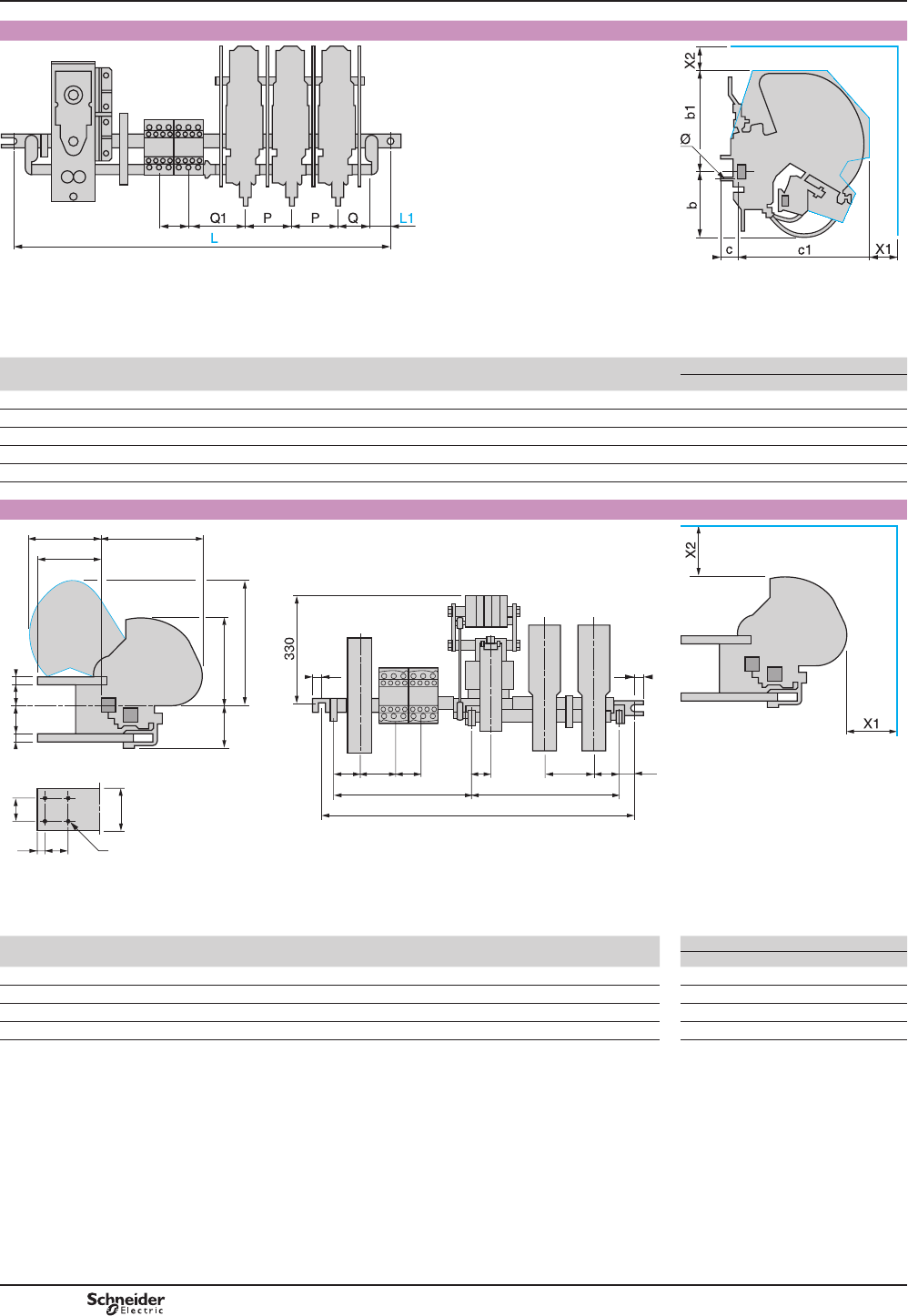
TeSys B
Contactors CRX B and CVX B, sizes F to K
50
DF567076.eps
DF567075.eps
'LPHQVLRQ/¿[LQJFHQWUHVGHSHQGLQJRQWKHQXPEHURI12RU1&PDLQSROHVZLWKRUZLWKRXWPDJQHWLFEORZRXWDQGWKHQXPEHURI=&*0DX[LOLDU\FRQWDFW
EORFNVLQDGGLWLRQWRWKHPDLQWDLQLQJFRQWDFW
CpX B
contactor size
Minimum electrical clearance
Ø b b1 c c1 L L1 P Q Q1 X1 X2
FM6 75 120 17 149 445 15 50 20 52 25 15
GM8 60 164 43 134 540 15 50 45 52 20 15
HM10 62 188 52 176 540 20 60 57 57 60 55
JM10 114 117 40 173 635 34 85 64 70 50 100
KM12 141 214 45 215 760 37 100 64 75 80 80
Contactors CRX B and CVX B, sizes L to R
CRX B
50 51 P Q
300
365
260N
30
C1
7565
Ø
S T
R
185 290
Tc cb85
a
15 15
L
DF567077.eps
DF567078.eps
'LPHQVLRQ/¿[LQJFHQWUHVGHSHQGLQJRQWKHQXPEHURI12RU1&PDLQSROHVZLWKRUZLWKRXWPDJQHWLFEORZRXWDQGWKHQXPEHURIZC4 GMDX[LOLDU\FRQWDFW
EORFNVLQDGGLWLRQWRWKHPDLQWDLQLQJFRQWDFW
CpX B
contactor size
Minimum electrical clearance
Ø b c C1 LN P Q R X1 X2
LM8 59 16 392 760 121 100 100 122 200 250
MM10 55 20 392 760 125 100 100 157 200 250
PM10 55 20 487 885 125 150 110 173 200 250
RM10 50 25 582 950 130 195 130 173 250 300
Dimensions CRX B and CVX B for switching
the excitation circuits of
synchronous machines
PCPB10T10-EN
Version : 1.0 13 novembre 2014 3:13 PM
B10/36
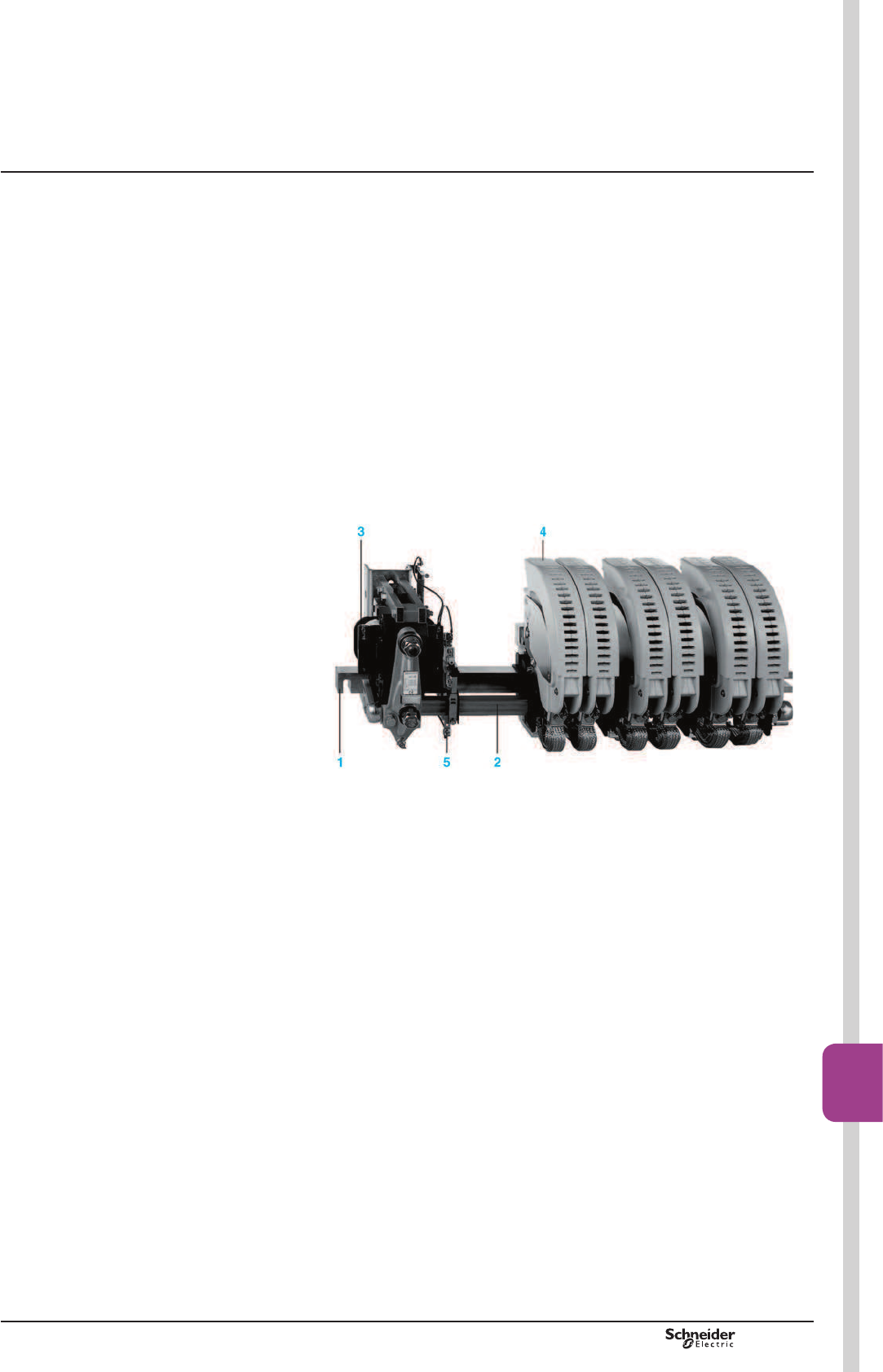
TeSys CV1 B, CV3 B
Presentation
The variable composition contactor range is split into 3 groups:
b Low power switching contactors:
v type CV1 Bp, 80 to 1000 A
v type CV3 Bp, 80 to 500 A.
For motor control, the references of the CV1 and CV3 contactors are given on
catalogue DIA2070702EN.
For other applications, the composition of the commercial references is described on
6\PEROFRPELQDWLRQWDEOHVHHSDJHV%DQG%RUXVHWKHFRQ¿JXUDWLRQ
software “bar contactor soft-customer.xls” to download on: www.schneider-electric.
com.
b Increased power switching contactors:
v type LC1 Bp, 800 to 2750 A. References shown on B10/2.
b 6SHFL¿FFRQWDFWRUV(large number of main poles, pole arrangement, customised
¿[LQJDQGGLPHQVLRQVFRPSRQHQWUHIHUHQFLQJHWF
v type CV1pB, 80 to 1000 A
v type CV3pB, 80 to 2750 A.
To order these contactors, complete the Order form on catalogue DIA2070702EN.
10267-100-M.eps
1 Mounting bar
2 Rotating armature shaft
3 Electromagnet
4 Main pole
5 Instantaneous auxiliary contacts, type GM
Variable composition contactors are particularly suited for switching a.c. or d.c.
motors and other circuits and are capable of providing a high number of operating
cycles.
7KHLUYDULDEOHFRPSRVLWLRQGHVLJQDOORZVWKHPWREHEXLOWWRFXVWRPHUVSHFL¿FDWLRQ
Applications
These variable composition contactors are ideally suited for the most frequently
encountered applications:
b Switching a.c. squirrel cage and slip-ring motors in all utilisation categories (AC-2,
AC-3, AC-4).
b Switching d.c. motors in all utilisation categories (DC-2, DC-3, DC-4, DC-5).
b Switching a.c. resistive loads (category AC-1) and d.c. resistive loads (category
DC-1).
b Switching distribution circuits (category AC-1).
b Short-circuiting of rotor resistors.
b Switching capacitors, power factor correction.
b Switching transformer primaries.
b Switching inductive circuits with high time constant (L/R > 15 ms)
Example: alternator excitation circuit.
b Severe duty requirements and main pole arrangements comprising 1 to 6 N/O
and/or N/C poles.
Variable composition
contactors
PCPB10T10-EN Version : 1.0 13 novembre 2014 3:13 PM
B10/37
Bar
mounted
contactors
B10/37
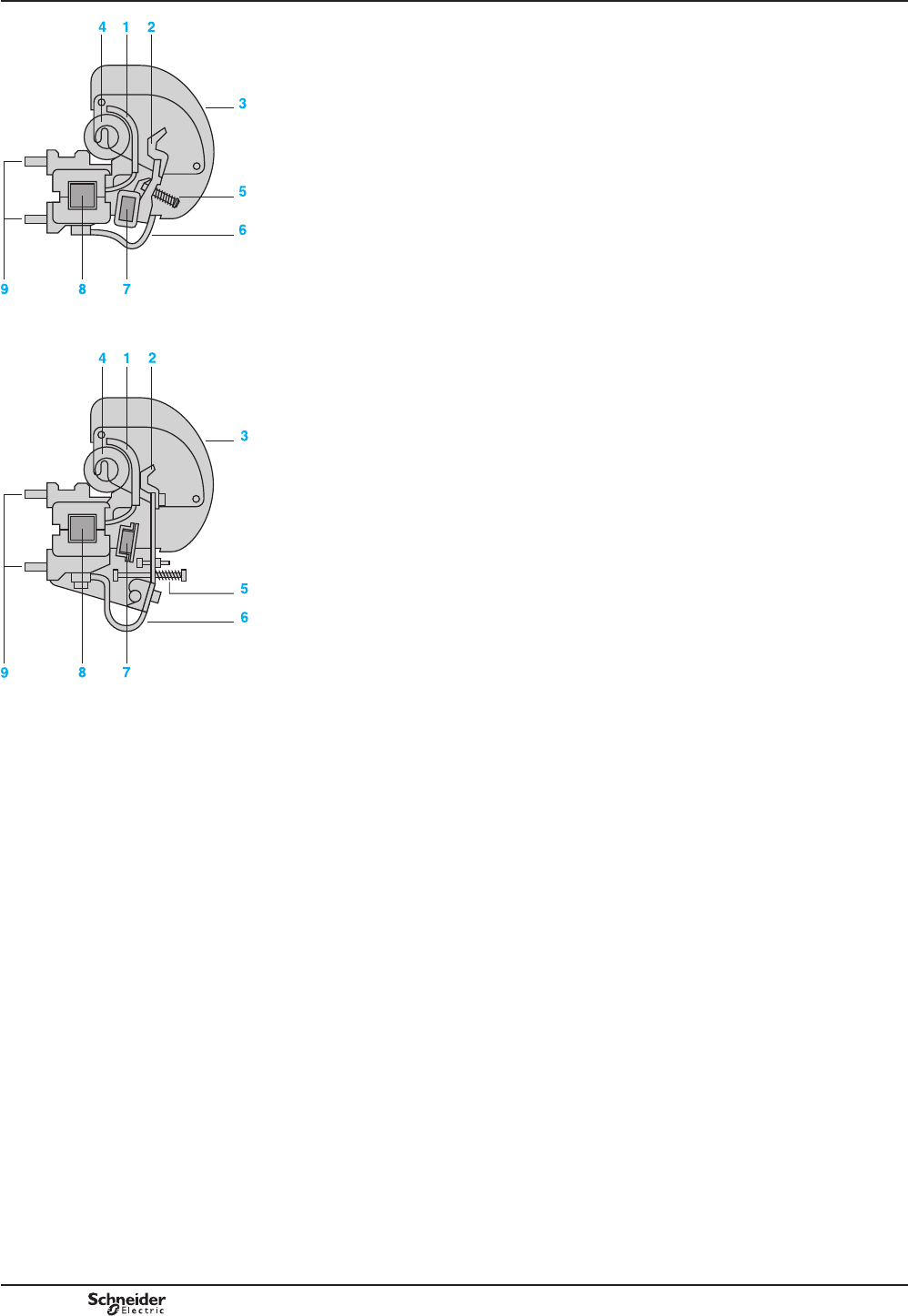
TeSys CV1 B, CV3 B
Power circuit
The principal function of a main pole is to make and break the supply current.
It is designed to continuously carry its nominal operational current.
Making the current
On energisation of the electromagnet coil, the armature shaft rotates and the moving
FRQWDFWPDNHVZLWKWKH¿[HGFRQWDFW7KHFRQWDFWSUHVVXUHPDLQWDLQHGE\WKHSROH
SUHVVXUHVSULQJLVVXI¿FLHQWWRRYHUFRPHWKHHOHFWURG\QDPLFIRUFHVRIWUDQVLHQW
current peaks (e.g.: switching a transformer, starting a motor, etc.).
Breaking the current
On de-energisation of the electromagnet coil, the contacts separate and electrical
arcing is dissipated by the blow-out coil and arc chamber. To optimise the
performance of the magnetic blow-out, the blow-out coil can be selected to suit the
operational current, which is particularly important when switching d.c.
The N/C pole operates in a reverse manner to the N/O pole, i.e. the contacts are
closed whilst the electromagnet coil is de-energised and open during energisation.
Main pole types
CV1 contactors
b 690 V a, 220 V c / pole
v N/O poles 80…1000 A (PN1)
v N/C poles 80…1000 A (PR1).
b Variants:
v no-load breaking poles
- N/O poles 80…1000 A (PN5)
- N/C poles 80…1000 A (PR5).
v arc chambers with splitters for dispersing the electric arc: 1000 V a / 440 V c
per pole
- N/O poles 500…1000 A (PN3)
- N/C poles 500…1000 A (PR3).
CV3 contactors
b 1000 V a, 440 V c / pole
v N/O poles 0…500 A (PA3)
v N/C poles 80…500 A (PR3)
v N/O poles 750…2750 A (PA1).
b Variants:
v high making capacity poles 750…2750 A (PA2)
v high breaking capacity poles and poles with reduced safety clearances (arc
chambers with closed splitters) 750…2750 A (PA1PX8)
v no-load breaking poles
- N/O poles 750…2750 A (PA5).
12SROH«$
DF511200.epsDF511201.eps
1 Fixed contact
2 Moving contact
3 Arc chamber
4 Blow-out coil
5 Pole pressure spring
6 Braided conductor
7 Rotating armature shaft (moving contact
actuator)
8 Mounting bar
9 Terminal lugs
1&SROH«$
Presentation Variable composition
contactors
PCPB10T10-EN
Version : 1.0 13 novembre 2014 3:13 PM
B10/38
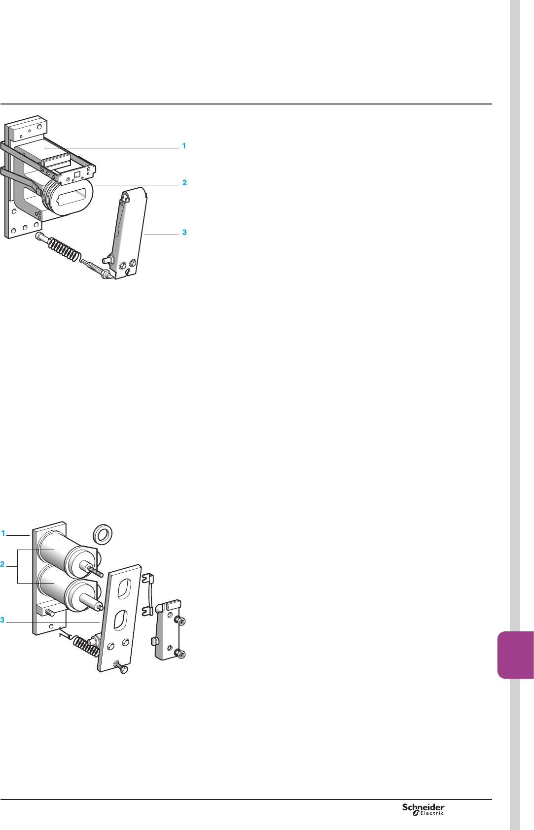
TeSys CV1 B, CV3 B
Presentation
Control circuit
b 2 types of electromagnet: E shaped core and U shaped core.
b 2 types of coil: type WB1 and type WB2.
Electromagnet with E shaped core and coil type WB1
b Electromagnet with E shaped laminated iron core, type EB or EC (1)
v with central air gap machined in armature,
v with single coil type WB1¿WWHGRQFHQWUHOLPERIFRUH
The upper limb incorporates a shading ring, the armature rotates.
b Coil - direct a.c. 50 or 60 Hz supply
v 20 to 600 V
v 1200 operations/hour.
At the moment of inrush, with the armature open, the coil impedance is low and
power consumption is high.
In the sealed state the armature is closed, the coil impedance increases and power
consumption is low.
The inrush current is 6 to 10 times higher than the sealed current.
b Electromagnet GLUHFWO\'&SRZHUHGRUYLDLQGLYLGXDOUHFWL¿HU+]
v the electromagnet is mounted with the reduction in consumption
v 12 to 500 V
v 120 operations/hour.
b Electromagnet SRZHUHGYLDLQGLYLGXDOUHFWL¿HU+]
v the electromagnet is mounted with the reduction in consumption
v 12 to 500 V
v 120 operations/hour.
At the moment of inrush, the full actuating voltage is applied to the coil and the inrush
current is determined by the coil resistance.
In the sealed state an additional resistor is switched automatically in series with the
coil, so as to reduce power consumption.
This economy resistor is switched by a N/C auxiliary contact which is adjusted to
open only when the armature is fully closed.
The inrush current is 15 to 40 times higher than the sealed current.
Coils type WB1, used in conjunction with laminated iron cores, have a much higher
inrush current than sealed current, whatever the nature of the supply current.
When establishing the current and selecting the supply voltage rating, it is important
to take into account the line voltage drop due to the inrush current.
Electromagnet with U shaped core and coil type WB2 for d.c. supply
b Electromagnet with U shaped solid iron core, type EK:
v 2 similar coils type WB2 FRQQHFWHGLQVHULHVRQHFRLOEHLQJ¿WWHGWRHDFKOLPERI
the core
v the armature rotates.
b Electromagnet for d.c. supply
v 12 to 600 V
v 1200 operations/hour.
The coils for this type of electromagnet have a considerable number of turns so as
WRREWDLQVXI¿FLHQWPDJQHWLFÀX[WRDWWUDFWWKHDUPDWXUH
Due to its simplicity and relatively slow movements the assembly is very robust and,
therefore, has increased mechanical durability.
(1) )RUFRQWDFWRUFRPSRVLWLRQVUHTXLULQJDQLQFUHDVHGQXPEHURISROHVXVH(&HOHFWURPDJQHWV
Variable composition
contactors
Electromagnet EB1 or EC1
1 Electromagnet core
2 Coil
3 Electromagnet armature
DF511202.epsDF511203.eps
Electromagnet EK
1 Electromagnet core
2 Coil
3 Electromagnet armature
PCPB10T10-EN Version : 1.0 13 novembre 2014 3:13 PM
B10/39
Bar
mounted
contactors
B10/39

TeSys CV1 B, CV3 B
Instantaneous and time delay auxiliary contacts
Signalling, electrical interlocking and slave functions can be achieved by using
auxiliary contacts.
Instantaneous auxiliary contacts suitable for use with all contactor types are available
in 2 versions:
b 1 N/O instantaneous contact, reference ZC4 GM1.
b 1 N/C instantaneous contact, reference ZC4 GM2.
b 1 block of 3 instantaneous N/O contacts and 2 N/C instantaneous contacts,
reference LA1BN32A.
Delayed auxiliary contacts can be mounted onto contactors CV1 and CV3:
b 1 N/O contact + 1 N/C contact, ON-delay, reference ZC2 GG1
(delay from 0.2 to 180 s)
b 1 N/O contact + 1 N/C contact, OFF-delay, reference ZC2 GG5
(delay from 0.2 to 180 s)
b On the block LA1 BN32A, 1 block of N/O ON-delayed contact + 1 N/C ON-delayed
contact , references LADT0 (delay from 0.1 to 3 s), LADT2 (0.1 to 30 s), LADT4
(10 to 180 s)
b On the block ref. LA1 BN32A: 1 block of N/O OFF-delayed contact + 1 N/C
OFF-delayed contact, references LADR0 (delay from 0.1 to 3 s), LADR4
(10 to 180 s).
The delayed contacts are established or separate some time after the closing or
opening of the contactor which operates them. This time is adjustable.
On the block LA1 BN32A all TeSys D contactors additives can be mounted,
with the exception of LA6DK, LAD6K and LAD8N
Assembling reversing/changeover contactor pairs
Mounting accessories
For applications involving the switching of reversing motors or changeover circuits,
contactors of different ratings can easily be mounted vertically and interlocked.
Mechanical interlock kits are available and auxiliary contacts can be used for
electrical interlocking.
Presentation Variable composition
contactors
PCPB10T10-EN
Version : 1.0 13 novembre 2014 3:13 PM
B10/40
