S555LT00 S256C_ 1000355910 Catalog
1000448853-Catalog 1000448853-Catalog 1000448853-Catalog B5 unilog cesco-content
1000491389-Catalog 1 1000491389-Catalog_1 1000491389-Catalog_1 B5 unilog cesco-content
2016-09-04
: Pdf 1000355910-Catalog 1000355910-Catalog B4 unilog
Open the PDF directly: View PDF ![]() .
.
Page Count: 56
System 2000
Lightning Protection Products
ERICO
®
Facility Electrical Protection
The Company
ERICO®was formed in 1903 as the Electric Railway Improvement Company. In 1938
ERICO developed the CADWELD®exothermic welding process which has found industry
wide acceptance as the ultimate electrical connection. During the 1970s, ERICO pio-
neered the development and standardization of the copper bonded steel grounding
electrode. Since that time, ERICO’s dominance as the world’s leading supplier of
grounding products has seen its expansion into many related industries. Most recently,
ERICO acquired Global Lightning Technologies (Australia), Sudafix (UK) and AC
Lightning Security Inc. (USA),
all leading manufacturers of lightning and surge protection
products. The synergy of these mergers has positioned ERICO as the largest global
supplier of lightning protection solutions
and products
under the trade names:
• ERITECH®lightning protection systems
• ERITECH®grounding products
• CADWELD®welded electrical connections
• CRITEC®surge protection devices
Facility Electrical Protection Products
Lightning protection, grounding, equipotential bonding and surge protection are all
interdependent disciplines and the focus of our Facility Electrical Protection product
offering.
Reliable protection of structures, industrial and commercial operations and
personnel demands
a systematic and comprehensive approach to minimizing threats
caused by transients. For instance, no air terminal can safely capture and arrest the
lightning energy without a
dependable route to ground. Equally, even the most expensive
Surge Protection Device (SPD)
will not provide optimum protection if a low impedance
electrical connection to the ground is not provided. The solution does not stop here
- a low impedance ground system may create hazards to equipment and personnel alike if equipotential
bonding practices are not
followed. These interdependent disciplines are best applied when looking at a
total facility rather than an individual
piece of equipment or portion of the facility. Our team of qualified
applications engineers is here to help you with such problems.
Noting that there is no single technology that can eliminate the harmful effects of lightning or induced
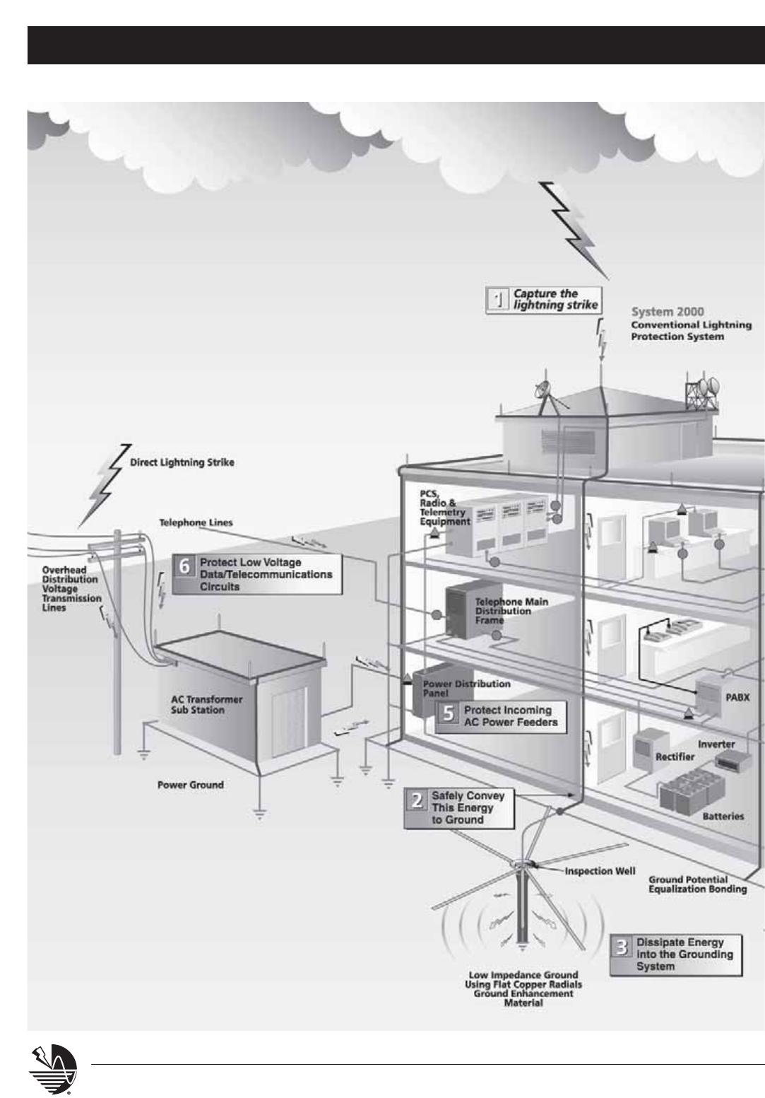
surge transients, ERICO Inc. has developed its generic Six Point Plan of Protection. The concept behind
this plan is to prompt the user to consider a holistic and coordinated approach to lightning protection,
that embraces all aspects of potential damage. This ranges from the more obvious direct strike to the
more subtle mechanisms of differential earth potential rises and voltage induction at service entry points.
The six interdependent disciplines that form the protection plan are:
1. Capture the lightning strike.
2. Safely convey this energy to ground.
3. Dissipate energy into the grounding system.
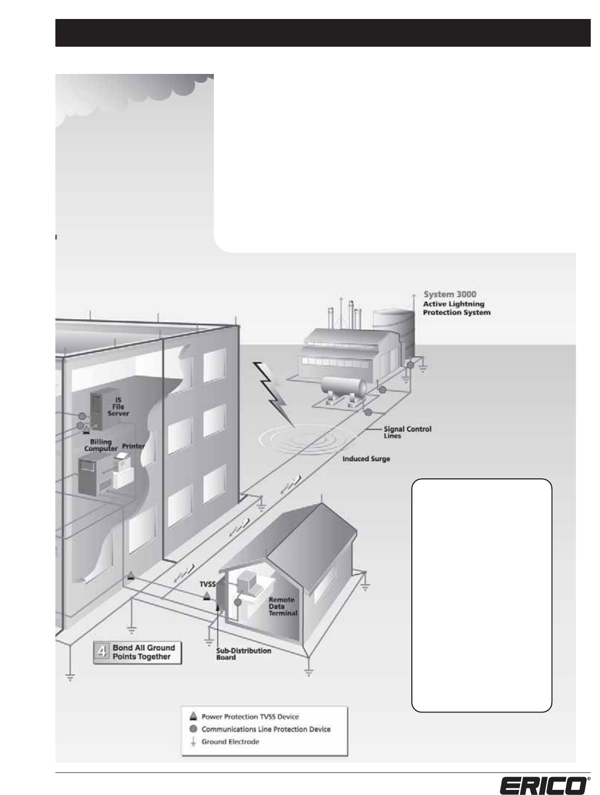
4. Bond all ground points together.
5. Protect incoming AC power feeders.
6. Protect low voltage data/telecommunications circuits.
ERITECH Lightning Protection Systems
This catalog details ERICO’s ERITECH range of lightning protection products to meet the needs of
points 1 and 2 of the Six Point Plan. For more information on the range of products designed to
cover points 3 through 6, please request a copy of the ERITECH Grounding, CADWELD electrical
connections, or CRITEC surge protection product catalogs.
www.erico.com

1
www.erico.com
Table Of Contents
Six Point Plan Of Protection................................................................. 2-3
The Need For Lightning Protection ..................................................... 4-7
General Installation Notes ...................................................................... 8
Isometric View Of Cable Lightning Protection Layout ......................... 9
Typical Installation Drawings........................................................... 10-13
General Specifications ...................................................................... 14-15
Series 100 — Conductors .................................................................. 16-17
Series 200 — Points & Accessories................................................... 18-20
Series 300 — Point Bases, Braces & Accessories............................. 21-24
Series 400 — Industrial Stack Equipment ....................................... 25-32
Series 500 — Clamps, Splices, Plates, & Lugs ................................. 33-37
Series 600 — Thru-Roofs, -Walls, & Special Purpose Parts............. 38-43
Series 700 — Ground Rods & Plates, Guards & Accessories .......... 44-46
Series 800 — Fasteners ..................................................................... 47-50
Series 900 — Ornaments & Insulators .................................................. 51
For a complete listing of ERITECH®grounding products, bonding
braids, insulators or other electrical grounding accessories refer to
the ERITECH Grounding Products and Systems Catalog (G281C).
Six Point Plan of Protection
2www.erico.com
Figure 1.
Six Point Plan of Protection
3
www.erico.com
The ERICO®Six Point Plan of Protection
1. Capture the lightning strike. Capture the lightning strike to a known and preferred
attachment point using a purpose-designed air terminal system.
2. Safely convey this energy to ground. Conduct the energy to the ground safely via
a purpose-designed downconductor.
3. Dissipate energy into the grounding system. Dissipate energy into a low impedance
grounding system.
4. Bond all ground points together. Bond all ground points to eliminate ground loops
and create an equipotential plane.
5. Protect incoming AC power feeders. Protect equipment from surges and
transients on incoming power lines to prevent equipment damage and costly
operational downtime.
6. Protect low voltage data/telecommunications circuits. Protect equipment from
surges and transients on incoming telecommunications and signal lines to prevent
equipment damage and costly operational downtime.
The ERICO Six Point Plan
of Protection provides
total facility protection by
integrating several concepts.
The Plan combines the
capture and dissipation
of lightning strikes, the
elimination of ground
loops, and the protection
of equipment from surges
and transients from
multiple sources. ERICO
manufactures all the
products and offers all the
expertise needed to form
a plan for any facility.
The Need for Lightning Protection
4www.erico.com
There is no known method of preventing
the occurrence of a lightning discharge. The
purpose of a lightning protection system,
therefore, is to control the passage of a
discharge in such a manner that prevents
personal injury or property damage.
The need to provide protection should be
assessed in the early stages of the structure
design. Although no strict rules can be given,
it is possible to use broad guidelines to arrive
at the degree of protection required.
Critical factors to be considered:
1. What is the risk to personnel?
2. What is the risk of equipment or
structural damage?
3. What are the consequential problems
of such failure?
4. Is the equipment associated with an
essential/public service?
5. Is there likely to be substantial revenue
loss in the time taken to restore services?
6. Is the structure of historical importance?
7. What are the legal implications of
providing inadequate protection?
8. Can the passage of a discharge in a
structure or a building give rise to side
flashing or simple sparks in an explosive
or flammable environment? i.e: The
extraction and storage of gas or oil,
storage and manufacture of explosives, etc.
9. Can side flashing between metallic
structures (as in a ship) cause damage
to essential electronics?
10. Will the discharge give rise to corona
phenomena causing disastrous surges
on the phase wires of electric lines or
breakdown in transformer stations?
The assessment of these factors is one of
judgement in comparing risks, economics
and aesthetics. Such assessment is not
always simple.
Lightning is an unknown phenomenon
It is possible to estimate the number of ground strikes expected per square kilometer per year and
statistically determine the risk of a building being struck. While still useful in modern lightning
protection techniques, such statistical calculations should, however, be viewed with caution. As an
example, it can be shown that a building in a low intensity area should be struck only once in 20
years. However, it is possible to receive several strikes in one storm and then no more for 30 years.
The random nature of lightning means the role of statistics is quite important in determining the
need for protection. The answers, however, to the previous 10 questions are equally important in
the assessment of the need for lightning protection.
Particularly at risk:
Installations where lightning protection is highly
desirable are summarized as follows:
•
Power stations
•
Sub-stations and transformer stations
•
Oil and gas storage and refinery
•
Drilling rigs
•
Grain storage
•
Explosives factories and storage areas
•
Flammable liquid or chemical storage
•
Factories such as chemical, textile, rubber,
sugar, glass, paint, etc.
•
Mining areas
•
Television, radio and telecommunications stations
•
High rise buildings - commercial and
apartment complexes
•
Hospitals
•
Transport - airports, shipping, rail etc.
•
Universities, education facilities
•
Historic structures
•
Churches, Mosques, etc.
•
Military installations
•
Golf courses, race courses, sports stadiums, etc.
•
Farms and food storage areas
•
Buildings containing computers and electronics
In a world of increasingly complex and sophisticated
buildings and equipment, lightning is a constant risk.
A single direct strike can result in physical damage to
buildings and catastrophic failure of sensitive electronic
equipment. It can start fires, cause major breakdowns
to electrical, telephone and computer installations, and
simultaneously cause substantial loss of revenue.
The Need for Lightning Protection
5
www.erico.com
Storm development and natural
ionization
A thunderstorm commences with the
development of a cumulonimbus thunder
cloud. The cloud is typically formed by rapidly
rising humid air which becomes electrified
due to convection and precipitation effects.
This is accompanied by wind speeds of up to
125 miles/hr.
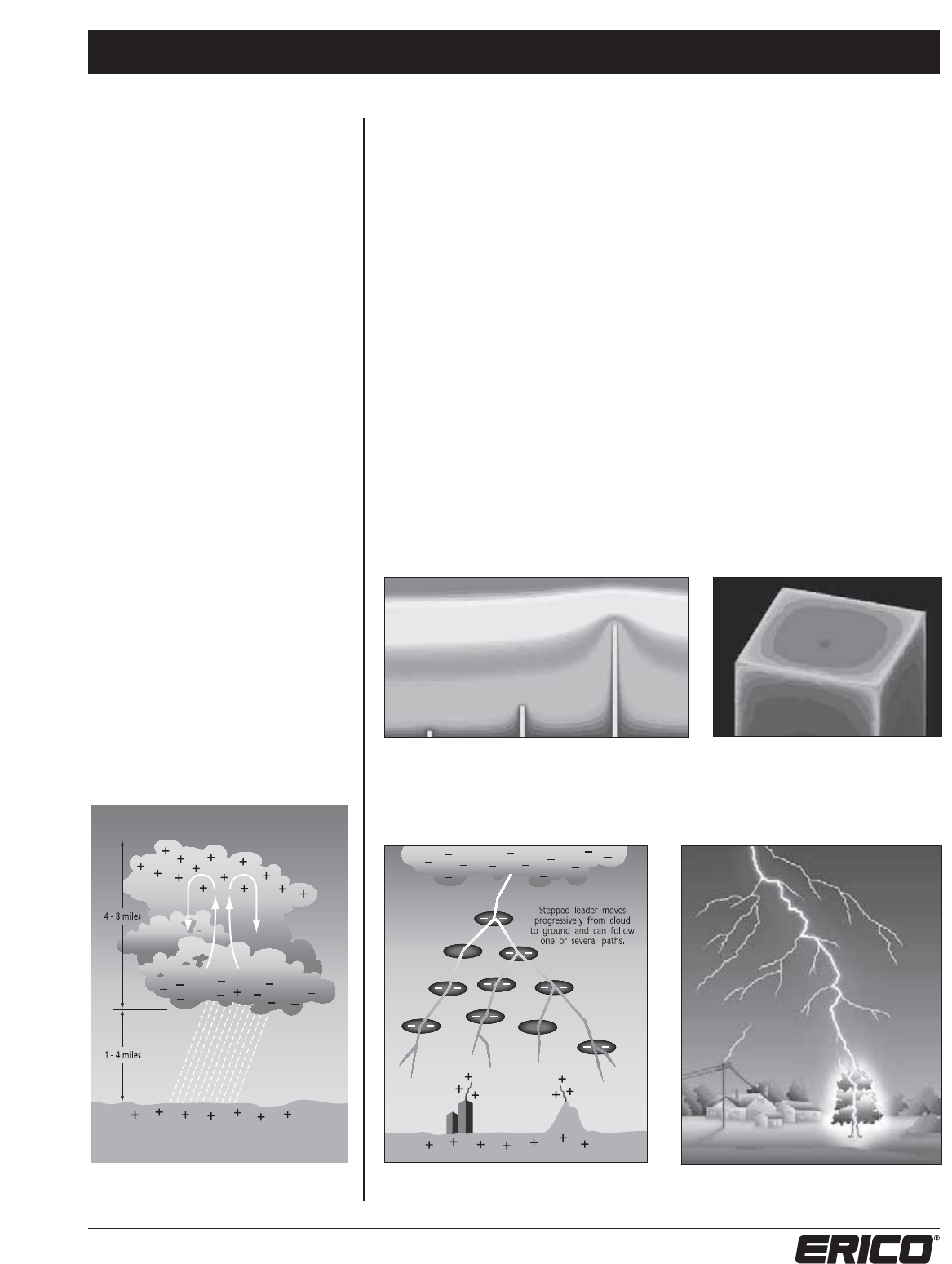
The end result is the separation of positive
and negative charges (see Figure 2). In
approximately 90% of cases, the lower part
of the thundercloud is comprised of a thin,
concentrated layer of negative charge, and
the upper part comprises a more diffuse
positively charged region. The cloud base is
typically 1 to 4 miles above the ground and
the cloud depth is typically 4 to 8 miles.
As a result of the cloud electrification, a
quasi-static electric field is established
between the cloud and ground. Pointed
ground objects subjected to this ambient
electric field emit varying amounts of point
discharge or “corona”, and the resulting
positive or negative ions drift upwards to
form a low density “space charge” which
extends from ground to cloud. This space
charge reduces the electric field observed
at ground level, typically from 50 - 60 kV/m
at heights of 1640 ft. to 2-15 kV/m at the
ground.
The Lightning Discharge
Within the confines of the cloud, static electricity builds to an extent where one or more
neutralizing discharges or flashes occur. These flashes can be in the form of an inter-cloud
(cloud-to-cloud), intra-cloud (within cloud) or cloud-to-ground flash.
The dramatic cloud-to-ground flash is of most concern. This dynamic phase of lightning
commences in the form of a luminescent downward leader from the base of the cloud, which
proceeds in a series of steps and branches toward the ground. The protrusion of ground objects
into an ambient electric field (such as that created by a lightning downward leader) increases the
electric field at the tip of the object, as shown in Figures 3 and 4. As the downleader approaches,
it causes the electric field around points on the surface of the earth to increase rapidly, leading to
the initiation of small upward streamers from the elevated points. Under the right conditions,
these upward streamers thermalize and become competing upward leaders which propagate
toward the approaching downleader, as shown in Figure 5.
The ability of one ground point to develop an upward intercepting leader before other nearby
competing points means that it can become the preferred strike point to successfully complete
an ionized path between cloud and ground, as shown in Figure 6.
The diagrams below illustrate the varying degrees of electric field intensification created by
grounded objects subjected to an ambient electric field (in this case, that of the lightning
downward leader).
Figure 6. Upward leaders propagate toward downward
leader to complete the ionized path between cloud and
ground.
Figure 4. Electric field plot of a real structure in an
ambient field, showing that the intensification is
high at the corners, moderate on the horizontal
and upper vertical edges and very low on flat
horizontal and vertical surfaces.
Figure 3. Field intensification, portrayed with lines of equal voltage
(equipotential lines), is a function of the height of the object as well
as its degree of “sharpness”.
Figure 5. Electric field due to downleader increases to the
point of initiation of an upward leader.
Figure 2. Typical positive and negative charge distribution in
the cumulonimbus cloud.
The Need for Lightning Protection
6www.erico.com
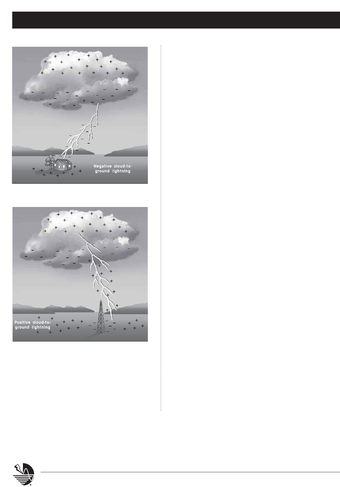
Figure 8. Positive cloud-to-ground lightning. Negative and positive cloud-to-
ground lightning typically occurs to an approximate ratio of 90:10.
Typically, 90% of cloud-to-ground flashes transfer negative
charge (negative lightning), as shown in Figure 7. Such a flash
consists of a sequence of one or more high amplitude, short
duration current impulses or strokes. The subsequent strokes are
sometimes called restrikes.
A small proportion of flashes transfer positive charge to ground (positive
lightning), as shown in Figure 8. Typically 10% of lightning flashes are positive,
although this can vary with latitude and season. The parameters for positive
lightning differ considerably from their negative counterparts. Some of the
main differences are that the:
•
restrike phenomenon is absent (no subsequent strokes)
•
peak current is higher (~ 2 x)
•
maximum rate of rise of current is less (~ 0.1 x)
•
total rise time is longer (~ 4 x)
•
stroke duration is longer (~ 4 x)
•
action integral (energy content) is higher (~ 10 x)
In summary, the main lightning discharge is characterized by a rapidly rising
current (averaging about 30,000 Amps) with maximum values exceeding
200,000 Amps. This whole process is extremely rapid, typically occurring
within milliseconds. The average energy released in a single discharge may be
55 kW hours. The danger lies in the extremely high rate of current rise (up to
1010 Amps per second) which can generate very high voltages, and also from
the continuing current following the peak.
Without proper intervention to capture and control the passage of this
lightning energy to ground, cloud-to-ground lightning can be catastrophic.
Capturing the lightning discharge
In general, the highest point of a facility is the most vulnerable to a direct
lightning strike. Lightning rods or air terminals are needed to capture the strike
to a preferred point, and to safely conduct the energy to ground to minimize
the risk of damage. The number of terminals required, and their placement, is
determined by the chosen lightning protection design method.
The placement of air terminals, whether conventional or active, is a critical
part of the lightning protection design process. Since the 1750’s the most
popular methods of lightning protection have involved sharp vertical rods
(Franklin), horizontal and vertical conductors (Faraday Cage or Mesh) or a
combination of both. Only if air terminals are placed in the optimum location
on the structure is it possible to achieve an efficient and reliable lightning
protection system. Historically, a number of methods have been employed,
some of which are still in common use, such as the Cone of Protection
(Protective Angle), Mesh and Rolling Sphere methods.
Figure 7. Negative cloud-to-ground lightning.
The Need for Lightning Protection
7
www.erico.com
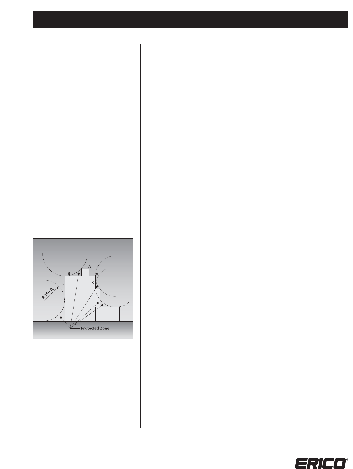
Figure 9. Rolling Sphere method detailing points A, B, C.
Rolling Sphere Method
The Rolling Sphere Method is undoubtedly the
most common recommended method in codes
of practice. It is based on the Electrogeometric
Model which relates the ”striking distance”
to the peak current delivered by the lightning
strike. To apply this technique, an imaginary
sphere, typically 150 ft. in radius (the striking
distance), is rolled over the structure. All
structure surface points that contact the
sphere are deemed to require protection,
while unaffected areas are deemed to be
protected, as shown in Figure 9.
It is claimed that the main advantage of the
Rolling Sphere Method is its simplicity. This is
true but only for simple structures. It is difficult
to apply it to complex structures as it requires
3D numerical modeling software. The
fundamental problem with this model is that
it assigns an equal leader initiation ability
to all contact points of the sphere on the
structure, for example: the striking distance
is assumed to be a constant value.
Corners or objects on elevated structures,
which may include antennae, satellite dishes or
advertising signs, create high levels of field
intensification and are more likely to launch an
upward leader than flat horizontal surfaces.
A lightning protection installation consists of three essential components.
1. The Air Terminal
The primary function of an air terminal, or air termination system, is to capture the lightning
strike to a preferred point, so that the discharge current can be safely directed via the down
conductor(s) to the grounding system.
2. The Downconductor
The function of a downconductor is to provide a low impedance path from the air termination
to the ground system so that the lightning current can be safely conducted to earth, without
the development of excessively large voltages.
In order to reduce the possibility of dangerous sparking (side-flashing), the downconductor
route(s) should be as direct as possible with no sharp bends or stress points where the
inductance, and hence impedance, is increased under impulse conditions.
3. The Grounding System
The grounding system must have a low impedance to safely disperse the energy of the
lightning strike. Since the lightning discharge consists of high frequency components,
we are particularly concerned with the impedance, as well as low resistance grounding.
Grounding systems are highly variable from site to site due to geographical considerations.
The grounding grid should minimize the ground voltage potential rise and minimize the
risk of injury to personnel or damage to equipment.
Summary
It is important to realize that inefficiency in the design of any one of the above components
represents an inefficiency in the protection system as a whole. Each of these components
must be considered independently and finally integrated together to form the complete
lightning protection system. Indeed, without such integration, there is limited protection.

General Installation Notes
8www.erico.com
1. The design layout and installation details shown
hereon shall meet the requirements of National Fire
Protection Association (NFPA®) #780 current edition.
2. Connection to ground rod or ground loop conductor
shall be made at a point not less than 18” below
grade, ground rods shall not be less than 8' long and
extend at least 10' into the earth.
3. Air terminals shall be placed at all unprotected
outside corners and located intermediately on 20’-0”
maximum spacing around the roof perimeter or ridge
and within 2’-0” of outside edge.
4. Midroof areas are to be provided with air terminals
spaced either at 50’ center or, of sufficient quantity
and height, to ensure the entire roof area is covered
by a “zone-of-protection” as afforded by a 150’
radius sphere, per NFPA #780.
5. Grounded metal bodies located about the structure
such as: soil pipe vents, roof drains, exhaust fans, air
handling units, any miscellaneous equipment with
electrical services, etc. shall be interconnected to the
lightning conductor system, if within the “bonding
distance” established by NFPA #780.
6. Bond all metallic pipes including water, fire, gas,
sewer, storm, etc. which enter the structure, within
12’ of grade, to the nearest downlead, ground rod,
or ground loop.
7. All reinforcing, structural, framing, and miscellaneous
steel shall be made electrically continuous throughout
construction by welding, clipping, bolting, or other
approved methods.
8. Telephone and/or electric service entrance grounds
shall be interconnected to one lightning protection
ground or water pipe.
9. All areas which have not been provided with
lightning protection components are protected from
higher roofs or structures. These areas fall within a
“zone-of-protection” as established by the current
edition of the NFPA #780 document for protection
against lightning.
10. The lightning protection system shall be installed
in a neat and inconspicuous manner so that all
components will blend with the appearance of
the building.
11. No bend of a conductor shall form a final included
angle of less than 90 degrees nor shall have a radius
of bend of less than 8”.
12. Conductors shall interconnect all air terminals and
shall form a two-way path from each air terminal
horizontally or downward to connections with
ground terminals, with the exception of vertical roof
members, upper roof to lower roof transitions, or
lower roof "dead ends".
13. All lightning protection conductors shall be fastened
not more than 3’-0” maximum spacing.
14. All adhesive type fittings shall be set in place with an
application of compatible adhesive compound before
roof gravel is applied.
15. Actual jobsite conditions may necessitate slight
alterations in air terminal and ground rod locations.
16. Bare copper lightning protection materials shall not
be installed on aluminum roof or siding or other alu-
minum surfaces and vice versa, aluminum lightning
protection materials shall not be installed on copper
roofing or copper siding or other copper surfaces.
17. Surge suppressor shall be provided on electric and
telephone service entrances and on radio and
television antenna lead-ins.
18. Seal ends of conduit moisture tight with duct seal
or lead wedge. All conduit, conduit fasteners, and
miscellaneous accessories shall be furnished and
installed by the electrical contractor.
19. The design layout and installation details shown
hereon shall meet the requirements of Underwriter’s
Laboratories UL®Standard 96A for Master Labeled
lightning protection systems. When desired, the
actual Master Label will be delivered upon completion
of installation.
20. The lightning protection installation shall comply in
all respects to Lightning Protection Institute Standard
175. The installation shall be made by or under the
supervision of an L.P.I. Certified Master Installer.
21. Metal bodies of inductance located about the roof
such as metal flashing, gravel stops, roof drains, soil
pipe vents, insulation vents, louvers, and door frames
situated within 6’-0” of a lightning conductor or
bonded metal body shall be interconnected to the
lightning conductor system.
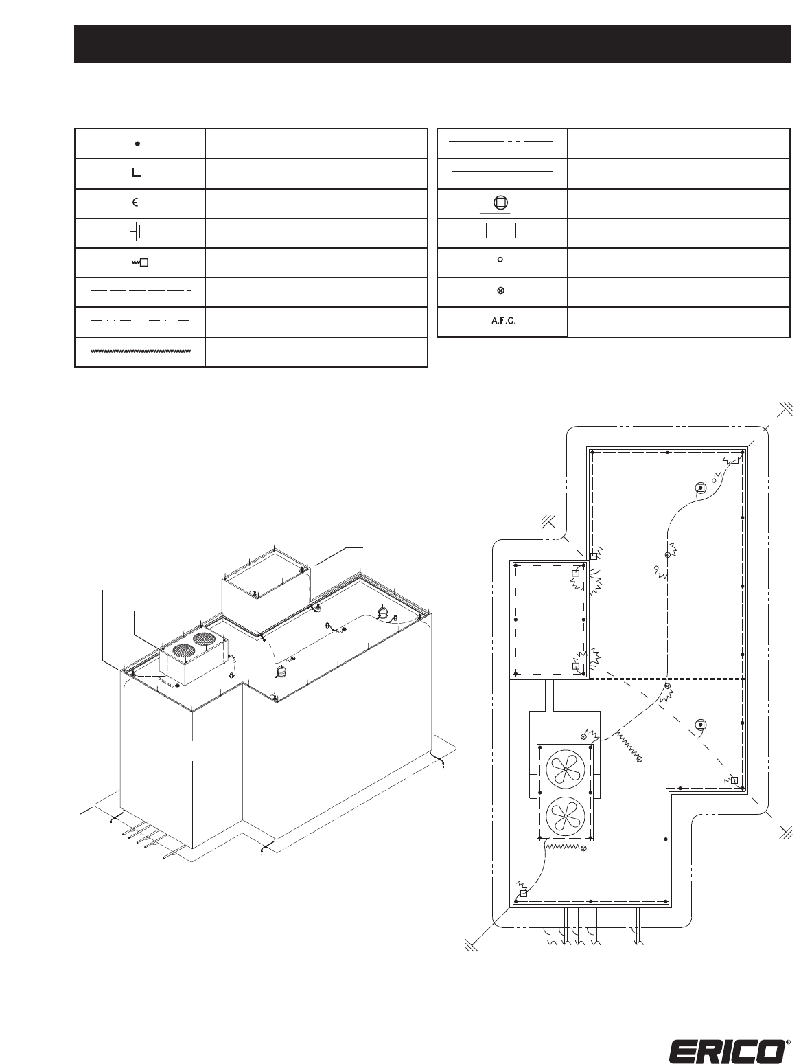
Isometric View of Cable Lightning Protection Layout
9
www.erico.com
Legend
No. LPC126 Copper Ground Loop Conductor
(Min. Class II Cable)
No. LPA141 Aluminum Secondary Bonding
(#4 AWG)
Exhaust Fan
Misc. Mechanical Equipment
Vent Thru-Roof
Roof Drain
Above Finished Grade
Note: The lightning protection materials to be used for this type
of installation may be aluminum or copper, within the allowances
of NFPA®code 780. Some of the criteria for choosing one type of
material over another are as follows:
1. Matching of materials to which lightning protection
components are to be installed for compatibility;
aluminum on aluminum, copper on copper, etc.
2. Location of materials (i.e. within concrete, below grade, etc.)
3. Lightning protection components to match existing
lightning protection materials.
4. Personal preferences of owner, architect, engineer, etc.
Air Terminal Location
Thru-Roof Connection Location
Thru-Wall Connection Location
Ground Rod Location
Thru-Roof Cable to Steel Connection
No. LPC120 Copper Cable (#2 AWG)
No. LPC126 Copper Cable (Min. Class II Cable)
No. LPC151 Copper Secondary Bonding Wire
(#6 AWG)
Class II Downlead Cable,
Concealed Within Construction.
Class I Downlead Cable,
Concealed Within Construction.
0' Grade
62' A.F.G. (Class I)
69' A.F.G. (Class I)
80' A.F.G. (Class II)
Class I Downlead Cable,
Concealed Within Construction.
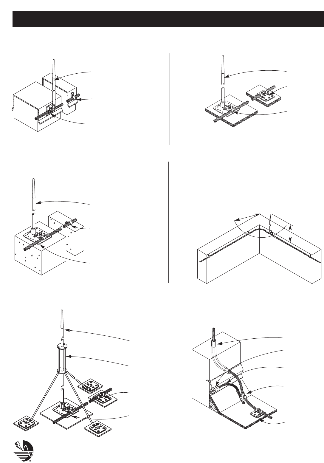
Typical Installation Drawings
10 www.erico.com
Typical Parapet
Air Terminal
Point to extend a
minimum of 10"
above top of parapet.
Cable Fastener
Point Base
Typical Mid-Roof
Air Terminal
Point
Adhesive type
cable holder
Adhesive type
point base
Typical Tri-Pod
Mid-Roof Air Terminal
Point
(>24" high)
Adhesive type
tripod holder
Adhesive type
cable holder
Adhesive type
point base
Typical Top Mount
Air Terminal
Point
Loop type masonry
cable anchor
Point base
Typical Air Terminal
Placement at
Outside Corners
2' - 0"
max.
10" min.
Typical Concealed
Downlead to
Lower Roof
1" PVC conduit
Terminal
bonding lug
Secondary
bonding wire
Parallel
combination
cable splicer
Adhesive type
cable holder
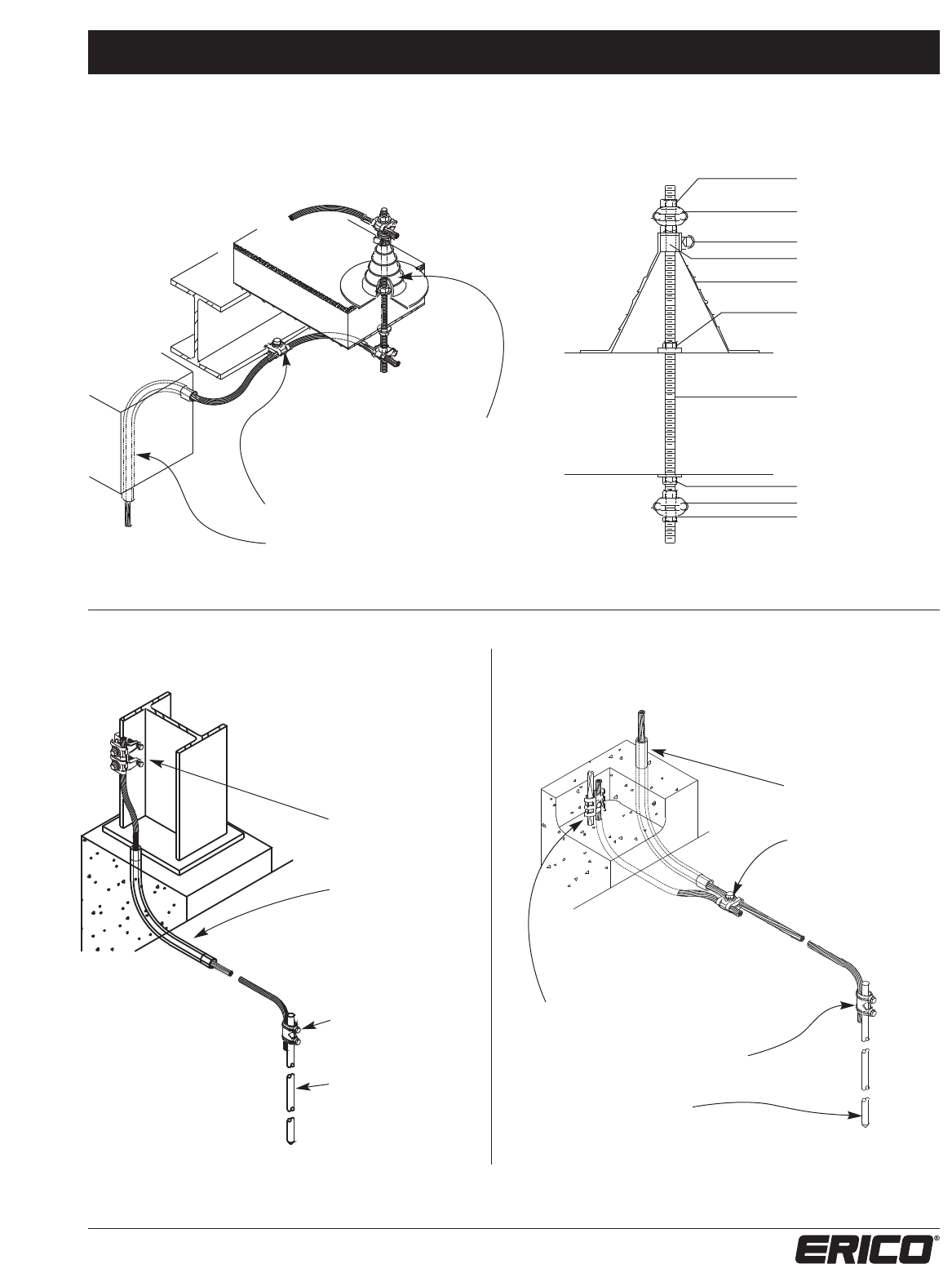
Typical Installation Drawings
11
www.erico.com
Typical Thru-Roof
Connection
Thru-roof cable connecting assembly,
furnished with EPDM pipe flashing and
1/2" dia. x 18" all thread rod
Cast cable to steel bonding clamp
1" PVC conduit
Washer & nut
Cable connection
Flashing clamp
Flashing collar
Flashing boot
Washer & nut
Threaded rod,
rod length
determined by
roof thickness
Washer & nut
Cable connection
Washer & nut
Typical Steel
Column
Grounding
Connection
Cast cable to steel
bonding clamp
1" PVC conduit
Cable to ground
rod clamp
10' - 0" copper
clad steel
ground rod
Typical Concealed
Download to
Grounding Connection
1" PVC conduit
Parallel combination
cable splice
Cast rebar bonding clamp
Cable to ground rod clamp
3/4" x 10' UL Listed
ground rod
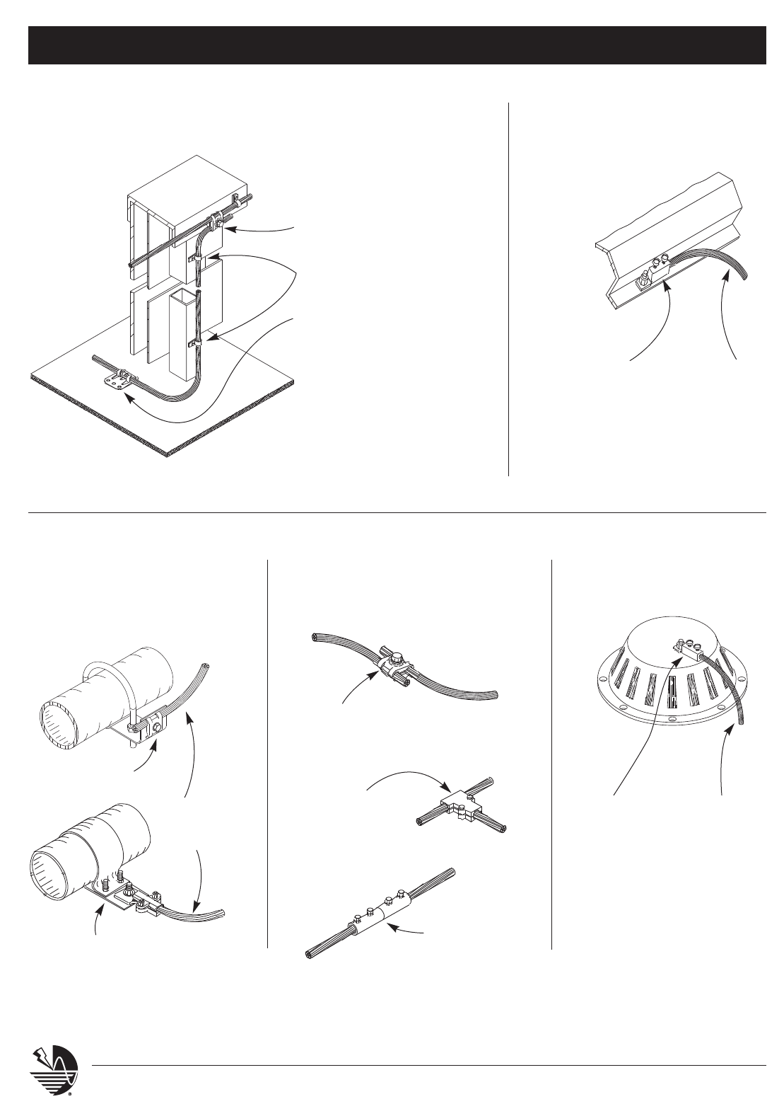
Typical Installation Drawings
12 www.erico.com
Typical Exposed
Downlead to
Lower Roof at
Screenwall
Combination cable splicer
Loop type cable fastener
Adhesive type cable holder
Typical
Flashing
Bond
Cast terminal
bonding lug.
Secure with
stainless steel
machine screw
and nut
Secondary
bonding
wire
Typical Roof
Drain Bond
Cast terminal
bonding lug
Secondary
bonding
wire
Typical Metallic
Water Pipe
Bonding Clamp
Adjustable pipe
bonding strap
Main
size
conductor
Cast pipe
bonding clamp
Typical
Cable
Splicers
Cast parallel
combination cable splicer
Cast bronze
to aluminum
bimetallic
cable splicer
Cast "tee" type
cable splicer
Typical Installation Drawings
13
www.erico.com
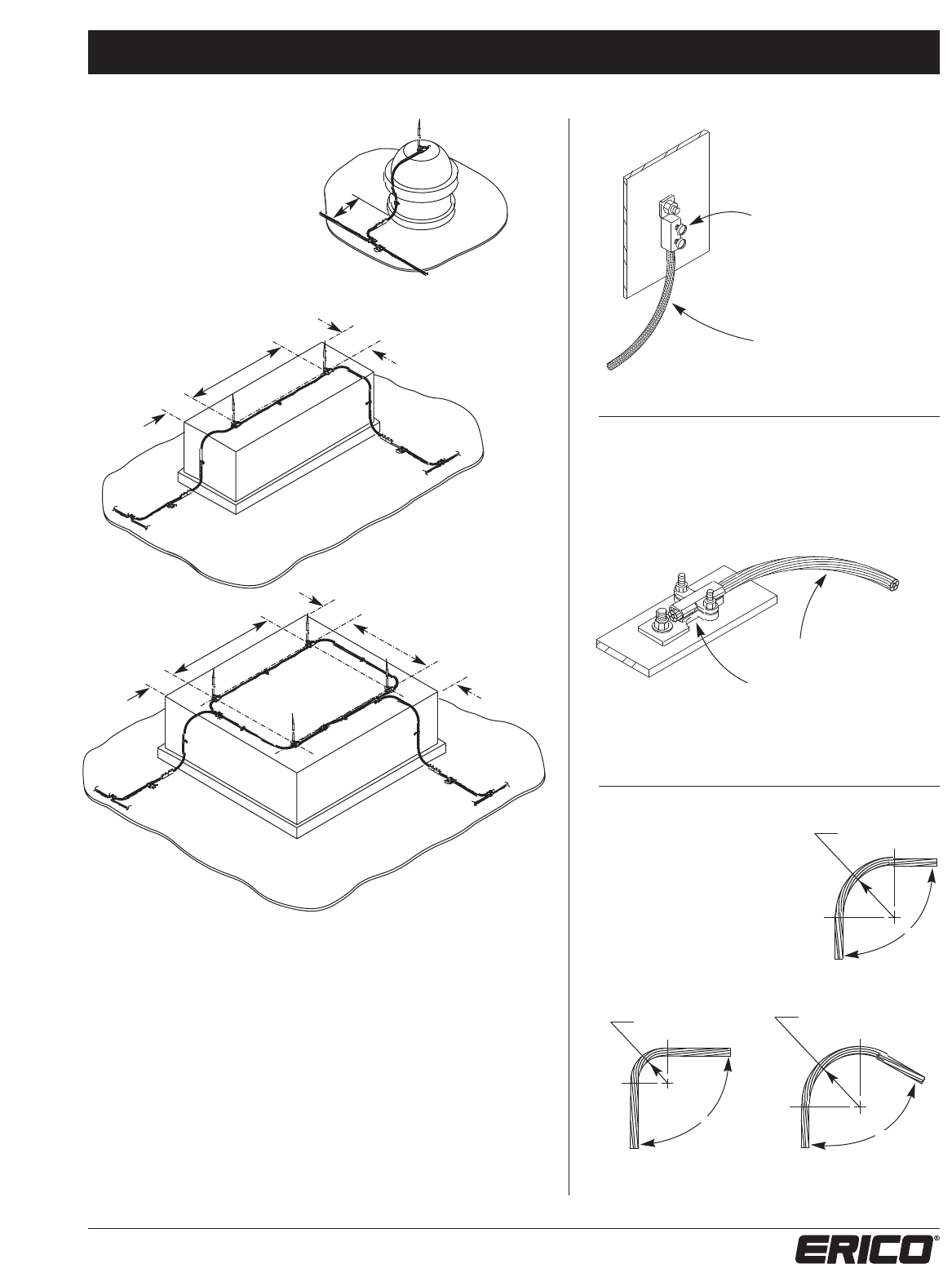
Schematic View:
Typical Cable
Routing at
Equipment
* NOTE: Per NFPA®, where only one strike
termination device is required on a chimney
or vent, at least one main sized conductor
(no longer than 16') shall connect the strike
termination device to a main conductor at
the location where the chimney or vent
meets the roof surface and provides two
or more paths to ground from that location
in accordance with section 3-9 and 3-9.2
** NOTE: Distance of 1'-4" determined
from provided point within 2'-0" of outside
corner at 90˚
Greater than 4'-0"
Not to exceed 20'-0"
**
1'-4" max.
**
1'-4" max.
Greater than 4'-0"
Not to exceed 20'-0"
**
1'-4" max.
**
1'-4" max.
Greater than 4'-0"
Not to exceed 20'-0"
**
1'-4" max.
*
Typical Secondary
Equipment Bond
Cast terminal bonding
lug. Secure with
stainless steel machine
screw and stainless
steel nut.
Copper secondary
bonding wire
Typical
Ladder/Equipment
Frame Bond
Main size conductor
Cast bonding lug.
Secure with stainless
steel machine screw
and stainless steel nut.
90˚ min.
8" Radius min.
Typical Bend
Requirements
ACCEPTABLE
90˚
8" Less Than Radius
NOT ACCEPTABLE
8" Radius
Less Than 90˚
NOT ACCEPTABLE

General Specification System 2000
14 www.erico.com
Short Form:
The contractor shall furnish all labor, materials, equipment
and services to provide a complete lightning protection
system for the building(s) included on this contract.
The system(s) shall include roof-mounted air terminals,
interconnecting conductors, downlead conductors
to ground and proper ground terminations as
provided by ERITECH®Lightning Protection/Grounding
Products from ERICO®Inc. phone: (800) 677-9089,
e-mail: application_eng@erico.com. This system will
comply with National Fire Protection Association (NFPA®),
Lightning Protection Standard No. 780. Upon completion
of the installation, the contractor shall deliver to the
owner the Master Label of Underwriters’ Laboratories, Inc.
(UL®) and the L.P.I. Certified System registration. Any com-
ponents or methods not found in accordance with this
specification shall be repaired or replaced without cost
to the owner before final payment is approved.
Long Form:
1.1 General:
A. The Contractor shall provide and install a complete
Lightning Protection System for all of the building(s)
included in this project. This specification addresses
the requirements of Lightning Protection Systems for
buildings only.
B. Compliance Requirements
1. System Design: NFPA 780, latest edition.
2. Component Design: UL 96 Standard, latest edi-
tion.
3. Certification: Lightning Protection Institute
Certified System and Underwriters’ Laboratories
96A Master Label.
C. Submittals
1. Complete Shop Drawings
a) Layout
b) Details
2. Catalog Data with complete description of mate-
rial components.
1.2 Product:
A. Manufacturer: ERITECH Lightning Protection/
Grounding Products from ERICO Inc. phone:
(800) 677-9089. E-mail: application_eng@erico.com
B. Prior approved manufacturer, who is a Lightning
Protection Institute Member in good standing.
C. Materials are to be listed and labeled in
accordance with Underwriters’ Laboratories (UL)
96A requirements.
1.3 System Design:
A. System to be designed by a L.P.I. Certified Master
Installer/Designer.
B. System to consist of groundings, down conductors,
air terminals, interconnecting conductors and bond-
ing, designed to appear as a part of the building.
1. Steel framing (minimum 3/16 in. thick) may be
used for the lightning protection component if
electrically continuous, or made so.
2. Cable system to be utilized if building
construction is not structural steel columns.
C. Design to be complete per current NFPA 780
requirements.
1. Class I materials required for structure 75 ft. and
less in height.
2. Class II materials required if structure is over 75
ft. in height.
3. Aluminum Lightning Protection materials are
not to be embedded in concrete or masonry
or installed on or below copper surfaces.
4. Copper Lightning Protection materials are not
to be installed on aluminum surfaces.
5. Grounding shall be suitable for the soil
conditions per NFPA 780, this may include:
a) Ground rods only for buildings less than
60 ft. high
b) Ground plates only for buildings less than 60
ft. high, in rocky soil.
c) Ground loop only (full size cable) for any
height building, buried 18 in. deep.
d) Ground loop combined with rods or plates for
any height building, buried 1 ft. deep.
6. Strike termination devices (air terminals) required
as follows, unless the area in question is located
under a zone of protection.
a) Minimum 10 in. projection above the
object protected.
b) Maximum 20 ft. spacing on roof ridges
or edges.
c) Maximum 24 in. distance from ridge
ends or roof edges & outside corners.

General Specification System 2000
15
www.erico.com
d) Penthouses, Protrusions and Mechanical
roof top equipment, same guidelines as
noted above:
1) Strike termination devices not needed if
metal thickness is 3/16 in. thick or more.
2) A conductor interconnecting the strike
termination devices is necessary on
metal less than 3/16 in. thick. The
interconnecting conductor may be the
continuous metal equipment housing
or a cable conductor.
e) Strike termination devices required on
eaves of sloping roofs, when the eave
is over 50 ft. in height.
f) Mid-roof areas are to be provided with Strike
termination devices at either 50 ft. spacing
or provided with Strike termination devices
of sufficient quantity & height, to ensure the
entire roof area is covered by a “zone of
protection” as afforded by a 150 ft. radius
sphere (per NFPA®780).
g) Strike termination safety devices to be
provided in mid-roof areas and high traffic
areas. Material to be the same as, or an alloy
of, the point and base and to be one of the
following:
1) 1-5/8 in. diameter Safety Cap, as approved
by Cal-OSHA
2) Safety tipped point
7. Bonding is required in strict accordance with
NFPA 780.
a) Ground level potential equalization; below the
12 ft. elevation of the structure all grounded
media to be interconnected.
b) Ground loop required for structures over
60 ft. in height.
c) Roof levels over 60 ft. to include
interconnection of all grounded media
within 12 ft. of the main roof level.
d) Intermediate levels:
1) Steel-framed structures – Intermediate
Loops not required.
2) Reinforced concrete – Intermediate
Loop at 200 ft. (vertical height)
intervals required connecting all
grounded systems.
3) Other structures – Intermediate Loops
at intervals, connecting all grounded media
at that height.
4) Lightning Surge Suppressors to be provided
on electrical and communication service
entrances and on communication antenna
lead-ins.
1.4 Installation:
A. L.P.I. Certified Master Installer or Underwriters’
Laboratories (UL®) Listed Installer or under supervision
thereof.
B. Complete per requirements of NFPA 780.
C. Neat and inconspicuous manner.
D. All mounting & penetration of roof surface shall
be coordinated with roofing contractor to assure
maximum roofing guarantee
E. All through-roof penetration flashings to be
furnished, sealed and guaranteed by the roofing
contractor.
F. Fasteners:
1. At 3 ft. centers, maximum, on exposed
conductor runs.
2. As necessary to maintain position and hold
permanently in place on concealed runs of
conductor.
1.5 Final Acceptance:
A. Procurement of L.P.I. Certification includes jobsite
verification and completion of:
1. Witness of Grounding System & Grade
bonding (Stage I)
2. Inspection of concealed equipment between
roof & grade (Stage II)
3. Final inspection of exposed equipment on
roof (Stage III)
B. Procurement of Underwriters’ Laboratories Master
Label indicating completion of;
1. Show owner or his representative the type and
manner of placing groundings and receiving his
record of review.
2. Completion of application form and submission
to Underwriters’ Laboratories for issuance of
certification.
C. Installation of Installer’s Nameplate at location
designated on UL application form.
D. Any components or methods found to be not in
accordance with this specification shall be repaired
or replaced without cost to the owner.
1.6 Special consideration:
If this contract includes the construction of a
building or buildings that are physically connected
to an existing building or are additions to existing
structures, then the Lightning Protection System(s) for
the new construction shall comply with the standards
stated above. The delivery of the L.P.I. Certification
and the Underwriters’ Laboratories Master Label shall
not be required. In place of this certification or label
the procedures of each program shall be followed to
deliver partial or qualified certification outlined by
either organization.
Conductors System 2000 – Series 100
16 www.erico.com
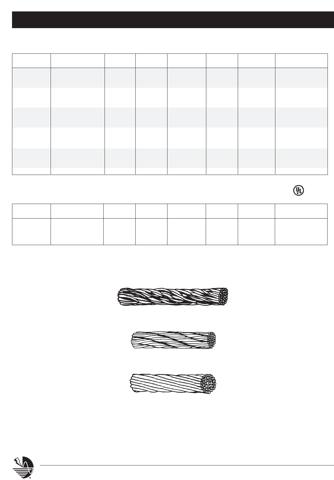
PRIMARY COPPER CONDUCTORS*
PART # CONDUCTOR # OF WIRE SIZE WEIGHT PER CIRCULAR EXCEEDS STANDARD
TYPE STRANDS GAUGE 1000 FEET MILS REQ’MENT LENGTHS ON REEL
LPC120 SMOOTH WEAVE 29 17 192 Lbs. 59,450 CLASS I 250’/500’
LPC121 SMOOTH WEAVE 30 17 202 Lbs. 61,500 CLASS I 250’/500’
LPC122 SMOOTH WEAVE 32 17 220 Lbs. 65,600 CLASS I 250’/500’
LPC123 SMOOTH WEAVE 36 17 240 Lbs. 73,800 CLASS I 250’/500’
LPC124 SMOOTH WEAVE 40 17 270 Lbs. 82,000 CLASS I 250’/500’
LPC128 SMOOTH WEAVE 24 14 340 Lbs. 98,640 CLASS I 250’/500’
LPC120L TINNED SM WEAVE 29 17 192 Lbs. 59,450 CLASS I 250’/500’
LPC122L TINNED SM WEAVE 32 17 220 Lbs. 65,600 CLASS I 250’/500’
LPC125 ROPELAY 24 14 340 Lbs. 98,600 CLASS I 250’
LPC126 SMOOTH WEAVE 28 14 380 Lbs. 115,080 CLASS II 250’/500’
LPC127 ROPELAY 32 14 440 Lbs. 131,520 CLASS II 250’/500’
LPC126L TINNED SM WEAVE 28 14 380 Lbs. 115,080 CLASS II 250’
LPC136 CONC. STRAND 37 13-1/2 520 Lbs. 167,800 CLASS II 250’
LPC137 CONC. STRAND 37 12-1/2 653 Lbs. 211,600 CLASS II 250’
LPC138 CONC. STRAND 37 12 772 Lbs. 250,000 250’
LPC139 CONC. STRAND 37 11 1,555 Lbs. 500,000 250’
* Conductors manufactured to UL®requirements. Contact ERICO®for other lengths.
PRIMARY ALUMINUM CONDUCTORS*
PART # CONDUCTOR # OF WIRE SIZE WEIGHT PER CIRCULAR EXCEEDS STANDARD
TYPE STRANDS GAUGE 1000 FEET MILS REQ’MENT LENGTH ON ROLL
LPA100 SMOOTH WEAVE 24 14 102 Lbs. 98,640 CLASS I 250’/500’
LPA101 SMOOTH WEAVE 26 14 109 Lbs. 106,860 CLASS I 500’
LPA102 SMOOTH WEAVE 28 14 115 Lbs. 115,080 CLASS I 500’
LPA105 CONC. STRAND 37 12-1/2 204 Lbs. 211,000 CLASS II 250’/500’
* Conductors manufactured to UL requirements. Contact ERICO for other lengths.
Smooth Weave
Ropelay
Conc. Strand
Conductors System 2000 – Series 100
17
www.erico.com
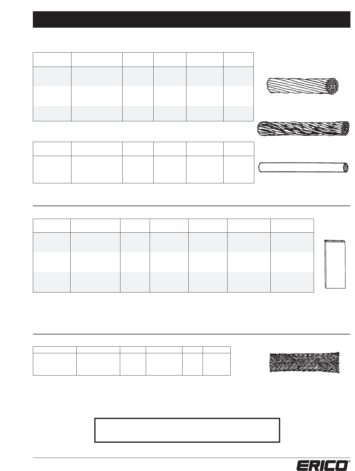
SECONDARY COPPER CONDUCTORS
PART # CONDUCTOR # OF WIRE SIZE WEIGHT PER CIRCULAR
TYPE STRANDS GAUGE 1000 FEET MILS
LPC150 SMOOTH WEAVE 14 17 92 Lbs. 28,700
LPC150L TINNED SM WEAVE 14 17 93 Lbs. 28,700
LPC152 CONC. STRAND 10 14 130 Lbs. 41,100
LPC152L TINNED CONC. STR. 10 14 130 Lbs. 41,100
LPC151 SOFT SOLID 1 6 80 Lbs. 26,240
LPC153 SOFT SOLID 1 4 127 Lbs. 41,740
LPC154 SOFT SOLID 1 2 204 Lbs. 66,360
LPC154L TINNED SOFT SOLID 1 2 204 Lbs. 66,360
SECONDARY ALUMINUM CONDUCTORS
PART # CONDUCTOR # OF WIRE SIZE WEIGHT PER CIRCULAR
TYPE STRANDS GAUGE 1000 FEET MILS
LPA140 SMOOTH WEAVE 10 14 42 Lbs. 41,100
LPA142 SMOOTH WEAVE 16 14 66 Lbs. 65,760
LPA141 SOFT SOLID 1 4 40 Lbs. 41,740
LPA143 SOFT SOLID 1 2 60 LbS. 66,360
SOLID COPPER & ALUMINUM STRIPS AND BARS
PART # MATERIAL WIDTH THICKNESS WEIGHT PER CABLE SIZE APPLICATION
TYPE 1000 FEET EQUIVALENT
LPC171L SOFT TINNED CU 1-1/4” 0.064” 319 Lbs. CLASS I
LPC171 SOFT COPPER 1-1/4” 0.051” 197 Lbs. CLASS I
LPC172 SOFT COPPER 3/4” 1/8” 362 Lbs. CLASS II
LPC173 HARD COPPER 3/4” 1/8” 363 Lbs. BUS BAR
LPC174 HARD COPPER 1” 1/8” 484 Lbs. #1/0 AWG GROUND BAR
LPC175 HARD COPPER 3/4” 1/4” 727 Lbs. #4/0 AWG GROUND BAR
LPC176 HARD COPPER 1” 1/4” 969 Lbs. GROUND BAR
LPA162 SFT ALUMINUM 1-1/4” 0.080” 118 Lbs. #1/0 AWG CLASS I
LPA163 SFT ALUMINUM 1” 3/16” 225 Lbs. #4/0 AWG CLASS II
Must specify length requirements.
EXTRA FLEXIBLE COPPER BRAIDED BONDING CABLE
PART # TINNED PART # COPPER WIDTH THICKNESS MM2LBS./M
557310 557110 30 mm 3.0 mm 60 1.31
557250 557050 20 mm 1.5 mm 20 0.42
557240 557040 15 mm 1.5 mm 16 0.32
Standard 80 foot coils.
Smooth Weave
Soft Solid
Conc. Strand
For a complete listing of ERITECH®grounding products, bonding
braids, insulators or other electrical grounding accessories refer to
the ERITECH Grounding Products and Systems Catalog (G281C).
Points & Accessories System 2000 – Series 200
18 www.erico.com
3/8” POINTS
COPPER (Class I)
NICKEL
NICKEL PLATED BARE TINNED
PLATED BARE SAFETY SAFETY SAFETY
LENGTH POINTED POINTED TIP* TIP* TIP*
10” LPC201 LPC201B LPC201ST LPC201BST LPC201LST
12” LPC202 LPC202B LPC202ST LPC202BST LPC202LST
15” LPC203 LPC203B LPC203ST LPC203BST LPC203LST
18” LPC204 LPC204B LPC204ST LPC204BST LPC204LST
24” LPC205 LPC205B LPC205ST LPC205BST LPC205LST
30” LPC206 LPC206B LPC206ST LPC206BST LPC206LST
36” LPC207 LPC207B LPC207ST LPC207BST LPC207LST
48” LPC208 LPC208B LPC208ST LPC208BST LPC208LST
1/2” POINTS
COPPER ALUMINUM
(Class II) (Class I)
NICKEL
NICKEL PLATED BARE TINNED
PLATED BARE SAFETY SAFETY SAFETY POINTED SAFETY
LENGTH POINTED POINTED TIP* TIP* TIP* TIP*
10” LPC221 LPC221B LPC221ST LPC221BST LPC221LST LPA221 LPA221ST
12” LPC222 LPC222B LPC222ST LPC222BST LPC222LST LPA222 LPA222ST
15” LPC223 LPC223B LPC223ST LPC223BST LPC223LST LPA223 LPA223ST
18” LPC224 LPC224B LPC224ST LPC224BST LPC224LST LPA224 LPA224ST
24” LPC225 LPC225B LPC225ST LPC225BST LPC225LST LPA225 LPA225ST
30” LPC226 LPC226B LPC226ST LPC226BST LPC226LST LPA226 LPA226ST
36” LPC227 LPC227B LPC227ST LPC227BST LPC227LST LPA227 LPA227ST
48” LPC228 LPC228B LPC228ST LPC228BST LPC228LST LPA228 LPA228ST
5/8” POINTS
COPPER ALUMINUM
(Class II) (Class II)
NICKEL
NICKEL PLATED BARE TINNED
PLATED BARE SAFETY SAFETY SAFETY POINTED SAFETY
LENGTH POINTED POINTED TIP* TIP* TIP* TIP*
10” LPC241 LPC241B LPC241ST LPC241BST LPC241LST LPA241 LPA241ST
12” LPC242 LPC242B LPC242ST LPC242BST LPC242LST LPA242 LPA242ST
15” LPC243 LPC243B LPC243ST LPC243BST LPC243LST LPA243 LPA243ST
18” LPC244 LPC244B LPC244ST LPC244BST LPC244LST LPA244 LPA244ST
24” LPC245 LPC245B LPC245ST LPC245BST LPC245LST LPA245 LPA245ST
30” LPC246 LPC246B LPC246ST LPC246BST LPC246LST LPA246 LPA246ST
36” LPC247 LPC247B LPC247ST LPC247BST LPC247LST LPA247 LPA247ST
48” LPC248 LPC248B LPC248ST LPC248BST LPC248LST LPA248 LPA248ST
NOTE: -Points are manufactured to UL®Requirements
-Copper points also available as tinned (Please contact ERICO® for details)
* Recommended safety tip for safety, performance, and value.
POINTED
SAFETY
TIP*
Points & Accessories System 2000 – Series 200
19
www.erico.com
TUBULAR COPPER POINTS TUBULAR ALUMINUM POINTS
(Class I) (Class I)
LENGTH 3 IN2NC LENGTH 3 IN2NC
CONTACT THREADS CONTACT THREADS
PAD PAD
12” LPC252 LPC262 12” LPA252 LPA262
15” LPC253 LPC263 15” LPA253 LPA263
18” LPC254 LPC264 18” LPA254 LPA264
24” LPC255 LPC265 24” LPA255 LPA265
30” LPC256 LPC266 30” LPA256 LPA266
36” LPC257 LPC267 36” LPA257 LPA267
48” LPC258 LPC268 48” LPA258 LPA268
Non-Standard
EXTENSION RODS
DIAMETER COPPER ALUMINUM STAINLESS
3/8” LPC271CTO
1/2” LPC272CTO LPA272CTO
5/8” LPC273CTO LPA273CTO LPS273CTO
STANDARD N.C. THREAD EACH END
CTO - Length “Cut to Order”
Extension rods available up to 120"
SPRING POINT ADAPTER
COPPER ALUMINUM
1/2” 5/8” 1/2” 5/8”
LPC27512 LPC27558 LPA27512 LPA27558
Can be used on 1/2" to 5/8" points, 10" to 24" in length.
5/8" DIAMETER POINTS
LENGTH STAINLESS COPPER-
STEEL BONDED
12” LPS242 LPCC242
24” LPS245 LPCC245
48” LPS248 LPCC248
Copper Bonded Steel
Stainless Steel
Copper Protective
Bullet
Points & Accessories System 2000 – Series 200
20 www.erico.com
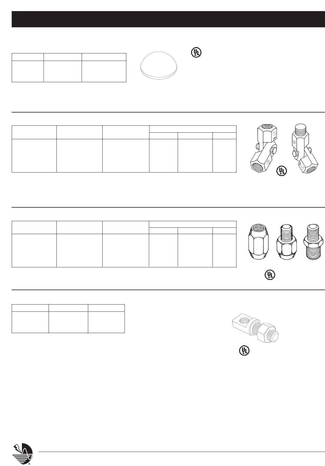
COUPLINGS AND ADAPTERS
MATERIAL CONN. NUMERIC CONNECTION TYPE CODE
CODE TYPE IDENTIFIER SIZE FEMALE MALE
LPC COPPER 3/8 TO 3/8 291 3/8” 3F 3M
LPA ALUMINUM 3/8 TO 1/2 292 1/2” 2F 2M
LPS STAINLESS 1/2 TO 1/2 293 5/8” 5F 5M
1/2 TO 5/8 294
5/8 TO 5/8 295
Example: LPC 291 3F 3M (Copper, 3/8” Female to 3/8” Male)
SAFETY BALL AIR TERMINAL
DIAMETER COPPER ALUMINUM
3/8” LPC27838
1/2” LPC27812 LPA27812
5/8” LPC27858 LPA27858
For use with series 271, 272, and 273 Extension Rods
ADJUSTABLE (SWIVEL) POINT ADAPTERS
MATERIAL CONN. NUMERIC CONNECTION TYPE CODE
CODE TYPE IDENTIFIER SIZE FEMALE MALE
LPC COPPER 3/8 TO 3/8 281 3/8” 3F 3M
LPA ALUMINUM 3/8 TO 1/2 282 1/2” 2F 2M
LPS STAINLESS 1/2 TO 1/2 283 5/8” 5F 5M
1/2 TO 5/8 284
5/8 TO 5/8 285
Example: LPC 282 3F 2M (Copper, 3/8” Female to 1/2” Male)
EXTENDABLE RIGHT-ANGLE ADAPTOR
THREAD SIZE COPPER ALUMINUM
3/8” LPC29638
1/2” LPC29612 LPA29612
5/8” LPC29658 LPA29658
- Provides 2” offset for vertical point when using any horizontal style point base.
- Suitable for modifying standard point bases such as the LP302 or LP372 for use in
vertical point applications and provides 2” clearance.
- Able to be extended to 3” in length when used with LP291- LP295.
CAL OSHA
Approved
Point Bases, Braces, and Accessories System 2000 – Series 300
21
www.erico.com
SERIES 305
Point Dia. Copper Aluminum
3/8” LPC30538 -
1/2” LPC30512 LPA30512
Vertical Mount Only
5/8" LPC30558V LPA30558V
Horizontal Mount Only
5/8" LPC30558H LPA30558H
Bronze or aluminum cast adhesive point base for use
on flat, vertical or gently sloping surface. Positive sin-
gle bolt tension for multi-directional cable clamping.
Four mounting holes for bolts or screws, or for use
with hot pitch, roofing compound or commercial
adhesive on built up roof surfaces or other locations
when no penetration can be made. Available for all
points 3/8”, 1/2”, and 5/8” diameter.
SERIES 309
Point Dia. Copper Aluminum
3/8” LPC30938 -
1/2” LPC30912 LPA30912
5/8” LPC30958 LPA30958
Bronze or aluminum cast adhesive point base for use
on flat or gently sloping surface when no penetration
may be made for anchoring. Positive single bolt ten-
sion cable clamping. For use with hot pitch, roofing
compound or commercial adhesive on built-up roof
surfaces or other locations. Available for all points
3/8”, 1/2” and 5/8” diameter.
SERIES 311
Point Dia. Copper Aluminum
3/8” LPC31138 -
1/2” LPC31112 LPA31112
5/8” LPC31158 LPA31158
Strap copper or aluminum point base for use on
ridged roof, sloping or flat surfaces. Compression
type fingers crimp over cable for direct contact. Holes
provided for optional nailing locations. Available for
all points 3/8”, 1/2” and 5/8” diameter.
SERIES 312
Point Dia. Copper Aluminum
3/8” LPC31238 -
1/2” LPC31212 LPA31212
5/8” LPC31258 LPA31258
Strap copper or aluminum point base for use on
ridged roof, sloping or flat surfaces. Positive bolt
tension cable clamping. Holes provided for
optional nailing locations. Available for all points
3/8”, 1/2” and 5/8” diameter.
SERIES 314
Point Dia. Copper Aluminum
3/8” LPC31438 -
1/2” LPC31412 LPA31412
5/8” LPC31458 LPA31458
Strap copper or aluminum point base for use on nar-
row surface or roof edge. Base 8” long with holes
for nails or screw anchors. Compressive type fingers
crimp over cable for direct contact. Available for all
points 3/8”, 1/2” and 5/8” diameter.
SERIES 315
Point Dia. Copper Aluminum
3/8” LPC31538 -
1/2” LPC31512 LPA31512
5/8” LPC31558 LPA31558
Strap copper or aluminum point base for use on
narrow surface or roof edge. Base 8” long with
holes for nails or screw anchors. Positive bolt
tension cable clamping. Available for all points
3/8”, 1/2” and 5/8” diameter.
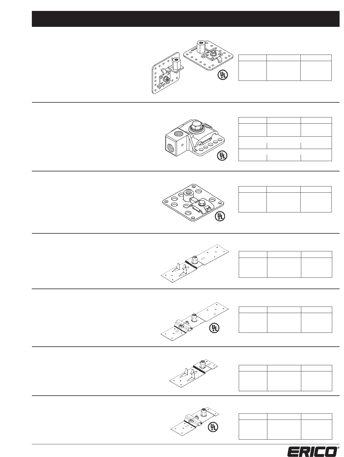
SERIES 302
Point Dia. Copper Aluminum
3/8” LPC30238 -
1/2” LPC30212 LPA30212
5/8” LPC30258 LPA30258
VERTICAL/HORIZONTAL MOUNT POINT BASE
HORIZONTAL MOUNT POINT BASE
Bronze or aluminum stamped adhesive point base for
use on flat, vertical or sloping surface. Positive single
bolt tension for multi-directional cable clamping. Four
mounting holes for bolts or screws. Air terminal
support tab is field adjustable for any angle as shown
from 0-90o, eliminating the need for swivel adaptors.
-Field adjustable tool part number LPT302
UNIVERSAL POINT BASE
RIDGE/SLOPING ROOF POINT BASE
RIDGE/SLOPING ROOF POINT BASE
RIDGE/SLOPING ROOF POINT BASE
RIDGE/SLOPING ROOF POINT BASE
Note:
- Available in tinned copper (eg. LPC302L12, tinned copper, 1/2” point)
- Also available pre-configured for vertical applications (eg. LPA30212V,
aluminum 1/2” point, factory set for vertical applications)
Class I
Class I
Point Bases, Braces, and Accessories System 2000 – Series 300
22 www.erico.com
SERIES 321
Point Dia. Copper Aluminum
3/8” LPC32138 -
1/2” LPC32112 LPA32112
5/8” LPC32158 LPA32158
Bronze or aluminum straight in line point base of
hexagon metal stock. Two set screws anchor cable
tight in base. Available for all points 3/8”, 1/2”
and 5/8” diameter.
SERIES 323
Point Dia. Copper
3/8” LPC32338
Bronze or aluminum cast straight in line point
base. Compression type fingers crimp over cable
for direct contact. Available for point size of 3/8”
diameter only.
SERIES 330
(suit pipe O.D. 1.315 - 1.9”)
Copper Aluminum Tinned Copper
LPC330 LPA330 LPC330L
Bronze or aluminum cast pipe mount point for
vertical pipe or cable pipe bond. When used as a
point support it may be used with or without
cable run on pipe or will allow point to stand off
pipe to use type 321 point to cable connector.
SERIES 319
Point Dia. Copper Aluminum
3/8” LPC31938 -
1/2” LPC31912 LPA31912
5/8” LPC31958 LPA31958
Bronze or aluminum cast point base for use on
vertical surface with horizontal or vertical run of cable.
Point attachment offset 2” from surface to clear over-
hang of wall cap or cover. Positive bolt tension cable
clamping. Two mounting holes for bolts or screws.
Available for all points 3/8”, 1/2” and 5/8” diameter.
SERIES 318
Point Dia. Copper Aluminum
3/8” LPC31838 -
1/2” LPC31812 LPA31812
5/8” LPC31858 LPA31858
Bronze or aluminum cast point base for use
on vertical surface with horizontal or vertical run
of cable. Positive bolt tension cable clamping. Two
mounting holes for bolts or screws. Available
for all points 3/8”, 1/2” and 5/8” diameter.
VERTICAL MOUNT POINT BASE
VERTICAL MOUNT POINT BASE
INLINE POINT BASE
INLINE POINT BASE
PIPE MOUNT POINT BASE AND CABLE CLAMP SUPPORT
Class I
Point Bases, Braces, and Accessories System 2000 – Series 300
23
www.erico.com
SERIES 339
Point Dia. Copper Aluminum
3/8” LPC33938 -
1/2” LPC33912 LPA33912
5/8” LPC33958 LPA33958
Bronze or aluminum cast point base for use on
cone shaped metal surface. No cable connector.
Use three bolts or screws for anchoring. Available
for all points 3/8”, 1/2” and 5/8” diameter.
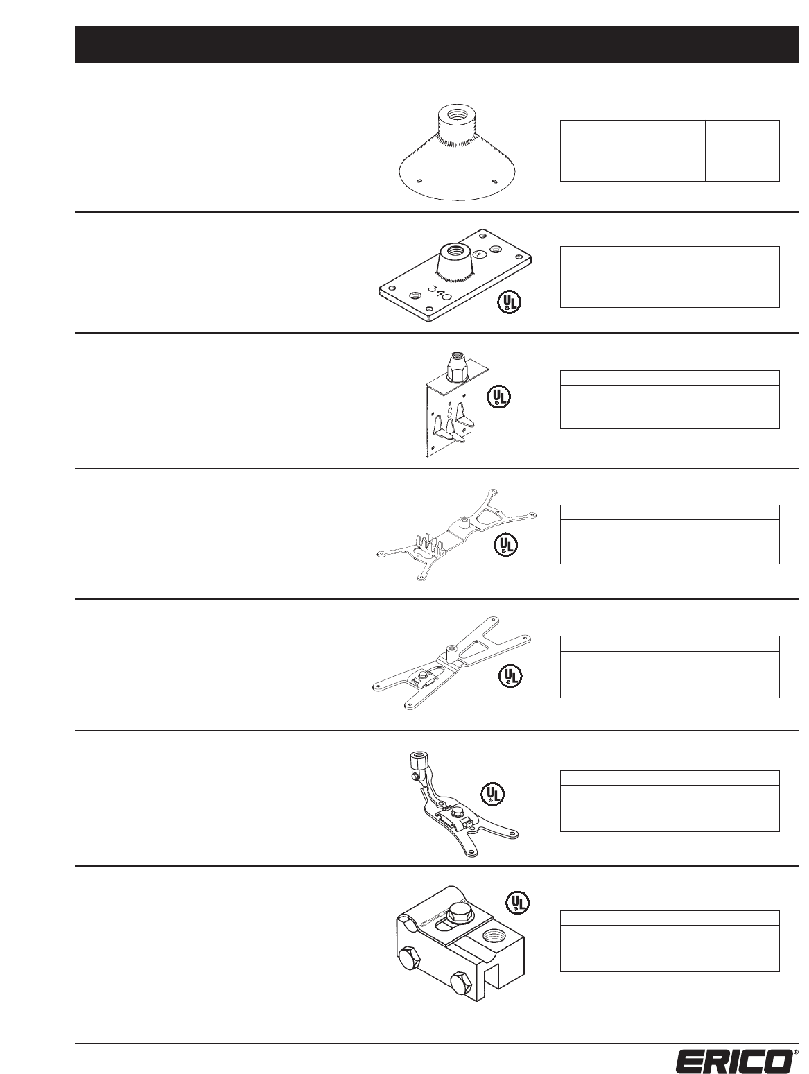
SERIES 340
Point Dia. Copper Aluminum
3/8” LPC34038 -
1/2” LPC34012 LPA34012
5/8” LPC34058 LPA34058
Bronze or aluminum cast point base for
mounting directly to horizontal structural steel
surface. Eight square inches of surface contact.
Available for all points 3/8”, 1/2” and 5/8”
diameter.
SERIES 343
Point Dia. Copper Aluminum
3/8” LPC34338 -
1/2” LPC34312 LPA34312
5/8” LPC34358 LPA34358
Strap copper or aluminum offset point base for use
on concealed or exposed systems. Compression type
fingers crimp over cable for direct contact. Holes
provided for optional nailing location. Available for all
points 3/8”, 1/2” and 5/8” diameter. We recommend
auxiliary point support for point lengths over 15”.
SERIES 344
Point Dia. Copper Aluminum
3/8” LPC34438 -
1/2” LPC34412 LPA34412
5/8” LPC34458 LPA34458
Bronze or aluminum cast point base for use on ridged
roof, sloping or flat surfaces. May be easily formed.
Compression type fingers crimp over cable for direct
contact. Holes provided for nails or metal screws stan-
dard – may be drilled for masonry drive-in anchors.
Available for all points 3/8”, 1/2” and 5/8” diameter.
SERIES 345
Point Dia. Copper Aluminum
3/8” LPC34538 -
1/2” LPC34512 LPA34512
5/8” LPC34558 LPA34558
Bronze or aluminum cast point base for use on
ridged roof, sloping or flat surfaces. May be easily
formed. Positive bolt tension cable clamping. Holes
provided for nails or metal screws standard – may
be drilled for masonry drive-in anchors. Available for
all points 3/8”, 1/2” and 5/8” diameter.
SERIES 347
Point Dia. Copper Aluminum
3/8” LPC34738 -
1/2” LPC34712 LPA34712
5/8” LPC34758 LPA34758
Bronze or aluminum cast point base for use on
ridged roof, sloping or flat surfaces. May be easily
formed. Positive bolt tension cable clamping. Holes
provided for nails or metal screws standard – may
be drilled for masonry drive-in anchors. Available
for all points 3/8”, 1/2” and 5/8” diameter.
SERIES 348
Point Dia. Copper Aluminum
3/8” LPC34838 —
1/2” LPC34812 LPA34812
5/8” LPC34858 LPA34858
Bronze or aluminum cast point base for standing
seam roofing systems. Bottom groove 1/2" wide by
3/4" deep to secure on seam with two set screws.
Adjustable cable connector for conductor runs either
parallel or perpendicular to the seam. Available for
all points 3/8”, 1/2” and 5/8” diameter.
CONE ROOF POINT BASE
HORIZONTAL BOND POINT BASE
VERTICAL POINT BASE
RIDGE MOUNT POINT BASE
RIDGE MOUNT POINT BASE
SLOPED ROOF POINT BASE
STANDING SEAM POINT BASE
Class I
Class I
Point Bases, Braces, and Accessories System 2000 – Series 300
24 www.erico.com
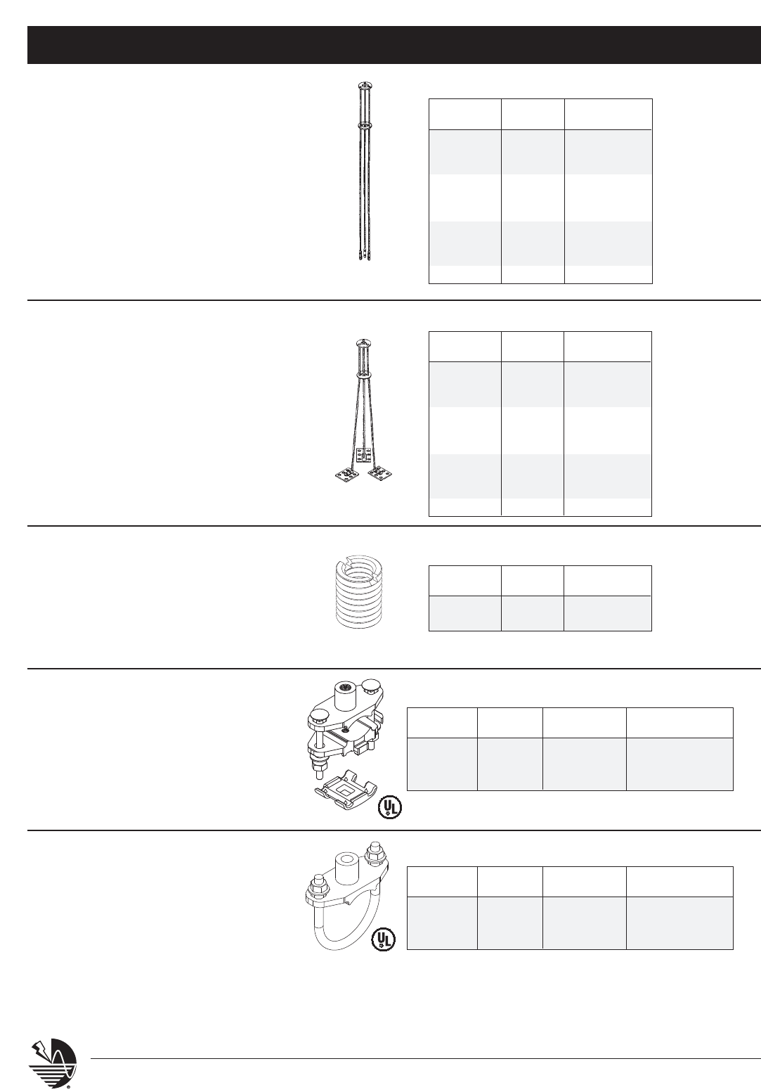
PART # LENGTH UP TO MAX.
POINT SIZE
LPG36012 14” 1/2” X 24”
LPG36058 14” 5/8” X 24”
LPG36112 18” 1/2” X 30”
LPG36158 18” 5/8” X 30”
LPG36212 24” 1/2” X 40”
LPG36258 24” 5/8” X 40”
LPG36312 36” 1/2” X 60”
LPG36358 36” 5/8” X 60”
LPG36412 48” 1/2” X 84”
LPG36458 48” 5/8” X 84”
PART # LENGTH UP TO MAX.
POINT SIZE
LPG35012 14” 1/2” X 24”
LPG35058 14” 5/8” X 24”
LPG35112 18” 1/2” X 30”
LPG35158 18” 5/8” X 30”
LPG35212 24” 1/2” X 40”
LPG35258 24” 5/8” X 40”
LPG35312 36” 1/2” X 60”
LPG35358 36” 5/8” X 60”
LPG35412 48” 1/2” X 84”
LPG35458 48” 5/8” X 84”
Galvanized steel tripod braces for additional
support of long air terminals. Constructed of
1/4” mild steel with heavy section washer guides.
All joints welded prior to galvanizing. Two
mounting holes per leg furnished for installation.
Available for all 1/2” and 5/8” diameter points.
Galvanized steel tripod braces for additional
support of long air terminals on flat or gently
sloping surface when no penetration may be
made for anchoring. Constructed of 1/4” mild
steel with heavy section washer guides. All joints
welded prior to galvanizing. For use with hot
pitch, roofing compound or commercial adhesive
on membrane surface or other locations. Available
for all 1/2” and 5/8” diameter points.
PENETRATING BASE
NON-PENETRATING BASE
PART # OUTSIDE INSIDE
THREAD THREAD
LPC37012 1/2” 3/8”
LPC37058 5/8” 3/8”
Copper bushing to convert either a 1/2” or 5/8”
female point base to accept a 3/8” diameter
point. Bushing fits neatly inside female point base.
POINT BUSHING SERIES 370
SERIES 350 - SERIES 354
SERIES 360 - SERIES 364
POINT COPPER ALUMINUM TINNED
DIAMETER COPPER
3/8” LPC37138 - LPC371L38
1/2” LPC37112 LPA37112 LPC371L12
5/8” LPC37158 LPA37158 LPC371L58
SERIES 371 (suit pipe OD 1.75”-2.5”)
POINT COPPER ALUMINUM TINNED
DIAMETER COPPER
3/8” LPC37238 - LPC372L38
1/2” LPC37212 LPA37212 LPC372L12
5/8” LPC37258 LPA37258 LPC372L58
SERIES 372 (suit pipe OD 1.75”-2.5”)
Bronze or aluminum cast pipe mount point base
with point coupling for horizontal pipe. Provided
with cable clamp to support cable beneath pipe.
Can be applied to vertical pipe with LP296 right
angle point coupler.
PIPE MOUNT POINT BASE
Bronze or aluminum cast pipe mount point base
with point coupling for horizontal pipe. Can be
applied to vertical pipe with LP296 right angle
point coupler.
PIPE MOUNT POINT BASE
Industrial Stack Equipment System 2000 – Series 400
25
www.erico.com
Note: All conductors listed on this page are manufactured to Underwriters’ Laboratories requirements.
Note: Specialty copper cables are available on request to meet specific job requirements. Please call for pricing and availability.
COPPER CABLES
PART # CONDUCTOR # OF WIRE SIZE WEIGHT PER CIRCULAR MEETS
TYPE STRANDS GAUGE 1000 FEET MILS REQ’MENT
LPC401
SMOOTH WEAVE
28 14 380 Lbs. 115,080 CLASS II
LPC404 CONCENTRIC 19 0.1055” 653 Lbs. 211,600 CLASS II 4/0
LEAD COVERED COPPER CABLES With a continuous 1/16” pure lead sheath.
PART # CONDUCTOR # OF WIRE SIZE WEIGHT PER CIRCULAR MEETS
TYPE STRANDS GAUGE 1000 FEET MILS REQ’MENT
LPLC401 CONCENTRIC 19 0.084” 1,380 Lbs. 115,080 CLASS II
LPLC404 CONCENTRIC 19 0.1055” 1,983 Lbs. 211,600 CLASS II 4/0
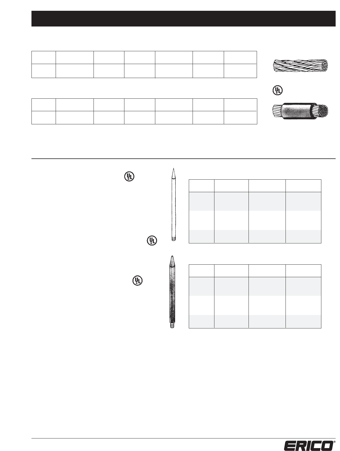
5/8” POINTS
LENGTH COPPER LEAD- STAINLESS
BARE COVERED STEEL
18” LPC411 LPLC411 LPS411
24” LPC412 LPLC412 LPS412
36” LPC413 LPLC413 LPS413
48” LPC414 LPLC414 LPS414
60” LPC415 LPLC415 LPS415
72” LPC416 LPLC416 LPS416
84” LPC417 LPLC417 LPS417
96” LPC418 LPLC418 LPS418
3/4” POINTS
LENGTH COPPER LEAD- STAINLESS
BARE COVERED STEEL
18” LPC421 LPLC421 LPS421
24” LPC422 LPLC422 LPS422
36” LPC423 LPLC423 LPS423
48” LPC424 LPLC424 LPS424
60” LPC425 LPLC425 LPS425
72” LPC426 LPLC426 LPS426
84” LPC427 LPLC427 LPS427
96” LPC428 LPLC428 LPS428
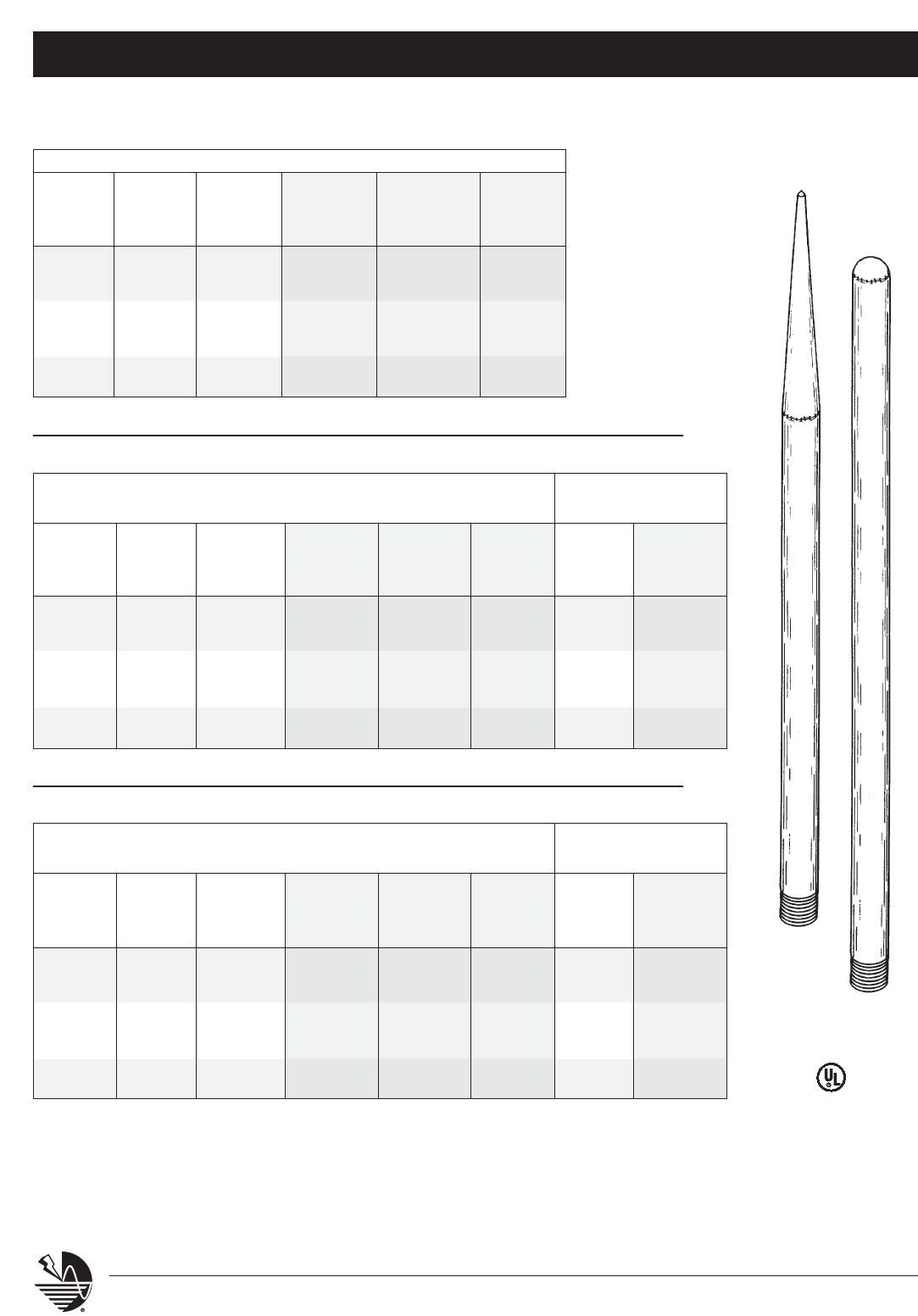
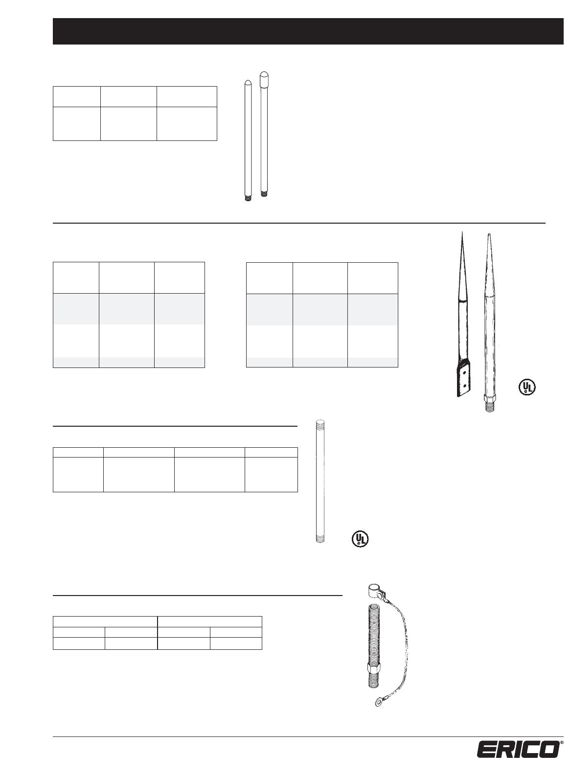
BARE COPPER POINTS
Solid copper points made from high
conductivity copper rod with tapered
point and standard N. C. threads.
LEAD COVERED COPPER POINTS
Solid copper points made from high
conductivity copper rod with a 1/16” thick lead
sheath, tapered point and standard N. C. threads.
STAINLESS STEEL POINTS
Stainless steel points made from 316 grade stainless
steel rod, with tapered point and standard N.C. threads.
Note: All points listed on this page are manufactured
to Underwriters’ Laboratories®requirements.
Industrial Stack Equipment System 2000 – Series 400
26 www.erico.com
POINT BASES
PART # MATERIAL POINT STUD*
THREAD LENGTH
SERIES 431
LPC431 BARE BRASS 5/8” –
LPLC431 LEAD COATED 5/8” –
SERIES 433
LPC433 BARE BRASS 5/8” –
LPLC433 LEAD COATED 5/8” –
SERIES 435
LPC435SH BARE BRASS 5/8” 7/8”
LPC435LG BARE BRASS 5/8” 1-1/2”
LPLC435SH LEAD COATED 5/8” 7/8”
LPLC435LG LEAD COATED 5/8” 1-1/2”
SERIES 436
LPC436SH BARE BRASS 5/8” 7/8”
LPC436LG BARE BRASS 5/8” 1-1/2”
LPLC436SH LEAD COATED 5/8” 7/8”
LPLC436LG LEAD COATED 5/8” 1-1/2”
SERIES 437
LPC437SH BARE BRASS 5/8” 7/8”
LPC437LG BARE BRASS 5/8” 1-1/2”
LPLC437SH LEAD COATED 5/8” 7/8”
LPLC437LG LEAD COATED 5/8” 1-1/2”
1/16" lead coating
* Use 7/8” stud w/drop-in (LPP48812 or LPS48812) or
caulk-in (LPP48712) anchors.
* Use 1-1/2” stud w/expansion shield (LPP48612) anchors.
CABLE SPLICERS
PART # MATERIAL
LPC441 COPPER
LPC443 COPPER
LPC446 COPPER
LPC448 COPPER
LPLC441 LEAD COATED
LPLC443 LEAD COATED
LPLC446 LEAD COATED
LPLC448 LEAD COATED
- 1/16" lead coating
- Suitable for cables from 2/0
to 4/0 in size
Note: Current standard requirements specify that side mounted
points be anchored at two locations to the structure with
the above provided stud counting as one. Refer to part
numbers LP-C480, LP-LC480, LP-C492 or LP-LC492 for
point holders to be used as the second required anchor.
SERIES 431 SERIES 433 SERIES 435
SERIES 436 SERIES 437
SERIES 441 SERIES 443
SERIES 446
SERIES 448
Industrial Stack Equipment System 2000 – Series 400
27
www.erico.com
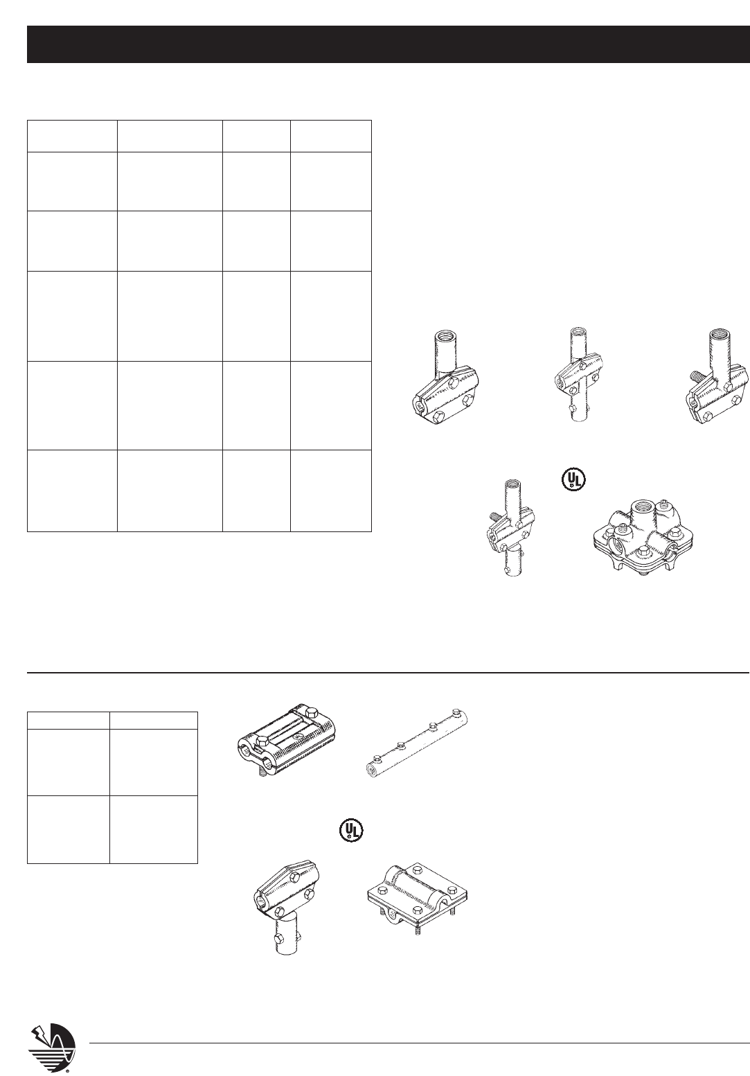
BONDING FITTINGS
CONTACT FOR USE WITH
SERIES 451 MATERIAL AREA CABLE No.
LPC451 BARE BRASS 3 IN2LPC401/LPC404
LPLC451 LEAD COATED 3 IN2LPLC401/LPLC404
LPS451 TYPE 316 SS 3 IN2LPC401/LPLC401 or
LPC404/LPLC404
- Standard bolt hole size = 13/16”.
- 1/16" lead coating.
HANDRAIL TO POINT
SERIES 456 MATERIAL Pipe Size (O.D.)
LPC456 COPPER 2" or 2.5"
LPS456 STAINLESS 2" or 2.5"
Suitable for 5/8” or greater point diameter.
SPECIAL BONDING ASSEMBLIES
SERIES 464
ASSEMBLY COMPONENTS
LUG
PART # LUGS MATERIAL
LPC464 LPC451 BARE BRASS
LPLC464 LPLC451 LEAD COATED
Notes: Standard bolt hole size = 13/16”.
Standard cable length = 36”.
Standard cable size = 2/0.
For 4/0 cable size insert "40" following 464 in the part number.
eg. LPC46440 for copper lug, 4/0 cable size.
SERIES 465
ASSEMBLY COMPONENTS
LUG CONNECTOR CONNECTOR
PART # LUG MATERIAL MATERIAL
LPC465 LPC451 BARE BRASS LPC441 BARE BRASS
LPLC465 LPLC451 LEAD COATED LPLC441 LEAD COATED
Notes: Standard bolt hole size = 13/16”.
Standard cable length = 36”.
Standard cable size = 2/0.
For 4/0 cable size insert "40" following 465 in the part number.
eg. LPC46540 for copper lug, 4/0 cable size.
Industrial Stack Equipment System 2000 – Series 400
28 www.erico.com
SERIES 466
Cast bronze universal cable to rebar bonding clamp.
Fits cable sizes through 250 MCM to reinforcing bars
up through #9 (1.128").
PART #
LPC466
REBAR BONDS
SERIES 467
Embedded rebar connection assembly
consists of 4” x 4” flush mount brass plate
with 1/2” tapped hole connecting Part No.
LPC401 and LPC404 bare copper cable to
rebar bonding clamp(s). Three feet of cable
provided per rebar clamp.
Note: Use this product in conjunction with
Part No. LPC468,
exposed downlead to flush
plate connectors.
SERIES 467
For use with Part No. LPC401 and LPC404
bare copper cable
LPC467X1 For Bonding 1 Rebar
LPC467X2 For Bonding 2 Rebars
Notes: Standard cable size = 2/0
For 4/0 cable size insert “40”
following 467 in the part number
eg. LPC46740X2 for 4/0
cable, 2X clamp and 6 ft cable.
LPC468
Bare brass; connect Part No. LPC467 flush rebar
to Part No. LPC401 and LPC404 bare copper
downlead cable
LPLC468
Lead covered brass; connect Part No. LPC467
flush rebar to Part No. LPLC401 and LPC404
lead covered copper downlead cable
SERIES 468 – Bare Brass
Cast cable connector for connecting
flush rebar plate to bare copper
downlead cable.
NOTE: The above iron band yokes are designed to fit over a single 3/8” thick band.
STEEL YOKE
SERIES 469
LP-S469
Stainless steel yoke for connections to iron bands. For use where lead covered
copper cables extend over bands. Drilled and tapped for 1/2” threaded stud.
Use with Series LPC481, LPC482 or LPC483.
Industrial Stack Equipment System 2000 – Series 400
29
www.erico.com
LPC475
Solid copper ground bar 1/4” x 4” x 16”
with a 2-1/8” offset.
GROUNDING BUSBAR
SERIES 475
LPC475 used as a ground bus to connect
bottom end of downlead to customer
provided ground tail at column base.
Standard holes provided for 1/2” bolt size
connections and anchors (two on the face
and one on each wing). Room available
to mount installer’s nameplate and
Underwriters’ Laboratories Master Label
Wing mounting holes 14” on center.
LPC477
for use with Part No. LPC401 copper cable.
LPC47740
for use with Part No. LPC47740 copper cable
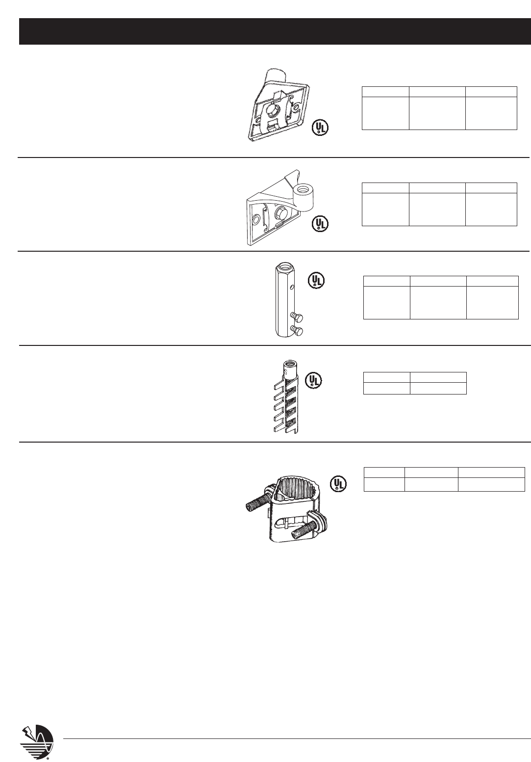
DOWNLEAD PROTECTOR
SERIES 477
Copper tube protector for use where
stranded cables are subject to displace-
ment or damage. Protectors are 8 ft. long
standard with set screw and wedge at
each end to bond cable to tube.
LPC478
for use with Part No. LPC477 tube protector
LPC47840
for use with Part No. LPC47740 tube protector
PIPE FASTENERS
SERIES 478
Bare bronze, protector pipe fastener.
Provided with 1/2” diameter X 7/8” long
threaded stud for anchoring.
LPC479
for use with Part No. LPC477 tube protector
SERIES 479
Bare bronze, lay-in, protector pipe
fastener. Mount in brick construction.
Industrial Stack Equipment System 2000 – Series 400
30 www.erico.com
Bare Bronze
LPC48058*
for 5/8” diameter bare copper point
LPC48034*
for 3/4” diameter bare copper point
POINT AND CABLE FASTENERS
SERIES 480
Bare bronze 2-bolt cap type point fastener
for use with bare copper points. Provided
with 1/2” threaded stud for anchoring.
Lead covered bronze 2-bolt cap type point
fastener for use with lead covered copper
or stainless steel points. Provided with 1/2”
threaded stud for anchoring.
* For stud length 7/8” specify “SH”
For stud length 1-1/2” specify “LG”
Lead Covered Bronze
LPLC48058* for 5/8” diameter points or
LPLC401 and LPLC404 lead covered cable
LPLC48034* for 3/4” diameter points
Bare Bronze
LPC481*
Bare bronze; use with Part No. LPC401 bare
copper cable
CABLE FASTENERS
SERIES 481
Pinch type cable fastener. Provided with
1/2” threaded stud for anchoring.
* For stud length 7/8” specify “SH”
For stud length 1-1/2” specify “LG”
Bare Bronze
LPC482*
Bare bronze; use with Part No. LPC401 bare
copper cable
SERIES 482
2-bolt cap type cable fastener. Provided
with 1/2” threaded stud for anchoring.
* For stud length 7/8” specify “SH”
For stud length 1-1/2” specify “LG”
Bare Bronze
LPC483
Bare bronze cable to metal surface fastener
SERIES 483
Bare bronze cable to metal surface
fastener. Provided with 1/2” x 2” silicon
bronze mounting bolt. May be used
with Part No. LPS469 iron band yoke.
Industrial Stack Equipment System 2000 – Series 400
31
www.erico.com
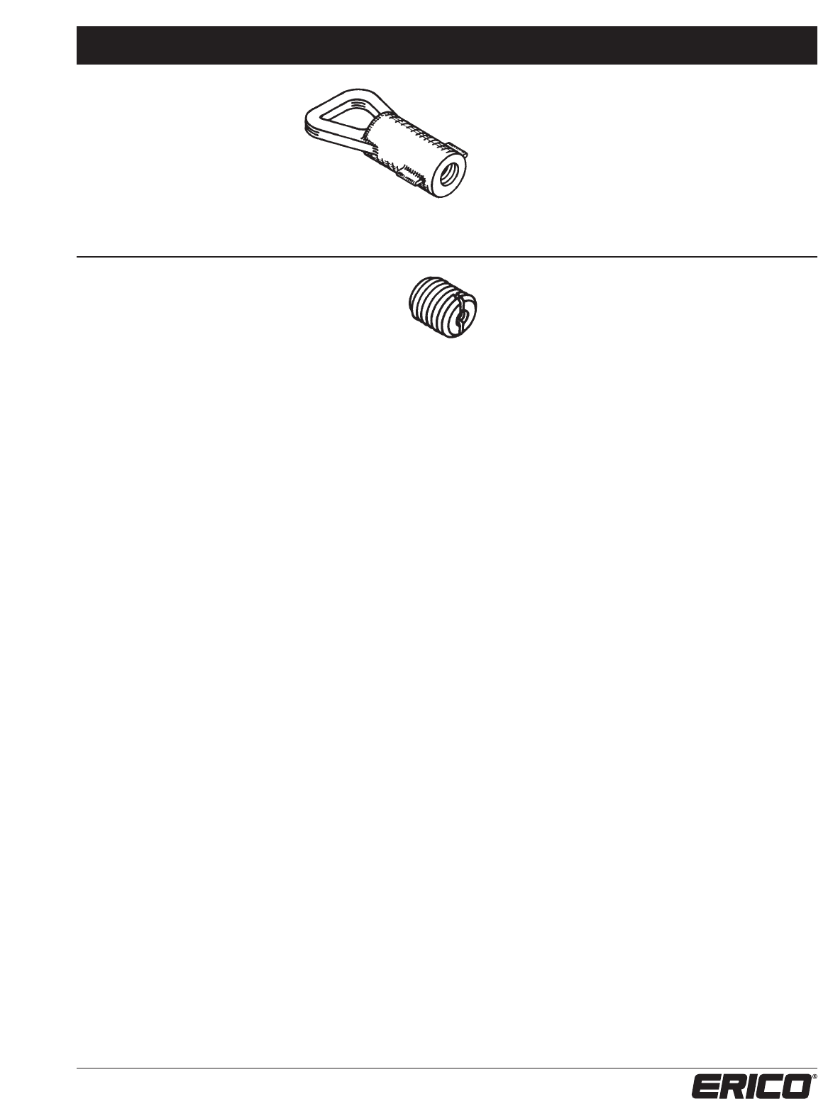
CONCRETE INSERT
SERIES 484
Insert for placement in concrete
during construction. Use with
standard length stud 7/8”
Cast Bronze
LPC48412
Cast bronze; provided with 1/2"-13 internal thread
LPC48512 for 1/2"-13 inserts
BRASS INSERT PLUG
SERIES 485
Provided with 1/4-20 centered thread and screw
driver slot. Allows for mounting LPC484 inserts
to forms and offers means of removal.
Industrial Stack Equipment System 2000 – Series 400
32 www.erico.com
Bare Bronze
LPC49258
Bare bronze; for 5/8” outside
diameter points
LPC49234
Bare bronze; for 3/4” outside
diameter points
Lead Covered Bronze
LPLC49258
Lead covered bronze; for 5/8”
outside diameter points or LPLC401
and LPLC404 lead covered cable
LPLC49234
Lead covered bronze; for 3/4”
outside diameter points
POINT AND CABLE INSERTS
SERIES 492
Lay-in point holder. Series LPC992 for use with
bare copper points. Series LPLC492 for use
with lead covered, or stainless steel points.
Lay-in brick construction.
Bare Bronze
LPC494
Bare bronze, for use with Part No.
LPC401 bare copper cable
SERIES 494
Lay-in pinch type cable holder. Lay-in
brick construction.
Bare Bronze
LPC495
Bare bronze, for use with Part No.
LPC401 bare copper cable
SERIES 495
Lay-in horizontal cable for brick
construction.
Bare Bronze
LPC496
Bare bronze; for use with Part No.
LPC401 bare copper cable
SERIES 496
2-bolt cap type, lay-in cable holder.
Lay-in brick construction.
Clamps, Splices, Plates, & Lugs System 2000 – Series 500
33
www.erico.com
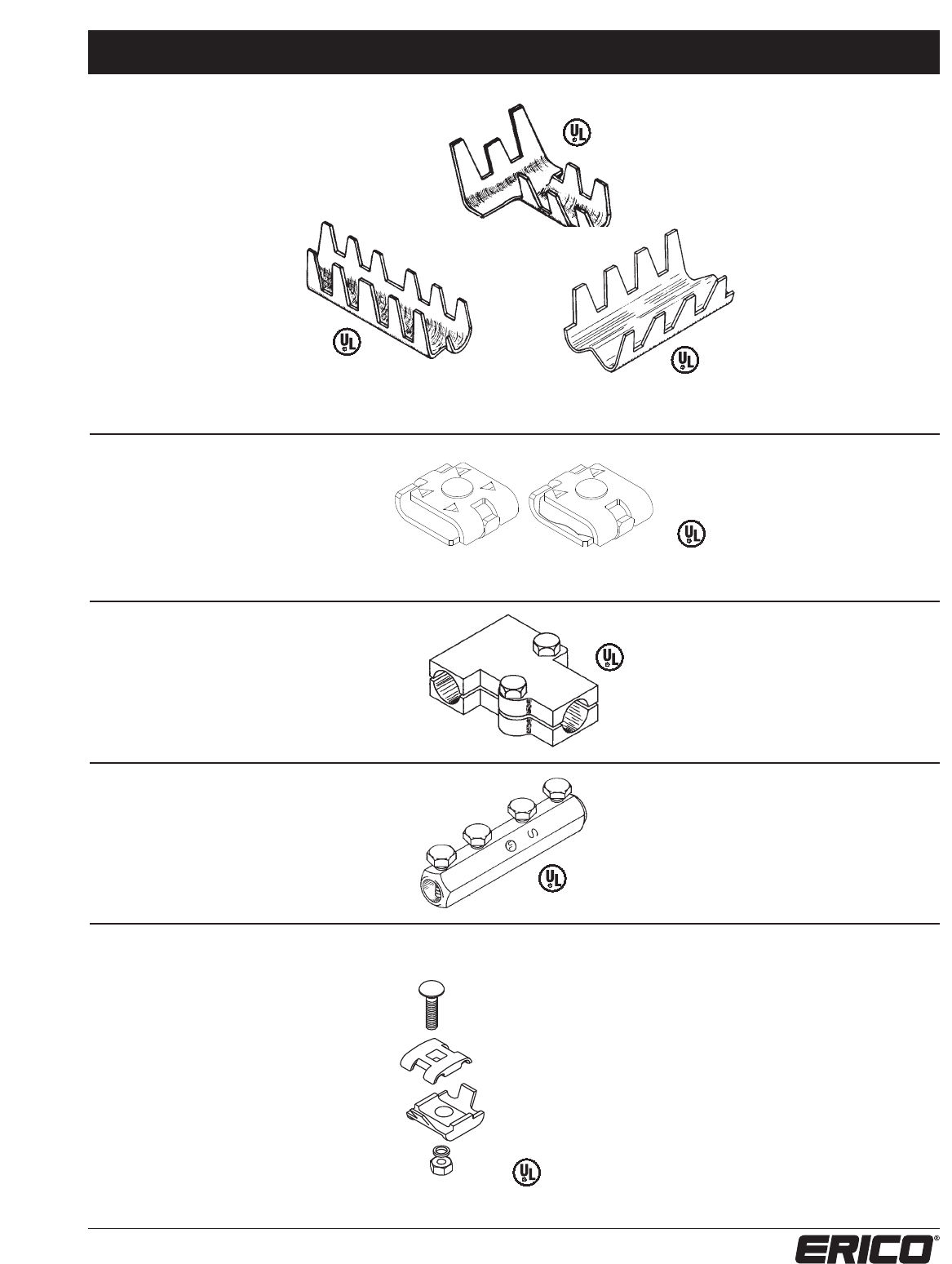
CABLE SPLICERS
SERIES 501, 503 & 505
Copper or aluminum splicer with
compression type fingers to crimp
over cable. Made from 14 gauge
copper or 10 gauge aluminum
sheet stock. For use with all full
size cables on Class I structures. Series 501
• Tee cable splicer
Series 503
• Butt end straight cable splicer Series 505
• Parallel cable splicer
Series 510
LPC510 for copper
LPA510 for aluminum
Series 513
LPC513 for copper
LPA513 for aluminum
Series 501
LPC501 for copper
LPA501 for aluminum
Series 503
LPC503 for copper
LPA503 for aluminum
Series 505
LPC505 for copper
LPA505 for aluminum
SERIES 510
Cast bronze or aluminum tee cable
splicer with positive bolt tension grip on
cables. For use with all full size cables.
Series 502
LPC502 for copper
LPA502 for aluminum
LPC502A for bi-metallic
LPC502L for tinned copper
SERIES 502
Stamped bronze or aluminum universal
parallel cable splicer. May be used with any
combination of full size cables and/or
miniature bonding wire or cables. Positive
single bolt tension grip on cables or wire.
Total contact length 1-1/2”
SERIES 513
Cast bronze or aluminum cable splicer.
For use with all cable sizes. Butt End
straight cable splicer with two set
screws for pressure on each cable.
SERIES 516
Cast bronze or aluminum universal
parallel cable splicer. May be used
with any combination of full size
cables and/or miniature bonding
wire or cables. Positive single bolt
tension grip on cables or wire.
Total contact length 1-1/2".
Series 516
LPC516 for copper
LPA516 for aluminum
Series 516
LP502 LPC502A Class I/II
Clamps, Splices, Plates, & Lugs System 2000 – Series 500
34 www.erico.com
SERIES 517
Cast bronze or aluminum universal parallel
cable splicer. May be used with any combi-
nation of full size cables and/or miniature
bonding wire or cables. Positive two bolt
tension grip on cables or wire. Total
contact length 2”.
Series 517
LPC517 for copper
LPA517 for aluminum
Series 527 (contact length 2”)
LPC527 for copper cables and
reinforcing steel bonding
LPA527 for aluminum cables
Series 528 (contact length 4”)
LPC528 for copper cables and
reinforcing steel bonding
LPA528 for aluminum cables
SERIES 527 & 528
Cast bronze or aluminum universal parallel
cable splicer. May be used with any combi-
nation of full size cables and/or miniature
bonding wires or cables. Positive single or
double bolt tension grip on cables or wires.
Total contact length 2” or 4”.
Series 532
LPC532 for copper cables to compatible
metal surface
LPC532L for copper cables to dissimilar
metal surface
LPA532 for aluminum cables to compatible
metal surface
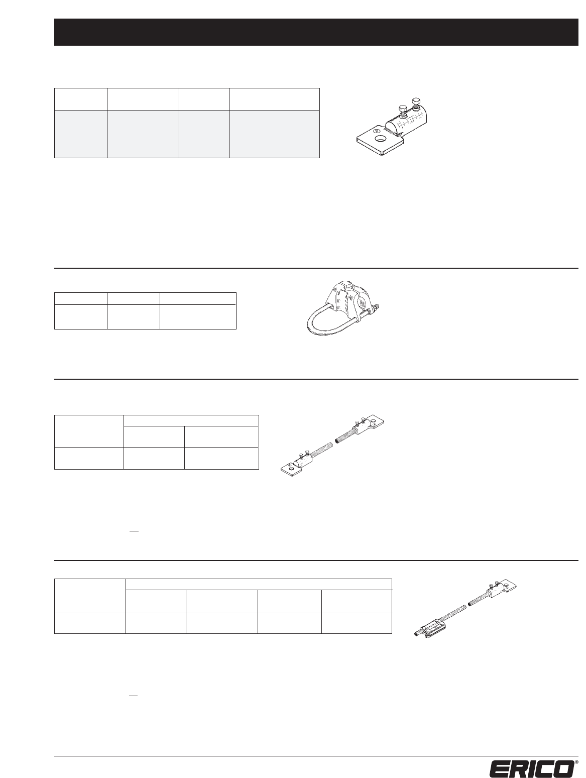
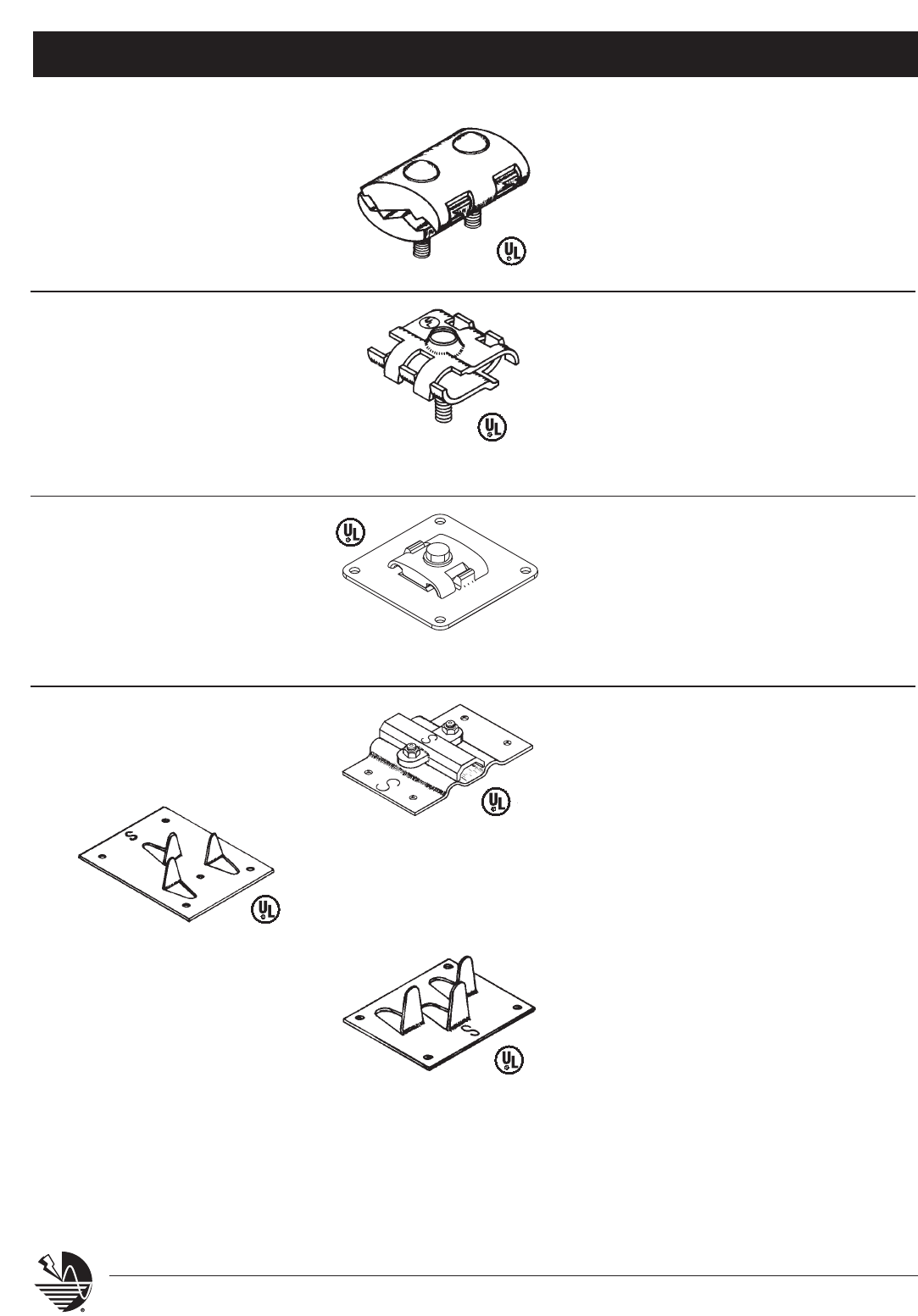
BONDING PLATES
SERIES 532
Cast bronze or aluminum flat metal
bonding plate with 8 square inches
of contact surface. Two set screws
for pressure on cable. For use with
all full size cables.
SERIES 533, 534 & 535
Copper or aluminum flat or curved
metal bonding plate. For use with all
cable sizes
Series 533
Compression type fingers crimp
over cable for direct contact. 8
square inches of contact surface.
Class I installations only.
Series 534
Double bolt tension grip on
cable. 8 square inches of contact
surface. Class I or II installations.
Series 535
Compression type fingers crimp
over cable for direct contact. 4
square inches of contact surface.
Class I installations only.
Series 533
LPC533 for copper cables to compatible
metal surface
LPC533L for copper cables to dissimilar
metal surface
LPA533 for aluminum cables to compatible
metal surface
Series 534
LPC534 for copper cables to compatible
metal surface
LPC534L for copper cables to dissimilar
metal surface
LPA534 for aluminum cables to compatible
metal surface
Series 535
LPC535 for copper cables to compatible
metal surface
LPC535L for copper cables to dissimilar
metal surface
LPA535 for aluminum cables to compatible
metal surface
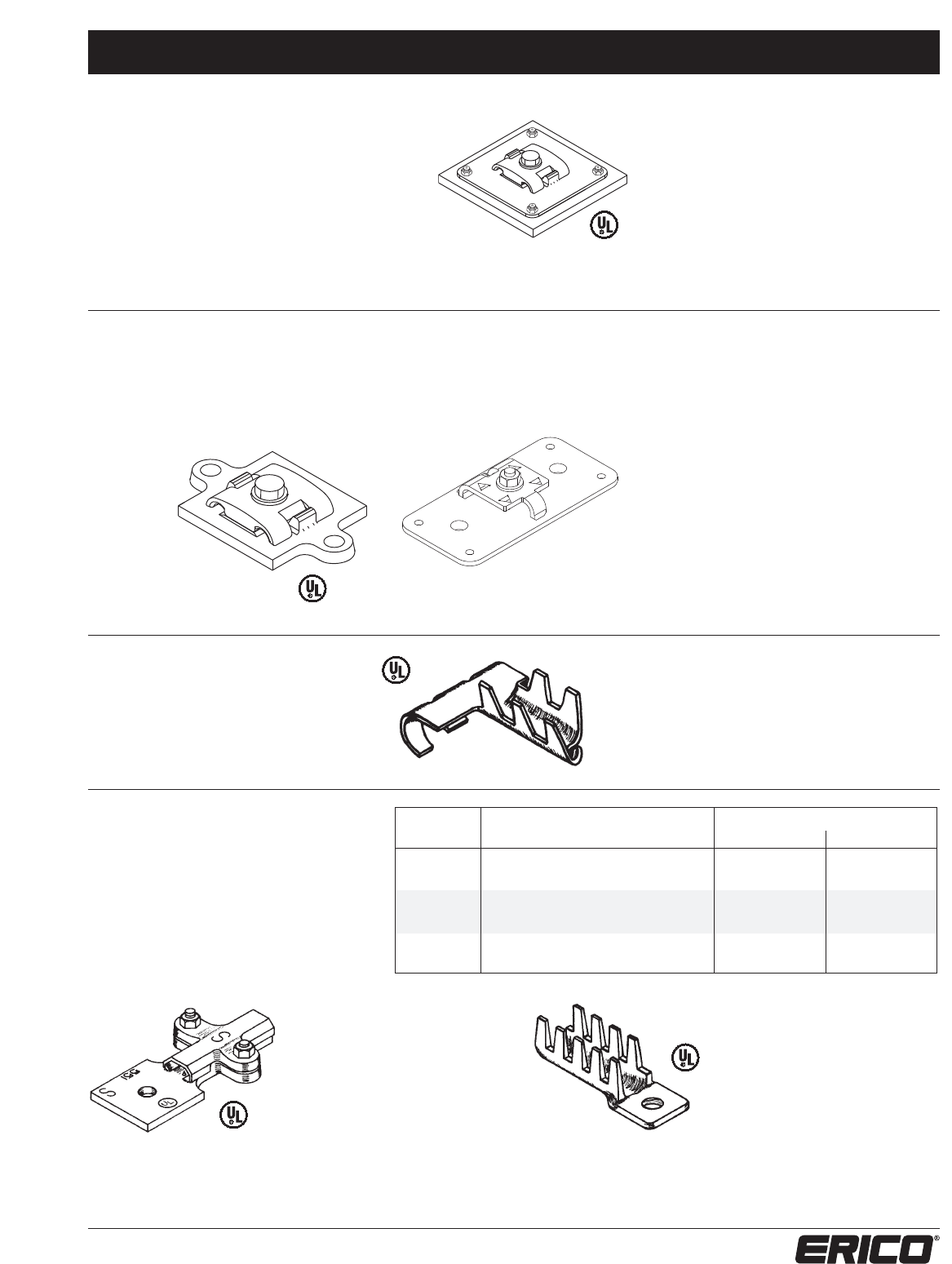
Clamps, Splices, Plates, & Lugs System 2000 – Series 500
35
www.erico.com
BONDING PLATES
SERIES 536
Cast bronze or aluminum flat metal bonding plate
Part Nos. LPC532 or LPA532 with mild steel weld-
ing plate 1/4” x 4” x 4” for attachment to steel
columns or beams when no holes may be made in
steel member. Steel plate to be electrically welded
to steel column or beam. Furnished with four set
screws to attach bonding plate to welding plate.
Series 536
Series 536
LPC536 for use with copper cables
LPA536 for use with aluminum cables
SERIES 537 & 540
Bronze or aluminum flat metal
bonding plate. Single bolt tension
grip on cable. For use with all full
size cables.
Series 537
3 square inches
of contact surface.
Series 537
LPC537 for copper cables to compatible
metal surface
LPC537L for copper cables to dissimilar
metal surface
LPA537 for aluminum cables to compatible
metal surface
Series 540
LPC540 for copper cables to compatible
metal surface
LPC540L for copper cables to dissimilar
metal surface
LPA540 for aluminum cables to compatible
metal surface
LPC540A for copper cables to aluminum or
compatible metal surface
Series 540
8 square inches
of contact surface.
SERIES 544
Copper or aluminum gutter clamp
with compression fingers to crimp
over gutter edge and cable. For use
with all full size cables.
Series 544
LPC544 for copper cables to compatible
metal surface
LPC544L for copper cables to dissimilar
metal surface
LPA544 for aluminum cables to compatible
metal surface
TERMINAL BONDING LUG
SERIES 551 & 552
Cast bronze or aluminum terminal bonding
lug. Available for bolt sizes 3/8”, and 1/2”
diameter. For use with all full size cable.
Series 551
Bolt tension grip on cable
for Class I or II installations
Series 552
Compression type fingers to
crimp over cable for Class I
installations only
PART NO.
BOLT DIA. CABLE TYPE TO SURFACE TYPE SERIES 551 SERIES 552
3/8" copper to copper LPC55138 LPC55238
1/2" copper to copper LPC55112 LPC55212
3/8" copper to dissimilar LPC551L38 LPC552L38
1/2" copper to dissimilar LPC551L12 LPC552L12
3/8" aluminum to aluminum LPA55138 LPA55238
1/2" aluminum to aluminum LPA55112 LPA55212
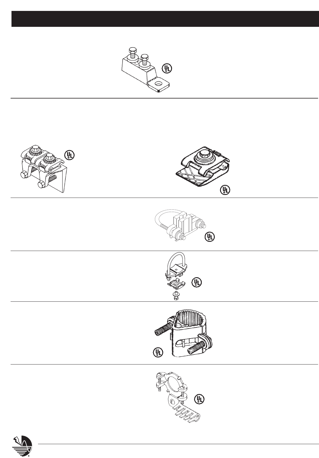
Clamps, Splices, Plates, & Lugs System 2000 – Series 500
36 www.erico.com
SERIES 555
Cast bronze or aluminum terminal
bonding lug with set screw pressure
on miniature cables and wires. Lug
hole for 1/4” diameter bolt. For use
with all miniature bonding cables
and wires.
Series 555
LPC555 for copper miniature cables and wires
LPC555L (tinned) for copper miniature cables and wires
LPA555 for aluminum miniature cables and wires
Series 557
Gives 8 square inches of bolt
tension contact. Draws tight
on member thickness up to 1”
Series 559
Provides bolt tension contact.
Draws tight on member thick-
ness up to 5/8”
BEAM/PURLIN FLANGE BONDING CLAMPS
SERIES 557 & 559
Cast bronze or aluminum universal cable to beam flange or purlin flange
bonding clamp. Requires no holes in heavy steel member. For use with
all full size cables and bonding cables and wires.
PIPE GROUNDING CLAMPS
SERIES 580
Cast bronze or aluminum pipe grounding clamp. For use
with all full size cables, miniature cables and bonding
wires. Suitable for pipe size 1/2” thru 1” inside pipe size
(O.D. range 0.750” to 1.315”). For pipe sizes greater
than 1.315" O.D. refer to Series 330, 331 or 596.
Series 580
LPC580 Copper
LPC580L Tinned Copper
LPA580 Aluminum
PIPE/REBAR GROUNDING CLAMPS
SERIES 570
Cast bronze or aluminum pipe or rebar grounding clamp.
For use with all full size cables. Suitable for pipe or rebar up
to O.D. 1-1/4”.
Series 570
LPC570 Copper
LPC570L Tinned Copper
LPA570 Aluminum
PIPE GROUNDING CLAMPS
SERIES 571
Cast bronze or aluminum pipe grounding clamp. For use with
all full size cables. Suitable for pipe size 1.75” to 2.5” O.D.
Series 571
LPC571 Copper
LPC571L Tinned Copper
LPA571 Aluminum
WATER SYSTEM
BONDING CLAMPS
SERIES 583
Cast bronze sill cock water system bonding clamp with
adjusting screws of various flange sizes. Fits behind
flange of sill cock with hammer down ears for positive
contact. Lug accepts all full size cables. Lug is plated
for use with copper or aluminum cables.
Series 583
LPC583 for copper cables and wires
Series 557
LPC557 for copper cables and wires
LPA557 for aluminum cables and wires
Series 559
LPC559 for copper cables and wires
LPA559 for aluminum cables and wires
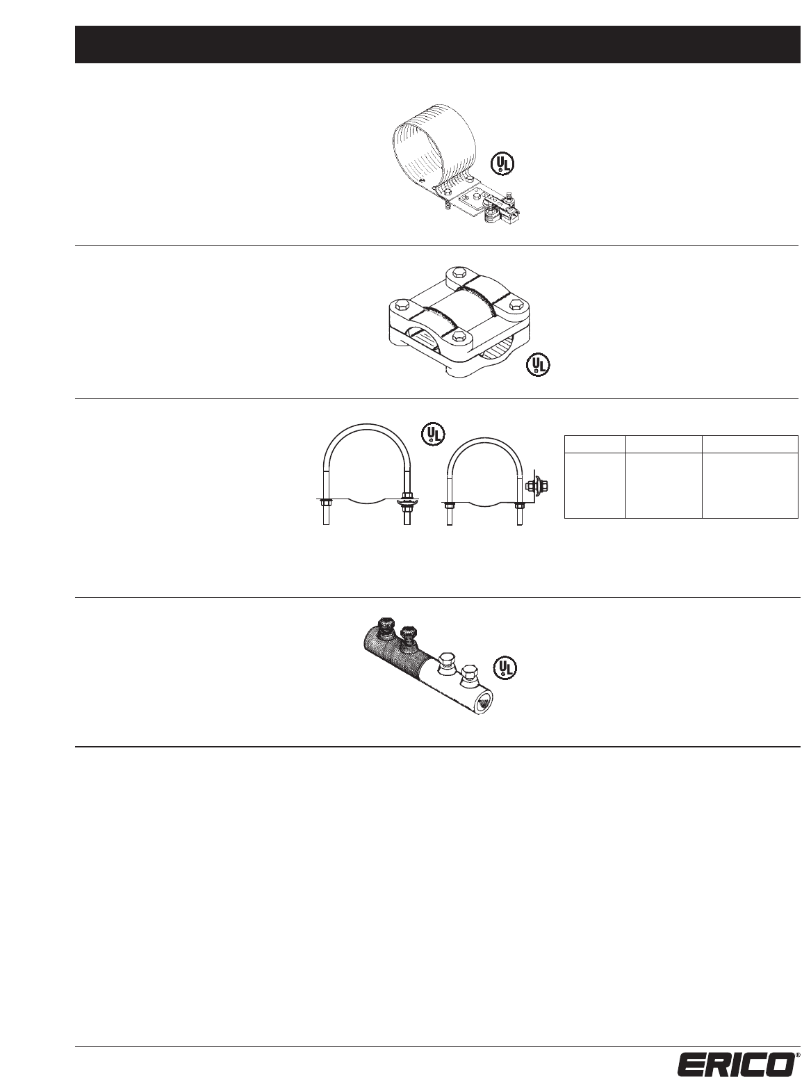
Clamps, Splices, Plates, & Lugs System 2000 – Series 500
37
www.erico.com
PIPE CLAMPS
SERIES 588 & 590
Strap copper or aluminum pipe bonding
clamp. Suitable for pipe sizes from
6.625” to 10.750” O.D. Other sizes
available upon request. For use with
all full size cables.
Series 588 (O.D. range 6.625 to 8.625)
LPC588 for copper cables
LPA588 for aluminum cables
Series 590 (O.D. range 8.625 to 10.750)
LPC590 for copper cables
LPA590 for aluminum cables
CROSS-RUN or 4-WAY
CABLE CONNECTOR
SERIES 595
Cast bronze or aluminum cross-run or
4-way cable connector. Four bolts for
positive bolt tension grip on cables.
For use with all full size cables.
Series 595
LPC595 for copper cables
LPA595 for aluminum cables
BI-METALLIC CONNECTOR
SERIES 598
Machined aluminum bi-metallic connector
for making connections between copper and
aluminum cables in straight run. Two-bolt
tension grip on each cable end. For use with
all full size cables. For cables sizes up to 4/0.
Series 598
LPA598 for aluminum to copper cables
PIPE CLAMPS
SERIES 596
Copper or aluminum pipe bonding clamp,
made of stainless steel u-bolt with tinned
copper strap. Suitable for pipe sizes from
2” to 6-1/2” O.D. Can be used with all
cable sizes and incorporated with Series
321 for point mounting. For pipe sizes
greater than 6-1/2” O.D. refer to Series
588 and 590.
Series 596
COPPER ALUMINUM
PIPE RANGE O.D.
LPC5962 LPA5962 2" - 2-5/8"
LPC5963 LPA5963 2-5/8" - 3-5/8"
LPC5964 LPA5964 4" - 4-1/2"
LPC5966 LPA5966 4-1/2" - 6-1/2"
Suitable for Class I and Class II cable sizes.
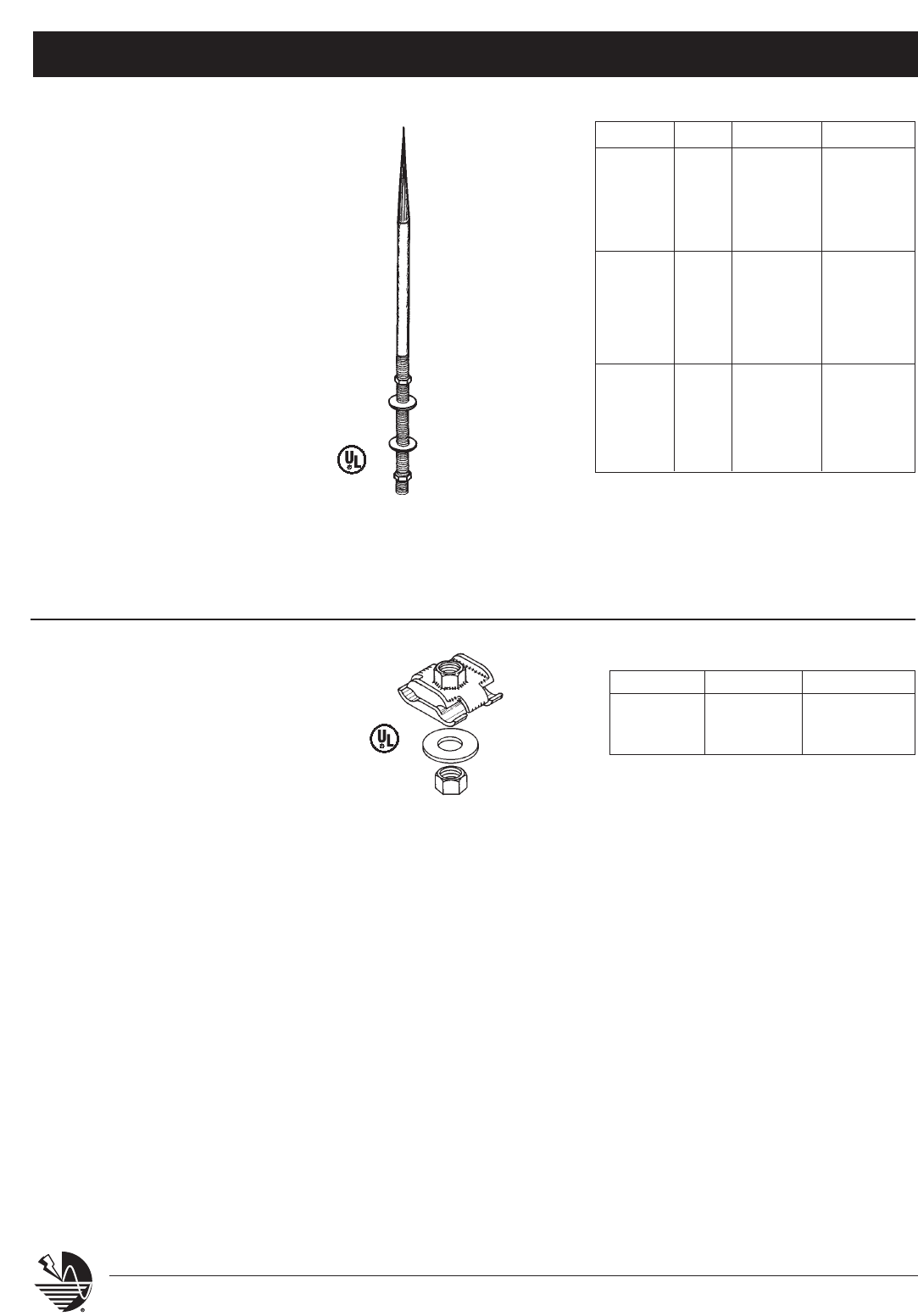
Thru-Roofs, -Walls, & Special Purpose Parts
System 2000 – Series 600
38 www.erico.com
CONCEALED POINTS
SERIES 601 thru 609
Solid copper or aluminum concealed
points, made in one continuous length
of point and threaded section. Points are
made from bare copper or aluminum rod
with highly polished finish. Rod ends
threaded standard N.C. and supplied
with two compatible nuts and washers.
Concealed points will adapt to most
bases Series 300 and Part No. 610.
LENGTH* DIA. MATERIAL PART NO.
18" 3/8" copper LPC601
18" 1/2" copper LPC604
18" 1/2" aluminum LPA604
18" 5/8" copper LPC607
18" 5/8" aluminum LPA607
24" 3/8" copper LPC602
24" 1/2" copper LPC605
24" 1/2" aluminum LPA605
24" 5/8" copper LPC608
24" 5/8" aluminum LPA608
32" 3/8" copper LPC603
32" 1/2" copper LPC606
32" 1/2" aluminum LPA606
32" 5/8" copper LPC609
32" 5/8" aluminum LPA609
* 18” (10” point length, 8” threaded length)
24” (12” point length, 12” threaded length)
32” (18” point length, 14” threaded length)
Note: Contact ERICO for points with
other specifications
CONCEALED POINT
BASE ASSEMBLIES
SERIES 610
Bronze or aluminum cast concealed point
base assemblies. Positive bolt tension
cable clamping for cables or wires,
accepts one or two of any combination
of full size and/or miniature bonding wires
or cables in a parallel manner. Furnished
with washer and standard N.C. nut for
secure connections. See Part No.’s LPC601
thru LPA609 for application.
Series 610
POINT DIA. COPPER ALUMINUM
3/8" LPC61038 —
1/2" LPC61012 LPA61012
5/8" LPC61058 LPA61058
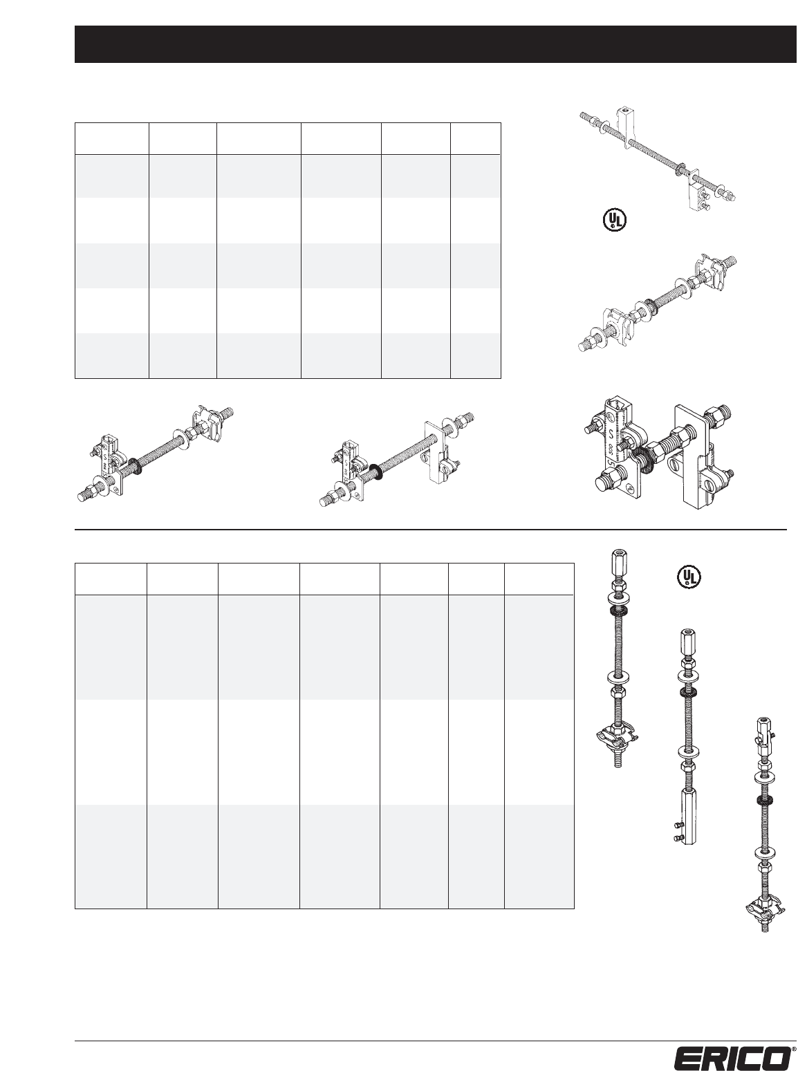
Thru-Roofs, -Walls, & Special Purpose Parts
System 2000 – Series 600
39
www.erico.com
Series 624
Series 626
Series 628
THRU-WALL CONNECTION ASSEMBLIES
PART # MATERIALS INSIDE OUTSIDE ROD ROD
CONNECTOR CONNECTOR DIAMETER LENGTH
LPC618 Cu - Cu LPC555 LPC555 5/16" 12"
LPC618A Cu - Al LPC555 LPA555 5/16" 12"
LPA618 Al - Al LPA555 LPA555 5/16" 12"
LPC619 Cu - Cu LPC61012 LPC61012 1/2" 12"
LPC619A Cu - Al LPC61012 LPA61012 1/2" 12"
LPA619 Al - Al LPA61012 LPA61012 1/2" 12"
LPC620 Cu - Cu LPC61012 LPC55112 1/2" 12"
LPC620A Cu - Al LPC61012 LPA55112 1/2" 12"
LPA620 Al - Al LPA61012 LPA55112 1/2" 12"
LPC621 Cu - Cu LPC55112 LPC55112 1/2" 12"
LPC621A Cu - Al LPC55112 LPA55112 1/2" 12"
LPA621 Al - Al LPA55112 LPA55112 1/2" 12"
LPC622 Cu - Cu LPC55112 LPC55112 1/2" 6"
LPC622A Cu - Al LPC55112 LPA55112 1/2" 6"
LPA622 Al - Al LPA55112 LPA55112 1/2" 6"
THRU-ROOF POINT ADAPTER ASSEMBLIES
PART # MATERIALS TOP BOTTOM ROD ROD POINT
CONNECTOR CONNECTOR DIAMETER LENGTH DIAMETER
LPC62438 Cu - Cu LPC2932F3F LPC61012 1/2" 12" 3/8"
LPC62412 Cu - Cu LPC2932F2F LPC61012 1/2" 12" 1/2"
LPC62458 Cu - Cu LPC2952F5F LPC61012 1/2" 12" 5/8"
LPC624A12 Cu - Al LPA2932F2F LPC61012 1/2" 12" 1/2"
LPC624A58 Cu - Al LPA2952F5F LPC61012 1/2" 12" 5/8"
LPA62412 Al - Al LPA2932F2F LPA61012 1/2" 12" 1/2"
LPA62458 Al - Al LPA2952F5F LPA61012 1/2" 12" 5/8"
LPC62638 Cu - Cu LPC2932F3F LPC32112 1/2" 12" 3/8"
LPC62612 Cu - Cu LPC2932F2F LPC32112 1/2" 12" 1/2"
LPC62658 Cu - Cu LPC2952F5F LPC32112 1/2" 12" 5/8"
LPC626A12 Cu - Al LPA2932F2F LPC32112 1/2" 12" 1/2"
LPC626A58 Cu - Al LPA2952F5F LPC32112 1/2" 12" 5/8"
LPA62612 Al - Al LPA2932F2F LPA32112 1/2" 12" 1/2"
LPA62658 Al - Al LPA2952F5F LPA32112 1/2" 12" 5/8"
LPC62838 Cu - Cu LPC2812F3F LPC61012 1/2" 12" 3/8"
LPC62812 Cu - Cu LPC2812F2F LPC61012 1/2" 12" 1/2"
LPC62858 Cu - Cu LPC2812F5F LPC61012 1/2" 12" 5/8"
LPC628A12 Cu - Al LPA2812F2F LPC61012 1/2" 12" 1/2"
LPC628A58 Cu - Al LPA2812F5F LPC61012 1/2" 12" 5/8"
LPA62812 Al - Al LPA2812F2F LPA61012 1/2" 12" 1/2"
LPA62858 Al - Al LPA2812F5F LPA61012 1/2" 12" 5/8"
Series 618
Series 619
Series 620 Series 621
Series 622
NOTE: Contact ERICO for thru-roof assemblies with other specifications.
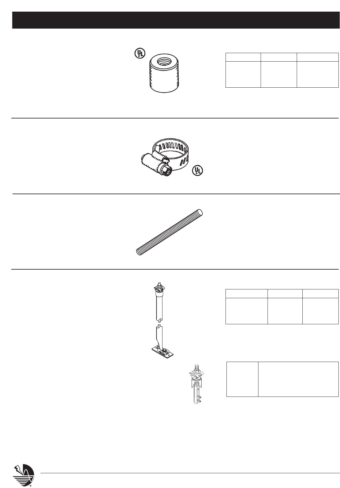
Thru-Roofs, -Walls, & Special Purpose Parts
System 2000 – Series 600
40 www.erico.com
FLASHING ADAPTER
SERIES 635
Flashing adapter for use in providing
weather tight seal between threaded
rod and Part No. LPP634 pipe flashing.
Diameter of 1” by 1” high. Available in
brass or aluminum with standard N.C.
internal threads. Use in conjunction
with Part No. LPP636.
PIPE FLASHING CLAMP
SERIES 636
Pipe flashing clamp for use with Part
No. LPP634. Constructed of stainless
steel material. Adjustable to
accommodate 1” diameter as required
for flashing. Use in conjunction with
Part No. 635 series.
Series 636
LPP636 pipe flashing clamp
ALL THREAD ROD
SERIES 661
Stainless steel all thread solid rod.
Available in lengths from a few
inches to 12’ for thru-roof or wall
rods. Use of 5/16” rod is for miniature
bonding only. All threads-5/16”, 3/8”,
1/2”, or 5/8” - N.C. standard.
Series 661
LPS660CTO 5/16” stainless steel
LPS661CTO 3/8” stainless steel
LPS662CTO 1/2” stainless steel
LPS663CTO 5/8” stainless steel
LPC661CTO 3/8” copper
LPC662CTO 1/2” copper
LPC663CTO 5/8” copper
THRU-ROOF ASSEMBLIES
SERIES 664
Thru-roof cable connecting assemblies for copper
to copper or aluminum to aluminum or copper
concealed system to aluminum above deck. The
top end is finished with a universal parallel cable
connection. Lower end finished with flat mount
rod and cable holder. Threaded rod is stainless
steel 1/2” housed in UV stabilized PVC 1” SCH40
1.315” OD tube or cap.
ROD DIA. COPPER ALUMINUM
3/8" LPC63538 —
1/2" LPC63512 LPA63512
5/8" LPC63558 LPA63558
Series 664 Full Assembly
CONNECTION 18" length 24" length
COPPER LPC66418 LPC66424
ALUMINUM LPA66418 LPA66424
BI-METALLIC* LPC664A18 LPC664A24
NOTE: Identify roof manufacturer
for proper EPDM pipe flashing.
Series 664 Connector
LPC664A* copper to aluminum top
LPC664B1 copper to bi-metallic top
LPC664L copper to tinned copper top
* Copper base, aluminum top
Full
Assembly
Connector
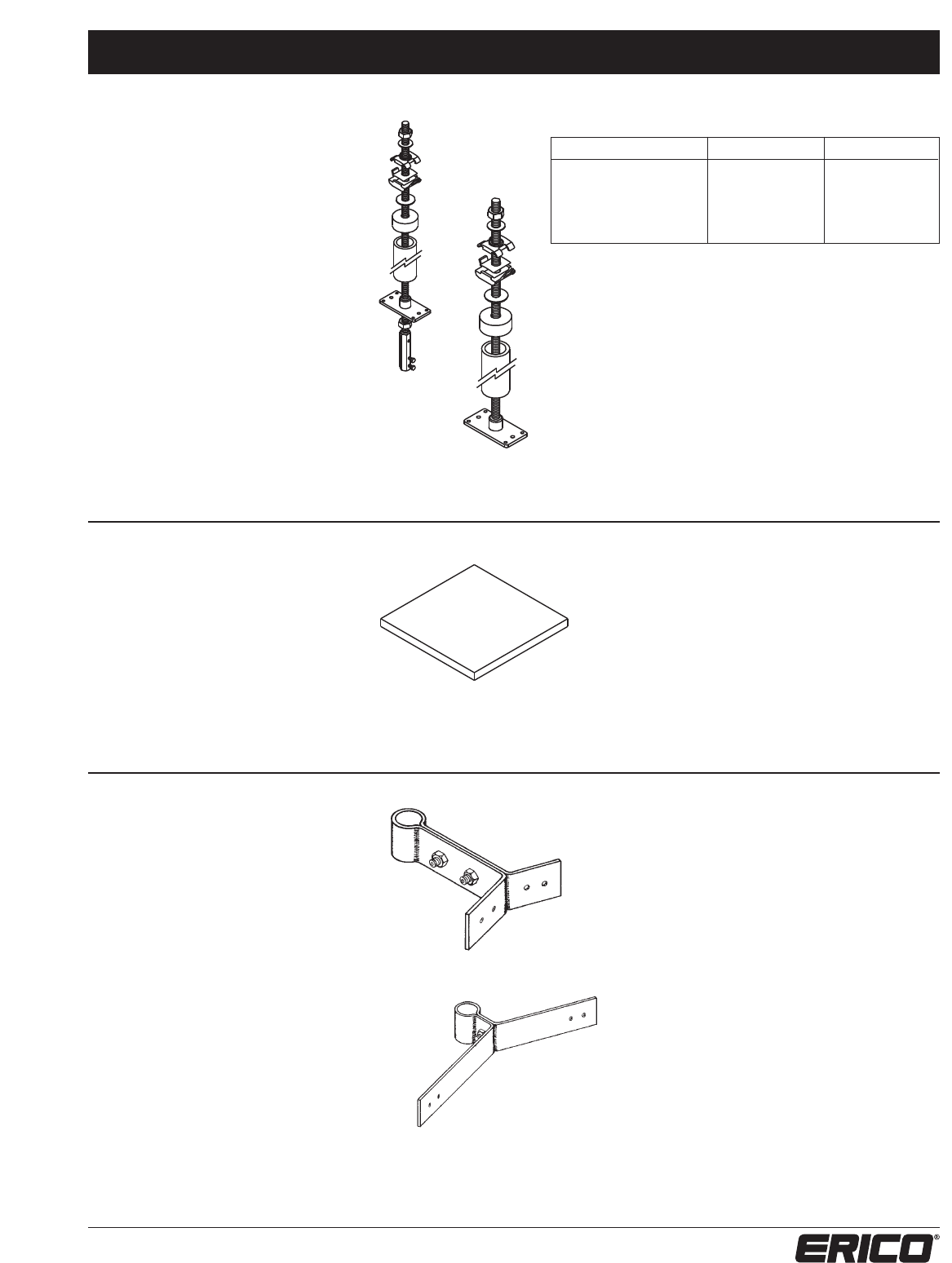
Thru-Roofs, -Walls, & Special Purpose Parts
System 2000 – Series 600
41
www.erico.com
THRU-ROOF
ASSEMBLIES (cont.)
SERIES 665
Thru-roof cable connecting assemblies
for copper to copper or copper con-
cealed system to aluminum above deck.
The top end is finished with a universal
parallel cable connection. Lower end is
finished with an option for either an 8
square inch flat surface or an additional
straight inline cable to rod coupler.
Threaded rod is 1/2” dia. stainless steel
housed in UV stabilized PVC 1-1/2”
SCH40 tube in either 18” or 24” lengths. Series
665
Series
665NC
WELDING PLATE
SERIES 667
Mild steel welding plate 1/4” x 4” x 4”
for attachment to steel columns or
beams when no holes may be made in
steel member. Steel plate to be welded
to steel column or beam. Provided with
four 1/4-20 x 3/8” screws for mounting
532 series bonding plates or 306, 307,
and 308 series point bases.
Series 667
LPP667 mild steel welding plate
NOTE: Similar steel welding plate can be provided
for 540 series bonding plate and 340 series point
bases. Specify Part No. LPP667X540 to receive steel
plate with the proper mounting hole pattern. Similar
steel welding plate can also be provided for connect-
ing to large diameter weldable metal piping. Use in
conjunction with 551 series terminal bonding lug.
Specify Part No. LPP667X551 to receive steel plate
with proper mounting hole pattern.
Series 669
Series 669
• Stand-off holder
• Offset distance 4” standard
• 2” long wings for attachment
LPC669 for copper points or cables
LPA669 for aluminum points or cables
Series 670
Series 670
• Offset distance 1” standard
• 6” long wings for attachment
LPC670 for copper points or cables
LPA670 for aluminum points or cables
STRAP TYPE POINT
OR CABLE HOLDER
SERIES 669 & 670
Copper or aluminum strap type point or
cable holder. Made of heavy tinned cop-
per or bare aluminum strap formed to
draw tight under bolt tension. Will hold
solid rod points or full size cables offset
from flat or curved mounting
surface. Available in various offset
distances.
Series 665, 665NC & 665 Bi-Metallic
CONNECTION 18" 24"
Copper LPC66518 LPC66524
Copper, no coupler LPC66518NC LPC66524NC
Bi-Metallic* LPC66518BI LPC66524BI
Bi-Metallic, no coupler LPC66518NCBI LPC66524NCBI
* Copper base, aluminum top
NOTE: Identify roof manufacturer
for proper EPDM pipe flashing.
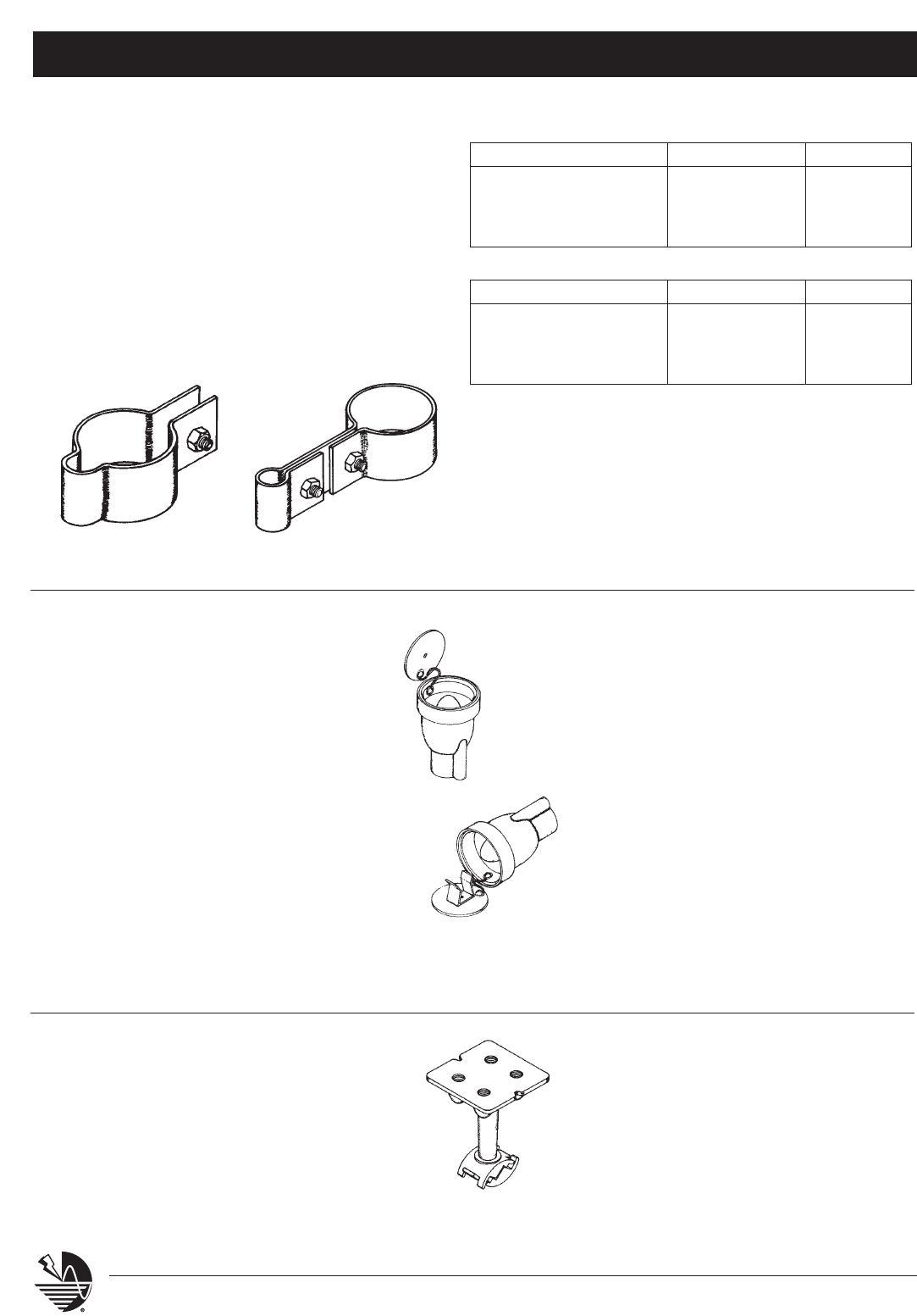
Thru-Roofs, -Walls, & Special Purpose Parts
System 2000 – Series 600
42 www.erico.com
Series 671-674 Series 675-679
STRAP TYPE POINT OR
CABLE TO PIPE HOLDER
SERIES 671 - 679
Copper or aluminum strap type point or
cable to pipe holder. Made of heavy
tinned copper or bare aluminum strap
formed to draw tight under bolt tension
to hold solid rod points or full size
cables close to pipe. Available in stan-
dard pipe sizes 1-1/2”, 2”, 3”, and 4”.
Other sizes available upon request.
GROUNDING RECEPTACLES
SERIES 680
Cast bronze aircraft type static grounding
receptacle with standard pin connection and
chain retained cover plate. Install flush with
finish floor surface. Designed to couple
directly to 3/4” section type ground rod or
3/4” extension rod.
SERIES 681
Cast bronze aircraft type static grounding
receptacle for mounting on a vertical surface.
Furnished with standard pin connection,
chain retained cover plate and spring clip to
secure cover plate when installed on a vertical
surface. Install flush with finished wall surface.
Designed to couple directly to 3/4” support
rod.
Series 680
LPC680 cast bronze aircraft type static
grounding receptacle
Series 681
Series 681
LPC681 cast bronze aircraft type static
grounding receptacle
Series 680
GROUNDING PLATE
SERIES 682
Cast bronze grounding plate for equipment,
machinery, or structure grounding points. May
be installed flush in concrete floor or wall. Face
measures 3-1/4” square with four holes for
1/2” bolts on 1-3/4” center. Cable connection
under bolt tension. For all standard cables.
Series 682
LPC682 cast bronze grounding plate
Series 671-674
PIPE SIZE TINNED COPPER ALUMINUM
1-1/2” inside (1.900” O.D.) LPC671 LPA671
2” inside (2.375” O.D.) LPC672 LPA672
3” inside (3.500” O.D.) LPC673 LPA673
4” inside (4.500” O.D.) LPC674 LPA674
Series 675-679*
PIPE SIZE TINNED COPPER ALUMINUM
1-1/2” inside (1.900” O.D.) LPC675 LPA675
2” inside (2.375” O.D.) LPC676 LPA676
3” inside (3.500” O.D.) LPC677 LPA677
4” inside (4.500” O.D.) LPC678 LPA678
* Stand-off fastener, offset distance 2-1/2” standard
(other distances available)
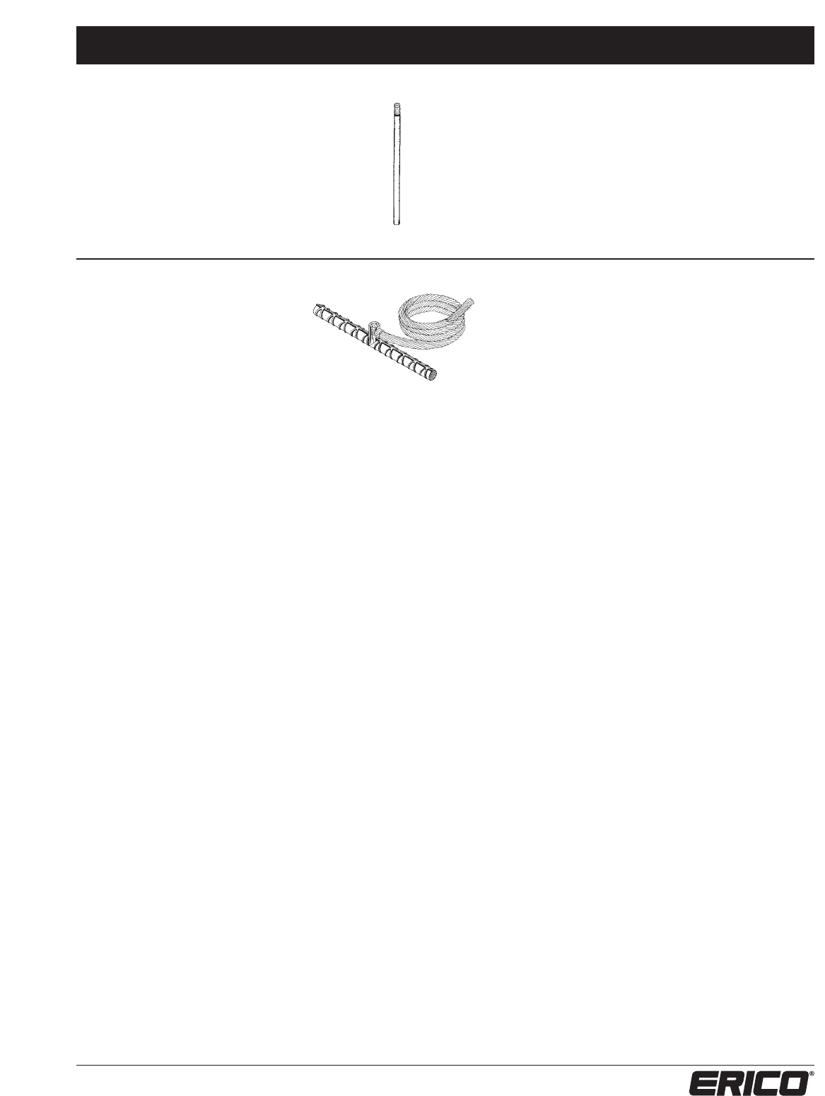
Thru-Roofs, -Walls, & Special Purpose Parts
System 2000 – Series 600
43
www.erico.com
EXTENSION ROD
SERIES 684
Copperclad steel extension rod for use
with Part No. LPC680 receptacle. Use
to hold receptacle at proper elevation
for concrete pour. Made of 3/4” rod
24” long with threaded end.
Series 684
LPCC684 copperclad steel extension rod
BONDING ASSEMBLY
SERIES 691 - 693
Prefabricated cable to reinforcing
bar bonding assemblies. Catalog
numbered assembly includes 18”
of #4 reinforcing bar with an
exothermic weld to 5 ft. of copper
cable. Wire tie or weld bar to
construction steel before pouring
concrete and route cable tail to
down lead or ground lead location.
Series 691-693
LPP691 bar with LPC122 copper cable (for Class I systems)
LPP692 bar with LPC126 copper cable (for Class II systems)
LPP693 bar with LPC137 copper cable (4/0)
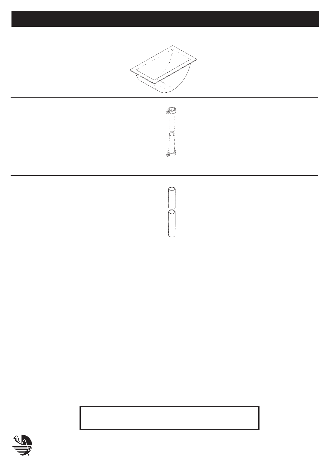
Ground Rods & Plates, Guards & Accessories
System 2000 – Series 700
44 www.erico.com
CONCRETE FORM
SERIES 736
Plastic form for making 3” x 6” x 2-1/2”
deep depression in concrete pour around
loop in aircraft tie-downs, for use with
Part No. LPCC730 and LPCC731.
Series 736
LPP736 plastic concrete pour form
CABLE PROTECTORS
SERIES 742
Copper tube protector for cables through 5/8”
diameter. For use where stranded cables are
subject to displacement or damage. Protector
3/4” O.D. copper tube 7’ long with set screw
collar each end to bond cable to tube. Secure
with Part No. LPC807 or LPC808 Fasteners.
Series 742
LPC742 copper tube protector for
cables through 5/8” diameter
SERIES 743
Polyvinylchloride Protector for cables through 5/8”
diameter. For use where stranded cables are
subject to displacement or damage. Protector
1” O.D. PVC Pipe, 10’ long. Secure with Part No.
LPC807 or LPC808 Fasteners.
Series 743
LPP743 polyvinylchloride protector for
cables through 5/8” diameter
For a complete listing of ERITECH®grounding products, bonding
braids, insulators or other electrical grounding accessories refer to
the ERITECH Grounding Products and Systems Catalog (G281C).
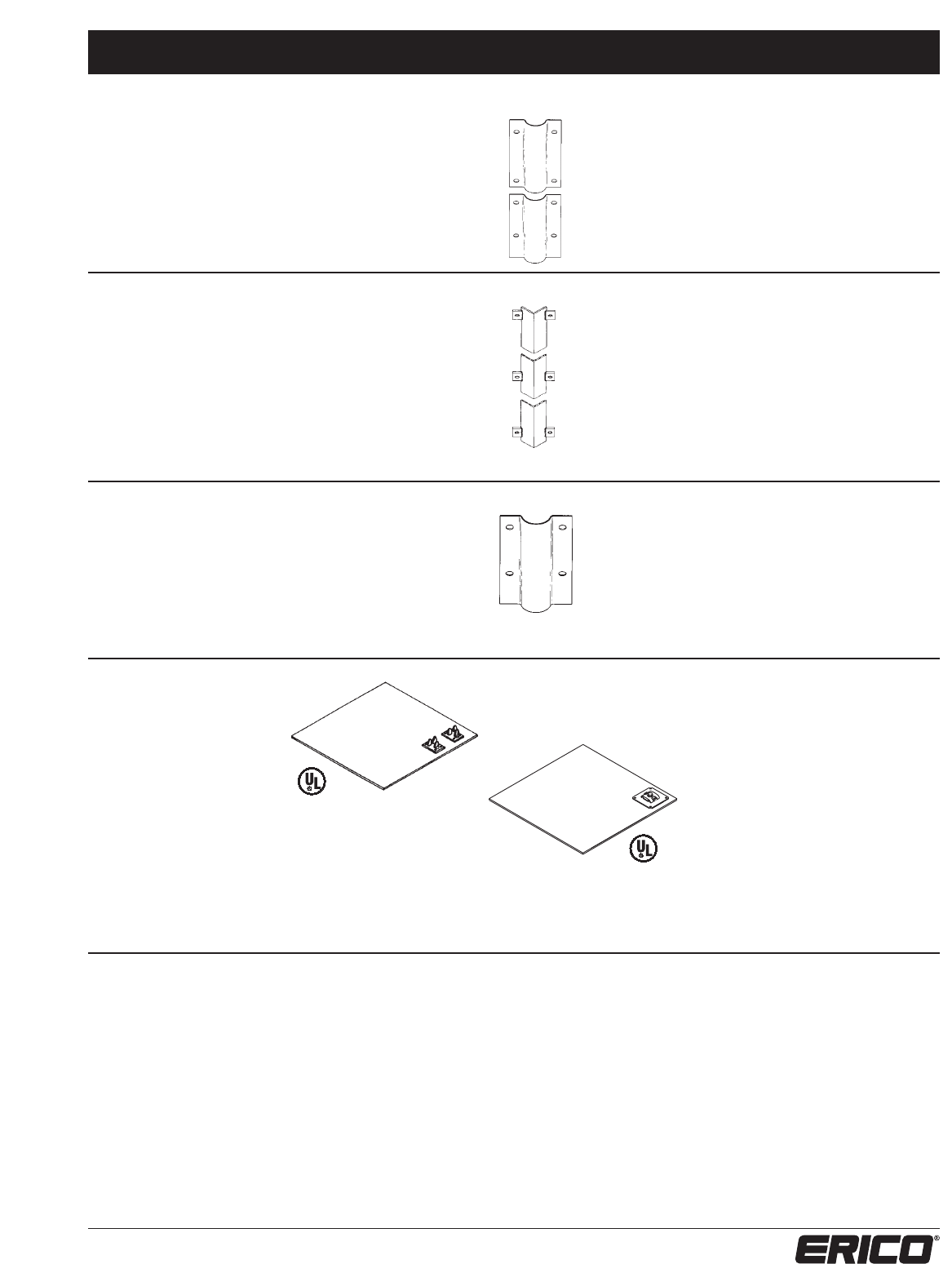
Ground Rods & Plates, Guards & Accessories
System 2000 – Series 700
45
www.erico.com
SERIES 745
Galvanized sheet steel protector for cables
through 3/4” diameter. For use where stranded
cables are subject to displacement or damage.
Protector 3” wide galvanized steel 8’ long with
eight mounting holes for 1/4” fasteners.
Series 745
LPP745 galvanized sheet steel
protector for cables
through 3/4” diameter
SERIES 746
Heavy duty galvanized angle iron protector for
cables through 3/4” diameter. Regularly used on
loading docks or areas where machine traffic
is heavy. Protector fabricated from 2” x 2” x
3/16” angle iron 7’ long. Six anchor tabs welded
to angle before galvanizing, each has mounting
hole for 1/4” fastener. Each end to be made
electrically continuous with conductor.
SERIES 747
PVC protector for cables of all sizes up to 1” or
2”. For use where stranded cables are subject to
displacement or damage. Two sizes available in 8’
lengths. Each section able to overlap for longer
lengths.
Series 746
LPP746 heavy duty galvanized
angle iron protector
for cables through 3/4”
diameter
Series 747
LPP74718 1”x 8’ PVC
LPP74728 2”x 8’ PVC
Series 750-752
Two cable attachments
LPC535L securely
fastened to plate.
12” wide by 24” long
(2 Square Feet)
LPC750 two cable attachments
LPC753 single cable attachment
18” wide by 18” long
(2-1/3 Square Feet)
LPC751 two cable attachments
LPC754 single cable attachment
36” wide by 36” long
(9 Square Feet)
LPC752 two cable attachments
LPC755 single cable attachment
Series 753-755
Cable attachment
LPC532L securely
fastened to plate.
GROUND PLATE
SERIES 750 - 755
Copper ground plate made
from 20 AWG thick high
conductivity copper sheet.
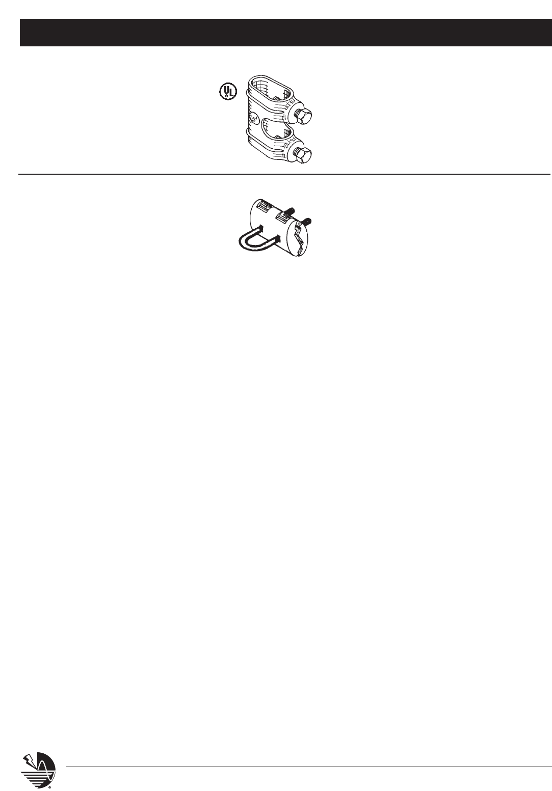
Ground Rods & Plates, Guards & Accessories
System 2000 – Series 700
46 www.erico.com
CABLE PROTECTORS
SERIES 791 - 793
Ground rod to cable clamps of high
conductivity red bronze. Three inch direct
contact along axis of cable and rod. Two
5/16” bolts for positive contact.
791-793 Series
LPC791 for 1/2” ground rod to cables
through 1/2” diameter
LPC792 for 5/8” ground rod to cables
through 5/8” diameter
LPC793 for 3/4” ground rod to cables
through 3/4” diameter
U-BOLT GROUND
ROD CLAMP
SERIES 795
U-Bolt ground rod clamp for high
conductivity red bronze with high
strength stainless steel u-bolt. Three
inch contact between clamp and cable.
795 Series
LPC795 for 1/2”, 5/8”, or 3/4”, and 1”
ground rods to all cables through
3/4” diameter
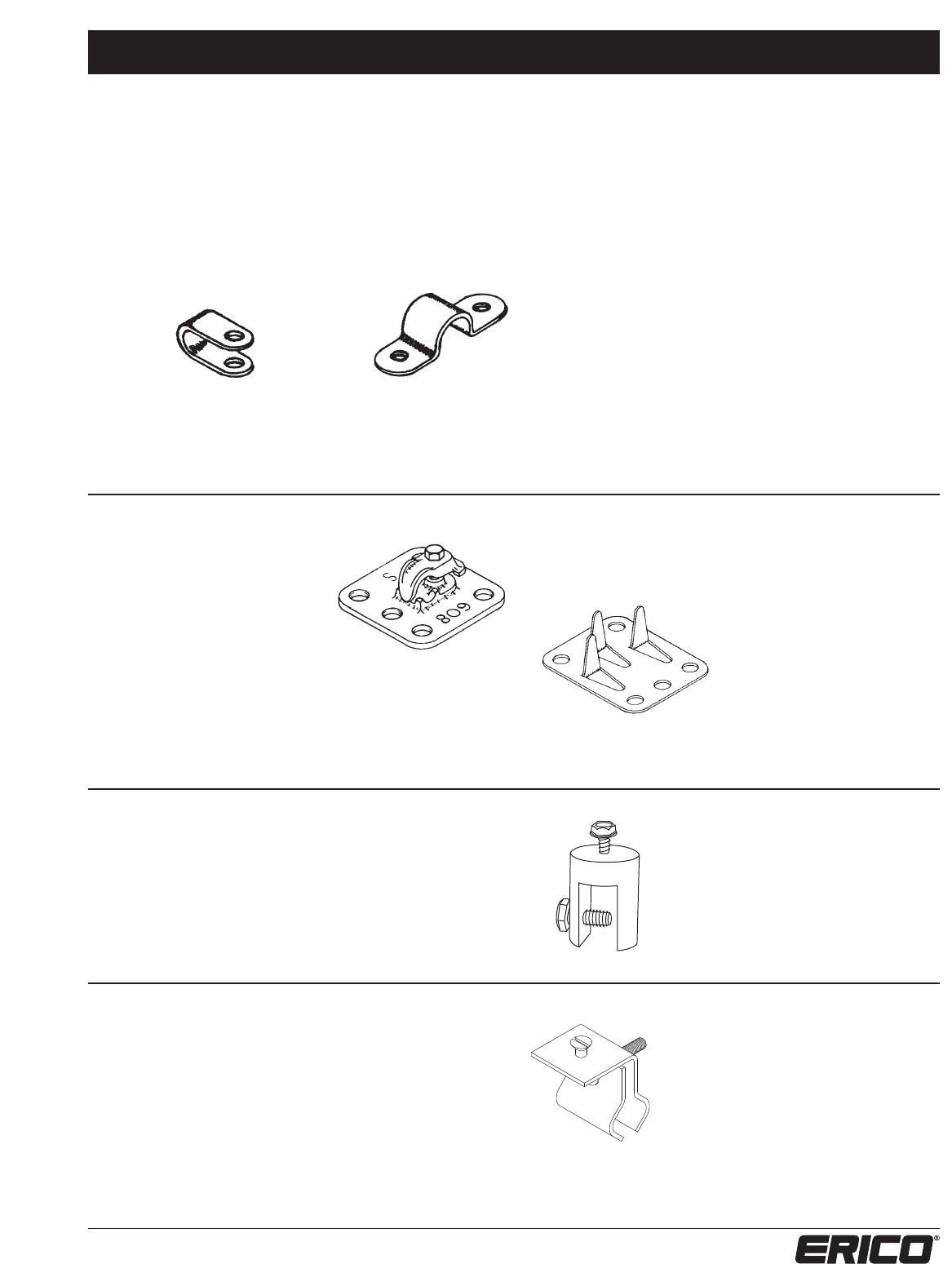
Fasteners System 2000 – Series 800
47
www.erico.com
COPPER AND ALUMINUM CABLE
STRAPS, ONE AND TWO HOLE
NOTE: (Part numbers 807 and 808 are conduit,
protector and pipe fasteners.)
Series 801, 803, 805, 807
Copper Strap, One Hole
Cable Strap - Copper, One Hole
LPC801 3/8” secured with nails
LPC803 1/2” secured with nails or screws
LPC805 5/8” secured with screws or 1/4” fasteners
LPC807 1-1/4” secured with screws or 1/4” fasteners
Cable Strap - Aluminum, One Hole
LPA803 1/2” secured with nails or screws
LPA805 5/8” secured with screws or 1/4” fasteners
LPA807 1-1/4” secured with screws or 1/4” fasteners
Cable Strap - Copper, Two Hole
LPC802 3/8” secured with nails
LPC804 1/2” secured with nails or screws
LPC806 5/8” secured with screws or 1/4” fasteners
LPC808 1-1/4” secured with screws or 1/4” fasteners
Cable Strap - Aluminum, Two Hole
LPA804 1/2” secured with nails or screws
LPA806 5/8” secured with screws or 1/4” fasteners
LPA808 1-1/4” secured with screws or 1/4” fasteners
Series 802, 804, 806, 808
Copper Strap, Two Hole
CABLE HOLDERS
SERIES 809 & 810
Flat cable holder for use with
hot pitch, roofing compound or
commercial adhesive on built-up
roof surfaces or other location
where holes cannot be made
for anchoring cable. Series 809
Cast bronze or aluminum.
Bolt tension cable clip.
Series 809
LPC809 for copper cables
LPA809 for aluminum cables
Series 810
Copper or aluminum. Compression
type fingers crimped over cable.
Series 810
LPC810 for copper cables
LPA810 for aluminum cables
STANDING-SEAM – NO PENETRATION
SERIES 814
Brass or aluminum cable holder for standing seam roofing
systems. Bottom groove machined 1/2" wide and 3/4" deep
to secure on seam with set screw. Cable fastener adjusts
for either parallel or perpendicular cable runs. For use with
LP801, 803, 805, and 807.
Series 814
LPC814 for copper cable saddle
LPA814 for aluminum cable saddle
STANDING-SEAM – NO PENETRATION
SERIES 815
Stainless steel cable holder for standing seam roofing systems.
Groove is variable up to 1” wide for rectangular seams or
beams, also suitable mounting to seams with rounded or boxed
ridge up to 1-1/2” wide. Cable fastener adjusts for either
parallel or perpendicular cable runs. For use with LP801, 803,
805, 807 or air terminal bases.
Series 815
LPS815 for all cables
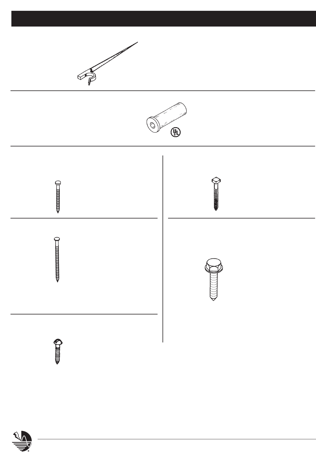
Fasteners System 2000 – Series 800
48 www.erico.com
TREE
SERIES 823
Series 823
LPC823 heavy duty bronze cast tree drive anchor for
main or miniature cable. Drive anchor then pinch
cable holder.
RUBBER EXPANSION ANCHOR A928Q001 #1/4-20 x 5/8”
A928Q002 #10-32 x 9/16”
A928Q003 #10-32 x 3/4”
A928Q004 #1/4-20 x 1”
A928Q005 #10-24 x 3/4”
A931A001 copper ring shank
slating nail, 1-1/2”
long
A931A002 stainless steel ring
shank, 1-1/2” long
A931A003 copper ring shank
slating nail, 1-3/4”
long
A931A004 large aluminum
nail, 6d
A931A005 large galvanized
nail, 6d
A931A006 stainless steel ring
shank nail, 2-1/2”
long
SLATING NAIL
SLATING NAIL
A927P021 brass wood screw,
#10 x 1-1/2”
A927P020 stainless steel wood
screw, #10 x 1-1/2”
WOOD SCREW
LPG844 galvanized steel lag
screw, 1/4” x 2”
LAG SCREWS
SERIES 844
A927P022 stainless steel hex
pan-head sheet metal
screw #10 x 5/8”
A927P023 stainless steel hex
pan-head self-drilling
tek screw #10 x 5/8”
A927P025 stainless steel hex
pan-head sheet metal
screw #10 x 1”
A927P024 stainless steel hex
pan-head self-drilling
tek screw #10 x 1”
SHEET METAL
SCREW
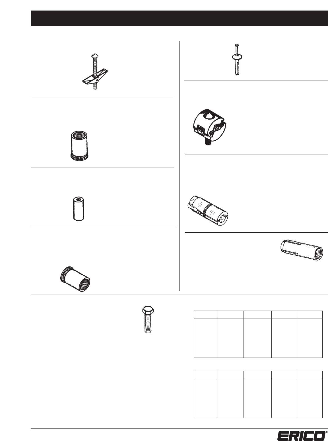
Fasteners System 2000 – Series 800
49
www.erico.com
LPG848 galvanized steel
toggle bolt, 1/4” x 3”
LPG849 galvanized steel
toggle bolt, 1/4” x 4”
A930W005 lead extension
anchor, 1/4-20
A930W006 lead extension
anchor, 5/16-18
A930W007 lead extension
anchor, 3/8-16
A930W008 lead extension
anchor, 1/2-13
A930W013 plastic plug anchor
for #10 screw
A930W004 one-piece lead
drive-In anchor with
stainless steel nail,
1/4” x 1-1/4”
Cast Bronze or Aluminum cable
clamp for fastening to flat metal
objects such as I-beams, angle irons,
channel irons, etc. Positive bolt
tension draws tight on steel member.
For use with all full size cables,
miniature cables, and bonding wires.
TOGGLE BOLT
SERIES 848 & 849
EXTENSION
ANCHOR
PLUG ANCHOR
DRIVE-IN
ANCHOR
CABLE CLAMP
SERIES 858
MACHINE SCREWS
Bronze and stainless steel
hex head machine screws.
Stainless Steel may be used
with bronze or aluminum
components.
BRONZE
LENGTH 1/4”-20 5/16”-18 3/8”-16 1/2”-13
1/2" A927F176 — — —
3/4" A927F178 A927F186 A927F192 —
1" A927F180 A927F188 A927F194 A927F198
1-1/4" A927F182 — — —
1-1/2" A927F184 A927F190 A927F196 A927F200
2" — — — A927F202
STAINLESS STEEL
LENGTH 1/4”-20 5/16”-18 3/8”-16 1/2”-13
1/2" A927F177 — — —
3/4" A927F179 A927F187 A927F193 —
1" A927F181 A927F189 A927F195 A927F199
1-1/4" A927F183 — — —
1-1/2" A927F185 A927F191 A927F197 A927F201
2" — — — A927F203
A930W009 Expansion shield anchor
EXPANSION SHIELD ANCHOR
Provided with 1/2-13 internal thread. Mounts
in drilled hole 7/8” diameter x 1-3/4” depth.
Use extra length stud products 1-1/2 Long.
Preferred anchoring method for brick chimney.
A930W010 Caulk-in anchor
CAULK-IN ANCHOR
Provided with 1/2-13 internal thread. Mounts
in drilled hole 7/8” diameter x 1-1/2” depth.
Use standard length stud 7/8”.
A930W011
Plain steel; mounts in drilled hole 5/8” diameter x 2” depth.
A930W012
Stainless steel; mounts in drilled hole 7/8” diameter x 2” depth.
DROP-IN ANCHOR
Provided with 1/2"-13 internal thread.
Use standard length stud 7/8”.
LPC858 for copper cables and wires
LPC858L tinned for copper cables and wires
LPA858 for aluminum cables and wires
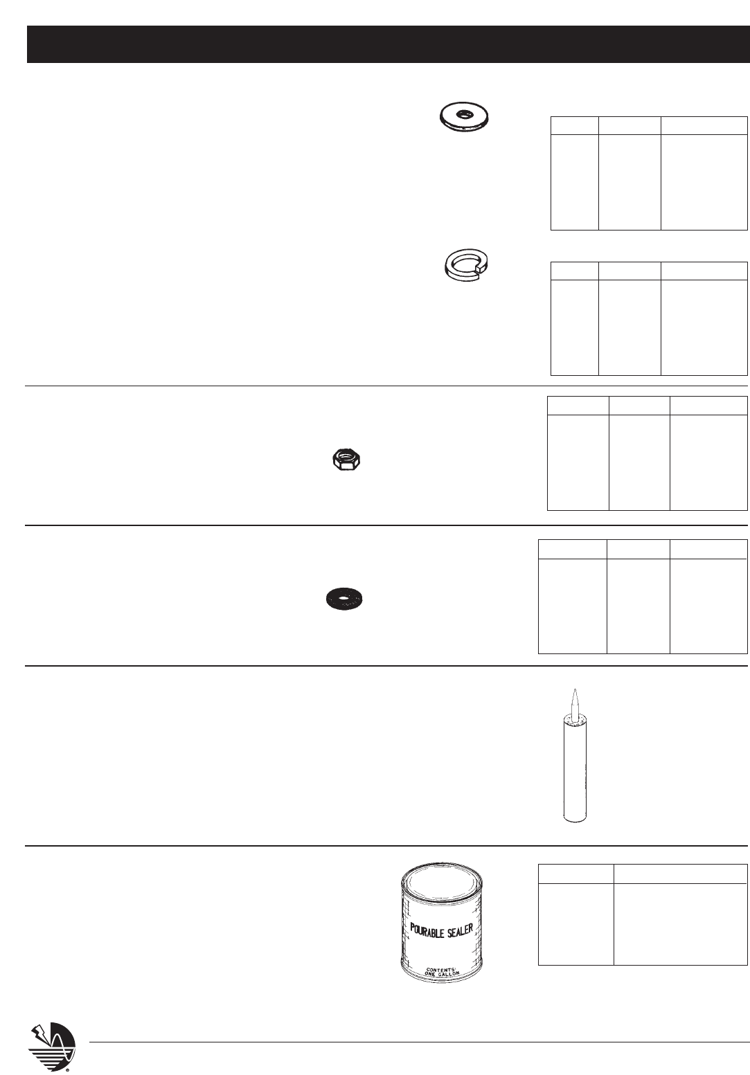
Fasteners System 2000 – Series 800
50 www.erico.com
REGULAR FLAT WASHERS
BRONZE AND STAINLESS STEEL
SPLIT LOCK-WASHER, MEDIUM SECTION
BRONZE AND STAINLESS STEEL
SERIES 874X - 879X
BRONZE
FLAT SPLIT LOCK
1/4" A929A094 A929B023
5/16" A929A096 A929B034
3/8" A929A098 A929B017
1/2" A929A100 A929B018
5/8" A929A102 A929B009
3/4 A929A104
STAINLESS STEEL
FLAT SPLIT LOCK
1/4" A929A095 A929B038
5/16" A929A097 A929B024
3/8" A929A099 A929B025
1/2" A929A101 A929B026
5/8" A929A103 A929B036
3/4 A929A105 A929B040
BRONZE AND STAINLESS
STEEL STANDARD HEXAGON
MACHINE SCREW NUTS
SERIES 880 - 885
ADHESIVES
SERIES 899
A fast drying waterproof synthetic rubber and resin-based adhesive. For example, the 30 oz. cartridge
will adhere 20- Part No. 302 adhesive bases, or 40- No. 810 adhesive cable holders to built-up surface.
For metal roofs, which cannot be penetrated, will adhere 30- Part No. 302, or 60- Part No. 810 cable
holders. Do not apply at temperatures below 10° F. The M-1®Structural Sealant is available in a 16 pack
of 10.3 oz cartridges, and bonds aggressively to EPDM, PVC, BUR, coal tar, SBS mod bit, granulated APP,
many types of coated metal, metal flashing details and FRP. The M-1 adhesive develops 300 lbs. per
square inch of shear strength on metal, masonry or wood.
LPP899LN
30 oz. Liquid NailsTM
LPP899GY (Grey)
10.3 oz. M-1®Structural Sealant
LPP899WH (White)
10.3 oz. M-1 Structural Sealant
LPP899BK (Black)
10.3 oz. M-1 Structural Sealant
Liquid Nails is a trademark of
Glidden Company
M-1 is a registered trademark of
Chem Link, Inc
SERIES 899R
A fast drying adhesive cement for rubber membrane roofing.
Apply only at temperatures above 40° F. One gallon will adhere
30- No. 309 adhesive bases or 60 No. 809 or No. 810 cable
holders to a smooth rubber surface.*
NOTE: Rubber adhesive cement pourable sealer must match
the rubber roof membrane. Specify the type of roofing
system being used.
*Improper selection of adhesive on roofing can cause serious deterioration to the roofing. Always verify compatibility of
adhesive with roofing contractor and/or manufacturer.
LEAD AND NEOPRENE
SEALING WASHERS
SERIES 886 - 897
BRONZE STAINLESS
1/4"-20 A928K015 A928K011
5/16"-18 A928K016 A928K017
3/8"-16 A928K018 A928K019
1/2"-13 A928K020 A928K021
5/8"-11 A928K022 A928K023
3/4"10 A928K024 A928K025
SIZE LEAD NEOPRENE
#10 Screw A929G001 A929H001
1/4" Bolt A929G002 A929H002
5/16" Bolt A929G003 A929H003
3/8" Bolt A929G004 A929H004
1/2" Bolt A929G005 A929H005
5/8" Bolt A929G006 A929H006
PART NO. ROOFING SYSTEM
LPP899RAS Ace Silicon
LPP899RCL Carlisle
LPP899RFS Firestone®
LPP899RGF Genflex®
Firestone is a registered trademark of Bridgestone/Firestone, Inc.
Genflex is a registered trademark of Omnova Solutions, Inc.
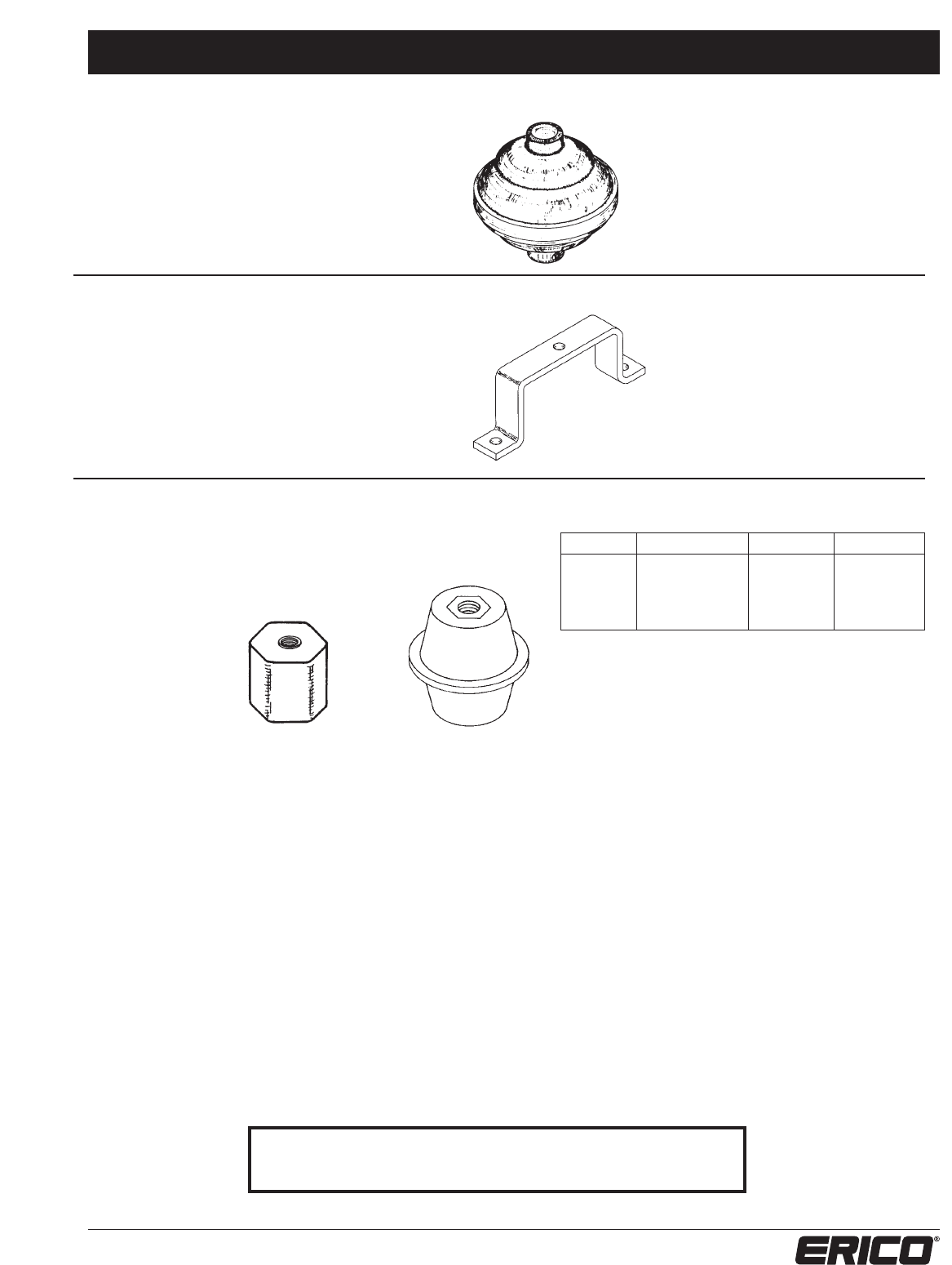
Ornaments & Insulators System 2000 – Series 900
51
www.erico.com
ORNAMENTAL BALLS
SERIES 930 & 931
Plastic ornamental balls for use on all standard
1/2” and 5/8” diameter points. Constructed
of molded polystyrene plastics. Colors tend to
fade after a period of time.
Series 930 Color: White
LPP93012 for 1/2" points
LPP93058 for 5/8" points
Series 931 Color: Red
LPP93112 for 1/2" points
LPP93158 for 5/8" points
SPACER BRACKET
SERIES 965
Solid galvanized steel spacer bracket for mounting
insulators and bus bar. Constructed of 1” x 1/4”
mild steel galvanized after construction, provided
with 3/8” hole for mounting insulator. Standard
configuration will set bottom of insulator or bus bar
2-1/2” off surface.
Series 965
LPP965 1" x 1/4" x 2-1/2"
one hole at 5-3/4" O.C.
FRP MOLDED STAND-OFF
INSULATORS WITH THREADED
ALUMINUM INSERTS
B546A07 559620, B546A02,
B546A01
PART NO. WIDTH HEIGHT BOLT SIZE
B546A07 1" Hex stock 1" 1/4-20
559620 2" Diameter 1-1/2" 1/4-20
B546A02 2" Diameter 1-1/2" 3/8-16
B546A01 2" Diameter 2" 1/2-16
For a complete listing of ERITECH®grounding products, bonding
braids, insulators or other electrical grounding accessories refer to
the ERITECH Grounding Products and Systems Catalog (G281C).

52 www.erico.com
www.erico.com
ERICO
®
Facility Electrical Protection Literature
ERITECH®Lightning Protection Catalogs
ERITECH®System 2000 Lightning Protection Products catalog highlights products used in
conventional lightning protection. Products detailed include conductors, ground rods
and plates, clamps, splices, points and accessories.
ERITECH®System 3000 Lightning Protection Products catalog details the active lightning
protection process. Information on air terminals, downconductors and design software
is included.
ERITECH®Grounding Products Catalog
Details ERICO’s extensive offering of ground rods and accessories, ground mesh and
mats, signal reference grids, ground bars, ground receptacles, transient earth clamps,
ground enhancement materials, and other grounding materials.
CADWELD®Welded Electrical Connections Catalog
Covers the range of hardware required to make a CADWELD connection as well as
detailed ordering information for molds, weld materials, fence and gate jumpers and the
smokeless CADWELD®EXOLON process.
CRITEC
®
Surge Protection Products Catalog
Details the extensive range of CRITEC Surge Protection Devices for industries such as
commercial & industrial, process control & automation and telecommunications. It
includes information on AC protection products, data control and signal protection
products, as well as point-of-use protection products.
WARNING
ERICO products shall be used only as illustrated and recommended in the product instruction sheets (additional instruction sheets are available at www.erico.com). Misuse or misapplication may cause failure resulting in possible property dam-
age or bodily injury.
WARRANTY; CLAIMS; EXCLUSIVE REMEDY
ERICO products are warranted to be free from defects in material and workmanship at the time of shipment. NO OTHER WARRANTY, WHETHER EXPRESS OR IMPLIED (INCLUDING ANY WARRANTY OF MERCHANTABILITY OR FITNESS FOR A
PARTICULAR PURPOSE), SHALL EXIST IN CONNECTION WITH THE SALE OR USE OF ANY ERICO PRODUCTS. Claims for errors, shortages, defects or nonconformities ascertainable upon inspection must be made in writing within 5 days after the
Buyer’s receipt of products. All other claims must be made in writing to ERICO within 6 months from the date of shipment or transport. Products claimed nonconforming or defective must, upon ERICO’s prior written approval in accordance
with its standard terms and procedures governing returns, promptly be returned to ERICO for inspection. Claims not made as provided above and within the applicable time period will be barred. ERICO shall in no event be responsible if the
products have not been stored or used in accordance with its specifications and recommended procedures. ERICO will, at its option, either repair or replace nonconforming or defective products for which it is responsible or return the purchase
price to Buyer. THE
FOREGOING STATES BUYER’S EXCLUSIVE REMEDY FOR ANY BREACH OF ERICO WARRANTY AND FOR ANY CLAIM, WHETHER SOUNDING IN CONTRACT, TORT OR NEGLIGENCE, FOR LOSS OR INJURY CAUSED BY THE SALE
OR USE OF ANY PRODUCT.
LIMITATION OF LIABILITY
ERICO excludes all liability except that is directly attributable to the willful or gross negligence of ERICO’s employees. Should ERICO be held liable its liability shall in no event exceed the total purchase price under the contract.
ERICO SHALL IN NO EVENT BE RESPONSIBLE FOR ANY LOSS OF BUSINESS OR PROFITS, DOWNTIME OR DELAY, LABOR, REPAIR OR MATERIAL COSTS OR ANY SIMILAR OR DISSIMILAR CONSEQUENTIAL LOSS OR DAMAGE INCURRED BY
BUYER.

E256C E867CT04EN 004WB5
Copyright ©2005 ERICO International Corporation. All rights reserved.
CADDY, CADWELD, CRITEC, ERICO, ERIFLEX, ERITECH, and LENTON are registered trademarks of ERICO International Corporation.
AUSTRALIA
6 Chilvers Road
P.O. Box 148
Thornleigh (Sydney) NSW 2120
Australia
Phone 61-2-9479-8500
Fax 61-2-9484-9188
BELGIUM
Postbus 33
3110 Rotselaar
Belgium
Phone 32-14-69-96-88
Fax 32-14-69-96-90
CANADA
34600 Solon Road
Solon, Ohio 44139
U.S.A.
Phone 1-800-677-9089
Fax 1-800-677-8131
CHILE
Alcantara 200, piso 6 Of. 17
Las Condes, Santiago
Chile
Phone 56-2-370-2908
Fax 56-2-370-2914
CHINA
Room 1204
Tomson Commercial Building
No. 710, Dongfang Road
Pudong, Shanghai
P.R. China 200122
Phone 86-21-5081-3900
DENMARK
Box 211
201 22 Malmö
Sweden
Phone 46-40-611-13-60
Fax 46-40-611-94-15
FRANCE
Rue Benoît Fourneyron Z.I. Sud
Boîte Postale 31
42161 Andrezieux Cedex
France
Phone 33-4-77-36-56-56
Fax 33-4-77-55-37-89
GERMANY
66851 Schwanenmuehle
Germany
Phone 49-6307-918-10
Fax 49-6307-918-150
HONG KONG
Unit 1, 2nd Floor, Block A
Po Yip Building
62-70 Texaco Road
Tsuen Wan, New Territories
Hong Kong
Phone 852-2764-8808
Fax 852-2764-4486
HUNGARY
Ceglédi út 1-3
1107 Budapest
Hungary
Phone 36-1-431-3464
Fax 36-1-431-3471
INDONESIA
Wisma Danamon Aetna Life 19th Floor
Jalan Jend. Sudirman Kav. 45-46
Jakarta 12930
Indonesia
Phone 62-21-575-0941
Fax 62-21-575-0942
ITALY
A&B Business Center
Via Valla 16, nr. 17
20141 Milano
Italy
Phone 39-02-8474-2250
Fax 39-02-8474-2251
MEXICO
Melchor Ocampo 193
Torre A piso 13
Col. Veronica Anzures
11300 Mexico D.F.
Mexico
Phone 52-55-5260-5991
Fax 52-55-5260-3310
NETHERLANDS
Postbus 487
5000 AL Tilburg
Netherlands
Phone 31-13-58-35-400
Fax 31-13-58-35-499
POLAND
ul. Krzemieniecka 17
54-156 Wroclaw
Poland
Phone 48-71-374-40-22
Fax 48-71-374-40-43
SINGAPORE
16 Wan Lee Road
Jurong Industrial Estate
Singapore 627946
Phone 65-6-268-3433
Fax 65-6-268-1389
SPAIN
C/Provenza 288, Pral.
08008 Barcelona
Spain
Phone 34-93-467-7726
Fax 34-93-467-7725
SWEDEN
Box 211
201 22 Malmö
Sweden
Phone 46-40-611-13-60
Fax 46-40-611-94-15
SWITZERLAND
Postfach 54
3280 Murten
Switzerland
Phone 00-800-5000-1090
Fax 00-800-6000-1090
UNITED KINGDOM
52 Milford Road
Reading, Berkshire RG1 8LJ
United Kingdom
Phone 44-118-958-8386
Fax 44-118-955-0925
UNITED STATES
34600 Solon Road
Solon, Ohio 44139
U. S. A .
Phone 1-440-248-0100
Fax 1-440-248-0723
NORWAY
Postboks 148
1366 Lysaker
Norway
Phone 47-67-53-12-00
Fax 47-67-12-42-68
BRAZIL
R. Dom Pedro Henrique de Orleans
e Braganca, 276
Vila Jaguara CEP 05117-000
São Paulo
Brazil
Phone 55-11-3621-4111
Fax 55-11-3621-4066
THAILAND
163 Ocean Insurance Bldg., 16th Fl., Unit B
Surawongse Road
Bangrak
Bangkok 10500
Thailand
Phone 66-2-634-1692
Fax 66-2-634-1694
www.erico.com
NFPA is a registered trademark of the National Fire Protection Association.
UL is a registered trademark of Underwriters Laboratories, Inc.
