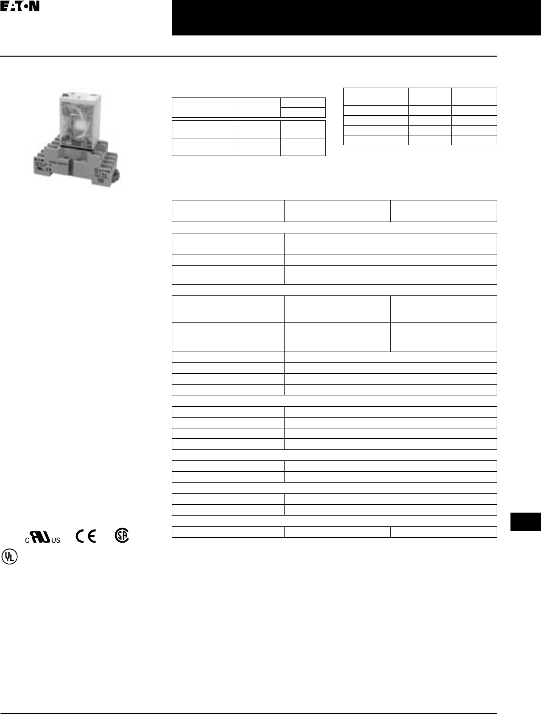
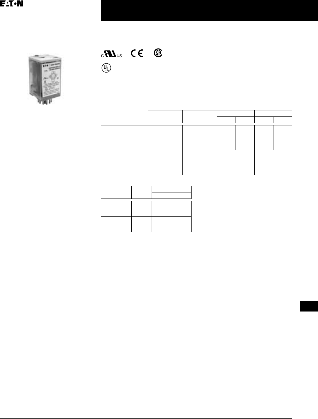
TAB49.BOO 1000366272 Catalog
1000504173-Catalog 1000504173-Catalog 1000504173-Catalog B5 unilog cesco-content
152529-Catalog 152529-Catalog 152529-Catalog B5 unilog cesco-content
578440-Brochure 578440-Brochure 578440-Brochure 782116 Batch3 unilog cesco-content
121017-Catalog 121017-Catalog 121017-Catalog 782114 Batch7 unilog cesco-content
121017-Catalog 121017-Catalog 121017-Catalog 786678 Batch7 unilog cesco-content
2016-09-04
: Pdf 1000366272-Catalog 1000366272-Catalog B4 unilog
Open the PDF directly: View PDF ![]() .
.
Page Count: 128 [warning: Documents this large are best viewed by clicking the View PDF Link!]
April 2009
CA08102002K07A For more information visit:
www.EatonCanada.ca
Contents
Control Relays & Timers 3-1
3
Control Relays &
Timers
Description Page
Relay Product Family Overview . . . . . . . . . . . . . . . . . . . . . . . . . . . . . . . . . . . . 3-2
XR
Series Terminal Block Relays
Standard Terminal Block Relays . . . . . . . . . . . . . . . . . . . . . . . . . . . . . . . . .
3-3
OptoCoupler Terminal Block Relays . . . . . . . . . . . . . . . . . . . . . . . . . . . . . .
3-8
High Current Terminal Block Relays . . . . . . . . . . . . . . . . . . . . . . . . . . . . . .
3-10
Accessories . . . . . . . . . . . . . . . . . . . . . . . . . . . . . . . . . . . . . . . . . . . . . . . . . .
3-12
General Purpose Plug-In Relays
. . . . . . . . . . . . . . . . . . . . . . . . . . . . . . . . . . . .
3-13
D2PF Series — Full Featured . . . . . . . . . . . . . . . . . . . . . . . . . . . . . . . . . . . .
3-15
D2PR Series — Standard . . . . . . . . . . . . . . . . . . . . . . . . . . . . . . . . . . . . . . .
3-19
D3PR/D3PF Series — Standard and Full Featured . . . . . . . . . . . . . . . . . . .
3-23
D4 Series — Standard . . . . . . . . . . . . . . . . . . . . . . . . . . . . . . . . . . . . . . . . .
3-29
D5PR/D5PF Series — Standard and Full Featured . . . . . . . . . . . . . . . . . . .
3-32
D7PR Series — Standard . . . . . . . . . . . . . . . . . . . . . . . . . . . . . . . . . . . . . .
3-36
D7PF Series — Full Featured . . . . . . . . . . . . . . . . . . . . . . . . . . . . . . . . . . . .
3-42
D8 Series — Standard . . . . . . . . . . . . . . . . . . . . . . . . . . . . . . . . . . . . . . . . .
3-47
D9 Series — Standard . . . . . . . . . . . . . . . . . . . . . . . . . . . . . . . . . . . . . . . . .
3-51
General Purpose Relays — Type AA
. . . . . . . . . . . . . . . . . . . . . . . . . . . . . . . . .
3-53
Machine Tool Relays
BF/BFD Series . . . . . . . . . . . . . . . . . . . . . . . . . . . . . . . . . . . . . . . . . . . . . . .
3-55
AR/ARD Series . . . . . . . . . . . . . . . . . . . . . . . . . . . . . . . . . . . . . . . . . . . . . . .
3-59
D26 Series — Type M . . . . . . . . . . . . . . . . . . . . . . . . . . . . . . . . . . . . . . . . . .
3-63
Timing Relays
TMR5 Series — Non-programmable . . . . . . . . . . . . . . . . . . . . . . . . . . . . .
3-68
TR Series — Programmable . . . . . . . . . . . . . . . . . . . . . . . . . . . . . . . . . . . .
3-73
D80 Series . . . . . . . . . . . . . . . . . . . . . . . . . . . . . . . . . . . . . . . . . . . . . . . . . .
3-77
Phase Monitoring Relays
D65 Series . . . . . . . . . . . . . . . . . . . . . . . . . . . . . . . . . . . . . . . . . . . . . . . . . .
3-78
Current Monitoring Relays
D65C Series . . . . . . . . . . . . . . . . . . . . . . . . . . . . . . . . . . . . . . . . . . . . . . . . .
3-89
Voltage Monitoring Relays
D65V Series. . . . . . . . . . . . . . . . . . . . . . . . . . . . . . . . . . . . . . . . . . . . . . . . . .
3-96
VSR Series . . . . . . . . . . . . . . . . . . . . . . . . . . . . . . . . . . . . . . . . . . . . . . . . . .
3-102
Alternating Relays
D85 Series . . . . . . . . . . . . . . . . . . . . . . . . . . . . . . . . . . . . . . . . . . . . . . . . . .
3-104
EZ Intelligent Relays
Product Family Overview. . . . . . . . . . . . . . . . . . . . . . . . . . . . . . . . . . . . . . .
3-109
EZ 500/700/800/EZD Intelligent Relays . . . . . . . . . . . . . . . . . . . . . . . . . . . .
3-110
EZD Controller I/O Modules. . . . . . . . . . . . . . . . . . . . . . . . . . . . . . . . . . . . .
3-117
EZ/EZD Expansion Modules . . . . . . . . . . . . . . . . . . . . . . . . . . . . . . . . . . . .
3-118
EZ/EZD Communication Modules . . . . . . . . . . . . . . . . . . . . . . . . . . . . . . . .
3-120
Control Relays
TAB49.BOO Page 1 Thursday, March 5, 2009 7:36 PM
April 2009
3-2
For more information visit:
www.EatonCanada.ca
CA08102002K07A
Control Relays & Timers
3
Relay Product Family Overview
Control Relays & Timers Comparison
Table 3-1. Selection Guide by Catalogue Number Prefix
Table 3-2. Selection Guide by Relay Type
Relays Type Mounting Contacts Maximum
Amperage
(AC)
UL CSA CE Page
Number
9575H3 General Purpose Panel Mount Fixed 30A X X X
3-53
AR/ARD Machine Tool Panel Mount Convertible 10A X X
3-59
BF/BFD Machine Tool Panel Mount Fixed 10A X X
3-55
XR Terminal Block Relay Screw Clamp / Spring Cage Fixed 6A X X
3-3
XR Terminal Block Relay Screw Clamp Fixed 2A X X
3-8
XR Terminal Block Relay Screw Clamp Fixed 10A X X
3-10
D2PR Standard Plug-In DIN Rail/Panel Mount/Flange Fixed 5A X X X
3-22
D3PF Full Featured Plug-In DIN Rail/Panel Mount Fixed 12A X X X X
3-23
D3PR Standard Plug-In DIN Rail/Panel Mount Fixed 12A X X X
3-23
D4PR Standard Plug-In DIN Rail/Panel Mount Fixed 10A X X X
3-27
D5PF Full Featured Plug-In DIN Rail/Panel Mount Fixed 12A X X X X
3-15
D5PR Standard Plug-In DIN Rail/Panel Mount/PC Board Fixed 15A X X X
3-30
D7PR Standard Plug-In DIN Rail/Panel Mount/Flange Fixed 15A X X X
3-32
D8PR Standard Plug-In DIN Rail/Panel Mount/Flange Fixed 30A X X X
3-38
D9PR Standard Plug-In Panel Mounting Fixed 25A X X
3-41
D26 Machine Tool Panel or Channel Mount Convertible 10A X X
3-63
D65 Voltage Monitoring DIN Rail/Panel Mount Fixed 10A Resistive X X
3-65
D80 Timer (Pneumatic) Panel Mount/Enclosure Fixed N/A X X
3-62
TR Timer (Solid-State) DIN Rail/Panel Mount Fixed 10A X X
3-58
VSR Voltage Sensing Panel Mount/Enclosure Fixed 2A
3-63
Type Relays Mounting Contacts Maximum
Amperage
(AC)
UL CSA CE Page
Number
Full Featured Plug-In D3PF DIN Rail/Panel Mount Fixed 12A X X X X
3-15
Full Featured Plug-In D5PF DIN Rail/Panel Mount Fixed 12A X X X X
3-15
General Purpose 9575H3 Panel Mount Fixed 30A X X X
3-53
Machine Tool AR/ARD Panel Mount Convertible 10A X X
3-59
Machine Tool BF/BFD Panel Mount Fixed 10A X X
3-55
Machine Tool D26 Panel or Channel Mount Convertible 10A X X
3-63
Standard Plug-In D2PR DIN Rail/Panel Mount/Flange Fixed 5A X X
3-19
Standard Plug-In D3PR DIN Rail/Panel Mount Fixed 12A X X
3-23
Standard Plug-In D4PR DIN Rail/Panel Mount Fixed 10A X X
3-27
Standard Plug-In D5PR DIN Rail/Panel Mount/PC Board Fixed 13A X X X
3-30
Standard Plug-In D7PR DIN Rail/Panel Mount/Flange Fixed 15A X X
3-32
Standard Plug-In D8PR DIN Rail/Panel Mount/Flange Fixed 30A X X
3-38
Standard Plug-In D9PR Panel Mounting Fixed 25A X X
3-41
Terminal Block Relay XR Screw Clamp Fixed 6A / 2A / 10A X X
3-3
Timer (Pneumatic) D80 Panel Mount/Enclosure Fixed N/A X X
3-62
Timer (Solid-State) TR DIN Rail/Panel Mount Fixed 10A X X
3-58
Voltage Monitoring D65 DIN Rail/Panel Mount Fixed 10A Resistive X X
3-65
Voltage Sensing VSR Panel Mount/Enclosure Fixed 2A
3-63
TAB49.BOO Page 2 Thursday, March 5, 2009 7:36 PM
April 2009
CA08102002K07A For more information visit:
www.EatonCanada.ca
3-3
Control Relays & Timers
3
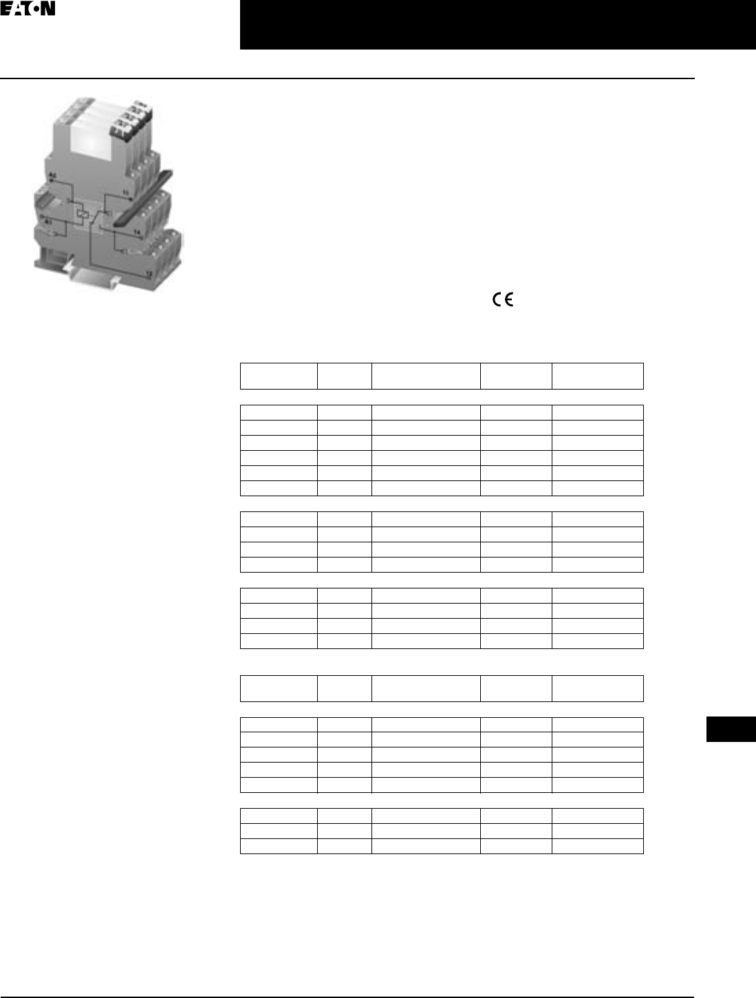
XR
Series Terminal Block Relays
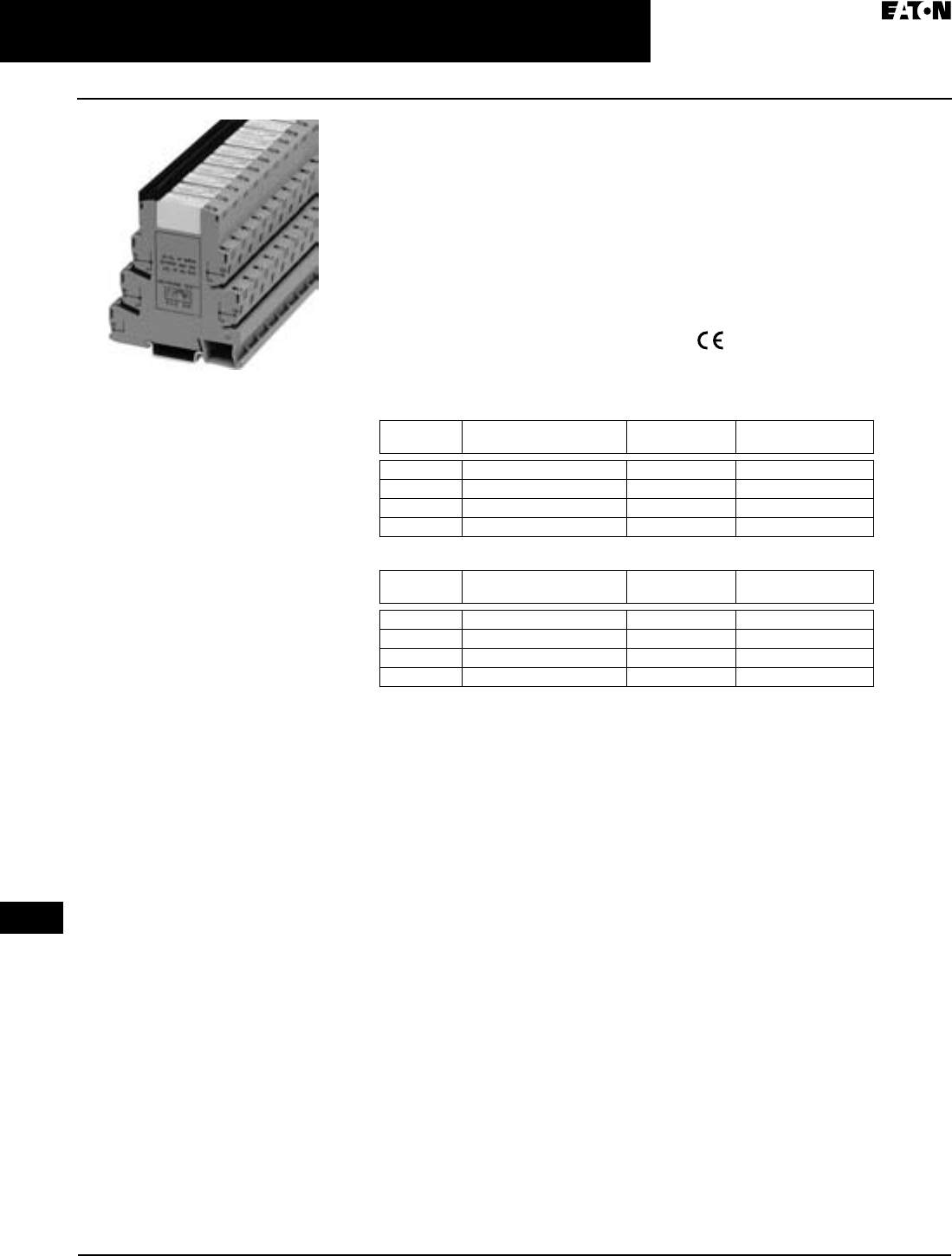
Standard Terminal Block Relays
Product Description
The new
XR
Series Terminal Block
Relays are ideal for applications that
require a high switching capacity and
long electrical service life. The relays
are plug-in interfaces that connect to
basic terminal blocks. The
XR
Series
utilizes screw or spring-cage technol-
ogy, as well as offers quick system wir-
ing, superior safety features, clear
labeling and a high level of modularity.
Application Description
Used in automation systems, electro-
mechanical relays guarantee a safe
connection between process I/O and
electronic controls. The following func-
tions are covered by relay coupling
elements:
■
Electrical isolation between the
input and output circuits
■
Independence of the type of switch-
ing current (AC and DC)
■
High short-term overload resistance
in the event of short circuits or volt-
age peaks
■
Low switching losses
■
Ease of operation
Standard Terminal
Block Relay
Features
■
Pluggable relay allows for field
replacement
■
Functional plug-in bridges
■
Choice of screw connections or
spring-cage connection
■
LED status indication
■
DIN Rail Mount
■
Only 6.2 mm wide for single pole
versions, 14 mm wide for double
pole
■
All common input voltages between
12V DC to 120V AC
■
Gold plated contacts available
■
Equipped with a robust, miniature
relay:
❑
IP67 protection
❑
Environmentally friendly,
cadmium-free contact material
❑
Easy, cost-effective installation
and replacement using the
engagement lever
Standards and Specifications
■
c
UL
us
Listed
■
Product Selection
Table 3-3. Standard Terminal Block Relays Product Selection
Table 3-4. Standard Replacement Relays
Gold Plated
Contacts
Rated
Current
Supply
Voltage
Standard
Pack
Catalogue
Number
1PDT Screw Connection
No 6A 12V DC 10
XRU1D12
No 6A 120V AC/110V DC 10
XRU1D120U
Yes 6A 120V AC/110V DC 10
XRU1D120UG
No 6A 24V DC 10
XRU1D24
No 6A 24V AC/DC 10
XRU1D24U
Yes 6A 24V AC/DC 10
XRU1D24UG
1PDT Spring Cage Connection
No 6A 12V DC 10
XRP1D12
No 6A 120V AC/110V DC 10
XRP1D120U
No 6A 24V DC 10
XRP1D24
No 6A 24V AC/DC 10
XRP1D24U
DPDT Screw Connection
No 6A 12V DC 10
XRU2D12
No 6A 120V AC/110V DC 10
XRU2D120U
No 6A 24V DC 10
XRU2D24
No 6A 24V AC/DC 10
XRU2D24U
Gold Plated
Contacts
Rated
Current
Supply
Voltage
Standard
Pack
Catalogue
Number
1PDT
No 6A 12V DC 10
XRR1D12
No 6A 120V AC/110V DC 10
XRR1D120U
Yes 6A 120V AC/110V DC 10
XRR1D120UG
No 6A 24V DC 10
XRR1D24
Yes 6A 24V DC 10
XRR1D24G
DPDT
No 6A 12V DC 10
XRR2D12
No 6A 120V AC/110V DC 10
XRR2D120U
No 6A 24V DC 10
XRR2D24
TAB49.BOO Page 3 Thursday, March 5, 2009 7:36 PM
April 2009
3-4
For more information visit:
www.EatonCanada.ca
CA08102002K07A
Control Relays & Timers
3
XR
Series Terminal Block Relays
Standard Terminal Block Relays
Technical Data and Specifications
Table 3-5. Standard 1PDT Screw Connection Terminal Block Relays
Technical Data
The separating plate, XRAPLCESK, should be installed for voltages
greater than 250V (L1, L2, L3) between identical terminal points of adja-
cent modules. Potential bridging is then possible with the XRAFBST
bridge system.
Table 3-6. Standard 1PDT Screw Connection Terminal Block Relays
with Gold Contacts Technical Data
The separating plate, XRAPLCESK, should be installed for voltages
greater than 250V (L1, L2, L3) between identical terminal points of adja-
cent modules. Potential bridging is then possible with the XRAFBST
bridge system.
If the maximum values are exceeded, the gold layer is destroyed and
the values in parentheses apply.
Catalogue
Number
XRU1D12 XRU1D24 XRU1D24U XRU1D120U
Replacement Relay XRR1D12 XRR1D24 XRR1D24 XRR1D120U
Input Voltage 12V DC 24V DC 24V AC/DC 120V AC/
110V DC
Connection Data
Rigid Solid
AWG (mm
2
)
26 – 14 (0.14 – 2.5)
Flexible Stranded
AWG (mm
2
)
26 – 14 (0.14 – 2.5)
Input Data for 1PDT Screw Connection Versions
Input Voltage 12V DC 24V DC 24V AC/DC 120V AC/
110V DC
Permissible Range
See
Page 3-7
See
Figure 3-5
See
Figure 3-7
See
Figure 3-8
See
Figure 3-6
Typical Input Current 15.3 mA 9 mA 11 mA
(24V AC)/
8.5 mA
(24V DC)
3.5 mA
(120V AC)/
3 mA
(110V DC)
Typical Response Time 5 mS 5 mS 6 mS 6 mS
Typical Release Time 8 mS 8 mS 15 mS 15 mS
Input Protection Polarity Protection
Diode, Free-
Wheeling Diode
Bridge Rectifier
Output Data
Contact Type 1PDT
Contact Material AgSnO
Max. Switching
Voltage
250V AC/DC
Min. Switching Voltage 12V AC/DC
Limiting Continuous
Current
6A
Min. Switching Current 10 mA
Min. Switching Power 120 mW
Miscellaneous Data
Test Voltage I/O 4 kV, 50 Hz, 1 min 4 kV 50 Hz
Ambient Temp Range -4° to 140°F (-20° to 60°C)
Rated Operating Mode 100% Operating Factor
Inflammability Class V0, in Accordance with UL 94
Mechanical Service
Life
2 x 10
7
Cycles
Catalogue
Number
XRU1D24UG XRU1D120UG
Replacement Relay XRR1D24G XRR1D120UG
Input Voltage 24V AC/DC 120V AC/110V DC
Connection Data
Rigid Solid
AWG (mm
2
)
26 – 14 (0.14 – 2.5)
Flexible Stranded
AWG (mm
2
)
26 – 14 (0.14 – 2.5)
Input Data for 1PDT Screw Connection Versions with Gold Contacts
Input Voltage 24V AC/DC 120V AC/110V DC
Permissible Range
See
Page 3-7
See Figure 3-8 See Figure 3-6
Typical Input Current 11 mA (24V AC)/
8.5 mA (24V DC)
3.5 mA (120V AC)/
3 mA (110V DC)
Typical Response Time 6 mS 6 mS
Typical Release Time 15 mS 15 mS
Input Protection Bridge Rectifier
Output Data
Contact Type 1PDT
Contact Material AgSnO, Gold Plated
Max. Switching Voltage 30V AC/36V DC
(250V AC/DC)
Min. Switching Voltage 100 mV
(12V AC/DC)
Limiting Continuous Current 50 mA (6A)
Min. Switching Current 1 mA (10 mA)
Min. Switching Power 100 (120 mW)
Miscellaneous Data
Test Voltage I/O 4 kV, 50 Hz, 1 min 50 Hz
Ambient Temp Range -4° to 140°F
(-20° to 60°C)
-40° to 131°F
(-20° to 55°C)
Rated Operating Mode 100% Operating Factor
Inflammability Class V0, in Accordance
with UL 94
Mechanical Service Life 2 x 10
7
Cycles
TAB49.BOO Page 4 Thursday, March 5, 2009 7:36 PM
April 2009
CA08102002K07A For more information visit:
www.EatonCanada.ca
3-5
Control Relays & Timers
3
XR
Series Terminal Block Relays
Standard Terminal Block Relays
Table 3-7. Standard 1PDT Spring Cage Terminal Block Relays
Technical Data
The separating plate, XRAPLCESK, should be installed for voltages
greater than 250V (L1, L2, L3) between identical terminal points of
adjacent modules. Potential bridging is then possible with the
XRAFBST bridge system.
Table 3-8. Standard DPDT Screw Connection Terminal Block Relays
Technical Data
Catalogue
Number
XRP1D12 XRP1D24 XRP1D24U XRP1D120U
Replacement Relay XRR1D12 XRR1D24 XRR1D24 XRR1D120U
Input Voltage 12V DC 24V DC 24V AC/DC 120V AC/
110V DC
Connection Data
Rigid Solid
AWG (mm
2
)
26 – 14 (0.14 – 2.5)
Flexible Stranded
AWG (mm
2
)
26 – 14 (0.14 – 2.5)
Input Data for 1PDT Spring Cage Versions
Input Voltage 12V DC 24V DC 24V AC/DC 120V AC/
110V DC
Permissible Range
See
Page 3-7
See
Figure 3-
5
See
Figure 3-
7
See
Figure 3-8
See
Figure 3-6
Typical Input Current 15.3 mA 9 mA 11 mA
(24V AC)/
8.5 mA
(24V DC)
3.5 mA
(120V AC)/
3 mA
(110V DC)
Typical Response Time 5 mS 5 mS 6 mS 6 mS
Typical Release Time 8 mS 8 mS 15 mS 15 mS
Input Protection Polarity Protection
Diode, Free-
Wheeling Diode
Bridge Rectifier
Output Data
Contact Type 1PDT
Contact Material AgSnO
Max. Switching Voltage 250V AC/DC
Min. Switching Voltage 12V AC/DC
Limiting Continuous
Current
6A
Min. Switching Current 10 mA
Min. Switching Power 120 mW
Miscellaneous Data
Test Voltage I/O 4 kV, 50 Hz, 1 min 4 kV 50 Hz
Ambient Temp Range -4° to 140°F
(-20° to 60°C)
-4° to 131°F
(-20° to 55°C)
Rated Operating Mode 100% Operating Factor
Inflammability Class V0, in Accordance with UL 94
Mechanical Service Life 2 x 10
7
Cycles
Catalogue
Number
XRU2D12 XRU2D24 XRU2D24U XRU2D120U
Replacement Relay XRR2D12 XRR2D24 XRR2D24 XRR2D120U
Input Voltage 12V DC 24V DC 24V AC/DC 120V AC/
110V DC
Connection Data
Rigid Solid
AWG (mm
2
)
26 – 14 (0.14 – 2.5)
Flexible Stranded
AWG (mm
2
)
26 – 14 (0.14 – 2.5)
Input Data
Input Voltage 12V DC 24V DC 24V AC/DC 120V AC /
110V DC
Permissible Range
See
Page 3-7
See
Figure 3-9
See
Figure 3-
11
See
Figure 3-12
See
Figure 3-10
Typical Input Current 33 mA 18 mA 17.5 mA 4.5 mA
(120V AC)
4.2 mA
(110V DC)
Typical Response Time 8 mS 8 mS 8 mS 7 mS
Typical Release Time 10 mS
Input Protection Polarity Protection
Diode, Free-Wheeling
Diode
Bridge Rectifier
Output Data:
Contact Type 2PDT Single Contact, 2PDT
Contact Material AgNi
Max. Switching
Voltage
250V AC/DC
Min. Switching Voltage 5V
Limiting Continuous
Current
6A
Max. Inrush Current 15A (300 mS)
Min. Switching Current 10 mA
Min. Switching Power 50 mW
General Data
Test Voltage I/O 4 kV, 50 Hz, 1 min /2.5 kV, 50 Hz,
1 Min. (Between the PDTs)
Ambient Temp Range -4° to 140°F (-20° to 60°C)
Rated Operating Mode 100% Operating Factor
Inflammability Class V0, in Accordance with UL 94
Mechanical Service
Life
3 x 10
7
cycles
TAB49.BOO Page 5 Thursday, March 5, 2009 7:36 PM
April 2009
3-6
For more information visit:
www.EatonCanada.ca
CA08102002K07A
Control Relays & Timers
3
XR
Series Terminal Block Relays
Standard Terminal Block Relays
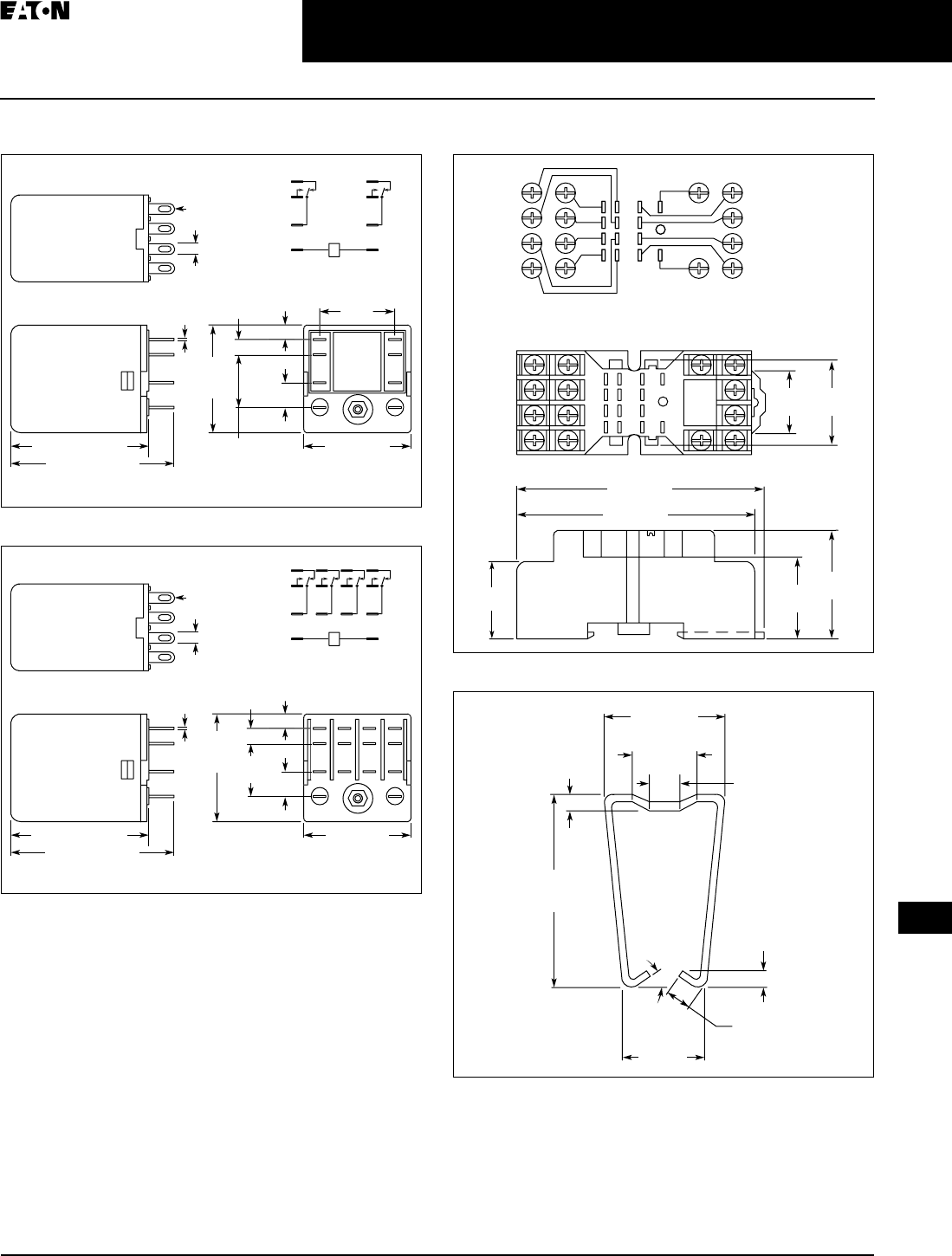
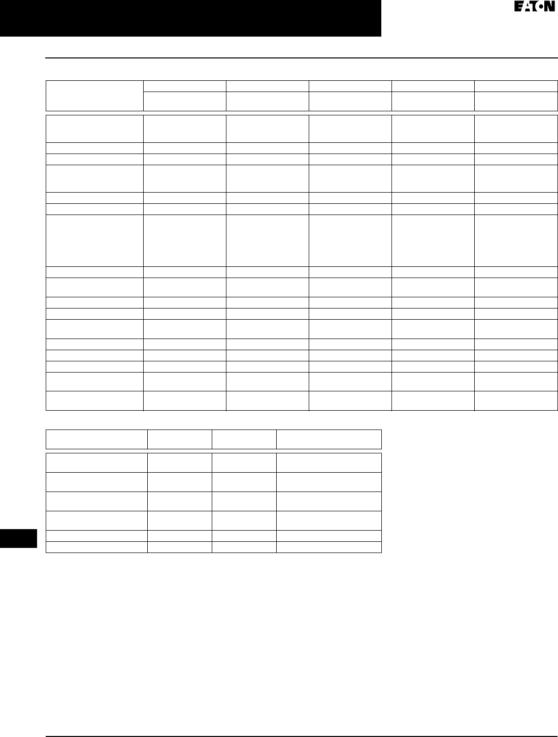
Dimensions
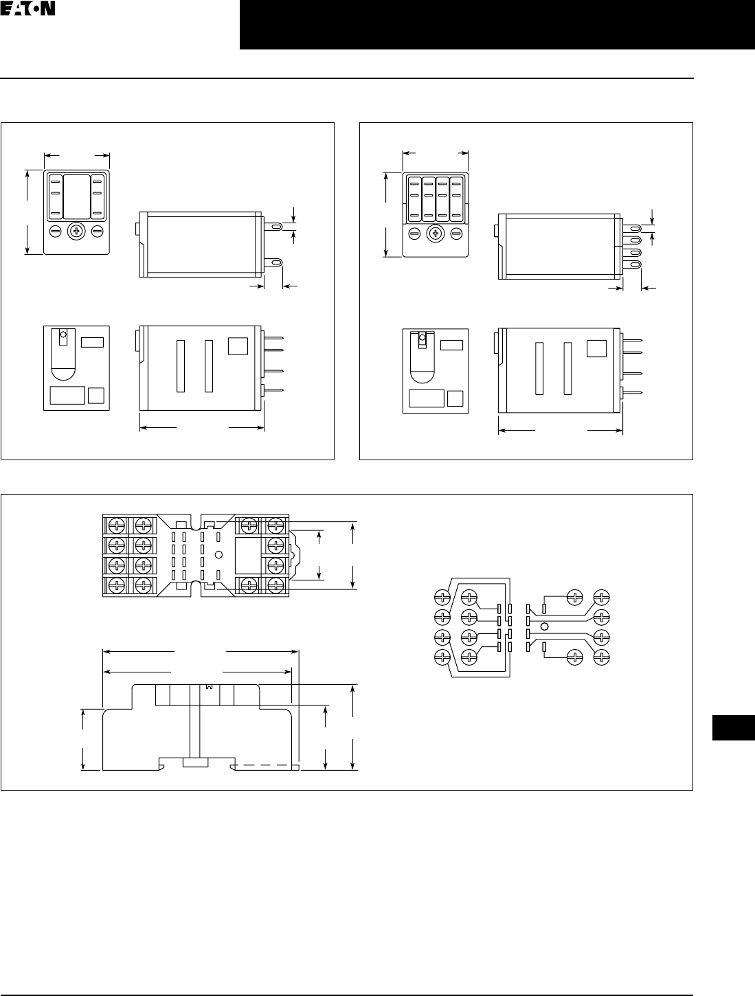
Figure 3-1. Standard 1PDT Terminal Block Relays —
Approximate Dimensions in Inches (mm)
Figure 3-2. Standard DPDT Terminal Block Relays —
Approximate Dimensions in Inches (mm)
Schematics
Figure 3-3. Schematics for 1PDT Terminal Block Relays
Figure 3-4. Schematic for DPDT Terminal Block Relays
3.70 (94)
0.24 (6.2)
3.15 (80)
3.70 (94)
0.55 (14)
3.15 (80)
11
14
12
A2
A1
12
22
24
21
A2
A1
11
14
TAB49.BOO Page 6 Thursday, March 5, 2009 7:36 PM
CA08102002K07A For more information visit:
www.EatonCanada.ca
3-7
Control Relays & Timers
April 2009
3
XR
Series Terminal Block Relays
Standard Terminal Block Relays
Permissible Range Diagrams
1PDT
Figure 3-5. Operating Range Voltage for 12V
DC 1PDT Relay Module
Figure 3-6. Operating Range Voltage for
120V AC/110V DC 1PDT Relay Module
Figure 3-7. Operating Range Voltage for 24V
DC 1PDT Relay Module
Figure 3-8. Operating Range Voltage for
24V AC/DC 1PDT Relay Module
DPDT
Figure 3-9. Operating Range Voltage for 12V
DC DPDT Relay Module
Figure 3-10. Operating Range Voltage for
120V AC/110V DC DPDT Relay Module
Figure 3-11. Operating Range Voltage for
24V DC DPDT Relay Module
Figure 3-12. Operating Range Voltage for
24V AC/DC DPDT Relay Module
1.4
1.3
1.2
1.1
1.0
0.9
0.8
0.7
20 25 30
A
B
35 40 45 50 55 60 65
U
UN
TN [°C]
UN = 12V DC
1.4
1.3
1.2
1.1
1.0
0.9
0.8
0.7
20 25 30
A
B
35 40 45 50 55 60 65
U
UN
TN [°C]
UN = 110V DC/120V AC
1.4
1.3
1.2
1.1
1.0
0.9
0.8
0.7
20 25 30
A
B
35 40 45 50 55 60 65
U
UN
TN [°C]
UN = 24V DC
1.4
1.3
1.2
1.1
1.0
0.9
0.8
0.7
20 25 30
A
B
35 40 45 50 55 60 65
U
UN
TN [°C]
UN = 24V DC
1.4
1.3
1.2
1.1
1.0
0.9
0.8
0.7
20 25 30
A
B
35 40 45 50 55 60 65
U
UN
TN [°C]
UN = 12V DC
1.4
1.3
1.2
1.1
1.0
0.9
0.8
0.7
20 25 30
A
B
35 40 45 50 55 60 65
U
UN
TN [°C]
UN = 120V AC
UN = 110V DC
1.4
1.3
1.2
1.1
1.0
0.9
0.8
0.7
20 25 30
A
B
35 40 45 50 55 60 65
U
UN
TN [°C]
UN = 24V DC
1.4
1.3
1.2
1.1
1.0
0.9
0.8
0.7
20 25 30
A
B
35 40 45 50 55 60 65
U
UN
TN [°C]
UN = 24V DC/24V AC
Notes:
General Conditions
— Direct alignment in
the block, all devices 100% operating factor,
horizontal or vertical mounting.
Curve A
— Maximum permissible continu-
ous operating voltage U
max
with limiting
continuous current on the contact side (see
respective technical data).
Curve B
— Minimum permissible relay
operate voltage U
op
after pre-excitation
)
(see respective technical data).
Pre-excitation: Relay has been operated in a
thermally steady state at the ambient tem-
perature TU with nominal voltage UN and
limiting continuous current on the contact
side (see respective technical data) (warm
coil). After being switched off for a short
time, the relay must reliably pick up again at
Uop.
TAB49.BOO Page 7 Thursday, March 5, 2009 7:36 PM
April 2009
3-8
For more information visit:
www.EatonCanada.ca
CA08102002K07A
Control Relays & Timers
3
XR
Series Terminal Block Relays
OptoCoupler Terminal Block Relays
Product Description
The new
XR
Series OptoCoupler Ter-
minal Block Relays can be used in all
applications and consist of a pluggable
miniature OptoCoupler and a basic ter-
minal block. The
XR
Series utilizes
screw or spring-cage technology, as
well as offers quick system wiring,
superior safety features, clear labeling
and a high level of modularity.
Application Description
The
XR
Series OptoCoupler relays can
be used as an input or output inter-
face. They provide the typical reliability
of OptoCouplers and are especially
suited for high operating frequencies.
OptoCoupler Terminal
Block Relay
Features
■
Pluggable relay allows for field
replacement
■
Functional plug-in bridges
■
LED status indication
■
DIN Rail Mount
■
Only 6.2 mm wide
■
Switching capacity up to 24V DC/3A
■
IP67-protected optical electronics
■
Wear-resistant and bounce-free
switching
■
Insensitive to shock and vibration
■Integrated protection circuit
■Zero voltage switch at AC output
Standards and Certifications
■cULus Listed
■
Product Selection
Table 3-9. OptoCoupler Terminal Block Relays Product Selection
Table 3-10. OptoCoupler Replacement Relays
Rated
Current
Supply
Voltage
Standard
Pack
Catalogue
Number
2A 120V AC/110V DC 10 XRU1S120U
2A 24V DC 10 XRU1S24
Rated
Current
Supply
Voltage
Standard
Pack
Catalogue
Number
2A 24V DC 18 XRR1S24
2A 120V AC/110V DC 10 XRR1S120U
TAB49.BOO Page 8 Thursday, March 5, 2009 7:36 PM

April 2009
CA08102002K07A For more information visit: www.EatonCanada.ca
3-9
Control Relays & Timers
3
XR Series Terminal Block Relays
OptoCoupler Terminal Block Relays
Technical Data and Specifications
Table 3-11. Pluggable Power OptoCoupler (Solid-State) Terminal Block
Relays Technical Data
Figure 3-13. Derating Curve
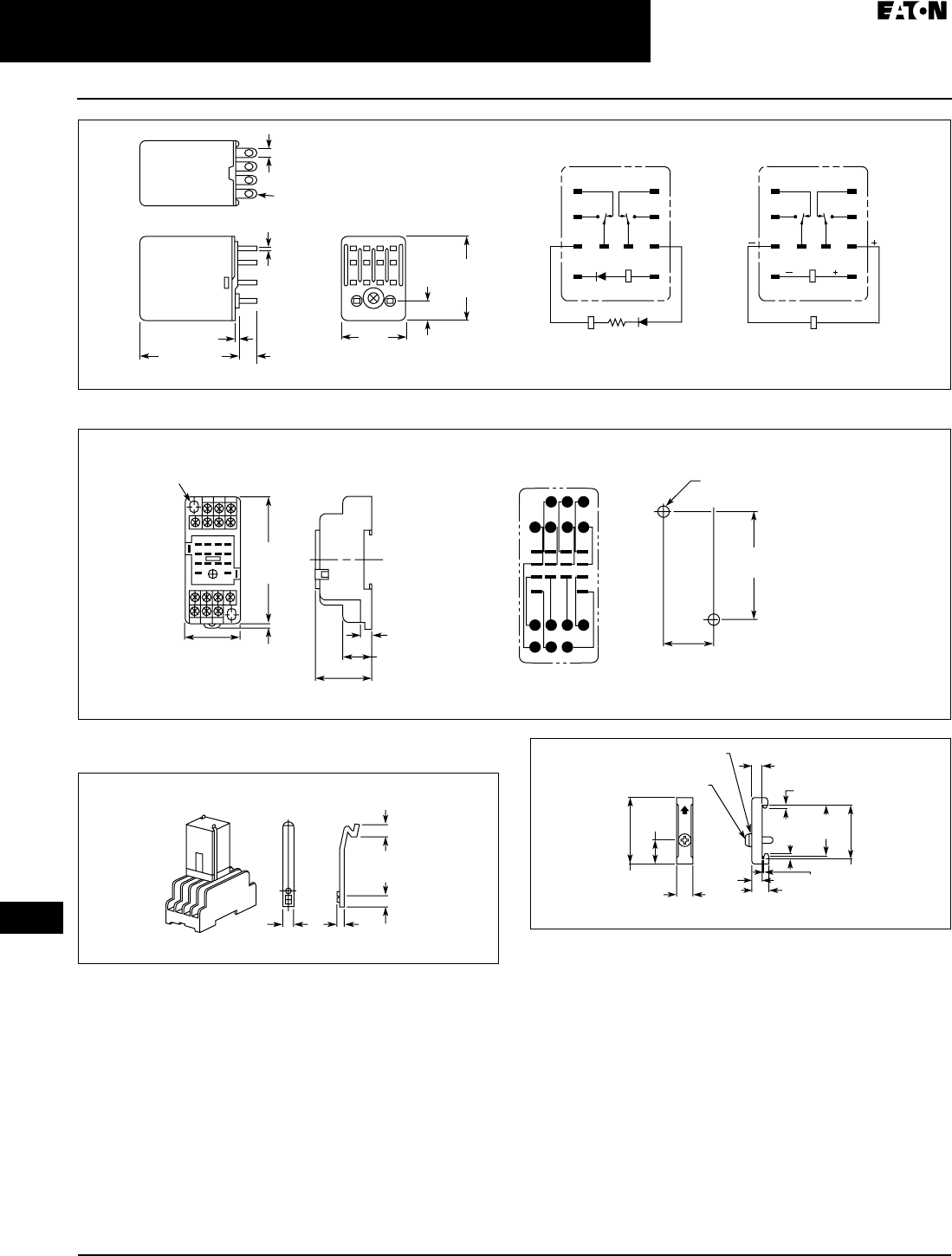
Dimensions
Figure 3-14. Pluggable Power OptoCoupler (Solid-State) Terminal
Block Relays — Approximate Dimensions in Inches (mm)
Schematic
Figure 3-15. Schematic for Pluggable Power OptoCoupler (Solid-State)
Terminal Block Relays
Catalogue Number XRU1S24 XRU1S120U
Replacement Relay XRR1S24 XRR1S120U
Input Voltage 24V DC 120V AC/110V DC
Connection Data
Rigid Solid
AWG (mm2)
26 – 14 (0.14 – 2.5)
Flexible Stranded
AWG (mm2)
26 – 14 (0.14 – 2.5)
Input Data
Input Voltage 24V DC 120V AC/110V DC
Permissible Range 0.8 – 1.2 0.8 – 1.1
Typical input current 9 mA 4 mA
Switching Level
1 signal (“H”)
≥ 0.8 ≥ 0.8
Switching Level
0 signal (“L”)
≤ 0.4 ≤ 0.25
Typical Switch-On Time 20 µS 6 mS
Typical Turn-Off Time 50 0 µS 10 mS
Input Protection Polarity Protection
Diode, Free-
Wheeling Diode
Bridge Rectifier
Output Data
Max. Switching Voltage 33V DC 33V DC
Min. Switching Voltage 3V DC 3V DC
Limiting Continuous Current 3A (See Figure 3-13)
Max. Inrush Current 15A (10 mS)
Output Circuit 2-Conductor Floating
Output Protection Polarity Protection, Surge Protection
Voltage Drop at Max. Limiting
Continuous Current
≤ 200 mV
General Data
Test Voltage I/O 2.5 kV, 50 Hz, 1 min
Ambient Temp Range -4° to 140°F (-20° to 60°C)
Rated Operating Mode 100% Operating Factor
Inflammability Class V0, in Accordance with UL 94
Mechanical Service Life 2 x 10⁷ cycles
0
0
1
2
3
10 20 30
Ambient Temperature (°C)
Load Current (A)
40 50 60
3.70 (94)
0.24 (6.2)
3.15 (80)
13+
14
A2
A1
TAB49.BOO Page 9 Thursday, March 5, 2009 7:36 PM
April 2009
3-10
For more information visit: www.EatonCanada.ca CA08102002K07A
Control Relays & Timers
3
XR Series Terminal Block Relays
High Current Terminal Block Relays
Product Description
The new XR Series Relays include
products designed to meet high con-
tinuous current and/or long electrical
service life applications. The XR Series
Relays are plug-in interfaces that con-
nect to basic terminal blocks that use
screw connection technology. Overall
width is 14 mm.
Application Description
These relays are best suited for appli-
cations that require higher continuous
load currents than miniature relays
can carry and switch. They can with-
stand inrush currents or brief over-
loads without damage, and allow for
continuous load currents of up to 10A.
The XR Series Relay boasts an average
service life of the contacts that is two
or three times the normal life of a less
powerful relay, resulting in service
cost savings.
High Current Terminal
Block Relay
Features
■14 mm wide
■Pluggable relay allows for field
replacement
■Convenient plug-in bridge system
■LED status indication
■DIN Rail Mount
■IP67-protected optical electronics
■Wear-resistant and bounce-free
switching
■Insensitive to shock and vibration
■Integrated protection circuit
■Zero voltage switch at AC output
■Environmentally friendly, cadmium-
free contact material
■Electrical isolation between input
and output
Standards and Certifications
■cULus Listed
■
Product Selection
Table 3-12. High Current Terminal Block Relays Product Selection
Table 3-13. High Current Replacement Relays
Rated
Current
Supply
Voltage
Standard
Pack
Catalogue
Number
10A 12V DC 10 XRU1H12
10A 120V AC/110V DC 10 XRU1H120U
10A 24V DC 10 XRU1H24
10A 24V AC/DC 10 XRU1H24U
Rated
Current
Supply
Voltage
Standard
Pack
Catalogue
Number
10A 24V DC 10 XRR1H24
10A 24V AC/DC 10 XRR1H24U
10A 12V DC 10 XRR1H12
10A 120V AC/110V DC 10 XRR1H120U
TAB49.BOO Page 10 Thursday, March 5, 2009 7:36 PM

April 2009
CA08102002K07A For more information visit: www.EatonCanada.ca
3-11
Control Relays & Timers
3
XR Series Terminal Block Relays
High Current Terminal Block Relays
Technical Data and Specifications
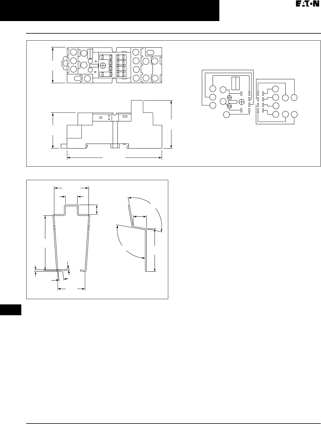
Table 3-14. Information for High Current Terminal Block Relays (1PDT)
The separating plate, XRAPLCESK, should be installed for voltages
greater than 250V (L1, L2, L3) between identical terminal points of adja-
cent modules. Potential bridging is then possible with the XRAFBST
bridge system.
The current rating for the normally open contact (#14) is 10A. The cur-
rent rating for the normally closed contact (#12) is 6A and can be
increased to 10A by bridging the two #12 contact connections.
Dimensions
Figure 3-16. High Current Terminal Block Relays — Approximate
Dimensions in Inches (mm)
Schematic
Figure 3-17. Schematic for High Current Terminal Block Relays
Catalogue Number
Assembled Unit
XRU1H12 XRU1H24 XRU1H24U XRU1H120U
Replacement Relay XRR1H12 XRR1H24 XRR1H24U XRR1H120U
Input Voltage 12V DC 24V DC 24V AC/DC 120V AC/
110V DC
Connection Data
Rigid Solid
AWG (mm2)
26 – 14 (0.14 – 2.5)
Flexible Stranded
AWG (mm2)
26 – 14 (0.14 – 2.5)
Input Data (Permissible Range — See Page 3-7)
Input Voltage 12V DC 24V DC 24V AC/DC 120V AC/
110V DC
Permissible Range
See Page 3-7
See
Figure 3-9
See
Figure 3-
11
See
Figure 3-12
See
Figure 3-10
Typical Input Current 33 mA 18 mA 17.5 mA 4.5 mA
(120V AC)/
4.2 mA
(110V DC)
Typical Response Time 8 mS 8 mS 8 mS 7 mS
Typical Release Time 10 mS
Input Protection Polarity Protection
Diode, Free-
Wheeling Diode
Bridge Rectifier
Output Data
Contact Type Single Contact, 1PDT
Contact Material AgNi
Max. Switching
Voltage
250V AC/DC
Min. Switching Voltage 12V AC/DC
Limiting Continuous
Current
10A (6)A
Max. Inrush Current 30A (300 mS)
Min. Switching Current 100 mA
Min. Switching Power 1.2W
Miscellaneous Data
Test Voltage I/O 4 kV, 50 Hz, 1 min
Ambient Temp Range -4° to 140°F (-20° to 60°C)
Rated Operating Mode 100% Operating Factor
Inflammability Class V0, in Accordance with UL 94
Mechanical Service
Life
3 x 10⁷ cycles
3.70 (94)
0.55 (14)
3.15 (80)
11
14
12
A2
A1
TAB49.BOO Page 11 Thursday, March 5, 2009 7:36 PM
April 2009
3-12
For more information visit: www.EatonCanada.ca CA08102002K07A
Control Relays & Timers
3
XR Series Terminal Block Relays
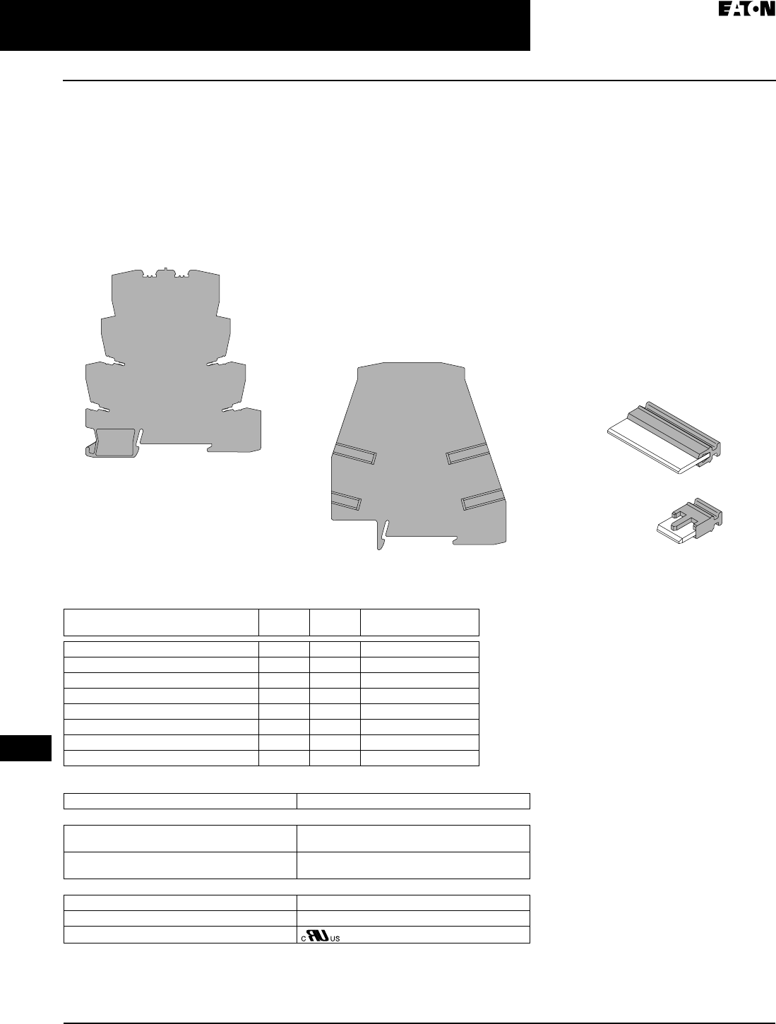
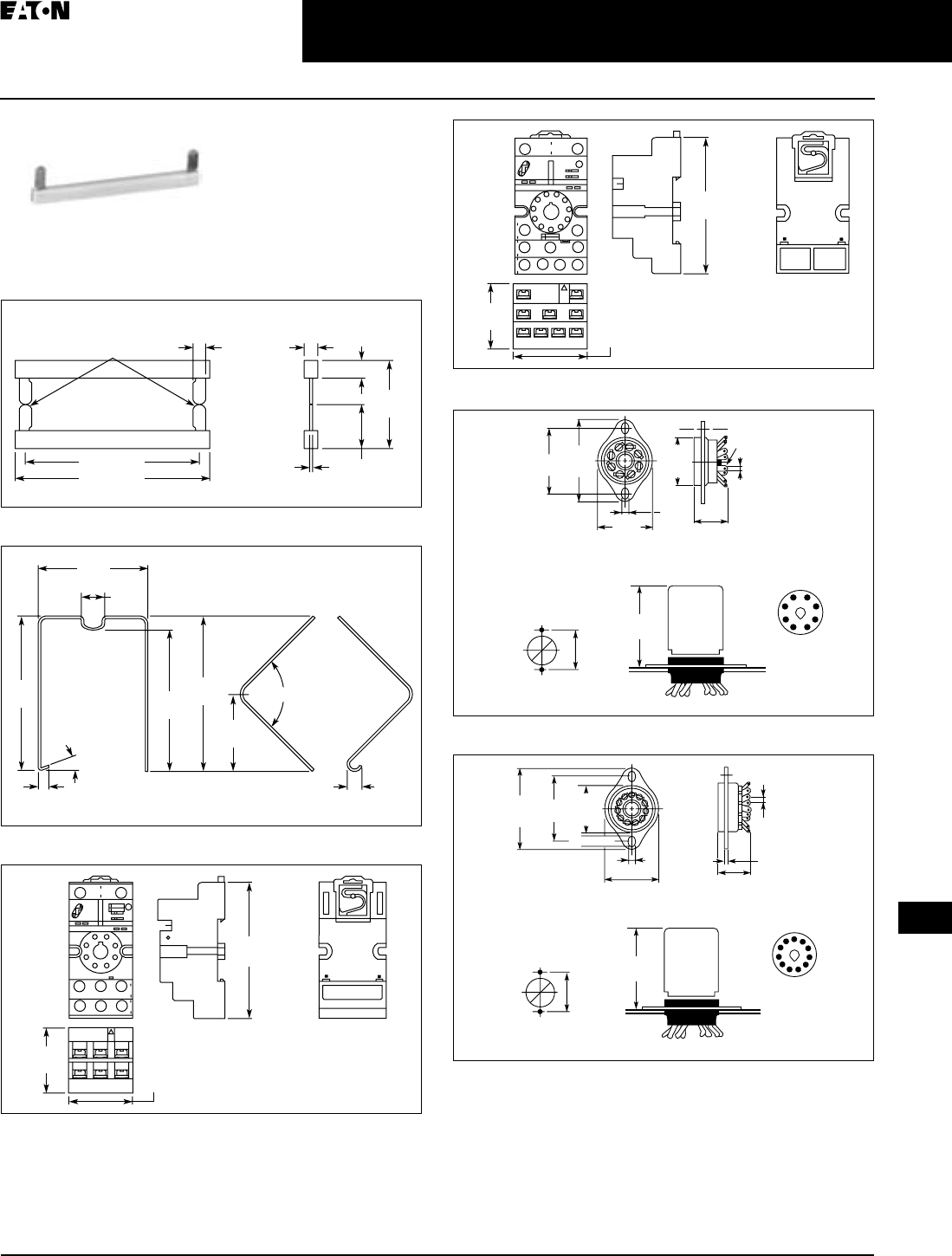
Accessories
Product Description
Power Terminal Block
The XRAPLCESK power terminal block
has the same shape as the relay mod-
ules and is used to feed in the bridging
potentials. The nominal current is 32A.
When the total current is less than or
equal to 6A, supply can take place
directly at the connecting terminal
blocks of one of the connected relays.
End Cover
The XRAATPBK end cover is required
at the start and stop of a relay strip. It
can also be used for visual separation
of groups of relays as well as separat-
ing relays with voltages greater than
250V and separating neighboring
bridges with different potentials. It is
equipped with pre-scored break out
points at the bridging positions so that
individual bridges can be passed
through as needed. It may also be nec-
essary to use the end cover between
adjacent relays when three phases (L1,
L2, L3) are used on the contact side of
the relay.
Bridges
The XRAFBST coloured, insulated
plug-in bridge system reduces wiring
time by up to 70% compared to con-
ventionally wired relays. The
XRAFBST2, 2-position bridges, are
suited for bridging a smaller number
of relays and total currents ≤ 6A. When
a circuit is supplied from both sides,
the circuit can be opened at any point,
allowing all other modules to continue
being supplied at the same time. The
XRAFBST500 allow up to 80 modules
to be bridged at one time. If bridges
with different potentials meet in neigh-
boring modules, the end cover
XRAATPBK should be used. All bridges
are equipped with a groove for
removal with a standard screwdriver.
Product Selection
Table 3-15. Product Selection Table for XR Series Accessories
Table 3-16. Power Terminal Block Technical Specifications
The separating plate, XRAPLCESK, should be installed for voltages greater than 250V (L1, L2, L3)
between identical terminal points of adjacent modules. Potential bridging is then possible
with the XRAFBST bridge system.
Description Colour Standard
Pack
Catalogue
Number
2-Position Snap-In Jumper Red 10 XRAFBST2RD
2-Position Snap-In Jumper Blue 10 XRAFBST2BU
2-Position Snap-In Jumper Grey 10 XRAFBST2GY
80-Position Snap-In Jumper Red 5 XRAFBST500RD
80-Position Snap-In Jumper Blue 5 XRAFBST500BU
80-Position Snap-In Jumper Grey 5 XRAFBST500GY
Power Terminal Block Grey 5 XRAPLCESK
End Cover Black 5 XRAATPBK
Description Specification
Connection Data
Rigid Solid
AWG (mm2)
24 – 10 (0.2 – 4)
Flexible Stranded
AWG (mm2)
24 – 10 (0.2 – 4)
Miscellaneous Data
Max. Current 32A
Max. Voltage 250V AC
Approvals
TAB49.BOO Page 12 Thursday, March 5, 2009 7:36 PM
April 2009
CA080102002K07A For more information visit: www.EatonCanada.ca
3-13
Control Relays & Timers
3
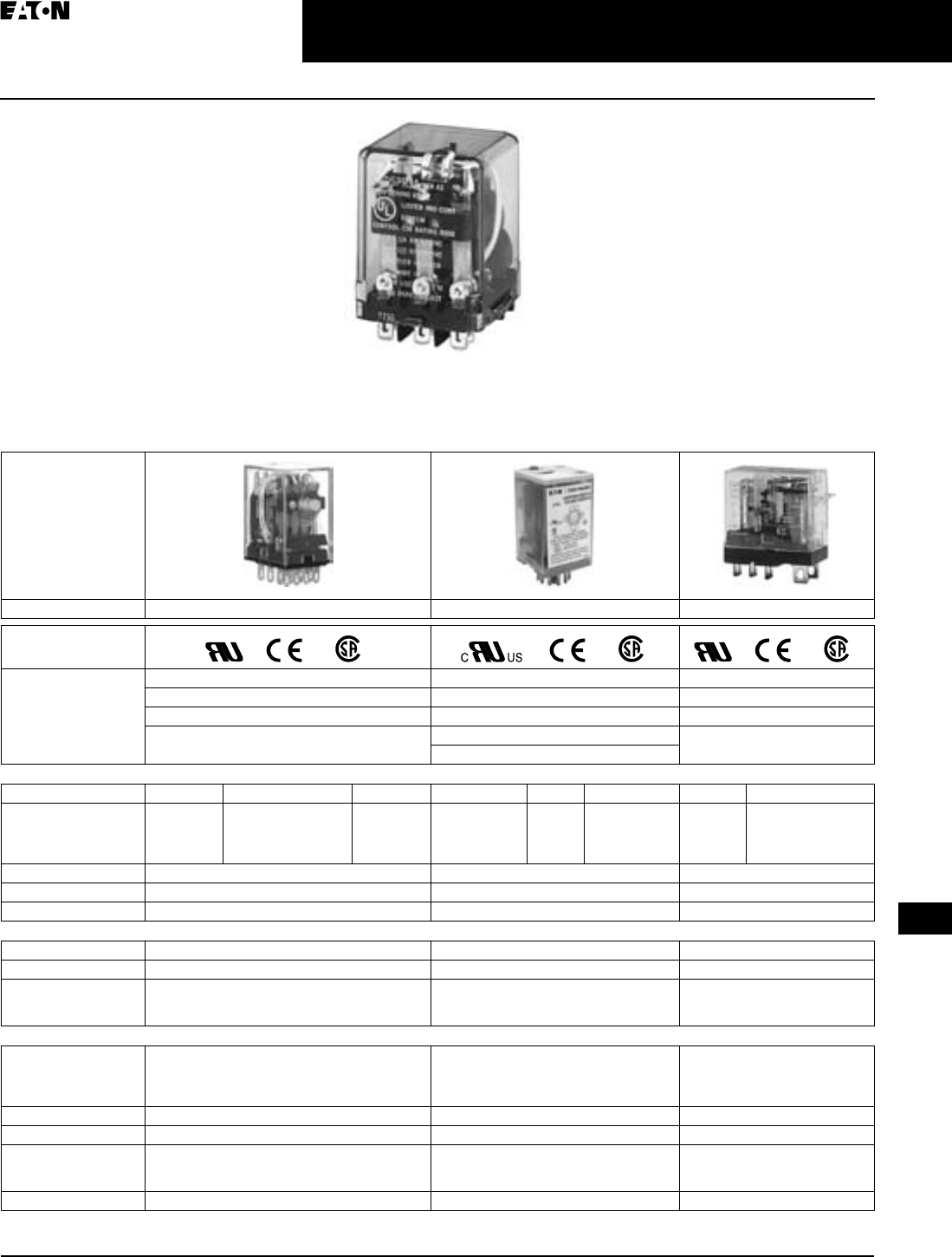
General Purpose Plug-In Relays
Selection Guide
Contents
Description Page
General Purpose
Plug-In Relays
Selection Guide . . . . . . . . . . . 3-13
D2 Series . . . . . . . . . . . . . . . . 3-15
D3 Series . . . . . . . . . . . . . . . . 3-23
D4 Series . . . . . . . . . . . . . . . . 3-29
D5 Series . . . . . . . . . . . . . . . . 3-32
D7 Series . . . . . . . . . . . . . . . . 3-36
D8 Series . . . . . . . . . . . . . . . . 3-47
D9 Series . . . . . . . . . . . . . . . . 3-51
Selection Guide
General Purpose Relay Selection
Characteristics
■Current Rating: 1A – 30A
■Contact Arrangement: SPDT, DPDT,
3PDT, 4PDT, etc.
■Coil Voltage: 6V – 240V AC/
6V – 110V DC
■Mounting Options: Socket, Flange,
DIN Rail, Panel
■Specifications: CSA, CE, IEC, NEMA,
UL, etc.
■Other: Physical Dimensions, Maxi-
mum Voltage, Mechanical/Electrical
Life, etc.
Table 3-17. General Purpose Plug-In Relays Selection Guide
General Purpose Plug-In Relay
Relay Series
D2PF/D2PR D3PF/D3PR D4PR
Approvals
Features Polycarbonate Cover Polycarbonate Cover Polycarbonate Cover
Indicator Lamp and Pushbutton Available Indicator Lamp and Pushbutton Available Indicator Lamp Available
Panel, DIN and Flange Mounting Panel and DIN Mounting Panel and DIN Mounting
Latching 8 or 11 Pin Octal Plug-In Socket Has Built-In Hold Down
Spring
Latching (D3PR version)
Contact Data
Configuration DPDT DPDT Latching 4PDT SPDT DPDT 3PDT SPDT DPDT
Max. Allowable Load D2PF: 10A at
120V AC
D2PR: 5A at
240V AC
3A at
220V AC
3A at
240V AC
12A at
120V AC
12A at
120V AC
10A at
240V AC
10A at
250V AC
5A at
240V AC
Material Ag (Au Flashed) AgCdO (Au Flashed) AgCdO
Resistance 50 Milliohms (Initial) 50 Milliohms (Initial) 100 Milliohms (Initial)
Dielectric Strength 1500V 1500V 5000V
Coil Data
AC 6 – 240V AC 24 – 240V AC (D3PF) / 6 – 240V AC (D3PR) 6 – 240V AC
DC 6 – 110V DC 12 – 110V DC (D3PF) / 6 – 110V DC (D3PR) 6 – 110V DC
Power
VA (V AC)
Watts (V DC)
1.2 VA
1.1 Watts
2.75 VA
1.2 Watts
0.9 VA
0.5 Watts
General Data
Ambient
Temperature
Operational
Storage
-40 – 158°F (-40° – 70°C)
-40 – 221°F (-40° – 105°C)
-49 – 131°F (-45° – 55°C)
-40 – 221°F (-40° – 105°C)
-40 – 158°F (-40° – 70°C)
-40 – 158°F (-40° – 70°C)
Maximum Pick-Up 20 / 25 Milliseconds 15 Milliseconds 15 Milliseconds
Maximum Release 20 / 25 Milliseconds 10 Milliseconds 10 (AC)/5 (DC) Milliseconds
Life
Mechanical Operations
Electrical Operations
10 Million
200,000
5 Million (D3PF) / 10 Million (D3PR)
200,000 (D3PF) / 100,000 (D3PR)
10 Million
100,000
Page Number Pages 3-15 – 3-22 Pages 3-23 – 3-28 Pages 3-29 – 3-31
TAB49.BOO Page 13 Thursday, March 5, 2009 7:36 PM
April 2009
3-14
For more information visit: www.EatonCanada.ca CA080102002K07A
Control Relays & Timers
3
General Purpose Plug-In Relays
Selection Guide
Table 3-17. General Purpose Plug-In Relays Selection Guide (Continued)
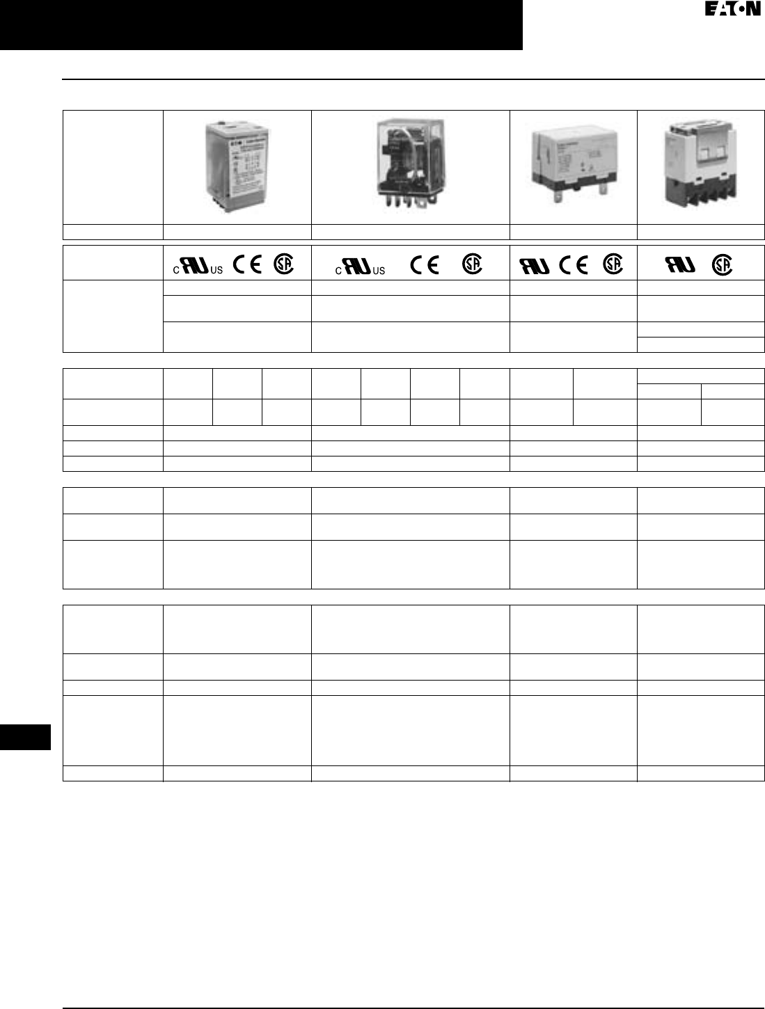
Relay Series
D5PF/D5PR D7PF/D7PR D8PR D9PR
Approvals
Features Polycarbonate Cover Polycarbonate Cover Dust Cover Dust Cover
Indicator Lamp and
Pushbutton Available
Indicator Lamp and Pushbutton
Available
Panel, DIN and Flange
Mounting
Pushbutton Available
Panel, DIN and PC Board
Mounting
Panel, DIN and Flange Mounting Quick-Connect and Screw
Terminals
Panel Mounting
Screw Terminals
Contact Data
Configuration SPDT DPDT 3PDT SPDT DPDT 3PDT 4PDT SPST-NO DPST-NO 4PST
NO NC
Max. Allowable
Load
15A at
240V AC
15A at
240V AC
15A at
240V AC
20A at
277V AC
15A at
120V AC
15A at
120V AC
15A at
120V AC
30A at
220V AC
25A at
220V AC
25A at
220V AC
8A at
220V AC
Material AgCdO (Au Flashed) AgCdO AgCdO AgCdO
Resistance 50 Milliohms (Initial) 50 Milliohms (Initial) 50 Milliohms (Initial) 50 Milliohms (Initial)
Dielectric Strength 1500V (D5PF) / 2000V (D5PR) 1000V(D7PF1, D7PF2, D7PF3) / 1500V 4000V 4000V
Coil Data
AC 24 – 110V AC (D5PF)
6 – 240V AC (D5PR)
6 – 240V AC 6 – 240V AC 24 – 240V AC
DC 24 – 110V DC (D5PF)
6 – 110V DC (D5PR)
6 – 110V DC 12 – 24V DC 12 – 110V DC
Power
VA (V AC)
Watts (V DC)
2.75 VA
1.2 Watts
3.0 VA (D7PF3, D7PF4) / 2.55 VA
2.3 Watts (D7PF1, D7PF2, D7PF4);
3.4 Watts (D7PF3) / 1.5 Watts
2.5 VA
1.9 Watts
2.6 VA
2.0 Watts
General Data
Ambient
Temperature
Operational
Storage
-22 – 122°F (-30° – 50°C)
-22 – 212°F (-30° – 100°C)
-40 – 158°F (-40° – 70°C)
-40 – 212°F (-40° – 100°C)
-4 – 185°F (-20° – 85°C)
-4 – 185°F (-20° – 85°C)
-13 – 140°F (-25° – 60°C)
-13 – 140°F (-25° – 60°C)
Maximum Pick-Up 24 Milliseconds 20 Milliseconds (D7PF1, D7PF4)
25 Milliseconds (All Others)
30 Milliseconds 50 Milliseconds
Maximum Release 26 Milliseconds 20 Milliseconds / 25 Milliseconds 30 Milliseconds 50 Milliseconds
Life
Mechanical
Operations
Electrical
Operations
5 Million
200,000 (D5PF) / 100,000 (D5PR)
10 Million
100,000 (D7PR3, D7PR4, D7PF1)
150,000 (D7PF3, D7PF4)
200,000 (D7PF2, D7PR1, D7PR2)
5 Million
100,000
1 Million
100,000
Page Number Pages 3-32 – 3-35 Pages 3-36 – 3-46 Pages 3-47 – 3-50 Pages 3-51, 3-52
TAB49.BOO Page 14 Thursday, March 5, 2009 7:36 PM
April 2009
CA080102002K07A For more information visit: www.EatonCanada.ca
3-15
Control Relays & Timers
3
General Purpose Plug-In Relays
D2PF Series — Full Featured
D2PF Series
Features
■Flag indicator shows relay status in
manual or powered condition
■Bi-polar LED status lamp allows for
reverse polarity applications
❑Shows coil ON or OFF status
❑Ideal in low light conditions
■Colour coded pushbutton identifies
AC coils with red or DC coils with
blue pushbuttons
❑Allows for manual operation of
relay without the need for coil
power
❑Ideal for field service personnel to
test control circuits
■Lock down door, when activated,
holds pushbutton and contacts in
the operate position
❑Excellent for analyzing circuit
problems
■Finger-grip cover allows operator to
remove relays from sockets more
easily than conventional relays
■White plastic I.D. tag/write label
used for identification of relays in
multi-relay circuits
Standards and Certifications
When used with accompanying
Cutler-Hammer® screw terminal
socket.
D2PF Series Relay
UL Listed
Technical Data and Specifications
Table 3-18. D2PF Coil Resistance
At 60 Hz for AC Coils.
Table 3-19. D2PF2 and D2PF4 Relay Specifications
Coil Voltage Ohms mA
50 Hz
6V AC
6V DC
9.6
40
200
150
12V AC
12V DC
46
160
100
75
24V AC
24V DC
180
650
50
37
48V DC 2600 18
110V DC 11000 10
120V AC 4430 10
240V AC 15700 5
D2PF2 D2PF4
Resistive Load (p.f. = 1.0) Inductive Load (p.f. = 1.0)
Coil
Pickup Voltage (Max.) 85% AC; 80% DC (% of nominal)
Drop Out Voltage (Min.) 10% AC; 10% DC (% of nominal)
Maximum Voltage 110% of nominal
Insulation System per UL
Standard 1446
Class B 266°F (130°C)
Contacts
Rated Load 120V AC – 10A
277V AC, 28V DC – 8A (UL),
10A (CSA)
120V AC – 3A
277V AC, 28V DC – 3A
Maximum hp Ratings 1/3 hp, 120V AC
1 hp, 277V AC
1/10 hp, 120V AC
1/10 hp, 277V AC
Contact Material Silver Tin Oxide (Gold Flashed) Fine Silver, Gold Diffused
Pilot Duty B300
Utilization Category (IEC) AC-15
Min. Permissible Load 100mA @ 5V DC or 0.5W
Contact Resistance 100 Milliohms Max. @ 6V, 1A
Dielectric Strength
Coil to Contacts 1500V RMS
Across Open Contacts 1000V RMS
Contacts to Frame 1500V RMS
Insulation Resistance 100 Megohms Min. @ 500V DC
Temperature
Operating -40 – 158°F (-40 – 70°C)
Storage -40 – 221°F (-40 – 105°C)
Life Expectancy
Electrical at Rated Resistive Load 200,000 Operations
Mechanical at No Load 10 Million Operations
Weight
Approximate Weight 0.079 lbs. (36G) 0.081 lbs. (37G)
TAB49.BOO Page 15 Thursday, March 5, 2009 7:36 PM
April 2009
3-16
For more information visit: www.EatonCanada.ca CA080102002K07A
Control Relays & Timers
3
General Purpose Plug-In Relays
D2PF Series — Full Featured
Catalogue Number Structure
Table 3-20. D2PF Series Catalogue Numbering System
For deciphering Catalogue Numbers. Do not use for ordering as not all
combinations are readily available.
Table 3-21. D2PF Relay/Socket Quick Reference
Table 3-22. D2PF Socket Specifications
Product Selection
Table 3-23. D2PF Product Selection
Additional end stop options available in CA08102001E on Page 55-74.
Relay
Type
Socket Socket Type Hold Down
Clip
D2PF2 D2PA6 Screw Terminal PQC-1342
D2PA7 Screw Terminal,
Finger-Safe
Included with Socket
D2PF4 D2PA6 Screw Terminal PQC-1342
D2PA7 Screw Terminal,
Finger-Safe
Included with Socket
Catalogue
Number
Electrical
Ratings
Mounting
Torque
Hook-up Wire
Range
D2PA6 10A, 300V 7 – 8 in-lbs.
(0.79 – 0.90 Nm)
AWG 14 to 28 Solid
or Stranded
D2PA7 10A, 300V 7 – 8 in-lbs.
(0.79 – 0.90 Nm)
AWG 14 to 20 Solid or
Stranded
Family Type
D2PF
Contact Configuration
2 = DPDT
4 = 4PDT
Standard Features
A = LED, Test Button, Flag Indicator,
Flange Mounting, Lock-Down
Door, Finger-Grip Cover, I.D. Tag
Coil Voltage
A =
A1 =
B =
P =
P1 =
R =
R1 =
T =
T1 =
W1 =
120V AC
110V DC
240V AC
6V AC
6V DC
12V AC
12V DC
24V AC
24V DC
48V DC
D 2 P F 2 A A
Std.
Pack
Catalogue
Number
DPDT
6V AC
6V DC
D2PF2AP
D2PF2AP1
12V AC
12V DC
D2PF2AR
D2PF2AR1
24V AC
24V DC
D2PF2AT
D2PF2AT1
48V DC D2PF2AW1
110V DC D2PF2AA1
120V AC D2PF2AA
240V AC D2PF2AB
4PDT
6V AC D2PF4AP
12V AC
12V DC
D2PF4AR
D2PF4AR1
24V AC
24V DC
D2PF4AT
D2PF4AT1
48V DC D2PF4AW1
110V DC D2PF4AA1
120V AC D2PF4AA
240V AC D2PF4AB
Sockets and Accessories
4-Pole DIN or Panel Mount
Socket
10 D2PA6
Hold Down Clip 10 PQC-1342
4-Pole DIN or Panel Mount
Socket — Finger-Safe
10 D2PA7
DIN Rail End Stop 200 PFP-M
TAB49.BOO Page 16 Thursday, March 5, 2009 7:36 PM
April 2009
CA080102002K07A For more information visit: www.EatonCanada.ca
3-17
Control Relays & Timers
3
General Purpose Plug-In Relays
D2PF Series — Full Featured
Dimensions
Figure 3-18. D2PF2 — Approximate Dimensions in Inches (mm) Figure 3-19. D2PF4 — Approximate Dimensions in Inches (mm)
Figure 3-20. D2PA6 — Approximate Dimensions in Inches (mm)
4
8
5
1
1413
912
Terminal
Arrangement
(Bottom View)
1.10
(27.9)
1.61 (40.9)
Max.
0.10 x 0.02
(2.5 x .5)
Typ.
0.24
(6.1)
0.86 (21.8)
Max
324
7685
1
1413
1110912
1.10
(27.9)
0.86 (21.8)
Max
0.10 x 0.02
(2.5 x 0.5)
Typ.
0.24
(6.1)
1.61 (40.9)
Max.
Terminal
Arrangement
(Bottom View)
0.66
(16.7)
Wiring Diagram
(Top View)
51
62
73
84
9
10
11
12
13
14
0.68
(17.1)
0.72
(18.2)
1.02
(25.8)
1.02
(26.0)
2.75 (69.9)
2.53 (64.3)
TAB49.BOO Page 17 Thursday, March 5, 2009 7:36 PM
April 2009
3-18
For more information visit: www.EatonCanada.ca CA080102002K07A
Control Relays & Timers
3
General Purpose Plug-In Relays
D2PF Series — Full Featured
Figure 3-21. D2PA7 — Approximate Dimensions in Inches (mm)
Figure 3-22. PQC-1342 — Approximate Dimensions in Inches (mm)
IEC:
NEMA:
INPUT
Wiring Diagram
(Top View)
14
13
31
10
12
11
21
41
11
A1
A2
9
42
32
22
121
4
3
2
7844
14
5
34
24
6
INPUT
INPUT
IEC:
NEMA:
3.12 (79.2)
1.17
(29.7)
1.16
(29.5)
1.56
(39.7)
1.49
(38) 1.18
(30)
0.86 (22)
0.67
(17.5)
Dimensions Calculated Using
0.03 (0.8) Wire Diameter
0.53
(13.5)
115°
96°
0.27
(7.1)
0.12
(3)
0.04
(1.1)
0.23
(6)
0.03 (0.8)
Dia.
TAB49.BOO Page 18 Thursday, March 5, 2009 7:36 PM
April 2009
CA080102002K07A For more information visit: www.EatonCanada.ca
3-19
Control Relays & Timers
3
General Purpose Plug-In Relays
D2PR Series — Standard
D2PR Series
Features
■Ultra-high sensitivity relay with
quick response
■Designed small, 2-pole type break
5A load and 4-pole type, 3A load
■High reliability, long life
■Panel, DIN rail and flange mounting
■Small size
Standards and Certifications
File # E37317, E65657
File # LR217017, LR217069
Technical Data and
Specifications
Table 3-24. D2PR Coil Resistance
Table 3-25. D2PR Socket Specifications
Coil Voltage Ohms mA
50 Hz 60 Hz
6V AC
12V AC
24V AC
48V AC
120V AC
240V AC
11
41
180
788
4430
15700
234
86.5
48
21
12.9
7
200
74
41
18
11
6
6V DC
12V DC
24V DC
48V DC
110V DC
40
160
650
2600
11000
150
75
36.9
18.5
10
Catalogue
Number
Electrical
Ratings
Mounting
Torque
Hook-Up
Wire
Range
D2PA4 7A, 250V .785 Nm –
1.18 Nm
AWG 14
Max.
D2PA6 10A, 300V 7 – 8 in-lbs AWG 14
to 28
Solid or
Stranded
D2PR Series Relay
Table 3-26. D2PR Relay Specifications
Resistive Load
(p.f. = 1)
Inductive Load
(p.f. = 0.4, L/R = 7 ms)
D2PR2
Rated Load 240V AC 5A
30V DC 5A
240V AC 2A
30V DC 2A
Carry Current 5A 5A
Max. Operating Voltage 250V AC/125V DC 250V AC/125V DC
Max. Operating Current 5A 5A
Contact Material Silver Cadmium Oxide Silver Cadmium Oxide
Max. Switching Capacity 1100 VA
120W
440 VA
48W
Min. Permissible Load 100 mA, 5V DC 100 mA, 5V DC
Pickup Voltage (max.) 80% AC, 75% DC 80% AC, 75% DC
Drop Out Voltage (min.) 30% AC, 10% DC 30% AC, 10% DC
Voltage (max.) 110% 110%
Mechanical Life (min.) 10,000,000 operations 10,000,000 operations
Electrical Life @
All Contact Ratings (min.)
200,000 operations 200,000 operations
Maximum hp Ratings 1/6 hp (120V AC) 1/6 hp (120/240V AC)
D2PR4
Rated Load 240V AC 3A
30V DC 3A
240V AC 0.8A
30V DC 1.5A
Carry Current 3A 3A
Max. Operating Voltage 250V AC/125V DC 250V AC/125V DC
Max. Operating Current 3A 3A
Contact Material Ag (Au Flashed) Ag (Au Flashed)
Max. Switching Capacity 660 VA
72W
176 VA
36W
Min. Permissible Load 1 mA, 1V DC 1 mA, 1V DC
Pickup Voltage (max.) 80% 80%
Drop Out Voltage (min.) 30% AC, 10% DC 30% AC, 10% DC
Voltage (max.) 110% 110%
Mechanical Life (min.) 10,000,000 operations 10,000,000 operations
Electrical Life @
All Contact Ratings (min.)
200,000 operations 200,000 operations
Maximum hp Ratings 1/10 hp (120/240V AC) 1/10 hp (120/240V AC)
D2PR5
Rated Load 250V AC 5A
30V DC 5A
250V AC 2A
30V DC 2A
Carry Current 3A 3A
Max. Operating Voltage 250V AC/125V DC 250V AC/125V DC
Max. Operating Current 3A 3A
Contact Material Ag (Au flashed) Ag (Au flashed)
Max. Switching Capacity 660 VA
72W
176 VA
36W
Min. Permissible Load 100 mA, 1V DC 100 mA, 1V DC
Pickup Voltage (max.) 80% 80%
Drop Out Voltage (min.) 30% AC, 10% DC 30% AC, 10% DC
Set/Reset Voltage (max.) 80% 80%
Voltage (max.) 110% 110%
Mechanical Life (min.) 100 million operations 100 million operations
Electrical Life @
All Contact Ratings (min.)
200,000 operations 200,000 operations
Maximum hp Ratings 1/8 hp (265V AC) 1/8 hp (265V AC)
TAB49.BOO Page 19 Thursday, March 5, 2009 7:36 PM
April 2009
3-20
For more information visit: www.EatonCanada.ca CA080102002K07A
Control Relays & Timers
3
General Purpose Plug-In Relays
D2PR Series — Standard
Catalogue Number Structure
Table 3-27. D2PR Series Catalogue Numbering System
For deciphering Catalog Numbers. Do not use for ordering as not all
combinations are readily available.
Table 3-28. D2PR Relay/Socket Quick Reference
Product Selection
Table 3-29. D2PR Product Selection
Additional coil voltages available — consult Contact Customer Support
Centre 1-800-268-3578.
Additional end stop options available in CA08102001E on Page 55-74.
Relay Type Socket Hold Down Spring/Clip
D2PR2 D2PA6 PMC-A1
D2PR4 D2PA6 PMC-A1
D2PR5 D2PA4 PYC-A1
Family Type
D2PR
Contact Configuration
2 = DPDT
4 = 4PDT
5 = DPDT Latching
Options
3 = Indicating Light and Test Button
4 = Flange Mounting
Coil Voltage
A =
A1 =
B =
P =
P1 =
R =
R1 =
T =
T1 =
W1 =
120V AC
110V DC
240V AC
6V AC
6V DC
12V AC
12V DC
24V AC
24V DC
48V DC
D 2 P R 2 3 A
Std.
Pack
Catalogue
Number
Standard DPDT
Coil Voltage:
24V AC
110V AC
240V AC
D2PR2T
D2PR2A
D2PR2B
12V DC
24V DC
D2PR2R1
D2PR2T1
DPDT with Indicating Light and Test Button
24V AC
110V AC
D2PR23T
D2PR23A
24V DC D2PR23T1
DPDT Flange Mount
110V AC D2PR24A
Standard 4PDT
Coil Voltage:
24V AC
110V AC
D2PR4T
D2PR4A
12V DC
24V DC
110V DC
D2PR4R1
D2PR4T1
D2PR4A1
4PDT with Indicating Light and Test Button
24V AC
110V AC
D2PR43T
D2PR43A
12V DC
24V DC
110V DC
D2PR43R1
D2PR43T1
D2PR43A1
4PDT Flange Mount
110V AC D2PR44A
DPDT Latching
110V AC D2PR5A
24V DC D2PR5T1
DIN Rail or Panel Mount Socket and Accessories
4-Pole Socket
Spring Clip
DIN Rail End Stop
10
100
100
D2PA6
PMC-A1
PFP-M
DIN Rail or Panel Mount Socket and Accessories for D2PR5
Latching Relays
4-Pole Socket
Hold-Down Spring
DIN Rail End Stop
10
100
100
D2PA4
PYC-A1
PFP-M
TAB49.BOO Page 20 Thursday, March 5, 2009 7:36 PM
April 2009
CA080102002K07A For more information visit: www.EatonCanada.ca
3-21
Control Relays & Timers
3
General Purpose Plug-In Relays
D2PR Series — Standard
Dimensions
Figure 3-23. D2PR2 — Approximate Dimensions in Inches (mm)
Figure 3-24. D2PR4/D2PR44 — Approximate Dimensions in Inches (mm)
Figure 3-25. D2PA6 — Approximate Dimensions in Inches (mm)
Figure 3-26. PMC-A1 Spring Clip for D2PA6
9
1
3
12
14
5
1
8
4
1
3
5
9
14
8
12
1
4
1.10
(27.9)
Max.
0
.2
4
(
6.0
)
M
a
x
.
0.15
(
3.8
)
M
a
x
.
0.15
(4.1)
Max.
0.50 (12.6)
Max.
0.02
(0.5)
0.10
(2.5)
0.05 x 0.12
(1.3 x 3.1)
Oval Holes
Terminal Arrangement
(Bottom View)
Schematic Diagram
1.42 (36.1) Max. 0.86 (21.8)
Max.
0.47
(
11.9
)
M
a
x
.
1.66 (42.2) Max.
9
1
3
11
12
1
4
1
0
5
1
7
3
8
4
6
2
6
1
0
1
3
5
9
7
11
14
8
12
2
1
3
4
1.10
(27.9)
Max.
0
.2
5
(
6.4
)
0
.17
(
4.3
)
0
.1
6
(
4.1
)
0
.
50
(
12.7
)
0.02
(0.5)
0.10
(2.5)
0.05 x 0.12
(1.3 x 3.1)
Oval Holes
Terminal Arrangement
(Bottom View)
Schematic Diagram
1.42 (36.1) Max. 0.86 (21.8)
Max.
1.65 (41.9) Max.
0.66
(16.7)
Wiring Diagram
(Top View)
51
62
73
84
9
10
11
12
13
14
0.68
(17.1)
0.72
(18.2)
1.02
(25.8)
1.02
(26.0)
2.75 (69.9)
2.53 (64.3)
1.58
(40.1)
Approx.
0.08 (2.0)
Max.
2 Places
0.14 (3.6)
Approx.
0.59 (15.0)
Approx.
20°
Approx. 0.16 (4.1)
Approx.
0.16 (4.1)
Approx.
0.44 (11.2)
Approx.
0.91 (23.1)
Approx.
TAB49.BOO Page 21 Thursday, March 5, 2009 7:36 PM
April 2009
3-22
For more information visit: www.EatonCanada.ca CA080102002K07A
Control Relays & Timers
3
General Purpose Plug-In Relays
D2PR Series — Standard
Figure 3-27. D2PR5 — Approximate Dimensions in Inches (mm)
Figure 3-28. D2PA4 Socket for D2PR5 DPDT Latching Relays Only —
Approximate Dimensions in Inches (mm)
Figure 3-29. PYC-A1 Hold down Clip for D2PA4 Socket — Approximate
Dimensions in Inches (mm)
Figure 3-30. PFP-M DIN Rail End Stop — Approximate Dimensions in
Inches (mm)
0.10
(2.5)
0.02
(0.5)
0.24
(6.1)
0.25
(6.4)
0.85
(21.6)
Max.
1.10
(27.9)
Max.
14 – 0.05 (1.3) Dia. x 0.09 (2.3)
Elliptic Holes
0.02 (0.5)
1.42 (36.1)
Max.
1
5
9
13
4
8
121110
14
RESET R
1
5
9
13
4
8
121110
14
RESET
SET
Terminal Arrangement/Internal Connections (Bottom View)
AC DC
Two 0.17 (4.3) x 0.20 (5.1)
Mounting Holes
2.83
(71.9)
Max.
0.16
(4.1)
1.18
(30.0)
0.65 (16.5)
(22.09 0.20)
0.0080.870 +
–
+
–
(58.92 0.10)
0.0042.320 +
–
+
–
0.24 (6.1)
87 6 5
12 11 10
414 13
9
321
Mounting Holes
Two 0.18 (4.6) Dia. or M4
(Two 0.16 (4.1) Dia. or M3)
Terminal Arrangement
(Top View)
1.16
(29.5)
Max.
Max.
0.20 (5.1)
Max.
1.43
(36.3)
0.06
(1.5)
0.18
(4.6)
0.18
(4.6)
1.97
(50.0)
0.45
(11.5)
1.47
(37.3)
1.39
(35.3)
0.39
(10.0)
0.39
(10.0)
0.19
(4.8)0.05
(1.3)
0.24
(6.2)
0.07
(1.8)
0.07
(1.8)
M4 x 8 Pan
Head Screw
M4 Spring Washer
TAB49.BOO Page 22 Thursday, March 5, 2009 7:36 PM
April 2009
CA080102002K07A For more information visit: www.EatonCanada.ca
3-23
Control Relays & Timers
3
General Purpose Plug-In Relays
D3PR/DP3F Series — Standard and Full Featured
D3PR/D3PF Series
D3 Series Relay
Features
D3PR
■Compact relay capable of breaking
relatively large load currents
■The contact operation can be easily
checked by push-to-test button
■Panel and DIN rail mounting
■8- or 11-pin octal plug-in
D3PF
■Flag indicator shows relay status in
manual or powered condition
■LED status lamp shows coil “ON” or
“OFF” status — ideal for use in low
light applications
■Push-to-test button allows for man-
ual operation of relay without the
need for coil power
■Lock-down door holds pushbutton
and contacts in the operate position
when activated
■Finger-grip cover allows operator to
remove relays from sockets easily
■I.D. tag/write label to identify relays
in multiple-relay circuits
■Bi-polar LED allows for reverse
polarity applications
Standards and Certifications
When used with accompanying Cutler-Hammer® screw terminal socket
(for D3PF only).
Technical Data and Specifications
Table 3-30. Coil Resistance for D3PR Series
Table 3-31. Coil Resistance for D3PF Series
(CSA approval not applicable to D3PR5 Relays)
UL Listed
Coil Voltage Ohms mA
D3PR2/PR3 D3PR5 – DC
(Each Coil)
D3PR2/PR3 – AC D3PR5 – AC
50 Hz 60 Hz 50 Hz 60 Hz
6V AC
12V AC
24V AC
120V AC
240V AC
4.2
18
72
2200
7200
—
—
52
1200
3200
550
275
137
28
13
458
229
114
23
11
—
—
13
3.5
1.7
—
—
11
2.8
1.6
6V DC
12V DC
24V DC
48V DC
110V DC
32
120
470
1900
10000
—
88
350
—
4000
187
100
50
25
11
—
136
69
—
27
Coil Voltage Ohms mA
50 Hz 60 Hz
24V AC
120V AC
240V AC
72
1,700
7,200
398.0
76.0
28.0
340
65
24
12V DC
24V DC
110V DC
120
470
10,000
100.0
49.9
13.2
—
—
—
TAB49.BOO Page 23 Thursday, March 5, 2009 7:36 PM
April 2009
3-24
For more information visit: www.EatonCanada.ca CA080102002K07A
Control Relays & Timers
3
General Purpose Plug-In Relays
D3PR/DP3F Series — Standard and Full Featured
Table 3-32. Relay Specifications
Table 3-33. Socket Specifications
D3PR2/D3PR3 D3PR2/D3PR3 D3PF2/D3PF3 D3PR5 D3PR5
Resistive Load
(p.f. = 1)
Inductive Load
(p.f. = 0.4, L/R = 7 ms)
Resistive Load
(p.f. = 1.0)
Resistive Load
(p.f. = 1)
Inductive Load
(p.f. = 0.4, L/R = 7 ms)
Rated Load 240V AC 10A
120V AC 12A
28V DC 10A
240V AC 7A
120V AC 7A
28V DC 7A
240V AC 12A
120V AC 12A
28V DC 12A
240V AC 10A
120V AC 12A
30V DC 10A
240V AC 7A
120V AC 7A
30V DC 7A
Carry Current 10A 10A 12 Amps 10A 10A
Max. Operating Voltage 240V AC/DC 240V AC/DC 110% of nominal 240V AC/DC 240V AC/DC
Contact Resistance 50 milli Ω’s Max. @
10 Amps 120V AC or
24V DC
50 milli Ω’s Max. @
10 Amps 120V AC or
24V DC
50 milli Ω’s Max. @
10 Amps 120V AC or
24V DC
50 milli Ω’s Max. @
10 Amps 120V AC or
24V DC
50 milli Ω’s Max. @
10 Amps 120V AC or
24V DC
Dielectric Strength 1500V 1500V 1500V 1500V 1500V
Approx. Weight 3.5 oz (99.2g) 3.5 oz (99.2g) 3.1 oz (88g) 3.5 oz (99.2g) 3.5 oz (99.2g)
Temperature —
Operating
Storage
-49 – 131°F
(-45 – 55°C) AC
-49 – 158°F
(-45 – 70°C) DC
-40 – 221°F (-40 – 105°C)
-49 – 131°F
(-45 – 55°C) AC
-49 – 158°F
(-45 – 70°C) DC
-40 – 221°F (-40 – 105°C)
-22 – 122°F (-30 – 50°C)
-22 – 212°F (-30 – 100°C)
-49 – 131°F
(-45 – 55°C) AC
-49 – 158°F
(-45 – 70°C) DC
-40 – 221°F (-40 – 105°C)
-49 – 131°F
(-45 – 55°C) AC
-49 – 158°F
(-45 – 70°C) DC
-40 – 221°F (-40 – 105°C)
Contact Material AgCdO (Au Flashed) AgCdO (Au Flashed) AgCdO (Au Flashed) AgCdO (Au Flashed) AgCdO (Au Flashed)
Max. Switching Capacity 2500 VA
280W
1750 VA
196W
12 Amps 1100 VA
72W
440 VA
60W
Min. Permissible Load 100 mA @ 12V 100 mA @ 12V 100 mA 100 mA @ 12V 100 mA @ 12V
Pickup Voltage (max.) 80% 80% 85% AC; 80% DC — —
Drop Out Voltage (min.) 10% 10% 30% AC
10% DC
——
Set/Reset Voltage (max.) — — — 80% 80%
Voltage (max.) 110% 110% 110% 110% 110%
Mechanical Life (min.) 10,000,000 10,000,000 5 million (No Load) 10,000,000 10,000,000
Electrical Life @
All Contact Ratings (min.)
100,000 100,000 200,000 operations at
Rated Res. Load
100,000 100,000
Maximum hp Ratings 1/3 hp (120V AC)
1/2 hp (240V AC)
1/3 hp (120V AC)
1/2 hp (240V AC)
1/3 hp, 120V AC
1/2 hp, 240V AC
1/3 hp (120V AC)
1/2 hp (240V AC)
1/3 hp (120V AC)
1/2 hp (240V AC)
Catalogue
Number
Electrical
Ratings
Mounting
Torque
Hook-Up Wire
Range
D3PA2 10A, 600V
15A, 300V
8 – 10 in-lbs AWG 12 to 22
Solid or Stranded
D3PA3-A2 5A, 600V
15A, 300V
8 – 10 in-lbs AWG 12 to 22
Solid or Stranded
D3PA6 5A, 600V
16A, 300V
8 – 10 in-lbs AWG 12 to 20
Solid or Stranded
D3PA7 5A, 600V
16A, 300V
8 – 10 in-lbs AWG 12 to 20
Solid or Stranded
D3PA4 10A, 260V N/A AWG 14 Max.
D3PA5 10A, 260V N/A AWG 14 Max.
TAB49.BOO Page 24 Thursday, March 5, 2009 7:36 PM

April 2009
CA080102002K07A For more information visit: www.EatonCanada.ca
3-25
Control Relays & Timers
3
General Purpose Plug-In Relays
D3PR/DP3F Series — Standard and Full Featured
Catalogue Number Structure
Table 3-34. D3 Series Catalogue Numbering System
For deciphering Catalogue Numbers. Do not use for ordering as not all
combinations are readily available.
D3PR only.
Table 3-35. Relay/Socket Quick Reference
Product Selection
Table 3-36. D3 Product Selection
Additional coil voltages available — consult Contact Customer Support
Centre 1-800-268-3578.
Dimensions on Page 31.
CSA approval is not applicable to D3PR5 Latching Relays.
IP20 Rated.
Relay
Type
Socket Type Socket Hold Down
Spring/Clip
D3PR2 8 Pin Octal D3PA2
D3PA4
D3PA6
PQC-1344
Not Available
PQC-1332
D3PF2 8 Pin Octal D3PA2 PQC-1344
8 Pin Octal —
Finger-safe terminals
D3PA6 PQC-1332
D3PR3 11 Pin Octal D3PA3-A2
D3PA5
D3PA7
PQC-1351
Not Available
PQC-1332
D3PF3 11 Pin Octal D3PA3-A2 PQC-1351
11 Pin Octal —
Finger-safe terminals
D3PA7 PQC-1332
D3PR5 11 Pin Octal D3PA3-A2
D3PA5
D3PA7
PQC-1351
Not Available
PQC-1332
Contact Configuration
2 = DPDT (8-Pin)
3 = 3PDT (11-Pin)
5 = DPDT Latching (11 Pin)
Options
Blank = Relay with Test Button
A = LED, Test Button, Flag Indicator, Lock-
Down Door, Finger-Grip Cover, I.D. Tag
Coil Voltage
A =
A1 =
B =
P =
P1 =
R =
R1 =
T =
T1 =
W1 =
120V AC
110V DC
240V AC
6V AC
6V DC
12V AC
12V DC
24V AC
24V DC
48V DC
D 3 P R 2 3 A
Family Type
D3PR — Standard Relay
D3PF — Full Featured Relay
Std.
Pack
Catalogue
Number
Standard DPDT with Test Button
Coil Voltage:
12V AC
24V AC
120V AC
240V AC
1
1
1
1
D3PR2R
D3PR2T
D3PR2A
D3PR2B
12V DC
24V DC
110V DC
1
1
1
D3PR2R1
D3PR2T1
D3PR2A1
DPDT Full Featured Relay
24V AC
120V AC
240V AC
1
1
1
D3PF2AT
D3PF2AA
D3PF2AB
12V DC
24V DC
110V DC
1
1
1
D3PF2AR1
D3PF2AT1
D3PF2AA1
Standard 3PDT with Test Button
Coil Voltage:
24V AC
120V AC
240V AC
1
1
1
D3PR3T
D3PR3A
D3PR3B
12V DC
24V DC
110V DC
1
1
1
D3PR3R1
D3PR3T1
D3PR3A1
3PDT Full Featured Relay
24V AC
120V AC
240V AC
1
1
1
D3PF3AT
D3PF3AA
D3PF3AB
24V DC
110V DC
1
1
D3PF3AT1
D3PF3AA1
DPDT Latching
24V AC
120V AC
1
1
D3PR5T
D3PR5A
DIN Rail Sockets
2-Pole (8-Pin)
2-Pole (8-Pin) Finger-Safe
3-Pole (11-Pin)
3-Pole (11-Pin) Finger-Safe
10
1
10
1
D3PA2
D3PA6
D3PA3
D3PA7
Panel Mount Sockets
2-Pole
3-Pole
10
10
D3PA4
D3PA5
Accessories
Hold Down Clip
Hold Down Clip
Hold Down Clip
Hold Down Clip
Coil Buss Jumper for
D3PA6 & D3PA7
DIN Rail End Stop
10
25
10
100
25
100
PQC-1344
PQC-1332
PQC-1351
PWC-1325
D3PJ1
PFP-M
TAB49.BOO Page 25 Thursday, March 5, 2009 7:36 PM
April 2009
3-26
For more information visit: www.EatonCanada.ca CA080102002K07A
Control Relays & Timers
3
General Purpose Plug-In Relays
D3PR/DP3F Series — Standard and Full Featured
Dimensions
Figure 3-31. D3PA2 — Approximate Dimensions in Inches (mm)
Figure 3-32. D3PR2/D3PR3 — Approximate Dimensions in Inches (mm)
Figure 3-33. D3PR5 — Approximate Dimensions in Inches (mm)
Figure 3-34. D3PA3-A2 — Approximate Dimensions in Inches (mm)
2187
3456
Terminal Arrangement
0.97
(24.6)
Max.
0.82 (20.8)
0.58 (14.7)
2.03
(51.4)
Two 0.165
(4.2) Dia.
Slots
2.14
(54.3)
1.60
(40.5)
Max.
1.30
(32.9)
6-32 x 0.312 Combination
Head Screw and Pressure Clamping Plate
(8 Places)
Tolerances: ± 0.010
± (0.25)
Unless Otherwise Shown
81
2
3
45
6
710
11 1
2
3
4
5
6
7
8
9
D3PR2
Terminal Arrangement
(Bottom View)
D3PR3
1.37
(34.8)
Max.
1.37
(34.8)
Max.
2.25
(57.2)
Max.
0.03
(0.8)
1.37 (34.8)
Max.
(
+
)
(
+
)
(–)
(–)
1.37
(34.8)
Max.
RESET
Recommended diodes used in
AC versions 1N4007 or equivalent.
OPERATE
2.33 (59.2)
Max.
210
3
7
6
DC Operated AC Operated
Single Wound AC Coil
111
9
48
5
RESET
COM
OPERATE
210
3
7
6
111
9
48
5
3
2 1 11 10
9
8765
4
Terminal Arrangement
6-32 x 0.312 Combination
Head Screw and Pressure Clamp
(11 Places)
2.05
(52.07)
Max.
2.33 (59.1)
Max.
2.06
(52.3)
0.97
(24.6)
0.77 (19.6)
0.58 (14.7)
0.15 (3.6)
0.125 – 0.156
(3.17 – 3.96))
Two 0.17
(4.3) Dia.
Holes
Tolerances: ± 0.010
± (0.25)
Unless Otherwise Shown
TAB49.BOO Page 26 Thursday, March 5, 2009 7:36 PM
April 2009
CA080102002K07A For more information visit: www.EatonCanada.ca
3-27
Control Relays & Timers
3
General Purpose Plug-In Relays
D3PR/DP3F Series — Standard and Full Featured
Figure 3-35. D3PJ1 — Approximate Dimensions in Inches (mm)
Figure 3-36. PQC-1332 — Approximate Dimensions in Inches (mm)
Figure 3-37. D3PA6 — Approximate Dimensions in Inches (mm)
Figure 3-38. D3PA7 — Approximate Dimensions in Inches (mm)
Figure 3-39. D3PA4 — Approximate Dimensions in Inches (mm)
Figure 3-40. D3PA5 — Approximate Dimensions in Inches (mm)
D3PJ1
1.26 (32.0)
Break-Away
Terminals 0.09
(2.3)
0.10
(2.5)
Max.
0.02
(0.6) 0.32
(8.1)
0.64
(16.2)
0.13 (3.3)
Max.
1.40 (35.6)
2.20
(55)
1.55
(39.4)
0.33
(8.4)
0.15
(3.8)
20°
0.14 (3.5)
Max.
2.00
(50.8)
2.14
(54.4)
1.00
(25.4)
90°
11
4
1
12
14
3
8
7
A2
7
5
22
21
24
68
36
54
2
A1
2
1
INPUT
INPUT
NEMA:
IEC:
3.01
(76.5)
Bottom View
1.44
(36.6) 1.41
(35.8)
7
6
32 24 22 12
54
6
21
1
11
14
87
11
31
34
10 2
11
2
1
5
4
3
39
10
8
9
INPUT INPUT
A1
A2
IEC:
NEMA:
3.01
(76.5)
1.44
(36.6) 1.50
(38.1)
Bottom View
1.99
(50.5)
Max.
0.14
(3.6)
1.32
(33.5) Max.
1.57
(39.9)
2 – 0.08 (2.0) Dia. Holes
0.15 (3.8)
1.18
(30.0)
Dia.
0.79
(20.1) Max.
1.57
(39.9)
2 – 0.14 (3.6) Dia. Mounting
Holes or 2 – M3 Mounting
Screw Holes
1.22
(31.0)
Dia. Holes
2.26
(57.4)
D3
PL
Bottom View
Mounting Holes
0.14 (3.6)
0.24 (6.1)
1.38
(35.1) Max.
2.01
(51.1)
Max.
1.57
(39.9)
1.18
(30.0)
Dia.
2 – 0.08 (2.0) Dia. Holes
0.15 (3.8)
0.83 (21.1) Max
0.04 (1.01)
1.57
(39.9)
2 – 0.14 (3.6) Dia. Mounting
Holes or 2 – M3 Mounting
Screw Holes
1.22
(31.0)
Dia. Holes
2.26
(57.4)
D3
PL
Bottom View
Mounting Holes
TAB49.BOO Page 27 Thursday, March 5, 2009 7:36 PM
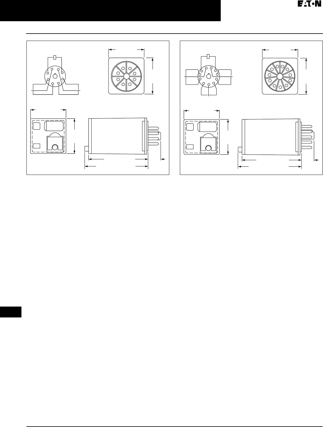
April 2009
3-28
For more information visit: www.EatonCanada.ca CA080102002K07A
Control Relays & Timers
3
General Purpose Plug-In Relays
D3PR/DP3F Series — Standard and Full Featured
Figure 3-41. D3PF2 — Approximate Dimensions in Inches (mm) Figure 3-42. D3PF3 — Approximate Dimensions in Inches (mm)
1.35
(34.3)
Max.
Plastic
ID Tag
1.32 (33.5)
Max.
2.25 (57.2) Max.
0.54
(13.7)
Max.
2.28 (57.9) Max.
1.4
0
(
35.6
)
M
a
x
.
1.38 (34.9)
M
a
x
.
Terminal Arrangement (Bottom View
)
Schematic Diagram
6
7
3
5
4
8
2
1
4
5
1
8
7
6
3
2
1.35
(34.3)
Max.
Plastic
ID Tag
1.32 (33.5)
Max.
2.25 (57.2) Max.
0.54
(13.7)
Max.
2.28 (57.9) Max.
1.4
0
(
35.6
)
M
a
x
.
1.38
(
35.1
)
M
a
x
.
Terminal Arrangement (Bottom View
)
Schematic Diagram
4
5
1
8
9
1
0
1
1
7
6
3
2
1
0
8
9
5
6
7
11
3
4
1
2
TAB49.BOO Page 28 Thursday, March 5, 2009 7:36 PM
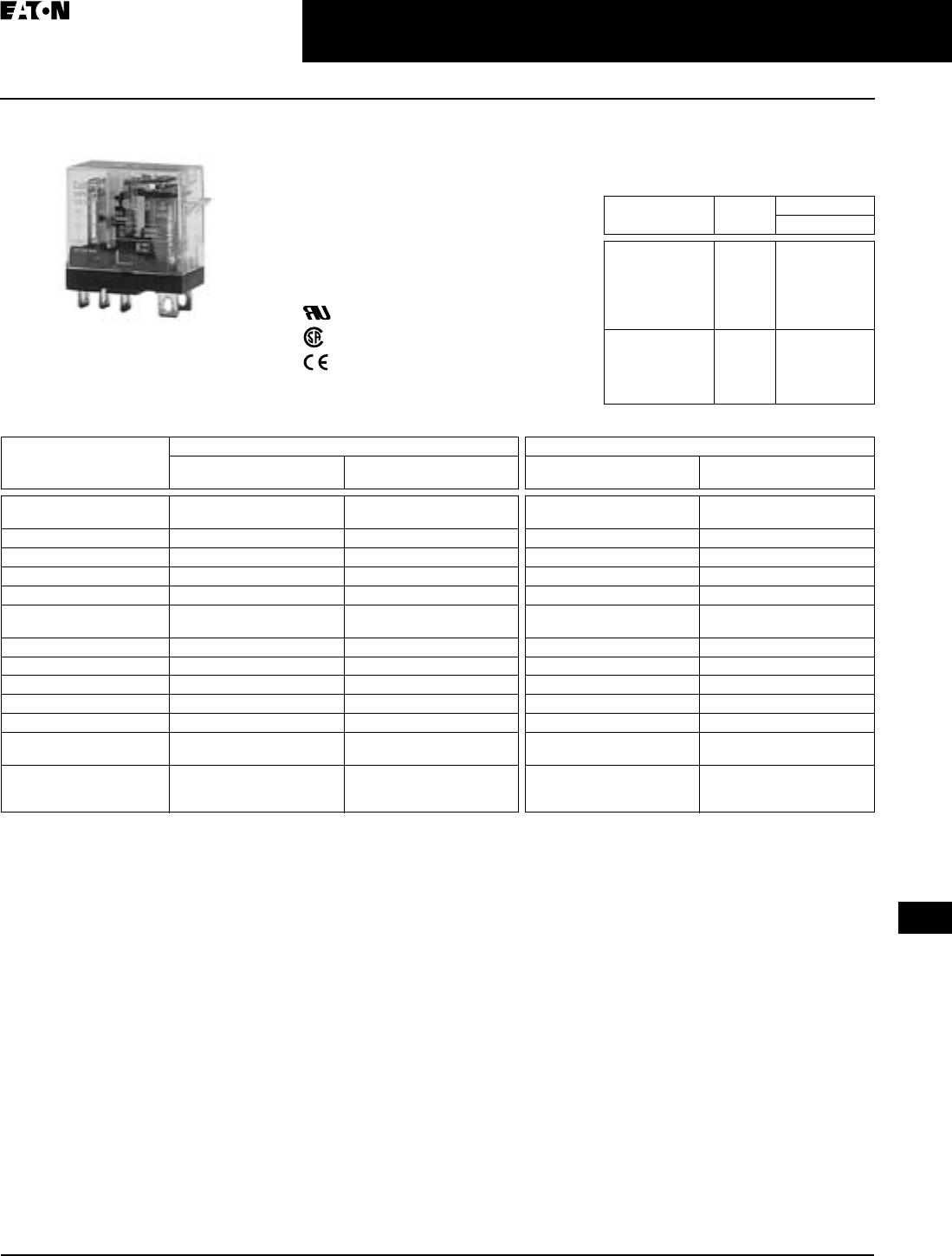
April 2009
CA080102002K07A For more information visit: www.EatonCanada.ca
3-29
Control Relays & Timers
3
General Purpose Plug-In Relays
D4 Series — Standard
D4 Series
Features
■Slim-styled power relay
■Socket has built-in hold-down clip
■Panel or DIN rail mounting
Standards and Certifications
File # E1491, E65657
File # LR701519
Technical Data and
Specifications
Table 3-37. Coil Resistance
Table 3-38. Specifications
D4 Series Relay
Coil Voltage Ohms mA
@ 60 Hz AC
6V AC
12V AC
24V AC
48V AC
110/120V AC
220/240V AC
16
65
260
1130
6500
30000
150
75
37.5
18
7.5
3.8
6V DC
12V DC
24V DC
48V DC
100/110V DC
68
275
1100
4170
22900
88.2
43.6
21.8
11.5
4.8
D4PR1 D4PR2
Resistive Load
(p.f. = 1)
Inductive Load
(p.f. = 0.4, L/R = 7 ms)
Resistive Load
(p.f. = 1)
Inductive Load
(p.f. = 0.4, L/R = 7 ms)
Rated Load 250V AC 10A
30V DC 10A
250V AC 7.5A
30V DC 5A
240V AC 5A
30V DC 5A
250V AC 2A
30V DC 3A
Carry Current 10A 10A 5A 5A
Max. Operating Voltage 380V AC/125V DC 380V AC/125V DC 380V AC/125V DC 380V AC/125V DC
Max. Operating Current 10A 10A 5A 5A
Contact Material AgCdO AgCdO AgCdO AgCdO
Max. Switching Capacity 2500 VA
300W
1875 VA
150W
1250 VA
150W
500 VA
90W
Min. Permissible Load 100 mA, 5V DC 100 mA, 5V DC 10 mA, 5V DC 10 mA, 5V DC
Pickup Voltage (max.) 80% AC/70% DC 80% AC/70% DC 80% AC/70% DC 80% AC/70% DC
Drop Out Voltage (min.) 30% AC/15% DC 30% AC/15% DC 30% AC/15% DC 30% AC/15% DC
Voltage (max.) 110% 110% 110% 110%
Mechanical Life (min.) 10,000,000 AC/20,000,000 DC 10,000,000 AC/20,000,000 DC 10,000,000 AC/20,000,000 DC 10,000,000 AC/20,000,000 DC
Electrical Life @
All Contact Ratings (min.)
100,000 100,000 100,000 100,000
Maximum hp Ratings 1/3 hp (125V AC)
1/2 hp (250V AC)
1/2 hp (277V AC)
1/3 hp (125V AC)
1/2 hp (250V AC)
1/2 hp (277V AC)
1/6 hp (120V AC)
1/3 hp (240V AC)
1/3 hp (265V AC)
1/6 hp (120V AC)
1/3 hp (240V AC)
1/3 hp (265V AC)
TAB49.BOO Page 29 Thursday, March 5, 2009 7:36 PM

April 2009
3-30
For more information visit: www.EatonCanada.ca CA080102002K07A
Control Relays & Timers
3
General Purpose Plug-In Relays
D4 Series — Standard
Catalogue Number Structure
Table 3-39. D4 Series Catalogue Numbering System
For deciphering Catalogue Numbers. Do not use for ordering as not all
combinations are readily available.
Table 3-40. Relay/Socket Quick Reference
Socket has built-in hold down spring.
Product Selection
Table 3-41. D4 Product Selection
Additional coil voltages available — consult Contact Customer Support
Centre 1-800-268-3578.
Relay Type Socket Hold Down Clip
D4PR1 D4PA1
D4PR2 D4PA2
Family Type
D4PR
Contact Configuration
1 = SPDT
2 = DPDT
Options
1 = Indicating Light
Coil Voltage
A =
A1 =
B =
P =
P1 =
R =
R1 =
T =
T1 =
W1 =
120V AC
110V DC
240V AC
6V AC
6V DC
12V AC
12V DC
24V AC
24V DC
48V DC
D 4 P R 1 1 A Std.
Pack
Catalogue
Number
Standard SPDT
Coil Voltage:
24V AC
120V AC
D4PR1T
D4PR1A
24V DC D4PR1T1
SPDT with Indicating Light
24V AC
120V AC
D4PR11T
D4PR11A
24V DC D4PR11T1
Standard DPDT
24V AC
120V AC
D4PR2T
D4PR2A
12V DC
24V DC
D4PR2R1
D4PR2T1
DPDT with Indicating Light
120V AC D4PR21A
24V DC D4PR21T1
DIN Rail Sockets
1-Pole
2-Pole
10
10
D4PA1
D4PA2
Accessories
DIN Rail End Stop 100 PFP-M
TAB49.BOO Page 30 Thursday, March 5, 2009 7:36 PM
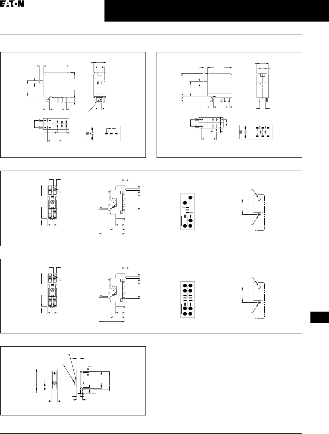
April 2009
CA080102002K07A For more information visit: www.EatonCanada.ca
3-31
Control Relays & Timers
3
General Purpose Plug-In Relays
D4 Series — Standard
Dimensions
Figure 3-43. D4PR1 — Approximate Dimensions in Inches (mm) Figure 3-44. D4PR2 — Approximate Dimensions in Inches (mm)
Figure 3-45. D4PA1 — Approximate Dimensions in Inches (mm)
Figure 3-46. D4PA2 — Approximate Dimensions in Inches (mm)
Figure 3-47. PFP-M DIN Rail End Stop — Approximate Dimensions in
Inches (mm)
1
2
4
3
5
1.14
(
29.0
)
M
a
x
.
1.14
(
29.0
)
M
a
x
.
0
.
51
(
13.0
)
M
a
x
.
0
.1
0
(
2.5
)
0
.
39
(
10.0
)
0
.1
6
(
4.0
)
0
.
08
(
2.0
)
0
.7
9
(
20.0
)
0
.1
9
(
4.8
)
0
.
30
(
7.5
)
0
.2
0
(
5.2
)
0
.
69
(
17.5
)
0
.2
0
(
5.2
)
Terminal Arrangement
/
In
te
rn
a
l
Co
nn
ect
i
o
n
s
(
Bottom View
)
0
.
02
(
0.5
)
0
.
02
(
0.5
)
5
–
0
.
035
x
0
.1
2
(
0.9 x 3
)
Elli
p
tic Hole
s
1.14
(
29.0
)
M
a
x
.
1.1
0
(
28.0
)
M
a
x
.
0
.
01
(
2.5
)
0
.2
4
(
6.0
)
0
.7
9
(
20.0
)
0
.
08
(
2.0
)
0
.1
0
(
2.6
)
0
.
02
(
0.5
)
0
.
30
(
7.5
)
0
.
35
(
8.9
)
0
.
02
(
0.5
)
0
.
02
(
0.5
)
1
8
7
6
5
4
0
.7
6
(
19.4
)
Terminal Arrangement
/
In
te
rn
a
l
Co
nn
ect
i
o
n
s
(
Bottom View
)
0
.1
6
(
4.0
)
0
.
51
(
13.0
)
M
a
x
.
0
.
39
(
10.0
)
0.28
(7.1) 0.08
(2.0)
Five
3.5 x 0.32
(88.9 x 8.0)
2.82
(71.6)
Max.
0.16
(4.1)
0.77
(19.6)
Max.
0.77 (19.6)
1.18 (30.0)
2.13 (54.1) Max.
1.180 ± 0.002
(29.97 ± 0.05)
1.40
(35.6)
0.16
(4.1)
Dia. Holes
15
3
2
4
M3 or
3.30 (0.13)
Dia. Holes
0.17 (4.2)
Dia. Holes
Mounting HolesTerminal Arrangement
0.28
(7.1) 0.08
(2.0)
Eight
3.5 x 0.32
(88.9 x 8.0)
2.82
(71.6)
Max.
0.16
(4.1)
0.77
(19.6)
Max.
0.77 (19.6)
1.18 (30.0)
2.13 (54.1) Max.
1.180 ± 0.002
(29.97 ± 0.05)
1.40
(35.6)
0.16
(4.1)
Dia. Holes
18
5
72
3
4
6
M3 or
0.13 (3.30)
Dia. Holes
0.17 (4.2)
Dia. Holes
Mounting HolesTerminal Arrangement
1.97
(50.0)
0.45
(11.5)
1.47
(37.3)
1.39
(35.3)
0.39
(10.0)
0.39
(10.0)
0.19
(4.8)0.05
(1.3)
0.24
(6.2)
0.07
(1.8)
0.07
(1.8)
M4 x 8 Pan
Head Screw
M4 Spring Washer
TAB49.BOO Page 31 Thursday, March 5, 2009 7:36 PM
April 2009
3-32
For more information visit: www.EatonCanada.ca CA080102002K07A
Control Relays & Timers
3
General Purpose Plug-In Relays
D5PR/D5PF Series — Standard and Full Featured
D5PR/D5PF Series
D5 Series Relay
Features
D5PR
■Industrial rated 300V, 15A relay in 2-
pole and 3-pole configurations
■Compact design can be panel or DIN
rail mounted
D5PF
■Flag indicator shows relay status in
manual or powered condition
■LED status lamp shows coil “ON” or
“OFF” status — ideal for use in low
light applications
■Push-to-test button allows for
manual operation of relay without
the need for coil power
■Lock-down door holds pushbutton
and contacts in the operate position
when activated
■Finger-grip cover allows operator to
remove relays from sockets easily
■I.D. tag/write label to identify relays
in multiple-relay circuits
■Bi-polar LED allows for reverse
polarity applications
Standards and Certifications
When used with accompanying
Cutler-Hammer® screw terminal
socket (D5PF only).
UL Listed
Technical Data and Specifications
Table 3-42. Coil Resistance for D5PR Series Table 3-43. Coil Resistance for D5PF Series
Table 3-44. Socket Specifications
Table 3-45. Relay Specifications
Coil
Voltage
Ohms mA
D5PR2 D5PR3 D5PR2 D5PR3
6V AC
12V AC
24V AC
48V AC
120V AC
240V AC
6
24
85
330
2250
9100
4.2
18
72
290
700
7200
330
160
80
40
16.6
8.3
458
229
114
57
23
11
6V DC
12V DC
24V DC
48V DC
110V DC
32
120
470
1900
10000
187
100
50
25
11
Coil
Voltage
Ohms mA
50 Hz 60 Hz
24V AC
120V AC
240V AC
72
1,700
7,200
398.0
76.0
28.0
340
65
24
12V DC
24V DC
110V DC
120
470
10,000
100.0
49.9
13.2
—
—
—
Catalogue
Number
Electrical
Ratings
Mounting
Torque
Hook-Up
Wire Range
D5PA2 15A, 300V 8 – 10
in-lbs
AWG 12
to 22
Solid or
Stranded
D5PA3L
D5PA3S
15A, 300V — Up to
AWG 16
Solid or
Stranded
D5PR (AC) D5PR (DC) D5PF2/D5PF3
Resistive Load
(p.f. = 1.0)
Rated Load (p.f. = 0.8) 120V AC 15A or
1/3 Hp 240V AC 15A or
1/2 Hp
28V DC, 13A, (1-Pole)
28V DC, 12A, (2-Pole)
28V DC, 11A, (3-Pole)
240V AC 12A
120V AC 12A
28V DC 12A
Carry Current 15A 15A 12A
Max. Operating Voltage 600V AC (3A max.) 125V DC (0.5A max.) 110% of nominal
Max. Operating Current 15A 15A 15A
Dielectric Strength 2000V 2000V 1500V
Approx. Weight 3.1 oz (88g) 3.1 oz (88g) 3.1 oz (88g)
Temperature —
Operating
Storage
-22 – 122°F (-30 – 50°C)
-22 – 212°F (-30 – 100°C)
-22 – 149°F (-30 – 65°C)
-22 – 212°F (-30 – 100°C)
-22 – 122°F (-30 – 50°C)
-22 – 212°F (-30 – 100°C)
Contact Resistance 50 milli Ω’s Max. @
Rated Current
50 milli Ω’s Max. @
Rated Current
50 milli Ω’s Max. @
Rated Current
Contact Material AgCdO (Au Flashed) AgCdO (Au Flashed) AgCdO (Au Flashed)
Pickup Voltage 85% of Nominal 80% of Nominal 85% AC
80% DC
Dropout Voltage (min.) 10% 10% 30% AC
10% DC
Voltage (max.) 110% 110% 110%
Mechanical Life (min.) 5,000,000 5,000,000 5 million (No Load)
Electrical Life (min.) 100,000 100,000 200,000 operations at
Rated Res. Load
Max. hp Ratings 1/3 hp, 120V AC
1/2 hp, 240V AC
1/3 hp, 120V AC
1/2 hp, 240V AC
1/3 hp, 120V AC
1/2 hp, 240V AC
TAB49.BOO Page 32 Thursday, March 5, 2009 7:36 PM
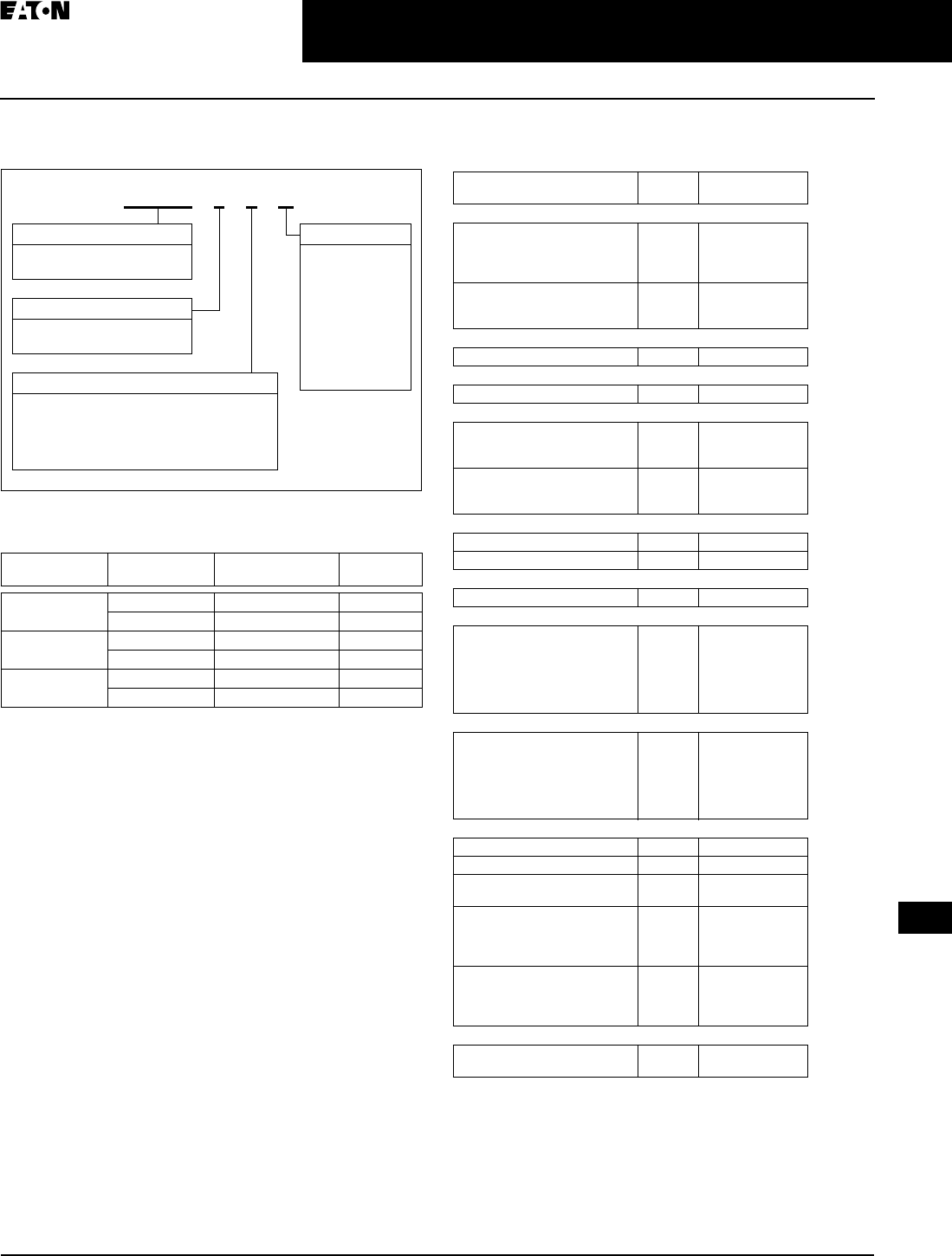
April 2009
CA080102002K07A For more information visit: www.EatonCanada.ca
3-33
Control Relays & Timers
3
General Purpose Plug-In Relays
D5PR/D5PF Series — Standard and Full Featured
Catalogue Number Structure
Table 3-46. D5 Series Catalogue Numbering System
For deciphering Catalogue Numbers. Do not use for ordering as not all
combinations are readily available.
Table 3-47. Relay/Socket Quick Reference
Product Selection
Table 3-48. D5 Product Selection
Additional coil voltages may be available — consult Contact Customer
Support Centre 1-800-268-3578.
Relay
Type
Socket
Type
Socket Hold Down
Spring
D5PR2 11 Pin Screw D5PA2 D5PB2
11 Pin Solder D5PA3S or D5PA3L D5PB2
D5PR3 11 Pin Screw D5PA2 D5PB2
11 Pin Solder D5PA3S or D5PA3L D5PB2
D5PF2/D5PF3 11 Pin Screw D5PA2 PQC-1351
11 Pin Solder D5PA3S or D5PA3L PWC-1325
Family Type
D5PR = Standard Relay
D5PF = Full Featured Relay
Contact Configuration
2 = DPDT
3 = 3PDT
Coil Voltage
A =
A1 =
B =
P =
P1 =
R =
R1 =
T =
T1 =
W1 =
120V AC
110V DC
240V AC
6V AC
6V DC
12V AC
12V DC
24V AC
24V DC
48V DC
D 5 P R 3 3 A
Options
Blank = Standard Relay
1 = Indicating Light
2 = Test Button
A = LED, Test Button, Flag Indicator, Lock-
Down Door, Finger-Grip Cover, I.D. Tag
Std.
Pack
Catalogue
Number
DPDT
Coil Voltage:
24V AC
120V AC
240V AC
—
—
—
D5PR2T
D5PR2A
D5PR2B
12V DC
24V DC
110V DC
—
—
—
D5PR2R1
D5PR2T1
D5PR2A1
DPDT with Indicating Light
120V AC — D5PR21A
DPDT with Test Button
120V AC — D5PR22A
3PDT
24V AC
120V AC
240V AC
—
—
—
D5PR3T
D5PR3A
D5PR3B
12V DC
24V DC
110V DC
—
—
—
D5PR3R1
D5PR3T1
D5PR3A1
3PDT with Indicating Light
120V AC — D5PR31A
24V DC — D5PR31T1
3PDT with Test Button
120V AC — D5PR32A
DPDT — 11 Pin Screw
24V AC
120V AC
240V AC
12V DC
24V DC
110V DC
—D5PF2AT
D5PF2AA
D5PF2AB
D5PF2AR1
D5PF2AT1
D5PF2AA1
3PDT — 11 Pin Solder
24V AC
120V AC
240V AC
12V DC
24V DC
110V DC
—D5PF3AT
D5PF3AA
D5PF3AB
D5PF3AR1
D5PF3AT1
D5PF3AA1
DIN Rail or Panel Mounting
Screw Terminal Socket 10 D5PA2
Hold Down Spring 100 D5PB2
Hold Down Clip 100
100
PWC-1325
PQC-1351
End Clamp with
Mounting Screw —
use with track
below, one at each end
100 PFP-M
35 mm x 7.5 mm
Aluminum
DIN Mounting Track
(2 meter lengths)
20 XBANS3575PL
Panel Mount Socket — Square Base
Long 0.130" Solder
Standard 0.130" Solder
10
10
D5PA3L
D5PA3S
TAB49.BOO Page 33 Thursday, March 5, 2009 7:36 PM
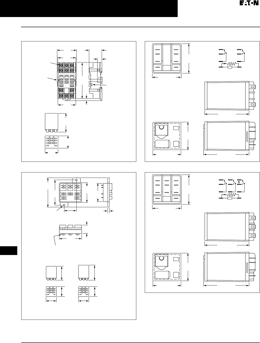
April 2009
3-34
For more information visit: www.EatonCanada.ca CA080102002K07A
Control Relays & Timers
3
General Purpose Plug-In Relays
D5PR/D5PF Series — Standard and Full Featured
Dimensions
Figure 3-48. D5PA2 — Approximate Dimensions in Inches (mm)
Figure 3-49. D5PA3L and D5PA3S— Approximate Dimensions in Inches
(mm)
Figure 3-50. D5PF2 — Approximate Dimensions in Inches (mm)
Figure 3-51. D5PF3 — Approximate Dimensions in Inches (mm)
3.00
(76.2)
0.15 (3.81)
1.57
(39.9)
1.70
(43.1)
1.44
(36.4)
1.53
(39)
2.18
(55.5)
1.40
(35.5)
1.03
(26.1)
0.39
(9.9)
6-32 x 0.312
Combination
Head Screw and
Pressure Clamp
0.15 (3.8) Dia.
(2 Places)
Tolerances: +
– 0.010 (+
– 0.25)
Unless Otherwise Shown
Retaining Notch
for Hold Down
Clip (2 Places)
0.54
(13.7)
0.165 (4.2)
Dia. Typ.
0.13 (3.3) Solder
Terminal or
0.187 (4.7)
Q.C. Terminal
D5PA3L
1.69
(42.9)
2.03
(51.6) 1.37
(34.8)
1.5
(38.1)
1.53
(39)
2.18
(55.5)
1.40
(35.5)
0.88
(22.2)
0.13
(3.3)
1.25
(31.8)
D5PA3S
1.53
(39)
2.02
(51.3)
1.40
(35.5)
Plastic
ID Tag
1.36
(34.4)
1.41
(
35.7
)
1.32 (33.5)
Max.
1.42
(
35.9
)
M
a
x
.
3
6
9
2.17 (55.1)
Max.
2.10 (53.3)
Max.
Schematic Diagram
Terminal Arrangement
(Bottom View)
(
-
)
A
7
1
4
7
A
B
B
(
+
)
1
4
9
3
6
Plastic
ID Tag
1.36
(34.4)
1.41
(
35.7
)
1.32 (33.5)
Max.
1.42
(
35.9
)
M
a
x
.
2
5
8
3
6
9
2.17 (55.1)
Max.
2.10 (53.3)
Max.
Terminal Arrangement
(Bottom View)
1
4
7
A
B
7
1
4
8
2
5
9
3
LED
(
-
)
A
Schematic Diagram
B
(
+
)
TAB49.BOO Page 34 Thursday, March 5, 2009 7:36 PM
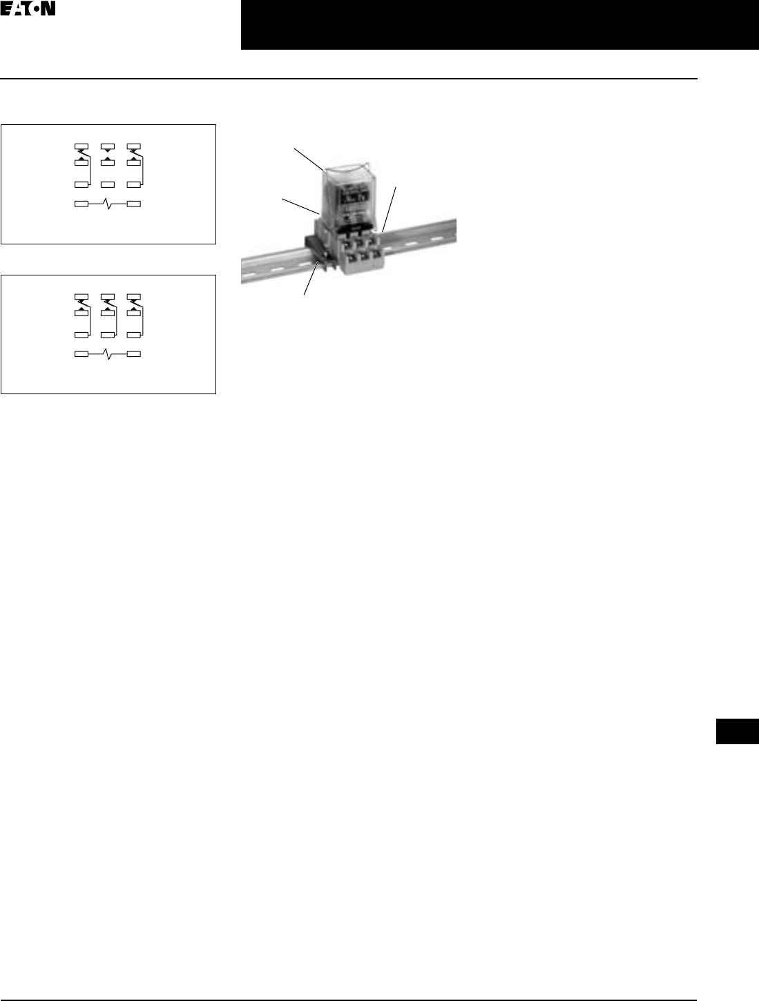
April 2009
CA080102002K07A For more information visit: www.EatonCanada.ca
3-35
Control Relays & Timers
3
General Purpose Plug-In Relays
D5PR/D5PF Series — Standard and Full Featured
Terminal Arrangements
Figure 3-52. D5PR2 (Bottom View)
Figure 3-53. D5PR3 (Bottom View)
D5PD2-20 DIN Rail Mounting
1
4
7
A
3
6
9
B
2
5
8
DPD
T
1
4
7
A
3
6
9
B
2
5
8
3
PD
T
DIN Rail
D5PB2
Hold Down Spring
D5PA2
Socket
PFP-M
End Clamp
TAB49.BOO Page 35 Thursday, March 5, 2009 7:36 PM
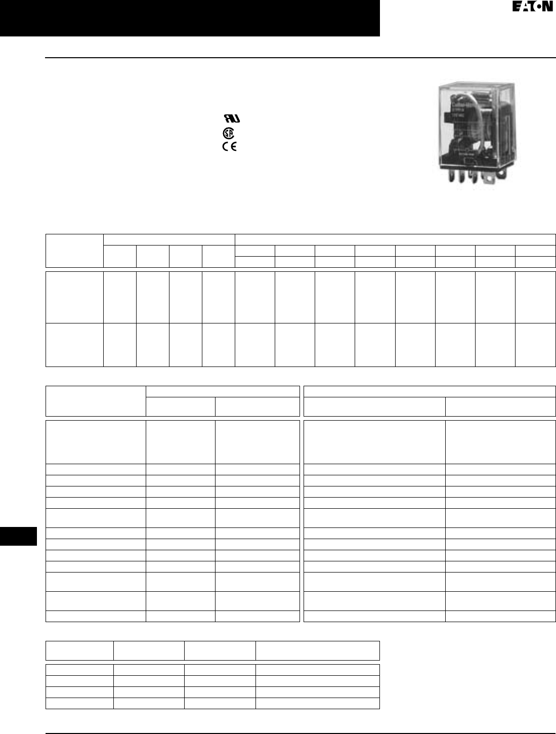
April 2009
3-36
For more information visit: www.EatonCanada.ca CA080102002K07A
Control Relays & Timers
3
General Purpose Plug-In Relays
D7PR Series — Standard
D7PR Series
Features
■Arc barrier equipped relay with high
dielectric strength
■Panel, DIN rail and flange mounting
Standards and Certifications
File # E37317, E65657
File # LR217017, LR217069
D7 Series Relay
Technical Data and Specifications
Table 3-49. D7PR Coil Resistance
Table 3-50. D7PR Relay Specifications
Table 3-51. D7PR Socket Specifications
Coil Voltage Ohms Milliamps
D7PR1 D7PR2 D7PR3 D7PR4 D7PR1 D7PR1 D7PR2 D7PR2 D7PR3 D7PR3 D7PR4 D7PR4
50 Hz 60 Hz 50 Hz 60 Hz 50 Hz 60 Hz 50 Hz 60 Hz
6V AC
12V AC
24V AC
48V AC
120V AC
240V AC
11
41
180
788
4430
15700
11
41
180
788
4430
15700
6.5
25.5
102
735
2700
10000
5
20
80
735
2000
8000
222.3
111. 2
58.5
21
12.9
5.9
190
95
50
18
11
5
234
95.9
48
21
12.9
7
200
82
41
18
11
6
326
148
77
21.5
14.7
9.7
278
126
66
18.4
12.6
8.3
393
202
91
24
17.3
11. 4
336
173
78
20
14.8
9.7
6V DC
12V DC
24V DC
48V DC
110V DC
47
188
750
2600
13800
40
160
650
2600
11000
25
100
400
1600
8400
24
96
360
1600
6800
—
—
—
—
—
127.7
63.8
32
18.5
8
—
—
—
—
—
150
75
36.9
18.5
10
—
—
—
—
—
240
120
60
18.5
13
—
—
—
—
—
250
125
67
18.5
16.2
D7PR1 D7PR2/D7PR3/D7PR4
Resistive Load
(p.f. = 1)
Inductive Load
(p.f. = 0.4, L/R = 7 ms)
Resistive Load
(p.f. = 1)
Inductive Load
(p.f. = 0.4, L/R = 7 ms)
Rated Load 120/240V AC 15A
30V DC 15A
120/240V AC 10A
30V DC 7A
120/240V AC
30V DC
250V AC
120V AC
28V DC
10A (D7PR2 only)
10A (D7PR2 only)
10A (D7PR3/D7PR4 only)
15A (D7PR2 only)
10A (D7PR3/D7PR4 only)
120/240V AC 7.5A
30V DC 5A
Carry Current 15A 15A 10A 10A
Max. Operating Voltage 250V AC/125V DC 250V AC/125V DC 250V AC/125V DC 250V AC/125V DC
Max. Operating Current 15A 15A 10A 10A
Contact Material AgCdO AgCdO AgCdO AgCdO
Max. Switching Capacity 1700 VA
360W
110 0 VA
170W
110 0 VA
240W
830 VA
120W
Min. Permissible Load 100 mA, 5V DC 100 mA, 5V DC 100 mA, 5V DC 100 mA, 5V DC
Pickup Voltage (max.) 80% 80% 80% 80%
Drop Out Voltage (min.) 30% AC, 10% DC 30% AC, 10% DC 30% AC, 10% DC 30% AC, 10% DC
Voltage (max.) 110% 110% 110% 110%
Mechanical Life (min.) 10,000,000 AC
100,000,000 DC
10,000,000 AC
100,000,000 DC
10,000,000 AC
100,000,000 DC
10,000,000 AC
100,000,000 DC
Electrical Life @
All Contact Ratings (min.)
200,000 200,000 200,000 200,000
Maximum hp Rating 1/3 hp (120V AC) 1/2 hp (240V AC) 1/3 hp (120V AC) (D7PR2 only) 1/2 hp (240V AC) (D7PR2 only)
Catalogue
Number
Electrical Ratings Mounting Torque Hook-Up Wire Range
D7PA2 15A, 250V .785 Nm – 1.18 Nm AWG 14 Max.
D7PA3 10A, 300V 7 – 8 in-lbs AWG 12 to 22 Solid or Stranded
D7PA4 10A, 300V 7 – 8 in-lbs AWG 12 to 22 Solid or Stranded
D7PA5 15A, 250V N/A AWG 14 Max.
TAB49.BOO Page 36 Thursday, March 5, 2009 7:36 PM
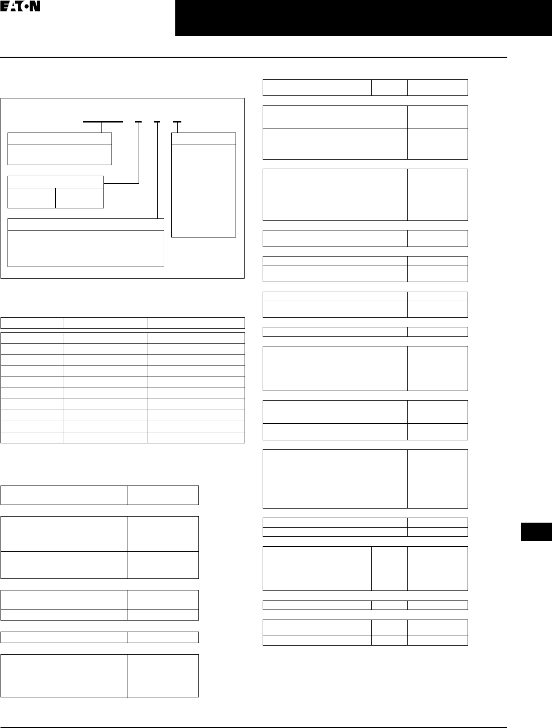
April 2009
CA080102002K07A For more information visit: www.EatonCanada.ca
3-37
Control Relays & Timers
3
General Purpose Plug-In Relays
D7 Series — Standard and Full Featured
Catalogue Number Structure
Table 3-52. D7 Series Catalogue Numbering System
For deciphering Catalogue Numbers. Do not use for ordering as not all
combinations are readily available.
Table 3-53. Relay/Socket Quick Reference
Product Selection
Table 3-54. D7 Product Selection
Table 3-54. D7 Product Selection, continued
Additional coil voltages available — consult Contact Customer Support
Centre 1-800-268-3578.
IP20 rated.Table 3-54.
Relay Type Socket Hold Down Spring
D7PR1 D7PA2/D7PA5 PMC-A1
D7PR2 D7PA2/D7PA5 PMC-A1
D7PR3 D7PA3 PYC-B2
D7PR4 D7PA4 PYC-B2
D7PF1/D7PF2 D7PA9/D7PA5 PQC-1342
D7PF1/D7PF2 D7PAA PQC-1349
D7PF3 D7PA3 N/A
D7PF4 D7PA4 N/A
D7PF3 D7PAB PQC-1350
D7PF4 D7PAD PQC-1351
Catalogue
Number
Standard SPDT
Coil Voltage:
24V AC
120V AC
240V AC
D7PR1T
D7PR1A
D7PR1B
6V DC
12V DC
24V DC
D7PR1P1
D7PR1R1
D7PR1T1
SPDT with Indicating Light
24V AC
120V AC
D7PR11T
D7PR11A
24V DC D7PR11T1
SPDT Flange Mount
120V AC D7PR14A
SPDT Full Featured Relay
120V AC
110V DC
12V DC
24V AC
24V DC
D7PF1AA
D7PF1AA1
D7PF1AR1
D7PF1AT
D7PF1AT1
Contact Configuration
1 = SPDT
2 = DPDT
3 = 3PDT
4 = 4PDT
Coil Voltage
A =
A1 =
B =
P =
P1 =
R =
R1 =
T =
T1 =
W =
W1 =
120V AC
110V DC
240V AC
6V AC
6V DC
12V AC
12V DC
24V AC
24V DC
48V DC
48V DC
D 7 P R 1 1 A
Options
1 = Indicating Light
4 = Flange Mounting
A = LED, Test Button, Flag Indicator, Lock-
Down Door, Finger-Grip Cover, I.D. Tag
Family Type
D7PR = Standard Relay
D7PF = Full Featured Relay
Std.
Pack
Catalogue
Number
Standard DPDT
24V AC
120V AC
240V AC
D7PR2T
D7PR2A
D7PR2B
12V DC
24V DC
48V DC
110V DC
D7PR2R1
D7PR2T1
D7PR2W1
D7PR2A1
DPDT Full Featured Relay
Coil Voltage:
120V AC
110V DC
240V AC
12V DC
24V AC
24V DC
D7PF2AA
D7PF2AA1
D7PF2AB
D7PF2AR1
D7PF2AT
D7PF2AT1
DPDT Flange Mount
24V AC
120V AC
D7PR24T
D7PR24A
Standard 3PDT
120V AC D7PR3A
12V DC
24V DC
D7PR3R1
D7PR3T1
3PDT with Indicating Light
120V AC D7PR31A
12V DC
24V DC
D7PR31R1
D7PR31T1
3PDT Flange Mount
120V AC D7PR34A
3PDT Full Featured Relay
120V AC
110V DC
240V AC
12V DC
24V AC
24V DC
D7PF3AA
D7PF3AA1
D7PF3AB
D7PF3AR1
D7PF3AT
D7PF3AT1
Standard 4PDT
Coil Voltage:
24V AC
120V AC
D7PR4T
D7PR4A
24V DC
110V DC
D7PR4T1
D7PR4A1
4PDT Full Featured
Coil Voltage:
120V AC
240V AC
12V AC
12V DC
24V AC
24V DC
48V DC
D7PF4AA
D7PF4AB
D7PF4AR
D7PF4AR1
D7PF4AT
D7PF4AT1
D7PF4AW1
4PDT Flange Mount
120V AC D7PR44A
24V DC D7PR44T1
DIN Rail Mount Sockets
1- and 2-Pole
1- and 2-Pole Finger-Safe
3-Pole
3-Pole Finger-Safe
4-Pole
4-Pole Finger-Safe
10
10
10
10
10
10
D7PA2
D7PAA
D7PA3
D7PAB
D7PA4
D7PAD
Panel Mount Sockets
1- and 2-Pole 10 D7PA5
Accessories
Spring Clip
DIN Rail End Stop 100
100
PMC-A1
PFP-M
Hold Down Spring 100 PYC-B2
TAB49.BOO Page 37 Thursday, March 5, 2009 7:36 PM
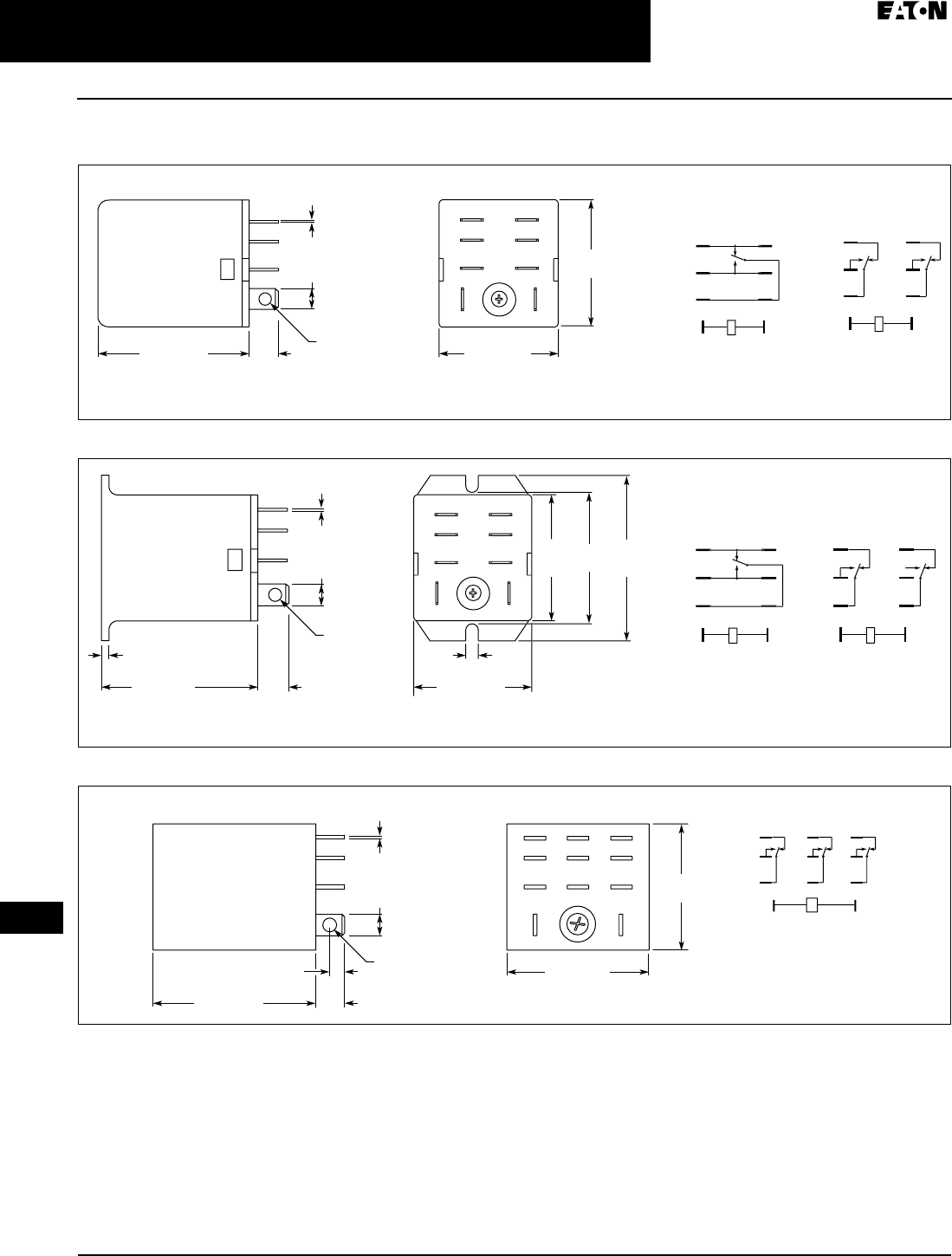
April 2009
3-38
For more information visit: www.EatonCanada.ca CA080102002K07A
Control Relays & Timers
3
General Purpose Plug-In Relays
D7PR Series — Standard
Dimensions
Figure 3-54. D7PR1 and D7PR2 — Approximate Dimensions in Inches (mm)
Figure 3-55. D7PR14 and D7PR24 — Approximate Dimensions in Inches (mm)
Figure 3-56. D7PR3 — Approximate Dimensions in Inches (mm)
7
3
5
8
4
6
1
2
7
5
3
1
8
6
4
2
7
5
3
1
8
6
4
2
D7PR1 and D7PR2
(Side View)
0.29
(7.4)
Max.
0.12/0.11
(3.1/2.8)
Dia. Hole
1.10
(
27.9
)
M
a
x
.
0.020
(0.51)
0.187
(4.75)
Terminal Arrangement
(Bottom View)
Schematic Diagra
m
D7PR1
Schematic Diagram
D7PR2
0.86
(
21.8
)
Max.
1.42 (36.1)
Max.
3
7
5
1
4
8
6
2
7
5
3
1
8
6
4
2
7
5
3
1
8
6
4
2
1.1
0
(
27.9
)
M
a
x
.
1.
33
(
33.8
)
1.72
(
43.7
)
Max.
Schematic Diagra
m
D7PR24
Schematic Diagra
m
D7PR14
Terminal Arrangement
(Bottom View)
D7PR14 and D7PR24
(Side View)
0.12/0.11
(3.1/2.8)
Dia. Hole
1.42 (36.1)
Max.
0.29
(7.4)
Max.
0.79
(2.0)
0.86 (21.8)
Max.
0
.1
4
(3.5)
0.020
(0.51)
0.187
(4.75)
0.12 (3.1) 11 Qty. –
0.12 (3.0)
Dia. Holes
1
0
7
4
1
11
9
8
6
5
3
2
3
9
6
11
4
5
1
0
7
8
1
2
0.25
(6.4)
Schematic Diagram
1.10
(
28.0
)
Terminal Arrangement
(Bottom View)
1.24 (31.5)
1.42 (36.0)
0.020
(0.51)
0.187
(4.75)
TAB49.BOO Page 38 Thursday, March 5, 2009 7:36 PM
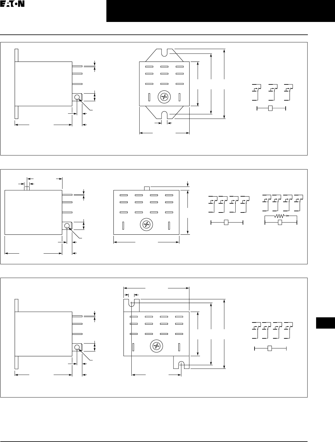
April 2009
CA080102002K07A For more information visit: www.EatonCanada.ca
3-39
Control Relays & Timers
3
General Purpose Plug-In Relays
D7PR Series — Standard
Figure 3-57. D7PR34 — Approximate Dimensions in Inches (mm)
Figure 3-58. D7PR43 — Approximate Dimensions in Inches (mm)
Figure 3-59. D7PR44 — Approximate Dimensions in Inches (mm)
0.12 (3.1) 11 Qty. –
0.12 (3.0)
Dia. Holes
1
0
7
4
1
11
9
8
6
5
3
2
3
9
6
11
4
5
1
0
7
8
1
2
0.25
(6.4)
Schematic Diagram
1.1
0
(
28.0
)
1.50
(38.1) 1.73
(43.9)
Terminal Arrangement
(Bottom View)
1.24 (31.5)
1.42 (36.0) 0.14
(3.6)
0.020
(0.51)
0.187
(4.75)
13 14
21
9
5
10
6
4
3
11
7
12
8
1
9
5
13
10
6
2
11
7
3
14
8
12
41
9
5
13
10
6
2
11
7
3
14
8
12
4
Schematic Diagram
AC Coil
Schematic Diagram
DC Coil
1.63 (41.4)
(-)
(+)
0.12 (3.1)
0.87 (22.1)
14 Qty. –
0.12 (3.0)
Dia. Holes
0.25
(6.4)
1.42 (36.0)
0.13
(3.3) 0.020
(0.51)
0.187
(4.75)
Terminal Arrangement
(Bottom View)
1.10
(28.0)
0.08 (2.0)
13
14
2
1
9
5
1
0
6
4
3
11
7
12
8
1
9
5
1
3
1
0
6
2
11
7
3
14
8
12
4
Schematic Diagra
m
0.14 (3.6)
1.63 (41.4)
0.12 (3.1) 14 Qty. –
0.12 (3.0)
Dia. Holes
0.25
(6.4)
1.1
0
(
28.0
)
1.50
(38.1) 1.7
3
(
43.9
)
Terminal Arrangement
(Bottom View)
1.42 (36.0) 1.10 (28.0)
0.020
(0.51)
0.187
(4.75)
TAB49.BOO Page 39 Thursday, March 5, 2009 7:36 PM
April 2009
3-40
For more information visit: www.EatonCanada.ca CA080102002K07A
Control Relays & Timers
3
General Purpose Plug-In Relays
D7PR Series — Standard
Figure 3-60. D7PR23 — Approximate Dimensions in Inches (mm)
Figure 3-61. D7PA2 — Approximate Dimensions in Inches (mm)
Figure 3-62. D7PA3 — Approximate Dimensions in Inches (mm)
7
3
5
8
8
4
6
1
2
3
5
4
6
1
2
7
5
3
1
8
6
4
2
0.29
(7.4)
Max.
0.12/0.11
(3.1/2.8)
Dia. Hole
Pushbutton
1.1
0
(
27.9
)
M
a
x
.
0.21
(5.2)
Max.
Terminal Arrangement
(Bottom View)
D
C
Co
i
l
Schematic Diagram
A
C
Co
i
l
0.86
(
21.8
)
Max
.
1.42 (36.1)
Max.
0.51
(13.0) M
a
x
.
7
(
-
)
(
+
)
0.020
(0.51)
0.187
(4.75)
12
4
6 5
87
3
1.12
(28.4)
Max. 1.18
(30.0)
Max.
0.750 ± 0.004
(19.1 ± 0.2)
0.31
(7.9)
3.09
(78.5)
Max.
1.39
(35.3) 2.680 ± 0.004
(68.1 ± 0.1)
Terminal Arrangement/
Mounting Holes
(Top View)
2 – 0.18 (4.6)
Dia. Holes or
2 – M4
8 – 0.31 (M3.5 x 7.9)
Sems Screw
1.44
(36.6)
1.27
(32.5)
1
2
3
4
5
7
8
911
10
6
Combination Slotted/Phillips
Head Screws 6-32 x 5/16"
2.58 (67.5) Max.
2.74 (69.8)
0.65
(16.6)
1.59
(40.5)
Max.
1.09
(27.8)
Max.
Wiring Diagram (Top View)
1
2
3
4
6
10
11
7
58
9
TAB49.BOO Page 40 Thursday, March 5, 2009 7:36 PM
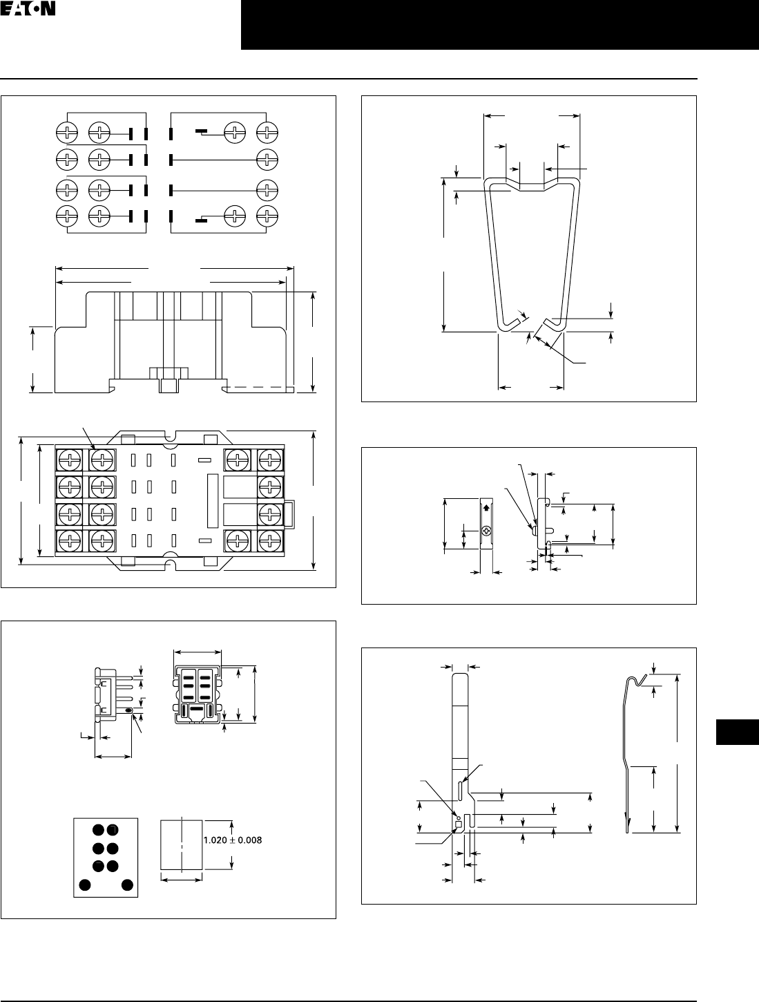
April 2009
CA080102002K07A For more information visit: www.EatonCanada.ca
3-41
Control Relays & Timers
3
General Purpose Plug-In Relays
D7PR Series — Standard
Figure 3-63. D7PA4 — Approximate Dimensions in Inches (mm)
Figure 3-64. D7PA5 — Approximate Dimensions in Inches (mm)
Figure 3-65. PMC-A1 Hold Down Clip — Approximate Dimensions in
Inches (mm)
Figure 3-66. PFP-M DIN Rail End Stop — Approximate Dimensions in
Inches (mm)
Figure 3-67. PYC-B2 Hold Down Spring — Approximate Dimensions in
Inches (mm)
1
2
5
6
3
4
7
8
9
1214
11
13
10
1.83
(46.5)
1.63
(41.4)
2.58 (67.5) Max.
2.74 (69.8)
Combination Slotted/Phillips
Head Screws 6-32 x 5/16"
0.65
(16.6)
1.98
50.5)
Max.
1.09
(27.8)
Max.
Wiring Diagram (Top View)
2
3
4
6
1
5
8
7
13
9
10
11
14
12
1
2
3
4
5
8
6
7
0
.
01
(
0.3
)
0.94
(
23.9
)
Max
.
0
.2
0
(
5.1
)
(
25.9
±
0.2
)
0.840 + 0.008
/
-
0
(
21.3 + 0.20
/
-0
)
0
.
81
(
20.6
)
M
a
x
.
1.
00
(
25.4
)
M
a
x
.
1.1
6
(
29.5
)
M
a
x
.
0
.1
1
(
2.8
)
8
–
0.07
(
1.8
)
Di
a
.
x
0.14
(
3.6
)
Elli
p
tic Hole
s
Terminal Arrangemen
t
(
Bottom View
)
0
.
08
(
2.0
)
1.58
(40.1)
Approx.
0.08 (2.0)
Max.
2 Places
0.14 (3.6)
Approx.
0.59 (15.0)
Approx.
20°
Approx. 0.16 (4.1)
Approx.
0.16 (4.1)
Approx.
0.44 (11.2)
Approx.
0.91 (23.1)
Approx.
1.97
(50.0)
0.45
(11.5)
1.47
(37.3)
1.39
(35.3)
0.39
(10.0)
0.39
(10.0)
0.19
(4.8)0.05
(1.3)
0.24
(6.2)
0.07
(1.8)
0.07
(1.8)
M4 x 8 Pan
Head Screw
M4 Spring Washer
0.039 x 0.24
(1.0 x 6.0)
Slot
0.039 (1.0)
Dia.
0.71 (1.8)
Square
0.87
(22.0)
0.19
(4.8)
0.49
(12.5)
0.16 (4.0)
0.10 (2.4)
0.07
(1.7)
0.39 (10.0)
0.28
(7.0)
0.06
(1.5)
0.15
(3.8)
0.16
(4.0)
1.99
(50.5)
TAB49.BOO Page 41 Thursday, March 5, 2009 7:36 PM
April 2009
3-42
For more information visit: www.EatonCanada.ca CA080102002K07A
Control Relays & Timers
3
General Purpose Plug-In Relays
D7PF Series — Full Featured
D7PF Series Features
■Flag indicator shows relay status in
manual or powered condition
■Bi-polar LED status lamp allows for
reverse polarity applications
❑Shows coil ON or OFF status
❑Ideal in low light conditions
■Colour coded pushbutton identifies
AC coils with red or DC coils with
blue pushbuttons
❑Allows for manual operation of
relay without the need for coil
power
❑Ideal for field service personnel to
test control circuits
■Lock down door, when activated,
holds pushbutton and contacts in
the operate position
❑Excellent for analyzing circuit
problems
■Finger-grip cover allows operator to
remove relays from sockets more
easily than conventional relays
■White plastic I.D. tag/write label
used for identification of relays in
multi-relay circuits
Standards and Certifications
When used with accompanying
Cutler-Hammer® screw terminal
socket.
Technical Data and Specifications
Table 3-55. D7PF Coil Resistance
At 60 Hz for AC Coils.
D7PF Series Relay
UL Listed
Coil Voltage Ohms Amps
D7PF1 D7PF2 D7PF3 D7PF4 D7PF1 D7PF2 D7PF3 D7PF4
6V AC
12V AC
24V AC
48V AC
120V AC
240V AC
9.5
46
180
770
3830
15700
9.5
46
180
770
3830
15700
6
25.3
103
460
2770
12100
5.4
21.2
84.5
338
2200
9120
0.167
0.081
0.042
0.018
0.012
0.004
0.168
0.082
0.041
0.018
0.012
0.004
0.27
0.148
0.08
0.035
0.016
0.006
0.255
0.164
0.09
0.044
0.018
0.008
6V DC
12V DC
24V DC
48V DC
110V DC
40
160
650
2600
11000
40
160
650
2600
11000
25
100
400
1600
8600
24
96
388
1550
7340
0.15
0.075
0.037
0.018
0.010
0.15
0.075
0.037
0.018
0.010
0.24
0.120
0.060
0.030
0.013
0.25
0.125
0.062
0.031
0.015
TAB49.BOO Page 42 Thursday, March 5, 2009 7:36 PM
April 2009
CA080102002K07A For more information visit: www.EatonCanada.ca
3-43
Control Relays & Timers
3
General Purpose Plug-In Relays
D7PF Series — Full Featured
Table 3-56. D7PF Relay Specifications
Table 3-57. D7PF Socket Specifications
D7PF1
Resistive Load
(p.f. = 1.0)
D7PF2
Resistive Load
(p.f. = 1.0)
D7PF3
Resistive Load
(p.f. = 1.0)
D7PF4
Resistive Load
(p.f. = 1.0)
Coil
Pickup Voltage (Max.) 85% AC; 80% DC (% of nominal)
Drop Out Voltage (Min.) 10% AC; 10% DC (% of nominal)
Maximum Voltage 110% of nominal
Insulation System per
UL Standard 1446
Class B 266°F (130°C)
Contacts
Rated Load 277V AC,
28V DC – 20A
220V DC – 0.5A
120V AC – 15A
277V AC,
28V DC – 12A
220V DC – 0.5A
120V AC,
28V DC – 15A
277V AC – 12A
220V DC – 0.5A
120V AC,
28V DC – 15A
277V AC – 12A
220V DC – 0.5A
Maximum hp Ratings 1/2 hp, 120V AC
1 hp, 250V AC
1/2 hp, 120V AC
3/4 hp, 250V AC
Contact Material Silver Alloy, Gold Flashed
Pilot Duty B300
Utilization Category (IEC) AC-15
Min. Permissible Load 100mA @ 5V DC or 0.5W
Contact Resistance 100 Milliohms Max @ 6V, 1A
Dielectric Strength
Coil to Contacts 2500V RMS
Across Open Contacts 1500V RMS 1000V RMS 1000V RMS 1000V RMS
Pole to Pole — 2500V RMS 2500V RMS 2500V RMS
Insulation Resistance 100 Megohms Min. @ 500V DC
Temperature
Operating -40 – 158°F (-40 to 70°C)
Storage -40 – 221°F (-40 to 105°C)
Life Expectancy
Electrical at Rated Resistive
Load
100,000
Operations
200,000
Operations
150,000
Operations
150,000
Operations
Mechanical at No Load 10 Million Operations
Weight
Approximate Weight 0.079 lbs. (36g) 0.079 lbs. (36g) 0.132 lbs. (60g) 0.176 lbs. (80g)
Catalogue
Number
Electrical Ratings Mounting Torque Hook-Up Wire Range
D7PA3 10A, 300V 7 – 8 in-lbs AWG 12 to 22 Solid or Stranded
D7PA4 10A, 300V 7 – 8 in-lbs AWG 12 to 22 Solid or Stranded
D7PA5 15A, 250V N/A AWG 14 Max.
D7PAA 16A, 300V 8 – 10 in-lbs 20 – 12 AWG
D7PAB 16A, 300V 8 – 10 in-lbs 20 – 12 AWG
D7PAO 16A, 300V 8 – 10 in-lbs 20 – 12 AWG
D7PA9 10A, 300V 7 – 8 in-lbs 20 – 12 AWG
TAB49.BOO Page 43 Thursday, March 5, 2009 7:36 PM
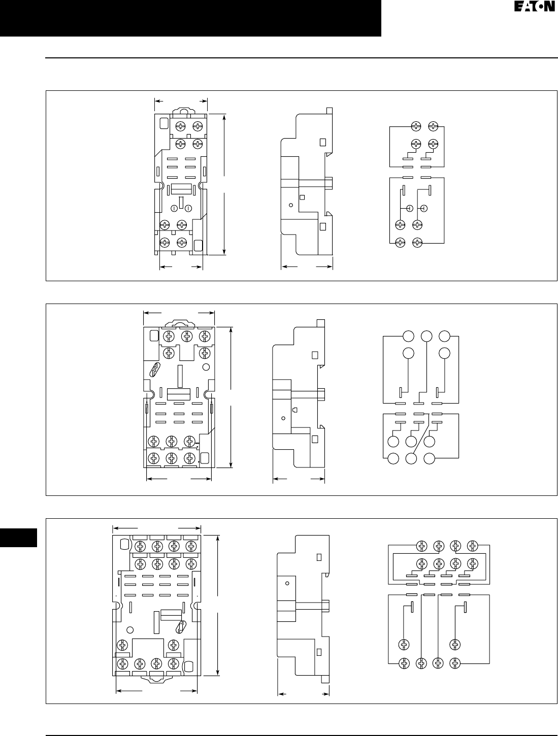
April 2009
3-44
For more information visit: www.EatonCanada.ca CA080102002K07A
Control Relays & Timers
3
General Purpose Plug-In Relays
D7PF Series — Full Featured
Dimensions
Figure 3-68. D7PAA — Approximate Dimensions in Inches (mm)
Figure 3-69. D7PAB — Approximate Dimensions in Inches (mm)
Figure 3-70. D7PAD — Approximate Dimensions in Inches (mm)
Wiring Diagram
(Top View)
(41) (11)
(12 )
(14 )
INPUT INPUT
NEMA:
IEC:
1314
(A2)
12 (A1)
9
(44)
14
(42)
5
8
3.12
(79.2)
0.957
(24.3)
1.15
(29.2)
1.17 (29.7)
1.15
(29.2) Wiring Diagram
(Top View)
(21) (41)
1210
(A2)
14
(11)
9
(A1)
13
8
(42)
4
(22)
6
2
(
12)
1
5
(44)(24)(14)
1.44
(36.6)
1.57 (39.9)
3.11
(79.0)
INPUTINPUT
NEMA:
IEC:
Wiring Diagram
(Top View)
1.96 (49.9)
3.12
(79.7)
1.81 (46.0) 1.16 (29.4)
IEC:
NEMA:
INPUTINPUT
9
11
12 10
(41) (21)
(31) 13
(A2)
(11)
(A1)
432
8
(42)(32)
76
(44) (34)
1
(22)(
12)
5
(24) (14)
14
TAB49.BOO Page 44 Thursday, March 5, 2009 7:36 PM
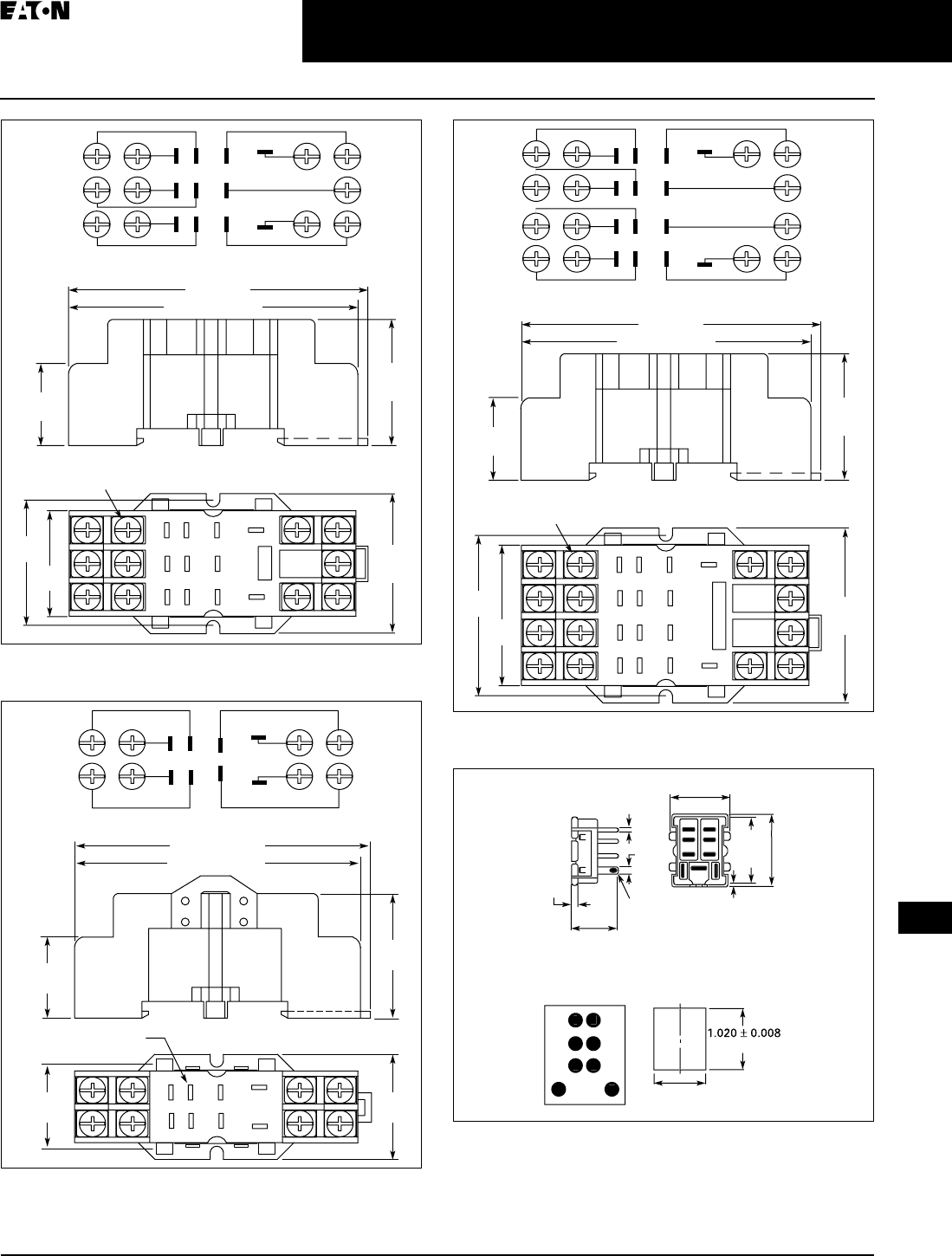
April 2009
CA080102002K07A For more information visit: www.EatonCanada.ca
3-45
Control Relays & Timers
3
General Purpose Plug-In Relays
D7PF Series — Full Featured
Figure 3-71. D7PA3 Standard Mount — Approximate Dimensions in
Inches (mm)
Figure 3-72. D7PA9 Standard Mount — Approximate Dimensions in
Inches (mm)
Figure 3-73. D7PA4 Panel Mount — Approximate Dimensions in Inches
(mm)
Figure 3-74. D7PA5 Panel Mount — Approximate Dimensions in Inches
(mm)
1.44
(36.6)
1.27
(32.5)
1
2
3
4
5
7
8
911
10
6
Combination Slotted/Phillips
Head Screws 6-32 x 5/16"
2.58 (67.5) Max.
2.74 (69.8)
0.65
(16.6)
1.59
(40.5)
Max.
1.09
(27.8)
Max.
Wiring Diagram (Top View)
1
2
3
4
6
10
11
7
58
9
1.04
(26.3)
5
6
7
8
1
2
3
4
0.04 x 0.22 (1.0 x 5.4)
Slots Typ.
1.06
(26.9)
0.65
(16.6)
1.18
(29.9)
2.60 (66.0) Max.
2.69 (68.3) Max.
Wiring Diagram (Top View)
1
2
5
6
3
4
7
8
9
1214
11
13
10
1.83
(46.5)
1.63
(41.4)
2.58 (67.5) Max.
2.74 (69.8)
Combination Slotted/Phillips
Head Screws 6-32 x 5/16"
0.65
(16.6)
1.98
50.5)
Max.
1.09
(27.8)
Max.
Wiring Diagram (Top View)
2
3
4
6
1
5
8
7
13
9
10
11
14
12
1
2
3
4
5
8
6
7
0
.
01
(
0.3
)
0.94
(
23.9
)
Max
.
0
.2
0
(
5.1
)
(
25.9
±
0.2
)
0.840 + 0.008
/
-
0
(
21.3 + 0.20
/
-0
)
0
.
81
(
20.6
)
M
a
x
.
1.
00
(
25.4
)
M
a
x
.
1.1
6
(
29.5
)
M
a
x
.
0
.1
1
(
2.8
)
8
–
0.07
(
1.8
)
Di
a
.
x
0.14
(
3.6
)
Elli
p
tic Hole
s
Terminal Arrangemen
t
(
Bottom View
)
0
.
08
(
2.0
)
TAB49.BOO Page 45 Thursday, March 5, 2009 7:36 PM
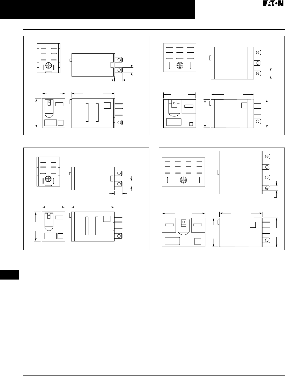
April 2009
3-46
For more information visit: www.EatonCanada.ca CA080102002K07A
Control Relays & Timers
3
General Purpose Plug-In Relays
D7PF Series — Full Featured
Figure 3-75. D7PF1 — Approximate Dimensions in Inches (mm)
Figure 3-76. D7PF2 — Approximate Dimensions in Inches (mm)
Figure 3-77. D7PF3 — Approximate Dimensions in Inches (mm)
Figure 3-78. D7PF4 — Approximate Dimensions in Inches (mm)
21
78
56
34
1.61 (40.9)
Max.
0.86 (21.8)
Max.
1.10
(27.9)
0.29 (7.4)
Max.
Terminal
Arrangement
(Bottom View)
0.19 x 0.02
(4.7 x 0.5)
Typ.
12
34
56
78
1.10
(27.9)
0.29 (7.4)
Max.
1.61 (40.9)
Max.
0.86 (21.8)
Max.
0.19 x 0.02
(4.7 x 0.5)
Typ.
Terminal
Arrangement
(Bottom View)
1.54 (39.1)
Max.
1.22 (30.7)
Max.
0.19 x 0.02
(4.7 x 0.5)
Typ.
1.08
(27.4)
1110
789
4
1
56
23
1.07
(27.1)
Max.
Terminal
Arrangement
(Bottom View)
0.19 x 0.02
(4.7 x 0.5)
Typ.
1.08
(27.4)
1.07
(27.1)
Max.
13
91011
6
2
5
1
7
3
14
12
8
4
1.60 (40.5)
Max.
1.60 (40.6)
Max.
Terminal
Arrangement
(Bottom View)
TAB49.BOO Page 46 Thursday, March 5, 2009 7:36 PM

April 2009
CA080102002K07A For more information visit: www.EatonCanada.ca
3-47
Control Relays & Timers
3
General Purpose Plug-In Relays
D8 Series — Standard
D8 Series
D8 Series Relay
Features
■Allows switching of 25A and 30A
loads
■A high-capacity, high-withstand
voltage relay compatible with
momentary voltage drops
■No contact chattering for momentary
voltage drops up to 50% of rated
voltage
■UL Class B construction standard
■Wide-range AC-activated coil that
handles 100 to 120V AC at either 50
or 60 Hz
■Panel, DIN rail and flange mounting
Standards and Certifications
File # E1491
File # LR701520
Technical Data and
Specifications
Table 3-58. Coil Resistance
Table 3-59. Specifications
Table 3-60. Coil Data
Coil Voltage Ohms mA
24V AC
110/120V AC
220/240V AC
303
5260
21000
71
20.4
10.2
12V DC
24V DC
75
303
158
79
D8PR6 D8PR7
Rated Load 220V AC 30A 220V AC 25A 220V AC 25A
Carry Current 30A 30A 25A
Max. Operating Voltage 250V AC 250V AC 250V AC
Max. Switching Current 30A 30A 25A
Contact Material AgCdO AgCdO AgCdO
Max. Switching Capacity 6600 VA 6600 VA 5500 VA
Min. Permissible Load 100 mA @ 5V DC 100 mA @ 5V DC 100 mA @ 5V DC
Mechanical Life (min.) 5,000,000 Operations 5,000,000 Operations 5,000,000 Operations
Electrical Life @
All Contact Ratings (min.)
100,000 Operations 100,000 Operations 100,000 Operations
Maximum hp Ratings 1-1/2 hp (120V AC)
3 hp (240/265/277V AC)
1-1/2 hp (120V AC)
3 hp (240/265/277V AC)
1-1/2 hp (120V AC)
3 hp (240/265/277V AC)
Coil Voltage Must Operate Must Release Maximum Voltage
24V DC/V AC, 12V DC 75% maximum 15% minimum 110%
120V AC 75V 18V 132V
240V AC 150V 36V 264V
TAB49.BOO Page 47 Thursday, March 5, 2009 7:36 PM
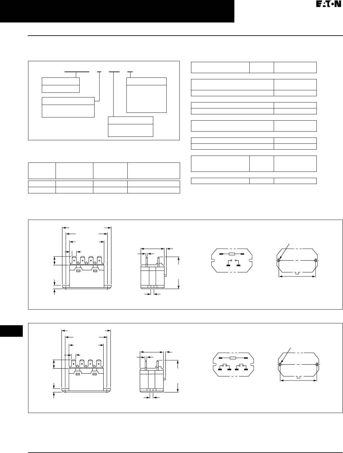
April 2009
3-48
For more information visit: www.EatonCanada.ca CA080102002K07A
Control Relays & Timers
3
General Purpose Plug-In Relays
D8 Series — Standard
Catalogue Number Structure
Table 3-61. D8 Series Catalogue Numbering System
For deciphering Catalogue Numbers. Do not use for ordering as not all
combinations are readily available.
Table 3-62. Relay/Socket Quick Reference
Product Selection
Table 3-63. D8 Product Selection
Additional coil voltages available — consult Contact Customer Support
Centre 1-800-268-3578.
Dimensions
Figure 3-79. D8PR6TF — Approximate Dimensions in Inches (mm)
Figure 3-80. D8PR7TF — Approximate Dimensions in Inches (mm)
Relay
Type
Mounting
Bracket
Adapter
Track/Panel
Mount
Front Connecting
Sockets
Track/Panel Mount
D8PR6TE D8PA5 D8PA1 D8PA2
D8PR7TE D8PA5 D8PA1 D8PA2
Family Type
D8PR
Contact Configuration
6 = SPST-NO
7 = DPST-NO
Coil Voltage
A =
B =
R1 =
T =
T1 =
120V AC
240V AC
12V DC
24V AC
24V DC
D 8 P R 6 T E A
Options
TE = E-Bracket
TF = Flange Mount
Std.
Pack
Catalogue
Number
SPST E-Bracket
Coil Voltage:
24V AC D8PR6TET
24V DC D8PR6TET1
SPST Flange Mount
120V AC D8PR6TFA
24V DC D8PR6TFT1
DPST E-Bracket
Coil Voltage:
120V AC D8PR7TEA
DPST Flange Mount
120V AC D8PR7TFA
24V DC D8PR7TFT1
Sockets
DIN Rail Adapter
Screw Terminal Adapter
Bracket Adapter
10
10
10
D8PA1
D8PA2
D8PA5
Accessory
DIN Rail End Stop 100 PFP-M
Two 0.18 (4.5) Dia. Holes
or M4 Tapped Holes
2.70 (68.5) Max.
1.32 (33.5)
Max. 0.08 (2.0)
1.85
(47.0)
Max.
0.18
(4.5)
0.03
(0.8)
2.36 (60.0)
1.99 (50.5)
Max.
0.25 (6.4)
0.43
(11.0)
0.12 (3.0)
01
46
2.362 ± 0.007
(60.0 ± 0.2)
Mounting Holes
(Bottom View)
Terminal Arrangement/
Internal Connections
(Top View)
Two 0.18 (4.5) Dia. Holes
or M4 Tapped Holes
2.70 (68.5) Max.
1.32 (33.5)
Max. 0.08 (2.0)
1.85
(47.0)
Max.
0.18
(4.5)
0.03
(0.8)
2.36 (60.0)
1.99 (50.5)
Max.
0.25 (6.4)
0.43
(11.0)
0.12
(3.0)
01
246 8
2.362 ± 0.007
(60.0 ± 0.2)
Mounting Holes
(Bottom View)
Terminal Arrangement/
Internal Connections
(Top View)
TAB49.BOO Page 48 Thursday, March 5, 2009 7:36 PM
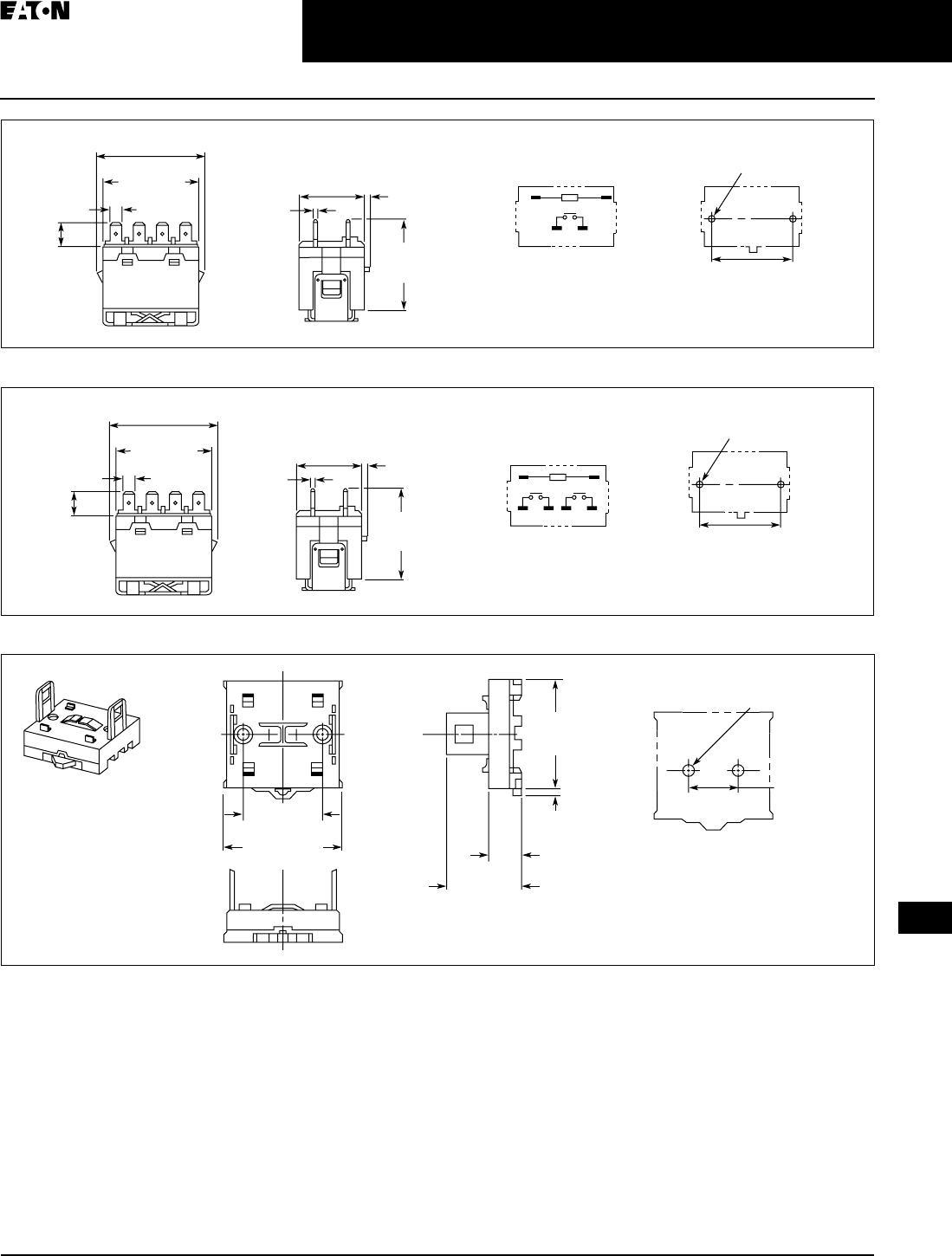
April 2009
CA080102002K07A For more information visit: www.EatonCanada.ca
3-49
Control Relays & Timers
3
General Purpose Plug-In Relays
D8 Series — Standard
Figure 3-81. D8PR6TE with D8PA5 Bracket Attached — Approximate Dimensions in Inches (mm)
Figure 3-82. D8PR7TE with D8PA5 Bracket Attached — Approximate Dimensions in Inches (mm)
Figure 3-83. D8PA1 — Approximate Dimensions in Inches (mm)
Note: Minimum spacing around relay = 0.20 inches (5 mm).
Two 0.18 (4.5) Dia. Holes
or M4 Tapped Holes
1.32 (33.5)
Max. 0.08 (2.0)
2.09
(53.0)
Max.
0.03
(0.8)
2.07 (52.5) Max.
1.99
(50.5) Max.
0.25 (6.4)
0.43
(11.0)
01
46
1.574 ± 0.003
(40.0 ± 0.1)
Mounting Holes
(Bottom View)
Terminal Arrangement/
Internal Connections
(Top View)
Two 0.18 (4.5) Dia. Holes
or M4 Tapped Holes
1.32 (33.5)
Max 0.08 (2.0)
2.09
(53.0)
Max.
0.03
(0.8)
2.07 (52.5) Max.
1.99
(50.5) Max.
0.25 (6.4) 01
246 8
1.574 ± 0.003
(40.0 ± 0.1)
Mounting Holes
(Bottom View)
Terminal Arrangement/
Internal Connections
(Top View)
0.43
(11.0)
2.19 (55.5)
Max.
2.03
(51.5)
Max.
0.20
(5.0)
1.574 ± 0.003
(40.0 ± 0.1)
1.39 (35.2)
Max.
0.57
(14.5)
1.574 ± 0.003
(40.0 ± 0.1)
Two M4 or
0.18 (4.5) Dia. Holes
Mounting Holes
(Bottom View)
TAB49.BOO Page 49 Thursday, March 5, 2009 7:36 PM
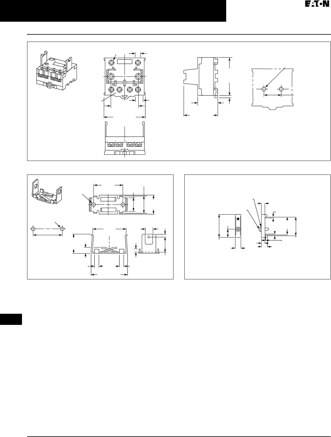
April 2009
3-50
For more information visit: www.EatonCanada.ca CA080102002K07A
Control Relays & Timers
3
General Purpose Plug-In Relays
D8 Series — Standard
Figure 3-84. D8PA2 — Approximate Dimensions in Inches (mm)
Figure 3-85. D8PA5 — Approximate Dimensions in Inches (mm) Figure 3-86. PFP-M DIN Rail End Stop — Approximate Dimensions
in Inches (mm)
2.19 (55.5)
Max.
0.36 (9.2)
2.03
(51.5)
Max.
0.20
(5.0)
1.574 ± 0.003
(40.0 ± 0.1) 1.81 (46.0)
Max.
0.98
(25.0)
1.574 ± 0.003
(40.0 ± 0.1)
Two M4 or
0.18 (4.5) Dia. Holes
Two M3.5 Screws
for Coil
Four M4 Screws
for Contact
0.31 (8.0)
Mounting Holes
(Bottom View)
0.78
(19.7)
0.12
(3.0)
0.17
(4.4)
0.20
(5.0)
0.20
(5.0)
1.20 (50.0)
1.18
(30.0)
1.81
(46.0)
1.57
(40.0)
1.02
(26.0)
0.94
(24.0)
0.70
(17.8)
0.94
(24.0)
0.27
(7.0)
0.39
(10.0)
Two
0.18 (4.5)
Dia. Holes
1.574 ± 0.003
(40.0 ± 0.1)
Mounting
Holes
(Bottom View)
Two M4 or 0.18 (4.5)
Dia. Holes
1.97
(50.0)
0.45
(11.5)
1.47
(37.3)
1.39
(35.3)
0.39
(10.0)
0.39
(10.0)
0.19
(4.8)0.05
(1.3)
0.24
(6.2)
0.07
(1.8)
0.07
(1.8)
M4 x 8 Pan
Head Screw
M4 Spring Washer
TAB49.BOO Page 50 Thursday, March 5, 2009 7:36 PM
April 2009
CA080102002K07A For more information visit: www.EatonCanada.ca
3-51
Control Relays & Timers
3
General Purpose Plug-In Relays
D9 Series — Standard
D9 Series
D9 Series Relay
Features
■Ideal for 3-phase motor control
applications
■No contact chattering for momen-
tary voltage drops up to 50% of
rated voltage
■Push-to-test button is a standard
feature to check contact operation
■Mounting bracket is supplied with
relay
Standards and Certifications
File # E1491
File # LR701520
Technical Data and
Specifications
Table 3-64. Coil Resistance
Table 3-65. Specifications
Table 3-66. Coil Data
Coil Voltage Ohms mA
24V AC
120V AC
240V AC
—
—
—
75
21.6
10.8
12V DC
24V DC
110V DC
72
288
6050
167
83
18
D9PR
NO Contacts
Resistive Load (p.f. = 1)
NC Contacts
Resistive Load (p.f. = 1)
Rated Load 220V AC 25A
30V DC 25A
220V AC 8A
30V DC 8A
Carry Current 25A 8A
Max. Operating Voltage 250V AC/125V DC 250V AC/125V DC
Max. Switching Current 25A 8A
Max. Switching Capacity 5500 VA
750W
1760 VA
240 W
Min. Permissible Load 100 mA @ 24V DC 100 mA @ 24V DC
Mechanical Life (min.) 1,000,000 operations 1,000,000 operations
Electrical Life @
All Contact Ratings (min.)
100,000 operations 100,000 operations
Maximum hp Ratings 1-1/2 hp (120V AC)
3 hp (240/265/277V AC)
3-Phase 3 hp (240/265/277V AC) 30,000 cycles
3-Phase 5 hp (240/265/277V AC) 30,000 cycles
1-1/2 hp (120V AC)
3 hp (240/265/277V AC)
3-Phase 3 hp (240/265/277V AC) 30,000 cycles
3-Phase 5 hp (240/265/277V AC) 30,000 cycles
Coil Voltage Must Operate Must Release Maximum Voltage
24V DC/V AC, 12V DC, 110V DC 75% maximum 10% minimum 110%
120V AC 75V 18V 132V
240V AC 150V 36V 264V
TAB49.BOO Page 51 Thursday, March 5, 2009 7:36 PM
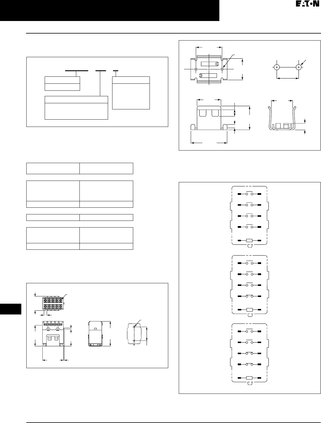
April 2009
3-52
For more information visit: www.EatonCanada.ca CA080102002K07A
Control Relays & Timers
3
General Purpose Plug-In Relays
D9 Series — Standard
Catalogue Number Structure
Table 3-67. D9 Series Catalogue Numbering System
For deciphering Catalogue Numbers. Do not use for ordering as not all
combinations are readily available.
Product Selection
Table 3-68. D9 Product Selection
Additional coil voltages available — consult Contact Customer Support
Centre 1-800-268-3578.
Dimensions
Figure 3-87. D9PR — Approximate Dimensions in Inches (mm)
Figure 3-88. Mounting Bracket — Approximate Dimensions
in Inches (mm)
Terminal Arrangements
Figure 3-89. Terminal Arrangements
Catalogue
Number
4PST-NO Power Relay
Coil Voltage:
24V AC
120V AC
240V AC
D9PR8BT
D9PR8BA
D9PR8BB
24V DC D9PR8BT1
3PST-NO/SPST-NC Power Relay
120V AC D9PR9BA
DPST-NO/DPST-NC Power Relay
Coil Voltage:
24V AC
120V AC
D9PR10BT
D9PR10BA
24V DC D9PR10BT1
D 9 P R 8 B A
Contact Configuration
8B = 4PST-NO
9B = 3PST-NO/SPST-NC
10B = DPST-NO/DPST-NC
Family Type
D9PR
Coil Voltage
A =
B =
R1 =
T =
T1 =
120V AC
240V AC
12V DC
24V AC
24V DC
2.03
(51.5)
Max.
1.70
(43.2)
2.52
(64.0)
Max.
1.378 ± 0.004
(35.0 ± 0.1)
0.08
(2.0)
0.30
(7.6)
2.17
(55.2)
1.36
(34.5)
Max.
0.17
(4.3)
Two M4 or
0.18 (4.5) Dia.
Ten M3.5
Screw Terminal Brackets
Mounting Holes
(Bottom View)
Mounting Hole
s
1.
37
(
35.0
)
0
.
95
(
24.0
)
1.1
8
(
30.0
)
1.7
3
(
44.0
)
1.14
(
29.0
)
0
.
35
(
9.0
)
0
.1
7
(
4.4
)
1.1
0
(
28.0
)
0
.2
8
(
7.0
)
1.
3
7
8
±
0
.
004
(
35.0
±
1.0
)
Tw
o
M4
or
0.18
(
4.5
)
Dia
.
Tw
o
M
4
A2 A1
44 43
34 33
24 23
14 13
A2 A1
42 41
34 33
24 23
14 13
A2 A1
42 41
34 33
24 23
14 13
D9PR8
D9PR9
D9PR10
TAB49.BOO Page 52 Thursday, March 5, 2009 7:36 PM
April 2009
CA08102002K07A For more information visit: www.CutlerHammer.ca
3-53
Control Relays & Timers
3
General Purpose Relays — Type AA
9575H Series 3000 — AC and DC
9575H Series 3000 — Type AA
— AC and DC
Product Description
Type AA panel mounted relays are
rated (each pole) 30A up to 300V AC, 50/
60 Hz; 5A @ 480/600V AC, 50/60 Hz.
Application Description
9575H Series 3000 relays are ideal for
applications when controlling smaller
loads such as single-phase motors.
Technical Data and
Specifications
Relay Specifications
Coil
■Pull-In Voltage: 80% DC coils, 85%
AC coils of nominal voltage or less
@ 25˚ C
■Dropout Voltage: 10% of nominal
voltage or more @ 25˚ C
■Coil Resistance: ±10% measured @
25˚ C
■Max DC Coil Dissipation Capability:
4 Watts DC continuous @ 25˚ C
Contacts
■Contact Combination: DPDT
■Contact Rating Each Pole (Main Con-
tacts): Each pole rated 40 Amps up
to 300V AC, 50/60 Hz, 5 Amps @ 480/
600V AC 50/60 Hz, 0.75pF inductive
load. 1-1/2 hp motor load (each pole)
@ 120 thru 600V AC 50/60 Hz. 2 hp
motor load @ 200 thru 600V AC, 50/
60 Hz only when using both poles to
switch both sides of load, 30 Amps
@ 28V DC resistive load each pole.
NEMA A 600 pilot duty 50/60 Hz.
■Contact Material: Silver Cadmium
Oxide, Gold Flashed. 5/16 inch
(7.9 mm) diameter standard.
Dielectric Withstanding Voltage
■Between Open Contacts: 1500 Vrms
■All Other Mutually Insulated Con-
ductive Elements: 2200 Vrms
Miscellaneous
■Coil Terminals: 6-32 Binder Head
Screws
■Contact Terminals: 8-32 Binder Head
Screws
■Main Base Material: Molded
Phenolic, UL recognized (QMFZ2)
■Weight (DPDT Relay): 11 oz. (311
grams) approximately
■Weight (DPDT Relay with Auxiliary
Switch) 14.5 oz. (411 grams)
approximately
Auxiliary Switch Specifications
■Contact Combination: SPDT
■Contact Rating: Auxiliary Switch
rated 10 Amps @ 125 or 250V AC,
resistive load; 1/4 hp at 125 or 250V
AC, motor load; 0.4 Amps at 125V
DC or 0.25 Amps at 250V DC, resis-
tive load; 3 Amps at 125V AC lamp
load. All AC ratings are 50/60 Hz.
■Dielectric Withstanding Voltage:
500V AC RMS between open con-
tacts, 1500V AC RMS between all
other mutually insulated conductive
elements.
■Terminals: 4-40 Round Head Screws
for Auxiliary Contacts standard.
Table 3-69. Average Operating Times
(Milliseconds)
Table 3-70. Temperature Ranges
Standards and Certifications
■UL listed, E1491
■CSA 41729
■CE: EN60947-4-1, EN60947-5-1
Options and Accessories
Table 3-71. Enclosure
Only 9575H3 relays without an auxiliary
switch should be mounted in the 9575H2449
enclosure.
Note: There are no “repair parts” available
for these relays.
9575H Series 3000 Relay
Operation DPDT
Relay
DPDT Relay
with Auxiliary
Switch
Pick-Up 40 50
Drop-Out 35 35
Temperature AC DC
Operating
Range
-30°C to
+50°C
-30°C to
+60°C
Non-operating
Range
-30C° to
+100°C
-30C° to
+100°C
Description Catalogue
Number
NEMA1 Enclosure — 9575H2449
TAB49.BOO Page 53 Thursday, March 5, 2009 7:36 PM
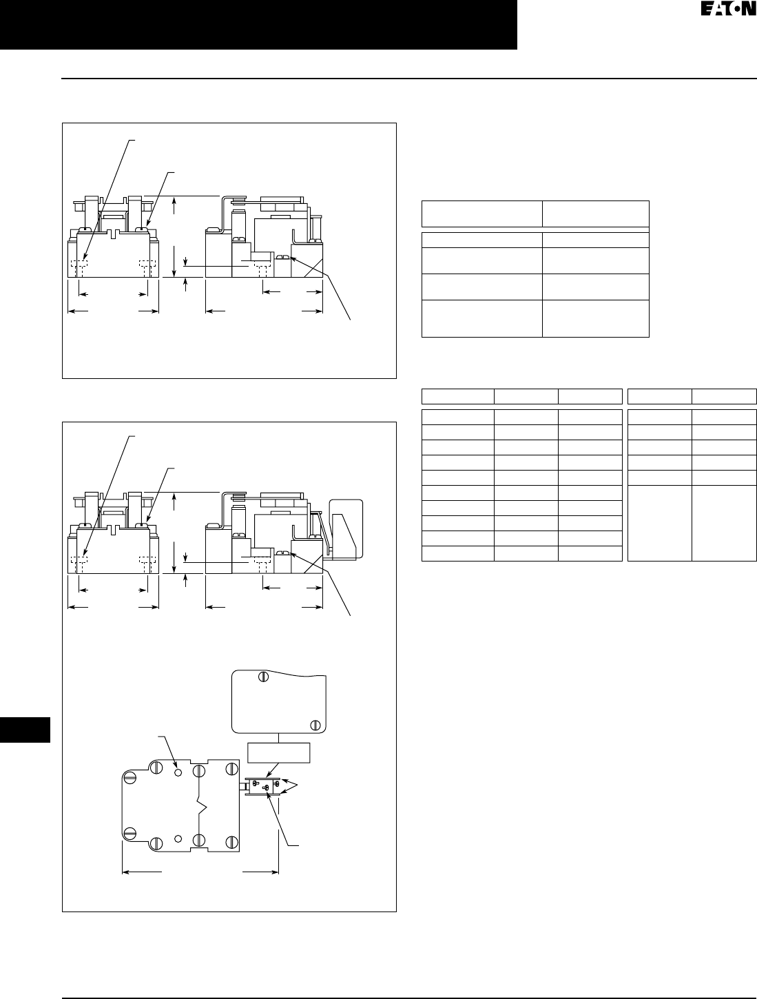
April 2009
3-54
For more information visit: www.CutlerHammer.ca CA08102002K07A
Control Relays & Timers
3
General Purpose Relays — Type AA
9575H Series 3000 — AC and DC
Dimensions
Figure 3-85. 9575H3 DPDT Relay — Approximate Dimensions
in Inches (mm)
Figure 3-86. 9575H3 DPDT Relay with Auxiliary SPDT Switch
Approximate Dimensions in Inches (mm)
Product Selection
When Ordering Specify
Catalogue Number and Magnet Coil Code Letter. Example:
for DPDT relay with Auxiliary Switch and a 120V 50/60 Hz
coil, order Catalogue Number 9575H3A010.
Table 3-72. Type AA Relays
Underscore indicates missing Code Suffix for Magnet Coil — see
Selection Table below.
Table 3-73. Coil Voltage Selection Table
2.25
(58.7)
Max.
8-32 Binder Head Machine Screw
on Contact Terminals (6 Places)
Mounting Holes 0.187 (4.75) Dia. (2 Places)
0.38
(9.5)
1.87 (47.5) 1.62
(41.1)
6-32 Binder Head
Machine Screw
on Coil
Terminals
(2 Places)
2.50 (63.5) 3.12 (79.2) Max.
2.25
(58.7)
Max.
8-32 Binder Head Machine Screw
on Contact Terminals (6 Places)
Mounting Holes 0.187 (4.75) Dia. (2 Places)
0.38
(9.5)
1.87 (47.5) 1.62
(41.1)
6-32 Binder Head
Machine Screw
on Coil
Terminals
(2 Places)
AUX. SWITCH
MARKING SURFACE
2.50 (63.5) 3.12 (79.2) Max.
Mounting Holes (2)
Screw Terminals
(4-40) RHMS
with External
Tooth Lockwashers
(3 Places)
Insulators
(2 Sides)
4.44 (112.7) Max.
NC 10A 1/4HP 125 OR 250VAC
1/2A 125VDC 1/4A 250VDC
3A 125VAC "LAMP"
278 VA 125/250 VAC P.D.
NO COM
RELAY TOP VIEW
Relay Style Catalogue
Number
Relay (DPDT) 9575H3_000
Relay with Auxiliary
Switch
9575H3_010
Relay with Blowout
Magnets
9575H3_100
Relay with Auxiliary
Switch and Blowout
Magnets
9575H3_110
Volts AC Hz Suffix Code Volts DC Suffix Code
120 50/60 A110 P
240 50/60 B220 Q
480/440 60/50 C 6 R
600/550 60/50 D 12 S
208 50/60 E 24 T
277 50/60 H 48 W
6 50/60 J
12 50/60 K
24 50/60 L
48 50/60 M
TAB49.BOO Page 54 Thursday, March 5, 2009 7:36 PM
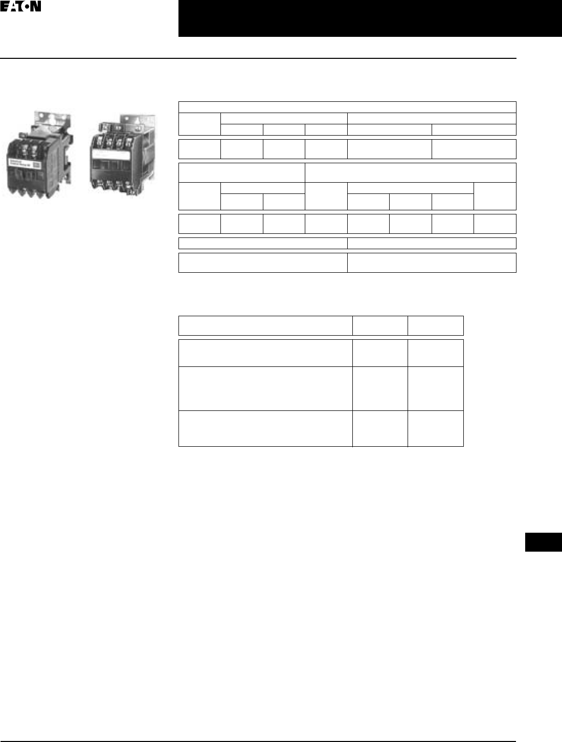
April 2009
CA08102002K07A For more information visit: www.CutlerHammer.ca
3-55
Control Relays & Timers
3
Machine Tool Relays
BF/BFD Series — Fixed Contact Industrial Control
BF/BFD Series — Fixed
Contact Industrial Control
Product Description
Type BF is AC operated, 300V maximum,
and the BFD is DC operated, 250V. Fixed
contact relays are available in any com-
bination of NO and NC from two to
twelve poles. BF and BFD relays have
captive clamp terminals fully accessible
from the front, a moulded coil with low
operating temperature and silver alloy
contacts suitable for low voltage circuits.
Standards and Certifications
■UL recognized, UL File No. E19223
(AC relays only)
■CSA certified, File No. LR39402-6,
LR28548-10, 11 (AC and DC relays)
Type BF Type BFD
Technical Data and Specifications
Table 3-74. Specifications
Options
Table 3-75. Options
BF Relay Electrical Ratings — NEMA A300
Volts Maximum Current Maximum VA
Cont. Make Break Make Break
120
240
10
10
60
30
6
3
7200
7200
720
720
Horsepower Ratings
(UL Recognized)
DC Rating — NEMA P300
Phase AC Volts Volts Maximum Current Max. Make
or Break
VA
115 230 Cont. Make Break
1
3
1/6
—
1/2
1
125
250
5.0
5.0
1.1
0.55
1.1
0.55
138
138
Resistive Rating Coil Power Requirements
125V DC: 3A
250V DC: 1.5A
AC: 72 VA open, 22 VA closed
DC: 12 watts (nominal), 250V max.
Description Code
Letter or
Catalogue
Number
FASTON Push-On Terminals
Insert letter F after relay type designation in listed
Catalogue Number. Example: BFF20F or BFDF20S
F—
Overlapping Contacts
NO contact closes before corresponding NC contact
opens — supplied as NO/NC set(s). Insert letter A
after relay type designation in listed Catalogue
Number. Example: BFA22F or BFDAF22S
A—
NEMA 1 Enclosure for Relay Types
BF, AR — all poles
BFD — 4 – 8 poles
ARD — 4 – 6 poles
— 4977D40G04
4977D40G04
4977D40G04
Replacement coils . . . . . . . . . . . . . . . . .Page A-3
TAB49.BOO Page 55 Thursday, March 5, 2009 7:36 PM
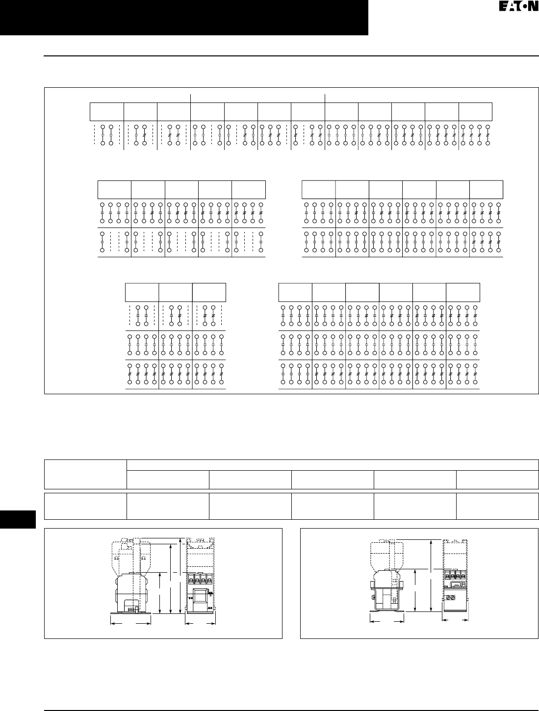
April 2009
3-56
For more information visit: www.CutlerHammer.ca CA08102002K07A
Control Relays & Timers
3
Machine Tool Relays
BF/BFD Series — Fixed Contact Industrial Control
Contact Arrangements
Figure 3-87. Contact Arrangements for BF, BFD Relays
Note: NO = Normally Open NC = Normally Closed
Dimensions
Table 3-76. Dimensions
Figure 3-88. BF Relay with Permanent Magnet Latch
and Solid-State Timer — Approximate Dimensions in Inches (mm)
Figure 3-89. BFD Relay with Solid-State Timer — Approximate
Dimensions in Inches (mm)
Enclosures
See Page 3-61.
Number of
Poles
Approximate Dimensions in Inches (mm)
A
BF Only
B
BF with Latch
C
BF with Timer
D
BFD Only
E
BFD with Timer
4
8
12
3.22 (81.8)
4.19 (106.4)
4.81 (122.2)
6.22 (158.0)
7.19 (182.6)
7.81 (198.4)
5.88 (149.4)
6.88 (174.8)
7.50 (190.5)
4.03 (102.4)
4.97 (126.2)
5.63 (143.0)
7.06 (179.3)
8.00 (203.2)
8.66 (220.0)
2NO
0NC
1NO
1NC
0NO
2NC
3NO
0NC
2NO
1NC
1NO
2NC
0NO
3NC
4NO
0NC
3NO
1NC
2NO
2NC
1NO
3NC
0NO
4NC
2 Poles 3 Poles 4 Poles
6NO
0NC
5NO
1NC
4NO
2NC
3NO
3NC
2NO
4NC
6 Poles
Rear
Front
6NO
4NC
5NO
5NC
4NO
6NC
10 Poles
Rear
Center
12NO
0NC
8NO
4NC
7NO
5NC
12 Poles
Rear
Center
Front Front
6NO
6NC
5NO
7NC
4NO
8NC
8NO
0NC
7NO
1NC
6NO
2NC
5NO
3NC
4NO
4NC
8 Poles
Rear
Front
0NO
8NC
A
B
C
3.13
(79.5)
1.97
(50)
D
E
3.13
(79.5)
1.69
(42.9)
TAB49.BOO Page 56 Thursday, March 5, 2009 7:36 PM

CA08102002K07A For more information visit: www.CutlerHammer.ca
3-57
Control Relays & Timers
April 2009
3
Machine Tool Relays
BF/BFD Series — Fixed Contact Industrial Control
Product Selection
When Ordering Specify
■Catalogue Number of Basic Relay.
■If a coil voltage other than listed is
required, select the Suffix Code
from the Coil Voltage Table and sub-
stitute it for the last letter in the
Catalogue Number. Example:
BF80V for a 110/60 AC coil.
Table 3-77. Complete Relay
Note: Relays listed above with equal number of NO and NC contact poles are specially
priced — 1NO and 1NC pole are supplied at no additional charge.
Table 3-78. Coil Voltage Table
Number
of Poles
Type of Contact BF 300V AC Basic Relays
120/60, 110/50 AC Coil
BFD 250V DC Basic Relays
120 DC Coil
NO (Form A) NC (Form B) Catalogue
Number
Catalogue
Number
22
1
0
0
1
2
BF20F
BF11F
BF02F
BFD20S
BFD11S
BFD02S
33
2
1
0
0
1
2
3
BF30F
BF21F
BF12F
BF03F
BFD30S
BFD21S
BFD12S
BFD03S
44
3
2
1
0
0
1
2
3
4
BF40F
BF31F
BF22F
BF13F
BF04F
BFD40S
BFD31S
BFD22S
BFD13S
BFD04S
66
5
4
3
2
0
0
1
2
3
4
6
BF60F
BF51F
BF42F
BF33F
BF24F
BF06F
BFD60S
BFD51S
BFD42S
BFD33S
BFD24S
BFD06S
88
7
6
5
4
0
0
1
2
3
4
8
BF80F
BF71F
BF62F
BF53F
BF44F
BF08F
BFD80S
BFD71S
BFD62S
BFD53S
BFD44S
BFD08S
10 10
8
7
6
5
4
2
0
2
3
4
5
6
8
BF100F
BF82F
BF73F
BF64F
BF55F
BF46F
BF28F
BFD100S
BFD82S
BFD73S
BFD64S
BFD55S
BFD46S
BFD28S
12 12
8
7
6
5
4
0
4
5
6
7
8
BF120F
BF84F
BF75F
BF66F
BF57F
BF48F
BFD120S
BFD84S
BFD75S
BFD66S
BFD57S
BFD48S
BF Coils BFD Coils
Volts AC Hz Suffix Code Volts DC Suffix Code
12
24
48
110
110/120
208
220/240
440
60
60
60
60
50/60
60
50/60
60
H
I
J
V
F
K
G
C
6
12
24
38
48
72
95
120
130
240
C
D
L
N
M
E
B
S
U
T
Replacement Coils . . . . . . . . . . . . . . . . . Page A-3
Dimensions. . . . . . . . . . . . . . . . . . . . . . . . Page 3-56
TAB49.BOO Page 57 Thursday, March 5, 2009 7:36 PM
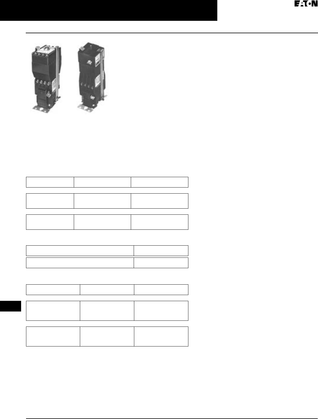
April 2009
3-58
For more information visit: www.CutlerHammer.ca CA08102002K07A
Control Relays & Timers
3
Machine Tool Relays
BF/BFD Series — Fixed Contact Industrial Control
Solid-State Timers
■Field-convertible to 48 or 24V DC
■Self-contained units have one NO
solid-state contact.
Application Description
Timers Only
■Minimal time-setting drift with age
■Adjustable timing range
■Increased resolution on short time
adjustments
■Operation in adverse environments
Wiring to Relay
■In parallel with coil — one timed and
up to 12 instantaneous contacts, or
■In series with coil — up to 12 timed
contacts in 1 relay
Permanent Magnet Latch
■Field mountable on Catalogue Num-
ber BF; factory installed on BFD
■Latch coil continuously rated
■Latch plunger adjustable for opti-
mum performance
Table 3-79. Solid-State Timers
For panel mount add Suffix F.
Table 3-80. Options
Table 3-81. Permanent Magnet Latch
Solid-State Timer,
Relay Mounted
Permanent Magnet
Latch, Relay Mounted
Voltage Time Delay Range Catalogue
Number
ON Delay
AC
AC
DC
0.1 to 30 Seconds
30 to 60 Seconds
0.1 to 30 Seconds
BST-ON
BST-ONB
BSTD-ON
OFF Delay
AC
AC
DC
0.1 to 30 Seconds
30 to 60 Seconds
0.1 to 30 Seconds
BST-OF
BST-OFB
BSTD-OF
Description Code
Letter
Panel Mounted Timers
Add Suffix Code to Catalogue Number
P
Coil Volts Coil Hz Catalogue
Number
AC Relays
24
48
110/120
220/240
60
60
50/60
50/60
BFMLI
BFMLJ
BFMLF
BFMLG
DC Relays
24
48
120
240
—
—
—
—
BFMLL
BFMLM
BFMLS
BFMLT
Specifications
Timer
■Input
❑120/110V AC, 50/60 Hz, ±10%
❑250, 120, 48, 24V DC, ±10%
■Power required: 2 VA maximum
■Contact ratings
❑BST: will switch 120V AC BF relay
❑BSTD: will switch BFD relays
– 120V DC: 0.1A
– 48V DC: 0.25A
– 24V DC: 0.5A
■Repeatability: ±3% of time setting
for ±10% change in line voltage, or
15°C change in ambient
temperature
■Ambient temperature range: -20° to
70°C
■Duty cycle: 150 operations/minute
maximum
■BST and BSTD reset time:
❑ON delay
– BST: 50 ms maximum
– BSTD: 100 ms (independent of
time setting and duty cycle)
❑OFF delay
– instantaneous
Permanent Magnet Latch
■Unlatching power requirements
❑Open gap: 24 VA AC
❑Closed gap: 7 VA
❑Burden: 4 watts (AC)
Dimensions . . . . . . . . . . . . . . . . . . . . . . . . Page 3-61
Replacement Coils. . . . . . . . . . . . . . . . . . Page A-3
TAB49.BOO Page 58 Thursday, March 5, 2009 7:36 PM
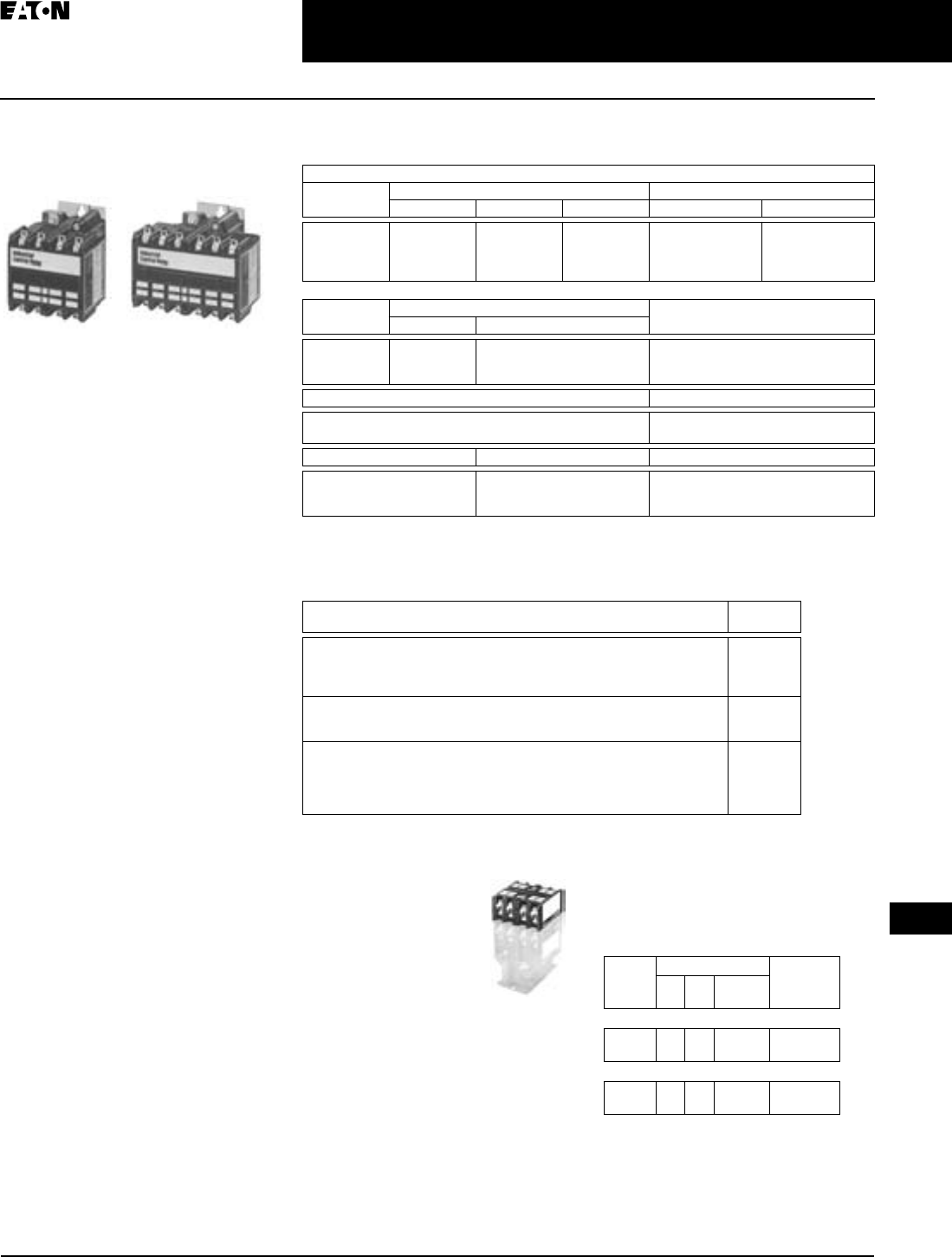
April 2009
CA08102002K07A For more information visit: www.CutlerHammer.ca
3-59
Control Relays & Timers
3
Machine Tool Relays
AR/ARD Series — Convertible Contact Industrial Control
AR/ARD Series
Convertible Contact
Industrial Control
Product Description
The AR/ARD relays are electromechan-
ical convertible contact relays. AR
relays are AC devices and the ARD is
for DC applications.
Application Description
Type AR and ARD relays are designed
for use on machine tools, process
lines, conveyors and similar automatic
and semi-automatic equipment.
Operation
AR relays are available in either 4- or
6-pole configurations. AR relays are
easily converted to 8 or 10 poles sim-
ply by adding a 4-pole deck. In addi-
tion, mechanical latch and solid-state
timer attachments are available with
4- and 6-pole relays.
Contacts are convertible from NO to
NC, to provide any combination
desired up to a maximum of 10. For
the ARD, the number of poles cannot
exceed four NC in any pole configura-
tion. Wide spacing of contacts simpli-
fies installation, contact testing and
maintenance. Contacts are electrically
and mechanically isolated from each
other. Overlap contacts are also avail-
able in one or two sets. These contacts
should be mounted in the centre pole
positions. AC and DC contact car-
tridges should not be used in the same
relay.
Standards and Certifications
■UL File No. E19223
■CSA File No. LR39402-6, LR54517
and LR54520
AR 4-Pole AR 6-Pole
Technical Data and Specifications
Table 3-82. Specifications
ARGC contact cartridges have a 20A thermal rating and A600 switching ratings.
Options
Table 3-83. Options
Accessories
Four-Pole Top Deck Adder
■Increases contact
capacity from four/six
poles to eight/ten
poles.
■Mounts on top of
basic relay using
three screws.
■Will not interfere with
wiring, testing or con-
vertible cartridges.
■Screw terminals for ring connectors
available; to order add Suffix R to
Catalogue Number listed below.
Table 3-84. Four-Pole Top Deck Adder
Contact Ratings — 600V AC Cartridge NEMA A600
Volts Maximum Current Maximum VA
Cont. Make Break Make Break
120
240
480
600
10
10
10
10
60
30
15
12
6
3
1.5
1.2
7200
7200
7200
7200
720
720
720
720
DC Cartridges NEMA P600
Volts Maximum Current Maximum VA
Make or Break
Cont. Make or Break
125
250
600
5
5
5
1.10
0.55
0.20
138
138
138
Resistive Rating Coil Power Requirements
125V DC: 3A
250V DC: 1.5A
AC: 96 VA open, 14 VA closed
DC: 14 watts open, 250V max.
Voltage AR Relays ARD Relays
Pickup Voltage (max.)
Dropout Voltage (min.)
Voltage (max.)
85%
60%
110 %
65%
15%
110 %
Description Suffix
Code
Convertible Contacts
AR and ARD relays listed are supplied with NO contacts which are easily
converted to NC. If both NO and NC poles are required, order by Catalogue
Number. Example: 4-pole relay with 1NO and 3NC contacts, order AR413A.
Screw Terminals
For ring-type connectors, add Suffix R to the Catalogue Number. Example:
AR420AR.
R
Overlapping Contacts
NO contact closes before corresponding NC contact opens — supplied as
NO/NC sets of two cartridges. Insert letter S after relay type designation in
listed Catalogue Number. Example: AR402AS. Specify the number of sets
required: S for one set and S2 for two sets.
S or S2
Four-Pole Top
Deck Adder
No. of
Pole
Spaces
Contacts Catalogue
Number
NO NC Blank
Cavities
With 600V AC Cartridges
42
4
0
0
2
0
ARA20
ARA40
With 600V DC Cartridges
42
4
0
0
2
0
ARDA20
ARDA40
Replacement coils . . . . . . . . . . . . . . . . .Page A-3
TAB49.BOO Page 59 Thursday, March 5, 2009 7:36 PM
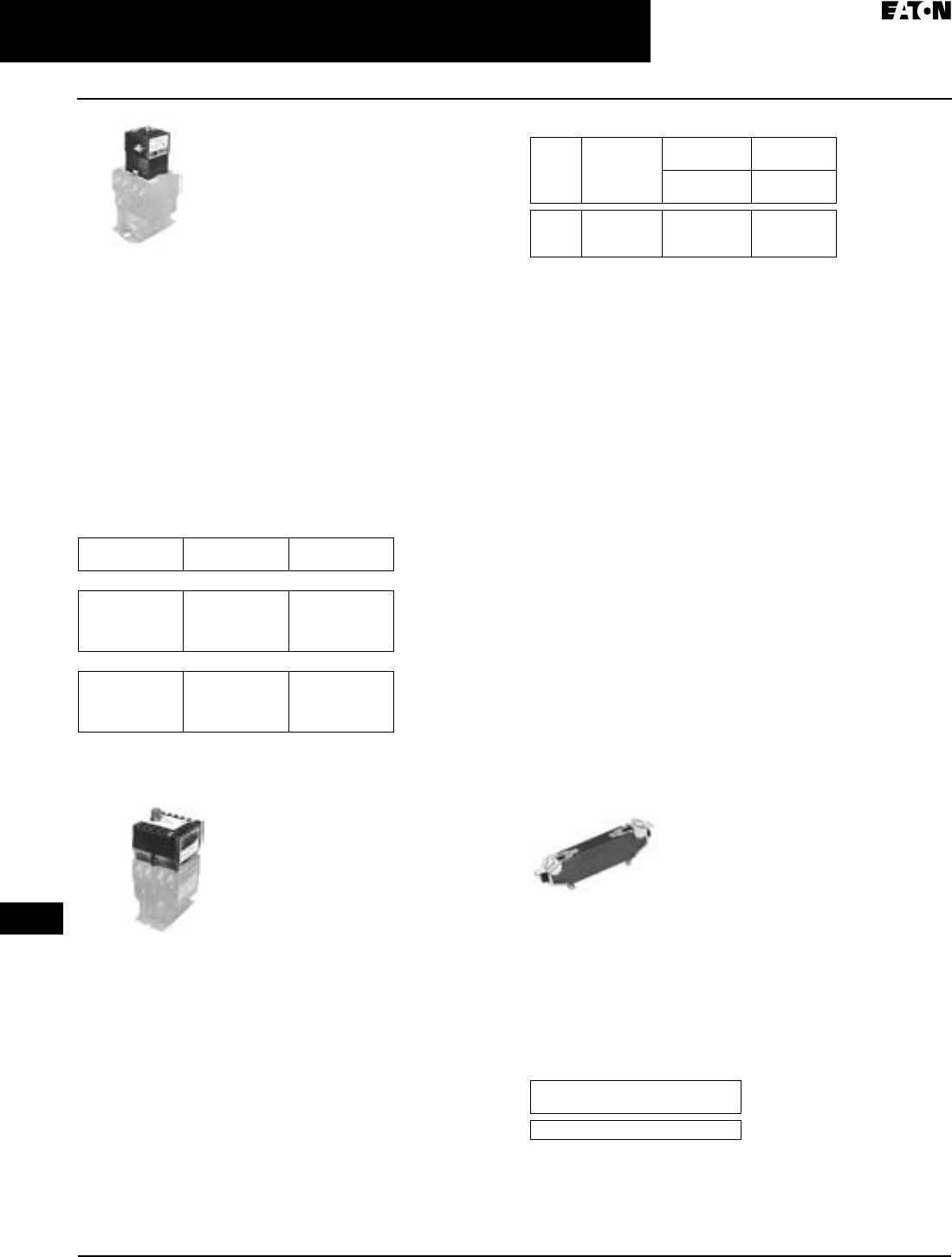
April 2009
3-60
For more information visit: www.CutlerHammer.ca CA08102002K07A
Control Relays & Timers
3
Machine Tool Relays
AR/ARD Series — Convertible Contact Industrial Control
Permanent Magnet Latch
By energizing the relay coil, the latch attachment “sets”
(when the base relay’s armature/crossbar assembly has
closed) holding the relay ON, even after the relay coil has
been de-energized. The clearing coil on the latch is energized
to release the armature/crossbar assembly.
■Field mountable to four and six pole
■Latch plunger is adjustable
■Latch coil continuously rated
■Unlatching power requirements
❑Open gap: 24 VA
❑Closed gap: 7 VA
❑Burden: 4 watts AC, 6 watts DC
Table 3-85. Permanent Magnet Latch
Reference Information
■ART, ARTD: IL 14510, IL 14485
Solid-State Timer
■Mounts on basic four- or six-pole relay using two screws
■Has one NO solid-state contact
■ON delay or OFF delay applications
■Will switch 120V AC and DC coils
■ARTD is field convertible to 24 or 48V DC
Table 3-86. Solid-State Timer
Solid-State Timer Electrical Ratings
■Input
❑120V AC, ±10%, 50/60 Hz
❑120, 48, 24V DC, ±10%
■Power Required: AC, DC: 2 VA max.
■Contact Ratings: AC, 0.2A inductive
❑Inrush: 1.3A max.
■DC will switch 4, 8 and 10-pole ARD relays
❑48V DC: 0.25A
❑24V DC: 0.5A
■Repeatability
❑AC ±2% w/10% voltage variation ±7.5% and 15% temper-
ature variation
❑DC ±1% w/10% voltage variation and 15°C temperature
variation
Specifications
■Ambient Temp. Range: -20° to 70°C
■Duty Cycle
❑AC, DC: 150 operations/minute max.
■Reset Time ART and ARTD
❑ON Delay ART: 50 ms max.
❑ON Delay ARTD: 100 ms independent of time setting
and duty cycle
❑OFF Delay: instantaneous
Surge Suppressor
■Mounts in contact cavity of AR relays
■Limits high transient voltages resulting from de-
energizing relay coil or other electromechanical devices
■Protects sensitive instruments and solid-state devices
■120V AC max, not used on DC
■For noise suppression, see Catalogue Number SS-56
starter mounted surge suppressor.
Table 3-87. Surge Suppressor
Operating
Volts
Coil Hz Catalogue
Number
For AC Control Circuits
24
48
120
240
60
60
60/50
60/50
ARML
ARMLG
ARMLA
ARMLW
For DC Control Circuits
24
48
120
240
—
—
—
—
ARMLL
ARMLM
ARMLS
ARMLT
Catalogue Number
ARML Permanent
Magnet Latch for
AR/ARD Relays
ART Solid-State
Timer
Volts Time
Delay
Seconds
ON
Delay
OFF
Delay
Catalogue
Number
Catalogue
Number
AC
AC
DC
0.1 – 30
30.0 – 60
0.1 – 30
ART-ON
ART-ONB
ARTD-ON
ART-OF
ART-OFB
ARTD-OF
Catalogue
Number
ARSS
Dimensions . . . . . . . . . . . . . . . . . . . . . . . . Page 3-61
Replacement coils . . . . . . . . . . . . . . . . . Page A-3
Catalogue Number
ARSS Surge
Suppressor for
AR/ARD Relays
TAB49.BOO Page 60 Thursday, March 5, 2009 7:36 PM
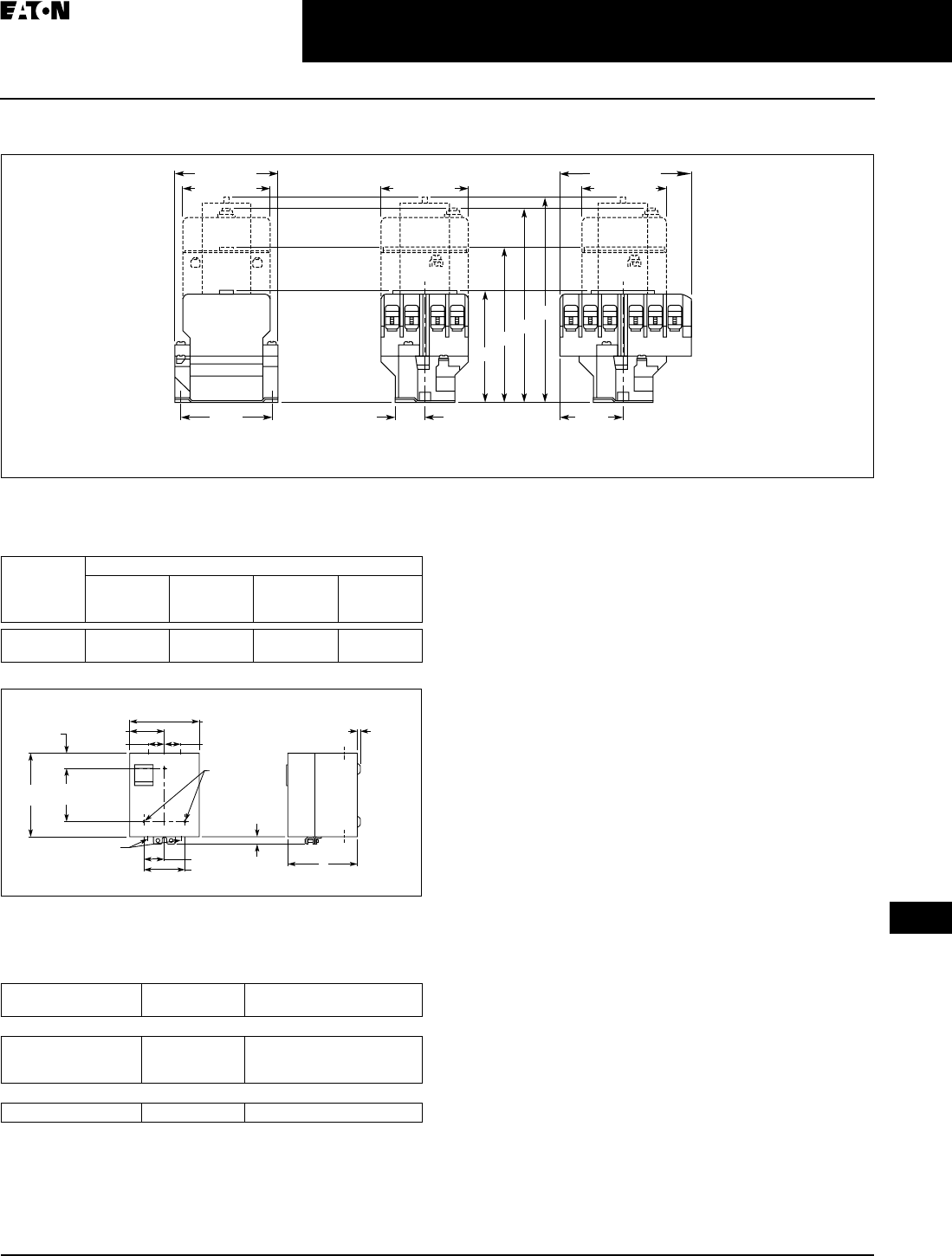
April 2009
CA08102002K07A For more information visit: www.CutlerHammer.ca
3-61
Control Relays & Timers
3
Machine Tool Relays
AR/ARD Series — Convertible Contact Industrial Control
Dimensions and Enclosures
Figure 3-90. 4- and 6-Pole with 4-Pole Adder, Solid-State Timer and Mechanical Latch — Approximate Dimensions in Inches (mm)
Table 3-88. 4- and 6-Pole with 4-Pole Adder, Solid-State Timer and
Mechanical Latch
Figure 3-91. Enclosures — NEMA 1 for BF, BFD, AR and DFRD —
Approximate Dimensions in Inches (mm)
Table 3-89. Enclosures — NEMA 1 for BF, BFD, AR, ARD
A
Base Relay
Adder Deck
S.S. Timer
Latch
B
C
D
1.44 (36.6)
End View, 4- and 6-Pole Side View, 4-Pole Side View, 6-Pole
3.13
(79.5)
2.75 (69.9) 2.88 (73.2)
3.44 (87.4)
2.88 (73.2)
4.09 (103.9)
2.05
(52.1)
C
L of Mounting
Slots (2) for
0.164 Screws
C
L of Mounting Slots
(2) for 0.164 Screws
C
L of Mounting Slots
(2) for 0.164 Screws
Relay
Catalogue
Number
Approximate Dimensions in Inches (mm)
A
4-, 6-Pole
Relays
B
Relay Adder
C
Relay with
Timer
D
Relay with
Latch
AR
ARD
3.56 (90.4)
4.63 (117.6)
4.94 (125.5)
6.00 (152.4)
6.00 (152.4)
7.06 (179.3)
6.39 (162.3)
7.45 (189.2)
Catalogue
Number
Poles Dimension A in Inches (mm)
NEMA 1
Relays without Attachments
BF, AR, ARD
BFD
BFD
All
4 – 8
10, 12
5.34 (135.6)
5.34 (135.6)
7.97 (202.4)
Relays with Attachments
BF, AR, ARD All 7.97 (202.4)
5.66 (143.8)
3.38 (85.9)
2.83 (71.9)
1.72 (43.7) 1.72 (43.7)
0.25 (6.4) Dia.
Mtg. Holes (3)
0.19 (4.8)
A
1.69 (42.9)
0.38 x 0.5 (9.7 x 12.7)
Conduit (2 Top, 2 Bottom)
6.59
(167.4)
4.5
(114.3) 0.63
(16)
1.05
(26.7)
KO KO KO
KO KO KO
KO
KO
TAB49.BOO Page 61 Thursday, March 5, 2009 7:36 PM

April 2009
3-62
For more information visit: www.CutlerHammer.ca CA08102002K07A
Control Relays & Timers
3
Machine Tool Relays
AR/ARD Series — Convertible Contact Industrial Control
Product Selection
When Ordering Specify
■Catalogue Number of Basic Relay
with 120/60, 110/50 AC coil from AR/
ARD Relays table.
■If a coil voltage other than listed is
required, select the Suffix Code
from the Coil Voltage table below
and substitute it for the last letter in
the Catalogue Number. Example:
AR64V for a 110/60 AC coil.
Table 3-90. AR/ARD Relays
Will not accept top-mounted latch or timers.
For 20A thermally rated AC contact cartridge models add a G after the AR Prefix. i.e. ARG660A
Table 3-91. Coil Voltage Table
Table 3-92. Contact Cartridges — 600V
Standard cartridges are sold in cartons of four cartridges. Catalogue Number is for single car-
tridge.
Overlap contact cartridges are sold in sets of two cartridges. Catalogue Number is for sets of two.
20A Thermally rated.
Number
of Pole
Spaces
Contacts AR 600V AC Relays
120/60, 110/50 AC Coil
ARD 600V DC Relays
120 DC Coil
NO NC Blank
Cavities
Catalogue
Number
Catalogue
Number
40
2
4
0
0
0
4
2
0
AR4A
AR420A
AR440A
ARD4S
ARD420S
ARD440S
60
4
6
0
0
0
6
2
0
AR6A
AR640A
AR660A
ARD6S
—
ARD660S
8 6
8
0
0
2
0
AR860A
AR880A
ARD860S
ARD880S
10 10 0 0 AR10100A ARD10100S
AR Coils ARD Coils
Volts AC Hz Suffix Code Volts DC Suffix Code
12
24
48
110
110/120
208
220/240
277
380/440
440/480
550
550/600
60
60
60
60
50/60
60
50/60
60
50/60
50/60
60
50/60
F
I
G
V
A
B
W
C
H
X
D
E
12
24
48
95
120
130
240
D
L
M
B
S
U
T
Type Terminal Standard Contact Cartridge Overlap Contact Cartridge
Catalogue
Number Catalogue
Number
AC Cartridges
With Clamp Terminals
With Screw Terminals
With Clamp Terminals
ARC
ARCR
ARGC
AROC
AROCR
—
DC Cartridges
With Clamp Terminals
With Screw Terminals
ARDC
ARDCR
ARDOC
ARDOCR
Replacement Coils. . . . . . . . . . . . . . . . . . Page A-3
Dimensions . . . . . . . . . . . . . . . . . . . . . . . . Page 3-61
TAB49.BOO Page 62 Thursday, March 5, 2009 7:36 PM
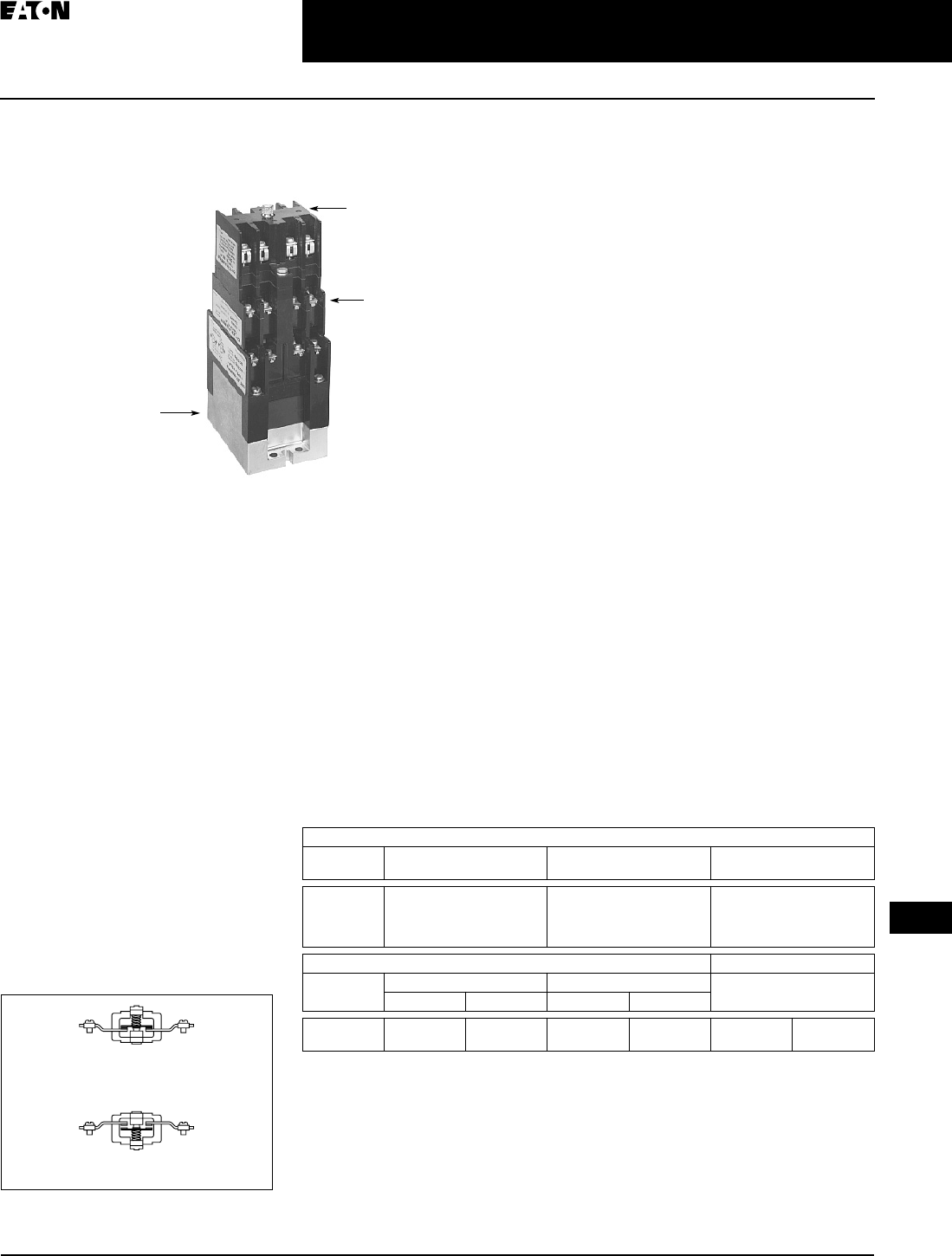
April 2009
CA08102002K07A For more information visit: www.CutlerHammer.ca
3-63
Control Relays & Timers
3
Machine Tool Relays
D26 Series — Type M, 600V AC Multipole with Convertible Contacts
D26 Series — Type M
600V AC Multipole with
Convertible Contacts
Product Description
Relays can be ordered as complete
devices in any pole combination up to a
maximum of 12NO or 8NC and 4 NO
poles, or can be assembled from com-
ponents shown on Pages 3-64 – 3-65.
Relay base assembly (D26MB) will
accept from 1 to 4 rear poles (D26MPR,
D26MPS and/or D26MPL).
Adding a front deck, the total number
of poles can be increased to 8, all con-
vertible NO to NC.
Adding a D26MF, 4-pole fixed NO
attachment, builds a 12-pole relay with
8 convertible poles and 4 fixed NO
poles.
Relays with mechanical latch are avail-
able in any convertible pole combina-
tion up to eight poles maximum.
To obtain overlapping contacts, use
D26MPS (NO early closing) and
D26MPL (NC late opening) rear poles,
in related circuits.
Figure 3-92. Mechanical Latch
Relay Base
Assembly D26MB
D26MD10 Front Deck,
D26MF Front Attachment,
Pneumatic Timer, Solid-
State Timer or Mechanical
Latch
D26MF Front
Attachment,
Solid-State Timer
Attachments or
Mechanical Latch
Relay Component Parts Location
Normally Closed
Contact
Normally Open
Contact
Contact poles D26MPR and D26MPF in
2- through 8-pole relays are convert-
ible NO to NC or vice versa. Simply
reverse the terminal screws and rotate
the unit pole 180° (in either direction).
Standards and Certifications
■UL Listed — Class No. NKCR2,
File E1230(N).
■CSA Certified — File LR353
Technical Data and Specifications
Table 3-93. Specifications
For DC contact ratings, see Page 3-66.
Contact Ratings (Amperes) A600
AC Volts Make and Emergency
Interrupting Capacity
Break Continuous
Thermal Rating
120
240
480
600
60
30
15
12
6
3
1.5
1.2
10
10
10
10
Coil Power Operating Time
Relay Watts VA Milliseconds
Inrush Sealed Inrush Sealed
2- to 12-Pole
Latch Coil
95.0
18.5
9
11
155
41
22
17
Pick-Up
Drop-Out
6 – 13
8 – 26
TAB49.BOO Page 63 Thursday, March 5, 2009 7:36 PM
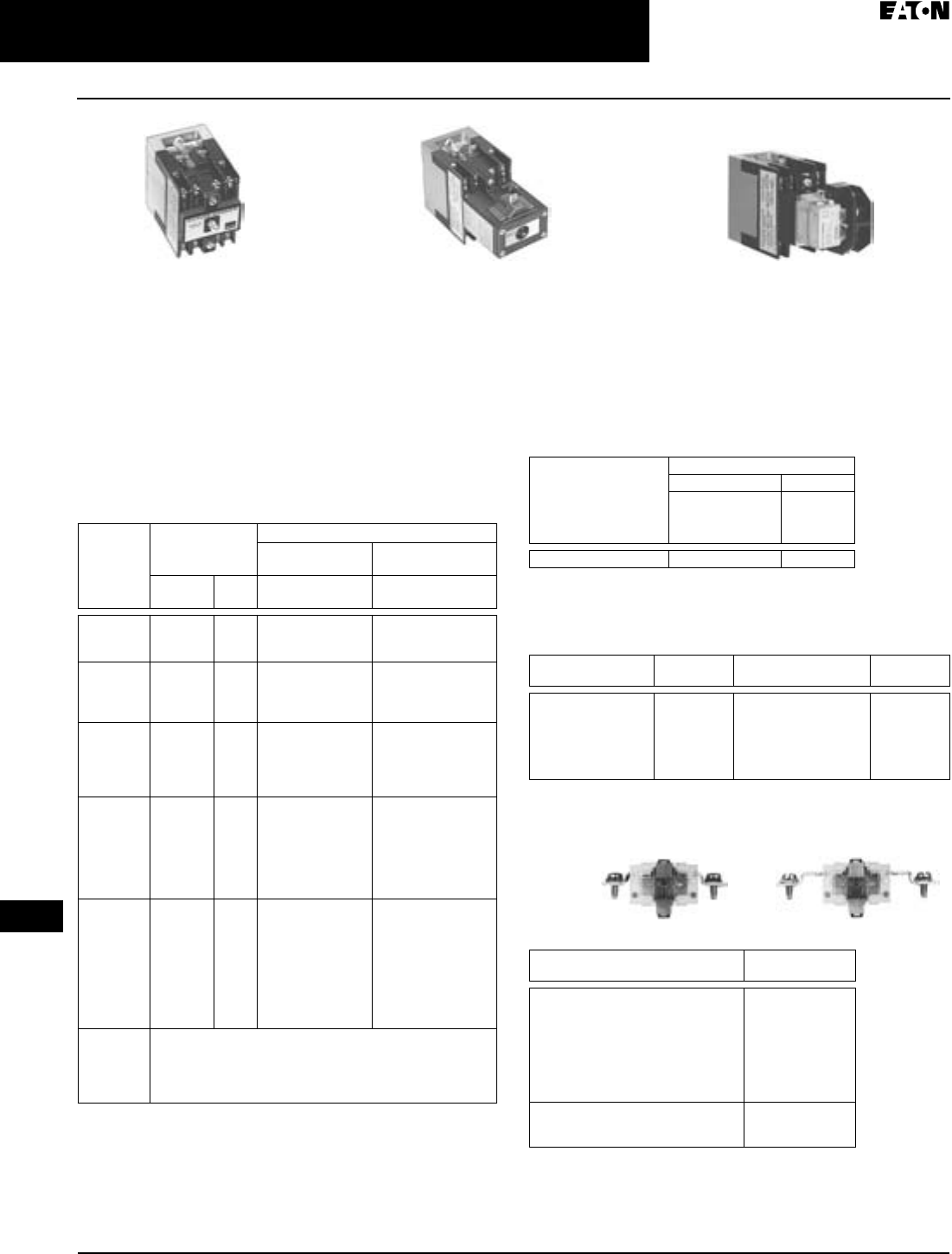
April 2009
3-64
For more information visit: www.CutlerHammer.ca CA08102002K07A
Control Relays & Timers
3
Machine Tool Relays
D26 Series — Type M, 600V AC Multipole with Convertible Contacts
Product Selection — Relays
When Ordering Specify
■Catalogue Number and Magnet Coil Suffix Letter.
■Example: For a 4-pole relay having 4NO contacts, order
Catalogue Number D26MR40, with a 120V, 60 Hz coil,
order D26MR40A.
■For fast delivery and minimum inventory, it is recom-
mended that component parts or complete relays with NO
poles be ordered.
Table 3-94. Complete AC Relays
Relay with Pneumatic Timer Attachment Factory
Installed (without Relay Contacts)
The relays listed below will accept up to four Catalogue Num-
ber D26MPR contacts (convertible — NO or NC) for instanta-
neous operation. Order contacts separately. For additional
information on timer attachment, see Page 3-65.
Table 3-95. Relay with Pneumatic Timer Attachment
Contact Customer Support Centre at 1-800-268-3578 for availability.
For assembly of relays from component parts and relay
accessories, see listing below.
Table 3-96. Magnet Coil Selection Table
Contact Customer Support Centre at 1-800-268-3578 for availability.
Product Selection — Component Parts
Separate Contacts
Table 3-97. Separate Contacts
To obtain overlapping contacts, these two special poles must be used
in related circuits.
4-Pole 4-Pole
with Latch
4-Pole with Pneumatic
Timer Attachment
Number
of
Contacts
Type of
Contacts
Open Type
Relay Only Relay with
Mechanical Latch
NO NC Catalogue
Number
Catalogue
Number
22
1
0
0
1
2
D26MR20
D26MR11
D26MR02
D26MR202
D26MR112
D26MR022
33
2
1
0
0
1
2
3
D26MR30
D26MR21
D26MR12
D26MR03
D26MR302
D26MR212
D26MR122
D26MR032
44
3
2
1
0
0
1
2
3
4
D26MR40
D26MR31
D26MR22
D26MR13
D26MR04
D26MR402
D26MR312
D26MR222
D26MR132
D26MR042
66
5
4
3
2
1
0
0
1
2
3
4
5
6
D26MR60
D26MR51
D26MR42
D26MR33
D26MR24
D26MR15
D26MR06
D26MR602
D26MR512
D26MR422
D26MR332
D26MR242
D26MR152
D26MR062
88
7
6
5
4
3
2
1
0
0
1
2
3
4
5
6
7
8
D26MR80
D26MR71
D26MR62
D26MR53
D26MR44
D26MR35
D26MR26
D26MR17
D26MR08
D26MR802
D26MR712
D26MR622
D26MR532
D26MR442
D26MR352
D26MR262
D26MR172
D26MR082
10 – 12 The 6 and 8 contact relays (without Mechanical Latch only)
listed above can be provided with four additional NO non-
convertible contacts. Add Suffix Number 4 to above listed
Catalogue Number plus Magnet Coil Suffix. Example: For a
12 contact relay, order D26MR804A.
Number of Available
Instantaneous Contact
Positions (Order
Contacts Separately —
Catalogue Number
D26MPR)
Timer Operation
ON Delay OFF Delay
Catalogue
Number
Catalogue
Number
4D26MR005 D26MR006
Volts/Hertz Suffix
Number
Volts/Hertz Suffix
Number
120/60 – 110/50
240/60 – 220/50
208/60
24/60
277/60
A
B
E
T
H
32/60
12/60
6/60
380/50
480/60 or 440/50
600/60 or 550/50
V
R
P
L
C
D
Description Catalogue
Number
Convertible Contacts
Rear Pole – NO
Rear Pole – NC
Front Pole – NO
Front Pole – NC
Gold Plated (for low power circuits)
Rear Pole – NO
Front Pole – NO
D26MPR
D26MPR02
D26MPF
D26MPF02
D26MPR03
D26MPF03
Non-convertible Contacts
Rear Pole NO Early Closing
Rear Pole NC Late Opening
D26MPS
D26MPL
Replacement Coils. . . . . . . . . . . . . . . . . . Page A-3
Dimensions . . . . . . . . . . . . . . . . . . . . . . . . Page 3-66
Front Pole Rear Pole
TAB49.BOO Page 64 Thursday, March 5, 2009 7:36 PM
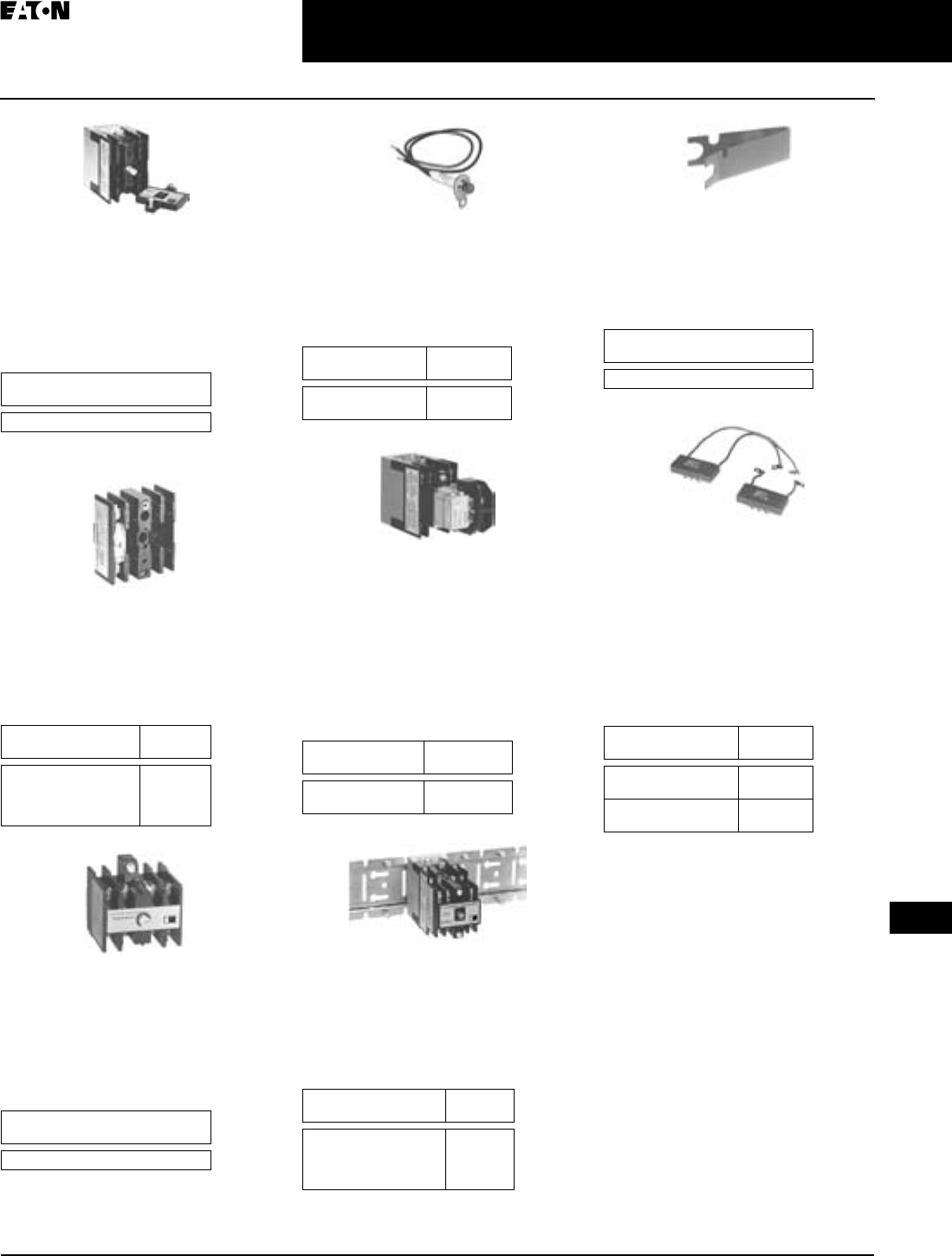
April 2009
CA08102002K07A For more information visit: www.CutlerHammer.ca
3-65
Control Relays & Timers
3
Machine Tool Relays
D26 Series — Type M, 600V AC Multipole with Convertible Contacts
Relay Base Assembly
(without Poles)
Basic 4-pole D26 relay without con-
tacts. Provision for adding one to four
poles as needed, D26MPR, D26MPL
and/or D26MPS rear pole type.
Table 3-98. Relay Base Assembly
Add Magnet Coil Suffix letter, see Page 3-64.
Example: D26MBA.
Front Deck
(Convertible Contact Poles)
Provides up to 4 additional front pole
type D26MPF contacts. Convertible,
NO to NC.
Table 3-99. Front Deck
Four-Pole Front Attachment
(4NO Fixed Circuit)
Can be added to any 2- to 8-pole Type
M, D26 relay to provide up to a 12-pole
relay. Four NO, non-convertible con-
tacts are included in this assembly.
Table 3-100. Four-Pole Front Attachment
Relay State Indicating Light
Light provided with leads and bracket
for mounting on 2- to 12-pole relays.
May be used to monitor state of mag-
net coil or relay contact operation.
Table 3-101. Relay State Indicating Light
Pneumatic Timer Attachment
Attachment mounts on any 0- to 4-pole
D26 relay without latch. Timer unit has
DPDT timed contacts (circuits in each
pole must be the same polarity).
Adjustable timing range — 0.1 to 180
seconds, repeat accuracy ±10%. Units
are convertible from OFF delay to ON
delay or vice versa.
Table 3-102. Pneumatic Timer Attachment
Mounting Channel
Pre-spaced mounting for adjacent
relay installation. Indexed for cutting
to desired length. Captive mounting
screws provided in channel for easier
installation.
Table 3-103. Mounting Channel
Note: See Dimensions on Page 3-67.
Manual Test Accessory
Tool to manually hold relays in the
energized position for circuitry testing
on completed panel. (10 per box, order
in multiples of 10.)
Table 3-104. Manual Test Accessory
Transient Suppressor
May be mounted on any 120V AC relay
magnet coil or latch coil or 120V DC
latch coil — connects directly across
coil terminals. All DC magnet coils
have a built-in varistor for transient
suppression. Limits high voltage tran-
sients produced in the circuit when
power is removed from the coil.
Table 3-105. Transient Suppressor
Catalogue
Number
D26MB
Description Catalogue
Number
Front Deck with:
1NO Contact Pole
2NO Contact Poles
4NO Contact Poles
D26MD10
D26MD20
D26MD40
Catalogue
Number
D26MF
Description Catalogue
Number
120V AC, 50/60 Hz
240V AC, 50/60 Hz
D26MAP120
D26MAP240
Description Catalogue
Number
ON Delay
OFF Delay
D26MTE
D26MTD
Description Catalogue
Number
10" Length for 4 Relays
20" Length for 8 Relays
30" Length for 12 Relays
40" Length for 16 Relays
D26MC4
D26MC8
D26MC12
D26MC16
Catalogue
Number
D26MTA
Description Catalogue
Number
Magnet Coil
Transient Suppressor
D26MAS1
Latch Coil Transient
Suppressor
D26MAS2
TAB49.BOO Page 65 Thursday, March 5, 2009 7:36 PM
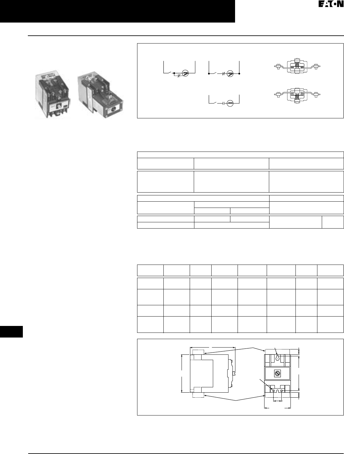
April 2009
3-66
For more information visit: www.CutlerHammer.ca CA08102002K07A
Control Relays & Timers
3
Machine Tool Relays
D26 Series — Type M, DC Multipole with Convertible Contacts
D26 Series — Type M
DC Multipole with
Convertible Contacts
Product Description
Type M, DC multipole relays are physi-
cally and mechanically similar to the
(D26) Type M AC relays described on
Page 3-63. They differ only in the elec-
trical ratings and available pole combi-
nations due to the use of a normally
closed late opening, coil clearing con-
tact, factory wired to the pick-up wind-
ing of the magnet coil. (Contact is
shown as L in Figure 3-93.) Magnet coil
has built-in varistor for transient
suppression.
The mechanically latched relay has
one extra contact, normally open early
closing, factory wired in series with
the winding of the intermittent rated
latch coil. (Contact is shown as S in
Figure 3-93.)
Component parts for these relays are
the same as those listed for the (D26)
Type M AC relays on Pages 3-64 and
3-65, except for the Indicating Light
which is not applicable to a DC relay.
Contact poles D26MPR and D26MPF in
2- to 7-pole relays are convertible NO
to NC or vice versa. Simply reverse the
terminal screws and rotate the unit
pole 180° (in either direction).
Latch Operation
With the latch coil de-energized, ener-
gizing the relay coil will pick up the
relay and mechanically latch it in the
pick-up position. With the relay coil
de-energized, energizing the latch coil
will allow the relay to drop out.
3-Pole 3-Pole with Latch Figure 3-93. Latch Operation
Technical Data and Specifications
Table 3-106. Specifications
Contact ratings do not apply to contacts D26MPL and D26MPS. For AC contact ratings,
see Page 3-63.
AC and DC Dimensions
Table 3-107. AC and DC D26 Relays — Approximate Dimensions in Inches (mm) and Shipping Wts.
Figure 3-94. Approximate Relay Dimensions in Inches (mm)
Contact Ratings (Amperes)
DC Volts Inductive
Make/Break
Resistive
Make/Break
28
48
120
240
7. 0
2.5
1.1
0.2
10.0
10.0
2.0
0.4
LS1
LS1
LS1 L
S
DC Input DC Input
DC Type M Relay DC Type M Relay
with Latch
Pick-Up
Pick-Up
L = NC Late OpeningL = NC Late Opening
S = NO Early Closing
Relay
Coil
Latch
Coil
Hold
(Not Used)
Release
Convertible Contacts
Normally Closed
Contact
Normally Open
Contact
Coil Power Operating Time
Relay Watts Average
Milliseconds
Inrush Sealed
2 – 11 Poles 168 13.2 Pick-Up
Drop-Out
10
16
Latch Coil 21.6 Intermittent
AC Relay
D26
DC Relay
D26
Dim. A Ship. Wt.
Lbs. (kg)
AC Relay
D26
DC Relay
D26
Dim. A Ship. Wt.
Lbs. (kg)
1 – 4 Poles 1 – 3 Poles 4.00
(101.6)
2.5 (1.1) 5 – 8 Poles 4 – 7 Poles 5.25
(133.4)
2.8 (1.3)
1 – 4 Poles
with Timer
D26 or D87
1 – 3 Poles
with Timer
D26 or D87
6.00
(152.4)
3.3 (1.5) 5 – 8 Poles
with Timer
D87
4 – 7 Poles
with Timer
D87
7.25
(184.2)
3.5 (1.6)
1 – 4 Poles
with Latch
1 – 2 Poles
with Latch
6.13
(155.7)
3.5 (1.6) 5 – 8 Poles
with Latch
3 – 6 Poles
with Latch
7.31
(185.7)
3.8 (1.7)
1 – 4 Poles
with
D26MF
1 – 3 Poles
with
D26MF
5.81
(147.6)
2.8 (1.3) 9 – 12 Poles 8 – 11 Poles 7.00
(177.8)
3.0 (1.4)
2.38 (60.5)
Max.
D26MAS2
D26MAS1
0.75
(19.1)
3.13
(79.5)
0.44
(11.2)
0.44
(11.2)
3.5
(88.9)
A
1 Slot
#10 Screw
2 Holes
#10 Screw
TAB49.BOO Page 66 Thursday, March 5, 2009 7:36 PM
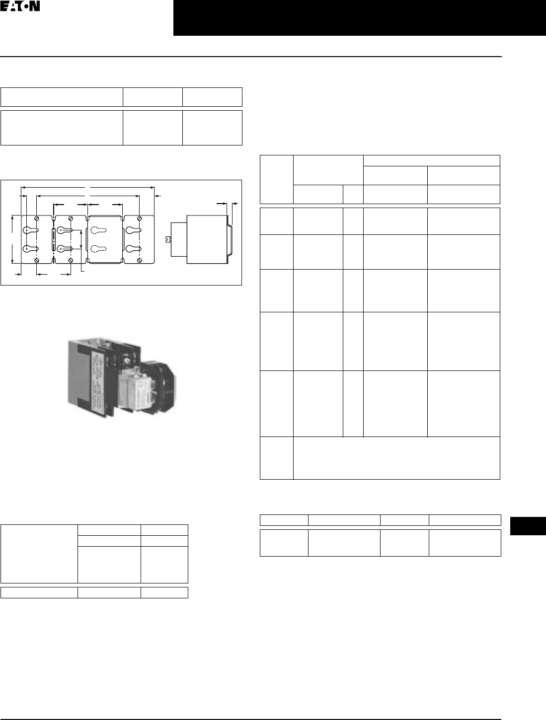
April 2009
CA08102002K07A For more information visit: www.CutlerHammer.ca
3-67
Control Relays & Timers
3
Machine Tool Relays
D26 Series — Type M, DC Multipole with Convertible Contacts
Table 3-108. Approximate Mounting Channel Dimensions in
Inches (mm)
Note: Channel mounts through keyholes with #10 screws (two each
end and one every fourth relay). Relays mount with screws captive in
channel. All screws must be tightened firmly.
Figure 3-95. Approximate Mounting Channel Dimensions in
Inches (mm)
Product Selection
Relay with Pneumatic Timer Attachment Factory
Installed (without Relay Contacts)
The relays listed below will accept up to three Catalogue
Number D26MPR contacts (convertible — NO or NC) for
instantaneous operation. Order contacts separately. For
additional information on timer attachment, see Page 3-65.
Table 3-109. Relay with Pneumatic Timer Attachment
Complete DC Relays
When Ordering Specify
■Catalogue Number and Magnet Coil Suffix letter.
■Example: For a 4-pole relay having 4NO contacts, order
Catalogue Number D26MRD40, with a 120V DC coil, order
D26MRD40A1.
Table 3-110. Complete DC Relays
Relay has additional factory wired normally closed coil clearing contact
(see diagram).
Table 3-111. Magnet Coil Selection
Catalogue
Number
A Dim. B Dim.
D26MC16
D26MC12
D26MC8
D26MC4
40 (1016)
30 (762)
20 (508)
10 (254)
37.5 (952.5)
27.5 (698.5)
17.5 (444.5)
7.5 (190.5)
Number of Available
Instantaneous
Contact Positions
(Order Contacts
Separately —
Catalogue Number
D26MPR)
Timer Operation
ON Delay OFF Delay
Catalogue
Number
Catalogue
Number
3D26MRD005 D26MRD006
2.5
(63.5)
2.5
(63.5) 2.38
(60.5)
B
0.69
(17.5) 1.0 6
(26.9)
A
1.25
(31.8)
3.63
(92.2)
1.38
(35.1)
0.38
(9.7)
Typ e
M
Relay
D26
3-Pole with Timer Attachment
Number
of
Contacts
Type of Contacts Open Type
Relay Only Relay with
Mechanical Latch
NO NC Catalogue
Number
Catalogue
Number
22
1
0
0
1
2
D26MRD20
D26MRD11
D26MRD02
D26MRD202
D26MRD112
D26MRD022
33
2
1
0
0
1
2
3
D26MRD30
D26MRD21
D26MRD12
D26MRD03
D26MRD302
D26MRD212
D26MRD122
D26MRD032
44
3
2
1
0
0
1
2
3
4
D26MRD40
D26MRD31
D26MRD22
D26MRD13
D26MRD04
D26MRD402
D26MRD312
D26MRD222
D26MRD132
D26MRD042
66
5
4
3
2
1
0
0
1
2
3
4
5
6
D26MRD60
D26MRD51
D26MRD42
D26MRD33
D26MRD24
D26MRD15
D26MRD06
D26MRD602
D26MRD512
D26MRD422
D26MRD332
D26MRD242
D26MRD152
D26MRD062
77
6
5
4
3
2
1
0
0
1
2
3
4
5
6
7
D26MRD70
D26MRD61
D26MRD52
D26MRD43
D26MRD34
D26MRD25
D26MRD16
D26MRD07
—
—
—
—
—
—
—
—
10 – 11 The 6 and 7 contact relays (without Mechanical Latch only)
listed above can be provided with four additional NO non-
convertible contacts. Add Suffix Number 4 to above listed Cata-
logue Number plus Magnet Coil Suffix. Example: For an 11 con-
tact relay, order D26MRD704A1.
Volts DC Suffix Number Volts DC Suffix Number
12
24
48
R1
T1
W1
120
240
A1
B1
Replacement Coils . . . . . . . . . . Page A-3
Components . . . . . . . . . . . . . . . . Pages 3-64, 3-65
TAB49.BOO Page 67 Thursday, March 5, 2009 7:36 PM
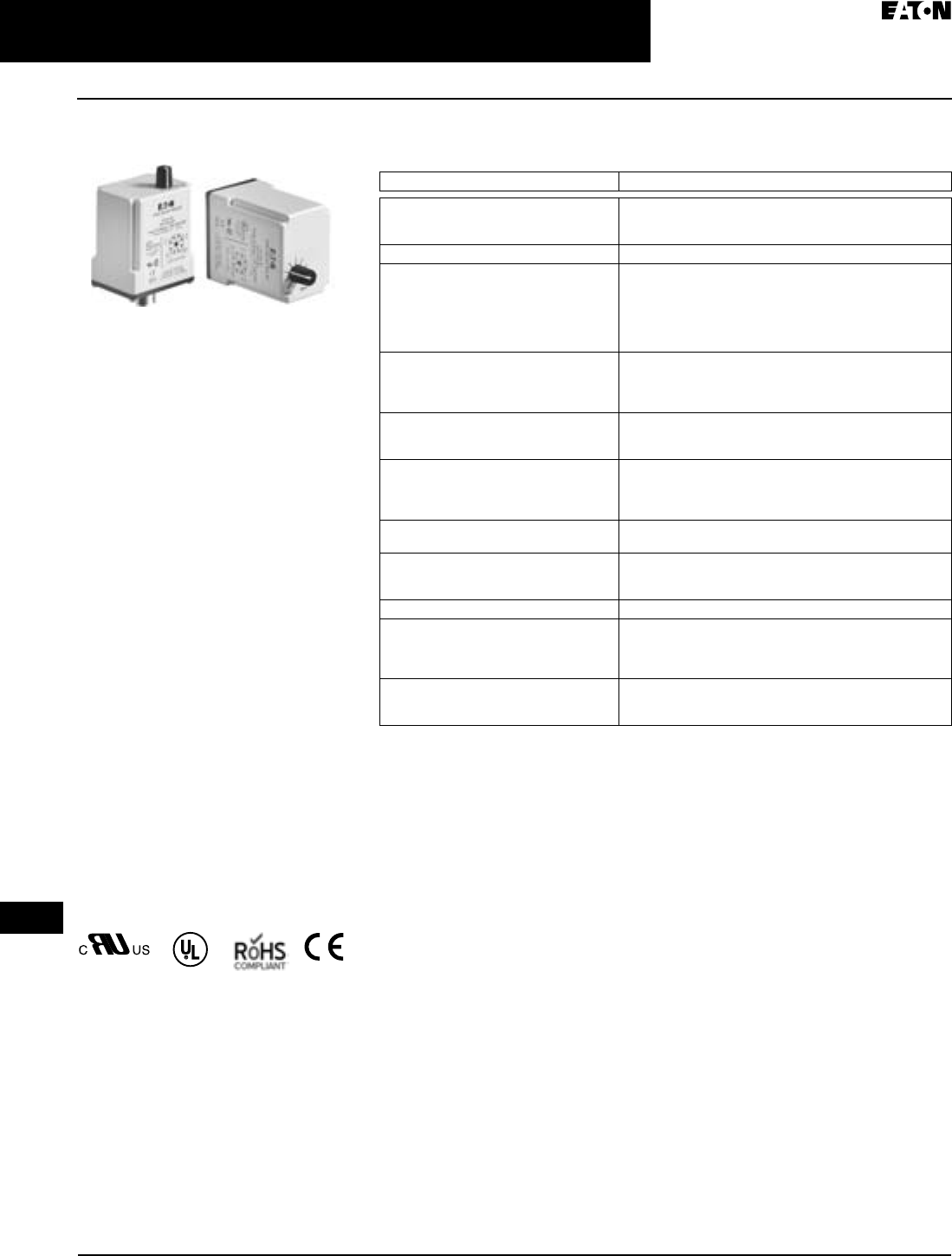
April 2009
3-68
For more information visit: www.EatonCanada.ca CA08102002K07A
Control Relays & Timers
3
Timing Relays
TMR5 Series
TMR5 Series
Product Description
The TMR5 Series Time Delay Relays
are designed for a broad range of
OEM applications. The TMR5 Series
offers non-programmable plug-in
style timers with a variety of functions
available. Each unit offers a single
function and single input voltage, and
operates over a defined time delay
range. Units with fixed time delays
are also available. Eaton also offers
customization capabilities for these
timers — remote adjustments, special
pin configurations, and more. Contact
us to discuss your specific application
and design of a custom timer.
Features
■Single timing range for each unit
■Ranges available from 0.02 sec to
24 hours
■Wide variety of functions available
■Plugs in to standard 8- or 11-Pin
socket
■10A DPDT output contacts
■Can be easily customized to meet
your needs
Standards and Certifications
TMR5 Time Delay Relays
with Eaton
socket
Technical Data and Specifications
Table 3-112. TMR5 Time Delay Relays — Technical Data
Description Specifications
Voltage Tolerance:
AC Operation
DC Operation
+10/-15% of nominal at 50/60 Hz
+10/-15% of nominal
Load Burden 2 VA
Setting Accuracy:
Maximum Setting (Adjustable)
Minimum Setting (Adjustable)
Fixed Time Delay:
< 2 Seconds
0.1 – 2 Seconds
+5%, -0%
+0%, -50%
+1%
±5%
Repeat Accuracy (constant voltage and
temperature):
> 2 Seconds Delay
0.1 – 2 Seconds Delay
±0.1%
±2%
Reset Time:
On Delay/Interval/Repeat Cycle
Off Delay/Single Shot/Watchdog
0.1 Seconds
0.04 Seconds
Start-Up Time (time from when power is
applied until unit is timing):
120 and 240V Units
12, 24 and 48V Units
0.05 Seconds
0.08 Seconds
Maintain Function Time (time unit contin-
ues to time after power is removed)
0.01 Seconds
Temperature:
12 – 120V Input Voltage
240V Input Voltage
-18° to 150°F (-28° to 65°C)
-18° to 122°F (-28° to 50°C)
Insulation Voltage 2,000V
Output Contacts DPDT 10A @ 240V AC / 30V DC,
1/2 hp @ 120/240V AC (NO contacts)
1/3 hp @ 120/240V AC (NC contacts)
B300 and R300; AC-15 and DC-13
Life:
Mechanical
Full Load
10,000,000 operations
100,000 operations
TAB49.BOO Page 68 Thursday, March 5, 2009 7:36 PM
April 2009
CA08102002K07A For more information visit: www.EatonCanada.ca
3-69
Control Relays & Timers
3
Timing Relays
TMR5 Series
Catalogue Numbering System
Table 3-113. Catalogue Numbering System — TMR5 Time Delay Relays
For more information on each operational mode, see Pages 3-70 and
3-71.
Indicates DUAL knob unit. All dual knob units can have independently
selectable and adjustable ON and OFF times. If different ON and OFF
times are desired, add two codes for time ranges in the part number.
The first code listed indicates the first timing range of the unit (OFF
time for R, ON time for Y) and the second code indicates the second
timing range (ON time for R, OFF Time for Y).
Any time range can be created as a custom unit. Contact Eaton for
details.
Fixed Time Delay settings are available for orders of 50 pieces
or more. Contact Customer Support Centre for additional information
at 1-800-268-3578.
Product Selection
When Ordering Specify
■Catalogue Number of Timing Relay
Table 3-114. Product Selection — TMR5 Time Delay Relays
All configurations from Catalogue Numbering System are
available.
Accessories
Table 3-115. Accessories for Use with TMR5 Time Delay Relays
T M R 5 N 0 5 1 2 0
Timing Range
03 = 0.02 – 2 sec
05 = 0.1 – 10 sec
08 = 0.6 – 60 sec
12 = 3 – 300 sec
15 = 0.3 – 30 min
16 = 0.6 – 60 min
20 = 4.8 min – 8 hr
22 = 6 sec – 10 min
23 = 14.4 min – 24 hr
Input Voltage
120 = 120V AC/DC
12 = 12V AC/DC
24 = 24V AC/DC
240 = 240V AC/DC
Operational Mode
8-Pin Octal Sockets
N= ON Delay
T= Interval ON
L= Flasher
R = Repeat Cycle
(OFF Time First
Followed by ON Time
and Repeating)
Y = Repeat Cycle
(On Time First
Followed by OFF Time
and Repeating)
11-Pin Octal Sockets
F= OFF Delay, Control
Switch Trigger
C= Single Shot, Control
Switch Trigger
W= Watchdog, Control
Switch Trigger
(Retriggerable Single
Shot)
P= OFF Delay, Power
Trigger
G= Single Shot, Power
Trigger
D= Watchdog, Power
Trigger (Regrigger-
able Single Shot)
Family Type
TMR5
Input
Voltage
Socket Timing
Range
Catalogue
Number
ON Delay
120V AC/DC 8-Pin 0.1 – 10 sec TMR5N05120
120V AC/DC 0.6 – 60 sec TMR5N08120
24V AC/DC 0.1 – 10 sec TMR5N0524
24V AC/DC 0.6 – 60 sec TMR5N0824
OFF Delay, Control Switch Trigger
120V AC/DC 11-Pin 0.1 – 10 sec TMR5F05120
120V AC/DC 0.6 – 60 sec TMR5F08120
24V AC/DC 0.1 – 10 sec TMR5F0524
24V AC/DC 0.6 – 60 sec TMR5F0824
Interval ON
120V AC/DC 8-Pin 0.1 – 10 sec TMR5T05120
120V AC/DC 0.6 – 60 sec TMR5T08120
24V AC/DC 0.1 – 10 sec TMR5T0524
24V AC/DC 0.6 – 60 sec TMR5T0824
Single Shot, Control Switch Trigger
120V AC/DC 11-Pin 0.1 – 10 sec TMR5C05120
120V AC/DC 0.6 – 60 sec TMR5C08120
24V AC/DC 0.1 – 10 sec TMR5C0524
24V AC/DC 0.6 – 60 sec TMR5C0824
Repeat Cycle (OFF Time First Followed by ON Time and Repeating)
120V AC/DC 8-Pin 0.1 – 10 sec TMR5R05120
120V AC/DC 0.6 – 60 sec TMR5R08120
24V AC/DC 0.1 – 10 sec TMR5R0524
24V AC/DC 0.6 – 60 sec TMR5R0824
Repeat Cycle (ON Time First Followed by OFF Time and Repeating)
120V AC/DC 8-Pin 0.1 – 10 sec TMR5Y05120
120V AC/DC 0.6 – 60 sec TMR5Y08120
24V AC/DC 0.1 – 10 sec TMR5Y0524
24V AC/DC 0.6 – 60 sec TMR5Y0824
Description Standard
Pack
Catalogue
Number
8-Pin Socket 10 D3PA2
11-Pin Socket 10 D3PA3-A2
Hold Down Spring 10 D65CHDS
TAB49.BOO Page 69 Thursday, March 5, 2009 7:36 PM
April 2009
3-70
For more information visit: www.EatonCanada.ca CA08102002K07A
Control Relays & Timers
3
Timing Relays
TMR5 Series
Operation
Figure 3-95. Operational Figures (1 of 2)
Function Operation Timing Chart
Delay
On
On
Off
Off
Input
Power
(Voltage)
Output
(Load)
Reset
Delay
On
On
Off
Off
Input
Power
(Voltage)
Output
(Load)
Reset
DelayDelayDelay
On
On
Off
Closed
Open
Off
Input
Power
(Voltage)
Output
(Load)
Trigger
Signal
DelayDelay
On
On
Off
Closed
Open
Off
Input
Power
(Voltage)
Output
(Load)
Trigger
Signal
Upon application of input
voltage, the time delay relay is
ready to accept trigger signals.
Upon application of the trigger
signal, the relay is energized.
Upon release of the trigger
signal, the preset time begins.
At the end of the preset time, the
relay is de-energized. Any
application of the trigger signal
during the preset time will keep
the relay energized and reset the
time delay.
Upon application of input voltage, the relay is
energized and the preset time begins. At the end
of the preset time, the relay is de-energized. Input
voltage must be removed and reapplied to reset
the time delay.
Upon application of input voltage, the preset time
begins. At the end of the preset time, the relay is
energized. Input voltage must be removed and
reapplied to reset the time delay and de-energize the
relay.
Upon application of input
voltage, the time delay
relay is ready to accept trigger
signals. Upon application of the
trigger signal, the relay is
energized and the preset time
begins. During the preset time,
the trigger signal is ignored.
The time delay relay is reset by
applying the trigger signal
when the relay is not energized.
ON-Delay
Delay on Operate
Delay on Make
Interval ON
Interval
OFF-Delay
Delay on Release
Delay on
De-energization
Delay on Drop-Out
Single Shot
One Shot
Momentary
Interval
TAB49.BOO Page 70 Thursday, March 5, 2009 7:36 PM

April 2009
CA08102002K07A For more information visit: www.EatonCanada.ca
3-71
Control Relays & Timers
3
Timing Relays
TMR5 Series
Figure 3-96. Operational Figures (2 of 2)
Timing ChartOperationFunction
Watchdog
Retriggerable
Single Shot
Upon application of input voltage, the time
delay relay is ready to accept trigger
signals. Upon application of the trigger
signal, the relay is energized and the preset
time begins. At the end of the preset time,
the relay is de-energized unless the trigger
signal is closed and opened prior to time
out (before preset time elapses).
Continuous cycling of the trigger signal at
a rate faster than the preset time will cause
the relay to remain energized.
Upon application of input voltage, the preset time (T1) begins.
At the end of the preset time, the relay is energized and remains in
that condition for the preset time (T1). At the end of this time, the
relay is de-energized and the sequence repeats until input voltage
is removed.
Upon application of input voltage, a preset delay begins (OFF).
At the end of the preset delay, the relay is energized and remains
in that condition for a second, independently adjustable preset
time (ON). At the end of this time, the relay is de-energized and
the sequence repeats until input voltage is removed.
Upon application of input voltage, the relay is energized and a
preset delay begins (ON). At the end of the preset delay, the relay
is de-energized and remains in that condition for a second,
independently adjustable preset time (OFF). At the end of this
time, the relay is energized and the sequence repeats until input
voltage is removed.
Repeat Cycle
OFF/ON Delay
Flasher
Repeat Cycle
ON/OFF Delay
On
On
Off
Off
Input
Power
(Voltage)
Output
(Load)
Reset
Action Continues Until
Power Is Removed
T1 T1 T1 T1
On
On
Off
Off
Input
Power
(Voltage)
Output
(Load)
Reset
Action Continues Until
Power Is Removed
Off On Off On
On
On
Off
Off
Input
Power
(Voltage)
Output
(Load)
Reset
Action Continues Until
Power Is Removed
OffOn OffOn
DelayDelay
On
On
Off
Closed
Open
Off
Input
Power
(Voltage)
Relay
Output
(Load)
Trigger
Signal
TAB49.BOO Page 71 Thursday, March 5, 2009 7:36 PM
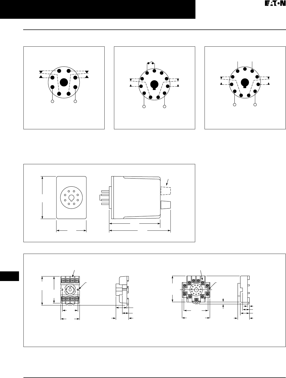
April 2009
3-72
For more information visit: www.EatonCanada.ca CA08102002K07A
Control Relays & Timers
3
Timing Relays
TMR5 Series
Wiring Diagrams
Figure 3-97. Wiring for 8-Pin Units Figure 3-98. Wiring for 11-Pin Control Switch
Trigger Units
Figure 3-99. Wiring for 11-Pin Power Trigger
Units
Dimensions
Figure 3-100. TMR5 Approximate Dimensions in Inches (mm)
Figure 3-101. D3PA2 and D3PA3 Sockets — Approximate Dimensions in Inches (mm)
1
(DC)+
L1
−(DC)
L2
8
Input Voltage
4
36
27
5
1
(DC)+
L1
(DC)−
L2
11
Input Voltage
Control
Switch
48
39
6
210
75
1
(DC)+
L1
(DC)−
L2
−+
11
Input Voltage
* Should Be Same Voltage
as Input Voltage
Power
Trigger *
48
39
6
210
75
2.4
(60)
1.7
(43)
2.9
(74) 3.5
(89)
Dual Knob
Only
0.97
(24.6)
Max.
0.82 (20.8)
0.58 (14.7)
2.03
(51.4)
Two 0.165
(4.2) Dia.
Slots
2.14
(54.3)
1.60
(40.5)
Max.
1.30
(32.9)
6-32 x 0.312 Combination
Head Screw and Pressure Clamping Plate
(8 Places)
Tolerances: ± 0.010
± (0.25)
Unless Otherwise Shown
6-32 x 0.312 Combination
Head Screw and Pressure Clamp
(11 Places)
2.05
(52.07)
Max.
2.33 (59.1)
Max.
2.06
(52.3)
0.97
(24.6)
0.77 (19.6)
0.58 (14.7)
0.15 (3.6)
0.125 – 0.156
(3.17 – 3.96))
Two 0.17
(4.3) Dia.
Holes
Tolerances: ± 0.010
± (0.25)
Unless Otherwise Shown
D3PA2 D3PA3
TAB49.BOO Page 72 Thursday, March 5, 2009 7:36 PM
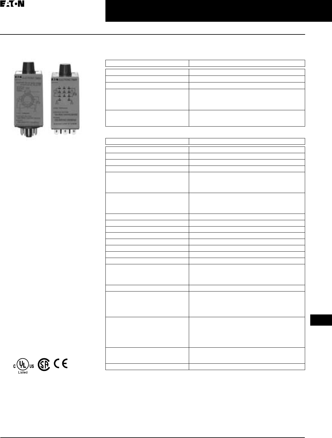
April 2009
CA08102002K07A For more information visit: www.EatonCanada.ca
3-73
Control Relays & Timers
3
Timing Relays
TR Series
TR Series
Product Description
The upgraded TR Series Timing Relays
are designed to meet most timing
requirements by offering more flexi-
bility in range of input voltage, timing
range and functionality. Use a rotary
switch to choose from 20 selectable
time ranges from 0.1 second to 600
hours. We offer both a power trig-
gered and signal triggered model —
each with expanded operation modes.
There is a green LED to indicate when
power is ON and an orange LED when
output is ON.
Features
■20 time ranges and 10 timing
functions
■Time delays from 0.1 sec to 600 hrs.
■Space-saving, compact package
■High repeat accuracy of ± 0.2%
■LED indication
■Standard 8- or 11-Pin and 11-blade
termination
■2 Form C DPDT delayed output
contacts
■10A Contact Rating
Standards and Certifications
TR Timing Relays
TUV
Technical Data and Specifications
Table 3-116. Contact Ratings
Table 3-117. General Specifications
For the value of the error against a preset time, whichever value is larger should apply.
Item Specification
Contact Configuration 2 Form C, DPDT (Delayed Output)
Allowable Voltage/Current 240V AC, 30V DC/10A
Max. Permissible Operating Frequency 1800 cycles per hour
Rated Load —
Resistive
Inductive
Horsepower Rating
10A, 240V AC / 30V DC
7A, 240V AC / 30V DC
1/6 hp 120V AC, 1/3 hp 240V AC
Life —
Electrical
Mechanical
500,000 operations min. (resistive)
50,000,000 operations minimum
Item Specification
Operation System Solid-State CMOS Circuit
Time Range 0.1 sec to 600 hours
Pollution Degree 2 (IE60664-1)
Overvoltage Category III (IE60664-1)
Rated Operational Voltage
240AC
24AC
12DC
100 – 240V AC (50/60 Hz)
24V AC (50/60 Hz)/24V DC
12V DC
Voltage Tolerance
240AC
24AC
12DC
85 – 264V AC (50/60 Hz)
20.4 – 26.4V AC (50/60 Hz)/21.6 – 26.4V DC
10.8 – 13.2V DC
Input OFF Voltage Rated Voltage x 10% Minimum
Ambient Operating Temperature -4 – 149°F (-20 – 65°C)
Reset Time 100 mS maximum
Repeat Error ± 0.2%, ± 20 mS
Voltage Error ± 0.2%, ± 20 mS
Temperature Error ± 0.5%, ± 20 mS
Setting Error ± 10% maximum
Insulation Resistance 100M ohm minimum (500V DC)
Dielectric Strength
Between power and output terminals
Between contacts of different poles
Between contacts of same pole
2000V AC, 1 minute
2000V AC, 1 minute
1000V AC, 1 minute
Vibration Resistance 10 – 55 Hz amplitude 0.5 mm; 2 hrs in each of 3 axes
Shock Resistance
Operating extremes
Damage limits —
TRNP, TRFP
TRNB, TRFB
10G
40G (3x in each of 3 axes)
10G (3x in each of 3 axes)
Power Consumption (Approx.)
240AC
120V AC / 60 Hz
240V AC / 60 Hz
24AC (AC/DC)
12DC
6.5 VA TRNP, TRNB/6.6 VA TRFP, TRFB
11.6 VA TRNP, TRNB/12.1 VA TRFP, TRFB
3.4 VA – 1.7W TRNP, TRNB/3.5 VA – 1.7W TRFP, TRFB
1.6W
Dimensions
TRNP, TRFP
TRNB, TRFB
1.58H x 1.42W x 3.07D in. (40H x 36W x 77.9D mm)
1.58H x 1.42W x 2.95D in. (40H x 36W x 74.9D mm)
Weight TRNP — 87g; TRFP — 89g; TRNB, TRFB — 85g
TAB49.BOO Page 73 Thursday, March 5, 2009 7:36 PM
April 2009
3-74
For more information visit: www.EatonCanada.ca CA08102002K07A
Control Relays & Timers
3
Timing Relays
TR Series
Operation
Figure 3-102. Operational Figures (1 of 2)
Operation
TRNP, TRNB
Internal Connections
Set Time TT
A: ON-Delay 1 (Power Start)
Set timer for desired delay, apply power to coil. Contacts transfer after
preset time has elapsed, and remain in transferred position until timer
is reset. Reset occurs with removal of power.
Terminal No. OperationItem
(1) 2-7
(2) A-B
(NC)
(1) 1-4, 5-8
(2) 1-7, 3-9
(NO)
(1) 1-3, 6-8
(2) 4-7, 6-9
OUT
PWR
Delayed
Contact
Power
Indicator
Set Time
Terminal No.Item
(1) 2-7
(2) A-B
(NC)
(1) 1-4, 5-8
(2) 1-7, 3-9
(NO)
(1) 1-3, 6-8
(2) 4-7, 6-9
OUT
PWR
Delayed
Contact
Power
Indicator
Set Time
Terminal No.Item
(1) 2-7
(2) A-B
(NC)
(1) 1-4, 5-8
(2) 1-7, 3-9
(NO)
(1) 1-3, 6-8
(2) 4-7, 6-9
OUT
PWR
Delayed
Contact
Power
Indicator
B: Interval (Power Start)
Set timer for desired delay, apply power to coil. Contacts transfer
immediately, and return to original position after preset time has
elapsed. Reset occurs with removal of power.
C: Cycle 1 (Power Start, OFF First)
Set timer for desired delay, apply power to coil. First transfer of
contacts occurs after preset delay has elapsed, after the next elapse of
preset delay contacts return to original position. The timer now cycles
between on and off as long as power is applied (Duty Ratio 1:1).
Operation
TT
Set Time
Terminal No.Item
(1) 2-7
(2) A-B
(NC)
(1) 1-4, 5-8
(2) 1-7, 3-9
(NO)
(1) 1-3, 6-8
(2) 4-7, 6-9
OUT
PWR
Delayed
Contact
Power
Indicator
Operation
TT
D: Cycle 3 (Power Start, ON First)
Functions in same manner as Mode C, with the exception that first
transfer of contacts occurs as soon as power is applied. The ratio is 1:1.
Time On = Time Off.
Note: T=Set Time, Ta=Shorter Than Set Time,
(
1):TRNP, (2): TRNB, (A): TRFP, (B): TRFB
2
36
7
45
18
(
˜
/
-
)(
˜
/+)
1
(
˜
/
-
)
23
456
789
AB
(
˜
/+)
TRNBTRNP
TAB49.BOO Page 74 Thursday, March 5, 2009 7:36 PM
April 2009
CA08102002K07A For more information visit: www.EatonCanada.ca
3-75
Control Relays & Timers
3
Timing Relays
TR Series
Figure 3-103. Operational Figures (2 of 2)
Operation
TRFP, TRFB
Set Time
A: ON-Delay 2 (Signal Start)
When a preset time has elapsed after the start input turned on while
power is on, the NO output contact goes on.
Terminal No. OperationItem
(A) 2-10
(B) A-B
(NC)
(A) 1-4, 8-11
(B) 1-7, 3-9
(NO)
(A) 1-3, 9-11
(B) 4-7, 6-9
OUT
PWR
Delayed
Contact
Power
Indicator
Set Time
Terminal No.Item
(A) 2-10
(B) A-B
(NC)
(A) 1-4, 8-11
(B) 1-7, 3-9
(NO)
(A) 1-3, 9-11
(B) 4-7, 6-9
OUT
PWR
Delayed
Contact
Power
Indicator
(A) 5-6
(B) 2-5
Start
(A) 5-6
(B) 2-5
Start
B: Cycle 2 (Signal Start, OFF First)
When the start input turns on while power is on, the output oscillates
at a preset cycle (Duty Ratio 1:1), starting while the NO contact off.
C: Cycle 4 (Signal Start, ON First)
When the start input turns on while power is on the NO contact goes
on. The output oscillates at a preset cycle (Duty Ratio 1:1).
D: Signal ON/OFF-Delay
When the start input turns on while power is on, the NO output contact
goes on. When a preset time has elapsed while the start input remains
on, the output contact goes off. When the start input turns off, the NO
contact goes on again. When a preset time has elapsed after the start
input turned off, the NO contact goes off.
TTaTa
TTTTTTTTT
Ta
TTTTTTTT
Operation
Set Time
Terminal No. OperationItem
(A) 2-10
(B) A-B
(NC)
(A) 1-4, 8-11
(B) 1-7, 3-9
(NO)
(A) 1-3, 9-11
(B) 4-7, 6-9
OUT
PWR
Delayed
Contact
Power
Indicator
Set Time
Terminal No.Item
(A) 2-10
(B) A-B
(NC)
(A) 1-4, 8-11
(B) 1-7, 3-9
(NO)
(A) 1-3, 9-11
(B) 4-7, 6-9
OUT
PWR
Delayed
Contact
Power
Indicator
(A) 5-6
(B) 2-5
Start
(A) 5-6
(B) 2-5
Start
TaTa
TT TT
E: Signal OFF-Delay
When power is turned on while the start input is on, the NO output
contact goes on. When a preset time has elapsed after the start input
F: One-Shot
(Signal Start)
When the start input turns on while power is on, the NO output contact
goes on. When a preset time has elapsed, the output contact goes off.
Operation
Set Time
Terminal No. OperationItem
(A) 2-10
(B) A-B
(NC)
(A) 1-4, 8-11
(B) 1-7, 3-9
(NO)
(A) 1-3, 9-11
(B) 4-7, 6-9
OUT
PWR
Delayed
Contact
Power
Indicator
Set Time
Terminal No.Item
(A) 2-10
(B) A-B
(NC)
(A) 1-4, 8-11
(B) 1-7, 3-9
(NO)
(A) 1-3, 9-11
(B) 4-7, 6-9
OUT
PWR
Delayed
Contact
Power
Indicator
(A) 5-6
(B) 2-5
Start
(A) 5-6
(B) 2-5
Start
Ta
T
TaTaTT
Internal Connections
Note: T=Set Time, Ta=Shorter Than Set Time,
(
1):TRNP, (2): TRNB, (A): TRFP, (B): TRFB.
210
(
˜
/+)
3
67
45
111
8
9
(
˜
/
-
)
2
(
˜
/+)
1
(
˜
/
-
)
3
456
789
AB
Start
Start
TRFP TRFB
External
Control
Signal
External
Control
Signal
TAB49.BOO Page 75 Thursday, March 5, 2009 7:36 PM
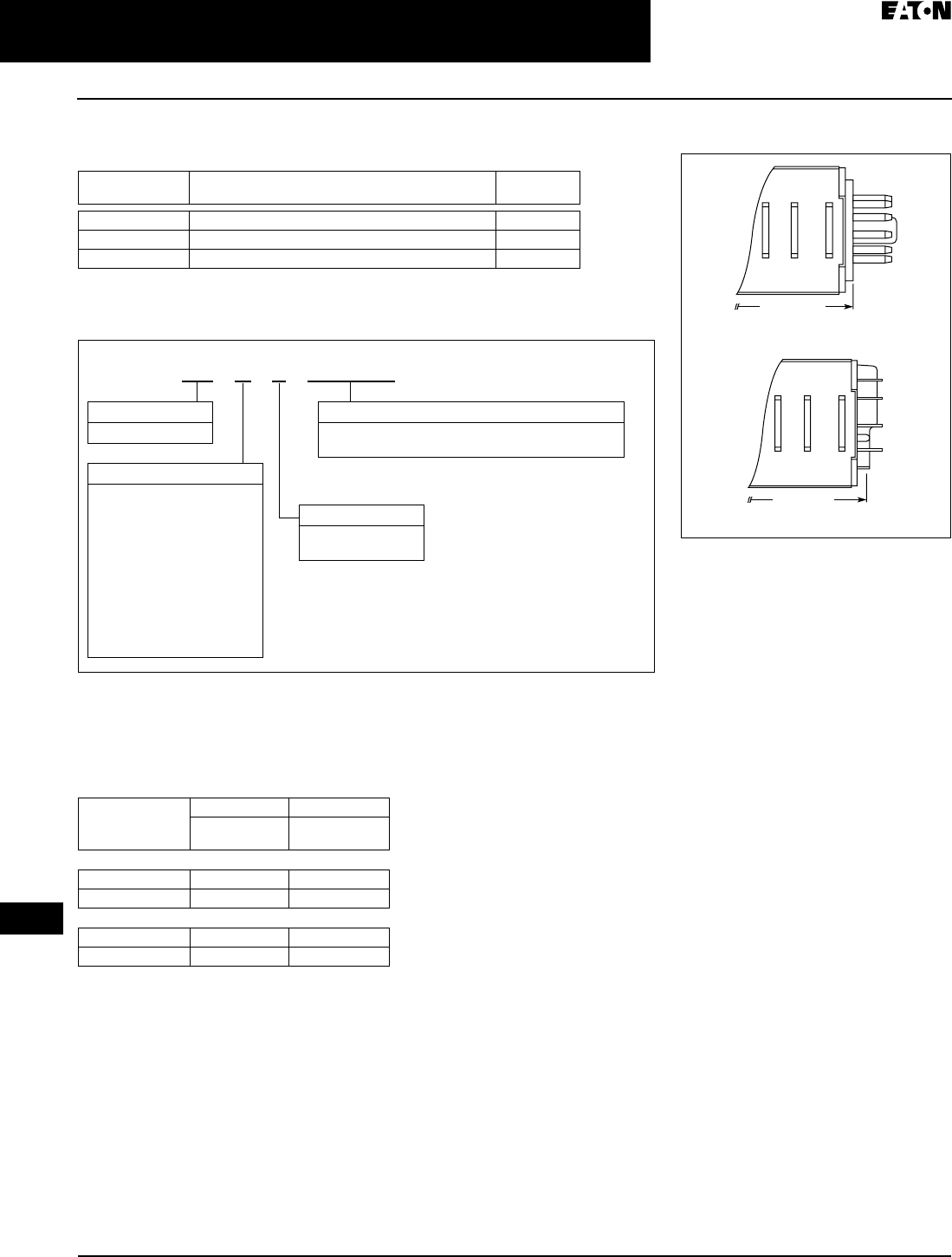
April 2009
3-76
For more information visit: www.EatonCanada.ca CA08102002K07A
Control Relays & Timers
3
Timing Relays
TR Series
Accessories
Table 3-118. Sockets for Use with TR Timers — Standard Pack of 10
Catalogue Numbering System
Table 3-119. Catalogue Numbering System
Product Selection
When Ordering Specify
■Catalogue Number of Timing Relay
Table 3-120. TR Plug-In Timing Relays
Timing
Relay
Terminal
Style
Catalogue
Number
TRNP 8-Pin Octal D3PA2
TRFP 11-Pin Octal D3PA3
TRNB, TRFB 0.187" solder/QC terminals (Blade style) D5PA2
T R N P 2 4 0 A C
Model Type
P = Pin/Octal
B = Blade Style
Family Type
TR
Operational Mode
N = Power Triggered
A = ON Delay
B = Interval
C = Cycle (OFF first)
D = Cycle (ON first)
F = Signal Triggered
A = ON Delay
B = Cycle (OFF first)
C = Cycle (ON first)
D = Signal ON/OFF Delay
E = OFF Delay
F = One-Shot
Input Voltage
24AD = 24V AC (50/60 Hz)/24V DC
240AC = 100 – 240V AC (50/60 Hz)
Coil
Voltage
Octal Blade
Catalogue
Number
Catalogue
Number
Power Triggered
24V AC/DC TRNP24AD TRNB24AD
100 – 240V AC TRNP240AC TRNB240AC
Signal Triggered
24V AC/DC TRFP24AD TRFB24AD
100 – 240V AC TRFP240AC TRFB240AC
Dimensions
Figure 3-104. Approximate Dimensions in
Inches (mm)
3.07 (77.9)
Pin (P) Type
Blade (B) Type
2.95 (74.9)
TAB49.BOO Page 76 Thursday, March 5, 2009 7:36 PM
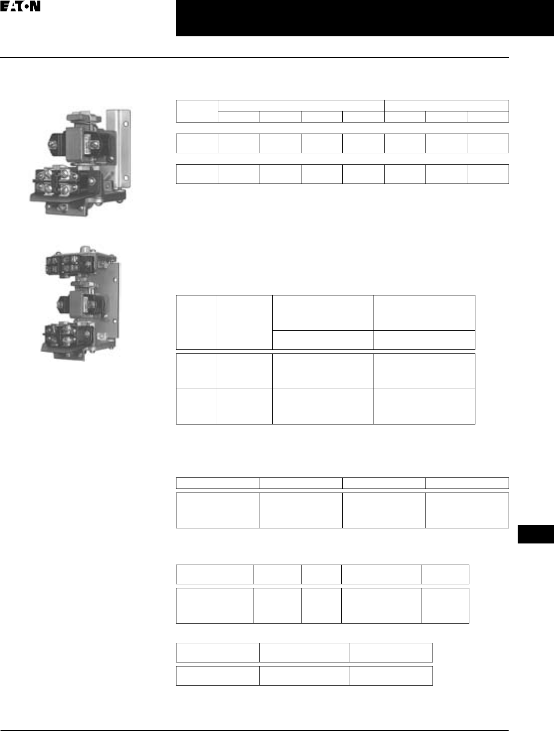
April 2009
CA08102002K07A For more information visit: www.EatonCanada.ca
3-77
Control Relays & Timers
3
Timing Relays
D80 Series — Pneumatic Timers
D80 Series — Pneumatic
Timers
Product Description
Type D80 Timers are supplied only as
complete devices with Switch Block(s)
and Solenoid assembled. The Sole-
noids and Switch Blocks listed in
Tables 3-124 and 3-125 can be used for
replacement or conversion of D80
Timers.
Design Characteristics
■Adjustable Timing Range:
0.5 to 180 seconds
■Repeat Accuracy: +10%
■Minimum Reset Time: 0.05 seconds
Standards and Certifications
■UL listed — File #E1230, Guide
#NKCR
■CSA certified
Catalogue Number
Catalogue Number
Technical Data and Specifications
Table 3-121. Contact Ratings
Product Selection
When Ordering Specify
■Catalogue Number of Timer plus
Suffix Letter for solenoid volts and
hertz.
■Catalogue Number of Enclosure (if
required).
Table 3-122. Pneumatic Timers
Must be ordered with solenoid assembly. Add Suffix letter from table below.
ON or OFF Delay Timers are field convertible from ON to OFF or OFF to ON Delay by rotating the
solenoid assembly 180° — timing function is shown on mounting plate.
These timers will not accept instantaneous contacts.
Table 3-123. Solenoid Suffix Selection Table
Contact Customer Support Centre at 1-800-268-3578 for availability.
Table 3-124. Solenoids – Can Be Used for Replacement or to Convert Above Items for Different
Volts/Hertz Applications
Table 3-125. Switch Blocks – Can Be Used for Either Timed or Instantaneous Contacts
AC Pilot Duty — Amperes A600 DC Pilot Duty — Amperes B600
120V 240V 480V 600V 120V 240V 600V
1NO-1NC
Make
Break
40.
15.
20.
10.
10.
6.
8.
5.
—
0.5
—
0.2
—
0.02
2NO-2NC
Make
Break
30.
3.
15.
1.5
8.
1.
6.
0.8
—
0.2
—
0.1
—
—
Timed
Contacts
Instantaneous
Contacts
ON Delay — Time Delay After
Energizing Timer Coil.
Convertible to OFF Delay
OFF Delay — Time Delay
After De-energizing Timer
Coil. Convertible to ON
Delay
Catalogue
Number
Catalogue
Number
1NO-1NC N/A
None
1NO-1NC
2NO-2NC
D80NE1_
D80JE10_
D80JE11_
D80JE12_
D80ND1_
D80JD10_
D80JD11_
D80JD12_
2NO-2NC N/A
NONE
1NO-1NC
2NO-2NC
D80NE2_
D80JE20_
D80JE21_
D80JE22_
D80ND2_
D80JD20_
D80JD21_
D80JD22_
Volts/Hertz Suffix Volts/Hertz Suffix
12 – 50/60
24 – 50/60
120/60 – 110/50
208 – 220/60
R
T
A
E
240/60 – 220/50
380/50
480/60 – 440/50
600/60 – 550/50
B
L
C
D
Volts/Hertz Catalogue
Number
Price
U.S. $
Volts/Hertz Catalogue
Number
12 – 50/60
24 – 50/60
120/60 – 110/50
208 – 220/60
D80AMR
D80AMT
D80AMA
D80AME
240/60 – 220/50
380/50
480/60 – 440/50
600/60 – 550/50
D80AMB
D80AML
D80AMC
D80AMD
Circuit Type of Contacts Catalogue
Number
SPDT
DPDT
1NO-1NC
2NO-2NC
D80AS1
D80AS2
TAB49.BOO Page 77 Thursday, March 5, 2009 7:36 PM
April 2009
3-78
For more information visit: www.EatonCanada.ca CA08102002K07A
Control Relays & Timers
3
Phase Monitoring Relays
D65 Series — Product Family Overview
Contents
Description Page
Phase Monitoring Relays — D65 Series
Product Family
Overview . . . . . . . . . . . . . . 3-78
Phase Reversal. . . . . . . . . . . 3-80
Phase Loss and
Reversal . . . . . . . . . . . . . . . 3-82
Phase Loss, Reversal and
Undervoltage. . . . . . . . . . . 3-84
Phase Loss, Reversal,
Unbalance and Under/
Overvoltage . . . . . . . . . . . . 3-86
Product Family Overview
The D65 Series Phase Monitoring
Relays provide protection against pre-
mature equipment failure caused by
voltage faults on three-phase systems.
All D65 phase monitoring relays are
compatible with most Wye or Delta
systems. In Wye systems, a connection
to neutral is not required. Phase Moni-
toring relays protect against single-
phasing regardless of any regenerative
voltages.
Standards and Certifications
D65VMC, D65PLR and D65PAR Series
D65VMLP Series
D65VMLS Series
Product Family Selection
Table 3-126. D65 Product Family Selection
In addition to the above approvals, all Plug-In Products are also UL Listed when used with the
appropriate Eaton socket.
pending
Catalogue
Number
Mounting
Style
Phase
Loss
Phase
Reversal
Phase
Unbalance
Under-
voltage
Over-
voltage
Time Delay on
Undervoltage
D65VMC Plug-In ✓
D65PLR Plug-In ✓✓
D65PAR Plug-In ✓✓ ✓ (adj.) 50 mS fixed
D65VMLP Plug-In ✓✓ ✓ ✓ (adj.) ✓ (fixed) 0.1 – 20 sec
D65VMLS Surface ✓✓ ✓ ✓ (adj.) ✓ (fixed) 0.1 – 20 sec
TAB49.BOO Page 78 Thursday, March 5, 2009 7:36 PM
April 2009
CA08102002K07A For more information visit: www.EatonCanada.ca
3-79
Control Relays & Timers
3
Phase Monitoring Relays
D65 Series — Product Family Overview
Application Description
Protection
Depending on the unit selected, it will
protect three-phase equipment
against:
■Phase Loss — total loss of one or
more of the three phases. Also
known as “single phasing”. Typically
caused by a blown fuse, broken wire
or worn contact. This condition
would result in a motor drawing
locked rotor current during start-up.
In addition, a three-phase motor will
continue to run after losing a phase,
resulting in possible motor burn-
out.
■Phase Reversal — reversing any two
of the three phases will cause a
three-phase motor to run in the
opposite direction. This may cause
damage to driven machinery or
injury to personnel. The condition
usually occurs as a result of mis-
takes made during routine mainte-
nance or when modifications are
made to the circuit.
■Phase Unbalance — unbalance of a
three-phase system occurs when
single-phase loads are connected
such that one or two of the lines
(phases) carry more or less of the
load. This could cause motors to run
at temperatures above published
ratings.
■Undervoltage — when voltage in all
three lines of a three-phase system
drop simultaneously.
■Overvoltage — when voltage in all
three lines of a three-phase system
increase simultaneously.
Typical Connections
Line Side Monitoring
With the relay connected before the motor starter, the motor can be started in the
reverse direction. However, the motor is unprotected against phase failures
between the relay and the motor.
Figure 3-105. Line Side Monitoring
Load Side Monitoring
With the relay connected directly to the motor, the total feed lines are monitored.
This connection should not be used with reversing motors.
Figure 3-106. Load Side Monitoring
L1
Stop Start
Phase
Monitor
Relay
M
3
Phase
Motor
O/L
L2
L1 M
M
M
M
Input Fuses
2A Max.
Phase
Monitor
Relay
L2
L3
L1
Stop
3
Phase
Motor
O/L
L2
M
M
M
M
Input Fuses
2A Max.
Phase
Monitor
Relay
Phase
Monitor Relay
Start
L1
L2
L3
TAB49.BOO Page 79 Thursday, March 5, 2009 7:36 PM
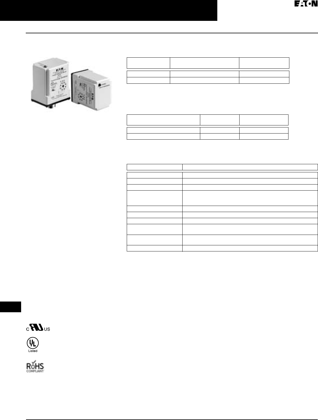
April 2009
3-80
For more information visit: www.EatonCanada.ca CA08102002K07A
Control Relays & Timers
3
Phase Monitoring Relays
D65 Series — Phase Reversal
Phase Reversal
Product Description
The D65VMC Series Monitoring Relays
provide protection against phase
reversal in a compact plug-in design.
One version will work on any three-
phase system from 208V to 480V
(a separate 120V-only version is also
available). These devices are designed
to be compatible with most Wye or
Delta systems. In Wye systems, a con-
nection to a neutral is not required.
The relay is energized and the LED on
when the sequence is correct. Any
fault will de-energize the relay and turn
off the LED. Re-energization is auto-
matic upon correction of the fault con-
dition.
Features
■Protects against phase reversal
■One version works on 208 – 480V
three-phase systems
■LED indicates both normal and fault
conditions
■Compact plug-in case utilizing
industry-standard 8-pin octal socket
■10A SPDT output contacts
Standards and Certifications
When used with appropriate
Eaton socket.
D65VMC Series
Phase Reversal
Product Selection
Table 3-127. Product Selection — D65VMC Series
Requires a 600V rated socket when used on system voltages greater than 300V.
Accessories
Table 3-128. Accessories — D65VMC Series
Technical Data and Specifications
Table 3-129. Technical Data — D65VMC Series, Phase Reversal
Mounting
Style
Nominal Voltage
50/60 Hz
Catalogue
Number
Plug-in 120V D65VMC120
Plug-in 208 – 480V D65VMC480
Description Standard Pack Catalogue
Number
8-Pin Socket 10 D3PA2
Hold Down Spring 10 D65CHDS
Description Specifications
Phase Reversal Unit trips if sequence of the three phases is anything other than A-B-C
Output Contacts 10A SPDT @ 240V AC, 1/3 hp @ 240V AC (NO), 1/6 hp @ 240V AC (NC)
Life Full Load — 100,000 operations
Response Times:
Operate
Release
50 mS
50 mS
Load (Burden) 3 VA
Temperature -20° to 150°F (-28° to 65°C)
Transient Protection 10,000 volts for 20 microseconds
Mounting Uses an 8-pin octal socket. Requires a 600V rated socket when used on
system voltages greater than 300V
Indicator LED Red LED on when all conditions are normal, and off when a fault condi-
tion has occurred
Reset Automatic upon correction of fault
TAB49.BOO Page 80 Thursday, March 5, 2009 7:36 PM
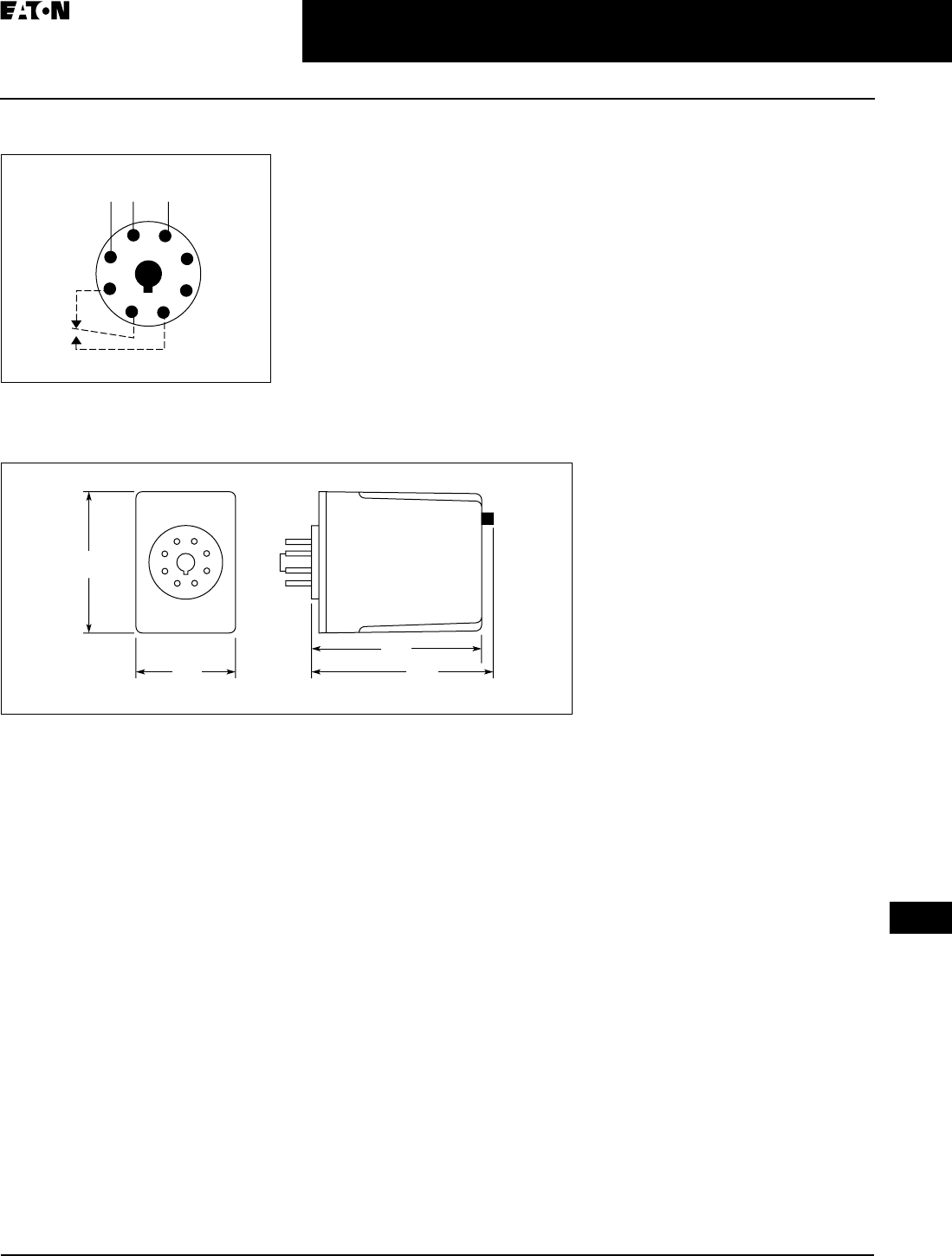
April 2009
CA08102002K07A For more information visit: www.EatonCanada.ca
3-81
Control Relays & Timers
3
Phase Monitoring Relays
D65 Series — Phase Reversal
Schematic
Figure 3-107. Wiring for 8-Pin Socket
Dimensions
Figure 3-108. D65VMC Series — Approximate
Dimensions in Inches (mm)
1
4
ØA ØB ØC
36
27
8
5
2.4
(60)
1.7
(43)
2.9
(74) 3.0
(76)
TAB49.BOO Page 81 Thursday, March 5, 2009 7:36 PM
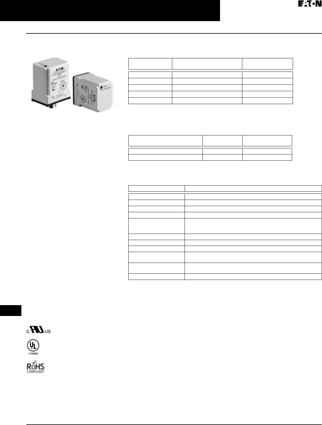
April 2009
3-82
For more information visit: www.EatonCanada.ca CA08102002K07A
Control Relays & Timers
3
Phase Monitoring Relays
D65 Series — Phase Loss and Reversal
Phase Loss and Reversal
Product Description
The D65PLR Series Monitoring Relays
provide protection against phase loss
and phase reversal in a compact plug-
in design. These devices are designed
to be compatible with most Wye or
Delta systems. In Wye systems, a con-
nection to a neutral is not required.
Phase monitoring relays protect
against single-phasing regardless of
any regenerative voltages.
The relay is energized and the LED on
when all three phases are present and
in the correct sequence. Any fault will
instantaneously de-energize the relay
and turn off the LED. Re-energization is
automatic upon correction of the fault
condition.
Features
■Protects against phase loss and
phase reversal
■LED indicates both normal and fault
conditions
■Compact plug-in case utilizing
industry-standard 8-pin octal socket
■10A SPDT output contacts
Standards and Certifications
When used with appropriate
Eaton socket
D65PLR Series
Phase Loss and Reversal
Product Selection
Table 3-130. Product Selection — D65PLR Series
Requires a 600V rated socket when using on system voltages greater than 300V.
Accessories
Table 3-131. Accessories — D65PLR Series
Technical Data and Specifications
Table 3-132. Technical Data — D65PLR Series, Phase Loss and Reversal
Mounting
Style
Nominal Voltage
50/60 Hz
Catalogue
Number
Plug-in 120V D65PLR120
Plug-in 208V D65PLR208
Plug-in 240V D65PLR240
Plug-in 400V D65PLR400
Plug-in 480V D65PLR480
Description Standard Pack Catalogue
Number
8-Pin Socket 10 D3PA2
Hold Down Spring 10 D65CHDS
Description Specifications
Phase Loss Unit trips on loss of any Phase A, B or C
Phase Reversal Unit trips if sequence of the three phases is anything other than A-B-C
Output Contacts 10A SPDT @ 240V AC, 1/3 hp @ 240V AC (NO), 1/6 hp @ 240V AC (NC)
Life Full Load — 100,000 operations
Response Times:
Operate
Release
50 mS
50 mS
Load (Burden) 3 VA
Temperature -20° to 150°F (-28° to 65°C)
Transient Protection 10,000 volts for 20 microseconds
Mounting Uses an 8-pin octal socket. Requires a 600V rated socket when used on
system voltages greater than 300V
Indicator LED Red LED on when all conditions are normal, and off when a fault condi-
tion has occurred
Reset Automatic upon correction of fault
TAB49.BOO Page 82 Thursday, March 5, 2009 7:36 PM

April 2009
CA08102002K07A For more information visit: www.EatonCanada.ca
3-83
Control Relays & Timers
3
Phase Monitoring Relays
D65 Series — Phase Loss and Reversal
Schematic
Figure 3-109. Wiring for 8-Pin Socket
Dimensions
Figure 3-110. D65PLR Series — Approximate
Dimensions in Inches (mm)
1
4
ØA ØB ØC
36
27
8
5
2.4
(60)
1.7
(43)
2.9
(74) 3.0
(76)
TAB49.BOO Page 83 Thursday, March 5, 2009 7:36 PM
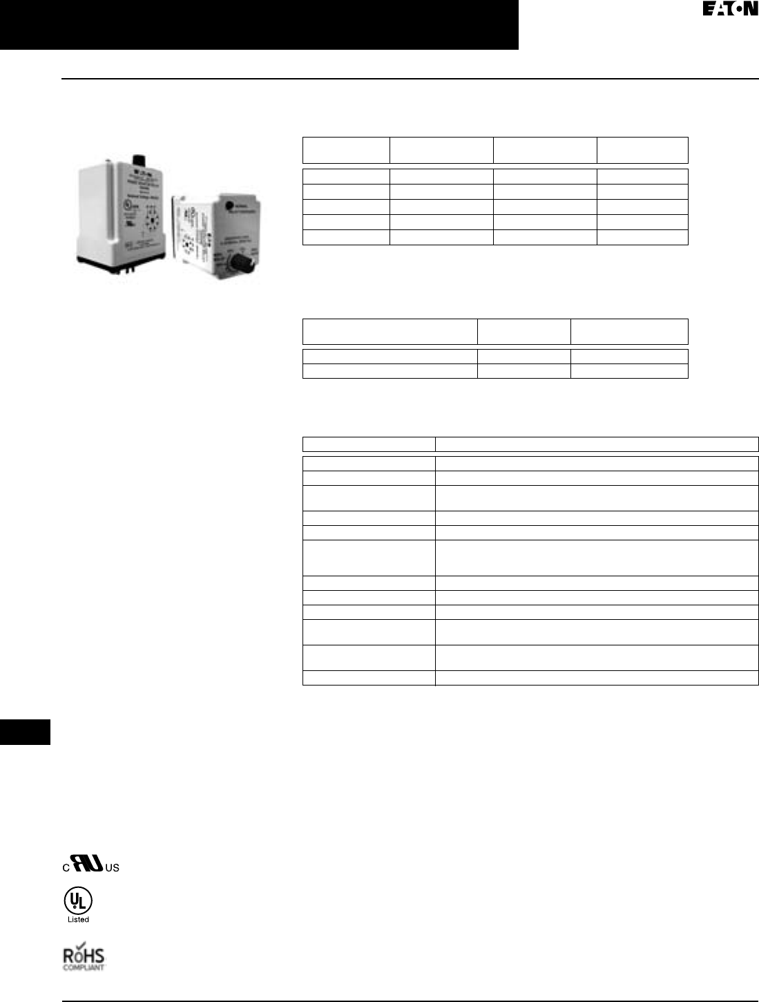
April 2009
3-84
For more information visit: www.EatonCanada.ca CA08102002K07A
Control Relays & Timers
3
Phase Monitoring Relays
D65 Series — Phase Loss, Reversal and Undervoltage
Phase Loss, Reversal and
Undervoltage
Product Description
The D65PAR Series Monitoring Relays
provide protection against phase loss,
phase reversal and undervoltage in a
compact plug-in design. These devices
are designed to be compatible with
most Wye or Delta systems. In Wye
systems, a connection to a neutral is
not required. Phase monitoring relays
protect against single-phasing regard-
less of any regenerative voltages.
The relay is energized and the LED on
when all three phases are present in
the correct sequence at a voltage level
above the undervoltage setting. The
undervoltage drop-out can be set at
75 – 95% of operating voltage. Any
fault will instantaneously de-energize
the relay and turn off the LED.
Re-energization is automatic upon
correction of the fault condition.
Features
■Protects against phase loss, phase
reversal and undervoltage
■Undervoltage setting is adjustable
from 75 – 95% of nominal
■LED indicates both normal and fault
conditions
■Compact plug-in case utilizing
industry-standard 8-pin octal socket
■10A SPDT output contacts
Standards and Certifications
When used with appropriate
Eaton socket.
D65PAR Series
Phase Loss, Reversal and Undervoltage
Product Selection
Table 3-133. Product Selection — D65PAR Series
Requires a 600V rated socket when using on system voltages greater than 300V.
Accessories
Table 3-134. Accessories — D65PAR Series
Technical Data and Specifications
Table 3-135. Technical Data — D65PAR Series, Phase Loss, Reversal and Undervoltage
Mounting
Style
Nominal Voltage
60 Hz
Undervoltage
Range
Catalogue
Number
Plug-in 120V 90 – 115V D65PAR120
Plug-in 208V 156 – 198V D65PAR208
Plug-in 240V 180 – 230V D65PAR240
Plug-in 400V 300 – 380V D65PAR400
Plug-in 480V 360 – 460V D65PAR480
Description Standard Pack Catalogue
Number
8-Pin Socket 10 D3PA2
Hold Down Spring 10 D65CHDS
Description Specifications
Phase Loss Unit trips on loss of any Phase A, B or C
Phase Reversal Unit trips if sequence of the three phases is anything other than A-B-C
Undervoltage Adjustable over a range per product selection table. Unit trips when the
average of all three lines is less than the adjusted set point.
Output Contacts 10A SPDT @ 240V AC, 1/3 hp @ 240V AC (NO), 1/6 hp @ 240V AC (NC)
Life Full Load — 100,000 operations
Response Times:
Operate
Release
50 mS
50 mS
Load (Burden) 3 VA
Temperature -20° to 150°F (-28° to 65°C)
Transient Protection 10,000 volts for 20 microseconds
Mounting Uses an 8-pin octal socket. Requires a 600V rated socket when used on
system voltages greater than 300V
Indicator LED Red LED on when all conditions are normal, and off when a fault condi-
tion has occurred
Reset Automatic upon correction of fault
TAB49.BOO Page 84 Thursday, March 5, 2009 7:36 PM

April 2009
CA08102002K07A For more information visit: www.EatonCanada.ca
3-85
Control Relays & Timers
3
Phase Monitoring Relays
D65 Series — Phase Loss, Reversal and Undervoltage
Schematic
Figure 3-111. Wiring for 8-Pin Socket
Dimensions
Figure 3-112. D65PAR Series — Approximate
Dimensions in Inches (mm)
1
4
ØA ØB ØC
36
27
8
5
2.4
(60)
1.7
(43)
2.9
(74)3.5
(89)
TAB49.BOO Page 85 Thursday, March 5, 2009 7:36 PM
April 2009
3-86
For more information visit: www.EatonCanada.ca CA08102002K07A
Control Relays & Timers
3
Phase Monitoring Relays
D65 Series — Phase Loss, Reversal, Unbalance and Under/Overvoltage
Phase Loss, Reversal,
Unbalance and Under/
Overvoltage
D65 Series
Product Description
The Cutler-Hammer® D65 Phase
Monitoring Relay from Eaton’s
electrical business protects distribution
systems supplying motor feeder or
branch circuits against premature
equipment failure caused by voltage
faults on three-phase systems — wye
or delta connected. Phase monitoring
relays protect against voltage imbalance
and single-phasing regardless of any
regenerative voltages. The relay is
energized when the phase sequence
and all voltages are correct. Any of five
abnormal conditions (phase loss,
phase reversal, overvoltage, under-
voltage or phase imbalance) will
de-energize the relay. As standard,
re-energization is automatic upon
correction of the fault condition. The
D65 can also be wired for manual reset.
Application Description
Protective Functions
The D65 Series Relay makes separate
trip decisions based on the status of
the three-phase voltage inputs. Control
power is derived from the three-phase
voltage inputs. Separate control power
is not required. The device will trip in
response to any combination of the
following conditions:
■Undervoltage — When voltage in
all three lines of a three-phase
system drops simultaneously.
Undervoltage drop-out can be set at
80 – 95% of operating voltage. Unit
trips when the average of all three
lines is less than the adjusted set
point for a period longer than the
adjustable time delay drop-out
(0.1 – 20 seconds). This time delay
eliminates nuisance tripping
caused by momentary voltage
fluctuation.
■Overvoltage — Fixed at 110%
of nominal, unit trips when the aver-
age of all three lines is greater than
the fixed set point for a period
longer than the time delay drop-out.
■Phase Imbalance — Imbalance of a
three-phase system occurs when
single-phase loads are connected
such that one or two of the lines
(phases) carry more or less of the
load. This could cause motors to run
at temperatures above published
ratings. Unit trips when any one of
the three lines is more than the
adjusted set point below the aver-
age of all three lines. The percent
phase imbalance is adjustable from
2 – 10% and also has a Disable set-
ting for applications where poor
voltage conditions could cause nui-
sance tripping.
■Phase Loss (Single-Phasing) — Total
loss of one or more of the three
phases. Typically caused by a blown
fuse, broken wire or worn contact.
This condition would result in a
motor drawing locked rotor current
during start-up. In addition, a three-
phase motor will continue to run
after losing a phase, resulting in
potential motor burn-out. Unit trips
on loss of any phase.
■Phase Reversal — Reversing any
two of the three phases will cause a
three-phase motor to run in the
opposite direction. This may cause
damage to machinery or injury to
personnel. Unit trips if rotation
(sequence) of the three phases is
anything other than A-B-C.
Features
■Universal voltage range of 208 –
480V provides the flexibility to cover
a variety of applications. 120V and
600V units also available.
■Automatic or manual reset after the
fault condition is corrected.
■Multi-colour LED indicates normal
condition and defines fault type for
simpler troubleshooting.
■D65VMLS can be either mounted
directly on 35 mm DIN rail with no
additional parts or to a back-panel
with two screws. No socket
required. D65VMLP will plug into
D3PA2 socket and mount on 35 mm
DIN rail.
■Small, compact size.
■User-adjustable settings include
nominal voltage, percent phase
imbalance, undervoltage drop-out,
time delay on undervoltage and
time delay on restart after fault.
TAB49.BOO Page 86 Thursday, March 5, 2009 7:36 PM
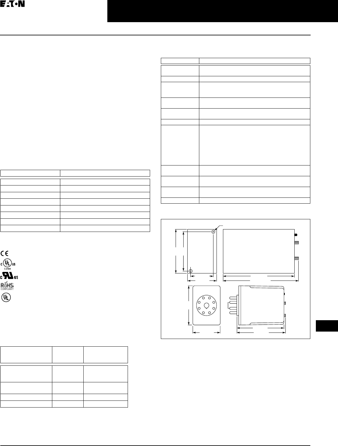
April 2009
CA08102002K07A For more information visit: www.EatonCanada.ca
3-87
Control Relays & Timers
3
Phase Monitoring Relays
D65 Series — Phase Loss, Reversal, Unbalance and Under/Overvoltage
Operation
The D65 provides protection against premature equipment
failure caused by voltage faults on three-phase systems. The
D65 is designed to be compatible with most wye or delta
systems. In wye systems, a connection to a neutral is not
required. D65 Phase Monitoring Relays protect against
unbalanced voltages or single-phasing regardless of any
regenerative voltages. The relay is energized when the phase
sequence and all voltages are correct. Any one of five fault
conditions will de-energize the relay. Re-energization is auto-
matic upon correction of the fault condition. Manual reset is
available if a NC switch is wired to the appropriate terminals.
A multi-colour LED indicates normal condition and also pro-
vides specific fault indication to simplify troubleshooting.
The percent phase imbalance is adjustable from
2 – 10%, and the undervoltage drop-out can be set at 80 – 95%
of operating voltage. The adjustable time delay drop-out on
undervoltage (0.1 – 20 sec.) eliminates nuisance tripping
caused by momentary voltage fluctuations.
Table 3-136. LED Operation
Standards and Certifications
(Low Voltage + EMC Directive EN60947-5-1)
(D65VMLS only)
(D65VMLP only)
When used with accompanying Eaton Socket.
(D65VMLP only)
Product Selection
When Ordering Specify
■Catalogue Number
Table 3-137. Phase Monitoring Relay
Requires a 600V-rated socket when used on system voltages greater
than 300V. The D3PA2 socket is rated 10A, 600V.
For Dimensions, see Page 3-46.
For Dimensions, see Page 3-47.
Additional models available. Please visit our website for the latest
offering.
Technical Data and Specifications
Table 3-138. D65 Series Specifications
Dimensions
Figure 3-113. Surface-Mount and Plug-In — Approximate Dimensions
in Inches (mm)
LED Status Indicator
Green Steady Normal/Relay ON
Green Flashing Power-Up/Restart Delay
Red Steady Unbalance
Red Flashing Undervoltage/Overvoltage
Amber Steady Reversal
Amber Flashing Loss
Alternating Green/Red Undervoltage/Overvoltage Trip Pending
Alternating Red/Amber Nominal Voltage Set Error
Mounting
Style
Operating
Voltage,
50/60 Hz
Catalogue
Number
Surface-Mount
(DIN Rail or Panel)
120V
208 – 480V
600V
D65VMLS120
D65VMLS480
D65VMLS600
Plug-In
(DIN Rail)
120V
208 – 480V
D65VMLP120
D65VMLP480
8-pin Socket — D3PA2
8-pin IP20 Rated Socket — D3PA6
UL Listed
Description Specifications
Nominal Voltages
(50 – 60 Hz)
120V, 208 – 480V, 575V
Connections 3-wire wye or delta
Output Contacts
for D65VMLS
SPDT and SPNC (surface mount version only)
NO: 10A Resistive @ 240V AC / 30V DC, 1/2 hp @ 240V AC
NC: 10A Resistive @ 240V AC / 30V DC, 1/3 hp @ 240V AC
Output Contacts
for D65VMLP
SPDT:
10A Resistive @ 240V AC / 30V DC; 1/2 hp @ 120/240V AC
Dielectric 1000V + (2 * Nominal Voltage Rating) between
input terminals and case or active circuitry
Operating Temp. -20° – 150°F (-28° – 65°C)
Response Time
Power Up
Restart after
Fault
Drop-out due
to Fault
1 – 300 seconds adjustable
1 – 300 seconds adjustable
100 mS fixed on phase loss and phase reversal;
2 seconds fixed on phase imbalance;
0.1 – 20 sec. adjustable on undervoltage only;
inverse time curve for overvoltage
Mechanical Life
Electrical Life
10,000,000 operations
100,000 operations
Power
Consumption
3 VA
Net Weight 10.3 oz. (292g) D65VMLS
6.4 oz. (181g) D65VMLP
Hysteresis 2 – 3%
1.7 (43)
2.9 (74)
3.0 (77)
2.4
(60)
1.4 (35)
0.2 (5) Mounting Holes – 2 Places
2.7
(70)
1.8 (45)
4.4 (112)
4.5 (114)
2.4
(60)
TAB49.BOO Page 87 Thursday, March 5, 2009 7:36 PM
April 2009
3-88
For more information visit: www.EatonCanada.ca CA08102002K07A
Control Relays & Timers
3
Phase Monitoring Relays
D65 Series — Phase Loss, Reversal, Unbalance and Under/Overvoltage
Wiring Diagrams
Figure 3-114. Surface-Mount and Plug-In Wiring Diagrams
Typical Connections
Line Side Monitoring
With the relay connected before the motor starter, the motor can
be started in the reverse direction. However, the motor is unpro-
tected against phase failures between the relay and the motor.
Load Side Monitoring
With the relay connected directly to the motor, the total feed
lines are monitored. This connection should not be used with
reversing motors.
Figure 3-115. Line Side and Load Side Monitoring
12 14
M
2
M
122
Manual Reset
AB C
ØA ØB ØC
11 21 ØA ØB ØC Manual
Reset
3
2
6
54
81 7
START
L1
L1
L2
Voltage Monitor
Relay
Input Fuses
(Recommended)
2A Max.
Input Fuses
(Recommended)
2A Max.
Voltage
Monitor
Relay
Line Side Monitoring
3
Phase
M
otor
O/L
STOP
M
M
L2 M
L3 M
M
START
L1
L1
L2
Voltage Monitor
Relay
Voltage
Monitor
Relay
Load Side Monitoring
3
Phase
M
otor
O/L
STOP
M
L2 M
L3 M
M
TAB49.BOO Page 88 Thursday, March 5, 2009 7:36 PM
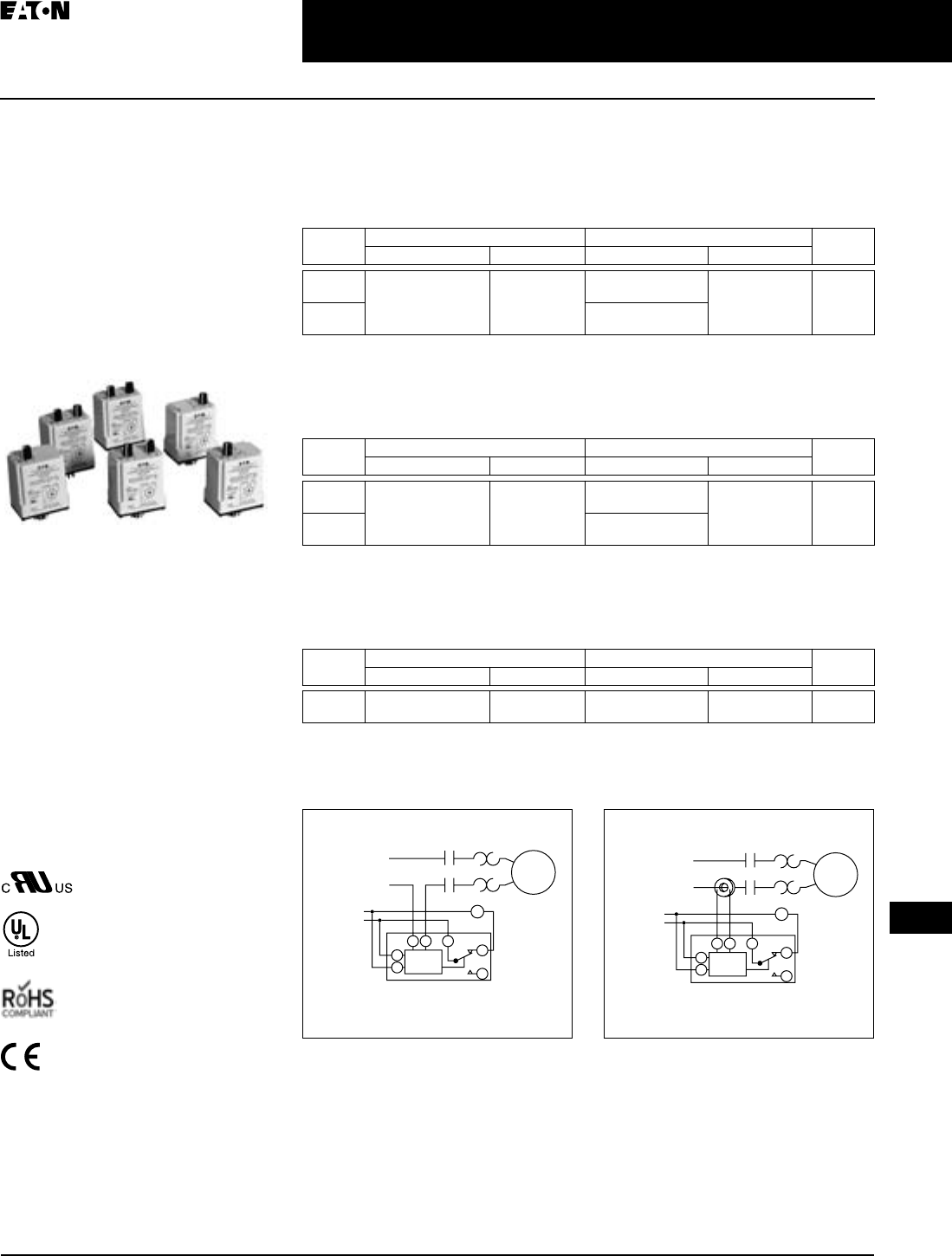
April 2009
CA08102002K07A For more information visit: www.EatonCanada.ca
3-89
Control Relays & Timers
3
Current Monitoring Relays
D65C Series — Product Family Overview
Contents
Description Page
D65C Series
Product Family
Overview . . . . . . . . . . . . . 3-89
Standard Current Monitors —
D65CE Series . . . . . . . . . . 3-90
Overcurrent Monitors —
D65CH Series . . . . . . . . . 3-92
Undercurrent Monitors —
D65CL Series . . . . . . . . . . 3-94
Product Family Overview
The D65C Series Current Monitoring
Relays monitor AC single-phase currents
for over- or undercurrent conditions
in
three current ranges: 0.1 – 1A, 0.5 – 5A,
and 1 – 10A. An external current trans-
former may be used to extend the
range of the product. A separate 24V
or 120V AC input (supply) voltage
is required to power the unit. All
versions are available in a compact
plug-in case utilizing industry standard
8- or 11-pin octal sockets.
Standards and Certifications
When used with accompanying
Eaton socket.
Current Monitoring Relays
Product Family Selection
Standard
Fixed time delay on both pick-up and drop-out current settings.
Table 3-139. D65C Product Family Selection — Standard Function
Fixed time delay eliminates nuisance tripping due to short current surges or drops.
Overcurrent
Adjustable time delay on pick-up and fixed time delay on drop-out current settings.
Table 3-140. D65C Product Family Selection — Overcurrent Function
Fixed time delay eliminates nuisance tripping due to short current surges or drops.
Undercurrent
Fixed time delay on pick-up and adjustable time delay on drop-out current settings.
Table 3-141. D65C Product Family Selection — Undercurrent Function
Fixed time delay eliminates nuisance tripping due to short current surges or drops.
Typical Installations
Figure 3-116. Typical Installation without
External CT
Figure 3-117. Typical Installation with
External CT
Series Pick-Up Drop-Out Page
Setting Time Delay Setting Time Delay
D65CE Adjustable (Across
Monitored Range)
Fixed 100 mS Fixed
(-5% Pick-Up)
Fixed 100 mS 3-90
D65CEK Adjustable
(50 – 95% Pick-Up)
Series Pick-Up Drop-Out Page
Setting Time Delay Setting Time Delay
D65CH Adjustable (Across
Monitored Range)
0.1 – 10 sec
Adjustable
Fixed
(-5% Pick-Up)
Fixed 100 mS 3-92
D65CHK Adjustable
(50 – 95% Pick-Up)
Series Pick-Up Drop-Out Page
Setting Time Delay Setting Time Delay
D65CL Fixed
(+5% Drop-Out)
Fixed 100 mS Adjustable (Across
Monitored Range)
0.1 – 10 sec
Adjustable
3-94
Without External CT
Current
Monitor
Relay
Control
Voltage
M
Motor
M
M
L1
L2
6
5
34 1 2
8
With External CT
Current
Monitor
Relay
Control
Voltage
M
M
L1
L2
M
Motor
6
5
34 1 2
8
TAB49.BOO Page 89 Thursday, March 5, 2009 7:36 PM
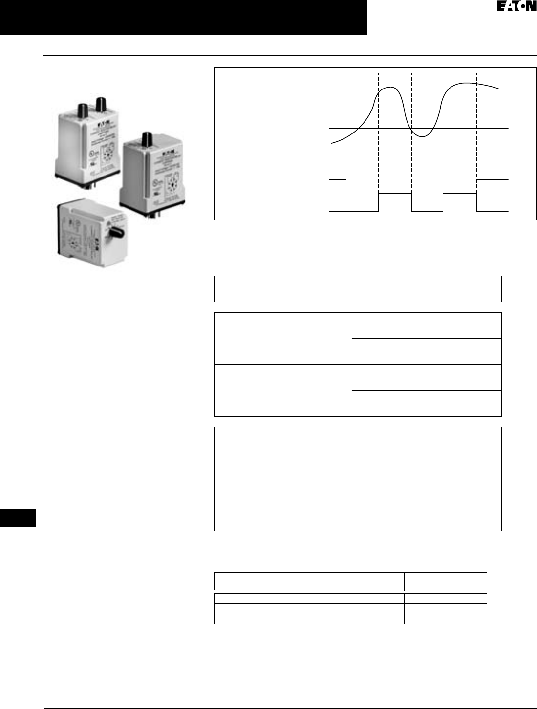
April 2009
3-90
For more information visit: www.EatonCanada.ca CA08102002K07A
Control Relays & Timers
3
Current Monitoring Relays
D65C Series — Standard Current Monitors
Standard Current Monitors
Product Description
The D65CE Series Standard Current
Monitors are used to detect either an
overcurrent or undercurrent condi-
tion. The pick-up current setting is user-
adjustable within three ranges (0.1 –
1A), (0.5 – 5A), or (1 – 10A). The range
can be extended beyond 10A with the
use of an external current transformer.
Choose between a fixed drop-out cur-
rent setting at 95% of the selected pick-
up setting or an adjustable drop-out
setting of 50 – 95% of the selected pick-
up setting. The relay will energize
when the monitored AC current is
above the pick-up setting, and will de-
energize when the monitored AC cur-
rent is below the drop-out setting. The
time delay on both pick-up and drop-
out is fixed at 100 mS. Adjustable time
delays are available with the D65CH
and D65CL Series.
Features
■Monitors AC single-phase currents
■Three separate current monitoring
ranges covering 0.1 – 10 amperes
■External CT can be used to extend
ranges
■Adjustable pick-up setting with
either fixed or adjustable drop-out
setting
■LED indicates output relay status
■Choice of compact 8-pin SPDT or 11-
pin DPDT plug-in case
■10A output contacts
D65C Series
Standard Current Monitors
Figure 3-118. Standard Current Monitoring
Product Selection
Table 3-142. Product Selection — D65C Series, Standard Current Monitors
Accessories
Table 3-143. Accessories — D65CE Current Monitors
Monitored
Current
Pick-Up
Current
Drop-Out
Current
Input
Power
(Voltage)
Relay
Output
On
On
Off
Off
Pick-Up
Setting
Drop-Out
Setting
Input
Voltage
Current
Range
Monitored
Catalogue
Number
SPDT — 8-Pin Plug-In
Adjustable Fixed
(At 95% of Pick-Up)
24V AC 0.1 – 1A
0.5 – 5A
1 – 10A
D65CE1C01T
D65CE1C5T
D65CE1C10T
120V AC 0.1 – 1A
0.5 – 5A
1 – 10A
D65CE1C01A
D65CE1C5A
D65CE1C10A
Adjustable Adjustable
(From 50- 95% of Pick-Up)
24V AC 0.1 – 1A
0.5 – 5A
1 – 10A
D65CEK1C01T
D65CEK1C5T
D65CEK1C10T
120V AC 0.1 – 1A
0.5 – 5A
1 – 10A
D65CEK1C01A
D65CEK1C5A
D65CEK1C10A
DPDT — 11-Pin Plug-In
Adjustable Fixed
(At 95% of Pick-Up)
24V AC 0.1 – 1A
0.5 – 5A
1 – 10A
D65CE2C01T
D65CE2C5T
D65CE2C10T
120V AC 0.1 – 1A
0.5 – 5A
1 – 10A
D65CE2C01A
D65CE2C5A
D65CE2C10A
Adjustable Adjustable
(From 50- 95% of Pick-Up)
24V AC 0.1 – 1A
0.5 – 5A
1 – 10A
D65CEK2C01T
D65CEK2C5T
D65CEK2C10T
120V AC 0.1 – 1A
0.5 – 5A
1 – 10A
D65CEK2C01A
D65CEK2C5A
D65CEK2C10A
Description Standard Pack Catalogue
Number
8-Pin Socket 10 D3PA2
11-Pin Socket 10 D3PA3-A2
Hold Down Spring 10 D65CHDS
TAB49.BOO Page 90 Thursday, March 5, 2009 7:36 PM
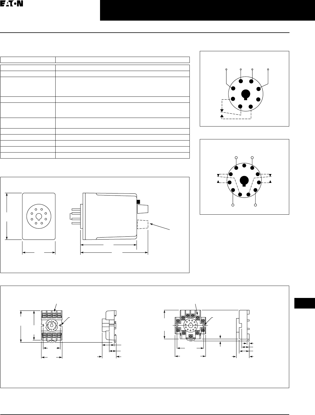
CA08102002K07A For more information visit: www.EatonCanada.ca
3-91
Control Relays & Timers
April 2009
3
Current Monitoring Relays
D65C Series — Standard Current Monitors
Technical Data and Specifications
Table 3-144. Technical Data — D65C Series, Standard Current Monitors
Dimensions
Figure 3-119. D65CE Series — Approximate Dimensions in Inches (mm)
Figure 3-120. D3PA2 and D3PA3 Sockets — Approximate Dimensions in Inches (mm)
Description Specifications
Input Voltage Tolerance AC Operation: +10/-15% of nominal voltage at 50/60 Hz
Load (Burden) Less than 5 VA
Current Settings:
Pick-Up
Drop-Out
Adjustable throughout current range monitored
Fixed at 95% of pick-up setting for D65CE
Adjustable from 50 – 95% of pick-up setting for D65CEK
Temperature -20 to 131°F (-28 to 55°C)
Response Times:
Pick-Up
Drop-Out
100 mS
100 mS
Output Contacts 10A Resistive @240V AC / 30V DC
1/2 hp @ 240V AC (NO); 1/3 hp @ 240V AC (NC)
Mechanical Life 10,000,000 operations
Electrical Life 100,000 operations
Indicator LED Green when input voltage is applied; Red when relay is energized
Reset Automatic
Mounting Requires an 8- or 11-pin socket
2.4
(60)
1.7
(43)
2.9
(74) 3.5
(89)
D65CEK
Only
0.97
(24.6)
Max.
0.82 (20.8)
0.58 (14.7)
2.03
(51.4)
Two 0.165
(4.2) Dia.
Slots
2.14
(54.3)
1.60
(40.5)
Max.
1.30
(32.9)
6-32 x 0.312 Combination
Head Screw and Pressure Clamping Plate
(8 Places)
Tolerances: ± 0.010
± (0.25)
Unless Otherwise Shown
6-32 x 0.312 Combination
Head Screw and Pressure Clamp
(11 Places)
2.05
(52.07)
Max.
2.33 (59.1)
Max.
2.06
(52.3)
0.97
(24.6)
0.77 (19.6)
0.58 (14.7)
0.15 (3.6)
0.125 – 0.156
(3.17 – 3.96))
Two 0.17
(4.3) Dia.
Holes
Tolerances: ± 0.010
± (0.25)
Unless Otherwise Shown
D3PA2 D3PA3
Schematics
Figure 3-121. Wiring for 8-Pin Socket
Figure 3-122. Wiring for 11-Pin Socket
1
4
(L1)
Monitored
Current
Input
Voltage
(L2)
36
27
8
5
1
(L1) (L2)
11
Monitored
Current
48
39
6
210
75
TAB49.BOO Page 91 Thursday, March 5, 2009 7:36 PM

April 2009
3-92
For more information visit: www.EatonCanada.ca CA08102002K07A
Control Relays & Timers
3
Current Monitoring Relays
D65C Series — Overcurrent Monitors
Overcurrent Monitors
Product Description
The D65C Series Overcurrent
Monitoring Relays are used to detect
an overcurrent condition. The pick-up
current setting is user-adjustable
within one of three ranges as shown in
product selection table. An external
current transformer can be used to
extend the range beyond 10A. Users
may select a fixed drop-out current
setting (95% of the selected pick-up
setting) or an adjustable drop-out
setting (50 – 95% of the selected pick-
up setting). The relay will energize
when the monitored AC current is
above the pick-up setting for a period
longer than the adjustable time delay
of 0.1 – 10 seconds. This delay prevents
nuisance tripping caused by inrush
currents. It will de-energize when the
monitored AC current is below the
drop-out setting.
Features
■Monitors AC single-phase currents
for overcurrent conditions
■Three separate current monitoring
ranges covering 0.1 – 10 amperes
■External CT can be used to extend
ranges
■Adjustable pick-up setting with either
fixed or adjustable drop-out setting
■Adjustable time delay of 0.1 – 10
seconds on pick-up
■LED indicates output relay status
■Choice of compact SPDT (8-pin) or
DPDT (11-pin) plug-in case
■10A output contacts
D65C Series
Overcurrent Monitors
Figure 3-123. Overcurrent Monitoring
Product Selection
Table 3-145. Product Selection — D65C Series, Overcurrent Monitors
Accessories
Table 3-146. Accessories — D65CH Overcurrent Monitors
Pick-Up
Setting
Drop-Out Setting Input
Voltage
Current
Range
Monitored
Catalogue
Number
SPDT — 8-Pin Plug-In
Adjustable Fixed
(At 95% of Pick-Up)
24V AC 0.1 – 1A
0.5 – 5A
1 – 10A
D65CH1C1T
D65CH1C5T
D65CH1C10T
120V AC 0.1 – 1A
0.5 – 5A
1 – 10A
D65CH1C1A
D65CH1C5A
D65CH1C10A
Adjustable Adjustable
(From 50- 95% of Pick-Up)
24V AC 0.1 – 1A
0.5 – 5A
1 – 10A
D65CHK1C1T
D65CHK1C5T
D65CHK1C10T
120V AC 0.1 – 1A
0.5 – 5A
1 – 10A
D65CHK1C1A
D65CHK1C5A
D65CHK1C10A
DPDT — 11-Pin Plug-In
Adjustable Fixed
(At 95% of Pick-Up)
24V AC 0.1 – 1A
0.5 – 5A
1 – 10A
D65CH2C1T
D65CH2C5T
D65CH2C10T
120V AC 0.1 – 1A
0.5 – 5A
1 – 10A
D65CH2C1A
D65CH2C5A
D65CH2C10A
Adjustable Adjustable
(From 50- 95% of Pick-Up)
24V AC 0.1 – 1A
0.5 – 5A
1 – 10A
D65CHK2C1T
D65CHK2C5T
D65CHK2C10T
120V AC 0.1 – 1A
0.5 – 5A
1 – 10A
D65CHK2C1A
D65CHK2C5A
D65CHK2C10A
Description Standard Pack Catalogue
Number
8-Pin Socket 10 D3PA2
11-Pin Socket 10 D3PA3-A2
Hold Down Spring 10 D65CHDS
Monitored
Current
Pick-Up
Current
Drop-Out
Current
Input
Power
(Voltage)
Relay
Output
On
On
TT
Off
Off
TAB49.BOO Page 92 Thursday, March 5, 2009 7:36 PM
CA08102002K07A For more information visit: www.EatonCanada.ca
3-93
Control Relays & Timers
April 2009
3
Current Monitoring Relays
D65C Series — Overcurrent Monitors
Technical Data and Specifications
Table 3-147. Technical Data — D65C Series, Overcurrent Monitors
Dimensions
Figure 3-124. D65CH Series — Approximate Dimensions in Inches (mm)
Figure 3-125. D3PA2 and D3PA3 Sockets — Approximate Dimensions in Inches (mm)
Description Specifications
Input Voltage Tolerance AC Operation: +10/-15% of nominal voltage at 50/60 Hz.
Load (Burden) Less than 5 VA
Current Settings:
Pick-Up
Drop-Out
Adjustable throughout current range monitored
Fixed at 95% of pick-up setting for D65CH
Adjustable from 50 – 95% of pick-up setting for D65CHK
Temperature -20 to 131°F (-28 to 55°C)
Response Times:
Pick-Up
Drop-Out
Adjustable 0.1 – 10 seconds
Fixed at 100 mS
Output Contacts 10A Resistive @240V AC / 30V DC
1/2 hp @ 240V AC (NO); 1/3 hp @ 240V AC (NC)
Mechanical Life 10,000,000 operations
Electrical Life 100,000 operations
Indicator LED Green when input voltage is applied; Red Flashing when in time delay;
Red Steady when relay is energized
Reset Automatic
Mounting Requires an 8- or 11-pin socket
2.4
(60)
1.7
(43)
2.9
(74) 3.5
(89)
D65CHK
Only
0.97
(24.6)
Max.
0.82 (20.8)
0.58 (14.7)
2.03
(51.4)
Two 0.165
(4.2) Dia.
Slots
2.14
(54.3)
1.60
(40.5)
Max.
1.30
(32.9)
6-32 x 0.312 Combination
Head Screw and Pressure Clamping Plate
(8 Places)
Tolerances: ± 0.010
± (0.25)
Unless Otherwise Shown
6-32 x 0.312 Combination
Head Screw and Pressure Clamp
(11 Places)
2.05
(52.07)
Max.
2.33 (59.1)
Max.
2.06
(52.3)
0.97
(24.6)
0.77 (19.6)
0.58 (14.7)
0.15 (3.6)
0.125 – 0.156
(3.17 – 3.96))
Two 0.17
(4.3) Dia.
Holes
Tolerances: ± 0.010
± (0.25)
Unless Otherwise Shown
D3PA2 D3PA3
Schematics
Figure 3-126. Wiring for 8-Pin Socket
Figure 3-127. Wiring for 11-Pin Socket
1
4
(L1)
Monitored
Current
Input
Voltage
(L2)
36
27
8
5
1
(L1) (L2)
11
Monitored
Current
48
39
6
210
75
TAB49.BOO Page 93 Thursday, March 5, 2009 7:36 PM
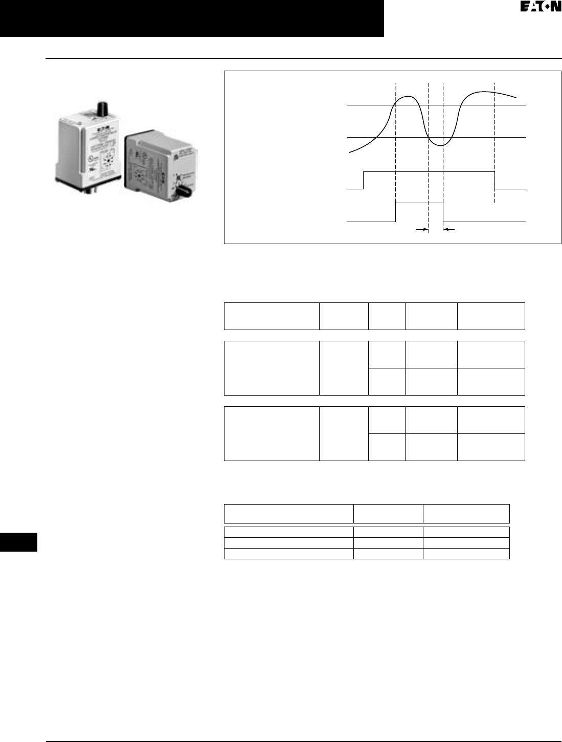
April 2009
3-94
For more information visit: www.EatonCanada.ca CA08102002K07A
Control Relays & Timers
3
Current Monitoring Relays
D65C Series — Undercurrent Monitors
Undercurrent Monitors
Product Description
The D65CL Series is designed to detect
an undercurrent condition. The drop-out
current setting is user-adjustable within
one of three ranges shown below. An
external current transformer can be used
to extend the range beyond 10A. The
pick-up current setting is fixed at +5% of
the selected drop-out setting. The relay
will energize when the monitored AC
current is above the pick-up setting. It
will de-energize when the monitored AC
current is below the drop-out setting for
a period longer than the adjustable time
delay of 0.1 – 10 seconds. This delay
prevents nuisance tripping caused by
momentary line dips. The relay will
energize when the current rises 5%
above the drop-out setting.
Features
■Monitors AC single-phase currents
for undercurrent conditions
■Three separate current monitoring
ranges covering 0.1 – 10 amperes
■External CT can be used to extend
ranges
■Adjustable drop-out setting with
fixed pick-up setting
■Adjustable time delay of 0.1 – 10
seconds on drop-out
■LED indicates output relay status
■Choice of compact SPDT (8-pin) or
DPDT (11-pin) plug-in case
■10A output contacts
D65C Series
Undercurrent Monitors
Figure 3-128. Undercurrent Monitoring
Product Selection
Table 3-148. Product Selection — D65C Series, Undercurrent Monitors
Accessories
Table 3-149. Accessories — D65CL Undercurrent Monitors
Pick-Up Setting Drop-Out
Setting
Input
Voltage
Current
Range
Monitored
Catalogue
Number
SPDT — 8-Pin Plug-In
Fixed
(At 5% of Drop-Out)
Adjustable 24V AC 0.1 – 1A
0.5 – 5A
1 – 10A
D65CL1C1T
D65CL1C5T
D65CL1C10T
120V AC 0.1 – 1A
0.5 – 5A
1 – 10A
D65CL1C1A
D65CL1C5A
D65CL1C10A
SPDT — 11-Pin Plug-In
Fixed
(At 5% of Drop-Out)
Adjustable 24V AC 0.1 – 1A
0.5 – 5A
1 – 10A
D65CL2C1T
D65CL2C5T
D65CL210T
120V AC 0.1 – 1A
0.5 – 5A
1 – 10A
D65CL2C1A
D65CL2C5A
D65CL2C10A
Description Standard Pack Catalogue
Number
8-Pin Socket 10 D3PA2
11-Pin Socket 10 D3PA3-A2
Hold Down Spring 10 D65CHDS
Monitored
Current
Pick-Up
Current
Drop-Out
Current
Input
Power
(Voltage)
Relay
Output
On
On
T
Off
Off
TAB49.BOO Page 94 Thursday, March 5, 2009 7:36 PM
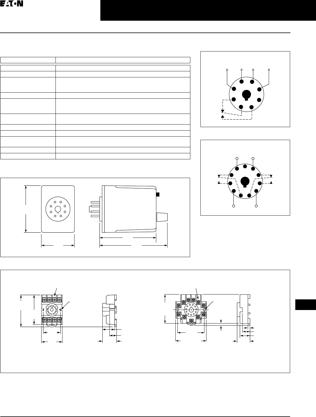
CA08102002K07A For more information visit: www.EatonCanada.ca
3-95
Control Relays & Timers
April 2009
3
Current Monitoring Relays
D65C Series — Undercurrent Monitors
Technical Data and Specifications
Table 3-150. Technical Data — D65C Series, Undercurrent Monitors
Dimensions
Figure 3-129. D65CL Series — Approximate Dimensions in Inches (mm)
Figure 3-130. D3PA2 and D3PA3 Sockets — Approximate Dimensions in Inches (mm)
Description Specifications
Input Voltage Tolerance AC Operation: +10/-15% of nominal voltage at 50/60 Hz.
Load (Burden) Less than 5 VA
Current Settings:
Pick-Up
Drop-Out
Fixed at 5% above adjustable drop-out setting
Adjustable throughout current range monitored
Temperature -20 to 131°F (-28 to 55°C)
Response Times:
Pick-Up
Drop-Out
Fixed at 100 mS
Adjustable 0.1 – 10 seconds
Output Contacts 10A Resistive @240V AC / 30V DC
1/2 hp @ 240V AC (NO); 1/3 hp @ 240V AC (NC)
Mechanical Life 10,000,000 operations
Electrical Life 100,000 operations
Indicator LED Green when input voltage is applied; Red Flashing when in time delay;
Red Steady when relay is energized
Reset Automatic
Mounting Requires an 8- or 11-pin socket
2.4
(60)
1.7
(43)
2.9
(74) 3.5
(89)
0.97
(24.6)
Max.
0.82 (20.8)
0.58 (14.7)
2.03
(51.4)
Two 0.165
(4.2) Dia.
Slots
2.14
(54.3)
1.60
(40.5)
Max.
1.30
(32.9)
6-32 x 0.312 Combination
Head Screw and Pressure Clamping Plate
(8 Places)
Tolerances: ± 0.010
± (0.25)
Unless Otherwise Shown
6-32 x 0.312 Combination
Head Screw and Pressure Clamp
(11 Places)
2.05
(52.07)
Max.
2.33 (59.1)
Max.
2.06
(52.3)
0.97
(24.6)
0.77 (19.6)
0.58 (14.7)
0.15 (3.6)
0.125 – 0.156
(3.17 – 3.96))
Two 0.17
(4.3) Dia.
Holes
Tolerances: ± 0.010
± (0.25)
Unless Otherwise Shown
D3PA2 D3PA3
Schematics
Figure 3-131. Wiring for 8-Pin Socket
Figure 3-132. Wiring for 11-Pin Socket
1
4
(L1)
Monitored
Current
Input
Voltage
(L2)
36
27
8
5
1
(L1) (L2)
11
Monitored
Current
48
39
6
210
75
TAB49.BOO Page 95 Thursday, March 5, 2009 7:36 PM
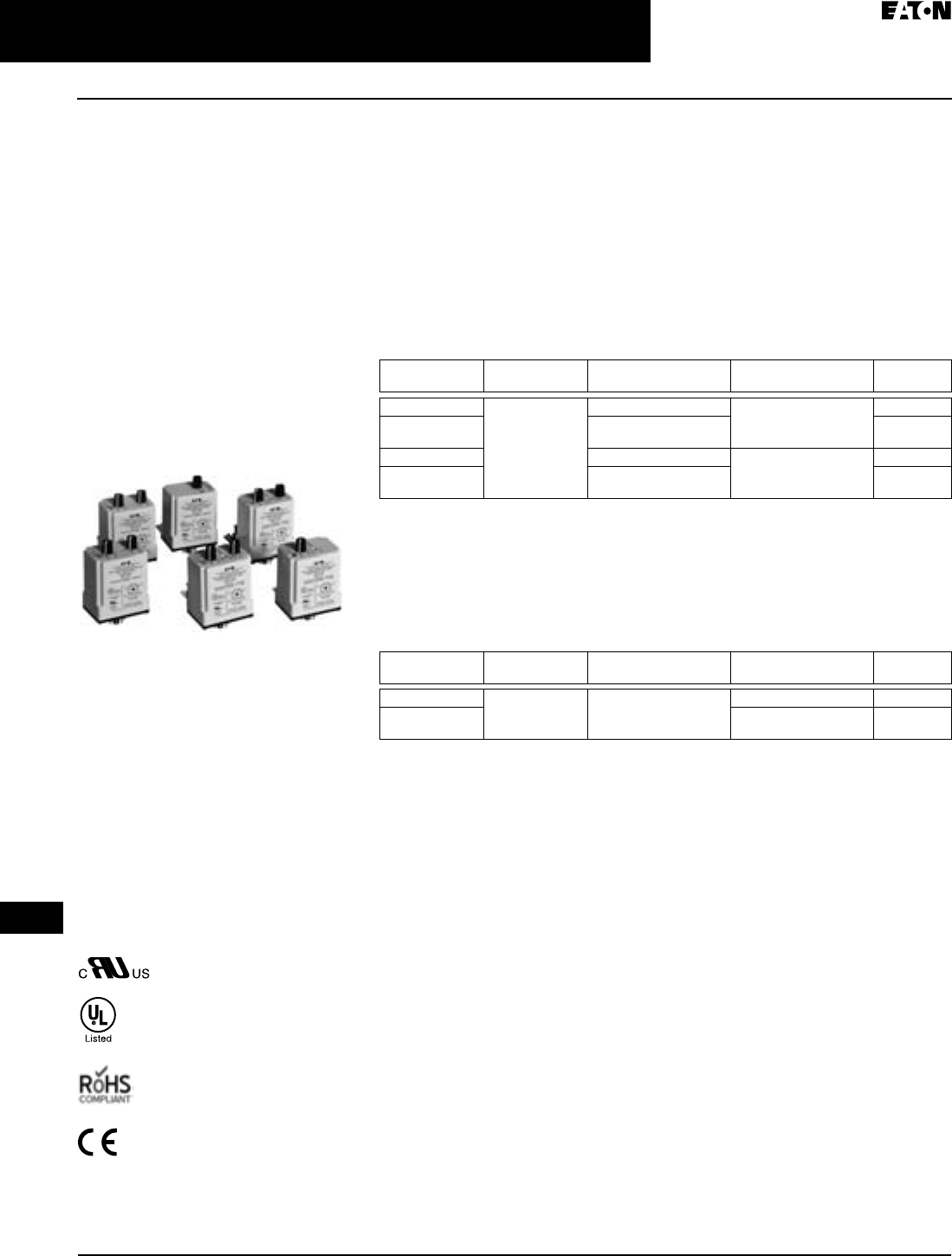
April 2009
3-96
For more information visit: www.EatonCanada.ca CA08102002K07A
Control Relays & Timers
3
Voltage Monitoring Relays
D65V Series — Product Family Overview
Contents
Description Page
D65V Series, Voltage Monitoring
Product Family
Overview . . . . . . . 3-96
Fixed Time Delay for
Over/Undervoltage —
D65VMP and
D65VMKP
Series . . . . . . . . . . 3-97, 3-99
Adjustable Time Delay for
Over/Undervoltage —
D65VAP and
D65VAKP
Series . . . . . . . . . . 3-98, 3-99
Voltage Band —
D65VW Series . . . 3-100
Product Family Overview
Voltage Monitoring Relays monitor
either AC single-phase (50/60 Hz) or DC
voltages to protect equipment against
voltage fault conditions. No separate
supply (input) voltage is required. All
versions are available in a compact plug-
in case utilizing an 8-pin octal socket.
There are two styles of Voltage
Monitoring Relays —
■Over/Undervoltage Relays
■Voltage Band Relays
Standards and Certifications
When used with accompanying
Eaton socket.
Product Family Selection
Over/Undervoltage Relays
Over/Undervoltage Relays provide protection to equipment where either an over-
or undervoltage condition is potentially damaging. Each relay can be used as
either an overvoltage or an undervoltage relay, depending on the output contact
used. When used as an undervoltage relay, it provides protection to equipment
that is required to operate above a minimum voltage. When used as an
overvoltage relay, it protects equipment against excessive voltage conditions.
Over/undervoltage relays are designed to operate when the operating voltage
reaches a preset value and drop out when the operating voltage drops to a level
below the preset value.
Table 3-151. D65V Product Family Selection — Over/Undervoltage Relays
Fixed time delay eliminates nuisance tripping due to short voltage surges or drops.
Voltage Band Relays
Voltage Band Relays provide protection to equipment that is required to operate
within an upper and lower voltage limit. As long as the operating voltage remains
within an over- and undervoltage range, the internal relay stays energized. If the
operating voltage falls outside this range, the relay will drop out.
Table 3-152. D65V Product Family Selection — Voltage Band Relays
Fixed time delay eliminates nuisance tripping due to short voltage surges or drops.
Series Pick-Up
Voltage
Drop-Out
Voltage
Time Delay
Drop-Out
Page
D65VMP Adjustable
85 – 115% Nomi-
nal
Fixed at 95% of Pick-Up Fixed 500 mS 3-97
D65VMKP Adjustable 75 – 95% of
Pick-Up
3-97
D65VAP Fixed at 95% of Pick-Up Adjustable
0.5 – 10 seconds
3-98
D65VAKP Adjustable 75 – 95% of
Pick-Up
3-98
Series Pick-Up
Voltage
Drop-Out
Voltage
Time Delay
Drop-Out
Page
D65VWP Adjustable 100 –-
125% Nominal
Adjustable
75 – 100% of Nominal
Fixed 500 mS 3-100
D65VWKP Adjustable
0.5 – 10 seconds
3-100
TAB49.BOO Page 96 Thursday, March 5, 2009 7:36 PM
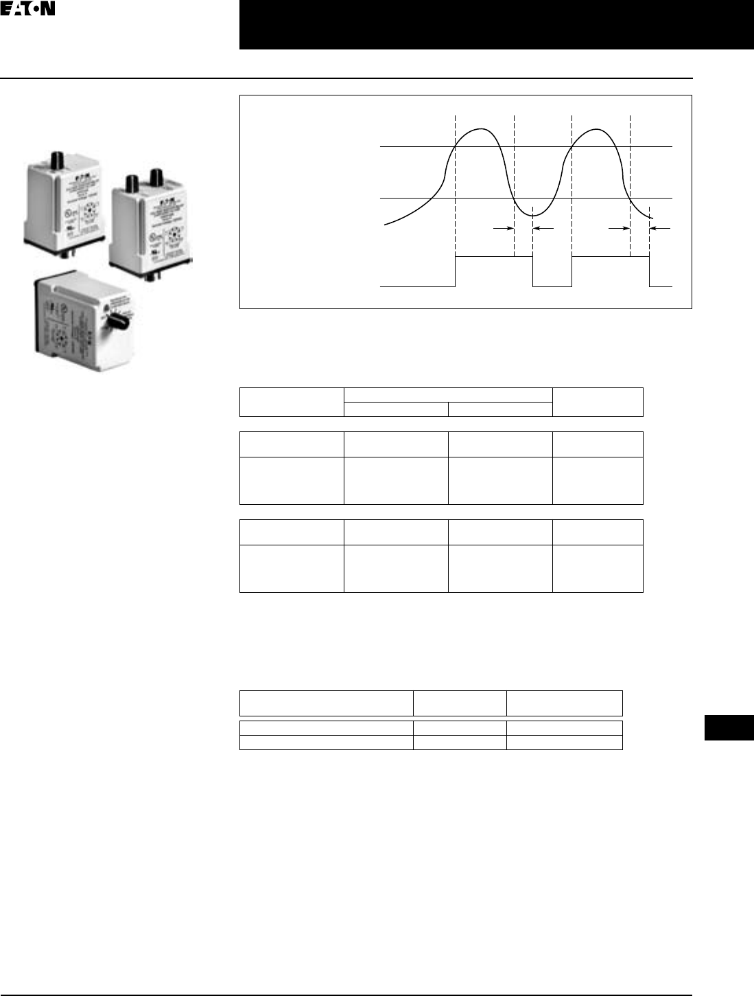
April 2009
CA08102002K07A For more information visit: www.EatonCanada.ca
3-97
Control Relays & Timers
3
Voltage Monitoring Relays
D65V Series — Fixed Time Delay Over/Undervoltage Relays
Fixed Time Delay for
Over/Undervoltage
Product Description
The D65VMRP & D65VMKP Over/Und-
ervoltage Relays provide protection to
equipment where either an over- or
undercurrent condition is potentially
damaging. They are designed to oper-
ate when the operating voltage
reaches a preset value and drop out
when the operating voltage drops to a
level below the preset value.
The pick-up voltage setting is user-
adjustable from 85 – 115% of the nomi-
nal voltage rating. As standard, the
D65VMRP Series has a drop-out volt-
age setting fixed at 95% of the pick-up
voltage setting. An adjustable drop-out
setting of 75 – 95% of the pick-up set-
ting is available on the D65VMKP
Series. The relay energizes when the
monitored voltage is above the pick-up
setting. The relay de-energizes when
the monitored voltage is below the
drop-out setting for a period longer
than the drop-out time delay, which is
fixed at 500 mS. An adjustable time
delay on drop-out of 0.5 – 10 seconds
is available.
Features
■Monitors AC single-phase and
DC voltages
■Wide range of user-adjustable pick-
up and drop-out settings
■Fixed time delay on drop-out of
500 mS
■LED indicates output relay status
■Compact plug-in case utilizing
industry standard 8-pin socket
■10A DPDT output contacts
D65VMP & D65VMKP Series
Over/Undervoltage Relays
Figure 3-133. Fixed Time Delay Over/Undervoltage
Product Selection
Table 3-153. Product Selection — D65VMP & D65VMKP Series, Over/Undervoltage Relays
Drop-out voltage is fixed at 95% of the adjusted Pick-Up Setting.
Drop-out voltage is adjustable from 75 – 95% of the adjusted Pick-Up Setting.
Time delay on drop-out fixed at 500 mS.
Accessories
Table 3-154. Accessories — Over/Undervoltage Relays
Monitored
Voltage
Relay
Output
Pick-Up
Voltage
Drop-Out
Voltage
On
TT
Off
Nominal
Voltage
Voltage Range Catalogue
Number
Pick-Up Drop-Out
Adjustable Pick-Up, Fixed Drop-Out Settings
24V AC
120V AC
21 – 27V AC
102 – 138V AC
20 – 26V AC
97 – 131V AC
D65VMRPT
D65VMRPA
12V DC
24V DC
48V DC
110V DC
10 – 14V DC
21 – 27V DC
41 – 55V DC
94 – 126V DC
9 – 13V DC
20 – 26V DC
39 – 52V DC
89 – 121V DC
D65VMRPR1
D65VMRPT1
D65VMRPW1
D65VMRPA1
Adjustable Pick-Up and Drop-Out Settings
24V AC
120V AC
21 – 27V AC
102 – 138V AC
16 – 26V AC
77 – 131V AC
D65VMKPT
D65VMKPA
12V DC
24V DC
48V DC
110V DC
10 – 14V DC
21 – 27V DC
41 – 55V DC
94 – 126V DC
8 – 13V DC
16 – 26V DC
32 – 52V DC
71 – 121V DC
D65VMKPR1
D65VMKPT1
D65VMKPW1
D65VMKPA1
Description Standard Pack Catalogue
Number
8-Pin Socket 10 D3PA2
Hold Down Spring 10 D65CHDS
TAB49.BOO Page 97 Thursday, March 5, 2009 7:36 PM
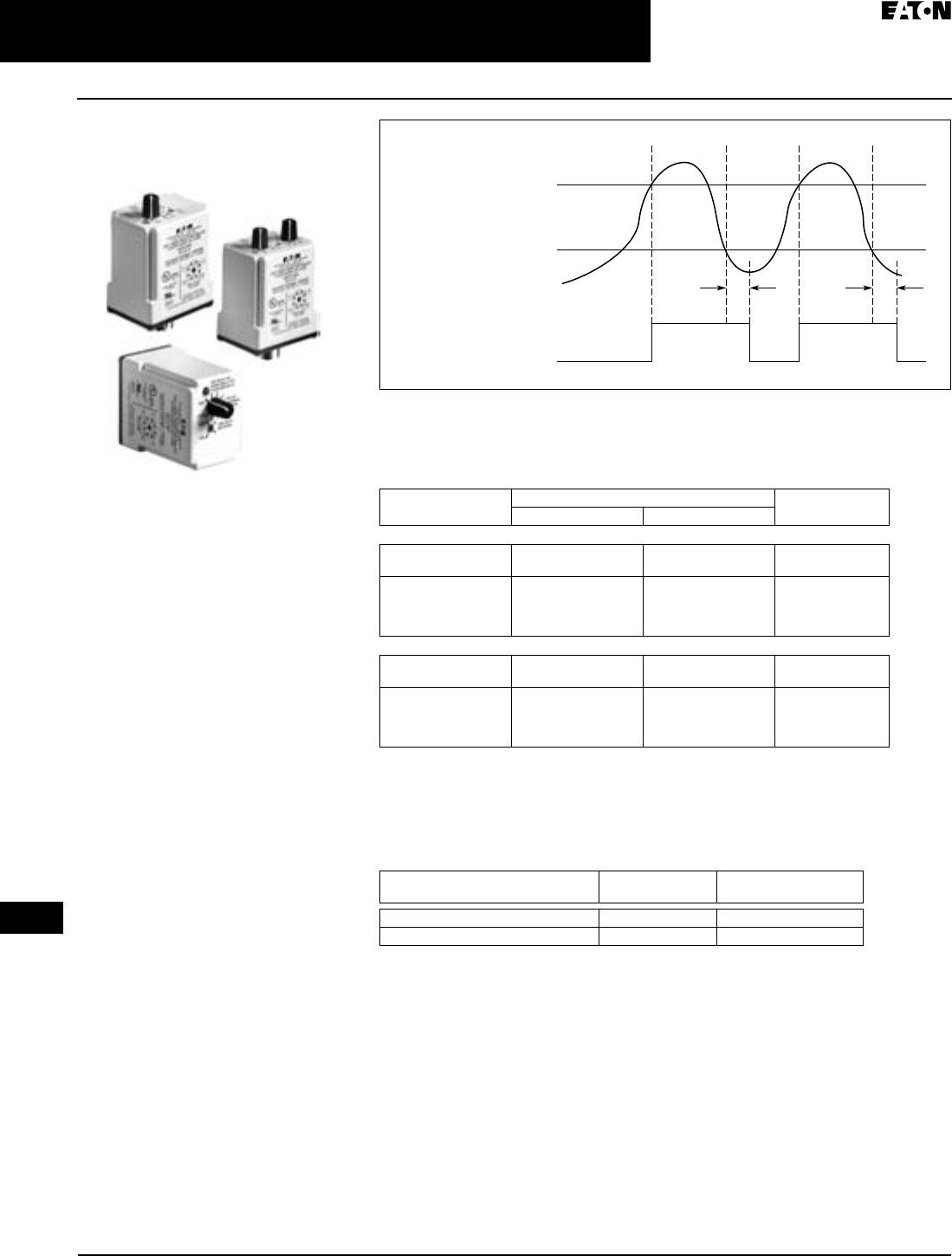
April 2009
3-98
For more information visit: www.EatonCanada.ca CA08102002K07A
Control Relays & Timers
3
Voltage Monitoring Relays
D65V Series — Adjustable Time Delay Over/Undervoltage Relays
Adjustable Time Delay for
Over/Undervoltage
Product Description
The D65VAP & D65VAKP Over/Under-
voltage Relays provide protection to
equipment where either an over- or
undercurrent condition is potentially
damaging. They are designed to oper-
ate when the operating voltage
reaches a preset value and drop out
when the operating voltage drops to a
level below the preset value.
The pick-up voltage setting is user-
adjustable from 85 – 115% of the nomi-
nal voltage rating. As standard, the
D65VAP Series has a drop-out voltage
setting fixed at 95% of the pick-up volt-
age setting. An adjustable drop-out
setting of 75 – 95% of the pick-up set-
ting is available on the D65VAKP
Series. The relay energizes when the
monitored voltage is above the pick-up
setting. The relay de-energizes when
the monitored voltage is below the
drop-out setting for a period longer
than the drop-out time delay, which is
adjustable from 0.5 – 10 seconds. A
fixed time delay of 500 mS is available
with the D65VMP Series.
Features
■Monitors AC single-phase and
DC voltages
■Wide range of user-adjustable pick-
up and drop-out settings
■Adjustable time delay on drop-out
of 0.5 – 10 seconds
■LED indicates output relay status
■Compact plug-in case utilizing
industry standard 8-pin socket
■10A DPDT output contacts
D65VAP & D65VAKP Series
Over/Undervoltage Relays
Figure 3-134. Adjustable Time Delay Over/Undervoltage
Product Selection
Table 3-155. Product Selection — D65VAP & D65VAKP Series, Over/Undervoltage Relays
Drop-out voltage is fixed at 95% of the adjusted Pick-Up Setting.
Drop-out voltage is adjustable from 75 – 95% of the adjusted Pick-Up Setting.
Adjustable time delay on drop-out from 0.5 – 10 seconds.
Accessories
Table 3-156. Accessories — Over/Undervoltage Relays
Monitored
Voltage
Relay
Output
Pick-Up
Voltage
Drop-Out
Voltage
On
TT
Off
Nominal
Voltage
Voltage Range Catalogue
Number
Pick-Up Drop-Out
Adjustable Pick-Up, Fixed Drop-Out Settings
24V AC
120V AC
21 – 27V AC
102 – 138V AC
20 – 26V AC
97 – 131V AC
D65VAPT
D65VAPA
12V DC
24V DC
48V DC
110V DC
10 – 14V DC
21 – 27V DC
41 – 55V DC
94 – 126V DC
9 – 13V DC
20 – 26V DC
39 – 53V DC
89 – 121V DC
D65VAPR1
D65VAPT1
D65VAPW1
D65VAPA1
Adjustable Pick-Up and Drop-Out Settings
24V AC
120V AC
21 – 27V AC
102 – 138V AC
16 – 26V AC
77 – 131V AC
D65VAKPT
D65VAKPA
12V DC
24V DC
48V DC
110V DC
10 – 14V DC
21 – 27V DC
41 – 55V DC
94 – 126V DC
8 – 13V DC
16 – 26V DC
32 – 52V DC
71 – 121V DC
D65VAKPR1
D65VAKPT1
D65VAKPW1
D65VAKPA1
Description Standard Pack Catalogue
Number
8-Pin Socket 10 D3PA2
Hold Down Spring 10 D65CHDS
TAB49.BOO Page 98 Thursday, March 5, 2009 7:36 PM

CA08102002K07A For more information visit: www.EatonCanada.ca
3-99
Control Relays & Timers
April 2009
3
Voltage Monitoring Relays
D65V Series — Fixed and Adjustable Time Delay Over/Undervoltage Relays
Technical Data and Specifications
Table 3-157. Technical Data — D65VMP, D65VMKP, D65VAP & D65VAKP Series,
Over/Undervoltage Relays
Schematics
Figure 3-135. Wiring for 8-Pin Socket
Dimensions
Figure 3-136. D65V Series — Approximate Dimensions in Inches (mm)
Description Specifications
Voltage Tolerance +25%/-50% of nominal voltage; AC voltages are 50/60 Hz;
No supply (input) voltage is required
Load (Burden) Less than 3VA
Voltage Settings:
Pick-Up
Drop-Out
Adjustable from 85 – 115% of nominal voltage
Fixed at 95% of the pick-up setting for D65VMP and D65VAP
Adjustable from 75 – 95% of the pick-up setting for D65VMKP
and D65VAKP
Temperature -20 to 131°F (-28 to 55°C)
Response Times:
Operate
Release
500 mS
Fixed 500 mS for D65VMP and D65VMKP
Adjustable 0.5 – 10 seconds for D65VAP and D65VAKP
Output Contacts 10A Resistive @240V AC / 30V DC, 1/2 hp @ 240V AC (NO),
1/3 hp @ 240V AC (NC)
Mechanical Life 10,000,000 operations
Electrical Life 100,000 operations
Indicator LED Red Steady when relay is energized; Green when relay is off
Transient Protection 10,000 volts for 20 microseconds
Reset Automatic
Mounting Requires an 8-pin socket
Monitored
Voltage
1
(DC)+
L1
(DC)−
L2
8
4
36
27
5
2.4
(60)
1.7
(43)
2.9
(74) 3.5
(89)
D65VMKP &
D65VAKP Only
Application Description
Each relay can be used as either an
overvoltage or an undervoltage relay,
depending on the output contact used.
Overvoltage Relay
Provides protection to equipment that
cannot handle excess voltages. Uses a
normally closed contact (NC). As long as
the monitored voltage remains below
the maximum voltage the equipment
can withstand (Pick-Up Setting), the relay
remains energized and the NC contact
remains closed, keeping the load
energized. If the operating voltage
increases beyond the maximum rating
of the equipment, the relay energizes
and the NC contact opens, turning off the
load. When the voltage falls below the
Drop-Out Settings (hysteresis), the relay
de-energizes and the NC contact
re-closes, turning on the load.
Undervoltage Relay
Provides protection to equipment that
is required to operate above a certain
minimum voltage. Uses a normally
open contact (NO). As long as the
monitored voltage is above the mini-
mum value required (Pick-Up Setting),
the relay will energize and the NO
contact closes, turning on the load. If
the voltage drops below the Drop-Out
Setting (the minimum voltage required
minus hysteresis), the relay will de-
energize and the NO contact will re-
open, turning off the load.
TAB49.BOO Page 99 Thursday, March 5, 2009 7:36 PM
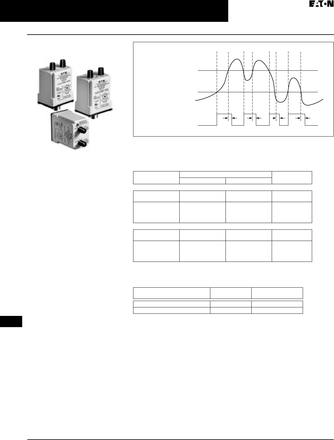
April 2009
3-100
For more information visit: www.EatonCanada.ca CA08102002K07A
Control Relays & Timers
3
Voltage Monitoring Relays
D65V Series — Voltage Band Relays
Voltage Band
Product Description
The D65VWP & D65VWKP Series
Voltage Band Relays provide
protection to equipment that is
required to operate within an upper
and lower voltage limit. As long as the
operating voltage remains within an
over- and undervoltage range, the
internal relay stays energized. If the
operating voltage falls outside this
range, the relay will drop out.
When nominal operating voltage is
applied, the internal relay will energize
(pick up). If the operating voltage falls
outside the preset over trip point
(adjustable 100 – 125% of nominal), or
under trip point (adjustable 75 – 100% of
nominal), for a period longer than the
drop-out time delay, the relay will de-
energize (drop out). When the voltage
returns to normal (within the preset over-
and undervoltage trip points), the unit
automatically resets and the relay
energizes. Choose between a unit with
fixed drop-out time of 500 mS or one
with an adjustable 0.5 – 10 seconds drop-
out time.
Features
■Monitors AC single-phase and
DC voltages
■Provides voltage band (window)
protection
■Wide range of user-adjustable over-
voltage and undervoltage settings
■Fixed or adjustable time delay on
drop-out
■LED indicates output relay status
■Compact plug-in case utilizing
industry standard 8-pin octal socket
■10A DPDT output contacts
D65VW Series
Voltage Band Relays
Figure 3-137. Voltage Band Relays
Product Selection
Table 3-158. Product Selection — D65VWP & D65VWKP Series, Voltage Band Relays
Accessories
Table 3-159. Accessories — Voltage Band Relays
Under
Voltage
Over
Voltage
Monitored
Voltage
Relay
Output
On
Off
TT TT
Nominal
Voltage
Voltage Range Catalogue
Number
Over Under
Fixed Drop-Out Time Delay, 500 mS
24V AC
120V AC
24 – 30V AC
120 – 150V AC
18 – 24V AC
90 – 120V AC
D65VWPT
D65VWPA
12V DC
24V DC
48V DC
110V DC
12 – 15V DC
24 – 30V DC
48 – 60V DC
110 – 137V DC
9 – 12V DC
18 – 24V DC
36 – 48V DC
83 – 110V DC
D65VWPR1
D65VWPT1
D65VWPW1
D65VWPA1
Adjustable Drop-Out Time Delay (0.5 – 10 Seconds)
24V AC
120V AC
24 – 30V AC
120 – 150V AC
18 – 24V AC
90 – 120V AC
D65VWKPT
D65VWKPA
12V DC
24V DC
48V DC
110V DC
12 – 15V DC
24 – 30V DC
48 – 60V DC
110 – 137V DC
9 – 12V DC
18 – 24V DC
36 – 48V DC
83 – 110V DC
D65VWKPR1
D65VWKPT1
D65VWKPW1
D65VWKPA1
Description Standard Pack Catalogue
Number
8-Pin Socket 10 D3PA2
Hold Down Spring 10 D65CHDS
TAB49.BOO Page 100 Thursday, March 5, 2009 7:36 PM
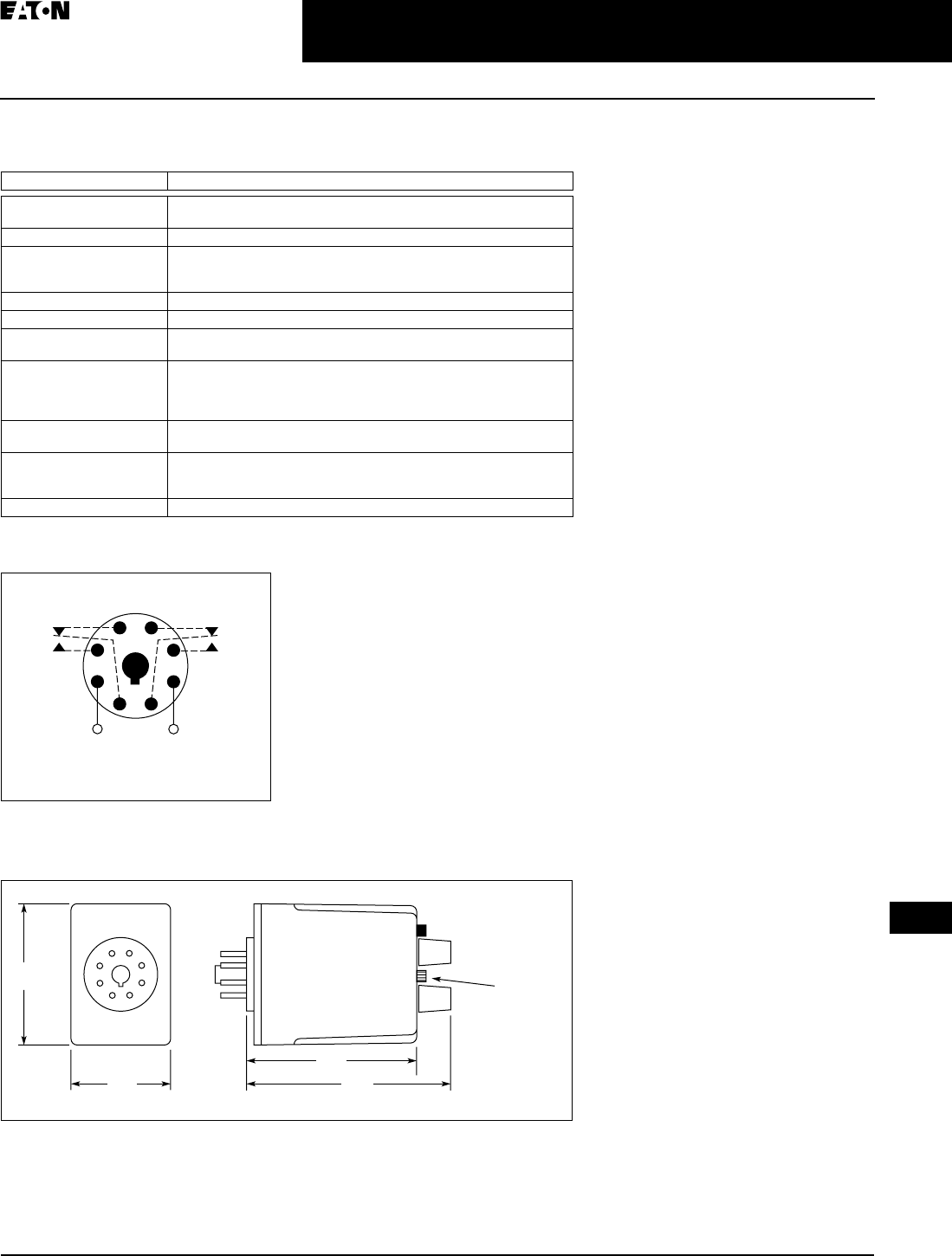
CA08102002K07A For more information visit: www.EatonCanada.ca
3-101
Control Relays & Timers
April 2009
3
Voltage Monitoring Relays
D65V Series — Voltage Band Relays
Technical Data and Specifications
Table 3-160. Technical Data — D65VWP & D65VWPK Series, Voltage Band Relays
Schematic
Figure 3-138. Wiring for 8-Pin Socket
Dimension
Figure 3-139. D65V Series — Approximate Dimensions in Inches (mm)
Description Specifications
Voltage Tolerance +25%/-50% of nominal voltage; AC voltages are 50/60 Hz;
No separate supply (input) voltage is required.
Load (Burden) Less than 3 VA
Voltage Settings:
Overvoltage
Undervoltage
100 – 125% of nominal voltage
75 – 100% of nominal voltage
Temperature -20° to 131°F (28° to 55°C)
Indicator LED Red steady when relay is energized; Green when relay is OFF
Reset Automatic. Contact Eaton for information on how to order a unit with
Manual Reset.
Response Times:
Operate
Release
500 mS
Fixed 500 mS (D65VWP Series)
Adjustable 0.5 – 10 seconds (D65VWKP Series)
Output Contacts 10A Resistive @ 240V AC / 30V DC, 1/2 hp @ 240V AC (NO),
1/3 hp @ 240V AC (NC)
Life:
Mechanical
Electrical
10,000,000 operations
100,000 operations
Transient Protection 10,000 volts for 20 microseconds
Monitored
Voltage
1
(DC)+
L1
(DC)−
L2
8
4
36
27
5
2.4
(60)
1.7
(43)
2.9
(74) 3.5
(89)
D65VWKP
Only
TAB49.BOO Page 101 Thursday, March 5, 2009 7:36 PM
April 2009
3-102
For more information visit: www.EatonCanada.ca CA08102002K07A
Control Relays & Timers
3
Voltage Monitoring Relays
VSR Series — Solid-State, Single-Phase
VSR Series — Solid-State,
Single-Phase Voltage Sensing
Product Description
The Catalogue Number VSR voltage
sensing relays are highly accurate,
solid-state, AC voltage sensing devices
available in both overvoltage and und-
ervoltage types. They include built-in
locking shaft potentiometers for voltage
and differential adjustment. Relay cir-
cuit boards are conformal contact for
environment-free operation. Input is
transformer isolated from solid-state
output contact. Mounting dimensions
are the same as Catalogue Number BF
relays.
Features
■Same base plate as Catalogue Num-
ber BF relay, mounts in same area
■Captive, pressure clamp terminals —
accept 1 or 2 solid or stranded 14
AWG or smaller wires
■Adjustment potentiometer with
locking shafts — provides shock-
proof adjustment
■Conformal coated printed circuit
board — protects relay against
shock, moisture, dirt and other
environmental hazards
■Built-in surge protection — protects
internal solid-state contact from dam-
age due to load and line transients
Technical Data and
Specifications
Electrical Ratings
■Operating Voltage Range:
70 – 140V AC, 200 – 280V AC
3 VA burden
■Variable Differential Range:
see curves at right
■Repeatability: ±0.5V AC of setting
■Solid-State Contacts:
2A continuous maximum inductive
or resistive, 132V AC maximum
Note: Can initiate a Size 4 motor starter.
Catalogue Number VSR Voltage
Sensitive Relay
Note: 12A RMS maximum inrush for 3
cycles. If inrush current is greater than 12A
and relay is operated more than 30 times
per minute, derating may be necessary. If
surge current is 12A or less, no derating is
necessary. If currents exceeding these rat-
ings could occur, a series fuse having an I2t
rating equal to 3A squared seconds is rec-
ommended.
■Ambient Temperature Range:
-20° to 60°C
Note: For operation in a higher ambient
temperature, derating may be necessary.
■Open Contact Leakage Current:
3 mA maximum
■Closed Contact Voltage Drop:
3V AC maximum
Operating Curves
Undervoltage Relay
Solid-state NO contact closes when
voltage exceeds upper limit set by
voltage adjustment potentiometer.
Contact remains closed until voltage
drops below the value set with differ-
ential adjustment. Contact will not
reclose until voltage once again
exceeds upper limit.
Overvoltage Relay
Providing a minimum of 60V input is
present, solid-state contact is NC. Dif-
ferential adjustment sets upper limit
where contact will open. After open-
ing, contact will remain open until volt-
age drops below value set with voltage
adjustment potentiometer.
Figure 3-140. Operating Curves
Voltage Ranges
Figure 3-141. Relay Pick-Up and Drop-Out Voltage Ranges
200 Volts
Minimum
70 Volts 280 Volts
120 Volts
to
Line VoltsLine Volts
to
Relay Contact
Status Dropping
Voltage
Relay Contact Status
Rising Voltage
CW
CCW
CCW
CW
Voltage Adjustment
(Pickup)
Differential
Adjustment
(Dropout)
1 Volt Minimum
Recommended
Differential
Maximum
200 Volts
Minimum
100 Volts 280 Volts
140 Volts
to
to
0 Volts
60 Volts
0 Volts
Relay Contact
Status Dropping
Voltage
Relay Contact Status
Rising Voltage
CW
CCW
Potentiometer Rotation
Potentiometer Rotation
CW
CCW
Voltage Adjustment
(Pickup)
Differential
Adjustment
(Dropout)
3 Volts Minimum
Recommended
Differential
Maximum
Diff. Adj. Max. CW
Pickup Voltage
(Variable from
100 to 137 Volts AC
or 200 Volts AC)
Dropout Voltage
(Variable Between
3 Volts AC More Than
Pickup Voltage and
140 Volts AC)
050
% Rotation Voltage Adj. Control
Overvoltage
100
140
or 280
100
or 200 3 VA-C
Diff. Adj.
Max. CCW
Line Voltage (VA-C)
on Terminals 1 & 2
Dropout Voltage
(Variable Between
70 Volts AC and
1 Volt AC Less Than
Pickup Voltage)
Diff. Adj. Max. CW
1 VA-C
Diff. Adj.
Max. CCW
050
% Rotation Voltage Adj. Control
Undervoltage
100
120
or 280
70
or 200
Line Voltage (VA-C)
on Terminals 1 & 2
Pickup Voltage (Variable
from 70 to 120 Volts AC
or 200 to 280 Volts AC)
TAB49.BOO Page 102 Thursday, March 5, 2009 7:36 PM

CA08102002K07A For more information visit: www.EatonCanada.ca
3-103
Control Relays & Timers
April 2009
3
Voltage Monitoring Relays
VSR Series — Solid-State, Single-Phase
Dimensions
Figure 3-142. Approximate Dimensions in Inches (mm)
Product Selection
When Ordering Specify
■Catalogue Number of Basic Relay.
Table 3-161. Voltage Sensing Relays
Description Voltage
Range
Catalogue
Number
Undervoltage Relay 70 – 120V AC
200 – 280V AC
VSRUA
VSRUB
Overvoltage Relay 100 – 140V AC
200 – 280V AC
VSROA
VSROB
4.69 (119.1)
0.5 (12.7)
Catalog Number VSR
3.13
(79.5)
1 (25.4)
2.81
(71.4)
0.16
(4.1)
1.63
(41.4)
0.81
(20.6)
Voltage Input:
Terminals 1 and 2
Solid-State Output:
Terminals 3 and 4
0.17 (4.3) Dia.
3 Mtg. Slots Lock
Nut
TAB49.BOO Page 103 Thursday, March 5, 2009 7:36 PM
April 2009
3-104
For more information visit: www.EatonCanada.ca CA08102002K07A
Control Relays & Timers
3
Alternating Relays
D85 Series
D85 Series — Alternating
Relays
Product Description
Alternating relays are used in applica-
tions where the optimization of load
usage is required by equalizing the run
time of two loads. They are also used
where additional capacity is required
in case of excess load requirements.
This alternating action is initiated by a
control switch — such as a float switch,
manual switch, timing relay, pressure
switch or other isolated contact. Each
time the initiating switch is opened,
the output relay contacts will change
state, thus alternating the two loads.
Two LED indicators show the status of
the output relay.
The D851 and D852 Series Relays are
used with one control switch and are
available in either SPDT or DPDT out-
put configurations with or without a
selector switch to lock in one
sequence. The D852X Series Relays are
available in DPDT Cross-Wired output
configurations for use with one or two
control switches (LEAD and LAG).
The D853 Series is designed for use
with three-switch applications (LEAD,
LAG and STOP). The D853 Series com-
bines a standard DPDT Cross-Wired
alternating relay, contactor auxiliary
contacts, and a control relay into one
compact and economical product. This
saves space and labor, while reducing
the number of components needed.
The D853 Series uses Sequence On –
Simultaneous Off (S.O.S.O.) operation,
where the two loads are energized
sequentially, but remain on together
until the STOP switch is opened. This
device also protects against failure of
the STOP and LEAD switches. If both
switches fail, the two pump motors
will be energized simultaneously when
the LAG switch is closed.
D85 Series
Alternating Relays
Each of the D85 Series alternating
relays is available with an optional
three-position selector switch, which
allows the unit to alternate the two
loads as normal, or lock the relay to
one load or the other. By locking the
alternating relay to one load, the other
load can be removed for service with-
out rewiring the first load for continu-
ous operation. The selector switch has
a low profile to prevent any accidental
actuation.
Features
■For duplex loads
■Works with 1-, 2-, or 3-switch
applications
■Compact plug-in design utilizing
industry standard sockets
■10A SPDT or DPDT output
configurations
■Optional low profile selector switch
to lock in one sequence
■2 LEDs indicate relay status
■D853 Series replaces separate
components in duplex panel —
saving space and reducing labor
Standards and Certifications
Product Selection
Table 3-162. Product Selection — D85 Series
Contact Eaton for relays for 3-switch applications (Lead-Lag-Stop).
Accessories
Table 3-163. Accessories — D85 Series
with Eaton
socket
Output Contacts Control
Voltage
Socket Catalogue
Number
SPDT 12V AC 8-Pin D851NR
SPDT 24V AC 8-Pin D851NT
SPDT 120V AC 8-Pin D851NA
SPDT 240V AC 8-Pin D851NB
SPDT w/Selector Switch 12V AC 8-Pin D851LR
SPDT w/Selector Switch 24V AC 8-Pin D851LT
SPDT w/Selector Switch 120V AC 8-Pin D851LA
SPDT w/Selector Switch 240V AC 8-Pin D851LB
DPDT 12V AC 11-Pin D852NR
DPDT 24V AC 11-Pin D852NT
DPDT 120V AC 11-Pin D852NA
DPDT 240V AC 11-Pin D852NB
DPDT w/Selector Switch 12V AC 11-Pin D852LR
DPDT w/Selector Switch 24V AC 11-Pin D852LT
DPDT w/Selector Switch 120V AC 11-Pin D852LA
DPDT w/Selector Switch 240V AC 11-Pin D852LB
DPDT Cross-Wired 12V AC 8-Pin D852XNR
DPDT Cross-Wired 24V AC 8-Pin D852XNT
DPDT Cross-Wired 120V AC 8-Pin D852XNA
DPDT Cross-Wired 240V AC 8-Pin D852XNB
DPDT Cross-Wired w/Selector Switch 12V AC 8-Pin D852XLR
DPDT Cross-Wired w/Selector Switch 24V AC 8-Pin D852XLT
DPDT Cross-Wired w/Selector Switch 120V AC 8-Pin D852XLA
DPDT Cross-Wired w/Selector Switch 240V AC 8-Pin D852XLB
Description Standard Pack Catalogue
Number
8-Pin Socket 10 D3PA2
11-Pin Socket 10 D3PA3-A2
Hold Down Spring 10 D65CHDS
TAB49.BOO Page 104 Thursday, March 5, 2009 7:36 PM
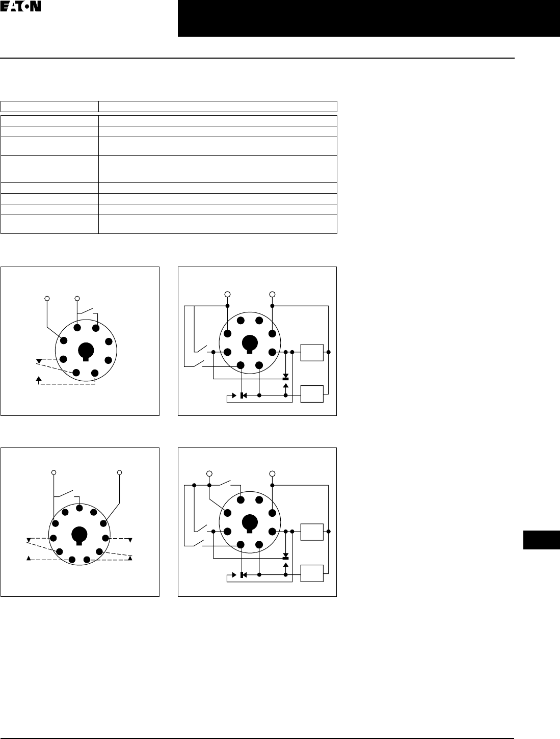
CA08102002K07A For more information visit: www.EatonCanada.ca
3-105
Control Relays & Timers
April 2009
3
Alternating Relays
D85 Series
Technical Data and Specifications
Table 3-164. Technical Data — D85 Series
Schematics
Figure 3-143. Wiring for D851 Series Relays,
SPDT
Figure 3-144. Wiring for D852 Series Relays,
DPDT
Figure 3-145. Wiring for D852X Series Relays,
DPDT Cross-Wired
Figure 3-146. Wiring for D853 Series Relays,
Three-Switch Applications
Description Specifications
Voltage Tolerance +10%/-15% of control voltage at 50/60 Hz
Load (Burden) Less than 3 VA
Output Contacts 10A Resistive @ 240V AC / 30V DC, 1/2 hp @ 120/240V AC (NO),
1/3 hp @ 120/240V AC (NC)
Life:
Mechanical
Electrical
10,000,000 operations
100,000 operations
Temperature -20° to 150°F (-28° to 65°C)
Transient Protection 10,000 volts for 20 microseconds
Indicator LEDs 2 LEDs marked LOAD A and LOAD B
Optional Selector Switch
Settings
ALTERNATE, LOCK LOAD A, LOCK LOAD B
Load A: Pin 2
Load B: Pin 8
1
4
Input
Voltage
Control
Switch
L2 L1
36
27
8
5
1
Load A: Pins 3 or 11
Load B: Pins 1 or 9
L2L1
11
Input
Voltage
Control
Switch
48
39
6
210
75
1
Lead
Lag
Load
B
Load
A
L1 L2
8
Input
Voltage
4
36
27
5
1
Lead
Lag
Load
B
Load
A
L1 L2
Stop
8
Input Voltage
4
36
27
5
TAB49.BOO Page 105 Thursday, March 5, 2009 7:36 PM
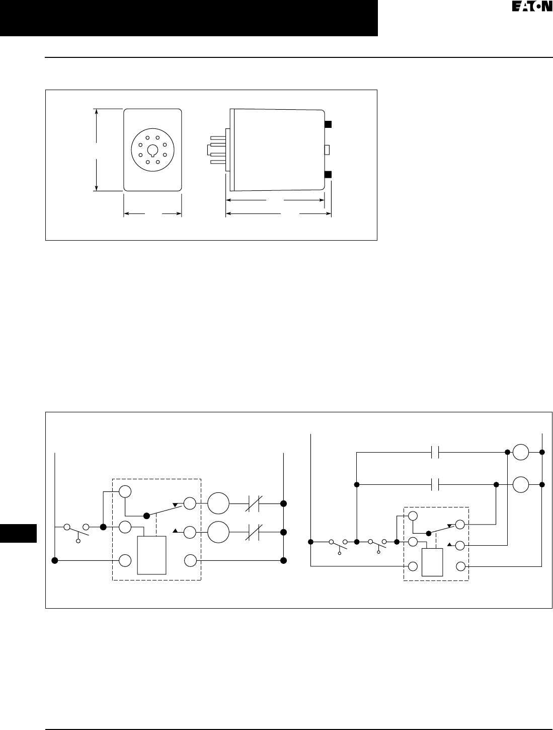
April 2009
3-106
For more information visit: www.EatonCanada.ca CA08102002K07A
Control Relays & Timers
3
Alternating Relays
D85 Series
Dimensions
Figure 3-147. D85 Series — Approximate Dimensions in Inches (mm)
Typical Installations
SPDT and DPDT Alternating Relays
In the OFF state (Standard Installation),
the Control Switch is open, the Alter-
nating Relay is in the LOAD A position,
and both loads (M1 & M2) are off.
When the Control Switch closes, it
energizes the first load (M1). The red
LED marked “LOAD A” glows. As long
as the Control Switch remains closed,
M1 remains energized. When the Con-
trol Switch opens, the first load (M1) is
turned off and the Alternating Relay
toggles to the LOAD B position. When
the Control Switch closes again, it
energizes the second load (M2). The
red LED marked “LOAD B” glows.
When the Control Switch opens, the
second load (M2) is turned off, the
Alternating Relay toggles back to the
LOAD A position, and the process can
be repeated again. On relays with
DPDT contacts, two pilot lights can be
used for remote indication of LOAD A
or LOAD B status.
To eliminate any bounce condition of
the Control Switch, the addition of a
second switch (OFF) along with two
auxiliary contacts is recommended as
shown in the Anti-Bounce Installation.
Figure 3-148. Typical Installations for SPDT and DPDT Alternating Relays
2.4
(60)
1.7
(43)
2.9
(74) 3.1
(79)
L1
SPDT
SPDT
Control
Switch
Control
Switch
O/L
O/L
1
2
8
3
4
5
L1
L2
1
2
3
4
5
Off
M1
M1
M1
M2
L2
M2
M2
8
Standard Installation Anti-Bounce Installation
TAB49.BOO Page 106 Thursday, March 5, 2009 7:36 PM

April 2009
CA08102002K07A For more information visit: www.EatonCanada.ca
3-107
Control Relays & Timers
3
Alternating Relays
D85 Series
DPDT Cross-Wired Alternating Relays
In the OFF state, both the LEAD Con-
trol Switch and the LAG Control Switch
are open, the Alternating Relay is in
the LOAD A position, and both loads
are off. When the LEAD Control Switch
closes, it energizes the first load (M1).
The red LED marked “LOAD A” glows.
As long as the LEAD Control Switch
remains closed, M1 remains ener-
gized. If the LAG Control Switch closes,
it energizes the second load (M2).
When the LAG Control Switch opens,
the second load (M2) is turned off.
When the LEAD Control Switch opens,
the first load (M1) is turned off and the
Alternating Relay toggles to the LOAD
B position. When the LEAD Control
Switch closes, it turns on the second
load (M2). The red LED marked “LOAD
B” glows. If the LAG Control Switch
closes, it will energize the first load
(M1). When the LAG Control Switch
opens, the first load (M1) is turned off.
When the LEAD Control Switch opens,
the second load (M2) is turned off, the
Alternating Relay toggles back to the
LOAD A position, and the process can
be repeated again.
To eliminate any bounce condition of
the Control Switch, the addition of a
second switch (OFF) along with two
auxiliary contacts is recommended as
shown in the Anti-Bounce Installation.
Figure 3-149. Typical Installations for DPDT Cross-Wired Alternating Relays
L1
Lag
Lead
Lag
Off Lead
Cross-Wired
O/L
O/L
1
28
3
7
6
L2
L2
L1
M1
Cross-Wired
M2
1
2
3
7
6
M1
M1
M2
M2
8
Standard Installation Anti-Bounce Installation
TAB49.BOO Page 107 Thursday, March 5, 2009 7:36 PM
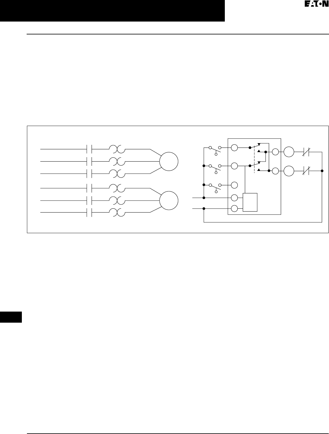
April 2009
3-108
For more information visit: www.EatonCanada.ca CA08102002K07A
Control Relays & Timers
3
Alternating Relays
D85 Series
DPDT Cross-Wired for Three-Switch Applications
In the OFF state, all three switches are
open, the Alternating Relay is in the
LOAD A position, and both loads are
off. No action happens with the Alter-
nating Relay or either load when the
STOP Switch closes. When the LEAD
Switch closes, Load #1 (M1) turns on.
When the LAG Switch closes, Load #2
(M2) turns on. Both loads remain on as
long as all three switches are closed.
When the LAG Switch opens, Load #2
(M2) remains on because the STOP
Switch is still closed. When the LEAD
Switch opens, Load #1 (M1) remains
on because the STOP Switch is still
closed. When the STOP Switch opens,
both Load #1 (M1) and Load #2 (M2)
are turned off simultaneously. The
Alternating Relay toggles to the LOAD
B position. The entire cycle is then
repeated, but with Load #2 (M2) ener-
gized first followed by Load #1 (M1).
This type of operation is known as
“Sequence On – Simultaneously Off
(S.O.S.O.)” — the two loads are ener-
gized sequentially, but remain on
together until the STOP switch is
opened.
If both the STOP Switch and LEAD
Switch fail to close and turn on the first
load, both loads will be turned on
simultaneously when the LAG Switch
is closed.
Figure 3-150. Typical Installations for DPDT Cross-Wired Relays for Three-Switch Applications
L1
Motor
1
Motor
2
L2
L3
L1
M1
M1
M1
M2
M2
M2
M2
M1
L2 L1
Lag
Switch
Lead
Switch
Stop
Switch
L2
L3
1
1
1
1
1
1
1
O/L
O/L
TAB49.BOO Page 108 Thursday, March 5, 2009 7:36 PM
April 2009
CA08102002K07A For more information visit: www.EatonCanada.ca
3-109
3
EZ Intelligent Relays
Product Family Overview
EZ Intelligent Relays Product Family
Product Family Overview
The EZ intelligent relays bring timers,
relays, counters, special functions,
inputs and outputs into one
compact
device that is easily configured.
The EZ
family of products provides excep-
tional levels of flexibility together with
substantial savings in commissioning
time and effort.
The EZ intelligent relays are available
in more than 32 different styles that
support from 12 I/O up to 320 I/O
points providing the ideal solution for
lighting, energy management, indus-
trial control, watering, pump control,
HVAC and home automation.
Once EZ products are installed, changes
are easily accomplished through front
panel programming, eliminating the
need to change wiring and wiring dia-
grams increasing the savings realized.
Other terms often used for intelligent
relay are relay replacer, control relay
and smart relay.
Application Description
Generally where multiple relays, timers
and pushbuttons are used there is an
opportunity to evaluate switching to
the EZ Intelligent Relays. Applications
span residential, commercial and
industrial installations. Typical applica-
tions are:
■Car washes.
■Automatic door control.
■Commercial lighting.
■Residential lighting.
■Exterior lighting.
■Pump control, 12V DC automotive
control.
■Greenhouse control.
■Crane control.
■Machinery.
■Paper/pulp.
■Elevator control.
■Livestock feed/gate control.
■Irrigation control.
■Cart chargers.
■Heating and air conditioning.
Control Relays & Timers
TAB49.BOO Page 109 Thursday, March 5, 2009 7:36 PM
April 2009
3-110
For more information visit: www.EatonCanada.ca CA08102002K07A
3
EZ Intelligent Relays
EZ 500/700/800/EZD Intelligent Relays
EZ 500/700/800/EZD Intelligent
Relays
EZ 500/700/800/EZD Intelligent Relays
Product Description
Four families make up the EZ Intelli-
gent Relay product line.
EZ500 Series — for controlling small
applications with up to 12 input/output
signals. Models are available with and
without displays. DIN rail mounted.
EZ700 Series — for controlling
medium-sized applications with up to
40 input/output signals. DIN rail
mounted.
EZ800 Series — for controlling large-
scale applications with up to 320 input/
output signals. Models are available
with and without displays. DIN rail
mounted.
EZD Series — for controlling large-
scale applications with up to 320 input/
output signals using powerful visual-
ization functions. The EZD display can
be linked to the EZ500/700/800 models
to provide an enhanced operator inter-
face. Panel mounted.
The EZ-NET integrated network called
provides easy and inexpensive linking
of up to eight EZ800/EZD devices over
a distance of up to1000 meters. The EZ
and EZD devices can run their own
program or be used as a distributed
input/output module.
Catalogue Number Selection
Table 3-165. EZ500/700/800 Module Definition Catalogue Numbering System
Product Selection
Table 3-166. EZ500 Intelligent Relays
Note: Analogue inputs optional.
Description Inputs Outputs Catalogue
Number
24V
AC
110 – 240V
AC
12V
DC
24V
DC
ALG RY TRN
12 I/O, Clock, Display
12 I/O, Clock, No Display
8
8
—
—
—
—
—
—
2
2
4
4
—
—
EZ512-AB-RC
EZ512-AB-RCX
12 I/O, No Clock, Display
12 I/O, Clock, Display
12 I/O, Clock, No Display
—
—
—
8
8
8
—
—
—
—
—
—
—
—
—
4
4
4
—
—
—
EZ512-AC-R
EZ512-AC-RC
EZ512-AC-RCX
12 I/O, Clock, Display
12 I/O, Clock, No Display
—
—
—
—
8
8
—
—
2
2
4
4
—
—
EZ512-DA-RC
EZ512-DA-RCX
12 I/O, No Clock, Display
12 I/O, Clock, Display
12 I/O, Clock, No Display
—
—
—
—
—
—
—
—
—
8
8
8
2
2
2
4
4
4
—
—
—
EZ512-DC-R
EZ512-DC-RC
EZ512-DC-RCX
12 I/O, Clock, Display
12 I/O, Clock, No Display
—
—
—
—
—
—
8
8
2
2
—
—
4
4
EZ512-DC-TC
EZ512-DC-TCX
EZ 7xx AC T C X
Module Type
5xx = 500 Series
7xx = 700 Series
8xx = 800 Series
Digital Inputs
AB = 24V AC
AC = 110 – 240V DC
DA = 12V DC
DC = 24V DC
Display
Blank = Display
X = No Display
Clock
C = Clock
Blank = No Clock
Digital Outputs
R = Relay
T = Transistor
EZ500 with Display EZ500 without Display
Control Relays & Timers
TAB49.BOO Page 110 Thursday, March 5, 2009 7:36 PM
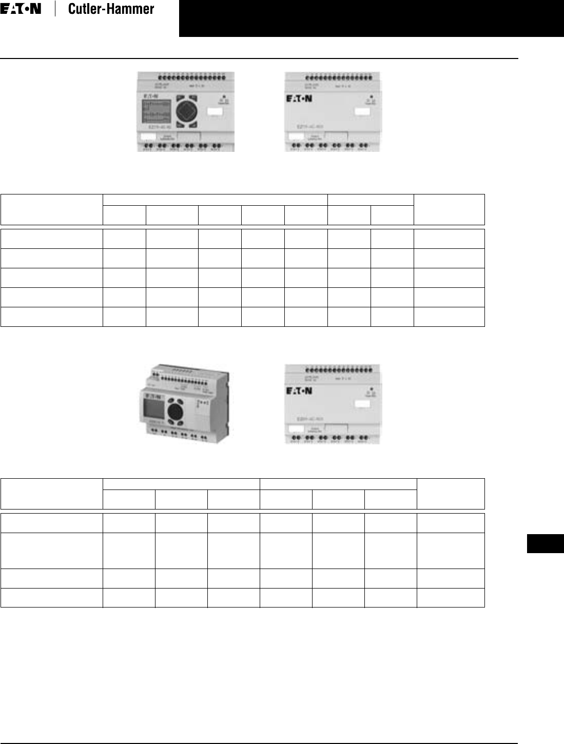
April 2009
CA08102002K07A For more information visit: www.EatonCanada.ca
3-111
3
EZ Intelligent Relays
EZ 500/700/800/EZD Intelligent Relays
Table 3-167. EZ700 Intelligent Relays
Note: Analogue inputs optional.
Table 3-168. EZ800 Intelligent Relays
Note: Analogue inputs optional, analogue outputs optional.
EZ700 with Display EZ700 without Display
Description Inputs Outputs Catalogue
Number
24V AC 110 – 240V
AC
12V DC 24V DC Analogue Relay Transistor
18 I/O, Clock, Display
18 I/O, Clock, No Display
12
12
—
—
—
—
—
—
4
4
6
6
—
—
EZ719-AB-RC
EZ719-AB-RCX
18 I/O, Clock, Display
18 I/O, Clock, No Display
—
—
12
12
—
—
—
—
—
—
6
6
—
—
EZ719-AC-RC
EZ719-AC-RCX
18 I/O, Clock, Display
18 I/O, Clock, No Display
—
—
—
—
12
12
—
—
4
4
6
6
—
—
EZ719-DA-RC
EZ719-DA-RCX
18 I/O, Clock, Display
18 I/O, Clock, No Display
—
—
—
—
—
—
12
12
4
4
6
6
—
—
EZ719-DC-RC
EZ719-DC-RCX
20 I/O, Clock, Display
20 I/O, Clock, No Display
—
—
—
—
—
—
12
12
4
4
—
—
8
8
EZ721-DC-TC
EZ721-DC-TCX
Description Inputs Outputs Catalogue
Number
110 – 240V
AC
24V DC Analogue Relay Transistor Analogue
18 I/O, Clock, Display
18 I/O, Clock, No Display
12
12
—
—
—
—
6
6
—
—
—
—
EZ819-AC-RC
EZ819-AC-RCX
18 I/O, Clock, Display
18 I/O, Clock, No Display
19 I/O, Clock, Display
19 I/O, Clock, No Display
—
—
—
—
12
12
12
12
4
4
4
4
6
6
6
6
—
—
—
—
—
—
1
1
EZ819-DC-RC
EZ819-DC-RCX
EZ820-DC-RC
EZ820-DC-RCX
20 I/O, Clock, Display
20 I/O, Clock, No Display
—
—
12
12
4
4
—
—
8
8
—
—
EZ821-DC-TC
EZ821-DC-TCX
21 I/O, Clock, Display
21 I/O, Clock, No Display
—
—
12
12
4
4
—
—
8
8
1
1
EZ822-DC-TC
EZ822-DC-TCX
EZ800 with Display EZ800 without Display
Control Relays & Timers
TAB49.BOO Page 111 Thursday, March 5, 2009 7:36 PM
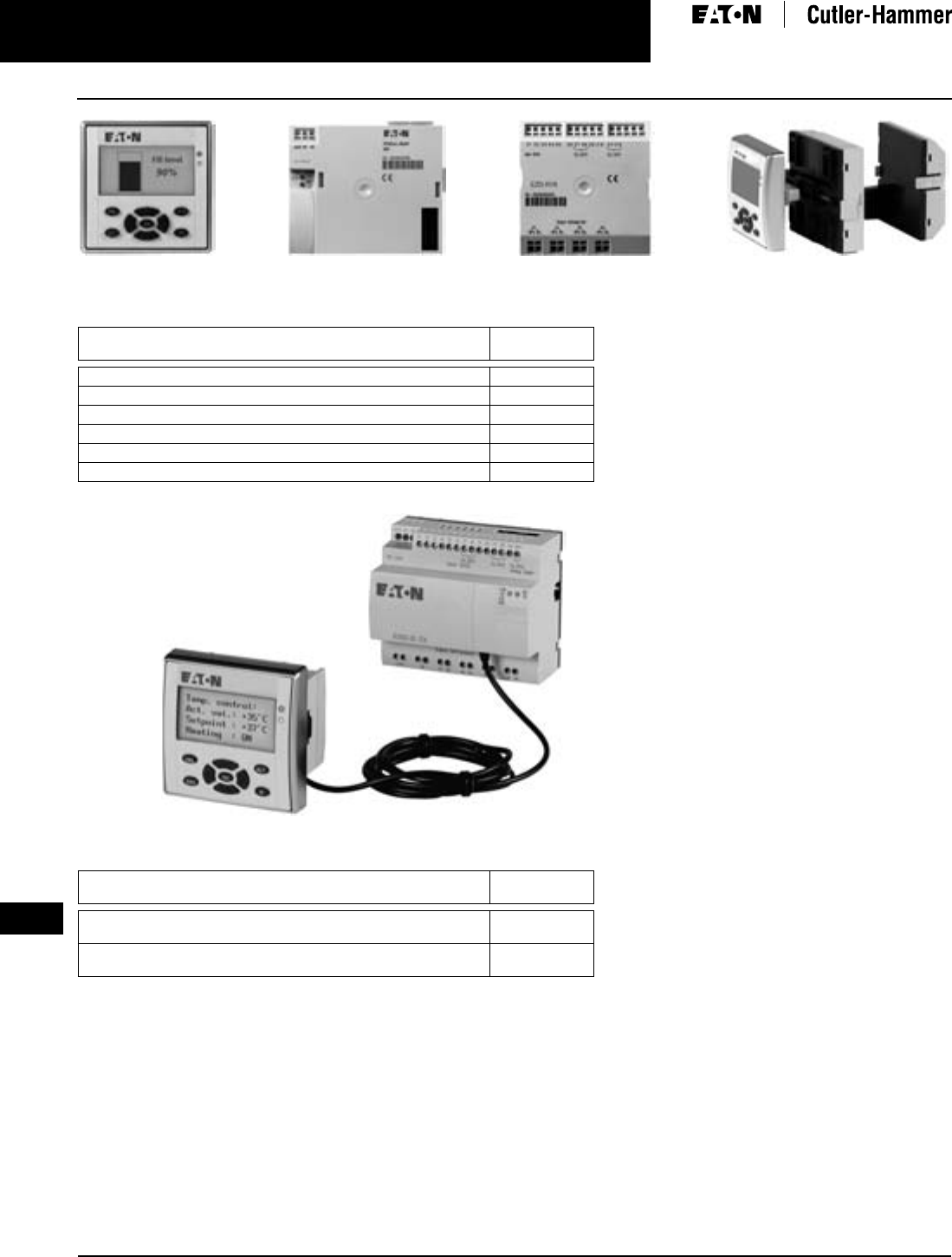
April 2009
3-112
For more information visit: www.EatonCanada.ca CA08102002K07A
3
EZ Intelligent Relays
EZ 500/700/800/EZD Intelligent Relays
Table 3-169. EZD Displays (EZD-80) and EZD Controllers (EZD-CP8)
Table 3-170. EZD Display to EZ Communication Modules (EZD-CP4)
EZD-80 EZD-CP8 EZD I/O EZD Assembly
Description Catalogue
Number
EZD, No Buttons EZD-80
EZD, Buttons EZD-80-B
EZD CPU with 24V DC, Power Supply, Clock EZD-CP8-ME
EZD CPU with 24V DC, Power Supply, Clock, EZ-Net EZD-CP8-NT
EZD CPU with 100 – 240V AC, Power Supply, Clock EZD-AC-CP8-ME
EZD CPU with 100 – 240V AC, Power Supply, Clock, EZ-Net EZD-AC-CP8-NT
Description Catalogue
Number
EZD Display to EZ500/700 Communication Module with EZ500/700
Communication Cable (EZD-CP4-500-CAB5)
EZD-CP4-500
EZD Display to EZ800 Communication Module with EZ800
Communication Cable (EZD-CP4-800-CAB5)
EZD-CP4-800
EZD-CP4-800 Attached to EZ-80 Display and EZ800 Unit
Control Relays & Timers
TAB49.BOO Page 112 Thursday, March 5, 2009 7:36 PM

April 2009
CA08102002K07A For more information visit: www.EatonCanada.ca
3-113
3
EZ Intelligent Relays
EZ 500/700/800/EZD Intelligent Relays
Technical Data and Specifications
Table 3-171. EZ500 Series
Table 3-172. EZ700 Series
Table 3-173. EZ800 Series
Table 3-174. EZD CP4 and CP8 Modules
Table 3-175. EZ500, EZ700, EZ800, EZD-80, EZD-CP4, EZD-CP8 Modules
Type EZ512-AB… EZ512-AC… EZ512-DA… EZ512-DC-R… EZ512-DC-TC.
Supply Voltage 24V AC 100 – 240V AC 12V DC 24V DC 24V DC
Heat Dissipation 5 VA 5 VA 2 W 2 W 2 W
Continuous Current Outputs (1) 8 A 8 A 8 A 8 A 0.5 A
Short-circuit Proof with Power Factor 1 Line Protection B16, 600 A —
Short-circuit Proof with Power Factor 0.7…0.7 Line Protection B16, 900 A —
Mounting On Top-hat Rail to DIN 50022, 35 mm or Screw Mounting with EZB4-101-GF1 Fixing Brackets
Type EZ719-AB… EZ719-AC… EZ719-DA… EZ719-DC-RC. EZ721-DC-TC.
Supply Voltage 24V AC 100 – 240V AC 12V DC 24V DC 24V DC
Heat Dissipation 7 VA 10 VA 3.5 W 3.5 W 3.5 W
Continuous Current Outputs (1) 8 A 8 A 8 A 8 A 0.5 A
Short-circuit Proof with Power Factor 1 Line protection B16, 600 A —
Short-circuit Proof with Power Factor 0.7…0.7 Line protection B16, 900 A —
Mounting On Top-hat Rail to DIN 50022, 35 mm or Screw Mounting with EZB4-101-GF1 Fixing Brackets
Type EZ819-AC… EZ819-DC-RC. EZ820-DC-RC. EZ821-DC-TC. EZ822-DC-TC.
Supply Voltage 100 – 240V AC 24V DC 24V DC 24V DC 24V DC
Heat Dissipation 10 VA 3.4 W 3.4 W 3.4 W 3.4 W
Continuous Current Outputs (1) 8 A 8 A 8 A 8 A 0.5 A
Short-circuit Proof with Power Factor 1 Line protection B16, 600 A —
Short-circuit Proof with Power Factor 0.7…0.7 Line protection B16, 900 A —
Mounting On Top-hat Rail to DIN 50022, 35 mm or Screw Mounting with EZB4-101-GF1 Fixing Brackets
Type EZD-80… EZD-CP4-… EZD-CP8… EZD-AC-CP8…
Supply Voltage Supply from -CP 24V DC 24V DC 100 – 240V AC
Heat Dissipation 3 W 1.5 W 3 W 8 VA
Mounting Front Mounting in
2 x 22.5 mm Standard
Drill Holes
Snap Fitted to EZD-80 Snap Fitted to EZD-80 or on Top-hat Rail to
DIN 50022, 35 mm or Screw Mounting with
EZB4-101-GF1 Fixing Brackets
Type EZD-80… EZ500/700/800, EZD-CP4/CP8
Connection Cables — 0.2 – 4.0 mm2 (AWG 22-12), solid
0.2 - 2.5 mm2 (AWG 22-12), flexible
Degree of Protections IP65 IP 20
RFI Suppression EN 55011, EN 55022 Class B, IEC 61000-6-1,2,3,4 EN 55011, EN 55022 Class B, IEC 61000-6-1,2,3,4
Ambient Operating Temperature Clearly Legible at -5 to 50ºC -25 to 55ºC
Transport and Storage Temperature -40 to 70ºC -40 to 70ºC
Certification, Standards EN 50178, IEC/EN 60947, UL, CSAEN 50178, IEC/EN 60947, UL, CSA
Control Relays & Timers
TAB49.BOO Page 113 Thursday, March 5, 2009 7:36 PM
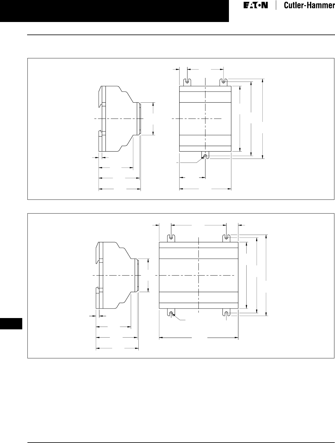
April 2009
3-114
For more information visit: www.EatonCanada.ca CA08102002K07A
3
EZ Intelligent Relays
EZ 500/700/800/EZD Intelligent Relays
Dimensions
Figure 3-99. EZ500 Series Dimensions in Inches (mm), Drawing Number MD05013001E
Figure 3-100. EZ600 and EZ700 Series Dimensions in Inches (mm), Drawing Number MD05013002E
2.81
(71.5)
1.41
(35.8)
3.54
(90.0) 4.02
(102.0)
4.33
(110.0)
1.97
(50.0)
0.42
(10.8)
(M4) .157
(3.9) DIA.
2.28
(58.0)
1.77
(45.0)
0.18
(4.5)
2.22
(56.5)
1.87
(47.5)
EZ500
4.23
(107.5)
3.54
(90.0)
4.02
(102.0)
4.33
(110.0)
2.96
(75.0)
0.64
(16.3)
(M4) .157
(3.9) DIA.
2.28
(58.0)
1.77
(45.0)
0.18
(4.5)
2.22
(56.5)
1.87
(47.5)
0.64
(16.3)
EZ600
EZ700
Control Relays & Timers
TAB49.BOO Page 114 Thursday, March 5, 2009 7:36 PM

April 2009
CA08102002K07A For more information visit: www.EatonCanada.ca
3-115
3
EZ Intelligent Relays
EZ 500/700/800/EZD Intelligent Relays
Figure 3-101. EZ800 Series Dimensions in Inches (mm), Drawing Number MD05013003E
Figure 3-102. EZD-80 Series Dimensions in Inches (mm), Drawing Number MD05013005E
4.23
(107.5)
3.54
(90.0)
4.02
(102.0)
4.33
(110.0)
2.96
(75.0)
0.64
(16.3)
(M4) .157
(3.9) DIA.
2.83
(72.0)
1.77
(45.0)
0.18
(4.5)
2.78
(70.5)
1.91
(48.5)
0.64
(16.3)
EZ800
3.41
(86.5)
2.44
(62.0)
1.11
(28.3)
1.18
(30.0)
±0.01
±0.2
3.41
(86.5)
1.26
(32.0)
0.67
(17.0)
1.18
(30.0)
0.88
(22.3)
+0.02
+0.4
0.54
(13.7)
0.79
(20.0)
1.11
(28.3)
0.89
(22.5)
1.18
(30.0)
Template for Holes, Scale 1:1
EZD-80
EZD-CP...
EZD-80
Control Relays & Timers
TAB49.BOO Page 115 Thursday, March 5, 2009 7:36 PM
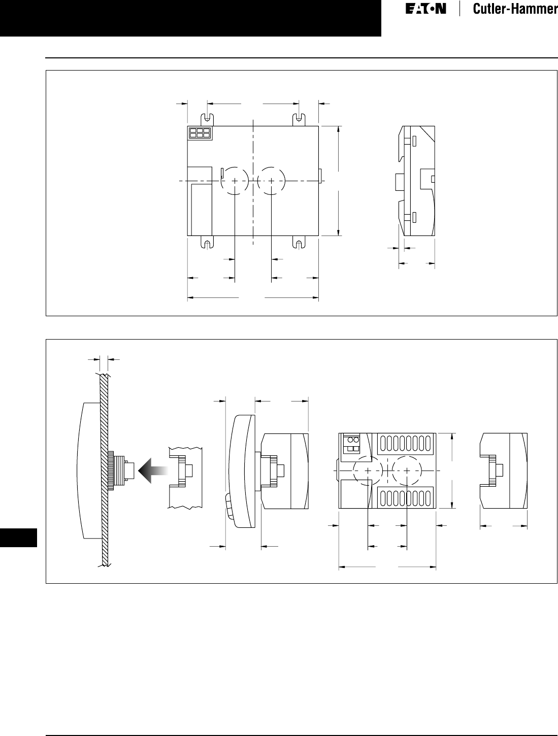
April 2009
3-116
For more information visit: www.EatonCanada.ca CA08102002K07A
3
EZ Intelligent Relays
EZ 500/700/800/EZD Intelligent Relays
Figure 3-103. EZD-CP8 Series Dimensions in Inches (mm), Drawing Number MD05013006E
Figure 3-104. EZD-CP4, EZD-80 and EZD-CP4 Series Combined Dimensions in Inches (mm), Drawing Number MD013013E
1.18
(30.0)
±0.01
±0.2
0.640
(16.3)
2.95
(75.0)
3.54
(90.0)
4.23
(107.5)
0.64
(16.3)
0.18
(4.5)
1.53
(38.8)
1.16
(29.5)
1.53
(38.8)
EZD-CP8
2.28
(58.0)
1.18
(30.0)
2.95
(75.0)
0.89
(22.5)
1.43
(36.2)
1.70
(43.2)
1-6 -0.24
(0.04)
1.08
(27.5)
0.81
(20.5)
0.89
(22.5)
EZD-CP4
EZD-80
EZD-CP4
EZD-CP4
Control Relays & Timers
TAB49.BOO Page 116 Thursday, March 5, 2009 7:36 PM

April 2009
CA08102002K07A For more information visit: www.EatonCanada.ca
3-117
3
EZ Intelligent Relays
EZD Controller I/O Modules
EZD Controller I/O Modules
Product Selection
Table 3-176. EZD Controller I/O Modules
Note: Analogue inputs optional.
Technical Data and Specifications
Table 3-177. EZD Specifications
Relay = 8 A (10 A to UL) with resistive load, 3 A with inductive load/transistor outputs = 0.5 A/24V DC, max 4 outputs switchable in parallel.
Dimensions
Figure 3-105. EZD-R/EZD-T I/O Module Dimensions in Inches (mm), Drawing Number MD05013007E
Description Inputs Outputs Catalogue
Number
110 – 240V AC 24V DC Analogue Relay Transistor Analogue
16 I/O
16 I/O
17 I/O
12
—
—
—
12
12
—
4
4
4
4
4
—
—
—
—
—
1
EZD-AC-R16
EZD-R16
EZD-RA17
16 I/O
17 I/O
—
—
12
12
4
4
—
—
4
4
—
1
EZD-T16
EZD-TA17
Type EZD-AC-R16 EZD-R16 EZD-RA17 EZD-T16 EZD-TA17
Supply Voltage Supply via EZD-CP8 module
Heat Dissipation 0.5 W 0.5 W 0.5 W 0.5 W 0.5 W
Continuous Current Outputs 8 A 8 A 8 A 0.5 A 0.5 A
Short-circuit Proof with Power Factor 1 Line protection B16, 600 A — —
Short-circuit Proof with Power Factor 0.7…0.7 Line protection B16, 900 A — —
Connection Cables 0.2 – 4.0 mm2 (AWG 22-12), Solid
0.2 – 2.5 mm2 (AWG 22-12), Flexible
Degree of Protections IP 20 IP 20 IP 20 IP 20 IP 20
RFI Suppression EN 55011, EN 55022 Class B, IEC 61000-6-1,2,3,4
Ambient Operating Temperature -25 to 55ºC -25 to 55ºC -25 to 55ºC -25 to 55ºC -25 to 55ºC
Transport and Storage Temperature -40 to 70ºC -40 to 70ºC -40 to 70ºC -40 to 70ºC -40 to 70ºC
Certification, Standards EN 50178, IEC/EN 60947, UL, CSA
Mounting Snap Fitted to EZD-CP8 Module
3.47
(88.1)
3.54
(90.0)
0.75
(19.0)
0.98
(25.0)
EZD-T I/O
EZD-R
Control Relays & Timers
TAB49.BOO Page 117 Thursday, March 5, 2009 7:36 PM
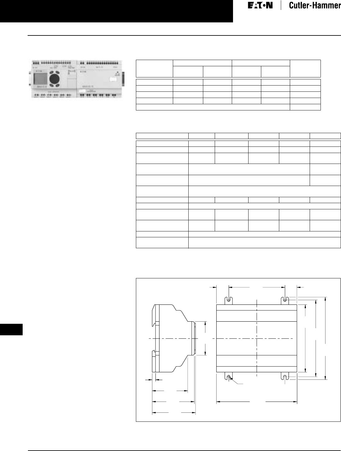
April 2009
3-118
For more information visit: www.EatonCanada.ca CA08102002K07A
3
EZ Intelligent Relays
EZ/EZD Expansion Modules
EZ/EZD Expansion Modules
EZ/EZD Expansion Modules
Product Description
Expansion modules are available for
increasing the input/output of the
EZ700/800 and EZD intelligent relays to
24 inputs and up to 16 outputs. Expan-
sion modules can be mounted directly
to the EZ/EZD unit or up to 98 ft. (30 m)
away using coupling module EZ200-EZ.
Product Selection
Table 3-178. EZ/EZD I/O Expansion Modules
Technical Data and Specifications
Table 3-179. EZ Specifications
Relay = 8A (10 A to UL) with resistive load, 3 A with inductive load/transistor outputs = 0.5 A/24V DC,
max 4 outputs switchable in parallel.
Dimensions
Figure 3-106. EZ600 and EZ700 Series Dimensions in Inches (mm), Drawing Number
MD05013002E
Description Inputs Outputs Catalogue
Number
110 – 240V
AC
24V DC RY TRN
2 I/O Expansion — — 2 — EZ202-RE
18 I/O Expansion 12 — 6 — EZ618-AC-RE
18 I/O Expansion — 12 6 — EZ618-DC-RE
20 I/O Expansion — 12 — 8 EZ620-DC-TE
Coupling Module for Remote Mounting of Expansion Modules EZ200-EZ
Type EZ202-RE EZ618-AC-RE EZ618-DC-RE EZ620-DC-TE EZ200EZ
Supply Voltage —
100 – 240V AC
24V AC 24V AC —
Heat Dissipation 1 W 10 VA 4 W 4 W 1 W
Continuous
Current Outputs
8 A 8 A 8 A 0.5 A —
Short-circuit Proof
with Power Factor 1
Line Protection B16, 600 A —
Short-circuit Proof with
Power Factor 0.7…0.7
Line Protection B16, 900 A —
Connection Cables 0.2 – 4.0 mm2 (AWG 22-12), Solid
0.2 – 2.5 mm2 (AWG 22-12), Flexible
Degree of Protections IP 20 IP 20 IP 20 IP 20 IP 20
RFI Suppression EN 55011, EN 55022 Class B, IEC 61000-6-1,2,3,4
Ambient Operating
Temperature
-25 to 55ºC -25 to 55ºC -25 to 55ºC -25 to 55ºC -25 to 55ºC
Transport and Storage
Temperature
-40 to 70ºC -40 to 70ºC -40 to 70ºC -40 to 70ºC -40 to 70ºC
Certification, Standards EN 50178, IEC/EN 60947, UL, CSA
Mounting On Top-hat Rail to DIN 50022, 35 mm or Screw Mounting with
EZB4-101-GF1 Fixing Brackets
4.23
(107.5)
3.54
(90.0)
4.02
(102.0)
4.33
(110.0)
2.96
(75.0)
0.64
(16.3)
(M4) .157
(3.9) DIA.
2.28
(58.0)
1.77
(45.0)
0.18
(4.5)
2.22
(56.5)
1.87
(47.5)
0.64
(16.3)
EZ600
EZ700
Control Relays & Timers
TAB49.BOO Page 118 Thursday, March 5, 2009 7:36 PM
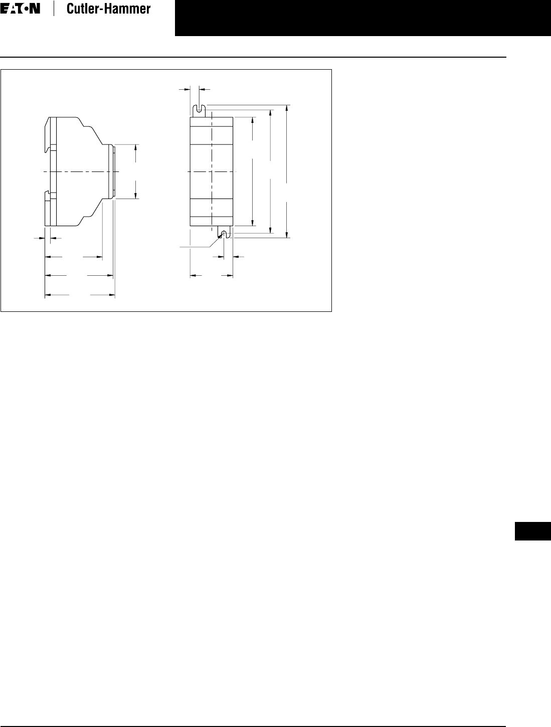
CA08102002K07A For more information visit: www.EatonCanada.ca
3-119
April 2009
3
EZ Intelligent Relays
EZ/EZD Expansion Modules
Figure 3-107. EZ202-RE/EZ200-EZ/EZ205-ASI Series Dimensions in Inches (mm), Drawing Number
MD05013012E
(M4) .157
(3.9) DIA.
0.30
(7.5)
4.33
(110.0)
4.02
(102.0)
3.54
(90.0)
0.30
(7.5)
1.40
(35.5)
1.87
(47.5)
2.22
(56.5)
0.18
(4.5)
1.77
(45.0)
2.28
(58.0)
EZ202-RE
EZ200-EZ
EZ205-ASI
Control Relays & Timers
TAB49.BOO Page 119 Thursday, March 5, 2009 7:36 PM
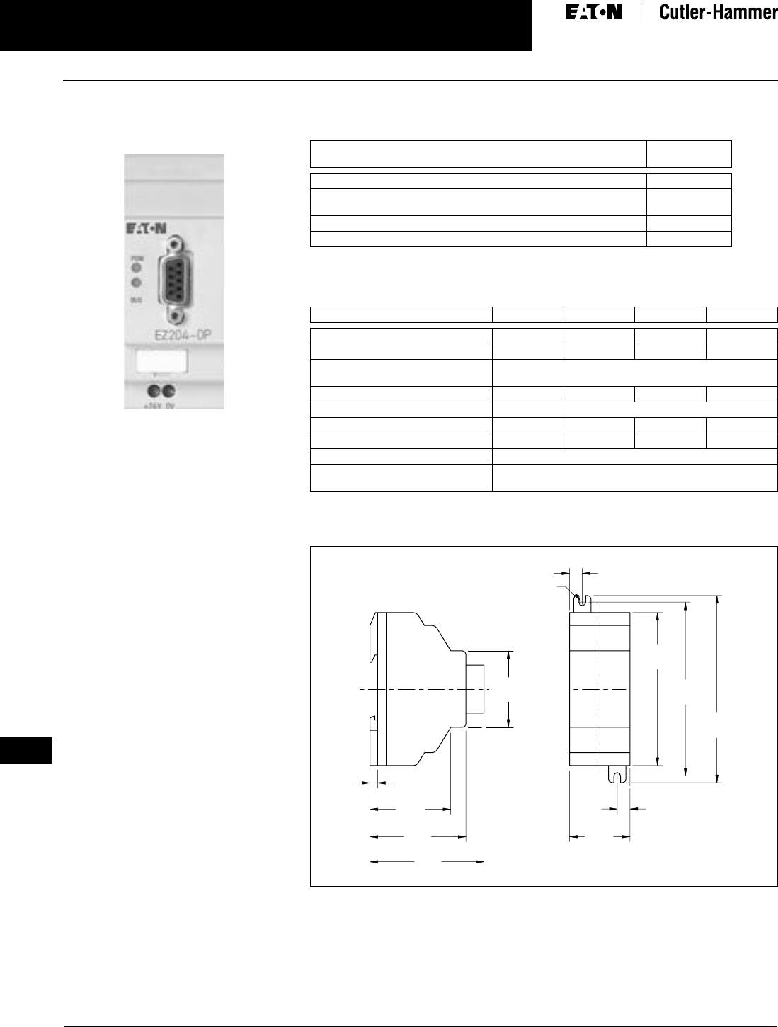
April 2009
3-120
For more information visit: www.EatonCanada.ca CA08102002K07A
3
EZ Intelligent Relays
EZ/EZD Communication Modules
EZ/EZD Communication
Modules
EZ204-DP Communication Module
Product Description
Four modules are available for easily
connecting to world-standard net-
works. The communication modules
can be used with the EZ700/800 and
EZD intelligent relays.
Available communication modules
support:
■PROFIBUS-DP.
■AS-I (Actuator Sensor Interface)
networks.
■CANopen.
■DeviceNet.
All modules act as a gateway and
operate exclusively as a slave station
on the network.
Product Selection
Table 3-180. EZ/EZD Communication Interface Modules
Technical Data and Specifications
Table 3-181. EZ/EZD Specifications
Dimensions
Figure 3-108. EZ221-CO/EZ222-DN Series Dimensions in Inches (mm), Drawing Number
MD05013010E
Description Catalogue
Number
PROFIBUS-DP Slave Interface Module EZ204-DP
AS-Interface Slave with 4 In and
4 Out Interface Module
EZ205-ASI
CANopen Interface Module EZ221-CO
DeviceNet Slave Interface Module EZ222-DN
Type EZ204-DP EZ205-ASI EZ221-CO EZ222-DN
Supply Voltage 24V DC 24V DC 24V DC 24V DC
Heat Dissipation 2 W 1 W 1 W 1 W
Connection Cables 0.2 – 4.0 mm2 (AWG 22-12), Solid
0.2 – 2.5 mm2 (AWG 22-12), Flexible
Degree of Protections IP 20 IP 20 IP 20 IP 20
RFI Suppression EN 55011, EN 55022 Class B, IEC 61000-6-1,2,3,4
Ambient Operating Temperature -25 to 55ºC -25 to 55ºC -25 to 55ºC -25 to 55ºC
Transport and Storage Temperature -40 to 70ºC -40 to 70ºC -40 to 70ºC -40 to 70ºC
Certification, Standards EN 50178, IEC/EN 60947, UL, CSA
Mounting On Top-hat Rail to DIN 50022, 35 mm or Screw Mounting
with EZB4-101-GF1 Fixing Brackets
2.64
(67.0)
1.77
(45.0)
0.18
(4.5)
2.22
(56.5)
1.87
(47.5)
(M4) .157
(3.9) DIA.
0.30
(7.5)
4.33
(110.0)
4.02
(102.0)
3.54
(90.0)
0.30
(7.5)
1.40
(35.5)
EZ222-DN
EZ221-CO
Control Relays & Timers
TAB49.BOO Page 120 Thursday, March 5, 2009 7:36 PM
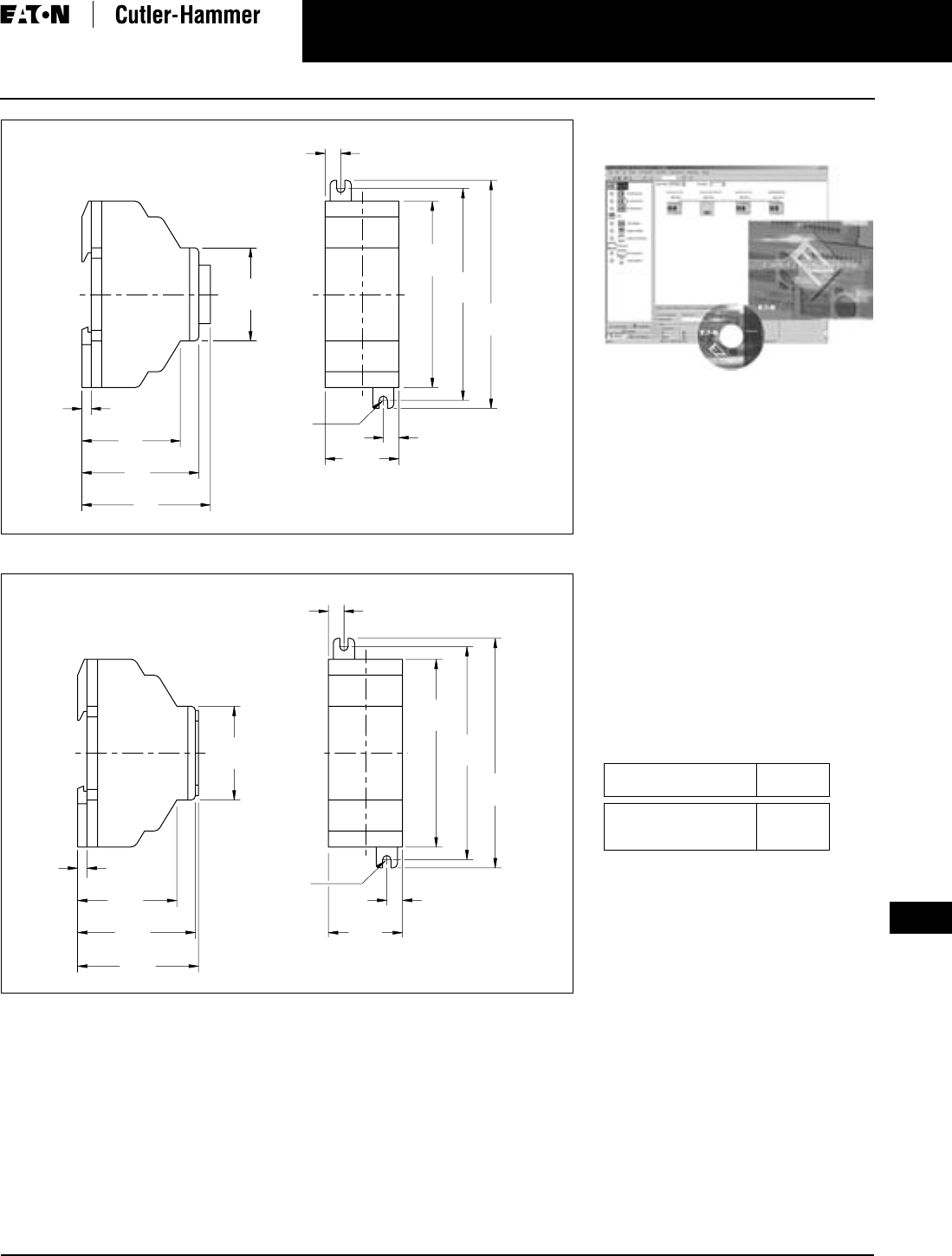
CA08102002K07A For more information visit: www.EatonCanada.ca
3-121
April 2009
3
EZ Intelligent Relays
EZ Software
Figure 3-109. EZ204-DP Series Dimensions in Inches (mm), Drawing Number MD05013011E
Figure 3-110. EZ202-RE/EZ200-EZ/EZ205-ASI Series Dimensions in Inches (mm), Drawing Number
MD05013012E
2.44
(62.0)
1.77
(45.0)
0.18
(4.5)
2.22
(56.5)
1.87
(47.5)
(M4) .157
(3.9) DIA.
0.30
(7.5)
4.33
(110.0)
4.02
(102.0)
3.54
(90.0)
0.30
(7.5)
1.40
(35.5)
EZ204-DP
(M4) .157
(3.9) DIA.
0.30
(7.5)
4.33
(110.0)
4.02
(102.0)
3.54
(90.0)
0.30
(7.5)
1.40
(35.5)
1.87
(47.5)
2.22
(56.5)
0.18
(4.5)
1.77
(45.0)
2.28
(58.0)
EZ202-RE
EZ200-EZ
EZ205-ASI
EZ Software
EZSoft Software
Product Description
The EZSoft software is used to program
all of the EZ and EZD controllers and
displays. The Windows-based software
provides straightforward circuit diagram
input and editing and the diagrams
can be displayed in the format desired.
When EZ800 and EZD controllers are
connected using EZ-NET, all connected
devices can be accessed and their pro-
grams loaded from a single controller.
EZSoft includes an integrated offline
simulation tool that allows users to
test a circuit diagram before commis-
sioning.
Product Selection
Table 3-182. EZ/EZD Software
Description Catalogue
Number
Programming Software
for EZ500/700/800 and
EZD
EZSOFT
Control Relays & Timers
TAB49.BOO Page 121 Thursday, March 5, 2009 7:36 PM
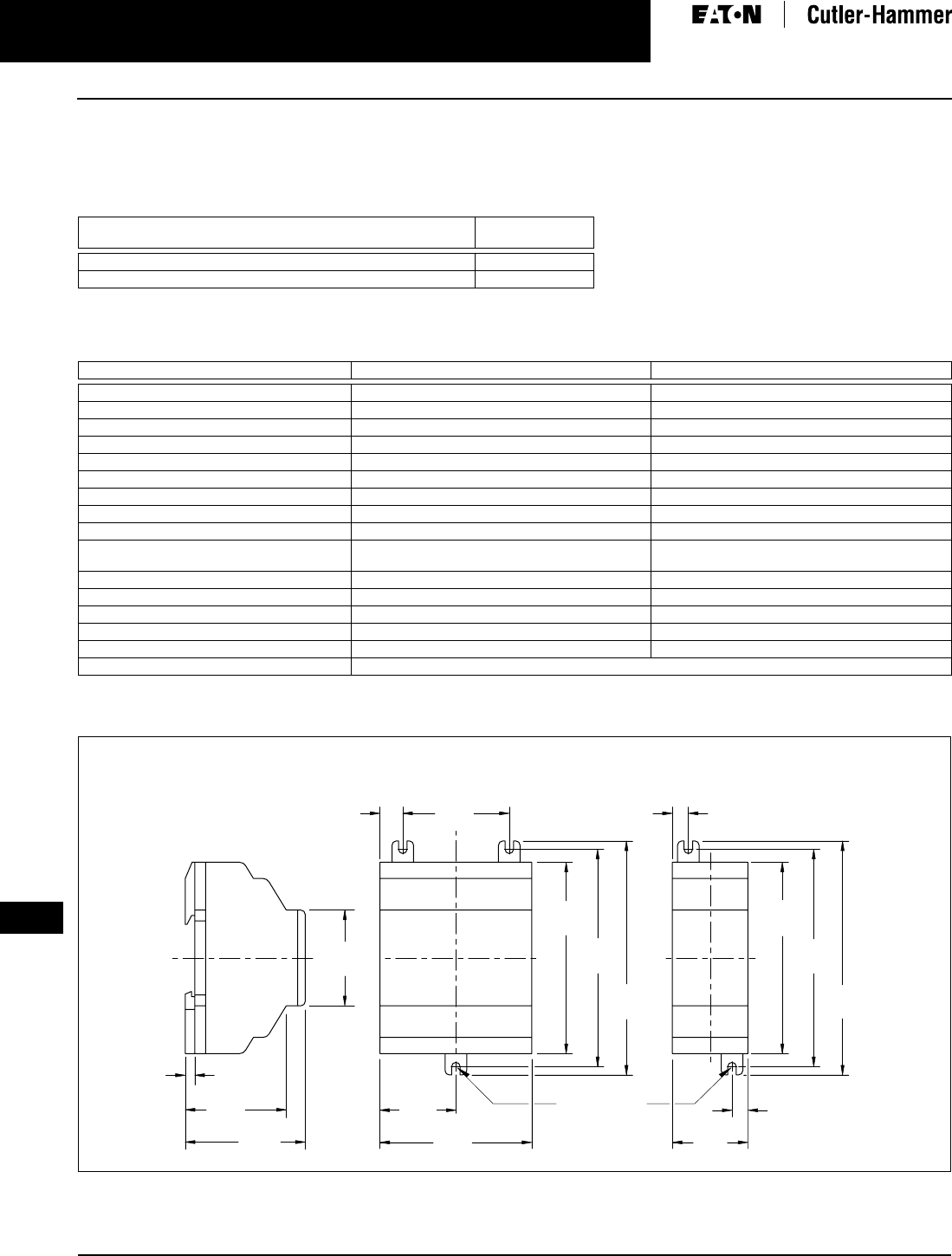
April 2009
3-122
For more information visit: www.EatonCanada.ca CA08102002K07A
3
EZ Intelligent Relays
EZ/EZD Power Supplies
EZ/EZD Power Supplies
Product Selection
Table 3-183. EZ/EZD-CP8 Power Supplies
Technical Data and Specifications
Table 3-184. EZ Specifications
Dimensions
Figure 3-111. EZ200-POW/EZ256-HCI and EZ400-POW Series Dimensions in Inches (mm), Drawing Number MD05013004E
Description Catalogue
Number
100 – 240V AC Input to 12V DC at 20 mA/24V DC at 250 mA EZ200-POW
100 – 240V AC Input to 24V DC at 1.25 A EZ400-POW
Type EZ200-POW EZ400-POW
Supply Voltage 100 – 240V AC 100 – 240V AC
Maximum Range 85 – 264V AC 85 – 264V AC
Output Voltage 24V DC (±3%) 24V DC (±3%)
Output Current (Rated Value) 0.25 A 1.25 A
Overcurrent Limitation Form 0.3 A 1.4 A
Short-circuit Proof (Secondary) YES YES
Overload Proof YES YES
Potential Isolation (prim/sec.) YES, SELV, (to EN 600950, VDE 805) YES, SELV, (to EN 600950, VDE 805)
Others Additional Output Voltage 12 dc, 20 mA Additional Output Voltage 12 dc, 20 mA
Connection Cables 0.2 – 4.0 mm2 (AWG 22-12), Solid
0.2 – 2.5 mm2 (AWG 22-12), Flexible
0.2 – 4.0 mm2 (AWG 22-12), Solid
0.2 – 2.5 mm2 (AWG 22-12), Flexible
Degree of Protections IP 20 IP 20
RFI Suppression EN 55011, EN 55022 Class B, IEC 61000-6-1, 2, 3, 4 EN 55011, EN 55022 Class B, IEC 61000-6-1, 2, 3, 4
Ambient Operating Temperature -25 to 55ºC -25 to 55ºC
Transport and Storage Temperature -40 to 70ºC -40 to 70ºC
Certification, Standards EN 50178, IEC/EN 60947, UL, CSA EN 50178, IEC/EN 60947, UL, CSA
Mounting On Top-hat Rail to DIN 50022, 35 mm or Screw Mounting with EZB4-101-GF1 Fixing Brackets
2.81
(71.5)
1.41
(35.8)
3.54
(90.0)
4.02
(102.0)
4.33
(110.0)
1.97
(50.0)
0.42
(10.8)
1.77
(45.0)
0.18
(4.5)
2.22
(56.5)
1.87
(47.5)
(M4) .157
(3.9) DIA.
0.30
(7.5)
0.30
(7.5)
1.40
(35.5)
3.54
(90.0)
4.02
(102.0)
4.33
(110.0)
EZ400-POW EZ256-HCI
EZ200-POW
Control Relays & Timers
TAB49.BOO Page 122 Thursday, March 5, 2009 7:36 PM
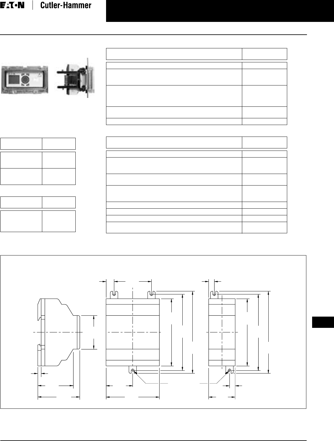
April 2009
CA08102002K07A For more information visit: www.EatonCanada.ca
3-123
3
EZ Intelligent Relays
EZ/EZD Accessories
EZ/EZD Accessories
EZ700/500 Panel Window and Mounting Kit
Product Selection
Table 3-185. EZ/EZD Memory Storage
Modules
Table 3-186. EZ/EZD Programming Cables
Dimensions
Description Catalogue
Number
EZ500/700 32K
Memory Storage
Module
EZ-M-32K
EZ800/EZD 256K
Memory Storage
Module
EZ-M-256K
Description Catalogue
Number
EZ500/700 to PC
Cable
EZ800/EZD to PC
Cable
EZ-PC-CAB
EZ800-PC-CAB
2.81
(71.5)
1.41
(35.8)
3.54
(90.0)
4.02
(102.0)
4.33
(110.0)
1.97
(50.0)
0.42
(10.8)
1.77
(45.0)
0.18
(4.5)
2.22
(56.5)
1.87
(47.5)
(M4) .157
(3.9) DIA.
0.30
(7.5)
0.30
(7.5)
1.40
(35.5)
3.54
(90.0)
4.02
(102.0)
4.33
(110.0)
EZ400-POW EZ256-HCI
EZ200-POW
Figure 3-112. EZ200-POW/EZ256-HCI and EZ400-POW Series Dimensions in Inches (mm), Drawing Number MD05013004E
Table 3-187. EZ/EZD Cables and Connectors
Table 3-188. EZ/EZD Miscellaneous Parts
Description Catalogue
Number
EZ500/700 to EZD-CP4 Communication Cable, 5 m EZD-CP4-500-CAB5
EZ800 to EZD-CP8 Communication Cable, 2 m
EZ800 to EZD-CP8 Communication Cable, 5 m
EZ800 to EZD-CP4 Communication Cable, 5 m
EZD-800-CAB
EZD-800-CAB5
EZD-CP4-800-CAB5
EZ800/EZD EZ-NET Cable, 0.3 m
EZ800/EZD EZ-NET Cable, 0.8 m
EZ800/EZD EZ-NET Cable, 1.5 m
EZ800/EZD Network Termination Resistor, 2/Pack
EZ-NT-30
EZ-NT-80
EZ-NT-150
EZ-NT-R
EZ800/EZD EZ-NET Cable (cable only, no connectors, see
EZ-NT-RJ45), 100 m
EZ-NT-CAB
RJ45 Network Connectors for EZ-NET Cable (EZ-NT-CAB), 10/Pack EZ-NT-RJ45
Description Catalogue
Number
EZ500 Relay Simulator EZ412-DC-SIM-NA
EZ500 Panel Window
EZ700/800 Panel Window
EZ500/700/800 Panel Window Mounting Kit to Front Mount Units
EZSKF-FF4
EZSKF-FF6
EZSKF-HA
EZ/EZD Panel Mount Brackets, 9/Pack
EZ/EZD Grounding Kit
EZB4-101-GF1
EZB4-102-KS1
EZD Display DIN Rail Mount Kit
EZD Display Protective Membrane Cover
EZD Display Protective Plastic Cover
EZD-TS144
EZD-XM-80
EZD-XS-80
EZ/EZD 6 Channel Noise Suppression Adapter EZ256-HCI
EZ/EZD Spare Interface Connector, Base to Expander EZ-LINK-DS
EZSoft Configuration Software EZSOFT
EZ Starter Kit (includes EZ512-DC-RC, EZ-PC-CAB,
EZ412-DC-SIM-NA, EZSoft
EZSTARTKIT1
Control Relays & Timers
TAB49.BOO Page 123 Thursday, March 5, 2009 7:36 PM
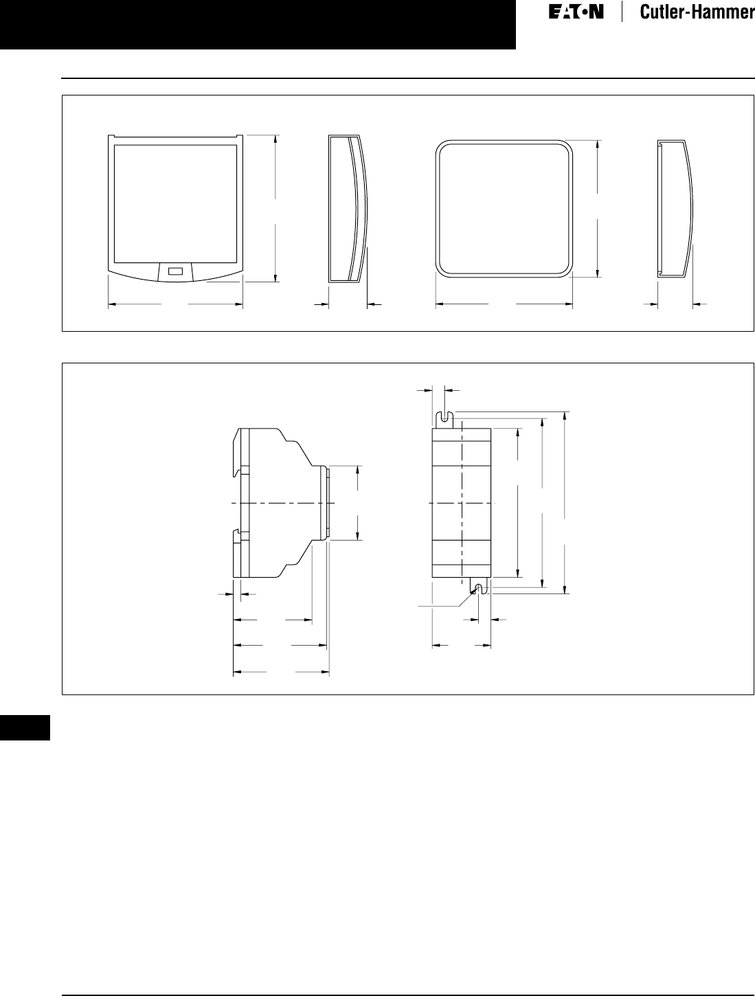
April 2009
3-124
For more information visit: www.EatonCanada.ca CA08102002K07A
3
EZ Intelligent Relays
EZ/EZD Accessories
Figure 3-113. EZD-XS-80 and EZD-XM-80 Series Dimensions in Inches (mm), Drawing Number MD05013009E
Figure 3-114. EZ202-RE/EZ200-EZ/EZ205-ASI Series Dimensions in Inches (mm), Drawing Number MD05013012E
0.98
(25.0)
3.74
(95.0)
3.41
(86.5)
3.48
(88.5)
3.48
(88.5)
0.89
(22.5)
EZD-XS-80EZD-XM-80
(M4) .157
(3.9) DIA.
0.30
(7.5)
4.33
(110.0)
4.02
(102.0)
3.54
(90.0)
0.30
(7.5)
1.40
(35.5)
1.87
(47.5)
2.22
(56.5)
0.18
(4.5)
1.77
(45.0)
2.28
(58.0)
EZ202-RE
EZ200-EZ
EZ205-ASI
Control Relays & Timers
TAB49.BOO Page 124 Thursday, March 5, 2009 7:36 PM
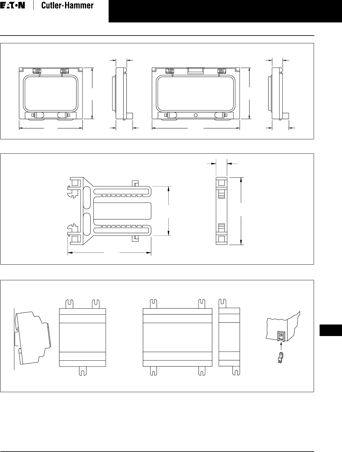
April 2009
CA08102002K07A For more information visit: www.EatonCanada.ca
3-125
3
EZ Intelligent Relays
EZ/EZD Accessories
Figure 3-115. EZSKF-FF4 and EZSKF-FF6 Series Dimensions in Inches (mm), Drawing Number MD05013014E
Figure 3-116. EZSKF-HA Series Dimensions in Inches (mm), Drawing Number MD05013015E
Figure 3-117. EZB4-101-GF1 Series
3.70
(94.0)
2.99
(76.0)
0.98
(25.0)
0.63
(16.0)
0.63
(16.0)
5.12
(130.0)
2.99
(76.0)
0.98
(25.0)
SKF-FF4 SKF-FF6
2.60
(66.0)
0.43
(11.0)
3.23
(82.0)
1.89
(48.0)
EZSKF-HA
Fitting on 35 mm Top-Hat Rail Fitting on Mounting Plate (Horizontal)
EZB4-101-GF1
* 3 fixing feet sufficient
**
**
Control Relays & Timers
TAB49.BOO Page 125 Thursday, March 5, 2009 7:36 PM
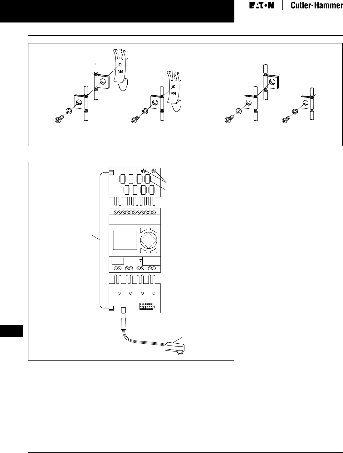
April 2009
3-126
For more information visit: www.EatonCanada.ca CA08102002K07A
3
EZ Intelligent Relays
EZ/EZD Accessories
Figure 3-118. EZB4-102-KS1 Series
Figure 3-119. EZ412-DC-SIM-NA Series
Grounding the Screen for
Top-Hat Rail
Grounding the Screen for
Mounting Plate
ESC OK
DEL ALT
Digital Inputs
Connection
Cable
Power Supply
Unit
Connect Outputs
Control Relays & Timers
TAB49.BOO Page 126 Thursday, March 5, 2009 7:36 PM
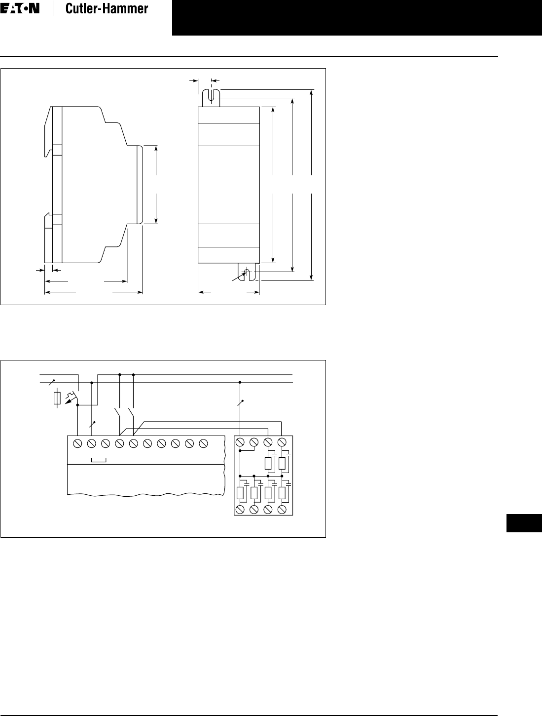
April 2009
CA08102002K07A For more information visit: www.EatonCanada.ca
3-127
3
EZ Intelligent Relays
EZ/EZD Accessories
Figure 3-120. EZ256-HCI Dimensions in Inches (mm)
Wiring Diagram
Figure 3-121. EZ256-HCI Wiring Diagram
M4
1.77
(45) 3.54
(90) 4.02
(102) 4.33
(110)
1.77 (45)
0.30 (7.5)
1.87 (47.5)
2.22 (56.5) 1.40 (35.5)
L
N
> 1 A
S..S..
L
115/230 Vh Input 115/230 Vh
N N I1 I2 I3 I4 I5 NN1 2
3456
.....
EZ5..-AC-..
EZ7..-AC-..
EZ256-HCI
Control Relays & Timers
TAB49.BOO Page 127 Thursday, March 5, 2009 7:36 PM

April 2009
3-128
For more information visit: www.EatonCanada.ca CA08102002K07A
3
EZ Intelligent Relays
This Page Left Intentionally Blank
Control Relays & Timers
TAB49.BOO Page 128 Thursday, March 5, 2009 7:36 PM
