Operating Manual Installation Directions
2016-10-06
: Pdf 1000368495-Installationsheet 1000368495-InstallationSheet B5 unilog
Open the PDF directly: View PDF ![]() .
.
Page Count: 92
Operating Manual
PacDriveTM
SM-Motor
MSM_OperaMan_us
Article number: 17130068-001
Edition: 08.2006

MSM_OpMan_00_us.FM
page 2 PacDrive SM-Motor ELAU AG
Imprint
Korrekturausdruck
Imprint
© All rights reserved to ELAU AG, also in case of patent right
applications.
No part of this documentation and the related software and firm-
ware may be reproduced, rewritten, stored on a retrieval system,
transmitted or translated into any other language or computer lan-
guage without the express written consent of ELAU AG.
Any possible measure was taken to ensure the that this product
documentation is complete and correct. However, since hardware
and software are continuously improved, ELAU makes no repre-
sentations or warranties with respect to the contents of this product
documentation.
Trademarks
PacDrive is a registered trademark of ELAU AG.
All other trademarks mentioned are the exclusive property of their
manufacturers.
ELAU AG ELAU Inc.
Dillberg 12 165 E. Commerce Drive
D-97828 Marktheidenfeld Schaumburg, IL 60173 - USA
Phone: 09391/606-0 Phone: +1 847 490 4270
Fax: 09391/606-300 Fax: +1 847 490 4206
eMail: info@elau.de e-mail: info@elau.com
Internet: www.elau.de Internet: www.elau.com

MSM_OperaMan_us1002IVZ.fm
ELAU AG PacDrive SM-Motor page 3
Inhaltsverzeichnis
Korrekturausdruck
Contents
1 On this manual 5
1.1 Introduction ............................................................................................ 5
1.2 Symbols, Signs and Forms of Depiction ................................................ 6
2 General Safety Notes 7
2.1 Basics .................................................................................................... 7
2.2 Depiction of Safety Notes ...................................................................... 8
2.3 Use as Directed ..................................................................................... 9
2.4 Selection and Qualification of Staff ...................................................... 10
2.5 Residual Risks ..................................................................................... 10
2.5.1 Installation and Handling ..................................................................... 10
2.5.2 Protection against Touching Electrical Parts ....................................... 11
2.5.3 Potentially Dangerous Movements ...................................................... 12
3 Overview 13
3.1 In General ............................................................................................ 13
3.2 Features of the servo motors ............................................................... 13
3.3 Versions ............................................................................................... 14
4 Transportation, Storage, Unpacking 15
4.1 Transportation ...................................................................................... 15
4.2 Storage ................................................................................................ 15
4.3 Unpacking ............................................................................................ 16
4.3.1 Modified connections ........................................................................... 17
5 Maintenance 19
5.1 Spare Parts, Components ................................................................... 19
5.2 Repair .................................................................................................. 20
5.3 Service Addresses ............................................................................... 20
5.4 Exchanging Units ................................................................................. 21
5.5 Cleaning ............................................................................................... 24
5.6 EMC Rules ........................................................................................... 25
5.7 Commissioning .................................................................................... 27
5.8 PacDrive SM Motor with Barrier Pressure System .............................. 28
5.9 Configuration / Programming / Diagnosis ............................................ 29
5.10 Order Numbers .................................................................................... 30
5.10.1 SM Motor ............................................................................................. 30
5.10.2 SM Motor ............................................................................................. 31

MSM_OperaMan_us1002IVZ.fm
page 4 PacDrive SM-Motor ELAU AG
Inhaltsverzeichnis
Korrekturausdruck
5.10.3 Cables .................................................................................................. 35
5.10.4 Connector Sets ..................................................................................... 36
6 Technical Data 37
6.1 General Technical Data ........................................................................ 37
6.1.1 Definitions and Physical Correlations ................................................... 38
6.1.2 Ambient conditions, approbations ........................................................ 43
6.1.3 Protection class .................................................................................... 45
6.1.4 Motor shaft and bearing ....................................................................... 46
6.1.5 Encoders .............................................................................................. 48
6.1.6 Holding brake (optional) ....................................................................... 51
6.1.7 Surface Ventilation (optional) ............................................................... 54
6.1.8 Technical Data in Detail ....................................................................... 55
6.1.9 Torque-speed characteristics ............................................................... 59
6.2 Electrical Connections .......................................................................... 69
6.2.1 X2 - motor ............................................................................................. 70
6.2.2 X3 - brake / motor temperature ............................................................ 71
6.2.3 X4 - encoder (SinCos) .......................................................................... 72
6.2.4 X4 - encoder (Resolver) ....................................................................... 73
6.3 Dimensions ........................................................................................... 74
6.3.1 SM-motor .............................................................................................. 74
6.3.2 SP-Gearbox .......................................................................................... 78
7 Appendix 83
7.1 Contact Addresses ............................................................................... 83
7.2 Further Literature .................................................................................. 84
7.3 Product Training ................................................................................... 86
7.4 Declaration by the manufacturer .......................................................... 87
7.5 Modifications ........................................................................................ 88
7.6 Index ..................................................................................................... 89
7.7 Form for Error Report ........................................................................... 91

M_Verwend_us.FM
ELAU AG PacDrive page 5
1 On this manual
Korrekturausdruck
1 On this manual
1.1 Introduction
Before using the motor for the first time, you should familiarize
yourself with this operating manual.
In particular, observe the safety notes described in chapter 2.
Only persons who meet the criteria for "Selection and Qualification
of Staff" (see chapter 2.4) are allowed to work on the motors.
One copy of this manual has to be available for staff working on the
motors with access at any time.
This manual is to help you use the motor safely and expertly and to
use it as directed.
Observe this manual. This will help to avoid risks, reduce repair
costs and down times and increase the lifetime and reliability of the
products.
You also need to observe the valid rules for the prevention of
accidents and for environmental protection in the country and place
where the device is used.
M_Verwend_us.FM
page 6 PacDrive ELAU AG
1 On this manual
Korrekturausdruck
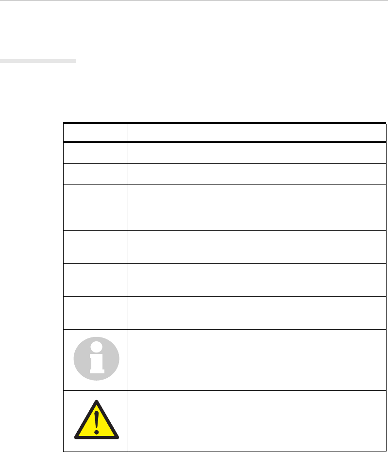
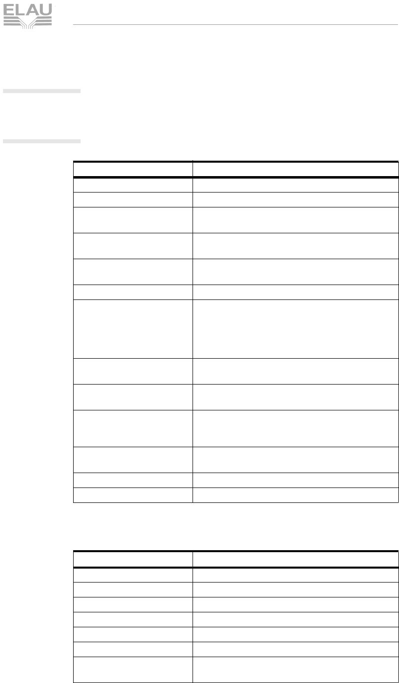
1.2 Symbols, Signs and Forms of Depiction
The following symbols and signs are used in this document:
Table 1-1: Symbols, signs and forms of depiction
Depiction Meaning
First level enumeration sign.
–Second level enumeration sign.
Action symbol: The text following this symbol inclu-
des an instruction for action. Execute the instruction
actions in the given order, from top to bottom.
9Result symbol: The text following this symbol con-
tains the result of an action.
Italics If the describing text contains special terms (e.g.
parameters) these are written in italics.
Serif font If the manual contains program code, this is marked
by Serif font.
Information symbol: This symbol marks notes and
useful tips for using the product.
Warning sign: Safety notes can be found in the rele-
vant places. They are marked by this symbol.

M_Sicherhneu_us.fm
ELAU AG PacDrive page 7
2.1 Basics
Korrekturausdruck
2 General Safety Notes
This chapter contains general requirements for working safely.
Every person using ELAU components or working on ELAU
components has to read and observe these general safety notes.
If activities involve a residual risk, you will find a clear note in the
respective places. The note describes the risk that may occur and
preventive measures to avoid that risk.
2.1 Basics
The motor is built according to the state of technology and
generally accepted safety rules. Nevertheless, its use may cause a
risk to life and limb or material damage if:
you do not use the motor as directed
work on the motor is not done by experts or instructed staff
you inexpertly alter or modify the motor
you fail to test the protective measures in place after installation,
commissioning or servicing
you do not observe the safety notes and regulations.
Only operate the motor in perfect technical condition, as directed,
with regard to safety and risks and observe this manual.
The flawless and safe operation of the motor requires appropriate
transport, storage, mounting and installation as well as careful
maintenance.
In case of any circumstances that impair the safety and cause
changes in the operating behavior, immediately bring the motor to a
stop and inform the service staff in charge.
In addition to this manual, observe
the prohibiting, warning and mandatory signs on the motor, the
connected components and in the switching cabinet
the relevant laws and regulations
the operating manuals of the other components
the universally valid local and national rules for safety and the
prevention of accidents.
M_Sicherhneu_us.fm
page 8 PacDrive ELAU AG
2 General Safety Notes
Korrekturausdruck
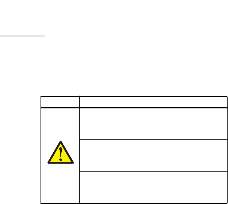
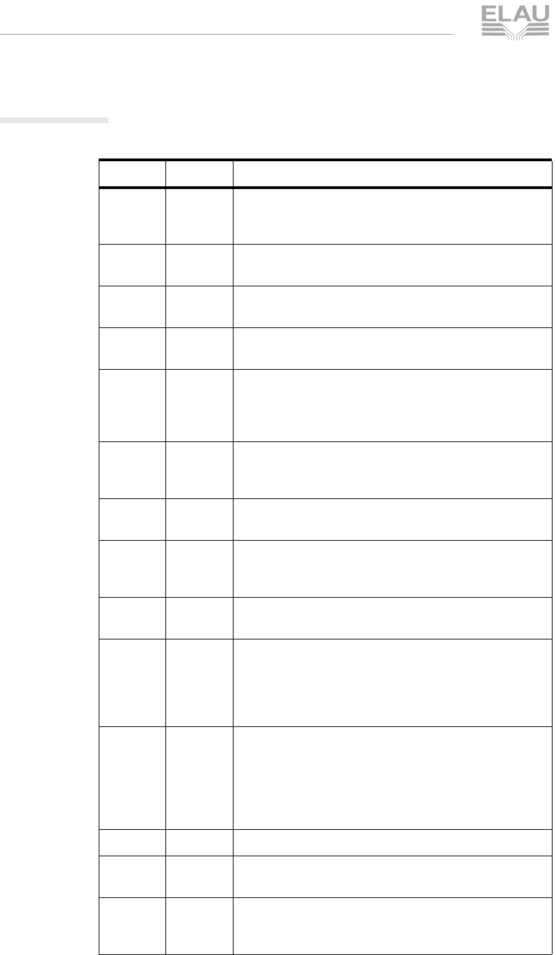
2.2 Depiction of Safety Notes
Risk categories
The safety notes in this manual are grouped into different risk
categories. The table below shows which risk and possible
consequences the symbol (pictograph) and the signal words
indicate.
Table 2-1: Risk categories
Pictograph Signal word Definition
DANGER!
Indicates an immediately dangerous
situation that will result in death or very
serious injuries if the safety rules are
not observed.
WARNING!
Indicates a possibly dangerous situa-
tion that can result in serious injuries or
major material damage if the safety
rules are not observed.
CAUTION!
Indicates a possibly dangerous situa-
tion that might result in material
damage if the safety rules are not
observed.

M_Sicherhneu_us.fm
ELAU AG PacDrive page 9
2.3 Use as Directed
Korrekturausdruck
2.3 Use as Directed
The motor is designed as a drive component for installation in a
machine or for combination with other components to form a
machine/plant. The motor may only be used under the installation
and operating conditions described in this documentation. You
must use the accessories and ancillary parts (components, cables,
etc.) mentioned in the documentation. You must not use any foreign
objects or components that are not explicitly approved by ELAU.
Use as directed also means that you
observe the operating manuals and other documentations (see
appendix)
observe the inspection and service instructions.
Misusage
The operating conditions at the place where the device is used
must be checked on the basis of the given technical data
(performance information and ambient conditions) and observed.
Commissioning is prohibited unless it is guaranteed that the
applicable machine or plant in which the motor is installed is in its
entirety compliant with the EC directive 98/37/EC (machine
directive).
In addition, the following norms, directives and rules need to be
observed:
DIN EN 60204 Safety of machines:
Electrical equipment of machines.
DIN EN 292 part 1 and part 2 Safety of machines:
Basics, general design rules.
DIN EN 50178 Equipment of high-voltage plants with electronic
operating means.
EMC directive 89/336/EEC

M_Sicherhneu_us.fm
page 10 PacDrive ELAU AG
2 General Safety Notes
Korrekturausdruck
2.4 Selection and Qualification of Staff
This manual is aimed exclusively at technically qualified staff with
detailed knowledge in the field of automation technology.
Only qualified staff can recognize the significance of safety notes
and implement them accordingly.
This manual is aimed in particular at design and application
engineers in the fields of mechanical and electrical engineering,
service and commissioning engineers.
Working on
electrical
equipment
Work on electrical equipment must only be done by qualified
electricians or by instructed staff supervised by an electrician
according to the electrotechnical rules.
An electrician is a person who, due to his vocational training, know-
how and experience as well as knowledge of the valid regulations,
is able to:
evaluate the work he is supposed to do
identify potential risks
implement suitable safety measures.
2.5 Residual Risks
The motors reflects the current technical standard. Nevertheless,
there is a residual risk, since the motors work with electrical current
and voltage. We minimized the health risk for people by means of
appropriate construction and safety technology.
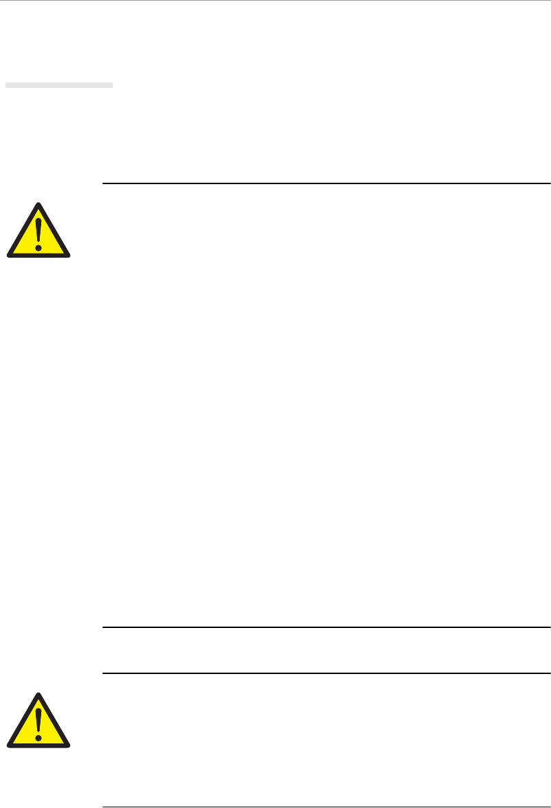
2.5.1 Installation and Handling
WARNING!
Risk of injury while handling the unit!
Risk of injury due to squeezing, cutting or hitting!
Observe the universally valid construction and safety rules for
handling and installation.
Use suitable installation and transport facilities and use them
professionally. If necessary, use special tools.
Take precautions against squeezing.
If necessary, use suitable protective clothing (e.g. safety
glasses, safety shoes, protective gloves).
Do not stay under pending loads.
Remove any leaking liquids from the floor immediately to avoid
skidding.
M_Sicherhneu_us.fm
ELAU AG PacDrive page 11
2.5 Residual Risks
Korrekturausdruck
2.5.2 Protection against Touching Electrical Parts
Touching parts carrying a voltage of 50 Volts or higher can be
dangerous. When electric appliances are operated, certain parts of
these appliances inevitably carry a dangerous voltage.
DANGER!
High voltage!
Life hazard!
Observe the universally valid construction and safety rules for
working on high-voltage units.
After installation, check the fixed connection of the earth
conductor on all electric appliances according to the connection
plan.
Operation, even for short-term measuring and test purposes, is
only permitted with an earth conductor firmly connected to all
electric components. Otherwise high voltages may occur on the
casing.
Before accessing electric parts with voltages exceeding 50 Volts,
disconnect the unit from mains or power supply and lock it out.
After switching off, wait for at least 5 minutes before touching
any components.
Do not touch electrical connections of the components while the
unit is on.
Before switching on the unit, cover all voltage carrying parts to
prevent accidental contact.
Provide for protection against indirect touching (DIN EN 50178 /
1998 section 5.3.2).
DANGER!
High leak current!
Life hazard!
The leak current is greater than 3.5 mA. Therefore the units
must have a firm connection to the power grid (according to DIN
EN 50178 - equipment of high-voltage systems).
M_Sicherhneu_us.fm
page 12 PacDrive ELAU AG
2 General Safety Notes
Korrekturausdruck
2.5.3 Potentially Dangerous Movements
There can be different causes for potentially dangerous
movements:
mistakes in wiring or cable connection
software errors
faulty components
errors in measuring value and signal encoders
operating mistakes
The monitoring functions in the driving components to a large
extent rule out malfunction. For your protection, you must not rely
on these functions alone. Until the controls installed become
effective, you should anticipate faulty movement of the drive, which
can vary depending on the kind of malfunction and the operating
state. Personal protection must be ensured by additional measures
superior to the plant. These are planned by the plant engineer with
regard to the specific circumstances of the plant and after a risk and
error analysis. The safety provisions of the plant are taken into
account.
DANGER!
Potentially dangerous movements!
Life hazard, serious injury or material damage!
No persons are allowed within the motion range of the machine.
This is to be ensured by means of devices like protective fences,
grids, covers or photoelectric barriers.
The fences and covers must be sufficiently strong to withstand
the maximum possible motion energy.
The emergency stop switch must be located very close to the
operator. Check the operation of the emergency stop before
starting up the plant.
Secure against unintentional start by enabling the mains
contactor of the drives via an emergency off circuit or by means
of the function 'safe stop'.
Before accessing the danger zone, bring the drives to a safe
stop.
To work on the plant, power must be turned off and locked out.
Avoid operating high-frequency, remote-control and radio
devices in the vicinity of the plant's electronics and connecting
wires. If the use of those devices is inevitable, check system and
plant for possible malfunctions before first operation. In some
cases a special EMC check may be necessary.

MSM_OpMan_03_us.FM
ELAU AG PacDrive SM-Motor page 13
3.1 In General
Korrekturausdruck
3 Overview
3.1 In General
The highly dynamic synchronous AC servo motors of ELAU's SM
series are permanent field synchronous machines designed espe-
cially for highly dynamic positioning tasks.
The low moment of inertia compared with other AC servo motors in
combination with the high overload tolerance not only guarantees
excellent acceleration values, but also reduces energy consump-
tion and stray heat of the motor.
The torque is generated by the stator coil fed by a sinusoidal three-
phase current system in combination with the magnetic field excited
by the rotor magnets.
The generation of the rotary current system depends on the rotor
position in the digital motor controller or the positioning motor
controller.
For that purpose, the rotor position is monitored by a resolver.
Thanks to that principle, the drives are extremely robust and work
without wearing down.
3.2 Features of the servo motors
The SM motors are characterised by the following features:
High equipment dependability
Maintenance-free operation
Overload protection (by motor temperature monitoring)
High performance data
High dynamics
High overload capacity
Large torque area
sinusoidal EMK
High volt technique = low currents
Low mass-moment of inertia
Motor link and feedback system over connection box
Simple and fast commissioning (by electronic vehicle identifica-
tion plate in the SinCos encoder)

MSM_OpMan_03_us.FM
page 14 PacDrive SM-Motor ELAU AG
3 Overview
Korrekturausdruck
3.3 Versions
Motor feedback
SinCos encoder singleturn or
SinCos encoder multiturn or
Resolver feedback
Holding brake
without brake (standard) or
with brake (option) to hold axis when in vertical position or when
plant is powerless.
Shaft
Smooth shaft (standard) or
Shaft with feather groove (option)
Miscellaneous
The SM motors also with ventilation and gear reducer options.

MSM_OpMan_04_us.FM
ELAU AG PacDrive SM-Motor page 15
Transportation, Storage, Unpacking
Korrekturausdruck
4 Transportation, Storage, Unpacking
4.1 Transportation
Avoid shocks.
Immediately check units for transport damage and inform your
transport company, if necessary.
4.2 Storage
Store units in a clean, dry place.
Storage conditions:
air temperature between - 25 °C and + 70 °C.
temperature fluctuations max. 30 K per hour.

MSM_OpMan_04_us.FM
page 16 PacDrive SM-Motor ELAU AG
Transportation, Storage, Unpacking
Korrekturausdruck
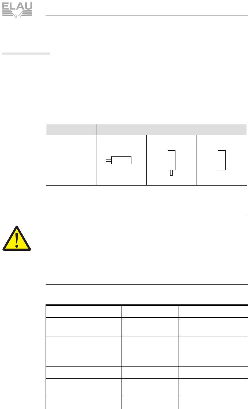
4.3 Unpacking
Check whether the delivery is complete.
Check all units for transport damage.
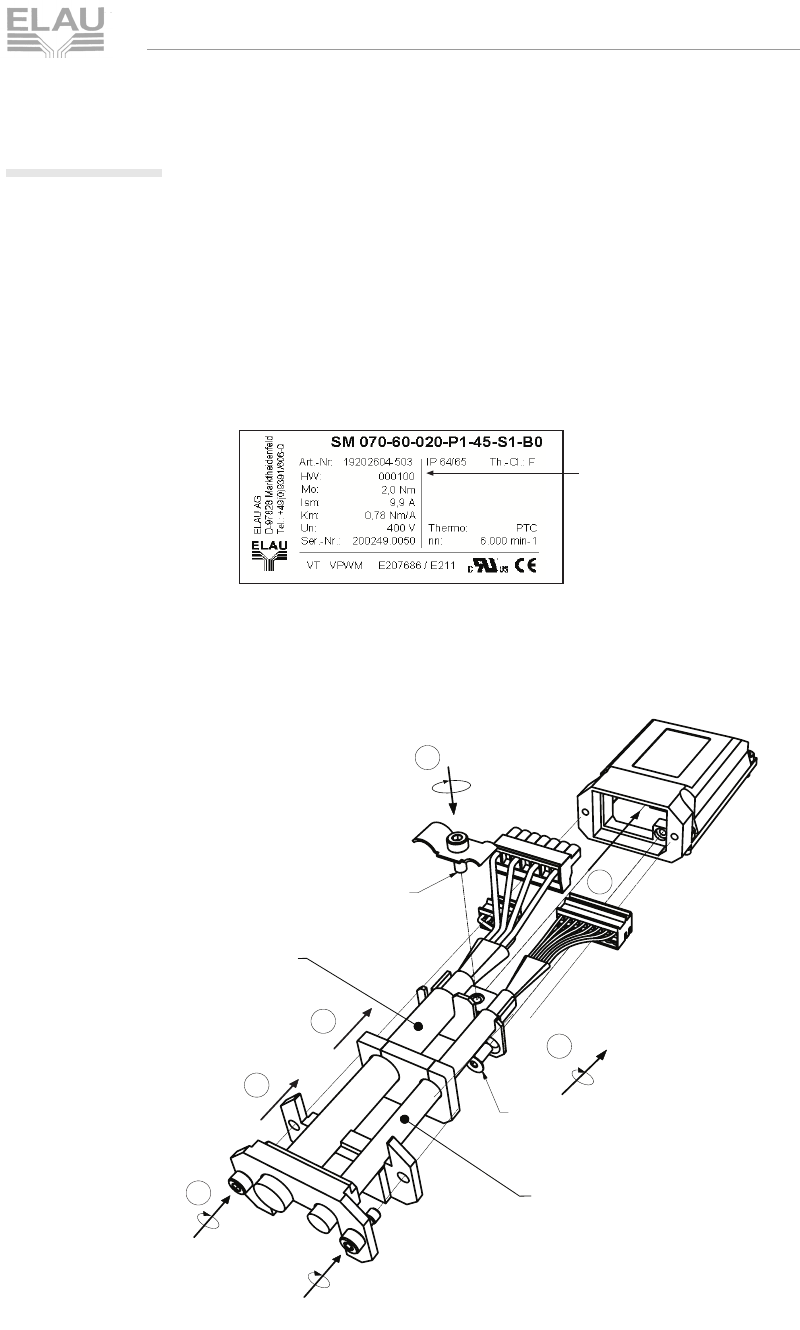
Type plate
The type plate contains all necessary motor information:
Fig. 4-1: type plate at the SM motor
Fig. 4-2: type plate of a SM motor
Article name
Article number
Serial number
Hardware-Code
MSM_OpMan_04_us.FM
ELAU AG PacDrive SM-Motor page 17
Transportation, Storage, Unpacking
Korrekturausdruck
4.3.1 Modified connections
Shield connection, connection technology and the installation of
connection cables for SM Motors were improved and the terminal
box adapted. Existing components, such as cables etc. can still be
used. The new and previous versions of the motor are fully
compatible.
In context with the improved connections, a hardware code was
added on the type plate and the packaging of the motors.
Example: Type plate of an SM motor with modified connections.
Fig. 4-3: Type plate of an SM motor with modified connections
The following diagram shows how the cables are installed in the
terminal box.
SM motor terminal box - cable installation
Hardware-Code
(C) 12/2002
2
1
3
1,4 Nm
1,4 Nm
1,4 Nm
2,5 Nm
Power
Feedback
DIN 7991 M4 x 10
DIN 912 M4x10
5
4
6

MSM_OpMan_04_us.FM
page 18 PacDrive SM-Motor ELAU AG
Transportation, Storage, Unpacking
Korrekturausdruck
MSM_OpMan_05_us.FM
ELAU AG PacDrive SM-Motor page 19
5.1 Spare Parts, Components
Korrekturausdruck
5 Maintenance
Recognizing and clearing an error quickly helps to keep the related
production loss down to a minimum.
The diagnosis messages of the PacDrive™ system, which can be
checked using EPAS, allows well directed and effective trouble-
shooting.
In case of an error, defective components can be exchanged with
no problem. This ensures that the problem can be solved quickly
and operation can be resumed soon. This work must be done by
qualified maintenance staff only.
When returning a defective unit to the ELAU customer service,
please complete the attached error report form.
5.1 Spare Parts, Components
Stock keeping of spare parts:
Keeping a stock of the essential components is a key prerequisite
for the continuious functionality of the equipment.
ATTENTION!
Device compatibility!
Only units with identical hardware configuration and identical soft-
ware version may be exchanged.
When ordering spare parts, please give the following data:
product name: e. g. SM 070-60-010-P0-44-M1-B0
article number: e. g. 19202602-509
You can find this information on the type plate of the motor (see
Fig. 4-1) or in the configuration of your PacDrive™ M system.

MSM_OpMan_05_us.FM
page 20 PacDrive SM-Motor ELAU AG
5 Maintenance
Korrekturausdruck
5.2 Repair
By all means complete the attached error report form when
returning defective components.
You can also make a photocopy of the error report form and use it
as a fax message.
ATTENTION!
Electro static discharge!
Components may be damaged!
Electronic parts may only be returned in the original or an
equivalent packaging. In any case the components must be
wrapped in an ESD packaging/foil. Otherwise warranty on
equipment will be subject to termination.
5.3 Service Addresses
For ordering spare parts
ELAU AG
Postfach 1255
97821 Marktheidenfeld
Phone: +49 (0) 93 91 / 606 - 0
Fax: +49 (0) 93 91 / 606 - 300
For repair
Please send the components to be repaired or checked, along with
the error report, to this address:
ELAU AG
Abt. Kundendienst
postal address: house address:
Postfach 1255 Dillberg 12
97821 Marktheidenfeld 97828 Marktheidenfeld
Service team
Should you need to talk to a member of our service team or require
on-site service, please contact:
ELAU AG
Abt. Kundendienst / Applikation
Postfach 1255
97821 Marktheidenfeld
Phone: +49 (0) 93 91 / 606 - 142
Fax: +49 (0) 93 91 / 606 - 300
MSM_OpMan_05_us.FM
ELAU AG PacDrive SM-Motor page 21
5.4 Exchanging Units
Korrekturausdruck
5.4 Exchanging Units
In addition to the notes below, please observe the information of the
machine producer when exchanging the motor.
DANGER!
High Voltage!
Life Hazard!
Before working on electrical units, disconnect from mains supply
and secure against being switched on accedentially.
The drives must be standing safely because life-threatening
voltages can occur on the motor cables of servo motors in
generator operation.
Do not disconnect connector plugs while they are carrying
voltage.
CAUTION!
Electro static discharge!
Components may be damaged!
Only touch the boards by the edges. Do not touch any
connections or components.
Before touching the boards, discharge any possible static
charge. For this purpose, touch an earthed metal surface, e.g.
the casing.
Do not place the boards on a metal surface.
Avoid the creation of electro static charge by the use of
appropriate clothing, carpets and furniture and by moving the
boards as little as possible.
MSM_OpMan_05_us.FM
page 22 PacDrive SM-Motor ELAU AG
5 Maintenance
Korrekturausdruck
Exchange motor
NOTE
If motors were stored longer than 2 years, the holding brake has to be
resurfaced before you use it. See also " holding brake (option)" on page
52.
Lift the main switch.
Secure against accendential switch-on.
DANGER!
High voltage!
Life hazard!
Connect or disconnect main power cable to motor only when no
voltage is present on unit!
CAUTION!
Mechanical force!
Possible damage of the encoder system!
When removing / applying a coupling off / to the motor shaft no
impact may be executed on the motor shaft, to avoid damage of the
encoder. Use suitable tools e. g. pullers.
WARNING!
Inadvertent movement of axes!
Danger of accident!
With servo axes with indirect distance measurement system over the
motor encoder the measure reference is lost with exchange of the
engine!
The measure reference to the machine coordinate system therefore
is to be reconstituted after the exchange!
Exchange motor as described by the machine manufacturer.
CAUTION!
Insufficient shield connection/earthing!
Motor damage!
In general operate motor only with tightly screwed connector box.

MSM_OpMan_05_us.FM
ELAU AG PacDrive SM-Motor page 23
5.4 Exchanging Units
Korrekturausdruck
Exchange cable
Lift the main switch
Secure against accendential switch-on
DANGER!
High voltage!
Life hazard!
Separate or join performance plug connectors of the cables only
in status without tension of the system!
Join performance plug connectors only with dry and clean
putting pages!
If no finished cables produced by ELAU are used, check
allocation of new cables for agreement with the connection
diagram of the machine manufacturer!
Exchange the cables considering the specification of the
machine manufacturer.

MSM_OpMan_05_us.FM
page 24 PacDrive SM-Motor ELAU AG
5 Maintenance
Korrekturausdruck
5.5 Cleaning
If installed appropriately, the devices are to a large extent
maintenance-free.
CAUTION!
Penetration of liquid due to inexpert cleaning!
Motor damage!
If the motor is cleaned with a high-pressure cleaner, liquid may
penetrate into the motor casing. Use cleaning methods
compliant with the protection type of the motor.

MSM_OpMan_05_us.FM
ELAU AG PacDrive SM-Motor page 25
5.6 EMC Rules
Korrekturausdruck
5.6 EMC Rules
To control and regulate motors, the mains voltage is stored in the
DC-circuit of the MC-4 MotorController by means of rectification.
This stored energy is fed to the motor by deliberately switching on
and off six semiconductor switches. The steep rise and fall of the
voltage puts high demands on the insulation strength of the motor
winding. Another essential aspect to be considered is the Electro
Magnetic Compatibility (EMC) with other system components. The
flank steepness of the clocked voltage generates harmonic
oscillations of great intensity, up into the high-frequency range.
Therefore observe the following EMC rules:
Choose the earthing option with the lowest possible ohm rate
(e.g. unpainted mounting board of the switching cabinet) for
installation.
Contact the largest possible surface (skin effect). If necessary,
remove existing paint to achieve large-surface contact.
From the Central Earthing Point (CEP), lay earthing wires to the
respective connections in a star structure. Earthing circuits are
not admissible and can cause unnecessary distortions.
Use shielded cables only.
Only large-surface shield transitions are admissible.
Shields must not be contacted via pin contacts of connector
plugs.
By all means observe the switching proposals.
Cut motor cables to minimum length.
Do not lay cable loops inside the switching cabinet.
MSM_OpMan_05_us.FM
page 26 PacDrive SM-Motor ELAU AG
5 Maintenance
Korrekturausdruck
CAUTION!
Electromagnetic fields!
Disturbances or failure of the system possible!
With the installation the following rules must be considered, in order
to exclude consequences of excessive disturbance effects as far as
possible.
In connection with electronic controls, no inductive loads
whatsoever must be switched without suitable interference
elimination.
For DC operation, suitable interference elimination can be
achieved by arranging recovery diodes. For AC operation,
commercially available erasing elements matching the
connector type can be used.
Only the interference elimination element mounted immediately
at the point of inductivity serves this purpose. In any other case,
the switching pulse may even emit increased interference via the
interference elimination elements. It is much easier to avoid
sources of interference in the first place, than to eliminate the
effects of existing interference.
In no case must the contacts switching unshielded inductive
loads be arranged in the same room as the MC-4
MotorController; the same goes for cables carrying unshielded,
switched inductivity and cables running parallel to them. The
control must be separated from such „distorters“ by a Faraday
cage (own section in the switching cabinet).
CAUTION!
Electromagnetic fields!
Disturbances or failure of the system possible!
Dependent on the MotorController/motor combination and the
cable length, system filters or motor filters should be used where
possible.
Please observe the project manuals of the MotorControllers
(MC-4/PMC-2).

MSM_OpMan_05_us.FM
ELAU AG PacDrive SM-Motor page 27
5.7 Commissioning
Korrekturausdruck
5.7 Commissioning
We urgently recommend using ELAU staff for initial commissioning.
This should not only be done for warranty reasons; at the same
time
the equipment is controlled,
the optimum configuration is determined,
the operating staff are instructed.
How to proceed when commissioning:
Unpack and
check
Remove packaging.
Check devices for damage. Only undamaged devices may be
put into operation.
Check shipment for completeness.
Check data using the type plates.
See also chapter Transportation, Storage, Unpacking.
Installation
Observe requirements for the place of installation.
Observe requirements for protection type and EMC rules.
Install devices.
See also chapter Maintenance.
Electrical
connection
Connect devices, starting with the earth conductor.
Check if the clamps are tight and the required cable cross
sections are correct,
Check the perfect execution of the shield, rule out short-circuits
and interruptions.
See also chapter Technical Data und Maintenance.
Check safety
functions
Check thermo contact of the motor and/or PTC sensor.
Check function of the brake (if any).
Check EMERGENCY OFF chain and EMERGENCY OFF limit
switch.
Continue
commissioning
the plant
Continue commissioning the plant according to the operating
manuals (packaging machine producer and MotorController).
MSM_OpMan_05_us.FM
page 28 PacDrive SM-Motor ELAU AG
5 Maintenance
Korrekturausdruck
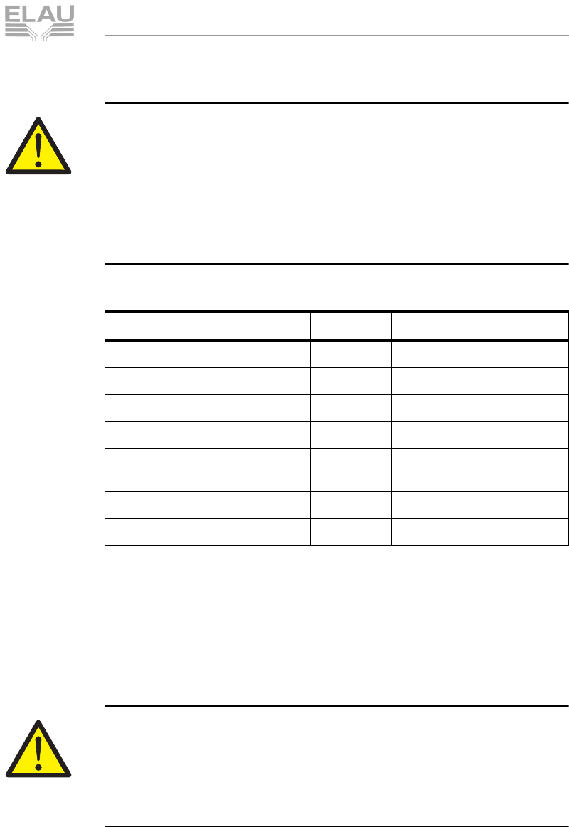
5.8 PacDrive SM Motor with Barrier Pressure System
The optional barrier pressure system is used to operate the motor
in ambient conditions with high demands on protection against
intrusion of liquids.
In practice, different liquids with creeping rates different from water
are used. Moreover, the pressure in the casing rises as the drive
gets hot and falls as the drive cools off. Those pressure differences
encourage the penetration of liquid
barrier pressure
system
Permanent, reliable protection against the penetration of liquids
and gases is achieved if the casing is kept under a slight
overpressure by means of an air barrier. The pressurized air used
for that purpose must be dry and free from dust and oil. As the
system is closed, air consumption is so low that it can be neglected.
Table 5-1: Operating conditions for the use of the barrier pressure system
Connection of
the barrier
pressure system
The motor is supplied with air via a commercially available com-
pressed air pipe (polyamide plastic pipe 4 x 0,75 mm). A thread M3
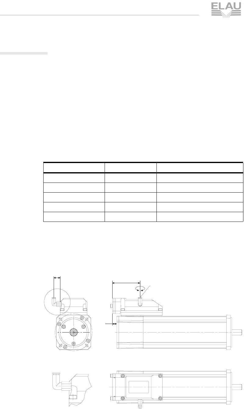
for the barrier pressure system is placed in the terminal box.
Fig. 5-1: Connection of the barrier pressure system at the SM-motor
Properties Value
Remark
Pressure 0,1...0,3 bar recommended
Pressure 0,4 bar maximum
Operating condition dust-free by means of suitable microfilters
Operating conditions oil-free by means of suitable oil separators
relative Luftfeuchtigkeit 20...30 %
13
56
180°
9
Connection of the barrier
pressure system
A ( 2 : 1 )
A

MSM_OpMan_05_us.FM
ELAU AG PacDrive SM-Motor page 29
5.9 Configuration / Programming / Diagnosis
Korrekturausdruck
5.9 Configuration / Programming / Diagnosis
The motors are adjusted by ELAU. The customer does not need to
execute alignment.
The adjustment of the MotorControllers to the motors is to be
inferred from the documentation of the respective MotorController.
See also the documentation of the MotorController.
Error diagnosis and monitoring of the operating conditions is
executed into the ELAU controllers.
See programing reference manual for appropriate descriptions.
MSM_OpMan_05_us.FM
page 30 PacDrive SM-Motor ELAU AG
5 Maintenance
Korrekturausdruck
5.10 Order Numbers
5.10.1 SM Motor
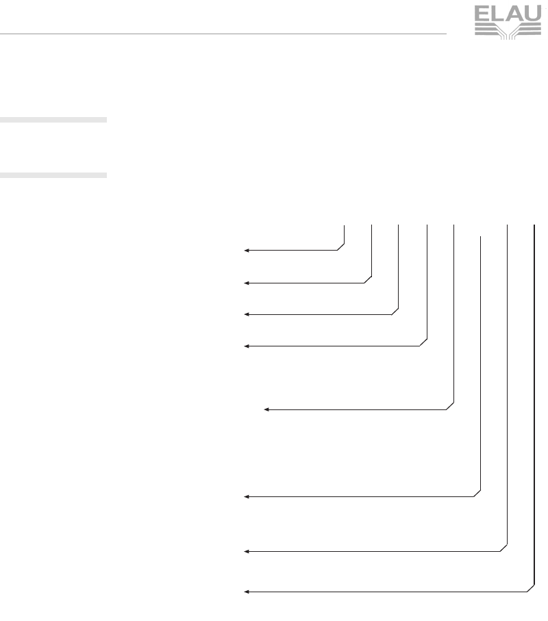
Fig. 5-2: Type key legend for SM motor
Type key SM - 100 / 50 / 030 / P0 / 45 / S1 / B0 / XY
Flange size
e.g.: 070 = 70 mm
Speed n
N
e.g.: 50 = 5000 min
-1
Torque M
0
e.g.: 030 = 3,0 Nm
Shaft version
P0 = without feather groove (smooth shaft)
P1 = with feather groove (key) according to DIN 6885
P3 = stainless steel shaft without feather groove (smooth shaft)
P4 = stainless steel shaft with feather groove (key) DIN 6885
Protection means shaft/casing
1. digit = shaft
4 = IP 64, 5 = IP 65
2. digit = casing
0 = IP 20 (with surface ventilation)
5 = IP 65
A = IP67 (with option barrier pressure system)
Encoder
S1 = SinCos single-turn
M1 = SinCos multi-turn
R1 = Resolver
Holding brake
B0 = without brake
B1 = with brake
Special option (bit coded)
Bit 0 = 1 (01) with fan 230 V AC
Bit 2 = 1 (04) without lacquer
MSM_OpMan_05_us.FM
ELAU AG PacDrive SM-Motor page 31
5.10 Order Numbers
Korrekturausdruck
5.10.2 SM Motor
Basic Types
Tabelle 5-2: Order numbers for SM Motor
Order number Product name Explanations
19202602-xxx SM-070/60/010/P0/45/S1/B0 SM-70
19202604-xxx SM-070/60/020/P0/45/S1/B0 SM-70
19203501-xxx SM-100/50/030/P0/45/S1/B0 SM-100
19203402-xxx SM-100/40/050/P0/45/S1/B0 SM-100
19203304-xxx SM-100/30/080/P0/45/S1/B0 SM-100
19203403-xxx SM-100/40/080/P0/45/S1/B0 SM-100
19204301-xxx SM-140/30/120/P0/45/S1/B0 SH-140
19204302-xxx SM-140/30/210/P0/45/S1/B0 SH-140
19204303-xxx SM-140/30/290/P0/45/S1/B0 SH-140
19204304-xxx SM-140/30/370/P0/45/S1/B0 SH-140
19204202-xxx SM-140/20/210/P0/45/S1/B0 SH-140
Order number Product name Explanations
Shaft (standard) / IP64
1920xxxx - 501 SM ... / .. / ... / P0 / 45 / S1 / B0 Singleturn
1920xxxx - 002 SM ... / .. / ... / P0 / 45 / S1 / B1 Singleturn, brake
1920xxxx - 503 SM ... / .. / ... / P1 / 45 / S1 / B0 Singleturn, shaft
1920xxxx - 004 SM ... / .. / ... / P1 / 45 / S1 / B1 Singleturn, brake, shaft
1920xxxx - 505 SM ... / .. / ... / P0 / 45 / R1 / B0 Resolver
1920xxxx - 006 SM ... / .. / ... / P0 / 45 / R1 / B1 Resolver, brake
1920xxxx - 507 SM ... / .. / ... / P1 / 45 / R1 / B0 Resolver, shaft
1920xxxx - 008 SM ... / .. / ... / P1 / 45 / R1 / B1 Resolver, shaft, brake
1920xxxx - 509 SM ... / .. / ... / P0 / 45 / M1 / B0 Multiturn
1920xxxx - 010 SM ... / .. / ... / P0 / 45 / M1 / B1 Multiturn, brake
1920xxxx - 511 SM ... / .. / ... / P1 / 45 / M1 / B0 Multiturn, shaft
1920xxxx - 012 SM ... / .. / ... / P1 / 45 / M1 / B1 Multiturn, shaft, brake
1920xxxx - 513 SM ... / .. / ... / P0 / 40 / S1 / B0 / 01 Singleturn, fan
1920xxxx - 014 SM ... / .. / ... / P0 / 40 / S1 / B1 / 01 Singleturn, brake, fan
1920xxxx - 515 SM ... / .. / ... / P1 / 40 / S1 / B0 / 01 Singleturn, shaft, fan
1920xxxx - 016 SM ... / .. / ... / P1 / 40 / S1 / B1 / 01 Singleturn, brake, shaft, fan
1920xxxx - 517 SM ... / .. / ... / P0 / 40 / R1 / B0 / 01 Resolver, fan
1920xxxx - 018 SM ... / .. / ... / P0 / 40 / R1 / B1 / 01 Resolver, brake, fan
1920xxxx - 519 SM ... / .. / ... / P1 / 40 / R1 / B0 / 01 Resolver, shaft, fan
1920xxxx - 020 SM ... / .. / ... / P1 / 40 / R1 / B1 / 01 Resolver, shaft, brake, fan
1920xxxx - 521 SM ... / .. / ... / P0 / 40 / M1 / B0 / 01 Multiturn, fan

MSM_OpMan_05_us.FM
page 32 PacDrive SM-Motor ELAU AG
5 Maintenance
Korrekturausdruck
1920xxxx - 022 SM ... / .. / ... / P0 / 40 / M1 / B1 / 01 Multiturn, brake, fan
1920xxxx - 523 SM ... / .. / ... / P1 / 40 / M1 / B0 / 01 Multiturn, shaft, fan
1920xxxx - 024 SM ... / .. / ... / P1 / 40 / M1 / B1 / 01 Multiturn, shaft, brake, fan
Shaft (stainless steel) / IP64
1920xxxx - 525 SM ... / .. / ... / P3 / 45 / S1 / B0 Singleturn
1920xxxx - 026 SM ... / .. / ... / P3 / 45 / S1 / B1 Singleturn, brake
1920xxxx - 527 SM ... / .. / ... / P4 / 45 / S1 / B0 Singleturn, shaft
1920xxxx - 028 SM ... / .. / ... / P4 / 45 / S1 / B1 Singleturn, brake, shaft
1920xxxx - 529 SM ... / .. / ... / P3 / 45 / R1 / B0 Resolver
1920xxxx - 030 SM ... / .. / ... / P3 / 45 / R1 / B1 Resolver, brake
1920xxxx - 531 SM ... / .. / ... / P4 / 45 / R1 / B0 Resolver, shaft
1920xxxx - 032 SM ... / .. / ... / P4 / 45 / R1 / B1 Resolver, shaft, brake
1920xxxx - 533 SM ... / .. / ... / P3 / 45 / M1 / B0 Multiturn
1920xxxx - 034 SM ... / .. / ... / P3 / 45 / M1 / B1 Multiturn, brake
1920xxxx - 535 SM ... / .. / ... / P4 / 45 / M1 / B0 Multiturn, shaft
1920xxxx - 036 SM ... / .. / ... / P4 / 45 / M1 / B1 Multiturn, shaft, brake
1920xxxx - 537 SM ... / .. / ... / P3 / 40 / S1 / B0 / 01 Singleturn, fan
1920xxxx - 038 SM ... / .. / ... / P3 / 40 / S1 / B1 / 01 Singleturn, brake, fan
1920xxxx - 539 SM ... / .. / ... / P4 / 40 / S1 / B0 / 01 Singleturn, shaft, fan
1920xxxx - 040 SM ... / .. / ... / P4 / 40 / S1 / B1 / 01 Singleturn, brake, shaft, fan
1920xxxx - 541 SM ... / .. / ... / P3 / 40 / R1 / B0 / 01 Resolver, fan
1920xxxx - 042 SM ... / .. / ... / P3 / 40 / R1 / B1 / 01 Resolver, brake, fan
1920xxxx - 543 SM ... / .. / ... / P4 / 40 / R1 / B0 / 01 Resolver, shaft, fan
1920xxxx - 044 SM ... / .. / ... / P4 / 40 / R1 / B1 / 01 Resolver, shaft, brake, fan
1920xxxx - 545 SM ... / .. / ... / P3 / 40 / M1 / B0 / 01 Multiturn, fan
1920xxxx - 046 SM ... / .. / ... / P3 / 40 / M1 / B1 / 01 Multiturn, brake, fan
1920xxxx - 547 SM ... / .. / ... / P4 / 40 / M1 / B0 / 01 Multiturn, shaft, fan
1920xxxx - 048 SM ... / .. / ... / P4 / 40 / M1 / B1 / 01 Multiturn, shaft, brake, fan
Shaft (standard) / IP65
1920xxxx - 549 SM ... / .. / ... / P0 / 55 / S1 / B0 Singleturn
1920xxxx - 050 SM ... / .. / ... / P0 / 55 / S1 / B1 Singleturn, brake
1920xxxx - 551 SM ... / .. / ... / P1 / 55 / S1 / B0 Singleturn, shaft
1920xxxx - 052 SM ... / .. / ... / P1 / 55 / S1 / B1 Singleturn, brake, shaft
1920xxxx - 553 SM ... / .. / ... / P0 / 55 / R1 / B0 Resolver
1920xxxx - 054 SM ... / .. / ... / P0 / 55 / R1 / B1 Resolver, brake
1920xxxx - 555 SM ... / .. / ... / P1 / 55 / R1 / B0 Resolver, shaft
1920xxxx - 056 SM ... / .. / ... / P1 / 55 / R1 / B1 Resolver, shaft, brake
1920xxxx - 557 SM ... / .. / ... / P0 / 55 / M1 / B0 Multiturn
1920xxxx - 058 SM ... / .. / ... / P0 / 55 / M1 / B1 Multiturn, brake
1920xxxx - 559 SM ... / .. / ... / P1 / 55 / M1 / B0 Multiturn, shaft
Order number Product name Explanations

MSM_OpMan_05_us.FM
ELAU AG PacDrive SM-Motor page 33
5.10 Order Numbers
Korrekturausdruck
1920xxxx - 060 SM ... / .. / ... / P1 / 55 / M1 / B1 Multiturn, shaft, brake
1920xxxx - 561 SM ... / .. / ... / P0 / 50 / S1 / B0 / 01 Singleturn, fan
1920xxxx - 062 SM ... / .. / ... / P0 / 50 / S1 / B1 / 01 Singleturn, brake, fan
1920xxxx - 563 SM ... / .. / ... / P1 / 50/ S1 / B0 / 01 Singleturn, shaft, fan
1920xxxx - 064 SM ... / .. / ... / P1 / 50 / S1 / B1 / 01 Singleturn, brake, shaft, fan
1920xxxx - 565 SM ... / .. / ... / P0 / 50 / R1 / B0 / 01 Resolver, fan
1920xxxx - 066 SM ... / .. / ... / P0 / 50 / R1 / B1 / 01 Resolver, brake, fan
1920xxxx - 567 SM ... / .. / ... / P1 / 50 / R1 / B0 / 01 Resolver, shaft, fan
1920xxxx - 068 SM ... / .. / ... / P1 / 50 / R1 / B1 / 01 Resolver, shaft, brake, fan
1920xxxx - 569 SM ... / .. / ... / P0 / 50 / M1 / B0 / 01 Multiturn, fan
1920xxxx - 070 SM ... / .. / ... / P0 / 50 / M1 / B1 / 01 Multiturn, brake, fan
1920xxxx - 571 SM ... / .. / ... / P1 / 50 / M1 / B0 / 01 Multiturn, shaft, fan
1920xxxx - 072 SM ... / .. / ... / P1 / 50 / M1 / B1 / 01 Multiturn, shaft, brake, fan
Shaft (stainless steel) / IP65
1920xxxx - 573 SM ... / .. / ... / P3 / 55 / S1 / B0 Singleturn
1920xxxx - 074 SM ... / .. / ... / P3 / 55 / S1 / B1 Singleturn, brake
1920xxxx - 575 SM ... / .. / ... / P4 / 55 / S1 / B0 Singleturn, shaft
1920xxxx - 076 SM ... / .. / ... / P4 / 55 / S1 / B1 Singleturn, brake, shaft
1920xxxx - 577 SM ... / .. / ... / P3 / 55 / R1 / B0 Resolver
1920xxxx - 078 SM ... / .. / ... / P3 / 55 / R1 / B1 Resolver, brake
1920xxxx - 579 SM ... / .. / ... / P4 / 55 / R1 / B0 Resolver, shaft
1920xxxx - 080 SM ... / .. / ... / P4 / 55 / R1 / B1 Resolver, shaft, brake
1920xxxx - 581 SM ... / .. / ... / P3 / 55 / M1 / B0 Multiturn
1920xxxx - 082 SM ... / .. / ... / P3 / 55 / M1 / B1 Multiturn, brake
1920xxxx - 583 SM ... / .. / ... / P4 / 55 / M1 / B0 Multiturn, shaft
1920xxxx - 084 SM ... / .. / ... / P4 / 55 / M1 / B1 Multiturn, shaft, brake
1920xxxx - 585 SM ... / .. / ... / P3 / 50 / S1 / B0 / 01 Singleturn, fan
1920xxxx - 086 SM ... / .. / ... / P3 / 50 / S1 / B1 / 01 Singleturn, brake, fan
1920xxxx - 587 SM ... / .. / ... / P4 / 50 / S1 / B0 / 01 Singleturn, shaft, fan
1920xxxx - 088 SM ... / .. / ... / P4 / 50 / S1 / B1 / 01 Singleturn, brake, shaft, fan
1920xxxx - 589 SM ... / .. / ... / P3 / 50 / R1 / B0 / 01 Resolver, fan
1920xxxx - 090 SM ... / .. / ... / P3 / 50 / R1 / B1 / 01 Resolver, brake, fan
1920xxxx - 591 SM ... / .. / ... / P4 / 50 / R1 / B0 / 01 Resolver, shaft, fan
1920xxxx - 092 SM ... / .. / ... / P4 / 50 / R1 / B1 / 01 Resolver, shaft, brake, fan
1920xxxx - 593 SM ... / .. / ... / P3 / 50 / M1 / B0 / 01 Multiturn, fan
1920xxxx - 094 SM ... / .. / ... / P3 / 50 / M1 / B1 / 01 Multiturn, brake, fan
1920xxxx - 595 SM ... / .. / ... / P4 / 50 / M1 / B0 / 01 Multiturn, shaft, fan
1920xxxx - 096 SM ... / .. / ... / P4 / 50 / M1 / B1 / 01 Multiturn, shaft, brake, fan
Option barrier pressure system / IP67
1920xxxx - 620 SM ... / .. / ... / P3 / 5A / M1 / B1 Multiturn, brake
Order number Product name Explanations

MSM_OpMan_05_us.FM
page 34 PacDrive SM-Motor ELAU AG
5 Maintenance
Korrekturausdruck
Table 5-3: Order numbers for SM motor
1920xxxx - 621 SM ... / .. / ... / P4 / 5A / M1 / B1 Multiturn, brake, shaft
1920xxxx - 622 SM ... / .. / ... / P0 / 5A / M1 / B1 Multiturn, brake
1920xxxx - 623 SM ... / .. / ... / P3 / 5A / M1 / B0 Multiturn
1920xxxx - 624 SM ... / .. / ... / P4 / 5A / M1 / B0 Multiturn, shaft
Order number Product name Explanations

MSM_OpMan_05_us.FM
ELAU AG PacDrive SM-Motor page 35
5.10 Order Numbers
Korrekturausdruck
5.10.3 Cables
Motor Cables
Table 5-4: Order numbers for motor cables
Order number Product name Explanations
15 15 41 01 E-MO-067 UL cable 1.5 mm2SM-070/100 on
MC-4 X4
15 15 41 21 E-MO-092 UL cable 1.5 mm2
SM-140
on
MC-4 X4
15 15 41 12 E-MO-082 UL cable 2.5 mm2
SM-140/30/210/..
with fan
on
MC-4 / 22 A X4
15 15 41 17 E-MO-087 UL cable 2.5 mm2SM-140/30/290;
SM-140/30/370
on MC-4 / 22 A X4
15 15 41 20 E-MO-091 UL cable 4 mm2SM-140/30/370/...
with fan
on MC-4 / 22 A X4
on MC-4 / 50 A X4
15 15 41 02 E-MO-068 CE cable 1.5 mm2
SM-070/100
on
MC-4 X4
15 15 41 07 E-MO-073 CE cable 1.5 mm2
SM-140
on
MC-4 X4
15 15 41 03 E-MO-069 CE cable 2.5 mm2
SM-140/30/210/...
with fan
on
MC-4 / 22 A X4
15 15 41 13 E-MO-083 CE cable 2.5 mm2SM-140/30/290;
SM-140/30/370
on MC-4 / 22 A X4
15 15 41 14 E-MO-084 CE cable 4 mm2SM-140/30/370/...
with fan
on MC-4 / 22 A X4
on MC-4 / 50 A X4
15 15 41 04 E-MO-070 UL cable 1.5 mm2SM-070/100
on PMC-2
15 15 41 05 E-MO-071 CE cable 1.5 mm2SM-070/100
on PMC-2
15 15 41 08 E-MO-074 CE cable 1.5 mm2SM-140
’on PMC-2
15 15 41 06 E-MO-072 CE cable 2.5 mm2SM-140
on PMC-2
MSM_OpMan_05_us.FM
page 36 PacDrive SM-Motor ELAU AG
5 Maintenance
Korrekturausdruck
Encoder Cables
Table 5-5: Order numbers for encoder cables
5.10.4 Connector Sets
Table 5-6: Order numbers for connector sets
Order number Product name Explanations
15 15 42 01 E-FB-060 UL cable
SM-070; SM-100 X4
on MC-4 X8
15 15 42 02 E-FB-061 CE cable
SM-070; SM-100 X4
on MC-4 X8
15 15 42 13-XXX E-FB-069 SM/SIN Ext.. motor side
SM070/100
15 15 42 15 E-FB-071 UL cable
SM-140 X4
on
MC-4 X8
15 15 42 17 E-FB-073 CE cable
SM-140 X4
on
MC-4 X8
15 15 42 03 E-FB-062 CE cable on PMC-2 X12
(SinCos)
15 15 42 04 E-FB-067 CE cable on PMC-2 X6
(resolver)
Order number Product name Explanaqtion
15 15 44 01 Connector Set SM070/100 Connector
motor cable
compl.
15 15 44 02-001 Connector Set SM140 Type1 Connector
motor cable
compl.
(up to
SM140/30/210)
15 15 44 02-002 Connector Set SM140 Type2 Connector
motor cable
compl.
(from
SM140/30/290)
15 15 44 02-003 Connector Set SR-058 connector motor
and feedback
MSM_OpMan_06_us.fm
ELAU AG PacDrive SM-Motor page 37
6.1 General Technical Data
Korrekturausdruck
6 Technical Data
6.1 General Technical Data
Table 6-1: General technical data
Table 6-2: General technical data (Options)
Designation Description
Motor type Rotary synchr. servomotor, permanently excited
Magnetic material Neodymium-Iron-Boron (NdFeB)
Insulation system
(according to DIN VDE 0530) Heat class F (155 °C)
Mounting orientation
(according to DIN 42 950) IM B5, IM V1, IM V3
Protection class
(according to EN 60529) IP65, in IM V3 shaft sealing required
IP67, with optional barrier pressure system
Cooling Self-cooling, rated ambient temperature up to 40 °C
Coating
Approvals two component high solid expoxid resin coating
USDA - Incidential food contact
NFPA - Class A
NSF Standard 61 - Potable water
Color of coating, Ral 9005
Temperature monitoring Three-code thermocontact (CPTC)in the stator coil,
switching temperature 130 °C
Shaft end Cylindrical shaft end according to DIN 748 without
key way
Concentric accuracy,
coaxiality, axial run
(according to DIN 42 955)
Tolerance N (normal)
Balancing class
(according to DIN ISO 1940) G 2.5
Built-in measuring system Resolver 2 polepairs
Connection system Cylindrical Connectors (IP67) turnable
Options Description
Keyed shaft Keyed shaft according to DIN 6885 T1
Brake Electromagnetic permanent-magnet holding brake
Shaft in stainless steel Shaft in stainless steel with / without keyed shaft
Sealing Housing Barrier pressure System (IP67)
Shaft Sealing Viton radial shaft seal on the flange side
Cooling air and water cooling (in preparation)
Measuring system SKS36, SKM36
more feedbacksystems available on request
MSM_OpMan_06_us.fm
page 38 PacDrive SM-Motor ELAU AG
6 Technical Data
Korrekturausdruck
6.1.1 Definitions and Physical Correlations
Abbrev. Unit Definition
I0M [A] standstill current of the motor
effective value of the motor current at standstill torque
M0
INM [A] rated motor current
effective value of the motor current at rated torque MN
ISM [A] peak motor current
effective value of the motor current at peak torque MSM
INC [A] rated current of MotorController
rated controller current (permanent operation S1)
ISC [A] peak current of the MotorController
peak current of the controller for acceleration phases
also effective value of the motor current at peak torque
MSA supplied for a short time by the drive combination
JM[kgcm2] rotor moment of inertia
the rotor moment of inertia refers to a motor with
resolver and without brake
Jges [kgcm2] moment of inertia
total moment of inertia (motor and load)
KM[Nm/A] torque constant of the motor
ratio of standstill torque M0 and standstill current I0M
(e.g. KM20 for 20°C).
m[kg]mass
motor mass without brake and without fan
M0[Nm] standstill torque of the motor
permanent torque (100% ED) at speed n0. With an
ambient temperature of 40 °C, an overtemperature of
60 °C occurs on the motor casing, depending on the
thermal motor time constant
MN[Nm] rated motor torque
permanent torque (100% ED) at rated speed nN. Due
to the speed-related losses, it is less than M0. With an
ambient temperature of 40 °C, an overtemperature of
60 °C occurs on the motor casing, depending on the
thermal motor time constant
MS3 [Nm] torque for intermittent operation S3 = 25% ED
MSA [Nm] peak motor torque of monitor in combination with Motor
Controller
MSM [Nm] peak motor torque
maximum torque which a servo motor can deliver on
the working shaft for a short time
MSM_OpMan_06_us.fm
ELAU AG PacDrive SM-Motor page 39
6.1 General Technical Data
Korrekturausdruck
Table 6-3: Physical definitions with units
nNM [1/min] rated motor speed
speed that can be used at rated torque. Idling speed nL
and mechanical limit speed nlimit of the servo motor
are higher
PNM [kW] rated mechanical power
rated mechanical power of the servo motor according
to rated speed nN and rated torque MN.
PNA [kW] rated motor power in combination with controller
PECKM [kW] fringe motor power (theoretical value)
PFRINGEM = M0M *nN *π /30
RW[Ω] resistance of a motor winding
resistance of a motor winding between phase and
neutral point (e.g. RW20 for a winding temperature of
20 °C).
LW[mH] winding inductivity
winding inductivity for a winding temperature of 20 °C
tbSM [ms] acceleration time
acceleration time of the motor without external torque
from 0 to rated speed nN with peak motor current ISM.
Abbrev. Unit Definition

MSM_OpMan_06_us.fm
page 40 PacDrive SM-Motor ELAU AG
6 Technical Data
Korrekturausdruck
physical correlations
Correlation between torque and current:
M in Nm
KM in Nm/A
Ieff in A (effective value of the phase current)
Current:
Ieff and Isummit in A
Rated motor power:
PNM in Watt
MN in Nm
nN in rpm
Admissible working time in AB operation (S3) with a play duration
of 15 minutes:
ED in %
MN and MS3 in Nm
Effective torque with changing loads:
Meff < MN
MK
M
I
e
ff
×
=
Ieff
I
summit
141,
------------------=
P
NM MNnN
×π
3
0
--
----
×=
E
DMN
MS3
------------
⎝⎠
⎜⎟
⎛⎞
2
10
0
×=
M
eff
M12t1
×M22t2
×…Mn2t
n
×+++
t1t2…tn
+++
--------------------------------------------------------------------------------------------
----
=

MSM_OpMan_06_us.fm
ELAU AG PacDrive SM-Motor page 41
6.1 General Technical Data
Korrekturausdruck
Velocity:
w in rad/sec
n in rpm
Acceleration moment:
Mb in Nm
Iges in kgm2
w in rad/sec
tb in sec (acceleration time)
Acceleration:
a in rad/sec2
w in rad/sec
tb in sec
wn2
π××
60
--------------------
---
=
M
bItotal
w
tb
-----
⎝⎠
⎛⎞
×=
aw
t
b
-
----
=
MSM_OpMan_06_us.fm
page 42 PacDrive SM-Motor ELAU AG
6 Technical Data
Korrekturausdruck
Fig. 6-1: Physical correlations
Limitation
by motor
peak
current
Limitation by motor
peak torque
Limitation
by indirect
voltage
Limitation
by max.
mechanical
limit speed
M [Nm]
I
[A]
S3
S1
ISM ISC INC I0M INM n0nN nLn
[1/min]
nlimit
MSM
MSA
MS3
M0
MN
MSM_OpMan_06_us.fm
ELAU AG PacDrive SM-Motor page 43
6.1 General Technical Data
Korrekturausdruck
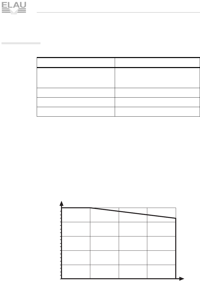
6.1.2 Ambient conditions, approbations
Table 6-4: Ambient conditions, approbations
Reduced performance in case of higher ambient temperature
and / or lower air pressure
If you operate the motors outside the specified nominal data, the
motors may be damaged. The effects of ambient temperature and
installation height are described below.
Increased
ambient
temperature
The maximum ambient temperature allowed for the SM motor is
40°C. If the ambient temperature rises to a maximum of 55°C, the
rated current drops by 1% for each °C.
Fig. 6-2: Reduced performance in case of higher ambient temperature
In the border range from 40°C to 55°C, multiply the performance
data with the load factor you determined for the ambient
temperature.
Parameter Value
admissible ambient temperature
from 0 to 1000 m over NN 0 - 40 °C
with higher temperatures, power
reduction by 1% per °C
air humidity class F according to DIN 40040
insulation class F
approbations UL / cUL / CE
load factor
1
0,8
0,6
0,4
0,2
0
35 40 45 50 55
ambient temperature in °C
P_ambient temp.fh8
MSM_OpMan_06_us.fm
page 44 PacDrive SM-Motor ELAU AG
6 Technical Data
Korrekturausdruck
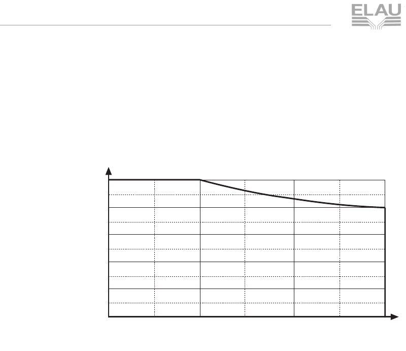
Low air
pressure In environments less than 1000 meters above the sea level, no
noteworthy performance reduction due to air pressure is to be
expected for SM motors. For heights greater than 1000 meters
above the sea level, note the performance data set forth in the
diagram below.
Fig. 6-3: Reduced performance when exceeding the installation height
In the border range from 1000 m to 3000 m, multiply the perfor-
mance data with the load factor you determined for the installation
height.
In case of a performance reduction resulting from both causes,
multiply the two load factors with the performance values.
load factor
1
0,8
0,6
0,4
0,2
0 1000 2000 3000
installation height over NN in m
P_height.fh8
MSM_OpMan_06_us.fm
ELAU AG PacDrive SM-Motor page 45
6.1 General Technical Data
Korrekturausdruck
6.1.3 Protection class
The protection class of the SM motor depends on the position in
which it is mounted.
All motor types have a fixing flange that makes it possible to install
them according to method B5 (fixing flange with through holes).
According to DIN 42950 part 1 (edition 08.77), the motors can be
mounted on the machine as follows:
Fig. 6-4: Mounting positions of the motor
CAUTION!
Inadmissible mounting position!
Penetrating liquid causes motor damage!
When installing the motor in position IM V3, make sure that there
are no liquids at the drive shaft for a longer time. Even if a shaft
seal is built in, one cannot rule out with absolute certainty that
liquid penetrates into the motor casing along the drive shaft.
Table 6-5: Protection means of SM Motors
Motor part Protection class Mounting position
shaft IP 64
IP 60 IM B5, IM V1
IM V3
shaft sealing IP 65 IM B5, IM V1, IM V3
shaft with barrier pressure
system IP 67 IM B5, IM V1, IM V3
surface / connection box IP 65 IM B5, IM V1, IM V3
surface / connection box
with barrier pressure system IP 67 IM B5, IM V1, IM V3
fan (optional) IP 20 IM B5, IM V1, IM V3
Structural shape Admissible mounting positions according to DIN IEC 34-7
B05
IM B5 IM V1 IM V3

MSM_OpMan_06_us.fm
page 46 PacDrive SM-Motor ELAU AG
6 Technical Data
Korrekturausdruck
6.1.4 Motor shaft and bearing
Execution of the shaft end
Smooth
shaft end
(standard)
With a frictional connection, torque transmission must be achieved by
pressure only. This ensures a safe load transmission without play.
Table 6-6: Manufacturers of frictional connections
Shaft end
with round-
ended
feather key
according to
DIN 6885
Shaft connections with round-ended feather key are form-fit. Under
continuous duty with variable torque rates or high reversing activity,
the position of the round-ended feather key may deflect. This
reduces the quality of smooth running (a play develops!).
Increasing deformation may cause the round-ended feather key to
break and thus damage the shaft. For this reason, this kind of shaft-
hub connection is suitable only for low strain. We recommend using
smooth shaft ends.
Bearing
The bearing on the A side is a fixed bearing, on the B side is a
loose bearing. Thus heat expansion of the slide has no effect on the
A side.
Manufacturer Designation Remarks
KTR
Kupplungstechnik GmbH
Rodder Damm 170
48432 Rheine
CLAMPEX clamp set SM 070: KTR 250
- 11x18
Spieth
Maschinenelemente
Alleenstraße 41
73730 Esslingen
Spieth pressure sleeve series
DSM SM 100: DSM
19.2
SM 140: DSM
24.2
MSM_OpMan_06_us.fm
ELAU AG PacDrive SM-Motor page 47
6.1 General Technical Data
Korrekturausdruck
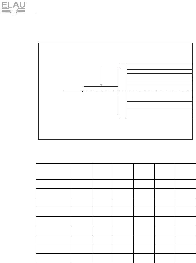
Admissible shaft strain
Fig. 6-5: Definition of shaft strain
Table 6-7: Admissible radial force Fradial [N]
Basis for calculation:
20.000 hours of operation as rated bearing life L10h for a shaft
without feather groove.
admissible axial force Faxial [N]
Motor 1000
1/min 2000
1/min 3000
1/min 4000
1/min 5000
1/min 6000
1/min
SM 070xx010 546 447 398 360 324 306
SM 070xx020 607 497 428 388 360 340
SM 100xx030 927 755 652 590 548
SM 100xx050 1000 820 710 643
SM 100xx080 1100 896 775 701
SM 140xx120 1335 1095 940 851
SM 140xx210 1445 1185 1020 923
SM 140xx290 1515 1240 1070 968
SM 140xx370 1560 1280 1100 996
Faxial
Fradial
(shaft center)
F
axial
02 F
radia
l
×
,=
MSM_OpMan_06_us.fm
page 48 PacDrive SM-Motor ELAU AG
6 Technical Data
Korrekturausdruck
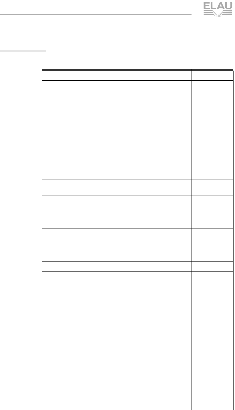
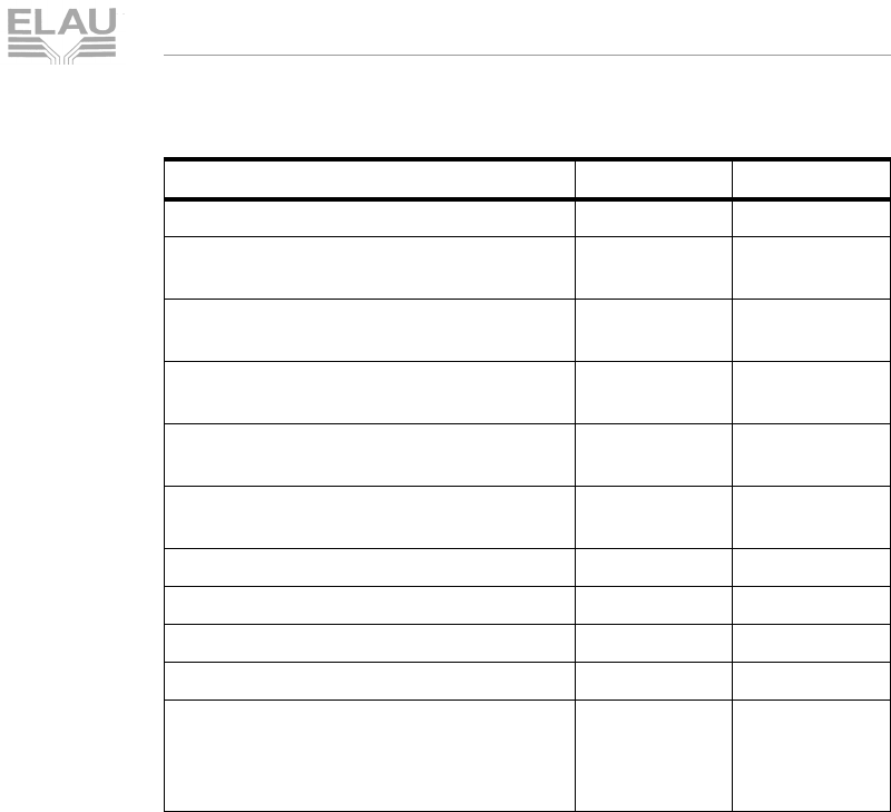
6.1.5 Encoders
SinCos
Parameter Value Unit
number of sinus-cosine phases per
revolution 1024
dimensions see
dimensional
drawing
mm
rotor moment of inertia 10 gcm2
code type for absolute value binary
code development for clockwise shaft
rotation, looking on >Α< (see dimensional
drawing)
rising
measuring step after arc tangent formation
with 12 bit resolution 0.3 angular
seconds
number of steps per revolution „SRS single-
turn“ 32.768
number of steps per revolution „SRM multi-
turn“ 134.217.728 =
32768 x 4096
error limits of the digital absolute value via
RS 485 +/- 90 angular
minutes
error limits for evaluation of the 1024-type
signals, integral non-linearity +/- 45 angular
minutes
non-linearity within a sinus, cosine period,
differential non-linearity +/- 7 angular
seconds
output frequency for sinus, cosine signals 0 ... 200 kHz
working speed up to which the absolute
position can be formed reliably 6000 min-1
max. angular acceleration 0.2 x 10⁶rad/s2
operating torque 0.2 Ncm
starting torque 0.4 Ncm
admissible shaft movements
- radial movement, static
- radial movement, dynamic
- axial movement, static
- axial movement, dynamic
- angular movement at right angle to turning
axis, static
- angular movement at right angle to turning
axis, dynamic
+/- 0.5
+/- 0.1
+/- 0.75
+/- 0.2
+/- 0.005
+/- 0.0025
mm
mm
mm
mm
mm/mm
mm/mm
bearing life 3.6 x 10⁹revolutions
working temperature range -20 ... +115 °Celsius
operating temperature range -20 ... +125 °Celsius
MSM_OpMan_06_us.fm
ELAU AG PacDrive SM-Motor page 49
6.1 General Technical Data
Korrekturausdruck
Table 6-8: Technical data of the SinCos encoder (SRS / SRM)
storage temperature range -40 ... +125 °Celsius
admissible relative air humidity (dewing
prohibited) 90 %
shock resistance when mounted according
to DIN IEC 68 part 2-27 100/10 g/ms
vibration resistance when mounted
according to DIN IEC 68 part 2-6 20/10 ... 2000 g/Hz
protection means according to DIN VDE
0470 part 1 when mounted IP 40
EMT according to EN 50082-2 and
EN 50081-2
operating voltage range 7 ... 12 V
recommended supply voltage 8 V
max. operating current without load 80 mA
available memory range in EEPROM 128 Byte
interface signals
SIN, REFSIN, COS, REFCOS = process
data channel
RS 485 = parameter channel
analog,
differential,
digital
Parameter Value Unit

MSM_OpMan_06_us.fm
page 50 PacDrive SM-Motor ELAU AG
6 Technical Data
Korrekturausdruck
Resolver
The SM motor can be supplied also with a brushless hollow shaft
resolver.
Advantages of brushless hollow shaft resolvers
Brushless resolvers permit accurate positioning, velocity
measurement and commutation of brushless electric motors
without mechanical or temperature-related restrictions known from
other sensors.
Brushless resolvers are excellently suited for industrial applications
in rough ambient conditions, as they are largely independent of
vibration, shock and increased temperature strain.
Main features
compact design
installation directly on the motor or drive shaft, no clutch
no brushes or contacts
no ball bearings
compatibly with resolver/digital transducer
MSM_OpMan_06_us.fm
ELAU AG PacDrive SM-Motor page 51
6.1 General Technical Data
Korrekturausdruck
6.1.6 Holding brake (optional)
To hold the axis without play in standstill or while the plant is
powerless, the servo motors can be supplied with a holding brake.
The permanent magnet brake is a unifacial device that uses the
power of a permanently magnetic field to generate brake power
(electromagnetic normally closed system).
To lift the brake, the permanently magnetic field is superseded by
an electromagnetic field. Safe lifting without residual moment,
irrespective of the mounting position, is ensured by a steel spring.
In addition to friction-free axial armature movement, the spring also
provides for play-free transmission of the brake moment.
DANGER!
Descending axes!
Persons run the risk of squeezing or cutting off limbs.
The holding brake alone does not guarantee personal
protection. To protect people, provide for superior constructive
measures, e.g. protective grid, or furnish the plant with a second
brake.
CAUTION!
Holding brake may wear out prematurely!
Risk of personal injury!
Only use holding brake during standstill
Only use holding brake to stop a moving axis in EMERGENCY
STOP situations.
The motors must not be operated against the closed brake. An
emergency stop of the motor (i.e. the brake drops while the motor is
running) is only allowed in exceptional cases, if the following
conditions are met:
The required brake power per emergency stop must not exceed
the following values:
– SM-070: 50 Ws
– SM-100: 200 Ws
– SM-140: 400 Ws

MSM_OpMan_06_us.fm
page 52 PacDrive SM-Motor ELAU AG
6 Technical Data
Korrekturausdruck
Between two emergency stops, the brakes must cool down for at
least 3 minutes.
After 2000 emergency stops, the brake has reached its wearing
limit.
NOTE
There are only a few diagnosis messages of the MotorController
(MC-4 diagnosis messages with reaction A) which do not permit a
controlled stop of the motor. In these few cases, the holding brake
of the motor is required for the complete brake procedure
(EMERGENCY STOP).
Example: To check whether the brake power is not exceeded in case of
EMERGENCY STOP, observe the following:
Motor type: SM-070 60 020 with JM = 0.79 kgcm2
Load: J_Load = 1.5 kgcm2
Speed: 2000 min-1
The times are valid for direct current, regular operating temperature
and rated voltage. Separation time is the time from switching on the
power to the point when the torque has faded to 10% of the rated
torque. Connection time is the time from switching off the power
until the rated torque is reached.
WK1
2
---Jω2
⋅⋅=
W
K1
2
---J2πn⋅⋅()
2
⋅⋅=
WK1
2
---0 000229kg m22π2000
60
------------1
s
---
⋅⋅ ⋅
⎝⎠
⎛⎞
2
⋅⋅,⋅=
WK1
2
---0 000229 Ns
2
⋅
m
------------- m22π2000
60
------------1
s
---
⋅⋅ ⋅
⎝⎠
⎛⎞
2
⋅⋅,⋅=
W
K5Ws=
MSM_OpMan_06_us.fm
ELAU AG PacDrive SM-Motor page 53
6.1 General Technical Data
Korrekturausdruck
CAUTION!
Power loss in case of long cables!
Brake may be worn out or damaged!
The data for rated power and rated voltage apply at the connec-
tion box. Check the data at the connection box. A higher or
separate power supply of the brake may be necessary.
Too high voltage can damage the brake!
The holding brake is dimensioned differently for each motor series:
Table 6-9: Technical data of the holding brake of the SM Motor
Holding brake grind in
If the motors are equipped with a holding brake and were already
stored for more than 2 years before the assembly, the holding
brake has to be ground in before you use it.
CAUTION!
High voltage!
Life hazard!
Grind in the holding brake only in the developed status of the
motor!
In addition turn the motor by hand for approx. 50 revolutions in
the closed state of the holding brake.
9The holding brake is now ready for use.
SM 070 SM 100 SM 140 Unit
holding moment 2.5 (22.2) 11 (97.4) 22 (195) [Nm] ([lb-in.])
connection time 5 20 25 [ms]
separation time 7 29 50 [ms]
mass 0.3 0.6 1.1 [kg]
moment of inertia 0.38
(0.00034) 1.06
(0.00094) 3.6
(0.0032) [kgcm2]
([lb-in.-s2])
rated power 12 16 18 [W]
rated voltage 24 +/- 10% 24 +/- 10% 24 +/- 10% [V] DC
MSM_OpMan_06_us.fm
page 54 PacDrive SM-Motor ELAU AG
6 Technical Data
Korrekturausdruck
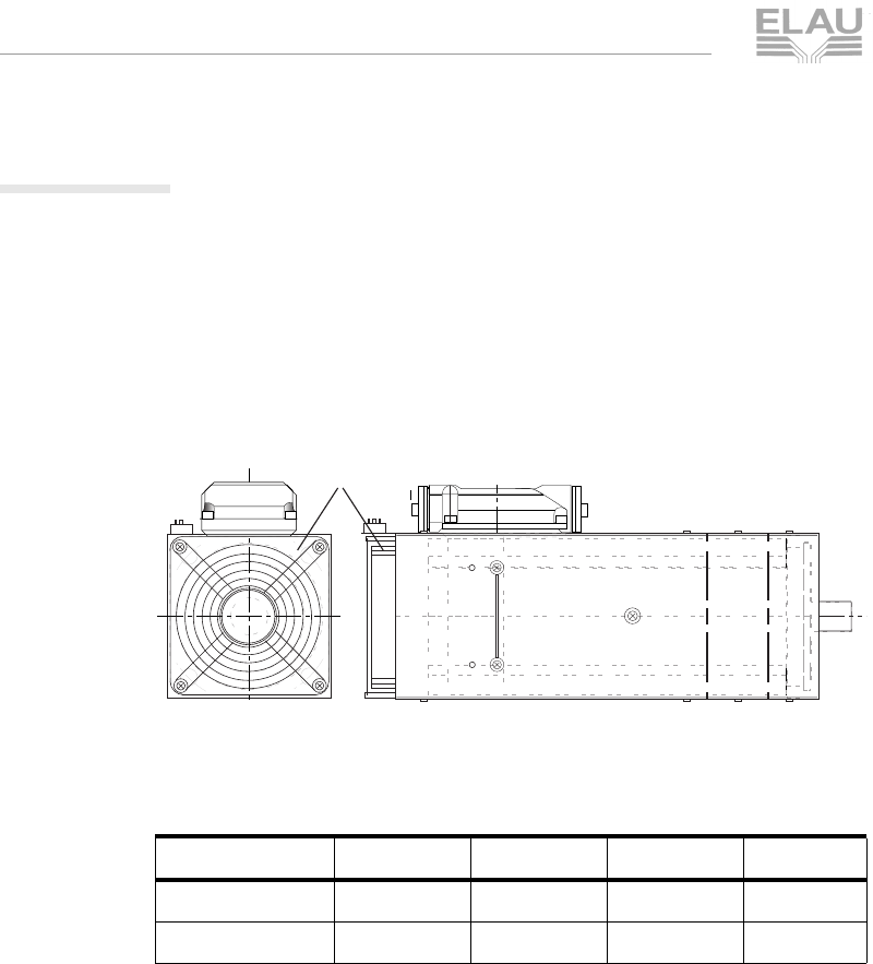
6.1.7 Surface Ventilation (optional)
To increase the permanent motor torque, the SM Motors can be
supplied with surface ventilation.
The surface ventilation reduces the thermal transition resistance,
so that the permanent torque characteristics of the motor are
shifted upwards. The peak motor torque is not changed.
The increased permanent torque values are saved in the electronic
type plate of the motor or the motor database.
Fig. 6-6: Example for an SM motor with surface ventilation
The fan is dimensioned differently for each motor series:
Table 6-10: Technical data of the fans
SM 070 SM 100 SM 140 Unit
rated voltage 230 230 230 [V] AC
power intake approx. 0.05 approx. 0.1 approx. 0.15 [A]
fan
V
MSM_MotorOberfl_de0009.fh
8

MSM_OpMan_06_us.fm
ELAU AG PacDrive SM-Motor page 55
6.1 General Technical Data
Korrekturausdruck
6.1.8 Technical Data in Detail
Technical Data SM 070
Winding data for 6000 rpm with 3 AC 400 V
Table 6-11: Technical data SM 070
Reference Data mnem
onic 60 010 60 020 Unit
Standstill torque (standard)
- motor with surface ventilation M0M 1.1
-2.0
2.7 [Nm]
Rated speed nN6000 6000 [rpm]
Fringe motor power PECKM 0.7 1.2 [kW]
Peak torque MSM 4.7 7.7 [Nm]
Physical data
Max. mechanical limit rpm nlimit 700 700 [rad/s]
Motor moment of inertia JM0.48 0.79 [kgmc2]
Acceleration at MSM ASM 129 175 125 230 [rad/s2]
Max. shock (all directions) S 200 200 [m/s2]
Max. vibration (radial) VR200 200 [m/s2]
Max. vibration (axial) VA40 40 [m/s2]
Mass m 2.754.25[kg]
Run-up time tbSM 55[ms]
Thermal data
Thermal time constant tA46 43 [min]
Operating thereshold thermo contact TTK 130 130 [°C]
Electrical data
Number of poles PZ 4 4
Circuit of the motor windings Y Y
Torque constant (20°C) KM20 0.86 0.85 [Nm/A]
Torque constant (120°C) KM120 0.78 0.78 [Nm/A]
Winding resistance (120°C) RW120 12.39 4.69 [Ohm]
Winding inductivity (20°C) LW21.9 10.8 [mH]
EMC at 1000 rpm EMC 52 52 [V]
Standstill current
- motor with surface ventilation I0M 1.43
-2.53
3.46 [A]
Peak current ISM 6.0 9.9 [A]

MSM_OpMan_06_us.fm
page 56 PacDrive SM-Motor ELAU AG
6 Technical Data
Korrekturausdruck
Technical Data SM 100
Winding data with 3 AC 400 V
Table 6-12: Technical Data SM 100
Reference Data mnem
onic 50
030 40
050 40 080 30 080 Unit
Standstill torque (standard)
- motor with surface ventilation M0M 2.6
-4.8
-8.0
13 8.2
14 [Nm]
Rated speed nN5000 4000 4000 3000 [rpm]
Fringe motor power P
ECKM
1.4 2.0 3.4 2.6 [kW]
Peak torque MSM 10 16 30 27 [Nm]
Physical data
Max. mechanical limit rpm nlimit 700 700 700 700 [rad/s]
Motor´s moment of inertia JM2.28 3.64 6.54 6.54 [kgcm2]
Acceleration at MSM ASM 55 885 54 308 47 188 49 168 [rad/s2]
Max. shock (all directions) S 200 200 200 200 [m/s2]
Max. vibration (radial) VR200 200 200 200 [m/s2]
Max. vibration (axial) VA50 40 40 40 [m/s2]
Mass m 4.9 7 11.2 11.2 [kg]
Run-up time tbSM 989 6 [ms]
Thermal data
Thermal time constant tA44 54 51 56 [min]
Operating thereshold thermo
contact TTK 130 130 130 130 [°C]
Electrical data
Number of poles PZ 8 8 8 8
Circuit of the motor windings Y Y Y Y
Torque constant (20°C) KM20 1.00 1.27 1.32 1.65 [Nm/A]
Torque constant (120°C) KM120 0.91 1.15 1.2 1.5 [Nm/A]
Winding resistance (120°C) RW120 5.61 2.94 1.39 2.07 [Ohm]
Winding inductivity (20°C) LW9.08 7.29 3.97 6.20 [mH]
EMK at 1000 rpm EMK 60 77 80 100 [V]
Standstill current
- motor with surface ventilation I0M 2.87
-4.19
-6.68
10.9 5.48
9.33 [A]
Peak current ISM 11 14 25 (22) 18 [A]
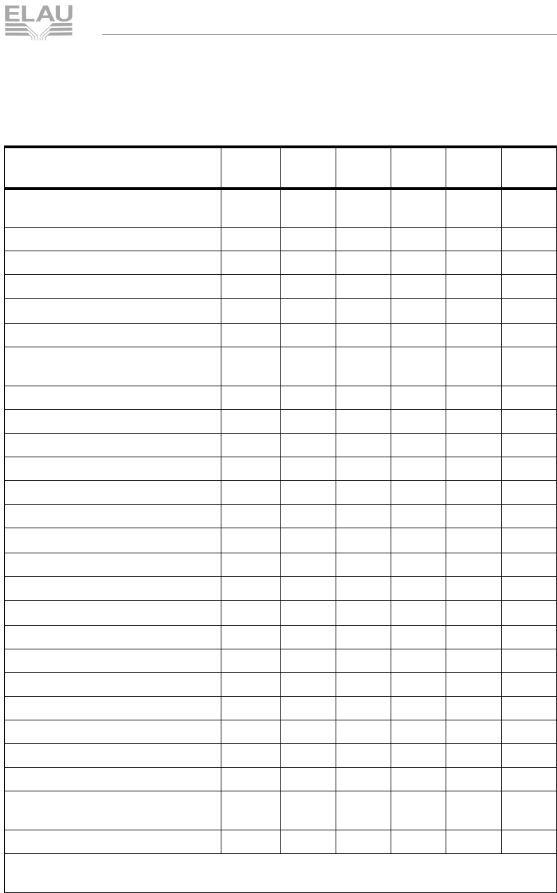
MSM_OpMan_06_us.fm
ELAU AG PacDrive SM-Motor page 57
6.1 General Technical Data
Korrekturausdruck
Technical Data SM 140
Winding data for 3000 rpm with 3 AC 400 V
Table 6-13: Technial data SM 140 30
Reference Data mnem
onic 30
120 30
210 30
290 30
370 Unit
Standstill torque (standard)
- motor with surface ventilation M0M 11
17 20
35 29
46 36
57* [Nm]
Rated speed nN3000 3000 3000 3000 [rpm]
Fringe motor power PECKM 3.46.58.611 [kW]
Peak torque MSM 45 76 103 126 [Nm]
Physical data
Max. mechanical limit rpm nlimit 700 700 700 700 [rad/s]
Motor´s moment of inertia JM10.3 18.1 24.9 33.1 [kgcm2
]
Acceleration at MSM ASM 46889 52473 53027 51485 [rad/s2]
Max. shock (all directions) S 200 200 200 200 [m/s2]
Max. vibration (radial) VR200 200 200 200 [m/s2]
Max. vibration (axial) VA40 40 40 40 [m/s2]
Mass m 10141822[kg]
Run-up time tbSM 7666[ms]
Electrical data
Thermal time constant tA70 88 91 98 [min]
Operating thereshold thermo contact TTK 130 130 130 130 [°C]
Electrical data
Number of poles PZ 8 8 8 8
Circuit of the motor windings Y Y Y Y
Torque constant (20°C) KM20 1.70 1.78 1.80 1.78 [Nm/A]
Torque constant (120°C) KM120 1.55 1.62 1.64 1.62 [Nm/A]
Winding resistance (120°C) RW120 1.65 0.57 0.36 0.24 [Ohm]
Winding inductivity (20°C) LW9.64 3.4 1.89 1.23 [mH]
EMC at 1000 rpm EMC 103 108 109 108 [V]
Standstill current
- motor with surface ventilation I0M 7.04
11 12.7
22 16.8
28.1 21.8
35.6* [A]
Peak current ISM 29 47 63 78 [A]
*In this case, the maximum motor current must be limited to 29.5 A, which is the maximum
permissible permanent current tolerance of the power cable.
MSM_OpMan_06_us.fm
page 58 PacDrive SM-Motor ELAU AG
6 Technical Data
Korrekturausdruck
Technical Data SM 140
Winding data for 2000 rpm with 3 AC 400 V
Table 6-14: Technical data SM 140 20 (data apply to flanged on motor at
aluminium plate)
Reference Data mnemoni
c20 210 Unit
Standstill torque (standard)
- motor with surface ventilation M0M 21 [Nm]
Rated speed nN2000 [rpm]
Fringe motor power PECKM 4.4 [kW]
Peak torque MSM 78 [Nm]
Physical data
Max. mechanical limit rpm nlimit 700 [rad/s]
Motor´s moment of inertia JM18.1 [kgcm2]
Acceleration at MSM ASM 53 303 [rad/s2]
Max. shock (all directions) S 200 [m/s2]
Max. vibration (radial) VR200 [m/s2]
Max. vibration (axial) VA40 [m/s2]
Mass m 14 kg
Run-up time tbSM 4[ms]
Thermal data
Thermal time constant tA91 [min]
Operating thereshold thermo contact TTK 130 [°C]
Electrical data
Number of poles PZ 8
Circuit of the motor windings Y
Torque constant (20°C) KM20 2.59 [Nm/A]
Torque constant (120°C) KM120 2.36 [Nm/A]
Winding resistance (120°C) RW120 1.14 [Ohm]
Winding inductivity (20°C) LW7.19 [mH]
EMC at 1000 rpm EMC 157 [V]
Standstill current I0M 8.97 [A]
Peak current ISM 33 [A]
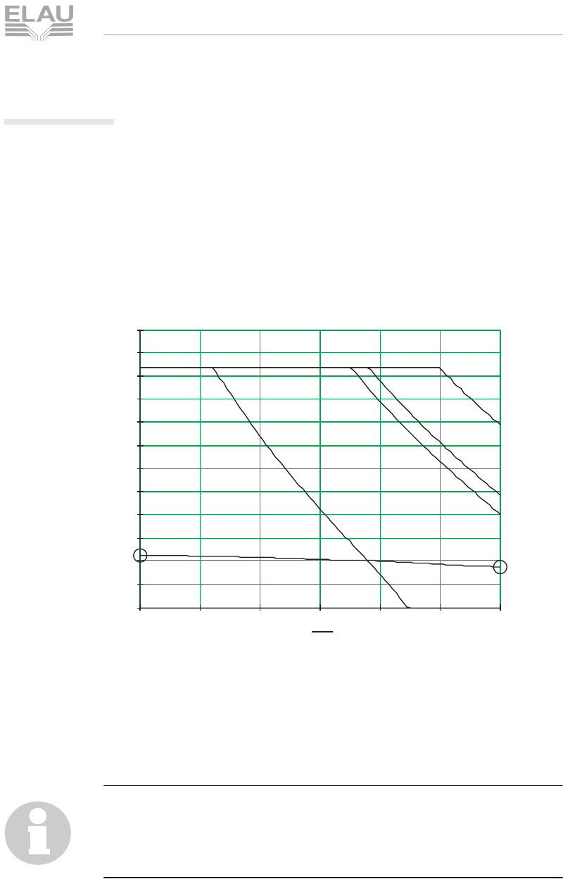
MSM_OpMan_06_us.fm
ELAU AG PacDrive SM-Motor page 59
6.1 General Technical Data
Korrekturausdruck
6.1.9 Torque-speed characteristics
The torque-speed characteristics depict the following
developments:
admissible permanent torque (operating mode S1)
peak torque at mains voltage = 230 V 3 AC
peak torque at mains voltage = 380 V 3 AC
peak torque at mains voltage = 400 V 3 AC
peak torque at mains voltage = 480 V 3 AC
Fig. 6-7: Example of torque-speed characteristics
The characteristics refer to an ambient temperature of 40 °C and a
casing overtemperature of 60 °C.
NOTE
With a single-phase mains connection (230 V) the characteristics of
„MSM 230 V 3 AC“ move approx. 20% to the left due to the lower DC-
circuit voltage.
0
0n
min-1
01000 2000 3000 4000 5000 6000
0.5
1
1.5
2
2.5
3
3.5
4
4.5
5
5.5
6
SM 070 60 010
torque [Nm]
M
NM
M
0M
M
NM
(operating mode S1)
M
SM 230 V 3 AC
M
SM 400 V 3 AC
M
SM 380 V 3 AC
M
SM 480 V 3 AC
with mains voltage = 480 V 3 AC
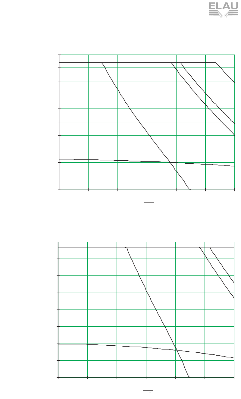
MSM_OpMan_06_us.fm
page 60 PacDrive SM-Motor ELAU AG
6 Technical Data
Korrekturausdruck
T
Fig. 6-8: Torque-speed characteristics SM 070 60 010
Fig. 6-9: Torque-speed characteristics SM 070 60 020
n
min 1
01000 2000 3000 4000 5000 6000
0.5
1
1.5
2
2.5
3
3.5
4
4.5
5
SM 070 60 010
torque [Nm]
n
min 1
01000 2000 3000 4000 5000 6000
1
2
3
4
5
6
7
8
SM 070 60 020
torque [Nm]
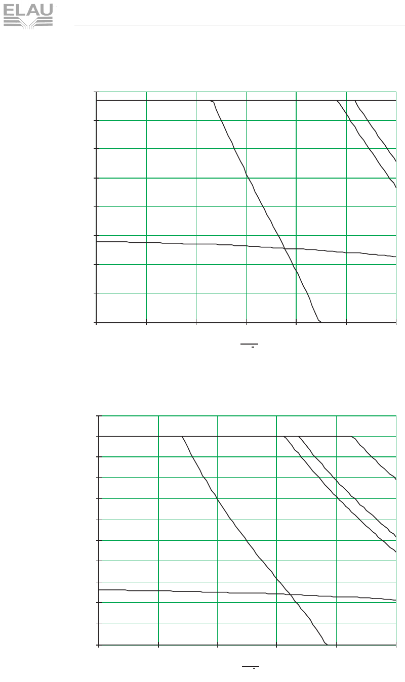
MSM_OpMan_06_us.fm
ELAU AG PacDrive SM-Motor page 61
6.1 General Technical Data
Korrekturausdruck
Fig. 6-10: Torque-speed characteristics SM 070 60 020 with surface ventilation
Fig. 6-11: torque-speed characteristics SM 100 50 030
n
min 1
01000 2000 3000 4000 5000 6000
1
2
3
4
5
6
7
8
SM 070 60 020 with surface ventilation
torque [Nm]
n
min 1
01000 2000 3000 4000 5000
1
2
3
4
5
6
7
8
9
10
11
SM 100 50 030
torque [Nm]
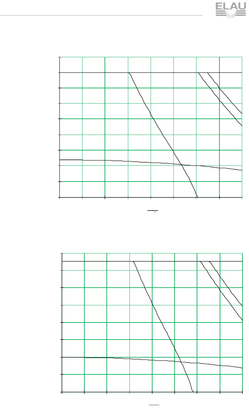
MSM_OpMan_06_us.fm
page 62 PacDrive SM-Motor ELAU AG
6 Technical Data
Korrekturausdruck
Fig. 6-12: Torque-speed characteristics SM 100 40 050
Fig. 6-13: Torque-speed characteristics SM 100 40 080
n
min 1
0500 1000 1500 2000 2500 3000 3500 4000
2
4
6
8
10
12
14
16
18
SM 100 40 050
torque [Nm]
n
min -1
0500 1000 1500 2000 2500 3000 3500 4000
4
8
12
16
20
24
28
32
SM 100 40 080
torque [Nm]
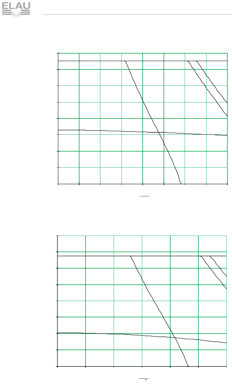
MSM_OpMan_06_us.fm
ELAU AG PacDrive SM-Motor page 63
6.1 General Technical Data
Korrekturausdruck
Fig. 6-14: Torque-speed characteristics SM 100 40 080 with surface ventilation
Fig. 6-15: Torque-speed characteristics SM 100 30 080
n
min-1
0500 1000 1500 2000 2500 3000 3500 4000
4
8
12
16
20
24
28
32
SM 100 40 080 with surface ventilation
torque [Nm]
n
min 1
0500 1000 1500 2000 2500 3000
4
8
12
16
20
24
28
32
SM 100 30 080
torque [Nm]
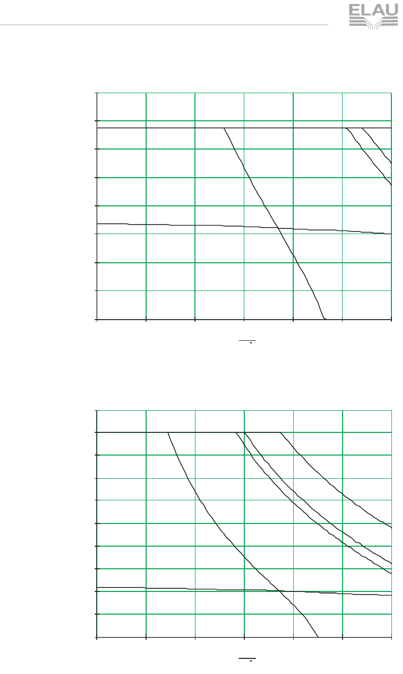
MSM_OpMan_06_us.fm
page 64 PacDrive SM-Motor ELAU AG
6 Technical Data
Korrekturausdruck
Fig. 6-16: Torque-speed characteristics SM 100 30 080 with surface ventilation
Fig. 6-17: Torque-speed characteristics SM 140 30 120
n
min 1
0500 1000 1500 2000 2500 3000
4
8
12
16
20
24
28
32
SM 100 30 080 with surface ventilation
torque [Nm]
n
min 1
0500 1000 1500 2000 2500 3000
5
10
15
20
25
30
35
40
45
50
SM 140 30 120
torque [Nm]
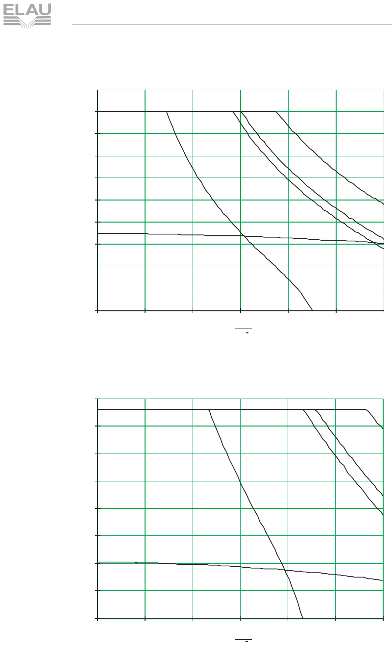
MSM_OpMan_06_us.fm
ELAU AG PacDrive SM-Motor page 65
6.1 General Technical Data
Korrekturausdruck
Fig. 6-18: Torque-speed characteristics SM 140 30 120 with surface ventilation
Fig. 6-19: Torque-speed characteristics SM 140 30 210
n
min 1
0500 1000 1500 2000 2500 3000
5
10
15
20
25
30
35
40
45
50
SM 140 30 120 with surface ventilation
torque [Nm]
n
min 1
0500 1000 1500 2000 2500 3000
10
20
30
40
50
60
70
80
SM 140 30 210
torque [Nm]
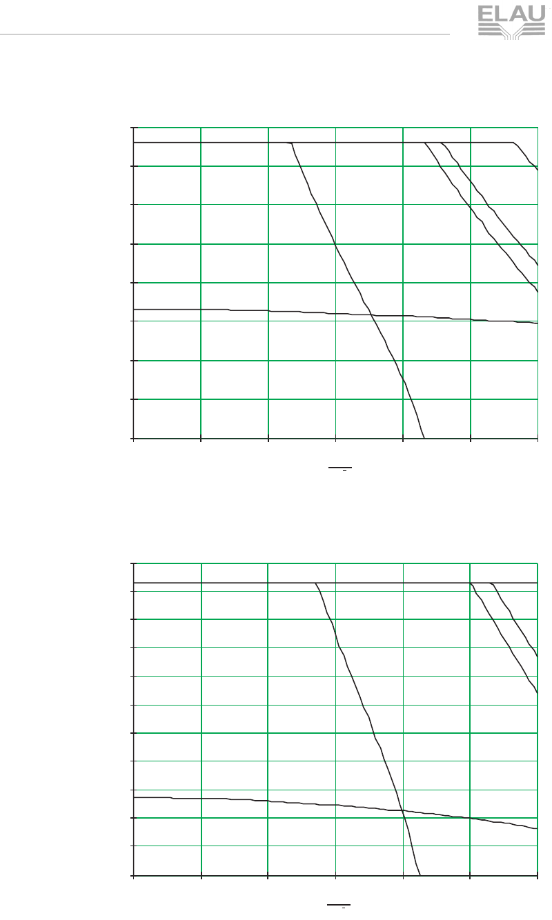
MSM_OpMan_06_us.fm
page 66 PacDrive SM-Motor ELAU AG
6 Technical Data
Korrekturausdruck
Fig. 6-20: Torque-speed characteristics SM 140 30 210 with surface ventilation
Fig. 6-21: Torque-speed characteristics SM 140 30 290
n
min 1
0500 1000 1500 2000 2500 3000
10
20
30
40
50
60
70
80
SM 140 30 210 with surface ventilation
torque [Nm]
n
min 1
0500 1000 1500 2000 2500 3000
10
20
30
40
50
60
70
80
90
100
110
SM 140 30 290
torque [Nm]
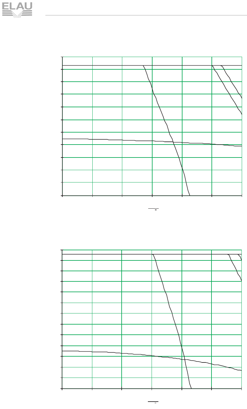
MSM_OpMan_06_us.fm
ELAU AG PacDrive SM-Motor page 67
6.1 General Technical Data
Korrekturausdruck
Fig. 6-22: Torque-speed characteristics SM 140 30 290 with surface ventilation
Fig. 6-23: Torque-speed characteristics SM 140 30 370
n
min 1
0500 1000 1500 2000 2500 3000
10
20
30
40
50
60
70
80
90
100
110
SM 140 30 290 with surface ventilation
torque [Nm]
n
min 1
0500 1000 1500 2000 2500 3000
10
20
30
40
50
60
70
80
90
100
110
120
130
SM 140 30 370
torque [Nm]
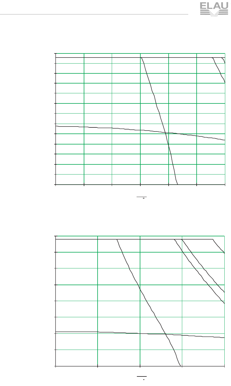
MSM_OpMan_06_us.fm
page 68 PacDrive SM-Motor ELAU AG
6 Technical Data
Korrekturausdruck
Fig. 6-24: Torque-speed characteristics SM 140 30 370 with surface ventilation
Fig. 6-25: Torque-speed characteristics SM 140 20 210
n
min 1
0500 1000 1500 2000 2500 3000
10
20
30
40
50
60
70
80
90
100
110
120
130
SM 140 30 370 with surface ventilation
torque [Nm]
n
min 1
0500 1000 1500 2000
10
20
30
40
50
60
70
80
SM 140 20 210
torque [Nm]
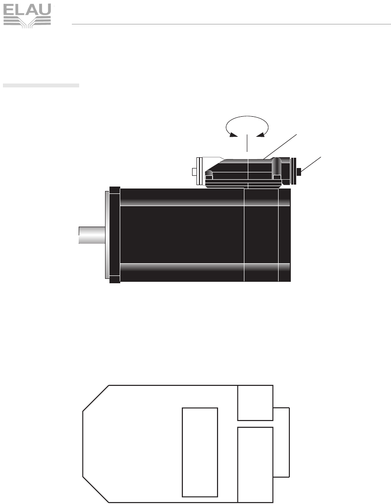
MSM_OpMan_06_us.fm
ELAU AG PacDrive SM-Motor page 69
6.2 Electrical Connections
Korrekturausdruck
6.2 Electrical Connections
Fig. 6-26: Overview of connections with SM Motor - 1
Fig. 6-27: Overview of connections with SM Motor - 2 (terminal box)
Connection of the motor cables to the terminal box, see also
chapter 4.3.1 Modified connections.
MSM_Anschlussübersicht_us0001.fh8
180°
cable duct
(can be turned by 180°)
terminal box
B-sideA-side
X2
X3
X4
1
1
1
SM_Klemmkasten.fh8
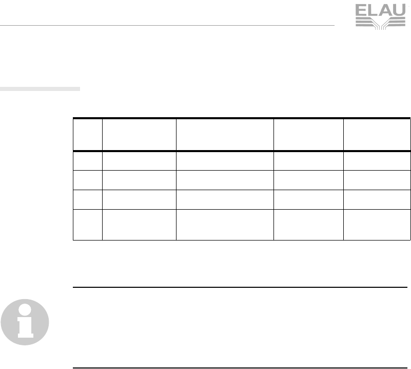
MSM_OpMan_06_us.fm
page 70 PacDrive SM-Motor ELAU AG
6 Technical Data
Korrekturausdruck
6.2.1 X2 - motor
Table 6-15: Connection X2 - motor
NOTE
For SM 140 XX 120 and SM 140 XX 210, the X2 connector plug
has a different shape and size.
For SM 140 XX 290 and SM 140 XX 370, X2 is a screw clamp, so
that also a motor cable with 4 mm2 can be connected.
Pin Designation
(lead no.) Meaning Range Max. cross
section
1 U (1) 3 AC 0 - 480 V 2.5 mm2
2 V (2) 3 AC 0 - 480 V 2.5 mm2
3 W (3) 3 AC 0 - 480 V 2.5 mm2
4 PE motor earth
conductor 2.5 mm2
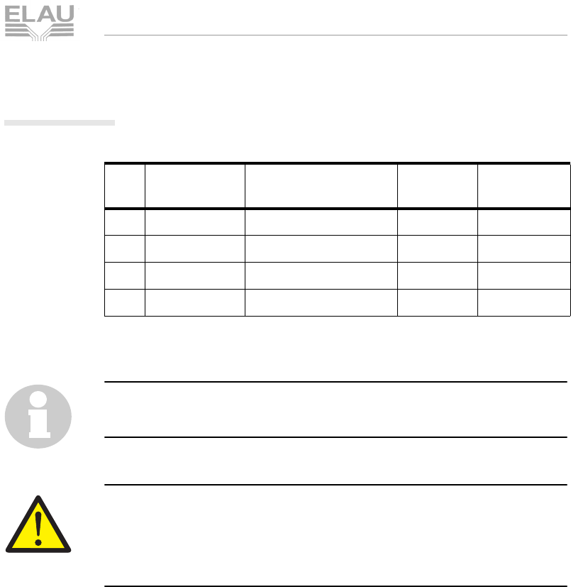
MSM_OpMan_06_us.fm
ELAU AG PacDrive SM-Motor page 71
6.2 Electrical Connections
Korrekturausdruck
6.2.2 X3 - brake / motor temperature
Table 6-16: Connection X3 - SM motor
NOTE
For SM motors SM 140 or higher, the X3 has a different size.
CAUTION!
Poles may be interchanged on the connector plug!
Motor may be damaged!
Make sure the pin numbers are allocated correctly!
Pin Designation
(lead no.) Meaning Range Max. cross
section
1 temp (5) PTC motor temperature 1.5 mm2
2 temp (6) PTC motortemperature 1.5 mm2
3 br- (7) holding brake DC 0 V 1.5 mm2
4 br+ (8) holding brake DC 24 V 1.5 mm2
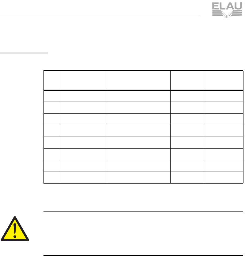
MSM_OpMan_06_us.fm
page 72 PacDrive SM-Motor ELAU AG
6 Technical Data
Korrekturausdruck
6.2.3 X4 - encoder (SinCos)
Table 6-17: Connection X4 - SM motor (SinCos encoder)
CAUTION!
Poles may be interchanged on the connector plug!
Motor may be damaged!
Make sure the pin numbers are allocated correctly!
Pin Designation Meaning Range Max. cross
section
1 Us supply voltage DC 7 - 12 V 0.25 mm2
2 GND supply voltage DC 0 V 0.25 mm2
3 REFSIN sinus reference signal 0.25 mm2
4 SIN sinus trace 0.25 mm2
5 REFCOS cosine reference signal 0.25 mm2
6 COS cosine trace 0.25 mm2
7 RS485- parameter channel - 0.25 mm2
8 RS485+ parameter channel + 0.25 mm2
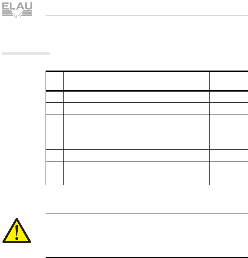
MSM_OpMan_06_us.fm
ELAU AG PacDrive SM-Motor page 73
6.2 Electrical Connections
Korrekturausdruck
6.2.4 X4 - encoder (Resolver)
Table 6-18: Connection X4 - SM motor (Resolver)
CAUTION!
Poles may be interchanged on the connector plug!
Motor may be damaged!
Make sure the pin numbers are allocated correctly!
Pin Designation Meaning Range Max. cross
section
1 reserves 0.25 mm2
2 reserves 0.25 mm2
3 SIN - Sinus - 0.25 mm2
4 SIN + Sinus + 0.25 mm2
5 COS - Cosinus - 0.25 mm2
6 COS + Cosinus + 0.25 mm2
7 EXCT - exciter signal - 0.25 mm2
8 EXCT + exciter signal + 0.25 mm2
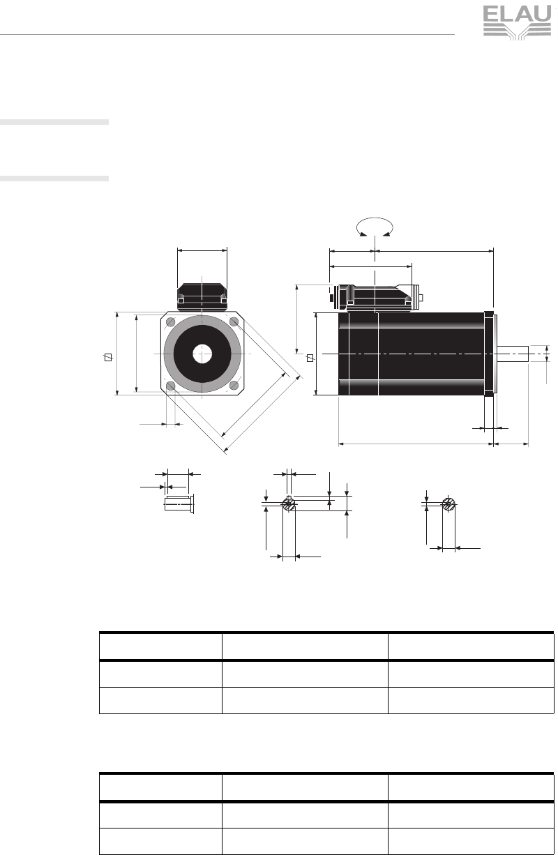
MSM_OpMan_06_us.fm
page 74 PacDrive SM-Motor ELAU AG
6 Technical Data
Korrekturausdruck
6.3 Dimensions
6.3.1 SM-motor
SM 070
Fig. 6-28: Dimensional drawing of SM 070
Table 6-19: Dimensions of SM 070 without brake
Table 6-20: Dimensions of SM 070 with brake
Tolerances Shaft diameter: j6
Round-ended feather key, round end according to DIN 6885 T1,
tolerance field N9
Rotor balanced with half feather key.
Dimensions xx 010 xx 020
A 201 (7.91) 261 (10.28)
X 152 (5.98) 212 (8.35)
Dimensions xx 010 xx 020
A 230 (9.06) 290 (11.42)
X 181 (7.13) 241 (9.49)
70
68,5
A23
ø11
54
2,5
106
65
63
180°
X
8,5
2,5
18
12,5
M4x10
M4x10
4
4
ø11
ø11
ø75
ø60 h6
ø5,5
90
MSM_MasszeichnungSM070_us0006.fh8
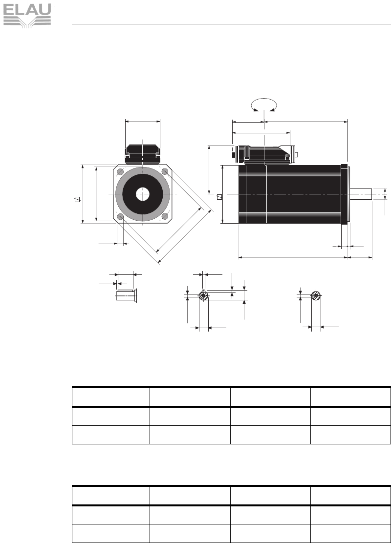
MSM_OpMan_06_us.fm
ELAU AG PacDrive SM-Motor page 75
6.3 Dimensions
Korrekturausdruck
SM 100
Fig. 6-29: Dimensional drawing of SM 100
Table 6-21: Dimensions of SM 100 without brake
Table 6-22: Dimensions of SM 100 with brake
Tolerances Shaft diameter: j6
Round-ended feather key, round end according to DIN 6885 T1,
tolerance field N9
Rotor balanced with half feather key.
Dimensions xx 030 xx 050 xx 080
A 196 (7.72) 240 (9.45) 328 (12.91)
X 147 (5.79) 191 (7.52) 279 (10.98)
Dimensions xx 030 xx 050 xx 080
A 231 (9.09) 275 (10.83) 363 (14.29)
X 182 (7.17) 226 (8.90) 314 (12.36)
100
86
A40
ø19
54
3,5
106
100
63
180°
X
11
5
30
21,5
M6x16
M6x16
6
6
ø19 ø19
ø115
ø95 h6
ø9
137,18
MSM_MasszeichnungSM100_us0006.fh8
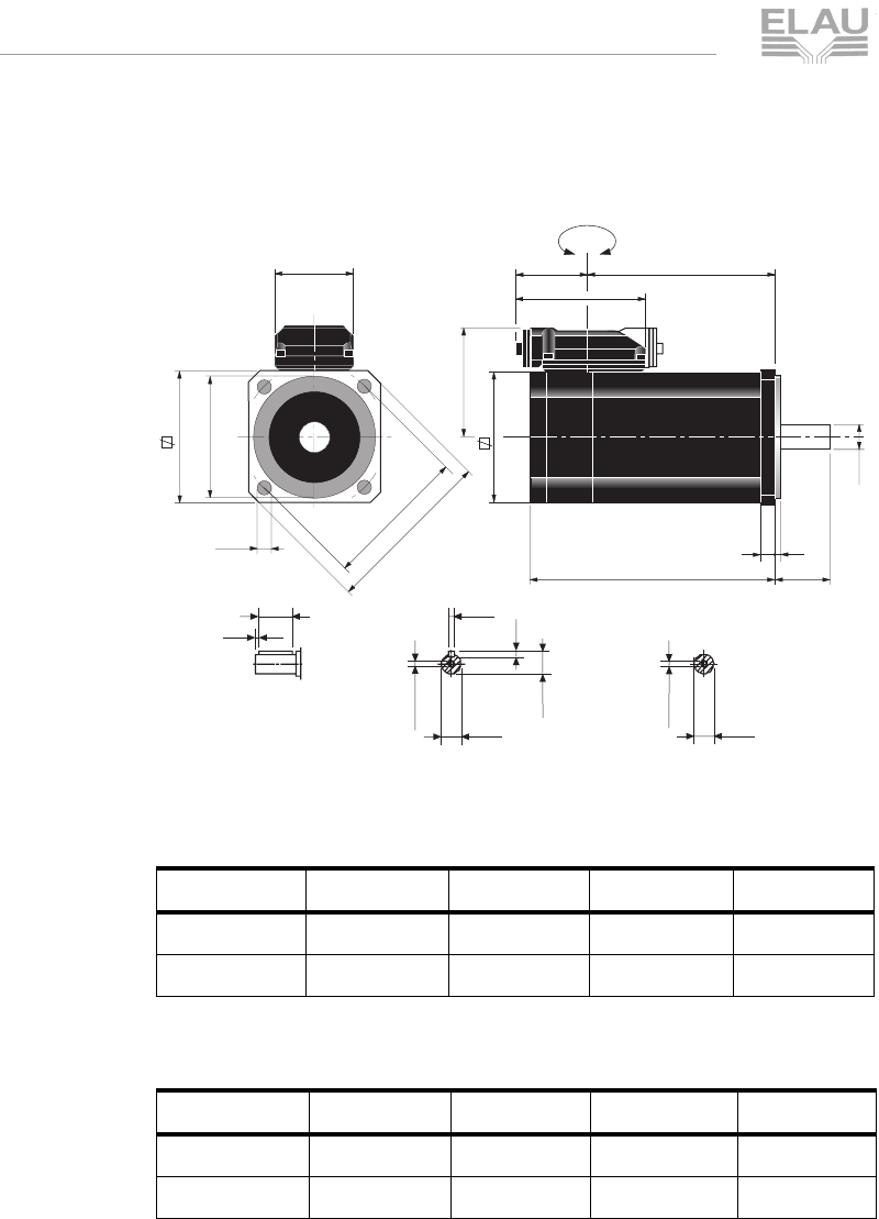
MSM_OpMan_06_us.fm
page 76 PacDrive SM-Motor ELAU AG
6 Technical Data
Korrekturausdruck
SM 140
Fig. 6-30: Dimensional drawing of SM 140
Table 6-23: Dimensions of SM 140 without brake
Table 6-24: Dimensions of SM 140 with brake
Tolerances Shaft diameter: j6
Round-ended feather key, round end according to DIN 6885 T1,
tolerance field N9
Rotor balanced with half feather key.
Dimensions xx 120 xx 210 xx 290 xx 370
A 248 (9.76) 310 (12.20) 372 (14.65) 434 (17.09)
X 178 (7.01) 240 (9.45) 302 (11.89) 364 (14.33)
Dimensions xx 120 xx 210 xx 290 xx 370
A 288 (11.34) 350 (13.78) 412 (16.22) 474 (18.66)
X 218 (8.58) 280 (11.02) 342 (13.46) 404 (15.91)
140
117,5
A50
ø24
71
3,5
147
135
86
180°
X
12
5
40
27
M8x19
M8x19
8
7
ø24 ø24
ø165
ø130 h6
ø11
190
MSM_MasszeichnungSM140_us0006.fh8
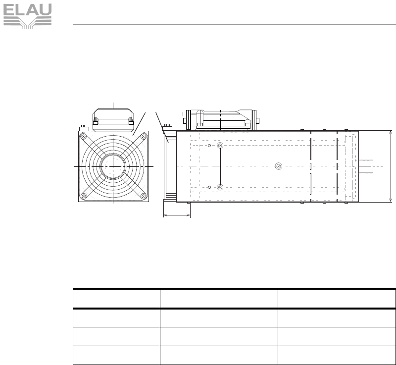
MSM_OpMan_06_us.fm
ELAU AG PacDrive SM-Motor page 77
6.3 Dimensions
Korrekturausdruck
SM Motor with surface ventilation
Fig. 6-31: Dimensional drawing of SM-Motor with surface ventilation
If an SM Motor has surface ventilation, the motor gets longer. Add
the size A2 to the size A of the „standard motor“.
Table 6-25: Dimensions of SM Motor with surface ventilation
SM motor Size A2 Size N
SM 070 approx. 59 mm (2.32) approx. 110 mm (4.33)
SM 100 approx. 59 mm (2.32) approx. 145 mm (5.71)
SM 140 approx. 70 mm (2.76) approx. 170 mm (6.69)
V
N
A2
fan
MSM_MasszeichnungOberfl_us0011.fh8
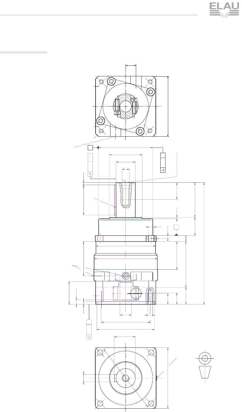
MSM_OpMan_06_us.fm
page 78 PacDrive SM-Motor ELAU AG
6 Technical Data
Korrekturausdruck
6.3.2 SP-Gearbox
Fig. 6-32: Dimensional drawing of SP gearbox
L6
L16
D
L15
C
L19
DIN 332/2
DR
Vkt. L13
projection method 1
according to DIN 6, part 1
E
L1
L3
L10
L2
t
L4
L14
L20
L5
L21
B
L9
L8
L12
Vkt. L11
D5
L7
L22
aA
A
aBB
A
O0,02
A
L17
D7
D8
D6
D9
D10
D11
D4
M
D3
D2
D1
L18
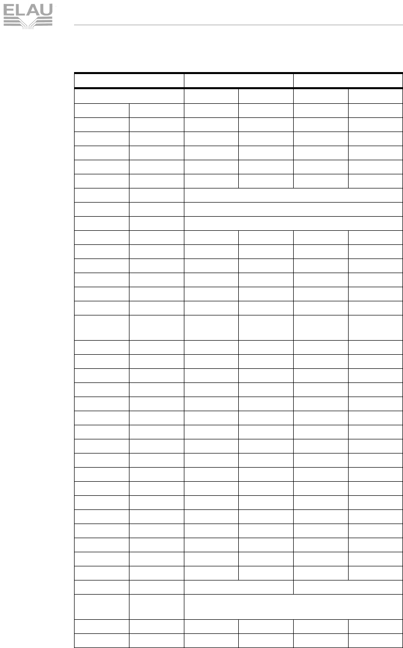
MSM_OpMan_06_us.fm
ELAU AG PacDrive SM-Motor page 79
6.3 Dimensions
Korrekturausdruck
Sizes SP 060 and SP 075
Table 6-26: Gearbox dimensions
Size SP 060 SP 075
Number of gears 1 2 1 2
D1 g6 60 60 70 70
D2 30 30 38 38
D3 k6 16 16 22 22
D4 4x 5.5 5.5 6.6 6.6
D5 68 68 85 85
D6 F7 14 14 19 19
D7 measure depends on the motor
D8 measure depends on the motor
D9 measure depends on the motor
D10 58.5 58.5 74 74
L1 +/- 2 129 149 156 182.5
L2 28 28 36 36
L3 20 20 20 20
L4 6677
L5 60 80 71 97.5
L6 min.
max. 15
30 15
30 23
40 23
40
L7+0.54444
L8 9.4 9.4 14 14
L9 9 9 12 12
L10 44 64 51 77.5
L11+/- 162627676
L12 2 2 2 2
L13+/- 160608080
L14* 25253232
L15 2 2 2 2
L16 h9 5 5 6 6
L17 18 18 24.5 24.5
L18** 10 10 12 12
L19 48.3 68.3 57 83.5
L20 - - - -
a 0.025 0.025 0.025 0.025
B881515
C 1xM6 1xM6 1xM8x1 1xM8x1
D- -
E round-ended feather key according to DIN 6885
sheet 1, form A
M M5M5M8M8
t 12.5 12.5 19 19
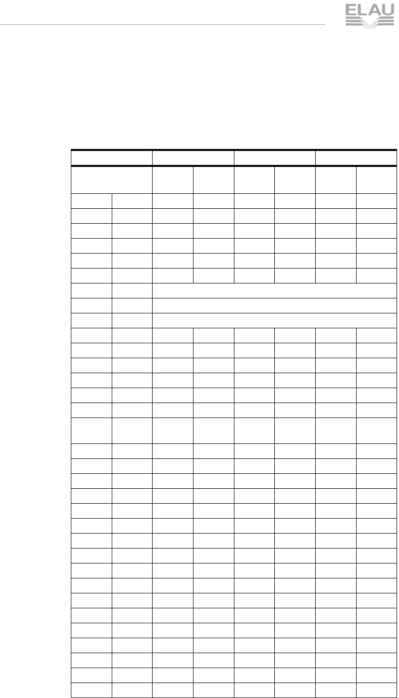
MSM_OpMan_06_us.fm
page 80 PacDrive SM-Motor ELAU AG
6 Technical Data
Korrekturausdruck
* (on L14) In case of reversing operation and high gear strain, we
recommend smooth drive shafts.
** (on L18) The dimensions may differ in case of very small motors.
Sizes SP 100, SP 140 und SP 180
Size SP 100 SP 140 SP 180
Number of
gears 121212
D1 g6 90 90 130 130 160 160
D2 55 55 70 70 90 90
D3 k6 32 32 40 40 55 55
D4 4x 9 9 11 11 13 13
D5 120 120 165 165 215 215
D6 F7 28 28 35 35 48 48
D7 measure depends on the motor
D8 measure depends on the motor
D9 measure depends on the motor
D10 99 99 124 124 180 180
L1 +/- 2 202 234,5 256,5 296,5 297 315,5
L2 58 58 82 82 82 82
L3 30 30 30 30 30 30
L4 10 10 12 12 15 15
L5 76 108,5 102 142 132,5 158
L6 min.
max. 30
50 30
50 32
60 32
60 45
82 45
82
L7+0,5556666
L8 18 18 18 18 24,5 18
L9 19 19 21 21 25 21
L10 50 82,5 66,5 106,5 84,5 122,5
L11 +/- 1 101 101 141 141 182 182
L12 223333
L13 +/- 1 100 100 140 140 190 140
L14* 50 50 70 70 70 70
L15 445566
L16h9101012121616
L17 353543435959
L18** 171719192619
L19 57 89,5 74,5 114,5 100,5 130,5
L20 55661212
L21 28 28 30,5 30,5 37,5 30,5
a 0,025 0,025 0,04 0,04 0,04 0,04
B 181820202020

MSM_OpMan_06_us.fm
ELAU AG PacDrive SM-Motor page 81
6.3 Dimensions
Korrekturausdruck
Table 6-27: Gearbox dimensions
* (on L14) In case of reversing operation and high gear strain, we
recommend smooth drive shafts.
** (on L18) The dimensions may differ in case of very small motors.
C 3xM12x1,5 3xM12x1,5 3xM12x1,5
D 1xM8x1 1xM8x1 1xM8x1
E
round-ended feather key according to DIN 6885 sheet 1, form A
M M12M12M16M16M20M20
t 282836364242
Size SP 100 SP 140 SP 180

MSM_OpMan_06_us.fm
page 82 PacDrive SM-Motor ELAU AG
6 Technical Data
Korrekturausdruck

M_AnhangStd_us.FM
PacDrive™ page 83
7.1 Contact Addresses
Korrekturausdruck
7 Appendix
7.1 Contact Addresses
For repair
Please send the components to be repaired or checked, along with
the error report, to this address:
ELAU AG
Abt. Kundendienst house address:
Postfach 1255 Dillberg 12
97821 Marktheidenfeld 97828 Marktheidenfeld
Phone: +49 (0) 93 91 / 606 - 142
Fax: +49 (0) 93 91 / 606 - 340
Service team
Should you need to talk to a member of our service team or require
on-site service, please contact:
ELAU AG
Dillberg 12
D-97828 Marktheidenfeld
Phone: +49 (0) 93 91 / 606 - 0
Fax: +49 (0) 93 91 / 606 - 300
e-mail: info@elau.de
Internet: www.elau.de
ELAU, Inc.
165 E. Commerce Drive
Schaumburg, IL 60173 - USA
Phone: +1 847 490 4270
Fax: +1 847 490 4206
e-mail: info@elau.com
Internet: www.elau.com
ELAU SYSTEMS ITALIA S.r.l.
Via Tosarelli 300
I-40050 Villanova di Castenaso (BO)
Phone: +39 051 / 7818 70
Fax: +39 051 / 7818 69
e-mail: info@elau.it
Internet: www.elau.it
NOTE
You find more contact addresses on the ELAU homepage
(www.elau.de).

M_AnhangStd_us.FM
page 84 PacDrive™
7 Appendix
Korrekturausdruck
7.2 Further Literature
ELAU can provide you with these manuals and instructions on the
PacDrive™ system:
Project Manual
Art. Nr. 17 13 00 58 -00x (DE, EN, FR)
Programming Manual
Art. Nr. 17 13 00 61 - 00x (DE, EN)
Operating Manual PacDrive MC-4
Art. Nr. 17 13 00 62 - 00x (DE, EN, IT, FR)
Operating Manual CAN L2
Art. Nr. 17 13 00 66 - 00x (DE, EN)
Operating Manual PROFIBUS-DP
Art. Nr. 17 13 00 67 - 00x (DE, EN)
Operating Manual SM-Motor
Art. Nr. 17 13 00 68 - 00x (DE, EN, IT, FR)
Operating Manual EPAS-4
Art. Nr. 17 13 00 70 - 00x (DE, EN)
Operating Manual PacDrive Controller MAx-4
Art. Nr. 17 13 00 71 - 00x (DE, EN, IT, FR)
User Manual OPC-Server
Art. Nr. 17 13 00 73 - 00x (DE, EN)
Bedienungsanleitung Device Net
Art. Nr. 17 13 00 76 - 00x (DE, EN)
Bedienungsanleitung HMI Bibliotheken
Art. Nr. 17 13 00 77 - 00x (DE, EN)
Operating Manual INC-4 Incremental Encoder Module
Art. Nr. 17 13 00 78 - 00x (DE, EN)
Operating Manual CANopen
Art. Nr. 17 13 00 79 - 00x (DE, EN)
Operating Manual Motion Toolkit ECAM-4
Art. Nr. 17 13 00 80 - 00x (DE, EN)
Operating Manual PacNet Modul PN-4
Art. Nr. 17 13 00 81 - 00x (DE, EN)
Art. Nr. -000 DEutsch -001 ENglish -002 ITalian -003 FRench

M_AnhangStd_us.FM
PacDrive™ page 85
7.2 Further Literature
Korrekturausdruck
Operating Manual SR-Motor
Art. Nr. 17 13 00 82 - 00x (DE, EN)
Operating Manual Bus Terminal BT-4/DIO1
Art. Nr. 17 13 00 83 - 00x (DE, EN)
Operating Manual TTS Training- and Testsystems
Art. Nr. 17 13 00 88 - 00x (DE)
Operating Manual Automatic Controller Optimization
Art. Nr. 17 13 00 89 - 00x (DE, EN)
Operating Manual PacDrive SCL
Art. Nr. 17 13 00 93 - 00x (DE, EN)
Operating Manual PacDrive PS-4 and PacDrive PD-8
Art. Nr. 17 13 00 94 - 00x (DE, EN)
User Manual Evaluation Kit
Art. Nr. 17 13 00 95 - 00x (DE)
Operating Manual PacDrive Controller P600
Art. Nr. 17 13 00 96 - 00x (DE)
Operating Manual PacDrive Controller C200
Art. Nr. 17 13 00 97 - 00x (DE, EN, FR)
Operating Manual PacDrive Controller C400
Art. Nr. 17 13 00 98 - 00x (DE, EN, FR)
Operating Manual PacDrive Controller C600
Art. Nr. 17 13 00 99 - 00x (DE, EN, FR)
Operating Manual PacDrive PC Panel PCP
Art. Nr. 17 13 01 02 - 00x (DE)
Operating Manual SH Motor
Art. Nr. 17 13 01 05- 00x (DE, EN)

M_AnhangStd_us.FM
page 86 PacDrive™
7 Appendix
Korrekturausdruck
7.3 Product Training
We offer practical workshops and seminars.
Our experienced seminar leaders will enable you to make optimum
use of the vast possibilities of the PacDrive™ system.
NOTE
Please contact us for further information or to order our seminar
program. See also our homepage (www.elau.de).
MSM_OpManAen_us.FM
PacDrive™ SM-Motor Seite 87
7.4 Declaration by the manufacturer
Korrekturausdruck
7.4 Declaration by the manufacturer
Herstellererklärung /
EC-Declaration by the manufacturer /
CE-Déclaration du fabricant
im Sinne der EG-Maschinenrichtlinie 98/37/EG,
Anhang II Abschnitt B
as defined by EC-machinery directive 98/37/EC,
Annexe II Section B
conformément à la directive "CE" relative aux
machines 98/37/CE Annexe II Section B
ELN
119-01/09.98
page1/1
Das von uns gelieferte Produkt
AC-Servomotor
SM 070
SM 100
SM 140
ist zum Einbau in eine Maschine be-
stimmt.
Die Inbetriebnahme ist solange unter-
sagt, bis festgestellt wurde, dass die
Maschine, in die dieses Produkt einge-
baut werden soll, den Bestimmungen der
EG-Richtlinie entspricht.
Hersteller:
ELAU AG
Dillberg 12
D-97828 Marktheidenfeld
Stellung im Betrieb / Position :
Vorstand/Chairman
15.9.1998 Günter Locherer
...........................................................
(Datum, Date / Unterschrift, Signature)
The product delivered by our company
AC-Servomotor
SM 070
SM 100
SM 140
is intended to be incorporated into a
machine.
The product must not be operated until
the machine into which this product is to
be incorporated has been declared in
conformity with the provisions of the
directive.
Manufacturer:
ELAU AG
Dillberg 12
D-97828 Marktheidenfeld
Le produit livré par notre société
AC-Servomotor
SM 070
SM 100
SM 140
est destiné à être installé dans une
machine.
La mise en service des composants est
fortement déconseillée avant que la
machine dans laquelle le produit sera
installés n'ait été déclarée conforme aux
dispositions de la directive.
Fabricant:
ELAU AG
Dillberg 12
D-97828 Marktheidenfeld

MSM_OpManAen_us.FM
Seite 88 SM-Motor PacDrive™
7 Anhang
Korrekturausdruck
7.5 Modifications
01 / 1999
SM motors run-up times, delay in lifting and delay in clamping revi-
sed
New motors: SM 140 30 290 and SM 140 30 370
03 / 2000
Insulation class is not H but F
M
0
updated (as type plate datas)
M
N
is now shown in the Torque-Motor Speed Characteristics
Stop Torque of the brake from the SM 070 is not 5 but 2,5 Nm
New motors: SM 100 40 080 and SM 140 20 210
Order numbers updated
Sales regions updated
Structure of the document modified
„technical data in detail“ modified
Various errors cleared and improvements made
01 / 2001
Structure of the document modified
Motors with surface ventilation new
Order numbers updated
Description of the encoder systems new
Description of the holding brake widen
Various errors cleared and improvements made
09 / 2002
Structure of the document modified
Changing to IP65 (casing and connection box)
Various errors cleared and improvements made
07 / 2004
product terms adjusted to new layout
10 / 2005
barrier pressure system option new
NOTE
The latest documentation and modification service on this product are
available on the ELAU Homepage (http://www.elau.de).

MSM_OperaMan_us1002SIX.fm
PacDrive™ SM-Motor Seite 89
7.6 Index
Korrekturausdruck
7.6 Index
A
admissible shaft strain 47
B
bearing 46
brake 14
SM motor 51
C
connections
SM motor 69
X2 - motor 70
X3 - brake / motor tempe-
rature 71
X4 - encoder (Resolver) 73
X4 - encoder (SinCos) 72
contact addresses
ELAU AG 83
ELAU Inc. 83
ELAU SYSTEMS ITALIA
S.r.l 83
D
definitions 38
dimensions
gearbox 78
SM motor 74
E
ELAU AG 2
eMail
ELAU AG 2
EMC rules 25
encoder 14
resolver 50
SinCos 48
exchanging units 21
exchange cable 23
exchange motor 22
F
features 13
feedback 14
H
holding brake 14
grind in 53
SM motor 51
homepage
ELAU AG 2
I
internet
ELAU AG 2
L
literature 84
M
maintenance 19
manuals 84
Modifications 88
motor
-feedback 14
-shaft 46
O
Operating 84
operating manual 84
order numbers
connector sets 36
encoder cables 36
motor cables 35
SM motor 30
P
physical correlations 38
pictograph 8
Programmierhandbuch 84
R
repair 20, 83
riskclassification 8
S
safety
notes 8
sales regions 83
seminare 86
service
-personnel 83

MSM_OperaMan_us1002SIX.fm
Seite 90 SM-Motor PacDrive™
7 Anhang
Korrekturausdruck
service addresses 20
shaft 14, 46
shaft strain 47
spare parts 19
storage 15
T
technical data 37
SM 070 55
SM 100 56
SM 140 57
torque-speed characteristics
59
trademarks 2
training 86
transportation 15
type plate 16
U
unpacking 16
Use as directed 9
W
warning notes 8

ELAU_FoStoerung_us.FM
ELAU AG PacDrive error report page 1
7.7 Form for Error Report
Korrekturausdruck
7.7 Form for Error Report
This error report is absoluteley necessary in order to enable
efficient processing.
Send the error report to your ELAU representative or to:
ELAU AG, Abt. Kundendienst
Dillberg 12, D-97828 Marktheidenfeld
Fax: +49 (0) 93 91 / 606 - 340
Sender:
Details on the defective product
Product name: ..................................................................................
Article number: .................................................................................
Serial number: ..................................................................................
Software version: ..............................................................................
Hardware code: ................................................................................
Parameter enclosed: yes [ ] no [ ]
IEC program enclosed: yes [ ] no [ ]
Details of the machine on which the problem occurred:
Machine producer: ...........................................................................
Type: ................................................................................................
Hours of operation: ...........................................................................
Machine number: ..............................................................................
Date of commissioning: ....................................................................
Producer/Type of machine control:
.........................................................................................................
Company: City: Date:
Department: Name: Phone:

ELAU_FoStoerung_us.FM
error report page 2 PacDrive ELAU AG
7.7 Form for Error Report
Korrekturausdruck
Description of the problem:
..........................................................................................................
..........................................................................................................
..........................................................................................................
Additional information:
Does the switching cabinet have an air conditioning system?Y/N [ ]
Have similar problems occurred before on the same axis?
How often: ..............................
Did the problems occur on certain days or times of day?
..........................................................................................................
further information:
..........................................................................................................
..........................................................................................................
..........................................................................................................
..........................................................................................................
..........................................................................................................
..........................................................................................................
..........................................................................................................
..........................................................................................................
..........................................................................................................
..........................................................................................................
..........................................................................................................
..........................................................................................................
..........................................................................................................
Problem state: Causes: Concomitant phenomena:
[ ] persistent [ ] unknown [ ] mechanical problems
[ ] when commissioning [ ] wiring error [ ] failure of mains supply (24V)
[ ] occurs sporadically [ ] mechanical damage [ ] failure of PMC-2
[ ] occurs after about.....hours [ ] moisture inside the unit [ ] motor failure
[ ] occurs in case of shocks [ ] encoder defective [ ] broken cable
[ ] depends on temperature [ ] insufficient ventilation
[ ] foreign object inside unit
