1000368593 Catalog
2016-09-04
: Pdf 1000368593-Catalog 1000368593-Catalog B4 unilog
Open the PDF directly: View PDF ![]() .
.
Page Count: 157 [warning: Documents this large are best viewed by clicking the View PDF Link!]
Volume 5—Motor Control and Protection CA08100006E—May 2016 www.eaton.com V5-T2-1
2
2
2
2
2
2
2
2
2
2
2
2
2
2
2
2
2
2
2
2
2
2
2
2
2
2
2
2
2
2
NEMA Contactors and Starters
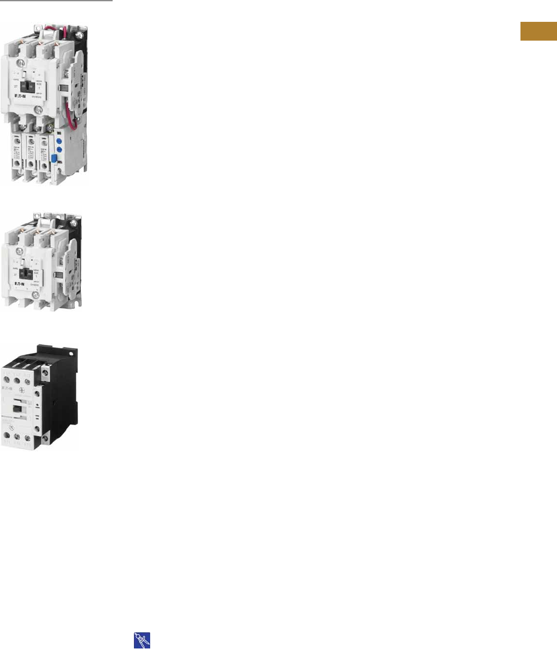
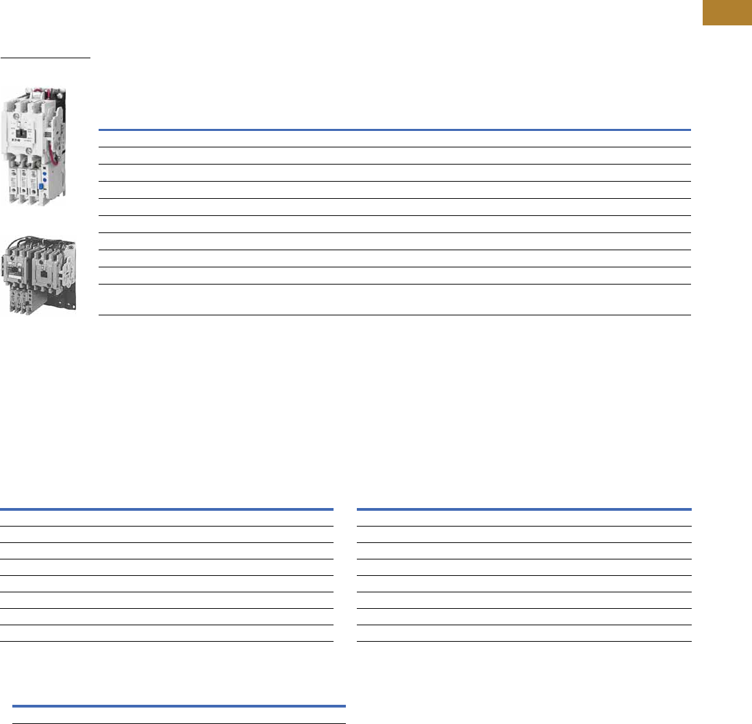
NEMA AN16DN0AB
NEMA Size 1 Starter
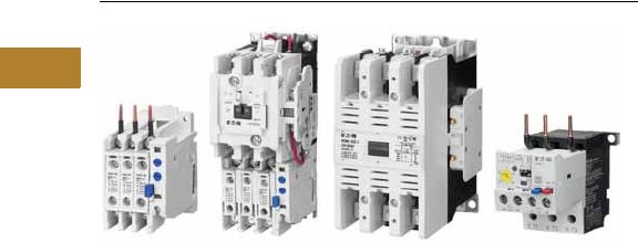
NEMA Size 1 Contactor
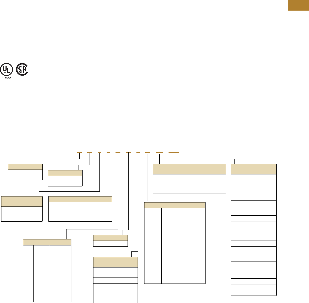
NEMA Space-Savings
Size 1C Contactor
2.1 Freedom Series
Product Overview . . . . . . . . . . . . . . . . . . . . . . . . . . . . . . . . . . . . . . . . V5-T2-2
Features, Benefits and Functions . . . . . . . . . . . . . . . . . . . . . . . . . . . . V5-T2-2
Standards and Certifications . . . . . . . . . . . . . . . . . . . . . . . . . . . . . . . . V5-T2-3
Catalog Number Selection . . . . . . . . . . . . . . . . . . . . . . . . . . . . . . . . . . V5-T2-3
Contactors—Non-Reversing and Reversing . . . . . . . . . . . . . . . . . . . . . V5-T2-4
Starters—Three-Phase Non-Reversing and Reversing,
Full Voltage . . . . . . . . . . . . . . . . . . . . . . . . . . . . . . . . . . . . . . . . . . . . V5-T2-10
Starters—Single-Phase Non-Reversing, Full Voltage,
Bi-Metallic Overload . . . . . . . . . . . . . . . . . . . . . . . . . . . . . . . . . . . . . V5-T2-15
Accessories . . . . . . . . . . . . . . . . . . . . . . . . . . . . . . . . . . . . . . . . . . . . . V5-T2-21
Renewal Parts . . . . . . . . . . . . . . . . . . . . . . . . . . . . . . . . . . . . . . . . . . . V5-T2-30
Technical Data and Specifications . . . . . . . . . . . . . . . . . . . . . . . . . . . . V5-T2-34
Relays—Thermal Overload . . . . . . . . . . . . . . . . . . . . . . . . . . . . . . . . . V5-T2-38
C440/XT Electronic Overload Relay . . . . . . . . . . . . . . . . . . . . . . . . . . . V5-T2-48
2.2 Space-Savings Series
Contactors and Starters
Product Description . . . . . . . . . . . . . . . . . . . . . . . . . . . . . . . . . . . . . V5-T2-65
Product Selection. . . . . . . . . . . . . . . . . . . . . . . . . . . . . . . . . . . . . . . V5-T2-66
Technical Data and Specifications . . . . . . . . . . . . . . . . . . . . . . . . . . V5-T2-73
XTOE/XT Electronic Overload Relay
Product Description . . . . . . . . . . . . . . . . . . . . . . . . . . . . . . . . . . . . . V5-T2-80
Product Selection. . . . . . . . . . . . . . . . . . . . . . . . . . . . . . . . . . . . . . . V5-T2-83
Technical Data and Specifications . . . . . . . . . . . . . . . . . . . . . . . . . . V5-T2-89
2.3 A200 Series
Contactors—Non-Reversing and Reversing . . . . . . . . . . . . . . . . . . . . . V5-T2-101
Starters—Non-Reversing and Reversing . . . . . . . . . . . . . . . . . . . . . . . V5-T2-107
Relays—Thermal and Fast Trip . . . . . . . . . . . . . . . . . . . . . . . . . . . . . . . V5-T2-128
Thermal Type B, Class 20, Manual Reset . . . . . . . . . . . . . . . . . . . . . . . V5-T2-130
Thermal Type A, Class 20, Auto/Manual Reset. . . . . . . . . . . . . . . . . . . V5-T2-133
Type FT Fast Trip, Class 10 . . . . . . . . . . . . . . . . . . . . . . . . . . . . . . . . . . V5-T2-136
Heater Selection . . . . . . . . . . . . . . . . . . . . . . . . . . . . . . . . . . . . . . . . . . V5-T2-139
Relays—Current Sensing Protective. . . . . . . . . . . . . . . . . . . . . . . . . . . V5-T2-141
2.4 Solenoids—Alternating Current
Product Description . . . . . . . . . . . . . . . . . . . . . . . . . . . . . . . . . . . . . . . V5-T2-144
Product Selection . . . . . . . . . . . . . . . . . . . . . . . . . . . . . . . . . . . . . . . . . V5-T2-145
Dimensions . . . . . . . . . . . . . . . . . . . . . . . . . . . . . . . . . . . . . . . . . . . . . V5-T2-146
2.5 Shoe Brakes—AC and DC Magnetic
Product Description . . . . . . . . . . . . . . . . . . . . . . . . . . . . . . . . . . . . . . . V5-T2-147
Product Selection . . . . . . . . . . . . . . . . . . . . . . . . . . . . . . . . . . . . . . . . . V5-T2-148
Dimensions . . . . . . . . . . . . . . . . . . . . . . . . . . . . . . . . . . . . . . . . . . . . . V5-T2-150
2.6 Reference Data
IEC Utilization Categories . . . . . . . . . . . . . . . . . . . . . . . . . . . . . . . . . . V5-T2-152
Annex A (informative) . . . . . . . . . . . . . . . . . . . . . . . . . . . . . . . . . . . . . V5-T2-153
Motor Ratings Data . . . . . . . . . . . . . . . . . . . . . . . . . . . . . . . . . . . . . . . V5-T2-155
Drawings
Online
V5-T2-2 Volume 5—Motor Control and Protection CA08100006E—May 2016 www.eaton.com
2
2
2
2
2
2
2
2
2
2
2
2
2
2
2
2
2
2
2
2
2
2
2
2
2
2
2
2
2
2
2.1
NEMA Contactors and Starters
Freedom Series
Freedom Series
Contents
Description Page
Technical Data and Specifications
Standards and Certifications . . . . . . . . . . . . . . . V5-T2-3
Catalog Number Selection . . . . . . . . . . . . . . . . V5-T2-3
Contactors—Non-Reversing and Reversing . . . V5-T2-4
Starters—Three-Phase Non-Reversing and
Reversing, Full Voltage . . . . . . . . . . . . . . . . . . V5-T2-10
Starters—Single-Phase Non-Reversing,
Full Voltage, Bi-Metallic Overload . . . . . . . . . . V5-T2-15
Accessories. . . . . . . . . . . . . . . . . . . . . . . . . . . . V5-T2-21
Renewal Parts . . . . . . . . . . . . . . . . . . . . . . . . . . V5-T2-30
Technical Data and Specifications . . . . . . . . . . . V5-T2-34
Relays—Thermal Overload . . . . . . . . . . . . . . . . V5-T2-38
C440/XT Electronic Overload Relay . . . . . . . . . V5-T2-48
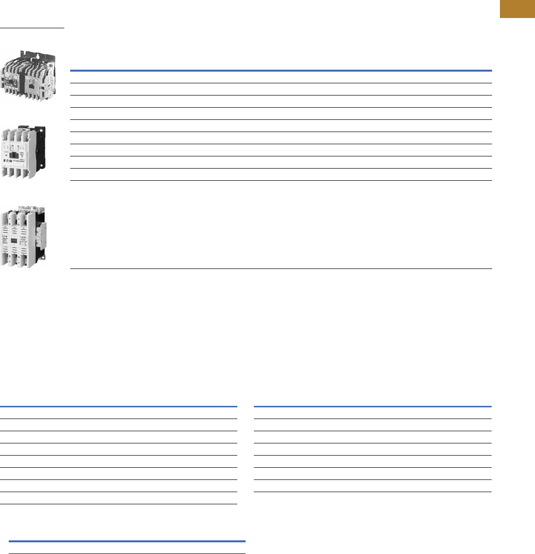
Product Overview
Freedom Series starters and
contactors
feature a compact,
space-saving design, using
state-of-the-art technology
and the latest in high
strength, impact and
temperature resistant
insulating materials.
Features, Benefits and Functions
Freedom NEMA
●Adjustable bimetallic
ambient compensated
overload relays with
interchangeable heater
packs—available in three
basic sizes, covering
applications up to
900 hp—reducing the
number of different
contactor/overload relay
combinations that have to
be stocked. Fixed heater
overloads are optional
●Electronic overload relay
(C440) available as a stand-
alone unit and assembled
with Freedom Contactor
●A full line of snap-on
accessories— top and side
mounted auxiliary contacts,
solid-state and pneumatic
timers, and so on
●Straight-through wiring—
line lugs at top, load lugs
at bottom
●Horizontal or vertical
mounting on upright panel
for application freedom
●Screw type power
terminals have captive,
backed-out self-lifting
pressure plates with
± screws—reduced
wiring time
●Accessible terminals for
easy wiring. Optional
fingerproof shields
available to prevent
electrical shock
●Top located coil terminals
convenient and readily
accessible. 45 mm
contactor magnet coils
have three terminals,
permitting either top or
diagonal wiring—easy to
replace European or U.S.
style starters or contactors
without changing wiring
layout
●Designed to meet or
exceed NEMA, UL, CSA,
VDE, BS and other
international standards
and listings
●American engineering—
built by Eaton, using the
latest in statistical process
control methods to
produce high quality,
reliable products
●Sized based on standard
NEMA classifications
●Easy coil change and
inspectable/replaceable
contacts
●Available in open and
NEMA Type 1, 3R, 4/4X
and 12 enclosures
Volume 5—Motor Control and Protection CA08100006E—May 2016 www.eaton.com V5-T2-3
2
2
2
2
2
2
2
2
2
2
2
2
2
2
2
2
2
2
2
2
2
2
2
2
2
2
2
2
2
2
2.1
NEMA Contactors and Starters
Freedom Series
Standards and Certifications
●Standard: designed to
meet or exceed UL,
NEMA, IEC, CSA, VDE
and BS
●UL listed: UL File #E1491,
Guide #NLDX—Open and
NEMA 1, 4, 12 Enclosed
●CSA Certified: CSA File
#LR353, Class #321104
Open and NEMA 1
Enclosed
ISO 9000 Certification
When you turn to Eaton’s
products, you turn to quality.
The International Standards
Organization (ISO) has
established a series of
standards acknowledged
by 91 industrialized nations
to bring harmony to the
international quest for quality.
The ISO certification process
covers 20 quality system
elements in design,
production and installation
that must conform to
achieve registration. This
commitment to quality will
result in increased product
reliability and total customer
satisfaction.
Short Circuit Protection
Fuses
and
Inverse-Time
Circuit Breakers
may be
selected per Article 430,
Part D of the National
Electrical Code to protect
motor branch circuits from
fault conditions. If higher
ratings or settings are required
to start the motor, do not
exceed the maximum as listed
in Exception No. 2, Article
430-52.
Catalog Number Selection
Freedom Series
Notes
1For contactor only orders, add B to end of catalog number if NEMA Size 00–2, 6.
2Only available on AN56 reversing starters.
3NEMA Sizes 00 and 0 only.
4NEMA Sizes 00 and 0 only. Sizes 1–8 are 24/60 only.
5NEMA Size 5 requires the use of CTs with 1-5A OL relay.
A N 1 9 A N 0 A 5E 005
Device Type
A = Starter
C = Contactor
Contactor Frame Size 1
NEMA
Size
Continuous
Amperes
A=
B=
D=
G=
K=
N=
S=
T=
U=
V=
00
0
1
2
3
4
5
6
7
8
9
18
27
45
90
135
270
540
810
1215
Device Assembly
Configuration
70 = Multi-speed
1= Non-reversing
5= Reversing
Standard
E = IEC
N = NEMA
C440 FLA Range
(FVNR and FVR only)
NEMA Size 00
1P6 = 0.33–1.65A
005 =1–5A
020 =4–20A
NEMA Size 0
1P6 = 0.33–1.65A
005 =1–5A
020 =4–20A
NEMA Size 1
1P6 = 0.33–1.65A
005 =1–5A
020 =4–20A
045 =9–45A
NEMA Size 2
005 =1–5A
020 =4–20A
045 =9–45A
NEMA Size 3
100 = 20–100A
NEMA Size 4
140 = 28–140A
NEMA Size 5 5
300 = 60–300A
AC Coil Suffix
Suffix Coil Volts and Hertz
A
B
C
D
E
H
J
K
L
N
T
U
V
W
Y
= 120/60 or 110/50
= 240/60 or 220/50
= 480/60 or 440/50
= 600/60 or 550/50
= 208/60
= 277/60
= 208 – 240/60 3
= 240/50
= 380 – 415/50
= 550/50
= 24/60, 24/50 4
= 24/50
= 32/50
= 48/60
= 48/50
C440 OLR Designation
(FVNR and FVR only)
5E = Standard feature set
SEL Reset, SEL Class (10A, 10, 20, 30)
5G = Ground fault feature set
SEL Reset, SEL Class (10, 20)
OLR Type
5 = Contactor only—no overload relay
6 = Starter w/C306 bi-metal OLR
9 = Starter w/C440 electronic
overload
NEMA Enclosure
N = Open
For Starters
Starter
Mounting Option
0 = Horizontal
V = Vertical 2
For Contactors Only
2 = Two-pole
3 = Three-pole
4 = Four-pole
5 = Five-pole
V5-T2-4 Volume 5—Motor Control and Protection CA08100006E—May 2016 www.eaton.com
2
2
2
2
2
2
2
2
2
2
2
2
2
2
2
2
2
2
2
2
2
2
2
2
2
2
2
2
2
2
2.1
NEMA Contactors and Starters
Freedom Series
Non-Reversing and Reversing Contactors
Contents
Description Page
Contactors—Non-Reversing and Reversing
Product Selection . . . . . . . . . . . . . . . . . . . . . . . V5-T2-5
Kits and Accessories. . . . . . . . . . . . . . . . . . . . . V5-T2-6
Renewal Parts Publication Numbers. . . . . . . . . V5-T2-6
Technical Data and Specifications . . . . . . . . . . . V5-T2-7
Dimensions. . . . . . . . . . . . . . . . . . . . . . . . . . . . V5-T2-8
Starters—Three-Phase Non-Reversing and
Reversing, Full Voltage . . . . . . . . . . . . . . . . . . . . V5-T2-10
Starters—Single-Phase Non-Reversing,
Full Voltage, Bi-Metallic Overload . . . . . . . . . . . . V5-T2-15
Accessories . . . . . . . . . . . . . . . . . . . . . . . . . . . . . . V5-T2-21
Renewal Parts . . . . . . . . . . . . . . . . . . . . . . . . . . . . V5-T2-30
Technical Data and Specifications . . . . . . . . . . . . . V5-T2-34
Relays—Thermal Overload. . . . . . . . . . . . . . . . . . . V5-T2-38
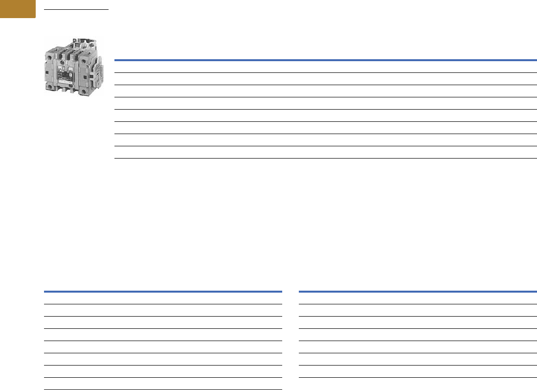
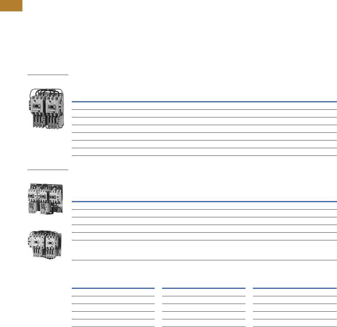
Contactors—Non-Reversing and Reversing
Product Description
Non-Reversing
Contactors are most
commonly used to switch
motor loads in applications
where running overcurrent
protection is either not
required or is provided
separately. Contactors consist
of a magnetically actuated
switch which can be remotely
operated by a pushbutton
station or pilot device such
as a proximity switch, limit
switch, float switch, auxiliary
contacts, and so on.
Reversing
Reversing contactors are
used primarily for reversing
single- or three-phase motors
in applications where running
overcurrent protection is
either not required or is
provided separately. They
consist of two contactors
mechanically and electrically
interlocked to prevent line
shorts and energization of
both contactors
simultaneously.
Features, Benefits and Functions
●Designed specifically for
use in applications
requiring NEMA ratings.
Contactors meet or
exceed NEMA standards
ICS 2-1993
●Long life twin break,
silver cadmium oxide
contacts—provide
excellent conductivity and
superior resistance to
welding and arc erosion
●Designed to 3,000,000
electrical operations at
maximum hp ratings up
through 25 hp at 600V
●Steel mounting plate
standard on all open
type contactors
Non-Reversing
●Holding circuit contact(s)
supplied as standard:
●Sizes 00–3 have NO
auxiliary contact block
mounted on right hand
side (on Size 00, contact
occupies 4th power pole
position—no increase
in width)
●Sizes 4–5 have a
NO contact block
mounted on left side
●Sizes 6–7 have a
2NO/2NC contact
block on top left
●Size 8 has a NO/NC
contact block on top left
back and a NO contact
block on top right back
Reversing
●One NO-NC side mounted
interlock supplied as
standard on each
contactor for Sizes 00–8
Volume 5—Motor Control and Protection CA08100006E—May 2016 www.eaton.com V5-T2-5
2
2
2
2
2
2
2
2
2
2
2
2
2
2
2
2
2
2
2
2
2
2
2
2
2
2
2
2
2
2
2.1
NEMA Contactors and Starters
Freedom Series
Product Selection
Three-Pole Contactors
Type CN15/CN55 NEMA Contactors—Non-Reversing and Reversing
Magnet Coils—AC and DC
Contactor coils listed in this
section also have a 50 Hz
rating as shown in the
adjacent table. Select
required contactor by
catalog number and replace
the magnet coil alpha
designation in the catalog
number (_) with the proper
code suffix from the table.
For Sizes 00–2, the magnet
coil alpha designation will be
the next to the last digit of
the listed catalog number.
EXAMPLE: For a 380V, 50 Hz
coil, change CN15AN3_B
to CN15AN3LB. For all
other sizes, the magnet
coil alpha designation will
be the last digit of the listed
catalog number.
For DC Magnet Coils,
see Accessories, Pages
V5-T2-28 and V5-T2-29.
AC Suffix
Notes
1Maximum horsepower rating of starters for 380V 50 Hz applications:
2Common control. For separate 120V control, insert letter D in 7th position of listed catalog number.
Example:CN15VND3C.
3NEMA Sizes 00 and 0 only.
4NEMA Sizes 00 and 0 only. Sizes 1–8 are 24/60 only.
NEMA
Size
Continuous
Ampere Rating
Maximum UL Horsepower 1
Non-Reversing ReversingSingle-Phase Three-Phase
115V 230V 208V 240V 480V 600V Catalog Number Catalog Number
00 9 1/3 1 1-1/2 1-1/2 2 2 CN15AN3_B CN55AN3_B
018 123355CN15BN3_B CN55BN3_B
1 27 2 3 7-1/2 7-1/2 10 10 CN15DN3_B CN55DN3_B
245 3 7-1/210152525CN15GN3_B CN55GN3_B
390 25305050CN15KN3_ CN55KN3_
4 135 40 50 100 100 CN15NN3_ CN55NN3_
5 270 75 100 200 200 CN15SN3_ CN55SN3_
6 540 150 200 400 400 CN15TN3_B CN55TN3_B
7 810 200 300 600 600 CN15UN3_ CN55UN3_
8 21215 400 450 900 900 CN15VN3_ CN55VN3_
NEMA Size 00
CN55AN3AB
NEMA Size 0
CN15BN3AB
NEMA Size 3
CN15KN3A
Coil Volts and Hertz Code Suffix Coil Volts and Hertz Code Suffix
120/60 or 110/50 A380–415/50 L
240/60 or 220/50 B550/50 N
480/60 or 440/50 C24/60, 24/50 4T
600/60 or 550/50 D24/50 U
208/60 E32/50 V
277/60 H48/60 W
208–240/60 3J48/50 Y
240/50 K
NEMA Size00012345678
Horsepower 1-1/2 5 10 25 50 75 150 300 600 900
V5-T2-6 Volume 5—Motor Control and Protection CA08100006E—May 2016 www.eaton.com
2
2
2
2
2
2
2
2
2
2
2
2
2
2
2
2
2
2
2
2
2
2
2
2
2
2
2
2
2
2
2.1
NEMA Contactors and Starters
Freedom Series
Two-, Four- and Five-Pole Contactors
Type CN15 NEMA Contactors—Non-Reversing
Magnet Coils—AC and DC
Select required starter by
catalog number and replace
the magnet coil alpha
designation in the catalog
number (_) with the proper
code suffix from the table.
For Sizes 00–2, the magnet
coil alpha designation will be
the next to the last digit of
the listed catalog number.
EXAMPLE: For a 380V, 50 Hz
coil, change CN15BN3_B
to CN15BN3LB. For all
other sizes, the magnet
coil alpha designation will
be the last digit of the listed
catalog number.
For DC Magnet Coils,
see Accessories, Pages
V5-T2-28 and V5-T2-29.
AC Suffix
Kits and Accessories
●Auxiliary contacts,
contactor mounted—
Pages V5-T2-25 to
V5-T2-27
●Transient suppressor, for
magnet coil—Page
V5-T2-24
●Timers—solid-state and
pneumatic, mount on
contactor—Page
V5-T2-22
Renewal Parts
Publication Numbers
●See Page V5-T2-30
Notes
1NEMA Sizes 00 and 0 only.
2NEMA Sizes 00 and 0 only. Sizes 1–8 are 24/60 only.
NEMA
Size
Continuous
Ampere
Rating
Maximum UL Horsepower
Two-Pole
Non-Reversing
Four-Pole
Non-Reversing
Five-Pole
Non-Reversing
Single-Phase (Two-Pole) Three-Phase Catalog
Number
Catalog
Number
Catalog
Number115V 230V 208V 240V 480V 600V
00 9 1/3 1 1-1/2 1-1/2 2 2 CN15AN2_B CN15AN4_B —
018 1 2 2355CN15BN2_B — —
127 2 3 7-1/27-1/21010CN15DN2_B CN15DN4_B CN15DN5_B
2 45 3 7-1/2 10152525CN15GN2_B CN15GN4_B CN15GN5_B
3 90 25305050CN15KN2_ — —
4 135 40 50 100 100 CN15NN2_ — —
5 270 75 100 200 200 CN15SN2_ — —
6 540 150 200 400 400 CN15TN2_B — —
NEMA Size 2
Five-Pole Contactor
CN15GN5AB
Coil Volts and Hertz Code Suffix Coil Volts and Hertz Code Suffix
120/60 or 110/50 A380–415/50 L
240/60 or 220/50 B550/50 N
480/60 or 440/50 C24/60, 24/50 2T
600/60 or 550/50 D24/50 U
208/60 E32/50 V
277/60 H48/60 W
208–240/60 1J48/50 Y
240/50 K

Volume 5—Motor Control and Protection CA08100006E—May 2016 www.eaton.com V5-T2-7
2
2
2
2
2
2
2
2
2
2
2
2
2
2
2
2
2
2
2
2
2
2
2
2
2
2
2
2
2
2
2.1
NEMA Contactors and Starters
Freedom Series
Technical Data and Specifications
Wire (75°C) Sizes—AWG or kcmil—Open and Enclosed
Plugging and Jogging Service Horsepower Ratings 2
Notes
1Two compartment box lug.
2Maximum horsepower where operation is interrupted more than 5 times per minute or more than 10 times in a 10 minute period.
NEMA standard ICS 2-1993 table 2-4-3.
NEMA Size Power Terminals Line or Load Control Terminals Cu Only
00 12–16 stranded; 12–14 solid Cu 12–16 stranded
12–14 solid
0 8–16 stranded; 10–14 solid Cu
1 8–14 stranded or solid Cu
2 3–14 (upper) and/or 6–14 (lower) stranded or solid 1 Cu
3 1/0–14 Cu/Al
4 250 mcm–6
5 750 kcmil–2, or (2) 250 kcmil–3/0 Cu/Al
6 (2) 750 kcmil–3/0 Cu/Al
7 (3) 750 kcmil–3/0 Cu/Al
8 (4) 750 kcmil–4/0 Cu/Al
NEMA Size 200V 230V 460V 575V
00 — 1/2 1/2 1/2
0 1-1/2 1-1/2 2 2
13355
2 7-1/2 10 15 15
3 15203030
4 25306060
5 6075150150
6 125 150 300 300
V5-T2-8 Volume 5—Motor Control and Protection CA08100006E—May 2016 www.eaton.com
2
2
2
2
2
2
2
2
2
2
2
2
2
2
2
2
2
2
2
2
2
2
2
2
2
2
2
2
2
2
2.1
NEMA Contactors and Starters
Freedom Series
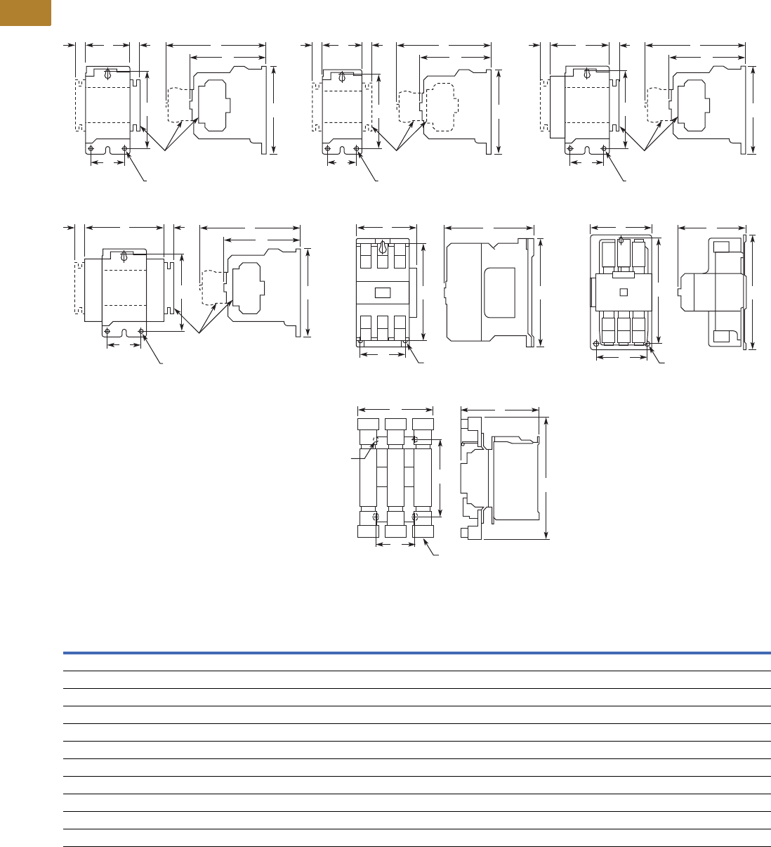
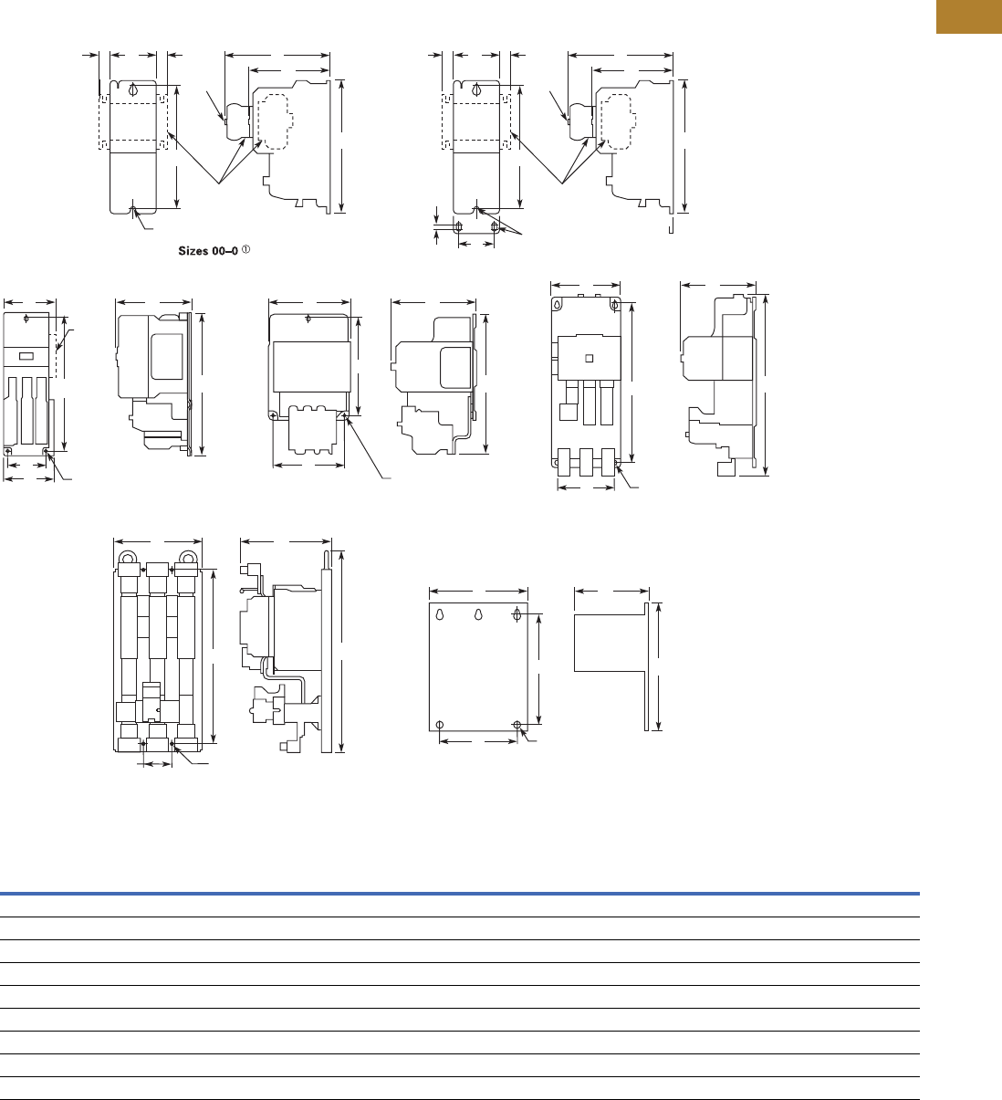
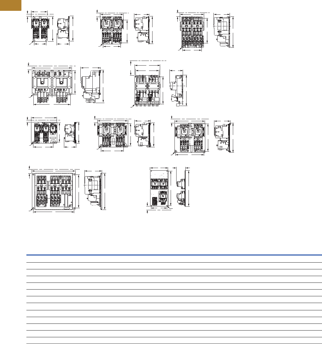
Dimensions
Approximate Dimensions in Inches (mm)
Non-Reversing Contactors—Open Type
Dimensions and Shipping Weights
Note
1Center mounting slot at bottom supplied only on Size 00 and 0 contactors.
NEMA
Size
Number
of Poles
Wide
A
High
B
Deep
C
Mounting
D
Mounting
EFG
Shipping Weight
Lbs (kg)
00 2–4 1.75 (44.5) 3.88 (98.6) 3.49 (88.6) 1.50 (38.1) 13.38 (85.9) 4.62 (117.3) 0.54 (13.7) 1.7 (0.7)
0 2–3 1.75 (44.5) 3.88 (98.6) 3.49 (88.6) 1.50 (38.1) 13.38 (85.9) 4.62 (117.3) 0.54 (13.7) 1.8 (0.8)
1–2 2–3 2.56 (65.0) 5.05 (128.3) 4.44 (112.8) 2.00 (50.8) 14.50 (114.3) 5.80 (147.3) 0.54 (13.7) 3.1 (1.4)
1–2 4 3.44 (87.4) 5.05 (128.3) 4.44 (112.8) 2.00 (50.8) 14.50 (114.3) 5.80 (147.3) 0.54 (13.7) 3.6 (1.6)
1–2 5 4.32 (109.7) 5.05 (128.3) 4.44 (112.8) 2.00 (50.8) 14.50 (114.3) 5.80 (147.3) 0.54 (13.7) 4.0 (1.8)
3 2–3 4.08 (103.6) 7.17 (182.1) 5.94 (150.9) 3.00 (76.2) 6.63 (168.4) — — 8.5 (3.9)
4 2–3 7.05 (179.1) 9.11 (231.4) 7.25 (184.2) 6.00 (152.4) 8.50 (215.9) — — 20.0 (9.1)
5 2–3 7.05 (179.1) 13.12 (333.2) 7.78 (197.6) 6.00 (152.4) 12.50 (317.5) — — 23.0 (10.4)
6 3 8.63 (219.2) 13.54 (343.9) 8.88 (225.6) 4.33 (110.0) 8.63 (219.2) — — 35.0 (15.9)
7 3 11.02 (279.9) 19.30 (490.2) 11.46 (291.1) 6.89 (175.0) 11.02 (279.9) — — 100.0 (45.4)
8 3 13.00 (330.2) 24.50 (622.3) 13.63 (346.2) 4.22 (107.2) 14.86 (377.4) — — 160.0 (72.6)
Mtg. Holes for
#10-32 Screws
A
U
X
A
U
X
AGGF
C
D
Top
Mtd.
Aux.
Auxiliary
Contacts
Top
Mtd.
Aux.
Side
Mtd.
Aux.
EB
Mtg. Holes for
#10-32 Screws
A
U
X
A
U
X
AGGF
C
D
Top
Mtd.
Aux.
Auxiliary
Contacts
To p
Mtd.
Aux.
Side
Mtd.
Aux.
EB
Mtg. Holes for
#10-32 Screws
A
U
X
A
U
X
AGGF
C
D
Top
Mtd.
Aux.
Auxiliary
Contacts
To p
Mtd.
Aux.
Side
Mtd.
Aux.
EB
Sizes 00, Two- to Four-Pole
Mtg. Holes for
#10-32 Screws
A
U
X
A
U
X
AGGF
C
D
Top
Mtd.
Aux.
Auxiliary
Contacts
Top
Mtd.
Aux.
Side
Mtd.
Aux.
Side
Mtd.
Aux.
EB
Sizes 1–2, Five-Pole
Mtg. Holes for (3)
1/4-20 Screws
ACAC
D
BE
Size 3
Mtg. Holes for
(3) Screws
D
B
E
Sizes 4–5
Sizes 0–2, Two- and Three-Pole Sizes 0–2, Two- and Three-Pole
C
Mtg. Slots for (2)
5/16-18 Screws
Mtg. Holes for (2)
5/16-18 Screws
D
A
B
E
Size 6

Volume 5—Motor Control and Protection CA08100006E—May 2016 www.eaton.com V5-T2-9
2
2
2
2
2
2
2
2
2
2
2
2
2
2
2
2
2
2
2
2
2
2
2
2
2
2
2
2
2
2
2.1
NEMA Contactors and Starters
Freedom Series
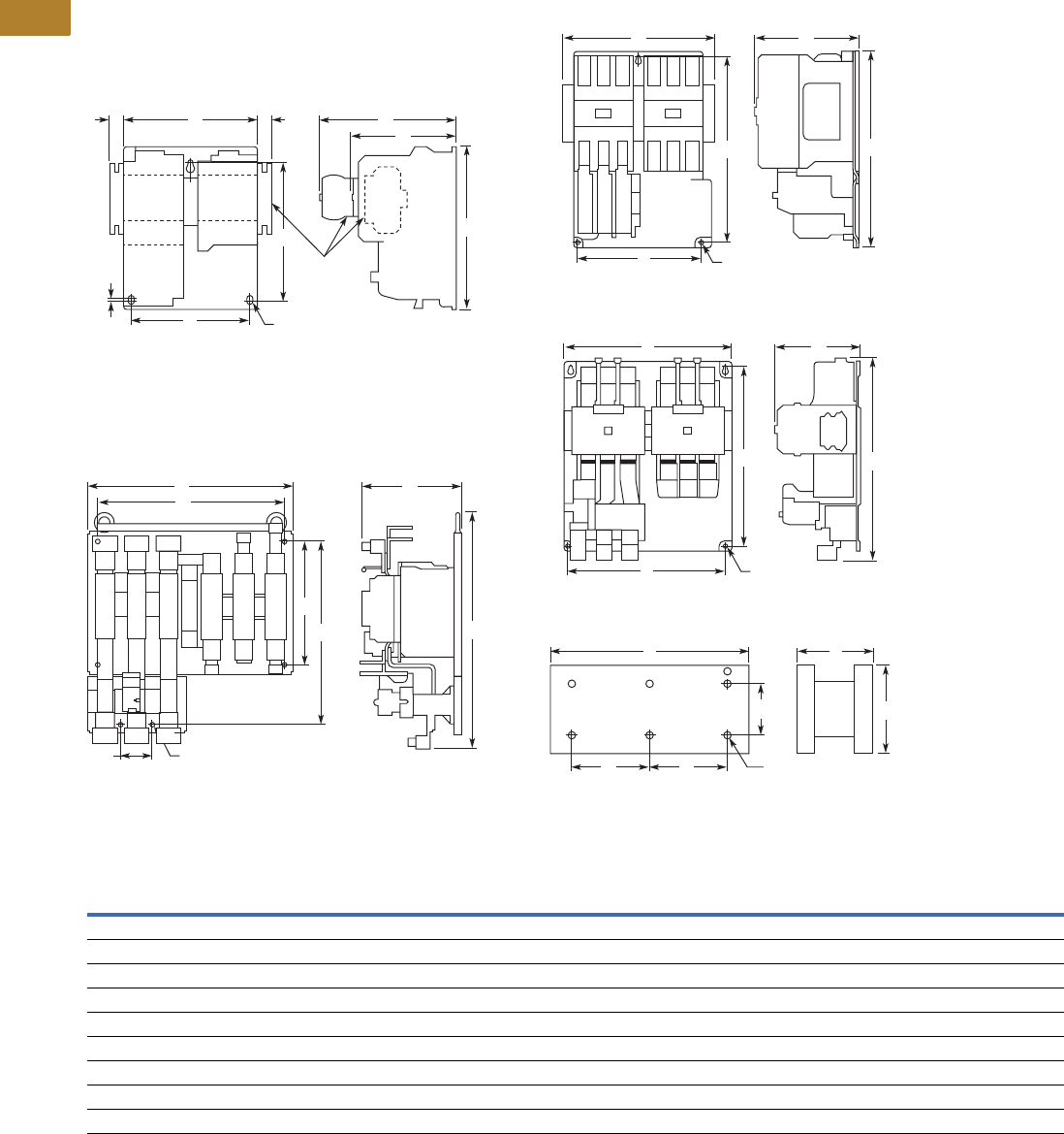
Approximate Dimensions in Inches (mm)
Reversing Contactors—Open Type
Dimensions and Shipping Weights
Note
1Includes cross wiring.
NEMA
Size
Wide
A
High
B
Deep
C
Mounting
D
Mounting
EFG
Shipping Weight
Lbs (kg)
00–0 4.20 (106.7) 4.35 (110.5) 3.52 (89.4) 3.50 (88.9) 3.86 (98.0) 4.90 (124.5) 0.54 (13.7) 3.3 (1.5)
1–2 5.71 (145.0) 5.05 (128.3) 4.44 (112.8) 5.25 (133.4) 3.63 (92.2) 5.80 (147.3) 0.54 (13.7) 7.8 (3.5)
3 8.70 (221.0) 7.17 (182.1) 5.94 (150.9) 7.00 (177.8) 6.63 (168.4) — — 17.0 (7.7)
4 14.68 (372.9) 9.11 (231.4) 7.25 (184.2) 13.50 (342.9) 8.50 (215.9) — — 47.0 (21.3)
5 14.50 (368.3) 12.25 (311.2) 7.78 (197.6) 13.50 (342.9) 11.50 (292.1) — — 63.0 (28.6)
6 19.77 (502.2) 16.61 (421.9) 9.90 (251.5) 18.00 (457.2) 12.00 (304.8) — — 80.0 (36.3)
7 28.00 (711.2) 26.75 (679.5) 112.75 (323.9) 12.75 (323.9) 11.00 (279.4) — — 260.0 (118.0)
8 30.13 (765.3) 39.00 (990.6) 114.69 (373.1) 14.13 (358.9) 15.00 (381.0) — — 350.0 (158.9)
Mtg. Holes for (3)
#10-32 Screws
A
U
X
A
U
X
AGGF
C
D
Top
Mtd.
Aux.
Top
Mtd.
Aux.
Auxiliary
Contacts
Top
Mtd.
Aux.
Side
Mtd.
Aux.
EB
Sizes 00–2 Size 3
Mtg. for (4)
1/4-20 Screws
AC
D
EB
CA
Sizes 4–5
Mtg. Holes for (3)
1/4-20 Screws
CA
D
EB
Mtg. Holes for (6)
1/2-13 Screws
DD
EB
Open Type—Sizes 7–8 Horizontal
Mtg. Holes for (4)
3/8-16 Screws
D
AC
EB
Size 6
V5-T2-10 Volume 5—Motor Control and Protection CA08100006E—May 2016 www.eaton.com
2
2
2
2
2
2
2
2
2
2
2
2
2
2
2
2
2
2
2
2
2
2
2
2
2
2
2
2
2
2
2.1
NEMA Contactors and Starters
Freedom Series
Three-Phase Non-Reversing and Reversing, Full Voltage Starters
Contents
Description Page
Contactors—Non-Reversing and Reversing . . . . . . V5-T2-4
Starters—Three-Phase Non-Reversing and
Reversing, Full Voltage
Product Selection . . . . . . . . . . . . . . . . . . . . . . . V5-T2-11
Kits and Accessories. . . . . . . . . . . . . . . . . . . . . V5-T2-13
Renewal Parts Publication Numbers. . . . . . . . . V5-T2-13
Technical Data and Specifications . . . . . . . . . . . V5-T2-13
Wiring Diagrams . . . . . . . . . . . . . . . . . . . . . . . . V5-T2-14
Starters—Single-Phase Non-Reversing,
Full Voltage, Bi-Metallic Overload . . . . . . . . . . . . V5-T2-15
Accessories . . . . . . . . . . . . . . . . . . . . . . . . . . . . . . V5-T2-21
Renewal Parts . . . . . . . . . . . . . . . . . . . . . . . . . . . . V5-T2-30
Technical Data and Specifications . . . . . . . . . . . . . V5-T2-34
Relays—Thermal Overload. . . . . . . . . . . . . . . . . . . V5-T2-38
C440/XT Electronic Overload Relay . . . . . . . . . . . . V5-T2-48
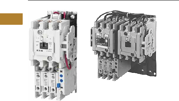
Starters—Three-Phase Non-Reversing and Reversing, Full Voltage
Product Description
Non-Reversing
Three-phase, full voltage
magnetic starters are most
commonly used to switch AC
motor loads. Starters consist
of a magnetically actuated
switch (contactor) and an
overload relay assembled
together.
Reversing
Three-phase, full voltage
magnetic starters are used
primarily for reversing of
three-phase squirrel cage
motors. They consist of two
contactors and a single
overload relay assembled
together. The contactors are
mechanically and electrically
interlocked to prevent line
shorts and energization of
both contactors
simultaneously.
Features, Benefits and
Functions
●Bimetallic ambient
compensated overload
relays—available in three
basic sizes covering
applications up to 900 hp—
reducing number of
different contactor/overload
relay combinations that
have to be stocked
These overload relays
feature:
●Selectable manual
or automatic reset
operation
●Interchangeable heater
packs adjustable ±24%
to match motor FLA and
calibrated for 1.0 and
1.15 service factors.
Heater packs for smaller
overload relay will mount
in larger overload relay—
useful in derating
applications such as
jogging
●Load lugs built into
relay base
●Single-phase protection,
Class 20 or Class 10
trip time
●Overload trip indication
●Electrically isolated
NO-NC contacts (pull
RESET button to test)
●The C440 is a self-
powered, robust
electronic overload
designed for integrated
use with Freedom
NEMA contactors
●Tiered feature set to
provide coverage
specific to your
application
●Broad 5: 1 FLA range
for maximum flexibility
●Coverage from
0.05–1500A to meet
all your needs
●Long life twin break,
silver cadmium oxide
contacts—provide
excellent conductivity
and superior resistance
to welding and arc erosion.
Generously sized for low
resistance and cool
operation
●Designed to 3,000,000
electrical operations at
maximum hp ratings up
through 25 hp at 600V
●Steel mounting plate
standard on all open
type starters
●Wired for separate or
common control
Non-Reversing
●Holding circuit contact(s)
supplied as standard:
●Sizes 00–3 have a NO
auxiliary contact block
mounted on right-hand
side (on Size 00, contact
occupies 4th power pole
position—no increase
in width)
●Sizes 4–5 have a
NO contact block
mounted on left side
●Sizes 6–7 have a
2NO/2NC contact
block on top left
●Size 8 has a NO/NC
contact block on top
left back and a NO on
top right back
Reversing
●Each contactor (Size 00–8)
supplied with one NO-NC
side mounted contact
block as standard. NC
contacts are wired as
electrical interlocks
Volume 5—Motor Control and Protection CA08100006E—May 2016 www.eaton.com V5-T2-11
2
2
2
2
2
2
2
2
2
2
2
2
2
2
2
2
2
2
2
2
2
2
2
2
2
2
2
2
2
2
2.1
NEMA Contactors and Starters
Freedom Series
Product Selection
When Ordering Supply
●Catalog number
●Heater pack number (see selection table, Pages V5-T2-40 to V5-T2-42) or full load current
Type AN16/AN56 NEMA—Manual or Automatic Reset Overload Relay—Non-Reversing and Reversing 1
Magnet Coils—AC or DC
Starter coils listed in this
section also have a 50 Hz
rating as shown in the
adjacent table. Select
required starter by catalog
number and replace the
magnet coil alpha designation
in the catalog number (_) with
the proper code suffix from
the table.
For Sizes 00–2 and 5–8, the
magnet coil alpha designation
will be the next to last digit
of the listed catalog number.
EXAMPLE: For a 380V, 50 Hz
coil, change AN16BN0_C
to AN16BN0LC. For all
other sizes, the magnet
coil alpha designation will
be the last digit of the listed
catalog number.
For DC Magnet Coils,
see Accessories, Pages
V5-T2-28 and V5-T2-29.
AC Suffix
Notes
1Starter catalog numbers do not include heater packs. Select one carton of three heater packs. Heater pack selection, Pages V5-T2-40 to V5-T2-42.
2Maximum horsepower rating of starters for 380V 50 Hz applications:
3Underscore (_) indicates coil suffix required, see AC Suffix table.
4The service-limit current ratings represent the maximum rms current, in amperes, which the controller shall be permitted to carry for protracted periods in normal service. At service-limit current
ratings, temperature rises shall be permitted to exceed those obtained by testing the controller at its continuous current rating. The current rating of overload relays or trip current of other motor
protective devices used shall not exceed the service-limit current rating of the controller.
5Common control. For separate 120V control, insert letter D in 7th position of listed catalog number. Example: AN56VND0CB.
6NEMA Sizes 00 and 0 only.
7NEMA Sizes 00 and 0 only. Sizes 1–8 are 24/60 only.
NEMA
Size
Continuous
Ampere
Rating
Service-Limit
Current Rating
(Amperes) 4
Maximum UL Horsepower 2Three-Pole
Non-Reversing 3
Three-Pole
Reversing 3
Vertical
Reversing 3
Single-Phase Three-Phase
115V 230V 208V 240V 480V 600V
Catalog
Number
Catalog
Number
Catalog
Number
00 9 11 1/3 1 1-1/2 1-1/2 2 2 AN16AN0_C AN56AN0_C —
0 18 21 123355AN16BN0_C AN56BN0_C AN56BNV0_
1 27 32 237-1/27-1/21010AN16DN0_B AN56DN0_B AN56DNV0_
2 45 52 3 7-1/2 10 15 25 25 AN16GN0_B AN56GN0_B AN56GNV0_
3 90 104 ——25305050AN16KN0_ AN56KN0_ AN56KNV0_
4 135 156 — — 40 50 100 100 AN16NN0_ AN56NN0_ AN56NNV0_
5 270 311 — — 75 100 200 200 AN16SN0_B AN56SN0_B —
6 540 621 — — 150 200 400 400 AN16TN0_C AN56TN0_C —
7 810 932 — — 200 300 600 600 AN16UN0_B AN56UN0_B —
8 51215 1400 — — 400 450 900 900 AN16VN0_B AN56VN0_B —
Size 0
Non-Reversing Starter
Size 1
Reversing Starter
Coil Volts and Hertz Code Suffix Coil Volts and Hertz Code Suffix
120/60 or 110/50 A380–415/50 L
240/60 or 220/50 B550/50 N
480/60 or 440/50 C24/60, 24/50 7T
600/60 or 550/50 D24/50 U
208/60 E32/50 V
277/60 H48/60 W
208–240/60 6J48/50 Y
240/50 K48/50 Y
NEMA Size00012345678
Horsepower 1-1/2 5 10 25 50 75 150 300 600 900
V5-T2-12 Volume 5—Motor Control and Protection CA08100006E—May 2016 www.eaton.com
2
2
2
2
2
2
2
2
2
2
2
2
2
2
2
2
2
2
2
2
2
2
2
2
2
2
2
2
2
2
2.1
NEMA Contactors and Starters
Freedom Series
Two-Speed Selective Control
When Ordering Supply
●Catalog number plus
magnet coil code suffix.
Example: Size 0—
AN700BN022B
●Heater pack number or full
load current for each speed
For two-speed other than
selective control:
●Catalog number plus
magnet coil code suffix and
option required. Example:
AN700BN022B except
compelling
●Heater pack number or full
load current for each speed
Note: Two-speed starters
are designed for starting and
controlling both separate
(two-winding) and reconnectable
(one-winding) motors. Separate
winding, WYE-WYE motors
have a separate winding for
each speed. Reconnectable,
consequent pole motors use the
same winding for both speeds. All
standard starters are wired
for selective control.
Separate Winding 1
Reconnectable Winding 1
Magnetic Coils—AC or DC
Notes
1 If branch circuit protective device is 45A or greater, C320FBR1 fuse kit(s) may be required for circuit protection per NEC 530-072.
2 NEMA Sizes 00 and 0 only. Sizes 1–5 are 24/60 only.
Maximum Horsepower—60/50 Hertz
NEMA
Size
Open Type
Catalog Number
Constant or Variable Torque Constant Horsepower
115V 200V 230V 460V/575V 115V 200V 230V 460/575V
1-1/233512230AN700BN022_
3 7-1/2 7-1/2 10 2 5 5 7-1/2 1 AN700DN022_
—101525—7-1/210202 AN700GN022_
—253050—2025403 AN700KN022_
—4050100—3040754 AN700NN022_
— 75 100 200 — 60 75 150 5 AN700SN022_
Prices of starters do not include heater packs. Select two packs (two overload relays, one for each speed). Heater pack selection, Pages V5-T2-40 to V5-T2-42.
Maximum Horsepower—60/50 Hertz
NEMA
Size
Open Type
Constant or Variable Torque Constant Horsepower
Constant or
Variable Torque
Constant
Horsepower
115V 200V 230V 460V/575V 115V 200V 230V 460/575V Catalog Number Catalog Number
1-1/2335 12230AN700BN0218_ AN700BN0219_
37-1/27-1/2102557-1/21AN700DN0218_ AN700DN0219_
—101525 —7-1/210202 AN700GN0218_ AN700GN0219_
— 25 30 50 — 20 25 40 3 AN700KN0218_ AN700KN0219_
—4050100—3040754 AN700NN0218_ AN700NN0219_
Prices of starters do not include heater packs. Select two packs (two overload relays, one for each speed). Heater pack selection, Pages V5-T2-40 to V5-T2-42.
Coil Voltage and Hz Code Suffix Coil Voltage and Hz Code Suffix Coil Voltage and Hz Code Suffix
120/60 or 110/50 A277/60 H24/60, 24/50 2T
240/60 or 220/50 B208–240/60 J24/50 U
480/60 or 440/50 C240/50 K32/50 V
600/60 or 550/50 D380–415/50 L48/60 W
208/60 E550/50 N48/50 Y
Two-Winding
AN700DN022
One-Winding
AN700BN0218
One-Winding
AN700DN0218

Volume 5—Motor Control and Protection CA08100006E—May 2016 www.eaton.com V5-T2-13
2
2
2
2
2
2
2
2
2
2
2
2
2
2
2
2
2
2
2
2
2
2
2
2
2
2
2
2
2
2
2.1
NEMA Contactors and Starters
Freedom Series
Kits and Accessories
●Auxiliary contacts,
contactor mounted—
Pages V5-T2-25 to
V5-T2-27
●Transient suppressor, for
magnet coil—Page
V5-T2-24
●Timers—solid-state and
pneumatic, mount on
contactor—Page
V5-T2-22
Renewal Parts
Publication Numbers
●See Page V5-T2-30
Technical Data and Specifications
Wire (75°C) Sizes—AWG or kcmil—NEMA Sizes 00–2—Open and Enclosed
Wire (75°C) Sizes—AWG or kcmil—NEMA Sizes 3–8—Open and Enclosed
Plugging and Jogging Service Horsepower Ratings 3
Notes
1Minimum per NEC. Maximum wire size: Sizes 00 and 0 to 8 AWG and Sizes 1–2 to 2 AWG.
2Two compartment box lug.
3Maximum horsepower where operation is interrupted more than 5 times per minute, or more than 10 times in a 10 minute period.
NEMA Standard ICS2-1993 table 2-4-3.
NEMA Size Wire Size 1 Cu Only
Power Terminals—Line
00 12–16 AWG stranded, 12–14 AWG solid
0 8–16 AWG stranded, 10–14 AWG solid
1 8–14 AWG stranded or solid
2 3–14 AWG (upper) and/or 6–14 AWG (lower) stranded or solid 2
Power Terminals—Load—Cu Only (stranded or solid)
00–0 14–6 AWG stranded or solid
1–2 14–2 AWG stranded or solid
Control Terminals—Cu Only
12–16 AWG stranded, 12–14 AWG solid
NEMA Size Wire Size 2
Power Terminals—Line and Load
3 1/0–14 AWG Cu/Al
4 Open—3/0–8 AWG Cu; Enclosed—250 kcmil—6 AWG Cu/Al
5 750 kcmil—2 AWG; or (2) 250 kcmil—3/0 AWG Cu/Al
6 (2) 750 kcmil—3/0 AWG Cu/Al
7 (3) 750 kcmil—3/0 AWG Cu/Al
8 (4) 750 kcmil—1/0 AWG Cu/Al
Control Terminals—Cu Only
12–16 AWG stranded, 12–14 AWG solid
NEMA Size 200V 230V 460V 575V
00 — 1/2 1/2 1/2
0 1-1/2 1-1/2 2 2
13355
2 7-1/2 10 15 15
3 15203030
4 25306060
5 60 75 150 150
6 125 150 300 300
V5-T2-14 Volume 5—Motor Control and Protection CA08100006E—May 2016 www.eaton.com
2
2
2
2
2
2
2
2
2
2
2
2
2
2
2
2
2
2
2
2
2
2
2
2
2
2
2
2
2
2
2.1
NEMA Contactors and Starters
Freedom Series
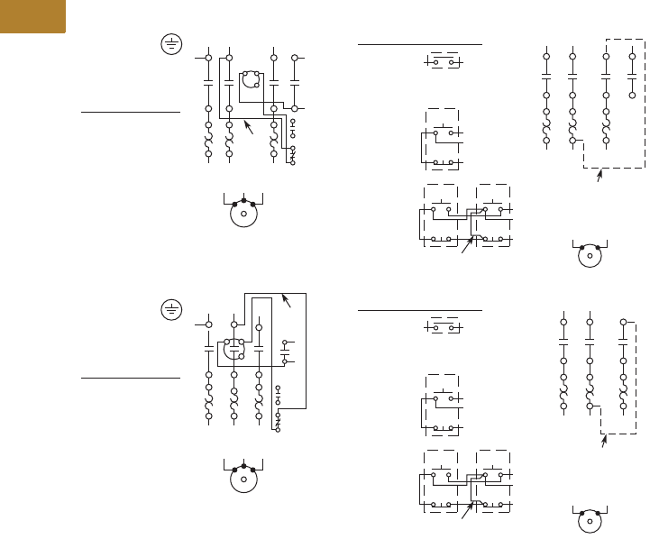
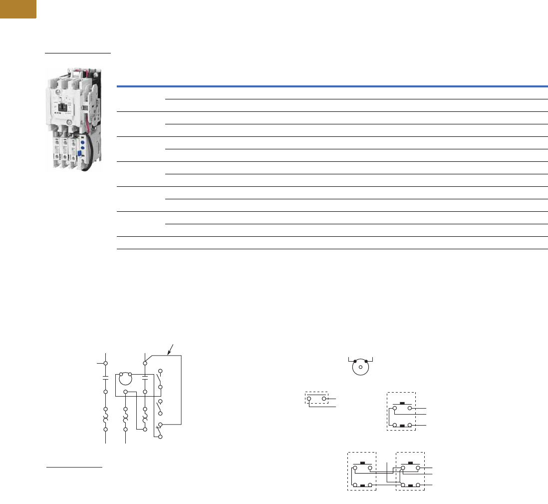
Wiring Diagrams
Three-Phase and Single-Phase Applications
Not for Use with
Auto Reset OL Relays
Separate Control
Remove Wire “c”
when it is supplied.
Connect separate
control lines to the
No. 1 Terminal on
the remote pilot
device and Terminal
96 on the overload
relay.
“c”
“A”
When more than
one pushbutton
station is used,
omit Connector
“A” and connect
per sketch.
Field Conversion
to Single-Phase, Add
Dotted Connections
Remote Pilot Devices
NEMA Size 00
Two-Wire
Control
L1 L2 L3
T1 T2 T3
T1 T2 T3
1A1 A2
A2
2
3
98
97
96
95
13
3
3
2
1
2
L1
T1 T2
T1 T2
L2
1
Start
Start Start
Stop
Stop Stop
Three-Wire
Control
Motor
Motor
Not for Use with
Auto Reset OL Relays
Separate Control
Remove Wire “c”
when it is supplied.
Connect separate
control lines to the
No. 1 Terminal on
the remote pilot
device and Terminal
96 on the overload
relay.
“A”
When more than
one pushbutton
station is used,
omit Connector
“A” and connect
per sketch.
Field Conversion
to Single-Phase, Add
Dotted Connections
Remote Pilot Devices
NEMA Sizes 0, 1 and 2
Two-Wire
Control
T1 T2 T3
“c”
L1 L2 L3
T1 T2 T3
1A1 A2 2
3
98
97
96
95
13
3
3
2
1
2
L1
T1 T2
T1 T2
L2
1
Start
Start Start
Stop
Stop Stop
Three-Wire
Control
Motor
Motor
Volume 5—Motor Control and Protection CA08100006E—May 2016 www.eaton.com V5-T2-15
2
2
2
2
2
2
2
2
2
2
2
2
2
2
2
2
2
2
2
2
2
2
2
2
2
2
2
2
2
2
2.1
NEMA Contactors and Starters
Freedom Series
NEMA Size 1—BN15DN0AB
Contents
Description Page
Contactors—Non-Reversing and Reversing . . . . . . V5-T2-4
Starters—Three-Phase Non-Reversing and
Reversing, Full Voltage. . . . . . . . . . . . . . . . . . . . . V5-T2-10
Starters—Single-Phase Non-Reversing,
Full Voltage, Bi-Metallic Overload
Product Selection . . . . . . . . . . . . . . . . . . . . . . . V5-T2-16
Wiring Diagrams . . . . . . . . . . . . . . . . . . . . . . . . V5-T2-16
Dimensions . . . . . . . . . . . . . . . . . . . . . . . . . . . . V5-T2-17
Accessories . . . . . . . . . . . . . . . . . . . . . . . . . . . . . . V5-T2-21
Renewal Parts. . . . . . . . . . . . . . . . . . . . . . . . . . . . . V5-T2-30
Technical Data and Specifications. . . . . . . . . . . . . . V5-T2-34
Relays—Thermal Overload . . . . . . . . . . . . . . . . . . . V5-T2-38
C440/XT Electronic Overload Relay . . . . . . . . . . . . V5-T2-48
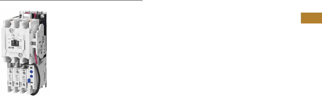
Starters—Single-Phase Non-Reversing, Full Voltage, Bi-Metallic Overload
Product Description
Single-phase, full voltage
magnetic starters connect
the motor directly across the
line, allowing it to draw full
inrush current during start-up.
These starters are most
commonly used for control of
self-starting single-phase
motors up to 15 hp at 230V.
They consist of a two-pole
electromagnetic contactor to
make and break the motor
power circuit and an overload
relay to provide running
overload protection. Starters
listed in the table include:
●Two-pole Freedom Series
contactor with long life
twin break, silver cadmium
oxide contacts. Generously
sized for low resistance
and cool operation.
Designed to 3 million
electrical operations
at maximum hp and
30 million mechanical
operations to Size 0,
10 million operations
to Size 2 and 6 million
operations to Size 3
●Three-pole Freedom Series
overload with poles two
and three wired in series
for motor overload
protection. This overload
is ambient compensated,
selectable manual or
automatic reset,
interchangeable Class 10 or
20 heater packs, 1.0
or 1.15 service factor
selectability, overload trip
indication and electrically
isolated NO-NC contacts
(pull RESET button to test)
●Holding circuit NO auxiliary
contact supplied as
standard. On Size 00, the
contact occupies the 4th
power pole position. Sizes
0–3 have the NO auxiliary
mounted on the right side
of the contactor
●Steel mounting plate as
standard on all open type
starters. Wired for separate
or common control
V5-T2-16 Volume 5—Motor Control and Protection CA08100006E—May 2016 www.eaton.com
2
2
2
2
2
2
2
2
2
2
2
2
2
2
2
2
2
2
2
2
2
2
2
2
2
2
2
2
2
2
2.1
NEMA Contactors and Starters
Freedom Series
Product Selection
When Ordering Specify
●Catalog number
●Heater pack number (see selection table, Pages V5-T2-40 to V5-T2-42) or full load current
Type BN16 NEMA—Manual or Automatic Reset Overload Relay
Note
1 For separate 120V control circuit. For maximum hp at listed motor voltages, use the rating of other starters of same size.
Wiring Diagrams
Single-Phase Applications (Factory Wired)
NEMA
Size
Maximum Horsepower Magnet Coil Voltage
(60 Hz)
Open Type Two-Pole
Motor Voltage Single-Phase Catalog Number
00 115 1/3 120 1BN16AN0AC
230 1 240 BN16AN0BC
0 115 1 120 1BN16BN0AC
230 2 240 BN16BN0BC
1 115 2 120 1BN16DN0AB
230 3 240 BN16DN0BB
1P 115 3 120 1BN16PN0AB
230 5 240 BN16PN0BB
2 115 3 120 1BN16GN0AB
230 7-1/2 240 BN16GN0BB
3 115 7-1/2 120 1BN16KN0A
230 15 240 BN16KN0B
Starter catalog numbers do not include heater packs. Select one carton of three heater packs. Heater pack selection, Pages V5-T2-40 to V5-T2-42.
BN16DM0AB
Front View of Panel
Single-Phase Motor
When more than
one pushbutton
station is used,
omit Connector “A”
and connect per
sketch at right.
Two-Wire Control
Not for Use with
Auto Reset OL Relays
Three-Wire Control
START
STOP
AC Lines
1
L1
1
M
OL
A1 A2 2/13
3/14
98
97
96
95
2/T1 4/T2 6/T3
Reset
3
L2
T1
2
T2
4
T1 T2
“C”
3/14
Separate Control
Remove Wire “C” if supplied and connect separate control
lines to the Number 1 Terminal on the remote pilot device
and to the Number 96 Terminal on the overload relay.
13/14
2/13
1
START “A”
STOP
START
STOP
3/14
2/13
1
Volume 5—Motor Control and Protection CA08100006E—May 2016 www.eaton.com V5-T2-17
2
2
2
2
2
2
2
2
2
2
2
2
2
2
2
2
2
2
2
2
2
2
2
2
2
2
2
2
2
2
2.1
NEMA Contactors and Starters
Freedom Series
Dimensions
Approximate Dimensions in Inches (mm)
Non-Reversing Starters, Bi-Metallic Overload—Open Type
Dimensions and Shipping Weights
Note
1Holding circuit contact for Size 00 occupies 4th power pole position—no increase in width.
NEMA
Size
Wide
A
High
B
Deep
C
Mounting
D
Mounting
EFG
Shipping Weight
Lbs (kg)
00–0 1.80 (45.7) 6.60 (167.6) 3.52 (89.4) — 6.07 (154.2) 4.90 (124.5) 0.54 (13.7) 2.2 (1.0)
1–1P 2.56 (65.0) 7.08 (179.8) 4.44 (112.8) 2.00 (50.8) 6.63 (168.4) 5.80 (147.3) 0.54 (13.7) 4.5 (2.0)
2 2.56 (65.0) 8.08 (205.2) 4.44 (112.8) 2.00 (50.8) 7.63 (193.8) 5.80 (147.3) 0.54 (13.7) 4.7 (2.1)
3 4.08 (103.6) 11.35 (288.3) 5.94 (150.9) 3.00 (76.2) 10.81 (274.6) — — 11.0 (5.0)
4 7.05 (179.1) 12.06 (306.3) 7.25 (184.2) 6.00 (152.4) 8.50 (215.9) — — 23.0 (10.4)
5 7.00 (177.8) 17.77 (451.4) 7.76 (197.1) 6.00 (152.4) 16.00 (406.4) — — 36.0 (16.3)
6 9.47 (240.5) 21.69 (550.9) 9.90 (251.5) 3.10 (78.7) 18.00 (457.2) — — 75.0 (34.1)
7 15.13 (384.3) 29.13 (739.9) 12.64 (321.1) 13.25 (336.6) 21.25 (539.8) — — 120.0 (54.5)
8 15.13 (384.3) 34.50 (876.3) 15.00 (381.0) 13.25 (336.6) 16.75 (425.5) — — 210.0 (95.3)
Side
Mtd.
Aux.
D
A
U
X
Aux.
Cont.
Aux.
A
U
X
AGG
C
F
Top
Mtd.
Aux.
Auxiliary
Contacts
Mtg. Holes for #10-32 Screws
Top
Mtd.
Aux.
E
C
LC
L
B
CACG
EB
Mtg. Holes for
#10-32 Screws
Sizes 1–2
D
AMtg. Holes for (3)
1/4-20 Screws
Size 3
E
B
AC
B
D
Mtg. Holes for
1/4-20 Screws
Size 4
E
DMtg. Holes for
1/4-20 Screws
Size 5
AC
B
E
DMtg. Holes for
1/2-13 Screws
Sizes 7–8
Size 6
AC
B
E
DMtg. Holes for (4)
3/8-16 Screws
Side
Mtd.
Aux.
A
U
X
A
U
X
AGGF
C
Top
Mtd.
Aux.
Auxiliary
Contacts
Top
Mtd.
Aux.
E
0.13
(3.3)
B
V5-T2-18 Volume 5—Motor Control and Protection CA08100006E—May 2016 www.eaton.com
2
2
2
2
2
2
2
2
2
2
2
2
2
2
2
2
2
2
2
2
2
2
2
2
2
2
2
2
2
2
2.1
NEMA Contactors and Starters
Freedom Series
Approximate Dimensions in Inches (mm)
Reversing Starters, Bi-Metallic Overload—Open Type
Dimensions and Shipping Weights
Notes
1Includes cross wiring overhang.
2See catalog listings for type and location of auxiliary contacts supplied with a particular starter.
NEMA
Size
Wide
A
High
B
Deep
C
Mounting
D
Mounting
ED1E1FG
Shipping Weight
Lbs (kg)
00–0 4.20 (106.7) 7.38 (187.5) 3.52 (89.4) 3.50 (88.9) 6.87 (174.5) — — 4.90 (124.5) 0.54 (13.7 3.6 (1.6)
1 5.71 (145.0) 7.08 (179.8) 4.44 (112.8) 5.25 (133.4) 5.75 (146.1) — — 5.80 (147.3) 0.54 (13.7) 8.3 (3.8)
2 5.71 (145.0) 8.08 (205.2) 4.44 (112.8) 5.25 (133.4 6.75 (171.5) — — 5.80 (147.3) 0.54 (13.7) 8.5 (3.9)
3 8.70 (221.0) 11.35 (288.3) 5.94 (150.9) 7.00 (177.8) 10.81 (274.6) — — — — 20.0 (9.1)
4 14.68 (372.9) 12.06 (306.3) 7.25 (184.2) 13.50 (342.9) 8.50 (215.9) — — — — 49.0 (22.2)
5 14.50 (368.3) 17.77 (451.4) 7.76 (197.1) 13.50 (342.9) 16.00 (406.4) — — — — 68.0 (30.9)
6 19.77 (502.2) 22.63 (574.8) 9.90 (251.5) 18.00 (457.2) 12.00 (304.8) 3.10 (78.7) 18.00 (457.2) — — 90.0 (40.9)
7 28.06 (712.7) 32.13 (816.1) 112.70 (322.6) 12.75 (323.9) 21.25 (539.8) — — — — 175.0 (79.5)
8 30.38 (771.7) 41.50 (1054.1) 114.70 (373.4) 14.13 (358.9) 16.75 (425.5) — — — — 430.0 (195.2)
Side
Mtd.
Aux.
A
U
X
A
U
X
A
D
.13
(3.3)
G
GF
C
Top
Mtd.
Aux.
Top
Mtd.
Aux.
Auxiliary
Contacts
b
Mtg. Holes for (3)
#10-32 Screws
Top
Mtd.
Aux.
EB
Sizes 00 – 2
A
D1
C
D
Mtg. Holes for (6)
3/8-16 Screws
E
E1 B
Size 6
DMtg. Holes for (3)
1/4-20 Screws
E
C
A
B
Size 3
DMtg. Holes for (4)
1/4-20 Screws
E
CA
B
Sizes 4 – 5
DD Mtg. Holes for (6)
1/2-13 Screws
E
AC
B
Open Type — Sizes 7 – 8 Horizontal
C
L
C
L
Volume 5—Motor Control and Protection CA08100006E—May 2016 www.eaton.com V5-T2-19
2
2
2
2
2
2
2
2
2
2
2
2
2
2
2
2
2
2
2
2
2
2
2
2
2
2
2
2
2
2
2.1
NEMA Contactors and Starters
Freedom Series
Approximate Dimensions in Inches (mm)
Reversing Starters—Vertical Construction, Bi-Metallic Overload—AN56V Open Vertical Starter
Dimensions and Shipping Weights
Note
1Wire overhang 1.00 mm left, 50 mm right.
NEMA
Size
Wide
A
High
B
Deep
C
Mounting
Wide
D
Mounting
HIgh
E Wire Zone
Shipping Weight
Lbs (kg)
0 4.25 (108.0) 12.05 (306.1) 3.84 (97.5) 2.00 (50.8) 11.50 (292.1) — 4.0 (1.8)
1 4.25 (108.0) 12.05 (306.1) 3.86 (98.0) 2.00 (50.8) 11.50 (292.1) 1.00 (25.4) 9.0 (4.1)
2 4.25 (108.0) 12.05 (306.1) 3.86 (98.0) 2.00 (50.8) 11.50 (292.1) 1.00 (25.4) 9.5 (4.3)
3 9.25 (235.0) 16.75 (425.5) 5.18 (131.6) 7.15 (181.6) 16.07 (408.2) 121.0 (9.5)
4 9.08 (230.6) 19.84 (503.9) 5.18 (131.6) 8.00 (203.2) 18.51 (470.2) 1.50 (38.1) 50.0 (22.7)
Mtg. Holes for (3)
#10-32 Screws
NEMA Size 0
D
E
A
B
C
Mtg. Holes for (3)
#10-32 Screws
NEMA Sizes 1 – 2
D
E
ACFF
B
Mtg. Holes for (3)
1/4-20 Screws
NEMA Size 3
D
E
ACFF
B
Mtg. Holes for (4)
1/4-20 Screws
NEMA Size 4
D
E
AC
FF
B
V5-T2-20 Volume 5—Motor Control and Protection CA08100006E—May 2016 www.eaton.com
2
2
2
2
2
2
2
2
2
2
2
2
2
2
2
2
2
2
2
2
2
2
2
2
2
2
2
2
2
2
2.1
NEMA Contactors and Starters
Freedom Series
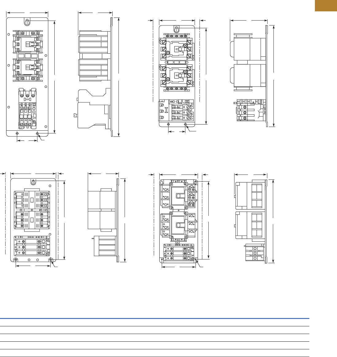
Approximate Dimensions in Inches (mm)
Multispeed Starters, Bi-Metallic Overload—AN700 Open Vertical Starter
Dimensions and Shipping Weights
Notes
1Mounting holes for (3) #10 screws.
2Mounting holes for (3) 1/4-20 screws.
3Mounting holes for (4) 1/4-20 screws.
4Mounting holes for (4) 5/16 screws.
5Mounting holes for (4) 3/8 screws.
NEMA
Size
Wide
A
High
B
Deep
C
Mounting
Wide
D
Mounting
High
E
Wire
Zone F
Shipping Weight
Lbs (kg)
Two-Speed—Selective Control—Separate Winding
0 5.19 (132) 7.38 (188) 3.52 (89) 3.50 (89) 6.87 (175) 0.89 (23) 4.5 (2.0)
1 5.66 (144) 7.08 (180) 4.42 (112) 5.25 (133) 5.75 (146) 1.23 (31) 9.0 (4.1)
2 5.66 (144) 8.08 (205) 4.42 (112) 5.25 (133) 6.75 (165) 1.63 (41) 10.0 (4.5)
3 8.72 (221) 11.35 (288) 5.89 (150) 7.00 (178) 10.81 (275) 1.77 (45) 24.0 (10.9)
4 14.68 (373) 12.06 (306) 7.25 (184) 13.50 (343) 8.50 (216) 1.95 (50) 53.0 (24.1)
5 14.50 (368) 17.82 (453) 7.76 (197) 13.50 (343) 16.00 (406) 4.56 (116) 73.0 (33.1)
Two-Speed—Selective Control—Reconnectable Winding
0 8.62 (219) 7.06 (179) 3.82 (81) 6.62 (168) 6.50 (165) 0.50 (13) 6.0 (2.7)
1 8.97 (228) 7.12 (181) 4.72 (120) 6.62 (168) 6.50 (165) 1.04 (26) 10.0 (4.5)
2 8.90 (226) 8.62 (219) 4.75 (121) 8.40 (213) 8.12 (206) 1.03 (26) 11.0 (5.0)
3 16.00 (406) 13.46 (342) 6.38 (162) 15.00 (381) 12.25 (311) 1.24 (31) 31.0 (14.1)
4 15.46 (393) 31.00 (787) 7.74 (197) 13.50 (343) 30.00 (762) 1.84 (47) 72.0 (32.7)
aa
b
EB
A
DC
F
EB
A
D
C
F
EB
A
D
C
F
Size “3” Multispeed Starter
2-Speed, 2-Winding
Size “1 – 2” Multispeed Starter
2-Speed, 2-Winding
Size “0” Multispeed Starter
2-Speed, 2-Winding
E
B
A
D
C
F
EB
A
FDC
c
Size “4” Multispeed Starter
2-Speed, 2-Winding
cSize “5” Multispeed Starter
2-Speed, 2-Winding
EB
A
DC
F
EB
A
D
C
F
EB
A
D
C
F
a
a
a
Size “2” Multispeed Starter
2-Speed, 1-Winding
Size “1” Multispeed Starter
2-Speed, 1-Winding
Size “0” Multispeed Starter
2-Speed, 1-Winding
EB
A
D
C
F
E B
A
D
C
F햶
d
Size “4” Multispeed Starter
2-Speed, 1-Winding
Size “3” Multispeed Starter
2-Speed, 1-Winding
Volume 5—Motor Control and Protection CA08100006E—May 2016 www.eaton.com V5-T2-21
2
2
2
2
2
2
2
2
2
2
2
2
2
2
2
2
2
2
2
2
2
2
2
2
2
2
2
2
2
2
2.1
NEMA Contactors and Starters
Freedom Series
Accessories
Three-Pole Top Mounted Fuse Block Kit
IEC Sizes A–K, NEMA Sizes 00–2
Field mount to Freedom
Series starters and contactors.
Designed to save space and
reduce installation costs. They
provide short circuit protection
for branch circuits.
Fuse Block Kits
Three-Pole Top Mounted Fuse Block Kit
Fuse Type Catalog Number
Class H—30A 250V C350KH21
Class R—30A 250V C350KR21
Class G—15A 300V C350KG37
Class G—20A 300V C350KG38
Class G—30A 300V C350KG31
Class G— 60A 300V C350KG32
Class T— 30A 300V C350KT31
Class T— 60A 300V C350KT32
Class J—30A 600V C350KJ61
Class J—60A 600V C350KJ62
Type M—30A 600V 1C350KM61
Class CC—30A 600V C350KC63
Class T—30A 600V C350KT61
Class T—60A 600V C350KT62
Fuse Block Approximate Dimensions in Inches (mm)
Class Amperes Volts Wide A High B Deep C D
G 15, 20, 30
60
300 2.40 (61.0) 3.00 (76.2) 2.04 (51.8) —
300 2.62 (66.5) 4.25 (108.0) 2.08 (52.8) —
H 30 250 3.00 (76.2) 3.10 (78.7) 2.23 (56.6) 3.62 (91.9)
J 30, 60 600 4.81 (122.2) 4.12 (104.6) 2.82 (71.6) —
M, CC 30 600 2.40 (61.0) 3.00 (76.2) 2.04 (51.8) —
R 30 250 3.00 (76.2) 3.10 (78.7) 2.23 (56.6) 3.62 (91.9)
T 30, 60 300 3.44 (87.4) 3.00 (76.2) 2.33 (59.2) —
30 600 3.75 (95.3) 3.31 (84.1) 2.26 (57.4) —
60 600 4.87 (123.7) 3.00 (76.2) 2.58 (65.5) —
Mounted Fuse
Block Kit
A C
Mounting
Plate
D
B
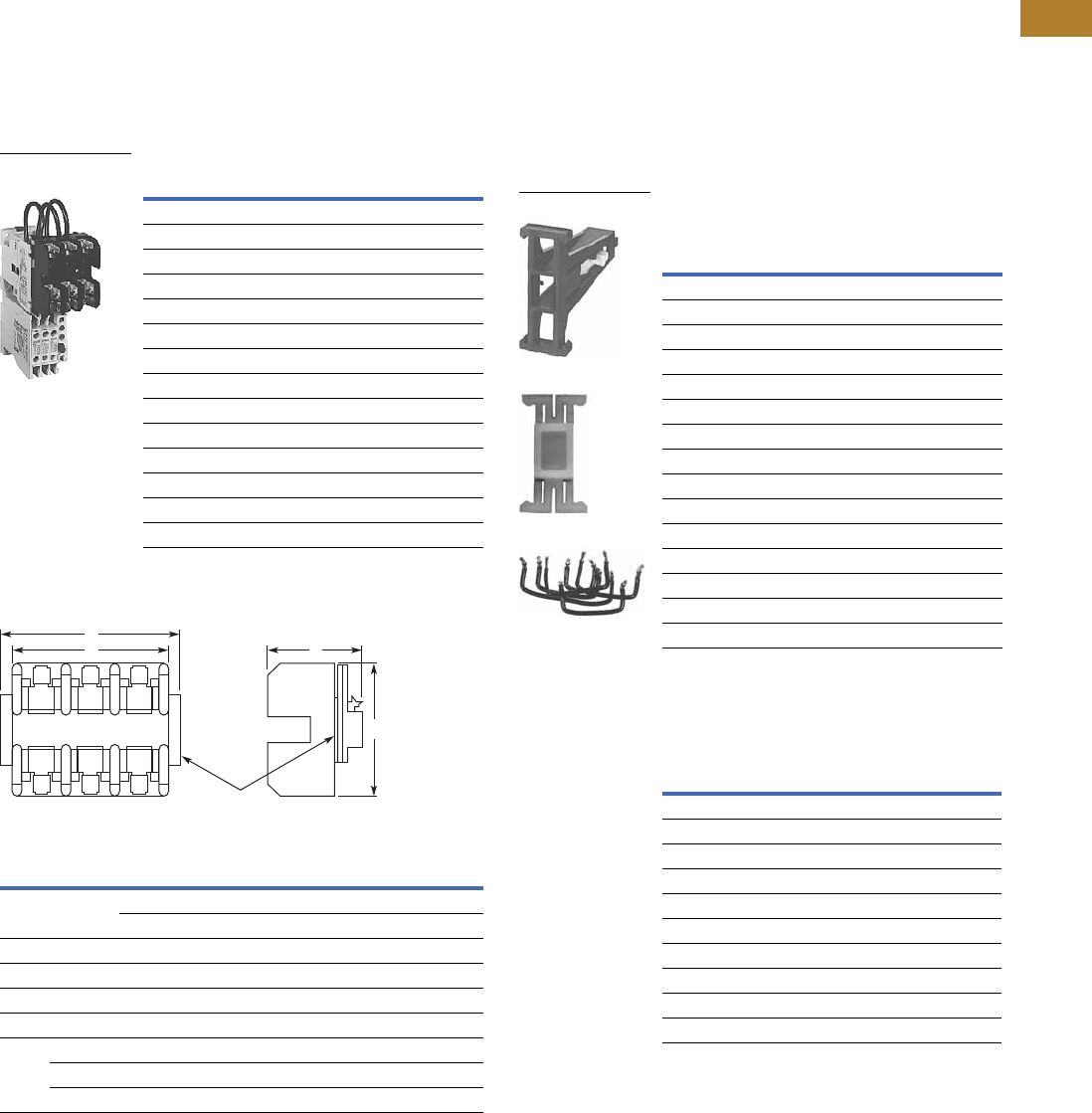
Mechanical Interlock and Reversing Kits
Mechanical interlocks and
reversing kits are designed
for field assembly of
reversing contactors or
starters from Freedom Series
components. The reversing
kits include a mechanical
interlock, stabilizer bar and
a pre-cut, trimmed and
formed wire set. Auxiliary
contacts, if required, must
be ordered separately. See
Pages V5-T2-25 and
V5-T2-26.
Mechanical Interlock Only 23
Reversing Kits (Horizontal Contactor
Mounting Only)
Notes
1Type M fuse block not approved for branch circuit protection.
2Without cross-wiring.
3For use with latest series product.
4Kit includes (2) NC auxiliary contacts.
Application
Catalog
Number
NEMA
Size IEC Size
Contactor
Mounting
00–2 A–K Horizontal C321KM60B
3 L–N Horizontal C321KM30
3 to 4 N to P Horizontal C321KM43
4 P–S Horizontal C321KM40
4 to 5 — Horizontal C321KM45
4 to 6 S to T/U Horizontal C321KM80
5 — Horizontal C321KM50
5 to 6 — Horizontal C321KM56
6 T and U Horizontal C321KM70
6 to 7 T/U to V–X Horizontal C321KM90
7 V, W and X Horizontal C321KM34
4 or 5 to 5 P–S to 5 Vertical C321KM55
5 to 6 — Vertical C321KM65
6 T and U Vertical C321KM66
6 to 7 T/U to V–X Vertical C321KM67
Application
Catalog
Number
NEMA
Size IEC Size
00 A–C C321KM60K14B
0D–FC321KM60K13B
1—C321KM60K15B
2G–KC321KM60K16B
3—C321KM60K17 4
— L and M C321KM60K21 4
—N C321KM60K18 4
4—C321KM60K19 4
5—C321KM60K20 4
—P–SC321KM60K44 4
C321KM60B
Part No. 23-7165
Wire Set
V5-T2-22 Volume 5—Motor Control and Protection CA08100006E—May 2016 www.eaton.com
2
2
2
2
2
2
2
2
2
2
2
2
2
2
2
2
2
2
2
2
2
2
2
2
2
2
2
2
2
2
2.1
NEMA Contactors and Starters
Freedom Series
Solid-State Timers
Solid-State ON DELAY Timer—Side Mounted on Freedom Series NEMA
00–2, IEC A–K and C25D, C25E and C25F Frame
This timer is designed to be
wired in series with the
load (typically a coil). When
the START button is pushed
(power applied to timer), the
ON DELAY timing function
starts. At the completion of
the set timing period, timer
and series wired load will
both be energized.
Mounted Timer Product Selection
Shorting Bar Kits
These kits provide phase-to-
phase power connections of
contactors for field assembly.
The kits include bus
connections and mounting
hardware. The shorting bars
connect all three phases of a
single contactor.
Shorting Bar Kits
Timing Range
Catalog
Number 123
0.1–1.0 seconds C320TDN1_
1–30 seconds C320TDN30_
30–300 seconds C320TDN300_
5–30 minutes C320TDN3000_ 4
Solid-State Timer
Description
Catalog
Number
NEMA Size 3, IEC Sizes L–N C321SB18
NEMA Size 4, IEC Sizes A–S C321SB19
NEMA Size 6, IEC Sizes T and U C321SB22
Pneumatic Timers—Top Mounted
Attachment mounts on top of
any NEMA Size 00–2 or IEC
Size A–K Freedom Series
starter or contactor (top
mounted auxiliary contacts
cannot be installed on device
when timer is used). Timer
unit has 1NO-1NC isolated
timed contacts—circuits in
each pole must be the same
polarity. Units are convertible
from OFF to ON DELAY or
vice-versa.
Pneumatic Timers
Maximum Ampere Ratings
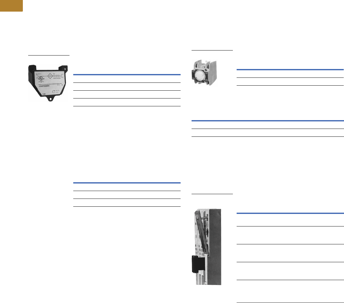
Locking Cover for Overload Relay—C306 Only
Snap-on transparent or
opaque plastic panel for
covering access port to the
overload relay trip setting
dial—helps prevent accidental
or unauthorized changes to
trip and reset setting.
Locking Cover for Overlay Relay
Notes
1Add operating voltage suffix to catalog number.
A = 120V, B = 240V, E = 208V
2Rated 0.5 ampere pilot duty—not to be used on larger contactors.
3Terminal connections are quick connects only. Two per side.
4240V operating voltage not available for C320TDN3000_.
Timing Range
Catalog
Number
0.1 to 30 seconds C320TP1
10 to 180 seconds C320TP2
Description
Vac
120 240 480 600
Make 30 15 7.5 6
Break 3 1.5 0.75 0.6
Pneumatic Timers
Description
Min. Ordering
Quantity (Std. Pkg.)
Catalog
Number
Clear cover, no
accessibility
50 C320PC3
Gray cover, no
accessibility, with
Auto only nib
50 C320PC4
Gray cover, no
accessibility, with
Manual only nib
50 C320PC5
Gray cover with FLA dial
accessibility, A, B, C, D
positions and Auto only nib
50 C320PC6
Gray cover with FLA dial
accessibility, A, B, C, D
positions and Manual
only nib
50 C320PC7
Locking Cover for
Overlay Relay
Volume 5—Motor Control and Protection CA08100006E—May 2016 www.eaton.com V5-T2-23
2
2
2
2
2
2
2
2
2
2
2
2
2
2
2
2
2
2
2
2
2
2
2
2
2
2
2
2
2
2
2.1
NEMA Contactors and Starters
Freedom Series
Identification Markers
IEC Sizes A–K, NEMA Sizes 00–2
Designed to snap on the face
of contactor for easy,
personalized identification of
individual devices. Includes
holder and labels.
Identification Markers
Control Circuit Fuse Block
These panel mounted
fuse holders, designed for
control circuit protection or
other similar low current
requirements, have extractor
type fuse caps. The Class CC
rejection type fuses (KTK-R)
used in these holders are
intended for use with
equipment designated as
being suitable for use on
systems having high available
fault currents. If branch
circuit protective device is
45A or greater, C320FBR
fuse kit may be required for
control circuit protection per
NEC 430-72.
Control Circuit Fuse Block
Dimensions
Approximate Dimensions in Inches (mm)
Description Catalog Number
Identification marker C320DL2
Type Max. Amperes Catalog Number
Fuse holder only 15 C320FB 1
30 C320FBR 2
Control Circuit
Fuse Block
0.97
(24.6)
1.25 (31.8)
1.88 (47.8)
1.19
(30.2)
0.88
(22.4)
2.06
(52.3)
Fuse
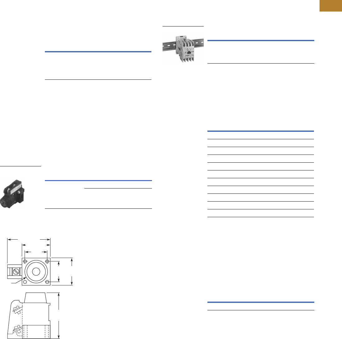
DIN Rail Mounting Channel—35 mm
Designed for DIN rail
mounting of IEC style
contactors and starters.
DIN Rail
Finger Protection Shields
Snap-on shields for both
contactors and starters
provide IEC Type IP20 finger
protection. Prevents
accidental contact with
line/load terminals.
Finger Protection Shields
Adapter to DIN Rail Mount
NEMA 1–2 and IEC G–K Contactors
Designed to allow DIN rail
mounting of NEMA 1–2 and
IEC G–K contactors. Includes
all hardware required to
convert contactors from
panel mounting to 35 mm
DIN rail mounting.
Adapter to DIN Rail Mount
Notes
1A fuse is not supplied, but holder will accept a Bussman Type KTK or KTK-R
(13/32 in x 1-1/2 in) fuse, 600V maximum.
2Includes a 5A, 600V KTK-R fuse.
Description Catalog Number
1 meter length MC382MA1
DIN Rail
Application Catalog Number
NEMA Size 00, IEC Sizes A–C C320LS1
NEMA Size 0, IEC Sizes D–F C320LS2
NEMA Sizes 1–2, IEC Sizes G–K
Contactors C320LS3
Reversing contactors C320LS4
NEMA Size 1
Starters C320LS5
Reversing starters C320LS6
NEMA Size 2, IEC Sizes G–K
Starters C320LS7
Reversing starters C320LS8
Catalog Number
C320DN65
V5-T2-24 Volume 5—Motor Control and Protection CA08100006E—May 2016 www.eaton.com
2
2
2
2
2
2
2
2
2
2
2
2
2
2
2
2
2
2
2
2
2
2
2
2
2
2
2
2
2
2
2.1
NEMA Contactors and Starters
Freedom Series
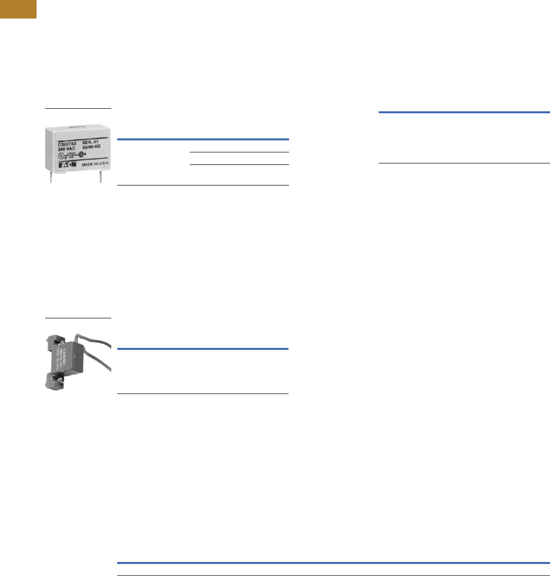
Transient Suppressor Kits
NEMA Sizes 00–2, IEC Sizes A–K
These kits limit high voltage
transients produced in the
control circuit when power is
removed from the contactor
or starter coil. There are three
separate suppressors for use
on 24–120V, 208–240V or
277–480V coils respectively.
These devices mount directly
to the coil terminals of
Freedom Series contactors
or starters NEMA Sizes 00–2,
IEC Sizes A–K and lighting
contactors 10–60A.
Reversing devices will
require two.
NEMA Sizes 00–2, IEC Sizes A–K
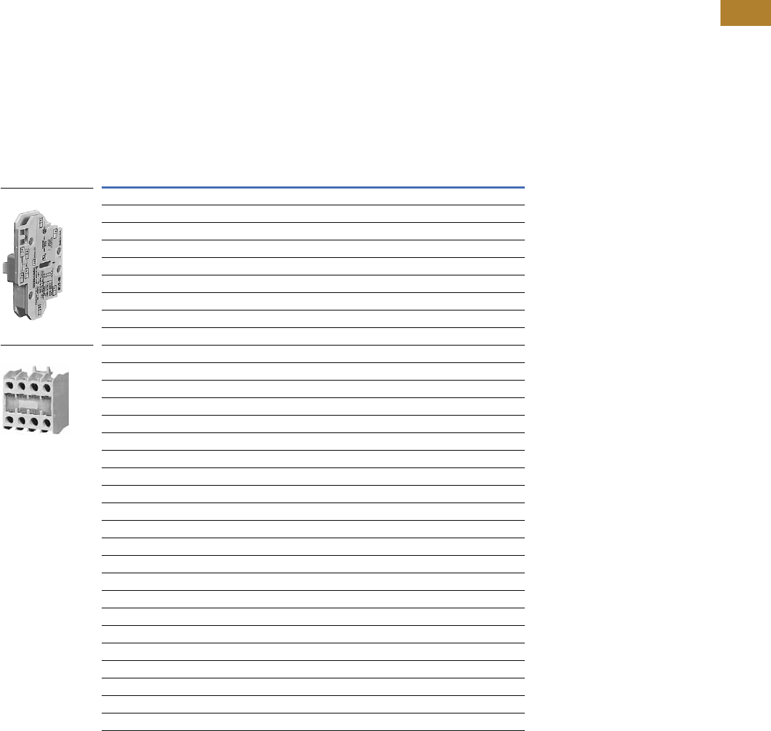
NEMA Sizes 3–5, IEC Sizes L–S
This device mounts on top
of any side mounted auxiliary
contact on Freedom Series
NEMA Sizes 3–5, IEC Sizes
L–S and lighting contactors
100–300A. It connects across
coil terminals on any 120V
contactor or starter magnet
coil (reversing starters or
contactors require 2).
Limits high voltage
transients produced in
the circuit when power is
removed from the coil.
NEMA Sizes 3–5, IEC Sizes L–S
Add-On Power Pole Kit 2
NEMA Sizes 00–0, IEC Sizes A–F
This device mounts on the
side of Freedom NEMA Size
00–0 and IEC Sizes A–F
contactors. One unit can be
mounted on each side and
carries UL, cUL and IEC
ratings. The device is rated
for resistive, inductive and
lighting applications.
NEMA Sizes 00–0, IEC Sizes A–F
Notes
1Suppressor is compatible with coil voltages/ranges as shown, both 50 and 60 Hz.
2Power pole kits sold for replacement purposes only. For new applications, order the correct
four-pole and five-pole contactor catalog numbers.
Description
Coil
Voltage 1
Catalog
Number
Transient suppressor 24/120V C320TS1
208/240V C320TS2
277/480V C320TS3
C320TS2
Description
Coil
Voltage
Catalog
Number
Transient suppressor 120V C320AS1
C320AS1
UL Ampere Rating IEC 947 Ampere Rating
1NO Power Pole
Catalog
Number
Inductive
600V
Resistive
600V
Horsepower Single-Phase Locked
Rotor
240V
Lighting Ballast
Tungsten
480V
AC-1
600V
AC-3
600V
AC-5a
AC-5b
480V115V 230V
15 20 1/2 2 96 20 20 12 18 C320PPD10
Adhesive Dust Cover
NEMA Sizes 00–2, IEC Sizes A–K
These adhesive stickers
come 25 to a package and
provide extra protection from
contaminants when applied
to the sides of Freedom
NEMA Sizes 00–2 and IEC
Sizes A–K. Adhesive covers
are easily applied to side
opening where auxiliaries
are not installed and provide
extra protection from metal
filings and other debris.
NEMA Sizes 00–2, IEC Sizes A–K
Description Catalog Number
25 to a package C320DSTCVR
Volume 5—Motor Control and Protection CA08100006E—May 2016 www.eaton.com V5-T2-25
2
2
2
2
2
2
2
2
2
2
2
2
2
2
2
2
2
2
2
2
2
2
2
2
2
2
2
2
2
2
2.1
NEMA Contactors and Starters
Freedom Series
Auxiliary Contacts
Contact Configuration Code
This two-digit code is found
on the auxiliary contact to
assist in identifying the
specific contact configuration.
The first digit indicates the
quantity of NO contacts and
the second indicates the
quantity of NC contacts.
NEMA Sizes 00–2—IEC Sizes A–K
The auxiliary contacts listed
on this page are designed
for installation on Freedom
Series starters and
contactors. Snap-on
design facilitates quick,
easy installation.
These bifurcated design
contact blocks, featuring
silver cadmium alloy
contacts, are well suited
for use in very low energy
(logic level) circuits.
NEMA Sizes 00–2—IEC Sizes A–K 1
Notes
1 NCI = Normally Closed early opening designed for use in reversing applications. EC = Early Closing. LO = Late Opening.
2 For reference only—not part of catalog number.
Description
Contact
Configuration Code 2Catalog Number
Side Mounted
1NO 10 C320KGS1
1NC 01 C320KGS2
1NO-1NC 11 C320KGS3
2NO 20 C320KGS4
2NC 02 C320KGS5
1NO-1NCI N/A C320KGS6
1NO (EC)-1NC (LO) N/A C320KGS7
1NCI N/A C320KGS8
Top Mounted
1NO 10 C320KGT1
1NC 01 C320KGT2
1NO-1NC 11 C320KGT3
2NO 20 C320KGT4
2NC 02 C320KGT5
1NO-1NCI N/A C320KGT6
1NO (EC)-1NC (LO) N/A C320KGT7
1NCI N/A C320KGT8
3NO 30 C320KGT9
2NO-1NC 21 C320KGT10
1NO-2NC 12 C320KGT11
3NC 03 C320KGT12
4NO 40 C320KGT13
3NO-1NC 31 C320KGT14
2NO-2NC 22 C320KGT15
1NO-3NC 13 C320KGT16
4NC 04 C320KGT17
3NO-1NCI N/A C320KGT18
2NO-1NCI-1NC N/A C320KGT19
2NO-1NO (EC)-1NC (LO) N/A C320KGT20
1NO-1NC-1NO (EC)-1NC (LO) N/A C320KGT21
Side Mounted
Top Mounted
V5-T2-26 Volume 5—Motor Control and Protection CA08100006E—May 2016 www.eaton.com
2
2
2
2
2
2
2
2
2
2
2
2
2
2
2
2
2
2
2
2
2
2
2
2
2
2
2
2
2
2
2.1
NEMA Contactors and Starters
Freedom Series
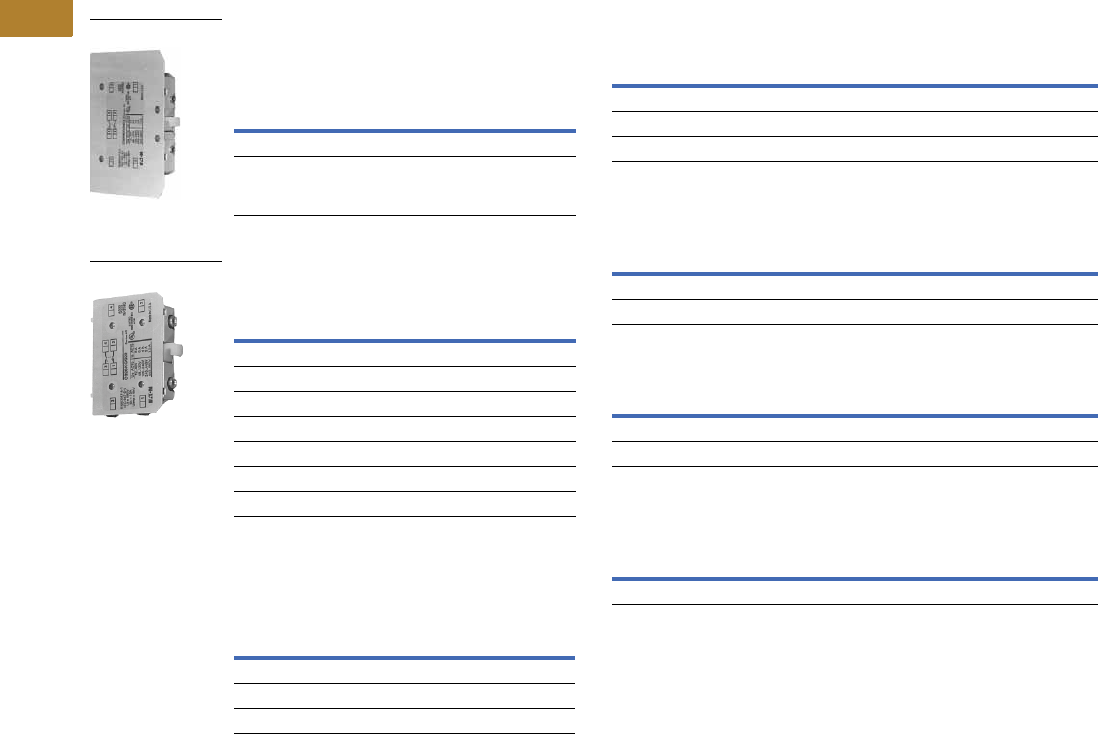
NEMA Sizes 3–8—IEC Sizes L–Z
Base Auxiliary Contacts—
NEMA Sizes 3–5, IEC Sizes L–S
Auxiliary Contacts—NEMA Sizes 3–5,
IEC Sizes L–S
Auxiliary Contacts—NEMA Sizes 6–8,
IEC Sizes T–Z
Circuit
Contact
Configuration
Code 1
NEMA Size 3
IEC Sizes L –N
Catalog
Number
NEMA Sizes 4–5
IEC Sizes P–S
Catalog
Number
NO 10 C320KGS31 C320KGS41
NO-NC 11 C320KGS32 C320KGS42
Circuit
Contact
Configuration Code 1
Catalog
Number
NO 10 C320KGS20
NC 01 C320KGS21
NO-NC 211 C320KGS22
Sealed Logic Level
NO 10 C320KGS20L
NC 01 C320KGS21L
NO-NC 311 C320KGS22L
Circuit
Contact
Configuration
Code 1Size
Catalog
Number
NO-NC 11 NEMA 8, IEC Z C320KA5
2NO-2NC 22 NEMA 6–7 C320KA6
2NO-2NC 22 IEC T–X C320KA8
C320KGS42
C320KGS22
Auxiliary Contact Ratings (Amperes)
Ratings—NEMA A600
Ratings—NEMA P300
Ratings—Logic Level
Ratings C320KGS20L, C320KGS21L, C320KGS22L
Notes
1For reference only—not part of catalog number.
2NO-NC occupies two position—L2 and L3, or R2 and R3. See figure on Page V5-T2-27.
3Form C contacts.
Current
AC Volts
120V 240V 480V 600V
Make 60 30 15 12
Break 631.51
Continuous 10 10 10 10
Continuous Thermal Rating: 5A
DC Volts Make/Break Amperes
125 1.10
250 0.55
Minimum Ratings for Logic Level and Hostile Atmosphere Application
Minimum Amperes 20 mA
Minimum Volts 24 Vac/Vdc
DC-12 AC-12
UeIeUeIe
80 0.1 250 0.1
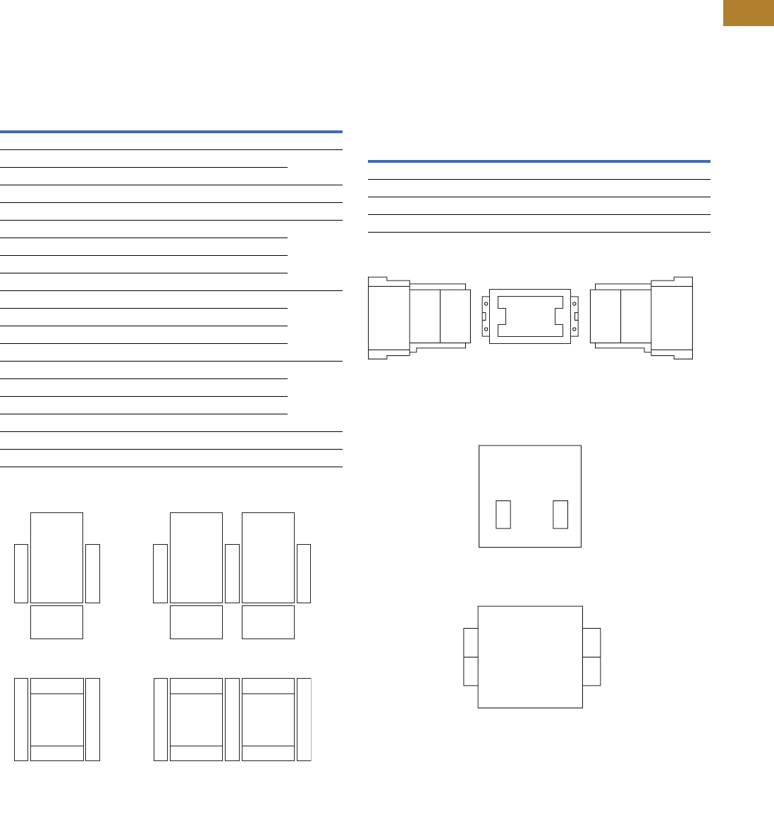
Volume 5—Motor Control and Protection CA08100006E—May 2016 www.eaton.com V5-T2-27
2
2
2
2
2
2
2
2
2
2
2
2
2
2
2
2
2
2
2
2
2
2
2
2
2
2
2
2
2
2
2.1
NEMA Contactors and Starters
Freedom Series
Auxiliary Contact Location
NEMA Sizes 00–2, IEC Sizes A–K
The sketches below illustrate
the maximum number of
auxiliary contacts that can be
assembled to a contactor or
starter and their locations.
Auxiliary Contacts
Auxiliary Contact Location
Size Poles
Available Mounting Positions 12 Catalog
NumberOpen Type Enclosed
A–K 3 T1, L1 L1 AE16
00 3 T1, L1, R1 L1 AN16
0–2 3 T1, L1 L1
A–K 3 L1, R1 L1, R1 AE56
00–2 3 T1, T2 — AN56
A–C 2–4 T1, L1, R1 L1, R1 CE15
D–K 3 T1, L1 L1
G–J 4 T1, R1 —
G–J 5 T1 —
00 2–4 T1, L1, R1 L1 CN15
0–2 2–3 T1, L1 L1
1, 2 4 T1, L1 —
1, 2 5 T1, L1 —
10A 2–4 T1, L1, R1 L1 CN35
20–60A 2–3 T1, L1 L1
60A 4 T1, L1 —
60A 5 T1, L1 —
A–K 3 L1, R1 L1, R1 CE55
00–2 3 T1, T2 — CN55
L1
T1 T2
R1
L1 T1 T2 R1
L1
T1
Top View
Front View
L1 T1 R1
Front View
Reversing
Contactors and Starters
Non-Reversing
Contactors and Starters
Top View
R1
NEMA Sizes 3–8, IEC Sizes L–Z
The sketches below illustrate
the maximum number of
auxiliary contacts that can be
assembled to a contactor and
their locations.
Note: A base auxiliary contact
must be added in position R1
before additional auxiliary
contacts can be mounted on
NEMA Size 3 and IEC Sizes L–N,
or in L1 on NEMA Sizes 4–5 and
IEC Sizes P–S.
Mounting Positions
Auxiliary Contact Location
Notes
1Available positions on contactors or starters other than what is factory installed.
2When a pneumatic timer is mounted on contactor, only side mounted auxiliary contact
positions are available. The solid-state timer, when added, takes up side mounted auxiliary
contact position.
Size Available Mounting Positions 1
NEMA Size 3, IEC Sizes L–N R2, R3, L1, L2, L3
NEMA Sizes 4–5, IEC Sizes P–S L2, L3, R1, R2, R3
NEMA Sizes 6–7, IEC Sizes T–X R1
NEMA Size 8, IEC Size Z L2, R2
NEMA Sizes 6–7
IEC Sizes T, U, V, W and X
NEMA Sizes 3–5
IEC Sizes L–S
NEMA Size 8
IEC Size Z
L1 R1
L1
Front
of Contactor
Left Side
of Contactor
L2
Aux.
Cont.
L3
Aux.
Cont.
R2
Aux.
Cont.
R3
Aux.
Cont.
L1
Base
Aux.
Cont.
R1
Base
Aux.
Cont.
Rear
Rear
Right Side
of Contactor
R1
L2 R2

V5-T2-28 Volume 5—Motor Control and Protection CA08100006E—May 2016 www.eaton.com
2
2
2
2
2
2
2
2
2
2
2
2
2
2
2
2
2
2
2
2
2
2
2
2
2
2
2
2
2
2
2.1
NEMA Contactors and Starters
Freedom Series
DC Magnet Coils
When Ordering Specify
Conversion Kit for
Field Assembly
●Catalog number
Factory Installed DC Coil
●For factory installed DC
magnet coil on AC
contactors or non-
combination starters (open
type only), substitute the
code suffix from the table
on this page for the
magnet coil identifier in
the device catalog number.
EXAMPLE: For Size 0 AC
contactor with a 24 Vdc
coil, change AN16BN0AC
to AN16BN0T1C
Application
●Connect for separate
control
●Not for use with cover
control switch operators
●Use twin break, heavy-
duty pilot devices
●Designed for +10%, –20%
rated voltage, continuous
duty operation
Non-Reversing Kit Consists of:
●One encapsulated DC
magnet coil
●One NCI or NO/NCI side
mounted auxiliary contact
Note: These kits are supplied
with a NO/NCI side mounted
auxiliary contact in place of the
NCI contact.
●Two blue colored
connection wires
●One instruction publication
Operation
See next page for operation
details.
DC Magnet Coils
Notes
1These kits are supplied with a NO/NCI side mounted auxiliary contact in place of the NCI contact.
2Kit does not include mechanical interlock or crossover wiring. Two NO/NCI top mounted auxiliary contacts are supplied for electrical interlocking.
3Factory installed DC coils on NEMA contactors and starters include a NO/NC top mounted auxiliary contact on each contactor for electrical
interlocking. On IEC contactors and starters, a NC top mounted auxiliary contact is supplied on each contactor for electrical interlocking.
4Available factory assembled only.
Contactor or
Starter Size
Conversion Data
Complete Conversion Kit
Factory
Installed
Volts
Magnet Coil
NCI
InterlockNEMA IEC
Coil
Number
Amps
P.U./Seal
Watts
P.U./Seal
Catalog
Number
Ship Wt.
Lbs (kg)
Code
Suffix
Non-Reversing—Kit Includes NCI Side Mounted Auxiliary Contact
00 and 0
CN35–A, B, D
D15 Relays
A–F 12 9-2988-11 6.4/0.28 76.8/3.36 C320KGD1 C335KD3R1 1.0 (0.5) R1
24 9-2988-12 3.2/0.14 76.8/3.36 C320KGD1 C335KD3T1 T1
48 9-2988-13 1.6/0.07 76.8/3.36 C320KGD1 C335KD3W1 W1
120 9-2988-14 0.64/0.028 76.8/3.36 C320KGD1 C335KD3A1 A1
1
00 and 0
CN35–A, B, D
D15 Relays
A–F 12 9-2988-11 6.4/0.28 76.8/3.36 C320KGD2 1C335KD3R4 1.0 (0.5) R4
24 9-2988-12 3.2/0.14 76.8/3.36 C320KGD2 1C335KD3T4 T4
48 9-2988-13 1.6/0.07 76.8/3.36 C320KGD2 1C335KD3W4 W4
120 9-2988-14 0.64/0.028 76.8/3.36 C320KGD2 1C335KD3A4 A4
1 and 2
CN35–G
G–K 12 9-2990-1 15.4/0.42 185/4.98 C320KGD5 C335KD4R4 1.0 (0.5) R4
24 9-2990-2 7.7/0.021 185/4.96 C320KGD5 C335KD4T4 T4
48 9-2990-3 3.9/0.11 185/5.04 C320KGD5 C335KD4W4 W4
120 9-2990-4 1.5/0.041 185/4.87 C320KGD5 C335KD4A4 A4
3
CN35–K
L–N 12 9-3002-1 24/0.40 293/4.84 C320KGD3 C335KD5R1 2.0 (0.9) R1
24 9-3002-2 12/0.20 288/4.75 C320KGD3 C335KD5T1 T1
48 9-3002-3 6.1/0.097 295/4.67 C320KGD3 C335KD5W1 W1
120 9-3002-4 2.5/0.038 298/4.57 C320KGD3 C335KD5A1 A1
4 and 5
CN35–N, S
P–S 24 9-2026-4 18/0.22 400/5.3 C320KGD3 C335KA3T1 2.5 (1.1) T1B
48 9-2026-3 9/0.11 400/5.2 C320KGD3 C335KA3W1 W1B
120 9-2026-2 3.3/0.05 450/5.4 C320KGD3 C335KA3A1 A1B
240 9-2026-1 1.7/0.02 440/4.9 C320KGD3 C335KA3B1 B1B
Reversing
00 and 0
CN35–A, B, D
D15 relays
A–F 12 (2) 9-2988-1 6.4/0.28 76.8/3.36 (2) C320KGD1 C335RD3R1 21.0 (0.5) R1 3
24 (2) 9-2988-2 3.2/0.14 76.8/3.36 (2) C320KGD1 C335RD3T1 2T1 3
48 (2) 9-2988-3 1.6/0.07 76.8/3.36 (2) C320KGD1 C335RD3W1 2W1 3
120 (2) 9-2988-4 0.64/0.028 76.8/3.36 (2) C320KGD1 C335RD3A1 2A1 3
1 and 2
CN35–G
G–K 12 (2) 9-2990-1 15.4/0.42 185/4.98 (2) C320KGD3 4—R1 3
24 (2) 9-2990-2 7.7/0.21 185/4.96 (2) C320KGD3 4T1 3
48 (2) 9-2990-3 3.9/0.11 185/5.04 (2) C320KGD3 4W1 3
120 (2) 9-2990-4 1.5/0.041 185/4.87 (2) C320KGD3 4A1 3

Volume 5—Motor Control and Protection CA08100006E—May 2016 www.eaton.com V5-T2-29
2
2
2
2
2
2
2
2
2
2
2
2
2
2
2
2
2
2
2
2
2
2
2
2
2
2
2
2
2
2
2.1
NEMA Contactors and Starters
Freedom Series
Operation
These DC coil kits have
separate pick-up and seal
windings. A special (side
mounted) early-break NCI
auxiliary contact is used to
either disconnect the pick-up
winding or insert the seal
winding in series with the
pick-up winding, depending
on the frame size of the
contactor. DC coil kits come
in two styles, a suffix 1 and a
suffix 4. Suffix 1 contains only
the special (side mounted)
early break NCI auxiliary
contact. Suffix 4 contains
a NO contact in the same
package as the special
(side mounted) early-break
NCI auxiliary contact.
Note: For NEMA Sizes 00 and 0
and IEC Sizes A–F, contactors
may utilize either suffix 1 or 4 DC
coil kits; starters may utilize suffix
4 DC coil kits only. For NEMA
Sizes 1 and 2 and IEC Sizes G–K,
both contactors and starters may
utilize a suffix 4 DC coil kit only.
On the above sizes only,
when the special auxiliary
package is mounted on the
side of a contactor or starter,
no standard auxiliary contact
may be mounted on the
same side.
Note: For NEMA Sizes 3–5 and
IEC Sizes L–S, special coil NCI
clearing contact is an add-on
auxiliary (must mount on a base
mount auxiliary contact; normally
a 1NO). This arrangement will
normally account for two of the
three contact positions on the
side of each contactor or starter.
Elementary Diagrams
Auxiliary
Contact
Important
Incoming DC must be connected
between A1 and Top A2 T erminal.
A1 A2
A1 A2 T op
A2 Bottom
3
NCI
NO a
a
3
2
3
NCI
NO
2
Hold Pick-Up
Hold
Pick-Up
DC Coil Elementary Diagram
for NEMA Sizes 1–3 and IEC Sizes G–N
Contactors and Starters
DC Coil Elementary Diagram
for NEMA Sizes 00, 0, 4 and 5
and IEC Sizes A–F and P–S
Contactors and Starters
Competitive Mounting Plates
The C321 adapter plates
permit direct replacement of
competitive starters with
Freedom Series starters
without drilling and tapping
new mounting holes. Allen-
Bradley 509, Eaton’s A10
(adapter plate not required for
replacing A10 Starter Sizes 1,
4 and 5), Furnas 14, ESP100,
General Electric CR206,
CR306, Siemens SXL,
Square D 8536,
Westinghouse A200, B200.
Competitive Mounting Plates
Note
11NO available in Suffix 4 kits only.
2Handling number only—does not appear on product. The handling number is stamped
on the carton label only.
Freedom
NEMA Size
Index Number 2
Catalog Number
00, 0 C321CMP0
1C321CMP1
2C321CMP2
3C321CMP3
4C321CMP4
5C321CMP5
C321CMP1

V5-T2-30 Volume 5—Motor Control and Protection CA08100006E—May 2016 www.eaton.com
2
2
2
2
2
2
2
2
2
2
2
2
2
2
2
2
2
2
2
2
2
2
2
2
2
2
2
2
2
2
2.1
NEMA Contactors and Starters
Freedom Series
Special Modifications
For Catalog Numbers AN16, AN56, CE15, CN15, CN35, CN55
Renewal Parts
For a complete listing of parts, refer to the Renewal Parts Publication Number referenced below.
For Catalog Numbers AN16, AN30, AN40, AN56, AN70, AN80, AN800, CN15,
CN35 4 and CN55 Contactors and Starters (Size 00, 0)
Notes
1These modifications are generally available in kit form at lower cost. See specific product sections for kit listings.
2Terminal extensions provided on Size 2 and up; not required for Size 1.
3The T16 modifications are only available on C306 overloads and the following three-pole devices: CN15, CN55, AN16, AN56 and AN700 (separate winding only).
The 45 mm and 65 mm frames (NEMA Size 0–2) reversing devices (CN55B, CN55D, CN55G, AN56B, AN56D, AN56G, AN700 and AN700G) with the T16 modification
are supplied without crossover wires.
4CN35A = Size 00, CN35B and CN35D = Size 0, CN35G = Size 2, CN35K = Size 3, CN35N = Size 4, and CN35S = Size 5.
5Replace with complete contactor.
Addition or Special Feature
Starter Size —NEMA
0001/—2345678
Control Circuit
Extra auxiliary circuit, factory installed NO or NC—each contact 12 Consult sales office for pricing adders.
Transient suppressor 1Consult sales office for pricing adders.
Power Circuit
Contactor/starter for ring lug capability—add Mod Code T16 to catalog number 3
(Power terminals only, control terminals as standard)
Standalone overload relays can not accept ring lugs on line side
Consult sales office for pricing adders.
Factory Installed Dust Covers
Factory installed C320DSTCVR—add Mod Code -53 to catalog number 1NA NA NA NA NA NA
Description
NEMA Size 00 NEMA Size 0
Series B1 Series C1 Series B1 Series C1
Part No.Part No.Part No.Part No.
Renewal Parts Publication Number 22177 22177 22177 22177
Contact Kits
Two-pole 5555
Three-pole 5555
Four-pole 5555
Five-pole 5555
Magnet Coils Coil Suffix
120V 60 Hz or 110V 50 Hz A 9-2875-1 9-2875-1 9-2876-1 9-2876-1
240V 60 Hz or 220V 50 Hz B 9-2875-2 9-2875-2 9-2876-2 9-2876-2
480V 60 Hz or 440V 50 Hz C 9-2875-3 9-2875-3 9-2876-3 9-2876-3
600V 60 Hz or 550V 50 Hz D 9-2875-4 9-2875-4 9-2876-4 9-2876-4
208V 60 Hz E 9-2875-5 9-2875-5 9-2876-5 9-2876-5
277V 60 Hz H 9-2875-12 9-2875-12 9-2876-12 9-2876-12
208/240V 60 Hz J 9-2875-37 9-2875-37 9-2876-37 9-2876-37
240V 50 Hz K 9-2875-11 9-2875-11 9-2876-11 9-2876-11
380–415V 50 Hz L 9-2875-6 9-2875-6 9-2876-6 9-2876-6
380V 50 Hz L — — — —
415V 50 Hz M — — — —
550V 50 Hz N — — — —
24V 60 Hz–24V 50 Hz T 9-2875-36 9-2875-36 9-2876-36 9-2876-36
24V 60 Hz T — — — —
24V 50 Hz U 9-2875-36 9-2875-36 9-2876-36 9-2876-36
32V 50 Hz V 9-2875-16 9-2875-16 9-2876-16 9-2876-16
48V 60 Hz W 9-2875-8 9-2875-8 9-2876-8 9-2876-8
48V 50 Hz Y 9-2875-9 9-2875-9 9-2876-9 9-2876-9
Magnet Frame Armature
Lower magnet frame 5555
Upper magnet frame 5555

Volume 5—Motor Control and Protection CA08100006E—May 2016 www.eaton.com V5-T2-31
2
2
2
2
2
2
2
2
2
2
2
2
2
2
2
2
2
2
2
2
2
2
2
2
2
2
2
2
2
2
2.1
NEMA Contactors and Starters
Freedom Series
For Catalog Numbers AN16, AN30, AN40, AN56, AN70, AN80, AN800, CN15, CN35 1
and CN55 Contactors and Starters (Size 1, 2)
Note
1CN35A = Size 00, CN35B and CN35D = Size 0, CN35G = Size 2, CN35K = Size 3, CN35N = Size 4, and CN35S = Size 5.
Description
NEMA Size 1 NEMA Size 2
NEMA Size 3Series A1 Series B1 Series A1 Series B1
Part No. Part No. Part No. Part No. Part No.
Renewal Parts Publication Number 20861 22177 20861 22177 20426
Contact Kits
Two-pole 6-65 6-65 6-65-7 6-65-7 6-43-5
Three-pole 6-65-2 6-65-2 6-65-8 6-65-8 6-43-6
Four-pole 6-65-9 6-65-9 6-65-15 6-65-15 —
Five-pole 6-65-10 6-65-10 6-65-16 6-65-16 —
Magnet Coils Coil Suffix
120V 60 Hz or 110V 50 Hz A 9-3285-1 9-3285-1 9-3285-1 9-3285-1 9-2756-1 KIT
240V 60 Hz or 220V 50 Hz B 9-2703-2 KIT 9-2703-2 KIT 9-2703-2 KIT 9-2703-2 KIT 9-2756-2 KIT
480V 60 Hz or 440V 50 Hz C 9-2703-3 KIT 9-2703-3 KIT 9-2703-3 KIT 9-2703-3 KIT 9-2756-3 KIT
600V 60 Hz or 550V 50 Hz D 9-2703-4 KIT 9-2703-4 KIT 9-2703-4 KIT 9-2703-4 KIT 9-2756-4 KIT
208V 60 Hz E 9-2703-9 KIT 9-2703-9 KIT 9-2703-9 KIT 9-2703-9 KIT 9-2756-5 KIT
277V 60 Hz H 9-2703-7 KIT 9-2703-7 KIT 9-2703-7 KIT 9-2703-7 KIT 9-2756-9 KIT
208/240V 60 Hz J—————
240V 50 Hz K 9-2703-14 KIT 9-2703-14 KIT 9-2703-14 KIT 9-2703-14 KIT 9-2756-13 KIT
380–415V 50 Hz L 9-2703-8 KIT 9-2703-8 KIT 9-2703-8 KIT 9-2703-8 KIT —
380V 50 Hz L — — — — 9-2756-12 KIT
415V 50 Hz M — — — — 9-2756-8 KIT
550V 50 Hz N — — — — 9-2756-14 KIT
24V 60 Hz–24V 50 Hz T—————
24V 60 Hz T 9-2703-6 KIT 9-2703-6 KIT 9-2703-6 KIT 9-2703-6 KIT 9-2756-6 KIT
24V 50 Hz U 9-2703-12 KIT 9-2703-12 KIT 9-2703-12 KIT 9-2703-12 KIT 9-2756-11 KIT
32V 50 Hz V 9-2703-10 KIT 9-2703-10 KIT 9-2703-10 KIT 9-2703-10 KIT 9-2756-10 KIT
48V 60 Hz W 9-2703-11 KIT 9-2703-11 KIT 9-2703-11 KIT 9-2703-11 KIT 9-2756-15 KIT
48V 50 Hz Y 9-2703-13 KIT 9-2703-13 KIT 9-2703-13 KIT 9-2703-13 KIT 9-2756-7 KIT
Magnet Frame Armature
Lower magnet frame 17-18200 17-18200 17-18200 17-18200 KIT 17-8955-2 KIT
Upper magnet frame 48-1936 48-1936 48-1936 48-1936 KIT 48-1902 KIT

V5-T2-32 Volume 5—Motor Control and Protection CA08100006E—May 2016 www.eaton.com
2
2
2
2
2
2
2
2
2
2
2
2
2
2
2
2
2
2
2
2
2
2
2
2
2
2
2
2
2
2
2.1
NEMA Contactors and Starters
Freedom Series
For a complete listing of parts, refer to the Renewal Parts Publication Number referenced below.
For Catalog Numbers AN16, AN30, AN40, AN56, AN70, AN80, AN800, CN15, CN35 1 and CN55
Contactors and Starters (Size 4, 5, 6)
Feeder Group Renewal 3
Notes
1CN35A = Size 00, CN35B and CN35D = Size 0, CN35G = Size 2, CN35K = Size 3, CN35N = Size 4, and CN35S = Size 5.
2Consult factory.
3Voltage ratings of the main coils must match those of the feeder group for proper operation of the starter/contactor.
Description
NEMA Size 4 NEMA Size 5 NEMA Size 6
Series A1 Series B1 Series A1 Series B1
Contactor and Starter
Series A1, Starter Series B1
Contactor and Starter
Series B1, Starter Series C1
Part No. Part No. Part No. Part No. Part No. Part No.
Renewal Parts Publication Number 20428 20428 20429 20429 20146 23349
Contact Kits
Two-pole 6-44 6-26 6-45 6-45 6-601-2 —
Three-pole 6-44-2 6-26-2 6-45-2 6-45-2 6-601 6-648
Magnet Coils Coil Suffix
120V 60 Hz or 110V 50 Hz A 9-1891-1 KIT 9-1891-1 KIT 9-1891-1 KIT 9-1891-1 KIT 9-2698 9-3006
240V 60 Hz or 220V 50 Hz B 9-1891-2 KIT 9-1891-2 KIT 9-1891-2 KIT 9-1891-2 KIT 9-2698-2 9-3006-2
480V 60 Hz or 440V 50 Hz C 9-1891-3 KIT 9-1891-3 KIT 9-1891-3 KIT 9-1891-3 KIT 9-2698-3 9-3006-3
600V 60 Hz or 550V 50 Hz D 9-1891-4 KIT 9-1891-4 KIT 9-1891-4 KIT 9-1891-4 KIT 9-2698-4 9-3006-4
208V 60 Hz E 9-1891-13 KIT 9-1891-13 KIT 9-1891-13 KIT 9-1891-13 KIT 9-2698-5 —
277V 60 Hz H 9-1891-26 KIT 9-1891-26 KIT 9-1891-26 KIT 9-1891-26 KIT — —
208/240V 60 Hz J————— —
240V 50 Hz K 9-1891-20 KIT 9-1891-20 KIT 9-1891-20 KIT 9-1891-20 KIT — —
380–415V 50 Hz L — — — — 9-2698-6 9-3006-7
380V 50 Hz L 9-1891-14 KIT 9-1891-14 KIT 9-1891-14 KIT 9-1891-14 KIT — —
415V 50 Hz M 9-1891-21 KIT 9-1891-21 KIT 9-1891-21 KIT 9-1891-21 KIT — —
550V 50 Hz N 9-1891-8 KIT 9-1891-8 KIT 9-1891-8 KIT 9-1891-8 KIT — —
24V 60 Hz–24V 50 Hz T — — — — — 9-3006-8
24V 60 Hz T 9-1891-15 KIT 9-1891-15 KIT 9-1891-15 KIT 9-1891-15 KIT — —
24V 50 Hz U 9-1891-16 KIT 9-1891-16 KIT 9-1891-16 KIT 9-1891-16 KIT — —
48V 60 Hz W — — — — 9-2698-8 9-3006-9
48V 50 Hz Y 9-1891-18 KIT 9-1891-18 KIT 9-1891-18 KIT 9-1891-18 KIT — —
Overload Relays
For replacement on existing starters three-pole—ambient
compensated bimetallic
10-6530-4 10-6530-4 C306DN3B C306DN3B C306DN3B C306DN3B
Current Transformer — — 42-3564 42-3564 42-3598 42-3598
Magnet Frame Armature 2
Lower Magnet Frame 48-1030-2 48-1030-2 48-1030-2 48-1030-2 — —
Upper Magnet Frame 48-1029-4 48-1029-4 48-1029-4 48-1029-4 — —
Volts Hertz
NEMA Size 4 NEMA Size 5 NEMA Size 6
Series A1 Series B1 Series A1 Series B1
Contactor and Starter
Series A1, Starter Series B1
Contactor and Starter
Series B1, Starter Series C1
110–120 50/60 — — — — 9-2705 9-3007
220–240 50/60 — — — — 9-2705-2 9-3007-2
440–480 50/60 — — — — 9-2705-3 9-3007-3
550–600 50/60 — — — — 9-2705-4 9-3007-4
208 50/60 — — — — 9-2705-5 9-3007-5
380–415 50/60 — — — — 9-2705-6 9-3007-7
48–52 50/60 — — — — 9-2705-8 9-3007-9
24 50/60 — — — — 9-2705-9 9-3007-8

Volume 5—Motor Control and Protection CA08100006E—May 2016 www.eaton.com V5-T2-33
2
2
2
2
2
2
2
2
2
2
2
2
2
2
2
2
2
2
2
2
2
2
2
2
2
2
2
2
2
2
2.1
NEMA Contactors and Starters
Freedom Series
For a complete listing of parts, refer to the Renewal Parts Publication Number referenced below.
For Catalog Numbers AN16, AN30, AN40, AN56, AN70, AN80, AN800, CN15, CN35 1
and CN55 Contactors and Starters (Size 7, 8)
Notes
1CN35A = Size 00, CN35B and CN35D = Size 0, CN35G = Size 2, CN35K = Size 3, CN35N = Size 4, and CN35S = Size 5.
2Consult factory.
Description
NEMA Size 7 NEMA Size 8
Series A1 Series B1 Series A1 Series B1
Part No. Part No. Part No. Part No.
Renewal Parts Publication Number 20848 20848 20849 20849
Contact Kits
Two-pole ————
Three-pole 6-613 6-613 6-571 6-571
Magnet Coils Coil Suffix
120V 60 Hz or 110V 50 Hz A 9-2698 9-2698 9-2654 9-2654
240V 60 Hz or 220V 50 Hz B 9-2698-2 9-2698-2 9-2654-2 9-2654-2
480V 60 Hz or 440V 50 Hz C 9-2698-3 9-2698-3 9-2654-3 9-2654-3
600V 60 Hz or 550V 50 Hz D 9-2698-4 9-2698-4 9-2654-4 9-2654-4
208V 60 Hz E 9-2698-5 9-2698-5 9-2654-6 9-2654-6
277V 60 Hz H————
208/240V 60 Hz J————
240V 50 Hz K————
380–415V 50 Hz L————
380V 50 Hz L 9-2698-6 9-2698-6 9-2654-5 9-2654-5
415V 50 Hz M————
550V 50 Hz N————
24V 60 Hz–24V 50 Hz T————
24V 60 Hz T————
24V 50 Hz U————
32V 50 Hz V————
48V 60 Hz W————
48V 50 Hz Y————
Overload Relays
For replacement on existing starters three-pole—ambient compensated bimetallic C306DN3B C306DN3B C306DN3B C306DN3B
Current Transformer 42-3598-2 42-3598-2 42-3598-3 42-3598-3
Magnet Frame Armature 2
Lower magnet frame ————
Upper magnet frame ————

V5-T2-34 Volume 5—Motor Control and Protection CA08100006E—May 2016 www.eaton.com
2
2
2
2
2
2
2
2
2
2
2
2
2
2
2
2
2
2
2
2
2
2
2
2
2
2
2
2
2
2
2.1
NEMA Contactors and Starters
Freedom Series
Feeder Group Renewal 1
Technical Data and Specifications
All data is based on a standard
contactor with no auxiliary
devices and a 120 Vac or
24 Vdc magnet coil. Coil data
has a ±5% range depending
on the application, therefore
specific data may vary.
Coil Data Notes
Note
1Voltage ratings of the main coils must match those of the feeder group for proper operation of the starter/contactor.
Volts Hertz
NEMA Size 7 NEMA Size 8
Series A1 Series B1 Series A1 Series B1
110–120 50/60 9-2705 9-2705 — —
220–240 50/60 9-2705-2 9-2705-2 — —
440–480 50/60 9-2705-3 9-2705-3 — —
550–600 50/60 9-2705-4 9-2705-4 — —
208 50/60 9-2705-5 9-2705-5 — —
380–415 50/60 9-2705-6 9-2705-6 — —
48–52 50/60 9-2705-8 9-2705-8 — —
120 50/60 — — 9-2664 9-2664
240 50/60 — — 9-2664-2 9-2664-2
480 50/60 — — 9-2664-3 9-2664-3
600 50/60 — — 9-2664-4 9-2664-4
380 50/60 — — 9-2664-5 9-2664-5
208 50/60 — — 9-2664-6 9-2664-6
415 50/60 — — 9-2664-7 9-2664-7
110 50/60 — — 9-2664-8 9-2664-8
220 50/60 — — 9-2664-9 9-2664-9
550 50/60 — — 9-2664-10 9-2664-10
440 50/60 — — 9-2664-11 9-2664-11
P.U. Pick-up time is the average time taken from closing of the coil circuit
to main contact touch
D.O. Drop-out time is the average time taken from opening of the coil circuit
to main contact separation
Cold Coil data with a cold coil
Hot Coil data with a hot coil

Volume 5—Motor Control and Protection CA08100006E—May 2016 www.eaton.com V5-T2-35
2
2
2
2
2
2
2
2
2
2
2
2
2
2
2
2
2
2
2
2
2
2
2
2
2
2
2
2
2
2
2.1
NEMA Contactors and Starters
Freedom Series
Specifications—Sizes 00–3
Description
Contactor Catalog Number/Size
CN15A
NEMA Size 00
CN15B
NEMA Size 0
CN15D
NEMA Size 1
CN15G
NEMA Size 2
CN15K
NEMA Size 3
Configuration
Number of poles 2, 3, 4 2, 3 2, 3, 4, 5 2, 3, 4, 5 2, 3
Auxiliary contacts, standard 4th pole NO (1) Side NO (1) Side NO (1) Side NO (1) Side NO (1)
Add-on auxiliary contacts Top (4) or side (4) Top (4) or side (3) Top (4) or side (3) Top (4) or side (3) Left side (4) or right side (3)
Frame size 45 mm 45 mm 65 mm 65 mm 90 mm
Maximum voltage rating 600 Vac 600 Vac 600 Vac 600 Vac 600 Vac
Continuous ampere ratings (I) 9A 18A 27A 45A 90A
Maximum Horsepower (hp)
Single-phase
115V 1/3 1 2 3 7-1/2
230V 1 2 3 7-1/2 15
Three-phase
200V 1-1/2 3 7-1/2 10 25
230V 1-1/2 3 7-1/2 15 30
460V 2 5 10 25 50
575V 2 5 10 25 50
AC Magnet Coil Data
Pick-up volts—cold 85% 85% 85% 85% 85%
Pick-up volts—hot 85% 85% 85% 85% 85%
Pick-up voltamperes 80 100 230 230 390
Pick-up watts 49659595112
Sealed voltamperes 7.5 10 28 28 49.8
Sealed watts 2.4 3.1 7.8 7.8 13
Drop-out volts—cold 75% 75% 75% 75% 75%
Drop-out volts—hot 75% 75% 75% 75% 75%
Maximum operation rate—ops/hour 12,000 12,000 12,000 12,000 7,200
Pick-up time (ms) 12 12 20 20 14
Drop-out time (ms) 12 12 14 14 11
Coil operating range % of rated voltage –15% to +10% –15% to +10% –15% to +10% –15% to +10% –15% to +10%
DC magnet coil data For DC magnet coils (and
coil data), see Accessories,
Pages V5-T2-28 and
V5-T2-29.
For DC magnet coils (and
coil data), see Accessories,
Pages V5-T2-28 and
V5-T2-29.
For DC magnet coils (and
coil data), see Accessories,
Pages V5-T2-28 and
V5-T2-29.
For DC magnet coils (and
coil data), see Accessories,
Pages V5-T2-28 and
V5-T2-29.
For DC magnet coils (and
coil data), see Accessories,
Pages V5-T2-28 and
V5-T2-29.
Operating temperature –20° to 65°C –20° to 65°C –20° to 65°C –20° to 65°C –20° to 65°C
Maximum operating altitude (ft) 6000 6000 6000 6000 6000
Mechanical life 20,000,000 20,000,000 10,000,000 10,000,000 6,000,000
Electrical Life (480V/60 Hz)
AC-3 4,000,000 3,000,000 5,000,000 3,500,000 1,700,000
AC-4 90,000 85,000 200,000 62,000 80,000
Wire Range
Power terminals 12–16 stranded,
12–14 solid Cu
8–16 stranded,
10–14 solid Cu
8–14 stranded or
solid Cu
2–14 (upper) and/or
6–14 (lower) stranded
or solid Cu
1/0–14 Cu
Control terminals 12–16 stranded,
12–14 solid Cu
12–16 stranded,
12–14 solid Cu
12–16 stranded,
12–14 solid Cu
12–16 stranded,
12–14 solid Cu
12–16 stranded,
12–14 solid Cu
Power terminal torque
Line and load—lb-in
715 20 40 (14–8 AWG) 35 (14–10 AWG)
45 (6–4 AWG) 40 (8 AWG)
50 (3 AWG) 45 (6–4 AWG)
50 (3–1/0 AWG)
Auxiliary contact rating A600, P300 A600, P300 A600, P300 A600, P300 A600, P300

V5-T2-36 Volume 5—Motor Control and Protection CA08100006E—May 2016 www.eaton.com
2
2
2
2
2
2
2
2
2
2
2
2
2
2
2
2
2
2
2
2
2
2
2
2
2
2
2
2
2
2
2.1
NEMA Contactors and Starters
Freedom Series
Specifications—Sizes 4–8
Note
120–30% of rated coil voltage.
Description
Contactor Catalog Number/Size
CN15N
NEMA Size 4
CN15S
NEMA Size 5
CN15T
NEMA Size 6
CN15U
NEMA Size 7
CN15V
NEMA Size 8
Configuration
Number of poles 2, 3 2, 3 3 3 3
Auxiliary contacts, standard Side NO (1) Side NO (1) Top left 2NO/2NC (1) Top left 2NO/2NC (1) Side 2NO/NC (1)
Add-on auxiliary contacts Left side (3) or right side (4) Left side (3) or right side (4) Top right 2NO/2NC (1) Top right 2NO/2NC (1) NO/NC (2)
Frame size 180 mm 180 mm 280 mm 280 mm 334 mm
Maximum voltage rating 600 Vac 600 Vac 600 Vac 600 Vac 600 Vac
Continuous ampere ratings (I) 135A 270A 540A 810A 1215A
Maximum Horsepower (hp)
Single-phase
115V —————
230V —————
Three-phase
200V 40 75 150 200 400
230V 50 100 200 300 450
460V 100 200 400 600 900
575V 100 200 400 600 900
AC Magnet Coil Data
Pick-up volts—cold 85% 85% 85% 85% 85%
Pick-up volts—hot 85% 85% 85% 85% 85%
Pick-up voltamperes 1158 1158 1600 1600 2450
Pick-up watts 240 240 1345 1345 2060
Sealed voltamperes 100 100 25 25 75
Sealed watts 27.2 27.2 22 22 60
Drop-out volts—cold 75% 75% 111
Drop-out volts—hot 75% 75% 111
Maximum operation rate—ops/hour 2400 2400 N/A N/A N/A
Pick-up time (ms) 28 25 105 105 70
Drop-out time (ms) 14 13 200 200 50
Coil operating range % of rated voltage –15% to +10% –15% to +10% –15% to +10% –15% to +10% –15% to +10%
DC magnet coil data For DC magnet coils (and
coil data), see Accessories,
Pages V5-T2-28 and
V5-T2-29.
For DC magnet coils (and
coil data), see Accessories,
Pages V5-T2-28 and
V5-T2-29.
For DC magnet coils (and
coil data), see Accessories,
Pages V5-T2-28 and
V5-T2-29.
For DC magnet coils (and
coil data), see Accessories,
Pages V5-T2-28 and
V5-T2-29.
For DC magnet coils (and
coil data), see Accessories,
Pages V5-T2-28 and
V5-T2-29.
Operating temperature –20° to 65°C –20° to 65°C –20° to 65°C –20° to 65°C –20° to 65°C
Maximum operating altitude (ft) 6000 6000 6000 6,00 6000
Mechanical life 5,000,000 5,000,000 5,000,000 5,000,000 5,000,000
Electrical Life (480V/60 Hz)
AC-3 800,000 500,000 590,000 450,000 420,000
AC-4 70,000 34,000 7400 5000 4200
Wire Range
Power terminals Open—3/0–8 Cu;
Enclosed—250 kcmil–
6 Cu/Al
750 kcmil—2 or
(2) 250 kcmil–3/0 Cu/Al
(2) 750 kcmil–3/0 Cu/Al (3) 750 kcmil–3/0 Cu/Al (4) 750 kcmil–1/0 Cu/Al
Control Terminals 12–16 stranded,
12–14 solid Cu
12–16 stranded,
12–14 solid Cu
12–16 stranded,
12–14 solid Cu
12–16 stranded,
12–14 solid Cu
12–16 stranded,
12–14 solid Cu
Power terminal torque line and load—lb-in 200 550 550 550 500
Auxiliary contact rating A600, P300 A600, P300 A600, P300 A600, P300 A600, P300
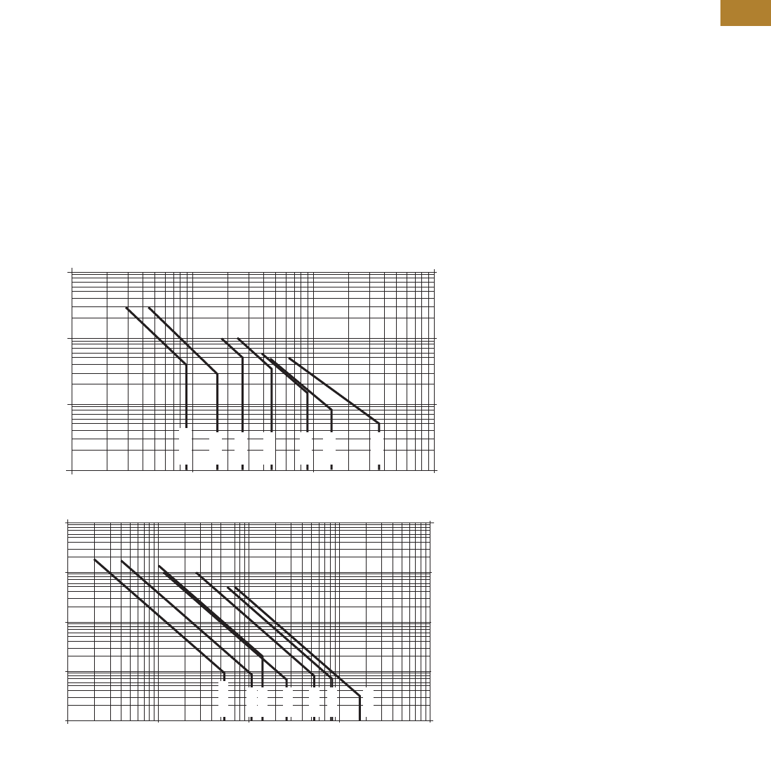
Volume 5—Motor Control and Protection CA08100006E—May 2016 www.eaton.com V5-T2-37
2
2
2
2
2
2
2
2
2
2
2
2
2
2
2
2
2
2
2
2
2
2
2
2
2
2
2
2
2
2
2.1
NEMA Contactors and Starters
Freedom Series
Electrical Life—AC-3 and AC-4 Utilization Categories
Life Load Curves
Eaton’s Freedom Series
NEMA contactors have been
designed and manufactured
for superior life performance
in any worldwide application.
All testing has been based on
requirements as found in
NEMA and UL standards and
conducted by Eaton. Actual
application life may vary
depending on environmental
conditions and application
duty cycle.
Utilization Categories
The International
Electrotechnical Commission
(IEC) has developed utilization
categories for contactors and
auxiliary contacts. The IEC
utilization categories are used
to define the type of electrical
load for estimating electrical
life, and do not imply the
devices are IEC rated.
AC-1—Non-inductive or
slightly inductive loads,
such as resistance furnaces
and heating.
AC-2—Starting of slip-ring
motors.
AC-3—Squirrel cage motors;
starting, switching off motors
during running.
AC-4—Squirrel cage motors;
starting, plugging, inching
or jogging.
Note: AC-3 tests are conducted at
rated device currents and AC-4
tests are conducted at six times
rated device currents. All tests
have been run at 460V, 60 Hz.
Contactor Choice
●Decide what utilization
category your application
is and choose the
appropriate curve
●Locate the intersection of
the life-load curve of the
appropriate contactor with
the applications operational
current (Ie), as found on the
horizontal axis
●Read the estimated
contact life along the
vertical axis in number
of operational cycles
AC-3 and AC-4 Utilization Categories
NEMA AC-3 Load Life, Sizes 00–5, 480V 60 Hz
100,000,000
10,000,000
1,000,000
100,000 9
110
Break Amperes 100 1000
18 27 45 90 135 270
Size 00
Size 0
Size 1
Size 2
Size 3
Size 4
Size 5
Operations Operations
NEMA AC-4 Load Life, Sizes 00–5, 480V 60 Hz
100,000,000
Size 00
Size 0
Size 1
Size 2
Size 3
Size 4
Size 5
10,000,000
1,000,000
100,000
10,000 10854
110
Break Amperes
100 1000 10,000
153 270 540 822 1620
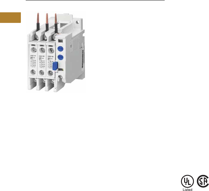
V5-T2-38 Volume 5—Motor Control and Protection CA08100006E—May 2016 www.eaton.com
2
2
2
2
2
2
2
2
2
2
2
2
2
2
2
2
2
2
2
2
2
2
2
2
2
2
2
2
2
2
2.1
NEMA Contactors and Starters
Freedom Series
32A Overload—C306DN3B
Contents
Description Page
Contactors—Non-Reversing and Reversing . . . . . . V5-T2-4
Starters—Three-Phase Non-Reversing and
Reversing, Full Voltage . . . . . . . . . . . . . . . . . . . . V5-T2-10
Starters—Single-Phase Non-Reversing,
Full Voltage, Bi-Metallic Overload . . . . . . . . . . . . V5-T2-15
Accessories . . . . . . . . . . . . . . . . . . . . . . . . . . . . . . V5-T2-21
Renewal Parts . . . . . . . . . . . . . . . . . . . . . . . . . . . . V5-T2-30
Technical Data and Specifications . . . . . . . . . . . . . V5-T2-34
Relays—Thermal Overload
Product Selection . . . . . . . . . . . . . . . . . . . . . . . V5-T2-39
Accessories. . . . . . . . . . . . . . . . . . . . . . . . . . . . V5-T2-43
Modifications . . . . . . . . . . . . . . . . . . . . . . . . . . V5-T2-43
Replacement Parts . . . . . . . . . . . . . . . . . . . . . . V5-T2-44
Technical Data and Specifications . . . . . . . . . . . V5-T2-45
Dimensions. . . . . . . . . . . . . . . . . . . . . . . . . . . . V5-T2-47
C440/XT Electronic Overload Relay . . . . . . . . . . . . V5-T2-48
Relays—Thermal Overload
Product Description
C306 Overload Relays are
designed for use with CE
or CN non-reversing and
reversing contactors. Four
sizes are available for
overload protection up
to 144A.
Features
●Selectable manual or
automatic reset operation
●Interchangeable heater
packs adjustable ±24%
to match motor FLA and
calibrated for use with
1.0 and 1.15 service factor
motors. Heater packs for
32A overload relay will
mount in 75A overload
relay—useful in derating
applications such as
jogging
●Class 10 or 20
heater packs
●Load lugs built into
relay base
●Bimetallic, ambient
compensated operated.
Trip free mechanism
●Electrically isolated NO-NC
contacts (pull RESET
button to test). (Electrical
ratings see table on
Page V5-T2-46)
●Overload trip indication
●Shrouded or fingerproof
terminals to reduce
possibility of electrical
shock
Standards and Certifications
●Meets UL 508 single-
phasing requirements
●UL listed, CSA certified and
NEMA compliance
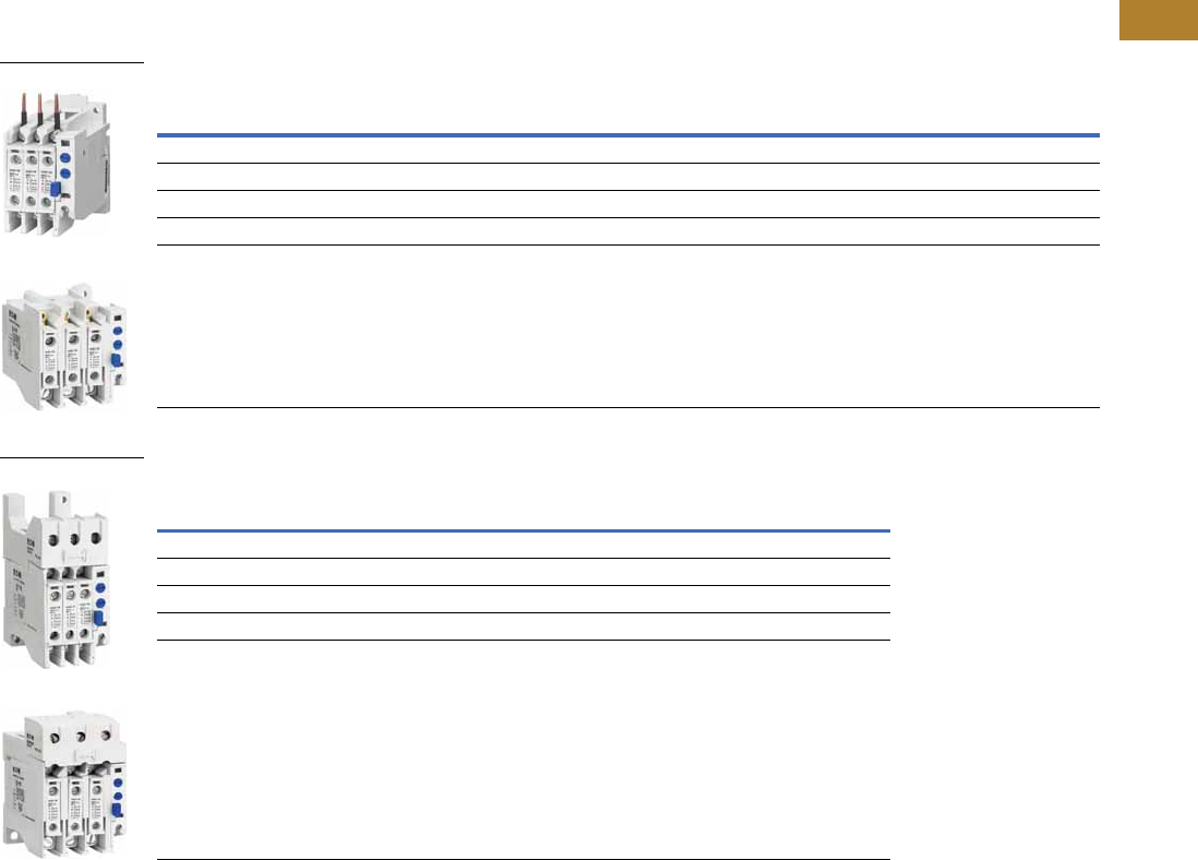
Volume 5—Motor Control and Protection CA08100006E—May 2016 www.eaton.com V5-T2-39
2
2
2
2
2
2
2
2
2
2
2
2
2
2
2
2
2
2
2
2
2
2
2
2
2
2
2
2
2
2
2.1
NEMA Contactors and Starters
Freedom Series
Product Selection
C306 Thermal Overload Relays
Contactors
Standalone Applications
Notes
1 NEMA Sizes 5–8 use the 32A overload in conjunction with CTs.
2 Series B overload relays have load lugs built into relay base and will only accept Series B heater packs. These relays
can be directly attached to contactor or they can be DIN rail or panel mounted using adapter on Page V5-T2-44.
3 These relays can be panel mounted only.
4 Overload relay assembled with mounting adapter for DIN rail or panel mount.
5 Panel mount only.
6 NEMA Sizes 5–8 use the 32A overload in conjunction with CTs.
NEMA Size
Maximum
Ampere Rating
Number
of Poles
Open Type NEMA 1 Enclosed
Catalog Number Catalog Number
00, 0 32 23C306DN3B C306DG3B
1, 2 75 23C306GN3B C306GG3B
3105
33C306KN3 —
4144
33C306NN3 —
5–8 1————
NEMA Size
Maximum
Ampere Rating
Number
of Poles
Open Type
Catalog Number
00, 0, 1 432 3 C306DT3B
1 475 3 C306GT3B
3 5105 3 C306KN3
4 5144 3 C306NN3
5–8 6———
C306DN3B
C306GN3B
C306DT3B
C306GT3B
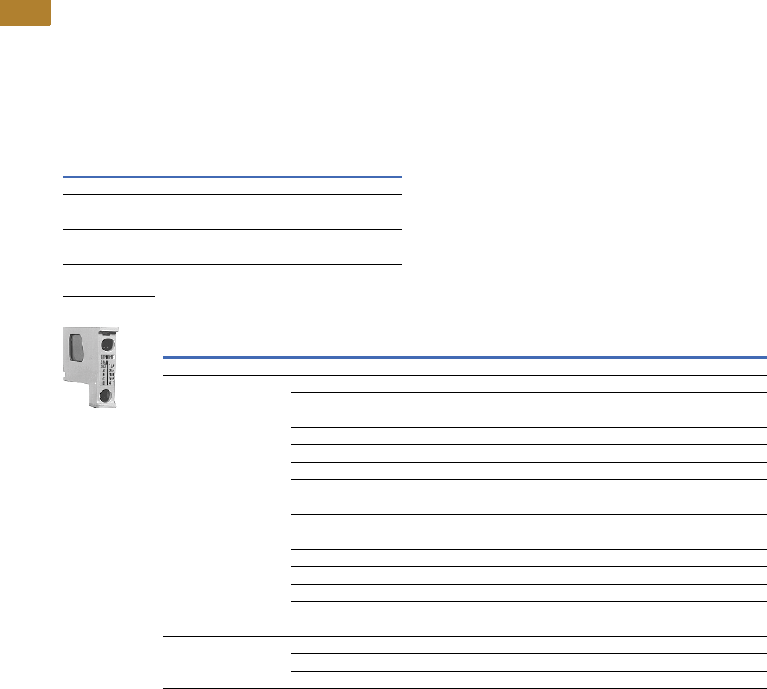
V5-T2-40 Volume 5—Motor Control and Protection CA08100006E—May 2016 www.eaton.com
2
2
2
2
2
2
2
2
2
2
2
2
2
2
2
2
2
2
2
2
2
2
2
2
2
2
2
2
2
2
2.1
NEMA Contactors and Starters
Freedom Series
Heater Pack Selection
Heater packs H2001B to
H2017B and H2101B to
H2117B are to be used only
with Series B overload relays
Catalog Numbers C306DN3B
(Part No. 10-7016) and
C306GN3B (Part No.
10-7020). The load lugs are
built into the overload relay
base to allow load wiring prior
to heater pack installation.
The previous heater design
had integral load lugs. The
Series B heater packs are
electrically equivalent to the
previous heater design.
Heaters H2018-3 to H2024-3
have not changed.
Starters with Series B Overload Relays 1
Standard Trip—Class 20 Heater
Notes
1 The series of a starter is the last digit of the listed catalog number. Example: AN16DN0AB.
2 Heater packs are shipped three to a carton. catalog numbers are for three heater packs.
NEMA—AN Type IEC—AE Type
Size Series Size Series
00–0 CA–F C
1–2 BG–K B
5BG–K B
6CG–K B
7–8 BG–K B
Overload Relay Size
Motor Full Load Ampere Rating
Catalog Number 2
Dial Position
ABCD
For Use with NEMA Sizes 00–0 Series C, NEMA Sizes 1–2 Series B; IEC Sizes A–F Series C, IEC Sizes G–K Series B
32A or 75A 0.254 0.306 0.359 0.411 H2001B-3
0.375 0.452 0.530 0.607 H2002B-3
0.560 0.676 0.791 0.907 H2003B-3
0.814 0.983 1.15 1.32 H2004B-3
1.20 1.45 1.71 1.96 H2005B-3
1.79 2.16 2.53 2.90 H2006B-3
2.15 2.60 3.04 3.49 H2007B-3
3.23 3.90 4.56 5.23 H2008B-3
4.55 5.50 6.45 7.40 H2009B-3
6.75 8.17 9.58 11.0 H2010B-3
9.14 10.8 12.4 14.0 H2011B-3
14.0 16.9 19.9 22.8 H2012B-3
18.7 22.7 26.7 30.7 H2013B-3
23.5 28.5 33.5 38.5 H2014B-3
For Use with NEMA Size 2, IEC Sizes G–K Only, Series B
75A 29.0 34.0 39.1 44.1 H2015B-3
39.6 45.5 51.5 57.4 H2016B-3
53.9 60.9 67.9 74.9 H2017B-3
Heater Pack
H2001B–H2017B
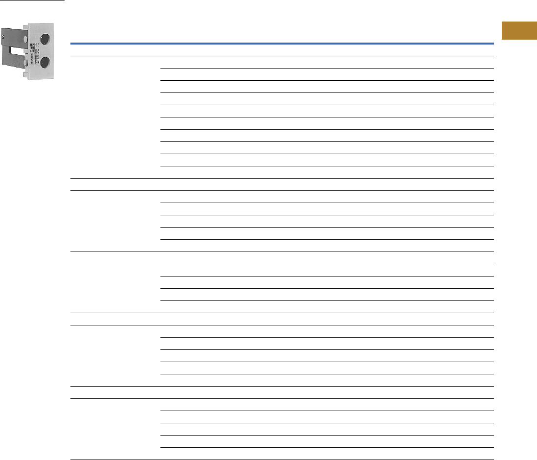
Volume 5—Motor Control and Protection CA08100006E—May 2016 www.eaton.com V5-T2-41
2
2
2
2
2
2
2
2
2
2
2
2
2
2
2
2
2
2
2
2
2
2
2
2
2
2
2
2
2
2
2.1
NEMA Contactors and Starters
Freedom Series
Standard Trip—Class 20 Heater, continued
Notes
1 Heater packs are shipped three to a carton. catalog numbers are for three heater packs.
2 Sizes 5–8 and IEC P–Z use the 32A overload relay with current transformers.
Overload Relay Size
Motor Full Load Ampere Rating
Catalog Number 1
Dial Position
ABCD
For Use with NEMA Sizes 3–4, IEC Sizes L–N Only—Series A
105A or 144A 8.0 9.2 10.3 11.5 H2025-3
11.4 12.8 14.3 15.7 H2026-3
14.3 15.7 17.4 19.0 H2027-3
18.0 20.2 22.3 24.5 H2018-3
24.6 27.6 30.5 33.4 H2019-3
33.5 37.5 41.5 45.6 H2020-3
45.7 51.2 56.7 62.1 H2021-3
62.2 69.7 77.1 84.6 H2022-3
84.7 95.0 105.0 115.0 H2023-3
106.0 118.0 131.0 144.0 H2024-3
For Use with Size 5 Starters—Series B and IEC P, R and S with 300/5 CT
32A 249 59 69 79 H2004B-3
72 87 103 118 H2005B-3
107 130 152 174 H2006B-3
129 156 182 209 H2007B-3
194 234 274 — H2008B-3
For Use with Size 6 Starters Only—Series B and IEC T–V with 600/5 CT
32A 2144 174 205 235 H2005B-3
215 259 304 348 H2006B-3
258 312 365 419 H2007B-3
388 468 547 627 H2008B-3
For Use with Size 7 Starters Only—Series B and IEC W–X with 1000/5 CT
32A 2163 197 230 264 H2004B-3
240 290 342 392 H2005B-3
358 432 506 580 H2006B-3
430 520 608 698 H2007B-3
646 780 912 — H2008B-3
For Use Size 8 Starters Only—Series B and IEC Z with 1500/5 CT
32A 2244 295 345 396 H2004B-3
360 435 513 588 H2005B-3
537 648 759 870 H2006B-3
645 780 912 1047 H2007B-3
969 1170 1368 — H2008B-3
Heater Pack
H2018–H2024
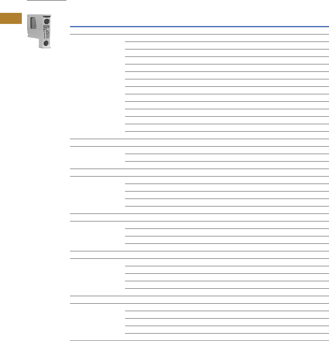
V5-T2-42 Volume 5—Motor Control and Protection CA08100006E—May 2016 www.eaton.com
2
2
2
2
2
2
2
2
2
2
2
2
2
2
2
2
2
2
2
2
2
2
2
2
2
2
2
2
2
2
2.1
NEMA Contactors and Starters
Freedom Series
Fast Trip—Class 10 Heater
Notes
1 Heater packs are shipped three to a carton. catalog numbers are for three heater packs.
2 Sizes 5–8 and IEC P–Z use the 32A overload relay with current transformers.
Overload Relay Size
Motor Full Load Ampere Rating
Catalog Number 1
Dial Position
AB C D
For Use with NEMA Sizes 00–0 Series C, NEMA Sizes 1–2 Series B; IEC Sizes A–F Series C, IEC Sizes G–K Series B
32A or 75A 0.260 0.313 0.367 0.420 H2101B-3
0.384 0.464 0.543 0.623 H2102B-3
0.570 0.688 0.806 0.924 H2103B-3
0.846 1.02 1.20 1.37 H2104B-3
1.28 1.55 1.83 2.10 H2105B-3
1.92 2.33 2.74 3.15 H2106B-3
2.30 2.79 3.28 3.77 H2107B-3
3.38 4.10 4.82 5.54 H2108B-3
4.96 6.03 7.09 8.16 H2109B-3
7.07 8.58 10.1 11.6 H2110B-3
9.60 11.2 12.8 14.4 H2111B-3
14.4 17.5 20.7 23.8 H2112B-3
18.7 21.8 25.0 28.1 H2113B-3
23.5 27.3 31.0 34.8 H2114B-3
For Use with Size 2, IEC Sizes G–K Only—Series B
75A 28.3 32.6 37.0 41.3 H2115B-3
36.6 42.3 48.1 53.8 H2116B-3
53.8 60.8 67.9 74.9 H2117B-3
For Use with Size 5 Starters Only—Series B and IEC P, R and S with 300/5 CT
32A 251 61 72 82 H2104B-3
77 93 110 126 H2105B-3
115 140 164 189 H2106B-3
138 167 197 226 H2107B-3
203 246 289 — H2108B-3
For Use with Size 6 Starters Only—Series B and IEC T–V with 600/5 CT
32A 2154 186 220 252 H2105B-3
230 280 329 378 H2106B-3
276 335 394 452 H2107B-3
406 492 578 — H2108B-3
For Use with Size 7 Starters Only—Series B and IEC W–X with 1000/5 CT
32A 2169 204 240 274 H2104B-3
256 310 366 420 H2105B-3
384 466 543 630 H2106B-3
460 558 656 754 H2107B-3
676 820 — — H2108B-3
For Use with Size 8 Starters Only—Series B and IEC Z with 1500/5 CT
32A 2254 306 360 411 H2104B-3
384 465 549 630 H2105B-3
576 699 822 945 H2106B-3
690 837 984 1131 H2107B-3
1014 1230 — — H2108B-3
Heater Pack
H2101B–H2117B
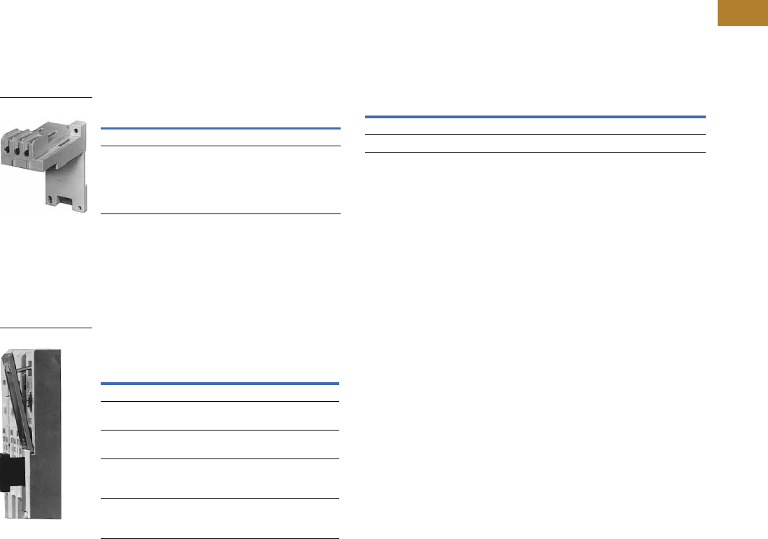
Volume 5—Motor Control and Protection CA08100006E—May 2016 www.eaton.com V5-T2-43
2
2
2
2
2
2
2
2
2
2
2
2
2
2
2
2
2
2
2
2
2
2
2
2
2
2
2
2
2
2
2.1
NEMA Contactors and Starters
Freedom Series
Accessories
DIN Rail and Panel Mounting Adapter
These adapters are required
when component overload
relays are to be separately
mounted. The terminal base
adapter includes line
terminals and connects
with the overload relays
on Page V5-T2-39.
DIN Rail and Panel Mounting Adapter
Locking Cover for Overload Relay—C306 Only
Snap-on transparent or
opaque plastic panel for
covering access port to the
overload relay trip setting
dial—helps prevent accidental
or unauthorized changes to
trip and reset setting.
Locking Cover for Overload Relay—
C306 Only
Note
1This Series B adapter will accept Series A or B overload relays (C306GN3 or C306GN3B),
C306TB2 can only be used with C306GN3.
Description Catalog Number
For 32A overload relay C306TB1
For 75A overload relay C306TB2B 1
C306TB1
Description
Min. Order Qty.
(Std. Pkg.)
Catalog
Number
Clear cover, no accessibility 50 C320PC3
Gray cover, no accessibility with
auto only nib
50 C320PC4
Gray cover, no accessibility with
manual only nib
50 C320PC5
Gray cover with FLA dial
accessibility, A, B, C, D positions
and auto only nib
50 C320PC6
Gray cover with FLA dial
accessibility, A, B, C, D positions
and manual only nib
50 C320PC7
Overload Relay Cover
Modifications
C306 Thermal Overload Relays with Mounting Adapter
Consists of a thermal
overload relay mounted to a
terminal base adapter—
permits fast and easy
installation.
C306 Thermal Overload Relays with Mounting Adapter
Description Catalog Number
C306DN3B + C306TB1 C306DT3B
C306GN3B + C306TB2B C306GT3B
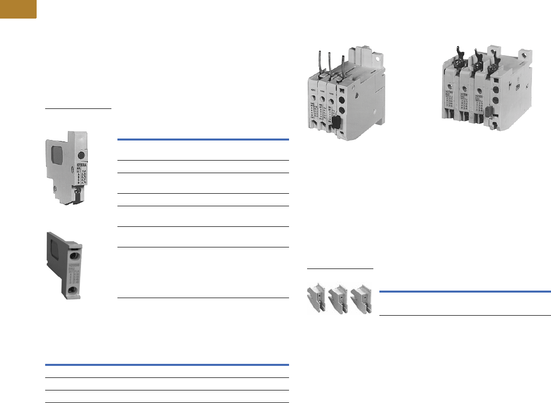
V5-T2-44 Volume 5—Motor Control and Protection CA08100006E—May 2016 www.eaton.com
2
2
2
2
2
2
2
2
2
2
2
2
2
2
2
2
2
2
2
2
2
2
2
2
2
2
2
2
2
2
2.1
NEMA Contactors and Starters
Freedom Series
Replacement Parts
Heater Pack Replacement
The heater pack series is
determined by the 6th
character of the catalog
number. Series A or prior
heater packs (identified by
either “A” or “-” as the 6th
character) have built-in load
lugs. Series B or later heater
packs do not (load lugs are on
overload relay). Replacement
of Series A or earlier heater
packs with Series B or later
heater packs, requires the
one time addition of Lug
Adapter Kit C306KAL1-3B to
the Series A1 overload relay.
Heater Pack Replacement Requirements
Heater Pack Ratings
Existing Heater Pack
Catalog Numbers Replacement Product Required
H2001-3–H2013-3
H2001A-3–H2013A-3
Lug adapter kit C306KAL1-3B and
Series B heater pack
H2001B-3–H2013B-3 Series B heater pack
H2014-3
H2014A-3
Replace with lug adapter kit
C306KAL1-3B and Series B heater pack
H2014B-3 Series B heater pack
H2015-3–H2017-3 Replace with heater pack chosen from
table below
H2015A-3–H2017A-3 Replace with lug adapter kit
C306KAL1-3B and Series B heater pack
H2015B-3–H2017B-3 Series B heater pack
Motor Full Load Ampere Rating
Order Heater Pack
Catalog Number
Dial Position
ABCD
29.0 32.5 36.0 39.5 H2015B-3
39.6 44.3 49.1 53.8 H2016B-3
53.9 60.4 66.8 74.9 H2017B-3
Superseded Series A
Heater Pack
Series B
Heater Pack
Overload Relay Lug Adapter Kit
Superseded 32A Series A Superseded 75A Series A
Overload Relay—C306DN3 Overload Relay—C306GN3
These kits are used in
conjunction with Catalog
Numbers H2001B–H2014B or
H2101B–H2114B heater
packs as a means of utilizing
these Series B heater packs
in Catalog Numbers
C306DN3 and C306GN3
Series Al overload relays. The
kit consists of three lug
adapters and installation
instructions. When installing
Series B heater packs plus
lug adapters in Series A
overload relays, refer to
heater pack FLA adjustment
tables originally supplied with
equipment (also supplied
with kit).
Overload Relay Lug
Overload Relay Replacement—
Series A Only
When replacing a Catalog
Number C306DN3 (Part No.
10-6044) or C306GN3 (10-
6319) Series A overload relay
on a starter, order a Series B
overload relay and Series B
heater packs.
Description Catalog Number
Series Al overload relay lug adapter kit C306KAL1-3B
C306KAL1
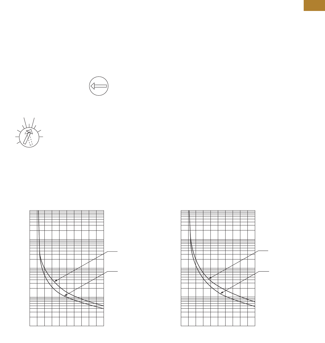
Volume 5—Motor Control and Protection CA08100006E—May 2016 www.eaton.com V5-T2-45
2
2
2
2
2
2
2
2
2
2
2
2
2
2
2
2
2
2
2
2
2
2
2
2
2
2
2
2
2
2
2.1
NEMA Contactors and Starters
Freedom Series
Technical Data and Specifications
Operation
C306 Overload Relay Setting
For motors having a 1.15
service factor, rotate the
FLA (Full Load Amperes)
adjustment dial to correspond
to the motor’s FLA rating.
Estimate the dial position
when the motor FLA falls
between two letter values as
shown in the example.
For motors having a 1.0
service factor, rotate the
FLA dial one-half position
counterclockwise (CCW).
FLA Dial Adjustment
The overload relay is factory
set at M for manual reset
operation. For automatic
reset operation, turn the reset
adjustment dial to the
A position as shown in the
illustration.
Automatic reset is not
intended for two-wire
control devices.
Manual/Automatic Reset
Test for Trip Indication
To test overload relay for trip
indication when in manual
reset, pull out the blue reset
button. An orange flag will
appear indicating that the
device has tripped. Push
reset button in to reset.
Warning—To provide
continued protection against
fire or shock hazard, the
complete overload relay must
be replaced if burnout of the
heater element occurs.
General
“Overload relays are provided
to protect motors, motor
control apparatus and motor-
branch circuit conductors
against excessive heating
due to motor overloads and
failure to start. This definition
does not include: 1) motor
circuits over 600V, 2) short
circuits, 3) ground faults
and 4) fire pump control.”
(NEC Art. 430-31)
Time Current Characteristics
The time-current
characteristics of an overload
relay is an expression of
performance which defines
its operating time at various
multiples of its current
setting. Tests are run at
Underwriters Laboratories
(UL) in accordance with
NEMA Standards and the
NEC. UL requires:
●When tested at 100
percent of its current
rating, the overload relay
shall trip ultimately
●When tested at 200
percent of its current rating,
the overload relay shall trip
in not more than 8 minutes
●When tested at 600 percent
of the current rating, the
overload relay shall trip
in not more than 10 or
20 seconds, depending
on the Class of the relay
“Current Rating” is defined
as the minimum current at
which the relay will trip. Per
NEC, an overload must
ultimately trip at 125% of FLA
current (heater) setting for a
1.15 service factor motor and
115% FLA for a 1.0 service
factor motor.
“Current Setting” is defined
as the FLA of the motor and
thus the overload heater
pack setting.
Example: 600% of current
rating is defined as 750%
(600 x 1.25) of FLA current
(heater) setting for a 1.15
service factor motor. A 10A
heater setting must trip in 20
seconds or less at 75A motor
current for a Class 20 relay.
Class 10 and Class 20 Trip Curves
1.0
Service
Factor
1.15
Service
Factor
A
BC
D
Example of 12.0 FLA setting
for heater pack number H2011B
showing position for
1.0 or 1.15 service
factor motors.
A
M
Example of setting for
manual reset.
0
1
2
3
4
5
10
20
30
40
50
100
200
300
400
500
1000
2000
3000
4000
5000
10,000
246810
From
Hot Start
From
Cold Start
Multiples of Current Setting
Trip Time
(Seconds)
Class 10 Overload Relay 25C Open Rating
0
1
2
3
4
5
10
20
30
40
50
100
200
300
400
500
1000
2000
3000
4000
5000
10,000
246810
From
Hot Start
From
Cold Start
Multiples of Current Setting
Trip Time
(Seconds)
Class 20 Overload Relay 25C Open Rating

V5-T2-46 Volume 5—Motor Control and Protection CA08100006E—May 2016 www.eaton.com
2
2
2
2
2
2
2
2
2
2
2
2
2
2
2
2
2
2
2
2
2
2
2
2
2
2
2
2
2
2
2.1
NEMA Contactors and Starters
Freedom Series
Wire (75°C) Sizes—AWG or kcmil—NEMA Sizes 00–2, IEC A–K—Open
Power Terminals—Line
Power Terminals—Load—Cu Only (Stranded or Solid)
Wire (75°C) Sizes—AWG or kcmil—NEMA Sizes 3–8, IEC L–N—Open
Power Terminals—Line and Load
Power Terminal Torque Line and Load Terminals
Plugging and Jogging Service Horsepower Ratings 2
Overload Relay UL/CSA Contact Ratings Control Circuit 3
Notes
1Two compartment box lug.
2Maximum horsepower where operation is interrupted more than 5 times per minute or more
than 10 times in a 10 minute period. NEMA standard ICS 2-1993 table 2-4-3.
3DC ratings cover Freedom Series coils only.
IEC Size NEMA Size Cu Only
A, B, C 00 12–16 stranded, 12–14 solid
D, E, F 0 8 –16 stranded, 10–14 solid
1 8–14 stranded or solid
G, H, J, K 2 3–14 (upper) and/or 6–14 (lower) stranded or solid 1
Catalog Number Terminal Wire Size
C306DN3B 32A 14–6 AWG
C306GN3B 75A 14–2 AWG
Control Terminals—Cu Only
12–16 AWG stranded, 12–14 AWG solid
IEC Size NEMA Size Wire Size
L 3 1/0–14 Cu/Al
M — 14–2/0 Cu/Al
N — 3/0–8 Cu/Al
— 4 Open—3/0–8 Cu
Enclosed—250 kcmil—6 Cu/Al
— 5 750 kcmil—2 or (2) 250 kcmil—3/0 Cu/Al
6–7 (2) 750 kcmil—3/0 Cu/Al
8 (2) 750 kcmil—1/0 Cu/Al
Control Terminals—Cu Only
12–16 AWG stranded, 12–14 AWG solid
Catalog Number Terminal Torque in lb-in
C306DT3B 32A 20
C306GT3B 75A 35 (14–10 AWG)
40 (8 AWG)
45 (6–4 AWG)
50 (3–2 AWG)
C306KN3
(socket head screw)
105A 120 (3/16)
200 (1/4)
250 (5/16)
C306NN3
(socket head screw)
144A 120 (3/16)
200 (1/4)
250 (5/16)
C306NN3
(slotted head screw)
35 (14–10 AWG)
40 (8 AWG)
45 (6–4 AWG)
50 (3–1/0 AWG)
NEMA Size 200V 230V 460V 575V
00 — 1/2 1/2 1/2
0 1-1/2 1-1/2 2 2
13355
2 7-1/2 10 15 15
3 15203030
4 25306060
5 6075150150
6 125 150 300 300
AC Volts 120V 240V 480V 600V
NC Contact B600
Make and break amperes 30 15 7.5 6
Break amperes 3 1.5 0.75 0.6
Continuous amperes5555
NO Contact C600
Make and break amperes 15 7.5 3.375 3
Break amperes 1.5 0.75 0.375 0.3
Continuous amperes 2.5 2.5 2.5 2.5

Volume 5—Motor Control and Protection CA08100006E—May 2016 www.eaton.com V5-T2-47
2
2
2
2
2
2
2
2
2
2
2
2
2
2
2
2
2
2
2
2
2
2
2
2
2
2
2
2
2
2
2.1
NEMA Contactors and Starters
Freedom Series
Dimensions
Approximate Dimensions in Inches (mm)
Stand-Alone Overload Relays
32A and 75A Sizes—C306DT38 and C306GT3B 105A and 144A Sizes—C306KN38 and C306NN3B
Dimensions and Shipping Weights
D C
E
B
A
F
G
A C
E
B
DMtg. Holes for (3)
1/4-20 Screws
Ampere
Size
Wide
A
High
B
Deep
C
Mounting Shipping Weight
Lbs (kg)D E F (Slot) G (Hole)
32A 1.77 (45.0) 4.13 (104.9) 3.69 (93.7) 1.36 (34.5) 3.74 (95.0) 0.18 x 0.30 (4.6 x 7.6) 0.18 (4.6) dia. 0.8 (0.4)
75A 2.54 (64.5) 4.69 (119.1) 3.74 (95.0) 2.00 (50.8) 3.45 (87.6) 0.22 x 0.26 (5.6 x 6.6) 0.21 (5.3) dia. 1.4 (0.6)
105 and 144A 4.00 (101.6) 7.17 (182.1) 4.91 (124.7) 3.00 (76.2) 6.62 (168.1) — — 4.0 (1.8)
V5-T2-48 Volume 5—Motor Control and Protection CA08100006E—May 2016 www.eaton.com
2
2
2
2
2
2
2
2
2
2
2
2
2
2
2
2
2
2
2
2
2
2
2
2
2
2
2
2
2
2
2.1
NEMA Contactors and Starters
Freedom Series
C440/XT Electronic Overload Relay
Contents
Description Page
Contactors—Non-Reversing and Reversing . . . . . . V5-T2-4
Starters—Three-Phase Non-Reversing and
Reversing, Full Voltage . . . . . . . . . . . . . . . . . . . . V5-T2-10
Starters—Single-Phase Non-Reversing,
Full Voltage, Bi-Metallic Overload . . . . . . . . . . . . V5-T2-15
Accessories . . . . . . . . . . . . . . . . . . . . . . . . . . . . . . V5-T2-21
Renewal Parts . . . . . . . . . . . . . . . . . . . . . . . . . . . . V5-T2-30
Technical Data and Specifications . . . . . . . . . . . . . V5-T2-34
Relays—Thermal Overload. . . . . . . . . . . . . . . . . . . V5-T2-38
C440/XT Electronic Overload Relay
Standards and Certifications . . . . . . . . . . . . . . V5-T2-49
Catalog Number Selection . . . . . . . . . . . . . . . . V5-T2-50
Product Selection . . . . . . . . . . . . . . . . . . . . . . . V5-T2-51
Accessories . . . . . . . . . . . . . . . . . . . . . . . . . . . V5-T2-53
Technical Data and Specifications . . . . . . . . . . V5-T2-57
Dimensions . . . . . . . . . . . . . . . . . . . . . . . . . . . V5-T2-63
C440/XT Electronic Overload Relay
Product Description
Eaton’s new electronic
overload relay (EOL) is
the most compact, high-
featured, economical product
in its class. Designed on a
global platform, the new
EOL covers the entire power
control spectrum including
NEMA, IEC and
DP contactors. The NEMA
and DP versions are offered
with the C440 designation
while the IEC offering has the
XT designation. The
electronic design provides
reliable, accurate and value
driven protection and
communications capabilities
in a single compact device. It
is the flexible choice for any
application requiring easy-to-
use, reliable protection.
Eaton has a long history of
innovations and product
development in motor control
and protection, including both
traditional NEMA, as well as
IEC control. It was from this
experience that the C440 was
developed, delivering new
solutions to meet today’s
demands.
C440 is a self-powered
electronic overload relay
available up to 175A as a
self contained unit. With
external CTs, C440 can
protect motor up to
1500 FLA. Available add-on
accessories include remote
reset capability and
communication modules
with I/O for DeviceNet,
PROFIBUS, and Modbus.
Features and Benefits
Features
●Reliable, accurate, electronic motor protection
●Easy to select, install and maintain
●Compact size
●Flexible, intelligent design
●Global product offering—available with NEMA, IEC and DP
power control
Size/Range
●Broad FLA range
(0.33–1500A)
●Selectable trip class
(10A, 10, 20, 30)
●Direct mounting to NEMA,
IEC and DP contactors
●Most compact electronic
overload in its class
Motor Control
●Two B600 alarm (NO) and
fault (NC) contacts
●Test/Trip button
Motor Protection
●Thermal overload
●Phase loss
●Selectable (ON/OFF)
phase unbalance
●Selectable (ON/OFF)
ground fault
User Interface
●Large FLA selection dial
●Trip status indicator
●Operating mode LED
●DIP switch selectable trip
class, phase unbalance and
ground fault
●Selectable Auto/Manual
reset
Feature Options
●Remote reset
●120 Vac
●24 Vac
●24 Vdc
●Tamper-proof cover
●Communications modules
●Modbus RTU RS-485
●DeviceNet with I/O
●PROFIBUS with I/O
●Modbus RTU with I/O
●Ethernet IP with I/O
●Modbus TCP with I/O

Volume 5—Motor Control and Protection CA08100006E—May 2016 www.eaton.com V5-T2-49
2
2
2
2
2
2
2
2
2
2
2
2
2
2
2
2
2
2
2
2
2
2
2
2
2
2
2
2
2
2
2.1
NEMA Contactors and Starters
Freedom Series
Benefits
Reliability and Improved
Uptime
●C440 provides the users
with peace of mind
knowing that their
assets are protected
with the highest level
of motor protection and
communication capability
in its class
●Extends the life of plant
assets with selectable
motor protection features
such as trip class, phase
unbalance and ground fault
●Protects against
unnecessary downtime
by discovering changes
in your system (line/load)
with remote monitoring
capabilities
●Status LED provides
added assurance that
valuable assets are
protected by indicating the
overload operational status
Flexibility
●Available with NEMA,
IEC and DP contactors
●Improves return on
investment by reducing
inventory carrying costs
with wide FLA adjustment
(5:1) and selectable
trip class
●Design incorporates built-in
ground fault protection
thus eliminating the need
for separate CTs and
modules
●Flexible communication
with optional I/O enables
easy integration into plant
management systems for
remote monitoring and
control
●Available as an open
component and in
enclosed control and motor
control center assemblies
Monitoring Capabilities
●Individual phase
currents RMS
●Average three-phase
current RMS
●Thermal memory
●Fault indication (overload,
phase loss, phase
unbalance, ground fault)
Safety
●IP 20 rated terminal blocks
●Available in Eaton’s
industry leading FlashGard
MCCs
●Tested to the highest
industry standards such
as UL, CSA, CE and IEC
●RoHS compliant
Standards and Certifications
●UL
●CSA
●CE
●NEMA
●IEC/EN 60947 VDE 0660
●ISO 13849-1 (EN954-1)
●RoHS
●ATEX directive 94/9/EC
●Equipment Group 2,
Category 2
Electronic Overload Education
Description Definition Cause Effect if not Protected C440/XT Protection
Motor Protection
Thermal overload Overload is a condition in which
current draw exceeds 115% of
the full load amperage rating for
an inductive motor.
• An increase in the load or torque that is
being driven by the motor.
• A low voltage supply to the motor
causes the current to go high to
maintain the power needed.
• A poor power factor causing above
normal current draw.
• Increase in current draw leads to heat
and insulation breakdown, which can
cause system failure.
• Increase in current can increase
power consumption and waste
valuable energy.
• Thermal trip behavior is defined by
UL, CSA and IEC standards.
• Trip class is settable from 10A,
10, 20, 30
Ground fault A line to ground fault. A current leakage path to ground. An undetected ground fault can burn
through multiple insulation windings,
ultimately leading to motor failure, not to
mention risk to equipment or personnel
Fixed protective setting that takes the
starter offline if ground fault current
exceeds 50% of the FLA dial setting,
that is, if the FLA dial is set to 12A, the
overload relay will trip if the ground
current exceeds 6A.
Unbalanced phases
(voltage and current)
Uneven voltage or current between
phases in a three-phase system.
When a three-phase load is powered with
a poor quality line, the voltage per phase
may be unbalanced.
Unbalanced voltage causes large
unbalanced currents and as a result this
can lead to motor stator windings being
overloaded, causing excessive heating,
reduced motor efficiency and reduced
insulation life.
Fixed protective setting that takes the
starter offline if a phase drops below
50% of the other two phases.
Phase loss—current
(single-phasing)
One of the three-phase voltages is
not present.
Multiple causes, loose wire, improper
wiring, grounded phase, open fuse,
and so on.
Single-phasing can lead to unwanted
motor vibrations in addition to the results
of unbalanced phases as listed above.
Fixed protective setting that takes the
starter offline if a phase drops below
50% of the other two phases.
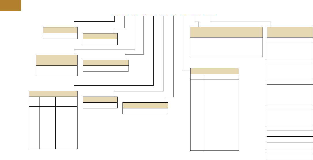
V5-T2-50 Volume 5—Motor Control and Protection CA08100006E—May 2016 www.eaton.com
2
2
2
2
2
2
2
2
2
2
2
2
2
2
2
2
2
2
2
2
2
2
2
2
2
2
2
2
2
2
2.1
NEMA Contactors and Starters
Freedom Series
Catalog Number Selection
Freedom Series NEMA Starters with C440 Electronic Overload Relays 1
Notes
1See Page V5-T2-51 for Product Selection.
2NEMA Sizes 00 and 0 only.
3NEMA Sizes 00 and 0 only. Sizes 1–3 are 24/60 only.
4NEMA Size 5 starter available with 60-300A panel mounted CTs. Starter shipped as an assembled unit with
1–5A C440 overload relay (C440A1A005SELAX or C440A2A005SELAX).
A N 1 9 A N 0 A 5E 005
Device Type
A = Starter
Contactor Frame Size
NEMA
Size
Continuous
Amperes
A =
B =
C =
D =
G =
K =
M =
N =
S =
00
0
1C
1
2
3
4C
4
5
9
18
27
27
45
90
135
135
270
Device Assembly
Configuration
1 = Non-reversing
5 = Reversing
Standard
N = NEMA
OLR Type
9 = Starter w/C440 EOLR
NEMA Enclosure
N = Open
For Starters
Starter Mounting Option
0 = Horizontal
AC Coil Suffix
Suffix Volts and Hertz
A=
B=
C=
D=
E=
H=
J=
K=
L=
N=
T=
U=
V=
W=
Y=
120/60 or 110/50
240/60 or 220/50
480/60 or 440/50
600/60 or 550/50
208/60
277/60
208–240/60 2
240/50
380–415/50
550/50
24/60, 24/50 3
24/50
32/50
48/60
48/50
C440 OLR Designation
(FVNR and FVR only)
5E = Standard feature set
SEL Reset, SEL Class (10A, 10, 20, 30)
5G = Ground fault feature set
SEL Reset, SEL Class (10, 20)
C440 FLA Range
(FVNR and FVR only)
NEMA Size 00
1P6 = 0.33–1.65A
005 =1–5A
020 =4–20A
NEMA Size 0
1P6 = 0.33–1.65A
005 =1–5A
020 =4–20A
NEMA Size 1/1C
1P6 = 0.33–1.65A
005 =1–5A
020 =4–20A
045 =9–45A
NEMA Size 2
005 =1–5A
020 =4–20A
045 =9–45A
NEMA Size 3
100 = 20–100A
NEMA Size 4/4C
140 = 28–140A
NEMA Size 5 4
300 = 60–300A
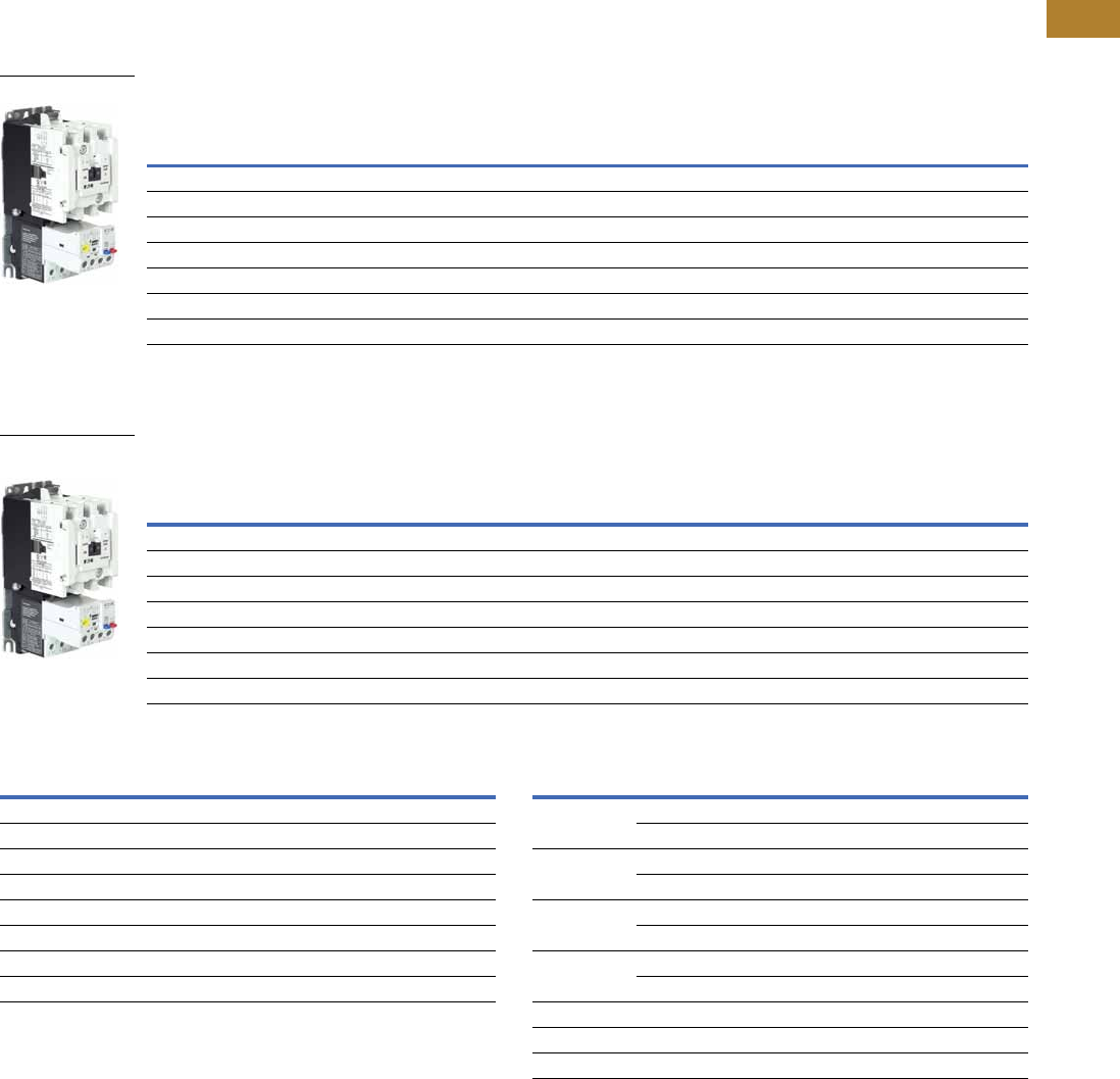
Volume 5—Motor Control and Protection CA08100006E—May 2016 www.eaton.com V5-T2-51
2
2
2
2
2
2
2
2
2
2
2
2
2
2
2
2
2
2
2
2
2
2
2
2
2
2
2
2
2
2
2.1
NEMA Contactors and Starters
Freedom Series
Product Selection
Type AN19/59 Freedom Series Starters
Type AN19/59 Freedom Series Starters with C440 Electronic Overload Relays
Non-Reversing and Reversing
Type AN19/59 Freedom Series Starters with C440 with Ground Fault Electronic Overload Relays
Non-Reversing and Reversing
Coil Suffix Codes C440 FLA Range (FVNR and FVR Starters Only)
Notes
1Underscore (_) indicates coils suffix required, see Coil Suffix table above.
2Underscore (_) indicates OLR designation required, see C440 FLA Range table above.
3NEMA Size 5 starter available with 60-300A panel mounted CTs. Starter shipped as an assembled unit with
1–5A C440 overload relay (C440A1A005SELAX or C440A2A005SELAX).
NEMA
Size
Continuous
Ampere
Rating
Service Limit
Current Rating
(Amps)
Maximum UL Horsepower Three-Pole
Non-Reversing 12
Three-Pole
Reversing 12
Single-Phase Three-Phase
115V 230V 208V 240V 480V 600V Catalog Number Catalog Number
00 9 11 1/3 1 1-1/2 1-1/2 2 2 AN19AN0_ 5E _ AN59AN0_ 5E _
018 21 123355AN19BN0_ 5E _ AN59BN0_ 5E _
127 32 237-1/27-1/21010AN19DN0_ 5E _ AN59DN0_ 5E _
2 45 52 3 7-1/210152525AN19GN0_ 5E _ AN59GN0_ 5E _
3 90 104 ——25305050AN19KN0_ 5E _ AN59KN0_ 5E _
4 135 156 — — 40 50 100 100 AN19NN0_ 5E _ AN59NN0_ 5E _
5 3270 311 — — 75 100 200 200 AN19SN0_ 5E _ AN59SN0_ 5E _
NEMA
Size
Continuous
Ampere
Rating
Service Limit
Current Rating
(Amps)
Maximum UL Horsepower Three-Pole
Non-Reversing 12
Three-Pole
Reversing 12
Single-Phase Three-Phase
115V 230V 208V 240V 480V 600V Catalog Number Catalog Number
00 9 11 1/3 1 1-1/2 1-1/2 2 2 AN19AN0_ 5G _ AN59AN0_ 5G _
018 21 123355AN19BN0_ 5G _ AN59BN0_ 5G _
127 32 237-1/27-1/21010AN19DN0_ 5G _ AN59DN0_ 5G _
2 45 52 3 7-1/210152525AN19GN0_ 5G _ AN59GN0_ 5G _
3 90 104 ——25305050AN19KN0_ 5G _ AN59KN0_ 5G _
4 135 156 — — 40 50 100 100 AN19NN0_ 5G _ AN59NN0_ 5G _
5 3270 311 — — 75 100 200 200 AN19SN0_ 5G _ AN59SN0_ 5G _
NEMA Starter
NEMA Starter with
Ground Fault
Suffix Coil Volts and Hertz Suffix Coil Volts and Hertz
A120/60 or 110/50 L380–415/50
B240/60 or 220/50 N550/50
C480/60 or 440/50 T24/60, 24/50
D600/60 or 550/50 U24/50
E208/60 V32/50
H277/60 W48/60
J208–240/60 Y48/50
K240/50
NEMA Size OLR Code FLA Range OLR Code FLA Rating
00 1P6 0.33–1.65A 020 4.0–20A
005 1.0–5.0A ——
01P6 0.33–1.65A 020 4.0–20A
005 1.0–5.0A ——
11P6 0.33–1.65A 020 4.0–20A
005 1.0–5.0A 045 9.0–45A
2005 1.0–5.0A 045 9.0–45A
020 4.0–20A ——
3100 20–100A ——
4140 28–140A ——
5 3300 60–300A ——
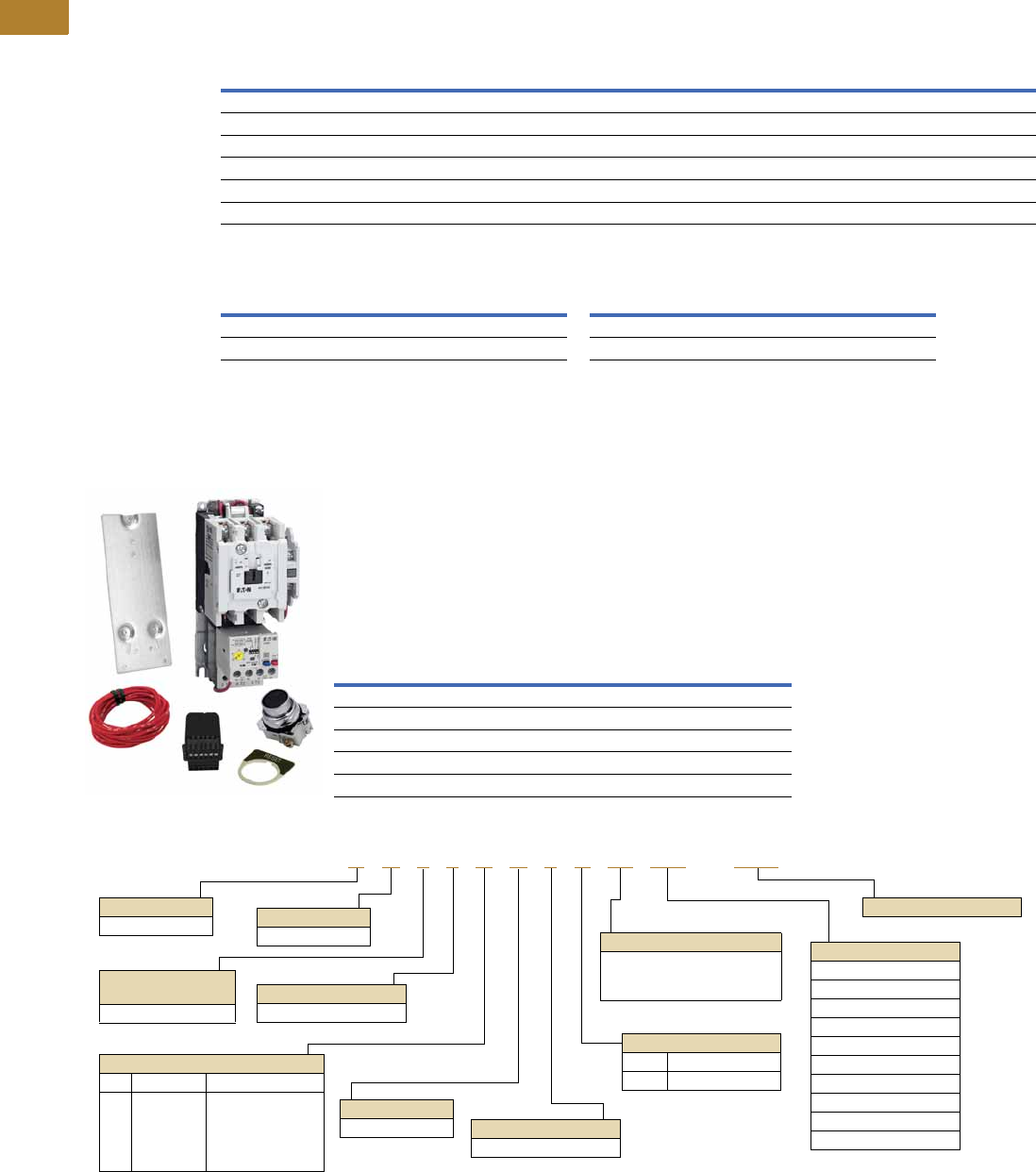
V5-T2-52 Volume 5—Motor Control and Protection CA08100006E—May 2016 www.eaton.com
2
2
2
2
2
2
2
2
2
2
2
2
2
2
2
2
2
2
2
2
2
2
2
2
2
2
2
2
2
2
2.1
NEMA Contactors and Starters
Freedom Series
Compact NEMA Size 1 and 4 Starters
New Compact NEMA Size 1 and 4 starters—available with electronic overload relay only.
Non-Reversing
Electrical Life at Rated Continuous Current
AN19 Competitive Retrofit Kits
The retrofit kits provide a packaged solution to replace competitive starters with the Freedom AN19 starter
using existing hole patterns. Suitable for replacement of Allen-Bradley, Square D, GE and Siemens starters.
Kit contents
AN19 Competitive Retrofit Kit—Product Selection
AN19 Competitive Retrofit Kit—Catalog Number Selection
NEMA
Size
Continuous
Ampere
Rating
Service Limit
Current Rating
(Amps)
Maximum UL Horsepower Three-Pole
Non-Reversing Single-Phase Three-Phase
115V 230V 208V 240V 480V 600V Catalog Number
Standard Fault Overload
1C 27 32 2 3 7.5 7.5 10 10 AN19CN0_5E_
4C 135 156 — — 40 50 100 100 AN19MN0_5E_
Ground Fault Overload
1C 27 32 2 3 7.5 7.5 10 10 AN19CN0_5G_
4C 135 156 — — 40 50 100 100 AN19MN0_5G_
NEMA
Size
Rated Current
(Amperage)
AC3/AC4 Operations
NEMA
Size
Rated Current
(Amperage)
AC3/AC4 Operations
1C 27/150 2,500,000/40,000 4C 135/516 500,000/40,000
1 27/153 5,000,000/110,000 4 135/822 800,000/70,000
Size Description Catalog Number
1 120 Vac coil, 4–20A overload AN19DN0A5E020-CRK
2 120 Vac coil, 9–45A overload AN19GN0A5E045-CRK
3 120 Vac coil, 20–100A overload AN19KN0A5E100-CRK
4 120 Vac coil, 28–140A overload AN19NN0A5E140-CRK
5 120 Vac coil, 60–300A overload AN19SN0A5E300-CRK
●Competitive mounting plate
●AN19 starter
●Remote reset module
●NO 10250T pushbutton
●RESET pushbutton legend plate
●16 gauge control wire
C440 OLR Designation
5E = Standard feature set
SEL Reset,
SEL Class (10A, 10, 20, 30)
A N 1 9 D N 0 A 5E 005 – CRK
Device Type
A = Starter
Contactor Frame Size
NEMA Size Continuous Amperes
D =
G =
K =
N =
S =
1
2
3
4
5
27
45
90
135
270
Device Assembly
Configuration
1 = Non-reversing
Standard
N = NEMA
OLR Type
9 = Starter w/C440 EOLR
NEMA Enclosure
N = Open
For Starters
Starter Mounting Option
0 = Horizontal
AC Coil Suffix
Suffix Volts and Hertz
A = 120/60 or 110/50
C440 FLA Range
NEMA Size 1/1C
020 = 4–20A
NEMA Size 2
045 = 9–45A
NEMA Size 3
100 = 20–100A
NEMA Size 4/4C
140 = 28–140A
NEMA Size 5
300 = 60–300A
Competitive Retrofit Kit
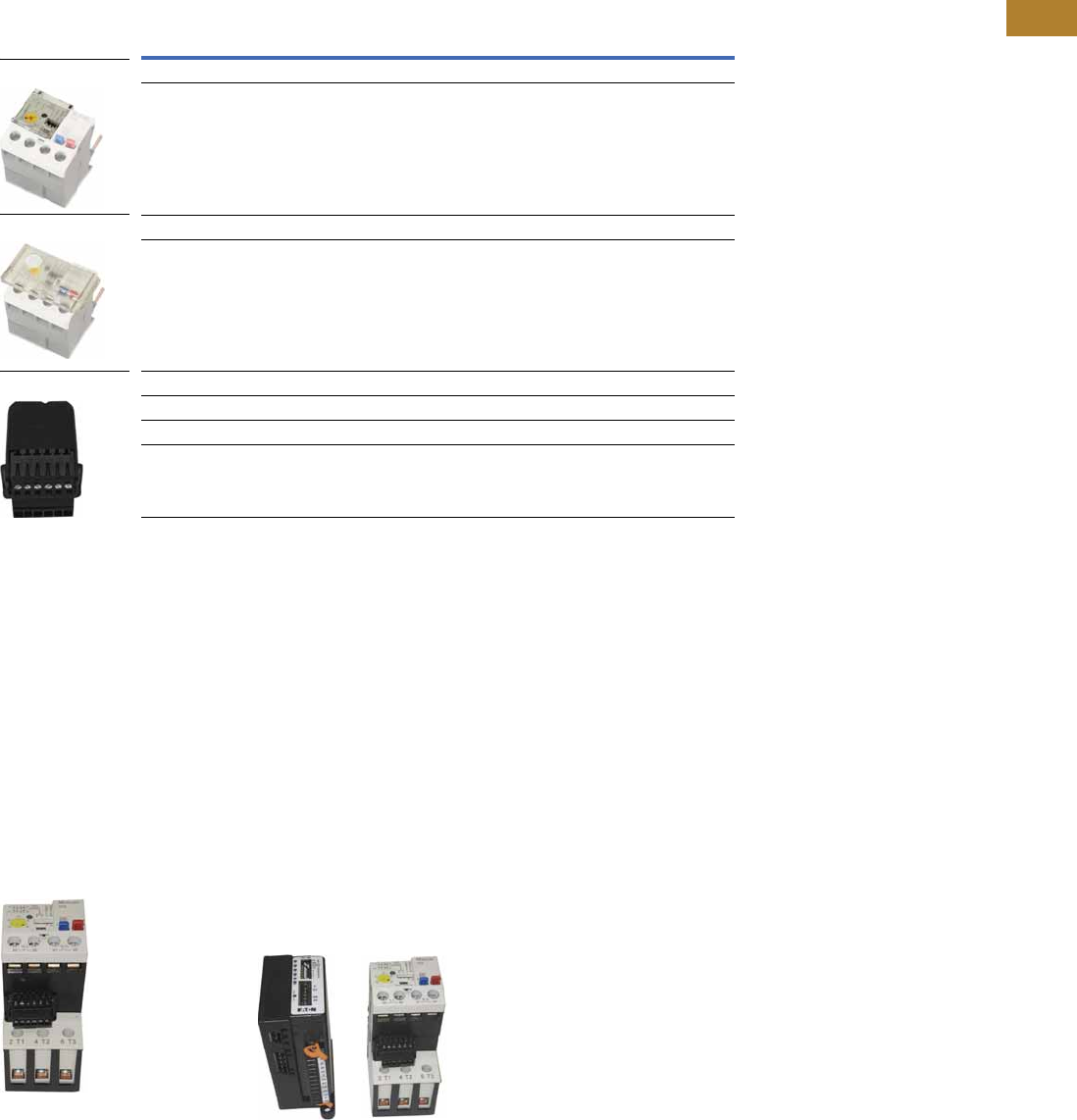
Volume 5—Motor Control and Protection CA08100006E—May 2016 www.eaton.com V5-T2-53
2
2
2
2
2
2
2
2
2
2
2
2
2
2
2
2
2
2
2
2
2
2
2
2
2
2
2
2
2
2
2.1
NEMA Contactors and Starters
Freedom Series
Accessories
CT Kits
Accessories
Communication
The C440/XTOE is provided with two levels of communication capability.
Basic Communication via
Expansion Module—
Monitoring Only
Basic communication on
the C440 is accomplished
using an expansion module
(C440-XCOM). The expansion
module plugs into the
expansion bay on the C440
overload relay, enabling
communications with the
overload via their Modbus
RTU (RS-485) network. No
additional cards or modules are
required. See figure below.
Basic Communication—
Modbus
Advanced
Communication—
Monitoring and Control
C440 also has the ability to
communicate on industrial
protocols such as Modbus
RTU, DeviceNet, PROFIBUS,
Modbus TCP, and EtherNet/IP
while providing control
capability using I/O.
An expansion module (C440-
XCOM) combined with a
communication adapter
(C440-COM-ADP) and a
communication module
allows easy integration onto
the customer's network.
Seefigurebelow.
2
Advanced Communication—
Communication Adapter with
Communication Module
Advanced
Communication—
Communication Adapter 2
The communication adapter
(C440-COM-ADP) is required
for obtaining control capability
via communications within
the C440 family. Combined
with a communication
module, the customer is
provided with flexible
mounting options (DIN rail or
panel) along with four inputs
and two outputs (24 Vdc or
120 Vac) as standard.
Notes
1Customer can wire remote mounted button to reset module (that is, 22 mm pushbutton, catalog number M22-D-B-GB14-K10).
2Modbus TCP and EtherNet/IP communication modules do not require the C440-COM-ADP communication adapter.
Description Catalog Number
Safety Cover
Clear Lexan cover that mounts on top of the FLA dial and DIP switches when closed. ZEB-XSC
Reset Bar
Assembles to the top of the overload to provide a larger target area for door
mounted reset operators.
ZEB-XRB
Remote Reset
Remote reset module (24 Vdc) 1C440-XCOM
Remote reset module (120 Vac) 1ZEB-XRR-120
Remote reset module (24 Vac) 1ZEB-XRR-24
Safety Cover
Reset Bar
Remote Reset
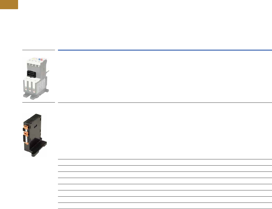
V5-T2-54 Volume 5—Motor Control and Protection CA08100006E—May 2016 www.eaton.com
2
2
2
2
2
2
2
2
2
2
2
2
2
2
2
2
2
2
2
2
2
2
2
2
2
2
2
2
2
2
2.1
NEMA Contactors and Starters
Freedom Series
The following information can be viewed using the communication option:
●Motor status—running,
stopped, tripped or
resetting
●Individual rms phase
currents (A, B, C)
●Average of three-phase
rms current
●Percent thermal capacity
●Fault codes (only available
prior to reset)
●Percent phase unbalance
●Ground fault current and
percent
●Overload relay settings—
trip class, DIP switch
selections, reset selections
●Modbus address (can be
set over the network)
Communication Accessories
Description Catalog Number
Expansion module (Remote Reset/Modbus RTU, RS-485 Communication) C440-XCOM
Communication adapter kit (DIN C Panel mounted adapter, required for advance communication option) C440-COM-ADP
DeviceNet communication module kit—120V I/O (consists of C440-XCOM + C441K + C440-COM-ADP) C440-DN-120
DeviceNet communication module kit—24 Vdc I/O (consists of C440-XCOM + C441L + C440-COM-ADP) C440-DN-24
PROFIBUS communication module kit—120V I/O (consists of C440-XCOM + C441S + C440-COM-ADP) C440-DP-120
PROFIBUS communication module kit—24V I/O (consists of C440-XCOM + C441Q + C440-COM-ADP) C440-DP-24
Modbus communication module kit—120V I/O (consists of C440-XCOM + C441N + C440-COM-ADP) C440-MOD-120
Modbus communication module kit—24 Vdc I/O (consists of C440-XCOM + C441P + C440-COM-ADP) C440-MOD-24
Modbus TCP/Ethernet IP communication module kit—120V I/O (consists of C440-XCOM + C441U) C440-ET-120
Modbus TCP/Ethernet IP communication module kit—24V I/O (consists of C440-XCOM + C441V) C440-ET-24
Expansion Module
Communication
Adapter

Volume 5—Motor Control and Protection CA08100006E—May 2016 www.eaton.com V5-T2-55
2
2
2
2
2
2
2
2
2
2
2
2
2
2
2
2
2
2
2
2
2
2
2
2
2
2
2
2
2
2
2.1
NEMA Contactors and Starters
Freedom Series
Modbus Communication Module
The Modbus communication
module combined with an
expansion module and a
communication adapter
provides monitoring and
control capability to the
C440/XTOE electronic
overload relay via Modbus
RTU communications.
These modules also provide
convenient I/O with 24 Vdc or
120 Vac options.
Features and Benefits
●The Modbus
communication module is
capable of baud rates
up to 115K
●The Modbus address and
baud rate configuration can
be easily changed using
the HMi user interface
●Modbus address and baud
rate are set via convenient
DIP switches; LEDs are
provided to display
Modbus traffic
●Configuration with
common Modbus
configuration tools
●Terminals
●Unique locking
mechanism provides for
easy removal of the
terminal block with the
field wiring installed
●Each terminal is marked
for ease of wiring and
troubleshooting
●Selectable I/O assemblies
●4IN/2OUT
●Signal types include
24 Vdc I/O and
120 Vac I/O
●Each I/O module is
optically isolated
between the field I/O
and the network adapter
to protect the I/O and
communication circuits
from possible damage
due to transients and
ground loops
●Input Module features a
user-definable input
debounce, which limits
the effects of transients
and electrical noise
●Output Module supports
a user-definable safe
state for loss of
communication; hold
last state, ON or OFF
DeviceNet Communication Modules
The DeviceNet communication
module combined with an
expansion module and a
communication adapter
provides monitoring and
control capability to the
C440/XTOE electronic
overload relay via DeviceNet
communications. These
modules also provide
convenient I/O with 24 Vdc
or 120 Vac options.
Features and Benefits
●Communication to
DeviceNet uses only one
DeviceNet MAC ID
●Configuration
●DeviceNet MAC ID and
Baud rate are set via
convenient DIP switches
with an option to set
from the network
●Advanced configuration
available using common
DeviceNet tools
●Terminals
●Unique locking
mechanism provides for
easy removal of the
terminal block with the
field wiring installed
●Each terminal is marked
for ease of wiring and
troubleshooting
●Selectable I/O assemblies
●4IN/2OUT
●Signal types include
24 Vdc I/O and
120 Vac I/O
●Each I/O module is
optically isolated
between the field I/O
and the network adapter
to protect the I/O and
communication circuits
from possible damage
due to transients and
ground loops
●Input Module features a
user-definable input
debounce, which limits
the effects of transients
and electrical noise
●Output Module supports
a user-definable safe
state for loss of
communication; hold
last state, ON or OFF
●Combined status LED
Modbus
Communication Module
DeviceNet
Communication Module
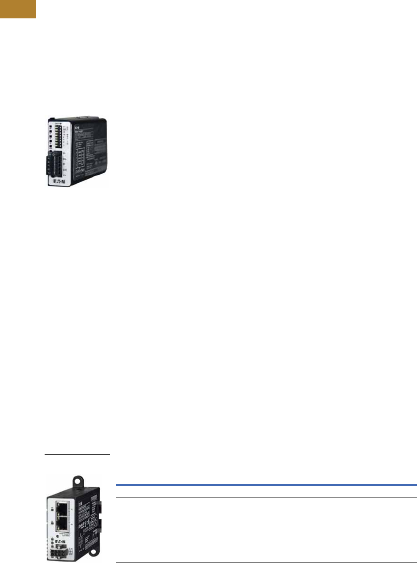
V5-T2-56 Volume 5—Motor Control and Protection CA08100006E—May 2016 www.eaton.com
2
2
2
2
2
2
2
2
2
2
2
2
2
2
2
2
2
2
2
2
2
2
2
2
2
2
2
2
2
2
2.1
NEMA Contactors and Starters
Freedom Series
PROFIBUS Communication Modules
The PROFIBUS
communication module
combined with an expansion
module and a communication
adapter provides monitoring
and control capability to the
C440 / XTOE electronic
overload relay via PROFIBUS
communications. These
modules also provide
convenient I/O with 24 Vdc or
120 Vac options.
Features and Benefits
●The PROFIBUS
communication module is
capable of baud rates
up to 12 Mb
●PROFIBUS address is
set via convenient DIP
switches; LEDs are
provided to display
PROFIBUS status
●Intuitive configuration
with common PROFIBUS
configuration tools
●Terminals
●Unique locking
mechanism provides for
easy removal of the
terminal block with the
field wiring installed
●Each terminal is marked
for ease of wiring and
troubleshooting
●Selectable I/O assemblies
●4IN/2OUT
●Signal types include
24 Vdc I/O and
120 Vac I/O
●Each I/O module is
optically isolated
between the field I/O
and the network adapter
to protect the I/O and
communication circuits
from possible damage
due to transients and
ground loops
●Input Module features a
user-definable input
debounce, which limits
the effects of transients
and electrical noise
●Output Module supports
a user-definable safe
state for loss of
communication; hold
last state, ON or OFF
Ethernet Communication Modules
The Ethernet communication
module combined with an
expansion module provides
both Modbus TCP and
EtherNet/IP communication
capabilities with built-in HTTP
web services to the C440/
XTOE overload relay. Unlike
the other communications
modules, a communication
adapter (C440-COM-ADP) is
not required when using the
Ethernet communication
module in C440/XTOE
applications.
The Ethernet communication
module has built-in I/O
providing communication,
monitoring and control for the
C440/XTOE overload relay.
Features and Benefits
●Supports Modbus TCP or
EtherNet/IP in a single
device
●Contains an internal
embedded switch which
provides two Ethernet
ports allowing linear or ring
network configurations
●Embedded web services
allow for simple
configuration and
monitoring through
Internet Explorer
●IP Address is set via
convenient DIP Switches
located on the device
●Terminals
●Unique locking
mechanism provides for
easy removal of the
terminal block with the
field wiring installed
●Each terminal is marked
for ease of wiring and
troubleshooting
●Selectable I/O assemblies
●4IN/2OUT
●Signal types include
24 Vdc I/O and
120 Vac I/O
●Each I/O module is
optically isolated
between the field I/O
and the network adapter
to protect the I/O and
communication circuits
from possible damage
due to transients and
ground loops
●Input Module features a
user-definable input
debounce, which limits
the effects of transients
and electrical noise
●Output Module supports
a user-definable safe
state for loss of
communication; hold
last state, ON or OFF
Ethernet Communication Module
PROFIBUS
Communication Module
Description I/O
Catalog
Number
Modbus TCP / EtherNet/IP Communication Module, 4IN/2OUT (DIN/Panel) 120 Vac C441U
Modbus TCP / EtherNet/IP Communication Module, 4IN/2OUT (DIN/Panel) 24 Vdc C441V
Ethernet with
I/O Module

Volume 5—Motor Control and Protection CA08100006E—May 2016 www.eaton.com V5-T2-57
2
2
2
2
2
2
2
2
2
2
2
2
2
2
2
2
2
2
2
2
2
2
2
2
2
2
2
2
2
2
2.1
NEMA Contactors and Starters
Freedom Series
Technical Data and Specifications
Electronic Overload Relays up to 1500A
Specification
Description 45 mm 55 mm 110 mm
Electrical Ratings Range Range Range
Operating voltage (three-phase) and frequency 690 Vac (60/50 Hz) 690 Vac (60/50 Hz) 690 Vac (60/50 Hz)
FLA Range
0.33–1.65A
1–5A
4–20A
9–45A
20–100A 28–140A (NEMA)
35–175A (IEC)
Use with Contactors
XT IEC frames B, C, D D, F, G G, H
Freedom NEMA sizes 00, 0, 1, 2 3 4
Tri p C l a s s
10A, 10, 20, 30
Selectable
10A, 10, 20, 30
Selectable
10A, 10, 20, 30
Selectable
Motor Protection
Thermal overload setting 1.05 x FLA: does not trip
1.15 x FLA: overload trip
1.05 x FLA: does not trip
1.15 x FLA: overload trip
1.05 x FLA: does not trip
1.15 x FLA: overload trip
Feature Range Range Range
Phase loss Fixed threshold 50% Fixed threshold 50% Fixed threshold 50%
Phase unbalance (selectable: enable/disable) Fixed threshold 50% Fixed threshold 50% Fixed threshold 50%
Ground fault (selectable: enable/disable) 50% of FLA dial setting
>150% = 2 sec
>250% = 1 sec
50% of FLA dial setting
>150% = 2 sec
>250% = 1 sec
50% of FLA dial setting
>150% = 2 sec
>250% = 1 sec
Reset Manual/automatic Manual/automatic Manual/automatic
Indicators
Trip status Orange flag Orange flag Orange flag
Mode LED One flash: Overload operating properly
Two flashes: Current is above FLA dial
setting—pending trip
One flash: Overload operating properly
Two flashes: Current is above FLA dial
setting—pending trip
One flash: Overload operating properly
Two flashes: Current is above FLA dial
setting—pending trip
Options
Remote reset Yes Yes Yes
Reset bar Yes Yes Yes
Communication expansion module Yes Yes Yes
Communication adapter Yes Yes Yes
Capacity
Load terminals
Terminal capacity 12–10 AWG (4–6 mm2)
8–6 AWG (6–16 mm2)
6–1 AWG (16–50 mm2) 8–4/0 AWG (10–95 mm2)
Tightening torque 20–25 lb-in (2.3–2.8 Nm)
25–30 lb-in (2.8–3.4 Nm)
25–30 lb-in (2.8–3.4 Nm) 124 lb-in (14 Nm)
Input, auxiliary contact and remote reset terminals
Terminal capacity 2 x (18–12) AWG 2 x (18–12) AWG 2 x (18–12) AWG
Tightening torque 7–11 lb-in (0.8–1.2 Nm) 7–11 lb-in (0.8–1.2 Nm) 7–11 lb-in (0.8–1.2 Nm)
Volt ages
Insulation voltage Ui (three-phase) 690 Vac 690 Vac 690 Vac
Insulation voltage Ui (control) 500 Vac 500 Vac 500 Vac
Rated impulse withstand voltage 6000 Vac 6000 Vac 6000 Vac
Overvoltage category/pollution degree III/3 III/3 III/3

V5-T2-58 Volume 5—Motor Control and Protection CA08100006E—May 2016 www.eaton.com
2
2
2
2
2
2
2
2
2
2
2
2
2
2
2
2
2
2
2
2
2
2
2
2
2
2
2
2
2
2
2.1
NEMA Contactors and Starters
Freedom Series
Electronic Overload Relays up to 1500A, continued
Specification
Description 45 mm 55 mm 110 mm
Auxiliary and Control Circuit Ratings
Conventional thermal continuous current 5A 5A 5A
Rated operational current—IEC AC-15
Make contact (1800 VA)
120V 15A 15A 15A
240V 15A 15A 15A
415V 0.5A 0.5A 0.5A
500V 0.5A 0.5A 0.5A
Break contact (180 VA)
120V 1.5A 1.5A 1.5A
240V 1.5A1.5A1.5A
415V 0.9A 0.9A 0.9A
500V 0.8A 0.8A 0.8A
IEC DC-13 (L/R F 15 ms1)
0–250V 1.0A 1.0A 1.0A
Rated operational current—UL B600
Make contact (3600 VA)
120V 30A 30A 30A
240V 15A 15A 15A
480V 7.5A 7.5A 7.5A
600V 6A 6A 6A
Break contact (360 VA)
120V 3A 3A 3A
240V 1.5A1.5A1.5A
480V 0.75A 0.75A 0.75A
600V 0.6A 0.6A 0.6A
R300—Vdc ratings (28 VA)
0–120V 0.22A 0.22A 0.22A
250V 0.11A 0.11A 0.11A
Short-Circuit Rating without Welding
Maximum fuse 6A gG/gL 6A gG/gL 6A gG/gL
Environmental Ratings
Ambient temperature (operating) –13° to 149°F (–25° to 65°C) –13° to 149°F (–25° to 65°C) –13° to 149°F (–25° to 65°C)
Ambient temperature (storage) –40° to 185°F (–40° to 85°C) –40° to 185°F (–40° to 85°C) –40° to 185°F (–40° to 85°C)
Operating humidity UL 991 (H3) 5% to 95% non-condensing 5% to 95% non-condensing 5% to 95% non-condensing
Altitude (no derating) NEMA ICS1 2000m 2000m 2000m
Shock (IEC 600068-2-27) 15g any direction 15g any direction 15g any direction
Vibration (IEC 60068-2-6) 3g any direction 3g any direction 3g any direction
Pollution degree per IEC 60947-4-1 3 for product (2 for pcb) 3 for product (2 for pcb) 3 for product (2 for pcb)
Ingress protection IP20 IP20 IP20
Protection against direct contact when actuated from
front (IEC 536)
Finger- and back-of-hand proof Finger- and back-of-hand proof Finger- and back-of-hand proof
Mounting position Any Any Any
Climatic proofing Damp heat, constant to IEC 60068-2-30 Damp heat, constant to IEC 60068-2-30 Damp heat, constant to IEC 60068-2-30

Volume 5—Motor Control and Protection CA08100006E—May 2016 www.eaton.com V5-T2-59
2
2
2
2
2
2
2
2
2
2
2
2
2
2
2
2
2
2
2
2
2
2
2
2
2
2
2
2
2
2
2.1
NEMA Contactors and Starters
Freedom Series
Electronic Overload Relays up to 1500A, continued
Specification
Description 45 mm 55 mm 110 mm
Electrical/EMC
Radiated emissions
IEC 60947-4-1-Table 15
EN 55011 (CISPIR 11) Group 1, Class A, ISM
30 mHz to 1000 mHz 30 mHz to 1000 mHz 30 mHz to 1000 mHz
Conducted emissions
IEC 60947-4-1-Table 14
EN 55011 (CISPIR 11) Group 1; Class ISM
0.15 mHz to 30 mHz 0.15 mHz to 30 mHz 0.15 mHz to 30 mHz
ESD immunity
IEC 60947-4-1 (Table 13)
±8 kV air, ±6 kV contact ±8 kV air, ±6 kV contact ±8 kV air, ±6 kV contact
Radiated immunity
IEC 60947-4-1
IEC 61000-4-3
10 V/m 80 mHz–1000 mHz
3 V/m from 1.4 to 2.7 gHz
80% amplitude modulated
1 kHz sine wave
10 V/m 80 mHz–1000 mHz
3 V/m from 1.4 to 2.7 gHz
80% amplitude modulated
1 kHz sine wave
10 V/m 80 mHz–1000 mHz
3 V/m from 1.4 to 2.7 gHz
80% amplitude modulated
1 kHz sine wave
Conducted immunity
IEC 60947-4-1, IEC 61000-4-6
140 dub (10V rms)
150 kHz–100 mHz
140 dub (10V rms)
150 kHz–100 mHz
140 dub (10V rms)
150 kHz–100 mHz
Fast transient immunity
IEC 60947-4-1 (Table 13)
IEC 61000-4-4
±4 kV using direct method
with accessory installed in expansion bay
±2 kV using direct method
±4 kV using direct method
with accessory installed in expansion bay
±2 kV using direct method
±4 kV using direct method
with accessory installed in expansion bay
±2 kV using direct method
Surge immunity
IEC 60947-4-1 (Table 13)
IEC 61000-4-5 a Class 4
Three-phase power inputs:
±4 kV line-to-line (DM)
±4 kV line-to-ground (CM)
Three-phase power inputs:
±4 kV line-to-line (DM)
±4 kV line-to-ground (CM)
Three-phase power inputs:
±4 kV line-to-line (DM)
±4 kV line-to-ground (CM)
With accessory installed in expansion bay:
±2 kV line-to-line (DM) –>1.2/50 us;
2 kV line-to-earth, 1 kV line-to-line
±4 kV line-to-ground (CM)
With accessory installed in expansion bay:
±2 kV line-to-line (DM) –>1.2/50 us;
2 kV line-to-earth, 1 kV line-to-line
±4 kV line-to-ground (CM)
With accessory installed in expansion bay:
±2 kV line-to-line (DM) –>1.2/50 us;
2 kV line-to-earth, 1 kV line-to-line
±4 kV line-to-ground (CM)
Power freq. magnetic field immunity
IEC 60947-4-1, IEC 61000-4-8
30 A/m, 50 Hz 30 A/m, 50 Hz 30 A/m, 50 Hz
Electromagnetic field
IEC 60947-4-1 Table 13, IEC 61000-4-3
10 V/m 10 V/m 10 V/m
Distortion IEEE 519 5% THD max., 5th harmonic 3% max. 5% THD max., 5th harmonic 3% max. 5% THD max., 5th harmonic 3% max.
Electrostatic discharge (ESD)
IEC 61000-4-2, EN 61131-2
4 kV contact
8 kV air discharge
4 kV contact
8 kV air discharge
4 kV contact
8 kV air discharge
Electrical fast transient (EFT)
IEC 61000-4-4, EN 61131-2
±2 kV using direct method ±2 kV using direct method ±2 kV using direct method
Surge immunity
IEC 61000-4-5, EN 61131-2
±2 kV line-to-ground (CM) ±2 kV line-to-ground (CM) ±2 kV line-to-ground (CM)

V5-T2-60 Volume 5—Motor Control and Protection CA08100006E—May 2016 www.eaton.com
2
2
2
2
2
2
2
2
2
2
2
2
2
2
2
2
2
2
2
2
2
2
2
2
2
2
2
2
2
2
2.1
NEMA Contactors and Starters
Freedom Series
Communication Modules
Note
1Relates to C441M only.
Description Modbus DeviceNet PROFIBUS Ethernet
Electrical/EMC
Radiated emissions
IEC 60947-4-1—Table 15, EN 55011
(CISPIR 11) Group 1, Class A
30–1000 mHz 30–1000 mHz 30–1000 mHz 30–1000 mHz
Conducted emissions
IEC 60947-4-1—Table 14, EN 55011
(CISPIR 11) Group 1, Class A
0.15–30 mHz 0.15–30 mHz 0.15–30 mHz 0.15–30 mHz
ESD immunity
IEC 60947-4-1 (Table 13)
±8 kV air, ±4 kV contact ±8 kV air, ±4 kV contact ±8 kV air, ±4 kV contact ±8 kV air, ±4 kV contact
Radiated immunity
IEC 60947-4-1
10 V/m 80–1000 mHz
80% amplitude modulated
1 kHz sine wave
10 V/m 80–1000 mHz
80% amplitude modulated
1 kHz sine wave
10 V/m 80–1000 mHz
80% amplitude modulated
1 kHz sine wave
10 V/m 80–1000 mHz
80% amplitude modulated
1 kHz sine wave
Conducted immunity
IEC 60947-4-1
140 dBuV (10V rms)
150 kHz–80 mHz
140 dBuV (10V rms)
150 kHz–80 mHz
140 dBuV (10V rms)
150 kHz–80 mHz
140 dBuV (10V rms)
150 kHz–80 mHz
Fast transient immunity
IEC 60947-4-1 (Table 13) IEC 6100-4-4
±2 kV using direct method ±2 kV supply and control,
±1 kV communication
±2 kV supply and control,
±1 kV communication
±2 kV supply and control,
±1 kV communication
Surge immunity
IEC 60947-4-1 (Table 13)
IEC 61000-4-5 Class 3
User IO and communication lines 1:
±1 kV line-to-line (DM)
±2 kV line-to-ground (CM)
User IO and communication lines:
±0.5 kV line-to-line (DM)
±1 kV line-to-ground (CM)
User IO and communication lines:
±0.5 kV line-to-line (DM)
±1 kV line-to-ground (CM)
User IO and communication lines:
±0.5 kV line-to-line (DM)
±1 kV line-to-ground (CM)
Electromagnetic field 1
IEC 60947-4-1 (Table 13) IEC 61000-4-3
10 V/m 10 V/m 10 V/m 10 V/m
Environmental Ratings
Ambient temperature (operating) –4° to 122°F (–20° to 50°C) –13° to 122°F (–25° to 50°C) –13° to 122°F (–25° to 50°C) –13° to 122°F (–25° to 50°C)
Ambient temperature (storage) –40° to 185°F (–40° to 85°C) –40° to 185°F (–40° to 85°C) –40° to 185°F (–40° to 85°C) –40° to 185°F (–40° to 85°C)
Operating humidity 5–95% noncondensing 5–95% noncondensing 5–95% noncondensing 5–95% noncondensing
Altitude (no derating) 2000m 2000m 2000m 2000m
Shock (IEC 600068-2-27) 15G any direction 15G any direction 15G any direction 15G any direction
Vibration (IEC 60068-2-6) 3G any direction 3G any direction 3G any direction 3G any direction
Pollution degree per IEC 60947-1 3 3 3 3
Degree of protection IP20 IP20 IP20 IP20
Overvoltage category per UL 508 III III III III
DeviceNet
DeviceNet connections — Group 2, polling, bit strobe,
explicit, no UCMM
——
DeviceNet baud rate — 125K, 250K, 500K — —
Ethernet
Ethernet connections — — — Integrated two-port switch with dual
RJ45 Ethernet connections
Ethernet type — — — Ethernet 10/100 Mbs, AutoMDX,
Auto Negotiation
PROFIBUS
PROFIBUS connections — — Group 2, polling, bit strobe,
explicit, no UCMM
—
PROFIBUS baud rate — — 9.6K, 19.2K, 45.45K, 93.75K, 187.5K,
500K, 1.5M, 3M, 6M, 12M
—

Volume 5—Motor Control and Protection CA08100006E—May 2016 www.eaton.com V5-T2-61
2
2
2
2
2
2
2
2
2
2
2
2
2
2
2
2
2
2
2
2
2
2
2
2
2
2
2
2
2
2
2.1
NEMA Contactors and Starters
Freedom Series
Communication Modules, continued
Note
1Relates to C441M only.
Description Modbus DeviceNet PROFIBUS Ethernet
C441_ 24 Vdc Input
Nominal input voltage 24 Vdc 24 Vdc 24 Vdc 24 Vdc
Operating voltage 18–30 Vdc 18–30 Vdc 18–30 Vdc 18–30 Vdc
Number of inputs 4 4 4 4
Signal delay 5 ms (programmable to 65 sec) 5 ms (programmable to 65 sec) 5 ms (programmable to 65 sec) 5 ms (programmable to 65 sec)
OFF-state voltage <6 Vdc <6 Vdc <6 Vdc <6 Vdc
ON-state voltage >18 Vdc >18 Vdc >10 Vdc >18 Vdc
Nominal input current 5 mA 5 mA 5 mA 5 mA
Isolation 1500V 1500V 1500V 1500V
Terminal screw torque 7–9 in-lb 7–9 in-lb 7–9 in-lb 7–9 in-lb
24V source current 50 mA 50 mA 50 mA 50 mA
Operating Voltage Range—DC Input Modules
OFF state 0–6 Vdc 0–6 Vdc 0–6 Vdc 0–6 Vdc
Transition region 6–18 Vdc 6–18 Vdc 6–18 Vdc 6–18 Vdc
ON state 18–30 Vdc 18–30 Vdc 18–30 Vdc 18–30 Vdc
C441_ 120 Vac Input
Nominal input voltage 120 Vac 120 Vac 120 Vac 120 Vac
Operating voltage 80–140 Vac 80–140 Vac 80–140 Vac 80–140 Vac
Number of inputs 4 4 4 4
OFF-state voltage <30 Vac <30 Vac <20 Vac <30 Vac
ON-state voltage >80 Vac >80 Vac >70 Vac >80 Vac
Nominal input current 15 mA 15 mA 15 mA 15 mA
Signal delay 1/2 cycle 1/2 cycle 1/2 cycle 1/2 cycle
Isolation 1500V 1500V 1500V 1500V
Terminal screw torque 7–9 in-lb 7–9 in-lb 7–9 in-lb 7–9 in-lb
Operating Voltage Range—AC Input Modules
OFF state 0–30 Vac 0–30 Vac 0–30 Vac 0–30 Vac
Transition region 30–80 Vac 30–80 Vac 30–80 Vac 30–80 Vac
ON state 80–140 Vac 80–140 Vac 80–140 Vac 80–140 Vac
Output Modules
Nominal voltage 120 Vac
24 Vdc
120 Vac
24 Vdc
120 Vac
24 Vdc
120 Vac
24 Vdc
Number of outputs (2) 1NO Form A
1NO/NC Form C
(2) 1NO Form A
1NO/NC Form C
(2) 1NO Form A
1NO/NC Form C
(2) 1NO Form A
1NO/NC Form C
Relay OFF time 3 ms 3 ms 3 ms 3 ms
Relay ON time 7 ms 7 ms 7 ms 7 ms
Max. current per point 15A (B300 rated) 5A (B300 rated) 5A (B300 rated) 5A (B300 rated)
Electrical life 100,000 cycles 100,000 cycles 100,000 cycles 100,000 cycles
Mechanical life 1,000,000 cycles 1,000,000 cycles 1,000,000 cycles 1,000,000 cycles

V5-T2-62 Volume 5—Motor Control and Protection CA08100006E—May 2016 www.eaton.com
2
2
2
2
2
2
2
2
2
2
2
2
2
2
2
2
2
2
2
2
2
2
2
2
2
2
2
2
2
2
2.1
NEMA Contactors and Starters
Freedom Series
Short Circuit Ratings (North America CSA, cUL)
Changes to UL 508A and NEC in recent years have brought a focus to control panel safety with
regard to short-circuit current ratings (SCCR). Eaton’s C440 electronic overload relays combined
with XT series IEC and Freedom Series NEMA contactors provide a wide variety of SCCR
solutions needed for a variety of applications. The SCCR data in this document reflects the
latest information as of April 2010.
C440/XT Standalone Overload Relays (XT, C440)
NEMA Freedom Series Starters with C440 Electronic Overload Relays
Overload
FLA Range
Maximum
Operating
Voltage
Standard-Fault Short Circuit Data High-Fault Short Circuit Data
600V (kA)
Maximum
Fuse Size (A)
(RK5)
Maximum
Breaker
Size (A)
Fuses (RK5, J, CC) Thermal-Magnetic Circuit Breakers
480V (kA) 600V (kA)
Maximum
Fuse Size 480V (kA) 600V (kA)
Maximum
Breaker Size
0.33–1.65A600 Vac1 6 15 ——————
1–5A 600 Vac 5 20 20 100 100 30 100 35 20
4–20A 600 Vac 5 80 80 100 100 100 100 35 80
9–45A 600 Vac 5 175 175 100 100 100 100 35 100/175 (480/600)
20–100A 600 Vac 10 400 400 100 100 200 150 35 250/400 (480/600)
28–140A 600 Vac 10 450 500 100 100 400 100 65 400
35–175A 690 Vac 10 500 (gG) 350 (690 Vac)
320 (415 Vac)
100 100 500 (gG) 100 (415 Vac) — 350 (LGC3350)
320 (NZMH3)
NEMA
Size
Maximum
Operating
Voltage
High-Fault Short Circuit Data
Maximum
Fuse Size
Thermal-Magnetic Circuit Breakers
Fuses (RK5, J, CC)
480V 600V 480V 600V
Maximum
Breaker Size
00 0.33–1.65A 100 100 30 — — —
1–5A 100 100 30 100 35 35
4–20A 100 100 30 100 35 35
0 0.33–1.65A 100 100 60 — — —
1–5A 100 100 60 100 35 70
4–20A 100 100 60 100 35 70
1 0.33–1.65A 100 100 100 — — —
1–5A 100 100 100 100 35 100
4–20A 100 100 100 100 35 100
9–45A 100 100 100 100 35 100
2 1–5A 100 100 100 100 35 175
4–20A 100 100 100 100 35 175
9–45A 100 100 100 100 35 175
3 20–100A 100 100 200 50 50 250
4 28–140A 100 100 400 100 65 300

Volume 5—Motor Control and Protection CA08100006E—May 2016 www.eaton.com V5-T2-63
2
2
2
2
2
2
2
2
2
2
2
2
2
2
2
2
2
2
2
2
2
2
2
2
2
2
2
2
2
2
2.1
NEMA Contactors and Starters
Freedom Series
Dimensions
Approximate Dimensions in Inches (mm)
NEMA Starters
Full Voltage Non-Reversing Starters
NEMA SizeABCDE
00, 0 1.97 (50.0) 6.60 (167.6) 4.90 (124.5) — 6.18 (157.0)
1, 2 2.60 (65.0) 7.10 (180.0) 4.98 (126.5) 2.00 (50.8) 6.50 (165.0)
3 3.00 (76.2) 11.40 (289.6) 5.92 (150.3) 1.77 (44.9) 10.81 (274.6)
4 7.10 (179.0) 17.00 (432.0) 7.00 (177.0) 3.70 (94.0) 16.30 (415.0)
5 7.00 (177.8) 17.81 (452.3) 8.08 (205.2) 6.00 (152.4) 16.01 (406.6)
A
B
C
E
Sizes 00, 0
A
B
CD
E
A
B
C
D
E
A
B
C
D
E
A
B
C
D
E
Sizes 1, 2
Size 4
Size 5Size 3
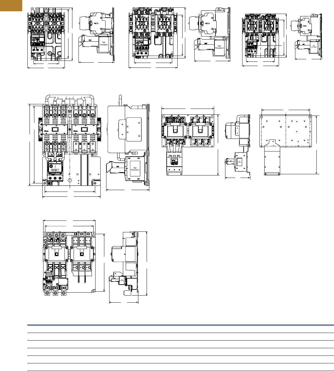
V5-T2-64 Volume 5—Motor Control and Protection CA08100006E—May 2016 www.eaton.com
2
2
2
2
2
2
2
2
2
2
2
2
2
2
2
2
2
2
2
2
2
2
2
2
2
2
2
2
2
2
2.1
NEMA Contactors and Starters
Freedom Series
Approximate Dimensions in Inches (mm)
Full Voltage Reversing Starters
NEMA SizeABCDE
00, 0 5.20 (132.0) 7.40 (187.0) 4.90 (125.0) 3.50 (89.0) 6.90 (174.0)
1 6.70 (171.0) 7.10 (180.0) 4.98 (126.5) 5.25 (133.0) 5.70 (144.0)
2 6.70 (171.0) 8.10 (205.0) 4.98 (126.5) 5.25 (133.0) 6.70 (170.0)
3 8.08 (205.2) 11.35 (288.3) 6.00 (152.0) 7.00 (177.8) 10.77 (273.6)
4 14.60 (371.0) 17.10 (433.0) 7.00 (177.0) 13.50 (343.0) 16.30 (145.0)
5 14.50 (368.3) 17.81 (452.3) 8.06 (204.8) 13.50 (342.9) 16.00 (406.6)
Sizes 00, 0
A
B
C
D
E
A
B
C
D
E
Size 5
Size 1
A
B
C
D
E
A
B
C
D
E
Size 3
A
B
C
D
E
Size 2
A
B
C
D
E
Size 4
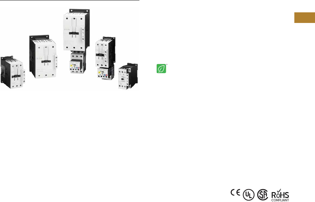
Volume 5—Motor Control and Protection CA08100006E—May 2016 www.eaton.com V5-T2-65
2
2
2
2
2
2
2
2
2
2
2
2
2
2
2
2
2
2
2
2
2
2
2
2
2
2
2
2
2
2
2.2
NEMA Contactors and Starters
Space-Savings Series
NEMA Space-Savings Family of Contactors and Starters
Contents
Description Page
Contactors and Starters
Catalog Number Selection . . . . . . . . . . . . . . . . V5-T2-66
Product Selection . . . . . . . . . . . . . . . . . . . . . . . V5-T2-66
Accessories . . . . . . . . . . . . . . . . . . . . . . . . . . . V5-T2-68
Renewal Parts . . . . . . . . . . . . . . . . . . . . . . . . . V5-T2-72
Technical Data and Specifications . . . . . . . . . . V5-T2-73
Dimensions . . . . . . . . . . . . . . . . . . . . . . . . . . . V5-T2-97
An Eaton
Green Solution
Contactors and Starters
Product Description
The Eaton NEMA® Space-
Savings line of contactors
and starters includes non-
reversing and reversing
contactors, electronic
overload relays and a variety
of related accessories.
Because the Space-Savings
family meets IEC, UL®, CSA®
and CE standards, it is the
perfect product solution for
applications all over the
world. The compact and easy
to install Space-Savings line
of NEMA contactors and
starters is the efficient and
effective solution for
customer applications from
Size 0 through Size 5.
Application Description
The Space-Savings line of
NEMA power control was
engineered to provide highly
effective control and
protection for a variety of
loads, including motors,
compressors, pumps,
resistive, capacitor banks,
isolation and others.
The Space-Savings
contactors are perfectly
suited for use in Motor
Control Center applications
where bucket space sizing is
critical. With both AC and DC
control and flexible
communication options, the
Space-Savings family can be
easily integrated into various
customer applications.
Features and Benefits
●AC control from
120V to 600V 50/60 Hz
●24 Vdc control
●Reversing or non-reversing
contactors and starters
●XTOE self-powered
electronic overload relay
●Non-reversing starters
to NEMA Size 5
●Panel or DIN rail mounting
to NEMA Size 2
●IP20 finger and back-of-
hand proof
●Large ambient temperature
range, –25 to 50°C
[–13 to 122°F]
●AC and DC controlled
contactors in the same
compact frame
●Low power consumption
AC and DC coils
●Built-in NO or NC auxiliary
contacts to 32A
●Plug-in accessories for
reduced installation time
●Coil replacement on NEMA
Size 0–5
●Contact replacement on
NEMA Size 1–5
●Integrated suppressor
NEMA Size 0–4 DC
operated contactors and
NEMA Size 5 AC and DC
operated contactors
Standards and Certifications
●IEC EN 60947
●CE approved
●UL
●CSA
●ATEX
●RoHS
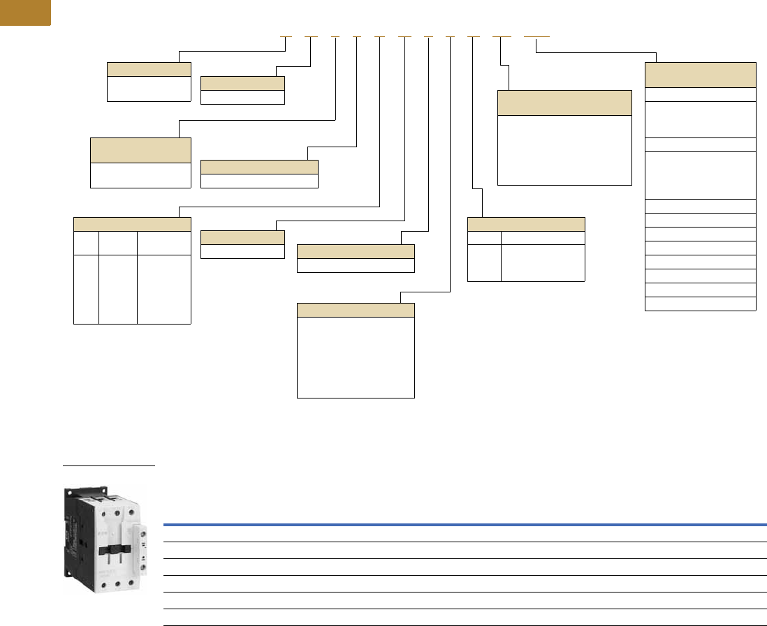
V5-T2-66 Volume 5—Motor Control and Protection CA08100006E—May 2016 www.eaton.com
2
2
2
2
2
2
2
2
2
2
2
2
2
2
2
2
2
2
2
2
2
2
2
2
2
2
2
2
2
2
2.2
NEMA Contactors and Starters
Space-Savings Series
Catalog Number Selection
Space-Savings NEMA Starters with XTOE Electronic Overload Relays
Product Selection
Type CN13/53 Space-Savings NEMA Contactors
Non-Reversing and Reversing
Notes
1Underscore (_) indicates coils suffix required, see Coil Suffix table above.
2NEMA Size 5 starter available with 60-300A panel mounted CTs. Starter shipped as an assembled unit with
1–5A C440 overload relay (C440A1A005SELAX or C440A2A005SELAX).
NEMA
Size
Continuous
Ampere
Rating
Service Limit
Current Rating
(Amps)
Maximum UL Horsepower Three-Pole
Non-Reversing 1
Three-Pole
Reversing 1
Single-Phase Three-Phase
115V 230V 208V 240V 480V 600V Catalog Number Catalog Number
0 18 21 123355CN13BN010_ —
1 27 32 2 3 7-1/2 7-1/2 10 10 CN13CN010_ CN53CN011_
2 45 52 3 7-1/210152525CN13GN000_ CN53GN011_
3 90 104 7.51525305050CN13KN000_ CN53KN011_
4 135 156 — — 40 50 100 100 CN13MN000_ —
5 2270 311 — — 75 100 200 200 CN13SN022_ —
A N 1 3 C N 0 1 A 5E 005
Device Type
A = Starter
C = Contactor
Contactor Frame Size
NEMA
Size
Continuous
Amperes
B =
C =
G =
K =
M =
S =
0
1
2
3
4
5
18
27
45
90
135
270
Device Assembly
Configuration
1 = Non-reversing
5 = Reversing
Standard
N = NEMA
OLR Type
3 = Starter w/XTOE EOLR
NEMA Enclosure
N = Open
For Starters
Starter Mounting Option
0 = Horizontal
Coil Suffix
Suffix Volts and Hertz
A =
B =
TD =
120/60 or 110/50
240/60 or 220/50
24 Vdc
XTOE OLR Designation
(FVNR and FVR only)
5E = Standard feature set
SEL Reset,
SEL Class (10A, 10, 20, 30)
5G = Ground fault feature set
SEL Reset,
SEL Class (10, 20)
XTOE FLA Range
(FVNR and FVR only)
NEMA Size 0
1P6 = 0.33–1.65A
005 = 1–5A
020 = 4–20A
NEMA Size 1
1P6 = 0.33–1.65A
005 = 1–5A
020 = 4–20A
045 = 9–45A
NEMA Size 2
045 = 9–45A
NEMA Size 3
100 = 20–100A
NEMA Size 4/4C
175 = 35–175A
NEMA Size 5
300 = 60–300A
For Contactors Only
Starter Mounting Option
10 = 1 normally open
01 = 1 normally closed
11 = 1 normally open,
1 normally closed
00 = No auxiliary contacts
22 = 2 normally open,
2 normally closed
NEMA Contactor
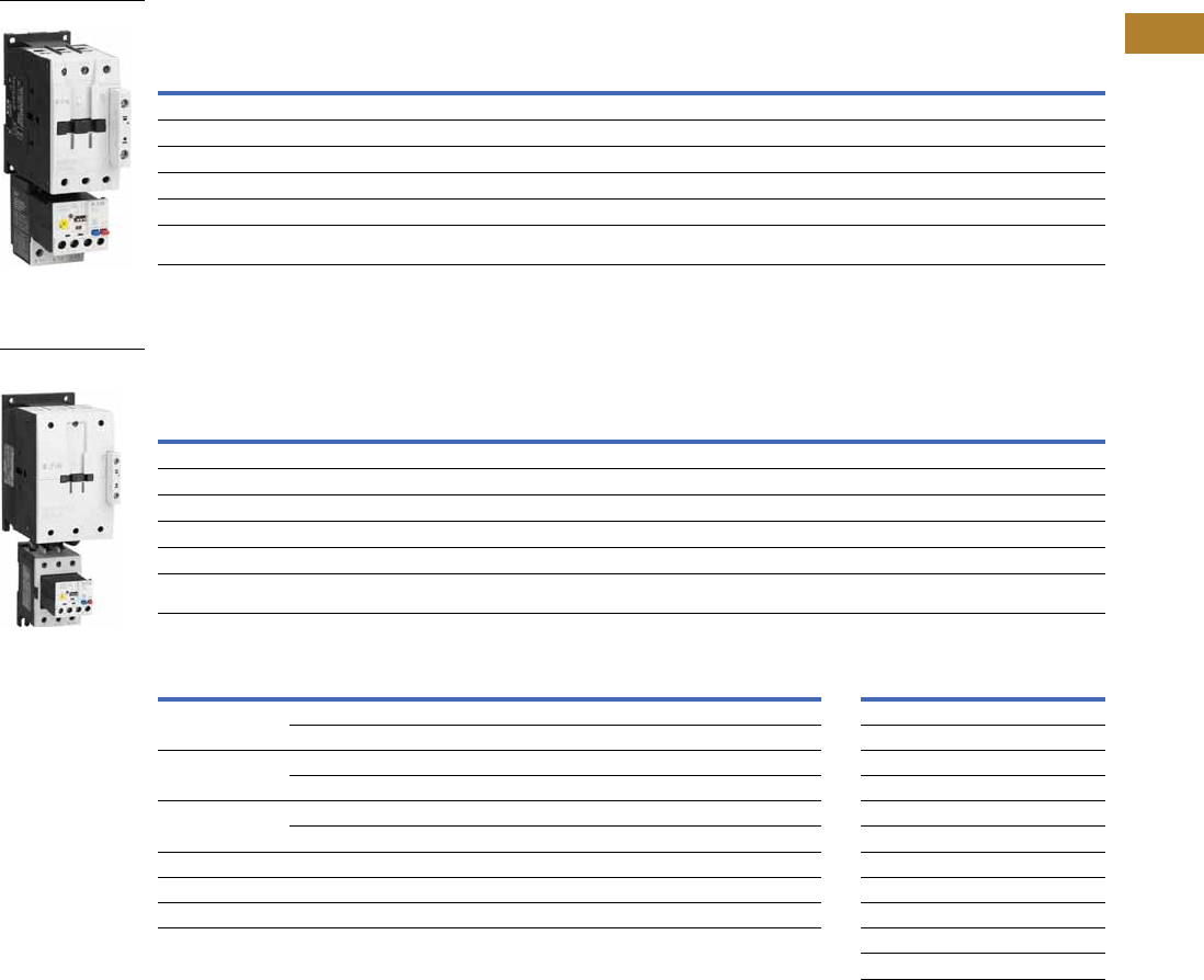
Volume 5—Motor Control and Protection CA08100006E—May 2016 www.eaton.com V5-T2-67
2
2
2
2
2
2
2
2
2
2
2
2
2
2
2
2
2
2
2
2
2
2
2
2
2
2
2
2
2
2
2.2
NEMA Contactors and Starters
Space-Savings Series
Type AN13/53 Space-Savings Starters with XTOE Electronic Overload Relays
Non-Reversing and Reversing
Type AN13/53 Space-Savings Starters with XTOE Ground Fault Electronic Overload Relays
Non-Reversing and Reversing
XTOE Overload FLA Range (FVNR and FVR Starters Only) Magnet Coil Suffix
Notes
1 Underscore (_) indicates coils suffix required, see Coil Suffix table above.
2 Underscore (_) indicates OLR designation required, see XTOE FLA Range table above.
3 For MCC replacement needs, contact MCC Aftermarket.
4 NEMA Size 5 starter available with 60-300A panel mounted CTs. Starter shipped as an assembled unit with
1–5A C440 overload relay (C440A1A005SELAX or C440A2A005SELAX).
NEMA
Size
Continuous
Ampere
Rating
Service Limit
Current Rating
(Amps)
Maximum UL Horsepower Three-Pole
Non-Reversing 12
Three-Pole
Reversing 12
Single-Phase Three-Phase
115V 230V 208V 240V 480V 600V Catalog Number 3Catalog Number 3
0 18 21 123355AN13BN0_ 5E _ AN53BN0_ 5E _
1 27 32 2 3 7-1/2 7-1/2 10 10 AN13CN0_ 5E _ AN53CN0_ 5E _
2 45 52 3 7-1/210152525AN13GN0_ 5E _ AN53GN0_ 5E _
3 90 104 ——25305050AN13KN0_ 5E _ AN53KN0_ 5E _
4 135 156 — — 40 50 100 100 AN13MN0_ 5E _ AN53MN0_ 5E _
5 4270 311 — — 75 100 200 200 AN13SN0_ 5E _ AN53SN0_ 5E _
NEMA
Size
Continuous
Ampere
Rating
Service Limit
Current Rating
(Amps)
Maximum UL Horsepower Three-Pole
Non-Reversing 12
Three-Pole
Reversing 12
Single-Phase Three-Phase
115V 230V 208V 240V 480V 600V Catalog Number 3Catalog Number 3
0 18 21 123355AN13BN0_ 5G _ AN53BN0_ 5G _
1 27 32 2 3 7-1/2 7-1/2 10 10 AN13CN0_ 5G _ AN53CN0_ 5G _
2 45 52 3 7-1/210152525AN13GN0_ 5G _ AN53GN0_ 5G _
3 90 104 ——25305050AN13KN0_ 5G _ AN53KN0_ 5G _
4 135 156 — — 40 50 100 100 AN13MN0_5G_ AN53MN0_5G_
5 4270 311 — — 75 100 200 200 AN13SN0_ 5G _ AN53SN0_ 5G _
NEMA Size OLR Code FLA Range OLR Code FLA Rating Coil Voltage Suffix Code
01P6 0.33–1.65A 020 4.0–20A. Sizes 0–2
005 1.0–5.0A —— 110V 50 Hz, 120V 60 Hz A
11P6 0.33–1.65A 020 4.0–20A 220V 50 Hz, 240V 60 Hz B
005 1.0–5.0A 045 9.0–45A 24–27 Vdc TD
2——045 9.0–45A Sizes 3, 4
———— 100–120V 50/60 Hz A
3100 20–100A —— 190–240V 50/60 Hz B
4175 35–175A —— 24–27 Vdc TD
5 4300 60–300A ——Sizes 5
100–120V 50/60 Hz A
24–48 Vdc TD
NEMA Starter
NEMA Starter with
Ground Fault
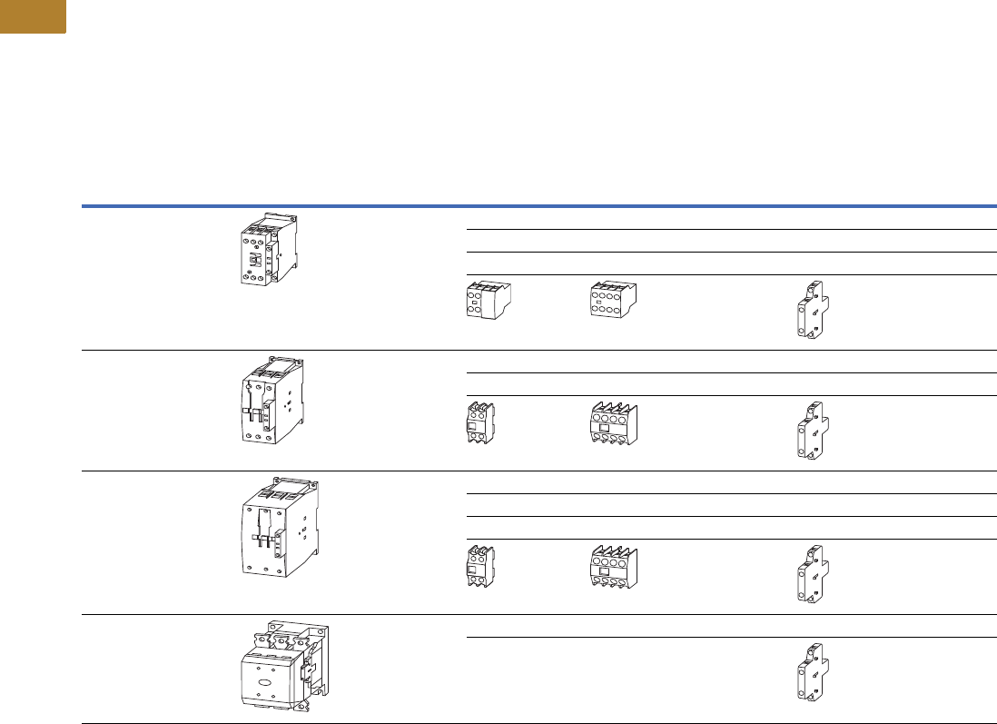
V5-T2-68 Volume 5—Motor Control and Protection CA08100006E—May 2016 www.eaton.com
2
2
2
2
2
2
2
2
2
2
2
2
2
2
2
2
2
2
2
2
2
2
2
2
2
2
2
2
2
2
2.2
NEMA Contactors and Starters
Space-Savings Series
Accessories
Auxiliary Contacts—Overview
Front-mounted snap-on
auxiliary contacts for Space-
Savings contactors are
available with screw
terminals in a variety of
contact configurations.
Auxiliary Contacts Possible Combinations
Frame
Size
Catalog
Number Contactor
Built-In
Auxiliary
Front (Top) Mount Side-Mount Total Auxiliary
Contacts AvailableTwo-Pole Four-Pole Single-Pole Two-Pole
0, 1 CN13BN0_ –
CN13CN0_
1NO or 1NC 1 — — — 3
—1 ——5
———13
——
2CN13GN0_ —1 — — 2 6
—1 —16
——
3, 4 CN13KN0_ –
CN13MN0_
—1 — — 2 6
—1 —28
———48
——
5CN13SN0 2NO–2NC — — 2 8
—— —
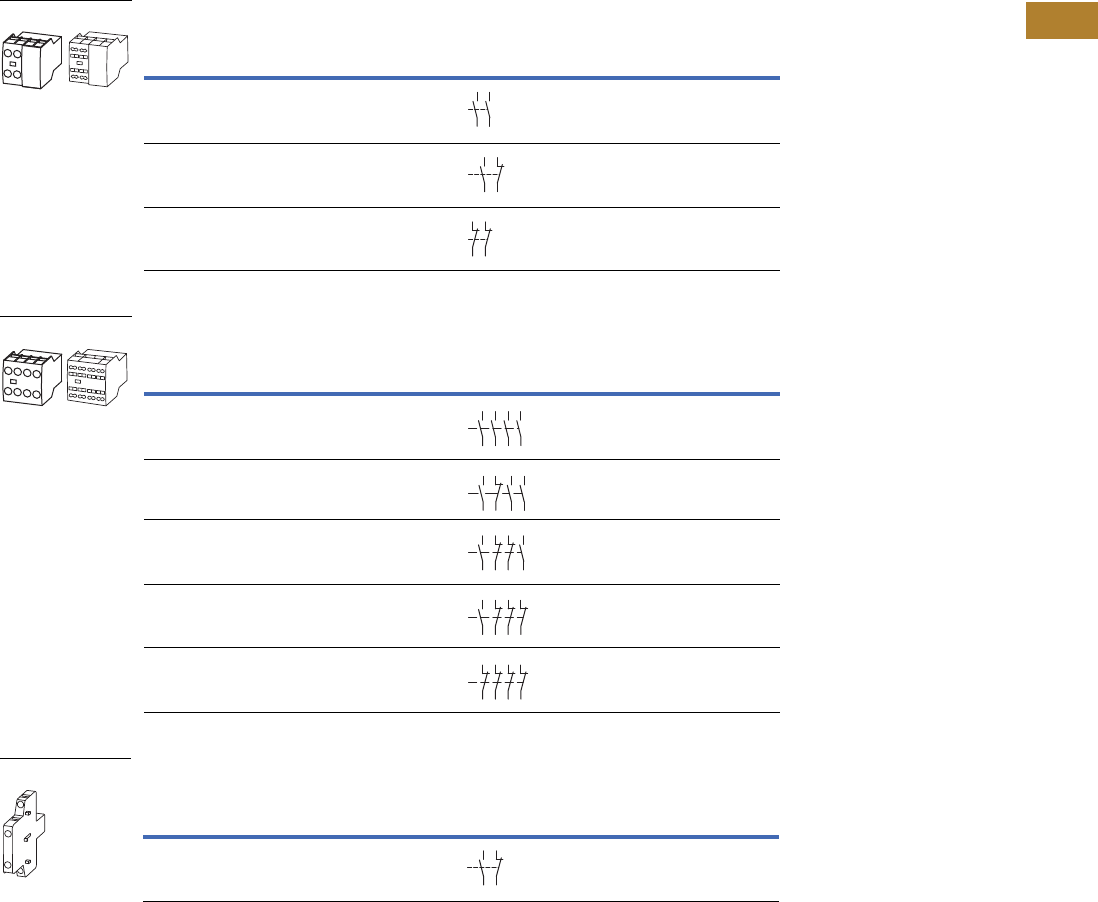
Volume 5—Motor Control and Protection CA08100006E—May 2016 www.eaton.com V5-T2-69
2
2
2
2
2
2
2
2
2
2
2
2
2
2
2
2
2
2
2
2
2
2
2
2
2
2
2
2
2
2
2.2
NEMA Contactors and Starters
Space-Savings Series
Auxiliary Contacts
NEMA Size 0, 1— Front (Top) Mount—Two-Pole
NEMA Size 0, 1— Front (Top) Mount—Four-Pole
NEMA Size 0, 1—Side-Mount—Two-Pole
Notes
No auxiliary contacts can be fitted between two contactors.
1 Orders must be placed in multiples of package quantity listed.
2 To avoid duplicate terminal numbers in contact sequence, these auxiliary contacts should only be used with contactors
having a built-in 1NO contact (XTCE…B10_, XTCE…C10_).
3 Can be mounted to the left side of contactor only. Cannot be used in combination with front (top) mount auxiliary
contacts or mechanical interlocks.
Conventional Thermal Current,
Open at 60°C
Ith = Ie, AC-1 in Amps
Contact
Configuration
Circuit
Symbol
Pkg.
Qty. 1
Screw Terminal
Catalog Number
16 2NO 5 XTCEXFAC20
16 1NO-1NC 5 XTCEXFAC11 2
16 2NC 5 XTCEXFAC02
Conventional Thermal Current,
Open at 60°C
Ith = Ie, AC-1 in Amps
Contact
Configuration
Circuit
Symbol
Pkg.
Qty. 1
Screw Terminal
Catalog Number
16 4NO 5 XTCEXFAC40 2
16 3NO-1NC 5 XTCEXFAC31 2
16 2NO-2NC 5 XTCEXFAC22 2
16 1NO-3NC 5 XTCEXFAC13
16 4NC 5 XTCEXFAC04
Conventional Thermal Current,
Open at 60°C
Ith = Ie, AC-1 in Amps
Contact
Configuration
Circuit
Symbol
Pkg.
Qty. 1
Screw Terminal
Catalog Number
10 1NO-1NC 1 XTCEXSCC11 3
XTCEXF_
54
63
64
53
54
53 61
62
51
52
61
62
XTCEXF_
54
63 73
64 74
53 83
8
4
54
53 61
62
73
74
83
84
54
53 61
62
71
72
83
84
53 61 71 81
82
72
62
54
51
52
61
62
71
72 82
81
XTCEXSCC11
54
53 61
62
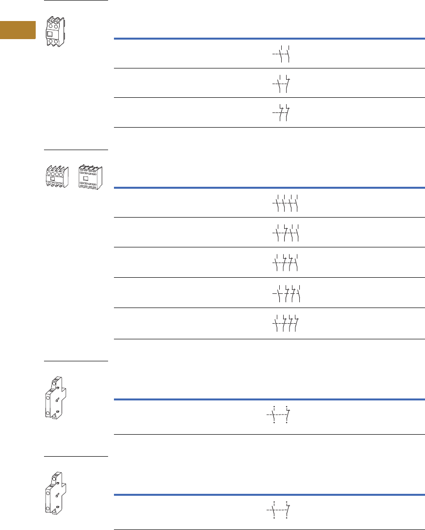
V5-T2-70 Volume 5—Motor Control and Protection CA08100006E—May 2016 www.eaton.com
2
2
2
2
2
2
2
2
2
2
2
2
2
2
2
2
2
2
2
2
2
2
2
2
2
2
2
2
2
2
2.2
NEMA Contactors and Starters
Space-Savings Series
NEMA Sizes 2–4—Two-Pole
NEMA Sizes 2–4—Four-Pole
NEMA Sizes 2–4, Side Mount (Snap-On)—Two-Pole
NEMA Size 5, Side Mount (Screw Mount)—Two-Pole
Notes
No auxiliary contacts can be fitted between two contactors.
1 Orders must be placed in multiples of package quantity listed.
2 For replacement only. XTCEXSBR11 and XTCEXSBLR11 cannot be added onto side mount auxiliaries that come with
the Size 5 contactors as standard. To add auxiliaries onto the included side auxiliaries on Size 5 contactors, use
XTCEXSCR11.
Conventional Thermal Current,
Open at 60°C
Ith = Ie, AC-1 in Amps
Contact
Configuration
Circuit
Symbol
Pkg.
Qty. 1
Screw Terminal
Catalog Number
16 2NO 5 XTCEXFBG20
16 1NO-1NC 5 XTCEXFBG11
16 2NC 5 XTCEXFBG02
Conventional Thermal Current,
Open at 60°C
Ith = Ie, AC-1 in Amps
Contact
Configuration
Circuit
Symbol
Pkg.
Qty. 1
Screw Terminal
Catalog Number
16 4NO-0NC 5 XTCEXFBG40
16 3NO-1NC 5 XTCEXFBG31
16 2NO-2NC 5 XTCEXFBG22
16 2NO-2NC 5 XTCEXFAG22
16 1NO-3NC 5 XTCEXFBG13
Conventional Free Air
Thermal Current,
Ith = Ie, AC-1 in Amps
Contact
Configuration
Circuit
Symbol
Pkg.
Qty. 1
Screw Terminal
Catalog Number
10 1NO–1NC 1 XTCEXSBN11
Conventional Free Air
Thermal Current,
Ith = Ie, AC-1 in Amps
Contact
Configuration
Circuit
Symbol
Pkg.
Qty. 1
Screw Terminal
Catalog Number
10 1NO–1NC 1 XTCEXSBR11 2
XTCEXF_
14 24
13 23
14
13 21
22
12
11 21
22
XTCEXF_
14
13 23
24
33
34
43
4
4
14
13 21
22
33
34
43
44
14
13 21
22
31
32
43
4
4
54
53 61
62
71
72
8
3
84
14
13 21
22
31
32
41
42
XTCEXS_
13
44
14
43
21
32
31
22
XTCEXS_
13
44
14
43
21
32
31
22
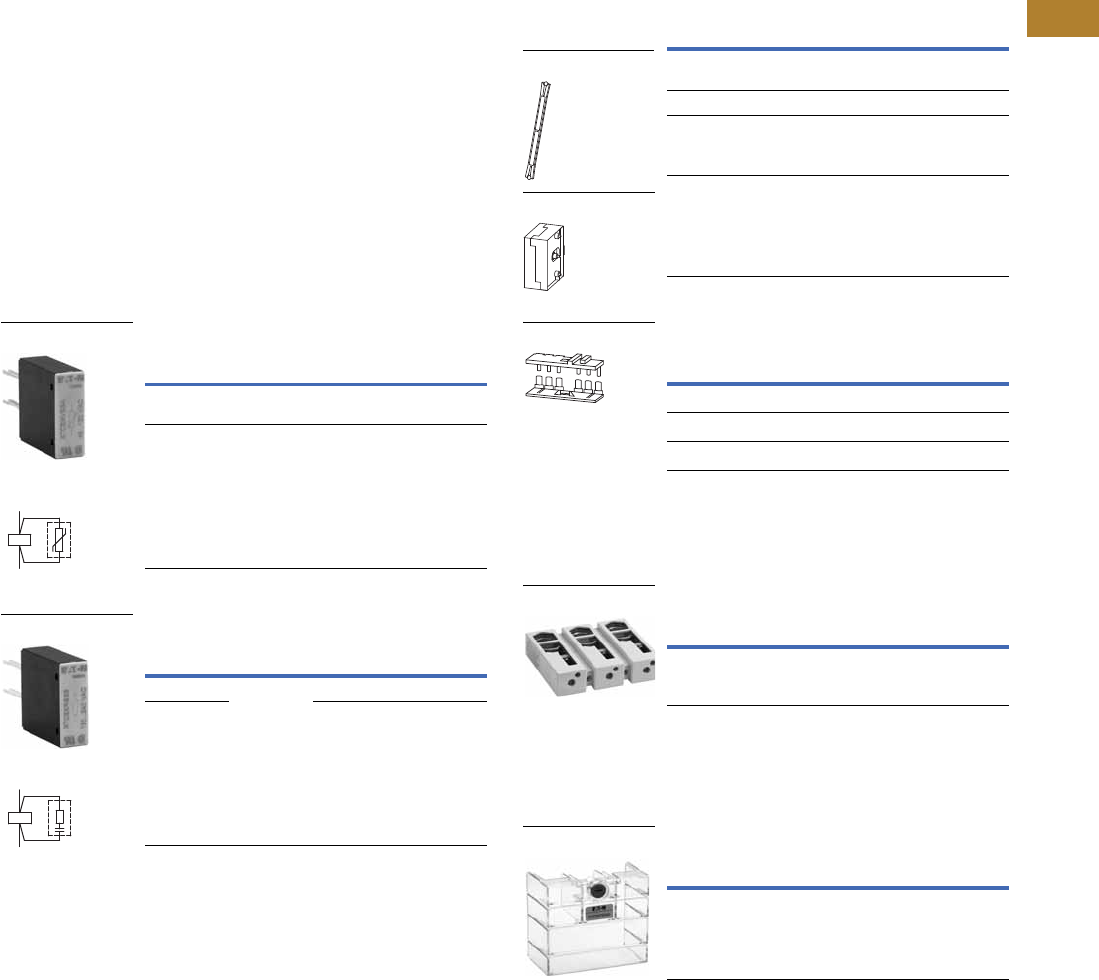
Volume 5—Motor Control and Protection CA08100006E—May 2016 www.eaton.com V5-T2-71
2
2
2
2
2
2
2
2
2
2
2
2
2
2
2
2
2
2
2
2
2
2
2
2
2
2
2
2
2
2
2.2
NEMA Contactors and Starters
Space-Savings Series
Suppressors
The switching of contactor
coils can generate voltage
transients that may cause
arching on switch contacts
and/or damage electronics on
the control line. Either an RC
or varistor suppressor is
recommended in these types
of applications. All Space-
Savings DC contactor coils
have built-in suppression.
Varistor suppressors clamp
the voltage transient above
the maximum coil voltage and
are recommended when the
level of the transient is
known to not exceed the coil
voltage. RC suppressors slow
and reduce the level of the
voltage transient but do not
clamp them at a specific
level. The slowing of the
transient can reduce
electrical interference.
These are recommended in
applications where operating
rates are high.
Varistor Suppressor 12
RC Suppressor 12
Notes
1Note dropout delay.
2For AC operated contactors, 50–60 Hz. Sizes 0–5 DC operated contactors and Size 5 AC
operated contactors have a built-in suppressor circuit.
3Orders must be placed in multiples of package quantity listed.
4In addition to the built-in suppressor circuit for DC actuated contactors. Prevents
negative breaking voltage when contactors are used in combination with a safety PLC.
5For two contactors with AC or DC operated magnet system which are horizontally or vertically
mounted. For Sizes 0–4, mechanical lifespan is 2.5 x 10⁶ operations
and the distance between contactors is 0 mm. For Size 5, mechanical lifespan is 5 x 10⁶
operations and no auxiliary contact can be mounted between the
mechanical interlock and the contactor—the distance between contactors is 15 mm.
6XTCEXMLG and XTCEXMLN consist of an interlock element and mounting plate.
Voltage
For Use
with…
Pkg.
Qty. 3Catalog Number
48–130 CN13BN0_
CN13CN0_
10 XTCEXVSCA
48–130 CN13GN0_ 10 XTCEXVSFA
Voltage
For Use
with…
Pkg.
Qty. 3Catalog Number
24–48
CN13GN0_ — XTCEXRSFW
110–130
—XTCEXRSFA
XTCEXVS_
Contact Sequence
A2
A1
XTCEXRS_
Contact Sequence
A1
A2
Additional Accessories
Mechanical Interlock 5
Reversing Link Kits
Main current wiring for reversing combinations. Includes
paralleling bridge and reversing bridge. Does not include
mechanical interlock, see table on this page.
Terminal Lug Assembly
For connection of: round conductor, flexible and stranded,
flat strip conductor, with control circuit terminal. See Page
V5-T2-74 for terminal capacities.
Terminal Shroud
Protection against direct contact with connection lugs when
touched vertically from the front.
For Use
with…
Pkg.
Qty. 3Catalog Number
CN13BN0_,
CN13CN0_
1XTCEXMLC
CN13GN0_ 1 XTCEXMLD
CN13KN0_,
CN13MN0_
1XTCEXMLG 6
CN13SN0_ 1 XTCEXMLM
For Use
with…
Pkg.
Qty. 3Catalog Number
CN13BN0_, CN13CN0_ 1 XTCEXRLC
CN13GN0_ 1 XTCEXRLD
CN13KN0_, CN13MN0_ 1 XTCEXRLG
For Use
with…
Pkg.
Qty. 3Catalog Number
CN13SN0_ 1 XTCEXTLA400
For Use
with…
Pkg.
Qty. 3Catalog Number
CN13SN0_ 1 XTCEXTS400
XTCEXML_
XTCEXMLM
XTCEXRL_
XTCEXTLA400
XTCEXTS_
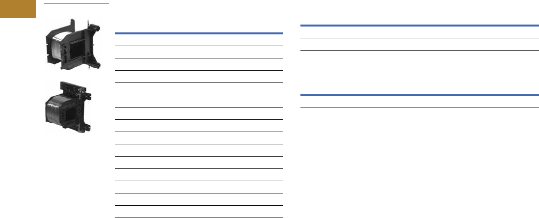
V5-T2-72 Volume 5—Motor Control and Protection CA08100006E—May 2016 www.eaton.com
2
2
2
2
2
2
2
2
2
2
2
2
2
2
2
2
2
2
2
2
2
2
2
2
2
2
2
2
2
2
2.2
NEMA Contactors and Starters
Space-Savings Series
Renewal Parts
Replacement Coils Replacement Contact Kit
Replacement Arc Chamber
Voltage
Coil
Suffix Catalog Number
Size 0, 1
110/50 120/60 A XTCERENCOILCA
220/50 240/60 B XTCERENCOILCB
24–27 Vdc TD XTCERENCOILCTD
Size 2
110/50 120/60 A XTCERENCOILDA
220/50 240/60 B XTCERENCOILDB
24–27 Vdc TD XTCERENCOILDTD
Size 3, 4
100–120V 50/60 A XTCERENCOILGA
190–240V 50/60 B XTCERENCOILGB
24–27 Vdc TD XTCERENCOILGTD
Size 5
110–250 Vac/Vdc A XTCERENCOILLA
24–48 Vdc TD XTCERENCOILLTD
XTCERENC_
For Use with… Catalog Number
CN13GN0_ XTCERENCONTACTD
CN13SN0_ XTCERENCONTACTL
For Use with… Catalog Number
CN13SN0_ XTCERENARC250

Volume 5—Motor Control and Protection CA08100006E—May 2016 www.eaton.com V5-T2-73
2
2
2
2
2
2
2
2
2
2
2
2
2
2
2
2
2
2
2
2
2
2
2
2
2
2
2
2
2
2
2.2
NEMA Contactors and Starters
Space-Savings Series
Technical Data and Specifications
Auxiliary Contacts
Notes
1Making and breaking conditions to DC-13, time L/R contact as stated.
2See fuses overlay for time/current characteristic (on request).
3Conventional thermal current (Ith) of XTCEXSCC_ is 10A.
Description
CN13BN0_,
CN13CN0_
XTCEXFAC_
XTCEXFATC_
XTCEXFCC_
XTCEXSCC_ XTCEXFAG_
XTCEXSBLN_
XTCEXSBN_
XTCEXSBNC_
XTCEXSCN_
XTCEXSCNC_
Interlocked opposing contacts with an auxiliary contact
module (to IEC 60947-5 -1 Annex L)
— Yes Yes Yes Yes
Break contact (not late-break contact) suitable as a mirror
contact (to IEC/EN 60947-4 -1 Annex F)
CN13BN0_, CN13CN0_ CN13BN0_, CN13CN0_ CN13BN0_, CN13CN0_ CN13GN0_ CN13GN0_, CN13SN0_
Rated impulse withstand voltage, (Uimp) Vac 6000 6000 6000 6000 6000
Overvoltage category/pollution degree III/3 III/3 III/3 III/3 III/3
Rated insulation voltage, (Ui) Vac 690 690 690 690 690
Rated operational voltage, (Ue) Vac 500 500 500 500 500
Safe isolation to VDE 0106 Part 101 and Part 101(A) in Vac
Between coil and auxiliary contacts 400 400 400 440 440
Between the auxiliary contacts 400 400 400 440 440
Rated operational current, le
AC-15
230V 6A 6A 6A 6A 6A
380/415V 4A 3A 4A 4A 4A
500V 1.5A — 1.5A 1.5A 1.5A
DC-3 L/R
<
5 ms 1
24V 10A 10A 10A 10A 10A
60V 6A6A6A6A6A
110V 3A 3A 3A 3A 3A
220V 1A 1A 1A 1A 1A
Conventional thermal current, Ith 16A 16A 16A 310A 10A
Control circuit reliability
(at Ue = 24 Vdc, Umin = 17 V, Imin = 5.4 mA)
<10-8, <1 failure at
100 million operations
<10-8, <1 failure at
100 million operations
<10-8, <1 failure at
100 million operations
<10-8, <1 failure at
100 million operations
<10-8, <1 failure at
100 million operations
Component lifespan, operations x 106
at Ue = 230V, AC-15, 3A
1.3 1.3 1.3 1.3 1.3
Short-circuit rating without welding 2
Maximum fuse, gG/gL 10A 10A 10A 16A 16A

V5-T2-74 Volume 5—Motor Control and Protection CA08100006E—May 2016 www.eaton.com
2
2
2
2
2
2
2
2
2
2
2
2
2
2
2
2
2
2
2
2
2
2
2
2
2
2
2
2
2
2
2.2
NEMA Contactors and Starters
Space-Savings Series
Parallel Link
Cable Terminal Block, Flat Cable Terminal
AC Ratings—AC-1 Operation
Description XTCEXPLKB XTECXPLKC XTCEXPLKD XTCEXPLKG XTCEXPLK185
Terminal capacity
Solid (mm2) 1–161616——
Flexible with ferrule (mm2) 1 x (0.5–25)
2 x (0.5–16)
1 x (16–35) 1 x (16–120) — —
Stranded (mm2) 1 x (0.5–25)
2 x (0.5–16)
1 x (16–50) 1 x (16–120) 1 x (35–300)
2 x (35–120)
—
Flat conductor—number of segments x width x thickness (mm) 6 x 9 x 0.8 — — 2 x (11 x 21 x 1) 1 x (6 x 16 x 0.8)
2 x (20 x 32 x 0.5)
2 x (11 x 21 x 1)
Tightening torque (Nm) 4 4 14 — —
Tools
Pozidriv screwdriver Size 2 Size 2 — — —
Hexagon socket head spanner—SW (mm) — — 5 6 —
Conventional thermal current
Three-pole (Ith) A 50 100 180 400 —
Four-pole (Ith) A 60 ————
Description XTCEXTLA400 XTCEXPLK185 XTCEXTFB650 XTCEXTFB820
Terminal capacity
Stranded (mm2) 1 x (120–300)
2 x (70–240)
———
Stranded (AWG) 1 x (250–600 kcmil)
2 x (2/0–500 kcmil)
———
Flat conductor—number of segments x width x thickness (mm) — 1 x (6 x 16 x 0.8)
2 x (20 x 32 x 0.5)
2 x (11 x 21 x 1)
1 x (6 x 16 x 0.8)
2 x (20 x 32 x 0.5)
2 x (11 x 21 x 1)
1 x (6 x 16 x 0.8)
2 x (10 x 40 x 1)
2 x (20 x 40 x 0.5)
Description CN13B CN13C CN13G CN13K CN13M CN13S
Conventional free air thermal current, three-pole, 50–60 Hz
Open
at 40°C (Ith) 40A 45A 80A 130A 190A 490
at 50°C (Ith) 38A 43A 71A 125A 180A 438
at 55°C (Ith) 37A 42A 68A 115A 170A 418
at 60°C (Ith) 35A 40A 65A 110A 160A 400
Enclosed 32A 36A 58A 100A 144A 315
Conventional free air thermal current, single-pole (Ith)
Open 88A 100A 162A 275A 400A —
Enclosed 80A 90A 145A 250A 360A —

Volume 5—Motor Control and Protection CA08100006E—May 2016 www.eaton.com V5-T2-75
2
2
2
2
2
2
2
2
2
2
2
2
2
2
2
2
2
2
2
2
2
2
2
2
2
2
2
2
2
2
2.2
NEMA Contactors and Starters
Space-Savings Series
Space-Savings Contactors—NEMA Sizes 0–2
Notes
1Damp heat, constant, to IEC 60068-2-78; damp heat, cyclic, to IEC 60 068-2-30.
2IEC 60947 Standard.
Description
Size 0
CN13BN010_
Size 1
CN13CN010_
Size 2
CN13GN000_
General
Standards IEC/EN 60947,
VDE 0660, UL, CSA,
CCC, RoHS
IEC/EN 60947,
VDE 0660, UL, CSA,
CCC, RoHS
IEC/EN 60947,
VDE 0660, UL, CSA,
CCC, RoHS
Weights in kg [lb]
AC operated 0.42 [0.93] 0.42 [0.93] 0.9 [2.0]
DC operated 0.48 [1.06] 0.48 [1.06] 1.1 [2.4]
Mechanical life—operations 10,000,000 10,000,000 10,000,000
Climatic proofing 111
Insulation voltage (Ui) Vac 690 690 690
Impulse withstand voltage (Uimp) Vac 8000 8000 8000
Operating voltage (Ue) Vac 690 690 690
Safe isolation to VDE 0106 Part 101 and Part 101/A1
Between coil and contacts (Vac) 440 440 440
Between contacts (Vac) 238 440 440
Making capacity (amps) 238 384 910
Breaking capacity (amps)
220/230V 170 320 650
380/400V 170 320 650
500V 170 320 650
660/690V 120 180 370
Short-circuit protection rating maximum fuse (amps)
Type 2 coordination 2
400V; gG/gL 500V 25 63 125
690V; gG/gL 690V 25 35 80
Type 1 coordination 2
400V; gG/gL 500V 63 125 250
690V; gG/gL 690V 50 63 100
Degree of protection IP00 IP00 IP00
Protection against direct contact when
actuated from front (IEC 536)
Finger and
back-of-hand proof
Finger and
back-of-hand proof
Finger and
back-of-hand proof
Terminal capacity main cable—screw terminals
Solid (mm2) 1 x (0.75–16)
2 x (0.75–10)
1 x (0.75–16)
2 x (0.75–10)
1 x (0.75–16)
2 x (0.75–10)
Flexible with ferrule (mm2) 1 x (0.75–16)
2 x (0.75–10)
1 x (0.75–16)
2 x (0.75–10)
1 x (2.5–35)
2 x (2.5–25)
Stranded (mm2) 1 x 16 1 x 16 1 x (16–50)
2 x (16–35)
Solid or stranded (AWG) 18–6 18–6 12–2
Flat conductor
(number of segments x width x thickness) (mm)
— — 2 x (6 x 9 x 0.8)
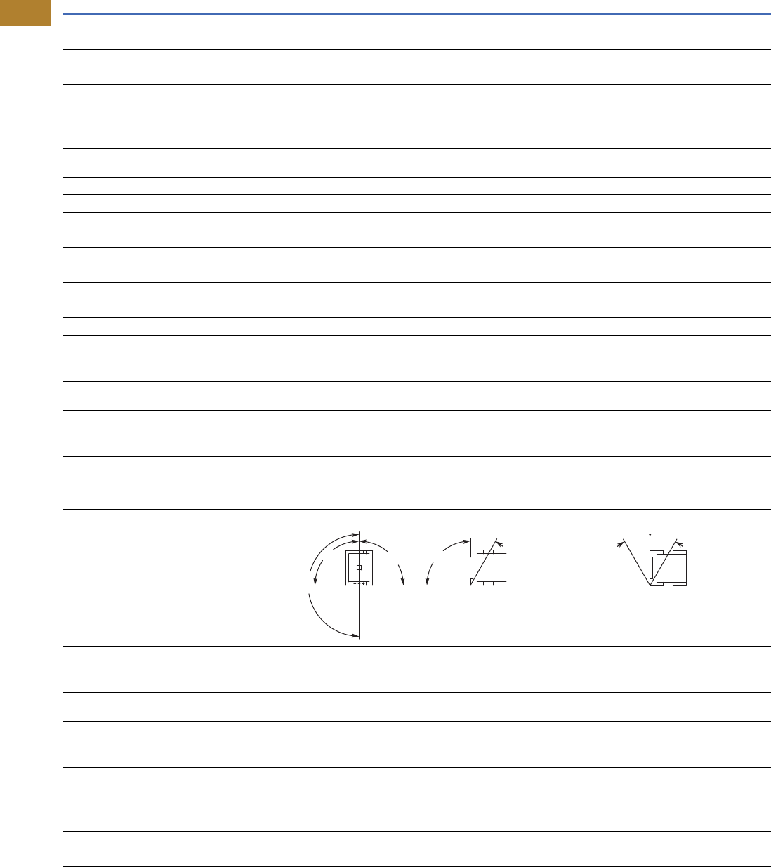
V5-T2-76 Volume 5—Motor Control and Protection CA08100006E—May 2016 www.eaton.com
2
2
2
2
2
2
2
2
2
2
2
2
2
2
2
2
2
2
2
2
2
2
2
2
2
2
2
2
2
2
2.2
NEMA Contactors and Starters
Space-Savings Series
Space-Savings Contactors—NEMA Sizes 0–2, continued
Description
Size 0
CN13BN010_
Size 1
CN13CN010_
Size 2
CN13GN000_
General, continued
Main cable connection screw/bolt M5 M5 M6
Tightening torque
Nm 333.3
Lb-in 26.6 26.6 29.2
Terminal capacity control circuit cable—screw terminals
Solid (mm2) 1 x (0.75–4)
2 x (0.75–4)
1 x (0.75–4)
2 x (0.75–4)
1 x (0.75–4)
2 x (0.75–4)
Flexible with ferrule (mm2) 1 x (0.75–2.5)
2 x (0.75–2.5)
1 x (0.75–2.5)
2 x (0.75–2.5)
1 x (0.75–2.5)
2 x (0.75–2.5)
Solid or stranded (AWG) 18–14 18–14 18–14
Control circuit cable connection screw/bolt M3.5 M3.5 M3.5
Tightening torque
Nm 1.2 1.2 1.2
Lb-in 10.6 10.6 10.6
Tools
Main and control circuit cable—screw terminals Size 2 Size 2 Size 2
Pozidriv screwdriver 0.8 x 5.5 0.8 x 5.5 0.8 x 5.5
Standard screwdriver 1 x 6 1 x 6 1 x 6
Terminal capacity control circuit cable—spring cage terminals
Solid (mm2) 1 x (0.75–2.5)
2 x (0.75–2.5)
1 x (0.75–2.5)
2 x (0.75–2.5)
1 x (0.75–2.5)
2 x (0.75–2.5)
Flexible (mm2) 1 x (0.75–2.5)
2 x (0.75–2.5)
1 x (0.75–2.5)
2 x (0.75–2.5)
1 x (0.75–2.5)
2 x (0.75–2.5)
Flexible with ferrule (mm2) 1 x (0.75–2.5)
2 x (0.75–2.5)
1 x (0.75–2.5)
2 x (0.75–2.5)
1 x (0.75–2.5)
2 x (0.75–2.5)
Solid or stranded (AWG) 18–14 18–14 18–14
Tools
Main and control circuit cable—spring cage terminals
Stripping length (mm) 10 10 10
Screwdriver blade width (mm) 3.5 3.5 3.5
Mounting position, AC and DC operated
Ambient temperature
Open –25 to 60°C
[–13 to 140°F]
–25 to 60°C
[–13 to 140°F]
–25 to 60°C
[–13 to 140°F]
Enclosed –25 to 40°C
[–13 to 104°F]
–25 to 40°C
[–13 to 104°F]
–25 to 40°C
[–13 to 104°F]
Ambient storage temperature –40 to 80°C
[–40 to 176°F]
–40 to 80°C
[–40 to 176°F]
–40 to 80°C
[–40 to 176°F]
Environmental
Mechanical shock resistance
(IEC/EN 60068-2-27)
Main contact—NO Contact 10 10 1
Auxiliary contact—NO Contact 7 7 7
Auxiliary contact—NC Contact 5 5 5
Overvoltage category/pollution degree III/3 III/3 III/3
180°
90°
90°
90°
30°
30° 30°

Volume 5—Motor Control and Protection CA08100006E—May 2016 www.eaton.com V5-T2-77
2
2
2
2
2
2
2
2
2
2
2
2
2
2
2
2
2
2
2
2
2
2
2
2
2
2
2
2
2
2
2.2
NEMA Contactors and Starters
Space-Savings Series
Space-Savings Contactors—NEMA Sizes 3, 4
Notes
1Damp heat, constant, to IEC 60068-2-78; damp heat, cyclic, to IEC 60 068-2-30.
2IEC 60947 Standard.
Description
Size 3
CN13KN000_
Size 4
CN13MN000_
General
Standards IEC/EN 60947,
VDE 0660, UL, CSA,
CCC, RoHS
IEC/EN 60947,
VDE 0660, UL, CSA,
CCC, RoHS
Weights in kg [lb]
AC operated 2 [4.41] 2 [4.41]
DC operated 2.1 [4.63] 2.1 [4.63]
Mechanical life—operations 10,000,000 10,000,000
Climatic proofing 11
Insulation voltage (Ui) Vac 690 690
Impulse withstand voltage (Uimp) Vac 8000 8000
Operational voltage (Ue) Vac 690 690
Safe isolation to VDE 0106 Part 101 and Part 101/A1
Between coil and contacts (Vac) 690 690
Between contacts (Vac) 690 690
Making capacity (amps) 1610 2100
Breaking capacity (amps)
220/230V 1150 1500
380/400V 1150 1500
500V 1150 1500
660/690V 1100 1200
1000V — —
Short-circuit protection rating maximum fuse
Type 2 coordination 2
400V; gG/gL 500V 250 25
690V; gG/gL 690V 25 250
Type 1 coordination 2
400V; gG/gL 500V 250 250
690V; gG/gL 690V 250 250
Degree of protection IP00 IP00
Protection against direct contact when actuated from front (IEC 536) Finger and
back-of-hand proof
Finger and
back-of-hand proof
Terminal capacity main cable—screw terminals
Solid (mm2)——
Flexible with ferrule (mm2) 1 x (10–95)
2 x (10–70)
1 x (10–95)
2 x (10–70)
Stranded (mm2) 1 x (10–95)
2 x (10–20)
1 x (10–95)
2 x (10–20)
Flat conductor
(number of segments x width x thickness) (mm)
2 x (6 x 16 x 0.8) 2 x (6 x 16 x 0.8)
Solid or stranded (AWG) 8–3/0 8–3/0
Main cable connection screw/bolt M10 M10
Tightening torque
Nm 14 14
Lb-in 123.9 123.9
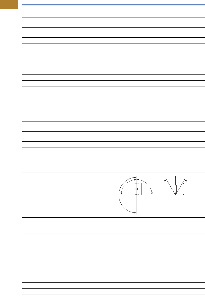
V5-T2-78 Volume 5—Motor Control and Protection CA08100006E—May 2016 www.eaton.com
2
2
2
2
2
2
2
2
2
2
2
2
2
2
2
2
2
2
2
2
2
2
2
2
2
2
2
2
2
2
2.2
NEMA Contactors and Starters
Space-Savings Series
Space-Savings Contactors—NEMA Sizes 3, 4, continued
Description
Size 3
CN13KN000_
Size 4
CN13MN000_
General, continued
Terminal capacity control circuit cable—screw terminals
Solid (mm2) 1 x (0.75–4)
1 x (0.75–4)
1 x (0.75–4)
1 x (0.75–4)
Flexible with ferrule (mm2) 1 x (0.75–2.5)
2 x (0.75–2.5)
1 x (0.75–2.5)
2 x (0.75–2.5)
Solid or stranded (AWG) 18–14 18–14
Control circuit cable connection screw/bolt M3.5 M3.5
Tightening torque
Nm 1.2 1.2
Lb-in 10.6 10.6
Tools
Main circuit cable—screw terminals
Hexagon socket-head spanner (mm) 5 5
Control circuit cable—screw terminals Size 2 Size 2
Pozidriv screwdriver 0.8 x 5.5 0.8 x 5.5
Standard screwdriver 1 x 6 1 x 6
Terminal capacity control circuit cable—spring cage terminals
Solid (mm2) 1 x (0.75–2.5)
2 x (0.75–2.5)
1 x (0.75–2.5)
2 x (0.75–2.5)
Flexible (mm2) 1 x (0.75–2.5)
2 x (0.75–2.5)
1 x (0.75–2.5)
2 x (0.75–2.5)
Flexible with ferrule (mm2) 1 x (0.75–2.5)
2 x (0.75–2.5)
1 x (0.75–2.5)
2 x (0.75–2.5)
Solid or stranded (AWG) 18–14 18–14
Tools
Control circuit cable—spring cage terminals
Stripping length (mm) 10 10
Screwdriver blade width (mm) 3.5 3.5
Mounting position, AC and DC operated
Ambient temperature
Open –25 to 60°C
[–13 to 140°F]
–25 to 60°C
[–13 to 140°F]
Enclosed –25 to 40°C
[–13 to 104°F]
–25 to 40°C
[–13 to 104°F]
Ambient storage temperature –40 to 80°C
[–40 to 176°F]
–40 to 80°C
[–40 to 176°F]
Environmental
Mechanical shock resistance
(IEC/EN 60068-2-27)
Half-sinusoidal shock 10 ms
Main contact—NO contact 10g 10g
Auxiliary contact—NO contact 7g 7g
Auxiliary contact—NC contact 5g 5g
Overvoltage category/pollution degree III/3 III/3
180°
90°
90°
30° 30°

Volume 5—Motor Control and Protection CA08100006E—May 2016 www.eaton.com V5-T2-79
2
2
2
2
2
2
2
2
2
2
2
2
2
2
2
2
2
2
2
2
2
2
2
2
2
2
2
2
2
2
2.2
NEMA Contactors and Starters
Space-Savings Series
Space-Savings Contactors—NEMA Size 5
Notes
1Damp heat, constant, to IEC 60068-2-78; damp heat, cyclic, to IEC 60 068-2-30.
2IEC 60947 Standard.
3Screw tightening with flat cable terminal or cable terminal blocks. See terminal capacity for cable terminal blocks.
4When using contactors for group compensation, a minimum inductance of approx. 6 uh per capacitor must be available to limit the high
inrush current peaks. This corresponds to an air-cored coil with five windings and a coil diameter of approximately 140 mm. The conductor
cross-section must be selected according to the rated current per phase.
Description
Size 5
CN13SN022_
General
Standards IEC/EN 60947,
VDE 0660, UL, CSA
Weights in kg [lb] 6.5 [14.3]
Mechanical life—operations 10,000,000
Mechanical operating frequency (ops/hr)
AC operated 3000
DC operated 3000
Climatic proofing 1
Insulation voltage (Ui) Vac 1000
Impulse withstand voltage (Uimp) Vac 8000
Operating voltage (Ue) Vac 1000
Safe isolation to VDE 0106 Part 101
and Part 101/A1
Between coil and contacts (Vac) 500
Between contacts (Vac) 500
Making capacity (amps) 3000
Breaking capacity (amps)
220/230V 2500
380/400V 2500
500V 2500
660/690V 2500
1000V 760
Short-circuit protection rating maximum fuse
Type 2 coordination 2
400V; gG/gL 500V 315
690V; gG/gL 690V 315
1000V; gG/gL 1000V 160
Type 1 coordination 2
400V; gG/gL 500V 400
690V; gG/gL 690V 400
1000V; gG/gL 1000V 200
Degree of protection IP00
Protection against direct contact when actuated
from front (IEC 536)
Finger and back-of-hand proof with
terminal shroud or terminal block
Main cable cross-section
Flexible with cable lug (mm2) 50–240
Stranded with cable lug (mm2) 70–240
Solid or stranded (AWG) 1/0–250 kcmil
Flat conductor (mm) 3
Bus bar—width in mm 25
Main cable connection screw/bolt M10
Tightening torque
Nm 24
Lb-in 213
Description
Size 5
CN13SN022_
General, continued
Control circuit cable cross-sections
Solid (mm2) 1 x (0.75–2.5)
2 x (0.75–2.5)
Flexible with ferrule (mm2) 1 x (0.75–2.5)
2 x (0.75–2.5)
Solid or stranded (AWG) 2 x (18–12)
Control circuit cable connection screw/bolt M3.5
Tightening torque
Nm 1.2
Lb-in 10.6
Tools
Main cable wrench 16 mm
Control circuit cable pozidriv screwdriver Size 2
Mounting position, AC and DC operated
Ambient temperature –25 to 60°C
[–13 to 140°F]
Ambient storage temperature –40 to 80°C
[–40 to 176°F]
Environmental
Mechanical shock
Resistance (IEC/EN 60068-2-27)
Half-sinusoidal shock 10 ms
Main contact—NO contact 10g
Auxiliary contact—NO contact 10g
Auxiliary contact—NC contact 8g
Overvoltage category/pollution degree III/3
Switching capacity, kVAR 4
Individual compensation
230V —
400/420/440V —
525V —
690V —
Group compensation, with choke
230V 100
400/420/440V 190
525V 260
690V 340
Group compensation, without choke
230V —
400/420/440V —
525V —
690V —
180°
90°
90°
30° 30°
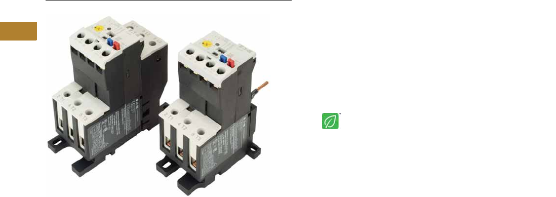
V5-T2-80 Volume 5—Motor Control and Protection CA08100006E—May 2016 www.eaton.com
2
2
2
2
2
2
2
2
2
2
2
2
2
2
2
2
2
2
2
2
2
2
2
2
2
2
2
2
2
2
2.2
NEMA Contactors and Starters
Space-Savings Series
XTOE/XT Electronic Overload Relay
Contents
Description Page
XTOE/XT Electronic Overload Relay
Standards and Certifications . . . . . . . . . . . . . . V5-T2-81
Catalog Number Selection . . . . . . . . . . . . . . . . V5-T2-82
Product Selection . . . . . . . . . . . . . . . . . . . . . . . V5-T2-83
Accessories . . . . . . . . . . . . . . . . . . . . . . . . . . . V5-T2-85
Technical Data and Specifications . . . . . . . . . . V5-T2-89
Dimensions . . . . . . . . . . . . . . . . . . . . . . . . . . . V5-T2-97
An Eaton
Green Solution
XTOE/XT Electronic Overload Relay
Product Description
Eaton’s new electronic
overload relay (EOL) is the
most compact, high-featured,
economical product in its
class. Designed on a global
platform, the new EOL covers
the entire power control
spectrum including NEMA,
IEC and DP Contactors. The
standard NEMA and DP
versions are offered with the
C440 designation while the
Space-Savings NEMA and
IEC versions have the XTOE
designation. The electronic
design provides reliable,
accurate and value driven
protection and communications
capabilities in a single
compact device. It is the
flexible choice for any
application requiring easy-to-
use, reliable protection.
Eaton has a long history of
innovations and product
development in motor control
and protection, including both
traditional NEMA, as well as
IEC control. It was from this
experience that the XTOE
was developed, delivering
new solutions to meet
today’s demands.
XTOE is a self-powered
electronic overload relay
available up to 175A as a
self contained unit. With
external CTs, XTOE can
protect motor up to
1500 FLA. Available add-on
accessories include remote
reset capability and
communication modules
with I/O for DeviceNet,
PROFIBUS, Modbus,
EtherNet/IP, and Modbus TCP.
Features and Benefits
Features
●Reliable, accurate, electronic motor protection
●Easy to select, install and maintain
●Compact size
●Flexible, intelligent design
●Global product offering—available with NEMA, IEC and DP
power control
Size/Range
●Broad FLA range
(0.33–1500A)
●Selectable trip class
(10A, 10, 20, 30)
●Direct mounting to NEMA,
IEC and DP contactors
●Most compact electronic
overload in its class
Motor Control
●Two B600 alarm (NO) and
fault (NC) contacts
●Test/Trip button
Motor Protection
●Thermal overload
●Phase loss
●Selectable (ON/OFF)
phase unbalance
●Selectable (ON/OFF)
ground fault
User Interface
●Large FLA selection dial
●Trip status indicator
●Operating mode LED
●DIP switch selectable trip
class, phase unbalance and
ground fault
●Selectable Auto/Manual
reset
Feature Options
●Remote reset
●120 Vac
●24 Vac
●24 Vdc
●Tamper-proof cover
●Communications modules
●Modbus RTU RS-485
●DeviceNet with I/O
●PROFIBUS with I/O
●Modbus RTU with I/O
●Ethernet IP with I/O
●Modbus TCP with I/O

Volume 5—Motor Control and Protection CA08100006E—May 2016 www.eaton.com V5-T2-81
2
2
2
2
2
2
2
2
2
2
2
2
2
2
2
2
2
2
2
2
2
2
2
2
2
2
2
2
2
2
2.2
NEMA Contactors and Starters
Space-Savings Series
Benefits
Reliability and Improved
Uptime
●XTOE provides the users
with peace of mind
knowing that their
assets are protected
with the highest level
of motor protection and
communication capability
in its class
●Extends the life of plant
assets with selectable
motor protection features
such as trip class, phase
unbalance and ground fault
●Protects against
unnecessary downtime
by discovering changes
in your system (line/load)
with remote monitoring
capabilities
●Status LED provides
added assurance that
valuable assets are
protected by indicating the
overload operational status
Flexibility
●Available with NEMA,
IEC and DP contactors
●Improves return on
investment by reducing
inventory carrying costs
with wide FLA adjustment
(5:1) and selectable
trip class
●Design incorporates built-in
ground fault protection
thus eliminating the need
for separate CTs and
modules
●Flexible communication
with optional I/O enables
easy integration into plant
management systems for
remote monitoring and
control
●Available as an open
component and in
enclosed control and motor
control center assemblies
Monitoring Capabilities
●Individual phase
currents RMS
●Average three-phase
current RMS
●Thermal memory
●Fault indication (overload,
phase loss, phase
unbalance, ground fault)
Safety
●IP 20 rated terminal blocks
●Available in Eaton’s
industry leading FlashGard
MCCs
●Tested to the highest
industry standards such
as UL, CSA, CE and IEC
●RoHS compliant
Standards and Certifications
●UL
●CSA
●CE
●NEMA
●IEC/EN 60947 VDE 0660
●ISO 13849-1 (EN954-1)
●RoHS
●ATEX directive 94/9/EC
●Equipment Group 2,
Category 2
Electronic Overload Education
Description Definition Cause Effect if not Protected XTOE/XT Protection
Motor Protection
Thermal overload Overload is a condition in which
current draw exceeds 115% of
the full load amperage rating for
an inductive motor.
• An increase in the load or torque that is
being driven by the motor.
• A low voltage supply to the motor
causes the current to go high to
maintain the power needed.
• A poor power factor causing above
normal current draw.
• Increase in current draw leads to heat
and insulation breakdown, which can
cause system failure.
• Increase in current can increase
power consumption and waste
valuable energy.
• Thermal trip behavior is defined by
UL, CSA and IEC standards.
• Trip class is settable from 10A,
10, 20, 30
Ground fault A line to ground fault. A current leakage path to ground. An undetected ground fault can burn
through multiple insulation windings,
ultimately leading to motor failure, not to
mention risk to equipment or personnel
Fixed protective setting that takes the
starter offline if ground fault current
exceeds 50% of the FLA dial setting,
i.e., if the FLA dial is set to 12A, the
overload relay will trip if the ground
current exceeds 6A.
Unbalanced phases
(voltage and current)
Uneven voltage or current between
phases in a three-phase system.
When a three-phase load is powered with
a poor quality line, the voltage per phase
may be unbalanced.
Unbalanced voltage causes large
unbalanced currents and as a result this
can lead to motor stator windings being
overloaded, causing excessive heating,
reduced motor efficiency and reduced
insulation life.
Fixed protective setting that takes the
starter offline if a phase drops below
50% of the other two phases.
Phase loss—current
(single-phasing)
One of the three-phase voltages is
not present.
Multiple causes, loose wire, improper
wiring, grounded phase, open fuse, etc.
Single-phasing can lead to unwanted
motor vibrations in addition to the results
of unbalanced phases as listed above.
Fixed protective setting that takes the
starter offline if a phase is lost.
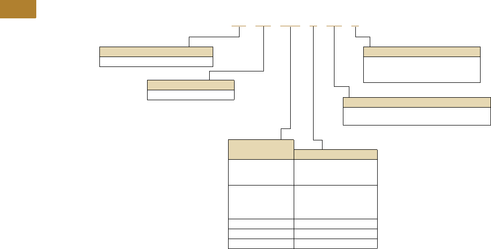
V5-T2-82 Volume 5—Motor Control and Protection CA08100006E—May 2016 www.eaton.com
2
2
2
2
2
2
2
2
2
2
2
2
2
2
2
2
2
2
2
2
2
2
2
2
2
2
2
2
2
2
2.2
NEMA Contactors and Starters
Space-Savings Series
Catalog Number Selection
XT Electronic Overload Relay—NEMA Space-Savings
Designation
XT = NEMA Space-Savings control
Type
OE = Electronic overload relay
Mounting
Blank = Direct to contactor
P = Pass-through
S = Separate mount (Frames C and G only)
Trip Type
CS = Selectable Class 10A, 10, 20, 30
GS = Ground fault with selectable Class 10, 20
Overload Range
Contactor Frame
1P6 = 0.33–1.65A
005 =1–5A
020 =4–20A
C = Space-Savings Size 0
1P6 = 0.33–1.65A
005 =1–5A
020 =4–20A
045 =9–45A
C = Space-Savings Size 1
045 =9–45A D = Space-Savings Size 2
100 = 20–100A G = Space-Savings Size 3
175 = 35–175A G = Space-Savings Size 4
XT OE 1P6 C CS S
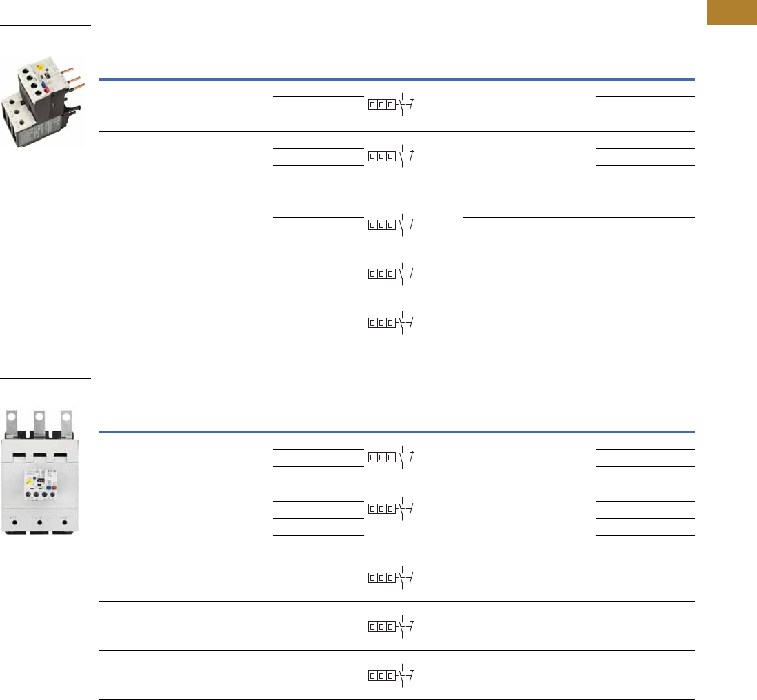
Volume 5—Motor Control and Protection CA08100006E—May 2016 www.eaton.com V5-T2-83
2
2
2
2
2
2
2
2
2
2
2
2
2
2
2
2
2
2
2
2
2
2
2
2
2
2
2
2
2
2
2.2
NEMA Contactors and Starters
Space-Savings Series
Product Selection
XT Electronic Overload Relays
XT Electronic Overload Relays for Direct Mount to NEMA Space-Savings Contactors
XT Electronic Overload Relays with Ground Fault for Direct Mount to NEMA Space-Savings Contactors
NEMA
Space-Savings
Size
For Use with
Contactor
Overload
Range (Amps)
Contact
Sequence
Frame
Size
Auxiliary
Contact
Configuration Catalog Number
0 CN13BN010_ 0.35–1.65 45 mm NO-NC XTOE1P6CCS
1–5 XTOE005CCS
4–20 XTOE020CCS
1 CN13CN010_ 0.35–1.65 45 mm NO-NC XTOE1P6CCS
1–5 XTOE005CCS
4–20 XTOE020CCS
9–45 XTOE045CCS
2 CN13GN000_ 9–45 45 mm NO-NC XTOE045DCS
20–100 55 mm NO-NC XTOE100DCS
3 CN13KN000_ 20–100 55 mm NO-NC XTOE100GCS
4 CN13MN000_ 35–175 110 mm NO-NC XTOE175GCS
NEMA
Space-Savings
Size
For Use with
Contactor
Overload
Range (Amps)
Contact
Sequence
Frame
Size
Auxiliary
Contact
Configuration Catalog Number
0 CN13BN010_ 0.33–1.65 45 mm NO-NC XTOE1P6CGS
1–5 XTOE005CGS
4–20 XTOE020CGS
1 CN13CN010_ 0.33–1.65 45 mm NO-NC XTOE1P6CGS
1–5 XTOE005CGS
4–20 XTOE020CGS
9–45 XTOE045CGS
2 CN13GN000_ 9–45 45 mm NO-NC XTOE045DGS
20–100 55 mm NO-NC XTOE100DGS
3 CN13KN000_ 20–100 55 mm NO-NC XTOE100GGS
4 CN13MN000_ 35–175 110 mm NO-NC XTOE175GGS
XTOE for Direct Mount
to NEMA Size 1
2 4 6 98 96
97 95
2 4 6 98 96
97 95
2 4 6 98 96
97 95
2 4 6 98 96
97 95
2 4 6 98 96
97 95
XTOE for Direct Mount
to NEMA Size 4
2 4 6 98 96
97 95
2 4 6 98 96
97 95
2 4 6 98 96
97 95
2 4 6 98 96
97 95
2 4 6 98 96
97 95
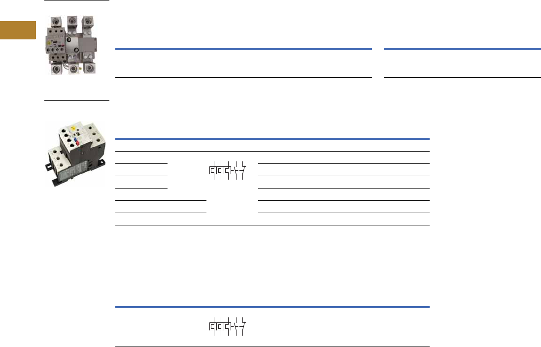
V5-T2-84 Volume 5—Motor Control and Protection CA08100006E—May 2016 www.eaton.com
2
2
2
2
2
2
2
2
2
2
2
2
2
2
2
2
2
2
2
2
2
2
2
2
2
2
2
2
2
2
2.2
NEMA Contactors and Starters
Space-Savings Series
XT Electronic Overload Relays for use with Size 5 NEMA Space-Savings Contactors
Use CTs and 1-5A XT overload relay. CT kit does not include overload relay (order separately).
XT Electronic Overload Relays for Separate Mount
XT Electronic Overload Relay for Pass-Through Design
Pass-through design does not include any lugs to land wires.
Terminate motor leads directly on contactor.
Space-Savings
Contactor Size
For Use with
Contactor
CT Range
(Amps) Description
CT Kit
Catalog Number
Terminal
Size
Overload Relay
Catalog Number
Overload Relay
with Ground Fault
Catalog Number
1 CN13SN022_ 60-300 300: 5 panel-mount CT kit
with integrated lugs
ZEB-XCT300 750 kcmil
(2) 250 kcmil
3/0 Cu/Al
XTOE005CCSS XTOE005CGSS
Overload
Range (Amps)
Frame
Size
Contact
Sequence Type
Overload Relay
Catalog Number
Overload Relay
with Ground Fault
Catalog Number
Overload Relay
0.33–1.65 45 mm ZEB32-1,65/KK XTOE1P6CCSS XTOE1P6CGSS
1–5 ZEB32-5/KK XTOE005CCSS XTOE005CGSS
4–20 ZEB32-20/KK XTOE020CCSS XTOE020CGSS
9–45 ZEB32-45/KK XTOE045CCSS XTOE045CGSS
20–100 55 mm ZEB150-100/KK XTOE100GCSS XTOE100GGSS
35–175 110 mm ZEB150-175/KK XTOE175GCSS XTOE175GGSS
Overload
Range (Amps)
Frame
Size
Contact
Sequence Type
Overload Relay
Catalog Number
Overload Relay
with Ground Fault
Catalog Number
35–175 110 mm ZEB150-175/PT XTOE175GCSP XTOE175GGSP
1–5A OL with CTs
45 mm XT for
Separate Mount
1359795
2469896
1359795
2469896

Volume 5—Motor Control and Protection CA08100006E—May 2016 www.eaton.com V5-T2-85
2
2
2
2
2
2
2
2
2
2
2
2
2
2
2
2
2
2
2
2
2
2
2
2
2
2
2
2
2
2
2.2
NEMA Contactors and Starters
Space-Savings Series
Accessories
CT Kits
Accessories
Communication
The XTOE is provided with two levels of communication capability.
Basic Communication via
Expansion Module—
Monitoring Only
Basic communication on
the XTOE is accomplished
using an expansion module.
The expansion module plugs
into the expansion bay on
the XTOE overload relay,
enabling communications
with the overload via their
Modbus RTU (RS-485)
network. No additional parts
are required. See
figure below.
Basic Communication—
Modbus
Advanced
Communication—
Monitoring and Control
XTOE also has the ability to
communicate on industrial
protocols such as DeviceNet,
PROFIBUS, Modbus RTU
and Modbus TCP, and
EtherNet/IP while providing
control capability using I/O.
An expansion module
(mentioned earlier) combined
with a communication
adapter and a communication
module allows easy
integration onto the
customer’s network. See
figure below.
Advanced Communication—
Communication Adapter with
Communication Module
Advanced
Communication—
Communication Module
The communication adapter
comes standard with four
inputs and two outputs
(24 Vdc or 120 Vac) while
providing the customer with
flexible mounting options
(DIN rail or panel). See
figure below,
Note
1Customer can wire remote mounted button to reset module (i.e., 22 mm pushbutton, catalog number M22-D-B-GB14-K10).
Description Catalog Number
Safety Cover
Clear Lexan cover that mounts on top of the FLA dial and DIP switches when closed. ZEB-XSC
Reset Bar
Assembles to the top of the overload to provide a larger target area for door
mounted reset operators.
ZEB-XRB
Remote Reset
Remote reset module (24 Vdc) 1C440-XCOM
Remote reset module (120 Vac) 1ZEB-XRR-120
Remote reset module (24 Vac) 1ZEB-XRR-24
Safety Cover
Reset Bar
Remote Reset

V5-T2-86 Volume 5—Motor Control and Protection CA08100006E—May 2016 www.eaton.com
2
2
2
2
2
2
2
2
2
2
2
2
2
2
2
2
2
2
2
2
2
2
2
2
2
2
2
2
2
2
2.2
NEMA Contactors and Starters
Space-Savings Series
The following information can be viewed using the communication option:
●Motor status—running,
stopped, tripped or
resetting
●Individual rms phase
currents (A, B, C)
●Average of three-phase
rms current
●Percent thermal capacity
●Fault codes (only available
prior to reset)
●Percent phase unbalance
●Ground fault current and
percent
●Overload relay settings—
trip class, DIP switch
selections, reset selections
●Modbus address (can be
set over the network)
Communication Accessories
Note
1 C440-COM-ADP Din C Panel adapter not required for ModbusTCP / EtherNet/IP communication module.
Description Catalog Number
Expansion module (Remote Reset/Modbus RTU, RS-485 Communication) C440-XCOM
Communication adapter kit (DIN C Panel mounted adapter, required for advance communication option) C440-COM-ADP 1
DeviceNet communication module kit—120V I/O (consists of C440-XCOM + C441K + C440-COM-ADP) C440-DN-120
DeviceNet communication module kit—24 Vdc I/O (consists of C440-XCOM + C441L + C440-COM-ADP) C440-DN-24
PROFIBUS communication module kit—120V I/O (consists of C440-XCOM + C441S + C440-COM-ADP) C440-DP-120
PROFIBUS communication module kit—24V I/O (consists of C440-XCOM + C441Q + C440-COM-ADP) C440-DP-24
Modbus communication module kit—120V I/O (consists of C440-XCOM + C441N + C440-COM-ADP) C440-MOD-120
Modbus communication module kit—24 Vdc I/O (consists of C440-XCOM + C441P + C440-COM-ADP) C440-MOD-24
Modbus TCP/Ethernet IP communication module kit—120V I/O (consists of C440-XCOM + C441U) C440-ET-120
Modbus TCP/Ethernet IP communication module kit—24V I/O (consists of C440-XCOM + C441V) C440-ET-24
Expansion Module
Communication
Adapter

Volume 5—Motor Control and Protection CA08100006E—May 2016 www.eaton.com V5-T2-87
2
2
2
2
2
2
2
2
2
2
2
2
2
2
2
2
2
2
2
2
2
2
2
2
2
2
2
2
2
2
2.2
NEMA Contactors and Starters
Space-Savings Series
Modbus Communication Module
The Modbus module
combined with an expansion
module and a communication
adapter provide Modbus
communication capability to
the XTOE electronic overload
relay.
Features and Benefits
●The Modbus
communication module is
capable of baud rates
up to 115K
●The Modbus address and
baud rate configuration can
be easily changed using
the HMi user interface
●Modbus address and baud
rate are set via convenient
DIP switches; LEDs are
provided to display
Modbus traffic
●Configuration with
common Modbus
configuration tools
●Terminals
●Unique locking
mechanism provides for
easy removal of the
terminal block with the
field wiring installed
●Each terminal is marked
for ease of wiring and
troubleshooting
●Selectable I/O assemblies
●4IN/2OUT
●Signal types include
24 Vdc I/O and
120 Vac I/O
●Each I/O module is
optically isolated
between the field I/O
and the network adapter
to protect the I/O and
communication circuits
from possible damage
due to transients and
ground loops
●Input Module features a
user-definable input
debounce, which limits
the effects of transients
and electrical noise
●Output Module supports
a user-definable safe
state for loss of
communication; hold
last state, ON or OFF
DeviceNet Communication Modules
The DeviceNet
Communication Module
provides monitoring and
control for the XTOE overload
relay from a single DeviceNet
node. These modules also
offer convenient I/O in two
voltage options,
24 Vdc and 120 Vac.
Features and Benefits
●Communication to
DeviceNet uses only one
DeviceNet MAC ID
●Configuration
●DeviceNet MAC ID and
Baud rate are set via
convenient DIP switches
with an option to set
from the network
●Advanced configuration
available using common
DeviceNet tools
●Terminals
●Unique locking
mechanism provides for
easy removal of the
terminal block with the
field wiring installed
●Each terminal is marked
for ease of wiring and
troubleshooting
●Selectable I/O assemblies
●4IN/2OUT
●Signal types include
24 Vdc I/O and
120 Vac I/O
●Each I/O module is
optically isolated
between the field I/O
and the network adapter
to protect the I/O and
communication circuits
from possible damage
due to transients and
ground loops
●Input Module features a
user-definable input
debounce, which limits
the effects of transients
and electrical noise
●Output Module supports
a user-definable safe
state for loss of
communication; hold
last state, ON or OFF
●Combined status LED
Modbus
Communication Module
DeviceNet
Communication Module
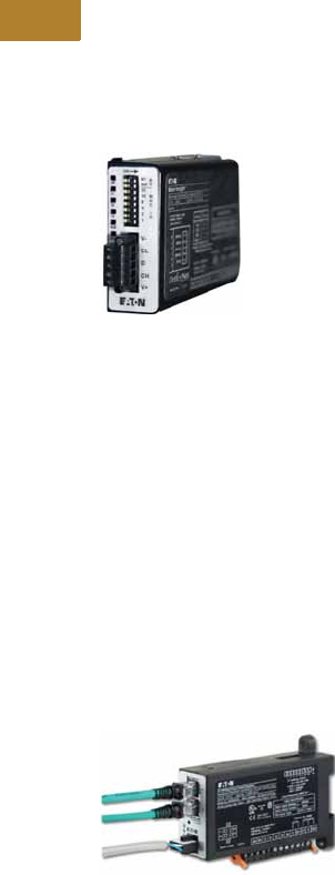
V5-T2-88 Volume 5—Motor Control and Protection CA08100006E—May 2016 www.eaton.com
2
2
2
2
2
2
2
2
2
2
2
2
2
2
2
2
2
2
2
2
2
2
2
2
2
2
2
2
2
2
2.2
NEMA Contactors and Starters
Space-Savings Series
PROFIBUS Communication Modules
The PROFIBUS module
combined with an expansion
module and a communication
adapter provide Modbus
communication capability to
the XTOE electronic overload
relay.
Features and Benefits
●The PROFIBUS
communication module is
capable of baud rates
up to 12 Mb
●PROFIBUS address is
set via convenient DIP
switches; LEDs are
provided to display
PROFIBUS status
●Intuitive configuration
with common PROFIBUS
configuration tools
●Terminals
●Unique locking
mechanism provides for
easy removal of the
terminal block with the
field wiring installed
●Each terminal is marked
for ease of wiring and
troubleshooting
●Selectable I/O assemblies
●4IN/2OUT
●Signal types include
24 Vdc I/O and
120 Vac I/O
●Each I/O module is
optically isolated
between the field I/O
and the network adapter
to protect the I/O and
communication circuits
from possible damage
due to transients and
ground loops
●Input Module features a
user-definable input
debounce, which limits
the effects of transients
and electrical noise
●Output Module supports
a user-definable safe
state for loss of
communication; hold
last state, ON or OFF
Modbus TCP / EtherNet/IP Communication Modules
The Ethernet module
combines user selectable
Modbus TCP and EtherNet/IP
protocols in a single device.
A communication adapter is
not required for this module
as it is designed for DIN/
Panel-Mounting. Combined
with an expansion module,
Modbus TCP and EtherNet/IP
capability are added to the
XTOE overload relay.
Features and Benefits
●Supports EtherNet/IP
Protocol
●Supports Modbus TCP
Protocol
●Integrated web page for
device monitoring and
configuration
●Dual Ethernet ports with
integrated switch
●Can simultaneously
support data access from
EtherNet/IP originators and
Modbus TCP clients
PROFIBUS
Communication Module
Modbus TCP / EtherNet/IP
Communication Module

Volume 5—Motor Control and Protection CA08100006E—May 2016 www.eaton.com V5-T2-89
2
2
2
2
2
2
2
2
2
2
2
2
2
2
2
2
2
2
2
2
2
2
2
2
2
2
2
2
2
2
2.2
NEMA Contactors and Starters
Space-Savings Series
Technical Data and Specifications
Electronic Overload Relays up to 1500A
Specification
Description 45 mm 55 mm 110 mm
Electrical Ratings Range Range Range
Operating voltage (three-phase) and frequency 690 Vac (60/50 Hz) 690 Vac (60/50 Hz) 690 Vac (60/50 Hz)
FLA Range
0.33–1.65A
1–5A
4–20A
9–45A
20–100A 28–140A (NEMA)
35–175A (IEC)
Use with Contactors
Space-Savings NEMA Size 0, 1, 2 2, 3 4
Tri p C l a s s
10A, 10, 20, 30
Selectable
10A, 10, 20, 30
Selectable
10A, 10, 20, 30
Selectable
Motor Protection
Thermal overload setting 1.05 x FLA: does not trip
1.15 x FLA: overload trip
1.05 x FLA: does not trip
1.15 x FLA: overload trip
1.05 x FLA: does not trip
1.15 x FLA: overload trip
Feature Range Range Range
Phase loss Fixed threshold 50% Fixed threshold 50% Fixed threshold 50%
Phase unbalance (selectable: enable/disable) Fixed threshold 50% Fixed threshold 50% Fixed threshold 50%
Ground fault (selectable: enable/disable) 50% of FLA dial setting
>150% = 2 sec
>250% = 1 sec
50% of FLA dial setting
>150% = 2 sec
>250% = 1 sec
50% of FLA dial setting
>150% = 2 sec
>250% = 1 sec
Reset Manual/automatic Manual/automatic Manual/automatic
Indicators
Trip status Orange flag Orange flag Orange flag
Mode LED One flash: Overload operating properly
Two flashes: Current is above FLA dial
setting—pending trip
One flash: Overload operating properly
Two flashes: Current is above FLA dial
setting—pending trip
One flash: Overload operating properly
Two flashes: Current is above FLA dial
setting—pending trip
Options
Remote reset Yes Yes Yes
Reset bar Yes Yes Yes
Communication expansion module Yes Yes Yes
Communication adapter Yes Yes Yes
Capacity
Load terminals
Terminal capacity 12–10 AWG (4–6 mm2)
8–6 AWG (6–16 mm2)
6–1 AWG (16–50 mm2) 8–4/0 AWG (10–95 mm2)
Tightening torque 20–25 lb-in (2.3–2.8 Nm)
25–30 lb-in (2.8–3.4 Nm)
25–30 lb-in (2.8–3.4 Nm) 124 lb-in (14 Nm)
Input, auxiliary contact and remote reset terminals
Terminal capacity 2 x (18–12) AWG 2 x (18–12) AWG 2 x (18–12) AWG
Tightening torque 7–11 lb-in (0.8–1.2 Nm) 7–11 lb-in (0.8–1.2 Nm) 7–11 lb-in (0.8–1.2 Nm)
Volt ages
Insulation voltage Ui (three-phase) 690 Vac 690 Vac 690 Vac
Insulation voltage Ui (control) 500 Vac 500 Vac 500 Vac
Rated impulse withstand voltage 6000 Vac 6000 Vac 6000 Vac
Overvoltage category/pollution degree III/3 III/3 III/3

V5-T2-90 Volume 5—Motor Control and Protection CA08100006E—May 2016 www.eaton.com
2
2
2
2
2
2
2
2
2
2
2
2
2
2
2
2
2
2
2
2
2
2
2
2
2
2
2
2
2
2
2.2
NEMA Contactors and Starters
Space-Savings Series
Electronic Overload Relays up to 1500A, continued
Specification
Description 45 mm 55 mm 110 mm
Auxiliary and Control Circuit Ratings
Conventional thermal continuous current 5A 5A 5A
Rated operational current—IEC AC-15
Make contact (1800 VA)
120V 15A 15A 15A
240V 15A 15A 15A
415V 0.5A 0.5A 0.5A
500V 0.5A 0.5A 0.5A
Break contact (180 VA)
120V 1.5A 1.5A 1.5A
240V 1.5A1.5A1.5A
415V 0.9A 0.9A 0.9A
500V 0.8A 0.8A 0.8A
IEC DC-13 (L/R F 15 ms1)
0–250V 1.0A 1.0A 1.0A
Rated operational current—UL B600
Make contact (3600 VA)
120V 30A 30A 30A
240V 15A 15A 15A
480V 7.5A 7.5A 7.5A
600V 6A 6A 6A
Break contact (360 VA)
120V 3A 3A 3A
240V 1.5A1.5A1.5A
480V 0.75A 0.75A 0.75A
600V 0.6A 0.6A 0.6A
R300—Vdc ratings (28 VA)
0–120V 0.22A 0.22A 0.22A
250V 0.11A 0.11A 0.11A
Short-Circuit Rating without Welding
Maximum fuse 6A gG/gL 6A gG/gL 6A gG/gL
Environmental Ratings
Ambient temperature (operating) –13° to 149°F (–25° to 65°C) –13° to 149°F (–25° to 65°C) –13° to 149°F (–25° to 65°C)
Ambient temperature (storage) –40° to 185°F (–40° to 85°C) –40° to 185°F (–40° to 85°C) –40° to 185°F (–40° to 85°C)
Operating humidity UL 991 (H3) 5% to 95% noncondensing 5% to 95% noncondensing 5% to 95% noncondensing
Altitude (no derating) NEMA ICS1 2000m 2000m 2000m
Shock (IEC 600068-2-27) 15g any direction 15g any direction 15g any direction
Vibration (IEC 60068-2-6) 3g any direction 3g any direction 3g any direction
Pollution degree per IEC 60947-4-1 3 for product (2 for pcb) 3 for product (2 for pcb) 3 for product (2 for pcb)
Ingress protection IP20 IP20 IP20
Protection against direct contact when actuated from
front (IEC 536)
Finger- and back-of-hand proof Finger- and back-of-hand proof Finger- and back-of-hand proof
Mounting position Any Any Any
Climatic proofing Damp heat, constant to IEC 60068-2-30 Damp heat, constant to IEC 60068-2-30 Damp heat, constant to IEC 60068-2-30

Volume 5—Motor Control and Protection CA08100006E—May 2016 www.eaton.com V5-T2-91
2
2
2
2
2
2
2
2
2
2
2
2
2
2
2
2
2
2
2
2
2
2
2
2
2
2
2
2
2
2
2.2
NEMA Contactors and Starters
Space-Savings Series
Electronic Overload Relays up to 1500A, continued
Specification
Description 45 mm 55 mm 110 mm
Electrical/EMC
Radiated emissions
IEC 60947-4-1-Table 15
EN 55011 (CISPIR 11) Group 1, Class A, ISM
30 MHz to 1000 MHz 30 MHz to 1000 MHz 30 MHz to 1000 MHz
Conducted emissions
IEC 60947-4-1-Table 14
EN 55011 (CISPIR 11) Group 1; Class ISM
0.15 MHz to 30 MHz 0.15 MHz to 30 MHz 0.15 MHz to 30 MHz
ESD immunity
IEC 60947-4-1 (Table 13)
±8 kV air, ±6 kV contact ±8 kV air, ±6 kV contact ±8 kV air, ±6 kV contact
Radiated immunity
IEC 60947-4-1
IEC 61000-4-3
10 V/m 80 MHz–1000 MHz
3 V/m from 1.4 to 2.7 GHz
80% amplitude modulated
1 kHz sine wave
10 V/m 80 MHz–1000 MHz
3 V/m from 1.4 to 2.7 GHz
80% amplitude modulated
1 kHz sine wave
10 V/m 80 MHz–1000 MHz
3 V/m from 1.4 to 2.7 GHz
80% amplitude modulated
1 kHz sine wave
Conducted immunity
IEC 60947-4-1, IEC 61000-4-6
140 dub (10V rms)
150 kHz–100 MHz
140 dub (10V rms)
150 kHz–100 MHz
140 dub (10V rms)
150 kHz–100 MHz
Fast transient immunity
IEC 60947-4-1 (Table 13)
IEC 61000-4-4
±4 kV using direct method
with accessory installed in expansion bay
±2 kV using direct method
±4 kV using direct method
with accessory installed in expansion bay
±2 kV using direct method
±4 kV using direct method
with accessory installed in expansion bay
±2 kV using direct method
Surge immunity
IEC 60947-4-1 (Table 13)
IEC 61000-4-5 a Class 4
Three-phase power inputs:
±4 kV line-to-line (DM)
±4 kV line-to-ground (CM)
Three-phase power inputs:
±4 kV line-to-line (DM)
±4 kV line-to-ground (CM)
Three-phase power inputs:
±4 kV line-to-line (DM)
±4 kV line-to-ground (CM)
With accessory installed in expansion bay:
±2 kV line-to-line (DM) –>1.2/50 us;
2 kV line-to-earth, 1 kV line-to-line
±4 kV line-to-ground (CM)
With accessory installed in expansion bay:
±2 kV line-to-line (DM) –>1.2/50 us;
2 kV line-to-earth, 1 kV line-to-line
±4 kV line-to-ground (CM)
With accessory installed in expansion bay:
±2 kV line-to-line (DM) –>1.2/50 us;
2 kV line-to-earth, 1 kV line-to-line
±4 kV line-to-ground (CM)
Power freq. magnetic field immunity
IEC 60947-4-1, IEC 61000-4-8
30 A/m, 50 Hz 30 A/m, 50 Hz 30 A/m, 50 Hz
Electromagnetic field
IEC 60947-4-1 Table 13, IEC 61000-4-3
10 V/m 10 V/m 10 V/m
Distortion IEEE 519 5% THD max., 5th harmonic 3% max. 5% THD max., 5th harmonic 3% max. 5% THD max., 5th harmonic 3% max.
Electrostatic discharge (ESD)
IEC 61000-4-2, EN 61131-2
4 kV contact
8 kV air discharge
4 kV contact
8 kV air discharge
4 kV contact
8 kV air discharge
Electrical fast transient (EFT)
IEC 61000-4-4, EN 61131-2
±2 kV using direct method ±2 kV using direct method ±2 kV using direct method
Surge immunity
IEC 61000-4-5, EN 61131-2
±2 kV line-to-ground (CM) ±2 kV line-to-ground (CM) ±2 kV line-to-ground (CM)

V5-T2-92 Volume 5—Motor Control and Protection CA08100006E—May 2016 www.eaton.com
2
2
2
2
2
2
2
2
2
2
2
2
2
2
2
2
2
2
2
2
2
2
2
2
2
2
2
2
2
2
2.2
NEMA Contactors and Starters
Space-Savings Series
Communication Modules
Note
1Relates to C441M only.
Description Modbus DeviceNet PROFIBUS Ethernet
Electrical/EMC
Radiated emissions
IEC 60947-4-1—Table 15, EN 55011
(CISPIR 11) Group 1, Class A
30–1000 MHz 30–1000 MHz 30–1000 MHz 30–1000 MHz
Conducted emissions
IEC 60947-4-1—Table 14, EN 55011
(CISPIR 11) Group 1, Class A
0.15–30 MHz 0.15–30 MHz 0.15–30 MHz 0.15–30 MHz
ESD immunity
IEC 60947-4-1 (Table 13)
±8 kV air, ±4 kV contact ±8 kV air, ±4 kV contact ±8 kV air, ±4 kV contact ±8 kV air, ±4 kV contact
Radiated immunity
IEC 60947-4-1
10 V/m 80–1000 MHz
80% amplitude modulated
1 kHz sine wave
10 V/m 80–1000 MHz
80% amplitude modulated
1 kHz sine wave
10 V/m 80–1000 MHz
80% amplitude modulated
1 kHz sine wave
10 V/m 80–1000 MHz
80% amplitude modulated
1 kHz sine wave
Conducted immunity
IEC 60947-4-1
140 dBuV (10V rms)
150 kHz–80 MHz
140 dBuV (10V rms)
150 kHz–80 MHz
140 dBuV (10V rms)
150 kHz–80 MHz
140 dBuV (10V rms)
150 kHz–80 MHz
Fast transient immunity
IEC 60947-4-1 (Table 13) IEC 6100-4-4
±2 kV using direct method ±2 kV supply and control,
±1 kV communication
±2 kV supply and control,
±1 kV communication
±2 kV supply and control,
±1 kV communication
Surge immunity
IEC 60947-4-1 (Table 13)
IEC 61000-4-5 Class 3
User IO and communication lines 1:
±1 kV line-to-line (DM)
±2 kV line-to-ground (CM)
User IO and communication lines:
±0.5 kV line-to-line (DM)
±1 kV line-to-ground (CM)
User IO and communication lines:
±0.5 kV line-to-line (DM)
±1 kV line-to-ground (CM)
User IO and communication lines:
±0.5 kV line-to-line (DM)
±1 kV line-to-ground (CM)
Electromagnetic field 1
IEC 60947-4-1 (Table 13) IEC 61000-4-3
10 V/m 10 V/m 10 V/m 10 V/m
Environmental Ratings
Ambient temperature (operating) –4° to 122°F (–20° to 50°C) –13° to 122°F (–25° to 50°C) –13° to 122°F (–25° to 50°C) –13° to 122°F (–25° to 50°C)
Ambient temperature (storage) –40° to 185°F (–40° to 85°C) –40° to 185°F (–40° to 85°C) –40° to 185°F (–40° to 85°C) –40° to 185°F (–40° to 85°C)
Operating humidity 5–95% noncondensing 5–95% noncondensing 5–95% noncondensing 5–95% noncondensing
Altitude (no derating) 2000m 2000m 2000m 2000m
Shock (IEC 600068-2-27) 15G any direction 15G any direction 15G any direction 15G any direction
Vibration (IEC 60068-2-6) 3G any direction 3G any direction 3G any direction 3G any direction
Pollution degree per IEC 60947-1 3 3 3 3
Degree of protection IP20 IP20 IP20 IP20
Overvoltage category per UL 508 III III III III
DeviceNet
DeviceNet connections — Group 2, polling, bit strobe,
explicit, no UCMM
— Group 2, polling, bit strobe,
explicit, no UCMM
DeviceNet baud rate — 125K, 250K, 500K — 125K, 250K, 500K
Ethernet
Ethernet connections — — — Integrated two-port switch with dual
RJ45 Ethernet connections
Ethernet type — — — Ethernet 10/100 Mbs, AutoMDX,
Auto Negotiation
PROFIBUS
PROFIBUS connections — — Group 2, polling, bit strobe,
explicit, no UCMM
—
PROFIBUS baud rate — — 9.6K, 19.2K, 45.45K, 93.75K, 187.5K,
500K, 1.5M, 3M, 6M, 12M
—

Volume 5—Motor Control and Protection CA08100006E—May 2016 www.eaton.com V5-T2-93
2
2
2
2
2
2
2
2
2
2
2
2
2
2
2
2
2
2
2
2
2
2
2
2
2
2
2
2
2
2
2.2
NEMA Contactors and Starters
Space-Savings Series
Communication Modules, continued
Note
1Relates to C441M only.
Description Modbus DeviceNet PROFIBUS Ethernet
C441_ 24 Vdc Input
Nominal input voltage 24 Vdc 24 Vdc 24 Vdc 24 Vdc
Operating voltage 18–30 Vdc 18–30 Vdc 18–30 Vdc 18–30 Vdc
Number of inputs 4 4 4 4
Signal delay 5 ms (programmable to 65 sec) 5 ms (programmable to 65 sec) 5 ms (programmable to 65 sec) 5 ms (programmable to 65 sec)
OFF-state voltage <6 Vdc <6 Vdc <6 Vdc <6 Vdc
ON-state voltage >18 Vdc >18 Vdc >10 Vdc >18 Vdc
Nominal input current 5 mA 5 mA 5 mA 5 mA
Isolation 1500V 1500V 1500V 1500V
Terminal screw torque 7–9 in-lb 7–9 in-lb 7–9 in-lb 7–9 in-lb
24V source current 50 mA 50 mA 50 mA 50 mA
Operating Voltage Range—DC Input Modules
OFF state 0–6 Vdc 0–6 Vdc 0–6 Vdc 0–6 Vdc
Transition region 6–18 Vdc 6–18 Vdc 6–18 Vdc 6–18 Vdc
ON state 18–30 Vdc 18–30 Vdc 18–30 Vdc 18–30 Vdc
C441_ 120 Vac Input
Nominal input voltage 120 Vac 120 Vac 120 Vac 120 Vac
Operating voltage 80–140 Vac 80–140 Vac 80–140 Vac 80–140 Vac
Number of inputs 4 4 4 4
OFF-state voltage <30 Vac <30 Vac <20 Vac <30 Vac
ON-state voltage >80 Vac >80 Vac >70 Vac >80 Vac
Nominal input current 15 mA 15 mA 15 mA 15 mA
Signal delay 1/2 cycle 1/2 cycle 1/2 cycle 1/2 cycle
Isolation 1500V 1500V 1500V 1500V
Terminal screw torque 7–9 in-lb 7–9 in-lb 7–9 in-lb 7–9 in-lb
Operating Voltage Range—AC Input Modules
OFF state 0–30 Vac 0–30 Vac 0–30 Vac 0–30 Vac
Transition region 30–80 Vac 30–80 Vac 30–80 Vac 30–80 Vac
ON state 80–140 Vac 80–140 Vac 80–140 Vac 80–140 Vac
Output Modules
Nominal voltage 120 Vac
24 Vdc
120 Vac
24 Vdc
120 Vac
24 Vdc
120 Vac
24 Vdc
Number of outputs (2) 1NO Form A
1NO/NC Form C
(2) 1NO Form A
1NO/NC Form C
(2) 1NO Form A
1NO/NC Form C
(2) 1NO Form A
1NO/NC Form C
Relay OFF time 3 ms 3 ms 3 ms 3 ms
Relay ON time 7 ms 7 ms 7 ms 7 ms
Max. current per point 15A (B300 rated) 5A (B300 rated) 5A (B300 rated) 5A (B300 rated)
Electrical life 100,000 cycles 100,000 cycles 100,000 cycles 100,000 cycles
Mechanical life 1,000,000 cycles 1,000,000 cycles 1,000,000 cycles 1,000,000 cycles

V5-T2-94 Volume 5—Motor Control and Protection CA08100006E—May 2016 www.eaton.com
2
2
2
2
2
2
2
2
2
2
2
2
2
2
2
2
2
2
2
2
2
2
2
2
2
2
2
2
2
2
2.2
NEMA Contactors and Starters
Space-Savings Series
Short Circuit Ratings (North America CSA, cUL)
Changes to UL 508A and NEC in recent years have brought a focus to control panel safety with
regard to short-circuit current ratings (SCCR). Eaton’s XTOE electronic overload relays combined
with XT Series IEC, Freedom Series NEMA and XT NEMA contactors provide a wide variety of
SCCR solutions needed for a variety of applications. The SCCR data in this document reflects
the latest information as of April 2010.
XTOE Standalone Overload Relays (XTOE)
NEMA Space-Savings Starters with XTOE Electronic Overload Relays
Overload
FLA Range
Maximum
Operating
Voltage
Standard-Fault Short Circuit Data High-Fault Short Circuit Data
600V (kA)
Maximum
Fuse Size (A)
(RK5)
Maximum
Breaker
Size (A)
Fuses (RK5, J, CC) Thermal-Magnetic Circuit Breakers
480V (kA) 600V (kA)
Maximum
Fuse Size 480V (kA) 600V (kA)
Maximum
Breaker Size
0.33–1.65A600 Vac1 6 15 ——————
1–5A 600 Vac 5 20 20 100 100 30 100 35 20
4–20A 600 Vac 5 80 80 100 100 100 100 35 80
9–45A 600 Vac 5 175 175 100 100 100 100 35 100/175 (480/600)
20–100A 600 Vac 10 400 400 100 100 200 150 35 250/400 (480/600)
28–140A 600 Vac 10 450 500 100 100 400 100 65 400
35–175A 690 Vac 10 500 (gG) 350 (690 Vac)
320 (415 Vac)
100 100 500 (gG) 100 (415 Vac) — 350 (LGC3350)
320 (NZMH3)
High-Fault Short Circuit Data
Fuses (RK5, J, CC) Thermal-Magnetic Circuit Breakers
Contactor
Frame Size
Overload
FLA Range 480V 600V
Maximum
Fuse Size 480V 600V
Maximum
Breaker Size
B 1–5A 100 100 30 ———
4–20A 100 100 30 — — —
C 1–5A 100 100 60 — — —
4–20A 100 100 60 — — —
9–45A 100 100 60 — — —
D 9–45A 100 100 200 65 35 175
20–100A 100 100 200 65 35 175
F 20–100A 100 100 200 65 65 350
G 20–100A 100 100 200 65 65 350
35–175A 100 100 400 65 30 250 (480 Vac)
350 (600 Vac)
H 35–175A 100 100 400 65 30 400

Volume 5—Motor Control and Protection CA08100006E—May 2016 www.eaton.com V5-T2-95
2
2
2
2
2
2
2
2
2
2
2
2
2
2
2
2
2
2
2
2
2
2
2
2
2
2
2
2
2
2
2.2
NEMA Contactors and Starters
Space-Savings Series
Coil Data—Frames B, C, G
Note
1Coil Suffix TD: Umin 24 Vdc/Umax 27 Vdc.
Coil Suffix WD: Umin 48 Vdc/Umax 60 Vdc.
Coil Suffix AD: Umin 110 Vdc/Umax 130 Vdc.
Coil Suffix BD: Umin 200 Vdc/Umax 240 Vdc.
Example:
Uc = 0.7 x Umin—1.2 x Umax
Uc = 0.7 x 24V—1.2 x 27 Vdc
Description
CN13B_
NEMA Size 0
CN13C_
NEMA Size 1
CN13G_
NEMA Size 2
Volt age Tolera nce
Pickup (x Uc)
AC operated 0.8–1.1 0.8–1.1 0.8–1.1
DC operated 0.7–1.2 10.7–1.2 10.7–1.2 1
Dropout (x Uc)
AC operated 0.3–0.6 0.3–0.6 0.3–0.6
DC operated 0.15–0.6 0.15–0.6 0.15–0.6
Power Consumption of the Coil at Cold State and 1.0 x Uc
AC operated
Single-voltage coil 50 Hz
Pickup VA 52 52 149
Pickup W 40 40 80
Sealing VA 7.1 7.1 16
Sealing W 2.1 2.1 4.3
Single-voltage coil 60 Hz
Pickup VA 67 67 178
Pickup W 50 50 117
Sealing VA 8.7 8.7 19
Sealing W 2.6 2.6 5.3
50/60 Hz
Pickup VA 62
58
62
58
168
154
Pickup W 48
43
48
43
120
43
Sealing VA 9.1
6.5
9.1
6.5
22
14
Sealing W 2.5
2
2.5
2
5.3
4.3
DC operated
Pickup W 12 at 24V 12 at 24V 24 at 24V
Sealing W 0.5 at 24V 0.5 at 24V 0.5 at 24V
Duty factor (%DF) 100 100 100
Switching Time at 100% Uc (Approximate Values)
Main contact
AC operated
Closing delay (ms) <22 <22 <18
Opening delay (ms) <14 <14 <13
DC operated
Closing delay (ms) <47 <47 <54
Opening delay (ms) <30 <30 <24
Arcing time (ms) 10 10 10
Electromagnetic Compatibility (EMC)
Emitted interference To EN-60947-1 To EN-60947-1 To EN-60947-1
Noise immunity To EN-60947-1 To EN-60947-1 To EN-60947-1

V5-T2-96 Volume 5—Motor Control and Protection CA08100006E—May 2016 www.eaton.com
2
2
2
2
2
2
2
2
2
2
2
2
2
2
2
2
2
2
2
2
2
2
2
2
2
2
2
2
2
2
2.2
NEMA Contactors and Starters
Space-Savings Series
Coil Data—Frames K–M Coil Data—Frame S
Notes
1At 24V: 0.7–1.3 without additional auxiliary contact modules and ambient
temperature +40°C [104°F].
2Control transformer with Uk <6%.
Description
CN13K_
NEMA Size 3
CN13M_
NEMA Size 4
Volt age Tolera nce
Pickup (x Uc)
AC operated 0.8–1.1 0.8–1.1
DC operated 0.7–1.2 10.7–1.2 1
Dropout (x Uc)
AC operated 0.25–0.6 0.25–0.6
DC operated 0.15–0.6 0.15–0.6
Power Consumption of the Coil at Cold State and 1.0 x Uc
AC operated
Single-voltage coil 50 Hz
Pickup VA 180 180
Pickup W 130 130
Sealing VA 3.1 3.1
Sealing W 2.1 2.1
Single-voltage coil 60 Hz
Pickup VA 170 170
Pickup W 130 130
Sealing VA 3.1 3.1
Sealing W 2.1 2.1
50/60 Hz
Pickup VA 170 170
Pickup W 130 130
Sealing VA 3.1 3.1
Sealing W 2.1 2.1
DC operated
Pickup W 149 at 24V 149 at 24V
Sealing W 2.1 at 24V 2.1 at 24V
Duty factor (%DF) 100 100
Switching Time at 100% Uc (Approximate Values)
Main contact
AC operated
Closing delay (ms) <33 <33
Opening delay (ms) <41 <41
DC operated
Closing delay (ms) <35 <35
Opening delay (ms) <30 <30
Arcing time (ms) 15 15
Permissible residual current with actuation of
A1–A2 by the electronics (with 0 signal) (mA)
<
1
<
1
Electromagnetic Compatibility (EMC)
Emitted interference To EN60947-1 To EN60947-1
Noise immunity To EN60947-1 To EN60947-1
Description
CN13S_
NEMA Size 5
Voltage Tolerance
Pickup (x Uc)0.7 x U
cmin–1.15 x Ucmax
Dropout (x Uc)0.2 x U
cmin–0.6 x Ucmax
Power Consumption of the Coil at Cold State and 1.0 x Uc
XTCE185L–XTCEC20R
Pickup VA 380 2
Pickup W 250
Sealing VA 4.3
Sealing W 3.3
Switching Time at 100% Main Contact Uc (Approximate Values)
XTCE185L–XTCEC20R
Closing delay (ms) <80
Opening delay (ms) <110
Reaction in Threshold and Sealing State Transition Range
Voltage interruptions
(0–0.2 x Ucmin)
<
10 ms Time is bridged successfully
(0–0.2 x Ucmin) >10 ms Dropout of the contactor
Voltage dips
(0.2–0.6 x Ucmin)
<
12 ms Time is bridged successfully
(0.2–0.6 x Ucmin) >12 ms Dropout of the contactor
(0.6–0.7 x Ucmin) Contactor remains switched on
Excess voltage
(1.15–1.3 x Ucmax) Contactor remains switched on
(>1.3 x Ucmax)
<
3s Contactor remains switched on
(>1.3 x Ucmax) >3s Dropout of the contactor
Pickup phase
(0–0.7 x Ucmin) Contactor does not switch on
(0.7 x Ucmin –1.15 x Ucmax) Contactor switches on with certainty
(>1.15 x Ucmax) Contactor switches on with certainty
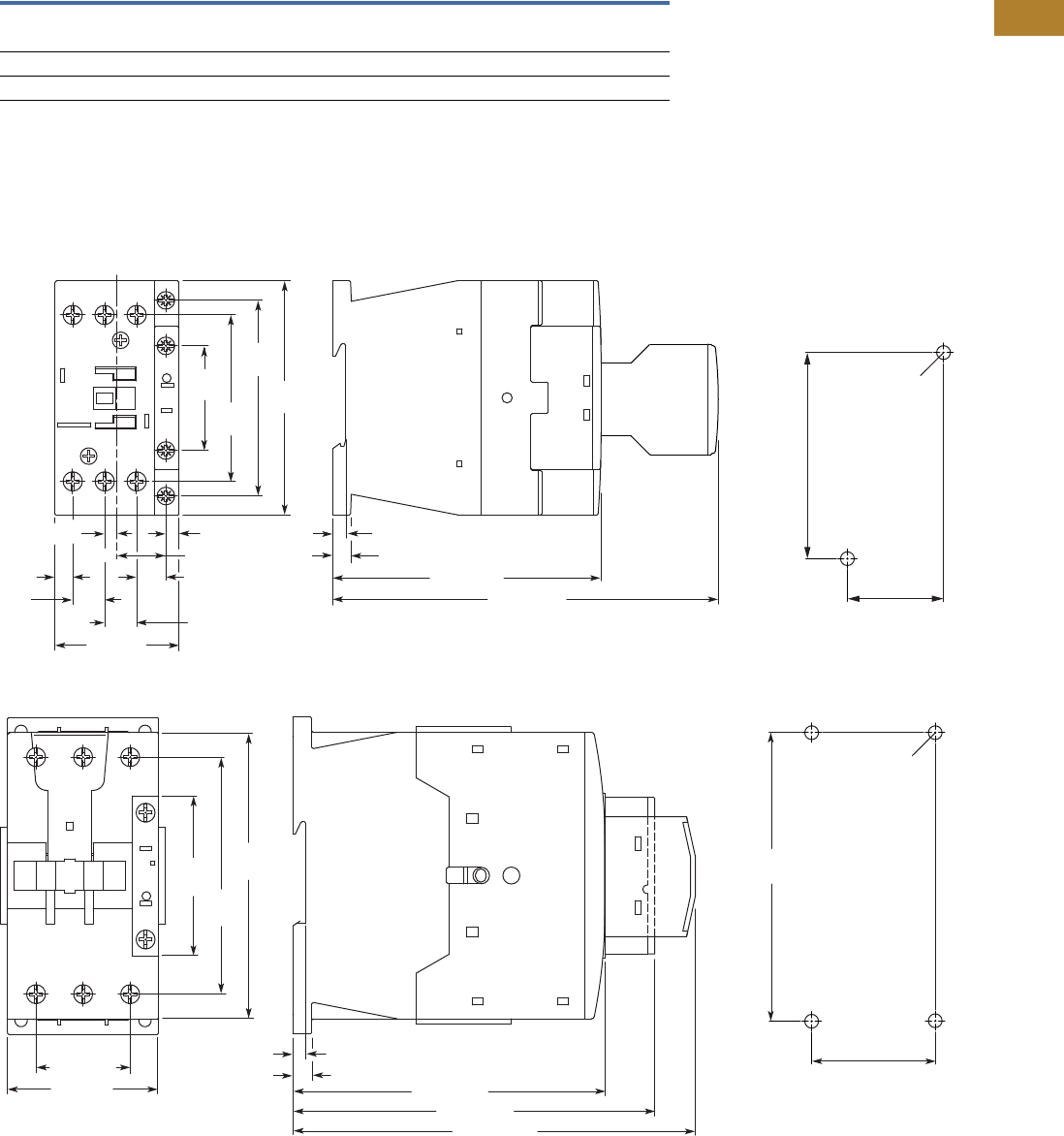
Volume 5—Motor Control and Protection CA08100006E—May 2016 www.eaton.com V5-T2-97
2
2
2
2
2
2
2
2
2
2
2
2
2
2
2
2
2
2
2
2
2
2
2
2
2
2
2
2
2
2
2.2
NEMA Contactors and Starters
Space-Savings Series
Current Heat Loss (Three-Pole) in Watts
Dimensions
Approximate Dimensions in mm [in]
Contactors
Type CN13 NEMA Size 0 and 1
Type CN13 NEMA Size 2
Description CN13BN0_ CN13CN0_ CN13GN0_ CN13KN0_ CN13MN0_
Current heat loss (three-pole) in watts
at Ith 7.3 12.1 28.8 20.3 30.7
at Ie to AC-3/400V 1.9 6.1 19 15.9 27.0
Impedance per pole, megohms 2 2 1.5 0.4 0.4
11. 6
[0.46] 11.6 [0.46]
4.5 [0.17]
17.7 [0.70]
10.6 [0.42]
6.4
[0.25]
38
[1.50]
71
[2.80]
60.4
[2.38]
85
[3.46]
45 [1.77]
4.8 [0.19]
138.7 [5.46]
6.5 [0.26]
97.4 [3.83]
Note: Sideways distance to grounded parts: 6 mm [0.39 in]
4.5 [0.17]
35 [1.38]
2 x M4 Dia.
75 [2.95]
6.9 [0.27]
4.7 [0.19]
34.4 [1.35]
113.8 [4.48]
132.1 [5.20]
146.8 [5.78]
Note: Sideways distance to
grounded parts: 6 mm [0.39 in]
55 [2.17]
57
[2.24]
86.4
[3.40]
104
[4.09]
45 [1.77]
4 x M4 Dia.
105 [4.13]
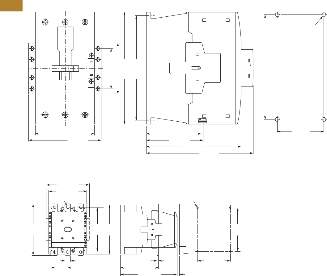
V5-T2-98 Volume 5—Motor Control and Protection CA08100006E—May 2016 www.eaton.com
2
2
2
2
2
2
2
2
2
2
2
2
2
2
2
2
2
2
2
2
2
2
2
2
2
2
2
2
2
2
2.2
NEMA Contactors and Starters
Space-Savings Series
Approximate Dimensions in mm [in]
Type CN13 NEMA Size 3 and 4
Type CN13 NEMA Size 5
Note: Sideways distance to
grounded parts: 10 mm [0.39 in]
90 [3.54]
111 [4.37]
82.5 [3.25]
85.5 [3.37]
142 [5.59]
160 [6.30]
76.5 [3.01]
57 [2.24]
170 [6.69]
156 [6.14]
4 x M6 Dia.
156 [6.14]
70 [2.79]
208 [8.19] 8 [0.31]
140 [5.51]
160
[6.30]
120 [4.72]
M6 Dia.
5 [0.20]
20 [0.79]
164
[6.46]
180
[7.09]
48 [1.89]
140 [5.51]
11 [0.43] Dia.
160 [6.30]
189
[7.44]
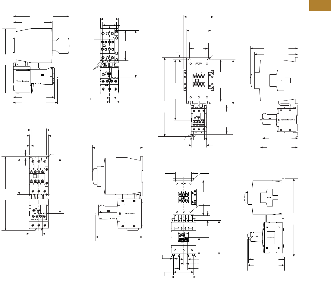
Volume 5—Motor Control and Protection CA08100006E—May 2016 www.eaton.com V5-T2-99
2
2
2
2
2
2
2
2
2
2
2
2
2
2
2
2
2
2
2
2
2
2
2
2
2
2
2
2
2
2
2.2
NEMA Contactors and Starters
Space-Savings Series
Approximate Dimensions in mm [in]
XTAE Starters with XTOE Overload Relay
Type AN13 NEMA Size 0 and 1
Type AN13 NEMA Size 2
Type AN13 NEMA Size 3
Type AN13 NEMA Size 4
140.0 [5.50]
98.0 [3.80]
110.4 [4.35]
102.7 [4.04]
161.0
[6.30] 2.5–3.0 Nm
[22–26 lb-in]
18.2 [0.71]
Trip/Test
10.6 [0.42]
Reset
35.0 [1.38]
Mounting
Holes for
M4 or #8
Screws
(2 places)
117.3
[4.62]
75.0
[2.95]
45.0 [1.77]
55.0 [2.17]
136.2 [5.36]
To Reset
38.7 [1.52]
To Reset
146.1 [5.75]
159.7
[6.29]
To Reset
5.0 [0.20]
105.0
[4.13]
Mtg.
213.6
[8.41]
Mtg. Holes for
(4) #8 Screws or
M4 Screws
5.0 [0.20]
45.0 [1.77] Mtg.
132.4 [5.21]
To Reset
Mtg. Holes
for (2) M4
or #8 Screws 140.2 [5.52]
175.0 [6.89]
160.0 [6.30]
Mtg. Holes for
(4) M6 or #10
Screws
156.0
[6.14]
Mtg. 167.3
[6.59]
Mtg.
108.4
[4.27]
Mtg.
41.2 [1.62] Mtg.
56.0 [2.20]
222.3
[8.75]
To Reset
291.1
[11.46]
7.8
[0.31]
70.0
[2.76]
90.0
[3.54]
Mtg.
111.8
[4.40]
345.0
[13.6]
89.0
[3.50]
Terminal
Torque:
14 Nm
[124 lb-in]
77.0
[3.00]
152.0
[6.00]
161.0 [6.30]
157.0 [6.18]
156.0
[6.14]
M6 [#10] Screws
70.0
[2.76]
21.3 [0.84]
5.0
[0.20]
18.2 [0.71] Trip/Test
10.6 [0.42] Reset
36.0 [1.42]
110.0 [4.30]
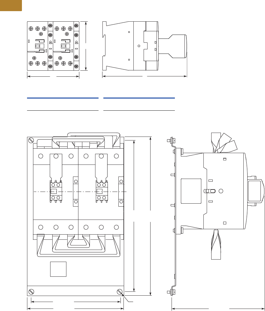
V5-T2-100 Volume 5—Motor Control and Protection CA08100006E—May 2016 www.eaton.com
2
2
2
2
2
2
2
2
2
2
2
2
2
2
2
2
2
2
2
2
2
2
2
2
2
2
2
2
2
2
2.2
NEMA Contactors and Starters
Space-Savings Series
Approximate Dimensions in mm [in]
Reversing Contactors
Type CN53 Size 0, 1 and 2
Type CN53 Size 3 and 4
Size 0 and 1 Size 2
WH D WH D
90
[3.54]
85
[3.34]
138
[5.43]
110
[4.33]
115
[4.53]
146.8
[5.78]
H
D
W
314
[12.36]
299
[11.77]
M6
176 [6.93]
196 [7.72] 183 [7.20]
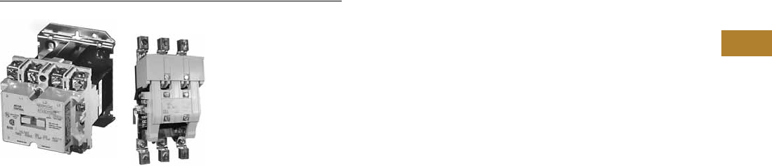
Volume 5—Motor Control and Protection CA08100006E—May 2016 www.eaton.com V5-T2-101
2
2
2
2
2
2
2
2
2
2
2
2
2
2
2
2
2
2
2
2
2
2
2
2
2
2
2
2
2
2
2.3
NEMA Contactors and Starters
A200 Series
Contactors—Non-Reversing and Reversing
Contents
Description Page
A200 Series
Contactors—Non-Reversing and Reversing
Starters—Non-Reversing and Reversing . . . . . . V5-T2-107
Relays—Thermal and Fast Trip . . . . . . . . . . . . . V5-T2-128
Thermal Type B, Class 20, Manual Reset . . . . . V5-T2-130
Thermal Type A, Class 20, Auto/Manual
Reset . . . . . . . . . . . . . . . . . . . . . . . . . . . . . . . V5-T2-133
Type FT Fast Trip, Class 10 . . . . . . . . . . . . . . . . V5-T2-136
Heater Selection . . . . . . . . . . . . . . . . . . . . . . . . V5-T2-139
Relays—Current Sensing Protective . . . . . . . . . V5-T2-141
Contactors—Non-Reversing and Reversing
Product Description
Class A201 Contactors,
Sizes 00–4; Three-Phase,
1-1/2–100 hp
A201 Magnetic Contactors
from Eaton’s Electrical Sector
are 600V rated devices
available in NEMA Sizes 00–
4, 10A through 150A (open
rating). Product features
include:
●Straight-through wiring
to line and load terminals
located up front for ease
of installation
●Moving and stationary
contacts are front
accessible, simplifying
inspection and
maintenance
●Reliable U-shaped magnet
for reduced power
consumption
●Coil design reduces
inventory/maintenance
expenses. For a given
voltage, one size coil fits
all contactors Sizes 00–2,
and a second coil fits three-
pole Model J Sizes 3 and 4.
Model K coils are different
design
A201 contactors have
normally open holding circuit
interlocks which are supplied
as standard.
Panel layout and drilling are
simplified through the use
of common backplates, one
for Sizes 00–2 and one for
Sizes 3–4. In addition, panel
space is reduced dramatically
through the use of unique
corner cavities for mounting
the wide variety of
modifications shown on
Page V5-T2-120.
For reversing applications,
two contactors are supplied
on a common base with
electrical and mechanical
interlocks which prevent both
contactors from being closed
at the same time.
Class A201 Contactors,
Sizes 5–9; Three-Phase,
Over 100 hp
These AC magnetic
contactors utilize clapper
design and feature straight-
through wiring.
Contacts are silver alloy for
longer life. The contacts close
with optimum wiping action
which serves to keep the
contacting surfaces clean.
De-ion® arc quenchers draw
the arc away from the
contacts at opening, which
reduces burning and pitting
and increases contact life.
All of the contactors are
complete with one unwired,
normally-open (NO) auxiliary
contact mounted and have
accommodations for
additional auxiliary contacts.
No control circuit wiring or
terminal markings are included.
Size 5, 300A, 600V, Open
Size 6, 600A, 600V, Open
Class A201 Size 5 and 6
contactors are front clapper
design, AC operated with the
armature pivoting on dual
needle bearings which assure
accurate contact alignment.
The contactor base is molded
of a high impact, non-
tracking, non-hygroscopic
glass polyester material
permitting front mounting
and wiring on a steel panel.
Floating magnet assures
quiet operation.
Size 5 and 6 contactors must
be mounted with the line
terminals directly above the
load terminals.
Multi-voltage coil ratings
allow selection of the voltage
which closely matches the
actual system voltage to assure
optimum contactor operation.
Each contactor
accommodates two Type J11
auxiliary contacts, providing
up to four auxiliary circuits,
normally-open or normally-
closed (NO and NC).
A201 Size 5 and 6
contactors and starters are
UL recognized when supplied
without terminals. When
supplied with terminals, the
devices are UL listed.
Two special configurations of
the Class A201 Size 5 and 6
contactors are available:
●Latched Design—
This is a mechanically
held, electrically released
device. It is applied where
the contactor must remain
closed during extreme
voltage fluctuations or
power failure. It is also
suitable for applications
requiring quiet operation
since the operating coil is
de-energized when the
contactor is closed. The
latch assembly consists
of a mechanical latch
mechanism, electrically
operated AC trip solenoid
and a clearing contact
●DC Operated—This device
is DC operated. It is used
where low dropout voltage
or exceptionally quiet
operation is desired. The
DC assembly consists of a
DC operating coil, integrally
mounted rectifier and
shorting contact

V5-T2-102 Volume 5—Motor Control and Protection CA08100006E—May 2016 www.eaton.com
2
2
2
2
2
2
2
2
2
2
2
2
2
2
2
2
2
2
2
2
2
2
2
2
2
2
2
2
2
2
2.3
NEMA Contactors and Starters
A200 Series
Size 7, 900A, 600V, Open
Size 8, 1350A, 600V, Open
Size 9, 2500A, 600V, Open
Class A201 Size 7 and 8
contactors are DC operated
side clapper design with the
shaft mounted on dual needle
bearings to ensure positive
contact alignment and long
contact life.
A steel panel base permits
mounting on angle or channel
without additional support,
for versatile low cost
installation.
Each stationary contact
assembly is mounted on an
individual molded insulator.
Each pair of contacts is
surrounded by a De-ion grid
type arc quencher for rapid
and confined arc interruption
and long contact life.
The shunt for each pole is
made of flexible, braided
copper cable for freedom of
movement and long life.
The rugged DC operating
coils are designed to operate
at high temperature and
insulated to meet Class H
service.
An integrally mounted
avalanche type silicon
rectifier supplies DC coil
voltage from the AC
control circuit.
Sizes 7 and 8 accommodate
three Type L-63 auxiliary
contacts which are easily
converted from normally-
open to normally-closed,
providing auxiliary circuit
flexibility. Size 9 uses L-64
auxiliary contacts with a total
of four circuits.
A201 Size 7, 8 and 9
contactors and starters are
UL recognized when supplied
without terminals. When
supplied with terminals, the
devices are UL listed.
Application Description
Magnetic contactors are
used to switch transformers
and capacitors and to control
electrical power circuits
such as heating, lighting
and motors that require
no overload protection, or
where overload protection
is separately provided. They
can be operated remotely
by manual or automatic
pilot devices.
Standards and Certifications
A201 contactors are UL listed
components and also have
CSA certification.
Instructional Leaflets
16960B Sizes 00–1 Magnetic
Contactor,
Non-reversing
or Reversing
16961E Size 2 Magnetic
Contactor,
Non-reversing
or Reversing
13238G Size 3 Magnetic
Contactor,
Non-reversing
or Reversing
17001C Size 4 Magnetic
Contactor,
Non-reversing
or Reversing
17049D Size 5 Magnetic
Contactor,
Non-reversing
or Reversing
17053B Size 6 Magnetic
Contactor,
Non-reversing
or Reversing
17048 Sizes 7–8 Magnetic
Contactor,
Non-reversing
or Reversing
16978 Size 9 Magnetic
Contactor,
Non-reversing
or Reversing
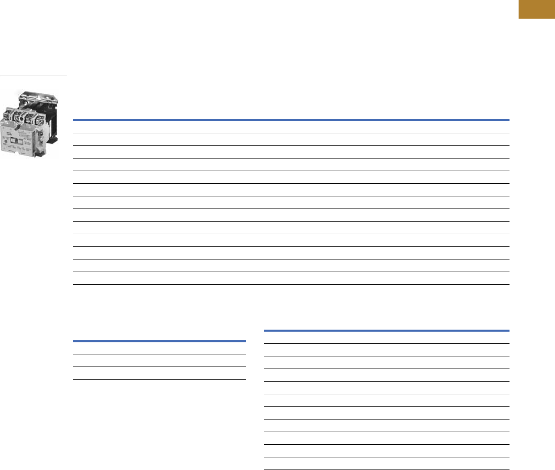
Volume 5—Motor Control and Protection CA08100006E—May 2016 www.eaton.com V5-T2-103
2
2
2
2
2
2
2
2
2
2
2
2
2
2
2
2
2
2
2
2
2
2
2
2
2
2
2
2
2
2
2.3
NEMA Contactors and Starters
A200 Series
Product Selection
Non-Reversing, Sizes 00–9
When Ordering Specify
Order by catalog number from the table below, plus suffix for
coil voltages, verifying usage of appropriate sizes.
Front Connected Contactors
Rear Connected Contactors Coil Suffix
Notes
1Sizes 7–9 use rectifier with DC coil.
2For Size 9, only available coil voltage is 120V.
3Supplied without terminal lugs.
Size Amps
Max. UL Horsepower Two Poles Open Three Poles Open Four Poles Open Five Poles Open
Single-Phase Three-Phase Catalog
Number
Catalog
Number
Catalog
Number
Catalog
Number115V 230V 208V 240V 480V 600V
Sizes 00–6
00 9 1/3 1 1-1/2 1-1/2 2 2 A201KAB_ A201KAC_ A201KAD_ A201KAE_
018123355A201K0B_ A201K0C_ A201K0D_ A201K0E_
1 27 2 3 7-1/2 7-1/2 10 10 A201K1B_ A201K1C_ A201K1D_ A201K1E_
245 3 7-1/210152525A201K2B_ A201K2C_ A201K2D_ A201K2E_
390 ——25305050A201K3B_ A201K3C_ A201K3D_ A201K3E_
4 135 — — 40 50 100 100 A201K4B_ A201K4C_ A201K4D_ A201K4E_
5 270 — — 75 100 200 200 A201K5B_ A201K5C_ — —
6 540 — — 150 200 400 400 A201K6B_ A201K6C_ — —
Sizes 7–9
7 1810 — — 200 300 600 600 A201K7B_ A201K7C_ — —
8 11215 — — 400 450 900 900 A201K8B_ A201K8C_ — —
9 12250 — — — 800 1600 — A201K9B_ A201K9C_Z1 23 ——
A201 Size 1 Contactor
120V Rectified Coil/Open Only
Size Catalog Number
7A201K7CJZ1Z4
8A201K8CJZ1Z4
9A201K9CJZ1Z4
Coil Volts and Hz Code Suffix
Sizes 00–6
120/60 or 110/50 A
200–208/60 B
240/60 W
Sizes 7, 8 and 9 2
480/60 X
600/60 E
110–120/50 or 60 J
220–240/50 or 60 K
440–480/50 or 60 U
600/60 E

V5-T2-104 Volume 5—Motor Control and Protection CA08100006E—May 2016 www.eaton.com
2
2
2
2
2
2
2
2
2
2
2
2
2
2
2
2
2
2
2
2
2
2
2
2
2
2
2
2
2
2
2.3
NEMA Contactors and Starters
A200 Series
Reversing, Sizes 00–9
When Ordering Specify
Order by catalog number from the table below, plus suffix for
coil voltages, verifying usage of appropriate sizes.
Class A211—Horizontally Mounted and Class A251—Vertically Mounted Reversing Contactors
Coil Suffix
Notes
1 Sizes 7–9 use rectifier with DC coil.
2 For Size 9, only available coil voltage is 120V.
Size Amps
Max. UL Horsepower Horizontal Design Vertical Design
Single-Phase Three-Phase Catalog
Number
Catalog
Number115V 230V 208V 240V 480V 600V
Sizes 0–6
018 123 3 5 5A211K0C_ A251K0C_
1 27 2 3 7-1/2 7-1/2 10 10 A211K1C_ A251K1C_
2 45 3 7-1/2 10 15 25 25 A211K2C_ A251K2C_
390 ——25 30 50 50 A211K3C_ A251K3C_
4 135 — — 40 50 100 100 A211K4C_ A251K4C_
5 270 — — 75 100 200 200 A211K5C_ A251K5C_
6 540 — — 150 200 400 400 A211K6C_ A251K6C_
Sizes 7–9
7 1810 — — 200 300 600 600 — A251K7C_
8 11215 — — 400 450 900 900 — A251K8C_
9 12250 — — — 800 1600 — — A251K9C_ 2
Coil Volts and Hz Code Suffix
Sizes 00–6
120/60 or 110/50 A
200–208/60 B
240/60 W
480/60 X
600/60 E
Sizes 7, 8 and 9 2
110–120/50 or 60 J
220 –240/50 or 60 K
440–480/50 or 60 U
600/60 E
Size 1 Horizontal
Reversing Contactor
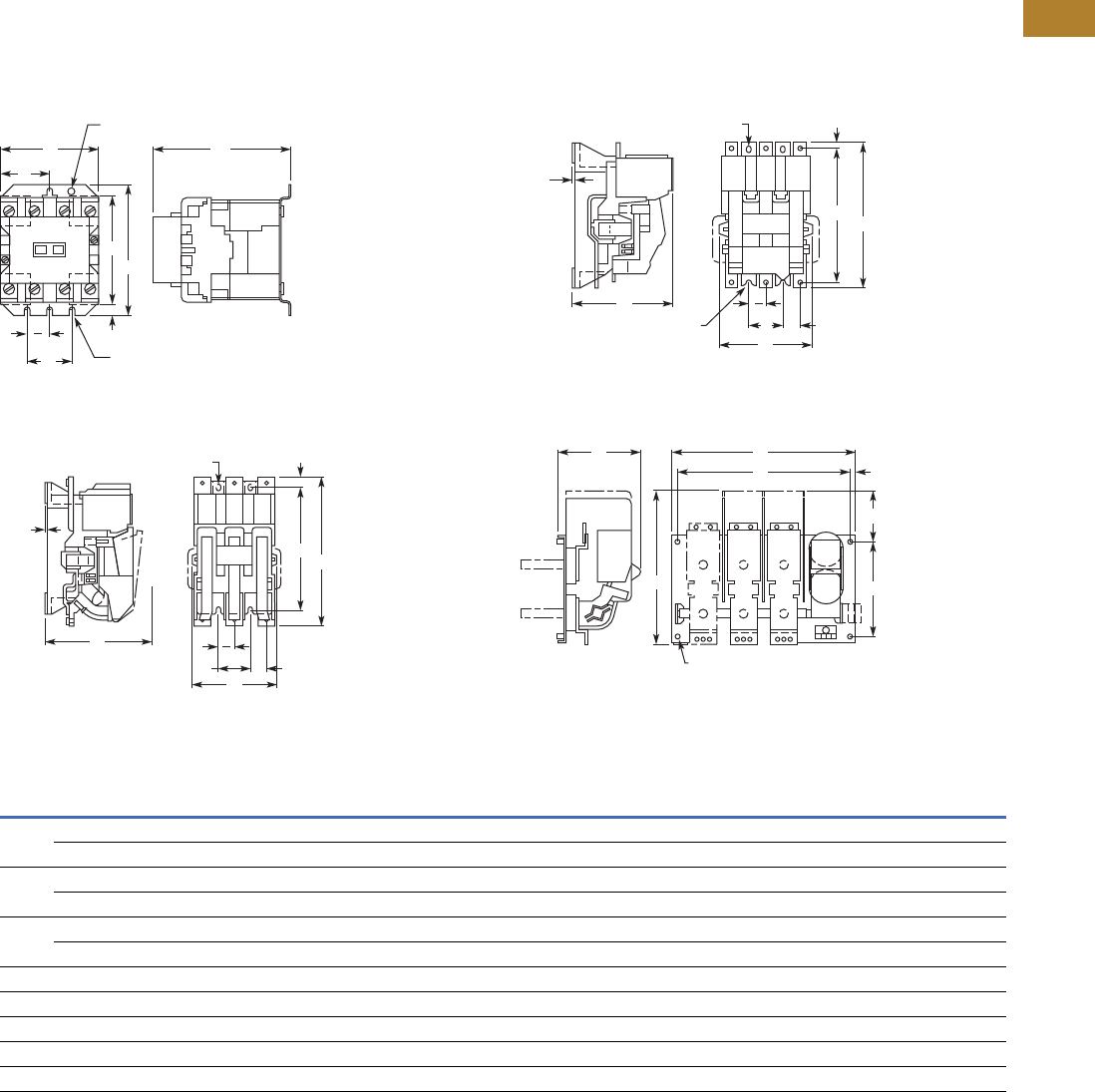
Volume 5—Motor Control and Protection CA08100006E—May 2016 www.eaton.com V5-T2-105
2
2
2
2
2
2
2
2
2
2
2
2
2
2
2
2
2
2
2
2
2
2
2
2
2
2
2
2
2
2
2.3
NEMA Contactors and Starters
A200 Series
Dimensions
Approximate Dimensions in Inches (mm)
Not to be used for construction purposes unless approved.
Non-Reversing Open Contactors
Figure A—Sizes 00–4 A210
Figure C—Size 6
Figure B—Size 5
Figure D—Sizes 7–9
Dimensions and Shipping Weights
AC
E
0.20 (5.1) 4
Mounting Slots
0.22 (5.6)
Dia. Hole
E
2G
D
B
F
C
0.12
(3.0)
0.38 x 0.5 (9.7 x 12.7)
2 Mounting Slots
E
A
H
B
D
G
E
2
C
0.12
(3.0)
0.38 x 0.5 (9.7 x 12.7)
2 Mounting Slots
A
E H
B
D
G
E
2
0.38 (9.7) Dia. Open End
Mounting Slot
(2 Places)
C A
EH
D
B
G
4 Holes for 0.38 (9.7) Dia.
Mounting Hardware
NEMA
Size
No. of
Poles Fig.
Mounting Screws
ABCDEFGH
Weight,
Lbs (kg)No. Size
00, 0, 1 2–4 A 3 #10 3.31 (84.1) 4.38 (111.3) 4.61 (117.1) 3.95 (100.3) 1.50 (38.1) 1.66 (42.2) 0.45 (11.5) — 2.6 (1.2)
5 A 3 #10 4.19 (106.4) 4.38 (111.3) 4.61 (117.1) 3.95 (100.3) 1.50 (38.1) 2.09 (53.1) 0.45 (11.5) — 3.2 (1.5)
2 2, 3 A 3 #10 3.31 (84.1) 4.38 (111.3) 4.94 (125.5) 3.95 (100.3) 1.50 (38.1) 1.66 (42.2) 0.45 (11.5) — 3.3 (1.5)
4, 5 A 3 #10 5.06 (128.5) 4.38 (111.3) 4.94 (125.5) 3.95 (100.3) 1.50 (38.1) 2.53 (64.3) 0.45 (11.5) — 4.5 (2.0)
3, 4 2, 3 A 3 1/4 in. 4.63 (117.6) 6.63 (168.4) 6.75 (171.5) 6.00 (152.4) 1.88 (47.8) 2.31 (58.7) 0.38 (9.7) — 9.3 (4.2)
4, 5 A 3 1/4 in. 7.25 (184.2) 6.63 (168.4) 6.75 (171.5) 6.00 (152.4) 1.88 (47.8) 3.63 (92.2) 0.38 (9.7) — 13.0 (5.9)
5 2, 3 B 4 3/8 in. 7.22 (183.4) 12.00 (304.8) 7.75 (196.9) 11.00 (279.4) 2.75 (69.9) — 0.59 (15.0) 2.22 (56.4) 25.0 (11.4)
6 2, 3 C 4 3/8 in. 7.22 (183.4) 13.50 (342.9) 9.50 (251.3) 11.00 (279.4) 2.75 (69.9) — 0.59 (15.0) 2.22 (56.4) 42.0 (19.1)
7 3 D 4 3/8 in. 23.50 (596.9) 18.63 (473.2) 11.00 (279.4) 12.00 (304.8) 22.00 (558.8) — 5.63 (143.0) 0.75 (19.1) 215.0 (97.6)
8 3 D 4 3/8 in. 23.50 (596.9) 19.25 (489.0) 11.00 (279.4) 12.00 (304.8) 22.00 (558.8) — 5.63 (143.0) 0.75 (19.1) 265.0 (120.3)
9 3 D 4 1/2 in. 33.00 (838.2) 29.75 (755.7) 12.94 (328.7) 8.00 (203.2) 30.75 (781.1) — 14.50 (368.3) 1.63 (41.4) 315.0 (143.0)
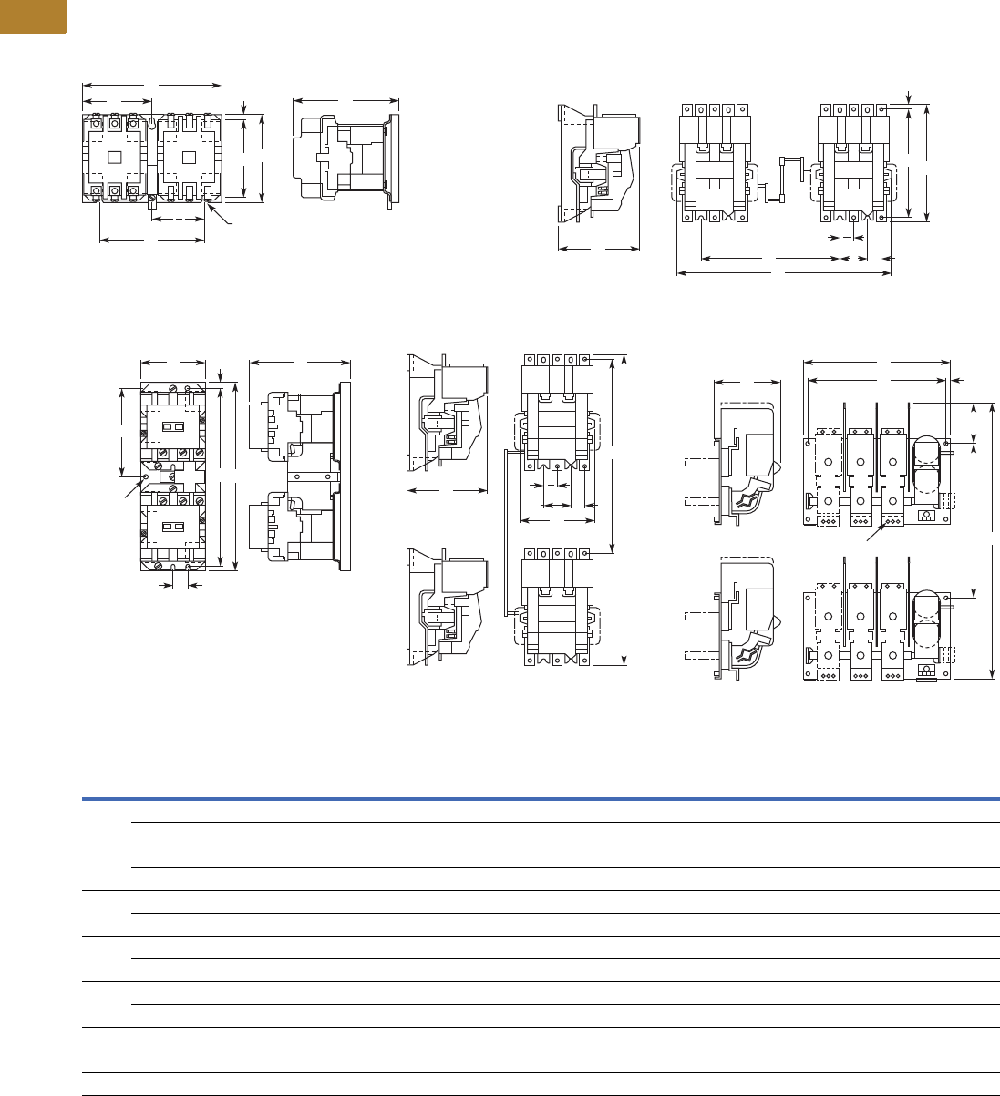
V5-T2-106 Volume 5—Motor Control and Protection CA08100006E—May 2016 www.eaton.com
2
2
2
2
2
2
2
2
2
2
2
2
2
2
2
2
2
2
2
2
2
2
2
2
2
2
2
2
2
2
2.3
NEMA Contactors and Starters
A200 Series
Approximate Dimensions in Inches (mm)
Not to be used for construction purposes unless approved.
Reversing Open Contactors
Figure A—Sizes 00–4 Horizontal Figure C—Sizes 5, 6 Horizontal
Figure B—Sizes 00–4 Vertical Figure D—Sizes 5, 6 Vertical Figure E—Sizes 7–9 Vertical
Dimensions and Shipping Weights
E
C
A
F
B
D
G
E
20.20 (5.1) Dia.
3 Mounting
Slots
CF E H
A
B
D
G
E
2
NEMA
Size
No. of
Poles Fig.
Mounting Screws Weight,
Lbs (kg)No. Size A B C D E F G H
00, 0, 1 3 x 3 H. A 3 #10 7.13 (181.1) 4.45 (113.0) 5.05 (128.3) 3.95 (100.3) 5.31 (134.9) 3.56 (90.4) 0.25 (6.4) — 7.8 (3.5)
3 x 3 V. B 3 #10 3.33 (84.6) 9.61 (244.1) 5.05 (128.3) 9.08 (230.6) 2.16 (54.9) 0.75 (19.1) 0.25 (6.4) 4.52 (114.8) 8.9 (4.0)
2 3 x 3 H. A 3 #10 7.13 (181.1) 4.45 (113.0) 5.38 (136.7) 3.95 (100.3) 5.31 (134.9) 3.56 (90.4) 0.25 (6.4) — 9.1 (4.1)
3 x 3 V. B 3 #10 3.33 (84.6) 9.61 (244.1) 5.38 (136.7) 9.08 (230.6) 2.16 (54.9) 0.75 (19.1) 0.25 (6.4) 4.52 (114.8) 10.0 (4.5)
3, 4 3 x 3 H. A 3 1/4 in. 9.75 (247.7) 6.88 (174.8) 7.25 (184.2) 6.00 (152.4) 7.00 (177.8) 4.88 (124.0) 0.44 (11.2) — 24.0 (10.9)
3 x 3 V. B 3 1/4 in. 4.63 (117.6) 16.56 (420.6) 7.25 (184.2) 15.69 (398.5) 2.75 (69.9) 0.94 (23.9) 0.44 (11.2) 7.78 (197.6) 25.0 (11.4)
5 3 x 3 H. C 8 3/8 in. 17.22 (437.4) 12.00 (304.8) 7.75 (196.9) 11.00 (279.4) 2.75 (69.9) 10.00 (254.0 0.59 (15.0) 1.38 (35.1) 55.0 (25.0)
3 x 3 V. D 8 3/8 in. 8.25 (209.6) 30.00 (762.0) 7.75 (196.9) 18.00 (457.8) 2.75 (69.9) — — 1.38 (35.1) 55.0 (25.0)
6 3 x 3 H. C 8 3/8 in. 17.22 (437.4) 13.50 (342.9) 8.75 (222.3) 11.00 (279.4) 2.75 (69.9) 10.00 (254.0) 0.59 (15.0) 1.38 (35.1) 90.0 (40.9)
3 x 3 V. D 8 3/8 in. 8.25 (209.6) 41.50 (1054.1) 8.75 (222.3) 28.00 (711.2) 2.75 (69.9) — — 1.38 (35.1) 90.0 (40.9)
7 3 x 3 V. E 8 3/8 in. 23.50 (596.9) 38.63 (981.2) 11.00 (279.4) 20.00 (508.0) 22.00 (558.8) — 5.63 (143.0) 0.75 (19.1) 450.0 (204.3)
8 3 x 3 V. E 8 3/8 in. 23.50 (596.9) 39.25 (997.0) 11.00 (279.4) 20.00 (508.0) 22.00 (558.8) — 5.63 (143.0) 0.75 (19.1) 550.0 (249.7)
9 3 x 3 V. E 8 1/2 in. 33.00 (838.2) 62.75 (1593.9) 12.94 (328.7) 33.00 (838.2) 30.75 (781.1) — 14.50 (368.3) 1.63 (41.4) 650.0 (295.1)
A
F
C
B
D
H
G
0.20 (5.1)
Dia.
3 Mtg.
Holes
C
B
D
A
E H
E
2
C
A
EH
D
G
B
0.53 (13.5) Dia.—3 Holes
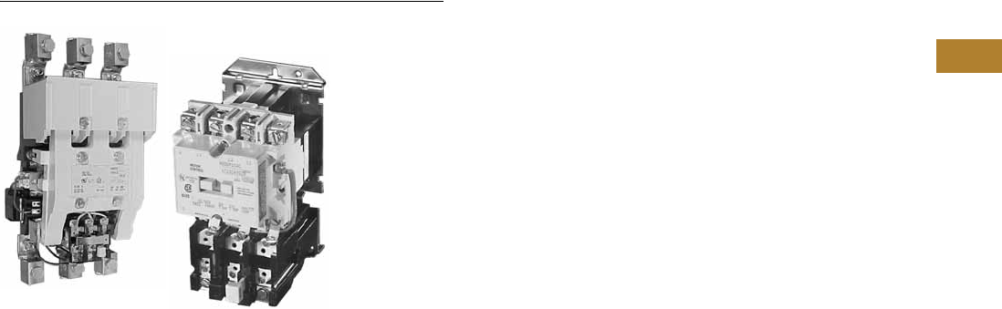
Volume 5—Motor Control and Protection CA08100006E—May 2016 www.eaton.com V5-T2-107
2
2
2
2
2
2
2
2
2
2
2
2
2
2
2
2
2
2
2
2
2
2
2
2
2
2
2
2
2
2
2.3
NEMA Contactors and Starters
A200 Series
Starters—Non-Reversing and Reversing
Contents
Description Page
Contactors—Non-Reversing and Reversing . . . . . . V5-T2-101
Starters—Non-Reversing and Reversing
Application Description . . . . . . . . . . . . . . . . . . . V5-T2-108
Features and Benefits . . . . . . . . . . . . . . . . . . . . V5-T2-108
Standards and Certifications . . . . . . . . . . . . . . . V5-T2-108
Instructional Leaflets . . . . . . . . . . . . . . . . . . . . . V5-T2-108
Product Selection . . . . . . . . . . . . . . . . . . . . . . . V5-T2-109
Accessories . . . . . . . . . . . . . . . . . . . . . . . . . . . . V5-T2-112
Renewal Parts . . . . . . . . . . . . . . . . . . . . . . . . . . V5-T2-115
Modifications. . . . . . . . . . . . . . . . . . . . . . . . . . . V5-T2-120
Technical Data and Specifications . . . . . . . . . . . V5-T2-121
Mechanical Characteristics . . . . . . . . . . . . . . . . V5-T2-123
Dimensions . . . . . . . . . . . . . . . . . . . . . . . . . . . . V5-T2-125
Relays—Thermal and Fast Trip . . . . . . . . . . . . . . . . V5-T2-128
Thermal Type B, Class 20, Manual Reset . . . . . . . . V5-T2-130
Thermal Type A, Class 20, Auto/Manual Reset . . . V5-T2-133
Type FT Fast Trip, Class 10 . . . . . . . . . . . . . . . . . . . V5-T2-136
Heater Selection. . . . . . . . . . . . . . . . . . . . . . . . . . . V5-T2-139
Relays—Current Sensing Protective. . . . . . . . . . . . V5-T2-141
Starters—Non-Reversing and Reversing
Product Description
NEMA Sizes 00–4; Three-Phase,
1-1/2–100 hp
These Starters from Eaton’s
Electrical Sector use Class
A201 contactors as described
on Page V5-T2-101.
Contactor features are
enhanced through the ability
to provide positive motor
protection in the form of
several types of overload
relays. See Pages V5-T2-128
to V5-T2-140.
Type B Overload Relay,
Manual Reset Only
Supplied as standard on
Class A200 and A900 starters
(two-speed). The bi-metallic
overload relay offers ambient
compensation and trip-to-test
feature (relay contact status
check) as standard. In
addition, an isolated normally-
open contact is available in kit
form for customer mounting.
Type B overload relays are
manual reset only.
Type A Overload Relay,
Manual or Automatic Reset
This is an optional overload
relay, offering the capability
of field conversion to
automatic reset. It is available
as an ambient compensated
or non-compensated type.
Non-Reversing Starters
Non-reversing starters are
supplied as open devices. All
starters are supplied with a
normally-open holding circuit
interlock.
Reversing Starters
For reversing applications
(Class A210), a starter and a
contactor electrically and
mechanically interlocked are
supplied on a common
baseplate. Reversing starters
are used to start, stop and
reverse AC squirrel cage
motors and for primary
control of reversing wound-
rotor motors.
For plugging or inching, when
operations exceed five times
per minute, decreased
horsepower ratings in
accordance with NEMA
Standard ICS 2-321 are
recommended.
Two-Speed Starters, A900s
For across-the-line starting of
two-speed constant hp,
constant torque and variable
torque squirrel cage motors,
two-speed starters (Class
A900) are available. These
starters consist of two
starters, one for each motor
speed, mechanically and
electrically interlocked and
wired for manual speed
selection by means of
pushbuttons. Auxiliary relays
may be added to provide
automatic acceleration or
deceleration.
Starters for two-speed, two
independent winding motors
consist of two-, three- or four-
pole starters electrically and
mechanically interlocked.
Starters for two-speed, single
reconnectable winding
motors consist of one three-
pole and one five-pole starter
mechanically and electrically
interlocked.

V5-T2-108 Volume 5—Motor Control and Protection CA08100006E—May 2016 www.eaton.com
2
2
2
2
2
2
2
2
2
2
2
2
2
2
2
2
2
2
2
2
2
2
2
2
2
2
2
2
2
2
2.3
NEMA Contactors and Starters
A200 Series
NEMA Sizes 5–9; Three-Phase
75 to 1600 hp
Non-reversing (Class A200),
and reversing (Classes A210,
A250) full voltage starters
are used for across-the-line
starting of squirrel cage
induction motors. They are
used with motors rated above
50 hp at 230V, and above
100 hp at 460 through 600V.
Sizes 5 and 6 starters use
Class A201 contactors as
described on Page V5-T2-101.
In addition to standard motor
starters, special application
devices are available: Sizes 5
and 6 starters with integrally
rectified AC to DC coils for
applications where low
voltage problems are
prevalent are available.
Front Removable Parts—
All operating parts can be
removed quickly and easily
from the front. Straight-
through wiring and
conveniently located
connection points for external
wires and cables minimize
installation time.
Type B Block Type
Thermal Overload Relay—
Dependable overload
protection is assured by
these snap-action, manual
reset relays. Automatic reset
Type A relays are available as
an option.
Types of Starters
Class A200, Sizes 5 and 6—
Non-reversing starters
contain an AC magnetically-
operated Size 5 or Size 6 line
contactor and block Type B
three-pole overload relay,
along with three current
transformers. A control relay
whose contacts handle the
coil current of the starter is
provided with Size 6 starters.
Class A200, Sizes 7, 8
and 9—Non-reversing
starters contain a DC
operated line contactor, DC
power supply, block Type B
three-pole overload relay with
three current transformers
and a control relay.
Class A960/A970/A980
Multi-Speed Starters:
Refer to Page V5-T2-111.
Application Description
Magnetic starters are used
for full-voltage, across-the-
line starting and stopping of
squirrel cage motors. They
can be operated locally or
remotely by manual or
automatic pilot devices.
Features and Benefits
Sizes 00–4
●Straight-Through Wiring,
Up-Front, Out-Front
Terminals for ease in
installation
●Unique Accessory
Mounting Cavities reduce
panel space requirements
●Snap-in Accessories for
application flexibility
●Vertical and Horizontal
Interlocking capability
increases application
flexibility
●Ambient Compensated
Overload Relays available
as standard, offering
superior motor protection
in variable motor/controller
environments
●Isolated Normally Open
Relay Contact available in
kit mounting form on Type
B Overload Relay
Sizes 5–9
●Rectified AC/DC Coils
available to reduce
premature drop-out or
“kiss” problems due to
inherent low voltage
conditions
●Clapper Design armature
assembly pivots on needle
bearings resulting in quick,
smooth opening and
closing of the magnet
●Stainless Steel Kick-Out
Spring assures quick,
positive drop-out time
●Front Removable Parts all
current carrying parts front
removable for easy
inspection and
maintenance
Standards and Certifications
Class A200 starters are UL
listed and recognized and also
carry CSA certification.
Instructional Leaflets
16958 Sizes 00–1, 3-Pole
Motor Controller
16956 Sizes 00–1, 2-Pole,
Single-Phase Motor
Controller
16959 Size 2, 3-Pole
Motor Controller
16957 Size 2, 2-Pole,
Single-Phase
Motor Controller
15465C Sizes 3 and 4J
Motor Controller
17000C Size 4, Model K
Motor Controller
17054C Size 5
Motor Controller
17055C Size 6
Motor Controller

Volume 5—Motor Control and Protection CA08100006E—May 2016 www.eaton.com V5-T2-109
2
2
2
2
2
2
2
2
2
2
2
2
2
2
2
2
2
2
2
2
2
2
2
2
2
2
2
2
2
2
2.3
NEMA Contactors and Starters
A200 Series
Product Selection
Non-Reversing, Sizes 00–9
When Ordering Specify
Order by catalog number
from the tables to the right,
plus suffix for coil voltages,
verifying usage of appropriate
sizes.
Heaters
Enter heaters as separate
item by listing catalog
number from the tables
on Pages V5-T2-139 and
V5-T2-140, as required per
starter.
Non-Reversing Starters
Coil Suffix
Notes
1 For ambient compensated overload relay with auto-reset, add Suffix D.
2 Single-phase with one single-pole overload relay.
3 Sizes 7–9 use rectifier with DC coil.
4 For Size 9, only available coil voltage is 120V.
Size Amperes
Max. UL Horsepower
Open
Catalog Number 1
Single-Phase Three-Phase
115V 230V 208V 240V 480V 600V
Tw o - P o l e s 2 —Sizes 00–2
00 9 1/3 — 1-1/2 1-1/2 2 2 A200MABR
018 1 —3 3 5 5 A200M0BR
127 2 —7-1/2 7-1/2 1010A200M1BR
1-1/2 36 3 — — — — — A200MDBR
2 45 7-12 — 10 15 25 25 A200M2BR
Three Poles—Sizes 00–6
00 9 1/3 — 1-1/2 1-1/2 2 2 A200MAC_
018 1 —3 3 5 5 A200M0C_
127 2 —7-1/2 7-1/2 1010A200M1C_
2 45 7-12 — 10 15 25 25 A200M2C_
3 90 ——25 30 50 50A200M3C_
4 135 — — 40 50 100 100 A200M4C_
5 270 — — 75 100 200 200 A200M5C_
6 540 — — 150 200 400 400 A200M6C_
Three Poles—Sizes 7–9
7 3810 — — 200 300 600 600 A200M7C_
8 31215 — — 400 450 900 900 A200M8C_
9 32250 — — — 800 1600 — A200M9C_ 4
Coil Volts and Hz Code Suffix
Sizes 00–6
120/60 or 110/50 AC
200–208/60 B
240/60 W
480/60 X
600/60 E
Sizes 7, 8 and 9 4
110–120/50 or 60 J
220–240/50 or 60 W
440–480/50 or 60 X
600/60 E
Size 3 Starter
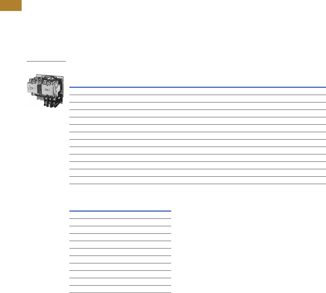
V5-T2-110 Volume 5—Motor Control and Protection CA08100006E—May 2016 www.eaton.com
2
2
2
2
2
2
2
2
2
2
2
2
2
2
2
2
2
2
2
2
2
2
2
2
2
2
2
2
2
2
2.3
NEMA Contactors and Starters
A200 Series
Reversing, Sizes 00–9
When Ordering Specify
Order by catalog number
from table below, plus suffix
for coil voltages, verifying
usage of appropriate sizes.
Heaters
Enter heaters as separate
item by listing catalog
number from the tables on
Pages V5-T2-139 and
V5-T2-140, as required per
starter.
Reversing Starters
Coil Suffix
Notes
1 For ambient compensated overload relay with auto-reset, add Suffix D.
2 Sizes 7–9 use rectifier with DC coil.
3 For Size 9, only available coil voltage is 120V.
Size Amps
Max. UL Horsepower Horizontal Design Vertical Design
Single-Phase Three-Phase Catalog
Number 1
Catalog
Number 1
115V 230V 208V 240V 480V 600V
Sizes 00–6
00 9 1/3 1 1-1/2 1-1/2 2 2 A210MAC_ A250MAC_
018123355A210M0C_ A250M0C_
1 27 2 3 7-1/2 7-1/2 10 10 A210M1C_ A250M1C_
24537-1/210152525A210M2C_ A250M2C_
390——25305050A210M3C_ A250M3C_
4 135 — — 40 50 100 100 A210M4C_ A250M4C_
5 270 — — 75 100 200 200 A210M5C_ A250M5C_
6 540 — — 150 200 400 400 A210M6C_ A250M6C_
Sizes 7–9
7 2810 — — 200 300 600 600 — A250M7C_
8 21215 — — 400 450 900 900 — A250M8C_
9 22250 — — — 800 1600 — — A250M9C_ 3
Coil Volts and Hz Code Suffix
Sizes 00–6
120/60 or 110/50 AC
200–208/60 B
240/60 W
480/60 X
600/60 E
Sizes 7, 8 and 9 3
110–120/50 or 60 J
220–240/50 or 60 W
440–480/50 or 60 X
600/60 E
Size 1 Horizontal
Reversing Starter

Volume 5—Motor Control and Protection CA08100006E—May 2016 www.eaton.com V5-T2-111
2
2
2
2
2
2
2
2
2
2
2
2
2
2
2
2
2
2
2
2
2
2
2
2
2
2
2
2
2
2
2.3
NEMA Contactors and Starters
A200 Series
For Separate Two-Winding Motors
Heaters
Enter heaters as separate
item by listing catalog
number from the tables
on Pages V5-T2-139 and
V5-T2-140, as required per
starter.
Three-Phase, Non-Reversing, Reversing 60 Hz Starters—Heater Selection
For Single-Winding Motors
Sizes 0–6
Coil Suffix
Note
1 For ambient compensated overload relay with auto-reset, add Suffix D.
NEMA Amperes
Constant or Variable Torque Constant Horsepower Three Poles Open
208V 240V 480V 600V 208V 240V 480V 600V Catalog Number 1
Sizes 0–6
0 18 33552 23 3 A960M0C_
1 27 7-1/2 7-1/2 10 10 5 5 7-1/2 7-1/2 A960M1C_
2 45 10 15 25 25 7-1/2 10 20 20 A960M2C_
3 90 25 30 505020 25 40 40 A960M3C_
4 135 40 50 100 100 30 40 75 75 A960M4C_
5 270 75 100 200 200 60 75 150 150 A960M5C_
6 540 150 200 400 400 100 150 300 300 A960M6C_
NEMA Amperes 208V 240V 480V 600V
Three Poles Open
Catalog Number 1
Constant Horsepower
018 3 3 5 5 A970M0C_
1 27 7-1/2 7-1/2 10 10 A970M1C_
24510152525A970M2C_
39025305050A970M3C_
4 135 40 50 100 100 A970M4C_
5 270 75 100 200 200 A970M5C_
6 540 150 200 400 400 A970M6C_
Constant or Variable Torque
018 2 2 3 3 A980M0C_
1 27 5 5 7-1/2 7-1/2 A980M1C_
2 45 7-1/2 10 20 20 A980M2C_
39020254040A980M3C_
4 135 30 40 75 75 A980M4C_
5 270 60 75 150 150 A980M5C_
6 540 100 150 300 300 A980M6C_
Coil Volts and Hz Coil Suffix
Sizes 0–6
120/60 or 110/50 AC
200–208/60 B
240/60 W
480/60 X
600/60 E
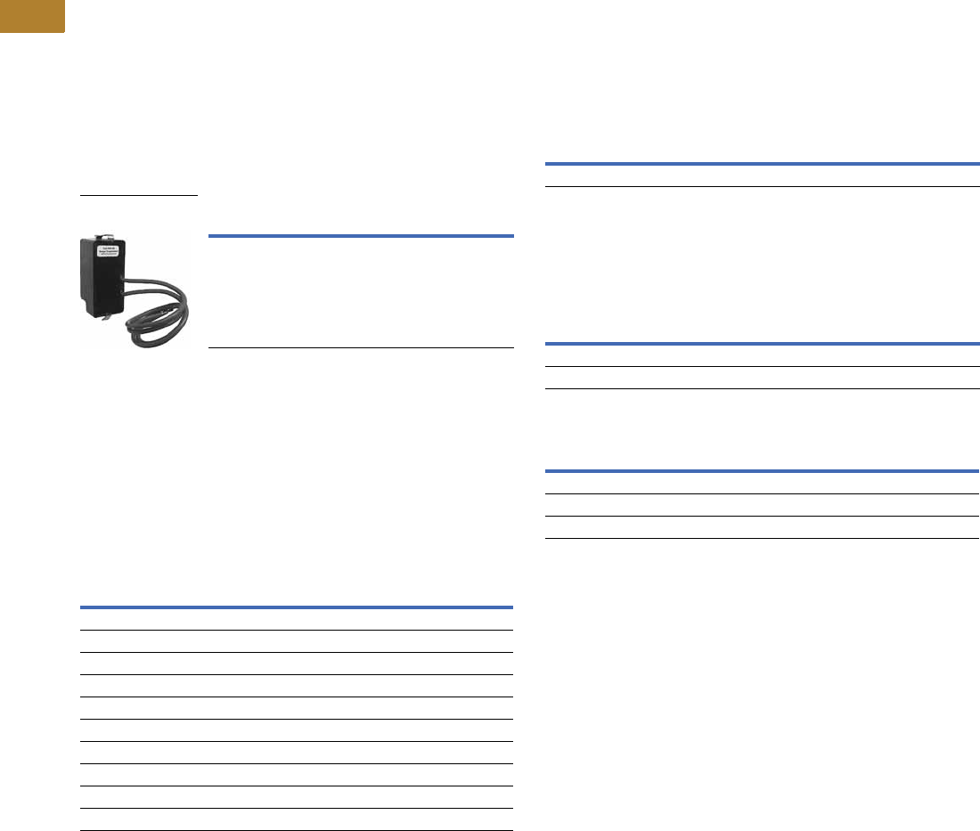
V5-T2-112 Volume 5—Motor Control and Protection CA08100006E—May 2016 www.eaton.com
2
2
2
2
2
2
2
2
2
2
2
2
2
2
2
2
2
2
2
2
2
2
2
2
2
2
2
2
2
2
2.3
NEMA Contactors and Starters
A200 Series
Accessories
SS-56 Surge Suppressor
●Designed to be used with
magnetic motor controllers
through Size 4 in 120V,
60 Hz control circuit
applications where
electronic equipment
is used
●Steady state coil volts: 120,
60 Hz, rms
●Peak input volts: 169.6,
60 Hz, max. amplitude
●Max. ambient temperature:
65°C
●Nominal limiting volts:
270 peak
●Nominal rate of volt rise:
0.5 per ms
Surge Suppressor 1
Mechanical Interlock
●Prevents closing of one
member of a reversing or
multi-speed contactor until
the opposite member is
completely open
●Lever type mechanism
assures positive action
●Can be factory assembled
or field mounted on A200
and A900 starters and
contactors
Mechanical Interlock
Type Mounting Kit Catalog Number
Starter SS-56
SS-56 Surge
Suppressor
Contactor Arrangement
(Number of Poles, Horizontal or Vertical)
Continuous
Size
Interlock
Catalog Number
3 x 3 horizontal 0, 1 M-33-1B
4 x 4 horizontal 0, 1 M-33-1B
5 x 3 horizontal 0, 1 M-33-1B
All pole combination, vertical 0, 1 M-34-1A
3 x 3 horizontal reversing 2 M-33-2B
3 x 3 vertical reversing 2 M-34-2A
5 x 3 horizontal 2 M-35-2A
4 x 4 horizontal 2 M-36-2A
All pole combination horizontal 3, 4 M-33-3B
All pole combination vertical 3, 4 M-34-3
R-56 Interposing Relay
The R-56AA interposing relay
is a low energy solid-state
device with a single NO solid-
state contact. It can be used
as a 120 Vac control relay, and
will operate on as little as 40
Vac input. Is useful in
applications requiring long
control wiring runs where
excessive voltage drop would
prevent the contactor or relay
from energizing. Will operate a
Size 4 contactor from 10,000
feet using 18 AWG wire.
Interposing Relay
B3NO Bell Alarm Contact
●Isolated normally open bell
alarm contact
●Mounts in Type B block-
type overload relay
Bell Alarm Contact
Control Contact Ratings (B600)
Overload Relay Reset Extension
●Used to adjust overload
reset rod depth of Class
A200 Model J starters
and current design
overload relays to same
dimensions as obsolete
B200 starters and overloads
identified by suffix B, for
example, BA13B
When replacing obsolete
B200 device with Class A200
starter and Type B overload,
order Style 6710C11H03.
No charge.
When replacing obsolete
B200 device with Class A200
starter and Type A overload,
order Style 1490C15H10.
No charge.
Notes
1Can be used on Sizes 5 and 6 with 120V coil. Mounting bracket required—order separately.
Mounting bracket 177C043G04.
2For Size 3 and 4.
Type Mounting Kit Catalog Number
Starter or panel R56-AA
Kit Catalog Number
B3NO-2
B3NO-4 2
AC Volts
Maximum Amperes
Make Break
24–120 30 3.00
121–600 3600 VA 360 VA
Continuous current rating: 5A

Volume 5—Motor Control and Protection CA08100006E—May 2016 www.eaton.com V5-T2-113
2
2
2
2
2
2
2
2
2
2
2
2
2
2
2
2
2
2
2
2
2
2
2
2
2
2
2
2
2
2
2.3
NEMA Contactors and Starters
A200 Series
Power Pole Kit
●Adds 1NO or 1NC power
pole to Size 00–1 A201
Class contactors
●Factory installed or field
mountable in load side
auxiliary cavities
●600 Vac
●Continuous current rating
of 18A for Size 0, 27A for
Size 1
Power Pole Kit 1
Replacement Auxiliary Contacts
Extra Auxiliary Contact Kits
All starters include an auxiliary
contact with 1NO and 1NC
contact. These kits include an
auxiliary contact with contacts
as shown, plus operating arm
and mounting bracket when
required.
Extra Auxiliary Contact Kits
Continuous Current Rating Kit Size Kit Catalog Number
Normally Open
18 0 PNO-0
27 1 PNO-1
Normally Closed
18 0 PNC-0
27 1 PNC-1
Contactor
Size
Contact
Arrangement
Auxiliary Elect. Contact
Catalog
Number
Style
Number
5, 6 1NO + 1NC J11 9084A17G01
2NO J20 9084A17G02
2NC J02 9084A17G03
7, 8 1NO — 578D461G01
1NC — 578D461G03
91NO + 1NC— 843D943G04
2NO — 843D943G05
2NC — 843D943G06
Contactor Size Contact Arrangement Style Number
5, 6 1NO + 1NC 3463D94G18
2NO 3463D94G04
2NC 3463D94G19
7, 8 22NO 818D498G06
1NO 818D498G04
DC Coil Conversion Kits
Kits listed below include all
necessary parts to convert
from AC to DC control
including the DC coil with
built-in diode, rectifier,
auxiliary interlock and all
mounting hardware.
DC Coil Conversion Kits
Mechanical Interlocks
Notes
1Do not use with DC operated contactors.
2Size 7 and larger use DC coils as standard.
Size Voltage Kit Style Number
5 110-120 7864A28G01
220-240 7864A28G02
440-480 7864A28G03
6 110-120 7864A29G01
220-240 7864A29G02
440-480 7864A29G03
Contactor Sizes
Style Numbers
Horizontal Vertical
3, 4 and 5 2050A11G75 2050A11G65
5 and 5 2050A11G27 2050A11G17
5 and 6 2050A11G26 2050A11G16
6 and 7, 8 — 2050A11G55
7, 8 and 7, 8 No (rear conn.) 567D624G01
7, 8 and 9 No (rear conn.) 9944D56G06
9 and 9 No (rear conn.) 9944D56G01

V5-T2-114 Volume 5—Motor Control and Protection CA08100006E—May 2016 www.eaton.com
2
2
2
2
2
2
2
2
2
2
2
2
2
2
2
2
2
2
2
2
2
2
2
2
2
2
2
2
2
2
2.3
NEMA Contactors and Starters
A200 Series
Overload Protection
Overload Protection
Size 5 Starters
Type B overload relay is a
three-pole, block type, thermal
ambient compensated device
with manual reset mounted
integrally. Current
transformers are enclosed in a
protective case and integrally
mounted to save panel space.
Standard ratio is 300:5.
Overload Protection
Size 6 Starters
Overload protection assembly
consists of three current
transformers, Type B three-
pole block overload relay and
an optional interposing relay.
These parts are mounted on a
panel which connects
directly to the load terminal
of the contactor. Current
transformers are 600:5 ratio
as standard.
If automatic reset is required,
the Type A, three-pole block,
ambient compensated relay
is available upon request.
Overload Relay Kits
Each kit includes three
current transformers
(standard ratio) and one
Type B, three-pole block
overload relay, ambient
compensated with
manual reset.
Overload Relay Kits
Replacement Terminal Lugs 1
Note
1All mounting hardware is included in kit.
Kit Size Kit Part Number
52057A34G01
66379D80G10
Contactor
Size
Cable
Size
Terminals
Kit Style
Number
Quantity
in Kit
Quantity Required
per Pole
5 1-500 MCM 6 2 2119A76G01
6 2-500 MCM 6 2 7858A96G01
7 4-500 MCM 12 4 7858A96G02
8 4-500 MCM 12 4 7858A96G03

Volume 5—Motor Control and Protection CA08100006E—May 2016 www.eaton.com V5-T2-115
2
2
2
2
2
2
2
2
2
2
2
2
2
2
2
2
2
2
2
2
2
2
2
2
2
2
2
2
2
2
2.3
NEMA Contactors and Starters
A200 Series
Renewal Parts
When Ordering Specify
Use this renewal parts data
to identify device by style
number, catalog number
and/or description.
Select style number of
replacement part from the
following pages.
For clarification of ordering
procedure, pricing and
discounts, contact the
Customer Support Center.
General Information
This renewal parts data
will provide the proper
identification of standard
parts which may be required
for maintenance of Eaton’s
components.
It is the intent of this catalog
section to make it possible
to quickly select the parts
needed.
An investment in
renewal parts and regular
maintenance program will
protect against downtime
and ensure a proper duty
cycle for your equipment.
To maintain maximum
operating efficiency and
dependability of your
equipment, only genuine
Eaton replacement parts
should be used.
This section identifies the
replacements parts which
are available. Order by style
number.
JF Autostarters
JF Autostarter Kits 1
Solenoid Assembly with Coil (All Sizes) 2
Notes
1Kits contain a complete set of moving contacts, stationary contacts and springs.
2When replacing solenoid assembly series 416C160 use adapter plate style 9917D02H01—
one required.
3These styles replace coil style 296B892G__. When ordering new style as replacement,
customer must order adapter plate 9917D02H01, one required.
Frame Size
Start Contacts Run Contacts Grid Stack Kit
Required Style Number Required Style Number Required Style Number
2–3 1 38A7018G12 138A7018G13 13354D90G10
4–5 5L 1 550D409G18 1550D409G19 13354D90G10
5M–5MM 1 3354D90G08 13354D90G09 23354D90G10
Volt Hz Style Number 3
115 60 5264C05H01
230 60 5264C05H02
460 60 5264C05H03
575 60 5264C05H04

V5-T2-116 Volume 5—Motor Control and Protection CA08100006E—May 2016 www.eaton.com
2
2
2
2
2
2
2
2
2
2
2
2
2
2
2
2
2
2
2
2
2
2
2
2
2
2
2
2
2
2
2.3
NEMA Contactors and Starters
A200 Series
AC Starters, Contactors A200, A201
AC Contactors Model J Sizes 00, 0, 1, 2 Kits 1
AC Coils
DC Coil 7
Notes
1Model C contact tips and coils 00-4, two-, three-, four- and five-pole contactors are same as
Model J. All other parts are unavailable.
2Mounting hardware included.
3Use one each of 373B331G11 and 373B331G12.
4Two-, three-pole.
5Four-, five-pole.
6Dual voltage coils. Use only on contactors or starters originally supplied with a dual
voltage coil.
7Use only on contactors originally supplied with a DC coil.
Part Poles
Size 00 Size 0 Size 1 Size 2
Style Number Style Number Style Number Style Number
Contact kit 2 373B331G17 373B331G02 373B331G07 373B331G11
3373B331G18 373B331G04 373B331G09 373B331G12
4373B331G18 373B331G04 373B331G09 373B331G13 3
5373B331G19 373B331G05 373B331G10 —
Arc box 22, 3, 4 6714C74G01 6714C74G02 6714C74G03 6714C74G07 4
56714C74G04 6714C74G05 6714C74G06 6714C74G08 5
Cross bar 2, 3 N/AN/AN/A672B788G32
4, 5 N/AN/AN/A672B788G34
Upper base (for single rated coils only) 2, 3 N/AN/AN/A672B788G33
4, 5 N/AN/AN/A672B788G35
Lower base 2, 3 N/A N/A N/A 1250C33G09
4, 5 N/A N/A N/A 1250C33G05
KO spring (package of 10) All N/A N/A N/A 503C796G01
Terminal line/load (package of 3) All N/AN/AN/A371B870G03
Voltage Hz
Size 00, 0, 1 Size 2
Two-, Three-, Four-Pole Five-Pole Two-, Three-Pole Four-, Five-Pole
Style Number Style Number Style Number Style Number
120/110 60/50 505C806G01 505C808G01 505C806G01 505C818G01
208 60 505C806G02 505C808G02 505C806G02 505C818G02
600/550 60/50 505C806G05 505C808G05 505C806G05 505C818G05
380 50 505C806G07 505C808G07 505C806G07 505C818G07
240/220 60/50 505C806G12 505C808G12 505C806G12 505C818G12
480/440 60/50 505C806G13 505C808G13 505C806G13 505C818G13
24 60 505C806G16 N/A 505C806G16 505C818G15
277 60 505C806G18 505C808G16 505C806G18 505C818G16
240/480 660/60 505C806G03 505C808G03 505C806G03 505C818G03
120/240 760/60 505C806G10 505C808G10 505C806G10 505C818G10
Voltage
Size 0, 1
Single-, Two-, Three-, Four-Pole
Style Number
Size 2
Single-, Two-, Three-Pole
Style Number
12 1268C86G07 1268C86G07
24 1268C86G04 1268C86G04
48 1268C86G05 1268C86G05
125 1268C86G02 1268C86G02
250 1268C86G01 1268C86G01
125/250 61268C86G03 1268C86G03

Volume 5—Motor Control and Protection CA08100006E—May 2016 www.eaton.com V5-T2-117
2
2
2
2
2
2
2
2
2
2
2
2
2
2
2
2
2
2
2
2
2
2
2
2
2
2
2
2
2
2
2.3
NEMA Contactors and Starters
A200 Series
Accessories for Size 5–9 AC Contactors
A rectifier circuit converts the AC supply to DC supply. This
conversion provides pick up and drop out characteristics. All
necessary parts are included in the kit.
AC-DC Coil Conversion Kits
Replacement Coils for AC-DC Coil Conversion Kit
Auxiliary Electrical Interlocks Size 7–9 AC and All DC Units
Accessories for Size 00–6 AC Contactors
Auxiliary Electrical Interlocks
Model J–K, Sizes 3 and 4
Sizes 3 and 4 Kits 1
Notes
1Model C contact tips and coils 00-4, two-, three-, four- and five-pole contactors are same as Model J. All other parts are unavailable.
2For 200A A202 magnetically latched lighting contactors order three-pole contact kit style 672B788G07.
3Model K replaces Model J, offering superior design life characteristics. Renewal parts are different. Use parts for proper model only.
4Use quantity two of 626B187G12.
5Use quantity one each of 626B187G12 and 626B187G13.
6Use quantity two of 626B187G16.
7Use quantity one each of 626B187G16 and 626B187G17.
Voltage
Size 5 Size 6
Style Number Style Number
120 Vac 7864A28G01 7864A29G01
240 Vac 7864A28G02 7864A29G02
480 Vac 7864A28G03 7864A29G03
Voltage
Size 5 Size 6
Style Number Style Number
120 Vac 7856A15G05 7856A16G05
240 Vac 7856A15G10 7856A16G10
480 Vac 7856A15G15 7856A16G15
Type Circuits Application Style Number
L63 NO Size 7–8 578D461G01
L63 NC Size 7–8 578D461G03
L64 NO-NC Size 9 843D943G04
L64 2NO Size 9 843D943G05
L64 2NC Size 9 843D943G06
Catalog
Number
(Obsolete)
Style
Number
(Obsolete) Circuits
Catalog
Number
Current
Style
Number
Current
(L-56) (2609D01G01) 1NO and 1NC J11 9084A17G01
(L-56D) (2609D01G02) 2NO J20 9084A17G02
(L-56E) (2609D01G03) 1NO and 1NC J11 9084A17G01
(L-56B) (2609D01G04) 2NO J20 9084A17G02
(L-56H) (2609D01G05) 2NO J20 9084A17G02
(L-56J) (2609D01G06) 1NO and1NC DB J1C 9084A17G04
(L-56A) (2609D01G07) N/A N/A N/A
(L-56B) (2609D01G08) N/A N/A N/A
(L-56F) (2609D01G09) N/A N/A N/A
(L-56G) (2609D01G10) 1NO and 1NC DB J1C 9084A17G04
(L-56C) (2609D01G11) 2NC J02 9084A17G03
(L-56M) (2609D01G12) N/A N/A N/A
(L-56P) (2609D01G17) 1NO and 1NC J11 9084A17G01
(L-56R) (2609D01G18) 2NC J02 9084A17G03
(L-56S) (2609D01G19) 1NO and 1NC J11 9084A17G01
Part Poles
Size 3–Model J
Style Number
Size 4–Model J 2
Style Number
Size 4–Model K 3
Style Number
Contact kit 2 626B187G12 626B187G16 5250C81G16
3626B187G13 626B187G17 5250C81G17
4465250C81G18
5575250C81G19
Arc box 2, 3 6714C74G09 6714C74G11 6714C74G11
4, 5 6714C74G10 6714C74G12 6714C74G12
Cross bar 2, 3 672B788G36 672B788G36 672B788G40
4, 5 672B788G38 672B788G38 —
Upper base 2, 3 672B788G37 672B788G37 672B788G52
4, 5 672B788G39 672B788G39 —
Lower base 2, 3 1250C33G03 1250C33G03 1250C33G10
4, 5 1250C33G06 1250C33G06 —
KO spring (package of 10) All 503C796G02 503C796G02 672B788G50
Terminal line/load (package of 3) All 372B357G12 372B357G18 372B357G18

V5-T2-118 Volume 5—Motor Control and Protection CA08100006E—May 2016 www.eaton.com
2
2
2
2
2
2
2
2
2
2
2
2
2
2
2
2
2
2
2
2
2
2
2
2
2
2
2
2
2
2
2.3
NEMA Contactors and Starters
A200 Series
Accessories for Model J–K, Series 3, 4
DC Coils 1
AC Coils
A201 Contactors—Size 5–9
GCA 530/630—GPD 7, 8, 9 Kits 4
Notes
1Use only on units originally supplied with DC coil.
2Dual voltage coils. Use only on contactors or starters originally supplied with dual voltage coil.
3Model K replaces Model J, offering superior design life characteristics. Renewal parts are
different. Use parts for proper model only.
4Catalog Number A201/A200 Series replaces GCA/GPD series. Renewal parts are the same.
5Use 477B477G06 for silver tungsten applications.
6R.C.
7F.C .
8C.T. kit which replaces the single molded 1 C.T. assembly used on the old size 6 airbreak. The kit
includes a single molded 3 C.T. assembly, 2 bus bar and hardware. This C.T. kit also replaces the
single molded 3 C.T. assembly used on the present size 6 airbreak and size vacuum.
9Set of three.
jSet of four.
Voltage
Model J Size 3, 4
Two-, Three-Pole
Style Number
24 1255C68G04
48 1255C68G05
125 1255C68G01
250 1255C68G02
125/250 21255C68G03
Voltage Hz
Model J Size 3, 4 Model K Size 4 3
Two-, Three-Pole Four-, Five-Pole Two-, Three-Pole Four-, Five-Pole
Style Number Style Number Style Number Style Number
120/110 60/50 505C633G01 505C635G01 5250C79G01 5250C80G01
208 60 505C633G02 505C635G02 5250C79G02 5250C80G02
600/550 60/50 505C633G05 505C635G05 5250C79G05 5250C80G05
380 50 505C633G07 505C635G07 5250C79G07 5250C80G07
240/220 60/50 505C633G12 505C635G12 5250C79G12 5250C80G12
480/440 60/50 505C633G13 505C635G13 5250C79G13 5250C80G13
24 60 505C633G34 N/A 5250C79G34 N/A
277 60 505C633G14 N/A 5250C79G14 N/A
240/480 260/60 505C633G03 505C635G03 5250C79G03 5250C80G03
120/244 260/60 505C633G10 505C635G10 5250C79G10 5250C80G10
Part
Size 5 Size 6 Size 7 Size 8 Size 9
Style Number Style Number Style Number Style Number Style Number
Contact kit (one per pole) 477B477G05 52066A10G11 461A757G17 646C829G05 5264C42G01 6
5264C42G02 7
Arc box 2050A15G45 2066A10G45 831D580G01 831D580G01 9917D69G02
Magnet assembly 2050A15G46 2050A15G46 N/A N/A N/A
Mag. spg. kit 2050A15G47 2050A15G47 N/A N/A N/A
Acr cup kit 2050A15G48 N/A N/A N/A N/A
Load conversion kit 2050A15G49 2066A10G49 N/A N/A N/A
Line conversion kit 2050A15G50 2066A10G50 N/A N/A N/A
K.O. spring–6 2050A15G51 2066A10G46 N/A N/A N/A
C.T. 300/5 655C285H03 N/A N/A N/A N/A
C.T. 400/5 655C285H04 N/A N/A N/A N/A
C.T. 600/5 8N/A 2066A10G18 N/A N/A N/A
C.T. 800/5 8N/A 2066A10G19 N/A N/A N/A
Phase barrier N/A N/A 640C441G01 640C441G01 5264C35G03 6
Cross bar 2050A15G12 2066A10G15 N/A N/A N/A
Shunt N/A 2066A10G48 650C129G01 646C831G02 95264C39G02 j

Volume 5—Motor Control and Protection CA08100006E—May 2016 www.eaton.com V5-T2-119
2
2
2
2
2
2
2
2
2
2
2
2
2
2
2
2
2
2
2
2
2
2
2
2
2
2
2
2
2
2
2.3
NEMA Contactors and Starters
A200 Series
Accessories for A201 Contactors—Size 5–9
Coils (Sizes 5 and 6)
Coils (Sizes 7–9)
Notes
1Rectifier 125V 2018A40G01 (one required).
2Rectifier 250V 2018A40G02 (one required).
3Rectifier 600V 2018A40G03 (one required).
4These coils require an external rectifier. If the rectifier needs replacement, order by the
appropriate style number.
5Contains coil and resistor.
Voltage Hz
Size 5 Size 6
Style Number Style Number
Sizes 5 and 6
110/120 60 2050A14G05 2050A12G05
110/120 50 2050A14G06 2050A12G06
200/208 50 2050A14G07 2050A12G07
220/240 50 2050A14G08 2050A12G08
200/208 60 2050A14G09 2050A12G09
220/240 60 2050A14G10 2050A12G10
277/303 60 2050A14G12 2050A12G12
380/415 50 2050A14G14 2050A12G14
440/480 60 2050A14G15 2050A12G15
440/480 50 2050A14G16 2050A12G16
550/600 60 2050A14G17 2050A12G17
550/600 50 2050A14G18 2050A12G18
380/415 60 2050A14G19 2050A12G19
120/240 60 2050A14G20 2050A12G20
24 DC — 2050A14G21 2050A12G21
48 DC — 2050A14G22 2050A12G22
125 DC — 2050A14G25 2050A12G25
250 DC — 2050A14G27 2050A12G27
Line Voltage Style Number Required
Sizes 7 and 8
125 Vdc 438C805G04 2
230 Vdc 438C805G02 2
250 Vdc 438C805G03 2
110/120 Vac 14 438C805G12 2
220/240 Vac 24 438C805G11 2
380 Vac 34 438C805G15 2
440/480 Vac 34 438C805G10 2
550/575 Vac 34 438C805G13 2
Size 9
110 Vdc 5264C34G01 5—
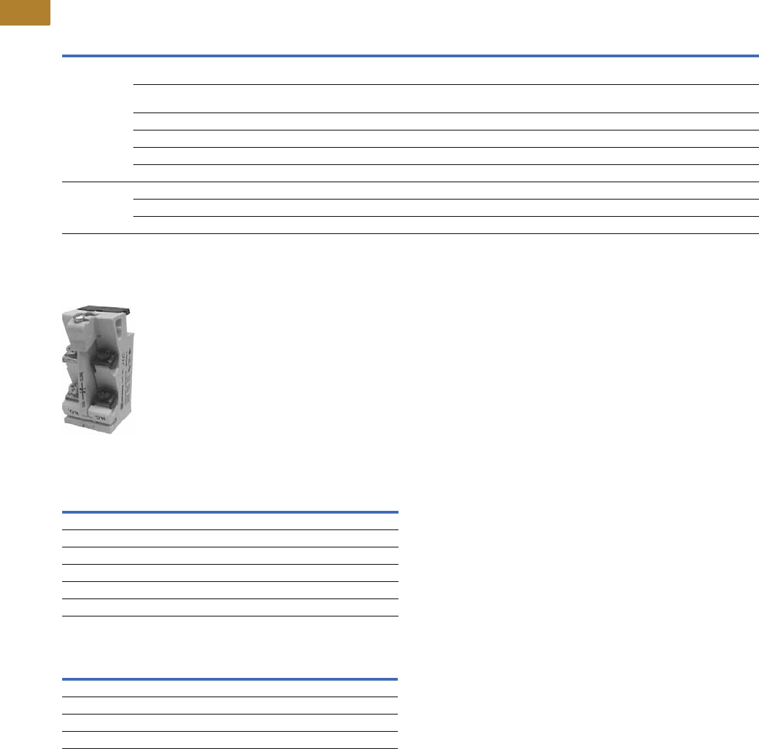
V5-T2-120 Volume 5—Motor Control and Protection CA08100006E—May 2016 www.eaton.com
2
2
2
2
2
2
2
2
2
2
2
2
2
2
2
2
2
2
2
2
2
2
2
2
2
2
2
2
2
2
2.3
NEMA Contactors and Starters
A200 Series
Modifications
Factory Modifications
Accessories and Field Modification Kits
Type J Auxiliary Contact ●Capable of being field
mounted in a contactor or
starter (Classes A200,
A900 Sizes 00–6, V200,
V201 vacuum and definite
purpose controllers)
●Provides two separate
electrical contact sets
which wire vertically and
are color coded; black
designates NC and silver
designates NO. Please
note that the vertical wiring
is contrary to the horizontal
wiring of the L-56 auxiliary
contacts
●Designed to fit within
dimensions of starter; no
additional panel space is
required
●Provides circuit isolation
(no polarity restrictions)
and single break bifurcated
contacts
Auxiliary Contact Ratings
Auxiliary Contact Types
Modification Description
Catalog
Number
Suffix
NEMA Size
00–123456789
Control circuit 1 Extra auxiliary contact (1NO-1NC) non-reversing,
reversing, 2-speed unwired
J1 Consult sales office for pricing adders.
2 Extra auxiliary contact non-reversing, reversing,
2-speed unwired
J2 Consult sales office for pricing adders.
3 Extra auxiliary contact non-reversing, unwired J3 Consult sales office for pricing adders.
4 Extra auxiliary contact non-reversing, unwired J4 Consult sales office for pricing adders.
Wired for separate control (NC) CConsult sales office for pricing adders.
Omit control wiring (NC) XConsult sales office for pricing adders.
Overload relays
(substitutions)
Ambient compensated with auto reset (NC) DConsult sales office for pricing adders.
Fast trip—ambient compensated (specify motor FLA) D7 Consult sales office for pricing adders.
Overload relay alarm contact (NO) per overload EConsult sales office for pricing adders.
Voltage Make Break
NEMA A600
120–600 Vac 7200 VA 720 VA
72–120 Vac 60A 720 VA
28–72 Vac 60 VA 10A
NEMA R300
28–300 Vdc 28 VA 28 VA
Contact Type Max. Catalog Number
1NO and 1NC 4 J11
2NC 4 J02
2NO 4 J20
1 coil clearing NC and 1NO 4 J1C

Volume 5—Motor Control and Protection CA08100006E—May 2016 www.eaton.com V5-T2-121
2
2
2
2
2
2
2
2
2
2
2
2
2
2
2
2
2
2
2
2
2
2
2
2
2
2
2
2
2
2
2.3
NEMA Contactors and Starters
A200 Series
Technical Data and Specifications
Electrical Characteristics
Sizes 00–4 Sizes 5–9
Notes
1Resistive loads having inrush currents not exceeding 1.5 times continuous rating.
2These ratings are for transformers having inrush currents not more than 20 times peak of
continuous current ratings. For inrush currents greater than 20 times, refer to factory.
3For ratings refer to factory.
Size 00Size 0Size 1Size 2Size 3Size 4
Max. voltage rating 600V 600V 600V 600V 600V 600V
Ampere rating
(Open) 10A 20A 30A 50A 100A 150A
(Enclosed) 9A 18A 27A 45A 90A 135A
Squirrel Cage Motor
Maximum horsepower at:
200V/60 Hz 1-1/2 hp 3 hp 7-1/2 hp 10 hp 25 hp 40 hp
230V/ 60 Hz 1-1/2 hp 3 hp 7-1/2 hp 15 hp 30 hp 50 hp
380V/50 Hz 1-1/2 hp 5 hp 10 hp 25 hp 50 hp 75 hp
460V–575V/60 Hz 2 hp 5 hp 10 hp 25 hp 50 hp 100 hp
Resistive Heating kW 1
Single-phase, two-pole
120V — — 3 kW 5 kW 10 kW 15 kW
240V — — 6 kW 10 kW 20 kW 30 kW
480V — — 12 kW 20 kW 40 kW 60 kW
600V — — 15 kW 25 kW 50 kW 75 kW
Three-phase, three-pole
120V — — 5 kW 8.5 kW 17 kW 26 kW
240V — — 10 kW 17 kW 34 kW 68 kW
480V — — 20 kW 34 kW 68 kW 105 kW
600V — — 25 kW 43 kW 86 kW 130 kW
Capacitor Switching kVAR, Three-Phase
240V — — — 12 kVAR 27 kVAR 40 kVAR
480V — — — 25 kVAR 53 kVAR 80 kVAR
600V — — — 31 kVAR 67 kVAR 100 kVAR
Transformer Switching kVA 2
Single-phase, two-pole
120V — 0.6 kVA 1.2 kVA 2.1 kVA 4.1 kVA 6.8 kVA
240V — 1.2 kVA 2.4 kVA 4.1 kVA 8.1 kVA 14 kVA
480V — 2.4 kVA 4.9 kVA 8.3 kVA 16 kVA 27 kVA
600V — 3 kVA 6.2 kVA 10 kVA 20 kVA 34 kVA
Three-phase, three-pole
120V — 1.8 kVA 3.6 kVA 6.3 kVA 12 kVA 20 kVA
240V — 2.1 kVA 4.3 kVA 7.2 kVA 14 kVA 23 kVA
480V — 4.2 kVA 8.5 kVA 14 kVA 28 kVA 47 kVA
600V — 5.2 kVA 11 kVA 18 kVA 35 kVA 59 kVA
Size 5Size 6Size 7Size 8Size 9
Max. voltage rating 600V 600V 600V 600V 600V
Ampere rating
(Open) 300A 600A 900A 1350A 2500A
(Enclosed) 270A 540A 810A 1215A 2250A
Squirrel Cage Motor
Maximum horsepower at:
200V/60 Hz 75 hp 150 hp — — —
230V/60 Hz 100 hp 200 hp 300 hp 450 hp 800 hp
380V/50 Hz 150 hp 300 hp — — —
460V–575V/60 Hz 200 hp 400 hp 600 hp 900 hp 1600 hp
Resistive Heating kW 1
Single-phase, two-pole
120V 30 kW 60 kW 90 kW 33
240V 60 kW 120 kW 180 kW 33
480V 120 kW 240 kW 360 kW 33
600V 150 kW 300 kW 450 kW 33
Three-phase, three-pole
120V 52 kW 105 kW 155 kW 33
240V 105 kW 210 kW 315 kW 33
480V 210 kW 415 kW 625 kW 33
600V 260 kW 515 kW 775 kW 33
Capacitor Switching kVAR, Three-Phase
240V 80 kVAR 160 kVAR 240 kVAR 360 kVAR 665 kVAR
480V 160 kVAR 320 kVAR 480 kVAR 720 kVAR 1325 kVAR
600V 200 kVAR 400 kVAR 600 kVAR 900 kVAR 1670 kVAR
Transformer Switching kVA 2
Single-phase, two-pole
120V 14 kVA 27 kVA 41 kVA 61 kVA 112 kVA
240V 27 kVA 54 kVA 81 kVA 122 kVA 225 kVA
480V 54 kVA 108 kVA 162 kVA 244 kVA 450 kVA
600V 68 kVA 135 kVA 203 kVA 304 kVA 562 kVA
Three-phase, three-pole
120V 41 kVA 81 kVA 122 kVA 182 kVA 337 kVA
240V 47 kVA 94 kVA 140 kVA 210 kVA 342 kVA
480V 94 kVA 188 kVA 280 kVA 420 kVA 783 kVA
600V 117 kVA 234 kVA 351 kVA 526 kVA 975 kVA

V5-T2-122 Volume 5—Motor Control and Protection CA08100006E—May 2016 www.eaton.com
2
2
2
2
2
2
2
2
2
2
2
2
2
2
2
2
2
2
2
2
2
2
2
2
2
2
2
2
2
2
2.3
NEMA Contactors and Starters
A200 Series
DC Power Pole Ratings
The following represent typical production test values and should
not be interpreted as a guarantee of actual performance.
DC Operated 120 and 240V Coils
380V, 50 Hz Starter Maximum Horsepower Ratings
Horsepower Ratings
Operating Coil Characteristics at Rated Coil Volts, Sizes 00–9
The following represent typical production test values and should not be interpreted as a guarantee of actual performance.
Operating Coil Characteristics
Notes
1Non-inductive load.
2AC coil data pertains to Model K, DC coil data pertains to Model J.
3DC operated only.
4Percent of rated coil voltage.
5At 60 Hz base.
6To contact touch.
7Lower figure when coil is cold. Higher figure when coil is hot.
8Drop-out time to clear arc. Time varies with type of load and contact wear.
Contactor Size
DC Contact Ampere Rating
Two Poles in Series 1
120V 240V
0——
12010
24530
37540
49070
NEMA Size00012345678
Maximum
horsepower
1-1/2 5 10 25 50 75 150 300 450 700
Sizes 00, 0, 1 Size 2 Size 3 Size 4 2Size 5 Size 6 Size 7 Size 8 Size 9
AC Coil
Burden
(Open VA) 160 VA 160 VA 625 VA 700 VA 1700 VA 2900 VA 333
(Closed VA) 25 VA 25 VA 50 VA 64 VA 180 VA 220 VA 333
(Closed Watts) 7.8 W 7.8 W 18 W 21 W 32 W 42 W — — —
Pick-up volts 485% 85% 85% 85% 78% 70% — — —
Drop-out volts 440–60% 40–60% 40–60% 40–60% 65 to 75% 60 to 70% — — —
Pick-up time Hz 56 1–1-1/2 1-1/2–2 2–2-1/2 1–1-1/2 1.5 4.0 — — —
Drop-out time Hz 53/4–1 3/4–1 3/4–1 3/4–1 0.75 0.75 — — —
DC Coil
Burden
(Open VA) 17 VA 17 VA 35 VA 35 VA 600 VA 2120 VA 400 VA 400 VA 2100 VA
(Closed VA) 17 VA 17 VA 35 VA 35 VA 22 VA 21 VA 400 VA 400 VA 350 VA
(Closed Watts) 18 W 18 W 35 W 35 W 20 W 20 W 400 W 400 W 350 W
Pick-Up Volts 480% 80% 80% 80% 64% 73% 45%–65% 745%–65% 750%–65% 7
Drop-Out Volts 45–10% 5–10% 5–10% 5–10% 18% 13% 30%–45% 730%–45% 740%–50% 7
Pick-Up Time Hz 6— 25–75 ms 25–75 ms 25–75 ms 2.7 Hz 53 Hz 521–41 Hz 75 17–29 Hz 75 16–18 75
Drop-Out Time Hz 5— 16–25 ms 16–25 ms 16–25 ms 9.3 Hz 517.5 Hz 57–12 Hz 85 7–12 Hz 85 18–20 Hz 75

Volume 5—Motor Control and Protection CA08100006E—May 2016 www.eaton.com V5-T2-123
2
2
2
2
2
2
2
2
2
2
2
2
2
2
2
2
2
2
2
2
2
2
2
2
2
2
2
2
2
2
2.3
NEMA Contactors and Starters
A200 Series
Mechanical Characteristics
NEMA Standard ICS 2-110
Direct-current operated
contactors shall withstand
110% of their rated voltage
continuously without injury to
the operating coils and shall
close successfully at 80% of
their rated voltage.
Alternating-current operated
contactors shall withstand
110% of their rated voltage
continuously without injury to
the operating coils and shall
close successfully at 85% of
their rated voltage.
Mechanical Characteristics, Sizes 00–9
Data from Tables 430—147 Through 150 of 1996 NEC: Motor Amperes at Full Load 2, Three-Phase AC
Notes
1For Sizes 5–9 contactors only; for starter Sizes 5–9, refer to factory.
2These current values are for motors running at usual speeds and with normal torque characteristics. Motors for special low speed or high torque may require higher current. In all cases, heaters
should be selected on basis of information on motor nameplate or motor card data.
Sizes 00, 0, 1 Size 2 Size 3 Size 4 Size 5 Size 6 Size 7 Size 8 Size 9
Dimensions in inches (mm)
Height 6.45 (163.8) 7.16 (181.9) 9.93 (252.2) 9.93 (252.2) 12.00 (304.8) 113.50 (342.9) 118.62 (472.9) 119.25 (489) 125.00 (635) 1
Width 3.31 (84.1) 3.31 (84.1) 4.62 (117.3) 4.62 (117.3) 7.00 (177.8) 17.00 (177.8) 123.50 (596.9) 123.50 (596.9) 132.00 (812.8) 1
Depth 4.61 (117.1) 4.96 (126) 6.75 (171.5) 6.75 (171.5) 7.75 (196.9) 18.75 (222.3) 111.00 (279.4) 111.00 (279.4) 113.00 (330.2) 1
Panel area—square inches 21.35 23.7 46.0 46.0 84.0 94.5 437.5 452.4 800
Weight—pounds 3.5 3.5 11.5 11.5 25 42 215 265 315
Cable connection — — — — Front Front Front/rear Front/rear Front/rear
Maximum cable size/phase
copper (AWG/MCM)
6 AWG 3 AWG 1/0 4/0 1–500 MCM 2–500 MCM 3–500 MCM 4–500 MCM 8–500 MCM
Auxiliary electrical circuits
available
8 66644334
Latched version available Yes Yes Yes Yes Yes Yes No No No
Mechanical interlock combinations available
Sizes
00, 0, 1, 2, 3, 4 Vert., Horiz.Vert., Horiz.Vert., Horiz.Vert., Horiz.Vert., Horiz.————
5 — — — — Vert., Horiz. Vert., Horiz. — — —
6 — — — — Vert., Horiz. Vert., Horiz. Vertical Vertical —
7, 8 — — — — — Vertical Vertical Vertical Vertical
9 — — — — — — Vertical Vertical Vertical
hp
Single-Phase
AC
Induction Type Squirrel Cage
and Wound-Rotor Amperes DC
hp
Single-Phase
AC
Induction Type Squirrel Cage
and Wound-Rotor Amperes DC
115V 230V 200V 230V 460V 575V 120V 240V 115V 230V 200V 230V 460V 575V 120V 240V
1/64.42.2—————— 30 ——92804032—106
1/45.82.9————3.11.6 40 ——1201045241 —140
1/37.23.6————4.12.0 50 ——1501306552 —173
1/2 9.8 4.9 2.5 2.2 1.1 0.9 5.4 2.7 60 — — 177 154 77 62 — 206
3/4 13.8 6.9 3.7 3.2 1.6 1.3 7.6 3.8 75 — — 221 192 96 77 — 255
1 16 8 4.8 4.2 2.1 1.7 9.5 4.7 100 — — 285 248 124 99 — 341
1-1/2 20 10 6.9 6.0 3.0 2.4 13.2 6.6 125 — — 359 312 156 125 — 425
2 24 12 7.8 6.8 3.4 2.7 17 8.5 150 — — 414 360 180 144 — 506
3 34 17 11.0 9.6 4.8 3.9 25 12.2 200 — — 552 480 240 192 — 675
5 56 28 17.5 15.2 7.6 6.1 40 20 250 — — — — 302 242 — —
7-1/2 80 40 25.3 22 11 9 58 29 300 — — — — 361 289 — —
10 100 50 32.2 28 14 11 76 38 350 — — — — 414 336 — —
15 — — 48.3 42 21 17 — 55 400 — — — — 477 382 — —
20 — — 62.1 54 27 22 — 72 450 — — — — 515 412 — —
25 — — 78.2 68 34 27 — 89 500 — — — — 590 472 — —

V5-T2-124 Volume 5—Motor Control and Protection CA08100006E—May 2016 www.eaton.com
2
2
2
2
2
2
2
2
2
2
2
2
2
2
2
2
2
2
2
2
2
2
2
2
2
2
2
2
2
2
2.3
NEMA Contactors and Starters
A200 Series
Combination Ratings
Sizes 00–2
Coil Suffix
Other Available Coil Voltages—AC and DC Coils 7
Sizes 3 and 4
Notes
1Instantaneous adjustable trip.
2Circuit breaker.
3Inverse time circuit breaker.
4Instantaneous adjustable trip with current limiting attachment.
5Inverse time with built-in current limiting attachment.
6Inverse time current limiting breaker.
7Availability may be limited.
8DC coils for Size 5 and 6 contactors and starters are intermittent duty rated only.
A mechanical latch is required.
9DC coils. Use only on contactors originally supplied with a DC coil.
Short-Circuit
Protective Device
(SCPD)
Max.
Rating
SCPD
Circuit Breaker
Interrupting
Rating
Short-Circuit
Withstand Capability
Current Voltage
Sizes 00, 0, 1
Class H fuse 60A — 5000A 600V
Class J fuse 60A — 100,000A 600V
Class R fuse 60A — 100,000A 600V
Class T fuse 60A — 100,000A 600V
Magnetic only 1
Type CB 2
30A Marked HMCP 100,000A 480V
50,000A 600V
Thermal/magnetic
Type CB 3
50A 65,000A 65,000A 480V
25,000A 25,000A 600V
100,000A 100,000A 480V
35,000A 35,000A 600V
Magnetic only
Type CB + CL 4
30A HMCP + current
limiter
100,000A 600V
Thermal/magnetic
Type CLB 5
50A 150,000A 100,000A 480V
Size 2
Class H fuse 100A — 5000A 600V
Class J fuse 100A — 100,000A 600V
Class R fuse 100A — 100,000A 600V
Class T fuse 100A — 100,000A 600V
Magnetic only 1
Type CB 2
50A Marked HMCP 100,000A 480V
50,000A 600V
Thermal/magnetic
Type CB 3
90A 65,000A 65,000A 480V
25,000A 25,000A 600V
100,000A 100,000A 480V
35,000A 35,000A 600V
Magnetic only
Type CB + CL 4
50A HMCP + current
limiter
100,000A 600V
Thermal/magnetic
Type CLB 5
50A 150,000A 100,000A 480V
Coils
Catalog
Number
Suffix
Coil Rating
(Volts/Hertz)
Catalog
Number
Suffix
Coil Rating
(Volts/Hertz)
AC A 120/60, 110/50 N110/50
B200-208/60 P48/60
C 240/60 and 480/60 R 120/60 and 240/60
D440/50 U440-480/50 or 60 Rect. to DC
E600/60 Hz V110/60
G220/50 W240/60
H380/50 X480/60
I24/60 Y415/50
J110-120/50 or 60 Rect. to DC Z277/60
K220-240/50 or 60 Rect. to DC — —
DC 89 L24 Vdc S125 Vdc
M48 Vdc T250 Vdc
Short-Circuit
Protective Device
(SCPD)
Max.
Rating
SCPD
Circuit Breaker
Interrupting
Rating
Short-Circuit
Withstand Capability
Current Voltage
Size 3
Class H fuse 60A — 5000A 600V
Class J fuse 60A — 100,000A 600V
Class R fuse 60A — 100,000A 600V
Class T fuse 60A — 100,000A 600V
Magnetic only 1
Type CB 2
100A Marked HMCP 100,000A 480V
50,000A 600V
Thermal/magnetic
Type CB 3
150A 65,000A 65,000A 480V
25,000A 25,000A 600V
100,000A 100,000A 480V
35,000A 35,000A 600V
Magnetic only
Type CB + CL 4
100A HMCP + current
limiter
100,000A 600V
Thermal/magnetic
Type CLB 5
150A 50,000A 100,000A 480V
Size 4
Class H fuse 400A — 10,000A 600V
Class J fuse 400A — 100,000A 600V
Class R fuse 400A — 100,000A 600V
Class T fuse 400A — 100,000A 600V
Magnetic only 1
Type CB 2
150A Marked HMCP 100,000A 480V
50,000A 600V
Thermal/magnetic
Type CB 3
250A 65,000A 65,000A 480V
25,000A 25,000A 600V
100,000A 100,000A 480V
35,000A 35,000A 600V
Magnetic only
Type CB + CL 4
150A HMCP + current
limiter
100,000A 600V
Thermal/magnetic
Type CB + CL 5
250A 200,000A 100,000A 600V
Thermal/magnetic
Type CLB 6
250A 150,000A 100,000A 480V

Volume 5—Motor Control and Protection CA08100006E—May 2016 www.eaton.com V5-T2-125
2
2
2
2
2
2
2
2
2
2
2
2
2
2
2
2
2
2
2
2
2
2
2
2
2
2
2
2
2
2
2.3
NEMA Contactors and Starters
A200 Series
Dimensions
Approximate Dimensions in Inches (mm)
Not to be used for construction purposes unless approved.
Open Non-Reversing Starters
Figure A—Sizes 00–4
Figure C—Size 6
Figure B—Size 5
Dimensions and Shipping Weights
Note
1Refer to factory.
EL
Reset Travel
M
J
F
C
A
BD
K
G
E
2
CAF
H
E
M
Reset
Rod
L
K
B
D
G
E
2
0.38 (9.7) Wide
4 Mtg. Slots
CA
L
MF
HE KJ
Reset Rod
BD
G
E
2
C
L
C
L
of Cont’r
Cont’r Mtg.
Holes
0.38 x .5 (9.7 x 12.7)
(2 Mtg. Slots)
Term. Lug
Supplied
When
Ordered
NEMA
Size
No. of
Poles Fig.
Mounting
Screws Weight,
Lbs (kg)No. SizeABCDEF GHJKL M
00, 0, 1 2, 3 A 3 #10 3.31
(84.1)
6.42
(163.1)
4.61
(117.1)
6.00
(152.4)
1.88
(47.8)
1.66
(42.2)
0.23
(5.8)
—0.39
(9.9)
0.59
(15.0)
4.48
(113.8)
0.27
(6.9)
35.0
(15.9)
2 2, 3 A 3 #10 3.31
(84.1)
7.17
(182.1)
4.94
(125.5)
6.75
(171.5)
1.88
(47.8)
1.66
(42.2)
0.23
(5.8)
—0.41
(10.4)
0.77
(19.6)
4.53
(115.1)
0.27
(6.9)
43.0
(19.5)
3, 4 2, 3 A 3 1/4 in. 4.63
(117.6)
9.94
(252.5)
6.75
(171.5)
9.25
(235.0)
2.88
(73.2)
.94
(23.9)
0.38
(9.7)
—0.55
(14.0)
0.80
(20.3)
6.36
(161.5)
0.27
(6.9)
115.0
(52.2)
5 3 B 4 3/8 in. 7.59
(192.8)
16.22
(412.0)
7.75
(196.9)
11.00
(279.4)
2.75
(69.9)
3.81
(96.8)
2.69
(68.3)
2.42
(61.5)
0.33
(8.4)
0.33
(8.4)
7.00
(177.8)
0.27
(6.9)
29.0
(13.2)
6 3 C 4 3/8 in. 9.25
(235.0)
23.50
(596.9)
9.50
(241.3)
11.00
(279.4)
2.75
(69.9)
4.81
(122.2)
2.75
(69.9)
3.06
(77.7)
—6.50
(165.1)
8.44
(214.4)
0.27
(6.9)
55.0
(25.0)
73
11 1 37.88
(962.2)
21.50
(546.1)
11.75
(298.5)
——————————
83
11 137.88
(962.2)
21.50
(546.1)
11.75
(298.5)
——————————
93
1111111111111111
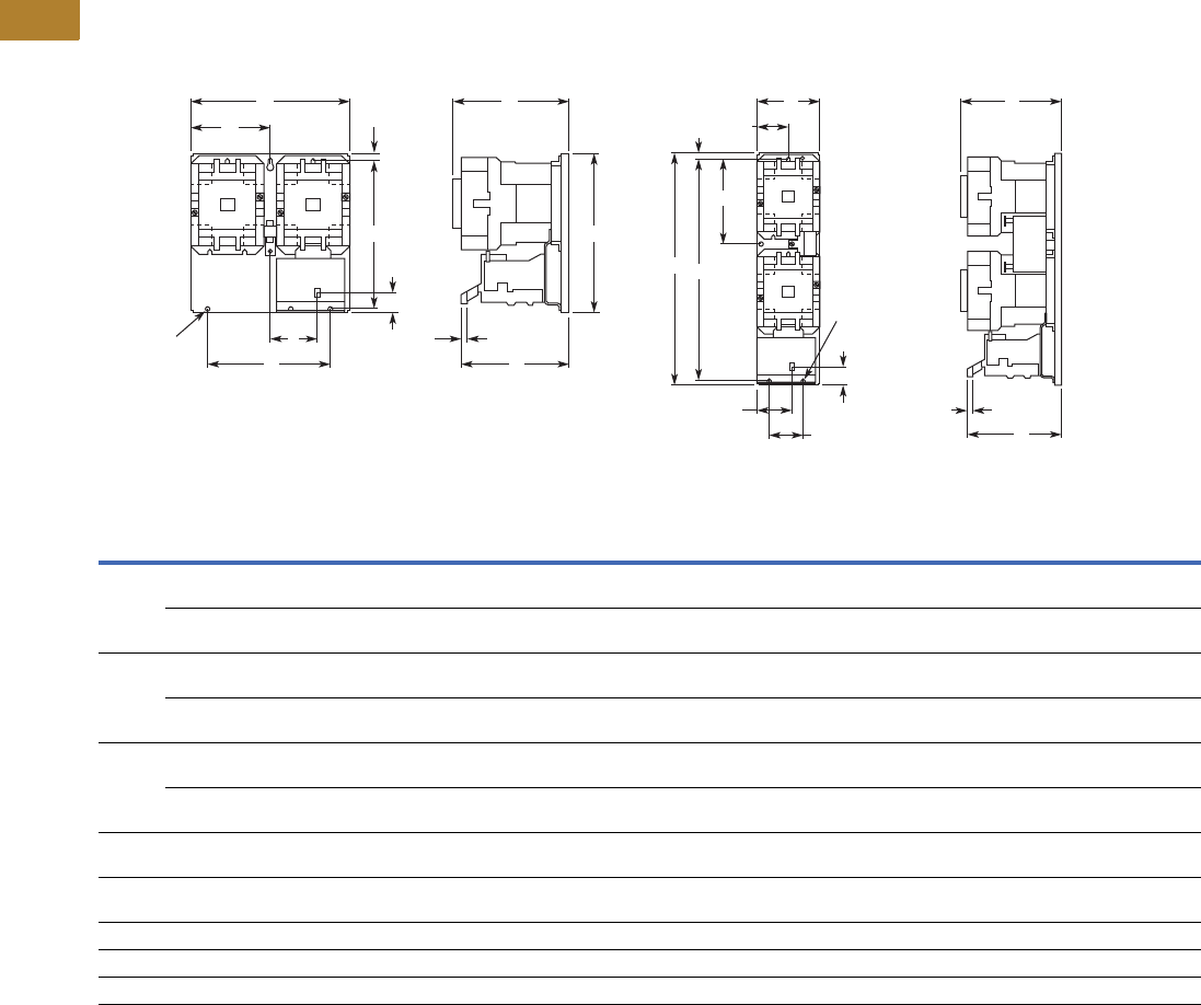
V5-T2-126 Volume 5—Motor Control and Protection CA08100006E—May 2016 www.eaton.com
2
2
2
2
2
2
2
2
2
2
2
2
2
2
2
2
2
2
2
2
2
2
2
2
2
2
2
2
2
2
2.3
NEMA Contactors and Starters
A200 Series
Approximate Dimensions in Inches (mm)
Not to be used for construction purposes unless approved.
Open Reversing Starters
Figure A—Sizes 00–4 Horizontal Figure B—Sizes 00–4 Vertical
Dimensions and Shipping Weights
Note
1Refer to factory.
E
0.28 (7.1) Dia.
3 Mtg. Holes L
JM
Reset
Travel
A C
F
B
D
K
G
L
E
JM
AC
F
BD
N
G
K
0.28 (7.1) Dia.
3 Mtg. Holes
Reset Travel
NEMA
Size
Number
of Poles Fig.
Mounting
Screws Weight,
Lbs (kg)No. SizeABCDEF GJ KL MN
00, 0, 1 3 x 3 Horiz. A 3 #10 7.13
(181.1)
6.50
(165.1)
5.05
(128.3)
6.00
(152.4)
5.69
(144.5)
3.56
(90.4)
0.25
(6.4)
2.3
(58.4)
0.59
(15.0)
4.92
(125.0
0.27
(6.9)
—9.0
(4.0)
3 x 3 Vert. B 3 #10 3.33
(84.6)
11.63
(295.4)
5.05
(128.3)
11.13
(282.7)
1.88
(47.8)
1.66
(42.2)
0.25
(6.4)
0.39
(9.9)
0.59
(15.0)
4.92
(125.0)
0.27
(6.9)
4.52
(114.8)
9.8
(4.4)
2 3 x 3 Horiz. A 3 #10 7.13
(181.1)
7.25
(184.2)
5.38
(136.7)
6.75
(171.5)
5.69
(144.5)
3.56
(90.4)
0.25
(6.4)
2.31
(58.7)
0.77
(19.6)
4.97
(126.2)
0.27
(6.9)
— 10.8
(4.9)
3 x 3 Vert. B 3 #10 3.33
(84.6)
12.38
(314.5)
5.38
(136.7)
11.88
(301.8)
1.88
(47.8)
1.66
(42.2)
0.25
(6.4)
0.39
(9.9)
0.77
(19.6)
4.97
(126.2)
0.27
(6.9)
4.52
(114.8)
12.2
(5.5)
3, 4 3 x 3 Horiz. A 3 1/4 in. 9.75
(247.7)
10.13
(257.3)
7.25
(184.2)
9.25
(235.0)
8.00
(203.2)
4.88
(124.0)
0.44
(11.2)
3.11
(79.0)
0.80
(20.3)
6.86
(174.2)
0.27
(6.9)
— 26.0
(11.8)
3 x 3 Vert. B 3 1/4 in. 4.63
(117.6)
19.81
(503.2)
7.25
(184.2)
18.94
(481.1)
2.88
(73.2)
2.94
(74.7)
0.44
(11.2)
0.55
(14.0)
0.80
(20.3)
6.86
(174.2)
0.27
(6.9)
7.91
(200.9)
28.0
(12.7)
5 3 x 3 Horiz. — 4 3/8 in. 35.25
(895.4)
25.50
(647.7)
8.75
(222.3)
—————————73.0
(33.1)
6 3 x 3 Horiz. — 4 3/8 in. 35.25
(895.4)
25.50
(647.7)
10.50
(266.7)
—————————127.0
(57.7)
71 1111111111111111
81 1111111111111111
91 1111111111111111
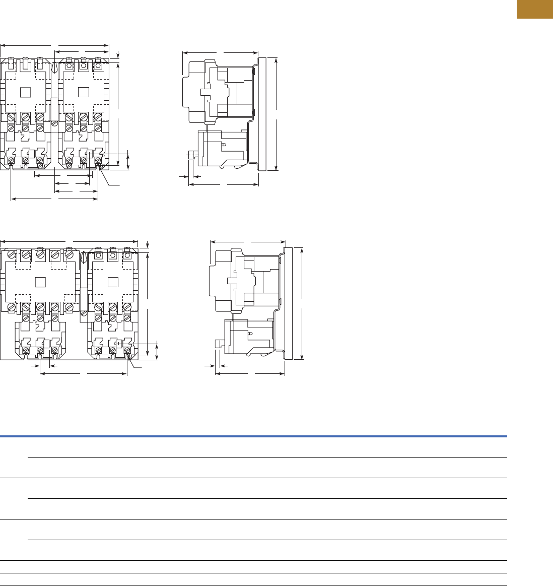
Volume 5—Motor Control and Protection CA08100006E—May 2016 www.eaton.com V5-T2-127
2
2
2
2
2
2
2
2
2
2
2
2
2
2
2
2
2
2
2
2
2
2
2
2
2
2
2
2
2
2
2.3
NEMA Contactors and Starters
A200 Series
Approximate Dimensions in Inches (mm)
Not to be used for construction purposes unless approved.
Open Multi-Speed Starters
Figure A—Sizes 00–4
Figure B—Sizes 2
Dimensions and Shipping Weights
Notes
Three-pole x three-pole devices are for Wye-Wye two-winding motors only.
1Refer to factory.
NEMA
Size
Number
of
Poles Fig.
Mounting
Screws Weight,
Lbs (kg) No. Size A B C D E F G J K L M N P R
00, 0, 1 3 x 3 Horiz. A 3 #10 7.13
(181.1)
6.50
(165.1)
5.05
(128.3)
6.00
(152.4)
5.69
(144.5)
3.56
(90.4)
0.25
(6.4)
2.30
(58.4)
0.33
(8.4)
4.92
(125.0)
0.27
(6.9)
3.81
(96.8)
—2.91
(73.9)
10.0
(4.5)
5 x 3 Horiz. B 3 #10 8.00
(203.2)
6.50
(165.1)
5.05
(128.3)
6.00
(152.4)
6.53
(165.9)
3.56
(90.4)
0.25
(6.4)
2.30
(58.4)
0.48
(12.2)
4.92
(125.0)
0.27
(6.9)
4.66
(118.4)
—2.91
(73.9)
11.0
(5.0)
2 3 x 3 Horiz. A 3 #10 7.13
(181.1)
7.25
(184.2)
5.38
(136.7)
6.75
(171.5)
5.69
(144.5)
3.56
(90.4)
0.25
(6.4)
2.69
(68.3)
0.69
(17.5)
4.97
(126.2)
0.27
(6.9)
3.81
(96.8)
—2.91
(73.9)
11.0
(5.0)
5 x 3 Horiz. B 3 #10 8.88
(225.6)
7.25
(184.2)
5.38
(136.7)
6.75
(171.5)
6.56
(166.6)
3.56
(90.4)
0.25
(6.4)
2.69
(68.3)
0.69
(17.5)
4.97
(126.2)
0.27
(6.9)
4.66
(118.4)
—2.84
(72.1)
13.0
(5.9)
3, 4 3 x 3 Horiz. A 3 1/4 in. 9.75
(247.7)
10.13
(257.3)
7.25
(184.2)
9.25
(235.0)
8.00
(203.2)
4.88
(124.0)
0.44
(11.2)
3.11
(79.0)
0.80
(20.3)
6.86
(174.2)
0.27
(6.9)
5.13
(130.3)
—4.00
(101.6)
28.0
(12.7)
5 x 3 Horiz. B 3 1/4 in. 12.38
(314.5)
10.13
(257.3)
7.25
(184.2)
9.25
(235.0)
9.31
(236.5)
4.88
(124.0)
0.44
(11.2)
3.11
(79.0)
0.80
(20.3)
6.86
(174.2)
0.27
(6.9)
6.44
(163.6)
—4.00
(101.6)
33.5
(15.2)
51 111111111111111111
61 111111111111111111
A
D
G
B
K
FC
J0.2 (5.1) Dia.
3 Mounting Slots
R
E
N
L
Reset TravelM
A
D
G
B
K
C
0.2 (5.1) Dia.
3 Mounting Slots
E
J
L
Reset TravelM
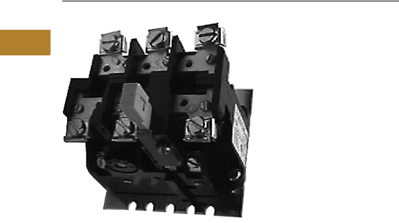
V5-T2-128 Volume 5—Motor Control and Protection CA08100006E—May 2016 www.eaton.com
2
2
2
2
2
2
2
2
2
2
2
2
2
2
2
2
2
2
2
2
2
2
2
2
2
2
2
2
2
2
2.3
NEMA Contactors and Starters
A200 Series
Relays—Thermal and Fast Trip
Contents
Description Page
Contactors—Non-Reversing and Reversing . . . . . . V5-T2-101
Starters—Non-Reversing and Reversing . . . . . . . . V5-T2-107
Relays—Thermal and Fast Trip
Standards and Certifications . . . . . . . . . . . . . . . V5-T2-129
Instruction Leaflets . . . . . . . . . . . . . . . . . . . . . . V5-T2-129
Thermal Type B, Class 20, Manual Reset. . . . . . . . V5-T2-130
Thermal Type A, Class 20, Auto/Manual Reset . . . V5-T2-133
Type FT Fast Trip, Class 10 . . . . . . . . . . . . . . . . . . . V5-T2-136
Heater Selection . . . . . . . . . . . . . . . . . . . . . . . . . . V5-T2-139
Relays—Current Sensing Protective . . . . . . . . . . . V5-T2-141
Relays—Thermal and Fast Trip
Product Overview
Type B and Type A, Class 20
Thermal Overload Relays
from Eaton’s Electrical Sector
will protect the motor against
abnormal
overload conditions.
Bimetallic actuated, they are
available as either ambient
compensated or non-
compensated in either single-
pole or block type three-pole
design. Type B use one pole
of the three-pole block for
single-phase.
Single-pole relays are also
available as Fast Trip Class 10
ambient compensated type,
which provides approximately
125% motor protection with
a tripping time of less than
10 seconds, at 600% of
heater current rating.
Fast trip relays can be
identified by the green reset
rods. They are available for
panel or starter mounting.
The three-pole fast trip design
is composed of
three single-pole relays
on a common baseplate,
with a common reset bar.
The bimetal element is
actuated by precisely
calibrated heater elements
which are connected directly
in the circuit to be protected.
Thermal actuation of this
device opens the contacts in
the coil circuit of a contactor
or relay which results in the
disconnection of power to the
overloaded circuit.
Interchangeable thermal
heater elements for single-
pole standard trip and block
type overload relays are
available to cover motor full
load currents from 0.29 to
133A in approximately 10%
steps (see Heater Application
Table). Fast trip overload
relays do not have
interchangeable heater
elements but are available
in a series of ratings to cover
motor full load currents from
1.6 to 150A in approximately
50% steps.
Features
Manual or Automatic Reset
Type B is furnished with a
manual reset. Type A is
normally furnished set for
manual reset operation and
may be quickly adjusted
for automatic reset when
required. Automatic reset
should not be used with
two-wire control or where
automatic restarting would
endanger either personnel
or equipment.
Trip Indication
An immediate visible
indication of trip is provided
on the overload relay. When
an overload occurs, which
causes the relay to operate,
a trip indicator projects out
and thus shows positive
visual indication of trip.
Type B has a mechanical
trip bar to manually check
the NC contact operation on
the overload relay.
Adjustable Trip
On Type A, the trip rating of a
specific heater element can
be adjusted over a range of
approximately 85% to 115%
of its respective rating to
permit the desired close
protection.
This is accomplished by
turning the adjusting knob
on the relay to the respective
stop position.
Positive Contact Break
A follow-through contact,
provided on the stationary
terminal of the snap action
control switch, provides
reliable electrical continuity
during toggling, thus
eliminating false trip
sometimes prevalent
with thermally operated
switches. This contact also
allows contact wipe for
further reliability.

Volume 5—Motor Control and Protection CA08100006E—May 2016 www.eaton.com V5-T2-129
2
2
2
2
2
2
2
2
2
2
2
2
2
2
2
2
2
2
2
2
2
2
2
2
2
2
2
2
2
2
2.3
NEMA Contactors and Starters
A200 Series
Ambient Compensation
Motor overload protection
can be provided with the
same trip characteristics in
ambient temperature from
–40° to 77°C (–40° to 167°F).
A compensating bimetal
maintains a constant “travel
to trip” distance independent
of ambient conditions.
The compensating feature
is fully automatic and no
adjustments are required
over wide fluctuations in
ambient temperatures.
Compensated relays are
identified by black reset rods
on Type A and light gray reset
rods on Type B, while non-
compensated relays use red
reset rods. AA three-pole
units have gray reset rods.
AA one-pole units have black
reset rods.
Control Contact
Single-pole and block
type relays are supplied as
standard with a SPST NC
control contact. A SPDT
NO-NC with common is
available as a factory
modification on Type A.
An isolated NO contact can
be supplied on Type B as
either a factory modification
or as a field kit.
Standards and Certifications
●UL 508
●CSA
●ANSI/NEMA ICS 2-222
Instruction Leaflets
14885B Fast Trip A
Sizes 0–4, 3-Pole
OL Relay
14567E Type A Sizes 1–2,
1-Pole OL Relay
Mod A
14568 Type A Sizes 1–2,
3-Pole OL Relay
Mod J
14570D Type A Sizes 3–4,
3-Pole OL Relay
Mod J
14569C Type A Sizes 3–4,
1-Pole OL Relay
Mod A
17093A Type B OLR for
Sizes 7, 8 and
9 Contactors
16955A Type B Sizes 1–2,
1-Pole OL Relay
16954A Type B Sizes 1–2,
3-Pole OL Relay
15392B Type B Sizes 3–4,
3-Pole OL Relay
13676F Fast Trip Sizes 0–4,
1-Pole OL Relay
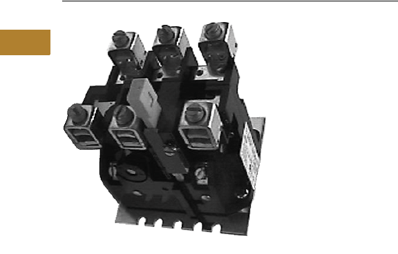
V5-T2-130 Volume 5—Motor Control and Protection CA08100006E—May 2016 www.eaton.com
2
2
2
2
2
2
2
2
2
2
2
2
2
2
2
2
2
2
2
2
2
2
2
2
2
2
2
2
2
2
2.3
NEMA Contactors and Starters
A200 Series
Thermal Type B, Class 20, Manual Reset
Contents
Description Page
Contactors—Non-Reversing and Reversing . . . . . . V5-T2-101
Starters—Non-Reversing and Reversing . . . . . . . . V5-T2-107
Relays—Thermal and Fast Trip . . . . . . . . . . . . . . . . V5-T2-128
Thermal Type B, Class 20, Manual Reset
Product Selection . . . . . . . . . . . . . . . . . . . . . . . V5-T2-131
Accessories. . . . . . . . . . . . . . . . . . . . . . . . . . . . V5-T2-131
Technical Data . . . . . . . . . . . . . . . . . . . . . . . . . . V5-T2-132
Dimensions. . . . . . . . . . . . . . . . . . . . . . . . . . . . V5-T2-132
Thermal Type A, Class 20, Auto/Manual Reset . . . V5-T2-133
Type FT Fast Trip, Class 10 . . . . . . . . . . . . . . . . . . . V5-T2-136
Heater Selection . . . . . . . . . . . . . . . . . . . . . . . . . . V5-T2-139
Relays—Current Sensing Protective . . . . . . . . . . . V5-T2-141
Thermal Type B, Class 20, Manual Reset
Application Description
The Type B overload relay is
designed to protect industrial
motors against overload
conditions. Using modern
block type, bimetallic design,
this relay will provide
Class 20 operation in either
single-phase or three-phase
applications.
Operation
The Type B overload relay
is a bimetallic actuated
device. The bimetal elements
are operated by precisely
calibrated heaters. The heater
elements are connected
either directly in the circuit
to be measured, or through
current transformers on
applications NEMA Size 5
and larger.
As the bimetals are heated
by motor current flow, a
deflection force is produced.
Upon a sustained level of
abnormal current flow, the
deflection becomes great
enough to open the snap-
action output contact.
Ambient Compensation
The Type B ambient
compensated design is
supplied as standard on
all A200 starters. This design
uses a second compensating
bimetal responsive to
ambient air temperature in
the surrounding enclosure.
This feature reduces
nuisance tripping in
applications using compact
control panels and motor
control centers where
internal temperature rise
is significant compared to
motor ambient temperature.
The compensating
characteristic is maintained
in ambient temperatures
from 40° to 77°C.
Features
●Ambient compensation
standard
●Alarm contact field
mountable
●Class 20—600V design
●Inverse time delay trip
●Test trip device for weld
check
●Hi-visibility up-front trip
indication
●Trip-free reset mechanism
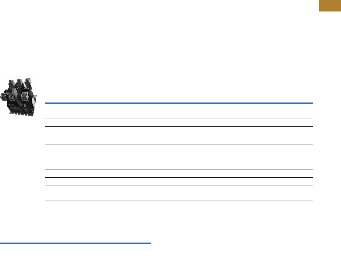
Volume 5—Motor Control and Protection CA08100006E—May 2016 www.eaton.com V5-T2-131
2
2
2
2
2
2
2
2
2
2
2
2
2
2
2
2
2
2
2
2
2
2
2
2
2
2
2
2
2
2
2.3
NEMA Contactors and Starters
A200 Series
Product Selection
Heaters
Enter heaters as separate
item by listing catalog
number from tables,
Pages V5-T2-139 and
V5-T2-140, as required per
starter.
Relays
Thermal Type B Overload Relay
Accessories
Alarm Contact Kit Selection 1
Notes
1Includes contactor mounting bracket, overload relay and connection straps to contactor.
2For replacement on B200 size 00, 0, 1 use BA23A instead of BA13A and use BN23A instead
of BN13A.
Motor Full
Load Amps
Panel Mounted
Starter Mounted
Replacement for
Type B Overload Relays
Replacement for Type A Overload Relays in
Manual Reset Mode (Three-Pole Only) 1
Ambient Comp.
Catalog Number
Non-Comp.
Catalog Number
Ambient Comp.
Catalog Number
Non-Comp.
Catalog Number
Ambient Comp.
Catalog Number
Non-Comp.
Catalog Number
Single-Pole (One NC Contact)
0.25–26.2 BA11JP BN11JP BA11A BN11A ——
26.3–45 BA21JP BN21JP BA21A BN21A ——
19–90 Use three-pole
design, wire three
poles in series
Use three-pole
design, wire three
poles in series
Use three-pole
design, wire three
poles in series
Use three-pole
design, wire three
poles in series
Use three-pole
design, wire three
poles in series
Use three-pole
design, wire three
poles in series
19–135 Use three-pole
design, wire three
poles in series
Use three-pole
design, wire three
poles in series
Use three-pole
design, wire three
poles in series
Use three-pole
design, wire three
poles in series
Use three-pole
design, wire three
poles in series
Use three-pole
design, wire three
poles in series
Three-Pole (One NC Contact)
0.25–26.2 BA13JP BN13JP BA13A 2BN13A 2BA13J BN13J
26.3–45 BA23JP BN23JP BA23A BN23A BA23J BN23J
19–90 BA33P BN33P BA33A BN33A BA33A BN33A
19–135 BA43P BN43P BA43A BN43A BA43A BN43A
Type B Overload Relay Size Catalog Number
1, 2 B3NO-2
3, 4 B3NO-4
Type B Overload Relay
Panel Mounting
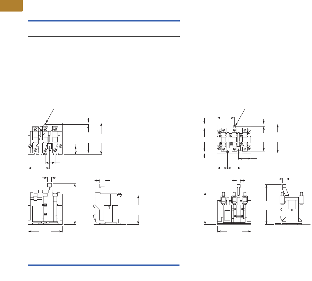
V5-T2-132 Volume 5—Motor Control and Protection CA08100006E—May 2016 www.eaton.com
2
2
2
2
2
2
2
2
2
2
2
2
2
2
2
2
2
2
2
2
2
2
2
2
2
2
2
2
2
2
2.3
NEMA Contactors and Starters
A200 Series
Technical Data
Control Contact Ratings—NEMA B600 NO and
NC Control Contact Rating
Dimensions
Approximate Dimensions in Inches (mm)
Not to be used for construction purposes unless approved.
Thermal Type B Overload Relays
Sizes 1 and 2—Three-Pole, Panel Mounted Sizes 3 and 4—Three-Pole, Panel Mounted
Dimensions
Note
1Alarm contact available as factory modification of field mountable. For factory modification,
add suffix B.
AC Volts Make Break
24–120 30A 3A
120–600 3600 VA 360 VA
0.94 (23.9)
1.98
(50.3)
0.8
(20.3)
3.14
(79.8)
2.81
(71.4)
.17
(4.3)
0.41 (10.4) 0.53
(13.5)
4.00
(101.6)
3.31
(84.1)
2.22
(56.4)
0.2 (5.1) Dia.
6 Mtg. Slots
C
D
A
1.38 (35.1)
1.75 (44.5)
0.47 (11.9)
0.47
(11.9)
4.44
(112.8)
5.28
(134.1)
3.88
(98.6)
3.38
(85.9)
2.22
(56.4)
1.34 (34.0)
B
0.25
(6.4)
0.28 (7.1) Dia.
3 Mtg. Slots
Relay Size A B C D
3 3.13 (79.5) 4.06 (103.1) 044 (11.2) 0.31 (7.9)
4 3.38 (85.9) 4.38 (111.3) 0.31 (7.9) 0.19 (4.8)
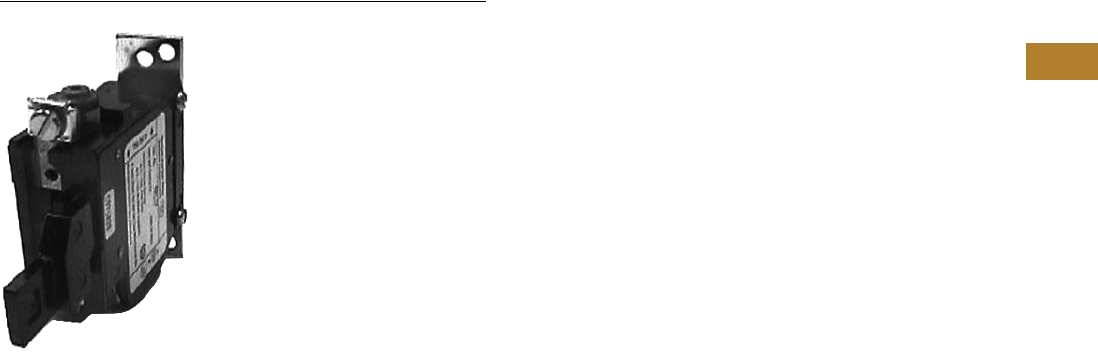
Volume 5—Motor Control and Protection CA08100006E—May 2016 www.eaton.com V5-T2-133
2
2
2
2
2
2
2
2
2
2
2
2
2
2
2
2
2
2
2
2
2
2
2
2
2
2
2
2
2
2
2.3
NEMA Contactors and Starters
A200 Series
Thermal Type A, Class 20, Auto/Manual Reset
Contents
Description Page
Contactors—Non-Reversing and Reversing . . . . . . V5-T2-101
Starters—Non-Reversing and Reversing . . . . . . . . V5-T2-107
Relays—Thermal and Fast Trip . . . . . . . . . . . . . . . . V5-T2-128
Thermal Type B, Class 20, Manual Reset . . . . . . . . V5-T2-130
Thermal Type A, Class 20, Auto/Manual Reset
Product Selection . . . . . . . . . . . . . . . . . . . . . . . V5-T2-134
Technical Data and Specifications . . . . . . . . . . . V5-T2-134
Dimensions . . . . . . . . . . . . . . . . . . . . . . . . . . . . V5-T2-135
Type FT Fast Trip, Class 10 . . . . . . . . . . . . . . . . . . . V5-T2-136
Heater Selection. . . . . . . . . . . . . . . . . . . . . . . . . . . V5-T2-139
Relays—Current Sensing Protective. . . . . . . . . . . . V5-T2-141
Thermal Type A, Class 20, Auto/Manual Reset
Application Description
The Type A overload relay is
designed to protect industrial
motors against overload
conditions. Using modern
block type, bimetallic design,
this relay will provide Class
20 operation in either single-
or three-phase applications.
Features
●Field selectable manual/
auto reset
●Alarm contract factory
available
●Class 20—600V design
●Inverse time delay trip
●Adjustable trip rating ±15%
●Color coded reset rod:
●Compensated (gray)
●Non-compensated (red)
Operation
The Type A overload relay is
a bimetallic actuated device.
The bimetal elements are
operated by precisely
calibrated heaters. The
heater elements are
connected either directly in
the circuit to be measured, or
through current transformers
on applications NEMA Size 5
and larger.
As the bimetals are heated
by motor current flow, a
deflection force is produced.
Upon a sustained level of
abnormal current flow, the
deflection becomes great
enough to open the snap-
action output contact.
Automatic Reset
The Type A overload relay can
be supplied as an option on all
A200 starters to provide
automatic reset operation.
The overload relay is always
shipped in the non-automatic
mode. To set up auto
operation, reposition the
reset rod by loosening and re-
tightening a hold-down clamp
at the base of overload relay.
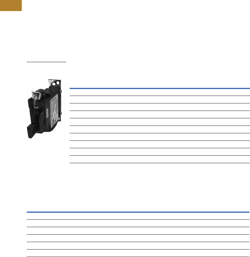
V5-T2-134 Volume 5—Motor Control and Protection CA08100006E—May 2016 www.eaton.com
2
2
2
2
2
2
2
2
2
2
2
2
2
2
2
2
2
2
2
2
2
2
2
2
2
2
2
2
2
2
2.3
NEMA Contactors and Starters
A200 Series
Product Selection
Heaters
Enter heaters as separate
item by listing catalog
number from tables,
Pages V5-T2-139 and
V5-T2-140, as required per
starter.
Relays
Thermal Type A Overload Relay 1
Technical Data and Specifications
Control Contact Ratings
Notes
1For alarm contact (Form C), add Suffix B. Available only as factory modification on Type A relay.
2Three-pole Type B overload relay is a suitable alternative to a three-pole Type A overload relay in
manual reset mode. For example, BA13JP for AA13P, BN23J for AN23A, and so on. (See Page V5-T2-131.)
Motor Full
Load Amps
Panel Mounted Starter Replacement
Ambient Comp. Non-Comp. Ambient Comp. Non-Comp.
Catalog Number Catalog Number Catalog Number Catalog Number
Single-Pole (One NC Contact)
0.25–26.2 AA11P AN11P AA11A AN11A
26.3–45 AA21P AN21P AA21A AN21A
19–90 AA31P AN31P AA31A AN31A
19–135 AA41P AN41P AA41A AN41A
Three-Pole (One NC Contact)
0.25–26.2 AA13P 2AN13P 2AA13A 2AN13A 2
26.3–45 AA23P 2AN23P 2AA23A 2AN23A 2
19–90 AA33P 2AN33P 2AA33A 2AN33A 2
19–135 AA43P 2AN43P 2AA43A 2AN43A 2
AC
Volts
Normally Closed Normally Open
Make Break Make Break
Three-Pole Control Contact Ratings
24–120 20A 2A 0.5A 0.5A
120–600 2400 VA 240 VA 600 VA 60 VA
Single-Pole Control Contact Ratings
24–120 30A 3A 10A 1A
120–600 3600 VA 360 VA 1200 VA 120 VA
Type A Overload Relay
Single-Pole Panel
Mounting
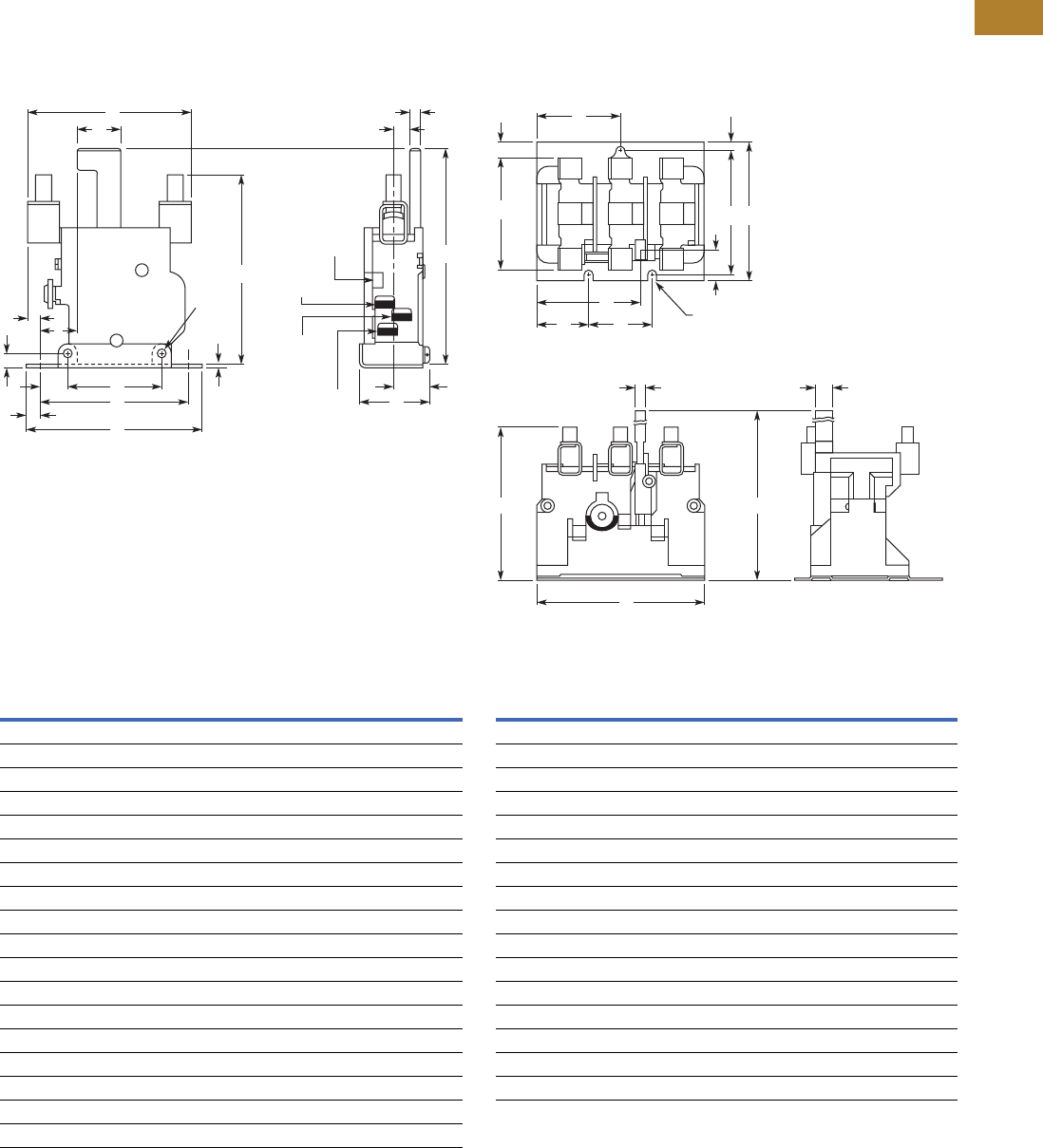
Volume 5—Motor Control and Protection CA08100006E—May 2016 www.eaton.com V5-T2-135
2
2
2
2
2
2
2
2
2
2
2
2
2
2
2
2
2
2
2
2
2
2
2
2
2
2
2
2
2
2
2.3
NEMA Contactors and Starters
A200 Series
Dimensions
Approximate Dimensions in Inches (mm)
Not to be used for construction purposes unless approved.
Type A
Single-Pole (Sizes 4 Shown)
Dimensions
Three-Pole (Size 4 Shown)
Dimensions
Dimension
Relay Size
1234
A 2.72 (69.1) 3.48 (88.4) 4.19 (106.4) 4.5 (114.3)
B 0.94 (23.9) 0.67 (17.0) 0.25 (6.4) 0.38 (9.7)
C 2.75 (69.9) 3.5 (88.9) 3.53 (89.7) 3.78 (96.0)
D 3.25 (82.6) 3.25 (82.6) 4.13 (104.9) 4.13 (104.9)
E 2.63 (66.8) 2.63 (66.8) 3.38 (85.9) 3.38 (85.9)
F 1.34 (34.0) 1.34 (34.0) 2.19 (55.6) 2.19 (55.6)
G 0.25 (6.4) 0.25 (6.4) 0.28 (7.1) 0.28 (7.1)
H 0.31 (7.9) 0.31 (7.9) 0.38 (9.7) 0.38 (9.7)
J 0.06 (1.5) 0.06 (1.5) 0.06 (1.5) 0.06 (1.5)
K 0.22 (5.6) 0.22 (5.6) 0.27 (6.8) 0.27 (6.8)
L 1.34 (34.0) 1.34 (34.0) 1.69 (42.9) 1.69 (42.9)
M 0.66 (16.8) 0.66 (16.8) 0.88 (22.4) 0.88 (22.4)
N 0.16 (4.1) 0.16 (4.1) 0.27 (6.8) 0.27 (6.8)
P 0.22 (5.6) 0.22 (5.6) 0.34 (8.6) 0.34 (8.6)
Q 0.06 (1.5) 0.06 (1.5) 0.69 (17.5) 0.69 (17.5)
R 4.00 (101.6) 4.00 (101.6) 5.19 (131.8) 5.19 (131.8)
S 0.47 (11.9) 0.47 (11.9) 0.59 (15.0) 0.59 (15.0)
T 1.11 (28.2) 1.11 (28.2) 0.69 (17.5) 0.69 (17.5)
C
Q P
N
F
T
B
MS
E L
H
D
A
J
G
R
Trip
Indicator
Common
Terminal
No Terminal
(When
Supplied)
NC Terminal
K Dia.
2 Mtg.
Holes
Dimension
Relay Size
1234
A 2.38 (60.5) 2.44 (62.0) 3.13 (79.5) 3.38 (85.9)
B 3.13 (79.5) 3.17 (80.5) 4.06 (103.1) 4.38 (111.3)
C 0.36 (9.1) 0.33 (8.4) 0.44 (11.2) 0.31 (7.9)
D 1.66 (42.2) 1.66 (42.2) 2.22 (56.4) 2.22 (56.4)
E 0.17 (4.3) 0.17 (4.3) 0.25 (6.4) 0.25 (6.4)
F 2.81 (71.4) 2.81 (71.4) 3.38 (85.9) 3.38 (85.9)
G 3.08 (78.2) 3.08 (78.2) 3.88 (98.6) 3.88 (98.6)
H 0.47 (11.9) 0.47 (11.9) 0.47 (11.9) 0.47 (11.9)
J 0.20 (5.1) 0.20 (5.1) 0.28 (7.1) 0.28 (7.1)
K 0.28 (7.1) 0.28 (7.1) 0.47 (11.9) 0.47 (11.9)
L 4.00 (101.6) 4.00 (101.6) 5.28 (134.1) 5.28 (134.1)
M 3.31 (84.1) 3.31 (84.1) 4.44 (112.8) 4.44 (112.8)
N 1.80 (45.7) 1.80 (45.7) 2.77 (70.4) 2.77 (70.4)
P 1.89 (48.0) 1.89 (48.0) 1.75 (44.5) 1.75 (44.5)
Q 1.00 (25.4) 1.00 (25.4) 1.34 (34.0) 1.34 (34.0)
R — — 1.03 (26.2) 1.03 (26.2)
D
N
Q P
K
J Dia.—3 Mtg. Slots
H
M
FG
A
C
B L
E
R
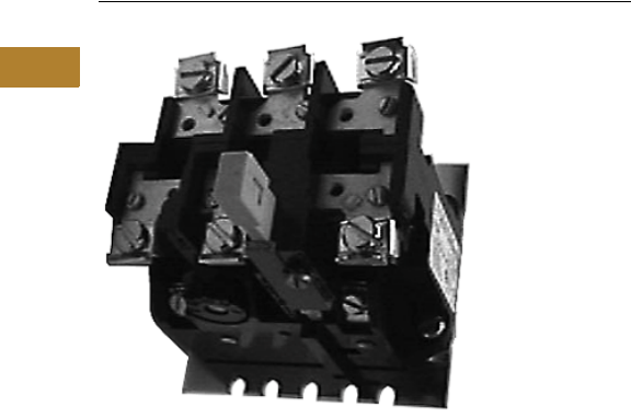
V5-T2-136 Volume 5—Motor Control and Protection CA08100006E—May 2016 www.eaton.com
2
2
2
2
2
2
2
2
2
2
2
2
2
2
2
2
2
2
2
2
2
2
2
2
2
2
2
2
2
2
2.3
NEMA Contactors and Starters
A200 Series
Type FT Fast Trip, Class 10
Contents
Description Page
Contactors—Non-Reversing and Reversing . . . . . . V5-T2-101
Starters—Non-Reversing and Reversing . . . . . . . . V5-T2-107
Relays—Thermal and Fast Trip . . . . . . . . . . . . . . . . V5-T2-128
Thermal Type B, Class 20, Manual Reset. . . . . . . . V5-T2-130
Thermal Type A, Class 20, Auto/Manual Reset . . . V5-T2-133
Type FT Fast Trip, Class 10
Product Selection . . . . . . . . . . . . . . . . . . . . . . . V5-T2-137
Technical Data and Specifications . . . . . . . . . . . V5-T2-137
Dimensions. . . . . . . . . . . . . . . . . . . . . . . . . . . . V5-T2-138
Heater Selection . . . . . . . . . . . . . . . . . . . . . . . . . . V5-T2-139
Relays—Current Sensing Protective . . . . . . . . . . . V5-T2-141
Type FT Fast Trip, Class 10
Application Description
The Type FT overload relay is
designed to protect special
purpose motors having
restricted thermal and locked
rotor capabilities. Using
modern block type, bimetallic
design, this relay will provide
Class 10 operation in single-
or three-phase applications.
Operation
The Type FT overload relay is
a bimetallic actuated device.
The bimetal elements are
operated directly from line
current, thus separate
calibrating heater elements
are not utilized. The overload
relay may be wired directly in
the motor circuit, or through-
current transformers on
applications larger than 150A.
As the bimetals are heated by
motor current flow, a
deflection force is produced.
Upon a sustained level of
abnormal current flow, the
deflection becomes great
enough to open the snap
action output contact.
Features
●Class 10—600V design
●Inverse time delay trip
●Color coded reset rod—
green
●Alarm contact factory
available
●Field selectable manual/
auto reset
●Adjustable trip rating
±20%
●Ambient compensation
included
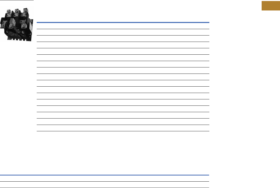
Volume 5—Motor Control and Protection CA08100006E—May 2016 www.eaton.com V5-T2-137
2
2
2
2
2
2
2
2
2
2
2
2
2
2
2
2
2
2
2
2
2
2
2
2
2
2
2
2
2
2
2.3
NEMA Contactors and Starters
A200 Series
Product Selection
Type FT Single-Pole (One NC Contact); Three-Phase (Three NC Contacts in Series) 1
Technical Data and Specifications
Control Contact Ratings
Note
1Single-pole (1NO-NC contact): add suffix B. Three-pole (3NO-NC contacts): add suffix B. Example: FT13PB-12.
Motor Full Load
Amperes
Panel Mounted Starter Replacement
Single-Pole Three-Pole
NEMA Size
Single-Pole
Catalog Number Catalog Number Catalog Number
0.76–1.1 FT11P-1.1 FT13P-1.1 —FT11A-1.1
1.1–1.6 FT11P-1.6 FT13P-1.6 —FT11A-1.6
1.6–2.4 FT11P-2.4 FT13P-2.4 0, 1 FT11A-2.4
2.4–3.6 FT11P-3.6 FT13P-3.6 0, 1 FT11A-3.6
3.6–5.4 FT11P-5.4 FT13P-5.4 0, 1 FT11A-5.4
5.4–8.0 FT11P-8.0 FT13P-8 0, 1 FT11A-8
8.0–12 FT11P-12 FT13P-12 0, 1 FT11A-12
12–18 FT11P-18 FT13P-18 1FT11A-18
16–24 —FT13P-24 —
22–32 FT11P-32 FT13P-32 0, 1 FT11A-32
24–36 FT21P-36 FT23P-36 2FT21A-36
36–54 FT21P-54 FT23P-54 12 FT21A-54
22–32 FT31P-32 FT33P-32 3FT31A-32
32–48 FT31P-48 FT33P-48 3FT31A-48
48–72 FT31P-72 FT33P-72 3FT31A-72
72–110 FT41P-110 FT43P-110 4FT41A-110
100–150 FT41P-150 FT43P-150 4FT41A-150
AC Volts
Normally Closed Normally Open
Make Break Make Break
24–120 30A 3A 10A 1A
120–600 3600 VA 360 VA 1200 VA 120 VA
Type FT Single-Pole
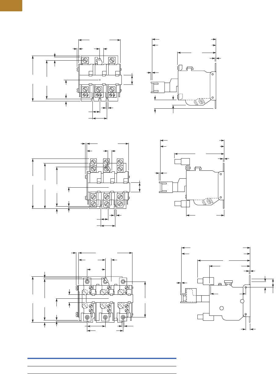
V5-T2-138 Volume 5—Motor Control and Protection CA08100006E—May 2016 www.eaton.com
2
2
2
2
2
2
2
2
2
2
2
2
2
2
2
2
2
2
2
2
2
2
2
2
2
2
2
2
2
2
2.3
NEMA Contactors and Starters
A200 Series
Dimensions
Approximate Dimensions in Inches (mm)
Not to be used for construction purposes unless approved.
Type FT Overload Relays
Three-Pole, Size 1
Three-Pole, Size 2
Three-Pole, Sizes 3, 4
Dimensions
Relay Size A B C D E
3 4.25 (108.0) 0.53 (13.5) 2.91 (73.9) 0.09 (2.3) 0.06 (1.5)
4 4.50 (114.3) 0.59 (15.0) 3.03 (77.0) 0.22 (5.6) 0.19 (4.8)
4.49 (114) Hand Reset Pos.
4.38 (111.3) Auto Reset Pos.
1.00 (25.4)
0.50
(12.7)
2.72
(69.1)
1.64
(41.7)
2.81
(71.4)
3.28 (83.3)
3.25
(82.6)
0.17 (4.3)
3 Mtg.
Holes
1.30
(33.0)
0.19
(4.8)
0.69
(17.5)
0.63
(16.0)
0.38
(9.7)
0.17
(4.3)
0.11
(2.8) 0.22
(5.6)
0.06
(1.5)
0.06
(1.5)
0.19
(4.8)
4.49 (114) Hand Reset Pos.
4.38 (111.3) Auto Reset Pos.
1.00 (25.4)
0.50 (12.7)
3.48
(88.4)
1.64
(41.7)
2.81
(71.4)
3.28 (83.3)
3.28 (83.3)
3.25
(82.6)
3.61
(91.7)
0.17 (4.3)
3 Mtg.
Holes
1.30
(33.0)
0.06
(1.5)
0.69
(17.5)
0.11
(2.8) 0.22
(5.6) 0.06
(1.5)
0.06
(1.5)
0.25
(6.4)
3.38
(85.9)
D
3.88
(98.6)
1.75
(44.5)
C
E
0.69
(17.5)
5.63 (143) Hand Reset Pos.
5.52 (140.2) Auto Reset Pos.
3.31 (84.1)
A
0.28 (7.1)
2.81 (71.4)
0.06
(1.5)
0.74
(18.8)
B
0.06
(1.5)
1.75 (44.5)
4.41 (112)
2.20
(55.9)
0.48
(12.2)
1.42
(36.1)
0.16 (4.1)
0.88 (22.4)
0.28 (7.1)
3 Mtg.
Holes
Volume 5—Motor Control and Protection CA08100006E—May 2016 www.eaton.com V5-T2-139
2
2
2
2
2
2
2
2
2
2
2
2
2
2
2
2
2
2
2
2
2
2
2
2
2
2
2
2
2
2
2.3
NEMA Contactors and Starters
A200 Series
Heater Selection
General Information on Heater Coil Selection
For maximum motor
protection and compliance
with Article 430-32 of the
National Electrical Code,
select heater coils from the
tables in this section on the
basis of motor nameplate
full load current.
When the full load current is
unknown, selection may be
made on the basis of average
full load currents as shown on
Pages V5-T2-155 and
V5-T2-156. Caution—The
average ratings could be
high or low for a specific
motor and therefore
selection on this basis
always involves risk. For
fully reliable motor
protection, select heater
coils on the basis of full
load current rating as
shown on the motor
nameplate.
Heater coils are rated to
protect 40°C rise motors, and
open and drip-proof motors
having a service factor of
1.15 where the motor and
the controller are at the same
ambient temperature.
Type A and B Overload Relays, Sizes 3 and 4
Size
Starter
Ambient Compensated
Enclosed Starters
Non-Compensating
Enclosed Starters Heater (One Heater
per Catalog Number)
Catalog Number
All Applications
Full Load Current of Motor Amps
12.8–14.1 11.9–13.0 FH68
14.2–15.5 13.1–14.3 FH69
15.6–17.1 14.4–15.9 FH70
17.2–18.9 16.0–17.4 FH71
19.0–20.8 17.5–19.1 FH72
20.9–22.9 19.2–21.1 FH73
23.0–25.2 21.2–23.2 FH74
25.3–27.8 23.3–25.6 FH75
27.9–30.6 25.7–28.1 FH76
30.7–33.5 28.2–30.8 FH77
33.6–37.5 30.9–34.5 FH78
37.6–41.5 34.6–38.2 FH79
41.6–56.3 38.3–42.6 FH80
46.4–50 42.7–46 FH81
51–55 47–51 FH82
56–61 52–56 FH83
62–66 57–61 FH84
67–73 62–67 FH85
74–78 68–72 FH86
79–84 73–77 FH87
85–92 78–84 FH88
93–101 85–91 FH89
102–110 92–99 FH90
111–122 100–110 FH91
123–129 111–122 FH92
130–133 123–128 FH93
— 129–133 FH94
For Size 4 Starters
For Size 3 Starters
For other conditions:
1. For 50°C, 55°C, 75°C rise
motors and enclosed
motors having a
service factor of 1.0,
select one
size smaller coil.
2. Ambient temperature of
controller lower than
motor by 26°C (47°F),
use one size smaller coil.
3. Ambient temperature of
controller higher than
motor by 26°C (47°F),
use one size larger coil.
Ultimate tripping current of
heater coils is approximately
1.25 times the minimum
current rating listed in the
tables.
Type A and B Overload Relays, Sizes 5 and 6 1
Note
1Size 7 and larger—advise full load current.
Compensated Overload Relay Heater (One Heater per
Catalog Number)
Catalog Number
Open Starter Enclosed Starter
Full Load Current of Motor (Amps)
Size 5 (with 300/5 Current Transformers)
—— FH23
118–129 118–129 FH24
130–141 130–141 FH25
142–155 142–155 FH26
156–170 156–170 FH27
171–187 171–187 FH28
188–205 188–205 FH29
206–224 206–224 FH30
225–244 225–244 FH31
245–263 245–263 FH32
264–292 264–292 FH33
293–300 — FH34
Size 6 (with 600/5 Current Transformers)
—— FH23
236–259 236–259 FH24
260–283 260–283 FH25
284–310 284–310 FH26
311–340 311–340 FH27
341–374 341–374 FH28
375–411 375–411 FH29
412–448 412–448 FH30
449–489 449–489 FH31
490–527 490–527 FH32
528–585 528–540 FH33
586–600 — FH34

V5-T2-140 Volume 5—Motor Control and Protection CA08100006E—May 2016 www.eaton.com
2
2
2
2
2
2
2
2
2
2
2
2
2
2
2
2
2
2
2
2
2
2
2
2
2
2
2
2
2
2
2.3
NEMA Contactors and Starters
A200 Series
Type A and B Overload Relays, Sizes 0, 1 and 2
Size
Starter
Non-Compensated Open Starters and
Ambient Comp. Open and Enclosed Starters Heater (One Heater
per Catalog Number)
Catalog Number
Non-Compensating
Enclosed Starters
Heater
Catalog Number
Block Type Overload
sing Three Heaters
Single-Pole Type
Overload
Block Type Overload
Using Three Heaters
Single-Pole Type
Overload
Full Load Current of Motor (Amps)
0.25–0.27 0.29–0.31 FH03 0.24–0.25 0.28–0.30 FH03
0.28–0.31 0.32–0.35 FH04 0.26–0.28 0.31–0.34 FH04
0.32–0.34 0.36–0.39 FH05 0.29–0.31 0.35–0.37 FH05
0.35–0.38 0.40–0.43 FH06 0.32–0.35 0.38–0.42 FH06
0.39–0.42 0.44–0.48 FH07 0.36–0.39 0.43–0.47 FH07
0.43–0.46 0.49–.053 FH08 0.40–0.43 0.48–0.52 FH08
0.47–0.50 0.54–0.58 FH09 0.44–0.47 0.53–0.56 FH09
0.51–0.55 0.59–0.64 FH10 0.48–0.51 0.57–0.63 FH10
0.56–0.62 0.65–0.71 FH11 0.52–0.57 0.64–0.70 FH11
0.63–0.68 0.72–0.79 FH12 0.58–0.63 0.71–0.77 FH12
0.69–0.75 0.80–0.87 FH13 0.64–0.70 0.78–0.85 FH13
0.76–0.83 0.88–0.96 FH14 0.71–0.77 0.86–0.94 FH14
0.84–0.91 0.97–1.06 FH15 0.78–0.85 0.95–1.03 FH15
0.92–1.00 1.07–1.16 FH16 0.86–0.93 1.04–1.13 FH16
1.01–1.11 1.17–1.28 FH17 0.94–1.03 1.14–1.25 FH17
1.12–1.22 1.29–1.41 FH18 1.04–1.13 1.26–1.38 FH18
1.23–1.34 1.42–1.55 FH19 1.14–1.25 1.39–1.52 FH19
1.35–1.47 1.56–1.71 FH20 1.26–1.37 1.53–1.67 FH20
1.48–1.62 1.72–1.87 FH21 1.38–1.51 1.68–1.83 FH21
1.63–1.78 1.88–2.06 FH22 1.52–1.65 1.84–2.01 FH22
1.79–1.95 2.07–2.26 FH23 1.66–1.81 2.02–2.21 FH23
1.96–2.15 2.27–2.48 FH24 1.82–1.99 2.22–2.43 FH24
2.16–2.35 2.49–2.72 FH25 2.00–2.19 2.44–2.66 FH25
2.36–2.58 2.73–2.99 FH26 2.20–2.39 2.67–2.92 FH26
2.59–2.83 3.00–3.28 FH27 2.40–2.63 2.93–3.21 FH27
2.84–3.11 3.29–3.60 FH28 2.64–2.89 3.22–3.53 FH28
3.12–3.42 3.61–3.95 FH29 2.90–3.17 3.54–3.87 FH29
3.43–3.73 3.96–4.31 FH30 3.18–3.47 3.88–4.22 FH30
3.74–4.07 4.32–4.71 FH31 3.48–3.79 4.23–4.61 FH31
4.08–4.39 4.72–5.14 FH32 3.80–4.11 4.62–4.9 FH32
4.40–4.87 5.15–5.6 FH33 4.12–4.55 5.0–5.5 FH33
4.88–5.3 5.7–6.2 FH34 4.56–5.0 5.6–6.0 FH34
5.4–5.9 6.3–6.8 FH35 5.1–5.5 6.1–6.6 FH35
6.0–6.4 6.9–7.5 FH36 5.6–5.9 6.7–7.3 FH36
6.5–7.1 7.6–8.2 FH37 6.0–6.6 7.4–8.0 FH37
7.2–.78 8.3–9.0 FH38 6.7–7.2 8.1–8.7 FH38
7.9–8.5 9.1–9.9 FH39 7.3–7.9 8.8–9.7 FH39
8.6–9.4 10.0–10.8 FH40 8.0–8.7 9.8–10.5 FH40
9.5–10.3 10.9–11.9 FH41 8.8–9.5 10.6–11.7 FH41
10.4–11.3 12.0–13.1 FH42 9.6–10.5 11.8–12.7 FH42
11.4–12.4 13.2–14.3 FH43 10.6–11.5 12.8–14.0 FH43
12.5–13.5 14.4–15.7 FH44 11.6–12.6 14.1–15.3 FH44
13.6–14.9 15.8–17.2 FH45 12.7–13.8 15.4–16.6 FH45
15.0–16.3 17.3–18.9 FH46 13.9–15.1 16.7–18.3 FH46
16.4–18.0 19.0–20.8 FH47 15.2–16.7 18.4–20.0 FH47
18.1–19.8 20.9–22.9 FH48 16.8–18.3 20.1–21.9 FH48
19.9–21.7 23.0–25.2 FH49 18.4–20.2 22.0–23.9 FH49
21.8–23.9 25.3–27.6 FH50 20.3–22.2 24.0–26.2 FH50
24.0–26.2 27.7–30.3 FH51 22.3–24.3 26.3–28.8 FH51
26.3–28.7 30.4–33.3 FH52 24.4–26.6 28.9–31.4 FH52
28.8–31.4 33.4–36.4 FH53 26.7–29.1 31.5–34.5 FH53
31.5–34.5 36.5–39.9 FH54 29.2–32.0 34.6–37.9 FH54
34.6–37.9 40.0–43.9 FH55 32.1–35.2 3.80–41.9 FH55
38.0–41.5 FH56 35.3–38.5 42.0–45.0 FH56
41.6–45.0 FH57 38.6–42.3 FH57
For Size 2 Starters
For Size 1 Starters
For Size 0 Starters

Volume 5—Motor Control and Protection CA08100006E—May 2016 www.eaton.com V5-T2-141
2
2
2
2
2
2
2
2
2
2
2
2
2
2
2
2
2
2
2
2
2
2
2
2
2
2
2
2
2
2
2.3
NEMA Contactors and Starters
A200 Series
Relays—Current Sensing Protective
Contents
Description Page
Contactors—Non-Reversing and Reversing . . . . . . V5-T2-101
Starters—Non-Reversing and Reversing . . . . . . . . V5-T2-107
Relays—Thermal and Fast Trip . . . . . . . . . . . . . . . . V5-T2-128
Thermal Type B, Class 20, Manual Reset . . . . . . . . V5-T2-130
Thermal Type A, Class 20, Auto/Manual Reset . . . V5-T2-133
Type FT Fast Trip, Class 10 . . . . . . . . . . . . . . . . . . . V5-T2-136
Heater Selection. . . . . . . . . . . . . . . . . . . . . . . . . . . V5-T2-139
Relays—Current Sensing Protective
Features. . . . . . . . . . . . . . . . . . . . . . . . . . . . . . . V5-T2-142
Standards and Certifications . . . . . . . . . . . . . . . V5-T2-142
Product Selection . . . . . . . . . . . . . . . . . . . . . . . V5-T2-142
Dimensions . . . . . . . . . . . . . . . . . . . . . . . . . . . . V5-T2-143
Relays—Current Sensing Protective
Product Description
The IQ500 is a heaterless,
current-sensing, solid-state
motor protective relay with
optional communications
capabilities. Several functions
are incorporated into the base
relay (IQ502/IQ504) as
standard:
●Overload (overcurrent)
protection
●Phase unbalance and
phase loss protection
●Ground current protection
(Class II)
The base relay can serve as
the initial building block for a
motor protection system by
adding the IQ500M Special
Function Module. The
module can address
application related motor load
functions with the additional
features:
●Underload protection
●Long acceleration
●Jam protection
●Load control
The IQ500 can provide a cost-
effective alternative to
conventional protective relays
such as current relays,
ground fault relays and phase
loss or phase unbalance
relays. Used with the
PowerNet system, a low-
cost, local area
communication network,
information such as current
values, status, setpoint
values and cause of trip can
be displayed remotely. The
IQ500 relay is ideal for a
variety of industrial
applications such as mining,
timber, material handling, air
conditioning compressors,
wastewater treatment plants
and petrochemical industries.

V5-T2-142 Volume 5—Motor Control and Protection CA08100006E—May 2016 www.eaton.com
2
2
2
2
2
2
2
2
2
2
2
2
2
2
2
2
2
2
2
2
2
2
2
2
2
2
2
2
2
2
2.3
NEMA Contactors and Starters
A200 Series
Features
●Overload class is
adjustable using DIP
switches for 5, 10, 20 or 30
seconds, maximum trip
times at six times rated
current
●Designed for 1000V and
less distribution systems
●Form C (NO/NC) contact on
output relay
●Isolated alarm relay output
contact
●Communications capability
using IMPACC network
●Manual or automatic reset
(either a true manual or
remote electrical reset)—
selectable
●Overload, Class II ground
current, phase unbalance
and single-phase
protection are standard
●LED indication (bi-
colored—red/green) for
device status, including
overload, phase unbalance
or ground current trip
●Special Function Module
adds protection for
underload and jam
conditions, also provides
for long acceleration
●Optional load control
feature available with
special function module
●Feed-through current
transformer windows for
contactors, NEMA Sizes 1–
4 (for Size 5 and larger,
external current
transformers can be used)
●Fits mounting footprint of
Eaton’s MORA relay
●Panel or starter mountable
●Cause of trip is held in
memory through a power
loss
●Bell alarm contact available
for remote status
indication
●DIP switch provided for
setting operating
frequency—50 or 60 Hz
●Plug-in terminal block for
control power, trip relay
and bell alarm relay
connections
●Operating temperature:
–20° to 60°C (–4° to 140°F)
Benefits
●No external current
transformers are required
since they are internal to
the IQ500
●DIP switches used to
select functions and
settings on base relay are
clearly marked and covered
with screw-on plastic
covers
●On the automatic reset,
the reset times can be
selected for long (90
second) or short (10
second) delay
●Device can be set for
different motor full load
currents without additional
parts or modules
Optional Benefits
●With the addition of the
IQ500M Special Function
Module, the enhanced
protection includes jam
(overtorque) and underload
and provides long
acceleration time (high
inertia load)
●The underload and jam
protection functions each
have independent Form C
output relays as part of the
module. In addition, the
underload and jam
functions each have their
own LEDs for status
indication
●The underload and jam
functions also have
separate selectable trip
levels and adjustable trip-
delay and start-delay
settings
●The IQ500M can be used
as a load control module
that allows “shedding and
restoring” a particular load
that contributes to the load
being monitored
●The PONI (Product
Operated Network
Interface) card attaches
directly to the base relay or
special function module for
interfacing with the Eaton’s
PowerNet communications
system
●Localized display can be
achieved with the Central
Monitoring Unit
Standards and Certifications
●UL File No. E19223
Product Selection
Current Sensing Protective Relay
Note
1 Can be used with external CTs having 5A secondary.
Maximum Horsepower Control Voltage
200V 230V 460–475V
Ampere
Rating
110/120V 50/60 Hz
Catalog Number
220/240V 50/60 Hz
Catalog Number
20 25 50 3.4–66A IQ502A IQ502B
60 75 150 10.8–207A IQ504A IQ504B
— — — 0.32–5.4A IQ500LA 1IQ500LB 1
Special function module IQ500M IQ500M
IQ502A
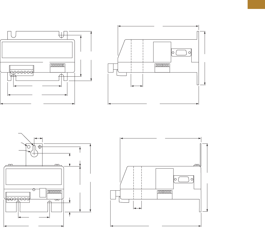
Volume 5—Motor Control and Protection CA08100006E—May 2016 www.eaton.com V5-T2-143
2
2
2
2
2
2
2
2
2
2
2
2
2
2
2
2
2
2
2
2
2
2
2
2
2
2
2
2
2
2
2.3
NEMA Contactors and Starters
A200 Series
Dimensions
Approximate Dimensions in Inches (mm)
Current Sensing Protective Relays
IQ504
IQ500L and IQ502
2.5
(63.5)
2.88
(73.2)
3.0
(76.2) 3.25
(82.6)
3.59
(91.2)
4.5
(114.3)
4.88
(124.0)
0.81
(20.6)
Dia.
5.47
(138.9)
0.53
(13.5)
1.88
(47.8)
2.75
(69.9)
0.78
(19.8)
1.19
(30.2)
4.13
(104.9)
4.13
(104.9)
3.59
(91.2)
4.88
(124.0)
0.5
(12.7)
0.44 (11.2)
Dia.
0.164-32 Tap
2 Holes
0.19 (4.8)
Dia.
0.5
(12.7)
Dia.
5.47
(138.9)

V5-T2-144 Volume 5—Motor Control and Protection CA08100006E—May 2016 www.eaton.com
2
2
2
2
2
2
2
2
2
2
2
2
2
2
2
2
2
2
2
2
2
2
2
2
2
2
2
2
2
2
2.4
NEMA Contactors and Starters
Solenoids—Alternating Current
Solenoids—Alternating Current
Contents
Description Page
Solenoids—Alternating Current
Product Selection . . . . . . . . . . . . . . . . . . . . . . . V5-T2-145
Dimensions. . . . . . . . . . . . . . . . . . . . . . . . . . . . V5-T2-146
Product Description
Solenoids from Eaton’s
Electrical Sector are used for
a wide variety of applications
where straight line motion is
to be obtained automatically
or at a remote point.
Features
●Plunger and frame are
machined to ensure
quiet operation
●Push- and pull-type
operation
●With and without
terminal box
●Plunger provided with
connecting pin
●Size C and D solenoids
are provided with special
bearing to minimize
wear in clevis under
severe service
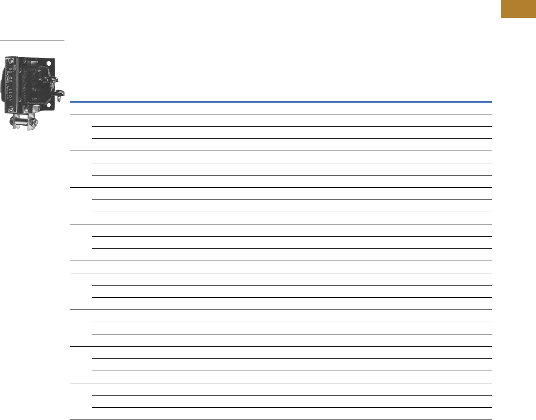
Volume 5—Motor Control and Protection CA08100006E—May 2016 www.eaton.com V5-T2-145
2
2
2
2
2
2
2
2
2
2
2
2
2
2
2
2
2
2
2
2
2
2
2
2
2
2
2
2
2
2
2.4
NEMA Contactors and Starters
Solenoids—Alternating Current
Product Selection
When Ordering Specify
●Catalog number
AC Solenoids—60 Hz, Continuous Duty
Notes
1 Mounting of solenoids “with conduit box”—Size A are for wall mounting—Size B, C and D are for floor mounting.
2 Recommended selection of solenoids on basis of 85% voltage values.
3 Part numbers are now obsolete.
Size Volt.
Operating Data 1
Without
Conduit Box
Floor Mtg.
Catalog
Number
Wall Mtg.
Catalog
Number
With
Conduit Box
Mtg. 2
Catalog
Number
Magnetic Force in Lbs
Max.
Stroke in
Inches (mm)
Current
Horizontal Position With Gravity Against Gravity
At 100%
Voltage
At 85%
Voltage
At 100%
Voltage
At 85%
Voltage
At 100%
Voltage
At 85%
Voltage Inrush Sealed
60 Hertz Pull Type
A 110 0.72 0.50 0.90 0.68 0.55 0.33 1 (25.4) 1.83 0.34 — 10370H1 10370H610
220 0.72 0.50 0.90 0.68 0.55 0.33 1 (25.4) 0.92 0.17 — 10370H2 10370H611
440 0.72 0.50 0.90 0.68 0.55 0.33 1 (25.4) 0.45 0.08 — 10370H3 10370H612
B 110 4.2 3 4.5 3.3 3.9 2.7 1 (25.4) 5.4 0.87 10370H57 10370H694 10370H69
220 4.2 3 4.5 3.3 3.9 2.7 1 (25.4) 2.6 0.42 10370H58 10370H696 10370H70
440 4.2 3 4.5 3.3 3.9 2.7 1 (25.4) 1.29 0.20 10370H59 10370H697 10370H71
C 110 7 5.25 8 6.25 6 4.25 1.25 (31.8) 10.4 1.07 10370H244 — 10370H256
220 7 5.25 8 6.25 6 4.25 1.25 (31.8) 5.2 0.52 10370H245 — 10370H257
440 7 5.25 8 6.25 6 4.25 1.25 (31.8) 2.5 0.26 10370H246 — 10370H258
D 110 12.4 10 13.65 11.25 11.15 8.75 1.25 (31.8) 18 1.58 10370H356 10370H814 10370H368
220 12.4 10 13.65 11.25 11.15 8.75 1.25 (31.8) 9.3 0.81 10370H357 10370H816 10370H369
440 12.4 10 13.65 11.25 11.15 8.75 1.25 (31.8) 4.4 0.40 10370H358 10370H817 10370H370
60 Hertz Push Type
A 110 0.72 0.50 0.90 0.68 0.55 0.33 1 (25.4) 1.83 0.34 — 10370H13 10370H25
220 0.72 0.50 0.90 0.68 0.55 0.33 1 (25.4) 0.92 0.17 — 10370H14 310370H26
440 0.72 0.50 0.90 0.68 0.55 0.33 1 (25.4) 0.45 0.08 — 10370H15 10370H27
B 110 4.2 3 4.5 3.3 3.9 2.7 1 (25.4) 5.4 0.87 10370H81 10370H708 10370H93
220 4.2 3 4.5 3.3 3.9 2.7 1 (25.4) 2.6 0.42 10370H82 10370H710 10370H94
440 4.2 3 4.5 3.3 3.9 2.7 1 (25.4) 1.29 0.20 10370H83 10370H711 10370H95
C 110 7 5.25 8 6.25 6 4.25 1.25 (31.8) 10.4 1.07 10370H268 — 10370H280
220 7 5.25 8 6.25 6 4.25 1.25 (31.8) 5.2 0.52 — 10370H774 10370H281
440 7 5.25 8 6.25 6 4.25 1.25 (31.8) 2.5 0.26 — 10370H775 10370H282
D 110 12.4 10 13.65 11.25 11.15 8.75 1.25 (31.8) 18 1.58 10370H380 10370H828 310370H392
220 12.4 10 13.65 11.25 11.15 8.75 1.25 (31.8) 9.3 0.81 10370H381 10370H830 310370H393
440 12.4 10 13.65 11.25 11.15 8.75 1.25 (31.8) 4.4 0.40 10370H382 10370H831 310370H394
10370
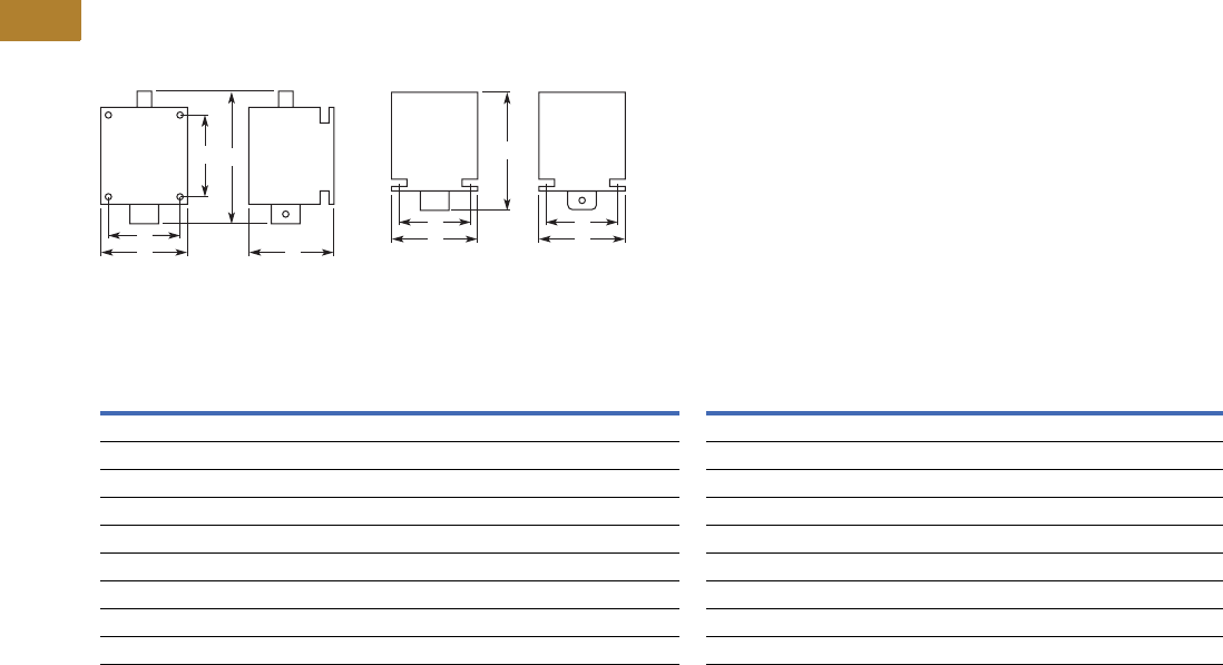
V5-T2-146 Volume 5—Motor Control and Protection CA08100006E—May 2016 www.eaton.com
2
2
2
2
2
2
2
2
2
2
2
2
2
2
2
2
2
2
2
2
2
2
2
2
2
2
2
2
2
2
2.4
NEMA Contactors and Starters
Solenoids—Alternating Current
Dimensions
Approximate Dimensions in Inches (mm)
AC Solenoids
Wall Mounted Floor Mounted
Dimensions and Shipping Weights
Note
1In sealed state.
D
A
B
C
E
D
A
E
C
B
Size
Push Type Mounting Shipping
Weight
Lbs (kg)
Pull Type Mounting Shipping
Weight
Lbs (kg)
Wide
A
High
B 1
Deep
CDE
Wide
A
High
B 1
Deep
CDE
Wall Mounted
A 2.38 (60.5) 3.63 (92.2) 2.25 (57.2) 1.13 (28.7) 1.63 (41.4) 2.0 (0.9) 2.38 (60.5) 2.63 (66.8) 2.25 (57.2) 1.13 (28.7) 1.63 (41.4) 2.0 (0.9)
B 2.63 (66.8) 4.88 (124.0) 3.00 (76.2) 2.00 (50.8) 2.13 (54.1) 2.5 (1.1) 2.63 (66.8) 3.63 (92.2) 3.00 (76.2) 2.00 (50.8) 2.13 (54.1) 2.5 (1.1)
C 3.00 (76.2) 6.13 (155.7) 4.13 (104.9) 2.38 (60.5) 3.13 (79.5) 5.0 (2.3) 3.00 (76.2) 4.88 (124.0) 4.13 (104.9) 2.38 (60.5) 3.13 (79.5) 5.0 (2.3)
D 4.00 (101.6) 6.13 (155.7) 4.13 (104.9) 2.75 (69.9) 3.13 (79.5) 7.0 (3.2) 4.00 (101.6) 4.88 (124.0) 4.13 (104.9) 2.75 (69.9) 3.13 (79.5) 7.0 (3.2)
Floor Mounted
B 3.13 (79.5) 4.88 (124.0) 3.00 (76.2) 1.50 (38.1) 2.25 (57.2) 2.5 (1.1) 3.13 (79.5) 3.88 (98.6) 3.00 (76.2) 1.50 (38.1) 2.25 (57.2) 2.5 (1.1)
C 3.50 (88.9) 6.13 (155.7) 3.75 (95.3) 1.75 (44.5) 3.13 (79.5) 5.0 (2.3) 3.50 (88.9) 4.88 (124.0) 3.75 (95.3) 1.75 (44.5) 3.13 (79.5) 5.0 (2.3)
D 3.88 (98.6) 6.13 (155.7) 3.75 (95.3) 2.25 (57.2) 3.13 (79.5) 7.0 (3.2) 3.88 (98.6) 4.88 (124.0) 3.75 (95.3) 2.25 (57.2) 3.13 (79.5) 7.0 (3.2)
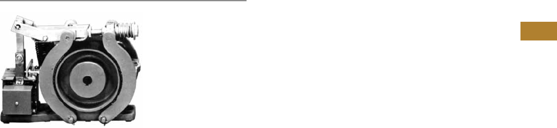
Volume 5—Motor Control and Protection CA08100006E—May 2016 www.eaton.com V5-T2-147
2
2
2
2
2
2
2
2
2
2
2
2
2
2
2
2
2
2
2
2
2
2
2
2
2
2
2
2
2
2
2.5
NEMA Contactors and Starters
Shoe Brakes—AC and DC Magnetic
Shoe Brakes—AC and DC, 511 Series
Contents
Description Page
Shoe Brakes—AC and DC Magnetic
Product Selection . . . . . . . . . . . . . . . . . . . . . . . V5-T2-148
Dimensions . . . . . . . . . . . . . . . . . . . . . . . . . . . V5-T2-150
Product Description
Type S Brakes from
Eaton’s Electrical Sector
are electrically released and
spring applied providing
“fail-safe” operation. The
retarding torque developed
is directly proportional to the
spring pressure.
Application Description
●Conveyors
●Machine tools
●Printing presses
●Small cranes
●Overhead doors
●Dumb waiters
●Vacuum molding machines
●Carnival rides
Features
The brake wheel is of
relatively large size in relation
to the torque developed by
the brake. This permits use of
a larger brake shoe lining and
lower shoe pressures. Low
shoe pressure, equally
distributed over a large lining
area, results in even wear of
the friction surfaces and even
braking torque. The oversize
wheel type construction also
permits use of a smaller
operating solenoid that
requires less current for a
given torque rating.
DC Brakes
Standard DC brakes are
equipped with shunt coils.
The magnet coil circuit on
DC brakes consists of two
separate windings and a
protective switch.
Mounting
Type S brakes are designed
and recommended for use
and mounting only in the
horizontal position. Side or
vertical mountings are not
recommended because the
solenoid loading is altered,
resulting in accelerated wear
and premature coil failure.
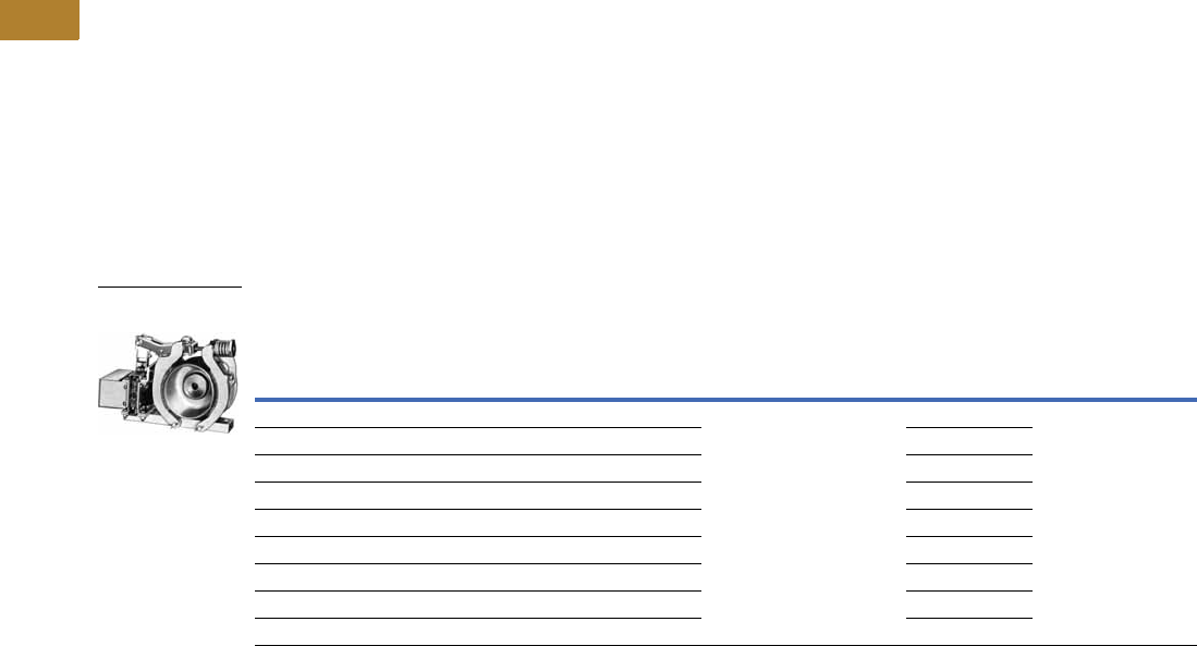
V5-T2-148 Volume 5—Motor Control and Protection CA08100006E—May 2016 www.eaton.com
2
2
2
2
2
2
2
2
2
2
2
2
2
2
2
2
2
2
2
2
2
2
2
2
2
2
2
2
2
2
2.5
NEMA Contactors and Starters
Shoe Brakes—AC and DC Magnetic
Product Selection
When Ordering Specify
●Brake
●Catalog number plus
suffix number for coil
●Example: 511H1193-41
●Wheel
●Catalog number plus
suffix number for
bore size
●Example: 511H1150-3
Type S Brakes—Floor Mounting
Notes
1 Intermittent duty indicates that the coil can be placed across the line continuously for one hour maximum without excessive heating. It is equivalent to 1/2 time ON
and 1/2 time OFF.
2 Add suffix number for coil voltage to base catalog number.
3 Does not include wheel.
Torque—lb-ft
Brake
Size
AC DC
Continuous Intermittent 1
Base
Catalog
Number 23
For Type S4, S5-1/2, S7, S10 Base
Catalog
Number 23
Coil
Voltage
Coil
Suffix 2
Coil Volts
and Hertz
Coil
Suffix 2
3 3 S-4 511H1194 120V 60 Hz
208V 60 Hz
240V 60 Hz
480V 60 Hz
600V 60 Hz
110V 50 Hz
220V 50 Hz
380V 50 Hz
440V 50 Hz
550V 50 Hz
-39
-45
-40
-41
-58
-5
-6
-7
-8
-9
511H955 120 Vdc
240 Vdc
-97
-98
10 10 S-4 511H1193 511H956
—15 S-4511H1192 511H957
25 25 S-5-1/2 511H992 511H994
— 35 S-5-1/2 511H993 511H995
50 50 S-7 511H970 511H975
—75 S-7511H971 511H976
85 85 S-7 511H1195 511H1197
— 110 S-7 511H1196 511H1198
Size S-4 Brake
and Wheel

Volume 5—Motor Control and Protection CA08100006E—May 2016 www.eaton.com V5-T2-149
2
2
2
2
2
2
2
2
2
2
2
2
2
2
2
2
2
2
2
2
2
2
2
2
2
2
2
2
2
2
2.5
NEMA Contactors and Starters
Shoe Brakes—AC and DC Magnetic
Brake Selection
The method most generally used to determine required
braking torque is to calculate the full load motor torque by
the following formula:
T = 5252 x hp
rpm
T = Full load motor torque in lb-ft
hp = Motor horsepower
rpm = Speed of shaft on which brake wheel is mounted
The torque rating of the brake selected should be at least equal
to the full load motor torque for the duty considered.
Brake Wheels
Brake Wheel Suffix Numbers
Notes
1Bore tolerance: +0.000–0.001 in.
2Taper is at rate of 1.25 in per ft on diameter. In bore size selection, use diameter of tapered shaft. Bore tolerance: +0.000–0.005 in.
3Add suffix number for bore size to base catalog number.
4Bore size selected must be between minimum and maximum dimensions listed in brake wheel selection table.
Wheel
Size in
Inches
Min.
Bore in
Inches (mm)
Max.
Bore in
Inches (mm)
Pilot
Bore in
Inches (mm) WK2
Straight
Bore 1
Tapered
Bore 2
Base 3
Catalog
Number
Base 3
Catalog
Number
4.0 0.50 (12.7) 1.38 (35.1) 0.50 (12.7) 0.06 511H1150 511H1151
5.5 0.75 (19.1) 2.00 (50.8) 0.75 (19.1) 0.26 511H1160 511H1161
7.0 1.00 (25.4) 2.25 (57.2) 0.75 (19.1) 0.77 511H1170 511H1171
Bore Size Suffix Number—Add to Base Catalog Number
Bore 4 in Inches (mm) Keyway in Inches Suffix Number Bore 4 in Inches (mm) Keyway in Inches (mm) Suffix Number
Standard Bore Sizes
Pilot bore None -1 1.625 (41.28) 3/38 x 3/16 -9
0.625 (15.88) 3/16 x 3/32 -2 1.875 (47.63) 1/2 x 1/4 -10
0.750 (19.05) 3/16 x 3/32 -3 2.125 (53.98) 1/2 x 1/4 -11
0.875 (22.23) 3/16 x 3/32 -4 —— —
1.000 (25.40) 1/4 x 1/8 -5 —— —
1.125 (28.58) 1/4 x 1/8 -6 —— —
1.250 (31.75) 1/4 x 1/8 -7 —— —
1.375 (34.93) 5/16 x 5/32 -8 —— —
Non-Standard Bore Sizes
0.500 (12.70) 1/8 x 1/16 -50 1.687 (42.85) 3/8 x 3/16 -58
0.750 (19.05) 1/4 x 1/8 -51 1.750 (44.45) 3/8 x 3/16 -59
0.875 (22.23) 1/4 x 1/8 -52 1.937 (49.20) 1/2 x 1/4 -60
1.000 (25.40) 5/16 x 5/32 -53 2.000 (50.80) 1/2 x 1/4 -61
1.187 (30.15) 1/4 x 1/8 -54 2.250 (57.15) 1/2 x 1/4 -62
1.375 (34.93) 3/8 x 3/16 -55 —— —
1.437 (36.50) 3/8 x 3/16 -56 —— —
1.500 (38.10) 3/8 x 3/16 -57 —— —
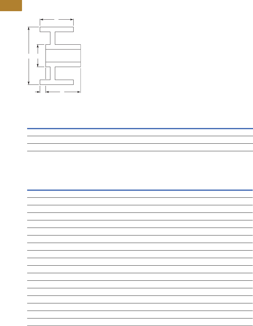
V5-T2-150 Volume 5—Motor Control and Protection CA08100006E—May 2016 www.eaton.com
2
2
2
2
2
2
2
2
2
2
2
2
2
2
2
2
2
2
2
2
2
2
2
2
2
2
2
2
2
2
2.5
NEMA Contactors and Starters
Shoe Brakes—AC and DC Magnetic
Dimensions
Approximate Dimensions in Inches (mm)
Standard Brake Wheels
Standard Brake Wheel Dimensions
Approximate Shipping Weights
Note
1Hub lengths other than standard are not available.
AZW
1XY
Bore
Max. Min.
4.00 (101.6) 2.75 (69.9) 1.63 (41.4) 1.38 (35.1) 2.50 (63.5) 1.38 (35.1) 0.50 (12.7)
5.50 (139.7) 3.25 (82.6) 2.00 (50.8) 1.63 (41.4) 3.25 (82.6) 2.00 (50.8) 0.75 (19.1)
7.00 (177.8) 4.25 (108.0) 3.00 (76.2) 1.25 (31.8) 4.00 (101.6) 2.25 (57.2) 1.00 (25.4)
Brake Size
Torque Rating
ft-lb
Weight in Lbs (kg)
Net —
Brake with Wheel
Net —
Wheel Only
Boxed —
Brake with Wheel
Type “S” AC Shoe Brakes
S-4 3 15.8 (7.2) 3.4 (1.5) 17.0 (7.7)
S-4 10 15.8 (7.2) 3.4 (1.5) 17.0 (7.7)
S-4 15 15.8 (7.2) 3.4 (1.5) 17.0 (7.7)
S-5-1/2 25 33.2 (15.1) 7.5 (3.4) 36.0 (16.3)
S-5-1/2 35 33.2 (15.1) 7.5 (3.4) 36.0 (16.3)
S-7 50 52.1 (23.7) 18.8 (8.5) 55.0 (25.0)
S-7 75 52.1 (23.7) 18.8 (8.5) 55.0 (25.0)
Type “S” DC Shoe Brakes
S-4 3 18.0 (8.2) 3.4 (1.5) 20.0 (9.1)
S-4 10 18.0 (8.2) 3.4 (1.5) 20.0 (9.1)
S-4 15 18.0 (8.2) 3.4 (1.5) 20.0 (9.1)
S-5-1/2 25 35.0 (15.9) 7.5 (3.4) 38.0 (17.3)
S-5-1/2 35 35.0 (15.9) 7.5 (3.4) 38.0 (17.3)
S-7 50 54.0 (24.5) 18.8 (8.5) 58.0 (26.3)
S-7 75 54.0 (24.5) 18.8 (8.5) 58.0 (26.3)
S-7 85 54.0 (24.5) 18.8 (8.5) 58.0 (26.3)
S-7 110 54.0 (24.5) 18.8 (8.5) 58.0 (26.3)
W
Z
X
AY
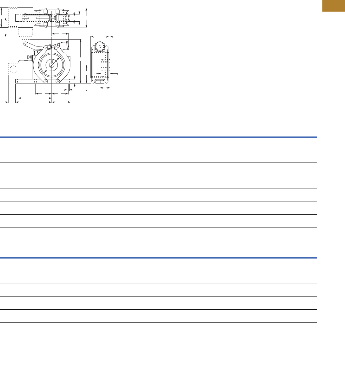
Volume 5—Motor Control and Protection CA08100006E—May 2016 www.eaton.com V5-T2-151
2
2
2
2
2
2
2
2
2
2
2
2
2
2
2
2
2
2
2
2
2
2
2
2
2
2
2
2
2
2
2.5
NEMA Contactors and Starters
Shoe Brakes—AC and DC Magnetic
Approximate Dimensions in Inches (mm)
Type S4, S5-1/2 and S7 Solenoid Operated
Type “S” AC Shoe Brakes
Type “S” DC Shoe Brakes
Note
1Open type brake only.
Brake
Size
Torque
Rating
ft-lb A B 1CDEFGHJKLMNOPQR
S-4 3 4.00
(101.6)
2.88
(73.2)
7.50
(190.5)
2.63
(66.8)
1.25
(31.8)
7.50
(190.5)
3.13
(79.5)
0.38
(9.7)
0.63
(16.0)
2.88
(73.2)
0.25
(6.4)
2.75
(69.9)
1.63
(41.4)
1.63
(41.4)
2.88
(73.2)
3.00
(76.2)
3.13
(79.5)
S-4 10 4.00
(101.6)
2.88
(73.2)
7.50
(190.5)
2.63
(66.8)
1.25
(31.8)
7.50
(190.5)
3.13
(79.5)
0.38
(9.7)
0.63
(16.0)
2.88
(73.2)
0.25
(6.4)
2.75
(69.9)
1.63
(41.4)
1.63
(41.4)
2.88
(73.2)
3.00
(76.2)
3.13
(79.5)
S-4 15 4.00
(101.6)
2.88
(73.2)
7.50
(190.5)
2.63
(66.8))
1.25
(31.8)
7.50
(190.5)
3.13
(79.5)
0.38
(9.7)
0.63
(16.0)
2.88
(73.2)
0.25
(6.4)
2.75
(69.9)
1.63
(41.4)
1.63
(41.4)
2.88
(73.2)
3.00
(76.2)
3.13
(79.5))
S-5-1/2 25 5.50
(139.7)
4.00
(101.6)
9.50
(241.3)
3.50
(88.9)
2.00
(50.8)
8.38
(212.9)
4.13
(104.9)
0.44
(11.2)
1.00
(25.4)
4.88
(124.0)
0.38
(9.7)
3.25
(82.6)
2.00
(50.8)
2.00
(50.8)
3.13
(79.5)
3.75
(95.3)
3.13
(79.5)
S-5-1/2 35 5.50
(139.7)
4.00
(101.6)
9.50
(241.3)
3.50
(88.9)
2.00
(50.8)
8.38
(212.9)
4.13
(104.9)
0.44
(11.2)
1.00
(25.4)
7.88
(200.2)
0.38
(9.7)
3.25
(82.6)
2.00
(50.8)
2.00
(50.8)
3.13
(79.5)
3.75
(95.3)
3.13
(79.5)
S-7 50 7.00
(177.8)
5.00
(127.0)
11.50
(292.1)
4.38
(111.3)
2.50
(63.5)
9.50
(241.3)
5.00
(127.0)
0.56
(14.2)
1.00
(25.4)
6.00
(152.4)
—4.25
(108.0)
2.13
(54.1)
3.00
(76.2)
3.13
(79.5)
4.75
(120.7)
3.13
(79.5)
S-7 75 7.00
(177.8)
5.00
(127.0)
11.50
(292.1)
4.38
(111.3)
2.50
(63.5)
9.50
(241.3)
5.00
(127.0)
0.56
(14.2)
1.00
(25.4)
6.00
(152.4)
—4.25
(108.0)
2.13
(54.1)
3.00
(76.2)
3.13
(79.5)
4.75
(120.7)
3.13
(79.5)
Brake
Size
Torque
Rating
ft-lb A B 1CDEFGHJKLMNOPQR
S-4 3 4.00
(101.6)
3.50
(88.9)
8.00
(203.2)
2.63
(66.8)
1.25
(31.8)
7.56
(192.0)
3.25
(82.6)
0.38
(9.7)
0.75
(19.1)
2.88
(73.2)
0.25
(6.4)
2.75
(69.9)
1.63
(41.4)
1.63
(41.4)
2.63
(66.8)
3.00
(76.2))
4.06
(103.1)
S-4 10 4.00
(101.6)
3.50
(88.9)
8.00
(203.2)
2.63
(66.8)
1.25
(31.8)
7.56
(192.0)
3.25
(82.6)
0.38
(9.7)
0.75
(19.1)
2.88
(73.2)
0.25
(6.4)
2.75
(69.9)
1.63
(41.4)
1.63
(41.4)
2.63
(66.8)
3.00
(76.2)
4.06
(103.1))
S-4 15 4.00
(101.6)
3.50
(88.9)
8.00
(203.2)
2.63
(66.8)
1.25
(31.8)
7.56
(192.0)
3.25
(82.6))
0.38
(9.7)
0.75
(19.1)
2.88
(73.2)
.25
(6.4)
2.75
(69.9)
1.63
(41.4)
1.63
(41.4)
2.63
(66.8)
3.00
(76.2)
4.06
(103.1)
S-5-1/2 25 5.50
(139.7)
4.00
(101.6)
9.50
(241.3)
3.50
(88.9)
2.00
(50.8)
8.38
(212.9)
4.13
(104.9)
0.44
(11.2)
0.75
(19.1)
4.88
(124.0)
0.38
(9.7)
3.25
(82.6)
2.00
(50.8)
2.00
(50.8)
2.88
(73.2)
3.75
(95.3)
4.06
(103.1)
S-5-1/2 35 5.50
(139.7)
4.00
(101.6)
9.50
(241.3)
3.50
(88.9)
2.00
(50.8)
8.38
(212.9)
4.13
(104.9)
0.44
(11.2)
0.75
(19.1)
4.88
(124.0)
0.38
(9.7)
3.25
(82.6)
2.00
(50.8)
2.00
(50.8)
2.88
(73.2)
3.75
(95.3)
4.06
(103.1)
S-7 50 7.00
(177.8)
5.00
(127.0)
11.50
(292.1)
4.38
(111.3)
2.50
(63.5)
9.50
(241.3)
5.00
(127.0)
0.56
(14.2)
0.75
(19.1)
6.00
(152.4)
—4.25
(108.0)
2.13
(54.1)
3.00
(76.2)
2.88
(73.2)
4.88
(124.0)
4.06
(103.1)
S-7 75 7.00
(177.8)
5.00
(127.0)
11.50
(292.1)
4.38
(111.3)
2.50
(63.5)
9.50
(241.3)
5.00
(127.0)
0.56
(14.2)
0.75
(19.1)
6.00
(152.4)
—4.25
(108.0)
2.13
(54.1)
3.00
(76.2)
2.88
(73.2)
4.88
(124.0)
4.06
(103.1)
S-7 85 7.00
(177.8)
5.00
(127.0)
11.50
(292.1)
4.38
(111.3)
2.50
(63.5)
9.50
(241.3)
5.00
(127.0)
0.56
(14.2)
0.75
(19.1)
6.00
(152.4)
—4.25
(108.0)
2.13
(54.1)
3.00
(76.2)
2.88
(73.2)
4.88
(124.0)
4.06
(103.1)
S-7 110 7.00
(177.8)
5.00
(127.0)
11.50
(292.1)
4.38
(111.3)
2.50
(63.5)
9.50
(241.3)
5.00
(127.0)
0.56
(14.2)
0.75
(19.1)
6.00
(152.4)
—4.25
(108.0)
2.13
(54.1)
3.00
(76.2)
2.88
(73.2)
4.88
(124.0)
4.06
(103.1)
F
T
D D
K
N
ML
(2) “H” Dia. Holes
for Mounting
Hub
Length
C
BO
Q
R
P
J
EU
GS
A

V5-T2-152 Volume 5—Motor Control and Protection CA08100006E—May 2016 www.eaton.com
2
2
2
2
2
2
2
2
2
2
2
2
2
2
2
2
2
2
2
2
2
2
2
2
2
2
2
2
2
2
2.6
NEMA Contactors and Starters
Reference Data
Reference Data
IEC Utilization Categories
(See also IEC/EN 60947-1;
2.1.18/IEV 441-17-19)
A combination of specified
requirements relating to the
condition in which the
switching device or fuse
fulfills its purpose and
selected to represent a
characteristic group of real-
life applications. The
specified requirements may,
for example, relate to the
values of making and
breaking capacity and other
characteristic values, data
concerning associated
circuits and the applicable
conditions of use and
operational behavior.
Used in Technical Data and Formulas
Code Descriptions Code Descriptions
DF Duty factory Irmv Response value of short-time delayed short-circuit release
IDn Response value of earth-fault release Isd Response value of short-time delayed short-circuit release
Icm Rated short-circuit making capacity ITResponse value of earth-fault release
Icn Rated short-circuit breaking capacity IgResponse value of earth-fault release
Ics Rated service short-circuit breaking capacity Ith Conventional free air thermal current
Icu Rated ultimate short-circuit breaking capacity Ithe Conventional thermal current of enclosed devices
Icw Rated short-time withstand current IuRated uninterrupted current
IeRated operational current SNT Transformer rating
IkTransformer initial short-circuit AC current trTime delay of overload release response
ILLoad monitoring response value tTTime delay of earth-fault release response
InRated current tgTime delay of earth-fault release response
INT Transformer rated current tvTime delay of short-circuit release response
IPK Rated peak withstand current UcRated actuating voltage
IqRated conditional short-circuit current UeRated operational voltage
IrOvercurrent release set value UiRated insulation voltage
Irm Response value of non-delayed short-circuit release Uimp Rated impulse withstand voltage
IiResponse value of non-delayed short-circuit release UkTransformer short-circuit voltage
Irmf Response value of fixed, non-delayed short-circuit release UsRated control voltage

Volume 5—Motor Control and Protection CA08100006E—May 2016 www.eaton.com V5-T2-153
2
2
2
2
2
2
2
2
2
2
2
2
2
2
2
2
2
2
2
2
2
2
2
2
2
2
2
2
2
2
2.6
NEMA Contactors and Starters
Reference Data
Annex A (informative)
Examples of Utilization Categories for Low-Voltage Switchgear and Controlgear 1
Notes
160947-1 © IEC: 2004.
2Plugging is understood to be stopping or reversing the motor rapidly by reversing motor primary connections while the motor is running.
3Inching is understood to be energizing a motor once or repeatedly for short periods to obtain small movements of the driven mechanism.
Category Typical Applications Relevant IEC Product Standard
Nature of Current—AC
AC-1 Non-inductive or slightly inductive loads, resistance furnaces 60947-4-1
AC-2 Slip-ring motors: starting, switching off 60947-4-1
AC-3 Squirrel-cage motors: starting, switching off motors during running 60947-4-1
AC-4 Squirrel-cage motors: starting, plugging 2, inching 360947-4-1
AC-5a Switching of electric discharge lamp controls 60947-4-1
AC-5b Switching of incandescent lamps 60947-4-1
AC-6a Switching of transformers 60947-4-1
AC-6b Switching of capacitor banks 60947-4-1
AC-7a Slightly inductive loads for household appliances and similar applications 61095
AC-7b Motor-loads for household applications 61095
AC-8a Hermetic refrigerant compressor motor control with manual resetting of overload releases 60947-4-1
AC-8b Hermetic refrigerant compressor motor control with automatic resetting of overload releases 60947-4-1
AC-12 Control of resistive loads and solid-state loads with isolation by optocouplers 60947-5-1
AC-12 Control of resistive loads and solid-state loads with optical isolation 60947-5-2
AC-13 Control of solid-state loads with transformer isolation 60947-5-1
AC-14 Control of small electromagnetic loads 60947-5-1
AC-15 Control of AC electromagnetic loads 60947-5-1
AC-20 Connecting and disconnecting under no-load conditions 60947-3
AC-21 Switching of resistive loads, including moderate overloads 60947-3
AC-22 Switching of mixed resistive and inductive loads, including moderate overloads 60947-3
AC-23 Switching of motor loads or other highly inductive loads 60947-3
AC-31 Non inductive or slightly inductive loads 60947-6-1
AC-33 Motor loads or mixed loads including motors, resistive loads and up to 30% incandescent lamp loads 60947-6-1
AC-35 Electric discharge lamp loads 60947-6-1
AC-36 Incandescent lamp loads 60947-6-1
AC-40 Distribution circuits comprising mixed resistive and reactive loads having a resultant inductive reactance 60947-6-2
AC-41 Non-inductive or slightly inductive loads, resistance furnaces 60947-6-2
AC-42 Slip-ring motors: starting, switching off 60947-6-2
AC-43 Squirrel cage motors: starting, switching off motors during running 60947-6-2
AC-44 Squirrel cage motors: starting, plugging 2, inching 360947-6-2
AC-45a Switching of electric discharge lamp controls 60947-6-2
AC-45b Switching of incandescent lamps 60947-6-2
AC-51 Non-inductive or slightly inductive loads, resistance furnaces 60947-4-3
AC-52a Control of slip ring motor stators: 8 h duty with on-load currents for start, acceleration, run 60947-4-2
AC-52b Control of slip ring motor stators: intermittent duty 60947-4-2
AC-53a Control of squirrel cage motors: 8 h duty with on-load currents for start, acceleration, run 60947-4-2
AC-53b Control of squirrel cage motors: intermittent duty 60947-4-2

V5-T2-154 Volume 5—Motor Control and Protection CA08100006E—May 2016 www.eaton.com
2
2
2
2
2
2
2
2
2
2
2
2
2
2
2
2
2
2
2
2
2
2
2
2
2
2
2
2
2
2
2.6
NEMA Contactors and Starters
Reference Data
Examples of Utilization Categories for Low-Voltage Switchgear and Controlgear, continued 1
Notes
160947-1 © IEC: 2004.
2Plugging is understood to be stopping or reversing the motor rapidly by reversing motor primary connections while the motor is running.
3Inching is understood to be energizing a motor once or repeatedly for short periods to obtain small movements of the driven mechanism.
Category Typical Applications Relevant IEC Product Standard
Nature of Current—AC, continued
AC-55a Switching of electric discharge lamp controls 60947-4-3
AC-55b Switching of incandescent lamps 60947-4-3
AC-56a Switching of transformers 60947-4-3
AC-56b Switching of capacitor banks 60947-4-3
AC-58a Control of hermetic refrigerant compressor motors with automatic resetting of overload releases: 8 h duty
with on-load currents for start, acceleration, run
60947-4-2
AC-58b Control of hermetic refrigerant compressor motors with automatic resetting of overload releases: intermittent duty 60947-4-2
AC-140 Control of small electromagnetic loads with holding (closed) current <0,2 A, for example contactor relays 60947-5-2
Nature of Current—AC and DC
A Protection of circuits, with no rated short-time withstand current 60947-2
B Protection of circuits, with a rated short-time withstand current 60947-2
Nature of Current—DC
DC-1 Non-inductive or slightly inductive loads, resistance furnaces 60947-4-1
DC-3 Shunt-motors: starting, plugging 2, inching 3, dynamic breaking of motors 60947-4-1
DC-5 Series-motors: starting, plugging 2, inching 3, dynamic breaking of motors 60947-4-1
DC-6 Switching of incandescent lamps 60947-4-1
DC-12 Control of resistive loads and solid-state loads with isolation by optocouplers 60947-5-1
DC-12 Control of resistive loads and solid-state loads with optical isolation 60947-5-2
DC-13 Control of electromagnets 60947-5-1
DC-13 Control of electromagnets 60947-5-2
DC-14 Control of electromagnetic loads having economy resistors in circuit 60947-5-1
DC-20 Connecting and disconnecting under no-load conditions 60947-3
DC-21 Switching of resistive loads, including moderate overloads 60947-3
DC-22 Switching of mixed resistive and inductive loads, including moderate overloads (for example shunt motors) 60947-3
DC-23 Switching of motor loads or other highly inductive loads (for example series motors) 60947-3
DC-31 Resistive loads 60947-6-1
DC-33 Motor loads or mixed loads including motors 60947-6-1
DC-36 Incandescent lamp loads 60947-6-1
DC-40 Distribution circuits comprising mixed resistive and reactive loads having a resultant inductive reactance 60947-6-2
DC-41 Non-inductive or slightly inductive loads, resistance furnaces 60947-6-2
DC-43 Shunt-motors: starting, plugging 2, inching 3, dynamic breaking of DC 60947-6-2
DC-45 Series-motors: starting, plugging 2, inching 3, dynamic breaking of DC 60947-6-2
DC-46 Switching of incandescent lamps 60947-6-2

Volume 5—Motor Control and Protection CA08100006E—May 2016 www.eaton.com V5-T2-155
2
2
2
2
2
2
2
2
2
2
2
2
2
2
2
2
2
2
2
2
2
2
2
2
2
2
2
2
2
2
2.6
NEMA Contactors and Starters
Reference Data
Motor Ratings Data
Ampere Rating of AC and DC Motors
Ampere ratings of motors
vary somewhat, depending
upon the type of motor. The
values given below are for
drip-proof, Class B insulated
(T Frame) where available,
1.15 service factor, NEMA
Design B motors. These
values represent an average
full load motor current which
was calculated from the
motor performance data
published by several motor
manufacturers. In the case
of high torque squirrel cage
motors, the ampere ratings
will be at least 10% greater
than the values given in the
following table.
Caution—These average
ratings could be high or low
for a specific motor
and therefore heater coil
selection on this basis
always involves risk.
For fully reliable motor
protection, select heater
coils on the basis of full
load current rating as
shown on the motor
nameplate.
Ampere Ratings of Three-Phase, 60 Hz, AC Induction Motor
Note
1380V 50 Hz.
hp
Syn. Speed
RPM
Current in Amperes
200V 230V 380V 1460V 575V 2200V
1/4 1800 1.09 .95 0.55 0.48 0.38 —
1200 1.61 1.40 0.81 0.70 0.56 —
900 1.841.600.930.800.64—
1/31800 1.371.190.690.600.48—
1200 1.83 1.59 0.92 0.80 0.64 —
900 2.071.801.040.900.72—
1/21800 1.981.720.990.860.69—
1200 2.47 2.15 1.24 1.08 0.86 —
900 2.742.381.381.190.95—
3/41800 2.832.461.421.230.98—
1200 3.36 2.92 1.69 1.46 1.17 —
900 3.753.261.881.631.30—
1 3600 3.222.801.701.401.12—
1800 4.09 3.56 2.06 1.78 1.42 —
1200 4.32 3.76 2.28 1.88 1.50 —
900 4.954.302.602.151.72—
1-1/23600 5.014.362.642.181.74—
1800 5.59 4.86 2.94 2.43 1.94 —
1200 6.07 5.28 3.20 2.64 2.11 —
900 6.445.603.392.802.24—
2 3600 6.445.603.392.802.24—
1800 7.36 6.40 3.87 3.20 2.56 —
1200 7.87 6.84 4.14 3.42 2.74 —
900 9.097.904.773.953.16—
3 3600 9.598.345.024.173.34—
1800 10.8 9.40 5.70 4.70 3.76 —
1200 11.7 10.2 6.20 5.12 4.10 —
900 13.111.46.905.704.55—
5 3600 15.513.58.206.765.41—
1800 16.6 14.4 8.74 7.21 5.78 —
1200 18.2 15.8 9.59 7.91 6.32 —
900 18.315.99.607.926.33—
7-1/2 3600 22.4 19.5 11.8 9.79 7.81 —
1800 24.7 21.5 13.0 10.7 8.55 —
1200 25.1 21.8 13.2 10.9 8.70 —
900 26.5 23.0 13.9 11.5 9.19 —
10 3600 29.2 25.4 15.4 12.7 10.1 —
1800 30.8 26.8 16.3 13.4 10.7 —
1200 32.2 28.0 16.9 14.0 11.2 —
900 35.1 30.5 18.5 15.2 12.2 —
15 3600 41.9 36.4 22.0 18.2 14.5 —
1800 45.1 39.2 23.7 19.6 15.7 —
1200 47.6 41.4 25.0 20.7 16.5 —
900 51.2 44.5 26.9 22.2 17.8 —
20 3600 58.0 50.4 30.5 25.2 20.1 —
1800 58.9 51.2 31.0 25.6 20.5 —
1200 60.7 52.8 31.9 26.4 21.1 —
900 63.1 54.9 33.2 27.4 21.9 —

V5-T2-156 Volume 5—Motor Control and Protection CA08100006E—May 2016 www.eaton.com
2
2
2
2
2
2
2
2
2
2
2
2
2
2
2
2
2
2
2
2
2
2
2
2
2
2
2
2
2
2
2.6
NEMA Contactors and Starters
Reference Data
Ampere Ratings of Three-Phase, 60 Hz, AC Induction Motor,
continued
hp
Syn. Speed
RPM
Current in Amperes
200V 230V 380V 1460V 575V 2200V
25 3600 69.9 60.8 36.8 30.4 24.3 —
1800 74.5 64.8 39.2 32.4 25.9 —
1200 75.4 65.6 39.6 32.8 26.2 —
900 77.4 67.3 40.7 33.7 27.0 —
30 3600 84.8 73.7 44.4 36.8 29.4 —
1800 86.9 75.6 45.7 37.8 30.2 —
1200 90.6 78.8 47.6 39.4 31.5 —
900 94.1 81.8 49.5 40.9 32.7 —
40 3600 111 96.4 58.2 48.2 38.5 —
1800 116 101 61.0 50.4 40.3 —
1200 117 102 61.2 50.6 40.4 —
900 121 105 63.2 52.2 41.7 —
50 3600 138 120 72.9 60.1 48.2 —
1800 143 124 75.2 62.2 49.7 —
1200 145 126 76.2 63.0 50.4 —
900 150 130 78.5 65.0 52.0 —
60 3600 164 143 86.8 71.7 57.3 —
1800 171 140 90.0 74.5 59.4 —
1200 173 150 91.0 75.0 60.0 —
900 177 154 93.1 77.0 61.5 —
75 3600 206 179 108 89.6 71.7 —
1800 210 183 111 91.6 73.2 —
1200 212 184 112 92.0 73.5 —
900 222 193 117 96.5 77.5 —
100 3600 266 231 140 115 92.2 —
1800 271 236 144 118 94.8 23.6
1200 275 239 145 120 95.6 24.2
900 290 252 153 126 101 24.8
125 3600 — 292 176 146 116 —
1800 — 293 177 147 117 29.2
1200 — 298 180 149 119 29.9
900 — 305 186 153 122 30.9
150 3600 — 343 208 171 137 —
1800 — 348 210 174 139 34.8
1200 — 350 210 174 139 35.5
900 — 365 211 183 146 37.0
200 3600 — 452 257 226 181 —
1800 — 458 265 229 184 46.7
1200 — 460 266 230 184 47.0
900 — 482 279 241 193 49.4
250 3600 — 559 338 279 223 —
1800 — 568 343 284 227 57.5
1200 — 573 345 287 229 58.5
900 — 600 347 300 240 60.5
300 1800 — 678 392 339 271 69.0
1200 — 684 395 342 274 70.0
400 1800 — 896 518 448 358 91.8
500 1800 — 1110 642 555 444 116
Single-Phase AC Motors
The following values of full-
load currents are for motors
running at usual speeds and
motors with normal torque
characteristics. Motors built
for especially low speeds or
high torques may have higher
full-load currents and
multispeed motors will have
full-load current varying with
speed, in which case the
nameplate current ratings
shall be used.
The voltages listed are rated
motor voltages. The currents
listed shall be permitted for
system voltage ranges of 110
to 120 and 220 to 240V.
Table 430.248. Full-Load
Currents in Amperes,
Single-Phase Alternating-
Current Motors
Note
1380V 50 Hz.
hp 115V 200V 208V 230V
1/6 4.4 2.5 2.4 2.2
1/4 5.8 3.3 3.2 2.9
1/3 7.2 4.1 4.0 3.6
1/2 9.8 5.6 5.4 4.9
3/4 13.8 7.9 7.6 6.9
1169.28.88
1-1/2 20 11.5 11 10
2 24 13.8 13.2 12
3 34 19.6 18.7 17
5 56 32.2 30.8 28
7-1/2 80 46 44 40
10 100 57.5 55 50

Volume 5—Motor Control and Protection CA08100006E—May 2016 www.eaton.com V5-T2-157
2
2
2
2
2
2
2
2
2
2
2
2
2
2
2
2
2
2
2
2
2
2
2
2
2
2
2
2
2
2
2.6
NEMA Contactors and Starters
Reference Data
DC Motors
The following values of full-
load currents are for motors
running at base speed.
These are average direct-
current quantities.
Table 430.247. Full-Load Current in Amperes,
Direct-Current Motors
hp
Armature Voltage Rating 1
Ampere Capacity of Fuses for Motors
Recommended Values
120V 240V 120V 240V
1/4 3.1 1.6 5 3
1/3 4.1 2.0 5 3
1/2 5.4 2.7 7 3
3/4 7.6 3.8 10 5
19.5 4.7 15 7
1-1/2 13.2 6.6 20 10
217 8.5 25 12
3 25 12.2 30 15
540 20 50 25
7-1/2 58 29 80 40
10 76 38 100 50
15 — 55 — 75
20 — 72 — 100
25 — 89 — 125
30 — 106 — 150
40 — 140 — 200
50 — 173 — 250
60 — 206 — 275
75 — 255 — 350
100 — 341 — 500
125 — 425 — 600
150 — 506 — —
200 — 675 — —
Three-Phase AC Motors
The following values of full-
load currents are typical for
motors running at speeds
usual for belted motors and
motors with normal torque
characteristics.
Motors built for low speeds
(1,200 RPM or less) or high
torques may require more
running current and
multispeed motors will have
full-load current varying with
speed. In these cases the
nameplate current rating shall
be used.
The voltages listed are rated
motor voltages. The currents
listed shall be permitted for
system voltage ranges of 110
to 120, 220 to 240, 440 to
480 and 550 to 600V.
Table 430.250. Full-Load Current Three-Phase
Alternating-Current Motors
Notes
1These are average direct-current quantities.
2For 90 and 80 percent power factor, the above figures shall be multiplied by 1.1 and
1.25 respectively.
hp
Induction Type Squirrel Cage and
Wound-Rotor Amperes
Synchronous Type Unity
Power Factor 2 Amperes
115V 200V 208V 230V 460V 575V 2300V 230V 460V 575V 2300V
1/24.42.52.42.21.10.9—————
3/46.43.73.53.21.61.3—————
1 8.44.84.64.22.11.7—————
1-1/212.06.96.66.03.02.4—————
2 13.67.87.56.83.42.7—————
3 —11.010.69.64.83.9—————
5 —17.516.715.27.66.1—————
7-1/2—25.324.222119 —————
10—32.230.8281411—————
15—48.346.2422117—————
20—62.159.4542722—————
25 — 78.2 74.8 68 34 27 — 53 26 21 —
30 —9288804032— 63 32 26 —
40 — 120 114 104 52 41 — 83 41 33 —
50 — 150 143 130 65 52 — 104 52 42 —
60 — 177 169 154 77 62 16 123 61 49 12
75 — 221 211 192 96 77 20 155 78 62 15
100 — 285 273 248 124 99 26 202 101 81 20
125 — 359 343 312 156 125 31 253 126 101 25
150 — 414 396 360 180 144 37 302 151 121 30
200 — 552 528 480 240 192 49 400 201 161 40
250————30224260 ————
300————36128972 ————
350————41433683 ————
400————47738295 ————
450————515412103————
500————590472118————
