Installation Directions
122513-Installationsheet 122513-InstallationSheet 122513-InstallationSheet 810048 Batch10 unilog cesco-content
123428-Installatiounsheet 123428-InstallatiounSheet 123428-InstallatiounSheet Batch9 unilog cesco-content
2016-10-06
: Pdf 1000377533-Installationsheet 1000377533-InstallationSheet B5 unilog
Open the PDF directly: View PDF ![]() .
.
Page Count: 2
INSTALLATION INSTRUCTIONS
CR Series Light Engine
1’x4’, 1’x2’ LED Luminaires
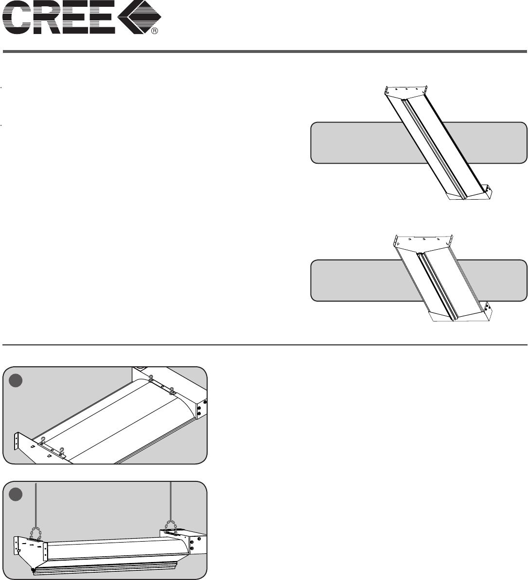
STEP 1:
Unpack the CR light engine from its shipping container.
STEP 2:
Install (4) S-Hooks (not included) into the hanging tabs.
STEP 3:
Tie jack chains (not included) with the S-hooks on each end of the light
engine and secure the jack chains with pendants/hanging chains.
STEP 4:
Adjust the jack chains location to evenly balance fixture.
NOTE: All additional objects need to be place in the center of CR-LE
TO INSTALL:
IMPORTANT SAFETY INFORMATION
Read all instructions before installation
(1) Before installing this fixture or doing any maintenance, make sure to turn
o the power supply at the circuit breaker or fuse box. (2) Do not handle
energized module with wet hands or when standing on wet or damp surfaces,
or in water.
WARNING - Risk of Electric Shock. Suitable for damp locations. Suitable for
suspended ceilings.
The CR Series Light Engines are for applications using S-Hook
suspended mounting and SMK-LE-L or SMK-LE-S surface
mount accessory kits (not included).
Designed for use in 120-277V 50-60 Hertz protected circuit
(fuse box, circuit breaker). Supply wire sized as per NEC or
governing code(s), 90C rated.
2
3
CR-LE (1x2)
CR-LE (1x4)
LPN000114_A
Designed and Produced in USA
CreeLEDLighting.com
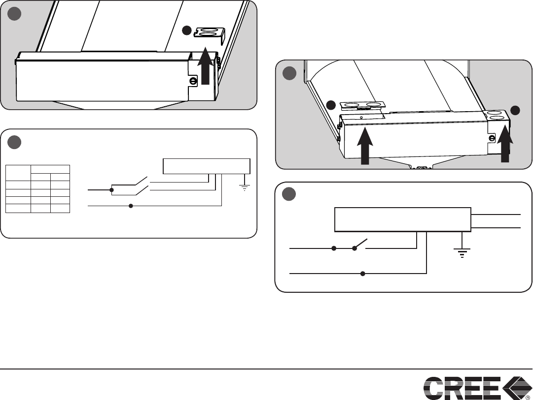
STEP DIMMING OPTION:
STEP 4:
Remove access plate from junction box (A). Using screw driver
blade, remove appropriate knockout from access plate door to
route input conduit.
STEP 5:
Connect input conduit to access plate. Connect wires as shown in
wiring diagram (below). Push all wires back into the junction box.
Re-install access plate.
GREEN – Ground
WHITE – Neutral
BLACK – Switched HOT #1 (S1)
BLACK – Switched HOT #2 (S2)
Power
Output
Position
S1
On
On
O
O
S2
On
O
On
O
100%
50%
50%
0%
DRIVER ASSEMBLY
BLACK
BLACK
WHITE
NEUTRAL
S1
LINE S2
5
4
4
6
LINE
VIOLET
GREY
DRIVER ASSEMBLY
BLACK
WHITE
NEUTRAL
NOTE: (1) DO NOT CONNECT two separate phases of the
line voltage to the input of the CR-LE, the LED driver will be
damaged and not covered by warranty.
(2) Install in accordance with National & Local Electric Code(s).
(3) The AC line inputs must be connected to the same phase of
the line voltage.
(4) If step dimming isn’t required, combine BLACK– Switched
HOT #1 (S1) and BLACK– Switched HOT #2 (S2) together.
0-10V DIMMING OPTION:
STEP 4:
Remove access plate (B) to access the power wiring. Using screw
driver blade, remove appropriate knockout from access plate (C) to
route input conduit.
STEP 5:
Remove access plate (C) to access the dimming wire.
Step 6:
Connect power conduit and dimming conduit to access plates
(and expanded J-Box if needed). Connect wires as shown in
wiring diagram. Push all wires back into the boxes and reinstall
the access plates.
GREEN – Ground
WHITE – Neutral
BLACK – Switched HOT
VIOLET – 0-10V Dimming Control +
GREY – 0-10V Dimming Control -
The limited warranty set forth below is given by the Cree company listed below (“Seller”) with respect to the lighting product packaged with this limited warranty (the “Product”). Your Product, when delivered
to you in new condition in its original packaging, is warranted against defects in materials or workmanship as follows: for a period of FIVE (5) YEARS from the date of original purchase, defective parts or a
defective Product returned with the sales receipt as proof of purchase to Seller, or its authorized service providers, as applicable, and proven to be defective upon inspection, will be repaired, or exchanged for
a new Product, as determined by Seller, or the authorized service provider. This limited warranty covers all defects encountered in normal use of the Product, and does not apply in the following cases: Loss
of or damage to the Product due to acts of God; re; vandalism; civil disturbances; power surges; improper power supply; electrical current uctuations; corrosive environment installations; induced vibration;
harmonic oscillation or resonance associated with movement of air currents around the product; abuse; alteration; accident, abuse; mishandling; alteration; accident; electrical current uctuations; failure to
follow operating, maintenance or environmental instructions prescribed by Seller in writing or services performed by someone other than Seller or its authorized service provider. WARRANTY IS VOID IF
PRODUCT IS NOT USED FOR THE PURPOSE FOR WHICH THIS PRODUCT IS MANUFACTURED. Any complaints you may have regarding the Product should be addressed to Ruud Lighting, Inc., 9201
Washington Avenue, Racine, WI 53406. Seller shall have no liability under this warranty unless Seller is notied in writing within sixty (60) days after your discovery of the defect and the defective items are
promptly returned to Seller, freight prepaid, and received by Seller. This warranty excludes eld labor and service charges related to the repair or replacement of the product. NO IMPLIED WARRANTY,
INCLUDING ANY IMPLIED WARRANTY OF MERCHANTABILITY OR FITNESS FOR A PARTICULAR PURPOSE, APPLIES TO THE PRODUCT AFTER THE APPLICABLE PERIOD OF THE EXPRESS
LIMITED WARRANTY STATED ABOVE, AND NO OTHER EXPRESS WARRANTY OR GUARANTY GIVEN BY ANY PERSON OR ENTITY WITH RESPECT TO THE PRODUCT SHALL BIND SELLER.
(SOME STATES AND PROVINCES DO NOT ALLOW LIMITATIONS ON HOW LONG AN IMPLIED WARRANTY LASTS, SO THE ABOVE LIMITATION MAY NOT APPLY TO YOU.)
CREE® TRUEWHITE® TECHNOLOGY FIXTURE LIMITED CONSUMER WARRANTY
A
B
C
