Product Range Catalog CA04020001Z EN INT 1000379728 1
164944-Catalog 1 164944-Catalog_1 164944-Catalog_1 B5 unilog cesco-content
2016-10-06
: Pdf 1000379728-Catalog 1 1000379728-Catalog_1 B5 unilog
Open the PDF directly: View PDF ![]() .
.
Page Count: 123 [warning: Documents this large are best viewed by clicking the View PDF Link!]
- Title
- Contents
- PowerXL™ DC1, DA1 variable frequency drives
- Soft starters DS7
- Rapid Link 4.0
- SmartWire-DT
- Appendix
Changes to the products, to the information contained in this document, and to prices
are reserved; so are errors and omissions. Only order confirmations and technical documenta-
tion by Eaton is binding. Photos and pictures also do not warrant a specific layout or function-
ality. Their use in whatever form is subject to prior approval by Eaton. The same applies to
Trademarks (especially Eaton, Moeller, Cutler-Hammer). The Terms and Conditions of Eaton
apply, as referenced on Eaton internet pages and Eaton order confirmations.
DC1, DA1 variable frequency drives
DS7 soft starters
Rapid Link 4.0 distributed, electronic drive system
Eaton is dedicated to ensuring that reliable, efficient and safe
power is available when it’s needed most. With unparalleled
knowledge of electrical power management across industries,
experts at Eaton deliver customized, integrated solutions to
solve our customers’ most critical challenges.
Our focus is on delivering the right solution for the application.
But, decision makers demand more than just innovative products.
They turn to Eaton for an unwavering commitment to personal
support that makes customer success a top priority. For more
information, visit www.eaton.eu.
To contact an Eaton salesperson or
local distributor/agent, please visit
www.eaton.eu/electrical/customersupport
Eaton Industries GmbH
Hein-Moeller-Str. 7–11
D-53115 Bonn / Germany
© 2012 by Eaton Corporation
All rights reserved
Printed in Germany 11/12
Publication No.: CA04020001Z_EN-INT
Doku/DHW/ip/MP 11/12
Article No.: 170504
Eaton is a registered trademark of Eaton
Corporation
All other trademarks are property of their
respective owners.
SmartWire-DT® is a registered trademark of
Eaton Corporation.
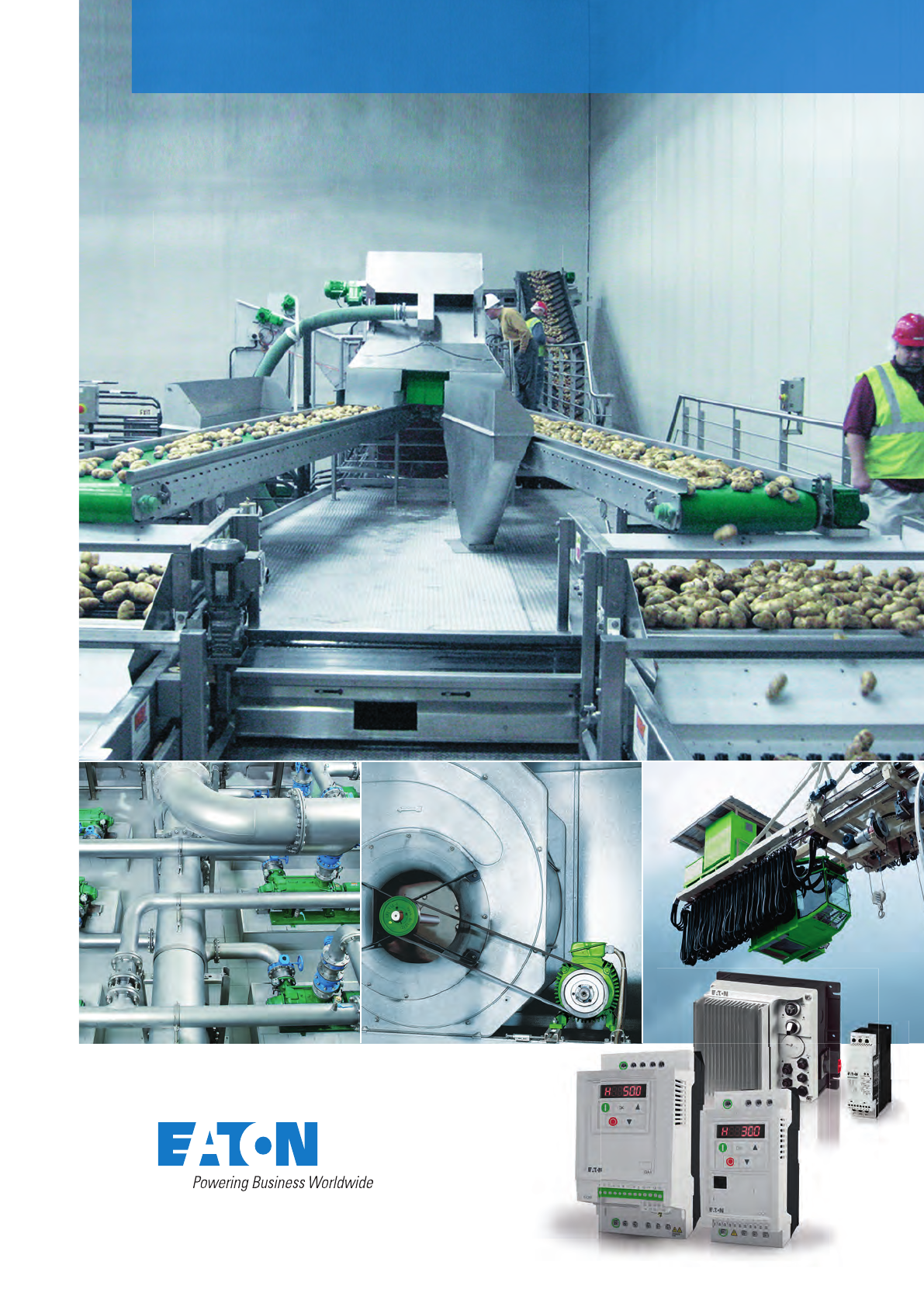
Product range catalog for variable frequency drives, soft starters, Rapid Link
Product range catalog
Efficient Engineering for
starting and controlling motors.
CA04020001Z-Umschlag.indd 4-6CA04020001Z-Umschlag.indd 4-6 06.12.12 10:0106.12.12 10:01

There's a certain energy at Eaton. An energy produced by the combina-
tion of globally established engineering companies into one brand. One
brand that cleverly and effi ciently meets all your requirements in the
fi eld of power management and industrial automation. Energy for our
customers worldwide – That's what we mean by 'Powering Business
Worldwide'. From power distribution and control to industrial automati-
on right through to uninterruptible power supply.
Eaton helps you to manage your entire power system proactively and
effi ciently. For this we offer you electrical solutions that make your ap-
plications safer, more reliable and highly effi cient. Visit us at www.ea-
ton.com/electrical.
All the above are trademarks of Eaton Corporation or its affi liates. The Westinghouse brand name
is used by temporary license in Asia Pacifi c. ©2009 Eaton Corporation.
The power of fusion
Minimum fuse sizes for short-circuit protection of three-phase motors
The maximum value depends on the switching device or the overload relay.
Motor power 230 V 400 V 440 V 500 V 690 V
Motor
rated
opera-
tional
current
Fuse Motor
rated
opera-
tional
current
Fuse Motor
rated
opera-
tional
current
Fuse Motor
rated
opera-
tional
current
Fuse Motor
rated
opera-
tional
current
Fuse
Starting Starting Starting Starting Starting
DOL Y/'DOL Y/'DOL Y/'DOL Y/'DOL Y/'
kWh p.f. K (%) A A A A A A A A A A A A A A A
0.06 0.7 58 0.37 2 – 0.21 2 – 0.19 2 – 0.17 2 – 0.12 2 –
0.09 0.7 60 0.54 2 – 0.31 2 – 0.28 2 – 0.25 2 – 0.18 2 –
0.12 0.7 60 0.72 4 2 0.41 2 – 0.37 2 – 0.33 2 – 0.24 2 –
0.18 0.7 62 1.04 4 2 0.6 2 – 0.54 2 – 0.48 2 – 0.35 2 –
0.25 0.7 62 1.4 4 2 0.8 4 2 0.76 2 – 0.7 2 – 0.5 2 –
0.37 0.72 66 2 6 4 1.1 4 2 1 4 2 0.9 2 2 0.7 2 –
0.55 0.75 69 2.7 10 41.5 4 2 1.4 4 2 1.2 4 2 0.9 4 2
0.75 0.79 74 3.2 10 41.9 6 4 1.7 4 2 1.5 4 2 1.1 4 2
1.1 0.81 74 4.6 10 62.6 6 4 2.4 4 2 2.1 6 4 1.5 4 2
1.5 0.81 74 6.3 16 10 3.6 6 4 3.3 6 4 2.9 6 4 2.1 6 4
2.2 0.81 78 8.7 20 10 510 64.6 10 6 4 10 42.9 10 4
30.8280 11.5 25 16 6.6 16 10 616 10 5.3 16 63.8 10 4
40.8283 14.8 32 16 8.5 20 10 7.7 16 10 6.8 16 10 4.9 16 6
5.5 0.82 86 19.6 32 25 11.3 25 16 10.2 20 10 920 16 6.5 16 10
7.5 0.82 87 26.4 50 32 15.2 32 16 13.8 25 16 12.1 25 16 8.8 20 10
11 0.84 87 38 80 40 21.7 40 25 19.8 32 25 17.4 32 20 12.6 25 16
15 0.84 88 51 100 63 29.3 63 32 26.6 50 32 23.4 50 25 17 32 20
18.5 0.84 88 63 125 80 36 63 40 32.8 63 32 28.9 50 32 20.9 32 25
22 0.84 92 71 125 80 41 80 50 37 80 40 33 63 32 23.8 50 25
30 0.85 92 96 200 100 55 100 63 50 100 63 44 80 50 32 63 32
37 0.86 92 117 200 125 68 125 80 61 125 80 54 100 63 39 80 50
45 0.86 93 141 250 160 81 160 100 74 125 100 65 125 80 47 80 63
55 0.86 93 173 250 200 99 200 125 90 125 100 79 160 80 58 100 63
75 0.86 94 233 315 250 134 200 160 122 160 125 107 200 125 78 160 100
90 0.86 94 279 400 315 161 250 200 146 200 160 129 200 160 93 160 100
110 0.86 94 342 500 400 196 315 200 179 250 200 157 250 160 114 200 125
132 0.87 95 401 630 500 231 400 250 210 315 250 184 250 200 134 250 160
160 0.87 95 486 630 630 279 400 315 254 400 250 224 315 250 162 250 200
200 0.87 95 607 800 630 349 500 400 318 400 315 279 400 315 202 315 250
250 0.87 95 – – – 437 630 500 397 630 400 349 500 400 253 400 315
315 0.87 96 – – – 544 800 630 495 630 630 436 630 500 316 500 400
400 0.88 96 – – – 683 1000 800 621 800 800 547 800 630 396 630 400
450 0.88 96 – – – 769 1000 800 699 800 800 615 800 630 446 630 630
500 0.88 97 – – – – – – – – – – – – 491 630 630
560 0.88 97 – – – – – – – – – – – – 550 800 630
630 0.88 97 – – – – – – – – – – – – 618 800 630
Instructions The rated motor currents apply to normal internally and surface-
cooled three-phase motors with 1500 rpm.
DOL starting: Starting current max. 6 × rated motor current.
Starting time max. 5 s.
Y/'-start: Starting current max. 2 × motor rated current.
Starting time max. 15 s.
Set overload relay in line to 0.58 × motor rated current.
Fuse ratings at Y/' starting apply also to three-phase slipring motors.
For higher rated currents, starting currents and/or longer starting times, larger
fuses will be required. Table applies for time delay and gL fuses (VDE 0636)
For LV h.b.c. fuse with aM characteristics
the fuse should be equal to the rated operational current.
CA04020001Z-Umschlag.indd 7-9CA04020001Z-Umschlag.indd 7-9 20.11.12 15:2820.11.12 15:28
CA04020001Z-EN-INT www.eaton.com

Variable frequency drivesSmartWire-DT®Rapid Link Soft startersAppendix
PowerXL™ DC1, DA1 variable frequency drives 6
DS7 soft starters 62
Rapid Link distributed, electronic drive system 90
SmartWire-DT® communication system 112
Appendix 124
Contents
Page
CA04020001Z.indd 132CA04020001Z.indd 132 22.11.12 09:2022.11.12 09:20
CA04020001Z-EN-INT www.eaton.com

Powering Business
Worldwide
Discover Eaton – a leader in the power management field
Since 1911, when our company began trading as a small truck parts supplier,
Eaton® Corporation has come a long way. Today, as a diversified power
management company, Eaton has sales of $16 billion USD (FY 2011),
employs 73,000 people and has customers in more than 150 countries.
Everyday, we help companies across the world to manage power, and do
more, while consuming less energy.
Eaton’s innovative products, solutions
and technologies are designed to
help customers to manage power and
conserve resources while working more
productively, safely and sustainably.
Our integrated and diversified business
strategy ensures that we remain at the
forefront of our industry, decade after
decade.
Aerospace
A leading global supplier to
commercial and military aviation and
aerospace industries. An extensive
technology portfolio includes hydraulic
systems, fuel systems, motion control
systems, propulsion sub-systems,
cockpit controls and displays and
fluid health monitoring systems. Our
products improve fuel economy,
aircraft performance, reliability and
safety.
Truck
A leader in the design, manufacture
and marketing of complete line of
drivetrain systems and components
for medium- and heavy-duty
commercial vehicles. Under the
“Roadranger” brand, Eaton also
markets lubricants, safety products
and service tools. Eaton’s hybrid
power systems have earned the
company recognition as a global
leader in alternative power for
commercial vehicles.
Electrical
A global leader in electrical control,
power distribution, uninterruptible
power supply and industrial
automation products and services.
Our products provide customer-driven
PowerChain Management® solutions
to serve the power system needs
of the industrial, institutional,
government, utility, commercial,
residential, IT, mission critical and
OEM markets worldwide.
Aerospace Truck
CA04020001Z-DE.indd 8CA04020001Z-DE.indd 8 13.11.12 15:1913.11.12 15:19
CA04020001Z-EN-INT www.eaton.com

Powering business
more sustainably
Sustainability – smaller footprint in the world
The principle of sustainability means meeting the current needs of our own
society without compromising the needs or options of future generations. It is
a principle, which forms the very core of our design and production philosophy
and guides all our activities across the world. Our commitment to reducing our
own ecological footprint covers a wide range of green technologies, products
and services that help our customers utilise electrical power more efficiently,
while improving environmental performance.
Eaton has been recognised
throughout the world for its
uncompromising business ethics.
For example, it was listed as
one of the ‘World’s Most Ethical
Companies’ on the Ethisphere
Institute’s annual list for six
consecutive years (2007, 2008,
2009, 2010, 2011 and 2012).
Learn more about Eaton Green Solutions
at www.eaton.com/greensolutions
When you see this symbol, you know
the solution represents an Eaton bench-
mark for environmental performance.
Electrical Automotive Hydraulics
Automotive
A supplier of critical components
that reduce emissions and fuel
consumption and improve stability
and performance of cars, light trucks
and commercial vehicles. Principal
products include engine valves and
valve train components, transmission
and engine controls, supercharger,
locking and limited slip differentials,
cylinder heads, fluid conveyance
components, body mouldings and
spoilers.
Hydraulics
A worldwide leader in reliable,
high-efficiency hydraulic systems and
components for use in mobile and
industrial applications. Markets include
agriculture, construction, mining,
forestry, utility, material handling, earth
moving, truck and bus, machine tools,
moulding, primary metals, automotive,
power generation, port machinery and
entertainment.
CA04020001Z-DE.indd 9CA04020001Z-DE.indd 9 13.11.12 15:1913.11.12 15:19
CA04020001Z-EN-INT www.eaton.com

Buildings Information Technology
• Data centers
• Telecommunication
• Networks
• Computer rooms
• World’s most efficient line of UPSs
to reduce footprint and save energy
• Reliable power systems with inherent
redundancy to improve availability
• Power metering and monitoring
to diagnose problems and lower costs
• Local service and support for quick
response
Powering electrical systems
worldwide
• Residential
• Healthcare
• Education
• Commercial offices
• Retail
• Public sector
• Airports
• Electrical distribution solutions for
safe and efficient power delivery
• Power quality systems for uptime
and reliability
• Power metering and monitoring
to add intelligence and save costs
• Industrial control products
for HVAC applications
CA04020001Z-DE.indd 10CA04020001Z-DE.indd 10 13.11.12 15:1913.11.12 15:19
CA04020001Z-EN-INT www.eaton.com

Industrial & Machinery Energy & Utilities
• Machine building:
• Food and
packaging machines
• Woodworking and processing
machines
• Agriculture
• Construction
• Mining and metals
• Paper industry
• Chemical and pharmaceutical industry
• Automotive industry
• Logistics centers
• Electrical distribution equipment to deliver power throughout
the enterprise
• Control & automation and power quality equipment for pro-
cess control
• Power metering and monitoring to manage energy costs
and uptime
• Power and motion control products to optimize productivity,
reliability, safety and operator comfort
• Renewable energy:
• Solar
• Wind
• Hydropower
• Traditional energy:
• Oil
• Gas
• Smart grid
• Water and waste water
• Electrical balance of system and
turnkey services for residential, utility
and commercial solar installations
• Power distribution equipment,
control components and system
installations services
• Network power grid technology for
intelligent data, lower costs and
crew / public safety
Public and private sectors
Buildings, Information Technology, Industrial & Machinery, Energy & Utilities
We provide reliable, efficient and safe power management.
CA04020001Z-DE.indd 11CA04020001Z-DE.indd 11 13.11.12 15:2013.11.12 15:20
CA04020001Z-EN-INT www.eaton.com

PowerXL™ DC1, DA1 variable frequency
drives
Variable frequency drives make it possible to use continuously variable speed control with
three-phase asynchronous motors and AC motors. To do this, they convert a single-phase
AC current or three-phase current with a specific frequency and voltage amplitudes into
a single-phase AC current or three-phase current with a variable frequency and variable
voltage amplitudes.
With its DC1 and DA1 series, Eaton has just the right variable frequency drives for any
series production application in the field of machine building and beyond, regardless of
whether your needs are extremely simple or extremely complex.
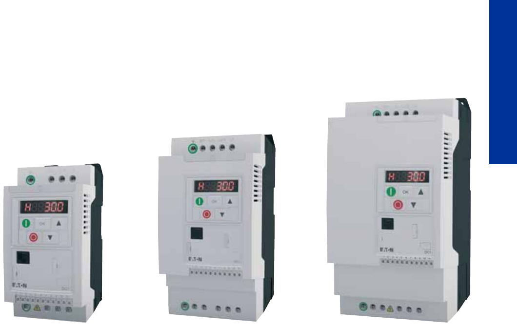
PowerXL™ DC1 variable frequency drives
Output voltage with sinusoidal pulse-width modulation (PWM) when using Volts-per-Hertz con-
trol (V/Hz control) and voltage boost
DC1-12…: 1~230 V/3~230 V, allocated motor rating 0.37 – 4 kW
DC1-32…: 3~230 V/3~230 V, allocated motor rating 0.37 – 4 kW
DC1-34…: 3~400 V/3~400 V, allocated motor rating 0.75 – 11 kW
DC1-S2…: 1~230 V/1~230 V, allocated motor rating 0.37 – 1.1 kW
DC1-S1…: 1~115 V/1~115 V, allocated motor rating 0.37 – 0.55 kW
DC1-1D…: 1~115 V/3~230 V, voltage doubler, allocated motor rating 0.37 – 1.1 kW
PowerXL™ DA1 variable frequency drives
Output voltage with sinusoidal pulse-width modulation (PWM) when using Volts-per-Hertz con-
trol (V/Hz control) and sensorless (SLVC) and sensored vector control
DA1-12…: 1~230 V/3~230 V, allocated motor rating 0.75 – 2.2 kW
DA1-32…: 3~230 V/3~230 V, allocated motor rating 0.75 – 75 kW
DA1-34…: 3~400 V/3~400 V, allocated motor rating 0.75 – 250 kW
CA04020001Z.indd 134CA04020001Z.indd 134 22.11.12 09:2122.11.12 09:21
CA04020001Z-EN-INT www.eaton.com

PowerXL™ variable frequency drives
CA04020001Z-EN-INT www.eaton.com
7
Variable frequency drives
System overview
PowerXL™ DC1 variable frequency drives 8
Description
PowerXL™ DC1 variable frequency drives 9
System overview
PowerXL™ DA1 variable frequency drives 10
Description
PowerXL™ DA1 variable frequency drives 11
Technical overview
PowerXL™ DC1, DA1 variable frequency drives 12
Key to type references
PowerXL™ DC1, DA1 variable frequency drives 13
Ordering
PowerXL™ DC1 variable frequency drives 14
PowerXL™ DA1 variable frequency drives 17
Accessories 26
Mains chokes, motor chokes 28
SVX, SPX variable frequency drives 30
Engineering
Components of a Power Drives System (PDS) 31
General information on Engineering 32
Connection example for DC1 34
Assigned switching and protective elements 36
Technical data
PowerXL™ DC1 variable frequency drives 38
PowerXL™ DA1 variable frequency drives 44
Mains chokes, motor chokes 52
Dimensions
PowerXL™ DC1 variable frequency drives 54
PowerXL™ DA1 variable frequency drives 54
Mains chokes, motor chokes 56
Sine filter 58

8 PowerXL™ variable frequency drives
DC1
CA04020001Z-EN-INT www.eaton.com
DC1
System overview
DC1 variable frequency drives 1
→ page 14
Mains choke, motor chokes, sine filter 2
→ page 28, → page 29
Brake resistor 3
→ page 26
Expansion modules 4
→ page 27
SmartWire-DT module 5
→ page 27
Bluetooth communication stick 6
→ page 26
External keypad 7
→ page 26
2
3
6
4
5
7
1
CA04020001Z-EN-INT www.eaton.com
PowerXL™ variable frequency drives
DC1
9
Variable frequency drives
DC1
Description
The DC1 is Eaton's compact variable frequency drive. It has been specifically
designed for simple applications. With only 14 basic parameters and
outstanding ease of mounting and installation, the DC1 is perfect for quick
commissioning. This makes these compact variable frequency drives ideal for
series production applications in the field of machine building.
Typical applications for this series include fans, pumps, and conveyor
systems. In addition, additional parameters and functionalities can be flexibly
enabled in order to allow the DC1 to handle more demanding applications as
well.
Essential features Accessories
• Fast commissioning with 14 basic parameters
• Performance range
– 0.37 - 4 kW (1~ 230 V / 3~ 230 V)
– 0.37 - 4 kW (3~ 230 V / 3~ 230 V)
– 0.75 - 11kW (3~ 400 V / 3~ 400 V)
– 0.37 - 1.1 kW (1~230 V / 1~230 V)
– 0.37 - 0.55 kW (1~ 115 V / 1~ 115 V)
– 0.37 - 1.1 kW (1~ 115 V / 3~ 230 V)
• Large overload capability: 150% for 60 seconds, 175% for 2 seconds
• Ambient air temperature of 50°C without derating (IP20)
• Plug-in modules can be used to expand the number of I/Os
• Integrated CANopen® and Modbus RTU
• Can be connected to SmartWire-DT
• Ingress protection: IP 20
• EMC filter, optional
• Braking transistor, optional
• Integrated PI controller
• V/Hz control with voltage boost
• International standards (CE, UL, cUL, c-Tick, Ukr Sepro, RoHS)
• Field bus module SmartWire-DT
• I/O expansions
• External keypad for the panel door
• Mains chokes
• Motor chokes
• Sine filter
• Braking resistances

10 PowerXL™ variable frequency drives
DA1
CA04020001Z-EN-INT www.eaton.com
DA1
System overview
DA1 variable frequency drives 1
→ page 17
Mains choke, motor choke, sine filter 2
→ page 28, → page 29
Braking resistance 3
→ page 26
Fieldbus modules 4
→ page 27
Bluetooth communication stick 5
→ page 26
External keypad 6
→ page 26
2
3
5
4
6
1

CA04020001Z-EN-INT www.eaton.com
PowerXL™ variable frequency drives
DA1
11
Variable frequency drives
DA1
Description
DA1 variable frequency drives are the perfect match for demanding,
speed-dependent applications. Their wide performance range of up to 250 kW,
together with their compact dimensions and high level of functionality, are
sure to leave a lasting impression. Accordingly, the DA1 comes with an
integrated EMC filter and braking transistor. Moreover, the Modbus RTU and
CANopen protocols are integrated as standard. With sensorless vector
control, the DA1 is able to provide 200% torque at zero revolutions. This makes
it the perfect choice for applications that involve lifting or tractive forces.
Comprehensive expansions such as additional inputs and outputs (analog,
digital) and various field bus modules round off this variable frequency drive's
flexibility.
Essential features Accessories
• Performance range:
– 0.75 - 2.2 kW (1~ 230 V / 3~ 230 V)
– 0.75 - 75 kW (3~ 230 V / 3~ 230 V)
– 0.75 - 250 kW (3~ 400 V / 3~ 400 V)
• Large overload capability: 150% for 60 seconds, 200% for 4 seconds
• Modbus RTU and integrated CANopen®
• EMC filter, integrated
• Braking transistor, integrated
• Control method: V/Hz control, sensorless vector control, vector control with
encoder
• Various I/O expansions
• Optional fieldbus module adapter
• Safe Torque Off (STO)
• Optional high-resolution OLED display
• Can be used to drive high-efficiency PM motors
• International standards (CE, UL, cUL, c-Tick, Ukr Sepro, RoHS)
• Field bus module SmartWire-DT
• Field bus modules (PROFIBUS, PROFINET, Ethernet/IP, EtherCat, Modbus
TCP, BACnet, and DeviceNet)
• I/O expansions
• External keypad for the panel door
• Mains chokes
• Motor chokes
• Sine filter
• Braking resistances

12 PowerXL™ variable frequency drives
DC1, DA1
CA04020001Z-EN-INT www.eaton.com
DC1, DA1
Technical overview
DC1... DA1...
Rated operational voltage Ue
115 V AC, 1-phase ✓-
230 V AC, 1-phase ✓ ✓
230 V AC, 3-phase ✓ ✓
400 V AC, 3-phase ✓ ✓
Supply frequency fLN Hz 50/60 50/60
Rated operational current IeA2.3 - 24 2.2 - 450
Overload current for 60 s every 600 s IL%150 150
Starting current for 2 s every 20 s IL%175 -
Starting current for 4 s every 40 s IL% - 200
Assigned motor rating
at 115 V, 50 Hz P kW 0.37 - 0.5 -
at 230 V, 50 Hz P kW 0.37 - 4 0.75 - 75
at 400 V, 50 Hz P kW 0.75 - 11 0.75 - 250
Ambient temperature
Operation °C
IP20/NEMA 0 -10 - +50 -10 - +50
IP40 --10 - +30
IP55 --10 - +30 / -10 - +40 (Ie < 180 A)
Storage °C -40 - +60 -40 - +60
Operation Mode
U/f control ✓ ✓
Slip compensation ✓ ✓
sensorless vector control (SLV) -✓
Vector control with feedback (CLV) -✓
Switching frequency fPWM kHz 4 - 32 4 - 32
Output voltage U2
115 V AC, 1-phase ✓-
230 V AC, 1-phase ✓-
230 V AC, 3-phase ✓ ✓
400 V AC, 3-phase ✓ ✓
Output Frequency f2Hz 0 - 500 Hz 0 - 500 Hz
Protection type
IP20/NEMA 0 ✓ ✓
IP40 -✓
IP55 -✓
Fitted with
Radio interference suppression filter ✓ ✓
Brake chopper ✓ ✓
Additional PCB protection -✓
7-digital display assembly ✓ ✓
OLED display -✓
Interface RS485/Modbus RTU, CANopen® RS485/Modbus RTU, CANopen®
Fieldbus connection SmartWire-DT Ethernet IP
DeviceNet
PROFIBUS
PROFINET
Modbus/TCP
EtherCAT
BACnet/IP
SmartWire-DT
Analog inputs parameterizable, max. 2 x (0 - 10 V, 0/4 - 20 mA) parameterizable, 2 x (0 - 10 V, 0/4 - 20 mA)
Analog outputs parameterizable, 1 x (0 - 10 V, 0/4 - 20 mA) parameterizable, max. 2 x (0 - 10 V, 0/4 - 20 mA)
Digital inputs parameterizable, max. 4 x (max. 30 V DC) parameterizable, 3 x (max. 30 V DC)
Digital outputs parameterizable, 1 x (24 V DC) parameterizable, max. 2 x (24 V DC)
Relay outputs parameterizable, 1 x N/O, 6 A (250 V AC) / 5 A (30
V DC)
parameterizable, 1 x N/O and 1 x changeover
contact, 6 A (250 V AC) / 5 A (30 V DC)
Production quality RoHS, ISO 9001 RoHS, ISO 9001
Safety functions -STO (Safe Torque Off)
Standards EMC: EN 61800-3:2004+A1-2012
Radio interference: EN 55011: 2010
Security: EN 61800-5: 2007
Protection type: EN 60529: 1992
EMC: EN 61800-3:2004+A1-2012
Radio interference: EN 55011: 2010
Security: EN 61800-5: 2007
Protection type: EN 60529: 1992
Certifications CE, cUL, UL, c-Tick, Ukr Sepro CE, cUL, UL, c-Tick, Ukr Sepro

PowerXL™ variable frequency drives
Key to type references
CA04020001Z-EN-INT www.eaton.com
13
Variable frequency drives
Key to type referenc es
DC1 variable frequency drives
DA1 variable frequency drives
DC1 - 1 2 4D1 F N - A 20 N
Connection in power section
1 = single-phase mains connection/
three-phase motor connection
3 = three-phase mains connection/
three-phase motor connection
S = single-phase mains connection/
single-phase motor connection
Mains voltage category
1 = 110 V (110 - 115 V ± 10 %)
2 = 230 V (200 - 240 V ± 10 %)
4 = 400 V (380 - 480 V ± 10 %)
D = 110 V input/230 V output
(voltage doubler)
Device series
DC1 = variable frequency drive, compact, series 1
(D = Drives, C = Compact, 1 = Series 1)
B = Brake chopper
N = no internal brake chopper
B = Brake chopper
Display unit (display)
A = LED display
B = OLED display
Degree of protection
20 = IP20/NEMA 0
66 = IP66/NEMA 4X
6S = IP66 with switch/NEMA 4X, switched
Type
N = Standard basic device
N = no internal RFI filter
F = Internal RFI filter
EMC (radio interference suppression filter)
Rated operational current (examples)
2D2 = 2,2 A
4D1 = 4,1 A
024 = 24 A
DA1 - 1 2 4D1 F N - A 20 N
Connection in power section
1 = single-phase mains connection/
three-phase motor connection
3 = three-phase mains connection/
three-phase motor connection
Mains voltage category
2 = 230 V (200 - 240 V ± 10 %)
4 = 400 V (380 - 480 V ± 10 %)
Device series
DA1 = variable frequency drive, compact, series 1
(D = Drives, A = Advanced, 1 = Series 1)
Brake chopper
N = no internal brake chopper
B = Brake chopper
Display unit (display)
A = LED display
B = OLED display
Degree of protection
20 = IP20/NEMA 0
40 = IP40
55 = IP55/NEMA 3
66 = IP66/NEMA 4X
6S = IP66 with switch/NEMA 4X, switched
Type
N = Standard basic device
C = coated printed circuit boards
N = no internal RFI filter
F = Internal RFI filter
EMC (radio interference suppression filter)
Rated operational current (examples)
2D2 = 2,2 A
4D1 = 4,1 A
024 = 24 A

14 PowerXL™ variable frequency drives
DC1, for AC motors
CA04020001Z-EN-INT www.eaton.com
DC1, for AC motors
Size Rated operational
current1)
Assigned motor
rating 2)
Rated motor
current
Fitted with Protection
type
Part no.
Article no.
Price
see price
list
Std. pack
IePI
e
7-digital display assembly
Brake chopper
Radio interference suppression filter
AkWA
Ue 115 V AC, 1-phase / U2 115 V AC, 1-phase
Mains voltage IEC (50/60Hz) ULN 110 (-10%) - 115 (+10%) V
Interface RS485/Modbus RTU, CANopen®
FS1 7 0.37 7 ✓- - IP20/NEMA 0 DC1-S17D0NN-A20N
169497
1off
FS2 10.5 0.5 10.5 ✓✓- IP20/NEMA 0 DC1-S1011NB-A20N
169500
Ue 230 V AC, 1-phase / U2 230 V AC, 1-phase
Mains voltage IEC (50/60Hz) ULN 200 (-10%) - 240 (+10%) V
Interface RS485/Modbus RTU, CANopen®
FS1 4.3 0.37 4.3 ✓- - IP20/NEMA 0 DC1-S24D3NN-A20N
169512
1off
FS1 4.3 0.37 4.3 ✓-✓IP20/NEMA 0 DC1-S24D3FN-A20N
169521
FS1 7 0.75 7 ✓- - IP20/NEMA 0 DC1-S27D0NN-A20N
169515
FS1 7 0.75 7 ✓-✓IP20/NEMA 0 DC1-S27D0FN-A20N
169524
FS2 10.5 1.1 10.5 ✓✓- IP20/NEMA 0 DC1-S2011NB-A20N
169518
FS2 10.5 1.1 10.5 ✓✓✓ IP20/NEMA 0 DC1-S2011FB-A20N
169527
Notes
FS1 FS2
1) Rated operational current at an operating frequency of 4 kHz and
an ambient air temperature of +50°C
2) For AC motors with internal and external ventilation with
50 Hz / 60 Hz
Information relevant for export to North America
Product Standards UL 508C; CSA-C22.2 No. 14; IEC/EN61800-3; IEC/EN61800-5;
CE marking
UL File No. E172143
UL CCN NMMS, NMMS7
CSA File No. UL report applies to both US and Canada
CSA Class No. 3211-06
NA Certification UL listed, certified by UL for use in Canada
Suitable for Branch circuits
Max. Voltage Rating 1~ 240 V AC IEC: TN-S UL/CSA: "Y" (Solidly Grounded Wey)
Degree of Protection IEC: IP20
⏚
L1/L L2/N L3
⏚
UVW
123456789
10
11
⏚
L1/L L2/N L3
DC-
⏚
U
DC+ BR VW
123456789
10
11

PowerXL™ variable frequency drives
DC1, for three-phase motors, 230 V
CA04020001Z-EN-INT www.eaton.com
15
Variable frequency drives
DC1, for three-phase motors, 230 V
Size Rated operational
current1)
Assigned motor
rating 2)
Rated motor
current
Fitted with Protection
type
Part no.
Article no.
Price
see price
list
Std. pack
IePI
e
7-digital display assembly
Brake chopper
Radio interference suppression filter
AkWA
Ue 115 V AC, 1-phase / U2 230 V AC, 3-phase
Mains voltage IEC (50/60Hz) ULN 110 (-10%) - 115 (+10%) V
Interface RS485/Modbus RTU, CANopen®
FS1 2.3 0.37 2 ✓- - IP20/NEMA 0 DC1-1D2D3NN-A20N
169503
1off
FS1 4.3 0.75 3.2 ✓- - IP20/NEMA 0 DC1-1D4D3NN-A20N
169506
FS2 5.8 1.1 4.6 ✓✓- IP20/NEMA 0 DC1-1D5D8NB-A20N
169509
Ue 230 V AC, 1-phase / U2 230 V AC, 3-phase
Mains voltage IEC (50/60Hz) ULN 200 (-10%) - 240 (+10%) V
Interface RS485/Modbus RTU, CANopen®
FS1 2.3 0.37 2 ✓- - IP20/NEMA 0 DC1-122D3NN-A20N
169222
1off
FS1 2.3 0.37 2 ✓-✓IP20/NEMA 0 DC1-122D3FN-A20N
169240
FS1 4.3 0.75 3.2 ✓- - IP20/NEMA 0 DC1-124D3NN-A20N
169225
FS1 4.3 0.75 3.2 ✓-✓IP20/NEMA 0 DC1-124D3FN-A20N
169243
FS1 7 1.5 6.3 ✓- - IP20/NEMA 0 DC1-127D0NN-A20N
169228
FS1 7 1.5 6.3 ✓-✓IP20/NEMA 0 DC1-127D0FN-A20N
169246
FS2 7 1.5 6.3 ✓✓- IP20/NEMA 0 DC1-127D0NB-A20N
169231
FS2 7 1.5 6.3 ✓✓✓ IP20/NEMA 0 DC1-127D0FB-A20N
169249
FS2 10.5 2.2 8.7 ✓✓- IP20/NEMA 0 DC1-12011NB-A20N
169234
FS2 10.5 2.2 8.7 ✓✓✓ IP20/NEMA 0 DC1-12011FB-A20N
169252
FS3 15 4 14.8 ✓✓- IP20/NEMA 0 DC1-12015NB-A20N
169237
Ue 230 V AC, 3-phase / U2 230 V AC, 3-phase
Mains voltage IEC (50/60Hz) ULN 200 (-10%) - 240 (+10%) V
Interface RS485/Modbus RTU, CANopen®
FS1 2.3 0.37 2 ✓- - IP20/NEMA 0 DC1-322D3NN-A20N
169255
1off
FS1 4.3 0.75 3.2 ✓- - IP20/NEMA 0 DC1-324D3NN-A20N
169258
FS1 7 1.5 6.3 ✓- - IP20/NEMA 0 DC1-327D0NN-A20N
169261
FS2 7 1.5 6.3 ✓✓- IP20/NEMA 0 DC1-327D0NB-A20N
169264
FS2 7 1.5 6.3 ✓✓✓ IP20/NEMA 0 DC1-327D0FB-A20N
169444
FS2 10.5 2.2 8.7 ✓✓- IP20/NEMA 0 DC1-32011NB-A20N
169438
FS2 10.5 2.2 8.7 ✓✓✓ IP20/NEMA 0 DC1-32011FB-A20N
169447
FS3 18 4 14.8 ✓✓- IP20/NEMA 0 DC1-32018NB-A20N
169441
FS3 18 4 14.8 ✓✓✓ IP20/NEMA 0 DC1-32018FB-A20N
169450
Notes 1) Rated operational current at an operating frequency of 4 kHz and an ambient air temperature of +50°C
2) for normal internally and externally ventilated 4 pole, three-phase asynchronous motors with 1500 rpm-1 at 50 Hz or 1800 min-1 at 60 Hz

16 PowerXL™ variable frequency drives
DC1, for three-phase motors, 400/480 V
CA04020001Z-EN-INT www.eaton.com
DC1, for three-phase motors, 400/480 V
Size Rated operational
current1)
Assigned motor
rating 2)
Rated motor
current
Fitted with Protection
type
Part no.
Article no.
Price
see price
list
Std. pack
IePI
e
7-digital display assembly
Brake chopper
Radio interference suppression filter
AkWA
Ue 400 V AC, 3-phase / U2 400 V AC, 3-phase
Mains voltage IEC (50/60Hz) ULN 380 (-10%) - 480 (+10%) V
Interface RS485/Modbus RTU, CANopen®
FS1 2.2 0.75 1.9 ✓- - IP20/NEMA 0 DC1-342D2NN-A20N
169453
1off
FS1 2.2 0.75 1.9 ✓-✓IP20/NEMA 0 DC1-342D2FN-A20N
169475
FS1 4.1 1.5 3.6 ✓- - IP20/NEMA 0 DC1-344D1NN-A20N
169456
FS1 4.1 1.5 3.6 ✓-✓IP20/NEMA 0 DC1-344D1FN-A20N
169478
FS2 4.1 1.5 3.6 ✓✓- IP20/NEMA 0 DC1-344D1NB-A20N
169459
FS2 4.1 1.5 3.6 ✓✓✓ IP20/NEMA 0 DC1-344D1FB-A20N
169481
FS2 5.8 2.2 5 ✓✓- IP20/NEMA 0 DC1-345D8NB-A20N
169462
FS2 5.8 2.2 5 ✓✓✓ IP20/NEMA 0 DC1-345D8FB-A20N
169484
FS2 9.5 4 8.5 ✓✓- IP20/NEMA 0 DC1-349D5NB-A20N
169465
FS2 9.5 4 8.5 ✓✓✓ IP20/NEMA 0 DC1-349D5FB-A20N
169487
FS3 14 5.5 11.3 ✓✓- IP20/NEMA 0 DC1-34014NB-A20N
169468
FS3 14 5.5 11.3 ✓✓✓ IP20/NEMA 0 DC1-34014FB-A20N
169490
FS3 18 7.5 15.2 ✓✓- IP20/NEMA 0 DC1-34018NB-A20N
169471
FS3 18 7.5 15.2 ✓✓✓ IP20/NEMA 0 DC1-34018FB-A20N
169493
FS3 24 11 21.7 ✓✓- IP20/NEMA 0 DC1-34024NB-A20N
169474
FS3 24 11 21.7 ✓✓✓ IP20/NEMA 0 DC1-34024FB-A20N
169496
Notes
FS1 FS2 FS3
1) Rated operational current at an operating frequency of 4 kHz and
an ambient air temperature of +50°C
2) for normal internally and externally ventilated 4 pole, three-phase
asynchronous motors with 1500 rpm-1 at 50 Hz or 1800 min-1 at 60 Hz
Information relevant for export to North America
Product Standards UL 508C; CSA-C22.2 No. 14; IEC/EN61800-3; IEC/EN61800-5;
CE marking
UL File No. E172143
UL CCN NMMS, NMMS7
CSA File No. UL report applies to both US and Canada
CSA Class No. 3211-06
NA Certification UL listed, certified by UL for use in Canada
Suitable for Branch circuits
Max. Voltage Rating 1~ 240 V AC IEC: TN-S UL/CSA: "Y" (Solidly Grounded Wey)
Degree of Protection IEC: IP20
⏚
L1/L L2/N L3
⏚
UVW
123456789
10
11
⏚
L1/L L2/N L3
DC-
⏚
U
DC+ BR VW
123456789
10
11
⏚
U
DC+BR VW
⏚
L1/L L2/N L3
DC-
123456789
10
11

PowerXL™ variable frequency drives
DA1, for three-phase motors, 230 V
CA04020001Z-EN-INT www.eaton.com
17
Variable frequency drives
DA1, for th ree-phase motors, 23 0 V
Size Rated operational
current1)
Assigned motor
rating 2)
Rated motor
current
Fitted with Protection
type
Part no.
Article no.
Price
see price list
Std. pack
IePI
e
Radio interference suppression filter
Brake chopper
7-digital display assembly
OLED display
Additional PCB protection
AkWA
Ue 230 V AC, 1-phase / U2 230 V AC, 3-phase
Mains voltage IEC (50/60Hz) ULN 200 (-10%) - 240 (+10%) V
Interface RS485/Modbus RTU, CANopen®
FS2 4.3 0.75 3.2 ✓✓✓- - IP20/NEMA 0 DA1-124D3FB-A20N
169152
1off
FS2 4.3 0.75 3.2 ✓✓✓-✓IP20/NEMA 0 DA1-124D3FB-A20C
169078
FS2 7 1.5 6.3 ✓✓✓- - IP20/NEMA 0 DA1-127D0FB-A20N
169155
FS2 7 1.5 6.3 ✓✓✓-✓IP20/NEMA 0 DA1-127D0FB-A20C
169081
FS2 10.5 2.2 8.7 ✓✓✓- - IP20/NEMA 0 DA1-12011FB-A20N
169158
FS2 10.5 2.2 8.7 ✓✓✓-✓IP20/NEMA 0 DA1-12011FB-A20C
169084
Ue 230 V AC, 3-phase / U2 230 V AC, 3-phase
Mains voltage IEC (50/60Hz) ULN 200 (-10%) - 240 (+10%) V
Interface RS485/Modbus RTU, CANopen®
FS2 4.3 0.75 3.2 ✓✓✓- - IP20/NEMA 0 DA1-324D3FB-A20N
169161
1off
FS2 4.3 0.75 3.2 ✓✓✓-✓IP20/NEMA 0 DA1-324D3FB-A20C
169087
FS2 7 1.5 6.3 ✓✓✓- - IP20/NEMA 0 DA1-327D0FB-A20N
169164
FS2 7 1.5 6.3 ✓✓✓-✓IP20/NEMA 0 DA1-327D0FB-A20C
169090
FS2 10.5 2.2 8.7 ✓✓✓- - IP20/NEMA 0 DA1-32011FB-A20N
169167
FS2 10.5 2.2 8.7 ✓✓✓-✓IP20/NEMA 0 DA1-32011FB-A20C
169093
FS3 18 4 14.8 ✓✓✓- - IP20/NEMA 0 DA1-32018FB-A20N
169170
FS3 18 4 14.8 ✓✓✓-✓IP20/NEMA 0 DA1-32018FB-A20C
169096
Notes
FS2 FS3
1) With a switching frequency of 4 kHz and an ambient air temperature of +40°C or
+50°C for IP20/NEMA 0
2) Assigned motor rating for normal internally and externally ventilated four-pole,
three-phase asynchronous motors with 1500 rpm (at 50 Hz) or 1800 rpm (at 60 Hz)
Information relevant for export to North America
Product Standards UL 508C; CSA-C22.2 No. 14; IEC/EN61800-3;
IEC/EN61800-5; CE marking
UL File No. E172143
UL CCN NMMS, NMMS7
CSA File No. UL report applies to both US and Canada
CSA Class No. 3211-06
NA Certification UL listed, certified by UL for use in Canada
Suitable for Branch circuits
Max. Voltage Rating 1~ 240 V AC IEC: TN-S UL/CSA: "Y" (Solidly
Grounded Wey)
Degree of Protection IEC: IP20
⏚
L1/L L2/NL3
DC-
⏚
U
DC+ BR
1 2 3 4 5 6 7 8 9 10 11 12 13
14 15 16 17 18
COM
VW
⏚
L1/LL2/NL3
DC-
1 2 3 4 5 6 7 8 9 10 11 12 13
14 15 16 17 18
COM
⏚
U
DC+ BR
VW

18 PowerXL™ variable frequency drives
DA1, for three-phase motors, 230 V
CA04020001Z-EN-INT www.eaton.com
Size Rated operational
current1)
Assigned motor
rating 2)
Rated motor
current
Fitted with Protection
type
Part no.
Article no.
Price
see price list
Std. pack
IePI
e
Radio interference
suppression filter
Brake chopper
7-digital display
assembly
OLED display
Additional PCB
protection
AkWA
Ue 230 V AC, 3-phase / U2 230 V AC, 3-phase
Mains voltage IEC (50/60Hz) ULN 200 (-10%) - 240 (+10%) V
Interface RS485/Modbus RTU, CANopen®
FS4 24 5.5 19.6 ✓✓-✓✓ IP55 DA1-32024FB-B55C
169361
1off
FS4 24 5.5 19.6 ✓✓✓-✓IP55 DA1-32024FB-A55C
169100
FS3 24 5.5 19.6 ✓✓✓-✓IP20/NEMA 0 DA1-32024FB-A20C
169099
FS4 24 5.5 19.6 ✓✓-✓- IP55 DA1-32024FB-B55N
169294
FS4 24 5.5 19.6 ✓✓✓- - IP55 DA1-32024FB-A55N
169174
FS4 39 7.5 26.5 ✓✓✓- - IP55 DA1-32039FB-A55N
169175
FS4 39 7.5 26.4 ✓✓✓-✓IP55 DA1-32039FB-A55C
169101
FS4 39 7.5 26.4 ✓✓-✓- IP55 DA1-32039FB-B55N
169295
FS4 39 7.5 26.4 ✓✓-✓✓ IP55 DA1-32039FB-B55C
169362
FS4 46 11 38 ✓✓-✓- IP55 DA1-32046FB-B55N
169296
FS4 46 11 38 ✓✓-✓✓ IP55 DA1-32046FB-B55C
169363
FS4 46 11 38 ✓✓✓- - IP55 DA1-32046FB-A55N
169176
FS4 46 11 38 ✓✓✓-✓IP55 DA1-32046FB-A55C
169102
FS5 61 15 51 ✓✓-✓- IP55 DA1-32061FB-B55N
169297
FS5 61 15 51 ✓✓-✓✓ IP55 DA1-32061FB-B55C
169364
FS5 61 15 51 ✓✓✓- - IP55 DA1-32061FB-A55N
169177
FS5 61 15 51 ✓✓✓-✓IP55 DA1-32061FB-A55C
169103
FS5 72 18.5 63 ✓✓-✓- IP55 DA1-32072FB-B55N
169298
FS5 72 18.5 63 ✓✓-✓✓ IP55 DA1-32072FB-B55C
169365
FS5 72 18.5 63 ✓✓✓- - IP55 DA1-32072FB-A55N
169178
FS5 72 18.5 63 ✓✓✓-✓IP55 DA1-32072FB-A55C
169104
FS6 90 22 71 ✓--✓- IP55 DA1-32090FN-B55N
169299
FS6 90 22 71 ✓✓✓- - IP55 DA1-32090FB-A55N
169180
FS6 90 22 71 ✓-✓-✓IP55 DA1-32090FN-A55C
169105
FS6 90 22 71 ✓✓✓-✓IP55 DA1-32090FB-A55C
169106
FS6 90 22 71 ✓✓-✓✓ IP55 DA1-32090FB-B55C
169367
FS6 90 22 71 ✓--✓✓ IP55 DA1-32090FN-B55C
169366
FS6 90 22 71 ✓-✓- - IP55 DA1-32090FN-A55N
169179
FS6 90 22 71 ✓✓-✓- IP55 DA1-32090FB-B55N
169300
FS6 110 30 96 ✓✓-✓✓ IP55 DA1-32110FB-B55C
169369
FS6 110 30 96 ✓✓✓- - IP55 DA1-32110FB-A55N
169182
FS6 110 30 96 ✓✓✓-✓IP55 DA1-32110FB-A55C
169108

PowerXL™ variable frequency drives
DA1, for three-phase motors, 230 V
CA04020001Z-EN-INT www.eaton.com
19
Variable frequency drives
Ue 230 V AC, 3-phase / U2 230 V AC, 3-phase
Mains voltage IEC (50/60Hz) ULN 200 (-10%) - 240 (+10%) V
Interface RS485/Modbus RTU, CANopen®
FS6 110 30 96 ✓-✓-✓IP55 DA1-32110FN-A55C
169107
1off
FS6 110 30 96 ✓✓-✓- IP55 DA1-32110FB-B55N
169302
FS6 110 30 96 ✓--✓- IP55 DA1-32110FN-B55N
169301
FS6 110 30 96 ✓-✓- - IP55 DA1-32110FN-A55N
169181
FS6 110 30 96 ✓--✓✓ IP55 DA1-32110FN-B55C
169368
FS6 150 45 141 ✓-✓- - IP55 DA1-32150FN-A55N
169183
FS6 150 45 141 ✓--✓- IP55 DA1-32150FN-B55N
169303
FS6 150 45 141 ✓-✓-✓IP55 DA1-32150FN-A55C
169109
FS6 150 45 141 ✓--✓✓ IP55 DA1-32150FN-B55C
169370
FS6 150 45 141 ✓✓✓- - IP55 DA1-32150FB-A55N
169184
FS6 150 45 141 ✓✓-✓✓ IP55 DA1-32150FB-B55C
169371
FS6 150 45 141 ✓✓✓-✓IP55 DA1-32150FB-A55C
169110
FS6 150 45 141 ✓✓-✓- IP55 DA1-32150FB-B55N
169304
Notes
FS3 FS4 FS5
1) With a switching frequency of 4 kHz and an ambient air temperature of +40°C or +50°C
for IP20/NEMA 0
2) Assigned motor rating for normal internally and externally ventilated four-pole,
three-phase asynchronous motors with 1500 rpm (at 50 Hz) or 1800 rpm (at 60 Hz)
Information relevant for export to North America
Product Standards UL 508C; CSA-C22.2 No. 14; IEC/EN61800-3;
IEC/EN61800-5; CE marking
UL File No. E172143
UL CCN NMMS, NMMS7
CSA File No. UL report applies to both US and Canada
CSA Class No. 3211-06
NA Certification UL listed, certified by UL for use in Canada
Suitable for Branch circuits
Max. Voltage Rating 1~ 240 V AC IEC: TN-S UL/CSA: "Y" (Solidly
Grounded Wey)
Degree of Protection IEC: IP20
Size Rated operational
current1)
Assigned motor
rating 2)
Rated motor
current
Fitted with Protection
type
Part no.
Article no.
Price
see price list
Std. pack
IePI
e
Radio interference
suppression filter
Brake chopper
7-digital display
assembly
OLED display
Additional PCB
protection
AkWA
⏚
L1/LL2/NL3
DC-
1 2 3 4 5 6 7 8 9 10 11 12 13
14 15 16 17 18
COM
⏚
U
DC+ BR
VW

20 PowerXL™ variable frequency drives
DA1, for three-phase motors, 230 V
CA04020001Z-EN-INT www.eaton.com
Size Rated
operational
current1)
Assigned motor
rating 2)
Rated
motor
current
Fitted with Protection
type
Part no.
Article no.
Price
see price list
Std. pack
IePI
e
Radio interference
suppression filter
Brake chopper
7-digital display
assembly
OLED display
Additional PCB
protection
AkWA
Ue 230 V AC, 3-phase / U2 230 V AC, 3-phase
Mains voltage IEC (50/60Hz) ULN 200 (-10%) - 240 (+10%) V
Interface RS485/Modbus RTU, CANopen®
FS6 180 55 173 ✓--✓- IP55 DA1-32180FN-B55N
169305
1off
FS6 180 55 173 ✓-✓- - IP55 DA1-32180FN-A55N
169185
FS6 180 55 173 ✓--✓✓ IP55 DA1-32180FN-B55C
169372
FS6 180 55 173 ✓✓-✓- IP55 DA1-32180FB-B55N
169306
FS6 180 55 173 ✓-✓-✓IP55 DA1-32180FN-A55C
169111
FS6 180 55 173 ✓✓✓- - IP55 DA1-32180FB-A55N
169186
FS6 180 55 173 ✓✓✓-✓IP55 DA1-32180FB-A55C
169112
FS6 180 55 173 ✓✓-✓✓ IP55 DA1-32180FB-B55C
169373
FS7 202 55 173 ✓-✓- - IP55 DA1-32202FN-A55N
169187
FS7 202 55 173 ✓--✓- IP55 DA1-32202FN-B55N
169307
FS7 202 55 173 ✓✓-✓- IP55 DA1-32202FB-B55N
169308
FS7 202 55 173 ✓-✓-✓IP55 DA1-32202FN-A55C
169113
FS7 202 55 173 ✓--✓✓ IP55 DA1-32202FN-B55C
169374
FS7 202 55 173 ✓✓✓- - IP55 DA1-32202FB-A55N
169188
FS7 202 55 173 ✓✓-✓✓ IP55 DA1-32202FB-B55C
169375
FS7 202 55 173 ✓✓✓-✓IP55 DA1-32202FB-A55C
169114
FS7 248 75 233 ✓-✓- - IP55 DA1-32248FN-A55N
169189
FS7 248 75 233 ✓--✓- IP55 DA1-32248FN-B55N
169309
FS7 248 75 233 ✓✓✓- - IP55 DA1-32248FB-A55N
169190
FS7 248 75 233 ✓✓-✓- IP55 DA1-32248FB-B55N
169310
FS7 248 75 233 ✓--✓✓ IP55 DA1-32248FN-B55C
169376
FS7 248 75 233 ✓-✓-✓IP55 DA1-32248FN-A55C
169115
FS7 248 75 233 ✓✓-✓✓ IP55 DA1-32248FB-B55C
169377
FS7 248 75 233 ✓✓✓-✓IP55 DA1-32248FB-A55C
169116

PowerXL™ variable frequency drives
DA1, for three-phase motors, 400 V
CA04020001Z-EN-INT www.eaton.com
21
Variable frequency drives
DA1, for th ree-phase motors, 40 0 V
Size Rated
operational
current1)
Assigned motor
rating 2)
Rated
motor
current
Fitted with Protection
type
Part no.
Article no.
Price
see price list
Std. pack
IePI
e
Radio interference
suppression filter
Brake chopper
7-digital display
assembly
OLED display
Additional PCB
protection
AkWA
Ue 400 V AC, 3-phase / U2 400 V AC, 3-phase
Mains voltage IEC (50/60Hz) ULN 380 (-10%) - 480 (+10%) V
Interface RS485/Modbus RTU, CANopen®
FS2 2.2 0.75 1.9 ✓✓✓- - IP20/NEMA 0 DA1-342D2FB-A20N
169191
1off
FS2 2.2 0.75 1.9 ✓✓✓-✓IP20/NEMA 0 DA1-342D2FB-A20C
169117
FS2 4.1 1.5 3.6 ✓✓✓- - IP20/NEMA 0 DA1-344D1FB-A20N
169194
FS2 4.1 1.5 3.6 ✓✓✓-✓IP20/NEMA 0 DA1-344D1FB-A20C
169120
FS2 5.8 2.2 5 ✓✓✓- - IP20/NEMA 0 DA1-345D8FB-A20N
169197
FS2 5.8 2.2 5 ✓✓✓-✓IP20/NEMA 0 DA1-345D8FB-A20C
169051
FS2 9.5 4 8.5 ✓✓✓- - IP20/NEMA 0 DA1-349D5FB-A20N
169200
FS2 9.5 4 58.5 ✓✓✓-✓IP20/NEMA 0 DA1-349D5FB-A20C
169054
FS3 14 5.5 11.3 ✓✓✓- - IP20/NEMA 0 DA1-34014FB-A20N
169203
FS3 14 5.5 11.3 ✓✓✓-✓IP20/NEMA 0 DA1-34014FB-A20C
169057
FS3 18 7.5 15.2 ✓✓✓- - IP20/NEMA 0 DA1-34018FB-A20N
169206
FS3 18 7.5 15.2 ✓✓✓-✓IP20/NEMA 0 DA1-34018FB-A20C
169060
FS4 24 11 21.7 ✓✓-✓-IP55 DA1-34024FB-B55N
169323
FS4 24 11 21.7 ✓✓✓-- IP55 DA1-34024FB-A55N
169210
FS3 24 11 21.7 ✓✓✓- - IP20/NEMA 0 DA1-34024FB-A20N
169209
FS4 24 11 21.7 ✓✓-✓✓ IP55 DA1-34024FB-B55C
169390
FS3 24 11 21.7 ✓✓✓-✓IP20/NEMA 0 DA1-34024FB-A20C
169063
FS4 24 11 21.7 ✓✓✓-✓IP55 DA1-34024FB-A55C
169064
Notes
FS2 FS3 FS4
1) With a switching frequency of 4 kHz and an ambient air
temperature of +40°C or +50°C for IP20/NEMA 0
2) Assigned motor rating for normal internally and externally
ventilated four-pole, three-phase asynchronous motors
with 1500 rpm (at 50 Hz) or 1800 rpm (at 60 Hz)
Information relevant for export to North America
Product Standards UL 508C; CSA-C22.2 No. 14; IEC/EN61800-3; IEC/EN61800-5; CE marking
UL File No. E172143
UL CCN NMMS, NMMS7
CSA File No. UL report applies to both US and Canada
CSA Class No. 3211-06
NA Certification UL listed, certified by UL for use in Canada
Suitable for Branch circuits
Max. Voltage Rating 1~ 240 V AC IEC: TN-S UL/CSA: "Y" (Solidly Grounded Wey)
Degree of Protection IEC: IP20
⏚
L1/L L2/NL3
DC-
⏚
U
DC+ BR
1 2 3 4 5 6 7 8 9 10 11 12 13
14 15 16 17 18
COM
VW
⏚
L1/L L2/NL3
DC-
1 2 3 4 5 6 7 8 9 10 11 12 13
14 15 16 17 18
COM
⏚
U
DC+ BR
VW

22 PowerXL™ variable frequency drives
DA1, for three-phase motors, 400 V
CA04020001Z-EN-INT www.eaton.com
Size Rated operational
current1)
Assigned motor
rating 2)
Rated motor
current
Fitted with Protection
type
Part no.
Article no.
Price
see price list
Std. pack
IePI
e
Radio interference
suppression filter
Brake chopper
7-digital display
assembly
OLED display
Additional PCB
protection
AkWA
Ue 400 V AC, 3-phase / U2 400 V AC, 3-phase
Mains voltage IEC (50/60Hz) ULN 380 (-10%) - 480 (+10%) V
Interface RS485/Modbus RTU, CANopen®
FS4 30 15 30 ✓✓-✓-IP55 DA1-34030FB-B55N
169324
1off
FS4 30 15 29.3 ✓✓✓-- IP55 DA1-34030FB-A55N
169211
FS4 30 15 29.3 ✓✓✓-✓IP55 DA1-34030FB-A55C
169065
FS4 30 15 29.3 ✓✓-✓✓ IP55 DA1-34030FB-B55C
169391
FS4 39 18.5 36 ✓✓✓-- IP55 DA1-34039FB-A55N
169212
FS4 39 18.5 36 ✓✓-✓-IP55 DA1-34039FB-B55N
169325
FS4 39 18.5 36 ✓✓✓-✓IP55 DA1-34039FB-A55C
169066
FS4 39 18.5 36 ✓✓-✓✓ IP55 DA1-34039FB-B55C
169392
FS4 46 22 41 ✓✓-✓-IP55 DA1-34046FB-B55N
169326
FS4 46 22 41 ✓✓✓-- IP55 DA1-34046FB-A55N
169213
FS4 46 22 41 ✓✓✓-✓IP55 DA1-34046FB-A55C
169067
FS4 46 22 41 ✓✓-✓✓ IP55 DA1-34046FB-B55C
169393
FS5 61 30 55 ✓✓✓-- IP55 DA1-34061FB-A55N
169214
FS5 61 30 55 ✓✓-✓-IP55 DA1-34061FB-B55N
169327
FS5 61 30 55 ✓✓✓-✓IP55 DA1-34061FB-A55C
169068
FS5 61 30 55 ✓✓-✓✓ IP55 DA1-34061FB-B55C
169394
FS5 72 37 68 ✓✓-✓-IP55 DA1-34072FB-B55N
169328
FS5 72 37 68 ✓✓✓-- IP55 DA1-34072FB-A55N
169215
FS5 72 37 68 ✓✓-✓✓ IP55 DA1-34072FB-B55C
169395
FS5 72 37 68 ✓✓✓-✓IP55 DA1-34072FB-A55C
169069
FS6 90 45 81 ✓--✓-IP55 DA1-34090FN-B55N
169329
FS6 90 45 81 ✓-✓-- IP55 DA1-34090FN-A55N
169216
FS6 90 45 81 ✓--✓✓ IP55 DA1-34090FN-B55C
169396
FS6 90 45 81 ✓✓-✓-IP55 DA1-34090FB-B55N
169330
FS6 90 45 81 ✓✓✓-- IP55 DA1-34090FB-A55N
169037
FS6 90 45 81 ✓-✓-✓IP55 DA1-34090FN-A55C
169070
FS6 90 45 81 ✓✓-✓✓ IP55 DA1-34090FB-B55C
169397
FS6 90 45 81 ✓✓✓-✓IP55 DA1-34090FB-A55C
169071
FS6 110 55 99 ✓--✓-IP55 DA1-34110FN-B55N
169331
FS6 110 55 99 ✓-✓-- IP55 DA1-34110FN-A55N
169038
FS6 110 55 99 ✓-✓-✓IP55 DA1-34110FN-A55C
169072
FS6 110 55 99 ✓--✓✓ IP55 DA1-34110FN-B55C
169398

PowerXL™ variable frequency drives
DA1, for three-phase motors, 400 V
CA04020001Z-EN-INT www.eaton.com
23
Variable frequency drives
Ue 400 V AC, 3-phase / U2 400 V AC, 3-phase
Mains voltage IEC (50/60Hz) ULN 380 (-10%) - 480 (+10%) V
Interface RS485/Modbus RTU, CANopen®
FS6 110 55 99 ✓✓✓-- IP55 DA1-34110FB-A55N
169039
1off
FS6 110 55 99 ✓✓-✓-IP55 DA1-34110FB-B55N
169332
FS6 110 55 99 ✓✓✓-✓IP55 DA1-34110FB-A55C
169265
FS6 110 55 99 ✓✓-✓✓ IP55 DA1-34110FB-B55C
169399
FS6 150 75 134 ✓--✓-IP55 DA1-34150FN-B55N
169333
FS6 150 75 134 ✓-✓-- IP55 DA1-34150FN-A55N
169040
FS6 150 75 134 ✓✓✓-- IP55 DA1-34150FB-A55N
169041
FS6 150 75 134 ✓✓-✓-IP55 DA1-34150FB-B55N
169334
FS6 150 75 134 ✓--✓✓ IP55 DA1-34150FN-B55C
169400
FS6 150 75 134 ✓-✓-✓IP55 DA1-34150FN-A55C
169266
FS6 180 90 161 ✓✓✓-- IP55 DA1-34180FB-A55N
169043
FS6 150 75 134 ✓✓✓-✓IP55 DA1-34150FB-A55C
169267
FS6 150 75 134 ✓✓-✓✓ IP55 DA1-34150FB-B55C
169401
FS6 180 90 161 ✓--✓-IP55 DA1-34180FN-B55N
169335
FS6 180 90 161 ✓-✓-- IP55 DA1-34180FN-A55N
169042
FS6 180 90 161 ✓✓-✓-IP55 DA1-34180FB-B55N
169336
FS6 180 90 161 ✓--✓✓ IP55 DA1-34180FN-B55C
169402
FS6 180 90 161 ✓-✓-✓IP55 DA1-34180FN-A55C
169268
FS6 180 90 161 ✓✓✓-✓IP55 DA1-34180FB-A55C
169269
FS6 180 90 161 ✓✓-✓✓ IP55 DA1-34180FB-B55C
169403
Notes
Information relevant for export to North America
Product Standards UL 508C; CSA-C22.2 No. 14; IEC/EN61800-3; IEC/EN61800-5;
CE marking
UL File No. E172143
UL CCN NMMS, NMMS7
CSA File No. UL report applies to both US and Canada
CSA Class No. 3211-06
NA Certification UL listed, certified by UL for use in Canada
Suitable for Branch circuits
Max. Voltage Rating 1~ 240 V AC IEC: TN-S UL/CSA: "Y" (Solidly Grounded Wey)
Degree of Protection IEC: IP20
FS4 FS5
1) With a switching frequency of 4 kHz and an ambient air temperature of
+40°C or +50°C for IP20/NEMA 0
2) Assigned motor rating for normal internally and externally ventilated
four-pole, three-phase asynchronous motors with 1500 rpm (at 50 Hz) or
1800 rpm (at 60 Hz)
Size Rated operational
current1)
Assigned motor
rating 2)
Rated motor
current
Fitted with Protection
type
Part no.
Article no.
Price
see price list
Std. pack
IePI
e
Radio interference
suppression filter
Brake chopper
7-digital display
assembly
OLED display
Additional PCB
protection
AkWA

24 PowerXL™ variable frequency drives
DA1, for three-phase motors, 400 V
CA04020001Z-EN-INT www.eaton.com
Size Rated operational
current1)
Assigned motor
rating 2)
Rated motor
current
Fitted with Protection
type
Part no.
Article no.
Price
see price list
Std. pack
IePI
e
Radio interference
suppression filter
Brake chopper
7-digital display
assembly
OLED display
Additional PCB
protection
AkWA
Ue 400 V AC, 3-phase / U2 400 V AC, 3-phase
Mains voltage IEC (50/60Hz) ULN 380 (-10%) - 480 (+10%) V
Interface RS485/Modbus RTU, CANopen®
FS7 202 110 196 ✓-✓-- IP55 DA1-34202FN-A55N
169044
1off
FS7 202 110 196 ✓--✓-IP55 DA1-34202FN-B55N
169337
FS7 202 110 196 ✓✓✓-- IP55 DA1-34202FB-A55N
169045
FS7 202 110 196 ✓--✓✓ IP55 DA1-34202FN-B55C
169404
FS7 202 110 196 ✓-✓-✓IP55 DA1-34202FN-A55C
169270
FS7 202 110 196 ✓✓-✓-IP55 DA1-34202FB-B55N
169338
FS7 202 110 196 ✓✓✓-✓IP55 DA1-34202FB-A55C
169271
FS7 202 110 196 ✓✓-✓✓ IP55 DA1-34202FB-B55C
169405
FS7 240 132 231 ✓-✓-- IP55 DA1-34240FN-A55N
169046
FS7 240 132 231 ✓--✓-IP55 DA1-34240FN-B55N
169339
FS7 240 132 231 ✓✓✓-- IP55 DA1-34240FB-A55N
169047
FS7 240 132 231 ✓-✓-✓IP55 DA1-34240FN-A55C
169272
FS7 240 132 231 ✓--✓✓ IP55 DA1-34240FN-B55C
169406
FS7 240 132 231 ✓✓-✓-IP55 DA1-34240FB-B55N
169340
FS7 240 132 231 ✓✓✓-✓IP55 DA1-34240FB-A55C
169273
FS7 240 132 231 ✓✓-✓✓ IP55 DA1-34240FB-B55C
169407
FS7 302 160 279 ✓-✓-- IP55 DA1-34302FN-A55N
169048
FS7 302 160 279 ✓--✓✓ IP55 DA1-34302FN-B55C
169408
FS7 302 160 279 ✓--✓-IP55 DA1-34302FN-B55N
169341
FS7 302 160 279 ✓✓-✓-IP55 DA1-34302FB-B55N
169342
FS7 302 160 279 ✓-✓-✓IP55 DA1-34302FN-A55C
169274
FS7 302 160 279 ✓✓✓-- IP55 DA1-34302FB-A55N
169073
FS7 302 160 279 ✓✓✓-✓IP55 DA1-34302FB-A55C
169275
FS7 302 160 279 ✓✓-✓✓ IP55 DA1-34302FB-B55C
169217
FS8 370 200 349 ✓-✓-- IP40 DA1-34370FN-A40N
169074
1off
FS8 370 200 349 ✓--✓-IP40 DA1-34370FN-B40N
169343
FS8 370 200 349 ✓-✓-✓IP40 DA1-34370FN-A40C
169276
FS8 370 200 349 ✓--✓✓ IP40 DA1-34370FN-B40C
169218
FS8 370 200 349 ✓✓✓-- IP40 DA1-34370FB-A40N
169075
FS8 370 200 349 ✓✓-✓-IP40 DA1-34370FB-B40N
169344
FS8 370 200 349 ✓✓✓-✓IP40 DA1-34370FB-A40C
169277
FS8 370 200 349 ✓✓-✓✓ IP40 DA1-34370FB-B40C
169219

PowerXL™ variable frequency drives
DA1, for three-phase motors, 400 V
CA04020001Z-EN-INT www.eaton.com
25
Variable frequency drives
Ue 400 V AC, 3-phase / U2 400 V AC, 3-phase
Mains voltage IEC (50/60Hz) ULN 380 (-10%) - 480 (+10%) V
Interface RS485/Modbus RTU, CANopen®
FS8 450 250 437 ✓-✓-- IP40 DA1-34450FN-A40N
169076
1off
FS8 450 250 437 ✓--✓-IP40 DA1-34450FN-B40N
169345
FS8 450 250 437 ✓✓-✓-IP40 DA1-34450FB-B40N
169346
FS8 450 250 437 ✓✓✓-- IP40 DA1-34450FB-A40N
169077
FS8 450 250 437 ✓-✓-✓IP40 DA1-34450FN-A40C
169278
FS8 450 250 437 ✓--✓✓ IP40 DA1-34450FN-B40C
169220
FS8 450 250 437 ✓✓-✓✓ IP40 DA1-34450FB-B40C
169221
FS8 450 250 437 ✓✓✓-✓IP40 DA1-34450FB-A40C
169279
Notes
1) With a switching frequency of 4 kHz and an ambient air temperature of +40°C or
+50°C for IP20/NEMA 0
2) Assigned motor rating for normal internally and externally ventilated four-pole,
three-phase asynchronous motors with 1500 rpm (at 50 Hz) or 1800 rpm (at 60 Hz)
Information relevant for export to North America
Product Standards UL 508C; CSA-C22.2 No. 14; IEC/EN61800-3;
IEC/EN61800-5; CE marking
UL File No. E172143
UL CCN NMMS, NMMS7
CSA File No. UL report applies to both US and Canada
CSA Class No. 3211-06
NA Certification UL listed, certified by UL for use in Canada
Suitable for Branch circuits
Max. Voltage Rating 1~ 240 V AC IEC: TN-S UL/CSA: "Y" (Solidly
Grounded Wey)
Degree of Protection IEC: IP20
Size Rated operational
current1)
Assigned motor
rating 2)
Rated motor
current
Fitted with Protection
type
Part no.
Article no.
Price
see price list
Std. pack
IePI
e
Radio interference
suppression filter
Brake chopper
7-digital display
assembly
OLED display
Additional PCB
protection
AkWA

26 PowerXL™ variable frequency drives
Accessories
CA04020001Z-EN-INT www.eaton.com
Accessories
minimum external
braking resistance
Continuous
braking rating
For use with Part no.
Article no.
Price
see price
list
Std. pack Information relevant for
export to North America
Rmin PDB
ΩW
Braking resistances
for direct installation in variable frequency drive enclosure of frame sizes 2 and 3.
Braking resistance in anodized aluminium enclosure
33 500 DC1, DA1 DX-BR3-033
169151
1off
100 200 DC1, DA1 DX-BR3-100
169150
1off
Description For use with Part no.
Article no.
Price
see price
list
Std. pack Information relevant for
export to North America
External keypad
with LED display DC1, DA1 DX-KEY-LED
169132
1off UL/CSA certification not
required
with OLED display DC1, DA1 DX-KEY-OLED
169133
Bluetooth communication stick
-DC1, DA1DX-COM-STICK
169134
1off UL/CSA certification not
required
Licence key
for enabling the
drivesConnect program's PLC
function
DA1 DX-COM-SOFT
169136
1off UL/CSA certification not
required
PC connection
Connection cable with RJ45 plugs
Length 0.5 m DC1, DA1 DX-CBL-RJ45-0M5
169137
1off UL/CSA certification not
required
Length 1 m DC1, DA1 DX-CBL-RJ45-1M0
169138
Length 3 m DC1, DA1 DX-CBL-RJ45-3M0
169139
Bus termination resistor
-DC1, DA1DX-CBL-TERM
169140
1off UL/CSA certification not
required
Cable and splitter
RJ45, 3 sockets DC1, DA1 DX-SPL-RJ45-3SL
169141
1off UL/CSA certification not
required
RJ45, 2 sockets/1 plug DC1, DA1 DX-SPL-RJ45-2SL1PL
169142

PowerXL™ variable frequency drives
Accessories
CA04020001Z-EN-INT www.eaton.com
27
Variable frequency drives
Accessories
Description For use with Part no.
Article no.
Price
see price
list
Std. pack Information relevant for
export to North America
Expansion modules
110-V-input
(electrically isolated)
DC1 DXC-EXT-IO110
169032
1off
230-V-input
(electrically isolated)
DC1 DXC-EXT-IO230
169033
-
2 relay outputs DC1 DXC-EXT-2RO
169031
3 relay outputs DA1 DXA-EXT-3RO
169121
2 relay outputs
1 analog output
DC1 DXC-EXT-2RO1AO
169030
3 digital inputs
Relay output 1
DA1 DXA-EXT-3DI1RO
169036
Simulator
3 digital inputs
Relay output 1
1 Potentiometer
DC1 DXC-EXT-LOCSIM
169034
1off UL/CSA certification not
required
Encoder
- DA1 DXA-EXT-ENCOD
169035
1off UL/CSA certification not
required
Fieldbus modules
Ethernet IP DA1 DX-NET-ETHERNET-2
169122
1off UL/CSA certification not
required
DeviceNet DA1 DX-NET-DEVICENET
169123
PROFIBUS DA1 DX-NET-PROFIBUS
169124
PROFINET DA1 DX-NET-PROFINET-2
169125
Modbus/TCP DA1 DX-NET-
MODBUSTCP-2
169126
EtherCAT DA1 DX-NET-ETHERCAT-2
169127
BACnet/IP DA1 DX-NET-BACNETIP-2
169128
SmartWire-DT DA1 (IP20) DX-NET-SWD1
169129
SmartWire-DT DC1/DA1 (IP55/IP66) DX-NET-SWD2
169130
SmartWire-DT DC1 (IP20) DX-NET-SWD3
169131
1 2 3 4 5 6 7 8 9 10 11
1 2 3 4 5 6 7 8 9 10 11
1 2 3 4 5 6 7 8 9 10 11
1 2 3 4 5 6 7 8 9 10 11
IN OUT
OP ST
PROFIBUS DP-V1
IN OUT

28 PowerXL™ variable frequency drives
Mains chokes, motor chokes
CA04020001Z-EN-INT www.eaton.com
Mains chokes, motor chokes
Rated operational
current
Inductance Maximum heat
dissipation
Part no.
Article no.
Price
see price list
Std. pack
IeLP
v
AmHW
Mains choke
1-phase
max. permitted mains supply voltage V AC: 260 V + 0% (50/60 Hz)
5.8 5.05 9 DX-LN1-006
269490
1off
8.6 3.41 11 DX-LN1-009
269495
13 2.25 12 DX-LN1-013
269496
18 1.63 17 DX-LN1-018
269497
24 1.22 20 DX-LN1-024
269498
32 0.92 24 DX-LN1-032
169791
3-phase
max. permitted mains supply voltage V AC: 550 V + 0% (50/60 Hz)
3.9 7.51 17 DX-LN3-004
269500
1off
64.919DX-LN3-006
269501
10 2.94 33 DX-LN3-010
269502
16 1.84 44 DX-LN3-016
269503
25 1.18 57 DX-LN3-025
269504
40 0.64 59 DX-LN3-040
269505
50 0.37 58 DX-LN3-050
269506
60 0.31 60 DX-LN3-060
269507
80 0.23 86 DX-LN3-080
269508
100 0.18 101 DX-LN3-100
269509
120 0.15 100 DX-LN3-120
269510
160 0.11 140 DX-LN3-160
269511
200 0.09 154 DX-LN3-200
269512
250 0.07 155 DX-LN3-250
269513
300 0.06 196 DX-LN3-300
269514
303 0.06 230 DX-LN3-303
169143
370 0.05 290 DX-LN3-370
169144
450 0.04 300 DX-LN3-450
169145
Motor chokes max. heat
dissipation (pulse
frequency)
(12 kHz)
3-phase
max. permitted mains supply voltage V AC: 750 V + 0% (50/60 Hz)
5224DX-LM3-005
269538
1off
84.154DX-LM3-008
269539
11 3 71 DX-LM3-011
269541
16 1.5 78 DX-LM3-016
269542
35 1 116 DX-LM3-035
269543
50 0.6 168 DX-LM3-050
269544

PowerXL™ variable frequency drives
Motor chokes, sine filters
CA04020001Z-EN-INT www.eaton.com
29
Variable frequency drives
Motor chokes, sine filters
Rated operational
current
Inductance Maximum heat
dissipation
Part no.
Article no.
Price
see price list
Std. pack
IeLP
v
AmHW
Motor chokes max. heat dissipation
(pulse frequency)
(12 kHz)
3-phase
max. permitted mains supply voltage V AC: 750 V + 0% (50/60 Hz)
63 0.5 193 DX-LM3-063
269545
1off
80 0.5 206 DX-LM3-080
269546
100 0.45 294 DX-LM3-100
269547
150 0.35 424 DX-LM3-150
269548
180 0.3 439 DX-LM3-180
269549
220 0.2 517 DX-LM3-220
269560
260 0.15 520 DX-LM3-260
269561
303 0.15 - DX-LM3-303
169146
370 0.12 - DX-LM3-370
169147
450 0.1 - DX-LM3-450
169148
Sine filter
3-phase
41150DX-SIN3-004
271538
1off
10 5.1 100 DX-SIN3-010
271590
16.5 3.07 70 DX-SIN3-016
271591
23.5 2.5 125 DX-SIN3-023
271593
32 2 100 DX-SIN3-032
271594
37 1.7 100 DX-SIN3-037
271595
48 1.2 240 DX-SIN3-048
271597
61 1 280 DX-SIN3-061
271599
72 0.95 300 DX-SIN3-072
271600
90 0.8 290 DX-SIN3-090
271601
115 0 460 DX-SIN3-115
271602
150 0.5 530 DX-SIN3-150
271603
180 0.4 500 DX-SIN3-180
271604
250 0.35 550 DX-SIN3-250
271605
440 0.14 650 DX-SIN3-440
271606
1off
480 0.14 1550 DX-SIN3-480
169149
1off
Notes Information relevant for export to North America
Product Standards UL 508C; CSA-C22.2 No. 14; IEC/EN61800-3; IEC/EN61800-5; CE marking
UL File No. E167225
UL CCN XPTQ2, XPTQ8
CSA File No. UL report applies to both US and Canada
CSA Class No. 3211-06
NA Certification UL listed, certified by UL for use in Canada
Suitable for Branch circuits
Max. Voltage Rating 1~ 240 V AC IEC: TN-S UL/CSA: "Y" (Solidly Grounded Wey)
Degree of Protection IEC: IP00

If you have any questions regarding our SVX or SPX variable frequency drives, please contact your Eaton contact person.
To find the right contact person:
The contact person for your region: Contact person for worldwide questions:
P http://salesbonn.moeller.net P www.eaton.eu/electrical/contact
SVX, SPX variable
frequency drives
SVX9000 variable frequency drives
The SVX9000 can be used for simple and complex applica-
tions. Typical applications are, for example, pumps, ventilation
systems and conveyor belts. The SVX9000 features integrated
help functions that simplify parameterization of the variable
frequency drives. Enclosures are available with IP21 and IP54
degree of protection.
The SVX9000 Series at a glance:
• Extensive range of power and voltage variants
• Quick start-up wizard.
• Modular design
• The communication can be operated via external 24 VDC
• Built-in 3% main choke
• 30-fault history with status at time of fault
• Simple operation
KiloWatts Voltage range Enclosures
0.55–75 208–240 IP21, IP54
0.75–132 380–500 IP21, IP54
2.2–160 525–690 IP21, IP54
SPX9000 variable frequency drives
SPX9000 units can be used in high-power and/or high-perfor-
mance applications. Typical high-power applications include:
synchronizing multi-motor systems, positioning control appli-
cations, and controlling and synchronizing winder systems.
The SPX9000 supports fast communications between multiple
variable frequency drives. Equipped with superior processing
power, the SPX9000 variable frequency drives can use an
absolute encoder or rotational feedback to provide precise
motor control. Enclosures are available with protection types
IP21, IP54, and IP00.
The SPX9000 Series at a glance:
• High performance for demanding applications
• Increased micro-processing power (4 times more CPU
capability)
• Encoder feedback
• High-resolution analog inputs
• Speed and torque loop capability
• Customized software
• Same ease of operation
• Master / Slave capability
KiloWatts Voltage range Enclosures
0.55–75 208–240 IP21, IP54
0.75–1100 380–500 IP21, IP54 and IP00 modules
2.2–1800 525–690 IP21, IP54 and IP00 modules
CA04020001Z.indd 138CA04020001Z.indd 138 22.11.12 09:2122.11.12 09:21
CA04020001Z-EN-INT www.eaton.com

CA04020001Z-EN-INT www.eaton.com
PowerXL™ variable frequency drives
Components of a Power Drives System (PDS)
31
Variable frequency drives
Components of a Power Drives System (PDS)
Engineering
Variable frequency drives can be connected without restriction to AC supply
systems with grounded star point (TN/TT networks).
Fuses (circuit-breakers) allow the protection of lines and electrical apparatus.
For the protection of persons, AC/DC-sensitive residual current devices
(RCD Type B) are required in addition.
Contactors are used to switch the mains voltage on and off.
Mains chokes damp harmonic distortion (THD) and current spikes and limit inrush
currents (the DC link capacitors' charging current). In addition, they protect the
mains rectifier from voltage spikes coming from the mains.
Radio interference suppression filter attenuate high-frequency electromagnetic
emissions from devices.
They ensure that the EMC limit values for conducted interference specified in the
applicable product standards are observed (variable frequency drives).
Note: Use only with variable frequency drives that do not feature an internal radio
interference suppression filter. They are usually integrated into variable frequency
drives nowadays. External radio interference suppression filters (optional) make it
possible to use longer motor cables and have low leakage currents.
Variable frequency drives allow a continuously variable speed control of three-
phase motors.
On Brake resistor converts the variable frequency drive’s regenerative braking
energy into heat.
The variable frequency drive must be equipped with a brake chopper, which
connects the braking resistance parallel to the internal DC link.
Motor chokes
• Compensate the capacitive capacitive currents,
• Reduce current ripple and the motor’s current change noise,
• Attenuate the retroaction on parallel connection of several motors.
Sine filter
• Smoothen the output voltage sinusoidally,
• reduce motor noise through du/dt reduction, and thereby increase the motor
insulation’s lifespan,
• Reduce the leakage currents to allow better motor performance at improved EMC
values.
Screened motor cables attenuate radiated and conducted high-frequency
emissions within the limits defined in the applicable product standard (EMC). They
must be connected to the earth potential on both sides across a large area.
Three-phase asynchronous motor (standard motor) converts electric power
(P ~ U × I) into mechanical power (P ~ M × n).
Equipment code
F = fuses and circuit-breakers
Q = controlled switching within energy flow (contactors, circuit-breakers)
R = limitation (chokes, resistors)
K = radio interference suppression filters
T = variable frequency drives
M = motors
M
3~
3~
F
Q
R
R
K
T
M
3
R
3
⏚
L1/L L2/N L3
⏚
UVW
123456789
10
11

CA04020001Z-EN-INT www.eaton.com
32 PowerXL™ variable frequency drives
General information on Engineering
General information on Engineering
Electrical mains connection
Variable frequency drives can be
connected to and operated on star
point-earthed AC supply systems (as
per IEC 60364) without restrictions.
Connecting them to and operating
them on asymmetrically earthed
networks, such as phase-earthed
delta networks (grounded delta, USA)
or non-earthed or high-resistance
earthed (> 30 Ω) IT networks is
permitted with limitations. In these
networks, only variable frequency
drives without internal radio
interference suppression filters (EMC)
may be used. In the case of devices
with an integrated radio interference
suppression filter, the filter’s
protective earth connection must be
disconnected.
The standardized rated operating
voltages of the utility companies fulfil
the following conditions at the point of
transfer to the consumer:
• maximum deviation from the rated
voltage (ULN): ±10 %
• Maximum deviation in the voltage
symmetry: ±3 %
• Maximum deviation from the rated
frequency: ±4 %
A further voltage drop of up to 4% in
the consumer networks is permissible
relative to the lower voltage value (ULN
-10%) of the mains voltage.
In ring-operated mesh networks (such
as in the EU) the standardized
consumer voltages (230/400/690 V) are
identical to the utility company’s
supply voltages. In star networks (for
example in North America/USA), the
stated consumer voltages take the
voltage drop from the utility company’s
infeed point to the last consumer into
account.
Safety and switching
For variable frequency drives, the
components placed on the mains-side
are assigned as per the input-side
rated operational current ILN and the
AC-1 utilization category.
Fuses, circuit-breakers and conductor
cross-sections must meet the national
and regional requirements and the
required approvals at the point of
operation.
For fire prevention and the protection
of persons and domestic animals from
excessive contact voltages residual
current devices (RCD) must be used.
Only AC/DC sensitive residual current
devices (RCD, type B) may be used in
connection with a variable frequency
drive.
Marking on residual current devices
for AC/DC sensitive RCDs, type B:
Earth leakage currents will be
produced when using frequency-
controlled drives due to the nature of
the system. The main reasons for this
consist of external capacitances
between the phases of the motor
cable, the motor cable's screening, Y
capacitors in the variable frequency
drive, and radio interference
suppression filters, as well as earthing
measures at the motor's site of
operation. These leakage currents can
exceed 3.5 mA and require improved
PDS earthing as per EN 50178 (earth
conductor cross-section ≥ 10 mm2).
EMC compliance
Variable frequency drives work with
fast electronic switches (IGBT) in the
inverter. This can cause radio
interference in a drive system, which,
in turn, can adversely affect nearby
electronic equipment. To provide
protection from this high-frequency
interference, these should be spatially
separated and screened from
frequency-controlled drives.
In Europe, adherence to the EMC
Directive is mandatory. The EMC
product standard for power drive
systems (PDS) is IEC/EN 61800-3. This
standard covers the complete drive
system, from mains infeed to the
motor.
Both versions of DC1 and DA1 series
variable frequency drives (with
internal/external radio interference
suppression filter) meet the
requirements of the EMC product
standard for residential areas (first
environment) and therefore the higher
limits for industrial environment
(second environment) as well.
L2
N
L1
L3
PE
L2
PEN
L1
L3
Table: North American voltage level
Supply voltage ULN of the
EVU
Motor voltage according
to UL 508 C
Consumer voltage, rated
value for the motors
120 V 110 - 120 V 115 V
240 V 220 - 240 V 230 V
480 V 440 - 480 V 460 V
600 V 550 - 600 V 575V
Variable frequency drives
A variable frequency drive is an
electronic apparatus used for the
variable-speed control of three-phase
motors. It is intended for installation in
a machine or for assembly with other
components to a machine or plant. The
main components of a modern
compact variable frequency drive are
a power section ① and a control
section ②.
The functional control of the variable
frequency drive and the output values
in the power section (such as
frequency, voltage and current) can be
adjusted through:
• Control terminals (I/O) with analog
and digital (binary) inputs,
• A keypad with function keys and
display units,
• Serial interfaces (BUS) with RS485
(Modbus RTU) and optional fieldbus
connections (CANopen, PROFIBUS-
DP etc.) and an optional PC
connection.
Internal open and closed-loop control
circuits monitor all variable values in
the variable frequency drive and
automatically switch the process off if
a value reaches a dangerous level.
The power section of a static compact
frequency generally consists of three
subgroups:
• Rectifier (A),
• Internal DC link (B),
• Inverter module (C).
Public medium-voltage system
PCC
Public
low-voltage
system Private
mains Industrial
mains
Category C1
Category C2
Category C1/C2 Category C1/C2
Category C3/C4 Category C3/C4
1. Environment 1.or 2. environment 2. Environment
①Power section with:
A = Rectifier
B = Internal DC link
C = inverter (IGBT)
②Control section with:
I/O = Analog and binary
inputs and outputs
KEYPAD = Operating unit with
display unit
BUS = Serial ports/interfaces
(RS485, field bus, PC interface)
⏚
L1/L L2/NL3
DC-
⏚
U
DC+ BR
1 2 3 4 5 6 7 8 9 10 11 12 13
14 15 16 17 18
COM
VW
①
②
ULN = phase voltage
fromsupplying AC
mains
UDC = DC link voltage
UDC = 1.41 x ULN
Output voltage =
switched DC link
voltage with sinusoidal
pulse width
modulation (PWM)
Block diagram with main components of a variable frequency drive
CPU
ABC
BUS
M
3 ∼
KEYPAD
I/O

CA04020001Z-EN-INT www.eaton.com
PowerXL™ variable frequency drives
General information on Engineering
33
Variable frequency drives
General information on Engineering
Control methods
The IGBTs in the variable frequency
drive series' inverter are controlled
with sinusoidal pulse-width
modulation (PWM). In real-life
applications, the industry draws a
distinction between the following
control methods:
• Voltage frequency control (U/f
control),
• V/Hz control with slip compensation
• Sensorless vector control (speed
control)
• Vector control (closed-loop)
The Voltage frequency control is the
best known and most commonly used
method. A simple characteristic curve
(linear or quadratic) defines the
motor’s rotating field frequency and
the corresponding three-phase
line-to-line motor voltage is selected
such that the motor is neither over nor
under-magnetized.
Main applications of U/f control:
• pump and fan drives,
• horizontal conveying and
transportation systems,
• multiple motor drives (parallel
operation of several motors at the
variable frequency drive’s output).
V/Hz control with slip compensation
can compensate for the load-
dependent speed change in individual
drives (sensorless).
In sensorless vector control the
magnetic fields of the stator and rotor
windings are aligned so as to oppose
each other. With asynchronous
motors the magnetic flux in the rotor
must be mapped in an electronic
model of the motor. This requires the
physical parameters on the motor’s
rating plate to be entered.
In vector operation the variable
frequency drives can control only one
motor. A parallel operation of several
motors is not possible here. The exact
calculation of the phase voltages at
the variable frequency drive’s output,
however, improves the motor’s
operational behavior. The motor also
heats up less in the lower speed range.
The field-oriented vector control
results in a significant improvement in
the drive dynamics as well as
optimizing performance; it also
increases the range of possible
applications.
The main applications of
sensorlessvector control are:
• Material machining and processing
equipment
• Condensors (compressor),
• Heavy starting duty (extruder,
agitators, mixer),
• Horizontal conveying equipment
(cranes, elevators).
Vector control uses the variable
frequency drive's output current as a
process variable. This makes it
possible to perfectly adjust the three-
phase motor in line with the
corresponding torque boost. The
motor speed can be controlled in
connection with an rpm sensor
(tachometer, pulse generator) (closed
loop).
Explanation:
EMC = Electromagnetic
compatibility
EVU = Utility company
IGBT = Insulated-gate bipolar
transistor
PDS = Power drives system
RCD = Residual current device
① Stator winding
② Air gap
③ Transformed rotor winding
Simplified equivalent circuit diagram for a three-phase motor
R1
acb
X'2
X1
i1iw
u1Xh
im
R'
2
s

CA04020001Z-EN-INT www.eaton.com
34 PowerXL™ variable frequency drives
Connection example for DC1
Connection example for DC1
Connecting example for a
0.75 kW motor with
the rating plate illustrated here.
The variable frequency drives are
configured by default in such a way
that they can be operated immediately
with V/Hz control when connected to
the assigned motor rating without
having to configure any additional
parameters.
To ensure ideal operational behavior
(e.g., slip compensation, vector
control, etc.), the data on the motor’s
rating plate should be entered into the
variable frequency drive (electric
motor map).
The following example shows the
necessary parameter settings for a
variable frequency drive (a DC1 in this
example) and connection examples for
1-phase and 3-phase mains voltages:
1410 min
230/400 V 3.2/1.9 A
50 Hz
-1
0.75 kW cos ϕ 0.79
P-07 P-08
P-10 P-09
Block diagram DC1-32... and DC1-34...
Only sizes FS2 and FS3 have connection terminals DC+ and DC- for an external braking resistor (optional).
⏚
⏚
DC+
BR
DC-
3 AC 230/400/460 V
WVU
M
3 ~
2
DI1 FWD
24 V
3
DI2 REV
4
DI3
AI2
FF1
5
+10 V Out
< 10 mA
10 V
6
AI1
DI4
f-Soll
7
0 V
1
+24 V Out
< 100 mA
L1/L
L3
EMC
8
0...+10 V
< 20 mA AO
+24 V DO
f-Out
+
9
0 V
PIN 8
(PIN2)
PIN 7
(PIN 1)
10
L2/N
VAR
11
RUN
6 A, 250 VAC
5 A, 30 VDC
RS485
CPU
0...+10 V
3 AC 230 V
3 AC 400/480 V
50/60 Hz
PES
X1
①
①
FS2, FS3
The control signal terminals are
factory set as follows:
1: 24 V: +24 V control voltage,
max. 100 mA
2: DI1: FWD = Clockwise rota-
ting field enable (Forward)
3: DI2: REV = Anticlockwise
rotating field enable
(Reverse)
4: DI3: FF1 = Fixed frequency 1
or AI2
5: 10 V: +10 V reference voltage,
max. 10 mA
6: AI1: f-setpoint = Frequency
setpoint value (0 - +10 V)
7: 0 V, reference potential
8: AO: f-Out = Output frequency
to motor (0 - +10 V)
9: 0 V, reference potential
10/11: Relay: RUN = Operating signal
(N/O)
DI: Digital input = +24 VDC digital
input
AI: Analog input = 0 - 10 V,
0/4 - 20 mA analog input
DO: Digital output = +24 VDC,
max. 20 mA digital output
AO: Analog output = 0 - +10 V,
max. 20 mA analog output
Parameters are used to define the
function and mode of operation for
the digital and analog inputs/outputs.
These parameters are described in
manual MN04020003Z.

CA04020001Z-EN-INT www.eaton.com
PowerXL™ variable frequency drives
Connection example for DC1
35
Variable frequency drives
Connection example for DC1
Connection example for a 0.75 kW motor
Motor: P = 0.75 kW
Mains: 3/N/PE 400 V 50/60 Hz
Connection examples meeting EMC requirements: Power section (see figure below)
Variant A:
Motor in delta configuration
DC1… variable frequency drive with 1-phase mains supply (230 V)
① Optional connection option for 1-phase connections
PE
L
N
PE
2
1
R1
①
PE
1 ∼ 230 V, 50/60 Hz
L1
T1
Q1
UVWPE
PES
PES
PES
PES
M
M1
X1
3 ~
F1FAZ-B10/1N
DX-LN1-009
DC1-124D3…
230 V
3.2 A
0.75 kW
DILM7
(+DILM12-XP1)
U1 V1 W1
W2 U2 V2
L2/N
The previously indicated 0.75 kW motor can be connected in a delta configuration
for a 1-phase 230-V supply system (version A) or in a star configuration for a
400-V supply system (version B).
The variable frequency drive and the type-specific accessories are selected for
1 AC 230 V (DC1-124D3...) or for 3 AC 400 V (MMX34AA2D4) depending on the mains
voltage selected.
Variant B:
Motor in star configuration
DC1… variable frequency drive with 3-phase mains supply (400 V)
3 ∼ 400 V, 50/60 Hz
W2
L1
L2/N
L3 PE
L1
L2
L3
PE
Q11
Q1
V2U2
W1V1U1
R1
PE
III
U1 V1 W1
W2 U2 V2
T1 UVWPE
PES
PES
PES
PES
M
M1
X1
3 ~
PKM0-6,3
DX-LN3-004
DC1-342D2…
400 V
1.9 A
0.75 kW
DILEM-10

36 PowerXL™ variable frequency drives
Assigned switching and protective elements
CA04020001Z-EN-INT www.eaton.com
Assigned switching and protective elements
Engineering
Part no. Motor Variable frequency drives Power Wiring Motor connection
Assigned motor
rating 1)
Rated
motor
current
Rated
operational
current2)
Input
current
Protection device
Protection
device
Contactor Mains
choke
Motor choke Sine filter
PPI
eIeILN
kW HP A A T
Ue230 V AC, 1-phase/U2230 V AC, 3-phase
DC1-122D3 0.37 0.5 2 2.3 5 FAZ-B10/1N -DILM7 DX-LN1-006 DX-LM3-005 DX-SIN3-004
DC1-124D3 0.75 1 3.2 4.3 8.5 FAZ-B10/1N -DILM7 DX-LN1-013 DX-LM3-005 DX-SIN3-010
DC1-127D0 1.5 2 6.3 7 13.9 FAZ-B16/1N -DILM7 DX-LN1-018 DX-LM3-008 DX-SIN3-010
DC1-12011 2.2 3 8.7 10.5 19.5 FAZ-B25/1N -DILM7 DX-LN1-024 DX-LM3-011 DX-SIN3-016
DC1-12015 4 5 14.8 15 30.5 FAZ-B40/1N -DILM7 DX-LN1-032 DX-LM3-016 DX-SIN3-016
Ue230 V AC, 3-phase/U2230 V AC, 3-phase
DC1-322D3 0.37 0.5 2 2.3 3 FAZ-B6/3 PKM0-6,3 DILM7 DX-LN3-004 DX-LM3-005 DX-SIN3-004
DC1-324D3 0.75 1 3.2 4.3 4.5 FAZ-B6/3 PKM0-6,3 DILM7 DX-LN3-006 DX-LM3-005 DX-SIN3-010
DC1-327D0 1.5 2 6.3 7 7.3 FAZ-B10/3 PKM0-10 DILM7 DX-LN3-010 DX-LM3-008 DX-SIN3-010
DC1-32011 2.2 3 8.7 10.5 11 FAZ-B16/3 PKM0-16 DILM7 DX-LN3-016 DX-LM3-011 DX-SIN3-016
DC1-32018 4 5 14.8 18 18.8 FAZ-B20/3 PKM0-20 DILM7 DX-LN3-025 DX-LM3-035 DX-SIN3-023
Ue400 V AC, 3-phase/U2400 V AC, 3-phase
DC1-342D2 0.75 1 1.9 2.2 2.4 FAZ-B6/3 PKM0-6,3 DILM7 DX-LN3-004 DX-LM3-005 DX-SIN3-004
DC1-344D1 1.5 2 3.6 4.1 4.3 FAZ-B6/3 PKM0-6,3 DILM7 DX-LN3-006 DX-LM3-005 DX-SIN3-010
DC1-345D8 2.2 3 5 5.8 6.1 FAZ-B10/3 PKM0-10 DILM7 DX-LN3-010 DX-LM3-008 DX-SIN3-010
DC1-349D5 4 5 8.5 9.5 9.8 FAZ-B16/3 PKM0-16 DILM7 DX-LN3-010 DX-LM3-011 DX-SIN3-010
DC1-34014 5.5 7.5 11.3 14 14.6 FAZ-B20/3 PKM0-20 DILM7 DX-LN3-016 DX-LM3-016 DX-SIN3-016
DC1-34018 7.5 10 15.2 18 18.1 FAZ-B25/3 PKM0-25 DILM7 DX-LN3-025 DX-LM3-035 DX-SIN3-023
DC1-34024 11 15 21.7 24 24.7 FAZ-B32/3 PKM0-32 DILM17 DX-LN3-025 DX-LM3-035 DX-SIN3-023
Ue230 V AC, 1-phase/U2230 V AC, 3-phase
DA1-124D3 0.75 1 3.2 4.3 8.5 FAZ-B10/1N -DILM7 DX-LN1-013 DX-LM3-005 DX-SIN3-010
DA1-127D0 1.5 2 6.3 7 13.9 FAZ-B16/1N -DILM7 DX-LN1-018 DX-LM3-008 DX-SIN3-010
DA1-12011 2.2 3 8.7 10.5 19.5 FAZ-B25/1N -DILM7 DX-LN1-024 DX-LM3-011 DX-SIN3-016
Ue230 V AC, 3-phase/U2230 V AC, 3-phase
DA1-324D3 0.75 1 3.2 4.3 4.5 FAZ-B6/3 PKM0-6,3 DILM7 DX-LN3-006 DX-LM3-005 DX-SIN3-010
DA1-327D0 1.5 2 6.3 7 7.3 FAZ-B10/3 PKM0-10 DILM7 DX-LN3-010 DX-LM3-008 DX-SIN3-010
DA1-32011 2.2 3 8.7 10.5 11 FAZ-B16/3 PKM0-16 DILM7 DX-LN3-016 DX-LM3-011 DX-SIN3-016
DA1-32018 4 5 14.8 18 18.8 FAZ-B20/3 PKM0-20 DILM7 DX-LN3-025 DX-LM3-035 DX-SIN3-023
DA1-32024 5.5 7.5 19.6 24 24.8 FAZ-B32/3 PKM0-32 DILM17 DX-LN3-025 DX-LM3-035 DX-SIN3-032
DA1-32039 7.5 10 26.4 39 40 FAZ-B50/3 -DILM25 DX-LN3-040 DX-LM3-050 DX-SIN3-048
DA1-32046 11 15 38 46 47.1 FAZ-B63/3 -DILM40 DX-LN3-050 DX-LM3-050 DX-SIN3-048
DA1-32061 15 20 51 61 62.4 NZMC1-S80 -DILM50 DX-LN3-080 DX-LM3-063 DX-SIN3-061
DA1-32072 18.5 25 63 72 74.1 NZMC1-S80 -DILM65 DX-LN3-080 DX-LM3-080 DX-SIN3-072
DA1-32090 22 30 71 90 92.3 NZMC2-S100 -DILM80 DX-LN3-100 DX-LM3-100 DX-SIN3-090
DA1-32110 30 40 96 110 112.7 NZMC2-S125-SVE -DILM95 DX-LN3-120 DX-LM3-150 DX-SIN3-115
DA1-32150 45 50 141 150 153.5 NZMC2-S160-SVE -DILM150 DX-LN3-160 DX-LM3-150 DX-SIN3-150
DA1-32180 55 60 173 180 183.8 NZMC2-S200-SVE -DILM170 DX-LN3-200 DX-LM3-180 DX-SIN3-180
DA1-32202 55 75 173 202 206.2 NZMC3-S250-AVE -DILM185A DX-LN3-250 DX-LM3-220 DX-SIN3-250
DA1-32248 75 100 233 248 252.8 NZMC3-S320-AVE -DILM185A DX-LN3-300 DX-LM3-260 DX-SIN3-250
1) Assigned motor rating for normal internally and externally ventilated four-pole, three-
phase asynchronous motors with 1500 rpm (at 50 Hz) or 1800 rpm (at 60 Hz)
2) With a switching frequency of 4 kHz and an ambient air temperature of +40°C or +50°C
for IP20/NEMA 0

PowerXL™ variable frequency drives
Assigned switching and protective elements
CA04020001Z-EN-INT www.eaton.com
37
Variable frequency drives
Ue400 V AC, 3-phase/U2400 V AC, 3-phase
DA1-342D2 0.75 1 1.9 2.2 2.4 FAZ-B6/3 PKM0-6,3 DILM7 DX-LN3-004 DX-LM3-005 DX-SIN3-004
DA1-344D1 1.5 2 3.6 4.1 4.3 FAZ-B6/3 PKM0-6,3 DILM7 DX-LN3-006 DX-LM3-005 DX-SIN3-010
DA1-345D8 2.2 3 5 5.8 6.1 FAZ-B10/3 PKM0-10 DILM7 DX-LN3-010 DX-LM3-008 DX-SIN3-010
DA1-349D5 4 5 8.5 9.5 9.8 FAZ-B16/3 PKM0-16 DILM7 DX-LN3-010 DX-LM3-011 DX-SIN3-010
DA1-34014 5.5 7.5 11.3 14 14.6 FAZ-B20/3 PKM0-20 DILM7 DX-LN3-016 DX-LM3-016 DX-SIN3-016
DA1-34018 7.5 10 15.2 18 18.1 FAZ-B25/3 PKM0-25 DILM7 DX-LN3-025 DX-LM3-035 DX-SIN3-023
DA1-34024 11 15 21.7 24 24.7 FAZ-B32/3 PKM0-32 DILM17 DX-LN3-025 DX-LM3-035 DX-SIN3-023
DA1-34030 15 20 29.3 30 30.8 FAZ-B40/3 -DILM17 DX-LN3-040 DX-LM3-035 DX-SIN3-032
DA1-34039 18.5 25 36 39 40 FAZ-B50/3 -DILM25 DX-LN3-040 DX-LM3-050 DX-SIN3-048
DA1-34046 22 30 41 46 47.1 FAZ-B63/3 -DILM40 DX-LN3-050 DX-LM3-050 DX-SIN3-048
DA1-34061 30 40 55 61 62.8 NZMC1-S80 -DILM50 DX-LN3-080 DX-LM3-063 DX-SIN3-061
DA1-34072 37 50 68 72 73.8 NZMC1-S80 -DILM65 DX-LN3-080 DX-LM3-080 DX-SIN3-090
DA1-34090 45 60 81 90 92.2 NZMC1-S100 -DILM80 DX-LN3-100 DX-LM3-100 DX-SIN3-115
DA1-34110 55 75 99 110 112.5 NZMC2-S125-SVE -DILM95 DX-LN3-120 DX-LM3-150 DX-SIN3-115
DA1-34150 75 100 134 150 153.2 NZMC2-S160-SVE -DILM150 DX-LN3-160 DX-LM3-150 DX-SIN3-150
DA1-34180 90 150 161 180 183.7 NZMC2-S200-SVE -DILM170 DX-LN3-200 DX-LM3-180 DX-SIN3-180
DA1-34202 110 175 196 202 205.9 NZMC3-S250-SVE -DILM185A DX-LN3-250 DX-LM3-220 DX-SIN3-250
DA1-34240 132 200 231 240 244.5 NZMC3-S320-SVE -DILM185A DX-LN3-250 DX-LM3-260 DX-SIN3-250
DA1-34302 160 250 279 302 307.8 NZMC3-S400-SVE -DILM225A DX-LN3-370 DX-LM3-303 DX-SIN3-440
DA1-34370 200 300 349 370 - - - - - - -
DA1-34450 250 350 437 450 - - - - - - -
1) Assigned motor rating for normal internally and externally ventilated four-pole,
three-phase asynchronous motors with 1500 rpm (at 50 Hz) or 1800 rpm (at 60 Hz)
2) With a switching frequency of 4 kHz and an ambient air temperature of +40°C or +50°C
for IP20/NEMA 0
Part no. Motor Variable frequency drives Power Wiring Motor connection
Assigned motor
rating 1)
Rated
motor
current
Rated
operational
current2)
Input
current
Protection device
Protection
device
Contactor Mains
choke
Motor choke Sine filter
PPI
eIeILN
kW HP A A T

38 PowerXL™ variable frequency drives
DC1 (Ue: 115 V AC, single-phase, U2: 115 V AC, 1-phasig/230 V AC, 3 phase)
CA04020001Z-EN-INT www.eaton.com CA04020001Z-EN-INT www.eaton.com
PowerXL™ variable frequency drives
DC1 (Ue: 230 V AC, single-phase, U2: 230 V AC, single-phase)
Variable frequency drives
DC1 (Ue: 115 V AC, single-phase, U2: 115 V AC, 1-phasig/230 V AC, 3 phase)DC1 (Ue: 230 V AC, single-phase, U2: 230 V AC, singl e-phase)
DC1-S17D0… DC1-S1011… DC1-1D2D3… DC1-1D4D3… DC1-1D5D3… DC1-S24D3… DC1-S27D0… DC1-S2011…
General
Climatic proofing ρw%< 95%, average relative humidity (RH), non-condensing (EN50178) < 95%, average relative humidity (RH), non-condensing (EN50178)
Mounting position Vertical Vertical
Altitude m 0 - 1000 m above sea level
above 1000m with 1% performance reduction per 100m
max. 4000 m
0 - 1000 m above sea level
above 1000m with 1% performance reduction per 100m
max. 4000 m
Protection against direct contact BGV A3 (VBG4, finger- and back-of-hand proof) BGV A3 (VBG4, finger- and back-of-hand proof)
Radio interference level
Radio interference class (EMC) C1, C2, C3, depending on the motor cable length, the connected load, and ambient conditions.
External radio interference suppression filters (optional) may be necessary.
C1, C2, C3, depending on the motor cable length, the connected load, and ambient conditions.
External radio interference suppression filters (optional) may be necessary.
Environment (EMC) 1st and 2nd environments 1st and 2nd environments
longest permissible length of motor cable I m 25 (200) 25 (200) 25 (200) 25 (200) 25 (200) 25 (200) 25 (200) 25 (200)
Main circuit
Supply
Rated operational voltage Ue115 V AC, 1-phase 230 V AC, 1-phase
Notes --The mains voltage of 115V is raised to 230V (output
voltage) through an internal voltage double connection.
- - -
Mains voltage IEC (50/60Hz) ULN V110 (-10%) - 115 (+10%) 200 (-10%) - 240 (+10%)
Input current ILN T8.5 12.5 11 19 25 69.3 14
Supply frequency fLN Hz 50/60 50/60 50/60 50/60 50/60 50/60 50/60 50/60
Frequency range fLN Hz 48 - 62 Hz 48 - 62 Hz 48 - 62 Hz 48 - 62 Hz 48 - 62 Hz 48 - 62 Hz 48 - 62 Hz 48 - 62 Hz
Mains switch-on frequency
Maximum of one time every 30 seconds
Maximum of one time every 30 seconds Maximum of one time every 30 seconds
Power section
Overload current for 60 s every 600 s ILA10.5 15.75 3.45 6.45 8.7 6.45 10.5 15.75
Starting current for 2 s every 20 s ILA12.25 18.38 4.03 7.53 10.15 7.53 12.25 18.38
Output voltage U2115 V AC, 1-phase 230 V AC, 3-phase 230 V AC, 1-phase 230 V AC, 1-phase 230 V AC, 1-phase
Output Frequency f2Hz 0 - 500 Hz 0 - 500 Hz 0 - 500 Hz 0 - 500 Hz 0 - 500 Hz 0 - 500 Hz 0 - 500 Hz 0 - 500 Hz
Switching frequency fPWM kHz 16
(adjustable 4 - 32)
16
(adjustable 4 - 32)
16
(adjustable 4 - 32)
16
(adjustable 4 - 32)
Operation Mode U/f control
Slip compensation
U/f control
Slip compensation
Frequency resolution (setpoint value) I Hz 0.1 0.1 0.1 0.1 0.1 0.1 0.1 0.1
Rated operational current IeA 7 10.5 2.3 4.3 5.8 4.3 710.5
Power loss
Heat dissipation at rated operational
current
PVW18.5 22 18.5 37.5 44 18.5 37.5 44
Efficiency η%95 96 95 95 96 95 95 96
Maximum leakage current to ground (PE)
without motor
IPE mA 2.49 2.49 < 1 < 1 < 1 2.49 2.49 2.49
Size FS1 FS2 FS1 FS1 FS2 FS1 FS1 FS2
Motor feeder
Assigned motor rating
at 115 V, 50 Hz P kW 0.37 0.5 - - - - - -
at 230 V, 50 Hz P kW --0.37 0.75 1.1 - - -
110 - 120 V, 60 Hz P HP 0.5 0.75 - - - - - -
at 220 - 240 V, 60 Hz P HP --0.5 11.5 - - -
Apparent power
Apparent power at rated operation 230 V S kVA 0 0 - - - 0.99 1.61 2.42
Apparent power at rated operation 240 V S kVA 0 0 - - - 1.03 1.68 2.52
Braking function
Standard braking torque --max. 30 % MN max. 30 % MN max. 30 % MN - - -
DC braking torque max. 100% of rated operational current Ie, variable max. 100% of rated operational current Ie, variable
Braking torque with external braking
resistance
-max. 100% rated
operational
current Ie, with
external braking
resistance
- - max. 100% rated
operational
current Ie, with
external braking
resistance
- - max. 100% rated operational
current Ie, with external
braking resistance
minimum external braking resistance Rmin Ω-47 - - 47 - - 47
Switch-on threshold for the braking
transistor
UDC V - - - - 390 V DC - - 390 V DC
DC braking % I/Ie- - - - - - - -
Braking torque % I/Ie- - - - - - - -
Control section
External control voltage UcV24 V DC (max. 100 mA) 24 V DC (max. 100 mA) 24 V DC (max. 100 mA) 24 V DC (max. 100 mA)
Reference voltage UsV10 V DC (max. 10 mA) 10 V DC (max. 10 mA) 10 V DC (max. 10 mA) 10 V DC (max. 10 mA)
Note 1) With a switching frequency of 4 kHz and an ambient air temperature of +40°C or +50°C for IP20/NEMA 0
39
DC1 (Ue: 115 V AC, 1-phase, U2: 115 V AC, 1-phase/230 V AC, 3-phase) DC1 (Ue: 230 V AC, 1-phase, U2: 230 V AC, 1-phase)

40 PowerXL™ variable frequency drives
DC1 (Ue: 230 V AC, single-phase, U2: 230 V AC, 3 phase)
CA04020001Z-EN-INT www.eaton.com CA04020001Z-EN-INT www.eaton.com
PowerXL™ variable frequency drives
DC1 (Ue: 230 V AC, 3 phase, U2: 230 V AC, 3 phase)
Variable frequency drives
DC1 (Ue: 230 V AC, single-phase, U2: 230 V AC, 3 phase)DC1 (Ue: 230 V AC, 3 phase, U2: 230 V AC, 3 ph ase)
Part no. DC1-122D3… DC1-124D3… DC1-127D0… DC1-12011… DC1-12015… DC1-322D3… DC1-324D3… DC1-327D0… DC1-32011… DC1-32018…
General
Climatic proofing ρw%< 95%, average relative humidity (RH), non-condensing (EN50178) < 95%, average relative humidity (RH), non-condensing (EN50178)
Mounting position Vertical Vertical
Altitude m 0 - 1000 m above sea level
above 1000m with 1% performance reduction per 100m
max. 4000 m
0 - 1000 m above sea level
above 1000m with 1% performance reduction per 100m
max. 4000 m
Protection against direct contact BGV A3 (VBG4, finger- and back-of-hand proof) BGV A3 (VBG4, finger- and back-of-hand proof)
Radio interference level
Radio interference class (EMC) C1, C2, C3, depending on the motor cable length, the connected load, and ambient conditions.
External radio interference suppression filters (optional) may be necessary.
C1, C2, C3, depending on the motor cable length, the connected load, and ambient conditions. External radio interference suppression filters (optional) may be necessary.
Environment (EMC) 1st and 2nd environments 1st and 2nd environments
longest permissible length of motor cable I m 25 (200) 25 (200) 25 (200) 25 (200) 25 (200) 25 (200) 25 (200) 25 (200) 25 (200) 25 (200)
Main circuit
Supply
Rated operational voltage Ue230 V AC, 1-phase 230 V AC, 3-phase 230 V AC, 3-phase 230 V AC, 3-phase 230 V AC, 3-phase 230 V AC, 3-phase
Mains voltage IEC (50/60Hz) ULN V200 (-10%) - 240 (+10%) 200 (-10%) - 240 (+10%)
Input current ILN T 5 8.5 13.9 19.5 30.5 34.5 7.3 11 18.8
Supply frequency fLN Hz 50/60 50/60 50/60 50/60 50/60 50/60 50/60 50/60 50/60 50/60
Frequency range fLN Hz 48 - 62 Hz 48 - 62 Hz 48 - 62 Hz 48 - 62 Hz 48 - 62 Hz 48 - 62 Hz 48 - 62 Hz 48 - 62 Hz 48 - 62 Hz 48 - 62 Hz
Mains switch-on frequency Maximum of one time every 30 seconds Maximum of one time every 30 seconds
Power section
Overload current for 60 s every 600 s ILA3.45 6.45 10.5 15.75 22.5 3.45 6.45 10.5 15.75 27
Starting current for 2 s every 20 s ILA4.03 7.53 12.25 18.38 26.25 4.03 7.53 12.25 18.38 31.5
Output voltage U2230 V AC, 3-phase 230 V AC, 3-phase
Output Frequency f2Hz 0 - 500 Hz 0 - 500 Hz 0 - 500 Hz 0 - 500 Hz 0 - 500 Hz 0 - 500 Hz 0 - 500 Hz 0 - 500 Hz 0 - 500 Hz 0 - 500 Hz
Switching frequency fPWM kHz 16
(adjustable 4 - 32)
8
(adjustable 4 - 24)
16
(adjustable 4 - 32)
16
(adjustable 4 - 32)
16
(adjustable 4 - 32)
16
(adjustable 4 - 32)
8
(adjustable 4 - 24)
Operation Mode U/f control
Slip compensation
U/f control
Slip compensation
Frequency resolution (setpoint value) I Hz 0.1 0.1 0.1 0.1 0.1 0.1 0.1 0.1 0.1 0.1
Rated operational current IeA2.3 4.3 710.5 15 2.3 4.3 710.5 18
Power loss
Heat dissipation at rated operational
current
PVW18.5 45.75 63 103.4 160 14.8 39.75 61.5 90.2 160
Efficiency η%95 93.9 95.8 95.3 96 96 94.7 95.9 95.9 96
Maximum leakage current to ground (PE)
without motor
IPE mA 2.49 2.49 2.49 2.49 < 1 < 1 < 1 < 1 < 1 < 1
Size FS1 FS1 FS2 FS2 FS3 FS1 FS1 FS2 FS2 FS3
Motor feeder
Assigned motor rating
at 230 V, 50 Hz P kW 0.37 0.75 1.5 2.2 40.37 0.75 1.5 2.2 4
at 220 - 240 V, 60 Hz P HP 0.5 1 2 3 5 0.5 1 2 3 5
Apparent power
Apparent power at rated operation 230 V S kVA 0.92 1.71 2.79 4.18 5.98 0.92 1.71 2.79 4.18 7.17
Apparent power at rated operation 240 V S kVA 0.96 1.79 2.91 4.36 6.24 0.96 1.79 2.91 4.36 7.48
Braking function
Standard braking torque max. 30 % MN max. 30 % MN max. 30 % MN max. 30 % MN max. 30 % MN max. 30 % MN max. 30 % MN max. 30 % MN max. 30 % MN max. 30 % MN
DC braking torque max. 100% of rated operational current Ie, variable max. 100% of rated operational current Ie, variable
Braking torque with external braking
resistance
- - max. 100% rated operational current Ie, with external
braking resistance
-max. 100% rated operational
current Ie, with external braking
resistance
max. 100% rated operational
current Ie, with external braking
resistance
max. 100% rated operational
current Ie, with external braking
resistance
minimum external braking resistance Rmin Ω- - 47 47 47 -47 47 47
Switch-on threshold for the braking
transistor
UDC V - - 390 V DC 390 V DC 390 V DC -390 V DC 390 V DC 390 V DC
DC braking % I/Ie- - - - - - - - -
Braking torque % I/Ie- - - - - - - - -
Control section
External control voltage UcV24 V DC (max. 100 mA) 24 V DC (max. 100 mA) 24 V DC (max. 100 mA) 24 V DC (max. 100 mA) 24 V DC (max. 100 mA) 24 V DC (max. 100 mA)
Reference voltage UsV10 V DC (max. 10 mA) 10 V DC (max. 10 mA) 10 V DC (max. 10 mA) 10 V DC (max. 10 mA) 10 V DC (max. 10 mA) 10 V DC (max. 10 mA)
Note 1) With a switching frequency of 4 kHz and an ambient air temperature of +40°C or +50°C for IP20/NEMA 0
41
DC1 (Ue: 230 V AC, 1-phase, U2: 230 V AC, 3-phase) DC1 (Ue: 230 V AC, 3-phase, U2: 230 V AC, 3-phase)

42 PowerXL™ variable frequency drives
DC1 (Ue: 400 V AC, 3 phase, U2: 400 V AC, 3 phase)
CA04020001Z-EN-INT www.eaton.com CA04020001Z-EN-INT www.eaton.com
PowerXL™ variable frequency drives
DC1 (Ue: 400 V AC, 3 phase, U2: 400 V AC, 3 phase)
Variable frequency drives
DC1 (Ue: 400 V A C, 3 phase, U2: 400 V AC, 3 phase)DC1 (Ue: 400 V AC, 3 phase, U2: 400 V AC, 3 phase)
Part no. DC1-342D2… DC1-344D1… DC1-345D8… DC1-349D5… DC1-34014… DC1-34018… DC1-34024…
General
Climatic proofing ρw%< 95%, average relative humidity (RH), non-condensing (EN50178) < 95%, average relative humidity (RH), non-condensing (EN50178)
Mounting position Vertical Vertical
Altitude m 0 - 1000 m above sea level
above 1000m with 1% performance reduction per 100m
max. 4000 m
0 - 1000 m above sea level
above 1000m with 1% performance reduction per 100m
max. 4000 m
Protection against direct contact BGV A3 (VBG4, finger- and back-of-hand proof) BGV A3 (VBG4, finger- and back-of-hand proof)
Radio interference level
Radio interference class (EMC) C1, C2, C3, depending on the motor cable length, the connected load, and ambient conditions.
External radio interference suppression filters (optional) may be necessary.
C1, C2, C3, depending on the motor cable length, the connected load, and ambient conditions. External radio
interference suppression filters (optional) may be necessary.
Environment (EMC) 1st and 2nd environments 1st and 2nd environments
longest permissible length of motor cable I m 25 (200) 25 (200) 25 (200) 25 (200) 25 (200) 25 (200) 25 (200)
Main circuit
Supply
Rated operational voltage Ue400 V AC, 3-phase 400 V AC, 3-phase 400 V AC, 3-phase 400 V AC, 3-phase 400 V AC, 3-phase 400 V AC, 3-phase 400 V AC, 3-phase
Mains voltage IEC (50/60Hz) ULN V380 (-10%) - 480
(+10%)
380 (-10%) - 480
(+10%)
380 (-10%) - 480
(+10%)
380 (-10%) - 480
(+10%)
380 (-10%) - 480 (+10%) 380 (-10%) - 480 (+10%) 380 (-10%) - 480 (+10%)
Input current ILN T2.4 4.3 6.1 9.8 14.6 18.1 24.7
Supply frequency fLN Hz 50/60 50/60 50/60 50/60 50/60 50/60 50/60
Frequency range fLN Hz 48 - 62 Hz 48 - 62 Hz 48 - 62 Hz 48 - 62 Hz 48 - 62 Hz 48 - 62 Hz 48 - 62 Hz
Mains switch-on frequency Maximum of one time every 30 seconds Maximum of one time every 30 seconds
Power section
Overload current for 60 s every 600 s ILA3.3 6.15 8.7 14.25 21 27 36
Starting current for 2 s every 20 s ILA3.85 7.18 10.15 16.63 24.5 31.5 42
Output voltage U2400 V AC, 3-phase 400 V AC, 3-phase 400 V AC, 3-phase 400 V AC, 3-phase 400 V AC, 3-phase 400 V AC, 3-phase 400 V AC, 3-phase
Output Frequency f2Hz 0 - 500 Hz 0 - 500 Hz 0 - 500 Hz 0 - 500 Hz 0 - 500 Hz 0 - 500 Hz 0 - 500 Hz
Switching frequency fPWM kHz 16
(adjustable 4 - 32)
16
(adjustable 4 - 32)
16
(adjustable 4 - 32)
16
(adjustable 4 - 32)
8
(adjustable 4 - 24)
8
(adjustable 4 - 24)
8
(adjustable 4 - 24)
Operation Mode U/f control
Slip compensation
U/f control
Slip compensation
Frequency resolution (setpoint value) I Hz 0.1 0.1 0.1 0.1 0.1 0.1 0.1
Rated operational current IeA2.2 4.1 5.8 9.5 14 18 24
Power loss
Heat dissipation at rated operational
current
PVW63.75 76.5 101.2 136 209 30 297
Efficiency η%91.5 94.9 95.4 96.6 96.2 99.6 97.3
Maximum leakage current to ground (PE)
without motor
IPE mA < 1 < 1 < 1 < 1 < 1 < 1 2.49
Size FS1 FS2 FS2 FS2 FS3 FS3 FS3
Motor feeder
Assigned motor rating
at 400 V, 50 Hz P kW 0.75 1.5 2.2 45.5 7.5 11
at 440 - 480 V, 60 Hz P HP 1 2 3 5 7.5 10 15
Apparent power
Apparent power at rated operation 400 V S kVA 1.52 2.84 4.02 6.58 9.67 12.47 16.63
Apparent power at rated operation 480 V S kVA 1.83 3.41 4.82 7.9 11.64 14.96 19.95
Braking function
Standard braking torque max. 30 % MN max. 30 % MN max. 30 % MN max. 30 % MN max. 30 % MN max. 30 % MN max. 30 % MN
DC braking torque max. 100% of rated operational current Ie, variable max. 100% of rated operational current Ie, variable
Braking torque with external braking
resistance
-max. 100% rated operational current Ie, with external braking resistance max. 100% rated operational current Ie, with external braking resistance
minimum external braking resistance Rmin Ω-100 100 100 22 22 22
Switch-on threshold for the braking
transistor
UDC V - 780 V DC 780 V DC 780 V DC 780 V DC 780 V DC 780 V DC
DC braking % I/Ie- - - - - - -
Braking torque % I/Ie- - - - - - -
Control section
External control voltage UcV24 V DC (max. 100 mA) 24 V DC (max. 100 mA) 24 V DC (max. 100 mA) 24 V DC (max. 100 mA) 24 V DC (max. 100 mA) 24 V DC (max. 100 mA) 24 V DC (max. 100 mA)
Reference voltage UsV10 V DC (max. 10 mA) 10 V DC (max. 10 mA) 10 V DC (max. 10 mA) 10 V DC (max. 10 mA) 10 V DC (max. 10 mA) 10 V DC (max. 10 mA) 10 V DC (max. 10 mA)
Note 1) With a switching frequency of 4 kHz and an ambient air temperature of +40°C or +50°C for IP20/NEMA 0
43
DC1 (Ue: 400 V AC, 3-phase, U2: 400 V AC, 3-phase) DC1 (Ue: 400 V AC, 3-phase, U2: 400 V AC, 3-phase)

44 PowerXL™ variable frequency drives
DA1 (Ue: 230 V AC, single-phase, U2: 230 V AC, single-phase)
CA04020001Z-EN-INT www.eaton.com CA04020001Z-EN-INT www.eaton.com
PowerXL™ variable frequency drives
DA1 (Ue: 230 V AC, 3 phase, U2: 230 V AC, 3 phase)
Variable frequency drives
DA1 (Ue: 230 V AC, single-p hase, U2: 230 V AC, single-phase)DA1 (Ue: 230 V AC, 3 phase, U2: 230 V AC, 3 phase)
Typ DA1-124D3… DA1-127D0… DA1-12011… DA1-324D3… DA1-327D0… DA1-32011… DA1-32018… DA1-32024…
General
Climatic proofing ρw%< 95%, average relative humidity (RH), non-condensing (EN50178) < 95%, average relative humidity (RH), non-condensing (EN50178)
Mounting position Vertical Vertical
Altitude m 0 - 1000 m above sea level
above 1000m with 1% performance reduction per 100m
max. 4000 m
0 - 1000 m above sea level
above 1000m with 1% performance reduction per 100m
max. 4000 m
Protection against direct contact BGV A3 (VBG4, finger- and back-of-hand proof) BGV A3 (VBG4, finger- and back-of-hand proof)
Radio interference level
Radio interference class (EMC) C1, C2, C3, depending on the motor cable length, the connected load, and ambient conditions.
External radio interference suppression filters (optional) may be necessary.
C1, C2, C3, depending on the motor cable length, the connected load, and ambient conditions. External radio interference
suppression filters (optional) may be necessary.
Environment (EMC) 1st and 2nd environments 1st and 2nd environments
longest permissible length of motor cable I m 25 (200) 25 (200) 25 (200) 25 (200) 25 (200) 25 (200) 25 (200) 25 (200)
Main circuit
Supply
Rated operational voltage Ue230 V AC, 1-phase 230 V AC, 1-phase 230 V AC, 1-phase 230 V AC, 3-phase 230 V AC, 3-phase 230 V AC, 3-phase 230 V AC, 3-phase 230 V AC, 3-phase
Mains voltage IEC (50/60Hz) ULN V200 (-10%) - 240 (+10%) 200 (-10%) - 240 (+10%)
Input current ILN T8.5 13.9 19.5 4.5 7.3 11 18.8 24.8
Supply frequency fLN Hz 50/60 50/60 50/60 50/60 50/60 50/60 50/60 50/60
Frequency range fLN Hz 48 - 62 Hz 48 - 62 Hz 48 - 62 Hz 48 - 62 Hz 48 - 62 Hz 48 - 62 Hz 48 - 62 Hz 48 - 62 Hz
Mains switch-on frequency Maximum of one time every 30 seconds Maximum of one time every 30 seconds
Power section
Overload current for 60 s every 600 s ILA6.45 10.5 15.75 6.45 10.5 15.75 27 36
Starting current for 4 s every 40 s ILA8.6 14 21 8.6 14 21 36 48
Output voltage U2230 V AC, 3-phase 230 V AC, 3-phase 230 V AC, 3-phase 230 V AC, 3-phase 230 V AC, 3-phase 230 V AC, 3-phase 230 V AC, 3-phase 230 V AC, 3-phase
Output Frequency f2Hz 0 - 500 Hz 0 - 500 Hz 0 - 500 Hz 0 - 500 Hz 0 - 500 Hz 0 - 500 Hz 0 - 500 Hz 0 - 500 Hz
Switching frequency fPWM kHz 16
(adjustable 4 - 32)
16
(adjustable 4 - 32)
16
(adjustable 4 - 32)
16
(adjustable 4 - 32)
16
(adjustable 4 - 32)
16
(adjustable 4 - 32)
16
(adjustable 4 - 24)
16
(adjustable 4 - 16)
Operation Mode U/f control
Slip compensation
sensorless vector control (SLV)
Vector control with feedback (CLV)
U/f control
Slip compensation
sensorless vector control (SLV)
Vector control with feedback (CLV)
Frequency resolution (setpoint value) I Hz 0.1 0.1 0.1 0.1 0.1 0.1 0.1 0.1
Rated operational current IeA4.3 710.5 4.3 710.5 18 24
Power loss
Heat dissipation at rated operational
current
PVW45.75 63 103.4 39.75 61.5 90.2 160 170.5
Efficiency η%93.9 95.8 95.3 94.7 95.9 95.9 96 96.9
Maximum leakage current to ground (PE)
without motor
IPE mA 2.49 2.49 2.49 1.73 1.73 1.73 0.93 0.93
Size FS2 FS2 FS2 FS2 FS2 FS2 FS3 FS3
Motor feeder
Assigned motor rating
at 230 V, 50 Hz P kW 0.75 1.5 2.2 0.75 1.5 2.2 45.5
at 220 - 240 V, 60 Hz P HP 1 2 3 1 2 3 5 7.5
Apparent power
Apparent power at rated operation 230 V S kVA 1.71 2.79 4.18 1.71 2.79 4.18 7.17 9.56
Apparent power at rated operation 240 V S kVA 1.79 2.91 4.36 1.79 2.91 4.36 7.48 9.98
Braking function
Standard braking torque max. 30 % MN max. 30 % MN max. 30 % MN max. 30 % MN max. 30 % MN max. 30 % MN max. 30 % MN max. 30 % MN
DC braking torque max. 100% of rated operational current Ie, variable max. 100% of rated operational current Ie, variable
Braking torque with external braking
resistance
max. 100% rated operational current Ie, with external braking resistance max. 100% rated operational current Ie, with external braking resistance
minimum external braking resistance Rmin Ω33 33 22 33 33 22 15 15
Switch-on threshold for the braking
transistor
UDC V390 V DC 390 V DC 390 V DC 390 V DC 390 V DC 390 V DC 390 V DC 390 V DC
Control section
External control voltage UcV24 V DC (max. 100 mA) 24 V DC (max. 100 mA) 24 V DC (max. 100 mA) 24 V DC (max. 100 mA) 24 V DC (max. 100 mA) 24 V DC (max. 100 mA) 24 V DC (max. 100 mA) 24 V DC (max. 100 mA)
Reference voltage UsV10 V DC (max. 10 mA) 10 V DC (max. 10 mA) 10 V DC (max. 10 mA) 10 V DC (max. 10 mA) 10 V DC (max. 10 mA) 10 V DC (max. 10 mA) 10 V DC (max. 10 mA) 10 V DC (max. 10 mA)
Note 1) With a switching frequency of 4 kHz and an ambient air temperature of +40°C or +50°C for IP20/NEMA 0
45
DA1 (Ue: 230 V AC, 1-phase, U2: 230 V AC, 3-phase) DA1 (Ue: 230 V AC, 3-phase, U2: 230 V AC, 3-phase)

46 PowerXL™ variable frequency drives
DA1 (Ue: 230 V AC, 3 phase, U2: 230 V AC, 3 phase)
CA04020001Z-EN-INT www.eaton.com CA04020001Z-EN-INT www.eaton.com
PowerXL™ variable frequency drives
DA1 (Ue: 230 V AC, 3 phase, U2: 230 V AC, 3 phase)
Variable frequency drives
DA1 (Ue: 230 V AC, 3 phase, U2: 230 V AC, 3 p hase)DA1 (Ue: 230 V AC, 3 phase, U2: 230 V AC, 3 phase)
Typ DA1-32039… DA1-32046… DA1-32061… DA1-32072… DA1-32090… DA1-32110… DA1-32150… DA1-32180… DA1-32202… DA1-32248…
General
Climatic proofing ρw%< 95%, average relative humidity (RH), non-condensing (EN50178) < 95%, average relative humidity (RH), non-condensing (EN50178)
Mounting position Vertical Vertical
Altitude m 0 - 1000 m above sea level
above 1000m with 1% performance reduction per 100m
max. 4000 m
0 - 1000 m above sea level
above 1000m with 1% performance reduction per 100m
max. 4000 m
Protection against direct contact BGV A3 (VBG4, finger- and back-of-hand proof) BGV A3 (VBG4, finger- and back-of-hand proof)
Radio interference level
Radio interference class (EMC) C1, C2, C3, depending on the motor cable length, the connected load, and ambient conditions.
External radio interference suppression filters (optional) may be necessary.
C1, C2, C3, depending on the motor cable length, the connected load, and ambient conditions. External radio interference suppression filters (optional) may be necessary.
Environment (EMC) 1st and 2nd environments 1st and 2nd environments
longest permissible length of motor cable I m 25 (200) 25 (200) 25 (200) 25 (200) 25 (200) 25 (200) 25 (200) 25 (200) 25 (200) 25 (200)
Main circuit
Supply
Rated operational voltage Ue230 V AC, 3-
phase
230 V AC, 3-
phase
230 V AC, 3-
phase
230 V AC, 3-
phase
230 V AC, 3-phase 230 V AC, 3-phase 230 V AC, 3-phase 230 V AC, 3-phase 230 V AC, 3-phase 230 V AC, 3-phase
Mains voltage IEC (50/60Hz) ULN V200 (-10%) - 240 (+10%) 200 (-10%) - 240 (+10%)
Input current ILN T40 47.1 62.4 74.1 92.3 112.7 153.5 183.8 206.2 252.8
Supply frequency fLN Hz 50/60 50/60 50/60 50/60 50/60 50/60 50/60 50/60 50/60 50/60
Frequency range fLN Hz 48 - 62 Hz 48 - 62 Hz 48 - 62 Hz 48 - 62 Hz 48 - 62 Hz 48 - 62 Hz 48 - 62 Hz 48 - 62 Hz 48 - 62 Hz 48 - 62 Hz
Mains switch-on frequency Maximum of one time every 30 seconds Maximum of one time every 30 seconds
Power section
Overload current for 60 s every 600 s ILA45 69 91.5 108 135 165 225 270 303 372
Starting current for 4 s every 40 s ILA60 92 122 144 180 220 300 360 404 496
Output voltage U2230 V AC, 3-phase 230 V AC, 3-phase 230 V AC, 3-phase 230 V AC, 3-phase 230 V AC, 3-phase 230 V AC, 3-phase
Output Frequency f2Hz 0 - 500 Hz 0 - 500 Hz 0 - 500 Hz 0 - 500 Hz 0 - 500 Hz 0 - 500 Hz 0 - 500 Hz 0 - 500 Hz 0 - 500 Hz 0 - 500 Hz
Switching frequency fPWM kHz 8
(adjustable 4 - 24)
4
(adjustable 4 - 16)
4
(adjustable 4 - 16)
4
(adjustable 4 - 12)
4
(adjustable 4 - 8)
4
(adjustable 4 - 16)
4
(adjustable 4 - 12)
Operation Mode U/f control
Slip compensation
sensorless vector control (SLV)
Vector control with feedback (CLV)
U/f control
Slip compensation
sensorless vector control (SLV)
Vector control with feedback (CLV)
Frequency resolution (setpoint value) I Hz 0.1 0.1 0.1 0.1 0.1 0.1 0.1 0.1 0.1 0.1
Rated operational current IeA39 46 61 72 90 110 150 180 202 248
Power loss
Heat dissipation at rated operational
current
PVW187.5 264 345 518 550 720 814 945 1100 1425
Efficiency η%97.5 97.6 97.7 97.2 97.5 97.6 97.8 97.9 98 98.1
Maximum leakage current to ground (PE)
without motor
IPE mA 1.42 1.42 0.28 0.28 1.54 1.54 1.54 1.54 2.74 2.74
Size FS4 FS4 FS5 FS5 FS6 FS6 FS6 FS6 FS7 FS7
Motor feeder
Assigned motor rating
at 230 V, 50 Hz P kW 7.5 11 15 18.5 22 30 45 55 55 75
at 220 - 240 V, 60 Hz P HP 10 15 20 25 30 40 50 60 75 100
Apparent power
Apparent power at rated operation 230 V S kVA 11.95 18.33 24.3 28.68 35.85 43.82 59.76 71.71 80.47 98.8
Apparent power at rated operation 240 V S kVA 12.47 19.12 25.36 29.93 37.41 45.73 62.35 74.82 83.97 103.09
Braking function
Standard braking torque max. 30 % MN max. 30 % MN max. 30 % MN max. 30 % MN max. 30 % MN max. 30 % MN max. 30 % MN max. 30 % MN max. 30 % MN max. 30 % MN
DC braking torque max. 100% of rated operational current Ie, variable max. 100% of rated operational current Ie, variable
Braking torque with external braking
resistance
max. 100% rated operational current Ie, with external braking resistance max. 100% rated operational current Ie, with external braking resistance
minimum external braking resistance Rmin Ω6 6 6 6 6 3 3 3 3 3
Switch-on threshold for the braking
transistor
UDC V390 V DC 390 V DC 390 V DC 390 V DC 390 V DC 390 V DC 390 V DC 390 V DC 390 V DC 390 V DC
Control section
External control voltage UcV24 V DC (max. 100 mA) 24 V DC (max. 100 mA) 24 V DC (max. 100 mA) 24 V DC (max. 100 mA) 24 V DC (max. 100 mA) 24 V DC (max. 100 mA)
Reference voltage UsV10 V DC (max. 10 mA) 10 V DC (max. 10 mA) 10 V DC (max. 10 mA) 10 V DC (max. 10 mA) 10 V DC (max. 10 mA) 10 V DC (max. 10 mA)
Note 1) With a switching frequency of 4 kHz and an ambient air temperature of +40°C or +50°C for IP20/NEMA 0
47
DA1 (Ue: 230 V AC, 3-phase, U2: 230 V AC, 3-phase) DA1 (Ue: 230 V AC, 3-phase, U2: 230 V AC, 3-phase)

48 PowerXL™ variable frequency drives
DA1 (Ue: 400 V AC, 3 phase, U2: 400 V AC, 3 phase)
CA04020001Z-EN-INT www.eaton.com CA04020001Z-EN-INT www.eaton.com
PowerXL™ variable frequency drives
DA1 (Ue: 400 V AC, 3 phase, U2: 400 V AC, 3 phase)
Variable frequency drives
DA1 (Ue: 400 V AC, 3 phase, U2: 400 V AC, 3 p hase)DA1 (Ue: 400 V AC, 3 phase, U2: 400 V AC, 3 phase)
Part no. DA1-342D2… DA1-344D1FB… DA1-345D8… DA1-349D5… DA1-34014… DA1-34018… DA1-34024… DA1-34030… DA1-34039… DA1-34046…
General
Climatic proofing ρw%< 95%, average relative humidity (RH), non-condensing (EN50178) < 95%, average relative humidity (RH), non-condensing (EN50178)
Mounting position Vertical Vertical
Altitude m 0 - 1000 m above sea level
above 1000m with 1% performance reduction per 100m
max. 4000 m
0 - 1000 m above sea level
above 1000m with 1% performance reduction per 100m
max. 4000 m
Protection against direct contact BGV A3 (VBG4, finger- and back-of-hand proof) BGV A3 (VBG4, finger- and back-of-hand proof)
Radio interference level
Radio interference class (EMC) C1, C2, C3, depending on the motor cable length, the connected load, and ambient conditions.
External radio interference suppression filters (optional) may be necessary.
C1, C2, C3, depending on the motor cable length, the connected load, and ambient conditions. External radio interference suppression filters (optional)
may be necessary.
Environment (EMC) 1st and 2nd environments 1st and 2nd environments
longest permissible length of motor cable I m 25 (200) 25 (200) 25 (200) 25 (200) 25 (200) 25 (200) 25 (200) 25 (200) 25 (200) 25 (200)
Main circuit
Supply
Rated operational voltage Ue400 V AC, 3-phase 400 V AC, 3-phase 400 V AC, 3-phase 400 V AC, 3-phase 400 V AC, 3-phase 400 V AC, 3-phase 400 V AC, 3-phase 400 V AC, 3-phase 400 V AC, 3-phase 400 V AC, 3-phase
Mains voltage IEC (50/60Hz) ULN V380 (-10%) - 480 (+10%) 380 (-10%) - 480 (+10%)
Input current ILN T2.4 4.3 6.1 9.8 14.6 18.1 24.7 30.8 40 47.1
Supply frequency fLN Hz 50/60 50/60 50/60 50/60 50/60 50/60 50/60 50/60 50/60 50/60
Frequency range fLN Hz 48 - 62 Hz 48 - 62 Hz 48 - 62 Hz 48 - 62 Hz 48 - 62 Hz 48 - 62 Hz 48 - 62 Hz 48 - 62 Hz 48 - 62 Hz 48 - 62 Hz
Mains switch-on frequency Maximum of one time every 30 seconds Maximum of one time every 30 seconds
Power section
Overload current for 60 s every 600 s ILA3.3 6.15 8.7 14.25 21 27 36 45 58.5 69
Starting current for 4 s every 40 s ILA4.4 8.2 11.6 19 28 36 48 60 78 92
Output voltage U2400 V AC, 3-phase 400 V AC, 3-phase 400 V AC, 3-phase 400 V AC, 3-phase 400 V AC, 3-phase 400 V AC, 3-phase 400 V AC, 3-phase 400 V AC, 3-phase 400 V AC, 3-phase 400 V AC, 3-phase
Output Frequency f2Hz 0 - 500 Hz 0 - 500 Hz 0 - 500 Hz 0 - 500 Hz 0 - 500 Hz 0 - 500 Hz 0 - 500 Hz 0 - 500 Hz 0 - 500 Hz 0 - 500 Hz
Switching frequency fPWM kHz 8
(adjustable 4 - 24)
8
(adjustable 4 - 24)
8
(adjustable 4 - 32)
8
(adjustable 4 - 32)
8
(adjustable 4 - 24)
8
(adjustable 4 - 24)
8
(adjustable 4 - 24)
8
(adjustable 4 - 24)
8
(adjustable 4 - 24)
8
(adjustable 4 - 24)
Operation Mode U/f control
Slip compensation
sensorless vector control (SLV)
Vector control with feedback (CLV)
U/f control
Slip compensation
sensorless vector control (SLV)
Vector control with feedback (CLV)
Frequency resolution (setpoint value) I Hz 0.1 0.1 0.1 0.1 0.1 0.1 0.1 0.1 0.1 0.1
Rated operational current IeA2.2 4.1 5.8 9.5 14 18 24 30 39 46
Power loss
Heat dissipation at rated operational
current
PVW63.75 76.5 101.2 136 209 30 297 375 444 506
Efficiency η%91.5 94.9 95.4 96.6 96.2 99.6 97.3 97.5 97.6 97.7
Maximum leakage current to ground (PE)
without motor
IPE mA 4.65 4.65 4.65 4.65 1.55 1.55 2.47 2.47 2.47 2.47
Size FS2 FS2 FS2 FS2 FS3 FS3 FS4 FS4 FS4 FS4
Motor feeder
Assigned motor rating
at 400 V, 50 Hz P kW 0.75 1.5 2.2 45.5 7.5 11 15 18.5 22
at 440 - 480 V, 60 Hz P HP 1 2 3 5 7.5 10 15 20 25 30
Apparent power
Apparent power at rated operation 400 V S kVA 1.52 2.84 4.02 6.58 9.67 12.47 16.63 20.78 27.02 31.87
Apparent power at rated operation 480 V S kVA 1.83 3.41 4.82 7.9 11.64 14.96 19.95 24.94 32.42 38.24
Braking function
Standard braking torque max. 30 % MN max. 30 % MN max. 30 % MN max. 30 % MN max. 30 % MN max. 30 % MN max. 30 % MN max. 30 % MN max. 30 % MN max. 30 % MN
DC braking torque max. 100% of rated operational current Ie, variable max. 100% of rated operational current Ie, variable
Braking torque with external braking
resistance
max. 100% rated operational current Ie, with external braking resistance max. 100% rated operational current Ie, with external braking resistance
minimum external braking resistance Rmin Ω47 47 47 33 22 22 22 22 12 12
Switch-on threshold for the braking
transistor
UDC V780 V DC 780 V DC 780 V DC 780 V DC 780 V DC 780 V DC 780 V DC 780 V DC 780 V DC 780 V DC
Control section
External control voltage UcV24 V DC (max. 100 mA) 24 V DC (max. 100 mA) 24 V DC (max. 100 mA) 24 V DC (max. 100 mA) 24 V DC (max. 100 mA) 24 V DC (max. 100 mA) 24 V DC (max. 100 mA) 24 V DC (max. 100 mA) 24 V DC (max. 100 mA) 24 V DC (max. 100 mA)
Reference voltage UsV10 V DC (max. 10 mA) 10 V DC (max. 10 mA) 10 V DC (max. 10 mA) 10 V DC (max. 10 mA) 10 V DC (max. 10 mA) 10 V DC (max. 10 mA) 10 V DC (max. 10 mA) 10 V DC (max. 10 mA) 10 V DC (max. 10 mA) 10 V DC (max. 10 mA)
Note 1) With a switching frequency of 4 kHz and an ambient air temperature of +40°C or +50°C for IP20/NEMA 0
49
DA1 (Ue: 400 V AC, 3-phasig, U2: 400 V AC, 3-phasig) DA1 (Ue: 400 V AC, 3-phase, U2: 400 V AC, 3-phase)

50 PowerXL™ variable frequency drives
DA1 (Ue: 400 V AC, 3 phase, U2: 400 V AC, 3 phase)
CA04020001Z-EN-INT www.eaton.com CA04020001Z-EN-INT www.eaton.com
PowerXL™ variable frequency drives
DA1 (Ue: 400 V AC, 3 phase, U2: 400 V AC, 3 phase)
Variable frequency drives
Part no. DA1-34061… DA1-34072… DA1-34090F… DA1-34110… DA1-34150… DA1-34180… DA1-34202… DA1-34240… DA1-34302…
General
Climatic proofing ρw%< 95%, average relative humidity (RH), non-condensing (EN50178) < 95%, average relative humidity (RH), non-condensing (EN50178)
Mounting position Vertical Vertical
Altitude m 0 - 1000 m above sea level
above 1000m with 1% performance reduction per 100m
max. 4000 m
0 - 1000 m above sea level
above 1000m with 1% performance reduction per 100m
max. 4000 m
Protection against direct contact BGV A3 (VBG4, finger- and back-of-hand proof) BGV A3 (VBG4, finger- and back-of-hand proof)
Radio interference level
Radio interference class (EMC) C1, C2, C3, depending on the motor cable length, the connected load, and ambient conditions.
External radio interference suppression filters (optional) may be necessary.
C1, C2, C3, depending on the motor cable length, the connected load, and ambient conditions. External radio interference
suppression filters (optional) may be necessary.
Environment (EMC) 1st and 2nd environments 1st and 2nd environments
longest permissible length of motor cable I m 25 (200) 25 (200) 25 (200) 25 (200) 25 (200) 25 (200) 25 (200) 25 (200) 25 (200)
Main circuit
Supply
Rated operational voltage Ue400 V AC, 3-phase 400 V AC, 3-phase 400 V AC, 3-phase 400 V AC, 3-phase 400 V AC, 3-phase 400 V AC, 3-phase 400 V AC, 3-phase 400 V AC, 3-phase 400 V AC, 3-phase
Mains voltage IEC (50/60Hz) ULN V380 (-10%) - 480 (+10%) 380 (-10%) - 480 (+10%)
Input current ILN T62.8 73.8 92.2 112.5 153.2 183.7 205.9 244.5 307.8
Supply frequency fLN Hz 50/60 50/60 50/60 50/60 50/60 50/60 50/60 50/60 50/60
Frequency range fLN Hz 48 - 62 Hz 48 - 62 Hz 48 - 62 Hz 48 - 62 Hz 48 - 62 Hz 48 - 62 Hz 48 - 62 Hz 48 - 62 Hz 48 - 62 Hz
Mains switch-on frequency Maximum of one time every 30 seconds Maximum of one time every 30 seconds
Power section
Overload current for 60 s every 600 s ILA91.5 105 135 165 225 270 303 360 453
Starting current for 4 s every 40 s ILA122 140 180 220 300 360 404 480 604
Output voltage U2400 V AC, 3-phase 400 V AC, 3-phase 400 V AC, 3-phase 400 V AC, 3-phase 400 V AC, 3-phase 400 V AC, 3-phase 400 V AC, 3-phase 400 V AC, 3-phase 400 V AC, 3-phase
Output Frequency f2Hz 0 - 500 Hz 0 - 500 Hz 0 - 500 Hz 0 - 500 Hz 0 - 500 Hz 0 - 500 Hz 0 - 500 Hz 0 - 500 Hz 0 - 500 Hz
Switching frequency fPWM kHz 8
(adjustable 4 - 24)
8
(adjustable 4 - 24)
4
(adjustable 4 - 16)
4
(adjustable 4 - 16)
4
(adjustable 4 - 12)
4
(adjustable 4 - 8)
4
(adjustable 4 - 16)
4
(adjustable 4 - 12)
4
(adjustable 4 - 8)
Operation Mode U/f control
Slip compensation
sensorless vector control (SLV)
Vector control with feedback (CLV)
U/f control
Slip compensation
sensorless vector control (SLV)
Vector control with feedback (CLV)
Frequency resolution (setpoint value) I Hz 0.1 0.1 0.1 0.1 0.1 0.1 0.1 0.1 0.1
Rated operational current IeA61 72 90 110 150 180 202 240 302
Power loss
Heat dissipation at rated operational
current
PVW840 925 1080 1210 1575 1800 2090 2376 3040
Efficiency η%97.2 97.5 97.6 97.8 97.9 98 98.1 98.2 98.1
Maximum leakage current to ground (PE)
without motor
IPE mA 0.49 0.49 2.68 2.68 2.68 2.68 4.75 4.75 4.75
Size FS5 FS5 FS6 FS6 FS6 FS6 FS7 FS7 FS7
Motor feeder
Assigned motor rating
at 400 V, 50 Hz P kW 30 37 45 55 75 90 110 132 160
at 440 - 480 V, 60 Hz P HP 40 50 60 75 100 150 175 200 250
Apparent power
Apparent power at rated operation 400 V S kVA 42.26 48.5 62.35 76.21 103.92 124.71 139.95 166.28 209.23
Apparent power at rated operation 480 V S kVA 50.71 58.2 74.82 91.45 124.71 149.65 167.94 199.53 251.08
Braking function
Standard braking torque max. 30 % MN max. 30 % MN max. 30 % MN max. 30 % MN max. 30 % MN max. 30 % MN max. 30 % MN max. 30 % MN max. 30 % MN
DC braking torque max. 100% of rated operational current Ie, variable max. 100% of rated operational current Ie, variable
Braking torque with external braking
resistance
max. 100% rated operational current Ie, with external braking resistance max. 100% rated operational current Ie, with external braking resistance
minimum external braking resistance Rmin Ω12 12 6 6 6 6 6 6 6
Switch-on threshold for the braking
transistor
UDC V780 V DC 780 V DC 780 V DC 780 V DC 780 V DC 780 V DC 780 V DC 780 V DC 780 V DC
Control section
External control voltage UcV24 V DC (max. 100 mA) 24 V DC (max. 100 mA) 24 V DC (max. 100 mA) 24 V DC (max. 100 mA) 24 V DC (max. 100 mA) 24 V DC (max. 100 mA) 24 V DC (max. 100 mA) 24 V DC (max. 100 mA) 24 V DC (max. 100 mA)
Reference voltage UsV10 V DC (max. 10 mA) 10 V DC (max. 10 mA) 10 V DC (max. 10 mA) 10 V DC (max. 10 mA) 10 V DC (max. 10 mA) 10 V DC (max. 10 mA) 10 V DC (max. 10 mA) 10 V DC (max. 10 mA) 10 V DC (max. 10 mA)
Note 1) With a switching frequency of 4 kHz and an ambient air temperature of +40°C or +50°C for IP20/NEMA 0
51
DA1 (Ue: 400 V AC, 3-phase, U2: 400 V AC, 3-phase) DA1 (Ue: 400 V AC, 3-phase, U2: 400 V AC, 3-phase)

52 PowerXL™ variable frequency drives
Mains chokes, motor chokes
CA04020001Z-EN-INT www.eaton.com
Mains chokes, motor chokes
Technical data
DX-LN1… DX-LN3… DX-LM3…
General
Standards IEC/EN 61558-2-20-2000, VDE
0570 Part 2-20/2001-04, UL, CSA
IEC/EN 61558-2-20-2000, VDE
0570 Part 2-20/2001-04, UL, CSA
IEC/EN 61558-2-20-2000, VDE
0570 Part 2-20/2001-04, UL, CSA
Operating temperature °C -25 to +40, up to 70 with current
derating (see the note)
-25 to +40, up to 70 with current
derating (see the note)
-25 to +40, up to 70 with current
derating (see the note)
Storage temperature ϑ°C -25 - +85 -25 - +85 -25 - +85
Mechanical shock resistance g 11 ms2/15
3 shocks
11 ms2/15
3 shocks
11 ms2/15
3 shocks
Vibration resistance g 1 (0 - 150 Hz) 1 (0 - 150 Hz) 1 (0 - 150 Hz)
Vibration 0.35 mm at 10 - 55 Hz 0.35 mm at 10 - 55 Hz 0.35 mm at 10 - 55 Hz
Altitude m 0 – 1000 above sea level, up to
5000 with current reduction (see
notes)
0 – 1000 above sea level, up to
5000 with current reduction (see
notes)
0 – 1000 above sea level, up to
5000 with current reduction (see
notes)
Mounting position Standing vertically, suspended
horizontally
Standing vertically, suspended
horizontally
Standing vertically, suspended
horizontally
Free surrounding areas MM < 50 < 50 < 50
Protection type IP20 (terminal) IP20 (terminal) IP20 (terminal)
Rated duty factor % DF 100 100 100
Weight kg 0.7 1.5 1.5
Electrical data
Rated operational voltage 1 AC 230 V 3 AC 400 V 3 AC 400 V
Max. supply voltage V AC 260 V + 0% (50/60 Hz) 550 V + 0% (50/60 Hz) 750 V + 0% (50/60 Hz)
Operating frequency f Hz 50/60 50/60 0…200
Insulation class BBB
Connection
Terminations ✓✓✓
Connection lugs -✓ (≧ 50 A) ✓ (≧ 63 A)
PE stud ✓✓✓

PowerXL™ variable frequency drives
Mains chokes, motor chokes
CA04020001Z-EN-INT www.eaton.com
53
Variable frequency drives
Part no. Rated
operational
current
Induct-
ance
Maximum
heat
dissipation
Cu factor Voltage sag Connection Drilling Tightening
torque
Weight
IeL PvUkTerminal Terminal Connection
lug
AmH Wkg %mm2AWG mm2mm Nm kg
Mains choke
Rated operational voltage 1 AC 230 V
DEX-LN1-006 5.8 5.05 90,09 4 4 20 - 10 - - 0.8 0.7
DEX-LN1-009 8.6 3.41 11 0,11 4 4 20 - 10 - - 0.8 0.7
DEX-LN1-013 13 2.25 12 0,18 4 4 20 - 10 - - 0.8 1.5
DEX-LN1-018 18 1.63 17 0,27 4 4 20 - 10 - - 0.8 1.5
DEX-LN1-024 24 1.22 20 0,33 4 4 20 - 10 - - 0.8 2
DX-LN1-032 32 0.92 24 0,00 4 4 20 - 10 - 0 0.8 3
Rated operational voltage 3 AC 400 V
DEX-LN3-004 3.9 7.51 17 0,25 4 4 20 - 10 - - 0.8 1.5
DEX-LN3-006 64.9 19 0,34 4 4 20 - 10 - - 0.8 1.5
DEX-LN3-010 10 2.94 33 0,45 4 4 20 - 10 - - 0.8 2.2
DEX-LN3-016 16 1.84 44 0,53 4 4 20 - 10 - - 0.8 2.9
DEX-LN3-025 25 1.18 57 0,90 4 4 20 - 10 - - 0.8 4.8
DEX-LN3-040 40 0.64 59 0,91 2.5 10 20 - 6 - - 1.5 4.8
DEX-LN3-050 50 0.37 58 1,08 2.5 - - Cu 15 x 2 7 3 5.9
DEX-LN3-060 60 0.31 60 1,51 2.5 - - Cu 15 x 2 7 3 5.9
DEX-LN3-080 80 0.23 86 1,67 2.5 - - Cu 20 x 3 9 6 7.3
DEX-LN3-100 100 0.18 101 1,68 2.5 - - Cu 20 x 3 9 6 10.2
DEX-LN3-120 120 0.15 100 2,26 2.5 - - Cu 25 x 5 11 10 10.2
DEX-LN3-160 160 0.11 140 2,35 2.5 - - Cu 25 x 5 11 10 12.3
DEX-LN3-200 200 0.09 154 3,81 2.5 - - Cu 25 x 5 11 10 14.9
DEX-LN3-250 250 0.07 155 4,26 2.5 - - Cu 40 x 5 14 15.5 20.6
DEX-LN3-300 300 0.06 196 4,28 2.5 - - Cu 40 x 5 14 15.5 20.6
DX-LN3-303 303 0.06 230 0,00 2.5 - - Cu 40 x 5 14 15.5 20.6
DX-LN3-370 370 0.05 290 0,00 2.5 - - Cu 40 x 5 14 15.5 24.3
DX-LN3-450 450 0.04 300 0,00 2.5 - - Cu 40 x 10 14 15.5 23.8
Part no. Rated
operational
current
Induct-
ance
max. heat dissipation (pulse
frequency)
Cu factor Connection Drilling Tightening
torque
Weight
IeL(3 kHz) (5 kHz) (12 kHz) Terminal Terminal Connection
lug
AmH PvPvPvkg mm Nm kg
WWW mm2AWG mm2
Motor chokes
Rated operational voltage 3 AC 400 V
DEX-LM3-005 5 2 12 14 24 0,29 420 - 10 - - 0.8 1.5
DEX-LM3-008 84.1 32 46 54 1,09 420 - 10 - - 0.8 4.8
DEX-LM3-011 11 345 66 71 1,23 420 - 10 - - 0.8 4.8
DEX-LM3-016 16 1.5 50 75 78 0,88 420 - 10 - - 0.8 4.8
DEX-LM3-035 35 175 114 116 2,30 420 - 10 - - 0.8 7.3
DEX-LM3-050 50 0.6 110 157 168 3,60 10 20 - 6 - - 1.5 12.3
DEX-LM3-063 63 0.5 130 190 193 3,01 --Cu 15 x 2 7 3 14.9
DEX-LM3-080 80 0.5 132 206 206 5,88 --Cu 20 x 2 9 6 20.6
DEX-LM3-100 100 0.45 177 279 294 10,10 --Cu 20 x 2 9 6 31
DEX-LM3-150 150 0.35 293 418 424 8,22 --Cu 25 x 5 11 10 45
DEX-LM3-180 180 0.3 418 298 439 14,75 --Cu 25 x 5 11 10 45
DEX-LM3-220 220 0.2 344 512 517 11,37 --Cu 40 x 5 14 15.5 45
DEX-LM3-260 260 0.15 358 526 520 11,10 --Cu 40 x 5 14 15.5 45
DX-LM3-303 303 0.15 685 - - 0,00 --Cu 40 x 5 14 15.5 48.7
DX-LM3-370 370 0.12 685 - - 0,00 --Cu 40 x 5 14 15.5 61.7
DX-LM3-450 450 0.1 730 - - 0,00 --Cu 40 x 10 14 15.5 81.7

54 PowerXL™ variable frequency drives
DC1, DA1
CA04020001Z-EN-INT www.eaton.com
DC1, DA1
Dimensions
DC1, sizes FS1 - FS3
DA1, sizes FS2 - FS3
c
c1
VAR
EMC
b
b1
a
a1
1234567891011
⌀1
⌀2
⌀
b2
a a1 b b1 b2 c c1 ⌀1⌀2WeightSize
mm (inch) mm (inch) mm (inch) mm (inch) mm (inch) mm (inch) mm (inch) mm (inch) mm (inch) kg
81 (3.19) 50 (1.97) 184 (7.24) 170 (6.69) 7 (0.28) 124 (4.88) 4 (0.16) 6 (0.24) 12 (0.47) 1.1 FS1
107 (4.21) 75 (2.95) 231 (9.09) 215 (8.46) 8 (0.31) 152 (5.98) 5 (0.2) 6 (0.24) 12 (0.47) 2.6 FS2
131 (5.16) 100 (3.94) 273 (10.75) 255 (10.04) 8.5 (0.33) 175 (6.89) 5 (0.2) 6 (0.24) 12 (0.47) 4 FS3
EMC
VAR
c
⌀1
⌀2
L2/N L3DC- L1/L
DC+ BR U V W
12345678910111213
14 15 16 17 18
COM
b1
b
a
a1 c1
⌀
b2
a a1 b b1 b2 c c1 ⌀1⌀2WeightSize
mm (inch) mm (inch) mm (inch) mm (inch) mm (inch) mm (inch) mm (inch) mm (inch) mm (inch) kg
107 (4.21) 75 (2.95) 231 (9.09) 215 (8.46) 8 (0.31) 186 (7.32) 5 (0.2) 6 (0.24) 12 (0.47) 1.8 FS2
131 (5.16) 100 (3.94) 273 (10.75) 255 (10.04) 8.5 (0.33) 204 (8.03) 5 (0.2) 6 (0.24) 12 (0.47) 3.5 FS3

PowerXL™ variable frequency drives
DA1
CA04020001Z-EN-INT www.eaton.com
55
Variable frequency drives
DA1
DA1, sizes FS4 - FS7
DA1, size FS8
b
a1
c
c1
a
b1 b2
⌀1
⌀2
⌀
a a1 b b1 b2 c c1 ⌀1⌀2WeightSize
mm (inch) mm (inch) mm (inch) mm (inch) mm (inch) mm (inch) mm (inch) mm (inch) mm (inch) kg
171 (6.73) 110 (4.33) 450 (17.72) 428 (16.85) 9 (0.35) 240 (9.45) 2 (0.08) 8 (0.31) 15 (0.59) 11.5 FS4
235 (9.25) 175 (6.89) 540 (20.28) 515 (20.28) 12 (0.47) 270 (10.63) 2 (0.08) 8 (0.31) 15 (0.59) 22.5 FS5
330 (12.99) 200 (7.87) 865 (34.06) 840 (33.07) 15 (0.59) 330 (12.99) 2 (0.08) 11 (0.43) 22 (0.87) 50 FS6
330 (12.99) 200 (7.87) 1280 (50.39) 1255 (44.41) 15 (0.59) 360 (14.17) 2 (0.08) 11 (0.43) 22 (0.87) 80 FS7
a a1 b b1 b2 c c1 ⌀1⌀2WeightSize
mm (inch) mm (inch) mm (inch) mm (inch) mm (inch) mm (inch) mm (inch) mm (inch) mm (inch) kg
500 (19.69) 350 (13.78) 2000 (78.74) 1950 (76.77) 33 (1.3) 516 (20.31) 2 (0.08) 18 (0.71) 35 (1.38) 270 FS8

56 PowerXL™ variable frequency drives
Mains chokes, motor chokes
CA04020001Z-EN-INT www.eaton.com
Mains chokes, motor chokes
Mains chokes
DX-LN1-…
Mains chokes, motor chokes
DX-LN3-004…-DX-LN3-040
DX-LM3-005…-DX-LM3-050
b2
b1
o d
a
a1
PE
12
c1 ± 5 mm
(c1 ± 0.20”)
b ± 5 mm
(b ± 0.20”)
c ± 5 mm
(c ± 0.20”)
a a1 b b1 b2 c c1 d Weight
mm (inch) mm (inch) mm (inch) mm (inch) mm (inch) mm (inch) mm (inch) mm (inch) kg
DX-LN1-006 66 (2.6) 50 (1.97) 71 (2.8) 44 (1.73) 55 (2.17) 80 (3.15) 61 (2.36) 4.5 x 8 (0.18 x 0.31) 0.7
DX-LN1-009 66 (2.6) 50 (1.97) 71 (2.8) 44 (1.73) 55 (2.17) 80 (3.15) 61 (2.36) 4.5 x 8 (0.18 x 0.31) 0.7
DX-LN1-013 84 (3.31) 64 (2.52) 67 (2.64) 47 (1.85) 60 (2.36) 90 (3.54) 75 (2.95) 4.8 x 8 (0.18 x 0.31) 1.5
DX-LN1-018 84 (3.31) 64 (2.52) 67 (2.64) 47 (1.85) 60 (2.36) 90 (3.54) 75 (2.95) 4.8 x 8 (0.18 x 0.31) 1.5
DX-LN1-024 84 (3.31) 64 (2.52) 81 (3.19) 61 (2.4) 74 (2.91) 90 (3.54) 75 (2.95) 4.8 x 8 (0.18 x 0.31) 2
DX-LN1-032 105 (4.13) 84 (3.31) 102 (4.02) 65 (2.56) 81 (3.19) 121 (4.76) 94 (3.7) 5.8 x 11 (0.23 x 0.43) 3
a1
a
b1
b2
od
W1W2
V1 V2
U1 U2
PE PE
b ± 5 mm (b ± 0.20”)
c1 ± 5 mm
(c1 ± 0.20”)
c ± 5 mm
(c ± 0.20”)
aa1bb1b2cc1d Weight
mm (inch) mm (inch) mm (inch) mm (inch) mm (inch) mm (inch) mm (inch) mm (inch) kg
DX-LN3-004 115 (4.53) 100 (3.94) 66 (2.6) 50 (1.97) 66 (2.6) 118 (4.65) 84 (3.31) 5 x 10 (0.2 x 0.39) 1.5
DX-LN3-006 115 (4.53) 100 (3.94) 66 (2.6) 50 (1.97) 66 (2.6) 118 (4.65) 84 (3.31) 5 x 10 (0.2 x 0.39) 1.5
DX-LN3-010 140 (5.51) 125 (4.92) 61 (2.4) 50 (1.97) 61 (2.4) 138 (5.43) 105 (4.13) 5 x 10 (0.2 x 0.39) 2.2
DX-LN3-016 140 (5.51) 125 (4.92) 71 (2.8) 50 (1.97) 71 (2.8) 138 (5.43) 105 (4.13) 5 x 10 (0.2 x 0.39) 2.9
DX-LN3-025 195 (7.68) 175 (6.89) 104 (4.09) 50 (1.97) 76.5 (3.01) 175 (6.89) 134 (5.28) 8 x 13 (0.31 x 0.51) 4.8
DX-LN3-040 195 (7.68) 175 (6.89) 104 (4.09) 50 (1.97) 76.5 (3.01) 188 (7.4) 134 (5.28) 8 x 13 (0.31 x 0.51) 4.8
DX-LM3-005 115 (4.53) 100 (3.94) 66 (2.6) 50 (1.97) 66 (2.6) 118 (4.65) 84 (3.31) 5 x 10 (0.2 x 0.39) 1.5
DX-LM3-008 195 (7.68) 175 (6.89) 104 (4.09) 50 (1.97) 76.5 (3.01) 175 (6.89) 134 (5.28) 8 x 13 (0.31 x 0.51) 4.8
DX-LM3-011 195 (7.68) 175 (6.89) 104 (4.09) 50 (1.97) 76.5 (3.01) 175 (6.89) 134 (5.28) 8 x 13 (0.31 x 0.51) 4.8
DX-LM3-016 195 (7.68) 175 (6.89) 104 (4.09) 50 (1.97) 76.5 (3.01) 175 (6.89) 134 (5.28) 8 x 13 (0.31 x 0.51) 4.8
DX-LM3-035 220 (8.66) 200 (7.87) 132 (5.2) 75 (2.95) 101.5 (4) 195 (7.68) 160 (6.3) 8 x 13 (0.31 x 0.51) 7.3
DX-LM3-050 270 (10.63) 250 (9.84) 106 (4.17) 75 (2.95) 96 (3.78) 228 (8.98) 198 (7.8) 8 x 13 (0.31 x 0.51) 12.3

PowerXL™ variable frequency drives
Mains chokes, motor chokes
CA04020001Z-EN-INT www.eaton.com
57
Variable frequency drives
Mains chokes, motor chokes
Mains choke, motor chokes
DX-LN3-050…-DX-LN3-450
DX-LM3-063…-DX-LM3-450
Height tolerance depends on gap
The position of connection lugs U2-V2-W2 depends on the coil material and can deviate from the position illustrated here.
⌀d b1
a1
a
PE
U1 V1 W1
U2 V2 W2
U2 V2 W2
b2
PE
b ± 10 mm (b ± 0.39”)
c ± 5 mm
(c ± 0.20”)
a a1 b b1 b2 c d Weight
mm (inch) mm (inch) mm (inch) mm (inch) mm (inch) mm (inch) mm (inch) kg
DX-LN3-050 195 (7.68) 175 (6.89) 105 (4.13) 75 (2.95) 91.5 (3.6) 132 ±5 (5.2 ±0.2) 8 x 13 (0.31 x 0.51) 5.9
DX-LN3-060 195 (7.68) 175 (6.89) 105 (4.13) 75 (2.95) 91.5 (3.6) 132 ±5 (5.2 ±0.2) 8 x 13 (0.31 x 0.51) 5.9
DX-LN3-080 220 (8.66) 200 (7.87) 110 (4.33) 50 (1.97) 81.5 (3.21) 160 ±5 (6.3 ±0.2) 8 x 13 (0.31 x 0.51) 7.3
DX-LN3-100 220 (8.66) 200 (7.87) 130 (5.12) 75 (2.95) 101.5 (4) 160 ±5 (6.3 ±0.2) 8 x 13 (0.31 x 0.51) 10.2
DX-LN3-120 220 (8.66) 200 (7.87) 130 (5.12) 75 (2.95) 101.5 (4) 160 ±5 (6.3 ±0.2 ) 8 x 13 (0.31 x 0.51) 10.2
DX-LN3-160 270 (10.63) 250 (9.84) 125 (4.92) 75 (2.95) 96 (3.75) 200 ±5 (7.87 ±0.2) 8 x 13 (0.31 x 0.51) 12.3
DX-LN3-200 270 (10.63) 250 (9.84) 155 (6.1) 100 (3.94) 120 (4.72) 202 ±5 (7.95 ±0.2) 8 x 13 (0.31 x 0.51) 14.9
DX-LN3-250 270 (10.63) 250 (9.84) 155 (6.1) 100 (3.94) 125 (4.92) 210 ±5 (8.27 ±0.2) 10 x 18 (0.39 x 0.71) 20.6
DX-LN3-300 270 (10.63) 250 (9.84) 155 (6.1) 100 (3.94) 125 (4.92) 210 ±5 (8.27 ±0.2) 10 x 18 (0.39 x 0.71) 20.6
DX-LN3-303 270 (10.63) 250 (9.84) 155 (6.1) 100 (3.94) 125 (4.92) 210 ±5 (8.27 ±0.2) 10 x 18 (0.39 x 0.71) 20.6
DX-LN3-370 384 (15.12) 350 (13.78) 215 (8.46) 100 (3.94) 130 (5.12) 258 ±5 (10.16 ±0.2) 12 x 20 (0.47 x 0.79) 24.3
DX-LN3-450 384 (15.12) 350 (13.78) 215 (8.46) 100 (3.94) 130 (5.12) 258 ±5 (10.16 ±0.2) 12 x 20 (0.47 x 0.79) 23.8
DX-LM3-063 270 (10.63) 250 (9.84) 155 (6.1) 100 (3.94) 120 (4.72) 202 ±10 (7.95 ±0.39) 8 x 13 (0.31 x 0.51) 14.9
DX-LM3-080 270 (10.63) 250 (9.84) 155 (6.1) 100 (3.94) 125 (4.92) 210 ±10 (8.27 ±0.39) 10 x 18 (0.39 x 0.71) 20.6
DX-LM3-100 384 (15.12) 350 (13.78) 215 (8.46) 100 (3.94) 130 (5.12) 258 ±30 (10.16 ±1.18) 12 x 20 (0.47 x 0.79) 31
DX-LM3-150 384 (15.12) 350 (13.78) 260 (10.24) 150 (5.91) 180 (7.09) 258 ±30 (10.16 ±1.18) 12 x 20 (0.47 x 0.79) 45
DX-LM3-180 384 (15.12) 350 (13.78) 260 (10.24) 150 (5.91) 180 (7.09) 258 ±30 (10.16 ±1.18) 12 x 20 (0.47 x 0.79) 45
DX-LM3-220 384 (15.12) 350 (13.78) 260 (10.24) 150 (5.91) 180 (7.09) 258 ±30 (10.16 ±1.18) 12 x 20 (0.47 x 0.79) 45
DX-LM3-260 384 (15.12) 350 (13.78) 260 (10.24) 150 (5.91) 180 (7.09) 258 ±30 (10.16 ±1.18) 12 x 20 (0.47 x 0.79) 45
DX-LM3-303 454 (17.87) 425 (16.73) 270 (10.63) 100 (3.94) 150 (5.9) 313 ±5 (12.32 ±0.2) 12 x 20 (0.47 x 0.79) 48.7
DX-LM3-370 454 (17.87) 425 (16.73) 285 (11.22) 125 (4.92) 165 (6.5) 313 ±5 (12.32 ±0.2) 12 x 20 (0.47 x 0.79) 61.7
DX-LM3-450 454 (17.87) 425 (16.73) 300 (11.81) 150 (5.9) 180 (7.09) 313 ±5 (12.32 ±0.2) 12 x 20 (0.47 x 0.79) 81.7

58 PowerXL™ variable frequency drives
Sine filter
CA04020001Z-EN-INT www.eaton.com
Sine filter
Sine filter
DX-SIN3-004 - DX-SIN3-180
a1
a
b1
b
c
⌀ d2
⌀ d1
aa1bb1cd1d2Weight
mm (inch) mm (inch) mm (inch) mm (inch) mm (inch) kg
DX-SIN3-004 155 (6.1) 130 (5.12) 105 (4.13) 56 (2.2) 160 (6.3) 4 x M5 M4 4.2
DX-SIN3-010 155 (6.1) 130 (5.12) 120 (4.72) 71 (2.8) 160 (6.3) 4 x M5 M4 6.1
DX-SIN3-016 190 (7.48) 170 (6.69) 160 (6.3) 67 (2.64) 185 (7.28) 4 x M5 M4 9.4
DX-SIN3-023 240 (9.45) 190 (7.48) 190 (7.48) 105 (4.13) 280 (11.02) 4 x M6 M6 14.5
DX-SIN3-032 240 (9.45) 190 (7.48) 200 (7.87) 105 (4.13) 280 (11.02) 4 x M6 M6 19.7
DX-SIN3-037 240 (9.45) 190 (7.48) 210 (8.27) 115 (4.53) 280 (11.02) 4 x M6 M6 21.3
DX-SIN3-048 240 (9.45) 190 (7.48) 220 (8.66) 125 (4.92) 280 (11.02) 4 x M6 M6 26.2
DX-SIN3-061 300 (11.81) 240 (9.45) 228 (8.97) 133 (5.24) 315 (12.4) 4 x M8 M8 35
DX-SIN3-072 300 (11.81) 240 (9.45) 240 (9.45) 145 (5.71) 315 (12.4) 4 x M8 M8 39
DX-SIN3-090 300 (11.81) 240 (9.45) 270 (10.63) 171 (6.73) 320 (12.6) 4 x M8 M8 53.3
DX-SIN3-115 360 (14.17) 264 (10.39) 210 (8.27) 125 (4.92) 415 (16.34) 4 x M8 M8 66
DX-SIN3-150 360 (14.17) 264 (10.39) 225 (8.86) 140 (5.51) 415 (16.34) 4 x M10 M8 69
DX-SIN3-180 360 (14.17) 264 (10.39) 240 (9.45) 154 (6.06) 415 (16.34) 4 x M10 M8 88.7

PowerXL™ variable frequency drives
Sine filter
CA04020001Z-EN-INT www.eaton.com
59
Variable frequency drives
Sine filter
Sine filter
DX-SIN3-250
DX-SIN3-440
DX-SIN3-480
≦ 450 mm (≦ 17.7")
≦ 500 mm (≦ 19.7")
≦ 320 mm (≦ 12.6")
≦ 450 mm (≦ 17.7") ± 3 mm (0.1")
≦ 400 mm (≦ 15.7")
⌀ 4 x M10
PE = M12
180 mm (7.1")
610 mm (24") 540 mm (21.3")
480 mm (18.9")
450 mm (17.7") ± 3 mm (0.1")
185 mm (7.3") 180 mm (7.1")32.5 mm
(1.3")
⌀ 6 x M10
PE = M12
≦ 730 mm (≦ 28.7")
110 mm
(4.3")
125 mm
(4.9")
165 mm (6.5") 160 mm (6.3") ≦ 370 mm (≦ 14.6")
425 mm (16.7") ± 3 mm (0.1")
408 mm (16.1") ± 3 mm (0.1")
d1 13 x 26 mm (0.5 x 1")
8 x M10
PE = M12

60 PowerXL™ variable frequency drives
Expansion module, simulator
CA04020001Z-EN-INT www.eaton.com
Expansion module, simulator
Expansion modules
DXC-EXT-IO110
DXC-EXT-IO230
DXC-EXT-2RO1AO
DXC-EXT-2RO
Simulator
DXC-EXT-LOCSIM
56 mm (2.2")
18 mm (0.71")
24 mm (0.95")
39 mm (1.54")
41 mm (1.61")
56 mm (2.2")
18 mm (0.71")
39 mm (1.54")
41 mm (1.61")
27 mm (1.06")
36 mm (1.42")
56 mm (2.2")
12.3 mm
(0.48")

CA04020001Z-EN-INT www.eaton.com
PowerXL™ variable frequency drives
Notes
61
Variable frequency drives
Notes
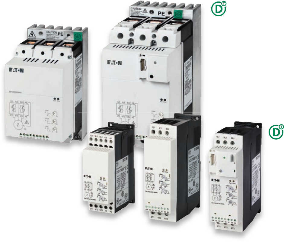
The soft starters have become increasingly established as an alternative
to the star-delta starter. The DS7 replaces the mechanical contactor and
extends the function “Motor soft start”. Motor start-up is soft but still at a
higher torque than other available solutions using the patented method.
Extended service intervals and reduced operating costs are welcomed
side effects.
Designed for normal applications such as pumps, fans and small
conveyors, the compact DS7 is ideal. The DS7 is also available with a
SmartWire-DT connection to simplify wiring and enhance functionality as
an automation solution.
DS7 soft starters in xStart system –
Soft to start, powerful in torque
CA04020001Z.indd 168CA04020001Z.indd 168 22.11.12 09:2122.11.12 09:21
CA04020001Z-EN-INT www.eaton.com

Soft starters DS7
CA04020001Z-EN-INT www.eaton.com
63
Soft starters
System overview
Soft starters DS7 < 32 A 64
Soft starters DS7 > 32 A 66
Key to type references
Soft starters DS7 67
Description
Soft starters DS7 68
Ordering
Soft starters DS7 69
Accessories DS7 70
Soft starters S801/S811 74
Engineering
Design with different load cycles 75
Potentiometer settings 76
LED and operation 77
Connection examples 78
Assigned switching and protective elements 80
Technical Data
Soft starters DS7 82
Abmessungen
Soft starters DS7 88
Fuse-links 89

64 Soft starters DS7
DS7 < 32 A
CA04020001Z-EN-INT www.eaton.com
Moeller® series
DS7 < 32 A
System overview
2 T1 4 T2 6 T3
2 T1 4 T2 6 T3
21
17
15
13
16
11
12
8
9
9
3
1
5
6
7
4
4
2
14
10
15
19
20
18
25
26 27
24
7
23
22
4
10

Soft starters DS7
DS7 < 32 A
CA04020001Z-EN-INT www.eaton.com
65
Moeller® series
Soft starters
Softstarter DS7 with SmartWire-DT 1
→ page 69
DS7 soft starters in construction size 1 for assigned motor
current up to 12 A
2
→ page 69
DS7 soft starters in construction size 2 for assigned motor
current up to 32 A
3
→ page 69
DS7-FAN-32 device fan 4
→ page 73
SmartWire-DT gateway 5
→ page 116
SmartWire-DT external device plug 6
→ page 116
SmartWire-DT flat band conductor 7
→ page 116
Overload relays 8
→ page 70
Motor plug in tool-less plug connection 9
→ page 71
Base for motor plugs 10
→ page 71
PKZM0-XDM wiring set in tool-less plug connection 11, 12
→ page 71
Wiring set PKZM0-XM 13
→ page 71
Three-phase commoning link 14
→ page 72
Standard auxiliary contact 15
→ Industrial Switchgear 2011 catalog, chapter 7
Early-make auxiliary contact 16
→ Industrial Switchgear 2011 catalog, chapter 7
Door coupling handle 17
→ Industrial Switchgear 2011 catalog, chapter 7
PKZM0 motor-protective circuit-breakers 18
→ Industrial Switchgear 2011 catalog, chapter 7
PKE motor-protective circuit-breakers 19
→ Industrial Switchgear 2011 catalog, chapter 7
Extension terminal 20
→ Industrial Switchgear 2011 catalog, chapter 7
Voltage release 21
→ Industrial Switchgear 2011 catalog, chapter 7
Trip indicator switches 22
→ Industrial Switchgear 2011 catalog, chapter 7
Standard auxiliary contact 23
→ Industrial Switchgear 2011 catalog, chapter 7
Motor-starter combination with PKZ 24
→ Industrial Switchgear 2011 catalog, chapter 8
Motor-starter combination with PKE 25
→ Industrial Switchgear 2011 catalog, chapter 8
Busbar adapters 26
→ page 71
Top-hat rail adapter 27
→ page 71

66 Soft starters DS7
DS7 > 32 A
CA04020001Z-EN-INT www.eaton.com
Moeller® series
DS7 > 32 A
22
23
19
13
12
11
15
10
14
21 20
6
18
4
3
9
8
16
17
7
1
10
2
5
7

Soft starters DS7
DS7 > 32 A
CA04020001Z-EN-INT www.eaton.com
67
Moeller® series
Soft starters
DS7 with SmartWire-DT 1
→ page 69
DS7 size 4 up to 200 A 2
→ page 69
DS7 size 3 up to 100 A 3
→ page 69
Device fans 4
→ page 73
Superfast semiconductor fuses 5
→ page 70
Fuse bases for superfast semiconductor fuses 6
→ page 70
IP2X protection against contact with a finger 7
→ page 73
Overload relays 8
→ Industrial Switchgear 2011 catalog, chapter 6
Gateways for SmartWire-DT 9
→ page 116
SmartWire-DT external device plug 10
→ page 116
NZM circuit-breakers 11
→ Industrial Switchgear 2011 catalog, chapter 17
Spacers 12
→ Industrial Switchgear 2011 catalog, chapter 17
Standard auxiliary contact/Trip-indicating auxiliary switch 13
→ Industrial Switchgear 2011 catalog, chapter 17
NZM communication module for SmartWire-DT 14
→ Industrial Switchgear 2011 catalog, chapter 17
Data management interface (DMI module) 15
→ Industrial Switchgear 2011 catalog, chapter 17
Voltage release/Early-make auxiliary contact 16
→ Industrial Switchgear 2011 catalog, chapter 17
Terminal cover for terminals 17
→ page 72
IP2X protection against contact with a finger 18
→ page 73
Terminal cover for cable lugs 19
→ page 72
Connection width extension 20
→ Industrial Switchgear 2011 catalog, chapter 17
Control circuit terminal 21
→ Industrial Switchgear 2011 catalog, chapter 17
Box terminals 22
→ Industrial Switchgear 2011 catalog, chapter 17
Tunnel terminals for Al and Cu cable 23
→ Industrial Switchgear 2011 catalog, chapter 17
Key to type references
DS7 - 3
4 0 SX 004
N
0 -
N
Device series
Radio interference suppression filters
Control voltage supply
SX = Standard soft starters
with internal bypass
Protection type
Rated operational current
004 = 4 A
:
200 = 200 A
N = No internal radio interference
suppression filter
0 = IP20
Options
Number of phases
3 = Three-phase mains
supply voltage
Voltage class
4 = 400 V (380 V - 15 % to
480 V + 10 %)
Generation 7
Device version
0 = 24 V AC/DC
2 = 110/230 V AC
D = 24 V DC SmartWire-DT
N = No option
D = SmartWire-DT

CA04020001Z-EN-INT www.eaton.com
68 Soft starters DS7
System
System
Description
Application
The DS7 series soft starters are
two-phased controlled soft starters
used for soft starting three-phase AC
motors for applications with a normal
operating frequency and a power
range of 3 to 200 A (1.1 to 110 kW with
a 400 V line voltage).
Starting transients and DC
components during startup are
effectively suppressed and guarantee
even motor starting.
The special actuation method
(asymmetrical trigger phase control)
for the soft starter function avoids the
DC components (Eaton patent) that
would normally occur in two-phase-
controlled soft starters. This
suppresses the generation of an
elliptical rotating field, which would
cause uneven motor starting and
increase the motor's startup time. The
true run behavior of the DS7 is
therefore comparable with that of a
three-phase controlled soft starter.
Functions
Typical fields of application for Series
DS7 soft starters are:
• Pump drives: pressure surges are
prevented through soft starting. The
mechanical load on the whole plant
is reduced and its service life
increases.
• Fan drives: soft starting keeps fan
belts from slipping, preventing
premature wear. This lowers
operating costs and extends the
system's lifespan.
• Conveyor belts: conveyor belts start
running smoothly, instead of starting
with a jolt. This ensures that any
goods being conveyed do not topple
over. Mechanical damage to the
belt itself is avoided, making it more
durable.
Features
• The ramp time can be adjusted by
potentiometer within a range of 1 to
30 s (for starting) or 0 to 30 s (for
stopping) with a potentiometer
• The start voltage (or start torque)
can be adjusted within a range of 30
to 100 percent of the line voltage
with a potentiometer
• Significant reduction in switch-on
current, achieved with a short soft
start ramp time (min. 1 s) for lamp
and heating loads
• Internal bypass relay: switches on
automatically after the end of the
ramp, bypassing the internal
thyristors.
• This makes it possible to comply
with radio interference level B
without any additional measures.
• The motor's thermal load is smaller
than it would be without asymmetric
ignition control.
• Designed specifically for long
cables
Documentation
Surface mounting and standard
mounting procedures are described in
the corresponding mounting
instructions and in the manual.
Instructional leaflets:
IL03902003Z: for size 1 devices
(up to 12 A motor rating)
IL03902004Z: for size 2 devices
(up to 32 A motor rating)
IL03902005Z: for size 3, 4 devices
(up to 200 A motor rating)
Manual:
MN03901001Z
You can download the documentation
for the DS7 soft starters from the
Internet
at: www.moeller.net/support
Communication interface
SmartWire-DT
Our SmartWire-DT interface
completely eliminates the need for
conventional control wiring. This has
several advantages:
• No incorrect wiring
•Faster wiring
• Cost saving
The interface can be used to send
control commands to the DS7-SWD
and change and diagnose its
parameter configuration; in addition,
the control electronics can be
powered via the SmartWire-DT cable.
The device is controlled with one of
three selectable profiles:
• A "start/stop" profile, which should
already be familiar from the PKE
motor-protective circuit-breaker
and contactor combination,
• An 8 bit-wide profile for the soft
starter, which is provided the same
way for the variable frequency drive
and features more options
• A control profile comparable to a
PROFIdrive profile, just like the one
available for the variable frequency
drive
Regardless of the profile chosen, the
DS7-SWD's parameters can be read
and written to at any time by using
acyclic services.
DS7-SWD makes it possible to read
and write to all device parameters. The
mechanisms of the parameter channel
that is described for the drives in the
PROFIdrive profile are used for this
purpose. This profile provides a
standardized parameter access
method for variable frequency drives
and soft starters.
It is also possible to overwrite the
potentiometer settings on the
DS7-SWD, which can come in handy,
for instance, when a change made to
the machine needs to be undone.
The DS7-SWD comes with a detailed
diagnostic system with options that
extend far beyond those of wired
devices. In addition to having an error
log, the DS7-SWD can detect and
report nine different device faults. A
warning parameter reports any
present warning messages. Moreover,
the response to each individual fault
can be customized. Finally, there are
35 additional messages for
communication errors. Using the DS7
in connection with the PKE opens up
new functionalities that were
previously thought impossible to
implement with a low-cost soft starter
and that were reserved to significantly
more expensive devices. Combining a
PKE unit and a DS7-SWD makes it
possible to completely protect the
DS7-SWD device against overloads. In
addition, it provides a current limiting
function and can report thermal
capacity utilization levels to higher
level controllers.

Soft starters DS7
Basic devices
CA04020001Z-EN-INT www.eaton.com
69
Moeller® series
Soft starters
Basic de vices
Ordering
Rated operational
current
Assigned
motor rating
Part no.
Article no.
Price
see price
list
Part no.
Article no.
Price
see price
list
Part no.
Article no.
Price
see price
list
Std. pack
Device (AC-53) at 400 V,
50 Hz
at 480 V,
60 Hz
IePKP
AkWHPUC 110 - 230 V AC
Us 24 V AC/DC
UC 110 - 230 V AC
Us 110/230 V AC
UC 24 V DC
Us 24 V DC
Soft starters
Soft starters for three-phase loads
Mains supply voltage (50/60 Hz)
ULN 200 - 480 V AC
41.52DS7-340SX004N0-N
134847
DS7-342SX004N0-N
134925
DS7-34DSX004N0-D
134943
1off
733DS7-340SX007N0-N
134849
DS7-342SX007N0-N
134927
DS7-34DSX007N0-D
134945
945DS7-340SX009N0-N
134910
DS7-342SX009N0-N
134928
DS7-34DSX009N0-D
134946
12 5.5 10 DS7-340SX012N0-N
134911
DS7-342SX012N0-N
134929
DS7-34DSX012N0-D
134947
16 7.5 10 DS7-340SX016N0-N
134912
DS7-342SX016N0-N
134930
DS7-34DSX016N0-D
134948
24 11 15 DS7-340SX024N0-N
134913
DS7-342SX024N0-N
134931
DS7-34DSX024N0-D
134949
32 15 25 DS7-340SX032N0-N
134914
DS7-342SX032N0-N
134932
DS7-34DSX032N0-D
134950
41 22 30 DS7-340SX041N0-N
134916
DS7-342SX041N0-N
134934
DS7-34DSX041N0-D
134952
55 30 40 DS7-340SX055N0-N
134917
DS7-342SX055N0-N
134935
DS7-34DSX055N0-D
134953
70 37 50 DS7-340SX070N0-N
134918
DS7-342SX070N0-N
134936
DS7-34DSX070N0-D
134954
81 45 60 DS7-340SX081N0-N
134919
DS7-342SX081N0-N
134937
DS7-34DSX081N0-D
134955
100 55 75 DS7-340SX100N0-N
134920
DS7-342SX100N0-N
134938
DS7-34DSX100N0-D
134956
135 75 100 DS7-340SX135N0-N
134921
DS7-342SX135N0-N
134939
DS7-34DSX135N0-D
134957
160 90 125 DS7-340SX160N0-N
134922
DS7-342SX160N0-N
134940
DS7-34DSX160N0-D
134958
200 110 150 DS7-340SX200N0-N
134923
DS7-342SX200N0-N
134941
DS7-34DSX200N0-D
134959
Notes
4 - 12 A 16 - 32 A 41 - 100 A 135 - 200 A
Information relevant for export to North America UL/CSA applies only for DS7…-N
Product Standards IEC/EN 60947-4-2; GB 14048.6; UL 508; CSA-C22.2 No 0-M91;
CSA-C22.2 No 14-05 CE marking
UL File No. E251034
CSA File No. 2511305
CSA Class No. 321106
Suitable for Branch circuits
Max. Voltage Rating 480 V
Degree of Protection IP20; UL/CSA Type 1

70 Soft starters DS7
Accessories
CA04020001Z-EN-INT www.eaton.com
Moeller® series
Accessories
Rated
device
current
Maximum
power loss
Size/inside
caliper
For use with Part no.
Article no.
Price
see price list
Std. pack Information relevant for export to North
America
Pv
AW mm
Fuses
- 16 5 10 x 38 DS4-140-010-H
DS7-34…SX004N0-…
50.179.06-16
232077
10off Product Standards UL 248-13
CE marking
UL File No. E180276
UL CCN JFHR2
CSA File No. UL report applies
to both US and
Canada
CSA Class No. JFHR8
NA Certification UL recognized,
certified by UL for
use in Canada
Max. Voltage Rating 660V
- 25 7 22 x 58 DS7-34…SX007N0-… 50.140.06-25
138284
1off
- 32 9 80 DS7-34…SX009N0-…
DS7-34…SX012N0-…
20.282.20-32
138285
1off
50 15 22 x 58 DS7-34…SX016N0-… 50.140.06-50
232079
10off
63 16 22 x 58 DS7-34…SX024N0-… 50.140.06-63
232080
10off
80 18 22 x 58 DS7-34…SX032N0-… 50.140.06-80
232081
10off
100 22 80 DS7-34…SX041N0-… 20.282.20-100
106654
6off
125 24 80 DS7-34…SX055N0-… 20.282.20-125
232087
6off
- 200 44 80 DS7-34…SX070N0-…
DS7-34…SX081N0-…
DS7-34…SX100N0-…
20.610.32-200
106475
3off
- 350 61 80 DS7-34…SX135N0-… 20.610.32-350
221161
2off
- 400 70 80 DS7-34…SX160N0-… 20.610.32-400
106476
3off
- 500 72 80 DS7-34…SX200N0-… 20.610.32-500
221163
2off
Fuse Bases
- - 10 x 38 50.179.06-… 51.063.04
232082
12off Product Standards UL 512;
CE marking
UL File No. E186970
UL CCN IZLT2
- - 22 x 58 50.140.06-… 51.060.04
232084
6off
- - 80 20.282.20-…
20.189.20-…
21.189.01
232064
5off
- - 80 20.6xx.32-… 21.313.02
232076
2off
For use with Part no.
Article no.
Price
see price list
Std. pack Information relevant for export to North America
Overload relays
DS7-34…SX004… ZB12-4
278438
1off Product Standards UL 508; CSA-C22.2 No. 14; IEC/EN
60947-4-1; IEC/EN 60947-5-1;
CE marking
UL File No. E29184
UL CCN NKCR
CSA File No. 12528
CSA Class No. 3211-03
NA Certification UL listed, CSA certified
Suitable for Branch circuits
Max. Voltage Rating 600 V AC
Degree of Protection IEC: IP20, UL/CSA Type: -
DS7-34…SX007…
DS7-34…SX009…
ZB12-10
278440
DS7-34…SX012… ZB12-12
278441
DS7-34…SX016… ZB32-16
278452
DS7-34…SX024… ZB32-24
278453
DS7-34…SX032… ZB32-32
278454

Soft starters DS7
Accessories
CA04020001Z-EN-INT www.eaton.com
71
Moeller® series
Soft starters
Wiring set
For DOL Starter
DS7-34…SX004…
DS7-34…SX007…
DS7-34…SX009…
DS7-34…SX012…
PKZM0-XDM12
283149
1off Product Standards UL 508; CSA-C22.2 No. 14;
IEC60947-4-1; CE marking
UL File No. E36332
UL CCN NLRV
CSA File No. 12528
CSA Class No. 3211-05
NA Certification UL listed, CSA certified
Electric contact module
DS7-34…SX016…
DS7-34…SX024…
DS7-34…SX032…
PKZM0-XM32DE
239349
5off Product Standards UL 508; CSA-C22.2 No. 14;
IEC60947-4-1; CE marking
UL File No. E36332
UL CCN NLRV
CSA File No. 12528
CSA Class No. 3211-05
NA Certification UL listed, CSA certified
Motor feeder plug
DS7-34…SX004…
DS7-34…SX007…
DS7-34…SX009…
DS7-34…SX012…
DILM12-XMCP/T
121770
1off Product Standards IEC/EN 60947-4-1; UL 508;
CSA-C22.2 No. 14-05; CE marking
NA Certification Request filed for UL and CSA
Busbar adapters
PKZM0, PKE + DS7...004N...
PKZM0, PKE + DS7...007N...
PKZM0, PKE + DS7...009N...
PKZM0, PKE + DS7...012N...
BBA0L-25
142526
1off
PKZM0, PKE + DS7...016N...
PKZM0, PKE + DS7...024N...
PKZM0, PKE + DS7...032N...
BBA0L-32
142527
1off
Top-hat rail adapter
45mm wide adapter plate
PKZM0, PKE + DS7...004N...
PKZM0, PKE + DS7...007N...
PKZM0, PKE + DS7...009N...
PKZM0, PKE + DS7...012N...
PKZM0-XC45L
142529
1off
PKZM0, PKE + DS7...016N...
PKZM0, PKE + DS7...024N...
PKZM0, PKE + DS7...032N...
PKZM0-XC45L/2
142570
1off
For use with Part no.
Article no.
Price
see price list
Std. pack Information relevant for export to North America

72 Soft starters DS7
Accessories
CA04020001Z-EN-INT www.eaton.com
Moeller® series
For use with Part no.
Article no.
Price
see price
list
Std. pack Notes Information relevant for export to
North America
Three-phase commoning links
For the primary side of DS7
Suitable for 3 DS7 soft starters
Length 112 mm
protected against accidental contact, short-
circuit proof, Ue = 690 V, Iu = 35 A
can be extended by rotating by mounting
DS7-34…SX004…
DS7-34…SX007…
DS7-34…SX009…
DS7-34…SX012…
DILM12-XDSB0/3
240084
5off For the primary side of DS7
Suitable for 3 DS7 soft starters
Length 112 mm
Product StandardsIEC/EN 60947-4-1;
UL 508; CSA-C22.2
No. 14-05; CE
marking
UL File No. E36332
UL CCN NLRV
CSA File No. 012528
CSA Class No. 2411-03
NA Certification UL listed, CSA
certified
DILM12-XDSB0/4
240085
For the primary side of DS7
Suitable for 4 DS7 soft starters
Length 157 mm
DILM12-XDSB0/5
240086
For the primary side of DS7
Suitable for 5 DS7 soft starters
Length 202 mm
Incoming connection block
DS7-34…SX004…
DS7-34…SX007…
DS7-34…SX009…
DS7-34…SX012…
DILM12-XEK
240083
5off For three-phase commoning
link, protected against
accidental contact, Ue = 690 V,
Iu = 35 A.
Connection cross section:
Stranded 2.5…16 mm2
Flexible with ferrule
2.5…16 mm2
AWG14…8
Product StandardsIEC/EN 60947-4-1;
UL 508; CSA-C22.2
No. 14-05; CE
marking
UL File No. E36332
UL CCN NLRV
CSA File No. 012528
CSA Class No. 2411-03
NA Certification UL listed, CSA
certified
Terminal cover
Type contains parts for a terminal located at top or
bottom for 3 pole circuit-breakers.
Enhancement of the busbar tag shroud (simple
protection against contact with a finger).
Cannot be combined with NZM-XSTK control
circuit terminal.
knockout
For box terminal
DS7-34…SX041…
DS7-34…SX055…
DS7-34…SX070…
DS7-34…SX081…
DS7-34…SX100…
NZM1-XKSFA
100780
1off Type contains parts for a
terminal located at top or
bottom for 3 pole circuit-
breakers.
Enhancement of the busbar
tag shroud (simple protection
against contact with a finger).
Cannot be combined with
NZM-XSTK control circuit
terminal.
UL/CSA certification not required
knockout DS7-34…SX135…
DS7-34…SX160…
DS7-34…SX200…
NZM2-XKSFA
104640
1off Type contains parts for a
terminal located at top or
bottom for 3 pole
circuit-breakers.
Enhancement of the busbar
tag shroud (simple protection
against contact with a finger).
Protection when reaching into
the cable connection area
with the connection of cables
in the box terminal.
With 2 conductors max cross
section 22 mm2 or AWG4.
Cannot be combined with
NZM-XSTK control circuit
terminal.
DS7-34…SX135…
DS7-34…SX160…
DS7-34…SX200…
NZM2-XKSA
260038
1off Type contains parts for a
terminal located at top or
bottom for 3 pole circuit-
breakers.
Busbar tag shroud where
cable lugs, busbars or tunnel
terminals are used.
When using insulated
conductor material to IP1X.
Product Standards UL489;
CSA-C22.2
No. 5-09;
IEC60947, CE
marking
UL File No. E31593
UL CCN DIHS
CSA File No. 22086
CSA Class No. 1432-01
NA Certification UL listed,
CSA certified
Suitable for Refer to main
component
information
2T1 4T2 6T3
1L3 3 L2 5 L1

Soft starters DS7
Accessories
CA04020001Z-EN-INT www.eaton.com
73
Moeller® series
Soft starters
IP2X protection against contact with a
finger
Typ enthält Teile für eine Schalterseite oben oder
unten für 3-polige Schalter.
Erhöhung des Berührungsschutzes auf IP2X.
For box terminal NZM2, PN2, N(S)2 NZM2-XIPK
266773
1off Type contains parts for a
terminal located at top or
bottom for 3 pole
circuit-breakers.
Enhancement of the busbar
tag shroud to IP2X.
Protection when reaching into
the cable connection area
with the connection of cables
in the box terminal.
With 2 conductors max cross
section 25 mm2 or AWG4.
Cannot be combined with
NZM-XSTK control circuit
terminal.
for cover NZM2-XKSA or
NZM2 or NZM2...(C)NA
und N(S)2...NA
NZM2, PN2, N(S)2 NZM2-XIPA
266777
1off Type contains parts for a
terminal located at top or
bottom for 3 pole
circuit-breakers.
Enhancement of the busbar
tag shroud to IP2X.
When mounting
NZM2-..-(C)NA or NZM...-NA
the following applies:
with 2 conductors max cross
section 25 mm2 or AWG4.
Mounting kit
when using covers NZM1-XKSFA and NZM2-
XKSA
DS7-34xSX041N0-x
DS7-34xSX055N0-x
DS7-34xSX070N0-x
DS7-34xSX081N0-x
DS7-34xSX100N0-x
DS7-34xSX135N0-x
DS7-34xSX160N0-x
DS7-34xSX200N0-x
DE6-MNT-NZM
107323
1off -
Device fans
Device fan for increasing the load cycle (more
starts per hour higher or longer-lasting starting
current)
DS7-34…SX004…
DS7-34…SX007…
DS7-34…SX009…
DS7-34…SX012…
DS7-34…SX016…
DS7-34…SX024…
DS7-34…SX032…
DS7-FAN-032
135553
1off NA Certification Request filed for
UL and CSA
DS7-34…SX041…
DS7-34…SX055…
DS7-34…SX070…
DS7-34…SX081…
DS7-34…SX100…
DS7-FAN-100
169021
1off
DS7-34…SX135…
DS7-34…SX160…
DS7-34…SX200…
DS7-FAN-200
169022
1off
For use with Part no.
Article no.
Price
see price
list
Std. pack Notes Information relevant for export to
North America

S801+ soft starters and S811+ soft starters
The S801+ and S811+ soft starter series feature a number of
multifunctional devices that are easy to install and program.
They have been designed for controlling three-phase motors
and cover a range of 11 – 1000 A. Not only are they among the
smallest and most compact soft starters on the market, but
they can also work with outputs of 10 – 900 kW.
S801+ Soft Starter
These soft starters meet today's need for smooth torque
increases. They control the power supplied to a three-phase
motor in such a way that its load behavior will be ideal for the
machine being used. To enable operators to do this, they
come with the option of using an extremely popular ramp con-
trol function with a starting torque of 0 –85% and a ramp time
of 0.5 –180 seconds, as well as other starting functions, such
as a kick start function (with breakaway torque) and current
limiting. Additional functions include a soft stop control func-
tion, variable torque control, a programmable overload setting
(31–100 %), and integrated overload protection. This overload
protection protects the device from overheating when the
temperature is too high and trips at a terminal temperature of
100 degrees.
S811+ Soft Starter
S811+ devices come with all the features of the S801+ series
and also include new and improved communication options.
The DIM digital interface module, with an alphanumeric dis-
play and soft keys, makes it possible to configure the device
and read and write data. The keypad and the aforementioned
soft keys are used to navigate through the devices' various
menus, and enable users to display and enter system and
parameter values. Moreover, measuring, monitoring, and diag-
nostic functions are available, as are troubleshooting error
codes. Finally, on-board Modbus® provides a ready-to-use
communications interface, and other field bus modules are
also available.
If you have any questions regarding our S801+ or S811+ soft starters, please contact your Eaton contact person.
To find the right contact person:
The contact person for your region: Contact person for worldwide questions:
P http://salesbonn.moeller.net P www.eaton.eu/electrical/contact
Sizes
This soft starter series features four sizes (T and U have the
same identical design) with five different performance ranges.
Construc-
tion size Max. cur-
rent
Three-phase motors
KW rate (50 Hz / 60 Hz)
230 V 380–400 V 440 V 575–690 V
N37 10 18.5 18.5 30
66 18.5 30 37 60
R105 30 55 59 100
135 40 63 80 125
T
180 51 90 110 150
240 75 110 147 200
304 90 160 185 300
U
360 110 185 220 350
420 129 220 257 450
500 150 257 300 500
V
360 110 185 220 350
420 129 220 257 450
500 150 257 300 500
650 200 355 425 600
720 220 400 450 700
850 257 475 500 900
1000 277 525 500 900
CA04020001Z.indd 140CA04020001Z.indd 140 22.11.12 09:2122.11.12 09:21
CA04020001Z-EN-INT www.eaton.com

Soft starters DS7
Design with different load cycles
CA04020001Z-EN-INT www.eaton.com
75
Soft starters
Design with different load cycles
Engineering
DS7-34...SX041N0-... DS7-34...SX055N0-...
DS7-34...SX070N0-... DS7-34...SX081N0-...
DS7-34...SX100N0-... DS7-34...SX135N0-...
DS7-34...SX160N0-... DS7-34...SX200N0-...
Note: Additional diagrams for 4-32 A soft starters can be found in the manual for DS7 soft starters (MN03901001Z).
22K 1/h
22K 10/h
22K 20/h
s
5 s
10 s
15 s
20 s
25 s
30 s
60 A
70 A
80 A
90 A
100 A
110 A
120 A
130 A
140 A
150 A
30K 1/h
30K 10/h
30K 20/h
s
5 s
10 s
15 s
20 s
25 s
30 s
80 A 100 A 120 A 140 A 180 A160 A 200 A
37K 1/h
37K 10/h
37K 20/h
s
5 s
10 s
15 s
20 s
25 s
30 s
100 A 125 A 150 A 175 A 225 A200 A 250 A
45K 1/h
45K 10/h
45K 20/h
s
5 s
10 s
15 s
20 s
25 s
30 s
100 A 125 A 175 A150 A 200 A 275 A250 A225 A 300 A
55K 1/h
55K 10/h
55K 20/h
s
5 s
10 s
15 s
20 s
25 s
30 s
175 A150 A 200 A 275 A250 A225 A 300 A 325 A 350 A
75K 1/h
75K 10/h
75K 20/h
s
5 s
10 s
15 s
20 s
25 s
30 s
125 A
150 A
175 A
200 A
225 A
250 A 300 A
275 A 325 A
350 A
375 A
400 A
425 A
450 A
475 A
500 A 550 A
525 A
90K 1/h
90K 10/h
90K 20/h
s
5 s
10 s
15 s
20 s
25 s
30 s
150 A
200 A
250 A
300 A
350 A
400 A
450 A
500 A
550 A
600 A
650 A
110K 1/h
110K 10/h
110K 20/h
s
5 s
10 s
15 s
20 s
25 s
30 s
200 A
250 A
300 A
350 A
400 A
450 A 550 A
600 A500 A
650 A
700 A
750 A
800 A

76 Soft starters DS7
Potentiometer settings
CA04020001Z-EN-INT www.eaton.com
Potentiomete r settings
UI
(R)
(L) (AC11
Imin Umin
250 V ∼0.2 A 1 A 10 mA 250 V ∼
30 V H 0.7 A 0.5 A 100 mA 5 V H
t-Start (s) U-Start % t-Stop (s)
∼10 ∼30 0 J → 0
Low flywheel mass
∼25 ∼30 ∼30 Conveyor belt with loose belt
∼20 ∼40 0 Roller conveyers
∼10 ∼30 ∼20 Centrifugal pump
∼15 ∼40 0 Fan general (building) with
belt drive
∼18 ∼40 0 J → ∞
Large gyrating mass→ The
DS7 soft starter's rating
should be higher than the
assigned motor output.
∼15 ∼50 0 Tunnel fan
Axial fan
a Soft starter DS7 should
have a higher rating than the
assigned motor.
∼10 ∼60 0 Bulk conveyor
Escalator
∼10 ∼60 0 Mixers
Agitators
a Soft starter DS7 should
have a higher rating than the
assigned motor.
U-Start
U
t-Start t-Stop t
13 14
TOR
(Top Of Ramp)
23 24
RUN
13 14
TOR
23 24
RUN
t-Start (s)
U-Start (%)
t-Stop (s)
30
1
20
10
100
30
30
0
2010
30
1
20
10
100
30
30
0
2010
30
1
20
10
100
30
30
0
2010
30
1
20
10
100
30
30
0
2010
30
1
20
10
100
30
30
0
2010
30
1
20
10
100
30
30
0
2010
30
1
20
10
100
30
30
0
2010
30
1
20
10
100
30
30
0
2010
30
1
20
10
100
30
30
0
2010

Soft starters DS7
LED and operation
CA04020001Z-EN-INT www.eaton.com
77
Soft starters
LED and operation
Operation Fault
RUN-LED green
Error-LED red
① Initialization
② Ready for operation
③ in ramp
④ Top of ramp reached
⑤ Fault – One phase drops out
Error
U
L1, L2, L3
RUN
+ 24 V
~ 0.5 s
U
Start
TOR
(13/14)
U
T1, T2, T3
EN
+ A1
ab
RUN
(23/24)
t - Start t - Stop
c
d
A
Error
U
L1, L2, L3
RUN
+ 24 V
TOR
(13/14)
U
T1, T2, T3
EN
+ A1
e
RUN
(23/24)
t - Start
c
d
A

78 Soft starters DS7
Connection examples
CA04020001Z-EN-INT www.eaton.com
Connection examples
Standard connection
Up to 12 A
Standard connection
Up to 32 A
M
3 ~
1L1
3L2
5L3
+ Us
TOR
- A2 + A1 13
2T1
4T2
6T3
L1
L2
L3
PE
Q1
Q21
F3
M1
I > I > I >
Q1
(+) U
s
24 V AC/DC, 120/230 V AC
(–) U
s
+ A1
t-Start
U
Start
TOR
(13/14)
U
T1, T2, T3
Q1
U
L1, L2, L3
U
s
M
3 ~
RUN
- U
s
+ U
s
1L1
3L2
5L3
TOR
- A2 + A1 13 14 2423
2T1
4T2
6T3
L1
L2
L3
PE
Q1
Q1
S3
Q21
F3
M1
I > I > I >
(+) U
s
24 V AC/DC, 120/230 V AC
(–) U
s
t-Start
UStart
t-Stop
TOR
(13/14)
S3
(Start/Stop)
UT1, T2, T3
RUN
(23/24)
Us
Q1
UL1, L2, L3

Soft starters DS7
Connection examples
CA04020001Z-EN-INT www.eaton.com
79
Soft starters
Standard connection
over 32 A
With Emergency switching off function according to IEC/EN 60 204-1 and VDE 0113 Part 1
= Emergency switching off
①Control circuit terminal
②Undervoltage release with
early-make auxiliary contact
M
3 ~
1L1
3L2
5L3
PE
PE
D2
D1 3.13
3.14
TOR
- A2 EN + A1 13 14 2423
2T1
4T2
6T3
L1
L2
L3
PE
Q1
Q1
S3
Q21
F3
M1
I >
U>
I > I >
RUN
- U
s
+ U
s
(+) U
s
24 V AC/DC, 110/230 V AC
(–) U
s
②
①
t - Start
U
Start
t - Stop
TOR
(13/14)
S3
(Start/Stop)
U
T1, T2, T3
RUN
(23/24)
U
L1, L2, L3
Q1, EN
U
s

80 Soft starters DS7
Assigned switching and protective elements
CA04020001Z-EN-INT www.eaton.com CA04020001Z-EN-INT www.eaton.com
Soft starters DS7
Assigned switching and protective elements
Soft starters
Assigned switching and protective elements
assigned Rated operational current1) Part no. Soft starter function Soft starter function with soft stop in case of overload Mains contactor Semiconductor contactor (optional, in addition to the
protective devices for type 1 coordination, required for type 2
coordination)5)
Motor power at Soft starters
(device to be selected)
400 V 480 V Motor Soft starters Cable protection2) Cable protection2) Overload relays3) optional4) Fuses Fuse holders
KP KP IeIeType “1” coordination Type “1” coordination
kWh HP T T Number x Part no. Number x Part no.
Soft starters for three-phase mains connection,
low operating frequency (5 s, 3 x Ie, 10 starts/h)
1.52 3.64 DS7-34xSX004N0-x PKZM0-4 (+ CL-PKZ0) PKM0-4 (+ CL-PKZ0) ZB12-4 DILM7 3 × 50.179.06-16 3 x 51.060.04
336.67DS7-34xSX007N0-x PKZM0-10 (+ CL-PKZ0) PKM0-10 (+ CL-PKZ0) ZB12-10 DILM9 3 × 50.140.06-25 3 x 51.060.04
458.59DS7-34xSX009N0-x PKZM0-10 (+ CL-PKZ0) PKM0-10 (+ CL-PKZ0) ZB12-10 DILM9 3 × 20.282.20-32 3 x 51.060.04
5.5 7.5 11.3 12 DS7-34xSX012N0-x PKZM0-12 (+ CL-PKZ0) PKM0-12 (+ CL-PKZ0) ZB12-12 DILM12 3 × 20.282.20-32 3 x 51.060.04
7.5 10 15.2 16 DS7-34xSX016N0-x PKZM0-16 (+ CL-PKZ0) PZM0-16 (+ CL-PKZ0) ZB32-16 DILM17 3 × 50.140.06-50 3 x 51.060.04
11 15 21.7 24 DS7-34xSX024N0-x PKZM0-25 (+ CL-PKZ0) PZM0-25 (+ CL-PKZ0) ZB32-24 DILM25 3 × 50.140.06-63 3 x 51.060.04
15 20 29.3 32 DS7-34xSX032N0-x PKZM0-32 (+ CL-PKZ0) PZM0-32 (+ CL-PKZ0) ZB32-32 DILM32 3 × 50.140.06-80 3 x 51.060.04
22 25 41 41 DS7-34xSX041N0-x NZMN1-M50 / PKZM4-50 NZMN1-M50 / PKZM4-50 ZB65-40+ZB65-XEZ DILM50 3 × 50.140.06-80 3 x 21.189.01
30 30 55 55 DS7-34xSX055N0-x NZMN1-M63 / PKZM4-58 NZMN1-M63 / PKZM4-58 ZB65-57+ZB65-XEZ DILM65 3 × 20.282.20-125 3 x 21.189.01
37 40 68 70 DS7-34xSX070N0-x NZMN1-M80 NZMN1-M80 ZB150-70/KK DILM80 3 × 20.610.32-200 3 x 21.313.02
45 50 81 81 DS7-34xSX081N0-x NZMN1-M100 NZMN1-M100 ZB150-100/KK DILM95 3 × 20.610.32-200 3 x 21.313.02
55 60 99 100 DS7-34xSX100N0-x NZMN1-M100 NZMN1-M100 ZB150-100/KK DILM115 3 × 20.610.32-200 3 x 21.313.02
75 75 134 135 DS7-34xSX135N0-x NZMN2-M160 NZMN2-M160 ZB150-150/KK DILM150 3 × 20.610.32-350 3 x 21.313.02
90 100 160 160 DS7-34xSX160N0-x NZMN2-M200 NZMN2-M200 Z5-160/FF250 DILM185 3 × 20.610.32-400 3 x 21.313.02
110 125 196 200 DS7-34xSX200N0-x NZMN2-M200 NZMN2-M200 Z5-220/FF250 DILM225 3 × 20.610.32-500 3 x 21.313.02
Instructions 1) Rated operational current based on the load cycle specified here.
2) Indicates the circuit-breaker required for the indicated load cycle. At different duty cycles (operating frequency, overcurrent, overcurrent time,
duty factor), this value changes and must then be adapted accordingly.
3) An external overload relay is required if the main contacts should not be disconnected in the event of an overload and a controlled soft stop is
desired instead.
4) A mains contactor is not required. Disconnection characteristics in accordance with VDE can only be ensured with the specified circuit-breaker.
5) The superfast semiconductor fuses protect the soft starters from motor-side short-circuits. This can not, however, prevent damage caused by
voltage peaks, for example through lightning strike.
81

82 DS7 soft starters
Soft starters
CA04020001Z-EN-INT www.eaton.com CA04020001Z-EN-INT www.eaton.com
DS7 soft starters
Soft starters
Soft starters
Soft starters
DS7-340SX004 DS7-340SX007 DS7-340SX009 DS7-340SX012 DS7-340SX016 DS7-340SX024 DS7-340SX032 DS7-340SX041 DS7-340SX055 DS7-340SX070 DS7-340SX081 DS7-340SX100 DS7-340SX135 DS7-340SX160 DS7-340SX200
General
Standards IEC/EN 60 947-4-2 IEC/EN 60 947-4-2
Climatic proofing Damp heat, cyclic, to DIN IEC Part 68 2-10,
Damp heat, constant, to DIN IEC 68 Part 2-3
Damp heat, cyclic, to DIN IEC Part 68 2-10,
Damp heat, constant, to DIN IEC 68 Part 2-3
Ambient temperature °C 0…40, up to 60 °C at 1 % derating per Kelvin temperature rise 0…40, up to 60 °C at 1 % derating per Kelvin temperature rise
Ambient temperature storage °C -25 - +55 -25 - +55
Installation altitude Higher installation altitude upon request 0…1000 m, above that 1 % derating per 100 m, up to 2000 m 0…1000 m, above that 1 % derating per 100 m, up to 2000 m
Mounting position Vertical Vertical
Protection type IP20 IP20
Protection type applies to the front and operator control and
operating elements. Protection type from all sides is IP00.
Protection type IP40 can be achieved on all sides with covers from the
NZM range.
Protection type IP40 can be achieved on all sides with covers from the NZM range.
Protection against direct contact Finger- and back-of-hand proof Finger- and back-of-hand proof
Overvoltage category/pollution degree II/2 II/2
Mechanical shock resistance 8 g/11 ms 8 g/11 ms
Vibration resistance to EN 60721-3-2 2M2 2M2
Average heat dissipation with nominal load cycle W 0.2 0.35 0.45 0.6 0.8 1.1 1.5 710 13 18 25 24 30 42
Dimensions (W x H x D) mm 45 x 130 x 95 45 x 150 x 118 93 x 175 x 139 108 x 215 x 178
Radio interference level B B
Weight kg 0.35 0.35 0.35 0.35 0.4 0.4 0.4 1.8 1.8 1.8 1.8 1.8 3.7 3.7 3.7
Main contacts
Rated operational voltage V AC 230 - 460 230 - 460
Mains frequency Hz 50/60 50/60
Rated operational current AC-53 (motor loads) IeA 4 7 9 12 16 24 32 41 55 70 81 100 135 160 200
Assigned motor rating 230 V P kWh 0.75 1.5 2.2 3 4 5.5 7.5 11 15 15 22 30 30 45 55
400 V P kWh 1.5 3 4 5.5 7.5 11 15 22 30 37 45 55 75 90 110
480 V P HP 2 3 5 7.5 10 15 20 30 40 50 60 75 100 125 150
Overload cycle to EN 60947-4-2
AC-53a (int. bypass) For AC-53a:3-5:75-10 A 4 7 9 12 16 24 32 41 55 70 81 100 135 160 200
Terminal capacity
Power cable
(box terminal)
Solid mm21 x (0.75 - 4); 2 x (0.75 - 2.5) 1 x (0.75 - 16); 2 x (0.75 - 10) 1 x (25 - 70); 2 x (6 - 25) 1 x (4 - 185); 2 x (4 - 70)
Flexible with ferrule mm21 x (0.75 - 2.5); 2 x (0.75 - 2.5) 1 x (0.75 - 16); 2 x (0.75 - 10) - - - - - - - -
Stranded mm2- - - - 1 x 16 1 x (25 - 70); 2 x (6 - 25) 1 x (4 - 185); 2 x (4 - 70)
Solid or stranded AWG 18 - 10 18 - 6 1 x (12 - 2/0) 1 x (12 - 350 kcmil); 2 x (12 - 00)
Flat conductor min, mm - - - - - - - 2 x 9 x 0.8 2 x 9 x 0.8
max, mm - - - - - - - 9 x 9 x 0.8 10 x 16 x 0.8
Tightening torque Nm 1.2 1.2 1.2 1.2 3 3 3 - - - - - - - -
Control cables Solid mm21 x (0.75 - 4); 2 x (0.75 - 2.5) 1 x (0.5 - 2.5); 2 x (0.5 - 1.0)
Flexible with ferrule mm21 x (0.75 - 2.5); 2 x (0.75 - 2.5) 1 x (0.5 - 1.5); 2 x (0.5 - 0.75)
Stranded mm2- - - - 1 x (0.5 - 1.5); 2 x (0.5 - 1.0)
Solid or stranded AWG 18 - 10 1 x (21 - 14); 2 x (21 - 18)
Tightening torque Nm 1.2 1.2 1.2 1.2 1.2 1.2 1.2 0.4 0.4 0.4 0.4 0.4 0.4 0.4 0.4
Screwdriver (flat blade) mm 0.8 x 5.5; 1 x 6 0.6 x 3.5
Power section
Rated impulse withstand voltage Uimp 1.2/50 μskV4 4 4 4 4 4 4 4 4 4 4 4 4 4 4
Rated insulation voltage UiV500 500 500 500 500 500 500 500 500 500 500 500 500 500 500
Short-circuit rating
Type "1" coordination For AC-53a:3-5:75-10 PKZM0-4
(+ CL-PKZ0)
PKZM0-10
(+ CL-PKZ0)
PKZM0-10
(+ CL-PKZ0)
PKZM0-12
(+ CL-PKZ0)
PKZM0-16
(+ CL-PKZ0)
PKZM0-25
(+ CL-PKZ0)
PKZM0-32
(+ CL-PKZ0)
NZMN1-M50 /
PKZM4-50
NZMN1-M63 /
PKZM4-58
NZMN1-M80 NZMN1-M100 NZMN1-M100 NZMN2-M160 NZMN2-M200 NZMN2-M200
Type "2" coordination
(in addition to fuses for type "1" of coordination)
3 x 50.179.06-16 3 x 50.140.06-25 3 x 20.282.20-32 3 x 20.282.20-32 3 x
50.140.06-50
3 x
50.140.06-63
3 x
50.140.06-80
3 x
20.282.20-100
3 x
20.282.20-125
3 x
20.610.32-200
3 x
20.610.32-200
3 x
20.610.32-200
3 x
20.610.32-350
3 x
20.610.32-400
3 x
20.610.32-500
Fuse holders 3 x 51.060.04 3 x 51.060.04 3 x 51.060.04 3 x 51.060.04 3 x 51.060.04 3 x 51.060.04 3 x 51.060.04 3 x 21.189.01 3 x 21.189.01 3 x 21.313.02 3 x 21.313.02 3 x 21.313.02 3 x 21.313.02 3 x 21.313.02 3 x 21.313.02
Control circuit
Controller supply voltage Voltage UsV24 V AC/DC + 10 % / - 15 % 24 V AC/DC + 10 % / - 15 %
Current consumption at no load 24 V DC mA - - - - - - - 35 35 35 35 35 35 35 35
Current consumption in operation at
24VDC
mA - - - - - - - 65 65 65 65 65 65 65 65
Current consumption at peak load
(close bypass) at 24 V DC
mA/ms - - - - - - - 600/50 600/50 600/50 600/50 600/50 600/50 600/50 600/50
Control voltage range AC operated 24 V AC/DC + 10 % / - 15 % 24 V AC/DC + 10 % / - 15 %
Current consumption at 230 V DC mA - - - - - - - 14 14 14 14 14 14 14 14
Pick-up voltage DC operated V DC +17.3 - +27 +17.3 - +27 +17.3 - +27 +17.3 - +27 +17.3 - +27 +17.3 - +27 +17.3 - +27 +17.3 - +27 +17.3 - +27 +17.3 - +27 +17.3 - +27 +17.3 - +27 +17.3 - +27 +17.3 - +27 +17.3 - +27
AC operated V AC - - - - - - - - - - - - - - -
Drop-out voltage DC operated V DC 0 - +3 0 - +3 0 - +3 0 - +3 0 - +3 0 - +3 0 - +3 0 - +3 0 - +3 0 - +3 0 - +3 0 - +3 0 - +3 0 - +3 0 - +3
AC operated V AC - - - - - - - - - - - - - - -
Pick-up time AC operated ms - - - - - - - 250 250 250 250 250 250 250 250
Drop-out time AC operated ms - - - - - - - 190 190 190 190 190 190 190 190
Relay outputs Number 1 (TOR) 2 (TOR)
Voltage range V AC 250 250
Current range A 1 A, AC-1 1 A, AC-1 3 A, AC-1
Soft start functions
Ramp times Acceleration s 1 - 30 1 - 30
Deceleration s 0 - 30 0 - 30
Start voltage (= switch-off voltage) 30 % - 100 % 30 % - 100 %
Voltage reduction at stop 8 % 8 %
83
DS7-340SX DS7-340SX

84 DS7 soft starters
Soft starters
CA04020001Z-EN-INT www.eaton.com CA04020001Z-EN-INT www.eaton.com
DS7 soft starters
Soft starters
Soft starters
Soft starters
DS7-342SX004 DS7-342SX007 DS7-342SX009 DS7-342SX012 DS7-342SX016 DS7-342SX024 DS7-342SX032 DS7-342SX041 DS7-342SX055 DS7-342SX070 DS7-342SX081 DS7-342SX100 DS7-342SX135 DS7-342SX160 DS7-342SX200
General
Standards IEC/EN 60 947-4-2 IEC/EN 60 947-4-2
Climatic proofing Damp heat, cyclic, to DIN IEC Part 68 2-10,
Damp heat, constant, to DIN IEC 68 Part 2-3
Damp heat, cyclic, to DIN IEC Part 68 2-10,
Damp heat, constant, to DIN IEC 68 Part 2-3
Ambient temperature °C 0…40, up to 60 °C at 1 % derating per Kelvin temperature rise 0…40, up to 60 °C at 1 % derating per Kelvin temperature rise
Ambient temperature storage °C -25 - +55 -25 - +55 °C
Installation altitude Higher installation altitude upon request 0…1000 m, above that 1 % derating per 100 m, up to 2000 m 0…1000 m, above that 1 % derating per 100 m, up to 2000 m
Mounting position Vertical Vertical
Protection type IP20 IP20
Protection type applies to the front and operator control and
operating elements. Protection type from all sides is IP00.
Protection type IP40 can be achieved on all sides with covers from the
NZM range.
Protection type IP40 can be achieved on all sides with covers from the NZM range.
Protection against direct contact Finger- and back-of-hand proof Finger- and back-of-hand proof
Overvoltage category/pollution degree II/2 II/2
Mechanical shock resistance 8 g/11 ms 8 g/11 ms
Vibration resistance to EN 60721-3-2 2M2 2M2
Average heat dissipation with nominal load cycle W 0.2 0.35 0.45 0.6 0.8 1.1 1.5 710 13 18 25 24 30 42
Dimensions (W x H x D) mm 45 x 130 x 95 45 x 150 x 118 93 x 175 x 139 108 x 215 x 178
Radio interference level B B
Weight kg 0.4 0.4 0.4 0.4 0.45 0.45 0.45 1.8 1.8 1.8 1.8 1.8 3.7 3.7 3.7
Main contacts
Rated operational voltage V AC 230 - 460 230 - 460
Mains frequency Hz 50/60 50/60
Rated operational current AC-53 (motor loads) IeA 4 7 9 12 16 24 30 41 55 70 81 100 135 160 200
Assigned motor rating 230 V P kWh 0.75 1.5 2.2 3 4 5.5 7.5 11 15 15 22 30 30 45 55
400 V P kWh 1.5 3 4 5.5 7.5 11 15 22 30 37 45 55 75 90 110
480 V P HP 2 3 5 7.5 10 15 20 30 40 50 60 75 100 125 150
Overload cycle to EN 60947-4-2
AC-53a (int. bypass) For AC-53a:3-5:75-10 A 4 7 9 12 16 24 30 41 55 70 81 100 135 160 200
Terminal capacity
Power cable
(box terminal)
Solid mm21 x (0.75 - 4); 2 x (0.75 - 2.5) 1 x (0.75 - 16); 2 x (0.75 - 10) 1 x (25 - 70); 2 x (6 - 25) 1 x (4 - 185); 2 x (4 - 70)
Flexible with ferrule mm21 x (0.75 - 2.5); 2 x (0.75 - 2.5) 1 x (0.75 - 16); 2 x (0.75 - 10) - - - - - - - -
Stranded mm2- - - - 1 x 16 1 x (25 - 70); 2 x (6 - 25) 1 x (4 - 185); 2 x (4 - 70)
Solid or stranded AWG 18 - 10 18 - 6 1 x (12 - 2/0) 1 x (12 - 350 kcmil); 2 x (12 - 00)
Flat conductor min, mm - - - - - - - 2 x 9 x 0.8 2 x 9 x 0.8
max, mm - - - - - - - 9 x 9 x 0.8 10 x 16 x 0.8
Tightening torque Nm 1.2 1.2 1.2 1.2 3 3 3 - - - - - - - -
Control cables Solid mm21 x (0.75 - 4); 2 x (0.75 - 2.5) 1 x (0.5 - 2.5); 2 x (0.5 - 1.0)
Flexible with ferrule mm21 x (0.75 - 2.5); 2 x (0.75 - 2.5) 1 x (0.5 - 1.5); 2 x (0.5 - 0.75)
Stranded mm2- - - - 1 x (0.5 - 1.5); 2 x (0.5 - 1.0)
Solid or stranded AWG 18 - 10 1 x (21 - 14); 2 x (21 - 18)
Tightening torque Nm 1.2 1.2 1.2 1.2 1.2 1.2 1.2 0.4 0.4 0.4 0.4 0.4 0.4 0.4 0.4
Screwdriver (flat blade) mm 0.8 x 5.5; 1 x 6 0.8 x 5.5; 1 x 6 0.6 x 3.5
Power section
Rated impulse withstand voltage Uimp 1.2/50 μskV4 4 4 4 4 4 4 4 4 4 4 4 4 4 4
Rated insulation voltage UiV500 500 500 500 500 500 500 500 500 500 500 500 500 500 500
Short-circuit rating
Type "1" coordination For AC-53a:3-5:75-10 PKZM0-4
(+ CL-PKZ0)
PKZM0-10
(+ CL-PKZ0)
PKZM0-10
(+ CL-PKZ0)
PKZM0-12
(+ CL-PKZ0)
PKZM0-16
(+ CL-PKZ0)
PKZM0-25
(+ CL-PKZ0)
PKZM0-32
(+ CL-PKZ0)
NZMN1-M50 /
PKZM4-50
NZMN1-M63 /
PKZM4-58
NZMN1-M80 NZMN1-M100 NZMN1-M100 NZMN2-M160 NZMN2-M200 NZMN2-M200
Type "2" coordination
(in addition to fuses for type "1" of coordination)
3 x 50.179.06-16 3 x 50.140.06-25 3 x 20.282.20-32 3 x 20.282.20-32 3 x
50.140.06-50
3 x
50.140.06-63
3 x
50.140.06-80
3 x
20.282.20-100
3 x
20.282.20-125
3 x
20.610.32-200
3 x
20.610.32-200
3 x
20.610.32-200
3 x
20.610.32-350
3 x
20.610.32-400
3 x
20.610.32-500
Fuse holders 3 x 51.060.04 3 x 51.060.04 3 x 51.060.04 3 x 51.060.04 3 x 51.060.04 3 x 51.060.04 3 x 51.060.04 3 x 21.189.01 3 x 21.189.01 3 x 21.313.02 3 x 21.313.02 3 x 21.313.02 3 x 21.313.02 3 x 21.313.02 3 x 21.313.02
Control circuit
Controller supply voltage Voltage UsV120 -15 % - 230 +10 % 120 -15 % - 230 +10 %
Current consumption at no load 24 V DC mA - - - - - - - 35 35 35 35 35 35 35 35
Current consumption in operation at
24VDC
mA - - - - - - - 65 65 65 65 65 65 65 65
Current consumption at peak load
(close bypass) at 24 V DC
mA/ms - - - - - - - 600/50 600/50 600/50 600/50 600/50 600/50 600/50 600/50
Control voltage range AC operated 120 -15 % - 230 +10 % 120 -15 % - 230 +10 %
Current consumption at 230 V DC mA - - - - - - - 14 14 14 14 14 14 14 14
Pick-up voltage DC operated V DC - - - - - - - - - - - - - - -
AC operated V AC 120 -15 % 120 -15 %
Drop-out voltage DC operated V DC - - - - - - - - - - - - - - -
AC operated V AC - - - - - - - - - - - - - - -
Pick-up time AC operated ms - - - - - - - 250 250 250 250 250 250 250 250
Drop-out time AC operated ms - - - - - - - 190 190 190 190 190 190 190 190
Relay outputs Number 1 (TOR) 2 (TOR)
Voltage range V AC 250 250
Current range A 3 A, AC1 3 A, AC1
Soft start functions
Ramp times Acceleration s 1 - 30 1 - 30
Deceleration s 0 - 30 0 - 30
Start voltage (= switch-off voltage) 30 % - 92 % 30 % - 92 %
Voltage reduction at stop 8 % 8 %
85
DS7-342SX DS7-342SX

86 DS7 soft starters
Soft starters
CA04020001Z-EN-INT www.eaton.com CA04020001Z-EN-INT www.eaton.com
DS7 soft starters
Soft starters
Soft starters
Soft starters
DS7-34DSX004 DS7-34DSX007 DS7-34DSX009 DS7-34DSX012
DS7-34DSX016 DS7-34DSX024 DS7-34DSX032 DS7-34DSX041 DS7-34DSX055 DS7-34DSX070 DS7-34DSX081 DS7-34DSX100 DS7-34DSX135 DS7-34DSX160 DS7-34DSX200
General
Standards IEC/EN 60 947-4-2 IEC/EN 60 947-4-2
Climatic proofing Damp heat, cyclic, to DIN IEC Part 68 2-10,
Damp heat, constant, to DIN IEC 68 Part 2-3
Damp heat, cyclic, to DIN IEC Part 68 2-10,
Damp heat, constant, to DIN IEC 68 Part 2-3
Ambient temperature °C 0…40, up to 60 °C at 1 % derating per Kelvin temperature rise 0…40, up to 60 °C at 1 % derating per Kelvin temperature rise
Ambient temperature storage °C -25 - +55 °C -25 - +55 °C
Installation altitude Higher installation altitude upon request 0…1000 m, above that 1 % derating per 100 m, up to 2000 m 0…1000 m, above that 1 % derating per 100 m, up to 2000 m
Mounting position Vertical Vertical
Protection type IP20 IP20
Protection type applies to the front and operator control and
operating elements.
Protection type from all sides is IP00.
Protection type IP40 can be achieved on all sides with covers from the
NZM range.
Protection type IP40 can be achieved on all sides with covers from the NZM range.
Protection against direct contact Finger- and back-of-hand proof Finger- and back-of-hand proof
Overvoltage category/pollution degree II/2 II/2
Mechanical shock resistance 8 g/11 ms 8 g/11 ms
Vibration resistance to EN 60721-3-2 2M2 2M2
Average heat dissipation with nominal load cycle W 0.2 0.35 0.45 0.6 0.8 1.1 1.5 710 13 18 25 24 30 42
Dimensions (W x H x D) mm 45 x 135 x 95 45 x 150 x 118 93 x 175 x 139 108 x 215 x 178
Radio interference level B B
Weight kg 0.41 0.41 0.41 0.41 0.41 0.46 0.46 1.8 1.8 1.8 1.8 1.8 3.7 3.7 3.7
Main contacts
Rated operational voltage V AC 230 - 460 230 - 460
Mains frequency Hz 50/60 50/60
Rated operational current AC-53 (motor loads) IeA 4 7 9 12 16 24 30 41 55 70 81 100 135 160 200
Assigned motor rating 230 V P kWh 0.75 1.5 2.2 3 4 5.5 7.5 11 15 15 22 30 30 45 55
400 V P kWh 1.5 3 4 5.5 7.5 11 15 22 30 37 45 55 75 90 110
480 V P HP 2 3 5 7.5 10 15 20 30 40 50 60 75 100 125 150
Overload cycle to EN 60947-4-2
AC-53a (int. bypass) For AC-53a:3-5:75-10 A 4 7 9 12 16 24 30 41 55 70 81 100 135 160 200
Terminal capacity
Power cable
(box terminal)
Solid mm21 x (0.75 - 4); 2 x (0.75 - 2.5) 1 x (0.75 - 16); 2 x (0.75 - 10) 1 x (25 - 70); 2 x (6 - 25) 1 x (4 - 185); 2 x (4 - 70)
Flexible with ferrule mm21 x (0.75 - 2.5); 2 x (0.75 - 2.5) 1 x (0.75 - 16); 2 x (0.75 - 10) - - - - - - - -
Stranded mm2- - - - 1 x 16 1 x (25 - 70); 2 x (6 - 25) 1 x (4 - 185); 2 x (4 - 70)
Solid or stranded AWG 18 - 10 18 - 6 1 x (12 - 2/0) 1 x (12 - 350 kcmil); 2 x (12 - 00)
Flat conductor min, mm - - - - - - - 2 x 9 x 0.8 2 x 9 x 0.8
max, mm - - - - - - - 9 x 9 x 0.8 10 x 16 x 0.8
Tightening torque Nm 1.2 1.2 1.2 1.2 3 3 3 - - - - - - - -
Control cables Solid mm21 x (0.75 - 4); 2 x (0.75 - 2.5) 1 x (0.75 - 4); 2 x (0.75 - 4) 1 x (0.5 - 2.5); 2 x (0.5 - 1.0) 1 x (0.5 - 2.5); 2 x (0.5 - 1.0)
Flexible with ferrule mm21 x (0.75 - 2.5); 2 x (0.75 - 2.5) 1 x (0.75 - 2.5); 2 x (0.75 - 2.5) 1 x (0.5 - 1.5); 2 x (0.5 - 0.75) 1 x (0.5 - 1.5); 2 x (0.5 - 0.75)
Stranded mm2- - - - - - - 1 x (0.5 - 1.5); 2 x (0.5 - 1.0) 1 x (0.5 - 1.5); 2 x (0.5 - 1.0)
Solid or stranded AWG 18 - 10 18 - 14 1 x (21 - 14); 2 x (21 - 18) 1 x (21 - 14); 2 x (21 - 18)
Tightening torque Nm 1.2 1.2 1.2 1.2 1.2 1.2 1.2 0.4 0.4 0.4 0.4 0.4 0.4 0.4 0.4
Screwdriver (flat blade) mm 0.8 x 5.5; 1 x 6 0.6 x 3.5; 1 x 6 0.6 x 3.5 0.6 x 3.5
Power section
Rated impulse withstand voltage Uimp 1.2/50 μskV4 4 4 4 4 4 4 4 4 4 4 4 4 4 4
Rated insulation voltage UiV500 500 500 500 500 500 500 500 500 500 500 500 500 500 500
Short-circuit rating
Type "1" coordination For AC-53a:3-5:75-10 PKZM0-4
(+ CL-PKZ0)
PKZM0-10
(+ CL-PKZ0)
PKZM0-10
(+ CL-PKZ0)
PKZM0-12
(+ CL-PKZ0)
PKZM0-16
(+ CL-PKZ0)
PKZM0-25
(+ CL-PKZ0)
PKZM0-32
(+ CL-PKZ0)
NZMN1-M50 /
PKZM4-50
NZMN1-M63 /
PKZM4-58
NZMN1-M80 NZMN1-M100 NZMN1-M100 NZMN2-M160 NZMN2-M200 NZMN2-M200
Type "2" coordination
(in addition to fuses for type "1" of coordination)
3 x 50.179.06-16 3 x 50.179.06-25 3 x 20.282.20-32 3 x 20.282.20-32 3 x
50.140.06-50
3 x
50.140.06-63
3 x
50.140.06-80
3 x
20.282.20-100
3 x
20.282.20-125
3 x
20.610.32-200
3 x
20.610.32-200
3 x
20.610.32-200
3 x
20.610.32-350
3 x
20.610.32-400
3 x
20.610.32-500
Fuse holders 3 x 51.060.04 3 x 51.060.04 3 x 21.189.01 3 x 21.189.01 3 x 51.060.04 3 x 51.060.04 3 x 51.060.04 3 x 21.189.01 3 x 21.189.01 3 x 21.313.02 3 x 21.313.02 3 x 21.313.02 3 x 21.313.02 3 x 21.313.02 3 x 21.313.02
Control circuit
Controller supply voltage Voltage UsV+24 V AC/DC +10 %/-15 % +24 V AC/DC +10 %/-15 %
Current consumption at no load 24 V DC mA - - - - - - - 35 35 35 35 35 35 35 35
Current consumption in operation at
24VDC
mA - - - - - - - 65 65 65 65 65 65 65 65
Current consumption at peak load
(close bypass) at 24 V DC
mA/ms - - - - - - - 600/50 600/50 600/50 600/50 600/50 600/50 600/50 600/50
Control voltage range AC operated 24 +10 %/-15 % 24 +10 %/-15 %
Current consumption at 230 V DC mA - - - - - - - 14 14 14 14 14 14 14 14
Pick-up voltage DC operated V DC +17.3 - +27 +17.3 - +27 +17.3 - +27 +17.3 - +27 +17.3 - +27 +17.3 - +27 +17.3 - +27 +17.3 - +27 +17.3 - +27 +17.3 - +27 +17.3 - +27 +17.3 - +27 +17.3 - +27 +17.3 - +27 +17.3 - +27
AC operated V AC - - - - - - - - - - - - - - -
Drop-out voltage DC operated V DC 0 - +3 0 - +3 0 - +3 0 - +3 0 - +3 0 - +3 0 - +3 0 - +3 0 - +3 0 - +3 0 - +3 0 - +3 0 - +3 0 - +3 0 - +3
AC operated V AC - - - - - - - - - - - - - - -
Pick-up time DC operated ms - - - - - - - 250 250 250 250 250 250 250 250
Drop-out time DC operated ms - - - - - - - 190 190 190 190 190 190 190 190
Relay outputs Number 1 (TOR) 2 (TOR, Ready)
Voltage range V AC 250 250
Current range A 3 A, AC1 3 A, AC1
Soft start functions
Ramp times Acceleration s 1 - 30 1 - 30
Deceleration s 0 - 30 0 - 30
Start voltage (= switch-off voltage) 30 % - 92 % 30 % - 92 %
Voltage reduction at stop 8 % 8 %
87
DS7-34DSX DS7-34DSX

88 Soft starters DS7
Soft starters
CA04020001Z-EN-INT www.eaton.com
Soft starters
Dimensions
DS7-340SX004N0-N DS7-342SX004N0-N DS7-340SX041N0-N DS7-342SX041N0-N DS7-34DSX041N0-D
DS7-340SX007N0-N DS7-342SX007N0-N DS7-340SX055N0-N DS7-342SX055N0-N DS7-34DSX055N0-D
DS7-340SX009N0-N DS7-342SX009N0-N DS7-340SX070N0-N DS7-342SX070N0-N DS7-34DSX070N0-D
DS7-340SX012N0-N DS7-342SX012N0-N DS7-340SX081N0-N DS7-342SX081N0-N DS7-34DSX081N0-D
DS7-340SX100N0-N DS7-342SX100N0-N DS7-34DSX100N0-D
DS7-34DSX004N0-D DS7-34DSX009N0-D
DS7-34DSX007N0-D DS7-34DSX012N0-D
① DS7-...-D
DS7-340SX016N0-N DS7-342SX016N0-N DS7-342SX135N0-N DS7-340SX135N0-N DS7-34DSX135N0-D
DS7-340SX024N0-N DS7-342SX024N0-N DS7-342SX160N0-N DS7-340SX160N0-N DS7-34DSX160N0-D
DS7-340SX032N0-N DS7-342SX032N0-N DS7-342SX200N0-N DS7-340SX200N0-N DS7-34DSX200N0-D
DS7-34DSX016N0-D
DS7-34DSX024N0-D
DS7-34DSX032N0-D
① DS7-...-D
4 x M4
35 mm
(1.38”) 45 mm (1.77”)
130 mm (5.12”)
122 mm (4.80”)
95 mm (3.74”)
125 mm (4.92”)
30 mm30 mm
22.5 mm PE 156 mm (6.14”) 1)
(0.89”)
(1.18”)(1.18”)
161 mm
129 mm
175 mm
(5.08”)
(6.34”)
(6.89”)
40 mm (1.58”)
22.5 mm
93 mm
35 mm
139 mm
(3.66”)
(0.89”) (1.38”)
(5.47”)
PE
4 x M4
35 mm
(1.38”) 45 mm (1.77”)
130 mm (5.12”)
122 mm (4.80”)
125 mm (4.92”)
95 mm (3.74”)
103 mm (4.05”)
4 x M4
35 mm
(1.38”) 45 mm (1.77”)
150 mm (5.90”)
140 mm (5.51”)
118 mm (4.65”)
(0.59”)
(1.38”)(1.38”)
35 mm35 mm
15 mm 195 mm (7.68”) 1)
PE
(6.22”)
(7.87”)
(8.46”)
215 mm
200 mm
158 mm
40 mm (1.58”)
(4.25”)
(0.59”) (2.07”)
(7.01”)
52.5 mm
178 mm
15 mm
108 mm
PE
2 x M4
35 mm
(1.38”) 45 mm (1.77”)
150 mm (5.90”)
140 mm (5.51”)
118 mm (4.65”)
126 mm (4.96”)

Soft starters DS7
Fuse-links
CA04020001Z-EN-INT www.eaton.com
89
Soft starters
Fuse-links
Fuse-links
21.313.02 21.189.01
Fuse-links
20.282.20-… 20.189.20-…
20.6X0.20
51.060.04
26
63
76
8
9
25
40
85
50
27
e
205
40
6.5
16
146
80
126
25
15.5
13
16
34
44
3
8.5
80
8.5 2
20 38
55
100
10.3
10.5
80
105
28.8 2.5
47
56
e1
i
e
a2
a1
i
b
e1
e2
Part no. a1a2b e e1e2i
20.610.32-200 109 47,5 26 76 51 6 11
20.610.32-350 109 47,5 26 76 51 6 11
20.610.32-450 109 47,5 26 76 51 6 11
20.610.32-500 109 47,5 26 76 51 6 11
20.610.32-630 109 47,5 26 76 51 6 11
20.610.32-900 109 49 35 76 73 6 11
20.610.32-1250 109 49 35 76 73 6 11
20.5
26
6
944.5
52.5
89
8
53.5
80
98
35.2
5
43.8
51.754.3
106

Standardized installation procedures, the ability to directly and locally configure parame-
ters with a plug and play configuration, and networked communications – these are the
needs of material handling system applications today when it comes to state-of-the-art
drive engineering and the systems it produces.
Eaton delivers a modern answer with the Rapid Link 4.0 distributed electronic drive
system. With its flexible power spectrum, its simple handling and its intelligent program-
ming options, this new motor starter and variable frequency drives generation is the first
choice for all kinds of conveying engineering applications.
RAMO electronic motor starters
Electronic DOL and reversing starters with a lifespan of more than 10 million Operations
Rated operational current of 0.3 – 6.6 A with a three-phase mains connection of 400 V;
assigned
Motor rating 0.09 – 3.0 kW, protection type IP65
RAMO-D…: DOL starter in a compact design
RAMO-W…: reversing starters in a compact design
RASP speed controllers
Frequency-controlled motor starters with Volts-per-Hertz control (V/Hz control) and vector con-
trol, as well as an integrated radio interference suppression filter (EMC), IP65 protection type.
RASP-2…: Rated operational current of 0.48 – 4.6 A with three-phase mains connection of
400 V; assigned motor output of up to 0.75 kW
RASP-3…: Rated operational current of 0.66 – 6.6 A with three-phase mains connection of
400 V; assigned motor output of up to 1.1 kW
RASP-4…: Rated operational current of 0.86 – 8.6 A with three-phase mains connection of
400 V; assigned motor output of up to 1.5 kW
RASP-5…: Rated operational current of 1.12 – 11.2 A with three-phase mains connection of
400 V; assigned motor output of up to 2.2 kW
Rapid Link 4.0 distributed, electronic drive
system
CA04020001Z.indd 136CA04020001Z.indd 136 22.11.12 09:2122.11.12 09:21
CA04020001Z-EN-INT www.eaton.com

Rapid Link 4.0
CA04020001Z-EN-INT www.eaton.com
91
Rapid Link
System overview 92
Description
Application, function, features 94
Description 95
Ordering
Motor starter RAMO 96
RASP speed controllers 97
Accessories 98
Engineering
Block diagram DOL starter RAMO-D 102
Block diagram reversing starter RAMO-W 103
Block diagram RASP 104
Technical data
Motor starter RAMO 106
Speed controller RASP 106
Accessories 108
Dimensions
Motor starter RAMO 109
RASP speed controllers 110
Accessories 111

92 Rapid Link 4.0
CA04020001Z-EN-INT www.eaton.com
System overview
3 AC, N, PE
50/60 Hz
M
3
M
3
18
21
5
10
15
6
1
7
2
3
4
8
9
11 12
12
10
11
13
14
17
20 22
16
19

Rapid Link 4.0
CA04020001Z-EN-INT www.eaton.com
93
Rapid Link
Function modules Motor feeder Power and data bus
Motor starter (Motor Control Unit) 1
Three-phase electronic DOL starter or
reversing starter
→ page 96
Speed controller RASP (Speed Control
Unit)
2
Three phase frequency-controlled motor
starter (fixed speeds, two rotational direc-
tions, adjustable acceleration and decele-
ration ramps)
→ page 97
Operating unit
for parameter setting
3
→ page 98
Fan
for operation at high temperatures without
derating
4
→ page 98
Unscreened motor cable 5
→ page 98
Screened motor cable (EMC) 6
→ page 98
Energy supply (3 AC 400 V) via circuit-
breaker for overload and short-circuit
protection
for protection against short-circuit and
overload
7
AS-Interface® Incomers 8
AS-Interface® flat cable 9
AS-Interface® connection cable 10
→ page 101
AS-Interface® junction 11
→ page 101
Sensor connection 12
→ page 101
End-piece for flat cable 13
→ page 100
Distributor module
for 400-V-AC incoming unit of the flat cable
14
→ page 99
Power connection cable
to flexible busbar junction
15
→ page 98
flexible busbar junction 16
→ page 99
Ribbon cable for 400 V AC 17
→ page 98
Power connection cable
to round cable junction
18
→ page 100
Round cable junction 19
→ page 100
Round cable for 400 V AC 20
Power connection cable
to round cable junction
21
→ page 101
Round cable junction 22
→ page 100

CA04020001Z-EN-INT www.eaton.com
94 Rapid Link 4.0
System
System
Overview of features
Rapid Link 4.0 is a modern, efficient drive and automation system. It is the
competent further development of the Rapid Link 2.1/3.0 device series, suitable
for simple and complex tasks in all aspects of material handling. For example
in airports, industrial production and logistics centers.
The Rapid Link system consists of the RAMO electronic motor starters and the
RASP frequency controlled motor starters.
The RAMO and RASP motor starters are designed with IP65 protection and
can be installed in direct proximity to the drive. Their versions and mounting
depend on the required specifications and the local conditions.
The RAMO and RASP are connected with standard plug connectors to the
energy and databus systems predominantly used in material handling systems
(AS-Interface). Connection can be implemented without interrupting the
required location. This simplifies installation and reduces the wiring
requirement.
RAMO 4.0 electronic motor starters Frequency controlled motor starter RASP 4.0
Application and function Application and function
The RAMO motor starters enable the electronic DOL or reversing starting of
three-phase motors in automatic or manual mode. The electronic overload
protection for motor ratings from 90 W to 3 kW at 400 V (50/60 Hz) is configured
with DIP switches. Full motor protection is ensured when used in connection
with temperature sensors.
The operating mode is set via the AUTO - OFF/RESET – MANUAL keyswitch
and can be combined with the 'Quick stop' and 'Interlocked manual operation'
via the two sensor inputs (M12 sockets). 2 settable fixed frequencies and
cyclical program sequences extend the application range and relieve the load
on the higher-level head-end controller (PLC). Operating states are diagnosed
and error messages (Reset) acknowledged on the device or via the
AS-Interface.
RAMO is available in different versions:
• with actuator output (24 V DC) for a direct actuation of external switching
devices, e.g. solenoid valves.
• with electronic actuation for mechanical motor brakes.
• with lockable repair switch for diagnostic and maintenance work, making it
possible to safely de-energize the device locally (under development).
Essential features
• Standard size in square enclosure. The bottom section with the two power
terminals (power plug, motor feeder socket) and the repair and maintenance
switch can be turned 90° clockwise and counterclockwise.
• Long lifespan up to 10 million switch operations and up to 3,000 switch
cycles per hour at 2.2 kW.
• Rated operational current 6.6 A.
• Operating and ambient temperature from -10 to +55 °C, without derating.
• Monitoring of thermistor and motor cable.
• Maximum motor cable length: 10 m.
The RASP motor starter enables the infinitely variable speed control of three-
phase motors in the range from zero to 320 Hz . The standard size for 400 V
(50/60 Hz) is assigned four motor ratings: 0.75 kW, 1.1 kW, 1.5 kW and 2.2 kW
(with fan). Full motor protection is ensured by the adjustable current limitation
(I2t controller) when used in connection with temperature sensors.
The operating mode is set via the AUTO - OFF/RESET – MANUAL keyswitch
and can be combined with the 'Quick stop' and 'Interlocked manual operation'
via the two sensor inputs (M12 sockets). Settable fixed frequencies and
cyclical program sequences extend the application range and relieve the load
on the higher-level head-end controller (PLC). Operating states are diagnosed
and error messages (Reset) acknowledged on the device or via the
AS-Interface. A hand-held programmer and a PC interface are available for
the parameterization of the variable frequency drive module.
RASP is available in different versions:
• with integrated brake chopper with braking resistor for dynamic braking.
• with electronic actuation for mechanical motor brakes.
• with lockable repair switch for diagnostic and maintenance work, making it
possible to safely de-energize the device locally (under development).
Essential features
• Standard size in square enclosure. The bottom section with the two power
terminals (power plug, motor feeder socket) and the repair and maintenance
switch can be turned 90° clockwise and counterclockwise.
• Monitoring of thermistor and motor cable.
• Operating and ambient temperatures from 0 to +40 °C without derating, with
optional fan in the performance range up to 1.5 kW max. +55 °C.
• Rated operational current: 2.4 A, 3.3 A, 4.3 A, 5.6 A
• EMC class C3 in 2nd environment
• Maximum motor cable length: 5 m.

CA04020001Z-EN-INT www.eaton.com
Rapid Link 4.0
Key to type references
95
Rapid Link
Key to type referenc es
Electronic motor starters RAMO
Frequency controlled motor starter RASP
RAMO - D A 2 AI1 S - C32 R S1
RAMO
AS-Interface®
2 = 230 V AC
4 = 400 V AC
S = Standard (-10 - 55 °C)
Type
Option
Breaking resistance
Profile 7.4
Power connections
Version
S1 = Standard
0 = no option
R = manual override switch (in preparation)
C32 = pluggable at bottom
Ambient temperature
during operation
Starters
D=DOL starter
W=Reversing starter
Output
0 = no output
A = Actuator output
0 = no breaking voltage
(in preparation)
RASP - 2 0 2 AI1 S 0 - C32 R S1
RASP
AS-Interface®
2 = 2.4 A
3 = 3.3 A
4 = 4.3 A
5 = 5.6 A
2 = 230 V AC
4 = 400 V AC
S = Standard (0 - 40 °C)
Rated operational current
Type
Option
Breaking resistance
Breaking voltage
Connection
Version
Fan
S1 = Standard
0 = no option
R = manual override switch (in preparation)
C32 = pluggable at bottom
0 = no fan
L = fan (only 2.2 kW)
Ambient temperature
during operation
0 = no breaking resistance
1 = integrated
Profile 7.4
0 = no breaking voltage
(in preparation)

96 Rapid Link 4.0
Motor starter RAMO
CA04020001Z-EN-INT www.eaton.com
Motor starte r RAMO
Ordering
Rated operational
current
Control voltage external
brake (50/60 Hz)1)
Actuator output2) Part no.
Article no.
Price
see price
list
Std. pack
Ie
A V AC Number
Motor starter RAMO
Rated operational voltage 400 V AC, 3-phase
DOL starters
6.6 - - RAMO-D00AI1S-C320S1
150150
1off
6.6 230 - RAMO-D02AI1S-C320S1
150152
6.6 230 1 RAMO-DA2AI1S-C320S1
164321
6.6 400 - RAMO-D04AI1S-C320S1
169799
6.6 400 1 RAMO-DA4AI1S-C320S1
169800
with manual override switch
6.6 - - RAMO-D00AI1S-C32RS1
150158
1off
6.6 230 - RAMO-D02AI1S-C32RS1
150160
6.6 400 - RAMO-D04AI1S-C32RS1
169801
Reversing starter
with selector switch REV - OFF - FWD
6.6 - - RAMO-W00AI1S-C320S1
150151
1off
6.6 230 - RAMO-W02AI1S-C320S1
150153
6.6 230 1 RAMO-WA2AI1S-C320S1
164322
6.6 400 - RAMO-W04AI1S-C320S1
169802
6.6 400 1 RAMO-WA4AI1S-C320S1
169803
with manual override switch
6.6 230 - RAMO-W02AI1S-C32RS1
150161
1off
6.6 400 - RAMO-W04AI1S-C32RS1
169804
6.6 - - RAMO-W00AI1S-C32RS1
150159
Notes 1) for actuation of motors with mechanical brake
2) Operation with external 24V DC supply
Information about equipment supplied
Motor feeder socket to DESINA Standard
with AS-Interface, Profile 7.4 for 31 stations (M12 plug) on the unit
with power incomer socket on the unit

Rapid Link 4.0
RASP speed controllers
CA04020001Z-EN-INT www.eaton.com
97
Rapid Link
RASP speed controllers
Rated
opera-
tional
current1)
assigned motor
rating P2)
Control
voltage
external
brake
(50/60 Hz)3)
with braking resistance4)
Part no.
Article no.
Price
see price
list
Part no.
Article no.
Price
see price
list
Std. pack
at 400 V, 50 Hz
IeP
AkW V AC
RASP speed controllers
Rated operational voltage 400 V AC, 3-phase
2.4 - - RASP-200AI1S0-C320S1
150168
RASP-210AI1S0-C320S1
150172
1off
2.4 - 230 RASP-202AI1S0-C320S1
150176
RASP-212AI1S0-C320S1
150180
2.4 - 400 RASP-204AI1S0-C320S1
169805
RASP-214AI1S0-C320S1
169809
3.3 - - RASP-300AI1S0-C320S1
150169
RASP-310AI1S0-C320S1
150173
3.3 - 230 RASP-302AI1S0-C320S1
150177
RASP-312AI1S0-C320S1
150181
3.3 - 400 RASP-304AI1S0-C320S1
169806
RASP-314AI1S0-C320S1
169810
4.3 - - RASP-400AI1S0-C320S1
150170
RASP-410AI1S0-C320S1
150174
4.3 - 230 RASP-402AI1S0-C320S1
150178
RASP-412AI1S0-C320S1
150182
4.3 - 400 RASP-404AI1S0-C320S1
169807
RASP-414AI1S0-C320S1
169811
5.6 - - RASP-500AI1SL-C320S1
150171
RASP-510AI1SL-C320S1
150175
5.6 - 230 RASP-502AI1SL-C320S1
150179
RASP-512AI1SL-C320S1
150183
5.6 - 400 RASP-504AI1SL-C320S1
169808
RASP-514AI1SL-C320S1
169812
with manual override switch
2.4 - - RASP-200AI1S0-C32RS1
150200
RASP-210AI1S0-C32RS1
150204
1off
2.4 - 230 RASP-202AI1S0-C32RS1
150208
RASP-212AI1S0-C32RS1
150212
2.4 - 400 RASP-204AI1S0-C32RS1
169813
RASP-214AI1S0-C32RS1
169817
3.3 - - RASP-300AI1S0-C32RS1
150201
RASP-310AI1S0-C32RS1
150205
3.3 - 230 RASP-302AI1S0-C32RS1
150209
RASP-312AI1S0-C32RS1
150213
3.3 - 400 RASP-304AI1S0-C32RS1
169814
RASP-314AI1S0-C32RS1
169818
4.3 - - RASP-400AI1S0-C32RS1
150202
RASP-410AI1S0-C32RS1
150206
4.3 - 230 RASP-402AI1S0-C32RS1
150210
RASP-412AI1S0-C32RS1
150214
4.3 - 400 RASP-404AI1S0-C32RS1
169815
RASP-414AI1S0-C32RS1
169819
5.6 - - RASP-500AI1SL-C32RS1
150203
RASP-510AI1SL-C32RS1
150207
5.6 - 230 RASP-502AI1SL-C32RS1
150211
RASP-512AI1SL-C32RS1
150215
5.6 - 400 RASP-504AI1SL-C32RS1
169816
RASP-514AI1SL-C32RS1
169820
Notes 1) for normal internally and externally ventilated 4 pole, three-phase asynchronous motors with 1500 rpm-1 at 50 Hz or 1800 min-1 at
60 Hz
2) Rated operational current at an operating frequency of 6 kHz and an ambient air temperature of +40°C
3) for actuation of motors with mechanical brake
4) integrated brake chopper with braking resistance for dynamic braking
Information about equipment supplied
Motor feeder socket to DESINA Standard
with AS-Interface, Profile 7.4 for 31 stations (M12 plug) on the unit
with power incomer socket on the unit

98 Rapid Link 4.0
Accessories
CA04020001Z-EN-INT www.eaton.com
Accessories
Description For use with Part no.
Article no.
Price
see price
list
Std.
pack
Notes
Communications
Operating unit
for setting the device parameters
with non-volatile parameter memory for copying
parameter sets
Equipment supplied: including 1 m connection
cable with RJ45 connectors
RASP RASP-KEY-S1
156644
1off -
Programming cable
for connecting the device to the PC
For configuring the device's parameters
with the MaxConnect computer program
with RJ 45 plug and USB plug
Length
3.4 m
RASP XMX-CBL-3M4-USB
153448
1off -
Device fans
RASP device fan
for operation at high temperatures without derating
Power supply and control via RASP through M12
plug connector
Enhanced cooling for ambient temperatures of up
to +55 °C for RASP-2…, RASP-3…., and RASP-4...
Spare part for RASP-5...
RASP RASP-FAN-S1
156643
1off -
Motor feeder
Motor cable
for connecting the motor starter to the motor
Length
m
halogen free, 8 x 1.5 mm2, plastic plug 2 RAMO RAMO-CM1-2M0
164282
1off -
5RAMO RAMO-CM1-5M0
164283
1off -
10 RAMO RAMO-CM1-10M
164284
1off -
halogen free, screened, 4 x 1.5 mm2 +
2 x (2 x 0.75 mm2), plastic plug
2RASP RASP-CM1-2M0
164285
1off -
5RASP RASP-CM1-5M0
164286
1off -
Locking brackets
for the safe isolation of the motor cables from power
For motor cables and motor plugs, disconnection
device to EN 60204-1
RAMO-CM1…
RASP-CM1…
SET-M-LOCK
272085
1off For padlocks
with hasp
thickness up to
8 mm
Power supply at flat cable RA-C1
Flat cable
for 400 V AC/24 V DC decentralized power supply or AS-Interface
halogen free, 7 x 4 mm2RA-C1… RA-C1-7X4HF
230860
100
runn. m
Paint film
contaminant/
silicon-free
Power connection cable
for connecting the device with the 400 V AC flexible busbar junction
with power plug and plug for flexible busbar
junction, halogen-free, 5 x 1.5 mm2
RAMO
RASP
RA-C1-PLF
RA-C3/C1-1,5HF
290210
1off -
I
OK
BACK
RESET
LOC
REM
USB
RJ 45

Rapid Link 4.0
Accessories
CA04020001Z-EN-INT www.eaton.com
99
Rapid Link
Description For use with Part no.
Article no.
Price
see price list
Std. pack Notes
Power supply at flat cable RA-C1
Flexible busbar junction 400 V AC/24 V DC
Connection socket for power connection cable
Insulation piercing terminals, terminal
socket with lock mechanism
RA-C1-7X4HF
RA-C3/C1-1,5HF
RA-C1-PLF
290188
5off -
Protection cover
for protecting the 400 V AC/24 V DC flexible busbar junction
- RA-C1-PLF RA-C1-COV
254693
10off -
Plug connector for 400 V AC/24 V DC flexible busbar junction
Plug insert with hood RA-C1-PLF RA-C1-VP-PLM
231574
5off Order cable gland
V-M25 separately.
Distributor module
for feeding the 400-V-AC/24-V-DC of the ribbon cable with a round cable
Termination with piercing screws,
2 x V-M25 and 2 x V-M20 knockout
plates, connection module with
spring-loaded terminals, connection of
round cables up to 4 mm2.
RA-C1-7X4HF RA-C1-AM-7
290214
5off Order cable gland
V-M25 or V-M20
separately.
Power/AS-Interface connection cable
for connecting the device with the 400 V AC AS-Interface flexible busbar junction
Double cable with outgoer plug (flexible
busbar end) and M12 plug and power
plug (device end)
RAMO
RASP
RA-C1-PLF1
RA-C1-PLM/C3-1M5
112624
1off Can be used when
AS‐Interface
implemented in flat
cable.
400 V AC/AS-Interface flexible busbar junction
Connection socket for power/AS-Interface cable
Insulation piercing terminals, terminal
socket with lock mechanism
RA-C1-7X4HF
RA-C1-PLM/C3-
1M5
RA-C1-PLF1
116904
1off Can be used when
AS‐Interface
implemented in flat
cable.
Power/AS-Interface connection cable
For connecting the device with 400 V AC/24 V DC/AS-Interface flexible busbar
Double cable with connection module
(flexible busbar end) and M12 plug as
well as power plug (device end),
termination with piercing screws,
knockouts
Length 1.5 m
RAMO
RASP
RA-C1-7X4HF
RA-C1-AM/C3-1M5
112625
1off Can be used when
AS‐Interface
implemented in flat
cable.
Distributor module
for the 400V AC feeding to the ribbon cable with a round cable
With 3 flexible busbar inputs and 2 round
cable inputs
Connection of round cables 4 mm2
RA-C1-7X4HF RA-C1-VM-7
264244
2off Order V-M25/V-M20
cable gland and
RA-C1-DF bushing
separately.
Flexible busbar bushing
for bushing for flat cable in distributor module or control cabinet
-RA-C1-VM-7RA-C1-DF
264243
10off -
Distributor module
24 V DC control voltage is taken from the ribbon cable
Termination with piercing screws,
connection sockets with screw contacts
RA-C1-7X4HF RA-C1-VP-AM-2
264315
5off Order cable gland V-
M20 separately
Flexible busbars
for fastening the ribbon cable
- RA-C1-7X4HF RA-C1-FIX
272086
100off One set with 100 clips.

100 Rapid Link 4.0
Accessories
CA04020001Z-EN-INT www.eaton.com
Description Length For use with Part no.
Article no.
Price
see price
list
Std.
pack
Notes
m
Power supply at flat cable RA-C1
End-piece
for terminating the ribbon cable
- RA-C1-7X4HF RA-C1-END1
290189
10off -
Tools
For cutting flat cable RA-C1-7X4HF RA-C1-CUT
254690
1off -
for removing casing at the ends of the
flat cable
RA-C1-7X4HF RA-C1-AZ-4
272087
1off A standard
engineer's pliers is
required.
Power supply at round cable RA-C2
Power connection cable
for connecting the device with the round cable junction
with power plug and plug for round
cable junction, halogen-free,
5 x 1.5 mm2
1.5 RAMO
RASP
RA-C2-S1-4
RA-C3/C2-1,5HF
290211
1off -
Round cable junction
Connection socket for power connection cable
for 7 x 2.5/4 mm2, 400 V AC and 24 V DC,
termination with insulation piercing
technology, cable fixing with metal
screws, pre-wired socket insert,
suitable for cable outer diameters
10 - 13 mm.
RA-C3/C2-1,5HF RA-C2-S1-4
257830
1off Equipment supplied:
1 pairs of gaskets
for these cable
diameters, 1 lock
mechanism.
Blanking plug
for closing the last round cable junction in the power line
- RA-C2-S1-4 RA-C2-SBL
265357
10off One set with
10 blanking plugs.
Power supply at round cable RA-C4
Round cable junction
Connection socket for power cables from 2.5 - 6 mm2
T junction via spring-cage terminal,
1.5 to 6 mm2 and/or plug connection of
0.5 - 4 mm2, Enclosure IP65
RA-C4-PPB/C3-
1M5
RA-C4-X/C3-1M5
RA-C4-PB65
116905
1off Tools required:
Stripping tool AM16
from Weidmüller or
similar.
Enclosure
continuous seals
must be ordered
separately.
Gasket
Slotted enclosure bushing seal
for Ø 11 - 13 mm EPDM round cable,
silicon free and halogen free, IP65
RA-C4-PB65 RA-C4-D13
116907
10off -
for Ø 13 - 15 mm EPDM round cable,
silicon free and halogen free, IP65
RA-C4-PB65 RA-C4-D15
116908
10off -
for Ø 15 - 17 mm EPDM round cable,
silicon free and halogen free, IP65
RA-C4-PB65 RA-C4-D17
116909
10off -
Blanking plug
for closing off unused housing openings
Enclosure seal, closed, EPDM, silicon
free and halogen free, IP65
RA-C4-PB65 RA-C4-D0
116960
10off One set with
10 blanking plugs.

Rapid Link 4.0
Accessories
CA04020001Z-EN-INT www.eaton.com
101
Rapid Link
Power connection cable
for connecting the device with the round cable junction
Cable 5 x 1.5 mm2, halogen-free, with
RA-C4-PPB plug for round cable
junction, power plug and gasket IP65
1.5 RAMO
RASP
RA-C4-PB65
RA-C4-PPB/C3-1M5
116962
1off -
Power connection cable for user assembly
for connecting the device with the round cable junction
Cable 5 x 1.5 mm2 halogen free, with
ferrules, power plug and IP65 gasket
1.5 RAMO
RASP
RA-C4-PB65
RA-C4-X/C3-1M5
116961
1off -
Plug connectors
for wiring the power connection cable for user assembly
Plug with spring-cage terminal
0.5 - 4 mm2, printed with 1; N; 2; PE; 3.
RA-C4-PB65 RA-C4-PPB
116906
10off -
AS-Interface connection and sensors
Connection clip for AS-Interface flat cable
to AS-Interface incomer/outgoer for connection modules
with integrated AS‐Interface
overvoltage protection, protection
against interference on switch
operations or short-circuit, cable
termination with insulation
displacement
RA-C1-AM-7
RA-C1-AM/C3-
1M5
RA-C1-VP-AM-2
RA-C1-AZPG
112978
1off -
AS-Interface link
M12 connection socket for AS-Interface connection cable
IDC termination RAMO
RASP
ZB2-100-AZ1
082667
1off -
24V/AS-Interface connection cable
for supplying the device with 24 V/AS-Interface
with M12 socket and double outgoer for
AS-Interface and 24 V, cable
termination with insulation
displacement
1RASP
RASP
RA-XAZ2-1M
292253
1off -
AS-Interface connection cable
for connecting the device with AS-Interface junction
with M12 socket and M12 plug, 3-pole 1 RAMO
RASP
RA-XM12-1M
272057
1off Pins 1, 3, 4 are
assigned
Y connector
For connecting up to 2 sensors per M12 socket
-RASPRA-XM12-Y
290424
1off -
AS-Interface connection and sensors
Spare keys
for AUTO - OFF/RESET - HAND key-switches
Lock mechanism MS1 RAMO
RASP
M22-ES-MS1
216416
5off -
Description Length For use with Part no.
Article no.
Price
see price
list
Std.
pack
Notes
m

102 Rapid Link 4.0
Connection examples
CA04020001Z-EN-INT www.eaton.com
Connection examples
Engineering
Block diagram DOL starter RAMO-D
Optional features:
① Repair and maintenance switch
② Actuation of external brake
③ Actuator output
123
L1 L2 L3 PE
1234
ASi+ ASi-
54
N
1
UVW
T1T2
73PE
PE
12
+24 V
< 160 m A I3 I4
O3
0 V
0 V
+ 24 V
3
64
LN
58 1234 4
M 3 ∼
ϑ
2134
3
1
4
①
②
③
146
358
PE 7
1
3
1
2
34
+24 V
< 1 A
2
453
1

Rapid Link 4.0
Connection examples
CA04020001Z-EN-INT www.eaton.com
103
Rapid Link
Block diagram reversing starter RAMO-W
Optional features:
① Repair and maintenance switch
② Actuation of external brake
③ Actuator output
123
L1 L2 L3 PE
1234
ASi+ ASi-
54
N
1
UVW
T1T2
73PE
PE
12
+24 V
< 160 m A I3 I4
O3
0 V
0 V
+ 24 V
3
64
L1 N
58 1234 4
M 3 ∼
ϑ
2134
3
1
4
①
②
③
146
358
PE 7
1
3
1
2
34
+24 V
< 1 A
2
453
1

104 Rapid Link 4.0
Connection examples
CA04020001Z-EN-INT www.eaton.com
Block diagram RASP
Optional features:
① Repair and maintenance switch
② Actuation of external brake
③ Device fans
④ Internal braking resistance
+24 V
RJ 45
0 V
M
123
L1 L2 L3 PE
1234
ASi+ ASi-(0 V) (+24 V)
54
N
1
UVW
T1T2
73PE
PE
12
+24 V
< 160 m A I3aI3(b) I4aI4(b)
F
+24 V
≤ 100 mA
0 V
3
64
L1 N
58 1234 4
M 3 ∼
ϑ
1234
3
2
(b)
1
(4)
(2)
4
(a)
3
4
①
②
④
③
146
358
PE 7
1
3
2
453
1

Rapid Link 4.0
Notes
CA04020001Z-EN-INT www.eaton.com
105
Rapid Link
Notes

106 Rapid Link 4.0
Motor starter RAMO, speed controller RASP
CA04020001Z-EN-INT www.eaton.com
Motor starter RAMO, speed controller RASP
Technical data
RAMO-D… RAMO-W… RASP-2… RASP-3… RASP-4… RASP-5…
General
Standards IEC/EN 60947-4-2
IEC/EN 60947-5-1
IEC/EN 61000-6-2
IEC/EN 61000-6-4
Directive 2002/95/EG (RoHS)
CE approval
EN 61800-5-1
EN 61800-3
Directive 2002/95/EG (RoHS)
CE approval
Climatic proofing ρw%< 95%, non-condensing
IEC/EN 50178
Ambient temperature
Operation ϑ°C -10 - +55 -10 - +55 0 - +40
0 - +55 (with fan RASP-FAN-1)
0 - +45
Storage ϑ°C -30 - +70 -30 - +70 -30 - +70 -30 - +70 -30 - +70 -30 - +70
Overvoltage category III III III III III III
Pollution degree 222222
Rated impulse withstand
voltage
Uimp kV 442222
Radio interference level
Environment (EMC) Device class A Device class A 2. Environment,
Class C3
2. Environment,
Class C3
2. Environment,
Class C3
2. Environment,
Class C3
longest permissible length of
motor cable
Im
10 10 5555
Mechanical shock resistance g 1000 shocks per shaft, semi-sinusoidal 15 g/11 ms
IEC/EN 60068-2-27
Vibration Oscillation frequency: 10 - 150 Hz
Amplitude 0.15 mm: 6 Hz
Amplitude transition frequency on acceleration: 57 Hz
IEC/EN 60068-2-6
Mounting position Vertical Vertical Vertical Vertical Vertical Vertical
Altitude m 0 - 1000 m above sea level
above 1000m with 1% performance reduction per 100m
max. 2000 m
Protection type IP65
IEC/EN 60529
IP65
IEC/EN 60529
IP65
IEC/EN 60529
IP65
IEC/EN 60529
IP65
IEC/EN 60529
IP65
IEC/EN 60529
Weight
without manual override
switch
mkg1,6160 1,6530 4,3750 4,3750 4,3750 4,5950
with manual override switch m kg 1,8690 1,9060 4,2220 4,2220 4,2220 4,4420
Main circuit
Supply
Rated operational voltage Ue400 V AC, 3-phase 400 V AC, 3-phase
Mains voltage IEC (50/60Hz) ULN V400 (-15%) - 415 (+10%) 380 (-15%) - 400 (+10%)
Input current ILN T≤ 6.6 ≤ 6.6 3.2 45.6 7.3
System configuration AC voltage
Center-point earthed star network (TN-S network)
Phase-earthed AC supply systems are not permitted.
Supply frequency fLN Hz 50/60 50/60 50/60 50/60 50/60 50/60
Frequency range fLN Hz 47 - 63 Hz ± 0% 47 - 63 Hz ± 0% 47 - 66 Hz ± 0% 47 - 66 Hz ± 0% 47 - 66 Hz ± 0% 47 - 66 Hz ± 0%
Mains switch-on frequency max. one time per minute
Mains current distortion THD % --> 120 > 120 > 120 > 120
Rated conditional short-
circuit current
IqkA < 10 < 10 < 5 < 5 < 5 < 5
Short-circuit protective
device
Type 1 coordination
Power bus incoming unit
-> PKZM0, FAZ
Type 1 coordination
Power bus incoming unit
-> PKZM0, FAZ

Rapid Link 4.0
Motor starter RAMO, speed controller RASP
CA04020001Z-EN-INT www.eaton.com
107
Rapid Link
Power section
Function DOL starter with
thyristors and
bypass contacts,
2-phase
Reversing starter
with relays,
thyristors and
bypass contacts,
2-phase
controlled
Variable frequency drive with internal DC link and IGBT inverter
On-delay tON ms 20 - 35 20 - 35 30 - 50 30 - 50 30 - 50 30 - 50
Off-delay tOFF ms 20 - 35 20 - 35 15 - 35 15 - 35 15 - 35 15 - 35
Lifespan, mechanical Opera-
tions
AC3: > 10.000.000 AC3: > 10.000.000 ----
Lifespan, electrical Opera-
tions
AC3: > 10.000.000 AC3: > 10.000.000 ----
Overload cycle AC-53a AC-53a ----
Overload current for 60 s
every 600 s
ILA--3.6 (at 40 °C) 5 (at 40 °C) 6.5 (at 40 °C) 8.4 (at 40 °C)
Starting current for 2 s every
20 s
ILA--4.8 (at 40 °C) 6.6 (at 40 °C) 8.6 (at 40 °C) 11.2 (at 40 °C)
Output voltage U2= ULN = ULN 0 - ULN 0 - ULN 0 - ULN 0 - ULN
Output Frequency f2Hz = fLN = fLN 0 - 50 Hz, max. 320
Switching frequency fPWM kHz --6
(adjustable 1.5 - 16)
Operation Mode --linear, parameterizable
Frequency resolution
(setpoint value)
IHz
--0.01 0.01 0.01 0.01
Rated operational current IeA6.6 6.6 2.4 3.3 4.3 5.6
Note --Rated operational current at an operating frequency of 6 kHz and an ambient
air temperature of +40°C
Motor current limit I A 0.3 - 6.6
adjustable
0.3 - 6.6
adjustable
0.48 - 4.8
adjustable
0.66 - 6.6
adjustable
0.86 - 8.6
adjustable
1.12 - 11.2
adjustable
Efficiency η%--0.95 0.95 0.96 0.96
Maximum leakage current to
ground (PE) without motor
IPE mA --3.5 3.5 3.5 3.5
Fan --internal, temperature controlled
optional RASP-FAN-S1 on heat sink,
temperature-controlled
internal and on
heat sink,
temperature-
controlled
Motor feeder
Assigned motor rating
Note for normal internally and externally ventilated 4 pole, three-phase asynchronous motors with 1500 rpm-1
at 50 Hz or 1800 min-1 at 60 Hz
at 400 V, 50 Hz P kW 0.09 - 3 0.09 - 3 ----
Actuator for external motor
brake
Breaking voltage U V 230 V AC -15% / +10%
400 V AC -15% / +10%
230 V AC -15% / +10%
400 V AC -15% / +10%
Braking current I A ≤ 0.6 A
(max. 6 A for
120 ms)
≤ 0.6 A
(max. 6 A for
120 ms)
≤ 0.6 A
(max. 6 A for
120 ms)
≤ 0.6 A
(max. 6 A for
120 ms)
≤ 0.6 A
(max. 6 A for
120 ms)
≤ 0.6 A
(max. 6 A for
120 ms)
Braking function
Braking torque % I/Ie--≦ 30 ≦ 30 ≦ 30 ≦ 30
Switch-on threshold for
the braking transistor
UDC V--765 V DC 765 V DC 765 V DC 765 V DC
DC braking % I/Ie--≦ 100, adjustable
Control section
External control voltage UcV24 V DC - 15 % / + 20 % (optional, for
actuators O3)
24 V DC - 15 % / + 20 % (for quick stop control via AS-Interface® plug)
AS-Interface®max. total power consumption from AS-Interface® power supply unit (30 V): 250 mA
Specification: 7.4
Number of slave addresses: 31
RAMO-D… RAMO-W… RASP-2… RASP-3… RASP-4… RASP-5…

108 Rapid Link 4.0
Accessories
CA04020001Z-EN-INT www.eaton.com CA04020001Z-EN-INT www.eaton.com
Rapid Link 4.0
Accessories
Rapid Link
Accessories
Flat cable Distributor module Distributor module
Flexible busbar junction 400 V AC/24 V DC
Round cable junction Round cable junction
RA-C1-7X4HF RA-C1-AM-7 RA-C1-VM-7 RA-C1-PLF RA-C2-S1-4 RA-C4-PB65
General
Standards IEC 60332-1
DIN VDE 0295 Class 6
DIN VDE 0281 Part 404
DIN/EN 60664-1
DIN/EN 60529
DIN/EN 60999
DIN VDE 0470 Part 1
IEC/EN 60047-7-1
DIN VDE 0470 Part 1
IEC/EN 68000-2-27
IEC/EN 60998-3
DIN VDE 0660 Part 1535
EN 61684
DIN VDE 0110
DESINA
-
Protection type IP65
IEC/EN 60529
IP65
IEC/EN 60529
IP65
IEC/EN 60529
IP65
IEC/EN 60529
IP65
IEC/EN 60529
IP65
IEC/EN 60529
Mounting position As required As required As required As required As required As required
Ambient temperature
Operation ϑ°C -15 - +50 -15 - +40 -15 - +50 -15 - +50 -15 - +50 -40 - +55
Storage ϑ°C -5 - +70 -5 - +50 -5 - +50 -5 - +50 -5 - +50 -10 - +40
Flame retardance, fire propagation Self-extinguishing to IEC 60332-1 - - - - -
Resistance to oils and acids To VDE0473, Part811-2-1 - - - - -
Sheathing Material according to DIN VDE 0282, EVA
mixture EM4, black
- - - - -
Minimum bending radius mm 18 - - - - -
Cable weight kg/km 440 - - - - -
Outer dimensions L x W x H mm L x 34.8 x 6.0 160 x 60.2 x 59.5 175 x 83 x 78 119 x 57.5 x H 158 x 112.5 x 55 181 x 104 x 67
Overvoltage category -III III III III III
Pollution degree - 3 3 3 3 3
Termination -Springloaded terminals 1.5 to 4 mm² Twin-level terminal block, 1.5 to 4mm² IDC termination Piercing/screw terminals Insulation piercing terminals
Outer cable diameter mm -V-M25: 9 - 17
V-M20: 6 - 13
9 - 17 -10 - 13
13 - 16
11 - 13
13 - 15
15 - 17
Main circuit
Rated operational voltage Ue500 V AC 500 V AC 500 V AC 500 V AC 500 V AC 690 V AC
Rated operational current IeA25 25 25 -20/25 (2.5 mm2/4 mm2)25 (4 mm2)
Line protection Type PKZ2/ZM25-8
FAZ-3-B20
FAZ-3-C20
PKZ2/ZM25-8
FAZ-3-B20
FAZ-3-C20
PKZ2/ZM25-8
FAZ-3-B20
FAZ-3-C20
PKZ2/ZM25-8
FAZ-3-B20
FAZ-3-C20
PKZ2/ZM25-8
FAZ-3-B20
FAZ-3-C20
PKZ2/ZM25-8
FAZ-3-B20
FAZ-3-C20
Control circuit
Rated operational voltage UeV24 V DC 24 V DC 24 V DC 24 V DC 24 V DC -
Rated operational current IeA25 10 25 -20/25 (2.5 mm2/4 mm2) -
Motor cable and motor feeder plug Motor cable and motor feeder plug
RAMO-CM1-2M0 /-5MO /-10MO RASP-CM1-2M0 /-5MO
General
Standards EN 61684
DIN VDE 0110
EN 61684
DIN VDE 0110
Protection type IP65
IEC/EN 60529
IP65
IEC/EN 60529
Ambient temperature
Operation ϑ°C -30 - +70 -30 - +70
Connection cable
Terminal capacities mm28 x 1.5 4 x 1.5 + 2 x (2 x 0.75) screened
Outer cable diameter mm 9 - 13 9 - 13
Minimum bending radius mm 6 x outer cable diameter 10 x outer cable diameter
Conductor material - -
Material Outer casing halogen free
Cable: Cu flexible to VDE 0295 Class 5
Outer casing halogen free
Cable: Cu flexible to VDE 0295 Class 6
Colour Silver grey (RAL 7001) Orange (RAL 2003)
Resistance to oils and acids VDE 0472 Part 803 B VDE 0472 Part 803 A/B
Flame retardance, fire propagation EN 50265-2-1 IEC 60332-2
Metal housing with plug-in connection
Conductor cross-section mm2Contact pins: 8 x 1.5 Contact pins: 4 x 1.5 + 4 x 0.75
Material
Contacts Polycarbonate Polycarbonate
Contact material Cu silver-plated Cu silver-plated
Housing Polycarbonate Polycarbonate
Locking facility Polyamide Polyamide
Dimensions
Motor starter RAMO
without manual override switch with manual override switch
245 120
270
173
220
0
I
II
⌀ 6.2
245 145
173
220
285
0
I
II
⌀ 6.2
109

110 Rapid Link 4.0
RASP speed controllers
CA04020001Z-EN-INT www.eaton.com
RASP speed controllers
RASP speed controllers Device fans RASP-FAN-S1
without fan
without manual override switch
with fan
without manual override switch
with manual override switch with manual override switch
146
45190
245
270
173
220
157
0
I
II
⌀ 6.2
195
245
270
173
220
0
I
II
⌀ 6.2
0
I
II
⌀ 6.2
182
245
173
220
285
220
245
173
220
285
0
I
II
⌀ 6.2

Rapid Link 4.0
Accessories
CA04020001Z-EN-INT www.eaton.com
111
Rapid Link
Accessories
Accessories
Round cable junction
RA-C2-S1-4 RA-C4-PB65
Distributor module
RA-C1-AM-7 RA-C1-VM-7
RA-C1-VP-AM-2
flexible busbar junction
RA-C1-PLF
RA-C1-PLF1
55
27
130
158
78.5
112.5
25.5
5.5
142.5
165
181
89
7
104
6
67
60.2
59.5
37.2
36.7
5
160
48.2
132
M4
162.5
4.5
6.5
175
70
83
3.3
78
107
115
6
54.5
47.5
55
4.5
6.5
57.5
119
109
47.5
M4

Cost-optimized communication for switchgear
Manufacturers of machines and systems strive to achieve a balance between
the maximum level of functionality and cost optimization. SmartWire-DT is a
communication system for industrial switchgear based on the concept of con-
tinued development in the control panel and in the peripherals:
from control through to protection and switching, and extending to driving,
operation and monitoring.
A technology that benefi ts you, both now, and in the future.
Protecting Operation &
monitoring
Controlling
Switching Drives
SmartWire-DT: The easy way to connect.
SmartWire-DT reduces the wiring effort and expense with many switchgear systems by more than 60% and helps along
the entire value-added chain – from the design to the construction, to the commissioning up to system expansion –
in the reduction of costs. SmartWire-DT relies on the tried-and-tested Eaton Moeller industrial switchgear and grants intel-
ligent communication features.
Effi cient planning and
engineering
Comfortable
operation
Quick to commission
Simple to expand
Fault-free mounting
and wiring
Maintenance with
direct diagnostics
W0211-7601.indd 2 12.11.2010 10:31:39 Uhr
SmartWire-DT ®
The easy way to connect
SmartWire-DT®.
CA04020001Z-EN-INT www.eaton.com


114 SmartWire-DT®
CA04020001Z-EN-INT www.eaton.com
Moeller® series
System overview
4
20
20
1
5
5
21
14
15
16
17
18
25
22
6
19
10
4
5
6
6
6
6
6
2
4
2
3
4
5
5
5
10
13
9
11
12
8
7
10
6
6
6
6
24
10
23 11
12
4

SmartWire-DT®
System overview
CA04020001Z-EN-INT www.eaton.com
115
Moeller® series
SmartWire-DT®
System overview
SmartWire-DT HMI-PLC 1
Industrial Switchgear 2011 catalog
Data plug Sub-D 9 pole 2
SmartWire-DT gateways 3
→ page 116
SmartWire-DT blade terminal 8 pole 4
→ page 116
SmartWire-DT flat ribbon cable 8 pole 5
→ page 116
SmartWire-DT external device plug 8
pole
6
→ page 116
SmartWire-DT PKE module (motor
starter)
7
Industrial Switchgear 2011 catalog
Motor starter with PKE electronic motor
protection
8
Industrial Switchgear 2011 catalog
Soft starter DS7 with electronic motor
protection from PKE
9
Industrial Switchgear 2011 catalog
SmartWire-DT module for
variable frequency drives
10
→ page 27
DC1 variable frequency drives 11
→ page 14
DA1 variable frequency drives 12
→ page 17
SmartWire-DT universal module,
front mount
13
→ page 117
SmartWire-DT control panel cable
entry for flat to round cable
14
→ page 117
SmartWire-DT plug connector 15
→ page 117
RMQ-Titan surface-mounting
enclosure with RMQ-Titan elements
16
Industrial Switchgear 2011 catalog
SmartWire-DT plug connector 17
→ page 117
SmartWire-DT round cable, 8-pole 18
→ page 117
SmartWire-DT adapter for flat/round
cable for top-hat rail mounting
19
→ page 117
SmartWire-DT PKE (motor-protective
circuit-breaker)
20
Industrial Switchgear 2011 catalog
Motor-protective circuit-breaker
PKE12, PKE32
21
Industrial Switchgear 2011 catalog
Soft starter DS7 < 32 A 22
→ page 69
Soft starter DS7 > 32 A 23
→ page 69
SmartWire-DT bus termination resistor
for 8-pole flat band conductor
24
→ page 117
SmartWire-DT planning and ordering
aid, SWD-Assist
25
Note: You can find the entire SmartWire-DT range of products by consulting our Industrial Switchgear 2011 catalog or our online catalog at http://ecat.moeller.net
Features
SmartWire-DT HMI-PLC
• with SmartWire-DT master
interface and PLC function
• Compact design with light plastic
enclosures
• Wide selection of onboard
interfaces
• 3.5” , 5.7” or 7” TFT-LCD screen
SmartWire-DT gateways
• Connection of SmartWire-DT to
field bus.
• Field bus address setting with dip
switches
• Automatic baud rate detection
• Feeding the supply voltage for the
SmartWire-DT modules
• Supplies the control voltage for the
motor starter or contactor
• Configuration button for automatic
addressing of the SmartWire-DT
slaves.
• Support of up to 99 SmartWire-DT
slaves.
SmartWire-DT module
• Function element for connecting to
RMQ-Titan pilot devices.
• Function element for connecting to
DLM contactors
• Function element for connecting to
PKZ/PKE motor-protective
circuit-breakers
• Function module for connecting to
NZM2,3,4 circuit-breakers
• Connection of digital and analog
input/output modules
• Connection to soft starter DS7
• Function element for connecting to
variable frequency drive
SmartWire-DT Assist (SWD-Assist)
• Easy creation of SmartWire-DT
networks
• Integrated validity check
• Generation of ordering lists.
• Online-Functionality
– Simple pre-commissioning
– Configuration check and
comparison
– Display of parameters and
diagnostics
– easy diagnostics of
SmartWire-DT slave
• Free download under: http://
downloadcenter.moeller.net

116 SmartWire-DT®
Gateways, accessories
CA04020001Z-EN-INT www.eaton.com
Moeller® series
Gateways, accessories
Ordering
Description Baud Rates Number of
SmartWire-
DT slaves
Part no.
Article no.
Price
see price
list
Std. pack Information relevant for export to
North America
SmartWire-DT gateways
supply of the SmartWire-DT modules and switchgear
For connection to
PROFIBUS-DP field bus
field bus connection
through 9-pin SUB-D
socket
Separate RS232
diagnostics interface
(RJ45)
up to 12 MBit/s Max. 58 EU5C-SWD-DP
116308
1off UL File No. E29184
UL CCN NKCR
CSA File No. 2324643
CSA Class No. 3211-07
NA Certification UL listed, CSA
certified
For connection to
CANopen® field bus
Field bus connection
through 9-pin SUB-D plug
Separate RS232
diagnostics interface
(RJ45)
up to 1 MBit/s Max. 99 EU5C-SWD-CAN
116307
For connection to the
Ethernet-IP/MODBUS-
TCP field bus
Field bus connection via
Ethernet Switch
Separate RS232
diagnostics interface
(RJ45)
10/100 MBit/s Max. 99 EU5C-SWD-EIP-
MODTCP
153163
for connection to field bus
PROFINET as PROFINET
IO-Device
Field bus connection via
Ethernet Switch
Separate USB diagnostics
interface (Mini-USB)
100 MBit/s Max. 99 EU5C-SWD-
PROFINET
170124
1off NA Certification Request filed for UL
and CSA
Flat band conductor, 8 pole
For connecting the SmartWire-DT modules within the control panel
8 pole
not ready-assembled Length 100 m SWD4-100LF8-24
116026
1off UL File No. E29184
UL CCN NKCR
CSA File No. 2324643
CSA Class No. 3211-07
NA Certification UL listed, CSA
certified
not ready-assembled Length 3 m SWD4-3LF8-24-2S
116027
Length 5 m SWD4-5LF8-24-2S
116028
Length 10 m SWD4-10LF8-24-2S
116029
External device plugs
For connecting the ribbon cable to SmartWire-DT modules SWD4-8SF2-5
116022
10off UL File No. E29184
UL CCN NKCR
CSA File No. 2324643
CSA Class No. 3211-07
NA Certification UL listed, CSA
certified
Link
For bridging open mounting locations for external device
plugs
Front fixing
SWD4-SEL8-10
116021
5off UL File No. E29184
UL CCN NKCR
CSA File No. 2324643
CSA Class No. 3211-07
NA Certification UL listed, CSA
certified
Blade terminal
For connecting the ribbon cable to the gateway, power
feeder module, coupling, bus termination resistor
SWD4-8MF2
116023
10off UL File No. E29184
UL CCN NKCR
CSA File No. 2324643
CSA Class No. 3211-07
NA Certification UL listed, CSA
certified
Coupling
Coupling blade terminal 8-pole SWD4-8SFF2-5
116024
1off UL File No. E29184
UL CCN NKCR
CSA File No. 2324643
CSA Class No. 3211-07
NA Certification UL listed, CSA
certified
SWD4-8SF2
SWD4-8SF2 SWD4-8S
+ 15V
SWD4-8SFF2-5

SmartWire-DT®
Accessories
CA04020001Z-EN-INT www.eaton.com
117
Moeller® series
SmartWire-DT®
Accessories
Description Part no.
Article no.
Price
see price
list
Std. pack Information relevant for export to
North America
Network terminator
For connecting each SmartWire-DT line SWD4-RC8-10
116020
1off UL File No. E29184
UL CCN NKCR
CSA File No. 2324643
CSA Class No. 3211-07
NA Certification UL listed, CSA
certified
Cable adapters
for connection flat cable (plug) on round cable
(terminal)
SWD4-8FRF-10
121377
1off UL File No. E29184
UL CCN NKCR
CSA File No. 2324643
CSA Class No. 3211-07
NA Certification UL listed, CSA
certified
Switch cabinet bushing
for transition from SmartWire-DT ribbon cable to round cable
Connection of ribbon cable with blade terminal SWD4-8MF2
8 pole
double conductor run pluggable
Additional control voltage feeder for the motor starter and contactors.
Connection round cable via socket SWD4-SFL8-20
121380
1off UL File No. E29184
UL CCN NKCR
CSA File No. 2324643
CSA Class No. 3211-07
NA Certification UL listed, CSA
certified
Connection round cable via plug SWD4-SML8-20
121381
1off
Round conductor
For laying the SmartWire-DT network outside of the control panel.
For connecting the SmartWire-DT module outside
the control panel
8 pole
HK-S0-Li2YY, 8 mm diameter
Length 50 m
SWD4-50LR8-24
116030
1off UL File No. E29184
UL CCN NKCR
CSA File No. 2324643
CSA Class No. 3211-07
NA Certification UL listed, CSA
certified
Connectors for SWD round conductors
8 pole socket
Straight
SWD4-SF8-67
116033
1off UL File No. E29184
UL CCN NKCR
CSA File No. 2324643
CSA Class No. 3211-07
NA Certification UL listed, CSA
certified
8-pinplug connector
Straight
SWD4-SM8-67
116034
8 pole socket
90° angled
SWD4-SF8-67W
116035
8-pinplug connector
90° angled
SWD4-SM8-67W
116036
Tools for plugs
Pliers for connecting external device plug and
ribbon cable
SWD4-CRP-1
116025
1off UL/CSA certification not required
Pliers for making contacts with blade terminals and
ribbon cables
SWD4-CRP-2
116699
Universal slave
for configured but not yet installed SmartWire-DT slaves
Front mount
Configuration M22-SWD-NOP
147637
20off NA Certification Request filed for UL
and CSA
+ 15V
SWD4-RC8-10
1 2 3 4 5 6 7 8
+ 15 V
1 4 3 6 2 5

118 SmartWire-DT®
Gateways
CA04020001Z-EN-INT www.eaton.com
Gateways
Technical data
EU5C-SWD-DP EU5C-SWD-CAN
EU5C-SWD-EIP-MODTCP
General
Standards IEC/EN 61131-2
EN 50178
Dimensions (W x H x D) mm 35 x 90 x 127 35 x 90 x 124
Weight kg 0.16 0.16 0.17
Mounting Top-hat rail IEC/EN 60715, 35 mm
Mounting position As required
Ambient conditions, mechanical
Protection type (IEC/EN 60529, EN50178, VBG 4) IP20 IP20 IP20
Vibrations (IEC/EN 61131-2:2008)
Constant amplitude 3,5 mm Hz 5 - 8.4 5 - 8.4 5 - 8.4
Constant acceleration 1 g Hz 8.4 - 150 8.4 - 150 8.4 - 150
Mechanical shock resistance (IEC/EN 60068-2-27) semi-
sinusoidal 15 g/11 ms
Impacts 999
Drop to IEC/EN 60068-2-31 Drop
height
mm 50 50 50
Free fall, packaged (IEC/EN 60068-2-32) m 0.3 0.3 0.3
Electromagnetic compatibility (EMC)
Overvoltage category II II II
Pollution degree 222
Electrostatic discharge (IEC/EN 61131-2:2008)
Air discharge (Level 3) kV 888
Contact discharge (Level 2) kV 444
Electromagnetic fields (IEC/EN 61131-2:2008)
80 - 1000 MHz V/m 10 10 10
1.4 - 2 GHz V/m 333
2 - 2.7 GHz V/m 111
Radio interference suppression (SmartWire-DT) EN 55011 Class A
Burst (IEC/EN 61131-2:2008, Level 3)
Supply cables kV 222
CAN/DP bus cable kV 111
SmartWire-DT cables kV 111
Surge (IEC/EN 61131-2:2008, Level 1)
Supply cables/CAN/DP bus cable Supply cables 0.5 kV, CAN/DP bus cable 1 kV
Radiated RFI (IEC/EN 61131-2:2008, Level 3) V 10 10 10
Climatic environmental conditions
Operating ambient temperature (IEC 60068-2) °C - 25 - + 55 - 25 - + 55 - 25 - + 55
Condensation Take appropriate measures to prevent condensation
Storage °C - 40 - + 70 - 40 - + 70 - 40 - + 70
relative humidity, non-condensing (IEC/EN 60068-2-30) % 5 - 95 5 - 95 5 - 95
Supply voltage UAux
Rated operational voltage V 24 V DC (-15/+20%)
Residual ripple on the input voltage % 555
Protection against polarity reversal Yes Yes Yes
Max. current Imax A 3 3 3
If contactors with a total power consumption > 3 A are connected, a power feeder
module EU5C-SWD-PF1/2 has to be used.
Short-circuit rating no, external fuse FAZ Z3
Power loss W Normally 1 Normally 1 Normally 1
Potential isolation No No No
Rated operating voltage of 24-V-DC slaves V typ. UAux - 0.2 typ. UAux - 0.2 typ. UAux - 0.2

SmartWire-DT®
Gateways
CA04020001Z-EN-INT www.eaton.com
119
SmartWire-DT
Supply voltage UPow
Supply voltage V 24 DC -15 % + 20 % 24 DC -15 % + 20 % 24 DC -15 % + 20 %
Input voltage ripple % ≦ 5 ≦ 5 ≦ 5
Siemens MPI, (optional) yes yes yes
Rated current I A 0.7 0.7 0.7
Overload proof yes yes yes
Inrush current and duration A 12.5 A/6 ms 12.5 A/6 ms 12.5 A/6 ms
Heat dissipation at 24 V DC W 3.8 3.8 3.8
Potential isolation between UPow and 15 V SmartWire-DT
supply voltage
No No No
Bridging voltage dips ms 10 10 10
Repetition rate s 111
Status indication LED yes yes yes
SmartWire-DT supply voltage
Rated operating voltage UeV14,5 ± 3 % 14,5 ± 3 % 14,5 ± 3 %
max. current Imax A0.7 0.7 0.7
If SmartWire-DT modules with a total power consumption > 0.7 A are connected,
a power feeder module EU5C-SWD-PF2 has to be used.
Short-circuit rating Yes Yes Yes
Connection supply and inputs/outputs
Connection type Push in terminals
Solid mm20.2 - 1.5 0.2 - 1.5 0.2 - 1.5
Flexible with ferrule mm20.25 - 1.5 0.25 - 1.5 0.25 - 1.5
UL/CSA solid or stranded AWG 24 - 16 24 - 16 24 - 16
SmartWire-DT network
Station type SmartWire-DT master
Number of SmartWire-DT slaves 58 99 99
Baud Rates kBd 125
250
125
250
125
250
Address allocation automatic automatic automatic
Status indication LED SmartWire-DT master LED: green
Configurations LED: red
Connection SmartWire-DT Plug, 8-pole
Plug connectors Blade terminal SWD4-8MF2
Fieldbus interface
Function PROFIBUS DP slave CANopen® slave Ethernet IP/MODBUS-
TCP Slave
Protocol PROFIBUS-DP CANopen® Ethernet IP/MODBUS-
TCP
Input data, max. Byte 240 128 Ethernet-IP: 546
MODBUS-TCP: 800
Output data, max. Byte 240 128 Ethernet-IP: 496
MODBUS-TCP: 642
Baud Rates up to 12 MBit/s up to 1 MBit/s 10/100 MBit/s
Baud rates switching automatic automatic automatic
Address 2 … 125 2 … 32 -
Address allocation DIP switch DIP switch Dip switch/DHCP/
BOOTP
Selection via DIP switch
Status display interface LED Two-coloured red/green Two-coloured red/green Link status: yellow (10
MBit), green (100 MBit)
flashing
Terminating resistor switchable via plug DIP switches -
Terminal type 1 x D-SUB socket, 9-pin 1 x D-SUB socket, 9-pin 2 x RJ45 (2-channel
switch)
Potential isolation Yes Yes Yes
EU5C-SWD-DP EU5C-SWD-CAN
EU5C-SWD-EIP-MODTCP

120 SmartWire-DT®
Accessories
CA04020001Z-EN-INT www.eaton.com CA04020001Z-EN-INT www.eaton.com
SmartWire-DT®
Accessories
SmartWire-DT®
Accessories
Part no. M22-SWD-NOP... SWD4-RC8-10 SWD4-8SF2-5 SWD4-8SFF2-5 SWD4-8FRF-10 SWD4-SFL8-20 SWD4-SML8-20
General
Standards IEC/EN 61131-2
EN 50178
IEC/EN 61131-2
EN 50178
IEC/EN 61131-2
EN 50178
IEC/EN 61131-2
EN 50178
IEC/EN 61131-2
EN 50178
IEC/EN 61131-2
EN 50178
IEC/EN 61131-2
EN 50178
Dimensions (W x H x D) mm 12 x 42 x 39 48.5 x 34.5 x 10 15 x 36.5 x 17.5 48.5 x 34.5 x 10 35 x 90 x 35 35 x 83 x 40 35 x 83 x 46
Weight kg - - - - - - -
Weight g 10 10 5.5 4.5 42 50 50
Mounting position As required As required As required As required As required As required As required
Ambient conditions, mechanical
Protection type (IEC/EN 60529, EN50178, VBG 4) IP20 IP20 IP20 IP20 IP20 IP67 IP67
Vibrations (IEC/EN 61131-2:2008)
Constant amplitude 3,5 mm Hz 5 - 8.4 5 - 8.4 5 - 8.4 5 - 8.4 5 - 8.4 5 - 8.4 5 - 8.4
Constant acceleration 1 g Hz 8.4 - 150 8.4 - 150 8.4 - 150 8.4 - 150 8.4 - 150 8.4 - 150 8.4 - 150
Mechanical shock resistance (IEC/EN 60068-2-27) semi-
sinusoidal 15 g/11 ms
Impacts 9 9 9 9 9 9 9
Drop to IEC/EN 60068-2-31 Drop
height
mm 50 50 - - - - -
Free fall, packaged (IEC/EN 60068-2-32) m 0.3 0.3 - - - - -
Electromagnetic compatibility (EMC)
Overvoltage category Not applicable II - - - - -
Pollution degree 2 2 - - - - -
Electrostatic discharge (IEC/EN 61131-2:2008)
Air discharge (Level 3) kV 8 8 - 8 8 8 8
Contact discharge (Level 2) kV 4 4 - 4 4 4 4
Electromagnetic fields (IEC/EN 61131-2:2008)
80 - 1000 MHz V/m 10 10 - - - 10 10
1.4 - 2 GHz V/m 3 3 - - - 3 3
2 - 2.7 GHz V/m 1 1 - - - 1 1
Radio interference suppression (SmartWire-DT) EN 55011 Class A EN 55011 Class A - - - - -
Burst (IEC/EN 61131-2:2008, Level 3)
Supply cables kV 2 - - -
SmartWire-DT cables kV 1 1 - - - - -
Radiated RFI (IEC/EN 61131-2:2008, Level 3) V 10 10 - - - 10 10
Climatic environmental conditions
Operating ambient temperature (IEC 60068-2) °C - 30 - + 55 - 25 - + 55 - 25 - + 55 - 25 - + 55 - 25 - + 55 - 25 - + 55 - 25 - + 55
Condensation Take appropriate
measures to prevent
condensation
Take appropriate
measures to prevent
condensation
Take appropriate
measures to prevent
condensation
Take appropriate
measures to prevent
condensation
Take appropriate
measures to prevent
condensation
Take appropriate
measures to prevent
condensation
Take appropriate
measures to prevent
condensation
Storage °C - 40 - 80 - 40 - 70 - 40 - 70 - 40 - 70 - 40 - 70 - 40 - 70 - 40 - 70
relative humidity, non-condensing (IEC/EN 60068-2-30) % 5 - 95 5 - 95 5 - 95 5 - 95 5 - 95 5 - 95 5 - 95
SmartWire-DT network
Station type SmartWire-DT slave - - - - - -
Number - - - - - - -
Baud rate setting automatic - - - - - -
SmartWire-DT status LED LED Green - - - - - -
Connections Plug, 8-pole - - - - - -
Plug connectors SWD4-8SF2-5 - - - - - -
Number of insertion cycles ≥ 50 - - - - - -
Function element
Contacts - - - - - - -
Lifespan mechanical/electrical Oper-
ations
- - - - - - -
LED display LED No - - - - - -
Diagnostics Yes - - - - - -
Fixing Front fixing - - - - - -
Connection options
SWD-In Plug, 8-pole Plug connector Plug, 8-pole Plug, 8-pole Plug, 8-pole Plug, 8-pole
Number of insertion cycles ≥ 200 ≥ 1 ≥ 200 ≥ 200 ≥ 200 ≥ 500
SWD-Out -Socket, 8-pole Plug, 8-pole Push in terminals Socket, 8-pole Plug, 8-pole
Number of insertion cycles -≥ 200 ≥ 200 -≥ 500 ≥ 200
121

122 SmartWire-DT®
Gateways, accessories
CA04020001Z-EN-INT www.eaton.com
Gateways, accessories
Dimensions
SmartWire-DT Gateways
External device plugs Network terminator Coupling
SWD4-8SF2-5 SWD4-RC8-10 SWD4-8SFF2-5
Switch cabinet bushing plug Switch cabinet bushing socket Adapter flat cable on round cable
SWD4-SM8-20 SWD4-SFL8-20 SWD4-8FRF-10
Connectors for SmartWire-DT round cables, angled Plug connectors for SmartWire-DT round cables, flat
SWD4-SF8-67W SWD4-SM8-67W SWD4-SF8-67
SWD4-SM8-67
4.5
a
35
90
a
EU5C-SWD-DP 122
EU5C-SWD-CAN 122
EU5C-SWD-EIP-MODTCP... 120
EU5C-SWD-PROFINET 120
30
36.4
12.8
17.2
14.9
34.3
25.9 10.15
4
48.4
34.3
25.9 10.15
4
48.4
82.4
21
M18 x 0.75
14
35
4
82.4
35
4
21
M18 x 0.75
14
90
35
36
23.2
M16 x 0.75
o 18
37.4
54
30.8
20
55
30.8
M16 x 0.75
o 18
20 37.1
45
o 18.5
44.5
o 18.5
M16 x 0.75

SmartWire-DT®
Notes
CA04020001Z-EN-INT www.eaton.com
123
SmartWire-DT®
Notes

CA04020001Z-EN-INT www.eaton.com
124 Motor lore
Drives egineering selection
criteria
Each drive task requires a drive motor.
The speed, torque and controllability
of each motor must fulfill the
requirements of the task. The following
generally applies:
the application determines the drive.
The drive motor most frequently used
worldwide in industrial plants and
large buildings is the 3-phase
asynchronous motor. Its robust and
simple construction as well as its high
degrees of protection and standard
types are the main features of this
inexpensive electric motor.
Motor connection
When connecting a 3-phase motor to
the mains supply, the data on the
rating plate of the motor must
correspond to the mains voltage and
frequency.
The standard connection is
implemented via six screw terminals in
the terminal box of the motor and with
two types of circuit, the star
connection and the delta circuit,
depending on the mains voltage.
The rotation direction of a motor is
always determined by directly looking
at the drive shaft of the motor (from the
drive end). On motors with two shaft
ends, the driving end is denoted with
D (= Drive), the non-driving end with
N (= No drive).
Regardless of the circuit type and the
type of three-phase asynchronous
motor, the connections must be
labeled, so that their alphabetical
sequence (e.g. U1, V1, W1)
corresponds with the order of the
mains voltage phase sequence (L1, L2,
L3) and causes the motor to rotate
clockwise.
On the three-phase asynchronous
motor, three windings are arranged
offset from each other by 120°/p
(p = number of pole pairs). To generate
a rotating field in the motor, an
alternating voltage is applied to each
phase in turn at a time delay of 120 °.
The effect of inductance causes the
rotation field and torque to be formed
in the rotor winding. The speed of the
motor thus depends on the number of
pole pairs and the frequency of the
supply voltage. The operating
direction can be reversed by swapping
over two of the supply phases.
Information on the rating plate
The electrical and mechanical rating
data of the motor must be stated on its
rating plate (IEC 34-1, VDE 0530). The
data on the rating plate describes the
stationary operation of the motor in the
area of its operating point (MN, e.g. at
400 V and 50 Hz). The operational data
is unstable in the motor start phase.
The following examples show the
rating plates for two motors with a
motor shaft output of 4 kW and the
respective connection circuits on a
3-phase AC network with 400 V and
50 Hz.
U1 V1 W1
W2 U2 V2
90°
0
L1
L
2
L
3
360°
L
120° 120° 120°
180°
270°
Clockwise
(FWD)
Anticlockwise operation
(REV)
FWD = forward run (clockwise
rotation field)
REV = reverse run (anticlockwise
rotation field)
L1 L2 L3
U1 V2
W3
L1 L2 L3
U1 V2
W3
Star circuit Delta circuit
, ,
• With the specified 230/400 V voltage,
this motor must be connected to the
3-phase system (ULN = 400 V) in a
star-connected circuit.
• With the specified 400/690 V voltage,
this motor must be connected to the
3-phase system (ULN = 400 V) in a
delta circuit.
• The voltage of each motor winding is
designed for 230 V. The windings
must therefore be connected in
sequence to the phase voltage (400 V).
• Each motor winding is designed here
for the maximum phase voltage of
400 V and can be connected directly.
• The three winding phases
(W2-U2-V2) are configured in the
terminal box to the so-called star
point. The voltage of the individual
phases to the star point is 230 V
(= UW).
• The three winding phases (U1 – W2,
V1 – U2, W1 – V2) are combined in
the terminal box and connected
directly to the individual phases.
1410 min-1
230 / 400 V 14.5 / 8.5 A
50 Hz
IP 54 Iso. KI F
4.0 KWS1 cos ϕ 0.82
△ /
1410 min-1
400 / 690 V 8.5 / 4.9 A
50 Hz
IP 54 Iso. KI F
4.0 KWS1 cos ϕ 0.82
△ /
L1 L3L2
V1
V2
U1 W1
W2
U2
U
LN
I
LN
L1 L3L2
U1
W1
V1
V2
W2
U2
ULN
ILN
LN 3U
W
=
LN IW
=
LN UW
=
LN 3I
W
=
U1 V1 W1
W2 U2 V2
U1 V1 W1
W2 U2 V2
Startup characteristics
The following figure shows the
characteristic startup curves of a
3-phase asynchronous motor.
IA: Starting current
IN: Rated operational current at the
operating point
MA: Starting torque
MB: Accelerating torque (MM > ML)
MK: Breakdown torque
ML: Load torque
MM: Motor torque
MN: Rated load torque, (stable operating
point, intersection point of the
3-phase speed torque characteristic
with the load characteristic)
MS: Pull-up torque
n: Speed (actual value)
nN: Rated speed at the operating point
nS: Synchronous speed
(nS - nN = slip speed s)
Synchronous speed:
Slip speed in %:
3-phase asynchronous motor speed:
f Frequency of voltage in Hz (= s-1)
n: Speed in r.p.m.
p Number of pole pairs
s: Slip speed in r.p.m.
Electric power:
P1: Electrical power in W
U: Rated operating voltage in V
I: Rated operational current in A
cos ?: Power factor
Motor output (power equation):
P2: Mechanical shaft output power in kW
MN: Rated torque in Nm
n: Speed in r.p.m.
Efficiency:
M
N
n
N
n
n
S
M
A
M
M
M
B
M
K
M
L
M
S
I
A
I
N
M, I
0
ns
f
p
---=
snsn–
ns
--------------100%=
nf
p
---1s–=
P1UI 3 cos=
P2
MNn
9550
-----------------=
P2
P1
-----=

Eaton is providing its customers with CAD data
to offer optimum support during planning. Both
electrical and mechanical design data can be called
up quickly and conveniently from the Internet
at any time. This reduces processing times,
minimizes errors and thus reduces costs already in
the engineering phase of control panels, systems
and machinery.
eCAD: Eaton makes product data and macros available for the EPLAN planning
system and the Electric P8 version. Device data for over 9,500 products can be
downloaded from the Eaton website and integrated in customer article data-
bases using a specially developed selector.
mCAD: Eaton makes 2D and 3D data available for more than 10,000 products.
Over 70 different neutral and native formats guarantee compatibility with the
project engineering systems of the customer. The models can either be inte-
grated directly into the planning software from the Partcommunity Portal on
the Internet or via the CADENAS Partsolution software.
Planning safety and process
optimization – CAD data at the
click of a mouse!
• 9,500 article data items
and macros
• Convenient selection tool
• Version P8
• Models for approx.
10,000 products
• 70 different neutral &
native formats
URL
www.moeller.net/cad
CA04020001Z-DE.indd 125CA04020001Z-DE.indd 125 13.11.12 15:2013.11.12 15:20
CA04020001Z-EN-INT www.eaton.com

Worldwide export of machines
and plants
European machine and system building and worldwide exports are
closely related. Even if you don't export your machines at present,
you should be prepared for it in the future. Eaton provides switchgear
and protective devices with all the essential approvals and certificates
for machine and system building. In most countries around the world,
conformity with international standards is the sole requirement for
successful exports. This is because components in these locations
are governed by compliance with well known and established IEC
standards. In this respect, the European CE mark is not only the
passport for exports within Europe but also far beyond its borders.
World market equipment for machine building
Nearly all the switchgear and protective devices of Eaton's Moeller® series
are world market devices. Each product line thus carries all the approvals and
certification marks required for worldwide use.
These product lines include those for
• Pilot devices, limit switches
• Contactors and various timing and special relays
• Motor-protective circuit-breakers and relays
• Electronic components and systems.
With circuit-breakers and switch-disconnectors, Eaton offers IEC devices for
use in most countries in the world and NA devices with virtually the same
dimensions and the same accessories for the North American market. This
considerably simplifies device selection since the North American standards
often involve the need for considerably different technical specifications.
CA04020001Z-DE.indd 4CA04020001Z-DE.indd 4 13.11.12 15:1913.11.12 15:19
CA04020001Z-EN-INT www.eaton.com

Electrical engineering products and their applications are not harmonized
internationally.
The greatest differences to the IEC world are in North Ame-
rica, i.e. the USA and Canada. For many newcomers to the
export business, it is initially surprising to experience the very
different approaches and solutions.
Special components, such as handles for main switches
that can only be operated by the intentional switching of an
additional handle when the control panel door is opened, may
sometimes be required for export to North America. Like-
wise, the European motor-protective circuit-breaker is only
accepted with an upstream protective device or with larger
air and creepage distances at the incoming terminals. Eaton
is the competent partner of choice for export-related issues
here.
Qualified information is a critical key to success
The Eaton Main Catalogue for Moeller® series products provides reliable
information for machine and panel builders on the approval of compo-
nents deployed for North American market. Each selection page provides
information such as the relevant product standard, the E-File Number, the
Category Control Number or the CSA Class Number. Many customers
incorporate this information in their parts lists in order to be well prepared
for the acceptance procedures.
Anyone wishing to avoid unfortunate experiences, should make
use beforehand of the large number of publications that Eaton
is offering on the issue of exports to North America. They con-
tain the implementation of the codes & standards and a descrip-
tion of different practices.
These technical articles can be accessed via
http://www.moeller.net/en/company/news/publications/index.jsp
They can be downloaded or ordered free of charge.
The link http://www.moeller.net/eaton-approbationen/en/index.jsp shows
the relevant approvals or permits for each component type. This therefore
enables you to view the certificates provided or, depending on the test
authority, also the product report. The information given is the same as
what is provided in the databases of the authorities.
Up to 13 data items are listed here for
each product, such as the suitability for
use in feeders or branch circuits, the
maximum operating voltage, or the North
American degree of protection, such as
UL / CSA Type 4X. The Main Catalogue
also contains a glossary with explanations
of the American terms.
Components and Systems for Global Markets
Switchgear and Systems
Moeller® series www.eaton.com/moellerproducts
VKF0211-563.indd 1 28.06.11 13:53
Technical Paper
Dipl.-Ing. Wolfgang Esser
Second, supplemented edition 2010
Special considerations governing the
application of Manual Motor Controllers
and Motor Starters in North America
Motor Starters for USA and Canada
Moeller® series www.eaton.com/moellerproducts
Packaging
Machine
SAFETY
GATE 4
OPEN
Product selection for
North American exports
made easy
Technical Paper
Dipl.-Ing. Wolfgang Esser
SUSA and Canada
Moeller® series www.eaton.com/moellerproducts
witchgear for
Technical Paper
Dipl.-Ing. Wolfgang Esser
Safe Isolation of Main Circuits
with Switch-Disconnectors
N
or
with Molded Case Switches
NS
USA and Canada
Moeller® series www.eaton.com/moellerproducts
Main Switch for
CA04020001Z.indd 3CA04020001Z.indd 3 03.12.12 11:0803.12.12 11:08
CA04020001Z-EN-INT www.eaton.com

In order to meet the needs of increasingly mobile customers and employees, Eaton is offering a mobile
solution for communication and product information.
Clearly designed shelf view
The Eaton Catalogs app offers an outstandingly clear user interface and several fully developed functions.In
the form of a shelf view, the user is provided with a clear overview of Eaton's latest product catalogs.These
can be leafed through on the fly or downloaded to the device – for situations when there is no Internet
access. Choose for yourself which catalogs are of interest and keep up-to-date using the Update function.
Intuitive browsing, searching and finding
Users can simply browse through the catalogs with intuitive navigation ensured. A linked table of
contents, thumbnail views and a rapid search function are also provided for finding information quickly
and conveniently.
Linked data sheets
It is often the case that product information is required which is not available in the product catalogs. The
“Eaton Catalogs” contain article numbers and type designations that are linked to the Online Catalog. This
enables the user to access highly detailed production information in the form of a technical data sheet.
From here other documents such as installation instructions and technical publications can be called up.
Whether on the building site, at the customer, on the train or at
home – “Eaton Catalogs” make sure that all product information is
close to hand.
Eaton Catalogs in the App Store –
all catalogs close at hand!
Now available in the
App Store
CA04020001Z-DE.indd 6CA04020001Z-DE.indd 6 13.11.12 15:1913.11.12 15:19
CA04020001Z-EN-INT www.eaton.com

You can find comprehensive up-to-date product information at http://ecat.moeller.net
Lookup
You can search by keywords, product names, article numbers,
technical data: The search understands everything and takes
you straight to the product you’re looking for.
Graphical navigation
Graphical representation of the fields of application and
product groups.
Selection aids
Tailored to the typical expert’s approach, this search aid helps
you quickly find the product you need.
Data sheets
For every article the catalog can generate a technical data
sheet, which you can convert to a PDF file for printing or
saving with a single click.
Parts lists
From your search results you can create a parts list that you
can then send to your Eaton sales partner as a query.
You can find comprehensive up-to-date
information about Eaton’s automation
products and switchgear in our Online
Catalog.
Eaton Online Catalog – find product
details quickly and efficiently!
HTML data sheet; can be saved as PDF file.
Parts list, e.g. for queries to Eaton Sales.
CA04020001Z-DE.indd 7CA04020001Z-DE.indd 7 13.11.12 15:1913.11.12 15:19
CA04020001Z-EN-INT www.eaton.com

At Eaton, an efficient customer relationship management is standard practice.
This guarantees you our support right from the start of any new project. Use these contact addresses to
find your personal customer contact:
In just a few steps we can direct you to specialist local support spe-
cifically for your business sector.
How to find the right contact:
Your customer contact in your region:
http://salesbonn.moeller.net
Your customer contact worldwide:
www.eaton.eu/electrical/contact
CA04020001Z.indd 130CA04020001Z.indd 130 03.12.12 11:0203.12.12 11:02
CA04020001Z-EN-INT www.eaton.com

Service and consulting for UPS
systems and hydraulic solutions.
Hotline
Free hotline for round-the-clock support.
+49 (0)180 522 3822 (24/7)
0.12 euros per minute for calls from within
the German Telecom network
Onsite service
Repair and replacement service for Eaton devices.
Repairs
Onsite service, analysis, conversions, expansions and main-
tenance.
Online services
Downloads, FAQs and interactive troubleshooting
Are your questions about uninterruptible
power supplies (USPs)?
Technical support
If you have any questions about our products and for
technical advice send an email to our support team:
supportgermany@eaton.com
or contact our telephone hotline at
Tel.: +49 (0)7841 604 - 334
Service
If you have a problem or a fault on one
of our products contact us by email:
servicegermany@eaton.com
or contact us by phone at:
Tel.: +49 (0)7841 604 - 334
We can be contacted here between
Monday – Thursday from 08.00 – 17.00 CET
and Friday from 08.00 – 16.00 CET.
Are your questions about hydraulic solutions?
Please contact the help desk of our Customer Service in
Baden-Baden. This service will put you in touch with a cus-
tomer contact in your locality.
Our customer service:
Eaton Hydraulics Group
Dr.-Reckeweg-Straße 1
D-76532 Baden-Baden
Tel.: +49 (0)7221 682 - 0
Fax: +49 (0)7221 682 - 788
Email: customersupportemea@eaton.com
This is the new name of Moeller‘s tried and trusted Field
Service. Only the name has changed. The reliable and
first-class service has stayed the same. Further informa-
tion and general terms and conditions can be found at
www.moeller.net/en/support/fieldservice/index.jsp.
Service specialists
Use our service personnel. Extensive know-how, combined
with many years of experience and state-of-the-art equipment
to help you find a solution for your tasks.
Material
Components, assemblies and spare parts for the Eaton prod-
uct range are available for your applications.
Service products
Eaton‘s After Sales Service offers the right service packages
for your products.
Further developing relations with our customers is particularly
important to us. Your requirements and suggestions will be
passed on promptly to the relevant specialists. After all, we
take up the challenges you give us as if they were our own.
Eaton's After Sales Service
CA04020001Z-DE.indd 131CA04020001Z-DE.indd 131 13.11.12 15:2013.11.12 15:20
CA04020001Z-EN-INT www.eaton.com

132 Full-load motor-running currents in amperes
corresponding to various AC horsepower ratings
CA04020001Z-EN-INT www.eaton.com
HP 110 - 120 V 220 - 240 Va,b 360 - 380 V 440 - 480 V 550 - 600 V
Single
phase
Two
phase
Three
phase
Single
phase
Two
phase
Three
phase
Single
phase
Three
phase
Single
phase
Two
phase
Three
phase
Single
phase
Two
phase
Three
phase
1/10 3.0 - - 1.5 - - 1.0 - - - - - - -
1/8 3.8 - - 1.9 - - 1.2 - - - - - - -
1/6 4.4 - - 2.2 - - 1.4 - - - - - - -
1/4 5.8 - - 2.9 - - 1.8 - - - - - - -
1/3 7.2 - - 3.6 - - 2.3 - - - - - - -
1/2 9.8 4.0 4.4 4.9 2.0 2.2 3.2 1.3 2.5 1.0 1.1 2.0 0.8 0.9
3/4 13.8 4.8 6.4 6.9 2.4 3.2 4.5 1.8 3.5 1.2 1.6 2.8 1.0 1.3
1 16.0 6.4 8.4 8.0 3.2 4.2 5.1 2.3 4.0 1.6 2.1 3.2 1.3 1.7
1-1/2 20.0 9.0 12.0 10.0 4.5 6.0 6.4 3.3 5.0 2.3 3.0 4.0 1.8 2.4
2 24.0 11.8 13.6 12.0 5.9 6.8 7.7 4.3 6.0 3.0 3.4 4.8 2.4 2.7
3 34.0 16.6 19.2 17.0 8.3 9.6 10.9 6.1 8.5 4.2 4.8 6.8 3.3 3.9
5 56.0 26.4 30.4 28.0 13.2 15.2 17.9 9.7 14.0 6.6 7.6 11.2 5.3 6.1
7-1/2 80.0 38.0 44.0 40.0 19.0 22.0 27.0 14.0 21.0 9.0 11.0 16.0 8.0 9.0
10 100 48.0 56.0 50.0 24.0 28.0 33.0 18.0 26.0 12.0 14.0 20.0 10.0 11.0
15 135 72.0 84.0 68.0 36.0 42.0 44.0 27.0 34.0 18.0 21.0 27.0 14.0 17.0
20 -94.0 108 88.0 47.0 54.0 56.0 34.0 44.0 23.0 27.0 35.0 19.0 22.0
25 -118 136 110 59.0 68.0 70.0 44.0 55.0 29.0 34.0 44.0 24.0 27.0
30 -138 160 136 69.0 80.0 87.0 51.0 68.0 35.0 40.0 54.0 28.0 32.0
40 -180 208 176 90.0 104 112 66.0 88.0 45.0 52.0 70.0 36.0 41.0
50 -226 260 216 113 130 139 83.0 108 56.0 65.0 86.0 45.0 52.0
60 --- -133 154 -103 -67.0 77.0 -53.0 62.0
75 --- -166 192 -128 -83.0 96.0 -66.0 77.0
100 --- -218 248 -165 -109 124 -87.0 99.0
125 --- --312 -208 -135 156 -108 125
150 --- --360 -240 -156 180 -125 144
200 --- --480 -320 -208 240 -167 192
250 --- --602 -403 - - 302 - - 242
300 --- --- -482 - - 361 - - 289
350 --- --- -560 - - 414 - - 336
400 --- --- -636 - - 477 - - 382
500 --- --- -786 - - 590 - - 472
a)To obtain full-load currents for 200 and 208 V motors, increase corresponding 220 - 240 V ratings by 15 and 10 percent, respectively.
b)To obtain full-load currents for 265 and 277 V motors, decrease corresponding 220 - 240 V ratings by 13 and 17 percent, respectively.
Quote from "Power Conversion Equipment - UL 508C, May 3, 2002".
Reproduced from UL 508 C, Power Conversion Equipment, 3rd edition (May 2, 2002) with permission of Underwriters Laboratories Inc.

There's a certain energy at Eaton. An energy produced by the combina-
tion of globally established engineering companies into one brand. One
brand that cleverly and effi ciently meets all your requirements in the
fi eld of power management and industrial automation. Energy for our
customers worldwide – That's what we mean by 'Powering Business
Worldwide'. From power distribution and control to industrial automati-
on right through to uninterruptible power supply.
Eaton helps you to manage your entire power system proactively and
effi ciently. For this we offer you electrical solutions that make your ap-
plications safer, more reliable and highly effi cient. Visit us at www.ea-
ton.com/electrical.
All the above are trademarks of Eaton Corporation or its affi liates. The Westinghouse brand name
is used by temporary license in Asia Pacifi c. ©2009 Eaton Corporation.
The power of fusion
Minimum fuse sizes for short-circuit protection of three-phase motors
The maximum value depends on the switching device or the overload relay.
Motor power 230 V 400 V 440 V 500 V 690 V
Motor
rated
opera-
tional
current
Fuse Motor
rated
opera-
tional
current
Fuse Motor
rated
opera-
tional
current
Fuse Motor
rated
opera-
tional
current
Fuse Motor
rated
opera-
tional
current
Fuse
Starting Starting Starting Starting Starting
DOL Y/'DOL Y/'DOL Y/'DOL Y/'DOL Y/'
kWh p.f. K (%) A A A A A A A A A A A A A A A
0.06 0.7 58 0.37 2 – 0.21 2 – 0.19 2 – 0.17 2 – 0.12 2 –
0.09 0.7 60 0.54 2 – 0.31 2 – 0.28 2 – 0.25 2 – 0.18 2 –
0.12 0.7 60 0.72 4 2 0.41 2 – 0.37 2 – 0.33 2 – 0.24 2 –
0.18 0.7 62 1.04 4 2 0.6 2 – 0.54 2 – 0.48 2 – 0.35 2 –
0.25 0.7 62 1.4 4 2 0.8 4 2 0.76 2 – 0.7 2 – 0.5 2 –
0.37 0.72 66 2 6 4 1.1 4 2 1 4 2 0.9 2 2 0.7 2 –
0.55 0.75 69 2.7 10 41.5 4 2 1.4 4 2 1.2 4 2 0.9 4 2
0.75 0.79 74 3.2 10 41.9 6 4 1.7 4 2 1.5 4 2 1.1 4 2
1.1 0.81 74 4.6 10 62.6 6 4 2.4 4 2 2.1 6 4 1.5 4 2
1.5 0.81 74 6.3 16 10 3.6 6 4 3.3 6 4 2.9 6 4 2.1 6 4
2.2 0.81 78 8.7 20 10 510 64.6 10 6 4 10 42.9 10 4
30.8280 11.5 25 16 6.6 16 10 616 10 5.3 16 63.8 10 4
40.8283 14.8 32 16 8.5 20 10 7.7 16 10 6.8 16 10 4.9 16 6
5.5 0.82 86 19.6 32 25 11.3 25 16 10.2 20 10 920 16 6.5 16 10
7.5 0.82 87 26.4 50 32 15.2 32 16 13.8 25 16 12.1 25 16 8.8 20 10
11 0.84 87 38 80 40 21.7 40 25 19.8 32 25 17.4 32 20 12.6 25 16
15 0.84 88 51 100 63 29.3 63 32 26.6 50 32 23.4 50 25 17 32 20
18.5 0.84 88 63 125 80 36 63 40 32.8 63 32 28.9 50 32 20.9 32 25
22 0.84 92 71 125 80 41 80 50 37 80 40 33 63 32 23.8 50 25
30 0.85 92 96 200 100 55 100 63 50 100 63 44 80 50 32 63 32
37 0.86 92 117 200 125 68 125 80 61 125 80 54 100 63 39 80 50
45 0.86 93 141 250 160 81 160 100 74 125 100 65 125 80 47 80 63
55 0.86 93 173 250 200 99 200 125 90 125 100 79 160 80 58 100 63
75 0.86 94 233 315 250 134 200 160 122 160 125 107 200 125 78 160 100
90 0.86 94 279 400 315 161 250 200 146 200 160 129 200 160 93 160 100
110 0.86 94 342 500 400 196 315 200 179 250 200 157 250 160 114 200 125
132 0.87 95 401 630 500 231 400 250 210 315 250 184 250 200 134 250 160
160 0.87 95 486 630 630 279 400 315 254 400 250 224 315 250 162 250 200
200 0.87 95 607 800 630 349 500 400 318 400 315 279 400 315 202 315 250
250 0.87 95 – – – 437 630 500 397 630 400 349 500 400 253 400 315
315 0.87 96 – – – 544 800 630 495 630 630 436 630 500 316 500 400
400 0.88 96 – – – 683 1000 800 621 800 800 547 800 630 396 630 400
450 0.88 96 – – – 769 1000 800 699 800 800 615 800 630 446 630 630
500 0.88 97 – – – – – – – – – – – – 491 630 630
560 0.88 97 – – – – – – – – – – – – 550 800 630
630 0.88 97 – – – – – – – – – – – – 618 800 630
Instructions The rated motor currents apply to normal internally and surface-
cooled three-phase motors with 1500 rpm.
DOL starting: Starting current max. 6 × rated motor current.
Starting time max. 5 s.
Y/'-start: Starting current max. 2 × motor rated current.
Starting time max. 15 s.
Set overload relay in line to 0.58 × motor rated current.
Fuse ratings at Y/' starting apply also to three-phase slipring motors.
For higher rated currents, starting currents and/or longer starting times, larger
fuses will be required. Table applies for time delay and gL fuses (VDE 0636)
For LV h.b.c. fuse with aM characteristics
the fuse should be equal to the rated operational current.
CA04020001Z-Umschlag.indd 7-9CA04020001Z-Umschlag.indd 7-9 20.11.12 15:2820.11.12 15:28
CA04020001Z-EN-INT www.eaton.com

Changes to the products, to the information contained in this document, and to prices
are reserved; so are errors and omissions. Only order confirmations and technical documenta-
tion by Eaton is binding. Photos and pictures also do not warrant a specific layout or function-
ality. Their use in whatever form is subject to prior approval by Eaton. The same applies to
Trademarks (especially Eaton, Moeller, Cutler-Hammer). The Terms and Conditions of Eaton
apply, as referenced on Eaton internet pages and Eaton order confirmations.
DC1, DA1 variable frequency drives
DS7 soft starters
Rapid Link 4.0 distributed, electronic drive system
Eaton is dedicated to ensuring that reliable, efficient and safe
power is available when it’s needed most. With unparalleled
knowledge of electrical power management across industries,
experts at Eaton deliver customized, integrated solutions to
solve our customers’ most critical challenges.
Our focus is on delivering the right solution for the application.
But, decision makers demand more than just innovative products.
They turn to Eaton for an unwavering commitment to personal
support that makes customer success a top priority. For more
information, visit www.eaton.eu.
To contact an Eaton salesperson or
local distributor/agent, please visit
www.eaton.eu/electrical/customersupport
Eaton Industries GmbH
Hein-Moeller-Str. 7–11
D-53115 Bonn / Germany
© 2012 by Eaton Corporation
All rights reserved
Printed in Germany 11/12
Publication No.: CA04020001Z_EN-INT
Doku/DHW/ip/MP 11/12
Article No.: 170504
Eaton is a registered trademark of Eaton
Corporation
All other trademarks are property of their
respective owners.
SmartWire-DT® is a registered trademark of
Eaton Corporation.
Product range catalog for variable frequency drives, soft starters, Rapid Link
Product range catalog
Design drives engineering efficiently,
start and control motors.
CA04020001Z-Umschlag.indd 4-6CA04020001Z-Umschlag.indd 4-6 20.11.12 15:2820.11.12 15:28
