Submittal Stamp 1000381490 Catalog
2016-09-04
: Pdf 1000381490-Catalog 1000381490-Catalog B4 unilog
Open the PDF directly: View PDF ![]() .
.
Page Count: 33

SOUTH INLAND RAW WATER PS
BOSSIER CITY PROJECT P14-02
SUBMITTAL FOR
Panelboards & Small Transformers
D-16462-001-A 7/1/14 Roy Thompson
Submittal Number Date Max Foote Construction
Certification Statement: By this submittal, I hereby represent that I have determined and
verified all field measurements, field construction criteria, materials, dimensions, catalog
numbers and similar data and I have reviewed and approved this submittal and checked and
coordinated each item with other applicable approved shop drawings and all contract
requirements.
City of Bossier Project #P14-02
South Inland Raw Water Pump Station
Electrical
16462 Panelboards and Small Transformers
Submittals
By
Feazel Electrical Contracting - Electrical Contractor
For
Max Foote Construction - General Contractor
Manchac Consulting Group - Engineers

Page: 1
Date: 06/30/2014
Bill of Material
Bossier City South Inland
SECTION 16462 Panelboards & Transformers BOM
Quote #: S032CD8
Revision #: 4.0
Job Specific Clarifications:
***5 padlock clips per panelboard and UPS provided by others***
_____________________________________________________________________________________________________________________________
Item# Qty Description
_____________________________________________________________________________________________________________________________
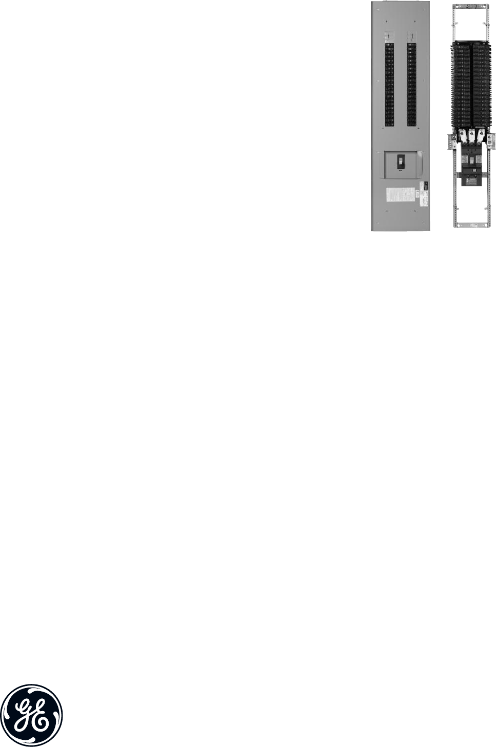
3 1 Panelboard, Type AS (101)
RWP-PNL-030
Single Section Panel Bottom Feed Surface Mnt 42 Ckts
3P4W 480Y/277V 35 KAIC
225A 3 Pole SFHA Main
1 1-LUG/PH 1-CABLE/LUG #8 -350 MCM
5 20A 1 Pole TEYH
6 20A 1 Pole TEYH Space
2 20A 2 Pole TEYH
4 15A 3 Pole TEYH
2 20A 3 Pole TEYH
2 40A 3 Pole TEYH
1 60A 3 Pole TEYH
1 Aluminum Bus Heat Rated
1 Corbin Latch Bolt 15767
1 Front Hinged To Box
1 Nameplates
1 ME, 65kA/mode,130kA/phase (TVSS) TPME277Y06AS
1 Ground main lug TGL20
4 Ground-Box bonded TGL2
1 AB64B Box
1 AF64SDLN Front
1 ASF3422KBX Interior AXT6
4 1 Panelboard, Type AQ (101)
RWP-PNL-040
Single Section Panel Bottom Feed Surface Mnt 42 Ckts
3P4W 208Y/120V 10 KAIC
100A 3 Pole THQB Main
1 1-LUG/PH 1-CABLE/LUG #14 -1/0
18 20A 1 Pole THQB
20 20A 1 Pole THQB Space
1 30A 2 Pole THQB
1 50A 2 Pole THQB
1 Aluminum Bus Heat Rated
1 Front Hinged To Box
1 Nameplates
1 ME, 65kA/mode,130kA/phase (TVSS) TPME120Y06AS
3 Ground-Box bonded TGL2
1 AB49B Box
1 AF49SDN Front
1 AQF3421ABX Interior AXT6

Page: 2
5 1 Panelboard, Type AQ (101)
RWP-PNL-050
Single Section Panel Bottom Feed Surface Mnt 30 Ckts
1P3W 120/240V 10 KAIC
100A 2 Pole THQB Main
1 1-LUG/PH 1-CABLE/LUG #14 -1/0
10 20A 1 Pole THQB
20 20A 1 Pole THQB Space
1 Aluminum Bus Heat Rated
1 Front Hinged To Box
1 Nameplates
1 ME, 65kA/mode,130kA/phase (TVSS) TPME120S06AS
3 Ground-Box bonded TGL2
1 AB43B Box
1 AF43SDN Front
1 AQF1301ABX Interior AXT6
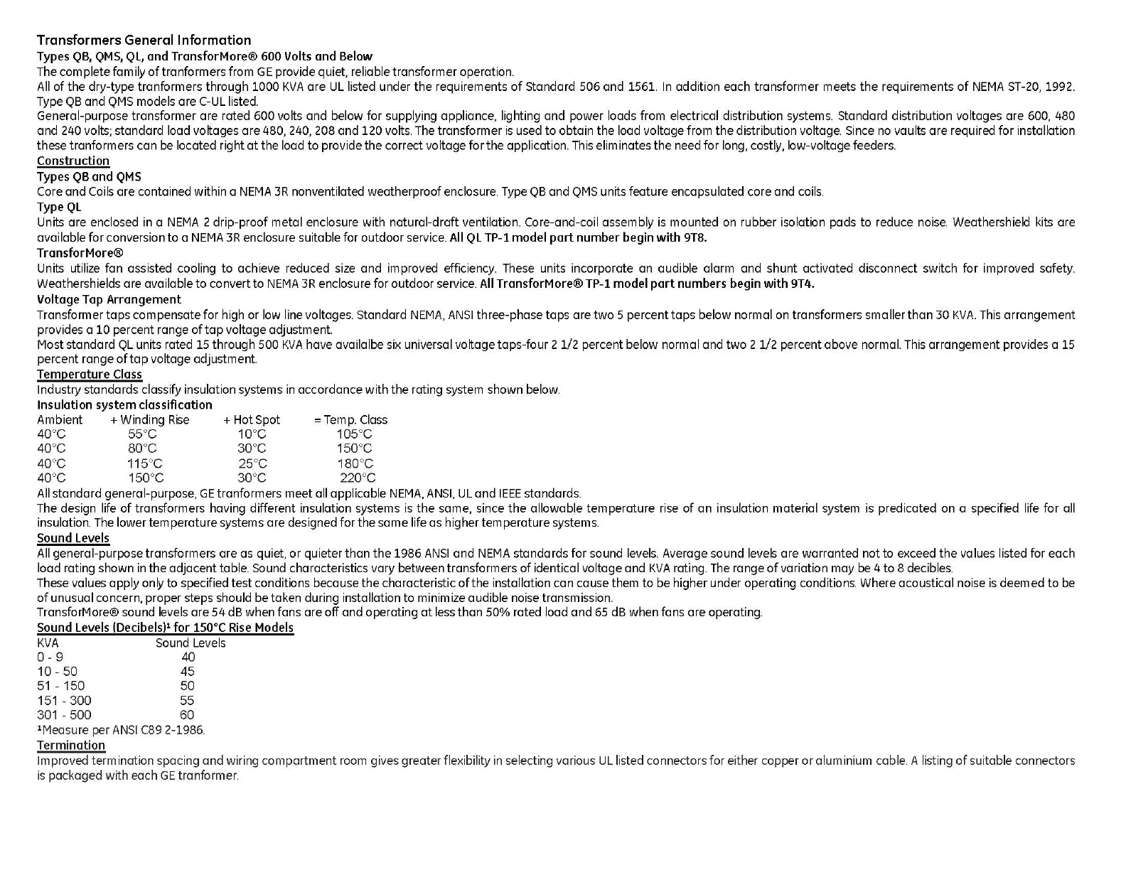
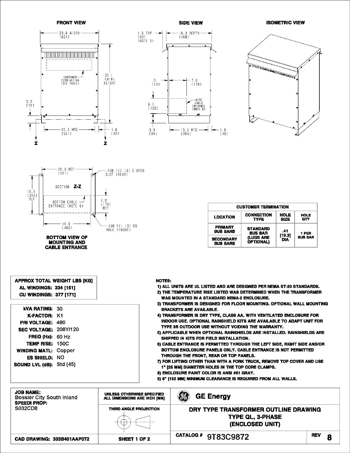
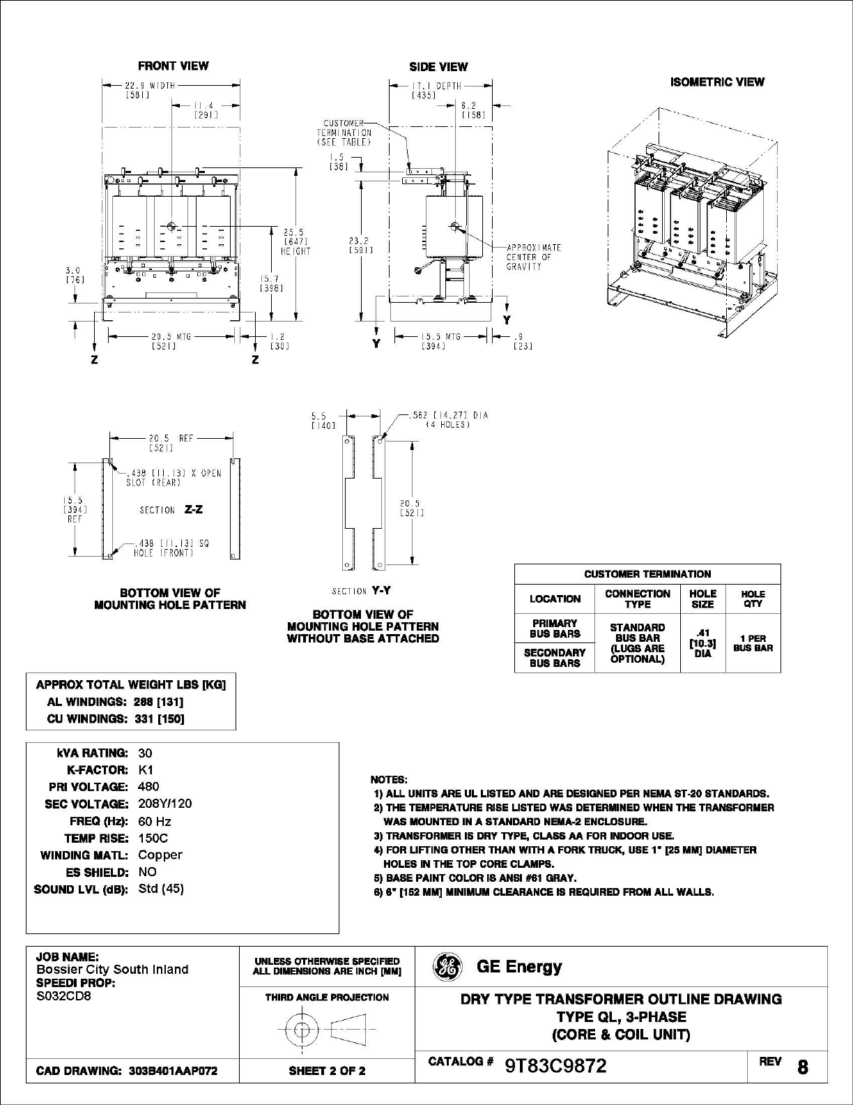
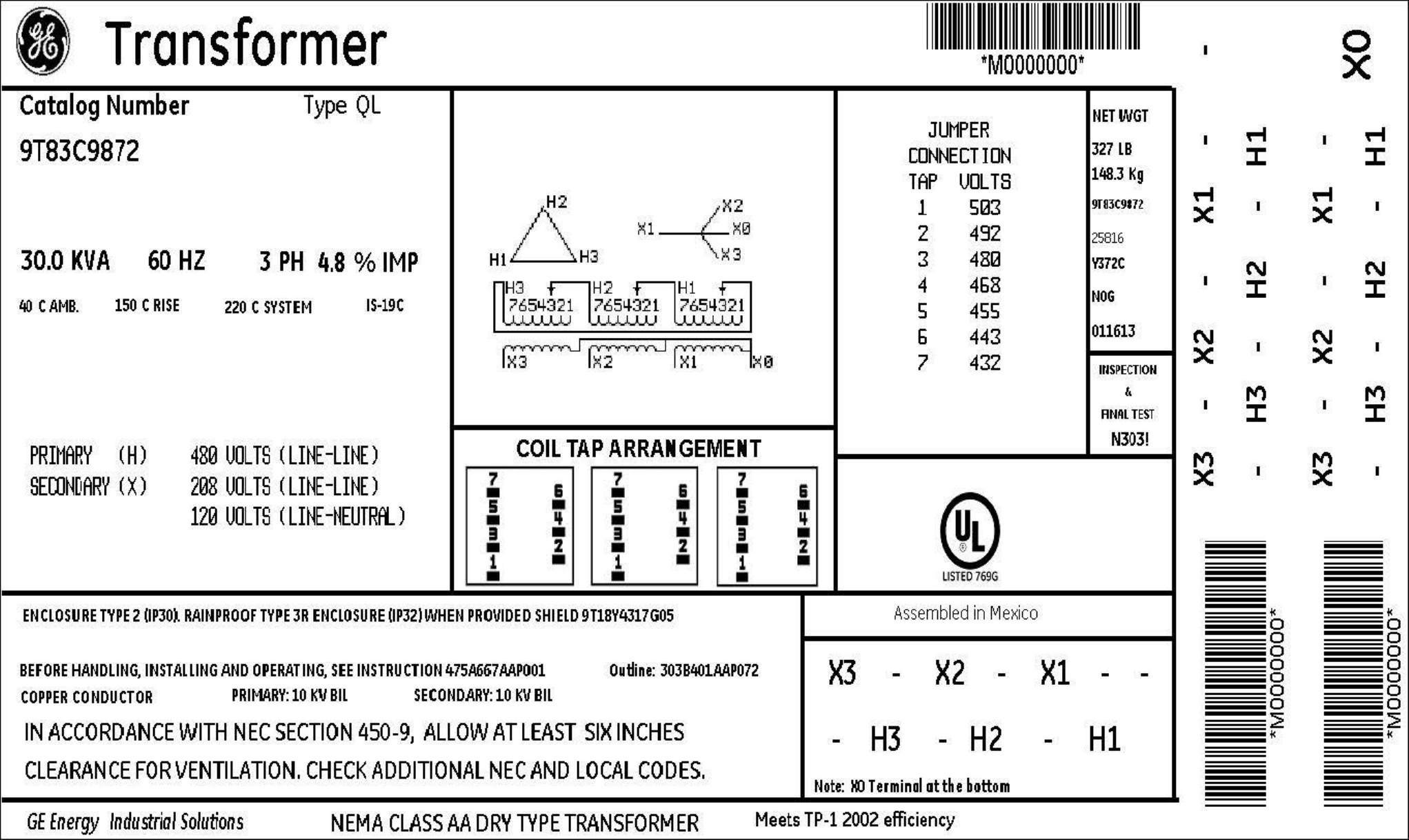
6 1 Transformer 66KC
XFMR 30KVA
9T83C9872
30 kVA 3 Ph Dry Type Transformer Coil Material = Copper
60 Hz 150C Rise Type QL-TP1
Primary Voltage: 480
Secondary Voltage: 208Y/120
Electrostatic Shield: No
A Series Panelboard Item 3 RWP-PNL-030
Panel Description
GE Type AS Panelboard
Qty 1
225 Amp,480Y/277V
3P4W
35 KAIC SC Fully Rated
Aluminum Bus
Nema 1 Enclosure
Surface Mounted
Bottom Feed
Main Description
Amps: 225 Amp
Poles: 3 Pole
Type: Main Breaker
Cat No.: SFHA36AT0250+
Acc: SRPF250A225
Rating Plg
3TCAL29
Lug Kit
Lugs: 1-lug/ph 1-cable/lug
#8 -350 mcm
Branch Devices
Qty Amps/P Cat#
5 20A/1P TEYH1020B
6 20A/1P Spaces
2 20A/2P TEYH2020B
4 15A/3P TEYH3015B
2 20A/3P TEYH3020B
2 40A/3P TEYH3040B
1 60A/3P TEYH3060B
Options Included
1 - Aluminum Bus Heat Rated
1 - Corbin Latch Bolt 15767
1 - Front Hinged To Box
1 - Nameplates
1 - ME, 65kA/mode,130kA/phase (TVSS) TPME277Y06AS
1 - Ground main lug TGL20
4 - Ground-Box bonded TGL2
Panel Interior
TVSS - DIRECT BUS CONNECTED
Ckt Type Amps/P Type Amps/P Ckt
1TEYH 60/3 TEYH 40/3 2
- - --
- - --
7TEYH 40/3 TEYH 20/3 8
- - --
- - --
13 TEYH 20/3 TEYH 15/3 14
- - --
- - --
19 TEYH 15/3 TEYH 15/3 20
- - --
- - --
25 TEYH 15/3 TEYH 20/2 26
- - --
- - TEYH 20/2 30
31 TEYH 20/1 --
33 TEYH 20/1 TEYH 20/1 34
35 TEYH 20/1 TEYH 20/1 36
37 SPACE 20/1 SPACE 20/1 38
39 SPACE 20/1 SPACE 20/1 40
41 SPACE 20/1 SPACE 20/1 42
225A VERTICAL MAIN BREAKER WITH NEUTRAL
225A 3P SFHA
* Drawing not to scale
Job Name: Bossier City South Inland
Prop No: 6L3-S032CD8 GE Req#:
PO#:
Marks: RWP-PNL-030 Dated: 06/30/2014
3A Interior ASF3422KBX AXT6
3B Box AB64B
3C Front AF64SDLN
Dimensions 64.5"H x 20"W x 5.75"D
A Series Panelboard Item 4 RWP-PNL-040
Panel Description
GE Type AQ Panelboard
Qty 1
125 Amp,208Y/120V
3P4W
10 KAIC SC Fully Rated
Aluminum Bus
Nema 1 Enclosure
Surface Mounted
Bottom Feed
Main Description
Amps: 100 Amp
Poles: 3 Pole
Type: Main Breaker
Cat No.: THQB32100
Acc:
Lugs: 1-lug/ph 1-cable/lug
#14 -1/0
Branch Devices
Qty Amps/P Cat#
18 20A/1P THQB1120
20 20A/1P Spaces
1 30A/2P THQB2130
1 50A/2P THQB2150
Options Included
1 - Aluminum Bus Heat Rated
1 - Front Hinged To Box
1 - Nameplates
1 - ME, 65kA/mode,130kA/phase (TVSS) TPME120Y06AS
3 - Ground-Box bonded TGL2
Panel Interior
TVSS - DIRECT BUS CONNECTED
Ckt Type Amps/P Type Amps/P Ckt
1THQB 50/2 THQB 30/2 2
- - --
5THQB 20/1 THQB 20/1 6
7THQB 20/1 THQB 20/1 8
9THQB 20/1 THQB 20/1 10
11 THQB 20/1 THQB 20/1 12
13 THQB 20/1 THQB 20/1 14
15 THQB 20/1 THQB 20/1 16
17 THQB 20/1 THQB 20/1 18
19 THQB 20/1 THQB 20/1 20
21 THQB 20/1 THQB 20/1 22
23 SPACE 20/1 SPACE 20/1 24
25 SPACE 20/1 SPACE 20/1 26
27 SPACE 20/1 SPACE 20/1 28
29 SPACE 20/1 SPACE 20/1 30
31 SPACE 20/1 SPACE 20/1 32
33 SPACE 20/1 SPACE 20/1 34
35 SPACE 20/1 SPACE 20/1 36
37 SPACE 20/1 SPACE 20/1 38
39 SPACE 20/1 SPACE 20/1 40
41 SPACE 20/1 SPACE 20/1 42
100A 3P THQB
- --
3 - FILLER -
125A NEUTRAL ONLY
* Drawing not to scale
Job Name: Bossier City South Inland
Prop No: 6L3-S032CD8 GE Req#:
PO#:
Marks: RWP-PNL-040 Dated: 06/30/2014
4A Interior AQF3421ABX AXT6
4B Box AB49B
4C Front AF49SDN
Dimensions 49.5"H x 20"W x 5.75"D
A Series Panelboard Item 5 RWP-PNL-050
Panel Description
GE Type AQ Panelboard
Qty 1
125 Amp,120/240
1P3W
10 KAIC SC Fully Rated
Aluminum Bus
Nema 1 Enclosure
Surface Mounted
Bottom Feed
Main Description
Amps: 100 Amp
Poles: 2 Pole
Type: Main Breaker
Cat No.: THQB21100
Acc:
Lugs: 1-lug/ph 1-cable/lug
#14 -1/0
Branch Devices
Qty Amps/P Cat#
10 20A/1P THQB1120
20 20A/1P Spaces
Options Included
1 - Aluminum Bus Heat Rated
1 - Front Hinged To Box
1 - Nameplates
1 - ME, 65kA/mode,130kA/phase (TVSS) TPME120S06AS
3 - Ground-Box bonded TGL2
Panel Interior
TVSS - DIRECT BUS CONNECTED
Ckt Type Amps/P Type Amps/P Ckt
1THQB 20/1 THQB 20/1 2
3THQB 20/1 THQB 20/1 4
5THQB 20/1 THQB 20/1 6
7THQB 20/1 THQB 20/1 8
9THQB 20/1 THQB 20/1 10
11 SPACE 20/1 SPACE 20/1 12
13 SPACE 20/1 SPACE 20/1 14
15 SPACE 20/1 SPACE 20/1 16
17 SPACE 20/1 SPACE 20/1 18
19 SPACE 20/1 SPACE 20/1 20
21 SPACE 20/1 SPACE 20/1 22
23 SPACE 20/1 SPACE 20/1 24
25 SPACE 20/1 SPACE 20/1 26
27 SPACE 20/1 SPACE 20/1 28
29 SPACE 20/1 SPACE 20/1 30
100A 2P THQB
- --
2 - FILLER -
125A NEUTRAL ONLY
* Drawing not to scale
Job Name: Bossier City South Inland
Prop No: 6L3-S032CD8 GE Req#:
PO#:
Marks: RWP-PNL-050 Dated: 06/30/2014
5A Interior AQF1301ABX AXT6
5B Box AB43B
5C Front AF43SDN
Dimensions 43.5"H x 20"W x 5.75"D
imagination at work
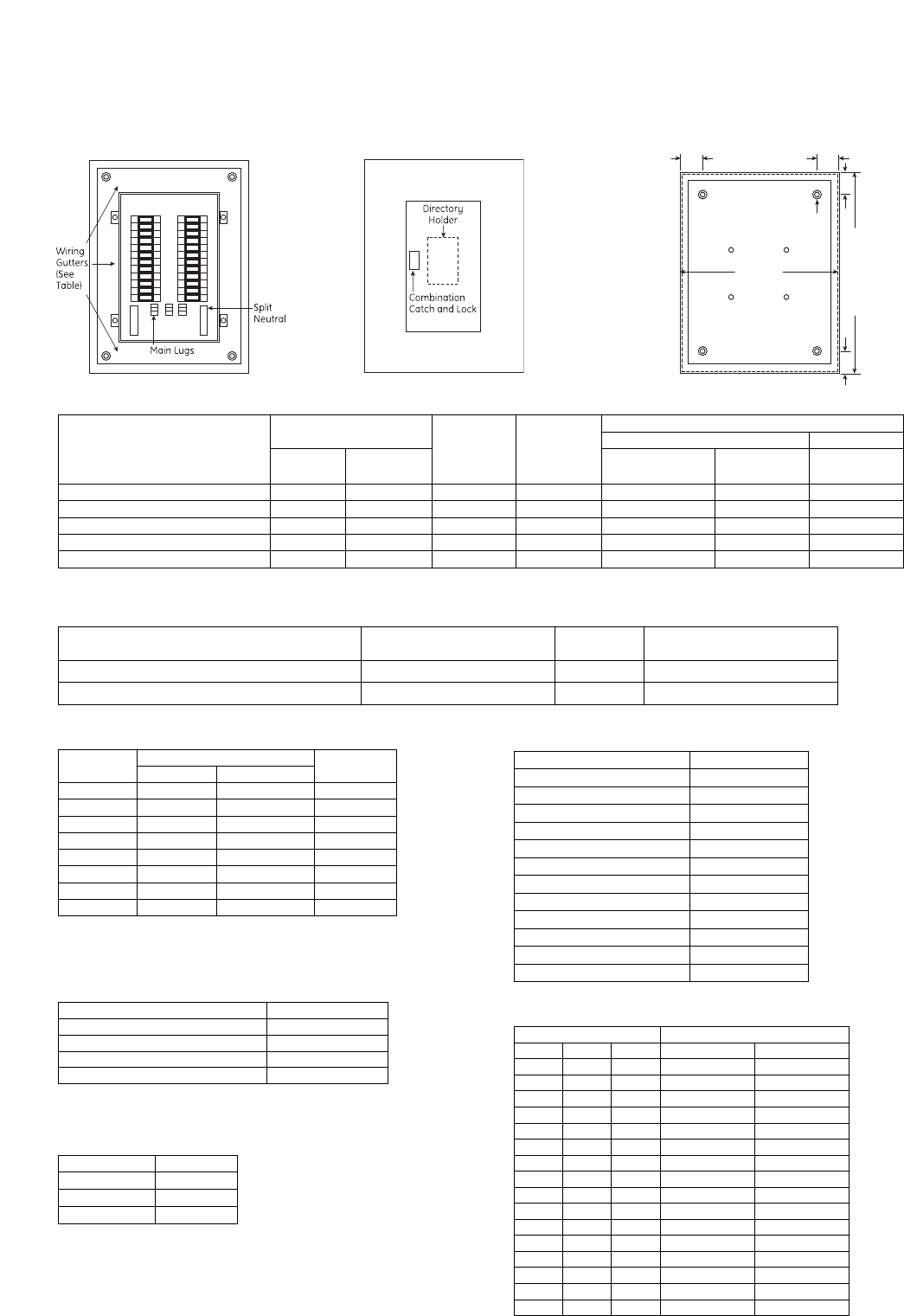
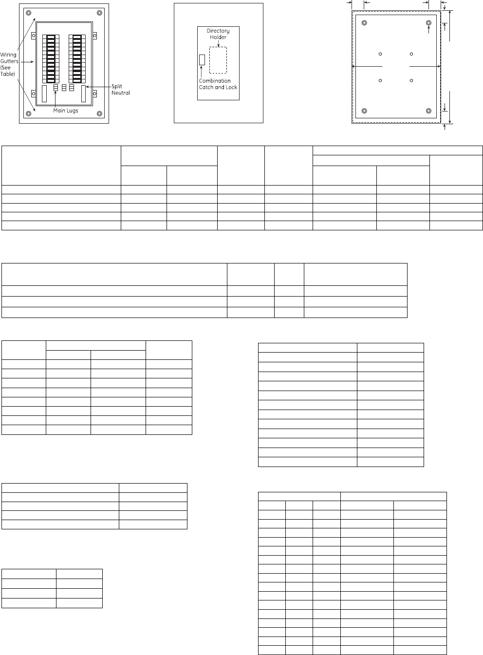
Typical AQ/AL Panelboard
Installation
Consult instructions NEMA PB-1.1 located in the circuit
directory on the front door before installing this panelboard.
If necessary, order replacement manual from supplier.
Wiring Guidelines (Cu or Al)
• Use 60°C or 75°C ampacity sized wire on line and neutral
and equipment ground terminals.
• Standard wire sizes listed in this publication may be
changed by using alternate terminal kits.
• Refer to circuit breakers for allowable wire temperature
rating, wire size and tightening torque.
• Neutral rated for 200% panelboard phase current option.
• Use copper wire only at neutral main lugs
- 125A (1) neutral cables 250 mcm maximum
- 225A (2) neutral cables 250 mcm maximum
- 400A (2) neutral cables 600 mcm maximum
- 600A (4) neutral cables 350 mcm maximum
Suitable for nonlinear loads, 200% rated neutral, additional
“Y” lugs provided for 200% neutral.
Short Circuit Current Rating
The panelboard’s maximum short circuit interrupting rating
in rms symmetrical amperes, is equal to the lowest inter-
rupting rating of any device installed, except as noted in the
series rating listed in DEH-40007, with integral or remote
main circuit breaker or fusible switch installed upstream of
the panelboard. Devices to be installed or replacement units
shall be from the same manufacturer, of the same type, and
have equal or greater interrupting capacity.
Maximum continuous loads on main or branch circuits shall
not exceed 80% of the ratings of the listed circuit breakers.
Branch breaker straps suitable for 180A maximum.
Tripped Breaker
If the breaker trips, handle will be in intermediate position.
Instructions To Restore Power
1. Move handle to OFF position.
2. Then move handle to ON position.
Seismic Rating
Meets or Exceeds the Requirements According to
• IEEE-693-2005
High Level with 1.8 Amplication Factor
• IBC-2006
Sds = 1.3g, Ss = 200%, Ip = 1.5, for z/h > 0
Sds = 2.0g, Ss = 300%, Ip = 1.5, for z/h = 0
In accordance with ICC-ES-AC156
Polybag Contents
A polybag of goods supplied with every panelboard interior
contains:
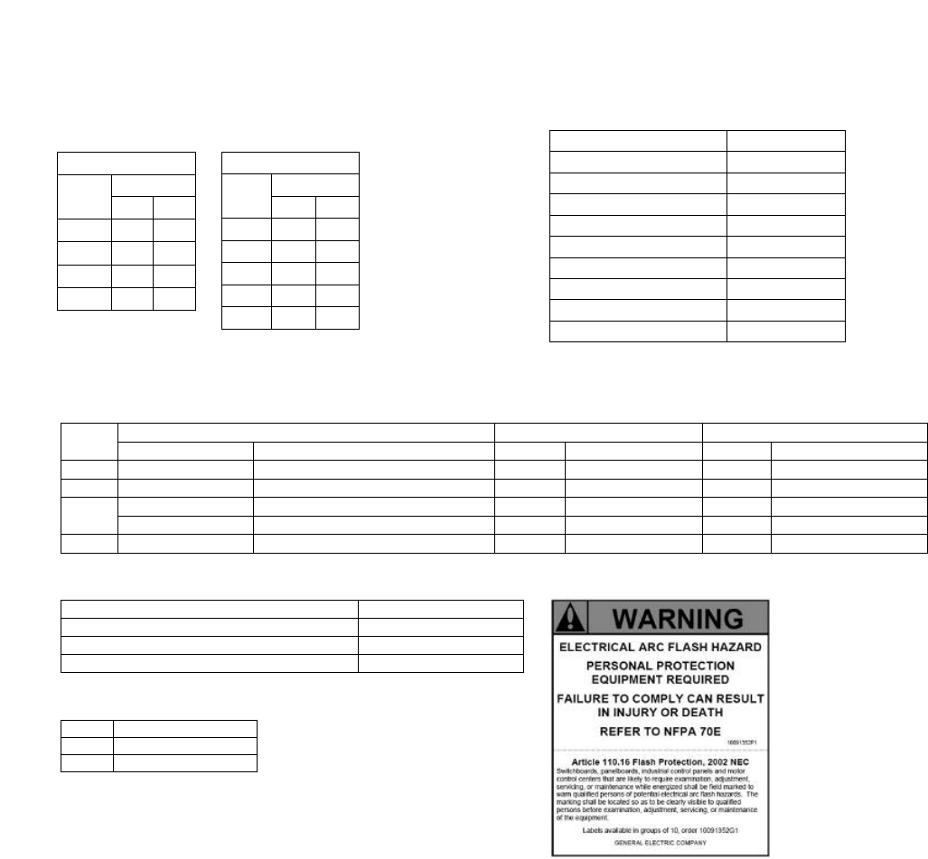
• Arc flash label
• DEH-40007 Series Ratings, Wiring Diagrams &
Circuit Directory
• Series rating sticker
• Front installation instructions
• ANSI PB1 documentation
• Circuit numbering stickers (1-84)
• Front and shield mounting screws
Torque
Tightening Torque Torque Values for Hardware
Applies to line, neutral and equipment ground terminal
Lug Kits
Lug Kits for A-Series II Panelboards
Crimp Tools
Neutral Lug Z
Arc fault label included with all interiors to
be applied by electrical contractor.
Holes Wire Size – Cu / Al
Large 2 / 0 - 14
Small No. 4 – 14
Wire Crimp Tool
All Al & Up to 500 MCM Cu Hubbell Anderson VC6
500-750 MCM Cu Hubbell Anderson VC7
Up to #6-1000 MCM Cu & #5-750 Kcmil Al Burndy Tool Y644HS
Rating Pressure Lug Kit Crimp Lug Kit Pressure Lug Kit
Cat. No. Wire Range Al/Cu Cat. No. Wire Range Al/Cu Cat. No. Wire Range Cu Only
125A MLA1 6-350 MLT1 4-300 MLR1 4-350
225A MLA2 1/0-250 MLT2 2/0 - 500 MLR2 1/0-600
400A Standard - MLA41 4-600 MLT41 500-750 (Cu Only) MLR41 1/0-600
Oversize – MLA62 3/0 - 800 (Main) & 4-600 (Neutral) - - - -
600A Standard -MLA61 4-500 - - MLR61 1/0-600
Screw Size Torque (In-Lbs)
#4 Steel 16
#10 Plastic 16
#8 Cu/Al/Steel 24
#10-32 Cu/Al/Steel 32
1/4-20 Al/<.150 Thick Cu 44
1/4-20 .150 Thick Cu 60
5/16-18 Cu/Al/Steel 110
3/8-16 Cu/Al/Steel 220
1/2-13 Cu/Al/Steel 220
Internal Hex
Hex
Size Lbs-Ins
Min Max
3/16 108 120
1/4 180 200
5/16 240 275
3/8 330 375
1/2 450 500
Slotted Screw
AWG
Wire Lbs-Ins
Min Max
14-10 32 35
8 36 40
6-4 41 45
3-2/0 45 50
Interrupting Ratings - Molded Case Circuit Breakers
(1) 3 Poles are not DC rated
(2) Not current limiting breaker type
Circuit Breaker Terminals (Cu-Al)
Frame Poles No. per
Pole Cat. No. Wire Cu-Al (Unless otherwise specified)
Standard Current Limiting /
High Interrupting Per
Lug Range
THQB, TXQB, THHQB,
THQL, THHQL, TXQL -1,2,3 1 Fixed to Breaker Terminal 1 (15-30A) #14-4 Cu or #12-4 Al, (35-100A)
#14-10 Cu or #12-1/0 Al
- SEH, SEL, SEP 2,3 1 TCAL18 1 #12-3/0 Al; #12-3/0 Cu
SFHA SFLA, SFPA 2,3 1 TCAL129 1 #8-350kcmil
SGHA SGL, SGP 2 1 TCLK265 - 2 (2/0-400kcmil, Cu) or 2 (2/0-500kcmil,
Al) or #6-600kcmil
3 1 TCLK365 - 2 (2/0-400kcmil, Cu) or 2 (2/0-500kcmil,
Al) or #6-600kcmil
- FGN4, FGH4 2,3 1 FCALK318H - Top Hole #8-400kcmil Cu or #6-500kcmil
Al. Bottom hole #2/0-600kcmil Cu & Al
SKHA8 SKLA8, SKPA8 2,3 1 TCAL41 1 #4-600kcmil or 2(1/0-250kcmil)
TCAL61 2 2/0-500kcmil
TCAL81 3 3/0-500kcmil
Molded Case Circuit Breakers Federal Spec UL Listed Interrupting Ratings in kA
Construction Frame Trip Range
(Amps) Pole AC DC C/B Class
W-C-375B RMS Symmetrical AC Volts
120 120/ 240 240 277 480Y/277 480 600
HQ Frame
THQB 15-70 1 120/240 12a 10 10
THQL 15-125 2 120/240 12a 10
15-100 2,3 240 12a 10
THQL-GF 15-30 1,2 120/240 10
THQL-HID 15-20 1,2 120/240 10
THQB-GF 15-30 1,2 120/240 10
THQB-HID 15-20 1,2 120/240 10
TXQB 15-30 1,2 120/240 65
HHQ Frame
THHQB 15-70 1 120/240 14a 22 22
THHQL
15-125 2 120/240 14a 22
15-100 2 240 14b 22
15-100 3 240 14b 22
THHQL-GF 15-30 1 120/240 22
THHQL-HID 15-20 1,2 120/240 22
THHQB-GF 15-30 1 120/240 22
THHQB-HID 15-20 1,2 120/240 22
Standard
Frames TQD 125-225 2,3 240 12b 10
TJD 250-400 2,3 240 250 (1) 14b 22
Hi-Break Frames THQD 125-225 2,3 N/A 22
Spectra RMS
SEH (2) 15-150 2 480 13b, 15b 65 25
3 600 22a 65 25 18
SEL 15-150 2 480 13b, 15b 100 65
3 600 21a, 22a, 23a 100 65 25
SEP 15-150 2 480 16a 200 100
3 600 16a, 23a 200 100 25
SFH 70-250 2 480 13b 65 35
3 600 20a, 22a 65 35 22
SFL 70-250 2 480 13b 100 65
3 600 21a, 23a 100 65 25
SFP 70-250 2 480 16a 200 65
3 600 16a, 23a 200 65 25
SGH4 (2) 125-400 2,3 600 21a, 23a 65 35 25
SGH6 (2) 250-600 2,3 600 23a 65 35 25
SGL4 125-400 2,3 600 23a 100 65 65
SGP4 125-400 2,3 600 23a 200 100 65
SGL6 250-600 2,3 600 24a 100 65 65
SGP6 250-600 2,3 600 25a 200 100 65
SKH8 300-800 2,3 600 21a, 23a 65 50 25
SKL8 300-800 2,3 600 24a 100 65 42
SKP8 300-800 2,3 600 25a 200 100 65
Wiring Space
Minimum Wiring Space, From End of Lug to Box Wall, in Inches
(1) To side wall (2) Box width is 30” and 7.81” deep
Wiring Space – Branch Circuit Breakers
Branch Circuit Devices Frame No. of Poles Minimum Wiring Spaces To
Side Wall (20" Wide Box)
Double Branched Bolt-on Devices THQL, THHQL, THQB, THHQB 1,2,3 6.5"
Horizontal Subfeeds Single Branch Mounted TQD, THQD 2,3 5.5"
Main rating in amps
Main Lugs Only, to
End Wall Frame
Type Mounting
Main Circuit Breaker
Phase Lug Neutral Lug
Phase Lug Neutral Lug To Side Wall
(20" Wide box) To End Wall
125A MLO, 100A Main Breaker 6 6 TEY, SE Horizontal 5 - 6
225A 12 12 TFJ, SF Vertical - 6 12
400A 15 11 (1) SF, SG, FG Vertical - 15 11 (1)
600A 15 11 (1) SG Vertical - 16 -
800A (2) 15 11 (1) SK Vertical - 18 -
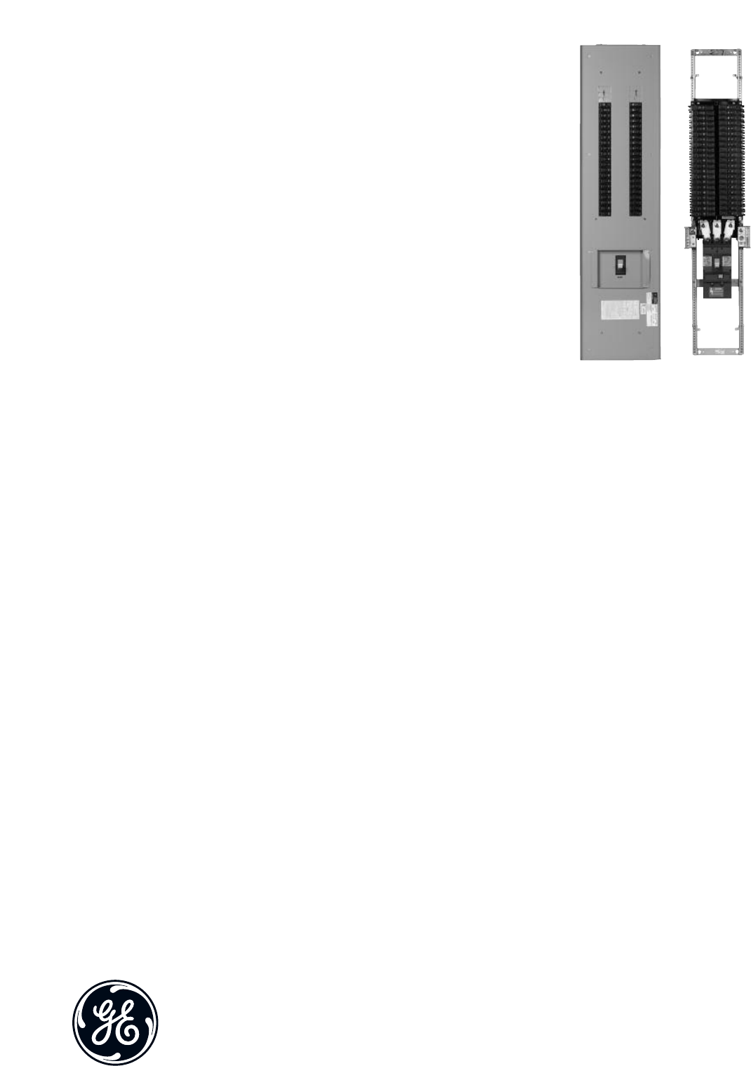
Typical Panelboard
Front view with trim removed Typical Front w/Concealed Hinges
and Trim Adjusting Screws
Surface mounting – add 1/4” to inside box dimensions
Flush mounting – add 1 1/2” to inside box dimensions
For 3/8” Bolt
Box Width
(Inside)
Box Height (Inside)
33
3
3
Typical Box
Enclosures
(1) “B” suffix provides blank end walls. Order “K” suffix for endwalls with knockouts.
(2) Standard boxes are 20" wide by 5.81" deep.
(3) Flush fronts are 1 1/2" larger than box. Surface fronts are 1/4" larger.
Box Options
(1) Add to base box product number.
(2) Includes field installable gutter barrier.
Permanent Circuit Number Kits
Front Options
Stainless Steel Enclosures
Dimensions (inches) Cat No.
H W D UL Standard CSA Labeled
25.5 20 6 AB254S AB254AS
25.5 30 8 AB254DWS AB254DWAS
31.5 20 6 AB314S AB314AS
31.5 30 8 AB314DWS AB314DWAS
37.5 20 6 AB374S AB374AS
37.5 30 8 AB374DWS AB374DWAS
43.5 20 6 AB434S AB434AS
43.5 30 8 AB434DWS AB434DWAS
49.5 20 6 AB494S AB494AS
49.5 30 8 AB494DWS AB494DWAS
55.5 20 6 AB554S AB554AS
55.5 30 8 AB554DWS AB554DWAS
64.5 20 6 AB644S AB644AS
64.5 30 8 AB644DWS AB644DWAS
76.5 20 6 AB764S AB764AS
76.5 30 8 AB764DWS AB764DWAS
Description Cat. No. Suffix (1)
Screw cover C
Front hinged to box D
Yale 5116 w/Rosette Lock Y
Corbin 15767 Lock L
GE 75 Key Lock E
Corbin 60 Key Lock J
Door within a door (2) P
Stainless steel (3) S
30” wide W
Nameplate N
Screw on nameplate U
Metal directory M
Description Cat. No.
1-48 APN48
43-84 APN84
85-126 APN126
Description Cat. No. Suffix (1)
Painted Box P
30" wide (2) W
NEMA 3R/12/4S/4X 3 or 4
NEMA 4X (316 Stainless Steel) 4S
Panel Size Box Front
Cat. No. (3)
Cat. No. (1) Size Inches (2)
0-25.5 AB25B 25.5 AF25F,S
28.5-31.5 AB31B 31.5 AF31F,S
34.5-37.5 AB37B 37.5 AF37F,S
40.5-43.5 AB43B 43.5 AF43F,S
46.5-49.5 AB49B 49.5 AF49F,S
52.5-55.5 AB55B 55.5 AF55F,S
57.5-64.5 AB64B 64.5 AF64F,S
67.5-76.5 AB76B 76.5 AF76F,S
(1) Add to base front
catalog number.
(2) Consists of two lock-
able doors—one over
panel interior and
one over box wiring
gutters. Yale locks
not available.
(3) Flush only. Available
with C and N options.
Accessories
Field Installed Kits/Replacement Parts
Filler Plates
Breaker Mounting Hardware Kits
For mounting breaker in existing space
Equipment Grounds
Bonding Kits
Installation & Maintenance Kit
Order catalog number PROCARE. Kit includes:
(5) filler plate hardware kits
(9) bus stud nuts
(5) MLA1 filler plates
(2) 225A phase barriers
(2) feed-thru barriers
(1) 400/600A phase barrier
(50) directorycards/rating books
(50) circuit number strips (1-48)
(50) circuit number strips (43-84)
(5) standardlocks & keys
(50) deadfront screws
(10) AQ/AE front hardware kits
(10) AD front hardware kits
(50) service disconnect labels
(50) main labels
Parts
Box Extensions
Bolts to box with or without endwall in place. Extensions can
be combined to obtain lengths greater than 18 and 24 inches.
Box Extension Covers Only
10 covers per kit
Description Cat. No.
9" Covers Surface ASPABX09S
9" CoversFlush ASPABX09F
18" CoversSurface ASPABX18S
18" Covers Flush ASPABX18F
64" to 76" Covers Surface ASPABX20S
64" to 76" Covers Flush ASPABX20F
Box Width and
Depth Box Mounting Box Extension
Length (Inches) Cat. No.
20 x 5.81
Flush 9ABX2509F
18 ABX2518F
24 ABX2524F
Surface
9ABX2509S
18 ABX2518S
24 ABX2524S
31 ABX2531S
37 ABX2537S
43 ABX2543S
49 ABX2549S
55 ABX2555S
64 ABX2564S
76 ABX2576S
30 x 5.81 Flush 18 ABX3518F
24 ABX3524F
Surface 18 ABX3518S
24 ABX3524S
30 x 7.81 Flush 18 ABX3718F
24 ABX3724F
Surface 18 ABX3718S
24 ABX3724S
Description Cat. No.
Directory Card 139C5612P3
Replacement Lock with Std. Key 569B737P1
Replacement Lock with GE75 Key 569B737P2
Additional Keys for Above Lock 569B737P5
Circuit Numbering Strips 1-48 569B806G1
Circuit Numbering Strips 49-84 569B806G2
Circuit Numbering Strips 85-126 569B806G3
Adhesive Backed Lamicoid Nameplate 3/4" x 3" 315A7190P1
Metal Directory Card Holder 139C5491G1
Directory Card Holder 139C5491P4
Delta Hi-leg Conversion Kit, to Add B-Phase
Plug on AL Panels APHBL
Bolt on AE/AQ Panels APHBQ
NEMA 3R/12 Tamper Proof Tork Screw Kit NEMATRX
2P to 3P TQD Conv. Kit ASP2PTQD3P
2P to 3P SF Conv. Kit for horizontal subfeed ASP2PTFJ3P
AD 25 to 65 kAIC Barrier kit ASP25AD65KA1
Service Entrance Kit ASPSERENT
2wire Relay Kit ASP2WRelay
Yale Lock Kit ASPYALE47
Corbin Lock Kit ASPCORBNTEU1
2-3 pole TQD Mechanical Interlock TQDFM1
AQ/AL/AE Rail Bracket ASPAQLEBKT
Front Flush Adjust Kit ASPFLUSHADJ
AE Front Mounting Kit 139C5720G3
AQ/AL Front Mounting Kit 139C5720G6
AD Front Mounting Kit 139C5728G9
Front Hinge to Box Mounting Kit 139C5700G6
Front Extension Mounting Kit 139C5700G11
Description Cat.No.
For Split & Load End Neutral 343L886G16
For 225A Horizontal Neutrals 343L886G13
225A Horizontal Neutral To Convert 3W to 4W ASP225HNCP
125/225A Horizontal Neutral Conversion from
Service Entrance to Non-Service Entrance ASPHNCPSENOT
125/225A Horizontal Neutral to Convert from
Non-Service Entrance to Service Entrance. ASPHNCPSE
Item Description Wire Range Cat. No.
Metal
Equipment
Ground
Bonded #14-#8 Cu, #12-#8 Al
(small holes); #14-#4 Cu,
#6-#4 Al (large holes) TGL2
Extruded Bonded #14-#8 Cu, #12-#8 Al
(small holes); #14-#4 Cu,
#6-#4 Al (large holes) EGS12
Aluminum
Equipment
Ground
Extruded Bonded (1) #6-350MCM AEBG
Extruded Isolated (2) #6-250MCM AEIG
Main Lug #14-#8 Cu, #12-#8 Al
(small holes); #14-#4 Cu,
#6-#4 Al (large holes) TGL2
Copper
Equipment
Ground
Bonded #14-#8 Cu, #12-#8 Al
(small holes); #14-#4 Cu,
#6-#4 Al (large holes) TGC2
Extruded Bonded (1) #4-350MCM AEBGC
Extruded Isolated (1) #6-250MCM AEIGC
Insulated Isolated 2/0 max. ASPGIBC
Breaker Type Cat. No.
TED/THED4/SE ASPTED3P
TQD/THQD ASPTQD3P
FB ASPFB12P
Breaker Type Cat. No.
THQB/THHQB/THQL/THHQL/TEY TQLFP1
TQD/THQD/TED4/SE/FB TEDFP1
AEBG
AEBGC
AEIG
AEIGC
ASPGIBC
Endwall Kits
Field installed.
1each, for
standard 20"w x
5.81"d boxes.
Type Cat. No.
Blank ABEW2
Knockout ABEW2

imagination at work
GE
41 Woodford Avenue, Plainville, CT 06062
www.geelectrical.com
©2008 General Electric Company
DE-42A REV 02 (6/08)
Specifications
A-Series Panelboards and branch breakers meet or exceed
the following standards and specifications:
•UL 50 Cabinets and Boxes
•UL 67 Panelboards
•UL 489 Circuit Breakers
•NEMA AB-1 Circuit Breakers
•NEMA PB-1 and PB-1.1 Panelboards
•US Federal Spec W-P.115B Panelboards
•US Federal Spec W-C375b Gen Circuit Breakers
Boxes
•Galvanized steel
•Blank end walls are standard; knockouts are available
when specified
•Boxes furnished with provisions for ground bus as standard
Fronts
•Finished in ANSI-61 grey polyester powder coat paint.
•Equipped with corrosion-resistant Valox combination
catch and lock door latch (doors over 48" high provided
with 2 latches)
•Equipped with concealed hinges and trim adjusting screws
•Directory holder permanently mounted to door
Panels
•Dead front construction
•Interiors are factory assembled on rigid steel frames
•Metal gages in accordance with UL and NEMA standards
•Solderless, anti-turn main lugs suitable for copper or
aluminium wires are front removable and branch straps
aresilver-plated copper fully rated at 100 amperes
•Main bus is aluminum with copper branch connections
unless otherwise specified
•Main disconnect device is identified when supplied, and
numbers are provided for branch circuits
•Interior base assemblies are Noryl and provide breaker
mounting and busbar insulation
Publications
E-DET-465 Certification of Seismic Compliance
DE-42A Typical AL/AQ Panelboard Technical Information
DEH 40007 Lighting Panels Rating Labels, Wiring Diagrams
and Circuit Directory
DEH 047 TED, THED, SED, SHE, SEL, SEP Circuit Breaker
Mounting Instructions
DEH 059 SGH, SFL, SFP Circuit Breaker Mounting Instructions
DEH 060 SGH, SGL,SGP Circuit Breaker Mounting
Instructions
DEH 061 SKH, SKL, SKP Circuit Breaker Mounting Instructions
DEH 065 TQD, THQD Circuit Breaker Mounting Instructions
imagination at work
Installation
Consult instructions NEMA PB-1.1 located in the circuit
directory on the front door before installing this panelboard.
If necessary, order replacement manual from supplier.
Wiring Guidelines (Cu or Al)
• Use 60°C or 75°C ampacity sized wire on line and neutral
and equipment ground terminals.
• Standard wire sizes listed in this publication may be
changed by using alternate terminal kits.
• Refer to circuit breakers for allowable wire temperature
rating, wire size and tightening torque.
• Neutral rated for 200% panelboard phase current option.
• Use copper wire only at neutral main lugs
- 125A (1) neutral cables 250 mcm maximum
- 225A (2) neutral cables 250 mcm maximum
- 400A (2) neutral cables 600 mcm maximum
- 600A (4) neutral cables 350 mcm maximum
Suitable for nonlinear loads, 200% rated neutral, additional
“Y” lugs provided for 200% neutral.
Short Circuit Current Rating
The panelboard’s maximum short circuit interrupting rating
in rms symmetrical amperes, is equal to the lowest inter-
rupting rating of any device installed, except as noted in the
series rating listed in DEH-40007, with integral or remote
main circuit breaker or fusible switch installed upstream of
the panelboard. Devices to be installed or replacement units
shall be from the same manufacturer, of the same type, and
have equal or greater interrupting capacity.
Maximum continuous loads on main or branch circuits shall
not exceed 80% of the ratings of the listed circuit breakers.
Branch breaker straps suitable for 250A maximum.
Tripped Breaker
If the breaker trips, handle will be in intermediate position.
Instructions To Restore Power
1. Move handle to OFF position.
2. Then move handle to ON position.
Seismic Rating
Meets or Exceeds the Requirements According to
• IEEE-693-2005
High Level with 1.8 Amplication Factor
• IBC-2006
Sds = 1.3g, Ss = 200%, Ip = 1.5, for z/h > 0
Sds = 2.0g, Ss = 300%, Ip = 1.5, for z/h = 0
In accordance with ICC-ES-AC156
Polybag Contents
A polybag of goods supplied with every panelboard interior
contains:
• Arc flash label
• DEH-40007 Series Ratings, Wiring Diagrams &
Circuit Directory
• Series rating sticker
• Front installation instructions
• ANSI PB1 documentation
• Circuit numbering stickers (1-84)
• Front and shield mounting screws
Typical AS Panelboard
Torque
Tightening Torque Torque Values for Hardware
Applies to line, neutral and equipment ground terminal
Lug Kits
Lug Kits for A-Series II Panelboards
Crimp Tools
Neutral Lug Z
Arc fault label included with all interiors to
be applied by electrical contractor.
Holes Wire Size – Cu / Al
Large 2 / 0 - 14
Small No. 4 – 14
Wire Crimp Tool
All Al & Up to 500 MCM Cu Hubbell Anderson VC6
500-750 MCM Cu Hubbell Anderson VC7
Up to #6-1000 MCM Cu & #5-750 Kcmil Al Burndy Tool Y644HS
Rating Pressure Lug Kit Crimp Lug Kit Pressure Lug Kit
Cat. No. Wire Range Al/Cu Cat. No. Wire Range Al/Cu Cat. No. Wire Range Cu Only
125A MLA1 6-350 MLT1 4-300 MLR1 4-350
225A MLA2 1/0-250 MLT2 2/0 - 500 MLR2 1/0-600
400A Standard - MLA41 4-600 MLT41 500-750 (Cu Only) MLR41 1/0-600
Oversize – MLA62 3/0 - 800 (Main) & 4-600 (Neutral) - - - -
600A Standard -MLA61 4-500 - - MLR61 1/0-600
Screw Size Torque (In-Lbs)
#4 Steel 16
#10 Plastic 16
#8 Cu/Al/Steel 24
#10-32 Cu/Al/Steel 32
1/4-20 Al/<.150 Thick Cu 44
1/4-20 .150 Thick Cu 60
5/16-18 Cu/Al/Steel 110
3/8-16 Cu/Al/Steel 220
1/2-13 Cu/Al/Steel 220
Internal Hex
Hex
Size Lbs-Ins
Min Max
3/16 108 120
1/4 180 200
5/16 240 275
3/8 330 375
1/2 450 500
Slotted Screw
AWG
Wire
Lbs-Ins
Min Max
14-10 32 35
8 36 40
6-4 41 45
3-2/0 45 50
Interrupting Ratings - Molded Case Circuit Breakers
(1) Not current limiting breaker type
Circuit Breaker Terminals (Cu-Al)
Frame Poles No. per
Pole Cat. No. Wire Cu-Al (Unless otherwise specified)
Standard Current Limiting /
High Interrupting Per
Lug Range
- TEYD/H/L 1,2,3 1 Fixed to Breaker Terminal 1 (15-20A) #14-#10 Cu or Al, (25-60A) #10-#4 Cu or Al,
(70-125A) #4-#1/0 Cu or Al
- SEH, SEL, SEP 2,3 1 TCAL18 1 #12-3/0 Al; #12-3/0 Cu
SFHA SFLA, SFPA 2,3 1 TCAL129 1 #8-350kcmil
SGHA SGL, SGP 2 1 TCLK265 - 2 (2/0-400kcmil, Cu) or 2 (2/0-500kcmil, Al) or #6-
600kcmil
3 1 TCLK365 - 2 (2/0-400kcmil, Cu) or 2 (2/0-500kcmil, Al) or #6-
600kcmil
- FGN4, FGH4 2,3 1 FCALK318H - Top Hole #8-400kcmil Cu or #6-500kcmil Al.
Bottom hole #2/0-600kcmil Cu & Al
SKHA8 SKLA8, SKPA8 2,3 1
TCAL41 1 #4-600kcmil or 2(1/0-250kcmil)
TCAL61 2 2/0-500kcmil
TCAL81 3 3/0-500kcmil
Molded Case Circuit Breakers Federal Spec UL Listed Interrupting Ratings in kA
Construction Frame Trip Range
(Amps) Pole AC DC C/B Class
W-C-375B RMS Symmetrical AC Volts
120 120/ 240 240 277 480Y/277 480 600
Standard
Frames TEYD/H/L 15-70 1 480Y/277 250 13a 65 25/35/65
15-125 2,3 480Y/277 250 13a 6525/35/65
Spectra RMS
SEH (2) 15-150 2 480 13b, 15b 65 25
3 600 22a 65 25 18
SEL 15-150 2 480 13b, 15b 100 65
3 600 21a, 22a, 23a 100 65 25
SEP 15-150 2 480 16a 200 100
3 600 16a, 23a 200 100 25
SFH 70-250 2 480 13b 65 35
3 600 20a, 22a 653522
SFL 70-250 2 480 13b 100 65
3 600 21a, 23a 100 65 25
SFP 70-250 2 480 16a 200 65
3 600 16a, 23a 200 65 25
SGH4 (1) 125-400 2,3 600 21a, 23a 65 35 25
SGH6 (1) 250-600 2,3 600 23a 65 35 25
SGL4 125-400 2,3 600 23a 100 65 65
SGP4 125-400 2,3 600 23a 200 100 65
SGL6 250-600 2,3 600 24a 100 65 65
SGP6 250-600 2,3 600 25a 200 100 65
SKH8 300-800 2,3 600 21a, 23a 65 50 25
SKL8 300-800 2,3 600 24a 100 65 42
SKP8 300-800 2,3 600 25a 200 100 65
Wiring Space
Minimum Wiring Space, From End of Lug to Box Wall, in Inches
(1) To side wall (2) Box width is 30” and 7.81” deep
Wiring Space – Branch Circuit Breakers
Branch Circuit Devices Frame No. of
Poles Minimum Wiring Spaces
To Side Wall (20" Wide Box)
Double Branched Bolt-on Devices TEYD/H/L 1,2,3 5.5"
Horizontal Subfeeds, Single Branch Mounted, Maximum 9 Poles SEHA, SELA 2,3
Horizontal Subfeeds, Single Branch Mounted, Maximum 6 Poles SFHA, SFLA 2,3 5.5"
Main rating in amps
Main Lugs Only, to End
Wall Frame
Type Mounting
Main Circuit Breaker
Phase Lug Neutral Lug
Phase Lug Neutral Lug To Side Wall
(20" Wide box) To End Wall
125A MLO, 100A Main Breaker 6 6 TEY, SE Horizontal 4 - 6
225A 12 12 TFJ, SF Vertical - 6 12
400A 15 11 (1) SF, SG, FG Vertical - 15 11 (1)
600A 15 11 (1) SG Vertical - 16 -
800A (2) 15 11 (1) SK Vertical - 18 -
Typical Panelboard
Front view with trim removed Typical Front w/Concealed Hinges
and Trim Adjusting Screws
Surface mounting – add 1/4” to inside box dimensions
Flush mounting – add 1 1/2” to inside box dimensions
For 3/8” Bolt
Box Width
(Inside)
Box Height (Inside)
33
3
3
Typical Box
Enclosures
(1) “B” suffix provides blank end walls. Order “K” suffix for endwalls with knockouts.
(2) Standard boxes are 20" wide by 5.81" deep.
(3) Flush fronts are 1 1/2" larger than box. Surface fronts are 1/4" larger.
Box Options
(1) Add to base box product number.
(2) Includes field installable gutter barrier.
Permanent Circuit Number Kits
Front Options
Stainless Steel Enclosures
Description Cat. No.
1-48 APN48
43-84 APN84
85-126 APN126
Dimensions (inches) Cat No.
H W D UL Standard CSA Labeled
25.5 20 6 AB254S AB254AS
25.5 30 8 AB254DWS AB254DWAS
31.5 20 6 AB314S AB314AS
31.5 30 8 AB314DWS AB314DWAS
37.5 20 6 AB374S AB374AS
37.5 30 8 AB374DWS AB374DWAS
43.5 20 6 AB434S AB434AS
43.5 30 8 AB434DWS AB434DWAS
49.5 20 6 AB494S AB494AS
49.5 30 8 AB494DWS AB494DWAS
55.5 20 6 AB554S AB554AS
55.5 30 8 AB554DWS AB554DWAS
64.5 20 6 AB644S AB644AS
64.5 30 8 AB644DWS AB644DWAS
76.5 20 6 AB764S AB764AS
76.5 30 8 AB764DWS AB764DWAS
Description Cat. No. Suffix (1)
Screw cover C
Front hinged to box D
Yale 5116 w/Rosette Lock Y
Corbin 15767 Lock L
GE 75 Key Lock (4) E
Corbin 60 Key Lock J
Door within a door (2) P
Stainless steel (3) S
30” wide W
Nameplate N
Screw on nameplate U
Metal directory M
Description Cat. No. Suffix (1)
Painted Box P
30" wide (2) W
NEMA 3R/12/4S/4X 3 or 4
NEMA 4X (316 Stainless Steel) 4S
Panel Size Box Front
Cat. No. (3)
Cat. No. (1) Size Inches (2)
0-25.5 AB25B 25.5 AF25F,S
28.5-31.5 AB31B 31.5 AF31F,S
34.5-37.5 AB37B 37.5 AF37F,S
40.5-43.5 AB43B 43.5 AF43F,S
46.5-49.5 AB49B 49.5 AF49F,S
52.5-55.5 AB55B 55.5 AF55F,S
57.5-64.5 AB64B 64.5 AF64F,S
67.5-76.5 AB76B 76.5 AF76F,S
(1) Add to base front
catalog number.
(2) Consists of two lock-
able doors—one over
panel interior and
one over box wiring
gutters. Yale locks
not available.
(3) Flush only. Available
with C and N options.
(4) Not available with
Type AS panel.
General Accessories
Field Installed Kits/Replacement Parts
Filler Plates
Breaker Mounting Hardware Kits
For mounting breaker in existing space
Equipment Grounds
Bonding Kits
Installation & Maintenance Kit
Order catalog number PROCARE. Kit includes:
(5) filler plate hardware kits
(9) bus stud nuts
(5) MLA1 filler plates
(2) 225A phase barriers
(2) feed-thru barriers
(1) 400/600A phase barrier
(50) directory cards/rating books
(50) circuit number strips (1-48)
(50) circuit number strips (43-84)
(5) standard locks & keys
(50) deadfront screws
(10) AQ/AE front hardware kits
(10) AD front hardware kits
(50) service disconnect labels
(50) main labels
Parts
(1) Not available with Type AS panel.
Box Extensions
Bolts to box with or without endwall in place. Extensions can
be combined to obtain lengths greater than 18 and 24 inches.
Box Extension Covers Only
10 covers per kit
Description Cat. No.
For Split & Load End Neutral 343L886G16
For 225A Horizontal Neutrals 343L886G13
225A Horizontal Neutral To Convert 3W to 4W ASP225HNCP
125/225A Horizontal Neutral Conversion from
Service Entrance to Non-Service Entrance ASPHNCPSENOT
125/225A Horizontal Neutral to Convert from
Non-Service Entrance to Service Entrance. ASPHNCPSE
Item Description Wire Range Cat. No.
Metal
Equipment
Ground
Bonded #14-#8 Cu, #12-#8 Al
(small holes); #14-#4 Cu,
#6-#4 Al (large holes) TGL2
Extruded Bonded #14-#8 Cu, #12-#8 Al
(small holes); #14-#4 Cu,
#6-#4 Al (large holes) EGS12
Aluminum
Equipment
Ground
Extruded Bonded (1) #6-350MCM AEBG
Extruded Isolated (2) #6-250MCM AEIG
Main Lug #14-#8 Cu, #12-#8 Al
(small holes); #14-#4 Cu,
#6-#4 Al (large holes) TGL2
Copper
Equipment
Ground
Bonded #14-#8 Cu, #12-#8 Al
(small holes); #14-#4 Cu,
#6-#4 Al (large holes) TGC2
Extruded Bonded (1) #4-350MCM AEBGC
Extruded Isolated (1) #6-250MCM AEIGC
Insulated Isolated 2/0 max. ASPGIBC
Description Cat. No.
Directory Card 139C5612P3
Replacement Lock with Std. Key (1) 569B737P1
Replacement Lock with GE75 Key (1) 569B737P2
Additional Keys for Above Lock 569B737P5
Circuit Numbering Strips 1-48 569B806G1
Circuit Numbering Strips 49-84 569B806G2
Circuit Numbering Strips 85-126 569B806G3
Adhesive Backed Lamicoid Nameplate 3/4" x 3" 315A7190P1
Metal Directory Card Holder 139C5491G1
Directory Card Holder 139C5491P4
Delta Hi-leg Conversion Kit, to Add B-Phase
Plug on AL Panels APHBL
Bolt on AE/AQ Panels APHBQ
NEMA 3R/12 Tamper Proof Tork Screw Kit NEMATRX
2P to 3P TQD Conv. Kit ASP2PTQD3P
2P to 3P SF Conv. Kit for horizontal subfeed ASP2PTFJ3P
AD 25 to 65 kAIC Barrier kit ASP25AD65KA1
Service Entrance Kit ASPSERENT
2 wire Relay Kit ASP2WRelay
Yale Lock Kit ASPYALE47
Corbin Lock Kit ASPCORBNTEU1
2-3 pole TQD Mechanical Interlock TQDFM1
AQ/AL/AE/AS Rail Bracket ASPAQLEBKT
Front Flush Adjust Kit ASPFLUSHADJ
AE/AS Front Mounting Kit 139C5720G3
AQ/AL Front Mounting Kit 139C5720G6
AD Front Mounting Kit 139C5728G9
Front Hinge to Box Mounting Kit 139C5700G6
Front Extension Mounting Kit 139C5700G11
Description Cat. No.
9" Covers Surface ASPABX09S
9" Covers Flush ASPABX09F
18" Covers Surface ASPABX18S
18" Covers Flush ASPABX18F
64" to 76" Covers Surface ASPABX20S
64" to 76" Covers Flush ASPABX20F
Box Width and
Depth Box Mounting Box Extension
Length (Inches) Cat. No.
20 x 5.81
Flush 9 ABX2509F
18 ABX2518F
24 ABX2524F
Surface
9 ABX2509S
18 ABX2518S
24 ABX2524S
31 ABX2531S
37 ABX2537S
43 ABX2543S
49 ABX2549S
55 ABX2555S
64 ABX2564S
76 ABX2576S
30 x 5.81 Flush 18 ABX3518F
24 ABX3524F
Surface 18 ABX3518S
24 ABX3524S
30 x 7.81 Flush 18 ABX3718F
24 ABX3724F
Surface 18 ABX3718S
24 ABX3724S
Breaker Type Cat. No.
TED/THED4/SE ASPTED3P
TQD/THQD ASPTQD3P
FB ASPFB12P
Breaker Type Cat. No.
THQB/THHQB/THQL/THHQL/TEY TQLFP1
TQD/THQD/TED4/SE/FB TEDFP1
AEBG
AEBGC
AEIG
AEIGC
ASPGIBC
Endwall Kits
Field installed.
1 each, for
standard 20"w x
5.81"d boxes.
Type Cat. No.
Blank ABEW2
Knockout ABEW2

imagination at work
GE Energy
41 Woodford Avenue, Plainville, CT 06062
www.geindustrial.com
© 2013 General Electric Company
DEE-592 (01/13)
Specifications
A-Series Panelboards and branch breakers meet or exceed
the following standards and specifications:
• UL 50 Cabinets and Boxes
• UL 67 Panelboards
• UL 489 Circuit Breakers
• NEMA AB-1 Circuit Breakers
• NEMA PB-1 and PB-1.1 Panelboards
• US Federal Spec W-P.115B Panelboards
• US Federal Spec W-C375b Gen Circuit Breakers
Boxes
• Galvanized steel
• Blank end walls are standard; knockouts are available
when specified
• Boxes furnished with provisions for ground bus as standard
Fronts
• Finished in ANSI-61 grey polyester powder coat paint.
• Equipped with corrosion-resistant Corbin Lock combination
catch and lock door latch (doors over 48" high provided
with 2 latches)
• Equipped with concealed hinges and trim adjusting screws
• Directory holder permanently mounted to door
Panels
• Dead front construction
• Interiors are factory assembled on rigid steel frames
• Metal gages in accordance with UL and NEMA standards
• Solderless, anti-turn main lugs suitable for copper or
aluminium wires are front removable and branch straps
are silver-plated copper fully rated at 100 amperes
• Main bus is aluminum with copper branch connections
unless otherwise specified
• Main disconnect device is identified when supplied, and
numbers are provided for branch circuits
• Interior base assemblies are Noryl and provide breaker
mounting and busbar insulation
Publications
E-DET-465 Certification of Seismic Compliance
DEH 40007 Lighting Panels Rating Labels, Wiring Diagrams
and Circuit Directory
DEH 047 TED, THED, SED, SHE, SEL, SEP Circuit Breaker
Mounting Instructions
DEH 059 SGH, SFL, SFP Circuit Breaker Mounting Instructions
DEH 060 SGH, SGL, SGP Circuit Breaker Mounting
Instructions
DEH 061 SKH, SKL, SKP Circuit Breaker Mounting Instructions
DEH 065 TQD, THQD Circuit Breaker Mounting Instructions
DEQ 195 TEYD/H/L Circuit Breakers in A Series Panelboards
GE Digital Energy
Power Quality
Introduction
Recommended installation locations are primary and
secondary distribution and point of use levels. Designed
for distribution and point of use locations, but rated for
service entrance, the Tranquell™ME with enhanced
thermal protection has been third-party tested to ANSI/
IEEE C310kA 8x20μs impulses. The Tranquell™ME Series
is designed for rigorous duty and long life, as evidenced
in our outstanding minimum repetitive surge current
capacity test results.
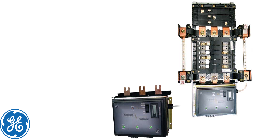
These Surge Protective Device (SPD) models connect
directly to GE A-Series panelboard bus bars without
adding width or depth to the panel enclosure. Third-party
tested per IEEE C62.62 and NEMA LS-1 for the rated 8x20μs
surge current, per mode with fusing included. Mounted
to the bus bars, a breaker feeder is not required or used.
This design allows for maximum protection. Ratings
are available from 65kA to 100kA per mode (130kA to
200kA per phase).
GE engineers design and build surge protective
devices in our state-of-the-art lab and production
facilities. Extensive testing is performed at GE and
third-party test labs across North America.
Features and Benefits
>UL 1449 3rd Edition, Type 1 or Type 2
>UL 96ALightning Protection Systems
> Optional UL 1283 noise filtering. The SPD device EMI-
RFI noise rejection or attenuation value is measured
in accordance with the procedures outlined in NEMA
LS 1-1992 (R2000)/MIL–STD-220B. Attenuation is -50db
minimum @ 100kHz.
> UL tested to 100,000 amperes symmetrical withstand
> Device is capable of surviving a minimum of 5,000
category C3impulses (10kA, 20kV) per mode
> Thermally protected
MOVs eliminate the need for
additional upstream fuses
> NO/NC Form C dry type contacts for remote monitoring
> Third-party tested to maximum surge rating as a
complete assembly
> 10 modes of protection (L-N, L-G, N-G, L-L)
> Green status indicating lights, red service light
> Audible alarm with test/disable feature
> Optional
LCD surge counter
> Factory installed in GE A-Series Panelboards, UL 67 listed
> 5 year limited warranty (standard),
10 year limited warranty (optional)
Integrated
Tranquell™ME
Surge Protective Device (SPD)
with Enhanced Thermal Protection
Direct Bus Connected Within
GE A-Series™Panelboards
Typical GE A-Series™
Branch Panel Interior
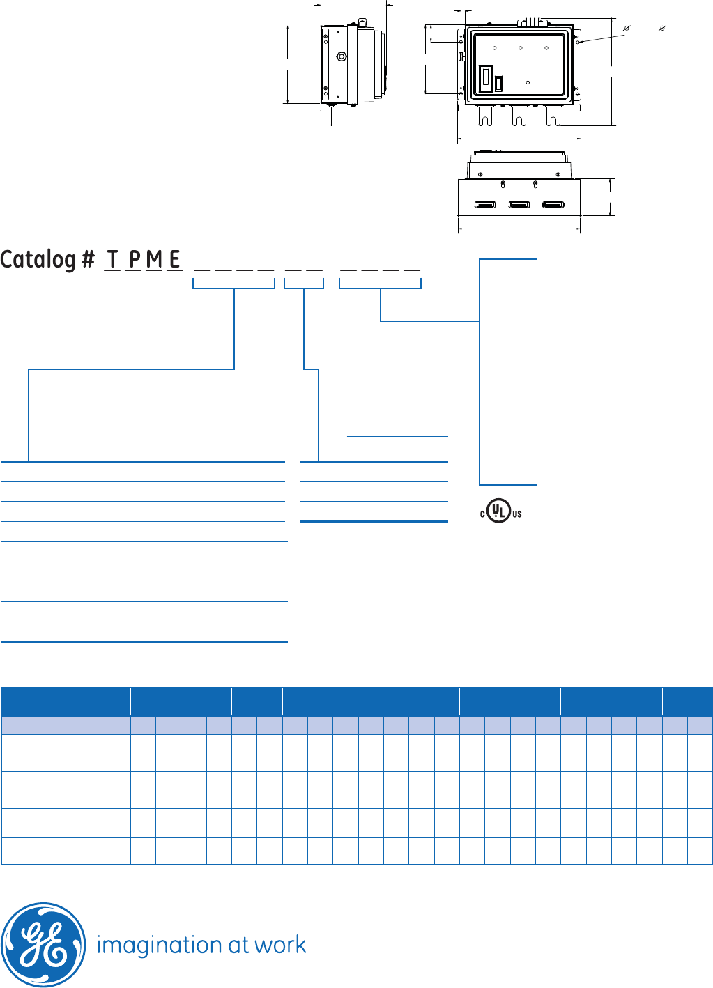
CAT# TPME277Y06AS
DEA-390 (12/09)
GE Digital Energy – Power Quality
830 W 40th Street, Chicago, IL 60609 USA
800 637 1738 www.gepowerquality.com
Information subject to change without notice. Please verify all details with GE.
©2009 General Electric Company All Rights Reserved
Phase Rating = (L-N+ L-G)
Catalog # example: TPME277Y10AS
– 277Y/480 V, 3 Ph, 4 W + G
– 100kA per mode
– Full featured, with UL 1283 noise filtering and surge counter
Nominal
Voltage
(Volts RMS)
System
Voltage
Configuration
MCOV
Max. Continuous
Operating
Voltage
L-N/G (Vrms)
120S 120/240 1 Ph, 3 W + G 150
120Y 120Y/208 3 Ph, 4 W + G 150
240 Delta 3 Ph, 3 W 270
240H 120/240 Delta HL 3 Ph, 4 W + G 150/270 HL
240Y 240Y/415 3 Ph, 4 W + G 320
277Y 277Y/480 3 Ph, 4 W + G 320
220Y 220Y/380 3 Ph, 4 W + G 320
480D 480 Delta 3 Ph, 3 W 550
347Y 347Y/600 3 Ph, 4 W + G 420
AS = Full featured, with UL 1283 noise
filtering and surge counter for
UL Type 2 locations
ASNF = without EMI/RFI noise filtering
(Available 100kA per Mode) only
for UL Type 2 locations
ASNC = without EMI/RFI noise filtering,
without surge counter for UL
Type 2 locations (Available 100kA
per Mode) only
AST1= Full featured, with UL 1283 noise
filtering and surge counter for
UL Type 1 locations
240D
1.331 [33.81]
5.331 [135.41]
0.312 [7.91] TYP
0.236 [ 5.99] HOLE
(4 PLACES)
5.064 [128.62]
9.494 [241.15]
8.321 [211.36]
6.000 [152.40]
9.400 [238.76]
2.869 [72.87]
Dimensions
Maximum Surge
Current Capacity
Per Mode Per Phase
65kA 130kA
80kA 160kA
100kA 200kA
06
08
10
NOTE:
All dimensions are for reference only
and are shown in Inches [millimeters]
Voltage Code 120S / 120Y 240D 240H 220Y / 240Y / 277Y 347Y 480D
Protection Mode L-N L-G N-G L-L L-G L-L L-N HL-N L-G HL-G N-G L-L HL-L L-N L-G N-G L-L L-N L-G N-G L-L L-G L-L
UL 1449, 3rd Edition Voltage
Protection Ratings (VPR)
(assigned UL rating)
700 600 600 1200 900 1800 700 1200 600 1000 600 1200 1900 1200 1000 1000 2000 1500 1500 1500 3000 1500 3000
UL 1449, 2nd Edition Suppression
Voltage Ratings (SVR)
(assigned UL rating) *500 500 500 700 800 1500 500 700 500 700 500 900 — 800 800 800 1500 1200 1000 1000 2000 1500 3000
B3 Ring Wave Clamping
Voltage @ 6kV, 500A 441 443 440 719 733 1207 437 — 438 — 440 789 — 727 800 792 1340 832 967 970 1657 1177 1643
C3 Combo Wave Clamping
Voltage @ 20kV, 10kA 673 547 564 883 840 1547 670 — 548 — 564 1093 — 993 937 1000 1667 1420 1180 1180 2880 1547 2880
Technical Specifications
Operating Frequency
50/60 Hz
Connection
Direct Bus, Parallel Connected
Operating Temperature
-40° Fto 149° F(-40° Cto +65° C)
Operating Humidity
0% to 95% Non-Condensing
Weight
13 lbs. (5.9 kg)
*NOTE: SVR Ratings are no longer assigned by UL and are included in the table above for reference purposes only.
Protection Ratings
2 7 7 Y 0 6 A S

GE Digital Energy
Power Quality
Introduction
Recommended installation locations are primary and
secondary distribution and point of use levels. Designed
for distribution and point of use locations, but rated for
service entrance, the Tranquell™ME with enhanced
thermal protection has been third-party tested to ANSI/
IEEE C310kA 8x20μs impulses. The Tranquell™ME Series
is designed for rigorous duty and long life, as evidenced
in our outstanding minimum repetitive surge current
capacity test results.
These Surge Protective Device (SPD) models connect
directly to GE A-Series panelboard bus bars without
adding width or depth to the panel enclosure. Third-party
tested per IEEE C62.62 and NEMA LS-1 for the rated 8x20μs
surge current, per mode with fusing included. Mounted
to the bus bars, a breaker feeder is not required or used.
This design allows for maximum protection. Ratings
are available from 65kA to 100kA per mode (130kA to
200kA per phase).
GE engineers design and build surge protective
devices in our state-of-the-art lab and production
facilities. Extensive testing is performed at GE and
third-party test labs across North America.
Features and Benefits
>UL 1449 3rd Edition, Type 1 or Type 2
>UL 96ALightning Protection Systems
> Optional UL 1283 noise filtering. The SPD device EMI-
RFI noise rejection or attenuation value is measured
in accordance with the procedures outlined in NEMA
LS 1-1992 (R2000)/MIL–STD-220B. Attenuation is -50db
minimum @ 100kHz.
> UL tested to 100,000 amperes symmetrical withstand
> Device is capable of surviving a minimum of 5,000
category C3impulses (10kA, 20kV) per mode
> Thermally protected
MOVs eliminate the need for
additional upstream fuses
> NO/NC Form C dry type contacts for remote monitoring
> Third-party tested to maximum surge rating as a
complete assembly
> 10 modes of protection (L-N, L-G, N-G, L-L)
> Green status indicating lights, red service light
> Audible alarm with test/disable feature
> Optional
LCD surge counter
> Factory installed in GE A-Series Panelboards, UL 67 listed
> 5 year limited warranty (standard),
10 year limited warranty (optional)
Integrated
Tranquell™ME
Surge Protective Device (SPD)
with Enhanced Thermal Protection
Direct Bus Connected Within
GE A-Series™Panelboards
Typical GE A-Series™
Branch Panel Interior
CAT# TPME120Y06AS

DEA-390 (12/09)
GE Digital Energy – Power Quality
830 W 40th Street, Chicago, IL 60609 USA
800 637 1738 www.gepowerquality.com
Information subject to change without notice. Please verify all details with GE.
©2009 General Electric Company All Rights Reserved
Phase Rating = (L-N+ L-G)
Catalog # example: TPME277Y10AS
– 277Y/480 V, 3 Ph, 4 W + G
– 100kA per mode
– Full featured, with UL 1283 noise filtering and surge counter
Nominal
Voltage
(Volts RMS)
System
Voltage
Configuration
MCOV
Max. Continuous
Operating
Voltage
L-N/G (Vrms)
120S 120/240 1 Ph, 3 W + G 150
120Y 120Y/208 3 Ph, 4 W + G 150
240 Delta 3 Ph, 3 W 270
240H 120/240 Delta HL 3 Ph, 4 W + G 150/270 HL
240Y 240Y/415 3 Ph, 4 W + G 320
277Y 277Y/480 3 Ph, 4 W + G 320
220Y 220Y/380 3 Ph, 4 W + G 320
480D 480 Delta 3 Ph, 3 W 550
347Y 347Y/600 3 Ph, 4 W + G 420
AS = Full featured, with UL 1283 noise
filtering and surge counter for
UL Type 2 locations
ASNF = without EMI/RFI noise filtering
(Available 100kA per Mode) only
for UL Type 2 locations
ASNC = without EMI/RFI noise filtering,
without surge counter for UL
Type 2 locations (Available 100kA
per Mode) only
AST1= Full featured, with UL 1283 noise
filtering and surge counter for
UL Type 1 locations
240D
1.331 [33.81]
5.331 [135.41]
0.312 [7.91] TYP
0.236 [ 5.99] HOLE
(4 PLACES)
5.064 [128.62]
9.494 [241.15]
8.321 [211.36]
6.000 [152.40]
9.400 [238.76]
2.869 [72.87]
Dimensions
Maximum Surge
Current Capacity
Per Mode Per Phase
65kA 130kA
80kA 160kA
100kA 200kA
06
08
10
NOTE:
All dimensions are for reference only
and are shown in Inches [millimeters]
Voltage Code 120S / 120Y 240D 240H 220Y / 240Y / 277Y 347Y 480D
Protection Mode L-N L-G N-G L-L L-G L-L L-N HL-N L-G HL-G N-G L-L HL-L L-N L-G N-G L-L L-N L-G N-G L-L L-G L-L
UL 1449, 3rd Edition Voltage
Protection Ratings (VPR)
(assigned UL rating)
700 600 600 1200 900 1800 700 1200 600 1000 600 1200 1900 1200 1000 1000 2000 1500 1500 1500 3000 1500 3000
UL 1449, 2nd Edition Suppression
Voltage Ratings (SVR)
(assigned UL rating) *500 500 500 700 800 1500 500 700 500 700 500 900 — 800 800 800 1500 1200 1000 1000 2000 1500 3000
B3 Ring Wave Clamping
Voltage @ 6kV, 500A 441 443 440 719 733 1207 437 — 438 — 440 789 — 727 800 792 1340 832 967 970 1657 1177 1643
C3 Combo Wave Clamping
Voltage @ 20kV, 10kA 673 547 564 883 840 1547 670 — 548 — 564 1093 — 993 937 1000 1667 1420 1180 1180 2880 1547 2880
Technical Specifications
Operating Frequency
50/60 Hz
Connection
Direct Bus, Parallel Connected
Operating Temperature
-40° Fto 149° F(-40° Cto +65° C)
Operating Humidity
0% to 95% Non-Condensing
Weight
13 lbs. (5.9 kg)
*NOTE: SVR Ratings are no longer assigned by UL and are included in the table above for reference purposes only.
Protection Ratings
1 2 0 Y 0 6 A S

GE Digital Energy
Power Quality
Introduction
Recommended installation locations are primary and
secondary distribution and point of use levels. Designed
for distribution and point of use locations, but rated for
service entrance, the Tranquell™ME with enhanced
thermal protection has been third-party tested to ANSI/
IEEE C310kA 8x20μs impulses. The Tranquell™ME Series
is designed for rigorous duty and long life, as evidenced
in our outstanding minimum repetitive surge current
capacity test results.
These Surge Protective Device (SPD) models connect
directly to GE A-Series panelboard bus bars without
adding width or depth to the panel enclosure. Third-party
tested per IEEE C62.62 and NEMA LS-1 for the rated 8x20μs
surge current, per mode with fusing included. Mounted
to the bus bars, a breaker feeder is not required or used.
This design allows for maximum protection. Ratings
are available from 65kA to 100kA per mode (130kA to
200kA per phase).
GE engineers design and build surge protective
devices in our state-of-the-art lab and production
facilities. Extensive testing is performed at GE and
third-party test labs across North America.
Features and Benefits
>UL 1449 3rd Edition, Type 1 or Type 2
>UL 96ALightning Protection Systems
> Optional UL 1283 noise filtering. The SPD device EMI-
RFI noise rejection or attenuation value is measured
in accordance with the procedures outlined in NEMA
LS 1-1992 (R2000)/MIL–STD-220B. Attenuation is -50db
minimum @ 100kHz.
> UL tested to 100,000 amperes symmetrical withstand
> Device is capable of surviving a minimum of 5,000
category C3impulses (10kA, 20kV) per mode
> Thermally protected
MOVs eliminate the need for
additional upstream fuses
> NO/NC Form C dry type contacts for remote monitoring
> Third-party tested to maximum surge rating as a
complete assembly
> 10 modes of protection (L-N, L-G, N-G, L-L)
> Green status indicating lights, red service light
> Audible alarm with test/disable feature
> Optional
LCD surge counter
> Factory installed in GE A-Series Panelboards, UL 67 listed
> 5 year limited warranty (standard),
10 year limited warranty (optional)
Integrated
Tranquell™ME
Surge Protective Device (SPD)
with Enhanced Thermal Protection
Direct Bus Connected Within
GE A-Series™Panelboards
Typical GE A-Series™
Branch Panel Interior
CAT# TPME120S06AS

DEA-390 (12/09)
GE Digital Energy – Power Quality
830 W 40th Street, Chicago, IL 60609 USA
800 637 1738 www.gepowerquality.com
Information subject to change without notice. Please verify all details with GE.
©2009 General Electric Company All Rights Reserved
Phase Rating = (L-N+ L-G)
Catalog # example: TPME277Y10AS
– 277Y/480 V, 3 Ph, 4 W + G
– 100kA per mode
– Full featured, with UL 1283 noise filtering and surge counter
Nominal
Voltage
(Volts RMS)
System
Voltage
Configuration
MCOV
Max. Continuous
Operating
Voltage
L-N/G (Vrms)
120S 120/240 1 Ph, 3 W + G 150
120Y 120Y/208 3 Ph, 4 W + G 150
240 Delta 3 Ph, 3 W 270
240H 120/240 Delta HL 3 Ph, 4 W + G 150/270 HL
240Y 240Y/415 3 Ph, 4 W + G 320
277Y 277Y/480 3 Ph, 4 W + G 320
220Y 220Y/380 3 Ph, 4 W + G 320
480D 480 Delta 3 Ph, 3 W 550
347Y 347Y/600 3 Ph, 4 W + G 420
AS = Full featured, with UL 1283 noise
filtering and surge counter for
UL Type 2 locations
ASNF = without EMI/RFI noise filtering
(Available 100kA per Mode) only
for UL Type 2 locations
ASNC = without EMI/RFI noise filtering,
without surge counter for UL
Type 2 locations (Available 100kA
per Mode) only
AST1= Full featured, with UL 1283 noise
filtering and surge counter for
UL Type 1 locations
240D
1.331 [33.81]
5.331 [135.41]
0.312 [7.91] TYP
0.236 [ 5.99] HOLE
(4 PLACES)
5.064 [128.62]
9.494 [241.15]
8.321 [211.36]
6.000 [152.40]
9.400 [238.76]
2.869 [72.87]
Dimensions
Maximum Surge
Current Capacity
Per Mode Per Phase
65kA 130kA
80kA 160kA
100kA 200kA
06
08
10
NOTE:
All dimensions are for reference only
and are shown in Inches [millimeters]
Voltage Code 120S / 120Y 240D 240H 220Y / 240Y / 277Y 347Y 480D
Protection Mode L-N L-G N-G L-L L-G L-L L-N HL-N L-G HL-G N-G L-L HL-L L-N L-G N-G L-L L-N L-G N-G L-L L-G L-L
UL 1449, 3rd Edition Voltage
Protection Ratings (VPR)
(assigned UL rating)
700 600 600 1200 900 1800 700 1200 600 1000 600 1200 1900 1200 1000 1000 2000 1500 1500 1500 3000 1500 3000
UL 1449, 2nd Edition Suppression
Voltage Ratings (SVR)
(assigned UL rating) *500 500 500 700 800 1500 500 700 500 700 500 900 — 800 800 800 1500 1200 1000 1000 2000 1500 3000
B3 Ring Wave Clamping
Voltage @ 6kV, 500A 441 443 440 719 733 1207 437 — 438 — 440 789 — 727 800 792 1340 832 967 970 1657 1177 1643
C3 Combo Wave Clamping
Voltage @ 20kV, 10kA 673 547 564 883 840 1547 670 — 548 — 564 1093 — 993 937 1000 1667 1420 1180 1180 2880 1547 2880
Technical Specifications
Operating Frequency
50/60 Hz
Connection
Direct Bus, Parallel Connected
Operating Temperature
-40° Fto 149° F(-40° Cto +65° C)
Operating Humidity
0% to 95% Non-Condensing
Weight
13 lbs. (5.9 kg)
*NOTE: SVR Ratings are no longer assigned by UL and are included in the table above for reference purposes only.
Protection Ratings
1 2 0 S 0 6 A S

imagination at work
GE
QL Dry Type Transformers
Up to 99% efficient
100% tested
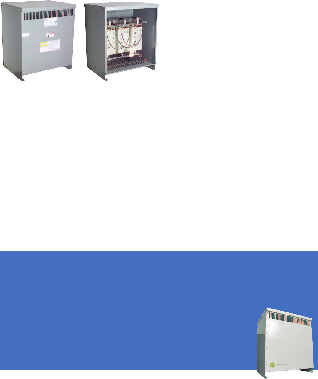
QL Dry Type Transformers
Our QL transformers are setting new standards for quality – in design, manufacturing
and testing. Before leaving the GE factory, every QL transformer must pass a series
of rigorous tests, performed with advanced equipment, on a range of measurements.
We test for:
• Shorts and coil integrity to help ensure high initial
quality and years of trouble-free operation
• Current and loss to help ensure peak efficiency, low
noise and the lowest operating cost possible
• Voltage to help ensure that input and output voltages
are exactly as specified
• Impedance to help ensure the transformer is producing
power that’s friendly to your building and equipment
That’s why you can be sure you’ll get the highest initial
quality and years of trouble-free operation.
All QL transformers feature:
• NEMA TP-1 2002 compliance
• Clear, comprehensive documentation and labeling
• Single-piece front/back for easier service
• Accessible mounting flanges with front/back slotted
mounting holes to speed installation
• Seismic qualifications to the requirements of ASCE 7.05,
IEEE-693-2005 and IBC-2006
• 200% neutral standard
• Copper ground strap standard
• Full capacity, universal taps consisting of two 2.5% above
nominal and four 2.5% below nominal
• Robust packaging with top and edge protection
• 220°C insulation system
• 40°C ambient
• 10kV-BIL
• Copper or aluminum windings
• UL Listing
• Standard NEMA 2 drip-proof enclosure with optional
weathershield kit for conversion to NEMA 3R outdoor
• A one-year limited warranty
NEW QL Ultra Efficient
Up to 99% efficient
More energy efficient than the TP-1 design, the QL
Ultra Efficient transformer – GE’s newest – can save
customers nearly $4,000 per year in operating costs,
based on a facility the size of an elementary school*,
and help them earn U. S. Green Building Council’s
LEED®certification points on a project. It’s significantly
quieter than standard transformers and features all
of the convenience and reliability you expect from a
QL transformer. It’s perfect for schools and colleges and
for government, healthcare and commercial buildings.
Features and benefits
• Efficiency up to 99% reduces operating cost by 30%
• Low core loss with maximum efficiency under
low-load conditions
• Aids in qualifying for more LEED points for sustainable
building appeal
• Ultra quiet operation
• Prime-9 offering with all standard
options fit many applications
• K1, K4 and K13 models available.
K-factor models available in
150°C and 115°C rise
*Based on upgrading pre-2007 (non-TP-1) GE transformers at an elementary school with 13 transformers, ranging in size
from 30kVA to 112.5 kVA and energy costs of $.077/kwh to the equivalent GE QL Ultra transformers.
QL K Factor
How to handle non-linear loads
K-Factor transformers are more robust than standard
transformers, so they are better able to withstand the
additional heating that accompanies the presence of
harmonics in electrical systems. K-factor transformers
are designed not to eliminate harmonics, but to
withstand their negative effects.
Features and benefits
• UL K-Factor Listed. UL 1561 listed
• Full-width copper electrostatic shielding standard
• Effective coupling capacitance 30 PF between primary
and secondary
______________________________________________
QL Low Noise
The quiet performers
These low noise transformers operate at reduced noise
levels. The vibrations within the magnetic steel core
have been greatly reduced, thus reducing transformer
hum. QL Low-Noise transformers operate at 3dB less
than NEMA/ANSI standards.
Features and benefits
• Great for noise-sensitive areas
• Operation at –3dB below NEMA standard
• 150°C, 115°C or 80°C rise
______________________________________________
QL Guard I, II, III Noise Isolation
Extra protection for sensitive equipment
Installations with sensitive electronic equipment –
computer rooms, x-ray rooms, electrical laboratories,
etc. – need the extra protection offered by GE’s Guard
I, II and III transformers.
Guard I
• Grounded copper electrostatic shield between primary
and secondary windings
• 120dB common-mode noise protection
• 30dB transverse-mode noise protection
Guard II
• Grounded copper electrostatic
shield between primary and
secondary windings
• Noise suppressors and
spike/surge suppressors
• 120dB common-mode noise
protection
• 60dB transverse-mode noise protection
Guard III
• Saves energy by reducing harmonic losses
• Eliminates transformer overheating and high operating
temperatures
• Maintains energy efficiency even when harmonics
are present in the electrical system
• Helps eliminate power quality problems that K-factor
transformers do not
QL Totally Enclosed Non-Ventillated (TENV)
Totally enclosed nonventilated (TENV) transformers are
an excellent choice for applications where standard
dry-type transformer enclosure openings are not
acceptable because dust, dirt or lint may be present or
because transformers are subject to sprays or controlled
wash-down conditions.
Features and benefits
• Convenient wiring compartment
beneath the transformer has
removable front and rear covers
• Clearly labeled copper bus bars are
located at the front of the wiring
compartment
• All electrical connections between
the transformer and bus bars are
factory wired
______________________________________________
QL Drive Isolation Transformers (DIT)
Built for SCR stresses
QL Drive Isolation Transformers (DIT) are designed
specifically to handle the use of SCR control circuitry of
adjustable-speed drives. Symmetrically placed taps
and added coil bracing are able to withstand the
mechanical forces involved. They also reduce line
pollution feedback resulting from SCR firing circuits.
Features and benefits
• Voltages up to 600V
• Conforms to ANSI , NEMA , UL and IEEE standards
• 3-15 KVA 3 phase and 5-25 KVA 1 phase
imagination at work
DEA-492A (04/10)
LEED is a registered trademark of the U.S. Green Building Council.
Information provided is subject to change without notice. Please verify all details with GE. All values are design or typical values when measured under
laboratory conditions, and GE makes no warranty or guarantee, express or implied, that such performance will be obtained under end-use conditions.
GE
41 Woodford Avenue
Plainville, CT 06062
www.geelectrical.com
© 2010 General Electric Company
QL Transformer Selection Guide
Application
QL
General
Purpose
QL Ultra
Efficiency
QL K -
Factor
(K=4)
QL K -
Factor
(K=13)
QL K -
Factor
(K=20)
QL K -
Factor
(K=30)
QL Low
Noise
QL Drive
Isolation
AC or DC variable speed drives ■
Computer installations ■ ■
Critical care facilities ■ ■ ■
Data processing equipment circuits ■ ■
HID lighting ■
Hospital operating rooms ■ ■
Incandescent lighting ■ ■
Induction heaters ■
Instrumentation ■ ■
LEED projects ■
Maximum energy efficiency ■
Motor generators (without solid state drives) ■ ■
Motors ■ ■
Multiple receptacle circuits in heath care facilities ■
Office buildings ■ ■ ■
PLC & solid state controls ■
Production or assembly line equipment ■
Programmable controllers ■ ■
Rectifier outputs ■
Resistance heating ■ ■
Schools & classroom facilities ■ ■ ■
SCR variable speed drives ■ ■
UPS with optional input filtering ■
UPS without optional input filtering ■
Welders ■
X-ray equipment ■ ■