Sensors, Limit Switches, And Connector Cables, 9006CT0101 1000388065 Catalog
124368-Catalog 124368-Catalog 124368-Catalog B4 unilog cesco-content
2016-07-29
: Pdf 1000388065-Catalog 1000388065-Catalog B2 unilog
Open the PDF directly: View PDF ![]() .
.
Page Count: 680 [warning: Documents this large are best viewed by clicking the View PDF Link!]
- Osiconcept™ Sensors
- Photoelectric Sensors
- Selection Guide
- Application Examples
- Interpretation of Catalog Numbers
- Osiconcept™ Multi-Mode™ Technology
- XUB 18 mm Tubular
- XUM Miniature Rectangular
- XUK Subcompact Rectangular
- XUX Compact Rectangular
- XUD Amplifiers, Self-Teach, DC
- XUA 8 mm Diameter
- Classic 18 mm Tubular
- Metal Body, Front Sensing, AC/DC
- Metal Body, 90˚ Sensing, AC/DC
- Stainless Steel, Front Sensing, DC
- Stainless Steel, 90˚ Sensing, DC
- Metal Body, High Excess Gain, Thru Beam, DC
- Metal Body, Analog Output, Proximity Diffuse, DC
- Metal Body, Ultraviolet (UV), DC
- Plastic Body, Laser, Thru-Beam Mode, DC
- Transparent Material Detection, DC
- Accessories-Replacement
- Accessories-Dimensions
- Osiris® Food and Beverage Processing, Stainless Steel
- XUM Miniature, Classic
- XUK Subcompact, Classic
- XUC Compact, Limit Switch Body Style
- XUL Subcompact
- XUJ Analog with Background Suppression
- Fiber Optics
- XUV with Separate Optical Heads
- XUK Subcompact
- XUM Miniature, Color Mark
- XUMW Liquid Detection
- XUR Rectangular Compact, Color
- XUV Fork and Frame
- XUZ Accessories
- Dimensions and Sensing Patterns
- Substitution Guide
- General
- Detection Systems
- Specific Systems
- Outputs and Wiring
- Outputs and Connections
- Complementary Functions
- Curves
- Standards and Certifications
- Specific Aspects of Electronic Sensors
- Electrical Installation of Electronic Sensors
- Proximity Sensors
- Inductive Sensors
- Selection Guide
- XS8 Auto-Adaptable Inductive Sensor
- XS7 Inductive Sensor
- XS6 Extended Range and Auto-Adaptable Inductive Sensor
- XS5 Inductive Sensor
- XS9 Application-Specific Inductive Sensor
- Basic, Plastic, Cylindrical, Non-Flush Mountable
- Basic, Metal, Cylindrical, Flush and Non-Flush Mountable
- XS Tubular, Inductive Sensors
- 4 mm Diameter, DC
- 5 mm Diameter, DC; Economy Short Length
- 6.5 mm Diameter, DC; Economy, Short Length, Smooth Barrel
- 8 mm Diameter, DC; Economy Short Length
- 8 mm Diameter, DC; Economy Short Length, Non-Corrosive
- 8 mm Diameter, DC; Universal Standard Length
- 8 mm Diameter, AC/DC; Universal Standard Length
- 12 mm Diameter, DC; Economy Short Length
- 12 mm Diameter, DC; Universal Standard Length
- 12 mm Diameter, DC; Universal Standard Length, Non-Corrosive
- 12 mm Diameter, AC/DC; Universal Standard Length
- 18 mm Diameter, DC; Economy Short Length
- 18 mm Diameter, DC; Universal Standard Length
- 18 mm Diameter, DC; Universal Standard Length, Non-Corrosive
- 18 mm Diameter, AC/DC; Universal Standard Length
- 30 mm Diameter, DC; Economy Short Length
- 30 mm Diameter, DC; Universal Standard Length
- 30 mm Diameter, DC; Universal Standard Length, Non-Corrosive
- 30 mm Diameter, AC/DC; Universal Standard Length
- Economy D Series-DC, AC
- Extended Range-AC/DC, DC
- XS Inductive Sensors
- XS5L8 Inductive Sensors
- XS7H, XS8H Miniature Inductive Sensor
- XS7G/XS8G Inductive Sensors
- XS7T/XS8T Inductive Sensors, Cubic Block Style
- XS7C/XS8C Limit Switch Type, Inductive Sensors
- XS Inductive Sensors, Limit Switch Body
- XSD Rectangular, Inductive Sensors
- XSAV Tubular, Inductive Sensors
- XS Inductive Sensors, Weld Field Immune, DC
- Inductive Sensors for Use in Hazardous Locations
- XS Inductive Sensors
- XS Inductive Sensors, Osiprox® Food and Beverage Processing
- XT Capacitive Sensors
- XS Inductive Sensors
- SG Magnet Actuated Sensors
- ST Grounded Probe Switch
- Inductive Sensor Accessories
- Sensing Curves
- Product Overview
- Catalog Number Cross-References
- Osisonic™ Ultrasonic Sensors
- Limit Switches
- Selection Guide
- Osiswitch® Miniature Snap Switches
- Osiswitch® Miniature, Metal
- Osiswitch® Miniature, Plastic
- Osiswitch® Compact
- Osiswitch® Compact, Metal
- Osiswitch® Compact, Plastic
- Osiswitch® Compact, Metal and Plastic
- Osiswitch® Compact, Plastic
- Osiswitch® Compact, Metal and Plastic
- Osiswitch® Compact with Manual Reset
- Osiswitch® Classic, Metal
- Osiswitch® Classic, Metal, Conforming to CENELEC EN 50041
- XCKJ
- XCKJ-Complete Switches, Plug-in Body, 1/2" NPT Cable Entry
- XCKJ-Complete Switches, Fixed Non-plug-in Body, Integral M12 Connector
- XCKJ-Complete Switches, Fixed Non-plug-in Body, Integral 7/8" 16UN connector
- XCKJ-Modular, Fixed Non-plug-in or Plug-in Bodies
- XCKJ-Modular, Fixed Non-plug-in or Plug-in Bodies with 1/2" NPT Cable Entry
- XCKJ-Modular, Fixed Non-plug-in Bodies with M12 Connector
- XCKJ-Modular, Fixed Non-plug-in or Plug-in Bodies with 1/2" NPT Cable Entry
- XCKJ-Modular, Fixed Non-plug-in or Plug-in Bodies-Components
- Osiswitch® Classic, Plastic, Conforming to CENELEC EN 50041
- Osiswitch® Classic, For Hoisting, Mechanical Handling, and Conveyer Belt Shift Monitoring
- Osiswitch® Classic, For Hoisting and Material Handling
- Osiswitch® Classic, For Material Handling
- Snap Action Industrial Switches
- Miniature
- Miniature Enclosed Reed
- 9007AW Heavy Duty Industrial
- 9007C Heavy Duty Industrial-Plug-in Body, Metal
- 9007C Heavy Duty Industrial-Non-Plug-in Body, Metal
- 9007C Heavy Duty Industrial
- 9007T and FT Severe Duty Mill and Foundry Switches
- 9007T Severe Duty Mill Switches
- 9007FT Severe Duty Foundry Switches
- R.B.Denison® Lox-Switch™ L Severe Duty Mill and Foundry Switches
- Interpretation of Catalog Numbers
- Cabling
- Selection Guide
- Nano-Style Connector Cables (Female)
- Micro-Style Connector Cables (Female)
- Mini-Style Connector Cables (Female)
- Micro-Style Field-Attachable Connectors
- Snap-C™ Quick Connector
- Mini and International Field-Attachable Connectors
- Micro- and Nano-Style Extension Cables
- Mini, Micro and DIN Style Extension Cables
- Micro to Micro Splitter Cables
- Micro-Style Splitter Boxes
- Sensor Dock (Connector Box)
- Micro-Style Sensor Dock (Connector Box) with Output LEDs
- AS-Interface® Bus
- Glossary of Terms
- Wire Size Chart
- Index of Product Catalog Numbers

File 9006
Sensors, Limit Switches,
and Connector Cables
Photoelectric, Proximity, and
Ultrasonic Sensors
CONTENTS PAGE
Sensors. . . . . . . . . . . . . . . . . . . . . . . . . . . . . . . . . . . . . . . . . . . . . . . . . . . 7
Photoelectric . . . . . . . . . . . . . . . . . . . . . . . . . . . . . . . . . . . . . . . . . . . . . . 12
Proximity . . . . . . . . . . . . . . . . . . . . . . . . . . . . . . . . . . . . . . . . . . . . . . . . 172
Ultrasonic. . . . . . . . . . . . . . . . . . . . . . . . . . . . . . . . . . . . . . . . . . . . . . . . 354
Limit Switches . . . . . . . . . . . . . . . . . . . . . . . . . . . . . . . . . . . . . . . . . . . 390
Connector Cables . . . . . . . . . . . . . . . . . . . . . . . . . . . . . . . . . . . . . . . . 626
Index of Product Catalog Numbers . . . . . . . . . . . . . . . . . . . . . . . . . . 674
Catalog
9006CT0101R5/04
07
Building a New Electric World

2
© 1997–2007 Schneider Electric All Rights Reserved 09/2007
NOTE: Sensors described in this catalog are designed to be used for standard industrial
presence sensing applications. These sensors do not include the self-checking redundant
circuitry necessary to allow their use in safety applications.
Square D®, Telemecanique®, Osiris®, Osiprox®, Osiswitch®, R.B.Denison®, Virtu® Lox-Switch™,
Osiconcept™, Osisonic™, and Preventa™ are trademarks or registered trademarks of Schneider Electric.
Other trademarks used herein are the property of their respective owners.

3
09/2007 © 1997–2007 Schneider Electric All Rights Reserved
Sensors, Limit Switches, and Connector Cables
Table of Contents
Osiconcept™ Sensors .........................................................................................................7
Introduction .......................................................................................................................7
Environmental Protection Classification ...........................................................................9
Photoelectric Sensors .......................................................................................................12
Selection Guide ..............................................................................................................12
Application Examples .....................................................................................................20
Interpretation of Catalog Numbers .................................................................................28
Osiconcept™ Multi-Mode™ Technology ........................................................................30
XUB 18 mm Tubular .......................................................................................................32
XUM Miniature Rectangular ...........................................................................................48
XUK Subcompact Rectangular .......................................................................................52
XUX Compact Rectangular ............................................................................................56
XUD Amplifiers, Self-Teach, DC .....................................................................................60
XUA 8 mm Diameter .......................................................................................................62
Classic 18 mm Tubular ...................................................................................................64
Osiris® Food and Beverage Processing, Stainless Steel ...............................................84
XUM Miniature, Classic ..................................................................................................90
XUK Subcompact, Classic ..............................................................................................92
XUC Compact, Limit Switch Body Style .........................................................................94
XUL Subcompact ............................................................................................................96
XUJ Analog with Background Suppression ....................................................................98
Fiber Optics ..................................................................................................................100
XUV with Separate Optical Heads ................................................................................106
XUK Subcompact .........................................................................................................112
XUM Miniature, Color Mark ..........................................................................................114
XUMW Liquid Detection ...............................................................................................116
XUR Rectangular Compact, Color ................................................................................118
XUV Fork and Frame ....................................................................................................126
XUZ Accessories ..........................................................................................................134
Dimensions and Sensing Patterns ...............................................................................141
Substitution Guide ........................................................................................................146
General .........................................................................................................................150
Detection Systems ........................................................................................................151
Specific Systems ..........................................................................................................155
Outputs and Wiring .......................................................................................................156
Outputs and Connections .............................................................................................157
Complementary Functions ............................................................................................158
Curves ..........................................................................................................................162
Standards and Certifications ........................................................................................164
Specific Aspects of Electronic Sensors ........................................................................165
Electrical Installation of Electronic Sensors ..................................................................167
Proximity Sensors ............................................................................................................172
Inductive Sensors .........................................................................................................172
Selection Guide ............................................................................................................174
XS8 Auto-Adaptable Inductive Sensor .........................................................................180
XS7 Inductive Sensor ...................................................................................................182
XS6 Extended Range and Auto-Adaptable Inductive Sensor ......................................184
XS5 Inductive Sensor ...................................................................................................186
XS9 Application-Specific Inductive Sensor ...................................................................188
Basic, Plastic, Cylindrical, Non-Flush Mountable .........................................................192
Basic, Metal, Cylindrical, Flush and Non-Flush Mountable ..........................................194
XS Tubular, Inductive Sensors .....................................................................................198
XS Inductive Sensors ...................................................................................................240
XS5L8 Inductive Sensors .............................................................................................246
XS7H, XS8H Miniature Inductive Sensor .....................................................................248

4
© 1997–2007 Schneider Electric All Rights Reserved 09/2007
XS7G/XS8G Inductive Sensors ................................................................................... 250
XS7T/XS8T Inductive Sensors, Cubic Block Style ...................................................... 252
XS7C/XS8C Limit Switch Type, Inductive Sensors ..................................................... 254
XS Inductive Sensors, Limit Switch Body .................................................................... 256
XSD Rectangular, Inductive Sensors .......................................................................... 258
XSAV Tubular, Inductive Sensors ............................................................................... 262
XS Inductive Sensors, Weld Field Immune, DC .......................................................... 264
Inductive Sensors for Use in Hazardous Locations ..................................................... 268
XS Inductive Sensors .................................................................................................. 270
XS Inductive Sensors, Osiprox® Food and Beverage Processing ............................... 272
XT Capacitive Sensors ................................................................................................ 280
XS Inductive Sensors .................................................................................................. 284
SG Magnet Actuated Sensors ..................................................................................... 288
ST Grounded Probe Switch ......................................................................................... 298
Inductive Sensor Accessories ...................................................................................... 300
Sensing Curves ........................................................................................................... 306
Product Overview ........................................................................................................ 309
Catalog Number Cross-References ............................................................................. 344
Osisonic™ Ultrasonic Sensors ...................................................................................... 354
Technical Overview ..................................................................................................... 354
Declaration of Conformity ............................................................................................ 361
SM300 Series .............................................................................................................. 362
SM600 Series .............................................................................................................. 367
SM900 Series .............................................................................................................. 374
Virtu® Series ................................................................................................................ 384
Limit Switches ................................................................................................................. 390
Selection Guide ........................................................................................................... 390
Osiswitch® Miniature Snap Switches ........................................................................... 410
Osiswitch® Miniature, Metal ......................................................................................... 418
Osiswitch® Miniature, Plastic ....................................................................................... 436
Osiswitch® Compact .................................................................................................... 440
Osiswitch® Compact, Metal ......................................................................................... 442
Osiswitch® Compact, Plastic ....................................................................................... 448
Osiswitch® Compact, Metal and Plastic ....................................................................... 451
Osiswitch® Compact, Plastic ....................................................................................... 452
Osiswitch® Compact, Metal and Plastic ....................................................................... 456
Osiswitch® Compact with Manual Reset ..................................................................... 462
Osiswitch® Classic, Metal ............................................................................................ 468
Osiswitch® Classic, Metal, Conforming to CENELEC EN 50041 ................................ 484
Osiswitch® Classic, Plastic, Conforming to CENELEC EN 50041 ............................... 512
Osiswitch® Classic, For Hoisting, Mechanical Handling, and Conveyer Belt Shift
Monitoring .................................................................................................................... 522
Osiswitch® Classic, For Hoisting and Material Handling ............................................. 524
Osiswitch® Classic, For Material Handling .................................................................. 530
Snap Action Industrial Switches .................................................................................. 536
Miniature ...................................................................................................................... 539
Miniature Enclosed Reed ............................................................................................. 544
9007AW Heavy Duty Industrial .................................................................................... 545
9007C Heavy Duty Industrial—Plug-in Body, Metal .................................................... 546
9007C Heavy Duty Industrial—Non-Plug-in Body, Metal ............................................ 582
9007C Heavy Duty Industrial ....................................................................................... 590
9007T and FT Severe Duty Mill and Foundry Switches .............................................. 598
9007T Severe Duty Mill Switches ................................................................................ 600
9007FT Severe Duty Foundry Switches ...................................................................... 602
R.B.Denison® Lox-Switch™ L Severe Duty Mill and Foundry Switches ...................... 610
Sensors, Limit Switches, and Connector Cables
Table of Contents

5
09/2007 © 1997–2007 Schneider Electric All Rights Reserved
Interpretation of Catalog Numbers ...............................................................................623
Cabling ..............................................................................................................................626
Selection Guide ............................................................................................................626
Nano-Style Connector Cables (Female) .......................................................................628
Micro-Style Connector Cables (Female) ......................................................................633
Mini-Style Connector Cables (Female) .........................................................................638
Micro-Style Field-Attachable Connectors .....................................................................644
Snap-C™ Quick Connector ..........................................................................................646
Mini and International Field-Attachable Connectors .....................................................647
Micro- and Nano-Style Extension Cables .....................................................................648
Mini, Micro and DIN Style Extension Cables ................................................................650
Micro to Micro Splitter Cables .......................................................................................652
Micro-Style Splitter Boxes ............................................................................................653
Sensor Dock (Connector Box) ......................................................................................654
Micro-Style Sensor Dock (Connector Box) with Output LEDs ......................................656
AS-Interface® Bus ........................................................................................................658
Glossary of Terms ........................................................................................................668
Wire Size Chart ............................................................................................................672
Index of Product Catalog Numbers ................................................................................674
Sensors, Limit Switches, and Connector Cables
Table of Contents

6
© 1997–2007 Schneider Electric All Rights Reserved 09/2007
Sensors, Limit Switches, and Connector Cables
Table of Contents

7
09/2007 © 1997–2007 Schneider Electric All Rights Reserved
Schneider Electric: Shaping the Future of Sensors
Schneider Electric is the first control and automation products manufacturer in the world to
introduce a comprehensive family of discrete sensor products—photoelectric, proximity, and
limit switches—built upon a common technology platform that combines intelligence and
modularity. Because this uniform approach to sensor design is so unique, we call it Global
Detection.
What is Global Detection?
Detection is an essential function to control and automate equipment within an industrial
environment. It has many variations based on different machinery requirements.
Traditionally, each sensor has been specific to an application—made by specialists who
focused on a single detection technology—with all the advantages and disadvantages
inherent in that technology.
Global Detection is Schneider Electric’s solution to that dilemma: a family of discrete sensing
products built on a common technology platform. What makes Global Detection possible is a
new Osiconcept™ approach, which combines smart technologies to simplify sensor
selection, stocking, installation, setup, and maintenance. OSI stands for Offering Simplicity
through Innovation.
Combining sophistication and simplicity was our primary objective in creating this new
technology and product platform: selection, installation, setup, and maintenance were made
as easy as possible. The second objective was availability: maximizing the number of
solutions while minimizing the product catalog numbers. A third objective was adaptability:
products that meet all the environmental constraints for a wide variety of installations.
We also added a fourth dimension—aesthetics—with uniform shapes, a compact body style,
and a uniform blue color across all products. This is important for machine builders who want
to present an image of engineering and manufacturing quality to their customers.
Innovation: Products that adapt to their environment
XS—Proximity Sensors
Conventional inductive proximity sensors can be the source of many types of application
difficulties. Apart from their size, they are also sensitive to metal environments, meaning that
some flush-mounted types must be shielded, while others may be unshielded. This causes
variances in performance. Setup and mounting can be both difficult and time consuming.
The new Telemecanique® XS Rectangular proximity sensor line, part of the Schneider
Electric Global Detection family, has been designed to eliminate all these problems. With the
flattest rectangular body size available, these compact sensors integrate easily into a
machine or process. The advanced microprocessor design of these auto-adaptable
proximity sensors allows them to easily adjust to deliver maximum sensing distance,
whatever the metal environment or mounting approach.
When the user presses a button, the product runs in teach mode to set the maximum sensing
distance. With quick attachment mounting brackets, these sensors can be quickly installed or
replaced. Once in place, there is no need to mechanically adjust their position, as tuning or
precise detection is integral to the sensor. Efficiency, performance, mounting time, and
flexibility have all been considered in the design of these proximity sensors to ensure
maximum productivity.
XU—Photoelectric Sensors
Photoelectric sensors present some equally difficult challenges. Different sensors have been
required depending on the target material—whether matte finish or reflective surfaces, light
or dark colors—and the overall environment, This complicates sensor selection, leading to a
great deal of trial and error. Sensor positioning and definition of the sensing range have also
been difficult to determine, particularly in three dimensions, which require special mountings
and protection, increasing installation costs.
Osiconcept™ Sensors
Introduction

8
© 1997–2007 Schneider Electric All Rights Reserved 09/2007
By applying the Osiconcept approach to photoelectric sensors, Schneider Electric has
considerably increased their capabilities. This new XU family of Multi-Mode™ photoelectric
sensors can do it all, operating accurately in diffuse environments and with background
suppression. This unique line of photoelectric sensors combines maximum flexibility and
precision. Each sensor can function in five sensing modes and two output states (NO or NC).
This flexibility can reduce the typical number of product part numbers required by a factor of
10.
To increase the sensing distance from the diffuse, simply add a reflector or a transmitter and
the sensor changes to retro-reflective or thru-beam mode, whichever is required. The idea of
light or dark switching is no longer relevant. The targeted object has only to be detected in
order to activate the output (or the reverse). The customer decides if it should be N.O. or N.C.
Built-in intelligence allows the sensor to run a teach mode setup for quick installation, with the
option of a second precise teach setting for very accurate and reliable detection. The sensor
is capable of adapting to any surrounding environment.
Accurate setting of the sensing range is achieved without using any particular accessories. If
the object to be detected is moved closer within the detection zone, just press a button and
the sensor learns this modification. Also, if the object is translucent, whatever the detection
method, it is simply placed in position, the adjustment button is pressed and the sensor
adjusts accordingly. Mounting brackets are standard across the product line. Options include
protective covers and a 3-D indexing system for setup adjustment in any direction.
Innovation: Modular approach adds flexibility
XC—Limit Switches
The Osiconcept principle has also been adapted to limit switches. The limited integration of
operating heads, bodies, and contact blocks from most manufacturers can make it difficult to
find exactly the right components for the configuration required for a particular application.
With the new XC family of limit switches from Schneider Electric, however, the complete
modularity of the bodies, contact blocks, operating heads, and cable entries simplifies any
configuration.
More than 40 metal operating heads, completely interchangeable, can be combined with five
different body styles and six conduit entries, all of which conform to standards and local
customs on a worldwide basis. Limit switch components that enable up to 5,000 different
configurations will be available anywhere in the world from Schneider Electric, normally within
48 hours.
The new XC limit switches are the only ones on the market with snap action contact blocks
(three or four contacts) with direct opening operation. Product cabling has been simplified,
reducing electrical connection time by up to 40 percent. Operating heads and levers with 3-D
orientation also make installation simpler and enable mounting these limit switches in any
position for accurate cam actuation.
All the new Square D® and Telemecanique® Global Detection products are entirely
compatible with the Schneider Electric Transparent Factory: a new approach to factory
management based on Ethernet and Web technologies.
This global approach to discrete sensing technology and product design means machine
builders can improve performance by having less complex and more intelligent machines;
distributors can improve their customer expertise with a more efficient product line offering,
simplified selection, and improved selling potential; and finally, users on the factory floor can
improve performance by reducing maintenance time with products that are simpler and have
unparalleled flexibility.
Osiconcept™ Sensors
Introduction

9
09/2007 © 1997–2007 Schneider Electric All Rights Reserved
Enclosures
An enclosure is a surrounding case constructed to provide a degree of protection for
personnel against incidental contact with the enclosed equipment, and to provide a degree of
protection for the enclosed equipment against specified environmental conditions.
Below is a brief description of the more common types of enclosures used by the electrical
industry relating to their environmental capabilities. Refer to the appropriate sections of the
standard publication for more information regarding applications, features, and design books.
Definition pertaining to nonhazardous locations
Type 1 Enclosure
Type 1 enclosures are intended for indoor use primarily to provide a degree of protection against
contact with the enclosed equipment.
Type 2 Enclosure
Type 2 enclosures are intended for indoor use primarily to provide a degree of protection against
limited amounts of falling water and dirt.
Type 3 Enclosure
Type 3 enclosures are intended for outdoor use primarily to provide a degree of protection against
windblown dust, rain, sleet, external ice formation, and falling dirt.
Type 3R Enclosure
Type 3R enclosures are intended for outdoor use primarily to provide a degree of protection against
falling dirt, rain, sleet and external ice formation.
Type 3S Enclosure
Type 3S enclosures are intended for outdoor use primarily to provide a degree of protection against
windblown dust, rain, sleet, and falling dirt, and to provide for operation of external mechanisms when
ice laden.
Type 4 Enclosure
Type 4 enclosures are intended for indoor or outdoor use primarily to provide a degree of protection
against windblown dust and rain, splashing water, hose-directed water, falling dirt, sleet, snow, and
formation of ice on the enclosure.
Type 4X Enclosure
Type 4X enclosures are intended for indoor or outdoor use primarily to provide a degree of protection
against corrosion, windblown dust and rain, splashing water, hose-directed water, falling dirt, sleet,
snow, and formation of ice on the enclosure.
Type 5 Enclosure
Type 5 enclosures are intended for indoor use primarily to provide a degree of
protection against dust, falling dirt, dripping, and light splashing.
Type 6 Enclosure
Type 6 enclosures are intended for indoor or outdoor use primarily to provide a degree
of protection against dust, falling dirt, dripping, light splashing, and the entry of water
during occasional temporary submersion at a limited depth.
Type 6P Enclosure
Type 6P enclosures are intended for indoor or outdoor use primarily to provide a
degree of protection against dust, falling dirt, dripping, light splashing, and the entry of
water during prolonged submersion at a limited depth.
Type 11 Enclosure
Type 11 enclosures are intended for indoor use primarily to provide a degree of
protection against dust, falling dirt and dripping noncorrosive liquids.
Type 12K Enclosure
Type 12K enclosures with knockouts are intended for indoor use primarily to provide a
degree of protection against dust, falling dirt and dripping noncorrosive liquids other
than at knockouts.
Type 13 Enclosure
Type 13 enclosures are intended for indoor use to provide a degree of protection
against lint, dust, NEMA Type 12, external condensation and spraying of water, oil and
noncorrosive liquids.
The IEC publications 144, 529, and the standard DIN 40050 define
the degrees of protection provided by electrical enclosures—with
respect to persons, equipment within the enclosure, and the
ingress of water—and enable this to be expressed by the letter IP
followed by two numerals. The standard NFC 20-010 also defines
the mechanical protection given by the enclosure (3rd numeral).
Example: IP559 (The table below explains the numerals.)
These standards do not apply to protection against the risk of
explosion or conditions such as humidity, corrosive gases, fungi or
vermin.
Certain equipment intended to be mounted in enclosures
also contributes to the degree of protection achieved.
Example: push buttons on enclosures
In this case the equipment will only conform with the
standard when it is correctly mounted.
Different parts of equipment can have different degrees of
protection and still comply with the standards.
Example: an opening in the base of an enclosure
1st Characteristic Numeral 2nd Characteristic Numeral 3rd Characteristic Numeral
Protection against contact and penetration of
solid bodies. Conforming to IEC, NF, DIN
Protection against the penetration of liquids.
Conforming to IEC, NFC, DIN
Protection against mechanical damages.
Conforming to NFC. c
Mass, kg Height of fall, m Impact energy, J
0Non-protected Non-protected Non-protected
1Protection against solid objects greater than 50 mm Protection against dripping water 0.15 0.15 0.225
2Protection against solid objects greater than 12 mm Protection against dripping water when tilted up to 15° 0.15 0.25 0.375
3Protection against solid objects greater than 1 mm Protection against rain 0.25 0.20 0.50
4Protection against solid objects Protection against splashing water greater than 1 mm — — —
5Dust protected Protection against water jets 0.50 0.40 2
6Dust tight Protection against heavy seas — — —
7— Protection against the effects of immersion 1.50 0.40 6
8— Protection against immersion in cutting oilsq—— —
9—— 50.4020
cDefined within conditions of hammer testing.
qDegree of protection undefined by the IEC standard. Left to the manufacturers and users to define it. Telemecanique® brand defines it as cuffing oil proof.
Osiconcept™ Sensors
Environmental Protection Classification

10
© 1997–2007 Schneider Electric All Rights Reserved 09/2007
Osiconcept™ Sensors

Photoelectric Sensors
File 9006
CONTENTS PAGE
Selection and Application Guide . . . . . . . . . . . . . . . . . . . . . . . . . . . . . . . 12
XUB 18 mm Tubular, Metal and Plastic . . . . . . . . . . . . . . . . . . . . . . . . . . 32
XUM Miniature Rectangular. . . . . . . . . . . . . . . . . . . . . . . . . . . . . . . . . . . 48
XUK Subcompact, 50 x 50 Rectangular . . . . . . . . . . . . . . . . . . . . . . . . . 52
XUX Compact Rectangular . . . . . . . . . . . . . . . . . . . . . . . . . . . . . . . . . . . 56
XUD Fiber Optic Amplifier, Self Teach . . . . . . . . . . . . . . . . . . . . . . . . . . . 60
XUA 8 mm, Miniature Precision . . . . . . . . . . . . . . . . . . . . . . . . . . . . . . . . 62
Classic XU Sensors . . . . . . . . . . . . . . . . . . . . . . . . . . . . . . . . . . . . . . . . . 64
XUC Compact, Limit Switch Body Style. . . . . . . . . . . . . . . . . . . . . . . . . . 94
XUL Subcompact. . . . . . . . . . . . . . . . . . . . . . . . . . . . . . . . . . . . . . . . . . . 96
XUJ Analog with Background Suppression . . . . . . . . . . . . . . . . . . . . . . . 98
Fiber Optics . . . . . . . . . . . . . . . . . . . . . . . . . . . . . . . . . . . . . . . . . . . . . . 100
XUV with Separate Optical Heads . . . . . . . . . . . . . . . . . . . . . . . . . . . . . 106
XUK Subcompact. . . . . . . . . . . . . . . . . . . . . . . . . . . . . . . . . . . . . . . . . . 112
XUM Miniature, Color Mark . . . . . . . . . . . . . . . . . . . . . . . . . . . . . . . . . . 114
XUMW Liquid Detection. . . . . . . . . . . . . . . . . . . . . . . . . . . . . . . . . . . . . 116
XUR Rectangular Compact, Color. . . . . . . . . . . . . . . . . . . . . . . . . . . . . 118
XUV Fork and Frame . . . . . . . . . . . . . . . . . . . . . . . . . . . . . . . . . . . . . . . 126
XUZ Accessories . . . . . . . . . . . . . . . . . . . . . . . . . . . . . . . . . . . . . . . . . . 134
Dimensions and Sensing Patterns . . . . . . . . . . . . . . . . . . . . . . . . . . . . 141
Operation and Technical Information . . . . . . . . . . . . . . . . . . . . . . . . . . . 146
Catalog
September
07

12
© 1997–2007 Schneider Electric All Rights Reserved 09/2007
Photoelectric
Photoelectric Sensors
Selection Guide
XUA Miniature Precision XU 18 mm
Classic
XUB 18 mm
Multi-Mode XUB 18 mm
Style Tubular Ultra-Short
8 mm Diameter
Tubula r
18 mm Diameter
Tubular
18 mm Diameter
Tubular
18 mm Diameter
Housing
Material Metal Metal and Plastic Metal and Plastic Metal and Plastic
NEMA Type 4, 6, 6P, 12, 13 4X (indoor), 12 4X (indoor), 12 4X (indoor), 12
CENELEC IP67IP67IP67IP67
Maximum
Sensing Range
Thru-Beam 2 m (6.6 ft) 20 m (65.6 ft) 15 m (49.2 ft) 15 m (49.2 ft)
Retroreflective
Polarized — 4 m (13.1 ft) 2 m (6.6 ft) 2 m (6.6 ft)
Non-Polarized — 6 m (19.7 ft) — 4 m (13.1 ft)
Proximity Diffuse
(Standard/Short Range) 50 mm (1.9 in.) 600 mm(23.6 in.) /
150 mm (5.9 in.)
300 mm (1 ft) /
120 mm (4.8 in.)
600 mm (23.6 in.) /
100 mm (3.9 in.)
Glass Fiber Optics Option No No No No
Output DC AC, DC DC, AC/DC DC
Page 62 72 32 40
XUX XUX
Multi-Mode XUFA XUFS
Style Compact Rectangular Compact Rectangular Glass Fiber Optic Cables Glass Fiber Optic Cables
Housing
Material Plastic Plastic Glass Glass
NEMA Type 1, 3, 4, 6, 12, 13 1, 3, 4, 6, 12, 13 — —
CENELEC IP67 IP67 — —
Maximum
Sensing Range
Thru-Beam 40 m (130 ft) 40 m (130 ft) 700 mm (28 in.) 250 mm (9.84 in.)
Retroreflective
Polarized 11 m (36 ft) 11 m (36 ft) — —
Non-Polarized 14 m (45 ft) — — —
Proximity Diffuse
(Standard/Short Range) 2.1 m (7.9 ft) 2 m (6.6 ft) /
1.3 m (4.2 ft) 150 mm (5.9 in.) 87 mm (3.44 in.)
Glass Fiber Optics Option No No — —
Output DC DC, AC/DC — —
Page 58 56 100 102

13
09/2007 © 1997–2007 Schneider Electric All Rights Reserved
Photoelectric
Photoelectric Sensors
Selection Guide
XUMA
Multi-Mode XUM XUK XUK
Multi-Mode
XUK
Classic
Miniature
Rectangular
Miniature
Rectangular SubCompact SubCompact
Universal
SubCompact
Universal
Plastic Plastic Plastic Plastic Plastic
1, 3, 4, 6, 6P, 12, 13 1, 3, 4, 6, 6P, 12, 13 3, 4, 4X, 6, 12, 13 3, 4, 4X, 6, 12, 13 3, 4, 4X, 6, 12, 13
IP67 IP67 IP65 IP65 IP65
14 m (45.9 ft) 8 m (26.2 ft) 30 m (98.4 ft) 30 m (98.4 ft) 30 m (98.4 ft)
3 m (9.8 ft) 2 m (6.6 ft) 5 m (16.4 ft) 4 m (13.1 ft) 6 m (19.7 ft)
— 4 m (13.1 ft) 9 m (29.5 ft) 0.8 m (2.6 ft) 10 m (32.8 ft)
40 cm (15.7 in.) /
10 cm (3.9 in.) 40 cm (15.7 in.) 1 m (3.3 ft) 300 mm (11.8 in.) 1.5 m (4.9 ft)
No No No No No
DC DC DC DC, AC/DC AC/DC, DC
48 50 54 52 92
XUC XUL XUFN XUDA1
Self-Teach
XUDA2
Self-Teach
Compact
Universal
SubCompact
Rectangular Plastic Fiber Optic Cables Fiber Optic Amplifier Fiber Optic Amplifier
Plastic Plastic Plastic Plastic Plastic
3, 4, 4X, 6, 6P, 12, 13 1, 3, 4, 6, 6P, 12, 13 — 1, 3, 4, 6, 12, 13 1, 3, 4, 6, 12, 13
IP67 IP67 — IP66 IP66
60 m (196.8 ft) 10 m (32.8 ft) 250 mm (9.84 in.) see Fiber Optics see Fiber Optics
9 m (29.5 ft) 5 m (16.4 ft) — — —
— 8 m (26.2 ft) — — —
1.2 m (3.9 ft) adj. 0.7 m (2.3 ft) 87 mm (3.44 in.) see Fiber Optics see Fiber Optics
—No—YesYes
AC/DC, DC AC/DC, DC — DC DC
94 96 102 60 60
+
-

14
© 1997–2007 Schneider Electric All Rights Reserved 09/2007
Photoelectric
Photoelectric Sensors
Selection Guide
XUFN XUVK XU XUB XUKT
Style Application specific Optical Sensing Heads
and Amplifiers Tubular 18 mm Diameter Transparent Material
Detection
Transparent Material
Detection
Housing
Material Plastic Plastic Stainless Steel Plastic Plastic
NEMA Type — — 4X, 12 — 3, 4, 4X, 6, 12, 13
CENELEC — Amplifiers IP50;
Heads IP50, 66, 67 IP67 IP67 IP67
Maximum
Sensing
Range
Thru-Beam 1.5 m (4.9 ft) 7.3 m (24 ft) 15 m (49.2 ft) — —
Retroreflective
Polarized — — 2 m (6.6 ft) — 1.5 m (4.9 ft)
Non-Polarized — 2.5 m (8 ft) 4 m (13.1 ft) 800 mm (31.5 in.) —
Proximity Diffuse
(Standard/Short
Range)
95 mm (3.74 in.) 125 mm (5 in.) 100 mm (3.9 in.) — —
Glass Fiber Optics Option — Yes No No No
Output — AC, DC DC DC DC
Page 104 106, 108 68 80 112
XU 18 XURU XURC3 XURC4 XUFN
Style Ultraviolet Ultraviolet Self-Teach Full Color Sensor Fiber Optic Full Color Sensor Convergent Beam
Fiber Optic Cables
Housing Material Nickel-Plated Brass Diecast Zinc Aluminum Aluminum Plastic
CENELEC IP67 IP67 IP67 IP67 —
Maximum
Sensing
Range
Thru-Beam — — — — 30 mm (1.18 in.) Convergent
Retroreflective
Polarized —————
Non-Polarized — — — see Fiber Optics —
Proximity Diffuse
(Standard/short range) 20 mm (0.79 in.) 20 mm (0.79 in.) 40 to 60 mm (1.57 to 2.36 in.) see Fiber Optics —
Glass Fiber Optics Option No No Yes Yes —
Output DC DC DC DC —
Page 76 122 124 124 104

15
09/2007 © 1997–2007 Schneider Electric All Rights Reserved
Photoelectric
Photoelectric Sensors
Selection Guide
XU 18 mm XU 18 mm XU 18 mm XUM XURK XURK
Laser High Excess Gain Analog Color Mark Color Mark Registration Self-Teaching Color Mark
Plastic Nickel-Plated Brass Nickel-Plated Brass Plastic Diecast Zinc Diecast Zinc
— 3, 4, 4X, 6, 12, 13 3, 4, 4X (indoor), 6, 12, 13 1, 3, 4, 6, 6P, 12, 13 — —
IP67 IP67 IP67 IP67 IP67 IP67
100 m (328.1 ft) 70 m (229.6 ft) — — — —
——————
———— — —
— — 50 to 400 mm (2.0 to 15.7 in.) 15 mm (0.6 in.) 9 mm (0.354 in.) 9 mm (0.354 in.)
No No No No No No
DC DC PNP Analog DC DC DC
78 72 74 114 118 120
XUVK XUV XUVF XUVF
Self-Teaching Label
Detection Fork Self Contained Fork Dynamic Fork Dynamic Frame Sensors
Zinc Alloy Plastic Aluminum Aluminum
IP65 IP54 IP65 IP65
2 mm (0.079 in.) 30 mm (1.18 in.) 60 x 60 mm (2.36 x 2.36 in.) 200 x 250 mm (7.87 x 9.84 in.)
————
————
—— ——
No No No No
DC DC DC DC
126 128 130 132
Reflectors . . . . . . . . . . . . . . . . . . . . . . . . .Page 136
Accessories . . . . . . . . . . . . . . . . . . . . . . .Page 137
Beam Patterns . . . . . . . . . . . . . . . .Pages 141–142
Dimensions . . . . . . . . . . . . . . . . . .Pages 142–145
Application Information . . Pages 20–27, 150–160

16
© 1997–2007 Schneider Electric All Rights Reserved 09/2007
Photoelectric
Photoelectric Sensors
Selection Guide
for Specific Applications
Packaging Machinery
Transparent Material Detection Opaque
Label Detection Color Mark Registration
XUB XUKT XUVK XURK XURK XUM
Style Tubu lar
18 mm Diameter
Transparent Material
Detection Label Detection Fork Color Mark Self-Teaching
Color Mark Color Mark
Housing
Material Nickel-Plated Brass PMMA Zinc Alloy ZAMAC Diecast Zinc ABS/PC
NEMA Type — 3, 4, 4X, 6, 12, 13 — — — 1, 3, 4, 6, 6P, 12, 13
CENELEC IP67 IP65 IP67 IP67 IP67 IP67
Maximum
Sensing
Range
Thru-Beam — — 2 mm (0.08 in.) — — —
Retroreflective Polarized — 2 m (6.6 ft) — — — —
Non-Polarized 990 mm (39 in.) — — — — —
Proximity Diffuse (Standard/Short range) — — — 9 mm (0.35 in.) 9 mm (0.35 in.) 15 mm (0.6 in.)
Glass Fiber Optics Option No No No No No —
Output DC DC DC DC DC DC
Page 80 112 126 118 120 114
OUTPUT
LD
Reading reference marks for trimming
Material Handling
Long Range
Sensing Analog
XU 18 mm XUC XU 18 mm XU 18 mm XUJ
Style Laser (pair) Thru-Beam High Excess
Gain Analog Analog
Housing
Material ABS/PMMA Plastic Nickel-Plated Brass Nickel-Plated Brass Plastic
NEMA Type — 3, 4, 4X, 6, 6P, 12, 13 3, 4, 4X, 6, 12, 13 3, 4, 4X (indoor), 6, 12, 13 1, 3, 6, 12, 13
CENELEC IP67 IP67 IP67 IP67 IP67
Maximum
Sensing
Range
Thru-Beam 100 m (328.1 ft) 60 m (196.8 ft) 70 m (229.6 ft) — —
Retroreflective Polarized — 9 m (29.5 ft) — — —
Non-Polarized — — — — —
Proximity Diffuse
(Standard/Short Range) — 1.2 m (3.9 ft) adj. — 50 to 400 mm
(2.0 to 15.7 in)
20 to 80 mm
(7.9 to 31.5 in)
Glass Fiber Optics Option No No No No No
Output DC AC/DC, DC DC PNP Analog PNP Analog
Page 78 94 72 74 98
Detecting cakes

17
09/2007 © 1997–2007 Schneider Electric All Rights Reserved
Photoelectric
Photoelectric Sensors
Selection Guide
for Specific Applications
Ultraviolet
Invisible Mark Detection Full Color Detection
XU 18 XURU XURC3 XURC4 XUFN
Ultraviolet Ultraviolet Self-Teach Full Color Sensor Fiber Optic
Full Color Sensor
Convergent Beam
Fiber Optic Cables
Nickel-Plated Brass Diecast Zinc Aluminum Aluminum Plastic
—————
IP67 IP67 IP67 IP65 —
— — — — 30 mm (1.18 in). Convergent
—————
— — — see Fiber Optics —
20 mm (0.79 in.) 20 mm (0.79 in.) 40 to 60 mm (1.57 to 2.36 in.) see Fiber Optics —
No No No Yes —
DC DC DC DC —
76 122 124 124 104
Flag Detection Background Suppression
Short Range
Background
Suppression
XUVH XU 18 mm Classic XUL XUJ Universal XUC XUL
Self Contained
Fork Background Suppression Subcompact
Rectangular
Standard
Rectangular
Compact
Universal
Subcompact
Rectangular
ABS/PMMA Metal or Plastic ABS/PC PEI Plastic ABS/PC
— 4X, 12 1, 3, 4, 6, 6P, 12, 13 1, 3, 6, 12, 13 3, 4, 4X, 6, 6P, 12, 13 1, 3, 4, 6, 6P, 12, 13
IP54 IP67 IP67 IP67 IP67 IP67
30 mm (1.18 in.) — 10 m (32.8 ft) 13 m (42.6 ft) 60 m (196.8 ft) —
— — 5 m (16.4 ft) 9 m (29.5 ft) 9 m (29.5 ft) —
— 150 mm (5.9 in.) 8 m (26.2 ft) 9 m (29.5 ft) — —
— 150 mm (5.9 in.) 0.7 m (2.3 ft) 1.2 m (48 in.) /
70 cm (27 in.) 1.2 m (3.9 ft) adj. 0.25 m (0.8 ft)
No No No No No No
DC AC/DC, DC AC/DC, DC AC/DC, DC, Analog AC/DC, DC DC
128 76–79 96 98 94 96

18
© 1997–2007 Schneider Electric All Rights Reserved 09/2007
Photoelectric
Photoelectric Sensors
Selection Guide
for Specific Applications
Assembly Equipment
Miniature Separate Optical Heads and Amplifiers Fiber Optics and Amplifiers
XUA Miniature Precision XUV XUVN XUFN
Style Tubular Ultra-Short
8 mm Diameter
Amplifier for
Separate Optical Head Separate Optical Heads Plastic Fiber Optic Cables
Housing
Material Nickel-Plated Brass ABS — —
NEMA Type 4X, 6P 1, 5 — —
CENELEC IP67 IP50 — —
Maximum
Sensing
Range
Thru-Beam 2 m (6.6 ft) — 7.3 m (24 ft) 250 mm (9.84 in.)
Retroreflective Polarized — — — —
Non-Polarized — — 2.5 m (8 ft) —
Proximity Diffuse (Standard/Short range) 50 mm (1.9 in.) — — 87 mm (3.44 in.)
Glass Fiber Optics Option No Yes — —
Output DC AC/DC 125 mm (5 in.) —
Page 62 108 106 102
Verifying plate feed
Harsh Environment
Washdown Metal Bodies
XUFA XUA Miniature Precision Classic XU 18 mm
Style Glass Fiber Optic Cables Tubular Ultra-Short
8 mm diameter
Tubula r
18 mm diameter
Housing
Material Glass Metal Metal
NEMA Type — 4X, 6P 4X, 12
CENELEC — IP67 IP67
Maximum
Sensing
Range
Thru-Beam 1.39 m (4.6 ft) 4 m (13.1 ft) —
Retroreflective Polarized — — —
Non-Polarized — — —
Proximity Diffuse
(Standard/Short Range) 200 mm (7.9 in.) 60 mm (2.4 in.) 150 mm (5.9 in.)
Glass Fiber Optics Option — No No
Output — DC AC/DC, DC
Page 100 62 72

19
09/2007 © 1997–2007 Schneider Electric All Rights Reserved
Photoelectric
Photoelectric Sensors
Selection Guide
for Specific Applications
Specialty Fiber Optics Dynamic Sensing
XUFN•P XUFN•S XUFN•T XUFN•L XUVF XUVF
High Power
Fiber Optic Cables
Soft
Fiber Optic Cables
Teflo n ® Coated
Fiber Optic Cables
Convergent
Fiber Optic Cables Dynamic Fork Dynamic
Frame Sensors
Plastic Plastic Plastic with Teflon Plastic Aluminum Aluminum
——————
IP64 IP64 IP671 IP65 IP65 IP65
300 mm (11.8 in.) 100 mm (3.93 in.) 1 m (39.3 in.) 1.5 mm (4.9 ft) 60 x 60 mm (2.36 x 2.36 in.) 200 x 250 mm (7.87 x 9.84 in.)
——————
——————
95 mm (3.74 in.) 55 mm (2.16 in.) 70 mm (2.75 in.) 30 mm (1.18 in.) — —
— — — — No No
————DC DC
104 104 104 104 130 132
Outdoor High Temperature Corrosive Environment
XUC XUFS XUFA XUFN•T
NEMA Type 4X Outdoor Glass Fiber Optic Cables Glass Fiber Optic Cables Teflon Coated
Fiber Optic Cables
Plastic Glass Glass Plastic with Teflon
3, 4, 4X, 6, 6P, 12, 13 — — —
IP67 — — IP67
60 m (196.8 ft) 250 mm (9.84 in.) 700 mm (28 in.) 1 m (39.3 in.)
9 m (29.5 ft) — — —
————
1.2 m (3.9 ft) adj. 87 mm (3.44 in.) 150 mm (5.9 in.) 70 mm (2.75 in.)
No———
AC/DC, DC — — —
94 102 100 104
Reflectors . . . . . . . . . . . . . . . . . . . . . . . . .Page 136
Accessories . . . . . . . . . . . . . . . . . . . . . . .Page 137
Beam Patterns . . . . . . . . . . . . . . . .Pages 141–142
Dimensions . . . . . . . . . . . . . . . . . .Pages 142–145
Application Information . . Pages 20–27, 150–160

20
© 1997–2007 Schneider Electric All Rights Reserved 09/2007
Photoelectric
Photoelectric Sensors
Application Examples
01: Monitoring the flow of bottles 02: Verifying liquid presence in a vial
XUB9•••WL2 or XUB0••SWL2 XUDA••SMM8 + XUFN12301 + XUFZ02
03: Monitoring the water level in a container 04: Car washes
XUDA••SML2 + XUFN12301 XUX0ARCTT16 or XUX9ARCNT16
05: Detecting small falling objects 06: Detecting reflective objects
XUVF••0M12 XUM0A•SAL2 or XUM9A••NL2

21
09/2007 © 1997–2007 Schneider Electric All Rights Reserved
Photoelectric
Photoelectric Sensors
Application Examples
07: Monitoring the height of lipsticks prior to capping 08: Monitoring the flow of pallets carrying bottled water
XUB0••SNL2R + XUB0•KSNL2T or XUB2•••NL2• + XUB2•KSNL2T XUX0AKSAT16 or XUX1A••NT16
09: Monitoring the flow of cans 10: Monitoring the position of cheese
XUX0AKSAT16 or XUX1A••NT16 XUK0AKSAL2 or XUK5A••NL2
11: Verifying the correct seating of a screw 12: Monitoring the flow of objects exiting vibrating bowl
XUDA••SML2 + XUFN35301 XUDA••SML2 + XUFN35301
Off On

22
© 1997–2007 Schneider Electric All Rights Reserved 09/2007
Photoelectric
Photoelectric Sensors
Application Examples
13: Detecting springs (considered a transparent material) 14: Monitoring the flow of printed circuit boards
XUB•01353 XUM•15353•
15: Detecting dark colored objects on a conveyor 16: Monitoring the alignment of glass panes
XUX0AKSAT16 or XUX5A••NT16 XUB•01353
17: Verifying plate feed 18: Verifying the presence of a plate
XUV•003530 + XUVN02428 XUK0AKSAL2 or XUK5A••NL2

23
09/2007 © 1997–2007 Schneider Electric All Rights Reserved
Photoelectric
Photoelectric Sensors
Application Examples
19: Indexing the height of a table 20: Detecting overlapping plates
XUJK803538 (analog) XUK0AKSAL2 or XUK5A••NL2
21: Indexing position of robot arms 22: Counting televisions
XUX0AKSAT16 or XUX5A••NT16 XUK0AKSAL2 or XUK5A••NL2
23: Verifying the presence of a plastic cap 24: Detecting plastic film
XUB0••SNM12 or XUB5•••NM12 + XUB0••SWL2 or XUB9•••WL2 XUB•01353

24
© 1997–2007 Schneider Electric All Rights Reserved 09/2007
Photoelectric
Photoelectric Sensors
Application Examples
25: Detecting a label on a transparent background 26: Counting tablets
XUVK0252 XUV•003530
27: Verifying the presence of tablets in a bottle 28: Verifying the presence of a label
XUB0••SNL2 + XUB0•KSNL2T or XUB2•••NL2R + XUB2•KSNL2T XUM0A•SAM8 + XUM0AKSAM8T or XUM2A••NM8R + XUM2AKSNM8T
29: Verifying presence of cakes in transparent
packaging
30: Detecting incorrect positioning of a label
XUDA••SML2 + XUFN12301 + XUFZ01 XUDA••SML2 + XUFN05321

25
09/2007 © 1997–2007 Schneider Electric All Rights Reserved
Photoelectric
Photoelectric Sensors
Application Examples
31: Reading reference marks for trimming 32: Detecting the end of a roll
XURK0955D XUM0A•SAL2 or XUM5A••NL2
33: Detecting cakes 34: Verifying correct positioning of labels
XUM0A•SAL2 or XUM5A••NL2 XU2P18•P340DL
35: Verifying the presence of adhesive 36: Synchronizing a cutting stroke
XUDA••SML2 + XUFN35301 XUVH0312
OUTPUT
LD

26
© 1997–2007 Schneider Electric All Rights Reserved 09/2007
Photoelectric
Photoelectric Sensors
Application Examples
37: Monitoring the position of tooth brushes 38: Monitoring the stock level in a hopper
XUV•003530 XUDA••SML2
39: Monitoring a cake position prior to packaging 40: Monitoring the positioning of a book cover
XUM0A•SAL2 or XUM5A••NL2 (miniature) + XUB••SNL2 + XUB0•KSNL2T
or XUB2•••NL2R + XUB2•KSNL2T (tubulars)
XUM•15353R (color mark reader)
41: Detecting a loop 42: Monitoring the flow of cartons
XUJK803538 (analog) XUK0AKSAL2 or XUK1A••NL2

27
09/2007 © 1997–2007 Schneider Electric All Rights Reserved
Photoelectric
Photoelectric Sensors
Application Examples
43: Detecting bottles filled with mineral water 44: Zone surveillance
XUM0A•SAL2 or XUK5A••NL2 XU2P18•P340DL
45: Controlling a parking barrier 46: Detecting people
XUK0AKSAL2 or XUK1A••NL2 XUK0AKSAL2 or XUK1A••NL2

28
© 1997–2007 Schneider Electric All Rights Reserved 09/2007
Photoelectric
Photoelectric Sensors
Interpretation of Catalog Numbers
X U X O A K S A T 1 6 • • • •
BODY STYLE
8 mm tubular A
18 mm tubular B
40 x 40 mm square C
Amplifier D
Rectangular compact E
Fiber optic F
Compact rectangular J
Rectangular subcompact 50 x 50 x 18 mm K
Subcompact rectangular L
Rectangular miniature M
Rectangular compact color R
Fork and frame sensors V
Rectangular output PE X
Accessories Z
FORMAT OR MODE
Multi-Mode 0
Retroreflective 1
Thru-beam 2
Fixed proximity long range 3
Fixed proximity short range 4
Adjustable proximity long range 5
Adjustable proximity short range 6
Background suppression 8
Polarized retroreflective 9
Fiber amplifier A
Color detection C
Glass fiber G
Separate head H
Laser L
Plastic fibers N
Color contrast R
Safety S
Transparent detection T
Amplifier heads V
Accessories Z
FAMILY TYPE OR MATERIAL
Osiris® applications (versions) 1–9
Plastic A
Metal B
Stainless Steel S
OUTPUT
DC 3-wire PNP P
DC 3-wire NPN N
DC 3-wire PNP/NPN K
DC 2-wire D
DC 2-wire automobile C
DC analog output A
AC 2-wire F
AC/DC 2-wire M
AC/DC 2-wire SCP S
AC/DC relay R
BUS B
FUNCTION
Analog 0–10 mA 1
Analog 4–20 mA 2
N.O. A
N.C. B
N.O. + N.C. C
Programmable/wiring P
Programmable S
ADDITIONAL FUNCTIONS
No additional functions N
Time delay T
Anti-interference I
Teach M
Alarm output A
Side sensing W
CONNECTION
M8 x 1 (S) M 8
M12 x 1 (D) M 1 2
7/8 16UN (A) U 7 8
1/2 20 UNF (K) U 2 0
Cable, 0.1 m (3.9 in.) L 0 1
Cable, 2 m (6.6 ft) L 2
Cable, 5 m (16.4 ft) L 5
Cable, 10 m (32.8 ft) L 1 0
M12 pigtail 0.1 m (3.9 in.) L 0 1 M 1 2
Cable entry metric 16 T 1 6
OPTIONAL
Emitter T
Receiver R

29
09/2007 © 1997–2007 Schneider Electric All Rights Reserved
Photoelectric
Photoelectric Sensors
Interpretation of Catalog Numbers
NOTE: Use these tables only for interpreting the catalog number. Some combinations are not
available. Consult your local field office.
Classic XU 18 mm Tubular
Example X U 2 M 1 8 M A 2 3 • D
Photoelectric
MODE OF SENSING
Retroreflective 1
Thru-beam 2
Proximity diffuse 5
Proximity diffuse with background suppression 8
Polarized retroreflective 9
ENCLOSURE TYPE
Plastic with sensitivity adjustment B
Metal with sensitivity adjustment M
Metal N
Plastic P
DIAMETER
18 mm diameter 1 8
OUTPUT
Analog A
2-wire AC/DC M
3-wire DC, NPN N
3-wire DC, PNP P
Ultraviolet U
OPERATION MODE
Dark operate A
Light operate B
Light and dark operate P
WIRING
2-Wire 2
3-Wire 3
AC/DC without short circuit protection 3
DC with short circuit protection 4
MISCELLANEOUS
DC micro-style connector D
Laser Sensor with micro-style connector DL
AC/DC micro-style connector K
Cable, 5 m L5
Cable, 10 m L10
Separate thru-beam receiver R
Separate thru-beam emitter T
90° side sensing W

30
© 1997–2007 Schneider Electric All Rights Reserved 09/2007
Photoelectric
Photoelectric Sensors
Osiconcept™ Multi-Mode™ Technology
Overview
Principle
• A single product that automatically adapts to every use
Telemecanique® brand offers this major innovation: Osiconcept technology—Offering
Simplicity through Innovation.
• With Osiconcept technology, simply clicking on the teach button automatically configures
the product for optimal use based on the application.
• In addition, Osiconcept technology offers:
— the maximum range for each environment
— a 90% reduction in the number of separate products needed
• The first sensor of its kind in the world for enhancing productivity
• A complete offering that resolves the most common sensing problems:
— simplifying your options
— simplifying your product inventories
— simplifying installation
— simplifying maintenance
Automatic Output Activation when the Object is Present
• All Osiconcept photoelectric sensors boast automatic activation of the output signal. When
an object is present, the output is activated—regardless of the sensing mode used (with or
without an accessory). See the figure at left.
NOTE: Reverse operation is available simply by pressing the teach button.
Installation
• The 3-D attachment kits provide quick installation or adjustment of Osiconcept
photoelectric sensors on 3 axes.
— Can also be used to install reflectors
— Includes a set of brackets, screws, and covers that can be used to install all new
enclosures in the Osiris® line of Osiconcept photoelectric sensors
1. Diffuse proximity sensing with no accessories
2. Diffuse proximity sensing with background suppression, with no accessories
3. Polarized retroreflexive sensing with a reflector accessory
4. Thru-beam sensing with thru-beam accessory
1. Output activated
2. Output activated
3. Output activated
2
3
4
S max.
S max.
S max.
S max.
YW
YW
YW
YW
1
YW
YW
YW
2
3
1

31
09/2007 © 1997–2007 Schneider Electric All Rights Reserved
Photoelectric
Photoelectric Sensors
Osiconcept™ Multi-Mode™ Technology
Overview
Tubular
Dimensions 18 mm (0.71 in.)
Applications Machine Building, Packaging, Counting, Conveyor
Range, m (ft)
with emitter accessory 15 (49.2)
with reflector accessory 2 (6.6)
diffuse without accessory 0.30 (1.0)
Diffuse with background
suppression, without
accessory
0.12 (0.4)
Body style XUB
Page 32
Rectangular
Dimensions—mm (in.) 12 x 34 x 20 (0.47 x 1.3 x 0.78) 18 x 50 x 50 (0.7 x 1.9 x 1.9) 30 x 114 x 87.5 (1.2 x 4.5 x 3.4)
Applications Packaging, Counting, Access Control, Conveyor
Range, m (ft)
thru-beam with emitter
accessory 8 (26.2) 30 (98.4) 40 (130)
with reflector accessory 2 (6.6) 4 (13) 11 (36.1)
diffuse without accessory 0.40 (1.3) 0.80 (2.6) 2.1 (6.9)
Diffuse with background
suppression, without
accessory
0.10 (0.3) 0.28 (0.9) 1.3 (4.3)
Body style XUM XUK XUX
Pages 48 52 56
A complete offer structured to the specific needs of the market today:
• Multi-Mode™ Sensors—Products for multiple functions
• General Sensors—Product with essential functions for minimum cost
• Application Specific—Products designed to perform the most difficult applications to the
customer’s requirements

32
© 1997–2007 Schneider Electric All Rights Reserved 09/2007
Photoelectric
Osiconcept™ Photoelectric Sensors
XUB 18 mm Tubular
Plastic, Multi-Mode™, Front Sensing, DC
Features
• Selectable sensing mode
— Diffuse
— Diffuse with background suppression
— Polarized retroreflective ■
— Thru-beam ★
• Light (N.C.) / Dark (N.O.) selectable
• Self-teaching feature enables setup with the press of a button
• Multi-Mode sensor allows stock reduction
• Plastic housing
Accessories (for additional accessories, see pages 134–139)
★Transmitter required for Multi-Mode receiver to operate in thru-beam mode
■Reflector required for Multi-Mode receiver to operate in polarized retroreflective mode
❏For a 5 m (16.4 ft) cable length, add suffix L5.
Excess Gain
An excess gain of 2 has been achieved at the nominal sensing distance (Sn) of all sensing
modes.
Output Mode Circuit
Type
Voltage
Range
Connection
Type ❏
Load Current
Maximum
Operating Frequency
Maximum Catalog Number
N.C. / N.O. PNP 12–24 Vdc 2 m (6.6 ft) cable 100 mA 250 Hz XUB0APSNL2
N.C. / N.O. PNP 12–24 Vdc 4-pin micro-style 100 mA 250 Hz XUB0APSNM12
N.C. / N.O. NPN 12–24 Vdc 2 m (6.6 ft) cable 100 mA 250 Hz XUB0ANSNL2
N.C. / N.O. NPN 12–24 Vdc 4-pin micro-style 100 mA 250 Hz XUB0ANSNM12
Description Connection Type Catalog Number
Reflector — XUZC50
Transmitter 2 m (6.6 ft) cable XUB0AKSNL2T
4-pin micro-style XUB0AKSNM12T
Variation of Usable Sensing Distance
Diffuse System with Adjustable Background Suppression
Learning at Minimum Learning at Maximum
A-B: Object Reflection Coefficient
Black 6%
Gray 18%
White 90%
Sensing Range
Non-Sensing Zone (matte surfaces)
Dimensions
Cable Connector
abab
∅ 18
Front
Sensing
2.5
(64)
1.7
(44)
3.1
(78)
1.7
(44)
∅ 18
XUB0...T
2.4
(62) —3.0
(76) —
in. (mm)
a
b
thread
M18x1
XUB0•••••NL2
XUB0••••NM12
A
B
0,1
0,08
0,01 S (m)
0,07 0,12
A
B
0,15
0,11
0,01 S (m)

33
09/2007 © 1997–2007 Schneider Electric All Rights Reserved
Photoelectric
Osiconcept™ Photoelectric Sensors
XUB 18 mm Tubular
Plastic, Multi-Mode™, Front Sensing, DC
Specifications
Accessories
Mechanical
For the usable sensing range, see the detection curves.
Sensing Distance (Sn)
(excess gain = 2)
Diffuse Background Suppression 12 cm (4.72 in.)
Diffuse Standard 30 cm (11.81 in.)
Polarized Retroreflective 2 m (6.6 ft)
Thru-Beam 15 m (49.2 ft)
Temperature Range Operating -13 to +131 °F (-25 to +55 °C)
Storage -40 to +158 °F (-40 to +70 °C)
Enclosure Rating NEMA Type 4X (indoor), 12
IEC IP67 Double Insulated
Enclosure Material
Case PBT
Lens PMMA
Cable PVR
Tightening Torque, Maximum Mounting Nuts 5 N•m (44.4 lb-in)
Connector 2 N•m (17.7 lb-in)
Vibration Resistance (IEC 60068-2-6) 7 g, amplitude ±1.5 mm (10–55 Hz)
Shock Resistance (IEC 60068-2-27) 30 g, 11 ms duration
LED Indicator
Output Ye l l ow
Signal Instability Red
Power and Teach Green
Connection Cable 4.2 mm (0.17 in.) O.D. 3 conductor 0.34 mm2 (22
AWG)
Connector 4-pin micro-style DC (M12)
Electrical
Voltage Range 12–24 Vdc
Voltage Limit (Including Ripple) 10–36 Vdc
Voltage Drop (Across Switch), Closed State Maximum 1.5 V
Current Consumption (No Load), Maximum 35 mA (20 mA–XUB0•••T)
Load Current, Maximum 100 mA
Operating Frequency, Maximum 250 Hz
On Delay, Maximum 2 ms
Off Delay, Maximum 2 ms
Power-up Delay, Maximum 200 ms
Short Circuit Protection Ye s
Overload Protection Yes
Reverse Polarity Protection Ye s
Agency Listings
Description Catalog Number
Reflector, 50 x 50 mm (1.97 x 1.97 in.) XUZC50
90° metal mounting bracket XUZA118
Plastic clamp style mounting bracket XUZA218
3-D mounting bracket (stem not included) XUZB2003
M12 stem, 75 mm (2.95 in.) usable length XUZ2001
3-D mounting base XUZ2003
XUZA118 XUZA218
XUZC50
Additional cable options and lengths. . . Page 484.
Connector Cables (M12 or D suffix)
XSZCD101Y Micro-style, 4-pin, 2 m, straight
XSZCD111Y Micro-style, 4-pin, 2 m, 90°
Wiring
Connector M12 Cable
(–) Blue
(+) Brown
(Output) Black
Beam Break Test Violet
NPN PNP
Emitter
12
43
3 (–)
1 (+)
4 Output
2 Test
BN/1
BU/3
+
–
BK/4
NPN
–
BN/1
BU/3
+
PNP BK/4
1/BN
3/BU
2/VI
XUZ2003
XUZ•200•
XUZ2001
®
Detection Curves
Thru-Beam with Thru-Beam Accessory Diffuse without Accessory Diffuse without Accessory
with Background Suppression
Polarized Retroreflective
with Reflector Accessory
Object: 100 x 100 mm (3.9 x 3.9 in.)
1: White 90%, 2: Gray 18% With Reflector XUZC50
15
-15
1510 20 m
Ø 12 mm
40
0,8
2
4
6
-2
-4
-6
0,2 m
Sn ≤ 2 m
3
2

34
© 1997–2007 Schneider Electric All Rights Reserved 09/2007
Photoelectric
Osiconcept™ Photoelectric Sensors
XUB 18 mm Tubular
Plastic, Multi-Mode™, 90° Side Sensing, DC
Features
• Selectable sensing mode
—Diffuse
— Diffuse with background suppression
— Polarized retroreflective ■
— Thru-beam ★
• Light (N.C.)/Dark (N.O.) selectable
• Self-teaching feature enables setup with the press of a button
• Multi-Mode sensor allows stock reduction
• Plastic housing
Accessories
★Transmitter required for Multi-Mode receiver to operate in thru-beam mode
■Reflector required for Multi-Mode receiver to operate in polarized retroreflective mode
❏For a 5 m (16.4 ft) cable length, add suffix L5.
Variation of Usable Sensing Distance
Excess Gain
An excess gain of 2 has been achieved at the nominal sensing distance (Sn) of all sensing
modes.
Output Mode Circuit
Type
Voltage
Range
Connection
Type ❏
Load Current
Maximum
Operating Frequency
Maximum Catalog Number
N.C. / N.O. PNP 12–24 Vdc 2 m (6.6 ft) cable 100 mA 250 Hz XUB0APSWL2
N.C. / N.O. PNP 12–24 Vdc 4-pin micro-style 100 mA 250 Hz XUB0APSWM12
N.C. / N.O. NPN 12–24 Vdc 2 m (6.6 ft) cable 100 mA 250 Hz XUB0ANSWL2
N.C. / N.O. NPN 12–24 Vdc 4-pin micro-style 100 mA 250 Hz XUB0ANSWM12
Description Connection Type Catalog Number
Reflector — XUZC50
Transmitter 2 m (6.6 ft) cable XUB0AKSWL2T
4-pin micro-style XUB0AKSWM12T
Diffuse System with Adjustable Background Suppression
Learning at Minimum Learning at Maximum
A-B: Object Reflection Coefficient
Black 6%
Gray 18%
White 90%
Sensing Range
Non-Sensing Zone (matte surfaces)
XUB0••••WL2
Dimensions
Cable Connector
abab
∅ 18
90° Side
Sensing
3.1
(78)
1.7
(44)
3.6
(92)
1.7
(44)
in. (mm)
a
b
thread
M18x1
XUB0•••••WM12
A
B
0,1
0,08
0,01 S (m)
0,07 0,12
A
B
0,15
0,11
0,01 S (m)

35
09/2007 © 1997–2007 Schneider Electric All Rights Reserved
Photoelectric
Osiconcept™ Photoelectric Sensors
XUB 18 mm Tubular
Plastic, Multi-Mode™, 90° Side Sensing, DC
Specifications
Accessories (for additional accessories, see pages 134–139)
Mechanical
For the usable sensing range, see the detection curves.
Sensing Distance (Sn)
(excess gain—2)
Diffuse Background Suppression 12 cm (4.72 in.)
Diffuse Standard 20 cm (7.87 in.)
Polarized Retroreflective 1.5 m (4.9 ft)
Thru-Beam 10 m (32.8 ft)
Temperature Range Operating -13 to +131 °F (-25 to +55 °C)
Storage -40 to +158 °F (-40 to +70 °C)
Enclosure Rating NEMA Type 4X (indoor), 12
IEC IP67 Double Insulated
Enclosure Material
Case PBT
Lens PMMA
Cable PVR
Tightening Torque, Maximum Mounting Nuts 5 N•m (44.4 lb-in)
Connector 2 N•m (17.7 lb-in)
Vibration Resistance (IEC 60068-2-6) 7 g, amplitude ±1.5 mm (10 Hz to 55 Hz)
Shock Resistance (IEC 60068-2-27) 30 g, duration 10 ms
LED Indicator
Output Yellow
Signal Instability Red
Power and Teach Green
Connection Cable 4.2 mm (0.17 in.) O.D. 3 conductor 0.34 mm2 (22
AWG)
Connector 4-pin micro-style DC (M12)
Electrical
Voltage Range 12–24 Vdc
Voltage Limit (Including Ripple) 10–36 Vdc
Voltage Drop (Across Switch), Closed State Maximum 1.5 V
Current Consumption (No Load), Maximum 35 mA (20 mA–XUB0•••T)
Load Current, Maximum 100 mA
Operating Frequency, Maximum 250 Hz
On Delay, Maximum 2 ms
Off Delay, Maximum 2 ms
Power-up Delay, Maximum 200 ms
Short Circuit Protection Yes
Overload Protection Yes
Reverse Polarity Protection Yes
Agency Listings
Description Catalog Number
Reflector, 50x50 mm XUZC50
90° metal mounting bracket XUZA118
Plastic clamp style mounting bracket XUZA218
3-D mounting bracket (stem not included) XUZB2003
M12 stem, 75 mm (2.95 in.) usable length XUZ2001
3-D mounting base XUZ2003
XUZA118 XUZA218
XUZC50
Additional cable options and lengths . . . Page 484
Connector Cables (M12 or D suffix)
XSZCD101Y Micro-style, 4-pin, 2 m, straight
XSZCD111Y Micro-style, 4-pin, 2 m, 90°
Wiring
Connector M12 Cable
(–) Blue
(+) Brown
(Output) Black
Beam Break Test Violet
NPN PNP
Emitter
12
43
3
(
–
)
1 (+)
4 Output
2 Test
BN/1
BU/3
+
–
BK/4
NPN
–
BN/1
BU/3
+
PNP BK/4
1/BN
3/BU
2/VI
XUZ2003
XUZ•200•
XUZ2001
®
Detection Curves
Thru-Beam with Thru-Beam Accessory Diffuse without Accessory Diffuse without Accessory
with Background Suppression
Polarized Retroreflective with Reflector
Accessory
Object: 100 x 100 mm (3.9 x 3.9 in.)
1: White 90%, 2: Gray 18% With Reflector XUZC50
15
-15
10
10
5m
Ø 12 mm
30
2.0
0,8
2
4
6
-2
-4
-6
0,2 m
Sn ≤ 1.5 m
2
1.5

36
© 1997–2007 Schneider Electric All Rights Reserved 09/2007
Photoelectric
Osiconcept™ Photoelectric Sensors
XUB 18 mm Tubular
Metal, Multi-Mode™, Front Sensing, DC
Features
• Selectable sensing mode
—Diffuse
— Diffuse with background suppression
— Polarized retroreflective ■
— Thru-beam ★
• Selectable N.C./N.O. output mode
• Self-teaching feature enables setup with the press of a button
• Multi-Mode sensor allows stock reduction
• Metal housing
Accessories
★Transmitter required for Multi-Mode receiver to operate in thru-beam mode
■Reflector required for Multi-Mode receiver to operate in polarized retroreflective mode
❏For a 5 m (16.4 ft) cable length, add suffix L5.
Excess Gain
An excess gain of 2 has been achieved at the nominal sensing distance (Sn) of all sensing
modes.
Output Mode Circuit
Type
Voltage
Range
Connection
Type ❏
Load Current
Maximum
Operating
Frequency Maximum Catalog Number
N.C. / N.O. PNP 12–24 Vdc 2 m (6.6 ft) cable 100 mA 250 Hz XUB0BPSNL2
N.C. / N.O. PNP 12–24 Vdc 4-pin micro-style 100 mA 250 Hz XUB0BPSNM12
N.C. / N.O. NPN 12–24 Vdc 2 m (6.6 ft) cable 100 mA 250 Hz XUB0BNSNL2
N.C. / N.O. NPN 12–24 Vdc 4-pin micro-style 100 mA 250 Hz XUB0BNSNM12
Description Connection Type Catalog Number
Reflector — XUZC50
Transmitter 2 m (6.6 ft) cable XUB0BKSNL2T
4-pin micro-style XUB0BKSNMT12T
Variation of Usable Sensing Distance
Diffuse System with Adjustable Background Suppression
Learning at Minimum Learning at Maximum
A-B: Object Reflection Coefficient
Black 6%
Gray 18%
White 90%
Sensing Range
Non-Sensing Zone (matte surfaces)
Dimensions
Cable Connector
abab
∅ 18
Front
Sensing
2.5
(64)
1.7
(44)
3.1
(78)
1.7
(44)
∅ 18
XUB0•••T
2.4
(62) —3.0
(76) —
in. (mm)
a
b
thread
M18x1
XUB0•••••ML2
XUB0••••NM12
A
B
0,1
0,08
0,01 S (m)
0,07 0,12
A
B
0,15
0,11
0,01 S (m)

37
09/2007 © 1997–2007 Schneider Electric All Rights Reserved
Photoelectric
Osiconcept™ Photoelectric Sensors
XUB 18 mm Tubular
Metal, Multi-Mode™, Front Sensing, DC
Specifications
Accessories (for additional accessories, see pages 134–139)
Mechanical
For the usable sensing range, see the detection curves.
Sensing Distance (Sn)
(Excess Gain = 2)
Diffuse with Background Suppression 12 cm (4.72 in.)
Standard Diffuse 30 cm (11.81 in.)
Polarized Retroreflective 2 m (6.6 ft)
Thru-Beam 15 m (49.2 ft)
Temperature Range Operating -13 to +131 °F (-25 to +55 °C)
Storage -40 to +158 °F (-40 to +70 °C)
Enclosure Rating NEMA Type 4X, 12
IEC IP67
Enclosure Material
Case Nickel-plated brass
Lens PMMA
Cable PVR
Tightening Torque, Maximum Mounting Nuts 15 N•m (133.3 lb-in)
Connector 2 N•m (17.7 lb-in)
Vibration Resistance (IEC 60068-2-6) 7 g, amplitude ±1.5 mm (10 Hz to 55 Hz)
Shock Resistance (IEC 60068-2-27) 30 g, 11 ms duration
LED Indicator
Output Yellow
Signal Instability Red
Power and Teach Green
Connection Cable 4.2 mm (0.17 in.) O.D. 3 conductor 0.34 mm2 (22 AWG)
Connector 4-pin micro-style DC (M12)
Electrical
Voltage Range 12–24 Vdc
Voltage Limit (Including Ripple) 10–36 Vdc
Voltage Drop (Across Switch), Closed State Maximum 1.5 V
Current Consumption (No Load), Maximum 35 mA (20 mA–XUB0•••T)
Load Current, Maximum 100 mA
Operating Frequency, Maximum 250 Hz
On Delay, Maximum 2 ms
Off Delay, Maximum 2 ms
Power-up Delay, Maximum 200 ms
Short Circuit Protection Yes
Overload Protection Yes
Reverse Polarity Protection Yes
Agency Listings
Description Catalog Number
Reflector, 50 x 50 mm (1.97 x 1.97 in.) XUZC50
90° metal mounting bracket XUZA118
Plastic clamp style mounting bracket XUZA218
3-D mounting bracket (stem not included) XUZB2003
M12 stem, 75 mm (2.95 in.) usable length XUZ2001
3-D mounting base XUZ2003
XUZA118 XUZA218
XUZC50
Additional cable options and lengths . . . Page 484
Connector Cables (M12 or D suffix)
XSZCD101Y Micro-style, 4-pin, 2 m, straight
XSZCD111Y Micro-style, 4-pin, 2 m, 90°
W
iring
Connector M12 Cable
(–) Blue
(+) Brown
(Output) Black
Beam Break Test Violet
NPN PNP
Emitter
12
43
3
(
–
)
1 (+)
4 Output
2 Test
BN/1
BU/3
+
–
BK/4
NPN
–
BN/1
BU/3
+
PNP BK/4
1/BN
3/BU
2/VI
XUZ2003
XUZ•200•
XUZ2001
®
Detection Curves
Thru-Beam with Thru-Beam Accessory Diffuse without Accessory Diffuse without Accessory
with Background Suppression
Polarized Retroreflective with Reflector
Accessory
Object: 100 x 100 mm (3.9 x 3.9 in.)
1: White 90%, 2: Gray 18% With Reflector XUZC50
15
-15
10
10
5m
Ø 12 mm
30
2.0
0,8
2
4
6
-2
-4
-6
0,2 m
Sn ≤ 1.5 m
2
1.5

38
© 1997–2007 Schneider Electric All Rights Reserved 09/2007
Photoelectric
Osiconcept™ Photoelectric Sensors
XUB 18 mm Tubular
Metal, Multi-Mode™ 90° Side Sensing, DC
Features
• Selectable sensing mode
—Diffuse
— Diffuse with background suppression
— Polarized retroreflective ■
— Thru-beam ★
• Selectable N.C. / N.O. output mode
• Self-teaching feature enables setup with the press of a button
• Multi-Mode sensor allows stock reduction
• Metal housing
Accessories
★Transmitter required for Multi-Mode receiver to operate in thru-beam mode
■Reflector required for Multi-Mode receiver to operate in polarized retroreflective mode
❏For a 5 m (16.4 ft) cable length, add suffix L5. For a 10 m (32.8 ft) cable length, add suffix L10.
Excess Gain
An excess gain of 2 has been achieved at the nominal sensing distance (Sn) of all sensing
modes.
Output Mode Circuit
Type
Voltage
Range
Connection
Type ❏
Load Current
Maximum
Operating
Frequency Maximum Catalog Number
N.C. / N.O. PNP 12–24 Vdc 2 m (6.6 ft) cable 100 mA 250 Hz XUB0BPSWL2
N.C. / N.O. PNP 12–24 Vdc 4-pin micro-style 100 mA 250 Hz XUB0BPSWM12
N.C. / N.O. NPN 12–24 Vdc 2 m (6.6 ft) cable 100 mA 250 Hz XUB0BNSWL2
N.C. / N.O. NPN 12–24 Vdc 4-pin micro-style 100 mA 250 Hz XUB0BNSWM12
Description Connection Type Catalog Number
Reflector — XUZC50
Transmitter 2 m (6.6 ft) cable XUB0BKSWL2T
4-pin micro-style XUB0BKSWMT12T
Variation of Usable Sensing Distance
Diffuse System with Adjustable Background Suppression
Learning at Minimum Learning at Maximum
A-B: Object Reflection Coefficient
Black 6%
Gray 18%
White 90%
Sensing Range
Non-Sensing Zone (matte surfaces)
XUB00••••WL2
Dimensions
Cable Connector
abab
∅ 18
90°
Side Sensing
3.1
(78)
1.7
(44)
3.6
(92)
1.7
(44)
in. (mm)
a
b
thread
M18x1
XUB0•••••WM12
A
B
0,1
0,08
0,01 S (m)
0,07 0,12
A
B
0,15
0,11
0,01 S (m)

39
09/2007 © 1997–2007 Schneider Electric All Rights Reserved
Photoelectric
Osiconcept™ Photoelectric Sensors
XUB 18 mm Tubular
Metal, Multi-Mode™, 90° Side Sensing, DC
Specifications
Accessories
Mechanical
For the usable sensing range, see the detection curves.
Sensing Distance (Sn)
(Excess Gain = 2)
Diffuse Background Suppression 12 cm (4.72 in.)
Standard Diffuse 20 cm (7.87 in.)
Polarized Retroreflective 1.5 m (4.9 ft)
Thru-Beam 10 m (32.8 ft)
Temperature Range Operating -13 to +131 °F (-25 to +55 °C)
Storage -40 to +158 °F (-40 to +70 °C)
Enclosure Rating NEMA Type 4X, 12
IEC IP67
Enclosure Material
Case Nickel-plated brass
Lens PMMA
Cable PVR
Tightening Torque, Maximum Mounting Nuts 15 N•m (133.3 lb-in)
Connector 2 N•m (17.7 lb-in)
Vibration Resistance (IEC 60068-2-6) 7 g, amplitude ±1.5 mm (10 Hz to 55 Hz)
Shock Resistance (IEC 60068-2-27) 30 g, 11 ms duration
LED Indicator
Output Yellow
Signal Instability Red
Power and Teach Green
Connection Cable 4.2 mm (0.17 in.) O.D. 3 conductor 0.34 mm2 (22 AWG)
Connector 4-pin micro-style DC (M12)
Electrical
Voltage Range 12–24 Vdc
Voltage Limit (Including Ripple) 10–36 Vdc
Voltage Drop (Across Switch), Closed State Maximum 1.5 V
Current Consumption (No Load), Maximum 35 mA
Load Current, Maximum 100 mA
Operating Frequency, Maximum 250 Hz
On Delay, Maximum 2 ms
Off Delay, Maximum 2 ms
Power-up Delay, Maximum 200 ms
Short Circuit Protection Yes
Overload Protection Yes
Reverse Polarity Protection Yes
Agency Listings
Description Catalog Number
Reflector, 50 x 50 mm (1.97 x 1.97 in.) XUZC50
90 ° metal mounting bracket XUZA118
Plastic clamp style mounting bracket XUZA218
3-D mounting bracket (stem not included) XUZB2003
M12 stem, 75 mm (2.95 in.) usable length. XUZ2001
3-D mounting base XUZ2003
XUZA118 XUZA218
XUZC50
Additional cable options and lengths. . . .Page 484
Connector Cables (M12 or D suffix)
XSZCD101Y Micro-style, 4-pin, 2 m, straight
XSZCD111Y Micro-style, 4-pin, 2 m, 90°
Wiring
Connector M12 Cable
(–) Blue
(+) Brown
(Output) Black
Beam Break Test Violet
NPN PNP
Emitter
12
43
3
(
–
)
1 (+)
4 Output
2 Test
BN/1
BU/3
+
–
BK/4
NPN
–
BN/1
BU/3
+
PNP BK/4
1/BN
3/BU
2/VI
XUZ2003
XUZ•200•
XUZ2001
®
Detection Curves
Thru-Beam with Thru-Beam Accessory Diffuse without Accessory Diffuse without Accessory
with Background Suppression
Polarized Retroreflective with Reflector
Accessory
Object: 100 x 100 mm (3.9 x 3.9 in.)
1: White 90%, 2: Gray 18% With Reflector XUZC50
15
-15
10
10
5m
Ø 12 mm
30
2.0
0,8
2
4
6
-2
-4
-6
0,2 m
Sn ≤ 1.5 m
2
1.5

40
© 1997–2007 Schneider Electric All Rights Reserved 09/2007
Photoelectric
Photoelectric Sensors
XUB 18 mm Tubular
Plastic, Front Sensing, DC
Features
• Plastic housing
• Mounting nuts included
• UL Listed, CSA Certified
• CE Marked
★For a 5 m (16.4 ft) cable length, add suffix L5.
Output
Mode
Circuit
Type
Voltage
Range
Connection
Type ★
Load Current
Maximum
Operating Frequency
Maximum Catalog Number
Thru-Beam (receiver)—15 m (49.2 ft) Nominal Sensing Distance (emitter sold separately)
N.O. PNP 12–24 Vdc 2 m (6.6 ft) cable 100 mA 500 Hz XUB2APANL2R
N.C PNP 12–24 Vdc 2 m (6.6 ft) cable 100 mA 500 Hz XUB2APBNL2R
N.O. NPN 12–24 Vdc 2 m (6.6 ft) cable 100 mA 500 Hz XUB2ANANL2R
N.C. NPN 12–24 Vdc 2 m (6.6 ft) cable 100 mA 500 Hz XUB2ANBNL2R
N.O. PNP 12–24 Vdc 4-pin micro-style 100 mA 500 Hz XUB2APANM12R
N.C PNP 12–24 Vdc 4-pin micro-style 100 mA 500 Hz XUB2APBNM12R
N.O. NPN 12–24 Vdc 4-pin micro-style 100 mA 500 Hz XUB2ANANM12R
N.C. NPN 12–24 Vdc 4-pin micro-style 100 mA 500 Hz XUB2ANBNM12R
Thru-Beam (emitter)
— — 12–24 Vdc 2 m (6.6 ft) cable — — XUB2AKSNL2T
— — 12–24 Vdc 4-pin micro-style — — XUB2AKSNM12T
Retroreflective—4 m (13.1 ft) Nominal Sensing Distance (reflector sold separately)
N.O. PNP 12–24 Vdc 2 m (6.6 ft) cable 100 mA 500 Hz XUB1APANL2
N.C PNP 12–24 Vdc 2 m (6.6 ft) cable 100 mA 500 Hz XUB1APBNL2
N.O. NPN 12–24 Vdc 2 m (6.6 ft) cable 100 mA 500 Hz XUB1ANANL2
N.C. NPN 12–24 Vdc 2 m (6.6 ft) cable 100 mA 500 Hz XUB1ANBNL2
N.O. PNP 12–24 Vdc 4-pin micro-style 100 mA 500 Hz XUB1APANM12
N.C PNP 12–24 Vdc 4-pin micro-style 100 mA 500 Hz XUB1APBNM12
N.O. NPN 12–24 Vdc 4-pin micro-style 100 mA 500 Hz XUB1ANANM12
N.C. NPN 12–24 Vdc 4-pin micro-style 100 mA 500 Hz XUB1ANBNM12
Polarized Retroreflective—2 m (6.6 ft) Nominal Sensing Distance
N.O. PNP 12–24 Vdc 2 m (6.6 ft) cable 100 mA 500 Hz XUB9APANL2
N.C. PNP 12–24 Vdc 2 m (6.6 ft) cable 100 mA 500 Hz XUB9APBNL2
N.O. NPN 12–24 Vdc 2 m (6.6 ft) cable 100 mA 500 Hz XUB9ANANL2
N.C. NPN 12–24 Vdc 2 m (6.6 ft) cable 100 mA 500 Hz XUB9ANBNL2
N.O. PNP 12–24 Vdc 4-pin micro-style 100 mA 500 Hz XUB9APANM12
N.C. PNP 12–24 Vdc 4-pin micro-style 100 mA 500 Hz XUB9APBNM12
N.O. NPN 12–24 Vdc 4-pin micro-style 100 mA 500 Hz XUB9ANANM12
N.C. NPN 12–24 Vdc 4-pin micro-style 100 mA 500 Hz XUB9ANBNM12
Fixed Proximity Diffuse—10 cm (4 in.) Nominal Sensing Distance
N.O. PNP 12–24 Vdc 2 m (6.6 ft) cable 100 mA 500 Hz XUB4APANL2
N.C. PNP 12–24 Vdc 2 m (6.6 ft) cable 100 mA 500 Hz XUB4APBNL2
N.O. NPN 12–24 Vdc 2 m (6.6 ft) cable 100 mA 500 Hz XUB4ANANL2
N.C. NPN 12–24 Vdc 2 m (6.6 ft) cable 100 mA 500 Hz XUB4ANBNL2
N.O. PNP 12–24 Vdc 4-pin micro-style 100 mA 500 Hz XUB4APANM12
N.C. PNP 12–24 Vdc 4-pin micro-style 100 mA 500 Hz XUB4APBNM12
N.O. NPN 12–24 Vdc 4-pin micro-style 100 mA 500 Hz XUB4ANANM12
N.C. NPN 12–24 Vdc 4-pin micro-style 100 mA 500 Hz XUB4ANBNM12
Adjustable Proximity Diffuse—60 cm (23.6 in.) Nominal Sensing Distance
N.O. PNP 12–24 Vdc 2 m (6.6 ft) cable 100 mA 500 Hz XUB5APANL2
N.C. PNP 12–24 Vdc 2 m (6.6 ft) cable 100 mA 500 Hz XUB5APBNL2
N.O. NPN 12–24 Vdc 2 m (6.6 ft) cable 100 mA 500 Hz XUB5ANANL2
N.C. NPN 12–24 Vdc 2 m (6.6 ft) cable 100 mA 500 Hz XUB5ANBNL2
N.O. PNP 12–24 Vdc 4-pin micro-style 100 mA 500 Hz XUB5APANM12
N.C. PNP 12–24 Vdc 4-pin micro-style 100 mA 500 Hz XUB5APBNM12
N.O. NPN 12–24 Vdc 4-pin micro-style 100 mA 500 Hz XUB5ANANM12
N.C. NPN 12–24 Vdc 4-pin micro-style 100 mA 500 Hz XUB5ANBNM12
Dimensions
Cable Connector
abab
∅ 18
Front
Sensing
1.8 (46) 1.1 (28) 2.4 (60) 1.1 (28)
18 mm
XUB5 2.5 (62) 1.7 (44) 3.0 (76) 1.7 (44)
XUB9 1.9 (48) — 2.4 (62) —
in. (mm)
a
b
thread
M18x1
XUB•A••NM12
XUB•A•••••WL2

41
09/2007 © 1997–2007 Schneider Electric All Rights Reserved
Photoelectric
Photoelectric Sensors
XUB 18 mm Tubular
Plastic, Front Sensing, DC
Excess Gain
An excess gain of 2 has been achieved at the nominal sensing distance (Sn) of all sensing
modes.
Specifications
Accessories
Mechanical
For the usable sensing range, see the detection curves.
Temperature Range Operating -13 to +131 °F (-25 to +55 °C)
Storage -40 to +158 °F (-40 to +70 °C)
Enclosure Rating NEMA Type 4X (indoor), 12
IEC IP67 Double Insulated
Enclosure Material
Case PBT
Lens PMMA
Cable PVR
Tightening Torque, Maximum Mounting Nuts 5 N•m (44.4 lb-in)
Connector 2 N•m (17.7 lb-in)
Vibration Resistance (IEC 60068-2-6) 7 g, amplitude ±1.5 mm (10 Hz to 55 Hz)
Shock Resistance (IEC 60068-2-27) 30 g, duration 10 ms
LED Indicator Output Yellow
Connection Cable 4.2 mm (0.17 in.) O.D. 3 conductor 0.34 mm2 (22 AWG)
Connector 4-pin micro-style DC (M12)
Electrical
Voltage Range 12–24 Vdc
Voltage Limit (Including Ripple) 10–36 Vdc
Voltage Drop (Across Switch), Closed State Maximum 1.5 V
Current Consumption (No Load), Maximum 35 mA
Load Current, Maximum 100 mA
Operating Frequency, Maximum 500 Hz
On Delay, Maximum 1 ms
Off Delay, Maximum 1 ms
Power-up Delay, Maximum 15 ms
Short Circuit Protection Yes
Overload Protection Ye s
Reverse Polarity Protection Yes
Agency Listings
Description Catalog Number
Reflector, 50 x 50 mm (1.97 x 1.97 in.) XUZC50
90° metal mounting bracket XUZA118
Plastic clamp mounting bracket XUZA218
3-D mounting bracket (stem not included) XUZB2003
M12 stem, 75 mm (2.95 in.) usable length XUZ2001
3-D mounting base XUZ2003
Plastic mounting nuts XSZE218
XUZ2003
XUZ•200•
XUZ2001
Wiring
Connector Cable
(–) Blue
(+) Brown
(Output) Black
Beam Break Test Violet
NPN PNP
Emitter
12
43
3 (–)
1 (+)
4 Output
2 Test
BN/1
BU/3
+
–
BK/4 (NO/NC)
NPN
–
BN/1
BU/3
+
PNP BK/4 (NO/NC)
1/BN
3/BU
2/VI
XUZA118 XUZA218
XUZC50
Additional cable options and lengths. . . .Page 484
Connector Cables (M12 or D suffix)
XSZCD101Y Micro-style, 4-pin, 2 m, straight
XSZCD111Y Micro-style, 4-pin, 2 m, 90°
®
Detection Curves
Thru-Beam System Diffuse System Diffuse System
with Adjustable Sensitivity Retroreflective System Polarized Retroreflective System
Object: 100 x 100 mm (3.9 x 3.9 in.); / 1: White 90%, 2: Gray 18% With Reflector XUZC50
15
-15
1510 m
Ø 12 mm
0,05 0,1 5
0,08
0,8
cm
4
10
-4
-10
m
4
2
2
4
6
-2
-4
-6
0,2 m
Sn ≤ 2 m
3
2

42
© 1997–2007 Schneider Electric All Rights Reserved 09/2007
Photoelectric
Photoelectric Sensors
XUB 18 mm Tubular
Plastic, 90° Side Sensing, DC
Features
• Plastic housing
• Mounting nuts included
• UL Listed, CSA Certified
• CE Marked
★For a 5 m (16.4 ft) cable length, add suffix L5.
Excess Gain
An excess gain of 2 has been achieved at the nominal sensing distance (Sn) of all sensing
modes.
Output Mode Circuit
Type
Voltage
Range
Connection
Type ★
Load Current
Maximum
Operating
Frequency Catalog Number
Thru-Beam (receiver)—15 m (49.2 ft) Nominal Sensing Distance (emitter sold separately)
N.O. PNP 12–24 Vdc 2 m (6.6 ft) cable 100 mA 500 Hz XUB2APAWL2R
N.C. PNP 12–24 Vdc 2 m (6.6 ft) cable 100 mA 500 Hz XUB2APBWL2R
N.O. NPN 12–24 Vdc 2 m (6.6 ft) cable 100 mA 500 Hz XUB2ANAWL2R
N.C. NPN 12–24 Vdc 2 m (6.6 ft) cable 100 mA 500 Hz XUB2ANBWL2R
N.O. PNP 12–24 Vdc 4-pin micro-style 100 mA 500 Hz XUB2APAWM12R
N.C. PNP 12–24 Vdc 4-pin micro-style 100 mA 500 Hz XUB2APBWM12R
N.O. NPN 12–24 Vdc 4-pin micro-style 100 mA 500 Hz XUB2ANAWM12R
N.C. NPN 12–24 Vdc 4-pin micro-style 100 mA 500 Hz XUB2ANBWM12R
Thru-Beam (emitter)
— — 12–24 Vdc 2 m (6.6 ft) cable — — XUB2AKSWL2T
— — 12–24 Vdc 4-pin micro-style — — XUB2AKSWM12T
Retroreflective—4 m (13.1 ft) Nominal Sensing Distance (reflector sold separately)
N.O. PNP 12–24 Vdc 2 m (6.6 ft) cable 100 mA 500 Hz XUB1APAWL2
N.C. PNP 12–24 Vdc 2 m (6.6 ft) cable 100 mA 500 Hz XUB1APBWL2
N.O. NPN 12–24 Vdc 2 m (6.6 ft) cable 100 mA 500 Hz XUB1ANAWL2
N.C. NPN 12–24 Vdc 2 m (6.6 ft) cable 100 mA 500 Hz XUB1ANBWL2
N.O. PNP 12–24 Vdc 4-pin micro-style 100 mA 500 Hz XUB1APAWM12
N.C. PNP 12–24 Vdc 4-pin micro-style 100 mA 500 Hz XUB1APBWM12
N.O. NPN 12–24 Vdc 4-pin micro-style 100 mA 500 Hz XUB1ANAWM12
N.C. NPN 12–24 Vdc 4-pin micro-style 100 mA 500 Hz XUB1ANBWM12
Polarized Retroreflective—2 m (6.6 ft) Nominal Sensing Distance
N.O. PNP 12–24 Vdc 2 m (6.6 ft) cable 100 mA 500 Hz XUB9APAWL2
N.C. PNP 12–24 Vdc 2 m (6.6 ft) cable 100 mA 500 Hz XUB9APBWL2
N.O. NPN 12–24 Vdc 2 m (6.6 ft) cable 100 mA 500 Hz XUB9ANAWL2
N.C. NPN 12–24 Vdc 2 m (6.6 ft) cable 100 mA 500 Hz XUB9ANBWL2
N.O. PNP 12–24 Vdc 4-pin micro-style 100 mA 500 Hz XUB9APAWM12
N.C. PNP 12–24 Vdc 4-pin micro-style 100 mA 500 Hz XUB9APBWM12
N.O. NPN 12–24 Vdc 4-pin micro-style 100 mA 500 Hz XUB9ANAWM12
N.C. NPN 12–24 Vdc 4-pin micro-style 100 mA 500 Hz XUB9ANBWM12
Fixed Proximity Diffuse—10 cm (4 in.) Nominal Sensing Distance
N.O. PNP 12–24 Vdc 2 m (6.6 ft) cable 100 mA 500 Hz XUB4APAWL2
N.C. PNP 12–24 Vdc 2 m (6.6 ft) cable 100 mA 500 Hz XUB4APBWL2
N.O. NPN 12–24 Vdc 2 m (6.6 ft) cable 100 mA 500 Hz XUB4ANAWL2
N.C. NPN 12–24 Vdc 2 m (6.6 ft) cable 100 mA 500 Hz XUB4ANBWL2
N.O. PNP 12–24 Vdc 4-pin micro-style 100 mA 500 Hz XUB4APAWM12
N.C. PNP 12–24 Vdc 4-pin micro-style 100 mA 500 Hz XUB4APBWM12
N.O. NPN 12–24 Vdc 4-pin micro-style 100 mA 500 Hz XUB4ANAWM12
N.C. NPN 12–24 Vdc 4-pin micro-style 100 mA 500 Hz XUB4ANBWM12
Adjustable Proximity Diffuse—60 cm (23.6 in.) Nominal Sensing Distance
N.O. PNP 12–24 Vdc 2 m (6.6 ft) cable 100 mA 500 Hz XUB5APAWL2
N.C. PNP 12–24 Vdc 2 m (6.6 ft) cable 100 mA 500 Hz XUB5APBWL2
N.O. NPN 12–24 Vdc 2 m (6.6 ft) cable 100 mA 500 Hz XUB5ANAWL2
N.C. NPN 12–24 Vdc 2 m (6.6 ft) cable 100 mA 500 Hz XUB5ANBWL2
N.O. PNP 12–24 Vdc 4-pin micro-style 100 mA 500 Hz XUB5APAWM12
N.C. PNP 12–24 Vdc 4-pin micro-style 100 mA 500 Hz XUB5APBWM12
N.O. NPN 12–24 Vdc 4-pin micro-style 100 mA 500 Hz XUB5ANAWM12
N.C. NPN 12–24 Vdc 4-pin micro-style 100 mA 500 Hz XUB5ANBWM12
Dimensions
Cable Connector
abab
∅ 18
90°
Side
Sensing
2.4
(62)
1.1
(28)
3.0
(76)
1.1
(28)
18 mm
XUB5
3.0
(78)
1.7
(44)
3.6
(92)
1.7
(44)
in. (mm)
a
b
thread
M18x1
XUB•A••WM12
XUB•A••••WL2

43
09/2007 © 1997–2007 Schneider Electric All Rights Reserved
Photoelectric
Photoelectric Sensors
XUB 18 mm Tubular
Plastic, 90° Side Sensing, DC
Specifications
Accessories
Mechanical
For the usable sensing range, see the detection curves.
Temperature Range Operating -13 to +131 °F (-25 to +55 °C)
Storage -40 to +158 °F (-40 to +70 °C)
Enclosure Rating NEMA Type 4X (indoor), 12
IEC IP67 Double Insulated
Enclosure Material
Case PBT
Lens PMMA
Cable PVR
Tightening Torque, Maximum Mounting Nuts 5 N•m (44.4 lb-in)
Connector 2 N•m (17.7 lb-in)
Vibration Resistance (IEC 60068-2-6) 7 g, amplitude ±1.5 mm (10 Hz to 55 Hz)
Shock Resistance (IEC 60068-2-27) 30 g, duration 10 ms
LED Indicator Output Ye l l o w
Connection Cable 4.2 mm (0.17 in.) O.D. 3 conductor 0.34 mm2 (22 AWG)
Connector 4-pin micro-style DC (M12)
Electrical
Voltage Range 12–24 Vdc
Voltage Limit (Including Ripple) 10–36 Vdc
Voltage Drop (Across Switch), Closed State Maximum 1.5 V
Current Consumption (No Load), Maximum 35 mA
Load Current, Maximum 100 mA
Operating Frequency, Maximum 500 Hz
On Delay, Maximum 1 ms
Off Delay, Maximum 1 ms
Power-up Delay, Maximum 15 ms
Short Circuit Protection Yes
Overload Protection Yes
Reverse Polarity Protection Yes
Agency Listings
Description Catalog Number
Reflector, 50 x 50 mm (1.97 x 1.97 in.) XUZC50
90° metal mounting bracket XUZA118
Plastic clamp mounting bracket XUZA218
3-D mounting bracket (stem not included) XUZB2003
M12 stem, 75 mm (2.95 in.) usable length XUZ2001
3-D mounting base XUZ2003
Plastic mounting nuts XSZE218
XUZ2003
XUZ•200•
XUZ2001
XUZA118 XUZA218
XUZC50
Wiring
Connector Cable
(–) Blue
(+) Brown
(Output) Black
Beam Break Test Violet
NPN PNP
Emitter
12
43
3 (–)
1 (+)
4 Output
2 Test
BN/1
BU/3
+
–
BK/4 (NO/NC)
NPN
–
BN/1
BU/3
+
PNP BK/4 (NO/NC)
1/BN
3/BU
2/VI
Additional cable options and lengths . . . Page 484
Connector Cables (M12 or D suffix)
XSZCD101Y Micro-style, 4-pin, 2 m, straight
XSZCD111Y Micro-style, 4-pin, 2 m, 90°
®
Detection Curves
Thru-Beam System Diffuse System Diffuse System
with Adjustable Sensitivity Retroreflective System Polarized Retroreflective System
Object: 100 x 100 mm (3.9 x 3.9 in.); / 1: White 90%, 2: Gray 18% With Reflector XUZC50
15
-15
10
10
5m
Ø 12 mm
0,05 0,1 5
0,08
0,8
cm
4
10
-4
-10
m
4
2
2
4
6
-2
-4
-6
0,2 m
Sn ≤ 2 m
3
2

44
© 1997–2007 Schneider Electric All Rights Reserved 09/2007
Photoelectric
Photoelectric Sensors
XUB 18 mm Tubular
Metal, Front Sensing, DC
Features
• Metal housing
• Mounting nuts included
• UL Listed, CSA Certified
• CE Marked
★For a 5 m (16.4 ft) cable length, add suffix L5.
Excess Gain
An excess gain of 2 has been achieved at the nominal sensing distance (Sn) of all sensing
modes.
Output Mode Circuit
Type
Voltage
Range
Connection
Type *
Load Current
Maximum
Operating
Frequency Catalog Number
Thru-Beam (receiver)—15 m (49.2 ft) Nominal Sensing Distance (emitter sold separately)
N.O. PNP 12–24 Vdc 2 m (6.6 ft) cable 100 mA 500 Hz XUB2BPANL2R
N.C. PNP 12–24 Vdc 2 m (6.6 ft) cable 100 mA 500 Hz XUB2BPBNL2R
N.O. NPN 12–24 Vdc 2 m (6.6 ft) cable 100 mA 500 Hz XUB2BNANL2R
N.C. NPN 12–24 Vdc 2 m (6.6 ft) cable 100 mA 500 Hz XUB2BNBNL2R
N.O. PNP 12–24 Vdc 4-pin micro-style 100 mA 500 Hz XUB2BPANM12R
N.C. PNP 12–24 Vdc 4-pin micro-style 100 mA 500 Hz XUB2BPBNM12R
N.O. NPN 12–24 Vdc 4-pin micro-style 100 mA 500 Hz XUB2BNANM12R
N.C. NPN 12–24 Vdc 4-pin micro-style 100 mA 500 Hz XUB2BNBNM12R
Thru-Beam (emitter)
— — 12–24 Vdc 2 m (6.6 ft) cable — — XUB2BKSNL2T
— — 12–24 Vdc 4-pin micro-style — — XUB2BKSNM12T
Retroreflective—4 m (13.1 ft) Nominal Sensing Distance (reflector sold separately)
N.O. PNP 12–24 Vdc 2 m (6.6 ft) cable 100 mA 500 Hz XUB1BPANL2
N.C. PNP 12–24 Vdc 2 m (6.6 ft) cable 100 mA 500 Hz XUB1BPBNL2
N.O. NPN 12–24 Vdc 2 m (6.6 ft) cable 100 mA 500 Hz XUB1BNANL2
N.C. NPN 12–24 Vdc 2 m (6.6 ft) cable 100 mA 500 Hz XUB1BNBNL2
N.O. PNP 12–24 Vdc 4-pin micro-style 100 mA 500 Hz XUB1BPANM12
N.C. PNP 12–24 Vdc 4-pin micro-style 100 mA 500 Hz XUB1BPBNM12
N.O. NPN 12–24 Vdc 4-pin micro-style 100 mA 500 Hz XUB1BNANM12
N.C. NPN 12–24 Vdc 4-pin micro-style 100 mA 500 Hz XUB1BNBNM12
Polarized Retroreflective—2 m (6.6 ft) Nominal Sensing Distance
N.O. PNP 12–24 Vdc 2 m (6.6 ft) cable 100 mA 500 Hz XUB9BPANL2
N.C. PNP 12–24 Vdc 2 m (6.6 ft) cable 100 mA 500 Hz XUB9BPBNL2
N.O. NPN 12–24 Vdc 2 m (6.6 ft) cable 100 mA 500 Hz XUB9BNANL2
N.C. NPN 12–24 Vdc 2 m (6.6 ft) cable 100 mA 500 Hz XUB9BNBNL2
N.O. PNP 12–24 Vdc 4-pin micro-style 100 mA 500 Hz XUB9BPANM12
N.C. PNP 12–24 Vdc 4-pin micro-style 100 mA 500 Hz XUB9BPBNM12
N.O. NPN 12–24 Vdc 4-pin micro-style 100 mA 500 Hz XUB9BNANM12
N.C. NPN 12–24 Vdc 4-pin micro-style 100 mA 500 Hz XUB9BNBNM12
Fixed Proximity Diffuse—10 cm (4 in.) Nominal Sensing Distance
N.O. PNP 12–24 Vdc 2 m (6.6 ft) cable 100 mA 500 Hz XUB4BPANL2
N.C. PNP 12–24 Vdc 2 m (6.6 ft) cable 100 mA 500 Hz XUB4BPBNL2
N.O. NPN 12–24 Vdc 2 m (6.6 ft) cable 100 mA 500 Hz XUB4BNANL2
N.C. NPN 12–24 Vdc 2 m (6.6 ft) cable 100 mA 500 Hz XUB4BNBNL2
N.O. PNP 12–24 Vdc 4-pin micro-style 100 mA 500 Hz XUB4BPANM12
N.C. PNP 12–24 Vdc 4-pin micro-style 100 mA 500 Hz XUB4BPBNM12
N.O. NPN 12–24 Vdc 4-pin micro-style 100 mA 500 Hz XUB4BNANM12
N.C. NPN 12–24 Vdc 4-pin micro-style 100 mA 500 Hz XUB4BNBNM12
Adjustable Proximity Diffuse—60 cm (23.6 in.) Nominal Sensing Distance
N.O. PNP 12–24 Vdc 2 m (6.6 ft) cable 100 mA 500 Hz XUB5BPANL2
N.C. PNP 12–24 Vdc 2 m (6.6 ft) cable 100 mA 500 Hz XUB5BPBNL2
N.O. NPN 12–24 Vdc 2 m (6.6 ft) cable 100 mA 500 Hz XUB5BNANL2
N.C. NPN 12–24 Vdc 2 m (6.6 ft) cable 100 mA 500 Hz XUB5BNBNL2
N.O. PNP 12–24 Vdc 4-pin micro-style 100 mA 500 Hz XUB5BPANM12
N.C. PNP 12–24 Vdc 4-pin micro-style 100 mA 500 Hz XUB5BPBNM12
N.O. NPN 12–24 Vdc 4-pin micro-style 100 mA 500 Hz XUB5BNANM12
N.C. NPN 12–24 Vdc 4-pin micro-style 100 mA 500 Hz XUB5BNBNM12
Dimensions
Cable Connector
abab
∅ 18
Front
Sensing
1.8
(46)
1.1
(28)
2.4
(60)
1.1
(28)
18 mm
XUB5
2.5
(62)
1.7
(44)
3.0
(76)
1.7
(44)
18 mm
XUB9
1.9
(48) —2.4
(62) —
in. (mm)
a
b
thread
M18x1
XUB•B••NM12
XUB•B•••••L2

45
09/2007 © 1997–2007 Schneider Electric All Rights Reserved
Photoelectric
Photoelectric Sensors
XUB 18 mm Tubular
Metal, Front Sensing, DC
Specifications
Accessories
Mechanical
For the usable sensing range, see the detection curves.
Temperature Range Operating -13 to +131 °F (-25 to +55 °C)
Storage -40 to +158 °F (-40 to +70 °C)
Enclosure Rating NEMA Type 4X, 12
IEC IP67 double insulated
Enclosure Material
Case Nickel-plated brass
Lens PMMA
Cable PVR
Tightening Torque, Maximum Mounting Nuts 15 N•m (133.3 lb-in)
Connector 2 N•m (17.7 lb-in)
Vibration Resistance (IEC 60068-2-6) 7 g, amplitude ±1.5 mm (10 Hz to 55 Hz)
Shock Resistance (IEC 60068-2-27) 30 g, 11 ms duration
LED Indicator Output Yellow
Connection Cable 4.2 mm (0.17 in.) O.D. 3 conductor 0.34 mm2 (22 AWG)
Connector 4-pin micro-style DC (M12)
Electrical
Voltage Range 12–24 Vdc
Voltage Limit (Including Ripple) 10–36 Vdc
Voltage Drop (Across Switch), Closed State Maximum 1.5 V
Current Consumption (No Load), Maximum 35 mA
Load Current, Maximum 100 mA
Operating Frequency, Maximum 500 Hz
On Delay, Maximum 1 ms
Off Delay, Maximum 1 ms
Power-up Delay, Maximum 15 ms
Short Circuit Protection Yes
Overload Protection Yes
Reverse Polarity Protection Yes
Agency Listings
Description Catalog Number
Reflector, 50 x 50 mm (1.97 x 1.97 in.) XUZC50
90° metal mounting bracket XUZA118
Plastic clamp mounting bracket XUZA218
3-D mounting bracket (stem not included) XUZB2003
M12 stem, 75 mm (2.95 in.) usable length XUZ2001
3-D mounting base XUZ2003
Metal mounting nuts XSZE108
XUZ2003
XUZ•200•
XUZ2001
XUZA118 XUZA218
XUZC50
Wiring
Connector Cable
(–) Blue
(+) Brown
(Output) Black
Beam Break Test Violet
NPN PNP
Emitter
12
43
3 (–)
1 (+)
4 Output
2 Test
BN/1
BU/3
+
–
BK/4 (NO/NC)
NPN
–
BN/1
BU/3
+
PNP BK/4 (NO/NC)
1/BN
3/BU
2/VI
Additional cable options and lengths. . . Page 484
Connector Cables (M12 or D suffix)
XSZCD101Y Micro-style, 4-pin, 2 m, straight
XSZCD111Y Micro-style, 4-pin, 2 m, 90°
®
Detection Curves
Thru-Beam System Diffuse System Diffuse System
with Adjustable Sensitivity Retroreflective System Polarized Retroreflective System
Object: 100 x 100 mm (3.9 x 3.9 in.); / 1: White 90%, 2: Gray 18% With Reflector XUZC50
15
-15
1510 m
Ø 12 mm
0,05 0,1 5
0,08
0,8
cm
4
10
-4
-10
m
4
2
2
4
6
-2
-4
-6
0,2 m
Sn ≤ 2 m
3
2

46
© 1997–2007 Schneider Electric All Rights Reserved 09/2007
Photoelectric
Photoelectric Sensors
XUB 18 mm Tubular
Metal, 90° Side Sensing, DC
Features
★For a 5 m (16.4 ft) cable length, add suffix L5.
Excess Gain
An excess gain of 2 has been achieved at the nominal sensing distance (Sn) of all sensing
modes.
• Metal housing • UL Listed, CSA Certified
• Mounting nuts included • CE Marked
Output Mode Circuit
Type
Voltage
Range
Connection
Type ★
Load Current
Maximum
Operating
Frequency Catalog Number
Thru-Beam (receiver)—15 m (49.2 ft) Nominal Sensing Distance (emitter sold separately)
N.O. PNP 12–24 Vdc 2 m (6.6 ft) cable 100 mA 500 Hz XUB2BPAWL2R
N.C. PNP 12–24 Vdc 2 m (6.6 ft) cable 100 mA 500 Hz XUB2BPBWL2R
N.O. NPN 12–24 Vdc 2 m (6.6 ft) cable 100 mA 500 Hz XUB2BNAWL2R
N.C. NPN 12–24 Vdc 2 m (6.6 ft) cable 100 mA 500 Hz XUB2BNBWL2R
N.O. PNP 12–24 Vdc 4-pin micro-style 100 mA 500 Hz XUB2BPAWM12R
N.C. PNP 12–24 Vdc 4-pin micro-style 100 mA 500 Hz XUB2BPBWM12R
N.O. NPN 12–24 Vdc 4-pin micro-style 100 mA 500 Hz XUB2BNAWM12R
N.C. NPN 12–24 Vdc 4-pin micro-style 100 mA 500 Hz XUB2BNBWM12R
Thru-Beam (emitter)
— — 12–24 Vdc 2 m (6.6 ft) cable — — XUB2BKSWL2T
— — 12–24 Vdc 4-pin micro-style — — XUB2BKSWM12T
Retroreflective—4 m (13.1 ft) Nominal Sensing Distance (reflector sold separately)
N.O. PNP 12–24 Vdc 2 m (6.6 ft) cable 100 mA 500 Hz XUB1BPAWL2
N.C. PNP 12–24 Vdc 2 m (6.6 ft) cable 100 mA 500 Hz XUB1BPBWL2
N.O. NPN 12–24 Vdc 2 m (6.6 ft) cable 100 mA 500 Hz XUB1BNAWL2
N.C. NPN 12–24 Vdc 2 m (6.6 ft) cable 100 mA 500 Hz XUB1BNBWL2
N.O. PNP 12–24 Vdc 4-pin micro-style 100 mA 500 Hz XUB1BPAWM12
N.C. PNP 12–24 Vdc 4-pin micro-style 100 mA 500 Hz XUB1BPBWM12
N.O. NPN 12–24 Vdc 4-pin micro-style 100 mA 500 Hz XUB1BNAWM12
N.C. NPN 12–24 Vdc 4-pin micro-style 100 mA 500 Hz XUB1BNBWM12
Polarized Retroreflective—2 m (6.6 ft) Nominal Sensing Distance
N.O. PNP 12–24 Vdc 2 m (6.6 ft) cable 100 mA 500 Hz XUB9BPAWL2
N.C. PNP 12–24 Vdc 2 m (6.6 ft) cable 100 mA 500 Hz XUB9BPBWL2
N.O. NPN 12–24 Vdc 2 m (6.6 ft) cable 100 mA 500 Hz XUB9BNAWL2
N.C. NPN 12–24 Vdc 2 m (6.6 ft) cable 100 mA 500 Hz XUB9BNBWL2
N.O. PNP 12–24 Vdc 4-pin micro-style 100 mA 500 Hz XUB9BPAWM12
N.C. PNP 12–24 Vdc 4-pin micro-style 100 mA 500 Hz XUB9BPBWM12
N.O. NPN 12–24 Vdc 4-pin micro-style 100 mA 500 Hz XUB9BNAWM12
N.C. NPN 12–24 Vdc 4-pin micro-style 100 mA 500 Hz XUB9BNBWM12
Fixed Proximity Diffuse—10 cm (4 in.) Nominal Sensing Distance
N.O. PNP 12–24 Vdc 2 m (6.6 ft) cable 100 mA 500 Hz XUB4BPAWL2
N.C. PNP 12–24 Vdc 2 m (6.6 ft) cable 100 mA 500 Hz XUB4BPBWL2
N.O. NPN 12–24 Vdc 2 m (6.6 ft) cable 100 mA 500 Hz XUB4BNAWL2
N.C. NPN 12–24 Vdc 2 m (6.6 ft) cable 100 mA 500 Hz XUB4BNBWL2
N.O. PNP 12–24 Vdc 4-pin micro-style 100 mA 500 Hz XUB4BPAWM12
N.C. PNP 12–24 Vdc 4-pin micro-style 100 mA 500 Hz XUB4BPBWM12
N.O. NPN 12–24 Vdc 4-pin micro-style 100 mA 500 Hz XUB4BNAWM12
N.C. NPN 12–24 Vdc 4-pin micro-style 100 mA 500 Hz XUB4BNBWM12
Adjustable Proximity Diffuse—60 cm (23.6 in.) Nominal Sensing Distance
N.O. PNP 12–24 Vdc 2 m (6.6 ft) cable 100 mA 500 Hz XUB5BPAWL2
N.C. PNP 12–24 Vdc 2 m (6.6 ft) cable 100 mA 500 Hz XUB5BPBWL2
N.O. NPN 12–24 Vdc 2 m (6.6 ft) cable 100 mA 500 Hz XUB5BNAWL2
N.C. NPN 12–24 Vdc 2 m (6.6 ft) cable 100 mA 500 Hz XUB5BNBWL2
N.O. PNP 12–24 Vdc 4-pin micro-style 100 mA 500 Hz XUB5BPAWM12
N.C. PNP 12–24 Vdc 4-pin micro-style 100 mA 500 Hz XUB5BPBWM12
N.O. NPN 12–24 Vdc 4-pin micro-style 100 mA 500 Hz XUB5BNAWM12
N.C. NPN 12–24 Vdc 4-pin micro-style 100 mA 500 Hz XUB5BNBWM12
Dimensions
Cable Connector
abab
∅ 18
90° Side
Sensing
2.4 (62) 1.1 (28) 3.0 (76) 1.1 (28)
18 mm
XUB5 3.0 (78) 1.7 (44) 3.6 (92) 1.7 (44)
in. (mm)
a
b
thread
M18x1
XUB•B••WM12
XUB•B••••WL2

47
09/2007 © 1997–2007 Schneider Electric All Rights Reserved
Photoelectric
Photoelectric Sensors
XUB 18 mm Tubular
Metal, 90° Side Sensing, DC
Specifications
Accessories
Mechanical
For the usable sensing range, see the detection curves.
Temperature Range Operating -13 to +131 °F (-25 to +55 °C)
Storage -40 to +158 °F (-40 to +70 °C)
Enclosure Rating NEMA Type 4X, 12
IEC IP67 double insulated
Enclosure Material
Case Nickel-plated brass
Lens PMMA
Cable PVR
Tightening Torque, Maximum Mounting Nuts 15 N•m (133.3 lb-in)
Connector 2 N•m (17.7 lb-in)
Vibration Resistance (IEC 60068-2-6) 7 g, amplitude ±1.5 mm (10 Hz to 55 Hz)
Shock Resistance (IEC 60068-2-27) 30 g, 11 ms duration
LED Indicator Output Yellow
Connection Cable 4.2 mm (0.17 in.) O.D. 3 conductor
Connector 4-pin micro-style DC (M12)
Electrical
Voltage Range 12–24 Vdc
Voltage Limit (Including Ripple) 10–36 Vdc
Voltage Drop (Across Switch), Closed State Maximum 1.5 V
Current Consumption (No Load), Maximum 35 mA
Load Current, Maximum 100 mA
Operating Frequency, Maximum 500 Hz
On Delay, Maximum 1 ms
Off Delay, Maximum 1 ms
Power-up Delay, Maximum 15 ms
Short Circuit Protection Yes
Overload Protection Yes
Reverse Polarity Protection Yes
Agency Listings
Description Catalog Number
Reflector, 50 x 50 mm (1.97 x 1.97 in.) XUZC50
90° metal mounting bracket XUZA118
Plastic clamp style mounting bracket XUZA218
3-D mounting bracket (stem not included) XUZB2003
M12 stem, 75 mm (2.95 in.) usable length XUZ2001
3-D mounting base XUZ2003
Metal mounting nuts XSZE108
XUZ2003
XUZ•200•
XUZ2001
XUZA118 XUZA218
XUZC50
Wiring
Connector Cable
(–) Blue
(+) Brown
(Output) Black
Beam Break Test Violet
NPN PNP
Emitter
12
43
3 (–)
1 (+)
4 Output
2 Test
BN/1
BU/3
+
–
BK/4 (NO/NC)
NPN
–
BN/1
BU/3
+
PNP BK/4 (NO/NC)
1/BN
3/BU
2/VI
Additional cable options and lengths . . . Page 484
Connector Cables (M12 or D suffix)
XSZCD101Y Micro-style, 4-pin, 2 m, straight
XSZCD111Y Micro-style, 4-pin, 2 m, 90°
®
Detection Curves
Thru-Beam System Diffuse System Diffuse System
with Adjustable Sensitivity Retroreflective System Polarized Retroreflective System
Object: 100 x 100 mm (3.9 x 3.9 in.); / 1: White 90%, 2: Gray 18% With Reflector XUZC50
15
-15
1510 m
Ø 12 mm
0,05 0,1 5
0,08
0,8
cm
4
10
-4
-10
m
4
2
2
4
6
-2
-4
-6
0,2 m
Sn ≤ 2 m
3
2

48
© 1997–2007 Schneider Electric All Rights Reserved 09/2007
Photoelectric
Osiconcept™ Photoelectric Sensors
XUM Miniature Rectangular
Multi-Mode™, DC
Features
• Selectable sensing mode:
—Diffuse
— Diffuse with background suppression
— Polarized retroreflective ■
— Thru-beam ★
• Selectable N.C. / N.O. output mode
• Self-teaching feature enables setup with the press of a button
• Multi-Mode sensor allows stock reduction
• Plastic housing
Accessories
★Transmitter required for Multi-Mode receiver to operate in thru-beam mode
■Reflector required for Multi-Mode receiver to operate in polarized retroreflective mode
❏For a 5 m (16.4 ft) cable length, add suffix L5. For a 10 m (32.8 ft) cable length, add suffix L10.
Excess Gain
An excess gain of 2 has been achieved at the nominal sensing distance (Sn) of all sensing
modes.
Output Mode Circuit
Type
Voltage
Range
Connection
Type ❏
Load Current
Maximum
Operating Frequency
Maximum Catalog Number
N.C. / N.O. PNP 12–24 Vdc 2 m (6.6 ft) cable 100 mA 250 Hz XUM0APSAL2
N.C. / N.O. PNP 12–24 Vdc M8 nano-style 100 mA 250 Hz XUM0APSAM8
N.C. / N.O. NPN 12–24 Vdc 2 m (6.6 ft) cable 100 mA 250 Hz XUM0ANSAL2
N.C. / N.O. NPN 12–24 Vdc M8 nano-style 100 mA 250 Hz XUM0ANSAM8
Description Connection Type Catalog Number
Reflector — XUZC50
Transmitter 2 m (6.6 ft) cable XUM0AKSAL2T
M8 nano-connector XUM0AKSAM8T
Variation of Usable Sensing Distance
Diffuse System with Adjustable Background Suppression
Learning at Minimum Learning at Maximum
A-B: Object Reflection Coefficient
Black 6%
Gray 18%
White 90%
Sensing Range
Non-Sensing Zone (matte surfaces)
XUM0A••L2
XUM0A••M8
Dimensions
XUM
0.47
12
0.78
20
1.3
34
1.0
25.5
Ø3
0.47
12
0.78
20
1.3
34
1.7
45
1.0
25.5
Ø3
Dual Dimensions inches
mm
A
B
0,08
0,06
0,01 S (m)
0,05 0,10
A
B
0,15
0,08
0,01 S (m)

49
09/2007 © 1997–2007 Schneider Electric All Rights Reserved
Photoelectric
Osiconcept™ Photoelectric Sensors
XUM Miniature Rectangular
Multi-Mode™, DC
Specifications
Accessories
See page 139 for complete 3-D assembly.
Mechanical
For the usable sensing range, see the detection curves.
Sensing Distance (Sn)
(excess gain = 2)
Diffuse Background Suppression 10 cm (3.9 in.)
Diffuse Standard 40 cm (15.7 in.)
Polarized Retroreflective 3 m (9.8 ft)
Thru-Beam 14 m (45.9 ft)
Temperature Range Operating -13 to +131 °F (-25 to +55 °C)
Storage -40 to +158 °F (-40 to +70 °C)
Enclosure Rating NEMA Type 1, 3, 4, 6, 6P (cable version only), 12, 13
IEC IP67
Enclosure Material
Case PBT
Lens PMMA
Cable PVR
Vibration Resistance (IEC 60068-2-6) 7 g, amplitude ±1.5 mm (10 Hz to 55 Hz)
Shock Resistance (IEC 60068-2-27) 30 g, 11 ms duration
LED Indicator
Output Yellow
Power and Teach Green
Signal Instability Red
Connection Cable 4.2 mm (0.17 in.) O.D. 4 conductor
Connector 4-pin nano-style M8
Electrical
Voltage Range 12–24 Vdc
Voltage Limit (Including Ripple) 10–30 Vdc
Voltage Drop (Across Switch), Closed State Maximum 1.5 V
Current Consumption (No Load), Maximum 35 mA (20 mA–XUM0•••T)
Load Current, Maximum 100 mA
Operating Frequency, Maximum 250 Hz
On Delay, Maximum 2 ms
Off Delay, Maximum 2 ms
Power-up Delay, Maximum 100 ms
Alarm Output 50 mA
Wavelength
Polarized—red 660 nm
Short Range Proximity 660 nm
All others 880 nm
Protective Circuitry
Reverse Polarity Protection Yes
Overload Protection Yes
Short Circuit Protection-SCP Yes
Agency Listings
Description Catalog Number
Reflector, 50 x 50 mm (1.97 x 1.97 in.) XUZC50
3-D mounting bracket (stem not included) for XUM or Reflector XUZM2003
3-D Protective mounting bracket (stem not included) for XUM XUZM2004
M12 stem, 75 mm (2.95 in.) usable length XUZ2001
3-D mounting base XUZ2003
Metal mounting nuts XSZE108
XUZM2003
XUZM2004
XUZC50
XUZ2001
Wiring
Connector Cable
(–) Blue
(+) Brown
(Output) Black
Alarm White
Beam Break Test Violet
NPN PNP
Emitter
24
13
3 (–)
1 (+)
4 Output
2 Alarm
or Test
BN/1
BU/3
+
–
NPN BK/4 WH/2
–
BN/1
BU/3
+
PNP BK/4 WH/2
1/BN
3/BU
2/VI
Additional cable options and lengths. . . Page 484
Connector Cables (M8 or S suffix)
XSZCS141 Nano-style, 4-pin, 2 m, straight
XSZCS151 Nano-style, 4-pin, 2 m 90 °
®
Detection Curves
Thru-Beam with Thru-Beam Accessory Diffuse without Accessory Diffuse without Accessory
with Background Suppression
Polarized Retroreflective with
Reflector Accessory
Object: 100 x 100 mm (3.9 x 3.9 in.)
1: White 90%, 2: Gray 18% With Reflector XUZC50
10
-10
10
Sn 10 m
Ø 10 mm
14 m
Sn 0,4 m
-2
-1
1
2
0,1
0,30
0,55 m
2
4
6
-2
-4
-6
3
0,2 4m
Sn 3 m

50
© 1997–2007 Schneider Electric All Rights Reserved 09/2007
Photoelectric
Photoelectric Sensors
XUM Miniature Rectangular
DC
Optimum miniature rectangular photoelectric sensors designed for OEMs and industrial
applications.
Features
• Small dimensions, designed to fit in those tight applications
• Quick connect versions
• Available in either N.C. or N.O. operation
★For a 5 m (16.4 ft) cable length, add suffix L5.
Output Mode Circuit
Type
Voltage
Range
Connection
Type ★
Load Current
Maximum
Operating Frequency
Maximum Catalog Number
Thru-Beam (receiver)—8 m (26 ft) Nominal Sensing Distance (emitter sold separately)
N.O. PNP 12–24 Vdc 2 m (6.6 ft) cable 100 mA 400 Hz XUM2APANL2R
N.C. PNP 12–24 Vdc 2 m (6.6 ft) cable 100 mA 400 Hz XUM2APBNL2R
N.O. NPN 12–24 Vdc 2 m (6.6 ft) cable 100 mA 400 Hz XUM2ANANL2R
N.C. NPN 12–24 Vdc 2 m (6.6 ft) cable 100 mA 400 Hz XUM2ANBNL2R
N.O. PNP 12–24 Vdc M8 nano-style 100 mA 400 Hz XUM2APANM8R
N.C. PNP 12–24 Vdc M8 nano-style 100 mA 400 Hz XUM2APBNM8R
N.O. NPN 12–24 Vdc M8 nano-style 100 mA 400 Hz XUM2ANANM8R
N.C. NPN 12–24 Vdc M8 nano-style 100 mA 400 Hz XUM2ANBNM8R
Thru-Beam (emitter)
— — 12–24 Vdc 2 m (6.6 ft) cable — — XUM2AKSNL2T
— — 12–24 Vdc M8 nano-style — — XUM2AKSNM8T
Retroreflective—4 m (13.1 ft) Nominal Sensing Distance (reflector sold separately)
N.O. PNP 12–24 Vdc 2 m (6.6 ft) cable 100 mA 500 Hz XUM1APANL2
N.C. PNP 12–24 Vdc 2 m (6.6 ft) cable 100 mA 500 Hz XUM1APBNL2
N.O. NPN 12–24 Vdc 2 m (6.6 ft) cable 100 mA 500 Hz XUM1ANANL2
N.C. NPN 12–24 Vdc 2 m (6.6 ft) cable 100 mA 500 Hz XUM1ANBNL2
N.O. PNP 12–24 Vdc M8 nano-style 100 mA 500 Hz XUM1APANM8
N.C. PNP 12–24 Vdc M8 nano-style 100 mA 500 Hz XUM1APBNM8
N.O. NPN 12–24 Vdc M8 nano-style 100 mA 500 Hz XUM1ANANM8
N.C. NPN 12–24 Vdc M8 nano-style 100 mA 500 Hz XUM1ANBNM8
Polarized Retroreflective—2 m (6.6 ft) Nominal Sensing Distance (reflector sold separately)
N.O. PNP 12–24 Vdc 2 m (6.6 ft) cable 100 mA 500 Hz XUM9APANL2
N.C. PNP 12–24 Vdc 2 m (6.6 ft) cable 100 mA 500 Hz XUM9APBNL2
N.O. NPN 12–24 Vdc 2 m (6.6 ft) cable 100 mA 500 Hz XUM9ANANL2
N.C. NPN 12–24 Vdc 2 m (6.6 ft) cable 100 mA 500 Hz XUM9ANBNL2
N.O. PNP 12–24 Vdc M8 nano-style 100 mA 500 Hz XUM9APANM8
N.C. PNP 12–24 Vdc M8 nano-style 100 mA 500 Hz XUM9APBNM8
N.O. NPN 12–24 Vdc M8 nano-style 100 mA 500 Hz XUM9ANANM8
N.C. NPN 12–24 Vdc M8 nano-style 100 mA 500 Hz XUM9ANBNM8
Adjustable Short Range Proximity Diffuse—10 cm (4 in.) Nominal Sensing Distance
N.O. PNP 12–24 Vdc 2 m (6.6 ft) cable 100 mA 500 Hz XUM6APANL2
N.C. PNP 12–24 Vdc 2 m (6.6 ft) cable 100 mA 500 Hz XUM6APBNL2
N.O. NPN 12–24 Vdc 2 m (6.6 ft) cable 100 mA 500 Hz XUM6ANANL2
N.C. NPN 12–24 Vdc 2 m (6.6 ft) cable 100 mA 500 Hz XUM6ANBNL2
N.O. PNP 12–24 Vdc M8 nano-style 100 mA 500 Hz XUM6APANM8
N.C. PNP 12–24 Vdc M8 nano-style 100 mA 500 Hz XUM6APBNM8
N.O. NPN 12–24 Vdc M8 nano-style 100 mA 500 Hz XUM6ANANM8
N.C. NPN 12–24 Vdc M8 nano-style 100 mA 500 Hz XUM6ANBNM8
Adjustable Long Range Proximity Diffuse—40 cm (16 in.) Nominal Sensing Distance
N.O. PNP 12–24 Vdc 2 m (6.6 ft) cable 100 mA 500 Hz XUM5APANL2
N.C. PNP 12–24 Vdc 2 m (6.6 ft) cable 100 mA 500 Hz XUM5APBNL2
N.O. NPN 12–24 Vdc 2 m (6.6 ft) cable 100 mA 500 Hz XUM5ANANL2
N.C. NPN 12–24 Vdc 2 m (6.6 ft) cable 100 mA 500 Hz XUM5ANBNL2
N.O. PNP 12–24 Vdc M8 nano-style 100 mA 500 Hz XUM5APANM8
N.C. PNP 12–24 Vdc M8 nano-style 100 mA 500 Hz XUM5APBNM8
N.O. NPN 12–24 Vdc M8 nano-style 100 mA 500 Hz XUM5ANANM8
N.C. NPN 12–24 Vdc M8 nano-style 100 mA 500 Hz XUM5ANBNM8
XUM•A••L2
Dimensions
XUM
1.06
27
0.15
4
1.3
34
0.5
12
0.3
8
Ø 3
51.0
25.5
0.1
3.5
Ø 3
0.7
17.5
Dual Dimensions inches
mm

51
09/2007 © 1997–2007 Schneider Electric All Rights Reserved
Photoelectric
Photoelectric Sensors
XUM Miniature Rectangular
DC
Specifications
Accessories
Excess Gain
An excess gain of 2 has been achieved at the nominal sensing distance (Sn) of all sensing
modes.
Mechanical
For the usable sensing range, see the detection curves.
Temperature Range Operating -13 to +131 °F (-25 to +55 °C)
Storage -40 to +158 °F (-40 to +70 °C)
Enclosure Rating NEMA Type 1, 3, 4, 4X (indoor), 6, 6P (cable version only), 12, 13
IEC IP67
Enclosure Material
Case PBT
Lens PMMA
Cable PVR
Vibration Resistance (IEC 60068-2-6) 7 g, amplitude ±1.5 mm (10 Hz to 55 Hz)
Shock Resistance (IEC 60067-2-27) 30 g, 11 ms duration
LED Indicator Output Yellow
Power Green (XUM2•••T)
Connection Cable 4.2 mm (0.17 in.) O.D. 3 conductor
Connector 4-pin nano-style DC (M8)
Electrical
Voltage Range 12–24 Vdc
Voltage Limit (Including Ripple) 10–30 Vdc
Voltage Drop (Across Switch), Closed State Maximum 1.5 V
Current Consumption (No Load), Maximum 35 mA
Load Current, Maximum 100 mA
Operating Frequency, Maximum 500 Hz (400 Hz Thru-Beam)
On Delay, Maximum 1 ms
Off Delay, Maximum 1 ms
Power-up Delay, Maximum 30 ms
Wavelength
Polarized—red 660 nm
Short Range Proximity 660 nm
All others 880 nm
Protective Circuitry Overload Protection Yes
Short Circuit Protection Yes
Agency Listings
Description Sensing Distance Catalog Number
90° mounting bracket (cable version) — XUZA47
90° mounting bracket (connector version) — XUZA46
Thru-Beam aperture
0.5 mm diameter 4.5 cm (1.78 in.) XUMZ01
1.0 mm diameter 4.5 cm (1.78 in.) XUMZ02
2.0 mm diameter 4.5 cm (1.78 in.) XUMZ03
Additional cable options and lengths. . . Page 484
Connector Cables (M8 or S suffix)
XSZCS141 Nano-style, 4-pin, 2 m, straight
XSZCS151 Nano-style, 4-pin, 2 m 90°
Wiring
Connector Cable
(–) Blue
(+) Brown
(Output) Black
Beam Break Test Violet
NPN PNP
Emitter
24
13
3 (–)
1 (+)
4 Output
2 Test
BN/1
BU/3
+
–
BK/4 (NO/NC)
NPN
–
BN/1
BU/3
+
PNP BK/4 (NO/NC)
1/BN
3/BU
2/VI
XUMZ0•
Thru-Beam Aperture
®
Detection Curves
Thru-Beam System Diffuse Diffuse Polarized Retroreflective Retroreflective
Long Range Short Range
Object: 100 x 100 mm (3.9 x 3.9 in.), 1: White 90%, 2: Gray 18% With Reflector XUZC50 With Reflector XUZC50
8
-8
8
Sn 8 m
m
Ø 6 mm
Sn 0,4 m
1
-2
-1
1
2
0,1 0,2
0,6 m
2
Sn 0,1 m
1
-2
-1
1
2
0,025
0,1
0,15 m
2
2
4
6
-2
-4
-6
2
0,2
Sn 2 m
2
4
6
-2
-4
-6
0,2 4
m
Sn 4 m

52
© 1997–2007 Schneider Electric All Rights Reserved 09/2007
Photoelectric
Osiconcept™ Photoelectric Sensors
XUK Subcompact Rectangular
Multi-Mode™, DC and AC/DC
Features
• Selectable sensing mode
—Diffuse
— Diffuse with background suppression
— Polarized retroreflective ■
— Thru-beam ★
• Selectable N.C. / N.O. output mode
• Self-teaching feature enables setup with the press of a button
• Multi-Mode sensor allows stock reduction
• Plastic housing
Accessories
★Transmitter required for Multi-Mode receiver to operate in thru-beam mode
■Reflector required for Multi-Mode receiver to operate in polarized retroreflective mode
❏For a 10 m (32.8 ft) cable length, add suffix L10.
Excess Gain
An excess gain of 2 has been achieved at the nominal sensing distance (Sn) of all sensing
modes.
Output Mode Circuit
Type
Voltage
Range
Connection
Type ❏
Load Current
Maximum
Operating Frequency
Maximum Catalog Number
N.C. / N.O. PNP/NPN 12–24 Vdc 2 m (6.6 ft) cable 100 mA 250 Hz XUK0AKSAL2
N.C. / N.O. PNP/NPN 12–24 Vdc 4-pin micro-style 100 mA 250 Hz XUK0AKSAM12
N.C. / N.O. AC/DC
relay 20–240 Vac/Vdc 2 m (6.6 ft) cable 3 A 20 Hz XUK0ARCTL2
Description Connection Type Catalog Number
Reflector — XUZC50
Transmitter
12–240 Vdc 2 m (6.6 ft) cable XUK0AKSAL2T
12–240 Vdc 4-pin micro-style XUK0AKSAM12T
24–240 Vac/Vdc 2 m (6.6 ft) cable XUK0ARCTL2T
Variation of Usable Sensing Distance
Diffuse System with Adjustable Background Suppression
Learning at Minimum Learning at Maximum
A-B: Object Reflection Coefficient
Black 6%
Gray 18%
White 90%
Sensing Range
Non-Sensing Zone (matte surfaces)
XUK0AKSAL2
XUK0AKSAM12
Dimensions
XUK
Ø 4.5
1.96
50 1.57
40
0.7
18
1.57
40
0.78
20
0.78
201.96
50
Dual Dimensions inches
mm
A
B
0,08
0,06
0,01 S (m)
0,05
0,3
A
B
0,38
0,26
0,02 S (m)

53
09/2007 © 1997–2007 Schneider Electric All Rights Reserved
Photoelectric
Osiconcept™ Photoelectric Sensors
XUK Subcompact Rectangular
Multi-Mode™, DC and AC/DC
Specifications
Accessories
See page 139 for complete 3-D assembly.
Mechanical
For the usable sensing range, see the detection curves.
Sensing Distance (Sn)
(excess gain = 2)
Diffuse Background Suppression 30 cm (11.81 in.)
Diffuse Standard 1 m (3.3 ft)
Polarized Retroreflective 4 m (13.1 ft)
Thru-Beam 30 m (98.4 ft)
Temperature Range Operating -13 to +131 °F (-25 to +55 °C)
Storage -40 to +158 °F (-40 to +70 °C)
Enclosure Rating NEMA Type 4, 4X (indoor), 12, 13
IEC IP65
Enclosure Material
Case PBT
Lens PMMA
Cable PVR
Vibration Resistance (IEC 60068-2-6) 7 g, amplitude ±1.5 mm (10 Hz to 55 Hz)
Shock Resistance (IEC 60068-2-27) 30 g, 11 ms duration
LED Indicator
Output Yellow
Signal Instability Red
Power and Teach Green
Connection Cable 4.2 mm (0.17 in.) O.D. 4, 5 conductor
Connector (DC version) 4-pin micro-style DC (M12)
Electrical AC/DC DC
Voltage Range 24–240 Vac/Vdc 12–24 Vdc
Voltage Limit (Including Ripple) 20–264 Vac/Vdc 10–30 Vdc
Voltage Drop (Across Switch), Closed State Maximum 2 V 2 V
Current Consumption (No Load), Maximum 3 W 10 mA
Load Current, Maximum 3 A 100 mA
Operating Frequency, Maximum 30 Hz 250 Hz
On Delay, Maximum 25 ms 20 ms
Off Delay, Maximum 25 ms 20 ms
Power-up Delay, Maximum 200 ms 300 ms
Protective Circuitry
Overload Protection Yes Ye s
Reverse Polarity Protection — Ye s
Short Circuit Protection — Yes
Agency Listings
Description Catalog Number
Reflector, 50 x 50 mm (1.97 x 1.97 in.) XUZC50
90° metal mounting bracket XUZA51
3-D mounting bracket (stem not included) XUZK2003
3-D protective mounting bracket (stem not included) XUZK2004
M12 stem, 75 mm (2.95 in.) usable length XUZ2001
3-D mounting base XUZ2003
Additional cable options and lengths . . . Page 484
Connector Cables (M12 or D suffix)
XSZCD101Y Micro-style, 4-pin, 2 m, 90°
XSZCD111Y Micro-style, 4-pin, 2 m, straight
Wiring
Connector Cable
(–) Blue
(+) Brown
(Output) Black
Alarm White
Beam Break Test Violet
NPN PNP
Emitter
Cable
Blue Common White
Brown N.O. Black
N.C. Gray
Emitter
12
43
3 (–)
1 (+)
4 Output
2 Alarm
or Test
BN/1
BU/3
+
–
NPN BK/4 WH/2
–
BN/1
BU/3
+
PNP BK/4 WH/2
1/BN
3/BU
2/VI
XUZK2004
XUZC50 XUZA51
XUZK2003
®
Detection Curves
Thru-Beam with Thru-Beam Accessory Diffuse without Accessory Diffuse without Accessory
with Background Suppression
Polarized Retroreflective with Reflector
Accessory
Object: 100 x 100 mm (3.9 x 3.9 in.)
1: White 90%, 2: Gray 18% With Reflector XUZC50
20
20
28 1,2
0,8m
21
0,4 4
4
5,7

54
© 1997–2007 Schneider Electric All Rights Reserved 09/2007
Photoelectric
Photoelectric Sensors
XUK Subcompact Rectangular
DC and AC/DC
Features
• Universal mounting and popular 50 mm x 50 mm housing size
• Optimum version, low cost, perfect for use by OEMs
• Hinged plastic cover locks to protect adjustments
★For a 10 m (32.8 ft) cable length, add suffix L10.
Excess Gain
An excess gain of 2 has been achieved at the nominal sensing distance (Sn) of all sensing
modes.
Output
Mode
Circuit
Type
Voltage
Range
Connection
Type ★
Load Current
Maximum
Operating Frequency
Maximum Catalog Number
Thru-Beam (receiver)—30 m (98 ft) Nominal Sensing Distance (emitter sold separately)
N.O. PNP 12–24 Vdc 2 m (6.6 ft) cable 100 mA 250 Hz XUK2APANL2R
N.C. PNP 12–240 Vdc 2 m (6.6 ft) cable 100 mA 250 Hz XUK2APBNL2R
N.O. NPN 12–24 Vdc 2 m (6.6 ft) cable 100 mA 250 Hz XUK2ANANL2R
N.C. NPN 12–24 Vdc 2 m (6.6 ft) cable 100 mA 250 Hz XUK2ANBNL2R
N.O. PNP 12–24 Vdc 4-pin micro-style 100 mA 250 Hz XUK2APANM12R
N.C. PNP 12–24 Vdc 4-pin micro-style 100 mA 250 Hz XUK2APBNM12R
N.O. NPN 12–24 Vdc 4-pin micro-style 100 mA 250 Hz XUK2ANANM12R
N.C. NPN 12–24 Vdc 4-pin micro-style 100 mA 250 Hz XUK2ANBNM12R
Thru-Beam (receiver)—20 m (66 ft) Nominal Sensing Distance (emitter sold separately)
N.C. / N.O. AC/DC relay 20–240 Vac/Vdc 2 m (6.6 ft) cable 3 A 20 Hz XUK2ARCNL2R
Thru-Beam (emitter)
——12–24 Vdc 2 m (6.6 ft) cable — — XUK2AKSNL2T
——12–24 Vdc 4-pin micro-style — — XUK2AKSNM12T
——20–240 Vac/Vdc 2 m (6.6 ft) cable — — XUK2ARCNL2T
Retroreflective—9 m (30 ft) Nominal Sensing Distance (reflectors sold separately)
N.O. PNP 12–24 Vdc 2 m (6.6 ft) cable 100 mA 250 Hz XUK1APANL2
N.C. PNP 12–24 Vdc 2 m (6.6 ft) cable 100 mA 250 Hz XUK1APBNL2
N.O. NPN 12–24 Vdc 2 m (6.6 ft) cable 100 mA 250 Hz XUK1ANANL2
N.C. NPN 12–24 Vdc 2 m (6.6 ft) cable 100 mA 250 Hz XUK1ANBNL2
N.O. PNP 12–24 Vdc 4-pin micro-style 100 mA 250 Hz XUK1APANM12
N.C. PNP 12–24 Vdc 4-pin micro-style 100 mA 250 Hz XUK1APBNM12
N.O. NPN 12–24 Vdc 4-pin micro-style 100 mA 250 Hz XUK1ANANM12
N.C. NPN 12–24 Vdc 4-pin micro-style 100 mA 250 Hz XUK1ANBNM12
Retroreflective—7 m (22 ft) Nominal Sensing Distance (reflectors sold separately)
N.C. / N.O. AC/DC relay 20–240 Vac/Vdc 2 m (6.6 ft) cable 3 A 20 Hz XUK1ARCNL2
Polarized Retroreflective—5 m (16 ft) Nominal Sensing Distance (reflectors sold separately)
N.O. PNP 12–24 Vdc 2 m (6.6 ft) cable 100 mA 250 Hz XUK9APANL2
N.C. PNP 12–24 Vdc 2 m (6.6 ft) cable 100 mA 250 Hz XUK9APBNL2
N.O. NPN 12–24 Vdc 2 m (6.6 ft) cable 100 mA 250 Hz XUK9ANANL2
N.C. NPN 12–24 Vdc 2 m (6.6 ft) cable 100 mA 250 Hz XUK9ANBNL2
N.O. PNP 12–24 Vdc 4-pin micro-style 100 mA 250 Hz XUK9APANM12
N.C. PNP 12–24 Vdc 4-pin micro-style 100 mA 250 Hz XUK9APBNM12
N.O. NPN 12–24 Vdc 4-pin micro-style 100 mA 250 Hz XUK9ANANM12
N.C. NPN 12–24 Vdc 4-pin micro-style 100 mA 250 Hz XUK9ANBNM12
Polarized Retroreflective—4 m (13 ft) Nominal Sensing Distance (reflectors sold separately)
N.C. / N.O. AC/DC relay 20–240 Vac/Vdc 2 m (6.6 ft) cable 3 A 20 Hz XUK9ARCNL2
Proximity Diffuse—1 m (3.3 ft) Nominal Sensing Distance
N.O. PNP 12–24 Vdc 2 m (6.6 ft) cable 100 mA 250 Hz XUK5APANL2
N.C. PNP 12–24 Vdc 2 m (6.6 ft) cable 100 mA 250 Hz XUK5APBNL2
N.O. NPN 12–24 Vdc 2 m (6.6 ft) cable 100 mA 250 Hz XUK5ANANL2
N.C. NPN 12–24 Vdc 2 m (6.6 ft) cable 100 mA 250 Hz XUK5ANBNL2
N.O. PNP 12–24 Vdc 4-pin micro-style 100 mA 250 Hz XUK5APANM12
N.C. PNP 12–24 Vdc 4-pin micro-style 100 mA 250 Hz XUK5APBNM12
N.O. NPN 12–24 Vdc 4-pin micro-style 100 mA 250 Hz XUK5ANANM12
N.C. NPN 12–24 Vdc 4-pin micro-style 100 mA 250 Hz XUK5ANBNM12
Proximity Diffuse—1 m (3.3 ft) Nominal Sensing Distance
N.C. / N.O. AC/DC relay 20–340 Vac/Vdc 2 m (6.6 ft) cable 3 A 20 Hz XUK5ARCNL2
Dimensions
Ø 4,5
1.9
50 1.57
40 0.7
18
1.57
40
0.8
20
0.8
20 1.9
50
XUK•AL•••2
XUK•A•••M12
Dual Dimensions inches
mm

55
09/2007 © 1997–2007 Schneider Electric All Rights Reserved
Photoelectric
Photoelectric Sensors
XUK Subcompact Rectangular
DC and AC/DC
Specifications
Accessories
See page 139 for complete 3-D assembly.
Mechanical
For usable sensing range, see detection curves
Temperature Range Operating -13 to +131 °F (-25 to +55 °C)
Storage -40 to +158 °F (-40 to +70 °C)
Enclosure Rating NEMA Type 4, 4X (indoor), 12, 13
IEC IP65
Enclosure Material
Case PBT
Lens PMMA
Cable PVR
Vibration Resistance (IEC 60068-2-6) 7 g, amplitude ±1.5 mm (10 Hz to 55 Hz)
Shock Resistance (IEC 60068-2-27) 30 g, 11 ms duration
LED Indicator
Output Yellow
Stability Red
Power Green (XUK2•••T)
Connection Cable 4.2 mm (0.17 in.) O.D. 3 conductor
Connector (DC version) 4-pin micro-style DC (M12)
Electrical AC/DC DC
Voltage Range 20–240 Vac/Vdc 12–24 Vdc
Voltage Limit (Including Ripple) 20–264 Vac/Vdc 10–30 Vdc
Voltage Drop (Across Switch), Closed State Maximum 1.5 V 1.5 V
Current Consumption (No Load), Maximum 2 W 35 mA
Load Current, Maximum 3 A 100 mA
Operating Frequency, Maximum 20 Hz 250 Hz
On Delay, Maximum 25 ms 2 ms
Off Delay, Maximum 25 ms 2 ms
Power-up Delay, Maximum 60 ms 15 ms
Protective Circuitry
Overload Protection Yes Ye s
Reverse Polarity Protection — Ye s
Short Circuit Protection — Yes
Agency Listings
Description Catalog Number
Reflector, 50 x 50 mm (1.97 x 1.97 in.) XUZC50
90° metal mounting bracket XUZA51
3-D mounting bracket (stem not included) XUZK2003
3-D protective mounting bracket (stem not included) XUZK2004
M12 stem, 75 mm (2.95 in.) usable length XUZ2001
3-D mounting base XUZ2003
Connector M12 Cable
(–)
(+)
(Output)
PNP/NPN
Blue
Brown
Black
NPN PNP
Emitter
Cable
Blue Common White
Brown N.O. Black
N.C. Gray
Emitter
12
43
BN/1
BU/3
+
–
BK/4 (NO/NC)
NPN
–
BN/1
BU/3
+
PNP BK/4 (NO/NC)
1/BN
3/BU
2/VI
XUZK2004
XUZC50 XUZA51
Additional cable options and lengths. . . Page 484
Connector Cables (M12 or D suffix)
XSZCD101Y Micro-style, 4-pin, 2 m, straight
XSZCD111Y Micro-style, 4-pin, 2 m, 90°
XUZK2003
®
Detection Curves
Thru-Beam System Polarized Retroreflective Retroreflective Systems Diffuse System
(1) Relay Output
(2) PNP/NPN (1) Relay Output
(2) PNP/NPN
(1) Relay Output
(2) PNP/NPN
1,5
0,8
0,5

56
© 1997–2007 Schneider Electric All Rights Reserved 09/2007
Photoelectric
Osiconcept™ Photoelectric Sensors
XUX Compact Rectangular
Multi-Mode™, DC and AC/DC
Features
• Selectable sensing mode
—Diffuse
— Diffuse with background suppression
— Polarized retroreflective ■
— Thru-beam ★
• Selectable N.C. / N.O. output mode
• Self-teaching feature enables setup with the press of a button
• Multi-Mode sensor allows stock reduction
• Plastic housing
Accessories
★Transmitter required for Multi-Mode receiver to operate in thru-beam mode
■Reflector required for Multi-Mode receiver to operate in polarized retroreflective mode
PG 16 cable gland is for cable size from 0.27 to 0.40 in. (7 to 10 mm) diameter.
Excess Gain
An excess gain of 2 has been achieved at the nominal sensing distance (Sn) of all sensing
modes.
Output
Mode
Circuit
Type
Voltage
Range
Connection
Type
Load Current
Maximum
Operating Frequency
Maximum Catalog Number
N.C. / N.O. PNP/NPN 12–24 Vdc PG 16 cable gland 100 mA 250 Hz XUX0AKSAT16
N.C. / N.O. PNP/NPN 12–24 Vdc 4-pin micro-style 100 mA 250 Hz XUX0AKSAM12
N.C. / N.O. AC/DC relay 20–240 Vac/Vdc PG 16 cable gland 3 A 25 Hz XUX0ARCTT16
Description Connection Type Catalog Number
Reflector — XUZC50
Transmitter
12–240 Vdc PG16 cable gland entry XUX0AKSAT16T
12–240 Vdc 4-pin micro-style XUX0AKSAM12T
24–240 Vac/Vdc PG16 cable gland entry XUX0ARCTT16T
Variation of Usable Sensing Distance
Diffuse System with Adjustable Background Suppression
Learning at Minimum Learning at Maximum
A-B: Object Reflection Coefficient
Black 6%
Gray 18%
White 90%
Sensing Range
Non-Sensing Zone (matte surfaces)
XUZX2001 XUZX2002
XUX0ARTT16
XUX0AKSAM12
Dimensions
XUX•••••M12
XUX•••••T16
M12
3.4
87
(3)
(2)
(1)
2.9
73
1.18
30
1.49
38
1.96
50
2.8
71
3.0
77
0.82
21 1.20
30.5
3.62
92
4.09
104 4.48
114
3.62
92
4.09
104 5.0
127
0.86
22
3.4
87
1.18
30
(3)
(2)
(1)
1.49
38
1.96
50
2.8
71 3.0
77
3.44
87.5
1.18
30
Dual Dimensions inches
mm
A
B
0,5
0,42
0,07 S (m)
0,4 1,35
A
B
1,5
1,3
0,01 S (m)
M20 x 1.5
M16 x 1.5
1.2
31 0.43
11
M16 x 1.5
1/2" NPT
1.2
31 0.43
11

57
09/2007 © 1997–2007 Schneider Electric All Rights Reserved
Photoelectric
Osiconcept™ Photoelectric Sensors
XUX Compact Rectangular
Multi-Mode™, DC and AC/DC
Specifications
Accessories
See page 139 for complete 3-D assembly.
Mechanical
For the usable sensing range, see the detection curves.
Sensing Distance (Sn)
(excess gain = 2)
Diffuse Background Suppression 1.3 m (4.3 ft)
Diffuse Standard 2 m (6.6 ft)
Polarized Retroreflective 11 m (36.1 ft)
Thru-Beam 40 m (131.2 ft)
Temperature Range Operating -13 to +131 °F (-25 to +55 °C)
Storage -40 to +158 °F (-40 to +70 °C)
Enclosure Rating NEMA Type 4, 4X (indoor), 12, 13
IEC IP67
Enclosure Material
Case PBT
Lens PMMA
Cable PVR
Vibration Resistance (IEC 60068-2-6) 7 g, amplitude ±1.5 mm (10 Hz to 55 Hz)
Shock Resistance (IEC 60068-2-27) 30 g, 11 ms duration
LED Indicator
Output Yellow
Signal Instability Red
Power and Teach Green
Connection Cable Gland PG16
Connector (DC version) 4-pin micro-style DC (M12)
Electrical AC/DC DC
Voltage Range 24–240 Vac/Vdc 12–24 Vdc
Voltage Limit (Including Ripple) 20–264 Vac/Vdc 10–36 Vdc
Voltage Drop (Across Switch), Closed State Maximum 1.5 V 1.5 V
Current Consumption (No Load), Maximum 2 W 35 mA (20 mA—Transmitter)
Alarm Output 100 mA
Load Current, Maximum 3 A 100 mA
Operating Frequency, Maximum 20 Hz 240 Hz
On Delay, Maximum 25 ms 2 ms
Off Delay, Maximum 25 ms 2 ms
Power-up Delay, Maximum 200 ms 200 ms
Protective Circuitry
Overload Protection Yes Yes
Reverse Polarity Protection — Yes
Short Circuit Protection — Yes
Agency Listings E164869
CCN NRKH
Description Catalog Number
Reflector, 50 x 50 mm (1.97 x 1.97 in.) XUZC50
3-D mounting bracket (stem not included) XUZX2003
3-D protective mounting bracket XUZX2004
M12 stem, 75 mm (2.95 in.) usable length XUZ2001
3-D mounting base XUZ2003
Adapter ISO 16 to 1/2 in. NPT XUZX2001
Adapter ISO 16 to ISO 20 XUZX2002
XUZC50
Additional cable options and lengths. . . .Page 484
Connector Cables (M12 or D suffix)
XSZCD101Y Micro-style, 4-pin, 2 m, straight
XSZCD111Y Micro-style, 4-pin, 2 m, 90°
XUZX2003 XUZX2004
Wiring
Connector M12
PNP/NPN Emitter
M12 Terminal M12 Terminal
1
3
4
–
–
•
•
•
•
•
1
2
3
4
5
+
–
—
—
1
3
2
•
•
•
1
2
3
+
–
Output
Te r min al
Emitter
Ter mina l
1
2
3
4
5
N.O.
N.C.
1
2
12
43
XUZX2001
®
Detection Curves
Thru-Beam with Thru-Beam Accessory Diffuse without Accessory Diffuse without Accessory
with Background Suppression
Polarized Retroreflective with Reflector
Accessory
Object: 100 x 100 mm (3.9 x 3.9 in.)
1: White 90%, 2: Gray 18% With Reflector XUZC50
40
Ø 8 mm
40
20
40
80
-80
-40
-20 60
20
1
1
2
2,6
2
2
1
3
1,5
Sn < 2
10
15
-10
-15
0,2 11 15m
Sn 11 m

58
© 1997–2007 Schneider Electric All Rights Reserved 09/2007
Photoelectric
Photoelectric Sensors
XUX Compact Rectangular
DC and AC/DC
Features
• Interchangeable mounting of competitive compact sensor body styles.
• Available with terminal block wiring or connector version.
PG 16 cable gland is for cable size from 0.27 to 0.40 in. (7 to 10 mm) diameter.
Excess Gain
An excess gain of 2 has been achieved at the nominal sensing distance (Sn) of all sensing
modes.
Output
Mode Circuit Type Voltage
Range
Connection
Type
Load Current
Maximum
Operating Frequency
Maximum Catalog Number
Thru-Beam (receiver)—40 m (130 ft) Nominal Sensing Distance (emitter sold separately)
N.O. PNP 12–24 Vdc PG16 cable entry 100 mA 250 Hz XUX2APANT16R
N.C. PNP 12–24 Vdc PG16 cable entry 100 mA 250 Hz XUX2APBNT16R
N.O. NPN 12–24 Vdc PG16 cable entry 100 mA 250 Hz XUX2ANANT16R
N.C. NPN 12–24 Vdc PG16 cable entry 100 mA 250 Hz XUX2ANBNT16R
N.O. PNP 12–24 Vdc 4-pin micro-style 100 mA 250 Hz XUX2APANM12R
N.C. PNP 12–24 Vdc 4-pin micro-style 100 mA 250 Hz XUX2APBNM12R
N.O. NPN 12–24 Vdc 4-pin micro-style 100 mA 250 Hz XUX2ANANM12R
N.C. NPN 12–24 Vdc 4-pin micro-style 100 mA 250 Hz XUX2ANBNM12R
N.O. AC/DC relay 20–240 Vac/Vdc PG16 cable entry 3 A 20 Hz XUX2ARCNT16R
Thru-Beam (emitter)
— — 12–24 Vdc PG16 cable entry — — XUX2AKSNT16T
— — 12–24 Vdc 4-pin micro-style — — XUX2AKSNM12T
— — 20–240 Vac/Vdc PG16 cable entry — — XUX0ARCTT16T
Retroreflective—14 m (45 ft) Nominal Sensing Distance (reflectors sold separately)
N.O. PNP 12–24 Vdc PG16 cable entry 100 mA 250 Hz XUX1APANT16
N.C. PNP 12–24 Vdc PG16 cable entry 100 mA 250 Hz XUX1APBNT16
N.O. NPN 12–24 Vdc PG16 cable entry 100 mA 250 Hz XUX1ANANT16
N.C. NPN 12–24 Vdc PG16 cable entry 100 mA 250 Hz XUX1ANBNT16
N.O. PNP 12–24 Vdc 4-pin micro-style 100 mA 250 Hz XUX1APANM12
N.C. PNP 12–24 Vdc 4-pin micro-style 100 mA 250 Hz XUX1APBNM12
N.O. NPN 12–24 Vdc 4-pin micro-style 100 mA 250 Hz XUX1ANANM12
N.C. NPN 12–24 Vdc 4-pin micro-style 100 mA 250 Hz XUX1ANBNM12
N.C. / N.O. AC/DC relay 20–240 Vac/Vdc PG16 cable entry 3 A 20 Hz XUX1ARCNT16
Polarized Retroreflective—10 m (36 ft) Nominal Sensing Distance (reflectors sold separately)
N.O. PNP 12–24 Vdc PG16 cable entry 100 mA 250 Hz XUX9APANT16
N.C. PNP 12–24 Vdc PG16 cable entry 100 mA 250 Hz XUX9APBNT16
N.O. NPN 12–24 Vdc PG16 cable entry 100 mA 250 Hz XUX9ANANT16
N.C. NPN 12–24 Vdc PG16 cable entry 100 mA 250 Hz XUX9ANBNT16
N.O. PNP 12–24 Vdc 4-pin micro-style 100 mA 250 Hz XUX9APANM12
N.C. PNP 12–24 Vdc 4-pin micro-style 100 mA 250 Hz XUX9APBNM12
N.O. NPN 12–24 Vdc 4-pin micro-style 100 mA 250 Hz XUX9ANANM12
N.C. NPN 12–24 Vdc 4-pin micro-style 100 mA 250 Hz XUX9ANBNM12
N.C. / N.O. AC/DC relay 20–240 Vac/Vdc PG16 cable entry 3 A 20 Hz XUX9ARCNT16
Proximity Diffuse—2.0 m (7 ft) Nominal Sensing Distance
N.O. PNP 12–24 Vdc PG16 cable entry 100 mA 250 Hz XUX5APANT16
N.C. PNP 12–24 Vdc PG16 cable entry 100 mA 250 Hz XUX5APBNT16
N.O. NPN 12–24 Vdc PG16 cable entry 100 mA 250 Hz XUX5ANANT16
N.C. NPN 12–24 Vdc PG16 cable entry 100 mA 250 Hz XUX5ANBNT16
N.O. PNP 12–24 Vdc 4-pin micro-style 100 mA 250 Hz XUX5APANM12
N.C. PNP 12–24 Vdc 4-pin micro-style 100 mA 250 Hz XUX5APBNM12
N.O. NPN 12–24 Vdc 4-pin micro-style 100 mA 250 Hz XUX5ANANM12
N.C. NPN 12–24 Vdc 4-pin micro-style 100 mA 250 Hz XUX5ANBNM12
N.C. / N.O. AC/DC relay 20–240 Vac/Vdc PG16 cable entry 3 A 20 Hz XUX5ARCNT16
XUZX2002 XUZX2001
Dimensions
XUX•••••M12
XUX•••••T16
M12
3.4
87
(3)
(2)
(1)
2.9
73
1.18
30
1.49
38
1.96
50
2.8
71
3.0
77
0.82
21 1.20
30.5
3.62
92
4.09
104 4.48
114
3.62
92
4.09
104 5.0
127
0.86
22
3.4
87
1.18
30
(3)
(2)
(1)
1.49
38
1.96
50
2.8
71 3.0
77
3.44
87.5
1.18
30
XUX•A••NT16
XUX•A••M12
Dual Dimensions inches
mm
M20 x 1.5
M16 x 1.5
1.2
31 0.43
11
M16 x 1.5
1/2" NPT
1.2
31 0.43
11

59
09/2007 © 1997–2007 Schneider Electric All Rights Reserved
Photoelectric
Photoelectric Sensors
XUX Compact Rectangular
DC and AC/DC
Specifications
Accessories
See page 139 for complete 3-D assembly.
Mechanical
For the usable sensing range, see the detection curves.
Temperature Range Operating -13 to +131 °F (-25 to +55 °C)
Storage -40 to +158 °F (-40 to +70 °C)
Enclosure Rating NEMA Type 1, 3, 4, 13
IEC IP67
Enclosure Material
Case PBT
Lens PMMA
Cable PVR
Vibration Resistance (IEC 60068-2-6) 7 g, amplitude ±1.5 mm (10 Hz to 55 Hz)
Shock Resistance (IEC 60068-2-27) 30 g, duration 10 ms
LED Indicator Output Yellow
Power Green
Connection Cable gland M16
Connector (DC version) 4-pin micro-style DC (M12)
Electrical AC/DC DC
Voltage Range 20–240 Vac/Vdc 12–24 Vdc
Voltage Limit (Including Ripple) 20–264 Vac/Vdc 10–36 Vdc
Voltage Drop (Across Switch), Closed State Maximum 1.5 V 1.5 V
Current Consumption (No Load), Maximum 2 W 35 mA
Load Current, Maximum 3 A 100 mA
Operating Frequency, Maximum 20 Hz 250 Hz
On Delay, Maximum 25 ms 2 ms
Off Delay, Maximum 25 ms 2 ms
Power-up Delay, Maximum 60 ms 15 ms
Protective Circuitry
Overload Protection Yes Yes
Reverse Polarity Protection — Yes
Short Circuit Protection — Yes
Agency Listings E164869
CCN NRKH
Description Catalog Number
Reflector, 50 x 50 mm (1.97 x 1.97 in.) XUZC50
3-D mounting bracket (stem not included) XUZX2003
3-D Protective mounting bracket (stem not included) XUZX2004
M12 stem, 75 mm (2.95 in.) usable length XUZ2001
3-D mounting base XUZ2003
Adapter ISO 16 to 1/2 in. NPT XUZX2001
Adapter ISO 16 to ISO 20 XUZX2002
XUZX2003 XUZX2004
XUZC50
Additional cable options and lengths . . . Page 484
Connector Cables (M12 or D suffix)
XSZCD101Y Micro-style, 4-pin, 2 m, straight
XSZCD111Y Micro-style, 4-pin, 2 m, 90°
Wiring
Connector M12
PNP/NPN Emitter
M12 Terminal M12 Terminal
1
3
4
–
–
•
•
•
•
•
1
2
3
4
5
+
–
—
—
1
3
2
–
–
•
•
•
•
•
1
2
3
4
5
+
–
—
—
Output
Te r min al
Emitter
Ter mina l
1
2
3
4
5
N.O.
N.C.
1
2
3
4
5
—
—
—
12
43
XUZX2001
®
Detection Curves
Thru-Beam System Diffuse System Polarized Retroreflective Retroreflective System
Object: 100 x 100 mm (3.9 x 3.9 in.),
1: White 90%, 2: Gray 18% With reflector XUZ C50
40
Ø 8 mm
40
20
40
80
-80
-40
-20 60
20
Sn 2,1m
-4
-2
2
6
4
0,7 3
-6
2,10
5
10
15
-5
-10
-15
510 15 m
Sn 11 m
5
10
15
-5
-10
-15
813 20 m
Sn 14 m

60
© 1997–2007 Schneider Electric All Rights Reserved 09/2007
Photoelectric
Photoelectric Sensors
XUD Amplifiers, Self-Teach, DC
For XUFN Plastic and XUFS Glass Fiber Optics
Features
XUDA1
• Self-teach capability
• Selectable light (N.C.)/dark (N.O.)
• Nano-style connector available
• Fast response time
• Short circuit protection
• Reverse polarity protection
XUDA2
• Digital display for adjustment
• Self-teach capability (and fine adjustment)
• 40 ms time delay on beam break—selectable on/off
• Nano-style connector available
• Higher frequency selectable
• Short circuit protection
• Reverse polarity protection
For XUFN and XUFS fiber optics see page 102–105.
Circuit
Type Output Mode Voltage
Range
Load Current
Maximum
Operating
Frequency Catalog Number
XUDA1—Amplifiers
2 m (6.6 ft) cable
PNP N.C. / N.O. 12–24 Vdc 100 mA 1,000 Hz XUDA1PSML2
NPN N.C. / N.O. 12–24 Vdc 100 mA 1,000 Hz XUDA1NSML2
M8 Nano-Connector
PNP N.C. / N.O. 12–24 Vdc 100 mA 1,000 Hz XUDA1PSMM8
NPN N.C. / N.O. 12–24 Vdc 100 mA 1,000 Hz XUDA1NSMM8
XUDA2—Amplifiers
2 m (6.6 ft) cable
PNP N.C. / N.O. 12–24 Vdc 100 mA 1,000 Hz or 5,000 Hz XUDA2PSML2
NPN N.C. / N.O. 12–24 Vdc 100 mA 1,000 Hz or 5,000 Hz XUDA2NSML2
M8 Nano-Connector
PNP N.C. / N.O. 12–24 Vdc 100 mA 1,000 Hz or 5,000 Hz XUDA2PSMM8
NPN N.C. / N.O. 12–24 Vdc 100 mA 1,000 Hz or 5,000 Hz XUDA2NSMM8
XUDA1
Dimensions
XUDA•
XUDA1
XUDA2
2.5
65
0.4
10
1.57
40
SET
OUTALM
-+
SET
OUT
H T S
+
-
XUDA2
Dual Dimensions inches
mm

61
09/2007 © 1997–2007 Schneider Electric All Rights Reserved
Photoelectric
Photoelectric Sensors
XUD Amplifiers, Self-Teach, DC
For XUFN Plastic and XUFS Glass Fiber Optics
Specifications
Mechanical
Temperature Range 13 to 131 °F (-10 to 55 °C)
Sensing Distance (Sn) Dependent on fiber optic (page 102)
Enclosure Rating NEMA Type 1, 3, 4, 6, 12, 13
IEC IP65
Vibration 7 g, amplitude ±0.5 mm (10–55 Hz)
Shock resistance 30 g, 11 ms duration
LED Indicator Output Yellow
Signal Instability XUDA1 Red / XUDA2 Green
Signal Level Display XUDA1–7 LED segment / XUDA2–4 digit display
Connection Cable version 4.2 mm (0.17 in.) O.D. 4 conductor
Connector version 4-pin M8 nano-connector
Electrical
Voltage Range 12–24 Vdc
Voltage Limit (Including Ripple) 10–30 Vdc
Maximum Load Current 100 mA
Current Consumption (No Load) 50 mA
Alarm Output Current 50 mA (XUDA2)
Voltage Drop across Switch 1 V
On Delay XUDA1–0.5 ms / XUDA2–0.1 ms
Off Delay XUDA1–0.5 ms / XUDA2–0.1 ms
Power-up Delay 120 ms
Short Circuit Protection Yes
Overload Protection Yes
Reverse Polarity Protection Yes
Agency Listings
Additional cable options and lengths. . . Page 484
Connector Cables (M8 or S suffix)
XSZCS141 Nano-style, 4-pin, 2 m, straight
XSZCS151 Nano-style, 4-pin, 2 m 90°
Wiring
XUDA1
Connector 1 (+)
3 (–)
4 Output
2
Cable
(+)
(–)
Output
Brown
Blue
Black
PNP NPN
24
13
–
BN/1
BU/3
+
PNP BK/4
BN/1
BU/3
+
–
NPN BK/4
XUDA2
Connector 1 (+)
3 (–)
4 Output
2 Alarm
Cable
(+)
(–)
Output
Alarm
Brown
Blue
Black
White
PNP NPN
24
13
–
BN/1
BU/3
+
PNP BK/4 WH/2
BN/1
BU/3
+
–
NPN BK/4 WH/2
®

62
© 1997–2007 Schneider Electric All Rights Reserved 09/2007
Photoelectric
Photoelectric Sensors
XUA 8 mm Diameter
Miniature Precision, DC
Features
• Ultra-short miniature body
• Very fast response time
• Rugged metal case
• Short circuit, overload, and reverse polarity protection
• CE Mark
★Excess gain one—in normal ambient conditions, maximum usable sensing distance is 75% of normal.
➀With 90% Kodak White paper. 2 in x 2 in (5 cm x 5 cm)
➁See p. 484 for nano-connector cables.
Circuit
Type
Output
Mode
Voltage
Range
Load
Current
Maximum
Operating
Frequency
Maximum
Catalog Number
Thru-Beam (Emitter-Receiver)—2 m (6.6 ft) Nominal Sensing Range★
DC—2 m (6.6 ft) cable
Emitter, 2-wire — 12–24 V — — XUAH0203
Receiver, 3-wire, PNP N.C. 12–24 V 100 mA 2,000 Hz XUAH0224
Receiver, 3-wire, PNP N.O. 12–24 V 100 mA 2,000 Hz XUAH0214
Receiver, 3-wire, NPN N.C. 12–24 V 100 mA 2,000 Hz XUAJ0224
Receiver, 3-wire, NPN N.O. 12–24 V 100 mA 2,000 Hz XUAJ0214
DC—Nano-style connector 8 mm (0.32 in.)➁
Emitter, 2-wire — 12–24 V — — XUAH0203S
Receiver, 3-wire, PNP N.C 12–24 V 100 mA 2,000 Hz XUAH0224S
Receiver, 3-wire, PNP N.O. 12–24 V 100 mA 2,000 Hz XUAH0214S
Receiver, 3-wire, NPN N.C 12–24 V 100 mA 2,000 Hz XUAJ0224S
Receiver, 3-wire, NPN N.O. 12–24 V 100 mA 2,000 Hz XUAJ0214S
Proximity (Diffuse)—5 cm (1.9 in.) Nominal Sensing Range ★ ➀
DC—2 m (6.6 ft) cable
3-wire, PNP N.O. 12–24 V 100 mA 700 Hz XUAH0515
3-wire, PNP N.C. 12–24 V 100 mA 700 Hz XUAH0525
3-wire, NPN N.O. 12–24 V 100 mA 700 Hz XUAJ0515
3-wire, NPN N.C. 12–24 V 100 mA 700 Hz XUAJ0525
DC—Nano-style connector 8 mm (0.32 in.)➁
3-wire, PNP N.O. 12–24 V 100 mA 700 Hz XUAH0515S
3-wire, PNP N.C. 12–24 V 100 mA 700 Hz XUAH0525S
3-wire, NPN N.O. 12–24 V 100 mA 700 Hz XUAJ0515S
3-wire, NPN N.C. 12–24 V 100 mA 700 Hz XUAJ0525S
Excess gain curves ambient temperature 25 °C (77 °F) Variation of sensing distance Sn
Thru-beam system Diffuse system Diffuse system
Detection differential (H) when the object approaches
from the front at the nominal distance: H≤ 25% of Sn
Dimensions
.16
4
1.18
30
1.57
40
.14
3.5
LED
M8x1
Nano-Style Connector
.16
4
1.02
26
1.81
46
LED *
M8x1
* One LED, visible from 4 quadrants
0.51
13
Dual Dimensions inches
mm
thread
M8x1
Nut dimensions
Gain
500
300
100
50
10
5
10.1 0.2 0.5 0.8124
5610
D (cm)
0.3
Gain
40
20
15
10
9
3
10.1 0.2 0.4
0.6
0.8
14
2610
D (cm)
9
8
Object 5 x 5 cm
White 90%
100
80
60
40
20
0
Sensing distance
(%)
042681012
C (cm)
14 16
C: Side of square object
White 90% Gray 18%

63
09/2007 © 1997–2007 Schneider Electric All Rights Reserved
Photoelectric
Photoelectric Sensors
XUA 8 mm Diameter
Miniature Precision, DC
Specifications
★L indicates level number
Sensing Pattern
Mechanical
For usable sensing range, see excess gain curve charts
Temperature range -13 to +131 °F (-25 to +55 °C)
Enclosure rating
NEMA Type 4, 6, 6P, 12, 13
CENELEC IP67 conforming to IEC60529
(IP673 conforming to NF C 20-010)
Tightening torque (maximum) Mounting torque 1.47 lb-in (2 N•m),
Connector tightening torque 0.14 lb-in (0.3 N•m)
Vibration 7 g, amplitude ±.75 mm (10–55 Hz)
Shock resistance 30 g, 11 ms duration, conforming to IEC 60068-2-27
Enclosure material Case Nickel-plated brass
Lens PMMA
Wiring Cable: PVC, diameter 3.5 mm, wire AWG 26, 3 x 0.14 mm2
Electrical
Voltage range 12–24 Vdc
Voltage limit (including ripple) 10–30 Vdc
Voltage drop (across switch), closed state (maximum) 1.8 V
Maximum load current 100 mA
Current consumption (no load) (maximum) Emitter: 20 mA; receiver: 20 mA; diffuse: 25 mA
Maximum operating frequency Thru-beam: 2,000 Hz; Proximity (diffuse) 700 Hz
On delay (maximum) Thru-beam: 0.25 ms; Proximity (diffuse): 0.75 ms
Off delay (maximum) Thru-beam: 0.25 ms; Proximity (diffuse): 0.75 ms
Power-up delay (maximum) 20 ms
Physical Characteristics
Ambient light immunity 3,000 Lux
Emitter wave length: Thru-beam 890 nm
Proximity (diffuse) 940 nm
Protective circuitry
Short circuit protection Yes
Overload protection Yes
Reverse polarity protection Yes
Electrostatic discharges DC 2-wire: IEC 61000-4-2, L3★ (8 kV)
DC 3-wire: IEC 61000-4-2, L2★ (4 kV)
Radio frequency immunity (RFI) IEC 61000-4-3, L3★ (10 V/m)
Fast transients
(motor start/stop interference) IEC 61000-4-4, L3 (1 kV)
Impulse voltages (lightning, etc.) IEC 60947-5-2, L3 (2.5 kV)
Agency listings E164869
CCN NRKH
Accessories
Description Catalog Number
Universal mounting bracket (Plastic) XSZB108
Diecast zinc mounting bracket 831608
Plastic mounting bracket XSAZ108
Metal mounting nuts XSZE108
XSZB108 831608
XSZE108 XSAZ108
For additional cable options and lengths Page 484
Accessories . . . . . . . . . . . . . . . . . . . . . . .Page 137
Connector Cables (M8 or S suffix)
XSZCS101 Nano-style, 3-pin, 2 m, straight
XSZCS111 Nano-style, 3-pin, 2 m, 90°
W
iring
Connector
Sensor side
(OUT)
(TEST)
3 (–)
(+) 1
4thru-beam
emitter only
BN
BU
VI Test
+
-
Emitter
BN
BU
1+
4
3 -
BK
NPN output
BN
BU
1+
4
3 -
PNP output
BK
®
.5 mm
6
cm
4
2
-6
-4
-2
T
Sn 2 m
2
R
3m
Diameter of Beam
Thru-beam System
T/R
Diameter of Beam
cm
1
0.5
-1
-0.5
Sn 0.5m
21
5cm
Diffuse System
Object 5 x 5 cm
1 White 90% 2 Gray 18%

64
© 1997–2007 Schneider Electric All Rights Reserved 09/2007
Photoelectric
Photoelectric Sensors
Classic 18 mm Tubular
Metal Body, Front Sensing, AC/DC
Features
• Nickel-plated brass housing
• Modulated LED output indication
• Sensing modes:
— Thru-beam (emitter and receiver packaged together)
— Retroreflective
— Polarized retroreflective (XUZC50 reflector included in Retroreflective models)
— Proximity diffuse
— Proximity diffuse with background suppression
• Also available in side sensing style
• Standard 2 m (6.6 ft) cable
• Connector versions available
• Wide selection of mounting brackets available
• Self-locking mounting nuts included
• UL Listed, CSA Certified, CE Marked
★Excess gain one—in normal ambient conditions, maximum usable sensing distance is 75% of normal.
■See p. 484 for matching connector cables
Circuit
Type
Output
Mode
Voltage
Range Connection Type Voltage Drop
Maximum
Load Current
Maximum
Operating Frequency
Maximum
Catalog
Number
Thru-Beam System (Emitter-Receiver)—15 m (49.2 ft) Nominal Sensing Distance ★
2-wire Dark 24–240 V 2 m (6.6 ft) cable 6 V 200 mA 25 Hz XU2M18MA230
2-wire Dark 24–240 V 3-pin AC/DC micro-connector■ 6 V 200 mA 25 Hz XU2M18MA230K
2-wire Light 24–240 V 2 m (6.6 ft) cable 6 V 200 mA 25 Hz XU2M18MB230
2-wire Light 24–240 V 3-pin AC/DC micro-connector
■ 6 V 200 mA 25 Hz XU2M18MB230K
Polarized Retroreflective—2 m (6.6 ft) Nominal Sensing Distance ★ (XUZC50 reflector included)
2-wire Dark 24–240 V 2 m (6.6 ft) cable 6 V 200 mA 25 Hz XU9M18MA230
2-wire Dark 24–240 V 3-pin AC/DC micro-connector ■ 6 V 200 mA 25 Hz XU9M18MA230K
2-wire Light 24–240 V 2 m (6.6 ft) cable 6 V 200 mA 25 Hz XU9M18MB230
2-wire Light 24–240 V 3-pin AC/DC micro-connector
■ 6 V 200 mA 25 Hz XU9M18MB230K
Proximity Diffuse—40 cm (15.7 in.) Nominal Sensing Range ★
2-wire Light 24–240 V 2 m (6.6 ft) cable 6 V 200 mA 25 Hz XU5M18MA230
2-wire Light 24–240 V 3-pin AC/DC micro-connector ■ 6 V 200 mA 25 Hz XU5M18MA230K
2-wire Dark 24–240 V 2 m (6.6 ft) cable 6 V 200 mA 25 Hz XU5M18MB230
2-wire Dark 24–240 V 3-pin AC/DC micro-connector ■ 6 V 200 mA 25 Hz XU5M18MB230K
Proximity Diffuse with Background Suppression—12 cm (4.7 in.) Nominal Sensing Distance
2-wire Light 24–240 V 2 m (6.6 ft) cable 6 V 200 mA 25 Hz XU8M18MA230
2-wire Light 24–240 V 3-pin AC/DC micro-connector ■ 6 V 200 mA 25 Hz XU8M18MA230K
2-wire Dark 24–240 V 2 m (6.6 ft) cable 6 V 200 mA 25 Hz XU8M18MB230
2-wire Dark 24–240 V 3-pin AC/DC micro-connector ■ 6 V 200 mA 25 Hz XU8M18MB230K
Excess Gain Curves ambient temperature 25 °C (77 °F)
Optimum
(alignment)
Signal
level
Red LED
LED off LED on
1.5
1
0.7
Thru-beam and reflex systems
4
.16 M18 x1
Potentiometer
LED
55
2.16
80
3.15
5
.16 Dia.
4
.16 M18x1 Potentiometer
LED
55
2.16
80
3.15
92
3.62
24
.94
Marginal Detection
XU•M18•230
XU•M18•230K
Variation of usable
sensing distance
B
A0.01 0.07
0.08 0.1 S (m)
Diffuse system with adjustable background
suppression. Potentiometer at minimum.
Diffuse system with adjustable background
suppression. Potentiometer at maximum.
B
A0.01 0.11
0.120.15 S (m)
A-B : Object reflection cefficient
Black 6%
Grey 18%
White 90%
Sensing range
Non sensing range
(Matt surfaces)
thread
M18x1
gain
100
80
50
30
20
10
8
5
3
2
1
123456810 15 20 30 50
D (m)
gain
10
1
0.1
0.1 0.5 12510
D (m)
gain
10
10
1
0.1
0.1 11040
100
D (cm
)
Diffuse (Sn = 40cm)
Polarized retroreflective
Thru-beam
With reflector XUZC50 Object 10 x 10 cm
White 90%
Dual Dimensions inches
mm

65
09/2007 © 1997–2007 Schneider Electric All Rights Reserved
Photoelectric
Photoelectric Sensors
Classic 18 mm Tubular
Metal Body, Front Sensing, AC/DC
Specifications
Accessories
Mechanical
For usable sensing range, see excess gain curve charts
Temperature range Operating
Storage
-13 to 131 °F (-25 to 55 °C)
-40 to 158 °F (-40 to 70 °C)
Enclosure rating NEMA Type
IEC
4X, 12
IP67 conforming to IEC 60529
Enclosure material
Case
Lens
Cable
Nickel-plated brass
PMMA
PvR
Maximum tightening torque Mounting nuts
Connector
5 N•m (44.4 lb-in)
2 N•m (17.7 lb-in)
Vibration resistance (IEC 60068-2-6) 25 g, ±2 mm amplitude (10 Hz to 55 Hz)
Shock resistance (IEC 60068-2-27) 30 g, 11 ms duration
LED Indicator type 360° ring LED shows output status
Connection
AC/DC
Cable
Connector
5 mm (0.2 in.) diameter cable, 2 x 0.34 mm2 (22 AWG) C.S.A.
3-pin micro-style AC/DC (M12 male)
Electrical
Voltage range AC/DC models 24–240 Vac/Vdc
Voltage limit (including ripple) AC/DC models 20–264 Vac/Vdc
Voltage drop (across switch)
closed state maximum AC/DC models 6 V
Residual leakage current
(open state) AC/DC models 1.5 mA
Load current AC/DC models 10–200 mA 20 ≤ Vdc ≤ 58 IEC 60947-5-2 Utilization category DC-13
Vdc > 58 IEC 60947-5-2 Utilization category DC-12
Maximum operating frequency AC/DC models 25 Hz
On delay, maximum AC/DC Models 20 ms
Off delay, maximum
Retroreflective
Proximity (diffuse)
Thru-beam
20 ms
20 ms
20 ms
Power-up delay, maximum AC/DC models 300 ms
Short circuit protection No
Overload protection No
Reverse polarity protection No
Agency listings E 164869
CCN NRKH
LR 44087
Class 3211 03
Description Catalog Number
Swivel ball mounting bracket XUZA218
Plastic mounting bracket XSZB118
Metal 90° mounting bracket 9006PA18
Diecast zinc 90° mounting bracket (included) XUZA118
Plastic mounting nuts XSZE218
Stainless steel mounting nuts XSZE318
90° mirror adapter for side sensing (Thru-beam only)
Decreases sensing distance by 20% (0.80) XUBZ02
90° mirror adapter for side sensing (All other models)
Decreases sensing distance by 20% (0.80) XUBZ01
Detection Curves
Thru-Beam System Polarized Reflex Diffuse (Sn = 40 cm) Diffuse Background Suppression
(Sn = 10 cm)
With reflector XUZ C50 Object: 100 x 100 mm (3.9 x 3.9 in.), 1: White 90%, 2: Gray 18%
Wiring
Connector
23
Thru-beam, reflex and diffuse
BN
BU
+/-
+/-
2-wire
AC/DC Receiver
BN
BU
+/-
+/-
2-wire
AC/DC Emitter
Additional cable options and lengths . . . Page 484
Accessories. . . . . . . . . . . . . . . . . . . . Page 82, 137
Reflectors . . . . . . . . . . . . . . . . . . . . . . . . Page 136
Connector Cables (U20 or K suffix)
XSZCK101Y Micro-style, 3-pin, 2 m, straight
XSZCK111Y Micro-style, 3-pin, 2 m, 90°
®
15
-15
1510 20 m
2
4
6
-2
-4
-6
1
0,2 m
23
2
-1
1
60 cm
0,3 12 cm
1
-1

66
© 1997–2007 Schneider Electric All Rights Reserved 09/2007
Photoelectric
Photoelectric Sensors
Classic 18 mm Tubular
Metal Body, 90° Sensing, AC/DC
Features
★Excess gain one—in normal ambient conditions, maximum usable sensing distance is 75% of normal.
■See p. 484 for matching connector cables.
• Nickel-plated brass housing
• Sensing modes:
— Thru-beam (emitter and receiver
packaged together)
— Polarized retroreflective (XUZC50 reflector
included in Retroreflective models)
— Proximity diffuse
— Proximity diffuse with background
suppression
• Modulated LED output indication
• Standard 2 m cable
• Connector versions available
• Wide selection of mounting brackets
available
• Self locking mounting nuts included
• Also available in side sensing style
• UL Listed, CSA Certified,
CE marked
Circuit
Type
Output
Mode
Voltage
Range Connection Type
Voltage
Drop,
Maximum
Load
Current
Maximum
Operating
Frequency,
Maximum
Catalog
Number
Thru-Beam System (Emitter-Receiver)—15 m (49.2 ft) Nominal Sensing Distance ★
2-wire Dark 24–240 V 2 m (6.6 ft) cable 6 V 200 mA 25 Hz XU2M18MA230W
2-wire Dark 24–240 V 3-pin AC/DC micro-connector ■ 6 V 200 mA 25 Hz XU2M18MA230WK
2-wire Light 24–240 V 2 m (6.6 ft) cable 6 V 200 mA 25 Hz XU2M18MB230W
2-wire Light 24–240 V 3-pin AC/DC micro-connector ■ 6 V 200 mA 25 Hz XU2M18MB230WK
Polarized Retroreflective—2 m (6.6 ft) Nominal Sensing Distance a (XUZC50 reflector included)
2-wire Dark 24–240 V 2 m (6.6 ft) cable 6 V 200 mA 25 Hz XU9M18MA230W
2-wire Dark 24–240 V 3-pin AC/DC micro-connector ■ 6 V 200 mA 25 Hz XU9M18MA230WK
2-wire Light 24–240 V 2 m (6.6 ft) cable 6 V 200 mA 25 Hz XU9M18MB230W
2-wire Light 24–240 V 3-pin AC/DC micro-connector ■ 6 V 200 mA 25 Hz XU9M18MB230WK
Proximity Diffuse—40 cm (15.7 in.) Nominal Sensing Range ★
2-wire Light 24–240 V 2 m (6.6 ft) cable 6 V 200 mA 25 Hz XU5M18MA230W
2-wire Light 24–240 V 3-pin AC/DC micro-connector ■ 6 V 200 mA 25 Hz XU5M18MA230WK
2-wire Dark 24–240 V 2 m (6.6 ft) cable 6 V 200 mA 25 Hz XU5M18MB230W
2-wire Dark 24–240 V 3-pin AC/DC micro-connector ■ 6 V 200 mA 25 Hz XU5M18MB230WK
Proximity Diffuse with Background Suppression—12 cm (4.7 in.) Nominal Sensing Distance
2-wire Light 24–240 V 2 m (6.6 ft) cable 6 V 200 mA 25 Hz XU8M18MA230W
2-wire Light 24–240 V 3-pin AC/DC micro-connector ■ 6 V 200 mA 25 Hz XU8M18MA230WK
2-wire Dark 24–240 V 2 m (6.6 ft) cable 6 V 200 mA 25 Hz XU8M18MB230W
2-wire Dark 24–240 V 3-pin AC/DC micro-connector ■ 6 V 200 mA 25 Hz XU8M18MB230WK
Variation of usable sensing distance
4.0
0.16 M18x1 LED
5mm Dia
.
0.2in. Dia
.
50
1.97
77
3.03
4.0
0.16 M18x1 LED
50
1.97
62
2.44
87
3.42
24
.94
Dimensions
XU•M18••340W
XU•M18••340WD
Dual Dimensions inches
mm
thread
M18x1
B
A0.01 0.07
0.08 0.1 S (m)
Potentiometer at maximum
Diffuse system with adjustable
background suppression Diffuse system with adjustable
background suppression
Potentiometer at minimum
B
A0.01 0.11
0.120.15 S (m)
A-B : Object reflection
coefficient
Black 6%
Gray 18%
White 90%
Sensing range
Non sensing range
(Matte surfaces)
Excess Gain Curves ambient temperature 25 °C (77 °F) Marginal Detection
gain
100
80
50
30
20
10
8
5
3
2
1
123456810 15 20 30 50
D (m)
gain
10
1
0.1
0.1 0.5 12510
D (m)
Polarized retroreflective
Thru-beam
With reflector XUZC50
gain
10
10
1
0.1
0.1 11040
100
D (cm)
Diffuse (Sn = 40cm)
Object 10 x 10 cm White 90%
Optimum
(alignment)
Signal
level
Red LED
LED off LED on
1.5
1
0.7
Thru-beam and reflex systems

67
09/2007 © 1997–2007 Schneider Electric All Rights Reserved
Photoelectric
Photoelectric Sensors
Classic 18 mm Tubular
Metal Body, 90° Sensing, AC/DC
Specifications
Accessories
See page 82 for complete assembly.
Mechanical
For usable sensing range, see excess gain curve charts
Temperature Range Operating
Storage
-13 to 131 °F (-25 to 55 °C)
-40 to 158 °F (-40 to 70 °C)
Enclosure Rating NEMA Type
IEC
4X (indoor), 12
IP67 conforming to IEC 60529
Enclosure Material
Case
Lens
Cable
Nickel-plated brass
PMMA
PvR
Maximum Tightening Torque Mounting Nuts
Connector
5 N•m (44.4 lb-in)
2 N•m (17.7 lb-in)
Vibration Resistance (IEC 60068-2-6) 25 g, ±2 mm amplitude (10 Hz to 55 Hz)
Shock Resistance (IEC 60068-2-27) 30 g, 11 ms duration
LED Indicator Type 360° ring LED shows output status
ConnectionAC/DC
AC/DC
Cable
Connector
5 mm (0.2 in.) diameter cable, 2 x 0.34 mm2 (22 AWG) c.s.a.
3-pin micro-style AC/DC (M12 male)
Electrical
Voltage Range AC/DC Models 24–240 Vac/Vdc
Voltage Limit (Including Ripple) AC/DC Models 20–264 Vac/Vdc
Voltage Drop (Across Switch)
Closed State Maximum AC/DC Models 6 V
Residual Leakage
Current (Open State) AC/DC Models 1.5 mA
Load Current AC/DC Models 10–200 mA 20 ≤ Vdc ≤ 58 IEC 60947-5-2 Utilization category DC-13
Vdc > 58 IEC 60947-5-2 Utilization category DC-12
Operating Frequency, Maximum AC/DC Models 25 Hz
On Delay, Maximum AC/DC Models 20 ms
Off Delay, Maximum
Retroreflective
Proximity (Diffuse)
Thru-Beam
20 ms
20 ms
20 ms
Power-up Delay, Maximum AC/DC Models 300 ms
Short Circuit Protection No
Overload Protection No
Reverse Polarity Protection No
Agency Listings E 164869
CCN NRKH
LR 44087
Class 3211 03
Description Catalog Number
Swivel Ball Mounting Bracket XUZA218
Plastic Mounting Bracket XSZB118
Metal 90° Mounting Bracket 9006PA18
Diecast Zinc 90° Mounting Bracket (included) XUZA118
Plastic Mounting Nuts XSZE218
Stainless Steel Mounting Nuts XSZE318
Detection Curves
Thru-Beam System Polarized Reflex Diffuse (Sn = 40 cm) Diffuse Background Suppression
(Sn = 10 cm)
With reflector XUZ C50 Object: 100 x 100 mm (3.9 x 3.9 in.), 1: White 90%, 2: Gray 18%
Wiring
Connector
23
Thru-beam, reflex and diffuse
BN
BU
+/-
+/-
2-wire
AC/DC Receiver
BN
BU
+/-
+/-
2-wire
AC/DC Emitter
Additional cable options and lengths . . . Page 484.
Accessories . . . . . . . . . . . . . . . . . . . Page 82, 137
Reflectors . . . . . . . . . . . . . . . . . . . . . . . . Page 136
Connector Cables (U20 or K suffix)
XSZCK101Y Micro-style, 3-pin, 2 m, straight
XSZCK111Y Micro-style, 3-pin, 2 m, 90°
®
15
-15
1510 20 m
2
4
6
-2
-4
-6
1
0,2 m
23
2
-1
1
60 cm
0,3 12 cm
1
-1

68
© 1997–2007 Schneider Electric All Rights Reserved 09/2007
Photoelectric
Photoelectric Sensors
Classic 18 mm Tubular
Stainless Steel, Front Sensing, DC
Features
• Stainless steel housing
• Food and beverage rated
• Mounting nuts included
• Short circuit (SCP) reverse polarity and overload protection
• UL Listed, CSA Certified, CE Marked
♦ For a 5 m (16.4 ft) cable length, add suffix L5.
Output Mode Circuit
Type
Voltage
Range
Connection
Type ♦
Load Current
Maximum
Operating
Frequency
Catalog
Number
Thru-Beam (emitter and receiver)—15 m (49.2 ft) Nominal Sensing Distance
Light/dark operate PNP 12–24 Vdc 2 m (6.6 ft) cable 100 mA 500 Hz XU2N18PP341
Light/dark operate NPN 12–24 Vdc 2 m (6.6 ft) cable 100 mA 500 Hz XU2N18NP341
Light/dark operate PNP 12–24 Vdc 4-pin micro-style 100 mA 500 Hz XU2N18PP341D
Light/dark operate NPN 12–24 Vdc 4-pin micro-style 100 mA 500 Hz XU2N18PP341D
Retroreflective—4 m (13.1 ft) Nominal Sensing Distance (reflector sold separately)
Light/dark operate PNP 12–24 Vdc 2 m (6.6 ft) cable 100 mA 500 Hz XU1N18PP341
Light/dark operate NPN 12–24 Vdc 2 m (6.6 ft) cable 100 mA 500 Hz XU1N18NP341
Light/dark operate PNP 12–24 Vdc 4-pin micro-style 100 mA 500 Hz XU1N18PP341D
Light/dark operate NPN 12–24 Vdc 4-pin micro-style 100 mA 500 Hz XU1N18NP341D
Polarized Retroreflective —2 m (6.6 ft) Nominal Sensing Distance
Light/dark operate PNP 12–24 Vdc 2 m (6.6 ft) cable 100 mA 500 Hz XU9N18PP341
Light/dark operate NPN 12–24 Vdc 2 m (6.6 ft) cable 100 mA 500 Hz XU9N18NP341
Light/dark operate PNP 12–24 Vdc 4-pin micro-style 100 mA 500 Hz XU9N18PP341D
Light/dark operate NPN 12–24 Vdc 4-pin micro-style 100 mA 500 Hz XU9N18NP341D
Proximity Diffuse—10 cm (4 in.) Nominal Sensing Distance
Light/dark operate PNP 12–24 Vdc 2 m (6.6 ft) cable 100 mA 500 Hz XU5N18PP341
Light/dark operate NPN 12–24 Vdc 2 m (6.6 ft) cable 100 mA 500 Hz XU5N18NP341
Light/dark operate PNP 12–24 Vdc 4-pin micro-style 100 mA 500 Hz XU5N18PP341D
Light/dark operate NPN 12–24 Vdc 4-pin micro-style 100 mA 500 Hz XU5N18NP341D
Excess Gain Curves
Thru-Beam Retroreflective Polarized Retroreflective Diffuse
With Reflector XUZC50 With Reflector XUZC50 Object 10 x 10 cm White 90%
Dimensions—Front Sensing
0.16
4
dia. 0.19
5
2.4
62 (2)
1.96
50
0.94
24
(1)
M18x1
0.16
4M18x1
2.4
62
(1)
1.96
50
2.8
72
0.94
24
XU•N18••341
XU•N18••341D
Dual Dimensions inches
mm
thread
M18x1
1234568 203050
100
80
50
30
20
8
5
3
2
10
1
D (m)
10 15
100
1
20
0,1
10
D (m)
4
0,1 10,5 5 10
0,2 0,1 0,5 1,5 35
10
1
0,1
D (m)
10,1 0,2 15
50
20
10
1
3
7
15
D (cm)
20,5
30
5
2
60
2010

69
09/2007 © 1997–2007 Schneider Electric All Rights Reserved
Photoelectric
Photoelectric Sensors
Classic 18 mm Tubular
Stainless Steel, Front Sensing, DC
Specifications
Mechanical
For usable sensing range, see excess gain curve charts
Temperature Range Operating -13 to +131 °F (-25 to +55 °C)
Storage -40 to +158 °F (-40 to +70 °C)
Enclosure Rating NEMA Type 4X (indoor), 12
IEC IP67 Double Insulated
Enclosure Material
Case Stainless Steel
Lens PMMA
Cable PVR
Tightening Torque, Maximum Mounting Nuts 15 N•m (133.3 lb-in)
Connector 2 N•m (17.7 lb-in)
Vibration Resistance (IEC 68868-2-6) 7 g, amplitude ±1.5 mm (10 Hz to 55 Hz)
Shock Resistance (IEC 60068-2-27) 30 g, 11 ms duration
LED Indicator Output Yellow
Connection Cable 5 mm (0.2 in.) O.D. 4 conductor 0.34 mm2 (22 AWG)
Connector 4-pin micro-style DC (M12)
Electrical
Voltage Range 12–24 Vdc
Voltage Limit (Including Ripple) 10–30 Vdc
Voltage Drop (Across Switch), Closed State Maximum 1.5 V
Current Consumption (No Load), Maximum 30 mA (reflex and diffuse), 50 mA (thru-beam)
Load Current, Maximum 100 mA
Operating Frequency, Maximum 500 Hz
On Delay, Maximum 1 ms
Off Delay, Maximum 1 ms
Power-up Delay, Maximum 15 ms
Short Circuit Protection Yes
Overload Protection Yes
Reverse Polarity Protection Yes
Agency Listings UL CSA CE
Accessories
Description Catalog Number
Reflector, 50 x 50 mm (1.97 x 1.97 in.) XUZC50
90° metal mounting bracket XUZA118
Plastic clamp mounting bracket XUZA218
3-D mounting bracket (stem not included) XUZB2003
M12 stem XUZ2001
Detection Curves
Thru-Beam Retroreflective Polarized Retroreflective Diffuse
With Reflector XUZC50 With Reflector XUZC50 Object: 100 x 100 mm (3.9 x 3.9 in.)
1: White 90%, 2: Gray 18%
Beam Break Test (For thru-beam emitter only)
Beam Made Beam Broken
Wiring
Connector
12
43
1 (+)
3 (-)
4
2
Test
1
2
3
4
(+)
(-)
Program-
ming Output
OG
BN
BK
BU
OG
BN
BK
BU
OG
BN
BK
BU
OG
BN
BK
BU
Light operate (no object present)
Retroreflective - PNP output
Retroreflective - NPN output
Diffuse - PNP output
Diffuse - NPN output
Dark operate (no object present)
Retroreflective - PNP output
Retroreflective - NPN output
Diffuse - PNP output
Diffuse - NPN output
OG
BN
BK
BU
OG
BN
BK
BU
OG
BN
BK
BU
OG
BN
BK
BU
Accessories . . . . . . . . . . . . . . . . . . . Page 82, 137
Reflectors . . . . . . . . . . . . . . . . . . . . . . . . Page 136
Connector Cables (M12 or D suffix)
XSZCD101Y Micro-style, 4-pin, 2 m, straight
XSZCD111Y Micro-style, 4-pin, 2 m, 90°
15
-15
1510 m
Ø 12 mm 4
10
-4
-10
m
4
2
2
4
6
-2
-4
-6
1,5
0,2 m
2
2
1
1,4
-1,4
-1
10 cm
1
Sn ≤ 0,10 m
+
–
BN/1
VI/2
BU/3
+
–
BN/1
VI/2
BU/3

70
© 1997–2007 Schneider Electric All Rights Reserved 09/2007
Photoelectric
Photoelectric Sensors
Classic 18 mm Tubular
Stainless Steel, 90° Sensing, DC
Features
• Stainless steel housing
• Food and beverage rated
• Mounting nuts included
• UL Listed, CSA Certified
• CE Marked
♦ For a 5 m (16.4 ft) cable length, add suffix L5.
Output Mode Circuit
Type
Voltage
Range
Connection
Type ♦
Load
Current
Maximum
Operating
Frequency Catalog Number
Thru-Beam (emitter and receiver)—15 m (49.2 ft) Nominal Sensing Distance
Light/dark operate PNP 12–24 Vdc 2 m (6.6 ft) cable 100 mA 500 Hz XU2N18PP341W
Light/dark operate NPN 12–24 Vdc 2 m (6.6 ft) cable 100 mA 500 Hz XU2N18NP341W
Light/dark operate PNP 12–24 Vdc 4-pin micro-style 100 mA 500 Hz XU2N18PP341WD
Light/dark operate NPN 12–24 Vdc 4-pin micro-style 100 mA 500 Hz XU2N18PP341WD
Retroreflective—4 m (13.1 ft) Nominal Sensing Distance (reflector sold separately)
Light/dark operate PNP 12–24 Vdc 2 m (6.6 ft) cable 100 mA 500 Hz XU1N18PP341W
Light/dark operate NPN 12–24 Vdc 2 m (6.6 ft) cable 100 mA 500 Hz XU1N18NP341W
Light/dark operate PNP 12–24 Vdc 4-pin micro-style 100 mA 500 Hz XU1N18PP341WD
Light/dark operate NPN 12–24 Vdc 4-pin micro-style 100 mA 500 Hz XU1N18NP341WD
Polarized Retroreflective —2 m (6.6 ft) Nominal Sensing Distance
Light/dark operate PNP 12–24 Vdc 2 m (6.6 ft) cable 100 mA 500 Hz XU9N18PP341W
Light/dark operate NPN 12–24 Vdc 2 m (6.6 ft) cable 100 mA 500 Hz XU9N18NP341W
Light/dark operate PNP 12–24 Vdc 4-pin micro-style 100 mA 500 Hz XU9N18PP341WD
Light/dark operate NPN 12–24 Vdc 4-pin micro-style 100 mA 500 Hz XU9N18NP341WD
Proximity Diffuse—10 cm (4 in.) Nominal Sensing Distance
Light/dark operate PNP 12–24 Vdc 2 m (6.6 ft) cable 100 mA 500 Hz XU5N18PP341W
Light/dark operate NPN 12–24 Vdc 2 m (6.6 ft) cable 100 mA 500 Hz XU5N18NP341W
Light/dark operate PNP 12–24 Vdc 4-pin micro-style 100 mA 500 Hz XU5N18PP341WD
Light/dark operate NPN 12–24 Vdc 4-pin micro-style 100 mA 500 Hz XU5N18NP341WD
Excess Gain Curves
Thru-Beam Retroreflective Polarized Retroreflective Diffuse
With Reflector XUXC50 With Reflector XUXC50 Object 10 x 10 cm White 90%
Dimensions Side Sensing
0.16
4
dia. 0.19
5
3.07
78
1.96
50
0.94
24
(1)
M18x1
0.16
4M18x1
2.4
62
1.96
50
2.8
88
0.94
24
(1)
XU•N18••341W
XU•N18••341WD
Dual Dimensions inches
mm
thread
M18x1
1234568 203050
100
80
50
30
20
8
5
3
2
10
1
D (m)
10 15
100
1
20
0,1
10
D (m)
4
0,1 10,5 5 10
0,2 0,1 0,5 1,5 35
10
1
0,1
D (m)
10,1 0,2 15
50
20
10
1
3
7
15
D (cm)
20,5
30
5
2
60
2010

71
09/2007 © 1997–2007 Schneider Electric All Rights Reserved
Photoelectric
Photoelectric Sensors
Classic 18 mm Tubular
Stainless Steel, 90° Sensing, DC
Specifications
Mechanical
For usable sensing range, see excess gain curve charts
Temperature Range Operating -13 to +131 °F (-25 to +55 °C)
Storage -40 to +158 °F (-40 to +70 °C)
Enclosure Rating NEMA Type 4X (indoor), 12
IEC IP67 Double Insulated
Enclosure Material
Case Stainless Steel
Lens PMMA
Cable PVR
Tightening Torque, Maximum Mounting Nuts 15 N•m (133.3 lb-in)
Connector 2 N•m (17.7 lb-in)
Vibration Resistance (IEC600 68-2-6) 7 g, amplitude ±1.5 mm (10 Hz to 55 Hz)
Shock Resistance (IEC 60068-2-27) 30 g, 11 ms duration
LED Indicator Output Yellow
Connection Cable 5 mm (0.2 in.) O.D. 4 conductor 0.34 mm2 (AWG)
Connector 4-pin micro-style DC (M12)
Electrical
Voltage Range 12–24 Vdc
Voltage Limit (Including Ripple) 10–30 Vdc
Voltage Drop (Across Switch), Closed State Maximum 1.5 V
Current Consumption (No Load), Maximum 30 mA (reflex and diffuse), 50 mA (thru-beam)
Load Current, Maximum 100 mA
Operating Frequency, Maximum 500 Hz
On Delay, Maximum 1 ms
Off Delay, Maximum 1 ms
Power-up Delay, Maximum 15 ms
Short Circuit Protection Yes
Overload Protection Yes
Reverse Polarity Protection Yes
Agency Listings UL CSA CE
Accessories (for additional accessories, see pages 134–139)
Description Catalog Number
Reflector, 50 x 50 mm (1.97 x 1.97 in.) XUZC50
90° metal mounting bracket XUZA118
Plastic clamp mounting bracket XUZA218
3-D mounting bracket (stem not included) XUZB2003
M12 stem XUZ2001
Detection Curves
Thru-Beam Retroreflective Polarized Retroreflective Diffuse
With Reflector XUZC50 With Reflector XUZC50 Object: 100x100 mm (3.9x3.9 in.)
1: White 90%, 2: Gray 18%
Beam Break Test (For thru-beam emitter only)
Beam Made Beam Broken
Wiring
Connector
12
43
1 (+)
3 (-)
4
2
Test
1
2
3
4
(+)
(-)
Program-
ming Output
OG
BN
BK
BU
OG
BN
BK
BU
OG
BN
BK
BU
OG
BN
BK
BU
Light operate (no object present)
Retroreflective - PNP output
Retroreflective - NPN output
Diffuse - PNP output
Diffuse - NPN output
Dark operate (no object present)
Retroreflective - PNP output
Retroreflective - NPN output
Diffuse - PNP output
Diffuse - NPN output
OG
BN
BK
BU
OG
BN
BK
BU
OG
BN
BK
BU
OG
BN
BK
BU
Accessories . . . . . . . . . . . . . . . . . . . . Page 82, 137
Reflectors . . . . . . . . . . . . . . . . . . . . . . . . Page 136
Connector Cables (M12 or D suffix)
XSZCD101Y Micro-style, 4-pin, 2 m, straight
XSZCD111Y Micro-style, 4-pin, 2 m, 90°
15
-15
1510 m
Ø 12 mm 4
10
-4
-10
m
4
2
2
4
6
-2
-4
-6
1,5
0,2 m
2
2
1
1,4
-1,4
-1
10 cm
1
Sn ≤ 0,10 m
+
–
BN/1
VI/2
BU/3
+
–
BN/1
VI/2
BU/3

72
© 1997–2007 Schneider Electric All Rights Reserved 09/2007
Photoelectric
Photoelectric Sensors
Classic 18 mm Tubular
Metal Body, High Excess Gain, Thru Beam, DC
Features
• Very high excess gain of 250,000 at 10 cm with strength to burn through polluted
environments such as in car washes or lumber milling applications
• Two distinct outputs: analog and digital with PNP output
• Analog can gauge density with sharp precision, as in hopper fill applications
• Digital output is ideal for detecting the presence of an object in nearly opaque packaging
• One catalog number for both emitter and receiver
• Four-pin micro-style connector standard
★Excess gain one—in normal ambient conditions, maximum usable sensing distance is 75% of normal.
■See p. 484 for matching connector cables.
Excess Gain Curves ambient temperature 25 °C (77 °F)
Output
Mode
Circuit
Type
Voltage
Range Connection Type
Load
Current
Maximum
Operating Frequency
Maximum
Catalog
Number
Thru-Beam System (Emitter–Receiver)—50 m (164 ft) Nominal Sensing Range★
Dark PNP 12–24 Vdc 4-pin micro-style ■ 100 mA 30 Hz XU2M18AP20D
3.23
82
2.16
55
3.74
95
.16
4
.94
24
M18x1 (1)
(2)
(1) LEDs
(2) Potentiometers
(Receiver Only)
cm
15
-15
Sn ≤ 50 m
Ø 12 mm
70 m
Dia. of beam
Dimensions
Dual Dimensions inches
mm
Beam Pattern
thread
M18x1
100
80
50
30
20
10
8
5
3
2
1
gain
5
3
2
105
8
5
3
2
104
8
5
3
2
103
800
500
300
200
0.1 0.2 0.5 1 2 3 5 10 20 30 50 1000.3
D(m)

73
09/2007 © 1997–2007 Schneider Electric All Rights Reserved
Photoelectric
Photoelectric Sensors
Classic 18 mm Tubular
Metal Body, High Excess Gain, Thru Beam, DC
Specifications
■See description of LED operation below.
Operation of LEDs in the Analog mode
When sensing a slightly opaque target at 20 mA, LED is illuminated at its maximum strength.
When sensing a target that is completely opaque at 4 mA, LED is illuminated at its minimum
strength.
Mechanical
For usable sensing range, see excess gain curve chart
Temperature Range Operation -13 to 131 °F (-25 to 55 °C)
Storage -40 to 158 °F (-40 to 70 °C)
Enclosure Rating NEMA Type 3, 4, 4X, 6, 12, 13
IEC IP67 conforming to IEC 60529
Vibration 7 g amplitude + 1.5 mm (10–55 Hz)
Shock Resistance 30 g for 11 ms conforming to 68-2-27
Tightening Torque Mounting Nuts 15 N•m (133 lb-in)
Connector 2 N•m (17.7 lb-in)
Repeatability (% of Sr) 3%
LED Indicator Type One green power LED ■
One yellow output LED ■
Enclosure Material Nickel-plated brass
Wiring 4-pin micro-style connector
Electrical
Voltage Limit (Including Ripple) 10–30 Vdc
Current Consumption (Maximum) (No Load) 55 mA (emitter and receiver)
Voltage Drop (Maximum) 1.5 V
Analog Output Range 4–20 mA
Current Drift Due to Temperature At -13 to 131 °F (-25 to 55 °C) 10%
At 32 to 104 °F (0 to 40 °C) 5%
Current Drift Due to Alignment 3%
Power-up Delay (Maximum) 50 ms
On Delay (Maximum) 15 ms
Off Delay (Maximum) 15 ms
LED Operation Discrete (on/off) Output Green LED is illuminated ■
Analog Output Yellow LED is illuminated ■
Protective Circuitry
Short Circuit Protection Yes
Overload Protection Yes
Reverse Polarity Protection Yes
Agency Listings E 164869
CCN NRKH
LR 44087
Class 3211 03
+
–
2
1
3
+
–
2
1
3
Beam Made
Beam Broken
1 (
+
)
3 (–)
4
2
1 (
+
)
3 (–)
4
2
Emitter Receiver
Test Analog Solid State
OutputOutput
Connector
Beam Break Test (Emitter Only)
Wiring
3
1+
–
2Ie = 4 to 20 mA
R
4Ie = 0 to 100 mA
R
mA
R max. < 800 Ω (Ue = 24 V), < 300 Ω (Ue = 12 V)
®
0
5
4
99.95
0
10
15
18
20
25
mA
99.8
99.4
0.1 100%01 01
0 to 99.5%
99.95 to 100%
99.5 to 99.95%
99.5 99.6 99.7 99.9
Amount Output Current
Type of Target: Opaque Analog Output Curve Potentiometer
at Minimum
Discrete (On/Off) Output
Level of Change
Potentiometer
at Maximum
Amount of Opacity
Example
Detecting sheets of white paper weighing 80 g (2.8 oz) with emitter and receiver 10 cm apart
Number of sheets 1 11 27 31
Analog output current (mA) 17.3 12 6 5
Additional cable options and lengths . . . Page 484
Accessories . . . . . . . . . . . . . . . . . . . . Page 82, 137
Connector Cables (M12 or D suffix)
XSZCD101Y Micro-style, 4-pin, 2 m, straight
XSZCD111Y Micro-style, 4-pin, 2 m, 90°

74
© 1997–2007 Schneider Electric All Rights Reserved 09/2007
Photoelectric
Photoelectric Sensors
Classic 18 mm Tubular
Metal Body, Analog Output, Proximity Diffuse, DC
Features
• 4 to 20 mA output that adjusts as target characteristics change
• Analog technology in popular 18 mm diameter body style
• Rugged metal enclosure with micro-style connector
• Potentiometer adjusts sensor’s sensitivity and reduces the color effects of the target
• Self locking mounting nuts included
■See p. 484 for matching connector cables.
Output Signal (relative to distance/color)
Output
Mode
Circuit
Type
Voltage
Range Connection Type Operating Frequency
Maximum
Catalog
Number
Proximity Diffuse 50 to 400 mm (2 to 15.7 in.) Nominal Sensing Range
Light Analog 12–24 Vdc 4-pin micro-style ■ 20 Hz @ 10 mA XU5M18AB20D
3.23
82
2.16
55
3.74
95
.16
4
.94
24
M18x1 (1) (2)
(1) Potentiometer
(2) Green LED
Dimensions
Dual Dimensions inches
mm
thread
M18x1
12
010
D (cm)
30 4020 50
1
5
4
10
15
20
25
Is (mA)
5
4
Potentiometer at Maximum
Potentiometer at Minimum
Target Color
1 White 90%
2 Gray 15%
Target Color
1 White 90%
2 Gray 15%
12
D (cm)
010 30 4020 50
Is (mA)
1
10
15
20
25

75
09/2007 © 1997–2007 Schneider Electric All Rights Reserved
Photoelectric
Photoelectric Sensors
Classic 18 mm Tubular
Metal Body, Analog Output, Proximity Diffuse, DC
Specifications
■See p. 484 for matching connector cables.
Mechanical
Temperature Range Operation -13 to 131 °F (-25 to 55 °C)
Storage -40 to 158 °F (-40 to 70 °C)
Enclosure Rating NEMA Type 3, 4, 4X (Indoor), 6, 12, 13
IEC IP67 per IEC 56029, IP671 per NFC 20-010
Vibration 7 g amplitude + 1.5 mm (10–55 Hz)
Shock Resistance 30 g for 11 ms conforming to 68-2-27
Tightening Torque Mounting Nuts 15 N•m (133 lb-in)
Connector 2 N•m (17.7 lb-in)
Repeatability (% of Sr) 3%
LED Indicator Type One green LED showing output
Enclosure Material Nickel-plated brass (window is PMAA)
Wiring 4-pin micro-style connector ■
Electrical
Voltage Range 12–24 Vdc
Voltage Limit (Including Ripple) 10–30 Vdc
Current Consumption (Maximum) (No Load) 30 mA
Output Range 4–20 mA
Maximum Output Current Drift At -13 to 131 °F (-25 to 55 °C) 10%
At 32 to 104 °F (0 to 40 °C) 5%
Power-up Delay (Maximum) 50 ms
Light Emission Infrared
LED Intensity At 20 mA LED burns brightly (at maximum)
At 4 mA LED burns dimly (at minimum)
Protective Circuitry
Short Circuit Protection Yes
Overload Protection Yes
Reverse Polarity Protection Yes
Agency Listings E 164869
CCN NRKH
LR 44087
Class 3211 03
Additional cable options and lengths . . . Page 484
Accessories. . . . . . . . . . . . . . . . . . . . Page 82, 137
Connector Cables (M12 or D suffix)
XSZCD101Y Micro-style, 4-pin, 2 m, straight
XSZCD111Y Micro-style, 4-pin, 2 m, 90°
W
iring
Connector
1 (
+
)
3 (
–
)
4
2
Analog
Output
D
3
1+
–
2
mA
Ie =
4 to
20 mA
R
®

76
© 1997–2007 Schneider Electric All Rights Reserved 09/2007
Photoelectric
Photoelectric Sensors
Classic 18 mm Tubular
Metal Body, Ultraviolet (UV), DC
Features
• Detection of ultraviolet marks and products containing UV bluing agents, as used for
packaging identification and quality assurance
• Either Mark Reader or standard Diffuse sensing modes
• Sensitivity adjustment by 20-turn potentiometer
• 20 ms Off Delay built-in timing feature
• Popular 18 mm tubular body style in rugged metal enclosure with a 4-pin micro-style
connection
★ Excess gain one—in normal ambient conditions, maximum usable sensing distance is 75% of normal
Circuit
Type
Output
Mode
Voltage
Range
Connection
Type
Load
Current
Maximum
Operating
Frequency
Maximum
Catalog
Number
Diffuse—20 mm (0.79 in.) Nominal Sensing Range★—Micro-Connector
PNP Light 12–24 Vdc 4-pin micro-style 100 mA 1,000 Hz XU5M18U1D
thread
M18x1
(1)
M18x1 (2)
3.79
95
2.16
55 3.23
82
.94
24
.16
4
1. Potentiometer
2. Green LED
Dual Dimensions inches
mm
cm
cm
8
2
3
3
Target 5 x 5 cm, white 90%
Spot size at 20 mm
Oval Dia. 3 x 1 mm
Dimensions Detection Curve

77
09/2007 © 1997–2007 Schneider Electric All Rights Reserved
Photoelectric
Photoelectric Sensors
Classic 18 mm Tubular
Metal Body, Ultraviolet (UV), DC
Specifications
Mechanical
Nominal sensing range 20 mm when reading UV mark
0 to 80 mm as standard diffuse
UV spot dimensions 0.12 x 0.04 in. (3 x 1 mm) diameter
Temperature range Operation -13 to 131 °F (-25 to 55 °C)
Storage -40 to 158 °F (-40 to 70 °C)
Enclosure rating IEC IP67 conforming to IEC 60529
Tightening torque 15 N•m (11 lb-in)
Vibration 7 g amplitude + 0.6 mm (10–55 Hz)
Shock resistance 30 g for 11 ms conforming to IEC 60068-2-27
LED indicator type Red—output
Enclosure material Nickel-plated brass (window is PMAA)
Sensitivity adjustment 20 turn potentiometer
Connection M12, 4-pin connector
Light emission Ultraviolet
Electrical DC models
Voltage range 12–24 V (with SCP)
Voltage limit (including limit) 10–30 Vdc
Operating frequency 1,000 Hz
Current consumption (maximum) (no load) 20 mA
Voltage drop (maximum) 1.5 V PNP
Power-up delay (maximum) 100 ms
On delay (maximum) 500 µs
Off delay (maximum) 500 µs
Timing function 20 ms off delay selectable by wiring
Agency listings E 164869
CCN NRKH
LR 44087
Class 3211 03
Additional cable options and lengths . . . Page 484
Accessories. . . . . . . . . . . . . . . . . . . . Page 82, 137
Connector Cables (M12 or D suffix)
XSZCD101Y Micro-style, 4-pin, 2 m, straight
XSZCD111Y Micro-style, 4-pin, 2 m, 90°
Wiring
Connector
Off delay:
For no delay, connect contact 2 to (+)
For 20 ms delay, connect contact 2 to (–)
1 (+)
3 (–)
4OutputTime Delay
(1)
2
1
4
3
2
+
–
1
4
3
2
+
–
Without time delay
With time delay (20 ms)
®
0.79"
20 mm
3.15"
80 mm
WH 90% Koda
k
2x2" (5x5cm)
Color Mark Reader
Diffuse Mode
spot : 3x1 mm
Dual Dimensions inches
mm

78
© 1997–2007 Schneider Electric All Rights Reserved 09/2007
Photoelectric
Photoelectric Sensors
Classic 18 mm Tubular
Plastic Body, Laser, Thru-Beam Mode, DC
Features
• Extremely long sensing distance of 100 m (328.1 ft) in an 18 mm tubular body
• Detection of very small objects
• Adjustable beam (or focus point) down to 0.5 mm (0.02 in.)
• System checking and marginal detection LEDs
• Reserve Mode option increases beam strength for visible alignment during setup
• Mounting nuts and adjustment screwdriver included
• Micro-style connector standard ■
★Excess gain one—in normal ambient conditions, maximum usable sensing distance is 75% of normal.
■See p. 484 for matching connector cables
Operating precaution
Circuit
Type
Output
Mode
Voltage
Range
Load Current
Maximum
Operating Frequency
Maximum Catalog Number
Thru-Beam Emitter-Receiver—100 m (328.1 ft) Nominal Sensing Distance ★
PNP Light/dark 12–24 Vdc 100 mA 500 Hz XU2P18PP340DL
NPN Light/dark 12–24 Vdc 100 mA 500 Hz XU2P18NP340DL
Adjustments Beam break test
The adjustment of the focusing point enables the detection of targets
down to a size of 0.5 mm.
To adjust the focusing point, loosen the mounting screws (1) and rotate
the serrated sleeve (2) located on the face of the sensor.
Re-tighten mounting screws.
Note: Saddle clamp XUZA218 incorporating a ball joint (see page 82) is
particularly suited for mounting the sensor and adjusting the beam
alignment when the sensing range is several tens of meters.
XU2P18•P340DLR XU2P18KP340DLT
Detection curve (set to infinity) Verification of correct operation
CAUTION
LASER RADIATION
Do not stare into the beam.
Failure to follow this instruction can result in injury.
CLASS II LASER PRODUCT
This product complies with CFR 1040.1
thread
M18x1
1
2
1
1
3
3
2
2
+
–
+
–
ON
OFF
cm
Sn = 100 m
10
-10
0.7
1
1.5
+
–
Optimum
alignment
LED off
LED on
Signal
level
Red LED

79
09/2007 © 1997–2007 Schneider Electric All Rights Reserved
Photoelectric
Photoelectric Sensors
Classic 18 mm Tubular
Plastic Body, Laser, Thru-Beam Mode, DC
Specifications
Mechanical
For usable sensing range, see excess gain curve charts
Temperature range Operation 14 to +113 °F (-10 to +45 °C)
Storage -40 to +158 °F (-40 to +70 °C)
Enclosure rating IEC IP67 conforming to IEC 60529
Tightening torque (maximum) 4 N•m (35.5 lb-in)
Vibration 7 g, amplitude ±1.5 mm, 10–55 Hz conforming to IEC 60068-2-6
Shock resistance 50 g for 11 ms conforming to 68-2-27
Enclosure material Case PC/ABS
Lens PMMA
Wiring Micro-style connector
Electrical
Voltage range 12–24 Vdc
Voltage limit (including ripple) 10–30 Vdc
Voltage drop (across switch), closed state 1.5 V
Maximum load current 100 mA
Current consumption (maximum) (no load) 50 mA (emitter and receiver)
Maximum operating frequency 500 Hz
On delay (maximum) 1 ms
Off delay (maximum) 1 ms
Power-up delay (maximum) 15 ms
Physical Characteristics
Emitter wave length Red laser 630 nm
Transmission power (maximum) 1 mW, class 2 conforming to IEC 60825-1 and CFR 1040.1
Protective circuitry
Short circuit protection yes
Overload protection yes
Reverse polarity protection yes
Agency listings
Excess gain curve ambient temperature 25 °C (77 °F)
Dimensions
(1) LED
(2) Adjustment potentiometer (receiver only)
Additional cable options and lengths . . . Page 484
Accessories. . . . . . . . . . . . . . . . . . . . Page 82, 137
Connector Cables (M12 or D suffix)
XSZCD101Y Micro-style, 4-pin, 2 m, straight
XSZCD111Y Micro-style, 4-pin, 2 m, 90°
Wiring
Connector
Receiver
1 (+)
3 (–)
4
2
1 (+)
3 (–)
4
2
Test
Programming
Output
Emitter
1
3
2Test
+
–
3
4
1
2
+
–
3
4
1
2
+
–
2
3
4
1
+
–
2
3
4
1
Light mode (no object present)
Receiver
PNP output
Emitter
NPN output
Dark mode (no object present)
Receiver
PNP output
NPN output
®
500
100
50
10
5
3
11 3 5 10 20 30 50 100 200
D (m)
2
0.1 0.3 1 2 20 100 (m)
10
12
0.1
0.5
1
10
mm
Focusing point
Minimum size of the
object being sensed
.157
4
M18x1
2.48
63
1.18
30
2.99
76
.94
24
(2) (1)
Dual Dimensions inches
mm

80
© 1997–2007 Schneider Electric All Rights Reserved 09/2007
Photoelectric
Photoelectric Sensors
XUB Plus 18 mm Short Body
Transparent Material Detection, DC
Features
• Ultra-short body
• Adjustable sensitivity
• Light/dark selectable
• Short circuit and overload protection
• Advanced features: 360° multi-functional LED indicator: output On, marginal detection
indicator and short circuit indicator, and transparent object detection in retroreflective
mode
■When used with XUZC50 reflector. 24 in. (60 cm) sensing range when used with XUZC24 reflector.
★Excess gain one—in normal ambient conditions, maximum usable sensing distance is 75% of normal.
♦ See p. 484 for matching connector cables
Circuit
Type
Output
Mode
Voltage
Range
Load Current
Maximum
Operating Frequency
Maximum Catalog Number
Retroreflective–80 cm (31.5 in.) Nominal Sensing Range ■—2 m (6.6 ft) cable
(Reflector sold separately)
3-wire, PNP Light/dark 12–24 V 100 mA 500 Hz XUBH01353
3-wire, NPN Light/dark 12–24 V 100 mA 500 Hz XUBJ01353
Retroreflective–80 cm (31.5 in.) Nominal Sensing Range—Micro-Connector ♦
(Reflector sold separately)
3-wire, PNP\ Light/dark 12–24 V 100 mA 500 Hz XUBH01353D
3-wire, NPN Light/dark 12–24 V 100 mA 500 Hz XUBJ01353D
Recommended distances and
application restraints
Recommended
approach direction
(lens on horizontal plane,
horizontal passage of target)
Excess gain curve
ambient temperature 25 °C (77 °F)
(1) 5 cm minimum
With reflector XUZC50
(2) Sensor-reflector distance
(see table below)
Material Reflector Sensor-reflector distance (2)
0 20 cm (7.9 in.) 40 cm (15.7 in.) 60 cm 80 cm
Tinted glass XUZC50
XUZC24
PVC bottles XUZC50
XUZC24
Clear glass XUZC50
XUZC24
PET bottles XUZC50
XUZC24
PE film XUZC50
XUZC24
RED LED off
RED LED on
Correct alignment – LED Off
Marginal alignment – LED On
Marginal alignment – LED On
Incorrect alignment – LED Off
Incorrect alignment – LED Off
R
E
55
2.17"
34
1.34"
55
2.17"
34
1.34"
70
2.76"
Dual Dimensions inches
mm
thread
M18x1
(1) (1)
(2)
5
3
4
2
1
10 20 30 50 80 100 D (cm)

81
09/2007 © 1997–2007 Schneider Electric All Rights Reserved
Photoelectric
Photoelectric Sensors
XUB Plus 18 mm Short Body
Transparent Material Detection, DC
Specifications
★L indicates level number.
Mechanical
For usable sensing range, see excess gain curve charts
Temperature range -13 to +131 °F (-25 to +55 °C)
Enclosure rating IEC IP67 (IEC 60529)
Enclosure material Case PC/ABS, Lens PMMA
Tightening torque (maximum) 5 N•m (44 lb-in)
Vibration resistance 7 g, amplitude ±1.5 mm (10–55 Hz)
Shock resistance 50 g, for 11 ms
Cable PvR, 0.16 in. dia. (4 mm2)
Conductors 24 AWG (0.222 mm2)
Electrical
Voltage range 12–24 Vdc
Voltage limit (including ripple) 10–30 Vdc
Voltage drop (across switch), closed state 1.5 V
Maximum load current 100 mA
Current consumption (no load) 35 mA Retroreflective
Maximum operating frequency 500 Hz
On delay (maximum) 1 ms (1.5 ms thru-beam)
Off delay (maximum) 1 ms (1.5 ms thru-beam)
Power-up delay (maximum) 30 ms
Short circuit protection Yes
Overload protection Yes
Protective circuitry
Radio frequency immunity (RFI) IEC 61000-4-3, L3★ (10 V/M)
Electrostatic discharges DC 2-wire: IEC 61000-4-2, L3★ (8 kV)
DC 3-wire: IEC 61000-4-2, L2★ (4 kV)
Fast transients
(motor start/stop interference) IEC 61000-4-4, L3★ (1 kV)
Impulse voltages (lightning, etc.) IEC 60947-5-2, L3★ (2.5 kV)
Agency listings E 164353
CCN NKCR2
LR 44087
Class 3211 03
Physical Characteristics
Ambient light immunity 10,000 Lux
Emitter wave length: Retroreflective 880 nm Pulsed Infrared LED
Options
Description Suffix
Extended cable length, 5 m (16.4 ft) cable L05
Extended cable length, 10 m (32.8 ft) cable L10
Accessories
Description Catalog Number
Metal mounting bracket 9006PA18
Plastic universal mounting bracket XSZB118
90° mirror adapter for side sensing (All other models)
Decrease sensing distance by 20% (0.80) XUBZ01
With reflector XUZC50
Polarized reflex
Reflex
E/R
6
4
2
-2
-4
-6 Sn: ≤ 2 m
Sn: ≤ 3 m
.2 2 3 m
cm
Beam Pattern
PA18
XSZB118
XUBZ01
Additional cable options and lengths . . . Page 484
Accessories. . . . . . . . . . . . . . . . . . . . Page 82, 137
Reflectors . . . . . . . . . . . . . . . . . . . . . . . . Page 136
Connector Cables (M12 or D suffix)
XSZCD101Y Micro-style, 4-pin, 2 m, straight
XSZCD111Y Micro-style, 4-pin, 2 m, 90°
Wiring
Connector
1
24
(+)
(-)
3
Output
Program-
ming
PNP output
BN
BU
OG
BR
+ light
- dark
Prog.
NPN output
BN
BU
BR
OG + light
- dark
Prog.
H
Load
Load
J
®

82
© 1997–2007 Schneider Electric All Rights Reserved 09/2007
Photoelectric
Photoelectric Sensors
Classic 18 mm Tubular
Accessories—Replacement
Accessories
Thru-Beam Emitter and Receiver Replacements
Description Catalog Number
Plastic swivel ball mounting bracket (18 mm) XUZA218
Plastic mounting bracket XSZB118
Metal 90° mounting bracket 9006PA18
Diecast zinc 90° mounting bracket XUZA118
Plastic mounting nuts XSZE218
Stainless steel mounting nuts XSZE318
90° mirror adapter for side sensing (Thru-beam only)
Decreases sensing distance by 20% (0.80) Classic type only XUBZ02
90° mirror adapter for side sensing (All other models)
Decreases sensing distance by 20% (0.80) Classic type only XUBZ01
3-D Mounting base XUZ2003
M12 stem, 75 mm (2.95 in.) usable length XUZ2001
3-D Mounting bracket (stem not included) XUZB2003
Description
Catalog Number
for Replacement of
Emitter/Receiver Pair
Catalog Number
for Emitter or Receiver Only
Classic Metal
AC/DC, Dark Operate XU2M18MA230 Emitter Only
Receiver Only
XU2M18MC230T
XU2M18MA230R
Classic Metal
AC/DC, Light Operate XU2M18MB230 Emitter Only
Receiver Only
XU2M18MC230T
XU2M18MB230R
Classic Metal AC/DC
Dark Operate, Micro-Connector XU2M18MA230K Emitter Only
Receiver Only
XU2M18MC230KT
XU2M18MA230KR
Classic Metal AC/DC
Light Operate, Micro-Connector XU2M18MB230K Emitter Only
Receiver Only
XU2M18MC230KT
XU2M18MB230KR
Classic Metal AC/DC
Dark Operate, 5 m (16.4 ft) Cable XU2M18MA230L5 Emitter Only
Receiver Only
XU2M18MC230L5T
XU2M18MA230L5R
Classic Metal AC/DC
Light Operate, 5 m (16.4 ft) Cable XU2M18MB230L5 Emitter Only
Receiver Only
XU2M18MC230L5T
XU2M18MB230L5R
Classic Metal DC, NPN
Light/Dark Operate XU2M18NP340 Emitter Only
Receiver Only
XU2M18KP340T
XU2M18NP340R
Classic Metal DC, NPN
Light/Dark Operate, Micro-Connector XU2M18NP340D Emitter Only
Receiver Only
XU2M18KP340DT
XU2M18NP340DR
Classic Metal DC, NPN
Light/Dark Operate, 5 m (16.4 ft) Cable with Connector XU2M18NP340L5 Emitter Only
Receiver Only
XU2M18KP340L5T
XU2M18NP340L5R
Classic Metal DC, PNP
Light/Dark Operate XU2M18PP340 Emitter Only
Receiver Only
XU2M18KP340T
XU2M18PP340R
Classic Metal DC, PNP
Light/Dark Operate, Micro-Connector XU2M18PP340D Emitter Only
Receiver Only
XU2M18KP340DT
XU2M18PP340DR
Classic Metal DC, PNP
Light/Dark Operate, 5 m (16.4 ft) Cable with Connector XU2M18PP340L5 Emitter Only
Receiver Only
XU2M18KP340L5T
XU2M18PP340L5R
Classic Plastic DC, NPN
Light/Dark Operate XU2B18NP340 Emitter Only
Receiver Only
XU2B18KP340T
XU2B18NP340R
Classic Plastic DC, NPN
Light/Dark Operate, Micro-Connector XU2B18NP340D Emitter Only
Receiver Only
XU2B18KP340DT
XU2B18NP340DR
Classic Plastic DC, PNP
Light/Dark Operate XU2B18PP340 Emitter Only
Receiver Only
XU2B18KP340T
XU2B18PP340R
Classic Plastic DC, PNP
Light/Dark Operate, Micro-Connector XU2B18PP340D Emitter Only
Receiver Only
XU2B18KP340DT
XU2B19PP340DR
Laser
Light/Dark Operate, NPN XU2P18NP340DL Emitter Only
Receiver Only
XU2P18KP340DLT
XU2P18NP340DLR
Laser
Light/Dark Operate, PNP XU2P18PP340DL Emitter Only
Receiver Only
XU2P18KP340DLT
XU2P18PP340DLR
.94
24
.94
24
.94
24
.94
24
XUZA218
XSZB118
9006PA18
XUZA118
XUBZ01
XUBZ02
XUZ2003
XUZ•200•
XUZ2001

83
09/2007 © 1997–2007 Schneider Electric All Rights Reserved
Photoelectric
Photoelectric Sensors
Classic 18 mm Tubular
Accessories—Dimensions
Dimensions
XUZA218
XUZA118
XSZB118
9006PA18
150
o
10
.39
5
.20
6.5
.25 8
.31
24
.94
8
.31
15 o
19.5
.77
27
1.06
45
1.77
18.5
.73 Dia.
55
2.16
25
.98
2.5
.10
35
1.38
28
1.10
18.5
.73 Dia.
50
1.97
15
.59
.04
16.5
.25
16.5
.65
10
.39
6.5
.25
20
.79
38.3
1.51
(1)
22
.87
4
.16
22
.87
8
.31
18
.71 Dia.
20.1
.79
11.5
.45
3.5
.14
15.7
.62
26
1.02
Dual Dimensions inches
mm
Full R
5
0.21 18
0.69
25
0.98 Dia
33
1.28
35
1.38
18
0.69 10
0.40
31
1.20
40
1.57
18
0.71 2
0.08
13
0.49 Dia. Hole
∅ 0.72
18.5
1.4
36
M4
1.6
40
0.22
5.75
0.86
22.0
1.3
33
0.47
12
4.7
120
0.76
19.5
0.76
19.5
∅
∅
0.25
6.5
0.5
12.5
0.9
23
1.57
40
0.07
1.9
0.9
23
XUZB2003 XUZ2001 XUZ2003

84
© 1997–2007 Schneider Electric All Rights Reserved 09/2007
Photoelectric
Photoelectric Sensors
Osiris® Food and Beverage Processing, Stainless Steel
18 mm, Programmable, Three-Wire DC, Solid-State Output
Ø 18 stainless steel
Pre-cabled (2)
Sensing distance (Sn) (3)
m (ft) Function Output Line of sight Catalog number Weight
kg (lb)
0–15 (0–49.2)
depending on whether
accessories are used
NO or NC,
using Osiconcept
programming
PNP
Along case axis XUB0SPSNL2 0.105
(0.231)
90° to case axis XUB0SPSWL2 (5) 0.110
(0.243)
NPN
Along case axis XUB0SNSNL2 0.105
(0.231)
90° to case axis XUB0SNSWL2 (5) 0.110
(0.243)
M12 connector
0–15 (0–49.2)
depending on whether
accessories are used
NO or NC,
using Osiconcept
programming
PNP
Along case axis XUB0SPSNM12 0.055
(0.121)
90° to case axis XUB0SPSWM12 (5) 0.060
(0.132)
NPN
Along case axis XUB0SNSNM12 0.055
(0.121)
90° to case axis XUB0SNSWM12 (5) 0.060
(0.132)
Accessories
Description Connection Line of sight Catalog
number
Weight
kg (lb)
Thru-beam accessories
(transmitter)
Pre-cabled (2)
Along case axis XUB0SKSNL2T 0.105
(0.231)
90° to case axis XUB0SKSWL2T (5) 0.110
(0.243)
M12 connector
Along case axis XUB0SKSNM12T 0.055
(0.121)
90° to case axis XUB0SKSWM12T (5) 0.060
(0.132)
Reflector
50 x 50 mm (1.97 x 1.97 in.) ——XUZC50 0.020
(0.044)
Mounting accessories (4)
Description Catalog
number
Weight
kg (lb)
Stainless steel mounting bracket XUZA118 0.045
(0.099)
Plastic mounting bracket with adjustable ball-joint XUZA218 0.035
(0.077)
Plastic mounting clamp, 24.1 mm (0.95 in.) centers
with locking screw XUZB2005 0.007
(0.015)
1. For further information on Osiconcept, see page 7.
2. For a 5 m (16.4 ft) cable, replace L2 with L5. Example: XUB0SPSNL2 becomes XUB0SPSNL5.
3. For further information, see page 85.
4. For further information, see page 139.
5. For line of sight 90° to case axis versions, see sensing distances on page 85.
550001
XUB0•••WL2
XUB0•••NM12
550002
XUB0•••WM12
550000
XUB0•••NL2
550055
805799
XUZC50
XUZA118
805817
503663
XUZA218
XUZB2005
805818

85
09/2007 © 1997–2007 Schneider Electric All Rights Reserved
Photoelectric
Photoelectric Sensors
Osiris® Food and Beverage Processing, Stainless Steel
18 mm, Programmable, Three-Wire DC, Solid-State Output
Specifications
Sensor type XUB0••••M12, XUB0••••M12T XUB0••••L2, XUB0••••L2T
Product certifications UL, CSA, e
Connection Connector M12 —
Pre-cabled — Length: 2 m (6.6 ft)
Sensing distance
nominal Sn / maximum
nominal Sn: excess gain = 2
maximum: excess gain = 1
Line of sight
along case axis
Line of sight
90° to case axis Accessory
m (ft) 0.12 / 0.12 (0.39 / 0.39) 0.11 / 0.11 (0.36 / 0.36) Without (diffuse with background suppression)
m (ft) 0.3 / 0.4 (1.0 / 1.3) 0.2 / 0.3 (0.7 / 1.0) Without (diffuse)
m (ft) 2 / 3 (6.6 / 9.8) 1.5 / 2 (4.9 / 6.6) With reflector (polarized reflex)
m (ft) 15 / 20 (49.2 / 65.6) 10 / 14 (32.8 / 45.9) With thru-beam accessory (thru-beam)
Type of transmission Infrared, except for polarized reflex (red)
Degree of protection IP 65, IP 67 conforming to IEC 60529; IP69 K to DIN 40050; double insulation i
Storage temperature °C -40 to +70
Operating temperature °C -25 to +55
Materials Case: stainless steel, grade 304CU; Lens: PMMA; Cable: PvR
Vibration resistance Conforming to IEC 60068-2-6 7 gn, amplitude ± 1.5 mm (10–55 Hz)
Shock resistance Conforming to IEC 60068-2-27 30 gn, duration 11 ms
Indicator lights
Output state Yellow LED (transmission present for XUB0••••••T)
Supply on Green LED
Stability Red LED (except for XUB0••••••T)
Rated supply voltage Vc 12–24 with protection against reverse polarity
Voltage limits (including ripple) Vc 10–36
Current consumption, no-load mA 35 (20 for XUB0ppppppT)
Switching capacity mA ≤ 100 with overload and short-circuit protection
Voltage drop, closed state V1.5
Maximum switching frequency Hz 250
Delays
First-up ms < 200
Response ms < 2
Recovery ms < 2
Connections
M12 connector Pre-cabled PNP NPN Thru-beam accessory
3 (-)
1 (+)
4 OUT/Output
2 Beam break
input (2)
(-) BU(Blue)
(+) BN(Brown)
OUT/Output BK (Black)
Beam break input (2)
VI (Violet) Input 2/VI:
- not connected: beam made
- connected to –: beam broken
For more connection information, refer to the Cabling section
beginning on page 625.
Detection curves (line of sight along case axis)
With thru-beam accessory (thru-beam) Without accessory
(diffuse)
Without accessory (diffuse
with bckgrnd. suppression)
With reflector
(polarized reflex)
Object: 10 x 10 cm, 1: white 90%, 2: gray18% With reflector XUZC50
Variation of usable sensing distance Su (without accessory, with adjustable background suppression)
Teach mode at minimum. Teach mode at maximum.
A-B: object reflection
coefficient
Black 6%
Gray 18%
White 90%
Sensing range
Non-sensing zone
(matt surfaces)
Dimensions
XUB
Pre-cabled (mm) Plug-in connector (mm)
Ø18 a b a b
Line of sight along case axis 64 (3) 44 78 (2) 44
Line of sight 90° to case axis 78 44 92 44
12
43
–
BN/1
BU/3
+
PNP BK/4
BN/1
BU/3
+
–
BK/4
NPN
1/BN
3/BU
2/VI
15
-15
1510 20m
Ø 12 mm
40
30 cm
8
12 cm
12 cm
2
4
6
-2
-4
-6 2
m
3
2
A
B
10
8
1S (cm) 12
A
B
17
9
1S (cm)
a
b

86
© 1997–2007 Schneider Electric All Rights Reserved 09/2007
Photoelectric
Photoelectric Sensors
Osiris® Food and Beverage Processing, Stainless Steel
M18x1 DC Solid-State Output
18 mm
1 2 3
System Thru-beam 1 Reflex 2 Polarized reflex 2 Diffuse 3
Type of transmission Infrared Infrared Red Infrared
Sensing
distance
Nominal, Sn (excess gain = 2) 15 m 4 m 2 m 0.10 m
Maximum (excess gain = 1) 20 m 5.5 m (with 50 x 50 mm
reflector)
3 m (with 50 x 50 mm
reflector) 0.15 m
Catalog numbers of pre-cabled versions (1) (2) (3) (3)
3-wire, PNP
NO or NC programmable
Line of sight along case axis XU2N18PP341 XU1N18PP341 XU9N18PP341 XU5N18PP341
Line of sight 90° to case axis XU2N18PP341W XU1N18PP341W XU9N18PP341W XU5N18PP341W
3-wire, NPN
NO or NC programmable
Line of sight along case axis XU2N18NP341 XU1N18NP341 XU9N18NP341 XU5N18NP341
Line of sight 90° to case axis XU2N18NP341W XU1N18NP341W XU9N18NP341W XU5N18NP341W
Weight (kg) 0.270 (0.595) 0.155 (0.342) 0.155 (0.342) 0.135 (0.298)
Catalog numbers of plug-in connector versions (2) (3) (3)
3-wire, PNP
NO or NC programmable
Line of sight along case axis XU2N18PP341D XU1N18PP341D XU9N18PP341D XU5N18PP341D
Line of sight 90° to case axis XU2N18PP341WD XU1N18PP341WD XU9N18PP341WD XU5N18PP341WD
3-wire, NPN
NO or NC programmable
Line of sight along case axis XU2N18NP341D XU1N18NP341D XU9N18NP341D XU5N18NP341D
Line of sight 90° to case axis XU2N18NP341WD XU1N18NP341WD XU9N18NP341WD XU5N18NP341WD
Weight (kg) 0.130 (0.287) 0.085 (0.187) 0.085 (0.187) 0.065 (0.143)
1. Sensors available with 5 m (16.4 ft) cable: To order, add the suffix L5 to the reference selected from above.
Example: sensor XU1N18PP341 with 5 m cable becomes XU1N18PP341L5.
2. Catalog number for both transmitter and receiver for thru-beam system sensors.
3. 50 x 50 mm reflector included with reflex system sensors.
Catalog numbers of mounting accessories
Description Catalog number Weight
kg (lb)
Stainless steel mounting bracket XUZA118 0.045 (0.099)
Plastic mounting bracket XUZA218 0.035 (0.077)
Set of 2 stainless steel nuts XSZE318 0.020 (0.044)
Set of 2 plastic nuts XSZE218 0.004 (0.009)
Accessories:
page 84
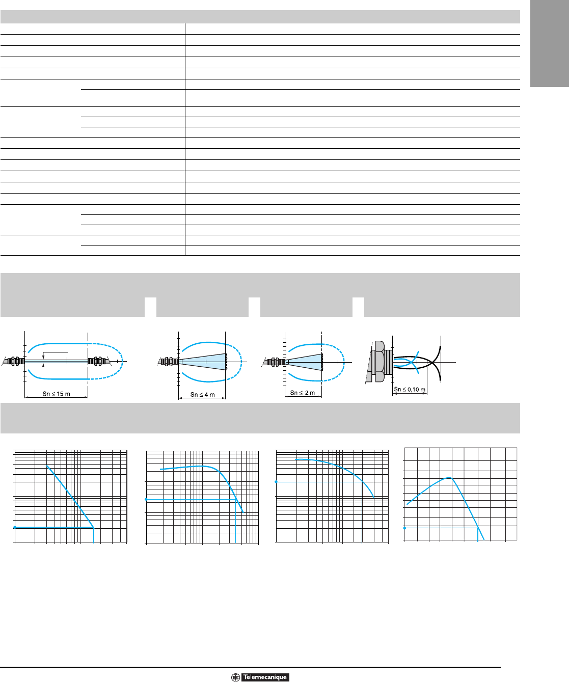
87
09/2007 © 1997–2007 Schneider Electric All Rights Reserved
Photoelectric
Photoelectric Sensors
Osiris® Food and Beverage Processing, Stainless Steel
M18x1 DC Solid-State Output
Specifications
Product certifications e, UL, CSA
Ambient air temperature Operation: -25 to +55 °C. Storage: -40 to +70 °C
Vibration resistance Conforming to IEC 60068-2-6 25 gn, amplitude ± 1.5 mm (10–55 Hz)
Shock resistance Conforming to IEC 60068-2-27 30 gn, duration 11 ms
Degree of protection Conforming to IEC 60529 IP 67
Connection
Pre-cabled Pre-cabled, diameter 4.2 mm, length 2 m (3), wire c.s.a.: 4 x 0.34 mm
2
Connector M12 male connector, 4-pin
(for suitable female connectors, including pre-wired versions, see the Cabling section beginning on page 625)
Materials
Case Food and beverage processing stainless steel, grade 304 Cu
Lenses PMMA
Cable PvR
Rated supply voltage 12–24 Vc with protection against reverse polarity
Voltage limits 10–30 Vc (including ripple)
Switching capacity (sealed) ≤ 100 mA with overload and short-circuit protection
Voltage drop, closed state ≤ 1.5 V
Current consumption, no-load ≤ 30 mA (reflex and diffuse), ≤ 50 mA (thru-beam)
Maximum switching frequency 500 Hz
Delays
First-up ≤ 15 ms
Response ≤ 1 ms
Recovery ≤ 1 ms
Indicator lights Supply on Green LED, on transmitter only
Output state Yellow LED, on receiver only
1. Sensors available with 5 m (16.4 ft) cable: To order, add the suffix L5 to the reference selected from above.
Example: sensor XU1N18PP341 with 5 m cable becomes XU1N18PP341L5.
Curves
Detection curves
Thru-beam system Reflex system
with reflector XUZC50
Polarized reflex system
with reflector XUZC50 Diffuse system
Object 10 x 10 cm
1 White 90%
2 Gray 18%
Excess gain curves (ambient temperature: + 25 °C)
Thru-beam system Reflex system with
reflector XUZC50
Polarized reflex system
with reflector XUZC50 Diffuse system
Object 10 x 10 cm
White 90%
15
-15
1510 m
Ø 12 mm
T
Ø of beam
cm
R4
10
-4
-10
m
4
2
T/R
Ø of beam
cm
2
4
6
-2
-4
-6
2
0,2 m
3
T/R
Ø
o
f
b
eam
cm
2
1
1,4
-1,4
-1
15 cm
1
T/R
Ø of beam
cm
1234568 203050
100
80
50
30
20
8
5
3
2
10
1
D (m)
10 15
Gain
100
1
20
0,1
10
D (m)
4
0,1 10,5 5 10
0,2
Gain
0,1 0,5 235
10
1
0,1
D (m)
1
Gain
0,1 0,2 15
50
20
10
1
3
7
15
D (cm)
2
0,5
30
5
2
602010
Gain
Accessories:
pa
g
e 84

88
© 1997–2007 Schneider Electric All Rights Reserved 09/2007
Photoelectric
Photoelectric Sensors
Osiris® Food and Beverage Processing, Stainless Steel
M18x1 DC Solid-State Output
Dimensions
XU•N18••341 XU•N18••341W
XU•N18••341D XU•N18••341WD
1. LED
2. 64 for XU9N18••341
Mounting nut tightening torque: < 15 N•m
Connector tightening torque: 2 N•m
4 (0.16)
62 (2.44) (2)
50 (1.97) 24 (0.94)
(1)
M18x1
5 (0.20)
78 (3.07)
(1)
M18x1
24 (0.94)
5 (0.20)
4 (0.16)
50 (1.97)
Dimensions: mm (in.)
M18x1 (1)
72 (2.83)
4 (0.16)
62 (2.44)
50 (1.97) 24 (0.94)
4 (0.16)
88 (3.46)
50 (1.97) 24 (0.94)
62 (2.44)
M18x1 (1)
Accessories:
page 84

89
09/2007 © 1997–2007 Schneider Electric All Rights Reserved
Photoelectric
Photoelectric Sensors
Osiris® Food and Beverage Processing, Stainless Steel
M18x1 DC Solid-State Output
Connections
M12 connector scheme Cable connections
3 (–) (–) BU (Blue)
1 (+) (+) BN (Brown)
4 OUT/Output (OUT/Output) BK (Black)
2 Prog (or beam break input
for thru-beam transmitter only) (Prog) OG (Orange)
(Beam break input) VI (Violet) on thru-beam transmitter only
For more connection information, refer to the Cabling section beginning on page 625.
Wiring diagrams—diffuse
PNP NO PNP NC NPN NO NPN NC Transmitter
Wiring diagrams—reflex and thru-beam
PNP NO PNP NC NPN NO NPN NC
Beam break input on thru-beam transmitter only
Beam made Beam broken
34
21
BN/1
BU/3
BK/4
OG/2
BN/1
BU/3
BK/4
OG/2
BN/1
BU/3
BK/4
OG/2
BN/1
BU/3
BK/4
OG/2
1/BN
3/BU
2/VI
BN/1
BU/3
BK/4
OG/2
BN/1
BU/3
BK/4
OG/2
BN/1
BU/3
BK/4
OG/2
BN/1
BU/3
BK/4
OG/2
+
–
BN/1
VI/2
BU/3
+
–
BN/1
VI/2
BU/3
Accessories:
page 84

90
© 1997–2007 Schneider Electric All Rights Reserved 09/2007
Photoelectric
Photoelectric Sensors
XUM Miniature, Classic
High Performance, DC
High performance, self contained, medium range, miniature photoelectric sensors for
industrial applications.
Features
• Very small dimensions: 1.4 x 0.87 x 0.39 in. (35.5 x 22 x 9.9 mm) fixed.
• Marginal detection signal (MDS) provided for alarm output and alignment help.
• Test input—system checking
• Light/dark selectable
• Short range proximity mode for background avoidance
• Color mark detection. Green and red light for difficult contrast sensing
• Two LED alignment system
• Mounting bracket included.
For options, see page 91.
▲XUM Color mark sensor, red and green light, see p. 114.
★Excess gain one—in normal ambient conditions, maximum usable sensing distance is 75% of normal.
Type Output
Mode
Voltage
Range
Load Current
Maximum
Operating Frequency
Maximum
Catalog
Number
Convergent Beam ▲—Sensing Range 15 mm (0.6 in.) ★
Red light
PNP 3-wire Light /dark 12–24 V 100 mA 500 Hz XUMH15353R
NPN 3-wire Light /dark 12–24 V 100 mA 500 Hz XUMJ15353R
RED LED off
RED LED on
Correct alignment – LED Off
Marginal alignment – LED On
Marginal alignment – LED On
Incorrect alignment – LED Off
Incorrect alignment – LED Off
R
E
Marginal Alignment Indication
3.5 mm3.5 mm
recommended
operating zone
Depth of field (mm) A B
510
diameter of light
spot at 15 mm : 2 mm
(side view)
Front face of reader
15 mm
optical
axis
BA
red emission
16 in.

91
09/2007 © 1997–2007 Schneider Electric All Rights Reserved
Photoelectric
Photoelectric Sensors
XUM Miniature, Classic
High Performance, DC
Specifications
★L indicates level number.
Mechanical
For usable sensing range, see excess gain curve charts
Temperature range -13 to 131 °F (-25 to 55 °C)
Enclosure rating NEMA Type 1, 3, 4, 6, 6P, 12, 13
IEC IP67 conforming to IEC 60529
Enclosure material Housing: ABS/PC; Lens: PMMA, PC; Cable: PVC
Vibration resistance 7 g amplitude ±1.5 mm, 10–55 Hz
Shock resistance 50 g at 3 axes, 3 times
Wiring 6 ft cable, 0.18 in. (4.5 mm) dia., 3 x #24 AWG
Electrical
Voltage limit (including ripple) 10–30 Vdc
Load current, maximum 100 mA, protected against overload and short circuit
Voltage drop, closed state 1.5 V
Current consumption (no load) receiver: 30 mA; emitter: 20 mA; reflex (diffuse): 35 mA
Test output current, maximum 50 mA
Test input voltage, maximum 1.5 V @ 1 mA maximum
Switching frequency, maximum 500 Hz
Power-up delay, maximum 1 ms
On/Off delay, maximum 1 ms
Wavelength
Polarized 660 nm
Convergent (red) 660 nm
All others 880 nm
Ambient light immunity 10,000 LUX
Protective circuitry
Radio frequency immunity (RFI) IEC 61000-4-3, L3★ (10 V/M)
Electrostatic discharges DC 2-wire: IEC 61000-4-2, L3★ (8 kV)
DC 3-wire: IEC 61000-4-2, L2★ (4 kV)
Fast transients (motor start/stop interference) IEC 61000-4-4, L3★ (1 kV)
Impulse voltages (lightning, etc.) IEC 60947-5-2, L3★ (2.5 kV)
Agency listings E 164869
CCN NRKH
LR 44087
Class 3211 03
-
Beam present
Blue
Purple
E
-
Beam broken
Blue
Purple
E
+
+
Brown
Brown
Dimensions . . . . . . . . . . . . . . . . . . Pages 142–145
Beam patterns . . . . . . . . . . . . . . . Pages 141–142
Reflectors . . . . . . . . . . . . . . . . . . . . . . . . Page 136
Beam break test (purple wire)
Wiring
PNP output
BN
BU
BK
LOAD
+ Light
- Dark
MDS
WLOAD
H
NPN output
BN
LOAD
+ Light
- Dark
MDS
OG
LOAD
J
SELECT
W
Select
OG
BK
BU
®

92
© 1997–2007 Schneider Electric All Rights Reserved 09/2007
Photoelectric
Photoelectric Sensors
XUK Subcompact, Classic
DC
Features
• Increasingly popular rectangular body style perfect for mounting flat against machine wall
• Versatility incorporated in every mode of detection
• Universal features simplify retrofit
• 10 s, three-mode programmable time delay
• High gain reserve produces superior sensing distances
• Smallest multi voltage time-delay photo available
• Mounting bracket included (adapts to competitive models)
• Hinged, locking plastic cover protects adjustments
■For 10 m (32.8 ft) cable, change L2 suffix to L10.
★Excess gain one—in nominal ambient conditions maximum usable sensing distance is 75% of normal
Circuit
Type
Output
Type
Voltage
Range
Load Current
Maximum
Operating Frequency
Maximum
Catalog
Number
Proximity Diffuse—1 m (3.3 ft) Nominal Sensing Distance—Adjustable High Precision
Cable style—2 m (6.6 ft) length ■
PNP/NPN Light/dark 12–24 V 100 mA 250 Hz XUK8AKSNL2
Micro-style connector
PNP/NPN Light/dark 12–24 V 100 mA 250 Hz XUK8AKSNM12
Excess gain curve Detection Curve
.71
18
.79
20
.86
22
.47
12
.47
12
Ø6x12
Ø6x13
.27
7
.59
15
.51
13
.19
5
10
°2.30
58
2.30
58
Ø4,5
1.34
34
1.97
50
1.97
50
.19
52xØ4
Ø6
3.15
80
3.23
82
2.56
65
1.57
40
1.57
40
1.57
40
1.57
40
1.57
40
.71
18
Dual Dimensions inches
mm
010020 40 60 80
20
0
10
18
16
14
12
8
6
4
2
%
Adustable Proximity Diffuse
1 White 90% 3 Black 6%
2 Gray 18%
Proximity Diffuse
(Copn)
Object 20 x 20 cm
White 90%
8
4
-4
-8
m
1
cm
Sn ≤ 1 m

93
09/2007 © 1997–2007 Schneider Electric All Rights Reserved
Photoelectric
Photoelectric Sensors
XUK Subcompact, Classic
DC
Specifications
Options
Mechanical
For usable sensing range, see excess gain curve charts
Temperature range Operation -13 to 131 °F (-25 to 55 °C)
Enclosure rating
Storage -30 to 158 °F (-30 to 70 °C)
NEMA Type 4, 4X (indoor), 12, 13
IEC IP65 conforming to IEC 60529
Vibration 7 g amplitude (10–55 Hz) Conforming to IEC 60068-2-6
Shock resistance 10 g for 11 ms conforming to 68-2-27
Wiring 22 AWG (0.34 mm2)
Tightening torque (maximum) 5 N•m (44.4 lb-in)
Enclosure material
Case PC/ABS
Lens PMMA
Cable PvR
Electrical
DC
Voltage limit (including ripple) 10–30 Vdc
Voltage drop (across switch, closed state) 1.5 V
Current consumption (maximum) (no load) 35 mA with SCP
Yellow Output LED yes
Red Stability LED yes
Power-up delay (maximum) 80 ms
On delay (maximum) 0.5 ms
Off delay (maximum) 0.5 ms
Protective circuitry
Short Circuit Protection —
Overload Protection yes
Reverse polarity protection — yes
Agency listings E164869
CCN NRKH
Pending
Description Suffix
10 m (32.8 ft) length cable L10
max. 1.5 m
min. 0
Recommended mounting
distances
Additional cable options and lengths . . . Page 484
Accessories . . . . . . . . . . . . . . . . . . . . . . .Page 137
Reflectors . . . . . . . . . . . . . . . . . . . . . . . .Page 136
Connector Cables (M12 or D suffix)
XSZCD101Y Micro-style, 4-pin, 2 m, straight
XSZCD111Y Micro-style, 4-pin, 2 m, 90°
W
iring
Connector
12
43
BN
BK
BU
+
–
NPN Yellow on
BN
BK
BU
+
–
PNP Yellow on
®

94
© 1997–2007 Schneider Electric All Rights Reserved 09/2007
Photoelectric
Photoelectric Sensors
XUC Compact, Limit Switch Body Style
DC or AC/DC Timer
Features
◆With 0–15 s timer option.
❏Excess gain one–in normal ambient conditions, maximum usable sensing distance is 75% of normal.
Beam Patterns
• Sleek but rugged compact body with
very long sensing distances
• Solid-state (NPN or PNP selectable) or
Relay output (N.O./N.C.)
• Built-in 0–15 s timer option on
AC/DC models
• Alarm output on DC versions
• Adjustable background suppression in
Diffuse modes
• Oversized potentiometer for sensitivity
adjustment
• Two 360° LED indicators
(output and stability)
• Light/dark selectable
• Hinged transparent cover protects
adjustments
• Cable or connector versions
(see p. 484 for cables)
• 30 mm (1.18 in.) tubular base with
mounting nuts
• UL rated for outdoor use, NEMA Type 4X
Circuit
Type
Output
Type Voltage Range Load Current
Maximum
Operating Frequency
Maximum
Catalog
Number
Thru-Beam (Emitter-Receiver)—60 m (196.8 ft) Nominal Sensing Distance ❏
Cable style—2 m (6.6 ft) length
AC/DC relay ◆ Light/dark 24–240 3 A 20 Hz XUC2ARCTL2
PNP/NPN Light/dark 12–24 V 100 mA 500 Hz XUC2AKSAL2
Mini-style connector
AC/DC relay ◆ Light/dark 24–240 3 A 20 Hz XUC2ARCTU78
Micro-style connector
PNP/NPN Light/dark 12–24 V 100 mA 500 Hz XUC2AKSAM12
Polarized Retroreflective (XUZC50 reflector included)
9 m (29.5 ft) Nominal Sensing Distance ❏
Cable style—2 m (6.6 ft) length
AC/DC relay ◆ Light/dark 24–240 3 A 20 Hz XUC9ARCTL2
PNP/NPN Light/dark 12–24 V 100 mA 500 Hz XUC9AKSAL2
Mini-style connector
AC/DC relay ◆ Light/dark 24–240 3 A 20 Hz XUC9ARCTU78
Micro-style connector
PNP/NPN Light/dark 12–24 V 100 mA 500 Hz XUC9AKSAM12
Proximity Diffuse with Adjustable Background Suppression
1.2 m (3.9 ft) Nominal Sensing Distance❏
Cable style—2 m (6.6 ft) length
AC/DC relay ◆ Light/dark 24–240 3 A 20 Hz XUC8ARCTL2
PNP/NPN Light/dark 12–24 V 100 mA 500 Hz XUC8AKSNL2
Mini-style connector
AC/DC relay ◆ Light/dark 24–240 3 A 20 Hz XUC8ARCTU78
Micro-style connector
PNP/NPN Light/dark 12–24 V 100 mA 500 Hz XUC8AKSNM12
M5
Screws
M30 x 1.5
Max. Torque 20 N•m
DC Models
Micro (M12) Connector
Max. Torque 2 N•m
AC/DC Models
Mini (U78) Connector
Max. Torque 5 N•m
1.71
43
1.77
45
.14
4
.71
18
.90
23
1.33
34
.21
5
3.74
95
Ø 5.5
.77
20
1.38
35
1.73
44
3.95
100
3.06
78
150°
Dual Dimensions inches
mm
Accessories . . . . . . . . . . . . . . . . . . . . . . Page 137
Reflectors . . . . . . . . . . . . . . . . . . . . . . . . Page 136
60
-60
m60
cm
Sn 50 m
Ø 16 mm
Thru-Beam
10
5
-5
-10
0.2 m9 m
6
cm
Sn 6 m
Retroflective
8
4
-8
-4
1.3
12
cm
Sn 1.2 m
Sn 1.15 m
Diffuse
1 white object
2 black object

95
09/2007 © 1997–2007 Schneider Electric All Rights Reserved
Photoelectric
Photoelectric Sensors
XUC Compact, Limit Switch Body Style
DC or AC/DC Timer
Specifications
Options
Mounting Brackets
Excess gain curve ambient temperature 25 °C (77 °F)
Mechanical
For usable sensing range, see Excess Gain Curve Charts
Temperature range Operation -13 to 131 °F (-25 to 55 °C)
Enclosure rating
Storage -40 to 158 °F (-40 to 70 °C)
NEMA Type 3, 4, 4X (outdoor use), 6, 6P, 12, 13
IEC IP67 conforming to IEC 60529
Vibration 7 g amplitude + 1.5 mm, 10–55 Hz
Shock resistance 30 g for 11 ms conforming to IEC 60068-2-27
Enclosure material
Case PC/ABS
Lens PMMA
Cable PvR
Electrical
AC/DC DC
Voltage limit (including ripple) 20–264 Vac/Vdc 10–38 Vdc
Voltage drop (across switch, closed state) — 1.5 V
Power current consumption (maximum) (no load) 2W 50 mA (thru-beam); 35 mA (others)
Power-up delay (maximum) 60 ms 15 ms
On delay (maximum) 25 ms 1 ms
Off delay (maximum) 25 ms 1 ms
Red LED: stability yes no
Yellow LED: output yes yes
Agency listings E164869
CCN NRKH
Description Suffix
5 m (16.4 ft) Cable L5
Description Catalog Number
Swivel Ball Bracket (plastic) XSZSB30
90° Bracket (steel) 9006PA30
–+
Optimum
Alignment
LED On
LED Off
Signal
Red LED
1.15
1
.85
1 2 6 7 8 9
45
3
6 7 8 9
T2T1
Delay
Range
Light
On T1 T2
0-2 s Time
Delay
Dark
On 0-15 s Delayed
One Shot
T1 T2
LED
1 Output
2 Instability
Switches
6 Light On / Dark On
7 T1 = On Delay Time 0-2 s or 0-15 s
8 T2 = Off Delay Time or One Shot
Time 0-2 s or 0-15 s
9 Time Delay / One Shot: 0-2 s or 0-15 s
Potentiometers
3 Sensitivity
4 T1
5 T2
Verifying Correct Operation
Programming AC/DC Model
Additional cable options and lengths . . . Page 484
Connector Cables
(M12 or D suffix; U78 or A suffix)
XSZCD101Y Micro-style, 4-pin, 2 m, straight
XSZCD111Y Mini-style, 4-pin, 2 m, 90°
XSZCA1501Y Mini-style, 5-pin, 2 m, straight
XSZCA9501Y Mini-style, 5-pin, 2 m, 90°
BN/4
BU/2
BN/4
BU/2
Transmitter
Light switching (no object present)
Thru-beam receiver and reflex
WH/5
GY/3
BK/1
Diffuse
Diffuse
BN/4
BU/2
WH/5
GY/3
BK/1
4
5
2
1
3
Connector schemes XUC•ARCTU78
Thru-beam
transmitter Thru-beam receiver,
reflex and diffuse
AC/DC (5-Wire )
BN/4
BU/2
WH/5
GY/3
BK/1
Dark switching (no object present)
Thru-beam receiver and reflex
BN/4
BU/2
WH/5
GY/3
BK/1
Cable connections XUC•ARCTL•
Relay common
N.O. contact
N.C. contact
4
5
2
1
3Relay Common
N.C. N.O.
BU
BN
GY
BK
WH
(Blue)
(Brown)
(Gray)
(Black)
(White)
Wiring
®
40
10000
1000
100
10
1
30
20
10
5
10.11 2 5 10 80100 0.2 0.4 0.8 2 3 5 7
46 90.6 1 D (m)D (m) 10
With reflector
XUZ-C50
Reflex system
gain
Thru-beam system
gain
0.05 1.10 1.50 S (m)
1.30
Diffuse system with adjustable
background suppression
Variation of usable sensing distance
A-B : Object reflection coefficient
Black 6% Sensing range
Gray 18% Non sensing zone
White 90%
A
B
BN/1
BU/3
+
–
Transmitter
Light switching (no object present)
Thru-beam receiver and reflex
PNP output
NPN output
BU/3
BN/1
BK/4
+
–
BU/3
BN/1
BK/4
+
–
43
12
(–)
(+) Alarm output
(except diffuse)
43
12
(–)
(+) Test input
Output
Signal
Dark switching (no object present)
Thru-beam receiver and reflex
PNP output
NPN output
Diffuse
PNP output
NPN output
Beam broken
Beam break test
(for thru-beam transmitter only)
Beam made
BU/3
BN/1
BK/4
+
–
BU/3
BN/1
BK/4
+
–
BU/3
BN/1
BK/4
+
–
Alarm output (for thru-beam
PNP Connector schemes XUC-•AKS•M12
BU/3
BN/1
WH/2
+
–
BU/3
BN/1
V1/2
+
–
BU/3
BN/1
BK/4
+
–
NPN
BU/3
BN/1
WH/2
+
–
BU/3
BN/1
V1/2
+
–
Thru-beam
transmitter Thru-beam receiver,
reflex and diffuse
Cable connections
XUC•AKS•L•
(–) BU (Blue)
(+) BN (Brown)
(OUT) BK (Black)
Alarm WH (White)
Test VI (Violet)
DC (3-Wire )
Diffuse
PNP output
NPN output
BU/3
BN/1
BK/4
+
–
BU/3
BN/1
BK/4
+
–
and reflex systems only)

96
© 1997–2007 Schneider Electric All Rights Reserved 09/2007
Photoelectric
Photoelectric Sensors
XUL Subcompact
DC, AC/DC
Features
★Excess gain one—in normal ambient conditions, maximum usable sensing distance is 75% of normal.
➀Fixed, no sensitivity adjustment.
➁See p. 484 for matching connector cables.
➂Supplied with potentiometer to adjust range between 15 and 30 cm (5.9 and 11.8 in.).
● 20 < Vdc < 58 IEC 60947-5-2 Utilization category DC-13. Vdc > 58 IEC 60947-5-2 Utilization category DC-12.
• Subcompact, medium-range, self-contained
photoelectric sensors for industrial
applications
• DC or AC/DC solid-state output, AC/DC
relay output
• 2-wire solid-state AC/DC output provides
substantially longer life than conventional
relays, ideally suited for intensive material
handling applications
• Economical
• Small size
• Flat lenses
• Side or front mounting
• LED visible from two directions (front, top)
• 45° cable entry for ease of wiring
• Cable or connector options available ➁
• 2-wire solid-state output saves wiring time
• Universal 24–240 Vac/Vdc power supply
• Double-insulated enclosure means no
grounding is required
• Programmable light/dark (DC only)
• UL Listed
Type Output
mode
Voltage range Load current
maximum ●
Operating frequency
maximum
Catalog
number
AC max. DC max.
Thru beam—Nominal Sensing Range 10 m (32.8 ft) ★
AC/DC—2 m (6.6 ft) cable
Emitter — 20–264 V 20–60 V — — XULM0600
Receiver, 5-wire, relay output Light 20–264 V 20–60 V 2 A 20 Hz XULM080314
DC—2 m (6.6 ft) cable
Emitter, 2-wire — — 10–30 V — — XULK0830
Receiver, 3-wire, PNP Light/dark — 10–30 V 200 mA 200 Hz XULH083534
Receiver, 3-wire, NPN Light/dark — 10–30 V 200 mA 200 Hz XULJ083534
Retroreflective—Nominal Sensing Range 8 m (25 ft) ★ (Reflector sold separately)
AC/DC—2 m (6.6 ft) cable
Solid-state output Light 20–264 V 20–60 V 500 mA 20 Hz XULA06021
Solid-state output Dark 20–264 V 20–60 V 500 mA 20 Hz XULA06011
5-wire, relay output Light 20–264 V 20–60 V 2 A 20 Hz XULM06031
DC—2 m (6.6 ft) cable
3-wire PNP Light/dark — 10–30 V 200 mA 250 Hz XULH06353
3-wire NPN Light/dark — 10–30 V 200 mA 250 Hz XULJ06353
Polarized Retroreflective—Nominal Sensing Range 5 m (16.4 ft) ★ (Reflector sold separately)
AC/DC—2 m (6.6 ft) cable
Solid-state output Light 20–264 V 20–60 V 500 mA 20 Hz XULA040219
Solid-state output Dark 20–264 V 20–60 V 500 mA 20 Hz XULA040119
5-wire, relay output Light 20–264 V 20–60 V 2 A 20 Hz XULM040319
DC—2 m (6.6 ft) cable
3-wire PNP Light/dark — 10–30 V 200 mA 200 Hz XULH043539
3-wire NPN Light/dark — 10–30 V 200 mA 200 Hz XULJ043539
Proximity Diffuse—Nominal Sensing Range 0.7 m (2.3 ft) ★
AC/DC—2 m (6.6 ft) cable
Solid-state output Light 20–264 V 20–60 V 500 mA 200 Hz XULA700115
Solid-state output Dark 20–264 V 20–60 V 500 mA 200 Hz XULA700215
DC—2 m (6.6 ft) cable
3-wire PNP Light/dark — 10–30 V 200 mA 200 Hz XULH703535
3-wire NPN Light/dark — 10–30 V 200 mA 200 Hz XULJ703535
Proximity Diffuse with Background Suppression—Sensing Range 0.3 m (0.15 ft) ➀ ★
AC/DC—2 m (6.6 ft) cable
5-wire, relay output Light 20–264 V 20–60 V 2 A 20 Hz XULM300318
DC—2 m (6.6 ft) cable
3-wire PNP➂ Light/dark — 10–30 V 200 mA 200 Hz XULH303538
3-wire NPN➂ Light/dark — 10–30 V 200 mA 200 Hz XULJ303538
Proximity Diffuse with Adjustable Background Suppression—Sensing Range 0.5–0.15 m (1.6–0.5 ft) ★
DC—2 m (6.6 ft) cable
3-wire PNP Light/dark — 12–24 Vdc 200 mA 200 Hz XULH153538
3-wire NPN Light/dark — 12–24 Vdc 200 mA 200 Hz XULJ153538
Cable
Micro-style connector

97
09/2007 © 1997–2007 Schneider Electric All Rights Reserved
Photoelectric
Photoelectric Sensors
XUL Subcompact
DC, AC/DC
Specifications
★L indicates level number.
Mechanical
For usable sensing range, see excess gain curve charts
Temperature range -13 to 140 °F (-25 to 60 °C)
Enclosure rating NEMA Type 1, 3, 4, 6, 6P, 12, 13
CENELEC IP67 conforming to IEC 60529 and IP671 conforming to NFC 20-010
Enclosure materials Housing:
ABS/PC
Lens:
PMMA
Cable:
PVC
Vibration resistance 7 g, mm amplitude, 10–55 Hz
Shock resistance 20 g for 11 ms
Wiring 2 m (6.6 ft) cable, 6 mm (0.2 in.) OD, 4 x 22 AWG or 2 x 22 AWG
Electrical DC Models Relay AC/DC Model, Solid-state
Voltage range — 24–240 Vac/Vdc 24–240 Vac/Vdc
Leakage current 1.7 mA 1.5 mA 1.7 mA AC; 1.5 mA DC
Minimum load current 0 mA 0 mA 5 mA
Power supply current (no load) 30 mA 5 mA (emitter) 25 mA (all others)
On delay maximum 4 ms 25 ms 25 ms
Off delay maximum 4 ms 25 ms 25 ms
Power-up delay maximum 15 ms 60 ms 60 ms
Wavelength 880 nm 880 nm 880 nm
Polarized 660 nm 660 nm 660 nm
Protective circuitry
Radio frequency immunity (RFI) IEC 61000-4-3, L3★ (10 V/M)
Electrostatic discharges
DC 2-wire: IEC 61000-4-2, L3★ (8 kV)
DC 3-wire: IEC 61000-4-2, L2★ (4 kV)
AC/DC: IEC 61000-4-2, L3★ (8 kV)
Fast transients
(motor start/stop interference) IEC 61000-4-4, L3★ (1 kV)
Impulse voltages (lightning, etc.) IEC 60947-5-2, L3★ (2.5 kV)
Agency listings E164353
CCN NKCR
LR44087
Class
3211 03
Options
Description Suffix Adder
Micro-style DC receptacle (DC models only) See p. 484 for matching connector
cables
D
Micro-style AC/DC receptacle (AC\DC models only) K
5 m (16.4 ft) cable L05
10 m (32.8 ft) cable L10
Example: XUL 08014L10
Accessories
Description Catalog Number
Mounting bracket (included) XULZ41
Detection Curves
Additional cable options and lengths . . . Page 484
Connector Cables
(M12 or D suffix; U20 or K suffix)
XSZCD101Y Micro-style, 4-pin, 2 m, straight
XSZCD111Y Micro-style, 4-pin, 2 m, 90°
XSZCK101Y Mini-style, 5-pin, 2 m, straight
XSZCK111Y Mini-style, 5-pin, 2 m, 90°
Wiring
Connector
12
43
1
3
2
DC
Emitter
BN
BU
AC/DC
Emitter
BN
BU
AC/DC
AC/DC
DC Receivers 3 wire
BN
BK
BU
RD
OG
AC/DC Receivers:
Relay
AC/DC
AC/DC
Cable, PNP
BN
BU
OG
BK
+ light
- dark
Select
Cable, NPN
BN
BU
BK
OG + light
- dark
Select
Connector, PNP
1
3
2+ light
- dark
Select
Connector, NPN
1
3
4
2+ light
- dark
Select
BN
BU
AC/DC
AC/DC
Solid state
4
-
®
Diffuse system
0.3
target
(1) white 90%
20 x 20 cm
2
6
4
-6
-8
-2
-4
8
10
-10
mm
Su 0.7m
2 ft
0.7 m
(1)
0.1
Thru-beam system
cm
Su 8 m
26 ft
10
5
-10
-5
m
Dia.16 mm
Diffuse system with
background suppression
0.2
target white 90%
black 6%
20 x 20 cm
mm
Su 0.25 m
1 ft
0.25 m
m
0.1
Polarized reflex system
cm
Su 4 m
15 ft
10
5
0.2
-10
46-5
2
6
4
-6
-8
-2
-4
8
10
-10

98
© 1997–2007 Schneider Electric All Rights Reserved 09/2007
Photoelectric
Photoelectric Sensors
XUJ Analog with Background Suppression
Analog Output, DC
Features
— Distance indication independent of target color or texture
— Elimination of background influence
— Dual outputs 4–20 mA and 0–10 Vdc (selectable)
— Long range proximity (diffuse) with background suppression 20–80 cm (7.87–31.50 in.)
— FDA approved housing material—Ultem® plastic
— Rated for resistance to shock, vibration, and aggressive industrial environments
(i.e. water, salts, oils, grease, alcohols and cleaning solutions)
— Seamless housing design
— LED indicator with an illumination level proportional to the output voltage
— Double-insulated enclosure means no grounding required
— UL Listed, CSA Certified, CE Marked
Applications:
— Bulk or liquid level control
— Thickness monitoring
— Winder speed control
— Position indication for feedback to drives and similar devices in web control applications
— Size sorting of objects such as fruit and vegetables
Circuit
Type
Output
Mode
Voltage
Range
Current
Output
Voltage
Output
Catalog
Number
Proximity (diffuse) with Background Suppression 20–80 cm (7.87–31.5 in.)
Analog type Light 20–30 Vdc 4–20 mA 0–10 V XUJK803538
.10
2.6
.35
9
10°10°
3.29
83.6
1.20
30.5
A
.66
17
2.40
61
A : 1/2" NPT
LED
.39
10
.78
20
1.18
30
B
B : 1 elongated hole Ø 4.2 x 14
* Front mounting
(Ø 4 screws and inserts supplied)
10 10
3.34
85
3.89
98.85
1.07
27.2
.51
13
1.28
32.6
2.46
62.5
.05
1.35
≤
1.18*
30
R
E
Dual Dimensions inches
mm

99
09/2007 © 1997–2007 Schneider Electric All Rights Reserved
Photoelectric
Osiconcept™ Photoelectric Sensors
XUJ Analog with Background Suppression
Analog Output, DC
Specifications
★L indicates level number.
Additional cable options and lengths, see p. 484.
Output Across Load
Mechanical
Temperature range -13 to 140 °F (-25 to 60 °C)
Enclosure rating
NEMA Types 1, 3, 6, 12, 13
IEC IP67 conforming to IEC 60529 and IP671
conforming to NFC 20-010, double insulated
Vibration 7 g, 1.5 mm amplitude, 10 Hz to 55 Hz
Shock resistance 30 g for 11 ms
Wiring—screw terminals #16 AWG
Electrical
Voltage limit (including ripple) 20–30 Vdc
Power supply current (no load) 40 mA
Operating frequency, maximum 50 Hz
Voltage output 0–10 Vdc
Current output 15 mA
Protective circuitry
Radio frequency immunity (RFI) IEC 61000-4-3, L3★ (10 V/M)
Electrostatic discharges DC 2-wire: IEC 61000-4-2, L3★ (8 kV)
DC 3-wire: IEC 61000-4-2, L2★ (4 kV)
Fast transients (motor start/stop interference) IEC 61000-4-4, L3★ (1 kV)
Impulse voltages (lightning, etc.) IEC 60947-5-2, L3★ (2.5 kV)
Agency listings E164353
CCN NKCR
LR44087
Class 3211 03
Options
Description Matching Connector Cables Suffix Adder
Receptacle mini-style 5-pin XSZCA1501Y R5
Accessories
Description Catalog
Number
Protective cover (top) XUJZ01
Mounting bracket (included) XUZA41
Dimensions. . . . . . . . . . . . . . . . . . Pages 142–145
Reflectors . . . . . . . . . . . . . . . . . . . . . . . . Page 136
Connectors . . . . . . . . . . . . . . . . . . . . . . . Page 484
Wiring
Connector
1
3
4
5
2
NOTE: Terminals 1 and 6 are
internally connected.
1 (–) Comm.
2
3(+) 24 Vdc
4Vs
5Is
6(–) Com.
®
15 20
10V
80
Vs
D (cm)
OV
Voltage output (Vs)
according to distance
1
2
3
4
5
6
R > 1 k
LOAD
Current Output (Is)
according to distance
1
2
3
4
5
6
R < 1 k
LOAD
15 20
20
80
mA
D (cm)
4
Is

100
© 1997–2007 Schneider Electric All Rights Reserved 09/2007
Photoelectric
Photoelectric Sensors
Fiber Optics
XUFA Glass Fiber Optics
The XUFA is one of the most versatile heavy-duty, glass-core fiber optic sensors in stainless
steel sheeting available.
Features
• Coiled stainless steel sheathing withstands most aggressive environments while
maintaining a high degree of flexibility
• Transmission of light through the fiber optics is not affected by water, gasoline, oil, sulfuric
acid or other organic acids
• Most common sensing tips are standard (other tip configurations and cable lengths can be
made to order—contact the factory)
• Very wide temperature range: -49 to 527 °F (-45 to 275 °C)
• Two scanning modes are recommended: thru-beam using a pair of cables (emitter-receiver)
• Proximity (diffuse) using a bifurcated cable with a triple sensing tip in which emitter and
receiver fibers are mixed.
NOTE: If steps are taken to avoid the effects of proximity, the bifurcated cable can also be
used in retroreflective scanning mode.
★Excess gain one—in normal ambient conditions, maximum usable sensing distance is 75% of normal.
Tip Nominal Sensing Distance ★
XUET
Length
Maximum
Bundle
Diameter
Catalog
Number
Thru-beam (pair) (single emitter and receiver sold as a pair)
Smooth, straight 11.8 in. (300 mm) 36 in. (914 mm) 0.125 in. (3.2 mm) XUFA110213
Threaded, straight 11.8 in. (300 mm) 36 in. (914 mm) 0.125 in. (3.2 mm) XUFA110113
Threaded, straight 11.8 in. (300 mm) 12 ft (3.66 m) 0.125 in. (3.2 mm) XUFA1101112
Smooth, 90° 11.8 in. (300 mm) 36 in. (914 mm) 0.125 in. (3.2 mm) XUFA110413
Threaded, 90° 11.8 in. (300 mm) 36 in. (914 mm) 0.125 in. (3.2 mm) XUFA110313
Window, short 10 in. (255 mm) 36 in. (914 mm) 0.38 x 0.032 in. (9.65 x 0.80 mm) XUFA110513
Proximity (bifurcated) (Y-shaped dual reflective type)
Smooth, straight 4.33 in. (110 mm) 36 in. (914 mm) 0.125 in. (3.2 mm) XUFA210213
Threaded, straight 5.51 in. (140 mm) 36 in. (914 mm) 0.125 in. (3.2 mm) XUFA210113
Threaded, straight 4.53 in. (115 mm) 12 ft (3.66 m) 0.125 in. (3.2 mm) XUFA2101112
Smooth, 90° 3.94 in. (100 mm) 36 in. (914 mm) 0.125 in. (3.2 mm) XUFA210413
Threaded, 90° 4.72 in. (120 mm) 36 in. (914 mm) 0.125 in. (3.2 mm) XUFA210313
Window, short 3.94 in. (100 mm) 36 in. (914 mm) 0.38 x 0.032 in. (9.65 x 0.80 mm) XUFA210513
1.1"
28
.8" (20.3)
28
1.1"
.8" (20.3)
1.5" (38.1)
.75"
19
1.00"
25.4 .032"
(0.8)
.25" (6.3)
.75" (19)
Smooth, straight
Threaded, straight
Smooth, 90 ˚
Threaded, 90˚
Window, short
.281" (7.1)
.187" (4.7)
.125" (3.1)
.125" (3.1)
1.5" (38.1)
.125" (3.1)
.125" (3.1)
.281" (7.1)
.187" (4.7)
.281" (7.1)
5/16-24
.281"(7.1)
.46 (11.7)

101
09/2007 © 1997–2007 Schneider Electric All Rights Reserved
Photoelectric
Photoelectric Sensors
Fiber Optics
XUFA Glass Fiber Optics
Amplifier Specifications
★L indicates level number.
✱ Will improve range approximately 3 to 5 times
Mechanical
Temperature range -13 to 158 °F (-25 to 70 °C)
Enclosure rating (XUET) NEMA Type 1
IEC IP40
Shock resistance 20 g for 11 ms
Vibration 7 g @ 0.6 mm amplitude
Cable Screw terminals #16 AWG
Electrical
Power supply current 45 mA
Voltage drop across switch —
On delay 25 ms
Off delay 30 ms
Power-up delay 80 ms
Wavelength 880 nm
Agency listings E164343
CCN NKCR
LR60942
Class 4812 05
Accessories
Description Magnification factor (thru-beam) ✱ Catalog Number
Lenses (pair) for threaded tips X10 XUFAZ01
Lenses (pair) for smooth tips X10 XUFAZ02
Wiring
Light mode: the output is energized
when a target is not present (the
proximity output is energized when a
target is detected).
Dark mode: the output is energized
when a target is present (the proximity
output is energized when a target is not
detected).
XUFAZ01
XUFAZ02
®

102
© 1997–2007 Schneider Electric All Rights Reserved 09/2007
Photoelectric
Photoelectric Sensors
Fiber Optics
XUFN Plastic and XUFS Glass Fiber Optics
Features—XUFN
Features—XUFS
Plastic Fiber Optics
➀Not recommended for very short sensing distances under 0.2 in. (5 mm) (coherent).
➁Recommended for very short sensing distances (randomized).
★ Sensing distances change when used with ZUCN0016, ZUCN0017, and XUET1401266 amplifiers. Contact Schneider Electric for
information and beam patterns.
Glass Fiber Optics—Threaded Tip 1 m (3 ft) long
★Nominal sensing distance. Recommended usable distance is x0.8 of the nominal sensing distance. This will cover variances in
temperature, supply voltage and manufacturing tolerances.
• The XUFN series of plastic core fiber
optics provides flexibility in usage at an
affordable price.
• Smooth plastic jacket (polyethylene) in
straight or coiled versions, withstands
most industrial environments including
food processing and pharmaceuticals
• Straight cable standard
• Threaded and flexible nozzle tips
• Suitable for very small part detection
• Two scanning modes are recommended
• Thru-beam using a pair of cables (emitter-
receiver); proximity diffuse using a
bifurcated cable with a single sensing tip in
which emitter and receiver fibers are mixed
• Standard separate emitter-receiver bundles
or randomized receiver with an emitter core
for very near detection are available.
NOTE: If steps are taken to avoid the effects
of proximity, the bifurcated cable can also be
used in retroreflective scanning mode.
• The XUFS series of glass core fiber optics
provides ruggedness, higher temperature
ratings and excellent withstanding in
aggressive/chemical environments
• Coiled fiber cable for applications with
significant movement between the amplifier
and the sensing tip
Tip Maximum Sensing distance, Sn ★ Beam
Diameter
Cable
Diameter (OD)
Catalog
Number
Standard w/XUFZ01 Lenses
Thru-beam (pairs)—2 m (6.6 ft) long (single emitter and receiver sold as a pair)
Straight cable
Threaded★ 9.84 in. (250 mm) 73.68 in. (1.87 m) 0.04 in. (1 mm) 0.09 in. (2.2 mm) XUFN12301
10 m (32.8 ft) Threaded★ 4.43 in. (113 mm) 44.30 in. (1.13 m) 0.04 in. (1 mm) 0.09 in. (2.2 mm) XUFN12301L10
Threaded 2.46 in. (62 mm) 19.68 in. (0.5 m) 0.02 in. (0.5 mm) 0.04 in. (1 mm) XUFN35301
3.5 in. Flexible nozzle 8.85 in. (225 mm) — 0.04 in. (1 mm) 0.09 in. (2.2 mm) XUFN12311
3.5 in. Flexible nozzle 2.48 in. (63 mm) — 0.02 in. (0.5 mm) 0.04 in. (1 mm) XUFN35311
Coiled cable
Threaded 7.30 in. (185 mm) 49.2 in. (1.2 m) 0.04 in. (1 mm) 0.09 in. (2.2 mm) XUFN10302
3.5 in. Flexible nozzle 7.30 in. (185 mm) — 0.04 in. (1 mm) 0.09 in. (2.2 mm) XUFN10312
Proximity diffuse (bifurcated)—2 m (6.6 ft) long (Y-shaped dual reflective type)
Straight cable
Threaded➀ ★ 3.44 in. (87 mm) — 2 x 0.04 in. (1 mm) 0.09 in. (2.2 mm) XUFN05321
10 m (32.8 ft) Threaded
➀ 1.96 in. (50 mm) — 2 x 0.04 in. (1 mm) 0.09 in. (2.2 mm) XUFN05321L10
Threaded➁ 3.44 in. (87 mm) — 0.04 in. (1 mm) +
16 x 0.01 in. (0.265 mm) 0.09 in. (2.2 mm) XUFN05323
Threaded➀ 0.89 in. (23 mm) — 2 x 0.02 in. (0.5 mm) 0.04 in. (1 mm) XUFN01321
Threaded➁ 1.47 in. (38 mm) — 0.02 in. (0.5 mm) +
4 x 0.01 in. (0.25 mm) 0.04 in. (1 mm) XUFN02323
3.5 in. Flexible nozzle 3.44 in. (87 mm) — 2 x 0.04 in. (1 mm) 0.09 in. (2.2 mm) XUFN05331
3.5 in. Flexible nozzle 0.89 in. (23 mm) — 2 x 0.02 in. (0.5 mm) 0.04 in. (1 mm) XUFN01331
0.6 in. Flexible nozzle 0.30 in. (7.5 mm) — 2 x 0.01 in. (0.265 mm) 0.04 in. (1 mm) XUFN04331
Coiled cable
Threaded 1.00 in. (25 mm) — 2 x 0.04 in. (1 mm) 0.09 in. (2.2 mm) XUFN15322
3.5 in. Flexible nozzle 1.00 in. (25 mm) — 2 x 0.04 in. (1 mm) 0.09 in. (2.2 mm) XUFN15332
Direct plug
3.5 in. Flexible nozzle 1.48 in. (37 mm) — 0.02 in. (0.5 mm)+
8 x 0.01 in. (0.265 mm) 0.06 in. (1.5 mm) XUDZ01
Type Maximum Sensing Distance, Sn★ Beam
Diameter
Catalog
Number
Standard w/ XUFZ01 Lenses
Thru-beam (pair) 9.84 in. (250 mm) 98.4 in. (2.5 m) 1 x 0.04 in. (1 mm) XUFS2020
Proximity diffuse (bifurcated) 3.44 in. (87 mm) 34.4 in. (870 mm) 2 x 0.04 in. (1 mm) XUFS0520
Threaded
3.5" Flexible nozzle
Coiled cable
Flexible nozzle, coiled cable
.6" Flexible nozzle
Direct plug
XUFS2020
XUFS0520
1.28
32.5
38.2
970
Ø0.08
2.2
M0.24
6
Ø0.15
13
Ø0.2
5
Ø0.08
2.2 Ø0.08
2.2
38.2
970
Ø0.16
5
M4
M0.1
(2.6)
1.0
25
Dual Dimensions inches
mm

103
09/2007 © 1997–2007 Schneider Electric All Rights Reserved
Photoelectric
Photoelectric Sensors
Fiber Optics
XUFN Plastic and XUFS Glass Fiber Optics
Specifications
Accessories (for amplifiers, refer to page 60)
✱ Will improve range approximately 3 to 5 times
Fiber optic type XUFN XUFS
Temperature -14 to 140 °F (-25 to 60 °C) -40 to 356 °F (-40 to 180 °C)
Vibration 7 g, 1.5 mm amplitude
Shock 30 g, for 11 ms
Materials core PMMA glass
jacket PE (polyethylene) stainless steel
Minimum bend radius 0.04 in (1 mm) OD 0.39 in (10 mm) —
0.08 in (2.2 mm) OD 1.0 in (25 mm) 3.5 in (90 mm)
Description Catalog Number
Lenses (pair) for standard threaded tips x10 Magnification ✱ XUFZ01
90° mirrors (pair) for standard threaded tips XUFZ02
Fiber cable cutter (one is included with each fiber optic cable) XUFZ11
4 mm stainless steel sheathing XUFZ210
6 mm stainless steel sheathing XUFZ310
Sensing range for length for cable
1 XUFN12301L10
2 XUFN05321L10
†
XUF-Z11
Utiliser 1 trou une seule fois
Please use each hole once
XUFZ•10
XUFZ11
XUFZ01
XUFZ02
2
200 mm
2 m 10 m
0 mm
100 mm
1
150 mm
50 mm
5 m
70 mm
120 mm

104
© 1997–2007 Schneider Electric All Rights Reserved 09/2007
Photoelectric
Photoelectric Sensors
Fiber Optics
XUFN Fiber Optic Cables for Specific Applications
Features
Suited for specific applications that were once difficult to tackle.
• Integrated focusing lens for precise spot-sensing
• Senses longer distances
• Convergent beam types sense to three different ranges
• Increases sensing distance by 40%
• Burns through pollutants for reliable detection
• Flexible enough for maneuvering tight corners
• Bend radius of 4 mm (0.16 in.)
• Resists chemical aggressions
• Ideal for food and beverage, assembly and electronic, semiconductor
◆with XUFZ01, 2 m (78.74 in.)
▲with XUFZ01, 750 mm (29.53 in.)
Convergent High Focus Lens
XUFN•L L for lens:
XUFN•P P for power:
XUFN•S S for soft:
XUFN•T T for Teflon®:
Sensing
Mode
Cable
Length
Beam
Diameter
Sensing
Distance
Dimensions
H x W x D
Catalog
Number
High Focus Lens
Convergent 2 m (6.6 ft) 0.1 in (2.5 mm) 0.4 in (10 mm) 1.2 x 0.35 x 1.2 in
(30 x 9 x 30 mm) XUFN5L01L2
Convergent 2 m (6.6 ft) 0.2 in (5 mm) 0.8 in (20 mm) 1.22 x 0.47 x 1.33 in
(31 x 12 x 34 mm) XUFN5L02L2
Convergent 2 m (6.6 ft) 0.31 in (8 mm) 1.18 in (30 mm) 1.22 x 0.47 x 1.2 in
(3 x 12 x 30 mm) XUFN5L03L2
Thru-Beam 2 m (6.6 ft) 0.31 in (8 mm) 59 in (1.5 m) see left XUFN2L01L2
Thru-Beam 10 m (32.8 ft) 0.31 in (8 mm) 59 in (1.5 m) see left XUFN2L01L10
Long Range Power
Thru-Beam 2 m (6.6 ft) 0.16 in (4 mm) 11.8 in (300 mm) ◆ see left XUFN2P01L2
Thru-Beam 10 m (32.8 ft) 0.16 in (4 mm) 11.8 in (300 mm) ◆ see left XUFN2P01L10
Diffuse 2 m (6.6 ft) 0.16 in (4 mm) 3.7 in (95 mm) see left XUFN5P01L2
Diffuse 10 m (32.8 ft) 0.16 in (4 mm) 3.7 in (95 mm) see left XUFN5N01L10
Soft Flexibility
Thru-Beam 2 m (6.6 ft) 0.16 in (4 mm) 3.9 in (100 mm) ▲ see left XUFN2S01L2
Thru-Beam 10 m (32.8 ft) 0.16 in (4 mm) 3.9 in (100 mm) ▲ see left XUFN2S01L10
Diffuse 2 m (6.6 ft) 0.16 in (4 mm) 2.1 in (55 mm) see left XUFN5S01L2
Diffuse 2 m (6.6 ft) 0.16 in (4 mm) 2.1 in (55 mm) see left XUFN5S01L10
Teflon Coated
Thru-Beam 2 m (6.6 ft) 0.16 in (4 mm) 3.9 in (100 mm) see left XUFN2T01L2
Diffuse 2 m (6.6 ft) 0.16 in (4 mm) 2.7 in (70 mm) see left XUFN5T01L2
Long Range
Power
XUFN•P•••
Thru-Beam
High Focus
Lens
XUFN2L•••
Teflon Coated
XUFN•T•••
Soft Flexibility
XUFN•S•••
Ø0.08
2.2
Ø0.16
4
0.79
20
78.7
2000
3.93
100
Ø0.19
5
M8 x 1.25
0.79
20
Ø0.08
2.2
0.47
12
M4x0.7
M2.6x0.45
Ø0.08
2.2
0.12
3
0.47
12
M4x0.7
M2.6x0.45
Ø0.08
2.2
0.12
3
Dual Dimensions inches
mm
XUFN5L01•••
D
W
H
XUFN5L02•••
D
W
H
XUFN5L03•••
D
W
H

105
09/2007 © 1997–2007 Schneider Electric All Rights Reserved
Photoelectric
Photoelectric Sensors
Fiber Optics
XUFN Fiber Optic Cables for Specific Applications
Unterminated Individual Cable
★Nominal sensing distance. Recommended usable distance is x0.8 of the nominal sensing distance. This will cover variances in
temperature, supply voltage and manufacturing tolerances.
Separate Tips and Mounting Brackets (pair) for Unterminated Cables—Thru-Beam
Mode
★Distance is at 2 m (6.6 ft) cable length
For other cable lengths:
5 m (16.4 ft) cable—apply a reduction factor of 0.70 x Sn
10 m (32.8 ft) cable—apply a reduction factor of 0.50 x Sn
20 m (65.6 ft) cable—apply a reduction factor of 0.30 x Sn
Multiple Head Thru-Beam (pair), 2 m (6.6 ft) length
★Nominal sensing distance. Recommended usable distance is x0.8 of the nominal sensing distance. This allows for variances in
temperature, supply voltage, and manufacturing tolerances.
Length Sensing Distance (Sn) @ 2 m
(6.6 ft), Straight Cable Only ★
Beam
Diameter
Outside
Diameter (OD)
Catalog
Number
Straight cable
10 m (32.8 ft) 250 mm (9.84 in.) 1 mm (0.04 in.) 2.2 mm (0.09 in.) XUFZ910
20 m (65.6 ft) 250 mm (9.84 in.) 1 mm (0.04 in.) 2.2 mm (0.09 in.) XUFZ920
10 m (32.8 ft) 375 mm (14.8 in.) 1.4 mm (0.06 in.) 2.2 mm (0.09 in.) XUFZ911
20 m (65.6 ft) 375 mm (14.8 in.) 1.4 mm (0.06 in.) 2.2 mm (0.09 in.) XUFZ921
Mounting
Sensing Distance ★ Catalog
Number
1 mm (0.04 in.)
diameter beam
1.4 mm (0.06 in.)
diameter beam
Non-Magnified
Axial 100 mm (3.94 in.) 150 mm (5.91 in.) XUFZ13
Frontal 70 mm (2.76 in.) 100 mm (3.94 in.) XUFZ14
Side 70 mm (2.76 in.) 100 mm (3.94 in.) XUFZ15
Magnified
Axial 800 mm (31.50 in.) 600 mm (23.62 in.) XUFZ03
Frontal 600 mm (23.62 in.) 400 mm (15.75 in.) XUFZ04
Side 600 mm (23.62 in.) 400 mm (15.75 in.) XUFZ05
Sensing range of cable length for unterminated cables
1 XUFZ911, 921
2 XUFZ910, 920
Tip Sensing distance, Sn ★ Beam
Diameter
Outside
Diameter (OD)
Catalog
Number
Standard (maximum) w/XUFZ01 Lenses
8 head, threaded 38 mm (1.48 in.) — 16 x 0.265 mm
(0.01 in.) 2.2 mm (0.09 in.) XUFN02801
XUFN02801
XUFZ15, XUFZ05
XUFZ14, XUFZ04
XUFZ13, XUFZ03
Unterminated cable
Dimensions. . . . . . . . . . . . . . . . . . Pages 142–145
M0.11x0.02
3x0.5
Ø0.08
2.2
L = 59.0
1500
0.7
18
Ø0.08
2.2
Ø0.04
1
0.39
10
L = 19.7
500
Dual Dimensions inches
mm
30 m
2
50 mm
300 mm
200 mm
4 m 40 m
0 mm
150 mm
1
250 mm
100 mm
20 m
10 m
120 mm

106
© 1997–2007 Schneider Electric All Rights Reserved 09/2007
Photoelectric
Photoelectric Sensors
XUV with Separate Optical Heads
Optical Sensing Heads
The XUV series of separate optical sensing heads and amplifiers provides maximum
flexibility in difficult applications.
Features
• Thru-beam, retroreflective, and proximity diffuse in several housing styles.
Tubular: threaded or clip-on for easy replacement
• Extra flat for hard-to-access places, i.e. small conveyers
• Fork style for edge or mark detection
• Convergent for background suppression
• Visible red or green light for easy positioning and better contrast detection
• UL Listed ■
• CSA Certified
For amplifiers, see page 108.
★Excess gain one—in normal conditions, maximum usable sensing distance is 75% of normal.
■The heads are not provided with the listing mark.
Optical Sensing Heads
Description Nominal Sensing
Distance ★ Light Beam Dia. Type Catalog
Number
Thru-Beam
Threaded (M18 x 1) 7.3 m (24 ft) IR 11 mm (0.43 in.) Emitter XUVN06240
Receiver XUVN06244
Clip-on 7.3 m (24 ft) IR 11 mm (0.43 in.) Emitter XUVN06250
Receiver XUVN06254
Extra flat 230 mm (9 in.) IR 3 mm (0.118 in.) Emitter XUVN20210
Receiver XUVN20214
Fork
20 mm (0.79 in.) Green 1 mm (0.04 in.) — XUVN0243G
Red 1 mm (0.04 in.) — XUVN0243R
5 mm (0.20 in.) Green 1 mm (0.04 in.) — XUVN0143G
Red 1 mm (0.04 in.) — XUVN0143R
Retroreflective
Threaded (M18 x 1) 2.5 m (8 ft) IR 11 mm (0.43 in.) — XUVN0244
Clip-on 2.5 m (8 ft) IR 11 mm (0.43 in.) — XUVN0245
Proximity Diffuse
Extra flat 63 mm (2.5 in.) IR 3 mm (0.12 in.) — XUVN05415
Convergent 20 mm (0.79 in.) Red 2 mm (0.08 in.) — XUVN02428
Convergent 10 mm (0.39 in.) Red 1 mm (0.04 in.) — XUVN01428
Threaded (M18 x 1) 125 mm (5 in.) IR 11 mm (0.43 in.) — XUVN10445
Thru beam Retroreflective
Thru beam Retroreflective
Thru beam Diffuse
20 mm (0.79 in.)
20 mm (0.79 in.) 10 mm (0.39 in.)
5 mm (0.20 in.)
Threaded, M18 x 1
Clip-on
Extra flat
Fork
Convergent

107
09/2007 © 1997–2007 Schneider Electric All Rights Reserved
Photoelectric
Photoelectric Sensors
XUV with Separate Optical Heads
Optical Sensing Heads
Mechanical Specifications—Thru-Beam Devices
Threaded Clip-on Extra flat Fork
20 mm (0.8 in.)
Fork
5 mm (0.2 in.)
Temperature range Operation: -13 to +131 °F (-25 to +55 °C).
Storage: -22 to +158 °F (-30 to +70 °C)
Resistance to vibration 7 g amplitude ±0.06 in (1.5 mm), 10–55 Hz
Resistance to shock 50 g at 3 axes, 3 times
Degree of protection:
NEMA Type 1, 4, 13 1, 5 1, 4, 6, 6P, 13
IEC IP66 IP50 IP67
Connections
Cable 2.2 x 4 mm (0.08 x 0.16 in.)
oval section
Length: 6 m (19.7 ft)
Cross section 0.3 mm2 (0.01 in.2)
Shielded (AWG 22)
Cable dia. 1.8 mm (0.07 in.)
Length: 2 m (6.6 ft)
Cross section 0.3 mm2 (0.01 in.2)
(AWG 22)
Cable dia. 1.8 mm (0.07 in.)
Length: 2 m (6.6 ft)
Cross section 0.3 mm2 (0.01 in.2)
(AWG 22)
Material Case: ABS/PC; Cable: PVC
Wavelength 880 nm 880 nm 880 nm Green: 565 nm Green: 565 nm
Red: 660 nm Red: 660 nm
Mechanical Specifications
Retroreflective Diffuse Convergent
Threaded Clip-on Extra flat Threaded 20 mm (0.8 in.) 10 mm (0.4 in.)
Temperature range Operation: -13 to +131 °F (-25 to +55 °C)
Storage: -22 to +158 °F (-30 to +70 °C)
Resistance to vibration 7 g amplitude ±0.6 in. (1.5 mm), 10–55 Hz
Resistance to shock 50 g at 3 axes, 3 times
Degree of protection:
NEMA Type 1, 4, 13 1, 5 1, 4, 13 1, 5
IEC IP66 IP50 IP66 IP50
Connections
Cable 2.2 x 4 mm (0.08 x 0.16 in.)
oval section
Length: 4 m (13.1 ft)
Cross section 0.3 mm2 (0.01 in.2)
shielded (AWG 22)
Cable dia. 1.8 mm (0.07 in.)
Length: 2 m (6.6 ft)
Cross section 0.3 mm2 (0.01 in.2)
(AWG 22)
Cable dia. 1.8 mm (0.07 in.)
Length 2 m (6.6 ft)
Cross section 0.3 mm2 (0.01 in.2)
(AWG 22)
Material Case: ABS/PC; Cable: PVC
Wavelength 880 nm 880 nm 660 nm 660 nm
Agency listings E164869
CCN NRKH
LR44087
Class 3211 03
®

108
© 1997–2007 Schneider Electric All Rights Reserved 09/2007
Photoelectric
Photoelectric Sensors
XUV with Separate Optical Heads
Amplifiers, DC and AC
The XUV series of amplifiers designed for use with XUV optical sensing heads provide
maximum flexibility in difficult applications. Features include:
• DIN rail mounting
• Light/dark programmable
• 3-LED alignment system
• 40 ms time delay programmable on beam break—selectable on/off
XUVH/J
• 2 potentiometers (coarse and fine)
• Marginal detection signal (MDS) output (alarm signals before sensor quits)
• System test input—turns off emitter; receiver follows suit if system is OK
• DC single channel, pre-wired
• Standard (1 ms) or fast (0.7 ms) response time (selectable)
• Gating (synchro) input for each channel (except XUVF)
XUVF
•AC
• Single and dual channel, relay output
• Screw terminals
For optical heads, see page 106.
DC Amplifiers
Output Operating Frequency
Maximum
Test
Output
Synchro
Input
Catalog
Number
PNP 500 Hz/2,500 Hz Yes Yes XUVH003530
NPN 500 Hz/2,500 Hz Yes Yes XUVJ003530
AC Amplifiers
No. of
Channels
Operating Frequency
Maximum
Test
Output
Synchro
Input
Catalog
Number
150 Hz ——XUVF000510
250 Hz —YesXUVF000511
XUVH/J
XUVF

109
09/2007 © 1997–2007 Schneider Electric All Rights Reserved
Photoelectric
Photoelectric Sensors
XUV with Separate Optical Heads
Amplifiers, DC and AC
Operating and Electrical Specifications
★L indicates the level number.
DC AC
Standard Fast 1 Channel 2 Channel
Temperature range -13 to +131 °F (-25 to +55 °C)
Enclosure rating NEMA Type 1, 5
IEC IP50
Vibration resistance 7 g amplitude ±0.06 in (1.5 mm), 10–55 Hz
Shock resistance 30 g
Wiring Dia. 4.5 mm (0.18 in.), Length 2 m (6.6 ft)
#22 AWG (0.2 mm2)
Terminals 1–8: 16–20 AWG
Terminals 9–29: 20–24 AWG
Housing material Plastic ABS
Cable PVC
Plastic ABS
Cable PVC
Voltage range (maximum) 10–30 Vdc including ripple 90–264 Vac
Output current (maximum) 100 mA 1 A (resistive load)
Short-circuit/overload protection Standard —
Relay output voltage (maximum) — 250 Vac, 30 Vdc
Power supply current (no load) 45 mA 30 mA 80 mA
Voltage drop (maximum) 1.5 V —
Operating frequency (maximum) 500 Hz 2,500 Hz 50 Hz 50 Hz
On/Off delay 1 ms 0.2 ms 10 ms 10 ms
Power-up delay 1 ms 0.2 ms 10 ms 10 ms
Pulse stretcher (monostable) delay 40 ms 40 ms 40 ms
Test input voltage (maximum) 1.5 V @ 1 mA — —
Test output current (maximum) 50 mA — —
Radio frequency immunity (RFI) IEC 61000-4-3, L3★ (10 V/m)
Electrostatic discharge IEC 61000-4-2, L2★ (4 kV) IEC 61000-4-2, L3★ (8 kV)
Fast transients (motor start/stop interference) IEC 61000-4-4, L3★ (1 kV)
Impulse voltages (e.g., lightning) IEC 60947-5-2, L3★ (2.5 kV)
Agency listings E164869
CCN NRKH
LR44087
Class 3211 03
Replacement Parts
Description Catalog Number
Protective cover for DC amplifiers XUVZ02
Dimensions. . . . . . . . . . . . . . . . . . Pages 142–145
®

110
© 1997–2007 Schneider Electric All Rights Reserved 09/2007
Photoelectric
Photoelectric Sensors
XUV with Separate Optical Heads
Amplifiers, DC and AC
DC Amplifier XUVH XUVJ Test Input (Beam Break) Variation of Sensing Distance
Depending on the sensitivity adjustment
NPN output
BN
MSD
Grey
J
W
PNP output
BN
BU
BK
MSD
W
H
Synchro
Grey H
PNP
Gating sensor
JGating sensor
Synchro
NPN
BK
BU LOAD
LOAD
LOAD
LOAD
-
Blue
Purple
Normal = Emitter ON
-
Blue
Purple
E
Test = Emitter OFF
E
Brown +
Brown +
00.25 0.5 0.75 1
Number of turns of potentiometer P1
20
0
60
100 sensing dist. (%) P2 (Fine) Max.
P2 (Fine) Min.
80
40
Marginal Detection LED Marginal Detection Signal (MDS) Optical Head Wire Stripping Dimensions
Excess gain
Red LED
Green LED
0.8
1
1.2
Optimum
alignment
angle
LED off LED on
optical axis
Output
MDS
Red LED
t t
State 0: output off
t = 40 ms*
* time delay to avoid nuisance signals
State 1: output on
Dual Dimensions inches
mm
.27
7
.19
5
.59
15
.15
4
Sensitivity Adjustment Switch Functions Optical Head DC Wiring Diagram
1 Response time selector switch:
H = quick response time
L = standard response time
2 Light/dark switching selector switch:
D = dark switching
L = light switching
3 Time delay selector switch:
1 = On
0 = Off
4 White wire function selector switch:
A = Test output
T = Test input
1 Plastic screwdriver (supplied)
2 Potentiometer P2 (fine adjustment)
3 Potentiometer P1 (coarse adjustment)
4 Red LED
5 Green LED
6 Yellow LED
1
3
24
5
6
OUT
UNST.
L
HD 1 A
LL0T
H
COARSE LH
FINE
12 34
1
2
3
4
Emission (red)
Emission shield
Reception (white)
Rec. shield
terminal
3
4
1
2

111
09/2007 © 1997–2007 Schneider Electric All Rights Reserved
Photoelectric
Photoelectric Sensors
XUV with Separate Optical Heads
Amplifiers, DC and AC
AC wiring diagrams
1 Channel Amplifier: XUVF000510
Terminals
2L1 supply
4L2 supply
6–8 Relay output (1 contact)
13 Receiver (white wire)
15 Receiver (shielded cable)
17 Emitter shield
19 Emitter (red wire)
LED Indicators
1 Power supply (green)
2 Unstable (red)
3 Output (yellow)
Potentiometers
A Sensitivity adjustment
Switches
1 Light/dark
2 Monostable timer (pulse stretcher)
23
A
2 4 6 8
13 15 17 19
1
12
Terminals
Potentiometers
Switches
LED indicators
Terminals
2 Channel Amplifier—Form C relay: XUVF000511
Terminals Switches
1 L1 supply 1 Time delay, channel 1
2L2 supply 2 Light/dark, channel 1
3 N.C. output, channel 2 3 Time delay, channel 2
4 N.C. output, channel 1 4 Light/dark, channel 2
5 Common, channel 2 Potentiometers
6 Common, channel 1 A Sensitivity adjustment, channel 1
7 N.O. output, channel 2 B Sensitivity adjustment, channel 2
8 N.O. output, channel 1 LED Indicators
9 Output for synchro sensors 12 Vdc (-) 1 Green: Power supply
10 Output for synchro sensors 12 Vdc (+) 2 Red: Unstable, channel 1
11 Synchronization, channel 2, NPN 3 Yellow: Output, channel 1
12 Synchronization, channel 1, NPN 4 Red: Unstable, channel 2
13 Emitter, shielded, channel 1 5 Yellow: Output, channel 2
14 Receiver, channel 1 (white wire)
15 Emitter, channel 1 (red wire)
16 Receiver, shield, channel 1
17 Emitter, shield, channel 2
18 Receiver, channel 2 (white wire)
19 Emitter, channel 2 (red wire)
20 Receiver, shield, channel 2
34
B
2 4 6 8
13 15 17 19
1357
52
A
1
3421
11
10 12 14 16 18 20
9
Terminals
Potentiometers
Switches
LED indicators
Terminals

112
© 1997–2007 Schneider Electric All Rights Reserved 09/2007
Photoelectric
Photoelectric Sensors
XUK Subcompact
Transparent Detection with Timer—DC
Features
• Detection of PVC, PET and glass targets at a high rate of speed
• Self-teaching feature enables setup with the press of a button
• Alarm output warns of marginal signal
• Time delay (perfect for avoiding jamming on bottling line) adjustment by potentiometer
• Cable or micro-connector style available
▲50 mA alarm output
Recommended mounting distances
Circuit
Type
Output
Type
Voltage
Range
Load Current
Maximum
Operating Frequency
Maximum
Catalog
Number
Polarized Retroreflective—DC, 1.5 m (4.9 ft) Nominal Sensing Distance ▲
Cable style—2 m (6.6 ft) length
PNP/NPN Light/dark 12–24 Vdc 100 mA 1,500 Hz XUKT1KSML2
Micro-style connector
PNP/NPN Light/dark 12–24 Vdc 100 mA 1,500 Hz XUKT1KSMM12
Dual Dimensions inches
mm
.71
18
.79
20
.86
22
.47
12
.47
12
Ø6x12
Ø6x13
.27
7
.59
15
.51
13
.19
5
10
°2.30
58
2.30
58
Ø4,5
1.34
34
1.97
50
1.97
50
.19
52xØ4
Ø6
3.15
80
3.23
82
2.56
65
1.57
40
1.57
40
1.57
40
1.57
40
1.57
40
.71
18
max. 4.9 ft (1.5 m)
min. 0

113
09/2007 © 1997–2007 Schneider Electric All Rights Reserved
Photoelectric
Photoelectric Sensors
XUK Subcompact
Transparent Detection with Timer—DC
Specifications
Mechanical
Temperature Range Operation -13 to 131 °F (-25 to 55 °C)
Storage -40 to 158 °F (-40 to 70 °C)
Enclosure Rating NEMA Type 3, 4, 4X, 6, 12, 13
IEC IP67 conforming to IEC 60529
Vibration 7 g amplitude ±0.6 in (1.5 mm), 10–55 Hz
Shock Resistance 30 g for 11 ms conforming to 68-2-27
Connection 6 mm dia. PVC cable with 0.34 mm wire
Tightening Torque (Maximum) 5 N•m (44.4 lb-in)
Enclosure Material
Case PC/ABS
Lens PMMA
Cable PvR
Electrical
Voltage Limit (Including Ripple) 10–30 V
Voltage Drop (Across Switch, Closed State) 2 V
Current Consumption (Maximum) (No Load) 35 mA
Yellow Output LED Yes
Red Stability LED Yes
Power-up Delay (Maximum) 80 ms
On Delay (Maximum) 0.3 ms
Off Delay (Maximum) 0.3 ms
Protective Circuitry
Short Circuit Protection Yes
Overload Protection Yes
Reverse Polarity Protection Yes
Agency Listings
BN
BK
BU
+
–
NPN Yellow on
BN
BK
BU
+
–
PNP Yellow on
Wiring
Additional cable options and lengths . . . Page 484
Reflectors . . . . . . . . . . . . . . . . . . . . . . . . Page 136
Connector Cables (M12 or D suffix)
XSZCD101Y Micro-style, 4-pin, 2 m, straight
XSZCD111Y Micro-style, 4-pin, 2 m, 90°
®
Time Dela
y
S
witch Position
s
No time dela
y
Normal time dela
y
(T) time
dela
y
on trip "OFF-DELAY
"
Normal time dela
y
(T) time
dela
y
on reset "OFF-DELAY
"
Monostable time dela
y
(T
)
R
ece
iv
e
r
s
t
a
t
e
Li
g
ht switchin
g
1
Dark switching
1
1
2
3
4
TT
TT
TT T
TT T
B
ea
m m
ade
B
ea
m
b
rok
e
n
Rela
y
on
Rela
y
off
Rela
y
off
Rela
y
o
n
TT
TT
1
2
3
4
1
2
3
4
1
2
3
4
A
B
1
2
3
4
5
7
6
T
8
T
=
T
ime dela
y
Switches
1. Light/dark switching programming
2. Time delay activated or deactivated
3. Normal time delay or monostable
4. Normal time delay, on-delay or off-delay
5. PNP or NPN output
LEDs
6. Yellow LED: output and teach mode aid
7. Red LED: alignment aid and alarm indicator
Potentiometer and button
Time delay adjustment
8. Self-teaching button (Set)
Control Panel Access

114
© 1997–2007 Schneider Electric All Rights Reserved 09/2007
Photoelectric
Photoelectric Sensors
XUM Miniature, Color Mark
DC
High-performance, self-contained, medium-range, miniature photoelectric sensors for color
mark detection.
Features
• Very small dimensions: 1.4 x 0.87 x 0.39 in. (35.5 x 22.1 x 9.9 mm)
• Marginal detection signal (MDS) provided for alarm output and alignment help
• Test input—system checking
• Light/dark selectable
• Green and red light for difficult contrast sensing
• 2 LED alignment system
• NEMA Types 4, 6, 6P ratings
• Mounting bracket included
• UL Listed, CSA Certified
▲To eliminate stray reflection
NOTE: If both the Green and Red light meet the application requirements, select the Red light, which is more sensitive
to contrasts.
Type Output
Mode
Voltage
Range
Horizontal inclination
of reader, maximum▲
Load Current
Maximum
Operating Frequency
Maximum
Catalog
Number
Color mark sensors—Sensing Range 15 mm (0.6 in.)
Red light
PNP 3-wire Light/dark 12–24 Vdc 30° 100 mA 500 Hz XUMH15353R
NPN 3-wire Light/dark 12–24 Vdc 30° 100 mA 500 Hz XUMJ15353R
Green light
PNP 3-wire Light/dark 12–24 Vdc 15° 100 mA 500 Hz XUMH15353G
NPN 3-wire Light/dark 12–24 Vdc 15° 100 mA 500 Hz XUMJ15353G
XUM Color Mark Sensor Selection Chart
Mark Color
Color of object
(surface background) Black Red Orange Yellow Green Blue White
White G, R G — — G, R G, R
Blue — R G, R G, R — G, R
Green — R G, R G, R —G, R
Yellow G, R R — G, R G, R —
Orange G, R G — G, R G, R —
Red R RGRRR
Black R G, R G, R — — G, R
R = Red light G = Green light — = Marginal detection
3.5 mm3.5 mm
recommended
operating zone
Depth of field (mm) A B
11
diameter of light
spot at 15 mm : 2 mm
(side view)
Front face of reader
15 mm
optical
axis
BA
green emission
33
red emission
Minimum detectable
width of mark: 1 mm
Maximum linear speed of mark:
2 m/s (for 2 mm wide mark)
16 in.

115
09/2007 © 1997–2007 Schneider Electric All Rights Reserved
Photoelectric
Photoelectric Sensors
XUM Miniature, Color Mark
DC
Specifications
Mechanical
Temperature range -13 to 131 °F (-25 to 55 °C)
Enclosure rating NEMA Type 1, 3, 4, 6, 6P, 12, 13
IEC IP67 conforming to IEC 60529
Enclosure material Housing: ABS/PC; Lens: PMMA, PC; Cable: PVC
Vibration resistance 7 g amplitude ±0.6 in (1.5 mm), 10–55 Hz
Shock resistance 50 g at 3 axes, 3 times
Wiring 2 m (6.6 ft) cable, 4.5 mm (0.18 in.) dia., 3 x 0.2 mm2 (24 AWG)
Electrical
Voltage limits (including ripple) 10–30 Vdc
Load current maximum 100 mA
Voltage drop, closed state 1.5 V
Current consumption (no load) 35 mA
Test output current maximum 50 mA
Test input voltage maximum 1.5 V @ 1 mA maximum
Switching frequency maximum 500 Hz
Power-up delay maximum 1 ms
On/Off delay maximum 1 ms
Wavelength Red color mark 660 nm
Green color mark 565 nm
Ambient light immunity 10,000 LUX
Protective circuitry
Radio frequency immunity (RFI) IEC 61000-4-3, Level 3 (10 V/M)
Electrostatic discharges DC 2-wire: IEC 61000-4-2, Level 3 (8 kV)
DC 3-wire: IEC 61000-4-2, Level 2 (4 kV)
Fast transients (motor start/stop interference) IEC 61000-4-4, Level 3 (1 kV)
Impulse voltages (lightning, etc.) IEC 60947-5-2, Level 3 (2.5 kV)
Agency listings E164869
CCN NRKH
LR44087
Class 3211 03
Accessories
Description Sensing Distance Catalog Number
Thru-beam aperture, one 0.5 mm (0.02 in.) and one 1 mm (0.04 in.) 1.78 in (4.5 cm) XUMZ01
Thru-beam aperture, one 1.5 mm (0.06 in.) and one 2 mm (0.08 in.) 1.78 in (4.5 cm) XUMZ03
PNP output
BN
BU
BK
LOAD
+ Light
- Dark
MDS
WLOAD
H
NPN output
BN
LOAD
+ Light
- Dark
MDS
OG
LOAD
J
SELECT
W
Prog.
OG
BK
BU
-
Beam present
Blue
Purple
E
-
Beam broken
Blue
Purple
E
+
+
Brown
Brown
Wiring
Beam break test
(purple wire)
®

116
© 1997–2007 Schneider Electric All Rights Reserved 09/2007
Photoelectric
Photoelectric Sensors
XUMW Liquid Detection
DC
Features
• Can reliably detect transparent or colored, water-based liquids
• Can detect liquid in thick containers
• Can control container filling
Circuit
Type Output Mode Voltage
Range
Connection
Type
Load Current
Maximum
Operating Frequency
Maximum Catalog Number
Thru-Beam—200 mm (7.9 in.) Nominal Sensing Distance
PNP/NPN N.C. / N.O. 12–24 Vdc 2 m (6.6 ft) cable 100 mA 1,000 Hz XUMW1KSNL2
Application Examples
Principle of Detection Light Emission Curve
1. Transmission curve of a standard photoelectric sensor
2. Transmission curve of sensor XUMW1KSNL2
3. Curve of water absorption against incident beam wavelength
Dimensions
d
d = 10 cm
d
d = 20 cm
Intensity of
beam
80
100
500
1100
1700
1450
60
40
20
2
0
1
2
1000 1500
3
Absorption level (%)
Transmission wavelength (nm)
1.6
41
0.8
20
(3)
(1) (2)
1.1
28
0.6
16
0.2
5.6
0.5
13
0.1
2.5
0.06
1.5
0.4
10
0.9
23
1.2
32
0.45
11.5
Dual Dimensions inches
mm
0.12
3
0.6 (15)
0.4 (10)
0.12
3.2
0.08
2
0.8
20

117
09/2007 © 1997–2007 Schneider Electric All Rights Reserved
Photoelectric
Photoelectric Sensors
XUMW Liquid Detection
DC
Specifications
Mechanical
Nominal sensing range (Sn) 200 mm for optimum water-based liquid detection
10 m as standard thru-beam
Temperature range Operation 32 to +104 °F (0 to +40 °C)
Storage 24 to +122 °F(-5 to +50 °C)
Enclosure rating IEC IP65 conforming to IEC60529
Vibration 25 g, ±2 mm amplitude (10–55 Hz)
Shock resistance 30 g for 11 ms conforming to IEC 60068-2-27
LED indicator Output Yellow
Signal stability Green
Enclosure material Case PBT
Lens Polycarbonate
Connection 2 m (6.6 ft) cable; 4 mm (0.16 in.) O.D.; 2, 3 conductor x 0.2 mm2 (24 AWG)
Light emission Infrared (1450 nm)
Electrical
Voltage range 12–24 Vdc
Voltage limit (including ripple) 10–30 Vdc
Operating frequency 1,000 Hz
Current consumption (no load) 45 mA
Voltage drop (maximum) 2 V
Power-up delay (maximum) 50 ms
On-delay (maximum) 0.5 ms
Off-delay (maximum) 0.5 ms
Agency listings
Excess Gain Curve Stability Curve
Principle of Function Functions
LED
1 Yellow output LED
2 Green stability LED
Potentiometer
3 Sensitivity adjustment switch
4 Light/dark switching programming
Wiring
Emitter
Black
White
PNP Output
NPN Output
N.O.
(no object present)
Black
White
PNP Output
NPN Output
N.C.
(no object present)
WH
WH
0,1 0,2 0,5 25
10
50
20
2
10
1
D (m)
150
3
500
200
100
5
2
5
104
10 20 100
Gain
10
2
1,25
1
0,75
Off
On
Off
On
Signal
level
Output
Yellow LED
Stability
Green LED
1,15
1
0,75
OFF
OFF
OFF
ON
ON
ON
Signal level
Time
1234

118
© 1997–2007 Schneider Electric All Rights Reserved 09/2007
Photoelectric
Photoelectric Sensors
XUR Rectangular Compact, Color
Color Mark Registration, DC
Features
• 20 turn sensitivity/potentiometer
• Light/dark selectable
• Red or green lens option, selectable via adjustment screw
• Standard micro-style connector receptacle ✱
• 20 ms off delay, selectable by internal jumper
• Heavy-duty metal enclosure
• Front or side sensing option, modifiable by customer
✱ See p. 484 for matching connector cables
▲7 mm (0.28 in.) with XURZ02 or 18 mm (0.71 in.) with XURZ01
Circuit
Type
Output
Mode
Voltage
Range
Load Current
Maximum
Operating Frequency
Maximum
Catalog
Number
Diffuse—9 mm (0.354 in.) Nominal Sensing Range ▲
PNP/NPN Light/dark 12–24 Vdc 200 mA 10,000 Hz XURK0955D
Maximum vertical inclination Programming features
Detection zone (in./mm) Size of mark (in./mm)
αα
5 < α < 20
5 5
OUTPUT
LD
Light/dark
switching
Output state
LED
LEDs to assist
adjustment
Red/green
transmission
(switch fitted with
protective cover)
Threshold
adjustment
An angle of 5 to 10° from vertical is recommended
for reflective or transparent surfaces.
Maximum vertical inclination: 20°
.20
5
.06
1.5
A
B
C
Note: Maximum linear speed of mark is 10 m/s (for 1 mm wide mark)
ABC
in. mm in. mm in. mm
XURK 0.35 9 0.20 5 0.06 1.5
XURK + XURZ01 0.71 18 0.28 7 0.08 2.0
XURK + XURZ02 0.28 7 0.16 4 0.04 1.0

119
09/2007 © 1997–2007 Schneider Electric All Rights Reserved
Photoelectric
Photoelectric Sensors
XUR Rectangular Compact, Color
Color Mark Registration, DC
Specifications
Accessories
Mechanical
Temperature range Operation 14 to 131 °F (-10 to 55 °C)
Storage -4 to 158 °F (-20 to 70 °C)
Enclosure rating IEC IP67 conforming to IEC60529 and IP673, NCF 20-010
Vibration 7 g amplitude ±0.6 mm conforming to IEC 60068-2-6
Shock resistance 30 g for 11 ms, conforming to IEC 60068-2-7
Enclosure material Case ZAMAC
Lens Glass
Wiring Micro-connector
Spot dimensions 1.5 x 5 mm (0.06 x 0.2 in.), min. detectable width 0.5 mm (0.02 in.)
Maximum linear speed of mark 10 ms (for 1 mm wide mark)
Maximum vertical inclination of reader 20°
Electrical
Voltage range 12–24 Vdc
Voltage limit (including ripple) 10–30 Vdc
Voltage drop
(across switch, closed state)
NPN 1.2 V
PNP 2.2 V
Load current (maximum) 100 mA
Current consumption (maximum) (no load) 80 mA
Operating frequency (maximum) 1,000 Hz
Power-up delay (maximum) 100 ms
On delay (maximum) 50 ms
Off delay (maximum) 50 ms
Time delay Off delay 20 ms
Physical Characteristics
Emitter wave length Red 635 nm
Green 565 nm
Protective circuitry
Short circuit protection yes
Overload protection yes
Reverse polarity
protection yes
Description Catalog Number
Magnifying lens XURZ01
Focusing lens XURZ02
Dimensions Detection curve
Additional cable options and lengths . . . Page 484
Connector Cables (M12 or D suffix)
XSZCD101Y Micro-style, 4-pin, 2 m, straight
XSZCD111Y Micro-style, 4-pin, 2 m, 90°
Wiring
Connector
1 (+)
3 (–)
24
Output
1
4
3
2
+
–
1
4
3
2
+
–
1
4
3
2
+
–
1
4
3
2
+
–
PNP output
PNP output
NPN output
NPN output
Light mode
Dark mode
2.30
58.5
M12
2.95
75
1.44
36.5
1.10
28
.16
4
2.46
62.5
.61
15.5
.94
24
.83
21
1.10
28
1.64
41.5
3.43
87
1.18
30
8 x M5x5
Dual Dimensions inches
mm
1
X
U
R
K
2
X
U
RZ
01
3
X
U
R
K
X
U
RZ
02
%
of si
g
nal
Dis
t
a
n
ce
(
mm
)
0
0
1
0
20
30
40
50
60
7
0
80
90
1
00
11
0
5
1
0
1
5
2
0
2
5
1
2
3
zzzzzzz

120
© 1997–2007 Schneider Electric All Rights Reserved 09/2007
Photoelectric
Photoelectric Sensors
XUR Rectangular Compact, Color
XURK1 Self-Teaching, Color Mark Registration, DC
Features
• Self-teaching capability for memorization of target and precision repeatability
• 0 to 5.5 V analog output, depending on the illumination level of the mark
• Magnifying lenses increase sensing distance to 18 mm or focus to 7 mm
• Optional straight or 90° sensing setup
• 20 ms Off Delay built-in timing feature
• Automatic sensitivity adjustment by self-teaching
• Automatic light/dark switching, depending on order of teaching (mark or background)
★Excess gain one—in normal ambient conditions, maximum usable sensing distance is 75% of normal
★7 mm with XURZ02 and 18 mm with XURZ01 (see chart)
Circuit
Type
Output
Mode
Voltage
Range
Voltage Drop
Maximum
Load Current
Maximum
Operating Frequency
Maximum
Catalog
Number
Diffuse—9 mm (0.354 in.) Nominal Sensing Range★—Micro-Connector
PNP/NPN or Analog Light/dark 12–24 Vdc 2 V PNP, 2 V
NPN 200 mA 10,000 Hz XURK1KSMM12
Ø25
8xM5x6
M12x1
1.56
40
.94
24
1.10
28
1.44
37
.23
61.66
42
.82
21 .33
8
1.10
28
1.08
27
.55
14
1.22
31
.17
4
.60
15
3.20
81
2.28
58
c
b
a
Detection Zone and
Mark Size (mm)
αα
5°< α < 20°
5°5°An angle of 5 to 10°
from vertical is recommended
for reflective or
transparent surfaces.
Max. vertical
inclination: 20°
abc
in. mm in. mm in. mm
XURK1KSMM12 .35 9 .20 5 .08 2
XURK1KSMM12 +
XURZ01 .7118.287.082
XURK1KSMM12 +
XURZ02 .28 7 .16 4 .004 1
Dual Dimensions inches
mm
Vertical Plane

121
09/2007 © 1997–2007 Schneider Electric All Rights Reserved
Photoelectric
Photoelectric Sensors
XUR Rectangular Compact, Color
XURK1 Self-Teaching, Color Mark Registration, DC
Specifications
Accessories
Mechanical
Nominal sensing range 0.35 in. (9 mm)
0.28 in. (7 mm) with XURZ01, 0.71 in. (18 mm) with XURZ01
Spot dimension 1.5 x 5 mm (0.06 x 0.2 in.) diameter
Minimum detectable width of mark 0.5 mm (0.02 in.)
Maximum linear speed of mark 10 m/s (32.8 ft/s) for 1 mm (0.04 in.) mark
Temperature range Operation: 14 to 131 °F (-10 to 55 °C)
Storage: -4 to 158 °F (-20 to 70 °C)
Enclosure rating IEC: IP67 conforming to IEC 60529
Vibration 7 g amplitude + 0.65 mm (10–55 Hz)
Shock resistance 30 g for 11 ms conforming to IEC 60068-2-27
LED indicator type Red—output, green—learning mode
Enclosure material Diecast zinc
Sensitivity adjustment Automatic, through self-teach function
Connection M12, 4-pin connector
Light emission Red or green (automatic selection)
Electrical
Voltage limits (including ripple) 10–0 Vdc
Rated supply voltage 12–24 V (with reverse polarity protection)
Operating frequency 10,000 Hz
Analog output 0–5.5 V (voltage proportional to light reflected by the object)
Current consumption (maximum) (no load) 80 mA
Power-up delay (maximum) 100 ms
On delay (maximum) 50 µs
Off delay (maximum) 50 µs
Timing 20 ms off delay
Description Catalog Number
Mark magnification lens XURZ01
Mark reduction lens XURZ02
Excess Gain Curve Optional Lenses for Focusing or Magnifying
1
2
4
3
+
–
0 to 5.5 V
R
PNP
1 (+)
3 (–)
4 Solid State
Output
Analog
Output
2
1
NPN
2
4
3
+
–
R0 to 5.5 V
Wiring
Additional cable options and lengths . . . Page 484
Connector Cables (M12 or D suffix)
XSZCD101Y Micro-style, 4-pin, 2 m, straight
XSZCD111Y Micro-style, 4-pin, 2 m, 90°
0
0
10
20
30
40
50
60
70
80
90
100
% of signal
Distance (mm)
1 XURK1KSMM12
2 XURK1KSMM12 + XURZ01
3 XURK1KSMM12 + XURZ02
510 15 20 25
12
3
2. Red LED, output state
3. Learning mode button
for mark
4. Learning mode button
for background
1. Green LED, unit in
learning mode
XURZ02
XURK1KSMM12 Lens
XURZ01

122
© 1997–2007 Schneider Electric All Rights Reserved 09/2007
Photoelectric
Photoelectric Sensors
XUR Rectangular Compact, Color
XURU Ultraviolet (UV), Self-Teaching, DC
Features
• Detection of invisible marks, glues, varnishes, etc.
• Detection of ultraviolet marks and products containing UV bluing agents, as used for
packaging identification and quality assurance.
• 0 to 7 V analog output, depending on the illumination level of UV mark
• Self-teaching capability for memorization of target and precision repeatability
• Optional magnifying lenses increase sensing distance to 18 mm (0.71 in.) or focus to
7 mm (0.28 in.)
• Mounting adjustable in 3 positions (straight or 90°)
• 20 ms Off Delay built-in timing feature
• Automatic sensitivity adjustment (self-teaching)
• Automatic light/dark switching, depending on order of teaching (mark or background)
★7 mm (0.28 in.) with XURZ02 and 18 mm (0.71 in.) with XURZ01 (see chart)
Circuit
Type
Output
Mode
Voltage
Range
Voltage Drop
Maximum
Load Current
Maximum
Operating Frequency
Maximum
Catalog
Number
Diffuse—9 mm (0.354 in.) Nominal Sensing Range★—Micro-Connector
Discrete and
analog outputs
Light
operate 12–24 Vdc 2 V PNP
1 V NPN 200 mA 2,000 Hz XURU1KSMM12
a
Ø
Detection zone and
mark size (mm)
Ø25
8xM5x6
M12x1
3.2
81 .60
15
.33
9
1.10
28
1.08
27
.55
14
.17
4
1.67
42
1.44
37
1.22
31
2.30
58
.23
6
1.10
28
.94
24 1.56
40
.82
21
0
0
10
20
30
40
50
60
70
80
90
100
% of signal
Distance (mm)
1 XURU1KSMM12
2 XURU1KSMM12 + XURZ01
3 XURU1KSMM12 + XURZ02
510 15 20 25
12
3
αα
5°< α < 20°
5°5°An angle of 5 to 10°
from vertical is recommended
for reflective or
transparent surfaces.
Max. vertical
inclination: 20°
a∅
in. mm in. mm
XURU1KSMM12 .359.205
XURU1KSMM12 +
XURZ01 .7118.28 7
XURU1KSMM12 +
XURZ02 .287.123
Excess Gain Curve
Dual Dimensions inches
mm
Vertical Plane

123
09/2007 © 1997–2007 Schneider Electric All Rights Reserved
Photoelectric
Photoelectric Sensors
XUR Rectangular Compact, Color
XURU Ultraviolet (UV), Self-Teaching, DC
Specifications
Accessories
Mechanical
Nominal sensing range 0.35 in. (9 mm)
0.28 in. (7 mm) with XURZ02; 0.71 in. (18 mm) with XURZ01
UV spot dimensions 0.20 (5 mm) diameter
Temperature range Operation 14 to 131 °F (-10 to 55 °C)
Storage -4 to 158 °F (-20 to 70 °C)
Enclosure rating NEMA Type 3, 4, 4X, 6, 6P, 12, 13
IEC IP67 conforming to IEC 60529
Vibration 7 g amplitude + 0.6 mm (10–55 Hz)
Shock resistance 30 g for 11 ms conforming to IEC 60068-2-27
LED indicator type Red—output, green—learning mode
Enclosure material Diecast zinc
Sensitivity adjustment Automatic, through self-teach function
Connection M12, 4-pin connector, with adjustable mounting plane
Light emission Red or green (automatically selected) 370 nm
Electrical DC models
Voltage range 10–30 Vdc
Rated supply voltage 12–24 V (reverse polarity protected)
Operating frequency 2,000 Hz
Current consumption (maximum) (no load) 80 mA
Power-up delay (maximum) 100 ms
On delay (maximum) 250 µs
Off delay (maximum) 250 µs
Timing 20 ms off delay selectable by internal switch
Analog output 0–7 V (voltage proportional to light reflected by the object)
Description Catalog Number
Mark magnification lens XURZ01
Mark reduction lens XURZ02
Selectable Mounting Orientation Functions
1 (+)
3 (–)
4Solid State
Output
Analog
Output
2
1
2
4
3
+
–
0 to 7 V
R
PNP
1
NPN
2
4
3
+
–
R0 to 7 V
Wiring
Additional cable options and lengths . . . Page 484
Connector Cables (M12 or D suffix)
XSZCD101Y Micro-style, 4-pin, 2 m, straight
XSZCD111Y Micro-style, 4-pin, 2 m, 90°
2. Red LED, output state
3. Learning mode button
for mark
4. Learning mode button
for background
1. Green LED, unit in
learning mode
XURZ02
XURU1KSMM12 Lens
XURZ01
Optional Lenses for Focusing or Magnifying

124
© 1997–2007 Schneider Electric All Rights Reserved 09/2007
Photoelectric
Photoelectric Sensors
XUR Rectangular Compact, Color
XURC Full Color and Fiber Optic Full Color
Features
Recommended Fiber Optics
For additional plastic fiber optics, see p. 102.
Application Notes
Optimal installation is achieved when the sensor is approximately 15° tilted towards the
object surface. One method for establishing an angle of 15° is shown in the illustration below.
When the visible spot is positioned 10 mm forward of the vertical center-line to the uppermost
mounting hole of the sensor, the face of the sensor is at an angle of 15° to the target object.
• Ideal for applications such as sorting,
label detection, and multi-color printing
• Self-teaching with adjustable sensitivity
for comparing and matching similar colors
• Three channels with independent outputs
• Selectable response time
• Synchronization option available
• Selectable 40 ms time delay on beam
break
• Adjustable sensing distance
• Withstands very high vibration
• Detects up to 8 mm diameter mark
• Easy-to-use programming panel under
hinged, protective cover
Circuit
Type
Output
Type Voltage Range Load Current
Maximum
Operating Frequency
Maximum
Catalog
Number
Diffuse—40 to 60 mm (1.57 to 2.36 in.) Nominal Sensing Range
PNP Light 12–24 Vdc 100 mA 1.2 kHz XURC3PPML2
NPN Light 12–24 Vdc 100 mA 1.2 kHz XURC3NPML2
Fiber Optic—See Fiber Optic Cables for Sensing Distances
PNP Light 12–24 Vdc 100 mA 1.2 kHz XURC4PPML2
NPN Light 12–24 Vdc 100 mA 1.2 kHz XURC4NPML2
Sensing Type System Sensing Distance Diameter of Spot Catalog Number
Convergent Diffuse 0.39 in. (10 mm) 0.1 in. (2.5 mm) XUFN5L01L2
Convergent Diffuse 0.79 in. (20 mm) 0.2 in. (5 mm) XUFN5L02L2
Convergent Diffuse 1.18 in. (30 mm) 0.32 in. (8 mm) XUFN5L03L2
Standard Diffuse 0.2 in. (5 mm) — XUFN05321
Standard Diffuse 0.16 in. (4 mm) — XUFS05320
Standard Thru-Beam 9.54 in. (250 mm) — XUFN12301 + XUFZ01
Standard Thru-Beam 5.91 in. (150 mm) — XUFS2020 + XUFZ01
2.68
68
3.15
80
.27
7
1.97
50
1.65
42
.27
7.86
22
.99 Dia.
25
2 x M5
(Depth 10)
.21 Dia.
5
1.18
30
Dual Dimensions inches
mm
XURC3
15°
Direction of Movement
.21
5.21
5
3.24
82 .99
25
(1)
(2)
1.73
44
(1) DIN Rail Mounting Accessory (Included)
(2) Locking Latch for Fiber Optic Cables
.59
15
.63
16
1.45
37
.98
25
(4)
Ø4.4 (3)
.19
5
XURC3
XURC4 Since the detection is less
affected by the changes in the
sensing angle, moving direction
of the object should be as shown
in the figure to the right.
XURC4
2.68
68
3.27
83
.71
18
1.97
50
2.60
66 .40
10
15°

125
09/2007 © 1997–2007 Schneider Electric All Rights Reserved
Photoelectric
Photoelectric Sensors
XUR Rectangular Compact, Color
XURC Full Color and Fiber Optic Full Color Sensors
Specifications
▲Ice and condensation may impede performance.
Selection of Operating Mode
Mechanical
Temperature Range Operation 14 to 122 °F (-10 to 50 °C) ▲
Storage -22 to 158 °F (-30 to -70 °C)
Enclosure Rating IEC IP67 conforming to IEC 60529
Vibration Amplitude 0.75 mm, 10–55 Hz (2 hours/each of 3 axes)
Shock Resistance 50 g (5 shocks/each of 3 axes)
Maximum Operating Humidity 35 to 85% RH ▲
Spot Diameter at 40 mm (1.57 in.) at 50 mm (1.97 in.) at 60 mm (2.36 in.)
4 mm (0.16 in.) 6 mm (0.24 in.) 8 mm (0.31 in.)
Enclosure Material
Case Aluminum
Lens Glass
Cover Polyarylate
Wiring 24 AWG (0.2 mm2), Cable: vinyl rubber sleeve
Electrical
Voltage Range 12–24 Vdc
Voltage Limit (Including Ripple) 10–30 Vdc
Voltage Drop (Across Switch, Closed State) 1.5 V
Load Current (Maximum) 100 mA
Current Consumption (Maximum) (No Load) 150 mA
Power-up Delay (Maximum) 100 ms
Time Delay Programmable by Switch 40 ms on falling edge
Programmable Response Time Fast Normal Slow
0.8 ms 1.5 ms 6 ms
Physical Characteristics
Ambient Light Immunity (Maximum) Sunlight: 10,000 Lux; halogen light: 3,000 Lux
Short Circuit Protection Yes, each Independent channel
1. Operating Status LED
2. Learning mode button, for memorizing reference colors
3. Reference color and operating mode selector
Selection of reference colors (Set)
Selection of operating mode
Tolerance mode (positions 1–5)
5 positions allow selection of the tolerance level to be
applied to the shading of the color to be detected.
Run mode (position S)
This mode enables sorting by color
4. C or C + I selector
Mode C
This mode is used to detect different colored objects.
Mode C or C + I
In this mode, the sensor is insensitive to varying surface finishes
of the object to be detected.
5. Synchronization mode selector
Internal synchronization mode (INT)
In this mode, color detection is performed continually.
External synchronization mode (EXT)
In this mode, color detection is synchronized with an external
signal.
6. Response time mode selector
Fast mode (F), Normal mode (N), Slow mode (S) 7. Output time delay selector (T-On/T-Off)
PNP
Ue: 12 to 24 V
le : 100 mA
BN
BU
PK (Set)
VT (Sync)
BK (Out A)
WH (Out B)
GY (Out C)
+
–
NPN
Ue: 12 to 24 V
le : 100 mA
BN
BU
BK (Out A)
WH (Out B)
PK (Set)
VT (Sync)
GY (Out C)
+
–
A
A
B
B
OUT
SET
C
EXT
INT
T-ON
(40ms)
T-OFF
FAST
N
SLOW
C
C
TOLERANCE
S
RUN SET
1
24
5
3
1
4
7
2
3
5
6
C + I
Wiring
XURC•PPML2
XURC•NPML2
Wire Definitions
Sleeve
Color Title Function
Brown +V Supply voltage, 12–24 V
Blue 0 V Supply ground
Pink SET Set signal
Violet EXT External synchronous input
Black OUT A Control output A
White OUT B Control output B
Gray OUT C Control output C
R = Response time
RRR
Same color
Different color
Object
External synchronization mode
detected
Ext. synchro
signal
ON
Output OFF
Object
detected
ON
Output OFF
40 ms 40 ms
Output time delay, internal synchronization mode
Object
detected
Ext. synchro
signal
ON
Output OFF
40 ms
40 ms
Output time delay, external synchronization mode

126
© 1997–2007 Schneider Electric All Rights Reserved 09/2007
Photoelectric
Photoelectric Sensors
XUV Fork and Frame
Advanced Label Detection Fork, DC
Features
• Detects opaque colors on transparent background
• Self teaches to memorize label for accurate detection
• Adjustable from straight to 90° connection
• Two LEDs indicate three conditions: yellow—output; green—ready; red—error
• Standard nano-style connector
• Durable zinc alloy enclosure
Function table
Output state (PNP or NPN) indicator (illuminated when sensor output is On)
1 Applications: the infrared transmission beam sensor XUVK0252S is suitable for detecting all types of opaque legends; the red/green
transmission beam sensor XUVK0252VS is suitable for detecting all types of opaque legends of different colors.
2 The sensor incorporates self-teaching setup: the light or dark switching function is selected when performing the first stage of the self-
teaching setup procedure during sensor installation (see self-teaching setup procedure, below).
Self-teaching setup procedure
• Place the label to be detected in the beam of the optical fork. Press the Set button and
hold it down until the green LED (2) goes out.
• When the green LED flashes, the sensor has learned the label. Place the item to which the
label is affixed in the beam of the optical fork. Press the Set button and hold down until the
green LED goes out.
• When the green LED illuminates as a steady light, the self-teaching setup procedure is
completed and the sensor is ready for operation.
Circuit
Type
Output
Mode
Voltage
Range
Load Current
Maximum
Operating Frequency
Maximum
Catalog
Number
Thru-Beam—2 mm (0.079 in.) Nominal Sensing Range—Infrared light emission
PNP/NPN Light/dark 12–24 Vdc 100 mA 10K Hz XUVK0252S
Thru-Beam—2 mm (0.079 in.) Nominal Sensing Range—
Visible red/green light emission
PNP/NPN Light/dark 12–24 Vdc 100 mA 10K Hz XUVK0252VS
Mode Thru-beam system
Absence of label in the beam Presence of label in the beam
Light switching
Dark switching
3
1
2
4
1 mm
1. Yellow LED—output state indicator
2. Double color green/red LED—Ready/Error
3. Self-teaching Set button
4. Locking screw

127
09/2007 © 1997–2007 Schneider Electric All Rights Reserved
Photoelectric
Photoelectric Sensors
XUV Fork and Frame
Advanced Label Detection Fork, DC
Specifications
Mechanical
Temperature range Operation 32 to 131 °F (0 to 55 °C)
Storage -4 to 158 °F (-20 to 70 °C)
Enclosure rating IEC IP65 conforming to IEC 60068-2-27
Vibration 7 g amplitude + 1 mm, 10–42 Hz conforming to IEC 60068-2-6
Shock resistance 30 g for 11 mm conforming to IEC 60068-2-7
Enclosure material Case Zinc alloy
Lens Glass
Wiring Female nano-connector
Electrical
Voltage range 12–24 Vdc
Voltage limit (including ripple) 10–30 Vdc
Voltage drop (across switch, closed state) 1.5 V
Load current (maximum) 100 mA
Current consumption (maximum) (no load) 50 mA
Operating frequency (maximum) 10K Hz
Power-up delay (maximum) 30 ms
On delay (maximum) 100 μ
Off delay (maximum) 100 μ
Physical Characteristics
Emitter wave length: XUVK0252S 880 nm
XUVK0252VS 635 nm
Protective circuitry
Short circuit protection Yes
Overload protection Yes
Reverse polarity protection Yes
.31
8
.71
18
.16
4
1.02
26
Ø0.17
Ø4.25
1.97
50
.71
18
1.02
26
.35
9
.35
9
.30
7.5
3.54
90
3.83
97.5
.30
7.5
M8
.79
20
.08
2
12
3
4
.30
7.5
3.54
90
.79
20
.71
18
1.02
26
.31
8
M8
.71
18
.16
4
1.02
26
.30
7.5
Ø0.17
Ø4.25
1.97
50
.35
9
.35
9
.08
2
12
3
4
+
–
2
31
4
NPN output PNP output
1. Green/Red LED = Ready/Error
2. Yellow LED = Output
3. Set button
4. Locking screw
Connector
Dual Dimensions inches
mm
Additional cable options and lengths . . . Page 484
Connector Cables (M8 or S suffix)
XSZCS141 Nano-style, 4-pin, 2 m, straight
XSZCS151 Nano-style, 4-pin, 2 m, 90°

128
© 1997–2007 Schneider Electric All Rights Reserved 09/2007
Photoelectric
Photoelectric Sensors
XUV Fork and Frame
Self-Contained Fork Type (30 mm), Economy, DC
Features
• Self-contained electronics eliminate the need for a separate amplifier
• Ideal for detecting small parts at fast speeds
• 360° LED output indicator
• ABS enclosure
Detection Curve
Circuit Type Output
Mode
Voltage Range
Maximum
Load Current
Maximum
Operating Frequency
Maximum Connection Catalog
Number
Thru-Beam—30 mm (1.18 in.) Nominal Sensing Range
PNP Dark 19–38 Vdc 150 mA 1,000 Hz 2 m (6.6 ft) cable XUVH0312
NPN Dark 19–38 Vdc 150 mA 1,000 Hz 2 m (6.6 ft) cable XUVJ0312
Function Table
Function Thru-Beam System
No object present in the beam Object present in the beam
Output state (PNP) LED
(illuminated when sensor
output is On)
Dark Mode
.06 (± .01) in.
1.5 (± 0.3) mm

129
09/2007 © 1997–2007 Schneider Electric All Rights Reserved
Photoelectric
Photoelectric Sensors
XUV Fork and Frame
Self-Contained Fork Type (30 mm), Economy, DC
Specifications
Mechanical
Temperature range Operating
Storage
23 to 131 °F (-5 to 55 °C)
-4 to 158 °F (-20 to 70 °C)
Enclosure rating IEC IP54 conforming to IEC 60529
Enclosure material
Case
Lens
Cable
PC/ABS
PMMA
PVC
Vibration resistance (IEC 60068-2-6) 7 g, amplitude ±0 mm, 42–150 Hz
Shock resistance (IEC 60068-2-27) 30 g, 11 ms duration
LED indicator type 360° ring LED shows output status
Connection Cable 5 mm (0.2 in.) diameter cable, 3 x 0.5 mm2 (20 AWG)
Electrical
Voltage limits (including ripple) 19–38 Vdc
Voltage drop (across switch) closed state maximum 1.5 V
Current consumption (no load) maximum 20 mA
Load current maximum 150 mA
Maximum operating frequency 1,000 Hz.
On delay, maximum 500 μs
Off delay, maximum 500 μs
Power-up delay, maximum 30 ms
Short circuit protection Yes
Overload protection Yes
Reverse polarity protection Yes
Physical Characteristics
Ambient light immunity 1,000 Lux.
Emitter wave length 880 nm
BN
BK
BU
Dark mode (no object present)
PNP output
Wiring
Dual Dimensions inches
mm
.10
2.7
2.28
58
1.18
30
.20 in. dia.
5 mm dia.
(1)
(3) (2)
.43 in. dia.
11 mm dia.
1.85
47
.08
2
.20
5
2.03
52
.08
2.20
5
.26
7
2.68
68
.55
14
.72
18
.79
20
1.10
28
1.18
30
==
(1) Optical Axis
(2) LED
(3) 360° Diffuser

130
© 1997–2007 Schneider Electric All Rights Reserved 09/2007
Photoelectric
Photoelectric Sensors
XUV Fork and Frame
XUVF Dynamic Fork Type, DC
XUVF sensors detect the dynamic flow of all types of objects (both metal and plastic, and of
any color or shape)
The fork body detects moving targets, for use in applications such as
• Parts ejection, as in air compression transfer of parts
• Counting of parts traveling down a chute
• Continuous feeding of thread, to detect breakage
Features
• Detects targets falling at a minimum of 10 cm/s (3.9 in./s), maximum 15 m/s (49.2 ft/s)
• Off-delay (reset) timer function: 0 to 5 s
• Sensitivity and timing adjustment by separate potentiometers
• Green output LED and red alarm LED for clear indications
• Sturdy aluminum body and M8 (Nano) connector
Circuit
Type
Output
Type
Voltage Range
Maximum
Load Current
Maximum
Operating Frequency
Maximum
Catalog
Number
Thru Beam—30 mm x 30 mm Fork—Minimum Target 2 mm—Nano-Style Connector
PNP/NPN Light/dark 18–30 Vdc 100 mA 500 Hz XUVF30M8
Thru Beam—60 mm x 60 mm Fork—Minimum Target 2 mm—Nano-Style Connector
PNP/NPN Light/dark 18–30 Vdc 100 mA 500 Hz XUVF60M8
4.25
108 1.18
30 .63
16
1.41
36
.86
22
.13
3.5
M8 2xØ4.2
1.97
50 .45
11.6
.59
15
Sensitivity
T imer off delay
0 to 5 s
LEDs
(R)
(E)
2xØ4.2
Sensitivity
M8
T imer off delay
0 to 5 s
LEDs
(R) (E)
5
.
16
131
2.36
60
.86
22
.59
15
3.38
86
.45
11.6
.13
3.5
2.75
70
.63
16
E=Emitter
R=Receiver
XUVF30M8 XUVF60M8
Dual Dimensions inches
mm

131
09/2007 © 1997–2007 Schneider Electric All Rights Reserved
Photoelectric
Photoelectric Sensors
XUV Fork and Frame
XUVF Dynamic Fork Type, DC
Specifications
Mechanical
Temperature range Operation 32 to 140 °F (0 to 60 °C)
Storage -4 to 176 °F (-20 to 80 °C)
Enclosure rating IEC IP65 conforming to IEC 60529
Vibration 25 g, ±2 mm amplitude (10–55 Hz)
Shock resistance 30 g for 11 ms conforming to IEC 60068-2-27
Enclosure material Case Aluminum
Lenses Polycarbonate
Connection M8 (nano-style 4-pin DC) connector
Minimum target size 2 mm diameter
Emission type Infrared
Ambient Immunity (maximum) Sunlight: 4,000 lux
Incandescent: 400 lux
Electrical
Voltage limits (including ripple) 18–30 Vdc (reverse polarity protected)
Voltage drop (across switch, closed state) 2 V
Current consumption (maximum) (no load) 120 mA
Power-up delay (maximum) 100 ms
On delay (maximum) 1 ms
Off delay (maximum) 1 ms
Timing Off-delay (reset): 0 to 5 s
Two LED indicators Output, alarm, supply failure and short circuit
Minimum target speed 10 cm/s (0.33 ft/s) @ 2 mm (0.08 in.) dia.
Maximum target speed 15 cm/s (0.49 ft/s) @ 2 mm (0.08 in.) dia.
Wiring
Connector
1 (+) 3 ( )
–
42
Alarm Output
+
–
3
4
2
1NPN
Output
Alarm
+
–
3
4
2
1PNP
Alarm
Output
Output
on GR
Alarm
on RD
Detecting parts passing through fork: green LED indicates output. If parts are lodged inside fork, red LED indicates alarm.
Additional cable options and lengths. . . .Page 484
Connector Cables (M8 or S suffix)
XSZCS101 Nano-style, 3-pin, 2 m, straight
XSZCS111 Nano-style, 3-pin, 2 m, 90°

132
© 1997–2007 Schneider Electric All Rights Reserved 09/2007
Photoelectric
Photoelectric Sensors
XUV Fork and Frame
XUVF Dynamic Window Type, DC
XUVF sensors detect the dynamic flow of all types of objects (both metal and plastic, and of
any color or shape).
Window body detects moving targets for use in applications such as
• Parts ejection, as in air compression transfer of parts
• Counting of parts traveling down a chute
• Continuous feeding of thread, to detect breakage
Features
• Detects targets falling at a minimum of 10 cm/s (3.9 in./s), maximum 15 m/s (49.2 ft/s)
• Off-delay (reset) timer function: 0 to 5 s
• Sensitivity and timing adjustment by separate potentiometers
• Green output LED and red alarm LED for clear indications
• Sturdy aluminum body and M12 (Micro) connector
Circuit
Type
Output
Type
Voltage Range
Maximum
Load Current
Maximum
Operating Frequency
Maximum
Catalog
Number
Thru Beam–200 mm x 120 mm Window–Minimum Target 4 mm–Micro-Connector
PNP/NPN Light/dark 18–30 Vdc 100 mA 500 Hz XUVF120M12
Thru Beam–200 mm x 180 mm Window–Minimum Target 4 mm–Micro-Connector
PNP/NPN Light/dark 18–30 Vdc 100 mA 500 Hz XUVF180M12
Thru Beam–200 mm x 250 mm Window–Minimum Target 4 mm–Micro-Connector
PNP/NPN Light/dark 18–30 Vdc 100 mA 500 Hz XUVF250M12
a1
a
4 x Ø5
M12
(R) (E)
3.34
85 1.97
50
Sensitivity adjustment
potentiometer
Time delay adjustment
potentiometer (0–5 s)
Red LED: Alarm
Green LED: Output
7.87
200 8.76
223
.86
22
.98
25
9.05
230
.98
25
2.36
60
In the event of a supply
malfunction, the red
LED flashes.
In the event of a short-
circuit on the output,
both the red and green
LEDs flash.
E=Emitter
R=Receiver
Dimensions
aa1
in. mm in. mm
XUVF120M12 8.07 205 4.72 120
XUVF180M12 10.43 265 7.09 180
XUVF250M12 13.19 335 9.84 250
Dual Dimensions inches
mm

133
09/2007 © 1997–2007 Schneider Electric All Rights Reserved
Photoelectric
Photoelectric Sensors
XUV Fork and Frame
XUVF Dynamic Window Type, DC
Specifications
Mechanical
Temperature range Operation 32 to 140 °F (0 to 60 °C)
Storage -4 to 176 °F (-20 to 80 °C)
Enclosure rating IEC IP65 conforming to IEC 60529
Vibration 25 g, ±2 mm amplitude (10–55 Hz)
Shock resistance 30 g for 11 ms conforming to IEC 60068-2-27
Enclosure material Case Aluminum
Lenses Polycarbonate
Connection M12 micro-style 4-pin connector
Minimum target size 4 mm (0.16 in.) diameter
Emission type Infrared
Ambient Immunity (maximum) Sunlight: 4,000 lux
Incandescent: 400 lux
Electrical
Voltage limits (including ripple) 18–30 Vdc (reverse polarity protected)
Voltage drop (across switch, closed state) 2 V
Current consumption (maximum) (no load) 400 mA
Power-up delay (maximum) 100 ms
On delay (maximum) 1 ms
Off delay (maximum) 1 ms
Timing Off-delay (reset): 0 to 5 s
LED indicators Output, alarm, supply failure and short circuit
Minimum target speed 10 cm/s (3.9 in./s) @ 4 mm (0.16 in.) dia.
Maximum target speed 15 cm/s @ 4 mm (0.16 in.) dia.
Wiring
Connector
1 (+)
3 (
–
)
4
2
Alarm Output
+
–
3
4
2
1NPN
Output
Alarm
+
–
3
4
2
1PNP
Alarm
Output
Detecting parts passing through window: green LED indicates output. If parts are lodged inside window, red LED indicates alarm,
but sensing operation is not affected.
Additional cable options and lengths . . . Page 484
Connector Cables (M12 or D suffix)
XSZCD101Y Micro-style, 4-pin, 2 m, straight
XSZCD111Y Micro-style, 4-pin, 2 m, 90°

134
© 1997–2007 Schneider Electric All Rights Reserved 09/2007
Photoelectric
Photoelectric Sensors
XUZ Accessories
Power Supply/Converter, AC to DC
Features
• AC supply, DC output
• Two channel converter, for PNP Solid State
• Three LED indicators: Power, Output 1, Output 2
• N.O. and N.C. output per channel relay
• 40 ms time delay optional
Circuit
Type
Output
Mode
Voltage
Range
Output Voltage
Maximum
Operating Frequency
Maximum Output
Catalog
Number
AC, Relay Output N.O. / N.C. 100–240 Vac 30 Vdc 50 Hz XUZF02
3.6
91.5 2.7
68.5
.59
15
2.5
63.5
+
–
1.77
45
3.09
78.5
1.44
36.5
.29
7.3
1.77
45
1.51
38.5
.78
4.5
.75
19.2
.75
19.2
.94
24
Mounting rail
Dual Dimensions inches
mm

135
09/2007 © 1997–2007 Schneider Electric All Rights Reserved
Photoelectric
Photoelectric Sensors
XUZ Accessories
Power Supply/Converter, AC to DC
Specifications
Terminals
LED indicators
Connections
Mechanical
Temperature range Storage -22 to 158 °F (-30 to 70 °C)
Operation 14 to 131 °F (-10 to 55 °C)
Enclosure rating IEC IP20 conforming to IEC 60529
Vibration 7 g ±1.5 mm, 10–55 Hz
Shock resistance 10 g at 3 axes, 3 times
LED indicator type
Supply: green
Output—channel 1: yellow
Output—channel 2: yellow
Enclosure material ABS
Electrical
Voltage range 100–240 Vac
Voltage on relay output 264 Vac, 30 Vdc
Current consumption (maximum) (no load) 10 mA
Operating frequency (maximum) 50 Hz
Power-up delay (maximum) 20 ms
On delay (maximum) .1 ms
Time delay 40 ms (fixed)
Relay load current 1 A
1–2 AC supply
3N.C. contact output, channel 1
4N.C. contact output, channel 2
5Common output, channel 1
6Common output, channel 2
7N.O. contact output, channel 1
8N.O. contact output, channel 2
9DC supply, 12 V (–) for the sensor controlling channel 1
11 Connection terminal for the output of the sensor controlling channel 1
13 DC supply, 12 V (+) for the sensor controlling channel 1
15 DC supply, 12 V (–) for the sensor controlling channel 2
17 Connection terminal for the output of the sensor controlling channel 2
19 DC supply, 12 V (+) for the sensor controlling channel 2
D1 Supply (green)
D2 Output, channel 1 (yellow)
D3 Output, channel 2 (yellow)
19
13 15 17
2468
911
1357
D1 D2 D3
19
13 15 17
911
1357
IN2
IN1
OUT1
OUT2
2468
AC
PNP
PNP
BN
BK
BU
BN
BK
BU
+
-
+
-

136
© 1997–2007 Schneider Electric All Rights Reserved 09/2007
Photoelectric
Photoelectric Sensors
XUZ Accessories
Reflectors
Corner cube reflectors used with retroreflective photoelectric sensors provide a high degree
of reliability, since they return the light to its source even if the reflector and the switch are
significantly skewed with respect to one another. Corner cube reflectors also have the only
reflective surface that works with polarized photoelectric sensors.
The nominal sensing distance for every retroreflective switch model in this catalog was
established using a 3 in. (76 mm) RF30 reflector. Smaller reflectors will result in shorter
sensing distances. They are used to detect smaller targets comparable with their dimension.
The standard reflectors present a blind spot at about 10% of the sensing distance. Special
reflectors XUZC24/50 are designed to eliminate this inconvenience and even allow the
reflector to touch the sensor lenses.
RF30 and RF20 models can be mounted with a bolt. RF10 models can be mounted using a
bezel or plate (not provided) or using its own adhesive tape.
Rectangular shaped reflectors increase sensing precision. They are also easier to mount side
by side to increase the reflective surface.
Reflective tape can be used to cover unusually shaped targets; it is not a corner cube
reflector. Only super-reflective tape is a corner cube reflector; it can also be used with
polarized retroreflective sensors.
★Note: XUZC24/50 reflectors must always be mounted in the vertical plane with respect to the optical axis of the switch.
➀Perpendicular reading. Expressed as times brighter than a perfectly diffusing, white surface.
➁Not suitable for polarized models.
➂Also available in 10 ft (3 m), 50 ft (15 m) and 100 ft (30 m) lengths.
Reflectors
Description Reflectivity Temperature Range Catalog Number
3 in. (76 mm) diameter, acrylic lens 4000X 150 °F (65 °C) RF30
2 in. (51 mm) diameter, acrylic lens 4000X 150 °F (65 °C) RF20
1 in. (25 mm) diameter, acrylic lens 4000X 150 °F (65 °C) RF10
3.25 x 1.5 in. (83 x 38 mm), acrylic lens (orange) 4000X 150 °F (65 °C) RF13
4 x 4 in. (102 x 102 mm) diameter, acrylic lens 4000X 150 °F (65 °C) XUZC100
1.3 x 1.1 in. (33 x 28 mm) close proximity—acrylic★ 6000X 150 °F (65 °C) XUZC24
2 x 2 in. (51 x 51 mm) close proximity—acrylic★ 6000X 150 °F (65 °C) XUZC50
0.63 in. (16 mm) 4000X 150 °F (65 °C) XUZC16
0.83 in. (21 mm) 4000X 150 °F (65 °C) XUZC21
1.22 in. (31 mm) 4000X 150 °F (65 °C) XUZC31
1.53 in. (39 mm) 4000X 150 °F (65 °C) XUZC39
3.15 in. (80 mm) 4000X 150 °F (65 °C) XUZC80
Retroreflective Tape
Description Typical Luminance Factor ➀ Temperature Catalog Number
Photoelectric grade sheeting with adhesive backing ➁
3 in. (76 mm) wide, 1 ft (0.3 m) long ➂ 200X 200 °F (93.4 °C) RF7590
High intensity sheeting with adhesive backing—vinyl sealed ➁
3 in. (76 mm) wide, 1 ft (0.3 m) long ➂ 670X 150 °F (65.6 °C) RF3870
High gain sheeting with adhesive backing—porous surface ➁
2 in. (51 mm) wide, 1 ft (0.3 m) long ➂ 900X 175 °F (79.5 °C) RF7610
Super Reflective Tape—corner cube type, adhesive backing
Can be used with polarized retroreflective systems
Description Typical Luminance Factor ➀ Temperature Catalog Number
1 in. (25 mm) wide, 3 ft (1 m) long 2000X 140 °F (60 °C) XUZB11
1 in. (25 mm) wide, 16 ft (5 m) long 2000X 140 °F (60 °C) XUZB15
3.9
100
3.9
100
0.31 (8)
3
76
2.0
51
1.0
25
3.25
83
1.0
25
0.82
21
1.30
33
0.94
24
==
1.14
29
0.3 (8)
0.3 (8)
XUZC100
XUZC24
RF10
RF13
RF20
RF30

137
09/2007 © 1997–2007 Schneider Electric All Rights Reserved
Photoelectric
Photoelectric Sensors
XUZ Accessories
Covers, Masks, Mirrors, and Mounting Hardware
★ See p. 145 for mounting positions of the XULZ41.
Description For Use with Catalog
Number
Covers
Protective Cover XUJ, XUE XUZD25
Potentiometer Cover XUJ XUJZ01
Reflector Cover XUZC XUZD15
Transparent Cover XUD XUDZ02
Transparent Cover XUV XUVZ02
Alignment Tool XUJ, XUE (Thru-Beam) XUZD09
Lens Hood XUE XUZD02
Bottom Entry Conduit Cover (9 mm) XUJ XUJZ09
Masks
Range: 10 cm/40 cm (3.94/15.75 in.); Diameter: 0.5 mm/1 mm (0.02/0.04 in.) Classic XUM (Thru-Beam except XUML) XUMZ01
Range: 0.9 m/1.5 m (2.95/4.92 ft); Diameter: 1.5 mm/2 mm (0.06/0.08 in.) Classic XUM (Thru-Beam except XUML) XUMZ03
Range: 1 m (3.28 ft); Diameter: 6 mm (0.24 in.) XUJ (Thru-Beam) XUJZ02
Mirrors
90° Mirror Adapter XU 18 mm (Retroreflective and Diffuse) XUBZ01
90° Mirror Adapter XU 18 mm (Thru-Beam) XUBZ02
Mounting Hardware
Mounting Bracket (Plastic) XUML•S XUZA46
Mounting Bracket (Metal) ★ XUL XULZ41
XULZ43
Mounting Bracket (Metal) XUJ XUZA41
Adjustable Mounting Bracket (Metal) XUJ XUZA43
Mounting Bracket (Metal) XUE XUZA44
Mounting Bracket (Metal) XUM XUZA47
Mounting Bracket (Metal) XUJL, XUJB XUZA49
Mounting Bracket (Metal) XU 18 mm, XUB XUZA118
Swivel Mounting Bracket (Plastic) XU 18 mm, XUB XUZA218
Precision Adjustment Mounting Bracket (micro metric precision) XU2 18 mm Laser, XUB XUZA318
Mounting Bracket (Plastic) XUA XSAZ108
Mounting Bracket (Plastic) XUA XSZB108
Mounting Bracket (Plastic) XU 18 mm, XUB XSAZ118
Mounting Bracket (Plastic) XU 18 mm, XUB XSZB118
Mounting Nuts (Plastic) XU 18 mm, XUB XSAZ318
Swivel Mounting Bracket (Plastic) XUC XSZSB30
3.5
91
3.1
80
2.83
72
2.8
73
2.0
59
2.71
69
.13
3.5 .31
8
1.85
47
2.36
60
2xR1
1.37
354xR5
4xØ4.5 4xR2.25 .31
8
XUZD15
XUZC50
XUZB• XUZC••
Dual Dimensions inches
mm
XUZD25
XUJZ01 XUZD15
XUVZ02
XUZD02
XUZD09
XUDZ02
XUMZ0•
XUJZ09
XUJZ02
XUBZ01
XUBZ02
XULZ41 XUZA41 XUZA43
XUZA46 XUZA44
XUZA47
XUZA318 XUZA49
XUZA118 XUZA218
XSAZ1•• XSZB1••

138
© 1997–2007 Schneider Electric All Rights Reserved 09/2007
Photoelectric
Photoelectric Sensors
XUZ Accessories
Dimensions
10¡
10¡
¯6
10¡
10¡
¯4,2
¯4
¯6
5.04É5.32
3.28
0.87
2.6
6.26
5.87
0.63
1.73
1.89
(1)
4.0 0.630.63
1.73
= =
2x¯7
83.4
128É135
22
66
133.5
149
16
44
101.516
44
48
16
3.15 5xØ8
2.87
2.83
3.59
3.46
==
80
72
88
73
91
27.9
(1.10)
29.2
(1.15)
28.7
(1.13) 50.8
(2.00)
66.7
(2.62)
12.7
(0.50) M30x1
14.2
(0.56)
6.34
(0.25)
20.3
(0.80)
XUZD25
XUZD15
1.45
Ø7
1.06
2.75
9.45 70
240
37
27
XUZD09
2.32
0.79 0.90
1.69
1.3
59
20 23
43
33
XUZD0•
4x¯4.2
4x¯4.2
1.18
1.18
1.57
==
=
=
==
=
=
1.57
0.27
1.18
0.27
==
1.57
1.65
2.64
30
40
30
40
30
40
42
67
7
7
0.10
1.38
1.10
0.039
0.59
0.790.25
0.25
=
0.39
=
0.65
Ø18.5
==
1.97
2.5
28
1
15
206.5
50
6.5
16.5
10
35
1.77
0.940.31
==
15
0.39
0.98
2.16
Ø18.5
0.31
15
0.19
0.25
0.76
1.06
45
248
10
55
8
25
5
6.5
19.5
27
XUZA43
XUZA118
XSAZ1•• Dual Dimensions, in. (mm)
XSA a b b1 c d ∅ d1 ∅ d2 ∅ d3 f g g1
Z108 0.92 (23.5) 0.56 (14.2) 0.66 (16.7) 0.39 (10) 0.31 (8) 0.33 (8.5) 0.07 (2.0) 0.12 (3) 0.51 (13) 0.63 (16) 0.19 (5)
Z118 1.61 (41) 1.18 (30) 1.3 (33) 0.79 (20) 0.71 (18) 0.72 (18.5) 0.15 (3.9) 0.23 (6) 1.14 (29) 1.18 (30) 0.31 (8)
Z130 2.06 (53) 1.55 (39.5) 1.67 (42.5) 0.79 (20) 0.85 (21.5) 1.2 (30.) 0.15 (3.9) 0.19 (5) 1.53 (39) 1.57 (40) 0.39 (10)
==
c
Ød2
b1
0.98
Ød3
GG1
a
==
d
f
b
Ød1
2.5
0.16 0.31
0.86
(1)
1.51
b
b2
a
0.14
b1
Ø
a1
4822
38.3
3.5
XSZB Dual Dimensions, in. (mm)
XSZ a a1 b b1 b2 ∅
B108 0.78 (19.9) 0.57 (14.5) 0.55 (14) 0.49 (12.5) 0.29 (7.5) 0.31 (8)
B118 1.02 (26.0) 0.62 (15.7) 0.86 (22) 0.79 (20.1) 0.45 (11.5) 0.71 (18)
B130 1.53 (39.0) 0.85 (21.7) 1.40 (35.5) 1.22 (31.0) 0.73 (18.5) 1.18 (30)
Dual Dimensions inches
mm
XSZSB30
XSAZ1••
XUZA218
XSZB

139
09/2007 © 1997–2007 Schneider Electric All Rights Reserved
Photoelectric
Photoelectric Sensors
XUZ Accessories
3-D Accessories
Description For Use With Catalog Number
3-D mounting kit for 18 mm tubular XUB, XU18, XUZC50 XUZB2003
3-D mounting kit for miniature rectangular XUM, XUZC50 XUZM2003
3-D mounting kit for subcompact, 50 x 50 mm XUK, XUZC50 XUZK2003
3-D mounting kit for compact rectangular XUX, XUZC50 XUZX2003
Protective 3-D mounting kit for XUM XUM XUZM2004
Protective 3-D mounting kit for XUK XUK XUZK2004
Protective 3-D mounting kit for XUX XUX XUZX2004
M12 stem, 75 mm (2.95 in.) usable length XUZB, XUZM, XUZK, XUZX XUZ2001
3-D mounting base XUZ2001 XUZ2003
XUZX2004 XUZX2003 XUZK2004 XUZK2003
XUZB2003 XUZM2003 XUZM2004
XUZ2001
XUZ2003

140
© 1997–2007 Schneider Electric All Rights Reserved 09/2007
Photoelectric
Photoelectric Sensors
XUZ Accessories
3-D Accessories
XUZK2003 XUZK2004 XUZX2003
XUZX2004 XUZB2003 XUZM2003 XUZM2004
XUZ2003 Component XUZ2001
Ø 0.2
5
0.18
4.5
2.3
59.25 1.57
40.02
1.57
40.02
2.2
56.35
1.1
28
1.3
33
1.77
45 2.48
63
1.59
40.5
2.36
60 1.57
40
1.57
40 2.36
60
M4
1.9
50
2.8
73
∅0.21
5.5
0.64
16.49
3.9
100 2.36
601.3
33
∅∅
0.17
4.5 0.22
5.5
1.59
40.5
1.63
41.5
M5
2.87
73
3.9
99
∅ 0.72
18.5
1.4
36
M4
1.6
40
0.22
5.75
0.86
22.0
1.3
33
1.14
29
M3
0.98
25
1.77
45
M4
1.65
42 1.3
33
1.49
38
0.76
19.5
0.51
13
1.59
40.5
M3
0.98
25
1.57
40
0.76
19.5
0.76
19.5
∅
∅
0.25
6.5
0.5
12.5
0.9
23
1.57
40
0.07
1.9
0.9
23
1.1
28
1.4
36
1.77
45
∅0.57
14.5
0.47
12
4.7
120
Dual Dimensions inches
mm

141
09/2007 © 1997–2007 Schneider Electric All Rights Reserved
Photoelectric
Photoelectric Sensors
Dimensions and Sensing Patterns
XUF Sensing Patterns
XUFN and XUFS Sensing Patterns
Thru-beam system
NOTE: Su = usable sensing distance
60
120
24-2-4
cm
mm
Su 120 mm
dia. of
beam beam
24-2-4
mm
60
120
cm
Su 120 mm
dia. of
100
24-2-4
dia. of
cm
mm
Su 100 mm
beam
50
dia. of
beam
mm
mm
(1)
Su 20 mm
2
4-
2
-
4
10
20
20
10
36-3-6
dia. of
cm
mm
Su ≤ 30 mm
beam
15
200
36-3-6
cm
mm
Su ≤ 200 mm
dia. of
beam
100
100
24-2-4
dia. of
cm
Su 100 mm
beam
50
mm
cm
24-2-4
dia. of
mm
Su 35 mm
beam
25
cm
24-2-4
dia. of
mm
Su 35 mm
beam
25
200
36-3-6
cm
mm
Su ≤ 200 mm
dia. of
beam
100
300
48-4-8
cm
mm
Su ≤ 300 mm
dia. of
beam
150
cm
mm
Su
dia. 5 mm
2-2
dia. of
beam
cm
mm
Su
dia. 5 mm
4-4
dia. of
beam
cm
mm
Su
6-6
dia. 1 mm
dia. of
beam
cm
mm
Su
6-6
dia. 1.4 mm
dia. of
beam
Brackets: XUFZ03, Z04 or Z05
Cable: XUFZ910 or Z920
Brackets: XUFZ03, Z04 or Z05
Cable: XUFZ911 or Z921
Brackets: XUFZ13, Z14 or Z15
Cable: XUFZ910 or Z920
Brackets: XUFZ13, Z14 or Z15
Cable: XUFZ911 or Z921
XUFN12301 XUFN12311 XUFN10302 XUFNZ01 XUFN02801 XUFS2020
XUFN10312 XUFN35301 XUFN35311 XUFZ910, Z920 XUFZ911, Z921

142
© 1997–2007 Schneider Electric All Rights Reserved 09/2007
Photoelectric
Photoelectric Sensors
Dimensions and Sensing Patterns
XUF Sensing Patterns and XUL Dimensions
XUFN and XUFS Sensing Patterns
Proximity diffuse system
20
30
40
50
24
1
6-2-4 -6
mm
mm
Su ≤ 50 mm
dia. of
beam
10
1
15
24-2
-4
mm
mm
Su ≤ 15 mm
dia. of
beam
10
1
24-2-4
mm
mm
Su ≤ 12 mm
dia. of
beam
10
2
24-2-4
mm
mm
Su ≤ 4 mm
dia. of
beam
2
1
24-2-4
mm
mm
Su ≤ 20 mm
dia. of
beam
10
20
50
70
12-1-2
dia. of
cm
Su ≤ 70 mm
beam
mm
XUFN05312
XUFN05323
XUFN05331
XUFN15322
XUFN15332
XUFN01321
XUFN01331
XUFN04331 XUDZ01
XUFN02323
XUFS0520
1. Target 30 x 30 cm, white 90%
2. Target 15 x 15 cm, white 90%
Su = usable sensing distance
XUL Dimensions
1.18
30
*Front mounting (3 mm / 0.12 in.
dia. screws and inserts supplied)
LED
.70
18
1.59
40.5
.55
14
2.75
70
3.15
80
2.14
54.5
.43
11
.47
12
R
1.10*
28
dia. 0.12
3
sensitivity
potentiometer
(diffuse model)
10˚
10˚
Optical axis
equivalent to
XUG
dia.
20.6
.81
1.37
35
10˚
.17
4.5
.39
10
1.5
39
Mounting bracket
A
B
B
A
1.18
30
1.10
28
.27
7
A: 1 elongated hole, dia. 4.1 x 10 mm
(0.16 x 0.39 in.)
B: 1 elongated hole, dia. 3.1 x 10 mm
(0.12 x 0.39 in.)
20¡
.57
14.5
1.77
45
1.18
30
10˚
10˚
0.24
6
0.24
6
dia.
.81
20.6
AC DC
Dual Dimensions inches
mm

143
09/2007 © 1997–2007 Schneider Electric All Rights Reserved
Photoelectric
Photoelectric Sensors
Dimensions and Sensing Patterns
XUF Dimensions
XUFN and XUFS Dimensions
Thru-beam (pairs)
Proximity (bifurcated)
M4
x 0.03
0.7
∅ 0.09
2.2
∅ 0.09
2.2
∅ 0.09
2.2 ∅ 0.09
2.2
M2.6
x 0.02
0.45
M2.6
x 0.02
0.45 ∅ 0.06
1.5
3.5
90
M2.6
x 0.02
0.45
∅ 0.06
1.5
3.5
90
∅ 0.03
0.8
3.5
90
.11
3
.47
12
0.19 (5)
0.59
15
0.11
3
0.47
12
0.19 (5)
.59
15
∅ .04
1
∅ .04
1
0.11
3
.47
12
0.59
15
1 x dia.
0.04 (1)
1 x dia.
0.04 (1) 1 x dia.
0.04 (1)
1 x dia.
0.04 (1)
1 x dia.
0.02 (0.5)
1 x dia.
0.02 (0.5)
M4
x 0.03
0.7 M4
x 0.03
0.7
M3
x 0.02
0.5
M4
x 0.03
0.7
M 3
x 0.02
0.5
(Use only with XUD sensors)
XUFN12301 XUFN11311 XUFN10302 XUFN10312 XUFN35301 XUFN35311
2 x dia.
0.01 (0.265)
16 x dia.
0.01 (0.265)
XUFN02801
Ø0.08
2.2
Ø0.08
2.2
XUFZ910 ZUFZ921
M0.11x0.02
3x0.5
Ø0.08
2.2
L = 59.0
1500
0.7
18
Ø0.08
2.2
Ø0.04
1
0.39
10
L = 19.7
500
Note: Used only with XUD sensors
Fiber tip diameter
Nuts M6 M4 M3
Across flats 10 7 5
Dual Dimensions inches
mm
2 x dia. 1 2 x dia. 1 1 x dia. 1 +
16 x dia.
0.265
2 x dia.
0.5 2 x dia.
0.265 1 x dia. 0.5 +
8 x dia. 0.265 1 x dia. 0.5 +
4 x dia. 0.25
dia. 0.04
1
dia. 0.08
2.2
M 4
x 0.7
.59
15
dia.
0.8
3.5
90
dia. 0.06
1.5
M 2.6
x 0.45
3.5
90
3.5
90
dia. 0.1
2.5
.59
15
0.2
5
.59
15
.11
3
.59
15
.13
3.5
.59
15
.11
3
.59
15
.31
8
M 2.6
x 0.45
.47
12
.11
3
3.5
90
dia. 0.06
1.5
.47
12
0.11
3
.59
15
.47
12
.70
18
dia. 0.08
2.2
.70
18
.47
12
11
3
dia. 0.08
2.2
dia.
0.08
2.2
( to be used only with XUD detectors )
M 6
x 0.75
M 3
x 0.5
M 4
x 0.7
M 6
x 0.75
M 6
x 0.75
M 6
x 0.75
M 6
x 0.75
M 4
x 0.7
M 4
x 0.7
dia. 0.08
2.2 dia. 0.08
2.2
dia. 0.04
1
dia. 2.5
NOTE: Emitter cable for XUFN05323,
XUFN04351, and XUFN02323
is marked with a white trace.
On the amplifiers the emitter
is at the bottom.
XUFN05321
XUFN05331 XUFN15322
XUFN15332 XUFN05323 XUFN01321
XUFN01331 XUFN04331 XUDZ01 XUFN02323
Dia
0.04 (1)
Dia
0.04 (1)
1.3
32.5
38.1
970
Ø0.08
2.2
M6
Ø0.5
13
Ø1.2
5
Ø0.08
2.2
XUFS0520

144
© 1997–2007 Schneider Electric All Rights Reserved 09/2007
Photoelectric
Photoelectric Sensors
Dimensions and Sensing Patterns
Dimensions of Accessories for XUF, XUA
XUF
XUA
0.3
7.5
0.22
5.5
ø0.14
3.5
0.37
9.5
0.10
2.75
0.10
2.75
(1)
0.6
15
0.23
6
ø0.14
3.5
0.37
9.5
0.10
2.75
0.6
15
0.10
2.75
(1)
0.3
7.5
0.23
6
0.47
12
0.47
12
0.22
5.5
0.3
7.5
0.22
5.5
ø0.14
3.5
0.37
9.5
0.10
2.75
0.10
2.75
(1)
0.6
15
0.23
6
ø0.14
3.5
0.37
9.5
0.10
2.75
0.6
15
0.10
2.75
(1)
0.3
7.5
0.23
6
0.47
12
0.47
12
0.22
5.5
0.3
7.5
0.22
5.5
ø0.14
3.5
0.37
9.5
0.10
2.75
0.10
2.75
(1)
0.6
15
0.23
6
ø0.14
3.5
0.37
9.5
0.10
2.75
0.6
15
0.10
2.75
(1)
0.3
7.5
0.23
6
0.47
12
0.47
12
0.22
5.5
ø0.18
4.5
0.11
3 0.4
10
ø0.2 (5)
ø0.11
2.8
ø0.2 (5)
0.25
6.5
0.36
9.2
0.79
20
1000
0.59
15
M8x1
7
M4
0.79
20
1000
0.59
15
M10x1 M6
10
XUFZ210
XUFZ310
XUFZ01 XUFZ03 XUFZ04 XUFZ05
XUFZ02 XUFZ13 XUFZ14 XUFZ15
Ø3
Ø3.8 panel drilling
Ø3 panel drilling
Ø3 screw
=
Ø8
=
24
.94
.53
13.5
.83
21
.12
3
.71
18
.37
9.5
.39
10
==
Ø 8
.43
11
.49
12.5
.30
7.5
.78
19.9
.28
7
1.06
27
.16
4
1.51
38.3
.87
22
2 elongated holes
4 x 8 (M4 screw)
.98
25
.201
5
.63
16
1.50
38
.63
16
dia. thru
No. 8-32 UNC
2B Type 2 tap .31
8dia.
.260
6.6 dia.
.375
9.5 dia. C
bore
XSAZ108 XSZB108 831608
Dual Dimensions inches
mm

145
09/2007 © 1997–2007 Schneider Electric All Rights Reserved
Photoelectric
Photoelectric Sensors
Dimensions and Sensing Patterns
XUV Dimensions
Thru-beam (pairs)
Reflex/Diffuse
Amplifiers
.86
22
.78
20
dia. 17
.78
20
dia.
2 holes
∅ .09
2.4
.47
12
.78
20
.11
3
11
.43
.13
3.5
.13
3.5
.19
5
3.0
78 2.5
65.5
.47
12
.17
4.5
.39
10
1.73
44
2 holes dia. 4.6
.17
4.5
.78
20
.21
5.5
.78
20
1.77
45
.11
3
.94
24
1.39
35.5
.11
3
.39
10
.19
5
2 holes Ø 3.4
.43
11
.37
9.5
.21
5.5
XUVN06240, 244 XUVN06520, 254 XUVN20210, 214 XUVN0243G, R XUVN0143G, R
.86
22
.78
20
.78
20
dia. .66
17
dia.
.65
16.5
.11
3
2 holes
Ø .09
2.4
.13
3.5
.43
11
.19
5
.78
20
.78
20
1.18
30
2 elongated
holes Ø 3.4 x 4.4
.35
9
.72
18.5
1.41
36
.35
9.39
10
1.02
26
.23
6
.90
23
2 holes Ø 3.4
.31
8
XUVN0244 XUVN0245 XUVN05415 XUVN02428 XUVN01428
1.43
36.5
45
3.09
78.5
3.60
91.5 2.69
68.5
.59
15
2.50
63.5
1.26
32
.55
14.2
4.5 dia.
.39
10
1.18
30 2.36
60
.78
20
1.10
28
2 holes dia. 3.4
Examples of utilization and mounting positions of the XULZ41 mounting bracket
1.77
45
XUVF
XUVH/J
Dual Dimensions inches
mm

146
© 1997–2007 Schneider Electric All Rights Reserved 09/2007
Photoelectric
Photoelectric Sensors
Substitution Guide
Old Design New Design Old Design New Design Old Design New Design
18 mm XU1P18PP340WL5 XUB1APAWL5 + XUZC50 XU2P18PP340W XUB2APBWL2R + XUB2AKSWL2T
XU1B18NP340 XUB0ANSNL2 + XUZC50 XU1P18PP340WL5 XUB1APBWL5 + XUZC50 XU2P18PP340WD XUB2APAWM12R + XUB2AKAWM12T
XU1B18NP340D XUB0ANSNM12 + XUZC50 XU2B18NP340 XUB0ANSNL2 + XUB0AKSNL2T XU2P18PP340WD XUB2APBWM12R + XUB2AKAWM12T
XU1B18PP340 XUB 0APSNL2 + XUZC50 XU2B18NP340D XUB0ANSNM12 + XUB0AKSNM12T XU5B18NP340 XUB0ANSNL2
XU1B18PP340D XUB0APSNM12 + XUZC50 XU2B18PP340 XUB0APSNL2 + XUB0AKSNL2T XU5B18NP340D XUB0ANSNM12
XU1N18NP340 XUB1BNANL2 + XUZC50 XU2B18PP340D XUB0APSNM12 + XUB0AKSNM12T XU5B18PP340 XUB0APSNL2
XU1N18NP340 XUB1BNBNL2 + XUZC50 XU2M18NP340 XUB0BNSNL2 + XUB0BKSNL2T XU5B18PP340D XUB0APSNM12
XU1N18NP340D XUB1BNANM12 + XUZC50 XU2M18NP340D XUB0BNSNM12 + XUB0BKSNM12T XU5B18PP340L5 XUB0APSNL5
XU1N18NP340D XUB1BNBNM12 + XUZC50 XU2M18NP340WD XUB0BNSWM12 + XUB0BKSWM12T XU5M18NP340 XUB0BNSNL2
XU1N18NP340L5 XUB1BNANL5 + XUZC50 XU2M18PP340 XUB0BPSNL2 + XUB0BKSNL2T XU5M18NP340D XUB0BNSNM12
XU1N18NP340L5 XUB1BNBNL5 + XUZC50 XU2M18PP340D XUB0BPSNM12 + XUB0BKSNM12T XU5M18NP340L5 XUB0BNSNL5
XU1N18NP340T10 XUB1BNANL2T10 + XUZC50 XU2M18PP340L10 XUB0BPSNL10 + XUB0BKSNL10T XU5M18NP340W XUB0BNSWL2
XU1N18NP340T10 XUB1BNBNL2T10 + XUZC50 XU2M18PP340L5 XUB0BPSNL5 + XUB0BKSNL5T XU5M18NP340WL5 XUB0BNSWL5
XU1N18NP340W XUB1BNAWL2 + XUZC50 XU2M18PP340W XUB0BPSWL2 + XUB0BKSWL2T XU5M18PP340 XUB0BPSNL2
XU1N18NP340W XUB1BNBWL2 + XUZC50 XU2M18PP340WD XUB0BPSWM12 + XUB0BKSWM12T XU5M18PP340D XUB0BPSNM12
XU1N18NP340WD XUB1BNAWM12 + XUZC50 XU2M18PP340WL5 XUB0BNSWL5 + XUB0BKSWL5T XU5M18PP340L5 XUB0BPSNL5
XU1N18NP340WD XUB1BNBWM12 + XUZC50 XU2N18NP340 XUB2BNANL2R + XUB2BKSNL2T XU5M18PP340W XUB0BPSWL2
XU1N18PP340 XUB1BPANL2 + XUZC50 XU2N18NP340 XUB2BNBNL2R + XUB2BKSNL2T XU5M18PP340WD XUB0BPSWM12
XU1N18PP340 XUB1BPBNL2 + XUZC50 XU2N18NP340D XUB2BNANM12R + XUB2BKSNM12T XU5M18PP340WL5 XUB0BPSWL5
XU1N18PP340D XUB1BPANM12 + XUZC50 XU2N18NP340D XUB2BNBNM12R + XUB2BKSNM12T XU5N18NP340 XUB4BNANL2
XU1N18PP340D XUB1BPBNM12 + XUZC50 XU2N18NP340WD XUB2BNAWM12R + XUB2BKAWM12T XU5N18NP340 XUB4BNBNL2
XU1N18PP340L5 XUB1BPANL5 + XUZC50 XU2N18NP340WD XUB2BNBWM12R + XUB2BKAWM12T XU5N18NP340D XUB4BNANM12
XU1N18PP340L5 XUB1BPBNL5 + XUZC50 XU2N18PP340 XUB2BPANL2R + XUB2BKSNL2T XU5N18NP340D XUB4BNBNM12
XU1N18PP340T10 XUB1BPANL2T10 + XUZC50 XU2N18PP340 XUB2BPBNL2R + XUB2BKSNL2T XU5N18NP340L5 XUB4BNANL5
XU1N18PP340T10 XUB1BPBNL2T10 + XUZC50 XU2N18PP340D XUB2BPANM12R + XUB2BKSNM12T XU5N18NP340L5 XUB4BNBNL5
XU1N18PP340W XUB1BPAWL2 + XUZC50 XU2N18PP340D XUB2BPBNM12R + XUB2BKSNM12T XU5N18NP340T10 XUB4BNANL2T10
XU1N18PP340W XUB1BPBWL2 + XUZC50 XU2N18PP340L5 XUB2BPANL5R + XUB2BKSNL5T XU5N18NP340T10 XUB4BNBNL2T10
XU1N18PP340WD XUB1BPAWM12 + XUZC50 XU2N18PP340L5 XUB2BPBNL5R + XUB2BKSNL5T XU5N18NP340W XUB4BNAWL2
XU1N18PP340WD XUB1BPBWM12 + XUZC50 XU2N18PP340W XUB2BPAWL2R + XUB2BKSWL2T XU5N18NP340W XUB4BNBWL2
XU1N18PP340WL5 XUB1BPAWL5 + XUZC50 XU2N18PP340W XUB2BPBWL2R + XUB2BKSWL2T XU5N18NP340WD XUB4BNAWM12
XU1N18PP340WL5 XUB1BPBWL5 + XUZC50 XU2N18PP340WD XUB2BPAWM12R + XUB2BKAWM12T XU5N18NP340WD XUB4BNBWM12
XU1P18NP340 XUB1ANANL2 + XUZC50 XU2N18PP340WD XUB2BPBWM12R + XUB2BKAWM12T XU5N18NP340WL5 XUB4BNAWL5
XU1P18NP340 XUB1ANBNL2 + XUZC50 XU2N18PP340WL5 XUB2BPAWL5R + XUB2BKSWL5T XU5N18NP340WL5 XUB4BNBWL5
XU1P18NP340D XUB1ANANM12 + XUZC50 XU2N18PP340WL5 XUB2BPBWL5R + XUB2BKSWL5T XU5N18PP340 XUB4BPANL2
XU1P18NP340D XUB1ANBNM12 + XUZC50 XU2P18NP340 XUB2ANANL2R + XUB2AKSNL2T XU5N18PP340 XUB4BPBNL2
XU1P18NP340L5 XUB1ANANL5 + XUZC50 XU2P18NP340 XUB2ANBNL2R + XUB2AKSNL2T XU5N18PP340D XUB4BPANM12
XU1P18NP340L5 XUB1ANBNL5 + XUZC50 XU2P18NP340D XUB2ANANM12R + XUB2AKSNM12T XU5N18PP340D XUB4BPBNM12
XU1P18NP340W XUB1ANAWL2 + XUZC50 XU2P18NP340D XUB2ANBNM12R + XUB2AKSNM12T XU5N18PP340L5 XUB4BPANL5
XU1P18NP340W XUB1ANBWL2 + XUZC50 XU2P18NP340W XUB2ANAWL2R + XUB2AKSWL2T XU5N18PP340L5 XUB4BPBNL5
XU1P18NP340WD XUB1ANAWM12 + XUZC50 XU2P18NP340W XUB2ANBWL2R + XUB2AKSWL2T XU5N18PP340T10 XUB4BPANL2T10
XU1P18NP340WD XUB1ANBWM12 + XUZC50 XU2P18NP340WD XUB2ANAWM12R + XUB2AKAWM12T XU5N18PP340T10 XUB4BPBNL2T10
XU1P18PP340 XUB1APANL2 + XUZC50 XU2P18NP340WD XUB2ANBWM12R + XUB2AKAWM12T XU5N18PP340W XUB4BPAWL2
XU1P18PP340 XUB1APBNL2 + XUZC50 XU2P18PP340 XUB2APANL2R + XUB2AKSNL2T XU5N18PP340W XUB4BPBWL2
XU1P18PP340D XUB1APANM12 + XUZC50 XU2P18PP340 XUB2APBNL2R + XUB2AKSNL2T XU5N18PP340WD XUB4BPAWM12
XU1P18PP340D XUB1APBNM12 + XUZC50 XU2P18PP340D XUB2APANM12R + XUB2AKSNM12T XU5N18PP340WD XUB4BPBWM12
XU1P18PP340L5 XUB1APANL5 + XUZC50 XU2P18PP340D XUB2APBNM12R + XUB2AKSNM12T XU5N18PP340WL5 XUB4BPAWL5
XU1P18PP340L5 XUB1APBNL5 + XUZC50 XU2P18PP340L10 XUB2APANL10R + XUB2AKSNL10T XU5N18PP340WL5 XUB4BPBWL5
XU1P18PP340W XUB1APAWL2 + XUZC50 XU2P18PP340L10 XUB2APBNL10R + XUB2AKSNL10T XU5P18NP340 XUB4ANANL2
XU1P18PP340W XUB1APBWL2 + XUZC50 XU2P18PP340L5 XUB2APANL5R + XUB2AKSNL5T XU5P18NP340 XUB4ANBNL2
XU1P18PP340WD XUB1APAWM12 + XUZC50 XU2P18PP340L5 XUB2APBNL5R + XUB2AKSNL5T XU5P18NP340D XUB4ANANM12
XU1P18PP340WD XUB1APBWM12 + XUZC50 XU2P18PP340W XUB2APAWL2R + XUB2AKSWL2T XU5P18NP340D XUB4ANBNM12

147
09/2007 © 1997–2007 Schneider Electric All Rights Reserved
Photoelectric
Photoelectric Sensors
Substitution Guide
Old Design New Design Old Design New Design Old Design New Design
18 mm XU9N18NP340 XUB9BNANL2 + XUZC50 XUDJ003937S XUDA2NSMM8
XU5P18NP340L5 XUB4ANANL5 XU9N18NP340 XUB9BNBNL2 + XUZC50 Compact
XU5P18NP340L5 XUB4ANBNL5 XU9N18NP340D XUB9BNANM12 + XUZC50 XUEF010315 XUX0ARCTT16 + XUZX2000
XU5P18NP340W XUB4ANAWL2 XU9N18NP340D XUB9BNBNM12 + XUZC50 XUEF010315H7 XUX0ARCTT16 + XUZX2000 + XUZX2001
XU5P18NP340W XUB4ANBWL2 XU9N18NP340L5 XUB9BNANL5 + XUZC50 XUEF080319 XUX0ARCTT16 + XUZX2000
XU5P18NP340WD XUB4ANAWM12 XU9N18NP340L5 XUB9BNBNL5 + XUZC50 XUEF080319H4 XUX0ARCTT16 + XUZX2000 + XUZX2001
XU5P18NP340WD XUB4ANBWM12 XU9N18NP340W XUB9BNAWL2 + XUZC50 XUEF10031 XUX0ARCTT16 + XUZX2000
XU5P18PP340 XUB4APANL2 XU9N18NP340W XUB9BNBWL2 + XUZC50 XUEF10031H7 XUX0ARCTT16 + XUZX2000 + XUZX2001
XU5P18PP340 XUB4APBNL2 XU9N18NP340WD XUB9BNAWM12 + XUZC50 XUEF300314 XUX0ARCTT16 + XUZX2000
XU5P18PP340D XUB4APANM12 XU9N18NP340WD XUB9BNBWM12 + XUZC50 XUEF300314H7 XUX0ARCTT16 + XUZX2000 + XUZX2001
XU5P18PP340D XUB4APBNM12 XU9N18PP340 XUB9BPANL2 + XUZC50 XUEH017535 XUX0AKSAT16 + XUZX2000
XU5P18PP340L10 XUB4APANL10 XU9N18PP340 XUB9BPBNL2 + XUZC50 XUEH017535H7 XUX0AKSAT16 + XUZX2000 + XUZX2001
XU5P18PP340L10 XUB4APBNL10 XU9N18PP340D XUB9BPANM12 + XUZC50 XUEH10753 XUX0AKSAT16 + XUZX2000
XU5P18PP340L5 XUB4APANL5 XU9N18PP340D XUB9BPBNM12 + XUZC50 XUEH10753H7 XUX0AKSAT16 + XUZX2000 + XUZX2001
XU5P18PP340L5 XUB4APBNL5 XU9N18PP340L5 XUB9BPANL5 + XUZC50 XUEH3000 XUX0AKSAT16T + XUZX2000
XU5P18PP340W XUB4APAWL2 XU9N18PP340L5 XUB9BPBNL5 + XUZC50 XUEH3000H7 XUX0AKSAT16T + XUZX2000 + XUZX2001
XU5P18PP340W XUB4APBWL2 XU9N18PP340W XUB9BPAWL2 + XUZC50 XUEH307534 XUX0AKSAT16 + XUZX2000
XU5P18PP340WD XUB4APAWM12 XU9N18PP340W XUB9BPBWL2 + XUZC50 XUEH307534H7 XUX0AKSAT16 + XUZX2000 + XUZX2001
XU5P18PP340WD XUB4APBWM12 XU9N18PP340WD XUB9BPAWM12 + XUZC50 XUEH753538 XUX0AKSAT16 + XUZX2000
XU5P18PP340WL5 XUB4APAWL5 XU9N18PP340WD XUB9BPBWM12 + XUZC50 XUEH753538H4 XUX0AKSAT16 + XUZX2000 + XUZX2001
XU5P18PP340WL5 XUB4APBWL5 XU9N18PP340WL5 XUB9BPAWL5 + XUZC50 XUET010315 XUX0ARCTT16 + XUZX2000
XU8B18NP340 XUB0ANSNL2 XU9N18PP340WL5 XUB9BPBWL5 + XUZC50 XUET010315H7 XUX0ARCTT16 + XUZX2000 + XUZX2001
XU8B18NP340D XUB0ANSNM12 XU9P18NP340 XUB9ANANL2 + XUZC50 XUET080319 XUX0ARCTT16 + XUZX2000
XU8B18PP340 XUB0APSNL2 XU9P18NP340 XUB9ANBNL2 + XUZC50 XUET080319H4 XUX0ARCTT16 + XUZX2000 + XUZX2001
XU8B18PP340D XUB0APSNM12 XU9P18NP340D XUB9ANANM12 + XUZC50 XUET10031 XUX0ARCTT16 + XUZX2000
XU8B18PP340L10 XUB0APSNL10 XU9P18NP340D XUB9ANBNM12 + XUZC50 XUET10031H7 XUX0ARCTT16 + XUZX2000 + XUZX2001
XU8M18NP340 XUB0BNSNL2 XU9P18NP340L5 XUB9ANANL5 + XUZC50 XUET300314 XUX0ARCTT16 + XUZX2000
XU8M18NP340D XUB0BNSNM12 XU9P18NP340L5 XUB9ANBNL5 + XUZC50 XUET300314H7 XUX0ARCTT16 + XUZX2000 + XUZX2001
XU8M18NP340L5 XUB0BNSNL5 XU9P18NP340W XUB9ANAWL2 + XUZC50 XUJK06353 XUX0AKSAT16 + XUZX2000
XU8M18NP340W XUB0BNSWL2 XU9P18NP340W XUB9ANBWL2 + XUZC50 XUJK063539 XUX0AKSAT16 + XUZX2000
XU8M18NP340WD XUB0BNSWM12 XU9P18NP340WD XUB9ANAWM12 + XUZC50 XUJK063539D1 XUX0AKSAM12 + XUZX2000
XU8M18PP340 XUB0BPSNL2 XU9P18NP340WD XUB9ANBWM12 + XUZC50 XUJK063539D2 XUX0AKSAM12 + XUZX2000
XU8M18PP340D XUB0BPSNM12 XU9P18PP340 XUB9APANL2 + XUZC50 XUJK063539H7 XUX0AKSAT16 + XUZX2000 + XUZX2001
XU8M18PP340L5 XUB0BPSNL5 XU9P18PP340 XUB9APBNL2 + XUZC50 XUJK063539P9 XUX0AKSAT16 + XUZX2000
XU8M18PP340W XUB0BPSWL2 XU9P18PP340D XUB9APANM12 + XUZC50 XUJK06353D1 XUX0AKSAM12 + XUZX2000
XU8M18PP340WD XUB0BPSWM12 XU9P18PP340D XUB9APBNM12 + XUZC50 XUJK06353D2 XUX0AKSAM12 + XUZX2000
XU9B18NP340 XUB0ANSNL2 + XUZC50 XU9P18PP340W XUB9APAWL2 + XUZC50 XUJK06353H7 XUX0AKSAT16 + XUZX2000 + XUZX2001
XU9B18NP340D XUB0ANSNM12 + XUZC50 XU9P18PP340W XUB9APBWL2 + XUZC50 XUJK06353P9 XUX0AKSAT16 + XUZX2000
XU9B18PP340 XUB0APSNL2 + XUZC50 XU9P18PP340WD XUB9APAWM12 + XUZC50 XUJK103534 XUX0AKSAT16 + XUZX2000
XU9B18PP340D XUB0APSNM12 + XUZC50 XU9P18PP340WD XUB9APBWM12 + XUZC50 XUJK103534D1 XUX0AKSAM12 + XUZX2000
XU9B18PP340L5 XUB0APSNL5 + XUZC50 XU9P18PP340WL5 XUB9APANL5 + XUZC50 XUJK103534D2 XUX0AKSAM12 + XUZX2000
XU9M18NP340 XUB0BNSNL2 + XUZC50 XU9P18PP340WL5 XUB9APBNL5 + XUZC50 XUJK103534P9 XUX0AKSAT16 + XUZX2000
XU9M18NP340D XUB0BNSNM12 + XUZC50 Amplifier Design XUJK123538 XUX0AKSAT16 + XUZX2000
XU9M18NP340L5 XUB0BNSNL5 + XUZC50 XUDH003537 XUDA1PSML2 XUJK123538D1 XUX0AKSAM12 + XUZX2000
XU9M18NP340W XUB0BNSWL2 + XUZC50 XUDH003537S XUDA1PSMM8 XUJK123538D2 XUX0AKSAM12 + XUZX2000
XU9M18PP340 XUB0BPSNL2 + XUZC50 XUDH003537T10 XUDA1PSML2T10 XUJK123538P9 XUX0AKSAT16 + XUZX2000
XU9M18PP340D XUB0BPSNM12 + XUZC50 XUDH003937 XUDA2PSML2 XUJK703538 XUX0AKSAT16 + XUZX2000
XU9M18PP340L5 XUB0BPSNL5 + XUZC50 XUDH003937S XUDA2PSMM8 XUJK703538D1 XUX0AKSAM12 + XUZX2000
XU9M18PP340W XUB0BPSWL2 + XUZC50 XUDJ003537 XUDA1NSML2 XUJK703538D2 XUX0AKSAM12 + XUZX2000
XU9M18PP340WD XUB0BPSWM12 + XUZC50 XUDJ003537S XUDA1NSMM8 XUJK703538H7 XUX0AKSAT16 + XUZX2000 + XUZX2001
XU9M18PP340WL5 XUB0BPSWL5 + XUZC50 XUDJ003937 XUDA2NSML2 XUJK703538P9 XUX0AKSAT16 + XUZX2000

148
© 1997–2007 Schneider Electric All Rights Reserved 09/2007
Photoelectric
Photoelectric Sensors
Substitution Guide
Old Design New Design Old Design New Design Old Design New Design
Compact XUJT060319P9 XUX0ARCTT16 + XUZX2000 XULH043539DH7 XUK9APANM12 + XUZK2003
XUJLM0811 XUX1ARCNT16 + XUZX2000 XUJT06031D1 XUX0ARCTT16 + XUZX2000 XULH043539DH7 XUK9APBNM12 + XUZK2003
XUJLM0811H7 XUX1ARCNT16 + XUZX2000 + XUZX2001 XUJT06031D2 XUX0ARCTT16 + XUZX2000 XULH043539H7 XUK9APANL2 + XUZK2003
XUJLM0811P9 XUX1ARCNT16 + XUZX2000 XUJT06031P9 XUX0ARCTT16 + XUZX2000 XULH043539H7 XUK9APBNL2 + XUZK2003
XUJLM0811T10 XUX1ARCNT16T10 + XUZX2000 XUJT100314 XUX0ARCTT16 + XUZX2000 XULH043539L05 XUK9APANL5 + XUZK2003
XUJLM1503 XUX0ARCTT16T + XUZX2000 XUJT100314D1 XUX0ARCTT16 + XUZX2000 XULH043539L05 XUK9APBNL5 + XUZK2003
XUJLM1503H7 XUX0ARCTT16T + XUZX2000 + XUZX2001 XUJT100314D2 XUX0ARCTT16 + XUZX2000 XULH043539L10 XUK9APANL10 + XUZK2003
XUJLM1503P9 XUX0ARCTT16T + XUZX2000 XUJT100314H7 XUX0ARCTT16 + XUZX2000 + XUZX2001 XULH043539L10 XUK9APBNL10 + XUZK2003
XUJLM1514 XUX2ARCNT16R + XUZX2000 XUJT100314P9 XUX0ARCTT16 + XUZX2000 XUJLM0619 XUK9ARCNL2 + XUZX2000
XUJLM1514H7 XUX2ARCNT16R + XUZX2000 + XUZX2001 XUJT120318 XUX0ARCTT16 + XUZX2000 XUJLM0619H7 XUK9ARCNL2 + XUZX2000
XUJLM1514P9 XUX2ARCNT16R + XUZX2000 XUJT120318D1 XUX0ARCTT16 + XUZX2000 XUJLM0619P9 XUK9ARCNL2 + XUZX2000
XUJM06031 XUX0ARCTT16 + XUZX2000 XUJT120318D2 XUX0ARCTT16 + XUZX2000 XULH06353 XUK1APANL2 + XUZK2003
XUJM060319 XUX0ARCTT16 + XUZX2000 XUJT120318H7 XUX0ARCTT16 + XUZX2000 + XUZX2001 XULH06353 XUK1APBNL2 + XUZK2003
XUJM060319D1 XUX0ARCTT16 + XUZX2000 XUJT120318P9 XUX0ARCTT16 + XUZX2000 XULH06353D XUK1APANM12 + XUZK2003
XUJM060319D2 XUX0ARCTT16 + XUZX2000 XUJT700318 XUX0ARCTT16 + XUZX2000 XULH06353D XUK1APBNM12 + XUZK2003
XUJM060319H7 XUX0ARCTT16 + XUZX2000 + XUZX2001 XUJT700318D1 XUX0ARCTT16 + XUZX2000 XULH06353H7 XUK1APANL2 + XUZK2003
XUJM060319P9 XUX0ARCTT16 + XUZX2000 XUJT700318D2 XUX0ARCTT16 + XUZX2000 XULH06353H7 XUK1APBNL2 + XUZK2003
XUJM06031D1 XUX0ARCTT16 + XUZX2000 XUJT700318H7 XUX0ARCTT16 + XUZX2000 + XUZX2001 XULH06353L05 XUK1APANL5 + XUZK2003
XUJM06031D2 XUX0ARCTT16 + XUZX2000 XUJT700318P9 XUX0ARCTT16 + XUZX2000 XULH06353L05 XUK1APBNL5 + XUZK2003
XUJM06031H7 XUX0ARCTT16 + XUZX2000 + XUZX2001 Compact 50 x 50 XULH06353L10 XUK1APANL10 + XUZK2003
XUJM06031P9 XUX0ARCTT16 + XUZX2000 XUK1ARCTL10 XUK0ARCTL10 + XUZK2003 + XUZA50 XULH06353L10 XUK1APBNL10 + XUZK2003
XUJM1000 XUX0AKSAT16T + XUZX2000 XUK1ARCTL2 XUK0ARCTL2 + XUZK2003 + XUZA50 XULH083534 XUK2APANL2R + XUZK2003
XUJM1000 XUX0ARCTT16T + XUZX2000 XUK2AKSAL10 XUK0AKSAL10 + XUZK2003 +
XUK0AKSAL10T + XUZK2003 XULH083534 XUK2APBNL2R + XUZK2003
XUJM1000D1 XUX0AKSAM12T + XUZX2000 XUK2AKSAL10R XUK0AKSAL10 + XUZK2003 XULH083534D XUK2APANM12R + XUZK2003
XUJM1000D1 XUX0ARCTT16T + XUZX2000 XUK2AKSAL10T XUK0AKSAL10T + XUZK2003 XULH083534D XUK2APBNM12R + XUZK2003
XUJM1000D2 XUX0AKSAM12T + XUZX2000 XUK2AKSAL2 XUK0AKSAL2 + XUZK2003 +
XUK0AKSAL2T + XUZK2003 XULH083534DH7 XUK2APANM12R + XUZK2003
XUJM1000D2 XUX0ARCTT16T + XUZX2000 XUK2AKSAL2R XUK0AKSAL2 + XUZK2003 XULH083534DH7 XUK 2APBNM12R + XUZK2003
XUJM1000H7 XUX0AKSAT16T + XUZX2000 + XUZX2001 XUK2AKSAL2T XUK0AKSAL2T + XUZK2003 XULH083534L05 XUK2APANL5R + XUZK2003
XUJM1000H7 XUX0ARCTT16T + XUZX2000 + XUZX2001 XUK2AKSAM12 XUK0AKSAM12 + XUZK2003 +
XUK0AKSAM12T + XUZK2003 XULH083534L05 XUK2APBNL5R + XUZK2003
XUJM1000P9 XUX0AKSAT16T + XUZX2000 XUK2AKSAM12R XUK0AKSAM12 + XUZK2003 XULH083534L10 XUK2APANL10R + XUZK2003
XUJM1000P9 XUX0ARCTT16T + XUZX2000 XUK2AKSAM12T XUK0AKSAM12T + XUZK2003 XULH083534L10 XUK2APBNL10R + XUZK2003
XUJM100314 XUX0ARCTT16 + XUZX2000 XUK2ARCTL10 XUK0ARCTL10 + XUZK2003 +
XUK2ARCTL10T + XUZK2003 XULH153538 XUK0AKSAL2 + XUZK2003
XUJM100314D1 XUX0ARCTT16 + XUZX2000 XUK2ARCTL10R XUK0ARCTL10 + XUZK2003 XULH153538D XUK0AKSAM12 + XUZK2003
XUJM100314D2 XUX0ARCTT16 + XUZX2000 XUK2ARCTL10T XUK2ARCTL10T + XUZK2003 XULH153538H7 XUK0AKSAL2 + XUZK2003
XUJM100314H7 XUX0ARCTT16 + XUZX2000 + XUZX2001 XUK2ARCTL2 XUK0ARCTL2 + XUZK2003 +
XUK2ARCTL2T + XUZK2003 XULH153538L05 XUK0AKSAL5 + XUZK2003
XUJM100314P9 XUX0ARCTT16 + XUZX2000 XUK2ARCTL2R XUK0ARCTL2 + XUZK2003 XULH303538 XUK0AKSAL2 + XUZK2003
XUJM120318 XUX0ARCTT16 + XUZX2000 XUK2ARCTL2T XUK2ARCTL2T + XUZK2003 XULH303538D XUK0AKSAM12 + XUZK2003
XUJM120318D1 XUX0ARCTT16 + XUZX2000 XUK5AKSAL10 XUK0AKSAL10 + XUZK2003 XULH303538DH7 XUK0AKSAM12 + XUZK2003
XUJM120318D2 XUX0ARCTT16 + XUZX2000 XUK5AKSAL2 XUK0AKSAL2 + XUZK2003 XULH303538L05 XUK0AKSAL5 + XUZK2003
XUJM120318H7 XUX0ARCTT16 + XUZX2000 + XUZX2001 XUK5AKSAM12 XUK0AKSAM12 + XUZK2003 XULH303538L10 XUK0AKSAL10 + XUZK2003
XUJM120318P9 XUX0ARCTT16 + XUZX2000 XUK5ARCTL10 XUK0ARCTL10 + XUZK2003 XULH703535 XUK5APANL2 + XUZK2003
XUJM700318 XUX0ARCTT16 + XUZX2000 XUK5ARCTL2 XUK0ARCTL2 + XUZK2003 XULH703535 XUK5APBNL2 + XUZK2003
XUJM700318D1 XUX0ARCTT16 + XUZX2000 XUK9AKSAL10 XUK0AKSAL10 + XUZK2003 + XUZA50 XULH703535D XUK5APANM12 + XUZK2003
XUJM700318D2 XUX0ARCTT16 + XUZX2000 XUK9AKSAL2 XUK0AKSAL2 + XUZK2003 + XUZA50 XULH703535D XUK5APBNM12 + XUZK2003
XUJM700318H7 XUX0ARCTT16 + XUZX2000 + XUZX2001 XUK9AKSAM12 XUK0AKSAM12 + XUZK2003 + XUZA50 XULH703535H7 XUK5APANL2 + XUZK2003
XUJM700318P9 XUX0ARCTT16 + XUZX2000 XUK9ARCTL10 XUK0ARCTL10 + XUZK2003 + XUZA50 XULH703535H7 XUK5APBNL2 + XUZK2003
XUJT06031 XUX0ARCTT16 + XUZX2000 XUK9ARCTL2 XUK0ARCTL2 + XUZK2003 + XUZA50 XULH703535L05 XUK5APANL5 + XUZK2003
XUJT060319 XUX0ARCTT16 + XUZX2000 XULH043539 XUK9APANL2 + XUZK2003 XULH703535L05 XUK5APBNL5 + XUZK2003
XUJT060319D1 XUX0ARCTT16 + XUZX2000 XULH043539 XUK9APBNL2 + XUZK2003 XULH703535L10 XUK5APANL10 + XUZK2003
XUJT060319D2 XUX0ARCTT16 + XUZX2000 XULH043539D XUK9APANM12 + XUZK2003 XULH703535L10 XUK5APBNL10 + XUZK2003
XUJT060319H7 XUX0ARCTT16 + XUZX2000 + XUZX2001 XULH043539D XUK9APBNM12 + XUZK2003 XULJ043539 XUK9ANANL2 + XUZK2003

149
09/2007 © 1997–2007 Schneider Electric All Rights Reserved
Photoelectric
Photoelectric Sensors
Substitution Guide
Old Design New Design Old Design New Design Old Design New Design
Compact 50 x 50 Miniature XUMLJ0259S XUM9ANBNM8 + XUZM2003
XULJ043539 XUK9ANBNL2 + XUZK2003 XUMH023539 XUM0APSAL2 + XUZM2003 XUMLJ0451 XUM1ANANL2 + XUZM2003
XULJ043539D XUK9ANANM12 + XUZK2003 XUMH023539L10 XUM0APSAL10 + XUZM2003 XUMLJ0451 XUM1ANBNL2 + XUZM2003
XULJ043539D XUK9ANBNM12 + XUZK2003 XUMH03353 XUM0APSAL2 + XUZM2003 XUMLJ0451S XUM1ANANM8 + XUZM2003
XULJ06353 XUK1ANANL2 + XUZK2003 XUMH03353L10 XUM0APSAL10 + XUZM2003 XUMLJ0451S XUM1ANBM8 + XUZM2003
XULJ06353 XUK1ANBNL2 + XUZK2003 XUMH07301 XUM2AKSNL2T + XUZM2003 XUMLJ0854 XUM2ANANL2R + XUZM2003
XULJ06353D XUK1ANANM12 + XUZK2003 XUMH07301L10 XUM2AKSNL10T + XUZM2003 XUMLJ0854 XUM2ANBNL2R + XUZM2003
XULJ06353D XUK1ANBNM12 + XUZK2003 XUMH073534 XUM0APSAL2 + XUZM2003 XUMLJ0854S XUM2ANANM8R + XUZM2003
XULJ06353L10 XUK1ANANL10 + XUZK2003 XUMH073534L10 XUM0APSAL10 + XUZM2003 XUMLJ0854S XUM2ANBNM8R + XUZM2003
XULJ06353L10 XUK1ANBNL10 + XUZK2003 XUMH103535 XUM0APSAL2 + XUZM2003 XUMLJ1055 XUM6ANANL2 + XUZM2003
XULJ083534 XUK2ANANL2R + XUZK2003 XUMH15353R XUM0APSAL2 + XUZM2003 XUMLJ1055 XUM6ANBNL2 + XUZM2003
XULJ083534D XUK2ANANM12R + XUZK2003 XUMH703535 XUM0APSAL2 + XUZM2003 XUMLJ1055S XUM6ANANM8 + XUZM2003
XULJ153538 XUK0AKSAL2 + XUZK2003 XUMJ023539 XUM0ANSAL2 + XUZM2003 XUMLJ1055S XUM6ANBNM8 + XUZM2003
XULJ153538D XUK0AKSAM12 + XUZK2003 XUMJ03353 XUM0ANSAL2 + XUZM2003 XUMLJ4055 XUM5ANANL2 + XUZM2003
XULJ153538H7 XUK0AKSAL2 + XUZK2003 XUMJ073534 XUM0ANSAL2 + XUZM2003 XUMLJ4055 XUM5ANBNL2 + XUZM2003
XULJ153538L05 XUK0AKSAL5 + XUZK2003 XUMJ103535 XUM0ANSAL2 + XUZM2003 XUMLJ4055S XUM5ANANM8 + XUZM2003
XULJ303538 XUK0AKSAL2 + XUZK2003 XUMJ15353R XUM0ANSAL2 + XUZM2003 XUMLJ4055S XUM5ANBNM8 + XUZM2003
XULJ303538D XUK0AKSAM12 + XUZK2003 XUMJ703535 XUM0ANSAL2 + XUZM2003
XULJ303538L05 XUK0AKSAL5 + XUZK2003 XUMLH0259 XUM9APANL2 + XUZM2003
XULJ703535 XUK5ANANL2 + XUZK2003 XUMLH0259 XUM9APBNL2 + XUZM2003
XULJ703535 XUK5ANBNL2 + XUZK2003 XUMLH0259S XUM9APANM8 + XUZM2003
XULJ703535D XUK5ANANM12 + XUZK2003 XUMLH0259S XUM9APBNM8 + XUZM2003
XULJ703535D XUK5ANBNM12 + XUZK2003 XUMLH0451 XUM1APANL2 + XUZM2003
XULK0830 XUK2AKSNL2T + XUZK2003 XUMLH0451 XUM1APBNL2 + XUZM2003
XULK0830D XUK2AKSNM12T + XUZK2003 XUMLH0451L10 XUM1APANL10 + XUZM2003
XULK0830L05 XUK2AKSNL5T + XUZK2003 XUMLH0451L10 XUM1APBNL10 + XUZM2003
XULK0830L10 XUK2AKSNL10T + XUZK2003 XUMLH0451S XUM1APANM8 + XUZM2003
XULM040319 XUK9ARCNL2 + XUZK2003 XUMLH0451S XUM1APBNM8 + XUZM2003
XULM040319H7 XUK9ARCNL2 + XUZK2003 XUMLH0451T10 XUM1APANL2T10 + XUZM2003
XULM040319L05 XUK9ARCNL5 + XUZK2003 XUMLH0451T10 XUM1APBNL2T10 + XUZM2003
XULM040319L10 XUK9ARCNL10 + XUZK2003 XUMLH0803 XUM2AKSNL2T + XUZM2003
XULM0600 XUK2ARCNL2T + XUZK2003 XUMLH0803S XUM2AKSNM8T + XUZM2003
XULM0600H7 XUK2ARCNL2T + XUZK2003 XUMLH0854 XUM2APANL2R + XUZM2003
XULM0600L05 XUK2ARCNL5T + XUZK2003 XUMLH0854 XUM2APBNL2R + XUZM2003
XULM0600L10 XUK2ARCNL10T + XUZK2003 XUMLH0854S XUM2APANM8R + XUZM2003
XULM06031 XUK1ARCNL2 + XUZK2003 XUMLH0854S XUM2APBNM8R + XUZM2003
XULM06031H7 XUK1ARCNL2 + XUZK2003 XUMLH1055 XUM6APANL2 + XUZM2003
XULM06031H7L10 XUK1ARCNL10 + XUZK2003 XUMLH1055 XUM6APBNL2 + XUZM2003
XULM06031L05 XUK1ARCNL5 + XUZK2003 XUMLH1055S XUM6APANM8 + XUZM2003
XULM06031L10 XUK1ARCNL10 + XUZK2003 XUMLH1055S XUM6APBNM8 + XUZM2003
XULM080314 XUK2ARCNL2R + XUZK2003 XUMLH4055 XUM5APANL2 + XUZM2003
XULM080314H7 XUK2ARCNL2R + XUZK2003 XUMLH4055 XUM5APBNL2 + XUZM2003
XULM080314L05 XUK2ARCNL5R + XUZK2003 XUMLH4055S XUM5APANM8 + XUZM2003
XULM080314L10 XUK2ARCNL10R + XUZK2003 XUMLH4055S XUM5APBNM8 + XUZM2003
XULM300318 XUK0ARCTL2 + XUZK2003 XUMLH4055T10 XUM5APANL2T10 + XUZM2003
XULM300318H7 XUK0ARCTL2 + XUZK2003 XUMLH4055T10 XUM5APBNL2T10 + XUZM2003
XULM300318H7L10 XUK0ARCTL10 + XUZK2003 XUMLJ0259 XUM9ANANL2 + XUZM2003
XULM300318L05 XUK0ARCTL5 + XUZK2003 XUMLJ0259 XUM9ANBNL2 + XUZM2003
XULM300318L10 XUK0ARCTL10 + XUZK2003 XUMLJ0259S XUM9ANANM8 + XUZM2003

150
© 1997–2007 Schneider Electric All Rights Reserved 09/2007
Photoelectric
Photoelectric Sensors
General
Principles of
optical detection
Composition of
a photoelectric
sensor
A photoelectric sensor basically comprises a light beam emitter (light emitting
diode) and a light sensitive receiver (photo-transistor).
A light emitting diode (LED) is an electronic semi-conductor component that
emits light when an electrical current flows through it. This light can be visible
or invisible, depending on the transmission wavelength.
Detection occurs when an object enters the transmitted light beam and, in so
doing, affects the intensity of the light at the receiver. As the light intensity at
the receiver decreases, a point is reached whereby the output of the sensor
changes state.
1 Light beam emitter
2 Light beam receiver
3 Processing stage
4 Output stage
Light spectrum Depending on the model, the transmission beam is either infrared, visible red,
or visible green.
Visible red LEDs and photo-transistors are used for plastic fiber-optic and
polarized retroreflective system sensors.
Modulation The advantage of LEDs is their very fast response. To render the
system insensitive to ambient light, the current flowing through the LED is
modulated to produce a pulsed light transmission.
Only the pulsed signal is used by the photo-transistor and processed to control
the load.
13
2
4
100 200 300 500 600 700 800 900 1100
400 nm 750 nm
10
1 nm 3 µm
1000

151
09/2007 © 1997–2007 Schneider Electric All Rights Reserved
Photoelectric
Photoelectric Sensors
Detection Systems
Thru-beam
system
The thru-beam system comprises two components:
an emitter and a receiver.
• long sensing distance—up to 203 ft (62 m)
• precise and reliable detection
• good resistance in polluted environments
(dust, stray light beams, etc.)
But:
• the object to be detected must be opaque
• it requires two components that must be mounted facing
each other (emitter and receiver)
Retroreflective
system
The retroreflective system comprises an emitter/receiver
unit and a reflector for returning the transmitted light beam
back to the receiver.
• medium sensing distance
• precise detection
• simple installation and setup
(only one component to be wired)
• detection of opaque objects (general retroreflective
system) or non-reflective transparent objects
(retroreflective system specifically for transparent
materials)
But: recommended for use only in clean environments.
Polarized
retroreflective
system
The polarized retroreflective system is an extension of the
retroreflective system and incorporates light beam
polarization filters. These filters enable reflective objects to
be detected.
Its characteristics are identical to those of the
retroreflective system, but include the following features:
• reliable detection of all types of reflective objects, due to
the polarization filters
• visible light beam transmission (red), which assists
alignment of the system
Proximity diffuse
system
The proximity diffuse system comprises one
emitter/receiver unit. The object itself reflects the
transmitted light beam back to the receiver.
• short sensing distance that depends on the color of the
object (reflection coefficient)
• simple installation and setup
(only one component to be mounted and wired)
• detection of any type of object
(opaque, reflective or transparent)
But: only recommended for use in clean environments.
Proximity diffuse
system with
background
suppression
The proximity diffuse system with background suppression
is an extension of the proximity diffuse system and
incorporates features that make it insensitive to background
objects.
Its characteristics are identical to those of the proximity
diffuse system, but include the following features:
• sensing distance not related to color of object
• insensitive to background objects, even if they are more
reflective than the object to be detected

152
© 1997–2007 Schneider Electric All Rights Reserved 09/2007
Photoelectric
Photoelectric Sensors
Detection Systems
Characteristics
Thru-beam system Aligning the emitter
and receiver
A thru-beam system requires precise alignment of the emitter and receiver.
The mechanical alignment tool is recommended for thru-beam systems with
long sensing distances.
Retroreflective
system
Function of
the reflector
The reflector comprises numerous corner cube cavities that ensure total
reflection of all light rays back along the same path.
Types of reflector:
• circular
• rectangular
• reflective tape
The reflector orientation angle (α) must be between 10 and 20°
(see the sensing distance correction coefficient graph below).
Angle of incidence αCorrection coefficient
Choosing a
reflector
Effect of the reflector size on the sensing distance of the sensor.
XUE, XUJ, XUL, XUM, ZUC
XUE, XUJ, XUL, XUM polarized retroreflective, ZUC
XUB, XUP, XU••18
■ For a surface area equivalent to the XUZC80.
The reflector must be smaller than the object to be detected.
α
40
30
20
10
0080 % 100 %
α
100 %50 %25 %0 10 %
XUZC16
XUZC21
XUZC31
XUZC24
XUZC39
XUZC80
XUZB01/B05 c
XUZC50
75 %
XUZB11/B15 c
125 % 150 %
XUZC100

153
09/2007 © 1997–2007 Schneider Electric All Rights Reserved
Photoelectric
Photoelectric Sensors
Detection Systems
Characteristics
Retroreflective
system (cont.)
Positioning
the reflector
The positioning of the reflector must be very precise to reflect the transmitted
beam back to the receiver.
Incorrect orientation
Incorrect centering
Correct position
To avoid inadvertent operation due to stray reflections, avoid mounting the
sensor-reflector optical axis at right-angles to the object to be detected, or any
other reflective objects.
Using reflectors for
short sensing
distances
When using a reflector with small corner cubes (for example XUZC80) for short
sensing distances (D < 10% Sn), almost all of the beam is reflected back to the
emitter and the sensor fails to operate correctly. Using a reflector with large
corner cubes (for example XUZC24 and XUZC50) ensures that the light beam
will be reflected back towards the receiver.
D < 10% Sn
Polarized
retroreflective
system
Detecting highly reflective
objects
In the polarized retroreflective system, the transmitted light beam is
filtered so that only the rays on a vertical plane are passed through. The corner
cube reflector depolarizes the beam and reflects it back to the receiver, which is
designed to accept light rays on a horizontal plane only.
Applications: A reflective object sends back the light rays in the same plane on
which they were received (vertical plane). The beam is blocked by the receiver
filter, since only rays on a horizontal plane are accepted.
1 Non-polarized
2 Vertically polarized
3 Horizontally polarized
4 The reflector depolarizes the light beam
D
D
1
2
3
4
1

154
© 1997–2007 Schneider Electric All Rights Reserved 09/2007
Photoelectric
Photoelectric Sensors
Detection Systems
Characteristics
Proximity diffuse
system
Influence of the
object material
to be detected
The sensing distance of a proximity diffuse system sensor is
influenced by the object material (reflection coefficient, color, etc.).
The curve above indicates the usable sensing distance (Sn) correction factor
related to the reflection coefficient of the object.
Note: If the application requires that different object materials be
detected at the same distance, the choice of sensor and adjustment of the
sensitivity is based on the object that has the lowest reflection coefficient.
Influence of
background
objects
If background objects are more reflective than the object to be detected, the
proximity diffuse system is not suitable. To avoid background detection, use a
proximity diffuse system with background suppression.
Proximity diffuse
system with
background
suppression
Principle This system enables detection of an object at a given distance
regardless of its color (reflection coefficient), while ignoring any background
objects.
It is a proximity diffuse system that focuses the light beam such that the
luminous spot being reflected back to the photo-sensitive receiver is at a
distance equal to that of the object to be detected. By relating to the distance of
this spot, the sensor differentiates the object from the background.
Setup
recommendations
Recommended trajectories of objects
Recommended Recommended Not recommended
Sn
1,2 Sn
Sn
0,5 Sn
0,1 Sn
10 % 50 % 100 % 140 %
Usable sensing distance
Object reflection
coefficient
White paper
Brown cardboard
Planed wood
Wooden pallets
Aluminum
Plastic bottles
Rubber
ON ON
Transmitter
Background
Non
detection
Detection
Back-
ground
spot
Object
spot 1
Object
spot 2
Detection
threshold
Object 1 Object 2

155
09/2007 © 1997–2007 Schneider Electric All Rights Reserved
Photoelectric
Photoelectric Sensors
Specific Systems
General
Fiber optics Principle The fiber optic acts as a light conductor. Light rays entering the fiber at a certain
angle are conveyed to the required place, with minimum loss.
1 core 2 sheath
Plastic fibers The core of the fiber is flexible plastic (PMMA).
There is usually a single fiber, 0.25 to 1 mm,
depending on the model.
Plastic fibers are used with amplifiers transmitting red light.
Minimum bend radius:
• 10 mm for fiber with 0.25 mm core,
• 25 mm for fiber with 1 mm core.
Advantage: Fibers can be cut to the required length.
Glass fibers The core of the fiber is silica. For maximum flexibility, each
fiber comprises numerous strands of approximate diameter
50 µ.
Glass fibers are used with amplifiers transmitting infrared
or red light.
Minimum bend radius:
• 10 mm (0.39 in.) with plastic sheath
• 90 mm (3.54 in.) with stainless steel sheath
Advantages:
• suitable for use in temperatures up to 250 °C (482 °F)
• stainless steel sheathed fibers provide protection
against mechanical impacts and crushing.
Specific aspects Separate amplifier
• Compact size
• Detection of very small objects
• Precise detection
Optical heads Specific aspects Separate amplifier
• Very small detection head
• Extensive range of heads
(fork, extra flat, convergent, etc.)
for specific applications
• Detection of small objects
Proximity diffuse
system for color
mark reading
Detection of
contrasting colors
Detection of color index mark on contrasting plain color background. Principle
of operation based on the difference between the colors (contrast) of the
background and index mark in green or red light. The stronger the contrast
between the colors, the higher the difference between the received signal
strengths and the more reliable the detection.
12
XUD-
H003537
t

156
© 1997–2007 Schneider Electric All Rights Reserved 09/2007
Photoelectric
Photoelectric Sensors
Outputs and Wiring
2-wire 2-wire AC or AC/DC • Not protected against overload and
short-circuit
• Light or dark switching output
function, depending on model
3-wire 3-wire DC
PNP or NPN type
• Protected against overload and
short-circuit
• 4 models:
– PNP light switching
– NPN light switching
– PNP dark switching
– NPN dark switching
3-wire DC
PNP or NPN type, light
or dark programmable
switching
• Protected against overload and
short-circuit
•2 models:
– PNP light/dark programmable
switching
– NPN light/dark programmable
switching
• Light or dark switching programming
by means of connecting orange wire
(OG) to either:
– brown wire (BN) for light
switching
– blue wire (BU) for dark
switching
5-wire 5-wire AC/DC
output relay
• Light switching or light/dark
programmable switching, depending
on model
• AC or DC supply with wide voltage
range
• 1 N.C./N.O. output relay, either 2 A
(cos ϕ = 1) or 0.5 A (cos ϕ = 0.4)
Analog output Output voltage • Analog output sensors are based on
a proximity diffuse system with
background suppression and provide
an output signal proportional to the
distance of the object from the sensor
(signal not dependent on the
reflection coefficient of the object).
• 2 output configurations possible on
the same unit:
– Output voltage: The output
voltage varies between 0 and
10 V, in proportion to the
sensor-object distance.
– Output current: The output
current varies between 4 and
20 mA, in proportion to the
sensor-object distance.
Output current
BN
BU
AC or
AC/DC
AC or
AC/DC
BN
BU
BK
PNP
+
–
BN
BU
BK
NPN
+
–
BN
OG
OG
BU
BK
PNP
+
–
BN
BU
BK
NPN
+
–
BK AC/DC
AC/DC
OG
RD
BN
BU
3
1
4
6
+
–
Vs
D
3
1
5
6
+
–
D
mA

157
09/2007 © 1997–2007 Schneider Electric All Rights Reserved
Photoelectric
Photoelectric Sensors
Outputs and Connections
Output functions Light switching:
beam received
= output On
Thru-beam and
retroreflective systems:
Output On = no object present
Proximity diffuse system:
Output On = object present
Dark switching:
beam not received
(broken)
= output On Thru-beam and
retroreflective systems:
Output On = object present
Proximity diffuse system:
Output On = no object present
Connection
methods
Pre-cabled Factory-fitted molded cable—good protection against splashing liquids
Connector Ease of installation and maintenance
Screw terminals Flexibility—cable runs to required length
OFF
ON
OFF
ON
OFF
ON
ON
OFF

158
© 1997–2007 Schneider Electric All Rights Reserved 09/2007
Photoelectric
Photoelectric Sensors
Complementary Functions
Output signal time
delay
Principle Some models of XUJ, XUX, XUV, and XUC sensors incorporate an
adjustable time delay.
The following configurations are possible:
• light switching output, time delay on beam break
• dark switching output, time delay on beam break
• light switching output, time delay on beam make
• dark switching output, time delay on beam make
Delay on beam make Delay on beam break
Object leaves detection zone: beam
made Object enters detection zone: beam
broken
Object enters detection zone: beam
made Object leaves detection zone: beam
broken
Time delay on beam
make
The time delay is triggered as the beam is made and the output will not change
state until the preset time (T) has elapsed. If the beam is
broken and re-made during this period, the timer resets to zero.
Time delay on beam
make
The time delay is triggered as the beam is broken and the output will not change
state until the preset time (T) has elapsed. If the beam is made and re-broken
during this period, the timer resets to zero.
Thru-beam system
Retroreflective system
Thru-beam system
Retroreflective system
Proximity diffuse system Proximity diffuse system
1
0
1
0
T
t
t
t
t
Receiver state
(beam made/
beam broken)
Time delay
period
Light switching
output
Dark switching
output
1
0
1
0
TT
t
t
t
t
Receiver state
(beam made/
beam broken)
Time delay
period
Light switching
output
Dark switching
output

159
09/2007 © 1997–2007 Schneider Electric All Rights Reserved
Photoelectric
Photoelectric Sensors
Complementary Functions
One shot function Principle The one shot function is an extension of the time delay function and
can either be on beam make or on beam break.
As the beam is made or broken, the output of the sensor immediately
changes state and remains in this condition during the preset time T,
regardless of further beam makes or breaks.
After the preset time T has elapsed, the output returns to its initial state
until the next beam make or beam break.
Time delay and one
shot function
Sensors incorporating
feature
Sensor type Time delay
function
Monostable
function
Time delay
XUJT••••• -Adjustable
0.25 to
15 s
XUX•••••
▲ Adjustable
0.03 to 1 s
or 1 to 60 s
XUVH•••••
XUVJ•••••
-40 ms
fixed
XUVF••••• -40 ms
fixed
XUVT•••••
▲ Adjustable
0.03 to 3 s or 1
to 60 s
■Time delay on beam make and/or beam break.
★Switchable selection of beam make or beam break.
▲Switchable selection of time delay or monostable.
Beam break test To confirm the correct operation of the sensor, a test input enables the transmitted beam to be broken, verifying that the
output of the sensor changes state. This function is incorporated in sensor types XUM and XUV.
Beam made Beam broken
and/or ■
or ★ or ★
or ★ or ★
BN
+
–
VI
BU
BN
+
–
VI
BU

160
© 1997–2007 Schneider Electric All Rights Reserved 09/2007
Photoelectric
Photoelectric Sensors
Complementary Functions
Verification of
correct operation
A red LED illuminates when the intensity of the light beam
at the receiver is no longer strong enough to ensure correct
operation of the sensor. This can result from dirty lenses,
excessively polluted atmosphere, disturbance of optical
alignment, etc.
This function is incorporated in retroreflective and
thru-beam system sensor types XU•B18,
XU•M18 (DC), XUM, XUJ, XUD and XUV.
In addition to the red LED indicting loss of received beam
strength, a warning output is available for
remote signalling. The output signal is delayed by 160 ms to
eliminate temporary conditions.
This function is incorporated in retroreflective and
thru-beam system sensor types XUM, XUJ and XUV.
Optical alignment
aid
A green LED assists setup by illuminating when optimum
optical alignment of the sensor is achieved.
This function is incorporated in sensor types XUJ, XUX,
XUD, and XUV.
Detecting
transparent
objects
These retroreflective system sensors, with low
hysteresis, are specifically designed for detecting
transparent object materials, such as:
• PET and PVC bottles and receptacles
• clear glass bottles, etc.
• PE (polyethylene) films
These systems use visible red beam transmission.
They are used in conjunction with a close-range
reflector, type XUZC24 or XUZC50.
The sensing distance of the sensor depends on the reflector
used.
The sensor-reflector distance depends on both the reflector
used and the material to be detected.
1,2
1
0,8
Signal
level
Red LED
LED off LED on
1,2
1
1
t
0
0,8
t
Signal
level
Warning
output
Red LED
LED off LED on
1,2
1
0,8
Signal
level
Red LED
Green LED
Optimum
alignment
LED off LED on

161
09/2007 © 1997–2007 Schneider Electric All Rights Reserved
Photoelectric
Photoelectric Sensors
Complementary Functions
Synchronization
inputs
The synchronization input is an additional wire used externally to either activate or deactivate the sensor. When the sensor
is deactivated (blocked) its output is Off, regardless of the presence or absence of an object. This synchronization input is
incorporated in amplifiers for use with optical sensing heads (type XUV).
PNP type sensors
NPN type sensors
Application example: Verification of cork presence in bottle
The synchronization feature makes it possible to verify the presence of a cork in a bottle and to feed this information to a
PLC in the form S = no cork present. This is achieved by two detections: “presence of bottle” (synchronization sensor 2) and
“absence of cork” (optical sensing head 3).
Advantages:
• Processing speed is very fast (unrelated to the cycle time of the PLC).
• Use of a PLC input is saved.
• This delocalized function can be used in an autonomous way, without a PLC, to directly control an actuator for the
removal of a defective product.
1 Amplifier type XUV (PNP).
2 Proximity diffuse system with a light-switching,
PNP-type photoelectric sensor
(detecting bottle presence/absence).
3 Convergent optical sensing head type
XUVN02428 (detecting cork
presence/absence).
BK = output signal wires from amplifier 1
and sensor 2.
GR = synchronization input wire of
amplifier 1.
PNP
+
–
PNP
+
–
Synchronization input open
Sensor deactivated (blocked)
Output Off
Synchronization input connected to “+”
Sensor activated
Normal operation of sensor
and associated output
NPN
+
–
NPN
+
–
Synchronization input connected to “–”
Sensor deactivated (blocked)
Output Off
Synchronization input open
Sensor activated
Normal operation of sensor
and associated output
1
2
3
BK
BK
SGR

162
© 1997–2007 Schneider Electric All Rights Reserved 09/2007
Photoelectric
Photoelectric Sensors
Curves
Detection curves Thru-beam
system
Ideal detection The zone indicates the
positioning tolerance of the receiver.
The zone represents the
usable sensing zone of the system.
Any opaque object entering this zone
breaks the beam and causes the
sensor’s output to change state.
T = emitter
R = receiver
Acceptable detection
Example: detecting an
object’s excessive height Special cases: It is possible to modify
the usable beam to suit the
application by masking the lenses.
1 Effective beam
2 Mask
Retroreflective
and polarized
retroreflective
systems
Ideal detection The zone indicates the
positioning tolerance of the reflector.
The zone represents the
usable sensing zone of the system.
Any opaque object entering this zone
breaks the beam and causes the
sensor’s output to change state.
T = emitter
R = receiver
Acceptable detection
Proximity diffuse and
proximity diffuse with
background
suppression systems
The zone represents the
sensor’s sensitivity zone. All of this
zone is usable: any sufficiently
reflective object entering this zone, in
the direction of the arrow, causes the
sensor’s output to change state. The
black line corresponds to a white
surface and the gray line to a darker
surface. A test, using the object to be
detected, enables calculation of the
zone of sensitivity in relation to the
object’s reflection coefficient.
90% white object
18% gray object
Proximity diffuse systems with
background suppression enable the
detection of colored objects, or
objects with different reflection
coefficients, at virtually the same
distance.
90% white object
6% black object
d ≤ Sn
TR
d ≤ Sn
T
R
12
Sn
Sn
T/R
Sn
T/R
Object 20 x 20 cm
Sn
T/R
Object 20 x 20 cm

163
09/2007 © 1997–2007 Schneider Electric All Rights Reserved
Photoelectric
Photoelectric Sensors
Curves
Gain curves Principle The operating distance (Sa) is the assured operating distance of the sensor,
accounting for the environment (dust, etc.) and the reflector used.
Sa < Sn (Sn = nominal sensing distance).
The gain curve indicates the acceptable safety margin for a thru-beam or
retroreflective system sensor before jeopardizing its correct operation.
The gain is defined by the following ratio:
gain =
Gain 1 corresponds to the minimum signal received that causes the sensor’s
output to change state.
The following thresholds should be used, depending on the ambient conditions:
•gain ≥ 5: slightly dusty environment
•gain ≥ 10: polluted environment (dusty ambient air, slight mist)
•gain ≥ 50: very polluted environment (fog, smoke, etc.)
The measured values are generally transcribed onto a log/log graph:
• the distances are shown by the x-axis
• the gain is shown by the y-axis
NOTE: The sensing distance varies with the temperature.
The nominal sensing distances, as indicated on the reference/characteristic
pages for the various types of photoelectric sensors, account for these
variations within the temperature limits shown.
Examples of excess
gain curves
Thru-beam system: XUJM1000 + XUJM100314
(measurement made at ambient temperature 25 °C / 77 °F).
Nominal sensing distance
Sn = 20 m
Polluted environment
(necessary gain = 10)
Sa ≤ 3 m
Very polluted environment
(necessary gain = 50)
Sa ≤ 1 m
Retroreflective system: XUJM06031
(measurement made at ambient temperature 25 °C / 77 °F, with reflector
XUZC80).
Nominal sensing distance
Sn = 12 m
Polluted environment
(necessary gain = 10)
Sa ≤ 5 m
signal received by the photo-transistor
signal needed for switching
0.1 0.2 0.40.6
0,8123456101520
500
100
50
10
5
1
D (m)
D (m)
0.1 0.2 0.40.6
0.8123459
10
40
30
20
10
1
5
68

164
© 1997–2007 Schneider Electric All Rights Reserved 09/2007
Photoelectric
Photoelectric Sensors
Standards and Certifications
Parameters Related to the Environment
Influence of climatic
environment
Ambient light Standard photoelectric sensors are designed to have a high immunity to
ambient light.
NOTE: Take precautions in the event of pulsed lights
(such as neon signs, flashing beacons, and flash lights).
Dust, fumes,
pollution,
temperature,
humidity
If the operating temperatures indicated on the reference/characteristic pages for
the various sensors are not followed, the sensing distances will be affected,
jeopardizing the correct operation of the unit.
Behavior in environments with high
levels of interference:
• retroreflective system:
risk of unreliable operation
• proximity diffuse system:
not recommended
• thru-beam system:
recommended
Correction coefficients to be applied to
sensing distances indicated:
•1.00: clean environment
•0.60: lightly polluted environment
•0.25: moderately polluted
environment
•0.10: heavily polluted environment
(for thru-beam system).
Outdoor mounting:
Ensure that the sensor (and
reflector) are well protected.
Mount the sensor (and reflector) on a
thermally insulated surface to prevent
frost, ice, or condensation from
affecting the optical components.
1Protective cover
2Sun shade
3Thermally insulated support
Resistance to
chemicals in the
environment
Due to the very wide range of chemicals encountered in modern industry, it is very difficult to give general
guidelines common to all sensors. To ensure lasting efficient operation, it is essential that the chemicals coming
into contact with the sensors do not affect their casings and, in doing so, prevent their reliable operation. Refer to
“Enclosure Materials” on the specification pages relating to the various sensor models.
Resistance to shock The sensors are tested in accordance with the standard IEC 60068-2-27.
Resistance to vibration The sensors are tested in accordance with the standard IEC 60068-2-6.
Degrees of protection Refer to the reference/characteristic pages for the various sensors.
IP67: Protection against the effects of immersion, tested in accordance with the standard IEC 60529. Sensor
immersed for 30 minutes in 1 m (3.28 ft) of water.
No deterioration in either operating or insulation characteristics is permitted.
1
2
3

165
09/2007 © 1997–2007 Schneider Electric All Rights Reserved
Photoelectric
Photoelectric Sensors
Specific Aspects of Electronic Sensors
Terminology Leakage current (Ir):
The leakage current (Ir) corresponds to the current flowing through the sensor
when in the open state.
Characteristic of 2-wire type photoelectric sensors.
Voltage drop (Vd):
The voltage drop (Vd) corresponds to the voltage at the sensor’s
terminals when in the closed state.
(Value measured at nominal current rating of sensor).
Characteristic of 2-wire type photoelectric sensors.
First-up delay:
The time (t) between the connection of the power supply to the
photoelectric sensor and its fully operational state.
Other delays:
• Response time (Ra):
The time delay between entry of an object into the operating zone of
the sensor, and the subsequent change of output state.
This parameter limits the speed and size of the object.
• Recovery time (Rr):
The time delay between an object leaving the operating zone,
in which it is being detected, and the subsequent change of
output state.
This parameter limits the interval between successive objects.
Supply Photoelectric sensors
for
AC circuits
(AC and AC/DC models)
Check that the voltage limits of the sensor are compatible with the rated voltage
of the AC supply used.
Photoelectric sensors
for DC circuits
DC source: Check that the voltage limits of the sensor and the
acceptable level of ripple, are compatible with the supply used.
AC source (comprising the transformer, rectifier, and smoothing capacitor):
The supply voltage must be within the operating limits specified for the sensor.
Where the voltage is derived from a single-phase AC supply, the voltage must be
rectified and smoothed to ensure that:
• The peak voltage of the DC supply is lower than the maximum
voltage rating of the sensor.
• The minimum voltage of the DC supply is greater than the
minimum voltage rating of the sensor, given that:
ΔV = maximum ripple: 10% (V)
I = anticipated load current (mA)
t = period of 1 cycle
(10 ms full wave rectified for a 50 Hz supply frequency voltage)
C = capacitance (µF)
As a general rule, use a transformer with a lower secondary voltage (Ve) than
the required DC voltage (V).
Example:
18 Vac to obtain 24 Vdc
36 Vac to obtain 48 Vdc
Fit a smoothing capacitor of 400 µF minimum per sensor, or 2,000 µF minimum
per ampere required.
Ir
MA
XU
Vd
V
XU
t
Supply voltage V on
Detector operational at state 1
Detector at state 0
RrRa
Peak voltage nominal voltage 2×=
ΔVlt×()C⁄=

166
© 1997–2007 Schneider Electric All Rights Reserved 09/2007
Photoelectric
Photoelectric Sensors
Specific Aspects of Electronic Sensors
Types of output 2-wire These sensors are wired in series with the load to be switched.
As a result, they are subject to:
• a leakage current (in the open state)
• a voltage drop (in the closed state)
For polarized (polarity conscious) DC sensors, the supply polarities must be
observed.
For non-polarized (not polarity conscious) AC sensors, the supply
polarity load connections to + or – are immaterial.
Advantages:
• The sensors can be wired in the same way as mechanical limit switches.
• For AC and AC/DC models, they can be connected to either positive (PNP)
or negative (NPN) logic inputs (no risk of incorrect connections).
But:
Check the possible effects of residual current and voltage drop on the input
device being controlled (pick-up and drop-out thresholds).
3-wire These sensors comprise 2 wires for the DC supply and a third wire for
transmission of the output signal.
• PNP type: switching the positive side to the load
• NPN type: switching the negative side to the load
The programmable universal sensors provide a choice of function,
either: PNP/N.O., PNP/N.C., NPN/N.O., NPN/N.C.
Advantages:
• No residual current, low voltage drop
• N.O. + N.C. versions, for solid-state input coincidence control
(4-wire type: XUJ, XUC, and XUX)
• Programmable models, reduced stock levels
But:
Certain models must be used only with their designated PNP or NPN type of
logic input.
5-wire Sensors incorporating output relay.
Both AC and DC sensors have electrically separate supply and output circuits.
Advantages:
• Higher output current, no voltage drop, no residual current
• Flexibility of output voltage
• Suitability for use with PLCs
But:
Reduced service life and operating rate
Example: XUJ, XUC, XUL and XUX sensors incorporating an output relay
Service life for cos ϕ = 0.4 Service life for cos ϕ = 1
AC/DC
AC/DC
PNP
+
–
NPN
+
–
AC/DC
AC/DC
1.5
100.01 0.1 1
i(A)
10
7
10
6
220 V
110 V
48 V
24 V
1.5
10
7
10
6
0.01 0.1 1 10
i(A)
5
220 V
110 V
48 V
24 V
Number of operating cycles Number of operating cycles

167
09/2007 © 1997–2007 Schneider Electric All Rights Reserved
Photoelectric
Photoelectric Sensors
Electrical Installation of Electronic Sensors
Connection
in series
2-wire type Consider the following points:
• Multivoltage sensors cannot be
connected in series.
• When in the open state, all sensors
share the supply voltage, i.e.:
U sensor =
(assuming that each sensor has
the same residual current value).
U sensor and U supply must
remain within the sensor’s voltage
limits.
• If only one sensor in the circuit is in
the open state, it will be supplied at
a voltage almost equal to the
supply voltage.
• When in the closed state, a small
voltage drop is present across
each sensor. The resultant loss of
voltage at the load will be the sum
of the individual voltage drops and,
therefore, the load voltage should
be selected accordingly.
3-wire type Not recommended. Prone to incorrect
operation, must be pretested. Consider
the following points:
• Sensor 1 carries the load current in
addition to the no-load current
consumption values of the other
sensors connected in series. For
certain models, this connection
method is not possible unless a
current limiting resistor is used.
• When in the closed state, each
sensor produces a voltage drop
and, therefore, the load voltage
should be selected accordingly.
• When sensor 1 closes, sensor 2
does not operate until a certain
time T has elapsed (corresponding
to the first-up delay) and likewise
for each sensor in the sequence.
• Flywheel diodes should be used
when the load being switched is
inductive.
5-wire type For these sensors the supply and
output circuits are electrically separate.
• The sensor/relay contact galvanic
isolation is 1,500 to 2,500 V,
depending on the model.
• The maximum voltage across each
contact is 250 V.
U supply
n sensors

168
© 1997–2007 Schneider Electric All Rights Reserved 09/2007
Photoelectric
Photoelectric Sensors
Electrical Installation of Electronic Sensors
Connection
in series
(continued)
Wiring sensor with
mechanical contact
2- and 3-wire type sensors
Consider the following points:
• When the mechanical contact is
open, the photoelectric sensor is not
supplied.
• When the contact closes, the sensor
does not operate until a certain time
T has elapsed (corresponding to the
first-up delay).
5-wire type sensors
Usage of schemes 2 or 3 is recommended. In scheme 1, as the external series
contact opens, the voltage transient caused by the breaking of the inductive load
will appear inside the sensor and, if greater than the recommended maximum
insulation voltage, may cause a flashover within the sensor. The return path of this
voltage will be back to one line of the supply, through the sensor, and should
flashover occur anywhere on the printed circuit board, severe damage could
occur.
Scheme 1 Scheme 2 Scheme 3
Connection in
parallel
2-wire type Using sensors wired in parallel, either
between themselves or together with
mechanical contacts, is not
recommended.
Should one of the sensors be in the
closed state, the sensor in parallel will be
shorted out and no longer supplied. As
the first sensor passes into the open
state, the second sensor will become
energized and will be subject to its first-
up delay.
The configuration is only permissible
where the sensors will be working
alternately.
This method of connection can lead to
irreversible damage of the units.
3-wire type No restrictions.
Using flywheel diodes is recommended
when an inductive load (relay) is being
switched.
5-wire type No restrictions.
For these sensors, the supply and output
circuits are electrically separate.
The sensor/relay contact galvanic
isolation is 1,500 to 2,500 V, depending
on the model.
The maximum voltage across each
contact is 250 Vac, depending on the
model.
U
AC AC AC
AC AC AC

169
09/2007 © 1997–2007 Schneider Electric All Rights Reserved
Photoelectric
Photoelectric Sensors
Electrical Installation of Electronic Sensors
Wiring advice Cable length No limitation up to 200 m (656 ft) or up to a line capacitance of ≤ 0.1 µF
(characteristics of the sensor remain unaffected). However, it is advisable to
account for voltage drop on the line.
Separation of control
and power cables
Telemecanique® photoelectric sensors are immune to electrical
interference encountered in normal industrial conditions.
Where extreme conditions of electrical noise could occur (large motors,
spot-welders, etc.), protect against transients in the normal way:
• suppress interference at the source
• limit the cable length
• separate power and control wiring from each other
• filter the supply
• use twisted and shielded cable pairs for output signals
In cases necessitating intervention at the machine (such as arc welding),
disconnect the sensors.
Dust and damp
protection of cable
glands
The level of dust and damp protection depends on how carefully the screws,
seals, cable glands, blanking plugs, etc. are tightened.
To ensure efficient dust and damp protection, use the correct diameter cable for
the cable gland used.
AC supply 2-wire type sensors must not be connected directly to an AC supply.
This would result in immediate destruction of the sensor and considerable
danger to the user.
An appropriate load (refer to the instruction sheet supplied with the sensor)
must always be connected in series with the sensor.
Capacitive load
(greater than
0.1 µF)
At switch-on, it is necessary to limit (by resistor) the charging current of the
capacitive load C.
The voltage drop in the sensor can also be accounted for by
subtracting it from the supply voltage for calculation of R.
R =
Load comprising
an incandescent
lamp
If the load comprises an incandescent lamp, the cold state resistance can be
one-tenth that of the hot state resistance. This can cause very high current
levels on switching.
Fit a pre-heat resistance in parallel with the photoelectric sensor.
R = x 10
V = supply voltage
P = lamp power
1
2
≥10
≥3.94
1
2
1 Control cable
2 Power cable
cm
in.
-
R
-
C
V (supply)
I max. (sensor)
+
a
–
+
a
–
V2
P

170
© 1997–2007 Schneider Electric All Rights Reserved 09/2007
Photoelectric
Photoelectric Sensors
Electrical Installation of Electronic Sensors
Troubleshooting
Problem Possible causes Remedy
The sensor’s output does not
change state when an object
enters the operating zone.
Output stage faulty or complete failure
of the sensor (in either case, the
sensor must be replaced), or the short-
circuit protection has tripped
Check that the sensor is compatible with the supply being used.
Check the load current characteristics:
• If load current I ≥ maximum current, a relay should be interposed between the
sensor and the load.
• If load current I ≤ maximum current, check for wiring faults (short circuit).
In any case, a quick-blow fuse should be placed in series with the sensor.
Wiring error Verify that the wiring conforms to the wiring shown on the sensor
label or instruction sheet.
Supply fault Check that the sensor is compatible with the supply (AC or DC).
Check that the supply voltage is within the voltage limits of the sensor.
Remember that with rectified, filtered supply: .
With a retroreflective system:
• incorrect use of reflector
• poor state of reflector
The retroreflective system must operate in conjunction with a reflector.
Respect the operating distances. Clean the reflector.
Replace the reflector if it has been damaged.
Operation is false or erratic, with
or without the presence of an
object in the operating zone
Influence of reflective background or
object surface (stray reflections)
Refer to the instruction sheet supplied with the sensor. For adjustable sensors,
reduce or increase the sensing distance.
Operating distance poorly defined for
the reflector or object used
Apply the correction coefficients.
Realign the system.
Clean the reflector or, if damaged, replace it.
Influence of immediate environment Clean the lenses and reflector.
Fit a lens hood, where required.
Influence of transient interference on
the supply lines. Ensure that any DC supplies, when derived from rectified AC, are correctly
smoothed (C > 400 µF).
Separate AC power cables and DC low level cables.
Where very long distances are involved, use suitable cable: screened and twisted
pairs of the correct cross-sectional area.
Presence of equipment liable to emit
electromagnetic interference Position the sensors as far away as possible from any sources of interference.
Response time of the sensor too slow
for the particular object to be detected Check the suitability of the sensor for the object to be detected.
If necessary, select a photoelectric sensor with a higher switching frequency.
Influence of high temperature Eliminate sources of radiated heat, or protect the sensor casing with a heat shield.
Adjust the temperature around the mounting support, and realign.
No detection following a period
of service
Vibration, shock Realign.
Change the support, or protect the sensor.
Contact deterioration On an inductive load, use an RC suppressor connected in parallel with the load.
Example: LA4D•••
To eliminate contact contamination, the minimum current recommended is 15 mA.
The relay output models are not recommended for rapid counting of objects, since
their service life is too short.
Use models with a solid-state output.
Dusty atmosphere Clean the lenses and reflectors with a soft cloth.
U peak U nominal 2×=()d

Proximity Sensors
File 9006
CONTENTS
Selection Guide . . . . . . . . . . . . . . . . . . . . . . . . . . . . . . . . . . . . . . . . . . . 174
Auto-Adaptable and Standard Flat Inductive Proximity Sensor . . . . . . . 180
Auto-Adaptable and Standard Tubular Inductive Proximity Sensor . . . . 184
Application-Specific Flat, Rectangular and Tubular . . . . . . . . . . . . . . . . 188
Capacitive Proximity Sensor . . . . . . . . . . . . . . . . . . . . . . . . . . . . . . . . . 280
Magnet-Actuated Sensor . . . . . . . . . . . . . . . . . . . . . . . . . . . . . . . . . . . . 288
Mechanical Accessories . . . . . . . . . . . . . . . . . . . . . . . . . . . . . . . . . . . . 300
Operation and Technical Information . . . . . . . . . . . . . . . . . . . . . . . . . . . . 309
Catalog Number Cross-Reference to New OSI Catalog Numbers . . . . . 344
Catalog
September
07

172
© 1997–2007 Schneider Electric All Rights Reserved 09/2007
Proximity
Proximity Sensors
Inductive Sensors
Interpretation of Catalog Numbers
I
Proximity Sensors Example X S 8 C 1 A 1 P A L 2
Inductive Sensor
TYPE
Tubular Optimum 5
Tubular Universal 6
Optimum Rectangular 7
Universal Rectangular 8
Application Specific 9
FORMAT OR MODE
Rectangular 8 x 8 x 20 mm J 1
Rectangular 8 x 15 x 32 mm F 1
Rectangular 13 x 26 x 26 mm E 1
Rectangular 15 x 40 x 40 mm C 1
Rectangular 26 x 80 x 80 mm D 1
Tubular Smooth 4 mm L 4
Tubula r 5 mm 0 5
Tubular Smooth 6 mm L 6
Tubula r 8 mm 0 8
Tubular 12 mm 1 2
Tubular 18 mm 1 8
Tubular 30 mm 3 0
FAMILY TYPE OR MATERIAL
Applications 1–9
Plastic A
Metal B
Stainless Steel S
APPLICATION
Operating Mode 1–9
Food and Beverage A
Namur E
Ferrous Only F
Light Industry L
Ferrous/Non-Ferrous M
Non-Ferrous only N
Speed Control R
Serdac S
Weld Field Immune W
OUTPUTS
DC 3-Wire PNP P
DC 3-Wire NPN N
DC 3-Wire PNP/NPN K
DC 2-Wire (3/4) D
DC 2-Wire Automobile (1/4) C
DC Analog Output A
AC 2-Wire F
AC/DC 2-Wire M
AC/DC 2-Wire SCP Protect S
AC/DC Relay Output R
Bus B
FUNCTION
Analog 0–10 mA 1
Analog 4–20 mA 2
N.O. A
N.C. B
N.O. + N.C. C
Programmable/Wiring P
Programmable S
CABLING OR CONNECTION
M8 x 1 Nano (S) M 8
M12 x 1 Micro (D) M 1 2
7/8 16UN Mini (A) U 7 8
1/2 20 UNF Micro (K) U 2 0
Cable 0.1 m (3.9 in.) L 0 1
Cable 2 m (6.6 ft) L 2
Cable 5 m (16.4 ft) L 5
Cable 10 m (32.8 ft) L 1 0
M12 Micro on 0.1 m (3.9 in.) Pigtail L 0 1 M 1 2
PG 16 Cable Gland T 1 6
NOTE: Use these tables only for interpreting the catalog number. Some combinations are not available. Consult your local field office.

173
09/2007 © 1997–2007 Schneider Electric All Rights Reserved
Proximity
Proximity Sensors
Inductive Sensors
Interpretation of Catalog Numbers
.
Rectangular Example X S 7 C 4 0 P C 4 4 0 R30 H*
SENSOR TYPE
Self Contained X
Component Z
SENSING TECHNOLOGY
Inductive Proximity S
Capacitive Proximity T
BODY STYLE
Miniature 5
Shielded 7
Non-Shielded 8
Block Style D
FAMILY TYPE
Limit Switch Style—Plastic Body C
Compact Block G
Subcompact Block H
Miniature L
Cubic T
MANUFACTURING CODES • •
OUTPUT TYPE
NPN N P
PNP P P
AC/DC Universal M A
2-Wire N.O./N.C. D P
NPN N.O.+N.C. N C
PNP N.O.+N.C. P C
MANUFACTURING CODES • • •
SUFFIX
2 m Cable or Conduit Opening Blank
Micro-Connector—DC D
Alternate Frequency F
Micro-Connector—AC/DC K
5 m (16.4 ft) Cable L2
10 m (32.8 ft) Cable L10
Mini-Connector, Normally Open R30
Mini-Connector, Normally Closed R31
Nano-Connector—DC S
Bulk Pack TQ
* H suffix, which may appear on the device or carton label, is for manufacturing purposes only. It designates compliance with specific national standards. EX: H7 = UL and CSA approval,
0.5 in. conduit opening (where applicable). Do not use H suffixes when ordering (except when non-U.S. standards are required)
Tubular Example X S 1 M 1 8 P A 3 7 0 D
SENSOR TYPE
Self Contained X
SENSING TECHNOLOGY
Inductive Proximity S
Capacitive Proximity T
BODY TYPE
Shielded—Metal Body 1
Non-Shielded—Metal Body 2
Non-Shielded—Plastic Body 4
TYPE OF ENCLOSURE OR FAMILY
Economy D
Standard Length—Threaded Metal Case M
Short Length—Threaded Metal Case N
Unthreaded Metal Case L
Threaded Plastic Case P
BARREL DIAMETER
4 mm 0 4
5 mm 0 5
6 mm 0 6
8 mm 0 8
12 mm 1 2
18 mm 1 8
30 mm 3 0
32 mm 3 2
MODEL TYPE
Analog AB
DC PNP P
DC NPN N
DC PNP/NPN, N.O./N.C. (Selectable) K
DC 2-Wire D
AC/DC 2-Wire (Universal) M
OUTPUT MODE
N.O. (Normally Open) A
N.C. (Normally Closed) B
N.O. + N.C. Complementary C
N.O. or N.C. Selectable P
MANUFACTURING CODES • • •
CONNECTORS
Nano (M8), DC Only S
Micro, DC Only D
Micro, AC Only K
Mini, AC or DC A
Micro, DC Pigtail LD
Mini, AC or DC Pigtail LA
EXTENDED CABLE LENGTH
5 m L1
10 m L2

174
© 1997–2007 Schneider Electric All Rights Reserved 09/2007
Proximity
Proximity Sensors
Selection Guide
Rectangular
Description Plastic, Shielded, Fixed and Adjustable Sensing Range
Fixed Sensing Range Auto-Adaptable Adjustable Sensing Range
XS7 XS8
Size / Dimensions
H x W x D (mm)
J
22 x 8 x 8
F
32 x 15 x 8
E
26 x 26 x 13
C
40 x 40 x 15
D
80 x 80 x 26
E
26 x 26 x 13
C
40 x 40 x 15
D
80 x 80 x 26
Nominal Sensing Distance
Sn (mm) 2.5 5 10 15 40 15 25 60
Supply (Voltage Limits)
DC 3-Wire 10–36 V 10–36 V 10–36 V 10–36 V 10–36 V 10–36 V 10–36 V 10–36 V
Maximum Load 100 mA 100 mA 100 mA 100 mA 100 mA 100 mA 200 mA 200 mA
DC 2-Wire 10–36 V 10–36 V 10–36 V 10–36 V 10–36 V — — —
Maximum Load 100 mA 100 mA 100 mA 100 mA 100 mA — — —
AC/DC 2-Wire — — — — — 20–264 V 20–264 V 20–264 V
Maximum Load — — — — — 200 mA 300 mA 300 mA
Enclosure Rating
Cable Version IP68 IP68 IP68 IP68 IP68 IP68 IP68 IP68
Connector Version IP67 IP67 IP67 IP67 IP67 IP67 IP67 IP67
Connection
Cable 2 m (6.6 ft) 2 m (6.6 ft) 2 m (6.6 ft) 2 m (6.6 ft) 2 m (6.6 ft) 2 m (6.6 ft) 2 m (6.6 ft) 2 m (6.6 ft)
Connector M8 M8 M8/M12 M8/M12 M12 M8/M12 / U20 M8/M12 / U20 M12 / U20
Temperature Range -13 to +158 °F
(-25 to +70 °C)
-13 to +158 °F
(-25 to +70 °C)
-13 to +158 °F
(-25 to +70 °C)
-13 to +158 °F
(-25 to +70 °C)
-13 to +158 °F
(-25 to +70 °C)
-13 to +158 °F
(-25 to +70 °C)
-13 to +158 °F
(-25 to +70 °C)
-13 to +158 °F
(-25 to +70 °C)
Page Number 182 182 182 182 182 180 180 180
Description Plastic, Classic, Rectangular, Shielded and Non-Shielded
Miniature Compact
XS5L XS7G/H/T; XS8G/H/T
Size (mm) 8 x 43 10 x 28 26 x 40 26 x 26 40 x 40
Nominal Sensing Distance
Shielded Sn (mm) 1.5 2 2 10 15
Nominal Sensing Distance
Non-Shielded Sn (mm) —3 4 1520
Supply (Voltage Limits)
DC 3-Wire 10–30 V 10–30 V 10–30 V 10–58 V 10–58 V
Maximum Load 100 mA 200 mA 200 mA 200 mA 200 mA
DC 2-Wire — — — 10–58 V 10–58 V
Maximum Load — — — 100 mA 100 mA
DC 4-Wire — — 10–58 V 10–58 V 10–58 V
Maximum Load — — 200 mA 200 mA 200 mA
AC 2-Wire—————
Maximum Load—————
AC/DC 2-Wire — — 20–264 V — —
Maximum Load — — 200 mA — —
Dimensions
(mm)
Cable 43 x 8 x 8 28 x 10 x 16 40 x 12 x 26 26 x 26 x 26 40 x 40 x 40
Connector 49 x 8 x 8 — 45 x 12 x 31 26 x 26 x 29 40 x 40 x 44
Enclosure Rating
Cable VersionIP67IP67IP67IP67IP67
Connector Version IP67 — IP67 IP67 IP67
Connection
Cable 2 m (6.6 ft) 2 m (6.6 ft) 2 m (6.6 ft) 2 m (6.6 ft) 2 m (6.6 ft)
Connector M8 — M8 M12 M12
Temperature Range -13 to +158 °F
(-25 to +70 °C)
-13 to +158 °F
(-25 to +70 °C)
-13 to +158 °F
(-25 to +70 °C)
-13 to +158 °F
(-25 to +70 °C)
-13 to +158 °F
(-25 to +70 °C)
Page Number 246 248 250 252 252

175
09/2007 © 1997–2007 Schneider Electric All Rights Reserved
Proximity
Proximity Sensors
Selection Guide
Rectangular and Application Specific
Description Plastic, Classic, Rectangular, Shielded and Non-Shielded
Limit switch style Long Range Block
XS7C/XS8C XS8 IQ Prox XSD
Dimensions (mm) 117 x 40 x 40 117 x 40 x 40 100 x 80 x 40 100 x 80 x 40
Nominal Sensing Distance
Shielded Sn (mm) 15 25 40 —
Nominal Sensing Distance
Non-Shielded Sn (mm) 20 25 50 30–60
Supply (Voltage Limits)
DC 3-Wire 10–58 V 19–30 V — —
Maximum Load 200 mA 200 mA — —
DC 2-Wire 10–58 V — 10–58 V 10–58 V
Maximum Load 100 mA — 100 mA 100 mA
DC 4-Wire 10–58 V — 10–58 V 10–58 V
Maximum Load 200 mA — 200 mA 200 mA
AC 2-Wire 20–264 V — 20–264 V 20–264 V
Maximum Load 350 mA — 500 mA 500 mA
AC/DC 2-Wire 20–264 V — — —
Maximum Load 200 mA — — —
Enclosure Rating
Conduit Version IP67 IP67 IP67 IP67
Connection
Conduit 1/2 in. NPT 1/2 in. NPT 1/2 in. NPT 1/2 in. NPT
Temperature Range -13 to +158 °F
(-25 to +70 °C)
-13 to +158 °F
(-25 to +70 °C)
-13 to +158 °F
(-25 to +70 °C)
-13 to +158 °F
(-25 to +70 °C)
Page Number 254 256 258 260
Description Tubular and Rectangular, Application Specific
Selective F, NF,
N&NF WFI Factory Mutual (FM) Analog Capacitive Magnet-Actuated Rotation Control
Size (mm) 18, 30 mm
Limit Switch
12, 18 mm
Compact Block
Style
4, 5, 6.5, 8, 12, 18,
30 mm Block Style
12, 18, 30 mm,
F, E, C, D Limit Switch
12, 18, 30, 32 mm
Limit Switch
Compact Block or
Tubular Style
30 mm
E, C
Nominal Sensing Distance
Shielded Sn (mm)
Maximum Sn shown
5–40 2–10 0.8–40 2–60 2–15 — 10–15
Supply (Voltage Limits)
DC 3-Wire 10–38 V 10–36 V — 24 V / 48 V 10–38 V — 10–58 V
Maximum Load 200 mA 250 mA — — 300 mA — 200 mA
DC 4-Wire 10–38 V — — — — — —
Maximum Load 200 mA — — — — — —
DC 2-Wire — 10–58 V 7–12 V 24 V / 48 V — 200 V —
Maximum Load — 100 mA 1.65 mA — — 0.5 A —
AC 2-Wire — 93–132 V — — 20–264 V 120–240 V —
Maximum Load — 150 mA — — 350 mA 0.5 A —
AC/DC 2-Wire 20–264 V — — — — 130–200 V 20–264 V
Maximum Load 300 mA — — — — 0.5 A 0.35 A
Enclosure Rating
Cable Version IP68 IP67 IP64/IP67 IP67 IP63/IP67 IP67 IP67
Connector Version IP67 IP67 — IP67 — IP67 IP67
Conduit Entry IP67 IP67 — IP67 — IP67 —
Temperature Range -13 to +158 °F
(-25 to +70 °C)
-13 to +158 °F
(-25 to +70 °C)
-13 to +158 °F
(-25 to +70 °C)
-13 to +158 °F
(-25 to +70 °C)
-13 to +158 °F
(-25 to +70 °C)
-40 to +140 °F
(-40 to +60 °C)
-13 to +158 °F
(-25 to +70 °C)
Page Number 240 264 268 188, 270 280 288 190, 262

176
© 1997–2007 Schneider Electric All Rights Reserved 09/2007
Proximity
Proximity Sensors
Selection Guide
Tubular
Description Metal, Fully Shielded, Fixed Sensing Range Metal, Fully Shielded/
Non-Shielded
Standard Sensing Range Extended Sensing Range Auto-Adaptable Adjustable Range
XS5 XS6 XS6
Diameter (mm) ∅ 8 ∅ 12 ∅ 18 ∅ 30 ∅ 8 ∅ 12 ∅ 18 ∅ 30 ∅ 12 ∅ 18 ∅ 30
Nominal Sensing Distance
Sn (mm) 1.525102.548154 8 15
Supply (Voltage Limits)
DC 3-Wire 10–36 V 10–36 V 10–36 V 10–36 V 10–58 V 10–58 V 10–58 V 10–58 V 10–36 V 10–36 V 10–36 V
Maximum Load 200 mA 200 mA 200 mA 200 mA 200 mA 200 mA 200 mA 200 mA 100 mA 100 mA 100 mA
Dimensions (mm) Cable M8 x 33 M12 x 33 M18 x 36.5 M30 x 40.6 M8 x 50 M12 x 50 M18 x 60 M18 x 60 — — —
Connector M8 x 42 M12 x 48 M18 x 48.6 M30 x 50.7 M8 x 61 M12 x 61 M18 x 72.2 M30 x 72.2 M12 x 50 M18 x 60 M30 x 60
DC 2-Wire 10–58 V 10–58 V 10–58 V 10–58 V — — — — — — —
Maximum Load 100 mA 100 mA 100 mA 100 mA — — — — — — —
Dimensions (mm) Cable M8 x 50 M12 x 50 M18 x 52.5 M30 x 50 — — — — — — —
Connector M8 x 61 M12 x 61 M18 x 64.6 M30 x 64.2 — — — — — — —
DC 4-Wire ————————— — —
Maximum Load ————————— — —
Dimensions (mm) Cable————————— — —
Connector————————— — —
AC/DC 2-Wire —————20–264 V20–264 V20–264 V— — —
Maximum Load —————100 mA100 mA100 mA— — —
Dimensions (mm) Cable—————M12 x 50M18 x 60M30 x 60— — —
Connector—————M12 x 61M18 x 72.2M30 x 72.2— — —
Enclosure Rating
Cable IP67 IP68 IP68 IP68 IP67 IP68 IP68 IP68 — — —
Connector IP67 IP67 IP67 IP67 IP67 IP67 IP67 IP67 IP67 IP67 IP67
Connection
Cable Version 2 m (6.6 ft) 2 m (6.6 ft) 2 m (6.6 ft) 2 m (6.6 ft) 2 m (6.6 ft) 2 m (6.6 ft) 2 m (6.6 ft) 2 m (6.6 ft) — — —
Connector Version M8 M12 M12 M12 M8 M12/U20 M12/U20 M12/U20 — — —
Operating
Temperature
°F -13 to +158 -13 to +158 -13 to +158 -13 to +158 -13 to +158 -13 to +158 -13 to +158 -13 to +158 -13 to +158 -13 to +158 -13 to +158
°C -25 to +70 -25 to +70 -25 to +70 -25 to +70 -25 to +70 -25 to +70 -25 to +70 -25 to +70 -25 to +70 -25 to +70 -25 to +70
Page Number 186 186 186 186 184 184 184 184 184 184 184

177
09/2007 © 1997–2007 Schneider Electric All Rights Reserved
Proximity
Proximity Sensors
Selection Guide
Tubular
Description Plastic, Non-Shielded Metal, Shielded/Non-Shielded, Fixed Sensing Range
Standard Sensing Range Standard Sensing Range (Classic) Nominal Range, Miniature
XS4P XS1M/N; XS2M/N XS1L/N; XS2L/N
Diameter (mm) ∅ 8 ∅ 12 ∅ 18 ∅ 30 ∅ 8 ∅ 12 ∅ 18 ∅ 30 ∅ 4 ∅ 5 ∅ 6.5
Nominal Sensing Distance
Shielded Sn (mm) ————1.52 5 101 1 1.5
Nominal Sensing Distance
Non-Shielded Sn (mm) 2.548152.54815——2.5
Supply (Voltage Limits)
DC 3-Wire 10–38 V 10–38 V 10–38 V 10–38 V 10–58 V 10–58 V 10–58 V 10–58 V 5–30 V 5–30 V 10–38 V
Maximum Load 200 mA 200 mA 200 mA 200 mA 100 mA 200 mA 200 mA 200 mA 100 mA 100 mA 200 mA
Dimensions (mm) Cable M8 x 33 M12 x 33 M18 x 33 M30 x 40 M8 x 50 M12 x 50 M18 x 60 M30 x 60 M4 x 29 M5 x 29 M6.5 x 33
Connector M8 x 45 M12 x 45 M18 x 45 M30 x 50 M8 x 61 M12 x 61 M18 x 70 M30 x 70 M4 x 41 M5 x 41 M6.5 x 45
DC 2-Wire — — — — 10–58 V 10–58 V 10–58 V 10–58 V — — —
Maximum Load — — — — 100 mA 100 mA 100 mA 100 mA — — —
Dimensions (mm) Cable———————————
Connector———————————
DC 4-Wire 10–38 V 10–38 V 10–38 V 10–38 V — — — — — — 10–38 V
Maximum Load 200 mA 200 mA 200 mA 200 mA — — — — — — 200 mA
Dimensions (mm) Cable M8 x 50 M12 x 50 M18 x 60 M30 x 60 — — — — — — M6.5 x 50
Connector M8 x 61 M12 x 61 M18 x 70 M30 x 70 — — — — — — —
AC/DC 2-Wire 20–264 V 20–264 V 20–264 V 20–264 V 20–264 V 20–264 V 20–264 V 20–264 V — — —
Maximum Load 100 mA 200 mA 200 mA 200 mA 100 mA 200 mA 200 mA 200 mA — — —
Dimensions (mm) Cable M8 x 50 M12 x 50 M18 x 60 M30 x 60 2 m (6.6 ft) 2 m (6.6 ft) 2 m (6.6 ft) 2 m (6.6 ft) — — —
Connector M8 x 61 M12 x 61 M18 x 70 M30 x 70 U20 U20 U20/U78 U20/U78 — — —
Enclosure Rating
Cable IP67 IP68 IP68 IP68 IP67 IP68 IP68 IP68 IP67 IP67 IP67
Connector IP67 IP67 IP67 IP67 IP67 IP67 IP67 IP67 IP67 IP67 IP67
Connection
Cable 2 m (6.6 ft) 2 m (6.6 ft) 2 m (6.6 ft) 2 m (6.6 ft) 2 m (6.6 ft) 2 m (6.6 ft) 2 m (6.6 ft) 2 m (6.6 ft) 2 m (6.6 ft) 2 m (6.6 ft) 2 m (6.6 ft)
Connector M8/U20 M12/U20 M12/U20 M12/U20 M12/U20 M12/U20 M12/U20 M12/U20 M8 M8 M8/M12
Operating
Temperature
°F -13 to +158 -13 to +158 -13 to +158 -13 to +158 -13 to +176 -13 to +176 -13 to +176 -13 to +176 -13 to +158 -13 to +158 -13 to +158
°C -25 to +70 -25 to +70 -25 to +70 -25 to +70 -25 to +80 -25 to +80 -25 to +80 -25 to +80 -25 to +70 -25 to +70 -25 to +70
Page Number 206 216 220 228 204 212 220 228 198 200 202

178
© 1997–2007 Schneider Electric All Rights Reserved 09/2007
Proximity
Proximity Sensors
Selection Guide
Auto-Adaptable Technology
Principle of Operation
Osiconcept technology offers simplicity through innovation.
With Osiconcept, a single product meets all metal-object detection needs. By simply pressing
the Teach Mode button, the product automatically adapts to an optimum configuration for all
detection, flush mountability, and environmental requirements. Other advantages of
Osiconcept technology include:
• Increased Performance
— Sensing distance is optimized regardless of the mounting configuration, the object, the
environment, or the background.
— Products are suitable for all metal environments.
• Simplified Use
— Osiconcept technology is associated with the availability of the flattest, most compact
sensors on the market, ensuring that the sensor is fully built into the machine, limiting
risks of mechanical damage.
— Using the teach mode eliminates mechanical adjustments.
• Lower Costs
— Adjustment times and complex supports are eliminated.
— The elimination of flush-mountable and non-flush-mountable versions halves the
number of catalog numbers.
— Product selection is easier and quicker.
Fine Adjustment for Precise Positioning
• Precision side-approach detection makes it possible to accurately define the position
where the object is detected as it passes the sensor. With Osiconcept technology, the
desired detection position can be stored in memory by simply pressing the teach button.
• Precision frontal-approach detection makes it possible to accurately define the position
where the object is detected as it approaches the sensor. With Osiconcept technology, the
desired detection position can be stored in memory by simply pressing the teach button.
Installation
A full line of support brackets allows for simple, fast installation or maintenance. No tools are
necessary; clip the sensor into place, and it is mounted and ready for operation. Brackets are
available for all sizes—J, F, E, C, D—in flat and 90° styles.
Brackets are also available to substitute for existing XS•E, XS•C, and XS•D. See page 284.
OK
GR
=
Sn max.
OK
GR
=
Sn max.
OK
GR
=
Sn max.
Sn Sn Sn
Sn Sn Sn
Precision side-approach detection
Precision frontal-approach detection

179
09/2007 © 1997–2007 Schneider Electric All Rights Reserved
Proximity
Proximity Sensors
Selection Guide
Auto-Adaptable Technology
Flat
Dimensions, in. (mm) 0.51 x 1.0 x 1.0 (13 x 26 x 26) 1.57 x 1.57 x 0.59 (40 x 40 x 15) 3.14 x 3.14 x 1.0 (80 x 80 x 26)
Size E Size C Size D
Applications Machine Tooling, Molding, Welding Machinery, and Packaging Material Handling, Conveyors
Sn—Flush Mounted, in. (mm) 0.2–0.39 (5–10) 0.31–0.59 (8–15) 0.78–1.57 (20–40)
Sn—Non-Flush Mounted, in. (mm) 0.2–0.59 (5–15) 0.31–0.98 (8–25) 0.78–2.36 (20–60)
Catalog Number XS8E1A1 XS8CE1A1 XS8D1A1
Pages 180 180 180
Tubular
Dimensions, in. (mm) 0.47 (12) 0.71 (18) 1.18 (30)
Applications Machining, Food Industry
Sn—Flush Mounted, in. (mm) 0.07–0.13 (1.7–3.4) 6.14–0.27 (3.5–7) 0.24–0.47 (6–12)
Sn—Non-Flush Mounted, in. (mm) 0.07–0.20 (1.7–5) 0.14–0.40 (3.5–10) 0.24–0.71 (6–18)
Catalog Number XS612B• XS618B•XS630B•
Pages 184 184 184

180
© 1997–2007 Schneider Electric All Rights Reserved 09/2007
Proximity
Proximity Sensors
XS8 Auto-Adaptable Inductive Sensor
Flat Rectangular, DC and AC/DC
Features
• Enhanced sensing distances
• Self-adapting to flush or non-flush mounted environments
• 3-wire DC and 2-wire AC/DC
• Self-teaching
aTo order a normally closed (N.C.) version, change the A to B. Example: XS8C1A1PAL2 to XS8C1A1PBL2.
qFor a 5 m (16.4 ft) cable length, add suffix L5. For a 10 m (32.8 ft) cable length, add suffix L10.
Nominal Sensing
Distance
Circuit
Type
Output
Mode
Voltage
Range
Load Current
Maximum
Operating
Frequency Catalog Number
DC
Size E (13 x 26 x 26 mm) 2 m (6.6 ft) cable q
15 mm PNP N.O.* 12–24 Vdc 100 mA 1,000 Hz XS8E1A1PAL2
15 mm NPN N.O.* 12–24 Vdc 100 mA 1,000 Hz XS8E1A1NAL2
Size E (13 x 26 x 26 mm) M8 connector
15 mm PNP N.O.* 12–24 Vdc 100 mA 1,000 Hz XS8E1A1PAM8
15 mm NPN N.O.* 12–24 Vdc 100 mA 1,000 Hz XS8E1A1NAM8
Size E (13 x 26 x 26 mm) M12 pigtail, 0.1 m (3.9 in.)
15 mm PNP N.O.* 12–24 Vdc 100 mA 1,000 Hz XS8E1A1PAL01M12
15 mm NPN N.O.* 12–24 Vdc 100 mA 1,000 Hz XS8E1A1NAL01M12
Size C (15 x 40 x 40 mm) 2 m (6.6 ft) cable q
25 mm PNP N.O.* 12–24 Vdc 200 mA 1,000 Hz XS8C1A1PAL2
25 mm NPN N.O.* 12–24 Vdc 200 mA 1,000 Hz XS8C1A1NAL2
Size C (15 x 40 x 40 mm) M8 connector
25 mm PNP N.O.* 12–24 Vdc 200 mA 1,000 Hz XS8C1A1PAM8
25 mm NPN N.O.* 12–24 Vdc 200 mA 1,000 Hz XS8C1A1NAM8
Size C (15 x 40 x 40 mm) M12 pigtail, 0.1 m (3.9 in.)
25 mm PNP N.O.* 12–24 Vdc 200 mA 1,000 Hz XS8C1A1PAL01M12
25 mm NPN N.O.* 12–24 Vdc 200 mA 1,000 Hz XS8C1A1NAL01M12
Size D (26 x 80 x 80 mm) 2 m (6.6 ft) cable q
60 mm PNP N.O.* 12–24 Vdc 200 mA 100 Hz XS8D1A1PAL2
60 mm NPN N.O.* 12–24 Vdc 200 mA 100 Hz XS8D1A1NAL2
Size D (26 x 80 x 80 mm) M12 connector
60 mm PNP N.O.* 12–24 Vdc 200 mA 100 Hz XS8D1A1PAM12
60 mm NPN N.O.* 12–24 Vdc 200 mA 100 Hz XS8D1A1NAM12
AC
Size E (13 x 26 x 26 mm) 2 m (6.6 ft) cable q
15 mm 2-wire N.O.* 24–240 Vac/24–210 Vdc 5–200 mA 1,000/50 Hz XS8E1A1MAL2
Size E (13 x 26 x 26 mm) U20 pigtail, 0.1 m (3.9 in.)
15 mm 2-wire N.O.* 24–240 Vac/24–210 Vdc 5–200 mA 1,000/50 Hz XS8E1A1MAL01U20
Size C (15 x 40 x 40 mm) 2 m (6.6 ft) cable q
25 mm 2-wire N.O.* 24–240 Vac/24–210 Vdc 5–300 mA 1,000/50 Hz XS8C1A1MAL2
Size C (15 x 40 x 40 mm) U20 pigtail, 0.1 m (3.9 in.)
25 mm 2-wire N.O.* 24–240 Vac/24–210 Vdc 5–300 mA 1,000/50 Hz XS8C1A1MAL01U20
Size D (26 x 80 x 80 mm) 2 m (6.6 ft) cable q
60 mm 2-wire N.O.* 24–240 Vac/24–210 Vdc 5–300 mA 100/50 Hz XS8D1A1MAL2
Size D (26 x 80 x 80 mm) U20 connector
60 mm 2-wire N.O.* 24–240 Vac/24–210 Vdc 5–300 mA 100/50 Hz XS8D1A1MAU20
Minimum Mounting Clearances, in. (mm)
Side by Side Face to Face
XS8E e ≥ 1.6 (40) e ≥ 5.9 (150) e ≥ 3.1 (80) e ≥ 11.8 (300)
XS8C e ≥ 2.4 (60) e ≥ 4.9 (125) e ≥ 4.7 (120) e ≥ 9.8 (250)
XS8D e ≥ 7.9 (200) e ≥ 23.6 (600) e ≥ 15.7 (400)
501559_1
XS8 •1A1••••L2
XS8 E1A1••M8
XS8 E1A1•••M8
XS8 C1A1•••M8
Dimensions
XS8 C/D XS8E
XS8
_
A
L2
A
M12 BCDEF G H
E0.55 0.4 1.0 0.5 0.3 0.8 0.1 0.26 0.25
14 11 26 13 8.8 20 3.5 6.8 6.6
C0.55 0.4 1.6 0.6 0.4 1.3 0.1 0.32 0.53
14 11 40 15 9.8 33 4.5 8.3 13.6
D0.9 0.5 3.1 1.0 0.6 2.5 0.2 0.33 1.5
23 14 80 26 16 65 5.5 8.5 37.8
in.
mm
E
E
C
D
A
B
B
F
G
H
F
B
E
B
ee

181
09/2007 © 1997–2007 Schneider Electric All Rights Reserved
Proximity
Proximity Sensors
XS8 Auto-Adaptable Inductive Sensor
Flat Rectangular, DC and AC/DC
Specifications
Mechanical Shielded Non-Shielded
Fine Detection Zone
XS8E 5–10 mm 5–15 mm
XS8C 8–15 mm 8–25 mm
XS8D 20–40 mm 20–60 mm
Sn
XS8E 0–10 mm 0–15 mm
XS8C 0–15 mm 0–25 mm
XS8D 0–40 mm 0–60 mm
Temperature Range Storage -40 to +185 °F (-40 to +85 °C)
Operation -13 to +158 °F (-25 to +70 °C)
Enclosure Rating NEMA Type 1, 4X, 12
IEC IP68 cable version / IP67 connector version
Vibration 25 g, ±2 mm amplitude (10–55 Hz)
Shock Resistance 50 g, 11 ms duration
Differential (% of Sr) 1–15%
Repeatability (% of Sr) 2%
LED Indicator Output Yellow
Power and Teach Green
Enclosure material PBT
Cable PVR 3 x 0.34 mm2
Connector M8 Nano 3-pin, M12 Micro 4-pin, U20 Micro 3-pin
Electrical 2-wire AC/DC 3-wire DC
Voltage Range 24–240 Vac/24–210 Vdc 12–24 Vdc
Voltage Limit (Including Ripple) 20–264 Vac/Vdc 10–36 Vdc
Voltage Drop 5.5 V 2 V
Maximum Load Current
XS8E 5–200 mA 100 mA
XS8C DC: 5–300 mA; AC: 5–260 mA 200 mA
XS8D DC: 5–300 mA; AC: 5–260 mA 200 mA
Maximum Leakage (Residual) Current—Open State 1.5 mA —
Current Consumption —10 mA
Power-up Delay (Maximum)
XS8E 10 ms 5 ms
XS8C 10 ms 5 ms
XS8D 15 ms 10 ms
On Delay (Maximum)
XS8E 0.3 ms 0.3 ms
XS8C 0.3 ms 0.3 ms
XS8D 0.3 ms 0.3 ms
Off Delay (Maximum)
XS8E 0.7 ms 0.7 ms
XS8C 0.7 ms 0.7 ms
XS8D 5 ms 5 ms
Protective Circuitry Short Circuit Protection No Ye s
Overload Protection No Ye s
Agency Listings
Additional cable options and lengths. . . .page 626
Connector Cables (M8 or S suffix;
M12 or D suffix; U20 or K suffix)
XSZCS101 Nano-style, 3-pin, 2 m, straight
XSZCS111 Nano-style, 3-pin, 2 m, 90°
XSZCD101Y Micro-style, 4-pin, 2 m, straight
XSZCD111Y Micro-style, 4-pin, 2 m, 90°
XSZCK101Y Micro-style, 3-pin, 2 m, straight
XSZCK111Y Micro-style, 3-pin, 2 m, 90°
Wiring
Connector
M8 M12 0.5 in. 20-UNF
Cable PNP/M12 or M8
Blue
Brown
Black
BU –
BN +
BK Output
NPN/M12 or M8
Type 2-Wire 0.5 in.
20-UNF
M8 connector, N.O. and N.C. to pin 4.
13
4
12
43 1
32
–
BN/1
BU/3
+
PNP BK/4 (NO)
BK/2 (NC)
BN/1
BU/3
+
–
BK/4 (NO)
BK/2 (NC)
NPN
BN/2
BU/3
®

182
© 1997–2007 Schneider Electric All Rights Reserved 09/2007
Proximity
Proximity Sensors
XS7 Inductive Sensor
Flat Rectangular, DC
Features
Entire range of flat proximity sensors dedicated to OEMs and their applications.
• Complete flat range offering
• 2- and 3-wire DC
• Normally open or normally closed outputs available
• Cable and connector versions
• PNP or NPN
aTo order a normally closed (N.C.) version, change the A to B. Example: XS718B1PAL2 to XS718B1PBL2.
◆0.8 m and 0.15 m pigtail length available on 2-wire E and C.
qFor a 5 m (16.4 ft) cable length, add suffix L5. For a 10 m (32.8 ft) cable length, add suffix L10.
Nominal Sensing
Distance
Circuit
Type
Output
Mode
Voltage
Range
Load Current
Maximum
Operating
Frequency Catalog Number
Size J (8 x 8 x 22 mm) 2 m (6.6 ft) cable q
2.5 mm 2-wire N.O.a12–24 Vdc 1.5–100 mA 4,000 Hz XS7J1A1DAL2
2.5 mm PNP N.O.a12–24 Vdc 100 mA 2,000 Hz XS7J1A1PAL2
2.5 mm NPN N.O.a12–24 Vdc 100 mA 2,000 Hz XS7J1A1NAL2
Size J (8 x 8 x 22 mm) M8 pigtail, 0.1 m (3.9 in.)
2.5 mm 2-wire N.O.a12–24 Vdc 1.5–100 mA 4,000 Hz XS7J1A1DAL01M8
2.5 mm PNP N.O.a12–24 Vdc 100 mA 2,000 Hz XS7J1A1PAL01M8
2.5 mm NPN N.O.a12–24 Vdc 100 mA 2,000 Hz XS7J1A1NAL01M8
Size F (8 x 15 x 32 mm) 2 m (6.6 ft) cable q
5 mm 2-wire N.O.a12–24 Vdc 1.5–100 mA 5,000 Hz XS7F1A1DAL2
5 mm PNP N.O.a12–24 Vdc 100 mA 2,000 Hz XS7F1A1PAL2
5 mm NPN N.O.a12–24 Vdc 100 mA 2,000 Hz XS7F1A1NAL2
Size F (8 x 15 x 32 mm) M8 pigtail, 0.1 m (3.9 in.)
5 mm 2-wire N.O.a12–24 Vdc 1.5–100 mA 5,000 Hz XS7F1A1DAL01M8
5 mm PNP N.O.a12–24 Vdc 100 mA 2,000 Hz XS7F1A1PAL01M8
5 mm NPN N.O.a12–24 Vdc 100 mA 2,000 Hz XS7F1A1NAL01M8
Size E (13 x 26 x 26 mm) 2 m (6.6 ft) cable q
10 mm 2-wire N.O.a12–24 Vdc 1.5–100 mA 1,000 Hz XS7E1A1DAL2
10 mm PNP N.O.a12–24 Vdc 100 mA 1,000 Hz XS7E1A1PAL2
10 mm NPN N.O.a12–24 Vdc 100 mA 1,000 Hz XS7E1A1NAL2
Size E (13 x 26 x 26 mm) M8 connector
10 mm 2-wire N.O.a12–24 Vdc 1.5–100 mA 1,000 Hz XS7E1A1DAM8
10 mm PNP N.O.a12–24 Vdc 100 mA 1,000 Hz XS7E1A1PAM8
10 mm NPN N.O.a12–24 Vdc 100 mA 1,000 Hz XS7E1A1NAM8
Size E (13 x 26 x 26 mm) M12 pigtail, 0.1 m (3.9 in.) ◆
10 mm 2-wire N.O.a12–24 Vdc 1.5–100 mA 1,000 Hz XS7E1A1DAL01M12
10 mm PNP N.O.a12–24 Vdc 100 mA 1,000 Hz XS7E1A1PAL01M12
10 mm NPN N.O.a12–24 Vdc 100 mA 1,000 Hz XS7E1A1NAL01M12
Size C (15 x 40 x 40 mm) 2 m (6.6 ft) cable q
15 mm 2-wire N.O.a12–24 Vdc 1.5–100 mA 1,000 Hz XS7C1A1DAL2
15 mm PNP N.O.a12–24 Vdc 100 mA 1,000 Hz XS7C1A1PAL2
15 mm NPN N.O.a12–24 Vdc 100 mA 1,000 Hz XS7C1A1NAL2
Size C (15 x 40 x 40 mm) M8 connector
15 mm 2-wire N.O.a12–24 Vdc 1.5–100 mA 1,000 Hz XS7C1A1DAM8
15 mm PNP N.O.a12–24 Vdc 100 mA 1,000 Hz XS7C1A1PAM8
15 mm NPN N.O.a12–24 Vdc 100 mA 1,000 Hz XS7C1A1NAM8
Size C (15 x 40 x 40 mm) M12 pigtail, 0.1 m (3.9 in.) ◆
15 mm 2-wire N.O.a12–24 Vdc 1.5–100 mA 1,000 Hz XS7C1A1DAL01M12
15 mm PNP N.O.a12–24 Vdc 100 mA 1,000 Hz XS7C1A1PAL01M12
15 mm NPN N.O.a12–24 Vdc 100 mA 1,000 Hz XS7C1A1NAL01M12
Size D (26 x 80 x 80 mm) 2 m (6.6 ft) cable q
40 mm 2-wire N.O.a12–24 Vdc 1.5–100 mA 100 Hz XS7D1A1DAL2
40 mm PNP N.O.a12–24 Vdc 100 mA 100 Hz XS7D1A1PAL2
40 mm NPN N.O.a12–24 Vdc 100 mA 100 Hz XS7D1A1NAL2
Size D (26 x 80 x 80 mm) M12 connector
40 mm 2-wire N.O.a12–24 Vdc 1.5–100 mA 100 Hz XS7D1A1CAM12
40 mm 2-wire N.O.a12–24 Vdc 1.5–100 mA 100 Hz XS7D1A1DAM12
40 mm PNP N.O.a12–24 Vdc 100 mA 100 Hz XS7D1A1PAM12
40 mm NPN N.O.a12–24 Vdc 100 mA 100 Hz XS7D1A1NAM12
501549_1
XS7FA1••L01M8
XS7J1A1••L2
XS7 1A1••L2
XS7 D1A1••M12
in. (mm)
Dimensions
XS7C/D XS7E
XS7_ A
L2
A
M12 BCDEF
E0.55
(14)
0.4
(11)
1.0
(26)
0.5
(13)
0.3
(8.8)
0.8
(20)
0.1
(3.5)
C0.55
(14)
0.4
(11)
1.6
(40)
0.6
(15)
0.4
(9.8)
1.3
(33)
0.1
(4.5)
D0.9
(23)
0.5
(14)
3.1
(80)
1.0
(26)
0.6
(16)
2.5
(65)
0.2
(5.5)
XS7F XS7J
B
E
E
C
D
A
B
B
F
E
B
F
B
E
B
0.3
8
1.2 (32)
0.6 (15)
0.3
9
Ø3
0.3
8
0.8 (22)
0.6 (16)
0.3 (8)
0.16
4
Ø3Ø 4
Dual Dimensions inches
mm

183
09/2007 © 1997–2007 Schneider Electric All Rights Reserved
Proximity
Proximity Sensors
XS7 Inductive Sensor
Flat Rectangular, DC
Specifications
Mechanical
Usable Sensing Range
XS7J 0–2 mm
XS7F 0–4 mm
XS7E 0–8 mm
XS7C 0–12 mm
XS7D 0–32 mm
Temperature Range Storage -40 to +185 °F (-40 to +85 °C)
Operational -13 to +158 °F (-25 to +70 °C)
Enclosure Rating NEMA Type 1, 4X, 12
IEC IP68 Cable version / IP67 Connector version
Vibration 25 g, ±2 mm amplitude (10–55 Hz)
Shock Resistance 50 g, 11 ms duration
Differential (% of Sr) 1–15%
Repeatability (% of Sr) 2%
LED Indicator Yellow output
Enclosure Material PBT
Cable PVR, 3 x 0.34 mm2
Connector Nano-style 3-pin M8 / micro-style 4-pin M12
Electrical 2-wire 3-wire
Voltage Range 12–24 Vdc 12–24 Vdc
Voltage Limit (Including Ripple) 10–36 Vdc 10–36 Vdc
Voltage Drop 2 V 4 V
Current Limit Maximum 100 mA 100 mA
Current consumption 0.5 mA 10 mA
Power-up Delay (Maximum)
XS7J 10 ms 5 ms
XS7F 5 ms 5 ms
XS7E 5 ms 10 ms
XS7C 5 ms 5 ms
XS7D 10 ms 30 ms
On Delay (Maximum)
XS7J 0.5 ms 0.1 ms
XS7F 0.5 ms 0.1 ms
XS7E 0.3 ms 2 ms
XS7C 0.3 ms 2 ms
XS7D 10 ms 5 ms
Off Delay (Maximum)
XS7J 1 ms 0.1 ms
XS7F 5 ms 0.1 ms
XS7E 0.7 ms 6 ms
XS7C 0.7 ms 5 ms
XS7D 10 ms 15 ms
Protective Circuitry Short Circuit Protection Ye s Ye s
Overload Protection Ye s Ye s
Agency Listings E164869
CCN NRKH
Minimum Mounting Clearances (mm)
Side by Side Face to Face Face to
Metal Object Side by Side Face to Face Face to
Metal Object
XS7E e ≥ 0.2 (4) e ≥ 0.9 (24) e ≥ 0.2 (6) XS7J e ≥ 0.03 (1) e ≥ 0.2 (6) e ≥ 0.08 (2)
XS7C e ≥ 0.4 (10) e ≥ 2.4 (60) e ≥ 0.6 (15) XS7F e ≥ 0.8(020) e ≥ 0.4(12) e ≥ 0.12 (3)
XS7D e ≥ 0.8 (20) e ≥ 4.7 (120) e ≥ 1.2 (30)
Additional cable options and lengths . . . page 626
Connector Cables
(M8 or S suffix; M12 or D suffix)
XSZCS101 Nano-style, 3-pin, 2 m, straight
XSZCS111 Nano-style, 3-pin, 2 m, 90°
XSZCD101Y Micro-style, 4-pin, 2 m, straight
XSZCD111Y Micro-style, 4-pin, 2 m, 90°
Wiring
XS7E, XS7C, XS7D
Connector Cable
Blue
Brown
Black
BU –
BN +
BK Output
M12 M8
PNP/M12 or M8 NPN/M12 or M8
M8 connector, N.O. and N.C. to pin 4.
2-Wire N.O. 2-Wire N.C.
Connector M8 Cable
Blue
Brown
Black
BU –
BN +
BK Output
XS7J, XS7F
PNP N.O. or N.C. NPN N.O. or N.C.
2-Wire N.O. 2-Wire N.C.
12
43
13
4
-
BN/1
BU/3
+
PNP BK/4 (NO)
BK/2 (NC)
BN/1
BU/3
+
-
BK/4 (NO)
BK/2 (NC)
NPN
BN/3
BU/4
+/-
-/+
NO
BN/1
BN/1
+/
-
-/
+
NC
BU/2 (M12)
BU/4 (M8)
13
4
-
BN/1
BU/3
+
PNP BK/4
BN/1
BU/3
+
-
BK/4
NPN
BN/3
BU/4
+/-
-/+
NO
BN/1
BN/1
BU/2
+/
-
-/
+
NC
®
ee
e
eee

184
© 1997–2007 Schneider Electric All Rights Reserved 09/2007
Proximity
Proximity Sensors
XS6 Extended Range and Auto-Adaptable Inductive Sensor
Metal Tubular, DC and AC/DC
Features
Entire range of fully shielded metal body tubular inductive proximity sensors
• Increased sensing range, fully shielded
• 2-wire AC/DC and 3-wire DC
• Normally open or normally closed outputs available
• Cable and connector versions
• PNP or NPN, DC
• Self-Teach available on 12–30 mm versions
aTo order a normally closed (N.C.) version, change the A to B. Example: XS518B1PAL2 to XS518B1PBL2.
◆Self-teach version only
qFor a 5 m (16.4 ft) cable length, add suffix L5. For a 10 m (32.8 ft) cable length, add suffix L10.XS
Nominal Sensing
Distance
Circuit
Type
Output
Mode Voltage Range
Load
Current
Maximum
Operating
Frequency Catalog Number
DC AC
8 mm Diameter, 2 m (6.6 ft) cable q
2.5 mm PNP N.O.a12–48 Vdc 200 mA 5,000 Hz —XS608B1PAL2
2.5 mm NPN N.O.a12–48 Vdc 200 mA 5,000 Hz —XS608B1NAL2
8 mm Diameter, M12 connector
2.5 mm PNP N.O.a12–48 Vdc 200 mA 5,000 Hz —XS608B1PAM8
2.5 mm NPN N.O.a12–48 Vdc 200 mA 5,000 Hz —XS608B1NAM8
12 mm Diameter, 2 m (6.6 ft) cable q
4 mm 2-wire N.O.a12–48 Vdc 1.5–100 mA 4,000 Hz 25 Hz XS612B1MAL2
4 mm PNP N.O.a12–48 Vdc 200 mA 5,000 Hz —XS612B1PAL2
4 mm NPN N.O.a12–48 Vdc 200 mA 5,000 Hz —XS612B1NAL2
12 mm Diameter, M12 connector
4 mm 2-wire N.O.a24–240 Vac/24–210 Vdc 1.5–100 mA 4,000 Hz 25 Hz XS612B1MAU20
4 mm PNP N.O.a12–48 Vdc 200 mA 5,000 Hz —XS612B1PAM12
4 mm NPN N.O.a12–48 Vdc 200 mA 5,000 Hz —XS612B1NAM12
18 mm Diameter, 2 m (6.6 ft) cable q
8 mm 2-wire N.O.a24–240 Vac/24–210 Vdc 1.5–100 mA 3,000 Hz 25 Hz XS618B1MAL2
8 mm PNP N.O.a12–48 Vdc 200 mA 2,000 Hz —XS618B1PAL2
8 mm NPN N.O.a12–48 Vdc 200 mA 2,000 Hz —XS618B1NAL2
18 mm Diameter, M12 connector
8 mm 2-wire N.O.a24–240 Vac/24–210 Vdc 1.5–100 mA 3,000 Hz 25 Hz XS618B1MAU20
8 mm PNP N.O.a12–48 Vdc 200 mA 2,000 Hz —XS618B1PAM12
8 mm NPN N.O.a12–48 Vdc 200 mA 2,000 Hz —XS618B1NAM12
30 mm Diameter, 2 m (6.6 ft) cable q
15 mm 2-wire N.O.a24–240 Vac/24–210 Vdc 1.5–100 mA 2,000 Hz 25 Hz XS630B1MAL2
15 mm PNP N.O.a12–48 Vdc 200 mA 1,000 Hz —XS630B1PAL2
15 mm NPN N.O.a12–48 Vdc 200 mA 1,000 Hz —XS630B1NAL2
30 mm Diameter, M12 connector
15 mm 2-wire N.O.a24–240 Vac/24–210 Vdc 1.5–100 mA 2,000 Hz 25 Hz XS630B1MAU20
15 mm PNP N.O.a12–48 Vdc 200 mA 1,000 Hz —XS630B1PAM12
15 mm NPN N.O.a12–48 Vdc 200 mA 1,000 Hz —XS630B1NAM12
Self-Teach version◆ (Auto-Adaptable)
12 mm Diameter, M12 connector pigtail 0.1 m (3.9 in.)
5 mm PNP N.O.a12–24 Vdc 100 mA 1,000 Hz —XS612B2PAL01M12
5 mm NPN N.O.a12–24 Vdc 100 mA 1,000 Hz —XS612B2NAL01M12
18 mm Diameter, M12 connector pigtail 0.1 m (3.9 in.)
9 mm PNP N.O.a12–24 Vdc 100 mA 1,000 Hz —XS618B2PAL01M12
9 mm NPN N.O.a12–24 Vdc 100 mA 1,000 Hz —XS618B2NAL01M12
30 mm Diameter, M12 connector pigtail 0.1 m (3.9 in.)
15 mm PNP N.O.a12–24 Vdc 100 mA 1,000 Hz —XS630B2PAL01M12
15 mm NPN N.O.a12–24 Vdc 100 mA 1,000 Hz —XS630B2NAL01M12
Minimum Mounting Clearances, in. (mm)
Auto-Adaptable Extended Range
Side by Side Face to Face Side by Side Face to Face Face to Metal Object
— Flush Not Flush Flush Not Flush ∅ 8e ≥ 0.1 (3) e ≥ 0.7 (18) e ≥ 0.17 (4.5)
∅ 12 e ≥ 0.55 (14) 1.9 (50) e ≥ 1.9 (50) 3.9 (100) ∅ 12 e ≥ 0.2 (4) e ≥ 0.9 (24) e ≥ 0.2 (6)
∅ 18 e ≥ 1.1 (28) 3.9 (100) e ≥ 3.9 (100) 7.9 (200) ∅ 18 e ≥ 0.4 (10) e ≥ 2.4 (60) e ≥ 0.6 (15)
∅ 30 e ≥ 1.9 (48) 7.1 (180) e ≥ 7.1 (180) 14.1 (360) ∅ 30 e ≥ 0.8 (20) e ≥ 4.7 (120) e ≥ 1.2 (30)
801267
XS6 ••B1••L2
520030
XS6••B2••L01M12
Dimensions
Cable Connector
ab a b
∅ 8 1.9 (50) 1.6 (42) 2.4 (61) 1.6 (40)
∅ 12 1.9 (50) 1.6 (42) 2.4 (61) 1.6 (42)
∅ 18 2.3 (60) 0.09 (51) 2.8 (72.2) 2.0 (51)
∅ 30 2.3 (60) 0.09 (51) 2.8 (72.2) 2.0 (51)
in. (mm)
a
bc
Dimensions
Connector M12
abc
∅ 12 1.9 (50) 1.4 (37) 0.2 (5)
∅ 18 2.3 (60) 1.5 (38.5) 0.31 (8)
∅ 30 29.9 (760) 1.5 (38.5) 0.5 (13)
in. (mm)
M12
20
2.44
62 a
bc
XS6 ••B1••M12
Dual Dimensions inches
mm
thread
M30 x 1.5
thread
M18x1
thread
M12x1
thread
M8 x 1
e
e
e
ee

185
09/2007 © 1997–2007 Schneider Electric All Rights Reserved
Proximity
Proximity Sensors
XS6 Extended Range and Auto-Adaptable Inductive Sensor
Metal Tubular, DC and AC/DC
Specifications
Accessories
Mechanical Extended Range Auto-Adaptable
Shielded Non-Shielded
Fine Detection Zone
8 mm 0–2 mm — —
12 mm 0–3.2 mm 1.7–3.4 mm 1.7–5 mm
18 mm 0–6.4 mm 3.5–6 mm 3.5–9 mm
30 mm 0–12 mm 6–12 mm 6–18 mm
Sn
12 mm —0–3.4 mm 0–5 mm
18 mm —0–6 mm 0–9 mm
30 mm —0–12 mm 0–18 mm
Temperature Rating Storage -40 to +185 °F (-40 to +85 °C)
Operation -13 to +158 °F (-25 to +70 °C)
Enclosure Rating NEMA Type 3, 4X, 6P, 12, 13
IEC IP68 cable versions (IP67 connector versions)
Enclosure Material Case Nickel-plated brass
Face PBT
Maximum
Tightening Torque
8 mm 9 N•m (6.7 lb-ft)
12 mm 15 N•m (11 lb-ft)
18 mm 35 N•m (26 lb-ft)
30 mm 50 N•m (37 lb-ft)
Vibration 25 g, ±2 mm amplitude (10–55 Hz)
Shock Resistance 50 g, 11 ms duration
Differential (%of Sr) 15%
Repeatability (% of Sr) 3%
LED Indicator Power and Teach —Green
Output Yellow
Cable PVR 3 x 0.34 mm2 / PVR2 x 0.5 mm2PVR – 4.2 mm (0.17 in.) O.D.
Connector M12 4-pin / U20 3-pin micro-style M12 micro-style 4-pin
Electrical 2-wire AC/DC 3-wire DC Auto-adaptable DC
Voltage Range 24–240 Vac; 24–210 Vdc 12–48 Vdc 12–24 Vdc
Voltage Limit (Including Ripple) 20–264 Vac/Vdc 10–58 Vdc 10–36 Vdc
Voltage Drop 5.5 V 2 V 2 V
Maximum Leakage (Residual) Current—Open State 0.8 mA — —
Current Consumption —10 mA 10 mA
Maximum Current Limit AC: 5–300 mA; DC: 5–200 mA 200 mA 100 mA
Power-up Delay (Maximum) 20 ms—12 mm; 25 ms—18/30 mm 5 ms 5 ms
On Delay (Maximum)
8 mm —0.2 ms —
12 mm 0.5 ms 0.2 ms 0.3 ms
18 mm 0.5 ms 0.3 ms 0.3 ms
30 mm 0.5 ms 0.6 ms 0.3 ms
Off Delay (Maximum)
8 mm —0.2 ms —
12 mm 0.2 ms 0.2 ms 0.7 ms
18 mm 0.5 ms 0.7 ms 0.7 ms
30 mm 2 ms 1.4 ms 0.7 ms
Operating Frequency,
Maximum
8 mm —2,500 Hz —
12 mm AC: 25 Hz / DC: 1,000 Hz 2,500 Hz 1,000 Hz
18 mm AC: 25 Hz / DC: 1,000 Hz 1,000 Hz 1,000 Hz
30 mm AC: 25 Hz / DC: 500 Hz 500 Hz 1,000 Hz
Protective Circuitry
Short Circuit
Protection No Yes Yes
Overload
Protection Yes Yes Ye s
Reverse Polarity
Protection Yes Yes Ye s
Agency Listings
Description Catalog Number
Mounting bracket for teach connector XSZBPM12
8 mm tubular mounting bracket XSZB108
12 mm tubular mounting bracket XSZB112
18 mm tubular mounting bracket XSZB118
30 mm tubular mounting bracket XSZB130
XSZB1kk XSZBPM12
Additional cable options and lengths. . . .page 626
Connector Cables
(M12 or D suffix; U20 or K suffix)
XSZCD101Y Micro-style, 4-pin, 2 m, straight
XSZCD111Y Micro-style, 4-pin, 2 m, 90°
XSZCK101Y Micro-style, 3-pin, 2 m, straight
XSZCK111Y Micro-style, 3-pin, 2 m, 90°
Wiring
3-Wire Selectable
Connector M12 Cable
Blue
Brown
Black
BU –
BN +
BK Output
PNP NPN
Connector M12 Cable
Blue
Brown
Black
BU –
BN +
BK Output
PNP NPN
2-Wire AC/DC
Connector U20 Cable
Blue
Brown
Black
BU –
BN +
BK Output
2-Wire Non-Polarized
12
43
–
BN/1
BU/3
+
PNP BK/4 (NO)
BK/2 (NC)
BN/1
BU/3
+
–
BK/4 (NO)
BK/2 (NC)
NPN
12
43
–
+
PNP
1
3
4
BN
BK
BU
+
–
NPN
1
3
4
BN
BK
BU
1
32
BN/2
BU/3
®

186
© 1997–2007 Schneider Electric All Rights Reserved 09/2007
Proximity
Proximity Sensors
XS5 Inductive Sensor
Metal Tubular, DC
Features
Complete range of tubular proximity sensors dedicated to OEMs and their applications
• Low cost shielded tubular inductive proximity sensors
• 2- and 3-wire DC
• Normally open or normally closed outputs available
• Cable and connector versions
• PNP or NPN
aTo order a normally closed (N.C.) version, change the A to B. Example: XS518B1PAL2 to XS518B1PBL2.
qFor a 5 m (16.4 ft) cable length, add suffix L5. For a 10 m (32.8 ft) cable length, add suffix L10.XS
Nominal Sensing
Distance
Circuit
Type
Output
Mode
Voltage
Range
Load Current
Maximum
Operating
Frequency Catalog Number
8 mm Diameter, 2 m (6.6 ft) cable q
1.5 mm 2-wire N.O.a12–48 Vdc 1.5–100 mA 4,000 Hz XS508B1DAL2
1.5 mm PNP N.O.a12–24 Vdc 200 mA 5,000 Hz XS508B1PAL2
1.5 mm NPN N.O.a12–24 Vdc 200 mA 5,000 Hz XS508B1NAL2
8 mm Diameter, M12 connector
1.5 mm 2-wire N.O.a12–48 Vdc 1.5–100 mA 4,000 Hz XS508B1DAM8
1.5 mm PNP N.O.a12–24 Vdc 200 mA 5,000 Hz XS508B1PAM8
1.5 mm NPN N.O.a12–24 Vdc 200 mA 5,000 Hz XS508B1NAM8
12 mm Diameter, 2 m (6.6 ft) cable q
2 mm 2-wire N.O.a12–48 Vdc 1.5–100 mA 4,000 Hz XS512B1DAL2
2 mm PNP N.O.a12–24 Vdc 200 mA 5,000 Hz XS512B1PAL2
2 mm NPN N.O.a12–24 Vdc 200 mA 5,000 Hz XS512B1NAL2
12 mm Diameter, M12 connector
2 mm 2-wire N.O.a12–48 Vdc 1.5–100 mA 4,000 Hz XS512B1DAM12
2 mm PNP N.O.a12–24 Vdc 200 mA 5,000 Hz XS512B1PAM12
2 mm NPN N.O.a12–24 Vdc 200 mA 5,000 Hz XS512B1NAM12
18 mm Diameter, 2 m (6.6 ft) cable q
5 mm 2-wire N.O.a12–48 Vdc 1.5–100 mA 3,000 Hz XS518B1DAL2
5 mm PNP N.O.a12–24 Vdc 200 mA 2,000 Hz XS518B1PAL2
5 mm NPN N.O.a12–24 Vdc 200 mA 2,000 Hz XS518B1NAL2
18 mm Diameter, M12 connector
5 mm 2-wire N.O.a12–48 Vdc 1.5–100 mA 3,000 Hz XS518B1DAM12
5 mm PNP N.O.a12–24 Vdc 200 mA 2,000 Hz XS518B1PAM12
5 mm NPN N.O.a12–24 Vdc 200 mA 2,000 Hz XS518B1NAM12
30 mm Diameter, 2 m (6.6 ft) cable q
10 mm 2-wire N.O.a12–48 Vdc 1.5–100 mA 2,000 Hz XS530B1DAL2
10 mm PNP N.O.a12–24 Vdc 200 mA 1,000 Hz XS530B1PAL2
10 mm NPN N.O.a12–24 Vdc 200 mA 1,000 Hz XS530B1NAL2
30 mm Diameter, M12 connector
10 mm 2-wire N.O.a12–48 Vdc 1.5–100 mA 2,000 Hz XS530B1DAM12
10 mm PNP N.O.a12–24 Vdc 200 mA 1,000 Hz XS530B1PAM12
10 mm NPN N.O.a12–24 Vdc 200 mA 1,000 Hz XS530B1NAM12
Minimum Mounting Clearances, in. (mm)
Side by Side Face to Face Facing a Metal Object
∅ 8 e ≥ 0.11 (3) e ≥ 0.7 (18) e ≥ 0.17 (4.5)
∅ 12 e ≥ 0.15 (4) e ≥ 0.9 (24) e ≥ 0.2 (6)
∅ 18 e ≥ 0.4 (10) e ≥ 2.4 (60) e ≥ 0.6 (15)
∅ 30 e ≥ 0.8 (20) e ≥ 4.7 (120) e ≥ 1.2 (30)
801267
XS5 ••B1••L2
Dimensions
2-Wire
Cable Connector
abab
∅ 8 1.9 (50) 1.6 (42) 2.4 (61) 1.6 (40)
∅ 12 1.9 (50) 1.6 (42) 2.4 (61) 1.6 (40)
∅ 18 2.0 (52.5) 1.7 (44) 2.5 (64.6) 1.7 (44)
∅ 30 1.9 (50) 1.6 (42) 2.5 (64.2) 1.6 (41)
in. (mm)
3-wire
Cable Connector
abab
∅ 8 1.3 (33) 1.0 (25) 1.6 (42) 1.0 (26)
∅ 12 1.3 (33) 1.0 (25) 1.9 (48) 1.1 (29)
∅ 18 1.4 (36.5) 1.1 (28) 1.9 (48.6) 1.1 (28)
∅ 30 1.6 (40.6) 1.2 (32) 2.0 (50.7) 1.3 (32)
in. (mm)
a
b
a
b
XS5 ••B1••M12
Dual Dimensions inches
mm
thread
M30x1.5
thread
M18x1
thread
M12x1
thread
M8 x 1
e
e
e

187
09/2007 © 1997–2007 Schneider Electric All Rights Reserved
Proximity
Proximity Sensors
XS5 Inductive Sensor
Metal Tubular, DC
Specifications
Accessories
Mechanical
Usable Sensing Range
8 mm 0–1.2 mm
12 mm 0–1.6 mm
18 mm 0–4 mm
30 mm 0–8 mm
Temperature Range Storage -40 to +185 °F (-40 to +85 °C)
Operation -13 to +158 °F (-25 to +70 °C)
Enclosure Rating NEMA Type 3, 4X, 6P, 12, 13
IEC IP68 cable version (except 8 mm and connector version: IP67)
Enclosure Material Case Nickel-plated brass
Face PBT
Maximum Tightening Torque
8 mm 5 N•m (3.7 lb-ft)
12 mm 6 N•m (4.4 lb-ft)
18 mm 15 N•m (11 lb-ft)
30 mm 40 N•m (29.5 lb-ft)
Vibration 25 g, ±2 mm amplitude (10–50 Hz)
Shock Resistance 50 g, 11 ms duration
Differential (%of Sr) 15%
Repeatability (% of Sr) 3%
LED Indicator Output status
Cable PVR 2 x 0.5 mm2 PVR 3 x 0.34 mm2
Connector M12 4-pin M8 3-pin / M12 4-pin
Electrical 2-wire 3-wire
Voltage Range 12–48 Vdc 12–24 Vdc
Voltage Limit (Including Ripple) 10–58 Vdc 10–36 Vdc
Voltage Drop 4 V 2 V
Maximum Load Current 1.5–100 mA 200 mA
Maximum Leakage (Residual) Current—Open State 0.5 mA —
Current consumption —10 mA
Power-up Delay (maximum) 5 ms 5 ms
On Delay (maximum)
8 mm 0.2 ms 0.1 ms
12 mm 0.2 ms 0.1 ms
18 mm 0.2 ms 0.15 ms
30 mm 0.3 ms 0.2 ms
Off Delay (maximum)
8 mm 0.2 ms 0.1 ms
12 mm 0.2 ms 0.1 ms
18 mm 0.2 ms 0.35 ms
30 mm 0.3 ms 0.7 ms
Protective Circuitry
Short Circuit Protection Ye s Yes
Overload Protection Ye s Yes
Radio Frequency Immunity (RFI) IEC 61000-4-3 Level 3 IEC 61000-4-3 Level 3
Reverse Polarity Protection Ye s Ye s
Agency Listings UL CE
Description Catalog Numbers
8 mm tubular mounting bracket XSZB108
12 mm tubular mounting bracket XSZB112
18 mm tubular mounting bracket XSZB118
30 mm tubular mounting bracket XSZB130
Additional cable options and lengths . . . page 626
Connector Cables
(M8 or S suffix; M12 or D suffix)
XSZCS101 Nano-style, 3-pin, 2 m, straight
XSZCS111 Nano-style, 3-pin, 2 m, 90°
XSZCD101Y Micro-style, 4-pin, 2 m, straight
XSZCD111Y Micro-style, 4-pin, 2 m, 90°
XSZB1kk
Wiring
2-Wire
Connector M12 Cable
Blue
Brown
BU –
BN +
2-Wire Non-Polarized
3-Wire
Connector Cable
Blue
Brown
Black
BU –
BN +
BK Output
M8 M12
PNP NPN
12
43
BN/2 + / -
+ / -
BU/3
13
4
12
43
–
BN/1
BU/3
+
PNP BK/4 (NO)
BK/2 (NC)
BN/1
BU/3
+
–
BK/4 (NO)
BK/2 (NC)
NPN
®
CSA

188
© 1997–2007 Schneider Electric All Rights Reserved 09/2007
Proximity
Proximity Sensors
XS9 Application-Specific Inductive Sensor
Flat Rectangular Analog Output, DC
Features
• DC output current is directly proportional to the target distance
• Four sizes: F (8 x 15 x 32); E (13 x 26 x 26); C (15 x 40 x 40); and D (26 x 80 x 80)
• Cable and connector versions
qFor a 5 m (16.4 ft) cable length, add suffix L5. For a 10 m (32.8 ft) cable length, add suffix L10.XS
Nominal Sensing
Distance Circuit Type Voltage Range Output Operating
Frequency Catalog Number
Size F (8 x 15 x 32), 2 m (6.6 ft) cable q
5 mm 3-wire 12–24 Vdc 1–10 V 2,000 Hz XS9F111A1L2
5 mm 3-wire 12–24 Vdc 4–20 mA 2,000 Hz XS9F111A2L2
Size F (8 x 15 x 32), M8 connector pigtail 0.1 m (3.9 in.)
5 mm 3-wire 12–24 Vdc 1–10 V 2,000 Hz XS9F111A1L01M8
5 mm 3-wire 12–24 Vdc 4–20 mA 2,000 Hz XS9F111A2L01M8
Size E (13 x 26 x 26), 2 m (6.6 ft) cable q
10 mm 3-wire 12–24 Vdc 1–10 V 1,000 Hz XS9E111A1L2
10 mm 3-wire 12–24 Vdc 4–20 mA 1,000 Hz XS9E111A2L2
Size E (13 x 26 x 26), M12 connector pigtail 0.1 m (3.9 in.)
10 mm 3-wire 12–24 Vdc 1–10 V 1,000 Hz XS9E111A1L01M12
10 mm 3-wire 12–24 Vdc 4–20 mA 1,000 Hz XS9E111A2L01M12
Size C (15 x 40 x 40), 2 m (6.6 ft) cable q
15 mm 3-wire 12–24 Vdc 1–10 V 1,000 Hz XS9C111A1L2
15 mm 3-wire 12–24 Vdc 4–20 mA 1,000 Hz XS9C111A2L2
Size C (15 x 40 x 40), M12 connector pigtail 0.1 m (3.9 in.)
15 mm 3-wire 12–24 Vdc 1–10 V 1,000 Hz XS9C111A1L01M12
15 mm 3-wire 12–24 Vdc 4–20 mA 1,000 Hz XS9C111A2L01M12
Size D (26 x 80 x 80), 2 m (6.6 ft) cable q
40 mm 3-wire 12–24 Vdc 1–10 V 100 Hz XS9D111A1L2
40 mm 3-wire 12–24 Vdc 4–20 mA 100 Hz XS9D111A2L2
Size D (26 x 80 x 80), M12 connector
40 mm 3-wire 12–24 Vdc 1–10 V 100 Hz XS9D111A1M12
40 mm 3-wire 12–24 Vdc 4–20 mA 100 Hz XS9D111A2M12
Minimum Mounting Clearances, in. (mm)
Side by Side Face to Face Face to Metal Object
XS9F e ≥ 0.08 (2) e ≥ 0.47 (12) e ≥ 0.12 (3)
XS9E e ≥ 0.16 (4) e ≥ 0.9 (24) e ≥ 0.23 (6)
XS9C e ≥ 0.40 (10) e ≥ 2.3 (60) e ≥ 0.6 (15)
XS9D e ≥ 0.8 (20) e ≥ 4.7 (120) e ≥ 1.2 (30)
XS9F111kkkL2 XS9E111kkkL2
XS9D111kkkL2
in. (mm)
Dimensions
XS9 F XS9E
XS9C/D
XS9
_
A
L2
A
M12 BCDEF
E0.55
(14) —1.0
(26)
0.5
(13)
0.3
(8.8)
0.8
(20)
0.1
(3.5)
C0.55
(14) —1.6
(40)
0.6
(15)
0.4
(9.8)
1.3
(33)
0.1
(4.5)
D0.9
(23)
0.5
(14)
3.1
(80)
1.0
(26)
0.6
(16)
2.5
(65)
0.2
(5.5)
0.3
8
1.2 (32)
0.6 (15)
0.3
9
Ø3
F
B
E
B
E
E
C
D
A
B
B
F
Dual Dimensions inches
mm
eee

189
09/2007 © 1997–2007 Schneider Electric All Rights Reserved
Proximity
Proximity Sensors
XS9 Application-Specific Inductive Sensor
Flat Rectangular Analog Output, DC
Specifications
Mechanical
Usable sensing range
XS9F 1–5 mm
XS9E 1–10 mm
XS9C 2–15 mm
XS9D 5–40 mm
Temperature range Storage -40 to +185 °F (-40 to +85 °C)
Operation -13 to +158 °F (-25 to +70 °C)
Enclosure rating NEMA Type 1, 4X (indoor only), 12
IEC IP68 cable version / IP67 connector version
Vibration 25 g, ±2 mm amplitude (10–55 Hz)
Shock 50 g, 11 ms duration
Enclosure material PBT
Cable PVR 3 x 0.34 mm2
Connector M8 nano-style 3-pin / M12 micro-style 4-pin
Electrical 2-wire DC
Voltage range 12–24 Vdc
Voltage limit (including ripple) 10–36 Vdc
Maximum output current drift with the rated operating temperature <10%
Linearity error ±5%
Protective circuitry Short circuit protection Yes
Overload protection Ye s
Agency listings
W
iring
Connector Cable
Blue
Brown
Black
BU –
BN +
BK Output
M8 M12
3-Wire (0–10 V)
2-Wire (4–20 mA)
13
4
12
43
BN/1
BK/4
BU/3 R
mA
–
+
Is
U=R.Is
Output Voltage
BN/1
BK/4
BU/3 R
mA
–
+
Is
U=R.Is
Output Current
Additional cable options and lengths . . . .page 626
Connector Cables
(M8 or S suffix; M12 or D suffix)
XSZCS101 Nano-style, 3-pin, 2 m, straight
XSZCS111 Nano-style, 3-pin, 2 m, 90°
XSZCD101Y Micro-style, 4-pin, 2 m, straight
XSZCD111Y Micro-style, 4-pin, 2 m, 90°
®
Output Curves
0 to 10 V
XS9F11 XS9E XS9C XS9D
Sn = 1–5 mm Sn = 1–10 mm Sn = 2–15 mm Sn = 5–40 mm
Distance in mm.
0 2.5 5
0
1
2
3
4
5
6
7
8
9
10
11
60510
0
1
2
3
4
5
6
7
8
9
10
11
12
0 7.5 15
0
1
2
3
4
5
6
7
8
9
10
11
17
02040
0
1
2
3
4
5
6
7
8
9
10
11
50
Output Current Resistance Output Voltage Resistance
12 V 0–10 mA R ≤ 560 Ω0–10 V Indeterminate
24 V 0–10 mA R ≤ 1,500 Ω0–10 V R = 1,000 Ω
Note: Ensure a minimum of 5 V between the (+) positive and the sensor output (terminal 3).
4 to 20 mA
XS9F11 XS9E XS9C XS9D
Sn = 1–5 mm Sn = 1–10 mm Sn = 2–15 mm Sn = 5–40 mm
Distance in mm.
0 2.5 5
0
2
4
6
8
10
12
14
16
18
20
22
6
0
2
4
6
8
10
12
14
16
18
20
22
0 5 10 13
0 7.5 15
0
2
4
6
8
10
2
14
16
18
20
22
18.5
0 20 40
0
2
4
6
8
10
2
14
16
18
20
22
50
Output Current Resistance
12 V 4–20 mA R ≤ 82 Ω
24 V 4–20 mA R ≤ 560 Ω
Note: Ensure a minimum of 10 V between the (+) positive and the sensor output (terminal 3).

190
© 1997–2007 Schneider Electric All Rights Reserved 09/2007
Proximity
Proximity Sensors
XS9 Application-Specific Inductive Sensor
Flat Rectangular Motion Detection, DC and AC/DC
Features
• Universal AC/DC versions
• Linear speed threshold adjustment
• Built-in fixed startup delay to overcome startup inertia
• Reverse polarity protection on DC models
• Ease of mounting (flat body style)
Principle and Applications
• Inductive proximity sensors for monitoring rotation or rolling speed operate by comparing a
speed threshold preset by the operator with an instantaneous measurement of the speed
of the moving part to be monitored or protected.
• These devices provide a simple and economical solution for monitoring drift, belt
breakage, couplings, overloads, etc.
• They are commonly used for applications such as crushers and grinders, mixers and
blenders, pumps, centrifuges and centrifugal separators, conveyor belts, bucket elevators,
and archimedean screws.
Installation and Setup
Installing and Positioning the Sensor
• The sensor must be properly positioned at the outset to ensure detection of all target
points on the monitored moving part. The XS9 sensor facilitates this task with its ability to
operate as a standard inductive sensor (Telemecanique® patent pending).
• Using this system, positioning is 100% reliable and can be checked at any time without
changing the product parameters.
Self-Teaching Speed Setup
• The normal or reference speed for the moving part (1) to be monitored can be set by
simply pressing the self-teaching button (2). It is then confirmed with the display LED.
— The product can be restarted at any time to return to the factory setting.
a. To ensure that the moving part can attain its normal speed (inertia), the product output
remains closed for 9 s.
b. By default, the sensor’s underspeed trip speed equals the preset speed minus 30%.
For example, if the preset speed is 1000 rotations/minute, underspeed tripping occurs
when the speed of the moving part falls below 1000 – (1000 x 0.3) = 700
rotations/minute. Thresholds of –20%, –11% and –6% can be set by pressing the self-
teaching button.
Nominal
Sensing
Distance
Circuit
Type
Threshold
Range
(Pulse/Min.)
Voltage
Range
Load Current
Maximum
Maximum
Frequency
(Pulse/Min.)
Startup
Delay Catalog Number
Size E (13 x 26 x 26 mm) M12 pigtail, 0.1 m (3.9 in.)
10 mm PNP 6–6,000 12–24 Vdc 100 mA 48,000 9 s XS9E11RPBL01M12
Size E (13 x 26 x 26 mm) U20 pigtail, 0.1 m (3.9 in.)
10 mm 2-wire 6–6,000 24–240 Vac/
24–210 Vdc 5–100 mA 48,000 9 s XS9E11RMBL01U20
Size C (15 x 40 x 40 mm) M12 pigtail, 0.1 m (3.9 in.)
15 mm PNP 6–6,000 12–24 Vdc 200 mA 48,000 9 s XS9C11RPBL01M12
Size C (15 x 40 x 40 mm) U20 pigtail, 0.1 m (3.9 in.)
15 mm 2-wire 6–6,000 24–240 Vac/
24–210 Vdc
5–200 mA AC
5–300 mA DC 48,000 9 s XS9C11RMBL01U20
Self-teaching LED
Self-teaching Button
Power
Supply
Output
LED
Reference
Speed
> 7 Sec.
Slow Flash
> 3 Sec.

191
09/2007 © 1997–2007 Schneider Electric All Rights Reserved
Proximity
Proximity Sensors
XS9 Application-Specific Inductive Sensor
Flat Rectangular Motion Detection, DC and AC/DC
Specifications
a1/Fr in the startup delay formula is the actual preset frequency adjusted via potentiometer
Accessories
Mechanical
Usable Sensing Range XS9E 0–8 mm
XS9C 0–12 mm
Temperature Range Storage -40 to +185 °F (-40 to +85 °C)
Operation -13 to +158 °F (-25 to +70 °C)
Enclosure Rating NEMA Type 1, 4X, 12
IEC IP67
Vibration 25 g, ±2 mm amplitude (10–55 Hz)
Shock Resistance 50 g, 11 ms duration
LED Indicator Output Ye l l o w
Power Green
Enclosure Material PBT
Connector DC: M12 4-pin; AC/DC: U20 3-pin
Electrical 2-wire AC/DC 3-wire DC
Voltage Range 24–240 Vac/24–210 Vdc 12–24 Vdc
Voltage Limit (Including Ripple) 20–264 Vac/Vdc 10–36 Vdc
Voltage Drop 5.5 V 2 V
Maximum Leakage (Residual) Current—Open State 1.5 mA —
Current Consumption —10 mA
Load Current Maximum
XS9E 100 mA 5–100 mA
XS9C 200 mA 5–200 mA; DC
5–300 mA; AC
Maximum Frequency (Pulse/Minute) 48,000
Startup Delay (Maximum) XS9E 9 s + 1/Fr a
XS9C 9 s + 1/Fr a
Protection Circuitry Overload Protection —Ye s
Short Circuit Protection —Ye s
Agency Listings
Description Catalog Number
Teach connector mounting bracket XSZBPM12
Minimum Mounting Clearances, in. (mm)
Side by Side Face to Face
XS9E e ≥ 1.6 (40) e ≥ 3.1 (80)
XS9C e ≥ 2.4 (60) e ≥ 4.7 (120)
Additional cable options and lengths. . . .page 626
Connector Cables
(M12 or D suffix; U20 or K suffix)
XSZCD101Y Micro-style, 4-pin, 2 m, straight
XSZCD111Y Micro-style, 4-pin, 2 m, 90°
XSZCK101Y Micro-style, 3-pin, 2 m, straight
XSZCK111Y Micro-style, 3-pin, 2 m, 90°
XSZBPM12
Wiring
Connector Cable
Blue
Brown
Black
BU –
BN +
BK Output
M12 0.5 in. UNF
3-Wire DC
XS9•11RPBL01M12
2-Wire AC/DC
XS9•11RMBL01U2
2
3
1
32
2
3
in. (mm)
Dimensions
XS9 E/C
TypeABCDEF
XS9
E
0.55
(14)
1.0
(26)
0.5
(13)
0.3
(8.8)
0.8
(20)
0.1
(3.5)
XS9
C
0.55
(14)
1.6
(40)
0.6
(15)
0.4
(9.8)
1.3
(33)
0.1
(4.5)
E
E
C
D
A
B
B
F
F
B
E
B
0.8
20 M12; 1/2 UNF
2.4 (62)
®
ee

192
© 1997–2007 Schneider Electric All Rights Reserved 09/2007
Proximity
Proximity Sensors
Basic, Plastic, Cylindrical, Non-Flush Mountable
Three-Wire DC, Solid-State Output
Selection
Sensing distance Sn
mm (in.) Function Output Connection Reference Weight
g (oz)
Ø 8, threaded M8 x 1
Three-wire 12-24 Vdc, non-flush mountable
2.5 (0.10)
NO PNP Pre-cabled, 2 m (6.6 ft) (1) XS208ALPAL2 30 (1.06)
NPN Pre-cabled, 2 m (6.6 ft) (1) XS208ALNAL2 30 (1.06)
NC PNP Pre-cabled, 2 m (6.6 ft) (1) XS208ALPBL2 30 (1.06)
NPN Pre-cabled, 2 m (6.6 ft) (1) XS208ALNBL2 30 (1.06)
Ø 12, threaded M12 x 1
Three-wire 12-24 Vdc, non-flush mountable
4 (0.16)
NO
PNP Pre-cabled, 2 m (6.6 ft) (2) XS212ALPAL2 65 (2.29)
M12 connector XS212ALPAM12 10 (0.35)
NPN Pre-cabled, 2 m (6.6 ft) (2) XS212ALNAL2 65 (2.29)
M12 connector XS212ALNAM12 10 (0.35)
NC
PNP Pre-cabled, 2 m (6.6 ft) (2) XS212ALPBL2 65 (2.29)
M12 connector XS212ALPBM12 10 (0.35)
NPN Pre-cabled, 2 m (6.6 ft) (2) XS212ALNBL2 65 (2.29)
M12 connector XS212ALNBM12 10 (0.35)
Ø 18, threaded M18 x 1
Three-wire 12-24 Vdc, non-flush mountable
8 (0.31)
NO
PNP Pre-cabled, 2 m (6.6 ft) (2) XS218ALPAL2 95 (3.35)
M12 connector XS218ALPAM12 25 (0.88)
NPN Pre-cabled, 2 m (6.6 ft) (2) XS218ALNAL2 95 (3.35)
M12 connector XS218ALNAM12 25 (0.88)
NC
PNP Pre-cabled, 2 m (6.6 ft) (2) XS218ALPBL2 95 (3.35)
M12 connector XS218ALPBM12 25 (0.88)
NPN Pre-cabled, 2 m (6.6 ft) (2) XS218ALNBL2 95 (3.35)
M12 connector XS218ALNBM12 25 (0.88)
Ø 30, threaded M30 x 1.5
Three-wire 12-24 Vdc, non-flush mountable
15 (0.59)
NO
PNP Pre-cabled, 2 m (6.6 ft) (2) XS230ALPAL2 135 (4.76)
M12 connector XS230ALPAM12 65 (2.29)
NPN Pre-cabled, 2 m (6.6 ft) (2) XS230ALNAL2 135 (4.76)
M12 connector XS230ALNAM12 65 (2.29)
NC
PNP Pre-cabled, 2 m (6.6 ft) (2) XS230ALPBL2 135 (4.76)
M12 connector XS230ALPBM12 65 (2.29)
NPN Pre-cabled, 2 m (6.6 ft) (2) XS230ALNBL2 135 (4.76)
M12 connector XS230ALNBM12 65 (2.29)
Accessories (3)
Description Reference Weight
g (oz)
Mounting clamps
Ø8 XSZB108 6 (0.21)
Ø12 XSZB112 6 (0.21)
Ø18 XSZB118 10 (0.35)
Ø30 XSZB130 20 (0.71)
(1) For a 5 m (16.4 ft) cable, replace L2 with L5.
Example: XS208ALPAL2 becomes XS208ALPAL5 with a 5 m cable.
(2) For a 5 m (16.4 ft) cable, replace L2 with L5; for a 10 m (32.8 ft) cable, replace L2 with L10.
Example: XS218ALPAL2 becomes XS218ALPAL5 with a 5 m cable.
(3) For more information, see page 284.
XS2••AL••2
XS2••AL••12
XSZB1••

193
09/2007 © 1997–2007 Schneider Electric All Rights Reserved
Proximity
Proximity Sensors
Basic, Plastic, Cylindrical, Non-Flush Mountable
Three-Wire DC, Solid-State Output
Specifications
Sensor type XS2ppALPpL2
XS2ppALNpL2
XS2ppALPpM12
XS2ppALNpM12
Product certifications UL, CSA, e
Connection Pre-cabled, length: 2 m (6.6 ft) M12 connector
Operating zone (1)
Ø8 mm (in.) 0–2 (0–0.08)
Ø12 mm (in.) 0–3.2 (0–0.13)
Ø18 mm (in.) 0–6.4 (0–0.25)
Ø30 mm (in.) 0–12 (0–0.47)
Differential travel %1–15 of real sensing distance (Sr)
Degree of protection Conforming to IEC 60529 IP67
Temperature Storage °C (°F) -40 to +85 (-40 to +185)
Operating °C (°F) -25 to +70 (-13 to +158)
Materials Case PPS
Cable PVC 3 x 0.34 mm2, except Ø 8: 3 x 0.11 mm2—
Vibration resistance Conforming to IEC 60068-2-6 25 gn, amplitude ±2 mm (@10 to 55 Hz)
Shock resistance Conforming to IEC 60068-2-27 50 gn, duration 11 ms
Output state indication Yellow LED on rear Yellow LED: 4 viewing ports at 90°
Rated supply voltage Vdc 12–24 with protection against reverse polarity
Voltage limits (including ripple) Vdc 10–36
Switching capacity mA y100 (except Ø 8 y 50) with overload and short-circuit protection
Voltage drop, closed state Vy2
Current consumption, no-load mA y10
Maximum
switching frequency
Ø8 Hz 3000
Ø12 Hz 1000
Ø18 Hz 250
Ø30 Hz 60
Delays
First-up ms y5 (except Ø 30 y10)
Response ms y0.5 for Ø8, Ø12; y1 for Ø 18; y2 for Ø 30
Recovery ms y1 for Ø 8; y0.5 for Ø 12; y2 for Ø 18; 6 for Ø 30
(1) Detection curves, see page 307.
Wiring
Connector Pre-cabled PNP NPN
M12
BU: Blue
BN: Brown
BK: Black
For connection information, refer to the Cabling section beginning on page 625.
Setup Minimum mounting distances, mm (in.)
Sensors Side by side Face to face Facing a metal object Mounted in a metal support
Ø8 XS208AL e > 10 (0.39) e > 30 (1.18) e > 7.5 (0.30) d > 24 (0.94), h > 5 (0.20)
Ø12 XS212AL e > 16 (0.63) e > 48 (1.89) e > 12 (0.47) d > 36 (1.42), h > 8 (0.31)
Ø18 XS218AL e > 16 (0.63) e > 96 (3.78) e > 24 (0.94) d > 54 (2.13), h > 16 (0.63)
Ø30 XS230AL e > 60 (2.36) e > 180 (7.09) e > 45 (1.77) d > 90 (3.54), h > 30 (1.18)
Dimensions Non-flush mountable in metal
Sensors Pre-cabled, mm (in.) Connector, mm (in.)
abab
Ø8 XS208AL 49 (1.93) 40 (1.57) — —
Ø12 XS212AL 49 (1.93) 42 (1.65) 61 (2.40) 42 (1.65)
Ø18 XS218AL 58.8 (2.31) 51.5 (2.03) 70.3 (2.77) 51.5 (2.03)
Ø30 XS230AL 58.8 (2.31) 51.5 (2.03) 70.3 (2.77) 51.5 (2.03)
12
43
–
BN/1
BU/3
+
PNP BK/4 (NO)
BK/2 (NC)
BN/1
BU/3
+
–
BK/4 (NO)
BK/2 (NC)
NPN
e
ee
h
d
a
b

194
© 1997–2007 Schneider Electric All Rights Reserved 09/2007
Proximity
Proximity Sensors
Basic, Metal, Cylindrical, Flush and Non-Flush Mountable
Two-Wire AC; Three-Wire DC, Solid-State Output
Selection
Sensing distance Sn
mm (in.) Function Output Connection Reference Weight
g (oz)
Ø 6.5, plain
Three-wire 12-24 Vdc, flush mountable
1.5 (0.06)
NO PNP Pre-cabled, 2 m (6.6 ft) (1) XS106BLPAL2 30 (1.06)
NPN Pre-cabled, 2 m (6.6 ft) (1) XS106BLNAL2 30 (1.06)
NC PNP Pre-cabled, 2 m (6.6 ft) (1) XS106BLPBL2 30 (1.06)
NPN Pre-cabled, 2 m (6.6 ft) (1) XS106BLNBL2 30 (1.06)
Ø 8, threaded M8 x 1
Three-wire 12-24 Vdc, flush mountable
1.5 (0.06)
NO
PNP
Pre-cabled, 2 m (6.6 ft) (1) XS108BLPAL2 35 (1.23)
M8 connector XS108BLPAM8 8 (0.28)
M12 connector XS108BLPAM12 15 (0.53)
NPN
Pre-cabled, 2 m (6.6 ft) (1) XS108BLNAL2 35 (1.23)
M8 connector XS108BLNAM8 8 (0.28)
M12 connector XS108BLNAM12 15 (0.53)
NC
PNP
Pre-cabled, 2 m (6.6 ft) (1) XS108BLPBL2 35 (1.23)
M8 connector XS108BLPBM8 8 (0.28)
M12 connector XS108BLPBM12 15 (0.53)
NPN
Pre-cabled, 2 m (6.6 ft) (1) XS108BLNBL2 35 (1.23)
M8 connector XS108BLNBM8 8 (0.28)
M12 connector XS108BLNBM12 15 (0.53)
Three-wire 12-24 Vdc, non-flush mountable
2.5 (0.10)
NO
PNP
Pre-cabled, 2 m (6.6 ft) (1) XS208BLPAL2 35 (1.23)
M8 connector XS208BLPAM8 8 (0.28)
M12 connector XS208BLPAM12 15 (0.53)
NPN
Pre-cabled, 2 m (6.6 ft) (1) XS208BLNAL2 35 (1.23)
M8 connector XS208BLNAM8 8 (0.28)
M12 connector XS208BLNAM12 15 (0.53)
NC
PNP
Pre-cabled, 2 m (6.6 ft) (1) XS208BLPBL2 35 (1.23)
M8 connector XS208BLPBM8 8 (0.28)
M12 connector XS208BLPBM12 15 (0.53)
NPN
Pre-cabled, 2 m (6.6 ft) (1) XS208BLNBL2 35 (1.23)
M8 connector XS208BLNBM8 8 (0.28)
M12 connector XS208BLNBM12 15 (0.53)
Ø 12, threaded M12 x 1
Three-wire 12-24 Vdc, flush mountable
2 (0.08)
NO
PNP Pre-cabled, 2 m (6.6 ft) (2) XS112BLPAL2 70 (2.47)
M12 connector XS112BLPAM12 15 (0.53)
NPN Pre-cabled, 2 m (6.6 ft) (2) XS112BLNAL2 70 (2.47)
M12 connector XS112BLNAM12 15 (0.53)
NC
PNP Pre-cabled, 2 m (6.6 ft) (2) XS112BLPBL2 70 (2.47)
M12 connector XS112BLPBM12 15 (0.53)
NPN Pre-cabled, 2 m (6.6 ft) (2) XS112BLNBL2 70 (2.47)
M12 connector XS112BLNBM12 15 (0.53)
Two-wire 24-240 Vac, flush mountable
2 (0.08) NO Pre-cabled, 2 m (6.6 ft) (2) XS112BLFAL2 75 (2.65)
Three-wire 12-24 Vdc, non-flush mountable
4 (0.16)
NO
PNP Pre-cabled, 2 m (6.6 ft) (2) XS212BLPAL2 70 (2.47)
M12 connector XS212BLPAM12 15 (0.53)
NPN Pre-cabled, 2 m (6.6 ft) (2) XS212BLNAL2 70 (2.47)
M12 connector XS212BLNAM12 15 (0.53)
NC
PNP Pre-cabled, 2 m (6.6 ft) (2) XS212BLPBL2 70 (2.47)
M12 connector XS212BLPBM12 15 (0.53)
NPN Pre-cabled, 2 m (6.6 ft) (2) XS212BLNBL2 70 (2.47)
M12 connector XS212BLNBM12 15 (0.53)
(1) For a 5 m (16.4 ft) cable, replace L2 with L5. Example: XS106BLPAL2 becomes XS106BLPAL5 with a 5 m cable.
(2) For a 5 m (16.4 ft) cable, replace L2 with L5; for a 10 m (32.8 ft) cable, replace L2 with L10. Example: XS112BLPAL2 becomes
XS112BLPAL5 with a 5 m cable.
XS106BL••L2
XS108BL••M8
XS208BL••L2
XS112BL••L2
XS212BL••M12

195
09/2007 © 1997–2007 Schneider Electric All Rights Reserved
Proximity
Proximity Sensors
Basic, Metal, Cylindrical, Flush and Non-Flush Mountable
Two-Wire AC; Three-Wire DC, Solid-State Output
Sensing distance Sn
mm (in.) Function Output Connection Reference Weight
g (oz)
Ø 18, threaded M18 x 1
Three-wire 12-24 Vdc, flush mountable
5 (0.20)
NO
PNP Pre-cabled, 2 m (6.6 ft) (1) XS118BLPAL2 105 (3.70)
M12 connector XS118BLPAM12 35 (1.23)
NPN Pre-cabled, 2 m (6.6 ft) (1) XS118BLNAL2 105 (3.70)
M12 connector XS118BLNAM12 35 (1.23)
NC
PNP Pre-cabled, 2 m (6.6 ft) (1) XS118BLPBL2 105 (3.70)
M12 connector XS118BLPBM12 35 (1.23)
NPN Pre-cabled, 2 m (6.6 ft) (1) XS118BLNBL2 105 (3.70)
M12 connector XS118BLNBM12 35 (1.23)
Two-wire 24-240 Vac, flush mountable
5 (0.20) NO — Pre-cabled, 2 m (6.6 ft) (1) XS118BLFAL2 120 (4.23)
Three-wire 12-24 Vdc, non-flush mountable
8 (0.31)
NO
PNP Pre-cabled, 2 m (6.6 ft) (1) XS218BLPAL2 105 (3.70)
M12 connector XS218BLPAM12 35 (1.23)
NPN Pre-cabled, 2 m (6.6 ft) (1) XS218BLNAL2 105 (3.70)
M12 connector XS218BLNAM12 35 (1.23)
NC
PNP Pre-cabled, 2 m (6.6 ft) (1) XS218BLPBL2 105 (3.70)
M12 connector XS218BLPBM12 35 (1.23)
NPN Pre-cabled, 2 m (6.6 ft) (1) XS218BLNBL2 105 (3.70)
M12 connector XS218BLNBM12 35 (1.23)
Ø 30, threaded M30 x 1.5
Three-wire 12-24 Vdc, flush mountable
10 (0.39)
NO
PNP Pre-cabled, 2 m (6.6 ft) (1) XS130BLPAL2 165 (5.82)
M12 connector XS130BLPAM12 75 (2.65)
NPN Pre-cabled, 2 m (6.6 ft) (1) XS130BLNAL2 165 (5.82)
M12 connector XS130BLNAM12 75 (2.65)
NC
PNP Pre-cabled, 2 m (6.6 ft) (1) XS130BLPBL2 165 (5.82)
M12 connector XS130BLPBM12 75 (2.65)
NPN Pre-cabled, 2 m (6.6 ft) (1) XS130BLNBL2 165 (5.82)
M12 connector XS130BLNBM12 75 (2.65)
Two-wire 24-240 Vac, flush mountable
10 (0.39) NO — Pre-cabled, 2 m (6.6 ft) (1) XS130BLFAL2 205 (7.23)
Three-wire 12-24 Vdc, non-flush mountable
15 (0.59)
NO
PNP Pre-cabled, 2 m (6.6 ft) (1) XS230BLPAL2 155 (5.47)
M12 connector XS230BLPAM12 85 (3.00)
NPN Pre-cabled, 2 m (6.6 ft) (1) XS230BLNAL2 155 (5.47)
M12 connector XS230BLNAM12 85 (3.00)
NC
PNP Pre-cabled, 2 m (6.6 ft) (1) XS230BLPBL2 155 (5.47)
M12 connector XS230BLPBM12 85 (3.00)
NPN Pre-cabled, 2 m (6.6 ft) (1) XS230BLNBL2 155 (5.47)
M12 connector XS230BLNBM12 85 (3.00)
Accessories (2)
Description Reference Weight
g (oz)
Mounting clamps
Ø6.5 XSZB165 5 (0.18)
Ø8 XSZB108 6 (0.21)
Ø12 XSZB112 6 (0.21)
Ø18 XSZB118 10 (0.35)
Ø30 XSZB130 20 (0.71)
(1) For a 5 m (16.4 ft) cable, replace L2 with L5; for a 10 m (32.8 ft) cable, replace L2 with L10.
Example: XS118BLPAL2 becomes XS118BLPAL5 with a 5 m cable.
(2) For further information, see page 284.
XS118BL••M12
XS118BL•••L2
XS130BL••L2
XS230BL••L2
XSZB1••

196
© 1997–2007 Schneider Electric All Rights Reserved 09/2007
Proximity
Proximity Sensors
Basic, Metal, Cylindrical, Flush and Non-Flush Mountable
Two-Wire AC; Three-Wire DC, Solid-State Output
Specifications
Sensor type XS1ppBLPpL2
XS1ppBLNpL2
XS1ppBLPpMp
XS1pBLNpMpXS2ppBLPpL2
XS2ppBLNpL2
XS2ppBLPpMp
XS2pBLNpMpXS1ppBLFAL2
Product certifications UL, CSA, e
Connection
Pre-cabled Length 2 m (6.6 ft) — Length 2 m (6.6 ft) — Length 2 m (6.6 ft)
Connector —
M8 on Ø 8
M12 on Ø 8, Ø 12,
Ø 18 and Ø 30
—
M8 on Ø 8
M12 on Ø8, Ø12,
Ø 18 and Ø 30
—
Operating zone (1)
Ø6.5 mm (in.) 0–1.2 (0–0.05) — —
Ø8 mm (in.) 0–1.2 (0–0.05) 0–2 (0–0.08) —
Ø12 mm (in.) 0–1.6 (0–0.06) 0–3.2 (0–0.13) 0–1.6 (0–0.06)
Ø18 mm (in.) 0–4 (0–0.16) 0–6.4 (0–0.25) 0–4 (0–0.16)
Ø30 mm (in.) 0–8 (0–0.31) 0–12 (0–0.47) 0–8 (0–0.31)
Differential travel %1–15 of real sensing distance (Sr)
Degree of protection Conforming to IEC 60529 IP67
Storage temperature °C (°F) -40 to +85 (-40 to +185)
Operating temperature °C (°F) -25 to +70 (-13 to +158)
Materials
Case Nickel plated brass
Cable
PVC
3 x 0.34 mm2
except Ø 6.5 and_8:
3 x 0.11 mm2
—
PVC
3 x 0.34 mm2
except Ø 6.5 and_8:
3 x 0.11 mm2
—PVC
2 x 0.34 mm2
Vibration resistance Conforming to IEC 60068-2-6 25 gn, amplitude ±2 mm (@10 to 55 Hz)
Shock resistance Conforming to IEC 60068-2-27 50 gn, duration 11 ms
Output state indication Yel lo w LE D,
on rear
Yel lo w L E D :
4 viewing ports at 90°
Yel lo w L E D,
on rear
Yellow LED:
4 viewing ports at 90°
Yellow LED,
on rear
Rated supply voltage V12–24 Vdc with protection against reverse polarity 24–240 Vac
Voltage limits (including ripple) V10–36 Vdc 20–264 Vac
Switching capacity mA y100 (except Ø 6.5 and 8: y50) with overload and short-circuit protection 5–300
(5–200 for Ø 12) (2)
Voltage drop, closed state Vy2y4.5 (y7 for Ø 12)
Current consumption, no-load mA y10 —
Residual current, open state mA —≤ 1.5
Maximum switching frequency
Ø 6.5, Ø 8 Hz 3000 —
Ø12 Hz 2000 1000 25
Ø18 Hz 2000 250 25
Ø30 Hz 200 60 25
Delays
First-up ms y5 (except Ø 30: y10) y40
Response ms y0.5 for Ø 8, Ø 12; y1 for Ø 18; y2 for Ø 30 y10
Recovery ms y1 for Ø 8; y0.5 for Ø 12; y2 for Ø 18; y6 for Ø 30 y15
(1) For detection curves, see page 307.
(2) These sensors do not incorporate overload or short-circuit protection, so it is essential to connect a 0.4 A quick-blow fuse in series with the load. See page 284.
Wiring Diagrams
Connector Pre-cabled PNP NPN 2-wire a
M8 M12
BU: Blue
BN: Brown
BK: Black
For connection information, refer to the Cabling section beginning on page 625.
13
4
12
43
–
BN/1
BU/3
+
PNP BK/4 (NO)
BK/2 (NC)
BN/1
BU/3
+
–
BK/4 (NO)
BK/2 (NC)
NPN BN
BU

197
09/2007 © 1997–2007 Schneider Electric All Rights Reserved
Proximity
Proximity Sensors
Basic, Metal, Cylindrical, Flush and Non-Flush Mountable
Two-Wire AC; Three-Wire DC, Solid-State Output
Setup
Minimum mounting distances, mm (in.)
Sensors Side by side Face to face Facing a metal object Mounted in a metal support
Ø 6.5 flush mountable XS106 e u 3 (0.12) e u 18 (0.71) e u 4.5 (0.18) d u 6.5 (0.26) h u 0
Ø 8 flush mountable XS108 e u 3 (0.12) e u 18 (0.71) e u 4.5 (0.18) d u 8 (0.31) h u 0
Ø 8 non-flush mountable XS208 e u 10 (0.39) e u 30 (1.18) e u 7.5 (0.30) d u 24 (0.94) h u 5 (0.20)
Ø 12 flush mountable XS112 e u 4 (0.16) e u 24 (0.94) e u 6 (0.24) d u 12 (0.47) h u 0
Ø 12 non-flush mountable XS212 e u 16 (0.63) e u 48 (1.89) e u 12 (0.47) d u 36 (1.42) h u 8 (0.31)
Ø 18 flush mountable XS118 e u 10 (0.39) e u 60 (2.36) e u 15 (0.59) d u 18 (0.71) h u 0
Ø 18 non-flush mountable XS218 e u 16 (0.63) e u 96 (3.78) e u 24 (0.94) d u 54 (2.13) h u 16 (0.63)
Ø 30 flush mountable XS130 e u 20 (0.79) e u 120 (4.72) e u 30 (1.18) d u 30 (1.18) h u 0
Ø 30 non-flush mountable XS230 e u 60 (2.36) e u 180 (7.09) e u 45 (1.77) d u 90 (3.54) h u 30 (1.18)
Dimensions
Flush mountable in metal
Sensors Pre-cabled, mm (in.) M8 connector, mm (in.) M12 connector, mm (in.)
abab ab
Ø 6.5 XS106 42 (1.65) — — — — —
Ø 8 XS108 42 (1.65) 39.4 (1.55) 52.2 (2.06) 41.3 (1.63) 61.4 (2.42) 39 (1.54)
Ø 12 XS112 41.3 (1.63) 38.7 (1.52) — — 53 (2.09) 39 (1.54)
Ø 18 XS118 51.3 (2.02) 48.4 (1.91) — — 64 (2.52) 48.5 (1.91)
Ø 30 XS130 51.3 (2.02) 48.4 (1.91) — — 64 (2.52) 48.5 (1.91)
Non-flush mountable in metal
Sensors Pre-cabled, mm (in.) M8 connector, mm (in.) M12 connector, mm (in.)
ababcabc
Ø 8 XS208 42 (1.65) 35.8 (1.41) 52.2 (2.06) 37.7 (1.48) 4 (0.16) 61.4 (2.42) 35.4 (1.39) 4 (0.16)
Ø 12 XS212 41.3 (1.63) 34.1 (1.34) — — — 52.6 (2.07) 34 (1.34) 5 (0.20)
Ø 18 XS218 50.6 (1.99) 40.4 (1.59)— — — 63.4 (2.50) 40.5 (1.59) 8 (0.31)
Ø 30 XS230 50.6 (1.99) 35.4 (1.39) — — — 63.4 (2.50) 35.5 (1.40) 13 (0.51)
e
ee
h
d
a
bc

198
© 1997–2007 Schneider Electric All Rights Reserved 09/2007
Proximity
Proximity Sensors
XS Tubular, Inductive Sensors
4 mm Diameter, DC
Features
• Rugged case designed for the industrial environment
• Mounting space savings due to short length
• Significant savings in replacement time by using the patented plastic mounting bracket
(no gauging) or connectors
• Extensive protective circuitry for trouble-free operation
• Works with 24 V secondary transformers
• Normally closed (N.C.) output available on versions marked a
• UL Listed, CSA Certified, and CE Marked
aTo order a normally closed (N.C.) version, change the A to B, example: XS1L04PA310 to XS1L04PB310.
Nominal Sensing
Distance
Circuit
Type
Voltage
Range
Output
Mode
Operating
Frequency
Mating
Connector Style
(See page 626)
Catalog
Number
Nickel-plated brass case
Shielded, 2 m (6.6 ft) cable
1 mm PNP 5–24 V N.O.a5,000 Hz — XS1L04PA310
1 mm NPN 5–24 V N.O.a5,000 Hz — XS1L04NA310
Shielded, nano-style connector
1 mm PNP 5–24 V N.O.a5,000 Hz 1 thru 8 XS1L04PA310S
1 mm NPN 5–24 V N.O.a5,000 Hz 1 thru 8 XS1L04NA310S
Stainless steel case
Shielded, 2 m (6.6 ft) cable
0.8 mm PNP 5–24 V N.O. 5,000 Hz — XS1L04PA311
0.8 mm NPN 5–24 V N.O. 5,000 Hz — XS1L04NA311
Shielded, nano-style connector
0.8 mm PNP 5–24 V N.O. 5,000 Hz 1 thru 8 XS1L04PA311S
0.8 mm NPN 5–24 V N.O. 5,000 Hz 1 thru 8 XS1L04NA311S
1.14
29
LED
1.61
41
LED
XS1Lk
XS1LkS
Dual Dimensions inches
mm
Minimum Mounting Clearances, mm (in.)
XS1 Shielded e: 2 (0.08) e: 12 (0.47) e: 3 (0.12) D: 4 (0.16)
Facing a metal object
e
Side by side
e
Face to face
e
Mounted in a metal support
D

199
09/2007 © 1997–2007 Schneider Electric All Rights Reserved
Proximity
Proximity Sensors
XS Tubular, Inductive Sensors
4 mm Diameter, DC
Specifications
Note: Refer to page 327 for target material correction coefficient Km.
Mechanical
Usable sensing range Shielded brass case 0 to 0.8 mm
Stainless steel case 0 to 0.64 mm
Standard temperature range -25 to +70 °C (-13 to +158 °F)
Enclosure rating—cable NEMA Types 3, 4X, 6P, 12, 13
(for connector, see page 626) CENELEC IP67
Enclosure material
Brass case Nickel-plated brass
Stainless steel case Stainless steel
Sensing face PBT
Vibration resistance (IEC 60068.2.6) 25 G, ±2 mm amplitude, 10–55 Hz
Shock resistance (IEC 60068.2.27) 50 G, 11 ms duration
Standard target size (steel) 4 x 4 mm (0.16 x 0.16 in.)
Differential (% of Sr) 15%
Repeatability (% of Sr) 3%
LED indicator type Side-mounted LED shows output status
Cable 3-wire 27 AWG (0.11 mm2), PvR
Electrical
Voltage range—nominal 5 to 24 Vdc
Voltage limit (Including Ripple) 5 to 30 Vdc
Voltage drop (across switch), closed state 2 V
Maximum load current 100 mA
Current consumption (no load) 10 mA
On delay (maximum) 0.1 ms
Off delay (maximum) 0.1 ms
Power-up delay (maximum) 5 ms
Protective circuitry
Short circuit protection Yes
Overload Yes
Radio frequency immunity (RFI) IEC 61000-4-3 L3
Electrostatic; transients; impulse IEC 6100-4-2 L2; IEC 61000-4-4 L3; 60947.5.2 L3
Reverse polarity protection Yes
Agency listings E164869
CCN NRKH
CR 44087
Class 3211 03
Options
Description Suffix
Extended temperature range
(cable type only) Down to -40° C (-40° F) TF
Extended cable length 5 m (16.4 ft) cable L1
10 m (32.8 ft) cable L2
Accessories
Description Catalog Number
Plastic mounting bracket XSZB104
Diecast zinc mounting bracket 831604
Additional cable options and lengths. . . . page 626
Accessories . . . . . . . . . . . . . . . . . . . . . . .page 284
Connector Cables (M8 or S suffix)
XSZCS101 Nano-style, 3-pin, 2 m, straight
XSZCS111 Nano-style, 3-pin, 2 m, 90°
XSZB1kk 8316kk
Wiring
Connector M8 Cable
Blue
Brown
Black
BU –
BN +
BK Output
13
4
BK/2 NC
BK/4 NO
3 wire NO or NC
wire color/connector pin
BN/1
BU/3
BK/4 NO
+
-
PNP
BU/3
+
-
NPN
BN/1
BK/2 NC
®

200
© 1997–2007 Schneider Electric All Rights Reserved 09/2007
Proximity
Proximity Sensors
XS Tubular, Inductive Sensors
5 mm Diameter, DC; Economy Short Length
Features
• Rugged case designed for the industrial environment
• Mounting space savings due to short length
• Significant savings in replacement time by using the patented plastic mounting bracket
(no gauging) or connectors
• Extensive protective circuitry for trouble-free operation
• Works with 24 V secondary transformers
• Metal mounting nuts included, diecast zinc
• Normally closed (N.C.) output available on versions marked a
• UL Listed, CSA Certified, and CE Marked
aTo order a normally closed (N.C.) version, change the A to B, example: XS1N05PA310 to XS1N05PB310
Nominal
Sensing
Distance
Circuit
Type
Voltage
Range
Output
Mode
Operating
Frequency
Mating
Connector Style
(See page 518)
Catalog
Number
Nickel-plated brass case
Shielded, 2 m (6.6 ft) cable
1 mm PNP 5–24 V N.O.a5,000 Hz — XS1N05PA310
1 mm NPN 5–24 V N.O.a5,000 Hz — XS1N05NA310
Stainless steel case
Shielded, 2 m (6.6 ft) cable
0.8 mm PNP 5–24 V N.O. 5,000 Hz — XS1N05PA311
0.8 mm NPN 5–24 V N.O. 5,000 Hz — XS1N05NA311
Shielded, nano-style connector
0.8 mm PNP 5–24 V N.O. 5,000 Hz 1 thru 8 XS1N05PA311S
0.8 mm NPN 5–24 V N.O. 5,000 Hz 1 thru 8 XS1N05NA311S
LED
LED
0.94
0.94
24
24
29
41
1.14
1.61
thread
M5 x 0.5
Dual Dimensions inches
mm
Minimum Mounting Clearances, mm (in.)
XS1 Shielded e: 2 (0.08) e: 12 (0.47) e: 3 (0.12) D: 5 (0.20)
Side by side
e
Face to face
e
Facing a metal object
e
Mounting in a metal support
d
h

201
09/2007 © 1997–2007 Schneider Electric All Rights Reserved
Proximity
Proximity Sensors
XS Tubular, Inductive Sensors
5 mm Diameter, DC; Economy Short Length
Specifications
Note: Refer to page 327 for target material correction coefficient Km.
Mechanical
Usable sensing range Shielded brass case 0 to 0.8 mm
Stainless steel case 0 to 0.64 mm
Standard temperature range -25 to +70° C (-13 to +158° F)
Enclosure rating—cable
(for connector, see page 626)
NEMA Type 3, 4X, 6P, 12, 13
IEC IP67
Enclosure material
Brass case Nickel-plated brass
Stainless steel case Stainless steel
Sensing face PBT
Maximum tightening torque Brass 1.6 N•m (1.2 lb-ft)
Stainless steel 2.2 N•m (1.75 lb-ft)
Vibration resistance
Shock resistance
(IEC 60068.2.6) 25 G, ±2 mm amplitude, 10–55 Hz
(IEC 60068.2.27) 50 G, 11 ms duration
Standard target size (steel) 4 x 4 mm (0.16 x 0.16 in.)
Differential (% of Sr) 15%
Repeatability (% of Sr) 3%
LED indicator type Side-mounted LED shows output status
Cable 3-wire 27 AWG (0.11 mm2), PvR
Electrical
Voltage range—nominal 5 to 24 Vdc
Voltage limit (including ripple) 5 to 30 Vdc
Voltage drop (across switch), closed state 2 V
Maximum load current 100 mA
Current consumption (no load) 10 mA
On delay (maximum) 0.1 ms
Off delay (maximum) 0.1 ms
Power-up delay (maximum) 5 ms
Protective circuitry
Short circuit protection Yes
Overload Yes
Radio frequency immunity (RFI) IEC 61000-4-3 L3
Electrostatic; transients; impulse IEC 61000-4-2 L2; IEC 61000-4-4 L3; 60947.5.2 L3
Reverse polarity protection Yes
Agency listings E164869
CCN NRKH
CR 44087
Class 3211 03
Options
Description Suffix
Extended temperature range (cable type only) Down to -40° C (-40° F) TF
Extended cable length 5 m (16.4 ft) cable L1
10 m (32.8 ft) cable L2
Accessories
Description Catalog Number
Metal, diecast zinc mounting nuts and lockwasher XSZE105
Plastic mounting bracket XSZB105
Diecast zinc mounting bracket 831605
Stainless steel mounting nuts and lockwasher XSZE305
Additional cable options and lengths . . . page 626
Accessories. . . . . . . . . . . . . . . . . . . . . . . page 284
Connector Cables (M8 or S suffix)
XSZCS101 Nano-style, 3-pin, 2 m, straight
XSZCS111 Nano-style, 3-pin, 2 m, 90°
XSZB1kk 8316kk
Wiring
Connector M8 Cable
Blue
Brown
Black
BU –
BN +
BK Output
13
4
BK/2 NC
BK/4 NO
3 wire NO or NC
wire color/connector pin
BN/1
BU/3
BK/4 NO
+
-
PNP
BU/3
+
-
NPN
BN/1
BK/2 NC
®

202
© 1997–2007 Schneider Electric All Rights Reserved 09/2007
Proximity
Proximity Sensors
XS Tubular, Inductive Sensors
6.5 mm Diameter, DC; Economy, Short Length, Smooth Barrel
Features
• Faster troubleshooting aided by high-visibility, 360° indicators
• Economy of size offered by extended range model
• Reduction of relay or software logic using complementary N.O. + N.C. outputs
• Significant savings in replacement time by using the patented plastic mounting bracket
(no gauging) or connectors
• Extensive protective circuitry for trouble-free operation
• Works with an unregulated DC supply powered by a 24 V secondary transformer
• Metal mounting nuts included
• Diecast zinc
• Normally closed (N.C.) output available on versions marked a
• UL Listed, CSA Certified, and CE Marked
aTo order a normally closed (N.C.) version, change A to B, example; XS1L06PA340 to XS1L06PB340.
◆See dimension x below.
Nominal
Sensing
Distance
Circuit
Type
Voltage
Range
Output
Mode
Operating
Frequency
Indicator
LED (see
next page)
Mating
Connector
(see page 626)
Catalog
Number
Stainless steel case
Shielded, 2 m (6.6 ft) cable
1.5 mm PNP 12–24 V N.O. a5,000 Hz A — XS1L06PA340
1.5 mm NPN 12–24 V N.O. a5,000 Hz A — XS1L06NA340
1.5 mm PNP 12–24 V N.O.+N.C. 5,000 Hz A — XS1L06PC410
1.5 mm NPN 12–24 V N.O.+N.C. 5,000 Hz A — XS1L06NC410
Shielded, nano-style connector
1.5 mm PNP 12–24 V N.O. a5,000 Hz B 1 thru 8 XS1L06PA340S
1.5 mm NPN 12–24 V N.O. a5,000 Hz B 1 thru 8 XS1L06NA340S
Shielded, micro-style connector
1.5 mm PNP 12–24 V N.O. 5,000 Hz B 11, 12, 13, 15, 16 XS1L06PA340D
1.5 mm NPN 12–24 V N.O. 5,000 Hz B 11, 12, 14, 15, 16 XS1L06NA340D
Nickel-plated brass case
Shielded◆, Extended Range, 2 m (6.6 ft) cable
2.5 mm PNP 12–24 V N.O. a2,500 Hz A — XS1L06PA349
2.5 mm NPN 12–24 V N.O. a2,500 Hz A — XS1L06NA349
Shielded◆, Extended Range, nano-style connector
2.5 mm PNP 12–24 V N.O. 2,500 Hz B 1 thru 8 XS1L06PA349S
2.5 mm NPN 12–24 V N.O. 2,500 Hz B 1 thru 8 XS1L06NA349S
Shielded◆, Extended Range, micro-style connector
2.5 mm PNP 12–24 V N.O. 2,500 Hz B 11, 12, 13, 15, 16 XS1L06PA349D
2.5 mm NPN 12–24 V N.O. 2,500 Hz B 11, 12, 14, 15, 16 XS1L06NA349D
Stainless steel case
Non-Shielded, 2 m (6.6 ft) cable
2.5 mm PNP 12–24 V N.O. 5,000 Hz A — XS2L06PA340
2.5 mm NPN 12–24 V N.O. 5,000 Hz A — XS2L06NA340
Non-Shielded, nano-style connector
2.5 mm PNP 12–24 V N.O. 5,000 Hz B 1 thru 8 XS2L06PA340S
2.5 mm NPN 12–24 V N.O. 5,000 Hz B 1 thru 8 XS2L06NA340S
Non-Shielded, micro-style connector DC
2.5 mm PNP 12–24 V N.O. 5,000 Hz B 11, 12, 13, 15, 16 XS2L06PA340D
2.5 mm NPN 12–24 V N.O. 5,000 Hz B 11, 12, 14, 15, 16 XS2L06NA340D
2.5 mm PNP 12–24 V N.O.+N.C. 5,000 Hz B 11, 12, 13, 15, 16 XS2L06PC410D
2.5 mm NPN 12–24 V N.O.+N.C. 5,000 Hz B 11, 12, 14, 15, 16 XS2L06NC410D
1.30
33
LED
1.30
33
LED
.82
21 1.77
45
LED
1.65
42
LED
1.18
30
.11
3
LED
1.77
45
.82
21
LED
.11
3
.82
21 1.65
42
LED
1.65
42
LED
1.49
38 .15
4
LED
1.97
50
LED
XS1L06kS
XS1L06kD
XS1L06k349
XS1L06k349S
XS1L06k349D
XS2L06k
XS2L06kS
XS2L06kD
XS1L06kA
XS1L06kC
Dual Dimensions inches
mm
Minimum Mounting Clearances, mm (in.)
XS1 Shielded e: 3 (0.12) e: 18 (0.71) e: 4.5 (0.17) — D: 6.5 (0.26); x: 0
XS1 Extended range e: 5 (0.20) e: 30 (1.18) e: 7.5 (0.30) — D: 10 (0.39); x: 1.6 (0.06)
XS2 Non-shielded e: 10 (0.39) e: 30 (1.18) e: 7.5 (0.30) D: 19.5 (0.77); H: 5 (0.20) —
Mounted in a metal supportFacing a metal object
e
Side to side
e
Face to face
e
D
H
Mounted in a metal support
Dx

203
09/2007 © 1997–2007 Schneider Electric All Rights Reserved
Proximity
Proximity Sensors
XS Tubular, Inductive Sensors
6.5 mm Diameter, DC; Economy, Short Length, Smooth Barrel
Specifications
Note: Refer to page 327 for target material correction coefficient Km.
Mechanical
Usable sensing range Shielded Standard sensing range 0 to 1.2 mm
Extended sensing range 0 to 2 mm
Non-shielded 0 to 2 mm
Standard temperature range Standard sensing range -25 to +70 °C (-13 to +158 °F)
Extended sensing range -25 to 50 °C (13 to 122 °F)
Enclosure rating—cable
(for connector see page 626)
NEMA Type 3, 4X, 6P, 12, 13
IEC IP67
Enclosure material Case Nickel-plated brass
Sensing face PBT
Vibration resistance (IEC 60068.2.6) 25 G, ±2 mm amplitude, 10–55 Hz
Shock resistance (IEC 60068.2.27) 50 G, 11 ms duration
Standard target size (steel) 6.5 x 6.5 mm (0.26 x 0.26 in.)
Differential (% of Sr) 15%
Repeatability (% of Sr) 3%
LED indicator type A 360° ring LED shows output status
B One LED visible from 4 quadrants shows output status
Cable 3-wire 27 AWG (0.11 mm2), PvR
4-wire (N.O. + N.C.) 28 AWG (0.08 mm2), PvR
Electrical
Voltage range—nominal 12–24 Vdc
Voltage limit (including ripple) 10–38 Vdc
Voltage drop (across switch), closed state 2 V (2.6 V extended sensing range)
Maximum load current 200 mA
Current consumption (no load) 10 mA
On delay (maximum) Standard sensing range 0.1 ms
Extended sensing range 0.2 ms
Off delay (maximum) Standard sensing range 0.1 ms
Extended sensing range 0.2 ms
Power-up delay (maximum) 5 ms
Protective circuitry
Short circuit protection Yes
Overload Yes
Radio frequency immunity (RFI) IEC 61000-4-3 L3
Electrostatic; transients; impulse IEC 61000-4-2 L2; IEC 61000-4-4 L3; 60947.5.2 L3
Reverse polarity protection Yes
Agency listings E164869
CCN NRKH
CR 44087
Class 3211 03
Options
Description Suffix
Extended temperature range
(cable type and standard sensing distance only) Down to -40° C (-40° F) TF
Extended cable length 5 m (16.4 ft) cable L1
10 m (32.8 ft) cable L2
Accessories
Description Catalog Number
Plastic mounting bracket XSZB165
Diecast zinc mounting bracket 831606
Additional cable options and lengths . . . page 626
Accessories. . . . . . . . . . . . . . . . . . . . . . . page 284
Connector Cables
(M8 or S suffix; M12 or D suffix)
XSZCS101 Nano-style, 3-pin, 2 m, straight
XSZCS111 Nano-style, 3-pin, 2 m, 90°
XSZCD101Y Micro-style, 4-pin, 2 m, straight
XSZCD111Y Micro-style, 4-pin, 2 m, 90°
XSZB1kk 8316kk
Wiring
Connector Cable
Blue
Brown
Black
BU –
BN +
BK Output
M8 M12
M8 connector, N.O. and N.C. to pin 4.
13
4
12
43
BK/4 NO
BK/2 NC
BK/2 NC
BK/4 NO
3 wire NO or NC
wire color/ connector pin
BN/1
BU/3
+
-
PNP
BU/3
+
-
NPN
BN/1
NC WH/2
BK/4
BN/1
BU/3
+
-
PNP NO
4 wire NO + NC
NC WH/2
BK/4
BN/1
BU/3
+
-
NPN NO
®

204
© 1997–2007 Schneider Electric All Rights Reserved 09/2007
Proximity
Proximity Sensors
XS Tubular, Inductive Sensors
8 mm Diameter, DC; Economy Short Length
Features
• Faster troubleshooting aided by high-visibility, 360° indicators
• Economy of size offered by extended range model
• Significant savings in replacement time by using the patented plastic mounting bracket
(no gauging) or connectors
• Extensive protective circuitry for trouble-free operation
• Works with an unregulated DC supply powered by a 24 V secondary transformer
• Metal mounting locknuts included
• Normally closed (N.C.) output available on versions marked a
• UL Listed, CSA Certified, and CE Marked
aTo order a normally closed (N.C.) version, change A to B, example; XS1N08PA349 to XS1N08PB349.
◆See dimension x below.
Nominal
Sensing
Distance
Circuit
Type
Voltage
Range
Output
Mode
Operating
Frequency
Indicator
LED (see
next page)
Mating
Connector Style
(See page 626)
Catalog
Number
Nickel-plated brass case
Shielded, micro-style connector
1.5 mm PNP 12–24 V N.O. a5,000 Hz B 11, 12, 13, 15, 16 XS1N08PA340D
1.5 mm NPN 12–24 V N.O. a5,000 Hz B 11, 12, 14, 15, 16 XS1N08NA340D
Shielded, ◆ Extended Range, 2 m (6.6 ft) cable
2.5 mm PNP 12–24 V N.O. a2,500 Hz A — XS1N08PA349
2.5 mm NPN 12–24 V N.O. a2,500 Hz A — XS1N08NA349
Shielded, ◆ Extended Range, nano-style connector
2.5 mm PNP 12–24 V N.O. a2,500 Hz B 1 thru 8 XS1N08PA349S
2.5 mm NPN 12–24 V N.O. a2,500 Hz B 1 thru 8 XS1N08NA349S
Shielded, ◆ Extended Range, micro-style connector DC
2.5 mm PNP 12–24 V N.O. a2,500 Hz B 11, 12, 13, 15, 16 XS1N08PA349D
2.5 mm NPN 12–24 V N.O. a2,500 Hz B 11, 12, 14, 15, 16 XS1N08NA349D
Non-shielded, 2 m (6.6 ft) cable
2.5 mm NPN 12–24 V N.O. a5,000 Hz A — XS2N08NA340
Non-shielded, micro-style connector
2.5 mm NPN 12–24 V N.O. 5,000 Hz B 11, 12, 14, 15, 16 XS2N08NA340D
LED
LED
LED
LED
LED
LED
LED
LED
LED
1.02
41
1.61
20
.78
38
1.49
23
.90
59
1.14
22
.86
4
4
4.15
.15
.15
45
1.17
24
.94
44
1.73
29
1.14
1.77
45
.94
24
1.02
26
33
1.30
26
42
1.02
1.65
33
1.30
26
XS2N08kD
Dual Dimensions inches
mm
XS2N08kS
XS2N08k
XS1N08k349D
XS1N08k349S
XS1N08k349
XS1N08kD
XS1N08kS
XS1N08k
thread
M8 x 1
Minimum Mounting Clearances mm (in.)
XS1 Shielded e: 3 (0.12) e: 18 (0.71) e: 4.5 (0.18) D: 8 (0.31); H: 0 x: 0
XS1 Extended range e: 5 (0.20) e: 30 (1.18) e: 7.5 (0.30) D: 10 (0.39); H: 1.6 (0.06) D: 8 (0.31); x: 1.6 (0.06)
XS2 Non-shielded e: 10 (0.39) e: 30 (1.18) e: 7.5 (0.30) D: 24 (0.94); H: 5 (0.20) —
Mountin
g
in a metal suppor
t
D
Facin
g
a metal objec
t
e
Side b
y
sid
e
e
F
ace
to f
ace
e
Mounted in a metal su
pp
ort

205
09/2007 © 1997–2007 Schneider Electric All Rights Reserved
Proximity
Proximity Sensors
XS Tubular, Inductive Sensors
8 mm Diameter, DC; Economy Short Length
Specifications
Note: Refer to page 327 for target material correction coefficient Km.
Mechanical
Usable sensing range Shielded Standard sensing range 0 to 1.2 mm
Extended sensing range 0 to 2 mm
Non-shielded 0 to 2 mm
Standard temperature range Standard sensing range -25 to +70 °C (-13 to +158 °F)
Extended sensing range -25 to 50 °C (-13 to 122 °F)
Enclosure rating—cable
(see page 626)
NEMA Types 3, 4X, 6P, 12, 13
IEC IP67
Enclosure material Case Nickel-plated brass
Sensing face PBT
Maximum tightening torque 5 N•m (3.7 lb-ft)
Vibration resistance (IEC 60068.2.6) 25 G, ±2 mm amplitude, 10–55 Hz
Shock resistance (IEC 60068.2.27) 50 G, 11 ms duration
Standard target size (steel) 8 x 8 mm (0.31 x 0.31 in.)
Differential (% of Sr) 15%
Repeatability (% of Sr) 3%
LED indicator type A 360° ring LED shows output status
B One LED visible from 4 quadrants shows output status
Cable 3-wire 27 AWG (0.11 mm2), PvR
Electrical
Voltage range—nominal 12–24 Vdc
Voltage limit (including ripple) 10–38 Vdc
Voltage drop (across switch), closed state 2 V (2.6 V extended sensing range)
Maximum load current 200 mA
Current consumption (no load) 10 mA
On delay (maximum) Standard sensing range 0.1 ms
Extended sensing range 0.2 ms
Off delay (maximum) Standard sensing range 0.1 ms
Extended sensing range 0.2 ms
Power-up delay (maximum) Standard/extended sensing range 5 ms
Protective circuitry
Short circuit protection Yes
Overload Yes
Radio frequency immunity (RFI) IEC 61000-4-3 L3
Electrostatic; transients; impulse IEC 61000-4-2 L2; IEC 61000-4-4 L3; 60947.5.2 L3
Extended sensing range: IEC 61000-4-4 L3
Reverse polarity protection Yes
Agency listings E164869
CCN NRKH
CR 44087
Class 3211 03
Options
Description Suffix
Extended temperature range
(cable type and standard sensing distance only) Down to -40° C (-40° F) TF
Extended cable length 5 m (16.4 ft) cable L1
10 m (32.8 ft) cable L2
Accessories
Description Catalog Number
Metal mounting locknuts XSZE108
Plastic mounting bracket XSZB108
Diecast zinc mounting bracket 831608
Additional cable options and lengths. . . . page 626
Accessories . . . . . . . . . . . . . . . . . . . . . . . page 284
Connector Cables
(M8 or S suffix; M12 or D suffix)
XSZCS101 Nano-style, 3-pin, 2 m, straight
XSZCS111 Nano-style, 3-pin, 2 m, 90°
XSZCD101Y Micro-style, 4-pin, 2 m, straight
XSZCD111Y Micro-style, 4-pin, 2 m, 90°
XSZB1kk 8316kk
Wiring
Connector Cable
Blue
Brown
Black
BU –
BN +
BK Output
M8 M12
M8 connector, N.O. and N.C. to pin 4.
13
4
12
43
BK/4 NO
BK/2 NC
BK/2 NC
BK/4 NO
3 wire NO or NC
wire color/ connector pin
BN/1
BU/3
+
-
PNP
BU/3
+
-
NPN
BN/1
®

206
© 1997–2007 Schneider Electric All Rights Reserved 09/2007
Proximity
Proximity Sensors
XS Tubular, Inductive Sensors
8 mm Diameter, DC; Economy Short Length, Non-Corrosive
Features
• Faster troubleshooting aided by high-visibility, 360° indicators
• Designed for chemically aggressive environments—cutting oils, grease, washdown, etc.
• Significant savings in replacement time using the patented plastic mounting bracket
(no gauging) or connectors
• Extensive protective circuitry for trouble-free operation
• Works with an unregulated DC supply powered by a 24 V secondary transformer
• Plastic mounting nuts included
• UL Listed, CSA Certified, and CE Marked
aTo order a normally closed (N.C.) version, change A to B, example XS3P08PA340 to XS3P08PB340
Nominal
Sensing
Distance
Circuit
Type
Voltage
Range
Output
Mode
Operating
Frequency
Indicator
LED (see
next page)
Mating
Connector Style
(See page 626)
Catalog
Number
Plastic
Non-shielded, 2 m (6.6 ft) cable
2.5 mm PNP 12–24 V N.O. a5,000 Hz A — XS4P08PA340
2.5 mm NPN 12–24 V N.O. a5,000 Hz A — XS4P08NA340
Non-shielded, nano-style connector
2.5 mm PNP 12–24 V N.O. 5,000 Hz A 1 thru 8 XS4P08PA340S
2.5 mm NPN 12–24 V N.O. 5,000 Hz A 1 thru 8 XS4P08NA340S
Non-shielded, micro-style connector
2.5 mm PNP 12–24 V N.O. 5,000 Hz B 11, 12, 13, 15, 16 XS4P08PA340D
2.5 mm NPN 12–24 V N.O. 5,000 Hz B 11, 12, 13, 15, 16 XS4P08NA340D
Minimum Mounting Clearances, mm (in.)
XS4 Non-shielded e: 10 (0.39) e: 30 (1.18) e: 7.5 (0.30) D: 24 (0.94); H: 5 (0.20)
LED
1.02
33
1.30
26
LED
26
42
1.02
1.65
LED
1.77
45
.94
24
XS4P08k
XS4P08kD
XS4P08kD
Dual Dimensions inches
mm
thread
M8 x 1
Mounting in a metal support
D
H
Facing a metal object
e
Side by side
e
Face to face
e

207
09/2007 © 1997–2007 Schneider Electric All Rights Reserved
Proximity
Proximity Sensors
XS Tubular, Inductive Sensors
8 mm Diameter, DC; Economy Short Length, Non-Corrosive
Specifications
Note: Refer to page 327 for target material correction coefficient Km.
Mechanical
Usable sensing range Shielded 0 to 1.2 mm
Non-shielded 0 to 2 mm
Standard temperature range -25 to +80 °C (-13 to +176 °F)
Enclosure rating—cable
(for connector, see page 626)
NEMA Type 3, 4X, 6P, 12, 13
IEC IP67
Enclosure material Case PBT
Sensing face PBT
Tightening torque (maximum) 1 N•m (0.74 lb-ft)
Vibration resistance (IEC 60068.2.6) 25 G, ±2 mm amplitude, 10–55 Hz
Shock resistance (IEC 60068.2.27) 50 G, 11 ms duration
Standard target size (steel) 8 x 8 mm (0.31 x 0.31 in.)
Differential (% of Sr) 15%
Repeatability (% of Sr) 3%
LED indicator type A 360° ring LED shows output status
B One LED visible from 4 quadrants shows output status
Cable 3-wire 27 AWG (0.11 mm2), PvR
Electrical
Voltage range—nominal 12–24 Vdc
Voltage limit (including ripple) 10–38 Vdc
Voltage drop (across switch), closed state 2 V
Maximum load current 200 mA
Current consumption (no load) 10 mA
On delay (maximum) 0.1 ms
Off delay (maximum) 0.1 ms
Power-up delay (maximum) 5 ms
Protective circuitry
Short circuit protection Yes
Overload Yes
Radio frequency immunity (RFI) IEC 61000-4-3 L3
Electrostatic; transients; impulse IEC 61000-4-2 L3; IEC 61000-4-4 L3; 60947.5.2 L
Reverse polarity protection Yes
Agency listings E164869
CCN NRKH
CR 44087
Class 3211 03
Options
Description Suffix
Extended temperature range (cable type only) Down to -40 °C (-40 °F) TF
Extended cable length 5 m (16.4 ft) cable L1
10 m (32.8 ft) cable L2
Accessories
Description Catalog Number
Plastic mounting nuts XSZE208
Plastic mounting bracket XSZB108
Additional cable options and lengths. . . .Page 626
Accessories . . . . . . . . . . . . . . . . . . .Page 284, 281
Connector Cables
(M8 or S suffix; M12 or D suffix)
XSZCS101 Nano-style, 3-pin, 2 m, straight
XSZCS111 Nano-style, 3-pin, 2 m, 90°
XSZCD101Y Micro-style, 4-pin, 2 m, straight
XSZCD111Y Micro-style, 4-pin, 2 m, 90°
XSZB1kk
Wiring
Connector Cable
Blue
Brown
Black
BU –
BN +
BK Output
M8 M12
M8 connector, N.O. and N.C. to pin 4.
13
4
12
43
BK/4 NO
BK/2 NC
BK/2 NC
BK/4 NO
3 wire NO or NC
wire color/ connector pin
BN/1
BU/3
+
-
PNP
BU/3
+
-
NPN
BN/1
®

208
© 1997–2007 Schneider Electric All Rights Reserved 09/2007
Proximity
Proximity Sensors
XS Tubular, Inductive Sensors
8 mm Diameter, DC; Universal Standard Length
Features
• Faster troubleshooting aided by high-visibility, 360° indicators
• Rugged case designed for very aggressive environments—cutting oils, grease, etc.
• Pigtail connectors maintain the cutting oil enclosure rating while removing the connector
from the aggressive environment
• Worry-free replacement: standard length, extended temperature and supply voltage
range, improved enclosure rating
• Significant savings in replacement time using the patented plastic mounting bracket
(no gauging) or connectors
• Extensive protective circuitry for trouble-free operation
• Works with unfiltered rectified power supply
• Metal mounting locknuts included
• Normally closed (N.C.) output available on versions marked a
• UL Listed, CSA Certified, and CE Marked
➂With stainless steel mounting nuts and washers.
aTo order a normally closed (N.C.) version, change A to B, example; XS1M08PA370 to XS1M08PB370.
Nominal
Sensing
Distance
Circuit
Type
Output
Mode a
Voltage
Range
Maximum
Load
Operating
Frequency
Indicator
LED (see
next page)
Mating
Connector Style
(see page 626)
Catalog
Number
Stainless steel case
Shielded, 2 m (6.6 ft) cable
1.5 mm PNP N.O. a12–48 V 200 mA 5,000 Hz A — XS1M08PA370
1.5 mm NPN N.O. a12–48 V 200 mA 5,000 Hz A — XS1M08NA370
1.5 mm ➂PNP N.O. 12–48 V 200 mA 5,000 Hz A — XS1M08PA371
Shielded, micro-style connector DC
1.5 mm PNP N.O. a12–48 V 200 mA 5,000 Hz B 11, 12, 15, 16 XS1M08PA370D
1.5 mm NPN N.O. a12–48 V 200 mA 5,000 Hz B 11, 12, 15, 16 XS1M08NA370D
Plastic case
Non-shielded, 2 m (6.6 ft) cable
2.5 mm PNP N.O.a12–48 V 200 mA 5,000 Hz A — XS4P08PA370
2.5 mm NPN N.O.a12–48 V 200 mA 5,000 Hz A — XS4P08NA370
2.5 mm PNP N.O.+N.C.a12–24 V 200 mA 5,000 Hz A — XS4P08PC410
2.5 mm NPN N.O.+N.C.a12–24 V 200 mA 5,000 Hz A — XS4P08NC410
Nickel-plated brass case, complementary N.O.+N.C. outputs
Shielded, 2 m (6.6 ft) cable
1.5 mm PNP N.O.+N.C. 12–24 V 200 mA 5,000 Hz A — XS1M08PC410
1.5 mm NPN N.O.+N.C. 12–24 V 200 mA 5,000 Hz A — XS1M08NC410
Shielded, micro-style connector
1.5 mm PNP N.O.+N.C. 12–24 V 200 mA 5,000 Hz B 11, 12, 15, 16 XS1M08PC410D
1.5 mm NPN N.O.+N.C. 12–24 V 200 mA 5,000 Hz B 11, 12, 15, 16 XS1M08NC410D
Non-shielded, 2 m (6.6 ft) cable
2.5 mm PNP N.O.+N.C. 12–24 V 200 mA 5,000 Hz A — XS2M08PC410
2.5 mm NPN N.O.+N.C. 12–24 V 200 mA 5,000 Hz A — XS2M08NC410
Non-shielded, micro-style connector
2.5 mm PNP N.O.+N.C. 12–24 V 200 mA 5,000 Hz B 11, 12, 15, 16 XS2M08PC410D
2.5 mm NPN N.O.+N.C. 12–24 V 200 mA 5,000 Hz B 11, 12, 15, 16 XS2M08NC410D
LED
1.97
50
1.57
40
LED
1.97
50
1.57
40
2.40
61
LED
1.57
40
LED
2.40
61
1.57
40
1.97
50
1.57
40
LED
LED
2.40
61
1.57
40
XS1M08kk410
XS1M08k370
XS1M08kk410D
XS1M08k370D
XS2M08PC410
XS2M08NC410
XS2M08PC410D
XS2M08NC410D
Dual Dimensions inches
mm
thread
M8 x 1
Minimum Mounting Clearances, mm (in.)
XS1Shielded e: 3 (0.11) e: 18 (0.71) e: 4.5 (0.18) D: 8 (0.31); H: 0
XS2/XS4 Non-shielded e: 10 (0.39) e: 30 (1.18) e: 7.5 (0.30) D: 24 (0.94); H: 5 (0.20)
Side by side
e
Face to face
e
Facing a metal object
e
Mounting in a metal support
d
h

209
09/2007 © 1997–2007 Schneider Electric All Rights Reserved
Proximity
Proximity Sensors
XS Tubular, Inductive Sensors
8 mm Diameter, DC; Universal Standard Length
Specifications
Note: Refer to page 327 for target material correction coefficient Km.
Mechanical
Usable sensing range Shielded 0 to 1.2 mm
Non-shielded 0 to 2 mm
Standard temperature range -25 to +80 °C (-13 to +176 °F)
Enclosure rating—cable
(for connector, see page 626)
NEMA Type 3, 4X, 6P, 12, 13
IEC IP67
Enclosure material
Stainless steel case stainless steel
Nickel-plated brass Case: Nickel-plated brass
Sensing face: PBT
Plastic PBT
Maximum tightening torque
Stainless steel 9 N•m (6.7 lb-ft)
Plastic 1 N•m (0.74 lb-ft)
Nickel-plated brass 9 N•m
Vibration resistance
Shock resistance
(IEC 60068.2.6) 25 G, ±2 mm amplitude, 10–55 Hz
(IEC 60068.2.27) 50 G, 11 ms duration
Standard target size (steel) 8 x 8 mm (0.31 x 0.31 in.)
Differential (% of Sr) 15%
Repeatability (% of Sr) 3%
LED indicator type A 360° ring LED shows output status
B One LED visible from 4 quadrants shows output status
Cable 3-wire 27 AWG (0.11 mm2), PvR
Electrical
Voltage range—nominal 12–48 Vdc (12–24 complementary output)
Voltage limit (including ripple) 10–58 Vdc (10–38 complementary output)
Voltage drop (across switch), closed state 3-wire 2 V
Maximum load current 3-wire 100 mA
4-wire complementary output 200 mA
Current consumption (no load) 3-wire 10 mA
On delay (maximum) 3-wire 0.1 ms
Off delay (maximum) 3-wire 0.1 ms
Power-up delay (maximum) 3-wire 5 ms
Protective circuitry
Short circuit protection Yes
Overload Yes
Radio frequency immunity
(RFI) IEC 61000-4-3 L3
Electrostatic; transients;
impulse 3-wire IEC 61000-4-2 L2, IEC 61000-4-4 L3; 60947.5.2 L2
Reverse polarity protection Yes
Agency listings E164869
CCN NRKH
CR 44087
Class 3211 03
Options
Description Suffix
Extended temperature range (cable type only) Down to -40° C (-40° F) TF
Extended cable length 5 m (16.4 ft) cable L1
10 m (32.8 ft) cable L2
Accessories
Description Catalog Number
Plastic mounting nuts XSZE208
Metal mounting nuts and lockwashers XSZE108
Plastic mounting bracket XSZB108
Diecast zinc mounting bracket 831608
Stainless steel mounting nuts XSZE208
Stainless steel lockwashers XSZE908
Additional cable options and lengths. . . .Page 626
Accessories . . . . . . . . . . . . . . . . . . .Page 284, 281
Connector Cables (M12 or D suffix)
XSZCD101Y Micro-style, 4-pin, 2 m, straight
XSZCD111Y Micro-style, 4-pin, 2 m, 90°
XSZB1kk 8316kk
W
iring
Connector M12 Cable
Blue
Brown
Black
BU –
BN +
BK Output
12
43
BK/4 NO
BK/2 NC
BK/2 NC
BK/4 NO
3 wire NO or NC
wire color/connector pin
BN/1
BU/3
+
-
PNP
BU/3
+
-
NPN
BN/1
NC WH/2
BK/4
BN/1
BU/3
+
-
PNP NO
4 wire NO + NC
NC WH/2
BK/4
BN/1
BU/3
+
-
NPN NO
®

210
© 1997–2007 Schneider Electric All Rights Reserved 09/2007
Proximity
Proximity Sensors
XS Tubular, Inductive Sensors
8 mm Diameter, AC/DC; Universal Standard Length
Features
• Faster troubleshooting aided by high-visibility, 360° indicator
• Rugged case designed for aggressive environments.
• Worry-free replacement: standard length, extended temperature range, AC or DC power
supply
• Significant savings in replacement time using the patented plastic mounting bracket
(no gauging) or connectors
• Extensive protective circuitry for trouble-free operation
• Normally closed (N.C.) output available on versions marked a
• Plastic mounting nuts for plastic and locknuts for metal housing included
• UL Listed, CSA Certified, and CE Marked
aTo order a normally closed (N.C.) version, change A to B, example; XS1M08MA230 to XS1M08MB230.
Nominal
Sensing
Distance
Output
Mode
Voltage Range Operating Frequency Indicator
LED (see
next page)
Mating
Connector Style
(see page 626)
Catalog
Number
AC DC AC DC
Nickel-plated brass case
Shielded, 2 m (6.6 ft) cable
1.5 mm N.O. a24–240 V 24–210 V 25 Hz 4,000 Hz A — XS1M08MA230
Shielded, micro-style connector AC
1.5 mm N.O. a24–240 V 24–210 V 25 Hz 4,000 Hz B 17, 18 XS1M08MA230K
Non-shielded, 2 m (6.6 ft) cable
2.5 mm N.O. a24–240 V 24–210 V 25 Hz 3,000 Hz A — XS2M08MA230
Non-shielded, micro-style connector AC
2.5 mm N.O. a24–240 V 24–210 V 25 Hz 3,000 Hz B 17, 18 XS2M08MA230K
Plastic case
Non-shielded, 2 m (6.6 ft) cable
2.5 mm N.O. a24–240 V 24–210 V 25 Hz 3,000 Hz A — XS4P08MA230
Non-shielded, micro-style connector AC
2.5 mm N.O. a24–240 V 24–210 V 25 Hz 3,000 Hz A 17, 18 XS4P08MA230K
LED
LED
LED
LED
LED
LED
61
2.40
40
1.57
50
1.97
40
1.57
57
2.42
36
1.41
46
1.81
36
1.41
4
4
.15
.15 61
2.40
40
1.57
50
1.97
40
1.57
XS1M08k230
XS1M08k230K
XS2M08k230
XS2M08k230K
XS4P08k230
XS2P08k230K
Dual Dimensions inches
mm
thread
M8 x 1
Minimum Mounting Clearances, mm (in.)
XS1 Shielded e: 3 (0.12) e: 18 (0.71) e: 4.5 (0.18) D:8 (0.31); H: 0
XS2/XS4 Non-shielded e: 10 (0.39) e: 30 (1.18) e: 7.5 (0.30) D: 24 (0.94); H: 5 (0.20)
Side by side
e
Face to face
e
Facing a metal object
e
Mounting in a metal support
d
h

211
09/2007 © 1997–2007 Schneider Electric All Rights Reserved
Proximity
Proximity Sensors
XS Tubular, Inductive Sensors
8 mm Diameter, AC/DC; Universal Standard Length
Specifications
Note: Refer to page 327 for target material correction coefficient Km.
Mechanical
Usable sensing range Shielded 0 to 1.2 mm
Non-shielded 0 to 2 mm
Standard temperature range -25 to +80 °C (-13 to +176 °F)
Enclosure rating—cable
(for connector, see page 626)
NEMA Type 3, 4X, 6P, 12, 13
IEC IP67
Enclosure material Nickel-plated brass Case: nickel-plated brass
Sensing face: PBT
Plastic PBT
Tightening torque (maximum) Nickel-plated brass 9 N•m (79.6 lb-ft)
Plastic 1 N•m (0.74 lb-ft)
Vibration resistance IEC 60068.2.6 25 G, ±2 mm amplitude, 10–55 Hz
Shock resistance IEC60068.2.27 50 G, 11 ms duration
Standard target size (steel) 8 x 8 mm (0.31 x 0.31 in.)
Differential (% of Sr) 15%
Repeatability (% of Sr) 3%
LED indicator type A 360° ring LED shows output status
B One LED visible from 4 quadrants shows output status
Cable 2-wire 27 AWG (0.11 mm2), PvR
Electrical
Voltage range 24 to 240 Vac (50/60 Hz), 24 to 210 Vdc
Voltage limit (including ripple) 20 to 264 Vac/Vdc
Maximum voltage drop (across switch), closed state 5.5 V
Inrush current (inductive @ 20 ms) 2 A
Minimum load current 5 mA
Maximum load current
100 mA
20 ≤ Vdc ≤ 58 IEC 60947-5-2 Utilization category DC-13
Vdc > 58 IEC 60947-5-2 Utilization category DC-12
Residual (leakage) current,
open state
24 Vac/Vdc 0.8 mA
120 Vac/Vdc 1.5 mA
On delay (maximum) 0.2 ms
Off delay (maximum) 0.2 ms
Power-up delay (maximum) 40 ms
Protective circuitry
Short circuit protection No (see page 284 for protective fuses)
Radio frequency immunity (RFI) IEC 61000-4-3 L3
Electrostatic; transients; impulse IEC 61000-4-2 L4; IEC 61000-4-4 L4; 60947.5.2 L3
Agency listings E164869
CCN NRKH
CR 44087
Class 3211 03
Options
Description Suffix
Extended temperature range (cable type only) Down to -40° C (-40° F) TF
Extended cable length 5 m (16.4 ft) cable L1
10 m (32.8 ft) cable L2
Accessories
Description Catalog Number
Plastic mounting nuts XSZE208
Metal mounting locknuts XSZE108
Plastic mounting bracket XSZB108
Diecast zinc mounting bracket 831608
Additional cable options and lengths . . . page 626
Accessories . . . . . . . . . . . . . . . . . . . . . . . page 284
Connector Cables (U20 or K suffix)
XSZCK101Y Micro-style, 3-pin, 2 m, straight
XSZCK111Y Micro-style, 3-pin, 2 m, 90°
XSZB1kk 8316kk
Wiring
Connector Cable
0.5 in. 20-UNF Blue
Brown
Black
BU –
BN +
BK Output
1
32
wire color/connector pin
2 wire, AC/DC for connector version only
BN/2 L1 +/-
L2 -/+
BU/3
AC/DC
®

212
© 1997–2007 Schneider Electric All Rights Reserved 09/2007
Proximity
Proximity Sensors
XS Tubular, Inductive Sensors
12 mm Diameter, DC; Economy Short Length
Features
◆See X dimension below.
aTo order a normally closed (N.C.) version, change A to B, example; XS1M08MA230 to XS1M08MB230.
• 360° LED indicators
• Extended range models
• Complementary N.O. + N.C. models
• Rugged metal or plastic cases
• Patented plastic mounting bracket
• Connector options
• Extensive protective circuitry
• Works with an unregulated DC supply powered
by a 24 V secondary transformer
• Metal locknuts or plastic mounting nuts included
• Normally closed (N.C.) output available on
versions marked a
• UL Listed, CSA Certified, and CE Marked
Nominal Sensing
Distance
Circuit
Type
Voltage
Range
Output
Mode
Operating
Frequency
Indicator LED
(see next page)
Mating Connector
Style (see p. 626)
Catalog
Number
Nickel-plated brass case
Shielded, 2 m (6.6 ft) cable
2 mm PNP 12–24 V N.O. + N.C. 5,000 Hz A — XS1N12PC410
2 mm NPN 12–24 V N.O. + N.C. 5,000 Hz A — XS1N12NC410
Shielded, micro-style connector
2 mm PNP 12–24 V N.O. + N.C. 5,000 Hz B 11, 12, 13, 15, 16 XS1N12PC410D
2 mm NPN 12–24 V N.O. + N.C. 5,000 Hz B 11, 12, 14, 15, 16 XS1N12NC410D
Shielded◆, Extended Range, 2 m (6.6 ft) cable
4 mm PNP 12–24 V N.O. a2,500 Hz A — XS1N12PA349
4 mm NPN 12–24 V N.O. a2,500 Hz A — XS1N12NA349
Shielded◆, Extended Range, micro-style connector DC
4 mm PNP 12–24 V N.O.a2,500 Hz B 11, 12, 13, 15, 16 XS1N12PA349D
4 mm NPN 12–24 V N.O.a2,500 Hz B 11, 12, 14, 15, 16 XS1N12NA349D
Non-shielded, 2 m (6.6 ft) cable
4 mm PNP 12–24 V N.O. + N.C. 5,000 Hz A — XS2N12PC410
4 mm NPN 12–24 V N.O. + N.C. 5,000 Hz A — XS2N12NC410
Non-shielded, micro-style connector DC
4 mm PNP 12–24 V N.O. + N.C. 5,000 Hz B 11, 12, 13, 15, 16 XS2N12PC410D
4 mm NPN 12–24 V N.O. + N.C. 5,000 Hz B 11, 12, 14, 15, 16 XS2N12NC410D
Plastic case
Non-shielded, 2 m (6.6 ft) cable
4 mm PNP 12–24 V N.O. a5,000 Hz A — XS4P12PA340
4 mm NPN 12–24 V N.O. a5,000 Hz A — XS4P12NA340
4 mm PNP 12–24 V N.O. + N.C. 5,000 Hz A — XS4P12PC410
4 mm NPN 12–24 V N.O. + N.C. 5,000 Hz A — XS4P12NC410
Non-shielded, micro-style connector DC
4 mm PNP 12–24 V N.O. a5,000 Hz A 11, 12, 13, 15, 16 XS4P12PA340D
4 mm NPN 12–24 V N.O. a5,000 Hz A 11, 12, 14, 15, 16 XS4P12NA340D
4 mm PNP 12–24 V N.O. + N.C. 5,000 Hz A 11, 12, 13, 15, 16 XS4P12PC410D
4 mm NPN 12–24 V N.O. + N.C. 5,000 Hz A 11, 12, 14, 15, 16 XS4P12NC410D
LED
LED
LED
LED
LED
LED
LED
LED
45
1.77
27
1.06
40
1.57
20
.78
33
1.30
26
1.02
28
1.10
21
.82
5
5
.19
.19
45
1.77
25
.98 33
1.30
26
1.02
45
1.77
25
.98 33
1.30
26
1.02
XS1N12k
XS1N12kD
XS1N12k349
XS1N12k349D
XS2N12k
XS2N12kD
XS4P12k
XS4P12kD
Dual Dimensions inches
mm
thread
M12x1
Minimum Mounting Clearances, mm (in.)
XS1 Shielded e: 4 (0.16) e: 24 (0.94) e: 6 (0.24) D: 12 (0.47) x: 0
XS1 Extended range e: 8 (0.31) e: 48 (1.89) e: 12 (0.47) D: 12 (0.47) D: 12 (0.47); x: 2.4 (0.09)
XS2/XS4 Non-shielded e: 16 (0.63) e: 48 (1.89) e: 12 (0.47) D: 36 (1.42); H: 8 (0.31) D: 12 (0.47); X: 2.4 (0.09)
Mountin
g
in a metal suppor
t
D
Facin
g
a metal objec
t
e
Side b
y
sid
e
e
F
ace
to f
ace
e
Mounted in a metal su
pp
ort

213
09/2007 © 1997–2007 Schneider Electric All Rights Reserved
Proximity
Proximity Sensors
XS Tubular, Inductive Sensors
12 mm Diameter, DC; Economy Short Length
Specifications
Note: Refer to page 327 for target material correction coefficient Km.
Mechanical
Usable sensing range Shielded Standard sensing range 0 to 1.6 mm
Extended sensing range 0 to 3.2 mm
Non-shielded 0 to 3.2 mm
Temperature range Standard sensing range Nickel-plated brass -25 to +70 °C (-13 to +158 °F)
Plastic -25 to +80 °C (-13 to +176 °F)
Extended sensing range -25 to +50 °C (-13 to +122 °F)
Enclosure rating—cable
(for connector see page
626)
Nickel-plated brass NEMA Type 3, 4X, 6P, 12, 13
IEC IP67
Plastic case NEMA Type 3, 4X, 6P, 12, 13
IEC IP68
Enclosure material Nickel-plated brass Case Nickel-plated brass
Sensing face PBT
Plastic case PBT
Tightening torque
(maximum)
Nickel-plated brass 6 N•m (4.4 lb-ft)
Plastic 2 N•m (1.5 lb-ft)
Vibration resistance (IEC 60068.2.6) 25 G, ±2 mm amplitude, 10–55 Hz
Shock resistance (IEC 60068.2.27) 50 G, 11 ms duration
Standard target size (steel) 12 x 12 mm (0.47 x 0.47 in.)
Differential (% of Sr) 15%
Repeatability (% of Sr) 3%
LED indicator type A 360° ring LED shows output status
B One LED visible from 4 quadrants shows output status
Cable 3-wire 22 AWG (0.34 mm2), PvR
4-wire (N.O. + N.C.) 21 AWG (0.22 mm2), PvR
Electrical
Voltage range—nominal 12–24 Vdc
Voltage limit (including ripple) 10–38 Vdc
Voltage drop (across switch), closed state 2 V
Maximum load current 200 mA
Current consumption (no load) 10 mA
On delay (maximum) Standard sensing range 0.1 ms
Extended sensing range 0.2 ms
Off delay (maximum) Standard sensing range 0.1 ms
Extended sensing range 0.2 ms
Power-up delay (maximum) Standard/extended sensing range 5 ms
Protective circuitry
Short circuit protection Yes
Overload Yes
Radio frequency immunity (RFI) IEC 61000-4-3 L3
Electrostatic; transients; impulse IEC 61000-4-2 L2; IEC 61000-4-4 L3; 60947.5.2 L3
Reverse polarity protection Yes
Agency listings E164869
CCN NRKH
CR 44087
Class 3211 03
Options
Description Suffix
Extended temperature range (cable type only) Down to -40 °C (-40 °F) TF
Extended cable length 5 m (16.4 ft) cable L1
10 m (32.8 ft) cable L2
Accessories
Description Catalog Number
Plastic mounting nuts XSZE212
Metal mounting nuts XSZE112
Steel mounting bracket, 90° 9006PA12
Plastic mounting bracket XSZB112
Diecast zinc mounting bracket 831612
0.5 in. (12.7 mm) NPT conduit adapter, length: 2 in. (50.8 mm) Aluminum 74281
Additional cable options and lengths . . . page 626
Accessories. . . . . . . . . . . . . . . . . . . page 284, 280
Connector Cables (M12 or D suffix)
XSZCD101Y Micro-style, 4-pin, 2 m, straight
XSZCD111Y Micro-style, 4-pin, 2 m, 90°
XSZB1kk 8316kk
9006PAkk
74281
Wiring
Connector M12 Cable
Blue
Brown
Black
BU –
BN +
BK Output
12
43
BK/4 NO
BK/2 NC
BK/2 NC
NO
3 wire NO or NC
wire color/connector pin
BN/1
BU/3
+
-
PNP
BU/3
+
-
NPN
BN/1
NC WH/2
BK/4
BN/1
BU/3
+
-
PNP NO
4 wire NO + NC
NC WH/2
BK/4
BN/1
BU/3
+
-
NPN NO
BK/4 NO
®

214
© 1997–2007 Schneider Electric All Rights Reserved 09/2007
Proximity
Proximity Sensors
XS Tubular, Inductive Sensors
12 mm Diameter, DC; Universal Standard Length
Features
• Faster troubleshooting aided by high-visibility, 360° indicators
• Rugged case designed for aggressive environments
• Worry free replacement: standard length, extended temperature and supply voltage range,
improved enclosure ratings (IP68), 3-wire complementary PNP + NPN with selectable
N.O./N.C. output circuit
• Significant savings in replacement time using the patented plastic mounting bracket
(no gauging) or connectors
• Pigtail connector version (0.8 m / 2.6 ft cable) provides cutting oil rating (IP68) and
connection for aggressive environments
• Trouble free operation ensured by extensive protective circuitry
• Works with unfiltered rectified power supply
• Metal mounting locknuts included
• Normally closed (N.C.) output available on versions marked a
• UL Listed, CSA Certified, and CE Marked
aTo order a normally closed (N.C.) version, change the A to B. Example: XS1M12PA370 to XS1M12PB370.
◆Available with TF suffix only (extended temperature range, down to -40 °C).
Nominal
Sensing
Distance
Circuit
Type
Voltage
Range
Output
Mode
Maximum
Load
Operating
Frequency
Indicator
LED (see
page 215)
Mating
Connector Style
(see page 626)
Catalog
Number
Nickel-plated brass case
Shielded, 2 m (6.6 ft) cable
2 mm 2-wire 12–48 V N.O. a1.5–100 mA 4,000 Hz A — XS1M12DA210TF◆
2 mm PNP 12–48 V N.O. a200 mA 5,000 Hz A — XS1M12PA370
2 mm NPN 12–48 V N.O. a200 mA 5,000 Hz A — XS1M12NA370
2 mm PNP/NPN 12–24V N.O./N.C. 200 mA 5,000 Hz A — XS1M12KP340
Shielded, micro-style connector DC
2 mm PNP 12–48 V N.O. a200 mA 5,000 Hz B 11, 12, 13, 15, 16 XS1M12PA370D
2 mm NPN 12–48 V N.O. a200 mA 5,000 Hz B 11, 12, 14, 15, 16 XS1M12NA370D
2 mm PNP/NPN 12–24V N.O./N.C. 200 mA 5,000 Hz B 11, 12, 15, 16 XS1M12KP340D
Non-shielded, 2 m (6.6 ft) cable
4 mm PNP 12–48 V N.O. a200 mA 5,000 Hz A — XS2M12PA370
4 mm NPN 12–48 V N.O. a200 mA 5,000 Hz A — XS2M12NA370
4 mm PNP + NPN 12–24V N.O./N.C. 200 mA 5,000 Hz A — XS2M12KP340
Non-shielded, micro-style connector DC
4 mm PNP 12–48 V N.O. a200 mA 5,000 Hz B 11, 12, 13, 15, 16 XS2M12PA370D
4 mm NPN 12–48 V N.O. a200 mA 5,000 Hz B 11, 12, 14, 15, 16 XS2M12NA370D
4 mm PNP + NPN 12–24V N.O./N.C. 200 mA 5,000 Hz B 11, 12, 15, 16 XS2M12KP340D
1.97
50
1.65
42
LED
2.40
61
1.57
40
LED
1.77
45
.19
5
1.45
37
LED
2.20
56
.19
5
1.37
35
LED
XS1k340/370
Dual Dimensions inches
mm
XS1k340/370D
XS2k370
XS2k370D
thread
M12 x 1
Minimum Mounting Clearances, mm (in.)
XS1 Shielded e: 4 (0.16) e: 24 (0.94) e: 6 (0.24) D: 12 (0.47); H: 0
XS2 Non-shielded e: 16 (0.63) e: 48 (1.89) e: 12 (0.47) D: 36 (1.42); H: 8 (0.31)
Side by side
e
Face to face
e
Facing a metal object
e
Mounting in a metal support
d
h

215
09/2007 © 1997–2007 Schneider Electric All Rights Reserved
Proximity
Proximity Sensors
XS Tubular, Inductive Sensors
12 mm Diameter, DC; Universal Standard Length
Specifications
aRefer to page 327 for target material correction coefficient Km.
Mechanical
Usable sensing range aShielded 0 to 1.6 mm
Non-shielded 0 to 3.2 mm
Standard temperature range -25 to +80 °C (-13 to +176 °F)
Enclosure rating—cable
(for connector, see page 626)
NEMA Types 3, 4X, 6P, 12, 13
IEC IP68—cutting oil proof
Enclosure material Nickel-plated
brass
Case Nickel-plated brass
Sensing face PBT
Tightening torque (maximum) Nickel-plated brass 15 N•m (11 lb-ft)
Vibration resistance (IEC 60068.2.6) 25 G, ±2 mm amplitude, 10–55 Hz
Shock resistance (IEC 60068.2.27) 50 G, 11 ms duration
Standard target size (steel) 12 x 12 mm (0.47 x 0.47 in.)
Differential (% of Sr) 15%
Repeatability (% of Sr) 3%
LED indicator type A 360° ring LED shows output status
B One LED visible from 4 quadrants: Shows output status
Cable 3-wire 22 AWG (0.34 mm2), PvR
Electrical Standard KP Models
Voltage range—nominal 12–48 Vdc 12–24 Vdc
Voltage limit (including ripple) 10–58 Vdc 10–38 Vdc
Voltage drop (across switch),
closed state 3-wire 2 V 2.6 V
Maximum load current 3-wire 200 mA
Current consumption (no load) 3-wire 10 mA
On delay (maximum) 3-wire 0.1 ms
Off delay (maximum) 3-wire 0.1 ms
Power-up delay (maximum) 3-wire 5 ms
Protective circuitry
Short circuit protection Yes
Overload Yes
Radio frequency immunity (RFI) IEC 61000-4-3 Level 3
Electrostatic; transients; impulse
(L—indicates level number)
3-wire: IEC 61000-4-2 L2; IEC 61000-4-4 L3;60947.5.2
L3
Reverse polarity protection Yes
Agency listings E164869
CCN NRKH
CR 44087
Class 3211 03
Options
Description Suffix
Extended temperature range (cable type only) Down to -40° C (-40° F) TF
Extended cable length 5 m (16.4 ft) cable L1
10 m (32.8 ft) cable L2
Accessories
Description Catalog Number
Plastic mounting nuts XSZE212
Metal mounting locknuts XSZE112
Steel mounting bracket, 90° 9006PA12
Plastic mounting bracket XSZB112
Diecast zinc mounting bracket 831612
0.5 in. (12.7 mm) NPT conduit adapter, length 2 in. (50.8 mm) Aluminum 74281
Additional cable options and lengths . . . page 626
Accessories . . . . . . . . . . . . . . . . . . . page 284, 280
Connector Cables
(M12 or D suffix; U78 or A suffix)
XSZCD101Y Micro-style, 4-pin, 2 m, straight
XSZCD111Y Micro-style, 4-pin, 2 m, 90°
XSZCA101Y Micro-style, 3-pin, 2 m, straight
XSZCA111Y Micro-style, 3-pin, 2 m, 90°
XSZB1kk 8316kk
9006PAkk
74281
Wiring
Connector Cable
Blue
Brown
Black
BU –
BN +
BK Output
12
43
13
2
BK/4 NO
BK/2 NC BK/2 NC
BK/4 NO
Wire color/connector pin
3 wire NO or NC
BN/1
BU/3
+
–
PNP
BU/3
+
–
NPN
BN/1
BK/4 NO
BK/2 NC BK/2 NC
BK/4 NO
BN/1
BU/3
+
–
PNP
BU/3
+
–
NPN
BN/1
BK/4
WH/2
BK/4
WH/2
BN/1 (NO), BU/3 (NC)
BU/3 (NO), BN/1 (NC)
+
–
PNP
BU/3 (NO), BN/1 (NC)
+
–
NPN
BN/1 (NO), BU/3 (NC)
3 wire, selectable PNP/NPN, NO/NC
4 wire, programmable, NO or NC output
®

216
© 1997–2007 Schneider Electric All Rights Reserved 09/2007
Proximity
Proximity Sensors
XS Tubular, Inductive Sensors
12 mm Diameter, DC; Universal Standard Length, Non-Corrosive
Features
• Faster troubleshooting aided by high-visibility, 360° indicators
• 2-wire versions simplify wiring
• High-impact stainless steel and plastic cases for aggressive environments—cutting oils,
grease, solvents, etc.
• Worry free replacement: standard length, extended temperature and supply voltage range,
improved enclosure ratings (IP68), 3-wire complementary PNP + NPN with selectable
N.O./N.C. output circuit
• Significant savings in replacement time using the patented plastic mounting bracket
(no gauging) or connectors
• Pigtail connector version (0.8 m / 2.6 ft cable) provides cutting oil rating (IP68) and
connection for aggressive environments.
• Trouble free operation ensured by extensive protective circuitry
• Works with unfiltered rectified power supply
• Stainless steel locknuts for metal or plastic mounting nuts for plastic housings included
• Normally closed (N.C.) output available on versions marked a
• UL Listed, CSA Certified, and CE Marked
aTo order a normally closed (N.C.) version, change the A to B. Example: XS1M12PA371 to XS1M12PB371.
Nominal
Sensing
Distance
Circuit
Type
Voltage
Range
Output
Mode
Maximum
Load
Operating
Frequency
Indicator
LED (see
page 217)
Mating
Connector Style
(see page 626)
Catalog
Number
Stainless steel case
Shielded, 2 m (6.6 ft) cable
2 mm 2-wire 12–48 V N.O. 1.5–100 mA 4,000 Hz A — XS1M12DA211
2 mm PNP 12–48 V N.O. 200 mA 5,000 Hz A — XS1M12PA371
2 mm NPN 12–48 V N.O. 200 mA 5,000 Hz A — XS1M12NA371
Shielded, mini-style connector—0.8 m (2.6 ft) pigtail
2 mm 2-wire 12–48 V N.O. 1.5–100 mA 4,000 Hz A 21, 22 XS1M12DA211LA
Non-shielded, 2 m (6.6 ft) cable
4 mm PNP 12–48 V N.O. 200 mA 5,000 Hz A — XS2M12PA371
4 mm NPN 12–48 V N.O. 200 mA 5,000 Hz A — XS2M12NA371
Plastic case
Non-shielded, 2 m (6.6 ft) cable
4 mm PNP 12–48 V N.O.a200 mA 5,000 Hz A — XS4P12PA370
4 mm NPN 12–48 V N.O.a200 mA 5,000 Hz A — XS4P12NA370
4 mm PNP + NPN 12–24 V N.O./N.C. 200 mA 5,000 Hz A — XS4P12KP340
Non-shielded, micro-style connector DC
4 mm PNP 12–48 V N.O.a200 mA 5,000 Hz A 11, 12, 13, 15, 16 XS4P12PA370D
4 mm NPN 12–48 V N.O.a200 mA 5,000 Hz A 11, 12, 14, 15, 16 XS4P12NA370D
4 mm PNP + NPN 12–24 V N.O./N.C. 200 mA 5,000 Hz A 11, 12, 15, 16 XS4P12KP340D
LED
LED
LED
LED
LED
61
2.40
42
1,65
50
1.97
42
1.65 45
1.77
37
1.45
5
.19
50
1.97 42
1.65
50
1.97
42
1.65
Dual Dimensions inches
mm
XS1M12k370/371
XS1M12DA211LA
XS2M12k370/371
XS1P12k370
XS4P12k370D
thread
M12x1
Minimum Mounting Clearances, mm (in.)
XS1 Shielded e: 4 (0.16) e: 24 (0.94) e: 6 (0.24) D: 12 (0.47); H: 0
XS2/XS4 Non-shielded e: 16 (0.63) e: 48 (1.89) e: 12 (0.47) D: 36 (1.42); H: 8 (0.31)
Side by side
e
Face to face
e
Facing a metal object
e
Mounting in a metal support
d
h

217
09/2007 © 1997–2007 Schneider Electric All Rights Reserved
Proximity
Proximity Sensors
XS Tubular, Inductive Sensors
12 mm Diameter, DC; Universal Standard Length, Non-Corrosive
Specifications
aRefer to page 327 for target material correction coefficient Km.
Mechanical
Usable sensing rangeaShielded 0 to 1.6 mm
Non-shielded 0 to 3.2 mm
Standard temperature range -25 to +80 °C (-13 to +176 °F)
Enclosure rating—cable
(for connector, see page 626)
NEMA Type 3, 4X, 6P, 12, 13
IEC IP68
Enclosure material
Stainless steel case #303 stainless steel
Sensing face PBT
Plastic PBT
Tightening torque (maximum) Stainless steel 30 N•m (22 lb-ft)
Plastic 2 N•m (1.5 lb-ft)
Vibration resistance (IEC 60068.2.6) 25 G, ±2 mm amplitude, 10–55 Hz
Shock resistance (IEC 60068.2.27) 50 G, 11 ms duration
Standard target size (steel) 12 x 12 mm (0.47 x 0.47 in.)
Differential (% of Sr) 15%
Repeatability (% of Sr) 3%
LED indicator type A 360° ring LED shows output status
Cable 2- or 3-wire 22 AWG (0.34 mm2), PvR
Electrical Standard KP Models
Voltage range—nominal 12–48 Vdc 12–24 Vdc
Voltage limit (including ripple) 10–58 Vdc 10–38 Vdc
Voltage drop (across switch),
closed state
3-wire 2 V 2.6 V
2-wire 4 V
Minimum load current 2-wire 1.5 mA
Maximum load current 2-wire 100 mA
3-wire 200 mA
Current consumption
(no load) 3-wire 10 mA
Residual (leakage) current, open state 2-wire 0.6 mA
On delay (maximum) 2-wire 0.5 ms
3-wire 0.1 ms
Off delay (maximum) 2-wire 0.5 ms
3-wire 0.1 ms
Power-up delay (maximum) 2-wire 5 ms
3-wire 5 ms
Protective circuitry
Short circuit protection Yes
Overload Yes
Radio frequency immunity (RFI) IEC 61000-4-3 Level 3
Electrostatic; transients; impulse
(L—indicates level number)
2-wire: IEC 61000-4-2 L3; IEC 61000-4-4 L3; 60947.5.2 L3
3-wire: IEC 61000-4-2 L2; IEC 61000-4-4 L3; 60947.5.2 L3
Reverse polarity protection Yes
Agency listings E164869
CCN NRKH
CR 44087
Class 3211 03
Options
Description Suffix
Extended temperature range (cable type only) Down to -40° C (-40° F) TF
Extended cable length 5 m (16.4 ft) cable L1
10 m (32.8 ft) cable L2
Accessories
Description Catalog Number
Plastic mounting nuts XSZE212
Stainless steel mounting nuts XSZE312
Stainless steel locknut washers XSZE912
Steel mounting bracket, 90° 9006PA12
Plastic mounting bracket XSZB112
Diecast zinc mounting bracket 831612
0.5 in. (12.7 mm) NPT conduit adapter, length 2 in. (50.8 mm) Aluminum 74281
Additional cable options and lengths . . . page 626
Accessories . . . . . . . . . . . . . . . . . . . page 284, 280
Connector Cables
(M12 or D suffix; U78 or A suffix)
XSZCD101Y Micro-style, 4-pin, 2 m, straight
XSZCD111Y Micro-style, 4-pin, 2 m, 90°
XSZCA101Y Mini-style, 3-pin, 2 m, straight
XSZCA111Y Mini-style, 3-pin, 2 m, 90°
XSZB1kk 8316kk
9006PAkk
74281
Wiring
Connector Cable
Blue
Brown
Black
BU –
BN +
BK Output
12
43
13
2
BK/4 NO
BK/2 NC BK/2 NC
BK/4 NO
Wire color/connector pin
3 wire NO or NC
BN/1
BU/3
+
–
PNP
BU/3
+
–
NPN
BN/1
BK/4 NO
BK/2 NC BK/2 NC
BK/4 NO
BN/1
BU/3
+
–
PNP
BU/3
+
–
NPN
BN/1
BK/4
WH/2
BK/4
WH/2
BN/1 (NO), BU/3 (NC)
BU/3 (NO), BN/1 (NC)
+
–
PNP
BU/3 (NO), BN/1 (NC)
+
–
NPN
BN/1 (NO), BU/3 (NC)
3 wire, selectable PNP/NPN, NO/NC
4 wire, programmable, NO or NC output
2 wire non-polarized
BN/3
+/–
–/+
BU/4
®

218
© 1997–2007 Schneider Electric All Rights Reserved 09/2007
Proximity
Proximity Sensors
XS Tubular, Inductive Sensors
12 mm Diameter, AC/DC; Universal Standard Length
Features
• Faster troubleshooting aided by high-visibility, 360° indicators
• Rugged metal or plastic cases designed for aggressive environments—cutting oils,
grease, etc.
• Worry free replacement: standard length, extended temperature and supply voltage range,
improved enclosure ratings (IP68), AC/DC power supply
• Significant savings in replacement time using the patented plastic mounting bracket
(no gauging) or connectors
• Metal locking nuts for metal or plastic mounting nuts for plastic housings included
• Normally closed (N.C.) output available on versions marked a
• UL Listed, CSA Certified, and CE Marked
aTo order a normally closed (N.C.) version, change the A to B. Example: XS1M12PA260 to XS1M12PB260.
Nominal
Sensing
Distance
AC or
AC/DC
Output
Mode a
Voltage Range Operating
Frequency SCP
Indicator
LED (see
page 219)
Mating
Connector Style
(see page 626)
Catalog
Number
AC DC AC DC
Nickel-plated brass case
Shielded, 2 m (6.6 ft) cable
2 mm AC/DC N.O. a24–240 V 24–210 V 25 Hz 4,000 Hz no A — XS1M12MA230
2 mm AC/DC N.O. a24–240 V 24–210 V 25 Hz 4,000 Hz yes A — XS1M12MA250
Shielded, micro-style connector AC
2 mm AC/DC N.O. a24–240 V 24–210 V 25 Hz 4,000 Hz no B 17, 18 XS1M12MA230K
Non-shielded, 2 m (6.6 ft) cable
4 mm AC/DC N.O. a24–240 V 24–210 V 25 Hz 3,000 Hz no A — XS2M12MA230
4 mm AC/DC N.O. a24–240 V 24–210 V 25 Hz 3,000 Hz yes A — XS2M12MA250
Non-shielded, micro-style connector AC
4 mm AC/DC N.O. a24–240 V 24–210 V 25 Hz 3,000 Hz no B 17, 18 XS2M12MA230K
Plastic case
Non-shielded, 2 m (6.6 ft) cable
4 mm AC/DC N.O. a24–240 V 24–210 V 25 Hz 4,000 Hz no A — XS4P12MA230
Non-shielded, micro-style connector
4 mm AC/DC N.O. a24–240 V 24–210 V 25 Hz 3,000 Hz no A 17, 18 XS4P12MA230K
1.97
50
1.65
42
LED
2.40
61
1.57
40
LED
.19
5
1.77
45
1.45
37
LED
.19
5
2.20
56
1.37
35
LED
2.40
61
1.65
42
LED
LED
1.65
42
1.97
50
Dual Dimensions inches
mm
XS1Mk
XS1MkK
XS2Mk
XS2MkK
XS3/XS4Pk
XS4PkK
thread
M12 x 1
Minimum Mounting Clearances, mm (in.)
XS1 Shielded e: 4 (0.16) e: 24 (0.94) e: 6 (0.24) D: 12 (0.47); H: 0
XS2/XS4 Non-shielded e: 16 (0.63) e: 48 (1.89) e: 12 (0.47) D: 36 (1.42); H: 8 (0.31)
Side by side
e
Face to face
e
Facing a metal object
e
Mounting in a metal support
d
h

219
09/2007 © 1997–2007 Schneider Electric All Rights Reserved
Proximity
Proximity Sensors
XS Tubular, Inductive Sensors
12 mm Diameter, AC/DC; Universal Standard Length
Specifications
aRefer to page 327 for target material correction coefficient Km.
qFor devices without SCP, see page 284 for protective fuses.
Mechanical
Usable sensing rangeaShielded 0 to 1.6 mm
Non-shielded 0 to 3.2 mm
Standard temperature range -25 to +80 °C (-13 to +176 °F)
Enclosure rating—cable
(for connector, see page 626)
NEMA Type 3, 4X, 6P, 12, 13
IEC IP68
Enclosure material Nickel-plated brass Case Nickel-plated brass
Sensing face PBT
Plastic case PBT
Tightening torque (maximum) Nickel-plated brass 15 N•m (11 lb-ft)
Plastic 2 N•m (1.5 lb-ft)
Vibration resistance (IEC 60068.2.6) 25 G, ±2 mm amplitude, 10–55 Hz
Shock resistance (IEC 60068.2.27) 50 G, 11 ms duration
Standard target size (steel) 12 x 12 mm (0.47 x 0.47 in.)
Differential (% of Sr) 15%
Repeatability (% of Sr) 3%
LED indicator type A 360° ring LED shows output status
B One LED visible from 4 quadrants shows output status
Cable 2-wire 22 AWG (0.34 mm2), PvR
Electrical
Voltage range 24 to 240 Vac (50/60 Hz), 24 to 210 Vdc
Voltage limit (including ripple) 20 to 264 Vac/Vdc
Maximum voltage drop (across switch), closed state 5.5 V
Inrush current (inductive @ 20 ms) 2 A
Minimum load current 5 mA
Maximum load current
200 mA
20 ≤ Vdc ≤ 58 IEC 60947-5-2 Utilization category DC-13
Vdc > 58 IEC 60947-5-2 Utilization category DC-12
Residual (leakage) current, open state 0.6 mA
On delay (maximum) 0.2 ms
Off delay (maximum) 0.2 ms
Power-up delay (maximum) Without SCP 40 ms
With SCP 70 ms
Protective circuitry
Short circuit protection Optionalq
Overload Yes
Radio frequency immunity (RFI) IEC 61000-4-3 Level 3
Electrostatic; transients; impulse
(L—level number) IEC 61000-4-2 L4; IEC 61000-4-4 L4; 60947.5.2 L3
Agency listings E164869
CCN NRKH
CR 44087
Class 3211 03
Options
Description Suffix
Extended temperature range (cable type only) Down to -40° C (-40° F) TF
Extended cable length 5 m (16.4 ft) cable L1
10 m (32.8 ft) cable L2
Accessories
Description Catalog Number
Plastic mounting nuts XSZE212
Metal mounting nuts and lockwashers XSZE112
Steel mounting bracket, 90° 9006PA12
Plastic mounting bracket XSZB112
Diecast zinc mounting bracket 831612
0.5 in. (12.7 mm) NPT conduit adapter, length 2 in. (50.8 mm) Aluminum 74281
Additional cable options and lengths. . . . page 626
Accessories . . . . . . . . . . . . . . . . . . .page 284, 280
Connector Cables (U20 or K suffix)
XSZCK101Y Micro-style, 3-pin, 2 m, straight
XSZCK111Y Micro-style, 3-pin, 2 m, 90°
XSZB1kk 8316kk
9006PAkk
74281
Wiring
Connector Cable
Blue
Brown
Black
BU –
BN +
BK Output
1
3
2
wire color/connector pin
2 wire, AC/DC for connector version only
BN/2 L1 +/-
L2 -/+
BU/3
AC/DC
®

220
© 1997–2007 Schneider Electric All Rights Reserved 09/2007
Proximity
Proximity Sensors
XS Tubular, Inductive Sensors
18 mm Diameter, DC; Economy Short Length
Features
aTo order a normally closed (N.C.) version, change the A to B. Example: XS1N18PA349 to XS1N18PB349.
◆See dimension X below.
• 360° LED indicators
• Extended range models
• Complementary N.O. + N.C. models
• Rugged metal or plastic cases
• Patented plastic mounting bracket
• Connector options
• Extensive protective circuitry
• Works with an unregulated DC supply powered
by a 24 V secondary transformer
• Metal locknuts or plastic mounting nuts included
• Normally closed (N.C.) output available on
versions marked a
• UL Listed, CSA Certified, and CE Marked
Nominal
Sensing
Distance
Circuit
Type
Voltage
Range
Output
Mode
Operating
Frequency
Indicator
LED (see
page 221)
Mating Connector
Style
(see page 626)
Catalog
Number
Nickel-plated brass case
Shielded, 2 m (6.6 ft) cable
5 mm PNP 10–38 V N.O. + N.C. 2,000 Hz A — XS1N18PC410
5 mm NPN 10–38 V N.O. + N.C. 2,000 Hz A — XS1N18NC410
Shielded, micro-style connector DC
5 mm PNP 10–38 V N.O. + N.C. 2,000 Hz B 11, 12, 13, 15, 16 XS1N18PC410D
5 mm NPN 10–38 V N.O. + N.C. 2,000 Hz B 11, 12, 14, 15, 16 XS1N18NC410D
Shielded◆, Extended Range, 2 m (6.6 ft) cable
10 mm PNP 10–38 V N.O. a1,000 Hz A — XS1N18PA349
10 mm NPN 10–38 V N.O. a1,000 Hz A — XS1N18NA349
Shielded◆, Extended Range, micro-style connector
10 mm PNP 10–38 V N.O. a1,000 Hz B 11, 12, 13, 15, 16 XS1N18PA349D
10 mm NPN 10–38 V N.O. a1,000 Hz B 11, 12, 14, 15, 16 XS1N18NA349D
Non-shielded, 2 m (6.6 ft) cable
8 mm PNP 10–38 V N.O. + N.C. 2,000 Hz A — XS2N18PC410
8 mm NPN 10–38 V N.O. + N.C. 2,000 Hz A — XS2N18NC410
Non-shielded, micro-style connector
8 mm PNP 10–38 V N.O. + N.C. 2,000 Hz B 11, 12, 13, 15, 16 XS2N18PC410D
8 mm NPN 10–38 V N.O. + N.C. 2,000 Hz B 11, 12, 14, 15, 16 XS2N18NC410D
Plastic case
Non-shielded, 2 m (6.6 ft) cable
8 mm PNP 10–38 V N.O. a2,000 Hz A — XS4P18PA340
8 mm NPN 10–38 V N.O. a2,000 Hz A — XS4P18NA340
8 mm PNP 10–38 V N.O. + N.C. 2,000 Hz A — XS4P18PC410
8 mm NPN 10–38 V N.O. + N.C. 2,000 Hz A — XS4P18NC410
Non-shielded, micro-style connector
8 mm PNP 10–38 V N.O. a2,000 Hz A 11, 12, 13, 15, 16 XS4P18PA340D
8 mm NPN 10–38 V N.O. a2,000 Hz A 11, 12, 14, 15, 16 XS4P18NA340D
8 mm PNP 10–38 V N.O. + N.C. 2,000 Hz A 11, 12, 13, 15, 16 XS4P18PC410D
8 mm NPN 10–38 V N.O. + N.C. 2,000 Hz A 11, 12, 14, 15, 16 XS4P18NC410D
1.31
33.5
1.02
26
LED
1.77
45
1.02
26
LED
1.31
33.5
1.02
26
LED
1.02
26
LED
1.77
45
.31
8
.88
22.5
.70
18
LED
1.45
37
LED
.70
18
.31
8
LED
1.02
26
1.31
33.5
1.77
45
1.14
29
LED
Dual Dimensions inches
mm
XS1k410
XS1k410D
XS1k349
XS1k349D
XS2k340/410
XS2kD
XS4k340/410
XS4kD
thread
M18x1
Minimum Mounting Clearances, mm (in.)
XS1 Shielded e: 10 (0.39) e: 60 (2.36) e: 15 (0.59) D: 18 (0.71); H: 0 D: 18 (0.71)
XS1 Extended range e: 20 (0.79) e: 96 (3.78) e: 24 (0.94) D: 18 (0.71); X: 3.6 (0.14)
XS2/XS4 Non-shielded e: 16 (0.63) e: 96 (3.78) e: 24 (0.94) D: 54 (2.13); H: 16 (0.63)
Mountin
g
in a metal suppor
t
D
Facin
g
a metal objec
t
e
Side b
y
sid
e
e
F
ace
to f
ace
e
Mounted in a metal su
pp
ort

221
09/2007 © 1997–2007 Schneider Electric All Rights Reserved
Proximity
Proximity Sensors
XS Tubular, Inductive Sensors
18 mm Diameter, DC; Economy Short Length
Specifications
aRefer to page 327 for target material correction coefficient Km.
Mechanical
Usable sensing rangeaShielded Standard sensing range 0 to 4 mm
Extended sensing range 0 to 8 mm
Non-shielded 0 to 6.4 mm
Temperature range Standard sensing range Nickel-plated brass -25 to +70 °C (-13 to +158 °F)
Plastic -25 to +80 °C (-13 to +176 °F)
Extended sensing range -25 to +50 °C (-13 to +122 °F)
Enclosure rating—cable
for connector, see page
626
Nickel-plated brass NEMA Type 3, 4X, 6P, 12, 13
IEC IP67
Plastic NEMA Type 3, 4X, 6P, 12, 13
IEC IP68
Enclosure material
Nickel-plated brass Case Nickel-plated brass
Sensing face PBT
Plastic Case PBT
Sensing face PBT
Tightening torque
(maximum)
Nickel-plated brass 15 N•m (11 lb-ft)
Plastic 5 N•m (3.7 lb-ft)
Vibration resistance (IEC 60068.2.6) 25 G, ±2 mm amplitude, 10–55 Hz
Shock resistance (IEC 60068.2.27) 50 G, 11 ms duration
Standard target size (steel) Shielded Standard sensing range 18 x 18 mm (0.71 x 0.71 in.)
Extended sensing range 30 x 30 mm (1.18 x 1.18 in.)
Non-shielded 24 x 24 mm (0.94 x 0.94 in.)
Differential (% of Sr) 15%
Repeatability (% of Sr) 3%
LED indicator type A 360° ring LED shows output status
B One LED visible from 4 quadrants shows output status
Cable 3- or 4-wire 22 AWG (0.34 mm2), PvR
Electrical
Voltage range—nominal 12–24 Vdc
Voltage limit (including ripple) 10–38 Vdc
Voltage drop (across switch), closed state 2 V
Maximum load current 200 mA
Current consumption (no load) 10 mA
On delay (maximum) 0.15 ms
Off delay (maximum) 0.35 ms
Power-up delay (maximum) 5 ms
Protective circuitry
Short circuit protection Yes
Overload Yes
Radio frequency immunity (RFI) IEC 61000-4-3 Level 3
Electrostatic; transients; impulse IEC 61000-4-2 L2; IEC 61000-4-4 L3; 60947.5.2 L3
Extended sensing range: IEC 61000-4-4 L3
Reverse polarity protection Yes
Agency listings E 164869
CCN NRKH
CR 44087
Class 3211 03
Options
Description Suffix
Extended temperature range
(cable type and standard sensing distance only) Down to -40° C (-40° F) TF
Extended cable length 5 m (16.4 ft) cable L1
10 m (32.8 ft) cable L2
Accessories
Description Catalog Number
Plastic mounting nuts XSZE218
Metal mounting nuts and lockwasher XSZE118
Steel mounting bracket, 90° 9006PA18
Plastic mounting bracket, long length XSZB118
0.5 in. (12.7 mm) NPT conduit adapter, length 2 in. (50.8 mm) Aluminum 7428
Stainless 74282
Additional cable options and lengths. . . . page 626
Accessories . . . . . . . . . . . . . . . . . . .page 284, 280
Connector Cables (M12 or D suffix)
XSZCD101Y Micro-style, 4-pin, 2 m, straight
XSZCD111Y Micro-style, 4-pin, 2 m, 90°
XSZB1kk
9006PAkk
74281
Wiring
Connector Cable
Blue
Brown
Black
BU –
BN +
BK Output
12
43
BK/4 NO
BK/2 NC
BK/2 NC
BK/4 NO
Wire color/connector pin
3 wire NO or NC
BN/1
BU/3
+
-
PNP
BU/3
+
-
NPN
BN/1
NC WH/2
BK/4
BN/1
BU/3
+
-
PNP NO
4 wire NO + NC
NC WH/2
BK/4
BN/1
BU/3
+
-
NPN NO
®

222
© 1997–2007 Schneider Electric All Rights Reserved 09/2007
Proximity
Proximity Sensors
XS Tubular, Inductive Sensors
18 mm Diameter, DC; Universal Standard Length
Features
• Faster troubleshooting aided by high-visibility, 360° indicators
• Rugged case designed for aggressive industrial environments
• Worry free replacement: standard length, extended temperature and supply voltage range,
improved enclosure ratings (IP68), 3-wire complementary PNP + NPN with selectable
N.O./N.C. output circuit
• Significant savings in replacement time using the patented plastic mounting bracket
(no gauging) or connectors
• Trouble free operation ensured by extensive protective circuitry
• Works with unfiltered rectified power supply
• Pigtail connector version (0.8 m / 2.6 ft cable) provides cutting oil ratings (IP68) and
connection for aggressive environments. Screw terminals models for wiring special cables.
• Metal mounting locknuts included
• Normally closed (N.C.) output available on versions marked a
• UL Listed, CSA Certified, and CE Marked
aTo order a normally closed (N.C.) version, change the A to B. Example: XS1M18PA370 to XS1M18PB370.
➀See page 223 under specifications for LED function.
Nickel-plated brass case
Nominal
Sensing
Distance
Circuit
Type
Voltage
Range
Output
Mode
Maximum
Load
Operating
Frequency
Indicator
LED ➀
Mating Connector
Style
(see page 626)
Catalog
Number
Shielded, 2 m (6.6 ft) cable
5 mm PNP 12–48 V N.O. a200 mA 2,000 Hz A — XS1M18PA370
5 mm NPN 12–48 V N.O. a200 mA 2,000 Hz A — XS1M18NA370
5 mm PNP + NPN 12–24 V N.O./N.C. 200 mA 2,000 Hz A — XS1M18KP340
Shielded, micro-style connector, DC
5 mm PNP 12–48 V N.O. a200 mA 2,000 Hz B 11, 12, 13, 15, 16 XS1M18PA370D
5 mm NPN 12–48 V N.O. a200 mA 2,000 Hz B 11, 12, 14, 15, 16 XS1M18NA370D
5 mm PNP + NPN 12–24 V N.O./N.C. 200 mA 2,000 Hz B 11, 12, 15, 16 XS1M18KP340D
Shielded, mini-style connector, 3-pin
5 mm PNP 12–48 V N.O. a200 mA 2,000 Hz B 21, 22 XS1M18PA370A
5 mm NPN 12–48 V N.O. a200 mA 2,000 Hz B 21, 22 XS1M18NA370A
Shielded, screw terminal connection
5 mm PNP 12–48 V N.O. a200 mA 2,000 Hz B — XS1M18PA370B
5 mm NPN 12–48 V N.O. a200 mA 2,000 Hz B — XS1M18NA370B
Non-shielded, 2 m (6.6 ft) cable
8 mm PNP 12–48 V N.O. a200 mA 2,000 Hz A — XS2M18PA370
8 mm NPN 12–48 V N.O. a200 mA 2,000 Hz A — XS2M18NA370
8 mm PNP + NPN 12–24 V N.O./N.C. 200 mA 2,000 Hz A — XS2M18KP340
Non-shielded, micro-style connector
8 mm PNP 12–48 V N.O. a200 mA 2,000 Hz B 11, 12, 13, 15, 16 XS2M18PA370D
8 mm NPN 12–48 V N.O. a200 mA 2,000 Hz B 11, 12, 14, 15, 16 XS2M18NA370D
8 mm PNP + NPN 12–24 V N.O./N.C. 200 mA 2,000 Hz B 11, 12, 15, 16 XS2M18KP340D
2.44
62
1.17
43.5
LED
.31
8
Dual Dimensions inches
mm
2.02
51.5
2.36
60
LED
2.75
70
2.02
51.5
LED
2.95
75
2.16
55
LED
2.04
52
.31
8
1.71
43.5
LED
4.17
106
LED
2.03
51.5
thread
M18x1
XS1M18k
XS1M18k370D
XS1M18k370A
XS2M18k370
XS2M18k370D
XS2M18kB
Minimum Mounting Clearances, mm (in.)
XS1 Shielded e: 10 (0.39) e: 60 (2.36) e: 15 (0.59) D: 18 (0.71); H: 0
XS2 Non-shielded e: 16 (0.63) e: 96 (3.78) e: 24 (0.94) D: 54 (2.13); H: 8 (0.31)
Side by side
e
Face to face
e
Facing a metal object
e
Mounting in a metal support
D
H

223
09/2007 © 1997–2007 Schneider Electric All Rights Reserved
Proximity
Proximity Sensors
XS Tubular, Inductive Sensors
18 mm Diameter, DC; Universal Standard Length
Specifications
aRefer to page 327 for target material correction coefficient Km.
Mechanical
Usable sensing range aShielded 0 to 4 mm
Non-shielded 0 to 6.4 mm
Standard temperature range -25 to +80 °C (-13 to +176 °F)
Enclosure rating—cable
(for connector, see page 626)
NEMA Type 3, 4X, 6P, 12, 13
IEC IP68—cutting oil proof; IP67 for B screw terminal
Enclosure material Nickel-plated brass Case: Nickel-plated brass
Sensing face: PBT
Tightening torque (maximum) Nickel-plated brass 35 N•m (26 lb-ft)
Vibration resistance (IEC 60068.2.6) 25 G, ±2 mm amplitude, 10–55 Hz
Shock resistance (IEC 60068.2.27) 50 G, 11 ms duration
Standard target size (steel) Shielded 18 x 18 mm (0.71 x 0.71 in.)
Non-shielded 24 x 24 mm (0.94 x 0.94 in.)
Differential (% of Sr) 15%
Repeatability (% of Sr) 3%
LED indicator type A 360° ring LED shows output status
B One LED visible from 4 quadrants shows output status
Cable 3-wire 22 AWG (0.34 mm2), PvR
Electrical Standard KP Models
Voltage range—nominal 12–48 Vdc 12–24 Vdc
Voltage limit (including ripple) 10–58 Vdc 10–38 Vdc
Voltage drop (across switch), closed state 3-wire 2 V 2.6 V
Maximum load current 3-wire 200 mA
Current consumption (no load) 3-wire 10 mA
On delay (maximum) 3-wire 0.15 ms
Off delay (maximum) 3-wire 0.35 ms
Power-up delay (maximum) 5 ms
Protective circuitry
Short circuit protection Yes
Overload Yes
Radio frequency immunity (RFI) IEC 61000-4-3 Level 3
Electrostatic; transients; impulse
(L—indicates level number) 3-wire: IEC 61000-4-2 L2; IEC 61000-4-4 L3; 60947.5.2 L3
Reverse polarity protection Yes
Agency listings E 164869
CCN NRKH
CR 44087
Class 3211 03
Options
Description Suffix
Extended temperature range (cable type only) Down to -40° C (-40° F) TF
Extended cable length 5 m (16.4 ft) cable L1
10 m (32.8 ft) cable L2
Accessories
Description Catalog Number
Plastic mounting nuts XSZE218
Metal mounting nuts and lockwashers XSZE118
Steel mounting bracket, 90° 9006PA18
Plastic mounting bracket XSZB118
0.5 in. (12.7 mm) NPT conduit adapter, length 2 in. (50.8 mm) Aluminum 7428
Stainless 74282
Additional cable options and lengths . . . page 626
Accessories . . . . . . . . . . . . . . . . . . . page 284, 280
Connector Cables
(M12 or D suffix; U78 or A suffix)
XSZCD101Y Micro-style, 4-pin, 2 m, straight
XSZCD111Y Micro-style, 4-pin, 2 m, 90°
XSZCA101Y Micro-style, 3-pin, 2 m, straight
XSZCA111Y Micro-style, 3-pin, 2 m, 90°
XSZB1kk
9006PAkk
74281
Wiring
Connector Cable
Blue
Brown
Black
BU –
BN +
BK Output
Connector Cable
Blue
Brown
Black
BU –
BN +
BK Output
12
43
BK/4 NO
BK/2 NC BK/2 NC
BK/4 NO
Wire color/connector pin
3 wire NO or NC
BN/1
BU/3
+
–
PNP
BU/3
+
–
NPN
BN/1
13
2
BK/4
WH/2
BK/4
WH/2
BN/1 (NO), BU/3 (NC)
BU/3 (NO), BN/1 (NC)
+
–
PNP
BU/3 (NO), BN/1 (NC)
+
–
NPN
BN/1 (NO), BU/3 (NC)
4 wire, programmable, NO or NC output
®

224
© 1997–2007 Schneider Electric All Rights Reserved 09/2007
Proximity
Proximity Sensors
XS Tubular, Inductive Sensors
18 mm Diameter, DC; Universal Standard Length, Non-Corrosive
Features
• Faster troubleshooting aided by high-visibility, 360° indicators
• 2-wire versions simplify wiring
• High-impact stainless steel and plastic cases for aggressive environments—cutting oils,
grease, solvents, etc.
• Worry free replacement: standard length, extended temperature and supply voltage range,
improved enclosure ratings (IP68)
• Pigtail connector version (0.8 m / 2.6 ft cable) provides cutting oil ratings (IP68) and
connection for aggressive environments.
• Significant savings in replacement time using the patented plastic mounting bracket
(no gauging) or connectors
• Trouble free operation ensured by extensive protective circuitry
• Works with unfiltered rectified power supply
• Stainless steel locknuts for metal or plastic mounting nuts for plastic housings included
• Normally closed (N.C.) output available on versions marked a
• UL Listed, CSA Certified, and CE Marked
a To order a normally closed (N.C.) version, change the A to B. Example: XS1M12PA371 to XS1M12PB371.
➀See page 225 under specifications for LED function.
Nominal
Sensing
Distance
Circuit
Type
Voltage
Range
Output
Mode
Maximum
Load
Operating
Frequency
Indicator
LED ➀
Mating Connector
Style
(see page 626)
Catalog
Number
Stainless steel case
Shielded, 2 m (6.6 ft) cable
5 mm 2-wire 12–48 V N.O. a1.5–100 mA 3,000 Hz A — XS1M18DA211
5 mm PNP 12–48 V N.O. 200 mA 2,000 Hz A — XS1M18PA371
5 mm NPN 12–48 V N.O. 200 mA 2,000 Hz A — XS1M18NA371
Shielded, mini-style connector—0.8 m (2.6 ft) pigtail
5 mm 2-wire 12–48 V N.O. a1.5–100 mA 3,000 Hz A 21, 22 XS1M18DA211LA
Non-shielded, 2 m (6.6 ft) cable
8 mm PNP 12–48 V N.O. 200 mA 2,000 Hz A — XS2M18PA371
8 mm NPN 12–48 V N.O. 200 mA 2,000 Hz A — XS2M18NA371
Plastic case
Non-shielded, 2 m (6.6 ft) cable
8 mm PNP 12–48 V N.O. a200 mA 2,000 Hz A — XS4P18PA370
8 mm NPN 12–48 V N.O. a200 mA 2,000 Hz A — XS4P18NA370
8 mm PNP +
NPN 12–24 V N.O./N.C. 200 mA 2,000 Hz A — XS4P18KP340
Non-shielded, micro-style connector
8 mm PNP 12–48 V N.O. a200 mA 2,000 Hz A 11, 12, 13, 15, 16 XS4P18PA370D
8 mm NPN 12–48 V N.O. a200 mA 2,000 Hz A 11, 12, 14, 15, 16 XS4P18NA370D
8 mm PNP +
NPN 12–24 V N.O./N.C. 200 mA 2,000 Hz A 11, 12, 15, 16 XS4P18KP340D
Non-shielded, screw terminal connector
8 mm PNP 12–48 V N.O. 200 mA 2,000 Hz A — XS4P18PA370B
8 mm NPN 12–48 V N.O. 200 mA 2,000 Hz A — XS4P18NA370B
.31
8
2.04
52
1.71
43.5
LED
1.97
50
1.65
42
LED
2.02
51.5
2.36
60
LED
1.97
50
1.65
42
LED
2.36
60
2.02
51.5
LED
2.75
70
2.02
51.5
LED
thread
M18x1
Dual Dimensions inches
mm
XS1M18DA211
XS1M18k371
XS1M18DA211LA
XS2M18k371
XS4P18k370
XS4P18k370D
Minimum Mounting Clearances, mm (in.)
XS1 Shielded e: 10 (0.39) e: 60 (2.36) e: 15 (0.59) D: 18 (0.71); H: 0
XS2/XS4 Non-shielded e: 16 (0.63) e: 96 (3.78) e: 24 (0.94) D: 54 (2.13); H: 8 (0.31)
Side by side
e
Face to face
e
Facing a metal object
e
Mounting in a metal support
D
H

225
09/2007 © 1997–2007 Schneider Electric All Rights Reserved
Proximity
Proximity Sensors
XS Tubular, Inductive Sensors
18 mm Diameter, DC; Universal Standard Length, Non-Corrosive
Specifications
aRefer to page 327 for target material correction coefficient Km.
Mechanical
Usable sensing rangeaShielded 0 to 4 mm
Non-shielded 0 to 6.4 mm
Standard temperature range -25 to +80 °C (-13 to +176 °F)
Enclosure rating—cable
(for connector, see page 626)
NEMA Type 3, 4X, 6P, 12, 13
IEC IP68
Enclosure material Stainless steel Case #303 stainless steel
Sensing face PBT
Plastic PBT
Tightening torque (maximum) Stainless steel 50 N•m (37 lb-ft)
Plastic 5 N•m (3.7 lb-ft)
Vibration resistance (IEC 60068.2.6) 25 G, ±2 mm amplitude, 10–55 Hz
Shock resistance (IEC 60068.2.27) 50 G, 11 ms duration
Standard target size (steel) Shielded 18 x 18 mm (0.71 x 0.71 in.)
Non-shielded 24 x 24 mm (0.94 x 0.94 in.)
Differential (% of Sr) 15%
Repeatability (% of Sr) 3%
LED indicator type A 360° ring LED shows output status
Cable 2-wire 20 AWG (0.5 mm2), PvR
3-wire 22 AWG (0.34 mm2), PvR
Electrical Standard KP Models
Voltage range 12–48 Vdc 12–24 Vdc
Voltage limit (including ripple) 10–58 Vdc 10–38 Vdc
Voltage drop (across switch),
closed state
Nickel-plated brass
or stainless
2-wire 4 V —
3-wire 2 V —
4-wire — 2.6
Plastic 3-wire 2 V
Minimum load current 2-wire 1.5 mA
Maximum load current 2-wire 100 mA
3-wire 200 mA
Residual (leakage) current,
open state 2-wire 0.6 mA
On delay (maximum) 0.15 ms
Off delay (maximum) 0.35 ms
Power-up delay (maximum) 5 ms
Protective circuitry
Short circuit protection Yes
Overload Yes
Radio frequency immunity (RFI) IEC 61000-4-3 Level 3
Electrostatic; transients; impulse
(L—indicates level number)
2-wire: IEC 61000-4-2 L3; IEC 61000-4-4 L3; 60947.5.2 L3
3-wire: IEC 6000-4-2 L2; IEC 61000-4-4 L3; 60947.5.2 L3
Reverse polarity protection Yes
Agency listings E 164869
CCN NRKH
CR 44087
Class 3211 03
Options
Description Suffix
Extended temperature range (cable type only) Down to -40° C (-40° F) TF
Extended cable length 5 m (16.4 ft) cable L1
10 m (32.8 ft) cable L2
Accessories
Description Catalog Number
Plastic mounting nuts XSZE218
Stainless steel mounting nuts XSZE318
Stainless steel locknut washers XSZE918
Steel mounting bracket, 90° 9006PA18
Plastic mounting bracket XSZB118
0.5 in. (12.7 mm) NPT conduit adapter, length 2 in. (50.8 mm) Aluminum 7428
Stainless 74282
Additional cable options and lengths . . . page 626
Accessories . . . . . . . . . . . . . . . . . . . page 284, 280
Connector Cables
(M12 or D suffix; U78 or A suffix)
XSZCD101Y Micro-style, 4-pin, 2 m, straight
XSZCD111Y Micro-style, 4-pin, 2 m, 90°
XSZCA101Y Micro-style, 3-pin, 2 m, straight
XSZCA111Y Micro-style, 3-pin, 2 m, 90°
XSZB1kk
9006PAkk
7428k
Wiring
Connector Cable
Blue
Brown
Black
BU –
BN +
BK Output
Connector Cable
Blue
Brown
Black
BU –
BN +
BK Output
12
43
BK/4 NO
BK/2 NC BK/2 NC
BK/4 NO
Wire color/connector pin
3 wire NO or NC
BN/1
BU/3
+
–
PNP
BU/3
+
–
NPN
BN/1
13
2
BK/4
WH/2
BK/4
WH/2
BN/1 (NO), BU/3 (NC)
BU/3 (NO), BN/1 (NC)
+
–
PNP
BU/3 (NO), BN/1 (NC)
+
–
NPN
BN/1 (NO), BU/3 (NC)
4 wire, programmable, NO or NC output
2 wire non-polarized
BN/3
+/–
–/+
BU/4
®

226
© 1997–2007 Schneider Electric All Rights Reserved 09/2007
Proximity
Proximity Sensors
XS Tubular, Inductive Sensors
18 mm Diameter, AC/DC; Universal Standard Length
Features
• 360° LED indicators
• Extended temperature range
• Extended supply voltage range
• IP68 AC/DC power supply
• Patented plastic mounting bracket
• Connector options
• Extensive protective circuitry
• Metal locknuts for metal or plastic mounting nuts for plastic housings included
• Normally closed (N.C.) output available on versions marked a
• UL Listed, CSA Certified, and CE Marked
aTo order a normally closed (N.C.) version, change the A to B. Example: XS1M12PA260 to XS1M12PB260.
➀See page 227 under specifications for LED function.
Nominal
Sensing
Distance
AC or
AC/DC
Output
Mode
Voltage Range Operating
Frequencies SCP Indicator
LED ➀
Mating
Connector Style
(see page 626)
Catalog
Number
AC DC AC DC
Nickel-plated brass case
Shielded, 2 m (6.6 ft) cable
5 mm AC/DC N.O. a24–240 V 24–210 V 25 Hz 3,000 Hz no A — XS1M18MA230
5 mm AC/DC N.O. a24–240 V 24–210 V 25 Hz 3,000 Hz yes C — XS1M18MA250
Shielded, micro-style connector AC
5 mm AC/DC N.O. a24–240 V 24–210 V 25 Hz 3,000 Hz no B 17, 18 XS1M18MA230K
5 mm AC/DC N.O. a24–240 V 24–210 V 25 Hz 3,000 Hz yes B 17, 18 XS1M18MA250K
Shielded, mini-style connector
5 mm AC/DC N.O. a24–240 V 24–210 V 25 Hz 3,000 Hz no B 23, 24 XS1M18MA230A
5 mm AC/DC N.O. a24–240 V 24–210 V 25 Hz 3,000 Hz yes C 23, 24 XS1M18MA250A
Shielded, screw terminal connection
5 mm AC/DC N.O. a24–240 V 24–210 V 25 Hz 3,000 Hz no B — XS1M18MA230B
Non-shielded, 2 m (6.6 ft) cable
8 mm AC/DC N.O. a24–240 V 24–210 V 25 Hz 2,000 Hz no A — XS2M18MA230
8 mm AC/DC N.O. a24–240 V 24–210 V 25 Hz 2,000 Hz yes C — XS2M18MA250
Non-shielded, micro-style connector AC
8 mm AC/DC N.O. a24–240 V 24–210 V 25 Hz 2,000 Hz no B 17, 18 XS2M18MA230K
8 mm AC/DC N.O. a24–240 V 24–210 V 25 Hz 2,000 Hz yes B 23, 24 XS2M18MA250K
Non-shielded, mini-style connector
8 mm AC/DC N.O. a24–240 V 24–210 V 25 Hz 2,000 Hz no B 22 XS2M18MA230A
8 mm AC/DC N.O. a24–240 V 24–210 V 25 Hz 2,000 Hz yes C 22 XS2M18MA250A
Plastic case
Non-shielded, 2 m (6.6 ft) cable
8 mm AC/DC N.O. a24–240 V 24–210 V 25 Hz 2,000 Hz no A — XS4P18MA230
Non-shielded, micro-style connector
8 mm AC/DC N.O. a24–240 V 24–210 V 25 Hz 2,000 Hz no A 17, 18 XS4P18MA230K
Non-shielded, mini-style connector
8 mm AC/DC N.O. a24–240 V 24–210 V 25 Hz 2,000 Hz no A 23, 24 XS4P18MA230A
Shielded, screw terminal connection
8 mm AC/DC N.O. a24–240 V 24–210 V 25 Hz 2,000 Hz no B — XS4P18MA230B
2.36
60
2.02
51.5
LED
2.75
70
2.02
51.5
LED
2.95
75
2.16
55
LED
2.04
52
.31
8
1.71
43.5
LED
2.44
62
.31
8
1.71
43.5
LED
2.63
67
.31
8
1.85
47
LED
2.36
60
2.02
51.5
LED
2.75
70
2.02
51.5
LED
2.89
73.5
2.04
52
LED
thread
M18x1
Dual Dimensions inches
mm
XS1M18 XS1M18kK
XS1M18kA
XS2M18k
XS2M18kK
XS2M18kA
XS4P18k230
XS4P18k230A
XS4P18k230K
Minimum Mounting Clearances, mm (in.)
XS1 Shielded e: 10 (0.39) e: 60 (2.36) e: 15 (0.59) D: 18 (0.71); H: 0
XS2/XS4 Non-shielded e: 16 (0.63) e: 96 (3.78) e: 24 (0.94) D: 54 (2.13); H: 8 (0.31)
Side by side
e
Face to face
e
Facing a metal object
e
Mounting in a metal support
D
H

227
09/2007 © 1997–2007 Schneider Electric All Rights Reserved
Proximity
Proximity Sensors
XS Tubular, Inductive Sensors
18 mm Diameter, AC/DC; Universal Standard Length
Specifications
aRefer to page 327 for target material correction coefficient Km.
qFor devices without SCP, see page 284 for protective fuses.
Mechanical
Usable sensing rangeaShielded 0 to 4 mm
Non-shielded 0 to 6.4 mm
Standard temperature range -25 to +80 °C (-13 to +176 °F)
Enclosure rating—cable
(for connector, see page 626)
NEMA Type 4X, 6P, 12, 13
IEC IP68
Enclosure material Nickel-plated brass Case Nickel-plated brass
Sensing face PBT
Plastic PBT
Tightening torque (maximum) Nickel-plated brass 35 N•m (26 lb-ft)
Plastic 5 N•m (3.7 lb-ft)
Vibration resistance (IEC 60068.2.6) 25 G, ±2 mm amplitude, 10–55 Hz
Shock resistance (IEC 60068.2.27) 50 G, 11 ms duration
Standard target size (steel) Shielded 18 x 18 mm (0.71 x 0.71 in.)
Non-shielded 24 x 24 mm (0.94 x 0.94 in.)
Differential (% of Sr) 15%
Repeatability (% of Sr) 3%
LED indicator type
A 360° ring LED shows output status
B One LED visible from 4 quadrants shows output status
C2 LED indicators: red shows output status;
green shows normal operation (SCP only)
Cable 2-wire 20 AWG (0.5 mm2), PvR
3-wire 22 AWG (0.34 mm2), PvR
Electrical
Voltage range 24 to 240 Vac, 24–210 Vdc
Voltage limit (including ripple) 20 to 264 Vac/Vdc
Voltage drop (across switch), closed state (maximum) 5.5 V
Inrush current 2 A
Minimum load current 5 mA
Maximum load current
200 mA
20 ≤ Vdc ≤ 58 IEC 60947-5-2 Utilization category DC-13
Vdc > 58 IEC 60947-5-2 Utilization category DC-12
Residual (leakage) current,
open state
without SCP 0.6 mA
with SCP 1.5 mA
On delay (maximum) without SCP 0.2 ms
with SCP 2 ms
Off delay (maximum) without SCP 0.2 ms
with SCP 4 ms
Power-up delay (maximum) without SCP 40 ms
with SCP 70 ms
Protective circuitry
Short circuit protection Optionalq
Radio frequency immunity (RFI) IEC 61000-4-3 Level 3
Electrostatic; transients; impulse IEC 61000-4-2 L4; IEC 61000-4-4 L4; 60947.5.2 L3
Agency listings E 164869
CCN NRKH
CR 44087
Class 3211 03
Options
Description Suffix
Extended temperature range (cable type only) Down to -40° C (-40° F) TF
Extended cable length 5 m (16.4 ft) cable L1
10 m (32.8 ft) cable L2
Accessories
Description Catalog Number
Plastic mounting nuts XSZE218
Metal mounting nuts and lockwashers XSZE118
Steel mounting bracket, 90° 9006PA18
Plastic mounting bracket XSZB118
0.5 in. (12.7 mm) NPT conduit adapter,
length 2 in. (50.8 mm)
Aluminum 7428
Stainless 74282
Additional cable options and lengths. . . .page 626
Accessories . . . . . . . . . . . . . . . . . . .page 284, 280
Connector Cables
(U20 or K suffix; U78 or A suffix)
XSZCK101Y Micro-style, 3-pin, 2 m, straight
XSZCK111Y Micro-style, 3-pin, 2 m, 90°
XSZCA101Y Micro-style, 3-pin, 2 m, straight
XSZCA111Y Micro-style, 3-pin, 2 m, 90°
XSZB1kk
9006PAkk
7428k
Wiring
Connector Cable
Blue
Brown
Black
BU –
BN +
BK Output
Micro Mini
1
3
2
13
2
Wire color/connector pin
2 wire, AC/DC or AC
BN/2 L1 +/-
L2 -/+
BU/3
AC/DC
®

228
© 1997–2007 Schneider Electric All Rights Reserved 09/2007
Proximity
Proximity Sensors
XS Tubular, Inductive Sensors
30 mm Diameter, DC; Economy Short Length
Features
aTo order a normally closed (N.C.) version, change the A to B. Example: XS1N30PA349 to XS1N30PB349.
➀ See next page under specifications for LED function.
◆See dimension X below.
• 360° LED indicators
• Extended range models
• Complementary N.O. + N.C. models
• Rugged metal or plastic cases
• Patented plastic mounting bracket
• Connector options
• Extensive protective circuitry
• Works with an unregulated DC supply powered
by a 24 V secondary transformer
• Metal locknuts for metal or plastic mounting
nuts for plastic housing included
• Normally closed (N.C.) output available on
versions mode marked a
• UL Listed, CSA Certified, and CE Marked
Nominal
Sensing
Distance
Circuit
Type
Voltage
Range
Output
Mode
Operating
Frequency
Indicator
LED ➀
Mating Connector
Style (see page 626)
Catalog
Number
Nickel-plated brass case
Shielded, 2 m (6.6 ft) cable
10 mm PNP 12–24 V N.O. + N.C. 1,000 Hz A — XS1N30PC410
10 mm NPN 12–24 V N.O. + N.C. 1,000 Hz A — XS1N30NC410
Shielded◆, micro-style connector
10 mm PNP 12–24 V N.O. + N.C. 1,000 Hz B 11, 12, 13, 15, 16 XS1N30PC410D
10 mm NPN 12–24 V N.O. + N.C. 1,000 Hz B 11, 12, 14, 15, 16 XS1N30NC410D
Shielded◆, Extended Range, 2 m (6.6 ft) cable
20 mm PNP 12–24 V N.O.a500 Hz A — XS1N30PA349
20 mm NPN 12–24 V N.O.a500 Hz A — XS1N30NA349
Shielded, Extended Range, micro-style connector
20 mm PNP 12–24 V N.O.a500 Hz B 11, 12, 13, 15, 16 XS1N30PA349D
20 mm NPN 12–24 V N.O.a500 Hz B 11, 12, 14, 15, 16 XS1N30NA349D
Non-shielded, 2 m (6.6 ft) cable
15 mm PNP 12–24 V N.O. + N.C. 1,000 Hz A — XS2N30PC410
15 mm NPN 12–24 V N.O. + N.C. 1,000 Hz A — XS2N30NC410
Non-shielded, micro-style connector
15 mm PNP 12–24 V N.O. + N.C. 1,000 Hz B 11, 12, 13, 15, 16 XS2N30PC410D
15 mm NPN 12–24 V N.O. + N.C. 1,000 Hz B 11, 12, 14, 15, 16 XS2N30NC410D
Plastic case
Non-shielded, 2 m (6.6 ft) cable
15 mm PNP 12–24 V N.O. 1,000 Hz A — XS4P30PA340
15 mm NPN 12–24 V N.O. 1,000 Hz A — XS4P30NA340
15 mm PNP 12–24 V N.O. + N.C. 1,000 Hz A — XS4P30PC410
15 mm NPN 12–24 V N.O. + N.C. 1,000 Hz A — XS4P30NC410
Non-shielded, micro-style connector
15 mm PNP 12–24 V N.O. 1,000 Hz A 11, 12, 13, 15, 16 XS4P30PA340D
15 mm NPN 12–24 V N.O. 1,000 Hz A 11, 12, 14, 15, 16 XS4P30NA340D
15 mm PNP 12–24 V N.O. + N.C. 1,000 Hz A 11, 12, 13, 15, 16 XS4P30PC410D
15 mm NPN 12–24 V N.O. + N.C. 1,000 Hz A 11, 12, 14, 15, 16 XS4P30NC410D
XS1N30k
1.59
40.5
1.26
32
LED
1.59
40.5
1.26
32
LED
1.97
50
1.18
30
LED
.51
13
27.5
.74
19
LED
.51
13
1.45
37
.74
19
LED
1.59
40.5
1.30
33
LED
1.97
50
1.33
34
LED
thread
M30x1.5
Dual Dimensions inches
mm
1.97
50
1.18
30
LED
XS1N30kD
XS1N30k349
XS1N30k349D
XS2N340k
XS2N30kD
XS4P30 XS4P30kD
thread
M30x1.5
Minimum Mounting Clearances, mm (in.)
XS1 Shielded e: 20 (0.79) e: 120 (4.72) e: 30 (1.18) D: 30 (1.18); H: 0 x: 0
XS1 Extended range e: 40 (1.57) e: 240 (9.45) e: 60 (2.36) — x: 6 (0.24)
XS2/XS4 Non-shielded e: 60 (2.36) e: 180 (7.09) e: 45 (1.77) D: 90 (3.54); H: 30 (1.18) —
Side by side
e
Face to face
e
Facing a metal object
e
Mounting in a metal support
D
H
Mounting in a metal
support x
D

229
09/2007 © 1997–2007 Schneider Electric All Rights Reserved
Proximity
Proximity Sensors
XS Tubular, Inductive Sensors
30 mm Diameter, DC; Economy Short Length
Specifications
aRefer to page 327 for target material correction coefficient Km.
Mechanical
Usable sensing rangeaShielded Standard sensing range 0 to 8 mm
Extended sensing range 0 to 16 mm
Non-shielded 0 to 12 mm
Temperature range
Standard
sensing range
Nickel-plated brass -25 to +70 °C (-13 to +158 °F)
Plastic -25 to +80 °C (-13 to +176 °F)
Extended sensing range -25 to 50 °C (-13 to +122 °F)
Enclosure rating—cable
(for connector, see
page 626)
Nickel-plated brass NEMA Type 3, 4X, 6P, 12, 13
IEC IP67
Plastic NEMA Type 3, 4X, 6P, 12, 13
IEC IP68
Enclosure material
Nickel-plated brass Case Nickel-plated brass
Sensing face PBT
Plastic Case PBT
Sensing face PBT
Tightening torque
(maximum)
Nickel-plated brass 40 N•m (29.5 lb-ft)
Plastic 20 N•m (15 lb-ft)
Vibration resistance (IEC 60068.2.6) 25 G, ±2 mm amplitude, 10–55 Hz
Shock resistance (IEC 60068.2.27) 50 G, 11 ms duration
Standard target size
(steel)
Shielded Standard sensing range 30 x 30 mm (1.18 x 1.18 in.)
Extended sensing range 48 x 48 mm (1.88 x 1.88 in.)
Non-shielded 36 x 36 mm (1.41 x 1.41 in.)
Differential (% of Sr) 15%
Repeatability (% of Sr) 3%
LED indicator type A 360° ring LED shows output status
B One LED visible from 4 quadrants shows output status
Cable 3 or 4-wire 22 AWG (0.34 mm2), PvR
Electrical
Voltage range 12–24 Vdc
Voltage limit (including ripple) 10–38 Vdc
Voltage drop (across switch), closed state 2 V
Maximum load current 200 mA
Current consumption (no load) 10 mA
On delay (maximum) Shielded Standard sensing range 0.3 ms
Extended sensing range 0.6 ms
Non-shielded 0.3 ms
Off delay (maximum) Shielded Standard sensing range 0.7 ms
Extended sensing range 1.4 ms
Non-shielded 0.7 ms
Power-up delay 5 ms
Protective circuitry
Short circuit protection Yes
Overload Yes
Radio frequency immunity (RFI) IEC 61000-4-3 Level 3
Electrostatic; transients; impulse
(L—indicates level number)
3-wire: IEC 61000-4-2 L3; IEC 61000-4-4L3; 60947.5.2 L3
Extended sensing range: IEC 61000-4-4 L3
Reverse polarity protection Yes
Agency listings E 164869
CCN NRKH
CR 44087
Class 3211 03
Options
Description Suffix
Extended temperature range (cable type and standard sensing distance only) Down to -40° C (-40° F) TF
Extended cable length 5 m (16.4 ft) cable L1
10 m (32.8 ft) cable L2
Accessories
Description Catalog Number
Plastic mounting nuts XSZE230
Metal mounting nuts and locknuts XSZE130
Steel mounting bracket, 90° 9006PA30
Plastic mounting bracket, long length XSZB130
0.5 in. (12.7 mm) NPT conduit adapter, length 2 in. (50.8 mm) Aluminum 7427
Additional cable options and lengths. . . .page 626
Accessories . . . . . . . . . . . . . . . . . . .page 284, 280
Connector Cables (M12 or D suffix)
XSZCD101Y Micro-style, 4-pin, 2 m, straight
XSZCD111Y Micro-style, 4-pin, 2 m, 90°
XSZB1kk
9006PAkk
7427
W
iring
Connector Cable
Blue
Brown
Black
BU –
BN +
BK Output
12
43
BK/4 NO
BK/2 NC
BK/2 NC
BK/4 NO
Wire color/connector pin
3 wire NO or NC
BN/1
BU/3
+
-
PNP
BU/3
+
-
NPN
BN/1
NC WH/2
BK/4
BN/1
BU/3
+
-
PNP NO
4 wire NO + NC
NC WH/2
BK/4
BN/1
BU/3
+
-
NPN NO
®

230
© 1997–2007 Schneider Electric All Rights Reserved 09/2007
Proximity
Proximity Sensors
XS Tubular, Inductive Sensors
30 mm Diameter, DC; Universal Standard Length
Features
• Faster troubleshooting aided by high-visibility, 360° indicators
• Rugged case designed for aggressive industrial environments
• Worry free replacement: standard length, extended temperature and supply voltage range,
improved enclosure ratings (IP68), 3-wire complementary PNP + NPN with selectable
N.O./N.C. output circuit
• Pigtail connector version (0.8 m / 2.6 ft cable) provides cutting oil ratings (IP68) and
connection for aggressive environments.
• Significant savings in replacement time using the patented plastic mounting bracket
(no gauging) or connectors
• Trouble free operation ensured by extensive protective circuitry
• Works with unfiltered rectified power supply
• Metal mounting locknuts included
• Normally closed (N.C.) output available on versions marked a
• UL Listed, CSA Certified, and CE Marked
aTo order a normally closed (N.C.) version, change the A to B. Example: XS1M12PA370 to XS1M12PB370.
➀See next page under specifications for LED function.
Nominal
Sensing
Distance
Circuit
Type
Voltage
Range
Output
Mode
Maximum
Load
Operating
Frequency
Indicator
LED ➀
Mating
Connector Style
(see page 626)
Catalog
Number
Nickel-plated brass case
Shielded, 2 m (6.6 ft) cable
10 mm PNP 12–48 V N.O.a200 mA 1,000 Hz A — XS1M30PA370
10 mm NPN 12–48 V N.O.a200 mA 1,000 Hz A — XS1M30NA370
10 mm PNP + NPN 12–24 V N.O./N.C. 200 mA 1,000 Hz A — XS1M30KP340
Shielded, micro-style connector DC
10 mm PNP 12–48 V N.O.a200 mA 1,000 Hz B 11, 12, 13, 15, 16 XS1M30PA370D
10 mm NPN 12–48 V N.O.a200 mA 1,000 Hz B 11, 12, 14, 15, 16 XS1M30NA370D
10 mm PNP + NPN 12–24 V N.O./N.C. 200 mA 1,000 Hz B 11, 12, 15, 16 XS1M30KP340D
Shielded, mini-style connector
10 mm PNP 12–48 V N.O. 200 mA 1,000 Hz B 21, 22 XS1M30PA370A
10 mm NPN 12–48 V N.O. 200 mA 1,000 Hz B 21, 22 XS1M30NA370A
Shielded, connector—screw terminal connection
10 mm PNP 12–48 V N.O.a200 mA 1,000 Hz B — XS1M30PA370B
10 mm NPN 12–48 V N.O.a200 mA 1,000 Hz B — XS1M30NA370B
Non-shielded, 2 m (6.6 ft) cable
15 mm PNP 12–48 V N.O.a200 mA 1,000 Hz A — XS2M30PA370
15 mm NPN 12–48 V N.O.a200 mA 1,000 Hz A — XS2M30NA370
15 mm PNP + NPN 12–24 V N.O./N.C. 200 mA 1,000 Hz A — XS2M30KP340
Non-shielded, micro-style connector
15 mm PNP 12–48 V N.O.a200 mA 1,000 Hz B 11, 12, 13, 15, 16 XS2M30PA370D
15 mm NPN 12–48 V N.O.a200 mA 1,000 Hz B 11, 12, 14, 15, 16 XS2M30NA370D
15 mm PNP + NPN 12–24 V N.O./N.C. 200 mA 1,000 Hz B 11, 12, 15, 16 XS2M30KP340D
LED
70
2.75
51.5
2.02
LED
47
1.85
38.5
13
.51
1.51
LED
74
2.95
54
2.12
LED
57
2.24
38.5
1.51
13
.51
thread
M30x1.5
Dual Dimensions inches
mm
LED
60
2.36
51.5
2.02
XS1M30k370
XS1M30k370D
XS2M30k370 XS1M30k370A
XS2M30k370D
thread
M30x1.5
Minimum Mounting Clearances, mm (in.)
XS1 Shielded e: 20 (0.79) e: 120 (4.72) e: 30 (1.18) D: 30 (1.18); H: 0
XS2 Non-shielded e: 60 (2.36) e: 180 (7.09) e: 45 (1.77) D: 90 (3.54); H: 30 (1.18)
Side by side
e
Face to face
e
Facing a metal object
e
Mounting in a metal support
D
H

231
09/2007 © 1997–2007 Schneider Electric All Rights Reserved
Proximity
Proximity Sensors
XS Tubular, Inductive Sensors
30 mm Diameter, DC; Universal Standard Length
Specifications
aRefer to page 327 for target material correction coefficient Km.
Mechanical
Usable sensing rangeaShielded 0 to 8 mm
Non-shielded 0 to 12 mm
Standard temperature range -25 to +80 °C (-13 to +176 °F)
Enclosure rating—cable
(for connector, see page 626)
NEMA Type 3, 4X, 6P, 12, 13
IEC IP68—cutting oil proof, IP67 for B screw terminals
Enclosure material Nickel-plated brass Case: Nickel-plated brass
Sensing face: PBT
Tightening torque (maximum) Nickel-plated brass 50 N•m (37 lb-ft)
Vibration resistance (IEC 60068.2.6) 25 G, ±2 mm amplitude, 10–55 Hz
Shock resistance (IEC 60068.2.27) 50 G, 11 ms duration
Standard target size (steel) Shielded 30 x 30 mm (1.18 x 1.18 in.)
Non-shielded 36 x 36 mm (1.41 x 1.41 in.)
Differential (% of Sr) 15%
Repeatability (% of Sr) 3%
LED indicator type A 360° ring LED shows output status
B One LED visible from 4 quadrants shows output status
Cable 3-wire 22 AWG (0.34 mm2), PvR
Electrical Standard KP Models
Voltage range—nominal 12–48 Vdc 12–24 Vdc
Voltage limit (including ripple) 10–58 Vdc 10–38 Vdc
Voltage drop (across switch), closed state 3-wire 2 V 2.6 V
Maximum load current 3-wire 200 mA
Current consumption (no load) 3-wire 10 mA
On delay (maximum) 3-wire 0.3 ms
Off delay (maximum) 3-wire 0.7 ms
Power-up delay (maximum) 5 ms
Protective circuitry
Short circuit protection Yes
Overload Yes
Radio frequency immunity (RFI) IEC 61000-4-3 Level 3
Electrostatic; transients; impulse
(L—indicates level number) 3-wire IEC 61000-4-2 L3; IEC 61000-4-4 L2; 60947.5.2 L3
Reverse polarity protection Yes
Agency listings E 164869
CCN NRKH
CR 44087
Class 3211 03
Options
Description Suffix
Extended temperature range (cable type only) Down to -40°+ C (-40°+ F) TF
Extended cable length 5 m (16.4 ft) cable L1
10 m (32.8 ft) cable L2
Accessories
Description Catalog Number
Metal mounting locknuts XSZE130
Steel mounting bracket, 90°, and lockwashers 9006PA30
Plastic mounting bracket XSZB130
0.5 in. (12.7 mm) NPT conduit adapter, length 2 in. (50.8 mm) Aluminum 7427
Additional cable options and lengths . . . page 626
Accessories . . . . . . . . . . . . . . . . . . . page 284, 280
Connector Cables
(M12 or D suffix; U78 or A suffix)
XSZCD101Y Micro-style, 4-pin, 2 m, straight
XSZCD111Y Micro-style, 4-pin, 2 m, 90°
XSZCA101Y Micro-style, 3-pin, 2 m, straight
XSZCA111Y Micro-style, 3-pin, 2 m, 90°
XSZB1kk
9006PAkk
7427
Wiring
Connector Cable
Blue
Brown
Black
BU –
BN +
BK Output
Connector Cable
Blue
Brown
Black
BU –
BN +
BK Output
12
43
BK/4 NO
BK/2 NC BK/2 NC
BK/4 NO
Wire color/connector pin
3 wire NO or NC
BN/1
BU/3
+
–
PNP
BU/3
+
–
NPN
BN/1
31
2
BK/4
WH/2
BK/4
WH/2
BN/1 (NO), BU/3 (NC)
BU/3 (NO), BN/1 (NC)
+
–
PNP
BU/3 (NO), BN/1 (NC)
+
–
NPN
BN/1 (NO), BU/3 (NC)
4 wire, programmable, NO or NC output
®

232
© 1997–2007 Schneider Electric All Rights Reserved 09/2007
Proximity
Proximity Sensors
XS Tubular, Inductive Sensors
30 mm Diameter, DC; Universal Standard Length, Non-Corrosive
Features
• Faster troubleshooting aided by high-visibility, 360° indicators
• 2-wire versions simplify wiring
• High-impact stainless steel and plastic cases for aggressive environments—cutting oils,
grease, solvents, etc.
• Worry free replacement: standard length, extended temperature and supply voltage range,
improved enclosure ratings (IP68), 3-wire complementary PNP + NPN with selectable
N.O./N.C. output circuit
• Significant savings in replacement time using the patented plastic mounting bracket
(no gauging) or connectors
• Pigtail connector version (0.8 m / 2.6 ft cable) provides cutting oil ratings (IP68) and
connection for aggressive environments.
• Trouble free operation ensured by extensive protective circuitry
• Works with unfiltered rectified power supply
• Stainless steel or plastic mounting nuts included
• Normally closed (N.C.) output available on versions marked a
• UL Listed, CSA Certified, and CE Marked
aTo order a normally closed (N.C.) version, change the A to B. Example: XS1M12PA371 to XS1M12PB371.
➀See next page under specifications for LED function.
Nominal
Sensing
Distance
Circuit
Type
Voltage
Range
Output
Mode
Maximum
Load
Operating
Frequency
Indicator
LED ➀
Mating
Connector Style
(see page 626)
Catalog
Number
Stainless steel case
Shielded, 2 m (6.6 ft) cable
10 mm 2-wire 12–48 V N.O. a1.5–100 mA 2,000 Hz A — XS1M30DA211
10 mm PNP 12–48 V N.O. 200 mA 1,000 Hz A — XS1M30PA371
10 mm NPN 12–48 V N.O. 200 mA 1,000 Hz A — XS1M30NA371
Shielded, micro-style connector—0.8 m (2.6 ft) pigtail
10 mm 2-wire 12–48 V N.O. a1.5–100 mA 2,000 Hz A 11, 12, 15, 16 XS1M30DA211LD
Shielded, mini-style connector—0.8 m (2.6 ft) pigtail
10 mm 2-wire 12–48 V N.O. a1.5–100 mA 2,000 Hz A 21, 22 XS1M30DA211LA
Non-shielded, 2 m (6.6 ft) cable
15 mm PNP 12–48 V N.O. 200 mA 1,000 Hz A — XS2M30PA371
15 mm NPN 12–48 V N.O. 200 mA 1,000 Hz A — XS2M30NA371
Plastic case
Non-shielded, 2 m (6.6 ft) cable
15 mm PNP 12–48 V N.O.a200 mA 1,000 Hz A — XS4P30PA370
15 mm NPN 12–48 V N.O.a200 mA 1,000 Hz A — XS4P30NA370
15 mm PNP/NPN 12–24 V N.O./N.C. 200 mA 1,000 Hz A — XS4P30KP340
Non-shielded, micro-style connector DC
15 mm PNP 12–48 V N.O.a200 mA 1,000 Hz A 11, 12, 13, 15, 16 XS4P30PA370D
15 mm NPN 12–48 V N.O.a200 mA 1,000 Hz A 11, 12, 14, 15, 16 XS4P30NA370D
15 mm PNP/NPN 12–24 V N.O/.N.C. 200 mA 1,000 Hz A 11, 12, 15, 16 XS4P30KP340D
2.36
60
2.02
51.5
LED
1.85
47
1.51
38.5
.51
13
LED
1.97
50
1.65
42
LED
2.36
60
2.02
51.5
LED
2.75
70
2.02
51.5
LED
LED
1.97
50
42
1.65
thread
M30x1.5
Dual Dimensions inches
mm
XS1M30kDA2
XS1M30k371
XS1M30DA211LA
XS2M30k371
XS4P30k370
XS4P30k370D
Minimum Mounting Clearances, mm (in.)
XS1 Shielded e: 20 (0.79) e: 120 (4.72) e: 30 (1.18) D: 30 (1.18); H: 0
XS2/XS4 Non-shielded e: 60 (2.36) e: 180 (7.09) e: 45 (1.77) D: 90 (3.54); H: 30 (1.18)
Side by side
e
Face to face
e
Facing a metal object
e
Mounting in a metal support
D
H

233
09/2007 © 1997–2007 Schneider Electric All Rights Reserved
Proximity
Proximity Sensors
XS Tubular, Inductive Sensors
30 mm Diameter, DC; Universal Standard Length, Non-Corrosive
Specifications
aRefer to page 327 for target material correction coefficient Km.
Mechanical
Usable sensing rangeaShielded 0 to 8 mm
Non-shielded 0 to 12 mm
Standard temperature range -25 to +80 °C (-13 to +176 °F)
Enclosure rating cable
(for connector, see page 626)
NEMA Type 3, 4X, 6P, 12, 13
IEC IP68
Enclosure material Stainless steel Case #303 stainless steel
Sensing face PBT
Plastic PBT
Tightening torque (maximum) Stainless steel 100 N•m (74 lb-ft)
Plastic 20 N•m (15 lb-ft)
Vibration resistance (IEC 60068.2.6) 25 G, ±2 mm amplitude, 10–55 Hz
Shock resistance (IEC 60068.2.27) 50 G, 11 ms duration
Standard target size (steel) Shielded 30 x 30 mm (1.18 x 1.18 in.)
Non-shielded 36 x 36 mm (1.41 x 1.41 in.)
Differential (% of Sr) 15%
Repeatability (% of Sr) 3%
LED indicator type A 360° ring LED shows output status
Cable 2-wire 20 AWG (0.5 mm2), PvR
3-wire 22 AWG (0.34 mm2), PvR
Electrical Standard KP Models
Voltage range—nominal 12–48 Vdc 12–24 Vdc
Voltage limit (including ripple) 10–58 Vdc 10–38 Vdc
Voltage drop (across switch), closed
state
2-wire 4 V
3-wire 2 V
4-wire — 2.6 V
Minimum load current 2-wire 1.5 mA
Maximum load current 2-wire 100 mA
3-wire 200 mA
Current consumption (on load) 3-wire 10 mA
Residual (leakage) current, open state 2-wire 0.5 mA
On delay (maximum) 2-wire 0.2 ms
3-wire 0.3 ms
Off delay (maximum) 2-wire 0.3 ms
3-wire 0.7 ms
Power-up delay (maximum) 5 ms
Protective circuitry
Short circuit protection Yes
Overload Yes
Radio frequency immunity (RFI) IEC 61000-4-3 Level 3
Electrostatic; transients; impulse
(L—indicates level number)
2-wire: IEC 61000-4-2 L3; IEC 61000-4-4 L3; 60947.5.2 L3
3-wire: IEC 61000-4-2 L2; IEC 61000-4-4 L3; 60947.5.2 L4
Reverse polarity protection Yes
Agency listings E 164869
CCN NRKH
CR 44087
Class 3211 03
Options
Description Suffix
Extended temperature range, cable type only Down to -40° C (-40° F) TF
Extended cable length 5 m (16.4 ft) cable L1
10 m (32.8 ft) cable L2
Accessories
Description Catalog Number
Plastic mounting nuts XSZE230
Stainless steel mounting nuts XSZE330
Stainless steel locknut washers XSZE930
Steel mounting bracket, 90° 9006PA30
Plastic mounting bracket XSZB130
0.5 in. (12.7 mm) NPT conduit adapter, length 2 in. (50.8 mm) Aluminum 7427
Additional cable options and lengths . . . page 626
Accessories . . . . . . . . . . . . . . . . . . . page 284, 280
Connector Cables
(M12 or D suffix; U78 or A suffix)
XSZCD101Y Micro-style, 4-pin, 2 m, straight
XSZCD111Y Micro-style, 4-pin, 2 m, 90°
XSZCA101Y Micro-style, 3-pin, 2 m, straight
XSZCA111Y Micro-style, 3-pin, 2 m, 90°
XSZB1kk
9006PAkk
7427
Wiring
Connector Cable
Blue
Brown
Black
BU –
BN +
BK Output
Connector Cable
Blue
Brown
Black
BU –
BN +
BK Output
12
43
BK/4 NO
BK/2 NC BK/2 NC
BK/4 NO
Wire color/connector pin
3 wire NO or NC
BN/1
BU/3
+
–
PNP
BU/3
+
–
NPN
BN/1
13
2
BK/4
WH/2
BK/4
WH/2
BN/1 (NO), BU/3 (NC)
BU/3 (NO), BN/1 (NC)
+
–
PNP
BU/3 (NO), BN/1 (NC)
+
–
NPN
BN/1 (NO), BU/3 (NC)
4 wire, programmable, NO or NC output
2 wire non-polarized
BN/3
+/–
–/+
BU/4
®

234
© 1997–2007 Schneider Electric All Rights Reserved 09/2007
Proximity
Proximity Sensors
XS Tubular, Inductive Sensors
30 mm Diameter, AC/DC; Universal Standard Length
Features
• 360° LED indicators
• Extended temperature range
• Extended supply voltage range
• IP68 rating
• AC/DC power supply
• Patented plastic mounting bracket
• Connector options
• Extensive protective circuitry
• Metal locknuts for metal or plastic mounting nuts for plastic housing and lockwashers
included
• Normally closed (N.C.) output available on versions marked a
• UL Listed, CSA Certified, and CE Marked
aTo order a normally closed (N.C.) version, change the A to B. Example: XS1M30PA260 to XS1M12PB260.
➀See next page under specifications for LED function.
Nominal
Sensing
Distance
AC or
AC/DC
Output
Modea
Voltage Range Operating
Frequency SCP Indicator
LED ➀
Mating
Connector Style
(see page 626)
Catalog
Number
AC DC AC DC
Nickel-plated brass case
Shielded, 2 m (6.6 ft) cable
10 mm AC/DC N.O.a24–240 V 24–210 V 25 Hz 2,000 Hz no A — XS1M30MA230
10 mm AC/DC N.O.a24–240 V 24–210 V 25 Hz 2,000 Hz yes C — XS1M30MA250
Shielded, micro-style connector AC
10 mm AC/DC N.O.a24–240 V 24–210 V 25 Hz 2,000 Hz no B 13, 14 XS1M30MA230K
10 mm AC/DC N.O.a24–240 V 24–210 V 25 Hz 2,000 Hz yes B 13, 14 XS1M30MA250K
Shielded, mini-style connector
10 mm AC/DC N.O.a24–240 V 24–210 V 25 Hz 2,000 Hz no B 17, 20 XS1M30MA230A
10 mm AC/DC N.O.a24–240 V 24–210 V 25 Hz 2,000 Hz yes C 18, 20 XS1M30MA250A
Shielded, screw terminal connection
10 mm AC/DC N.O.a24–240 V 24–210 V 25 Hz 2,000 Hz no B — XS1M30MA230B
Non-shielded, 2 m (6.6 ft) cable
15 mm AC/DC N.O.a24–240 V 24–210 V 25 Hz 1,000 Hz no A — XS2M30MA230
15 mm AC/DC N.O.a24–240 V 24–210 V 25 Hz 1,000 Hz yes C — XS2M30MA250
Non-shielded, micro-style connector AC
15 mm AC/DC N.O.a24–240 V 24–210 V 25 Hz 1,000 Hz no B 13, 14 XS2M30MA230K
15 mm AC/DC N.O.a24–240 V 24–210 V 25 Hz 1,000 Hz yes B 13, 14 XS2M30MA250K
Non-shielded, mini-style connector
15 mm AC/DC N.O.a24–240 V 24–210 V 25 Hz 1,000 Hz no B 18, 19 XS2M30MA230A
15 mm AC/DC N.O.a24–240 V 24–210 V 25 Hz 1,000 Hz yes C 18, 19 XS2M30MA250A
Plastic case
Non-shielded, 2 m (6.6 ft) cable
15 mm AC/DC N.O.a24–240 V 24–210 V 25 Hz 1,000 Hz no A — XS4P30MA230
Non-shielded, micro-style connector
15 mm AC/DC N.O.a24–240 V 24–210 V 25 Hz 1,000 Hz no A 13, 14 XS4P30MA230K
Non-shielded, mini-style connector
15 mm AC/DC N.O.a24–240 V 24–210 V 25 Hz 1,000 Hz no A 18, 20 XS4P30MA230A
Non-shielded, screw terminal connector
15 mm AC/DC N.O.a24–240 V 24–210 V 25 Hz 1,000 Hz no B — XS4P30MA230B
Dual Dimensions inches
mm
2.36
60
2.02
51.5
LED
2.75
70
2.02
51.5
LED
2.95
75
2.12
54
LED
1.85
47
.51
13
1.51
38.5
LED
2.24
57
.51
13
1.51
38.5
LED
2.44
62
.51
13
1.61
41
LED
LED
2.36
60
2.02
51.5
2.75
70
2.02
51.5
LED
2.95
75
2.12
54
LED
XS4P30k230A
XS2P30kXS4P30k230K
XS2M30kA
XS1M30kK
XS2M30k
XS1M30kA
XS1M30kK
XS1M30k
thread
M30x1.5
Minimum Mounting Clearances, mm (in.)
XS1 Shielded e: 20 (0.79) e: 120 (4.72) e: 30 (1.18) D: 30 (1.18); H: 0
XS2/XS4 Non-shielded e: 60 (2.36) e: 180 (7.09) e: 45 (1.77) D: 90 (3.54); H: 30 (1.18)
Side by side
e
Face to face
e
Facing a metal object
e
Mounting in a metal support
D
H

235
09/2007 © 1997–2007 Schneider Electric All Rights Reserved
Proximity
Proximity Sensors
XS Tubular, Inductive Sensors
30 mm Diameter, AC/DC; Universal Standard Length
Specifications
aRefer to page 327 for target material correction coefficient Km.
qFor devices without SCP, see page 284 for protective fuses.
Mechanical
Usable sensing rangeaShielded 0 to 8 mm
Non-shielded 0 to 12 mm
Standard temperature range -25 to +80 °C (-13 to +176 °F)
Enclosure rating—cable
(connector, see page 626)
NEMA Type 3, 4X, 6P, 12, 13
IEC IP68; IP67 for B screw terminals
Enclosure material Nickel-plated brass Case Nickel-plated brass
Sensing face PBT
Plastic PBT
Tightening torque (maximum) Nickel-plated brass 50 N•m (37 lb-ft)
Plastic 20 N•m (15 lb-ft)
Vibration resistance (IEC 60068.2.6) 25 G, ±2 mm amplitude, 10–55 Hz
Shock resistance (IEC 60068.2.27) 50 G, 11 ms duration
Standard target size (steel) Shielded 30 x 30 mm (1.18 x 1.18 in.)
Non-shielded 36 x 36 mm (1.41 x 1.41 in.)
Differential (% of Sr) 15%
Repeatability (% of Sr) 3%
LED indicator type
A 360° ring LED shows output status
B One LED visible from 4 quadrants shows output status
C2 LED indicators: red shows output status;
green shows normal operation (SCP only)
Cable 2-wire 22 AWG (0.5 mm2), PvR
Electrical
Voltage range—nominal 24 to 240 Vac (50/60 Hz), 24 to 210 Vdc
Voltage limit (including ripple) 20 to 264 Vac/Vdc
Voltage drop (across switch), closed state 5.5 V
Inrush current 2 A
Minimum load current 5 mA
Maximum load current
AC 300 mA
DC
200 mA
20 ≤ Vdc ≤ 58 IEC 60947-5-2 Utilization category DC-13
Vdc > 58 IEC 60947-5-2 Utilization category DC-12
Residual (leakage) current,
open state
Without SCP 0.6 mA
With SCP 1.5 mA
On delay (maximum) Without SCP 0.2 ms
With SCP 2 ms
Off delay (maximum)
Without SCP 0.3 ms
With SCP 5 ms
Without SCP 40 ms
With SCP 70 ms
Power-up delay (maximum) Without SCP 40 ms
With SCP 70 ms
Protective circuitry
Short circuit protection Optionalq
Radio frequency immunity (RFI) IEC 61000-4-3 Level 3
Electrostatic; transients; impulse IEC 61000-4-2 L4; IEC 61000-4-4 L4; 60947.5.2 L3
Agency listings E 164869
CCN NRKH
CR 44087
Class 3211 03
Options
Description Suffix
Extended temperature range, cable type only Down to -40° C (-40° F) TF
Extended cable length 5 m (16.4 ft) cable L1
10 m (32.8 ft) cable L2
Accessories
Description Catalog Number
Plastic mounting nuts XSZE230
Metal mounting nuts and lockwashers XSZE130
Steel mounting bracket, 90° 9006PA30
Plastic mounting bracket XSZB130
0.5 in. (12.7 mm) NPT conduit adapter, length 2 in. (50.8 mm) Aluminum 7427
Additional cable options and lengths. . . .page 626
Accessories . . . . . . . . . . . . . . . . . . .page 284, 280
Connector Cables
(U20 or K suffix; U78 or A suffix)
XSZCK101Y Micro-style, 3-pin, 2 m, straight
XSZCK111Y Micro-style, 3-pin, 2 m, 90°
XSZCA101Y Mini-style, 3-pin, 2 m, straight
XSZCA111Y Mini-style, 3-pin, 2 m, 90°
XSZB1kk
9006PAkk
7427
Wiring
Connector Cable
Blue
Brown
Black
BU –
BN +
BK Output
Micro Mini
1
3
2
31
2
Wire color/connector pin
2 wire, AC/DC or AC
BN/2 L1 +/-
L2 -/+
BU/3
AC/DC
®

236
© 1997–2007 Schneider Electric All Rights Reserved 09/2007
Proximity
Proximity Sensors
XS Tubular, Inductive Sensors
Economy D Series—DC, AC
Features
Entire family of proximity sensors dedicated to OEMs and “just enough” applications.
• DC tubular body style ranging from 6.5 mm to 30 mm diameter, in 3-wire, N.O. output
• AC tubular body style ranging from 12 mm to 30 mm diameter, in 2-wire, N.O. output
• Brass metal case with either 2 m cable or connector options
• Shielded and non-shielded versions available
• Mounting nuts included
• Sold in multiples of ten easy-open bags
Circuit
Type
Output
Mode
Voltage
Range
Voltage Drop
Maximum
Load Current
Maximum
Operating Frequency
Maximum Catalog Number
6.5 mm, Shielded, DC—2 m (6.6 ft) Cable—Nominal Sensing Distance—1.5 mm
PNP N.O. 12–24 Vdc 3 V 50 mA 3,000 Hz XS1L06PA140
NPN N.O. 12–24 Vdc 3 V 50 mA 3,000 Hz XS1L06NA140
Agency Listings E 164869
CCN NRKH
CR 44087
Class 3211 03
c
b
a
a = Overall Length (mm)
b = Threaded Section (mm)
c = for Non-shielded Sensors (mm)
Dimensions
abc
in. mm in. mm in. mm
6.5
mm
Cable 1.6542.0————
Connector——————
thread
M30x1.5
thread
M18x1
thread
M12x1
thread
M8 x 1
®

237
09/2007 © 1997–2007 Schneider Electric All Rights Reserved
Proximity
Proximity Sensors
XS Tubular, Inductive Sensors
Economy D Series—DC, AC
Specifications
aRefer to page 327 for target material correction coefficient Km.
Accessories
Mechanical DC
Diameter 6.5 mm (0.26 in.)
Usable Sensing Range aShielded 1.2 mm (0.04 in.)
Non-Shielded —
Temperature Range -13 to +158° F (-25 to +70° C)
Enclosure Rating NEMA Type 1
CENELEC IP66 (connector style is IP65)
Vibration 25 G, ±2 mm amplitude, 10–55 Hz
Shock Resistance 50 G for 11 ms
Maximum Differential (% of Sr) 15%
Maximum Repeatability (% of Sr) 3%
LED Indicator Type One, mounted at rear (connector style is 4 viewing ports at 90°)
Enclosure Material Brass
Wiring 3 x 0.34 mm2 (8 mm = 3 x 0.11 mm2)
Electrical
Voltage Range 12–24 Vdc
Voltage Limit (Including Ripple) 10–30 Vdc
Current Consumption (Maximum) (No Load) 10 mA
Maximum Leakage (Residual) Current—Open State —
Voltage Drop (Closed State) 3 V
Power-up Delay (Maximum) 5 ms
On Delay (Maximum) 0.5 ms
Off Delay (Maximum) 1 ms
Protective Circuitry Short Circuit Protection Yes
Overload Protection Yes
Agency Listings E 164869
CCN NRKH
CR 44087
Class 3211 03
Description For Sensor Diameter Catalog Number
Mounting Brackets, Plastic 6.5 mm (0.25 in.) XSZB165
Minimum Mounting Clearances
ee e d h
in. mm in. mm in. mm in. mm in. mm
XS1L06 0.12 3 0.71 18 0.18 4.5 0.31 8 0 0
XS1D08 0.12 3 0.71 18 0.18 4.5 0.31 8 0 0
XS1D/M12 0.16 4 0.94 24 0.24 6.0 0.47 12 0 0
XS2D12 0.63 16 1.89 48 0.47 12.0 1.42 36 0.31 8
XS1D/M18 0.39 10 2.36 60 0.59 15.0 0.59 15 0 0
XS1D/M30 0.79 20 4.72 120 1.18 30.0 1.18 30 0 0
Additional cable options and lengths. . . . page 626
Accessories . . . . . . . . . . . . . . . . . . .page 284, 280
Connector Cables (M12 or D suffix)
XSZCD101Y Micro-style, 4-pin, 2 m, straight
XSZCD111Y Micro-style, 4-pin, 2 m, 90°
XSZB1kk
9006PAkk
XSZEkkk
Wiring
Connector Cable
Blue
Brown
Black
BU –
BN +
BK Output
12
43
BU/3
+
BK/4
PNP
–
BN/1
BU/3
+
BK/4
NPN
–
BN/1
BN
BU
3 Wire, NPN, NO
3 Wire, PNP, NO
2 Wire, AC, NO
®
Side by side
e
Face to face
e
Facing a metal object
e
Mounting in a metal support
D
H

238
© 1997–2007 Schneider Electric All Rights Reserved 09/2007
Proximity
Proximity Sensors
XS Tubular, Inductive Sensors
Extended Range—AC/DC, DC
Features
• Extended range feature available in Universal AC/DC, or DC only sensors, where
previously only available in DC
• AC/DC has same extended sensing range as in DC only sensors
• Available in molded cable or connector versions
• Rugged IP68 nickel-plated brass casing
• 360° LED for complete visibility
• Metal locknuts included in carton
aSee page 626 for matching connector cables.
Circuit
Type
Output
Mode
Voltage
Range
Voltage Drop
Maximum
Load Current
Maximum
Operating
Frequency
Maximum
Connection aCatalog
Number
6.5 mm Diameter, DC, Shielded—Nominal Sensing Distance—2 mm
PNP N.O. 12–24 Vdc 2.6 V 200 mA 2,500 Hz 2 m (6.6 ft) cable XS1L06PA349
NPN N.O. 12–24 Vdc 2.6 V 200 mA 2,500 Hz 2 m (6.6 ft) cable XS1L06NA349
PNP N.O. 12–24 Vdc 2.6 V 200 mA 2,500 Hz Nano-style connector XS1L06PA349S
NPN N.O. 12–24 Vdc 2.6 V 200 mA 2,500 Hz Nano-style connector XS1L06NA349S
PNP N.O. 12–24 Vdc 2.6 V 200 mA 2,500 Hz Micro-style connector XS1L06PA349D
NPN N.O. 12–24 Vdc 2.6 V 200 mA 2,500 Hz Micro-style connector XS1L06NA349D
8 mm Diameter, DC, Shielded—Nominal Sensing Distance—2.5 mm
PNP N.O. 12–24 Vdc 2.6 V 200 mA 2,500 Hz 2 m (6.6 ft) cable XS1N08PA349
NPN N.O. 12–24 Vdc 2.6 V 200 mA 2,500 Hz 2 m (6.6 ft) cable XS1N08NA349
PNP N.O. 12–24 Vdc 2.6 V 200 mA 2,500 Hz Nano-style connector XS1N08PA349S
NPN N.O. 12–24 Vdc 2.6 V 200 mA 2,500 Hz Nano-style connector XS1N08NA349S
PNP N.O. 12–24 Vdc 2.6 V 200 mA 2,500 Hz Micro-style connector XS1N08PA349D
NPN N.O. 12–24 Vdc 2.6 V 200 mA 2,500 Hz Micro-style connector XS1N08NA349D
12 mm Diameter, DC, Shielded—Nominal Sensing Distance—4 mm
PNP N.O. 12–24 Vdc 2 V 200 mA 2,500 Hz 2 m (6.6 ft) cable XS1N12PA349
NPN N.O. 12–24 Vdc 2 V 200 mA 2,500 Hz 2 m (6.6 ft) cable XS1N12NA349
PNP N.O. 12–24 Vdc 2 V 200 mA 2,500 Hz Micro-style connector XS1N12PA349D
NPN N.O. 12–24 Vdc 2 V 200 mA 2,500 Hz Micro-style connector XS1N12NA349D
12 mm Diameter, Universal AC/DC, Shielded—Nominal Sensing Distance—4 mm
2-wire N.O. 12–24 Vdc 5.5 V 200 mA 25 Hz /1,000 Hz 2 m (6.6 ft) cable XS1M12MA239
2-wire N.O. 12–24 Vdc 5.5 V 200 mA 25 Hz /1,000 Hz Micro-style connector XS1M12MA239K
18 mm Diameter, DC, Shielded—Nominal Sensing Distance—10 mm
PNP N.O. 12–24 Vdc 2 V 200 mA 1,000 Hz 2 m (6.6 ft) cable XS1N18PA349
NPN N.O. 12–24 Vdc 2 V 200 mA 1,000 Hz 2 m (6.6 ft) cable XS1N18NA349
PNP N.O. 12–24 Vdc 2 V 200 mA 1,000 Hz Micro-style connector XS1N18PA349D
NPN N.O. 12–24 Vdc 2 V 200 mA 1,000 Hz Micro-style connector XS1N18NA349D
18 mm Diameter, Universal AC/DC, Shielded—Nominal Sensing Distance—10 mm
2-wire N.O. 12–24 Vdc 5.5 V 200 mA 25 Hz /1,000 Hz 2 m (6.6 ft) cable XS1M18MA239
2-wire N.O. 12–24 Vdc 5.5 V 200 mA 25 Hz /1,000 Hz Micro-style connector XS1M18MA239K
30 mm Diameter, DC, Shielded—Nominal Sensing Distance—20 mm
PNP N.O. 12–24 Vdc 2 V 200 mA 500 Hz 2 m (6.6 ft) cable XS1N30PA349
NPN N.O. 12–24 Vdc 2 V 200 mA 500 Hz 2 m (6.6 ft) cable XS1N30NA349
PNP N.O. 12–24 Vdc 2 V 200 mA 500 Hz Micro-style connector XS1N30PA349D
NPN N.O. 12–24 Vdc 2 V 200 mA 500 Hz Micro-style connector XS1N30NA349D
30 mm Diameter, Universal AC/DC, Shielded—Nominal Sensing Distance—20 mm
2-wire N.O. 24 to 240 V 5.5 V 200 mA 25 Hz /1,000 Hz 2 m (6.6 ft) cable XS1M30MA239
fFor 6.5 mm diameter, b = smooth length
aAC/DC DC
mm in. mm in.
6.5
mm
Cabled version — — 33 1.29
Nano-connector — — 42 1.65
Micro-connector — — 45 1.77
8 mm
Cabled version — — 33 1.29
Nano-connector — — 42 1.65
Micro-connector — — 45 1.77
12 mm Cabled version 50 1.96 33 1.29
Micro-connector 61 2.40 48 1.88
18 mm
Cabled version 60 2.36 33.5 1.31
Micro-connector 70 2.75 48 1.88
Mini-Connector — — — —
30 mm Cabled version 60 2.36 40.5 1.59
Micro-connector 70 2.75 50 1.96
b fAC/DC DC
mm in. mm in.
6.5
mm
Cabled version — — 30 1.18
Nano-connector — — 34 1.33
Micro-connector — — 24 0.94
8 mm
Cabled version — — 26 1.02
Nano-connector — — 26 1.02
Micro-connector — — 24 0.94
12 mm Cabled version 42 1.65 26 1.02
Micro-connector 40 1.57 25 0.98
18 mm
Cabled version 51.5 2.02 26 1.02
Micro-connector 51.5 2.02 26 1.02
Mini-Connector — — — —
30 mm Cabled version 51.5 2.02 32 1.25
Micro-connector 51.5 2.02 32 1.25
b
a
a = Overall Length (mm)
b = Threaded Section (mm)
thread
M18x1
thread
M12x1
thread
M8 x 1
Minimum Mounting Clearances, mm (in.)
Mountin
g
in a metal suppor
t
D
Facin
g
a metal objec
t
e
Side b
y
sid
e
e
F
ace
to f
ace
e
Mounted in a metal su
pp
ort
6.5 mm 5 (0.196) 30 (1.18) 7.5 (0.29) d = 10 (0.393) h = 1.6 (0.062) d = 6.5 (0.255) x = 1.3 (0.051)
8 mm 5 (0.196) 30 (1.19) 7.5 (0.29) d = 10 (0.393) h = 1.6 (0.062) d = 8 (0.314) x = 1.6 (0.062)
12 mm 8 (0.314) 48 (1.88) 12 (0.47) d = 14 (0.551) h = 2.4 (0.094) d = 12 (0.472) x = 1.6 (0.062)
12 mm (AC/DC) 8 (0.314) 48 (1.88) 12 (0.47) d = 14 (0.551) h = 1.2 (0.047) d = 12 (0.472) x = 1.6 (0.062)
18 mm 20 (0.787) 96 (3.77) 30 (1.18) d = 28 (1.10) h = 3.6 (0.141) d = 18 (0.708) x = 3.6 (0.141)
18 mm (AC/DC) 20 (0.787) 96 (3.77) 30 (1.18) d = 28 (1.10) h = 1.8 (0.070) d = 18 (0.708) x = 1.8 (0.070)
30 mm 40 (1.57) 240 (9.44) 60 (2.36) d = 50 (1.96) h = 6 (0.236) d = 30 (1.18) x = 6 (0.236)

239
09/2007 © 1997–2007 Schneider Electric All Rights Reserved
Proximity
Proximity Sensors
XS Tubular, Inductive Sensors
Extended Range—AC/DC, DC
Specifications
aRefer to page 327 for target material correction coefficient Km.
Options
Accessories
Mechanical 6.5 mm 8 mm 12 mm 18 mm 30 mm
Usable sensing range a0 to 2 mm
(0 to 0.08 in.)
0 to 2 mm
(0 to 0.08 in.)
0 to 3.2 mm
(0 to 0.12 in.)
0 to 8 mm
(0 to 0.31 in.)
0 to 16 mm
(0 to 0.62 in.)
Temperature range -13 to + 25 °F (-25 to +70 °C)
Enclosure
rating
NEMA Type 3, 4X, 6P, 12, 13
IEC IP68 (except connectors)
Maximum tightening torque — 5 N•m (3.7 lb-ft) 6 N•m (4.4 lb-ft) 15 N•m (11 lb-ft) 40 N•m (29.5 lb-ft)
Vibration 25 G, ±2 mm amplitude, 10–55 Hz
Shock resistance 50 G, 11 ms duration
Standard target size (steel) (mm) 6.5 x 6.5 x 1 8 x 8 x 1 12 x 12 x 1 18 x 18 x 1 30 x 30 x 1
Maximum differential (% of Sr) 15%
Maximum repeatability (% of Sr) 3%
LED indicator
type
Cable 360° ring LED, visible from all quadrants
Connector One LED, visible from 4 quadrants
Enclosure material Nickel-plated brass
Wiring 27 AWG 27 AWG 22 AWG 22 AWG 22 AWG
Cable material PvR PvR PvR PvR PvR
Electrical DC DC AC / DC AC / DC AC / DC
Voltage range 24–240 Vac/Vdc, 12–24 Vdc
Voltage limit (including ripple) 20–264 Vac/Vdc, 10–38 Vdc
Voltage drop (maximum) 2.6 V 2.6 V 5.5 V / 2.6 V 5.5 V / 2 V 5.5 V / 2 V
Maximum leakage (residual) current—
open state, AC — — 0.8 mA 0.8 mA 0.8 mA
Current consumption (no load) 10 mA
Power-up delay (maximum) 5 ms 5 ms 20 ms / 5 ms 25 ms / 5 ms 25 ms / 5 ms
On delay (maximum) 0.2 ms 0.2 ms 0.5 ms / 0.2 ms 0.5 ms 0.3 ms 0.5 ms / 0.6 ms
Off delay (maximum) 0.2 ms 0.2 ms 0.2 ms 0.5 ms / 0.7 ms 2 ms / 1.4 ms
Protective
circuitry
Short circuit protection yes
Overload protection yes
Reverse polarity protection yes
Radio frequency immunity (RFI) IEC 61000-4-3 Level 3
Electrostatic, Transients, Impulse IEC 61000-4-2 Level 3; IEC 61000-4-4 Level 3; 60947.5.2 Level 3
Agency listings
Description Suffix
5 m (16.4 ft) cable L2
10 m (32.8 ft) cable L5
Description For Sensor Diameter Catalog Number
Mounting Brackets, Plastic
6.5 mm (0.25 in.) XSZB165
8 mm (0.31 in.) XSZB108
12 mm (0.47 in.) XSZB112
18 mm (0.71 in.) XSZB118
30 mm (1.18 in.) XSZB130
Mounting Brackets, Metal
12 mm (0.47 in.) 9006PA12
18 mm (0.71 in.) 9006PA18
30 mm (1.18 in.) 9006PA30
Mounting Nuts
8 mm (0.31 in.) XSZE108
12 mm (0.47 in.) XSZE112
18 mm (0.71 in.) XSZE118
30 mm (1.18 in.) XSZE130
XSZB1kk
9006PAkk
XSZEkkk
Additional cable options and lengths. . . .page 626
Accessories . . . . . . . . . . . . . . . . . . .page 284, 280
Connector Cables
(M8 or S suffix; M12 or D suffix;
U20 or K suffix; U78 or A suffix)
XSZCS101 Nano-style, 3-pin, 2 m, straight
XSZCS111 Nano-style, 3-pin, 2 m, 90°
XSZCD101Y Micro-style, 4-pin, 2 m, straight
XSZCD111Y Micro-style, 4-pin, 2 m, 90°
XSZCK101Y Micro-style, 3-pin, 2 m, straight
XSZCK111Y Micro-style, 3-pin, 2 m, 90°
XSZCA901Y Mini-style, 3-pin, 2 m, straight
XSZCA911Y Mini-style, 3-pin, 2 m, 90°
Wiring
Connector Cable
Blue
Brown
Black
BU –
BN +
BK Output
Micro Mini
Connector Cable
Blue
Brown
Black
BU –
BN +
BK Output
Nano Micro
1
3
2
13
2
wire color/connector pin
2 wire, AC/DC for connector version only
BN/2 L1 +/-
L2 -/+
BU/3
AC/DC
31
4
12
43
BK/4 NO
BK/2 NC BK/4 NO
BK/2 NC
3 wire, DC, NO or NC
BN/1
BU/3
+
-
PNP
BU/3
+
-
NPN
BN/1
®

240
© 1997–2007 Schneider Electric All Rights Reserved 09/2007
Proximity
Proximity Sensors
XS Inductive Sensors
18 mm, Ferrous Only—DC
Features
• Ideal for machining, sorting applications
• Responds only to ferrous metals, ignoring non-ferrous metals such as aluminum
• Stainless steel body
• Cable and micro-style connector versions offered t
t See page 626 for matching connector cables
Circuit Type Output Mode Voltage Range Load Current
Maximum
Operating Frequency
Maximum Catalog Number
Shielded—2 m (6.6 ft) cable—Nominal Sensing Distance—5 mm
PNP N.O. 12–24 Vdc 200 mA 1,000 Hz XS1M18PAS40
Shielded—micro-style connector t—Nominal Sensing Distance—5 mm
PNP N.O. 12–24 Vdc 200 mA 1,000 Hz XS1M18PAS40D
2.02
51.5
2.36
60
LED
2.75
70
2.02
51.5
LED
Dual Dimensions inches
mm
thread
M18x1
XS1M18PAS40
XS1M18PAS40D
Minimum Mounting Clearances, mm (in.)
e: 10 (0.39) e: 60 (2.36) e: 15 (0.59) D: 18 (0.71); H: 0
Side by side
e
Face to face
e
Facing a metal object
e
Mounting in a metal support
D
H

241
09/2007 © 1997–2007 Schneider Electric All Rights Reserved
Proximity
Proximity Sensors
XS Inductive Sensors
18 mm, Ferrous Only—DC
Specifications
aRefer to page 327 for target material correction coefficient Km
Mechanical
Usable sensing range a 0–4 mm (0–0.16 in.)
Temperature range -13° to 158° F (-25° to 70° C)
Enclosure rating IEC IP68 (except connector version)
Tightening torque (maximum) 50 N•m (37 lb-ft)
Standard target size (steel) 18 x 18 x 1
Differential (% of Sr) 15%
Repeatability (% of Sr) 3%
LED indicator type Cable version 360° ring LED
Connector version 4 LED windows at 90°
Enclosure material Stainless steel
Wiring 22 AWG (0.34 mm2), PvR cable
Electrical
Voltage range 12–24 Vdc
Voltage limit (including ripple) 10–38 Vdc
Voltage drop (across switch, closed state) 2.6 V
Current consumption (no load) 15 mA
Maximum load current 200 mA
Power-up delay (maximum) 5 ms
On delay (maximum) 0.3 ms
Off delay (maximum) 0.7 ms
Protective circuitry
Short circuit protection Yes
Overload protection Yes
Reverse polarity protection Yes
Radio frequency immunity (RFI) Yes
Electrostatic discharges Yes
Fast transients (motor start/stop interference) Yes
Impulse voltages (lightning, etc.) Yes
Agency listings E 164869
CCN NRKH
CR 44087
Class 3211 03
Options
Description Suffix
Extended temperature range (cable type only) Down to -40+ C (-40+ F) TF
Extended cable length 5 m (16.4 ft) cable L1
10 m (32.8 ft) cable L2
Accessories
Description Catalog Number
Stainless steel mounting nuts XSZE318
Steel mounting bracket, 90° 9006PA18
Plastic mounting bracket XSZB118
0.5 in. (12.7 mm) NPT conduit adapter, length 2 in. (50.8 mm) Aluminum 7428
Stainless 74282
Additional cable options and lengths. . . . page 626
Accessories . . . . . . . . . . . . . . . . . . .page 284, 280
Connector Cables (M12 or D suffix)
XSZCD101Y Micro-style, 4-pin, 2 m, straight
XSZCD111Y Micro-style, 4-pin, 2 m, 90°
XSZB1kk
9006PAkk
7428k
Wiring
Connector Cable
Blue
Brown
Black
BU –
BN +
BK Output
3-wire, PNP, NO
12
43
BK/4 NO
BN/1
BU/3
+
-
PNP
®

242
© 1997–2007 Schneider Electric All Rights Reserved 09/2007
Proximity
Proximity Sensors
XS Inductive Sensors
18 mm, Non-Ferrous Only—DC
Features
• Response to non-ferrous metals only, such as aluminum, ignoring ferrous material
such as steel
• Ideal for mounting in areas where metal is close
• Stainless steel body
• Cable and micro-style connector versions offered t
t See p.626 for matching connector cables
Circuit Type Output Mode Voltage Range Load Current
Maximum
Operating Frequency
Maximum Catalog Number
Shielded—2 m (6.6 ft) Cable—Nominal Sensing Distance—5 mm
PNP N.O. 12–24 Vdc 200 mA 1,000 Hz XS1M18PAS20
Shielded—Micro-style Connector t—Nominal Sensing Distance—5 mm
PNP N.O. 12–24 Vdc 200 mA 1,000 Hz XS1M18PAS20D
2.02
51.5
2.36
60
LED
2.75
70
2.02
51.5
LED
Dual Dimensions inches
mm
thread
M18x1
XS1M18PAS20
XS1M18PAS20D
Minimum Mounting Clearances mm (in.)
e: 10 (0.39) e: 60 (2.36) e: 15 (0.59) D: 18 (0.71); H: 0
Side by side
e
Face to face
e
Facing a metal object
e
Mounting in a metal support
D
H

243
09/2007 © 1997–2007 Schneider Electric All Rights Reserved
Proximity
Proximity Sensors
XS Inductive Sensors
18 mm, Non-Ferrous Only—DC
Specifications
aRefer to page 327 for target material correction coefficient Km
Mechanical
Usable sensing range a 0–4 mm (0.16 in.)
Temperature range -13° to 158° F (-25° to 70° C)
Enclosure rating IEC IP68 (except connector version)
Tightening torque (maximum) 50 N•m (37 lb-ft)
Standard target size (aluminum) 18 x 18 x 1
Differential (% of Sr) 15%
Repeatability (% of Sr) 3%
LED indicator type Cable version 360° ring LED
Connector version 4 LED windows at 90°
Enclosure material Metal
Wiring 22 AWG (0.34 mm2), PvR cable
Electrical
Voltage range 12–24 Vdc
Voltage limit (including ripple) 10–38 Vdc
Voltage drop (across switch, closed state) 2.6 V
Current consumption (no load) 15 mA
Maximum load current 200 mA
Power-up delay (maximum) 5 ms
On delay (maximum) 0.3 ms
Off delay (maximum) 0.7 ms
Protective circuitry
Short circuit protection Yes
Overload protection Yes
Reverse polarity protection Yes
Radio frequency immunity (RFI) Yes
Electrostatic discharges Yes
Fast transients (motor start/stop interference) Yes
Impulse voltages (lightning, etc.) Yes
Agency listings E 164869
CCN NRKH
CR 44087
Class 3211 03
Options
Description Suffix
Extended temperature range (cable type only) Down to -40° C (-40° F) TF
Extended cable length 5 m (16.4 ft) cable L1
10 m (32.8 ft) cable L2
Accessories
Description Catalog Number
Stainless steel mounting nuts XSZE318
Steel mounting bracket, 90° 9006PA18
Plastic mounting bracket XSZB118
0.5 in. (12.7 mm) NPT conduit adapter, length 2 in. (50.8 mm) Aluminum 7428
Stainless 74282
Additional cable options and lengths . . . page 626
Accessories . . . . . . . . . . . . . . . . . . . page 284, 280
Connector Cables (M12 or D suffix)
XSZCD101Y Micro-style, 4-pin, 2 m, straight
XSZCD111Y Micro-style, 4-pin, 2 m, 90°
XSZB1kk
9006PAkk
7428k
Wiring
Connector Cable
Blue
Brown
Black
BU –
BN +
BK Output
3-wire, PNP, NO
12
43
BK/4 NO
BN/1
BU/3
+
-
PNP
®

244
© 1997–2007 Schneider Electric All Rights Reserved 09/2007
Proximity
Proximity Sensors
XS Inductive Sensors
Ferrous/Non-Ferrous; Universal, DC
Features
• Detects all types of metals at the same sensing distance, whereas metals such as
aluminum and copper require a standard sensor to be closer (see chart on next page).
• Body types include 18 mm nickel-plated brass housing, 30 mm stainless steel housing,
and limit switch style in plastic housing.
• All are suitable for flush mounting in metal.
• Ideal for drop-in replacements for tubular and limit switch style standard sensors.
• Universal selectable output: PNP, NPN, N.O. and N.C.
• Available with 2 m cable, micro-style connector or 2.6 ft pigtail with micro-connector for
very aggressive chemical environments.
• Tubular bodies have 360° visibility LED (four LED windows at 90° for connector version).
• Metal mounting nuts included with tubular versions.
• UL Listed, CSA Certified, and CE Marked.
t See page 626 for matching connector cables
Sensing
Distance
Circuit
Type
Output
Mode
Voltage
Range Connection
Load
Current
Maximum
Operating
Frequency
Catalog
Number
Shielded, 18 mm Diameter
5 mm PNP/NPN N.O./N.C. 12–24 Vdc 2 m (6.6 ft) cable 200 mA 1,000 Hz XS1M18KPM40
5 mm PNP/NPN N.O./N.C. 12–24 Vdc Micro-style DC connector t 200 mA 1,000 Hz XS1M18KPM40D
Shielded, 30 mm Diameter
10 mm PNP/NPN N.O./N.C. 12–24 Vdc 2 m (6.6 ft) cable 200 mA 1,000 Hz XS1M30KPM40
10 mm PNP/NPN N.O./N.C. 12–24 Vdc Micro-style DC connector,
0.8 m (2.6 ft) pigtail t 200 mA 1,000 Hz XS1M30KPM40LD
Shielded, Limit Switch Style Body
15 mm PNP/NPN N.O./N.C. 12–24 Vdc Screw Terminal 200 mA 1,000 Hz XS7C40KPM40
Minimum Mounting Clearances
2.02
51.5 2.75
70
LED
1.57
40
1.57
40
1.77
45
4.6
117
1.18
30
1.57
40
2.36
60
XS1M30KPM40LD
2.02
51.5 2.75
70
4 x 90° LED
XS1M18KPM40D
2.02
51.5 2.36
60
LED
XS1M30KPM40
2.02
51.5 2.36
60
LED
XS1M18KPM40
(1) Output LED (Yellow)
(2) 0.5 in. (12.7 mm) NPT conduit opening
(3) Oblong mounting hole:
0.21 x 0.28 in. (5.3 x 7 mm)
Dual Dimensions inches
mm
thread
M30x1.5
thread
M18x1
Side by side
e
Face to face
e
Facing a metal object
Side by side Face to face Facing a metal object
e
Mounting in a metal support
d
h
ee
XS7C40KPM40 e = 1.57 in. (40 mm) e = 4.72 in. (120 mm)
e
e = 1.77 in. (45 mm)
e = 0.40 in. (10 mm)
e = 0.79 in. (20 mm)
e = 2.36 in. (60 mm)
e = 4.72 in. (120 mm)
e = 0.59 in. (15 mm)
e = 1.18 in. (30 mm
d = 0.71 in. (18 mm), h = 0
d = 1.18 in. (30 mm), h = 0
XS1M18
XS1M30

245
09/2007 © 1997–2007 Schneider Electric All Rights Reserved
Proximity
Proximity Sensors
XS Inductive Sensors
Ferrous/Non-Ferrous; Universal, DC
Specifications
Accessories
Standard sensor technology requires an
adjustment of up to 70% of the sensing
distance to detect various metals. Because the
ferrous/non-ferrous sensor detects all metals
at the same distance, compensation is no
longer needed. A smaller device can now
perform at a range comparable to a larger
sized or non-shielded device.
Mechanical
Standard temperature range 32° to 122° F (0° to 50° C)
Enclosure rating
NEMA Type
Tubular, cable
Tubular, connector
Limit switch body
3, 4X, 6P, 12, 13
See connector rating
4, 6P, 12
IEC
Tubular, cable
Tubular, connector
Limit switch body
IP68
See connector rating
IP67
Enclosure material Case
XS1M18
XS1M30
XS7
Nickel-plated brass
Stainless steel
ABS plastic
Tightening torque (maximum) XS1M18
XS1M30
35 N•m
50 N•m
Vibration resistance (IEC 60068-2-6) 7 gn, amplitude ±1 mm (10 Hz to 42 Hz)
Shock resistance (IEC 60068-2-27) 30 gn, 11 ms duration
Standard target size
18 mm (0.71 in.)
30 mm (1.18 in.)
Limit switch
18 x 18 mm (0.71 x 0.71 in.)
30 x 30 mm (1.18 x 1.18 in.)
45 x 45 mm (1.77 x 1.77 in.)
Differential (maximum) (% of Sr.) 15%
Repeatability (maximum) (% of Sr.) 3%
LED indicator type
Tubular, cable
Tubular, connector
Tubular, pigtail
Limit switch body
360° ring LED
4 LED windows at 90°
360° ring LED
LED power On
Connection
18 mm (0.71 in.), cable
18 mm (0.71 in.), connector
30 mm (1.18 in.), cable
30 mm (1.18 in.), pigtail
Limit switch body
4-wire #22 AWG (0.34 mm2), PvR
4-pin micro-style DC
4-wire #22 AWG (0.34 mm2), PvR
4-pin micro-style DC, 0.8 m (2.6 ft) pigtail, PvR
#14 AWG screw terminals
Electrical
Voltage range 12–24 Vdc
Voltage limit (including ripple) 10–38 Vdc
Voltage drop (across switch) closed state (maximum) 2.6 V
Current consumption (no load) (maximum) 15 mA
Load current (maximum) 200 mA
Operating frequency (maximum) 1,000 Hz
On delay (maximum) 0.3 ms
Off delay (maximum) 0.7 ms
Power-up delay (maximum) 5 ms
Short circuit protection Yes
Overload protection Yes
Reverse polarity protection Yes
Protective circuitry Radio frequency immunity (RFI)
Electrostatic, transients, impulse IEC 60947-5-2 and NEMA ICS 5, Part 4
Agency listings E 164869
CCN NRKH
CR 44087
Class 3211 03
Size Description Catalog Number
18 mm
Metal mounting nuts XSZE118
Metal mounting bracket 9006PA18
Plastic mounting bracket XSZB118
30 mm
Stainless steel mounting nuts XSZE330
Metal mounting bracket 9006PA30
Plastic mounting bracket XSZB130
XSZB1kk
9006PAkk
XSZEkkk
Additional cable options and lengths . . . page 626
Accessories . . . . . . . . . . . . . . . . . . . page 284, 280
Connector Cables (M12 or D suffix)
XSZCD101Y Micro-style, 4-pin, 2 m, straight
XSZCD111Y Micro-style, 4-pin, 2 m, 90°
Wiring
Connector Cable
Blue
Brown
Black
BU –
BN +
BK Output
12
43
4 wire programmable
NO or NC selectable output
BN/1 (NO), BU/3 (NC)
BN/1 (NO), BU/3 (NC)
+
-
BK/4
BK/4
WH/2
WH/2
BU/3 (NO), BN/1 (NC)
BU/3 (NO), BN/1 (NC)
PNP
+
-
NPN
®
0
10
20
30
40
50
60
70
80
90
100
Mag.
Steel
304
Stainless
Steel
Al Cu
std
Fe/NFe
Standard vs. Ferrous/NonFerrous Proximity
Sensing Range (%)

246
© 1997–2007 Schneider Electric All Rights Reserved 09/2007
Proximity
Proximity Sensors
XS5L8 Inductive Sensors
Miniature, Rectangular, DC
Features
• 90° sensing for mounting in restricted spaces with face at end or center
• PNP/NPN, N.O. Output
•360°
ring or LED indicator visible from 4 quadrants
• Small, 8 x 8 x 43 mm (0.13 x 0.13 x 1.7 in.) square metal housing
• Mount side by side with no interference
• UL Listed and CSA Certified
t See page 626 for matching connector cables
Sensing
Face
Circuit
Type
Output
Mode
Voltage Range
Maximum
Load Current
Maximum
Operating Frequency
Maximum Catalog Number
1.5 mm Nominal Sensing Distance, 2 m (6.6 ft) cable
Top PNP N.O. 10–30 Vdc 100 mA 2,500 Hz XS5L81PA140
Top NPN N.O. 10–30 Vdc 100 mA 2,500 Hz XS5L81NA140
1.5 mm Sensing Distance, Nano-Style Connector t
Top PNP N.O. 10–30 Vdc 100 mA 2,500 Hz XS5L81PA140S
Top NPN N.O. 10–30 Vdc 100 mA 2,500 Hz XS5L81NA140S
1.5 mm Nominal Sensing Distance, 2 m (6.6 ft) cable
Center PNP N.O. 10–30 Vdc 100 mA 2,500 Hz XS5L82PA140
Center NPN N.O. 10–30 Vdc 100 mA 2,500 Hz XS5L82NA140
1.5 mm Sensing Distance, Nano-Style Connector t
Center PNP N.O. 10–30 Vdc 100 mA 2,500 Hz XS5L82PA140S
Center NPN N.O. 10–30 Vdc 100 mA 2,500 Hz XS5L82NA140S
Minimum Mounting Clearances
Dimensions
XS5L81•••S
XS5L82
XS5L82•••S
XS5L81
0.7 in.
18 mm
0 in.
0 mm
0.31
8
1.69
43
0.18
4.7
==
LED LEDS
M8
1.93
49
0.79
20
0.39
10
0.12
3
2 x M3
XS5L81/82 XS5 L81/82kkk
Dual Dimensions inches
mm

247
09/2007 © 1997–2007 Schneider Electric All Rights Reserved
Proximity
Proximity Sensors
XS5L8 Inductive Sensors
Miniature, Rectangular, DC
Specifications
a Refer to page 327 for target material correction coefficient Km
Mechanical
Usable sensing range a 1.2 mm
Temperature range -13° to 158° F (-25° to 70° C)
Enclosure rating IEC IP67 (connector version depends on connector)
Differential (% of Sr) 20%
Repeatability (% of Sr) 3%
LED indicator Cable Type 360° ring
Connector type 90°, or visible from 4 quadrants
Enclosure material Metal
Wiring 27 AWG (0.11 mm2), PvR cable
Electrical
Voltage range 12–24 Vdc
Voltage limit (including ripple) 10–30 Vdc
Voltage drop (across switch, closed state) 2.6 V
Maximum load current 100 mA
Current consumption (maximum) (no load) 10 mA
Residual (leakage) current, open state 0.1 mA
Power-up delay (maximum) 5 ms
On delay (maximum) 0.5 ms
Off delay (maximum) 1 ms
Physical characteristics
Protective circuitry
Short circuit protection yes
Overload protection yes
Reverse polarity protection yes
Agency listings E 164869
CCN NRKH
CR 44087
Class 3211 03
Options
Description Suffix
5 m (16.4 ft) cable L1
10 m (32.8 ft) cable L2
Additional cable options and lengths . . . page 626
Connector Cables (M8 or S suffix)
XSZCS101 Nano-style, 3-pin, 2 m, straight
XSZCS111 Nano-style, 3-pin, 2 m, 90°
Wiring
Connector Cable
Blue
Brown
Black
BU –
BN +
BK Output
13
4
BK/4 NO
BK/4 NO
BN/1
BU/3
+
-
PNP
BU/3
+
-
NPN
BN/1
3 Wire, PNP, NO
3 Wire, NPN, NO
®

248
© 1997–2007 Schneider Electric All Rights Reserved 09/2007
Proximity
Proximity Sensors
XS7H, XS8H Miniature Inductive Sensor
Subcompact Block Style, DC
Miniature microswitch type inductive proximity sensor for industrial applications.
Features
• Very fast response time
• Rugged plastic housing
• Extremely small for mounting in difficult-to-access locations
• Easy replacement of mechanical microswitches with matching footprint (V3)
• Longer life and substantially faster speed than mechanical switches
• High levels of radio frequency immunity (RFI): electrostatic discharge, fast transients and
impulse voltage protected
• UL Listed, CSA Certified, and CE Marked
Circuit type Output mode Voltage range Load current
(maximum)
Operating
frequency Catalog Number
2 mm (0.078 in.) Sensing Range—Shielded
DC models, 3-wire 2 m (6.6 ft) cable
PNP N.O. 10–30 Vdc 200 mA 5,000 Hz XS7H10PA340
NPN N.O. 10–30 Vdc 200 mA 5,000 Hz XS7H10NA340
3 mm (0.118 in.) Sensing Range—Non-Shielded
DC models, 3-wire 2 m (6.6 ft) cable
PNP N.O. 10–30 Vdc 200 mA 5,000 Hz XS8H10PA340
NPN N.O. 10–30 Vdc 200 mA 5,000 Hz XS8H10NA340
Minimum Mounting Clearances, mm (in.)
XS7 Shielded e: 7 (0.27) e: 30 (1.18) e: 7 (0.27) e: 0
XS8 Non-shielded e: 10 (0.39) e: 40 (1.57) e: 10 (0.39) e: 5 (0.19)
1.10
28
0.88
22.5
0.11
2.8
∅ 0.12
∅ 3.1
0.11
2.75
0.14
3.5
0.12
3.1
0.62
16
0.40
10.3
∅ 0.11
∅ 3
LED
.39
10.1
.23
6
Front View
Dual Dimensions inches
mm
Side by side Face to face Facing a metal object
e
Mounting in a metal support
e
e
e

249
09/2007 © 1997–2007 Schneider Electric All Rights Reserved
Proximity
Proximity Sensors
XS7H, XS8H Miniature Inductive Sensor
Subcompact Block Style, DC
Specifications
Note: Refer to page 327 for target material correction coefficient Km.
Mechanical
Usable sensing range Shielded 0–1.6 mm (0.06 in.)
Non-shielded 0–2.4 mm (0.19 in.)
Standard temperature range Shielded -13 to +158 °F (-25 to +70 °C)
Non-shielded +14 to +122 °F (-10 to +50 °C)
Enclosure rating IEC IP67
Vibration resistance 25 G, ±2 mm amplitude, 10–55 Hz
Standard target size (steel) Shielded 2 x 2 x 1 mm (0.08 x 0.08 x 0.04 in.)
Non-shielded 3 x 3 x 1 mm (0.12 x 0.12 x 0.04 in.)
Repeatability (% of Sr) 3%
Cable 22 AWG, PvR
Electrical
Differential (% of Sr) Maximum 15%
Voltage drop (across switch) 2 V
Current consumption (no load) 10 mA
On and off delay (maximum) 0.1 ms
Power-up delay 5 ms
Reverse polarity protection Standard
Protective circuitry
Radio frequency immunity (RFI) IEC 61000-4-3 Level 3
Electrostatic: transients: impulse IEC 61000-4-2 Level 2: IEC 61000-4-4 Level 4:
IEC 60947.5.2
Agency listings E 164869
CCN NRKH
CR 44087
Class 3211 03
Options
Description Suffix
5 m (16.4 ft) cable L1
10 m (32.8 ft) cable L2
Wiring
3 wire, N.O.
BN +
-
BK
BU
PNP
BN +
-
BK
BU
NPN
®

250
© 1997–2007 Schneider Electric All Rights Reserved 09/2007
Proximity
Proximity Sensors
XS7G/XS8G Inductive Sensors
Compact Block Style
Features
• Universal AC/DC and DC only models available
• Selectable PNP/NPN, N.O. and N.C. output
• Compact 12 x 26 x 40 mm (0.47 x 1.02 x 1.57 in.) body style, for tight mounting spaces
•PLC compatible
• Rugged plastic housing
• Very high radio frequency immunity
• Cable or nano-style connector versions offered t
• UL Listed, CSA Certified, and CE Marked
c0.6 A fuse is recommended for devices without short circuit protection. See accessories on page 284.
t See page 626 for matching connector cables
Minimum Mounting Clearances
Circuit
Type
Output
Mode
Voltage Range
Maximum
Voltage Drop
Maximum
Load Current
Maximum
Operating Frequency
Maximum
Catalog
Number
Universal AC/DC, Shielded—2 m (6.6 ft) cable, Nominal Sensing Distance—2 mm
2-wire N.O. 20–264 Vac/Vdc 5.5 V 5 to 200 mA c25 Hz AC/350 Hz DC XS7G12MA230
2-wire N.C. 20–264 Vac/Vdc 5.5 V 5 to 200 mA c25 Hz AC/350 Hz DC XS7G12MB230
DC, Shielded—2 m (6.6 ft) cable, Nominal Sensing Distance—2 mm
PNP N.O. 10–30 Vdc 1.8 V 100 mA 2,000 Hz XS7G12PA140
NPN N.O. 10–30 Vdc 1.8 V 100 mA 2,000 Hz XS7G12NA140
PNP N.O.+N.C. 10–58 Vdc 2.6 V 200 mA 2,000 Hz XS7G12PC440
NPN N.O.+N.C. 10–58 Vdc 2.6 V 200 mA 2,000 Hz XS7G12NC440
DC, Shielded—Nano-Connector, Nominal Sensing Distance—2 mm t
PNP N.O. 10–30 Vdc 1.8 V 100 mA 2,000 Hz XS7G12PA140S
NPN N.O. 10–30 Vdc 1.8 V 100 mA 2,000 Hz XS7G12NA140S
Universal AC/DC, Non-shielded—2 m (6.6 ft) cable, Nominal Sensing Distance—4 mm
2-wire N.O. 20–264 Vac/Vdc 5.5 V 5 to 200 mA c25 Hz AC/350 Hz DC XS8G12MA230
2-wire N.C. 20–264 Vac/Vdc 5.5 V 5 to 200 mA c25 Hz AC/350 Hz DC XS8G12MB230
DC, Non-shielded—2 m (6.6 ft) cable, Nominal Sensing Distance—4 mm
PNP N.O. 10–30 Vdc 1.8 V 100 mA 1,000 Hz XS8G12PA140
NPN N.O. 10–30 Vdc 1.8 V 100 mA 1,000 Hz XS8G12NA140
PNP N.O.+N.C. 10–58 Vdc 2.6 V 200 mA 1,000 Hz XS8G12PC440
NPN N.O.+N.C. 10–58 Vdc 2.6 V 200 mA 1,000 Hz XS8G12NC440
DC, Shielded—Nano-Connector, Nominal Sensing Distance—4 mm t
PNP N.O. 10–30 Vdc 1.8 V 100 mA 1,000 Hz XS8G12PA140S
NPN N.O. 10–30 Vdc 1.8 V 100 mA 1,000 Hz XS8G12NA140S
XS7G Shielded e: 0 mm (0 in.) e: 15 mm (0.6 in.)
XS8G Non-shielded e: 10 mm (0.4 in.) e: 60 mm (2.4 in.)
0.15
40.70
18
26
1.02 0.15
4
0.15
4
(1)
45˚
(2)
0.26
32
1.57
40
∅ 0.12
∅ 3.1
0.47
12
(3)
0.39
10
0.67
16
1.18
30
1.22
31
M8
1.77
45
Dual Dimensions inches
mm
(1) 1 elongated hole, 3.1 x 5.1 mm (0.12 x 0.20 in.)
(2) Cable, 2 m (6.6 ft)
(3) 2 holes, 3 x 5 mm (0.12 x 0.20 in.)
XS•G12•A140S
Side view
Side by side Face to face
e
e

251
09/2007 © 1997–2007 Schneider Electric All Rights Reserved
Proximity
Proximity Sensors
XS7G/XS8G Inductive Sensors
Compact Block Style
Specifications
aRefer to page 327 for target material correction coefficient Km.
Mechanical
Usable sensing range aShielded 0–1.6 mm (0.06 in.)
Non-shielded 0–3.2 mm (0.13 in.)
Temperature range -13° to 158° F (-25° to 70° C)
Enclosure rating IEC IP67 (except connector style)
Vibration (conforming to IED 68-2-6) 25 G, ±2 mm amplitude, 10–55 Hz
Shock resistance 50 G for 11 ms (conforming to IEC 60068-2-7)
Standard target size (steel) 12 x 12 mm (0.47 x 0.47 in.)
Differential (% of Sr) 20%
Repeatability (% of Sr) 10%
LED indicator Located on top of sensor
Enclosure material Plastic
Wiring 22 AWG (0.34 mm2), PvR cable
Electrical AC/DC models DC models
Voltage range 24 to 240 Vac 12–24 Vdc
24 to 210 Vdc —
Voltage limit (including ripple) 20 to 264 Vac/Vdc 10–30 Vdc
Current consumption (maximum) (no load) — 10 mA
Maximum leakage (residual) current—open state 0.8 mA at 24 V, 1.5 mA at 120 V 0.1 mA
Power-up delay (maximum) 40 ms 4 ms
On delay (maximum) 1 ms 0.5 ms
Off delay (maximum) 2 ms 1 ms
Protective circuitry Short circuit protection No Yes
Overload protection No Yes
Agency listings E 164869
CCN NRKH
CR 44087
Class 3211 03
Options
Description Suffix
Extended temperature range to +185° F (+85° C) TT
to -40° F (-40° C) TF
5 m (16.4 ft) cable length L1
10 m (32.8) cable length L2
Additional cable options and lengths. . . . page 626
Connector Cables (M8 or S suffix)
XSZCS101 Nano-style, 3-pin, 2 m, straight
XSZCS111 Nano-style, 3-pin, 2 m, 90°
Wiring
Connector Cable
Blue
Brown
Black
BU –
BN +
BK Output
13
4
2-wire AC or DC NO or NC
XS•G12M•230
BN
BU
+
+
3-wire DC NO
XS•G12PA140
XS•G12PA140S
BN/1
BU/3
+
BK/4
PNP
XS•G12NA140
XS•G12NA140S
BN/1
BU/3
+
BK/4
NPN
4-wire DC NO + NC
XS•G12PC440
BN/1
BU/3
+
WH(NC)
PNP
BK(NO)
XS•G12NC440
BN
BU
+
WH(NC)
NPN BK(NO)
®

252
© 1997–2007 Schneider Electric All Rights Reserved 09/2007
Proximity
Proximity Sensors
XS7T/XS8T Inductive Sensors, Cubic Block Style
26 x 26 mm and 40 x 40 mm Square, DC
Features
• Compact cubic body style in rugged PBT plastic
• Flush and non-flush mountable
• Comparable sensing distance to limit switch style in half the body size
• Mounting bracket included with each sensor
• Elbow bracket provides interchangeability with limit switch style sensor, and enables
multiple positioning of sensing face
• Molded cable, or molded cable with micro-connector pigtail 0.8 or 0.15 m (31.5 or 5.9 in.)
qSee page 626 for matching connector cables
Minimum Mounting Clearances
Circuit
Type
Output
Mode
Voltage
Range
Voltage Drop
Maximum
Load Current
Maximum
Operating Frequency
Maximum Catalog Number
26 mm x 26 mm
DC, Flush Mountable, Nominal Sensing Distance—10 mm
2 m (6.6 ft) Cable q
2-wire N.O. 12–48 Vdc 5.2 V 100 mA 100 Hz XS7T2DA210
PNP N.O. + N.C. 12–48 Vdc 2 V 200 mA 1,000 Hz XS7T2PC440
NPN N.O. + N.C. 12–48 Vdc 2 V 200 mA 1,000 Hz XS7T2NC440
0.8 m (31.5 in.) Pigtail with 4-Pin Micro-Connector q
2-wire N.O. 12–48 Vdc 5.2 V 100 mA 100 Hz XS7T2DA214LD
PNP N.O. + N.C. 12–48 Vdc 2 V 200 mA 1,000 Hz XS7T2PC440LD
NPN N.O. + N.C. 12–48 Vdc 2 V 200 mA 1,000 Hz XS7T2NC440LD
0.15 m (5.9 in.) Pigtail with 4-Pin Micro-Connector q
2-wire N.O. 12–48 Vdc 5.2 V 100 mA 100 Hz XS7T2DA214LD01
DC, Non-Flush Mountable, Nominal Sensing Distance—15 mm
2 m (6.6 ft) Cable q
PNP N.O. + N.C. 12–48 Vdc 2 V 200 mA 500 Hz XS8T2PC440
NPN N.O. + N.C. 12–48 Vdc 2 V 200 mA 500 Hz XS8T2NC440
0.8 m (2.6 ft) Pigtail with 4-Pin Micro-Connector q
PNP N.O. + N.C. 12–48 Vdc 2 V 200 mA 500 Hz XS8T2PC440LD
NPN N.O. + N.C. 12–48 Vdc 2 V 200 mA 500 Hz XS8T2NC440LD
40 mm x 40 mm
DC, Flush Mountable, Nominal Sensing Distance—15 mm
2 m (6.6 ft) Cable q
2-wire N.O. 12–48 Vdc 5.2 V 100 mA 150 Hz XS7T4DA210
PNP N.O. + N.C. 12–48 Vdc 2 V 200 mA 1,000 Hz XS7T4PC440
NPN N.O. + N.C. 12–48 Vdc 2 V 200 mA 1,000 Hz XS7T4NC440
0.8 m (31.5 in.) Pigtail with 4-Pin Micro-Connector q
2-wire N.O. 12–48 Vdc 5.2 V 100 mA 150 Hz XS7T4DA214LD
PNP N.O. + N.C. 12–48 Vdc 2 V 200 mA 1,000 Hz XS7T4PC440LD
NPN N.O. + N.C. 12–48 Vdc 2 V 200 mA 1,000 Hz XS7T4NC440LD
0.15 m (5.9 in.) Pigtail with 4-Pin Micro-Connector q
2-wire N.O. 12–48 Vdc 5.2 V 100 mA 150 Hz XS7T4DA214LD01
DC, Non-Flush Mountable, Nominal Sensing Distance—20 mm
2 m (6.6 ft) Cable q
PNP N.O. + N.C. 12–48 Vdc 2 V 200 mA 1,000 Hz XS8T4PC440
NPN N.O. + N.C. 12–48 Vdc 2 V 200 mA 1,000 Hz XS8T4NC440
0.8 m (31.5 in.) Pigtail with 4-Pin Micro-Connector q
PNP N.O. + N.C. 12–48 Vdc 2 V 200 mA 1,000 Hz XS8T4PC440LD
NPN N.O. + N.C. 12–48 Vdc 2 V 200 mA 1,000 Hz XS8T4NC440LD
E1 E2 E3 D1 H
in. mm in. mm in. mm in. mm in. mm
XS7T2 Shielded 0.98 25 4.32 110 1.18 30 1.02 26 0 0
XS7T4 Non-shielded 1.57 40 4.71 120 1.77 45 1.57 40 0 0
XS7T4 Shielded 1.49 38 4.72 120 1.77 45 3.07 78 1.02 26
XS8T4 Non-shielded 2.36 60 6.29 160 2.36 60 4.72 120 1.57 40
1.57
40
1.57
40
1.18
30
1.22
31
1.57
40
2.17
55
.98
25
1.69
43
== Ø5.3
Ø4.2
Ø5.3x8
1.18
30
Ø5.3
Ø5.3x8
Ø3
LED
1.57
40
1.57
40
2.09
53
2.16
55
1.73
44
1.57
40
.94
24
1.73
44
==
1.02
26
1.02
26
.98
25
1.02
26
.67
17
==
LED
LED
1.18
301.73
44
Dual Dimensions inches
mm
E1 E2
D1
H
E3
Side by Side Facing a Metal Object Mounted in a Metal Support
Face to Face

253
09/2007 © 1997–2007 Schneider Electric All Rights Reserved
Proximity
Proximity Sensors
XS Inductive Sensors, Cubic Block Style
26 x 26 mm and 40 x 40 mm Square, DC
Specifications
aRefer to page 327 for target material correction coefficient Km.
Mechanical
Usable Sensing Range aXS7T2 0–8 mm (0.32 in.)
XS8T2 0–12 mm (0.47 in.)
Temperature Range -13° to 158° F (-25° to 70° C)
Enclosure Rating NEMA Type 1, 4X, 12
IEC IP67 (connector version: depends on connector)
Vibration 25 G, ±2 mm amplitude, 10–55 Hz
Shock Resistance 50 G for 11 ms
Differential (% of Sr) 20%
Repeatability (% of Sr) 3%
LED Indicator Type Yes, located at cable
Enclosure Material Plastic
Wiring 20 AWG (0.5 mm2), PvR cable
Electrical 2-wire 3-wire 4-wire
Voltage Range 12–48 Vdc 12–48 Vdc 12–48 Vdc
Voltage Limit (Including Ripple) 10–58 Vdc 10–58 Vdc 10–58 Vdc
Voltage Drop 5.2 V 2 V 5.2 V
Maximum Leakage (Residual) Current—Open State 0.7 mA 0.1 mA 0.1 mA
Current Consumption 10 mA 10 mA 10 mA
Power-up Delay (maximum) 5 ms 5 ms 7 ms
On Delay (maximum) 2 ms 0.3 ms 0.3 ms
Off Delay (maximum) 5 ms 0.7 ms 0.7 ms
Protective Circuitry Short Circuit Protection Yes Yes Yes
Overload Protection Yes Yes Yes
Agency Listings E 164869
CCN NRKH
CR 44087
Class 3211 03
Mounting options
Additional cable options and lengths. . . .page 626
Connector Cables (M12 or D suffix)
XSZCD101Y Micro-style, 4-pin, 2 m, straight
XSZCD111Y Micro-style, 4-pin, 2 m, 90°
Wiring
Connector Cable
Blue
Brown
Black
BU –
BN +
BK Output
12
43
WH/2 (N.C.)
+
-
PNP
BK/4 (N.O.)
WH/2 (N.C.)
+
-
NPN
BK/4 (N.O.)
BN/1
BU/3
BN/1
BU/3
4 Wire
2 Wire
BN/1
BU/4
+/-
-/+
®
90°
45°
0
90°
45°
0
M3 x 6 CHCM3 x 6 CHC
M3 x 6 CHC
M3 x 6 CHC
90°
45°
90°
90°
M3 x 6 CHC
90°
45°
M3 x 6 CHC
90°
90°
90°
90°
XS7/8T2
XS7/8T4

254
© 1997–2007 Schneider Electric All Rights Reserved 09/2007
Proximity
Proximity Sensors
XS7C/XS8C Limit Switch Type, Inductive Sensors
5-Position Turret Head, Plastic AC/DC, DC or AC
Standard limit switch housing inductive proximity sensors for industrial applications
Features
• PBT plastic body with stainless steel screws for corrosive environments
• Plug-in design for ease in replacement
• 5-position turret head for reduced inventory
• 0.5 in. (12.7 mm) NPT conduit entrance with many wiring and connecting options
• Radio frequency immunity (RFI) standard
•PLC compatible
• 2-LED system on selected models indicates on/off, power on
• DC versions work with unfiltered power supply
• Noise and transient protection
• Reverse polarity protection (DC models)
• Excellent resistance to aggressive environments (dripping corrosive fluids, submersion
in water)
• Universal AC/DC 2-wire
• Longest extended range using the standard dimensions
• UL Listed, CSA Certified, and CE Marked
aFor devices without SCP, a 0.8 A quick-blow fuse wired in series is recommended. See page 284 for protective fuses.
c20 ≤ Vdc 58 IEC 60947-5-2 Utilization category DC-13; Vdc > IEC 60947-5-2 Utilization category DC-12
Circuit
Type
Output
Mode
Voltage Range Maximum
Load
Current c
Residual
(leakage)
current
Operating
Frequency LED SCPaCatalog
Number
AC DC
Shielded
15 mm (0.59 in.) sensing range universal, AC/DC
2-wire N.O./N.C. 24–240 V 24–210 V 300 mA/200 mA 0.5 mA at 24 V
1.5 mA at 120 V 25/50 Hz Yes No XS7C40MP230
15 mm (0.59 in.) sensing range, DC
2-wire N.O. — 12–48 V 100 mA 0.5 mA 1,500 Hz Yes Yes XS7C40DA210
2-wire N.O./N.C. — 12–48 V 100 mA 0.5 mA 1,500 Hz Yes Yes XS7C40DP210
PNP N.O. + N.C. — 12–48 V 200 mA — 1,000 Hz 2 Yes XS7C40PC440
NPN N.O. + N.C. — 12–48 V 200 mA — 1,000 Hz 2 Yes XS7C40NC440
20 mm (0.79 in.) extended range, DC 3-wire
PNP N.O. + N.C. — 12–48 V 200 mA — 1,000 Hz 2 Yes XS7C40PC449
NPN N.O. + N.C. — 12–48 V 200 mA — 1,000 Hz 2 Yes XS7C40NC449
15 mm (0.59 in.) sensing range, AC
2-wire N.O./N.C. 24–240 V — 500 mA 1.5 mA 25 Hz Yes No XS7C40FP260
Non-Shielded
20 mm (0.79 in.) sensing range universal, AC/DC
2-wire N.O./N.C. 24–240 V 24–210 V 300 mA/200 mA 0.5 mA at 24 V
1.5 mA at 120 V 25/50 Hz Yes No XS8C40MP230
20 mm (0.79 in.) sensing range, DC
2-wire N.O. — 12–48 V 100 mA 0.6 mA 150 Hz Yes No XS8C40DA210
2-wire N.O./N.C. — 12–48 V 100 mA 0.6 mA 150 Hz Yes No XS8C40DP210
PNP N.O. + N.C. — 12–48 V 200 mA — 1,000 Hz 2 Yes XS8C40PC440
NPN N.O. + N.C. — 12–48 V 200 mA — 1,000 Hz 2 Yes XS8C40NC440
40 mm (1.6 in.) extended range, DC 3-wire
PNP N.O. + N.C. — 12–48 V 200 mA — 500 Hz 2 Yes XS8C40PC449
NPN N.O. + N.C. — 12–48 V 200 mA — 500 Hz 2 Yes XS8C40NC449
20 mm (0.79 in.) sensing range, AC
2-wire N.O./N.C. 24–240 V — 500 mA 1.5 mA 25 Hz Yes No XS8C40FP260
20 mm (0.79 in.) sensing range, AC Model with Timer (1–20s)
2-wire N.O./N.C. 24–240 V — 350 mA 2.0 mA (R) 13 Hz Yes No XSCT023319
Minimum Mounting Clearances, mm (in.)
XS7 Shielded e: 40 (1.57) e: 120 (4.72)
XS8 Non-shielded e: 80 (3.15) e: 160 (6.30)
1.57
40
1.57
40
1.77
45
4.6
117
1.18
30
1.57
40
2.36
60
1/2" NPT
conduit ent.
1.57
40
1.57
40
4.5
114.5
LED
1.
1
28
2.36
60
1.18
30
2 x .2" dia.
1.77
45
2 x 5.3mm dia.
XS7/8
XSCT
Sensing head turns to
accommodate 5 different
sensing positions
Dual Dimensions inches
mm
e
Side by Side
e
Face to Face

255
09/2007 © 1997–2007 Schneider Electric All Rights Reserved
Proximity
Proximity Sensors
XS7C/XS8C Limit Switch Type, Inductive Sensors
5-Position Turret Head, Plastic AC/DC, DC or AC
Specifications
tSee page 327 for target material corrective coefficient km.
aWithout overload or SCP, a 0.8 A quick-blow fuse wired in series is recommended. See page 284 for protective fuses.
Mechanical
Usable sensing
range t
Shielded 0–12 mm (0.47 in.)
Non-shielded 0–16 mm (0.63 in.)
Standard temperature range -13 to +158 °F (-25 to +70 °C)
Enclosure rating NEMA Type 4, 6P, 12 (UL test pending)
CENELEC IP67
Enclosure material Body and sensing face PBT
Screws Stainless steel
Vibration resistance IEC 60068.2.6 25 G, amplitude at 55 Hz, frequency = 10–55 Hz
Shock resistance IEC 60068.2.27 50 G, 11 ms duration
Standard target size
(steel)
Shielded 45 x 45 mm (1.8 x 1.8 in.)
Non-shielded 60 x 60 mm (2.4 x 2.4 in.)
Differential Maximum 20%
Repeatability Maximum 3%
Radio frequency immunity (RFI) Standard
Cable Screw terminals
Electrical AC Models DC Models AC/DC Models
2-wire 4-wire
Voltage range 24–240 V 50/60 Hz 12–48 V 12–48 V 24–240 Vac 50/60 Hz
24–210 Vdc
Voltage limit (including ripple) 20–264 V 50/60 Hz 10–58 V 10–58 V 20–264 Vac/Vdc
Voltage drop (across switch) closed state 5.5 V 4 V 2 V 5.5 V
Minimum load current 5 mA 1.5 mA — 5 mA
Maximum load current 500 mA 100 mA 100 mA 300 mA/200 mA
Inrush 2 Aa——2 Aa
Current consumption (no load) — — 10 mA —
On delay (maximum) 30 ms 2 ms 0.3 ms 30 ms
Off delay (maximum) Shielded 20 ms 5 ms 0.7 ms 20 ms
Non-shielded 20 ms 7 ms 0.7 ms 20 ms
Power-up delay (maximum) 120 ms 5 ms 5 ms 120 ms
Protective circuitry
Short circuit protection Optional a
Overload protection Yes
Radio frequency immunity (RFI) IEC 61000-4-3 Level 3
Electrostatic; transients; impulse IEC 61000-4-2 Level 4; IEC 61000-4-3 Level 3; IEC 60947.5.2 Level 3
Reverse polarity protection DC Versions Yes
Agency listings E 164869
CCN NRKH
CR 44087
Class 3211 03
Options
Description Suffix
Extended temperature range +185° F (+85 °C) TT
-40° F (-40 °C) TF
3-pin mini-style connector Normally open R30
Normally closed R31
5-pin mini-style connector R5
3-pin micro-style connector AC only, wired normally open K30
AC only, wired normally closed K31
,
Wiring
Connector
K30/K31 R30/R31 R5
Cable
Blue
Brown
Black
BU –
BN +
BK Output
1
3
22
1
13
34
5
2
2 wire DC Non Polarized
5
6
+/-
-/+
NO
NC
4 wire DC NO/NC
1
3
4 (NO)
+
-
PNP
2 (NC)
1
3
4 (NO)
+
-
NPN
2 (NC)
PNP
NPN
5
6
2 wire AC
NO/NC Selector Jumper
NO
NC
Additional cable options and lengths. . . . page 626
Connector Cables (R3, R5, or K suffix)
XSZCK101Y Micro-style, 3-pin, 2 m, straight
XSZCK111Y Micro-style, 3-pin, 2 m, 90°
XSZCA901Y Mini-style, 3-pin, 2 m, straight
XSZCA911Y Mini-style, 3-pin, 2 m, 90°
XSZCA1501Y Mini-style, 5-pin, 2 m, straight
XSZCA1511Y Mini-style, 5-pin, 2 m, 90°
®

256
© 1997–2007 Schneider Electric All Rights Reserved 09/2007
Proximity
Proximity Sensors
XS Inductive Sensors, Limit Switch Body
5-Position Turret Head, DC IQ Prox™
Features
Microprocessor based, self-teaching proximity switch adjusts to its environment on
command, suppressing any metal background, then detecting the target it was taught to
identify (see illustration).
• Can be recess mounted in metal without interfering with the sensing field
• Long range sensing 0.98 in. (25 mm)
• Plastic limit switch plug-in body style with 5-position turret head
• Two LEDs: (1) power supply and terminal mode (flashes in learning mode when sensor is
learning its environment), (2) output
• 24 Vdc, complementary PNP- and NPN-type output
• UL Listed, CSA Certified, CE Marked
Illustrations:
Sensing Distance Circuit Type Output Mode Connection Catalog Number
25 mm PNP N.O. Screw Terminal XS8C40PAA40
25 mm NPN N.O. Screw Terminal XS8C40NAA40
Minimum Mounting Clearances, mm (in.)
XSC8C40•AA40 e: 80 (3.15) e: 9.45 (240)
1.57
40
1.57
40
1.77
45
4.6
117
1.18
30
1.57
40
2.36
60
(1) Output LED (Yellow)
(2) Power/Teach LED (Green)
(3) 1/2" NPT conduit opening
(4) Two elongated mounting holes:
0.21" x 0.28" (5.3 mm x 7 mm)
(2)
(3)
(1)
(4)
Dual Dimensions inches
mm
GN YW GN YW
1. The sensor can be flush mounted,
non-flush mounted, or recess mounted.
A metal background can be placed in
immediate proximity to the sensor.
2. For setup, the teach mode is activated.
When no target is present, the sensor learns
the environment. Then, the target is passed in
front of the sensor in the usual way.
3. The green LED flashes while the sensor is
learning its environment and target, then
becomes steady when the sensor is set.
4. The newly programmed sensor recognizes
the target and provides output.
ee
Side by side Face to face

257
09/2007 © 1997–2007 Schneider Electric All Rights Reserved
Proximity
Proximity Sensors
XS Inductive Sensors, Limit Switch Body
5-Position Turret Head, DC IQ Prox™
Specifications
Activating self-teaching mode
When in the self-teaching mode, the green LED (status) flashes rapidly.
As objects pass through the detection zone, the sensor memorizes the two opposing
thresholds in relation to its environment. When the self-teaching setup is complete, the green
LED ceases to flash and maintains a steady light. The yellow LED indicates output.
Mechanical
Temperature range Operating
Storage
-13 to 158 °F (-25 to 70 °C)
-13 to 158 °F (-25 to 70 °C)
Enclosure rating NEMA Type 4, 4X, 6, 6P, 12,
IEC IEC IP67 per IEC 60529
Enclosure material Case PBT
Vibration resistance (IEC 60068-2-6) 25 G, amplitude at 55 Hz, 10–55 Hz
Shock resistance (IEC 60068-2-27) 50 G, 11 ms duration
Differential (maximum) (% of Sr.) 15%
Repeatability (maximum) (% of Sr.) 3%
LED indicator type Power/Teach (green)
Output (yellow)
Connection Screw Terminal
Electrical
Voltage limit (including ripple) 19–30 Vdc
Voltage drop (across switch) closed state (maximum) 2 V
Current consumption (no load) (maximum) 20 mA
Load current (maximum) 200 mA
Operating frequency (maximum) 600 Hz
On delay (maximum) 1 ms
Off delay (maximum) 1 ms
Power-up delay (maximum) 250 ms
Short circuit protection Yes
Overload protection Yes
Reverse polarity protection Yes
Agency listings E 164869
CCN NRKH
CR 44087
Class 3211 03
Wiring
XS8C40kAA40
3-wire DC, NO output
1
1
+
-
4
4
3
3
PNP
+
-
NPN
BN
BK
BU
BN
BK
BU
®
Option 1
by external contact
Option 2
internally (repositioning of jumper)
1
External
contact (pulse)
2
3
+
-
or

258
© 1997–2007 Schneider Electric All Rights Reserved 09/2007
Proximity
Proximity Sensors
XSD Rectangular, Inductive Sensors
Long Range Block, AC and DC—Plug-in
Features
Rectangular low-profile switch, 3.5 in. square by 1.63 in. high (88.4 x 41.4 mm) designed for
very demanding industrial applications.
• Housings: Plastic (thermoplastic polyester)
• LED indicators: target sensed, power on and short circuit (selected models)
• Timer model available for jamming applications
• Plug-in modular design
• Radio frequency immunity (RFI)
• Short circuit protection (SCP) (selected models)
• Alternate frequency models for side by side mounting (selected models)
• DC models: complementary outputs (PNP or NPN)
• AC models: selectable normally open (N.O.) or normally closed (N.C.)
• UL Listed, CSA Certified, and CE marked
k100 mA for DC.
cPLC applications: P= PLC compatible. R= Bleeder resistor needed.
jAlso available with alternate frequency. Add F to catalog number. No additional charge.
f1 LED for Power On, 1 LED for Output On, 1 LED for SCP triggered.
lMating connector, see page 626.
aFor devices without SCP, see page 284 for protective fuses.
Circuit
Type Output Mode Voltage
Range q
Maximum
Load
Residual
(Leakage)
Current
Operating
Frequency
Maximum
LED SCPaCatalog
Number
40 mm (1.57 in.) Sensing Range, Shielded
DC Model, Screw Terminals
2-wire N.O. 12–48 V 100 mA 0.5 mA 180 Hz Yes Yes XSDC407138
40 mm (1.57 in.) Sensing Range, Non-Shielded
DC Model, Screw Terminals
2-wire N.O. 12–48 V 100 mA 0.5 mA 180 Hz Yes Yes XSDC407139
PNP N.O. + N.C. 12–48 V 200 mA — 50 Hz Yes Yes XSDH407339j
NPN N.O. + N.C. 12–48 V 200 mA — 50 Hz Yes Yes XSDJ407339j
AC Model, Screw Terminals
2-wire N.O./N.C. 24–240 V 500 mA 1.5 mA (P) c10 Hz Yes No XSDA400519j
2-wire N.O./N.C. 24–240 V 500 mA 1.5 mA (P) c10 Hz 3 fYe s XSDA405539j
AC Model Mini-Style Connector, 3-Pin l
2-wire N.O./N.C. 24–240 V 500 mA 1.5 mA (P) c10 Hz Yes No XSDA400519R3j
2-wire N.O./N.C. 24–240 V 500 mA 1.5 mA (P) c10 Hz 3 fYe s XSDA405539R3j
AC Model with Timer
2-wire N.O./N.C. 24–240 V 500 mA 3.5 mA (R) c10 Hz Yes No XSDT023319
50 mm (2 in.) Sensing Range, Shielded
AC/DC Model, Screw Terminals
2-wire N.O./N.C. 24–240 V 5–100 mA DC
5–500 mA AC
1.7 mA at 120 V
3 mA at 240 V k10 Hz 3 fYe s XSDM500538
50 mm (2 in.) Sensing Range, Non-Shielded
DC Model, Screw Terminals
2-wire N.O. 12–48 V 100 mA 0.5 mA 180 Hz Yes Yes XSDC507139
AC Model, Screw Terminals
2-wire N.O./N.C. 24–240 V 500 mA 1.5 mA 10 Hz Yes No XSDA500519
2-wire N.O./N.C. 24–240 V 500 mA 1.5 mA 10 Hz 3 fYe s XSDA505539
AC Model Mini-Style Connector, 3-Pin l
2-wire N.O/.N.C. 24–240 V 500 mA 1.5 mA 10 Hz Yes No XSDA500519Rj
2-wire N.O./N.C. 24–240 V 500 mA 1.5 mA 10 Hz 3 fYe s XSDA505539Rj
Minimum Mounting Clearances (Except XSDM500538), mm (in.)
XSD40 e: 200 (7.9) e: 400 (15.7)
XSD50 e: 250 (10) e: 500 (20)
1/2" NPT
conduit ent.
LED
3.90
100
1.5
40
2.56
65
2.56
65
.29
7.5
3.10
80
4 x
∅
5.5
4 x
∅0
.21
4 x
∅
5.5
4 x
∅0
.21
3.98
101
1.5
40
2.96
75
2.56
65
.33
8.5
3.23
82
Unshielded
Shielded
Dual Dimensions inches
mm
e
Side by side Face to face
e

259
09/2007 © 1997–2007 Schneider Electric All Rights Reserved
Proximity
Proximity Sensors
XSD Rectangular, Inductive Sensors
Long Range Block, AC and DC—Plug-in
Specifications
a Timer model voltage drop is 4.5 V.
Ex: XSD605539 TTR3
pRefer to page 327 for target material correction coefficient Km.
Mechanical
Usable Sensing Rangea24–48 mm (0.94–1.89 in.)
Standard Temperature Range -13 to +158 °F (-25 to +70 °C)
Enclosure Rating NEMA Type 3, 4X (indoor), 12, 13
IEC IP67
Vibration Resistance 25 G, ±2 mm amplitude, 10–55 Hz
Shock Resistance 50 G for 11 ms
Standard Target Size (Mild Steel) 120 x 120 mm (4.7 x 4.7 in.)
Differential Maximum 20%
Repeatability Maximum 5%
Cable, PVC Screw terminals, #16 AWG
Electrical AC Models DC Models AC/DC Models
2-wire 4-wire
Voltage Range, Maximum (Including Ripple) 20–264 V 10–58 V 10–58 V 20–264 V
Voltage Drop (Across Switch) 5.5 Va4 V 1.8 V 6 V
Inrush Current (Inductive @ 20 ms) 2 A — — 2 A
Minimum Load Current 5 mA 1.5 mA — 5 mA
Current Consumption (No Load) — — 10 mA —
On Delay (Maximum) 30 ms 0.2 ms 10 ms 40 ms
Off Delay (Maximum) 20 ms 3 ms 10 ms 60 ms
Power-up Delay (Maximum) 120 ms 5 ms 10 ms 100 ms
Reverse Polarity Protection — Standard Standard —
Radio Frequency Immunity (RFI) 4 cm (1.6 in.) minimum from antenna
Agency Listings E 164353 c
CCN NRKH
LR 44087 a
Class 3211 03 FM: J.I. OROH9.AX
(3610, 3611)
Options
Description Suffix
Extended Temperature Range to +185 °F (85 °C) (p Not Available on AC Models with SCP) TT
to -40 °F (-40 °C) TF
Replacement Modules
Description Catalog Number
DC 2-Wire
Base Receptacle, N.O. Contact ZSDZ03
N.O. Contact Switch ZSDC607139
Base Receptacle, N.O./N.C. ZSDZ02
N.O./N.C. Contact Switch ZSDC607319
DC 3-Wire
Base Receptacle ZSDZ02
PNP Switch ZSDH607339
NPN Switch ZSDJ607339
AC 2-Wire
Base Receptacle ZSDZ01
1 LED, N.O. SCP Switch ZSDA600519
3 LED, SCP Switch ZSDA605539
AC/DC ZSDM600539
Additional cable options and lengths . . . page 626
Connector Cables (A or R3 suffix)
XSZCA901Y Mini-style, 3-pin, 2 m, straight
XSZCA911Y Mini-style, 3-pin, 2 m, 90°
Wiring
Connector Cable
Blue
Brown
Black
BU –
BN +
BK Output
13
2
3 wire DC, NO/NC
1
3
4 (NO)
+
-
PNP
2 (NC)
1
3
4 (NO)
+
-
NPN
2 (NC)
2 wire DC, non polarized
3
4
+/-
-/+
NO
3
4
+/-
-/+
2 wire AC and AC/DC,
programmable NO/NC
L1
7NO
8
7NC
load
8
L2
NC
®

260
© 1997–2007 Schneider Electric All Rights Reserved 09/2007
Proximity
Proximity Sensors
XSD Rectangular, Inductive Sensors
Long Range Block, AC and DC; Adjustable Sensing Range
Features
Rectangular, low-profile switch 3.5 in. square by 1.63 in. high (88.4 x 41.4 mm) designed for
very demanding industrial applications. Especially recommended for long-sensing-range
applications with metal in the background.
• Housings: plastic (thermoplastic polyester)
• Adjustable sensing range (30 to 60 mm); sensitivity can be decreased below the maximum
usable sensing distance (48 mm) to cancel the metal background influence (20-turn
potentiometer under the front plastic cap). For fixed long sensing distance, see page 258.
• LED indicators: target sensed, power on and short circuit (selected models)
• Plug-in modular design
• AC/DC model available
• Radio frequency immunity (RFI)
• Short circuit protection (SCP) (selected models)
• 1/2 in. NPT conduit entrance
• Protected, captive saddle-clamp terminals in ready-to-wire position
• DC models: complementary outputs PNP or NPN
• AC models: programmable output N.O./N.C.
• UL Listed and CSA Certified
NOTE: Sensors are factory adjusted for the maximum sensing distance.
Do not attempt to increase the sensing distance above the factory setting;
sensor behavior becomes unpredictable.
➁PLC compatible.
➂1 LED for Power Out and 1 LED for Output On, 1 LED for SCP triggered.
c< 1 mA @ 24 V, < 3 mA @ 240 V
aFor devices without SCP, see page 284 for protective fuses.
30–60 mm (2.36 in.) Sensing Range, Non-Shielded
Circuit
Type
Output
Mode
Voltage
Range
Maximum
Load
Residual (Leakage)
Current Maximum
Operating
Frequency Maximum LED SCPaCatalog
Number
DC model, 2- and 3-wire screw terminals
2-wire N.O. 12–48 V 100 mA 0.8 mA 20 Hz Yes Yes XSDC607139
2-wire N.O., N.C. 12–48 V 100 mA 0.8 mA 20 Hz Yes No XSDC607319
PNP N.O., N.C. 12–48 V 200 mA — 50 Hz Yes Yes XSDH607339
NPN N.O., N.C. 12–48 V 200 mA — 50 Hz Yes Yes XSDJ607339
AC model, screw terminals
2-wire N.O./N.C. 24–240 V 500 mA 1.7 mA ➁ 10 Hz Yes No XSDA600519
2-wire N.O./N.C. 43–132 V 500 mA 1.7 mA ➁ 10 Hz 3➂Ye s XSDA605539
AC and DC models, screw terminals
2-wire N.O./N.C. 24–240 Vac 500 mA 1.7 mA @ 120 V ➁ c————
24–210 Vdc 100 mA 115 V 10 Hz 3➂Yes XSDM600539
AC and AC/DC models, mini-style receptacle, 3-pins
2-wire N.O./N.C. 24–240 V 500 mA 1.7 mA ➁ 10 Hz Yes No XSDA600519R3
2-wire N.O./N.C. 93–132 V 500 mA 1.7 mA ➁ 10 Hz 3➂Ye s XSDA605539R3
2-wire N.O./N.C. 24–240 Vac 500 mA 1.7 mA ➁ ————
24–210 Vdc 100 mA 1.7 mA @ 120 V ➁ c10 Hz 3➂Yes XSDM600539R3
Minimum Mounting Clearances, mm (in.)
XSD30-60 e: 300 (12) e: not recommended
1/2" NPT
conduit ent.
4 x ∅5.5
4 x ∅0.21 LED
3.90
100
1.5
40
2.56
65
2.56
65
0.29
7.5
3.10
80
Dual Dimensions inches
mm
e
Side by side Face to face
e

261
09/2007 © 1997–2007 Schneider Electric All Rights Reserved
Proximity
Proximity Sensors
XSD Rectangular, Inductive Sensors
Long Range Block, AC and DC; Adjustable Sensing Range
Specifications
Ex: XSD605539 TTR3
aRefer to page 327 for target material correction coefficient Km.
Mechanical
Usable sensing range a24–48 mm (0.94–1.89 in.)
Standard temperature range -13 to +158° F (-25 to +70° C)
Enclosure rating
NEMA
Type 3, 4, 6, 12, 13
IEC IP67
Vibration resistance 25 G, ±2 mm amplitude, 10–55 Hz
Shock resistance 50 G for 11 ms
Standard target size (mild steel) 120 x 120 mm (4.7 x 4.7 in.)
Differential Maximum 20%
Repeatability Maximum 5%
Cable, PVC Screw terminals, #16 AWG
Electrical AC Models DC Models AC/DC
Models
2-wire, N.O. 2-wire, N.O./N.C. 4-wire
Voltage range (including ripple) 20–264 V 10–58 V 10–58 V 10–58 V 20–264 V
Voltage drop (across switch) 4.5 V 4 V 7 V 1.8 V 6 V
Inrush current (inductive @ 20 ms) 2 A — — — 2 A
Minimum load current 5 mA — 1.5 V — 5 mA
Current consumption (no load) — 10 mA — 10 mA —
On delay (maximum) 30 ms 5 ms 5 ms 10 ms 40 ms
Off delay (maximum) 20 ms 40 ms 25 ms 10 ms 60 ms
Power-up delay (maximum) 120 ms 75 ms 30 ms 10 ms 100 ms
Reverse polarity protection — Standard Standard Standard —
Radio frequency immunity (RFI) 40 mm (1.6 in.) minimum from antenna
Agency listings E 164353 c
CCN NRKH
LR 44087 a
Class 3211 03
FM: J.I. OROH9.AX
(3610, 3611)
Options
Extended temperature range (Not available on AC models with SCP) Suffix
to +185° F (85° C) TT
to -40° F (-40° C) TF
Replacement modules
Description Catalog Number
DC 2-wire
Base receptacle, N.O. contact ZSDZ03
N.O. contact switch ZSDC607139
Base receptacle, N.O./N.C. ZSDZ02
N.O./N.C. contact switch ZSDC607319
DC 3-wire
Base receptacle ZSDZ02
PNP switch ZSDH607339
NPN switch ZSDJ607339
AC 2-wire
Base receptacle ZSDZ01
1 LED, N.O. SCP switch ZSDA600519
3 LED, SCP switch ZSDA605539
AC/DC ZSDM600539
Additional cable options and lengths . . . page 626
Connector Cables (A or R3 suffix)
XSZCA901Y Mini-style, 3-pin, 2 m, straight
XSZCA911Y Mini-style, 3-pin, 2 m, 90°
Wiring
Connector Cable
Blue
Brown
Black
BU –
BN +
BK Output
13
2
3 wire DC, NO/NC
1
3
4 (NO)
+
-
PNP
2 (NC)
1
3
4 (NO)
+
-
NPN
2 (NC)
2 wire DC, non polarized
3
4
+/-
-/+
NO
3
4
+/-
-/+
2 wire AC, programmable
NO/NC
L1
7NO 8
7NC
load
8
L2
NC
®

262
© 1997–2007 Schneider Electric All Rights Reserved 09/2007
Proximity
Proximity Sensors
XSAV Tubular, Inductive Sensors
30 mm Diameter, Motion Detection, DC or AC/DC
The XSAV is a self-contained device used to detect and send output alarms for machinery
underspeed or zero-speed conditions, as well as early jamming detection. Early detection of
an underspeed condition helps reduce downtime due to jamming or transmission failure,
especially for medium and large motors.
The zero speed condition is used extensively for safety interlocking applications, including:
conveyors, pumps, mixers, centrifugal separators, elevators, saws, and crushers.
As long as the speed (pulses/minute) is above the threshold level—adjustable via a 25-turn
potentiometer within the threshold range—the output circuit assumes its closed state. When
the actual speed falls below the threshold level, the output circuit assumes its open state. To
preserve the startup delay, the switch should be reset by recycling power.
When the line voltage is initially applied, the output automatically assumes its closed state for
the duration of the startup delay. This allows the mechanical assembly to overcome inertia
and reach its nominal speed, greatly simplifying the interlocking circuit. After the startup
delay, the switch performs as described above.
Take care to avoid exceeding the maximum frequency rating. Above this level, the sensor
cannot detect the target and assumes zero-speed condition.
Features
• Universal AC/DC versions
• AC/DC models are PLC compatible
• Linear speed threshold adjustment
• Two adjustment ranges: 6–150 pulses/minute for zero-speed, 120–3000 pulses/minute
for jamming detection
• Built-in fixed power-up delay to overcome startup inertia
• Radio frequency immunity (RFI)
• Reverse polarity protection on DC models
• Noise and transient protection
• Overload and short circuit protection (SCP) on DC models
• LED indicators for switch in closed state
• 25-turn potentiometer provides fine adjustment of the underspeed threshold
a(P)—PLC Compatible, (R)—Bleeder resistor required for PLC applications
qFor devices without SCP, see page 284 for protective fuses.
Circuit
Type Maximum Load
Residual
(Leakage)
Current
Threshold
Range
(Pulse/Min.)
Maximum
Frequency
(Pulse/Min.)
Startup
Delay ➂ LED SCP qCatalog
Number
30 mm Diameter, 10 mm Sensing Range, Shielded, 2 m (6.6 ft) Cable
DC models, 10–58 Vdc (including ripple)
PNP 200 mA 0 6–150 6,000 9 s Yes Yes XSAV11373
PNP 200 mA 0 6–150 6,000 3 s Yes Yes XSAV31373
PNP 200 mA 0 120–3,000 48,000 9 s Yes Yes XSAV12373
PNP 200 mA 0 120–3,000 48,000 3 s Yes Yes XSAV32373
AC/DC models, 20–264 Vac/Vdc
2-wire 0.35 A Vac/0.2 A Vdc 1.5 mA (P)a6–150 6,000 9 s Yes No XSAV11801
2-wire 0.35 A Vac/0.2 A Vdc 1.5 mA (P)a6–150 6,000 0 s Yes No XSAV01801
2-wire 0.35 A Vac/0.2 A Vdc 1.5 mA (P)a120–3,000 48,000 9 s Yes No XSAV12801
2-wire 0.35 A Vac/0.2 A Vdc 1.5 mA (P)a120–3,000 48,000 0 s Yes No XSAV02801
2.24
57
.94
24
Adjustment
potentiometer
M 30 x 1.5
Dual Dimensions inches
mm
Minimum Mounting Clearances, mm (in.)
30 mm e: 20 (0.79) e: 120 (4.7) e: 30 (1.2) D: 30 (1.2); H: 0
Side by side
e
Face to face
e
Facing a metal object
e
Mounting in a metal support
d
h

263
09/2007 © 1997–2007 Schneider Electric All Rights Reserved
Proximity
Proximity Sensors
XSAV Tubular, Inductive Sensors
30 mm Diameter, Motion Detection, DC or AC/DC
Specifications
➀1/Fr in the startup delay formula is the actual preset frequency adjusted via potentiometer. (1/Fr is not significant if threshold is above 60
pulses/minute).
aRefer to page 327 for target material correction coefficient Km.
Ex: XSAV11373 TT L05
Mechanical
Usable sensing rangea0.71 in. (18 mm) 0–0.15 in. (0–4 mm)
1.18 in. (30 mm) 0–0.31 in. (0–8 mm)
Standard temperature range -13 to +158 °C (-25 to +70 °F)
Enclosure rating NEMA Type 1, 3, 4, 6, 12, 13
IEC IP67
Vibration resistance 25 G, ±2 mm amplitude, 10–55 Hz
Shock resistance 50 G, 11 ms duration
Standard target size (steel) 0.71 in. (18 mm) diameter 18 x 18 mm (0.71 x 0.71 in.)
1.18 in. (30 mm) diameter 30 x 30 mm (1.18 x 1.18 in.)
Repeatability (% of Sr) 3%
Differential (hysteresis) 5–15% of pre-set frequency
Cable PvR 20 AWG
Electrical AC/DC DC
Voltage drop (across switch) maximum 5.7 V 1.8 Vdc
Inrush current (inductive @ 20 ms) 2 A —
Minimum load current 5 mA —
Current consumption (no load) — 15 mA
Startup delay (maximum)
XSAV1 models 9 s ±20% + 1/Fr ➀
XSAV3 models 3 s ±20% + 1/Fr ➀
XSAV0 models 0 s
Agency listings
Options
Description Suffix
Extended temperature range
(only one option per device)
to +185° F (+85° C) TT
to -40° F (-40° C) TF
5 m (16.4 ft) cable length L05
10 m (32.8 ft) cable length L10
Accessories
Description Catalog Number
Metal locknuts (1 pair included) XSZE130
Steel mounting bracket, 90° 9006PA30
Plastic mounting bracket XSZB130
0.5 in. (12.7 mm) NPT conduit adapter 7427
Application Notes:
The number of targets is determined knowing that the actual number of pulses per minute n, is n=mN where m is the number of targets
and N the speed in rpm.
This number (n) should be within the operating frequency range given in the selection table. For reasons of mechanical balance,
even numbers are recommended (2, 4, 6 etc.).
Frequency threshold adjustment:
As long as the speed (number of pulses/minute) is above the threshold level—adjustable within the threshold range via the 25-turn
potentiometer—the output circuit assumes its closed state. When the actual speed falls below the threshold level, the output circuit
assumes its open state. To preserve the startup delay, the switch should be reset by removing and reapplying the power supply.
When the line voltage is initially applied, the output automatically assumes its closed state for the duration of the startup delay. This allows
the mechanical assembly to overcome inertia and reach its nominal speed, greatly simplifying the interlocking circuit. After the startup
delay, the switch will perform as described above.
Care should be taken not to exceed the maximum frequency rating above which the sensor cannot detect the target, therefore, assuming
zero speed condition.
XSZB130
9006PA30
7427
A
ccessories. . . . . . . . . . . . . . . . . . . . . . . page 284
Wiring
3 wire, DC
+
-
PNP
Bk
Bn
Bu
Bn
Bu
2 wire, AC/DC
+/-
+/-
Cover
25 turn
Potentiometer

264
© 1997–2007 Schneider Electric All Rights Reserved 09/2007
Proximity
Proximity Sensors
XS Inductive Sensors, Weld Field Immune, DC
Tubular
Features
Industrial welding processes create fields of electromagnetic noise that can interfere with the
magnetic fields of inductive proximity sensors. Standard proximity sensors can be falsely
triggered when near to these fields. WFI sensors allow uninterrupted performance when
placed extremely close to the conductor carrying the welding current.
• The body styles are tubular in 12, 18, and 30 mm (0.47, 0.71, and 1.18 in.) diameters.
• Enclosure material is brass, coated in Teflon® to prevent slag (molten bits of metal) from
sticking to the sensing face, reducing the possibility of false triggering.
• Micro-connector versions are available.a
• Mounting nuts are included.
aSee page 626 for matching connector cables.
The formula below shows the relationship between distance (r [mm]) and electromagnetic
flux density (B [mT]).
Circuit
Type
Output
Mode
Voltage
Range
Voltage Drop
Maximum
Load Current
Maximum
Operating Frequency
Maximum Catalog Number
12 mm Shielded, DC with Micro-Connector a, Nominal Sensing Distance—2 mm
PNP N.O. 10–36 Vdc 2.5 V 250 mA 1,000 Hz XS1M12PAW01D
12 mm Non-Shielded, DC with Micro-Connector a, Nominal Sensing Distance—4 mm
PNP N.O. 10–36 Vdc 2.5 V 250 mA 1,000 Hz XS2M12PAW01D
18 mm Shielded, DC with Micro-Connector a, Nominal Sensing Distance—5 mm
PNP N.O. 10–36 Vdc 2.5 V 250 mA 500 Hz XS1M18PAW01D
30 mm Shielded, DC with Micro-Connector a, Nominal Sensing Distance—10 mm
PNP N.O. 10–36 Vdc 2.5 V 250 mA 250 Hz XS1M30PAW01D
B [mT] =
I [A] =
r [mm] =
Electromagnetic Flux Density
Welding Current
Distance
Minimum Mounting Clearances
Side by Side Face to Face Facing a Metal Object Mounted in Metal
ee edh
in. mm in. mm in. mm in. mm in. mm
XS1M12 0 0 0.27 7 0.24 6 0.47 12 0 0
XS2M12 0.59 15 0.27 7 0.43 11 1.42 36 0.31 8
XS1M18 0 0 0.63 16 0.35 9 0.71 18 0 0
XS1M30 0 0 0.79 20 0.79 20 1.18 30 0 0
LED
LED
LED
LED
c
b
a
a = Overall Length (mm)
b = Threaded Section (mm)
c = for Non-shielded Sensors (mm)
abc
XS1M12 2.3 in. (60) 1.6 in. (40) 0
XS2M12 2.3 in. (60) 1.5 in. (38) 0.16 in. (4)
XS1M18 2.3 in. (60) 1.6 in. (40) 0
XS1M30 2.3 in. (60) 1.6 in. (40) 0
XS1M18 XS1M30
XS1M12 XS2M12
Dimensions
B [mT] 0.2 I [A]×
r [mm]
--------------------------=
Side by side
e
Face to face
e
Facing a metal object
e
Mounting in a metal support
D
H

265
09/2007 © 1997–2007 Schneider Electric All Rights Reserved
Proximity
Proximity Sensors
XS Inductive Sensors, Weld Field Immune, DC
Tubular
Specifications
aRefer to page 327 for target material correction coefficient Km.
Accessories
Mechanical XS1M12 XS2M12 XS1M18 XS1M30
Usable Sensing Range a1.6 mm 3.2 mm 4 mm 8 mm
Temperature Range 13 to +158 °F (-25 to +70 °C)
Enclosure Rating NEMA Type 3, 4, 6, 12, 13, 4X Indoor
IEC IP67 (or depending on connector)
Tightening torque (maximum) 15 N•m (11.1 lb-ft) 15 N•m (11.1 lb-ft) 35 N•m (26 lb-ft) 50 N•m (37 lb-ft)
Vibration 25 G, ±2 mm amplitude, 10–55 Hz
Shock Resistance 50 G for 11 ms
Differential (% of Sr) 20%
Repeatability (% of Sr) 3%
LED Indicator Type 4 LED windows at 90°
Enclosure Material Brass with Teflon® coating
Electrical
Voltage Range 12–24 Vdc
Voltage Limit (Including Ripple) 10–36 Vdc
Current Consumption (Maximum) (No Load) 15 mA
Maximum Leakage (Residual) Current—Open State —
Power-up Delay (Maximum) 10 ms 10 ms 10 ms 10 ms
On Delay (Maximum) 0.1 ms 0.2 ms 0.2 ms 0.7 ms
Off Delay (Maximum) 0.4 ms 0.4 ms 0.6 ms 5 ms
Protective Circuitry
Short Circuit Protection Yes
Overload Protection Yes
Reverse Polarity Protection Yes
Agency Listings E 164869
CCN NRKH
LR 702985
Class 3211 03
Description For Sensor Diameter Catalog Number
Mounting Bracket, Plastic
12 mm (0.47 in.) XSZB112
18 mm (0.71 in.) XSZB118
30 mm (1.18 in.) XSZB130
Mounting Bracket, Metal
12 mm (0.47 in.) 9006PA12
18 mm (0.71 in.) 9006PA18
30 mm (1.18 in.) 9006PA30
Mounting Nuts
12 mm (0.47 in.) XSZE112
18 mm (0.71 in.) XSZE118
30 mm (1.18 in.) XSZE130
XSZB1
9006PA
XSZE
Additional cable options and lengths . . . page 626
Accessories . . . . . . . . . . . . . . . . . . . page 284, 280
Connector Cables (M12 or D suffix)
XSZCD101Y Micro-style, 4-pin, 2 m, straight
XSZCD111Y Micro-style, 4-pin, 2 m, 90°
Wiring
BN/1
BU/3
BK/4 N.O.
PNP
+
–
14
23
®

266
© 1997–2007 Schneider Electric All Rights Reserved 09/2007
Proximity
Proximity Sensors
XS Inductive Sensors, Weld Field Immune, DC
Rectangular
Features
Compact rectangular inductive proximity sensors for demanding applications including
welding and machine tools.
•Housings—XSE: Plastic (fiberglass-reinforced polyamide); screw terminal models are
also offered in slag-resistant thermoset plastic
• XSE models can be flush mounted in metal k Screw terminals, PVC cable, mini-style
receptacle connections depending on the model k Weld Field Immunity (WFI) on most
models k Radio frequency immunity (RFI)
• Noise and transient protection k Reverse polarity protection (DC models) k Selected
models are offered with short circuit protection (SCP) and overload protection k
UL Recognized and CSA Certified k Factory Mutual approved for non-incendive
application
tFor side sensing, change last numeric digit as follows; Front: 1; Right: 3; Left: 4. Ex: XSB A105114C for left sensing.
➀PLC Applications:
R = Bleeder resistor needed.
P = PLC compatible.
aFor devices without SCP, see page 284 for protective fuses.
Output Mode/
Sensing Face
(XSE)
Voltage
Range
Maximum
Load
Current
Residual
(leakage)
Current
Operating
Frequency Housing LED SCPa WFI Catalog
Number
XSE 10 mm (0.393 in.) sensing range, Shielded, DC models, 2-wire, N.O.
2 m (6.6 ft) cable
End 12–48 V 100 mA 0.5 mA 1,000 Hz Polyamide Yes Yes Yes XSEC1071300
Side 12–48 V 100 mA 0.5 mA 1,000 Hz Polyamide Yes Yes Yes XSEC1071330
Screw terminals
End 12–48 V 100 mA 0.5 mA 1,000 Hz Polyamide Yes Yes Yes XSEC107130
Side 12–48 V 100 mA 0.5 mA 1,000 Hz Polyamide Yes Yes Yes XSEC107133
Sealed cable, 0.8 m (2.6 ft), with pig-tailed mini-style connector
End 12–48 V 100 mA 0.5 mA 1,000 Hz Polyamide Yes Yes Yes XSEC1071302
Side 12–48 V 100 mA 0.5 mA 1,000 Hz Polyamide Yes Yes Yes XSEC1071332
End 12–48 V 100 mA 0.5 mA 1,000 Hz Polyamide Yes Yes Yes XSEC1072301
Side 12–48 V 100 mA 0.5 mA 1,000 Hz Polyamide Yes Yes Yes XSEC1072331
Sealed cable, 0.8 m (2.6 ft), with pig-tailed micro-style connector
End 12–48 V 100 mA 0.5 mA 1,000 Hz Polyamide Yes Yes Yes XSEC1071301
Side 12–48 V 100 mA 0.5 mA 1,000 Hz Polyamide Yes Yes Yes XSEC1071331
L=2 m
6.6 ft
LED
1.02
26
1.95
49.5
0.78
20
Side b
End a
0.49
12.5
0.98
25
2x∅ 0.16
1.02
26
4.2
XSE
Dual Dimensions inches
mm

267
09/2007 © 1997–2007 Schneider Electric All Rights Reserved
Proximity
Proximity Sensors
XS Inductive Sensors, Weld Field Immune, DC
Rectangular
Specifications
tRefer to page 327 for target material correction coefficient Km.
Mechanical
Usable sensing range t0–8 mm (0.31 in.) for XSE
Standard temperature range -13 to +158 °F (-25 to +70 °C)
Enclosure rating NEMA Type 3, 4, 6, 12, 13
IEC IP67
Vibration resistance 25 G, ±2 mm amplitude, 10–55 Hz
Shock resistance 50 G for 11 ms
Standard target size (steel) 30 x 30 mm (1.18 x 1.18 in.) for XSE
Differential Maximum 20%
Repeatability Maximum 5%
Radio frequency immunity (RFI) Standard
Cable Screw terminals, #16 AWG
PvR, #20 AWG
Electrical DC Models—XSE
Voltage drop (across switch) 4 V
Minimum load current 1.5 mA
On delay (maximum) 12 ms
Off delay (maximum) 3 ms
Power-up delay (maximum) 16 ms
Reverse polarity protection Standard
Agency listings E 164353 c
CCN NRKH
LR 44087
Class 3211 03
FM: J.I. OROH9.AX
(3610, 3611)
Options
Description Suffix
Extended temperature range to +185° F(+85° C) TT
to -40° F(-40° C) TF
5 m (16.4 ft) cable length L05
Accessories
XSE mounting brackets Catalog Number
Flat XSEZ01
90° XSEZ02
Minimum Mounting Clearances, mm (in.)
XSE.15 e: 38 (1.5) e: 97 (3.8)
XSB.20 e: 80 (3.1) e: 160 (6.3)
Additional cable options and lengths . . . page 626
Connector Cables (A or R3 suffix)
XSZCA901Y Mini-style, 3-pin, 2 m, straight
XSZCA911Y Mini-style, 3-pin, 2 m, 90°
Wiring
Connector Cable
Blue
Brown
Black
BU –
BN +
BK Output
13
2
2 wire DC
1
4
NO
+
-
XSE 2 wire type DC
BN/3
BU/4
NO
+/-
-/+
®
e
Side by side Face to face
e

268
© 1997–2007 Schneider Electric All Rights Reserved 09/2007
Proximity
Proximity Sensors
Inductive Sensors for Use in Hazardous Locations
Factory Mutual, 2 Wire DC
Tubular type
Plastic block type
Applications
Intrinsically safe applications (hazardous area).
When used in these applications, it is imperative that (Factory Mutual) sensors be used only
with an NY2 intrinsically safe relay/amplifier, or a suitably approved, compatible solid-state
system. Example: Painting line in car assembly plant.
tRefer to page 327 for target material correction coefficient Km.
Barrel
Diameter
Barrel
Type
Nominal Sensing
Distance t
Operating
Zone
Operating
Frequency
Catalog
Number
Nickel-plated brass case
Shielded, 2 m (6.6 ft) cable
4 mm smooth 0.03 in. (0.8 mm) 0–0.02 in. (0–0.6 mm) 1,500 Hz XSLN08122
5 mm threaded 0.03 in. (0.8 mm) 0–0.02 in. (0–0.6 mm) 1,500 Hz XSMN08122
6.5 mm smooth 0.04 in. (1 mm) 0–0.03 in. (0–0.8 mm) 1,500 Hz XSLN01122
8 mm threaded 0.06 in. (1.5 mm) 0–0.03 in. (0–0.8 mm) 1,500 Hz XSAN01122
Plastic case
Shielded, 2 m (6.6 ft) cable
8 mm threaded 0.06 in. (1.5 mm) 0–0.05 in. (0–1.2 mm) 1,000 Hz XSPN01122
12 mm threaded 0.08 in. (2 mm) 0–0.06 in. (0–1.6 mm) 800 Hz XSPN02122
18 mm threaded 0.2 in. (5 mm) 0–0.16 in. (0–4.0 mm) 500 Hz XSPN05122
30 mm threaded 0.4 in. (10 mm) 0–0.31 in. (0–8.0 mm) 300 Hz XSPN10122
Non-shielded, 2 m (6.6 ft) cable
12 mm threaded 0.16 in. (4 mm) 0–0.12 in. (0– 3.2 mm) 400 Hz XSPN04122
18 mm threaded 0.31 in. (8 mm) 0–0.25 in. (0– 6.4 mm) 300 Hz XSPN08122
30 mm threaded 0.6 in. (15 mm) 0–0.47 in. (0–12.0 mm) 200 Hz XSPN15122
Enclosure Style Nominal Sensing
Distance tOperating Zone Operating
Frequency
Catalog
Number
Shielded, terminal connections
Limit switch style 0.6 in. (15 mm) 0–0.47 in. (0–12.0 mm) 100 Hz XSCN151229
4
3
2
1.65
1
Sn Distance
(mm)
current I (mA)
Principle of operation
2-wire Factory Mutual proximity
sensors are characterized by
a change in current consumption
when a metal object is present
within the sensing zone.
They differ from standard
sensors by the absence of an
output circuit. All processing is
carried out by the associated
amplifier or solid-state system to
which they are connected.
The mode of operation is
analogous to an N.C. contact:
• no object present: sensor is in
the conducting state
• object present: sensor is in
the non-conducting state
Factory Mutual System
Approved for Div I, II hazardous
location with NY2 safe barrier
relay.
Proximity
switch

269
09/2007 © 1997–2007 Schneider Electric All Rights Reserved
Proximity
Proximity Sensors
Inductive Sensors for Use in Hazardous Locations
Factory Mutual, 2 Wire DC
Specifications
tConsider for intrinsically safe systems.
Mechanical
Standard temperature range Operation -25 to +70 °C (-13 to +158 °F)
Storage -40 to +80 °C (-40 to +176 °F)
Enclosure rating
N EM A Ty pe s 4 mm and 5 mm 1, 3, 4, 13
All others 3, 4, 6, 12, 13
IEC 4 mm and 5 mm IP64
All others IP67
Repeatability (% of Sr) 5% or less
Cable 2-wire 22 AWG (0.11 mm2), PvR
Electrical
Voltage range 7–12 Vdc
Current consumption from supply
8.2 V (internal resistance: about 1 KΩ)
Sensor activated (target present) = 1 mA or less;
Sensor not activated (target absent) = 3 mA or more;
Switching point defined for usable sensing distance
and standard metal target: 1.65 mA
Maximum line resistance Between sensor and amplifier: 50 ohms
Apparent sensing capacitance t280 nF maximum
Apparent sensing inductance t220 μH maximum
Agency listings LR 15996
Class 3218 06
FM: J.I. OROH9.AX
(3610, 3611)
Factory Mutual Sensors
DC 2-wire, N.C.
M: Metal case; P: Plastic case
4 mm unthreaded
Metal
M5 x 0.5
Metal
6.5 mm unthreaded
Metal
M8 x 1
Metal
M8 x 1
Plastic
M12 x 1
Plastic
M18 x 1
Plastic
XSLN08122 XSMN08122 XSLN01122 XSAN01122 XSPN01122 XSPN02122 XSPN05122
M30 x 1.5
Plastic
Dimensions
page 270
Plastic
Sensors not suitable for flush mounting in metal
M12 x 1
Plastic
M18 x 1
Plastic
M30 x 1.5
Plastic
XSPN10122 XSCN151229 XSPN04122 XSPN08122 XSPN15122
1.18
30
1.18
30
1.57
40
1.04
26.5
1.04
26.5
1.45
37
1.71
43.5
1.65
42
1.45
37
1.71
43.5
1.71
43.5
connected to a solid state input (e.g.: TSX PLC input card, TSX DET 466)
_
+
BU-2
BN-1 Ri = 1K
I > 3mA
7 to 12 Vdc
BU-2
BN-1 Ri = 1K
I < 1mA
7 to 12 Vdc
Object
present
Object
absent
+
+
-
-
+
+
-
-
Non-intrinsically safe applications (normal safe zone).

270
© 1997–2007 Schneider Electric All Rights Reserved 09/2007
Proximity
Proximity Sensors
XS Inductive Sensors
Analog Output, DC
Features
• DC output current directly proportional to the target distance
• Three body styles: tubular, limit switch style (with 5-position turret head), block style
• Both metal and plastic enclosures available
• Two types of output: 3-wire: 0–10 mA, 0–16 mA
2-wire: 4–20 mA, 4–14 mA
Nominal Sensing
Distance
Enclosure
Style
Enclosure
Material
Voltage
Range Max.
Circuit
Type
Output
Current
Operating
Frequency Max.
Catalog
Number
12 mm Diameter—2 m cable
0.2–2 mm Shielded Metal 24 Vdc 2-wire 4–20 mA 1,500 Hz XS1M12AB120
3-wire 0–16 mA
0.4–4 mm Non-Shielded Plastic 24 Vdc 2-wire 4–20 mA 1,500 Hz XS4P12AB120
3-wire 0–16 mA
0.4–4 mm Non-Shielded Plastic 24–48 Vdc 2-wire 4–14 mA 1,500 Hz XS4P12AB110
3-wire 0–10 mA
18 mm Diameter—2 m (6.6 ft) cable
0.5–5 mm Shielded Metal 24 Vdc 2-wire 4–20 mA 500 Hz XS1M18AB120
3-wire 0–16 mA
0.8–8 mm Non-Shielded Plastic 24 Vdc 2-wire 4–20 mA 500 Hz XS4P18AB120
3-wire 0–16 mA
0.8–8 mm Non-Shielded Plastic 24–48 Vdc 2-wire 4–14 mA 500 Hz XS4P18AB110
3-wire 0–10 mA
30 mm Diameter—2 m (6.6 ft) cable
1–10 mm Shielded Metal 24 Vdc 2-wire 4–20 mA 300 Hz XS1M30AB120
3-wire 0–16 mA
1.5–15 mm Non-Shielded Plastic 24 Vdc 2-wire 4–20 mA 300 Hz XS4P30AB120
3-wire 0–16 mA
1.5–15 mm Non-Shielded Plastic 24–48 Vdc 2-wire 4–14 mA 300 Hz XS4P30AB110
3-wire 0–10 mA
Limit Switch Style—2 m (6.6 ft) cable
2–20 mm Non-Shielded Plastic 24–48 Vdc 2-wire 4–14 mA 60 Hz XSCH207629
3-wire 0–10 mA
2–20 mm Non-Shielded Plastic 24 Vdc 2-wire 4–20 mA 60 Hz XSCH203629
3-wire 0–16 mA
Block Style—2 m (6.6 ft) cable
6–60 mm Non-Shielded Plastic 24–48 Vdc 2-wire 4–14 mA 50 Hz XSDH607629
3-wire 0–10 mA
6–60 mm Non-Shielded Plastic 24 Vdc 2-wire 4–20 mA 50 Hz XSDH603629
3-wire 0–16 mA
c
b
a
Dimensions:
a = overall length (mm)
b = threaded section (mm)
c = for non-shielded sensors (mm)
1/2" NPT
conduit ent.
1.57
40
1.57
40
4.5
114.5
LED
1.1
28
2.36
60
1.18
30
2 x ∅0.2
1.77
45
2 x ∅5.3
1/2" NPT
conduit ent.
4 x ∅5.5
4 x ∅0.21 LED
3.90
100
1.5
40
2.56
65
2.56
65
0.29
7.5
3.10
80
XSD
Dual Dimensions inches
mm
thread
M12x1
M18x1
M30x1
XSC
Tubular Style dimensions, in. (mm)
abc
12
mm
Metal 1.9 (50) 1.6 (42) 0
Plastic 1.9 (50) 1.6 (42) 0
18
mm
Metal 1.9 (50) 1.6 (42) 0
Plastic 1.6 (40.6) 1.0 (26) 0.3 (8)
30
mm
Metal 1.9 (50) 1.6 (42) 0
Plastic 2.07 (52.6) 1.2 (32) 0.5 (13)
Minimum Mounting Clearances, mm (in.)
Side by side Face to face Facing a metal object Mounted in metal
12 mm Shielded e: 4 mm (0.16 in.) e: 24 mm (0.94 in.) e: 6 mm (0.24 in.) d: 12 mm (0.47 in.) h: 0 mm (0 in.)
12 mm Non-shielded, 24 V e: 16 mm (0.63 in.) e: 48 mm (1.89 in.) e: 12 mm (0.47 in.) d: 36 mm (1.42 in.) h: 8 mm (0.31 in.)
12 mm Non-shielded, 48 V e: 16 mm (0.63 in.) e: 48 mm (1.89 in.) e: 12 mm (0.47 in.) d: 36 mm (1.42 in.) h: 8 mm (0.31 in.)
18 mm Shielded e: 10 mm (0.39 in.) e: 60 mm (2.36 in.) e: 15 mm (0.59 in.) d: 18 mm (0.71 in.) h: 0 mm (0 in.)
18 mm Non-shielded, 24 V e: 32 mm (1.26 in.) e: 96 mm (3.78 in.) e: 24 mm (0.94 in.) d: 54 mm (2.12 in.) h: 16 mm (0.63 in.)
18 mm Non-shielded, 48 V e: 32 mm (1.26 in.) e: 96 mm (3.78 in.) e: 24 mm (0.94 in.) d: 54 mm (2.12 in.) h: 16 mm (0.63 in.)
30 mm Shielded e: 20 mm (0.79 in.) e: 120 mm (4.72 in.) e: 30 mm (1.18 in.) d: 30 mm (1.18 in.) h: 0 mm (0 in.)
30 mm Non-shielded, 24 V e: 60 mm (2.36 in.) e: 180 mm (7.08 in.) e: 45 mm (1.77 in.) d: 90 mm (3.54 in.) h: 30 mm (1.18 in.)
30 mm Non-shielded, 48 V e: 60 mm (2.36 in.) e: 180 mm (7.08 in.) e: 45 mm (1.77 in.) d: 90 mm (3.54 in.) h: 30 mm (1.18 in.)
Limit switch style e: 80 mm (3.15 in.) e: 160 mm (6.30 in.) — — —
Block style e: 300 mm (11.81 in.) not recommended — — —
Side by side
e
Face to face
e
Facing a metal object
e
Mounting in a metal support
d
h
e
Side by side Face to face
e
e
Side by side Face to face
e

271
09/2007 © 1997–2007 Schneider Electric All Rights Reserved
Proximity
Proximity Sensors
XS Inductive Sensors
Analog Output, DC
Specifications
Mechanical
Temperature range -13 to +158 °F (-25 to +70 °C)
Enclosure rating IEC Type IP67
Enclosure material Metal Plastic
Tightening torque
(maximum)
12 mm 6 N•m (4.5 lb-ft) 2 N•m (1.5 lb-ft)
18 mm 15 N•m (11.1 lb-ft) 5 N•m (3.7 lb-ft)
30 mm 40 N•m (29.5 lb-ft) 20 N•m (14.7 lb-ft)
Wiring Tubular 22 AWG (0.34 mm2), PvR
Limit Switch/Block style Screw term. 16 AWG(1.5 mm2)
Electrical
Voltage limit (including ripple)
XS1••••120, XS4••••120: 15–38 Vdc
XS1•••110, XS4•••110: 15–58 Vdc
XSCH207•••, XSDH607•••: 19–58 Vdc
XSCH203•••, XSDH603•••: 19–30 Vdc
Current consumption (no load) 4 mA
Maximum output current drift with the rated operating temperature 10%
Power supply current (no load) 4 mA
Repeat accuracy ±1%
Linearity error ±4%
Protective circuitry
Short circuit protection yes
Overload protection yes
Reverse polarity protection yes
Agency listings (XS1, XS4) E 164869 CCN NRKH
(XSC, XSD) E 164353 CCN NKCR
LR 44087
Class 3211 03
Output current Value of R
(R = load impedance)
24 V 0 to 10 mA ≤ 1800 Ω
0 to 16 mA ≤ 1125 Ω
48 V 0 to 10 mA ≤ 4200 Ω
Ensure a minimum of 5 V between the + and
sensor output
W
iring
+
BN/1
BK/4
BU/3
mA
R
Is
Output Current
2-wire
+
BN/1
BK/4
BU/3
mA
R
IsOutput Voltage
3-wire
U=R Is
®
Output Curves 4 to 20 mA, 2-wire connection (tubular models)
XSCH20k629 XS1M12AB120 XS1M18AB120 XS1M30AB120
XSDH20k629 XS4P12AB120 XS4P18AB120 XS4P30AB120
Output Curves 0 to 10 mA, 3-wire connection, (tubular models)
XS4P12AB110 XS4M18AB110 XS4P30AB110
22
Sn = 0.2...2 mm Ø 12 mm
20
18
16
14
12
10
8
6
4
2
0
0 0.2 0.4 0.6 0.8 1 1.2 1.4 1.6 1.8 2
Sensing distance/object (mm)
Output current Is (mA)
22
Sn = 0.5...5 mm Ø 18 mm
20
18
16
14
12
10
8
6
4
2
0
0 0.5 1 1.5 2 2.5 3 3.5 4 4.5 5
Sensing distance/object (mm)
Output current Is (mA)
22
Sn = 1....10 mm Ø 30 mm
20
18
16
14
12
10
8
6
4
2
0
0 1 2 3 4 5 6 7 8 9 10
Sensing distance/object (mm)
Output current Is (mA)
Sn = 20 mm
1 XSCH203629 2 XSCH207629
1
2
Sensing distance/object (mm)
Output current Is (mA)
20
16
12
8
4
0
0 3 6 9 12 15 18 21 24 27
22
Sn = 1.5...15 mm Ø 30 mm
20
18
16
14
12
10
8
6
4
2
0
0 1.5 3 4.5 6 7.5 9 10.5 12 13.5 15
Sensing distance/object (mm)
Output current Is (mA)
22
Sn = 0.8...8 mm Ø 18 mm
20
18
16
14
12
10
8
6
4
2
0
0 0.8 1.6 2.4 3.2 4 4.8 5.6 6.1 7.2 8
Sensing distance/object (mm)
Output current Is (mA)
22
Sn = 0.4...4 mm Ø 12 mm
20
18
16
14
12
10
8
6
4
2
0
0 0.4 0.8 1.2 1.6 2 2.4 2.8 3.2 3.6 4
Sensing distance/object (mm)
Output current Is (mA)
Sn = 6 0 mm
1 XSDH603629 2 XSDH607629
1
2
Sensing distance/object (mm)
Output current Is (mA)
20
16
12
8
4
0
0 10 20 30 40 50 60 70
11
Sn = 0.4...4 mm Ø 12 mm
10
9
8
7
6
5
4
3
2
1
0
0 0.4 0.8 1.2 1.6 2 2.4 2.8 3.2 3.6 4
Sensing distance/object (mm)
Output current Is (mA)
11
Sn = 0.8...8 mm Ø 18 mm
10
9
8
7
6
5
4
3
2
1
0
0 0.8 1.6 2.4 3.2 4 4.8 5.6 6.4 7.2 8
Sensing distance/object (mm)
Output current Is (mA)
11
Sn = 1.5...15 mm Ø 30 mm
10
9
8
7
6
5
4
3
2
1
0
0 1.5 3 4.5 6 7.5 9 10.5 12 13.5 15
Sensing distance/object (mm)
Output current Is (mA)

272
© 1997–2007 Schneider Electric All Rights Reserved 09/2007
Proximity
Proximity Sensors
XS Inductive Sensors, Osiprox® Food and Beverage Processing
Cylindrical, Stainless Steel, Non-Flush-Mountable, Three-Wire DC, Solid-State Output
Ø 12, threaded M12 x 1
Sensing distance (Sn),
mm (in.) Function Output Connection Catalog Number Weight
kg (lb)
7 (0.28) NO
PNP Pre-cabled, 2 m (6.6 ft) (1) XS212SAPAL2 0.075 (0.165)
M12 connector XS212SAPAM12 0.035 (0.077)
NPN Pre-cabled, 2 m (6.6 ft) (1) XS212SANAL2 0.075 (0.165)
M12 connector XS212SANAM12 0.035 (0.077)
Ø 18, threaded M18 x 1
Sensing distance (Sn),
mm (in.) Function Output Connection Catalog Number Weight
kg (lb)
12 (0.47) NO
PNP Pre-cabled, 2 m (6.6 ft) (1) XS218SAPAL2 0.120 (0.265)
M12 connector XS218SAPAM12 0.060 (0.132)
NPN Pre-cabled, 2 m (6.6 ft) (1) XS218SANAL2 0.120 (0.265)
M12 connector XS218SANAM12 0.060 (0.132)
Ø 18, plain
Sensing distance (Sn),
mm (in.) Function Output Connection Catalog Number Weight
kg (lb)
12 (0.47) NO
PNP Pre-cabled, 2 m (6.6 ft) (1) XS2L2SAPAL2 0.120 (0.265)
M12 connector XS2L2SAPAM12 0.060 (0.132)
NPN Pre-cabled, 2 m (6.6 ft) (1) XS2L2SANAL2 0.120 (0.265)
M12 connector XS2L2SANAM12 0.060 (0.132)
Ø 30, threaded M30 x 1.5
Sensing distance (Sn,)
mm (in.) Function Output Connection Catalog Number Weight
kg (lb)
22 (0.87) NO
PNP Pre-cabled, 2 m (6.6 ft) (1) XS230SAPAL2 0.205 (0.452)
M12 connector XS230SAPAM12 0.145 (0.320)
NPN Pre-cabled, 2 m (6.6 ft) (1) XS230SANAL2 0.205 (0.452)
M12 connector XS230SANAM12 0.145 (0.320)
Accessories (2)
Description For use with Catalog Number Weight
kg (lb)
Plastic fixing clamp,
24.1 mm (0.95 in.) centers, with locking screw
Ø 18 sensor,
plain case XUZB2005 0.007 (0.015)
Stainless steel fixing bracket
Ø 12 sensor XSZBS12 0.060 (0.132)
Ø 18 sensor XUZA118 0.045 (0.099)
Ø 30 sensor XSZBS30 0.080 (0.176)
Connecting cables
Description Type Cable length, m (ft) Catalog Number Weight
kg (lb)
Pre-wired M12 connectors
Female, 4-pin,
stainless steel clamping ring
Straight
2 (6.6) XZCPA1141L2 0.090 (0.198)
5 (16.4) XZCPA1141L5 0.210 (0.463)
10 (32.8) XZCPA1141L10 0.410 (0.904)
Elbowed
2 (6.6) XZCPA1241L2 0.090 (0.198)
5 (16.4) XZCPA1241L5 0.210 (0.463)
10 (32.8) XZCPA1241L10 0.410 (0.904)
M12 jumper cable
Male, 3-pin,
stainless steel clamping ring
Straight
2 (6.6) XZCRA151140A2 0.095 (0.209)
5 (16.4) XZCRA151140A5 0.200 (0.441)
1. For a 5 m (16.4) cable replace L2 with L5; for a 10 m (32.8) cable replace L2 with L10.
Example: XS212SAPAL2 becomes XS212SAPAL5 with a 5 m cable.
2. For further information, see page 284.
XS2••SA••L2
DF532016
XS2••SA••M12
DF532015
XUZB2005
503663
XS2L2SA••L2
534440
XS230SA••L2
822116
XSZBS12
523363
XUZA118
805817
XSZBS30
503663

273
09/2007 © 1997–2007 Schneider Electric All Rights Reserved
Proximity
Proximity Sensors
XS Inductive Sensors, Osiprox® Food and Beverage Processing
Cylindrical, Stainless Steel, Non-Flush-Mountable, Three-Wire DC, Solid-State Output
Specifications
Sensor type XS2••SA••M12 XS2••SA••L2
Product certifications/approvals UL, CSA, e
Connection Connector M12 —
Pre-cabled — Length: 2 m (6.6 ft)
Operating zone
Ø12 mm (in.) 0–5.6 (0–0.22)
Ø18 mm (in.) 0–9.6 (0–0.38)
Ø30 mm (in.) 0–17.6 (0–0.69)
Differential travel %1–15 of real sensing distance (Sr)
Degree of protection Conforming to IEC 60529 IP67 IP68, double insulation i
DIN 40050 IP69 K
Storage temperature °C (°F) -40 to +85 (-40 to +185) (1)
Operating temperature °C (°F) -25 to +85 (-13 to +185)
Materials Case Stainless steel, grade 316 L
Cable — Non-poisonous PVC, 3 x 0.34 mm2
Vibration resistance Conforming to IEC 60068-2-6 25 gn, amplitude ± 2 mm (@10 to 55 Hz)
Shock resistance Conforming to IEC 60068-2-27 50 gn, duration 11 ms
Output state indication Yellow LED: 4 viewing ports at 90° Yellow LED: annular
Rated supply voltage Vdc 12–24 with protection against reverse polarity
Voltage limits (including ripple) Vdc 10–36
Switching capacity mA y200 with overload and short-circuit protection
Voltage drop, closed state Vy2
Current consumption, no-load mA y10
Maximum switching
frequency
XS212SA•••• Hz 2500
XS218SA•••• and XS2L2•••• Hz 1000
XS230SA•••• Hz 500
Delays
First-up ms y10
Response ms y0.2 for Ø 12, y0.3 for Ø 18, y0.6 for Ø 30
Recovery ms y0.2 for Ø 12, y0.7 for Ø 18, y1.4 for Ø 30
1. + 100 °C (+ 212 °F) for cleaning and sterilization phases while not in service.
Wiring diagrams
Connector Pre-cabled PNP NPN
M12 BU: Blue
BN: Brown
BK: Black
For connection information, refer
to the Cabling section beginning
on page 625.
Setup
Minimum mounting distances, mm (in.)
Side by side Face to face Facing a metal object
Ø12 e u 48 (1.89) e u 84 (3.31) e u 21 (0.83)
Ø18 e u 72 (2.83) e u 144 (5.67) e u 36 (1.42)
Ø30 e u 120 (4.72) e u 264 (10.39) e u 66 (2.60)
Dimensions
XS2 XSZBS12 XUZA118 XSZBS30
1. LED
Ø: 2 elongated holes,
7.14 x 29.36 mm
(0.28 x 1.16 in.)
Dia. Pre-cabled, mm (in.) Connector, mm (in.)
a b a b c
Ø 12 54.5 (2.15) 38 (1.50) 61 (2.40) 37 (1.46) 5 (0.20)
Ø 18 60 (2.36) 40 (1.57) 70 (2.76) 42 (1.65) 8 (0.31)
Ø 30 62.5 (2.46) 41 (1.61) 70 (2.76) 36 (1.42) 13 (0.51)
12
43
–
BN/1
BU/3
+
PNP BK/4 (NO)
BN/1
BU/3
+
–
BK/4 (NO)
NPN
3 Sn
Metal
Metal
Object to be detected
e
ee
(1)
a
bc
5,6
7,9
11,1
2,3
25,4
22,4
30,2
Ø12,5
2,5
35
28
1
15
206,5
6,5
=
10
=
16,5
==
50
Ø18,2
7,92
6,35
3,18
28,6
2,36
38,10
60,33
Ø32,54
44,45
Ø

274
© 1997–2007 Schneider Electric All Rights Reserved 09/2007
Proximity
Proximity Sensors
XS Inductive Sensors, Osiprox® Food and Beverage Processing
Cylindrical, Stainless Steel, Non-Flush-Mountable, Two-Wire AC or DC
Ø 18, threaded M18 x 1
Sensing distance (Sn),
mm (in.) Function Connection Catalog Number Weight, kg
12 (0.47) NO
Pre-cabled, 2 m (6.6 ft) (1) XS218SAMAL2 0.120 (0.265)
1/2"-20UNF connector XS218SAMAU20 0.060 (0.132)
Ø 30, threaded M30 x 1.5
Sensing distance (Sn),
mm (in.) Function Connection Catalog Number Weight, kg
22 (0.87) NO
Pre-cabled, 2 m (6.6 ft) (1) XS230SAMAL2 0.205 (0.452)
1/2"-20UNF connector XS230SAMAU20 0.145 (0.320)
Connecting cables (2)
Description Type Cable length, m Catalog Number Weight, kg
Pre-wired connectors
1/2"-20UNF 3-pin female,
stainless steel clamping ring
Straight
5 (16.4) XZCPA1865L5 0.210 (0.463)
10 (32.8) XZCPA1865L10 0.410 (0.904)
Elbowed
5 (16.4) XZCPA1965L5 0.250 (0.551)
10 (32.8) XZCPA1965L10 0.485 (1.069)
Accessories
Description For use with Catalog Number Weight, kg
Stainless steel fixing bracket
Ø 18 sensor XUZA118 0.045 (0.099)
Ø 30 sensor XSZBS30 0.080 (0.176)
1. For a 5 m (16.4 ft) cable, replace L2 with L5; for a 10 m (32.8 ft) cable, replace L2 with L10.
Example: XS218SAMAL2 becomes XS218SAMAL5 with a 5 m cable.
2. For further information, see page 284.
XS218SAM•L2
523361
XS230SAM•L2
523218
XS218SAM•U20
523362
XUZA118
805817
XSZBS30
523364

275
09/2007 © 1997–2007 Schneider Electric All Rights Reserved
Proximity
Proximity Sensors
XS Inductive Sensors, Osiprox® Food and Beverage Processing
Cylindrical, Stainless Steel, Non-Flush-Mountable, Two-Wire AC or DC
Specifications
Sensor type XS2••SAM•U20 XS2••SAM•L2
Product certifications/approvals UL, CSA, e
Connection Connector 1/2"- 20UNF —
Pre-cabled — Length: 2 m (6.6 ft)
Operating zone Ø18 mm (in.) 0–9.6 (0–0.38)
Ø30 mm (in.) 0–17.6 (0–0.69)
Differential travel %1–15 of real sensing distance (Sr)
Degree of protection Conforming to IEC 60529 IP67 IP68, double insulation i
DIN 40050 IP69 K
Storage temperature °C (°F) - 40 to + 85 (-40 to +185) (1)
Operating temperature °C (°F) - 25 to + 85 (-13 to +185)
Materials Case Stainless steel, grade 316 L
Cable — Non-poisonous PVC, 2 x 0.34 mm2
Vibration resistance Conforming to IEC 60068-2-6 25 gn, amplitude ± 2 mm (@10 to 55 Hz)
Shock resistance Conforming to IEC 60068-2-27 50 gn, duration 11 ms
Output state indication Yellow LED: 4 viewing ports at 90° Yellow LED: annular
Rated supply voltage Vac / Vdc 24–240 (AC: 50/60 Hz)
Voltage limits (including ripple) Vac / Vdc 20–264
Switching capacity mA AC: 5–300; DC: 5–200 (2)
Voltage drop, closed state Vy5.5
Residual current, open state mA y0.8
Maximum switching
frequency
XS218SAM••• Hz AC: 25; DC: 1000
XS230SAM••• Hz AC: 25; DC: 300
Delays
First-up ms y30
Response ms y0.5
Recovery ms y0.5 for XS218SAM•••, y2 for XS230SAM•••
1. + 100 °C for cleaning and sterilization phases while not in service. 2. It is essential to connect a 0.4 A quick-blow fuse in series with the load.
Wiring diagrams
Connector Pre-cabled 2-wire a or c
1/2"- 20UNF BU: Blue
BN: Brown
For connection information, refer
to the Cabling section beginning
on page 625.
NO output
t: on connector models only
Setup
Minimum mounting distances, mm (in.)
Side by side Face to face Facing a metal object
Ø18 e u 72 (2.83) e u 144 (5.67) e u 36 (1.42)
Ø30 e u 120 (4.72) e u 264 (10.39) e u 66 (2.60)
Dimensions
XS2 XSZA118 XSZBS30
1. LED Ø: 2 elongated holes,
7.14 x 29.36 mm (0.28 x 1.16 in.)
Dia. Pre-cabled (mm) Connector (mm)
a b a b c
Ø 18 60 (2.36) 40 (1.57) 72 (2.83) 44 (1.73) 8 (0.31)
Ø 30 62.5 (2.46) 41 (1.61) 74 (2.91) 40 (1.57) 13 (0.51)
1
32
AC/DC: 2
t: 1
AC/DC: 3
BN/2
BU/3
/1
3 Sn
Metal
Metal
Object to be detected
e
ee
(1)
a
bc
2,5
35
28
1
15
206,5
6,5
=
10
=
16,5
==
50 Ø18,2
7,92
6,35
3,18
28,6
2,36
38,10 44,45
60,33
Ø32,54
Ø

276
© 1997–2007 Schneider Electric All Rights Reserved 09/2007
Proximity
Proximity Sensors
XS Inductive Sensors, Osiprox® Food and Beverage Processing
Cylindrical, Plastic, Non-Flush-Mountable, Three-Wire DC, Solid-State Output
Ø 12, threaded M12 x 1
Sensing distance (Sn),
mm (in.) Function Output Connection Catalog Number Weight,
kg (lb)
7 (0.28) NO
PNP Pre-cabled, 2 m (6.6 ft) (1) XS212AAPAL2 0.065 (0.143)
M12 connector XS212AAPAM12 0.030 (0.066)
NPN Pre-cabled, 2 m (6.6 ft) (1) XS212AANAL2 0.065 (0.143)
M12 connector XS212AANAM12 0.030 (0.066)
Ø 18, threaded M18 x 1
Sensing distance (Sn),
mm (in.) Function Output Connection Catalog Number Weight,
kg (lb)
12 (0.47) NO
PNP Pre-cabled, 2 m (6.6 ft) (1) XS218AAPAL2 0.100 (0.220)
M12 connector XS218AAPAM12 0.040 (0.088)
NPN Pre-cabled, 2 m (6.6 ft) (1) XS218AANAL2 0.100 (0.220)
M12 connector XS218AANAM12 0.040 (0.088)
Ø 30, threaded M30 x 1.5
Sensing distance (Sn),
mm (in.) Function Output Connection Catalog Number Weight,
kg (lb)
22 (0.87) NO
PNP Pre-cabled, 2 m (6.6 ft) (1) XS230AAPAL2 0.140 (0.309)
M12 connector XS230AAPAM12 0.080 (0.176)
NPN Pre-cabled, 2 m (6.6 ft) (1) XS230AANAL2 0.140 (0.309)
M12 connector XS230AANAM12 0.080 (0.176)
Accessories (2)
Description Catalog Number Weight,
kg (lb)
Fixing clamps
Ø12 XSZB112 0.006 (0.013)
Ø18 XSZB118 0.010 (0.022)
Ø30 XSZB130 0.020 (0.044)
Connecting cables
Description Type Cable length, m (ft) Catalog Number Weight,
kg (lb)
Pre-wired M12 connectors
Female, 4-pin,
stainless steel clamping ring
Straight
2 (6.6) XZCPA1141L2 0.090 (0.198)
5 (16.4) XZCPA1141L5 0.190 (0.419)
10 (32.8) XZCPA1141L10 0.370 (0.816)
Elbowed
2 (6.6) XZCPA1241L2 0.090 (0.198)
5 (16.4) XZCPA1241L5 0.190 (0.419)
10 (32.8) XZCPA1241L10 0.370 (0.816)
M12 jumper cable
Male, 3-pin,
stainless steel clamping ring
Straight
2 (6.6) XZCRA151140A2 0.090 (0.198)
5 (16.4) XZCRA151140A5 0.190 (0.419)
1. For a 5 m (16.4 ft) cable, replace L2 with L5; for a 10 m (32.8 ft) cable, replace L2 with L10.
Example: XS212AAPAL2 becomes XS212AAPAL5 with a 5 m cable.
2. For further information, see page 284.
XS2••AA••L2
DF535159
XS2••AA••M12
801167
XSZB•••
825994
XS230AA••L2
DF535161

277
09/2007 © 1997–2007 Schneider Electric All Rights Reserved
Proximity
Proximity Sensors
XS Inductive Sensors, Osiprox® Food and Beverage Processing
Cylindrical, Plastic, Non-Flush-Mountable, Three-Wire DC, Solid-State Output
Specifications
Sensor type XS2••AA••M12 XS2••AA••L2
Product certifications/approvals UL, CSA, e
Connection Connector M12 —
Pre-cabled — Length: 2 m (6.6 ft)
Operating zone
Ø12 mm (in.) 0–5.6 (0–0.22)
Ø18 mm (in.) 0–9.6 (0–0.38)
Ø30 mm (in.) 0–17.6 (0–0.69)
Differential travel %1–15 of real sensing distance (Sr)
Degree of protection Conforming to IEC 60529 IP67 IP68, double insulation i
DIN 40050 IP69 K
Storage temperature °C (°F) -40 to +85 (-40 to +185)
Operating temperature °C (°F) -25 to +85 (-13 to +185)
Materials Case PPS
Cable — PvR and 3 x 0.34 mm2
Vibration resistance Conforming to IEC 60068-2-6 25 gn, amplitude ± 2 mm (@10 to 55 Hz)
Shock resistance Conforming to IEC 60068-2-27 50 gn, duration 11 ms
Output state indication Yellow LED: annular
Rated supply voltage Vdc 12–48 at -25 to +70 °C (-13 to +158 °F)
Vdc 12–24 at +70 to +85 °C (158 to +185 °F)
Voltage limits
(including ripple)
Vdc 10–58 at -25 to +70 °C (-13 to +158 °F)
Vdc 10–36 at +70 to +85 °C (158 to +185 °F)
Switching capacity mA y200 with overload and short-circuit protection
Voltage drop, closed state Vy2
Current consumption, no-load mA y10
Maximum switching
frequency
XS212AA•••• Hz 2500
XS218AA•••• Hz 1000
XS230AA•••• Hz 500
Delays
First-up ms y10
Response ms y0.2 for Ø 12; y0.3 for Ø 18; y0.6 for Ø 30
Recovery ms y0.2 for Ø 12; y0.7 for Ø 18; y1.4 for Ø 30
Wiring diagrams
Connector Pre-cabled PNP NPN
M12
For connection information, refer to the
Cabling section beginning on
page 625.
BU: Blue
BN: Brown
BK: Black
Setup
Minimum mounting distances, mm (in.)
Side by side Face to face Facing a metal object
Ø12 e u 48 (1.89) e u 84 (3.31) e u 21 (0.83)
Ø18 e u 72 (2.83) e u 144 (5.67) e u 36 (1.42)
Ø30 e u 120 (4.72) e u 264 (10.39) e u 66 (2.60)
Dimensions
XS2
Diameter Pre-cabled, mm (in.) Connector, mm (in.)
a b a b
Ø12 50 (1.97) 42 (1.65) 61 (2.40) 43 (1.69)
Ø18 60 (2.36) 51 (2.01) 70 (2.76) 52 (2.05)
Ø30 60 (2.36) 51 (2.01) 70 (2.76) 52 (2.05)
12
43
–
BN/1
BU/3
+
PNP BK/4 (NO)
BN/1
BU/3
+
–
BK/4 (NO)
NPN
3 Sn
Metal
Metal
Object to be detected
e
e
e
a
b

278
© 1997–2007 Schneider Electric All Rights Reserved 09/2007
Proximity
Proximity Sensors
XS Inductive Sensors, Osiprox® Food and Beverage Processing
Cylindrical, Plastic, Non-Flush-Mountable, Two-Wire AC or DC
Ø 18, threaded M18 x 1
Sensing distance (Sn),
mm (in.) Function Connection Catalog Number Weight,
kg (lb)
12 (0.47) NO
Pre-cabled, 2 m (6.6 ft) (1) XS218AAMAL2 0.100 (0.220)
1/2"-20UNF connector XS218AAMAU20 0.040 (0.088)
Ø 30, threaded M30 x 1.5
Sensing distance (Sn),
mm (in.) Function Connection Catalog Number Weight,
kg (lb)
22 (0.87) NO
Pre-cabled, 2 m (6.6 ft) (1) XS230AAMAL2 0.140 (0.309)
1/2"-20UNF connector XS230AAMAU20 0.080 (0.176)
Accessories (2)
Description Catalog Number Weight,
kg (lb)
Fixing clamps
Ø18 XSZB118 0.010 (0.022)
Ø30 XSZB130 0.020 (0.044)
Connecting cables
Description Type Cable length, m (ft) Catalog Number Weight,
kg (lb)
Pre-wired connectors
1/2"-20UNF 3-pin female,
stainless steel 316 L
clamping ring
Straight
5 (16.4) XZCPA1865L5 0.180 (0.40)
10 (32.8) XZCPA1865L10 0.350 (0.77)
Elbowed
5 (16.4) XZCPA1965L5 0.180 (0.40)
10 (32.8) XZCPA1965L10 0.350 (0.77)
1. For a 5 m (16.4 ft) cable replace, L2 with L5; for a 10 m (32.8 ft) cable, replace L2 with L10.
Example: XS218AAMAL2 becomes XS218AAMAL5 with a 5 m cable.
2. For further information, see page 284.
XS2••AAM•L2
535156
XS2••AAM•U20
523382
XSZB1••
825994
XS230AAM•L2
535158

279
09/2007 © 1997–2007 Schneider Electric All Rights Reserved
Proximity
Proximity Sensors
XS Inductive Sensors, Osiprox® Food and Beverage Processing
Cylindrical, Plastic, Non-Flush-Mountable, Two-Wire AC or DC
Specifications
Sensor type XS2••AAM•U20 XS2••AAM•L2
Product certifications/approvals UL, CSA, e
Connection Connector 1/2"-20UNF —
Pre-cabled — Length: 2 m (6.6 ft)
Operating zone Ø18 mm 0–9.6
Ø30 mm 0–17.6
Differential travel %1–15 of real sensing distance (Sr)
Degree of protection Conforming to IEC 60529 IP67 IP68, double insulation i
DIN 40050 IP69K
Storage temperature °C (°F) -40 to +85 (-40 to +185)
Operating temperature °C (°F) -25 to +85 (-13 to +185)
Materials Case PPS
Cable — PvR and 2 x 0.34 mm2
Vibration resistance Conforming to IEC 60068-2-6 25 gn, amplitude ± 2 mm (@10 to 55 Hz)
Shock resistance Conforming to IEC 60068-2-27 50 gn, duration 11 ms
Output state indication Yellow LED: annular
Rated supply voltage Vac
Vdc 24–240 (AC: 50/60 Hz)
Voltage limits (including ripple) Vac
Vdc 20–264
Switching capacity mA AC: 5–300; DC: 5–200 (1)
Voltage drop, closed state Vy 5.5
Residual current, open state mA y 0.8
Maximum switching
frequency
XS218AAM••• Hz AC: 25; DC: 1000
XS230AAM••• Hz AC: 25; DC: 300
Delays
First-up ms y 30
Response ms y 0.5
Recovery ms y 0.5 XS218AAM•••, y 2 XS230AAM•••
1. It is essential to connect a 0.4 A quick-blow fuse in series with the load.
Wiring diagrams
Connector Pre-cabled 2-wire a or c
1/2"-20UNF
For connection information, refer to
the Cabling section beginning on
page 625.
BU: Blue
BN: Brown
NO output
t: on connector models only
Setup
Minimum mounting distances, mm (in.)
Side by side Face to face Facing a metal object
Ø18 e u 72 (2.83) e u 144 (5.67) e u 36 (1.42)
Ø30 e u 120 (4.72) e u 264 (10.39) e u 66 (2.60)
Dimensions
XS2
1. LED
Diameter Pre-cabled, mm (in.) Connector, mm (in.)
a b a b
Ø18 60 (2.36) 51 (2.01) 70 (2.76) 52 (2.05)
Ø30 60 (2.36) 51 (2.01) 70 (2.76) 52 (2.05)
1
32
AC/DC: 2
t: 1
AC/DC: 3
BN/2
BU/3
/1
3 Sn
Metal
Metal
Object to be detected
e
ee
a
b
(1)

280
© 1997–2007 Schneider Electric All Rights Reserved 09/2007
Proximity
Proximity Sensors
XT Capacitive Sensors
12 mm, 18 mm, 30 mm, 32 mm and Limit Switch Style; AC and DC
Features
Capacitive proximity sensors are ideal for sensing non-metal objects or for level control of
fluids and granular material. A special wall-mounting bracket has been designed to replace
thick or metal walls that the sensor cannot penetrate. The actual sensing range varies widely
depending on the target material and environmental conditions (humidity, dust, etc.).
An internal compensation electrode is incorporated to suppress the effects of material
deposits on the sensor’s face. The threshold level is adjustable via a 20-turn potentiometer
(except 12 mm) located at the rear of the switch. This adjustment can be used to zero out the
presence of a plastic tube allowing the switch to sense through a bulk material or liquid level.
Other features include: metal housing (nickel-plated brass) or plastic housing (PBT); flush
mountable in metal (except XT4); LED indication for output in closed state; mounting nuts
included for threaded models; mounting bracket included for non-threaded versions, well-
mounting brackets optional; sensitivity adjustment tool included; UL and CSA; CE mark.
Sensitivity Adjustment
Nominal Sensing
Distance
AC or
DC Output Mode Circuit
Type Voltage Range Operating
Frequency Catalog Number
12 mm diameter, 2 m (6.6 ft) cable, Non-Adjustment
Flush Mountable—Threaded Metal Case
2 mm DC N.O. PNP 12–24 V 100 Hz XT1M12PA372
2 mm DC N.C. PNP 12–24 V 100 Hz XT1M12PB372
2 mm DC N.O. NPN 12–24 V 100 Hz XT1M12NA372
18 mm diameter, 2 m (6.6 ft) cable, with Sensitivity Adjustment
Flush Mountable—Threaded Metal Case
5 mm AC N.O. 2-wire 24–240 V 25 Hz XT1M18FA262
5 mm AC N.C. 2-wire 24–240 V 25 Hz XT1M18FB262
5 mm DC N.O. PNP 12–24V 100 Hz XT1M18PA372
5 mm DC N.C. PNP 12–24V 100 Hz XT1M18PB372
5 mm DC N.O. NPN 12–24V 100 Hz XT1M18NA372
Non-Flush Mountable—Threaded Plastic Case
8 mm AC N.O. 2-wire 24–240 V 25 Hz XT4P18FA262
8 mm DC N.O. PNP 12–24V 100 Hz XT4P18PA372
8 mm DC N.O. NPN 12–24V 100 Hz XT4P18NA372
30 mm diameter, 2 m (6.6 ft) cable, with Sensitivity Adjustment
Flush Mountable—Threaded Metal Case
10 mm AC N.O. 2-wire 24–240 V 25 Hz XT1M30FA262
10 mm AC N.C. 2-wire 24–240 V 25 Hz XT1M30FB262
10 mm DC N.O. PNP 12–24V 100 Hz XT1M30PA372
10 mm DC N.C. PNP 12–24V 100 Hz XT1M30PB372
10 mm DC N.O. NPN 12–24V 100 Hz XT1M30NA372
Non-Flush Mountable—Threaded Plastic Case
15 mm AC N.O. 2-wire 24–240 V 25 Hz XT4P30FA262
15 mm AC N.C. 2-wire 24–240 V 25 Hz XT4P30FB262
15 mm DC N.O. PNP 12–24V 100 Hz XT4P30PA372
15 mm DC N.O. NPN 12–24V 100 Hz XT4P30NA372
32 mm diameter, 2 m (6.6 ft) cable, with Sensitivity Adjustment
Flush Mountable—Smooth Plastic Case
15 mm AC N.O. 2-wire 110–220 V 10 Hz XT1L32FA262
15 mm AC N.C. 2-wire 110–220 V 10 Hz XT1L32FB262
Non-Flush Mountable—Smooth Plastic Case
20 mm AC N.O. 2-wire 110–220 V 10 Hz XT4L32FA262
20 mm AC N.C. 2-wire 110–220 V 10 Hz XT4L32FB262
Limit Switch Style, 0.5 in. (12.7 mm) NPT, with Sensitivity Adjustment
Flush Mountable—Plastic Case
15 mm AC N.O. or N.C. 2-wire 24–240 V 25 Hz XT7C40FP262
15 mm DC N.O. / N.C. PNP 12–24V 100 Hz XT7C40PC440
15 mm DC N.O. / N.C. NPN 12–24V 100 Hz XT7C40NC440
Front face
Contamination
(a)
(b)
Main electrode
Earth electrode
Compensation electrode
(a) : compensation field (suppression
of external contamination)
(b) : main electric field
XS7 Limit
Switch Style
XT1/4 Smooth
XT1/4 Threaded
Level Detection
Well Bracket
XTAZ
thread
M30x1.5
thread
M18x1
thread
M12x1
12
1 Sensitivity adjustment potentiometer and output
state indicator ( yellow LED )
2 Adjustment using screwdriver

281
09/2007 © 1997–2007 Schneider Electric All Rights Reserved
Proximity
Proximity Sensors
XT Capacitive Sensors
12 mm, 18 mm, 30 mm, 32 mm and Limit Switch Style; AC and DC
Specifications
tMaximum load current 150 mA when Ue=220 V.
The operating distance of the sensor is related to the dielectric constant (εϒ) of the object
material to be detected. The higher the value of εϒ, the easier it will be for the object to be
detected.
NOTE: Do not use this product in an environment with dew or condensation.
The usable sensing distance depends on the object material: Su = Sn × Fc
Su = usable sensing distance; Sn = nominal sensing distance; Fc = correction coefficient for
the object material
Example: Sensor XT1M30PA372 used to detect a rubber object: Sn = 10 mm, Fc = 0.3
Su = 10 mm × 0.3 = 3 mm
Accessories
Mechanical
Standard Temperature Range -13 to +158 °F (-25 to +70 °C)
Enclosure Rating NEMA Type 4, 4X, 6, 6P, 12, 13 (Except Smooth Case 4, 4X, 6, 12)
IEC IP67 (Except Smooth Case—IP63)
Differential (%of Sr.) 20%
Repeatability (% of Sr.) 10%
Electrical AC Models (All) Smooth DC Models
Voltage Range 24–240 V 110–220 V 12–24 V
Voltage Limit 20–264 V 90–250 V 10–38 V
Voltage Drop (Across Switch) Closed State 5.5 V 9 V 2 V
Minimum Load Current 5 mA 15 mA 0 mA
Maximum Load Current Tubular 300 mA 250 mA (Ue=110 Vt)300 mA
Limit Switch 350 mA — 200 mA
Current Consumption (No Load) — — 10 mA
Residual Leakage Current 1.5 mA at 120 V 7 mA —
On Delay Maximum Tubular 50 ms 50 ms 5 ms
Limit Switch 20 ms — 5 ms
Off Delay Maximum Tubular 50 ms 15 ms 5 ms
Limit Switch 30 ms — 5 ms
Power-up Delay Maximum Tubular 300 ms 300 ms 30 ms
Limit Switch 150 ms — 30 ms
Protective Circuitry
Electrostatic Discharges
IEC 60947-5-2 and NEMA ICS 5, Part 4
Radio Magnetic Fields
Fast Transients
Impulse Voltage
Agency Listings E 164869
CCN NRKH
LR 44087
Class 3211 03
Material εϒ Fc Material εϒ Fc Material εϒ Fc
Acetone 20 0.8 Glass 3–10 0.3–0.7 Polystyrene 3 0.3
Air 1 0 Marble 6–7 0.5–0.6 Porcelain 5–7 0.4–0.5
Alcohol 24 0.85 Mica 6–7 0.5–0.6 Powered Milk 3.5–4 0.3–0.4
Ammonia 15–25 0.75–0.85 Nylon 4–5 0.3–0.4 Rubber 2.5–3 0.3
Cement (powder) 4 0.35 Oil 2.2 0.2 Salt 6 0.5
Cereals 3–5 0.3–0.4 Paper 2–4 0.2–0.3 Sand 3–5 0.3–0.4
Damp wood 10–30 0.7–0.9 Paraffin 2–2.5 0.2 Sugar 3 0.3
Dry wood 2–7 0.2–0.6 Petrol 2.2 0.2 Teflon® 20.2
Ethylene glycol 38 0.95 Plexiglass 3.2 0.3 Vaseline 2–3 0.2–0.3
Epoxy resin 4 0.36 Polyester resin 2.8–8 0.2–0.6 Water 80 1
Flour 2.5–3 0.2–0.3
Size Description Catalog Number
18 mm
Mounting nuts Plastic XSZE218
Metal XSZE118
Mounting bracket Plastic XSZB118
Metal 9006PA18
30 mm
Mounting nuts Plastic XSZE230
Metal XSZE130
Mounting bracket
Plastic XSZB130
Metal 9006PA30
Well XTAZ30
32 mm Mounting bracket Well XTAZ32
32 mm Surface XUZB32
XSZB1kk
9006PAkk
XSZEkkk
XTAZ3k
Well mounting
bracket
Wiring
2-wire AC, N.O. or N.C. output
XT1L32Fz262, XT4L32Fz262
3-wire DC, N.O. or N.C. output
XT1M12FzA372, XT1M12PB372
2-wire AC, programmable
N.O. or N.C. output depending on
position of jumper XT7C40FP262
5
6
L1
L2
GR / YW
BN /1
BU /3
BK /4 (NO)
BK /2 (NC)
+
BN /1
BU /3
BK /4 (NO)
BK /2 (NC)
+
NPN
PNP
12
34
PNP NC
NO
1
2
3
4
NPN
NC
NO
L1
L2
6
5
7
NO
NC
®

282
© 1997–2007 Schneider Electric All Rights Reserved 09/2007
Proximity
Proximity Sensors
XT Capacitive Sensors
12 mm, 18 mm, 30 mm, 32 mm and Limit Switch Style; AC and DC
Minimum Mounting Clearances
Minimum Mounting Clearances Side by Side
mm (in.)
Face to Face
mm (in.)
Facing a Metal Object
mm (in.)
Mounting in Metal
mm (in.)
XT1
Flush Mountable
18 mm e: 0 e: 30 (1.18) e: 30 (1.18) d: 18 (0.71) h: 0
30 mm e: 0 e: 60 (2.36) e: 60 (2.36) d: 30 (1.18) h:0
32 mm e: 0 e: 100 (3.94) e: 100 (3.94) d: 32 (1.26) h:0 x: 2 (0.07)
XT4
Non-Flush Mountable
18 mm e: 40 (1.57) e: 50 (1.97) e: 80 (3.15) d: 18 (0.71) h: 0
30 mm e: 60 (2.36) e: 80 (3.15) e: 100 (3.94) d: 90 (3.54) h: 20 (0.79)
32 mm e: 60 (2.36) e: 100 (3.94) e: 100 (3.94) d: 96 (3.78) h: 25 (0.98)
XT7 Limit Switch Style e: 40 (1.57) e: 120 (4.72)
e
e e
d
Mounted in metalFacing a metal objectFace to faceSide by side
h
ee
Sensitivity adjustment
potentiometer
Flush mountingFace to faceSide by side
To avoid influence of the immediate surroundings
it maybe necessary to reduce the sensitivity when
flush mounting the sensor.

283
09/2007 © 1997–2007 Schneider Electric All Rights Reserved
Proximity
Proximity Sensors
XT Capacitive Sensors
12 mm, 18 mm, 30 mm, 32 mm and Limit Switch Style; AC and DC
Dimensions, mm (in.)
XT1/4 XT7
(1) Output LED
(2) Supply LED (depending on model)
(3) 1 entry threaded for 0.5 NPT
(4) 2 elongated holes 5.3 x 7 mm (0.21 x 0.28 in.)
a
a
b
a = Overall
b = Threaded Section
Dimensions, mm (in.) a b
XTzM18 60 (2.36) 51 (2.03)
XTzM30 60 (2.36) 51 (2.03)
XTzM32 80 (3.15) n/a
40
1.57
40
1.57
117
4.6
(3)
16
.63
41
1.6
24
.94
(4)
(2) (1)
.79
20
.98
25
2.36
60
30
40 1.18
1.57
2 x O 5.3
2 x 0.21
dia.
Accessories Dimensions (mm/in.)
XSZB112, B118, B130 XUZB32
38.3
1.51
(1)
Dia.
4
.16
22
.86
8
.31
b
b2
b1
3.5
.14
a1
a
(1) 2 elongated holes 4 x 8 mm (0.16 x 0.31 in)
XSZ a a1 b b1 b2 Dia.
B112 21.9
0.86
14.5
0.57
16
0.63
15.5
0.61
8.5
0.33 12
B118 26
1.02
15.7
0.62
22
0.87
20.1
0.80
11.5
0.45 18
B130 39
1.53
21.7
0.85
35.5
1.40
31
1.22
18.5
0.73 30
15
0.69
∅32
(2)
(2)
50
1.97
60
2.36
25 (1)
0.98 40
1.57
∅1.26
(1) maximum value
(2) 2 holes ∅ 5.5 mm (0.22 in)
Clamp supplied with two M5 screws. HM head
XTAZ30 XTAZ32
2.00 .37
1.00
1.00
1.312
1.219 dia.
1 1/2 X 12 UNF
Thread
M30 X 1.5
2.00 dia.
1.75
.06
2.00 .50
1.00
1.348
1.219 dia.
1 1/2 X 12 UNF
Thread
2.00 dia.
1.75
.06
10/32 Set screw
50.8
44.4
9.39
25.4
50.8
25.4
1.52
30.9
50.8
44.4
25.4
50.8
1.52
30.9
34.2
12.7
9006PA••
C
E
D
B
Full R
H
F
A
G
L
M
"K" hole
J
Type ABCDEFGHJKLM
in. mm in. mm in. mm in. mm in. mm in. mm in. mm in. mm in. mm in. mm in. mm in. mm
PA30 2.54 67 2.56 65 1.39 35 1.99 51 0.39 10 1.28 33 1.97 50 0.21 5 2.05 52 1.20 31 0.08 2 0.98 25
PA18 2.05 52 1.97 50 0.98 25 1.60 41 0.39 10 0.98 25 1.38 35 0.21 5 1.65 42 0.73 19 0.08 2 0.79 20
PA12 1.38 35 1.57 40 069 18 1.20 31 0.39 10 069 18 0.98 25 0.21 5 1.28 33 0.49 13 0.08 2 0.71 18

284
© 1997–2007 Schneider Electric All Rights Reserved 09/2007
Proximity
Proximity Sensors
XS Inductive Sensors
Mounting Accessories
Protective fuses
For AC and AC/DC proximity sensors that do not incorporate overload and short circuit
protection, using a quick-blow fuse connected in series with the sensor is recommended.
Description Quantity Catalog Number
0.6 A quick-blow cartridge fuse (5 x 20)
(XSB proximity sensors)
(Use with Class 9080 Type FB, IEC 5 x 20 fuseholder—see Digest)
Sold in lots of 10 XUZE06
0.8 A quick-blow cartridge fuse (5 x 20)
(XS dia. 8, 12, 18, 30, and XSD proximity sensors)
(Use with Class 9080 Type FB, IEC 5 x 20 fuseholder—see Digest)
Sold in lots of 10 XUZE08
Mounting brackets
Description Sensor Diameter For use with Catalog Number
Plastic mounting bracket
for tubular inductive proximity sensors
4 unthreaded XS1L04 XSZB104
5 (M5 x 0.5) XS1N05 XSZB105
6.5 unthreaded XS1L06, XS2L06 XSZB165
8 (M8 x 1) XS1, XS2, XS4 XSZB108
12 (M12 x 1) XS1, XS2, XS4 XSZB112
18 (M18 x 1) XS1, XS2, XS4 XSZB118
30 (M30 x 1.5) XS1, XS2, XS4 XSZB130
Steel mounting bracket, 90°
for tubular inductive proximity sensors
12 (M12 x 1) XS1, XS2, XS4 9006PA12
18 (M18 x 1) XS1, XS2, XS4 9006PA18
30 (M30 x 1.5) XS1, XS2, XS4 9006PA30
Diecast zinc mounting bracket
for tubular sensors, 4–12 mm dia.
4 mm XS1L04 831604
5 mm XS1L05 831605
6 mm XS1L06, XS2L06 831606
8 mm XS1, XS2, XS4 831608
12 mm XS1, XS2, XS4 831612
Metal plate bracket
for XSE sensors
Straight XSE XSEZ01
Right angled XSE XSEZ02
Mounting nuts
Description Sensor Diameter For use with Catalog Number
2 Zamac nuts,
nickel and chromium plated,
with 2 lockwashers
5 (M5 x 0.5) XS1N05 XSZE105
8 (M8 x 1) XS1, XS2 XSZE108
12 (M12 x1) XS1, XS2 XSZE112
18 (M18 x 1) XS1, XS2 XSZE118
30 (M30 x 1.5) XS1, XS2 XSZE130
2 plastic nuts
8 (M8 x 1) XS4 XSZE208
12 (M12 x1) XS4 XSZE212
18 (M18 x 1) XS4 XSZE218
30 (M30 x 1.5) XS4 XSZE230
Stainless steel
mounting nuts
12 (M12 x1) XS1, XS2 XSZE312
18 (M18 x 1) XS1, XS2 XSZE318
30 (M30 x 1.5) XS1, XS2 XSZE330
Stainless steel
locknut washers
8 (M8 x 1) XS1, XS2 XSZE908
12 (M12 x1) XS1, XS2 XSZE912
18 (M18 x 1) XS1, XS2 XSZE918
30 (M30 x 1.5) XS1, XS2 XSZE930
Protective cable end,
(CNOMO type)
12 XS1, XS2, XS4 XSZP112
18 XS1, XS2, XS4 XSZP118
30 XS1, XS2, XS4 XSZP130
Flat mounting plate
— XS•JXSZBJ00
— XS•FXSZBF00
— XS•EXSZBE00
— XS•CXSZBC00
— XS•DXSZBD00
90° angle flat mounting plate
— XS•JXSZBJ90
— XS•FXSZBF90
— XS•EXSZBE90
— XS•CXSZBC90
— XS•DXSZBD90
Substitution mounting bracket
— XS•EXSZBE10
— XS•CXSZBC10
— XS•DXSZBD10
Protective cover
— XS•EXSZEE10
— XS•CXSZEC10
— XS•DXSZED10
XUZE08
8316kk
XSEZ01 XSEZ02
XSZP1kk
XSZEkkk
XSZB1kk
9006PAkk
XSZBk00

285
09/2007 © 1997–2007 Schneider Electric All Rights Reserved
Proximity
Proximity Sensors
XS Inductive Sensors
Dimensions
Mounting brackets
XSZB104/105 XSZB165/108/112/118/130
e
c
a
h
d
0.13
3.5
1.50
38.3
b
0.15
40.86
22 0.31
82 elongated holes 4 (screw) x 8
0.59
15
0.31
8
0.15
4
0.33
8.5
0.48
12.3
d
6.7
0.11
3
==
0.35
9
screw
2 x ∅ 0.12
2 x ∅ 3
See the table below for additional dimensions.
XSEZ01 XSEZ02
Sensors Brackets abcdeh
in.mmin.mmin.mmin.mmin.mmin.mm
4 mm
Unthreaded XSZB104 ——————0.154.0————
5 mm XSZB105 ——————0.195.0————
6.5 mm
Unthreaded XSZB165 0.78 19.9 0.55 14.0 0.57 14.5 0.25 6.5 0.29 7.5 0.49 12.5
8 mm XSZB108 0.78 19.9 0.55 14.0 0.57 14.5 0.31 8.0 0.29 7.5 0.49 12.5
12 mm XSZB112 0.86 21.9 0.63 16.0 0.57 14.5 0.47 12.0 0.33 8.5 0.21 15.5
18 mm XSZB118 1.00 26.0 0.86 22.0 0.61 15.7 0.70 18.0 0.45 11.5 0.79 20.1
30 mm XSZB130 1.53 39.0 1.40 35.5 0.85 21.7 1.18 30.0 0.72 18.5 1.20 31.0
0.39
10
0.31
8
0.15
4
==
0.78
20
0.07
2
1.97
50
0.98
25
0.47
12
0.49
12.5
0.98
25
2 X ∅
M3
.47
12
0.07
2
1.61
41
1.97
50
.15
4
.31
8
0.98
25
.78
20
.35
9
2 X ∅
M3
=
=
Approximate Dimensions
9006PA•• 8316 Bracket
Full R
J
C
E
DB
G
H
F
A
"K" Hole
L
M
Dual Dimensions inches
mm
0.625
16
1.5
38
0.980
25
0.625 (16)
∅ 0.201 (5) thru
∅ 0.375 (10) C bore
No. 8-32 UNC
2B Type 2 tap
∅ 0.260 (7)
Type ABCDEFGHJKLM
in.mmin.mmin.mmin.mmin.mmin.mmin.mmin.mmin.mmin.mmin.mmin.mm
PA30 2.64 67 2.56 65 1.39 35 1.99 51 0.39 10 1.28 33 1.97 50 0.21 5 2.05 52 1.20 31 0.08 2 0.98 25
PA18 2.05 52 1.97 50 0.97 25 1.60 41 0.39 10 0.98 25 1.38 35 0.21 5 1.65 42 0.73 19 0.08 2 0.79 20
PA12 1.38 35 1.57 40 0.69 18 1.20 31 0.39 10 0.69 18 0.98 25 0.21 5 1.28 33 0.49 13 0.08 3 0.71 18

286
© 1997–2007 Schneider Electric All Rights Reserved 09/2007
Proximity
Proximity Sensors
XS Inductive Sensors
Dimensions
XSZBJ00 XSZBF00
XSZBE00 XSZBC00
XSZBF90 XSZBJ90
XSZBE90
0
.74
19
0.39
0
0
.
31
8
0
.
88
22.
5
0.21
0
5
.
5
0.47
12
0
.2
0
5
.
1
M
3
M
3
1
.
08
2
7.
5
0
.
06
15
1.
35
3
4.
5
0.27
7
0
.7
8
2
0
0.24
6.1
M
3
M
3
0
.4
0
1
0
0
.4
7
11.
9
0.23
3
0
6
0
.
6
7
17
1
.
08
27.4
1.
90
4
8
.
5
0
.2
0
5
M
3
0
.
63
1
6
0.47
0
12
0.39
0
10
1
.1
8
30
1
.
6
42
3
.
0
77.2
0
.1
8
4.
5
M
5
9
1.2
32
0
.7
2
1
8
.
5
0
.
59
15
0
.7
8
2
0
6
.
1
M
3
M
3
M
3
16
1.35
34
.
5
45
4
5
4
.
5
4
14
M
3
M
3
0.47
0
12
0.20
5
.
1
0
.
88
22.
5
0
.
31
8
0.41
10
.
5
0
.4
0
1
0
1
.
08
27.4
0
.
6
7
17
0
.
94
2
3
.
9
1.1
5
2
9
.
4
1.21
30
.
8
M
3
Dual Dimensions inches
mm

287
09/2007 © 1997–2007 Schneider Electric All Rights Reserved
Proximity
Proximity Sensors
XS Inductive Sensors
Dimensions
XSZBC90 XSZBE10
XSZBD10 XSZBC10
XSZEE10 XSZEC10
XSZED10
0
.
63
1
6
0
.
39
10
1.18
1
30
1.
65
42
1.74
44.3
1.74
44.4
1.4
5
36
.
9
36 9
M
5
1
.
6
7
4
2.
5
1.
37
35
3
1.
53
39
39
0.98
25
M
3
3.14
80
3.14
80
2.55
65
2.55
65
0.55
14
M
5
1.65
42
1.61
41
2.16
55
1.18
30 1.61
41
0.11
2.8
M
5
0
.7
8
20
1
.1
8
30
.2
1.1
8
30
.
2
1.1
5
47.1
0
.2
6
6
.
8
M
3
20
M4
0
.
30
7.
8
1
.2
9
33
33
1.74
44.2
1.2
9
33
2.44
6
2.
1
0
.
64
1
6
.
4
3
.4
8
88
.
5
0.55
14
0
2
.
55
65
M
5
2.
55
65
1.1
3
2
8
.
8
3
.4
8
88
.
5
4.
51
114.
8
Dual Dimensions inches
mm

288
© 1997–2007 Schneider Electric All Rights Reserved 09/2007
Proximity
Proximity Sensors
SG Magnet Actuated Sensors
Surface Mounted Style
Surface-mounted, magnet-actuated sensors for industrial applications
• Sensing is independent of magnet polarity.
• Typical applications: security systems (gate interlocks), high-speed rotational counting,
identification of metal bins with magnet-coded labels, sensing through non-magnetic walls.
Features
• Housing: aluminum; plastic (PBT) for SG08168 and SG28195
• Completely encapsulated in epoxy
• Very fast response time (reed output only)
• PLC-compatible AC models (triac output)
• High transients protection (AC models)
• No bouncing
➀PLC applications:
P = PLC compatible.
R = Bleeder resistor required.
✝For reed output: maximum voltage. For triac output: nominal voltage.
aUL Recognized
➂All block sensors except SG28195.
Magnet-actuated proximity sensors
Circuit
Type
AC ratings DC ratings Leakage
(mA)
Dim.
Figure
Wiring
Figure
Catalog
Number
VA
(max.)
Voltage
✝
Current
(max.)
VA
(max.)
Voltage
(max.)
Current
(max.)
Reed output—DC only
N.O. — — — 10 200 0.5 A 0 1 A SGA8016
N.O. — — — 10 200 0.5 A 0 2 A SGA8031
Reed output—DC only—Built-in resistor protection
N.O. — — — 10 200 0.5 A 0 1 A SGA8182
Reed output—DC only—High temperature -40 to 300 °F
N.O. — — — 10 200 0.5 A 0 1 A SGA8053
Reed output—AC and DC—Built-in RC protection
N.C. 3 130 0.25 A 3 100 0.25 A 6 (R) ➀ 2BSGB8175
N.O. 10 130 0.5 A 10 200 0.5 A 6 (R) ➀ 2ASGA8176
N.O. 10 130 0.5 A 10 200 0.5 A 6 (R) ➀ 1ASGA8177
Triac output—AC only (inductive PLC)
N.O. 240 120 2.0 A — — — 1.7 (P) ➀ 3ASG08168 a
N.O./N.C. 50 240 0.5 A — — — 1.7 (P) ➀ 3CSG28195 a
N.O. 50 130 0.5 A — — — 1.7 (P) ➀ 1ASG08239
Magnet actuators
Description Sensing distance Catalog
Number
All ➂ SG2 8195
Tubular 1.3 in. (33 mm) 1 in. (25.4 mm) 7046
Flat bracket, center South pole 0.7 in. (17.7 mm) 0.4 in. (10 mm) 7093
Flat bracket, side South pole 0.5 in. (12.7 mm) 0.2 in. (5 mm) 7063
90° bracket South pole 0.5 in. (12.7 mm) 0.2 in. (5 mm) 7062
Block type 0.5 in. (12.7 mm) 0.2 in. (5 mm) 7099
Flexible tape, 1 ft (305 mm) long 0.3 in. (7.6 mm) 0.2 in. (5 mm) 7096
made in USA
R.B. Denison
Mag. Switch
200VDC/0.5A MAX
10VA MAX. (RES.)
Telemecanique
SGA-8016
80

289
09/2007 © 1997–2007 Schneider Electric All Rights Reserved
Proximity
Proximity Sensors
SG Magnet Actuated Sensors
Surface Mounted Style
Specifications
➀Voltage drop = IR, where I= load current, R = 150 Ω
Ex: SGO8168L05
Dimensions
Mechanical
Standard temperature range -40 to +140 °F (-40 to +60 °C); to 300 °F (149 °C) for SGA8053
Enclosure ratings NEMA Types 1, 4, 13
Vibration resistance 20 G (10 to 2,000 Hz)
Shock resistance 50 G for 11 ms
Differential Maximum 75%
Repeatability 0.003 in.
Electrical AC (triac) DC
Voltage drop (across switch) 2 V 0 V (IR for SGA8182) ➀
Minimum load current 15 mA —
On delay (ms) 1 ms 0.75 ms
Off delay (ms) 8 ms 0.75 ms
Cable, 3 ft (0.9 m) #22 AWG vinyl, except: #16 AWG SJTO for SGO8168;
2 individual Teflon® #22 AWG for SGA8053
Agency listings E 42259
CCN NKCR2 (SGO8168 and SG28195 only)
Options
Description Cable Type Suffix
2 m (6.6 ft) of individual wires Teflon (SGA8053) L02
5 m (16.4 ft) of individual wires Teflon (SGA8053) L05
5 m (16.4 ft) of cable Vinyl L05
SJTO (SGO8168) L05
10 m (32.8 ft) of cable
for triac and models with built-in resistor
Vinyl L10
SJTO (SGO8168) L10
Wiring
LOAD
LOAD
LOAD
LOAD
Red
White
Figure A (N/O)
Figure B (N/C)
Figure C (N/O or N/C)
Black
®
0.625
15.88
2.080
52.82
1.562
39.67
0.980
24.89
2.00
50.8
1.00
25.4
0.875
22.2
2 x 0.187 (4.75) dia.
0.5 (12.7)
NPT
conduit
entrance
1.25
31.75
1.25
31.75
0.75
19
1.25
31.75
0.875
22
1.00
25
1.75
44
0.200 dia.
5
C. Bore
0.406 dia.
10
0.310
7.87
Figure 3
SGO8168
SG28195
Dual Dimensions inches
mm
Figure 2
SGA8031
SGA8175
SGA8176
Figure 1
SGA8016
SGA8177
SGA8182
SGA8053
SGO8239

290
© 1997–2007 Schneider Electric All Rights Reserved 09/2007
Proximity
Proximity Sensors
SG Magnet Actuated Sensors
Limit Switch Style
Limit-switch style, magnet-actuated proximity sensors for heavy-duty industrial applications
• Sensing independent of magnet polarity
• Typical applications: security systems (gate interlocks), high-speed rotational countings,
identification
Features
• Diecast zinc housing
• Completely encapsulated in epoxy
• Plug-in models for fast replacement
• Very fast response time (reed output only)
• PLC-compatible AC models
• High transient protection
• Overload and short protection (transistor models)
• No bouncing
• 0.5 in. (12.7 mm) NPT conduit entrance
• UL recognized (except where indicated)
q(P)=PLC compatible. (R) Bleeder resistor required for PLC compatibility.
Circuit
Type
AC ratings
(inductive or resistive) VA
(max.)
DC ratings
(resistive only) Leakage
(mA)
Dim.
Figure
Wiring
Figure
Catalog
Number
VA
(max.)
Voltage
(nom.)
Current
(max.)
Voltage
(max.)
Current
(max.)
AC triac output, non-plug-in
N.O. 360 120 3.0 A — — — 1.7 (P) q1ASG08003
N.C. 360 120 3.0 A — — — 1.7 (P) q1BSG18004
Non-plug-in with light indicator
N.O. 360 120 3.0 A — — — 1.7 (P) q1ASG0L8003
N.C. 360 120 3.0 A — — — 1.7 (P) q1BSG1L8004
DC, transistor output, non-plug-in
N.O. — — — 7.5 30 0.25 A 0 1 D SG08079
N.C. — — — 7.5 30 0.25 A 0 1 E SG18056
Reed output, non-plug-in (AC model has built-in surge RC protection)
N.O. — — — 10 200 0.5 A 0 1 A SGA8005
N.O. 15 120 1.0 A 15 250 1.0 A 6 (R) q1ASGA8040
N.O./N.C. — — — 3 200 0.25 A 0 1 C SGC8027
N.O./N.C. — — — 20 500 1.5 A 0 3 C SGC8025
Magnet actuators, in. (mm)
Description Sensing distance Catalog
Number
8079 8040 8027 8025 All others
Tubular 1.2 (30.5) 0.8 (20.3) 0.9 (23) 1.0 (25.4) 1.3 (33) 7046
Flat bracket, center South pole 0.5 (12.7) 0.4 (10.1) 0.4 (10.1) 0.4 (10.1) 0.7 (17.7) 7093
Flat bracket, side South pole 0.4 (10.0) 0.2 (5.1) 0.2 (5.1) 0.2 (5.1) 0.5 (12.7) 7063
90° bracket South pole 0.4 (10.1) 0.2 (5.1) 0.2 (5.1) 0.2 (5.1) 0.5 (12.7) 7062
Block type 0.2 (5.1) 0.2 (5.1) 0.3 (7.6) 0.2 (5.1) 0.5 (12.7) 7099
Flexible type—1 ft (305 mm) long 0.1 (2.5) — 0.2 (5.1) 0.1 (2.5) 0.3 (7.6) 7096
For more information, see page 276.
Non-plug-in

291
09/2007 © 1997–2007 Schneider Electric All Rights Reserved
Proximity
Proximity Sensors
SG Magnet Actuated Sensors
Limit Switch Style
Specifications
➀See page 626 for matching connector cables.
Dimensions
General characteristics
Temperature range -40 to 140 °F (-40 to 60 °C)
-40 to 125 °F (-40 to 52 °C) for transistor models
Enclosure ratings NEMA Types 1, 4, 13
Vibration resistance 20 G (10 to 2,000 Hz)
Shock resistance 50 G for 11 ms
Differential Maximum 75%
Repeatability 0.003 in.
AC triac Transistor Reed
Voltage drop (across switch) 2 V — —
Minimum load current (maximum) 15 mA — —
SGA8005 SGA8040 SGS8027 SGC8025
On delay (maximum) 1 ms 0.75 ms 0.75 2 ms 1 ms N.O./
1.5 ms N.C.
2 ms N.O./
4 ms N.C.
Off delay (maximum) — 0.75 ms 0.75 2 ms 11 ms N.O./
1.5 ms N.C.
2 msN.O./
4 ms N.C.
Cable—screw terminals #16 AWG —
Agency listings
except where noted
E 42259
CCN NKCR2
Options—triac models only
Description Figure Suffix adder
3 ft (0.9 m) 16-3 SJTO vinyl cable, epoxy sealed A, B 320
3 ft (0.9 m) 16-3 SJTO vinyl cable, cord connector A, B 321
3 ft (0.9 m) 16-4 SJTO vinyl cable, epoxy sealed C, D, E 420
3-pin mini-style receptacle ➀ —347
Wiring
LOAD
LOAD
LOAD
LOAD
Figure A
Figure B
Figure C
Com
LOAD
Figure D
L1 L2
L1 L2
NO
NC
Com
++-
Terminal strip marked: NO-COM-NC
SG18056 is normally closed.
Connect the red terminal (+) to
the power source. Connect the
minus terminal (-) to the load. The
housing must be connected to minus.
LOAD
Figure E
+Com
+
®
3.42
86
0.84
21
1.75
44
0.28
7
0.71
18
2.34
59
1.15
29
1.62
41
2.34
59
1.34
34
4.06
103
1.15
29
1.62
41
1.75
44
0.84
21
Sensing face Sensing face
#10-32 x
0.375 (9.5) deep
Mtg. holes tapped
from back #10-32 x
0.375 (9.5) deep
Mtg. holes tapped
from back
∅ 0.203 (5)
Mtg holes.
thru ∅ 0.203 (5)
Mtg holes.
thru
Figure 2
Style C
SGC8025
Dual Dimensions inches
mm
Figure 1
non-plug-in
SGA8005
SGO8003
SGC8027
SGI8056
SGO8056
SGI8004
SGO8040
SGO8079

292
© 1997–2007 Schneider Electric All Rights Reserved 09/2007
Proximity
Proximity Sensors
SG Magnet Actuated Sensors
Tubular Style
Tubular, magnet-actuated proximity sensors for heavy-duty applications such as:
• High-speed rotational counting
• Identification of metal bins with magnet-coded labels
• Sensing through non-magnetic walls
Sensing is independent of magnet polarity.
Features
• Housings: aluminum for SGA8057; plastic (PVC) for SGC8058, SGA8072, SGA8039;
polymide for SGA8179, SGA8180, SGA8181
• Completely encapsulated in epoxy
• High transient protection
• Threaded and smooth housings
• High voltage versions
• SPST and SPDT models
• No bouncing
• UL recognized (except where noted with a).
➁Bleeder resistor required for PLC AC switching compatibility.
➂150 Ω for SGA8180 and 470 Ω for SGC8181.
aNot UL
Circuit
type
AC ratings
(inductive or resistive)
DC ratings
(resistive only) Leakage
(mA)
Dim.
Figure
Wiring
Figure
Catalog
Number
VA
(max.)
Voltage
nominal
Current
(max.)
VA
(max.)
Voltage
(max.)
Current
(max.)
Reed output AC and DC switching (built-in RC protection), threaded
N.O. 15 120 1.0 A 12 48 0.25 A 6 ➁ 1A SGA8057
N.O./N.C. 15 120 1.0 A 15 100 1.0 A 6 ➁ 1C SGC8058
N.O. 15 120 1.0 A 15 250 1.0 A 6 ➁ 1A SGA8072
N.O. 25 480 1.0 A 25 480 1.0 A .16 2 A SGA8179 a
Reed output—DC, threaded, resistor built-in for long cable runs ➂
N.O. — — — 10 200 0.5 A 0 2 A SGA8180 a
N.O./N.C. — — — 3 100 0.25 A 0 2 C SGC8181 a
Reed output—AC and DC (built-in RC protection), smooth
1 N.O. 15 120 1.0 A 15 250 1.0 A 6 ➁ 3A SGA8038 a
Magnet actuators, in. (mm)
Description Sensing distance Catalog Number
SGA8180 All Others
Tubular 1.3 (33) 0.8 (20.3) 7046
Flat bracket, center South pole 0.7 (17.8) 0.4 (10.1) 7093
Flat bracket, side South pole 0.2 (5.1) 0.2 (5.1) 7063
90° bracket South pole 0.2 (5.1) 0.2 (5.1) 7062
Block type 0.2 (5.1) 0.2 (5.1) 7099
Flexible tape—1 ft (305 mm) long 0.1 (2.5) 0.1 (2.5) 7096
For more information, see page 276.
2.25
57
1.25
31
1"-14
UNS
-2A
Thread
1.00
25
3.25
82
0.5 (12.7)
NPT
conduit
entrance
1.00
25
0.70
18
M18 x 1 Thread
2 locking
nuts
furnished
with each
sensor
0.15
4
1.09
27
0.945
24
2.13
54.1
2.72
69
Figure 1
SGA8057
(Aluminum)
SGC8058 (PVC)
SGA8072 (PVC)
SGA8189 (Brass)
Figure 2
SGA8179
SGA8180
SGC8181
Figure 3
SGA8038
Dual Dimensions inches
mm

293
09/2007 © 1997–2007 Schneider Electric All Rights Reserved
Proximity
Proximity Sensors
SG Magnet Actuated Sensors
Tubular Style
Specifications
➀Voltage drop = IR, where I is the load current and R the built-in resistor.
General characteristics
Temperature range -40 to 140 °F (-40 to 60 °C)
Enclosure ratings NEMA Types 1, 4, 13
Vibration resistance 20 G (10 to 1000 Hz)
Shock resistance 50 G for 11 ms
Differential Maximum 75% (except SGA8179 = 1.06 in. maximum)
Repeatability Maximum 0.003 in.
Reed AC and DC SGA8180
Built-in resistor (DC)
SGC8181
Built-in resistor (DC)
Voltage drop ➀25 mV IR IR
On delay (maximum) 2 ms 0.75 ms 2.5 ms N.O.
3.5 ms N.C.
Cable, 3 ft (0.9 m) 22-2 vinyl: SGA8038, 8180; 23-2 vinyl SGC 8181;
16-2 SJTO: SGA8057, 8072. SO cable for SGA8179
Agency listings
except where noted
E 42259
CCN NKCR2
Options
Description Suffix
5 m (16.4 ft) of cable Vinyl L05
SJTO (8057, 8072, 8179) L05
10 m (32.8 ft) of cable
(for models with built-in resistor)
Vinyl L10
SJTO (8057, 8072, 8179) L10
Wiring
LOAD
L1 L2
LOAD
LOAD
Com
NO
NC
L1 L2
Figure A
Figure C
SGC8058 and SGC8181
Black—Com
Blue—N.O.
Brown—N.C.
®

294
© 1997–2007 Schneider Electric All Rights Reserved 09/2007
Proximity
Proximity Sensors
SG Magnet Actuated Sensors
Maintained Contact
Maintained contact model—A highly reliable, magnet-actuated proximity limit switch
designed to maintain contact for high-speed stacker cranes, slow-down, and memory
applications. Eliminates the camming required for mechanically operated limit switches.
Maintains the information even if power is down.
Features
• Diecast zinc housing
• PLC compatibility
• High transient protection
• No bouncing
• 0.5 in. (12.7 mm) NPT conduit entrance
• UL recognized and CSA certified
When the north or south pole of a magnet actuator moves past the blue-dot sensitive area
within the specified range along the switch, the contact position changes from open to closed.
Once latched, the movement of the same magnetic pole in the opposite direction—or the
movement of the opposite magnetic pole in the same direction—unlatches the switch.
NOTE: If during this procedure the switch closes and then opens again (pulses), reverse the
polarity of the magnet and repeat the above procedure. If the desired direction of operation is
opposite to that established above, reverse the polarity of the magnet.
Circuit
Type
AC ratings
(inductive or resistive)
DC ratings
(resistive only) Leakage
(mA)
Wiring
Figure
Catalog
Number
VA
(max.)
Voltage
(nom.)
Current
(max.)
VA
(max.)
Voltage
(max.)
Current
(max.)
Reed, DC
1 N.O.———152501.0 A0 A SGA8018
Triac, AC
1 N.O. 360 120 3.0 A — — — 1.7 A SGO8026
Triac, AC low temperature: -30 to 85° F
1 N.O. 360 120 3.0 A — — — 1.7 B SGO8110
Magnet actuators, in. (mm)
Description Sensing Distance Catalog Number
Tubular 1.3 (33) 7046
Flat bracket, center South pole 1.0 (25) 7093
North pole 1.0 (25) 7547
Flat bracket, side South pole 0.7 (18) 7063
North pole 0.7 (18) 70631
90° bracket South pole 0.7 (18) 7062
North pole 0.7 (18) 70621
Block type 0.5 (13) 7099
Flexible tape—1 ft (305 mm) long 0.5 (13) 7096
For more information, see page 276.
1.25
31
0.94
23
3.88
98
3.06
77
0.75
19
0.69
17
1.93
49
1.44
36 1.75
44
Sensing face
0.203 (5)
dia.
thru mtg
holes
0.5 (12.7)
pipe tap
3.50
88
1.06
26
1.44
36
0.18
4
0.203 (5)
dia.
thru mtg
holes
0.19
4
Figure 1
SGA8018
SGO8026
SGO8110
SGO8141
Dual Dimensions inches
mm

295
09/2007 © 1997–2007 Schneider Electric All Rights Reserved
Proximity
Proximity Sensors
SG Magnet Actuated Sensors
Maintained Contact
Specifications
Mechanical
Temperature range +32 to 140 °F (0 to 60 °C)
+30 to 85 °F (-35 to 30 °C) for SGO8110
Enclosure ratings NEMA Types 1, 4, 13
Vibration resistance 20 G (10 to 2,000 Hz)
Shock resistance 50 G @ 11 ms
Differential Maximum 50%
Repeatability Maximum 0.003 in.
Electrical Reed Triac
Voltage drop — 3 V
Minimum load current — 15 mA
On delay 2 ms 2 ms
Off delay 2 ms 2 ms
Cable—screw terminals — #16 AWG
Agency Listings E 42259
CCN NKCR2
LR 25490
Class 3211 03
Wiring
LOAD
Figure A
L1 L2
LOAD
Figure B
L1 L2
6.8k
2
3
1
Connect terminal 3 (heater) to line
(L2) for operation below +32 °F.
®

296
© 1997–2007 Schneider Electric All Rights Reserved 09/2007
Proximity
Proximity Sensors
SG Magnet Actuated Sensors
Magnet Actuators
Features
• Industrial grade magnet is recommended for magnet-actuated proximity sensors.
• Alnico is used as magnet material for all rigid models.
• Kevlar is used for the flexible magnetic tape.
• The rigid models come mounted on one of several types of standard brackets for
convenience (except the tubular high-power version).
• Both south and north poles are accessible and marked. The south pole version is the
standard. North pole versions may be required in conjunction with the maintained
magnetic switch (see page 294).
• For comparison, an average magnetic strength rating is listed below. Measurements were
made with a Gaussmeter at 0.13 in. from the sensing surface.
t For longer tape, specify the total length in feet. Example: 70966 = 6 ft.
Description Magnetic Strength Catalog Number
Tubular 700 Gauss 7046
Flat bracket, center South pole 330 Gauss 7093
North pole 330 Gauss 7547
Flat bracket, side South pole 240 Gauss 7063
North pole 240 Gauss 70631
90° bracket South pole 260 Gauss 7062
North pole 260 Gauss 70621
Block type 340 Gauss 7099
Flexible tape 1 ft long 180 Gauss 7096 t
7046
7093
7063
7062
7099
7096

297
09/2007 © 1997–2007 Schneider Electric All Rights Reserved
Proximity
Proximity Sensors
SG Magnet Actuated Sensors
Magnet Actuators
Magnet actuator dimensions
Tubular magnet actuator 7046 Magnet actuator 7093 (south pole)
Magnet actuator 7597 (north pole)
Magnetic actuator 7063 (south pole)
Magnet actuator 70631 (north pole)
Magnet actuator 7062 (south pole)
Magnet actuator 70621 (north pole)
Block type magnet actuator 7099 Flexible magnetic tape 7096 1 foot
3.0
76
0.62
15
SN
S
S
S
2.56
65
0.34
8
0.50
12
3.25
82
0.50
12
0.12
3
1.00
25
0.31
7
4 holes
∅0.18 (5)
1.50
38
0.75
19
3.37
85
3.75
95
0.50
12
0.87
22
0.31
7
0.50
12
0.12
3
2 holes
∅ 0.266 (7)
2.37
60
1.50
38
0.37
9
0.37
9
0.75
19
0.50
12
2 holes
∅ 0.266 (7)
0.87
17
1.00
25 1.75
44
0.43
10
0.75
19
0.62
15
1.25
31
2 holes thru
∅ 0.18 (5)
Ainico
magnet
1 ft (0.3 m)
standard length
1.00
25
0.18
4Dual Dimensions inches
mm

298
© 1997–2007 Schneider Electric All Rights Reserved 09/2007
Proximity
Proximity Sensors
ST Grounded Probe Switch
The touch switch is a highly reliable AC solid-state presence sensor designed for precise
conductivity sensing. Applications include high temperature, light conductive, aggressive
mechanical, and chemical environments that target positive end-point sensing. All models
have a visible neon pilot light to indicate operation of the switch.
Features
• Diecast zinc housing
• Solid state—no moving parts
• 115 Vac, completely self-contained
• Probes up to 10 ft (3 m) long
• High current output—no relay required for most applications
• Fast response—no warm-up time
• 0.5 in. (12.7 mm) NPT conduit entrance
• UL Recognized
Operation
The switch is actuated when a conductive path is established between the probe terminal and
ground (1 MΩ or less). The electrical contact to ground operates the switching thyristor.
Internal RC snubber and varistor provide effective protection from typical transients. Normal
open models have a 10 ms (maximum) turn on time. Different off-delay times are offered to
permit compensation for relay chatter when the probe is subjected to bounce from irregular
contact with the grounded metal point of contact.
NOTE: For isolated circuits where the ground is not common, the ground terminal of the
switch should be connected to the neutral. The metal target to be detected by the probe
should also then be wired to the neutral.
Probe characteristics
The probe terminal is an 8-32 stud protruding from the center of the head. Extensions may be
any electrically conductive wire or material suitably insulated from grounded surface and
limited in length to 10 ft (3 m) or less.
• Open voltage: 12 Vdc
• Peak current: 1 mA
Switch models
Circuit
type
Voltage
(nominal)
Current load
(maximum)
Leakage
current
(maximum)
On
delay
Off
delay
Catalog
Number
Terminal screws
N.O. 120 Vac 3 A 1.7 mA 10 ms 100 ms STO8164
N.C. 120 Vac 3 A 1.7 mA 100 ms 30 m s ST18165
N.O. 120 Vac 3 A 1.7 mA 10 ms 400 ms STO8166
N.O. 120 Vac 3 A 1.7 mA 10 ms 20 ms STO8167
Pre-wired with 3 ft (0.9 m) of cable
N.O. 120 Vac 3 A 1.7 mA 10 ms 100 ms STO8001
N.C. 120 Vac 3 A 1.7 mA 100 ms 30 ms ST18002
N.O. 120 Vac 3 A 1.7 mA 10 ms 400 ms STO8036
N.O. 120 Vac 3 A 1.7 mA 10 ms 20 ms STO8042
1.1562
29.4 1.625
41.2
2.343
59.5
0.2812
(7.1)
1.0312
26.2
0.8437
21.4
1.75
44.5
0.2812
7.1
8-32
probe
terminal
2 mtg holes
∅ 0.203 (5)
10-32 x 0.375 (9.5)
deep mtg holes
tapped from back
0.375
9.5
2.343
59.5

299
09/2007 © 1997–2007 Schneider Electric All Rights Reserved
Proximity
Proximity Sensors
ST Grounded Probe Switch
Specifications
General characteristics
Temperature range -40 to 158 °F (-40 to 70 °C)
Enclosure ratings NEMA Types 1, 4, 13
Voltage drop 2 V
Maximum inrush current 10 A
Minimum load current 15 mA
Power supply current (no load) 30 mA
Cable 3 ft (0.9 m) 16-4 SJTO or terminal screws #16 AWG
Wiring
Blk Gnd Wht Red
Cable wiring
L1
hot
L2
neutral
LOAD
Target connected to ground
1 2 3 4
Terminal strip wiring
L1 L2
hot
neutral
LOAD
Target connected to ground.
Housing must be grounded for
proper operation.
Not
used
housing
Model ST switches may be wired in
series or parallel. Connect the red
lead to the black lead of other switch
(terminal 4 to terminal 1 of the other
switch) for series operation. The
voltage drop across each switch
(in the closed state) does not
exceed 2 Vac.

300
© 1997–2007 Schneider Electric All Rights Reserved 09/2007
Proximity
Proximity Sensors
Inductive Sensor Accessories
Conduit Adapters for Tubular Sensors
Features
• Available for 12, 18, and 30 mm tubular sensors
• 1/2 in.—14 NPT inside thread
• Nickel-plated brass
Tube
Diameter
Tube Thread
Size Dimensions, mm (in.) Catalog
Number
12 mm
(0.47 in.) M12 x 1 XSZCAR12
18 mm
(0.71 in.) M18 x 1 XSZCAR18
30 mm
(1.18) M30 x 1.5 XSZCAR30
XSZCAR••

301
09/2007 © 1997–2007 Schneider Electric All Rights Reserved
Proximity
Proximity Sensors
Inductive Sensor Accessories
Face Caps for Tubular Proximity Sensors
Features
• Shielded and non-shielded caps available
• Different versions available (beveled or non-beveled)
• Provides sensor face protection with no effect on operation
Description
Protection in harsh applications, helps to prevent abrasions, cracks, and other possible
damage to the sensor face. Available in several different materials: Ceramic, Delrin® acetal
resin, and Teflon® material. Provides the sensor with protection and a longer life without the
additional charge of a stainless steel face option.
Beveled caps (30° chamfer), mm (in.)
Non-beveled caps, mm (in.)
ABCDECatalog Number
8 mm diameter shielded
5.1 (0.20) 15.1 (0.59) 0.38 (0.15) 7.00 (0.28) — XSZEN08
12 mm diameter shielded
6.2 (0.26) 24.1 (0.95) 0.76 (0.03) 12.2 (0.48) — XSZEN12
18 mm diameter shielded
8.2 (0.32) 31.2 (1.23) 0.76 (0.03) 17.0 (0.67) — XSZEN18
30 mm diameter shielded
7.6 (0.30) 44.5 (1.75) 1.01 (0.04) 29.0 (1.19) — XSZEN30
8 mm diameter non-shielded
5.1 (0.20) 14.1 (0.56) 0.38 (0.15) 7.00 (2.76) 9.60 (0.37) XSZENN08
12 mm diameter non-shielded
6.5 (0.26) 22.9 (0.90) 0.76 (0.03) 12.9 (0.51) 17.3 (0.68) XSZENN12
18 mm diameter non-shielded
8.2 (0.32) 34.0 (1.34) 0.76 (0.03) 16.6 (0.65) 17.8 (0.70) XSZENN18
30 mm diameter non-shielded
7.5 (0.30) 44.5 (1.75) 1.01 (0.04) 30.0 (1.18) 22.8 (0.90) XSZENN30
ABCCatalog Number
12 mm diameter shielded
8.90 (0.35) 16.1 (0.63) 1.26 (0.05) XSZSC12C
8.90 (0.35) 16.1 (0.63) 0.76 (0.03) XSZSC12D
8.90 (0.35) 16.1 (0.63) 0.76 (0.03) XSZSC12T
18 mm diameter shielded
8.80 (0.35) 24.4 (0.96) 1.27 (0.05) XSZSC18D
8.80 (0.35) 24.4 (0.96) 1.27 (0.05) XSZSC18T
12 mm diameter non-shielded
15.2 (0.60) 16.1 (0.63) 0.76 (0.03) XSZSC12ND
15.2 (0.60) 16.1 (0.63) 0.76 (0.03) XSZSC12NT
18 mm diameter non-shielded
18.0 (0.59) 24.4 (0.96) 1.27 (0.05) XSZSC18ND
18.0 (0.59) 24.4 (0.96) 1.27 (0.05) XSZSC18NT
B
C
D
30
A
o
B
C
D
30
E
o
A
B
C
A
XSZENkk
XSZENNkk
XSZSCkkkk

302
© 1997–2007 Schneider Electric All Rights Reserved 09/2007
Proximity
Proximity Sensors
Inductive Sensor Accessories
Plunger Screw Adapters
Features
• Accepts 8, 12, or 18 mm shielded sensor
• Heat-treated alloy steel construction
• Rugged stop with solid-state output
Description
Plunger screw adapters allow a shielded inductive proximity sensor to be used as a
mechanical stop switch in applications requiring a precise end-of-travel signal or a hard stop.
The spring requires a force of 252 g (9 oz) to actuate the sensor.
ABCDE (dia.)F GImpact Force
(Maximum)
Catalog
Number
8 mm diameter shielded sensors
M8x1 25 (1) M8x1 3.16 (0.12) 5.84 (0.23) 6.26 (0.24) 11.0 (0.43) 2,000 N (450 lbf) XSZB0825
M8x1 50 (2) M8x1 3.16 (0.12) 5.84 (0.23) 6.26 (0.24) 11.0 (0.43) 2,000 N (450 lbf) XSZB0850
12 mm diameter shielded sensors
M12x1 25 (1) M12x1 4.32 (0.17) 9.40 (0.37) 4.22 (0.17) 15.7 (0.62) 20,500 N (4,609 lbf) XSZB1225
M12x1 50 (2) M12x1 4.32 (0.17) 9.40 (0.37) 4.22 (0.17) 15.7 (0.62) 20,500 N (4,609 lbf) XSZB1250
M12x1 75 (3) M12x1 4.32 (0.17) 9.40 (0.37) 4.22 (0.17) 15.7 (0.62) 20,500 N (4,609 lbf) XSZB1275
M12x1 100 (4) M12x1 4.32 (0.17) 9.40 (0.37) 4.22 (0.17) 15.7 (0.62) 20,500 N (4,609 lbf) XSZB1210
18 mm diameter shielded sensors
M18x1 25 (1) M18x1 4.32 (0.17) 14.2 (0.56) 4.22 (0.17) 22.1 (0.87) 45,000 N (10,116 lbf) XSZB1825
M18x1 50 (2) M18x1 4.32 (0.17) 14.2 (0.56) 4.22 (0.17) 22.1 (0.87) 45,000 N (10,116 lbf) XSZB1850
M18x1 75 (3) M18x1 4.32 (0.17) 14.2 (0.56) 4.22 (0.17) 22.1 (0.87) 45,000 N (10,116 lbf) XSZB1875
M18x1 100 (4) M18x1 4.32 (0.17) 14.2 (0.56) 4.22 (0.17) 22.1 (0.87) 45,000 N (10,116 lbf) XSZB1810
D
G
16.7
(0.66)
C
31.8
(1.25)
E
A
F
B
XSZBkkkk

303
09/2007 © 1997–2007 Schneider Electric All Rights Reserved
Proximity
Proximity Sensors
Inductive Sensor Accessories
Proximity Probe Adapters
Features
• Accepts any 8 or 12 mm shielded sensor
• Accurate and compact switching in confined areas
• Large variety of stand probe lengths and diameters
Description
Proximity probes are spring-loaded actuators designed to work with 8 mm or 12 mm tubular
inductive proximity sensors. The probe and sensor combination offers increased flexibility in
applications that require tight positioning.
A B C D E (Dia.) F Catalog Number
8 mm Diameter Shielded Sensor
75.6 (2.98) 25.0 (1.00) M8 x 1 to depth of 21.8 (0.86) M8 x 1 3.18 (0.125) 11.1 (0.436) XSZPP0825
99.6 (3.92) 50.0 (2.00) M8 x 1 to depth of 21.8 (0.86) M8 x 1 3.18 (0.125) 11.1 (0.436) XSZPP0850
126 (4.96) 75.0 (3.00) M8 x 1 to depth of 21.8 (0.86) M8 x 1 3.18 (0.125) 11.1 (0.436) XSZPP0875
150 (5.91) 100 (4.00) M8 x 1 to depth of 21.8 (0.86) M8 x 1 3.18 (0.125) 11.1 (0.436) XSZPP0810
12 mm Diameter Shielded Sensor
75.6 (2.98) 25.0(1.00) M12 x 1 to depth of 18.0 (0.71) M12 x 1 6.35 (0.25) 15.8 (0.623) XSZPP1225
99.6 (3.92) 50.0 (2.00) M12 x 1 to depth of 18.0 (0.71) M12 x 1 6.35 (0.25) 15.8 (0.623) XSZPP1250
126 (4.96) 75.0 (3.00) M12 x 1 to depth of 18.0 (0.71) M12 x 1 6.35 (0.25) 15.8 (0.623) XSZPP1275
150 (5.91) 100 (4.00) M12 x 1 to depth of 18.0 (0.71) M12 x 1 6.35 (0.25) 15.8 (0.623) XSZPP1210
Dimensions: mm (in.)
Probe
travel
E
B
F
C
3.90
(0.15)
D
A
17.4
(0.685)
XSZPPkkkk

304
© 1997–2007 Schneider Electric All Rights Reserved 09/2007
Proximity
Proximity Sensors
Inductive Sensor Accessories
Quick Change Mounting Tube
Features
• Quick change mounting available for 8, 12, 18, and 30 mm sensors
• Short and long barrel lengths available
• One-time adjustment simplifies sensor replacement
• Protection to sensor from impact and damage
•Teflon
® caps available for quick change mounts (shown below)
Description
The quick change mounting tube reduces sensor maintenance and helps prevent downtime.
An internal shoulder stop and collet-style locknut precisely hold the sensor in place—helping
maintain a precise sensing distance and simplifying sensor installation.
Teflon caps for quick change mounting tubes
ABCDEF Catalog Number
8 mm diameter shielded sensors
8.18 (0.32) 32.4 (1.28) 17.5 (0.69) M12x1 3.85 (0.15) 16.9 (0.67) XSZQT08
8.18 (0.32) 48.0 (1.90) 34.0 (1.34) M12x1 3.85 (0.15) 16.9 (0.67) XSZQTL08
12 mm diameter shielded sensors
12.1 (0.48) 33.7 (1.34) 19.5 (0.77) M16.5x1.5 4.01 (0.16) 21.8 (0.86) XSZQT12
12.1 (0.48) 44.8 (1.76) 30.0 (1.18) M16.5x1.5 4.01 (0.16) 21.8 (0.86) XSZQTL12
18 mm diameter shielded sensor
18.1 (0.71) 38.5 (1.52) 20.0 (0.79) M24 x 1.5 4.95 (0.19) 30.0 (1.18) XSZQT18
18.1 (0.71) 58.0 (2.28) 40.0 (1.57) M24 x 1.5 4.95 (0.19) 30.0 (1.18) XSZQTL18
30 mm diameter shielded sensors
30.1 (1.19) 35.0 (1.50) 20.0 (0.79) M36 x 1.5 6.13 (0.24) 41.0 (1.61) XSZQT30
30.1 (1.19) 58.0 (2.28 40.0 (1.57) M36 x 1.5 6.13 (0.24) 41.0 (1.61) XSZQTL30
AB CDCatalog Number
8.84 (0.35) 14.8 (0.59) 0.76 (0.03) M12x1 XSZQTC08
7.24 (0.29) 19.9 (0.75) 0.76 (0.03 M16x1 XSZQTC12
9.00 (0.35) 28.7 (1.13) 0.76 (0.03 M24x1.5 XSZQTC18
9.00 (0.35) 41.4 (1.63) 1.26 (0.05) M36x1.5 XSZQTC30
Dimensions: mm (in.)
B
C
DE
A
F
XSZQTkkk
DB
C
A
XSZQTCkk

305
09/2007 © 1997–2007 Schneider Electric All Rights Reserved
Proximity
Proximity Sensors
Inductive Sensor Accessories
Spring-loaded Tubular Sensor Mount
Features
• Accepts 8, 12, 18, and 30 mm shielded or non-shielded sensors
• Sensors become unaffected by accidental impact
• Shielded and non-shielded caps available (see page 301)
Description
Spring-loaded sensor mount for tubular body styles provides impact protection for the sensor
against target overtravel. The mount is designed to be threaded onto a tubular sensor and
held in place with one of the mounting nuts provided with the sensor. Caps are available to
help protect the face of the sensor from lateral and axial impacts (see page 301).
A
Inside
Thread
B
Outside
Thread
C
Maximum
D
Across
Flats
E
Maximum
Overtravel
FG
Catalog
Number
8 mm Diameter Sensors
M8 x 1 M16 x 1.5 12.2 (0.481) 22.2 (0.875) 9.22 (0.363) 22.0 (0.867) 3.10 (0.155) XSZSN08
12 mm Diameter Sensors
M12 x 1 M18 x 1 10.0 (0.394) 23.9 (0.943) 12.1 (0.476) 21.3 (0.840) 3.94 (0.156) XSZSN12LP
M12 x 1 M22 x 1.5 11.5 (0.454) 28.4 (1.12) 10.5 (0.413) 22.1 (0.871) 3.88 (0.153) XSZSN12
18 mm Diameter Sensors
M18 x 1 M30 x 1.5 16.1 (0.634) 34.8 (1.37) 13.3 (0.523) 29.7 (1.17) 5.08 (0.20) XSZSN18
30 mm Diameter Sensors
M30 x 1.5 M47 x 1.5 24.6 (0.972) 50.8 (2.00) 15.6 (0.615) 37.0 (1.37) 4.98 (0.196) XSZSN30
Dimensions: mm (in.)
B
C
DE
A
F
G
XSZSNkk

306
© 1997–2007 Schneider Electric All Rights Reserved 09/2007
Proximity
Proximity Sensors
Sensing Curves
Flat Inductive
Shielded
0
mm
-2-4 2 4
1,5
2
2,5
3
0,5
1
-3 -1 31
Sn (mm) _______ pick up points
- - - - - - - drop out points
Target size
(mm)
Usable range
(mm)
XS7J1A1D 5 x 5 x 1 0–2
0
mm
-4-8 4 8
3
5
6
1
2
-6 -2 62
4
Sn (mm) _______ pick up points
- - - - - - - drop out points
Target size
(mm)
Usable range
(mm)
XS7F1A1D 5 x 5 x 1 0–4
0
mm
-5-10 5 10
6
8
10
12
2
4
Sn (mm)
_______ pick up points
- - - - - - - drop out points
Target size
(mm)
Usable range
(mm)
XS7E1A1D 8 x 8 x 1 0–8
XS7E1A1C 8 x 8 x 1 0–8
0
mm
-15 -10 -5 5 10 15 20
6
8
10
2
4
14
16
12
Sn (mm)
_______ pick up points
- - - - - - - drop out points
Target size
(mm)
Usable range
(mm)
XS7C1A1D 18 x 18 x 1 0–12
XS7C1A1C 18 x 18 x 1 0–12
0
mm
-30 -20 -10 10 20 30 40-40
15
20
25
45
30
5
40
10
35
Sn (mm) _______ pick up points
- - - - - - - drop out points
Target size
(mm)
Usable range
(mm)
XS7D1A1D 30 x 30 x 1 0–32
XS7D1A1C 30 x 30 x 1 0–32

307
09/2007 © 1997–2007 Schneider Electric All Rights Reserved
Proximity
Proximity Sensors
Sensing Curves
Tubular Inductive
Shielded
1 ∅ 4 XS1
∅ 5 (M5x0.5) XS1
2 ∅ 6.5 XS1
∅ 8 (M8x1) XS1, XS3
3 ∅ 12 (M12x1)
XS1, XS3
1 ∅ 18 (M18x1)
XS1, XS3
2 ∅ 30 (M30x1.5)
XS1, XS3
Non-Shielded and Extended Range
1 ∅ 8 (M8x1)
XS1, XS2, XS4
2 ∅ 12 (M12x1)
XS1, XS2, XS4
1 ∅ 18 (M18x1) XS1,
XS2, XS4
2 ∅ 30 (M30x1.5) XS1,
XS2, XS4
Sn (mm)
65
mm
445
06
22
11
2
0.5
33
1
3 2 1 123
_______ pick up points
- - - - - - - drop out points
Standard
targets
Size
(mm)
Usable range
(mm)
4 5 x 5 x 1 0–0.8
5 5 x 5 x 1 0–0.8
6.5 8 x 8 x 1 0–1.2
8 8 x 8 x 1 0–1.2
12 12 x 12 x 1 0–1.6
Sn (mm)
15
mm
10 10
015
22
1
5
2.5
7.5 5 2.5 2.5 5 7.5
1
10
8
15
_______ pick up points
- - - - - - - drop out points
Standard
targets
Size
(mm)
Usable range
(mm)
18 18 x 18 x 1 0–4
30 30 x 30 x 1 0–8
Sn (mm)
6
mm
44
06
22
1
0.5
321 123
1
2
4
1
_______ pick up points
- - - - - - - drop out points
Standard
targets
Size
(mm)
Usable range
(mm)
8 8 x 8 x 1 0–2
12 12 x 12 x 1 0–3.2
Sn (mm)
15
mm
10 10
015
22
1
2.5
7.5 5 2.5 2.5 5 7.5
1
5
15
10
8_______ pick up points
- - - - - - - drop out points
Standard
targets
Size
(mm)
Usable range
(mm)
18 24 x 24 x 1 0–6.4
30 45 x 45 x 1 0–12

308
© 1997–2007 Schneider Electric All Rights Reserved 09/2007
Proximity
Proximity Sensors
Sensing Curves
Block Type Inductive
1shielded, XSEC10
2shielded, XSG•02
3non-shielded,
XSG•04
1XSB•10
2XSB•25
1shielded, XS7
2 non-shielded, XS8
1fixed sensing
distance, XSD•40
2adjustable sensing
distance, XSD•60
Sn (mm)
15
mm
10 10
50 515
11
10
5
4
2
33
22
_______ pick up points
- - - - - - - drop out points
Standard
targets
Size
(mm)
Usable range
(mm)
XSEC10 30 x 30 x 1 0–8
XSG•02 12 x 12 x 1 0–1.6
XSG•04 12 x 12 x 1 0–3.2
Sn (mm)
30
mm
20 20
10 010 30
25
13
20
10
22
11_______ pick up points
- - - - - - - drop out points
Standard
targets
Size
(mm)
Usable range
(mm)
XSB•10 40 x 40 x 1 0–9
XSB•25 75 x 75 x 1 0–20
Sn (mm)
30
mm
20 20
10 010 30
22
11
20
15
10
_______ pick up points
- - - - - - - drop out points
Standard
targets
Size
(mm)
Usable range
(mm)
XSC/XS7 45 x 45 x 1 0–12
XSC/XS8 60 x 60 x 1 0–16
Sn (mm)
40
mm
20 20
040
22
11
30 22
40
60
20
_______ pick up points
- - - - - - - drop out points
Standard
targets
Size
(mm)
Usable range
(mm)
XSD•40 120 x 120 x
10–32
XSD•60 180 x 180 x
10–48

309
09/2007 © 1997–2007 Schneider Electric All Rights Reserved
Proximity
Proximity Sensors
Product Overview
What is a Proximity Sensor?
A proximity sensor is an
important component in an
automation control system.
It transmits information to the
logic processing system about
the operating conditions of a
machine:
• Presence, passage, flow of
parts
• End of travel
• Rotation and counting
Essentially, it is a non-contact
part presence sensor.
OSCILLATOR
OUTPUT SWITCH
OUTPUT DRIVER
Detection stage Output stage
• no physical contact with • no wear, ability to detect
the target fragile or freshly painted
objects
• high operating rate • perfect compatibility with
electronic, automated
systems
• high approach speeds • fast response
• rugged, fully • excellent resistance to
encapsulated industrial environments
• solid state, no moving • life of the device is
parts independent of the
number of operations
Composition
Detection stage Output stage
• type of mounting (cylindrical, • type of supply (DC, AC,
rectangular) AC/DC)
• detection characteristics • electrical characteristics
(sensing distance, hysteresis) (current and voltage)
Application Advantages

310
© 1997–2007 Schneider Electric All Rights Reserved 09/2007
Proximity
Proximity Sensors
Product Overview
Why the Different Types of Sensors?
An inductive proximity sensor essentially comprises an oscillator whose windings constitute
the sensing face. An electromagnetic field is generated in front of these windings.
When a metal object is placed within this field, the resulting currents induced into the target
form an additional load, and the oscillations cease.
This causes the output driver to operate, producing an On or Off output signal.
Inductive
•Identifies only metal targets
•Predictable sensing
technology—few variables
•Reliable industrial technology
Suitable for the detection of metal objects
Sensor
Target
Target
Principle of operation

311
09/2007 © 1997–2007 Schneider Electric All Rights Reserved
Proximity
Proximity Sensors
Product Overview
Why the Different Types of Sensors?
A capacitive proximity sensor basically comprises an oscillator whose capacitors constitute
the sensing face.
When a conducting or insulating material with a permittivity greater than air is placed within
this field, it modifies the coupling capacitance and causes oscillations.
This actuates the output driver, and depending on the model, an On or Off output signal is
produced.
Capacitive
• Detects any material
• Affected by environment:
humidity, dust, etc.
• Best for:
— bulk material
— liquids
— targets behind a
separation wall
Suitable for the detection of non-conductive
targets, liquids and powders
Principle of operation
Target
Target
Sensor

312
© 1997–2007 Schneider Electric All Rights Reserved 09/2007
Proximity
Proximity Sensors
Product Overview
Detection Stage
Housing types
LED
LED
Nonplug-in type Plug-in type
Tubular type
Block type
Advantages
Metal housing
Short caseStandard
(Form A)
Standard
(Form A)
Plastic housing
Short case
omni-directional
LED
omni-directional
LED
• Simple installation and set-up: pre-wired or connector models
• Excellent environmental protection:
- encapsulated
- metal housing (plated brass)
- plastic or stainless steel housing (food, pharmaceuticals)
• Two choices:
- very short for restricted access areas
- standard length (form A) for ease of replacement
• No-adjustment replacement using a patented indexing mounting bracket
• Direct interchangeability, no need for readjustment
• Flexibility of connections: screw terminals or connector
• Long sensing distance
Indexed
mounting bracket
Stop, for indexing
the proximity sensor
Bracket + sensoradjustments
Advantages

313
09/2007 © 1997–2007 Schneider Electric All Rights Reserved
Proximity
Proximity Sensors
Product Overview
Sensing Parameters
The targets are generally of steel, and of a size equivalent to the sensing face of the sensor.
To ensure detection, the target should pass at a distance less than or equal to the usable
sensing distance given in the data sheet of the sensor selected.
Operating
zone
Suitabiliy for flush
mounting in metal
Target
Circular LED indicator
Operating state
Operating
zone
• No lateral effect • Sensing distance + 50 to + 100%
• Reduced sensing distance • Space required around the device
to eliminate the effects of the
surrounding metal
Suitable (shielded) Not suitable
(unshielded)
AdvantagesAdvantages
But
But

314
© 1997–2007 Schneider Electric All Rights Reserved 09/2007
Proximity
Proximity Sensors
Product Overview
Output Stage Parameters
Check that the power supply range limits of the proximity sensor are compatible with the
nominal voltage of the AC supply used.
Where a DC supply is available, check that the voltage limits of the sensor, including ripple,
are compatible with the supply used.
If an AC supply is available, a suitable DC power supply must be selected. A simple one has
a transformer, a rectifier, and a smoothing capacitor.
Where voltage is derived from a single-phase AC supply, it must be rectified and filtered to
ensure that:
• The peak voltage of the DC supply is lower than the maximum operating voltage of the
sensor, .
• The minimum voltage of the DC supply is greater than the minimum voltage rating of the
sensor, given that , where:
ΔV = maximum ripple: 10% (V)
I = anticipated load current (mA)
t = period of 1 cycle (8.8 ms full wave rectified, 60 Hz frequency voltage)
C = capacitance (μF)
As a general rule, use a transformer with a lower secondary voltage (Ue) than the required
DC voltage (U).
Mount a filtering capacitor of minimum 400 μF per sensor or 2,000 μF for each ampere of
load current required.
NOTE: Tubular 3-wire DC universal models (10–58 V), 3-wire DC XSF models, and all
AC/DC models can be supplied from full-wave rectified non-filtered power supplies (no
capacitor C in the diagram above).
Example: 18 Vac to obtain 24 Vdc
35 Vac to obtain 48 Vdc
Power supply
AC or AC/DC sensors
for AC circuits
Sensors for DC circuits
Ve
Vs
Vs without C
(non-filtered)
C
AC
50 - 60 Hz
-
t
voltage
V peak
V av.
V rms
V
V
ΔV
+
p
eak voltage rated voltage Ve 2×=
ΔVIt×()
3C=

315
09/2007 © 1997–2007 Schneider Electric All Rights Reserved
Proximity
Proximity Sensors
Product Overview
Output Stage Parameters
2-wire sensors are wired in series with the load to be switched.
They are subject to:
• a residual current (leakage current)—in the open state
• a voltage drop—in the closed state
For the AC and AC/DC versions, certain models are protected against short-circuits. Refer to
the product characteristics.
Output signal
2 Wire type
XS
RLoad
~/
~/
AC/DC 2 wire BN
BU
XS
RLoad
~
~
AC 2 wire BN
BU
XS
RLoad
-/+
+/-
DC, 2 wire, not polarity sensitive BN
BU
• They can be wired in the same way as mechanical limit switches.
• For the DC and AC/DC versions, they can be connected to either
positive (PNP) or negative (NPN) logic inputs.
•Polarity insensitive versions, no risk of incorrect connection.
• AC/DC versions, reduces stock requirements
Advantages
Check the possible effects of residual current and voltage drop on the
input device controlled (pick-up and drop-out thresholds).
But

316
© 1997–2007 Schneider Electric All Rights Reserved 09/2007
Proximity
Proximity Sensors
Product Overview
Output Stage Parameters
The sensors in this category have:
• 2 wires for the power supply
• 1 wire for the output signal
NOTE: Some models include an additional wire for a complementary output 4-wire type, N.O.
+ N.C. The technology is still 3 wire.
They are protected against reverse supply polarity and against overloads and short-circuit of
the load. For the DC version, there are two types of sensor:
• Basic sensor
— PNP model, switching the positive side to the load (sourcing)
— NPN model, switching the negative side to the load (sinking)
• Universal DC sensors
A single universal sensor, depending on the wiring connections can perform any of the
following 4 functions: PNP/N.O., PNP/N.C., NPN/N.O., NPN/N.C.
Output signal
3 Wire type
XS
3 wire type, programmable
PNP/NPN/N.O./N.C.
C
BN
BK
+-BN
BK
C
BU BU
NPN
N.C.
PNP
N.O.
Polarity (case 1)
-
+
BN
BK
C
BU
PNP
N.C.
NPN
N.O.
Polarity (case 2)
-
+
L : Load
XS
LoadS
+
-
3 wire type
PNP
BN
BU
XS
LoadS
+
-
3 wire type
NPN
BN
BU
C C
Advantages
But
•
• N.O. + N.C. versions
• Universal versions, reduces stock requirements
Requires the use of a specialized sensor (PNP or NPN, function of the
load connection to negative or positive, respectively) or a selectable
universal type.
Best switching characteristics: no residual current, low voltage drop, fast

317
09/2007 © 1997–2007 Schneider Electric All Rights Reserved
Proximity
Proximity Sensors
Product Overview
Output Stage Parameters
These proximity sensors convert the approach of a metal target towards the sensing face into
a current output signal that is proportional to the distance between the target and the sensing
face.
Two models:
Dual Voltage: 24/48 Vdc
Output: 0–10 mA with 3-wire connection
4–14 mA with 2-wire connection
Single Voltage: 24 Vdc
Output: 0–16 mA with 3-wire connection
4–20 mA with 2-wire connection
Output signal
Analog type
Load
-
S
+
I
XS
Load
-
S
+
I
XS
3-wire type 2-wire type
• Output signal proportional to the distance.
• Two- or three-wire connection using the same device.
Advantages

318
© 1997–2007 Schneider Electric All Rights Reserved 09/2007
Proximity
Proximity Sensors
Product Overview
Output Stage Parameters
Namur type proximity sensors (DIN 19234) are electronic sensors in which the current
consumption varies when a metal object approaches.
Their operating principle and compact size make them suitable for a large number of
applications:
• Intrinsically safe (for hazardous environments, i.e. explosive). Sensors are used with an
NY2 intrinsically safe relay/amplifier, or an equivalent, approved intrinsically safe solid-
state input.
• Non-intrinsically safe (for a normal, safe zone). NAMUR sensors associated with a power
supply and amplifier unit, or an equivalent solid-state input.
Output signal
Namur type
+
-
7 to 12 Vdc
R = 1 kΩ
Load
• Basic product, without amplifier.
• Compact size.
• Can work in hazardous environments.
Advantages

319
09/2007 © 1997–2007 Schneider Electric All Rights Reserved
Proximity
Proximity Sensors
Product Overview
Output Stage Parameters
Connection
method
Cable Connector Screw Terminals
Ease of
installation and
replacement.
Features
Features
Features
Note
Pre-wired sealed
cable, excellent
resistance to
splashing liquid
(IP67) or cutting
oils (IP68).
Flexibility: user
selects type and
length of cable.
In practice, the preceding information facilitates the selection and
installation of a proximity sensor for applications having normal
operating conditions. The following pages contain details for
applications needing more specific information.

320
© 1997–2007 Schneider Electric All Rights Reserved 09/2007
Proximity
Proximity Sensors
Product Overview
Environmental Parameters
The XS sensors are tested according to IEC 60947.5.2 standard (similar to the proposed new
NEMA ICS 5-4-2005x standard).
Electromagnetic
interference
IEC 1000-4-3
10 V / meter
LEVEL 3
ELECTRO-MAGNETIC
WAVES
WALKIE
TALKIE
RADIATING ELECTRO-MAGNETIC FIELD
SHOCK VOLTAGES
TRANSFORMER
MAINS
FACTORY
OVERVOLTAGE
IMPULSE VOLTAGE
LIGHTNING
ELECTRO-STATIC
DISCHARGE
IEC 1000-4-2
10 kV4 kV 15 kV
LEVEL
3
LEVEL
2
LEVEL
4
INSULATING
FLOOR
(carpeting)
ELECTRO-STATIC DISCHARGES
FAST TRANSIENTS
IEC 1000-4-4
1 kV 2 kV
LEVEL
3
0.5 kV
LEVEL
2
LEVEL
4
MOTOR
STOP
START
CONTROL
MOTOR START/STOP
INTERFERENCE
CAPACITIVE COUPLING
IEC 947.5.2
2.5 kV 5 kV
LEVEL
3
1 kV
LEVEL
2
LEVEL
4
DC versions
• level 2 immunity (3-wire type)
• level 3 immunity (2-wire type)
AC/DC versions
• level 4 immunity
DC and AC/DC versions
• level 3 immunity
(RFI: radio frequency
immunity)
DC versions
• level 3 immunity
AC/DC versions
• level 4 immunity
Extended range DC
• level 3 immunity
DC and AC/DC versions
• level 3 immunity
(over 8 mm diameter)
• level 2 immunity
(tubular 8 mm and smaller)

321
09/2007 © 1997–2007 Schneider Electric All Rights Reserved
Proximity
Proximity Sensors
Product Overview
Environmental Parameters
Temperature: where sensors are used outside the ranges shown, reliable operation cannot
be assured and permanent damage could result.
Standard length tubular sensors have a very large temperature range: -25 to 80 °C
(-13 to 176 °F).
NOTE: For extended temperature range, consult the factory.
Chemicals: Due to the very wide range of chemicals found in modern industry, it is very
difficult to give general guidelines on sensor applications.
To ensure lasting efficient operation, it is essential that the chemicals coming in contact with
the sensors will not affect their housings and, in doing so, prevent their reliable operation.
The XS1/XS2 M series is particularly well adapted to severe environments, such as
machine tool applications.
NOTE: The cables used conform to standard NFC 32 206 and to recommendations CNOMO
E03-40-150 N. They are UL Listed and CSA Certified.
The series XS4P plastic tubular proximity sensors and the stainless steel XS1/XS2
sensors exhibit excellent overall resistance to:
•Chemical products such as salts, halophytic and aromatic oils, petrols, acids, and diluted
bases. For acids, ketones, and phenols, preliminary test should be made according to the
nature and concentration of the liquid.
•Agriculture and food industry products such as animal- and vegetable-based food
products (vegetable oils, animal fat, fruit juice, dairy proteins, etc.).
NOTE: For specific details, please consult the factory. Have the following information
available when making the inquiry:
•type of substance
•concentration
•maximum temperature
•specific sensor part numbers considered for the application
Temperature
and Chemicals

322
© 1997–2007 Schneider Electric All Rights Reserved 09/2007
Proximity
Proximity Sensors
Product Overview
Environmental Parameters
Shock
• The sensors are tested according to IEC 60068.2.27, 50 g, 11 ms duration.
Vibration
• The sensors are tested according to IEC 60068.2.6, ±2 mm amplitude, 10–55 Hz, 25 g to
55 Hz.
Degrees of protection
• IP67: protection against the effects of immersion, tested according to IEC 60529. Sensor
immersed for 30 minutes in 1 m of water.
• UL Listed: typical NEMA Types 4X, 6P, 12. No deterioration in either operating or
insulation characteristics.
• IP68: protection against effects of prolonged immersion: the test conditions are subject to
agreement between the manufacturer and user.
Telemecanique® brand selected machine tool applications or other machines frequently
drenched in cutting fluids. IP68 means, in this case, cutting oil proof, a degree of
protection requiring a superior encapsulation technology. Extensive testing is performed—
1,500 hours immersion in fluid at 70 °C.
Shock – Vibration

323
09/2007 © 1997–2007 Schneider Electric All Rights Reserved
Proximity
Proximity Sensors
Product Overview
Definition of Terms
Nominal (or rated) sensing distance Sn:
The rated operating distance for which the sensor is designed. It does not account for
manufacturing tolerances, or any change in supply voltage, temperature, etc. during
operation. Used for selection and the base for exact calculations.
Real sensing distance Sr:
The real sensing distance is measured at rated voltage (Un) and at the rated ambient
temperature (Tn). It must be between 90% and 110% of the nominal sensing distance:
0.9Sn ≤ Sr ≤ 1.1Sn.
Usable sensing distance Su:
The usable sensing distance is measured at the limits of the permissible variations of the
ambient temperature (Ta) and the supply voltage (Ub). It must be between 90% and 110% of
the real sensing distance: 0.9Sr ≤ Su ≤ 1.1Sr.
Operating zone Sa (usable sensing range):
The operating zone is between 0 and 81% of the nominal sensing distance Sn:
0 ≤ Sa ≤ 0.81Sn
This is the operating zone of the sensor and corresponds to the area within which detection of
the standard metal target is certain whatever the variations in voltage or temperature.
This is the maximum sensing distance that the designer should consider for all applications.
Correction factors should be considered only when conditions preclude using the standard
target in the operating temperature and voltage range.
Definition of
sensing distances
Output
ON
Standard metal target
S Certain detection
Output
OFF
Sensing face
S max + H
u
S max + H
r
S + H
n
S min + H
r
S min + H
u
Su max
a
Sr max
Sn
Sr min
Su min
Proximity sensor

324
© 1997–2007 Schneider Electric All Rights Reserved 09/2007
Proximity
Proximity Sensors
Product Overview
Definition of Terms
Standard metal target:
1 mm thick, square mild cold rolled steel, type FE 360. The side of the square is either equal
to the diameter of the sensor or of the circle engraved on the active face of the sensing face
or is 3 times the nominal sensing distance (Sn). The higher of these values is used.
Differential travel: (hysteresis) H:
The distance between the pick-up point as the standard metal target frontally approaches the
sensor, and the drop-out point as it moves away. Expressed as a percentage of the real
sensing distance Sr.
Repeat accuracy (repeatability) R:
The repeatability of the sensing distance between successive operations. Readings are taken
over a period of time while the sensor is subjected to environmental extremes, e.g., an 8-hour
cycle between 10 and 30 °C, with supply voltage variation ±5% of nominal. Expressed as a
percentage of the real sensing distance Sr. Important parameter for positioning applications.
Class 2 material—Double isolation
The symbol represents electrical insulation conforming to IEC 60536
class 2. It means that all live parts are isolated inside the housing and
touching any exterior exposed metal is harmless. No groundings
required.
International symbol for proximity switches.
Standard metal
target
Differential
travel
Repeat accuracty
(Repeatability)
Class 2 material
Double isolation
Symbol
Drop-out point
Pick-up point
H
Sensing distance
Frontal approach Standard target
Proximity sensor

325
09/2007 © 1997–2007 Schneider Electric All Rights Reserved
Proximity
Proximity Sensors
Product Overview
Definition of Terms
The leakage or residual current corresponds to the current flowing through the sensor in the
off or open state. Important for 2-wire proximity sensors.
The voltage drop corresponds to the voltage at the proximity sensor’s terminals in the on or
closed state. Especially important for 2-wire proximity sensors.
The period of time between energizing the sensor and its fully operational condition. Also
known as warm-up or first-up delay.
The maximum number of targets a proximity sensor can detect in a second, under standard
test conditions (standard EN50018, IEC 60947.5.2). Do not use for selection or design
purposes unless the geometry of the application is identical with the one in the picture.
Leakage or
Residual current
(lr)
Voltage drop
(Ud)
Response Time
power-up delay
Maximum operating
frequency
XS
mA
Supply
Load
XS
Supply
Load
V
Power supply
Sensor output
t
Proximity sensor
1/2 Sn
m
2m
Standard metal
target
Nonmetallic
material Output signal
T on T off
1
f = (T on + T off)

326
© 1997–2007 Schneider Electric All Rights Reserved 09/2007
Proximity
Proximity Sensors
Product Overview
Definition of Terms
On delay Ra:
The period between the detection of the target and the subsequent change in its output state.
This design parameter determines the relationship between the speed of travel and the size
of the target.
Off delay Rr:
The period between the exit of the target from the sensor’s operating zone and the
subsequent change in its output state. This design parameter limits the interval between
successive targets.
N.O. (Normally open)
The output circuit turns on the output current when
a target is present.
N.C. (Normally closed)
The output circuit turns off the output current when
a target is present.
N.O. + N.C.
Complementary outputs: proximity sensor with two
outputs—one opens, the other closes when a
target is present.
Response time
Output signal
RrRa
Presence of the target
Absent
Present
OFF
ON
Proximity sensor output signal
XS
XS
XS
N.O. + N.C.
output
N.C. output
N.O. output

327
09/2007 © 1997–2007 Schneider Electric All Rights Reserved
Proximity
Proximity Sensors
Product Overview
Sensing Distance Correction Factors
In practice, most targets are made of steel and are of a size equal to or greater than the
sensing face of the sensor. Where this is the case, use the sensing distance values given
in the characteristics for the particular sensor. To calculate the precise sensing distance for
specific applications, consider the following parameters, which affect the sensing distance.
Target material correction coefficient Km
Target
Material
Stainless Steel Mild Steel Brass Aluminum Copper
Magn. Type 316 Type 304 A37 UZ33 AU4G CU
Km 1.00 0.70 0.30 1.00 0.37 0.35 0.30
Theoretical
calculation
-25 0 20 50 70 temperature C
θ
K
Temperature
θK
0,9
Real
sensing
distance
1
0,5
Km
magn. type 316 type 304 UZ33 AU4G CuA37
Stainless steel Alum. CopperBrassSteel
Material
Apply a correction factor K
θ
to be determined using the curve above.
1,1
Km
0.40.30.20.1
1
0.9
0.8
0.7
0.6
0.5
0.4
0.3
0.2
0.1
0.5 1 1.5
Typical curve for a copper target with an 18mm dia. cylindrical model
thickness
in mm
Thickness
Application tip: Aluminum foil on a nonmetallic surface makes an
excellent target.
Apply a correction factor Km
to be determined using the graph above.
Special case of a very thin target object made of non-ferrous material.

328
© 1997–2007 Schneider Electric All Rights Reserved 09/2007
Proximity
Proximity Sensors
Product Overview
Sensing Distance Correction Factors
For all situations, use the general correction factor Kt = 0.9 for power supply variations within
the entire voltage range.
Sa = Sn x KΘ x Km x Kd x Kt
Where Sa = usable sensing distance
Sn = nominal sensing distance
Proximity sensor XS7C40MP230 with nominal sensing distance Sn = 15 mm.
Ambient temperature variation 0 to + 20 °C.
Target characteristics:
material: Steel
dimensions: 45 mm x 45 mm x 1 mm
The operating zone, Sa can be found using the formula:
Sa = Sn x KΘ x Km x Kd x Kt
Sa = 15 x 0.98 x 1 x 0.95 x 0.9
Sa = 12.5 mm
For standard targets, the general rule is:
Sa = 0.8 Sn
Calculation
example
Usable sensing
distance
General rule
Always test!
Kd
Dimension
length of the
object to be
detected
4 Sn3Sn2SnSn
1
0.9
0.8
0.7
0.6
0.5
0.4
0,3
0.2
0.1
Apply a correction factor Kd
to be determined using the curve above.
The above curves are typical curves only. They are given as a guide to
the approximate usable sensing distance of a proximity sensor for a
given application
Note

329
09/2007 © 1997–2007 Schneider Electric All Rights Reserved
Proximity
Proximity Sensors
Product Overview
Mechanical Installation
Mounting
• Patented design
• Replacement without
re-adjustment Indexed mounting bracket XSZB
STEP 1
STEP 2
screw V
STEP 3
screws F
If for any reason adjustment or replacement is necessary:
- Unscrew screw V.
- Butt the new sensor against the stop. Once screw V has
been tightened, the new sensor will be indexed in the same
position as the old one. No adjustment is necessary.
Note: these functions are similar to those of a block type sensor.
• Insert the sensor in the bracket until it
butts against the stop.
• Secure the sensor using screw (V).
• Adjust the sensor/bracket combination to
ensure detection.
• Secure the combination using two screws
(F).

330
© 1997–2007 Schneider Electric All Rights Reserved 09/2007
Proximity
Proximity Sensors
Product Overview
Mechanical Installation
Clearing distances
Tubular proximity sensor
Target
3 Sn
dia.
3 dia.
2 Sn
Extended range model
3 Sn
0,2 dia
Standard model
3 Sn
e (mm)
metal
metal
metalmetal
metal
metal
metal
Target
Versions not suitable for flush mounting in metal (non-shielded)
Versions suitable for flush mounting in metal (shielded)
Mounting with XSZB mounting bracket
•Versions suitable for
flush mounting in metal
e (min): 0
•Versions not suitable
for flush mounting in
metal
M8: e (min) = 5 mm
M12: e (min) = 8 mm
M18: e (min) = 16 mm
M30: e (min) = 30 mm

331
09/2007 © 1997–2007 Schneider Electric All Rights Reserved
Proximity
Proximity Sensors
Product Overview
Mechanical Installation
NOTE: For shorter distances, alternate frequency models are required. Consult the factory
for availability.
Clearing distances
Side by side
Face to face
Block type proximity sensors
not suitable for mounting in metal
Sensing
face
1,5 a
1,5 a
a
Sensing
face
1,5 a
3 Sn
40
a
Sensing
face
2 a
2 a
a
2 a
Sensing
face
2 a
3 Sn
a
40
Sensing
face
a
1,5 a
3 Sn
Sensing
face
a
2 a
2 a
3 Sn
Mounting into a T section Mounting into a U section
Non-shielded
metal
metal
metal
metal
metal
metal
metal
metal
metal
metal
metal
metal
Side by side
e
Face to face
e

332
© 1997–2007 Schneider Electric All Rights Reserved 09/2007
Proximity
Proximity Sensors
Product Overview
Mechanical Installation
Any metal within the immediate vicinity of a proximity sensor distorts the magnetic field
around the sensing face. The clearance distances shown above are given for a simplified
installation arrangement and would result in the increase of the sensing distance of less than
5%.
Suitable for flush mounting in metal
Mounting with metal on one or more sides simultaneously
e
e (min): 0
not to be
recess mounted
not to be mounted
adjacent to an
angle section
Shielded
metal
metal
metal

333
09/2007 © 1997–2007 Schneider Electric All Rights Reserved
Proximity
Proximity Sensors
Product Overview
Mounting Tips
Cable Protection
Protection of the cable
10 cm
Sensor on
moving support
mobile carrier
fixed support
Cable clamps
incorrect
correct
F
incorrect
correct
CNOMO adaptor
protective sleeve
Avoid repetitive flexing movement between the cable and the sensor.
The sensor must never be used as a mechanical stop as this may cause
irreparable damage.
Protection of the sensing face
Do not exert a pulling force of
over 4.4 lb on the sensor cable.
Consider using a protective sleeve
or rigid conduit, where necessary.

334
© 1997–2007 Schneider Electric All Rights Reserved 09/2007
Proximity
Proximity Sensors
Product Overview
Mounting Tips
Use of tools for adjustment
of the proximity sensor
appropriate tool
Incorrect Correct
Mounting
Tubular sensor Block type sensor
Ensure a rigid mounting
the mounting must be sufficiently
rigid and thick to resist shock
and vibrations
Ensure a rigid mounting
the mounting area must be large
enough to support the sensor
correctly

335
09/2007 © 1997–2007 Schneider Electric All Rights Reserved
Proximity
Proximity Sensors
Product Overview
Mounting Tips
Remember: For proper installation, the sensor must be mounted solidly to its support.
Depending on the application, the operating distance is adjusted by either:
• moving the mounting bracket
• adjusting the target
Sensor
Positioning
Positioning
Sensing face
Sensing face
Top
Bottom
Top
Bottom
Sensing face
Mechanical protection
Incorrect Correct
•possibility of debris collecting
on the sensor sensing face
•possibility of liquid entry if
the cable gland ismounted
improperly
A proximity sensor should never
be used as a footrest.
Where the possibility of this type
of misuse exists, a protective
cover should be fitted over the
sensor.

336
© 1997–2007 Schneider Electric All Rights Reserved 09/2007
Proximity
Proximity Sensors
Product Overview
PLC Compatibility
For a solid-state, 2-wire, AC sensor to be directly compatible with a PLC, two conditions must
be met:
1. Leakage current: (I off) less than 1.7 mA (Off state)
2. Load current: greater than the sensor minimum load current (On state). Typical PLC
input currents (load current, I load) are 12–16 mA. Typical values for PLC input resistance
(Rin) are 7.5–10 kΩ.
If the sensor does not meet both requirements, a bleeder resistor (Rb) must be wired in
parallel with the load. Calculate the bleeder resistor parameters as shown below. The
smaller value should be selected for the application.
Example:
Example:
NOTE: All DC 3-wire sensors are PLC compatible.
❊
Where: Vo max. = PLC input maximum Off voltage (20–40 Vac)
Rin = PLC input resistance
Vs = Line voltage
Pb = Minimum bleeder resistor power rating
I off = 3.5 mA
Vo max. = 20 V
Rin = 6.5 kΩ
Typical examples for Telemecanique® TSX DET input modules:
TSX DET 1604 TSX DET 0804
For I off = 3.5 mA 47 kΩ/0.5 W —
For I off = 7 mA 4.7 kΩ/3 W 12 kΩ/1.5 W
❊
I min = 30 mA
Vs = 120 V
Rin = 7 kΩ
Typical examples using TSX programmable controllers:
TSX DET 1604 TSX DET 0804
For I min = 20 mA 64 kΩ/0.5 W 24 kΩ/1 W
For I min = 30 mA 8.7 kΩ/2 W 8.7 kΩ/2 W
V supply
Sensor
Rb Rin
PLC
1. Rb Rin Vo max.×
I off (Rin) Vo max.–
-------------------------------------------------------= Pb Vs2
Rb
----------=
2. Rb Rin Vo max.×
I off (Rin) Vo max.–
-------------------------------------------------------= Pb Vs2
Rb
----------=

337
09/2007 © 1997–2007 Schneider Electric All Rights Reserved
Proximity
Proximity Sensors
Product Overview
Electrical Installation
Consider the following points:
1. When in the open state, each sensor will share the supply voltage:
Vsensor and Vsupply must fall within the sensor’s voltage range.
2. If a sensor is off, it will be supplied with nearly all the supply voltage.
3. When all sensors are on, a small voltage drop is present across each sensor; the resultant
loss of voltage at the load will be the sum of the individual voltage drops. Select the load
voltage accordingly.
4. Series connection is only possible for sensors with a wide voltage range.
Example: Four sensors rated at 24–240 Vac can be wired in series at 120 V because
even at 90%, V supply = 108 V. When all sensors are off, each will see
108/4 = 27 V, which is higher than the minimum voltage rating of the switch
(24 V).
Wiring
in series
Wiring two or more sensors in series
2 wire type
V supply
Sensor
" 1"
Sensor
" n "
load
V supply
Voltage across the sensor Vsupply
number of proximity sensors
----------------------------------------------------------------------------------=

338
© 1997–2007 Schneider Electric All Rights Reserved 09/2007
Proximity
Proximity Sensors
Product Overview
Electrical Installation
Consider the following points:
1. Sensor 1, when conducting its load current, also carries the leakage currents of all other
sensors.
2. Each sensor, when conducting, produces a voltage drop of 2.6 V maximum. Select the
load voltage accordingly.
3. Sensor 2 is powered only when Sensor 1 turns on. Only after its power-up delay can
Sensor 2 function properly. Consider this delay when speed is a factor.
4. Use of flywheel diodes is recommended where an inductive load is being switched.
Wiring two or more sensors in series
3 wire type
Sensor "1"
V supply
+
V supply
-
Sensor "2"
load
Sensor "n"

339
09/2007 © 1997–2007 Schneider Electric All Rights Reserved
Proximity
Proximity Sensors
Product Overview
Electrical Installation
Consider the following points:
1. When the mechanical contact is open, the sensor is not supplied.
2. When the contact closes, the proximity sensor does not operate until a certain time T has
elapsed, corresponding to the power-up delay. Please refer to the individual sensor
characteristics.
.
Using proximity sensors wired in parallel either to each other or to mechanical contacts is not
recommended.
When one of the sensors is in the On state, the sensor in parallel is shorted out and thus no
longer supplied.
As the first unit passes into the Off state, the second sensor becomes energized and is
subject to its power-up delay. This configuration is used where the sensors work alternately.
When the sensors are Off, the sum of the leakage currents must be less than the holding
current of the load.
Wiring
in series
Wiring proximity sensors in series with
mechanical contact devices
V supply
+
V supply
-
Mechanical
contact
load
Sensor
fuse
Wiring several sensors in parallel
2 wire type
3 wire type
No restriction
Sensor "1" V supply
-
V supply
+
Sensor "n"
load

340
© 1997–2007 Schneider Electric All Rights Reserved 09/2007
Proximity
Proximity Sensors
Product Overview
Electrical Installation
Cable length
No restrictions up to 660 ft (200 m) or up to a line capacitance of 0.1 μF. It is important to
account for voltage drop on the line over 660 ft (200 m).
The XS models can withstand the electrical interference encountered in normal industrial
conditions.
Where extreme electrical noise conditions could occur (large motors, spot welders, etc.), it is
advisable to protect against transients in the following ways:
• Suppress interference at the source
• Limit the length of the cables
• Separate power and control wiring
• Ensure that the logic systems contain input transient suppression means
• Use twisted pair and shielded cables
* Use of individual cables is recommended if long lengths are involved.
Cable Routing
Separation of power and control wiring
control cables *
power cables
10 cm
4 in
correct
incorrect
conduit
high voltage
or power cables
Incorrect
Correct

341
09/2007 © 1997–2007 Schneider Electric All Rights Reserved
Proximity
Proximity Sensors
Product Overview
Wiring Tips
Proper Loads
Electrical connections
XS
+
-
R
XS
+
-
solution
XS
AC
XS
AC
Load
If the load consists of an
incandescent lamp, the cold state
resistance can be one-tenth
the hot state resistance.
This can cause very high
current levels on switching.
Install a pre-heat resistance in
parallel with the proximity sensor.
V= supply voltage
P= power of lamp
Do not connect an XS proximity
sensor directly to an AC supply
source.
Connect a suitable load
(see product data) in series
with the proximity sensor.
V x 10
2
P
R=

342
© 1997–2007 Schneider Electric All Rights Reserved 09/2007
Proximity
Proximity Sensors
Product Overview
Troubleshooting Guide
Troubleshooting
The sensor’s output does not
change state when a metal
target is moved within its
operating zone.
False or erratic operation with or
without the presence of the
target object.
Remedial actionPossible cause
• Check that the sensor is correct for
the supply being used.
• Check the load current.
Characteristics:
- If load current is greater than the max.
rated current, a relay should be inter-
posed between the sensor and the load.
- If load current is lower than the nominal
rated current, check for wiring faults
which could have caused a short circuit.
In any case, a fast-blow fuse should be
wired in series with the sensor (AC).
- For a tubular sensor, if the sensor is
brand new, check the mounting torque.
• Check the wiring.
• Check voltage range.
• Check that the supply voltage falls
within the operating limits of the sensor
in question. Remember that with a
rectified supply: Vpeak = Vrms x √2
• Install transient suppressors across
potential sources (coils, arcing
contactors)
Output failure, or the short circuit
protection has operated.
Wiring error
Supply problems
Transients
• Refer to the instruction sheet supplied
with the sensor.
• Ensure that any DC supplies, when
derived from rectified AC, are correctly
filtered (C ≥ 400 μf)
• Ensure that AC power cables are run
separately from low level DC cables.
• Where very long distances are involved,
use suitable cable:
- shielded and/or twisted pair
- suitable wire gauge
• Position the sensor as far as possible
from any source of interference.
• Check suitability of the sensor for the
target; choose a sensor with a faster
response time, or use a longer target.
• Eliminate sources of radiated heat, or
protect the housing with a heat shield.
Influence of surrounding metal
Effect of interference on the supply lines
Response time of the sensor is too long
for the particular target.
Effects of high temperature

343
09/2007 © 1997–2007 Schneider Electric All Rights Reserved
Proximity
Proximity Sensors
Product Overview
Troubleshooting Guide
Series XS1N/XS2N, XS1M/XS2M, and XS4P also conform to the requirements of IEC
60947.5.2 standard. (ISO 9000 Self-Certification, NEMA project ICS 5-4-2002X)
Cenelec
standards
Approvals
File LR46094 + LR44087
class 321103
File E39291
guide NKCR2
File E39281
guide NKCR
Intrinsically safe
applications
Special North American
version (1/2" NPT cable
entry, UL label, etc.)
Standard version
approved
pending
FM
EN 50008
(NFC 63-076)
DC
3 or 4 terminals
EN 50040
(NFC 63-071)
DC
2 terminals
EN 50036
(NFC 63-081)
AC
terminals
Cylindrical Block type
Form A Form C Form D
EN 50025
(NFC 63-077)
DC
3 or 4 terminals
EN 50037
(NFC 63-082)
AC
2 terminals
EN 50026
(NFC 63-078)
DC
3 or 4 terminals
EN 50038
(NFC 63-083)
AC
2 terminals
EN 50010 (NFC 63-075) Determination of sensing
distance and operating frequencies
EN 50032 (NFC 63-079) Definitions, classification, description
EN 50040 (NFC 63-074) Connection identification
XS1 / XS2 L/N
XS1 / XS2 M
XS4P
XS5
USSR
XSB
XS7 / 8
XSD
XSE
XSG
XS6
XS7
XS8
XS9

344
© 1997–2007 Schneider Electric All Rights Reserved 09/2007
Proximity
Proximity Sensors
Catalog Number Cross-References
Old Design to New Design
Old Design New Design Old Design New Design Old Design New Design
8 mm Tubular c XS1N08PA349L2 XS608B1PAL10 XS1M12KP340D XS508B1NBM8
XS1M08DA210 XS508B1DAL2 XS1N08PA349S XS608B1PAM12 XS1M12KP340L1 XS508B1PAL5
XS1M08DA210D XS508B1DAM12 XS1N08PB340 XS508B1PBL2 XS1M12KP340L1 XS508B1PBL5
XS1M08DA210L1 XS508B1DAL5 XS1N08PB340D XS508B1PBM8 XS1M12KP340L1 XS508B1NAL5
XS1M08DA210L2 XS508B1DAL10 XS1N08PB340L1 XS508B1PBL5 XS1M12KP340L1 XS508B1NBL5
XS1M08DA210LD XS508B1DAL08M12 XS1N08PB340S XS508B1PBM8 XS1M12KP340L2 XS508B1PAL10
XS1M08DB210 XS508B1DBL2 XS1N08PB349 XS608B1PBL2 XS1M12KP340L2 XS508B1PBL10
XS1M08DB210D XS508B1DBM12 XS1N08PB349D XS608B1PBM12 XS1M12KP340L2 XS508B1NAL10
XS1M08DB210L1 XS508B1DBL5 XS1N08PB349L1 XS608B1PBL5 XS1M12KP340L2 XS508B1NBL10
XS1M08NA370 XS608B1NAL2 XS1N08PB349L2 XS608B1PBL10 XS1M12NA370 XS612B1NAL2
XS1M08NA370D XS608B1NAM12 XS1N08PB349S XS608B1PBM12 XS1M12NA370D XS612B1NAM12
XS1M08NA370L1 XS608B1NAL5 XS2M08NA340 XS608B1NAL2 XS1M12NA370L1 XS612B1NAL5
XS1M08NB370 XS608B1NBL2 XS2M08NC410 XS608B1NAL2 XS1M12NA370L2 XS612B1NAL10
XS1M08NB370D XS608B1NBM12 XS2M08NC410 XS608B1NBL2 XS1M12NA370S XS612B1NAM12
XS1M08NC410 XS508B1NAL2 XS2M08NC410D XS608B1NAM12 XS1M12NB370 XS612B1NBL2
XS1M08NC410 XS508B1NBL2 XS2M08NC410D XS608B1NBM12 XS1M12NB370D XS612B1NBM12
XS1M08NC410D XS508B1NAM8 XS2M08PC410 XS608B1PAL2 XS1M12PA370 XS612B1PAL2
XS1M08NC410D XS508B1NBM8 XS2M08PC410 XS608B1PBL2 XS1M12PA370D XS612B1PAM12
XS1M08PA370 XS608B1PAL2 XS2M08PC410D XS608B1PAM12 XS1M12PA370L1 XS612B1PAL5
XS1M08PA370D XS608B1PAM12 XS2M08PC410D XS608B1PBM12 XS1M12PA370L2 XS612B1PAL10
XS1M08PA370L1 XS608B1PAL5 XS2N08NA340 XS608B1NAL2 XS1M12PB370 XS612B1PBL2
XS1M08PA370L2 XS608B1PAL10 XS2N08NA340D XS608B1NAM8 XS1M12PB370D XS612B1PBM12
XS1M08PA370LD XS608B1PAL08M12 XS2N08NA340L1 XS608B1NAL5 XS1M12PB370L1 XS612B1PBL5
XS1M08PA370S XS608B1PAM12 XS2N08NA340S XS608B1NAM8 XS1N12NA340 XS512B1NAL2
XS1M08PB370 XS608B1PBL2 XS2N08NB340 XS608B1NBL2 XS1N12NA340D XS512B1NAM12
XS1M08PB370D XS608B1PBM12 XS2N08PA340 XS608B1PAL2 XS1N12NA340L1 XS512B1NAL5
XS1M08PB370L1 XS608B1PBL5 XS2N08PA340D XS608B1PAM8 XS1N12NA349 XS612B1NAL2
XS1M08PB370L2 XS608B1PBL10 XS2N08PA340L1 XS608B1PAL5 XS1N12NA349D XS612B1NAM12
XS1M08PC410 XS508B1PAL2 XS2N08PA340L2 XS608B1PAL10 XS1N12NA349L1 XS612B1NAL5
XS1M08PC410 XS508B1PBL2 XS2N08PA340S XS608B1PAM8 XS1N12NA349L2 XS612B1NAL10
XS1M08PC410D XS508B1PAM8 XS2N08PB340 XS608B1PBL2 XS1N12NB340 XS512B1NBL2
XS1M08PC410D XS508B1PBM8 XS2N08PB340D XS608B1PBM8 XS1N12NB340D XS512B1NBM12
XS1N08NA340D XS508B1NAM8 XS2N08PB340S XS608B1PBM8 XS1N12NB349 XS612B1NBL2
XS1N08NA340L1 XS508B1NAL5 XS3P08NA340 XS508B1NAL2 XS1N12NB349D XS612B1NBM12
XS1N08NA340L2 XS508B1NAL10 XS3P08NA340D XS508B1NAM8 XS1N12NB349L2 XS612B1NBL10
XS1N08NA340S XS508B1NAM8 XS3P08NA370 XS608B1NAL2 XS1N12NC410 XS512B1NAL2
XS1N08NA349 XS608B1NAL2 XS3P08PA340 XS508B1PAL2 XS1N12NC410 XS512B1NBL2
XS1N08NA349D XS608B1NAM12 XS3P08PA340D XS508B1PAM12 XS1N12NC410D XS512B1NBM12
XS1N08NA349L1 XS608B1NAL5 XS3P08PA340L1 XS508B1PAL5 XS1N12NC410D XS512B1NAM12
XS1N08NA349S XS608B1NAM12 XS3P08PA370 XS608B1PAL2 XS1N12NC410L1 XS512B1NAL5
XS1N08NB340 XS508B1NBL2 12 mm Tubular c XS1N12NC410L1 XS512B1NBL5
XS1N08NB340D XS508B1NBM8 XS1M12DA210 XS512B1DAL2 XS1N12PA340 XS512B1PAL2
XS1N08NB340S XS508B1NBM8 XS1M12DA210D XS512B1DAM12 XS1N12PA340D XS512B1PAM12
XS1N08NB349 XS608B1NBL2 XS1M12DA210L1 XS512B1DAL5 XS1N12PA340L1 XS512B1PAL5
XS1N08NB349D XS608B1NBM12 XS1M12DA210L2 XS512B1DAL10 XS1N12PA340L2 XS512B1PAL10
XS1N08NB349S XS608B1NBM12 XS1M12DB210 XS512B1DBL2 XS1N12PA340S XS512B1PAM12
XS1N08PA340 XS508B1PAL2 XS1M12DB210D XS512B1DBM12 XS1N12PA349 XS612B1PAL2
XS1N08PA340D XS508B1PAM8 XS1M12DB210L1 XS512B1DBL5 XS1N12PA349D XS612B1PAM12
XS1N08PA340L1 XS508B1PAL5 XS1M12KP340 XS508B1PAL2 XS1N12PA349L1 XS612B1PAL5
XS1N08PA340L2 XS508B1PAL10 XS1M12KP340 XS508B1PBL2 XS1N12PA349L2 XS612B1PAL10
XS1N08PA340LD XS508B1PAL08M12 XS1M12KP340 XS508B1NAL2 XS1N12PA349S XS612B1PAM12
XS1N08PA340S XS508B1PAM8 XS1M12KP340 XS508B1NBL2 XS1N12PB340 XS512B1PBL2
XS1N08PA349 XS608B1PAL2 XS1M12KP340D XS508B1PAM8 XS1N12PB340D XS512B1PBM12
XS1N08PA349D XS608B1PAM12 XS1M12KP340D XS508B1PBM8 XS1N12PB349 XS612B1PBL2
XS1N08PA349L1 XS608B1PAL5 XS1M12KP340D XS508B1NAM8 XS1N12PB349D XS612B1PBM12

345
09/2007 © 1997–2007 Schneider Electric All Rights Reserved
Proximity
Proximity Sensors
Catalog Number Cross-References
Old Design to New Design
Old Design New Design Old Design New Design Old Design New Design
XS1N12PB349L1 XS612B1PBL5 XS2N12PA340 XS612B1PAL2 XS1M18NA370C XS618B1NAM12
XS1N12PB349L2 XS612B1PBL10 XS2N12PA340D XS612B1PAM12 XS1M18NA370D XS618B1NAM12
XS1N12PB349S XS612B1PBM12 XS2N12PA340L1 XS612B1PAL5 XS1M18NA370L1 XS618B1NAL5
XS1N12PC410 XS512B1PAL2 XS2N12PA340L2 XS612B1PAL10 XS1M18NA370L2 XS618B1NAL10
XS1N12PC410 XS512B1PBL2 XS2N12PB340 XS612B1PBL2 XS1M18NB370 XS618B1NBL2
XS1N12PC410D XS512B1PAM12 XS2N12PB340D XS612B1PBM12 XS1M18NB370C XS618B1NBM12
XS1N12PC410D XS512B1PBM12 XS2N12PC410 XS612B1PAL2 XS1M18NB370D XS618B1NBM12
XS1N12PC410L1 XS512B1PAL5 XS2N12PC410 XS612B1PBL2 XS1M18NB370L1 XS618B1NBL5
XS1N12PC410L1 XS512B1PBL5 XS2N12PC410D XS612B1PAM12 XS1M18NB370L2 XS618B1NBL10
XS1N12PC410L2 XS512B1PAL10 XS2N12PC410D XS612B1PBM12 XS1M18PA370 XS618B1PAL2
XS1N12PC410L2 XS512B1PBL10 XS2N12PC410L1 XS612B1PAL5 XS1M18PA370A XS618B1PAM12
XS1N12PC419D XS612B1PAM12 XS2N12PC410L1 XS612B1PBL5 XS1M18PA370B XS618B1PAM12
XS1N12PC419D XS612B1PBM12 XS2N12PC410L2 XS612B1PAL10 XS1M18PA370C XS618B1PAM12
XS2M12KP340 XS612B1PAL2 XS2N12PC410L2 XS612B1PBL10 XS1M18PA370D XS618B1PAM12
XS2M12KP340 XS612B1PBL2 XS3P12NA340 XS512B1NAL2 XS1M18PA370E XS618B1PAM12
XS2M12KP340 XS612B1NAL2 XS3P12NA340D XS512B1NAM12 XS1M18PA370G XS618B1PAM12
XS2M12KP340 XS612B1NBL2 XS3P12NA370 XS612B1NAL2 XS1M18PA370L1 XS618B1PAL5
XS2M12KP340D XS612B1PAM12 XS3P12PA340 XS512B1PAL2 XS1M18PA370L2 XS618B1PAL10
XS2M12KP340D XS612B1PBM12 XS3P12PA340D XS512B1PAM12 XS1M18PA370T XS618B1PAL2T
XS2M12KP340D XS612B1NAM12 XS3P12PA340L1 XS512B1PAL5 XS1M18PB370 XS618B1PBL2
XS2M12KP340D XS612B1NBM12 XS3P12PA370 XS612B1PAL2 XS1M18PB370A XS618B1PBM12
XS2M12KP340L1 XS612B1PAL5 XS3P12PA370L1 XS612B1PAL5 XS1M18PB370B XS618B1PBM12
XS2M12KP340L1 XS612B1PBL5 18 mm Tubular c XS1M18PB370C XS618B1PBM12
XS2M12KP340L1 XS612B1NAL5 XS1M18DA210 XS518B1DAL2 XS1M18PB370D XS618B1PBM12
XS2M12KP340L1 XS612B1NBL5 XS1M18DA210B XS518B1DAM12 XS1M18PB370G XS618B1PBM12
XS2M12KP340L2 XS612B1PAL10 XS1M18DA210C XS518B1DAM12 XS1M18PB370L1 XS618B1PAL5
XS2M12KP340L2 XS612B1PBL10 XS1M18DA210D XS518B1DAM12 XS1M18PB370L2 XS618B1PAL10
XS2M12KP340L2 XS612B1NAL10 XS1M18DA210G XS518B1DAM12 XS1N18NA340 XS518B1NAL2
XS2M12KP340L2 XS612B1NBL10 XS1M18DA210L1 XS518B1DAL5 XS1N18NA340D XS518B1NAM12
XS2M12NA370 XS612B1NAL2 XS1M18DA210L2 XS518B1DAL10 XS1N18NA340L1 XS518B1NAL5
XS2M12NA370D XS612B1NAM12 XS1M18DA210LD XS518B1DAL08M12 XS1N18NA340L2 XS618B1NAL10
XS2M12NA370L1 XS612B1NAL5 XS1M18DA214D XS518B1CAM12 XS1N18NA349 XS618B1NAL2
XS2M12NB370 XS612B1NBL2 XS1M18DA214LD XS518B1CAL08M12 XS1N18NA349D XS618B1NAM12
XS2M12NB370D XS612B1NBM12 XS1M18DB210 XS518B1DBL2 XS1N18NA349L1 XS618B1NAL5
XS2M12PA370 XS612B1PAL2 XS1M18DB210B XS518B1DBM12 XS1N18NB340 XS518B1NBL2
XS2M12PA370D XS612B1PAM12 XS1M18DB210D XS518B1DBM12 XS1N18NB340D XS518B1NBM12
XS2M12PA370L1 XS612B1PAL5 XS1M18KP340 XS518B1PAL2 XS1N18NB349 XS618B1NBL2
XS2M12PA370L2 XS612B1PAL10 XS1M18KP340 XS518B1PBL2 XS1N18NB349D XS618B1NBM12
XS2M12PB370 XS612B1PBL2 XS1M18KP340 XS518B1NAL2 XS1N18NC410 XS518B1NAL2
XS2M12PB370D XS612B1PBM12 XS1M18KP340 XS518B1NBL2 XS1N18NC410 XS518B1NBL2
XS2M12PB370S XS612B1PBM12 XS1M18KP340D XS518B1PAM12 XS1N18NC410D XS518B1NAM12
XS2M12PC410D XS612B1PAM12 XS1M18KP340D XS518B1PBM12 XS1N18NC410D XS518B1NBM12
XS2M12PC410D XS612B1PBM12 XS1M18KP340D XS518B1NAM12 XS1N18NC410L1 XS518B1NAL5
XS2N12NA340 XS612B1NAL2 XS1M18KP340D XS518B1NBM12 XS1N18NC410L1 XS518B1NBL5
XS2N12NA340D XS612B1NAM12 XS1M18KP340L1 XS518B1PAL5 XS1N18PA340 XS518B1PAL2
XS2N12NA340L1 XS612B1NAL5 XS1M18KP340L1 XS518B1PBL5 XS1N18PA340D XS518B1PAM12
XS2N12NA340L2 XS612B1NAL10 XS1M18KP340L1 XS518B1NAL5 XS1N18PA340L1 XS518B1PAL5
XS2N12NB340 XS612B1NBL2 XS1M18KP340L1 XS518B1NBL5 XS1N18PA340L2 XS518B1PAL10
XS2N12NB340D XS612B1NBM12 XS1M18KP340L2 XS518B1PAL10 XS1N18PA349 XS618B1PAL2
XS2N12NC410 XS612B1NAL2 XS1M18KP340L2 XS518B1PBL10 XS1N18PA349D XS618B1PAM12
XS2N12NC410 XS612B1NBL2 XS1M18KP340L2 XS518B1NAL10 XS1N18PA349L1 XS618B1PAL5
XS2N12NC410D XS612B1NAM12 XS1M18KP340L2 XS518B1NBL10 XS1N18PA349L2 XS618B1PAL10
XS2N12NC410D XS612B1NBM12 XS1M18NA370 XS618B1NAL2 XS1N18PA349S XS618B1PAM12
XS2N12NC410L1 XS612B1NAL5 XS1M18NA370A XS618B1NAM12 XS1N18PB340 XS518B1PBL2
XS2N12NC410L1 XS612B1NBL5 XS1M18NA370B XS618B1NAM12 XS1N18PB340D XS518B1PBM12

346
© 1997–2007 Schneider Electric All Rights Reserved 09/2007
Proximity
Proximity Sensors
Catalog Number Cross-References
Old Design to New Design
Old Design New Design Old Design New Design Old Design New Design
XS1N18PB340L2 XS518B1PBL10 XS2N18NC410 XS618B1NBL2 XS1M30NA370 XS630B1NAL2
XS1N18PB349 XS618B1PBL2 XS2N18NC410D XS618B1NAM12 XS1M30NA370B XS630B1NAM12
XS1N18PB349D XS618B1PBM12 XS2N18NC410D XS618B1NBM12 XS1M30NA370C XS630B1NAM12
XS1N18PB349L1 XS618B1PBL5 XS2N18PA340 XS618B1PAL2 XS1M30NA370D XS630B1NAM12
XS1N18PB349L2 XS618B1PBL10 XS2N18PA340D XS618B1PAM12 XS1M30NA370G XS630B1NAM12
XS1N18PB349S XS618B1PBM12 XS2N18PA340L1 XS618B1PAL5 XS1M30NA370L1 XS630B1NAL5
XS1N18PC410 XS518B1PAL2 XS2N18PA340L2 XS618B1PAL10 XS1M30NA370L2 XS630B1NAL10
XS1N18PC410 XS518B1PBL2 XS2N18PB340 XS618B1PBL2 XS1M30NA370T XS630B1NAL2T
XS1N18PC410D XS518B1PAM12 XS2N18PB340D XS618B1PBM12 XS1M30NB370 XS630B1NBL2
XS1N18PC410D XS518B1PBM12 XS2N18PC410 XS618B1PAL2 XS1M30NB370B XS630B1NBM12
XS1N18PC410L1 XS518B1PAL5 XS2N18PC410 XS618B1PBL2 XS1M30NB370D XS630B1NBM12
XS1N18PC410L1 XS518B1PBL5 XS2N18PC410D XS618B1PAM12 XS1M30PA349C XS630B1PAM12
XS1N18PC410P XS518B1PAL10 XS2N18PC410D XS618B1PBM12 XS1M30PA349D XS630B1PAM12
XS1N18PC410P XS518B1PBL10 XS2N18PC410L1 XS618B1PAL5 XS1M30PA370 XS630B1PAL2
XS2M18KP340 XS618B1PAL2 XS2N18PC410L1 XS618B1PBL5 XS1M30PA370A XS630B1PAM12
XS2M18KP340 XS618B1PBL2 XS3P18NA340 XS518B1NAL2 XS1M30PA370B XS630B1PAM12
XS2M18KP340 XS618B1NAL2 XS3P18NA340D XS518B1NAM12 XS1M30PA370C XS630B1PAM12
XS2M18KP340 XS618B1NBL2 XS3P18NA370 XS618B1NAL2 XS1M30PA370D XS630B1PAM12
XS2M18KP340D XS618B1PAM12 XS3P18PA340 XS518B1PAL2 XS1M30PA370G XS630B1PAM12
XS2M18KP340D XS618B1PBM12 XS3P18PA340D XS518B1PAM12 XS1M30PA370L1 XS630B1PAL5
XS2M18KP340D XS618B1NAM12 XS3P18PA340L1 XS518B1PAL5 XS1M30PA370L2 XS630B1PAL10
XS2M18KP340D XS618B1NBM12 XS3P18PA370 XS618B1PAL2 XS1M30PA370T XS630B1PAL2T
XS2M18KP340L1 XS618B1PAL5 30 mm Tubular c XS1M30PB370 XS630B1PBL2
XS2M18KP340L1 XS618B1PBL5 XS1M30DA210 XS530B1DAL2 XS1M30PB370B XS630B1PBM12
XS2M18KP340L1 XS618B1NAL5 XS1M30DA210B XS530B1DAM12 XS1M30PB370C XS630B1PBM12
XS2M18KP340L1 XS618B1NBL5 XS1M30DA210C XS530B1DAM12 XS1M30PB370D XS630B1PBM12
XS2M18KP340L2 XS618B1PAL10 XS1M30DA210D XS530B1DAM12 XS1M30PB370G XS630B1PBM12
XS2M18KP340L2 XS618B1PBL10 XS1M30DA210G XS530B1DAM12 XS1M30PB370L1 XS630B1PBL5
XS2M18KP340L2 XS618B1NAL10 XS1M30DA210L1 XS530B1DAL5 XS1M30PB370L2 XS630B1PBL10
XS2M18KP340L2 XS618B1NBL10 XS1M30DA210L2 XS530B1DAL10 XS1N30NA340 XS530B1NAL2
XS2M18NA370 XS618B1NAL2 XS1M30DA210LA XS530B1DAM12 XS1N30NA340D XS530B1NAM12
XS2M18NA370C XS618B1NAM12 XS1M30DA210LD XS530B1DAM12 XS1N30NA349 XS630B1NAL2
XS2M18NA370D XS618B1NAM12 XS1M30DB210 XS530B1DBL2 XS1N30NA349D XS630B1NAM12
XS2M18NA370L1 XS618B1NAL5 XS1M30DB210B XS530B1DBM12 XS1N30NA349L1 XS630B1NAL5
XS2M18NA370L2 XS618B1NAL10 XS1M30DB210D XS530B1DBM12 XS1N30NA349L2 XS630B1NAL10
XS2M18NA370T XS618B1NAM12T XS1M30KP340 XS530B1PAL2 XS1N30NB340 XS530B1NBL2
XS2M18NB370 XS618B1NBL2 XS1M30KP340 XS530B1PBL2 XS1N30NB349 XS630B1NBL2
XS2M18NB370D XS618B1NBM12 XS1M30KP340 XS530B1NAL2 XS1N30NB349D XS630B1NBM12
XS2M18PA370 XS618B1PAL2 XS1M30KP340 XS530B1NBL2 XS1N30NC410 XS530B1NAL2
XS2M18PA370C XS618B1PAM12 XS1M30KP340D XS530B1PAM12 XS1N30NC410 XS530B1NBL2
XS2M18PA370D XS618B1PAM12 XS1M30KP340D XS308B1PBM12 XS1N30NC410D XS530B1NAM12
XS2M18PA370G XS618B1PAM12 XS1M30KP340D XS530B1NAM12 XS1N30NC410D XS530B1NBM12
XS2M18PA370L1 XS618B1PAL5 XS1M30KP340D XS530B1NBM12 XS1N30PA340 XS530B1PAL2
XS2M18PA370L2 XS618B1PAL10 XS1M30KP340L1 XS530B1PAL5 XS1N30PA340D XS530B1PAM12
XS2M18PA370T XS618B1PAL2T XS1M30KP340L1 XS530B1PBL5 XS1N30PA340L1 XS530B1PAL5
XS2M18PB370 XS618B1PBL2 XS1M30KP340L1 XS530B1NAL5 XS1N30PA340L2 XS530B1PAL10
XS2M18PB370C XS618B1PBM12 XS1M30KP340L1 XS530B1NBL6 XS1N30PA349 XS630B1PAL2
XS2M18PB370D XS618B1PBM12 XS1M30KP340L2 XS530B1PAL10 XS1N30PA349D XS630B1PAM12
XS2M18PB370G XS618B1PBM12 XS1M30KP340L2 XS530B1PBL10 XS1N30PA349L1 XS630B1PAL5
XS2M18PB370L1 XS618B1PBL5 XS1M30KP340L2 XS530B1NAL10 XS1N30PA349L2 XS630B1PAL10
XS2M18PB370L2 XS618B1PBL10 XS1M30KP340L2 XS530B1NBL10 XS1N30PA349S XS630B1PAM12
XS2N18NA340 XS618B1NAL2 XS1M30KP370 XS630B1PAL2 XS1N30PB340 XS530B1PBL2
XS2N18NA340D XS618B1NAM12 XS1M30KP370 XS630B1PBL2 XS1N30PB340D XS530B1PBM12
XS2N18NA340L1 XS618B1NAL5 XS1M30KP370 XS630B1NAL2 XS1N30PB349 XS630B1PBL2
XS2N18NC410 XS618B1NAL2 XS1M30KP370 XS630B1NBL2 XS1N30PB349D XS630B1PBM12

347
09/2007 © 1997–2007 Schneider Electric All Rights Reserved
Proximity
Proximity Sensors
Catalog Number Cross-References
Old Design to New Design
Old Design New Design Old Design New Design Old Design New Design
XS1N30PB349L1 XS630B1PBL5 XS2N30PB340D XS630B1PBM12 XS1M18MA230B XS618B1MAU20
XS1N30PB349L2 XS630B1PBL10 XS2N30PC410 XS630B1PAL2 XS1M18MA230C XS618B1MAU20
XS1N30PC410 XS530B1PAL2 XS2N30PC410 XS630B1PBL2 XS1M18MA230G XS618B1MAU20
XS1N30PC410 XS530B1PBL2 XS2N30PC410D XS630B1PAM12 XS1M18MA230K XS618B1MAU20
XS1N30PC410D XS530B1PAM12 XS2N30PC410D XS630B1PBM12 XS1M18MA230L1 XS618B1MAL5
XS1N30PC410D XS530B1PBM12 XS2N30PC410L1 XS630B1PAL5 XS1M18MA230L2 XS618B1MAL10
XS1N30PC410L1 XS530B1PAL5 XS2N30PC410L1 XS630B1PBL5 XS1M18MA230T XS618B1MAL2T
XS1N30PC410L1 XS530B1PBL5 XS3P30NA340 XS530B1NAL2 XS1M18MA239 XS618B1MAL2
XS1N30PC410L2 XS530B1PAL10 XS3P30NA340D XS530B1NAM12 XS1M18MA239A XS618B1MAU20
XS1N30PC410L2 XS530B1PBL10 XS3P30NA370 XS630B1NAL2 XS1M18MA239K XS618B1MAU20
XS2M30KP340 XS630B1PAL2 XS3P30PA340 XS530B1PAL2 XS1M18MA250 XS618B1MAL2
XS2M30KP340 XS630B1PAL2 XS3P30PA340D XS530B1PAM12 XS1M18MA250A XS618B1MAU20
XS2M30KP340 XS630B1PAL2 XS3P30PA340L1 XS530B1PAL5 XS1M18MA250H4 XS618B1MAL2
XS2M30KP340 XS630B1PAL2 XS3P30PA340L2 XS530B1PAL10 XS1M18MA250K XS618B1MAU20
XS2M30KP340D XS630B1PAM12 XS3P30PA370 XS630B1PAL2 XS1M18MA250KH4 XS618B1MAU20
XS2M30KP340D XS630B1PAM12 XS3P30PA370L1 XS630B1PAL5 XS1M18MA250L1 XS618B1MAL5
XS2M30KP340D XS630B1PAM12 XS3P30PA370L2 XS630B1PAL10 XS1M18MA250L2 XS618B1MAL10
XS2M30KP340D XS630B1PAM12 12 mm Tubular a XS1M18MB230 XS618B1MBL2
XS2M30KP340L1 XS630B1PAL5 XS1M12MA230 XS612B1MAL2 XS1M18MB230A XS618B1MBU20
XS2M30KP340L1 XS630B1PAL5 XS1M12MA230K XS612B1MAU20 XS1M18MB230B XS618B1MBU20
XS2M30KP340L1 XS630B1PAL5 XS1M12MA230L1 XS612B1MAL5 XS1M18MB230C XS618B1MBU20
XS2M30KP340L1 XS630B1PAL5 XS1M12MA230L2 XS612B1MAL10 XS1M18MB230G XS618B1MBU20
XS2M30KP340L2 XS630B1PAL10 XS1M12MA239 XS612B1MAL2 XS1M18MB230K XS618B1MBU20
XS2M30KP340L2 XS630B1PAL10 XS1M12MA239K XS612B1MAU20 XS1M18MB230L1 XS618B1MBL5
XS2M30KP340L2 XS630B1PAL10 XS1M12MA250 XS612B1MAL2 XS1M18MB230L2 XS618B1MBL10
XS2M30KP340L2 XS630B1PAL10 XS1M12MA250K XS612B1MAU20 XS1M18MB250 XS618B1MBL2
XS2M30NA370 XS630B1NAL2 XS1M12MA250L1 XS612B1MAL5 XS1M18MB250A XS618B1MBU20
XS2M30NA370D XS630B1NAM12 XS1M12MA250L2 XS612B1MAL10 XS1M18MB250K XS618B1MBU20
XS2M30NA370L1 XS630B1NAL5 XS1M12MB230 XS612B1MBL2 XS1M18MB250L1 XS618B1MBL5
XS2M30NB370 XS630B1NBL2 XS1M12MB230K XS612B1MBU20 XS1M18MB250L2 XS618B1MBL10
XS2M30NB370D XS630B1NBM12 XS1M12MB230L1 XS612B1MBL5 XS2M18DA210L2 XS612B1MAL10
XS2M30PA370 XS630B1PAL2 XS1M12MB230L2 XS612B1MBL10 XS2M18MA230 XS618B1MAL2
XS2M30PA370C XS630B1PAM12 XS1M12MB250 XS612B1MBL2 XS2M18MA230A XS618B1MAU20
XS2M30PA370D XS630B1PAM12 XS2M12MA230 XS612B1MAL2 XS2M18MA230C XS618B1MAU20
XS2M30PA370G XS630B1PAM12 XS2M12MA230K XS612B1MAU20 XS2M18MA230G XS618B1MAU20
XS2M30PA370L1 XS630B1PAL5 XS2M12MA230L1 XS612B1MAL5 XS2M18MA230K XS618B1MAU20
XS2M30PA370L2 XS630B1PAL10 XS2M12MA230L2 XS612B1MAL10 XS2M18MA230L1 XS618B1MAL5
XS2M30PA370T XS630B1PAL2T XS2M12MA250 XS612B1MAL2 XS2M18MA230L2 XS618B1MAL10
XS2M30PB370 XS630B1PBL2 XS2M12MA250K XS612B1MAU20 XS2M18MA230T XS618B1MAL2T
XS2M30PB370C XS630B1PBM12 XS2M12MA250L1 XS612B1MAL5 XS2M18MA250 XS618B1MAL2
XS2M30PB370D XS630B1PBM12 XS2M12MA250L2 XS612B1MAL10 XS2M18MA250A XS618B1MAU20
XS2M30PB370L1 XS630B1PBL5 XS2M12MB230 XS612B1MBL2 XS2M18MA250K XS618B1MAU20
XS2M30PB370L2 XS630B1PBL10 XS2M12MB230K XS612B1MBU20 XS2M18MA250L1 XS618B1MAL5
XS2N30NA340 XS630B1NAL2 XS2M12MB230L1 XS612B1MBL5 XS2M18MA250L2 XS618B1MAL10
XS2N30NA340D XS630B1NAM12 XS2M12MB230L2 XS612B1MBL10 XS2M18MB230 XS618B1MBL2
XS2N30NB340 XS630B1NBL2 XS2M12MB250 XS612B1MBL2 XS2M18MB230A XS618B1MBU20
XS2N30NC410 XS630B1NAL2 XS2M12MB250L1 XS612B1MBL5 XS2M18MB230C XS618B1MBU20
XS2N30NC410 XS630B1NBL2 XS2M12MB250L2 XS612B1MBL10 XS2M18MB230G XS618B1MBU20
XS2N30NC410D XS630B1NAM12 XS3P12MA230 XS612B1MAL2 XS2M18MB230K XS618B1MBU20
XS2N30NC410D XS630B1NBM12 XS3P12MA230K XS612B1MAU20 XS2M18MB230L1 XS618B1MBL5
XS2N30PA340 XS630B1PAL2 XS3P12MA230L1 XS612B1MAL5 XS2M18MB230L2 XS618B1MBL10
XS2N30PA340D XS630B1PAM12 XS3P12MB230 XS612B1MBL2 XS2M18MB250 XS618B1MBL2
XS2N30PA340L1 XS630B1PAL5 18 mm Tubular a XS2M18MB250A XS618B1MBU20
XS2N30PA340L2 XS630B1PAL10 XS1M18MA230 XS618B1MAL2 XS2M18MB250K XS618B1MBU20
XS2N30PB340 XS630B1PBL2 XS1M18MA230A XS618B1MAU20 XS2M18MB250L1 XS618B1MBL5

348
© 1997–2007 Schneider Electric All Rights Reserved 09/2007
Proximity
Proximity Sensors
Catalog Number Cross-References
Old Design to New Design
Old Design New Design Old Design New Design Old Design New Design
XS2M18MB250L2 XS618B1MBL10 XS2M30MB230 XS630B1MBL2 XS7C40DP210TF XS7C1A1DAM8 + XSZBC10
XS3P18MA230 XS618B1MAL2 XS2M30MB230A XS630B1MBU20 XS7C40DP210TF XS7C1A1DBM8 + XSZBC10
XS3P18MA230A XS618B1MAU20 XS2M30MB230C XS630B1MBU20 XS7C40KPM40 XS9C11MPAM8 + XSZBC10
XS3P18MA230K XS618B1MAU20 XS2M30MB230G XS630B1MBU20 XS7C40KPM40 XS9C11MPBM8 + XSZBC10
XS3P18MA230L1 XS618B1MAL5 XS2M30MB230K XS630B1MBU20 XS7C40KPM40 XS9C11MNAM8 + XSZBC10
XS3P18MA230L2 XS618B1MAL10 XS2M30MB230L1 XS630B1MBL5 XS7C40KPM40 XS9C11MPBM8 + XSZBC10
XS3P18MB230 XS618B1MBL2 XS2M30MB230L2 XS630B1MBL10 XS7C40KPM40H29 XS9C11MPAM8 + XSZBC10
XS3P18MB230A XS618B1MBU20 XS2M30MB250 XS630B1MBL2 XS7C40KPM40H29 XS9C11MPBM8 + XSZBC10
XS3P18MB230K XS618B1MBU20 XS2M30MB250K XS630B1MBU20 XS7C40KPM40H29 XS9C11MNAM8 + XSZBC10
XS3P18MB230L1 XS618B1MBL5 XS2M30MB250L1 XS630B1MBL5 XS7C40KPM40H29 XS9C11MPBM8 + XSZBC10
30 mm Tubular a XS3P30MA230 XS630B1MAL2 XS7C40KPM40H7 XS9C11MPAM8 + XSZBC10
XS1M30MA230 XS630B1MAL2 XS3P30MA230A XS630B1MAU20 XS7C40KPM40H7 XS9C11MPBM8 + XSZBC10
XS1M30MA230A XS630B1MAU20 XS3P30MA230K XS630B1MAU20 XS7C40KPM40H7 XS9C11MNAM8 + XSZBC10
XS1M30MA230B XS630B1MAU20 XS3P30MA230L1 XS630B1MAL5 XS7C40KPM40H7 XS9C11MPBM8 + XSZBC10
XS1M30MA230C XS630B1MAU20 XS3P30MA230L2 XS630B1MAL10 XS7C40NC440 XS7C1A1NAM8 + XSZBC10
XS1M30MA230G XS630B1MAU20 XS3P30MB230 XS630B1MBL2 XS7C40NC440 XS7C1A1NBM8 + XSZBC10
XS1M30MA230K XS630B1MAU20 XS3P30MB230A XS630B1MBU20 XS7C40NC440D XS7C1A1NAM8 + XSZBC10
XS1M30MA230L1 XS630B1MAL5 XS3P30MB230K XS630B1MBU20 XS7C40NC440D XS7C1A1NBM8 + XSZBC10
XS1M30MA230L2 XS630B1MAL10 XS3P30MB230L1 XS630B1MBL5 XS7C40NC440H29 XS7C1A1NAM8 + XSZBC10
XS1M30MA230T XS630B1MAL2T XSC Rectangular a XS7C40NC440H29 XS7C1A1NBM8 + XSZBC10
XS1M30MA239 XS630B1MAL2 XSCA150549 XS8C1A1MAL01U20 + XSZBC10 XS7C40NC449 XS8C1A1NAM8 + XSZBC10
XS1M30MA239A XS630B1MAU20 XSCA150549 XS8C1A1MBL01U20 + XSZBC10 XS7C40NC449 XS8C1A1NBM8 + XSZBC10
XS1M30MA250 XS630B1MAL2 XSD Rectangular a XS7C40NC449H29 XS8C1A1NAM8 + XSZBC10
XS1M30MA250A XS630B1MAU20 XSDA400519 XS8D1A1MAU20 + XSZBD10 XS7C40NC449H29 XS8C1A1NBM8 + XSZBC10
XS1M30MA250AH4 XS630B1MAU20 XSDA400519 XS8D1A1MBU20 + XSZBD10 XS7C40PC440 XS7C1A1PAM8 + XSZBC10
XS1M30MA250H4 XS630B1MAL2 XSDA400519H7 XS8D1A1MAU20 + XSZBD10 XS7C40PC440 XS7C1A1PBM8 + XSZBC10
XS1M30MA250K XS630B1MAU20 XSDA400519H7 XS8D1A1MBU20 + XSZBD10 XS7C40PC440D XS7C1A1PAM8 + XSZBC10
XS1M30MA250KH4 XS630B1MAU20 XSDA500519 XS8D1A1MAU20 + XSZBD10 XS7C40PC440D XS7C1A1PBM8 + XSZBC10
XS1M30MA250L1 XS630B1MAL5 XSDA500519 XS8D1A1MBU20 + XSZBD10 XS7C40PC440H29 XS7C1A1PAM8 + XSZBC10
XS1M30MA250L2 XS630B1MAL10 XSDA500519H7 XS8D1A1MAU20 + XSZBD10 XS7C40PC440H29 XS7C1A1PBM8 + XSZBC10
XS1M30MB230 XS630B1MBL2 XSDA500519H7 XS8D1A1MBU20 + XSZBD10 XS7C40PC440H7 XS7C1A1PAM8 + XSZBC10
XS1M30MB230A XS630B1MBU20 XSDA505539H4 XS8D1A1MAU20 + XSZBD10 XS7C40PC440H7 XS7C1A1PBM8 + XSZBC10
XS1M30MB230B XS630B1MBU20 XSDA505539H4 XS8D1A1MBU20 + XSZBD10 XS7C40PC449 XS8C1A1PAM8 + XSZBC10
XS1M30MB230C XS630B1MBU20 XSDA600519 XS8D1A1MAU20 + XSZBD10 XS7C40PC449 XS8C1A1PBM8 + XSZBC10
XS1M30MB230G XS630B1MBU20 XSDA600519 XS8D1A1MBU20 + XSZBD10 XS7C40PC449H29 XS8C1A1PAM8 + XSZBC10
XS1M30MB230K XS630B1MBU20 XSDA600519H7 XS8D1A1MAU20 + XSZBD10 XS7C40PC449H29 XS8C1A1PBM8 + XSZBC10
XS1M30MB230L1 XS630B1MBL5 XSDA600519H7 XS8D1A1MBU20 + XSZBD10 XS7C40PC449H7 XS8C1A1PAM8 + XSZBC10
XS1M30MB230L2 XS630B1MBL10 XSDM500538 XS8D1A1MAU20 + XSZBD10 XS7C40PC449H7 XS8C1A1PBM8 + XSZBC10
XS1M30MB250 XS630B1MBL2 XSDM500538 XS8D1A1MBU20 + XSZBD10 XS7T2DA210 XS7E1A1DAL2 + XSZBE10
XS1M30MB250A XS630B1MBU20 XSDM600539 XS8D1A1MAU20 + XSZBD10 XS7T2DA214LD XS7E1A1CAL08M12 + XSZBE10
XS1M30MB250K XS630B1MBU20 XSDM600539 XS8D1A1MBU20 + XSZBD10 XS7T2DA214LD01 XS7E1A1CAL01M12 + XSZBE10
XS1M30MB250L1 XS630B1MBL5 XSDM600539H7 XS8D1A1MAU20 + XSZBD10 XS7T2NC440 XS7E1A1NAL2 + XSZBE10
XS1M30MB250L2 XS630B1MBL10 XSDM600539H7 XS8D1A1MBU20 + XSZBD10 XS7T2NC440 XS7E1A1NBL2 + XSZBE10
XS2M30MA230 XS630B1MAL2 XS7 Rectangular cXS7T2NC440LD XS7E1A1NAL01M12 + XSZBE10
XS2M30MA230A XS630B1MAU20 XS7C40DA210 XS7C1A1DAM8 + XSZBC10 XS7T2NC440LD XS7E1A1NBL01M12 + XSZBE10
XS2M30MA230C XS630B1MAU20 XS7C40DA210A XS7C1A1DAM8 + XSZBC10 XS7T2PC440 XS7E1A1PAL2 + XSZBE10
XS2M30MA230G XS630B1MAU20 XS7C40DA214D XS7C1A1CAL08M12 + XSZBC10 XS7T2PC440 XS7E1A1PBL2 + XSZBE10
XS2M30MA230K XS630B1MAU20 XS7C40DP210 XS7C1A1DAM8 + XSZBC10 XS7T2PC440LD XS7E1A1PAL08M12 + XSZBE10
XS2M30MA230L1 XS630B1MAL5 XS7C40DP210 XS7C1A1DBM8 + XSZBC10 XS7T2PC440LD XS7E1A1PBL08M12 + XSZBE10
XS2M30MA230L2 XS630B1MAL10 XS7C40DP210H29 XS7C1A1DAM8 + XSZBC10 XS7T4DA210 XS7C1A1DAL2 + XSZBC10
XS2M30MA230T XS630B1MAL2T XS7C40DP210H29 XS7C1A1DBM8 + XSZBC10 XS7T4DA214LD XS7C1A1CAL08M12 + XSZBC10
XS2M30MA250 XS630B1MAL2 XS7C40DP210H7 XS7C1A1DAM8 + XSZBC10 XS7T4DA214LD01 XS7C1A1CAL01M12 + XSZBC10
XS2M30MA250K XS630B1MAU20 XS7C40DP210H7 XS7C1A1DBM8 + XSZBC10 XS7T4NC440 XS7C1A1NAL2 + XSZBC10
XS2M30MA250L1 XS630B1MAL5 XS7C40DP210TT XS7C1A1DAM8 + XSZBC10 XS7T4NC440 XS7C1A1NBL2 + XSZBC10
XS2M30MA250L2 XS630B1MAL10 XS7C40DP210TT XS7C1A1DBM8 + XSZBC10 XS7T4NC440LD XS7C1A1NAL01M12 + XSZBC10

349
09/2007 © 1997–2007 Schneider Electric All Rights Reserved
Proximity
Proximity Sensors
Catalog Number Cross-References
Old Design to New Design
Old Design New Design Old Design New Design Old Design New Design
XS7T4NC440LD XS7C1A1NBL01M12 + XSZBC10 XS7 Rectangular a XS8C40MP230H7 XS8C1A1MAL01U20 + XSZBC10
XS7T4PC440 XS7C1A1PAL2 + XSZBC10 XS7C40DA210 XS8C1A1MAL01U20 + XSZBC10 XS8C40MP230H7 XS8C1A1MBL01U20 + XSZBC10
XS7T4PC440 XS7C1A1PBL2 + XSZBC10 XS7C40DA210A XS8C1A1MAL01U20 + XSZBC10 XSD Rectangular c
XS7T4PC440LD XS7C1A1PAL01M12 + XSZBC10 XS7C40DP210 XS8C1A1MAL01U20 + XSZBC10 XSDC407138 XS7D1A1DAM12 + XSZBD10
XS7T4PC440LD XS7C1A1PBL01M12 + XSZBC10 XS7C40DP210 XS8C1A1MBL01U20 + XSZBC10 XSDC407139 XS7D1A1DAM12 + XSZBD10
XS8 Rectangular cXS7C40DP210H29 XS8C1A1MAL01U20 + XSZBC10 XSDC407139D4 XS7D1A1DAM12 + XSZBD10
XS8C40DA210 XS7C1A1DAL01M12 + XSZBC10 XS7C40DP210H29 XS8C1A1MBL01U20 + XSZBC10 XSDC407139H7 XS7D1A1DAM12 + XSZBD10
XS8C40DP210 XS8C1A1DAM8 + XSZBC10 XS7C40DP210H7 XS8C1A1MAL01U20 + XSZBC10 XSDC407139LD XS7D1A1DAM12 + XSZBD10
XS8C40DP210 XS8C1A1DBM8 + XSZBC10 XS7C40DP210H7 XS8C1A1MBL01U20 + XSZBC10 XSDC407139LD01 XS7D1A1DAM12 + XSZBD10
XS8C40DP210H29 XS8C1A1DAM8 + XSZBC10 XS7C40DP210TT XS8C1A1MAL01U20 + XSZBC10 XSDC507139 XS7D1A1DAM12 + XSZBD10
XS8C40DP210H29 XS8C1A1DBM8 + XSZBC10 XS7C40DP210TT XS8C1A1MBL01U20 + XSZBC10 XSDC607139 XS7D1A1DAM12 + XSZBD10
XS8C40DP210H7 XS8C1A1DAM8 + XSZBC10 XS7C40DP210TF XS8C1A1MAL01U20 + XSZBC10 XSDC607139H7 XS7D1A1DAM12 + XSZBD10
XS8C40DP210H7 XS8C1A1DBM8 + XSZBC10 XS7C40DP210TF XS8C1A1MBL01U20 + XSZBC10 XSDC607139LD XS7D1A1DAM12 + XSZBD10
XS8C40NC440 XS8C1A1NAM8 + XSZBC10 XS7C40FP260 XS8C1A1MAL01U20 + XSZBC10 XSDC607139LD01 XS7D1A1DAM12 + XSZBD10
XS8C40NC440 XS8C1A1NBM8 + XSZBC10 XS7C40FP260 XS8C1A1MBL01U20 + XSZBC10 XSDC607319 XS7D1A1DAM12 + XSZBD10
XS8C40NC440H29 XS8C1A1NAM8 + XSZBC10 XS7C40FP260A XS8C1A1MAL01U20 + XSZBC10 XSDC607319 XS7D1A1DBM12 + XSZBD10
XS8C40NC440H29 XS8C1A1NBM8 + XSZBC10 XS7C40FP260A XS8C1A1MBL01U20 + XSZBC10 XSDH407339 XS8D1A1PAM12 + XSZBD10
XS8C40NC449 XS8C1A1NAM8 + XSZBC10 XS7C40FP260H29 XS8C1A1MAL01U20 + XSZBC10 XSDH407339 XS8D1A1PBM12 + XSZBD10
XS8C40NC449 XS8C1A1NBM8 + XSZBC10 XS7C40FP260H29 XS8C1A1MBL01U20 + XSZBC10 XSDH407339H7 XS8D1A1PAM12 + XSZBD10
XS8C40NC449H29 XS8C1A1NAM8 + XSZBC10 XS7C40FP260H7 XS8C1A1MAL01U20 + XSZBC10 XSDH407339H7 XS8D1A1PBM12 + XSZBD10
XS8C40NC449H29 XS8C1A1NBM8 + XSZBC10 XS7C40FP260H7 XS8C1A1MBL01U20 + XSZBC10 XSDH607339 XS8D1A1PAM12 + XSZBD10
XS8C40NC449H7 XS8C1A1NAM8 + XSZBC10 XS7C40FP260TF XS8C1A1MAL01U20 + XSZBC10 XSDH607339 XS8D1A1PBM12 + XSZBD10
XS8C40NC449H7 XS8C1A1NBM8 + XSZBC10 XS7C40FP260TF XS8C1A1MBL01U20 + XSZBC10 XSDH607339H7 XS8D1A1PAM12 + XSZBD10
XS8C40PC440 XS8C1A1PAM8 + XSZBC10 XS7C40FP260TT XS8C1A1MAL01U20 + XSZBC10 XSDH607339H7 XS8D1A1PBM12 + XSZBD10
XS8C40PC440 XS8C1A1PBM8 + XSZBC10 XS7C40FP260TT XS8C1A1MBL01U20 + XSZBC10 XSDH607339TF XS8D1A1PAM12 + XSZBD10
XS8C40PC440D XS8C1A1PAL01M12 + XSZBC10 XS7C40MP230 XS8C1A1MAL01U20 + XSZBC10 XSDH607339TF XS8D1A1PBM12 + XSZBD10
XS8C40PC440D XS8C1A1PAL01M12 + XSZBC10 XS7C40MP230 XS8C1A1MBL01U20 + XSZBC10 XSDJ407339 XS8D1A1NAM12 + XSZBD10
XS8C40PC440H29 XS8C1A1PAM8 + XSZBC10 XS7C40MP230A XS8C1A1MAL01U20 + XSZBC10 XSDJ407339 XS8D1A1NBM12 + XSZBD10
XS8C40PC440H29 XS8C1A1PBM8 + XSZBC10 XS7C40MP230A XS8C1A1MBL01U20 + XSZBC10 XSDJ407339H7 XS8D1A1NAM12 + XSZBD10
XS8C40PC440H7 XS8C1A1PAM8 + XSZBC10 XS7C40MP230H29 XS8C1A1MAL01U20 + XSZBC10 XSDJ407339H7 XS8D1A1NBM12 + XSZBD10
XS8C40PC440H7 XS8C1A1PBM8 + XSZBC10 XS7C40MP230H29 XS8C1A1MBL01U20 + XSZBC10 XSDJ607339 XS8D1A1NAM12 + XSZBD10
XS8C40PC449 XS8C1A1PAM8 + XSZBC10 XS7C40MP230H7 XS8C1A1MAL01U20 + XSZBC10 XSDJ607339 XS8D1A1NBM12 + XSZBD10
XS8C40PC449 XS8C1A1PBM8 + XSZBC10 XS7C40MP230H7 XS8C1A1MBL01U20 + XSZBC10 XSDJ607339H7 XS8D1A1NAM12 + XSZBD10
XS8C40PC449D XS8C1A1PAL01M12 + XSZBC10 XS7C40MP230TF XS8C1A1MAL01U20 + XSZBC10 XSDJ607339H7 XS8D1A1NBM12 + XSZBD10
XS8C40PC449D XS8C1A1PAL01M12 + XSZBC10 XS7C40MP230TF XS8C1A1MBL01U20 + XSZBC10 XSE Rectangular c
XS8C40PC449H29 XS8C1A1PAM8 + XSZBC10 XS7C40MP230TT XS8C1A1MAL01U20 + XSZBC10 XSEC107130 XS7E1A1DAL01M12 + XSZBE10
XS8C40PC449H29 XS8C1A1PBM8 + XSZBC10 XS7C40MP230TT XS8C1A1MBL01U20 + XSZBC10 XSEC1071300 XS7E1A1DAL2 + XSZBE10
XS8C40PC449H7 XS8C1A1PAM8 + XSZBC10 XS8 Rectangular a XSEC1071300L05 XS7E1A1DAL01M12 + XSZBE10
XS8C40PC449H7 XS8C1A1PBM8 + XSZBC10 XS8C40DA210 XS8C1A1MAL01U20 + XSZBC10 XSEC1071301 XS7E1A1DAL01M12 + XSZBE10
XS8T2NC440 XS8E1A1NAL2 + XSZBE10 XS8C40DP210 XS8C1A1MAL01U20 + XSZBC10 XSEC1071302 XS7E1A1DAL01M12 + XSZBE10
XS8T2NC440 XS8E1A1NBL2 + XSZBE10 XS8C40DP210 XS8C1A1MBL01U20 + XSZBC10 XSEC1071304 XS7E1A1DAL01M12 + XSZBE10
XS8T2NC440LD XS8E1A1NAL01M12 + XSZBE10 XS8C40DP210H29 XS8C1A1MAL01U20 + XSZBC10 XSEC107130D4 XS7E1A1DAL01M12 + XSZBE10
XS8T2NC440LD XS8E1A1NBL01M12 + XSZBE10 XS8C40DP210H29 XS8C1A1MBL01U20 + XSZBC10 XSEC107130H7 XS7E1A1DAL01M12 + XSZBE10
XS8T2PC440 XS8E1A1PAL2 + XSZBE10 XS8C40DP210H7 XS8C1A1MAL01U20 + XSZBC10 XSEC107133 XS7E1A1DAL01M12 + XSZBE10
XS8T2PC440 XS8E1A1PBL2 + XSZBE10 XS8C40DP210H7 XS8C1A1MBL01U20 + XSZBC10 XSEC1071330 XS7E1A1DAL2 + XSZBE10
XS8T2PC440LD XS8E1A1PAL01M12 + XSZBE10 XS8C40FP260 XS8C1A1MAL01U20 + XSZBC10 XSEC1071331 XS7E1A1DAL01M12 + XSZBE10
XS8T2PC440LD XS8E1A1PBL01M12 + XSZBE10 XS8C40FP260 XS8C1A1MBL01U20 + XSZBC10 XSEC1071332 XS7E1A1DAL01M12 + XSZBE10
XS8T4NC440 XS8C1A1NAL2 + XSZBC10 XS8C40FP260H29 XS8C1A1MAL01U20 + XSZBC10 XSEC1071334 XS7E1A1DAL01M12 + XSZBE10
XS8T4NC440 XS8C1A1NBL2 + XSZBC10 XS8C40FP260H29 XS8C1A1MBL01U20 + XSZBC10 XSEC107133D4 XS7E1A1DAL01M12 + XSZBE10
XS8T4NC440LD XS8C1A1NAL01M12 + XSZBC10 XS8C40MP230 XS8C1A1MAL01U20 + XSZBC10 XSEC107230 XS7E1A1DBM12 + XSZBE10
XS8T4NC440LD XS8C1A1NBL01M12 + XSZBC10 XS8C40MP230 XS8C1A1MBL01U20 + XSZBC10 XSEC1072301 XS7E1A1DBL01M12 + XSZBE10
XS8T4PC440 XS8C1A1PAL2 + XSZBC10 XS8C40MP230 XS8C1A1MAL01U20 + XSZBC10 XSEC107233 XS7E1A1DBM12 + XSZBE10
XS8T4PC440 XS8C1A1PBL2 + XSZBC10 XS8C40MP230 XS8C1A1MAL01U20 + XSZBC10 XSEC1072331 XS7E1A1DBL08M12 + XSZBE10
XS8T4PC440LD XS8C1A1PAL01M12 + XSZBC10 XS8C40MP230H29 XS8C1A1MAL01U20 + XSZBC10 XSEC1571300 XS7E1A1DAL2 + XSZBE10
XS8T4PC440LD XS8C1A1PBL01M12 + XSZBC10 XS8C40MP230H29 XS8C1A1MBL01U20 + XSZBC10 XSEC1571330 XS7E1A1DAL2 + XSZBE10

350
© 1997–2007 Schneider Electric All Rights Reserved 09/2007
Proximity
Proximity Sensors
Catalog Number Cross-References
Old Design to New Design
Old Design New Design
XSC Rectangular a
XSCA150549 XS8C1A1MAL01U20 + XSZBC10
XSCA150549 XS8C1A1MBL01U20 + XSZBC10
XSD Rectangular a
XSDA400519 XS8D1A1MAU20 + XSZBD10
XSDA400519 XS8D1A1MBU20 + XSZBD10
XSDA400519H7 XS8D1A1MAU20 + XSZBD10
XSDA400519H7 XS8D1A1MBU20 + XSZBD10
XSDA500519 XS8D1A1MAU20 + XSZBD10
XSDA500519 XS8D1A1MBU20 + XSZBD10
XSDA500519H7 XS8D1A1MAU20 + XSZBD10
XSDA500519H7 XS8D1A1MBU20 + XSZBD10
XSDA505539H4 XS8D1A1MAU20 + XSZBD10
XSDA505539H4 XS8D1A1MBU20 + XSZBD10
XSDA600519 XS8D1A1MAU20 + XSZBD10
XSDA600519 XS8D1A1MBU20 + XSZBD10
XSDA600519H7 XS8D1A1MAU20 + XSZBD10
XSDA600519H7 XS8D1A1MBU20 + XSZBD10
XSDM500538 XS8D1A1MAU20 + XSZBD10
XSDM500538 XS8D1A1MBU20 + XSZBD10
XSDM600539 XS8D1A1MAU20 + XSZBD10
XSDM600539 XS8D1A1MBU20 + XSZBD10
XSDM600539H7 XS8D1A1MAU20 + XSZBD10
XSDM600539H7 XS8D1A1MBU20 + XSZBD10

351
09/2007 © 1997–2007 Schneider Electric All Rights Reserved
Proximity
Proximity Sensors
Catalog Number Cross-References
AC Only to AC/DC
Obsolete Part Number Replaced by Part Number
AC AC/DC
XS1M12FA260 XS1M12MA230
XS1M12FA260K XS1M12MA230K
XS1M12FB260 XS1M12MB230
XS1M12FB260K XS1M12MB230K
XS1M18FA260 XS1M18MA230
XS1M18FA260A XS1M18MA230A
XS1M18FA260K XS1M18MA230K
XS1M18FB260 XS1M18MB230
XS1M18FB260A XS1M18MB230A
XS1M18FB260K XS1M18MB230K
XS1M30FA260 XS1M30MA230
XS1M30FA260A XS1M30MA230A
XS1M30FA260K XS1M30MA230K
XS1M30FB260 XS1M30MB230
XS1M30FB260A XS1M30MB230A
XS1M30FB260K XS1M30MB230K
XS2M12FA260 XS2M12MA230
XS2M12FA260K XS2M12MA230K
XS2M12FB260 XS2M12MB230
XS2M12FB260K XS2M12MB230K
XS2M18FA260 XS2M18MA230
XS2M18FA260A XS2M18MA230A
XS2M18FA260K XS2M18MA230K
XS2M18FB260 XS2M18MB230
XS2M18FB260A XS2M18MB230A
XS2M18FB260K XS2M18MB230K
XS2M30FA260 XS2M30MA230
XS2M30FA260A XS2M30MA230A
XS2M30FA260K XS2M30MA230K
XS2M30FB260 XS2M30MB230
XS2M30FB260A XS2M30MB230A
XS2M30FB260K XS2M30MB230K
XS3P12FA260 XS3P12MA230
XS3P12FA260K XS3P12MA230K
XS3P12FB260 XS3P12MB230
XS3P12FB260K XS3P12MB230K
XS3P18FA260 XS3P18MA230
XS3P18FA260A XS3P18MA230A
XS3P18FA260K XS3P18MA230K
XS3P18FB260 XS3P18MB230
XS3P18FB260A XS3P18MB230A
XS3P18FB260K XS3P18MB230K
XS3P30FA260 XS3P30MA230
XS3P30FA260A XS3P30MA230A
XS3P30FA260K XS3P30MA230K
XS3P30FB260 XS3P30MB230
XS3P30FB260A XS3P30MB230A
XS3P30FB260K XS3P30MB230K
XS4P12FA260 XS4P12MA230
XS4P12FA260K XS4P12MA230K
XS4P12FB260 XS4P12MB230
XS4P12FB260K XS4P12MB230K
XS4P18FA260 XS4P18MA230
XS4P18FA260A XS4P18MA230A
XS4P18FA260K XS4P18MA230K
XS4P18FB260 XS4P18MB230
XS4P18FB260A XS4P18MB230A
XS4P18FB260K XS4P18MB230K
XS4P30FA260 XS4P30MA230
XS4P30FA260A XS4P30MA230A
XS4P30FA260K XS4P30MA230K
XS4P30FB260 XS4P30MB230
XS4P30FB260A XS4P30MB230A
XS4P30FB260K XS4P30MB230K

352
© 1997–2007 Schneider Electric All Rights Reserved 09/2007
Proximity

Ultrasonic Sensors
File 9006
CONTENTS
Technical Overview . . . . . . . . . . . . . . . . . . . . . . . . . . . . . . . . . . . . . . . . 354
Declaration of Conformity . . . . . . . . . . . . . . . . . . . . . . . . . . . . . . . . . . . 361
SM300 Series . . . . . . . . . . . . . . . . . . . . . . . . . . . . . . . . . . . . . . . . . . . . 362
SM600 Series . . . . . . . . . . . . . . . . . . . . . . . . . . . . . . . . . . . . . . . . . . . . 367
SM900 Series . . . . . . . . . . . . . . . . . . . . . . . . . . . . . . . . . . . . . . . . . . . . 374
Virtu® Series . . . . . . . . . . . . . . . . . . . . . . . . . . . . . . . . . . . . . . . . . . . . . 384
Catalog
September
07

354
© 1997–2007 Schneider Electric All Rights Reserved 09/2007
Ultrasonic
Osisonic™ Ultrasonic Sensors
Technical Overview
Standards and Environment
Quality, standards, and certifications
Osisonic ultrasonic sensors are designed and manufactured to provide reliable service in the
most arduous industrial environments.
•Qualification
A qualification procedure on the characteristics of Osisonic ultrasonic sensors is
performed in our laboratories.
•Production
— The electrical characteristics and the sensing distances at ambient temperature and
operating temperatures are 100% verified.
— Sensors randomly selected during production are subjected to monitoring tests on all
qualified characteristics.
•Customer returns
Defective ultrasonic sensors are subjected to systematic analysis, and corrective actions
are implemented to eliminate recurrence of the fault.
Compliance with standards
The Osisonic ultrasonic sensors comply with IEC 60947-5-2 standards. Refer to “Definitions”
on page 356.
Resistance to chemicals in the environment
To provide reliable operation, Osisonic ultrasonic sensors are highly resistant to:
• Food products
— Vegetable oils, animal fats
— Fruit juices
— Milk proteins, etc.
• Chemical agents
—Salts
— Aliphatic and aromatic oils
— Petroleum, diluted bases, and acids
Depending on their nature and concentration, tests should be carried out beforehand for
the following chemical agents:
— Alcohols
— Ketones
— Phenols
Resistance to the environment
• IP 67: Protection against the effects of immersion.
Tested in accordance with IEC 60529: Immersion in 1 m of water for 30 minutes,
with no deterioration in either operating or insulation characteristics.
Recommendations
Ultrasonic sensors do not incorporate a redundant electrical circuit, so they are not suitable
for use in safety applications. Refer to catalog 9007CT0201, Preventa™ Machine
Safeguarding Products, for safety applications.

355
09/2007 © 1997–2007 Schneider Electric All Rights Reserved
Ultrasonic
Osisonic™ Ultrasonic Sensors
Technical Overview
Principle of Detection
Principle of ultrasonic
detection
Introduction
Ultrasonic sensors enable detection, without contact, of any object regardless of its:
• material (metal, plastic, wood, cardboard, etc.)
• nature (solid, liquid, powder, etc.)
• color
• degree of transparency
Uses in industrial applications include the detection of:
• the position of machine parts
• the presence of the windshield during automobile assembly
• the flow of objects on a conveyor system: glass bottles, cardboard packages, cakes, etc.
• the level of:
— different colored paints in pots
— plastic pellets in injection-molding machine feeders
The ultrasonic sensors are simple to install thanks to their output connectors, cabling, and
mounting accessories.
Operating principle
The principle of ultrasonic detection is based on measuring the time between the
transmission of an ultrasonic wave (pressure wave) and the reception of its echo (return of
the transmitted wave).
Osisonic ultrasonic sensors are of the barrel and flat-profile type. They contain:
1. a high voltage generator
2. a piezo-electric transducer (transmitter and receiver)
3. a signal processing stage
4. an output stage
Excited by the high-voltage generator 1, the transducer (transmitter-receiver) 2 generates a
pulsed ultrasonic wave (200 to 500 kHz depending on the sensor) which travels through the
air at the speed of sound. When it encounters an object, a reflected sound wave (echo)
returns to the transducer. A microprocessor 3 analyzes the received signal and measures the
elapsed time interval between the transmitted signal and the echo. By comparing this with the
preset or learned times, it determines and controls the output states 4.
The output stage 4 controls a solid-state switch (PNP or NPN transistor) corresponding to an
N.O. or N.C. closing contact (detection of object).
Advantages of ultrasonic detection
• No physical contact with the detected object, eliminating wear and allowing detection of
fragile or freshly painted objects, etc.
• Detection of any material, regardless of color, at the same distance, without adjustment or
correction factor.
• Teach mode function, by the press of a button, defining the effective sensing range. Self-
teaching of the minimum and maximum sensing distances (very precise foreground and
background suppression, ± 6 mm).
• Very good resistance to industrial environments (robust sensors entirely encapsulated in
resin).
• Solid-state units: no moving parts in the sensor, so the service life is independent of the
number of operating cycles.
1
2
34
Targe t

356
© 1997–2007 Schneider Electric All Rights Reserved 09/2007
Ultrasonic
Osisonic™ Ultrasonic Sensors
Technical Overview
Principle of Detection
Definitions
The terms listed below are defined by standard IEC 60947-5-2:
• Nominal sensing distance (Sn)—The conventional value for indicating the sensing
distance. It does not consider manufacturing tolerances or variations caused by external
conditions such as voltage and temperature.
• Sensing range (Sd)—The zone in which the sensor is sensitive to objects.
• Minimum sensing distance—The lower limit of the specified sensing range.
• Maximum sensing distance—The upper limit of the specified sensing range.
• Assured operating distance (Sa)—The operating zone of the sensor (activation of outputs),
included in the sensing range.
Its limits are established:
— at the factory for sensors with a fixed sensing distance
— during application setup for sensors with teach mode
• Blind zone (Deadband)—The zone between the sensing face of the sensor and the
minimum sensing distance, where no object can be detected reliably.
Avoid passing objects through the deadband during operation of the sensor. This could
lead to instability of the output states.
• Repeat accuracy—The repeat accuracy (R) is the precision of reproduction between two
successive measurements of the sensing distance, made in identical conditions.
• Overall beam angle—Solid angle around the reference axis of an ultrasonic proximity
sensor.
• Standard target—IEC 60947-5-2 defines the standard target as a square metal plate,
1 mm thick with rolled finish, placed perpendicular to the reference axis.
Its dimensions depend on the sensing range:
Sensing range (mm) Size of target (mm)
< 300 10 x 10
300 < d < 800 20 x 20
> 800 100 x 100
• Voltage drop (Ud)—The voltage drop (Ud) corresponds to the voltage at the terminals of
the sensor when in the closed state (value measured at the sensor’s rated current).
• First-up delay—Time required to ensure operation of the sensor’s output signal following
power-up.
1. Power-up
2. Output signal state (0 or 1)
• Response time
— Response time (Ra): the time between an object’s entry into the active zone and the
changing of the output signal state. Response time limits the passing speed of the
target relative to its dimensions.
— Recovery time (Rr): the time between an object’s departure from the active zone and
the changing of the output signal state. Recovery time limits the interval between two
objects.
Sn
Minimum
sensing distance Maximum
sensing distance
Assured operating
distance (Sa)
Reference axis
Overall
beam angle
Blind
zone
Standard
metal
target
Sensing range (Sd)
Ud
V
t
1
2
12
Sensor
output
Supply
Ra Rr
Object
to be
detected
Sensor
output

357
09/2007 © 1997–2007 Schneider Electric All Rights Reserved
Ultrasonic
Osisonic™ Ultrasonic Sensors
Technical Overview
Principle of Detection
Discrete switching sensors—Output logic contacts
•N.O. (normally open)—The sensor’s output changes to the closed state when an object is
detected in the operating zone.
•N.C. (normally closed)—The sensor’s output changes to the open state when an object is
detected in the operating zone.
•PNP—switching a load connected to the negative side (sourcing)
•NPN—switching a load connected to the positive side (sinking)
Contact N.O. Contact N.C.
4-wire technique c
N.O. / PNP and NPN output N.O. + N.C. / NPN output N.O. + N.C. / PNP output
These sensors include two wires for the power supply and one wire for each output signal.
3-wire technique c
N.O. / NPN output N.O. / PNP output
These sensors include two wires for the power supply and one wire for the output signal.
+
–
NPN
PNP
NO
NO
+
–
NPN NC
NO
+
–
PNP NC
NO
+
–
NPN
+
–
PNP
Analog output sensors—Operation
The characteristic feature of these sensors is that the output generates a signal (in current or
voltage) that is proportional to the distance of the object detected. This value increases as the
object moves further away, within the detection limits. These detection limits can be adjusted
using the self-teaching function.
As soon as an object is detected, an LED indicator illuminates and increases in brightness
proportionally to the output signal value.
Advantages
• Availability of physical data based on the distance between the sensor and the object
• Reverse polarity protection
• Overload and short circuit protection
• No residual current, low level of voltage drop
10 V / 20 mA
0 V / 4 mA
D
Output
Deadband
Adjustable detection limits
Object

358
© 1997–2007 Schneider Electric All Rights Reserved 09/2007
Ultrasonic
Osisonic™ Ultrasonic Sensors
Technical Overview
Power Supply and Mounting Considerations
Power supply DC source
Ensure that the supply used is compatible with the voltage limits of the sensor and the
acceptable level of ripple.
AC source (consisting of a transformer, rectifier, and smoothing capacitor)
Ensure that the supply voltage is within the operating limits of the sensor.
If the voltage is derived from a single-phase AC supply, the voltage must be rectified and
smoothed to ensure that:
• The peak voltage of the DC supply is lower than the maximum voltage rating of the sensor.
Peak voltage = rated voltage ×
• The minimum voltage of the DC supply is greater than the minimum voltage rating of the
sensor, given that:
ΔV = (I × t) ÷ C
Where:
ΔV = maximum ripple: 10% (V),
I = anticipated load current (mA),
t = period of 1 cycle (10 ms full-wave rectified for a 50 Hz supply frequency),
C = capacitance (µF).
As a general rule, use a transformer with a lower secondary voltage (Ue) than the required
DC voltage (U).
Example: 18 Vac to obtain 24 Vdc.
Mounting
Adhere to the minimum mounting distance between ultrasonic sensors. If two standard
sensors are mounted too close together, the wave transmitted by one sensor can interfere
with the wave transmitted by the other, causing erratic operation.
Maximum tightening torque
Sensor Diameter Torque—all models
12 mm 0.7 N•m (6.2 lb-in)
18 mm 1.4 N•m (12.4 lb-in)
30 mm 1.4 N•m (12.4 lb-in)
Interchangeability
Using the indexed mounting bracket, the assembly is similar to a block type sensor.
Cabling—Electrical connection
• Connect the sensor before turning on the supply.
• Cable length
— Use a maximum cable length of 200 m (656 ft), or a line capacitance of < 0.1 μF.
— Consider the voltage drop on the line.
• Separation of control and power cables
— The sensors are immune to electrical interference encountered in normal industrial
conditions.
— Where extreme conditions of electrical noise could occur (such as large motors and
spot welders), take standard precautions for protecting against transients:
o Suppress interference at the source.
o Separate power wiring from control wiring.
o Smooth the supply.
o Limit the cable length.
e
Mounting side by side
e
u
2 Sn
2
e
Mounting face to face
e
u
max. 4.5 Sn

359
09/2007 © 1997–2007 Schneider Electric All Rights Reserved
Ultrasonic
Osisonic™ Ultrasonic Sensors
Technical Overview
Connection Considerations
Connection in series
Connection in series is not recommended.
• Correct operation of the sensors cannot be assured and, if this method is used, tests must
be made before installation. Consider the following points:
— Sensor 1 carries the load current in addition to the no-load current consumption values
of the other sensors connected in series. For certain models, this connection method is
not possible unless a current limiting resistor is used.
— When in the closed state, each sensor will produce a voltage drop and, therefore, the
load voltage should be selected accordingly.
— As sensor 1 closes, sensor 2 will not operate until a certain time T has elapsed
(corresponding to the first-up delay) and likewise for the following sensors in the
sequence.
— Flywheel diodes should be used when the load being switched is inductive.
Sensors and units in series with an external mechanical contact
• Consider the following points:
— When the mechanical contact is open, the sensor is not supplied.
— When the contact closes, the sensor will not operate until a certain time T has elapsed
(corresponding to the first-up delay).
Connection in parallel
• There are no specific restrictions for connection in parallel. The use of flywheel diodes is
recommended when an inductive load (relay) is being switched.
Capacitive load (C > 0.1 μF)
• At power-on, limit the inrush current of the capacitive load C using a resistor.
The voltage drop in the sensor can also be accounted for by subtracting it from the supply
voltage for the calculation of R.
R =
Load containing an incandescent lamp
• If the load contains an incandescent lamp, the cold state resistance can be one-tenth of
the hot state resistance. This can cause very high current levels on switching. Provide for
a preheat resistor in parallel with the sensor.
R = , where U = supply voltage and P = lamp power
Sensor 1
Sensor 2
Sensor 3
– R
– C U (supply)
I max. (sensor)
U2
P× 10

360
© 1997–2007 Schneider Electric All Rights Reserved 09/2007
Ultrasonic
Osisonic™ Ultrasonic Sensors
Technical Overview
Detection
Detection
• Influencing factors
The ultrasonic sensors are particularly suited to the detection of a hard object with a flat
surface perpendicular to the detection axis.
However, proper operation of the ultrasonic sensor can be disrupted by:
— Air currents, which can accelerate or divert the acoustic wave transmitted by the sensor
(ejection of part by air jet)
— High temperature gradients within the sensing range: an object emitting considerable
heat can create zones of varying temperature that will modify the propagation time of
the wave and thus prevent reliable operation
— Sound insulators: sound-absorbing materials (cotton, fabrics, rubber, etc.)
— The angle between the surface of the object to be detected and the reference axis of
the sensor:
When the angle is offset from 90°, the wave is no longer reflected back along the
sensor axis, and the operating distance is reduced. The greater the distance between
the sensor and the target, the greater the effect. Detection is not possible when the
angle exceeds ± 10°.
— The shape of the object to be detected: similar to the example above, an excessively
angular object can be difficult to detect (1).
• Detection by beam break (reflex system)
In cases requiring detection of sound-insulating materials or angular objects, or when an
angle exists between the surface of the object to be detected and the reference axis of the
sensor, selection of a sensor with the teach mode feature is recommended. This feature
enables beam break detection using a reflector, which can be any flat, hard, stationary
part of the machine (2).
The sensor with the teach mode feature can also be used in confined spaces by using a
90° reflector. In the same manner as for the return reflector, the 90° reflector can be a flat
part of the machine (3).
It is also possible to use beam break detection (reflex system) with the 90° reflector (4).
NOTE: In reflex mode, the N.O. function de-energizes when an object is present, and the
N.C. function energizes when an object is present.
1
2
Reflector
3
4
Targ e t
Reflector

361
09/2007 © 1997–2007 Schneider Electric All Rights Reserved
Ultrasonic
Osisonic™ Ultrasonic Sensors
Declaration of Conformity
MANUFACTURER’S DECLARATION OF CONFORMITY
ALL DISTRIBUTION OR REPRODUCTION WITHOUT WRITTEN AUTHORIZATION IS FORBIDDEN. Page 1 of 1
The undersigned, representing the manufacturer Document No: EW2007042401
Company: HYDE PARK ELECTRONICS LLC
address: 1875 Founders Drive
Dayton, OH 45420-4017
USA
Herewith declares that the product(s)
Product identification: SM300 Series, 12mm cylindrical ultrasonic sensor
SM600 Series, 18 mm cylindrical and flat profile ultrasonic sensors
SM900 Series, 30 mm cylindrical ultrasonic sensors
Virtu Series, 18 mm, 30 mm cylindrical and dual mount ultrasonic sensors
XX512A1KAM8, 12 mm cylindrical ultrasonic sensor
XX518A1KAM12, 18 mm cylindrical ultrasonic sensor
XX630A1KAM12, 30 mm cylindrical ultrasonic sensor
To which this declaration refers are in conformity with the following:
Standards
And/Or
Normative Documents:
Low Voltage Switchgear and Controlgear,
EN60947-1: General rules
EN60947-5-2: Proximity Switches
Subject to installation, maintenance and utilization in accordance with their purpose, regulations, current
standards, manufacturer‘s instructions and industry standards. Meet(s) the provisions of the following EC
Directive(s): (Including all applicable amendments)
reference n° title
2006/95/EEC
2004/10/EC
Low-voltage Directive 73/23/EEC of February 19, 1973 modified by Directive
93/68/EC of July 22, 1993.
Electromagnetic Compatibility Directive of May 3, 1989 modified by Directives
92/31/CEE of April 28, 1992 and 93/68/CEE of July 22, 1993.
The CE marking on the product and/or the packaging signifies that the product is in compliance with the
applicable EU Directives .
Location Date Authorization Signature
Dayton, OH May 1, 2007 Name: Mike Edmiston
Position: Vice President of Operations
Signature:

362
© 1997–2007 Schneider Electric All Rights Reserved 09/2007
Ultrasonic
Osisonic™ Ultrasonic Sensors
SM300 Series
Features
Features
• PNP or NPN output
• Plastic housing with durable glass epoxy sensing face
• 360° LED for complete visual inspection
• Mounting nuts included
• Nano (M8) connector version
The SM300 range offers two special model types:
•Windowed
An example of a windowed model is SM3•04A1600, which has a sensing window of
3–4 in. (76.2–101.6 mm). Moving the sensing window of the sensor away from the
deadband allows for more discriminate sensing: objects immediately in front of the sensor
are ignored, while objects further away (within the sensing range of 3–4 in.) are detected.
•Non-windowed
An example of a non-windowed model is SM3•04A46000, which has a sensing window of
0.25–4 in. (6.35–101.6 mm). This range allows detection of objects immediately in front of
the sensor (minus the deadband), up to a distance of 4 in.
Sensing Range: Example of Windowed vs. Non-Windowed
Windowed Sensing Range, in. (mm) Non-Windowed Sensing Range, in. (mm)
SM3•04A1600 1–4 (25.4–101.6) SM3•0A46000 3.75–4.0 (95.3–101.6)
0.47
12
1.5
38
1.95
50
M12x1
SM300
SM300
Amber LED is ON
when an object is
not sensed.
Green LED is ON
when an object is
sensed Deadband
Amber
LED
Erratic operation
within this range
Sensing Field
ON OFF
V+
BLK
(sink)
WHT
(source)
V+
BLK
(sink)
WHT
(source)
ON
OFF Green
LED
Small objects are
best sensed about
38.1 mm (1.5 in.)
Far Limit
50.8 mm (2.00 in.)
Near Limit
6.35 mm (0.25 in.)
6.35 mm
(0.25 in.)
0.0 mm
(0.0 in.)
020406080 100
-20
-30
-10
10
20
30
mm 6.35 mm deadband
mm mm
20 40 60 80 1000
10
-10
20
30
-20
-30
mm 6.35 mm deadband
Windowed Non-Windowed

363
09/2007 © 1997–2007 Schneider Electric All Rights Reserved
Ultrasonic
Osisonic™ Ultrasonic Sensors
SM300 Series
Specifications and Accessories
Specifications
Accessories
SM3•0A…
Mechanical
Sensing range 0.25–5.0 in. (6.4–127.0 mm)
Ultrasonic cone angle (see beam plot) 7°
Maximum angular deviation ±10°
Temperature range -4 to 149 °F (-20 to 65 °C)
Humidity 100%
Enclosure rating NEMA Type 4X
CENELEC IP 67 conforming to IEC 60529
Hysteresis (max) 0.7 mm (0.027 in.)
Vibration 7 G amplitude + 1 mm (f =10 to 55 Hz)
Shock resistance 30 G for 11 ms (conforming to 68-2-27)
Repeat accuracy ±0.027 in. (0.7 mm)
Wiring 22 AWG
Minimum size detection 0.1 in. dia. (2.5 mm) rod or 0.4 in. (1 mm) flat bar
Enclosure material Case Ultem® Plastic
Sensing face Glass epoxy
Electrical
Voltage rating 12–24 Vdc
Voltage limits (including ripple) 10–28 Vdc
Voltage drop (across switch, closed state) 0.79 V (PNP), 0.58 V (NPN)
Max. load current 100 mA
Residual current (open state) 0.7 uA max.
Current consumption, no load 25 mA
LED indicators 360° LED ring
Power Amber
Output Green
Power-up delay (max.) 20 ms
On delay (max.) 2 ms
Off delay (max.) 2 ms
Ultrasonic frequency 500 kHz
Protective circuitry
Electrostatic Yes
Overvoltage Yes
Reverse polarity Yes
Agency listings IEC 60947-5-2, UL508, CSA C22-2
Description Catalog Number
Flush mount plastic mounting bracket XSZB112
90° metal mounting bracket 9006PA112
Plastic mounting nuts XSZE112
Nano (M8) Connector Cables
Nano connector, 4 pin, 2 m (6.6 ft), straight XSZCS141
Nano connector, 4 pin, 2 m (6.6 ft), 90° XSZCS151
For additional cable options and lengths, see page 368.
24
13
BN/1
BU/3
+
–
BK/4
WH/2
PNP/NPN
0.098
2.5
0.717
18.2
1.378
35
1.102
28
0.039
1
0.591
15
0.787
20
0.256
6.5
0.256
6.5
=
0.393
10
=
0.649
16.5
= =
1.969
50
Ø
0.158
4
0.315
8
0.878
22.3
1.508
38.3
0.629
16
0.335
8.5
0.862
21.9
0.138
3.5
0.610
15.5
0.571
14.5
12
2 elon
g
ated holes 4 x 8 mm
(1)
(1)
1 (+)
2 PNP Output
3 (-)
4 NPN Output
Wiring
9006PA112

364
© 1997–2007 Schneider Electric All Rights Reserved 09/2007
Ultrasonic
Osisonic™ Ultrasonic Sensors
SM300 Series
General Specifications
General Specifications
Sensing
[TA = 20 °C
(68 °F)]
Sensing range 6.4 to 102 mm (0.25 to 4.0 in.) (large flat objects)
Highest sensitivity over the range 38.1 to 102 mm (1.5 to 4.0 in.)
Sonic frequency 500 kHz
Minimum size detection 2.5 mm (0.098 in.) diameter rod or 1.0 mm (0.039 in.) wide flat bar at a distance of 38 mm (1.5 in.)
NOTE: Smaller object may not be detected at closer distances.
Maximum angular deviation ± 8° on a 100 x 100 mm (4 x 4 in.) flat target at a distance of 89 mm (3.5 in.) (4 in. range flat-profile)
Sonic cone profile See beam plot
Limit position accuracy ± 1.6 mm (0.062 in.) max.
Repeatability ± 0.7 mm (0.027 in.) or better
Power
requirements
Supply voltage 12 Vdc to 24 Vdc ± 10%, regulated supply
Current consumption 25 mA max. (excluding load)
Power consumption 0.5 W max. (excluding load)
Output
Sinking output (NPN)
Maximum on-state voltage 0.75 V @ 100 mA
Maximum load current 100 mA
Maximum applied voltage 30 Vdc
Sourcing output (PNP)
Maximum on-state voltage drop 1.10 V @ 100 mA
Maximum load current 100 mA
Output voltage VSupply - 1.10 V @ 100 mA
Response
time
2 in. range barrel unit 2.0 ms on / 2.0 ms off
2 in. range flat-profile unit 3.0 ms on / 3.0 ms off
4 in. range flat-profile unit 4.0 ms on / 4.0 ms off
Indicators
Amber LED Illuminated if power applied and no object detected
Green LED Illuminated if object is detected within the window, regardless of output polarity (N.O./N.C.) style
NOTE: Amber and green LEDs are never illuminated simultaneously
Connections
Cable style models 28 AWG, foil shield, lead-free, PVC jacket, 4-conductor, 3 m (10 ft) long
Connector style models
8 mm, circular 4-pole, male,
Flat-profile pigtail 152 mm (6.0 in.) long
micro-connector
Protection Power supply Current-limited over-voltage, ESD, reverse polarity
Outputs Current-limited over-voltage, ESD, reverse polarity, over-current
Environment
Temperature Range Operating -30 to 70 °C (-22 to 152 °F) @ 12 V supply
-30 to 65 °C (-22 to 149 °F) @ 24 V supply
Storage -40 to 100 °C (-40 to 212 °F)
Operating humidity 100%
Protection ratings NEMA Type 4X, IP67
Chemical resistance Resists most acids and bases, including most food products.
Agency
approvals
CE mark CE conformity is declared to: EN60947:1998 (proximity sensors); EN61010-1 (general safety)
EMC FCC 47 CFR Part 15 Class A (USA); EN5022:1994 / A2:1997 Class A ITE (EU)
VCCI Class A ITE (Japan); ASNZS 3548:1995 / CISPR 22 Class A ITE (Australia)
Construction
Barrel dimensions Cable model 12 mm (0.472 in.) dia. x 1 mm-6g threaded housing x 53.3 mm (2.10 in.) long
Connector model 12 mm (0.472 in.) dia. x 1 mm-6g threaded housing x 55 mm (2.17 in.) long
Overall length, including right angle, connector/cable assembly 67.6 mm (2.66 in.)
Flat-profile Cable/connector model 33.0 x 7.62 x 19.05 mm (1.3 x 0.3 x 0.75 in.) H x W x L
Housing Shock and vibration resistant case Ultem® plastic (FDA Approved)
Transducer face Epoxy
Sensor cable Lead-free, PVC jacketed, black
LED light ring Polycarbonate

365
09/2007 © 1997–2007 Schneider Electric All Rights Reserved
Ultrasonic
Osisonic™ Ultrasonic Sensors
SM300 Series
Selection and Specifications
Specifications and Catalog Numbers
Specifications 12 mm / Flat Profile M12
Sensing characteristics
Range 51–127 mm (2.0–5.0 in.)
Frequency 500 kHz
Power requirements (supply)
Voltage 12–24 Vdc
Current 25 mA (excluding load)
Environmental ratings
Operating temperature -30 to 70 °C (-22 to 158 °F)
Environment NEMA Type 4X, IP67
Construction
Barrel, ØxL 12 x 1 mm threaded housing
Flat Profile, wxhxd 7.62 x 33.0 x 19.05 mm (0.3 x 1.3 x 0.75 in.)
Housing Ultem® Plastic
Transducer Glass epoxy
Output Type Catalog Number
Proximity output
Cable Barrel Flat Profile
N.O. SM300A46000 SM300A46000FP
N.C. SM300A46010 SM300A46010FP
Connector
N.O. SM350A46000 SM350A46000FP
N.C. SM350A46010 SM350A46010FP
Dual-level
Cable Barrel Flat Profile
N.O., pump-out latch SM302A42000 SM302A42000FP
N.O., pump-in latch SM302A42010 SM302A42010FP
Connectors Barrel Flat Profile
N.O., pump-out latch SM352A42000 SM352A42000FP
N.O., pump-in latch SM352A42010 SM352A42010FP
NOTE: Other configurations available. Contact your local field office.
Electrical Wiring
The sensor wires must be run in conduit free of any AC power or control wires.
Connector Model Pin Assignments NPN/Sinking and PNP/Sourcing Outputs
On/Off Latch Outputs, SM352
NOTE: Sensor view: Pico connector
On/Off Latch Outputs, SM382
NOTE: Sensor pigtail view: Micro connector
On/Off Latch Outputs, SM332 & SM342
NOTE: Sensor view: Pico connector
PNP
NPN
BROWN
BLACK
WHTE
BLUE
LOAD
INTERNAL EXTERNAL
LOAD
Dc
Com
DC
(+)
Current
Limit
Current
Limit
PNP / Sourcing
2 WHITE
BLUE 3
DC Com
1 BROWN
+ 12 to 24 VDC
BLACK 4
NPN / Sinking
PNP / Sourcing
WHITE 2
4 BLACK
NPN / Sinking
BLUE 3
DC Com
BROWN 1
+12 to 24 VDC
Output
4 BLACK
3 BLUE
Com
BROWN 1
+ 12 to 24 VDC

366
© 1997–2007 Schneider Electric All Rights Reserved 09/2007
Ultrasonic
Osisonic™ Ultrasonic Sensors
SM300 Series
Dimensions and Operating Profiles
Dimensions
Flat-profile Cable/Connector Style
(Ultem® Plastic) SM300A-XXX-XXFP
Barrel Connector Style
(Ultem Plastic) SM332, SM 342, SM352A-XXX-XX
Barrel Cable Micro Style
(Ultem Plastic) SM382A-XXX-XX
Sensor Operating Profiles (SM302—Dual Level)
Pump-out Level Control Pump-in Level Control
19.05 mm
(.750)
3.05 mm
(.120) 20.07 mm
(.790)
33.02 mm
(1.300)
7.62 mm
(.300)
LED
3.51 mm
(0.138) dia.
Mounting Holes
13.00 mm
(.512)
4.67 mm (0.184) dia.
Sensing
face
8 mm x 1 mm
Thread
57.99 mm
(2.293)
12 mm x 1 mm
Thread
12mm
(0.472) Dia.
37.74 mm
(1.486)
49.48 mm
(1.948)
1 (BRN) (BLU) 3
(BLK) 4
2 (WHT)
Flat-profile pico connector style
(Ultem plastic) SM330FP, SM340FP, SM350-XX-XXXFP
Flat-profile micro connector style
(Ultem plastic) SM380A-XXX-XXFP
Sensing
face
12 mm x 1 mm
Thread
Pigtail 152 mm(6")
0.67 in
1.57 in2.09 in
0.0 mm
(0.00 in.)
31.7 mm
(1.25 in.)
Deadband
Erratic operation
within this range
Bold line indicates when LED
is ON and outputs are ON.
Green LED is ON
when power is applied
Amber LED is ON
when outputs are ON
(NPN is sinking,
PNP is sourcing)
On loss of echo,
the multicolor LED
turns off and the
outputs turn off
Near Limit
Far Limit
Range
0.0 mm
(0.00 in.)
31.7 mm
(1.25 in.)
Deadband
Erratic operation
within this ran
g
e
Bold line indicates when LED
is ON and outputs are ON.
Green LED is ON
when power is applied
On loss of echo,
the multicolor LED
turns off and the
outputs turn off
Near Limit
Far Limit
Range
Amber LED is ON
when outputs are ON
(NPN is sinking,
PNP is sourcing)

367
09/2007 © 1997–2007 Schneider Electric All Rights Reserved
Ultrasonic
Osisonic™ Ultrasonic Sensors
SM600 Series
Features, Selection, and Specifications
Features
• Most popular 18 mm body style
• PNP or NPN output
• Plastic housing with durable silicone rubber face
• Mounting nuts included
• Micro (M12) connector version
SM6•0A
12 mm x 1 mm
Thread
18 mm x 1 mm
65 mm
(2.55 in.)
51 mm
(2.01 in.)
18 mm
74 mm
(2.91 in.)
Green LED
Amber LED
12 mm x 1 mm
Thread
4.20 mm
(.165 in.) 2x
74 mm
(2.91 in.)
4.5 mm
(.177 in.)
9.80 mm
(.386 in.)
21.03 mm
(.828 in.)
40 mm
(1.575 in.)
24.05 mm
(.947 in.)
16.25 mm
(.64 in.)
84.4 mm
(3.32 in.)
30 mm
(1.18 in.)
Sensing face
Sensing face 100 150 200 250 300500 mm
40
-40
80
120
19 mm deadband
-80
-120
mm
SM6•0A…
Amber LED is ON
when an object is
not sensed.
Green LED is ON
when an object is
sensed Deadband
Amber
LED
Erratic operation
within this range
Sensing Field
ON OFF
V+
BLK
(sink)
WHT
(source)
V+
BLK
(sink)
WHT
(source)
ON
OFF Green
LED
Small objects are
best sensed about
38.1 mm (1.5 in.)
Far Limit
50.8 mm (2.00 in.)
Near Limit
6.35 mm (0.25 in.)
6.35 mm
(0.25 in.)
0.0 mm
(0.0 in.)
SM6•0A…FP
Flat Profile
SM6•0A…
Barrel
Shorter beam:
Sensors with a range
of 1.25–6 in.
(31.75–152 mm).
Longer beam:
Sensors with an
extended range of
2–10 in. (51–254 mm).
NOTE: Some extended range sensors are not listed in the table
below. Contact the factory for part numbers and availability.
NOTE: LED requires NPN
illuminated style cable.
Specifications Catalog Numbers
Proximity Output Analog Output
Cable Barrel Flat Profile Cable Barrel Flat Profile
N.O. SM600A21600 SM600A21600FP Voltage
N.C. SM600A21610 SM600A21610FP Inverse slope SM606A44800 SM606A44800FP
Connector Barrel Flat Profile Inverse slope, LOE SM606A44803 SM606A44803FP
N.O. SM650A21600 SM650A21600FP Direct slope SM606A44801 SM606A44801FP
N.C. SM650A21610 SM650A21610FP Direct slope, LOE SM606A44806 SM606A44806FP
Dual-Level Output Current
Cable Barrel Flat Profile Inverse slope SM606A44810 SM606A44810FP
Pump-out latch SM602A60400 SM602A60400FP Inverse slope, LOE SM606A44813 SM606A44813FP
Pump-out latch, LOE SM602A60403 SM602A60403FP Direct slope SM606A44811 SM606A44811FP
18 mm / Flat Profile M18 Pump-in latch SM602A60410 SM602A60410FP Direct slope, LOE SM606A44816 SM606A44816FP
Sensing characteristics Pump-in latch, LOE SM602A60413 SM602A60413FP Connector Barrel Flat Profile
Range 51–254 mm (2–10 in.) Dual alarm, N.O. SM602A60420 SM602A60420FP Voltage
Frequency 500 kHz Dual alarm, N.O., LOE SM602A60423 SM602A60423FP Inverse slope SM656A44800 SM606A44800FP
Power requirements (supply) Dual alarm, N.C. SM602A60430 SM602A60430FP Inverse slope, LOE SM656A44803 SM606A44803FP
Voltage 12–24 Vdc Dual alarm, N.C., LOE SM602A60433 SM602A60433FP Direct slope SM656A44801 SM606A44801FP
Current 50 mA (excluding load) Connectors Barrel Flat Profile Direct slope, LOE SM656A44806 SM606A44806FP
Environmental ratings Pump-out latch SM652A60400 SM652A60400FP Current
Operating temp. 0 to 60 °C (32 to 140 °F) Pump-out latch, LOE SM652A60403 SM652A60403FP Inverse slope SM656A44810 SM656A44810FP
Environment NEMA Type 4X, IP67 Pump-in latch SM652A60410 SM652A60410FP Inverse slope, LOE SM656A44813 SM656A44813FP
Construction Pump-in latch, LOE SM652A60413 SM652A60413FP Direct slope SM656A44811 SM656A44811FP
Barrel, ØxL 18 x 1 mm threaded housing Dual alarm, N.O. SM652A60420 SM652A60420FP Direct slope, LOE SM656A44816 SM656A44816FP
Flat Profile, wxhxd 16.25 x 30 x 84.40 mm (1.182 x 0.640 x 3.322 in.) Dual alarm, N.O., LOE SM652A60423 SM652A60423FP
NOTE: LOE = hold on loss of echoHousing Ultem® Plastic Dual alarm, N.C. SM652A60430 SM652A60430FP
Transducer Silicon Rubber Dual alarm, N.C., LOE SM652A60433 SM652A60433FP

368
© 1997–2007 Schneider Electric All Rights Reserved 09/2007
Ultrasonic
Osisonic™ Ultrasonic Sensors
SM600 Series
Specifications and Accessories
Specifications
Accessories
Barrel (SM6•0A…) Flat Profile (SM6•0A…FP)
Mechanical
Sensing range 1–10 in. (25–254 mm)
Ultrasonic cone angle (see beam plot) 10°
Maximum angular deviation ±10°
Temperature range +32 to 122 °F (0 to 50 °C)
Humidity 100%
Enclosure rating NEMA Type 4X
CENELEC IP 67 conforming to IEC 60529
Hysteresis 0.013 in. (0.35 mm) 0.98 in. (2.5 mm)
Vibration 7 G amplitude + 1 mm (f =10 to 55 Hz)
Shock resistance 30 G for 11 ms (conforming to 68-2-27)
Repeat Accuracy ±0.027 in. (0.7 mm) ±0.05 in. (1.27 mm)
Wiring 22 AWG
Minimum size detection 0.06 in. (1.5 mm) dia. rod 2.5 in. (63.5 mm) dia. rod
Enclosure material Case Ultem® plastic PBT
Sensing face Silicone rubber
Electrical
Voltage rating 12–24 Vdc
Voltage limits (including ripple) 10–28 Vdc
Voltage drop (across switch, closed state) 1 V (PNP or NPN)
Max. load current 100 mA
Residual current (open state) 0.5 uA max.
Current consumption, no load 60 mA 50 mA (60 mA connector)
LED Indicators No LED
Power-up delay (max.) 350 ms 100 ms
Ultrasonic frequency 500 kHz 300 kHz
Protective circuitry
Electrostatic Yes
Overvoltage Yes
Reverse polarity Yes
Agency listings IEC 60947-5-2, UL508, CSA C22-2
Description Catalog Number
Flush mount plastic mounting bracket XSZB118
90° metal mounting bracket 9006PA118
Plastic mounting nuts XSZE118
Micro (M12) Connector Cables
Micro connector, 4 pin, 2 m (6.6 ft), straight XSZCD101Y
Micro connector, 4 pin, 2 m (6.6 ft), 90° XSZCD111Y
For additional cable options and lengths, see the Cabling section beginning on page 625.
4
4
1
1
3
3
4
1
3
2
2
4
1
3
12
43
2/WH
3/BU
4/BK
1/BN
NPN
PNP
0.158
4
0.315
8
0.878
22.3
1.508
38.3
0.878
22.3
0.453
11.5
1.024
26
0.138
3.5
0.791
20.1
0.618
15.7
18
2 elon
g
ated holes 4 x 8 mm
(1)
(1)
M12 Connector
Wiring
1 (+)
2 PNP Output
3 (-)
4 NPN Output
0.098
2.5
0.717
18.2
1.378
35
1.102
28
0.039
1
0.591
15
0.787
20
0.256
6.5
0.256
6.5
=
0.393
10
=
0.649
16.5
= =
1.969
50
Ø
M12 Male
Connector
M12 Female
Connector
Sensor Side Output
XSZB118
9006PA118

369
09/2007 © 1997–2007 Schneider Electric All Rights Reserved
Ultrasonic
Osisonic™ Ultrasonic Sensors
SM600 Series
General Specifications and Operating Profiles—SM600
General Specifications—SM600
Sensing
Ranges Up to 254 mm (10 in.)
Spans From 3.18 mm (1/8 in.) to 228.6 mm (9 in.)
Window position, initial accuracy ± 1.59 mm (0.062 in.) max.
Window position repeatability ± 0.69 mm (0.027 in.) max.
Detection
benchmarks
Models with ranges to 177.8 mm (7 in.) 1.59 mm (1/6 in.) diameter rod at a distance of 63.5 mm (2.5 in.)
Max. ± 10° tilt of large flat object at a distance of 127 mm (5 in.)
Models with ranges from over 177.8 to 254 mm (7 to 10 in.) 1.59 mm (1/6 in.) diameter rod at a distance of 76.2 mm (3 in.)
Max. ± 10° tilt of large flat object at a distance of 203.2 mm (8 in.)
Sonic frequency 500 kHz
Sonic cone angle 7° (see beam plots, page 4-64)
Power
requirements
Supply voltage 12 Vdc to 24 Vdc ± 10%, regulated supply
Current
consumption
Cable 50 mA max. (excluding load)
Connector 60 mA max. (excluding load)
Power consumption 1 W max. (excluding load)
Output NPN Sinking 0 to 30 V
Maximum on-state voltage 10.2 volts @100 mA
PNP Sourcing 100 mA @ 24 Vdc, max.
Response time Standard On 3 ms, Off 3 ms
Optional On 1.5 ms, Off 1.5 ms
Indicators
Green LED power On
Amber LED
On if object is detected within the window, regardless of output polarity (N.O./N.C.)
style.
Connector model using cable with built-in LEDs: On if NPN output is low.
Connections Cable 24 AWG, foil shield, lead-free, PVC jacket, 4-conductor, 3 m (10 ft) long
Connector 24 AWG, foil shield, lead-free, PVC jacket, 4-conductor, right-angle Micro style
Protection Power supply current-limited over-voltage, ESD, reverse polarity
Outputs current-limited over-voltage, ESD, over-current
Environment
Operating temperature range 0 to 60 °C (32 to 140 °F)@ 12 Vdc supply
0 to 50 °C (32 to 122 °F) @ 24 Vdc supply
Storage temperature range -40 to 100 °C (-40 to 212 °F)
Operating humidity 100%
Protection ratings NEMA Type 4X, IP67
Chemical resistance Resists most acids and bases, including most food products.
Agency approvals CE Mark CE conformity is declared to: EN61326:1997 (annex A, industrial) including
amendment A1:1998. EN55011 Group1 Class A.
Construction
Dimensions
Barrel
Cable 18 mm dia. x 1 mm threaded housing x 65 mm (2.55 in.) long
Connector 18 mm dia. x 1 mm threaded housing x 102 mm (4 in.) long,
including connector/cable assembly
Flat-profile Cable 30 x 16.25 x 93 mm (1.182 x 0.640 x 3.66 in.) H x W x L
Connector 30 x 16.25 x 84.40 mm (1.182 x 0.640 x 3.322 in.) H x W x L
Housing
Shock and vibration resistant
Case Ultem® plastic (FDA Approved)
(SS303 stainless steel available only in 18 mm barrel-style)
Transducer Face Silicone rubber, gray
Sensor Cables Lead-free PVC jacket, black (Model AC117)
LED Polycarbonate
Sensor Operating Profiles—SM600
Normally Open Output
The sensor output is On with the object in the fixed sensing window.
Normally Closed Output
The sensor output is Off with the object in the fixed sensing window.
Near Limit
76.2 mm
(3.00 in.)
Far Limit
101.6 mm
(4.00 in.)
Amber LED is ON
when an object is
within window
Green LED is ON
when power is applied
Deadband
0.0 mm
(0.00 in.)
Amber
LED
Erratic operation
within this range
Fixed Sensing
Window
BLK
(sink)
WHT
(source)
19.0 mm
(0.75 in.)
ON OFF
BLK
(sink)
WHT
(source)
BLK
(sink)
WHT
(source)
OFF
V+V+V+
Near Limit
76.2 mm
(3.00 in.)
Far Limit
101.6 mm
(4.00 in.)
Amber LED is ON
when an object is
within window
Green LED is ON
when power is applied
Deadband
0.0 mm
(0.00 in.)
Amber
LED
Erratic operation
within this range
Fixed Sensing
Window
BLK
(sink)
WHT
(source)
19.0 mm
(0.75 in.)
BLK
(sink)
WHT
(source)
BLK
(sink)
WHT
(source)
OFF
V+ V+ V+
ON
Example: Model No. SM600A-416-10Example: Model No. SM600A-416-00
ON

370
© 1997–2007 Schneider Electric All Rights Reserved 09/2007
Ultrasonic
Osisonic™ Ultrasonic Sensors
SM600 Series
General Specifications—SM602
General Specifications—SM602
Sensing
Ranges Up to 254 mm (10 in.)
Spans From 3.18 mm (1/8 in.) to 228.6 mm (9 in.)
Window position, initial accuracy ± 1.59 mm (0.062 in.) max.
Window position repeatability ± 0.69 mm (0.027 in.) max.
Detection benchmarks
Models with ranges to 177.8 mm (7 in.) 1.59 mm (1/6 in.) diameter rod at a distance of 63.5 mm (2.5 in.)
Max. ±10° tilt of large flat object at a distance of 127 mm (5 in.)
Models with ranges from over 177.8 mm (7 in.) to
254 mm (10 in.)
1.59 mm (1/6 in.) diameter rod at a distance of 76.2 mm (3 in.)
Max. ± 10° tilt of large flat object at a distance of 203.2 mm (8 in.)
Sonic frequency 500 kHz
Sonic cone angle 7° (see beam plot, page 4-72)
Power
requirements
Supply voltage 12 to 24 Vdc ± 10%, regulated supply
Current consumption Cable model 50 mA max. (excluding load)
Connector model 60 mA max. (excluding load)
Power consumption 1.0 W max. (excluding load)
Output NPN sinking 0 to 30 V
Maximum on-state voltage at 100 mA: 0.2 volts
PNP sourcing 100 mA @ 24 Vdc, max.
Response Time Standard On 3 ms, Off 3 ms
Optional On 1.5 ms, Off 1.5 ms
Indicators
Green LED Power On
Amber LED Cable model On if object is detected within the window,
regardless of output polarity (N.O./N.C.) style
Connector model with built-in cable LEDs (1) On if NPN output is sinking
Connections Cable models 24 AWG, foil shield, lead-free, PVC jacket, 4-conductor, 3 m (10 ft) long
Connector models 4-conductor, straight and right-angle micro-style
Protection Power supply Current-limited over-voltage, ESD, reverse polarity
Outputs Current-limited over-voltage, ESD, over-current
Environment
Operating temperature range 0 to 60 °C @ 12 Vdc supply
0 to 50 °C @ 24 Vdc supply
Storage temperature range -40 to 100 °C (-40 to 212 °F)
Operating humidity 100%
Protection ratings NEMA Type 4X, IP67
Chemical resistance Resists most acids and bases, including most food products
Agency approvals CE mark CE conformity is declared to: EN61326:1997 (annex A, industrial) including
amendment A1:1998. EN55011 Group1 Class A.
Construction
Dimensions
Barrel
Cable model 18 mm dia. x 1 mm threaded housing x 65 mm (2.55 in.) long
Connector model 18 mm dia. x 1 mm threaded housing x 102 mm (4 in.) long, including
connector/cable assembly
Flat-profile Cable model 30 x 16.25 x 93 mm (1.182 x 0.640 x 3.66 in.) H x W x L
Connector model 30 x 16.25 x 84.40 mm (1.182 x 0.640 x 3.322 in.) H x W x L
Housing
Shock and vibration resistant
Case Ultem® plastic (FDA Approved)
(SS303 stainless steel available only in 18 mm barrel-style)
Transducer face Silicone rubber, gray
Sensor cables Lead-free PVC jacket, black (Model AC117)
LED Polycarbonate
1Requires an NPN illuminated-style cable.

371
09/2007 © 1997–2007 Schneider Electric All Rights Reserved
Ultrasonic
Osisonic™ Ultrasonic Sensors
SM600 Series
Operating Profiles and Wire Assignments—SM602
Sensor Operating Profiles—SM602
Pump-in Level Control Pump-out Level Control
Alarm Level Control
Electrical Wiring—SM602
The sensor wires must be run in conduit free of any AC power or control wires.
Cable Model Wire Assignments
On/Off Latch Outputs
Connector Model Pin Assignments
On/Off Latch Outputs
0.0 mm
(0.00 in.)
31.8 m m
(1.25 in.)
Deadband
Erratic operation
within this range
Bold line indicates when LED
is ON and outputs are ON.
Green LED is ON
when power is applied
On loss of echo,
the multicolor LED
turns off and the
outputs turn off
Near Limit
Far Limit
Range
Amber LED is ON
when outputs are ON
(NPN is sinking,
PNP is sourcing)
0.0 mm
(0.00 in.)
31.8 mm
(1.25 in.)
Deadband
Erratic operation
within this range
Bold line indicates when LED
is ON and outputs are ON.
Green LED is ON
when power is applied
Amber LED is ON
when outputs are ON
(NPN is sinking,
PNP is sourcing)
On loss of echo,
the multicolor LED
turns off and the
outputs turn off
Near Limit
Far Limit
Range
0.0 mm
(0.00 in.)
19.0 mm
(0.75 in.)
Amber
LED
V+
BLK
(sink )
WHT
(source)
Flashing
BLK
(sink )
WHT
(source)
V+
BLK
(sink )
WHT
(source)
On Off
BLK
(sin k )
WHT
(source)
Flashing
PNP=On
NPN=Off
PNP=On
NPN=On
PNP=Off
NPN=On
PNP=Off
NPN=Off
V+
V+
Deadband
Erratic operation
within this range
If target is not
detected for
one second,
both outputs
turn off.
Green LED is On
when power is applied
Amber LED is On
when an object is
between near and
far alarm, flashing
when in alarm, and
Off on loss of echo.
Note: When in alarm
and on loss of echo for
barrel connector style
models only, amber LED is Off.
Near Alarm
Far Alarm
Range
Normally Open Outputs Operation
Amber
LED
V+
BLK
(sink )
WHT
(source)
Flashing
BLK
(sink )
WHT
(source)
V+
BLK
(sink )
WHT
(source)
Off On
BLK
(sink )
WHT
(source)
Flashing
PNP=Off
NPN=On
PNP=Off
NPN=Off
PNP=On
NPN=Off
PNP=On
NPN=On
V+
V+
Deadband
Erratic operation
within this range
If target is not
detected for
one second,
both outputs
turn on.
Green LED is On
when power is applied
Amber LED is Off
when an object is
between near and
far alarm, flashing
when in alarm, and
On on loss of echo.
Note: When in alarm
and on loss of echo for
barrel connector style
models only, amber LED is On.
Near Alarm
Far Alarm
Range
Normally Closed Outputs Operation
0.0 mm
(0.00 in.)
31.8 mm
(1.25 in.)
Brn
Blu
Blk
Wht
SM602 Series
Barrel or Flat-profile
Style
Brn
Blu
Blk
Wht
SM602 Series
Barrel or Flat-profile
Style
+12 to 24 VDC
NPN/Sinking
PNP/Sourcing
DC Com
+12 to 24 VDC
Near Alarm
NPN/Sinking
Far Alarm
PNP/Sourcing
DC Com
Dual Alarm Outputs
2
34
1
White
PNP/Sourcing
Blue
DC Com
Brown
+12 to 24 VDC
Black
NPN/Sinking
2
34
1
White
Far Alarm
PNP/Sourcing
Blue
DC Com
Brown
+12 to 24 VDC
Black
Near Alarm
NPN/Sinking
Dual Alarm Outputs

372
© 1997–2007 Schneider Electric All Rights Reserved 09/2007
Ultrasonic
Osisonic™ Ultrasonic Sensors
SM600 Series
General Specifications—SM606
General Specifications—SM606
Sensing
Ranges Up to 254 mm (10 in.)
Spans From 3.18 mm (0.125 in.) to 228.6 mm (9 in.)
Detection benchmarks
Models with ranges to 177.8 mm (7 in.) 1.59 mm (0.06 in.) diameter rod at a distance of 63.5 mm (2.5 in.)
Max. ±10° tilt of large flat object at a distance of 127 mm (5 in.)
Models with ranges from over 177.8 mm (7 in.) to
254 mm (10 in.)
1.59 mm (1/6 in.) diameter rod at a distance of 76.2 mm (3 in.)
Max. ±10° tilt of large flat object at a distance of 203.2 mm (8 in.)
Position sensing @
20 °C
Resolution, position Voltage model span/1023, minimum 0.043 mm (0.0017 in.)
Current model span/818, minimum 0.043 mm (0.0017 in.)
Resolution, output Voltage model 9.775 mV
Current model 15.6 uA
Window edge position (either edge) Error, maximum ±1.57 mm (0.062 in.)
Repeatability, max. error ±0.381 mm (0.015 in.)
Zero offset Voltage model +18 mV/-11 mV
Current model 4 mA +0.11 mA/-0.141 mA
Full scale offset,
maximum
Voltage model ±43 mV
Current model +0.147 mA/-0.300 mA
Slope error, maximum 0.59% of Span (1% to 99% of Span)
Non-linearity, maximum 0.76 mm (.030 in.)
Temperature compensation -20 to 60 °C
Position error due to temperature shift ±01.59 mm (0.062 in.)
Sonic frequency 500 kHz
Sonic cone angle 7° (see beam plot)
Sensing bandwidth (sinusoidal oscillation) 50 Hz
Power
requirements
Supply voltage 15 to 24 Vdc ± 10%, regulated supply
Current consumption 50 mA max. (excluding load)
Power consumption 1.2 W max. (excluding load)
Output
Voltage model Range 0-10 Vdc
Min. load resistance 1000 Ohms
Current model
(flat-profile only)
Range 4-20 mA (0-20 mA optional)
Load resistance 0.1 to 350 Ohms
Response time Standard 2.5 ms
Optional 1.5 ms
Indicators Green LED Connector model only power
Amber LED Connector & cable models intensity increases as output voltage increases
Connections(1) Cable 24 AWG, foil shield, lead-free, PVC jacketed, 4-conductor, 3 m (10 ft) long
Connector 4-pin, 12 mm micro-style
Protection Power supply current-limited over-voltage, ESD, reverse polarity
Outputs current-limited over-voltage, ESD, overcurrent
Environment
Operating temperature range 0 to 60 °C @ 15 Vdc supply
0 to 50 °C @ 24 Vdc supply
Storage temperature range -40 to 100 °C (-40 to 212 °F)
Operating humidity 100%
Protection ratings NEMA Type 4X, IP67
Chemical resistance Resists most acids and bases, including most food products.
Agency approvals CE mark
CE conformity is declared to:
EN61326:1997 (annex A, industrial) including amendment A1:1998. EN55011
Group1 Class A.
Construction
Dimensions
Barrel
Cable 18 mm dia. x 1 mm threaded housing x 65 mm (2.55 in.) long
Connector 18 mm dia. x 1 mm threaded housing x 102 mm (4 in.) long, including
connector/cable assembly
Flat-profile Cable 30 x 16.25 x 93 mm (1.182 x 0.640 x 3.66 in.) H x W x L
Connector 30 x 16.25 x 84.40 mm (1.182 x 0.640 x 3.322 in.) H x W x L
Housing
Shock and vibration resistant
Case Ultem® plastic (FDA Approved)
(SS303 stainless steel available only in 18 mm barrel-style)
Transducer face Silicone rubber, gray
Sensor cables Nontoxic PVC jacket, food grade
LED Polycarbonate
1LEDs not built into this sensor. Must use AC119 right-angle mating connector with built-in LEDs. No other mating connector cable may be substituted due to unique LED circuit impedance.

373
09/2007 © 1997–2007 Schneider Electric All Rights Reserved
Ultrasonic
Osisonic™ Ultrasonic Sensors
SM600 Series
Operating Profiles and Wire Assignments—SM606
Sensor Operating Profiles—SM606
Direct Proportional Output
The analog signal value increases as the object moves
closer to the near span limit.
Inverse Proportional Output
The analog signal value decreases as the object moves closer to the near span
limit.
Note: Cable style sensors have an amber signal LED only—no green LED.
Electrical Wiring
The sensor wires must be run in conduit free of any AC power or control wires.
Cable Style Model Wire Assignments Connector Style Model Pin Assignments
Deadband
0.0 mm
(0.00 in.)
Near Limit
35.0 mm
(1.38 in.)
Far Limit
152.4 mm
(6.00 in.)
Erratic operation
within this range
Fixed Sensing
Span
19.0 mm
(0.75 in.)
Amber LED indicates
magnitude of analog
output. The amber
LED is at full brightness
when the analog output
is at 10 volts.
Amber
LED
OFF
ON ON
ON
20mA /10 V olts
4mA/0 Volts
ON
Output Voltage
On loss of echo,
the analog output
goes to 0 volts.
And the amber
LED is off.
Note:
Connector Style has a green LED in addition
to amber LED to indicate power "ON".
OFF ONON ON ON
Deadband
0.0 mm
(0.00 in.)
Near Limit
35.0 mm
(1.38 in.)
Far Limit
152.4 mm
(6.00 in.)
Erratic operation
within this range
Fixed Sensing
Span
19.0 mm
(0.75 in.)
Amber LED indicates
magnitude of analog
output. The amber
LED is at full brightness
when the analog output
is at 10 volts.
Amber
LED
20mA/10 Volts
4mA/0 Volts
Output Voltage On loss of echo,
the analog output
goes to 0 volts.
And the amber
LED is off.
Barrel or Flat-profile
Style
Brn
+VDC
Blu
DC
Com
Blk
Wht
Analog signal
Analog return
Analog return
White 2
3
DC Com
Blue
1
+ 15 to 24 VDC
Brown
4
Analog Signal
Black
LED Drive
(Do not use)
White 2
3
DC Com &
Analog Return
Blue
1
+ 15 to 24 VDC
Brown
4
Analog Signal
Black
Flat-profile style
Barrel style

374
© 1997–2007 Schneider Electric All Rights Reserved 09/2007
Ultrasonic
Osisonic™ Ultrasonic Sensors
SM900 Series
Specifications and Accessories
Specifications
Accessories
1 or 2 m
(SM9•0A1 or SM9•0A4)
8 m
(SM9•0A8)
Mechanical
Nominal sensing range 3.3 ft (1 m) or 6.6 ft (2 m) 26.2 ft (8 m)
Sensing zone 2.0–39.0 in. (51–991 mm) 8 in. to 26.25 ft (203 mm to 8 m)
Ultrasonic cone angle (see beam plot) 10° 16°
Maximum angular deviation ±7° ±5°
Temperature range 32 to 122 °F (0 to 50 °C) -4 to 149 °F (-20 to 65 °C)
Humidity 100%
Enclosure rating
NEMA Type 4X
CENELEC IP 67 conforming to IEC 60529
Hysteresis (max) 0.98 in. (24.8 mm) 0.5 in. (12.7 mm)
Vibration 7 G amplitude + 1 mm (f =10 to 55 Hz)
Shock resistance 30 G for 11 ms (conforming to 68-2-27)
Repeat accuracy ±0.035 in. (0.9 mm) ±0.1 in. (2.54 mm)
Wiring 22 AWG
Minimum size detection 0.063 in. (1.6 mm) dia. rod 2.00 in. (50.68 mm) dia. rod
Enclosure material
Case Ultem® plastic
Sensing face Silicone rubber Epoxy
Electrical
Voltage rating 12–24 Vdc
Voltage limits (including ripple) 10–28 Vdc
Voltage drop (across switch, closed state) 1 V (PNP or NPN)
Max. load current 100 mA
Residual current (open state) 0.5 uA max.
LED indicators Multi-Color
Power Green
Output Amber
Power-up delay (max.) 720 ms 800 ms
On delay (max.) 20 ms 200 ms
Off delay (max.) 20 ms 200 ms
Ultrasonic Frequency 200 kHz 75 kHz
Protective Circuitry
Electrostatic Yes
Overvoltage Yes
Reverse polarity Yes
Agency listings IEC 60947-5-2, UL508, CSA C22-2
Description Catalog Number
90° metal mounting bracket 9006PA130
Plastic mounting nuts XSZE130
Micro (M12) Connector Cables
Micro connector, 4 pin, 2 m (6.6 ft), straight XSZCD101Y
Micro connector, 4 pin, 2 m (6.6 ft), 90° XSZCD111Y
For additional cable options and lengths, see page 368.
2.638
67
0.394
10
Ø 0.197
5
1.22
31
1.299
33
1.969
50
1.378
35
2.008
51
0.984
25
2.047
52
0.079
2
2.559
65
XXZ30
SM900A1
SM900A8

375
09/2007 © 1997–2007 Schneider Electric All Rights Reserved
Ultrasonic
Osisonic™ Ultrasonic Sensors
SM900 Series
Selection and Specifications
Specifications and Catalog Numbers
30 mm (1 or 2 m)
M30
30 mm (8 m)
M30
Sensing characteristics
Range 51 mm to 1 m (2–39 in.); 119 mm to 2 m (4.7–79 in.) 203 mm to 8 m (8–315 in.)
Frequency 200 kHz 200 kHz
Power requirements (supply)
Voltage 12–24 Vdc Discrete; 15–24 Vdc Analog 12–24 Vdc Discrete; 15–24 Vdc Analog
Current 60 mA (excluding load)
Environmental ratings
Operating temperature -30 to 70 °C (-22 to 158 °F)
Environment NEMA Type 4X, IP67 NEMA Type 4X, IP67
Construction
Barrel, ØxL 30 x 1 x 95.26 mm (1.18 x 3.75 in.)
Flat profile, WxHxD —
Housing Ultem® plastic Ultem plastic
Transducer Silicon rubber Glass epoxy
Output type Description Catalog No. Description Catalog No.
Proximity output
1 m 8 m
Connector SM950A100000 Cable SM900A800000
Cable SM900A100000 Connector SM950A800000
2 m
Connector SM950A400000
Cable SM900A400000
Dual-level
Cable 1 m 2 m Cable 8 m
Pump-out latch SM902A100000 SM902A400000 Pump-out latch SM902A800000
Pump-out latch w/alarm SM902A150000 SM902A450000 Pump-out latch w/alarm SM902A850000
Pump-out latch, w/setpoint SM902A170000 SM902A470000 Pump-out latch, w/setpoint SM902A870000
Pump-in latch SM902A110000 SM902A410000 Pump-in latch SM902A810000
Pump-in latch w/alarm SM902A140000 SM902A440000 Pump-in latch w/alarm SM902A840000
Pump-in latch, w/setpoint SM902A160000 SM902A460000 Pump-in latch, w/setpoint SM902A860000
Dual setpoint SM902A120000 SM902A420000 Dual setpoint SM902A820000
Dual alarm SM902A130000 SM902A430000 Dual alarm SM902A830000
Connector Connector
Pump-out latch SM952A100000 SM952A400000 Pump-out latch SM952A800000
Pump-out latch w/alarm SM952A150000 SM952A450000 Pump-out latch w/alarm SM952A850000
Pump-out latch, w/setpoint SM952A170000 SM952A470000 Pump-out latch, w/setpoint SM952A870000
Pump-in latch SM952A110000 SM952A410000 Pump-in latch SM952A810000
Pump-in latch w/alarm SM952A140000 SM952A440000 Pump-in latch w/alarm SM952A840000
Pump-in latch, w/setpoint SM952A160000 SM952A460000 Pump-in latch, w/setpoint SM952A860000
Dual setpoint SM952A120000 SM952A420000 Dual setpoint SM952A820000
Dual alarm SM952A130000 SM952A430000 Dual alarm SM952A830000
Analog
Cable 1 m 2 m Cable 8 m
Voltage Voltage
Auto slope SM906A180000 SM906A480000 Auto slope SM906A880000
Direct slope SM906A110000 SM906A410000 Direct slope SM906A810000
Inverse slope SM906A100000 SM906A400000 Inverse slope SM906A800000
Current Current
Auto slope SM906A190000 SM906A490000 Auto slope SM906A890000
Direct slope SM906A130000 SM906A430000 Direct slope SM906A830000
Inverse slope SM906A120000 SM906A420000 Inverse slope SM906A820000
Connector Connector
Voltage Voltage
Auto slope SM956A180000 SM956A480000 Auto slope SM956A880000
Direct slope SM956A110000 SM956A410000 Direct slope SM956A810000
Inverse slope SM956A100000 SM956A400000 Inverse slope SM956A800000
Current Current
Auto slope SM956A190000 SM956A490000 Auto slope SM956A890000
Direct slope SM956A130000 SM956A430000 Direct slope SM956A830000
Inverse slope SM956A120000 SM956A420000 Inverse slope SM956A820000

376
© 1997–2007 Schneider Electric All Rights Reserved 09/2007
Ultrasonic
Osisonic™ Ultrasonic Sensors
SM900 Series
Dimensions
Dimensions—SM900 Series
Cable Style
(Ultem® plastic and SS303 stainless steel)
SM900A-1, SM900A-4, SM900A-7STS
Cable Style
(Ultem plastic & SS303 stainless steel)
SM900A-8 Long-range
Connector Style
(Ultem plastic and SS303 stainless steel)
SM950A-1, SM950A-4, SM950A-7STS
Connector Style
(Ultem plastic & SS303 stainless steel)
SM950A-8 Long-range
Setup
Pushbutton
LED
Amber
LED
28.30 mm
[1.114] DIA
34.70 mm
[1.365]
DIA
M30 x 1.5 mm-6g
THREADS
20.10 mm
[.790]
94.95 mm
(3.738) 84.51 mm
(3.327)
Multicol
M30 x 1.5 -6g
28.30 mm DIA
(1.114)
43.18 mm
(1.700) DIA
42.09 mm
(1.657)
106.38 mm
(4.188)
116.31 mm
(4.579)
125.00 mm
[4.921]
84.51 mm
[3.327]
AC130
34.70 mm
[1.365]
DIA
(1.102) DIA
147.04 mm
(5.789)
139.19 mm
(5.480)
AC132
AC130
14.7 mm
(0.580)
14.7 mm
(0.580)
38.0 mm
(1.500)
M30 x 1.5 -6g
28.30 mm DIA
(1.114)
43.18 mm
(1.700)
DIA
42.09 mm
(1.657)
106.38 mm
(4.188)
117.35 mm
(4.620)
28.30 mm
[1.114] DIA
34.70 mm
[1.365]
DIA
M30 x 1.5 mm-6g
THREADS
84.51 mm
[3.327]
20.10 mm
[.790]
2-White 1- Brown
4- Black
3- Blue
M12 mm x 1 mm -6g
Threads
95.99 mm
(3.779)
AC132
117.15 mm
[4.612]
84.51 mm
[3.320]
.600
1.523
34.70 mm
[1.365]
DIA

377
09/2007 © 1997–2007 Schneider Electric All Rights Reserved
Ultrasonic
Osisonic™ Ultrasonic Sensors
SM900 Series
General Specifications—SM900
General Specifications—SM900
1 and 2 m ranges 8 m, long range
Sensing
[TA = 20 °C
(68 °F)]
Model Sensing Ranges
51 mm to 1 m (2.0 to 39 in.)
120 mm to 1 m (4.7 to 39 in.) (1)
120 mm to 2 m (4.7 to 79 in.)
203 mm to 8 m (8.0 in. to 26 ft)
Sonic Frequency 200 kHz 75 kHz
Minimum Size Detection
Model SM900A1:
1.59 mm (0.0625 in.) diameter rod
up to 635 mm (25 in.) distance from sensor
Model SM900A8:
50.8 mm (2.0 in.) diameter rod
up to 4572 mm (15 ft) distance from the sensor
Maximum Angular Deviation + 10° on 305 x 305 mm (12 x 12 in.) flat target at a
distance of 305 mm (12 in.)
+ 10° on a large flat surface at a distance of 6.096 m
(20 ft)
+ 5° on a large flat surface at a distance of 8 m
(26 ft)
Sonic Cone Profile See Beam Plots
Limit Adjustment Resolution 0.08 mm (0.003 in.) 0.254 mm (0.01 in.)
Repeatability + 0.8716 mm (0.03431 in.) max.
Temperature Compensated
+ 2.54 mm (0.10 in.) max.
Temperature Compensated
Power
Requirements
Supply Voltage 12 to 24 Vdc + 10% excluding output load (regulated supply)
Current Consumption 100 mA max., excluding load
Peak Inrush Current 0.50 A
Power Consumption 1.2 W max., excluding load
Outputs
Sinking Output (NPN)
Maximum on-state voltage 0.37 V @ 100 mA
Maximum load current 100 mA
Maximum applied voltage 35 Vdc
Sourcing Output (PNP) Maximum on-state voltage drop 0.50 V @ 100 mA
Maximum load current 100 mA
Response
Times
Minimum, Standard
(Other response times are available)
1 m range models: 10 ms on/off, 20 ms on/off 100 ms on/off, 200 ms on/off
2 m range models: 15 ms on/off, 30 ms on/off
Indicators Multicolored LED (Amber, Red, Green) Indicates limits, setup, and operational modes
Amber LED Illuminated when sensor output is in an active (on) state.
Connection
Options
Cable Model 24 AWG, foil shield, lead-free PVC jacketed, 4-conductor, 3 m (10 ft) long, standard
Connector Model 12 mm, 4 pole, male
Protection Note: This sensor is not
rated explosion proof!
Power Supply Current-limited over-voltage, ESD, reverse polarity
Outputs Current-limited over-voltage, ESD, over-current
Environment
Operating Temperature Range: Silicone faced: 0 to 50 °C (32 to 122 °F)
Stainless-steel faced: - 20 to 50 °C (-4 to 122 °F) -20 to 60 °C (-4 to 140 °F)
Storage Temperature Range Silicone faced: -20 to 80 °C (-4 to 176 °F)
Stainless-steel faced: -50 to 80 °C (-58 to 176 °F) -40 to 100 °C (-40 to 212 °F)
Operating Humidity 100% 100%
Protection Ratings NEMA Type 4X, IP67 NEMA Type 4X, IP67
Chemical Resistance
Unaffected by most acids, bases, and oils.
Fluorosilicone- and stainless steel-faced
transducers available for severe, corrosive-type
environments.
Unaffected by most acids, bases, and oils.
Construction
Dimensions
Cable Model
30 mm (1.181 in.) dia. x 1.5 mm-6g threaded
housing x 94.95 mm (3.738 in.) mm long,
including 34.70 mm (1.365 in.) dia. x 20.10 mm
(0.790 in.) long sensing head
30 mm (1.181 in.) dia. x 1.5 mm-6g threaded
housing x 116.31 mm (4.579 in.) mm long, including
43.18 mm (1.700 in.) dia. x 42.09 mm (1.657 in.)
long sensing head
Connector Model
30 mm (1.181 in.) dia x 1.5 mm-6g threaded
housing x 95.99 mm (3.779 in.) long.
With AC132 right-angle, M12 micro, connector/cable
assembly: 117.15 mm (4.612 in.) long.
With AC130 straight, M12 micro, connector/cable
assembly: 125.00 mm (4.921 in.) long.
Sensing head dimension same as cable model.
30 mm (1.181 in.) dia x 1.5 mm- 6g threaded
housing x 117.35 mm (4.620 in.) long.
With AC132 right-angle, connector/cable assembly:
139.19 mm (5.480 in.) long.
With AC130 straight, connector/cable assembly:
147.04 mm (5.789 in.) long.
Sensing head dimension same as cable model.
Housing Epoxy encapsulated to resist shock and vibration
Case Ultem® plastic (FDA Approved) or
SS303 stainless steel Ultem plastic (FDA Approved)
Transducer Face Silicone rubber, gray
SS304 stainless steel, 0.051 mm (0.002 in.) thick(1) Epoxy, white
Sensor Cables Lead-free, black PVC jacketed
Agency
Approvals CE Mark CE conformity is declared to:
EN61326:1997 (annex A, industrial) including amendment A1:1998. EN55011 Group 1 Class A
1Available only in the stainless-steel faced, 1 m range models.

378
© 1997–2007 Schneider Electric All Rights Reserved 09/2007
Ultrasonic
Osisonic™ Ultrasonic Sensors
SM900 Series
Wire Assignments—SM900
Electrical Wiring—SM900
The sensor wires must be run in conduit free of any AC power or control wires.
Cable/Connector Wire Colors and Outputs NPN/Sinking and PNP/Sourcing Outputs
Cable Model Wire Assignments
Sinking/Sourcing N.O./N.C.
Complementary Sinking
Complementary Sourcing
Connector Model Pin Assignments
Sinking/Sourcing N.O./N.C.
Complementary Sinking
Complementary Sourcing
Complementary NPN/Sinking Outputs
Complementary PNP/Sourcing Outputs
Brn
Blu
Blk
Wht
+ 12 to 24 Vdc
NPN /Sinking
PNP /Sourcing
DC Com
Brn
Blu
Blk
Wht
+ 12 to 24 Vdc
DC Com
NPN/Sinking - N.O.
NPN/Sinking - N.C.
Brn
Blu
Blk
Wht
+ 12 to 24 Vdc
DC Com
PNP/Sourcing - N.O.
PNP/Sourcing - N.C.
2
3
1
4
PNP /Sourcing
White
NPN /Sinking
Black
+ 12 to 24 Vdc
Brown
DC Com
Blue
2
3
1
4
White
+ 12 to 24 Vdc
Brown
Black
DC Com
Blue
NPN/Sinking - N.C.
NPN/Sinking - N.O.
2
3
1
4
White
+ 12 to 24 V
Brown
Black
DC Com
Blue
PNP/Sourcing - N.C.
PNP/Sourcing - N.O.
PNP
NPN
BROWN
BLACK
WHTE
BLUE
LOAD
INTERNAL EXTERNAL
LOAD
DC
Com
DC
(+)
Current
Limit
Current
Limit
NPN
BROWN
BLACK
WHTE
BLUE
INTERNAL EXTERNAL
LOAD
DC
Com
DC
(+)
NPN
LOAD
Current
Limit
Current
Limit
PNP
BROWN
WHTE
BLUE
LOAD
INTERNAL EXTERNAL
DC
Com
DC
(+)
Current
Limit
PNP
Current
Limit
LOAD
BLACK

379
09/2007 © 1997–2007 Schneider Electric All Rights Reserved
Ultrasonic
Osisonic™ Ultrasonic Sensors
SM900 Series
General Specifications—SM902
General Specifications—SM902
1 and 2 m ranges 8 m, long range
Sensing
[TA = 20 °C (68 °F)]
Model Sensing Ranges
51 mm to 1 m (2.0 to 39 in.)
120 mm to 1 m (4.7 to 39 in.) (1)
120 mm to 2 m (4.7 to 79 in.)
203 mm to 8 m (8.0 in. to 26 ft)
Sonic Frequency 200 kHz 75 KHz
Minimum Size Detection (Model SM902A-1): 1.59 mm (0.0625 in.) diameter
rod up to 635 mm (25 in.) distance from sensor
(Model SM902A-8): 50.8 mm (2.0 in.) diameter rod up to
4572 mm (15 ft) distance from the sensor
Maximum Angular Deviation + 10° on 305 x 305 mm (12 x 12 in.) flat target at a
distance of 305 mm (12 in.)
+ 10° on a large flat surface at a distance of 6.096 m
(20 ft)
+ 5° on a large flat surface at a distance of 8 m (26 ft)
Sonic Cone Profile See Beam Plots
Limit Adjustment Resolution 0.08 mm (0.003 in.) 0.254 mm (0.01 in.)
Repeatability + 0.8716 mm (0.03431 in.) max.
Temperature Compensated
+ 2.54 mm (0.10 in.) max.
Temperature Compensated
Power
Requirements
Supply Voltage 12 to 24 Vdc + 10% excluding output load
(regulated supply)
12 to 24 Vdc + 10% excluding output load
(regulated supply)
Current Consumption 100 mA max., excluding load 100 mA max., excluding load
Peak Inrush Current 0.50 A 0.50 A
Power Consumption 1.2 W max., excluding load 1.2 W max., excluding load
Outputs
Sinking Output (NPN)
Maximum on-state
voltage 0.37 V @ 100 mA 0.37 V @ 100 mA
Maximum load current 100 mA 100 mA
Maximum applied
voltage 35 Vdc 35 Vdc
Sourcing Output (PNP)
Maximum on-state
voltage drop 0.50 V @ 100 mA 0.50 V @ 100 mA
Maximum load current 100 mA 100 mA
Response Time Standard
(Other response times are available)
150 ms on/off (1 m range models)
200 ms on/off (2 m range models) 1 s on/off
Indicators Multicolored LED (Amber, Red, Green) Indicates limits setup and operational modes.
Amber LED Illuminated when sensor output is in an active (on) state.
Connection Options Cable Model 24 AWG, foil shield, lead-free PVC jacketed,
4-conductor, 3 m (10 ft) long, standard
24 AWG, foil shield, lead-free PVC jacketed, 4-conductor,
3 m (10 ft) long, standard
Connector Model 12 mm, 4 pole, male 12 mm, 4 pole, male
Protection Note: This sensor is not
rated explosion proof!
Power Supply Current-limited overvoltage, ESD, reverse polarity Current-limited overvoltage, ESD, reverse polarity
Outputs Current-limited overvoltage, ESD,
overcurrent Current-limited overvoltage, ESD, overcurrent
Environment
Operating Temperature Range Silicone faced: 0 to 50 °C (32 to 122 °F)
Stainless-steel faced: - 20 to 50 °C (-4 to 122 °F) - 20 to 60 °C (-4 to 140 °F)
Storage Temperature Range Silicone faced: 20 to 80 °C (14 to 176 °F)
Stainless-steel faced: -50 to 80 °C (-58 to 176 °F) -40 to 100 °C (-40 to 212 °F)
Operating Humidity 100%
Protection Ratings NEMA Type 4X, IP67 NEMA Type 4X, IP67
Chemical Resistance
Unaffected by most acids, bases, and oils.
Fluorosilicone and stainless steel-faced transducers
available for severe, corrosive-type environments.
Unaffected by most acids, bases, and oils.
Construction
Dimensions
Cable Model
30 mm (1.181 in.) dia. x 1.5 mm-6g threaded
housing x 94.95 mm (3.738 in.) long, including
34.70 mm (1.365 in.) dia. x 20.10 mm (0.790 in.)
long sensing head
30 mm (1.181 in.) dia. x 1.5 mm-6g threaded housing x
116.31 mm (4.579 in.) mm long, including 43.18 mm
(1.70 in.) dia. x 42.09 mm (1.657 in.) long sensing head
Connector Model
30 mm (1.181 in.) dia x 1.5 mm-6g threaded
housing x 95.99 mm (3.779 in.) long.
With AC132 right-angle, M12 micro, connector/cable
assembly: 117.15 mm (4.612 in.) long.
With AC130 straight, M12 micro, connector/cable
assembly: 125 mm (4.921 in.) long.
Sensing head dimension same as cable model.
30 mm (1.181 in.) dia x 1.5 mm-6g threaded housing x
117.35 mm (4.62 in.) long;
With AC132 right-angle, connector/cable assembly:
139.19 mm (5.48 in.) long.
With AC130 straight, connector/cable assembly:
147.04 mm (5.789 in.) long.
sensing head dimension same as cable model.
Housing Epoxy encapsulated to resist shock and vibration Epoxy encapsulated to resist shock and vibration
Case Ultem® plastic (FDA Approved)
or SS303 stainless steel Ultem plastic (FDA Approved)
Transducer Face Silicone rubber, gray
SS304 stainless steel, 0.051 mm (0.002 in.) thick (1) Epoxy, white
Sensor Cables Lead-free, black PVC jacketed Lead-free, black PVC jacketed
Agency Approvals CE Mark —
CE conformity is declared to: EN63126: 1997
(annex A, industrial) including amendment A1:1998.
EN55011 group 1 Class A.
1Available only in the stainless-steel faced, 1 m range models.

380
© 1997–2007 Schneider Electric All Rights Reserved 09/2007
Ultrasonic
Osisonic™ Ultrasonic Sensors
SM900 Series
Wire Assignments—SM902
Electrical Wiring—SM902
The sensor wires must be run in conduit free of any AC power or control wires.
Cable Model Wire Assignments Connector Model Pin Assignments
Sinking/Sourcing N.O./N.C.
Complementary Sinking
Complementary Sourcing
Sinking/Sourcing N.O./N.C.
Complementary Sinking
Complementary Sourcing
Dual Alarm Setpoint Outputs
NPN/Sinking - N.O./N.C., PNP/Sourcing - N.O./N.C.
Brn
Blu
Blk
Wht
+ 12 to 24 Vdc
NPN /Sinking
PNP /Sourcing
DC Com
Brn
Blu
Blk
Wht
+ 12 to 24 Vdc
DC Com
NPN/Sinking - N.O.
NPN/Sinking - N.C.
Brn
Blu
Blk
Wht
+ 12 to 24 Vdc
DC Com
PNP/Sourcing - N.O.
PNP/Sourcing - N.C.
2
3
1
4
PNP /Sourcing
White
NPN /Sinking
Black
+ 12 to 24 Vdc
Brown
DC Com
Blue
2
3
1
4
White
+ 12 to 24 Vdc
Brown
Black
DC Com
Blue
NPN/Sinking - N.C.
NPN/Sinking - N.O.
2
3
1
4
White
+ 12 to 24 V
Brown
Black
DC Com
Blue
PNP/Sourcing - N.C.
PNP/Sourcing - N.O.
Brn
Blu
Blk
Wh
t
+ 12 to 24 Vdc
DC Com
Far Setpoint Limit
Near Setpoint Limit
2
3
1
4
DC Com
Blue
+ 12 to 24 Vdc
White
Black
Brown
Near Setpoint Limit
Far Setpoint Limit
Sensor Operating Profiles—SM902
Pump-in Latch Pump-out Latch
Continued on next page
AmberRed Green
Multicolor
LED
Connector
Multicolor LED
0.0 mm
(0.0 in)
Near Limit
Range
Far Limit
Bold line indicates when LED
is ON and outputs are ON.
Deadband
Erratic operation
within this range
On loss of echo, the
multicolor LED turns off
and the outputs turn off
Amber Status
LED
Setup
Pushbutton
Deadband
Multicolor
LED
Connector
Multicolor LED
0.0 m m
(0.0 in)
Near Limit
Range
Far Limit
Deadband
Erratic operation
within this range
Red AmberGreen
Bold line indicates when LED
is ON and outputs are ON.
On loss of echo, the
multicolor LED turns off
and the outputs turn off
Amber Status
LED
Setup
Pushbutton
Deadband

381
09/2007 © 1997–2007 Schneider Electric All Rights Reserved
Ultrasonic
Osisonic™ Ultrasonic Sensors
SM900 Series
Operating Profiles—SM902
Sensor Operating Profiles—SM902 (continued)
Dual Setpoint Dual Alarm
NPNs Pump Latch with N.O. Setpoint NPNs Pump Latch with N.O. Alarm
Off
Amber
Green
Red
Off
Off
Flashing
On
- No object detected
- Object farther than far setpoint
- Object between setpoints
- Object closer than near setpoint
Amber
Green Off
Multicolor LED
Red
Near
Setpoint
Far
Setpoint
0.0 mm
(0.0 in)
WHT
Near Output
BLK
Far Output
WHT
Near Output
BLK
Far Output
WHT
Near Output
BLK
Far Output
WHT
Near Output
BLK
Far Output
Red
LED On
Red
LED Flashing
Red
LED Off
WHT
Near Output
BLK
Far Output
WHT
Near Output
BLK
Far Output
WHT
Near Output
BLK
Far Output
WHT
NearOutput
BLK
Far Output
Red
LED On
Red
LED Flashing
Red
LED Off
Multicolor
LED
Connector
Red
LED Off
Red
LED On
Range
*
*
*
Deadband
Erratic operation
within this range
On loss of echo, the
multicolor LED turns off
and the outputs turn off
On loss of echo, the
multicolor LED turns off
and the outputs turn on
Amber
LED
Setup
Pushbutton
Multicolor LED Amber LED Description
Multicolor LED Amber LED Description
Off
Amber
Green
Red
On
On
Flashing
Off
- No object detected
- Object farther than far setpoint
- Object between setpoints
- Object closer than near setpoint
Normally Closed Outputs Operation
Normally Open Outputs Operation
= Illustrated are NPN/Sinking Outputs. PNP/Sourcing Outputs are also available.
Deadband
Amber LED
Amber LED
Amber
Amber
LED
Multicolor
LED
Setup
Pushbutton
Connector
Pump-in Control
Near Limit Far Limit
Red Red
Setpoin t
Output
Off
Amber
Green Amber
Flashing
Green
Red Off
Green Amber
Red
Flashing
Red Off
Setpoint
Output
Amber
Flashing
Red / Green
Red
Deadband
Erratic operation
within this range
Sensing Range
0.0 mm
(0.0 in) Deadband
Range
Pump-Out Control
Setpoint farther than far lim it
Setpoint between control limits
Setpoint
Output
Setpoin t closer than near limit
Bold lines for
the control and
setpoint outputs
indicate when
that output is
on.
If no object is
detected for
1 second, the
multicolor LED
turns off, and
both outputs turn
off.
Diagram is for Pump Latch output wi th N.O . Setpoint.
N.C . setpoint is also available
Flashing
Flashing
Flashing
Deadband
Erratic operation
within this range
Sensing Range
Amber
LED
Multicolor
LED
Setup
Pushbutton
Connector
Pump-In Control
Green
Red Amber
Alarm
Output
OffAmber
Flashing
Green Amber
Flashing
Green
Red Amber
Amber
Off
Green Amber
Red
Flashing
Red Off
Alarm limit between midpoint of control limits and far limit
Alarm limit farther than far limit
Alarm
Output
Bold lines for
the control and
alarm outputs
indicate when
that output is
on.
If no object is
detected for
1 second, the
multicolor LED
turns of f , and
both outputs turn
off.
Pump-Out Control
Control
Output
Diagram is for Pump Latch output with N.O. Alarm.
N.C. alarm is also available
Alarm
Output
0.0 mm
(0.0 in) Deadband
Range
Near Limit Far Limit
Flashing
Alarm limit between midpoint of control limits and near limit
Flashing
Amber
Flashing
Green
Red Green Of f
Alarm
Output
Alarm limit closer than near limit

382
© 1997–2007 Schneider Electric All Rights Reserved 09/2007
Ultrasonic
Osisonic™ Ultrasonic Sensors
SM900 Series
General Specifications—SM906
General Specifications—SM906
1 and 2 m ranges 8 m, long range
Sensing
[TA = 20 °C (68 °F)]
Model Sensing Ranges
51 mm to 1 m (2.0 to 39 in.)
120 mm to 1 m (4.7 to 39 in.) (1)
120 mm to 2 m (4.7 to 79 in.)
203 mm to 8 m (8.0 in. to 26 ft)
Sonic Frequency 200 kHz 75 kHz
Minimum Object-size Detection 1.59 mm (0.0625 in.) diameter rod up to 635 mm
(26 in.) distance from sensor
50.8 mm (2.0 in.) diameter rod up to 4.572 m (15 ft)
distance from the sensor
Maximum Angular Deviation + 10° on 305 mm x 305 mm (12 x 12 in.) flat target
at a distance of 305 mm (12 in.)
+ 10° on a large flat surface at a distance of 6.096 m
(20 ft)
+ 5 on a large flat surface at a distance of 8 m (26 ft)
Sonic Cone Profile See Beam Plots
Limit Adjustment Resolution 0.08 mm (0.003 in.) 0.254 mm (0.01 in.)
Repeatability + 0.8716 mm (0.03431 in.) max.
Temperature Compensated
Repeatability: + 2.54 mm (0.10 in.) max.
Temperature Compensated
Power
Requirements
Supply Voltage 15 to 24 Vdc @ 80 mA, excluding output load 15 to 24 Vdc + 10%, excluding output load,
regulated supply
Current Consumption 100 mA max., excluding load
Peak Inrush Current 0.5 A
Power Consumption 1.2 W max., excluding load
Outputs
Output Range 0 to 10 Vdc or 4 to 20 mA, depending on model
Output Configuration Inverse 0 to 10 Vdc or 4 to 20 mA
Direct 10 to 0 Vdc or 20 to 4 mA
Voltage Output Slope 33 mV/mm (0.833 V/inch)
using a 305 mm (12 in.) span
3.28 mV/mm (83.3 mV/inch) using a 3.048 m (10 ft) span
1.64 mV/mm (41.7 mV/inch) using a 6.096 m (20 ft) span
Minimum Load Resistance 1 kΩ
(5 kΩ recommended for best accuracy)
Current Output Slope: 52 µA/mm (1.33 mA/inch) using a 305 mm (12 in.)
span
5.2 µA/mm (0.133 mA/inch) using a 3.048 m (10 ft) span
2.6 µA/mm (0.066 mA/inch) using a 6.096 m (20 ft) span
Maximum Load Resistance 500 Ω (250 Ω recommended for best accuracy) 500 Ω
Response Times Minimum, standard
Other response times are available
15 ms on/off, 25 ms on/off (1 m range models)
20 ms on/off, 35 ms on/off (2 m range models) 150 ms on/off, 250 ms on/off
Indicators Multicolored LED (Amber, Red, Green) Indicates object position relative to the span limits
Red LED Intensity increases as output signal increases.
Connection Options Cable Style 24 AWG, foil shield, lead-free PVC jacketed, 4-conductor, 3 m (10 ft) long, standard
Connector Style 12 mm, 4-pole, male 4-conductor, straight and right-angle, micro style
Protection Note: This sensor is not
rated explosion proof!
Power Supply Current-limited overvoltage, ESD, reverse polarity
Outputs Current-limited overvoltage, ESD, overcurrent
Environment
Operating Temperature Silicone-faced: 0 to 50 °C (32 to 122 °F)
Stainless-steel faced: -20 to 50 °C (-4 to 122 °F) -20 to 60 °C (-4 to 140 °F)
Storage Temperature Silicone-faced: -40 to 100 °C (-40 to 212 °F)
Stainless-steel faced: -50 to 80 °C (-58 to 176 °F) -40 to 100 °C (-40 to 212 °F)
Operating Humidity 100%
Protection Ratings NEMA Type 4X, IP67
Chemical Resistance
Unaffected by most acids, bases, and oils.
Fluorosilicone and stainless steel-faced transducers
available for severe, corrosive-type environments.
Unaffected by most acids, bases, and oils.
Construction
Dimensions
Cable Model
30 mm (1.181 in.) dia. x 1.5 mm-6g threaded
housing x 94.95 mm (3.738 in.) mm long, including
34.70 mm (1.365 in.) dia. x 20.10 mm (0.790 in.)
long sensing head
30 mm (1.181 in.) dia. x 1.5 mm-6g threaded housing x
94.95 mm (3.738 in.) mm long, including 34.70 mm
(1.365 in.) dia. x 20.10 mm (0.790 in.) long sensing head
Connector Model
30 mm (1.181 in.) dia x 1.5mm-6g threaded housing
x 95.99 mm (3.779 in.) long.
With AC 132 rightangle, M12 micro, connector/cable
assembly: 117.15 mm (4.612 in.) long.
With AC130 straight, M12 micro, connector/cable
assembly: 125 mm (4.921 in.) long.
Sensing head dimension same as cable model.
30 mm (1.181 in.) dia x 1.5 mm-6g threaded housing x
95.99 mm (3.779 in.) long.
With AC132 right-angle, connector/cable assembly:
117.15 mm (4.612 in.) long.
With AC130 straight, connector/cable assembly:
125.00 mm (4.921 in.) long.
Sensing head dimension same as cable model.
Housing Epoxy encapsulated to resist shock and vibration Epoxy encapsulated to resist shock and vibration
Case Ultem® plastic or SS303 stainless steel Ultem plastic (FDA Approved)
Transducer Face Silicone rubber, gray
SS304 stainless steel, 0.051 mm (0.002 in.) thick (1) Epoxy, white
Sensor Cables Lead-free, black PVC jacketed
Agency Approvals CE Mark —
CE conformity is declared to: EN63126: 1997 (annex A,
industrial) including amendment A1:1998. EN55011
group 1 Class A.
1Available only in the stainless steel-faced, 1 m-span models.

383
09/2007 © 1997–2007 Schneider Electric All Rights Reserved
Ultrasonic
Osisonic™ Ultrasonic Sensors
SM900 Series
Output Specifications and Wire Assignments—SM906
Analog Output Electrical Specifications——SM906
1 and 2 m ranges 8 m, long range
Current output (1)
1Tested with 250 Ω load.
Voltage output (2)
2Tested with 1000 Ω load; a low value is recommended to minimize noise pickup.
Current output (1) Voltage output
(2)
Output Range 4-20 mA 0-10 V 4-20 mA 0-10 V
Load Resistance 10 to 500 Ω 1 kΩ to ∞ 10 to 500 Ω 1 kΩ to ∞
Resolution (3)
3Resolution = span/4096. Maximum: 0.23 mm (0.009 in.) for 1 m model, max. span; 0.459 mm (0.018 in.) for 2 m model, max. span; 1.90
mm; (0.071 in.) for 8 m, long-range model, max. span
4.88 µA 2.44 mVdc 4.88 µA 2.44 mVdc
Accuracy (% of span) (4)
4For 1 m and 2 m models: Best accuracy may be limited to 0.794 mm (0.03125 in.) due to wave-skip phenomena.
For 8 m models: Best accuracy may be limited to 2.117 mm (0.083 in.) due to wave-skip phenomena.
+ 0.50 + 0.40 + 0.50 + 0.40
Linearity (% of span) + 0.10 + 0.10 + 0.15 + 0.15
Temperature Dependence (% of span/°C) + 0.006 + 0.004 + 0.006 + 0.004
Test conditions 24 Vdc, TA = 20 °C, large flat target, still air,
@ minimum span size of 304.8 mm or 12 in.)
24 Vdc, TA = 20 °C, large flat target, still air,
@ minimum span size of 3.048 m or 10 ft)
Inverse Proportional Output
The analog 0 to 10 Volt or 4 to 20 mA signal value decreases as the object moves closer to the near span limit.
Multicolor LED:
Indicates the relative object position
within the sensing range
Amber LED:
The brightness indicates the
relative value of the analog output.
•Off if the analog output is at
minimum
•Bright amber if the analog
output is at maximum
Direct Proportional Output
The analog 10 to 0 Volt or 20 to 4 mA signal value increases as the object moves closer to the near span limit.
Multicolor LED:
Indicates the relative object position
within the sensing range
Amber LED:
The brightness indicates the
relative value of the analog output.
•Off if the analog output is at
minimum
•Bright amber if the analog
output is at maximum
Multicolor LED Operation
•Red: object sensed closer than the near span
limit.
•Green: object sensed at or between the near
and far span limits.
•Amber: object sensed beyond the far span
limit.
•Off: no object sensed within the full sensing
range.
Amber LED Operation
The amber LED intensity varies directly with the
magnitude of the analog output.
The amber LED is off when the output is at the
minimum and full brightness when the output is at
the maximum.
Electrical Wiring
The sensor wires must be run in conduit free of any AC power of control wires.
Cable Model Wire Assignments Connector Model Pin Assignments
Analog
Span
Amber LED
ONOFF ON
ON
10 Volts or 20 mA
Red
Near
Limit
Far
Limit
Green
Multicolor LED
Output
0 Volts or 4 mA
Sensing Range
Amber
Amber
LED
Multicolor
LED
Off
ON
Span Span
Deadband
Erratic operation
within this range
Analog
Span
Amber LED
ONON ON OFF
ON
10 Volts or 20 mA
Red
Near
Span
Limit
Far
Limit
Green
Multicolor LED
Output
0 Volts or 4 mA
Sensing Range
Amber
LED
Multicolor
LED
Off
Span
Deadband
Erratic operation
within this range
Amber
Brn
+Vdc
Blu
Blk
Wht
Analog return
DC
Com
or 4 to 20 mA
analo g signal
0 to 10 V
2
3
1
4
Analog Return
White
Analog Signal
Black
DC Com
Blue
+ 15 to 24 Vdc
Brown

384
© 1997–2007 Schneider Electric All Rights Reserved 09/2007
Ultrasonic
Osisonic™ Ultrasonic Sensors
Virtu® Series
Features and Selection
Features:
• Combination of dual-mount or barrel-style PNP or NPN output
• Plastic housing with durable glass epoxy sensing face
• Mounting nuts included
• Self-Teach removable cable offered separately
• Micro (M12) connector version
Self-Teach Connector Cable (XXZPB100)—6 in. length
Description
Connector cable, 6 in. (152 mm) long, with a male M12 connector, a female M12 connector,
and a push button module for customizing performance of the Virtu VM1 and VM18 ultrasonic
sensor.
Operation
With the self-teach cable connected between the sensor and the standard connector cable,
push the button at each sensing point to teach the sensing range. The sensor can be set
using one sensing point, or can provide foreground and background suppression to create a
sensing window.
Specifications and Catalog Numbers—Virtu VM1 and VM18
Sensing Characteristics
Range 51–508 mm (2–20 in.)
Frequency 300 kHz
Power Requirements (Supply)
Voltage 12–24 Vdc
Current 40 mA (excluding load)
Environmental Ratings
Operating Temperature -30 to 70 °C (-22 to 158 °F)
Environment NEMA Type 4X, IP67
Construction
Barrel, ØxL 18 x 77.62 mm (0.70 x 3.06 in.)
Flat Profile, wxhxd 43.7 x 18 x 59.7 mm (1.72 x 0.70 x 2.35 in.)
Housing Valox® Plastic
Transducer Glass Epoxy
Catalog Numbers
Proximity Output
Output Cable Quick Disconnect
PNP Sourcing N.O. VM1PNO VM1PNOQ VM18PNOQ
N.C. VM1PNC VM1PNCQ VM18PNCQ
NPN Sinking N.O. VM1NNO VM1NNOQ VM18NNOQ
N.C. VM1NNC VM1NNCQ VM18NNCQ
Self-Teach Connector Cable XXZPB100
XXZPB100
Virtu VM1
65 190 320 445 570
mm
0
mm
100
-100
200
300
-200
-300
2.48
63
0.63
16
0.571
14.5
6
152.4
M 0.472x1
12x1
0.787
20
Cable length

385
09/2007 © 1997–2007 Schneider Electric All Rights Reserved
Ultrasonic
Osisonic™ Ultrasonic Sensors
Virtu® Series
Specifications and Accessories
Specifications
VM1 VM18
Mechanical
Sensing Range 2–20 in. (51–508 mm)
Ultrasonic Cone Angle (see beam plot) 10°
Maximum Angular Deviation ±10°
Temperature range +32 to 122 °F (0 to 50 °C)
Humidity 100%
Enclosure rating NEMA Type 4X
CENELEC IP 67 conforming to IEC 60529
Hysteresis 0.013 in. (0.35 mm)
Vibration 7 G amplitude + 1 mm (f =10 to 55 Hz)
Shock resistance 30 G for 11 ms (conforming to 68-2-27)
Repeat Accuracy ±0.027 in. (0.7 mm)
Wiring 22 AWG
Minimum size detection 0.06 in. (1.5 mm) dia. rod 2.5 in. (63.5 mm) dia. rod
Enclosure material Case Ultem® Plastic PBT
Sensing Face Glass epoxy
Electrical
Voltage Rating 12–24 Vdc
Voltage Limits (including ripple) 10–28 Vdc
Voltage Drop (across switch, closed state) 1 V (PNP or NPN)
Max. Load Current 100 mA
Residual Current (open state) 0.5 uA max.
Current Consumption, No Load 60 mA 40 mA
LED Indicators No LED
Power-up delay (max.) 350 ms 100 ms
On delay (max.) 3 ms 10 ms
Off delay (max.) 3 ms 10 ms
Ultrasonic Frequency 500 kHz 300 kHz
Protective Circuitry
Electrostatic Yes
Overvoltage Yes
Reverse polarity Ye s
Agency Listings IEC 60947-5-2, UL508, CSA C22-2
Accessories
Description Catalog Number
Flush mount plastic mounting bracket XSZB118
90° metal mounting bracket 9006PA118
Plastic mounting nuts XSZE118
Micro (M12) Connector Cables
Micro Connector, 4 pin, 2 m (6.6 ft), straight XSZCD101Y
Micro Connector, 4 pin, 2 m (6.6 ft), 90° XSZCD111Y
Micro Connector, 4 pin, 5 m (16.4 ft), straight XXZAC130
For additional cable options and lengths, see page 368.
3/BU
4/BK
1/BN
NPN
4/BK
3/BU
1/BN
PNP
4
4
1
1
3
3
4
1
3
2
2
4
1
3
3/BU
1/BN 1/BN
NO 2/WH
4/BK
3/BU
4/BK
XX7 V1A1 XXZ PB100
Wiring
XXZPB100

386
© 1997–2007 Schneider Electric All Rights Reserved 09/2007
Ultrasonic
Osisonic™ Ultrasonic Sensors
Virtu® Series
General Specifications—VM1 and VM18
General Specifications—Virtu VM1 and VM18
Sensing
[TA = 20 °C (68 °F)]
Sensing Range: 50 to 508 mm (2 to 20 in.), large flat objects
Sonic Frequency 300 kHz
Minimum-size Detection 2.5 mm (0.098 in.) diameter rod or 1.0 mm (.039 in.) bar at a distance of 200 mm (8 in.)
NOTE: Smaller object may not be detected at closer distances
Maximum Angular Deviation ± 5° on a 100 x 100 mm (4 x 4 in.) flat target at a distance of 508 mm (20 in.)
Sonic Cone Profile See beam plot
Limit Position Accuracy ± 1.6 mm (0.062 in.) max.
Repeatability ± 0.7 mm (0.027 in.) or better
Power Requirements
Supply Voltage 12 to 24 Vdc ± 10%, regulated supply
Current Consumption 40 mA max. (excluding load)
Power Consumption 1.0 W max. (excluding load)
Output
Sinking Output
(NPN Model VM1-NXX)
Maximum on-state voltage 0.75 V @ 100 mA
Maximum load current 100 mA
Maximum applied voltage 30 Vdc
Sourcing Output
(PNP Model VM1-PXX)
Maximum on-state voltage drop 1.10 V @ 100 mA
Maximum load current 100 mA
Output voltage VSupply - 1.10 V @ 100 mA
Input
Teach Setup Contact Closure (push-button) to common. Internal 115KW pull-up to 5V
Voltage Range
Setup Input Active 0 to 1 V
Setup Input Inactive 2.5 to 5 V
Max Voltage without Damage -30 to 30 V
Response Time 15.0 ms on/ 15.0 ms off max
Indicators
(Green and Amber LEDs are never illuminated simultaneously)
Green LED Illuminated if output is off
Amber LED Illuminated if output is on
Connections Cable models 24 AWG, foil shield, lead-free, PVC jacket, 4-conductor, 3 m (10 ft) long
Connector models 12 mm, circular 4-pole, male micro connector
Protection
Power Supply Current-limited over-voltage, ESD, reverse polarity
Output Current-limited over-voltage, ESD, reverse polarity
Input Current-limited over-voltage, ESD, reverse polarity
Environment
Operating Temperature -30 to 70 °C (-22 to 152 °F)
Storage Temperature -40 to 85 °C (-40 to 185 °F)
Operating Humidity 100% non-condensing
Protection Ratings NEMA Type 4X, IP67
Chemical Resistance Resists most acids and bases, including most food products

387
09/2007 © 1997–2007 Schneider Electric All Rights Reserved
Ultrasonic
Osisonic™ Ultrasonic Sensors
Virtu® Series
Wire Assignments, Operating Profiles, and Dimensions—VM1 and VM18
Electrical Wiring Output Type
The sensor cable must be run in
conduit, free of any AC power or
control wires.
NPN - Normally Closed Output
PNP - Normally Open Output
Dimensions
Blk
Brn
Wht
Blu
NPN
Sinking Output
+VDC
Input
Teach
DC Com
DC Com
Teach
Input
+VDC
Sourcing Output
PNP
Blu
Wht
Brn
Blk
NPN Cable Style Wire
(dual-mount model only)
PNP Cable Style Wire
(dual-mount model only)
BROWN 1
+VDC
PNP/Sourcing
BLACK 4
BLUE 3
DC Com
DC Com
BLUE 3
WHITE 2
Teach Input
BLACK 4
NPN/Sinking
+VDC
BROWN 1
Teach Input
WHITE 2
NPN Discrete Micro Connector Style
PNP Discrete Micro Connector Style
2-color LED is green
when output is off
(object within window)
and amber when output is
on (no object in window).
Deadband
Erratic operation
within this range
Black Wire
(Sinking/
NPN)
0.0 mm
(0.0 in.)
50.8 mm
(2.0 in.)
Near
Limit
Far
Limit
508 mm
(20 in.)
Black Wire
(Sinking/
NPN)
LED is
Amber
LED is
Green
The sensing window is determined by a teachable near and far limit, which can be set anywhere
between the deadband (50.8 mm / 2.0 in) and the maximum sensing range (508 mm / 20 in.).
The sensing window is taught using either an inline pushbutton switch or by grounding the teach wire.
Maximum
Sensing
Range
Sensing Window
Black Wire
(Sinking/
NPN)
LED is
Amber
Black Wire
(Sinking/
NPN)
LED is
Amber
2-color LED is amber
when output is on
(object within window)
and green when output is
off (no object in window).
Deadband
Erratic operation
within this range
Black Wire
(Sourcing/
PNP)
0.0 mm
(0.0 in.)
50.8 mm
(2.0 in.)
Near
Limit
Far
Limit
508 mm
(20 in.)
Black Wire
(Sourcing/
PNP)
LED is
Amber
LED is
Green
The sensing window is determined by a teachable near and far limit, which can be set anywhere
between the deadband (50.8 mm / 2.0 in) and the maximum sensing range (508 mm / 20 in.).
The sensing window is taught using either an inline pushbutton switch or by grounding the teach wire.
Maximum
Sensing
Range
LED is
Green
Sensing Window
LED is
Green
V+ V+
Black Wire
(Sourcing/
PNP)
V+
Black Wire
(Sourcing/
PNP)
V+
1.722
(43.74)
1.300
(33.02)
1.475 (37.47)
2.350 (59.69)
0.354 (8.99)
0.413 (10.49)
M18x1 6g
0.709
(18.00)
0.050
(1.27)
0.354 (8.99)
0.650
(16.51)
0.950
(24.13)
0.175
(4.44)
1.225
(31.12)
0.13 (3.2)
THRU (2x)
M12x1 6g
Quick Disconnect Style
(Valox® Plastic) VM1-XXX-X
0.654
(16.61)
3.056 (77.62)
1.701 (43.21)
0.191 (4.85)
Ø 0.709
(18.00)
0.350
(8.89)
M12x1 Conn.
M18x1
Thread
18 mm Barrel Style
(Valox® Plastic) VM18-XXX-X
Dimensions: in. (mm)

388
© 1997–2007 Schneider Electric All Rights Reserved 09/2007
Ultrasonic

Building a New Electric World
Limit Switches
File 9007 / XC
CONTENTS
Selection Guide . . . . . . . . . . . . . . . . . . . . . . . . . . . . . . . . . . . . . . . . . . . . 390
Applications by Market Segment . . . . . . . . . . . . . . . . . . . . . . . . . . . . . . . 398
Osiswitch® XC Product Overview . . . . . . . . . . . . . . . . . . . . . . . . . . . . . . 400
Osiswitch Miniature Snap Switches . . . . . . . . . . . . . . . . . . . . . . . . . . . . . 410
Osiswitch Miniature Limit Switches . . . . . . . . . . . . . . . . . . . . . . . . . . . . . 418
Osiswitch Compact Limit Switches . . . . . . . . . . . . . . . . . . . . . . . . . . . . . 440
Osiswitch Classic Limit Switches. . . . . . . . . . . . . . . . . . . . . . . . . . . . . . . 468
Class 9007 Industrial Snap Switches . . . . . . . . . . . . . . . . . . . . . . . . . . . 536
Class 9007 Miniature Limit Switches . . . . . . . . . . . . . . . . . . . . . . . . . . . . 539
Class 9007AW Heavy Duty Industrial Limit Switches . . . . . . . . . . . . . . . 545
Class 9007C Heavy Duty Industrial Limit Switches . . . . . . . . . . . . . . . . . 546
Class 9007T and FT Severe Duty Mill and Foundry Limit Switches . . . . 598
R.B.Denison® Lox-Switch™ L Severe Duty Mill and Foundry Switches . 610
Catalog
September
07

390
© 1997–2007 Schneider Electric All Rights Reserved 09/2007
Limit Switches
Limit Switches
Selection Guide
Osiswitch® Universal
Design Miniature Compact
Catalog number XCMD XCKD XCKP XCKT
Enclosure Metal Plastic, double insulated
Features Mounting by the body or by the head
Modularity Head, body and connection modularity Head and body modularity
CENELEC conformity —EN 50047 EN 50047 compatible
Body dimensions (w x h x d),
mm (in.)
30 x 50 x 16
(1.18 x 1.97 x 0.63)
31 x 65 x 30
(1.22 x 2.56 x 1.18)
58 x 51 x 30
(2.28 x 2.01 x 1.18)
Head
Linear movement (plunger)
Rotary movement (lever)
Rotary movement, multi-directional
Same heads for ranges XCMD, XCKD, XCKP and XCKT
Contact
blocks
2 snap action contacts with
positive opening operation N/C + N/O; N/C + N/C N/C + N/O
3 snap action contacts with
positive opening operation N/C + N/C + N/O N/C + N/C + N/O; N/C + N/O + N/O —
4 snap action contacts with
positive opening operation N/C + N/C + N/O + N/O —
2 slow break contacts with
positive opening operation N/C + N/O break before make N/C + N/O break before make; N/O + N/C make before break;
N/C + N/C simultaneous
2 slow break contacts —N/O + N/O simultaneous
3 slow break contacts with
positive opening operation N/C + N/C + N/O break before
make
N/C + N/C + N/O break before make;
N/C + N/O + N/O break before make —
Insulation voltage (Ui) / thermal current
(Ithe)
Pre-cabled
2 contacts: 400 V/6 A
3 contacts: 400 V/4 A
4 contacts: 400 V/3 A
Screw terminal
2 contacts: 500 V/10 A
3 contacts: 400 V/6 A
Screw terminal
2 contacts:
500 V/10 A
Connector
Integral M12, 4-pin:
250 V/3 A
Integral M12, 5-pin:
60 V/4 A
Remote 7/8" 16UN:
250 V/6 A
Integral M12, 5-pin:
60 V/4 A
Integral M12, 4-pin:
250 V/3 A —
Degree of protection
NEMA Types 1, 2, 4X, 6, 12
IP 66, IP 67, IP 68,
IK 06
NEMA Types 1, 2, 4, 6, 12, 13
IP 66, IP 67,
IK 06
NEMA Types 1, 2, 4, 6, 6P, 12,
13
IP 66, IP 67,
IK 04
NEMA Types 1, 2, 4, 6, 12, 13
IP 66, IP 67,
IK 04
Connection
Screw terminals —1 entry for ISO M16 or M20, PG 11, PG 13 conduit thread or
1/2" NPT, PF 1/2
2 entries for ISO M16 or PG 11
conduit thread or 1/2" NPT
(using adapter
Pre-cabled Integral: No
Remote: Yes —
Connector Integral or remote M12 or
remote 7/8" 16UN Integral M12 —
Page 430 442 and 446 448 and 452 454

391
09/2007 © 1997–2007 Schneider Electric All Rights Reserved
Limit Switches
Limit Switches
Selection Guide
Osiswitch® Optimum and Application
Design Miniature Optimum Compact Application: with manual reset
Catalog number XCMN XCDR XCPR XCTR
Enclosure Plastic, double insulated Metal Plastic, double insulated
Features Mounting by the body or by the
head Mounting by the body
Modularity —
CENELEC conformity —
Body dimensions (w x h x d),
mm (in.)
30 x 50 x 16
(1.18 x 1.97 x 0.63)
31 x 65 x 30
(1.22 x 2.56 x 1.18)
58 x 51 x 30
(2.28 x 2.01 x 1.18)
Head
Linear movement (plunger)
Rotary movement (lever)
Rotary movement, multi-
directional
Linear movement (plunger)
Rotary movement (lever)
Same heads for ranges XCDR, XCPR and XCTR
Contact
blocks
2 snap action contacts with
positive opening operation N/C + N/O
3 snap action contacts with
positive opening operation —
4 snap action contacts with
positive opening operation —
2 slow break contacts with
positive opening operation —N/C + N/O break before make
2 slow break contacts —
3 slow break contacts with
positive opening operation —
Insulation voltage (Ui) / thermal current (Ithe)
Screw terminal
2 contacts:
400 V/6 A
Screw terminal
2 contacts:
500 V/10 A
Connector —
Degree of protection
NEMA Types 1, 2, 13
IP 65,
IK 04
IP 66, IP 67,
IK 04
Connection
Screw terminals —1 entry for ISO M20 or PG 13 conduit thread or 1/2" NPT
2 entries for ISO M16 or PG 11
conduit thread or 1/2" NPT
(using adapter)
Pre-cabled Yes —
Connector
—
Page 438 462 464 466

392
© 1997–2007 Schneider Electric All Rights Reserved 09/2007
Limit Switches
Limit Switches
Selection Guide
Osiswitch® Classic
Design Classic
Catalog number XCKM XCKL XCKJ
Enclosure Metal
Features 3 conduit entries Fixed or plug-in body, -40 °C (-40 °F)
or +120 °C (+248 °F) versions
Modularity Head + Body + Operator
CENELEC or DIN conformity —EN 50041
Body dimensions (w x h x d),
mm (in.)
63 x 64 x 30
(2.48 x 2.52 x 1.18)
52 x 72 x 30
(2.05 x 2.83 x 1.18)
40 x 77 x 44 (1.57 x 3.03 x 1.73)
42.5 x 84 x 36 (1.67 x 3.31 x 1.42)
Head
Linear movement (plunger)
Rotary movement (lever)
Rotary movement, multi-directional
Contact
blocks
2 snap action contacts with
positive opening operation N/C + N/O; N/C + N/C N/C + N/O N/C + N/O; N/C + N/C
3 snap action contacts with
positive opening operation N/C + N/C + N/O; N/C + N/O + N/O
C/O snap action contacts —2 C/O
C/O slow break contacts —
2 slow break contacts with
positive opening operation
N/C + N/O break before make
N/O + N/C make before break
N/C + N/C simultaneous
2 slow break contacts N/O + N/O simultaneous
3 slow break contacts with
positive opening operation N/C + N/C + N/O break before make; N/C + N/O + N/O break before make
Insulation voltage (Ui) / thermal current (Ithe)
Screw terminal
2 contacts: 500 V/10 A
3 contacts: 400 V/6 A
—
Connector
Integral M12, 5-pin: 60 V/4 A
Integral 7/8" 16UN: 250 V/6 A
Degree of protection
NEMA Types 1, 2, 4, 6, 6P, 12, 13
IP 66,
IK 06
NEMA Types 1, 2, 4, 12
IP 66
IK 07
Connection
Screw terminals
(cable entry) 3 entries for ISO M20 or PG 11 conduit
thread or 1/2" NPT
1 entry incorporating cable entry or tapped
1/2" NPT
1 entry for ISO M20 or PG 13 conduit
thread or 1/2" NPT
Connector ——Integral M12
or 7/8" 16UN
Page 468 468 484

393
09/2007 © 1997–2007 Schneider Electric All Rights Reserved
Limit Switches
Limit Switches
Selection Guide
Osiswitch® Classic, Application, and Miniature Snap Switches
Design Classic
Application: for
installations requiring
electrical redundancy
Application: for lifting
and materials handling
equipment or very
severe applications
Sub-miniature,
miniature: applications
requiring high
precision and a low
operating force
Catalog number XCKS XCKML XCR, XC1AC XEP, XCO
Enclosure Plastic, double insulated Metal Metal or polyester Plastic
Features —2 sets of contacts —Depending on type
Modularity Head + Body + Operator Fixed composition
Depending on type, fixed
composition or contact and
operator
CENELEC or DIN conformity EN 50041 —
Body dimensions (w x h x d),
mm (in.)
40 x 72.5 x 36
(1.57 x 2.85 x 1.42)
72 x 81 x 36
(2.83 x 3.19 x 1.42) Depending on type DIN 41635, depending on
type
Head
Linear movement (plunger)
Rotary movement (lever)
Rotary movement, multi-directional
Linear movement (plunger)
Rotary movement (lever) Linear movement (plunger)
Contact
blocks
2 snap action contacts with
positive opening operation N/C + N/O; N/C + N/C 2 x N/C + N/O contact
blocks Depending on type —
3 snap action contacts with
positive opening operation N/C + N/C + N/O; N/C + N/O + N/O —
C/O snap action contacts 2 C/O —Depending on type 1 single-pole contact
C/O slow break contacts —Depending on type —
2 slow break contacts with
positive opening operation
N/C + N/O break before make
N/O + N/C make before break
N/C + N/C simultaneous
2 x N/C + N/O break before
make contact blocks Depending on type —
2 slow break contacts N/O + N/O simultaneous —
3 slow break contacts with
positive opening operation N/C + N/C + N/O break before make
N/C + N/O + N/O break before make —
Insulation voltage (Ui) / thermal current (Ithe)
Screw terminal
2 contacts: 500 V/10 A
3 contacts: 400 V/6 A
Screw terminal
2 contacts: 500 V/10 A Depending on type
—
Degree of protection IP 65
IK 03
NEMA Types:
1, 2, 4, 6, 6P, 12, 13
IP 66
IK 06
Depending on type:
IP 66, IK 05;
IP 65, IK 05; or
IP 54, IK 05
Depending on type
Connection
Screw terminals
(cable entry) 1 entry for ISO M20 or
PG 13 conduit thread
3 entries for ISO M20 or
PG 13 conduit thread; or
PG 13 to 1/2” NPT with
adapter
Depending on type: 1 or
3 entries for ISO M20 or
PG 13 conduit thread
Depending on type: by tags
or pre-wired
Connector —
Page 512 468 522 and 530 412

394
© 1997–2007 Schneider Electric All Rights Reserved 09/2007
Limit Switches
Limit Switches
Selection Guide
Class 9007 Industrial Snap Switches and Miniature Industrial Switches
Design Industrial Snap Switch Miniature Switch Miniature Enclosed Reed Heavy Duty Industrial,
Precision Oiltight
Catalog Number Prefix 9007A
9007C
9007MS
9007ML 9007XA 9007AW
Description Industrial snap switches
with or without operators
Miniature enclosed switches,
potted and pre-wired with cable.
Unique rotary head. 9007 ML has
double break contacts.
Miniature enclosed switches,
potted and pre-wired with cable.
Reed contacts for superior low-
energy switching.
Precision oil tight enclosed
switches with unique features,
micrometer adjustable and low
temperature operation.
Enclosure Material Plastic Metal bodies, metal head Metal bodies, metal head Metal bodies, metal heads
Enclosure Rating None
NEMA: Types 1, 2, 4, 6, 6P, 12,
13
IEC: IP67
NEMA: Types 1, 2, 4, 6, 6P, 12,
13
NEMA: Types 1, 2, 4, 6, 6P, 12,
13
Approximate Body Dimensions,
mm (in.)
29.0 x 63.5 x 21.0
(1.14 x 2.5 x 0.83)
40.1 x 44.4 x 15.8
(1.58 x 1.75 x 0.62)
40.1 x 44.2 x 16.0
1.58 x 1.74 x 0.63)
36.6 x 98.5 x 63.5
(1.44 x 3.88 x 2.5)
Heads Linear Linear or Rotary Linear or Rotary Linear or Rotary
Contact Blocks
N.C. + N.O. snap action X X N.O. or N.C. X
N.C. + N.O. break before make,
slow break
N.O. + N.C. make before break,
slow break
N.C. + N.C. simultaneous,
slow break
N.O. + N.O. simultaneous,
slow break
C/O snap action
C/O slow break
N.C. + N.C. 2-step, slow break
N.O. + N.O. 2-step, slow break
N.C. + N.C. snap action
N.O. + N.C. slow make, slow break
Cabling Pre-wired cable,
M12 Connector option available. Pre-wired cable.
Temperature Range -65 to +221 °F
(-54 to +105 °C)
-40 to +221 °F
(-40 to +105 °C)
-20 to + 140 °F
(-29 to +60 °C)
0 to +185 °F (-17.8 to 85 °C)
Lever operated:
-65 to +185 °F (-54 to 85 °C)
Additional Features A variety of operators are
available, page 536
Bottom or side cable entry.
Full range of operating heads,
page 540.
Bottom cable entry.
Three common operating heads,
page 544.
Most common operating heads.
Micrometer adjustable push rod
plunger. Uses 9007C levers,
page 574.

395
09/2007 © 1997–2007 Schneider Electric All Rights Reserved
Limit Switches
Limit Switches
Selection Guide
Class 9007 Type C Heavy Duty Industrial
Applications Material handling—mechanical conveying, automotive, machine tool, packaging
Hazardous application
locations: gases (explosion),
dust environment.
Design Standard body type 9007C••••• Standard body reed
contacts
Compact body type
9007C52••
Hazardous location body type
9007CR••••
Catalog number
9007C54•••
9007C62•••
9007C68•••
9007C66•••
9007C84•••
9007C86••• 9007C52••
9007CR53••
9007CR61••
9007CR65••
9007CR67••
Enclosure Metal, diecast, zinc alloy
Features Plug-in body Non-plug-in body
Factory modifications (Forms) See pages 560 to 564
Modularity Head + body + lever
Conforming to standards
NEMA 250,
EN 60947-1, EN 60947-5-1,
IEC 60947, UL 508, C22-2-14-95,
e conformity documentation
NEMA 250,
EN 60947-1, EN 60947-5-1,
IEC 60947, UL 508, C22-2-14-95,
e conformity documentation
Product certifications UL, CSA, e
Body dimensions
(w x h x d), mm (in.)
with rotary head
39 x 102 x 45 (1.54 x 4.02 x 1.77) 39 x 80 x 45 (1.54 x 3.15 x 1.77) 69 x 156 x 53 (2.72 x 6.14 x 2.10)
Head
Linear movement (plunger)
Rotary movement (lever)
Multi-directional movement (wobble stick, cat whisker)
Contact
blocks
Snap action
contacts
9007C54••• 1 N.O. + 1 N.C.
Reed contacts
1N.O. or 1N.C. 1 N.O. + 1 N.C.
9007CR53•• 1 N.O. + 1 N.C.
9007C62••• 2 N.O. + 2 N.C. 9007CR61•• 2 N.O. + 2 N.C.
9007C68••• 2 N.O. + 2 N.C.
neutral position 9007CR65•• 2 N.O. + 2 N.C.
neutral position
9007C66••• 2 N.O. + 2 N.C.
two stage 9007CR67•• 2 N.O. + 2 N.C.
two stage
Direct opening
(positive opening)
9007C•••• Y1561 Plunger and lever heads only
Single pole only
9007C•••• Y1561
Single pole only
9007CR•••• Y1561
Single pole only
Rated insulation voltage 600 V —
Insulation voltage (Ui)—
top half of body
600 V
Except: 9007CO62, 9007CO66, 9007CO68 (Ui = 250 V)
and 9007C84, 9007C86 (Ui = 125 V)
600 V
600 V
Except: 9007CR63, 9007CR65,
9007CR67 (Ui = 250 V)
Thermal current (Ithe)—
top half of body 10 A
Excepted: 9007CO84, 9007CO86 (2.5 A) 10 A 10 A
Degree of protection IP 67 conforming to IEC 60529,
NEMA Types 2, 4, 6, 6P, 12, 13
IP 67 conforming to IEC 60529
NEMA Types 2, 4, 6, 6P, 12, 13, NEMA Types 2, 4, 6P, 7, 9, 13
Connection (1)
Cable entry or connector
Depending on model: 1/2"-14 NPT,
M20 x 1.5 ISO cable entry,
5-pin mini connector.
Cable entry or connector
Depending on model: 1/2"-14 NPT,
M20 X 1.5 ISO cable entry,
5 pin mini connector.
Cable entry or connector
Depending on model: 1/2"-14 NPT,
M20 X 1,5 ISO cable entry,
3/4 14 NPT available.
Page 548 556 582
1. A wide range of connectors are available. Contact your local field office.

396
© 1997–2007 Schneider Electric All Rights Reserved 09/2007
Limit Switches
Limit Switches
Selection Guide
Severe Duty Mill and Foundry Switches
Applications Mill Mill Mill Mill
Design 9007T
Convertible sequence
L100
Fixed sequence
L14 Single Cable Pulls
Fixed sequence
L525 Belt Conveyor
Fixed sequence
Catalog number 9007T••• L100••• L14 L525
Enclosure Metal Metal Metal Metal
Features Extra heavy duty contact
ratings
Extra heavy duty contact
ratings
Extra heavy duty
contact ratings
Extra heavy duty
contact ratings
Factory modifications (Forms) Page 605 Page 621 Page 621 Page 621
Conforming to standards NEMA A600 UL508 NEMA A600 UL508 NEMA A600 UL508 NEMA A600 UL508
Product certifications UL Listed, CSA Certified UL Listed, CSA Certified UL Listed, CSA Certified UL Listed, CSA Certified
Body dimensions (w x h x d), mm (in.)
surface mounting
58.7 x 114.3 x 64.5
(2.31 x 4.5 x 2.54)
58.7 x 126 x 53.3
(2.31 x 4.95 x 2.10)
58.7 x 126 x 53.3
(2.31 x 4.95 x 2.10)
58.7 x 126 x 53.3
(2.31 x 4.95 x 2.10)
Head Rotary movement (lever) Rotary movement (lever) Rotary movement (lever) (3) Rotary movement (lever) (3)
Contact
blocks
Snap action contacts (1) 1 N.C. + 1 N.O. 1 N.C. + 1 N.O. 1 N.C. + 1 N.O. 1 N.C. + 1 N.O.
Sequences Convertible Fixed Fixed Fixed
Rated insulation voltage 600 V 600 V 600 V 600 V
Thermal current (Ithe) 20 A ac/dc 20 A ac, 5 A dc 20 A ac, 5 A dc 20 A ac, 5 A dc
Degree of protection NEMA Types 1, 2, 4, 12, 13
IP65, 66, 67
NEMA Types 1, 4, 13
IP65, 66
NEMA Types 1, 4, 13
IP65, 66
NEMA Types 1, 4, 13
IP65, 66
Connection (2)
Cable entry or connector
1/2" NPT
(metric available)
Cable entry or connector
1/2" NPT
(metric available)
Cable entry or connector
1/2" NPT
(metric available)
Cable entry or connector
1/2" NPT
(metric available)
Presentation, Applications and Characteristics Page 600 Page 612 Page 616 Page 617
Interpretation of Catalog Numbers Page 623 Page 623 Page 623 Page 623
1. For other contact options see page 600.
2. A wide range of connectors are available. Contact your local field office.
3. Lever arms are optional and must be ordered separately.

397
09/2007 © 1997–2007 Schneider Electric All Rights Reserved
Limit Switches
Limit Switches
Selection Guide
Severe Duty Mill and Foundry Switches
Applications Foundry Foundry Mill and Foundry
Design 9007FT
Convertible sequence
L300
Fixed sequence
L2153 Dual Pull Stop
Fixed sequence
Catalog number 9007FT••• L300••• L2153
Enclosure Metal Metal Metal
Features Designed specifically for rough foundry
applications
Designed specifically for
rough foundry applications Extra heavy duty contact ratings
Factory modifications (Forms) Page 605 Page 621 Page 621
Conforming to standards NEMA A600 UL508 NEMA A600 UL508 NEMA A600 UL508
Product certifications UL Listed, CSA Certified UL Listed, CSA Certified UL Listed, CSA Certified
Body dimensions (w x h x d), mm (in.)
surface mounting
58.7 x 114.3 x 86.6
(2.31 x 4.5 x 3.41)
58.7 x 126 x 53.3
(2.31 x 4.95 x 2.10)
58.7 x 126 x 53.3
(2.31 x 4.95 x 2.10)
Head Rotary movement (lever) Rotary movement (lever) Rotary movement (lever) (2)
Contact
blocks
Snap action contacts f1 N.C. + 1 N.O. 1 N.C. + 1 N.O. 1 N.C. + 1 N.O.
Sequences Convertible Fixed Fixed
Rated insulation voltage 600 V 600 V 600 V
Thermal current (Ithe) 20 A ac/dc 20 A ac, 5 A dc 20 A ac, 5 A dc
Degree of protection NEMA Types 1, 2, 4, 12, 13
IP65, 66, 67
NEMA Types 1, 4, 13
IP65, 66
NEMA Types 1, 4, 13
IP65, 66
Connection (1)
Cable entry or connector
1/2" NPT
(metric available)
Cable entry or connector
1/2" NPT
(metric available)
Cable entry or connector
1/2" NPT
(metric available)
Presentation, Applications and Characteristics Page 602 Page 614 Page 616
Interpretation of Catalog Numbers Page 623 Page 623 Page 623
1. A wide range of connectors are available. Contact your local field office.
2. Lever arms are optional and must be ordered separately.

398
© 1997–2007 Schneider Electric All Rights Reserved 09/2007
Limit Switches
Limit Switches
Selection Guide
Applications by Market Segment
Crane and Hoist
•Overhead Cranes
•Transport Systems
Mill and Foundry
•Iron and Steel
•Cement and Glass
Process Machinery
•Machine Tools
•Plastic, Rubber, Molding
•Printing
•Textile
•Pulp, Paper, Wood
Material Handling
•Conveyance
•Carousels
•Automatic Storage/Retrieval
Packaging Machinery
•Packaging Machines
•Shrink Wrap
Food and Beverage Machinery
•Bottling
•Canning
Simple Machines
•Transportation Wash
•Light Handling
•Assembly Stations
•General Purpose
Electric Lifts
•Lifting Platforms
•Elevators
•Escalators
XCKP
XCKT
XCKD
XCKM
XCKL
XCKML
XCMD
9007MS/ML
9007XA
XCKS
NOTE: Special electrical options available for:
• Low current switching for programmable controllers
• Hazardous locations

399
09/2007 © 1997–2007 Schneider Electric All Rights Reserved
Limit Switches
Limit Switches
Selection Guide
Applications by Market Segment
9007AW XCKJ
9007C
L100/L300
9007T/FT
XCR
9007CLS

400
© 1997–2007 Schneider Electric All Rights Reserved 09/2007
Limit Switches
Limit Switches
Selection Guide
Osiswitch® XC Product Overview
Introduction Electromechanical detection
Limit switches are used in all automated installations and also in a wide variety of applications,
due to the numerous advantages inherent to their technology.
They transmit data to the logic processing system regarding:
• presence/absence
• passing
• positioning
• end of travel
Simplicity of installation, advantages
From an electrical viewpoint
• galvanic separation of circuits,
• models suitable for low power switching, combined with good electrical durability,
• very good short-circuit withstand in coordination with appropriate fuses,
• total immunity to electromagnetic interference,
• high rated operational voltage.
From a mechanical viewpoint
• N/C contacts with positive opening operation,
• high resistance to the different ambient conditions encountered in industry (standard tests
and specific tests under laboratory conditions),
• high repeat accuracy, up to 0.01 mm on the tripping points.
Detection movements
• Linear movement
(plunger) • Rotary movement (lever) • Multi-directional movement
Terminology Rated value of a quantity • This replaces the term “nominal value.”
• It is the fixed value for a specific function.
Utilization categories
• AC-15 replaces AC-11: control of an electromagnet on a.c.,
test 10 le/le.
• AC-12: control of a resistive load on a.c. or static load isolated
by opto-coupler.
• DC-13 replaces DC-11: control of an electromagnet on d.c.,
test le/le.
Switching capacity
• Ithe is no longer a rated value but a conventional current used
for heating tests.
Example: for category A300 the corresponding operational
current, le maximum, is 6 A-120 V or 3 A-240 V, the equivalent
Ithe being 10 A.
Positive opening travel
• Minimum travel from the initial movement of contact actuator
to the position required to accomplish positive opening
operation.
Positive opening force • The force required on the contact actuator to accomplish
positive opening operation.
Positive opening
operation
• A limit switch complies with this specification when all the
closed contact elements of the switch can be changed, with
certainty, to the open position (no flexible link between the
moving contacts and the operator of the switch, to which an
actuating force is applied).
• All limit switches incorporating either a slow break contact
block or a snap action N/C + N/O (form Zb), N/C + N/O + N/O,
N/C + N/C + N/O, N/C + N/C + N/O + N/O contact block are
positive opening operation, in complete conformity with
standard IEC 60947-5-1 Appendix K.
Tripped Unactuated Tripped Unactuated Tripped Unactuated

401
09/2007 © 1997–2007 Schneider Electric All Rights Reserved
Limit Switches
Limit Switches
Selection Guide
Osiswitch® XC Product Overview
Contact blocks Snap action contacts
• Snap action contacts are characterized by different tripping and reset points (differential
travel).
• The displacement speed of the moving contacts is not related to the speed of the operator.
• This feature ensures satisfactory electrical performance in applications involving low speed
actuators.
Unactuated state Approach travel Contact change of state Positive opening
Slow break contacts
• Slow break contacts are characterized by identical tripping and resetting points.
• The displacement speed of the moving contacts is equal, or proportional, to the speed of
the operator—which must not be less than 0.1 m/s, or 6 m/minute (0.33 ft/s, or
19.68 ft/minute).
• The opening distance also depends on the distance traveled by the operator.
Electrical durability for normal loads
• Normally, for inductive loads, the current value is less than 0.1 A (sealed), i.e., values of 3 to
40 VA sealed and 30 to 1000 VA inrush, depending on the voltage.
For this type of application the electrical durability exceeds 10 million operating cycles.
Application example: XCKJ161 + LC1D12•••• (7 VA sealed, 70 VA inrush).
Electrical durability = 10 million operating cycles.
Switching capacity
3. Normal industrial PLC input type 1
4. Normal industrial PLC input type 2
5. Switching capacity conforming to IEC 60947-5-5, utilization category AC-15, DC-13
A300 240 V 3 A B300 240 V 1.5 A
Q300 250 V 0.27 A R300 250 V 0.13 A
6. Switching capacity conforming to IEC 60947-5-1, utilization category AC-15, DC-13
A300 120 V 6 A B300 120 V 3 A
Q300 125 V 0.55 A R300 125 V 0.27 A
Electrical durability for small loads
• The use of limit switches with programmable controllers is becoming more common.
• With small loads, limit switches offer the following levels of reliability:
• failure rate of less than 1 for 100 million operating cycles using snap action contacts
(contacts XE2SP).
• failure rate of less than 1 for 20 million operating cycles using slow break contacts (contacts
XE•NP and XE3SP).
• failure rate of less than 1 for 5 million operating cycles using contacts XCMD.
Range of use
Standard contacts
Continuous service
(frequent switching)
XE2SP2151, P3151
XE2NP••••
Contacts of XCMD, XE3•P••••
Gold flashed contacts
on resistive load
Occasional service
Infrequent switching, y1 operating cycle/day
and/or corrosive atmosphere
(1) 1. Usable up to 48 V/10 mA.
13
21
14
22
13
21
14
22
13
21
14
22
13
21
14
22
21 22
13 14
21 22
13 14
1 mA 2
mA 3 mA 6 mA 10
mA
5
6
10
8
20
60
100
15
150
200
500
2 A 3A 6A 10 A 1 A
120
240
24
1
2
3
4
V
48
(1)
Insulation voltage limit
Heating limit (Ithe)
Inductive
zone

402
© 1997–2007 Schneider Electric All Rights Reserved 09/2007
Limit Switches
Limit Switches
Selection Guide
Osiswitch® XC Product Overview
Principle Innovation through modularity
•The Miniature design XCMD and Compact design XCKD, XCKP and XCKT
product range family benefits from the
Osi
concept™ principle:
O
ffering
s
implicity
through
i
nnovation.
•A first in worldwide detection for improving productivity.
A complete offer for resolving the most commonly encountered detection
problems:
— product selection simplified,
— product availability simplified,
— installation and setup simplified,
— maintenance simplified.
Heads
•A single metal operating head type for the Miniature design XCMD and Compact
design XCKD, XCKP and XCKT ranges.
.
•Interchanging of heads achieved by simple operation of forked metal latch.
•Adjustable in 3 planes:
All the heads can be adjusted in
15° steps throughout 360°, in
relation to the body.
All the levers can be adjusted in 15° steps throughout
360°, in relation to the horizontal axis of the head.
15˚
15˚
15˚

403
09/2007 © 1997–2007 Schneider Electric All Rights Reserved
Limit Switches
Limit Switches
Selection Guide
Osiswitch® XC Product Overview
Principle (continued) Cable entries
The cable entries for Compact design XCKD and XCKP switches enable:
•simple cabling due to unrestricted access to contacts
•simple adaptation to the various worldwide markets
6 models are available:
•ISO M16 x 1.5
•PG 11
•ISO M20 x 1.5
•PG 13
•1/2" NPT
• PF 1/2 (G 1/2)
Each model is available in metal or plastic, suited for compact design XCKD or XCKP,
respectively. A connector version is also available.
Connection components
•The miniature XCMD range allows interchangeability of these pre-cabled
connection components:
— 1/4 turn is all that is required to remove the connection component on XCMD
bodies with 2 and 3 contacts,
— 6 alternative cable lengths are available.
•The miniature XCMD range also includes an integral or remote connector solution.
Contact block or body with contacts
•2 and 3 snap action and slow break contact blocks, with positive opening
operation, are interchangeable between the Compact design XCKD and XCKP
and Classic XCKJ, XCKS, XCKM and XCKL ranges.
•For the Miniature design XCMD range, the contacts are an integral part of the
body:
— 2 and 3 snap action and slow break contacts, with positive opening operation,
and interchangeable connection component,
— 4 snap action contacts, with positive opening operation, with monolithic body
and connection components.
1/4 turn

404
© 1997–2007 Schneider Electric All Rights Reserved 09/2007
Limit Switches
Limit Switches
Selection Guide
Osiswitch® XC Product Overview
Contact blocks (continued) Functional diagrams of snap action contacts
Example: N/C + N/O
A—Maximum travel of the operator in mm or degrees.
B—Tripping travel of contact.
C—Resetting travel of contact.
D—Differential travel = B–C.
P—Point from which positive opening is assured.
Linear movement (plunger)
1—Resetting point of contact.
2—Tripping point of contact.
A—Maximum travel of the operator in mm.
B—Tripping travel of contact.
C—Resetting travel of contact.
D—Differential travel = B–C.
P—Point from which positive opening is assured.
Rotary movement (lever)
1—Resetting point of contact.
2—Tripping point of contact.
A—Maximum travel of the operator in degrees.
B—Tripping travel of contact.
C—Resetting travel of contact.
D—Differential travel = B–C.
P—Point from which positive opening is assured.
Functional diagrams of slow break contacts
Example: N/C + N/O break before make
A—Maximum travel of the operator in mm or degrees.
B—Tripping and resetting travel of contact 21-22.
C—Tripping and resetting travel of contact 13-14.
P—Point from which positive opening is assured.
Linear movement (plunger)
1—Tripping and resetting points of contact 21-22.
2—Tripping and resetting points of contact 13-14.
A—Maximum travel of the operator in mm.
B—Tripping and resetting travel of contact 21-22.
C—Tripping and resetting travel of contact 13-14.
P—Positive opening point.
Rotary movement (lever)
1—Tripping and resetting points of contact 21-22.
2—Tripping and resetting points of contact 13-14.
A—Maximum travel of the operator in degrees.
B—Tripping and resetting travel of contact 21-22.
C—Tripping and resetting travel of contact 13-14.
P—Positive opening point.
B
C
0D
21 - 22
13 - 14
21 - 22
13 - 14
A
P
Tri p ping
Resetting
D
B
A
0
1
2
P
C
max.
A
B
D
P
2
1
C
21 - 22
13 - 14
A
0
BP
C
Tripping
and
Resetting
B
C
A
0
1
2
P
max.
A
C
B
P
12

405
09/2007 © 1997–2007 Schneider Electric All Rights Reserved
Limit Switches
Limit Switches
Selection Guide
Osiswitch® XC Product Overview
Contact blocks (continued) Contact connections
XE2•P screw clamp terminal connections
XE3•P screw clamp terminal connections
•Tightening torque:
— minimum tightening torque ensuring the nominal characteristics of the contact:
0.8 N•m (7.08 lb-in)
— maximum tightening torque without damage to the
terminals: 1.2 N•m (10.62 lb-in) for XE2•P,
1 N•m (8.85 lb-in) for XE3•P
•Connecting cable: cable preparation lengths:
—for XE2• P, L = 22 mm (0.87 in.)
—for XE2•P3•••, L = 45 mm (1.77 in.)
—for XE3•P:
L = 14 mm (0.55 in.)
L1 = 11 mm (0.43 in.)
Mounting Sweep of connecting cable
1. Recommended
2. To be avoided
Position of cable entry
1. Recommended
2. To be avoided
Type of cam
1. Recommended
2. To be avoided
Mounting limit switches by the head
1. Recommended
2. Forbidden
Types XCKD, XCKP and XCKT, XCMD and XCMN
L
L L1
12
12
30 30
12
122

406
© 1997–2007 Schneider Electric All Rights Reserved 09/2007
Limit Switches
Limit Switches
Selection Guide
Osiswitch® XC Product Overview
Setup Tightening torque
• The minimum torque is that required to ensure correct operation of the switch.
• The maximum torque is the value which, if exceeded, will damage the switch.
Range Item Torque, N•m (lb-in)
Min. Max.
Compact design XCKD, XCKP, XCKT Cover 0.8 (7.08) 1.2 (10.62)
Mounting screw for lever on rotary head 1 (8.85) 1.5 (13.28)
Miniature design XCMD, XCMN ———
Mounting screw for lever on rotary head 1 (8.85) 1.5 (13.28)
Classic design XCKJ Cover 1 (8.85) 1.5 (13.28)
Mounting nut for lever on rotary head 1 (8.85) 1.5 (13.28)
Classic design XCKS Cover 0.8 (7.08) 1.2 (10.62)
Mounting nut for lever on rotary head 1 (8.85) 1.5 (13.28)
Classic design XCKM, XCKML, XCKL Cover 0.8 (7.08) 1.2 (10.62)
Mounting nut for lever on rotary head 1 (8.85) 1.5 (13.28)
Types XCKD, XCKP, XCKT, XCMD
• Adjustable in 3 planes:
All the heads can be adjusted in 15° steps
throughout 360°, in relation to the body.
All the levers can be adjusted in 15° steps throughout 360°, in
relation to the horizontal axis of the head.
Type XCKJ
• Adjustable through 360° in 5° steps, or
in 45° steps by reversing the lever or its
mounting.
1. Reversed
α
= 5°
2. Forward α = 45°
15˚
15˚
15˚
1
1
2
2
5° steps
throughout
360°
45° steps
throughout
360°

407
09/2007 © 1997–2007 Schneider Electric All Rights Reserved
Limit Switches
Limit Switches
Selection Guide
Osiswitch® XC Product Overview
Setup (continued) Direction of actuation programming
•XCKJ
Head ZCKE05
•XCKS
Head ZCKD05
•XCKD, XCKP, XCKT and XCMD
Head ZCE05
Specific cams for heads ZCKE09 and ZC2J09
1. 0.5 mm (0.02 in.) min.
2. 2 mm (0.08 in.) min.
A = length of lever + 11 mm (0.43 in.)
ZCKE09: h = 13–18 mm (0.51–0.71 in.) and B = 12 mm (0.47 in.) max.
ZCKJE09: h = 14–24 mm (0.55–0.94 in.) and B = 6 mm (0.24 in.) max.
ZCKG00 Head Programming
The ZCKG00 head is field convertible to CW, CCW or CW/CCW.
The diagram below shows the conversion process.
2
A
h
B
1
1

408
© 1997–2007 Schneider Electric All Rights Reserved 09/2007
Limit Switches
Limit Switches
Selection Guide
Osiswitch® XC Product Overview
Compliance with standards
The majority of Telemecanique® brand products comply to national standards (such as French NF C standards, German DIN standards), European standards (such
as CENELEC), or international standards (such as IEC). These standards rigidly stipulate the characteristic requirements of the designated products (for example
IEC 60947 relating to low voltage switchgear and controlgear).
These products, when correctly used, enable the production of control equipment assemblies, machine control equipment or installations conforming to their own
specific standards (for example IEC 60204 for the electrical equipment of industrial machines).
IEC 60947-5-1
Insulation coordination (and dielectric strength)
•The standard IEC 60664 defines 4 categories of prospective transient overvoltages. It is important for the user
to select control circuit components which are able to withstand these overvoltages. To these ends, the
manufacturer states the rated impulse withstand voltage (U imp) applicable to the product.
Terminal connections
•The cabling capacity, mechanical robustness and durability of the terminals, as well as the ability to resist
loosening, are verified by standardized tests.
•Terminal reference marking conforms to standard EN 50013.
Switching capacity •With maximum electrical load. A single designation (A300 for example) enables indication of the contact block
characteristics related to its utilization category.
Positive opening operation (IEC 60947-5-1 Appendix K)
•For contacts used in safety applications (end of travel, emergency stop device, etc.) the assurance of positive
opening is required (see IEC 60204, EN 60204) after each test, the opening of the contact being verified by
testing with an impulse voltage (2500 V).
Electrical symbols for contacts
• Form Za,
the 2 contacts are
the same polarity.
• Form Zb,
the 2 contacts are electrically separate.
Symbol for positive opening • Simplified version • Complete symbol
CENELEC EN 50047
The European standards organization CENELEC, which has 14 member countries, has defined in this standard the first type of limit switch.
This standard defines 4 variants of devices (forms A, B, C, E).
Limit switches XCKP, XCKD and XCKT conform to standard EN 50047.
Form A, with roller lever Form B, with end plunger (rounded)
1. Minimum value
2. Maximum value
A: reference axis
H: differential travel
P: tripping point
E: cable entry
Form C, with end roller plunger Form E, with roller lever for 1 direction of actuation
30
(2)
12,5
(1)
50 (2)
5
(1)
10
(1)
E
20
(1)
31
55
H
A
55
(2)
40
P
(2)
12,5
21
(1)
H
15
(1)
P
2,5
(1)
10
(1)
25
(1)
31
(1)
H
P
H
35
P
25
20
(1)
28
H
40
30
(2)
P
20
(1)
5
(1)
10
(1)
12,5
10 2

409
09/2007 © 1997–2007 Schneider Electric All Rights Reserved
Limit Switches
Limit Switches
Selection Guide
Osiswitch® XC Product Overview
Compliance with standards (continued)
CENELEC EN 50041
The European standards organization CENELEC, which has 14 member countries, has defined in this standard the second type of limit switch.
It defines 6 variants of devices (forms A, B, C, D, F, G).
Limit switches XCKJ and XCKS conform to standard EN 50041.
Form A, with roller lever Form B, with end plunger (rounded)
1. Minimum value
2. Maximum value
A: reference axis
B: optional elongated holes
H: differential travel
P: tripping point
E: cable entry
Za: tripping zone
Sa:tripping threshold
Form C, with end roller plunger Form D, with rod lever
Form F, with side plunger (rounded) Form G, with side roller plunger
70
(2)
5
(1)
10
(1)
15
(1)
46
(2)
30
E
42,5
(2)
80
(2)
67
70
(2)
A
20
(1)
HP
7,3
5,3
B
31
(1)
40
(1)
H
P
20
(1)
58
H
P
10
(1)
3
(1)
44
(1)
53
(1)
H
P
100
(1)
20
(2)
20
(2)
40˚
40˚
Za
Sa
200
H
20
30
(1)
39
(1)
H
47
(1)
56
(1)
H
55
3
H
20
20
(1)
41
41
(1)
50
(1)
H
3
(1)
20
H
72
20
(1)
30˚
H
58
59
(1)
67
(1)
H

410
© 1997–2007 Schneider Electric All Rights Reserved 09/2007
Limit Switches
Limit Switches
Osiswitch® Miniature Snap Switches
XEP and XC0
Introduction Electromechanical detection
Osiswitch miniature snap switches, featuring electromechanical technology, assure the
following functions:
•detection of presence or absence
•detection of position.
Actuation of the operator (plunger or lever) on the miniature snap switch causes the electrical
contact to change state. This information can then be processed by a PLC controlling the
installation.
Osiswitch miniature snap switches can be used both for industrial applications and the
building sector.
Features
Osiswitch miniature snap switches incorporate a C/O snap-action, single-break contact. They
are characterized by:
•high electrical ratings for their very small size
•short tripping travel
•low tripping force
•high repeat accuracy on the
tripping points
•long service life
Terminology Forces
Maximum tripping force: maximum force which must be applied to the operator to move it
from the rest (unactuated) position to the trip position (tripping point).
Minimum release force: value to which the force on the operator must be reduced to allow
the snap action mechanism to return to its rest (unactuated) position.
Maximum permissible end of travel force: maximum force that can be applied to the
operator at the end of its travel without damaging the switch.
Position / Travel
1. Tripping point: position of the operator in relation to the switch mountings (mounting hole
center line) at the instant the switch contact changes state.
A. Differential travel: distance between the tripping point and the position at which the snap
action mechanism returns to its initial state on release of the operator.
2. Overtravel limit: position of the operator when an extreme force has moved it to the
effective end of its available travel.
B. Overtravel: distance between the tripping point and the overtravel limit.
The reference point for the figures given for forces and travel is a point F, which is situated on
the plunger in the case of a basic switch or at 3 mm (0.12 in.) from the end of the plain lever
in the case of a lever operated switch.
Mechanical characteristics Changeover time
T1: bounce time
T: changeover time
This is the time taken by the moving contact when moving from one fixed contact to another
until it becomes fully stable (contact bounce included).
This time is related to the inter-contact distance, the mechanical characteristics of the snap
action mechanism, and the mass of the moving element. However, due to the snap action
mechanisms used, the time is largely independent of the speed of operation. It is normally
less than 20 ms (including bounce times of less than 5 ms).
Operating speed and maximum usable operating rate
Our miniature snap switches are suitable for a wide range of operating speeds: generally,
from 1 mm/mn to 1 m/s (0.04 in/mn to 3.28 ft/s). The maximum usable operating rate on a
light electrical load may be as high as 10 operations/second.
Mounting Mounting and operation
Operating speed and rate
To conform to the leakage paths and air gaps in standards EEC 24 - EN/IEC 61058 and
EN/IEC 60947:
•an insulation pad must be inserted between the snap switch and the mounting surface if
the latter is metal,
•manual operation of a metal actuator must only be carried out with the aid of an
intermediate actuator made of an insulating material.
•The installer must ensure adequate protection against direct contact with the output
terminals.
Actuation method
Direct operation: The plunger should preferably be actuated along its axis. However, the
majority of our miniature snap switches will accept skewed operation provided the angle of
actuation is not more than 45°.
The travel of the actuator must not be limited to only reaching the tripping point. The actuator
must always be operated in such a manner that the plunger reaches a point at least 0.5 times
the stated overtravel value of the switch. Also, it should not reach its end of travel nor exceed
the maximum permissible end-of-travel force.
XEP3
XC0
XEP4E1W
p
XEP5
XEP4E1FD
p
NC
NO
TT1
ABC
ABC

411
09/2007 © 1997–2007 Schneider Electric All Rights Reserved
Limit Switches
Limit Switches
Osiswitch® Miniature Snap Switches
XEP and XC0
Mounting (continued) Actuation method (continued)
Lever operators:
•when actuation is by a roller lever, force should preferably be applied in the
direction shown in the diagrams opposite,
•where the movements involved are fast, the ramp should be so designed as to
ensure that the operator is not subjected to any violent impact or abrupt release.
Mounting—Tightening torque
The tightening torque of the fixing screws must conform to the following values:
Ø of mounting screw 22.5 33.5 4
Tightening torque,
N•cm (lb-in)
Maximum 25 (2.21) 35 (3.10) 60 (5.31) 100 (8.85) 150 (13.28)
Minimum 15 (1.33) 25 (2.21) 40 (3.54) 60 (5.31) 100 (8.85)
Resistance to mechanical shock and vibration
•Resistance to shock and vibration depends on the mass of the moving parts and
on the forces holding the contacts together.
•In general, for a miniature snap switch without accessory:
— vibration > 10 gn, 10 to 500 Hz
— shock > 50 gn 11 ms 1/2 sine wave
Electrical characteristics Operating curves
These indicate the electrical life of the miniature snap switches under standard
conditions [20°C (68 °F), 1 cycle/2 seconds], by showing the number of switching
operations which can be performed with given types of load. For sealed snap
switches, the operating rate is 1 cycle/6 s.
Insulation resistance
The insulation resistance of the miniature snap switches is generally greater than
50,000 MΩ, measured at 500 Vdc
Dielectric strength
The dielectric strength of our miniature snap switches is generally superior to:
•1500 V between live parts and earth
•1000 V between contacts
•600 V between contacts for switches with an inter-contact distance less than 0.3 mm
3
0˚ 30˚
ABC ABC
0,1 0,2 0,5
12 5
16 A10
10
7
10
6
10
5
10
4
2
2
2
5
5
5
Resistive circuit
Inductive circuit
Cos
ϕ
0.8
Number of cycles
Current
1500 V
1000 V

412
© 1997–2007 Schneider Electric All Rights Reserved 09/2007
Limit Switches
Limit Switches
Osiswitch® Miniature Snap Switches
Subminiature (DIN 41635 B format, sealed) and Sub-subminiature (DIN 41635 D format)
Catalog numbers
Subminiature design, DIN 41635 B format, sealed
Type of operator Plunger Flat lever (1) Roller lever (1)
Single-pole C/O
snap action
Wiring:
1 Black
2 Grey
4 Blue
2.8 mm (0.11 in.) cable
clip tag connections XEP4E1W7 (3) XEP4E1W7A326 (3) XEP4E1W7A454 (3)
Weight, g (oz) 2.4 (0.08) 3.1 (0.11) 3.2 (0.11)
Pre-cabled connections XEP4E1FD (3) XEP4E1FDA326 (3) XEP4E1FDA454 (3)
Weight, g (oz) 14.1 (0.50) 14.8 (0.52) 14.9 (0.53)
Separate components
Flat lever (2) ZEP4L326 (3) ——
Weight, g (oz) 0.7 (0.02) — —
Roller lever (2) ZEP4L454 (3) ——
Weight, g (oz) 0.8 (0.03) — —
Sub-subminiature design, DIN 41635D format
Type of operator Plunger Flat lever (1)
Single-pole C/O
snap action
Solder tag
connections XEP5P1W2 (3) XEP5P1W2Z55B (3)
Weight, g (oz) 1.4 (0.05) 1.9 (0.07)
Dimensions
XEP4E1W7 XEP4E1W7A326 XEP4E1W7A454
XEP4E1FD XEP4E1FDA326 XEP4E1FDA454
XEP5P1W2 XEP5P1W2Z55B
1. To avoid damage to the mounting spigots, removal of the lever from complete products is not recommended.
2. Levers only for mounting on basic (plunger) snap switches (XEP4E1W7 and XEP4E1FD).
3. Switches sold in lots of 5.
4. A, B, Z: lever fixing positions.
142
142
A
(4)
==
7,5
Ø1,2
7,5
5,2
9,5
0,5
2,5
r = 2
7,5
2,5
2,25
B
(4
)
1,55
Ø2,2
8,4
39˚
0,5
2,8
2
2,2
r = 24
F
4x0,3
2,2
r = 20
3
5
4,8
B
(4)
A
(4)
6,4 3
19,9
3
19,9
2
2,2
r = 24
F
2,2
4,8
r = 20
3
19,9
2,1
1,9
1,5
9,62,3
0,8
5
8,4
4,753,8
1,5
0,5
1,4 4,7
4,7
0,5
13
8,9
r = 19,9
F
9,1
10,3
0,4x2,9
Z
(4)
5,1
6,7
4,7

413
09/2007 © 1997–2007 Schneider Electric All Rights Reserved
Limit Switches
Limit Switches
Osiswitch® Miniature Snap Switches
Subminiature (DIN 41635 B format, sealed) and Sub-subminiature (DIN 41635 D format)
Switch type
XEP4E1••,
XEP5P1W2
XEP4E1••A326,
XEP5P1W2Z55B XEP4E1••A454
Plunger Flat lever Roller lever
Environmental characteristics
Lever fixing position (1) —AA
Switch actuation On end Horizontal
Product certifications e, IEC 60947-5-1, EN 60947-5-1, c UR us, UL 1054, EN 61058
Degree of protection IP 67 XEP4E1FD••, case IP 67 and tags IP 00 XEP4E1W7••, case IP 40 and tags IP 00 XEP5P1W2••
Operating temperature - 40...+ 105 °C XEP4E1FD••, -40...+125 °C XEP4E1W•••• and XEP5P1•••
Materials
Enclosure Polyester XEP4, diallyl-phtalate XEP5
Lever — Stainless steel Stainless steel, glass reinforced polyamide roller
Contact AgCdO XEP4E1••, Ag XEP5
Tags Tinned brass XEP4E1W•••, gold plated brass XEP5P1••
Mechanical characteristics
Lever
fixing
position
(1)
Maximum tripping force,
N (oz)
XEP4 A2.5 N (8.99 oz) 0.63 N (2.27 oz) 0.83 N (2.99 oz)
B2.5 N (8.99 oz) 1.25 N (4.50 oz) 1.67 N (6.01 oz)
XEP5 2 N (7.19 oz) 0.80 N (2.88 oz) —
Minimum release force,
N (oz)
XEP4 A0.80 N (2.88 oz) 0.20 N (0.72 oz) 0.27 N (0.97 oz)
B0.80 N (2.88 oz) 0.40 N (1.44 oz) 0.53 N (1.91 oz)
XEP5 0.40 N (1.44 oz) 0.15 N (0.54 oz) —
Maximum permissible
end of travel force, N (lb)
XEP4 A10 N (2.25 lb) 2.5 N (0.56 lb) 3.33 N (0.75 lb)
B10 N (2.25 lb) 5 N (1.12 lb) 6.67 N (1.50 lb)
XEP5 10 N (2.25 lb) — —
Tripping point (TP) (2) XEP4 A8.40 +/- 0.3 mm 10.7 +/- 1.7 mm 15.5 +/- 1.4 mm
B8.40 +/- 0.3 mm 9.6 +/- 1.0 mm 14.5 +/- 0.9 mm
XEP5 8.40 mm 9.20 mm —
Maximum differential travel XEP4 A0.13 mm 0.52 mm 0.39 mm
B0.13 mm 0.26 mm 0.20 mm
XEP5 0.06 mm 0.25 mm —
Minimum overtravel XEP4 A0.60 mm 2.40 mm 1.80 mm
B0.60 mm 1.20 mm 0.90 mm
XEP5 0.10 mm — —
Inter-contact distance XEP4 0.4 mm
XEP5 0.3 mm
Mechanical durability XEP4 2 million operating cycles
XEP5 0.1 million operating cycles
Electrical characteristics
Operational characteristics XEP4
AC-15: B300 (Ue: 240 V, Ie: 1.5 A)
DC-13: R300 (Ue: 250 V, Ie: 0.1 A) conforming to IEC 60947-5-1, EN 60947-5-1 Appendix A
125-250 Vac 6.0 A conforming to UL 1054
6 (1) A 250 Vac 10,000 cycles conforming to EN 61058
XEP5 AC-15: D300 (Ue: 240 V, Ie: 0.3 A) conforming to IEC 60947-5-1, EN 60947-5-1 Appendix A
Thermal current XEP4 7.5 A on 250 V (50/60 Hz)
XEP5 8.5 A on 250 V (50/60 Hz)
Connection XEP4 XEP4E1W7•: 2.8 mm (0.11 in.) cable clip tags
XEP4E1FD: Pre-cabled (horizontally in-line), 3 x 0.5 mm2, length 0.5 m (1.6 ft)
XEP5 Solder tags
Operating curves
XEP4E1•• XEP5P1••
1. Miniature snap switches fitted with a lever are supplied with the lever fixed in position A (see page 412).
For basic (plunger) snap switches, it is possible to fix a lever in position A or B, depending on the required tripping conditions (see page 412).
2. Position of the operator in relation to the switch mountings (mounting hole center line), at the instant the contact changes state.
0,05 0,1 0,2 0,5
12 510A
2x10
10
10
10
6
5
4
6
Number of cycles
Current
250 V
a
resistive circuit
10
3
10
4
2
2
10
5
2
0,1 0,2 0,5 1 2 5 10 16 A
5
5
1
2
Current
1 Resistive circuit
2 Inductive circuit
Cos
ϕ
0.8
Number of cycles
250 V
a

414
© 1997–2007 Schneider Electric All Rights Reserved 09/2007
Limit Switches
Limit Switches
Osiswitch® Miniature Snap Switches
Miniature (DIN 41635 A format)
Catalog numbers
Type of operator Plunger (2) Flat lever (1) (2) Roller lever (1) (2)
Single-pole
C/O
snap action
Standard
contacts
Solder tags XEP3S1W2 XEP3S1W2B524 XEP3S1W2B529
4.8 mm (0.19 in.) cable clip tags XEP3S1W6 XEP3S1W6B524 XEP3S1W6B529
6.35 mm (0.25 in.) cable clip tags XEP3S1W3 XEP3S1W3B524 XEP3S1W3B529
Weight, g (oz) 5.6 (0.20) 6.3 (0.22) 6.6 (0.23)
Very low
operating
force
contacts
Solder tags XEP3S2W2 XEP3S2W2B524 XEP3S2W2B529
4.8 mm (0.19 in.) cable clip tags XEP3S2W6 XEP3S2W6B524 XEP3S2W6B529
6.35 mm (0.25 in.) cable clip tags XEP3S2W3 XEP3S2W3B524 XEP3S2W3B529
Weight, g (oz) 5.6 (0.20) 6.3 (0.22) 6.6 (0.23)
Separate components
Flat lever (3) ZEP3L524
Weight, g (oz) 0.7 (0.02)
Roller lever (3) ZEP3L529
Weight, g (oz) 1 (0.04)
Dimensions
XEP3S•W2 XEP3S•W6 XEP3S•W3
ZEP3L529 ZEP3L524
1. To avoid damage to the mounting spigots, removal of the lever from complete products is not recommended.
2. Switches sold in lots of 10.
3. Levers only for mounting on basic (plunger) snap switches (XEP3S•W2, XEP3S•W3 and XEP3S•W6), in mounting positions A, B or C.
1
4
2
=
2,8 22,2 2,8
20,2
15,8
3,4
3
10,3
=
6,3
3,2
3,2
3,2
3
ABC
47˚
1,7
2,8
3,9x0,8
10,3
3,9
27,8
3
1,4
=
2,8 22,2 2,8
20,2
15,8
4,8x0,5
3,4
3
10,3
=
6,3 3,2
10,7
3
4
ABC
10,3
3,9
27,8
33,1
7,1
17,4
47˚
=
2,8 22,2 2,8
20,2
15,8
3,4 9,8
3
10,3
=
3
ABC
10,3
3,9
27,8
4,3
9,3
6,3x0,8
47˚
1,7
3
17,4
6,2
6,7
3
4,3
3,4
2,4
r=24,1
4,8
6,3
87
4,3
2,4
r=25,4
0,3

415
09/2007 © 1997–2007 Schneider Electric All Rights Reserved
Limit Switches
Limit Switches
Osiswitch® Miniature Snap Switches
Miniature (DIN 41635 A format)
Switch type
Type of operator
XEP3S•W2 XEP3S•W2B254 XEP3S•W2B259
Plunger Flat lever Roller lever
Environmental characteristics
Lever fixing position (1) —BB
Switch actuation On end Horizontal
Product certifications cUR us, e, IEC/EN 60947-5-1, UL 1054, EN 61058-1
Degree of protection Case IP 40 and tags IP 00
Operating temperature - 25...+ 125 °C
Materials
Enclosure Polyester
Lever — Stainless steel Stainless steel, glass reinforced polyamide roller
Contact AgNi
Mechanical characteristics
Lever fixing position (1)
Maximum tripping force,
N (oz)
Standard
A 0.80 N (2.88 oz) 0.20 N (0.72 oz)
B 0.80 N (2.88 oz) 0.40 N (1.44 oz)
C 0.80 N (2.88 oz) 0.53 N (1.91 oz)
Very low force
A 0.25 N (0.90 oz) 0.06 N (0.22 oz)
B 0.25 N (0.90 oz) 0.13 N (0.47 oz)
C 0.25 N (0.90 oz) 0.17 N (0.61 oz)
Minimum release force,
N (oz)
Standard
A 0.20 N (0.72 oz) 0.05 N (0.18 oz)
B 0.20 N (0.72 oz) 0.10 N (0.36 oz)
C 0.20 N (0.72 oz) 0.13 N (0.47 oz)
Very low force
A 0.05 N (0.18 oz) 0.01 N (0.04 oz)
B 0.05 N (0.18 oz) 0.03 N (0.11 oz)
C 0.05 N (0.18 oz) 0.03 N (0.11 oz)
Maximum permissible
end of travel force, N (lb)
Standard,
very low force
A 20 N (4.50 lb) 5 N (1.12 lb)
B 20 N (4.50 lb) 10 N (2.25 lb)
C 20 N (4.50 lb) 13 N (2.92 lb)
Tripping point (TP) (2) Standard,
very low force
A 14.70+/- 0.4 mm 15.20+/- 2.5 mm 20.5+/- 2.9 mm
B14.70
+/- 0.4 mm 15.20+/- 1.0 mm 20.5+/- 1.5 mm
C14.70
+/- 0.4 mm 15.20+/- 0.8 mm 20.5+/- 1.2 mm
Maximum differential travel Standard,
very low force
A 0.35 mm 1.40 mm
B 0.35 mm 0.70 mm
C 0.35 mm 0.53 mm
Minimum overtravel
Standard
A 1.20 mm 4.80 mm
B 1.20 mm 2.40 mm
C 1.20 mm 1.80 mm
Very low force
A 1.10 mm 4.40 mm
B 1.10 mm 2.20 mm
C 1.10 mm 1.65 mm
Inter-contact distance 0.40 mm
Mechanical durability
for 2/3 overtravel
Standard 20 million operating cycles
Very low force 50 million operating cycles
Electrical characteristics
Operational characteristics
Standard
AC-15: B300 (Ue: 240 V, Ie: 1.5 A)
DC-13: R300 (Ue: 250 V, Ie: 0.1 A) conforming to IEC/EN 60947-5-1 Appendix A
125-250 Vac 10.1 A—1/2 HP conforming to UL 1054
12 (3) A 250 Vac 10,000 cycles conforming to EN 61058-1
Very low force AC-15: D300 (Ue: 240 V, Ie: 0.3 A) conforming to IEC/EN 60947-5-1 Appendix A
125-250 Vac 4 A—1/10 HP conforming to UL 1054
4 (1) A 250 Vac 50,000 cycles conforming to EN 61058-1
Thermal current Standard 15 A on 250 V (50/60 Hz)
Very low force 5 A on 250 V (50/60 Hz)
Connection XEP3 S•W2: solder tags, XEP3 S•W6: 4.8 mm (0.19 in.) cable clip tags
XEP3 S•W3: 6.35 mm (0.25 in.) cable clip tags.
Operating curves
XEP3S1•• XEP3S2••
1. Miniature snap switches fitted with a lever are supplied with the lever fixed in position B (see page 414). For basic (plunger) snap switches, it is possible to fix a lever in position A, B or C,
depending on the required tripping conditions (see page 414).
2. Position of the operator in relation to the switch mountings (mounting hole center line), at the instant the contact changes state.
0,1 0,2 0,5 1
2512A
10
7
10
6
10
5
10
4
2
2
2
5
5
5
250 V
Resistive circuit
Inductive circuit
Cos
ϕ
0.8
N
um
b
er o
f
cyc
l
es
Current
0,1 0,2 0,5 1 2 4 A
10
8
10
7
10
6
10
5
2
2
2
5
5
5
250 V
Number of cycles
Resistive circuit
Inductive circuit
Cos
ϕ
0.8
Current

416
© 1997–2007 Schneider Electric All Rights Reserved 09/2007
Limit Switches
Limit Switches
Osiswitch® Miniature Snap Switches
Sealed Design Pre-Cabled
Type of head Plunger (mounting by the body)
Type of operator Head with flat plunger Head with domed encased plunger
Catalog numbers
Single-pole C/O snap action
Wiring:
1 Black
2 Brown
4 Blue
XC010L2 XC011L2
Weight, kg (lb) 0.145 (0.320) 0.150 (0.331)
Dimensions
XC010L2
XC011L2
1
2
4
1
10,3
12,3
6
20
32
26
16
49
71
24
2000
12
PA
1
10,3
18,3
6
20
32
26
16
49
71
24
2000
PA
r6

417
09/2007 © 1997–2007 Schneider Electric All Rights Reserved
Limit Switches
Limit Switches
Osiswitch® Miniature Snap Switches
Sealed Design Pre-Cabled
Switch type XC010• XC011•
Environmental characteristics
Switch actuation On end, flat plunger (1) On end, domed plunger (1)
Product certifications e, IEC 60947-5-1
Degree of protection IP 66
Operating temperature 0...85 °C (32…185 °F)
Materials
Internal housing Metal
Casing Nitrile
Mounting support Steel, zinc passivated
Contact Ag
Mechanical characteristics
Maximum tripping force 5.3 N (1.19 lb)
Minimum release force 1.5 N (0.34 lb)
Maximum permissible end of travel force 30 N (6.74 lb)
Tripping point (TP) (2) 11.4± 0.4 mm 17.4± 0.5 mm
Maximum differential travel 0.2 mm
Minimum overtravel 0.2 mm
Inter-contact distance 0.5 mm
Mechanical durability 2 million operating cycles
Electrical characteristics
Operational current 1 A on 24 V (50/60 Hz)
Thermal current/insulation voltage 12 A/60 V
Connection A05 VVF cable, 3 x 0.75 mm2, length 2 m (6.6 ft), overall diameter ≤ 7.6 mm (0.30 in.)
Electrical durability AC-15: 0.5 million operating cycles
Operating curve
1. Manual actuation must be made by an intermediate insulated part, in order to meet basic safety requirements.
One of the two mounting holes must also be used as an earth protection terminal.
2. Distance between the base of the switch and the top of the plunger at the instant the contact changes state (see dimensions, page 416).

418
© 1997–2007 Schneider Electric All Rights Reserved 09/2007
Limit Switches
Limit Switches
Osiswitch® Miniature, Metal
Universal, XCMD
b XCMD
pre-cabled v With head for linear movement (plunger). Mounting by the body.
Page 420
v With head for linear movement (plunger). Mounting by the head.
Page 420
v With head for rotary movement (lever) or multi-directional. Mounting by the body.
Page 421
b XCMD
with integral connector
v With head for linear movement (plunger)
Mounting by the body Mounting by the head
Page 424
v
With head for rotary movement (lever) or multi-directional. Mounting by the body.
Page 425
520341
561279
520343
520344
561280
520346
520347
561281
561282
561283
561284
561285

419
09/2007 © 1997–2007 Schneider Electric All Rights Reserved
Limit Switches
Limit Switches
Osiswitch® Miniature, Metal
Universal, XCMD
Environmental characteristics
Conforming to standards Products IEC 60947-5-1, EN 60947-5-1, UL 508, CSA C22-2 n° 14
Machine assemblies IEC 60204-1, EN 60204-1
Product certifications UL, CSA (except products with special cables), CCC
Protective treatment Standard version: “TC”
Ambient air temperature Operation: -25…+70 °C (-13…+158 °F). Storage: -40…+70 °C (-40…+158 °F)
Vibration resistance XCMD snap action: 5 gn. XCMD slow break: 25 gn (10…500 Hz)
conforming to IEC 60068-2-6
Shock resistance 25 gn (18 ms) conforming to IEC 60068-2-27
Electric shock protection Class I conforming to IEC 61-140 and NF C 20-030
Degree of protection
NEMA Types 1, 2, 4, 12, 13
IP 66, IP 67 and IP 68 (1) conforming to IEC 60529
IK 06 conforming to EN 50102
Materials Bodies and heads: Zamak® zinc alloy
Repeat accuracy 0.05 mm on the tripping points, with 1 million operating cycles for head with end plunger
Protection against prolonged immersion: the test conditions are subject to agreement between the manufacturer and the user.
Contact block characteristics
Rated operational
characteristics
Switches with 2 contacts
a AC-15; B300 (Ue = 240 V, Ie = 1.5 A)
c DC-13; R300 (Ue = 250 V, Ie = 0.1 A), conforming to IEC 60947-5-1 Appendix A,
EN 60947-5-1
Switches with 3 and 4 contacts
a AC-15; C300 (Ue = 240 V, Ie = 0.75 A)
c DC-13; R300 (Ue = 250 V, Ie = 0.1 A), conforming to IEC 60947-5-1 Appendix A,
EN 60947-5-1
Pre-cabled switches Ithe = 6 A for 2 contacts, 4 A for 3 contacts, 3 A for 4 contacts
Switches with 4-pin
M12 connector Ui = 250 V, Ie = 3 A maximum, Ithe = 3 A
Switches with 5-pin
M12 connector Ui = 60 V, Ie = 4 A maximum, Ithe = 4 A
Switches with 5-pin
7/8" 16UN connector Ui = 250 V, Ie = 6 A maximum, Ithe = 6 A
Rated insulation voltage Ui = 400 V degree of pollution 3 conforming to IEC 60947-5-1
Ui = 300 V conforming to UL 508, CSA C22-2 n° 14
Rated impulse withstand voltage U imp = 4 kV conforming to IEC 60947-1, IEC 60664
Positive operation (depending on model) N/C contacts with positive opening operation conforming to IEC 60947-5-1 Appendix K, EN 60947-5-1
Resistance across terminals ≤ 25 mΩ conforming to IEC 60255-7 category 3
Electric shock protection 6 A cartridge fuse type gG (gl)
Minimum actuation speed Snap action contact: 0.01 m/minute (0.03 ft/minute)
Slow break contact: 6 m/minute (19.68 ft/minute)
Electrical durability
•Conforming to IEC 60947-5-1 Appendix C
•Utilization categories AC-15 and DC-13
•Maximum operating rate: 3600 operating cycles/hour
•Load factor: 0.5
a.c. supply
a 50/60 Hz
o inductive circuit
XCMD snap action (N/C + N/O, N/C + N/C,
N/C + N/C + N/O, N/C + N/C + N/O + N/O
contacts)
XCMD slow break (N/C + N/O, N/C + N/C +
N/O contacts)
d.c. supply c
Power switched in W for
5 million operating cycles Power switched in W for
5 million operating cycles
Voltage V 24 48 120 Voltage V 24 48 120
oW321 oW433
0,1
0,5
1
5
0,5 1 5 10
2
3
4
230 V
234
Ithe
6
48 V
12/24 V
110 V
Millions of operating cycles
Current in A
0,5
1
5
0,5 12 610
0,1
Ithe
12/24/48 V
2
3
4
5
34
230 V 110 V
Millions of operating cycles
Current in A

420
© 1997–2007 Schneider Electric All Rights Reserved 09/2007
Limit Switches
Limit Switches
Osiswitch® Miniature, Metal
Universal, XCMD, Pre-Cabled
Type of head Plunger (mounting by the body) Plunger (mounting by the head)
Type of operator Metal end plunger Metal end plunger
with elastomer boot Steel roller plunger Retractable steel
roller lever plunger
M12 with metal end
plunger
M16 with metal end
plunger with
elastomer boot
M12 with steel roller
plunger
Catalog numbers
2-pole N/C + N/O snap action XCMD2110L1 XCMD2111L1 XCMD2102L1 XCMD2124L1 XCMD21F0L1 XCMD21G1L1 XCMD21F2L1
2-pole N/C + N/O break
before make, slow break
XCMD2510L1 XCMD2511L1 XCMD2502L1 XCMD2524L1 XCMD25F0L1 XCMD25G1L1 XCMD25F2L1
2-pole N/C + N/C snap action ZCMD29L1 +
ZCE10
ZCMD29L1 +
ZCE11
ZCMD29L1 +
ZCE02
ZCMD29L1 +
ZCE24
ZCMD29L1 +
ZCEF0
ZCMD29L1 +
ZCEG1
ZCMD29L1 +
ZCEF2
3-pole N/C + N/C + N/O
snap action
ZCMD39L1 +
ZCE10
ZCMD39L1 +
ZCE11
ZCMD39L1 +
ZCE02
ZCMD39L1 +
ZCE24
ZCMD39L1 +
ZCEF0
ZCMD39L1 +
ZCEG1
ZCMD39L1 +
ZCEF2
3-pole N/C + N/C + N/O break
before make, slow break
ZCMD37L1 +
ZCE10
ZCMD37L1 +
ZCE11
ZCMD37L1 +
ZCE02
ZCMD37L1 +
ZCE24
ZCMD37L1 +
ZCEF0
ZCMD37L1 +
ZCEG1
ZCMD37L1 +
ZCEF2
Weight, kg (lb) 0.180 (0.397) 0.180 (0.397) 0.185 (0.408) 0.200 (0.441) 0.195 (0.430) 0.220 (0.485) 0.205 (0.452)
4-pole N/C + N/C + N/O + N/O
snap action
ZCMD41L1 +
ZCE10
ZCMD41L1 +
ZCE11
ZCMD41L1 +
ZCE02
ZCMD41L1 +
ZCE24
ZCMD41L1 +
ZCEF0
ZCMD41L1 +
ZCEG1
ZCMD41L1 +
ZCEF2
Weight, kg (lb) 0.160 (0.353) 0.160 (0.353) 0.165 (0.364) 0.180 (0.397) 0.175 (0.386) 0.200 (0.441) 0.185 (0.408)
Contact operation contact closed
contact open
(A) = cam displacement
(P) = positive opening point
N/C contact with positive opening operation, when properly
mounted and using a conforming operator
Characteristics
Switch actuation On end By 30° cam On end By 30° cam
Type of actuation
Maximum actuation speed 0.5 m/s (1.64 ft/s) 0.1 m/s (0.33 ft/s)
Minimum
force or
torque
For tripping 8.5 N (1.91 lb) 7 N (1.57 lb) 2.5 N (0.56 lb) 8.5 N (1.91 lb) 7 N (1.57 lb)
For positive
opening 42.5 N (9.55 lb) 35 N (7.87 lb) 12.5 N (2.81 lb) 42.5 N (9.55 lb) 35 N (7.87 lb)
Cabling PvR cable, 1 m (3.3 ft) long: 5 x 0.75 mm2 for 2-pole contact versions; 7 x 0.5 mm2 for 3-pole contact versions; 9 x 0.34 mm2 for 4-pole contact versions.
For other cable lengths, see page 430.
NOTE: For more information, consult pages 426–428.
BK-WH BK
BU
BN
GN-YE 1,8
05mm
0,8
BK-BK-WH
BN-BU
BK-BK-WH
BN-BU
4,2(P) 1,8
05mm
0,8
BK-BK-WH
BN-BU
BK-BK-WH
BN-BU
4,2(P) 3,1(A)
BK-BK-WH
BN-BU
BK-BK-WH
BN-BU 0mm
1,4
7(P) 11,2(A)
0mm
4,9
BK-BK-WH
BN-BU
BK-BK-WH
BN-BU
25(P) 1,8
05mm
0,8
BK-BK-WH
BN-BU
BK-BK-WH
BN-BU
4,2(P) 1,8
05mm
0,8
BK-BK-WH
BN-BU
BK-BK-WH
BN-BU
4,2(P) 3,1(A)
BK-BK-WH
BN-BU
BK-BK-WH
BN-BU 0mm
1,4
7(P)
BK-WH BK
BU
BN
GN-YE
1,8
05 mm
2,6
BK-BK-WH
BN-BU
3,1(P) 1,8
05 mm
2,6
BK-BK-WH
BN-BU
3,1(P) 3,1(A)
0mm
4,6
BK-BKWH
BN-BU
5,6(P) 11,2(A)
0mm
16
BK-BK-WH
BN-BU
19,5(P) 1,8
05 mm
2,6
BK-BK-WH
BN-BU
3,1(P) 1,8
05 mm
2,6
BK-BK-WH
BN-BU
3,1(P) 3,1(A)
0mm
4,6
BK-BKWH
BN-BU
5,6(P)
BK-WH BK
RD
RD-WH
GN-YE
1,8
05 mm
0,8
BK-BK-WH
RD-RD-WH
BK-BK-WH
RD-RD-WH
4,2 (P) 1,8
05 mm
0,8
BK-BK-WH
RD-RD-WH
BK-BK-WH
RD-RD-WH
4,2 (P)
3,1(A)
BK-BK-WH
RD-RD-WH
BK-BK-WH
RD-RD-WH
0mm
1,4
7(P)
11,2(A) 25(P)
0mm
4,9
BK-BK-WH
BK-BK-WH
RD-RD-WH
RD-RD-WH
1,8
05 mm
0,8
BK-BK-WH
RD-RD-WH
BK-BK-WH
RD-RD-WH
4,2 (P) 1,8
05 mm
0,8
BK-BK-WH
RD-RD-WH
BK-BK-WH
RD-RD-WH
4,2 (P)
3,1(A)
BK-BK-WH
RD-RD-WH
BK-BK-WH
RD-RD-WH
0mm
1,4
7(P)
RD-WH RD
BU
BN
GN-YE
BK-WH BK
1,8
5 mm
0
0,8
BK-BK-WH
BN-BU
BK-BK-WH
BN-BU
RD-RD-WH
RD-RD-WH
4,2(P) 1,8
5 mm
0
0,8
BK-BK-WH
BN-BU
BK-BK-WH
BN-BU
RD-RD-WH
RD-RD-WH
4,2(P)
3,1(A)
0mm
1,4
BN-BU
BK-BK-WH
BN-BU
BK-BK-WH
RD-RD-WH
RD-RD-WH
7(P)
11,2(A) 25(P)
0mm
4,9
BU-BN
BK-BK-WH
BU-BN
BK-BK-WH
RD-RD-WH
RD-RD-WH
1,8
5 mm
0
0,8
BK-BK-WH
BN-BU
BK-BK-WH
BN-BU
RD-RD-WH
RD-RD-WH
4,2(P) 1,8
5 mm
0
0,8
BK-BK-WH
BN-BU
BK-BK-WH
BN-BU
RD-RD-WH
RD-RD-WH
4,2(P)
3,1(A)
0mm
1,4
BN-BU
BK-BK-WH
BN-BU
BK-BK-WH
RD-RD-WH
RD-RD-WH
7(P)
RD-WH RD
BU
BN
GN-YE
BK-WH BK
1,8
05 mm
2,6
BK-BK-WH
BN-BU
RD-RD-WH
3,1(P) 1,8
05 mm
2,6
BK-BK-WH
BN-BU
RD-RD-WH
3,1(P)
3,1(A)
0mm
4,6
BK-BK-WH
BN-BU
RD-RD-WH
5,6(P)
11,2(A)
0mm
16
BK-BK-WH
BU-BN
RD-RD-WH
19,5(P)
1,8
05 mm
2,6
BK-BK-WH
BN-BU
RD-RD-WH
3,1(P) 1,8
05 mm
2,6
BK-BK-WH
BN-BU
RD-RD-WH
3,1(P)
3,1(A)
0mm
4,6
BK-BK-WH
BN-BU
RD-RD-WH
5,6(P)
RD-WH RD
VT
VT-WH
GN-YE
BK-WH BK
BU
BN
1,8
5 mm
0
0,8
BK-BK-WH
BN-BU
BK-BK-WH
BN-BU
RD-RD-WH
RD-RD-WH
VT-VT-WH
VT-VT-WH
4,2(P) 1,8
5 mm
0
0,8
BK-BK-WH
BN-BU
BK-BK-WH
BN-BU
RD-RD-WH
RD-RD-WH
VT-VT-WH
VT-VT-WH
4,2(P)
3,1(A)
0mm
1,4
BN-BU
BK-BK
BN-BU
BK-BK-WH
RD-RD-WH
RD-RD-WH
VT-VT-WH
VT-VT-WH
7(P)
11,2(A) 25(P)
0mm
4,9
BU-BN
BK-BK-WH
BU-BN
BK-BK-WH
RD-RD-WH
RD-RD-WH
VT-VT-WH
VT-VT-WH
1,8
5 mm
0
0,8
BK-BK-WH
BN-BU
BK-BK-WH
BN-BU
RD-RD-WH
RD-RD-WH
VT-VT-WH
VT-VT-WH
4,2(P) 1,8
5 mm
0
0,8
BK-BK-WH
BN-BU
BK-BK-WH
BN-BU
RD-RD-WH
RD-RD-WH
VT-VT-WH
VT-VT-WH
4,2(P)
3,1(A)
0mm
1,4
BN-BU
BK-BK
BN-BU
BK-BK-WH
RD-RD-WH
RD-RD-WH
VT-VT-WH
VT-VT-WH
7(P)

421
09/2007 © 1997–2007 Schneider Electric All Rights Reserved
Limit Switches
Limit Switches
Osiswitch® Miniature, Metal
Universal, XCMD, Pre-Cabled
Type of head Rotary (mounting by the body) Multi-directional
Type of operator Thermoplastic roller
lever Steel roller lever
Roller lever with
ball bearing
mounted roller
Variable length
thermoplastic roller
lever
Cat’s whisker (1)
Catalog numbers
2-pole
N/C + N/O
snap action
XCMD2115L1 XCMD2116L1 XCMD2117L1 XCMD2145L1 XCMD2106L1
2-pole
N/C + N/O
break before make,
slow break
XCMD2515L1 XCMD2516L1 XCMD2517L1 XCMD2545L1 XCMD2506L1
2-pole
N/C + N/C
snap action
ZCMD29L1 +
ZCE01 +
ZCY15
ZCMD29L1 +
ZCE01 +
ZCY16
ZCMD29L1 +
ZCE01 +
ZCY17
ZCMD29L1 +
ZCE01 +
ZCY45
ZCMD29L1 +
ZCE06
3-pole
N/C + N/C + N/O
snap action
ZCMD39L1 +
ZCE01 +
ZCY15
ZCMD39L1 +
ZCE01 +
ZCY16
ZCMD39L1 +
ZCE01 +
ZCY17
ZCMD39L1 +
ZCE01 +
ZCY45
ZCMD39L1 +
ZCE06
3-pole
N/C + N/C + N/O
break before make,
slow break
ZCMD37L1 +
ZCE01 +
ZCY15
ZCMD37L1 +
ZCE01 +
ZCY16
ZCMD37L1 +
ZCE01 +
ZCY17
ZCMD37L1 +
ZCE01 +
ZCY45
ZCMD37L1 +
ZCE06
Weight, kg (lb) 0.220 (0.485) 0.225 (0.496) 0.220 (0.485) 0.230 (0.507) 0.180 (0.397)
4-pole
N/C + N/C + N/O + N/O
snap action
ZCMD41L1 +
ZCE01 +
ZCY15
ZCMD41L1 +
ZCE01 +
ZCY16
ZCMD41L1 +
ZCE01 +
ZCY17
ZCMD41L1 +
ZCE01 +
ZCY45
ZCMD41L1 +
ZCE06
Weight, kg (lb) 0.200 (0.441) 0.205 (0.452) 0.200 (0.441) 0.210 (0.463) 0.160 (0.353)
Contact operation contact closed
contact open
(A) = cam displacement
(P) = positive opening point
N/C contact with positive opening
operation, when properly mounted and
using a conforming operator
1. Value taken with actuation by moving part at 100 mm (3.94 in.) from the mountings.
Characteristics
Switch actuation By 30° cam By any moving part
Type of actuation
Maximum actuation speed 1.5 m/s (4.92 ft/s) 1 m/s (3.28 ft/s)
Minimum force or torque For tripping 0.1 N•m (0.89 lb-in)
For positive opening 0.5 N•m (4.43 lb-in) —
Cabling PvR cable, 1 m (3.3 ft) long: 5 x 0.75 mm2 for 2-pole contact versions; 7 x 0.5 mm2 for 3-pole contact versions,
9 x 0.34 mm2 for 4-pole contact versions. For other cable lengths, see page 430.
NOTE: For more information, consult pages 426–428.
BK-WH BK
BU
BN
GN-YE
25˚
090˚
12˚
BK-BK-WH
BN-BU
BK-BK-WH
BN-BU
70˚(P) 25˚
090˚
12˚
BK-BK-WH
BN-BU
BK-BK-WH
BN-BU
70˚(P) 25˚
090˚
12˚
BK-BK-WH
BN-BU
BK-BK-WH
BN-BU
70˚(P) 25˚
090˚
12˚
BK-BK-WH
BN-BU
BK-BK-WH
BN-BU
70˚(P)
20˚
10˚
BK-BK-WH
BU-BN
BK-BK-WH
BU-BN
BK-WH BK
BU
BN
GN-YE
0
BK-BK-WH
BN-BU
25˚ 45˚(P)
36˚ 90˚ 0
BK-BK-WH
BN-BU
25˚ 45˚(P)
36˚ 90˚ 0
BK-BK-WH
BN-BU
25˚ 45˚(P)
36˚ 90˚ 0
BK-BK-WH
BN-BU
25˚ 45˚(P)
36˚ 90˚
20˚
40˚
BK-BK-WH
BN-BU
BK-WH BK
RD
RD-WH
GN-YE
25˚
090˚
12˚
BK-BK-WH
BK-BK-WH
RD-RD-WH
RD-RD-WH
70˚(P) 25˚
090˚
12˚
BK-BK-WH
BK-BK-WH
RD-RD-WH
RD-RD-WH
70˚(P) 25˚
090˚
12˚
BK-BK-WH
BK-BK-WH
RD-RD-WH
RD-RD-WH
70˚(P) 25˚
090˚
12˚
BK-BK-WH
BK-BK-WH
RD-RD-WH
RD-RD-WH
70˚(P)
20˚
10˚
BK-BK-WH
BK-BK-WH
RD-RD-WH
RD-RD-WH
RD-WH RD
BU
BN
GN-YE
BK-WH BK
25˚
090˚
12˚
BK-BK-WH
BN-BU
BK-BK-WH
BN-BU
RD-RD-WH
RD-RD-WH
70˚(P) 25˚
090˚
12˚
BK-BK-WH
BN-BU
BK-BK-WH
BN-BU
RD-RD-WH
RD-RD-WH
70˚(P) 25˚
090˚
12˚
BK-BK-WH
BN-BU
BK-BK-WH
BN-BU
RD-RD-WH
RD-RD-WH
70˚(P) 25˚
090˚
12˚
BK-BK-WH
BN-BU
BK-BK-WH
BN-BU
RD-RD-WH
RD-RD-WH
70˚(P)
20˚
10˚
BK-BK-WH
BU-BN
RD-RD-WH
BU-BN
RD-RD-WH
BK-BK-WH
RD-WH RD
BU
BN
GN-YE
BK-WH BK
25˚ 45˚(P)
0 36˚ 90˚
BN-BU
BK-BK-WH
RD-RD-WH
25˚ 45˚(P)
0 36˚ 90˚
BN-BU
BK-BK-WH
RD-RD-WH
25˚ 45˚(P)
0 36˚ 90˚
BN-BU
BK-BK-WH
RD-RD-WH
25˚ 45˚(P)
0 36˚ 90˚
BN-BU
BK-BK-WH
RD-RD-WH
20˚
40˚
BK-BK-WH
BN-BU
RD-RD-WH
RD-WH RD
VT
VT-WH
GN-YE
BK-WH BK
BU
BN
25˚
090˚
12˚
BK-BK-WH
BK-BK-WH
BN-BU
RD-RD-WH
RD-RD-WH
BN-BU
VT-VT-WH
RD-RD-WH
70˚(P) 25˚
090˚
12˚
BK-BK-WH
BK-BK-WH
BN-BU
RD-RD-WH
RD-RD-WH
BN-BU
VT-VT-WH
RD-RD-WH
70˚(P) 25˚
090˚
12˚
BK-BK-WH
BK-BK-WH
BN-BU
RD-RD-WH
RD-RD-WH
BN-BU
VT-VT-WH
RD-RD-WH
70˚(P) 25˚
090˚
12˚
BK-BK-WH
BK-BK-WH
BN-BU
RD-RD-WH
RD-RD-WH
BN-BU
VT-VT-WH
RD-RD-WH
70˚(P)
20˚
10˚
BK-BK-WH
BU-BN
RD-RD-WH
VT-VT-WH
RD-RD-WH
BK-BK-WH
VT-VT-WH
BU-BN

422
© 1997–2007 Schneider Electric All Rights Reserved 09/2007
Limit Switches
Limit Switches
Osiswitch® Miniature, Metal
Universal, XCMD, Pre-Cabled—Dimensions
XCMD2•10L1 XCMD2•11L1 XCMD2•02L1
XCMD2•24L1 XCMD2•F0L1 XCMD2•G1L1
XCMD2•F2L1
1. 2 mounting holes Ø 4.2 mm (0.17 in.), counterbored Ø 8 mm (0.31 in.) by 4 mm (0.16 in.) deep.
2. Overall diameter of cable 7.5 mm (0.30 in.).
3. Mounting nut thickness 3.5 mm (0.14 in.).
e: 8 mm (0.31 in.) max, panel cut-out Ø 12.5 mm (0.49 in.).
f: 8 mm (0.31 in.) max, panel cut-out Ø 16.5 mm (0.65 in.).
(1)
(2)
(1)
(2)
(1)
(2)
12
2
45
19
85
(1)
(2)
e
76
52 24
(2)
(3)
f
(2
)
50
88
(3)
36
52
88
e
(2)

423
09/2007 © 1997–2007 Schneider Electric All Rights Reserved
Limit Switches
Limit Switches
Osiswitch® Miniature, Metal
Universal, XCMD, Pre-Cabled—Dimensions
XCMD2•15L1 XCMD2•16L1 XCMD2•17L1
XCMD2•45L1 XCMD2•06L1
1. 2 mounting holes Ø 4.2 mm (0.17 in.), counterbored Ø 8 mm (0.31 in.) by 4 mm (0.16 in.) deep.
2. Overall diameter of cable 7.5 mm (0.30 in.).
e: 8 mm (0.31 in.) max, panel cut-out Ø 12.5 mm (0.49 in.).
f: 8 mm (0.31 in.) max, panel cut-out Ø 16.5 mm (0.65 in.).
31
(2)
(1)
31
(2)
(1)
31
(2)
(1)
5,5
33
20
30
16
15°
15°
33,5…83,540
53…103
93…143
Ø16
(2)
(1)
(2
)
(1)
40

424
© 1997–2007 Schneider Electric All Rights Reserved 09/2007
Limit Switches
Limit Switches
Osiswitch® Miniature, Metal
Universal, XCMD, Integral or Remote Connector
Type of head Plunger (mounting by the body) Plunger (mounting by the head)
Type of operator Metal end plunger Metal end plunger
with elastomer boot Steel roller plunger Retractable steel
roller lever plunger
M12 with metal end
plunger
M16 with metal end
plunger with
elastomer boot
M12 with steel roller
plunger
Catalog numbers
Single-pole
C/O
snap action
+ integral M12
4-pin
connector
XCMD2110M12 XCMD2111M12 XCMD2102M12 XCMD2124M12 XCMD21F0M12 XCMD21G1M12 XCMD21F2M12
2-pole
N/C + N/O
snap action
+ integral M12
5-pin
connector
XCMD2110C12 XCMD2111C12 XCMD2102C12 XCMD2124C12 XCMD21F0C12 XCMD21G1C12 XCMD21F2C12
2-pole
N/C + N/C
snap action
+ integral M12
5-pin
connector
ZCMD29C12 +
ZCE10
ZCMD29C12 +
ZCE11
ZCMD29C12 +
ZCE02
ZCMD29C12 +
ZCE24
ZCMD29C12 +
ZCEF0
ZCMD29C12 +
ZCEG1
ZCMD29C12 +
ZCEF2
Weight, kg (lb) 0.085 (0.187) 0.085 (0.187) 0.090 (0.198) 0.105 (0.231) 0.100 (0.220) 0.125 (0.276) 0.110 (0.243)
2-pole
N/C + N/O
snap action
+ M12 5-pin
connector on
0.8 m (2.6 ft)
flying lead
ZCMD21L08R12
+ ZCE10
ZCMD21L08R12
+ ZCE11
ZCMD21L08R12
+ ZCE02
ZCMD21L08R12
+ ZCE24
ZCMD21L08R12
+ ZCEF0
ZCMD21L08R12
+ ZCEG1
ZCMD21L08R12
+ ZCEF2
2-pole
N/C + N/O
snap action
+ 7/8" 16UN
5-pin
connector on
0.8 m (2.6 ft)
flying lead
ZCMD21L08U78
+ ZCE10
ZCMD21L08U78
+ ZCE11
ZCMD21L08U78
+ ZCE02
ZCMD21L08U78
+ ZCE24
ZCMD21L08U78
+ ZCEF0
ZCMD21L08U78
+ ZCEG1
ZCMD21L08U78
+ ZCEF2
Weight, kg (lb) 0.150 (0.331) 0.150 (0.331) 0.155 (0.342) 0.170 (0.375) 0.165 (0.364) 0.190 (0.419) 0.175 (0.386)
Contact operation contact closed
contact open
(A) = cam displacement
(P) = positive opening point
N/C contact with positive opening operation, when properly
mounted and using a conforming operator
Characteristics
Switch actuation On end By 30° cam On end By 30° cam
Type of actuation
Maximum actuation
speed 0.5 m/s (1.64 ft/s) 0.1 m/s (0.33 ft/s)
Minimum
force or
torque
For tripping 8.5 N (1.91 lb) 7 N (1.57 lb) 2.5 N (0.56 lb) 8.5 N (1.91 lb) 7 N (1.57 lb)
For positive
opening 42.5 N (9.55 lb) 35 N (7.87 lb) 12.5 N (2.81 lb) 42.5 N (9.55 lb) 35 N (7.87 lb)
Positive operation Although their design is identical to the pre-cabled switches, the switches incorporating an M12 4-pin connector cannot be marked with the symbol
because they are single-pole C/O.
NOTE: For more information, consult pages 426–428.
1,8
05mm
0,8
1-2
1-4
1-2
1-4
4,2(P) 1,8
05mm
0,8
1-2
1-4
1-2
1-4
4,2(P)
3,1(A)
1-2
1-4
1-2
1-4
0mm
1,4
7(P)
11,2(A)
0mm
4,9
1-2
1-4
1-2
1-4
25(P)
1,8
05mm
0,8
1-2
1-4
1-2
1-4
4,2(P)
1,8
05mm
0,8
1-2
1-4
1-2
1-4
4,2(P)
3,1(A)
1-2
1-4
1-2
1-4
0mm
1,4
7(P)
1,8
05mm
0,8
1-2
3
-4
1-2
3
-4
4,2(P) 1,8
05mm
0,8
1-2
3
-4
1-2
3
-4
4,2(P) 3,1(A)
1-2
3-4
1-2
3-40mm
1,4
7(P) 11,2(A)
0mm
4,9
1-2
3-4
1-2
3-4
25(P) 1,8
05mm
0,8
1-2
3
-4
1-2
3
-4
4,2(P) 1,8
05mm
0,8
1-2
3
-4
1-2
3
-4
4,2(P) 3,1(A)
1-2
3-4
1-2
3-40mm
1,4
7(P)
4,2(P)
1,8
05m
m
0,8
1 - 2
3 - 4
1 - 2
3 - 4
4,2(P)
1,8
05m
m
0,8
1 - 2
3 - 4
1 - 2
3 - 4
3,1(A)
0mm
1,4
1 - 2
3 - 4
1 - 2
3 - 4
7(P) 11,2(A)
0mm
4,9
1-2
3-4
1-2
3-4
25(P) 4,2(P)
1,8
05mm
0,8
1 - 2
3 - 4
1 - 2
3 - 4
4,2(P)
1,8
05mm
0,8
1 - 2
3 - 4
1 - 2
3 - 4
3,1(A)
0mm
1,4
1 - 2
3 - 4
1 - 2
3 - 4
7(P)
1,8
05mm
0,8
1-2
3
-4
1-2
3
-4
4,2(P) 1,8
05mm
0,8
1-2
3
-4
1-2
3
-4
4,2(P) 3,1(A)
1-2
3-4
1-2
3-40mm
1,4
7(P) 11,2(A)
0mm
4,9
1-2
3-4
1-2
3-4
25(P) 1,8
05mm
0,8
1-2
3
-4
1-2
3
-4
4,2(P) 1,8
05mm
0,8
1-2
3
-4
1-2
3
-4
4,2(P) 3,1(A)
1-2
3-4
1-2
3-40mm
1,4
7(P)
1,8
05mm
0,8
4
-5
1-2
4
-5
1-2
4,2(P) 1,8
05mm
0
,
8
4
-5
1-2
4
-5
1-2
4,2(P) 3,1(A)
4-5
1-2
4-5
1-20mm
1
,
4
7(P) 11,2(A)
0mm
4,9
4-5
1-2
4-5
1-2
25(P) 1,8
05mm
0,8
4
-5
1-2
4
-5
1-2
4,2(P) 1,8
05mm
0
,
8
4
-5
1-2
4
-5
1-2
4,2(P) 3,1(A)
4-5
1-2
4-5
1-20mm
1,4
7(P)

425
09/2007 © 1997–2007 Schneider Electric All Rights Reserved
Limit Switches
Limit Switches
Osiswitch® Miniature, Metal
Universal, XCMD, Integral or Remote Connector
Type of head Rotary (mounting by the body) Multi-directional
Type of operator Thermoplastic roller
lever Steel roller lever Roller lever with ball
bearing mounted roller
Variable length
thermoplastic roller
lever
Cat’s whisker (1)
Catalog numbers
Single-pole C/O snap action
With integral M12 4-pin connector
XCMD2115M12 XCMD2116M12 XCMD2117M12 XCMD2145M12 XCMD2106M12
2-pole N/C + N/O snap action
With integral M12 5-pin connector
XCMD2115C12 XCMD2116C12 XCMD2117C12 XCMD2145C12 XCMD2106C12
2-pole N/C + N/C snap action
With integral M12 5-pin connector
ZCMD29C12 +
ZCE01 +
ZCY15
ZCMD29C12 +
ZCE01 +
ZCY16
ZCMD29C12 +
ZCE01 +
ZCY17
ZCMD29C12 +
ZCE01 +
ZCY45
ZCMD29C12 +
ZCE06
Weight, kg (lb) 0.125 (0.276) 0.130 (0.287) 0.125 (0.276) 0.135 (0.298) 0.085 (0.187)
2-pole N/C + N/O snap action
With M12 5-pin connector
on 0.8 m (2.6 ft) flying lead
ZCMD21L08R12 +
ZCE01 +
ZCY15
ZCMD21L08R12
+ ZCE01 +
ZCY16
ZCMD21L08R12 +
ZCE01 +
ZCY17
ZCMD21L08R12 +
ZCE01 +
ZCY45
ZCMD21L08R12 +
ZCE06
2-pole N/C + N/O snap action
With 7/8" 16UN 5-pin connector
on 0.8 m (2.6 ft) flying lead
ZCMD21L08U78 +
ZCE01 +
ZCY15
ZCMD21L08U78
+ ZCE01 +
ZCY16
ZCMD21L08U78 +
ZCE01 +
ZCY17
ZCMD21L08U78 +
ZCE01 +
ZCY45
ZCMD21L08U78
+ ZCE06
Weight, kg (lb) 0.200 (0.441) 0.205 (0.452) 0.200 (0.441) 0.210 (0.463) 0.160 (0.353)
Contact operation contact closed
contact open
(A) = cam displacement
(P) = positive opening point
N/C contact with positive opening
operation, when properly mounted and using
a conforming operator
1. Value taken with actuation by moving part at 100 mm (3.94 in.) from the mounting.
Characteristics
Switch actuation By 30° cam By any moving part
Type of actuation
Maximum actuation speed 1.5 m/s (4.92 ft/s) 1 m/s (3.28 ft/s)
Minimum force or torque For tripping 0.1 N•m (0.89 lb-in)
For positive opening 0.5 N•m (4.43 lb-in) —
Positive operation Although their design is identical to the pre-cabled switches, the switches incorporating an M12 4-pin connector cannot
be marked with the symbol because they are single-pole C/O.
25˚
090˚
12˚
1-2
1-4
1-2
1-4
70˚(P) 25˚
090˚
12˚
1-2
1-4
1-2
1-4
70˚(P) 25˚
090˚
12˚
1-2
1-4
1-2
1-4
70˚(P) 25˚
090˚
12˚
1-2
1-4
1-2
1-4
70˚(P) 20
˚
10˚
1-2
1-4
1-2
1-4
25˚
090˚
12˚
1-2
3-4
1-2
3-4
70˚(P) 25˚
090˚
12˚
1-2
3-4
1-2
3-4
70˚(P) 25˚
090˚
12˚
1-2
3-4
1-2
3-4
70˚(P) 25˚
090˚
12˚
1-2
3-4
1-2
3-4
70˚(P) 20˚
10˚
1-2
3-4
1-2
3-4
20˚
090˚
12˚
3-4
1-2
1-2
3
-4
70˚
(P)
20˚
090˚
12˚
3-4
1-2
1-2
3-4
70˚
(P)
20˚
090˚
12˚
3-4
1-2
1-2
3-4
70˚
(P)
20˚
090˚
12˚
3-4
1-2
1-2
3-4
70˚
(P)
20˚
10˚
1-2
3-4
1-2
3-4
25˚
090˚
12˚
1-2
3-4
1-2
3-4
70˚(P) 25˚
090˚
12˚
1-2
3-4
1-2
3-4
70˚(P) 25˚
090˚
12˚
1-2
3-4
1-2
3-4
70˚(P) 25˚
090˚
12˚
1-2
3-4
1-2
3-4
70˚(P) 20˚
10˚
1-2
3-4
1-2
3-4
25˚
090˚
12˚
4-5
1-2
4-5
1-2
70˚(P) 25˚
090˚
12˚
4-5
1-2
4-5
1-2
70˚(P) 25˚
090˚
12˚
4-5
1-2
4-5
1-2
70˚(P) 25˚
090˚
12˚
4-5
1-2
4-5
1-2
70˚(P) 20˚
10˚
4-5
1-2
4-5
1-2

426
© 1997–2007 Schneider Electric All Rights Reserved 09/2007
Limit Switches
Limit Switches
Osiswitch® Miniature, Metal
Universal, XCMD—Modular
ZCE 02 ZCE 29
ZCE 10 ZCE 11 ZCE 13 ZCE 14
ZCE 07 ZCE 08 ZCE 06
ZCE 67
ZCE 21 ZCE 27 ZCE 28 ZCE 24
ZCE 62
ZCE 63 ZCE 64 ZCE 65 ZCE 66
ZCM D21 ZCM D29 ZCM D25 ZCM D37 ZCM D39
ZCM D21L1
ZCM D21L2
ZCM D21L5
ZCM D29L1
ZCM D29L2
ZCM D29L5
ZCM D25L1
ZCM D25L2
ZCM D25L5
ZCM D37L1
ZCM D37L2
ZCM D37L5
ZCM D39L1
ZCM D39L2
ZCM D39L5
ZCE F0 ZCE F2 ZCE G1
(1) (1) (1) (1) (1)
Thermoplastic roller
lever plunger,
horizontal
actuation
Thermoplastic roller
lever plunger,
vertical actuation
Thermoplastic roller
lever plunger,
horizontal or vertical
actuation
Retractable
steel roller lever
plunger
Side metal
plunger,
adjustable Side metal
plunger
Side steel
roller plunger,
horizontal
Side steel
ball bearing
plunger
M12 with
metal end
plunger
Side steel
roller plunger,
vertical
M12 with
steel
roller
plunger
M16 with
steel end
plunger
with
elastomer
boot
Steel
roller
plunger
Steel
roller plunger
with elastomer
boot
Spring rod
with
thermoplastic
end
Spring rod Cat’s
whisker
Metal end
plunger Metal end plunger
with elastomer
boot
Steel ball bearing
plunger
Metal end
plunger,
adjustable
Side
Cat’s
whisker
Body with
2-pole
N/C +
N/O snap
action
contact
Body with
2-pole
N/C + N/C
snap
action
contact
Body with
2-pole
N/C + N/O
break before
make, slow
break
contact
Body with
3-pole
N/C + N/C
+ N/O break
before
make, slow
break
contact
Body with
3-pole
N/C + N/C
+ N/O snap
action
contact
Bodies with pre-
cabled contacts
Bodies with pre-
cabled contacts
Bodies with pre-
cabled contacts Bodies with pre-
cabled contacts
Bodies with pre-
cabled contacts
1. Pre-cabled connection components: replace the “•” in the catalog number with the required cable length in meters, either: 1, 2, 3, 5, 7 or 10.
Example: ZCMC21L• becomes ZCMC21L7 for a 7 m (23.0 ft) cable.
Note: only cable lengths of 1, 2 and 5 m (3.3, 6.6, and 16.4 ft) are available for pre-cabled connection components ZCMC37L• and ZCMC39L•.

427
09/2007 © 1997–2007 Schneider Electric All Rights Reserved
Limit Switches
Limit Switches
Osiswitch® Miniature, Metal
Universal, XCMD—Modular
ZCE 01
ZCE 09
ZCY 71ZCY 61
ZCY 19 ZCY 12 ZCY 15 ZCY 16ZCY 18
ZCY 17 ZCY 25 ZCY 26 ZCY 23
ZCY 44 ZCY 45 ZCY 46 ZCY 48
ZCY 22 ZCY 81 ZCY 91
ZCY 54 ZCY 55 ZCY 59
ZCY 53
ZCM D41L1
ZCM D41L2
ZCM D41L5
ZCM D21C12
ZCM D29C12
ZCM D21M12
ZCM D21L08U78
ZCM D21L08R12
(1)
Round rod lever,
steel, Ø 3 (0.12)
L = 125 (4.92)
Square rod
lever, steel,
U3 (0.12)
L = 125 (4.92)
Round rod lever,
glass fibre,
Ø 3 (0.12)
L = 125 (4.92)
Round rod lever,
thermoplastic,
Ø 6 (0.24)
L = 200 (7.87)
Ceramic
roller lever
Spring lever with
thermoplastic
end
Spring–rod
lever, metal
Variable length
thermoplastic
roller lever,
with pliable
lever
Variable length
thermoplastic
roller lever
Variable length
steel roller
lever
Variable length
steel roller lever,
with pliable
lever
Spring return
for actuation
from left AND
right Steel ball earing
mounted roller
lever,
track 20/36
(0.79/1.42)
Thermoplastic
roller lever,
track 24/31
(0.94/1.22)
Steel roller lever,
track 24/31
(0.94/1.22)
Steel ball bearing
mounted roller
lever,
track 24/31
(0.94/1.22)
Thermoplastic
roller lever,
track 20/36
(0.79/1.42)
Steel roller lever,
track 20/36
(0.79/1.42)
Steel ball bearing
mounted roller
lever,
track 16/39
(0.63/1.54)
Thermoplastic
roller lever,
track 16/39
(0.63/1.54)
Steel roller lever,
track 16/39
(0.63/1.54)
Stay put
for actuation
from left AND
right
Forked arm with
rollers, 2 track,
track 21/35
(0.83/1.38)
Forked arm with
rollers, 1 track,
track 28 (1.10)
Pre-cabled bodies
with 4-pole
N/C + N/C + N/O +
N/O snap action
contact
Bodies with integral connector, with
2-pole snap action contact:
N/C + N/O, M12 5-pin connector
N/C + N/C, M12 5-pin connector
C/O, M12 4-pin connector
Body with 7/8" 16UN 5-pin connector
on 0.8 m (2.6 ft) flying lead, with
2-pole N/C + N/O snap action contact
Body with M12 5-pin connector on
0.8 m (2.6 ft) flying lead, with
2-pole N/C + N/O snap action contact
1. Cannot be used on bodies ZCMD21, ZCMD29, ZCMD39, ZCMD41, ZCMD21C12,
ZCMD21M12, ZCMD29C12, ZCMD21L08•••.
Dimensions: mm (in.)

428
© 1997–2007 Schneider Electric All Rights Reserved 09/2007
Limit Switches
Limit Switches
Osiswitch® Miniature, Metal
Universal, XCMD—Modular
Special Features and Catalog Number Explanation
Interpretation of the Catalog Number
XCM D 21 02 qL1
XCM—Assembled unit Contact Description Cable Length
ZCM—Body, contacts and base 21—1 N.O. + 1 N.C. Snap Action Silver L1—1 m (3.3 ft)
25—1 N.O. + 1 N.C. Slow Make/Break Silver L2—2 m (6.6 ft)
29—1 N.C. + 1 N.C. Snap Action Silver L3—3 m (9.8 ft)
37—1 N.O. + 2 N.C. Slow Make/Break Silver L5—5 m (16.4 ft)
39—1 N.O. + 2 N.C. Snap Action Silver L7—7 m (23.0 ft)
41—2 N.O. + 2 N.C. Snap Action Silver L10—10 m (32.8 ft)
61—1 N.O. + 1 N.C. Snap Action Gold
65—1 N.O. + 1 N.C. Slow Make/Break Gold Head Assembly k
69—1 N.C. + 1 N.C. Snap Action Gold 01—Rotary Head without Lever Arm
77—1 N.O. + 2 N.C. Slow Make/Break Gold 02—Steel Roller Plunger
79—1 N.O. + 2 N.C. Snap Action Gold 05—Rotary Head without lever arm /
Programmable f
81—2 N.O. + 2 N.C. Snap Action Gold 06—Cat Whisker
07—Spring Rod with Plastic End c
Body (or base) 08—Spring Rod c
D—Metal Modular 09—Maint. Rotary without Arm c
N—Plastic (not modular) 10—Top Push Rod Plunger
C—Plug-in Base (with ZCM only) 11—Booted Top Push Rod Pl.
13—Top Ball Bearing Plunger c
14—Adjustable Top Plunger c
21—One-way Horiz. Plastic Roller
24—Retractable Steel Roller,
9 mm (0.35 in.)
27—One-way Vert. Plastic Roller
28—One-way Horiz. or Vert. Roller
29—Booted Top Roller Plunger c
62—Adjust. Side Push Rod Pl. c
Important Note:
Use this chart for interpretation only. Some possibilities are not shown
and some combinations of components are not available. Some switches
are not modular. Refer to the additional information in this catalog.
For interpretation of catalog numbers for heads and levers, see page 426.
63—Side Push Rod Plunger c
64—Horiz. Side Roller Plunger c
65—Vertical Side Roller Plunger c
66—Side Ball Bearing Plunger c
67—Horizontal Cat Whisker c
F0—M12 Threaded Plunger Head c
F2—M12 Threaded Roller Pl. Hd. c
G1—M16 Threaded Booted Pl. Hd. c
H0—M18 Threaded Plunger Head c
H2—M18 Threaded Roller Pl. Hd. c
cConsult your local field sales office for availability.
qLast two digits of lever catalog number occupy this position when rotary heads with levers are required.
kSee page 426 for levers.
fSee page 431 for available levers, specifically allowed for the ZCE05 programmable head.

429
09/2007 © 1997–2007 Schneider Electric All Rights Reserved
Limit Switches
Limit Switches
Osiswitch® Miniature, Metal
Universal, XCMD—Modular
Components
fThe plug-in base receptacle must match the contact pin outs in the body. Only the length of cord is variable. See page 426 for 3-pole
plug-in bases with cord. The 4-pole units and connector versions do not have component modular bases. See pages 420 and 421 for
4 contact bodies, and pages 424 and 425 for M12 connector bodies.
cAvailable cable lengths:
ZCMC29L•: 1, 2, 3, 5, 7, and 10 m (3.3, 6.6, 9.8, 16.4, 23.0, and 32.8 ft)
ZCMC37L•: 1, 2, and 5 m (3.3, 6.6, and 16.4 ft)
ZCMC39L•: 1, 2, and 5 m (3.3, 6.6, and 16.4 ft)
Plug-in base with PVR cable f
Contact type Diagram Length of PVR cable
m (ft) Catalog number cWeight
lb (kg)
2-pole
2-pole N.C. + N.O.
snap action 1 (3.3) ZCMC21L1 0.22
(0.100)
2-pole N.C. + N.O.
snap action 2 (6.6) ZCMC21L2 0.42
(0.190)
2-pole N.C. + N.O.
snap action 3 (9.8) ZCMC21L3 0.62
(0.280)
2-pole N.C. + N.O.
snap action 5 (16.4) ZCMC21L5 1.00
(0.440)
2-pole N.C. + N.O.
snap action 7 (23.0) ZCMC21L7 1.50
(0.700)
2-pole N.C. + N.O.
snap action 10 (32.8) ZCMC21L10 2.10
(0.970)
2-pole N.C. + N.O.
slow break-before-make 1 (3.3) ZCMC25L1 0.22
(0.100)
2-pole N.C. + N.O.
slow break-before-make 2 (6.6) ZCMC25L2 0.42
(0.190)
2-pole N.C. + N.O.
slow break-before-make 3 (9.8) ZCMC25L3 0.62
(0.280)
2-pole N.C. + N.O.
slow break-before-make 5 (16.4) ZCMC25L5 1.00
(0.440)
2-pole N.C. + N.O.
slow break-before-make 7 (23.0) ZCMC25L7 1.50
(0.700)
2-pole N.C. + N.O.
slow break-before-make 10 (32.8) ZCMC25L10 2.10
(0.970)
ZCMC2kLk
BK-WH BK
BU
BN
GN-YE
BK-WH BK
BU
BN
GN-YE
BK-WH BK
BU
BN
GN-YE
BK-WH BK
BU
BN
GN-YE
BK-WH BK
BU
BN
GN-YE
BK-WH BK
BU
BN
GN-YE
BK-WH BK
BU
BN
GN-YE
BK-WH BK
BU
BN
GN-YE
BK-WH BK
BU
BN
GN-YE
BK-WH BK
BU
BN
GN-YE
BK-WH BK
BU
BN
GN-YE
BK-WH BK
BU
BN
GN-YE

430
© 1997–2007 Schneider Electric All Rights Reserved 09/2007
Limit Switches
Limit Switches
Osiswitch® Miniature, Metal
Universal, XCMD—Modular
Components
Pre-cabled connection components (CEI cable) (1)
Type of contact Wiring
diagram
Length of CEI
cable, m (ft) Catalog Number Weight
kg (lb)
2-pole
N/C + N/O
snap action
1 (3.28) ZCMC21E1 0.100
(0.220)
2 (6.56) ZCMC21E2 0.190
(0.419)
3 (9.84) ZCMC21E3 0.280
(0.617)
5 (16.40) ZCMC21E5 0.440
(0.970)
7 (22.97) ZCMC21E7 0.700
(1.543)
10 (32.81) ZCMC21E10 0.970
(2.138)
Bodies with gold contacts
Type of contact Positive
operation (2)
Wiring
diagram
Length of cable, m
(ft) Catalog Number Weight
kg (lb)
2-pole
N/C + N/O
snap action —ZCMD61 0.055
(0.121)
N/C + N/C
snap action
—ZCMD69 0.055
(0.121)
N/C + N/O
break before make,
slow break
—ZCMD65 0.055
(0.121)
3-pole
N/C + N/C + N/O
snap action
—ZCMD79 0.055
(0.121)
N/C + N/C + N/O
break before make,
slow break
—ZCMD77 0.055
(0.121)
4-pole
N/C + N/C + N/O + N/O
snap action
1 (3.28) ZCMD81L1 0.160
(0.353)
2 (6.56) ZCMD81L2 0.255
(0.562)
5 (16.40) ZCMD81L5 0.525
(1.157)
1. Cable not UL, CSA certified.
2. bodies with contacts assuring positive opening operation, when properly mounted and using a conforming operator.
BK-WH BK
BU
BN
GN-YE
ZCMC21E•
520719
BK-WH BK
BU
BN
GN-YE
520720
ZCMD6•
ZCMD7•
BK-WH BK
RD
RD-WH
GN-YE
BK-WH BK
BU
BN
GN-YE
RD-WH RD
BU
BN
GN-YE
BK-WH BK
RD-WH RD
BU
BN
GN-YE
BK-WH BK
RD-WH RD
VT
VT-WH
GN-YE
BK-WH BK
BU
BN
520721
ZCMD81L•

431
09/2007 © 1997–2007 Schneider Electric All Rights Reserved
Limit Switches
Limit Switches
Osiswitch® Miniature, Metal
Universal, XCMD
Bodies with gold contacts, integral connector
Type of contact Positive
operation (1)
Wiring
diagram Connector Catalog Number Weight
kg (lb)
2-pole
N/C + N/O
snap action — M12 5-pin ZCMD61C12 0.065
(0.143)
N/C + N/C
snap action — M12 5-pin ZCMD69C12 0.065
(0.143)
Single-pole
C/O
snap action —M12 4-pin ZCMD61M12 0.065
(0.143)
Accessories
Description Positive
operation (1)
Suitable levers for
use with head Catalog Number Weight
kg (lb)
Rotary head, without lever, spring return,
for actuation from left AND right
or
from left OR right (2)
ZCY12, ZCY15, ZCY16,
ZCY17, ZCY18, ZCY19,
ZCY22, ZCY23, ZCY25,
ZCY26, ZCY39, ZCY53,
ZCY54, ZCY55, ZCY81
ZCE05 0.045
(0.099)
Spacer for mounting
multi-track XCMD —— XCMZ06 0.005
(0.011)
Spacer for angular positioning of heads
with adjustable levers, for values other
than -90°, 0° and 90°
—— XCMZ07 0.005
(0.011)
Bodies with contacts, with rotary head (without operating lever), pre-cabled
Type of contact Positive
operation (1)
Wiring
diagram
Length of cable,
m (ft) Catalog Number Weight
kg (lb)
2-pole
N/C + N/O
snap action 1 (3.28) XCMD2101L1 0.180
(0.397)
N/C + N/O
break before make,
slow break
1 (3.28) XCMD2501L1 0.180
(0.397)
Bodies with contacts, with rotary head (without operating lever), integral connector
Type of contact Positive
operation (1)
Wiring
diagram Connector Catalog Number Weight
kg (lb)
2-pole
N/C + N/O
snap action M12 5-pin XCMD2101C12 0.110
(0.243)
Single-pole
C/O
snap action — M12 4-pin XCMD2101M12 0.110
(0.243)
1. bodies with contacts or head assuring positive opening operation, when properly mounted and using a conforming operator.
2. For programming see page 400.
ZCMD61•••
562245
ZCE05
561408
XCMZ06
566637
XCMZ07
566638
BK-WH BK
BU
BN
GN-YE
XCMD2•01L1
562246
BK-WH BK
BU
BN
GN-YE
562247
XCMD2101•12

432
© 1997–2007 Schneider Electric All Rights Reserved 09/2007
Limit Switches
Limit Switches
Osiswitch® Miniature, Metal
Universal, XCMD—Connector Cabling Accessories
Catalog Numbers of suitable pre-wired female connectors
Type of connector M12 straight, 4-pin
4 A, 250 V
M12 straight, 5-pin
4 A, 24 V
M12 elbowed, 5-pin
4 A, 24 V
7/8" 16 UN straight,
5-pin, 6 A, 250 V
With cable
L = 2 m (6.56 ft) XZCP1169L2 XZCP1164L2 XZCP1264L2 XZCP1771L2
L = 5 m (16.40 ft) XZCP1169L5 XZCP1164L5 XZCP1264L5 XZCP1771L5
L = 10 m (32.81 ft) XZCP1169L10 XZCP1164L10 XZCP1264L10 XZCP1771L10
Weight, kg (lb) 0.105 (0.231) 0.115 (0.254) 0.115 (0.254) 0.190 (0.419)
Connections
XCMD with connector
4-pin, M12 5-pin, M12 5-pin, 7/8" 16 UN
3 A—250 V
1 = common
2 = N/C
3 = t
4 = N/O
4 A—60 V
XCMD21•• or ZCMD21••
1–2 = N/C
3–4 = N/O
5 = t
XCMD29•• or ZCMD29••
1–2 = N/C
3–4 = N/C
5 = t
6 A—250 V
1–2 = N/C
4–5 = N/O
3 = t
Pre-wired female connectors XZCP
4-pin, M12 5-pin, M12 5-pin, 7/8" 16 UN
1 = brown
2 = blue
3 = yellow/green t
4 = black
1 = brown
2 = white
3 = blue
4 = black
t = yellow/green
1 = black
2 = blue
3 = yellow/green t
4 = brown
5 = white
Dimensions
XZCP116•L• XZCP1264L• XZCP1771L•
L: cable length 2, 5, or 10 m (6.6, 16.4, or 32.8 ft)
Distances required for plug-in connectors
M12 straight connector M12 elbowed connector Connector on flying lead
d: min. 65 mm (2.56 in.),
recommended 69 mm (2.72 in.)
d: min. 42 mm (1.65 in.),
recommended 45 mm (1.77 in.) d: min. 20 mm (0.79 in.)
3
4
2
13
4
2
1
5
24
3
1
3
4
2
13
4
2
1
5
24
3
1
42 L
32
26
L
40
20
55 L
d
d
d

433
09/2007 © 1997–2007 Schneider Electric All Rights Reserved
Limit Switches
Limit Switches
Osiswitch® Miniature, Metal
Universal, XCMD, Integral or Remote Connector
XCMD2•10M12 XCMD2•11M12 XCMD2•02M12
XCMD2•24M12 XCMD2•F0M12 XCMD2•G1M12
XCMD2•F2M12 XCMD2•45M12 XCMD2•15M12 / 16M12 / 17M12
XCMD2•06M12
1. 2 mounting holes Ø 4.2 mm (0.17 in.), counterbored Ø 8 mm (0.31 in.) by 4 mm (0.16 in.) deep.
e: 8 mm (0.31 in.) max., panel cut-out Ø 12.5 mm (0.49 in.), mounting nut thickness 3.5 mm (0.14 in.).
f: 8 mm (0.31 in.) max., panel cut-out Ø 16.5 mm (0.65 in.), mounting nut thickness 3.5 mm (0.14 in.).
(1)
82
60
50
M12
(1)
92
70
50
(1)
92,4
70,4
50
45
21,4
Ø9
12
85
50
107
(1)
M12x1
24
52
98
e
88
38
50
f
110
M16X1
M12
16 52
30
Ø7
30
88
36
52
e
110
Ø10,6
3,5
M12x1
30
52
16
M12
(1)
115…165
53…103
93…143
31
(1)
34,5
32,4
94
116
54
1,2
204
182

434
© 1997–2007 Schneider Electric All Rights Reserved 09/2007
Limit Switches
Limit Switches
Osiswitch® Miniature, Metal
Universal, XCMD, Integral or Remote Connector
ZCMD21L08••• + ZCE10 ZCMD21L08••• + ZCE11 ZCMD21L08••• + ZCE02
ZCMD21L08••• + ZCE24 ZCMD21L08••• + ZCEF0 ZCMD21L08••• + ZCEG1
1. 2 mounting holes Ø 4.2 mm (0.17 in.), counterbored Ø 8 mm (0.31 in.) by 4 mm (0.16 in.) deep.
2. Overall diameter 7.5 mm (0.30 in.).
e: 8 mm (0.31 in.) max., panel cut-out Ø 12.5 mm (0.49 in.), mounting nut thickness 3.5 mm (0.14 in.).
f: 8 mm (0.31 in.) max., panel cut-out Ø 16.5 mm (0.65 in.), mounting nut thickness 3.5 mm (0.14 in.).
60
(1)
(2
)
30
70
(2
)
(1) (1)
(2
)
12
45
19
Ø9
85
(1)
(2)
52
76
24
(2
)
e
38
50
88
(2
)
f

435
09/2007 © 1997–2007 Schneider Electric All Rights Reserved
Limit Switches
Limit Switches
Osiswitch® Miniature, Metal
Universal, XCMD, Integral or Remote Connector
ZCMD21L08••• + ZCEF2 ZCMD21L08••• + ZCE01 + ZCY15/16/17 ZCMD21L08••• + ZCE01 + ZCY45
ZCMD21L08••• + ZCE06
1. 2 mounting holes Ø 4.2 mm (0.17 in.), counterbored Ø 8 mm (0.31 in.) by 4 mm (0.16 in.) deep.
2. Overall diameter 7.5 mm (0.30 in.).
e: 8 mm (0.31 in.) max., panel cut-out Ø 12.5 mm (0.49 in.), mounting nut thickness 3.5 mm (0.14 in.).
f: 8 mm (0.31 in.) max., panel cut-out Ø 16.5 mm (0.65 in.), mounting nut thickness 3.5 mm (0.14 in.).
36
52
88
(2)
e
(2
)
(1)
32,4
31
54
94
5,5
33
20
(1)
30
16
15°
15°
33,5…83,5
53…103
93…143
Ø16
(2)
(2
)
(1)
40

436
© 1997–2007 Schneider Electric All Rights Reserved 09/2007
Limit Switches
Limit Switches
Osiswitch® Miniature, Plastic
XCMN
b XCMN
pre-cabled v With head for linear movement (plunger). Mounting by the body.
Page 438
v With head for linear movement (plunger). Mounting by the head.
Page 438
v With head for rotary movement (lever) or multi-directional.
Page 439
520366
530750
530751
530752
530753
520371

437
09/2007 © 1997–2007 Schneider Electric All Rights Reserved
Limit Switches
Limit Switches
Osiswitch® Miniature, Plastic
XCMN
Environmental characteristics
Conforming to standards
Products IEC 60947-5-1, EN 60947-5-1, UL 508, CSA C22-2 n° 14
Machine assemblies IEC 60204-1, EN 60204-1
Product certifications UL, CSA, CCC
Protective treatment Standard version “TC”
Ambient air temperature
Operation - 25…+70 °C (-13…+158 °F)
Storage - 40…+70 °C (-40…+158 °F)
Vibration resistance Conforming to IEC 60068-2-6 5 gn (10…500 Hz)
Shock resistance Conforming to IEC 60068-2-27 25 gn (18 ms)
Electric shock protection Class II conforming to IEC 61140 and NF C 20030
Degree of protection IP 65 conforming to IEC 60529; IK 04 conforming to EN 50102
Materials Bodies Plastic
Heads Zamak® zinc alloy
Contact block characteristics
Rated operational characteristics
a AC-15; B300 (Ue = 240 V, Ie = 1.5 A); Ithe = 6 A
c DC-13; R300 (Ue = 250 V, Ie = 0.1 A), conforming to IEC 60947-5-1 Appendix A, EN 60947-5-1
Rated insulation voltage Ui = 400 V degree of pollution 3 conforming to IEC 60947-1
Ui = 300 V conforming to UL 508, CSA C22-2 n° 14
Rated impulse withstand voltage U imp = 4 kV conforming to IEC 60947-1, IEC 60664
Short-circuit protection 6 A cartridge fuse type gG (gl)

438
© 1997–2007 Schneider Electric All Rights Reserved 09/2007
Limit Switches
Limit Switches
Osiswitch® Miniature, Plastic
XCMN, Pre-Cabled
Type of head Plunger (mounting by the body) Plunger (mounting by the head)
Type of operator Metal end plunger
Steel roller plunger
for lateral cam
approach
Steel roller plunger
for traverse cam
approach
Thermoplastic roller
lever plunger,
1 direction of actuation
M12 with metal end
plunger
M12 with steel roller
plunger for lateral
cam approach
M12 with steel roller
plunger for traverse
cam approach
Catalog Numbers
2-pole
N/C + N/O
snap action
XCMN2110L1 XCMN2102L1 XCMN2103L1 XCMN2121L1 XCMN21F0L1 XCMN21F2L1 XCMN21F3L1
Weight, kg (lb) 0.080 (0.176) 0.080 (0.176) 0.080 (0.176) 0.090 (0.198) 0.065 (0.143) 0.095 (0.209) 0.095 (0.209)
Contact operation contact closed
contact open
(A) = cam displacement
(P) = positive opening point
N/C contact with positive opening operation, when properly
mounted and using a conforming operator
Characteristics
Switch actuation On end By 30° cam On end By 30° cam
Type of actuation
Maximum actuation
speed 0.5 m/s (1.64 ft/s) 0.1 m/s (0.33 ft/s) 0.5 m/s (1.64 ft/s) 0.1 m/s (0.33 ft/s)
Minimum
force or
torque
For tripping 8.5 N (1.91 lb) 7 N (1.57 lb) 2.5 N (0.56 lb) 8.5 N (1.91 lb) 7 N (1.57 lb)
For positive
opening 42.5 N (9.55 lb) 35 N (7.87 lb) 12.5 N (2.81 lb) 42.5 N (9.55 lb) 35 N (7.87 lb)
Cabling PvR cable, 4 x 0.75 mm2, length 1 m (3.28 ft)
Dimensions
XCMN2110L1 XCMN2102L1, XCMN2103L1 XCMN21F2L1, XCMN21F3L1
XCMN2121L1 XCMN21F0L1
1. 2 mounting holes Ø 4.2 mm (0.17 in.),
counterbored Ø 8 mm (0.31 in.)
by 4 mm (0.16 in.) deep.
2. Overall diameter 7.5 mm (0.30 in.).
e: 8 mm (0.31 in.) max, panel cut-out Ø 12.5 mm
(0.49 in.), mounting nut thickness 3.5 mm (0.14 in.).
BK-WH BK
BU
BN
1,8
05mm
0,8
B
K-BK-WH
B
N-BU
B
K-BK-WH
B
N-BU
4,2(P) 3,1(A)
B
K-BK-WH
B
N-BU
B
K-BK-WH
B
N-BU 0mm
1,4
7(P) 3,1(A)
B
K-BK-WH
B
N-BU
B
K-BK-WH
B
N-BU 0mm
1,4
7(P)
6,5 (A)
0mm
2,8
BK-BK-WH
BN-BU
BK-BK-WH
BN-BU
14 (P)
1,8
05mm
0,8
B
K-BK-WH
B
N-BU
B
K-BK-WH
B
N-BU
4,2(P) 3,1(A)
B
K-BK-WH
B
N-BU
B
K-BK-WH
B
N-BU 0mm
1,4
7(P) 3,1(A)
B
K-BK-WH
B
N-BU
B
K-BK-WH
B
N-BU 0mm
1,4
7(P)
Ø7
20
30
16
50
40
60
20
(1)
(2
)
3,5 Ø11,6
20
30
16
50
40
70,4
30,4
(1)
(2)
M12x1
3,5
e
Ø10,6
30
16
52
88
36
(2)
20
30
16
50
40
(2)
16
39
(1)
M12x1 Ø7
30
16
52
76
24
e
(2)

439
09/2007 © 1997–2007 Schneider Electric All Rights Reserved
Limit Switches
Limit Switches
Osiswitch® Miniature, Plastic
XCMN, Pre-Cabled
Type of head Rotary (mounting by the body) Multi-directional
Type of operator Thermoplastic roller
lever
Variable length
thermoplastic roller
lever
Round thermoplastic
rod lever Ø 6 mm
(0.24 in.) (1)
Spring lever with
thermoplastic end (1) Cat’s whisker (1)
Catalog Numbers
2-pole
N/C + N/O
snap action
XCMN2115L1 XCMN2145L1 XCMN2159L1 XCMN2107L1 XCMN2106L1
Weight, kg (lb) 0.100 (0.220) 0.105 (0.231) 0.080 (0.176) 0.085 (0.187) 0.080 (0.176)
Contact operation contact closed
contact open
(A) = cam displacement
(P) = positive opening point
N/C contact with positive opening
operation, when properly mounted and using a
conforming operator
1. Value taken with actuation by moving part at 100 mm (3.94 in.) from the mountings.
Characteristics
Switch actuation By 30° cam By any moving part
Type of actuation
Maximum actuation speed 1.5 m/s (4.92 ft/s) 1 m/s (3.28 ft/s) 1 m/s (3.28 ft/s), any direction
Minimum force or torque For tripping 0.1 N•m (0.89 lb-in)
For positive opening 0.5 N•m (4.43 lb-in) — —
Cabling PvR cable, 4 x 0.75 mm2, length 1 m (3.28 ft)
Dimensions
XCMN2115L1 XCMN2159L1 XCMN2107L1
XCMN2145L1 XCMN2106L1
1. 2 mounting holes Ø 4.2 mm (0.17 in.),
counterbored Ø 8 mm (0.31 in.)
by 4 mm (0.16 in.) deep.
2. Overall diameter 7.5 mm (0.30 in.).
BK-WH BK
BU
BN
25˚
090˚
12˚
B
K-BK-WH
B
N-BU
B
K-BK-WH
B
N-BU
70˚(P) 25˚
090˚
12˚
B
K-BK-WH
B
N-BU
B
K-BK-WH
B
N-BU
70˚(P) 25˚
090˚
12˚
BK-BK-WH
BN-BU
BK-BK-WH
BN-BU
20˚
10˚
BK-BK-WH
BU-BN
BK-BK-WH
BU-BN
20˚
10˚
BK-BK-WH
BU-BN
BK-BK-WH
BU-BN
34,4
40
94
54
Ø16
30
32,4
5,5
20
24
16
(1)
31
(2)
40
232
192
30
40,5
20
16
(2)
30
(1)
Ø6
12840
168
20
Ø6,4
30
16
(2)
(1)
5,5
33
20
30
16
33,5…83,5
53…103
93…143
Ø16
(1)
(2)
20
30
16
182
142
Ø1,2
(1)
40
(2)

440
© 1997–2007 Schneider Electric All Rights Reserved 09/2007
Limit Switches
Limit Switches
Osiswitch® Compact
Universal, XCKP and XCKT Plastic / XCKD Metal
b XCKP, XCKD
with 1 cable entry
Conforming to CENELEC EN 50047
v With head for linear movement (plunger). Mounting by the head or by the body.
XCKD XCKP
Pages 442 and 446 Pages 448 and 452
v
With head for rotary movement (lever) or multi-directional. Mounting by the body.
XCKD XCKP
Pages 443 and 447 Pages 449 and 453
b XCKT
with 2 cable entries
Tripping/resetting points and mounting centers conform
to CENELEC EN 50047
v With head for linear movement (plunger). Mounting by the head or by the body.
XCKT
Page 454
v
With head for rotary movement (lever) or multi-directional. Mounting by the body.
XCKT
Page 454
Environmental characteristics
Conforming to standards Products IEC 60947-5-1, EN 60947-5-1, UL 508, CSA C22-2 n° 14
Machine assemblies IEC 60204-1, EN 60204-1
Product certifications UL, CSA, CCC
Protective treatment Standard version “TC”
Ambient air temperature Operation - 25…+70 °C (-13…+158 °F)
Storage - 40…+70 °C (-40…+158 °F)
Vibration resistance Conforming to IEC 60068-2-6 25 gn (10…500 Hz) except switch with head ZCE24: 20 gn
Shock resistance Conforming to IEC 60068-2-27 50 gn (11 ms) except heads ZCE08: 15 gn (11 ms) and ZCE24: 30 gn (18 ms)
Electric shock protection Class II conforming to IEC 61140 and NF C 20-030 for XCKP and XCKT
Class I conforming to IEC 61140 and NF C 20-030 for XCKD
Degree of protection IP 66 and IP 67 conforming to IEC 60529; IK 04 conforming to EN 50102 for XCKP and XCKT, IK 06
conforming to EN 50102 for XCKD
Repeat accuracy 0.1 mm on the tripping points, with 1 million operating cycles for head with end plunger
Cable entry or
integral connector Depending on model Either: tapped entry for PG 11 or PG 13 conduit thread, tapped ISO M16 x 1.5 or ISO M20 x 1.5,
tapped 1/2" NPT, tapped PF 1/2 (G1/2) or integral M12 connector
Materials XCKD: Zamak® bodies and heads, XCKP and XCKT: plastic bodies, Zamak heads
520353
520354
520355
520356
520357
520358
520359
520360
520361
520362
520363
520364
520365

441
09/2007 © 1997–2007 Schneider Electric All Rights Reserved
Limit Switches
Limit Switches
Osiswitch® Compact
Universal, XCKP and XCKT Plastic / XCKD Metal
Contact block characteristics
Rated operational
characteristics
XE2•P a AC-15; A300 (Ue = 240 V, Ie = 3 A); Ithe = 10 A
c DC-13; Q300 (Ue = 250 V, Ie = 0.27 A), conforming to IEC 60947-5-1 Appendix A, EN 60947-5-1
XE3•P a AC-15; B300 (Ue = 240 V, Ie = 1.5 A); Ithe = 6 A
c DC-13; R300 (Ue = 250 V, Ie = 0.1 A), conforming to IEC 60947-5-1 Appendix A, EN 60947-5-1
Rated insulation voltage
XE2•P Ui = 500 V degree of pollution 3 conforming to IEC 60947-1
Ui = 300 V conforming to UL 508, CSA C22-2 n° 14
XE3•P Ui = 400 V degree of pollution 3 conforming to IEC 60947-1
Ui = 300 V conforming to UL 508, CSA C22-2 n° 14
Rated impulse withstand
voltage
XE2•P U imp = 6 kV conforming to IEC 60947-1, IEC 60664
XE3•P U imp = 4 kV conforming to IEC 60947-1, IEC 60664
Positive operation (depending on model) N/C contacts with positive opening operation conforming to IEC 60 947-5-1 Appendix K, EN 60947-5-1
Resistance across terminals y 25 mΩ conforming to IEC 60255-7 category 3
Short-circuit protection XE2•P 10 A cartridge fuse type gG (gl)
XE3•P 6 A cartridge fuse type gG (gl)
Cabling
(screw clamp terminals)
XE2SP•151 and XE2SP2141 Clamping capacity, min: 1 x 0.34 mm
2
, max: 2 x 1.5 mm
2
XE2NP21•1 and XE2NP31•1 Clamping capacity, min: 1 x 0.5 mm
2
, max: 2 x 2.5 mm
2
XE3NP and XE3SP Clamping capacity, min: 1 x 0.34 mm
2
, max: 1 x 1 mm
2
or 2 x 0.75 mm
2
Minimum actuation speed
(for head with end plunger)
XE2SP•151, XE2SP2141 and XE3SP: 0.01 m/minute (0.03 ft/minute)
XE2NP21•1, XE2NP31•1 and XE3NP: 6 m/minute (19.68 ft/minute)
Electrical durability
•Conforming to IEC 60947-5-1 Appendix C
•Utilization categories AC-15 and DC-13
•Maximum operating rate: 3600 operating cycles/hour
•Load factor: 0.5
XE2SP•151, XE2SP2141 XE2NP21•1, XE2NP31•1
a.c. supply
a 50/60 Hz
o inductive circuit
d.c. supply c
Power switched in W for 5 million operating
cycles.
Power switched in W for 5 million
operating cycles.
Voltage V 24 48 120 Voltage V 24 48 120
oW10 7 4 oW13 9 7
For XE2SP•151 on a or c, N/C and N/O contacts simultaneously loaded to the values shown with reverse polarity.
XE3NP•••• XE3SP••••
a.c. supply
a 50/60 Hz
o inductive circuit
d.c. supply c
Power switched in W for 5 million operating
cycles.
Power switched in W for 5 million
operating cycles.
Voltage V 24 48 120 Voltage V 24 48 120
oW321 oW432
Millions of operating cycles
Current in A
0,1
0,5
1
5
0,5 1 5 10
110 V
48 V
230/400 V
234
Ithe
24 V
Millions of operating cycles
Current in A
0,5 1 2 3 4 5 10
0,1
0,2
0,5
1
5
2
4
3
Ithe
230 V
12/24/48 V
110 V
0,1
0,5
1
5
0,5 1 5 10
110 V
48 V
230/400 V
234
Ithe
24 V
Millions of operating cycles
Current in A
Millions of operating cycles
Current in A
0,5 1 2 3 4 5 10
0,1
0,2
0,5
1
5
2
4
3
Ithe
230 V
110 V
12/24/48 V

442
© 1997–2007 Schneider Electric All Rights Reserved 09/2007
Limit Switches
Limit Switches
Osiswitch® Compact, Metal
Universal, XCKD—Complete Units with 1/2" NPT Cable Entry
Type of head Plunger (mounting by the body)
Form B (1) Form C (1) Form E (1)
Type of operator Metal end plunger Metal end plunger
with elastomer boot Steel roller plunger
Thermoplastic roller
lever plunger,
horizontal actuation
in 1 direction
Thermoplastic roller
lever plunger,
vertical actuation in
1direction
Thermoplastic roller
lever plunger, horiz. or
vert. actuation in
1 direction
Catalog Numbers (2) (3)
2-pole N/C + N/O
snap action (XE2SP2151)
XCKD2110N12 XCKD2111N12 XCKD2102N12 XCKD2121N12 XCKD2127N12 XCKD2128N12
2-pole N/C + N/O
break before make, slow
break (XE2NP2151)
XCKD2510N12 XCKD2511N12 XCKD2502N12 XCKD2521N12 XCKD2527N12 XCKD2528N12
2-pole N/C + N/C
snap action (XE2SP2141)
ZCD29 +
ZCDEN12 +
ZCE10
ZCD29 +
ZCDEN12 +
ZCE11
ZCD29 +
ZCDEN12 +
ZCE02
ZCD29 +
ZCDEN12 +
ZCE21
ZCD29 +
ZCDEN12 +
ZCE27
ZCD29 +
ZCDEN12 +
ZCE28
2-pole N/C + N/C
simultaneous, slow break
(XE2NP2141)
ZCD27 +
ZCDEN12 +
ZCE10
ZCD27 +
ZCDEN12 +
ZCE11
ZCD27 +
ZCDEN12 +
ZCE02
ZCD27 +
ZCDEN12 +
ZCE21
ZCD27 +
ZCDEN12 +
ZCE27
ZCD27 +
ZCDEN12 +
ZCE28
3-pole N/C + N/C + N/O
snap action (XE3SP2141)
ZCD39 +
ZCDEN12 +
ZCE10
ZCD39 +
ZCDEN12 +
ZCE11
ZCD39 +
ZCDEN12 +
ZCE02
ZCD39 +
ZCDEN12 +
ZCE21
ZCD39 +
ZCDEN12 +
ZCE27
ZCD39 +
ZCDEN12 +
ZCE28
3-pole N/C + N/C + N/O
break before make, slow
break
(XE3NP2141)
ZCD37 +
ZCDEN12 +
ZCE10
ZCD37 +
ZCDEN12 +
ZCE11
ZCD37 +
ZCDEN12 +
ZCE02
ZCD37 +
ZCDEN12 +
ZCE21
ZCD37 +
ZCDEN12 +
ZCE27
ZCD37 +
ZCDEN12 +
ZCE28
Weight, kg (lb) 0.180 (0.397) 0.180 (0.397) 0.185 (0.408) 0.195 (0.430) 0.190 (0.419) 0.195 (0.430)
Contact operation contact closed
contact open
(A)(B) = cam displacement
(P) = positive opening point
N/C contact with positive opening
operation, when properly mounted and using a
conforming operator
Characteristics
Switch actuation On end By 30° cam
Type of actuation
Maximum actuation speed 0.5 m/s (1.64 ft/s) 1 m/s (3.28 ft/s)
Minimum force
or torque
For tripping 15 N (3.37 lb) 12 N (2.70 lb) 6 N (1.35 lb)
For positive opening 45 N (10.12 lb) 36 N (8.09 lb) 18 N (4.05 lb)
Cable entry (3) 1 entry tapped M16 x 1.5 mm for ISO cable entry, clamping capacity 4 to 8 mm (0.16 to 0.31 in.)
1. Form conforming to EN 50047. See page 408.
2. Switches with gold contacts or ring type connections: please consult your local sales office.
3. For an entry tapped for a PG 11 conduit thread, replace N12 in the catalog number with G11. Examples: XCKD2110N12 becomes XCKD2110G11, ZCDEN12 becomes ZCDEG11.
1314
22 21
1,8
05mm
0,9
4,6(P)
21-22
13-14
21-22
13-14
1,8
05mm
0,9
4,6(P)
21-22
13-14
21-22
13-14
3,1(A)
21-22
13-14
21-22
13-140mm
1,5
7,8(P) 6,5(A)
0mm
3
15,7(P)
21-22
13-14
21-22
13-14
6,5(B)
0mm
3
15,7(P)
21-22
13-14
21-22
13-14
9,8(A)
0mm
4,9
22,5(P)
2
1-22
1
3-14
2
1-22
1
3-14
13
14
22 21
1,8
05mm
3
3,2(P)
21-22
13-14
1,8
05mm
3
3,2(P)
21-22
13-14
3,1(A)
0mm
5,2
5,6(P)
21-22
13-14
6,5(A)
0mm
10,5
11,3(P)
21-22
13-14
6,5(B)
0mm
10,5
11,3(P)
21-22
13-14
9,8(A)
0mm
16,1
17,2(P)
21-22
13-14
12 11
22 21
1,8
05mm
0,9
4,6(P)
11-12
21-22
11-12
21-22
1,8
05mm
0,9
4,6(P)
11-12
21-22
11-12
21-22
3,1(A)
11-12
21-22
11-12
21-220mm
1,5
7,8(P) 6,5(A)
0mm
3
15,7(P)
11-12
21-22
11-12
21-22
6,5(B)
0mm
3
15,7(P)
11-12
21-22
11-12
21-22
9,8(A)
0mm
4,9
22,5(P)
11-12
21-22
11-12
21-22
12 11
22 21
1,8
05mm
3,2(P)
11-12
21-22
1,8
05mm
3,2(P)
11-12
21-22
5,6(P)
05mm
3,1
11-12
21-22
6,6(A) 11,6(P)
05mm
11-12
21-22
6,6(B) 11,6(P)
05mm
11-12
21-22
5,3(A)
05mm
11-12
21-22
32 31
22 21
1314
1,8 4,6(P)
05mm
0,9
21-22
31-32
13-14
21-22
31-32
13-14
1,8 4,6(P)
05mm
0,9
21-22
31-32
13-14
21-22
31-32
13-14
3,1(A) 7,8(P)
0mm
1
,
5
21-22
31-32
13-14
21-22
31-32
13-14
6,5(A) 15,7(P)
0mm
3
21-22
31-32
13-14
21-22
31-32
13-14
6,5(B) 15,7(P)
0mm
3
21-22
31-32
13-14
21-22
31-32
13-14
9,8(A) 22,5(P)
0mm
4
,
9
21-22
31-32
13-14
21-22
31-32
13-14
32 31
22 21
1314
3,2(P)1,8
05mm
3
21-22
31-32
13-14
3,2(P)1,8
05mm
3
21-22
31-32
13-14
5,6(P)3,1(A)
0mm
5,2
21-22
31-32
13-14
11,3(P)6,5(A)
0mm
10,5
21-22
31-32
13-14
11,3(P)6,5(B)
0mm
10,5
21-22
31-32
13-14
17,2(P)9,8(A)
0mm
16,1
21-22
31-32
13-14

443
09/2007 © 1997–2007 Schneider Electric All Rights Reserved
Limit Switches
Limit Switches
Osiswitch® Compact, Metal
Universal, XCKD—Complete Units with 1/2" NPT Cable Entry
Type of head Plunger (mounting by the head) Rotary (mounting by the body) Multi-directional
Form A (1)
Type of operator M18 with metal end
plunger
M18 with steel
roller plunger
Thermoplastic roller
lever
Variable length
thermoplastic roller
lever
Thermoplastic roller
lever,
Ø 50 mm (1.97 in.)
Variable length
thermoplastic roller lever,
Ø 50 mm (1.97 in.)
Cat’s whisker (3)
Catalog Numbers (2) (4)
2-pole N/C + N/O
snap action
(XE2SP2151)
XCKD21H0N12 XCKD21H2N12 XCKD2118N12 XCKD2145N12 XCKD2139N12 XCKD2149N12 XCKD2106N12
2-pole N/C + N/O
break before
make, slow
break
(XE2NP2151)
XCKD25H0N12 XCKD25H2N12 XCKD2518N12 XCKD2545N12 XCKD2539N12 XCKD2549N12 XCKD2506N12
2-pole N/C +
N/C
snap action
(XE2SP2141)
ZCD29 +
ZCDEN12 +
ZCEH0
ZCD29 +
ZCDEN12 +
ZCEH2
ZCD29 +
ZCDEN12 +
ZCE01 +
ZCY18
ZCD29 +
ZCDEN12 +
ZCE01 +
ZCY45
ZCD29 +
ZCDEN12 +
ZCE01 +
ZCY39
ZCD29 +
ZCDEN12 +
ZCE01 +
ZCY49
ZCD29 +
ZCDEN12 +
ZCE06
2-pole N/C +
N/C
simultaneous
,
slow break
(XE2NP2141)
ZCD27 +
ZCDEN12 +
ZCEH0
ZCD27 +
ZCDEN12 +
ZCEH2
ZCD27 +
ZCDEN12 +
ZCE01 +
ZCY18
ZCD27 +
ZCDEN12 +
ZCE01 +
ZCY45
ZCD27 +
ZCDEN12 +
ZCE01 +
ZCY39
ZCD27 +
ZCDEN12 +
ZCE01 +
ZCY49
ZCD27 +
ZCDEN12 +
ZCE06
3-pole N/C +
N/C + N/O
snap action
(XE3SP2141)
ZCD39 +
ZCDEN12 +
ZCEH0
ZCD39 +
ZCDEN12 +
ZCEH2
ZCD39 +
ZCDEN12 +
ZCE01 +
ZCY18
ZCD39 +
ZCDEN12 +
ZCE01 +
ZCY45
ZCD39 +
ZCDEN12 +
ZCE01 +
ZCY39
ZCD39 +
ZCDEN12 +
ZCE01 +
ZCY49
ZCD39 +
ZCDEN12 +
ZCE06
3-pole N/C +
N/C + N/O
break before
make, slow
break
(XE3NP2141)
ZCD37+
ZCDEN12 +
ZCEH0
ZCD37 +
ZCDEN12 +
ZCEH2
ZCD37 +
ZCDEN12 +
ZCE01 +
ZCY18
ZCD37 +
ZCDEN12 +
ZCE01 +
ZCY45
ZCD37 +
ZCDEN12 +
ZCE01 +
ZCY39
ZCD37 +
ZCDEN12 +
ZCE01 +
ZCY49
ZCD37 +
ZCDEN12 +
ZCE06
Weight, kg (lb) 0.220 (0.485) 0.220 (0.485) 0.225 (0.496) 0.235 (0.518) 0.235 (0.518) 0.245 (0.540) 0.175 (0.386)
Contact operation contact closed
contact open
(A) = cam displacement
(P) = positive opening point
N/C contact with positive opening operation, when properly
mounted and using a conforming operator
Characteristics
Switch actuation On end By 30° cam By any moving part
Type of actuation
Maximum actuation
speed 0.5 m/s (1.64 ft/s) 1.5 m/s (4.92 ft/s) 1 m/s (3.28 ft/s),
any direction
Minimum
force or
torque
For tripping 15 N (3.37 lb) 10 N (2.25 lb) 0.1 N•m (0.89 lb-in) 0.13 N•m (1.15 lb-in)
For positive
opening 45 N (10.12 lb) 36 N (8.09 lb) 0.25 N•m (2.21 lb-in) —
Cable entry (4) 1 entry tapped M16 x 1.5 mm for ISO cable entry, clamping capacity 4 to 8 mm (0.16 to 0.31 in.)
1. Form conforming to EN 50047. See page 408.
2. Switches with gold contacts or ring type connections: please consult your local sales office.
3. Value taken with actuation by moving part at 100 mm (3.94 in.) from the mountings.
4. For an entry tapped for a PG 11 conduit thread, replace N12 in the catalog number with G11. Examples: XCKD21H0N12 becomes XCKD21H0G11, ZCDEN12 becomes ZCDEG11.
Note: For more information, consult pages 63, 456–457.
1314
22 21
1,8
05mm
0,9
4,6(P)
21-22
13-14
21-22
13-14
3,1(A)
21-22
13-14
21-22
13-140mm
1,5
7,8(P)
0
21-22
13-14
21-22
13-14
70
0
21-22
13-14
21-22
13-14
70
0
21-22
13-14
21-22
13-14
70
0
21-22
13-14
21-22
13-14
70
0
21-22
13-14
21-22
13-14
13
14
22 21
1,8
05mm
3
3,2(P)
21-22
13-14
3,1(A)
0mm
5,2
5,6(P)
21-22
13-14 0
21-22
13-14
46
0
21-22
13-14
46
0
21-22
13-14
46
0
21-22
13-14
46
0
21-22
13-14
12 11
22 21
1,8
05mm
0,9
4,6(P)
11-12
21-22
11-12
21-22
3,1(A)
11-12
21-22
11-12
21-220mm
1,5
7,8(P)
0
11-12
21-22
11-12
21-22
70
0
11-12
21-22
11-12
21-22
70
0
11-12
21-22
11-12
21-22
70
0
11-12
21-22
11-12
21-22
70
0
11-12
11-12
21-22
21-22
12 11
22 21
1,8
05mm
3,2(P)
11-12
21-22
5,6(P)
05mm
3,1
11-12
21-22
0
11-12
21-22
46
0
11-12
21-22
46
0
11-12
21-22
46
0
11-12
21-22
46
0
11-12
21-22
32 31
22 21
1314
1,8 4,6(P)
05mm
0,9
21-22
31-32
13-14
21-22
31-32
13-14
3,1(A) 7,8(P)
0mm
1,5
21-22
31-32
13-14
21-22
31-32
13-14
25˚ 70˚(P)
090˚
12˚
21-22
31-32
13-14
21-22
31-32
13-14
25˚ 70˚(P)
090˚
12˚
21-22
31-32
13-14
21-22
31-32
13-14
25˚ 70˚(P)
090˚
12˚
21-22
31-32
13-14
21-22
31-32
13-14
25˚ 70˚(P)
090˚
12˚
21-22
31-32
13-14
21-22
31-32
13-14
20˚
0
15˚
21-22
31-32
13-14
21-22
31-32
13-14
32 31
22 21
1314
3,2(P)1,8
05mm
3
21-22
31-32
13-14
5,6(P)3,1(A)
0mm
5,2
21-22
31-32
13-14
46˚(P)25˚
042˚ 90˚
21-22
31-32
13-14
46˚(P)25˚
042˚ 90˚
21-22
31-32
13-14
46˚(P)25˚
042˚ 90˚
21-22
31-32
13-14
46˚(P)25˚
042˚ 90˚
21-22
31-32
13-14
20˚
045˚
21-22
31-32
13-14

444
© 1997–2007 Schneider Electric All Rights Reserved 09/2007
Limit Switches
Limit Switches
Osiswitch® Compact, Metal
Universal, XCKD—Complete Units with 1/2" NPT Cable Entry
ZCD2• + ZCDEN12 / ZCD3• + ZCDEN12 ZCE10 ZCE11
ZCE02 ZCE21 ZCE27
ZCE28 ZCEH0 ZCEH2
1. Tapped entry for ISO M16 x 1.5 or PG 11 conduit thread.
2. 2 elongated holes Ø 4.3 x 6.3 mm (0.17 x 0.25 in.) on 22 mm (0.87 in.) centers, 2 holes Ø 4.3 mm (0.17 in.) on 20 mm (0.79 in.) centers.
3. 2 x Ø 3 holes for support studs, depth 4 mm (0.16 in.).
4. Mounting nut thickness 3.5 mm (0.14 in.).
(1)
(2)
(3)
2
10
19
51
12,5
20
12,5 8
30
3,5
30,5
12,5
11,6
12,5
5,5
20,2
16
39
5,5
12
22
41
13
2,5
=
12,5
36,2
16
7
5,5
48
29
2,5=
22
M18x1
(4)
26
12,5
7
38
M18x1
(4)
3,5
12,5

445
09/2007 © 1997–2007 Schneider Electric All Rights Reserved
Limit Switches
Limit Switches
Osiswitch® Compact, Metal
Universal, XCKD—Complete Units with 1/2" NPT Cable Entry
ZCE01 + ZCY18 ZCE01 + ZCY45 ZCE01 + ZCY39
ZCE01 + ZCY49 ZCE06
40
5,5
24
33
52,5
12,5
37,5
5,5
12,5
16
33…83,5
52,5…103
10
42
58
77,5
12,5
10
16
40
12,5
142
12,5

446
© 1997–2007 Schneider Electric All Rights Reserved 09/2007
Limit Switches
Limit Switches
Osiswitch® Compact, Metal
Universal, XCKD—Integral M12 Connector
Type of head Plunger (mounting by the body)
Form B (1) Form C (1) Form E (1)
Type of operator Metal end plunger Metal end plunger
with elastomer boot Steel roller plunger
Thermoplastic roller
lever plunger,
horizontal actuation
in 1 direction
Thermoplastic roller
lever plunger,
vertical actuation
in 1 direction
Thermoplastic roller
lever plunger,
horiz. or vert. actu-
ation in 1 direction
Catalog Numbers
2-pole N/C + N/O snap action (XE2SP2151)
XCKD2110M12 XCKD2111M12 XCKD2102M12 XCKD2121M12 XCKD2127M12 XCKD2128M12
2-pole N/C + N/C snap action (XE2SP2141) ZCD29M12 +
ZCE10
ZCD29M12 +
ZCE11
ZCD29M12 +
ZCE02
ZCD29M12 +
ZCE21
ZCD29M12 +
ZCE27
ZCD29M12 +
ZCE28
Weight, kg (lb) 0.190 (0.419) 0.190 (0.419) 0.195 (0.430) 0.205 (0.452) 0.200 (0.441) 0.205 (0.452)
Contact operation contact closed
contact open
(A) (B) = cam displacement
(P) = positive opening point
1. Form conforming to EN 50047. See page 408.
Characteristics
Switch actuation On end By 30° cam
Type of actuation
Maximum actuation speed 0.5 m/s (1.64 ft/s) 1 m/s (3.28 ft/s)
Minimum force or
torque
For tripping 15 N (3.37 lb) 12 N (2.70 lb) 6 N (1.35 lb)
For positive opening 45 N (10.12 lb) 36 N (8.09 lb) 18 N (4.05 lb)
Connection M12 5-pin connector, Ui = 60 V, Ie = 4 A maximum, Ith = 4 A
Connections
Integral M12 connector
XE2SP2151
1-2: N/C
3-4: N/O
5: t
XE2SP2141
1-2: N/C
3-4: N/C
5: t
Dimensions
ZCD2•M12 ZCE10 ZCE11 ZCE02 ZCE21
ZCE27 ZCE28 ZCEH0
1. 2 elongated holes Ø 4.3 x 6.3 mm (0.17 x 0.25 in.) on 22 mm (0.87 in.) centers,
2 holes Ø 4.3 mm (0.17 in.) on 20 mm (0.79 in.) centers.
2. 2 x Ø 3 holes for support studs, depth 4 mm (0.16 in.).
3. Mounting nut thickness 3.5 mm (0.14 in.).
1314
22 21
1,8
05mm
0,9
4,6(P)
21-22
13-14
21-22
13-14
1,8
05mm
0,9
4,6(P)
21-22
13-14
21-22
13-14
3,1(A)
21-22
13-14
21-22
13-140mm
1,5
7,8(P) 6,5(A)
0mm
3
15,7(P)
21-22
13-14
21-22
13-14
6,5(B)
0mm
3
15,7(P)
21-22
13-14
21-22
13-14
9,8(A)
0mm
4,9
22,5(P)
21-22
13-14
21-22
13-14
12 11
22 21
1,8
05mm
0,9
4,6(P)
11-12
21-22
11-12
21-22
1,8
05mm
0,9
4,6(P)
11-12
21-22
11-12
21-22
3,1(A)
11-12
21-22
11-12
21-220mm
1,5
7,8(P) 6,5(A)
0mm
3
15,7(P)
11-12
21-22
11-12
21-22
6,5(B)
0mm
3
15,7(P)
11-12
21-22
11-12
21-22
9,8(A)
0mm
4,9
22,5(P)
11-12
21-22
11-12
21-22
12
43
5
(1)
2
M12
30 31
20/22
65
77
(2)
10
19
51
12,5
20
Ø7
30
12,5
12,5
Ø11,6
3,5
30,5
16
Ø14
12,5
5,5
39
20,2
Ø14
5,5
12
22
41
13
2,5 = Ø22
12,5
36,2
16
6
48
7
29
2,5
=M18x1
(3)
26
12,5
Ø7

447
09/2007 © 1997–2007 Schneider Electric All Rights Reserved
Limit Switches
Limit Switches
Osiswitch® Compact, Metal
Universal, XCKD—Integral M12 Connector
Type of head Plunger (mounting by the head) Rotary (mounting by the body) Multi-directional
Form A (1)
Type of operator M18 with metal end
plunger
M18 with steel
roller plunger
Thermoplastic roller
lever
Variable length
thermoplastic roller
lever
Thermoplastic roller
lever,
Ø 50 mm (1.97 in.)
Variable length
thermoplastic roller
lever, Ø 50 mm
(1.97 in.)
Cat’s whisker (2)
Catalog Numbers
2-pole N/C + N/O
snap action
(XE2SP2151)
XCKD21H0M12 XCKD21H2M12 XCKD2118M12 XCKD2145M12 XCKD2139M12 XCKD2149M12 XCKD2106M12
2-pole N/C + N/C
snap action
(XE2SP2141)
ZCD29M12 +
ZCEH0
ZCD29M12 +
ZCEH2
ZCD29M12 +
ZCE01 + ZCY18
ZCD29M12 +
ZCE01 + ZCY45
ZCD29M12 +
ZCE01 + ZCY39
ZCD29M12 +
ZCE01 + ZCY49
ZCD29M12 +
ZCE06
Weight, kg (lb) 0.235 (0.518) 0.235 (0.518) 0.220 (0.485) 0.220 (0.485) 0.220 (0.485) 0.220 (0.485) 0.185 (0.408)
Contact operation contact closed
contact open
(A) = cam displacement
(P) = positive opening point
1. Form conforming to EN 50047. See page 408.
2. Value taken with actuation by moving part at 100 mm (3.94 in.) from the mounting.
Characteristics
Switch actuation On end By 30° cam By any moving part
Type of actuation
Maximum actuation
speed 0.5 m/s (1.64 ft/s) 1.5 m/s (4.92 ft/s) 1 m/s (3.28 ft/s),
any direction
Minimum
force or
torque
For tripping 15 N (3.37 lb) 10 N (2.25 lb) 0.1 N•m (0.89 lb-in) 0.13 N•m (1.15 lb-in)
For positive
opening 45 N (10.12 lb) 36 N (8.09 lb) 0.25 N•m (2.21 lb-in) —
Connection M12 5-pin connector, Ui = 60 V, Ie = 4 A maximum, Ith = 4 A
Dimensions
ZCE01 + ZCY18 ZCE01 + ZCY45 ZCE01 + ZCY39 ZCE01 + ZCY49 ZCE06
ZCEH2
3. Mounting nut thickness 3.5 mm (0.14 in.)
1314
22 21
1,8
05mm
0,9
4,6(P)
21-22
13-14
21-22
13-14
3,1(A)
21-22
13-14
21-22
13-140mm
1,5
7,8(P)
0
21-22
13-14
21-22
13-14
70
0
21-22
13-14
21-22
13-14
70
0
21-22
13-14
21-22
13-14
70
0
21-22
13-14
21-22
13-14
70
0
21-22
13-14
21-22
13-14
12 11
22 21
1,8
05mm
0,9
4,6(P)
11-12
21-22
11-12
21-22
3,1(A)
11-12
21-22
11-12
21-220mm
1,5
7,8(P)
0
11-12
21-22
11-12
21-22
70
0
11-12
21-22
11-12
21-22
70
0
11-12
21-22
11-12
21-22
70
0
11-12
21-22
11-12
21-22
70
0
11-12
11-12
21-22
21-22
40
5,524
33
52,5
12,5
19
37,5
5,5
12,5
16
33…83,5
52,5…103
Ø16
10
42
58
77,5
12,5
10
16
54…100,5
73,5…120
40
12,5
Ø50
142
12,5
Ø1,2
38
M18x1
(3)
3,5
12,5

448
© 1997–2007 Schneider Electric All Rights Reserved 09/2007
Limit Switches
Limit Switches
Osiswitch® Compact, Plastic
Universal, XCKP—Complete Units with 1/2" NPT Cable Entry
Type of head Plunger (mounting by the body)
Form B (1) Form C (1) Form E (1)
Type of operator
Metal end plunger Metal end plunger
with elastomer boot Steel roller plunger
Thermoplastic roller
lever plunger,
horizontal actuation
in 1 direction
Thermoplastic roller
lever plunger,
vertical actuation in
1direction
Thermoplastic roller
lever plunger, horiz.
or vert. actuation in
1direction
Catalog Numbers (2) (3)
2-pole N/C + N/O
snap action (XE2SP2151)
XCKP2110N12 XCKP2111N12 XCKP2102N12 XCKP2121N12 XCKP2127N12 XCKP2128N12
2-pole N/C + N/O
break before make, slow break
(XE2NP2151)
XCKP2510N12 XCKP2511N12 XCKP2502N12 XCKP2521N12 XCKP2527N12 XCKP2528N12
2-pole N/C + N/C
snap action (XE2SP2141)
ZCP29 +
ZCPEN12 +
ZCE10
ZCP29 +
ZCPEN12 +
ZCE11
ZCP29 +
ZCPEN12 +
ZCE02
ZCP29 +
ZCPEN12 +
ZCE21
ZCP29 +
ZCPEN12 +
ZCE27
ZCP29 +
ZCPEN12 +
ZCE28
2-pole N/C + N/C
simultaneous, slow break
(XE2NP2141)
ZCP27 +
ZCPEN12 +
ZCE10
ZCP27 +
ZCPEN12 +
ZCE11
ZCP27 +
ZCPEN12 +
ZCE02
ZCP27 +
ZCPEN12 +
ZCE21
ZCP27 +
ZCPEN12 +
ZCE27
ZCP27 +
ZCPEN12 +
ZCE28
3-pole N/C + N/C + N/O
snap action (XE3SP2141)
ZCP39 +
ZCPEN12 +
ZCE10
ZCP39 +
ZCPEN12 +
ZCE11
ZCP39 +
ZCPEN12 +
ZCE02
ZCP39 +
ZCPEN12 +
ZCE21
ZCP39 +
ZCPEN12 +
ZCE27
ZCP39 +
ZCPEN12 +
ZCE28
3-pole N/C + N/C + N/O
break before make, slow
break (XE3NP2141)
ZCP37 +
ZCPEN12 +
ZCE10
ZCP37 +
ZCPEN12 +
ZCE11
ZCP37 +
ZCPEN12 +
ZCE02
ZCP37 +
ZCPEN12 +
ZCE21
ZCP37 +
ZCPEN12 +
ZCE27
ZCP37 +
ZCPEN12 +
ZCE28
Weight, kg (lb) 0.090 (0.198) 0.090 (0.198) 0.095 (0.209) 0.105 (0.231) 0.100 (0.220) 0.105 (0.231)
Contact operation contact closed
contact open
(A)(B) = cam displacement
(P) = positive opening point
N/C contact with positive opening
operation, when properly mounted and
using a conforming operator
Characteristics
Switch actuation On end By 30° cam
Type of actuation
Maximum actuation speed 0.5 m/s (1.64 ft/s) 1 m/s (3.28 ft/s)
Minimum force or
torque
For tripping 15 N (3.37 lb) 12 N (2.70 lb) 6 N (1.35 lb)
For positive opening 45 N (10.12 lb) 36 N (8.09 lb) 18 N (4.05 lb)
Cable entry (3) 1 entry tapped M16 x 1.5 mm for ISO cable entry, clamping capacity 4 to 8 mm (0.16 to 0.31 in.)
1. Form conforming to EN 50047. See page 408.
2. Switches with gold contacts or ring type connections: please consult your local sales office.
3. For an entry tapped for a PG 11 conduit thread, replace N12 in the catalog number with G11. Examples: XCKP2110N12 becomes XCKP2110G11, ZCPEN12 becomes ZCPEG11.
Note: For more information, consult pages 63, 456–457.
1314
22 21
1,8
05mm
0,9
4,6(P)
21-22
13-14
21-22
13-14
1,8
05mm
0,9
4,6(P)
21-22
13-14
21-22
13-14
3,1(A)
21-22
13-14
21-22
13-140mm
1,5
7,8(P) 6,5(A)
0mm
3
15,7(P)
21-22
13-14
21-22
13-14
6,5(B)
0mm
3
15,7(P)
21-22
13-14
21-22
13-14
9,8(A)
0mm
4,9
22,5(P)
21-22
13-14
21-22
13-14
13
14
22 21
1,8
05mm
3
3,2(P)
21-22
13-14
1,8
05mm
3
3,2(P)
21-22
13-14
3,1(A)
0mm
5,2
5,6(P)
21-22
13-14
6,5(A)
0mm
10,5
11,3(P)
21-22
13-14
6,5(B)
0mm
10,5
11,3(P)
21-22
13-14
9,8(A)
0mm
16,1
17,2(P)
21-22
13-14
12 11
22 21
1,8
05mm
0,9
4,6(P)
11-12
21-22
11-12
21-22
1,8
05mm
0,9
4,6(P)
11-12
21-22
11-12
21-22
3,1(A)
11-12
21-22
11-12
21-220mm
1,5
7,8(P) 6,5(A)
0mm
3
15,7(P)
11-12
21-22
11-12
21-22
6,5(B)
0mm
3
15,7(P)
11-12
21-22
11-12
21-22
9,8(A)
0mm
4,9
22,5(P)
11-12
21-22
11-12
21-22
12 11
22 21
1,8
05mm
3,2(P)
11-12
21-22
1,8
05mm
3,2(P)
11-12
21-22
5,6(P)
0mm
3,1
11-12
21-22
6,6(A) 11,6(P)
0mm
11-12
21-22
6,6(B) 11,6(P)
0mm
11-12
21-22
5,3(A)
0mm
11-12
21-22
32 31
22 21
1314
1,8 4,6(P)
05mm
09
21-22
31-32
13-14
21-22
31-32
13-14
1,8 4,6(P)
05mm
09
21-22
31-32
13-14
21-22
31-32
13-14
3,1(A) 7,8(P)
0mm
1,5
21-22
31-32
13-14
21-22
31-32
13-14
6,5(A) 15,7(P)
0mm
3
21-22
31-32
13-14
21-22
31-32
13-14
6,5(B) 15,7(P)
0mm
3
21-22
31-32
13-14
21-22
31-32
13-14
9,8(A) 22,5(P)
0mm
4,9
21-22
31-32
13-14
21-22
31-32
13-14
32 31
22 21
1314
3,2(P)1,8
05mm
3
21-22
31-32
13-14
3,2(P)1,8
05mm
3
21-22
31-32
13-14
5,6(P)3,1(A)
0mm
5,2
21-22
31-32
13-14
11,3(P)6,5(A)
0mm
10,5
21-22
31-32
13-14
11,3(P)6,5(B)
0mm
10,5
21-22
31-32
13-14
17,2(P)9,8(A)
0mm
16,1
21-22
31-32
13-14

449
09/2007 © 1997–2007 Schneider Electric All Rights Reserved
Limit Switches
Limit Switches
Osiswitch® Compact, Plastic
Universal, XCKP—Complete Units with 1/2" NPT Cable Entry
Type of head Plunger (mounting by the head) Rotary (mounting by the body) Multi-directional
Form A (1)
Type of operator M18 with metal end
plunger
M18 with steel
roller plunger
Thermoplastic roller
lever
Variable length
thermoplastic roller
lever
Thermoplastic roller
lever,
Ø 50 mm (1.97 in.)
Variable length
thermoplastic roller
lever, Ø 50 mm (1.97 in.)
Cat’s whisker (4)
Catalog Numbers (2)
2-pole N/C + N/O
snap action
(XE2SP2151)
XCKP21H0N12 XCKP21H2N12 XCKP2118N12 XCKP2145N12 XCKP2139N12 XCKP2149N12 XCKP2106N12
2-pole N/C + N/O
break before
make, slow
break
(XE2NP2151)
XCKP25H0N12 XCKP25H2N12 XCKP2518N12 XCKP2545N12 XCKP2539N12 XCKP2549N12 XCKP2506N12
2-pole N/C +
N/C snap action
(XE2SP2141)
ZCP29 +
ZCPEN12 +
ZCEH0
ZCP29 +
ZCPEN12 +
ZCEH2
ZCP29 +
ZCPEN12 +
ZCE01 +
ZCY18
ZCP29 +
ZCPEN12 +
ZCE01 +
ZCY45
ZCP29 +
ZCPEN12 +
ZCE01 +
ZCY39
ZCP29 +
ZCPEN12 +
ZCE01 +
ZCY49
ZCP29 +
ZCPEN12 +
ZCE06
2-pole N/C + N/C
simultaneous,
slow break
(XE2NP2141)
ZCP27 +
ZCPEN12 +
ZCEH0
ZCP27 +
ZCPEN12 +
ZCEH2
ZCP27 +
ZCPEN12 +
ZCE01 +
ZCY18
ZCP27 +
ZCPEN12 +
ZCE01 +
ZCY45
ZCP27 +
ZCPEN12 +
ZCE01 +
ZCY39
ZCP27 +
ZCPEN12 +
ZCE01 +
ZCY49
ZCP27 +
ZCPEN12 +
ZCE06
3-pole
N/C + N/C +
N/O snap
action
(XE3SP2141)
ZCP39 +
ZCPEN12 +
ZCEH0
ZCP39 +
ZCPEN12 +
ZCEH2
ZCP39 +
ZCPEN12 +
ZCE01 +
ZCY18
ZCP39 +
ZCPEN12+
ZCE01 +
ZCY45
ZCP39 +
ZCPEN12 +
ZCE01 +
ZCY39
ZCP39 +
ZCPEN12 +
ZCE01 +
ZCY49
ZCP39 +
ZCPEN12 +
ZCE06
3-pole
N/C + N/C +
N/O
break before
make, slow
break
(XE3NP2141)
ZCP37+
ZCPEN12 +
ZCEH0
ZCP37 +
ZCPEN12 +
ZCEH2
ZCP37 +
ZCPEN12 +
ZCE01 +
ZCY18
ZCP37 +
ZCPEN12 +
ZCE01 +
ZCY45
ZCP37 +
ZCPEN12 +
ZCE01 +
ZCY39
ZCP37 +
ZCPEN12 +
ZCE01 +
ZCY49
ZCP37 +
ZCPEN12 +
ZCE06
Weight, kg (lb) 0.130 (0.287) 0.130 (0.287) 0.135 (0.298) 0.145 (0.320) 0.145 (0.320) 0.155 (0.342) 0.085 (0.187)
Contact operation contact closed
contact open
(A) = cam displacement
(P) = positive opening point
N/C contact with positive opening operation, when properly
mounted and using a conforming operator
Characteristics
Switch actuation On end By 30° cam By any moving part
Type of actuation
Maximum actuation
speed 0.5 m/s (1.64 ft/s) 1.5 m/s (4.92 ft/s) 1 m/s (3.28 ft/s),
any direction
Minimum
force or
torque
For tripping 15 N (3.37 lb) 10 N (2.25 lb) 0.1 N•m (0.89 lb-in) 0.13 N•m (1.15 lb-in)
For positive
opening 45 N (10.12 lb) 36 N (8.09 lb) 0.25 N•m (2.21 lb-in) —
Cable entry (3) 1 entry tapped M16 x 1.5 mm for ISO cable entry, clamping capacity 4 to 8 mm (0.16 to 0.31 in.)
1. Form conforming to EN 50047. See page 408.
2. Switches with gold contacts or ring type connections: please consult your local sales office.
3. For an entry tapped for a PG 11 conduit thread, replace N12 in the catalog number with G11. Examples: XCKP21H0N12 becomes XCKP21H0G11, ZCPEN12 becomes ZCPEG11.
4. Value taken with actuation by moving part at 100 mm (3.94 in.) from the mountings.
Note: For more information, consult pages 63, 456–457.
1314
22 21
1,8
05mm
0,9
4,6(P)
21-22
13-14
21-22
13-14
3,1(A)
21-22
13-14
21-22
13-140mm
1,5
7,8(P)
0
21-22
13-14
21-22
13-14
70
0
21-22
13-14
21-22
13-14
70
0
21-22
13-14
21-22
13-14
70
0
21-22
13-14
21-22
13-14
70
0
21-22
13-14
21-22
13-14
13
14
22 21
1,8
0 5mm
3
3,2(P)
21-22
13-14
3,1(A)
0mm
5,2
5,6(P)
21-22
13-14
0
21-22
13-14
46
0
21-22
13-14
46
0
21-22
13-14
46
0
21-22
13-14
46
0
21-22
13-14
12 11
22 21
1,8
05mm
0,9
4,6(P)
11-12
21-22
11-12
21-22
3,1(A)
11-12
21-22
11-12
21-220mm
1,5
7,8(P)
0
11-12
21-22
11-12
21-22
70
0
11-12
21-22
11-12
21-22
70
0
11-12
21-22
11-12
21-22
70
0
11-12
21-22
11-12
21-22
70
0
11-12
11-12
21-22
21-22
12 11
22 21
1,8
05mm
3,2(P)
11-12
21-22
5,6(P)
0mm
3,1
11-12
21-22
0
11-12
21-22
46
0
11-12
21-22
46
0
11-12
21-22
46
0
11-12
21-22
46
0
11-12
21-22
32 31
22 21
1314
1,8 4,6(P)
05mm
09
21-22
31-32
13-14
21-22
31-32
13-14
3,1(A) 7,8(P)
0mm
1,5
21-22
31-32
13-14
21-22
31-32
13-14
25˚ 70˚(P)
090˚
12˚
21-22
31-32
13-14
21-22
31-32
13-14
25˚ 70˚(P)
090˚
12˚
21-22
31-32
13-14
21-22
31-32
13-14
25˚ 70˚(P)
090˚
12˚
21-22
31-32
13-14
21-22
31-32
13-14
25˚ 70˚(P)
090˚
12˚
21-22
31-32
13-14
21-22
31-32
13-14
20˚
0
15˚
21-22
31-32
13-14
21-22
31-32
13-14
32 31
22 21
1314
3,2(P)1,8
05mm
3
21-22
31-32
13-14
5,6(P)3,1(A)
0mm
5,2
21-22
31-32
13-14
46˚(P)25˚
042˚ 90˚
21-22
31-32
13-14
46˚(P)25˚
042˚ 90˚
21-22
31-32
13-14
46˚(P)25˚
042˚ 90˚
21-22
31-32
13-14
46˚(P)25˚
042˚ 90˚
21-22
31-32
13-14
20˚
045˚ ˚
21-22
31-32
13-14

450
© 1997–2007 Schneider Electric All Rights Reserved 09/2007
Limit Switches
Limit Switches
Osiswitch® Compact, Plastic
Universal, XCKP—Complete Units with 1/2" NPT Cable Entry
ZCP2• + ZCPEN12 / ZCP3• + ZCPEN12 ZCE10 ZCE28
ZCE11
ZCE02 ZCE21 ZCE27
ZCE06 ZCEH0 ZCE01 + ZCY18
ZCEH2
ZCE01 + ZCY49 ZCE01 + ZCY45
ZCE01 + ZCY39
1. Tapped entry for ISO M16 x 1.5 or PG 11 conduit thread.
2. 2 elongated holes Ø 4.3 x 6.3 mm (0.17 x 0.25 in.) on 22 mm (0.87 in.) centers,
2 holes Ø 4.3 mm (0.17 in.) on 20 mm (0.79 in.) centers.
3. 2 x Ø 3 holes for support studs,
depth 4 mm (0.16 in.).
4. Mounting nut thickness 3.5 mm (0.14 in.).
2
(2)
(1)
20/22
12,5
15˚
15˚
30
31
19
65
(3)
10
51
12,5
20
=
2,5
12,5
36,2
16
713
5,5
48
29
2,5
=
Ø22
12,5
30
3,5
30,5
12,5
Ø 11,6
5,5 12,5
20,2
16
39
Ø14
5,5
12
22
41
142
12,5
M18x1
(4)
26
12,5
Ø7
40
5,5 24
33
52,5
12,5
38
M18x1
(4)
3,5
12,5
10
16
40
12,5
37,5
5,5
12,5
16
52,5…103
10
42
58
77,5
12,5

451
09/2007 © 1997–2007 Schneider Electric All Rights Reserved
Limit Switches
Limit Switches
Osiswitch® Compact, Metal and Plastic
Universal, XCKD, XCKP, and XCKT
Catalog Number Interpretation
For Interpretation of the Catalog Number Only
XCK P 21 10 N12
XCK—Assembled unit Contact Description Conduit Threads
ZCP—Plastic body components 21—1 N.O. + 1 N.C. Snap Action Silver F12—PF 1/2
ZCD—Metal body components 25—1 N.O. + 1 N.C. Slow Make/Break Silver G11—PG 11
ZCT—Wide body components 26—1 N.O. + 1 N.C. Overlapping Cont. Gold G13—PG 13.5
ZCPE—Plastic conduit components 27—1 N.C. + 1 N.C. Slow Make/Break Silver c—4- or 5-Pin Connector
ZCDE—Metal conduit components 28—1 N.O. + 1 N.O. Slow Make/Break Silver N12—1/2 NPT
29—1 N.C. + 1 N.C. Snap Action Silver P16—ISO M16
31—2 N.O. + 1 N.C. Snap Action Silver P20—M20
35—2 N.O. + 1 N.C. Slow Make/Break Silver c
37—1 N.O. + 2 N.C. Slow Make/Break Silver cHead Assembly
39—1 N.O. + 2 N.C. Snap Action Silver 01—Rotary Head without Lever Arm
41—2 N.O. + 2 N.C. Snap Action Silver c02—Steel Top Roller Plunger
61—1 N.O. + 1 N.C. Snap Action Gold 05—Rotary Head Programmable
65—1 N.O. + 1 N.C. Slow Make/Break Gold c06—Cat Whisker
Body 66—1 N.O. + 1 N.C. Overlapping Cont. Gold c07—Spring Rod with Plastic End c
P—Plastic 67—1 N.C. + 1 N.C. Slow Make/Break Gold c08—Spring Rod c
D—Metal 68—1 N.O. + 1 N.O. Slow Make/Break Gold 09—Maint. Rotary without Arm c
T—Plastic wide body 69—1 N.C. + 1 N.C. Snap Action Gold 10—Top Push Rod Plunger
71—2 N.O. + 1 N.C. Snap Action Gold c11—Booted Top Push Rod Pl.
75—2 N.O. + 1 N.C. Slow Make/Break Gold c13—Top Ball Bearing Plunger c
77—1 N.O. + 2 N.C. Slow Make/Break Gold c14—Adjustable Top Plunger c
79—1 N.O. + 2 N.C. Snap Action Gold c21—One-way Horiz. Plastic Roller
81—2 N.O. + 2 N.C. Snap Action Gold c24—Retractable Steel Roller, 9 mm (0.35 in.)
C1—1 N.O. + 1 N.C. Snap Action Quick Connect c27—One-way Vert. Plastic Roller
C9—1 N.C. + 1 N.C. Snap Action Quick Connect c28—One-way Horiz. or Vert. Roller
29—Booted Top Roller Plunger c
62—Adjust. Side Push Rod Pl. c
63—Side Push Rod Plunger c
64—Horiz. Side Roller Plunger c
65—Vertical Side Roller Plunger c
66—Side Ball Bearing Plunger c
67—Horizontal Cat Whisker c
F0—M12 Threaded Plunger Head c
Important Note:
Use for interpretation only. Some possibilities are not shown and some combinations
of components are not available. Not all switches are modular. See additional
information in this catalog. For interpretation of heads and levers, see page 456–457.
F2—M12 Threaded Roller Plunger Head c
G1—M16 Threaded Booted Plunger Head c
H0—M18 Threaded Plunger Head c
H2—M18 Threaded Roller Plunger Head c
cCall your local field sales office for availability.

452
© 1997–2007 Schneider Electric All Rights Reserved 09/2007
Limit Switches
Limit Switches
Osiswitch® Compact, Plastic
Universal, XCKP—Integral M12 Connector
Type of head Plunger (mounting by the body)
Form B (1) Form C (1) Form E (1)
Type of operator Metal end plunger Metal end plunger
with elastomer boot
Steel roller
plunger
Thermoplastic roller
lever plunger,
horizontal actuation
in 1 direction
Thermoplastic roller
lever plunger,
vertical actuation in
1 direction
Thermoplastic roller
lever plunger,
horiz. or vert. actu-
ation in 1 direction
Catalog Numbers
2-pole N/C + N/O
snap action (XE2SP2151)
XCKP2110M12 XCKP2111M12 XCKP2102M12 XCKP2121M12 XCKP2127M12 XCKP2128M12
2-pole N/C + N/C
snap action (XE2SP2141)
ZCP29M12 +
ZCE10
ZCP29M12 +
ZCE11
ZCP29M12 +
ZCE02
ZCP29M12 +
ZCE21
ZCP29M12 +
ZCE27
ZCP29M12 +
ZCE28
Weight, kg (lb) 0.100 (0.220) 0.100 (0.220) 0.100 (0.220) 0.110 (0.243) 0.110 (0.243) 0.110 (0.243)
Contact operation contact closed
contact open
(A)(B) = cam displacement
(P) = positive opening point
N/C contact with positive opening
operation, when properly mounted and
using a conforming operator
1. Form conforming to EN 50047. See page 408.
Characteristics
Switch actuation On end By 30° cam
Type of actuation
Maximum actuation speed 0.5 m/s (1.64 ft/s) 1 m/s (3.28 ft/s)
Minimum force or
torque
For tripping 15 N (3.37 lb) 12 N (2.70 lb) 6 N (1.35 lb)
For positive opening 45 N (10.12 lb) 36 N (8.09 lb) 18 N (4.05 lb)
Connection M12 4-pin connector, Ui = 250 V, Ie = 3 A maximum, Ith = 3 A
Connections
Integral M12 connector
XE2SP2151
1-2: N/C
3-4: N/O
XE2SP2141
1-2: N/C
3-4: N/C
Dimensions
ZCP2•M12 ZCE10 ZCE11 ZCE02 ZCE21
ZCE27 ZCE28 ZCEH0
1. 2 elongated holes Ø 4.3 x 6.3 mm (0.17 x 0.25 in.) on 22 mm (0.87 in.)
centers, 2 holes Ø 4.3 mm (0.17 in.) on 20 mm (0.79 in.) centers.
2. 2 x Ø 3 mm (0.12 in.) holes for support studs, depth 4 mm (0.16 in.).
3. Mounting nut thickness 3.5 mm (0.14 in.).
1314
22 21
1,8
05mm
0,9
4,6(P)
21-22
13-14
21-22
13-14
1,8
05mm
0,9
4,6(P)
21-22
13-14
21-22
13-14
3,1(A)
21-22
13-14
21-22
13-140mm
1,5
7,8(P) 6,5(A)
0mm
3
15,7(P)
21-22
13-14
21-22
13-14
6,5(B)
0mm
3
15,7(P)
21-22
13-14
21-22
13-14
9,8(A)
0mm
4,9
22,5(P)
21-22
13-14
21-22
13-14
12 11
22 21
1,8
05mm
0,9
4,6(P)
11-12
21-22
11-12
21-22
1,8
05mm
0,9
4,6(P)
11-12
21-22
11-12
21-22
3,1(A)
11-12
21-22
11-12
21-220mm
1,5
7,8(P) 6,5(A)
0mm
3
15,7(P)
11-12
21-22
11-12
21-22
6,5(B)
0mm
3
15,7(P)
11-12
21-22
11-12
21-22
9,8(A)
0mm
4,9
22,5(P)
11-12
21-22
11-12
21-22
12
43
30
M12
65
77
2
20/22
31
==
12,5
(1)
(2)
10
19
51
12,5
20
Ø7
30
12,5
12,5
Ø11,6
3,5
30,5
16
Ø14
12,5
5,5
39
20,2
Ø14
5,5
12
22
41
13
2,5 = Ø22
12,5
36,2
16
6
48
7
29
2,5
=M18x1
(3)
26
12,5
Ø7

453
09/2007 © 1997–2007 Schneider Electric All Rights Reserved
Limit Switches
Limit Switches
Osiswitch® Compact, Plastic
Universal, XCKP—Integral M12 Connector
Type of head Plunger (mounting by the head) Rotary (mounting by the body) Multi-directional
Form A (1)
Type of operator M18 with metal end
plunger
M18 with steel
roller plunger
Thermoplastic
roller lever
Variable length
thermoplastic roller
lever
Thermoplastic
roller lever,
Ø 50 mm (1.97 in.)
Variable length
thermoplastic
roller lever,
Ø 50 mm (1.97 in.)
Cat’s whisker (2)
Catalog Numbers
2-pole N/C + N/O
snap action
(XE2SP2151)
XCKP21H0M12 XCKP21H2M12 XCKP2118M126 XCKP2145M12 XCKP2139M12 XCKP2149M12 XCKP2106M126
2-pole N/C + N/C
snap action
(XE2SP2141)
ZCP29M12 +
ZCEH0
ZCP29M12 +
ZCEH2
ZCP29M12 +
ZCE01 +
ZCY18
ZCP29M12 +
ZCE01 +
ZCY45
ZCP29M12 +
ZCE01 +
ZCY39
ZCP29M12 +
ZCE01 +
ZCY49
ZCP29M12 +
ZCE06
Weight, kg (lb) 0.140 (0.309) 0.140 (0.309) 0.140 (0.309) 0.150 (0.331) 0.155 (0.342) 0.160 (0.353) 0.090 (0.198)
Contact operation contact closed
contact open
(A) = cam displacement
(P) = positive opening point
N/C contact with positive opening operation, when properly
mounted and using a conforming operator
1. Form conforming to EN 50047. See page 408.
2. Value taken with actuation by moving part at 100 mm (3.94 in.) from the mountings.
Characteristics
Switch actuation On end By 30° cam By any moving part
Type of actuation
Maximum actuation speed 0.5 m/s (1.64 ft/s) 1.5 m/s (4.92 ft/s) 1 m/s (3.28 ft/s),
any direction
Minimum
force or
torque
For tripping 15 N (3.37 lb) 10 N (2.25 lb) 0.1 N•m (0.89 lb-in) 0.13 N•m (1.15 lb-in)
For positive
opening 45 N (10.12 lb) 36 N (8.09 lb) 0.25 N•m (2.21 lb-in) —
Connection M12 4-pin connector, Ui = 250 V, Ie = 3 A maximum, Ith = 3 A
Dimensions
ZCE01 + ZCY18 ZCE01 + ZCY45 ZCE01 + ZCY39 ZCE01 + ZCY49 ZCE06
3. Mounting nut thickness
3.5 mm (0.14 in.).
ZCEH2
1314
22 21
1,8
05mm
0,9
4,6(P)
21-22
13-14
21-22
13-14
3,1(A)
21-22
13-14
21-22
13-140mm
1,5
7,8(P)
0
21-22
13-14
21-22
13-14
70
0
21-22
13-14
21-22
13-14
70
0
21-22
13-14
21-22
13-14
70
0
21-22
13-14
21-22
13-14
70
0
21-22
13-14
21-22
13-14
12 11
22 21
1,8
05mm
0,9
4,6(P)
11-12
21-22
11-12
21-22
3,1(A)
11-12
21-22
11-12
21-220mm
1,5
7,8(P)
0
11-12
21-22
11-12
21-22
70
0
11-12
21-22
11-12
21-22
70
0
11-12
21-22
11-12
21-22
70
0
11-12
21-22
11-12
21-22
70
0
11-12
11-12
21-22
21-22
40
5,5
24
33
52,5
12,5
19
37,5
5,5
12,5
16
33…83,5
52,5…103
Ø16
10
42
58
77,5
12,5
10
16
54…100,5
73,5…120
40
12,5
Ø50
142
12,5
Ø1,2
38
M18x1
(3)
3,5
12,5

454
© 1997–2007 Schneider Electric All Rights Reserved 09/2007
Limit Switches
Limit Switches
Osiswitch® Compact, Plastic
Universal, XCKT—Complete Units with Two Cable Entries and 1/2" NPT Adapter
Type of head Plunger (mounting by the body) Multi-directional
Form B (1) Form C (1) Form E (1)
Type of operator Metal end plunger Metal end plunger with
elastomer boot Steel roller plunger
Thermoplastic roller
lever
plunger, horizontal
actuation
in 1 direction
Cat’s whisker (4)
Catalog Numbers (2) (3)
2-pole N/C + N/O
snap action
(XE2SP3151)
XCKT2110N12 XCKT2111N12 XCKT2102N12 XCKT2121N12 XCKT2106N12
2-pole N/C + N/O
break before make,
slow break
(XE2NP3151)
ZCT25N12 +
ZCE10
ZCT25N12 +
ZCE11
ZCT25N12 +
ZCE02
ZCT25N12 +
ZCE21
ZCT25N12 +
ZCE06
2-pole N/C + N/O
make before break,
slow break
(XE2NP3161)
ZCT26N12 +
ZCE10
ZCT26N12 +
ZCE11
ZCT26N12 +
ZCE02
ZCT26N12 +
ZCE21
ZCT26N12 +
ZCE06
2-pole N/C + N/C
simultaneous,
slow break
(XE2NP3141)
ZCT27N12 +
ZCE10
ZCT27N12 +
ZCE11
ZCT27N12 +
ZCE02
ZCT27N12 +
ZCE21
ZCT27N12 +
ZCE06
2-pole N/O + N/O
simultaneous,
slow break
(XE2NP3131)
ZCT28N12 +
ZCE10
ZCT28N12 +
ZCE11
ZCT28N12 +
ZCE02
ZCT28N12 +
ZCE21
ZCT28N12 +
ZCE06
Weight, kg (lb) 0.100 (0.220) 0.100 (0.220) 0.105 (0.231) 0.115 (0.254) 0.095 (0.209)
Contact operation contact closed
contact open
(A) = cam displacement
(P) = positive opening point
N/C contact with positive opening operation, when
properly mounted and using a conforming operator
Characteristics
Switch actuation On end By 30° cam By any moving part
Type of actuation
Maximum actuation speed 0.5 m/s (1.64 ft/s) 1 m/s (3.28 ft/s) 1 m/s (3.28 ft/s),
any direction
Minimum force or
torque
For tripping 15 N (3.37 lb) 12 N (2.70 lb) 6 N (1.35 lb) 0.3 N•m (2.66 lb-in)
For positive opening 45 N (10.12 lb) 36 N (8.09 lb) 18 N (4.05 lb) —
Cable entry (3) 2 entries tapped M16 x 1.5 for ISO cable entry. Clamping capacity 4 to 8 mm (0.16 to 0.31 in.) (1 entry fitted with blanking plug).
1. Form conforming to EN 50047. See page 408.
2. Switches with gold contacts or ring connections: please consult your local sales office.
3. For cable entries tapped for a PG 11 conduit thread, replace N12 in the catalog
number with G11. Example: XCKT2110N12 becomes XCKT2110G11.
4. Value taken with actuation by moving part at 100 mm (3.94 in.) from the mountings.
Dimensions
ZCT2•N12 ZCE10 ZCE11 ZCE21
ZCE02 ZCE06
1. 2 tapped entries for ISO M16 x 1.5 or PG 11 conduit thread.
2. 4 elongated holes Ø 4.3 x 6.3 mm (0.17 x 0.25 in.) on 22/42 mm (0.87/1.65 in.) centers,
4 holes Ø 4.3 mm (0.17 in.) on 20/40 mm (0.79/1.57 in.) centers.
3. 2 x Ø 3 holes for support studs, depth 4 mm (0.16 in.).
1314
22 21
1,8
05mm
0,9
4,6(P)
21-22
13-14
21-22
13-14
1,8
05mm
0,9
4,6(P)
21-22
13-14
21-22
13-14
3,1(A)
21-22
13-14
21-22
13-140mm
1,5
7,8(P) 6,5(A)
0mm
3
15,7(P)
21-22
13-14
21-22
13-14 0
21-22
13-14
21-22
13-14
13
14
22 21
1,8
05mm
3
3,2(P)
21-22
13-14
1,8
05mm
3
3,2(P)
21-22
13-14
3,1(A)
0mm
5,2
5,6(P)
21-22
13-14
6,5(A)
0mm
10,5
11,3(P)
21-22
13-14 0
21-22
13-14
22 21
14 13
3
05mm
1,8
4,4(P)
21-22
13-14
3
05mm
1,8
4,4(P)
21-22
13-14
5,2
0mm
3,1
7,6(P)
21-22
13-14
10,9(A)
0mm
6,6
16(P)
21-22
13-14 0
21-22
13-14
12 11
22 21
1,8
05mm
3,2(P)
11-12
21-22
1,8
05mm
3,2(P)
11-12
21-22
5,6(P)
0mm
3,1
11-12
21-22
6,6(A) 11,6(P)
0mm
11-12
21-22 0
11-12
21-22
1314
24 23
1,8
05mm
13-14
23-24
1,8
05mm
13-14
23-24
3,1(A)
0mm
13-14
23-24
6,6(A)
0mm
13-14
23-24 0
13-14
23-24
20/22
40/42
30
58
51
2
==
12,5 37,6
10
(2)
(1)
15˚
15˚
(3)
40
20
12,5
Ø7
30
12,5
16
39
3,5
30,5
12,5
Ø11,6
12,5
142
Ø
1,2

455
09/2007 © 1997–2007 Schneider Electric All Rights Reserved
Limit Switches
Limit Switches
Osiswitch® Compact, Plastic
Universal, XCKT—Complete Units with Two Cable Entries and 1/2" NPT Adapter
Type of head Plunger (mounting by the head) Rotary (mounting by the body)
Form A (1)
Type of operator M18 with metal end
plunger
M18 with steel roller
plunger Thermoplastic roller lever Variable length
thermoplastic roller lever
Thermoplastic roller lever,
Ø 50 mm (1.97 in.)
Catalog Numbers (2) (3)
2-pole N/C + N/O
snap action
(XE2SP3151)
XCKT21H0N12 XCKT21H2N12 XCKT2118N12 XCKT2145N12 XCKT2139N12
2-pole N/C + N/O
break before make,
slow break
(XE2NP3151)
ZCT25N12 +
ZCEH0
ZCT25N12 +
ZCEH2
ZCT25N12 +
ZCE01 + ZCY18
ZCT25N12 +
ZCE01 + ZCY45
ZCT25N12+
ZCE01 + ZCY39
2-pole N/O + N/C
make before break,
slow break
(XE2NP3161)
ZCT26N12 +
ZCEH0
ZCT26N12 +
ZCEH2
ZCT26N12 +
ZCE01 + ZCY18
ZCT26N12 +
ZCE01 + ZCY45
ZCT26N12 +
ZCE01 + ZCY39
2-pole N/C + N/C
simultaneous,
slow break
(XE2NP3141)
ZCT27N12 +
ZCEH0
ZCT27N12 +
ZCEH2
ZCT27N12 +
ZCE01 + ZCY18
ZCT27N12 +
ZCE01 + ZCY45
ZCT27N12+
ZCE01 + ZCY39
2-pole N/O + N/O
simultaneous,
slow break
(XE2NP3131)
ZCT28N12 +
ZCEH0
ZCT28N12 +
ZCEH2
ZCT28N12 +
ZCE01 + ZCY18
ZCT28N12 +
ZCE01 + ZCY45
ZCT28N12 +
ZCE01 + ZCY39
Weight, kg (lb) 0.145 (0.320) 0.145 (0.320) 0.145 (0.320) 0.155 (0.342) 0.160 (0.353)
Contact operation contact closed
contact open
(A) = cam displacement
(P) = positive opening point
N/C contact with positive opening operation, when
properly mounted and using a conforming operator
Characteristics
Switch actuation On end By 30° cam
Type of actuation
Maximum actuation speed 0.5 m/s (1.64 ft/s) 1.5 m/s (4.92 ft/s)
Minimum force or
torque
For tripping 15 N (3.37 lb) 10 N (2.25 lb) 0.1 N•m (0.89 lb-in)
For positive opening 45 N (10.12 lb) 36 N (8.09 lb) 0.25 N•m (2.21 lb-in)
Cable entry (3) 2 entries tapped M16 x 1.5 for ISO cable entry. Clamping capacity 4 to 8 mm (0.16 to 0.31 in.) (1 entry fitted with blanking plug).
1. Form conforming to EN 50047. See page 408.
2. Switches with gold contacts or ring type connections: please consult your local sales office.
3. For cable entries tapped for a PG 11 conduit thread, replace N12 in the catalog number with G11. Example: XCKT21H0N12 becomes XCKT21H0G11.
Dimensions
ZCEH0 ZCE01 + ZCY18 ZCE01 + ZCY39 ZCE01 + ZCY45
ZCEH2
4. Mounting nut thickness 3.5 mm (0.14 in.)
1314
22 21
1,8
05mm
0,9
4,6(P)
21-22
13-14
21-22
13-14
3,1(A)
21-22
13-14
21-22
13-140mm
1,5
7,8(P)
0
21-22
13-14
21-22
13-14
70
0
21-22
13-14
21-22
13-14
70
0
21-22
13-14
21-22
13-14
70
13
14
22 21
1,8
05mm
3
3,2(P)
21-22
13-14
3,1(A)
0mm
5,2
5,6(P)
21-22
13-14
0
21-22
13-14
46
0
21-22
13-14
46
0
21-22
13-14
46
22 21
14 13
3
05mm
1,8
4,4(P)
21-22
13-14
5,2
0mm
3,1
7,6(P)
21-22
13-14
0
21-22
13-14
0
21-22
13-14
0
21-22
13-14
12 11
22 21
1,8
05mm
3,2(P)
11-12
21-22
5,6(P)
0mm
3,1
11-12
21-22
0
11-12
21-22
46
0
11-12
21-22
46
0
11-12
21-22
46
1314
24 23
1,8
05mm
13-14
23-24
3,1(A)
0mm
13-14
23-24 0
13-14
23-24
90˚ 0
13-14
23-24
90˚ 0
13-14
23-24
90˚
12,5
26
M18x1
(4)
Ø7
33
52,5
40
5,5
24
12,5
12,5
42
58
77,5
10 Ø50
37,5
12,5
16
33…83,5
52,5…103
5,5 Ø16
3,5
38
12,5
M18x1
(4)

456
© 1997–2007 Schneider Electric All Rights Reserved 09/2007
Limit Switches
Limit Switches
Osiswitch® Compact, Metal and Plastic
Universal, XCKD, XCKP, and XCKT—Modular
ZCE H0 ZCE H2
ZCE 02 ZCE 29
ZCE 10 ZCE 11 ZCE 13ZCE 14
ZCE 07 ZCE 08ZCE 06
ZCE 21 ZCE 27 ZCE 28ZCE 24
ZCE 62
ZCE 63ZCE 64 ZCE 65 ZCE 66
ZCP 21M12
ZCP 29M12
ZCP EP16
ISO M16 x 1.5
ZCP EP20
ISO M20 x 1.5
ZCP EG13
Pg 13.5
ZCP EN12
1/2" NPT
ZCP EG11
Pg 11
ZCP EF12
PF 1/2 (G 1/2)
ISO M16 x 1.5
Pg 11
1/2” NPT
ZCE 67
Thermoplastic roller
lever plunger,
horizontal or vertical
actuation
Thermoplastic roller
lever plunger,
horizontal
actuation
Thermoplastic
roller lever plunger,
vertical
actuation
Retractable
steel roller
lever plunger
Side metal
plunger,
adjustable Side
metal
plunger
Side steel
roller plunger,
horizontal
Side steel
roller plunger,
vertical
Side steel
ball bearing
plunger
M18 with metal
end plunger M18 with steel
roller plunger
Steel roller
plunger Steel roller plunger
with elastomer
boot
Spring rod with
thermoplastic
end
Spring
rod Cat’s
whisker
Metal end
plunger
Metal end plunger
with elastomer
boot
Steel ball
bearing plunger
Metal end
plunger,
adjustable
Side cat’s
whisker
Plastic bodies with integral
M12 connector, with:
N/C + N/O
snap action contact
Plastic bodies
with contacts (1)
for use in
conjunction
with cable entry
(see below)
Plastic bodies with contacts (1)
with 2 cable entries
Cable entry:
1. For further details, see page 458.
2. Cannot be used on bodies: ZCD21, ZCP21, ZCT21, ZCD29, ZCP29, ZCD31, ZCP31, ZCD39.ZCP39, ZCD2•M12, ZCP2•M12.
PG 11 conduit entries convert
to 1/2" NPT using adapter
DE9RA1012 (included)
N/C + N/C
snap action contact

457
09/2007 © 1997–2007 Schneider Electric All Rights Reserved
Limit Switches
Limit Switches
Osiswitch® Compact, Metal and Plastic
Universal, XCKD, XCKP, and XCKT—Modular
ZCD EP16
ISO M16 x 1.5
ZCD EP20
ISO M20 x 1.5
ZCD EG11
Pg 11
ZCD EG13
Pg 13.5
ZCD EN12
1/2" NPT
ZCD EF12
PF 1/2 (G1/2)
ZCY 39
ZCY 49 ZCY 69
ZCE 01
ZCE 09
ZCY 71ZCY 61
ZCY 19 ZCY 12 ZCY 15 ZCY 16ZCY 18
ZCY 17 ZCY 25 ZCY 26 ZCY 23
ZCY 44 ZCY 45 ZCY 46 ZCY 48
ZCY 22 ZCY 81 ZCY 91
ZCY 54 ZCY 55 ZCY 59
ZCY 53
ZCD 29M12
ZCD 21M12 ZCD
Round rod lever,
steel, Ø 3 (0.12)
L = 125 (4.92)
Square rod lever,
steel, U 3 (0.12)
L = 125 (4.92)
Round rod lever,
glass fibre,
Ø 3 (0.12)
L = 125 (4.92)
Round rod lever,
thermoplastic, Ø 6 (0.24)
L = 200 (7.87)
Ceramic
roller
lever
Spring lever
with
thermoplastic
end
Spring–
rod lever,
metal
Variable
length
thermoplastic
roller lever,
Ø 50 (1.97)
Variable length
thermoplastic
roller lever,
Ø 50 (1.97), with
adjustable track
Variable length
thermoplastic
roller lever, with
pliable lever
Variable length
thermoplastic
roller lever
Variable length
steel roller lever Variable length
steel roller lever,
with pliable lever
Thermoplastic
roller lever,
Ø 50 (1.97)
Thermoplastic
roller lever,
track: 24/40
(0.94/1.57)
Steel roller
lever,
track: 24/40
(0.94/1.57)
Steel ball bearing
mounted roller
lever, track:
24/40
(0.94/1.57)
Thermoplastic
roller lever,
track:
29/36
(1.14/1.42)
Steel roller
lever, track:
29/36
(1.14/1.42)
Spring return,
for actuation
from left AND
right
Stay put,
for actuation
from left
AND right
(2)
Thermoplastic
roller lever,
track: 21/44
(0.83/1.73)
Steel ball bearing
mounted roller
lever, track: 21/44
(0.83/1.73)
Forked arm with
rollers, 2 track, track:
25/39 (0.98/1.54)
Steel roller
lever, track:
21/44
(0.83/1.73)
Steel ball bearing
mounted roller
lever, track: 29/36
(1.14/1.42)
Forked arm with
rollers, 1 track,
track: 32 (1.26)
Metal bodies with integral
M12 connector, with:
N/C + N/O
snap action contact
Metal bodies with contacts (1)
for use in conjunction with cable
entry (see below)
Cable entry:
N/C + N/C
snap action contact
Dimensions: mm (in.)

458
© 1997–2007 Schneider Electric All Rights Reserved 09/2007
Limit Switches
Limit Switches
Osiswitch® Compact, Metal and Plastic
Universal, XCKD, XCKP, and XCKT—Modular
Bodies with contacts, types XCKD and XCKP (1)
Type of contact Positive
operation (2)
Function
diagram
Body
material Catalog Number Weight
kg (lb)
2-pole
N/C + N/O
snap action
(XE2SP2151)
Metal ZCD21 0.140
(0.309)
Plastic ZCP21 0.070
(0.154)
N/C + N/C
snap action
(XE2SP2141)
Metal ZCD29 0.140
(0.309)
Plastic ZCP29 0.070
(0.154)
N/C + N/O
break before make,
slow break
(XE2NP2151)
Metal ZCD25 0.140
(0.309)
Plastic ZCP25 0.070
(0.154)
N/O + N/C
make before break,
slow break
(XE2NP2161)
Metal ZCD26 0.140
(0.309)
Plastic ZCP26 0.070
(0.154)
N/C + N/C
simultaneous,
slow break
(XE2NP2141)
Metal ZCD27 0.140
(0.309)
Plastic ZCP27 0.070
(0.154)
N/O + N/O
simultaneous,
slow break
(XE2NP2131)
—
Metal ZCD28 0.140
(0.309)
Plastic ZCP28 0.070
(0.154)
3-pole
N/C + N/O + N/O
snap action
(XE3SP2151)
Metal ZCD31 0.140
(0.309)
Plastic ZCP31 0.070
(0.154)
N/C + N/C + N/O
snap action
(XE3SP2141)
Metal ZCD39 0.140
(0.309)
Plastic ZCP39 0.070
(0.154)
N/C + N/C + N/O
break before make,
slow break
(XE3NP2141)
Metal ZCD37 0.140
(0.309)
Plastic ZCP37 0.070
(0.154)
N/C + N/O + N/O
break before make,
slow break
(XE3NP2151)
Metal ZCD35 0.140
(0.309)
Plastic ZCP35 0.070
(0.154)
1. Bodies with gold contacts or eyelet type connections: please consult your local sales office.
2. : bodies with contacts assuring positive opening operation, when properly mounted and using a conforming operator.
520710
ZCD••
1314
22 21
12 11
22 21
13
14
22 21
13
14
22 21
12 11
22 21
1314
24 23
22 21
1314
3334
520711
ZCP••
32 31
22 21
1314
32 31
22 21
1314
22 21
1314
3334

459
09/2007 © 1997–2007 Schneider Electric All Rights Reserved
Limit Switches
Limit Switches
Osiswitch® Compact, Metal and Plastic
Universal, XCKD, XCKP, and XCKT—Modular
Bodies with contacts, type XCKT plastic, 2 cable entries
Type of contact Positive
operation (1)
Function
diagram
Cable
entries Catalog Number Weight
kg (lb)
2-pole
N/C + N/O
snap action
(XE2SP3151)
ISO M16 x 1.5 ZCT21P16 0.085
(0.187)
PG 11 ZCT21G11 0.085
(0.187)
N/C + N/O
break before make,
slow break
(XE2NP3151)
ISO M16 x 1.5 ZCT25P16 0.085
(0.187)
PG 11 ZCT25G11 0.085
(0.187)
N/C + N/C
simultaneous,
slow break
(XE2NP3141)
ISO M16 x 1.5 ZCT27P16 0.085
(0.187)
PG 11 ZCT27G11 0.085
(0.187)
N/O + N/O
simultaneous,
slow break
(XE2NP3131)
—ISO M16x1.5ZCT28P16 0.085
(0.187)
PG 11 ZCT28G11 0.085
(0.187)
N/O + N/C
make before break,
slow break
(XE2NP3161)
ISO M16 x 1.5 ZCT26P16 0.085
(0.187)
PG 11 ZCT26G11 0.085
(0.187)
Bodies with contacts, type XCKT, plastic, 2 cable entries with 1/2" NPT adapter
Type of contact Positive
operation (1) Function diagram Catalog Number Weight
kg (lb)
2-pole
N/C + N/O
snap action
(XE2SP3151)
ZCT21N12 0.130
(0.287)
N/C + N/O
break before make,
slow break
(XE2NP3151)
ZCT25N12 0.130
(0.287)
N/C + N/C
simultaneous,
slow break
(XE2NP3141)
ZCT27N12 0.130
(0.287)
N/O + N/O
simultaneous,
slow break
(XE2NP3131)
—ZCT28N12 0.130
(0.287)
N/O + N/C
make before break,
slow break
(XE2NP3161)
ZCT26N12 0.130
(0.287)
1. : bodies with contact assuring positive opening operation, when properly mounted and using a conforming operator.
1314
22 21
561390
ZCT•••
13
14
22 21
12 11
22 21
1314
24 23
13
14
22 21
1314
22 21
561387
ZCT••N12
13
14
22 21
12 11
22 21
1314
24 23
13
14
22 21

460
© 1997–2007 Schneider Electric All Rights Reserved 09/2007
Limit Switches
Limit Switches
Osiswitch® Compact, Metal and Plastic
Universal, XCKD, XCKP, and XCKT—Modular
Accessories
Description Suitable levers
for use with head Unit catalog number Weight
kg (oz)
Rotary head,
without lever,
spring return,
for actuation from
left AND right
or
left OR right (1)
ZCY12, ZCY15, ZCY16, ZCY17,
ZCY18, ZCY19, ZCY22, ZCY23,
ZCY25, ZCY26, ZCY39, ZCY53,
ZCY54, ZCY55, ZCY81
ZCE05 0.045
(1.59)
Tap-off terminal (for XCKT) Sold in lots of 10 XALZ09 0.010
(0.35)
Spacer for angular positioning of heads with
adjustable levers, for values other than -90°, 0°
and 90°
—XCMZ07 0.002
(0.07)
Adapter for 1/2" NPT conduit
Converts PG 11 conduit entries to 1/2" NPT Sold in lots of 10 DE9RA1012 0.050
(1.76)
Bodies with contacts, type XCKP plastic, with rotary head (without operating lever)
Type of contact Function
diagram
Positive
operation (2)
Cable
entry Catalog Number Weight
kg (lb)
2-pole
N/C + N/O
snap action
(XE2SP2151)
1/2" NPT XCKP2101N12 0.115
(0.254)
PG 11 XCKP2101G11 0.115
(0.254)
M12 connector XCKP2101M12 0.125
(0.276)
N/C + N/O
break before make,
slow break
(XE2NP2151)
1/2" NPT XCKP2501N12 0.115
(0.254)
PG 11 XCKP2501G11 0.115
(0.254)
Bodies with contacts, type XCKD metal, with rotary head
(without operating lever)
Type of contact Function
diagram
Positive
operation (2)
Cable
entry Catalog Number Weight
kg (lb)
2-pole
N/C + N/O
snap action
(XE2SP2151)
1/2" NPT XCKD2101N12 0.185
(0.408)
PG 11 XCKD2101G11 0.185
(0.408)
M12 connector XCKD2101M12 0.195
(0.430)
N/C + N/O
break before make,
slow break
(XE2NP2151)
1/2" NPT XCKD2501N12 0.185
(0.408)
PG 11 XCKD2501G11 0.185
(0.408)
561427
ZCE05
DE9RA1012
561392
1314
22 21
XCK•2•01••
561388
13
14
22 21
1314
22 21
13
14
22 21

461
09/2007 © 1997–2007 Schneider Electric All Rights Reserved
Limit Switches
Limit Switches
Osiswitch® Compact, Metal and Plastic
Universal, XCKD, XCKP, and XCKT—Modular
Contact blocks with screw clamp terminals for XCKD and XCKP
Type of contact Positive
operation (1) Function diagram Catalog number for
standard contacts
Weight
kg (lb)
2-pole
N/C + N/O
snap action XE2SP2151 0.020
(0.044)
N/C + N/C
simultaneous,
snap action
XE2SP2141 0.020
(0.044)
N/C + N/O
break before make,
slow break
XE2NP2151 0.020
(0.044)
N/O + N/C
make before break,
slow break
XE2NP2161 0.020
(0.044)
N/C + N/C
simultaneous,
slow break
XE2NP2141 0.020
(0.044)
N/O + N/O
simultaneous,
slow break
—XE2NP2131 0.020
(0.044)
3-pole
N/C + N/O + N/O
snap action XE3SP2151 0.035
(0.077)
N/C + N/C + N/O
snap action XE3SP2141 0.035
(0.077)
N/C + N/C + N/O
break before make,
slow break
XE3NP2141 0.035
(0.077)
N/C + N/O + N/O
break before make,
slow break
XE3NP2151 0.035
(0.077)
Contact blocks with screw clamp terminals for XCKT
Type of contact Positive
operation (1) Function diagram Catalog number for
standard contacts
Weight
kg (lb)
2-pole
N/C + N/O
snap action XE2SP3151 0.015
(0.033)
N/C + N/O
break before make,
slow break
XE2NP3151 0.015
(0.033)
N/O + N/C
make before break,
slow break
XE2NP3161 0.015
(0.033)
N/C + N/C
simultaneous,
slow break
XE2NP3141 0.015
(0.033)
N/O + N/O
simultaneous,
slow break
—XE2NP3131 0.015
(0.033)
1. : contact blocks assuring positive opening operation, when properly mounted and using a conforming operator.
1314
22 21
XE2••21••
561393
12 11
22 21
13
14
22 21
13
14
22 21
12 11
22 21
1314
24 23
22 21
1314
3334
XE3••21••
561394
32 31
22 21
1314
32 31
22 21
1314
22 21
1314
3334
1314
22 21
13
14
22 21
13
14
22 21
12 11
22 21
1314
24 23

462
© 1997–2007 Schneider Electric All Rights Reserved 09/2007
Limit Switches
Limit Switches
Osiswitch® Compact with Manual Reset
Application, XCDR—Complete Switches, Metal, with One Cable Entry, 1/2" NPT
Type of head Plunger (mounting by the body) Rotary (mounting by the body)
Type of operator Metal end plunger Steel roller
plunger
Thermoplastic
roller lever plunger,
horizontal actuation
in 1 direction
Thermoplastic
roller lever plunger,
vertical actuation
in 1 direction
Thermoplastic roller
lever Steel roller lever
Catalog numbers of complete switches with one 1/2" NPT cable entry
2-pole N/C + N/O
snap action
(XE2SP2151)
XCDR2110N12 XCDR2102N12 XCDR2121N12 XCDR2127N12 XCDR2118N12 XCDR2119N12
2-pole N/C + N/O
break before make,
slow break
(XE2NP2151)
XCDR2510N12 XCDR2502N12 XCDR2521N12 XCDR2527N12 XCDR2518N12 XCDR2519N12
Weight, kg (lb) 0.215 (0.474) 0.220 (0.485) 0.225 (0.496) 0.225 (0.496) 0.255 (0.562) 0.255 (0.562)
Catalog numbers of complete switches with one PG 13.5 cable entry
For complete switches with 1 PG 13.5 cable entry, replace N12 with G13.
Example: XCDR 2110P20 becomes XCDR 2110G13.
Catalog numbers of complete switches with one P20 cable entry
For complete switches with 1 ISO M20 x 1.5 cable entry, replace N12 with P20.
Example: XCDR 2110N12 becomes XCDR 2110P20.
Contact operation contact closed
contact open
(A) (B) = cam displacement
(P) = positive opening point
N/C contact with positive opening
operation, when properly mounted and
using a conforming operator
Characteristics
Switch actuation On end By 30° cam
Type of actuation
Maximum actuation speed 0.5 m/s (1.64 ft/s) 1 m/s (3.28 ft/s) 1.5 m/s (4.92 ft/s)
Minimum force
or torque
For tripping 15 N (3.37 lb) 12 N (2.70 lb) 6 N (1.35 lb) 0.1 N•m (0.89 lb-in)
For positive opening 45 N (10.12 lb) 36 N (8.09 lb) 18 N (4.05 lb) 0.25 N•m (2.21 lb-in)
Cable entry
1 entry tapped M20 x 1.5 mm for ISO cable entry, clamping capacity 7 to 13 mm (0.28 to 0.51 in.), or
1 entry tapped PG 13.5, clamping capacity 9 to 12 mm (0.35 to 0.47 in.), or
1 entry tapped for 1/2" NPT (USAS B2-1) conduit
1314
22 21
1,8
05mm
0,9
4,6(P)
21-22
13-14
21-22
13-14
3,1(A)
21-22
13-14
21-22
13-140mm
1,5
7,8(P) 6,5(A)
0mm
3
15,7(P)
21-22
13-14
21-22
13-14
6,5(B)
0mm
3
15,7(P)
21-22
13-14
21-22
13-14 0
21-22
13-14
21-22
13-14
70
0
21-22
13-14
21-22
13-14
70
1314
22 21
1,8
0 5mm
3
3,2(P)
21-22
13-14
3,1(A)
0mm
5,2
5,6(P)
21-22
13-14
6,5(A)
0mm
10,5
11,3(P)
21-22
13-14
6,5(B)
0mm
10,5
11,3(P)
21-22
13-14
0
21-22
13-14
46
0
21-22
13-14
46

463
09/2007 © 1997–2007 Schneider Electric All Rights Reserved
Limit Switches
Limit Switches
Osiswitch® Compact with Manual Reset
Application, XCDR—Complete Switches, Metal, with One Cable Entry, 1/2" NPT
Dimensions
XCDR2•10••• XCDR2•02••• XCDR2•21•••
1. Tapped entry for ISO M20 x 1.5 or PG 13.5 conduit thread
or 1/2" NPT conduit
2. 2 elongated holes Ø 4.3 x 6.3 mm (0.17 x 0.25 in.)
on 22 mm (0.87 in.) centers,
2 holes Ø 4.3 mm (0.17 in.) on 20 mm (0.79 in.) centers
3. 2 x Ø 3 holes for support studs, depth 4 mm (0.16 in.)
Dimensions
XCDR2•27••• XCDR2•18•••, XCDR2•19•••
1. Tapped entry for ISO M20 x 1.5 or PG 13.5 conduit thread or 1/2" NPT conduit.
2. 2 elongated holes Ø 4.3 x 6.3 mm (0.17 x 0.25 in.) on 22 mm (0.87 in.) centers, 2 holes Ø 4.3 mm (0.17 in.) on 20 mm (0.79 in.) centers.
3. 2 x Ø 3 holes for support studs, depth 4 mm (0.16 in.).
39,5
(1)
14
12,5
35,5
(2
)
(3
)
65
2
19
51
39,5
(1)
14
46
12,5
(2)
65
(3)
2
19
51
3,5
39,5
(1)
14
16
54,5
(2
)
20,2
5,5
12,5
65
(3
)
2
19
51
39,5
(1)
14
5,5
12
22
56,5
(2)
65
12,5
(3)
2
19
51
39,5
(1)
14
40
5,5 24
33
68
(2
)
(3)
2
19
51
19

464
© 1997–2007 Schneider Electric All Rights Reserved 09/2007
Limit Switches
Limit Switches
Osiswitch® Compact with Manual Reset
Application, XCPR—Complete Switches, Plastic, with One Cable Entry, 1/2" NPT
Type of head Plunger (mounting by the body) Rotary (mounting by the body)
Type of operator Metal end
plunger Steel roller plunger
Thermoplastic
roller lever plunger,
horizontal actuation in
1direction
Thermoplastic roller
lever plunger, vertical
actuation in 1 direction
Thermoplastic roller
lever Steel roller lever
Catalog numbers of complete switches with one 1/2" NPT cable entry
2-pole N/C + N/O
snap action
(XE2SP2151)
XCPR2110N12 XCPR2102N12 XCPR2121N12 XCPR2127N12 XCPR2118N12 XCPR2119N12
2-pole N/C + N/O
break before make,
slow break
(XE2NP2151)
XCPR2510N12 XCPR2502N12 XCPR2521N12 XCPR2527N12 XCPR2518N12 XCPR2519N12
2-pole N/C + N/C
snap action
(XE2SP2141)
XCPR2910N12
XCPR2902N12
XCPR2921N12
XCPR2927N12
XCPR2918N12
—
Weight, kg (lb) 0.115 (0.254) 0.115 (0.254) 0.125 (0.276) 0.120 (0.265) 0.155 (0.342) —
Catalog numbers of complete switches with one PG 13.5 cable entry
For complete switches with one PG 13.5 cable entry, replace N12 with G13.
Example: XCPR 2110P20 becomes XCPR 2110G13.
Catalog numbers of complete switches with one P20 cable entry
For complete switches with one ISO M20 x 1.5 cable entry, replace N12 with P20.
Example: XCPR 2110N12 becomes XCPR 2110P20.
Contact operation contact closed
contact open
(A) (B) = cam displacement
(P) = positive opening point
N/C contact with positive opening
operation, when properly mounted and
using a conforming operator
Characteristics
Switch actuation On end By 30° cam
Type of actuation
Maximum actuation speed 0.5 m/s (1.64 ft/s) 1 m/s (3.28 ft/s) 1.5 m/s (4.92 ft/s)
Minimum force
or torque
For tripping 15 N (3.37 lb) 12 N (2.70 lb) 6 N (1.35 lb) 0.1 N•m (0.89 lb-in)
For positive opening 45 N (10.12 lb) 36 N (8.09 lb) 18 N (4.05 lb) 0.25 N•m (2.21 lb-in)
Cable entry
1 entry tapped M20 x 1.5 mm for ISO cable entry, clamping capacity 7 to 13 mm (0.28 to 0.51 in.), or
1 entry tapped PG 13.5, clamping capacity 9 to 12 mm (0.35 to 0.47 in.), or
1 entry tapped for 1/2" NPT (USAS B2-1) conduit
Other versions Complete switches with cable entries other than those listed above: consult your local sales office.
1314
22 21
1,8
05mm
0,9
4,6(P)
21-22
13-14
21-22
13-14
3,1(A)
21-22
13-14
21-22
13-140mm
1,5
7,8(P) 6,5(A)
0mm
3
15,7(P)
21-22
13-14
21-22
13-14
6,5(B)
0mm
3
15,7(P)
21-22
13-14
21-22
13-14 0
21-22
13-14
21-22
13-14
70
0
21-22
13-14
21-22
13-14
70
1314
22 21
1,8
0 5mm
3
3,2(P)
21-22
13-14
3,1(A)
0mm
5,2
5,6(P)
21-22
13-14
6,5(A)
0mm
10,5
11,3(P)
21-22
13-14
6,5(B)
0mm
10,5
11,3(P
)
21-22
13-14
0
21-22
13-14
46
0
21-22
13-14
46
12 11
22 21
1,8
05mm
0,9
4,6(P)
11-12
21-22
11-12
21-22
3,1(A)
11-12
21-22
11-12
21-220mm
1,5
7,8(P) 6,5(A)
0mm
3
15,7(P)
11-12
21-22
11-12
21-22
6,5(B)
0mm
3
15,7(P)
11-12
21-22
11-12
21-22 0
11-12
21-22
11-12
21-22
70

465
09/2007 © 1997–2007 Schneider Electric All Rights Reserved
Limit Switches
Limit Switches
Osiswitch® Compact with Manual Reset
Application, XCPR—Complete Switches, Plastic, with One Cable Entry, 1/2" NPT
Dimensions
XCPR2•10••• XCPR2•02••• XCPR2•21•••
1. Tapped entry for ISO M20 x 1.5 or PG 13.5 conduit thread
or 1/2" NPT conduit.
2. 2 elongated holes Ø 4.3 x 6.3 mm (0.17 x 0.25 in.)
on 22 mm (0.87 in.) centers,
2 holes Ø 4.3 mm (0.17 in.) on 20 mm (0.79 in.) centers.
3. 2 x Ø 3 holes for support studs, depth 4 mm (0.16 in.).
Dimensions
XCPR2•27••• XCPR2•18•••, XCPR2•19•••
1. Tapped entry for ISO M20 x 1.5 or PG 13.5 conduit thread or 1/2" NPT conduit.
2. 2 elongated holes Ø 4.3 x 6.3 mm (0.17 x 0.25 in.) on 22 mm (0.87 in.) centers, 2 holes Ø 4.3 mm (0.17 in.) on 20 mm (0.79 in.) centers.
3. 2 x Ø 3 holes for support studs, depth 4 mm (0.16 in.).
39,5
30
31
65
12,5
35,5
(1)
(2)
14
(3
)
2
19
51
39,5
(1)
14
46
12,5
(2)
(3)
2
19
51
3,5
(1)
39,5
14
16
5,5
12,5
54,5
20,2
(2)
(3)
2
19
51
5,5
12,5
20
56,5
(2)
39,5
(1)
14
(3)
2
19
51
39,5
(1)
14 65
30
40
5,524
33
68
(2)
(3)
2
19
51
19

466
© 1997–2007 Schneider Electric All Rights Reserved 09/2007
Limit Switches
Limit Switches
Osiswitch® Compact with Manual Reset
Application, XCTR—Complete Switches, Plastic, with Two Cable Entries, 1/2" NPT
Type of head Plunger (mounting by the body)
Type of operator Metal end plunger Steel roller plunger Thermoplastic roller lever
plunger
Thermoplastic
roller lever plunger,
horizontal actuation in
1direction
Catalog numbers of complete switches with two cable entries, 1/2" NPT (1)
2-pole N/C + N/O
snap action
(XE2SP3151)
XCTR2110N12 XCTR2102N12 XCTR2118N12 XCTR2121N12
2-pole N/C + N/O
break before make,
slow break
(XE2NP3151)
XCTR2510N12 XCTR2502N12 XCTR2518N12 XCTR2521N12
Weight, kg (lb) 0.120 (0.265) 0.125 (0.276) 0.165 (0.364) 0.135 (0.298)
1. One PG 11 to 1/2" NPT adapter and one plug included.
Catalog numbers of complete switches with two PG 11 cable entries
For complete switches with two PG 11 cable entries, replace N12 with G11.
Example: XCTR2110N12 becomes XCTR2110G11.
Catalog numbers of complete switches with two ISO M16 x 1.5 cable entries
For complete switches with two ISO M16 x 1.5 cable entries, replace N12 with P16.
Example: XCTR2110N12 becomes XCTR2110P16.
Weight, kg (lb) 0.120 (0.265) 0.125 (0.276) 0.165 (0.364) 0.135 (0.298)
Contact operation contact closed
contact open
(A) = cam displacement
(P) = positive opening point
N/C contact with positive opening operation, when
properly mounted and using a conforming operator
Characteristics
Switch actuation On end By 30° cam
Type of actuation
Maximum actuation speed 0.5 m/s (1.64 ft/s) 1.5 m/s (4.92 ft/s) 1 m/s (3.28 ft/s)
Minimum force or torque For tripping 15 N (3.37 lb) 12 N (2.70 lb) 0.1 N•m (0.89 lb-in) 6 N (1.35 lb)
For positive opening 45 N (10.12 lb) 36 N (8.09 lb) 0.25 N•m (2.21 lb-in) 18 N (4.05 lb)
Cable entry
(1 entry fitted with blanking plug)
2 entries tapped M16 x 1.5 mm for ISO cable entry, clamping capacity 4 to 8 mm (0.16 to 0.31 in.), or
2 entries tapped PG 11, clamping capacity 7 to 10 mm (0.28 to 0.39 in.), or
2 entries tapped for 1/2" NPT (USAS B2-1) conduit using PG 11 to 1/2" NPT adapter DE9RA1012
(1 entry fitted with adapter)
1314
22 21
1,8
05mm
0,9
4,6(P)
21-22
13-14
21-22
13-14
3,1(A)
21-22
13-14
21-22
13-140mm
1,5
7,8(P)
0
21-22
13-14
21-22
13-14
70
6,5(A)
0mm
3
15,7(P)
21-22
13-14
21-22
13-14
1314
22 21
1,8
0 5mm
3
3,2(P)
21-22
13-14
3,1(A)
0mm
5,2
5,6(P)
21-22
13-14
0
21-22
13-14
46 6,5(A)
0mm
10,5
11,3(P)
21-22
13-14

467
09/2007 © 1997–2007 Schneider Electric All Rights Reserved
Limit Switches
Limit Switches
Osiswitch® Compact, Metal with Manual Reset
Application, XCDR—Complete Switches with Two Cable Entries, 1/2" NPT
Dimensions
XCTR2•18••• XCTR2•21•••
1. Tapped entry for ISO M16 x 1.5 or PG 11 conduit thread. 1/2" NPT adapter included.
2. 4 elongated holes Ø 4.3 x 6.3 mm (0.17 x 0.25 in.) on 22/42 mm (0.87/1.65 in.) centers, 4 holes Ø 4.3 mm (0.17 in.) on 20/40 mm (0.79/1.57 in.) centers.
3. 2 x Ø 3 holes for support studs, depth 4 mm (0.16 in.).
XCTR2•10••• XCTR2•02••• DE9RA1012
1. Tapped entry for ISO M16 x 1.5 or PG 11 conduit thread. 1/2" NPT adapter included.
2. 4 elongated holes Ø 4.3 x 6.3 mm (0.17 x 0.25 in.) on 22/42 mm (0.87/1.65 in.) centers,
4 holes Ø 4.3 mm (0.17 in.) on 20/40 mm (0.79/1.57 in.) centers.
3. 2 x Ø 3 holes for support studs, depth 4 mm (0.16 in.).
4. Tapped entry for 1/2" NPT conduit.
5. PG 11 threaded sleeve.
20/22
40/42
58
==
12,5
(3)
40
37,6
39,5
40
5,5
24
33
68
2
51
(1)
(2)
19
20/22
40/42
58
==
12,5
(3)
40
37,6
39,5
30
16
54,5
2
51
(1)
(2)
12,5
5,5
20,2
40/42
58
==
39,5
30
12,5
35,5
2
51
(1
)
(2
)
(3)
40
37,6
20/22
40/42
58
==
12,5
39,5
3,5
46
2
12,5
51
30
(3)
(2)
(1)
40
37,6
21
(5)
(4)
Ø26

468
© 1997–2007 Schneider Electric All Rights Reserved 09/2007
Limit Switches
Limit Switches
Osiswitch® Classic, Metal
XCKM, XCKL, and XCKML
b XCKM
with 3 cable entries
v With plunger head v With rotary or multi-directional head
Page 470
b XCKL
with 1 cable entry
v With plunger head v With rotary or multi-directional head
Page 472
b XCKML
with 3 cable entries and two 2-pole contacts
v With plunger head v With rotary or multi-directional head
Page 482
Environmental characteristics
Conforming to standards Products IEC 60947-5-1, EN 60947-5-1, UL 508, CSA C22-2 n° 14
Machine assemblies IEC 60204-1, EN 60204-1
Product certifications UL, CSA, CCC (for XCKM)
Protective treatment Version Standard “TC”. Special “TH”
Ambient air temperature For operation - 25…+70 °C (-13…+158 °F)
For storage - 40…+70 °C (-40…+158 °F)
Vibration resistance Conforming to IEC 60068-2-6 25 gn (10…500 Hz)
Shock resistance Conforming to IEC 60068-2-27 50 gn (11 ms)
Electric shock protection Class I conforming to IEC 61140 and NF C 20-030
Degree of protection IP 66 conforming to IEC 60529; IK 05 conforming to EN 50102
Repeat accuracy XCKML 0.1 mm; XCKM and XCKL 0.05 mm on the tripping points, with 1 million operating cycles for head
with end plunger
Cable entry or
integral connector Depending on model XCKM: 3 tapped entries, PG 11 conduit thread (1/2" NPT adapter available), or tapped M20
XCKL: 1 tapped entry incorporating 1/2" NPT adapter
XCKML: 3 tapped entries, PG 13 conduit thread (1/2" NPT adapter included), or tapped M20
Materials Bodies: Zamak® zinc alloy
Rotary heads: Zamak® zinc alloy or plastic depending on model; other heads: plastic
561643
561644
808148
561645
808140
808145
808141
808147
561639
561640
561641
561642

469
09/2007 © 1997–2007 Schneider Electric All Rights Reserved
Limit Switches
Limit Switches
Osiswitch® Classic, Metal
XCKM, XCKL, and XCKML
Contact block characteristics
Rated operational
characteristics
XE2•P a AC-15; A300 (Ue = 240 V, Ie = 3 A); Ithe = 10 A
c DC-13; Q300 (Ue = 250 V, Ie = 0,27 A), conforming to IEC 60947-5-1 Appendix A, EN 60947-5-1
XE3•P a AC-15; B300 (Ue = 240 V, Ie = 1,5 A); Ithe = 6 A
c DC-13; R300 (Ue = 250 V, Ie = 0,1 A), conforming to IEC 60947-5-1 Appendix A, EN 60947-5-1
Rated insulation voltage
XE2•P Ui = 500 V degree of pollution 3 conforming to IEC 60947-1
Ui = 300 V conforming to UL 508, CSA C22-2 n° 14
XE3•P Ui = 400 V degree of pollution 3 conforming to IEC 60947-1
Ui = 300 V conforming to UL 508, CSA C22-2 n° 14
Rated impulse
withstand voltage
XE2•P U imp = 6 kV conforming to IEC 60947-1, IEC 60664
XE3•P U imp = 4 kV conforming to IEC 60947-1, IEC 60664
Positive operation (depending on model) N/C contacts with positive opening operation conforming to IEC 947-5-1 Section 3, EN 60 947-5-1
Resistance across terminals y 25 mΩ conforming to IEC 60255-7 category 3
Short-circuit protection XE2•P 10 A cartridge fuse type gG (gl)
XE3•P 6 A cartridge fuse type gG (gl)
Cabling
(screw and captive cable
clamp terminals)
XE2SP21•1 Clamping capacity, min: 1 x 0.34 mm
2
, max: 2 x 1.5 mm
2
XE2NP21•1 Clamping capacity, min: 1 x 0.5 mm
2
, max: 2 x 2.5 mm
2
XESP2151L and XENP2151L Clamping capacity, min: 1 x 0.34 mm
2
, max: 2 x 1,5 mm
2
or 1 x 2.5 mm
2
XE3NP and XE3SP Clamping capacity, min: 1 x 0.34 mm
2
, max: 1 x 1 mm
2
or 2 x 0.75 mm
2
Minimum actuation speed XE2SP21•1, XESP2151L and XE3SP: 0.01 m/minute (0.03 ft/minute)
XE2NP21•1, XENP2151L and XE3NP: 6 m/minute (19.68 ft/minute)
Electrical durability
•Conforming to IEC 60947-5-1 appendix C
•Utilization categories AC-15 and DC-13
•Maximum operating rate: 3600 operating cycles/hour
•Load factor: 0,5
XE2SP21•1, XE2SP2141, XESP2151L XE2NP21•1, XENP2151L
a.c. supply
a 50/60 Hz
o inductive circuit
d.c. supply c
Power switched in W for 5 million operating
cycles
Power switched in W for 5 million operating
cycles
Voltage V 24 48 120 Voltage V 24 48 120
oW10 7 4 oW13 9 7
For XE2SP•151 on a or c, the “N/C” and “N/O” contacts are simultaneously loaded to the values shown with reverse
polarity.
XE3SP•••• XE3NP••••
a.c. supply
a 50/60 Hz
o inductive circuit
d.c. supply c
Power switched in W for 5 million operating
cycles
Power switched in W for 5 million operating
cycles
Voltage V 24 48 120 Voltage V 24 48 120
oW321 oW432
Millions o
f
operating cycles
Current in A
0,1
0,5
1
5
0,5 1 5 10
110 V
48 V
230/400 V
234
Ithe
24 V
Millions of operating cycless
Current 1n A
0,5 1 2 3 4 5 10
0,1
0,2
0,5
1
5
2
4
3
Ithe
230 V
12/24/48 V
110 V
0,1
0,5
1
5
0,5 1 5 10
110 V
48 V
230/400 V
234
Ithe
24 V
Millions o
f
operating cycles
Current in A
Millions of operating cycles
Current in A
0,5 1 2 3 4 5 10
0,1
0,2
0,5
1
5
2
4
3
Ithe
230 V
110 V
12/24/48 V

470
© 1997–2007 Schneider Electric All Rights Reserved 09/2007
Limit Switches
Limit Switches
Osiswitch® Classic, Metal
XCKM—Complete Switches w/ 3 ISO M20x1.5 Cable Entries, Including One 1/2" NPT Adapter
Type of head Plunger (mounting by the body) Rotary (mounting by
the body)
Multi-directional
(mounting by the
body)
Type of operator Metal end plunger Steel roller plunger
Thermoplastic roller lever
plunger, horizontal
actuation in 1 direction
Thermoplastic roller lever
(1) Cat’s whisker (4)
Catalog numbers (
2)
(3)
2-pole N/C + N/O
snap action
(XE2SP2151)
XCKM110H29 XCKM102H29 XCKM121H29 XCKM115H29 XCKM106H29
2-pole N/C + N/O
break before make,
slow break
(XE2NP2151)
XCKM510H29 XCKM502H29 XCKM521H29 XCKM515H29 XCKM506H29
2-pole N/C + N/C
snap action
(XE2SP2141)
ZCKM9H29 +
ZCKD10
ZCKM9H29 +
ZCKD02
ZCKM9H29 +
ZCKD21
ZCKM9H29 +
ZCKD15
ZCKM9H29 +
ZCKD06
2-pole N/C + N/C
simultaneous,
slow break
(XE2NP2141)
ZCKM7H29 +
ZCKD10
ZCKM7H29 +
ZCKD02
ZCKM7H29 +
ZCKD21
ZCKM7H29 +
ZCKD15
ZCKM7H29 +
ZCKD06
3-pole
N/C + N/C + N/O
snap action
(XE3SP2141)
ZCKMD39H29 +
ZCKD10
ZCKMD39H29 +
ZCKD02
ZCKMD39H29 +
ZCKD21
ZCKMD39H29 +
ZCKD15
ZCKMD39H29 +
ZCKD06
3-pole
N/C + N/C + N/O
break before make, slow
break (XE3NP2141)
ZCKMD37H29 +
ZCKD10
ZCKMD37H29 +
ZCKD02
ZCKMD37H29 +
ZCKD21
ZCKMD37H29 +
ZCKD15
ZCKMD37H29 +
ZCKD06
Weight, kg (lb) 0.250 (0.551) 0.255 (0.562) 0.300 (0.661) 0.280 (0.617) 0.250 (0.551)
Contact operation contact closed (A) = cam displacement
(P) = positive opening point
N/C contact with positive opening operation, when
properly mounted and using a conforming operator
contact open
Characteristics
Switch actuation On end By 30° cam By any moving part
Type of actuation
Maximum actuation speed 0.5 m/s (1.64 ft/s) 1.5 m/s (4.92 ft/s) 1 m/s (3.28 ft/s),
any direction
Minimum force
or torque
For tripping 15 N (3.37 lb) 12 N (2.70 lb) 8 N (1.80 lb) 0.1 N•m (0.89 lb-in) 0.13 N•m (1.15 lb-in)
For positive opening 45 N (10.12 lb) 36 N (8.09 lb) 24 N (5.40 lb) 0.25 N•m (2.21 lb-in) —
Cable entry (3) 3 entries tapped M20 x 1.5 mm for ISO cable entry, clamping capacity 7 to 13 mm (0.28 to 0.51 in.)
1. Adjustable throughout 360° in 5° steps, or in 90° steps by reversing the notched washer.
2. Switches with gold contacts or eyelet type connections: please consult your local sales office.
3. For an entry tapped for a PG 11 conduit thread, delete H29 from the end of the catalog number. Example: XCKM110H29 becomes XCKM110.
4. Value taken with actuation by moving part at 100 mm (3.94 in.) from the mounting.
Note: To convert XCKM110 from PG 11 to 1/2" NPT, use adapter DE9RA1012, included.
1314
22 21
1,8
05,5mm
0,9
4,5(P)
21-22
13-14
21-22
13-14
3,1(A)
0mm
1,5
7,8(P)
21-22
13-14
21-22
13-14
4,6(A)
0mm
2,2
11,1(P)
21-22
13-14
21-22
13-14 0
21-22
13-14
21-22
13-14 0
21-22
13-14
21-22
13-14
1314
22 21
1,8
0 5,5mm3
3,2(P)
21-22
13-14
3,1(A)
0mm
5,2
5,6(P)
21-22
13-14
4,6(A)
07,6 mm
8(P)
21-22
13-14 0
21-22
13-14 0
21-22
13-14
12 11
22 21
1,8
05,5mm
0,9
4,5(P)
11-12
21-22
11-12
21-22
3,1(A)
0mm
1,5
7,8(P)
11-12
21-22
11-12
21-22
4,6(A)
0mm
2,2
11,1(P)
11-12
21-22
11-12
21-22 0
11-12
21-22
11-12
21-22 0
11-12
21-22
11-12
21-22
12 11
22 21
3,2(P)
5,5mm
1,8
11-12
21-22 9mm
3,1(A)
5,6(P)
11-12
21-22 4,6(A)
8(P)
11-12
21-22 mm
11-12
21-22 11-12
21-22
22 21
32 31
14 13
13-14
21-22
31-32
13-14
31-32
21-22
5,5
0,9
1,8 4,5 (P) mm
13-14
21-22
31-32
13-14
31-32
21-22
1,5
3,1 (A) 7,8 (P) mm
13-14
21-22
31-32
13-14
31-32
21-22
2,2
4,6 (A) 11,1 (P)mm
13-14
21-22
31-32
13-14
31-32
21-22
70˚
0
11˚
26˚ 58˚ (P)
13-14
21-22
31-32
13-14
31-32
21-22
14˚
30˚
22 21
32 31
14 13
13-14
31-32
3
1,8 mm
0 5,5
3,2 (P)
21-22
13-14
31-32
5,2
3,1 (A) mm
0 5,5
3,2 (P)
21-22
13-14
31-32
0 7,6
4,6 (A) mm8 (P)
21-22
13-14
31-32
0 36˚
26˚
70˚
42˚ (P)
21-22
13-14
31-32
040˚
30˚
21-22

471
09/2007 © 1997–2007 Schneider Electric All Rights Reserved
Limit Switches
Limit Switches
Osiswitch® Classic, Metal
XCKM—Complete Switches w/ 3 ISO M20x1.5 Cable Entries, Including One 1/2" NPT Adapter
XCKM•10
ZCKMD3• + ZCKD10
XCKM•02
ZCKMD3• + ZCKD02
XCKM•21
ZCKMD3• + ZCKD21
XCKM•15
ZCKMD3• + ZCKD15
XCKM•06
ZCKMD3• + ZCKD06
Rear view
XCKM•••, ZCKM•, ZCKMD3•
1. 3 tapped entries for ISO M20 x 1.5 or PG 11 conduit thread. Includes 1/2" NPT conduit adapter DE9RA1012.
2. 2 x Ø 4 H 11, depth 10.
Ø: 2 elongated holes Ø 5.2 x 6.2.
Adapter for 1/2" NPT conduit
DE9RA1012
1. Tapped entry for 1/2" NPT conduit.
2. PG 11 threaded sleeve.
41
64
30
==
88,5
30
14
(1)
48,5
41
64
==
4
14
108
30
(1)
8
14
112,5
30
(1)
54
41
65
11,5
34,5
60,5
41
64
==
5,5
22 15
119
30
34
(1)
8
14
201
30
(1)
142,5
41
64
==
41
=27 =
54
(2)
21
(2)
(1)

472
© 1997–2007 Schneider Electric All Rights Reserved 09/2007
Limit Switches
Limit Switches
Osiswitch® Classic, Metal
XCKL—Complete Switches Incorporating Adapter for 1/2" NPT
Type of head Plunger (mounting by the body) Rotary (mounting
by the body)
Multi-directional
(mounting by the
body)
Type of operator Metal end plunger Steel roller plunger
Thermoplastic roller lever
plunger,
horizontal actuation in 1
direction
Thermoplastic roller lever
(1) Cat’s whisker (2)
Catalog numbers (
3)
2-pole N/C + N/O
snap action
(XE2SP2151)
XCKL110 XCKL102 XCKL121 XCKL115 XCKL106
2-pole N/C + N/O
break before make,
slow break
(XE2NP2151)
XCKL510 XCKL502 XCKL521 XCKL515 XCKL506
3-pole
N/C + N/C + N/O
snap action
(XE3SP2141)
ZCKLD39 +
ZCKD10
ZCKLD39 +
ZCKD02
ZCKLD39 +
ZCKD21
ZCKLD39 +
ZCKD15
ZCKLD39 +
ZCKD06
2-pole N/C + N/C
simultaneous,
slow break
(XE2NP2141)
ZCKL7 + ZCKD10 ZCKL7 + ZCKD02 ZCKL7 + ZCKD21 ZCKL7+ ZCKD15 ZCKL7 + ZCKD06
3-pole
N/C + N/C + N/O
break before make,
slow break (XE3NP2141)
ZCKLD37 +
ZCKD10
ZCKLD37 +
ZCKD02
ZCKLD37 +
ZCKD21
ZCKLD37 +
ZCKD15
ZCKLD37 +
ZCKD06
Weight, kg (lb) 0.255 (0.562) 0.260 (0.573) 0.305 (0.672) 0.285 (0.628) 0.255 (0.562)
Contact operation contact closed (A) = cam displacement
(P) = positive opening point
N/C contact with positive opening operation, when
properly mounted and using a conforming operator
contact open
Characteristics
Switch actuation On end By 30° cam By any moving part
Type of actuation
Maximum actuation speed 0.5 m/s (1.64 ft/s) 1.5 m/s (4.92 ft/s) 1 m/s (3.28 ft/s),
any direction
Minimum force
or torque
For tripping 15 N (3.37 lb) 12 N (2.70 lb) 8 N (1.80 lb) 0.1 N•m (0.89 lb-in) 0.13 N•m (1.15 lb-in)
For positive opening 45 N (10.12 lb) 36 N (8.09 lb) 24 N (5.40 lb) 0.25 N•m (2.21 lb-in) —
Cable entry 1 entry incorporating metal cable entry. Clamping capacity 6 to 13.5 mm (0.24 to 0.53 in.).
1. Adjustable throughout 360° in 5° steps, or in 90° steps by reversing the notched washer.
2. Value taken with actuation by moving part at 100 mm (3.94 in.) from the mounting.
3. Switches with gold contacts or eyelet type connections: please consult your local sales office.
1314
22 21
1,8
05,5mm
0,9
4,5(P)
21-22
13-14
21-22
13-14
3,1(A)
0mm
1,5
7,8(P)
21-22
13-14
21-22
13-14
4,6(A)
0mm
2,2
11,1(P)
21-22
13-14
21-22
13-14 0
21-22
13-14
21-22
13-14 0
21-22
13-14
21-22
13-14
1314
22 21
1,8
0 5,5mm3
3,2(P)
21-22
13-14
3,1(A)
0mm
5,2
5,6(P)
21-22
13-14
4,6(A)
07,6 mm
8(P)
21-22
13-14 0
21-22
13-14 0
21-22
13-14
22 21
32 31
14 13
13-14
21-22
31-32
13-14
31-32
21-22
5,5
0,9
1,8 4,5 (P) mm
13-14
21-22
31-32
13-14
31-32
21-22
1,5
3,1 (A) 7,8 (P) mm
13-14
21-22
31-32
13-14
31-32
21-22
2,2
4,6 (A) 11,1 (P)mm
13-14
21-22
31-32
13-14
31-32
21-22
70˚
0
11˚
26˚ 58˚ (P)
13-14
21-22
31-32
13-14
31-32
21-22
14˚
30˚
12 11
22 21
3,2(P)
5,5mm
1,8
11-12
21-22 9mm
3,1(A)
5,6(P)
11-12
21-22 4,6(A)
8(P)
11-12
21-22 mm
11-12
21-22 11-12
21-22
22 21
32 31
14 13
13-14
31-32
3
1,8 mm
0 5,5
3,2 (P)
21-22
13-14
31-32
5,2
3,1 (A) mm
0 5,5
3,2 (P)
21-22
13-14
31-32
0 7,6
4,6 (A) mm8 (P)
21-22
13-14
31-32
0 36˚
26˚
70˚
42˚ (P)
21-22
13-14
31-32
0 40˚
30˚
21-22

473
09/2007 © 1997–2007 Schneider Electric All Rights Reserved
Limit Switches
Limit Switches
Osiswitch® Classic, Metal
XCKL—Complete Switches Incorporating Adapter for 1/2" NPT
XCKL•10
ZCKL• + ZCKD10
ZCKLD3• + ZCKD10
XCKL•02
ZCKL3• + ZCKD02
ZCKLD3• + ZCKD02
XCKL•21
ZCKL• + ZCKD21
ZCKLD3• + ZCKD21
XCKL•15
ZCKL• + ZCKD15
ZCKLD3• + ZCKD15
XCKL•06
ZCKL• + ZCKD06
ZCKLD3• + ZCKD06
Body mountings
1. Incorporated cable entry.
Ø: 2 elongated holes Ø 5.2 x 6.2.
30
41
52
==
14
(1)
97
30
48,5
41
52
==
4
14
(1)
115,5
30
54
41
59,5
5,5
8
14
121
30 (1)
6
22 15
127,5
30
34
(1)
8
41
52
==
34,5
60,5
14
(1)
209,5
30
142,5
41
52
==
41
67
52
==
(1)
72
30
6

474
© 1997–2007 Schneider Electric All Rights Reserved 09/2007
Limit Switches
Limit Switches
Osiswitch® Classic, Metal
XCKM and XCKL—Modular
1. For further details. See page 476.
2. For 3 cable entries tapped ISO M20 x 1.5, add H29 to the catalog number. Example: ZCKM1 becomes ZCKM1H29.
ZCK D029ZCK D10 ZCK D109
ZCK D08ZCK D06
ZCK M1, M5, M6, M7, M9
ZCK M8
ZCK D02
ZCK D16 ZCK D17ZCK D15
ZCK D219 ZCK D23ZCK D21 ZCK D239
ZCK D41ZCK D81 ZCK D91 ZCK D59
ZCK MD3
ZCK L1, L5, L6, L7
ZCK LD3
ZCK L8
Cat’s whisker
Round rod lever,
thermoplastic, Ø 6 (0.24)
L = 200 (7.87) (5)
Spring lever with
thermoplastic end
(4)
Spring-rod lever,
metal (4)
Variable length
thermoplastic roller
lever (4)
Spring rod
Thermoplastic
roller lever (4)
Steel ball bearing
mounted roller lever (4)
Steel
roller lever (4)
Thermoplastic
roller lever
plunger
1 direction of
actuation
Thermoplastic
roller lever
plunger with
protective boot,
1 direction
of actuation
Metal end plunger Steel roller plunger
Metal end plunger
with protective boot Steel roller plunger
with protective boot
Body with 2-pole contact,
3 cable entries for PG 11 (1) (2)
Body with 2-pole contact,
with incorporated cable entry (1)
Body with 3-pole contact,
3 cable entries for PG 11 (1) (2)
Body with 3-pole contact,
with incorporated cable entry (1)
Steel
roller lever plunger
with protective boot
1 direction of actuation
Steel
roller lever
plunger
1 direction of
actuation
Dimensions: mm (in.)

475
09/2007 © 1997–2007 Schneider Electric All Rights Reserved
Limit Switches
Limit Switches
Osiswitch® Classic, Metal
XCKM and XCKL—Modular
: head assuring positive opening operation, when properly mounted and using a conforming operator.
3. Adjustable throughout 360° in 5° steps, or in 90° steps by reversing the notched washer.
4. Adjustable throughout 360° in 5° steps, or in 45° steps by reversing the lever mounting.
ZCK D05
ZCK Y33 ZCK Y34ZCK Y31
ZCK Y41 ZCK Y43
ZCK Y81ZCK Y91
ZCK Y55 ZCK Y59ZCK Y54
ZCK Y49 ZCK Y39
ZCK G00
Square rod lever,
steel, U 3 (0.12)
L = 125 (4.92) (4)
Round rod lever,
thermoplastic, Ø 6 (0.24)
L = 200 (7.87) (4)
Round rod lever,
glass fibre Ø 3
(0.12)
L = 125 (4.92) (4)
Spring lever with
thermoplastic end
(3)
Spring-rod lever,
metal (3)
Variable length
thermoplastic
roller lever (3)
Variable
length
steel
roller
lever (3)
Variable
length
elastomer
roller lever,
Ø 50 (1.97) (3)
Elastomer
roller lever,
Ø 50 (1.97) (3)
Thermoplastic
roller lever
(3)
Steel
roller lever
(3)
Steel ball bearing
mounted roller lever
(3)
For actuation
from left AND right
or
from left OR right
Dimensions: mm (in.)

476
© 1997–2007 Schneider Electric All Rights Reserved 09/2007
Limit Switches
Limit Switches
Osiswitch® Classic, Metal
XCKM and XCKL—Modular
Bodies with 2-pole contact
With contact block Function diagram Positive
operation (1) Cable entry Catalog number Weight
kg (lb)
For limit switches type XCKM
N/C + N/O
snap action
(XE2SP2151)
1/2" NPT (2) ZCKM1 0.210 (0.463)
ISO M20 x 1.5 ZCKM1H29 0.210 (0.463)
N/C + N/O
break before make,
slow break
(XE2NP2151)
1/2" NPT (2) ZCKM5 0.210 (0.463)
ISO M20 x 1.5 ZCKM5H29 0.210 (0.463)
N/O + N/C
make before make,
slow break
(XE2NP2161)
1/2" NPT (2) ZCKM6 0.210 (0.463)
ISO M20 x 1.5 ZCKM6H29 0.210 (0.463)
N/C + N/C
simultaneous,
slow break
(XE2NP2141)
1/2" NPT (2) ZCKM7 0.210 (0.463)
ISO M20 x 1.5 ZCKM7H29 0.210 (0.463)
N/O + N/O
simultaneous,
slow break
(XE2NP2131)
—
1/2" NPT (2) ZCKM8 0.210 (0.463)
ISO M20 x 1.5 ZCKM8H29 0.210 (0.463)
N/C + N/C
snap action
(XE2SP2141)
ISO M20 x 1.5 ZCKM9H29 0.210 (0.463)
For limit switches type XCKL
N/C + N/O
snap action
(XE2SP2151)
1/2" NPT ZCKL1 0.210 (0.463)
N/C + N/O
break before make,
slow break
(XE2NP2151)
1/2" NPT ZCKL5 0.210 (0.463)
N/O + N/C
make before make,
slow break
(XE2NP2161)
1/2" NPT ZCKL6 0.210 (0.463)
N/C + N/C
simultaneous,
slow break
(XE2NP2141)
1/2" NPT ZCKL7 0.210 (0.463)
N/O + N/O
simultaneous,
slow break
(XE2NP2131)
—1/2" NPTZCKL8 0.210 (0.463)
1. : N/C contact with positive opening operation, when properly mounted and using a conforming operator.
2. 3 PG 11 tapped entries, one with metal adapter for 1/2" NPT (USASB2-1) conduit (PG 8).
22 21
13
14
22 21
13
14
22 21
14 13
12 11
22 21
1314
24 23
12 11
22 21
22 21
13
14
22 21
13
14
22 21
14 13
12 11
22 21
1314
24 23

477
09/2007 © 1997–2007 Schneider Electric All Rights Reserved
Limit Switches
Limit Switches
Osiswitch® Classic, Metal
XCKM and XCKL—Modular
Bodies with 3-pole contact
With contact block Function diagram Positive
operation (1) Cable entry Catalog number Weight
kg (lb)
For limit switches type XCKM
N/C + N/O + N/O
snap action
(XE3SP2151)
1/2" NPT (2) ZCKMD31 0.210 (0.463)
ISO M20 x 1.5 ZCKMD31H29 0.210 (0.463)
N/C + N/C + N/O
snap action
(XE3SP2141)
1/2" NPT (2) ZCKMD39 0.210 (0.463)
ISO M20 x 1.5 ZCKMD39H29 0.210 (0.463)
N/C + N/C + N/O
break before make,
slow break
(XE3NP2141)
1/2" NPT (2) ZCKMD37 0.210 (0.463)
ISO M20 x 1.5 ZCKMD37H29 0.210 (0.463)
N/C + N/O + N/O
break before make,
slow break
(XE3NP2151)
1/2" NPT (2) ZCKMD35 0.210 (0.463)
ISO M20 x 1.5 ZCKMD35H29 0.210 (0.463)
For limit switches type XCKL
N/C + N/O + N/O
snap action
(XE3SP2151)
1/2" NPT ZCKLD31 0.210 (0.463)
N/C + N/C + N/O
snap action
(XE3SP2141)
1/2" NPT ZCKLD39 0.210 (0.463)
N/C + N/C + N/O
break before make,
slow break
(XE3NP2141)
1/2" NPT ZCKLD37 0.210 (0.463)
N/C + N/O + N/O
break before make,
slow break
(XE3NP2151)
1/2" NPT ZCKLD35 0.210 (0.463)
1. : N/C contact with positive opening operation, when properly mounted and using a conforming operator.
2. 3 PG 11 tapped entries, one with metal adapter for 1/2" NPT (USASB2-1) conduit (PG 8).
32 31
1314
3334
32 31
22 21
1314
32 31
22 21
1314
22 21
1314
3334
32 31
1314
3334
32 31
22 21
1314
32 31
22 21
1314
22 21
1314
3334

478
© 1997–2007 Schneider Electric All Rights Reserved 09/2007
Limit Switches
Limit Switches
Osiswitch® Classic, Metal
XCKM and XCKL—Modular
Contact blocks
Type of contact Function diagram For bodies Positive
operation (1) Catalog number Weight
kg (lb)
2-pole contact
N/C + N/O
snap action
ZCKM1
ZCKL1 XE2SP2151 0.020 (0.044)
N/C + N/O
break before make,
slow break
ZCKM5
ZCKL5 XE2NP2151 0.020 (0.044)
N/O + N/C
make before break,
slow break
ZCKM6
ZCKL6 XE2NP2161 0.020 (0.044)
N/C + N/C
simultaneous,
slow break
ZCKM7
ZCKL7 XE2NP2141 0.020 (0.044)
N/O + N/O
simultaneous,
slow break
ZCKM8
ZCKL8 —XE2NP2131 0.020 (0.044)
N/C + N/C
snap action ZCKM9 XE2SP2141 0.020 (0.044)
3-pole contact
N/C + N/O + N/O
snap action
ZCKMD31
ZCKLD31 XE3SP2151 0.035 (0.077)
N/C + N/C + N/O
snap action
ZCKMD39
ZCKLD39 XE3SP2141 0.035 (0.077)
N/C + N/C + N/O
break before make,
slow break
ZCKMD37
ZCKLD37 XE3NP2141 0.035 (0.077)
N/C + N/O + N/O
break before make,
slow break
ZCKMD35
ZCKLD35 XE3NP2151 0.035 (0.077)
1. : N/C contact with positive opening operation or sub-assembly assuring positive opening operation when properly mounted and using a
conforming operator.
Accessories for limit switches type XCKM
Description Sold in
lots of
Unit catalog
number
Weight
kg (lb)
Tap-off terminal
for cabling continuity 1XCKZ09 0.010 (0.022)
Clip-in markers
(strips of 10 numbers: 0 to 9)
Other markers, please consult your local sales office.
25 AB1R11 0.002 (0.004)
Other versions Gold flashed contacts: consult your local sales office.
22 21
13
14
22 21
13
14
22 21
14 13
12 11
22 21
1314
24 23
12 11
22 21
32 31
1314
3334
32 31
22 21
1314
32 31
22 21
1314
22 21
1314
3334
0987654321

479
09/2007 © 1997–2007 Schneider Electric All Rights Reserved
Limit Switches
Limit Switches
Osiswitch® Classic, Metal
XCKM and XCKL—Modular
Heads ZCKD10, D109 with
body
ZCKM1, L1 ZCKM5, L5 ZCKM6, L6 ZCKM7, L7 ZCKM8, L8
ZCKM9 ZCKMD39, LD39 ZCKMD37, LD37 ZCKMD31, LD31 ZCKMD35, LD35
Heads ZCKD02, D029 with
body
ZCKM1, L1 ZCKM5, L5 ZCKM6, L6 ZCKM7, L7 ZCKM8, L8
ZCKM9 ZCKMD39, LD39 ZCKMD37, LD37 ZCKMD31, LD31 ZCKMD35, LD35
Heads ZCKD21, D23, D219,
D239 with body
ZCKM1, L1 ZCKM5, L5 ZCKM6, L6 ZCKM7, L7 ZCKM8, L8
ZCKM9 ZCKMD39, LD39 ZCKMD37, LD37 ZCKMD31, LD31 ZCKMD35, LD35
Heads ZCKD15, D16, D17
with body
ZCKM1, L1 ZCKM5, L5 ZCKM6, L6 ZCKM7, L7 ZCKM8, L8
ZCKM9 ZCKMD39, LD39 ZCKMD37, LD37 ZCKMD31, LD31 ZCKMD35, LD35
Heads ZCKD41, D59, D81,
D91 with body
ZCKM1, L1 ZCKM5, L5 ZCKM6, L6 ZCKM7, L7 ZCKM8, L8
ZCKM9 ZCKMD39, LD39 ZCKMD37, LD37 ZCKMD31, LD31 ZCKMD35, LD35
Heads ZCKD06, D08 with
body
ZCKM1, L1 ZCKM5, L5 ZCKM6, L6 ZCKM7, L7 ZCKM8, L8
ZCKM9 ZCKMD39, LD39 ZCKMD37, LD37 ZCKMD31, LD31 ZCKMD35, LD35
Contact operation G contact closed
H contact open
(A) = cam displacement
(P) = positive opening point
1,8
05,5mm
0,9
4,5(P)
21-22
13-14
21-22
13-14
1,8
0 5,5mm3
3,2(P)
21-22
13-14
3
5,5mm
1,8
4,4(P)
21-22
13-14
3,2(P)
5,5mm
1,8
11-12
21-22 5,5mm
1,8
13-14
23-24
1,8
05,5mm
0,9
4,5(P)
11-12
21-22
11-12
21-22
1,8 4,5(P)
5,5mm
13-14
31-32
21-22
21-22
31-32
13-1400,9
3,2(P)
5,5mm3
1,8
21-22
31-32
13-140
1,8 4,5(P)
5,5mm
13-14
33-34
21-22
21-22
33-34
13-1400,9
3,2(P)
5,5mm3
1,8
21-22
33-34
13-14
0
3,1(A)
0mm
1,5
7,8(P)
21-22
13-14
21-22
13-14
3,1(A)
0mm
5,2
5,6(P)
21-22
13-14
9mm
3,1
5,2(A) 7,6(P)
21-22
13-14 9mm
3,1(A)
5,6(P)
11-12
21-22
9mm
3,1(A)
13-14
23-24
3,1(A)
0mm
1,5
7,8(P)
11-12
21-22
11-12
21-22
3,1(A) 7,8(P)
mm
13-14
31-32
21-22
21-22
31-32
13-14
01,5
5,6(P)
mm5,2
3,1(A)
21-22
31-32
13-140
3,1(A) 7,8(P)
mm
13-14
33-34
21-22
21-22
33-34
13-1401,5
5,6(P)
mm5,2
3,1(A)
21-22
33-34
13-140
4,6(A)
0mm
2,2
11,1(P)
21-22
13-14
21-22
13-14
4,6(A)
07,6 mm
8(P)
21-22
13-14
4,6(A)
21-22
13-14
7,6 11,1(P)
mm 4,6(A)
8(P)
11-12
21-22
mm 4,6(A)
13-14
23-24
mm
4,6(A)
0mm
2,2
11,1(P)
11-12
21-22
11-12
21-22
4,6(A) 11,1(P)
mm
13-14
31-32
21-22
21-22
31-32
13-14
2,2
0
mm7,6
0
8(P)
4,6(A)
21-22
31-32
13-14
4,6(A) 11,1(P)
mm
13-14
33-34
21-22
21-22
33-34
13-14
02,2
0
8(P)
mm7,6
4,6(A)
21-22
33-34
13-14
26
070
11
58
21-22
13-14
21-22
13-14
(P) 21-22
13-14
(P)
26
036 70
42
24 70
21-22
13-14
40 60 (P)
24 70
11-12
21-22
43 (P)
24 70
13-14
23-24
26
070
11
58
11-12
21-22
11-12
21-22
(P) 58˚(P)
26˚
70˚
13-14
31-32
21-22
21-22
31-32
13-14011˚
070˚36˚
26˚ 42˚(P)
21-22
31-32
13-14
26˚ 58˚(P)
13-14
33-34
21-22
21-22
33-34
13-14011˚ 70˚
0
42˚(P)
70˚36˚
26˚
21-22
33-34
13-14
26
070
11
21-22
13-14
21-22
13-14
21-22
13-14
26
036 70 24 70
21-22
13-14
40
24 70
11-12
21-22
24 70
13-14
23-24
26
070
11
11-12
21-22
11-12
21-22
26˚
70˚
13-14
31-32
21-22
21-22
31-32
13-14011˚
070˚36˚
26˚
21-22
31-32
13-14
70˚
13-14
33-34
21-22
21-22
33-34
13-14011˚
26˚
070˚36˚
26˚
21-22
33-34
13-14
21-22
13-14
21-22
13-14
30
014
30
040
21-22
13-14
30
21-22
13-14
40
30
11-12
21-22 30
13-14
23-24
11-12
21-22
11-12
21-22
30
014
30˚
13-14
31-32
21-22
21-22
31-32
13-14014˚
040˚
30˚
21-22
31-32
13-14
30˚
13-14
33-34
21-22
21-22
33-34
13-14
014˚
040˚
30˚
21-22
33-34
13-14

480
© 1997–2007 Schneider Electric All Rights Reserved 09/2007
Limit Switches
Limit Switches
Osiswitch® Classic, Metal
XCKM and XCKL—Modular
Complete Switches
NOTE: Some combinations are not available. Use this information to interpret catalog numbers, not to create them.
Bodies with contacts
ZCKM1, M5, M6, M7, M8,
ZCKM1H29, M5H29, M6H29, M7H29, M8H29, M9H29 ZCKL1, L5, L6, L7, L8, LD3• (5)
Adapter for 1/2" NPT conduit
DE9RA1012
1. 3 tapped entries for ISO M20 x 1.5 or PG 11 conduit thread.
2. Incorporated cable entry.
Ø: 2 elongated holes Ø 5.2 x 6.2.
3. Tapped entry for 1/2" NPT conduit.
4. Threaded sleeve, PG 11.
5. XCKL provided with 1/2" NPT adapter shown above, DE9RA1012.
63,6
30
6
(1)
41
64
58,5
==
41
67
52
==
(2)
72
30
6
21
(4)
(3)
Ø26
For interpreting the complete switch catalog number only
XCKL
X—complete
Z—component
Switch type
1 SPDT N.O., N.C. snap
5 SPDT N.O., N.C. slow
Head type
00—rotary programmable
02—roller plunger
06—wobble stick
10—steel plunger
21—one way
15—rotary
Levers (for rotary head 00 only)
11—Delrin® roller
41—adjustable Delrin roller
Direct opening contacts
meet IEC 60947-5-1
requirements.

481
09/2007 © 1997–2007 Schneider Electric All Rights Reserved
Limit Switches
Limit Switches
Osiswitch® Classic, Metal
XCKM and XCKL—Modular
Plunger heads
ZCKD10 ZCKD109 ZCKD02
ZCKD029 ZCKD21, D23 ZCKD219, D239
Rotary heads
ZCKD15, D16, D17 ZCKD41 ZCKD59
ZCKD81 ZCKD91 ZCKG00
Multi-directional heads
ZCKD06 ZCKD08
1. 190 max.
2. 215.5 max.
NOTE: operating lever spindle threaded M6.
14
30
30
14 4
14
48,5
48
4
14
8
14
54
13 8
14
54
13
5,5
37
15
34
34,5
60,5
6 43
51
56
29,5...84
50 ...104,5
55
44,5 31,7
(1)
(2)
51
56
112
179
51
56
6 43
51
56
29,5...84
50 ...104,5
14
142,5
129,5
14

482
© 1997–2007 Schneider Electric All Rights Reserved 09/2007
Limit Switches
Limit Switches
Osiswitch® Classic, Metal
XCKML, 2 x 2-Pole Contacts—Complete Switches
Type of head Plunger (mounting by the body) Rotary
(mounting by the body)
Type of operator Metal end plunger Steel roller plunger
Thermoplastic roller lever plunger,
horizontal actuation
in 1 direction
Thermoplastic roller lever (1)
Catalog numbers (
2)
Switches with 3 entries tapped ISO M20 x 1.5
2 x 2-pole N/C + N/O
snap action (XESP2151L)
XCKML110H29 XCKML102H29 XCKML121H29 XCKML115H29
2 x 2-pole N/C + N/O
break before make, slow break
(XENP2151L)
XCKML510H29 XCKML502H29 XCKML521H29 XCKML515H29
Switches with 3 entries tapped for PG 13 conduit thread, plus adapter for 1/2" NPT
2 x 2-pole N/C + N/O
snap action (XESP2151L)
XCKML110 XCKML102 XCKML121 XCKML115
2 x 2-pole N/C + N/O
break before make, slow break
(XENP2151L)
XCKML510 XCKML502 XCKML521 XCKML515
Weight, kg (lb) 0.400 (0.882) 0.405 (0.893) 0.450 (0.992) 0.430 (0.948)
Contact operation contact closed (A) = cam displacement N/C contact with positive opening operation, when properly mounted
and using a conforming operator
contact open (P) = positive opening point
Characteristics
Switch actuation On end By 30° cam
Type of actuation
Maximum actuation speed 0.5 m/s (1.64 ft/s) 1.5 m/s (4.92 ft/s)
Minimum
force
For tripping 15 N (3.37 lb) 12 N (2.70 lb) 8 N (1.80 lb) 0.2 N•m (1.77 lb-in)
For positive
opening 60 N (13.49 lb) 50 N (11.24 lb) 50 N (11.24 lb) 0.5 N•m (4.43 lb-in)
Cable entry
3 entries tapped ISO M20 x 1.5, clamping capacity 7 to 13 mm (0.28 to 0.51 in.); or
3 entries tapped for PG 13 conduit thread conforming to NF C 68-300 (DIN PG 13.5),
clamping capacity 9 to 12 mm (0.35 to 0.47 in.) (0.35 to 0.47 in.), plus adapter for 1/2" NPT
1. Adjustable throughout 360° in 5° steps, or in 90° steps by reversing the notched washer.
2. Switches available with other 2-pole slow break contact blocks: N/O + N/C make before break, N/C + N/C simultaneous (with positive opening operation, when properly mounted and
using a conforming operator), N/C + N/C simultaneous, please consult your local sales office.
Replacement parts
The heads of limit switches type XCKML are the same as those for types XCKM and XCKL
(see heads ZCKD10, ZCKD02, ZCKD21 and ZCKD15 on page 474).
1314
22 21
A
1314
22 21
B
25(P)
21-22
13-14
21-22
13-14
06mm
1,2
21-22
13-14
21-22
13-14
A
B
4(A) 9(P)
21-22
13-14
21-22
13-14
0mm
A
B
2
21-22
13-14
21-22
13-14
5(A) 12,6(P)
21-22
13-14
21-22
13-14
0mm
3
21-22
13-14
21-22
13-14
A
B
21-22
13-14
21-22
13-14
0
21-22
13-14
21-22
13-14
A
B
1314
22 21
A
1314
22 21
B
23,4(P)
21-22
13-14
0 6,6mm3,3
21-22
13-14
A
B
3,3(A) 6(P)
21-22
13-14
0mm
6
21-22
13-14
A
B
6(A) 9,3(P)
21-22
13-14
010 mm
21-22
13-14
A
B
21-22
13-14
0
21-22
13-14
A
B
1314
22 21
A
1314
22 21
B
25(P)
21-22
13-14
21-22
13-14
06mm
1,2
21-22
13-14
21-22
13-14
A
B
4(A) 9(P)
21-22
13-14
21-22
13-14
0mm
A
B
2
21-22
13-14
21-22
13-14
5(A) 12,6(P)
21-22
13-14
21-22
13-14
0mm
3
21-22
13-14
21-22
13-14
A
B
21-22
13-14
21-22
13-14
0
21-22
13-14
21-22
13-14
A
B
1314
22 21
A
1314
22 21
B
23,4(P)
21-22
13-14
0 6,6mm3,3
21-22
13-14
A
B
3,3(A) 6(P)
21-22
13-14
0mm
6
21-22
13-14
A
B
6(A) 9,3(P)
21-22
13-14
010 mm
21-22
13-14
A
B
21-22
13-14
0
21-22
13-14
A
B

483
09/2007 © 1997–2007 Schneider Electric All Rights Reserved
Limit Switches
Limit Switches
Osiswitch® Classic, Metal
XCKML, 2 x 2-Pole Contacts—Complete Switches
XCKML110H29, XCKML510H29, XCKML110, XCKML510 XCKML102H29, XCKML502H29, XCKML102, XCKML502
XCKML121H29, XCKML521H29, XCKML121, XCKML521 XCKML115H29, XCKML515H29, XCKML115, XCKML515
1. XCKML•••H29: 3 entries tapped M20 x 1.5. XCKML•••: 3 entries tapped for PG 13 conduit thread (adapter DE9RA1212 for 1/2" NPT available).
2. 2 centering holes Ø 3.9 ± 0.2, cover mounting holes axis.
Ø: 2 elongated holes 6.2 x 6.5, inclined at 26°30’ to the vertical axis, for M5 screws.
DE9RA1212
(PG 13 to 1/2" NPT adapter)
1. Tapped entry for 1/2" NPT conduit
2. PG 13 threaded sleeve
14,65
35,6
5,5
14,65
(1)
105
5
(2)
Ø10
35
Ø
81
11,5
77
61,5==
6,2
6,5
(1) (1)
4
35,6
14,65
123,2
5,5
15
(1)
5
(2)
Ø13
54,5
Ø
81
11,5
77
61,5==
6,2
6,5
(1) (1)
8
35,6
5,5
15
5
(1)
129
14,65
(2)
Ø20
59
Ø
81
11,5
77
61,5==
6,2
6,5
(1) (1)
5,5
5,5
22 15,45
35,6
15
(1)
(1) (1)
135
5
(2)
21.3(2
)
(1)
25.4
20.4

484
© 1997–2007 Schneider Electric All Rights Reserved 09/2007
Limit Switches
Limit Switches
Osiswitch® Classic, Metal, Conforming to CENELEC EN 50041
XCKJ
b XCKJ
fixed, non-plug-in body with 1 cable entry
v With head for linear movement (plunger)
Page 486
v With head for rotary movement (lever) or multi-directional
Page 486
b XCKJ
plug-in body with 1 cable entry
v With head for linear movement (plunger)
Page 488
v With head for rotary movement (lever)
Page 488
Environmental characteristics
Conforming to standards Products IEC 60947-5-1, EN 60947-5-1, UL 508, CSA C22-2 n° 14
Machine assemblies IEC 60204-1, EN 60204-1
Product certifications UL, CSA, CCC
Protective treatment Version Standard “TC”, special “TH”
Ambient air temperature Operation -25…+70 °C (-13…+158 °F),
special sub-assemblies available for extreme temperatures: -40 °C (-40 °F) or +120 °C (248 °F)
Storage -40…+70 °C (-40…+158 °F)
Vibration resistance Conforming to IEC 60068-2-6 25 gn (10…500 Hz)
Shock resistance Conforming to IEC 60068-2-27 50 gn (11 ms)
Electric shock protection Class I conforming to IEC 61140 and NF C 20-030
Degree of protection NEMA Types 1, 2, 4, 12; IP 66 conforming to IEC 60529; IK 07 conforming to EN 50 102
Repeat accuracy 0.01 mm on the tripping points, with 1 million operating cycles for head with end plunger
Cable entry or integral connector Depending on model Tapped entry for PG 13 conduit thread, or tapped ISO M20 x 1.5 or 1/2" NPT, or M12 connector
Materials Bodies and heads in Zamak® zinc alloy
561646
561647
561648
561649
561650
561651
561652
561653
561654
561655

485
09/2007 © 1997–2007 Schneider Electric All Rights Reserved
Limit Switches
Limit Switches
Osiswitch® Classic, Metal, Conforming to CENELEC EN 50041
XCKJ
Contact block characteristics
Rated operational
characteristics
XE2•P a AC-15; A300 (Ue = 240 V, Ie = 3 A); Ithe = 10 A
c DC-13; Q300 (Ue = 250 V, Ie = 0.27 A), conforming to IEC 60947-5-1 appendix A, EN 60947-5-1
XE3•P a AC-15; B300 (Ue = 240 V, Ie = 1.5 A); Ithe = 6 A
c DC-13; R300 (Ue = 250 V, Ie = 0.1 A), conforming to IEC 60947-5-1 appendix A, EN 60947-5-1
Rated insulation voltage
XE2•P Ui = 500 V degree of pollution 3 conforming to IEC 60947-1
Ui = 300 V conforming to UL 508, CSA C22-2 n° 14
XE3•P Ui = 400 V degree of pollution 3 conforming to IEC 60947-1
Ui = 300 V conforming to UL 508, CSA C22-2 n° 14
Rated impulse withstand
voltage
XE2•P U imp = 6 kV conforming to IEC 60947-1, IEC 60664
XE3•P U imp = 4 kV conforming to IEC 60947-1, IEC 60664
Positive operation (depending on model) N/C contacts with positive opening operation conforming to IEC 60947-5-1 Appendix K, EN 60947-5-1
Resistance across terminals y 25 mΩ conforming to IEC 60255-7 category 3
Short-circuit protection XE2•P 10 A cartridge fuse type gG (gl)
XE3•P 6 A cartridge fuse type gG (gl)
Cabling
(screw clamp terminals)
XE2SP21•1 Clamping capacity, min: 1 x 0.34 mm
2
, max: 2 x 1.5 mm
2
XE2NP21•1 Clamping capacity, min: 1 x 0.5 mm
2
, max: 2 x 2.5 mm
2
XCKJ plug-in and XESP20•1 Clamping capacity, min: 1 x 0.75 mm
2
, max: 2 x 1.5 mm
2
XE3NP and XE3SP Clamping capacity, min: 1 x 0.34 mm
2
, max: 1 x 1 mm
2
or 2 x 0.75 mm
2
Minimum actuation speed XE2SP21•1 and XE3SP: 0.01 m/minute (0.03 ft/minute)
XE2NP21•1 and XE3NP: 6 m/minute (19.68 ft/minute)
Electrical durability
•Conforming to IEC 60947-5-1 Appendix C
•Utilization categories AC-15 and DC-13
•Maximum operating rate: 3600 operating cycles/hour
•Load factor: 0.5
XE2SP21•1, XE2SP2141 XE2NP21•1 XCKJ plug-in, XESP20•1
a.c. supply
a 50/60 Hz
o inductive circuit
d.c. supply cPower switched in W for 5 million
operating cycles.
Power switched in W for 5 million
operating cycles.
Power switched in W for 5 million
operating cycles.
Voltage V 24 48 120 Voltage V 24 48 120 Voltage V 24 48 120
oW10 7 4 oW13 9 7 oW10 7 4
For XE2SP•151 on
a
or
c
, N/C and N/O contacts simultaneously loaded to the values shown with reverse polarity.
XE3NP•••• XE3SP••••
a.c. supply
a 50/60 Hz
o inductive circuit
d.c. supply c
Power switched in W for 5 million
operating cycles.
Power switched in W for 5 million
operating cycles.
Voltage V 24 48 120 Voltage V 24 48 120
oW321oW432
Millions of operating cycles
Current in A
0,1
0,5
1
5
0,5 1 5 10
110 V
48 V
230/400 V
234
Ithe
24 V
0,5 1 2 3 4 5 10
0,1
0,2
0,5
1
5
2
4
3
Ithe
230 V
12/24/48 V
110 V
Millions of operating cycles
Current in A
Millions of operating cycles
Current in A
0,5 1 2 5 10
0,1
0,5
1
5
2
3
4
230 V 48 V
Ithe
12/24 V
34
110 V
0,1
0,5
1
5
0,5 1 5 10
110 V
48 V
230/400 V
234
Ithe
24 V
Millions of operating cycles
Current in A
0,5 1 2 3 4 5 10
0,1
0,2
0,5
1
5
2
4
3
Ithe
230 V
110 V
12/24/48 V
Millions of operating cycles
Current in A

486
© 1997–2007 Schneider Electric All Rights Reserved 09/2007
Limit Switches
Limit Switches
Osiswitch® Classic, Metal, Conforming to CENELEC EN 50041
XCKJ—Complete Switches, Fixed Non-plug-in Body, 1/2" NPT Cable Entry
Type of head Plunger (mounting by the body) Rotary (mounting by the body)
(switches supplied for actuation from left AND right)
Form B (1) Form C (1) Form A (1) Form D (1)
Type of operator Metal end plunger Steel roller plunger Thermoplastic roller lever
(3)
Steel roller lever (3) Variable length
thermoplastic roller lever
(3)
Round thermoplastic rod
lever, Ø 6 mm (0.24 in.)
(3) (4)
Catalog numbers (2)
2-pole N/C +
N/O
snap action
(XE2SP2151)
XCKJ161 XCKJ167 XCKJ10511 XCKJ10513 XCKJ10541 XCKJ10559
2-pole N/C +
N/O break
before make,
slow break
(XE2NP2151)
XCKJ561 XCKJ567 XCKJ50511 XCKJ50513 XCKJ50541 XCKJ50559
2-pole N/C + N/C
snap action
(XE2SP2141)
ZCKJ9 +
ZCKE61
ZCKJ9 +
ZCKE67
ZCKJ9 +
ZCKE05 + ZCKY11
ZCKJ9 +
ZCKE05 + ZCKY13
ZCKJ9 +
ZCKE05 + ZCKY41
ZCKJ9 +
ZCKE05 + ZCKY59
2-pole N/C + N/C
simultaneous,
slow break
(XE2NP2141)
ZCKJ7 +
ZCKE61
ZCKJ7 +
ZCKE67
ZCKJ7 +
ZCKE05 + ZCKY11
ZCKJ7 +
ZCKE05 + ZCKY13
ZCKJ7 +
ZCKE05 + ZCKY41
ZCKJ7 +
ZCKE05 + ZCKY59
3-pole
N/C + N/C +
N/O
snap action
(XE3SP2141)
ZCKJD39 +
ZCKE61
ZCKJD39 +
ZCKE67
ZCKJD39 +
ZCKE05 + ZCKY11
ZCKJD39 +
ZCKE05 + ZCKY13
ZCKJD39 +
ZCKE05 + ZCKY41
ZCKJD39 +
ZCKE05 + ZCKY59
3-pole
N/C + N/C +
N/O break
before make,
slow break
(XE3NP2141)
ZCKJD37 +
ZCKE61
ZCKJD37 +
ZCKE67
ZCKJD37 +
ZCKE05 + ZCKY11
ZCKJD37 +
ZCKE05 + ZCKY13
ZCKJD37 +
ZCKE05 + ZCKY41
ZCKJD37 +
ZCKE05 + ZCKY59
Weight, kg (lb) 0.430 (0.948) 0.455 (1.003) 0.480 (1.058) 0.490 (1.080) 0.485 (1.069) 0.485 (1.069)
Contact operation contact closed
contact open
(A) = cam displacement
(P) = positive opening point
N/C contact with positive opening operation, when
properly mounted and using a conforming operator
Characteristics
Switch actuation On end By 30° cam By any moving part
Type of actuation
Maximum actuation
speed 0.5 m/s (1.64 ft/s) 1 m/s (3.28 ft/s) 1.5 m/s (4.92 ft/s)
Minimum
force or
torque
For tripping 20 N (4.50 lb) 16 N (3.60 lb) 0.25 N•m (2.21 lb-in)
For positive
opening 50 N (11.24 lb) 40 N (8.99 lb) 0.50 N•m (4.43 lb-in) —
Cable entry 1 entry tapped 1/2" NPT for ISO cable entry, clamping capacity 9 to 12 mm (0.35 to 0.47 in.)
1. Form conforming to EN 50041. See page 409.
2. Switches with gold contacts or eyelet type connections: please consult your local sales office.
3. Adjustable throughout 360° in 5° steps, or in 45° steps by reversing the lever or its mounting.
4. Value taken with actuation by moving part at 100 mm (3.94 in.) from the mounting.
1314
22 21
2 4,7(P)
6
mm
13-14
21-22
21-22
13-14
00,9
3,2(A) 8,1(P)
mm
13-14
21-22
21-22
13-14
01,5
23˚ 58˚(P)
90˚
13-14
21-22
21-22
13-14
011˚
23˚ 58˚(P)
90˚
13-14
21-22
21-22
13-14
011˚
23˚
90˚
13-14
21-22
21-22
13-14
011˚
23˚
90˚
13-14
21-22
21-22
13-14
011˚
1314
22 21
2 3,4(P)
6
mm
13-14
21-22
0 3,2
3,2(A) 5,9(P)
mm
13-14
21-22
0 5,3
23˚ 40˚(P)
90˚
13-14
21-22
0 33˚
23˚ 40˚(P)
90˚
13-14
21-22
0 33˚
23˚
90˚
13-14
21-22
0 33˚
23˚
90˚
13-14
21-22
0 33˚
12 11
22 21
2 4,7(P)
6
mm
21-22
11-12
11-12
21-22
00,9
21-22
11-12
11-12
21-22
3,2(A) 8,1(P)
mm
01,5
21-22
11-12
11-12
21-22
23˚ 58˚(P)
90˚
011˚
21-22
11-12
11-12
21-22
23˚ 58˚(P)
90˚
011˚
21-22
11-12
11-12
21-22
23˚
90˚
011˚
21-22
11-12
11-12
21-22
23˚
90˚
011˚
12 11
22 21
2
3,4(P)
6
mm
0
21-22
11-12
3,5(A)
5,9(P)
mm
0
21-22
11-12
28˚
62˚(P)
90˚
21-22
11-12
028˚
62˚(P)
90˚
21-22
11-12
028˚ 90˚
21-22
11-12
028˚ 90˚
21-22
11-12
0
32 31
22 21
1314
13-14
21-22
31-32
6
mm
13-14
0
0,9
2 4,7(P)
31-32
21-22
13-14
21-22
31-32
13-14
31-32
21-22
mm
0
1,5
3,2(A) 8,1(P)
13-14
21-22
31-32
13-14
31-32
21-22
90˚
0
11˚
23˚ 58˚(P)
13-14
21-22
31-32
13-14
31-32
21-22
90˚
0
11˚
23˚ 58˚(P)
13-14
21-22
31-32
13-14
31-32
21-22
90˚
0
11˚
23˚
13-14
21-22
31-32
13-14
31-32
21-22
090˚
32 31
22 21
14 13
6
mm
13-14
31-32
0 3,2
2 3,4(P)
21-22
mm
13-14
31-32
0 5,3
3,2(A) 5,9(P)
21-22
90˚
13-14
31-32
0 33˚
23˚ 40˚(P)
21-22
90˚
13-14
31-32
0 33˚
23˚ 40˚(P)
21-22
90˚
13-14
31-32
0 33˚
23˚
21-22
13-14
31-32
21-22

487
09/2007 © 1997–2007 Schneider Electric All Rights Reserved
Limit Switches
Limit Switches
Osiswitch® Classic, Metal, Conforming to CENELEC EN 50041
XCKJ—Complete Switches, Fixed Non-plug-in Body, 1/2" NPT Cable Entry
For Interpretation of the Complete Switch Catalog Number Only
Note: See following pages for the complete switch offering
XCKJ•61
ZCKJ•+ ZCKE61
XCKJ•67
ZCKJ• + ZCKE67
XCKJ•051•
ZCKJ• + ZCKE05 + ZCKY11 or ZCKY13
XCKJ•0541
ZCKJ• + ZCKE05 + ZCKY41
XCKJ•0559
ZCKJ• + ZCKE05 + ZCKY59
1. 1 tapped entry for 1/2" NPT.
2. Rod Ø 6 mm (0.24 in.), length 200 mm (7.87 in.).
3. 282 max.
4. 190 max.
5. 212 max.
Ø: 2 elongated holes Ø 5.3 x 7.3.
33,5
17
44
107
(1)
37
60
30
40
=
=
50
60
30
40
=
=
33,5
17
44
120
(1)
5
63
60
30
40
=
=
41
33,5
57
62
5
133
41
(1)
62…107
60
30
40
=
=
40…85
33,5
52
60
5,5
132…177
(1)
44
33,5
48
60
(3)
(1)
(5)
60
30
40
=
=
(4)
26,2
(2)
XCKJ ——— —— ——
Head type
05—Rotary
09—Rotary maintained
61—Top rod plunger
67—Top roller plunger
Levers
11—Delrin® roller
13—Steel roller
41—Adjustable Delrin roller
59—Round plastic rod
Z—component
X—complete
Switch type
1 SPDT Non-plug-in
2 2SPDT Non-plug-in
4 2SPDT Non-plug-in for 2 step or neutral position
5 SPDT Non-plug-in slow make slow break
8 SPDT Gold Contacts
11 SPDT Plug-in
21 2SPDT Plug-in
41 2SPDT Plug-in for 2 step or neutral position

488
© 1997–2007 Schneider Electric All Rights Reserved 09/2007
Limit Switches
Limit Switches
Osiswitch® Classic, Metal, Conforming to CENELEC EN 50041
XCKJ—Complete Switches, Plug-in Body, 1/2" NPT Cable Entry
Type of head Plunger (mounting by the body) Rotary (mounting by the body)
(switches supplied for actuation from left AND right)
Form B (1) Form C (1) Form A (1) Form D (1)
Type of operator Metal end
plunger Steel roller plunger Thermoplastic roller
lever (3) Steel roller lever (3)
Variable length
thermoplastic roller
lever (3)
Round thermoplastic rod
lever, Ø 6 mm (0.24 in.)
(3) (4)
Catalog numbers (2)
Single-pole C/O
snap action
XCKJ1161 XCKJ1167 XCKJ110511 XCKJ110513 XCKJ110541 XCKJ110559
Weight, kg (lb) 0.430 (0.948) 0.455 (1.003) 0.480 (1.058) 0.490 (1.080) 0.485 (1.069) 0.485 (1.069)
Contact operation contact
closed
contact
open
(A) = cam displacement
Characteristics
Switch actuation On end By 30° cam By any moving part
Type of actuation
Maximum actuation speed 0.5 m/s
(1.64 ft/s) 1 m/s (3.28 ft/s) 1.5 m/s (4.92 ft/s)
Minimum force or torque for tripping 20 N (4.50 lb) 16 N (3.60 lb) 0.25 N•m (2.21 lb-in)
Cable entry 1 entry tapped for 1/2" NPT cable entry.
Clamping capacity 7 to 13 mm (0.28 to 0.51 in.)
1. Form conforming to EN 50041. See page 409.
2. Switches with gold contacts: please consult your local sales office.
3. Adjustable throughout 360° in 5° steps, or in 45° steps by reversing the lever mounting or clamp.
4. Value taken with actuator operating at 100 mm (3.94 in.) from the mounting.
12 11
13
14
2
06mm
0,9
11-12
13-14
11-12
13-14
3,2(A)
0mm
1,5
11-12
13-14
11-12
13-14
11-12
13-14
11-12
13-140
11-12
13-14
11-12
13-140
11-12
13-14
11-12
13-140
11-12
13-14
11-12
13-140

489
09/2007 © 1997–2007 Schneider Electric All Rights Reserved
Limit Switches
Limit Switches
Osiswitch® Classic, Metal, Conforming to CENELEC EN 50041
XCKJ—Complete Switches, Plug-in Body, 1/2" NPT Cable Entry
XCKJ1611 XCKJ1167 XCKJ110511, XCKJ110513
XCKJ110541 XCKJ110559
1. Tapped entry for 1/2" NPT conduit.
2. Rod Ø 6 mm (0.24 in.), length 200 mm (7.87 in.).
3. 289 max.
4. 190 max.
5. 212 max.
36
25
114
17
(1)
42,5
30
==
60 37
(1)
42,5
30
==
60 50
36
25
127
17
5
63
60
30
42,5
=
=
41
(1)
25
57
62
5
140
41
25
52
60
5,5
139…184
44
62…107
60
30
42,5
=
=
40…85
(1)
60
25
(3)
48
(1)
42,5
30
==
60 (5)
(4)
26,2
(2)

490
© 1997–2007 Schneider Electric All Rights Reserved 09/2007
Limit Switches
Limit Switches
Osiswitch® Classic, Metal, Conforming to CENELEC EN 50041
XCKJ—Complete Switches, Fixed Non-plug-in Body, Integral M12 Connector
Type of head Plunger (mounting by the body) Rotary (mounting by the body)
(switches supplied for actuation from left AND right)
Form B (1) Form C (1) Form A (1) Form D (1)
Type of operator
Metal end
plunger Steel roller plunger Thermoplastic roller
lever (2) Steel roller lever (2)
Variable length
thermoplastic roller
lever (2)
Round thermoplastic rod
lever, Ø 6 mm (0.24 in.)
(2) (3)
Catalog numbers (4)
2-pole N/C + N/O
snap action (XE2SP2151)
XCKJ161D XCKJ167D XCKJ10511D XCKJ10513D
XCKJ10541D XCKJ10559D
Weight, kg (lb) 0.430 (0.948) 0.455 (1.003) 0.480 (1.058) 0.490 (1.080) 0.485 (1.069) 0.485 (1.069)
Contact operation contact closed
contact open
(A) = cam displacement
(P) = positive opening point
Characteristics
Switch actuation On end By 30° cam By any moving part
Type of actuation
Maximum actuation speed 0.5 m/s (
1.64 ft/s) 1 m/s (3.28 ft/s) 1.5 m/s (4.92 ft/s)
Minimum force or
torque
For tripping 20 N (4.50 lb) 16 N (3.60 lb) 0.25 N•m (2.21 lb-in)
For positive opening 50 N (11.24 lb) 40 N (8.99 lb) 0.50 N•m (4.43 lb-in) — —
Connection M12 5-pin connector, Ui = 60 V, Ie = 4 A (see suitable pre-wired female connectors below).
1. Form conforming to EN 50041. See page 409.
2. Adjustable throughout 360° in 5° steps, or in 45° steps by reversing the lever or its mounting.
3. Value taken with actuation by moving part at 100 mm (3.94 in.) from the mounting.
4. Switches with gold contacts: please consult your local sales office.
Catalog numbers of suitable pre-wired female connectors
Type of connector Length (L) M12 straight, 5-pin, 4 A/24 V max. M12 elbowed, 5-pin, 4 A/24 V max. Weight, kg (lb)
With cable, Ø 5.8 mm
(0.23 in.)
(4 x 0.34 mm
2
+ 1 x 0.5 mm
2
)
2 m (6.56 ft) XZCP1164L2 XZCP1264L2 0.115 (0.254)
5 m (16.40 ft) XZCP1164L5 XZCP1264L5 0.270 (0.595)
10 m (32.8 ft) XZCP1164L10 XZCP1264L10 0.520 (1.146)
1314
22 21
2
21-22
13-14
21-22
13-140
4,7(P)
0,9 6mm
3,2(A)
0mm
1,5
8,1(P)
21-22
13-14
21-22
13-14 0
21-22
13-14
21-22
13-14 0
21-22
13-14
21-22
13-14 0
21-22
13-14
21-22
13-14 0
21-22
13-14
21-22
13-14

491
09/2007 © 1997–2007 Schneider Electric All Rights Reserved
Limit Switches
Limit Switches
Osiswitch® Classic, Metal, Conforming to CENELEC EN 50041
XCKJ—Complete Switches, Fixed Non-plug-in Body, Integral M12 Connector
Dimensions
XCKJ161D XCKJ167D XCKJ1051•D
XCKJ10541D XCKJ10559D XZCP1164L•
XZCP1264L•
1. Rod Ø 6 mm (0.24 in.), length 200 mm (7.87 in.)
2. 282 max.
3. 190 max.
4. 212 max.
Ø: 2 elongated holes Ø 5.3 x 7.3
L: Cable length 2, 5, or 10 m (6.6, 16.4, or 32.8 ft)
Connections
Limit switch XCKJ••••D Pre-wired female connector XZCP1•64L•
1-2 = N/C
3-4 = N/O
5 = t
4 A / 24 V max.
1 = brown
2 = white
3 = blue
4 = black
5 = t yellow/green
17
107
33,5
44
12
37
60
30
40
=
=
17
120
5
33,5
44
12
50
60
30
40
=
=
57
5
133
41
33,5
62
12
63
60
41
30
40
=
=
52
5,5
132…177
44
33,5
59
12
62…107
60
40…85
30
40
=
=33,5
48
59
(2)12
(4)
60
30
40
=
=
(3)
26,2
(1) 42 L
32
26
L
40
20
3
4
2
13
4
2
1
1314
22 21

492
© 1997–2007 Schneider Electric All Rights Reserved 09/2007
Limit Switches
Limit Switches
Osiswitch® Classic, Metal, Conforming to CENELEC EN 50041
XCKJ—Complete Switches, Fixed Non-plug-in Body, Integral 7/8" 16UN connector
Type of head Plunger (mounting by the body) Rotary (mounting by the body)
(switches supplied for actuation from left AND right)
Form B (1) Form C (1) Form A (1) Form D (1)
Type of operator Metal end
plunger Steel roller plunger Thermoplastic roller
lever (2) Steel roller lever (2)
Variable length
thermoplastic roller
lever (2)
Round thermoplastic rod
lever, Ø 6 mm (0.24 in.)
(2) (3)
Catalog numbers (4)
2-pole N/C + N/O
snap action (XE2SP2151)
XCKJ161A XCKJ167A XCKJ10511A XCKJ10513A
XCKJ10541A XCKJ10559A
Weight, kg (lb) 0.430 (0.948) 0.455 (1.003) 0.480 (1.058) 0.490 (1.080) 0.485 (1.069) 0.485 (1.069)
Contact operation contact closed
contact open
(A) = cam displacement
(P) = positive opening point
N/C contact with positive opening
operation, when properly mounted and using a
conforming operator
Characteristics
Switch actuation On end By 30° cam By any moving part
Type of actuation
Maximum actuation speed 0.5 m/s (1.64 ft/s) 1 m/s (3.28 ft/s) 1.5 m/s (4.92 ft/s)
Minimum force
or torque
For tripping 20 N (4.50 lb) 16 N (3.60 lb) 0.25 N•m (2.21 lb-in)
For positive opening 50 N (11.24 lb) 40 N (8.99 lb) 0.50 N•m (4.43 lb-in) — —
Connection 7/8" 16UN 5-pin connector, Ui = 250 V; Ie = 6 A (see suitable pre-wired female connectors below).
1. Form conforming to EN 50041. See page 409.
2. Adjustable throughout 360° in 5° steps, or in 45° steps by reversing the lever mounting or clamp.
3. Value taken with actuator operating at 100 mm (3.94 in.) from the mounting.
4. Switches with gold contacts: please consult your local sales office.
Catalog numbers of suitable pre-wired female connectors
Type of connector Length (L) 7/8" 16UN straight, 5-pin, 6 A/250 V max. Weight, kg (lb)
With cable, Ø 6.7 mm
(5 x 0.5 mm
2
)
2 m (6.56 ft) XZCP1771L2 0.190 (0.419)
5 m (16.40 ft) XZCP1771L5 0.475 (1.047)
10 m (32.8 ft) XZCP1771L10 0.950 (2.094)
1314
22 21
2
21-22
13-14
21-22
13-140
4,7(P)
0,9 6mm
3,2(A)
0mm
1,5
8,1(P)
21-22
13-14
21-22
13-14 0
21-22
13-14
21-22
13-14 0
21-22
13-14
21-22
13-14 0
21-22
13-14
21-22
13-14 0
21-22
13-14
21-22
13-14

493
09/2007 © 1997–2007 Schneider Electric All Rights Reserved
Limit Switches
Limit Switches
Osiswitch® Classic, Metal, Conforming to CENELEC EN 50041
XCKJ—Complete Switches, Fixed Non-plug-in Body, Integral 7/8" 16UN connector
Dimensions
XCKJ161A XCKJ167A XCKJ1051•A
XCKJ10541A XCKJ10559A XZCP1771L•
1. Rod Ø 6 mm (0.24 in.), length 200 mm (7.87 in.)
2. 282 max.
3. 190 max.
4. 212 max.
Ø: 2 elongated holes Ø 5.3 x 7.3
L: cable length: 2, 5, or 10 m (6.6, 16.4, or 32.8 ft)
Connections
Limit switch XCKJ••••APre-wired female connector XZCP1771L•
1 = 21
2 = 22
3 = t
4 = 14
5 = 13
1 = black
2 = blue
3 = yellow/green t
4 = brown
5 = white
17
107
33,5
44
17
37
60
30
40
=
=
17
120
5
33,5
44
17
50
60
30
40
=
=
57
5
133
41
33,5
62
17
63
60
41
30
40
=
=
52
5,5
132…177
44
33,5
59
17
62…107
60
40…85
30
40
=
=33,5
48
59
(2)17
(4)
60
30
40
=
=
(3)
26,2
(1)
55 L
5
24
3
15
24
3
1
1314
22 21

494
© 1997–2007 Schneider Electric All Rights Reserved 09/2007
Limit Switches
Limit Switches
Osiswitch® Classic, Metal, Conforming to CENELEC EN 50041
XCKJ—Modular, Fixed Non-plug-in or Plug-in Bodies
1. Cannot be used with bodies ZCKJ4 and ZCKJ41.
2. For further details, see page 496.
3. For a cable entry tapped ISO M20 x 1.5, add H29 to the catalog number. Example: ZCKJ1 becomes ZCKJ1H29.
For a cable entry tapped 1/2" NPT, do not add an H code to the catalog number. Example: ZCKJ1.
ZCK E67 ZCK E629
ZCK E61 ZCK E66 ZCK E619
ZCK E08 ZCK E06
ZCK E21 ZCK E23
ZCK E63 ZCK E64 ZCK E65
ZCK J1D, J5D, J6D, J7D
ZCK J8D
ZCK JD3p,
ZCK J1, J5, J6, J7, J9
ZCK J2, J8
ZCK J11, J21, J41
ZCK E62
ZCK J4
Thermoplastic roller
lever plunger,
1 direction of actuation
Steel roller
lever plunger,
1 direction of actuation
Side metal
plunger Side steel roller
plunger,
horizontal (1)
Spring rod
Side steel roller
plunger,
vertical (1)
Cat’s whisker
End reinforced
steel roller plunger
End steel roller
plunger with
protective boot
End steel roller
plunger
End metal
plunger End steel ball
bearing plunger End metal plunger
with protective boot
Body with 2-pole contact, fixed,
1 step,
M12 connector (2)
Body with contact, cable
entry for PG 13, fixed,
1 step (2) (3)
Body with contact, cable
entry for PG 13, fixed,
1 step (2) (3)
Body with contact, cable
entry for PG 13, fixed,
2 step (2) (3)
Body with contact, cable
entry for PG 13, plug-in,
1 or 2 step (2) (3)

495
09/2007 © 1997–2007 Schneider Electric All Rights Reserved
Limit Switches
Limit Switches
Osiswitch® Classic, Metal, Conforming to CENELEC EN 50041
XCKJ—Modular, Fixed Non-plug-in or Plug-in Bodies
: head assuring positive opening operation, when properly mounted and using a conforming operator.
4. Adjustable throughout 360° in 5° steps, or in 90° steps by reversing the notched washer.
5. Adjustable throughout 360° in 5° steps, or in 45° steps by reversing the lever mounting.
ZCK E05
ZCK E09 ZCK Y61ZCK Y71
ZCK Y13 ZCK Y14ZCK Y11
ZCK Y41 ZCK Y43
ZCK Y81 ZCK Y91
ZCK Y53 ZCK Y52 ZCK Y59ZCK Y51
ZCK J404 ZCK J4104
Square rod lever,
steel, U 3 (0.12)
L = 125 (4.92) (5)
Round rod lever,
steel, Ø 3 (0.12)
L = 125 (4.92) (5)
Round rod
lever, glass
fibre,
Ø 3 (0.12)
L = 125 (4.92)
(5)
Round rod lever,
thermoplastic,
Ø 6 (0.24)
L = 200 (7.87) (5)
Spring lever with
thermoplastic end
(4)
Spring-rod lever,
metal (4)
Variable length
thermoplastic roller
lever (4)
Variable length
steel roller
lever (4)
Thermoplastic roller
lever (5)
Steel ball bearing
mounted roller lever (5)
Spring
return, for
actuation
from left
AND right
or
from left
OR right
Stay put, for
actuation from
left AND right
Forked arm with
thermoplastic
rollers, 1 track (5)
Forked arm with
thermoplastic rollers,
2 track (5)
Fixed body with one SPDT contact switch per
direction: past 20° CW contact 1 (11–12 / 13–14)
switches; past 20° CCW contact 2
(21–22 / 23–24) switches (3)
Plug-in body with one SPDT contact switch per
direction: past 20° CW contact 1
(11–12 / 13–14) switches; past 20° CCW
contact 2 (21–22 / 23–24) switches (3)
Steel roller
lever (5)
Dimensions: mm (in.)

496
© 1997–2007 Schneider Electric All Rights Reserved 09/2007
Limit Switches
Limit Switches
Osiswitch® Classic, Metal, Conforming to CENELEC EN 50041
XCKJ—Modular, Fixed Non-plug-in or Plug-in Bodies with 1/2" NPT Cable Entry
Fixed bodies with 2-pole contact
Type With contact
block
Function
diagram
Positive
operation (1) Cable entry Catalog number Weight
kg (lb)
1 step
N/C + N/O
snap action
(XE2SP2151)
1/2" NPT ZCKJ1 0.310
(0.683)
ISO M20 x 1.5 ZCKJ1H29 0.310
(0.683)
2 C/O
simultaneous,
snap action
(XESP2021)
—
1/2" NPT ZCKJ2 0.310
(0.683)
ISO M20 x 1.5 ZCKJ2H29 0.310
(0.683)
N/C + N/O
break before make,
slow break
(XE2NP2151)
1/2" NPT ZCKJ5 0.310
(0.683)
ISO M20 x 1.5 ZCKJ5H29 0.310
(0.683)
N/C + N/O
make before make,
slow break
(XE2NP2161)
1/2" NPT ZCKJ6 0.310
(0.683)
ISO M20 x 1.5 ZCKJ6H29 0.310
(0.683)
N/C + N/C
simultaneous,
slow break
(XE2NP2141)
1/2" NPT ZCKJ7 0.310
(0.683)
ISO M20 x 1.5 ZCKJ7H29 0.310
(0.683)
N/O + N/O
simultaneous,
slow break
(XE2NP2131)
—
1/2" NPT ZCKJ8 0.310
(0.683)
ISO M20 x 1.5 ZCKJ8H29 0.310
(0.683)
N/C + N/C
snap action
(XE2SP2141)
1/2" NPT ZCKJ9 0.310
(0.683)
ISO M20 x 1.5 ZCKJ9H29 0.310
(0.683)
2 step
2 C/O
staggered,
snap action
(XESP2031)
—
1/2" NPT ZCKJ4 0.310
(0.683)
ISO M20 x 1.5 ZCKJ4H29 0.310
(0.683)
Fixed bodies with 3-pole contact
Type With contact
block
Function
diagram
Positive
operation (1) Cable entry Catalog number Weight
kg (lb)
—
N/C + N/O + N/O
snap action
(XE3SP2151)
1/2" NPT ZCKJD31 0.310
(0.683)
ISO M20 x 1.5 ZCKJD31H29 0.310
(0.683)
N/C + N/C + N/O
snap action
(XE3SP2141)
1/2" NPT ZCKJD39 0.310
(0.683)
ISO M20 x 1.5 ZCKJD39H29 0.310
(0.683)
N/C + N/C + N/O
break before make,
slow break
(XE3NP2141)
1/2" NPT ZCKJD37 0.310
(0.683)
ISO M20 x 1.5 ZCKJD37H29 0.310
(0.683)
N/C + N/O + N/O
break before make,
slow break
(XE3NP2151)
1/2" NPT ZCKJD35 0.310
(0.683)
ISO M20 x 1.5 ZCKJD35H29 0.310
(0.683)
1. : N/C contact with positive opening operation, when properly mounted and using a conforming operator.
22 21
13
14
22 21
23
24
12 11
13
14
22 21
13
14
22 21
14 13
12 11
22 21
1314
24 23
12 11
22 21
22 21
23
24
12 11
13
14
32 31
1314
3334
32 31
22 21
1314
32 31
22 21
1314
22 21
1314
3334

497
09/2007 © 1997–2007 Schneider Electric All Rights Reserved
Limit Switches
Limit Switches
Osiswitch® Classic, Metal, Conforming to CENELEC EN 50041
XCKJ—Modular, Fixed Non-plug-in or Plug-in Bodies with 1/2" NPT Cable Entry
Plug-in bodies with contact
Type With contact
block
Function
diagram
Positive
operation
(1)
Cable entry Catalog number Weight
kg (lb)
1 step
Single-pole C/O
snap action
—
1/2" NPT ZCKJ11 0.300
(0.661)
ISO M20 x 1.5 ZCKJ11H29 0.300
(0.661)
Double-pole 2 C/O
simultaneous,
snap action
—
1/2" NPT ZCKJ21 0.300
(0.661)
ISO M20 x 1.5 ZCKJ21H29 0.300
(0.661)
2 step
Double-pole 2 C/O
staggered,
snap action
—
1/2" NPT ZCKJ41 0.300
(0.661)
ISO M20 x 1.5 ZCKJ41H29 0.300
(0.661)
Bodies with contact, with rotary head (without operating lever)
Type With contact
block
Function
diagram
Positive
operation
(1)
Cable entry Catalog number Weight
kg (lb)
Fixed non-plug-in body
Neutral position
1 from the left AND
1 from the right
One SPDT contact
switch per direction:
past 20° CW contact
1 (11–12 / 13–14)
switches; past 20°
CCW contact 2
(21–22 / 23–24)
switches
—
1/2" NPT ZCKJ404 0.455
(1.003)
ISO M20 x 1.5 ZCKJ404H29 0.455
(1.003)
Plug-in body
Neutral position
1 from the left AND
1 from the right
One SPDT contact
switch per direction:
past 20° CW contact
1 (11–12 / 13–14)
switches; past 20°
CCW contact 2
(21–22 / 23–24)
switches
—
1/2" NPT ZCKJ4104 0.465
(1.025)
ISO M20 x 1.5 ZCKJ4104H29 0.465
(1.025)
Plug-in housing switch top only
Description For use with Contacts Catalog number Weight
kg (lb)
Single-pole 1 C/O
with positive opening operation ZCKJ11 Silver ZCKJ01 0.150
(0.331)
Double-pole 2 C/O simultaneous
with positive opening operation ZCKJ21 Silver ZCKJ02 0.160
(0.353)
Double-pole 1 C/O + 1 C/O neutral position ZCKJ41 Silver ZCKJ04 0.160
(0.353)
1. : N/C contact with positive opening operation, when properly mounted and using a conforming operator.
12 11
13
14
ZCKJ•1
22 21
23
24
12 11
13
14
22 21
23
24
12 11
13
14
22 21
23
24
12 11
13
14
ZCKJ404
22 21
23
24
12 11
13
14
ZCKJ0•

498
© 1997–2007 Schneider Electric All Rights Reserved 09/2007
Limit Switches
Limit Switches
Osiswitch® Classic, Metal, Conforming to CENELEC EN 50041
XCKJ—Modular, Fixed Non-plug-in or Plug-in Bodies with 1/2" NPT Cable Entry
With Indicator Light Module
Fixed non-plug-in bodies with 2-pole contact
Type With contact
block
Function
diagram
Positive
operation (1) Cable entry Catalog number Weight
kg (lb)
With module comprising 1 LED, 24 Vc
1 step
N/C + N/O
snap action
(XE2SP2151)
1/2" NPT ZCKJ120 0.320
(0.705)
N/C + N/O
break before make,
slow break
(XE2NP2151)
1/2" NPT ZCKJ520 0.320
(0.705)
With module comprising 2 LEDs, 24 Vc
1 step
N/C + N/O
snap action
(XE2SP2151)
1/2" NPT ZCKJ121 0.320
(0.705)
ISO M20 x 1.5 ZCKJ121H29 0.320
(0.705)
N/C + N/O
break before make,
slow break
(XE2NP2151)
1/2" NPT ZCKJ521 0.320
(0.705)
ISO M20 x 1.5 ZCKJ521H29 0.320
(0.705)
With module comprising 2 neon indicator lights, 110/120 Va
1 step
N/C + N/O
snap action
(XE2SP2151)
1/2" NPT ZCKJ133 0.320
(0.705)
ISO M20 x 1.5 ZCKJ133H29 0.320
(0.705)
N/C + N/O
break before make,
slow break
(XE2NP2151)
1/2" NPT ZCKJ533 0.320
(0.705)
ISO M20 x 1.5 ZCKJ533H29 0.320
(0.705)
With module comprising 2 neon indicator lights, 220/240 Va
1 step
N/C + N/O
snap action
(XE2SP2151)
1/2" NPT ZCKJ134 0.320
(0.705)
ISO M20 x 1.5 ZCKJ134H29 0.320
(0.705)
1/2" NPT ZCKJ534 0.320
(0.705)
N/C + N/O
break before make,
slow break
(XE2NP2151) ISO M20 x 1.5 ZCKJ534H29 0.320
(0.705)
Plug-in bodies with single-pole contact
Type With contact
block
Function
diagram
Positive
operation (1) Cable entry Catalog number Weight
kg (lb)
With module comprising 2 LEDs, 24 Vc
1 step C/O
snap action —
1/2" NPT ZCKJ1121 0.340
(0.750)
ISO M20 x 1.5 ZCKJ1121H29 0.340
(0.750)
With module comprising 2 neon indicator lights, 110/120 Va
1 step C/O
snap action —
1/2" NPT ZCKJ1133 0.340
(0.750)
ISO M20 x 1.5 ZCKJ1133H29 0.340
(0.750)
With module comprising 2 neon indicator lights, 220/240 Va
1 step C/O
snap action —
1/2" NPT ZCKJ1134 0.340
(0.750)
ISO M20 x 1.5 ZCKJ1134H29 0.340
(0.750)
1. : N/C contact with positive opening operation, when properly mounted and using a conforming operator.
Indicator light module characteristics
Type of indicator 1 LED or 2 LEDs 2 neon lights
Rated insulation voltage c 50 V, conforming to IEC 60947-1 250 Va, conforming to IEC 60947-1
Current consumption 7 mA per LED 2.5 mA per neon 5 mA per neon
Rated operational voltage 24 Vc 110/120 Va 220/240 Va
Voltage limits 20…30 Vc (including ripple) 95…130 Va 190…260 Va
Service life 100 000 hours 20 000 hours 20 000 hours
Reverse polarity protection Ye s —
22 21
13
14
22 21
13
14
22 21
13
14
22 21
13
14
22 21
13
14
22 21
13
14
22 21
13
14
22 21
13
14
12 11
13
14
12 11
13
14
12 11
13
14

499
09/2007 © 1997–2007 Schneider Electric All Rights Reserved
Limit Switches
Limit Switches
Osiswitch® Classic, Metal, Conforming to CENELEC EN 50041
XCKJ—Modular, Fixed Non-plug-in Bodies with M12 Connector
Fixed bodies with 2-pole contact
Type With contact
block Function diagram Positive
operation (1) Catalog number Weight
kg (lb)
1 step
N/C + N/O
snap action
(XE2SP2151)
ZCKJ1D 0.320
(0.705)
N/C + N/O
break before make,
slow break
(XE2NP2151)
ZCKJ5D 0.320
(0.705)
N/O + N/C
make before make,
slow break
(XE2NP2161)
ZCKJ6D 0.320
(0.705)
N/C + N/C
simultaneous,
slow break
(XE2NP2141)
ZCKJ7D 0.320
(0.705)
N/O + N/O
simultaneous,
slow break
(XE2NP2131)
—ZCKJ8D 0.320
(0.705)
1. N/C contact with positive opening operation, when properly mounted and using a conforming operator.
22 21
13
14
22 21
13
14
22 21
14 13
12 11
22 21
1314
24 23

500
© 1997–2007 Schneider Electric All Rights Reserved 09/2007
Limit Switches
Limit Switches
Osiswitch® Classic, Metal, Conforming to CENELEC EN 50041
XCKJ—Modular, Fixed Non-plug-in or Plug-in Bodies with 1/2" NPT Cable Entry
Low-Temperature Applications (–40 °F / –40 °C)
Body with contacts—For plunger or rotary head
Type Contact block Function
diagram
Positive
operation
(1)
Cable entry Catalog
number
Weight
kg (lb)
Fixed non-plug-in body
1 step
2-pole 1 N/C + 1 N/O
snap action
(XE2SP2151)
1/2" NPT ZCKJ1 0.310
(0.683)
ISO M20 x 1.5 ZCKJ1H29 0.310
(0.683)
Double-pole 2 C/O
simultaneous
snap action
(XESP2021)
—
1/2" NPT ZCKJ2 0.310
(0.683)
ISO M20 x 1.5 ZCKJ2H29 0.310
(0.683)
2-pole 1 N/C + 1 N/O
break before make
slow break
(XE2NP2151)
1/2" NPT ZCKJ5 0.310
(0.683)
ISO M20 x 1.5 ZCKJ5H29 0.310
(0.683)
2-pole 1 N/O + 1 N/C
make before break
slow break
(XE2NP2161)
1/2" NPT ZCKJ6 0.310
(0.683)
ISO M20 x 1.5 ZCKJ6H29 0.310
(0.683)
2-pole 1 N/C + 1 N/C
simultaneous
slow break
(XE2NP2141)
1/2" NPT ZCKJ7 0.310
(0.683)
ISO M20 x 1.5 ZCKJ7H29 0.310
(0.683)
2-pole 1 N/O + 1 N/O
simultaneous
slow break
(XE2NP2131)
—
1/2" NPT ZCKJ8 0.310
(0.683)
ISO M20 x 1.5 ZCKJ8H29 0.310
(0.683)
2-pole 1 N/C + 1 N/C
snap action
(XE2SP2141)
1/2" NPT ZCKJ9 0.310
(0.683)
ISO M20 x 1.5 ZCKJ9H29 0.310
(0.683)
2 step
Double-pole 2 C/O
staggered
snap action
(XESP2031)
—
1/2" NPT ZCKJ4 0.310
(0.683)
ISO M20 x 1.5 ZCKJ4H29 0.310
(0.683)
Plug-in body
1 step
Single-pole 1 C/O
snap action —
1/2" NPT ZCKJ11 0.300
(0.661)
ISO M20 x 1.5 ZCKJ11H29 0.300
(0.661)
Double-pole 2 C/O
simultaneous
snap action
—
1/2" NPT ZCKJ21 0.300
(0.661)
ISO M20 x 1.5 ZCKJ21H29 0.300
(0.661)
2 step
Double-pole 2 C/O
staggered
snap action
—
1/2" NPT ZCKJ41 0.300
(0.661)
ISO M20 x 1.5 ZCKJ41H29 0.300
(0.661)
Body with contacts—With spring return rotary head (without operating lever)
Type Contact block Function
diagram
Positive
operation
(1)
Cable entry Catalog
number
Weight
kg (lb)
Fixed non-plug-in body
Neutral position
1 from the left and
1 from the right
Double-pole 2 C/O
staggered
snap action
—
1/2" NPT ZCKJ4046 0.455
(1.003)
ISO M20 x 1.5 ZCKJ4046H29 0.455
(1.003)
Plug-in body
Neutral position
1 from the left and
1 from the right
Double-pole 2 C/O
staggered
snap action
—
1/2" NPT ZCKJ41046 0.465
(1.025)
ISO M20 x 1.5 ZCKJ41046H29 0.465
(1.025)
1. : Operating head able to guarantee positive opening operation, when properly mounted and using a conforming operator.
The positive opening feature requires additional travel past the trip point. See the contact function diagrams.
ZCKJ1
ZCKJ11
22 21
13
14
22 21
23
24
12 11
13
14
22 21
13
14
22 21
14 13
12 11
22 21
1314
24 23
12 11
22 21
22 21
23
24
12 11
13
14
12 11
13
14
22 21
23
24
12 11
13
14
22 21
23
24
12 11
13
14
ZCKJ4046
22 21
23
24
12 11
13
14
22 21
23
24
12 11
13
14
Setup:
page 508 Dimensions:
page 510

501
09/2007 © 1997–2007 Schneider Electric All Rights Reserved
Limit Switches
Limit Switches
Osiswitch® Classic, Metal, Conforming to CENELEC EN 50041
XCKJ—Modular, Fixed Non-plug-in or Plug-in Bodies with 1/2" NPT Cable Entry
Low-Temperature Applications (–40 °F / –40 °C)
Plunger heads
Type of operator Compatible
bodies
Max. actuation
speed
Positive
operation (1)
Catalog
number
Weight
kg (lb)
For actuation on end
End plunger
metal ZCKJ•, ZCKJ•• 0.5 m/s (1.64 ft/s) ZCKE616 0.140
(0.309)
Side plunger
metal
ZCKJ•, ZCKJ••,
except ZCKJ4 and
J41
0.5 m/s (1.64 ft/s) ZCKE636 0.200
(0.441)
For actuation by 30° cam
End roller plunger
steel ZCKJ•, ZCKJ•• 1 m/s (3.28 ft/s) ZCKE626 0.155
(0.342)
End reinforced roller plunger
steel
ZCKJ•,
ZCKJ•• 1 m/s (3.28 ft/s) ZCKE676 0.155
(0.342)
Side roller
plunger
steel
Horizontal
ZCKJ•, ZCKJ••,
except ZCKJ4 and
J41
0.6 m/s (1.97 ft/s) ZCKE646 0.205
(0.452)
Vertical
ZCKJ•, ZCKJ••,
except ZCKJ4 and
J41
0.6 m/s (1.97 ft/s) ZCKE656 0.205
(0.452)
Roller lever
plunger
(1 direction
of actuation)
Thermoplastic ZCKJ•, ZCKJ•• 1.5 m/s (4.92 ft/s) ZCKE216 0.185
(0.408)
Steel ZCKJ•, ZCKJ•• 1.5 m/s (4.92 ft/s) ZCKE236 0.195
(0.430)
Rotary heads
(without operating lever)
Type Compatible
bodies
Max. actuation
speed
Positive
operation (1)
Catalog
number
Weight
kg (lb)
Spring return,
actuation from left AND right or from
left OR right
(see page 408)
ZCKJ•, ZCKJ•• 1.5 m/s (4.92 ft/s)
by 30° cam ZCKE056 0.165
(0.364)
Stay put,
actuation from left AND right
(see page 408)
ZCKJ1, J11
ZCKJ2, J21 1.5 m/s (4.92 ft/s) — ZCKE096 0.190
(0.419)
Multi-directional heads
Type of operator Compatible
bodies
Max. actuation
speed
Positive
operation (1)
Catalog
number
Weight
kg (lb)
For actuation by any moving part
“Cat’s whisker”
ZCKJ•, ZCKJ••,
except ZCKJ4 and
ZCKJ41
1 m/s (3.28 ft/s)
in any direction —ZCKE066 0.115
(0.254)
Spring rod lever
ZCKJ•, ZCKJ••,
except ZCKJ4 and
ZCKJ41
0.5 m/s (1.64 ft/s)
in any direction —ZCKE086 0.125
(0.276)
1. : Operating head able to guarantee positive opening operation, when properly mounted and using a conforming operator. The
positive opening feature requires additional travel past the trip point. See the contact function diagrams.
ZCKE616 ZCKE636
ZCKE646 ZCKE656
ZCKE086ZCKE066
ZCKE096ZCKE056
ZCKE216 ZCKE236
ZCKE626 ZCKE676
Setup:
page 508 Dimensions:
page 510

502
© 1997–2007 Schneider Electric All Rights Reserved 09/2007
Limit Switches
Limit Switches
Osiswitch® Classic, Metal, Conforming to CENELEC EN 50041
XCKJ—Modular, Fixed Non-plug-in or Plug-in Bodies with 1/2" NPT Cable Entry
Low-Temperature Applications (–40 °F / –40 °C)
Operating levers for rotary heads
Description Positive
operation (1)
Catalog
number
Weight
kg (lb)
For actuation by 30° cam
Roller lever
(2)
Thermoplastic ZCKY11 0.025
(0.055)
Steel ZCKY13 0.035
(0.077)
Steel, ball bearing mounted ZCKY14 0.030
(0.066)
Variable length roller
lever (3)
Thermoplastic — ZCKY41 0.030
(0.066)
Steel — ZCKY43 0.040
(0.088)
For actuation by any moving part
Square rod (2) U 3 mm (0.12 in.) steel,
L = 125 mm (4.92 in.) —ZCKY51 0.025
(0.055)
Round rod (2)
Ø 3 mm (0.12 in.) steel,
L = 125 mm (4.92 in.) —ZCKY53 0.025
(0.055)
Ø 3 mm (0.12 in.) glass fibre,
L = 125 mm (4.92 in.) —ZCKY52 0.020
(0.044)
Ø 6 mm (0.24 in.) thermoplastic,
L = 200 mm (7.87 in.) —ZCKY59 0.030
(0.066)
Spring lever (3) —ZCKY81 0.020
(0.044)
Spring metal rod lever (3) —ZCKY91 0.025
(0.055)
For actuation by specific cam (for operation with ZCK-E096 head)
Forked arm and
rollers (2)
thermoplastic
1 track — ZCKY71 0.035
(0.077)
2 track — ZCKY61 0.035
(0.077)
2- or double-pole contact blocks
Type Function diagram For body
type
Positive
operation (1)
Catalog
number
Weight
kg (lb)
1 N/C + 1 N/O
snap action ZCKJ1 XE2SP2151 0.020
(0.044)
1 N/C + 1 N/O
break before make
slow break
ZCKJ5 XE2NP2151 0.020
(0.044)
2 C/O
simultaneous
snap action
ZCKJ2 — XESP2021 0.045
(0.099)
2 C/O
staggered
snap action
ZCKJ4 — XESP2031 0.045
(0.099)
1 N/O + 1 N/C
make before break
slow break
ZCKJ6 XE2NP2161 0.020
(0.044)
1 N/C + 1 N/C
simultaneous
slow break
ZCKJ7 XE2NP2141 0.020
(0.044)
1 N/O + 1 N/O
simultaneous
slow break
ZCKJ8 — XE2NP2131 0.020
(0.044)
1 N/C + 1 N/C
snap action ZCKJ9 XE2SP2141 0.020
(0.044)
1. : Operating lever able to guarantee positive opening operation, when properly mounted and using a conforming
operator, or N/C contact with positive opening operation. The positive opening feature requires additional travel past the trip
point. See the contact function diagrams.
2. Adjustable throughout 360° in 5° steps, or in 45° steps by reversing the lever mounting or clamp.
3. Adjustable throughout 360° in 5° steps.
Setup:
page 508
Dimensions:
page 510
ZCKY4•
ZCKY81
ZCKY51
ZCKY61
XE2SP21•1 XE2NP21•1
XESP20•1
ZCKY91
ZCKY71
ZCKY5• ZCKY59
ZCKY1•
22 21
13
14
22 21
13
14
22 21
23
24
12 11
13
14
22 21
23
24
12 11
13
14
22 21
14 13
12 11
22 21
1314
24 23
12 11
22 21

503
09/2007 © 1997–2007 Schneider Electric All Rights Reserved
Limit Switches
Limit Switches
Osiswitch® Classic, Metal, Conforming to CENELEC EN 50041
XCKJ—Modular, Fixed Non-plug-in or Plug-in Bodies with 1/2" NPT Cable Entry
High-Temperature Applications (+248 °F /+120 °C)
Body with contacts—For plunger or rotary head
Type Contact block Function
diagram
Positive
operation
(1)
Cable entry Catalog
number
Weight
kg (lb)
Fixed body
1 step
2-pole 1 N/C + 1 N/O
snap action
(XE2SP2151)
1/2" NPT ZCKJ1 0.310
(0.683)
ISO M20 x 1.5 ZCKJ1H29 0.310
(0.683)
Double-pole 2 C/O
simultaneous
snap action
(XESP20215)
—
1/2" NPT ZCKJ25 0.310
(0.683)
ISO M20 x 1.5 ZCKJ25H29 0.310
(0.683)
2-pole 1 N/C + 1 N/O
break before make
slow break
(XE2NP2151)
1/2" NPT ZCKJ5 0.310
(0.683)
ISO M20 x 1.5 ZCKJ5H29 0.310
(0.683)
2-pole 1 N/O + 1 N/C
make before break
slow break
(XE2NP2161)
1/2" NPT ZCKJ6 0.310
(0.683)
ISO M20 x 1.5 ZCKJ6H29 0.310
(0.683)
2-pole 1 N/C + 1 N/C
simultaneous
slow break
(XE2NP2141)
1/2" NPT ZCKJ7 0.310
(0.683)
ISO M20 x 1.5 ZCKJ7H29 0.310
(0.683)
2-pole 1 N/O + 1 N/O
simultaneous
slow break
(XE2NP2131)
—
1/2" NPT ZCKJ8 0.310
(0.683)
ISO M20 x 1.5 ZCKJ8H29 0.310
(0.683)
2-pole 1 N/C + 1 N/C
snap action
(XE2SP2141)
1/2" NPT ZCKJ9 0.310
(0.683)
ISO M20 x 1.5 ZCKJ9H29 0.310
(0.683)
2 step
Double-pole 2 C/O
break before make
snap action
(XESP20315)
—
1/2" NPT ZCKJ45 0.310
(0.683)
ISO M20 x 1.5 ZCKJ45H29 0.310
(0.683)
Plug-in body
1 step
Single-pole 1 C/O
snap action —
1/2" NPT ZCKJ115 0.300
(0.661)
ISO M20 x 1.5 ZCKJ115H29 0.300
(0.661)
Double-pole 2 C/O
simultaneous
snap action
—
1/2" NPT ZCKJ215 0.300
(0.661)
ISO M20 x 1.5 ZCKJ215H29 0.300
(0.661)
2 step
Double-pole 2 C/O
break before make
snap action
—
1/2" NPT ZCKJ415 0.300
(0.661)
ISO M20 x 1.5 ZCKJ415H29 0.300
(0.661)
Body with contacts—With spring return rotary head (without operating lever)
Type Contact block Function
diagram
Positive
operation
(1)
Cable entry Catalog
number
Weight
kg (lb)
Fixed body
2 step
1 from the left AND
1 from the right
Double-pole 2 C/O
break before make
snap action
—
1/2" NPT ZCKJ4045 0.455
(1.003)
ISO M20 x 1.5 ZCKJ4045H29 0.455
(1.003)
Plug-in body
2 step
1 from the left AND
1 from the right
Double-pole 2 C/O
break before make
snap action
—
1/2" NPT ZCKJ41045 0.465
(1.025)
ISO M20 x 1.5 ZCKJ41045H29 0.465
(1.025)
1. : Operating head able to guarantee positive opening operation, when properly mounted and using a conforming operator. The positive opening
feature requires additional travel past the trip point. See the contact function diagrams.
ZCKJ•
ZCKJ•15
22 21
13
14
22 21
23
24
12 11
13
14
22 21
13
14
22 21
14 13
12 11
22 21
1314
24 23
12 11
22 21
22 21
23
24
12 11
13
14
12 11
13
14
22 21
23
24
12 11
13
14
22 21
23
24
12 11
13
14
ZCKJ4045
22 21
23
24
12 11
13
14
22 21
23
24
12 11
13
14
Setup:
page 508 Dimensions:
page 510

504
© 1997–2007 Schneider Electric All Rights Reserved 09/2007
Limit Switches
Limit Switches
Osiswitch® Classic, Metal, Conforming to CENELEC EN 50041
XCKJ—Modular, Fixed Non-plug-in or Plug-in Bodies with 1/2" NPT Cable Entry
High-Temperature Applications (+248 °F /+120 °C)
Plunger heads
Type of operator Compatible bodies
Max.
actuation
speed
Positive
operation
(1)
Catalog
number
Weight
kg (lb)
For actuation on end
End plunger Metal
ZCKJ1, J2, J4,
ZCKJ115, J215, J415,
ZCKJ5, J6, J7, J8, J9
0.5 m/s
(1.64 ft/s) ZCKE615 0.140
(0.309)
Side plunger Metal
ZCKJ1, J2,
ZCKJ115, J215,
ZCKJ5, J6, J7, J8, J9
0.5 m/s
(1.64 ft/s) ZCKE635 0.200
(0.441)
For actuation by 30° cam
End ball bearing plunger Steel
ZCKJ1, J2, J4,
ZCKJ115, J215, J415,
ZCKJ5, J6, J7, J8, J9
0.1 m/s
(0.33 ft/s) ZCKE665 0.150
(0.331)
End roller plunger Steel
ZCKJ1, J2, J4,
ZCKJ115, J215, J415,
ZCKJ5, J6, J7, J8, J9
1 m/s (3.28 ft/s) ZCKE625 0.155
(0.342)
End reinforced roller
plunger Steel
ZCKJ1, J2, J4,
ZCKJ115, J215, J415,
ZCKJ5, J6, J7, J8, J9
1 m/s (3.28 ft/s) ZCKE675 0.155
(0.342)
Side roller plunger
Steel
Horizontal
ZCKJ1, J2,
ZCKJ115, J215,
ZCKJ5, J6, J7, J8, J9
0.6 m/s
(1.97 ft/s) ZCKE645 0.205
(0.452)
Steel
Ver tical
ZCKJ1, J2,
ZCKJ115, J215,
ZCKJ5, J6, J7, J8, J9
0.6 m/s
(1.97 ft/s) ZCKE655 0.205
(0.452)
Roller lever plunger
(1 direction of actuation)
Steel
ZCKJ1, J2, J4,
ZCKJ115, J215, J415,
ZCKJ5, J6, J7, J8, J9
1.5 m/s
(4.92 ft/s) ZCKE235 0.195
(0.430)
Thermoplastic
ZCKJ1, J2, J4,
ZCKJ115, J215, J415,
ZCKJ5, J6, J7, J8, J9
1.5 m/s
(4.92 ft/s) ZCKE215 0.185
(0.408)
Rotary heads
(without operating lever)
Type Compatible bodies
Max.
actuation
speed
Positive
operation
(1)
Catalog
number
Weight
kg (lb)
Spring return
actuation from left AND right or from left OR right
(see page 408)
ZCKJ1, J2, J4,
ZCKJ115, J215,
ZCKJ415,
ZCKJ5, J6, J7, J8, J9
1.5 m/s
(4.92 ft/s)
by 30° cam
ZCKE055 0.165
(0.364)
Stay put
actuation from left AND right (see page 408
ZCKJ1, J2,
ZCKJ115, J215
0.5 m/s
(1.64 ft/s) —ZCKE095 0.190
(0.419)
Multi-directional heads
Type of operator Compatible bodies
Max.
actuation
speed
Positive
operation
(1)
Catalog
number
Weight
kg (lb)
For actuation by any moving part
“Cat’s whisker”
ZCKJ1, J2,
ZCKJ115, J215,
ZCKJ5, J6, J7, J8, J9
1 m/s (3.28 ft/s)
in any direction —ZCKE065 0.115
(0.254)
Spring rod lever
ZCKJ1, J2,
ZCKJ115, J215,
ZCKJ5, J6, J7, J8, J9
0.5 m/s
(1.64 ft/s)
in any direction
—ZCKE085 0.125
(0.276)
1. : Operating head able to guarantee positive opening operation, when properly mounted and using a conforming operator.
The positive opening feature requires additional travel past the trip point. See the contact function diagrams.
ZCKE615 ZCKE635
ZCKE645
ZCKE655
ZCKE085ZCKE065
ZCKE095ZCKE055
ZCKE235
ZCKE625
ZCKE675
ZCKE665
Setup:
page 508 Dimensions:
page 510

505
09/2007 © 1997–2007 Schneider Electric All Rights Reserved
Limit Switches
Limit Switches
Osiswitch® Classic, Metal, Conforming to CENELEC EN 50041
XCKJ—Modular, Fixed Non-plug-in or Plug-in Bodies with 1/2" NPT Cable Entry
High-Temperature Applications (+248 °F /+120 °C)
Operating levers for rotary heads
Description Positive
operation (1)
Catalog
number
Weight
kg (lb)
For actuation by 30° cam
Roller lever (2)
Thermoplastic ZCKY115 0.025 (0.055)
Steel ZCKY13 0.035 (0.077)
Steel, ball bearing mounted ZCKY14 0.030 (0.066)
Variable length
roller lever (3)
Thermoplastic — ZCKY415 0.030 (0.066)
Steel — ZCKY43 0.040 (0.088)
For actuation by any moving part
Square rod (2) U 3 mm (0.12 in.) Steel, L = 125 mm (4.92 in.) — ZCKY51 0.025 (0.055)
Round rod (2) Ø 3 mm (0.12 in.) steel, L = 125 mm (4.92 in.) — ZCKY53 0.025 (0.055)
Ø 3 mm (0.12 in.) glass fibre, L = 125 mm (4.92 in.) — ZCKY52 0.020 (0.044)
For actuation by specific cam (for operation with ZCK-E095 head only)
Forked arm and
rollers (2)
thermoplastic
1 track — ZCKY715 0.035 (0.077)
2 track — ZCKY615 0.035 (0.077)
2- or double-pole contact blocks
Type of operator Function diagram For body
type
Positive
operation
(1)
Catalog
number
Weight
kg (lb)
1 N/C + 1 N/O
snap action ZCKJ1 XE2SP2151 0.020 (0.044)
1 N/C + 1 N/O
break before
make
slow break
ZCKJ5 XE2NP2151 0.020 (0.044)
2 C/O
simultaneous
snap action
ZCKJ25 — XESP20215 0.045 (0.099)
2 C/O staggered
snap action ZCKJ45 — XESP20315 0.045 (0.099)
1 N/O + 1 N/C
make before
break
slow break
ZCKJ6 XE2NP2161 0.020 (0.044)
1 N/C + 1 N/C
simultaneous
slow break
ZCKJ7 XE2NP2141 0.020 (0.044)
1 N/O + 1 N/O
simultaneous
slow break
ZCKJ8 — XE2NP2131 0.020 (0.044)
1 N/C + 1 N/C
snap action ZCKJ9 XE2SP2141 0.020 (0.044)
1. : Operating head able to guarantee positive opening operation, when properly mounted and using a conforming operator.
The positive opening feature requires additional travel past the trip point. See the contact function diagrams.
2. Adjustable throughout 360° in 5° steps, or in 45° steps by reversing the lever mounting or clamp.
3. Adjustable throughout 360° in 5° steps.
ZCKY43
ZCKY51
ZCKY615
XE2SP21•1 XE2NP21•1
XESP20•15
ZCKY715
ZCKY5•
ZCKY1•
22 21
13
14
22 21
13
14
22 21
23
24
12 11
13
14
22 21
23
24
12 11
13
14
22 21
14 13
12 11
22 21
1314
24 23
12 11
22 21
Setup:
page 508
Dimensions:
page 510

506
© 1997–2007 Schneider Electric All Rights Reserved 09/2007
Limit Switches
Limit Switches
Osiswitch® Classic, Metal, Conforming to CENELEC EN 50041
XCKJ—Modular, Fixed Non-plug-in or Plug-in Bodies—Components
Contact blocks
Type of contact Function diagram For bodies Positive
operation (1) Catalog number Weight
kg (lb)
2-pole contact
N/C + N/O
snap action
ZCKJ1
ZCKJ1D XE2SP2151 0.020 (0.044)
N/C + N/O
break before make,
slow break
ZCKJ5
ZCKJ5D XE2NP2151 0.020 (0.044)
2 C/O
simultaneous,
snap action
ZCKJ2 — XESP2021 0.045 (0.099)
2 C/O
staggered,
snap action
ZCKJ4 — XESP2031 0.045 (0.099)
N/O + N/C
make before break,
slow break
ZCKJ6
ZCKJ6D XE2NP2161 0.020 (0.044)
N/C + N/C
simultaneous,
slow break
ZCKJ7
ZCKJ7D XE2NP2141 0.020 (0.044)
N/O + N/O
simultaneous,
slow break
ZCKJ8
ZCKJ8D —XE2NP2131 0.020 (0.044)
N/C + N/C
snap action ZCKJ9 XE2SP2141 0.020 (0.044)
3-pole contact
N/C + N/O + N/O
snap action ZCKJD31 XE3SP2151 0.035 (0.077)
N/C + N/C + N/O
snap action ZCKJD39 XE3SP2141 0.035 (0.077)
N/C + N/C + N/O
break before make,
slow break
ZCKJD37 XE3NP2141 0.035 (0.077)
N/C + N/O + N/O
break before make,
slow break
ZCKJD35 XE3NP2151 0.035 (0.077)
1. : N/C contact with positive opening operation, when properly mounted and using a conforming operator.
22 21
13
14
22 21
13
14
22 21
23
24
12 11
13
14
22 21
23
24
12 11
13
14
22 21
14 13
12 11
22 21
1314
24 23
12 11
22 21
32 31
1314
3334
32 31
22 21
1314
32 31
22 21
1314
22 21
1314
3334

507
09/2007 © 1997–2007 Schneider Electric All Rights Reserved
Limit Switches
Limit Switches
Osiswitch® Classic, Metal, Conforming to CENELEC EN 50041
XCKJ—Modular, Fixed Non-plug-in or Plug-in Bodies—Components
Covers + indicator light module
For use with Number and type
of indicators Voltage Catalog number Weight
kg (lb)
Fixed non-plug-in body
1 LED 24 Vc ZCKZ020 0.060
(0.132)
2 LEDs 24 Vc ZCKZ021 0.060
(0.132)
2 neon lights
110/120 Va ZCKZ033 0.060
(0.132)
220/240 Va ZCKZ034 0.060
(0.132)
Plug-in switch-top body with
pilot lights
2 LEDs 24 Vc ZCKJ0121 0.200
(0.441)
2 neon lights
110/120 Va ZCKJ0133 0.200
(0.441)
220/240 Va ZCKJ0134 0.200
(0.441)
Indicator light modules
For use with Number and type
of indicators Voltage Catalog number Weight
kg (lb)
Fixed non-plug-in body
1 LED 24 Vc ZCKJ902 0.030
(0.066)
2 LEDs 24 Vc ZCKJ906 0.030
(0.066)
2 neon lights
110/120 Va ZCKJ903 0.030
(0.066)
220/240 Va ZCKJ904 0.030
(0.066)
Module with resistor for machine diagnostics
For use with Resistor value Catalog number Weight
kg (lb)
Fixed non-plug-in body
(XCKJ1 and ZCKJ1 only) 15 kΩ, 1/4 W ZCKJ82A 0.030
(0.066)
Other versions Covers + indicator light module for other supply voltages.
Please consult your local sales office.

508
© 1997–2007 Schneider Electric All Rights Reserved 09/2007
Limit Switches
Limit Switches
Osiswitch® Classic, Metal, Conforming to CENELEC EN 50041
XCKJ—Modular, Fixed Non-plug-in or Plug-in Bodies—Components
Function diagrams (positive operation assured only if the associated sub-assemblies are )
Heads ZCKE61,
E619, E66 with
body
ZCKJ1• ZCKJ2• ZCKJ5• ZCKJ6• ZCKJ7• ZCKJ8•
ZCKJ9 ZCKJD39 ZCKJD37 ZCKJD31 ZCKJD35
Head ZCKE63 with
body
ZCKJ1• ZCKJ2• ZCKJ5• ZCKJ6 ZCKJ7 ZCKJ8
ZCKJ9 ZCKJD39 ZCKJD37 ZCKJD31 ZCKJD35
Heads ZCKE64,
E65 with body
ZCKJ1• ZCKJ2• ZCKJ5• ZCKJ6 ZCKJ7 ZCKJ8
ZCKJ9 ZCKJD39 ZCKJD37 ZCKJD31 ZCKJD35
Heads ZCKE67,
E629 with body
ZCKJ1• ZCKJ2• ZCKJ5• ZCKJ6 ZCKJ7 ZCKJ8
ZCKJ9 ZCKJD39 ZCKJD37 ZCKJD31 ZCKJD35
Heads ZCKE21,
E23 with body
ZCKJ1• ZCKJ2• ZCKJ5• ZCKJ6 ZCKJ7 ZCKJ8
ZCKJ9 ZCKJD39 ZCKJD37 ZCKJD31 ZCKJD35
Heads ZCKE06,
E08 with body
ZCKJ1• ZCKJ2• ZCKJ5• ZCKJ6 ZCKJ7 ZCKJ8
ZCKJ9 ZCKJD39 ZCKJD37 ZCKJD31 ZCKJD35
ZCKJ4•
Unactuated 1st step 2nd step
Contact operation G contact closed
H contact open
(A) = cam displacement
(P) = positive opening point
2
21-22
13-14
21-22
13-140
4,7(P)
0,9
6mm
2
11-12/21-22
13-14/23-24
11-12/21-22
13-14/23-240
0,9 6mm
2
06mm
3,2
3,4(P)
21-22
13-14
3,2
6mm2
4,6(P)
21-22
13-14
6mm2
3,4(P)
11-12
21-22
6mm2
13-14
23-24
2
11-12
21-22
11-12
21-220
4,7(P)
0,9 6mm
2 4,7(P)
6
mm
13-14
31-32
21-22
21-22
31-32
13-1400,9
3,4(P)
6mm3,2
2
21-22
31-32
13-14 0
2 4,7(P)
6mm
13-14
33-34
21-22
21-22
33-34
13-1400,9
3,4(P)
6mm3,2
2
21-22
33-34
13-14 0
1,5
05,5mm
0,9
4(P)
21-22
13-14
21-22
13-14
1,5
05,5mm
0,9
11-12/21-22
13-14/23-24
11-12/21-22
13-14/23-24
1,5
21-22
13-1402,7 5,5mm
2,9(P) 2,7
21-22
13-1401,5 5,5mm
4,1(P) 21-22
13-1401,5 5,5mm
2,9(P) 21-22
13-1401,5 5,5mm
1,5
05,5mm
0,9
4(P)
11-12
21-22
11-12
21-22
1,5 4(P)
5,5mm
13-14
31-32
21-22
21-22
31-32
13-1400,9
2,9(P)
5,5mm2,7
1,5
21-22
31-32
13-14 0
1,5 4(P)
5,5mm
13-14
33-34
21-22
21-22
33-34
13-1400,9
2,9(P)
5,5mm2,7
1,5
21-22
33-34
13-14 0
2,6(A)
0mm
1,5
6,4(P)
21-22
13-14
21-22
13-14
2,6(A)
0mm
1,5
11-12/21-22
13-14/23-24
11-12/21-22
13-24/23-24
2,6(A)
21-22
13-1404,6 mm
4,7(P) 3,7
21-22
13-140mm
5,8(P)
2,6(A)
21-22
13-140mm
4,7(P)
2,6(A)
21-22
13-140mm
2,6(A)
2,6(A)
0mm
1,5
6,4(P)
11-12
21-22
11-12
21-22
2,6(A) 6,4(P)
mm
13-14
31-32
21-22
21-22
31-32
13-14
1,5
0
mm4,6
0
4,7(P)
2,6(A)
21-22
31-32
13-14
2,6(A) 6,4(P)
mm
13-14
33-34
21-22
21-22
33-34
13-1401,5
0
4,7(P)
mm4,6
2,6(A)
21-22
33-34
13-14
3,2(A)
0mm
1,5
8,1(P)
21-22
13-14
21-22
13-14
3,2(A)
0mm
1,5
11-12/21-22
13-14/23-24
11-12/21-22
13-14/23-24
3,2(A)
0mm
5,3
5,9(P)
21-22
13-14
5,3(A)
m
m
3,2(A)
8(P)
21-22
13-14
5,9(P)
mm3,2(A)
11-12
21-22
mm3,2(A)
13-14
23-24
3,2 (A)
0mm
1,5
8,1(P)
11-12
21-22
11-12
21-22
8,1(P)
3,2
mm
13-14
31-32
21-22
21-22
31-32
13-1401,5
0mm5,3
3,2 5,9(P)
21-22
31-32
13-14
mm
13-14
33-34
21-22
21-22
33-34
13-1401,5
3,2(A) 8,1(P)
0
5,9(P)
mm5,3
3,2(A)
21-22
33-34
13-14
5(A)
0mm
2,2
11,5(P)
21-22
13-14
21-22
13-14
5(A)
0mm
2,2
11-12/21-22
13-14/23-24
11-12/21-22
13-14/23-24
5(A)
21-22
13-1408mm
8,5(P) 8,(A)
21-22
13-1405(A) mm
11,5(P) 8,5(P)
21-22
13-14
05(A) mm
21-22
13-1405(A) mm
5(A)
0mm
2,2
11,5(P)
11-12
21-22
11-12
21-22
mm
5(A) 11,5(P)
13-14
31-32
21-22
21-22
31-32
13-1402,2
0mm
8
5(A) 8,5(P)
21-22
31-32
13-14
mm
5(A) 11,5(P)
13-14
33-34
21-22
21-22
33-34
13-1402,2
0mm
8,5(P)
8
5(A)
21-22
33-34
13-14
0
21-22
13-14
21-22
13-14 0
11-12/21-22
13-14/23-24
11-12/21-22
13-14/23-24
21-22
13-140
21-22
13-140
21-22
13-140
21-22
13-140
0
11-12
21-22
11-12
21-22 13-14
31-32
21-22
21-22
31-32
13-140
0
21-22
31-32
13-14 13-14
33-34
21-22
21-22
33-34
13-140
0
21-22
33-34
13-14
22 21
23
24
12 11
13
14
12 11
13
14
22 21
23
24
2
12 11
13
14
22 21
23
24
3,5

509
09/2007 © 1997–2007 Schneider Electric All Rights Reserved
Limit Switches
Limit Switches
Osiswitch® Classic, Metal, Conforming to CENELEC EN 50041
XCKJ—Modular, Fixed Non-plug-in or Plug-in Bodies—Components
Function diagrams (positive operation assured only if the associated sub-assemblies are )
Head ZCKE05 with body
ZCKJ1• ZCKJ2• ZCKJ5• ZCKJ6 ZCKJ7 ZCKJ8 ZCKJ9
ZCKJD39 ZCKJD37 ZCKJD39 ZCKJD31
ZCKJ4•
Unactuated 1st step, actuated from left or right 2nd step, actuated from left or right
Head ZCKE09 with body
ZCKJ1• ZCKJ2• ZCKJD31 ZCKJD39
ZCKJ404, J4104 (body with head)
Unactuated Actuated from left Actuated from right
Contact operation G contact closed
H contact open (P) = positive opening point
Wiring diagrams
Indicator light modules Module with resistor
1 LED, 24 Vc2 LEDs, 24 Vc2 neon lights, 110/120 or 220/240 Va
1. Orange indicator
2. Green indicator
ZCKJ•D
1–2= N/C
3–4= N/O
5= t
4 A / 24 V max.
0
21-22
13-14
21-22
13-14 0
11-12/21-22
13-14/23-24
11-12/21-22
13-14/23-24 0
21-22
13-14 21-22
13-14 11-12
21-22 13-14
23-24
0
11-12
21-22
11-12
21-22
13-14
31-32
21-22
21-22
31-32
13-140
0
21-22
31-32
13-14 0
21-22
33-34
13-14 13-14
33-34
21-22
21-22
33-34
13-140
22 21
23
24
12 11
13
14
12 11
13
14
22 21
23
24
12 11
13
14
22 21
23
24
21-22
13-14
0
21-22
13-14 0
0
0
11-12/21-22
13-14/23-24
11-12/21-22
13-14/23-24
13-14
33-34
21-22
21-22
33-34
13-140
13-14
31-32
21-22
21-22
31-32
13-140
22 21
23
24
12 11
13
14
22 21
23
24
12 11
13
14
12 11
13
14
22 21
23
24
X3X1
(1)
14
21
13
22
+
–
X3
X1
(1)
+
–
X2
(2)
14 13
X3
X1
(1)
X2
(2)
14 13
14 13
15 kΩ
1/4 W
3
4
2
1
1314
22 21

510
© 1997–2007 Schneider Electric All Rights Reserved 09/2007
Limit Switches
Limit Switches
Osiswitch® Classic, Metal, Conforming to CENELEC EN 50041
XCKJ—Modular, Fixed Non-plug-in or Plug-in Bodies—Components
Bodies
Non-plug-in
ZCKJ1, J2, J5, J4, J•2•, J•3•, J6, J7, J8, J9
ZCKJ1H29, J2H29, J5H29, J4H29, J•2•H29, J•3•H29,
J6H29, J7H29, J8H29, J9H29
Plug-in
ZCKJ11, J21, J41, J11••
ZCKJ11H29, J21H29, J41H29, J11••H29
Non-plug-in
ZCKJ1D, J5D, J6D, J7D, J8D
Bodies with rotary head mounted
Non-plug-in
ZCKJ404, ZCKJ404H29
Plug-in
ZCKJ4104, ZCKJ4104H29
Plunger heads
ZCKE61 ZCKE619 ZCKE63
ZCKE64 ZCKE65 ZCKE66
ZCKE62, ZCKE67 ZCKE629 ZCKE21, E23
1. 1 tapped entry for 1/2" NPT.
Ø: 2 elongated holes Ø 5.3 x 7.3.
33,5
44
76,5 5
(1)
6,5
60
30
40
=
=
(1)
36
83,5 5
42,5
30
==
60 6,5
6,5
60
30
40
=
=
33,5
44
76,5 5
12
22
60
30
40
=
=
10
(1)
33,5
60
102
44
M6
(1)
36
60
109
42,5
30
==
60 10
22
M6
17
37
17
49,5
10
20
52,3
5
10
20
63,6
5
10
20
63,6
41
17
17
5
50
17
5
50
7
17
19
61

511
09/2007 © 1997–2007 Schneider Electric All Rights Reserved
Limit Switches
Limit Switches
Osiswitch® Classic, Metal, Conforming to CENELEC EN 50041
XCKJ—Modular, Fixed Non-plug-in or Plug-in Bodies—Components
Rotary head ZCKE05 with operating lever
ZCKY11, Y13, Y14 ZCKY41, Y43 ZCKY51, Y52, Y53, Y59
JJ1 K
max K1 Ø
ZCKY81 ZCKY91 ZCKY51 20 49 137 123 U 3
ZCKY52 20 49 137 125 Ø 3
ZCKY53 20 49 137 125 Ø 3
ZCKY59 26.2 48 212 200 Ø 6
Rotary head ZCKE09 with operating lever
ZCKY61 ZCKY71
Multi-directional heads
ZCKE06 ZCKE08
NOTE: Operating lever spindle threaded M6.
63
41
62
541
57
62…107
40…85
57
5,5
44
52
59
J1
K
K1
J
92
114
535
157
179
535
15
56
63
5
68
56 15
56
63
5
68
17
155
17
141

512
© 1997–2007 Schneider Electric All Rights Reserved 09/2007
Limit Switches
Limit Switches
Osiswitch® Classic, Plastic, Conforming to CENELEC EN 50041
XCKS—Double Insulated
b XCKS
fixed, non-plug-in body with 1 cable entry v With head for linear movement (plunger) operators
Page 514
v With head for rotary movement (lever) operators
Page 514
Environmental characteristics
Conforming to standards Products IEC 60947-5-1, EN 60947-5-1, UL 508, CSA C22-2 n° 14
Machine assemblies IEC 60204-1, EN 60204-1
Approvals UL, CSA, CCC
Protective treatment Version Standard “TC” and “TH”
Ambient air temperature For operation - 25…+70 °C (-13…+158 °F)
For storage - 40…+70 °C (-40…+158 °F)
Vibration resistance Conforming to IEC 60068-2-6 25 gn (10…500 Hz)
Shock resistance Conforming to IEC 60068-2-27 50 gn (11 ms)
Electric shock protection Class II conforming to IEC 61140 and NF C 20-030
Degree of protection IP 65 conforming to IEC 60529; IK 03 conforming to EN 50102
Repeat accuracy 0.05 mm on the tripping points, with 1 million operating cycles for head with end plunger
Cable entry Depending on model Tapped entry for PG 13 conduit thread, or tapped ISO M20 x 1.5, 1/2" NPT with adapter
Materials Body and heads: plastic
561656
561657
561658
561659
561660
561661

513
09/2007 © 1997–2007 Schneider Electric All Rights Reserved
Limit Switches
Limit Switches
Osiswitch® Classic, Plastic, Conforming to CENELEC EN 50041
XCKS—Double Insulated
Contact block characteristics
Rated operational
characteristics
XE2•P a AC-15; A300 (Ue = 240 V, Ie = 3 A); Ithe = 10 A
c DC-13; Q300 (Ue = 250 V, Ie = 0,27 A), conforming to IEC 60947-5-1 Appendix A, EN 60947-5-1
XE3•P a AC-15; B300 (Ue = 240 V, Ie = 1,5 A); Ithe = 6 A
c DC-13; R300 (Ue = 250 V, Ie = 0,1 A), conforming to IEC 60947-5-1 Appendix A, EN 60947-5-1
Rated insulation voltage
XE2•P Ui = 500 V degree of pollution 3 conforming to IEC 60947-1
Ui = 300 V conforming to UL 508, CSA C22-2 n° 14
XE3•P Ui = 400 V degree of pollution 3 conforming to IEC 60947-1
Ui = 300 V conforming to UL 508, CSA C22-2 n° 14
Rated impulse withstand
voltage
XE2•P U imp = 6 kV conforming to IEC 60947-1, IEC 60664
XE3•P U imp = 4 kV conforming to IEC 60947-1, IEC 60664
Positive operation (depending on model) N/C contacts with positive opening operation conforming to IEC 60947-5-1 Appendix K,
EN 60947-5-1
Resistance across terminals y 25 mΩ conforming to IEC 60255-7 category 3
Short-circuit protection XE2•P 10 A cartridge fuse type gG (gl)
XE3•P 6 A cartridge fuse type gG (gl)
Cabling
(screw and captive cable
clamp terminals)
XE2SP21•1 Clamping capacity, min.: 1 x 0.34 mm2, max.: 2 x 1.5 mm2
XE2NP21•1 Clamping capacity, min.: 1 x 0.5 mm
2
, max.: 2 x 2.5 mm
2
XESP3021 Clamping capacity, min.: 1 x 0.75 mm
2
,
max.: 2 x 1.5 mm
2
XE3NP and XE3SP Clamping capacity, min.: 1 x 0.34 mm
2
, max.: 1 x 1 mm
2
or 2 x 0.75 mm
2
Minimum actuation speed XE2SP21•1, XESP3021 and XE3SP: 0.01 m/minute (0.03 ft/minute)
XE2NP21•1 and XE3NP: 6 m/minute (19.68 ft/minute)
Electrical durability
•Conforming to IEC 60947-5-1 Appendix C
•Utilization categories AC-15 and DC-13
•Maximum operating rate: 3600 operating cycles per hour
•Load factor: 0.5
XE2SP21•1, XE2SP2141 XE2NP21•1 XESP3021
a.c. supply
a 50/60 Hz
o inductive circuit
d.c. supply c Power switched in W for 5 million operating
cycles. Power switched in W for 5 million operating cycles. Power switched in W for 5 million operating cycles.
Voltage V 24 48 120 Voltage V 24 48 120 Voltage V 24 48 120
oW10 7 4 oW13 9 7 oW10 7 4
For XE2SP•151 on
a
or
c
, N/C and N/O contacts simultaneously loaded to the values shown with reverse polarity.
XE3SP•••• XE3NP••••
a.c. supply
a 50/60 Hz
o inductive
circuit
d.c. supply c
Power switched in W for 5 million
operating cycles. Power switched in W for 5 million operating
cycles.
Voltage V 24 48 120 Voltage V 24 48 120
oW32 1 oW432
Millions of operating cycles
Current in A
0,1
0,5
1
5
0,5 1 5 10
110 V
48 V
230/400 V
234
Ithe
24 V
0,5 1 2 3 4 5 10
0,1
0,2
0,5
1
5
2
4
3
Ithe
230 V
12/24/48 V
110 V
Millions of operating cycles
Current in A
Millions of operating cycles
Current in A
0,5 1 2 5 10
0,1
0,5
1
5
2
3
4
230 V 48 V
Ithe
12/24 V
34
110 V
0,1
0,5
1
5
0,5 1 5 10
110 V
48 V
230/400 V
234
Ithe
24 V
Millions of operating cycles
Current in A
Millions of operating cycles
Current in A
0,5 1 2 3 4 5 10
0,1
0,2
0,5
1
5
2
4
3
Ithe
230 V
110 V
12/24/48 V

514
© 1997–2007 Schneider Electric All Rights Reserved 09/2007
Limit Switches
Limit Switches
Osiswitch® Classic, Plastic, Conforming to CENELEC EN 50041
XCKS—Double Insulated, Complete Switches with 1/2" NPT Adapter Included
Type of head Plunger (mounting by the body) Rotary (mounting by the body)
Form B (1) Form C (1) Form A (1) Form D (1)
Type of operator Metal end plunger Steel roller plunger Thermoplastic roller
lever (4)
Elastomer roller
lever, Ø 50 mm
(1.97 in.) (4)
Variable length
thermoplastic roller
lever (4)
Variable length
elastomer roller lever,
Ø 50 mm (1.97 in.) (4)
Round thermoplastic
rod lever, Ø 6 mm
(0.24 in.) (5) (6)
Catalog numbers (2) (3)
2-pole N/C + N/O
snap action
(XE2SP2151)
XCKS101 XCKS102 XCKS131 XCKS139 XCKS141 XCKS149 XCKS159
2-pole N/C + N/O
break before
make, slow
break
(XE2NP2151)
XCKS501 XCKS502 XCKS531 XCKS539 XCKS541 XCKS549 XCKS559
2-pole N/C + N/C
snap action
(XE2SP2141)
ZCKS9 +
ZCKD01
ZCKS9 +
ZCKD02
ZCKS9 +
ZCKD31
ZCKS9 +
ZCKD39
ZCKS9 +
ZCKD41
ZCKS9 +
ZCKD49
ZCKS9 +
ZCKD59
2-pole N/C + N/C
simultaneous,
slow break
(XE2NP2141)
ZCKS7 +
ZCKD01
ZCKS7 +
ZCKD02
ZCKS7 +
ZCKD31
ZCKS7 +
ZCKD39
ZCKS7 +
ZCKD41
ZCKS7 +
ZCKD49
ZCKS7 +
ZCKD59
3-pole
N/C + N/C +
N/O
snap action
(XE3SP2141)
ZCKSD39 +
ZCKD01
ZCKSD39 +
ZCKD02
ZCKSD39 +
ZCKD31
ZCKSD39 +
ZCKD39
ZCKSD39 +
ZCKD41
ZCKSD39 +
ZCKD49
ZCKSD39 +
ZCKD59
3-pole
N/C + N/C +
N/O
break before
make, slow
break
(XE3NP2141)
ZCKSD37 +
ZCKD01
ZCKSD37 +
ZCKD02
ZCKSD37 +
ZCKD31
ZCKSD37 +
ZCKD39
ZCKSD37 +
ZCKD41
ZCKSD37 +
ZCKD49
ZCKSD37 +
ZCKD59
Weight, kg (lb) 0.095 (0.209) 0.105 (0.231) 0.145 (0.320) 0.150 (0.331) 0.155 (0.342) 0.155 (0.342) 0.150 (0.331)
Contact operation contact closed
contact open
(A) = cam displacement
(P) = positive opening point
N/C contact with positive opening operation, when properly
mounted and using a conforming operator
Characteristics
Switch actuation On end By 30° cam By any moving part
Type of actuation
Maximum actuation speed 0.5 m/s (1.64 ft/s) 1.5 m/s (4.92 ft/s) 1 m/s (3.28 ft/s)
Minimum
force or
torque
For tripping 15 N (3.37 lb) 12 N (2.70 lb) 0.15 N•m (1.33 lb-in)
For positive
opening 45 N (10.12 lb) 36 N (8.09 lb) 0.3 N•m
(2.66 lb-in) ——
Cable entry (3) 1 entry tapped M20 x 1.5 mm for ISO cable entry, clamping capacity 7 to 13 mm (0.28 to 0.51 in.)
1. Form conforming to EN 50041. See page 409.
2. Switches with gold contacts or eyelet type connections: please consult your local sales office.
3. To convert PG 13 to 1/2" NPT, use adapter DE9RA1212. For ISO M20 x 1.5, add H29 to the end of the catalog number. Example: XCKS101 becomes XCKS101H29.
4. Adjustable throughout 360° in 5° steps, or in 90° steps by reversing the notched washer.
5. Adjustable throughout 360° in 5° steps, or in 45° steps by reversing the lever mounting.
6. Value taken with actuation by moving part at 100 mm (3.94 in.) from the mounting.
1314
22 21
1,8 4,5(P)
5,5
mm
13-14
21-22
21-22
13-14
00,9
3,1(A) 7,8(P)
mm
13-14
21-22
21-22
13-14
01,5
23˚ 58˚(P)
80˚
13-14
21-22
21-22
13-14
011˚
23˚
80˚
13-14
21-22
21-22
13-14
011˚
23˚
80˚
13-14
21-22
21-22
13-14
011˚
23˚
80˚
13-14
21-22
21-22
13-14
011˚
23˚
80˚
13-14
21-22
21-22
13-14
011˚
1314
22 21
1,8 3,2(P)
5,5
mm
13-14
21-22
03
3,1(A) 5,6(P)
mm
13-14
21-22
0 5,2
23˚ 42˚(P)
80˚
13-14
21-22
0 33˚
23˚
80˚
13-14
21-22
0 33˚
23˚
80˚
13-14
21-22
0 33˚
23˚
80˚
13-14
21-22
0 33˚
23˚
80˚
13-14
21-22
0 33˚
12 11
22 21
1,8 4,5(P)
5,5
mm
21-22
11-12
11-12
21-22
00,9
21-22
11-12
11-12
21-22
3,1(A) 7,8(P)
mm
01,5
21-22
11-12
11-12
21-22
23˚ 58˚(P)
80˚
011˚
21-22
11-12
11-12
21-22
23˚
80˚
011˚
21-22
11-12
11-12
21-22
23˚
80˚
011˚
21-22
11-12
11-12
21-22
23˚
80˚
011˚
21-22
11-12
11-12
21-22
23˚
80˚
011˚
12 11
22 21
1,8
3,2(P)
5,5
mm
0
21-22
11-12
3,1(A)
5,6(P)
0
21-22
11-12
23˚
42˚(P)
80˚
21-22
11-12
023˚ 80˚
21-22
11-12
023˚ 80˚
21-22
11-12
023˚ 80˚
21-22
11-12
023˚ 80˚
21-22
11-12
0
32 31
22 21
1314
13-14
21-22
31-32
5,5
mm
13-14
00,9
1,8 4,5(P)
31-32
21-22
13-14
21-22
31-32
13-14
31-32
21-22
mm
01,5
3,1(A) 7,8(P)
13-14
21-22
31-32
13-14
31-32
21-22
80˚
011˚
23˚ 58˚(P)
13-14
21-22
31-32
13-14
31-32
21-22
80˚
011˚
23˚
13-14
21-22
31-32
13-14
31-32
21-22
80˚
011˚
23˚
13-14
21-22
31-32
13-14
31-32
21-22
80˚
011˚
23˚
13-14
21-22
31-32
13-14
31-32
21-22
80˚
011˚
23˚
32 31
22 21
14 13
5,5
mm
13-14
31-32
03
1,8 3,2(P)
21-22
mm
13-14
31-32
0 5,2
3,1(A) 5,6(P)
21-22
80˚
13-14
31-32
0 33˚
23˚ 42˚(P)
21-22
80˚
13-14
31-32
0 33˚
23˚
21-22
80˚
13-14
31-32
0 33˚
23˚
21-22
80˚
13-14
31-32
0 33˚
23˚
21-22
80˚
13-14
31-32
0 33˚
23˚
21-22

515
09/2007 © 1997–2007 Schneider Electric All Rights Reserved
Limit Switches
Limit Switches
Osiswitch® Classic, Plastic, Conforming to CENELEC EN 50041
XCKS—Double Insulated, Complete Switches with 1/2" NPT Adapter Included
XCKS•01
ZCKS• + ZCKD01
XCKS•02
ZCKS• + ZCKD02
XCKS•31
ZCKS• + ZCKD31
XCKS•39
ZCKS• + ZCKD39
XCKS•41
ZCKS• + ZCKD41
XCKS•49
ZCKS• + ZCKD49
XCKS•59
ZCKS• + ZCKD59
1. 1 tapped entry for PG 13 conduit thread (convertible to 1/2" NPT using adapter DE9RA1212, included); or
1 tapped entry for ISO M20 x 1.5 conduit thread (with suffix H29 added to the catalog number).
2. Rod Ø 6 mm (0.24 in.), length 200 mm (7.87 in.)
3. 190 max.
4. 212 max.
Ø: 2 elongated holes Ø 5.3 x 7.3.
36
29,5
103
(1)
16
40
30==
60 36,5
116
16
4
36
29,5
(1)
60 49,5
40
30==
60
29,5
129
55
639
(1)
40
30==
60 63
41
60 76,5
54,5
40
30==
65
29,5
142,5
(1)
57
10
57
29,5
117...172
53
645
(1)
60 51,5...106
29,5...84
40
30==
132,5...187,5
58
10
57
29,5
(1)
40
30==
60 67...121,5
45...99,5
98...280
48,5
(2)
57
29,5
(1)
60 (4)
(3)
24
40
30==

516
© 1997–2007 Schneider Electric All Rights Reserved 09/2007
Limit Switches
Limit Switches
Osiswitch® Classic, Plastic, Conforming to CENELEC EN 50041
XCKS—Double Insulated, Modular
1. For further details, see page 518. For a cable entry tapped ISO M20 x 1.5, add H29 to the catalog number. Example: ZCKS1 becomes ZCKS1H29.
To convert PG 13 to 1/2" NPT, use adapter DE9RA1212. See page 521 for dimensional drawing.
2. Adjustable throughout 360° in 5° steps, or in 90° steps by reversing the notched washer.
3. Adjustable throughout 360° in 5° steps, or in 45° steps by reversing the lever mounting.
ZCK D02 ZCK D029ZCK D01 ZCK D019
ZCK D08 ZCK D06
ZCK S1, S5, S6, S7, S9
ZCK S2, S8
ZCK D81 ZCK D91
ZCK D33 ZCK D34ZCK D31
ZCK D39 ZCK D49 ZCK D41
ZCK D54 ZCK D55 ZCK D59
ZCK SD31, SD35, SD37, SD39
Square rod lever,
steel, U 3 (0.12)
L = 125 (4.92) (2)
Round rod lever,
thermoplastic,
Ø 6 (0.24)
L = 200 (7.87) (3)
Round rod lever,
glass fibre,
Ø 3 (0.12)
L = 125 (4.92) (2)
Elastomer
roller lever,
Ø 50 (1.97) (2)
Variable length
thermoplastic
roller lever (2)
Variable length
elastomer roller lever,
Ø 50 (1.97) (2)
Thermoplastic
roller lever (2)
Spring rod Cat’s whisker Spring lever with
thermoplastic end
(2)
Spring-rod lever,
metal (2)
Metal end plunger Steel roller plunger
Metal end plunger
with protective boot
Steel roller plunger
with protective boot
Body with 2-pole contact,
cable entry for PG 13
1 step (1)
Body with 2-pole contact,
cable entry for PG 13
1 step (1)
Steel roller
lever (2)
Steel ball bearing
mounted roller lever (2)
Dimensions: mm (in.)

517
09/2007 © 1997–2007 Schneider Electric All Rights Reserved
Limit Switches
Limit Switches
Osiswitch® Classic, Plastic, Conforming to CENELEC EN 50041
XCKS—Double Insulated, Modular
1. For further details, see page 518. For a cable entry tapped ISO M20 x 1.5, add H29 to the catalog number. Example: ZCKS1 becomes ZCKS1H29.
To convert PG 13 to 1/2" NPT, use adapter DE9RA1212.
: N/C contact with positive opening operation or head assuring positive opening operation, when properly mounted and using a conforming operator.
2. Adjustable throughout 360° in 5° steps, or in 90° steps by reversing the notched washer.
3. Adjustable throughout 360° in 5° steps, or in 45° steps by reversing the lever mounting.
ZCK D05
ZCK Y33 ZCK Y34ZCK Y31
ZCK Y41 ZCK Y43
ZCK Y81 ZCK Y91
ZCK Y59
ZCK S404
ZCK Y49 ZCK Y39
ZCK Y55ZCK Y54
Square rod lever,
steel, U 3 (0.12)
L = 125 (4.92) (3)
Round rod lever,
thermoplastic, Ø 6 (0.24)
L = 200 (7.87) (3)
Round rod lever,
glass fibre,
Ø 3 (0.12)
L = 125 (4.92) (3)
Spring lever with
thermoplastic end (2)
Spring-rod lever,
metal (2)
Variable
length
thermoplastic
roller lever (2)
Variable
length
steel
roller lever (2)
Variable length
elastomer
roller lever,
Ø50
(1.97) (2)
Elastomer
roller lever,
Ø 50 (1.97) (2)
Thermoplastic
roller lever (2)
Steel
roller lever (2)
Steel ball bearing
mounted roller lever (2)
For actuation from
left AND right
or
from left OR right
Body with double-pole 2 C/O
staggered, snap action contact
cable entry for PG 13
2 step, 1 from left and 1 from right (1)
Dimensions: mm (in.)

518
© 1997–2007 Schneider Electric All Rights Reserved 09/2007
Limit Switches
Limit Switches
Osiswitch® Classic, Plastic, Conforming to CENELEC EN 50041
XCKS—Double Insulated, Modular
Bodies with 2-pole contact
Type With contact
block
Function
diagram
Positive
operation
(1)
Cable entry Catalog number Weight
kg (lb)
1 step
N/C + N/O
snap action
(XE2SP2151)
1/2" NPT ZCKS1 0.080
(0.176)
ISO M20 x 1.5 ZCKS1H29 0.080
(0.176)
2 C/O
simultaneous,
snap action
(XESP3021)
—
1/2" NPT ZCKS2 0.080
(0.176)
ISO M20 x 1.5 ZCKS2H29 0.080
(0.176)
N/C + N/O
break before make,
slow break
(XE2NP2151)
1/2" NPT ZCKS5 0.080
(0.176)
ISO M20 x 1.5 ZCKS5H29 0.080
(0.176)
N/O + N/C
make before make,
slow break
(XE2NP2161)
1/2" NPT ZCKS6 0.080
(0.176)
ISO M20 x 1.5 ZCKS6H29 0.080
(0.176)
N/C + N/C
simultaneous,
slow break
(XE2NP2141)
1/2" NPT ZCKS7 0.080
(0.176)
ISO M20 x 1.5 ZCKS7H29 0.080
(0.176)
N/O + N/O
simultaneous,
slow break
(XE2NP2131)
—
1/2" NPT ZCKS8 0.080
(0.176)
ISO M20 x 1.5 ZCKS8H29 0.080
(0.176)
N/C + N/C
snap action
(XE2SP2141)
1/2" NPT ZCKS9 0.080
(0.176)
ISO M20 x 1.5 ZCKS9H29 0.080
(0.176)
Bodies with double-pole contact and spring return rotary head
Without operating lever
Type With contact
block
Function
diagram
Positive
operation
(1)
Cable entry Catalog number Weight
kg (lb)
2 step
1 from left and
1 from right
2 C/O
staggered,
snap action
—
1/2" NPT ZCKS404 0.150
(0.331)
ISO M20 x 1.5 ZCKS404H29 0.150
(0.331)
Bodies with 3-pole contact and 1 cable entry
Type With contact
block
Function
diagram
Positive
operation
(1)
Cable entry Catalog number Weight
kg (lb)
1 step
N/C + N/O + N/O
snap action
(XE3SP2151)
1/2" NPT ZCKSD31 0.080
(0.176)
ISO M20 x 1.5 ZCKSD31H29 0.080
(0.176)
N/C + N/C + N/O
snap action
(XE3SP2141)
1/2" NPT ZCKSD39 0.080
(0.176)
ISO M20 x 1.5 ZCKSD39H29 0.080
(0.176)
N/C + N/C + N/O
break before make,
slow break
(XE3NP2141)
1/2" NPT ZCKSD37 0.080
(0.176)
ISO M20 x 1.5 ZCKSD37H29 0.080
(0.176)
N/C + N/O + N/O
break before make,
slow break
(XE3NP2151)
1/2" NPT ZCKSD35 0.080
(0.176)
ISO M20 x 1.5 ZCKSD35H29 0.080
(0.176)
1. : N/C contact with positive opening operation or head assuring positive opening operation, when properly mounted and using a
conforming operator.
22 21
13
14
22 21
23
24
12 11
13
14
22 21
13
14
22 21
14 13
12 11
22 21
1314
24 23
12 11
22 21
22 21
23
24
12 11
13
14
32 31
1314
3334
32 31
22 21
1314
32 31
22 21
1314
22 21
1314
3334

519
09/2007 © 1997–2007 Schneider Electric All Rights Reserved
Limit Switches
Limit Switches
Osiswitch® Classic, Plastic, Conforming to CENELEC EN 50041
XCKS—Double Insulated, Modular
Contact blocks
Type of contact Function diagram For body Positive
operation (1) Catalog number Weight
kg (lb)
2-pole contact
N/C + N/O
snap action
ZCKS1 XE2SP2151 0.020
(0.044)
N/C + N/O
break before make,
slow break
ZCKS5 XE2NP2151 0.020
(0.044)
2 C/O
simultaneous,
snap action
ZCKS2 — XESP3021 0.045
(0.099)
N/O + N/C
make before break,
slow break
ZCKS6 XE2NP2161 0.020
(0.044)
N/C + N/C
simultaneous,
slow break
ZCKS7 XE2NP2141 0.020
(0.044)
N/O + N/O
simultaneous,
slow break
ZCKS8 — XE2NP2131 0.020
(0.044)
N/C + N/C
snap action ZCKS9 XE2SP2141 0.020
(0.044)
3-pole contact
N/C + N/O + N/O
snap action ZCKSD31 XE3SP2151 0.035
(0.077)
N/C + N/C + N/O
snap action ZCKSD39 XE3SP2141 0.035
(0.077)
N/C + N/C + N/O
break before make,
slow break
ZCKSD37 XE3NP2141 0.035
(0.077)
N/C + N/O + N/O
break before make,
slow break
ZCKSD35 XE3NP2151 0.035
(0.077)
Other versions Gold flashed contacts: consult your local sales office.
1. : N/C contact with positive opening operation or sub-assembly assuring positive opening operation, when properly mounted and
using a conforming operator.
1/2" NPT Adapter
Description Catalog number Weight
kg (lb)
PG 13 to 1/2" NPT adapter DE9RA1212 —
22 21
13
14
22 21
13
14
22 21
23
24
12 11
13
14
22 21
14 13
12 11
22 21
1314
24 23
12 11
22 21
32 31
1314
3334
32 31
22 21
1314
32 31
22 21
1314
22 21
1314
3334

520
© 1997–2007 Schneider Electric All Rights Reserved 09/2007
Limit Switches
Limit Switches
Osiswitch® Classic, Plastic, Conforming to CENELEC EN 50041
XCKS—Double Insulated, Modular
Heads ZCKD01,
D109 with body
ZCKS1 ZCKS2 ZCKS5 ZCKS6 ZCKS7 ZCKS8
ZCKS9 ZCKSD39 ZCKSD37 ZCKSD31 ZCKSD35
Heads ZCKD02,
D029 with body
ZCKS1 ZCKS2 ZCKS5 ZCKS6 ZCKS7 ZCKS8
ZCKS9 ZCKSD39 ZCKSD37 ZCKSD31 ZCKSD35
Heads ZCKD31,
D33, D34 with
body
ZCKS1 ZCKS2 ZCKS5 ZCKS6 ZCKS7 ZCKS8
ZCKS9 ZCKSD39 ZCKSD37 ZCKSD31 ZCKSD35
Heads ZCKD39,
D41, D49, D54,
D55, D59, D81,
D91 with body
ZCKS1 ZCKS2 ZCKS5 ZCKS6 ZCKS7 ZCKS8
ZCKS9 ZCKSD39 ZCKSD37 ZCKSD31 ZCKSD35
Heads ZCKD05
(positive
operation only
assured with a
operating
lever) with body
ZCKS1 ZCKS2 ZCKS5 ZCKS6 ZCKS7 ZCKS8
ZCKS9 ZCKSD39 ZCKSD37 ZCKSD31 ZCKSD35
Heads ZCKD06,
D08 with body
ZCKS1 ZCKS2 ZCKS5 ZCKS6 ZCKS7 ZCKS8
ZCKS9 ZCKSD39 ZCKSD37 ZCKSD31 ZCKSD35
ZCKS404 (body
with head)
Unactuated Actuated from left Actuated from right
Contact operation G contact closed H contact open (A) = cam displacement (P) = positive opening point
1,8
05,5mm
0,9
4,5(P)
21-22
13-14
21-22
13-14
1,8
05,5mm
0,9
11-12/21-22
13-14/23-24
11-12/21-22
13-14/23-24
1,8
0 5,5mm
3
3,2(P)
21-22
13-14
3
5,5mm
1,8
4,4(P)
21-22
13-14
3,2(P)
5,5mm
1,8
11-12
21-22 5,5mm
1,8
13-14
23-24
1,8
05,5mm
0,9
4,5(P)
11-12
21-22
11-12
21-22
1,8 4,5(P)
5,5mm
13-14
31-32
21-22
21-22
31-32
13-14
00,9
3,2(P)
5,5mm3
1,8
21-22
31-32
13-140
1,8 4,5(P)
5,5mm
13-14
33-34
21-22
21-22
33-34
13-1400,9
3,2(P)
5,5mm3
1,8
21-22
33-34
13-140
3,1(A)
0mm
1,5
7,8(P)
21-22
13-14
21-22
13-14
3,1(A)
0mm
1,5
11-12/21-22
13-14/23-24
11-12/21-22
13-14/23-24
3,1(A)
0mm
5,2
5,6(P)
21-22
13-14
3,1
5,2(A) 7,6(P)
21-22
13-14
mm 3,1(A)
5,6(P)
11-12
21-22
mm 5,5mm
3,1(A)
13-14
23-24
3,1(A)
0mm
1,5
7,8(P)
11-12
21-22
11-12
21-22
3,1 7,8(P)
5,5mm
13-14
31-32
21-22
21-22
31-32
13-1401,5
5,6(P)
mm5,2
3,1
21-22
31-32
13-140
3,1 7,8(P)
mm
13-14
33-34
21-22
21-22
33-34
13-1401,5
5,6(P)
mm5,2
3,1
21-22
33-34
13-140
0
21-22
13-14
21-22
13-14 0
11-12/21-22
13-14/23-24
11-12/21-22
13-14/23-24 0
21-22
13-14 21-22
13-14 11-12
21-22
13-14
23-24
0
11-12
21-22
11-12
21-22
23˚ 58˚(P)
80˚
13-14
31-32
21-22
21-22
31-32
13-14
11˚
0
42˚(P)
80˚33˚
0
23˚
21-22
31-32
13-14
23˚ 58˚(P)
80˚
13-14
33-34
21-22
21-22
33-34
13-14011˚
0
42˚(P)
80˚33˚
23˚
21-22
33-34
13-14
0
21-22
13-14
21-22
13-14
0
11-12/21-22
13-14/23-24
11-12/21-22
13-14/23-24 0
21-22
13-14 21-22
13-14
11-12
21-22 13-14
23-24
0
11-12
21-22
11-12
21-22
23˚
80˚
13-14
31-32
21-22
21-22
31-32
13-14011˚
080˚33˚
23˚
21-22
31-32
13-14
23˚
80˚
13-14
33-34
21-22
21-22
33-34
13-14
011˚
080˚33˚
23˚
21-22
33-34
13-14
0
21-22
13-14
21-22
13-14 0
11-12/21-22
13-14/23-24
11-12/21-22
13-14/23-24 0
21-22
13-14 21-22
13-14 11-12
21-22
13-14
23-24
0
11-12
21-22
11-12
21-22
23˚ 58˚(P)
80˚
13-14
31-32
21-22
21-22
31-32
13-14
11˚
0
42˚(P)
80˚33˚
0
23˚
21-22
31-32
13-14
23˚ 58˚(P)
13-14
33-34
21-22
21-22
33-34
13-14080˚
11˚
0
42˚(P)
80˚33˚
23˚
21-22
33-34
13-14
0
21-22
13-14
21-22
13-14 0
11-12/21-22
13-14/23-24
11-12/21-22
13-14/23-24 0
21-22
13-14 21-22
13-14
11-12
21-22 13-14
23-24
0
11-12
21-22
11-12
21-22
30˚
80˚
13-14
31-32
21-22
21-22
31-32
13-14
14˚
0
80˚40˚
0
30˚
21-22
31-32
13-14
30˚
13-14
33-34
21-22
21-22
33-34
13-14
014˚
040˚
30˚
21-22
33-34
13-14
22 21
23
24
12 11
13
14
22 21
23
24
12 11
13
14
12 11
13
14
22 21
23
24

521
09/2007 © 1997–2007 Schneider Electric All Rights Reserved
Limit Switches
Limit Switches
Osiswitch® Classic, Plastic, Conforming to CENELEC EN 50041
XCKS—Double Insulated, Modular
Plunger heads
ZCKD01 ZCKD019 ZCKD02 ZCKD029
Rotary heads
ZCKD31, D33, D34 ZCKD39 ZCKD41 ZCKD49
ZCKD54, D55, D59 ZCKD81 ZCKD91
ZCK (1) rod (2) (3) (4) (5)
D54 U 3, L = 125 115 max. 137 max. 49 24
D55 Ø 3, L = 125 115 max. 137 max. 49 24
D59 Ø 6, L = 200 190 max. 212 max. 46.5 26.2 NOTE: operating lever spindle threaded M6.
Multi-directional heads Bodies with contacts
ZCKD06 ZCKD08
ZCKS1, S2, S5, S6, S7, S8, S9
ZCKS1H29, S2H29, S5H29,
S6H29, S7H29, S8H29, S9H29
ZCKSD3•, SD3•H29
ZCKS404, S404H29
DE9RA1212 (PG 13 to 1/2" NPT adapter)
1. Tapped entry for 1/2" NPT conduit
2. PG 13 threaded sleeve
1. 1 tapped entry for PG 13 conduit thread (convertible to 1/2" NPT using adapter
DE9RA1212); or 1 tapped entry for ISO M20 x 1.5 conduit thread (with suffix H29
added to the catalog number).
Ø: 2 elongated holes Ø 5.3 x 7.3.
16
36,5
36,5
16
4
16
49,5
49,5
4
16
41
63
6
55
39
60
10
57
65
54,5
76,5
645
53
58
29,5...84
51,5...106
65
10
57
45...99,5
67...121,5
57
(4) (5)
(2)
(3)
(1)
553
113,5
553
179
16
144
16
131
29,5
36
(1)
72,5
30
40
=
=
6,5
60
2xØ5,8
Ø
29,5
57
98,5
(1)
10
32
30
40
=
=
60
M6
Ø
2xØ5,3
21.3(2
)
(1)
25.4
20.4

522
© 1997–2007 Schneider Electric All Rights Reserved 09/2007
Limit Switches
Limit Switches
Osiswitch® Classic, For Hoisting, Mechanical Handling, and Conveyer Belt Shift Monitoring
XCR and XCRT
b XCR v With head for rotary movement operators, spring return to off position
1 contact actuation position per direction
Page 524
v With head for rotary movement operators, stay put
1 contact actuation position per direction
Page 524
b XCRT v With head for rotary movement operators, spring return to off position
2 contact actuation positions per direction
1 actuated at 10°, other contact actuated at 18°
Page 526
562248
562249
562250
500779_1
562252
562253

523
09/2007 © 1997–2007 Schneider Electric All Rights Reserved
Limit Switches
Limit Switches
Osiswitch® Classic, For Hoisting, Mechanical Handling, and Conveyer Belt Shift Monitoring
XCR and XCRT
Environmental characteristics
Conforming to standards Products IEC/EN 60947-5-1, VDE 0660-200 (CSA C22-2 n° 14 for XCR), CCC (for XCR)
Machine assemblies IEC/EN 60204-1, NF C 79-130
Product certifications Standard version XCRA, B, E, F: CSA A300
Special version XCRA, B, E, F: CSA A300, 1/2" NPT
Protective treatment Standard version “TC”
Ambient air temperature Operation: -25…+70 °C (-13…+158 °F); Storage: -40…+70 °C (-40…+158 °F)
Vibration resistance 9 gn (10…500 Hz)
Shock resistance XCRA, B, E, F: 68 gn; XCRT: 30 gn (18 ms)
Electric shock protection Class I conforming to IEC 60536 and NF C 20-030
Degree of protection XCRA, B, E, F: IP 54 conforming to IEC 60529; IP 545 conforming to NF C 20-010
XCRT: IP 65 conforming to IEC 60529; IP 655 conforming to NF C 20-010
Enclosure Metal, except XCRT315: polyester
Cable entry Tapped entry for PG 13 (PG 13.5) conduit thread
Contact block characteristics
Rated operational characteristics a AC-15; A300 (Ue = 240 V, Ie = 3 A)
c DC-13; Q300 (Ue = 250 V, Ie = 0.27 A), conforming to IEC 60947-5-1 Appendix A, EN 60947-5-1
Rated insulation voltage Ui = 500 V degree of pollution 3 conforming to IEC 60947-1 and VDE 0110, group C conforming to NF C 20-040
Ui = 300 V conforming to UL 508, CSA C22-2 n° 14
Rated impulse withstand voltage U imp = 6 kV conforming to IEC 60947-1, IEC 60664
Positive operation (depending on model) N/C contacts with positive opening operation to IEC 60947-5-1 Section 3, EN 60947-5-1
Resistance across terminals ≤ 25 mΩ conforming to NF C 93-050 method A or IEC 60255-7 category 3
Short-circuit protection 10 A cartridge fuse type gG (gl)
Cabling Screw clamp terminals XE2SP2151: Clamping capacity, min: 1 x 0.34 mm2, max: 2 x 1.5 mm2
XE2NP2151: Clamping capacity, min: 1 x 0.5 mm2, max: 2 x 2.5 mm2
XCRT contacts: Clamping capacity, min: 1 x 0.5 mm2, max: 2 x 2.5 mm2
Minimum actuation speed XE2SP2151 and XCRT contacts: 0.01 m/minute (0.03 ft/minute),
XE2NP2151: 6 m/minute (19.68 ft/minute)
Electrical durability
Conforming to IEC 60947-5-1 Appendix C
Utilization categories AC-15 and DC-13
Maximum operating rate: 3600 operating cycles per hour
Load factor: 0.5
a.c. supply
a 50/60 Hz
inductive circuit
XE2SP2151 XE2NP2151
XCRT contacts
d.c. supply cVoltage 24 V 48 V 120 V
Power switched in W for 5 million
operating cycles W
XE2SP2151 10 7 4
XE2NP2151 13 9 7
XCRT contacts 10 7 4
For XE2SP2151 on a or c N/C and N/O contacts simultaneously loaded to the values shown with reverse
polarity.
0,1
0,5
1
5
0,5 1 5 10
110 V
48 V
230/400 V
234
Ithe
24 V
Millions of operating cycles
Current in A
0,5 1 2 3 4 5 10
0,1
0,2
0,5
1
5
2
4
3
Ithe
230 V
12/24/48 V
110 V
Millions of operating cycles
Current in A
0,5 1 2 5 10
0,1
0,5
1
5
2
3
4
230 V 48 V
Ithe
12/24 V
34
110 V
Millions of operating cycles
Current in A

524
© 1997–2007 Schneider Electric All Rights Reserved 09/2007
Limit Switches
Limit Switches
Osiswitch® Classic, For Hoisting and Material Handling
XCR—Complete Switches with One Cable Entry
Type of head Rotary with spring return to off position Stay put
Type of operator Metal rod, U6 mm
(0.24 in.)
Thermoplastic roller
lever
Large thermoplastic
roller lever
Metal rods, U6 mm (0.24 in.)
crossed or “T” (1)
Maximum displacement 55° in each direction 90° in each direction
1. Crossed rods for XCRE•8, “T” rods for XCRF•7.
Catalog numbers of complete switches ( N/C contact with positive opening operation)
Two 2-pole 1 N/C + 1 N/O
snap action
XE2SP2151
Both contacts operate in each
direction XCRA11 XCRA12 XCRA15 XCRE18
1 contact operates in each
direction XCRB11 XCRB12 XCRB15 XCRF17
Two 2-pole 1 N/C + 1 N/O
break before make, slow
break XE2NP2151
Both contacts operate in each
direction XCRA51 XCRA52 XCRA55 XCRE58
1 contact operates in each
direction XCRB51 XCRB52 XCRB55 XCRF57
Weight, kg (lb) 1.110 1.145 1.155 1.135
Contact operation contact closed
contact open (P) = positive opening point 1. 1st contact
2. 2nd contact
Complementary characteristics not shown under general characteristics (page 513)
Maximum actuation speed 1.5 m/s (4.92 ft/s)
Minimum torque For tripping 0.45 N•m (3.98 lb-in) 0.60 N•m (5.31 lb-in)
For positive opening 0.75 N•m (6.64 lb-in) 0.70 N•m (6.20 lb-in)
Cable entry
1 entry tapped for PG 13 conduit thread conforming to NF C 68-300 (DIN PG 13.5).
Clamping capacity 9 to 12 mm (0.35 to 0.47 in.).
1/2" NPT with adapter DE9RA1212.
22 21
12
14
22 21
13
14
1st contact 2nd contact
21-22
13-14
21-22
13-14 5 5
016
16
55 55
30
30
21-22
13-14
21-22
13-14
(P) (P)
(1)
(2) 21-22
13-14
21-22
13-14 5 5
016
16
55 55
30
30
21-22
13-14
21-22
13-14
(P) (P)
(1)
(2) 21-22
13-14
21-22
13-14 5 5
016
16
55 55
30
30
21-22
13-14
21-22
13-14
(P) (P)
(1)
(2)
25 25
065
65
90 90
75
75
15
21-22
13-14
21-22
13-14
21-22
13-14
21-22
13-14
(P)
(P)
(P)
(1)
(2)
5 5
020
20
55 55
34
34
21-22
13-14
21-22
13-14
21-22
13-14
21-22
13-14
(P) (P)
(1)
(2)
5 5
020
20
55 55
34
34
21-22
13-14
21-22
13-14
21-22
13-14
21-22
13-14
(P) (P)
(1)
(2)
5 5
020
20
55 55
34
34
21-22
13-14
21-22
13-14
21-22
13-14
21-22
13-14
(P) (P)
(1
)
(2
)
35 35
065 9090 65 7575
21-22
13-14
21-22
13-14
21-22
13-14
21-22
13-14
(P) (P)
(1
)
(2
)
22 21
12
14
22 21
13
14
1st contact 2nd contact
21-22
13-14
0
21-22
13-14 (1)
(2) 21-22
13-14
0
21-22
13-14 (1
)
(2
)
21-22
13-14
0
21-22
13-14 (1
)
(2
)
0
21-22
13-14
21-22
13-14
21-22
13-14
21-22
13-14 (1)
(2)
21-22
13-14
0
21-22
13-14 (1)
(2) 21-22
13-14
0
21-22
13-14 (1
)
(2
)
21-22
13-14
0
21-22
13-14 (1)
(2)
0
21-22
13-14
21-22
13-14
21-22
13-14
21-22
13-14 (1)
(2)

525
09/2007 © 1997–2007 Schneider Electric All Rights Reserved
Limit Switches
Limit Switches
Osiswitch® Classic, For Hoisting and Material Handling
XCR—Complete Switches with One Cable Entry
Separate components
Description For
switches Type Catalog
number
Weight
kg (lb)
Rod, U 6 mm (0.24 in.) XCRA
XCRB
L = 200 mm (7.87 in.) XCRZ03 0.020 (0.044)
L = 300 mm (11.81 in.) XCRZ04 0.030 (0.066)
Roller lever
thermoplastic roller
XCRA
XCRB —XCRZ02 0.050 (0.110)
Large roller lever
thermoplastic roller
XCRA
XCRB —XCRZ05 0.090 (0.198)
Quick mounting/
release bracket
XCRA, XCRB
XCRE, XCRF —XCRZ09 0.520 (1.146)
Contact block
(2 contacts) with
mounting plate
XCRA, XCRB
XCRE, XCRF
2-pole 1 N/C + 1 N/O
snap action XCRZ12 0.135 (0.298)
2-pole 1 N/C + 1 N/O
break before make,
slow break
XCRZ15 0.135 (0.298)
Description Application Sold in lots of Unit catalog
number
Weight
kg (lb)
Adapter PG 13.5 to
ISO M20 x 1.5 5DE9RA13520 0.050 (0.110)
Adapter PG 13.5 to
1/2" NPT 5 DE9RA1212 0.050 (0.110)
XCRZ02 XCRZ05
XCRZ09 XCRZ1•

526
© 1997–2007 Schneider Electric All Rights Reserved 09/2007
Limit Switches
Limit Switches
Osiswitch® Classic, For Conveyer Belt Shift Monitoring
XCRT—Complete Switches with One Cable Entry and 1/2" NPT Adapter Included
Type of switch Standard For corrosive atmospheres
Features
Zinc alloy enclosure
Color: industrial blue
Zinc plated steel lever,
spring return to off position
Cam angles: 10° and 18°
Maximum displacement: 90°
Zinc alloy enclosure
Color: blue
Stainless steel lever,
spring return to off position
Cam angles: 10° and 18°
Maximum displacement: 90°
Glass reinforced polyester enclosure
Color: grey
Stainless steel lever,
spring return to off position
Cam angles: 10° and 18°
Maximum displacement: 70°
Catalog numbers of complete switches
2 single-pole C/O snap action XCRT115 XCRT215 XCRT315
Weight, kg (lb) 1.170 (2.579) 1.170 (2.579) 1.520 (3.351)
Contact operation contact closed
contact open
Complementary characteristics not shown under general characteristics (page 513)
Minimum tripping torque 1.0 N•m (8.85 lb-in)
Cable entry
1 entry tapped for PG 13 conduit thread conforming to NF C 68-300 (DIN PG 13.5)
Clamping capacity 9 to 12 mm (0.35 to 0.47 in.)
1/2" NPT with adapter DE9RA1212 included
Switch operation
Normal position Fault signalling Stopping of the conveyor belt Maximum rotation
12 11
13
14
1st contact
0
11-12
13-14
11-12
13-14 4 4
1010
90 90 0
11-12
13-14
11-12
13-14 4 4
1010
90 90 0
11-12
13-14
11-12
13-14 4 4
1010
70 70
2nd contact
12 11
13
14
0
44
1818
11-12
13-14
11-12
13-14
90 90 0
44
1818
11-12
13-14
11-12
13-14
90 90 0
44
1818
11-12
13-14
11-12
13-14
70 70
Dimensions:
page 529

527
09/2007 © 1997–2007 Schneider Electric All Rights Reserved
Limit Switches
Limit Switches
Osiswitch® Classic, For Conveyer Belt Shift Monitoring
XCRT—Complete Switches with One Cable Entry and 1/2" NPT Adapter Included
Separate components
Description Type For
switches
Catalog
number
Weight
kg (lb)
Roller with lever
Zinc plated steel XCRT115
XCRT215 XCRZ901 0.230 (0.507)
Stainless steel
XCRT115
XCRT215 XCRZ902 0.230 (0.507)
XCRT315 XCRZ903 0.230 (0.507)
Quick mounting/release
bracket —XCRT115
XCRT215 XCRZ09 0.520 (1.146)
Contact block (2 contacts)
with mounting plate
Single-pole C/O
snap action XCRT•15 XCRZ42 0.135 (0.298)
Description Application Sold in
lots of
Unit catalog
number
Weight
kg (lb)
Adapter PG 13.5 to
ISO M20 x 1.5 5DE9RA13520 0.050 (0.110)
Adapter PG 13.5 to
1/2" NPT 5 DE9RA1212 0.050 (0.110)
XCRZ9••
XCRZ42
XCRZ09

528
© 1997–2007 Schneider Electric All Rights Reserved 09/2007
Limit Switches
Limit Switches
Osiswitch® Classic, For Hoisting, Mechanical Handling, and Conveyer Belt Shift Monitoring
XCR and XCRT
XCRA11, B11, A51, B51 XCRA12, B12, A52, B52
XCRA15, B15, A55, B55 XCRE18, E58, F17, F57
1. 1 tapped entry for PG 13 conduit thread.
2. Rod length: 200 mm (7.87 in.).
3. Rod + roller length: 160 mm (6.30 in.).
4. Rod length: 300 mm (11.81 in.) for XCRF17 and F57, 200 mm (7.87 in.) for XCR E18 and E58.
Supplementary mounting using 2 adjustable lugs (included with switch) Quick mounting/release bracket XCRZ09
Horizontally positioned Vertically positioned
Ø: 1 elongated hole Ø 6 x 8.
66
53
75
=
=32
95
(2)
85
85
== 75
(1)
18
= =
6
72…60
4
9
53
75
=
=32
95
(3)
85
85
== 75
(1)
18
= =
9
68
53
75
=
=32
95
18
85
78
85
== 75
(1)
= =
102
66
53
75
=
=32
95
(2)
(4)
85
== 75
(1)
18
= =
85
6
53
=
=
5
595
100
11
127
107 =
==
=
36
=
=117
95
137
11
50 50
85=
10 =10
140
Characteristics:
pages 523 and 524
Catalog numbers:
page 524
Operation:
page 524

529
09/2007 © 1997–2007 Schneider Electric All Rights Reserved
Limit Switches
Limit Switches
Osiswitch® Classic, For Hoisting, Mechanical Handling, and Conveyer Belt Shift Monitoring
XCR and XCRT
XCRT115, T215
XCRT315
1. 200 max., 83 min.
2. 90° max.
3. 1 tapped entry for PG 13 conduit thread.
4. 70° max.
5. 1 plain entry for PG 13 conduit thread.
Supplementary mounting using 2 adjustable lugs (included with XCRT115 and T215) Quick mounting/release bracket XCRZ09
Horizontally positioned Vertically positioned
Ø: 1 elongated hole Ø 6 x 8.
85
85
== 75
(3)
18
= =
(2) (2)
53
75
=
=32
95
66
80
(1)
==
105
70
==
83
107
80
188
87 85
(5)
146
54
(4) (4)
53
=
=
5
595
100
11
127
107 =
==
=
36
=
=117
95
137
11
50 50
85=
10 =10
140
Characteristics:
pages 523 and 526 Catalog numbers:
page 526 Operation:
page 527


531
09/2007 © 1997–2007 Schneider Electric All Rights Reserved
Limit Switches
Limit Switches
Osiswitch® Classic, For Material Handling
XC1AC
Environmental characteristics
Conformity to standards IEC/EN 60947-5-1, IEC 60337-1, VDE 0660-200, CSA C22-2 n° 14
Product certifications Special version CSA 600 V (ac) HD
Protective treatment Version Standard “TC”, special “TH”
Ambient air temperature For operation - 25…+70 °C (-13…+158 °F)
For storage - 40…+70 °C (-40…+158 °F)
Operating position All positions
Vibration resistance 9 gn (10…500 Hz) conforming to IEC 60068-2-6
Shock resistance 95 gn (11 ms) conforming to IEC 60068-2-27
Electric shock protection Class I conforming to IEC 60536 and NF C 20-030
Degree of protection IP 65 conforming to IEC 60529 and NF C 20-010
Mechanical durability 10 million operating cycles
Cable entry 3 tapped entries for PG 13 conduit thread
Contact block characteristics
Conventional thermal current 10 A
Rated insulation voltage Slow break contact blocks a 500 V and c 600 V conforming to IEC 60947-5-1, NF C 20-040
a and c 600 V conforming to CSA C22-2 n° 14
Resistance across terminals ≤ 8 mΩ
Minimum tripping force XC1AC1•1: 33 N (7.42 lb); XC1AC1•6: 23 N (5.17 lb); XC1AC1•7: 29 N (6.52 lb)
Terminal referencing Conforming to CENELEC EN 50013
Short-circuit protection 10 A cartridge fuse type gG (gl)
Electrical durability
Conforming to IEC 60947-5-1 Appendix C
Utilization categories AC-15 and DC-13
Maximum operating rate: 3600 operating cycles/hour
Load factor: 0.5
Slow break contact blocks
a.c. supply
a 50/60 Hz
inductive circuit
Power switched in VA
Voltage V 48 110 230
For 1 million operating cycles 450 900 1900
For 3 million operating cycles 170 350 430
d.c. supply c
inductive circuit
Power switched in W
Voltage V 48 110 230
For 1 million operating cycles 100 100 95
For 3 million operating cycles 35 40 33

532
© 1997–2007 Schneider Electric All Rights Reserved 09/2007
Limit Switches
Limit Switches
Osiswitch® Classic, For Material Handling
XC1AC—Complete Switches with Slow-Break Contacts and 1/2" NPT Adapter Included
Type of head Plunger
Type of operator End plunger End ball bearing
plunger Roller lever Offset roller lever Reinforced roller
lever
Roller lever on
needle roller bearing
Catalog numbers of complete switches
Single pole C/O
slow break ZC1AZ11
XC1AC111 XC1AC115 XC1AC116 XC1AC118 XC1AC117 XC1AC119
2-pole N/C + N/O
break before make, slow break ZC1AZ12
XC1AC121 XC1AC125 XC1AC126 XC1AC128 XC1AC127 XC1AC129
2-pole N/O + N/C
make before break, slow break ZC1AZ13
XC1AC131 XC1AC135 XC1AC136 XC1AC138 XC1AC137 XC1AC139
2-pole N/C + N/C
simultaneous, slow break ZC1AZ14
XC1AC141 XC1AC145 XC1AC146 XC1AC148 XC1AC147 XC1AC149
2-pole N/O + N/O
simultaneous, slow break ZC1AZ15
XC1AC151 XC1AC155 XC1AC156 XC1AC158 XC1AC157 XC1AC159
2-pole N/C + N/C
staggered, slow break ZC1AZ16
XC1AC161 XC1AC165 XC1AC166 XC1AC168 XC1AC167 XC1AC169
2-pole N/O + N/O
staggered, slow break ZC1AZ17
XC1AC171 XC1AC175 XC1AC176 XC1AC178 XC1AC177 XC1AC179
Weight, kg (lb) 0.530 (1.168) 0.530 (1.168) 0.595 (1.312) 0.595 (1.312) 0.870 (1.918) 0.870 (1.918)
Contact operation contact closed
contact open
Complementary characteristics not shown under general characteristics (page 523)
Switch actuation On end By 30° cam
Type of actuation
Maximum actuation speed 0.5 m/s
(1.64 ft/s) Direction A: 1 m/s (3.28 ft/s); Direction B: 0.5 m/s (1.64 ft/s) (1)
Cable entry
3 tapped entries for PG 13 (DIN PG 13.5) conduit thread, clamping capacity 9 to 12 mm (0.35 to 0.47 in.)
(2 entries fitted with blanking plug)
1/2" NPT with adapter DE9RA1212
Connection Screw terminals. Clamping capacity: min 1 x 0.5 mm 2, max 1 x 2.5 mm 2
1. For a 45° cam the maximum actuation speed becomes 0.5 m/s (1.64 ft/s) and for a 15° cam, 1 m/s (3.28 ft/s).
1314
12 11
2,1
5,6 mm
9
11-12
13-14
2,1
5,6 mm
9
11-12
13-14
2,3
7,3
12
11-12
13-14 mm
2,3
7,3
12
11-12
13-14 mm
1,6
6,2
11,5
11-12
13-14 mm
1,6
6,2
11,5
11-12
13-14 mm
1314
12 11
6
6,8
7,5
11-12
13-14 mm
6
6,8
7,5
11-12
13-14 mm
7
8
11,5
11-12
13-14 mm
7
8
11,5
11-12
13-14 mm
5,2 11,5
11-12
13-14 6,8 mm
5,2 11,5
11-12
13-14 6,8 mm
1314
12 11
3,5
4,8
8
mm
11-12
13-14
3,5
4,8
8
mm
11-12
13-14
4,5
7
10,5
mm
11-12
13-14
4,5
7
10,5
mm
11-12
13-14
4,4
6,5
11,5
mm
11-12
13-14
4,4
6,5
11,5
mm
11-12
13-14
12 11
22 21
4,3 9,3
mm
11-12
21-22
4,3 9,3
mm
11-12
21-22
5,5 12
11-12
21-22 mm
5,5 12
11-12
21-22 mm
512,5
11-12
21-22 mm
512,5
11-12
21-22 mm
1314
24 23
5,6 9
13-14
23-24 mm
5,6 9
13-14
23-24 mm
7,2 11,5
13-14
23-24 mm
7,2 11,5
13-14
23-24 mm
711,5
13-14
23-24 mm
711,5
13-14
23-24 mm
12 11
22 21
3,7
4,9
9
11-12
21-22 mm
3,7
4,9
9
11-12
21-22 mm
4,5
6,2
12
11-12
21-22 mm
4,5
6,2
12
11-12
21-22 mm
4
5,5
12
11-12
21-22 mm
4
5,5
12
11-12
21-22 mm
1314
24 23
4,8
6
8,5
13-14
23-24 mm
4,8
6
8,5
13-14
23-24 mm
5,8
7,6
12
13-14
23-24 mm
5,8
7,6
12
13-14
23-24 mm
6
7,5
12
13-14
23-24 mm
6
7,5
12
13-14
23-24 mm
BA

533
09/2007 © 1997–2007 Schneider Electric All Rights Reserved
Limit Switches
Limit Switches
Osiswitch® Classic, For Material Handling
XC1AC—Complete Switches with Slow-Break Contacts and 1/2" NPT Adapter Included
XC1AC1•1 XC1AC1•5 XC1AC1•6
XC1AC1•8 XC1AC1•7, XC1AC1•9 DE9RA1212
(PG 13 to 1/2" NPT adapter)
1. Tapped entry for 1/2" NPT conduit
2. PG 13 threaded sleeve
1. 3 tapped entries for PG 13 conduit thread or ISO 20 with adapter DE9RA1620.
Ø: 2 elongated holes Ø 6.5 x 10.
(1)
44
20
12
53
=67
77
83 30
113
=(1)
44
20
53
12
=67
77
83 47
130
=(1)
44
5
26
53
12
=67
77
83 56
139
=
37
(1)
44
5
3
53
12
=67
77
83 56
139
=
37
(1)
44
14
20
110
12
=67
77
83 73,5
156,5
=
45,5
5330
Ø28
21.3(2
)
(1)
25.4
20.4

534
© 1997–2007 Schneider Electric All Rights Reserved 09/2007
Limit Switches
Limit Switches
Osiswitch® Classic, For Material Handling
XC1AC—Renewal Parts
Plunger heads
Type of operator Maximum actuation
speed Type of actuation Catalog number Weight
kg (lb)
For actuation on end
End plunger 0.5 m/s (1.64 ft/s) ZC1AC001 0.035
(0.077)
For actuation by 30° cam
End ball bearing
plunger 0.5 m/s (1.64 ft/s) ZC1AC005 0.050
(0.110)
Roller lever
Direction A
Direction B
1 m/s (3.28 ft/s)
0.5 m/s (1.64 ft/s)
ZC1AC006 0.100
(0.220)
Reinforced roller lever
Direction A
Direction B
1 m/s (3.28 ft/s)
0.5 m/s (1.64 ft/s)
ZC1AC007 0.375
(0.827)
Offset roller lever
Direction A
Direction B
1 m/s (3.28 ft/s)
0.5 m/s (1.64 ft/s)
ZC1AC008 0.100
(0.220)
Roller lever on needle
roller bearing
Direction A
Direction B
1 m/s (3.28 ft/s)
0.5 m/s (1.64 ft/s)
ZC1AC009 3.380
(7.452)
Contact blocks
Type of contact Function diagram Catalog number Weight
kg (lb)
C/O, single pole ZC1AZ11 0.040
(0.088)
N/C + N/O break before make ZC1AZ12 0.045
(0.099)
N/O + N/C make before break ZC1AZ13 0.040
(0.088)
N/C + N/C simultaneous ZC1AZ14 0.045
(0.099)
N/O + N/O simultaneous ZC1AZ15 0.045
(0.099)
N/C + N/C staggered ZC1AZ16 0.040
(0.088)
N/O + N/O staggered ZC1AZ17 0.040
(0.088)
Adapter plate
Description Catalog number Weight
kg (lb)
Mounting plate
(For replacing an old version type RN-67522 limit switch with an XC1AC limit switch) ZC1AZ8 3.380
(7.452)
ZC1AC001
ZC1AC005
BA
ZC1AC006
BA
ZC1AC007
ZC1AC009
BA
ZC1AC008
BA
1314
12 11
ZC1AZ1•
1314
12 11
1314
12 11
12 11
22 21
1314
24 23
12 11
22 21
1314
24 23

535
09/2007 © 1997–2007 Schneider Electric All Rights Reserved
Limit Switches
Limit Switches
Osiswitch® Classic, For Material Handling
XC1AC—Renewal Parts
Dimensions
ZC1AC001 ZC1AC005 ZC1AC006
ZC1AC008 ZC1AC007, AC009 DE9RA1212
(PG 13 to 1/2" NPT adapter)
1. Tapped entry for 1/2" NPT conduit
2. PG 13 threaded sleeve
53
30
20
20
53
47
53
56
37
5
26
53
56
37
5
316
20
110
73,5
45,5
5330
Ø28
21.3(2
)
(1)
25.4
20.4

536
© 1997–2007 Schneider Electric All Rights Reserved 09/2007
Limit Switches
Limit Switches
Snap Action Industrial Switches
Class 9007
Industrial Snap Switches and Limit Switches without Enclosures
Industrial Snap Switches have been incorporated in many Square D® products such as timers,
specialty push buttons, foot switches, operating mechanisms, door interlocks, motor control centers,
position switches, and many other control products.
•Recommended Actuator—An adjustable actuator is recommended. If a non-adjustable actuator is used,
a resilient type or a mechanical stop should be used to prevent bottoming of button mechanism.
•Adjustable Actuator Overtravel—Minimum recommended overtravel in both trip and reset directions is 0.015 in. (0.38 mm).
•Non-Adjustable Actuator Total Travel—Maximum differential limit plus 0.030 in. (0.76 mm). Example: 0.076 in. (1.9 mm) for Type AO2.
•Non-Adjustable Actuator Total Travel—Fully retracted—from mounting surface, at least 0.139 in. (3.5 mm) for Type AO1 and 0.160 in.
(4.0 mm) for Types AO2 and CO3. Fully engaged—from mounting surface, at least 0.061 in. (1.5 mm) but not closer than 0.045 in. (1.1 mm).
Quick Make and Break
Type of
Operator
Contact
Arrangement kType Type of
Operator
Contact
Arrangement kType Type of
Operator
Contact
Arrangement •Type
Basic
Snap Switch
1 N.O.
1 N.C. AO1
Rigid Roller
Lever Type
2 N.O.
2 N.C.
CB31 (RH) q
Roller
Plunger Type
Panel Mounting
Non-Oiltight
1 N.O.
1 N.C.
AP321
1 N.C. AO1A CB32 (LH) qAP324 j
1 N.O. AO1B CB41 q
(without Side Mtg. Bracket) 2 N.O.
2 N.C.
CP321
1 N.O.
1 N.C.
AO2 CB33 (RH) fCP324 j
AO6 (Plug-in) CB34 (LH) fOperator Only AP301 t
1 N.C. AO2A
Rigid Roller
Lever Type
One Way Roller
1 N.O.
1 N.C.
AB25 (RH) AP304 j t
1 N.O. AO2B AB26 (LH)
Roller
Plunger Type
Panel Mounting
Oiltight
1 N.O.
1 N.C.
AP323
2 N.O.
2 N.C. CO3 2 N.O.
2 N.C.
CB35 (RH) AP325 j
2 N.O. CO6 (Plug-in) CB36 (LH)
2 N.O.
2 N.C.
CP323
Two St a ge
2 N.O.
2 N.C.
CO7 Cabinet
Door Type
1 N.O.
1 N.C. AC1 CP325 j
Rigid Roller
Lever Type
1 N.O.
1 N.C.
AB21 (RH) q2 N.O.
2 N.C. CC1
Operator Only
AP303 t
AB22 (LH) q
Plunger Type
Panel Mounting
1 N.O.
1 N.C. AP221 AP305 j t
AB41 q
(without Side
Mtg. Bracket)
2 N.O.
2 N.C. CP221 Mushroom
Button Type
Panel Mounting
1 N.O.
1 N.C. AP222
AB23 (RH) fOperator Only AP201 t
2 N.O.
2 N.C. CP222
AB24 (LH) fOperator Only AP202 t
kSingle-pole snap switches that contain two double-break contact elements (1 N.O. and 1 N.C.) must
be used on circuits of the same polarity. Two-pole snap switches contain two electrically separated
sets of contact elements allowing use on circuits of opposite polarity. Each set contains two double-
break contact elements (1 N.O. and 1 N.C.) that must be used on circuits of the same polarity.
jRoller turned 90° from standard (perpendicular to mounting holes).
qWith 0.22 in. (5.6 mm) width roller.
fWith 0.47 in. (12.0 mm) width roller.
tFor use with Type AO and CO basic switches.
Type AB21
Type AO2
Maximum Current Ratings For Control Contacts—All Types
Switch
Type Contacts
Direct
Opening
Contacts Meet
IEC 60947-5-1
Requirements
AC—50 or 60 Hz DC
AC or DC
Voltage
Inductive
35% Power Factor
Resistive 75%
Power Factor
Voltage
Inductive and Resistive
Make Break Make and
Break
Amperes
Make and Break
Amperes Continuous
Carrying
Amperes
AVA AVA Single
Pole
Double
Pole
AO1, AC
SPDT
Form Z
SPST k
Form X or Y
No
120
240
480
600
40
20
10
8
4800
4800
4800
4800
15
10
6
5
1800
2400
2880
3000
15
10
6
5
125
250
600
—
0.5
0.25
0.05
—
0.25
0.1
—
—
15
15
15
15
AW, AO2
and AO6,
AB, AP
SPDT
Form Z
SPST k
Form X or Y
No
120
240
480
600
40
20
10
8
4800
4800
4800
4800
15
10
6
5
1800
2400
2880
3000
15
10
6
5
125
250
600
—
2.0
0.5
0.1
—
0.5
0.2
0.02
—
15
15
15
15
AW, CO3
and CO6,
CB, CC,
CP
DPDT
Form ZZ
DPST
Form AA or BB
No
120
240
480
600
30
15
7.5
6
3600
3600
3600
3600
3
1.5
0.75
0.6
360
360
360
360
3
1.5
0.75
0.6
125
250
600
—
1.0
0.3
0.1
—
0.2
0.1
—
—
10
10
10
10
Acceptable Wire Size . . . . . . . . . . . . .14–22 AWG
Recommended Terminal Clamp Torque 6–9 lb-in (0.7–1 N•m) ®
File E42259
CCN NKCR2
File LR25490
Class 3211-03 Marking

537
09/2007 © 1997–2007 Schneider Electric All Rights Reserved
Limit Switches
Limit Switches
Snap Action Industrial Switches
Class 9007
Approximate Dimensions and Operating Data, Types AO, CO, AP, and CP
Class 9007 Type AO, Single-Pole Snap Switch Class 9007 Type CO, Two-Pole Snap Switch
Operating Data, in. (mm) Operating Data, in. (mm)
AO1, 1A, 1B AO2, 2A, 2B CO3 C07
Pre-travel
Differential
Total travel
Operating force
0.057–0.074 (1.4–1.8)
0.015–0.025 (0.6–0.6)
0.103–0.125 2.6–3.2)
7–11 oz (0.05–0.08 N)
0.057–0.074 (1.4–1.8)
0.035–0.046 (0.9–1.16)
0.103–0.125 (2.6–3.2)
10–14 oz (0.07–0.1 N)
Pre-travel 1st stage
Pre-travel 2nd stage
Differential
Total travel
Operating force
0.057–0.074 (1.4–1.8)
—
0.025–0.046 (0.6–1.16)
0.103–0.125 (2.6–3.2)
7–12 oz (0.05–0.084 N)
0.035–0.060 (0.9–1.5)
0.060–0.085* (1.5–2.1)
0.010–0.020 (0.25–0.50)
—
7–12 oz (0.05–0.084 N)
tSeparation between first and second stage trip points is 0.020–.025 (0.5–0.6).
Note: Shipping weight of Type AO and CO is 0.25 lb (0.11 kg).
2242-D24
Same Polarity
Must Be
B
B
A
A
Terminal Screws
4-#6 Binder head
#6 Mounting Screws
2 Holes for
Surface
Mounting
Dia.
Operating Button
.167 Max.
0.83
21.1
.330
.310
1.03
26.2
R
R
0.25
6.35
0.17
4.3
1.06
27.0
0.19
4.8
2.5
63.5
2.13
54.1
0.25
6.35
0.19
4.8
0.25
6.35 Dia. Operating Button
1.06
27.0
0.83
21.1
0.19
4.8
2.13
54.1
2.5
63.5
.167 Max.
Mounting
Surface 0.31
7.9 1.14
29.0
1B 1A 2A 2B
Pole 1 Pole 2
2 Holes for
#6 Mounting Screws
Dual Dimensions inches
mm
Type AP201, 221, and CP221 Type AP301, 303, 304, 305, 321, 323, 324, 325, and CP321, 323, 324, 325
NOTE: Type AP221 shown. NOTE: Type AP321 shown.
Type Dimension A Type Dimension A
AP221 0.70 (17.8) AP321, 323, 324, 325 0.70 (17.8)
CP221 0.80 (20.3) CP321, 323, 324, 325 0.80 (20.3)
Operating Data Operating Data
AP221 CP221 AP321, 324 AP323, 325 CP321, 324 CP323, 325
Pretravel
Differential
Overtravel
Total travel
Operating force
0.070–0.089 (1.8–2.2)
0.035–0.046 (0.9–1.2)
0.161–0.180 (4.1–4.6)
0.231–0.269 (5.8–6.8)
10–14 oz (0.07–0.1 N)
0.070–0.089 (1.8–2.2)
0.025–0.046 (0.9–1.2)
0.161–0.180 (4.1–4.6)
0.231–0.269 (5.8–6.8)
7–12 oz (0.05–0.08 N)
Pretravel
Differential
Total t ravel
Operating force
max.
0.060–0.150 (1.5–3.8)
0.035–0.046 (0.9–1.2)
0.200–0.340 (5.1–8.6)
20 oz (0.14 N)
0.060–0.150 (1.5–3.8)
0.035–0.046 (0.9–1.2)
0.200–0.340 (5.1–8.6)
28 oz (0.2 N)
0.060–0.150 (1.5–3.8)
0.025–0.046 (0.9–1.2)
0.200–0.340 (5.1–8.6)
26 oz (0.18 N)
0.060–0.150 (1.5–3.8)
0.035–0.046 (0.9–1.2)
0.200–0.340 (5.1–8.6)
28 oz (0.2 N)
Note: Shipping weight 0.25 lb (0.11 kg).
.414
0.83
21.0
0.39
9.9
A
0.19
4.8
2.13
54.1
thread
0.47" x 32
0.80
20.3
Plunger to mount in
1/2" Dia. Hole in panels
up to 0.38" (9.6mm) thick.
*6-32 Mtg. Screw
0.09
2.3
2.5
63.5
2.20
55.9
0.38
9.6
0.25
6.35
0.19
4.8
2.13
54.1
0.31
7.9
2.5
63.5
0.38
9.6
*
6-32 Mtg. Screw Plunger to mount in
1/2" Dia. Hole in panels
up to 0.38" (9.6mm) thick.
0.25
6.35
thread
0.47" x 32
.414
0.83
21.0
0.39
9.9
2.69
68.3
A
0.09
2.3
0.86
21.8
1.59
4
0.3
0.19
4.8
.192

538
© 1997–2007 Schneider Electric All Rights Reserved 09/2007
Limit Switches
Limit Switches
Snap Action Industrial Switches
Class 9007
Approximate Dimensions and Operating Data, Types AB, CB, AC, and CC
Types AB21 through 24 and CB31 through 34 Types AB25, 26 and CB35, 36
Note: Type CB31 RH mounting shown.
Type AB41 and CB41 same as above except without side mounting plates.
Note: Type CB35 mounting shown.
Type Dimension Type Dimension
A B C A B C
AB21, 22 1.03 (26.2) 0.5 (12.7) 0.22 (5.6) AB25, 26 1.03 (26.2) 0.5 (12.7) 0.22 (5.6)
AB23, 24 1.03 (26.2) 0.5 (12.7) 0.47 (12.0) CB35, 36 1.13 (28.7) 0.59 (15.0) 0.22 (5.6)
AB41 1.03 (26.2) — 0.22 (5.6)
CB31, 32 1.13 (28.7) 0.59 (15.0) 0.22 (5.6)
CB33, 34 1.13 (28.7) 0.59 (15.0) 0.47 (12.0)
CB41 1.13 (28.7) — 0.22 (5.6)
Operating Data Operating Data
Pre-travel 0.16 (4.5) Pre-travel 0.16 (4.5)
Differential 0.08 (2.0) Differential 0.08 (2.0)
Overtravel 0.06 (1.5) Overtravel 0.06 (1.5)
Total travel 0.22 (5.6) Total travel 0.22 (5.6)
Operating force 8 oz (0.23 kg) Operating force 8 oz (0.23 kg)
Note: Shipping weight 0.25 lb (0.11 kg).
Provisions for
#6 Mtg. Screws
Initial Position
0.5
12.7
Dia.
1.41
35.8
0.53
13.4
A
B
0.53
13.4 0.19
4.8
0.19
4.8
2.13
54.1
2.5
63.5
0.41
10.4
0.83
21.0
0.95
24.1
C
Dia.
0.41
10.4
Initial Position
Provisions for
#6 Mtg. Screws
0.19
4.8
0.19
4.8 2.5
63.5
2.13
54.1
A
B
0.5
12.7
0.83
21.0
0.95
24.1
1.91
48.5
0.53
13.4
0.56
14.2
.240
Types AC1 and CC1
Dimensions Operating Data
AC1 CC1
Pre-travel 0.16 (4.5) 0.16 (4.5)
Differential 0.05 (1.3) 0.07 (1.8)
Overtravel 0.09 (2.3) 0.09 (2.3)
Total travel 0.25 (6.4) 0.25 (6.4)
Operating force 8 oz (0.23 kg) 8 oz (0.23 kg)
Note: Type AC1 shown.
Type Dimension
A B
AC1 1.91 (48.5) 1.5 (38.1)
CC1 2 (50.8) 1.59 (40.4
Note: Shipping weight 0.25 lb (0.11 kg).
0.83
21.1
0.41
10.5
(2) Holes for 10
Mtg. Screws
0.19
4.8
0.19
4.8
1
3.5
88.9 3.88
98.5 .015
.005
0.41
10.4
B
A
Dual Dimensions inches
mm

539
09/2007 © 1997–2007 Schneider Electric All Rights Reserved
Limit Switches
Limit Switches
Miniature
Class 9007 Type MS and ML
Description
Mini-Switch (MS) miniature switches meet the need for very small, enclosed switches with
environmental sealing. A full range of styles are available, including top push plunger, parallel
roller plunger, cross roller plunger, rotary lever, and omnidirectional whisker. Factory pre-
wiring with industrial grade cable (type SJTO) eliminates the need to remove the cover to wire
the switch. Bottom- or side-entrance cable connection is available.
Housings are rugged diecast zinc construction. Excellent sealing is achieved with
an epoxy compound encapsulation of the electrical cable connections and switch housing.
AViton
® O-ring seal on the plunger keeps liquids from entering the switch cavity.
Features
The heavy-duty, completely encapsulated miniature MS limit switch is intended for difficult
applications such as machine tools, earth moving equipment, and general transportation.
Key features include:
Rotary Head
Conventional rotary limit switches have mounting holes in the base or body of the switch. In
our rotary design, mounting holes are located in the head also. Cycling and stress forces are
transmitted from the shaft in the head directly to the mounting bolts. The strain on the joint
between the body and the head is eliminated. The result is a stronger and more rigid
mounting, less subject to vibration or a weakness in the joint.
Bulkhead Mounted Mini-Switches
The MS housing is designed for multiple switching by gang mounting several switches.
Two mounting holes can be tapped in the top of each switch (except rotary lever) for #8-32
thread bolts. Switches can be readily mounted to any frame or plate by drilling holes through
same to accommodate #8-32 bolts and switch plungers. Both sides of the housing are
counter-bored for surface mounting.
•Symmetrical design and top mounting holes for easy gang mounting of several switches for
multiple switching
•Epoxy encapsulation sealing the pre-wired heavy duty #18 AWG SJTO cable and protecting
against temporary submersion
•Single-pole double-throw (SPDT) Form C or Form Z, 1 N.O. + 1 N.C. contact
•Fine rotary lever adjustment •Stainless steel rollers
•Compact diecast zinc housing •UL Listed and CSA Certified
•NEMA Type 6P and IP67 rated •CE Marking
•10 ampere continuous current rating •Standard temperature range:
-40 to +220 °F (-40 to +104 °C)
•Gold contacts for low level logic switching
Options
•Gold crosspoint contacts •Yellow or gray SJTO cable
•Double-break contacts (Type ML only) •4- or 5-pin micro-connectors, AC and DC
•Side-entrance cable or connectors •#16 AWG SJTO cable
•Low force (top plunger models only) •Tapped 8-32 holes on top of housing
Shown with Standard
Bottom Entrance Cable
Shown with
4-Pin Micro-Connector
®
®
File E42259
CCN NKCR
File LR 25490
Class 3211 03
Marking

540
© 1997–2007 Schneider Electric All Rights Reserved 09/2007
Limit Switches
Limit Switches
Miniature
Class 9007 Types MS and ML
General Specifications Type MS Circuit—
Form C
Electrical Ratings/SPDT
Temperature range
-40 to +220 °F (-40 to +104 °C)
The minimum temperatures listed are
based on the absence of freezing
moisture or water.
Silver Contacts Gold Contacts
1 N.O.—1 N.C. Voltage Make Break
100 mA @
125 Vac
30 mA
28 Vdc
120 AC 60 A 6 A
Enclosure rating NEMA Types 1, 2, 4, 6, 6P, 12, 13, IP67 240 AC 30 A 3 A
Vibration resistance 10G (75–1200 Hz) 10.0 Amperes Continuous
Shock resistance 35G DC Contact Rating: 5 A
(Resistance), 28 Vdc
Cable #18 AWG SJTO
Contact Characteristics Type ML Circuit—
Form Z
Electrical Rating/SPDT-DB
Rated thermal current 10 A (standard) Silver Contacts
1 N.O.—1 N.C. Voltage Make Break
Rated insulation voltage 300 Vac and Vdc
(standard)
120 AC 60 A 6 A
240 AC 30 A 3 A
Gold contact switching ratings 0.1 A, 24 Vdc; 0.24 VA 10.0 Amperes, Continuous
DC Contact Rating: 5 A (Res), 28 Vdc
Shown with Side-Entrance Cable
•0.98 in. (25 mm) Mounting Hole Centers
•3 ft (0.9 m) Cable, Standard
•For other available lengths, and for a list of
options, see page 542.
Description / Functional Diagrams
Top Plunger
MS ML MS ML MS ML MS ML
Top plunger Bushing mounted—top plunger Adjustable top plunger
Operating Force/Torque 80 oz (0.6 N)
Contact SPDT
Form Form C Form Z Form C Form Z Form C Form Z
Contact Type Silver MS01S0100 ML01S0100 MS06S0100 ML06S0100 MS09S0100 ML09S0100
Gold MS01G0100 —MS06G0100 —MS09G0100 —
Parallel roller plunger
MS ML MS ML MS ML
Parallel roller plunger Bushing mounted—parallel roller plunger
Operating Force/Torque 80 oz (0.6 N)
Contact SPDT
Form Form CForm ZForm CForm Z
Contact Type Silver MS02S0100 ML02S0100 MS07S0100 ML07S0100
Gold MS02G0100 —MS07G0100 —
Cross roller plunger
MS ML MS ML MS ML
Cross roller plunger Bushing mounted—cross roller plunger
Operating Force/Torque 80 oz (0.6 N)
Contact SPDT
Form Form CForm ZForm CForm Z
Contact Type Silver MS03S0100 ML03S0100 MS08S0100 ML08S0100
Gold MS03G0100 —MS08G0100 —
Rotary lever, CW and CCW Omnidirectional—wire whisker (NEMA Types 1, 2, 12, 13 only)
MS ML MS ML MS
Note: Lever
not included.
Operating Force/Torque 48 oz-in (0.3 N•m) 15 oz-in (0.1 N•m)
Contact SPDT
Form Form C Form Z Form C
Contact Type Silver MS04S0100 ML04S0100 MS05S0100
Gold MS04G0100 —MS05G0100
.004"
max.
.003"
max.
.19"
min.
.19"
min.
0
0
Bk-Rd
Bk-W
Bk-Rd
Bk-W
Bk-Rd
Bk-W
Bk-Rd
Bk-W
0.70" max. 0.80" max.
.004"
max.
.003"
max.
.19"
min.
.19"
min.
0
0
Bk-Rd
Bk-W
Bk-Rd
Bk-W
Bk-Rd
Bk-W
Bk-Rd
Bk-W
0.70" max. 0.80" max.
.004"
max.
.003"
max.
.19"
min.
.19"
min.
0
0
Bk-Rd
Bk-W
Bk-Rd
Bk-W
Bk-Rd
Bk-W
Bk-Rd
Bk-W
0.70" max. 0.80" max.
Bk-Rd
Bk-W
Bk-Rd
Bk-W
5°
35°
Bk-Rd
Bk-W
Bk-Rd
Bk-W
20°
40°
70°
70°
Bk-Rd
Bk-W
Bk-Rd
Bk-W
5°
1
5°
15°

541
09/2007 © 1997–2007 Schneider Electric All Rights Reserved
Limit Switches
Limit Switches
Miniature
Class 9007 Type MS and ML
Note: See the available options on page 542 and add the designator (up to three) to the end of the catalog number, if applicable.
See the example on page 542 for conductor length selection.
Lever Arm Selection
There are many styles of levers to accommodate most industrial applications. The levers are diecast
metal. The standard roller levers are available with nylon rollers and are also available with steel rollers.
See the tables below. Dimensions are given as in. (mm).
Lever tightening torque for mounting the lever on the shaft: minimum 17 lb-in (1.9 N•m).
Description / Functional Diagram
Booted Devices
MS ML MS ML MS ML MS ML
Booted top plunger Booted parallel roller plunger Booted cross roller plunger
Operating Force/Torque 80 oz (0.6 N)
Contact SPDT
Form Form C Form Z Form C Form Z Form C Form Z
Contact Type Silver MS10S0100 ML10S0100 MS12S0100 ML12S0100 MS13S0100 ML13S0100
Gold MS10G0100 —MS12G0100 —MS13G0100 —
Style 7 Levers—0.75 in. (19 mm) diameter, nylon or steel roller
Length Catalog Number
0.25 (6) Wide
Catalog Number
0.5 (13) Wide
Catalog Number
0.75 (19) Wide
Catalog Number
1 (25) Wide
in. mm Nylon Steel Nylon Steel Nylon Steel Nylon Steel
0.875 22.23 7A2N 7A2 7B2N 7B2 7F2N —7J2N —
1.375 34.93 7A3N —7B3N —7F3N —7J3N —
1.5 38.10 7A1N 7A1 7B1N —7F1N —7J1N —
1.75 44.45 7A7N —7B7N —7F7N —7J7N —
2.00 50.8 7A4N —7B4N —7F4N —7J4N —
Style 7X Levers—0.75 in. (19 mm) diameter, nylon or steel roller
Length Catalog Number
0.25 (6) Wide
Catalog Number
0.5 (13) Wide
Catalog Number
0.75 (19) Wide
Catalog Number
1 (25) Wide
in. (mm) Nylon Steel Nylon Steel Nylon Steel Nylon Steel
.875 22.23 7XA2N 7XA2 7XB2N 7XB2 7XF2N —7XJ2N —
1.375 34.93 7XA3N —7XB3N —7XF3N —7XJ3N —
1.5 38.10 7XA1N 7XA1 7XB1N —7XF1N —7XJ1N —
1.75 44.45 7XA7N —7XB7N —7XF7N —7XJ7N —
2.00 50.8 7XA4N —7XB4N —7XF4N —7JX4N —
Specialty Arms and Options
Description Length Diameter Width Catalog Number
Style 7D adjustable length, metal roller 1.38 to 3.38 (35 to 85.8) 0.75 (19) 0.25 (6.35) 7D
Style 7D adjustable length, nylon roller 1.38 to 3.38 (35 to 85.8) 0.75 (19) 0.25 (6.35) 7DN
Style 7S spring nylon rod 6 (152.4) 0.3 (7.6) — 7S
Style 7N nylon rod 5 (127) 0.3 (7.6) — 7N
Corrosion proof (option available with nylon rollers only)—Suffix to add to the end of catalog number S
Lever
.004"
max.
.003"
max.
.19"
min.
.19"
min.
0
0
Bk-Rd
Bk-W
Bk-Rd
Bk-W
Bk-Rd
Bk-W
Bk-Rd
Bk-W
0.70" max. 0.80" max.

542
© 1997–2007 Schneider Electric All Rights Reserved 09/2007
Limit Switches
Limit Switches
Miniature
Class 9007 Type MS and ML
Catalog Number Interpretation and Options
cEx: 9007MS01S0100 with a 9 ft (2.7 m) cable becomes 9007MS01S0300. 9007MS01S0100 with side entrance becomes
9007MS01S0106.
tFor side entry connectors, include 06, then 12, 54, 55, 82, or 84; otherwise the connector will come from bottom of housing. Example of
catalog no. with side entrance connector: 9007MS01S000654. No cable available with 54 and 55. Option 12 is supplied with 3 ft (0.9 m)
of cable.
jDC connectors are rated 3 A, 250 Vac/Vdc.
For Interpretation of the Catalog Number Only
9007 M S 0 1 S 0 1 0 0
Mini Line M
Contact Form Conductor Length Options
S 00No Cable
L 0 1 3 ft (0.9 m) (stranded)
0 2 6 ft (1.8 m)
0 3 9 ft (2.7 m)
Actuator Type 0 4 12 ft (3.7 m)
Top Push Plunger 0 1 0 5 18 ft (5.5 m)
Parallel Roller Plunger 0 2 1 3 33 ft (10 m)
Cross Roller Plunger 0 3 Contact Type
Rotary Lever CW & CCW 0 4 S 10 A Silver Contacts (standard)
Omnidirectional Wire Whisker 0 5 G Gold Contacts
Bushing Mounted Top Push Plunger 0 6 Examples ♦
Bushing Mounted Parallel Roller Plunger 0 7 Option Description
Bushing Mounted Cross Roller Plunger 0 8 0 2 # 16 AWG SJTO Cable
Adjustable Top Push Plunger 0 9 0 6 Side Entrance 18-4 SJTO Cable
Booted Top Push Plunger 1 0 1 0 Gray 18-4 SJTO Cable
Booted Parallel Roller Plunger 1 2 1 1 # 18 AWG Individual Conductors
Booted Cross Roller Plunger 1 3 2 1 Low Force (top plunger only) 18 oz.
♦List options in numerically ascending
order. Example: 9007MS01S030621.
See other options below.
Conductor
Length
Designator
c
MS Options
(Does not apply to ML except where noted)
Designator
c
No cable 00 #16 AWG SJTO cable 02
3 ft (0.9 m)—standard 01 Side entrance, #18 AWG SJTO cable, or Connector 12, 54, 55, 82, 84 t06
6 ft (1.8 m) 02 Gray #18 AWG SJTO cable 10
9 ft (2.7 m) 03 #18 AWG individual conductors 11
12 ft (3.7 m) 04 Male 4-pin mini-connector with 3 ft (0.9 m) cable (MS only) 12
18 ft (5.5 m) 05 Low force (NEMA Type 1 only)18 oz. 21
33 ft (10 m) 13 High Pre-Travel—adds 0.030 30
Male 4-pin micro-connector in housing (DC type) j (no cable) (MS only) 54
NOTE: For other cabling options,
refer to pages 648–652.
Male 5-pin micro-connector in housing (DC type) j (no cable) (ML only) 55
Tapped holes in top of plunger style housing (MS and ML) 81
Male 4-pin micro-connector in housing (AC type) (no cable) (MS only) 82
Black 18/5 SJTO Cable (ML only) 83
Male 4-pin micro-connector in housing (AC type) (no cable) (MS only) 84
9007MS02 Shown with
M12 Connector
Male Plug (face) Pin-outs
Option 54 (MS only) Option 55 (ML only) Option 12 (MS only) Option 82 (MS only) Option 84 (MS only)
N.O.
N.C.
C
GND
KEY
#4 #3
#1 #2 N.C.
N.C.
GND
KEY
N.O.
N.O.
#4
#3
#5
#1 #2
N.C.
#3
#4
GND
N.O.
#2
#1
C
N.O.
#2
N.C.
#3
G
#4
C
#1
Keys
Key N.C.
# 2
G
# 3
N.O.
# 4
C
# 1

543
09/2007 © 1997–2007 Schneider Electric All Rights Reserved
Limit Switches
Limit Switches
Miniature
Class 9007 Type MS and ML
Dimensions
Top Push Plunger Rotary Lever Booted Top Push Plunger
with Mid-Side Entry Cable
MS01, MLO1 MSO4, ML04 MS10, ML10
Parallel Roller Plunger Cross Roller Plunger Adjustable Top Push Plunger Omnidirectional
MS02, ML02 MS03, ML03 MS09, ML09 MS05, ML05
Bushing Mounted Top Push Plunger Bushing Mounted
Parallel Roller Plunger Parallel Booted Roller Plunger Cross-Booted Roller Plunger
MS06, ML06 MS07, ML07 MS12, ML12 MS13, ML13
0.56
(14.2)
Dia.
Dia.
0.38
(9.6)
0.70
(17.78)
0.31
(7.87)
0.62
(15.8)
1.75
(44.45)
0.98
(25.0)TYP
0.20/(5.1) Dia. Typ.
mounting holes
0.40/(10.2) Dia.
C Bore
0.21/(5.3) deep
1.56
(39.6) TYP
Cable
SJTO
TYP
TYP
TYP
0.29
(7.3)
R
0.31
(7.8)
0.75
(19.0)
2.49
(63.25) 1.44
(36.58)
0.20 Dia. Mtg. Holes
0.406 Dia. C Bore
0.20 Deep
(0.25 Dia. Mtg.
holes optional)
1.39
(35.3)
0.91
(23.1)
0.77
(19.5)
0.98
(24.89)
Dual Dimensions inches
mm
.50
(12.7)
1.19
(30.22)
0.56
(14.2)
Dia.
Dia.0.13
(3.3)
1.19
(30.2)
#10-32
Hex Screw
and Locknut
min.
1.30
(33.0)
max.
1.5
(38.1)
1.36
(34.5)
0.13
(3.3) 0.56
(14.2)
M14 x 1
Threaded
0.44
(11.17)
M14 x 1
Threaded
1.72
(43.7)
1.49
(37.8) 1.49
(37.8)

544
© 1997–2007 Schneider Electric All Rights Reserved 09/2007
Limit Switches
Limit Switches
Miniature Enclosed Reed
Class 9007 Type XA
Description and Specifications
Sealed construction keeps contaminants out of the contact area, making it the ideal choice for low
voltage, low current circuits used by programmable controllers.
Type XA is designed for use in applications where contact reliability, environmental immunity, small size,
or low cost are required.
NOTE:
•Because reed switches are operated by a magnet, they should not be installed in areas where strong
magnetic fields may be present. The devices should always be checked for proper operation after
installation.
•Type XA cannot be used in Division 2 locations since the National Electrical Code (NEC) requires
provisions for conduit connection. The Type C reed switches have this provision for conduit but the
Type XA do not.
tOther cable lengths are available. Order by changing the last two numerical digits of the Type number to the length desired.
Example: An XA7303E with 15 ft (4.5 m) of cable would become an XA7315E.
NOTE: The XA switch is available with a 3 ft (0.9 m) cable and 3-pin Brad Harrison male connector No. 40904 (or equivalent). Form Y190.
Maximum Current Ratings for Control Circuit Contacts—Type XA
Cable Lengtht
ft (m)
Straight Plunger Roller Plunger Cross Roller Plunger
N.O. N.C. N.O. N.C. N.O. N.C.
Type Type Type Type Type Type
3 (0.9) XA7303E XA7503E XA7303D XA7503D XA7303DC XA7503DC
6 (1.8) XA7306E XA7506E XA7306D XA7506D XA7306DC XA7506DC
9 (2.7) XA7309E XA7509E XA7309D XA7509D XA7309DC XA7509DC
Operating Data
Dimensions
in. (mm)
Top Push Rod
(Type E)
Roller Plunger
(Types D, DC)
Initial position (D) 0.690 (17.5) 1.190 (30.2)
Trip position (B) 0.620 (15.7) 1.120 (28.4)
Pre-travel (E) 0.07 (1.8) 0.07 (17.8)
Reset position (C) maximum 0.655 (16.6) 1.155 (29.3)
Differential (F) 0.015 (0.38) 0.015 (0.38)
Final position (A) 0.492 (12.5) 0.992 (25.2)
Total stroke 0.198 (5.0) 0.198 (5.0)
Operating force (max.) 2.75 lb (0.31 N) 2.75 lb (0.31 N)
Contacts
The contact is a fully encapsulated, hermetically sealed reed, suitable for controlling solid-state loads as
well as industrial relays. Switches can also be used as inputs to intrinsically safe systems. Use of a
transient suppressor extends the life of the switch when used on heavy electrical loads.
Enclosure Construction Diecast zinc—baked, gray enamel finish. Meets NEMA Types 2, 4, 4X, 6P, 12 and 13 requirements.
Oil-tight, dust-tight, water-tight, and submersible.
Cable SJTOWA jacketed cable with 18 gauge wire.
Ambient Temperature -20 to +140 °F (-28.9 to +60 °C).
Agency Listings UL: File E42259 CCN NKCR CSA: File LR 25490, Class 3211 03
ABCD
E (PRETRAVEL)
INITIAL POSITION
CONTACTS RESET
CONTACTS TRIP
FINAL POSITION
F (DIFFERENTIAL)
Cross Roller Plunger
Straight Plunger
Roller Plunger
AC—50/60 Hz DC
Volts
Inductive (35% Power Factor) Resistive (75% Power Factor)
Volts
Resistive
Make Break Continuous
Carrying
Amperes
Make, Break, and
Continuous Carrying Amperes
Make and Break
Amperes Continuous
Carrying
Amperes
AVA AVA Single Throw
120 2.0 240 0.2 24 0.5 0.2 120 0.2 0.5
240 1.0 240 0.1 24 0.5 0.1 ———
Contact Diagrams Dimensions
Bk-W
Bk-W
0.070
0.198
0.035
0
Bk-W
Bk-W
0.070
0.198
0.035
0
9007XA73 (N.O.)
9007XA75 (N.C.)
Dual Dimensions inches
mm

545
09/2007 © 1997–2007 Schneider Electric All Rights Reserved
Limit Switches
Limit Switches
9007AW Heavy Duty Industrial
Precision, Oiltight
Lever Arm And Plunger Types
Select Switch
Select Operator
Lever Arm Type Without
Lever Arm.
Select from CCW
Operation c
Roller Plunger Type
With Micrometer
Adjustment
Push Rod Plunger
Type
With Micrometer
Adjustment
Mounting Contacts Type Type Type
Surface
Mounting
Plug-in
1 N.O.—1 N.C. AW16 AW36 AW46
2 N.O. u——
2 N.C. AW19u——
Surface Mounting
Nonplug-in Standard Box 1 N.O.—1 N.C. AW12 AW32 AW42
Surface
Mounting
Nonplug-in
Deep Box
1 N.O.—1 N.C. AW14 — —
2 N.O.—2 N.C. AW18 AW38 —
Open Type
(Without Box)
Plug-in
1 N.O.—1 N.C. AO16 AO36 —
2 N.O. u——
2 N.C. u——
Open Type
(Without Box)
Nonplug-in
1 N.O.—1 N.C. AO12 — —
2 N.O.—2 N.C. AO18 — —
Flush Mounting 1 N.O.—1 N.C. AF12 — —
Nominal
Operating
Data
in. (mm)
Pre-travel 5° 0.09 (2.3) 0.09 (2.3)
Total-travel 30° 0.25 (6.3) ±0.06 (1.5) Adjustable 0.25 (6.3) ±0.06 (1.5) Adjustable
Differential 2.5° 0.05 (1.3) 0.05 (1.3)
Reverse Over-travel 25° — —
Operating Torque or Force 2.75 lb-in (0.31 N•m) 3 lb-in (0.34 N•m) 3 lb-in (0.34 N•m)
Repeat Accuracy
±0.002 (0.05)
Linear travel of cam
on 1.38 (35) lever arm
±0.001 (0.02) ±0.001 (0.02)
cField convertible to CW operation.
u2 N.O. contact only when Type AW19 is operated in clockwise direction. 2 N.C. contacts only when Type AW19 is operated in
counterclockwise direction.
Lever arms, see page 574.
Plunger Type
Dual Dimensions inches
mm
Lever Arm Type
Approximate Dimensions
Type AW Type AO Type AW42, 46, 48, and 49
Type AW32, 36, and 38
Type C D E F G H
AW12 0.31 (7.9) 2.69 (68.3) 2.19 (56) 1.16 (29.4) 2.5–2.56 (63.5–65) 2.06–2.13 (52.3–54)
AW14
AW16
AW18
AW19
1.25 (32) 3 (76) 2.5 (63.5) 1.47 (37) 2.81–2.88 (71–73) 2.38–2.44 (60–62)
AO12 — — — 1.03 (26 1.06–1.13 (27–29) 0.63–0.69 (16–17.5)
AO18 — — — 1.13 (29) 1.06–1.13 (27–29) 0.63–0.69 (16–17.5)
Type A B C D
AW32 and AW42 0.31
(7.9)
2.22
(56)
1.16
(29.4)
1.81
(46)
AW36, 38, 46, 48, and
49
1.25
(32)
2.53
(64)
1.47
(37.3)
2.13
(5.4)
0
.
25
6
.35 Adjustment
G
0.19
4.8
0.25
6.35
0.06
1.5
0.44
11.2
0.5
12.7
Pipe Tap0.25
6.35
0.19
4.8
E
D
C
0.69
17.5
F
H
3.06
77.7
0.63
16.0
0.19
4.8
ON AW14 and AW18, 0.5 Pipe
Tap may be placed here for
straight through wiring.
1.44
36.6
1.06
27.0
0.53
13.5
3.5
88.9
3.88
98.5
(6) 0.198 Dia.
Mtg. Holes
0.84
21.3
Adjustment
G
H
0.25
6.35
0.25
6.35
◗
◗
0.19
4.8
0.19
4.8
❅
❅
0.06
1.5 0.06
1.5
F
0.75
19.0
1.25
31.75
1.38
35.0
0.69
17.5
3.09
78.5
3.47
88.1
0.31
7.9
2.5
63.5
0.32
8.1
0.83
21.1
2 - 196 Dia. Mtg. Holes
Dia.
0.44
11.7
D
0.31
7.9
C
A
B
Initial
Position
0.44
11.2
0.38
9.6
Dia. roller can be turned 90
o
0.63
16.0
Initial
Position
0.69
17.5
0.22
5.6
0.38
9.6
0.19
4.8
D
0.13
3.3
C
A
B
0.19
4.8
0.75
19.0
(6) 0.198 Dia. mtg. holes
3.06
77.7 3.5
88.9
3.88
98.5
1.44
36.6
1.06
27.0 0.53
13.5
0.5
12.7 Pipe Tap

546
© 1997–2007 Schneider Electric All Rights Reserved 09/2007
Limit Switches
Limit Switches
9007C Heavy Duty Industrial—Plug-in Body, Metal
Standard and Compact
Standard plug-in body type With head for linear movement
with 1 cable entry (1) side plunger top plunger
The standard plug-in body types
with one cable entry are also
available with reed contacts
Page 548 Page 549
With reed contacts Page 552 Page 557
With head for rotary movement (lever) With head for multi-directional movement
Page 550 Page 551
With reed contacts Page 554 Page 555
Compact plug-in body type With head for linear movement
with one cable entry (1) Side plunger Top plunger
Page 556 Page 557
With head for rotary movement (lever) With head for multi-directional movement
Page 558 Page 559
1. Factory modifications: see pages 560 to 564

547
09/2007 © 1997–2007 Schneider Electric All Rights Reserved
Limit Switches
Limit Switches
9007C Heavy Duty Industrial—Plug-in Body, Metal
Standard and Compact
Environmental characteristics
Conforming to standards Products NEMA 250, EN 60947-1, EN 60947-5-1, IEC 60947, UL 508, C22-2-14-95, e conformity documentation
Product certifications UL, CSA, e
Protective treatment Epoxy powder coat (additional protection available)
Ambient air temperature Operation -20…+185 °F (-28.9…+85 °C), wider range available
Storage -20…+185 °F (-28.9…+85 °C), wider range available
Vibration resistance Conforming to IEC 60068-2-6 25 gn (10…150 Hz, 11 ms) (Reed switch good for 18.5g only)
Shock resistance Conforming to IEC 60068-2-27 60 gn (9 ms)
40 gn (9 ms) for reed switch
Electric shock protection Conforming to IEC 61140 Class 0
Degree of protection Conforming to IEC 60529 IP 67
Cable entry or connector (1) Depending on model 1/2-14 NPT, M20 x 1.5, ISO cable entry, 5-pin mini connector, 4-pin micro connector
Materials Bodies, heads, levers Bodies and heads in Zamak® zinc alloy, levers and rods in zinc, steel, stainless steel, Delrin® resin.
1. A wide range of connectors are available. Contact your local field office.
Contact block characteristics
Rated operational
characteristics hard contacts
-AC Voltage
(top half of body)
9007CO52 (compact single) NEMA A600 (Ue = 600 V, Ie = 1.2 A); Ithe = 10 A
9007CO54 (single pole) NEMA A600 (Ue = 600 V, Ie = 1.2 A); Ithe = 10 A
9007CO62 (two pole) NEMA A600 (Ue = 600 V, Ie = 1.2 A); Ithe = 10 A
9007CO66 (two pole two stage) NEMA A600 (Ue = 600 V, Ie = 1.2 A); Ithe = 10 A
9007CO68 (two pole neutral) NEMA A600 (Ue = 600 V, Ie = 1.2 A); Ithe = 10 A
Reed switches,
complete body
9007C84 (1 N.O.) NEMA C600 (Ue = 600 V, Ie = 0.3 A); Ithe = 2.5 A
9007C86 (1 N.C.) NEMA C600 (Ue = 600 V, Ie = 0.3 A); Ithe = 2.5 A
Rated operational
characteristics hard contacts
-DC Voltage
(top half of body)
9007CO52 (compact single) NEMA Q600 (Ue = 600 V, Ie = 0.1 A); Ithe = 2.5 A
9007CO54 (single pole) NEMA Q600 (Ue = 600 V, Ie = 0.1 A); Ithe = 2.5 A
9007CO62 (two pole) NEMA R300 (Ue = 250 V, Ie = 0.11 A); Ithe = 1.0 A
9007CO66 (two pole two stage) NEMA R300 (Ue = 250 V, Ie = 0.11 A); Ithe = 1.0 A
9007CO68 (two pole neutral) NEMA R300 (Ue = 250 V, Ie = 0.11 A); Ithe = 1.0 A
Reed switches,
complete body
9007C84 (1 N.O.) NEMA Q150 (Ue = 125 V, Ie = 0.55 A); Ithe = 2.5 A
9007C86 (1 N.C.) NEMA Q150 (Ue = 125 V, Ie = 0.55 A); Ithe = 2.5 A
Rated insulation voltage 600 V
Rated impulse withstand voltage 2,500 Vac for 1 minute for CE; 2,200 Vac for 1 minute for UL; and 2,640 Vac for 1 s for CSA
Positive opening Special Y1561 Special Y1561 (one pole slow break only)
Short circuit protection 10 A. Bussmann Class CC KTK-R-10 fuse non-time-delay
Terminal wire sizes (cabling/screw clamp) 1 or 2, 12–22 AWG (2.05–0.644 mm2) wires maximum
Maximum actuation speed 15.2 mpm / 27.4 mpm (50 fpm / 90 fpm) with 45 degree cam angle, levers only
Electrical durability 1 million operating cycles
Types of contact elements IEC 60947-5-1 NEMA JIS
Form Symbol Description Form Symbol Description Form Symbol Description
Example: 9007C54 single-pole limit switch,
Form Z, same polarity A
X
Single break A—3—
Double break
B
Y
Single break B—2—
Double break
C—C—1Single break
Za Same polarity Z“Same
polarity”
only
Double break
Zb Electrically
separate

548
© 1997–2007 Schneider Electric All Rights Reserved 09/2007
Limit Switches
Limit Switches
9007C Heavy Duty Industrial—Plug-in Body, Metal
Standard Body
Type of head Side Plunger (mounting by the body)
Standard plug-in body type
Type of operator
Side roller plunger,
spring return,
vertical roller (1)
Side push rod plunger,
spring return
Side push rod plunger,
adjustable (2)
spring return
Side push rod plunger,
maintained contact
Catalog numbers
1 N.O. 1 N.C. snap action 9007C54F 9007C54G 9007C54GD 9007C54H
2 N.O. 2 N.C. snap action 9007C62F
9007C62G 9007C62GD 9007C62H
2 N.O. 2 N.C. Two stage snap action 9007C66F 9007C66G 9007C66GD
Weight, kg (lb) 0.568 (1.25) 0.568 (1.25) 0.568 (1.25) 0.568 (1.25)
Contact operation contact closed
contact open
Characteristics (nominal operating data)
Switch actuation On end
Type of actuation
Pre-travel 2 mm (0.08 in.) 3.6 mm (0.14 in.)
Pre-travel two Stage First stage 2 mm (0.08 in.)
First stage to second stage 0.5 mm (0.02 in.)
Total travel 6.3 mm (0.25 in.)
Differential 0.8 mm (0.03 in.)
Reverse overtravel —
Minimum force or
torque 1 pole & 2 pole 4 lb (17.8 N) 7 lb (31.1 N)
Terminal wire sizes
(Cabling/Screw Clamp) 1 or 2, 12–22AWG (2.05–0.644 mm2) wires maximum
Repeatability (linear travel of cam) 0.03 mm (0.001 in.) —
Cable entry 1/2-14 NPT standard, optional M20 x 1.5 mm for ISO cable entry
1. Can be converted to horizontal roller type in the field. To order horizontal roller version add the letter H at the end of the equivalent vertical roller version type.
2. To lock the nut in the desired position, crimp the slot near the bottom of the nut.
34
12 1-2
3-4
1-2
3-4
0.8
2
6.3 mm 0
1-2
3-4
1-2
3-4
0.8
2
6.3 mm 0
1-2
3-4
1-2
3-4
0.8
2
6.3 mm 0
1-2
3-4
1-2
3-4
3.6
6.3 mm 0
3
4
2
1
7
8
6
50.8
1-2
3-4
1-2
3-4
5-6
7-8
5-6
7-8
2
6.3 mm 0 0.8
1-2
3-4
1-2
3-4
5-6
7-8
5-6
7-8
2
6.3 mm 0 0.8
1-2
3-4
1-2
3-4
5-6
7-8
5-6
7-8
2
6.3 mm 0
1-2
3-4
5-6
7-8
5-6
7-8
1-2
3-4
3.6
6.3 mm 0
3
4
2
1
7
8
6
5
1-2
3-4
5-6
7-8
5-6
7-8
1-2
3-4
0.8
0
6.3 mm
0.8
2
2.5 1-2
3-4
5-6
7-8
5-6
7-8
1-2
3-4
0.8
0
6.3 mm
0.8
2
2.5 1-2
3-4
5-6
7-8
5-6
7-8
1-2
3-4
0.8
0
6.3 mm
0.8
2
2.5
Dimensions:
pages 566 to 569

549
09/2007 © 1997–2007 Schneider Electric All Rights Reserved
Limit Switches
Limit Switches
9007C Heavy Duty Industrial—Plug-in Body, Metal
Standard Body
Type of head Top Plunger (mounting by the body)
Standard plug-in body type
Type of operator Top roller plunger
spring return
Top push rod plunger
spring return
Top push rod plunger
adjustable (1)
spring return
Palm operated
(2)
Catalog numbers
1 N.O. 1 N.C. snap action 9007C54D 9007C54E 9007C54ED 9007C54R (2)
2 N.O. 2 N.C. snap action 9007C62D 9007C62E 9007C62ED 9007C62R (2)
2 N.O. 2 N.C. Two stage snap action 9007C66D 9007C66E 9007C66ED 9007C66R (2)
Weight, kg (lb) 0.568 (1.25) 0.568 (1.25) 0.568 (1.25) 0.568 (1.25)
Contact operation contact closed
contact open
Characteristics (nominal operating data)
Switch actuation On end
Type of actuation
Pre-travel 2 mm (0.08 in.)
Pre-travel two Stage First stage 2 mm (0.08 in.)
First stage to second
stage 0.3 mm (0.01 in.)
Total travel 6.3 mm (0.25 in.)
Differential 0.5 mm (0.02 in.)
Reverse overtravel —
Minimum force or
torque 1 pole & 2 pole 3 lb (13.3 N) 7 lb (31.1 N)
Terminal wire sizes
(Cabling/Screw Clamp) 1 or 2, 12–22 AWG (2.05–0.644 mm2) wires maximum
Repeatability (linear travel of cam) 0.03 mm (0.001 in.)
Cable entry 1/2-14 NPT standard, optional M20 x 1.5 mm for ISO cable entry
1. To lock the nut in the desired position, crimp the slot near the bottom of the nut.
2. Does not include mushroom button. Must be ordered separately see page 573.
34
12
1-2
3-4
1-2
3-4
0.5
2
6.3 mm 0
1-2
3-4
1-2
3-4
0.5
2
6.3 mm 0
1-2
3-4
1-2
3-4
0.5
2
6.3 mm 0
1-2
3-4
1-2
3-4
0.5
2
6.3 mm 0
3
4
2
1
7
8
6
50.8
1-2
3-4
1-2
3-4
5-6
7-8
5-6
7-8
2
6.3 mm 0 0.8
1-2
3-4
1-2
3-4
5-6
7-8
5-6
7-8
2
6.3 mm 0 0.8
1-2
3-4
1-2
3-4
5-6
7-8
5-6
7-8
2
6.3 mm 0 0.8
1-2
3-4
1-2
3-4
5-6
7-8
5-6
7-8
2
6.3 mm 0
3
4
2
1
7
8
6
5
1-2
3-4
5-6
7-8
5-6
7-8
1-2
3-4
0.8
0
6.3 mm
0.8
2
2.5 1-2
3-4
5-6
7-8
5-6
7-8
1-2
3-4
0.8
0
6.3 mm
0.8
2
2.5 1-2
3-4
5-6
7-8
5-6
7-8
1-2
3-4
0.8
0
6.3 mm
0.8
2
2.5 1-2
3-4
5-6
7-8
5-6
7-8
1-2
3-4
0.8
0
6.3 mm
0.8
2
2.5
Dimensions:
pages 566 to 569

550
© 1997–2007 Schneider Electric All Rights Reserved 09/2007
Limit Switches
Limit Switches
9007C Heavy Duty Industrial—Plug-in Body, Metal
Standard Body
Dimensions:
pages 566 to 569
Type of head Rotary (lever arm type) (1)
Standard plug-in body
type
Type of operator Standard pre-travel,
spring return
Low differential,
spring return
Neutral position Light operating torque
spring return Maintained contact
Standard pre-travel,
spring return
Low differential,
spring return
Type of direction CW & CCW (2) CW & CCW (2) CW & CCW CW & CCW CW & CCW (2) CW (trip) CCW (reset)
Catalog numbers
1 N.O., 1 N.C. snap action 9007C54B2 9007C54A2 9007C54N2 9007C54C
2 N.O., 2 N.C. snap action 9007C62B2 9007C62A2 9007C62N2 9007C62C
2 N.O., 2 N.C. snap action
Neutral position 9007C68T10 9007C68T5
2 N.O., 2 N.C.
Two stage snap action 9007C66B2 9007C66A2 9007C66N2
Weight, kg (lb) 0.568 (1.25) 0.568 (1.25) 0.568 (1.25) 0.568 (1.25) 0.568 (1.25) 0.568 (1.25)
Contact operation contact closed contact open
Characteristics (nominal operating data)
Switch actuation By 30° cam
Type of actuation
Pre-travel 10° 5° 10° 5° 10° 45°
Pre-travel two stage
First stage 10° 5° — — 10° —
First stage to second stage 2.5° 1.5° — — 2.5° —
Total travel 90° 90°
Differential 4° 2° 4° 2° 4° —
Reverse overtravel 90° —
Operating torque/force
1 pole & 2 pole 4 lb-in (0.45 N•m) 25 oz-in (0•18 N•m) 3 lb-in (0.34 N•m)
Terminal wire sizes
(Cabling/Screw Clamp) 1 or 2, 12–22 AWG (2.05–0.644 mm2) wires maximum
Repeatability
(linear travel of cam) 0.05 mm (± 0.002 in.) 0.03 mm (± 0.001 in.) 0.05 mm (± 0.002 in.) 0.05 mm (± 0.002 in.) 0.05 mm (± 0.002 in.) 0.05 mm (± 0.002 in.)
Cable entry 1/2-14 NPT standard, optional M20 x 1.5 mm for ISO cable entry
1. Lever arm type must be ordered separately from pages 574 to 579.
2. These devices are factory set to operate the contacts in both the CW and CCW directions. Mode of operation is field convertible to CW only or CCW only. To order factory converted
devices: For CCW only operation, change the 2 at the end of the Type number to 1 (for example, C54B2 becomes C54B1). For CW only operation, delete the 2 at the end of the Type
number (for example C54B2 becomes C54B).
Mode of operation of the lever arm is easily convertible to clockwise or both. Simply pull out and rotate the arrow to the letters representing the desired
direction—CW, CCW, or CW/CCW.
34
12
1-2
3-4
1-2
3-4
4°
10°
90°0
1-2
3-4
1-2
3-4
2°
5°
90°0
1-2
3-4
1-2
3-4
4°
10°
90°0
1-2
3-4
1-2
3-4
45°
90°0
3
4
2
1
7
8
6
5
10°
4°
1-2
3-4
1-2
3-4
5-6
7-8
5-6
7-8
90° 0 2°
1-2
3-4
1-2
3-4
5-6
7-8
5-6
7-8
5°
90° 0
10°
4°
1-2
3-4
1-2
3-4
5-6
7-8
5-6
7-8
90° 0
1-2
3-4
1-2
3-4
5-6
7-8
5-6
7-8
45°
90° 0
3
4
2
1
7
8
6
5
10° 0 10°
1-2
3-4
1-2
3-4
5-6
7-8
5-6
7-8
4°4°
90°CW
90°CCW
CCW
CW
0
5° 0 5°
1-2
3-4
1-2
3-4
5-6
7-8
5-6
7-8
2°2°
90°CW
90°CCW
CCW CW
0
3
4
2
1
7
8
6
54°
4°
10° 12.5°
1-2
3-4
1-2
3-4
5-6
7-8
5-6
7-8
90°
0
5° 6.5°
2°
1-2
3-4
1-2
3-4
5-6
7-8
5-6
7-8
2° 90°
0
4°
4°
10° 12.5°
1-2
3-4
1-2
3-4
5-6
7-8
5-6
7-8
90°
0
C
W
/
C
C
W
C
W
W
/
CW
C
C
C
C
W

551
09/2007 © 1997–2007 Schneider Electric All Rights Reserved
Limit Switches
Limit Switches
9007C Heavy Duty Industrial—Plug-in Body, Metal
Standard Body
Type of head Flexible operator (wobble stick)
Standard plug-in body type
Type of operator Universal (1) Wobble stick
Delrin® extension (1)
Wobble stick
wire extension (1)
Wobble stick
coil spring extension (1) Cat whisker
Catalog numbers
1 N.O. 1 N.C. snap action 9007C54JKC 9007C54J 9007C54K 9007C54KC 9007C54L
2 N.O. 2 N.C. snap action 9007C62JKC 9007C62J 9007C62K 9007C62KC 9007C62L
2 N.O. 2 N.C. Two stage snap action 9007C66JKC 9007C66J 9007C66K 9007C66KC 9007C66L
Weight, kg (lb) 0.568 (1.25) 0.568 (1.25) 0.568 (1.25) 0.568 (1.25) 0.568 (1.25)
Contact operation contact closed
contact open
Characteristics (nominal operating data)
Switch actuation Object from any direction
Type of actuation
Pre-travel 10° (any direction) 20°
Pre-travel two stage
First stage 10° (any direction) 20°
First stage to second stage 4° 5°
Total travel 90°
Differential 36°
Reverse overtravel —
Operating torque/force
1 pole & 2 pole 3 lb-in (0.34 N•m) 7 oz-in (0.05 N•m)
Terminal wire sizes
(Cabling/Screw Clamp) 1 or 2, 12–22 AWG (2.05–0.644 mm2) wires maximum
Repeatability
(linear travel of cam) —
Cable entry 1/2-14 NPT standard, optional M20 x 1.5 mm for ISO cable entry
1. Wobble stick extensions are available separately for the universal head. See page 573.
34
12 1-2
3-4
1-2
3-4
3°
10°
90°
0
1-2
3-4
1-2
3-4
3°
10°
90°
0
1-2
3-4
1-2
3-4
3°
10°
90°
0
1-2
3-4
1-2
3-4
3°
10°
90°
0
1-2
3-4
1-2
3-4
6°
20°
90°0
3
4
2
1
7
8
6
5
10°
3°
1-2
3-4
1-2
3-4
5-6
7-8
5-6
7-8
90° 0
10°
3°
1-2
3-4
1-2
3-4
5-6
7-8
5-6
7-8
90° 0
10°
3°
1-2
3-4
1-2
3-4
5-6
7-8
5-6
7-8
90° 0
10°
3°
1-2
3-4
1-2
3-4
5-6
7-8
5-6
7-8
90° 0 6°
1-2
3-4
1-2
3-4
5-6
7-8
5-6
7-8
20°
90° 0
3
4
2
1
7
8
6
5
10°
3°
3°
14°
1-2
3-4
5-6
7-8
5-6
7-8
1-2
3-4
0
90°
10°
3°
3°
14°
1-2
3-4
5-6
7-8
5-6
7-8
1-2
3-4
0
90°
10°
3°
3°
14°
1-2
3-4
5-6
7-8
5-6
7-8
1-2
3-4
0
90°
10°
3°
3°
14°
1-2
3-4
5-6
7-8
5-6
7-8
1-2
3-4
0
90° 6°
0 90°
6°
25°20°
1-2
3-4
5-6
7-8
5-6
7-8
1-2
3-4
Dimensions:
pages 566 to 569

552
© 1997–2007 Schneider Electric All Rights Reserved 09/2007
Limit Switches
Limit Switches
9007C Heavy Duty Industrial—Plug-in Body, Metal
Standard Body—Reed Contacts
Type of head Side Plunger (mounting by the body)
Standard plug-in body type
Type of operator
Side roller plunger
spring return
vertical roller (1)
Side push rod plunger
spring return
Side push rod plunger
adjustable (2)
spring return
Side push rod plunger
maintained contact
Catalog numbers
1 N.O. Reed contacts snap action 9007C84F 9007C84G 9007C84GD 9007C84H
1 N.C. Reed contacts snap action 9007C86F 9007C86G 9007C86GD 9007C86H
Weight, kg (lb) 0.568 (1.25) 0.568 (1.25) 0.568 (1.25) 0.568 (1.25)
Contact operation contact closed
contact open
Characteristics (nominal operating data)
Switch actuation On end
Type of actuation
Pre-travel 2.8 mm (0.110 in.) 3.6 mm (0.14 in.)
Total travel 6.3 mm (0.25 in.)
Differential 1.8 mm (0.07 in.) —
Reverse overtravel — —
Minimum force or torque
1 pole & 2 pole 4 lb (17.8 N) 7 lb (31.1 N)
Terminal wire sizes
(Cabling/Screw Clamp)
1 or 2, 12–22 AWG (2.05–0.644 mm2) wires maximum
Repeatability
(linear travel of cam) 0.076 mm (± 0.003 in.) —
Cable entry 1/2-14 NPT standard, optional M20 x 1.5 mm for ISO cable entry
1. Can be converted to horizontal roller type in the field. To order horizontal roller version add the letter H at the end of the equivalent vertical roller version type.
2. To lock the nut in the desired position, crimp the slot near the bottom of the nut.
34
3-4
3-4
1.8
2.8
6.3 mm 0 3-4
3-4
1.8
2.8
6.3 mm 0 3-4
3-4
1.8
2.8
6.3 mm 0 3-4
3-4 3.6
6.3 mm 0
12
1-2
1-2
1.8
2.8
6.3 mm 0 1-2
1-2
1.8
2.8
6.3 mm 0 1-2
1-2
1.8
2.8
6.3 mm 0 1-2
1-2
6.3 mm 0
3.6
Dimensions:
pages 566 to 569

553
09/2007 © 1997–2007 Schneider Electric All Rights Reserved
Limit Switches
Limit Switches
9007C Heavy Duty Industrial—Plug-in Body, Metal
Standard Body—Reed Contacts
Type of head Top Plunger (mounting by the body)
Standard plug-in body type
Type of operator Top roller plunger
spring return
Top push rod plunger
spring return
Top push rod plunger
adjustable (1)
spring return
Palm operated
(2)
Catalog numbers
1 N.O. Reed contacts snap action 9007C84D 9007C84E 9007C84ED 9007C84R (2)
1 N.C. Reed contacts snap action 9007C86D 9007C86E 9007C86ED 9007C86R (2)
Weight, kg (lb) 0.568 (1.25) 0.568 (1.25) 0.568 (1.25) 0.568 (1.25)
Contact operation contact closed
contact open
Characteristics (nominal operating data)
Switch actuation On end
Type of actuation
Pre-travel 2.5 mm (0.100 in.)
Total travel 6.3 mm (0.25 in.)
Differential 1.3 mm (0.05 in.)
Reverse overtravel —
Minimum force or torque
1 pole & 2 pole 4 lb (17.8 N)
Terminal wire sizes
(Cabling/Screw Clamp) 1 or 2, 12–22 AWG (2.05–0.644 mm2) wires maximum
Repeatability
(linear travel of cam) 0.076 mm (± 0.003 in.)
Cable entry 1/2-14 NPT standard, optional M20 x 1.5 mm for ISO cable entry
1. To lock the nut in the desired position, crimp the slot near the bottom of the nut.
2. Does not include mushroom button. Must be ordered separately from page 573.
34
3-4
3-4
1.3
2.5
6.3 mm 0 3-4
3-4
1.3
2.5
6.3 mm 0 3-4
3-4
1.3
2.5
6.3 mm 0 3-4
3-4
1.3
2.5
6.3 mm 0
12
1-2
1-2
1.3
2.5
6.3 mm 0 1-2
1-2
1.3
2.5
6.3 mm 0 1-2
1-2
1.3
2.5
6.3 mm 0 1-2
1-2
1.3
2.5
6.3 mm 0
Dimensions:
pages 566 to 569

554
© 1997–2007 Schneider Electric All Rights Reserved 09/2007
Limit Switches
Limit Switches
9007C Heavy Duty Industrial—Plug-in Body, Metal
Standard Body—Reed Contacts
Type of head Rotary (lever arm type) (1)
Standard plug-in body type
Type of operator Standard pre-travel
spring return
Low differential
spring return
Light operating torque
spring return Maintained contact
Type of direction CW & CCW (2) CW & CCW (2) CW & CCW (2) CW (trip) CCW (reset)
Catalog numbers
1 N.O. Reed contacts snap action 9007C84B2 9007C84A2 9007C84N2 9007C84C
1 N.C. Reed contacts snap action 9007C86B2 9007C86A2 9007C86N2 9007C86C
Weight, kg (lb) 0.568 (1.25) 0.568 (1.25) 0.568 (1.25) 0.568 (1.25)
Contact operation contact closed
contact open
Characteristics (nominal operating data)
Switch actuation By 30° cam
Type of actuation
Pre-travel 13° 7° 13° 45°
Total travel 90°
Differential 7° 4° 7° —
Reverse overtravel 90° 90° 90° —
Operating torque force
1 pole & 2 pole 4 lb-in (17.8 N•m) 25 oz-in (0.18 N•m) 3 lb-in (0.34 N•m)
Terminal wire sizes
(Cabling/Screw Clamp)
1 or 2, 12–22 AWG (2.05–0.644 mm2) wires maximum
Repeatability
(linear travel of cam) 0.15 mm (± 0.006 in.) 0.076 mm (± 0.003 in.) 0.15 mm (± 0.006 in.) 0.15 mm (± 0.006 in.)
Cable entry 1/2-14 NPT standard, optional M20 x 1.5 mm for ISO cable entry
1. Lever arm type must be ordered separately from pages 574 to 579.
2. These devices are factory set to operate the contacts in both the CW and CCW directions. Mode of operation is field convertible to CW only or CCW only. To order factory
converted devices: For CCW only operation, change the 2 at the end of the Type number to 1 (for example, C54B2 becomes C54B1). For CW only operation, delete the 2 at the end
of the Type number (for example, C54B2 becomes C54B).
Mode of operation of the lever arm is easily convertible to clockwise or both.
Simply pull out and rotate the arrow to the letters representing the desired direction—CW, CCW, or CW/CCW.
34
3-4
3-4
7°
13°
90° 0 3-4
3-4
4°
7°
90° 0 3-4
3-4
7°
13°
90° 0 3-4
3-4 45°
90° 0
12
1-2
1-2
7°
13°
90° 0 1-2
1-2
4°
7°
90° 0 1-2
1-2
7°
13°
90° 0 1-2
1-2 45°
90° 0
C
W
/
C
C
W
C
W
W
/
CW
C
C
C
C
W
Dimensions:
pages 566 to 569

555
09/2007 © 1997–2007 Schneider Electric All Rights Reserved
Limit Switches
Limit Switches
9007C Heavy Duty Industrial—Plug-in Body, Metal
Standard Body—Reed Contacts
Type of head Flexible operator (wobble stick)
Standard plug-in body type
Type of operator Universal (1) Wobble stick
Delrin® extension (1)
Wobble stick
wire extension (1)
Wobble stick
coil spring extension (1) Cat whisker
Catalog numbers
1 N.O. Reed contacts snap action 9007C84JKC 9007C84J 9007C84K 9007C84KC 9007C84L
1 N.C. Reed contacts snap action 9007C86JKC 9007C86J 9007C86K 9007C86KC 9007C86L
Weight, kg (lb) 0.568 (1.25) 0.568 (1.25) 0.568 (1.25) 0.568 (1.25) 0.568 (1.25)
Contact operation contact closed
contact open
Characteristics (nominal operating data)
Switch actuation By any moving object in any direction
Type of actuation
Pre-travel 13° (any direction) 25°
Total travel 90°
Differential 11° 18°
Reverse overtravel —
Operating torque/force
1 pole & 2 pole 3 lb-in (0.34 N•m) 7 oz-in (0.05 N•m)
Terminal wire sizes
(Cabling/Screw Clamp) 1 or 2, 12–22 AWG (2.05–0.644 mm2) wires maximum
Repeatability
(linear travel of cam) —
Cable entry 1/2-14 NPT standard, optional M20 x 1.5 mm for ISO cable entry
1. Wobble stick extensions are available separately for the universal head. See page 573.
Acceptable wire sizes: 12-22 AWG Recommended,
Terminal clamp torque: 7 lb-in (0.80 N•m).
34
11°
3-4
3-4 13°
90° 0 11°
3-4
3-4 13°
90° 0 11°
3-4
3-4 13°
90° 0 11°
3-4
3-4 13°
90° 0 18°
3-4
3-4 25°
90° 0
12
11°
1-2
1-2 13°
90° 0 11°
1-2
1-2 13°
90° 0 11°
1-2
1-2 13°
90° 0 11°
1-2
1-2 13°
90° 0 18°
1-2
1-2 25°
90° 0
Dimensions:
pages 566 to 569

556
© 1997–2007 Schneider Electric All Rights Reserved 09/2007
Limit Switches
Limit Switches
9007C Heavy Duty Industrial—Plug-in Body, Metal
Compact Body
Type of head Side Plunger (mounting by the body)
Compact plug-in body type
Type of operator
Side roller plunger
spring return vertical roller
(1)
Side push rod plunger
spring return
Side push rod plunger
adjustable (2)
spring return
Side push rod plunger
maintained contact
Catalog numbers
1 N.O. 1 N.C. snap action 9007C52F 9007C52G 9007C52GD 9007C52H
Weight, kg (lb) 0.456 (1.01) 0.445 (0.98) 0.422 (0.93) 0.568 (1.25)
Contact operation contact closed
contact open
Characteristics (nominal operating data)
Switch actuation On end
Type of actuation
Pre-travel 2 mm (0.08 in.) 3.6 mm (0.14 in.)
Pre-travel two Stage First stage 2 mm (0.08 in.) —
First stage to second stage 0.5 mm (0.02 in.) —
Total travel 6.3 mm (0.25 in.) 6.3 mm (0.25 in.)
Differential 0.8 mm (0.03 in.) —
Reverse overtravel — —
Minimum force or torque 1 pole & 2 pole 4 lb (17.8 N) 7 lb (31.1 N)
Terminal wire sizes
(Cabling/Screw Clamp) 1 or 2, 12–22 AWG (2.05–0.644 mm2) wires maximum
Repeatability
(linear travel of cam) 0.03 mm (0.001 in.) —
Cable entry 1/2-14 NPT standard, optional M20 x 1.5 mm for ISO cable entry. Prewired options available.
1. Can be converted to horizontal roller type in the field. To order horizontal roller version add the letter H at the end of the equivalent vertical roller version type.
2. To lock the nut in the desired position, crimp the slot near the bottom of the nut.
34
12
1-2
3-4
1-2
3-4
0.8
2
6.3 mm 0
1-2
3-4
1-2
3-4
0.8
2
6.3 mm 0
1-2
3-4
1-2
3-4
0.8
2
6.3 mm 0
1-2
3-4
1-2
3-4
3.6
6.3 mm 0
Dimensions:
pages 566 to 569

557
09/2007 © 1997–2007 Schneider Electric All Rights Reserved
Limit Switches
Limit Switches
9007C Heavy Duty Industrial—Plug-in Body, Metal
Compact Body
Type of head Top Plunger (mounting by the body)
Compact plug-in body type
Type of operator Top roller plunger
spring return
Top push rod plunger
spring return
Top push rod plunger
adjustable (1)
spring return
Palm operated
(2)
Catalog numbers
1 N.O. 1 N.C. snap action 9007C52D 9007C52E 9007C52ED 9007C52R (2)
Weight, kg (lb) 0.169 (0.43) 0.169 (0.43) 0.422 (0.93) 0.568 (1.25)
Contact operation contact closed
contact open
Characteristics (nominal operating data)
Switch actuation On end
Type of actuation
Pre-travel 2 mm (0.08 in.)
Pre-travel two Stage First stage 2 mm (0.08 in.)
First stage to second stage 0.03 mm (0.01 in.)
Total travel 6.3 mm (0.25 in.)
Differential 0.5 mm (0.02 in.)
Reverse overtravel
Minimum force or torque 1 pole & 2 pole 3 lb (13.3 N)
Terminal wire sizes
(Cabling/Screw Clamp) 1 or 2, 12–22 AWG (2.05–0.644 mm2) wires maximum
Repeatability
(linear travel of cam) 0.03 mm (0.001 in.)
Cable entry 1/2-14 NPT standard, optional M20 x 1.5 mm for ISO cable entry. Prewired options available.
1. To lock the nut in the desired position, crimp the slot near the bottom of the nut.
2. Does not include mushroom button. Must be ordered separately see page 573.
34
12
1-2
3-4
1-2
3-4
0.5
2
6.3 mm 0
1-2
3-4
1-2
3-4
0.5
2
6.3 mm 0
1-2
3-4
1-2
3-4
0.5
2
6.3 mm 0
1-2
3-4
1-2
3-4
0.5
2
6.3 mm 0
Dimensions:
pages 566 to 569

558
© 1997–2007 Schneider Electric All Rights Reserved 09/2007
Limit Switches
Limit Switches
9007C Heavy Duty Industrial—Plug-in Body, Metal
Compact Body
Type of head Rotary (lever arm type) (1)
Compact plug-in body type
Type of operator Standard pre-travel
spring return
Low differential
spring return
Light operating torque
spring return Maintained contact
Type of direction CW & CCW (2) CW & CCW (2) CW & CCW (2) CW (trip) CCW (reset)
Catalog numbers
1 N.O. 1 N.C. snap action 9007C52B2 9007C52A2 9007C52N2 9007C52C
Weight, kg (lb) 0.481 (1.06) 0.481 (1.06) 0.481 (1.06) 0.481 (1.06)
Contact operation contact closed
contact open
Characteristics (nominal operating data)
Switch actuation By 30° cam
Type of actuation
Pre-travel 10° 5° 10° 45°
Pre-travel two Stage
First stage 10° 5° 10° —
First stage to second stage 2.5° 1.5° 2.5° —
Total travel 90° 90° 90° 90°
Differential 4° 2° 4° —
Reverse overtravel 90° 90° 90° —
Operating torque/force
1 pole & 2 pole 4 lb-in (0.45 N•m) 25 oz-in (0.18 N•m) 3 lb-in (0.34 N•m)
Terminal wire sizes
(Cabling/Screw Clamp) 1 or 2, 12–22 AWG (2.05–0.644 mm2) wires maximum
Repeatability
(linear travel of cam) 0.05 mm (± 0.002 in.) 0.03 mm (± 0.001 in.) 0.05 mm (± 0.002 in.) 0.05 mm (± 0.002 in.)
Cable entry 1/2-14 NPT standard, optional M20 x 1.5 mm for ISO cable entry
1. Lever arm type must be ordered separately from pages 574 to 579.
2. These devices are factory set to operate the contacts in both the CW and CCW directions. Mode of operation is field convertible to CW only or CCW only.
To order factory converted devices: For CCW only operation, change the 2 at the end of the Type number to 1 (for example, C52B2 becomes C52B1). For CW only operation, delete
the 2 at the end of the Type number (for example, C52B2 becomes C52B).
Mode of operation of the lever arm is easily convertible to clockwise or both.
Simply pull out and rotate the arrow to the letters representing the desired direction—CW, CCW, or CW/CCW.
34
12
1-2
3-4
1-2
3-4
4°
10°
90°0
1-2
3-4
1-2
3-4
2°
5°
90°0
1-2
3-4
1-2
3-4
4°
10°
90°0
1-2
3-4
1-2
3-4
45°
90°0
C
W
/
C
C
W
C
W
W
/
CW
C
C
C
C
W
Dimensions:
pages 566 to 569

559
09/2007 © 1997–2007 Schneider Electric All Rights Reserved
Limit Switches
Limit Switches
9007C Heavy Duty Industrial—Plug-in Body, Metal
Compact Body
Type of head Flexible operator (wobble stick)
Compact plug-in body type
Type of operator Universal (1) Wobble stick
Delrin® extension (1)
Wobble stick
wire extension (1)
Wobble stick
coil spring extension (1) Cat whisker
Catalog numbers
1 N.O. 1 N.C. 9007C52JKC 9007C52J 9007C52K 9007C52KC 9007C52L
Weight, kg (lb) 0.468 (1.03) 0.568 (1.25) 0.540 (1.19) 0.568 (1.25) 0.468 (1.03)
Contact operation contact closed
contact open
Characteristics (nominal operating data)
Switch actuation By any moving
Type of actuation
Pre-travel 10° (any direction) 20°
Pre-travel two stage
First stage 10° (any direction) 20°
First stage to second stage 4° 5°
Total travel 90°
Differential 3° 6°
Reverse overtravel —
Operating torque/force
1 pole & 2 pole 3 lb-in (0.34 N•m) 7 oz-in (0.05 N•m)
Terminal wire sizes
(Cabling/Screw Clamp) 1 or 2, 12–22 AWG (2.05–0.644 mm2) wires maximum
Repeatability
(linear travel of cam) —
Cable entry 1/2-14 NPT standard, optional M20 x 1.5 mm for ISO cable entry
1. Wobble stick extensions are available separately for the universal head. See page 573.
34
12
1-2
3-4
1-2
3-4
3°
10°
90°
0
1-2
3-4
1-2
3-4
3°
10°
90°
0
1-2
3-4
1-2
3-4
3°
10°
90°
0
1-2
3-4
1-2
3-4
3°
10°
90°
0
1-2
3-4
1-2
3-4
6°
20°
90°0
Dimensions:
pages 566 to 569

560
© 1997–2007 Schneider Electric All Rights Reserved 09/2007
Limit Switches
Limit Switches
9007C Heavy Duty Industrial—Plug-in Body, Metal
Factory Modifications (Forms)
Special features and modifications
Special features do not apply to 9007CR unless noted. Not field installable, except where noted.
Shaft equipped with hub for mounting larger diameter lever used with 9007T/FT limit switches
Any rotary lever arm 9007C, CF or CR switch can be furnished with an optional shaft and hub combination which will
accept the lever arms normally used with 9007T and FT limit switches. To order, add S9 as suffix to the device
number. For example, to order a 9007C54B2 with this modification, order as a 9007C54B2S9. For details about
switches and lever arms that can be furnished with this modification, see the appropriate catalog or the Digest.
Description Suffix to add to the
device catalog number
Weight
kg (lb)
Optional hub for 9007T/FT levers S9 0.018 (0.04)
Hub only: can be field installed on rotary shaft; see accessories, page 565
Addition of LED pilot light (1)
Description Suffix to add to the
device catalog number
Weight
kg (lb)
LED Pilot light, 24 to 120 V AC or DC
on plug-in type switch
(9007C52, C54, C62, C66, C68 or (2))
Addition of LED pilot light in parallel with
N.O. contact (light normally on) P5 (2) 0.57 (1.25)
Addition of LED pilot light in parallel with
N.C. contact (light normally off) P6 (2) 0.57 (1.25)
Addition of two LED pilot lights, one in
parallel with N.O. contact (light normally on),
one in parallel with N.C. contact (light
normally off)
P7 0.57 (1.25)
Addition of two LED pilot lights in parallel
with N.O. contacts (lights normally on) P8 (3) 0.57 (1.25)
Addition of two LED pilot lights in parallel
with N.C. contacts (lights normally off) P9 (3) 0.57 (1.25)
Addition of one isolated LED pilot light (light
on when load is energized) P10 (4) 0.57 (1.25)
1. Bleeder circuit must be added to ensure PLC compatibility.
2. 9007C84 and C86 are available with P5 or P6 pilot lights only.
3. 9007C62, C66 or C68 only.
4. 9007C54 only. Not available with prewired receptacles.
Examples of complete units with pilot lights in standard plug-in body type
Single pole Catalog number Weight
kg (lb)
Side plunger 9007C54FP6 0.57 (1.25)
Top plunger 9007C54DP6 0.57 (1.25)
9007C54EP6 0.57 (1.25)
Rotary 9007C54B2P6 0.57 (1.25)
Wobble stick 9007C54LP6 0.57 (1.25)
9007C54JP6 0.57 (1.25)
Two poles
Side plunger 9007C62FP6 0.57 (1.25)
Top plunger 9007C62DP6 0.57 (1.25)
9007C62EP6 0.57 (1.25)
Rotary 9007C62B2P6 0.57 (1.25)
Wobble stick 9007C62LP6 0.57 (1.25)
9007C62JP6 0.57 (1.25)
S9
Rotary head shown
with S9 option
A
CR2
CR1
L2
L1
B
Form P5 Thru P9
Light normally on
Light normally off
CR2
L2
L1
CR1
Form P10
*
Customer
installed
jumper
* Only one of the jumpers may be used.
Pilot light is On when load is energized

561
09/2007 © 1997–2007 Schneider Electric All Rights Reserved
Limit Switches
Limit Switches
9007C Heavy Duty Industrial—Plug-in Body, Metal
Factory Modifications (Forms)
Special features and modifications (continued)
Special features do not apply to 9007CR unless noted. Not field installable, except where noted.
Manifold mounting
Description
Suffix to add to the
device catalog
number
Weight
kg (lb)
Manifold mounting available on standard and compact types.
Replaces existing type B installations if new hole is drilled to
match knockout. Supersedes type C with form Y205.
Receptacle is furnished with a wiring hole and a gasket in the
base.
Y2051 0.57 (1.25)
Special chemical resistant coating (includes Viton®
fluorocarbon seals—Y140, and stainless steel head and body
screws) (1)
L3 0.57 (1.25)
Low temperature – lever types only: limit switch will operate in
an ambient temperature range of -40 to 185 °F (standard limit
switch ambient temperature range is -20 to 185 °F). Minimum
temperature is based on the absence of freezing moisture or
water.
Y128 0.57 (1.25)
Viton fluorocarbon gaskets and seals (1)
Substitution of Viton fluorocarbon gaskets and seals on:
Lever arm type, standard box (Viton fluorocarbon shaft
seals on lever arm types as standard) Y140 0.57 (1.25)
Lever arm type, compact box (Viton fluorocarbon shaft
seals on lever arm types as standard) Y140 0.57 (1.25)
Plunger type, standard box Y140 0.57 (1.25)
Plunger type, compact box Y140 0.57 (1.25)
Substitution of Viton fluorocarbon boot only on plunger
type switches Y1401 0.57 (1.25)
1. Fluorocarbon (as found in Viton seals) has been shown to resist sunlight aging problems.
Mini and micro connectors, ISO M20 (Form M11)
To order 9007C with ISO M 20 thread add the suffix M11 to the device number.
Examples of complete unit catalog numbers with ISO M20 thread in standard plug-in body type
Type of head Catalog number Weight
kg (lb)
Single pole
Side plunger 9007C54FM11 0.57 (1.25)
Top plunger 9007C54DM11 0.57 (1.25)
9007C54EM11 0.57 (1.25)
Rotary 9007C54B2M11 0.57 (1.25)
Wobble stick 9007C54LM11 0.57 (1.25)
9007C54JM11 0.57 (1.25)
Two poles
Side plunger 9007C62FM11 0.57 (1.25)
Top plunger 9007C62DM11 0.57 (1.25)
9007C62EM11 0.57 (1.25)
Rotary 9007C62B2M11 0.57 (1.25)
Wobble stick 9007C62LM11 0.57 (1.25)
9007C62JM11 0.57 (1.25)
15
0.58
9
0.36
16
7
0.61
x
x
0.29
Y2051
Form
Y205

562
© 1997–2007 Schneider Electric All Rights Reserved 09/2007
Limit Switches
Limit Switches
9007C Heavy Duty Industrial—Plug-in Body, Metal
Factory Modifications (Forms)
Special features and modifications (continued)
Special features do not apply to 9007CR unless noted. Not field installable, except where noted.
Pre-wired receptacle (1) (2)
Description For use Suffix to add to the device
catalog number
Weight
kg (lb)
Plug-in limit switch furnished with pre-wired mini 5-pin Brad Harrison male connector
Single pole For use with Brad Harrison female portable plug
No.41306, 41307 or 41308 (or equal). Y1901 0.60 (1.33)
Same as Y1901 but with different wire color
coding Y1905 0.60 (1.33)
Tamper proof screws in complete switch only
Single pole Same as Y1901 but with tamper proof screws
on head and body Y1903 0.60 (1.33)
Similar to Y1905 except for double pole device Y19013 0.60 (1.33)
1. Plug and cable assemblies: see accessories page 565
2. Not available with P10 or for Hazardous location switches
Examples of complete unit catalog numbers with mini or micro connectors in standard plug-in body type
Type of head Catalog number Weight
kg (lb)
Single pole, 5-pin mini connector (7/8"-16 UN-2A thread)
Side plunger 9007C54FY1901 0.57 (1.25)
Top plunger 9007C54DY1901 0.57 (1.25)
9007C54EY1901 0.57 (1.25)
Rotary 9007C54B2Y1901 0.57 (1.25)
Wobble stick 9007C54LY1901 0.57 (1.25)
9007C54JY1901 0.57 (1.25)
Two poles, 9-pin mini connector (1-2/8"-16 UN-2A thread)
Side plunger 9007C62FY19016 0.57 (1.25)
Top plunger 9007C62DY19016 0.57 (1.25)
9007C62EY19016 0.57 (1.25)
Rotary 9007C62B2Y19016 0.57 (1.25)
Wobble stick 9007C62LY19016 0.57 (1.25)
9007C62JY19016 0.57 (1.25)
Single pole, 5-pin micro single key (M12 x 1 thread)
Side plunger 9007C62FY1912 0.57 (1.25)
Top plunger 9007C54DY1912 0.57 (1.25)
9007C54EY1912 0.57 (1.25)
Rotary 9007C54B2Y1912 0.57 (1.25)
Wobble stick 9007C54LY1912 0.57 (1.25)
9007C54JY1912 0.57 (1.25)
Single pole, 5-pin micro connector two keys (1/2’’-20 UNF-2A thread)
Side plunger 9007C54FY19019 0.57 (1.25)
Top plunger 9007C54DY19019 0.57 (1.25)
9007C54EY19019 0.57 (1.25)
Rotary 9007C54B2Y19019 0.57 (1.25)
Wobble stick 9007C54LY19019 0.57 (1.25)
9007C54JY19019 0.57 (1.25)
Y190•
Standard body shown
with Y190• option
2
1
4
3
1
2
4
3
5
6
7
8
Form Y1901, Y1903
Red
Orange
BlackWhite
Green
Orange
Black
Red
White
5, 6 Not
connected
1, 2 Not
connected
Form Y19013
2
1
4
3Black
White
RedOrange
Green
Form Y1905

563
09/2007 © 1997–2007 Schneider Electric All Rights Reserved
Limit Switches
Limit Switches
9007C Heavy Duty Industrial—Plug-in Body, Metal
Factory Modifications (Forms)
Special features and modifications (continued)
Special features do not apply to 9007CR unless noted. Not field installable, except where noted.
Potted limit (position) switch or plug-in receptacle only (1)
Description (2)
Suffix to add to the
device catalog
number
Weight
kg (lb)
With individual
wires
Single pole With five #16 wires five ft long Y1841 0.59 (1.30)
Two pole With nine #16 wires five ft long Y1842 0.60 (1.32)
With STOWA
cord
Single pole With five conductor #16 STOWA cord eight ft long Y1851 1.30 (2.88)
Single pole Same as Y1851 but with different wire color coding Y1855 1.30 (2.88)
Two pole With nine conductor #16 STOWA cord eight ft long Y1852 1.31 (2.90)
Two pole Same as Y1852 but with different wire color coding Y1856 1.31 (2.90)
Tamper proof screws—complete switch only
With individual
wires
Same as Y1841but with tamper proof screws on head and body Y1843 0.59 (1.30)
Same as Y1842 but with tamper proof screws on head and body Y1844 0.60 (1.32)
With STOWA
cord
Same as Y1851 but with tamper proof screws on head and body Y1853 1.30 (2.88)
Same as Y1852 but with tamper proof screws on head and body Y1854 1.30 (2.88)
Same as Y1855 but with tamper proof screws on head and body Y1857 1.31 (2.90)
Same as Y1856 but with tamper proof screws on head and body Y1858 1.31 (2.90)
1. Not for 9007CR Hazardous location devices
2. Wire entry completely sealed with epoxy resin.
Dust boot (protects against abrasive dusts, dirt, grit and sand)
Description
Suffix to add to the
device catalog
number
Weight
kg (lb)
Lever type limit switch furnished with
a boot around the shaft On all 9007C and 9007CR lever type switches Y33 0.01 (0.01)
Dust boot only See accessories, page 565
Wiring Diagrams
Forms Y1851 and Y1853 Forms Y1852 and Y1854 Forms Y1855 and Y1857 Forms Y1856 and Y1858
Y
18••
T
erminal base shown
w
ith Y18•• option
2
1
4
3
26
15
48
37
OrangeRed
BlackWhite
Green
BrownOrange
Ye l l owRed
Green
BlueBlack
PinkWhite
26
15
48
37
2
1
4
3BlackWhite
RedOrange
Green
BlackYellow
WhiteBrown
Green
BlueRed
PinkOrange

564
© 1997–2007 Schneider Electric All Rights Reserved 09/2007
Limit Switches
Limit Switches
9007C Heavy Duty Industrial—Plug-in Body, Metal
Factory Modifications (Forms)
Special features and modifications (continued)
Special features do not apply to 9007CR unless noted. Not field installable, except where noted.
Optional shafts
Description
Suffix to add to the
device catalog
number
Weight
kg (lb)
Optional shaft, 7.8 mm (0.306 in.) diameter:
To accommodate lever arms from the obsolete R.B.Denison® C limit switches.
Available on all 9007C, CF, or CR limit switches
Y247 0.57 (1.25)
Optional shaft, 7.1 mm (0.28 in.) diameter:
Available on all 9007C, CF, or CR limit switches Y249 0.57 (1.25)
Switch with adapter plate
Description
Suffix to add to the
device catalog
number
Weight
kg (lb)
Switch with adapter plate permitting substitution of any 9007C switch with standard
body for any type T switch with style B base plate Y147 —
Direct acting contacts / Positive opening contacts Y1561
One pole, normally closed, slow make-slow break, direct acting contact mechanism substituted for standard snap switch on
9007C52, C54 and CR53 devices.
This mechanism was designed for use in emergency overtravel applications. The movable contact of this basic switch unit is
acted upon directly by the actuating mechanism of the limit switch and is not dependent upon the force exerted by a snap switch
blade or spring to open the circuit. Because these contacts are slow make-slow break, they are best suited for applications
where they are not actuated during normal operation, but only if abnormal overtravel is encountered.
Electrical contact ratings
AC—NEMA A600
maximum current—35% power factor DC maximum current
Make Break Continuous
carrying Make or break Continuous
carrying
Volts AVA AVA AVolts AVA A
120 60 7200 6 720 10 125 1.1/0.55 (1) 138/69 (1) 5/2.5 (1)
240 30 7200 3 720 10 — — — —
480 15 7200 1.5 720 10 250 0.27 67.5 2.5
600 12 7200 1.2 720 10 600 0.10 60 2.5
1. 9007C52 compact unit ratings at 125 Vdc—same ratings as 9007C54 and 9007CR53 at other voltages.
Description
Suffix to add to the
device catalog
number
Weight
kg (lb)
Direct acting contact/positive opening contact block (slow break single pole only) Y1561 0.566 (1.25)

565
09/2007 © 1997–2007 Schneider Electric All Rights Reserved
Limit Switches
Limit Switches
9007C Heavy Duty Industrial—Plug-in Body, Metal
Accessories
Accessories
Hub only
Description Catalog number Weight
kg (lb)
Hub can be field installed on any 9007C lever type switch, increasing
the shaft diameter from 0.375–0.749 in. (9.53–19 mm), to accept levers
normally used with 9007T/FT switches.
9007S9 0.02 (0.04)
Dust boot only
Description Catalog number Weight
kg (lb)
Dust boot can be field installed on any 9007C and CR lever type
switch 9007BT3 0.01 (0.01)
Conduit seal insert (field instable)
Description Catalog number Weight
kg (lb)
Conduit seal fits in conduit entrance and excludes liquids
5 hole seal 31032-488-01 0.01 (0.02)
9 hole seal 31032-815-01 0.01 (0.02)
Plug and cable assemblies
Description Catalog number Weight
kg (lb)
5-pin mini connecting cables
(to fit certain switches with Form Y190••)
Plug and 3 ft (0.91 m) cable BH2053 —
Plug and 6 ft (1.83 m) cable BH2056 —
Plug and 12 ft (3.66 m) cable BH20512 —
Note: Other cables available. See the “Cabling” section beginning on page 625.
Adapter—Field installable
Description Catalog number Weight
kg (lb)
Adapter plate kit only
Plate plus mounting screws for substitution of any 9007C switch with
standard box for any 9007T switch with style B base plate
9007BT1 0.23 (0.50)
Adapter plate
for direct substitution of any 9007C plunger switches for 9007B plug-in
plunger switches—use only if there is a problem in lining up cam tracks
Standard body type 9007CT10 (1) 0.13 (0.28)
Compact body type 9007CT13 (2) 0.01 (0.20)
Adapter plate kit
permitting direct substitution of any 9007C lever arm switch with
standard box for any 9007AW lever arm switch
9007CT11 0.23 (0.50)
20 mm conduit connection adapter
male 0.5 in. (12.7 mm) NPT on one end,
female 0.787 in. (20 mm) on other end
9007CT12 0.01 (0.20)
1. Dimensions: 0.22 x 2.94 x 1.54 in. (5.6 x 75 x 39 mm)
2. Dimensions: 0.22 x 2.07 x 1.54 in. (5.6 x 53 x 39 mm)

566
© 1997–2007 Schneider Electric All Rights Reserved 09/2007
Limit Switches
Limit Switches
9007C Heavy Duty Industrial—Plug-in Body, Metal
Dimensions—Standard Body
Side Plunger
9007C••F 9007C••G 9007C••GD 9007C••H
Dual dimensions:
1. 2 x 0.20/5 x 0.22/6 HLS.
2. 2 x 10-24 Tapped HLS Back Mtg 0.29/7 DP.
3. 1/2 14 NPT.
4. Adjustable.
Top Plunger
9007C••D 9007C••E 9007C••ED
Dual dimensions:
1. 2 x 0.20/5 x 0.22/6 HLS.
2. 2 x 10-24 Tapped HLS Back Mtg 0.29/7 DP.
3. 1/2 14 NPT.
4. Adjustable.
0.63
19
0.75
15
0.58
(3)
20
0.78
3
0.12
Ø
16
48
1.88
67
2.63
(2)
(1)
31
1.24
60
2.35
30
1.17
1.55
39
102
4.02
0.64
16
1.79
45
20
0.78
36
19
0.75
15
0.58 Ø
9
0.37
1.41
55
2.16
31
1.24
60
2.35
30
1.17
1.55
39
102
4.02
0.64
16
1.79
(3)
45
(2)
(1)
13
0.50
0.19
5
1.96
50
69
2.71
31
1.24
19
0.75
30
1.17
60
2.35
1.55
15
0.58
102
4.02
0.64
16
1.79
(3)
20
0.78
4539
(2)
(1)
(4)
Min.
Min.
1.24
20
19
0.75
30
1.17
60
2.35
1.55
15
0.58 9
0.37
Ø
43 37
1.68 1.44
79
3.12
31
39
0.78
102
4.02
0.64
16
1.79
(3)
45
(2)
(1)
in.
mm
20
0.78
0.63
16
56
2.19
(3)
119
4.66
0.64
16
1.79
45
3
0.12
Ø15
0.58
48
60
2.35
1.88
30
1.17
1.55
39
(2)
(1)
Ø
9
0.36
44
1.72
15
0.58
60
2.35
30
1.17
1.55
39
20
0.78
115
4.50
0.64
16
1.79
45
(2)
(1)
(3)
1.17
13
0.50
133
5.22
57
2.25
5
0.19 15
0.58
60
2.35
30
1.55
39
20
0.78
0.64
16
1.79
45
(2)
(1)
(3)
(4)
in.
mm

567
09/2007 © 1997–2007 Schneider Electric All Rights Reserved
Limit Switches
Limit Switches
9007C Heavy Duty Industrial—Plug-in Body, Metal
Dimensions—Standard Body
Rotary
9007C•••• A, B, C, N, T5, T10
Dual dimensions:
1. 2 x 0.20/5 x 0.22/6 HLS.
2. 2 x 10-24 Tapped HLS Back Mtg 0.29/7 DP.
3. 1/2 14 NPT.
Wobble stick
9007C••JKC 9007C••J
9007C••K 9007C••KC 9007C••L
Dual dimensions:
1. 2 x 0.20/5 x 0.22/6 HLS.
2. 2 x 10-24 Tapped HLS Back Mtg 0.29/7 DP.
3. 1/2 14 NPT.
Ø
11
0.44
19
0.75
15
0.58
(3)
31
1.24
60
2.35
30
1.17
1.55
39
102
4.02
0.64
16
1.79
45
1.72
44
2.50
64
(2)
(1)
in.
mm
20
0.78
(3)
126
4.94
0.64
16
1.79
45
6
0.25
46
1.80
15
0.58
55
60
2.35
2.16
30
1.17
1.55
39
Ø
(2)
(1)
20
0.78
(3)
211
8.28
0.64
16
1.79
45
140
5.50
15
0.58
76
60
2.35
3.00
30
1.17
1.55
39
6
0.25
Ø
(2)
(1)
84
3.30
13.30
2
0.08
338
16.08
409
Ø
15
0.58
60
2.35
30
1.17
1.55
39
20
0.78
(3)
0.64
16
1.79
45
(2)
(1)
20
0.78
(3)
207
8.14
0.64
16
1.79
45
136
5.36
15
0.58
60
2.35
30
1.17
1.55
39
(2)
(1)
10
0.38
20
0.78
(3)
231
9.07
0.64
16
1.79
45
160
6.29
15
0.58
58
60
2.35
2.28
30
1.17
1.55
39
2
0.07
Ø
(2)
(1)
in.
mm

568
© 1997–2007 Schneider Electric All Rights Reserved 09/2007
Limit Switches
Limit Switches
9007C Heavy Duty Industrial—Plug-in Body, Metal
Dimensions—Compact Body
Side Plunger
9007C52F 9007C52G 9007C52GD 9007C52H
Dual dimensions:
1. 2 x 0.20/5 HLS.
2. 2 x 10-24 Tapped HLS Back Mtg 0.20/5 DP.
3. 1/2 14 NPT.
4. Adjustable.
Top Plunger
9007C52D 9007C52E 9007C52ED
Dual dimensions:
1. 2 x 0.20/5 HLS.
2. 2 x 10-24 Tapped HLS Back Mtg 0.20/5 DP.
3. 1/2 14 NPT.
4. Adjustable.
0.63
19
0.75
15
0.58 20
0.78
3
0.12
Ø
16
48
1.88
67
2.63
31
1.24
37
1.47 80
3.14
30
1.17
1.55
39
(2)
(1)
(3)
0.64
16
1.79
45
80
3.14
20
0.78
36
19
0.75
15
0.58 Ø
9
0.36
1.41
55
2.16
31
1.24
37
1.47
30
1.17
1.55
39
(2)
(1)
(3)
0.64
16
1.79
45
80
3.1
4
13
50.50
0.19
1.96
50
69
2.71
19
0.75
15
0.58
20
0.78
(3)
0.64
16
1.79
45
31
1.24
37
1.47
30
1.17
1.55
39
(2)
(1)
(4)
Min.
Min.
1.24
80
3.14
20
19
0.75
15
0.58 9
0.37
Ø
43 37
1.68 1.44
79
3.12
31
0.78
(3)
0.64
16
1.79
45
37
1.47
30
1.17
1.55
39
(2)
(1)
in.
mm
20
0.78
0.63
16
56
2.19
97
3.78
3
0.12
Ø15
0.58
48
1.88
37
1.47
30
1.17
1.55
39
(2)
(1)
(3)
0.64
16
1.79
45
Ø
9
0.36
44
1.72
15
0.58
20
0.78
93
3.62
37
1.47
30
1.17
1.55
39
(2)
(1)
(3)
0.64
16
1.79
45
13
0.50
105
4.15
57
2.25
5
0.19 15
0.58 20
0.78
37
1.47
30
1.17
1.55
39
(2)
(1)
(3)
0.64
16
1.79
45
(4)
in.
mm

569
09/2007 © 1997–2007 Schneider Electric All Rights Reserved
Limit Switches
Limit Switches
9007C Heavy Duty Industrial—Plug-in Body, Metal
Dimensions—Compact Body
Rotary
9007C52•• A, B, C, N, T5, T10
Dual dimensions:
1. 2 x 0.20/5 x 0.22/6 HLS.
2. 2 x 10-24 Tapped HLS Back Mtg 0.29/7 DP.
3. 1/2 14 NPT.
Wobble stick
9007C52JKC 9007C52J
9007C52K 9007C52KC 9007C52L
Dual dimensions:
1. 2 x 0.20/5 x 0.22/6 HLS.
2. 2 x 10-24 Tapped HLS Back Mtg 0.29/7 DP.
3. 1/2 14 NPT.
Ø
11
0.44
19
0.75
15
0.58
31
1.24
80
3.14
1.72
44
2.50
64
37
1.47
30
1.17
1.55
39
(2)
(1)
(3)
0.64
16
1.79
45
in.
mm
20
0.78
104
4.06
6
0.25
46
1.80
15
0.58
55
2.16
37
1.47
30
1.17
1.55
39
(2)
(1)
(3)
0.64
16
1.79
45
20
0.78
189
7.40
140
5.50
15
0.58
76
3.00
6
0.25
(3)
0.64
16
1.79
45
37
1.47
30
1.17
1.55
39
(2)
(1)
84
3.30
13.30
2
0.08
338
15.2
386
15
0.58 20
0.78
(3)
0.64
16
1.79
45
37
1.47
30
1.17
1.55
39
(2)
(1)
184
7.26
(3)
0.64
16
1.79
45
37
1.47
30
1.17
1.55
39
(2)
(1)
136
5.36
15
0.58 20
0.78
10
0.38
20
0.78
209
8.19
160
6.29
15
0.58
58
2.28
2
0.07
(3)
0.64
16
1.79
45
30
1.17
1.55
39
(2)
(1)
37
1.47
in.
mm

570
© 1997–2007 Schneider Electric All Rights Reserved 09/2007
Limit Switches
Limit Switches
9007C Heavy Duty Industrial—Plug-in Body, Metal
Adaptable Sub-Assemblies
9007 CT54 9007 CT62
9007 CT52
9007 D 9007 F 9007 JKC 9007 KC
9007 E 9007 ED 9007 J
9007 R + mushroom button 9007 GD
9007 H 9007 G 9007 K 9007 L
9007 CO54 9007 CO62 9007 CO52

571
09/2007 © 1997–2007 Schneider Electric All Rights Reserved
Limit Switches
Limit Switches
9007C Heavy Duty Industrial—Plug-in Body, Metal
Adaptable Sub-Assemblies
9007
A, B, C, N, T5, T10
9007 MA11 9007 HA1 9007 FA1 9007 EA1 9007 FA6 9007 LA19
9007 AA1 9007 LA4 9007 KB11 9007 CA11
9007 BA3 9007 KA11 9007 HA21 9007 RA11 9007 HA23

572
© 1997–2007 Schneider Electric All Rights Reserved 09/2007
Limit Switches
Limit Switches
9007C Heavy Duty Industrial—Plug-in Body, Metal
Adaptable Sub-Assemblies
Body with contacts for plunger or rotary heads
Plug-in Unit (Top) with contacts
Type Type of contact Function diagram Catalog number Weight
kg (lb)
For standard
plug-in body type
Single pole 9007CO54 0.19 (0.42)
Two pol e 9007CO62 0.20 (0.44)
Two stage 9007CO66 0.23 (0.50)
Neutral position 9007CO68 0.20 (0.45)
For compact
plug-in body type Single pole 9007CO52 0.18 (0.40)
Plug-in Receptacle (Base) with screw terminals (1)
Type Type of contact Function diagram Catalog number Weight
kg (lb)
For standard
plug-in body type
Single pole 9007CT54 0.22 (0.48)
Two pol e 9007CT62 0.22 (0.48)
Neutral position 9007CT62 0.22 (0.48)
Two stage 9007CT62 0.22 (0.48)
Reed switches,
either N/O
or N/C (2)
9007CT54 0.22 (0.48)
For compact
plug-in body type Single pole 9007CT52 0.15 (0.34)
1. Acceptable wire sizes: 12-22 AWG (2.05 mm2-0.644mm2).
Recommended terminal clamp torque: 7 lb-in (0.80 N•m).
2. Reed switches: plug-in switches less heads are not available as separate units.
Order complete plug-in unit with a head. Example: 9007C084B2.
34
12
9007CO54
DF563880
3
4
2
1
7
8
6
5
9007CO62
DF563881
3
4
2
1
7
8
6
5
3
4
2
1
7
8
6
5
34
12
34
12
9007CT54
DF563882
3
4
2
1
7
8
6
5
9007CT62
DF563883
3
4
2
1
7
8
6
5
3
4
2
1
7
8
6
5
34
12
34
12
Dimensions:
page 580

573
09/2007 © 1997–2007 Schneider Electric All Rights Reserved
Limit Switches
Limit Switches
9007C Heavy Duty Industrial—Plug-in Body, Metal
Adaptable Sub-Assemblies
Heads for linear, rotary and multi-directional movements
Side plunger heads
Type of operator Catalog number Weight
kg (lb)
Side roller plunger, spring return, vertical roller (1) 9007F 0.16 (0.36)
Side push rod plunger, spring return 9007G 0.15 (0.34)
Side push rod plunger, adjustable spring return 9007GD 0.16 (0.36)
Side push rod plunger, maintained contact 9007H 0.16 (0.36)
Top plunger heads
Type of operator Catalog number Weight
kg (lb)
Top roller plunger, spring return 9007D 0.12 (0.26)
Top push rod plunger, spring return 9007E 0.11 (0.24)
Top push rod plunger, adjustable spring return 9007ED 0.12 (0.27)
Palm operated turret head without mushroom button
Mushroom button see Accessories (below) 9007R 0.13 (0.28)
Rotary heads (without lever arm type)
Type of operator Type of
direction Catalog number Weight
kg (lb)
Standard pre-travel spring return CW & CCW 9007B 0.19 (0.41)
Low differential spring return CW & CCW 9007A 0.19 (0.41)
Neutral position
Standard pre-travel spring return CW & CCW 9007T10 0.16 (0.36)
Neutral position
Low differential spring return CW & CCW 9007T5 0.16 (0.36)
Extra light operating torque spring return CW & CCW 9007N 0.18 (0.40)
Maintained contact CW (trip)
CCW (reset) 9007C 0.19 (0.41)
Multi-directional head
Type of operator Catalog number Weight
kg (lb)
Universal (2) 9007JKC 0.19 (0.41)
Wobble stick, Delrin® extension (2) 9007J 0.20 (0.43)
Wobble stick, wire extension (2) 9007K 0.26 (0.57)
Wobble stick, coil spring extension (2) 9007KC 0.22 (0.48)
Cat whisker 9007L 0.17 (0.37)
Accessories
Description Diameter
in. (mm) Color Catalog number Weight
kg (lb)
Mushroom button for palm
operated turret head
1.38 (35)
Black 2358C6G3 0.03 (0.06)
Red 2358C6G2 0.03 (0.06)
Green 2358C6G6 0.03 (0.06)
Ye l l ow 2358C6G8 0.03 (0.06)
2.25 (57.2)
Black — —
Red 2358C22G3 0.05 (0.10)
Green 2358C22G6 0.05 (0.10)
Ye l l ow 2358C22G8 0.05 (0.10)
Description
(2) Type of extension Catalog number Weight
kg (lb)
Wobble stick extensions for
the universal head
Delrin® extension 9007WJ 0.01 (0.03)
Wire extension 9007WK 0.01 (0.02)
Coil spring extension 9007WKC 0.02 (0.04)
1. Field convertible to horizontal.
2. Acceptable wire sizes: 12-22 AWG (2.05 mm2-0.644mm2).
Recommended terminal clamp torque: 7 lb-in (0.80 N•m).
9007F
DF563884
9007GD
DF563885
9007H
DF564138
9007D
DF563886
9007ED
DF563887
9007R + mushroom button
DF563888
9007C
DF563889
9007JKC
DF564139
9007J
DF563890
9007L
DF563891
Dimensions:
page 580

574
© 1997–2007 Schneider Electric All Rights Reserved 09/2007
Limit Switches
Limit Switches
9007C Heavy Duty Industrial—Plug-in Body, Metal
Lever Arms for Rotary Heads
Cast zinc lever arms with standard roller
Lever arms with steel roller (1)
Arm Steel roller
Catalog number Weight
kg (lb)
Length (a)
in. (mm)
Diameter (b)
in. (mm)
Width (c)
in. (mm)
0.88 (22) 0.63 (16) 0.25 (6.3) 9007AA1 0.02 (0.05)
0.63 (16) 9007AA2 0.03 (0.07)
1.38 (35)
0.75 (19) 0.25 (6.3) 9007BA11 0.03 (0.07)
0.63 (16) 9007BA12 0.05 (0.10)
0.63 (16) 0.25 (6.3) 9007BA1 0.03 (0.07)
0.63 (16) 9007BA2 0.04 (0.08)
1.5 (38)
0.75 (19) 0.25 (6.3) 9007MA11 0.03 (0.07)
0.63 (16) 9007MA12 0.05 (0.11)
0.63 (16) 0.25 (6.3) 9007MA1 0.03 (0.06)
0.63 (16) 9007MA2 0.05 (0.10)
2 (51)
0.75 (19) 0.25 (6.3) 9007CA11 0.04 (0.08)
0.63 (16) 9007CA12 0.05 (0.12)
0.63 (16) 0.25 (6.3) 9007CA1 0.04 (0.08)
0.63 (16) 9007CA2 0.05 (0.10)
2.5 (63.5)
0.75 (19) 0.25 (6.3) 9007DA11 0.05 (0.10)
0.63 (16) 9007DA12 0.06 (0.13)
0.63 (16) 0.25 (6.3) 9007DA1 0.04 (0.08)
0.63 (16) 9007DA2 0.05 (0.11)
3 (76)
0.75 (19) 0.25 (6.3) 9007EA11 0.05 (0.10)
0.63 (16) 9007EA12 0.06 (0.14)
0.63 (16) 0.25 (6.3) 9007EA1 0.04 (0.09)
0.63 (16) 9007EA2 0.06 (0.14)
Lever arms with nylon roller
Arm Nylon roller
Catalog number Weight
kg (lb)
Length (a)
in. (mm)
Diameter (b)
in. (mm)
Width (c)
in. (mm)
0.88 (22) 0.63 (16) 0.25 (6.3) 9007AA8 0.02 (0.05)
0.63 (16) 9007AA17 0.03 (0.07)
1.38 (35)
0.75 (19) 0.25 (6.3) 9007BA18 0.03 (0.07)
0.63 (16) 0.25 (6.3) 9007BA8 0.05 (0.10)
0.63 (16) 9007BA17 0.05 (0.11)
1 (25.4) 0.25 (6.3) 9007BA4 0.03 (0.06)
0.63 (16) 9007BA13 0.05 (0.10)
1.5 (38)
0.75 (19) 0.25 (6.3) 9007MA18 0.03 (0.06)
0.63 (16) 0.25 (6.3) 9007MA8 0.05 (0.10)
0.63 (16) 9007MA17 0.05 (0.10)
1 (25.4) 0.25 (6.3) 9007MA4 0.05 (0.10)
0.63 (16) 9007MA13 0.05 (0.12)
2 (51)
0.75 (19) 0.25 (6.3) 9007CA18 0.05 (0.10)
0.63 (16) 0.25 (6.3) 9007CA8 0.03 (0.06)
0.63 (16) 9007CA17 0.03 (0.07)
1 (25.4) 0.25 (6.3) 9007CA4 0.05 (0.12)
0.63 (16) 9007CA13 0.06 (0.14)
2.5 (63.5)
0.75 (19) 0.25 (6.3) 9007DA18 0.03 (0.07)
0.63 (16) 0.25 (6.3) 9007DA8 0.06 (0.13)
0.63 (16) 9007DA17 0.06 (0.13)
1 (25.4) 0.25 (6.3) 9007DA4 0.06 (0.14)
0.63 (16) 9007DA13 0.07 (0.15)
3 (76)
0.75 (19) 0.25 (6.3) 9007EA18 0.04 (0.08)
0.63 (16) 0.25 (6.3) 9007EA8 0.06 (0.14)
0.63 (16) 9007EA17 0.07 (0.16)
1 (25.4) 0.25 (6.3) 9007EA4 0.07 (0.15)
0.63 (16) 9007EA13 0.08 (0.17)
1. Material is hardened, oil-impregnated, sintered iron.
a
c
b
a: Length of lever arm
b: Roller diameter
c: Roller width
DF563135
9007AA1
DF563899
9007MA11
DF563900
9007CA11
DF531698
9007EA1
DF531684
Dimensions:
page 581

575
09/2007 © 1997–2007 Schneider Electric All Rights Reserved
Limit Switches
Limit Switches
9007C Heavy Duty Industrial—Plug-in Body, Metal
Lever Arms for Rotary Heads
Cast zinc lever arms (continued)
Lever arms with ball bearing roller
Arm Ball bearing roller
Catalog number Weight
kg (lb)
Length (a)
in. (mm)
Diameter (b)
in. (mm)
Width (c)
in. (mm)
0.88 (22) 0.69 (17.5) 0.25 (6.3) 9007AA9 0.04 (0.09)
1.38 (35) 0.69 (17.5) 0.25 (6.3) 9007BA9 0.04 (0.09)
1.5 (38) 0.69 (17.5) 0.25 (6.3) 9007MA9 0.04 (0.09)
2 (51) 0.69 (17.5) 0.25 (6.3) 9007CA9 0.04 (0.09)
2.5 (63.5) 0.69 (17.5) 0.25 (6.3) 9007DA9 0.04 (0.09)
3 (76) 0.69 (17.5) 0.25 (6.3) 9007EA9 0.04 (0.09)
Lever arms with roller on opposite side to standard
Lever arm Roller on opposite side
Catalog number Weight
kg (lb)
Length (a)
in. (mm)
Diameter (b)
in. (mm)
Width (c)
in. (mm)
0.88 (22) 0.63 (16) 0.25 (6.3) 9007AA5 0.04 (0.09)
0.63 (16) 0.63 (16) 9007AA6 0.04 (0.09)
1.38 (35)
0.75 (19) 0.25 (6.3) 9007BA15 0.04 (0.09)
0.63 (16) 0.25 (6.3) 9007BA5 0.04 (0.09)
0.63 (16) 0.63 (16) 9007BA6 0.04 (0.09)
1.5 (38)
0.75 (19) 0.25 (6.3) 9007MA15 0.04 (0.09)
0.63 (16) 0.25 (6.3) 9007MA5 0.04 (0.09)
0.63 (16) 0.63 (16) 9007MA6 0.04 (0.09)
2 (51)
0.75 (19) 0.25 (6.3) 9007CA15 0.04 (0.09)
0.63 (16) 0.25 (6.3) 9007CA5 0.04 (0.09)
0.63 (16) 0.63 (16) 9007CA6 0.04 (0.09)
2.5 (63.5)
0.75 (19) 0.25 (6.3) 9007DA15 0.04 (0.09)
0.63 (16) 0.25 (6.3) 9007DA5 0.04 (0.09)
0.63 (16) 0.63 (16) 9007DA6 0.04 (0.09)
3 (76)
0.75 (19) 0.25 (6.3) 9007EA15 0.04 (0.09)
0.63 (16) 0.25 (6.3) 9007EA5 0.04 (0.09)
0.63 (16) 0.63 (16) 9007EA6 0.04 (0.09)
Lever arms with roller countersunk roller pin
Arm Roller (countersunk roller pin)
Catalog number Weight
kg (lb)
Length (a)
in. (mm)
Diameter (b)
in. (mm)
Width (c)
in. (mm)
1.5 (38) 0.75 (19) 0.25 (6.3) 9007MA31 0.03 (0.07)
2 (51) 0.75 (19) 0.25 (6.3) 9007CA31 0.04 (0.08)
2.5 (63.5) 0.75 (19) 0.25 (6.3) 9007DA31 0.04 (0.09)
Lever arms with cable operated with eyebolt (I.D.) instead of roller
Arm Cable
Catalog number Weight
kg (lb)
Length
in. (mm)
Length
in. (mm)
1.5 (38) 0.38 (9.6) 9007MA22 0.05 (0.10)
a
c
b
a: Length of lever arm
b: Roller diameter
c: Roller width
DF563135
Dimensions:
page 581

576
© 1997–2007 Schneider Electric All Rights Reserved 09/2007
Limit Switches
Limit Switches
9007C Heavy Duty Industrial—Plug-in Body, Metal
Lever Arms for Rotary Heads
Flat steel lever arms with standard roller (1)
Arm Roller
Catalog number Weight
kg (lb)
Length (a)
in. (mm)
Diameter (b)
in. (mm)
Width (c)
in. (mm)
Lever arms with steel roller
0.88 (22) 0.63 (16) 0.25 (6.3) 9007AA1S 0.01 (0.03)
0.63 (16) 0.63 (16) 9007AA2S 0.01 (0.03)
1.38 (35) 0.63 (16) 0.25 (6.3) 9007BA1S 0.01 (0.03)
0.63 (16) 0.63 (16) 9007BA2S 0.01 (0.03)
2 (51) 0.63 (16) 0.25 (6.3) 9007CA1S 0.03 (0.07)
0.63 (16) 0.63 (16) 9007CA2S 0.04 (0.08)
2.5 (63.5) 0.63 (16) 0.25 (6.3) 9007DA1S 0.04 (0.08)
0.63 (16) 0.63 (16) 9007DA2S 0.04 (0.08)
3 (76) 0.63 (16) 0.25 (6.3) 9007EA1S 0.04 (0.08)
0.63 (16) 0.63 (16) 9007EA2S 0.04 (0.08)
Lever arms with nylon roller
1.38 (35) 1 (25.4) 0.25 (6.3) 9007BA4S 0.01 (0.03)
1.5 (38) 0.75 (19) 0.25 (6.3) 9007MA18S 0.01 (0.03)
2 (51) 1 (25.4) 0.25 (6.3) 9007CA4S 0.03 (0.07)
2.5 (63.5) 1 (25.4) 0.25 (6.3) 9007DA4S 0.04 (0.08)
3 (76) 1 (25.4) 0.25 (6.3) 9007EA4S 0.04 (0.08)
Lever arms without roller
0.88 (22) ——9007AA0S
1.38 (35) ——9007BA0S 0.01 (0.02)
2 (51) ——9007CA0S 0.03 (0.06)
2.5 (63.5) ——9007DA0S 0.03 (0.07)
3 (76) 9007EA0S 0.03 (0.07)
1. Material is hardened, oil-impregnated, sintered iron.
90° Forked cast zinc lever arms
Arm Roller
position
Roller
Catalog number Weight
kg (lb)
Length (a)
in. (mm)
Diameter (b)
in. (mm)
Width (c)
in. (mm)
Lever arms with steel roller
1.5 (38)
Rollers on same side 0.75 (19) 0.25 (6.3) 9007LA4 0.05 (0.12)
0.63 (16) 0.25 (6.3) 9007LA1 0.07 (0.15)
R.H. Roller on
opposite side
0.75 (19) 0.25 (6.3) 9007LA5 0.05 (0.12)
0.63 (16) 0.25 (6.3) 9007LA2 0.07 (0.15)
L.H. Roller on
opposite side
0.75 (19) 0.25 (6.3) 9007LA6 0.05 (0.12)
0.63 (16) 0.25 (6.3) 9007LA3 0.07 (0.15)
Lever arms with nylon rollers
1.5 (38)
Rollers on same side 0.75 (19) 0.25 (6.3) 9007LA16 0.04 (0.09)
1 (25.4) 9007LA10 0.06 (0.14)
R.H. Roller on
opposite side 0.75 (19) 0.25 (6.3) 9007LA17 0.04 (0.09)
1 (25.4) 9007LA11 0.06 (0.14)
L.H. Roller on
opposite side 0.75 (19) 0.25 (6.3) 9007LA18 0.04 (0.09)
1 (25.4) 9007LA12 0.06 (0.14)
Lever arms with ball bearing rollers
1.5 (38)
Rollers on same side 0.69 (17.5) 0.25 (6.3) 9007LA7 0.11 (0.25)
R.H. Roller on
opposite side 0.69 (17.5) 0.25 (6.3) 9007LA8 0.11 (0.25)
L.H. Roller on
opposite side 0.69 (17.5) 0.25 (6.3) 9007LA9 0.11 (0.25)
a
c
b
a: Length of lever arm
b: Roller diameter
c: Roller width
DF563135
9007LA4
DF531692
Dimensions:
page 581

577
09/2007 © 1997–2007 Schneider Electric All Rights Reserved
Limit Switches
Limit Switches
9007C Heavy Duty Industrial—Plug-in Body, Metal
Lever Arms for Rotary Heads
One-way lever arm
Arm Steel roller
Catalog number Weight
kg (lb)
Length (a)
in. (mm)
Diameter (b)
in. (mm)
Width (c)
in. (mm)
Lever arm with standard roller
1.5 (38) 0.75 (19) 0.25 (6.3) 9007RA11 0.05 (0.12)
Lever arm with nylon roller
1.5 (38) 0.75 (19) 0.25 (6.3) 9007RA18 0.05 (0.12)
Lever arm with ball bearing roller
1.5 (38) 0.69 (17.5) 0.25 (6.3) 9007RA9 0.05 (0.12)
Lever arm with rod type
5 (127) ——9007FA2 0.05 (0.12)
One-way cast zinc roller lever arm
Arm Roller
Catalog number Weight
kg (lb)
Length (a)
in. (mm)
Diameter (b)
in. (mm)
Width (c)
in. (mm)
Cast arm with steel roller
1.38 (35) 1.25 (32) 0.25 (6.3) 9007BA3 0.07 (0.15)
1.5 (38) 1.25 (32) 0.25 (6.3) 9007MA3 0.10 (0.23)
2 (51) 1.25 (32) 0.25 (6.3) 9007CA3 0.12 (0.27)
2.5 (63.5) 1.25 (32) 0.25 (6.3) 9007DA3 0.12 (0.27)
3 (76) 1.25 (32) 0.25 (6.3) 9007EA3 0.13 (0.29)
Flat steel arm with steel roller
1.38 (35) 1.25 (32) 0.25 (6.3) 9007BA3S 0.07 (0.15)
2 (51) 1.25 (32) 0.25 (6.3) 9007CA3S 0.10 (0.23)
2.5 (63.5) 1.25 (32) 0.25 (6.3) 9007DA3S 0.12 (0.27)
3 (76) 1.25 (32) 0.25 (6.3) 9007EA3S 0.13 (0.29)
Offset type cast zinc lever arm
Offset lever arm Roller
Catalog number Weight
kg (lb)
Length in. (mm) Offset Diameter
in. (mm)
Width
in. (mm)
Offset cast zinc arm with steel roller
2 (51) 0.44 (11)
0.63 (16) 0.25 (6.3) 9007KA1 0.04 (0.08)
0.63 (16) 0.63 (16) 9007KA2 0.04 (0.08)
0.75 (19) 0.25 (6.3) 9007KA11 0.04 (0.09)
0.75 (19) 0.63 (16) 9007KA12 0.05 (0.12)
1.5 (38) 0.88 (22) 0.75 (19) 0.25 (6.3) 9007KB11 0.04 (0.10)
0.75 (19) 0.25 (6.3) 9007KB15 0.04 (0.10)
Offset cast zinc arm with ball bearing roller
2 (51) 0.44 (11) 0.69 (17.5) 0.25 (6.3) 9007KA9 0.04 (0.10)
Offset cast zinc arm with nylon roller
2 (51) 0.44 (11) 0.75 (19) 0.25 (6.3) 9007KA18 0.04 (0.10)
0.75 (19) 1 (25.4) 9007KA21 0.04 (0.10)
a
c
b
a: Length of lever arm
b: Roller diameter
c: Roller width
DF563135
9007RA11
DF531694
9007BA3
DF531683
9007KB11
DF531691
9007KA11
DF531690
Dimensions:
page 581

578
© 1997–2007 Schneider Electric All Rights Reserved 09/2007
Limit Switches
Limit Switches
9007C Heavy Duty Industrial—Plug-in Body, Metal
Lever Arms for Rotary Heads
Adjustable length lever arm
Lever arm Roller
Catalog number Weight
kg (lb)
Dimensions length (a)
in. (mm)
Diameter (b)
in. (mm)
Width (c)
in. (mm)
Adjustable length arm with steel roller
Non-bendable, adjustable from
0.88 (22) to 4 (101)
0.63 (16) 0.25 (6.3) 9007HA1 0.05 (0.12)
0.63 (16) 0.63 (16) 9007HA2 0.07 (0.14)
Bendable, adjustable
from 0.88 (22) to 4 (101)
0.63 (16) 0.25 (6.3) 9007HA5 0.06 (0.14)
0.63 (16) 0.63 (16) 9007HA6 0.04 (0.18)
Adjustable length arm with nylon roller
Non-bendable, adjustable
from 0.88 (22) to 4 (101)
0.63 (16) 0.25 (6.3) 9007HA4 0.05 (0.12)
1 (25.4) 0.63 (16) 9007HA22 0.06 (0.13)
Bendable, adjustable
from 0.88 (22) to 4 (101)
0.63 (16) 0.25 (6.3) 9007HA8 0.06 (0.14)
1.0 (16) 0.63 (16) 9007HA23 0.07 (0.16)
2 (51) 0.25 (6.3) 9007HA26 0.08 (0.17)
Adjustable length arm with ball bearing roller
Non-bendable, adjustable
from 0.88 (22) to 4 (101) 0.69 (17.5) 0.25 (6.3) 9007HA24 0.06 (0.13)
Bendable, adjustable
from 0.88 (22) to 4 (101) 0.69 (17.5) 0.25 (6.3) 9007HA25 0.07 (0.16)
Adjustable length arm with ball Delrin® roller
Bendable, adjustable
from 0.88 (22) to 4 (101) 1.63 (41) 0.25 (6.3) 9007HA20 0.07 (0.16)
Adjustable length arm with rubber tire roller
Bendable, adjustable
from 0.88 (22) to 4 (101) 2.13 (54) 0.5 (12.7) 9007HA21 0.10 (0.22)
Adjustable length arm without roller
Non-bendable, adjustable from
0.88 (22) to 4 (101) ——9007HA0 0.15 (0.33)
Bendable, adjustable
from 0.88 (22) to 4 (101) ——9007HA9 0.11 (0.25)
Rod type lever arm
Description Length Catalog number Weight
kg ( lb)
in. (mm)
Rod
Stainless steel rod 10 (254) 9007FA1 0.07 (0.15)
Spring rod, steel 12 (304) 9007FA3 0.07 (0.15)
Spring rod, Delrin®12 (304) 9007FA5 0.07 (0.15)
Looped Delrin rod arm —9007FA6 0.05 (0.11)
90° forked rod
Spring rods, steel 2.5 (63.5) 9007LA19 0.06 (0.13)
d
e
a
f
c
b
a: Length of lever arm
b: Roller diameter
c: Roller width
d, e, f: see page 581
DF56313
6
9007HA1
DF531687
9007HA23
DF531689
9007HA21
DF531688
9007FA6
DF531687
9007FA1
DF531687
9007LA19
DF531697
Dimensions:
page 581

579
09/2007 © 1997–2007 Schneider Electric All Rights Reserved
Limit Switches
Limit Switches
9007C Heavy Duty Industrial—Plug-in Body, Metal
Lever Arms for Rotary Heads
360° angular adjustable lever arm
360° angular adjustable lever
arm Roller
Catalog number Weight
kg (lb)
Length (a)
in. (mm)
Roller (1)
position
Diameter (b)
in. (mm)
Width (c)
in. (mm)
Lever arms with steel roller
0.88 (22)
Roller outside 0.63 (16) 0.25 (6.3) 9007AA1M 0.09 (0.20)
Roller inside 0.63 (16) 0.25 (6.3) 9007AA5M 0.09 (0.20)
Roller outside 0.75 (19) 0.25 (6.3) 9007AA11M 0.09 (0.20)
1.38 (35)
Roller outside 0.63 (16) 0.25 (6.3) 9007BA1M 0.09 (0.22)
Roller inside 0.63 (16) 0.25 (6.3) 9007BA5M 0.10 (0.22)
Roller outside 0.75 (19) 0.25 (6.3) 9007BA11M 0.10 (0.22)
1.5 (38)
Roller outside 0.63 (16) 0.25 (6.3) 9007MA1M 0.11 (0.24)
Roller inside 0.63 (16) 0.25 (6.3) 9007MA5M 0.11 (0.24)
Roller outside 0.75 (19) 0.25 (6.3) 9007MA11M 0.11 (0.24)
2 (51)
Roller outside 0.63 (16) 0.25 (6.3) 9007CA1M 0.11 (0.24)
Roller inside 0.63 (16) 0.25 (6.3) 9007CA5M 0.11 (0.24)
Roller outside 0.75 (19) 0.25 (6.3) 9007CA11M 0.11 (0.25)
2.5 (63.5)
Roller outside 0.63 (16) 0.25 (6.3) 9007DA1M 0.11 (0.25)
Roller inside 0.63 (16) 0.25 (6.3) 9007DA5M 0.12 (0.27)
Roller outside 0.75 (19) 0.25 (6.3) 9007DA11M 0.12 (0.27)
3 (76)
Roller outside 0.63 (16) 0.25 (6.3) 9007EA1M 0.12 (0.27)
Roller inside 0.63 (16) 0.25 (6.3) 9007EA5M 0.12 (0.27)
Roller outside 0.75 (19) 0.25 (6.3) 9007EA11M 0.13 (0.29)
Lever arms with nylon roller
0.88 (22) Roller outside 0.63 (16) 0.25 (6.3) 9007AA8M 0.09 (0.20)
0.75 (19) 0.25 (6.3) 9007AA18M 0.09 (0.20)
1.38 (35) Roller outside 0.63 (16) 0.25 (6.3) 9007BA8M 0.11 (0.25)
0.75 (19) 0.25 (6.3) 9007BA18M 0.11 (0.25)
1.5 (38) Roller outside 0.63 (16) 0.25 (6.3) 9007MA8M 0.10 (0.23)
0.75 (19) 0.25 (6.3) 9007MA18M 0.11 (0.25)
2 (51) Roller outside 0.63 (16) 0.25 (6.3) 9007CA8M 0.12 (0.27)
0.75 (19) 0.25 (6.3) 9007CA18M 0.12 (0.27)
2.5 (63.5) Roller outside 0.63 (16) 0.25 (6.3) 9007DA8M 0.12 (0.27)
0.75 (19) 0.25 (6.3) 9007DA18M 0.12 (0.27)
3 (76) Roller outside 0.63 (16) 0.25 (6.3) 9007EA8M 0.12 (0.26)
0.75 (19) 0.25 (6.3) 9007EA18M 0.12 (0.27)
Lever arms with ball bearing roller
0.88 (22) Roller outside 0.69 (17.5) 0.25 (6.3) 9007AA9M 0.10 (0.23)
1.38 (35) Roller outside 0.69 (17.5) 0.25 (6.3) 9007BA9M 0.11 (0.24)
1.5 (38) Roller outside 0.69 (17.5) 0.25 (6.3) 9007MA9M 0.19 (0.26)
2 (51) Roller outside 0.69 (17.5) 0.25 (6.3) 9007CA9M 0.19 (0.26)
2.5 (63.5) Roller outside 0.69 (17.5) 0.25 (6.3) 9007DA9M 0.12 (0.27)
3 (76) Roller outside 0.69 (17.5) 0.25 (6.3) 9007EA9M 0.13 (0.28)
1. Roller can be changed in the field from roller outside to roller inside position or vice versa.
a
b
f
ce
d
a: Length of lever arm
b: Roller diameter
c: Roller width
d, e: see page 581
Dimensions:
page 581

580
© 1997–2007 Schneider Electric All Rights Reserved 09/2007
Limit Switches
Limit Switches
9007C Heavy Duty Industrial—Plug-in Body, Metal
Bodies and Heads, Dimensions
Body
Standard Compact
Dual dimensions:
1. 2 x 0.20/5 x 0.22/6 HLS.
2. 2 x 10-24 Tapped HLS Back Mtg 0.29/7
DP.
3. 1/2 14 NPT.
Dual dimensions:
1. 2 x 0.20/5 HLS.
2. 2 x 10-24 Tapped HLS Back Mtg 0.20/5
DP.
3. 1/2 14 NPT.
Side plunger heads
9007F 9007G 9007GD 9007H
Top plunger heads
9007D 9007E 9007ED
1. Adjustable
Rotary heads Multi-directional heads
9007C 9007JKC 9007J 9007KC
Multi-directional heads (continued)
9007K 9007L
15
0.58
(3)
20
0.78
(2)
(1)
60
2.35
30
1.17
1.55
39
0.64
16
1.79
45
9
0.36
in.
mm
15
0.58
9
0.36
20
0.78
37
1.47
30
1.17
1.55
39
(2)
(1)
(3)
0.64
16
1.79
45
in.
mm
0.63
19
0.75 22
0.88
15
0.58 20
0.78
3
0.12
Ø
16
48
1.88
67
2.63
31
1.24
20
0.78
36
19
0.75
15
0.58 Ø
9
0.36
1.41
55
2.16
31
1.24 22
0.88
31
1.24
13
0.5
0.19
1.96
Min.
50
69
2.71 Min.
19
0.75
15
0.58 20
0.78
5
22
0.88
(1)
1.24
20
19
0.75
15
0.58 9
0.37
Ø
43 37
1.68 1.44
79
3.12
31
0.78
22
0.88
1.55
39
20
0.78
0.63
16
56
2.19
3
0.12
Ø15
0.58
48
1.88 46
1.83
1.55
39
Ø
9
0.36
44
1.72
15
0.58
20
0.78
35
1.36
1.55
39
57
2.25
13
0.50
5
0.19 15
0.58 20
0.78
48
1.89
(1)
Ø
11
0.44
19
0.75
15
0.58
31
1.24
1.55
39
1.72
44
2.50
64
22
0.88
1.55
39
20
0.78
6
0.25
46
1.80
15
0.58
55
2.16
Ø
46
1.80
1.55
39
20
0.78
140
5.50
15
0.58
76
3.00
6
0.25
Ø
131
5.14
1.55
39
20
0.78
127
5.00
15
0.58
10
0.38
136
5.36
1.55
39
338
13.30
84
3.30
2
0.08
Ø
15
0.58 20
0.78
329
12.94
1.55
39
20
0.78
15
0.58
58
2.28
2
0.07
Ø
160
6.29 151
5.93
Catalog numbers:
pages 572 and 573

581
09/2007 © 1997–2007 Schneider Electric All Rights Reserved
Limit Switches
Limit Switches
9007C Heavy Duty Industrial—Plug-in Body, Metal
Lever Arms for Rotary Heads, Dimensions
Lever arms
9007AA••, BA••, CA••, DA••, EA••, FA••, KA••, LA••, MA••, RA••
a: Length of lever arm
b: Roller diameter
c: Roller width
a, b, c: pages 574 to 577
Adjustable length lever arms
9007HA• and 9007HA•••
a: Length of lever arm
b: Roller diameter
c: Roller width
d = 0.38/10
e= 4.38/111
a, b, c: page 578
360° angular adjustable lever arms
9007AA••M, 9007BA••M, 9007CA••M, 9007DA••M, 9007EA••M, 9007MA••M
a: Length of lever arm
b: Roller diameter
c: Roller width
d = 0.84/21
e = 0.38/10
f = 1.05/27
a, b, c: page 579
Rod type lever arms
9007FA1 9007FA6 9007LA19
c
0.16
3.96
b
a
d
a
e
c
0.34
86
b
a
0.69
17.5
b
0.88
22
f
ce
d
2
53
9
.97 (max)
30
1.19
0.41
10
1.00
25
17
0.67
4
0.16
0.80
20
0.41
10
272
10.72 3.3
0.13
Ø
0.80
20
2.06
52
0.41
10
30
1.19
13
0.52
0.41
10
1.00
25
3.3
0.13
5.5
12.7
65
2.56
0.41
45˚
90˚
10
1.00
25
4.31
109
2.5
63.5
0.78
19.8
0.72
18
0.39
9.9
19
0.75
Ø
17
0.66
Catalog numbers:
pages 574 to 579

582
© 1997–2007 Schneider Electric All Rights Reserved 09/2007
Limit Switches
Limit Switches
9007C Heavy Duty Industrial—Non-Plug-in Body, Metal
Hazardous Location
Hazardous Non-Plug-in Body Type (1) With head for linear movement
side plunger top plunger
Page 584 Page 585
With head for rotary movement (lever) With head for multi-directional movement
1. Factory modifications: see pages 560 to 564. Page 586 Page 587
b Application Information—Hazardous Locations
Classification of hazardous locations
Hazardous locations are those areas that may have flammable gases or combustible dusts present in quantities sufficient to produce an
explosive or ignitable mixture. These gases, dusts, may always be present or may only be present in abnormal situations. The National Electrical
Code (NEC) describes these areas in Articles 500 through 503 and divides them into three types of categories: Class, Group, Division.
•Classes
The Classes (I, II, III) differentiate between the type of hazardous materials: I is for gases, II is for dusts, and III is for fibers.
•Groups
The Groups (A, B, C, D, E, F, and G) further subdivide each class according to the relative explosive force of the materials. Group A
atmosphere is acetylene which has a higher explosive force than Group B (which may contain hydrogen, for example); and Group B has a
higher explosive force than Group D, etc.
•Divisions
The Divisions (1 and 2) refer to the presence of these hazardous gases and dusts. Division 1 areas can have these gases or dusts present at
all times under normal operating conditions in an ignitable concentration. Division 2 areas only have ignitable concentrations of dusts
or gases present during abnormal conditions, such as machine failures or container breakage.
The table below summarizes the classifications described above.
Summary of Classification Chart
Class Division Group
I. Gas
1. Hazard May Exist
May Exist In Atmosphere Under Normal Operating Conditions
A. Acetylene
B. Manufactured Gases Containing Hydrogen
C. Petrochemicals (e.g. ethylene)
D. Petrochemicals (e.g. alcohol)
2. Potential Hazard
A. May be present in atmosphere only under abnormal circumstances.
A. Acetylene
B. Manufactured Gases Containing Hydrogen
C. Petrochemicals (e.g. ethylene)
D. Petrochemicals (e.g. alcohol)
II. Dust
1. Hazard May Exist
May Exist In Atmosphere Under Normal Operating Conditions
E. Conductive and Combustible Dust (Resistivity y105 ohms/cm)
F. Carbonaceous Dusts (Resistivity >102 ohm/cm but < 108ohm/cm)
G. Non-Conductive Combustible Dust (Resistivity > = 105 ohms/cm)
2. Potential Hazard
A. May be present in atmosphere only under abnormal circumstances. G. Non-Conductive Combustible Dust (Resistivity > = 105 ohms/cm)
III. Fibers 1. Production Areas Easily Ignitable Fibers
2. Handling and Storage Areas Easily Ignitable Fibers

583
09/2007 © 1997–2007 Schneider Electric All Rights Reserved
Limit Switches
Limit Switches
9007C Heavy Duty Industrial—Non-Plug-in Body, Metal
Hazardous Location
Environmental characteristics
Conforming to standards Products NEMA 250, EN 60947-1, EN 60947-5-1, IEC 60947, UL 508, C22-2-14-95, CE conformity documentation
Machine assemblies IEC 60204-1
Product certifications UL, CSA, CE
Protective treatment Epoxy powder coat
Ambient air temperature
(Lever/rotary head)
Operation -20…+185 °F (-29…+85 °C), wider range available
Storage -20…+185 °F (-29…+85 °C), wider range available
Vibration resistance Conforming to IEC 60068-2-6 25 gn (10…150 Hz, 11 ms) (C86F switch good for 18.5g only)
Shock resistance Conforming to IEC 60068-2-27 60 gn (9 ms)
40 gn (9 ms) for reed switch
Electric shock protection Conforming to IEC 61140 Class 0
Degree of protection Conforming to IEC 60529 IP 67
Cable entry or connector Depending on model 1/2-14 NPT, M20 X 1.5, ISO cable entry, 5-pin mini connector, 4-pin micro connector
Materials Bodies, heads, levers Bodies in aluminum, heads in Zamak® zinc alloy, levers and rods in zinc, steel, stainless steel, Delrin® resin.
Contact block characteristics
Rated operational
characteristics hard contacts
-AC Voltage
9007CR53 (single pole) NEMA A600 (Ue = 600 V, Ie = 1.2 A); Ithe = 10 A
9007CR61 (two pole) NEMA A600 (Ue = 600 V, Ie = 1.2 A); Ithe = 10 A
9007CR65
(two pole two stage) NEMA A600 (Ue = 600 V, Ie = 1.2 A); Ithe = 10 A
9007CR67 (two pole neutral) NEMA A600 (Ue = 600 V, Ie = 1.2 A); Ithe = 10 A
Rated operational
characteristics hard contacts
-DC Voltage
9007CR53 (single pole) NEMA Q600 (Ue = 600 V. Ie = 0.1 A); Ithe = 2.5 A
9007CR61 (two pole) NEMA R300 (Ue = 250 V. Ie = 0.11 A); Ithe = 1.0 A
9007CR65
(two pole two stage) NEMA R300 (Ue = 250 V. Ie = 0.11 A); Ithe = 1.0 A
9007CR67 (two pole neutral) NEMA R300 (Ue = 250 V. Ie = 0.11 A); Ithe = 1.0 A
Rated insulation voltage 600 V
Rated Impulse Withstand Voltage 2,500 Vac for 1 minute for CE; 2,200 Vac for 1 minute for UL; and 2,640 Vac for 1 s for CSA
Positive Opening Special Y1561 Special Y1561 (one pole slow break only)
Short Circuit Protection 10 A Bussmann Class CC KTK-R-10 fuse non-time-delay
Terminal wire sizes
(Cabling/Screw Clamp) 1 or 2, 12–22 AWG (2.05–0.644 mm2) wires maximum
Maximum Actuation Speed 50 fpm / 90 fpm (15.2 m/min / 27.4 m/min) with 45 degree cam angle, levers only
Electrical Durability 1 million operating cycles
Types of contact elements IEC 60947-5-1 NEMA JIS
Form Symbol Description Form Symbol Description Form Symbol Description
A
X
Single break A—3—
Double
break
B
Y
Single break B—2—
Double
break
C—C—1Single break
Za Same
polarity
Z“Same
polarity” only
Double
break
Zb Electrically
separate

584
© 1997–2007 Schneider Electric All Rights Reserved 09/2007
Limit Switches
Limit Switches
9007C Heavy Duty Industrial—Non-Plug-in Body, Metal
Hazardous Location
Type of head Side Plunger (mounting by the body)
Hazardous location non-plug-in body type
Type of operator
Side roller plunger
spring return vertical roller
(1)
Side push rod plunger
spring return
Side push rod plunger
adjustable (2)
spring return
Side push rod plunger
maintained contact
Catalog numbers
1 N.O. 1 N.C. snap action 9007CR53F 9007CR53G 9007CR53GD 9007CR53H
2 N.O. 2 N.C. snap action 9007CR61F
9007CR61G 9007CR61GD 9007CR61H
2 N.O. 2 N.C. Two stage snap action 9007CR65F 9007CR65G 9007CR65GD
Weight, kg (lb) 1.020 (2.25) 1.020 (2.25) 1.020 (2.25) 1.020 (2.25)
Contact operation contact closed
contact open
Characteristics (nominal operating data)
Switch actuation On end
Type of actuation
Pre-travel 2 mm (0.08 in.) 3.6 mm (0.14 in.)
Pre-travel two Stage First stage 2 mm (0.08 in.)
First stage to second stage 0.5 mm (0.02 in.)
Total travel 6.3 mm (0.25 in.)
Differential 0.8 mm (0.03 in.)
Reverse overtravel —
Minimum force or torque 1 pole & 2 pole 4 lb (17.8 N) 7 lb (31.1 N)
Terminal wire sizes
(Cabling/Screw Clamp) 1 or 2, 12–22 AWG (2.05–0.644 mm2) wires maximum
Repeatability (linear travel of cam) 0.03 mm (0.001 in.) —
Cable entry 1/2-14 NPT standard, optional M20 x 1.5 mm for ISO cable entry
1. Can be converted to horizontal roller type in the field. To order horizontal roller version add the letter H at the end of the equivalent vertical roller version type.
2. To lock the nut in the desired position, crimp the slot near the bottom of the nut.
34
12
1-2
3-4
1-2
3-4
0.8
2
6.3 mm 0
1-2
3-4
1-2
3-4
0.8
2
6.3 mm 0
1-2
3-4
1-2
3-4
0.8
2
6.3 mm 0
1-2
3-4
1-2
3-4
3.6
6.3 mm 0
3
4
2
1
7
8
6
50.8
1-2
3-4
1-2
3-4
5-6
7-8
5-6
7-8
2
6.3 mm 0 0.8
1-2
3-4
1-2
3-4
5-6
7-8
5-6
7-8
2
6.3 mm 0 0.8
1-2
3-4
1-2
3-4
5-6
7-8
5-6
7-8
2
6.3 mm 0
1-2
3-4
5-6
7-8
5-6
7-8
1-2
3-4
3.6
6.3 mm 0
3
4
2
1
7
8
6
5
1-2
3-4
5-6
7-8
5-6
7-8
1-2
3-4
0.8
0
6.3 mm
0.8
2
2.5 1-2
3-4
5-6
7-8
5-6
7-8
1-2
3-4
0.8
0
6.3 mm
0.8
2
2.5 1-2
3-4
5-6
7-8
5-6
7-8
1-2
3-4
0.8
0
6.3 mm
0.8
2
2.5
Dimensions:
pages 588 and 589

585
09/2007 © 1997–2007 Schneider Electric All Rights Reserved
Limit Switches
Limit Switches
9007C Heavy Duty Industrial—Non-Plug-in Body, Metal
Hazardous Location
Type of head Top Plunger (mounting by the body)
Hazardous location non-plug-in body type
Type of operator Top roller plunger
spring return
Top push rod plunger
spring return
Top push rod plunger
adjustable (1)
spring return
Palm operated
(2)
Catalog numbers
1 N.O. 1 N.C. snap action 9007CR53D 9007CR53E 9007CR53ED 9007CR53R (2)
2 N.O. 2 N.C. snap action 9007CR61D 9007CR61E 9007CR61ED 9007CR61R (2)
2 N.O. 2 N.C. Two stage snap action 9007CR65D 9007CR65E 9007CR65ED 9007CR65R (2)
Weight, kg (lb) 1.020 (2.25) 1.020 (2.25) 1.020 (2.25) 1.020 (2.25)
Contact operation contact closed
contact open
Characteristics (nominal operating data)
Switch actuation On end
Type of actuation
Pre-travel 2 mm (0.08 in.)
Pre-travel two Stage First stage 2 mm (0.08 in.)
First stage to second stage 0.3 mm (0.01 in.)
Total travel 6.3 mm (0.25 in.)
Differential 0.5 mm (0.02 in.)
Reverse overtravel —
Minimum force or torque 1 pole & 2 pole 3 lb (13.3 N) 7 lb (31.1 N)
Terminal wire sizes
(Cabling/Screw Clamp) 1 or 2, 12–22 AWG (2.05–0.644 mm2) wires maximum
Repeatability (linear travel of cam) 0.03 mm (0.001 in.)
Cable entry 1/2-14 NPT standard, optional M20 x 1.5 mm for ISO cable entry
1. To lock the nut in the desired position, crimp the slot near the bottom of the nut.
2. Does not include mushroom button. Must be ordered separately see page 573.
34
12
1-2
3-4
1-2
3-4
0.5
2
6.3 mm 0
1-2
3-4
1-2
3-4
0.5
2
6.3 mm 0
1-2
3-4
1-2
3-4
0.5
2
6.3 mm 0
1-2
3-4
1-2
3-4
0.5
2
6.3 mm 0
3
4
2
1
7
8
6
50.8
1-2
3-4
1-2
3-4
5-6
7-8
5-6
7-8
2
6.3 mm 0 0.8
1-2
3-4
1-2
3-4
5-6
7-8
5-6
7-8
2
6.3 mm 0 0.8
1-2
3-4
1-2
3-4
5-6
7-8
5-6
7-8
2
6.3 mm 0 0.8
1-2
3-4
1-2
3-4
5-6
7-8
5-6
7-8
2
6.3 mm 0
3
4
2
1
7
8
6
5
1-2
3-4
5-6
7-8
5-6
7-8
1-2
3-4
0.8
0
6.3 mm
0.8
2
2.5 1-2
3-4
5-6
7-8
5-6
7-8
1-2
3-4
0.8
0
6.3 mm
0.8
2
2.5 1-2
3-4
5-6
7-8
5-6
7-8
1-2
3-4
0.8
0
6.3 mm
0.8
2
2.5 1-2
3-4
5-6
7-8
5-6
7-8
1-2
3-4
0.8
0
6.3 mm
0.8
2
2.5
Dimensions:
pages 588 and 589

586
© 1997–2007 Schneider Electric All Rights Reserved 09/2007
Limit Switches
Limit Switches
9007C Heavy Duty Industrial—Non-Plug-in Body, Metal
Hazardous Location
Type of head Rotary (lever arm type) (1)
Hazardous location
non-plug-in body type
Type of operator Standard pre-travel
spring return
Low differential
spring return
Neutral position Light operating torque
spring return Maintained contact
Standard pre-travel
spring return
Low differential
spring return
Type of direction CW & CCW (2) CW & CCW (2) CW & CCW CW & CCW CW & CCW (2) CW (trip) CCW (reset)
Catalog numbers
1 N.O. 1 N.C. snap action 9007CR53B2 9007CR53A2 9007CR53N2 9007CR53C
2 N.O. 2 N.C. snap action 9007CR61B2 9007CR61A2 9007CR61N2 9007CR61C
2 N.O. 2 N.C. snap action
Neutral position
9007CR67T10 9007CR67T5
2 N.O. 2 N.C. two stage
snap action 9007CR65B2 9007CR65A2 9007CR65N2
Weight, kg (lb) 1.020 (2.25) 1.020 (2.25) 1.020 (2.25) 1.020 (2.25) 1.020 (2.25) 1.020 (2.25)
Contact operation contact closed contact open
Characteristics (nominal operating data)
Switch actuation By 30° cam
Type of actuation
Pre-travel 10° 5° 10° 5° 10° 45°
Pre-travel two stage
First stage 10° 5° — — 10° —
First stage to second stage 2.5° 1.5° — — 2.5° —
Total travel 90° 90°
Differential 4° 2° 4° 2° 4° —
Reverse overtravel 90° —
Operating torque/force
1 pole & 2 pole 4 lb-in (0.45 N•m) 25 oz-in (0.18 N•m) 3 lb-in (0.34 N•m)
Terminal wire sizes
(Cabling/Screw Clamp) 1 or 2, 12–22 AWG (2.05–0.644 mm2) wires maximum
Repeatability
(linear travel of cam) 0.05 mm (± 0.002 in.) 0.03 mm (± 0.001 in.) 0.05 mm (± 0.002 in.) 0.05 mm (± 0.002 in.) 0.05 mm (± 0.002 in.) 0.05 mm (± 0.002 in.)
Cable entry 1/2-14 NPT standard, optional M20 x 1.5 mm for ISO cable entry
1. Lever arm type must be ordered separately from page 574 to 577.
2. These devices are factory set to operate the contacts in both the CW and CCW directions. Mode of operation is field convertible to CW
only or CCW only.
To order factory converted devices: For CCW only operation, change the 2 at the end of the Type number to 1 (for example: C54B2
becomes C54B1). For CW only operation, delete the 2 at the end of the Type number (for example, C54B2 becomes C54B).
Mode of operation of the lever arm is easily convertible to clockwise or both.
Simply pull out and rotate the arrow to the letters representing the desired direction—CW, CCW, or CW/CCW.
34
12
1-2
3-4
1-2
3-4
4°
10°
90°0
1-2
3-4
1-2
3-4
2°
5°
90°0
1-2
3-4
1-2
3-4
4°
10°
90°0
1-2
3-4
1-2
3-4
45°
90°0
3
4
2
1
7
8
6
5
10°
4°
1-2
3-4
1-2
3-4
5-6
7-8
5-6
7-8
90° 0 2°
1-2
3-4
1-2
3-4
5-6
7-8
5-6
7-8
5°
90° 0
10°
4°
1-2
3-4
1-2
3-4
5-6
7-8
5-6
7-8
90° 0
1-2
3-4
1-2
3-4
5-6
7-8
5-6
7-8
45°
90° 0
3
4
2
1
7
8
6
5
10° 0 10°
1-2
3-4
1-2
3-4
5-6
7-8
5-6
7-8
4°4°
90°CW
90°CCW
CCW
CW
0
5° 0 5°
1-2
3-4
1-2
3-4
5-6
7-8
5-6
7-8
2°2°
90°CW
90°CCW
CCW CW
0
3
4
2
1
7
8
6
54°
4°
10° 12.5°
1-2
3-4
1-2
3-4
5-6
7-8
5-6
7-8
90°
0
5° 6.5°
2°
1-2
3-4
1-2
3-4
5-6
7-8
5-6
7-8
2° 90°
0
4°
4°
10° 12.5°
1-2
3-4
1-2
3-4
5-6
7-8
5-6
7-8
90°
0
C
W
/
C
C
W
C
W
W
/
CW
C
C
C
C
W
Dimensions:
pages 588 and 589

587
09/2007 © 1997–2007 Schneider Electric All Rights Reserved
Limit Switches
Limit Switches
9007C Heavy Duty Industrial—Non-Plug-in Body, Metal
Hazardous Location
Type of head Flexible operator (wobble stick)
Hazardous location
non-plug-in body type
Type of operator Universal (1) Wobble stick
Delrin® extension (1)
Wobble stick wire
extension (1)
Wobble stick coil spring
extension (1) Cat whisker
Catalog numbers
1 N.O. 1 N.C. snap action 9007CR53JKC 9007CR53J 9007CR53K 9007CR53KC 9007CR53L
2 N.O. 2 N.C. snap action 9007CR61JKC 9007CR61J 9007CR61K 9007CR61KC 9007CR61L
2 N.O. 2 N.C. Two stage snap action 9007CR65JKC 9007CR65J 9007CR65K 9007CR65KC 9007CR65L
Weight, kg (lb) 1.020 (2.25) 1.020 (2.25) 1.020 (2.25) 1.020 (2.25) 1.020 (2.25)
Contact operation contact closed
contact open
Characteristics (nominal operating data)
Switch actuation By any moving object from any direction
Type of actuation
Pre-travel 10° (any direction) 20°
Pre-travel two-stage
First stage 10° (any direction) 20°
First stage to second stage 4° 5°
Total travel 90°
Differential 36°
Reverse overtravel —
Operating torque/force
1 pole & 2 pole 3 lb-in (0.34 N•m) 7 oz-in (0.05 N•m)
Terminal wire sizes
(Cabling/Screw Clamp) 1 or 2, 12–22 AWG (2.05–0.644 mm2) wires maximum
Repeatability
(linear travel of cam) —
Cable entry 1/2-14 NPT standard, optional M20 x 1.5 mm for ISO cable entry
1. Wobble stick extensions are available separately for the universal head or as replacements for complete devices (see page 573)
34
12
1-2
3-4
1-2
3-4
3°
10°
90°
0
1-2
3-4
1-2
3-4
3°
10°
90°
0
1-2
3-4
1-2
3-4
3°
10°
90°
0
1-2
3-4
1-2
3-4
3°
10°
90°
0
1-2
3-4
1-2
3-4
6°
20°
90°0
3
4
2
1
7
8
6
5
10°
3°
1-2
3-4
1-2
3-4
5-6
7-8
5-6
7-8
90° 0
10°
3°
1-2
3-4
1-2
3-4
5-6
7-8
5-6
7-8
90° 0
10°
3°
1-2
3-4
1-2
3-4
5-6
7-8
5-6
7-8
90° 0
10°
3°
1-2
3-4
1-2
3-4
5-6
7-8
5-6
7-8
90° 0 6°
1-2
3-4
1-2
3-4
5-6
7-8
5-6
7-8
20°
90° 0
3
4
2
1
7
8
6
5
10°
3°
3°
14°
1-2
3-4
5-6
7-8
5-6
7-8
1-2
3-4
0
90°
10°
3°
3°
14°
1-2
3-4
5-6
7-8
5-6
7-8
1-2
3-4
0
90°
10°
3°
3°
14°
1-2
3-4
5-6
7-8
5-6
7-8
1-2
3-4
0
90°
10°
3°
3°
14°
1-2
3-4
5-6
7-8
5-6
7-8
1-2
3-4
0
90° 6°
0 90°
6°
25°20°
1-2
3-4
5-6
7-8
5-6
7-8
1-2
3-4
Dimensions:
pages 588 and 589

588
© 1997–2007 Schneider Electric All Rights Reserved 09/2007
Limit Switches
Limit Switches
9007C Heavy Duty Industrial—Non-Plug-in Body, Metal
Hazardous Location—Dimensions
Side Plunger
9007C••F 9007C••G
9007C••GD 9007C••H
1. 2 x 0.27/7, front Mtg holes.
2. 2 x 0.63/16 1/4-20 DP UNC-2B back mounting holes.
3. 2 x 0.26/7 dia. holes.
4. 2 1/4-20 UNC-2B, both sides 0.32/8 DP.
5. 1/2 or 3/4 NPT.
6. Adjustable.
Dual dimensions:
Top Plunger
9007C••D 9007C••E 9007C••ED
1. 2 x 0.27/7, front Mtg holes.
2. 2 x 0.63/16 1/4-20 DP UNC-2B back mounting holes.
3. 2 x 0.26/7 dia. holes, back Mtg. holes.
4. 2 1/4-20 UNC-2B, both sides 0.32/8 DP.
5. 1/2 or 3/4 NPT.
6. Adjustable.
Dual dimensions:
105
40
1.58
30
1.19
1.1
1,68
4.13 155
6.10
53
2.07
76
3.00
43
69
38
1.5
2.72
53
2.08
28 0.34
9
1.01
26
(1)
(2)
(3)
(4)
(5)
0.63
16
48
1.88
62
3.24
3
0.12 27
1.07
30
1.19
27
1.07
36 9
0.36
1.41
70
2.77
1.1
1,68
4.13 155
6.10
53
2.07
76
3.00
43
105
69
38
1.5
2.72
53
2.08
28 0.34
9
1.01
26
(1)
(2)
(3)
(4)
(5)
40
1.58
1.19
105
0.19
5
1.96
50
69
2.71
13
0.50
1.1
1,68
4.13 155
6.10
53
2.07
76
3.00
43
69
38
1.5
2.72
53
2.08
28
0.34
9
1.01
26
(1)
(6)
(2)
(3)
(4)
(5)
30
1.07
27
40
1.58
43 37
1.68 1.44
79
3.12
9
0.37
1.1
1,68
4.13 155
6.10
53
2.07
76
3.00
43
105
1.07
27
69
38
1.5
2.72
53
2.08
28 0.34
9
1.01
26
(1)
(2)
(3)
(4)
(5)
30
1.19 40
1.58
in.
mm
1.07
2.32
59
67
2.63
69
2.71
19
0.75
1.1
4.13 76
3.00 179
7.05
105
69
38
1.5
2.72
53
2.08
28 0.34
9
1.01
26
(1)
(2)
(3)
(4)
(5)
0.63
16
3
0.12 27 27
105
2.55
65
(2)
9
0.36 19
0.75
1.07
1.1
4.13
167
6.58
76
3.00
2.16
55
69
38
1.5
2.72
53
2.08
28 0.34
9
1.01
26
(1) (3)
(4)
(5)
7.11
180
13
0.50
19
0.75
19
0.75
1.1
4.13
76
3.00
105
3.08
78
2.69
68
69
38
1.5
2.72
53
2.08
28 0.34
9
1.01
26
(1)
(2)
(6)
(3)
(4)
(5)
5
0.19
in.
mm

589
09/2007 © 1997–2007 Schneider Electric All Rights Reserved
Limit Switches
Limit Switches
9007C Heavy Duty Industrial—Non-Plug-in Body, Metal
Hazardous Location—Dimensions
Rotary
9007C••••
1. 2 x 0.27/7, front Mtg holes.
2. 2 x 0.63/16 1/4-20 DP UNC-2B back mounting holes.
3. 2 x 0.26/7 dia. holes, back Mtg. holes.
4. 2 1/4-20 UNC-2B, both sides 0.32/8 DP.
5. 1/2 or 1/4 NPT.
Dual dimensions:
Wobble stick
9007C••JKC 9007C••J
9007C••K 9007C••KC 9007C••L
1. 2 x 0.27/7, front Mtg holes.
2. 2 x 0.63/16 1/4-20 DP UNC-2B back mounting holes.
3. 2 x 0.26/7 dia. holes, back Mtg. holes.
4. 2 1/4-20 UNC-2B, both sides 0.32/8 DP.
5. 1/2 or 1/4 NPT.
Dual dimensions:
1.1
30
1.19
1,68
19
0.75
4.13 155
6.10
53
2.07
76
3.00
11
0.44 1.72
44
2.79
71
43
105
69
38
1.5
2.72
53
2.08
28 0.34
9
1.01
26
(1)
(2)
(3)
(4)
(5)
in.
mm
105
19
0.75
57
2.24
66
2.60
6
0.25 27
1.07
1.1
4.13 76
3.00
76
2.99
178
7.02
69
38
1.5
2.72
53
2.08
28 0.34
9
1.01
26
(1)
(2)
(3)
(4)
(5)
263
10.35
6
0.25
88
3.45
151
5.93 161
6.32
19
0.75
1.1
4.13 76
3.00
105
69
38
1.5
2.72
53
2.08
28 0.34
9
1.01
26
(1)
(2)
(3)
(4)
(5)
27
1.07
2
0.08
359
14.13
461
18.16
19
0.75
27
1.07
1.1
4.13
76
3.00
105
13.74
349
3.74
95
69
38
1.5
2.72
53
2.08
28 0.34
9
1.01
26
(1)
(2)
(3)
(4)
(5)
157,2
6.19
260
10.22
19
0.75 27
1.07
1.1
4.13 76
3.00
105
5.80
147
69
38
1.5
2.72
53
2.08
28 0.34
9
1.01
26
(1)
(2)
(3)
(4)
(5)
6
0.25 1
0.04
19
0.75
171
6.72
181
7.11
50
1.97
283
11.4
1.1
4.13 76
3.00
105
69
38
1.5
2.72
53
2.08
28 0.34
9
1.01
26
(1)
(2)
(3)
(4)
(5)
27
1.07
in.
mm

590
© 1997–2007 Schneider Electric All Rights Reserved 09/2007
Limit Switches
Limit Switches
9007C Heavy Duty Industrial
Technical Information
Glossary
CCW—Counterclockwise only (for lever types).
CW—Clockwise only (for lever types).
Differential—The movement differential or differential is the distance or angle from the operating
position to the releasing position.
Free or normal position—Free or normal position is the initial position of the actuator when there is
no external force (other than gravity) applied on the actuator.
Neutral position—Lever operated switch with a minimum of two contacts. One contact changes
state only when lever moves CW. The second contact changes state only when the lever moves
CCW. (The center position is the free position.)
Operating position—Operating position is the position of the actuator at which the contacts change
state.
Overtravel—Overtravel is the distance or angle through which the actuator moves when traveling
from the operating position to the overtravel limit position.
Pre-travel—Pre-travel is the distance or angle through which the actuator moves from the free
position to the position at which the contacts change state, the operating position.
Release position—Release position is that position of the actuator at which the contacts change
state from the operated contact position to the normal contact position.
Release torque—Release torque is the value to which the torque on the actuator must be reduced
to allow the contacts to change state from the operated position to the normal contact position.
Actuator-lever—An actuator is the mechanism of the switch or enclosure which, when moved as
intended, will operate the contacts.
Maintained contact limit switch—A maintained contact limit switch is a switch which remains in a
given condition until actuated to another condition, which is also maintained until further actuation.
Momentary contact limit switch—A momentary contact limit switch is a switch which returns from
the operated condition to its free or normal circuit condition when the actuating force is removed.
N.C.—Normally closed contact, when the switch mechanism is at its free or normal position.
N.O.—Normally open contact, when the switch mechanism is at its free or normal position.
Operating torque—Operating torque (force) is the minimum torque (force) value which must be
applied to the actuator to cause the contacts to change state.
Overtravel limit position—Overtravel limit position is that position of the actuator beyond which
further overtravel would cause damage to the switch or actuator.
Repeatability—Repeatability is the ability to consistently maintain the original operating
characteristics. Measured by the difference between the operating position of a new switch and of
the same after 1 million operations.
Total travel—Total travel is the sum of the pre-travel and overtravel.
Travel—Movement of the actuator from its free or normal position when force is applied. (See pre-
travel and over travel.)
531627
Free
position Releasing
position
Movement
differential
Operating
position
Overtravel
limit
position
Overtravel
Total travel
Pretravel
Operating torque
Figure 1: Rotary lever type
531628
Free position
Releasing position
Movement differential
Operating position
Overtravel limit position
Overtravel
Total travel
Pretravel
Operating
force
Figure 2: Linear (or Plunger) type

591
09/2007 © 1997–2007 Schneider Electric All Rights Reserved
Limit Switches
Limit Switches
9007C Heavy Duty Industrial
Technical Information
Glossary (continued)
Definition of limit switch terms
There are many terms common to position switches that are not used with other control devices.
Before proceeding further, definitions of the commonly used terms should be understood as these
terms will be used throughout this document.
Limit switch—A device that converts a mechanical motion into an electrical control signal.
Actuator—The mechanism of a limit switch that operates the contacts, i.e., lever arm, plunger,
wobble stick.
Cam—A machine part or component that applies force to the switch actuator causing it to move as
intended. Also known as “dog”.
Cam track dimension—The distance from the switch mounting surface to some point on the roller
or actuator.
Differential—The distance that the limit switch actuator moves, from the trip point to the reset point
of the contacts.
Direct-acting/positive opening contacts—Normally closed contacts that are moved directly by
the operating shaft. They are slow make-slow break contacts and have a shorter life than snap
action contacts due to longer arcing times. In general, these should only be used where movement
of actuator must break welded contacts, as in a crane safety limit switch. (Snap action positive
opening contacts are available in the Telemecanique® XCKJ limit switch.)
Maintained contacts—Contacts that remain in the tripped position until the return travel of the cam
moves the switch actuator back and resets the contacts.
Neutral (free or normal) position limit switch—A lever arm type switch with two sets of contacts.
One set operates when the shaft is rotated clockwise; the other operates when the shaft is rotated
counterclockwise.
Operating force—The force required to move limit switch actuator to cause the contacts to change
state.
Overtravel—The distance that the position switch actuator may move beyond the trip point, (see
figure 5) without damage to the switch.
Pole—The number of moveable contacts in a switching mechanism. A single pole device may be 1
N.O., 1 N.C. or 1 N.O. and 1 N.C. with a single set of moveable contacts is used to bridge those
stationary contacts. A double or two pole switch has two moveable contacts.
Positive break contacts—Normally closed contacts with a special mechanism to ensure opening.
Can be snap acting positive break or direct acting slow make, slow break type. The slow break
direct acting type is not recommended for high cycle applications due to shorter life.
Pre-travel—The distance that the limit switch actuator must move to trip the contacts.
Reed contacts—A mechanism consists of a set of contacts hermetically sealed in a glass envelope
and actuated by a magnet attached to the operator. This sealed construction keeps contaminants
out of the contact area, making the reed switch ideal for low voltage, low current circuits such as
programmable controllers.
Reset point—The position of the actuator at which the contacts return to the normal position.
Snap action contacts—Contacts that move rapidly to open or closed position and are relatively
independent of cam speed. Because of shorter arcing times, snap acting contacts have longer
contact life than slow make and break contacts and should be used where fast moving cams are
encountered or where good repeat accuracy is required.
Spring return—Contacts that return to their original position when the actuating force is removed.
L1 L2
531629
Cam
(dog)
Position
switch
Actuator
level type
shown
Coil
Figure 3—Limit switch
531630
Cam track
Lever inverted
Coil
Figure 4—Cam track dimension
531631
Reset over travel
Figure 5—Contact travel
Pre travel
Initial position Differential
Contacts trip
Reverse
over
travel
Contacts
reset
Over
travel

592
© 1997–2007 Schneider Electric All Rights Reserved 09/2007
Limit Switches
Limit Switches
9007C Heavy Duty Industrial
Technical Information
Slow break contacts—The speed of transfer of the moveable contacts depends on the speed of the
operator. The amount of travel of the moveable contacts is also dependent on the amount of travel by the
operator. Slow make and break contacts have the same trip and reset points, and do not have the
differential travel common to snap switches.
Snap action contacts—The speed of transfer of the moveable contacts is not dependent on the speed
of the operator. The amount of travel of the moveable contacts is also not dependent on the amount of
travel by the operator. The movement of the moveable contacts are determined by a preset travel, after
this point is reached, the contacts will trip. Snap action contacts have different trip and reset points, the
difference is identified as “differential.”
Flexible operators—Flexible resilient or elastic operators, i.e., wobble sticks, do not ensure direct
opening/positive opening action.
Isolated contacts—Single-pole double-throw (SPDT) contacts with four terminals which have two
isolated contact bars mechanically linked. No polarity restrictions apply. Different (isolated) power
supplies can also be applied.
Same polarity—Single-pole double throw (SPDT) contacts with four terminals that require the supply to
be applied with the same polarity (i.e., L1 or +) on the same side of the contact bar. Two different
supplies are not allowed in this configuration. (The loads should always be on the same side of the
contact bar.)
Direct opening contact (also known as positive opening contacts)—A normally closed contact
element coupled with the switch actuator via a non-resilient (non-elastic) member so that full contact
opening is obtained when the actuator is moved through the direct opening travel by applying a direct
opening force. The contact element will shear open in the event of sticking contacts or broken springs.
Proper fusing of the control circuit is required. Direct opening contacts meet IEC 60947-5-1
requirements.
Direct opening travel (also known as positive opening travel)—Minimum travel from the actuator
free position to the position where the direct opening operation is completed. Usually longer than the
normal pre-travel.
Reed contacts—Contact mechanism consists of a set of contacts hermetically sealed in a glass
envelope and actuated by a magnet attached to the operator. This sealed construction keeps
contaminants out of the contact area, making the reed switch the ideal switch for low voltage, low current
circuits such as programmable controllers.
NOTE: Because reed switches are operated by a magnet, they should not be installed in areas where strong magnetic
fields may be present. The devices should always be checked for proper operation after installation.
Definition
Polarity Power sources
Opposite polarities should not be
connected to the contacts of one limit
switch unless the limit switch is
specifically designed for such service
(isolated contacts—no polarity). See
page 593.
Power from different sources should not
be connected to the contacts of one limit
switch unless the switch is specifically
designed for such service (isolated
contacts—no polarity).
Incorrect
Correct
AC
DC
IM
CR
Incorrect

593
09/2007 © 1997–2007 Schneider Electric All Rights Reserved
Limit Switches
Limit Switches
9007C Heavy Duty Industrial
Technical Information
Overriding Cams
The cam trailing edge on overriding cams must also be considered for maximum switch life
(see figure 6). Lever arm snap back causes shock loads which reduce switch life. Also, with
reversing cams the trailing edge becomes a leading edge on the return stroke. The
overtravel of the limit switch should not be exceeded, but 5° minimum to 15° travel past the
trip point is recommended. Additional travel should only be used for set up and emergencies.
Cam design procedures for limit switches with other than lever arm actuators vary from
switch type to switch type and are discussed along with other limit switch application design
suggestions in additional literature “Proper Application of Limit Switches” (SM444).
Contacts
• Make sure the electrical load is within limit switch contact ratings.
• The single pole, double throw contacts of a snap switch used in a limit switch should not be
used on opposite polarities. When load M1 is connected between the contact and line L2,
and load M2 is connected between the other contact and line L1 (figure 7), a line-to-line short
(bold line) can occur through the arc, which may be drawn as the contacts operate. When
contacts are connected to the same polarity (figure 8), this line-to-line short cannot occur.
• The same result can occur if different power sources are connected to the single-pole,
double-throw contacts of a snap switch.
• With limit switches having reed contacts, some form of transient protection should be used.
This protects the small contacts from damaging surges and increases contact life.
Coolant
• When possible, avoid mounting limit switches where they will be constantly exposed to
coolant, chips, etc. Although designed for such applications, switches last longer when not
exposed to these contaminants.
• Make sure cover screws are tightened to ensure a good oiltight seal.
• When possible, avoid using fire-resistant coolants of the phosphate ester type. Equipment
exposed to these coolants requires special seals and gaskets. Viton® fluoroelastomer, resistant
to these types of coolants, is the standard shaft seal material on Type C lever arm types. If
required, all gaskets, as well as boots on plunger types, can be furnished in Viton material.
Recommendations for Conduit Installation
Limit switch leakage is often traced to the conduit system. Coolant or condensation in the
conduit line can enter the switch through the conduit entry. Oil tightness depends on the
condition of the conduit connection and seal. Recommendations for installing conduit to
position switches are as follows:
• To ensure an oiltight seal, use thread sealant and a conduit seal or a sealing bushing
around the conduit fitting. Otherwise, the fitting probably will leak.
• Limit switches should be installed with the conduit end down whenever possible.
• If condensation or moisture is present inside the conduit, a Square D® conduit seal can be
inserted into the conduit entry. The conduit fitting can then be connected in the normal
manner. Thread sealant and a sealing bushing must still be used.
• Often a junction box fills with coolant and/or condensation, which backs up into the position
limit through the conduit. A simple solution is to drill a hole in the bottom of the junction box to
allow the liquid to drain out.
• If conduit leakage is severe, pre-wired and potted position limit (Forms Y184• and Y185•)
should be used. The switches are pre-wired with either individual wires or multiconductor
STOWA cord, and the receptacle is sealed with a potting material.
• The Square D limit switch is available with a pre-wired male plug receptacle. The
connector provides an effective oiltight seal when used with the appropriate female
connector cord.
30˚
30˚
60˚
0.72 min.
18
0.75
19
531632
Make these angles approximately
the same 45° recommended
Figure 6
Recommended
overtravel
5° min. to 15°
use additional
overtravel available
for set up and
emergency only
Do not contact
the roller within
shaded areas
L1 L2
L1 L2
M1
M1
M2
M2
531633
Incorrect
Figure 7—Contacts connected to
opposite polarities.
Line to line short (bold line) can
occur through arc drawn when
contacts operate
Arc
L1 L2
L1 L2
M1
M2
M1
M2
531634
Correct
Figure 8—Contacts connected to
same polarity. Line to line short
cannot occur when contacts
operate
Arc

594
© 1997–2007 Schneider Electric All Rights Reserved 09/2007
Limit Switches
Limit Switches
9007C Heavy Duty Industrial
Technical Information
Terminal Identification
European (IEC) contact terminals marking
Single pole Double pole Each terminal is marked with 2 digits: First digit indicates the pole (circuit). The
second digit indicates the type of contact:
_1–_2 is N.C., _3–_4 is N.O.
i.e.: 11–12, 21–22 are N.C. 13–14, 23–24 are N.O.
Example of European Terminal Markings:
For switch elements without isolated contacts:
11-12 Is the N.C. contact of pole No. 1, 13-14 Is the N.O. contact of pole No. 2
For switch elements with isolated contacts:
13-14 Is the N.O. contact of pole No. 1, 21-22 Is the N.C. contact of pole No. 2
1st pole 2nd pole
11-12 11-12 21-22
13-14 13-14 23-24
11-12 11-12 21-22
13-14 13-14 23-24
Example of US Terminal Markings
Single pole Double pole Each contact terminal is marked with one digit, i.e., 1-2, 3-4, 5-6,7-8.
Example of US Terminal Markings:
For most snap switch elements (isolated contacts not usually on US manufactured
switches):
1-2 is the N.C. contact of pole No. 1,
3-4 is the N.O. contact of pole No. 1
5-6 is the N.C. contact of pole No. 2,
7-8 is the N.O. contact of pole No. 2
1st pole 2nd pole
1-2 1-2 5-6
3-4 3-4 7-8
1-2 1-2 5-6
3-4 3-4 7-8
Make-before-break (overlapping) SPDT: the normally open contact closes before
the normally closed contact opens.
Break-before-make (offset) SPDT: the normally closed contact opens before the
normally open contact closes.
Simultaneous make and break SPDT: the normally closed contact opens at the
same time as the normally open contact closes.
A = Maximum travel of the operator in mm or degrees.
B = Tripping travel of the contact.
C = Resetting travel of contact.
D = B-C = Differential travel.
P = Point from which positive opening is assured.
NOTE: The arrows indicate direction of actuation clockwise (CW) and return for simplicity
reasons. For counterclockwise (CCW) only direction of actuation is reversed.
Wiring diagrams
Form A Form B Form C Form AA Form BB
SPST-NO SPST-NC SPDT DPST-NO DPST-NC
Form CC Form X Form Y Form Zb Form Z
DPDT SPST-NO-DB SPST-NC-DB SPDT isolated contacts DPDT-DB
Form XX Form YY Form ZZ
DPST-NO-DB DPST-NC-DB DPDT-DB
21-22
13-14
21-22
13-14
21-22
13-14
B
C
0D
21 - 22
13 - 14
21 - 22
13 - 14
A
P
Contact open
Contact closed
Tripping
Resetting

595
09/2007 © 1997–2007 Schneider Electric All Rights Reserved
Limit Switches
Limit Switches
9007C Heavy Duty Industrial
Cam Design
Excessive impact from improperly designed actuating systems is without question the leading cause of
premature failure of the electromechanical limit switch. At slow speed, impact is rarely troublesome, but
as speed increases, impact applied to the switch becomes a critical problem. In today’s higher speed
machines, therefore, it is important to give proper consideration to correctly designed actuating systems.
These recommendations are designed to assist you in obtaining greater life from your limit switches. The
black sector in the roller indicates the recommended design limits of the angle of pressure shown in the
illustrations as “P”. Three main design and installation considerations are:
•The pressure applied by the actuating mechanism to switch operating lever should approximate
direction of lever rotation with a variation not to exceed 30°.
•Since the angle of pressure changes drastically with rotation of the lever, the cam must be designed
for proper pressure angles at all positions of the lever travel.
•The switch operating levers should be positioned as nearly parallel with the leading edges of the
cams as possible.
Considering these three factors:
•The cam in Figure 1A is satisfactory for speeds up to 50 fpm (15.2 mpm)
•The cam in Figure 1B is suitable for speeds up to 200 fpm (60.9 mpm) (nonuniform acceleration of
switch lever)
•The cam in Figure 1C is satisfactory for speeds up to 400 fpm (121.9 mpm) (uniform or other
controlled acceleration)
Designing proper pressure angles
for overriding cams for electromechanical limit switches
Don’t underestimate the importance of adjusting the cams and operating levers in electromechanical limit
switches to provide the proper pressure angles in every travel position. Without the means to control the
angle of pressure or the limit of override, the operating lever may spring back with damaging results.
Lever flyback usually causes double pulsing of the contacts, and places additional stresses on the
mechanical system of the limit switch. The excessive impacts absorbed from inadequately designed
actuating devices eventually leads to abnormal wear and premature failure of the limit switch.
By looking closely at the actuating angles of the cam surface, designers and engineers can obtain the
maximum operating life from electromechanical limit switches. The following recommendations help
provide a workable knowledge of proper lever and cam angles—and how they are applied to secure
optimum conditions:
•Actuating cam on machinery or slide should provide a trailing edge so that upon overriding the
operating lever will not snap back.
•During the approach phase, the pressure angle of the cam should not vary from the lever angle
more than 30°.
•On the override phase, the angle of the trailing edge of the cam to the lever should be no more
than 60°.
If these guidelines are followed, the switch operating levers will always be approximately parallel with the
leading edges of the actuating surfaces or cams.
Figure 2 shows leading edge of cam about to depress and actuate the electromechanical limit switch.
The black sector of the roller indicates the recommended design limits of the angle of pressure shown in
drawings as “P”.
Figure 3 shows operating lever roller following the trailing edge of the cam on the override cycle. Unless
a one-way lever is used, the cam will operate the switch on the return cycle.
Application information
45°
45°
P
P
30°
60°
531666
Position 1
Figure 1A cam design for
speeds up to 50 fpm
Cam
Position 2
Cam
P
531667
4 in. min.
(101.6 mm)
Figure 1B cam design for
speeds from 50 to 200 fpm
(15.2 to 60.9 mpm).
Cam
15°
to
30°
P
D
531668
Precise
trip point
Figure 1C cam design for
speeds from 200 to 400 fpm
(60.9 to 121.9 mpm).
3 in. min.
(76.2 mm)
Cam
15°
to
30°
P
30°
.
531669
Cam
30° max.
Figure 2
P
531670
Cam
60° max.
Figure 3

596
© 1997–2007 Schneider Electric All Rights Reserved 09/2007
Limit Switches
Limit Switches
9007C Heavy Duty Industrial
Linear/Angular Lever Travel
The table below can assist the designer of machine tools and conveyors, the plant engineer, or the
maintenance personnel responsible for keeping this equipment in a satisfactory operating condition.
The design engineer will find the table useful in making trouble-free cam layouts. For example, if the
recommended operating travel for a switch is between 15° and 30°, use the table to figure cam rise and
travel. This aids in determining what type of cam to design, its dimensions, etc.
The plant engineer can use the table to determine where to position levers on replacement switches or
revamped circuitry to operate existing cams. The engineer can also use the table to position the lever in
proper relationship to the cam, and to find out whether switches and cams are installed properly to obtain
maximum switch life.
All dimensions in the table are for 1 in. (25.4 mm) levers. If you use longer levers, multiply the
figures by the increased lever length. For example, for a 2 in. (50.8 mm) lever, use the multiplier 2.
1. Refer to document SM444R1 for additional information regarding Cam speed and angles.
Application information (continued)
All limit switches have a recommended operating travel and for best performance should be
installed within these limits. (1)
A B C A B C
1° 0.0002 (0.005 mm) 0.017 (0.43 mm) 46° 0.305 (7.7 mm) 0.719 (18.2 mm)
2° 0.0006 (0.015 mm) 0.035 (0.89 mm) 47° 0.318 (8.1 mm) 0.731 (18.6 mm)
3° 0.0014 (0.035 mm) 0.052 (1.3 mm) 48° 0.331 (8.4 mm) 0.743 (18.9 mm)
4° 0.002 (0.05 mm) 0.070 (1.8 mm) 49° 0.344 (8.7 mm) 0.755 (19.2 mm)
5° 0.004 (0.101 mm) 0.087 (2.2 mm) 50° 0.357 (9.0 mm) 0.766 (19.4 mm)
6° 0.005 (0.127 mm) 0.105 (2.6 mm) 51° 0.371 (9.4 mm) 0.777 (19.7 mm)
7° 0.007 (0.178 mm) 0.122 (3.1 mm) 52° 0.384 (9.7 mm) 0.788 (20.0 mm)
8° 0.010 (0.254 mm) 0.139 (3.5 mm) 53° 0.398 (10.1 mm) 0.799 (20.3 mm)
9° 0.012 (0.304 mm) 0.156 (4.0 mm) 54° 0.412 (10.4 mm) 0.809 (20.5 mm)
10° 0.015 (0.381 mm) 0.174 (4.4 mm) 55° 0.426 (11.0 mm) 0.819 (20.8 mm)
11° 0.018 (0.457 mm) 0.191 (4.8 mm) 56° 0.441 (11.2 mm) 0.829 (21.0 mm)
12° 0.022 (0.559 mm) 0.208 (5.3 mm) 57° 0.455 (11.5 mm) 0.839 (21.3 mm)
13° 0.026 (0.660 mm) 0.225 (5.7 mm) 58° 0.485 (12.3 mm) 0.857 (21.7 mm)
14° 0.030 (0.762 mm) 0.242 (6.1 mm) 59° 0.485 (12.3 mm) 0.857 (21.7 mm)
15° 0.034 (0.863 mm) 0.259 (6.6 mm) 60° 0.500 (12.7 mm) 0.866 (22 mm)
16° 0.039 (0.990 mm) 0.276 (7.2 mm) 61° 0.515 (13.1 mm) 0.875 (22.2 mm)
17° 0.044 (1.12 mm) 0.292 (7.4 mm) 62° 0.531 (13.5 mm) 0.883 (22.4 mm)
18° 0.049 (1.24 mm) 0.309 (7.8 mm) 63° 0.546 (14.0 mm) 0.891 (22.6 mm)
19° 0.054 (1.37 mm) 0.326 (8.3 mm) 64° 0.562 (14.3 mm) 0.899 (22.8 mm)
20° 0.060 (1.52 mm) 0.342 (8.7 mm) 65° 0.577 (14.6 mm) 0.906 (23.0 mm)
21° 0.066 (1.67 mm) 0.358 (9.1 mm) 66° 0.593 15.0( mm) 0.914 (23.2 mm)
22° 0.073 (1.85 mm) 0.375 (9.5 mm) 67° 0.609 15.5( mm) 0.921 (23.4 mm)
23° 0.079 (2.00 mm) 0.391 (9.9 mm) 68° 0.625 (16.0 mm) 0.927 (23.5 mm)
24° 0.086 (2.2 mm) 0.407 (10.3 mm) 69° 0.642 (16.3 mm) 0.934 (23.7 mm)
25° 0.094 (2.38 mm) 0.423 (10.7 mm) 70° 0.658 (16.7 mm) 0.940 (23.9 mm)
26° 0.101 (2.56 mm) 0.438 (11.1 mm) 71° 0.674 (17.1 mm) 0.946 (24.0 mm)
27° 0.109 (2.77 mm) 0.454 (11.5 mm) 72° 0.691 (17.5 mm) 0.951 (24.1 mm)
28° 0.117 (2.9 mm) 0.469 (12 mm) 73° 0.708 (18.0 mm) 0.956 (24.3 mm)
29° 0.125 (3.17 mm) 0.485 (12.3 mm) 74° 0.724 (18.4 mm) 0.961 (24.4 mm)
30° 0.134 (3.40 mm) 0.500 (12.7 mm) 75° 0.741 (19.0 mm) 0.966 (24.5 mm)
31° 0.143 (3.6 mm) 0.515 (13.1 mm) 76° 0.758 (19.2 mm) 0.970 (24.6 mm)
32° 0.152 (3.9 mm) 0.530 (13.4 mm) 77° 0.775 (20.0 mm) 0.974 (24.7 mm)
33° 0.161 (4.1 mm) 0.545 (14.0 mm) 78° 0.792 (20.1 mm) 0.978 (24.8 mm)
34° 0.171 (4.3 mm) 0.559 (14.2 mm) 79° 0.809 (20.5 mm) 0.982 (24.9 mm)
35° 0.181 (4.6 mm) 0.574 (14.6 mm) 80° 0.826 (21.0 mm) 0.985 (25.0 mm)
36° 0.191 (4.8 mm) 0.588 (15 mm) 81° 0.844 (21.4 mm) 0.988 (25.1 mm)
37° 0.201 (5.1 mm) 0.602 (15.3 mm) 82° 0.861 (21.8 mm) 0.990 (25.1 mm)
38° 0.212 (5.4 mm) 0.616 (15.6 mm) 83° 0.878 (22.3 mm) 0.993 (25.2 mm)
39° 0.223 (5.7 mm) 0.629 (16.0 mm) 84° 0.895 (22.7 mm) 0.995 (25.3 mm)
40° 0.234 (6.0 mm) 0.643 (16.3 mm) 85° 0.913 (23.2 mm) 0.996 (25.3 mm)
41° 0.245 (6.2 mm) 0.656 (16.6 mm) 86° 0.930 (23.6 mm) 0.9976 (25.3 mm)
42° 0.257 (6.5 mm) 0.669 (17.0 mm) 87° 0.948 (24.0 mm) 0.9986 (25.4 mm)
43° 0.269 (6.8 mm) 0.682 (17.3 mm) 88° 0.965 (24.5 mm) 0.9994 (25.4 mm)
44° 0.281 (7.1 mm) 0.695 (17.6 mm) 89° 0.983 (25.0 mm) 0.9999 (25.4 mm)
45° 0.293 (7.4 mm) 0.707 (18 mm) 90° 1.000 (25.4 mm) 1.000 (25.4 mm)
C
A
R
531671
Per inch R
Cam travel
B cam rise
C = R sine A
B = R (1-cosine A)
Dual dimensions: in. (mm)

597
09/2007 © 1997–2007 Schneider Electric All Rights Reserved
Limit Switches
Limit Switches
9007C Heavy Duty Industrial
Installation Considerations
Lever Actuators
For limit switches with lever actuators, the actuating force should be applied as nearly perpendicular to the lever as practical and perpendicular
to the shaft axis about which the lever rotates.
Lever Actuators
Correct Incorrect
Dwelling Requirements Overtravel limitations
Where relatively fast motions are involved, the cams
should be so designed that the limit switch will be held
operated long enough to operate relays, valves, etc.
Operating mechanisms for limit switches should be so designed that, under any
operating or emergency conditions, the limit switch is not operated beyond its
overtravel limit position. A limit switch should not be used as a mechanical stop.
Correct Incorrect
Correct
Incorrect
Correct
Incorrect
Correct
Dwell
Stop
Free position
Operated
position
End of
overtravel
Stop

598
© 1997–2007 Schneider Electric All Rights Reserved 09/2007
Limit Switches
Limit Switches
9007T and FT Severe Duty Mill and Foundry Switches
Conforming to NEMA A600 and UL508
Application Information
Type T — Ideal for applications requiring extra heavy duty contact ratings, or higher operating and reset
forces. Rugged mechanical construction with several different operating sequences in one basic switch.
Type FT — Designed specifically for rough foundry application. The shaft is entirely beyond the switch
case to prevent jamming of the lever arm due to build up of sand. A dust boot is furnished as standard to
further prevent sand packing and allow free movement of the lever arm. An extra long shaft bearing
makes the switch extremely rugged and able to handle the rough applications encountered in foundries,
mills, machine tool and similar industries. The switch will withstand hot falling sand up to 300° F (149° C).
Type T and FT
Enclosure — Oil-tight, dust-tight, water-tight, drip-tight meets NEMA Types 2, 4, and 13 requirements.
Die cast zinc construction.
Operating Sequences — Fifteen sequences available. Universal type has 12 different operating
sequences with CW only, CCW only, and neutral position operation. Standard type has three operating
sequences with CW and CCW operation. Various sequences will give quick make and break,
spring return with maintained contact, or slow make and break. Most sequences are convertible by
removing the base plate and adjusting the positioning plate and/or latches
Ambient Temperature Range — 10° F (-12.2° C) to 185° F (85° C) ambient at full rated load, up to 220°
F (104° C) ambient with single coil load.
Lever Arm — Die cast zinc construction with hardened, oil-impregnated, sintered iron rollers.
Conduit — 0.5 in. standard / 20 mm optional—Form M11
Mounting — Four baseplates provide end or side mounting holes and/or manifold mounting. All
mounting holes are 0.25 in. (6.35 mm) diameter. Two tapped holes on each side of switch allows side
mounting.
Contacts — SPDT1 double break and three point double throw single break. Silver contact tips. Phenolic
contact block. Nylon liner. Polarity must be the same on double throw contacts.
1. Single pole, double throw.
Description 9007 (convertible sequence)
9007T Mill Switches
Use the 9007T Mill switches instead of other limit switches in
the following applications:
• Where the current load exceeds the typical heavy duty limit
switch contact rating of 10 A and falls within the range of
up to 20 A continuous.
• Where an operating sequence is required that is not
possible on other limit switches. Fifteen sequences are
available. Universal type has twelve different operating
sequences with CW only, CCW only and neutral position.
Standard type has three operating sequences with CW and
CCW operation.
• Where higher reset forces are required due to foreign
material interfering with lever arm operation, or where long
heavy arms must reset against gravity.
9007FT Foundry Switches
The 9007FT Foundry switches are for use in foundries or mills
where the applications described above are required, and
where falling foundry sand or similar material could build up
and jam the operating mechanism. The shaft has a dust boot
and extends from the switch case, preventing sand build up
around the shaft. The devices can withstand hot falling sand
up to 300° F (149° C.).
9007T Mill Switches 9007FT Foundry Switches
Page 600 Page 602
Interpretation of Catalog Numbers:
p
a
g
e 623

599
09/2007 © 1997–2007 Schneider Electric All Rights Reserved
Limit Switches
Limit Switches
9007T and FT Severe Duty Mill and Foundry Switches
Conforming to NEMA A600 and UL508
Environmental characteristics
Conforming to standards UL508
Product certifications UL Listed, CSA Certified, CE Marked
Protective treatment Corrosion resistant gray paint
Ambient air temperature -10 to +185 °F (-23 to +85 °C)
Housing can withstand falling sand at +300 °F (+149 °C)
Vibration resistance 10G (10–55 Hz)
Shock resistance 30G
Electric shock protection Class 0
Degree of protection NEMA Types 1, 2, 4, 12, 13, IP65, 66, 67
Cable entry or connector 1/2" NPT (metric available)
Materials Cast zinc n
Contact block characteristics
Rated operational
characteristics hard contacts AC Voltage NEMA A600 Ithe = 20 A
20 A Resistive and continuous
Rated operational
characteristics hard contacts DC Voltage NEMA P 600 Ithe = 20 A
20 A Resistive and continuous
Rated insulation voltage 600 V
Rated impulse withstand voltage 2,500 Vac for 1 minute for CE, 2,200 Vac for 1 minute for UL, and
2,640 Vac for 1 minute for CSA
Positive opening No
Short circuit protection 20 A Bussmann Class CC KTK-R-20 fuse, non-time-delay
Terminal wire sizes (Cabling/Screw Clamp) 12 – 22 AWG (3.31 mm2 – 0.326 mm2) wire max.
Maximum actuation speed 15.2 mpm / 27.4 mpm (50 fpm / 90 fpm) with 45 ° Cam angle, levers only
Maximum current ratings for control circuit contacts
Contacts
AC DC
Volts
Inductive
35% Power Factor
Resistive
75% Power Factor
Volts
Inductive
and Resistive
Make Break Continuous
Carrying
Amperes
Make, Break and
Continuous Carrying
Amperes
Make and Break
Amperes Continuous
Carrying
Amperes
Amperes VA Amperes VA Single
Throw
Double
Throw
SPDT
Quick Make
and Break
120
240
480
600
150
75
37.5
30
18,000
18,000
18,000
18,000
20
12.5
6.25
5
2400
3000
3000
3000
20
20
20
20
20
20
20
20
120
250
600
5.0
1.0
0.2
º
º
º
20
20
20
All Slow Make
and Break
120
240
480
600
60
30
15
12
7200
7200
7200
7200
6
3
1.5
1.2
720
720
720
720
20
20
20
20
10
10
10
10
20
20
20
20
—
—
—
—
—
—
—
—
—
—
—
—
—
—
—
—
Characteristics for material and ratings comparisons — standard switches n
9007 Type T/FT Type L (R. B.Denison® Loxswitch™)
Body material Cast zinc Cast aluminum
Cover material Cast zinc Aluminum
Base plate material Steel with zinc plating Steel with chromate plating
Shaft seal material Nitrile PVC
Contact block material Phenolic Glass filled nylon
Moveable contact material Fine silver on copper backing Coin Silver on steel backing
Stationary contact material Fine silver on copper backing 90/10 AgCdO on copper backing
Low ambient temperature rating -10° F 0° F
High ambient temperature at full rating f180° F 200° F
Enclosure rating NEMA Types 1, 2, 4, 12 and 13 NEMA Types 1, 4 and 13
Vibration resistance 10G (10–150 Hz) 40G max (10-150 Hz)
f Many switches are available with higher or lower temperature limits by selecting special versions or special options. See page 621.

600
© 1997–2007 Schneider Electric All Rights Reserved 09/2007
Limit Switches
Limit Switches
9007T Severe Duty Mill Switches
Universal Operating Sequences
Universal Catalog Numbers
Base Plate
A
B
C
D
9007TUA1
9007TUB1
9007TUC1
9007TUD1
9007TUA2
9007TUB2
9007TUC2
9007TUD2
9007TUA3
9007TUB3
9007TUC3
9007TUD3
9007TUA4
9007TUB4
9007TUC4
9007TUD4
9007TUA5
9007TUB5
9007TUC5
9007TUD5
9007TUA6
9007TUB6
9007TUC6
9007TUD6
No. 1 No. 2 No. 3 ➃No. 4 No. 5 No. 6
SPDT
Spring Return
CW Only
SPDT
Spring Return
CW Only
SPDT
Maintained
Contact
SPDT
Spring Return
Neutral Position
SPDT
Spring Return
CCW Only
SPDT
Spring Return
CCW Only
Characteristics
Nominal Operating Data
Pre-travel ➀14° Int. Pos. 9°, Final 16° 7° 6° 14° Int. Pos. 9°, Final 16°
Total travel 88° 88° 81° 81° 88° 88°
Differential 12° 5° 7° 5° 12° 5°
Operating torque 12 lb-in (1.35 N•m) 12 lb-in (1.35 N•m) 12 lb-in (1.35 N•m) 12 lb-in (1.35 N•m) 12 lb-in (1.35 N•m) 12 lb-in (1.35 N•m)
Repeat accuracy ➁± 0.004 in. (0.10 mm) ± 0.004 in. (0.10 mm) ± 0.004 in. (0.10 mm) ± 0.004 in. (0.10 mm) ± 0.004 in. (0.10 mm) ± 0.004 in. (0.10 mm)
To convert sequences, remove base plate, position plate and latches. Reassemble positioning plate and latches as shown.
Weight lb (kg) 2.35 lb. (1.07 kg) 2.35 lb. (1.07 kg) 2.35 lb. (1.07 kg) 2.35 lb. (1.07 kg) 2.35 lb. (1.07 kg) 2.35 lb. (1.07 kg)
Universal Catalog Numbers (continued)
Base Plate
A
B
C
D
9007TUA7
9007TUB7
9007TUC7
9007TUD7
9007TUA8
9007TUB8
9007TUC8
9007TUD8
9007TUA9
9007TUB9
9007TUC9
9007TUD9
9007TUA10
9007TUB10
9007TUC10
9007TUD10
9007TUA11
9007TUB11
9007TUC11
9007TUD11
9007TUA12
9007TUB12
9007TUC12
9007TUD12
No. 7 No. 8 ➃No. 9 No. 10 No. 11 No. 12
SPDT
Maintained
SPDT
Maintained
Neutral Position
SPDT
Spring Return
Slow Make, Slow Break
SPDT
Spring Return
Slow Make, Slow Break
SPDT
Spring Return
Slow Make, Slow Break
SPDT
Maintained
Characteristics
Nominal Operating Data
Pre-travel ➀10° 6° 12° 3° 12° 45°
Total travel 85° 81° 87° 81° 87° 90°
Differential 12° 10° 0° 0° 0° 0°
Operating torque 2.5 lb-in (0.28 N•m) 2.5 lb-in (0.28 N•m) 12 lb-in (1.35 N•m) 12 lb-in (1.35 N•m) 12 lb-in (1.35 N•m) 8 lb-in (0.9 N•m)
Repeat accuracy ➁± 0.004 in. (0.10 mm) ± 0.004 in. (0.10 mm) ± 0.004 in. (0.10 mm) ± 0.004 in. (0.10 mm) ± 0.004 in. (0.10 mm) ± 0.004 in. (0.10 mm)
To convert sequences, remove base plate, position plate and latches. Reassemble positioning plate and latches as shown.
➂
Not adjustable
Weight lb (kg) 2.35 lb (1.07 kg) 2.35 lb. (1.07 kg) 2.35 lb. (1.07 kg) 2.35 lb. (1.07 kg) 2.35 lb. (1.07 kg) 2.35 lb. (1.07 kg)
Footnotes: see page 601
Surface
Mounted
AB
AB
Initial position
and CCW
CW
AB
ABAB
Initial position
and CCW
Middle
CW
Final
CW
AA
BB
Spring return of arm
to initial pos. Contact
pos. maintained until
operated in reverse
direction
CCW CW
If high speed cam
or snap-back is
present, use No. 12
AA
A
BB
B
Initial position
CWCCW
A
A
B
B
Initial position
and CW
CCW
AA
A
BB
B
Initial position
and CW
Middle
CCW
Final
CCW
A
A
BB
Surface
Mounted
A
A
B
B
If high speed cam
or snap-back
present, use No. 12
CCW
AA
A
BB
B
Initial position
If high speed cam
or snap-back is
present, use No. 12
CCW CW
A
A
B
B
Initial position
and CCW
CW
AA
A
BB
B
Initial position
CCW CW
A
A
B
B
Initial position
and CW
CCW
A
A
B
B
CCW
CW
➂ AB
Dimensions:
pages 606 to 609
Interpretation of Catalog Numbers:
page 623
Base Plates:
pages 605 and 606

601
09/2007 © 1997–2007 Schneider Electric All Rights Reserved
Limit Switches
Limit Switches
9007T Severe Duty Mill Switches
Standard Operating Sequences
Standard Catalog Numbers
Base Plate
A
B
C
D
9007TSA1
9007TSB1
9007TSC1
9007TSD1
9007TSA2
9007TSB2
9007TSC2
9007TSD2
9007TSA3
9007TSB3
9007TSC3
9007TSD3
No. 1 No. 2 No. 3
SPDT
Spring Return
CW & CCW
SPDT
Spring Return
CW & CCW
SPDT
Spring Return
CW & CCW
Slow Make, Slow Break
Characteristics (nominal operating data)
Switch actuation By 30° cam
Type of actuation
Pre-travel ➀14° Int. Pos. 9°, Final 16° 9°
Total travel 89° 89° 89°
Differential 12° Int. Pos. 5.5°, Final 7.5° 5°
Reverse overtravel N/A (future availability) N/A (future availability) N/A (future availability)
Operating torque/force
1 pole & 2 pole 10 lb-in (1.13 N•m) 10 lb-in (1.13 N•m) 10 lb-in (1.13 N•m)
Terminal wire sizes
(Cabling/Screw Clamp) #12–22 AWG
(3.31–0.326 mm2)
#12–22 AWG
(3.31–0.326 mm2)
#12–22 AWG
(3.31–0.326 mm2)
Repeatability ➁
(linear travel of cam) ± 0.004 in. (0.10 mm) ± 0.004 in. (0.10 mm) ± 0.004 in. (0.10 mm)
Cable entry
(metric available) 1/2" NPT 1/2" NPT 1/2" NPT
Weight lb (kg) 2.35 lb. (1.07 kg) 2.35 lb. (1.07 kg) 2.35 lb. (1.07 kg)
➀The pre-travel listed may vary up to 5° additional for universal switches or up to 2° additional for standard switches due to free travel of lever arm at initial position.
➁Linear travel of cam on 1.5 in. (38.1mm) lever arm.
➂Remove spring from the positioning plate.
➃Sequence 3, 7, and 8 devices are available but are not recommended where high speed cams or lever arm snap-back is present.
The application should be checked and No. 12 sequences substituted where possible.
Note: For Type FT foundry switches, change the “T” at the beginning of the equivalent Type number above to “FT” (Example: FTUB1). See page 602.
Surface
Mounted
A
A
B
B
Initial position
CW and CCW
AA
A
BB
B
Initial position
Middle Final
CW and CCW
A
A
B
B
Initial position
CW
and
CCW

602
© 1997–2007 Schneider Electric All Rights Reserved 09/2007
Limit Switches
Limit Switches
9007FT Severe Duty Foundry Switches
Universal Operating Sequences
Universal Catalog Numbers
Base Plate
A
B
C
D
9007FTUA1
9007FTUB1
9007FTUC1
9007FTUD1
9007FTUA2
9007FTUB2
9007FTUC2
9007FTUD2
9007FTUA3
9007FTUB3
9007FTUC3
9007FTUD3
9007FTUA4
9007FTUB4
9007FTUC4
9007FTUD4
9007FTUA5
9007FTUB5
9007FTUC5
9007FTUD5
9007FTUA6
9007FTUB6
9007FTUC6
9007FTUD6
No. 1 No. 2 No. 3 ➃No. 4 No. 5 No. 6
SPDT
Spring Return
CW Only
SPDT
Spring Return
CW Only
SPDT
Maintained
Contact
SPDT
Spring Return
Neutral Position
SPDT
Spring Return
CCW Only
SPDT
Spring Return
CCW Only
Characteristics
Nominal Operating Data
Pre-travel ➀ 14° Int. Pos. 9°, Final 16° 7° 6° 14° Int. Pos. 9°, Final 16°
Total travel 88° 88° 81° 81° 88° 88°
Differential 12°5°7°5°12°5°
Operating torque 12 lb-in (1.35 N•m) 12 lb-in (1.35 N•m) 12 lb-in (1.35 N•m) 12 lb-in (1.35 N•m) 12 lb-in (1.35 N•m) 12 lb-in (1.35 N•m)
Repeat accuracy ➁± 0.004 in. (0.10 mm) ± 0.004 in. (0.10 mm) ± 0.004 in. (0.10 mm) ± 0.004 in. (0.10 mm) ± 0.004 in. (0.10 mm) ± 0.004 in. (0.10 mm)
To convert sequences, remove base plate, position plate and latches. Reassemble positioning plate and latches as shown.
Weight lb (kg) 2.57 lb (1.17 kg) 2.57 lb (1.17 kg) 2.57 lb (1.17 kg) 2.57 lb (1.17 kg) 2.57 lb (1.17 kg) 2.57 lb (1.17 kg)
Universal Catalog Numbers (continued)
Base Plate
A
B
C
D
9007FTUA7
9007FTUB7
9007FTUC7
9007FTUD7
9007FTUA8
9007FTUB8
9007FTUC8
9007FTUD8
9007FTUA9
9007FTUB9
9007FTUC9
9007FTUD9
9007FTUA10
9007FTUB10
9007FTUC10
9007FTUD10
9007FTUA11
9007FTUB11
9007FTUC11
9007FTUD11
9007FTUA12
9007FTUB12
9007FTUC12
9007FTUD12
No. 7 No. 8 ➃No. 9 No. 10 No. 11 No. 12
SPDT
Maintained
SPDT
Maintained
Neutral Position
SPDT
Spring Return
Slow Make, Slow Break
SPDT
Spring Return
Slow Make, Slow Break
SPDT
Spring Return
Slow Make, Slow Break
SPDT
Maintained
Characteristics
Nominal Operating Data
Pre-travel ➀ 10° 6° 12° 3° 12° 45°
Total travel 85° 81° 87° 81° 87° 90°
Differential 12° 10° 0° 0° 0° 0°
Operating torque 2.5 lb-in (0.28 N•m) 2.5 lb-in (0.28 N•m) 12 lb-in (1.35 N•m) 12 lb-in (1.35 N•m) 12 lb-in (1.35 N•m) 8 lb-in (0.9 N•m)
Repeat accuracy ➁± 0.004 in. (0.10 mm) ± 0.004 in. (0.10 mm) ± 0.004 in. (0.10 mm) ± 0.004 in. (0.10 mm) ± 0.004 in. (0.10 mm) ± 0.004 in. (0.10 mm)
To convert sequences, remove base plate, position plate and latches. Reassemble positioning plate and latches as shown.
➂➂
Not adjustable
Weight lb (kg) 2.57 lb (1.17 kg) 2.57 lb (1.17 kg) 2.57 lb (1.17 kg) 2.57 lb (1.17 kg) 2.57 lb (1.17 kg) 2.57 lb (1.17 kg)
Footnotes: see page 603
Surface
Mounted
AB
AB
Initial position
and CCW
CW
AB
ABAB
Initial position
and CCW
Middle
CW
Final
CW AA
BB
Spring return of
arm to initial pos.
Contact pos.
maintained until
operated in reverse
direction
CCW CW
If high speed cam
or snap-back is
present, use No. 12
AA
A
BB
B
Initial position
CWCCW
A
A
B
B
Initial position
and CW
CCW
AA
A
BB
B
Initial position
and CW
Middle
CCW
Final
CCW
A
A
BB
Surface
Mounted
A
A
B
B
If high speed cam
or snap-back
present, use No. 12
CCW
AA
A
BB
B
Initial position
If high speed cam or
snap-back present, use
No. 12
CCW CW A
A
B
B
Initial position
and CCW
CW
AA
A
BB
B
Initial position
CCW CW
A
A
B
B
Initial position
and CW
CCW
A
A
B
B
CCW
CW
AB
Dimensions:
pages 606 to 609
Interpretation of Catalog Numbers:
page 623

603
09/2007 © 1997–2007 Schneider Electric All Rights Reserved
Limit Switches
Limit Switches
9007FT Severe Duty Foundry Switches
Standard Operating Sequences
Standard Catalog Numbers
Base Plate
A
B
C
D
9007FTSA1
9007FTSB1
9007FTSC1
9007FTSD1
9007FTSA2
9007FTSB2
9007FTSC2
9007FTSD2
9007FTSA3
9007FTSB3
9007FTSC3
9007FTSD3
No. 1 No. 2 No. 3
Single Pole
Double Throw
Spring Return
CW & CCW
Single Pole
Double Throw
Spring Return
CW & CCW
Single Pole
Double Throw
Spring Return
CW & CCW
Slow Make
Slow Break
Characteristics (nominal operating data)
Switch actuation By 30° cam
Type of actuation
Pre-travel ➀ 14° Int. Pos. 9°, Final 16° 9°
Total travel 89° 89° 89°
Differential 12° Int. Pos. 5.5°, Final 7.5° 5°
Reverse overtravel N/A (future availability) N/A (future availability) N/A (future availability)
Operating torque/force
1 pole & 2 pole 10 lb-in (1.13 N•m) 10 lb-in (1.13 N•m) 10 lb-in (1.13 N•m)
Terminal wire sizes
(Cabling/Screw Clamp)
#12–22 AWG
(3.31–0.326 mm2)
#12–22 AWG
(3.31–0.326 mm2)
#12–22 AWG
(3.31–0.326 mm2)
Repeatability ➁
(linear travel of cam) ± 0.004 in. (0.10 mm) ± 0.004 in. (0.10 mm) ± 0.004 in. (0.10 mm)
Cable entry
(metric available) 1/2" NPT 1/2" NPT 1/2" NPT
Weight lb (kg) 2.57 lb. (1.17 kg) 2.57 lb. (1.17 kg) 2.57 lb. (1.17 kg)
➀ The pre-travel listed may vary up to 5° additional for universal switches or up to 2° additional for standard switches due to free travel of lever arm at initial position.
➁ Linear travel of cam on 1.5 in. (38.1mm) lever arm.
➂ Remove spring from the positioning plate.
➃ Sequence 3, 7, and 8 devices are available but are not recommended where high speed cams or lever arm snap-back is present.
The application should be checked and No. 12 sequences substituted where possible.
Note: Type FT Foundry Switches are obtained by changing the “T” at the beginning of the equivalent type number to “FT” (Example: FTUB1).
Surface
Mounted
A
A
B
B
Initial position
CW and CCW
AA
A
BB
B
Initial position
Middle Final
CW and CCW
A
A
B
B
Initial position
CW
and
CCW

604
© 1997–2007 Schneider Electric All Rights Reserved 09/2007
Limit Switches
Limit Switches
9007T and FT Severe Duty Mill and Foundry Switches
Lever Arms and Renewal Parts
Standard Roller
Arm Steel Roller Catalog
Number
Weight
lb (kg)
Length
in. (mm)
Diameter
in. (mm)
Roller
Position
Width
in. (mm)
1.5 (38.1) 0.75 (19) Optional 0.25 (6.3) 9007B1 0.17 (0.077)
1.5 (38.1) 1.0 (25.4) Optional 0.25 (6.3) 9007B2 0.19 (0.086)
1.5 (38.1) 1.38 (35) Optional 0.25 (6.3) 9007B3 0.23 (0.104)
2.5 (63.5) 0.75 (19) Optional 0.25 (6.3) 9007B7 0.25 (0.113)
2.5 (63.5) 1.0 (25.4) Optional 0.25 (6.3) 9007B8 0.25 (0.113)
2.5 (63.5) 1.38 (35) Optional 0.25 (6.3) 9007B9 0.27 (0.122)
1.5 (38.1) 0.75 (19) Optional 0.5 (12.7) 9007B12 0.34 (0.154)
1.5 (38.1) 1.0 (25.4) Optional 0.5 (12.7) 9007B13 0.34 (0.154)
1.5 (38.1) 1.38 (35) Optional 0.5 (12.7) 9007B14 0.42 (0.191)
5 (127) 0.75 (19) Optional 0.25 (6.3) 9007B19 1.00 (0.454)
2.88 (73.1) 0.75 (19) No roller — 9007B21 0.20 (0.091)
2.5 (63.5) 0.75 (19) Optional 0.5 (12.7) 9007B22 0.22 (0.100)
2.5 (63.5) 1.0 (25.4) Optional 0.5 (12.7) 9007B23 0.28 (0.127)
2.5 (63.5) 1.38 (35) Optional 0.5 (12.7) 9007B24 0.36 (0.163)
Adjustable (1) 0.75 (19) Optional 0.25 (6.3) 9007R18 0.50 (0.227)
Adjustable (1) 1.0 (25.4) Optional 0.25 (6.3) 9007R19 0.50 (0.227)
Adjustable (1) 1.38 (35) Optional 0.25 (6.3) 9007R20 0.50 (0.227)
1. Does not include lever arm clamp or rod. If lever arm clamp is required, use 9007R16 or R17.
Offset Type (for obtaining different cam track dimensions)
Arm Steel Roller Catalog
Number
Weight
lb (kg)
Length
in. (mm)
Diameter
in. (mm)
Roller
Position
Width
in. (mm)
1.5 (38.1) 0.75 (19) Inside offset 0.25 (6.3) 9007C1 0.50 (0.227)
1.5 (38.1) 1.0 (25.4) Inside offset 0.25 (6.3) 9007C2 0.50 (0.227)
1.5 (38.1) 1.38 (35) Inside offset 0.25 (6.3) 9007C3 0.50 (0.227)
1.5 (38.1) 0.75 (19) Outside offset 0.25 (6.3) 9007D1 0.18 (0.082)
1.5 (38.1) 1.0 (25.4) Outside offset 0.25 (6.3) 9007D2 0.18 (0.082)
1.5 (38.1) 1.38 (35) Outside offset 0.25 (6.3) 9007D3 0.18 (0.082)
1.88 (48) 0.75 (19) Outside offset 0.25 (6.3) 9007E4 0.20 (0.091)
1.88 (48) 1.0 (25.4) Outside offset 0.25 (6.3) 9007E5 0.27 (0.122)
1.88 (48) 1.38 (35) Outside offset 0.25 (6.3) 9007E6 0.27 (0.122)
1.88 (48) 0.75 (19) Inside offset 0.25 (6.3) 9007F4 0.30 (0.136)
1.88 (48) 1.0 (25.4) Inside offset 0.25 (6.3) 9007F5 0.30 (0.136)
1.88 (48) 1.38 (35) Inside offset 0.25 (6.3) 9007F6 0.30 (0.136)
120° Forked (for maintained contact lever arm type switches)
Arm Steel Roller Catalog
Number
Weight
lb (kg)
Length
in. (mm)
Diameter
in. (mm)
Roller
Position
Width
in. (mm)
1.5 (38.1) 0.75 (19) Same side 0.25 (6.3) 9007J1 0.31 (0.141)
1.5 (38.1) 1.0 (25.4) Same side 0.25 (6.3) 9007J2 0.40 (0.181)
1.5 (38.1) 0.75 (19) LH on opp. side 0.25 (6.3) 9007K1 0.50 (0.227)
1.5 (38.1) 1.0 (25.4) LH on opp. side 0.25 (6.3) 9007K2 0.50 (0.227)
1.5 (38.1) 0.75 (19) RH on opp. side 0.25 (6.3) 9007N1 0.66 (0.299)
1.5 (38.1) 1.0 (25.4) RH on opp. side 0.25 (6.3) 9007N2 0.70 (0.316)
90° Forked (for maintained contact lever arm type switches)
Arm Steel Roller Catalog
Number
Weight
lb (kg)
Length
in. (mm)
Diameter
in. (mm)
Roller
Position
Width
in. (mm)
1.5 (38.1) 0.75 (19) Same side 0.25 (6.3) 9007X1 0.30 (0.136)
1.5 (38.1) 1.0 (25.4) Same side 0.25 (6.3) 9007X2 0.40 (0.181)
1.5 (38.1) 0.75 (19) RH on opp. side 0.25 (6.3) 9007Y1 0.50 (0.227)
1.5 (38.1) 1.0 (25.4) RH on opp. side 0.25 (6.3) 9007Y2 0.50 (0.227)
1.5 (38.1) 0.75 (19) LH on opp. side 0.25 (6.3) 9007Z1 0.66 (0.299)
1.5 (38.1) 1.0 (25.4) LH on opp. side 0.25 (6.3) 9007Z2 0.70 (0.316)
Standard Roller
Offset Type
120° Forked
90° Forked
Dimensions:
pages 606 to 609

605
09/2007 © 1997–2007 Schneider Electric All Rights Reserved
Limit Switches
Limit Switches
9007T and FT Severe Duty Mill and Foundry Switches
Lever Arms and Renewal Parts
Cable operated
Arm Steel roller Roller Catalog
Number
Weight
lb (kg)
Length
in. (mm)
Diameter
in. (mm) Roller Position Width
in. (mm)
1.5 (38.1) 0.75 (19) None None 9007Y3 —
2.5 in. (63.5mm) long with eyebolt 0.25 (6.3mm) I.D. instead of roller. 9007B27 —
Rod Type (used on conveyor systems or where unusual shapes are required)
Adjustable 0.75 (19) 0.19 (4.8) None 9007 R16 0.18 (0.081)
Adjustable 0.75 (19) 0.25 (6.3) None 9007R17 0.18 (0.081)
1. Rod not included
2. Key stock not included
Ball Bearing Type (for abrasive dust areas or with high speed cams)
1.5 (38.1) 0.75 (19) Center 0.28 (7.1) 9007B16 0.15 (0.068)
Weld-On Type (used where a special operator is required to weld to lever)
3.5 (89) 0.75 (19) None None 9007G10 0.50 (0.227)
One Way Roller Type (used with reversible cams for one way operations)
1.5 (38.1) 0.75 (19) Outside offset 0.25 (6.3) 9007D4 0.64 (0.290)
Conveyor Side Guide
8.44 in. (214.3) long with 1.5 in. (38.1) dia. 3.75 in. (95.2) Delrin® roller 9007R21 1.63 (0.739)
8.44 in. (214.3) long with 0.88 in. (22.3) dia. 3.75 in. (95.2) Delrin roller 9007R22 1.42 (0.644)
Separate Base Plates (2)
Style Mounting Holes Catalog
Number
Weight
lb (kg)
ANone (1) 2934D32G1 —
BEnd 2934D14G1 0.34 (0.154)
CSide 2934D33G1 0.42 (0.191)
DEnd 2934D34G1 0.36 (0.163)
1. No mounting holes in base plate. Side mounting holes in switch case must be used.
2. Acceptable wire sizes 14–18 AWG (2.08–0.823 mm2); recommended terminal clamp torque 13–16 lb-in.
(1.46–1.80 N•m).
Optional Conduit Threads
Description Catalog
Number
Weight
lb (kg)
Metric
M20 - 20mm (per B.S. 4568) M11 —
Example: 9007TUB4M11
Three Point Contacts — Ordering Information
Select Type number of desired contact operating sequence for standard contact switch.
Change the letter following “T” or “FT” as shown below.
Change:
For example:
TUB1 changes to TYB1
TSB1 changes to TKB1
U to Y
S to K Contact Configuration Changes
From:
With Reset Cable Operated
Rod Type
(rod not included)
Ball Bearing Type
Weld-On Type 1-Way Roller Type
Conveyor Side Guide
(use with 9007R16 or R17)
Base Plates
Style C Style DStyle BStyle A

606
© 1997–2007 Schneider Electric All Rights Reserved 09/2007
Limit Switches
Limit Switches
9007T and FT Severe Duty Mill and Foundry Switches
Dimensions
Surface Mounting
Type T Type FT
Base Plates
Style A Style B Style C Style D
Dual dimensions:
Pipe Tap
Optional 20 Tap deep
Both Sides
0.56
14.2
0.75
19.05
2.06
52.32
2.63
66.80
2.44
61.98
0.50
12.7
0.75
19.05
0.56
14.22
0.25
6.35
0.38
9.53
0.63
15.9
0.91
23.1
3.0
76.2 0.75
19.05
0.56
14.22
0.56
14.22
2.63
66.80
3.41
86.61
0.63
16.00
0.91
23.11
Pipe Tap
Optional
0.50
12.7
0.75
19.05
20 Tap deep
Both Sides
0.25
6.35
0.38
9.53
2.06
52.3
0.75
19.00.56
14.2
2.63
66.8
0.56
14.2
0.91
23.1
0.63
16.0
2.44
62.0
Center of
Shaft
Mtg. Holes 0.257 Dia.
0.22
5.59
1.81
45.97
2.25
57.15
0.22
5.59
4.66
118.36
4.22
107.12
3.16
80.3
1
25.4
0.44
11.18
6.53
6.53
Mtg. Holes 0.257 Dia.
Center of
Shaft
4.50
114.3
2.81
71.37
1.81
35.81
2.44
61.98
129.29
1.13
28.70
0.66
16.76
3.25
82.55
0.38
9.65
1.25
31.75
3
76.2 Center of
Shaft
5.09
129.29
1.75
44.45
.22
5.59
.53
13.46
4.31
109.47
2.25
57.15 6.53
Mtg. Holes .257 Dia.
in.
mm

607
09/2007 © 1997–2007 Schneider Electric All Rights Reserved
Limit Switches
Limit Switches
9007T and FT Severe Duty Mill and Foundry Switches
Dimensions
CAM Track Dimensions
Type T
Type FT
Dual dimensions:
R.
Type D
Roller
Arms
Type C
Roller
Arms
Type B
Roller
Arms
Type D
Roller
Arms
Type B
Roller
Arms
2.81
20.57
0.38
9.65
2.44
61.98
2.06
52.32
1.69
42.93
1.31
33.27
0.38
9.65
0.38
9.65
0.38
9.65
1.5
38.1
Type E
Roller
Arms
Type F
Roller
Arms
Type E
Roller
Arms
R.
0.75
19.05
3.28
83.31
2.53
65.26
1.59
40.39
0.94
23.88 0.75
19.05
0.84
21.34
0.84
21.34
1.875
47.62
Type D
Roller
Arms
Type C
Roller
Arms
Type B
Roller
Arms
Type D
Roller
Arms
Type B
Roller
Arms
R.
0.38
9.65
3.75
95.25
3.00
76.2
3.38
85.85
2.63
66.80
2.25
57.15
0.38
9.65
0.38
9.65
0.38
9.65
1.5
38.1
Type E
Roller
Arms
Type E
Roller
Arms
Type F
Roller Arms
R.
0.75
19.05
0.94
23.88 0.75
19.05
1.78
45.21
0.84
21.34
4.22
107.19
4.06
103.12
2.53
64.36
1.875
47.62
in.
mm

608
© 1997–2007 Schneider Electric All Rights Reserved 09/2007
Limit Switches
Limit Switches
9007T and FT Severe Duty Mill and Foundry Switches
Dimensions
Type T and FT Lever Arms
Standard Roller Offset Type Adjustable Length Rod Type Ball Bearing Roller Type B16
Roller Arm for use with Type R17 1-Way Roller Type D4 Weld-On Arm Type G10 Cable Operated with Reset Type Y3
Cable Operated Type B27
Dual dimensions:
NOTE: All levers on this page can be used on Type C limit switches by installing the 9007S9 hub.
E
A
B
D
C
0.31
7.87
For dimension A refer to page 12.
B
A
E
Inside
Offset
CDF
F
CD
E
Outside
Offset
0.31
7.87
0.31
7.87
A
Hole for Rod
or Key Stock
0.31
7.87
1.66
43.16
0.69
17.53
1.75
44.45
0.75
19.05
0.88
22.35
1.50
38.1
0.28
7.11
0.70
17.78
B
0.44
11.18
0.38
9.53
0.88
22.35
0.28
7.11
0.75
19.05
1.75
44.45
1.50
38.10
1.50
38.10
0.25
6.35
0.38
9.65
0.38
9.65
0.31
7.87
0.75
19.05
0.625
15.88
1.50
38.10 3.50
88.9
0.09
2.29
0.63
16.0
0.31
7.84
1.50
38 0.25
6Dia.
90
o
2.12
54
1.06
27
2.28
58 0.38
10 Dia
2.50
64
0.63
16
0.50
13
Dia. Hole
0.34
8.64
3.53
89.66
1.13
28.7
0.31
7.87
1.06
26.92
2.50
63.5
0.47
11.89
0.59
15.06
0.31
7.87
0.75
19.05
0.75
19.05
2.41
61.21
in.
mm

609
09/2007 © 1997–2007 Schneider Electric All Rights Reserved
Limit Switches
Limit Switches
9007T and FT Severe Duty Mill and Foundry Switches
Dimensions
Type T and FT Lever Arms (continued)
90° Forked 120° Forked
90
0
A
X1
X2 A
Y1
Y2
A
Z1
Z2 A
Arm Type Dim A
X1, Y1, Z1
X2, Y2, Z2
2.13
54.10
0.25
6.35
1.06
26.92
1.50
38.10
0.38
9.65 0.25
6.35
0.38
9.65
1.16
29.46
1.31
33.27
1.31
33.27
0.38
9.65 0.25
6.35
0.25
6.35
0.38
9.65
0.38
9.65
0.25
6.35
0.75
19.05
1.00
25.4
120° J1, K1, N1
J2, K2, N2
Type J1 & J2
Type N1 & N2
Type K1 & K2
2.59
65.79
0.75
19.05
1.50
98.10
0.38
9.53
0.75
19.05
1.00
25.4
0.25
6.35
0.38
9.53
0.38
9.53
0.38
9.53
1.16
29.46
0.50
12.7
0.38
9.53
0.25
6.35 0.67
17.02
1.34
34.04
1.34
34.04
0.25
6.35
0.38
9.53
0.67
17.02

610
© 1997–2007 Schneider Electric All Rights Reserved 09/2007
Limit Switches
Limit Switches
R.B.Denison® Lox-Switch™ L Severe Duty Mill and Foundry Switches
L100, L300 Mill and Foundry Switches, L140, L2153 Cable Pulls, L529 Belt Conveyor
Conforming to NEMA A600 and UL508
Description L100, L300 Switches (fixed sequence)
L100W Switches f
Use the L100W Mill switches instead of other limit switches in the
following applications:
• Where the current load exceeds the typical heavy duty limit
switch contact rating of 10 A and falls within the range of up to
20 A continuous.
• Where an operating sequence is required that is not possible
on other limit switches (35 choices with the L switches).
• Where higher reset forces are required due to foreign material
interfering with lever arm operation, or where long heavy arms
must reset against gravity.
f L switches are not preceded by 9007. They are known as the
R.B.Denison® Loxswitch™ L, and include conveyor belt and slack
cable pull switches in the product offering.
L300W Switches
The L300W Foundry switches are for use in foundries or mills
where the applications described above are required, and where
falling foundry sand or similar material could build up and jam the
operating mechanism. The shaft has a dust boot and extends
from the switch case, preventing sand buildup around the shaft.
The devices can withstand hot falling sand up to 300° F (149° C).
L100 Mill L300 Foundry
• Model L300 is an extra heavy duty
version for very aggressive environments
– The booted shaft design prevents
penetration of foreign materials such as
sand, dust, or grit between the shaft and
the bushing.
– Heavy duty stainless steel springs and
hardened spring operators permit longer
life under extreme lever fly-back and high
impact.
– Same parameters as L100 models,
except that the distance between the back
of the switch and the lever is increased by
0.34 in. (8.6 mm).
Page 612 Page 614
Features L100, L300, L140, L2153, L525 Cable Pulls (fixed sequence)
• Captive cover screws.
• Heavy duty snap action mechanism prevents teasing or false
contact opening.
• Positive trip action prevents the lever from slipping around the
0.5 in. (12.7 mm) shaft even if not properly tightened.
• High current capability. 20 A maximum continuous.
• Isolated (no polarity) double and triple circuits with double
break (throw) action.
• Wide 0.25 in. (6.3 mm) contact gap ensures very high shock
and vibration resistance.
• Easy-to-access contacts allow for easy inspection and
replacement.
• Stamped contact configuration number for easy identification
even if the switch is painted.
• Many contact arrangements to solve difficult applications.
• Model L300 is an extra heavy duty version for very aggressive
environments.
– The booted shaft design prevents penetration of foreign
materials such as sand, dust, or grit between the shaft and the
bushing.
– Heavy duty stainless steel springs and hardened spring
operators permit longer life under extreme lever fly-back and
high impact.
– Same parameters as L100 models, except that the distance
between the back of the switch and the lever is increased by
0.34 in. (8.6 mm).
• Two and three circuits in CW, CCW, neutral position,
spring return and maintained, snap action or slow-make
slow-break, two steps (L525) are available.
• Two circuit models can be CW or CCW field converted.
• Wide range of options: high shock and vibration, with gold
contact, low or very high temperature.
• 0.5 in. (12.7 mm) NPT conduit entrance standard on 2-pole
models (5 wires max.).
• 0.75 in. (19 mm) NPT conduit entrance standard on 3-pole
models (7 wires max.).
L140 Mill and Foundry L2153 Mill and Foundry
Page 616 Page 616
Belt Conveyors
L525 Mill and Foundry
Conveyor belt limit switches are ideal for
policing the lateral movement of belt
conveyors. When the conveyor belt shifts, it
contacts the switch roller and a 12°
movement of the lever transfers the first set
of contacts. This set is usually wired to
initiate a warning alarm system to alert the
worker that the belt is moving off the rollers.
Further lateral movement of the belt, causing
the lever to move another 8°, trips the second
set of contacts. These contacts are normally
wired to the conveyor drive system, and
when actuated, stop the system—minimizing
damage to the conveyor, or loss of material
on the belt.
Page 617
R. B. Denison
Type L
Limit Switch
NEMA A600
Made in U.S.A.
Lox-Switch
R. B. Denison
Type L
Limit Switch
NEMA A600
Made in U.S.A.
Lox-Switch
R. B. Denison
Type L
Limit Switch
NEMA A600 P600
Made in U.S.A.
Lox-Switch
R. B. Denison
Type L
Limit Switch
NEMA A600 P6 00
Made in U.S.A.
Lox-Switch
R. B. Denison
Type L
Limit Switch
NEMA A600 P600
Made in U.S.A.
Lox-Switch

611
09/2007 © 1997–2007 Schneider Electric All Rights Reserved
Limit Switches
Limit Switches
R.B.Denison® Lox-Switch™ L Severe Duty Mill and Foundry Switches
L100, L300 Mill and Foundry Switches, L140, L2153 Cable Pulls, L529 Belt Conveyor
Environmental characteristics
Conforming to standards UL508
Product certifications UL Listed, CSA Certified, CE Marked
Protective treatment Corrosion resistant gray paint
Ambient air temperature -10 to +185 °F (-23 to +85 °C)
With H prefix: -10 to +350 °F (-23 to +177 °C). (1)
Vibration resistance 10G (10–55 Hz)
Shock resistance 30G
Electric shock protection Class 0
Degree of protection NEMA Types 1, 2, 4, 12, 13, IP65, 66, 67
Cable entry or connector 1/2" NPT (metric available)
Materials Cast zinc n
1. For a switch with an ambient temperature rating up to 350 °F (177 °C), add an H to the beginning of the catalog number.
For example, change catalog number L100WS2M2 to HL100WS2M2.
Contact block characteristics
Rated operational
characteristics hard contacts AC Voltage NEMA A600 Ithe = 20 A
20 A Resistive and continuous
Rated operational
characteristics hard contacts DC Voltage NEMA P600 Ithe = 20 A
20 A Resistive and continuous
Rated insulation voltage 600 V
Rated impulse withstand voltage 2,500 Vac for 1 minute for CE, 2,200 Vac for 1 minute for UL, and
2,640 Vac for 1 minute for CSA
Positive opening No
Short circuit protection 20 A Bussmann Class CC KTK-R-20 fuse, non-time-delay
Terminal wire sizes
(Cabling/Screw Clamp) 12 – 22 AWG (3.31 mm2 – 0.326 mm2) wire max.
Maximum actuation speed 15.2 mpm / 27.4 mpm (50 fpm / 90 fpm) with 45 ° Cam angle, levers only
Maximum current ratings for control circuit contacts
Contacts
AC DC
Volts
Inductive
35% Power Factor
Resistive
75% Power Factor
Volts
Inductive
and Resistive
Make Break Con-
tinuous
Carrying
Amperes
Make, Break and
Continuous Carrying
Amperes
Make and Break
Amperes
Con-
tinuous
Carrying
Amperes
Amperes VA Amperes VA Single
Throw
Double
Throw
SPDT
Quick Make
and Break
120
240
480
600
150
75
37.5
30
18,000
18,000
18,000
18,000
20
12.5
6.25
5
2400
3000
3000
3000
20
20
20
20
20
20
20
20
120
250
600
5.0
1.0
0.2
º
º
º
20
20
20
All Slow Make
and Break
120
240
480
600
60
30
15
12
7200
7200
7200
7200
6
3
1.5
1.2
720
720
720
720
20
20
20
20
10
10
10
10
20
20
20
20
—
—
—
—
—
—
—
—
—
—
—
—
—
—
—
—
Characteristics for material and ratings comparisons — standard switches n
9007 Type T/FT Type L (R. B.Denison® Loxswitch™)
Body material Cast zinc Cast aluminum
Cover material Cast zinc Aluminum
Base plate material Steel with zinc plating Steel with chromate plating
Shaft seal material Nitrile PVC
Contact block material Phenolic Glass filled nylon
Moveable contact material Fine silver on copper backing Coin silver on steel backing
Stationary contact material Fine silver on copper backing 90/10 AgCdO on copper backing
Low ambient temperature rating -10° F 0° F
High ambient temperature at full rating f180° F 200° F
Enclosure rating NEMA Types 1, 2, 4, 12 and 13 NEMA Types 1, 4 and 13
Vibration resistance 10G (10–150 Hz) 40G max (10-150 Hz)
f Many switches are available with higher or lower temperature limits by selecting special versions or special options. See page 621.

612
© 1997–2007 Schneider Electric All Rights Reserved 09/2007
Limit Switches
Limit Switches
R.B.Denison® Lox-Switch™ L Severe Duty Mill and Foundry Switches
L100 Mill Switches
Dimensions:
page 622 Operating Data:
page 613
Interpretation of Catalog Numbers:
page 623
L100 Mill Switches
Description Operating Torque Contact Diagram Catalog Number Operating Data Weight, lb (kg)
Snap-action
CW
spring return
190 oz-in (1.34 N•m) L100WS2M1 A
(see page 613) 1.51 (0.68)
Snap-action
CCW
spring return
190 oz-in (1.34 N•m) L100WS2M2 A
(see page 613) 1.51 (0.68)
Maintained contact c
CW and CCW
snap action
45 oz-in (0.32 N•m) L100WS2M3 A
(see page 613) 1.51 (0.68)
Snap action
CW
spring return
190 oz-in (1.34 N•m) L100WDR2M4 A
(see page 613) 1.51 (0.68)
Snap action
CCW
spring return
190 oz-in (1.34 N•m) L100WDR2M5 A
(see page 613) 1.51 (0.68)
Maintained contact c
CW and CCW
snap action
45 oz-in (0.32 N•m) L100WDR2M6 A
(see page 613) 1.51 (0.68)
Snap action
CCW
spring return
190 oz-in (1.34 N•m) L100WDL2M7 A
(see page 613) 1.51 (0.68)
Snap action
CW
spring return
190 oz-in (1.34 N•m) L100WDL2M8 A
(see page 613) 1.51 (0.68)
Snap action
CW
1 N.C./ 2 N.O.
spring return
190 oz-in (1.34 N•m) L100WTR2M10 A
(see page 613) 1.51 (0.68)
Snap action
CCW
1 N.O./ 2 N.C.
spring return
190 oz-in (1.34 N•m) L100WTR2M11 A
(see page 613) 1.51 (0.68)
Maintained contact c
CW and CCW
snap action
3 poles
45 oz-in (0.32 N•m) L100WTR2M12 A
(see page 613) 1.51 (0.68)
Snap action
CCW
2 N.O./ 1 N.C.
spring return
190 oz-in (1.34 N•m) L100WTL2M13 A
(see page 613) 1.51 (0.68)
Snap action
CW
1 N.O./ 2 N.C.
spring return
190 oz-in (1.34 N•m) L100WTL2M14 A
(see page 613) 1.51 (0.68)
Maintained contact c
CW and CCW
snap action
3 poles
45 oz-in (0.32 N•m) L100WTL2M15 A
(see page 613) 1.51 (0.68)
Neutral position c
spring return
slow make and break
1 N.O. contact per direction
95 oz-in (0.67 N•m) L100WN2M16 B
(see page 613) 1.51 (0.68)
Neutral position c
spring return
slow make and break
1 N.O. contact for both directions
95 oz-in (0.67 N•m) L100WN2M17 B
(see page 613) 1.51 (0.68)
1
2
3
4
1
2
3
4
1
2
3
4
1
2
3
4
1
2
3
4
1
2
3
4
5
6
3
4
5
6
3
4
5
6
3
4
5
6
3
4
5
6
3
4
5
6
3
4
1
2
5
6
1
2
5
6
1
2
5
6
1
2
5
6
1
2
3
4
5
6
1
2
3
4
5
6
1
2
3
4
5
6
1
2
3
4
5
6
1
2
3
4
5
6
1
2
3
4
5
6
1
2
3
4
5
6
1
2
3
4
5
6
1
2
3
4
5
6
1
2
3
4
5
6
1
2
3
4
5
6
1
2
3
4
5
6
1
2
3
4
1
2
3
4
1
2
3
4
1
2
3
4
1
2
3
4
1
2
3
4

613
09/2007 © 1997–2007 Schneider Electric All Rights Reserved
Limit Switches
Limit Switches
R.B.Denison® Lox-Switch™ L Severe Duty Mill and Foundry Switches
L100 Mill Switches
L100 Mill Switches (continued)
Description Operating Torque Contact Diagram Catalog Number Operating Data Weight, lb (kg)
Neutral position c
spring return
slow make and break
1 N.C.-CW, 1 N.C.-CCW
95 oz-in (0.67 N•m) L100WNC2M18 B
(see table below) 1.51 (0.68)
Neutral position c
spring return
slow make and break
2 N.O.-CW, 1 N.O.-CCW
95 oz-in (0.67 N•m) L100WTRN2M20 B
(see table below) 1.51 (0.68)
Neutral position c
spring return
slow make and break
N.O.-CW, 2 N.O.-CCW
95 oz-in (0.67 N•m) L100WTLN2M21 B
(see table below) 1.51 (0.68)
Slow make-before-break
CW
spring return
170 oz-in (1.2 N•m) L100WS02M22 C
(see table below) 1.51 (0.68)
Slow make-before-break
CCW
spring return
170 oz-in (1.2 N•m) L100WS02M23 C
(see table below) 1.51 (0.68)
Neutral position c
N.O.-CW, N.O.-CCW
spring return
snap action
170 oz-in (1.2 N•m) L100WNS2M26 D
(see table below) 1.51 (0.68)
Neutral position c
N.O.-CW, N.O.-CCW
maintained in CCW only
170 oz-in (1.2 N•m) L100WNSR2M28 D
(see table below) 1.51 (0.68)
Neutral position c
N.O.-CW, N.O.-CCW
maintained in CW only
170 oz-in (1.2 N•m) L100WNSL2M29 D
(see table below) 1.51 (0.68)
Neutral position c
N.C.-CW, N.C.-CCW
spring return
snap action
170 oz-in (1.2 N•m) L100WNCS2M34 D
(see table below) 1.51 (0.68)
Neutral position c
N.O.-CW, N.O./N.C.-CCW
spring return
slow make and break
95 oz-in (0.67 N•m) L100WTRN1C2M38 B
(see table below) 1.51 (0.68)
Neutral position c
N.O./N.C.-CW, N.O.-CCW
spring return
slow make and break
95 oz-in (0.67 N•m) L100WTLN1C2M39 B
(see table below) 1.51 (0.68)
Neutral position c
N.O./N.C.-CW, N.C.-CCW
spring return
slow make and break
95 oz-in (0.67 N•m) L100WTRN2C2M40 B
(see table below) 1.51 (0.68)
Neutral position c
N.C.-CW, N.O./N.C.-CCW
spring return
slow make and break
95 oz-in (0.67 N•m) L100WTLN2M41 B
(see table below) 1.51 (0.68)
Neutral position c
N.O./N.C.-CW, N.C.-CCW
spring return
snap action
95 oz-in (0.67 N•m) L100WTRN2CS2M48 D
(see table below) 1.51 (0.68)
Operating Data for Contact Arrangements A B C D
Pretravel 17° nominal 7° maximum 7° nominal 9° nominal
Differential travel 11° nominal 4° maximum — 6° nominal
Overlapping travel ——4° nominal —
Total travel 80° 70° 80° 70°
Recommended installation travel 20°–35°10° − 25° 20° − 35° 13° − 30°
Repetitive accuracy of switch ± 0.03× — — ± 0.03×
Operating torque, max with return spring 190 oz-in (1.34 N•m) 95 oz-in (0.67 N•m) 170 oz-in (1.2 N•m) 170 oz-in (1.2 N•m)
Maintained contact 45 oz-in (0.317 N•m) — — 45 oz-in (0.317 N•m)
1
2
3
4
1
2
3
4
1
2
3
4
1
2
3
4
5
6
1
2
3
4
5
6
1
2
3
4
5
6
1
2
3
4
5
6
1
2
3
4
5
6
1
2
3
4
5
6
1
2
3
4
1
2
3
4
1
2
3
4
1
2
3
4
1
2
3
4
1
2
3
4
1
2
3
4
1
2
3
4
1
2
3
4
1
2
3
4
1
2
3
4
1
2
3
4
1
2
3
4
1
2
3
4
1
2
3
4
1
2
3
4
1
2
3
4
1
2
3
4
1
2
3
4
5
6
1
2
3
4
5
6
1
2
3
4
5
6
1
2
3
4
5
6
1
2
3
4
5
6
1
2
3
4
5
6
1
2
3
4
5
6
1
2
3
4
5
6
1
2
3
4
5
6
1
2
3
4
5
6
1
2
3
4
5
6
1
2
3
4
5
6
1
2
3
4
5
6
1
2
3
4
5
6
1
2
3
4
5
6
Dimensions:
page 622
Operating Sequences for Conveyor Belts:
page 617

614
© 1997–2007 Schneider Electric All Rights Reserved 09/2007
Limit Switches
Limit Switches
R.B.Denison® Lox-Switch™ L Severe Duty Mill and Foundry Switches
L300 Foundry Switches
L300 Foundry Switches
Description Operating Torque Contact Diagram Catalog Number Operating Data Weight, lb (kg)
Snap-action
CW
spring return
190 oz-in (1.34 N•m) L300WS2M1 A
(see page 615) 1.54 (0.70)
Snap-action
CCW
spring return
190 oz-in (1.34 N•m) L300WS2M2 A
(see page 615) 1.54 (0.70)
Maintained contact c
CW and CCW
snap action
45 oz-in (0.32 N•m) L300WS2M3 A
(see page 615) 1.54 (0.70)
Snap action
CW
spring return
190 oz-in (1.34 N•m) L300WDR2M4 A
(see page 615) 1.54 (0.70)
Snap action
CCW
spring action
190 oz-in (1.34 N•m) L300WDR2M5 A
(see page 615) 1.54 (0.70)
Maintained contact c
CW and CCW
snap action
45 oz-in (0.32 N•m) L300WDR2M6 A
(see page 615) 1.54 (0.70)
Snap action
CCW
spring return
190 oz-in (1.34 N•m) L300WDL2M7 A
(see page 615) 1.54 (0.70)
Snap action
CW
spring return
190 oz-in (1.34 N•m) L300WDL2M8 A
(see page 615) 1.54 (0.70)
Snap action
CW
1 N.C./2 N.O.
spring return
190 oz-in (1.34 N•m) L300WTR2M10 A
(see page 615) 1.54 (0.70)
Snap action
CCW
1 N.O./ 2 N.C.
spring return
190 oz-in (1.34 N•m) L300WTR2M11 A
(see page 615) 1.54 (0.70)
Maintained contact c
CW and CCW
snap action
3 poles
45 oz-in (0.32 N•m) L300WTR2M12 A
(see page 615) 1.54 (0.70)
Snap action
CCW
2 N.O./ 1 N.C.
spring return
190 oz-in (1.34 N•m) L300WTL2M13 A
(see page 615) 1.54 (0.70)
Snap action
CW
1 N.O./ 2 N.C.
spring return
190 oz-in (1.34 N•m) L300WTL2M14 A
(see page 615) 1.54 (0.70)
Maintained contact c
CW and CCW
snap action
3 poles
45 oz-in (0.32 N•m) L300WTL2M15 A
(see page 615) 1.54 (0.70)
Neutral position c
spring return
slow make and break
1 N.O. contact per direction
95 oz-in (0.67 N•m) L300WN2M16 B
(see page 615) 1.54 (0.70)
Neutral position c
spring return
slow make and break
1 N.O. contact for both directions
95 oz-in (0.67 N•m) L300WN2M17 B
(see page 615) 1.54 (0.70)
1
2
3
4
1
2
3
4
1
2
3
4
1
2
3
4
1
2
3
4
1
2
3
4
5
6
3
4
5
6
3
4
5
6
3
4
5
6
3
4
5
6
3
4
5
6
3
4
1
2
5
6
1
2
5
6
1
2
5
6
1
2
5
6
1
2
3
4
5
6
1
2
3
4
5
6
1
2
3
4
5
6
1
2
3
4
5
6
1
2
3
4
5
6
1
2
3
4
5
6
1
2
3
4
5
6
1
2
3
4
5
6
1
2
3
4
5
6
1
2
3
4
5
6
1
2
3
4
5
6
1
2
3
4
5
6
1
2
3
4
1
2
3
4
1
2
3
4
1
2
3
4
1
2
3
4
1
2
3
4
Dimensions:
page 622 Operating Data:
page 615 Interpretation of Catalog Numbers:
page 623

615
09/2007 © 1997–2007 Schneider Electric All Rights Reserved
Limit Switches
Limit Switches
R.B.Denison® Lox-Switch™ L Severe Duty Mill and Foundry Switches
L300 Foundry Switches
L300 Foundry Switches (continued)
Description Operating Torque Contact Diagram Catalog Number Operating Data Weight, lb (kg)
Neutral position c
spring return
slow make and break
1 N.C.-CW, 1 N.C.-CCW
95 oz-in (0.67 N•m) L300WNC2M18 B
(see table below) 1.54 (0.70)
Neutral position c
spring return
slow make and break
2 N.O.-CW, 1 N.O.-CCW
95 oz-in (0.67 N•m) L300WTRN2M20 B
(see table below) 1.54 (0.70)
Neutral position c
spring return
slow make and break
N.O.-CW, 2 N.O.-CCW
95 oz-in (0.67 N•m) L300WTLN2M21 B
(see table below) 1.54 (0.70)
Slow make-before-break
CW
spring return
170 oz-in (1.2 N•m) L300WS02M22 C
(see table below) 1.54 (0.70)
Slow make-before-break
CCW
spring return
170 oz-in (1.2 N•m) L300WS02M23 C
(see table below) 1.54 (0.70)
Neutral position c
N.O.-CW, N.O.-CCW
spring return
snap action
170 oz-in (1.2 N•m) L300WNS2M26 D
(see table below) 1.54 (0.70)
Neutral position c
N.O.-CW, N.O.-CCW
maintained in CCW only
170 oz-in (1.2 N•m) L300WNSR2M28 D
(see table below) 1.54 (0.70)
Neutral position c
N.O.-CW, N.O.-CCW
maintained in CW only
170 oz-in (1.2 N•m) L300WNSL2M29 D
(see table below) 1.54 (0.70)
Neutral position c
N.C.-CW, N.C.-CCW
spring return
snap action
170 oz-in (1.2 N•m) L300WNCS2M34 D
(see table below) 1.54 (0.70)
Neutral position c
N.O.-CW, N.O./N.C.-CCW
spring return
slow make and break
95 oz-in (0.67 N•m) L300WTRN1C2M38 B
(see table below) 1.54 (0.70)
Neutral position c
N.O./N.C.-CW, N.O.-CCW
Spring return
slow make and break
95 oz-in (0.67 N•m) L300WTLN1C2M39 B
(see table below) 1.54 (0.70)
Neutral position c
N.O./N.C.-CW, N.C.-CCW
spring return
slow make and break
95 oz-in (0.67 N•m) L300WTRN2C2M40 B
(see table below) 1.54 (0.70)
Neutral position c
N.C.-CW, N.O./N.C.-CCW
spring return
slow make and break
95 oz-in (0.67 N•m) L300WTLN2M41 B
(see table below) 1.54 (0.70)
Neutral position c
N.O./N.C.-CW, N.C.-CCW
spring return
snap action
95 oz-in (0.67 N•m) L300WTRN2CS2M48 D
(see table below) 1.54 (0.70)
Operating Data for Contact Arrangements A B C D
Pretravel 17° nominal 7° maximum 7° nominal 9° nominal
Differential travel 11° nominal 4° maximum — 6° nominal
Overlapping travel — — 4° nominal —
Total travel 80° 70° 80° 70°
Recommended installation travel 20°–35°10° − 25° 20° − 35° 13° − 30°
Repetitive accuracy of switch ± 0.03× — — ± 0.03×
Operating torque, max with return spring 190 oz-in (1.34 N•m) 95 oz-in (0.67 N•m) 170 oz-in (1.2 N•m) 170 oz-in (1.2 N•m)
Maintained contact 45 oz-in (0.317 N•m) — — 45 oz-in (0.317 N•m)
1
2
3
4
1
2
3
4
1
2
3
4
1
2
3
4
5
6
1
2
3
4
5
6
1
2
3
4
5
6
1
2
3
4
5
6
1
2
3
4
5
6
1
2
3
4
5
6
1
2
3
4
1
2
3
4
1
2
3
4
1
2
3
4
1
2
3
4
1
2
3
4
1
2
3
4
1
2
3
4
1
2
3
4
1
2
3
4
1
2
3
4
1
2
3
4
1
2
3
4
1
2
3
4
1
2
3
4
1
2
3
4
1
2
3
4
1
2
3
4
1
2
3
4
5
6
1
2
3
4
5
6
1
2
3
4
5
6
1
2
3
4
5
6
1
2
3
4
5
6
1
2
3
4
5
6
1
2
3
4
5
6
1
2
3
4
5
6
1
2
3
4
5
6
1
2
3
4
5
6
1
2
3
4
5
6
1
2
3
4
5
6
1
2
3
4
5
6
1
2
3
4
5
6
1
2
3
4
5
6
Dimensions:
page 622
Operating Sequences for Conveyor Belts:
page 617

616
© 1997–2007 Schneider Electric All Rights Reserved 09/2007
Limit Switches
Limit Switches
R.B.Denison® Lox-Switch™ L Severe Duty Mill and Foundry Switches
L140 and L2153 Cable Pulls
L140 Series Cable Pulls (1)
Circuit Direction Catalog
Number (2)
Weight
lb (kg)
1 N.C. CW right L142 1.54 (0.70)
1 N.O. and 1 N.C. CW right L143 1.54 (0.70)
1 N.O. and 1 N.C. CCW left L144 1.54 (0.70)
1 N.C. CCW left L145 1.54 (0.70)
2 N.O. and 1 N.C. CW right L146 1.54 (0.70)
2 N.C. and 1 N.O. CW right L147 1.54 (0.70)
2 N.O. and 1 N.C. CCW left L148 1.54 (0.70)
2 N.C. and 1 N.O. CCW left L149 1.54 (0.70)
1. Style K levers were designed specifically for this application; see page 619 (order separately).
2. To complete the catalog number, refer to page 623 and add the suffix for the mounting plate style and
the front cover material.
L2153 Dual Pull Stop
Description Catalog
Number
Weight
lb (kg)
Dual pull cord switch—maintained contacts
(stop and lever included) L2153 2.04 (0.93)
Characteristics
Pretravel 17° ± 2°
Differential travel 11° ± 2°
Overlapping travel —
Total t ravel 80°
Recommended installation travel —
Repetitive accuracy of switch ± 0.03×
Operating torque, max with return spring 13–27 lb-in (1.47–3.05 N•m)
Reset torque 7–19 lb-in (0.79 –2.14 N•m)
Temperature range -20 to 120 °F (-6.6 to 48.8 °C)
Maintained contact —
L140 Cable Pull
L2153 Dual Pull Stop

617
09/2007 © 1997–2007 Schneider Electric All Rights Reserved
Limit Switches
Limit Switches
R.B.Denison® Lox-Switch™ L Severe Duty Mill and Foundry Switches
L525 Belt Conveyor Switches
L525
Belt Conveyor Switches
Description Operating Torque Contact Diagram Catalog Number Weight
lb (kg)
2 step sequence
CW
spring return,
snap action,
2 N.O.
150 oz-in (1.06 N•m) L525WDR2M56 1.5 (0.68)
2 step sequence
CCW
spring return,
snap action,
2 N.O.
150 oz-in (1.06 N•m) L525WDL2M57 1.5 (0.68)
2 step sequence
CW
spring return,
snap action,
2 N.C.
150 oz-in (1.06 N•m) L525WDL2M58 1.5 (0.68)
2 Step sequence
CCW
spring return,
snap action,
2 N.C
150 oz-in (1.06 N•m) L525WDR2M59 1.5 (0.68)
2 Step sequence
CW
spring return,
snap action,
N.O./N.C c
150 oz-in (1.06 N•m) L100WS0S2M60 1.5 (0.68)
c Two step snap action. One normally closed, one normally open; CW operation to first step to 2-C. Further CW operation to second step, 1-O, 1-C. Spring return. Pretravel 9° nominal.
Additional travel 8° nominal. Differential second step 7° nominal. Differential first step 7° nominal.
Characteristics
Pretravel 12° nominal
Additional travel 8° nominal
Differential travel 7× nominal
Total travel 75° nominal
Operating torque, max with return spring 150 oz-in nominal (1.06 N•m)
5
6
3
4
5
6
3
4
5
6
3
4
1
2
5
6
1
2
5
6
1
2
5
6
1
2
5
6
1
2
5
6
1
2
5
6
5
6
3
4
5
6
3
4
5
6
3
4
1
2
3
4
1
2
3
4
1
2
3
4
Dimensions:
p
a
g
e 622

618
© 1997–2007 Schneider Electric All Rights Reserved 09/2007
Limit Switches
Limit Switches
R.B.Denison® Lox-Switch™ L Severe Duty Mill and Foundry Switches
L100/L300 Lever Arms
Lever Arms
Lever arms are constructed of machined aluminum.
Style A Steel Roller
Arm Steel roller Catalog
Number i
Weight
lb (kg)
Length Diameter Width
1.25 (31.7) 0.75 (19) 0.25 (6.3) AC 0.06 (0.027)
1.50 (38.1) 0.75 (19) 0.25 (6.3) AA 0.06 (0.027)
1.75 (44.4 0.75 (19) 0.25 (6.3) AD 0.07 (0.031)
2.00 (50.8) 0.75 (19) 0.25 (6.3) AH 0.08 (0.036)
2.25 (57.1) 0.75 (19) 0.25 (6.3) AJ 0.09 (0.041)
2.50 (63.5) 0.75 (19) 0.25 (6.3) AO 0.10 (0.045)
2.75 (69.8) 0.75 (19) 0.25 (6.3) AK 0.10 (0.045)
3.00 (76.2) 0.75 (19) 0.25 (6.3) AB 0.11 (0.050)
3.50 (88.9) 0.75 (19) 0.25 (6.3) AL 0.12 (0.054)
4.00 (101.6) 0.75 (19) 0.25 (6.3) AM 0.13 (0.059)
4.50 (114.3) 0.75 (19) 0.25 (6.3) AN 0.14 (0.064)
5.00 (127.0) 0.75 (19) 0.25 (6.3) AP 0.16 (0.073)
5.50 (139.7) 0.75 (19) 0.25 (6.3) AQ 0.18 (0.082)
6.00 (152.4) 0.75 (19) 0.25 (6.3) AR 0.20 (0.091)
i Example: AC — This is the complete catalog number to order.
Style A Options
Diameter Description Catalog Number—Add Suffix
1.00 (25.4) Roller 1
1.25 (32) Roller 4
1.50 38.1) Roller 2
—Nylon roller N
0.75 (19) Ball bearing roller R
—Stainless steel roller NS
Style B Steel Roller
Arm Steel roller Catalog
Number
Weight
lb (kg)
Length Diameter Width
1.50 (38.1) 0.75 (19) 0.50 (12.7) BA 0.06 (0.027)
2.00 (50.8) 0.75 (19) 0.50 (12.7) BH 0.08 (0.036)
2.50 (63.5) 0.75 (19) 0.50 (12.7) BO 0.10 (0.045)
3.00 (76.2) 0.75 (19) 0.50 (12.7) BB 0.12 (0.054)
4.00 (101.6) 0.75 (19) 0.50 (12.7) BM 0.13 (0.059)
4.50 (114.3) 0.75 (19) 0.50 (12.7) BN 0.14 (0.064)
5.50 (139.7) 0.75 (19) 0.50 (12.7) BQ 0.18 (0.082)
6.00 (152.4) 0.75 (19) 0.50 (12.7) BR 0.20 (0.091)
Style B Options
Diameter Description Catalog Number—Add Suffix
—Nylon roller N
1.50 (38.1) Roller 2
Style C Steel Roller On Side
Arm Steel roller Catalog
Number
Weight
lb (kg)
Length Diameter Width
1.25 (31.7) 0.75 (19) 0.25 (6.3) CC 0.06 (0.027)
1.50 (38.1 0.75 (19) 0.25 (6.3) CA 0.06 (0.027)
1.75 (44.4) 0.75 (19) 0.25 (6.3) CD 0.07 (0.031)
2.00 (50.8) 0.75 (19) 0.25 (6.3) CH 0.08 (0.036)
2.50 (63.5) 0.75 (19) 0.25 (6.3) CO 0.10 (0.045)
3.00 (76.2) 0.75 (19) 0.25 (6.3) CB 0.11 (0.050)
3.50 (88.9) 0.75 (19) 0.25 (6.3) CL 0.12 (0.054)
4.00 (101.6) 0.75 (19) 0.25 (6.3) CM 0.13 (0.059)
6.00 (152.4) 0.75 (19) 0.25 (6.3) CR 0.20 (0.091)
Style C Options
Diameter Description Catalog Number—Add Suffix
1.0 (24.5) Roller 1
1.25 (32) Roller 4
1.50 (38.1) Roller 2
— Nylon roller N
Style A
L
.75
19
.25
6.3 .25
6.3
.62
15
50
12
Dual dimensions: in. (mm)
Style B
L
.75
19 12
.62
15
.50
9.5
.37
.50
12
Style C
L
.75
19
.62
15.8 .25
6.3
.62
15.8
.50
12.7
Dimensions:
page 622

619
09/2007 © 1997–2007 Schneider Electric All Rights Reserved
Limit Switches
Limit Switches
R.B.Denison® Lox-Switch™ L Severe Duty Mill and Foundry Switches
L100/L300 Lever Arms
Style E One Way Steel Roller
Arm Steel roller Catalog
Number
Weight
lb (kg)
Length Diameter Width
1.50 (38.1 0.75 (19) 0.50 (12.7) EA 0.30 (0.136)
1.75 (44.4) 0.75 (19) 0.50 (12.7) ED 0.40 (0.181)
3.00 (76.2) 0.75 (19) 0.50 (12.7) EB 0.50 (0.227)
Style E Options
Diameter
in. (mm) Description Catalog Number
Add Suffix
—Nylon roller N
Style F Offset Steel Roller
Arm Steel roller Roller Position Catalog
Number
Weight
lb (kg)
Length Diameter Offset Width
1.50 (38.1) 0.75 (19) 0.62 (15.8) 0.15 (3.8) FB 0.06 (0.027)
1.50 (38.1) 0.75 (19) 0.87 (22.2) 0.15 (3.8) FA 0.06 (0.027)
1.50 (38.1) 0.75 (19) 1.00 (25.4) 0.15 (3.8) FC 0.06 (0.027)
2.00 (50.8) 0.75 (19) 1.00 (25.4) 0.15 (3.8) FE 0.08 (0.036)
2.50 (63.5) 0.75 (19) 1.00 (25.4) 0.15 (3.8) FG 0.10 (0.045)
3.00 (76.2) 0.75 (19) 0.62 (15.8) 0.15 (3.8) FI 0.11 (0.050)
3.00 (76.2) 0.75 (19) 1.00 (25.4) 0.15 (3.8) FJ 0.11 (0.050)
Style F Options
Diameter Description Catalog Number—Add Suffix
1.00 (24.5) Roller 1
—Nylon roller N
Style K (for use with L140 cable pulls)
Arm Steel roller Description Catalog
Number i
Weight
lb (kg)
Length Diameter
1.50 (38.1 —— KA 0.05 (0.023)
2.50 (63.5) —— KO 0.08 (0.036)
3.00 (76.2) —— KB 0.09 (0.041)
i Example: KA — This is the complete catalog number to order.
Style L (renewal parts for L2153 dual pull stop)
Description Catalog
Number
Weight
lb (kg)
Lever AL1746 0.25 (0.113)
Mechanical stop AL1649 0.10 (0.045)
Style E
L
.75
19 50°
.50
12.7 .25
6.3
.68
17.4
.50
12.7
.62
15.8
Dual dimensions: in. (mm)
Style F
L
.62
15.8
.50
12.7
.75
19
.25
6.3
Style K
0.31
7.9
0.25
6.3 0.50
12.7 0.37
9.5
0.81
20.6
0.62
15.8
0.50
12.7
L

620
© 1997–2007 Schneider Electric All Rights Reserved 09/2007
Limit Switches
Limit Switches
R.B.Denison® Lox-Switch™ L Severe Duty Mill and Foundry Switches
Lever Arms
Style R Steel Rod
Description Catalog
Number
Weight
lb (kg)
Hub only R0.10 (0.045)
Rod only R9 0.09 (0.041)
Style V Yoke (for maintained position switches)
Description Catalog
Number
Weight
lb (kg)
Yoke VA 0.50 (0.227)
Style V Options
Diameter Description Catalog Number—Add Suffix
1.0 (24.5) Roller 1
—Nylon roller N
0.75 (19) Ball bearing roller R
Style LA (to pass over switch cover)
Arm Catalog
Number
Weight
lb (kg)
Length
1.50 (30) LAA1 0.12 (0.054)
2.00 (50) LAH1 0.12 (0.054)
2.50 (63) LA01 0.12 (0.054)
Style LA Options
Diameter Description Catalog Number—Add Suffix
1.5 (38) Roller 2
—Nylon roller N
Style LC (to pass over switch cover)
Arm Catalog
Number
Weight
lb (kg)
Length
1.50 (30) LCA1 0.12 (0.054)
2.00 (50) LCH1 0.12 (0.054)
2.50 (63) LCO1 0.13 (0.059)
Style LC Options
Diameter Description Catalog Number—Add Suffix
1.25 (32) Roller 4
1.5 (38) Roller 2
—Nylon roller N
Rolling Pin (for use with 2 step switches for conveyor or belt applications)
Arm Catalog
Number
Weight
lb (kg)
Length
2.25 (75.1) AL1650 0.30 (0.136)
2.25 (75.1) High temp. Teflon® material AL16501 0.33 (0.150)
3.0 (50.8) AL1802 0.33 (0.150)
Rolling Pin (adjustable)
Arm Steel roller Catalog
Number
Weight
lb (kg)
Length Diameter Width
2.00 (51) to
4.00 (102) 0.75 (19) 0.25 (6.3) AL1650 0.30 (0.136)
i Example: KA — This is the complete catalog number to order.
Note: No hub component is needed for Type AL rolling pins. The arm mounts directly onto the shaft of the switch.
Style R
1.00
25.4
.87
22.2 .68
17.4
.18
4.7
9.00
228
Dual dimensions: in. (mm)
Style V
Adjustable from
75° to 180° in
increments of 7.5°
70°
180°
1.56
39.8
.50
12.7
.62
15.8
.75
19
3.12
79.3
Style LA
L
.75
19
1.25
31.7
1.00
25.4
1.00
25.4
Style LC
L
1.00
25.4
1.37
34.9
.75
19
1.25
31.7
Rolling Pin Adjustable Rolling Pin
1.25
31.8
2.23
56.64
5.73
145.54
3.00
76.2
.97
2.45
.75
19
4.06
103
1.93
23.8
Dimensions:
p
a
g
e 622

621
09/2007 © 1997–2007 Schneider Electric All Rights Reserved
Limit Switches
Limit Switches
R.B.Denison® Lox-Switch™ L Severe Duty Mill and Foundry Switches
L100/L300 Options and Accessories
Housing Options k
Example Catalog Number Weight
Description Full Catalog Number Add Prefix lb (kg)
0.75 in. conduit opening
Available on 2 circuit switches.
Standard on 3 circuit switches
L100WS2M1 changes to
GL100WS2M1 G1.54 (0.70)
High temperature 0 to +350 °F
(-17.7 to +176.6 °C) c
Metal front cover only
L100WS2M1 changes to
HL100WS2M1 H1.54 (0.70)
Low temperature -20 to 200 °F
(-28.8 to +93.3 °C) c
L100WS2M1 changes to
TL100WS2M1 T1.54 (0.70)
High shock
Available only on operating
sequences 1, 2, 4, 5, 7-11, 13, 14
L100WS2M1 changes to
L526WS2M1 526
1.54 (0.70)
L300WS2M1 changes to
L326WS2M1 326
Gold contacts
L100WS2M1 changes to
L522WS2M1 522
1.54 (0.70)
L300WS2M1 changes to
L322WS2M1 322
Metric conduit threads
M20 (20 mm)
L100WS2M1 changes to
ML100WS2M1 M1.54 (0.70)
Wiring
Example Catalog Number Weight
lb (kg)
Description Full Catalog Number Add Prefix
Straight male receptacle 4-pin q
Factory prewired
L100WS2M1 changes to
PL100WS2M1 P1.54 (0.70)
90° Angle male receptacle 4-pin q
Factory prewired—facing right
L100WS2M1 changes to
APL100WS2M1 AP 1.54 (0.70)
Ministyle male receptacle j
8 A max. 5-pin (double circuit) or
7 A max. 7-pin (triple circuit)
L100WS2M1 changes to
BL100WS2M1 B1.54 (0.70)
Potted and prewired Example Add Suffix Weight
lb (kg)
Full Catalog Number
5 wires 6 ft (1.8 mm) long L100WS2M1 changes to
L100WS2M1PP
1.54 (0.70)
5 wires 12 ft (3.6 mm) long L100WS2M1 changes to
L100WS2M1P12 P12
5 wires 18 ft (5.5 mm) long L100WS2M1 changes to
L100WS2M1P18 P18
Front Covers
Example Catalog Number Weight
lb (kg)
Description Full Catalog Number Add Suffix
Standard metal M—
Transparent plastic cover with
metal frame PF —
Transparent plastic cover with
metal frame and
Neon indicator light (not connected)
GF —
L100WS2M1 changes to
L100WS2PF 1 1.54 (0.70)
Accessories
Description Catalog Number Weight
lb (kg)
Sealed female plug and cable for P and AP connector
4 pin, #16 AWG STO cable
140 °F (60 °C)
4 ft. (1.21 m) 1010004 1.20 (0.54)
6 ft. (1.82 m) 1010006 1.25 (0.57)
10 ft. (3.04 m) 10100010 1.50 (0.68)
Sealed female plug and cable for ministyle connector (B)
5 pin, #16 AWG STO cable
221 °F (105 °C)
3 ft. (0.91 m) BH2053 1.50 (0.68)
6 ft. (1.82 m) BH2056 1.70 (0.77)
12 ft. (3.65 m) BH20512 2.10 (0.95)
kOther options available — contact your local field office for details.
qReceptacle is a 4-pin male APL/PL-SWTS, Cannon part # MS3102E20-4P-F79 or equal.
jMinistyle male connectors are:
• 5-pin: Brad Harrison #41310 (or equal)
• 7-pin: Brad Harrison #42805 (or equal)
cThe minimum temperatures listed are based on the absence of freezing moisture or water.
Straight Male Connector
Mini Change Connector
90° Angle Male Connector

622
© 1997–2007 Schneider Electric All Rights Reserved 09/2007
Limit Switches
Limit Switches
R.B.Denison® Lox-Switch™ L Severe Duty Mill and Foundry Switches
Dimensions
Switches
Type L100 Type L300
Base Plates
Style 1 Style 2 Style 3 Style 4
Receptacles
PL APL 101000
Dual dimensions:
.28
7.1
3.93
100
4.95
125.7
1.81
46
2.31
58.7
Switch shown
with AA lever
.95
24.2
2.10
53.5
2.62
66.7 4.95
125.7
.89
22.6
.75
19
1.78
45.2
1.53
38.8
Type L with
style 2
mounting plate
.25” - 20 tap
.625” deep
2 holes
both sides
1/2” pipe tap - 2 circuit switches
3/4” pipe tap - 3 circuit switches
.28
7.1
4.22
107.2
3.93
100
1.81
46
2.31
58.7
.95
24.2
2.10
53.5
2.62
66.7 4.95
125.7
.89
22.6
.75
19
2.12
53.9 1.75
44.4
.25” - 20 tap
.625” deep
2 holes
both sides
1/2” pipe tap - 2 circuit switches
3/4” pipe tap - 3 circuit switches
CA Lever
1.87
47.5
AA Lever
2.81
71.4 2.25
57.1
1.40
35.7
.20
5.2 slot
3.25
82.5
.26
6.7
dia.
mounting hole
1.40
35.7
2.43
61.9
4.56
115.8
5.5
.21
16.5
6.5
38.1
1.50
1.81
46
.90
22.8
2.25
57.1 .26
6.7
4 mounting
holes
4.22
107.2
.26 dia.
6.7
1.40
35.7
.62
15.8
115.8
4.56
80.5
3.17
mtg.
hole
4.94
125.4
.75
19
3.17
80.5
.90
23
.62
15
dia.
hole
.26
6.7
4 mounting holes
.95
2.87
73
3.20
81.3
3.59
91.2
24.2
1.09
27.7
1.31
33.3 2.26
57.3
.95
24.2
1.48
37.7
1.46
37.3
.72
18.2
2.65
67.4
Ground clamp
screw
4 Ft.
16/4 STO cable
Yellow
in.
mm

623
09/2007 © 1997–2007 Schneider Electric All Rights Reserved
Limit Switches
Limit Switches
Interpretation of Catalog Numbers
Severe Duty Mill and Foundry Switches
Interpretation of Catalog Numbers
The interpretation of catalog numbers is intended to help you understand how the catalog number is laid out. It is to be used with existing
numbers only. The table below should not be used to generate new catalog numbers. If the contact sequence required is not listed, contact
your local field office.
L100 and L300
The only modifications to the existing catalog numbers are:
•Base Plates: Select style 1, 2, 3 or 4
•Front Covers: Select metal, transparent plastic, or transparent plastic with neon light.
For special features see page 621.
9007T and FT

624
© 1997–2007 Schneider Electric All Rights Reserved 09/2007
Limit Switches

Cabling
File 9006
CONTENTS
Selection Guide . . . . . . . . . . . . . . . . . . . . . . . . . . . . . . . . . . . . . . . . . . . 626
Nano-Style Connector Cables . . . . . . . . . . . . . . . . . . . . . . . . . . . . . . . . 628
Micro-Style Connector Cables . . . . . . . . . . . . . . . . . . . . . . . . . . . . . . . . 633
Mini-Style Connector Cables . . . . . . . . . . . . . . . . . . . . . . . . . . . . . . . . . 638
Field-Attachable Connectors and Extension Cables . . . . . . . . . . . . . . . 644
Splitter Cables and Sensor Dock Stations . . . . . . . . . . . . . . . . . . . . . . . 652
AS-Interface® Bus—Intelligent Splitter Modules . . . . . . . . . . . . . . . . . . . 658
Glossary of Terms . . . . . . . . . . . . . . . . . . . . . . . . . . . . . . . . . . . . . . . . . . 668
Catalog
September
07

626
© 1997–2007 Schneider Electric All Rights Reserved 09/2007
Cabling
Cabling
Selection Guide
Connector Cables and Field-Attachable Connectors
Selection Guide for Typical Cabling Systems with Wiring to Connectors
Description
Connector Cables Field-Attachable Connectors
Nano-Style M8 Micro-Style
M12
Micro-Style
0.5 in. 20 UNF
Mini-Style
0.88 in.
16 UNF
Micro-Style
M12
Micro-Style
0.5 in. 20 UNF
Mini-Style
0.88 in.
16 UNF
M18 DIN
43650 A Type 717
Connector Type
Female k k k k k k k k k k
Male k k k
Connection Type
Non-Locking k
Locking k k k k k k k k k k
Model
Straight k k k k k k k k
90° k k k k k k k k k k
Number of
Contacts 3, 4 2, 4, 5 3, 4, 5 3, 4, 5,
6, 7, 9 4, 5 3 3, 4, 5 4 4 5
Signaling
without LED k k k k k k k k k k
with LED k k k k k k k k k k
Voltage
DC kk k k k k k k
AC/DC k k k k k
Color
Yellow k k k k
Black k k k k k k k k k k
Current (A) 4 3, 4 3, 4 2, 8, 10, 12 4 4 8, 13 16 16 16
Cable Length
1 m (3.3 ft)
2 m (6.6 ft) k k k k
5 m (16.4 ft) k k k k
10 m (32.8 ft) k k k k
Catalog Number
Prefix
XSZCS9,
XSZCS1,
XZCP
XSZCD, XZCP XSZCK, XZCP XSZCA,
XZCP XSZFD XSZFK XSZFA XZCC XZCC XZCC
Page Number 628 633 636 638 644 644 647 647 647 647
kAvailable selection

627
09/2007 © 1997–2007 Schneider Electric All Rights Reserved
Cabling
Cabling
Selection Guide
Extension Cables, Splitters, and Docks
Selection Guide for Typical Cabling Systems with Wiring to Connectors
Description
Extension Cables Splitter Cables Splitter Boxes Sensor Docks
Nano-Style
M8 to
Micro-Style
Micro-Style
M12 to
Micro-Style
DIN
43650 A to
Micro-Style
Mini-Style 3-Pin
to
Mini-Style 3-Pin
2 Input
Micro-Style M12
to Micro-Style
2 Input
Micro-Style to
Micro-Style
4 Input
Micro-Style
M12
6 Input
Micro-Style
M12
8 Input
Micro-Style
M12
AS-Interface®
Modules
Connector Type
Female k M8 k M12 k DIN k M8 k M12 k M12 k k k
Male k M12 k M12 k M12 k M12 k M12 k M12
Connection Type
Non-Locking
Locking k k k k k k k k k
Model
Straight k k k k k
90° k k k k k
Number of
Contacts 3 3, 45 3 4 4, 5 3, 43, 43, 4
Signaling
without LED k k k k k k k k k
with LED k (PNP)
Voltage
DC k k k k k k k k
AC/DC k k k k k
Color
Orange k k k k
Yellow k k k k k k
Black k k k k k k k
Current (A) 3, 4 3, 4 4 8 3 3 4/12 4/12 4/12
Cable Length
1 m (3.3 ft) k k k k k
2 m (6.6 ft) k k k k k
5 m (16.4 ft) k k k k
10 m (32.8 ft) k k k
Catalog
Number Prefix
XSZESD,
XZCR
XSZEKK,
XSZEDD,
XZCR
XZCR XSZEAA XSZSDD,
XSZSSD
XSZSDD,
XZLC
XSZLD,
XSZLK,
XZLC
XSZLD,
XSZLK,
XZLC
XSZLD,
XSZLK,
XZLC
Page Number 648 648, 650 650 650 652 653 654 654 654 656

628
© 1997–2007 Schneider Electric All Rights Reserved 09/2007
Cabling
Cabling
Nano-Style Connector Cables (Female)
Non-Locking, with and without LEDs
Non-Locking Type—DC 3-Pin—Without LED
Non-Locking Type—PNP DC 3-Pin—With LEDs
Non-Locking Type—NPN DC 3-Pin—With LEDs
Sensor Suffix
Letter
Connector
Reference Number
Cable Length Connector
Style
Cable
Material
Cable
Color
Catalog
Number
ft m
S, M8 1 6.6 2 Straight PVC Yellow XSZCS901
S, M8 1 16.4 5 Straight PVC Yellow XSZCS902
S, M8 1 32.8 10 Straight PVC Yellow XSZCS903
S, M8 1 6.6 2 Straight PUR Yellow XSZCS904
S, M8 1 16.4 5 Straight PUR Yellow XSZCS905
S, M8 1 32.8 10 Straight PUR Yellow XSZCS906
S, M8 1 6.6 2 Straight PVR Black XZCP0166L2
S, M8 1 16.4 5 Straight PVR Black XZCP0166L5
S, M8 1 32.8 10 Straight PVR Black XZCP0166L10
S, M8 2 6.6 2 90° PVC Yellow XSZCS911
S, M8 2 16.4 5 90° PVC Yellow XSZCS912
S, M8 2 32.8 10 90° PVC Yellow XSZCS913
S, M8 2 32.8 10 90° PVC Yellow XSZCS914
S, M8 2 16.4 5 90° PUR Yellow XSZCS915
S, M8 2 32.8 10 90° PUR Yellow XSZCS916
S, M8 2 6.6 2 90° PVR Black XZCP0266L2
S, M8 2 16.4 5 90° PVR Black XZCP0266L5
S, M8 2 32.8 10 90° PVR Black XZCP0266L10
Sensor Suffix
Letter
Connector
Reference Number
Cable Length Connector
Style
Cable
Material
Cable
Color
Catalog
Number
ft m
S, M8 3 6.6 2 90° PVC Yellow XSZCS921
S, M8 3 16.4 5 90° PVC Yellow XSZCS922
S, M8 3 32.8 10 90° PVC Yellow XSZCS923
S, M8 3 6.6 2 90° PUR Yellow XSZCS924
S, M8 3 16.4 5 90° PUR Yellow XSZCS925
S, M8 3 32.8 10 90° PUR Yellow XSZCS926
S, M8 3 6.6 2 90° PVR Black XZCP0366L2
S, M8 3 16.4 5 90° PVR Black XZCP0366L5
S, M8 3 32.8 10 90° PVR Black XZCP0366L10
Sensor Suffix
Letter
Connector
Reference Number
Cable Length Connector
Style
Cable
Material
Cable
Color
Catalog
Number
ft m
S, M8 4 6.6 2 90° PVC Yellow XSZCS931
S, M8 4 16.4 5 90° PVC Yellow XSZCS932
S, M8 4 32.8 10 90° PVC Yellow XSZCS933
S, M8 4 6.6 2 90° PUR Yellow XSZCS934
S, M8 4 16.4 5 90° PUR Yellow XSZCS935
S, M8 4 32.8 10 90° PUR Yellow XSZCS936
S, M8 4 6.6 2 90° PVR Black XZCP0466L2
S, M8 4 16.4 5 90° PVR Black XZCP0466L5
S, M8 4 32.8 10 90° PVR Black XZCP0466L10
7.87mm
Ø.31" REF
29.30mm
1.15" REF
4.06mm
.16" REF .75" REF
19.05mm
LENGTH
17.85mm
.70" REF
7.80mm
Ø.31" REF
.16" REF
4.06mm
26.50mm
1.04" REF
.75" REF
19.05mm
LENGTH
17.85mm
.70" REF
7.80mm
Ø.31" REF
.16" REF
4.06mm
26.50mm
1.04" REF
.75" REF
19.05mm
LENGTH
Reference Number 1
Reference Number 2
Reference Number
3 and 4

629
09/2007 © 1997–2007 Schneider Electric All Rights Reserved
Cabling
Cabling
Nano-Style Connector Cables (Female)
Non-Locking, with and without LEDs
Specifications
Mechanical
Yellow Cable (PVC) Yellow Cable (PUR) Black Cable (PVR)
Standard temperature range -4 to +221 °F (-20 to +105 °C) -4 to +176 °F (-20 to +80 °C) -31 to +212 °F (-35 to +100 °C)
Materials
Molded body Transparent (LED version only)—
PVC – TPE
Transparent (LED version only)—
PVC – TPE TPU
Contact Solid machined brass, gold over
nickel plating
Solid machined brass, gold over
nickel plating Cu. Zn
Cable PVC PUR PvR (PVC/NBR)
Insert PBT PBT TPU PA6 GV
Cable
0.22 mm2 (24 AWG) conductor,
PVC, Hi-Flex bare, UL style 2661
copper stranding
0.22 mm2 (24 AWG) conductor,
PUR, Hi-Flex bare, UL style 20233
copper stranding
0.22 mm2 (24 AWG) conductor
PVC TI2
Enclosure
rating
NEMA Type44—
IECIP65IP65IP65
Shock IEC 60068-2-27 IEC 60068-2-27 IEC 60068-2-27
Vibration IEC 60068-2-6 IEC 60068-2-6 IEC 60068-2-6
Electrical
Contact resistance ≤ 5 mΩ≤ 5 mΩ≤ 5 mΩ
Current ratings 4 A 4 A 4 A
Working voltage 60 Vac rms / 75 Vdc, Non-LED
version; 10–30 Vdc, LED version
60 Vac rms / 75 Vdc, Non-LED
version; 10–30 Vdc, LED version
60 Vac rms / 75 Vdc, Non-LED
version; 10–30 Vdc, LED version
Dielectric withstanding voltage 2 kVac rms / 60 s 2 kVac rms / 60 s 1.5 kVac rms / 60 s
Insulation resistance > 109 Ω > 109 Ω > 109 Ω
LED (LED
versions only)
Green Power Power Power
Yellow Sensor Output Signal Sensor Output Signal Sensor Output Signal
1
4
3
Female
1
4
3
Brown
Black
Blue
+
-
pnp - normally open
GreenYellow
4
3 1
1 = Brown
3 = Blue
4 = Black
1
4
3
Brown
Black
Blue
+
-
npn - normally open
Green
Yellow
4
3 1
1 = Brown
3 = Blue
4 = Black
Reference Number 3 Reference Number 4Reference Number
1 and 2

630
© 1997–2007 Schneider Electric All Rights Reserved 09/2007
Cabling
Cabling
Nano-Style Connector Cables (Female)
Locking, with and without LEDs
Locking Type—DC 3-Pin—Without LED
Locking Type—PNP DC 3-Pin—With LEDs
Locking Type—NPN DC 3-Pin—With LEDs
Sensor Suffix
Letter
Connector
Reference Number
Cable Length Connector
Style
Cable
Material
Cable
Color
Catalog
Number
ft m
S, M8 5 6.6 2 Straight PVC Yellow XSZCS101
S, M8 5 16.4 5 Straight PVC Yellow XSZCS102
S, M8 5 32.8 10 Straight PVC Yellow XSZCS103
S, M8 5 6.6 2 Straight PUR Yellow XSZCS104
S, M8 5 16.4 5 Straight PUR Yellow XSZCS105
S, M8 5 32.8 10 Straight PUR Yellow XSZCS106
S, M8 5 6.6 2 Straight PVR Black XZCP0566L2
S, M8 5 16.4 5 Straight PVR Black XZCP0566L5
S, M8 5 32.8 10 Straight PVR Black XZCP0566L10
S, M8 6 6.6 2 90° PVC Yellow XSZCS111
S, M8 6 16.4 5 90° PVC Yellow XSZCS112
S, M8 6 32.8 10 90° PVC Yellow XSZCS113
S, M8 6 6.6 2 90° PUR Yellow XSZCS114
S, M8 6 16.4 5 90° PUR Yellow XSZCS115
S, M8 6 32.8 10 90° PUR Yellow XSZCS116
S, M8 6 6.6 2 90° PVR Black XZCP0666L2
S, M8 6 16.4 5 90° PVR Black XZCP0666L5
S, M8 6 32.8 10 90° PVR Black XZCP0666L10
Sensor Suffix
Letter
Connector
Reference Number
Cable Length Connector
Style
Cable
Material
Cable
Color
Catalog
Number
ft m
S, M8 7 6.6 2 90° PVR Black XZCP0766L2
S, M8 7 16.4 5 90° PVR Black XZCP0766L5
S, M8 7 32.8 10 90° PVR Black XZCP0766L10
Sensor Suffix
Letter
Connector
Reference Number
Cable Length Connector
Style
Cable
Material
Cable
Color
Catalog
Number
ft m
S, M8 8 6.6 2 90° PVC Yellow XSZCS131
S, M8 8 16.4 5 90° PVC Yellow XSZCS132
S, M8 8 32.8 10 90° PVC Yellow XSZCS133
S, M8 8 6.6 2 90° PVR Black XZCP0866L2
S, M8 8 16.4 5 90° PVR Black XZCP0866L5
S, M8 8 32.8 10 90° PVR Black XZCP0866L10
Ø.39" REF
10.00mm
M8x1
4.06mm
.16" REF
31.00mm
1.22" REF
.75" REF
19.05mm
LENGTH
18.25mm
.72" REF
10.00mm
Ø.39" REF
M8x1
26.50mm
1.04" REF
4.06mm
.16" REF .75" REF
19.05mm
LENGTH
18.25mm
.72" REF
10.00mm
Ø.39" REF
M8x1
26.50mm
1.04" REF
4.06mm
.16" REF .75" REF
19.05mm
LENGTH
Reference Number 5
Reference Number 6
Reference Number 7 and 8
Dual Dimensions inches
mm

631
09/2007 © 1997–2007 Schneider Electric All Rights Reserved
Cabling
Cabling
Nano-Style Connector Cables (Female)
Locking, with and without LEDs
Specifications
Mechanical
Yellow Cable (PVC) Yellow Cable (PUR) Black Cable (PVR)
Standard temperature range -4 to +221 °F (-20 to +105 °C) -4 to +176 °F (-20 to +80 °C) -31 to +212 °F (-35 to 100 °C)
Materials
Molded body Transparent (LED version only)—
PVC–TPE
Transparent (LED version only)—
PVC–TPE TPU
Contact Solid machined brass, gold over
nickel plating
Solid machined brass, gold over
nickel plating Cu ZA
Cable PVC PUR PVR (PVC/NBR)
Coupling nut Nickel-plated brass Nickel-plated brass Cu Zn
Insert PBT PBT TPU
Cable
0.22 mm2 (24 AWG) conductor,
PVC, Hi-Flex bare, UL style 2661
copper stranding
0.22 mm2 (24 AWG) conductor,
PUR, Hi-Flex bare, UL style 20233
copper stranding
0.22 mm2 (24 AWG) conductor
PVC TI2
Enclosure
rating
NEMA Type c6P 6P —
IEC cIP68 IP68 IP67
Shock IEC 60068-2-27 IEC 60068-2-27 IEC 60068-2-27
Vibration IEC 60068-2-6 IEC 60068-2-6 IEC 60068-2-6
Electrical
Contact resistance ≤ 5 mΩ≤ 5 mΩ≤ 5 mΩ
Current ratings 4 A 4 A 4 A
Working voltage 60 Vac rms / 75 Vdc, Non-LED
version; 10–30 Vdc, LED version
60 Vac rms / 75 Vdc, Non-LED
version; 10–30 Vdc, LED version
60 Vac rms / 75 Vdc, Non-LED
version; 10–30 Vdc, LED version
Dielectric withstanding
voltage 2 kVac rms / 60 s 2 kVac rms / 60 s 1.5 kVac rms / 60 s
Insulation resistance > 109 Ω > 109 Ω > 109 Ω
LED (LED
versions
only)
Green Power Power Power
Yellow Sensor Output Signal Sensor Output Signal Sensor Output Signal
cOnly in fully locked position
1
4
3
Brown
Black
Blue
+
-
pnp - normally open
GreenYellow
4
3 1
1 = Brown
3 = Blue
4 = Black
1
4
3
Brown
Black
Blue
+
-
npn - normally open
Green
Yellow
4
3 1
1 = Brown
3 = Blue
4 = Black
1
4
3
1 = Brown
3 = Blue
4 = Black
Reference Number 7 Reference Number 8Reference Number
6 and 7

632
© 1997–2007 Schneider Electric All Rights Reserved 09/2007
Cabling
Cabling
Nano-Style Connector Cables (Female)
Locking, without LEDs
Locking Type—DC 4-Pin—Without LED
Specifications
Sensor Suffix
Letter
Connector
Reference Number
Cable Length Connector
Style
Cable
Material
Cable
Color
Catalog
Number
ft m
S, M8 9 6.6 2 Straight PVC Yellow XSZCS141
S, M8 9 16.4 5 Straight PVC Yellow XSZCS142
S, M8 9 32.8 10 Straight PVC Yellow XSZCS143
S, M8 9 6.6 2 Straight PVR Black XZCP0941L2
S, M8 9 16.4 5 Straight PVR Black XZCP0941L5
S, M8 9 32.8 10 Straight PVR Black XZCP0941L10
S, M8 10 6.6 2 90° PVC Yellow XSZCS151
S, M8 10 16.4 5 90° PVC Yellow XSZCS152
S, M8 10 32.8 10 90° PVC Yellow XSZCS153
S, M8 10 6.6 2 90° PVR Black XZCP1041L2
S, M8 10 16.4 5 90° PVR Black XZCP1041L5
S, M8 10 32.8 10 90° PVR Black XZCP1041L10
Mechanical
Yellow Cable (PVC) Black Cable (PVR)
Standard temperature range — -31 to +212 °F (-35 to 100 °C)
Materials
Molded body TPE TPU
Contact Solid machined brass, gold over nickel plating Cu Zn
Cable PVC PVR (PVC/NBR)
Coupling nut Nickel-plated brass Cu Zn
Insert PBT TPU
Cable 0.22 mm2 (24 AWG) conductor, PVC, Hi-Flex
bare, UL style 2661 copper stranding 0.34 mm2 (22 AWG) conductor, PVC TI2
Enclosure rating NEMA Type c6P —
IEC cIP68 IP67
Shock IEC 60068-2-27 IEC 60068-2-27
Vibration IEC 60068-2-6 IEC 60068-2-6
Electrical
Contact resistance < 5 mΩ< 5 mΩ
Current ratings 4 A 4 A
Working voltage 60 Vac rms / 75 Vdc 60 Vac rms / 75 Vdc
Dielectric withstanding voltage 2 kVac rms / 60 s 2 kVac rms / 60 s
Insulation resistance > 109 Ω > 109 Ω
cOnly in fully locked position
Ø.39" REF
10.00mm
M8x1
4.06mm
.16" REF
31.00mm
1.22" REF
.75" REF
19.05mm
LENGTH
18.25mm
.72" REF
10.00mm
Ø.39" REF
M8x1
26.50mm
1.04" REF
4.06mm
.16" REF .75" REF
19.05mm
LENGTH
Reference Number 9
Reference Number 10
1
42
3
1 = Brown
2 = White
3 = Blue
4 = Black
Reference Number 9 and 10

633
09/2007 © 1997–2007 Schneider Electric All Rights Reserved
Cabling
Cabling
Micro-Style Connector Cables (Female)
Locking, without LEDs
DC 4-Pin—Without LED
Specifications
Sensor Suffix
Letter
Connector
Reference Number
Cable Length Connector
Style
Cable
Material
Cable
Color
Catalog
Number
ft m
D, M12 11 6.6 2 Straight PVC Yellow XSZCD101Y
D, M12 11 16.4 5 Straight PVC Yellow XSZCD102Y
D, M12 11 32.8 10 Straight PVC Yellow XSZCD103Y
D, M12 11 6.6 2 Straight PUR Yellow XSZCD104Y
D, M12 11 16.4 5 Straight PUR Yellow XSZCD105Y
D, M12 11 32.8 10 Straight PUR Yellow XSZCD106Y
D, M12 11 6.6 2 Straight PVR Black XZCP1141L2
D, M12 11 16.4 5 Straight PVR Black XZCP1141L5
D, M12 11 32.8 10 Straight PVR Black XZCP1141L10
D, M12 12 6.6 2 90° PVC Yellow XSZCD111Y
D, M12 12 16.4 5 90° PVC Yellow XSZCD112Y
D, M12 12 32.8 10 90° PVC Yellow XSZCD113Y
D, M12 12 6.6 2 90° PUR Yellow XSZCD114Y
D, M12 12 16.4 5 90° PUR Yellow XSZCD115Y
D, M12 12 32.8 10 90° PUR Yellow XSZCD116Y
D, M12 12 6.6 2 90° PVR Black XZCP1241L2
D, M12 12 16.4 5 90° PVR Black XZCP1241L5
D, M12 12 32.8 10 90° PVR Black XZCP1241L10
Mechanical
Yellow Cable (PVC) Yellow Cable (PUR) Black Cable (PVR)
Standard temperature range -4 to +221 °F (-20 to +105 °C) -4 to +176 °F (-20 to +80 °C) -31 to +212 °F (-35 to 100 °C)
Materials
Molded body PVC PUR (Polyurethane) TPU
Contact Copper alloy, gold over nickel
plating
Copper alloy, gold over nickel
plating Cu Zn
Cable PVC, Self extinguishing PUR (Polyurethane), Self
extinguishing PVR (PVC/NBR)
Coupling nut Nickel-plated brass Nickel-plated brass Cu Zn
Insert Nylon 6/6 Nylon 6/6 TPU
Cable 22 AWG, UL style 2661; Hi-Flex
bare, 26x36 copper stranding
22 AWG, UL style 20233; Hi-Flex
bare, 26x36 copper stranding
0.34 mm2 (22 AWG) conductor,
PVC TI2
Enclosure
rating
NEMA Type c6P 6P —
IEC cIP68 IP68 IP67
Shock IEC 60068-2-27 IEC 60068-2-27 IEC 60068-2-27
Vibration IEC 60068-2-6 IEC 60068-2-6 IEC 60068-2-6
Electrical
Contact resistance ≤ 5 mΩ≤ 5 mΩ≤ 5 mΩ
Current ratings 4 A 4 A 4 A
Working voltage 250 Vdc 250 Vdc 250 Vac / 300 Vdc
Dielectric withstanding
voltage 2 kVac rms / 60 s 2 kVac rms / 60 s 2 kVac rms / 60 s
Insulation resistance ≥ 109 Ω ≥ 109 Ω ≥ 109 Ω
Agency
Approvals
UL Yes Yes —
CSA Yes Yes —
cOnly in fully locked position
9.65mm
.38" REF
Ø.57" REF
14.48mm
M12x1 1.84" REF
LENGTH
46.74mm
1.50" REF
38.10mm
14.48mm
Ø.57" REF
1.23" REF
31.24mm
LENGTH
M12x1
9.65mm
.38" REF
38.10mm
1.50" REF
31.24mm
1.23" REF
Reference Number 11
Reference Number 12
21
4
3
1 = Brown
2 = White
3 = Blue
4 = Black
5 = not used
Reference Number 11 and 12

634
© 1997–2007 Schneider Electric All Rights Reserved 09/2007
Cabling
Cabling
Micro-Style Connector Cables (Female)
DC with and without LEDs
PNP DC 4-Pin—With LEDs
NPN DC 4-Pin—With LEDs
DC 5-Pin—Without LED
Sensor Suffix
Letter
Connector
Reference Number
Cable Length Connector
Style
Cable
Material
Cable
Color
Catalog
Number
ft m
D, M12 13 6.6 2 90° PVC Yellow XSZCD121Y
D, M12 13 16.4 5 90° PVC Yellow XSZCD122Y
D, M12 13 32.8 10 90° PVC Yellow XSZCD123Y
D, M12 13 6.6 2 90° PUR Yellow XSZCD124
D, M12 13 16.4 5 90° PUR Yellow XSZCD125
D, M12 13 32.8 10 90° PUR Yellow XSZCD126
D, M12 13 6.6 2 90° PVR Black XZCP1340L2
D, M12 13 16.4 5 90° PVR Black XZCP1340L5
D, M12 13 32.8 10 90° PVR Black XZCP1340L10
Sensor Suffix
Letter
Connector
Reference Number
Cable Length Connector
Style
Cable
Material
Cable
Color
Catalog
Number
ft m
D, M12 14 6.6 2 90° PVC Yellow XSZCD131Y
D, M12 14 16.4 5 90° PVC Yellow XSZCD132Y
D, M12 14 32.8 10 90° PVC Yellow XSZCD133Y
D, M12 14 6.6 2 90° PUR Yellow XSZCD134
D, M12 14 16.4 5 90° PUR Yellow XSZCD135
D, M12 14 32.8 10 90° PUR Yellow XSZCD136
D, M12 14 6.6 2 90° PVR Black XZCP1440L2
D, M12 14 16.4 5 90° PVR Black XZCP1440L5
D, M12 14 32.8 10 90° PVR Black XZCP1440L10
Sensor Suffix
Letter
Connector
Reference Number
Cable Length Connector
Style
Cable
Material
Cable
Color
Catalog
Number
ft m
— 15 6.6 2 Straight PVC Yellow XSZCD1501Y
— 15 16.4 5 Straight PVC Yellow XSZCD1502Y
— 15 32.8 10 Straight PVC Yellow XSZCD1503Y
— 16 6.6 2 90° PVC Yellow XSZCD1511Y
— 16 16.4 5 90° PVC Yellow XSZCD1512Y
— 16 32.8 10 90° PVC Yellow XSZCD1513Y
14.48mm
Ø.57" REF
1.23" REF
31.24mm
LENGTH
M12x1
9.65mm
.38" REF
38.10mm
1.50" REF
31.24mm
1.23" REF
14.48mm
Ø.57" REF
1.23" REF
31.24mm
LENGTH
M12x1
9.65mm
.38" REF
38.10mm
1.50" REF
31.24mm
1.23" REF
9.65mm
.38" REF
Ø.57" REF
14.48mm
M12x1 1.84" REF
LENGTH
46.74mm
1.50" REF
38.10mm
Reference Number 13 and 14
Reference Number 15
Reference Number 16

635
09/2007 © 1997–2007 Schneider Electric All Rights Reserved
Cabling
Cabling
Micro-Style Connector Cables (Female)
DC with and without LEDs
Specifications
Mechanical
Yellow Cable (PVC) Yellow Cable (PUR) Black Cable (PVR)
Standard temperature range -4 to +221 °F (-20 to +105 °C) -4 to +176 °F (-20 to +80 °C) -31 to +212 °F (-35 to 100 °C)
Materials
Molded body PUR (Polyurethane), Transparent
(LED version only)
PUR (Polyurethane), Transparent
(LED version only) TPU
Contact Copper alloy, gold over nickel
plating
Copper alloy, gold over nickel
plating Cu Sn
Cable PVC, Self extinguishing PUR/PVC PVR (PVC/NBR)
Coupling nut Nickel-plated brass Nickel-plated brass Cu Zn
Insert PUR PUR TPU
Cable 22 AWG, UL style 2661; Hi-Flex
bare, 26x36 copper stranding
22 AWG, UL style 20233; Hi-Flex
bare, 26x36 copper stranding
0.34 mm2 (22 AWG) conductor,
PVC TI2
Enclosure
rating
NEMA Type c6P 6P —
IEC cIP68 IP68 IP67
Shock IEC 60068-2-27 IEC 60068-2-27 IEC 60068-2-27
Vibration IEC 60068-2-6 IEC 60068-2-6 IEC 60068-2-6
Electrical
Contact resistance ≤ 5 mΩ≤ 5 mΩ≤ 5 mΩ
Current ratings 3 A 3 A 3 A
Working voltage 250 Vdc 250 Vdc 250 Vdc (LED version 10–30 Vdc)
Dielectric withstanding
voltage 2 kVac rms / 60 s 2 kVac rms / 60 s 2 kVac rms / 60 s
Insulation resistance > 109 Ω > 109 Ω > 109 Ω
LED (LED
versions
only)
Green Power Power Power
Yellow Sensor Output Signal Sensor Output Signal Sensor Output Signal
Agency
Approvals
UL Yes Yes —
CSA Yes Yes —
cOnly in fully locked position
1
4
3
Brown
Black
Blue
+
-
pnp - normally open
GreenYellow
1 = Brown
2 = Blank
3 = Blue
4 = Black
5 = not used
21
4
3
1
4
3
Brown
Black
Blue
+
-
npn - normally open
Green
Yellow
1 = Brown
2 = Blank
3 = Blue
4 = Black
5 = not used
21
4
3
21
4
3
5
1 = Brown
2 = White
3 = Blue
4 = Black
5 = Gray
Reference Number 13 Reference Number 14
Reference Number
15 and 16

636
© 1997–2007 Schneider Electric All Rights Reserved 09/2007
Cabling
Cabling
Micro-Style Connector Cables (Female)
AC/DC without LED
AC/DC 3-Pin—Without LED
AC/DC 4-Pin—Without LED
AC/DC 5-Pin—Without LED
Sensor Suffix
Letter
Connector
Reference Number
Cable Length Connector
Style
Cable
Material
Cable
Color
Catalog
Number
ft m
K, U20 18 6.0 1.8 90° PVC Yellow XSZCK101Y
K, U20 18 15.0 4.6 90° PVC Yellow XSZCK102Y
K, U20 18 30.0 9.1 90° PVC Yellow XSZCK103Y
K, U20 18 6.6 2.0 90° PVR Black XZCP1865L2
K, U20 18 16.4 5.0 90° PVR Black XZCP1865L5
K, U20 18 32.8 10.0 90° PVR Black XZCP1865L10
K, U20 17 6.0 1.8 Straight PVC Yellow XSZCK111Y
K, U20 17 15.0 4.6 Straight PVC Yellow XSZCK112Y
K, U20 17 30.0 9.1 Straight PVC Yellow XSZCK113Y
K, U20 17 6.6 2.0 Straight PVR Black XZCP1965L2
K, U20 17 16.4 5.0 Straight PVR Black XZCP1965L5
K, U20 17 32.8 10.0 Straight PVR Black XZCP1965L10
Sensor Suffix
Letter
Connector
Reference Number
Cable Length Connector
Style
Cable
Material
Cable
Color
Catalog
Number
ft m
— 17 6.6 2 Straight PVC Yellow XSZCK1401Y
— 17 16.4 5 Straight PVC Yellow XSZCK1402Y
— 17 32.8 10 Straight PVC Yellow XSZCK1403Y
— 19 6.6 2 90° PVC Yellow XSZCK1411Y
— 19 16.4 5 90° PVC Yellow XSZCK1412Y
— 19 32.8 10 90° PVC Yellow XSZCK1413Y
Sensor Suffix
Letter
Connector
Reference Number
Cable Length Connector
Style
Cable
Material
Cable
Color
Catalog
Number
ft m
— 17 6.6 2 Straight PVC Yellow XSZCK1501Y
— 17 16.4 5 Straight PVC Yellow XSZCK1502Y
— 17 32.8 10 Straight PVC Yellow XSZCK1503Y
— 20 6.6 2 90° PVC Yellow XSZCK1511Y
— 20 16.4 5 90° PVC Yellow XSZCK1512Y
— 20 32.8 10 90° PVC Yellow XSZCK1513Y
1/2"-20
UNF-2B
14.48mm
Ø.57" REF
45.47mm
1.79" REF
9.65mm
.38" REF
1.50" REF
38.10mm
LENGTH
9.65mm
31.24mm
1.23" REF
1.17" REF
29.72mm
1/2"-20 UNF-2B
14.48mm
Ø.57" REF
.38" REF 1.50" REF
38.10mm
LENGTH
Reference Number 17
Reference Number
18, 19 and 20

637
09/2007 © 1997–2007 Schneider Electric All Rights Reserved
Cabling
Cabling
Micro-Style Connector Cables (Female)
AC/DC without LED
Specifications
Mechanical
Yellow Cable (PVC) Black Cable (PVR)
Standard temperature range -4 to +221 °F (-20 to +105 °C) -31 to +212 °F (-35 to 100 °C)
Materials
Molded body PVC TPU
Contact Copper alloy, gold over nickel plating Cu Sn
Cable PVC, self extinguishing PVR (PVC/NBR)
Coupling nut Nickel-plated brass Cu Zn
Insert Nylon 6/6 TPU
Cable 22 AWG, UL style 2661;
Metallic braid, 26x36 copper stranding 0.34 mm2 (22 AWG) conductor, PVC TI2
Enclosure rating NEMA Type c6P —
IEC cIP68 IP67
Shock IEC 60068-2-27 IEC 60068-2-27
Vibration IEC 60068-2-6 IEC 60068-2-6
Electrical
Contact resistance ≤ 5 mΩ≤ 5 mΩ
Current ratings 4 A 4 A
Working voltage 250 Vac/Vdc 250 Vac / 300 Vdc
Dielectric withstanding voltage 2 kVac rms / 60 s 2 kVac rms / 60 s
Insulation resistance > 109 Ω > 109 Ω
Agency Approvals UL Yes —
CSA Yes —
cOnly in fully locked position
1
2
3
1 = Green
2 = Red/Black
3 = Red/White
4
2
31
1 = Red/Black
2 = Red/White
3 = Red
4 = Green
3
2
5
4
1
1 = Red/White
2 = Red
3 = Green
4 = Red/Yellow
5 = Red/Black
Reference Number
17 and 18 Reference Number
17 and 19
Reference Number
17 and 20

638
© 1997–2007 Schneider Electric All Rights Reserved 09/2007
Cabling
Cabling
Mini-Style Connector Cables (Female)
DC, AC/DC without LEDs—3 Pin
DC 3-Pin—Without LED
AC/DC 3-Pin—Without LED
AC/DC 3-Pin—Without LED—(10 A rated)
Sensor Suffix
Letter
Connector
Reference Number
Cable Length Connector
Style
Cable
Material
Cable
Color
Catalog
Number
ft m
A, R3 21 6.0 1.8 Straight PVC Yellow XSZCA101Y
A, R3 21 15.0 4.6 Straight PVC Yellow XSZCA102Y
A, R3 21 30.0 9.1 Straight PVC Yellow XSZCA103Y
A, R3 21 6.6 2.0 Straight PVR Black XZCP1662L2
A, R3 21 16.4 5.0 Straight PVR Black XZCP1662L5
A, R3 21 32.8 10.0 Straight PVR Black XZCP1662L10
A, R3 22 6.0 1.8 90° PVC Yellow XSZCA111Y
A, R3 22 15.0 4.6 90° PVC Yellow XSZCA112Y
A, R3 22 30.0 9.1 90° PVC Yellow XSZCA113Y
Sensor Suffix
Letter
Connector
Reference Number
Cable Length Connector
Style
Cable
Material
Cable
Color
Catalog
Number
ft m
A, R3 23 6.0 1.8 Straight PVC Yellow XSZCA901Y
A, R3 23 15.0 4.6 Straight PVC Yellow XSZCA902Y
A, R3 23 30.0 9.1 Straight PVC Yellow XSZCA903Y
A, R3 23 6.6 2.0 Straight PVR Black XZCP1670L2
A, R3 23 16.4 5.0 Straight PVR Black XZCP1670L5
A, R3 23 32.8 10.0 Straight PVR Black XZCP1670L10
A, R3 24 6.0 1.8 90° PVC Yellow XSZCA911Y
A, R3 24 15.0 4.6 90° PVC Yellow XSZCA912Y
A, R3 24 30.0 9.1 90° PVC Yellow XSZCA913Y
Sensor Suffix
Letter
Connector
Reference Number
Cable Length Connector
Style
Cable
Material
Cable
Color
Catalog
Number
ft m
A, R3 25 6 1.8 Straight STOOW Yellow XSZCA1311Y
A, R3 25 15 4.6 Straight STOOW Yellow XSZCA1312Y
A, R3 25 30 9.1 Straight STOOW Yellow XSZCA1313Y
A, R3 26 6 1.8 90° STOOW Yellow XSZCA9311Y
A, R3 26 15 4.6 90° STOOW Yellow XSZCA9312Y
A, R3 26 30 9.1 90° STOOW Yellow XSZCA9313Y
14.22mm
Ø.56" REF
25.40mm
Ø 1.00" REF
47.75mm
1.88" REF
.38" REF
9.65mm 2.25" REF
57.15mm
LENGTH
40.64mm
25.40mm
Ø1.00" REF
7/8"-16 UN-2B
.38" REF
9.65mm
32.51mm
1.28" REF
1.60" REF
57.15mm
2.25" REF
LENGTH
Reference Number
21 and 23
Reference Number
22 and 24
Reference Number 25 Reference Number 25

639
09/2007 © 1997–2007 Schneider Electric All Rights Reserved
Cabling
Cabling
Mini-Style Connector Cables (Female)
DC, AC/DC without LEDs—3 Pin
Specifications
Mechanical
Yellow Cable (PVC) Yellow Cable (STOOW) 13 A Black Cable (PVR)
Standard temperature range -4 to +221 °F (-20 to +105 °C) -4 to +221 °F (-20 to +105 °C) -31 to +212 °F (-35 to 100 °C)
Materials
Molded body PVC - UL - 94 PVC - UL - 94 TPU
Contact Solid machined brass, gold over
silver plating
Solid machined brass, gold over silver
plating Cu Sn
Cable PVC, Self extinguishing STOOW PVR (PVC/NBR)
Coupling nut Diecast zinc with black epoxy coat Diecast zinc with black epoxy coat Cu Zn
Insert PVC - UL STD - 94 PVC - UL STD - 94 TPU
Cable 18 AWG, UL style 2661; Hi-Flex
bare, 41x34 copper stranding
1.23 mm2 (16 AWG), UL-STOOW;
Hi-Flex bare, 65x34 copper stranding
0.5 mm2 (20 AWG) conductor,
PVC TI2
Enclosure
rating
NEMA Type c6P 6P —
IEC cIP68 IP68 IP67
Insertion force ≤ 3.0 N (0.67 lb) ≤ 3.0 N (0.67 lb) ≤ 3.0 N (0.67 lb)
≥ 1.0 N (0.22 lb) ≥ 1.0 N (0.22 lb) ≥ 1.0 N (0.22 lb)
Shock IEC 60068-2-27 IEC 60068-2-27 IEC 60068-2-27
Vibration IEC 60068-2-6 IEC 60068-2-6 IEC 60068-2-6
Electrical
Contact resistance ≤ 5 mΩ≤ 5 mΩ≤ 5 mΩ
Current ratings 7 A 10 A 12 A
Working voltage 300 Vac/Vdc rms 600 Vac rms 250 Vac rms
Dielectric withstanding
voltage 2 kVac rms / 60 s 2 kVac rms / 60 s 2 kVac rms / 60 s
Insulation resistance > 109 Ω > 109 Ω > 109 Ω
Agency
Approvals
UL Yes Yes —
CSA Yes Yes —
cOnly in fully locked position
1
2
3
1 = Brown
2 = Black (Ground)
3 = Blue
2
1
3
1 = Green (Ground)
2 = Red w/Black
3 = Red w/White
Reference Number
21 and 22
Reference Number
23 and 24
Reference Number
25 and 26
2
1
3
1 = Green (Ground)
2 = Red w/Black
3 = Red w/White

640
© 1997–2007 Schneider Electric All Rights Reserved 09/2007
Cabling
Cabling
Mini-Style Connector Cables (Female)
DC, AC/DC without LEDs—4 and 5 Pin
DC 4-Pin—Without LED
AC/DC 4-Pin—Without LED
Sensor Suffix
Letter
Connector
Reference Number
Cable Length Connector
Style
Cable
Material
Cable
Color
Catalog
Number
ft m
A, R4 27 6 1.8 Straight STOOW Yellow XSZCA1401Y
A, R4 27 15 4.6 Straight STOOW Yellow XSZCA1402Y
A, R4 27 30 9.1 Straight STOOW Yellow XSZCA1403Y
A, R4 28 6 1.8 90° STOOW Yellow XSZCA9401Y
A, R4 28 15 4.6 90° STOOW Yellow XSZCA9402Y
A, R4 28 30 9.1 90° STOOW Yellow XSZCA9403Y
Sensor Suffix
Letter
Connector
Reference Number
Cable Length Connector
Style
Cable
Material
Cable
Color
Catalog
Number
ft m
— 29 6 1.8 Straight STOOW Yellow XSZCA1411Y
— 29 15 4.6 Straight STOOW Yellow XSZCA1412Y
— 29 30 9.1 Straight STOOW Yellow XSZCA1413Y
— 30 6 1.8 90° STOOW Yellow XSZCA9411Y
— 30 15 4.6 90° STOOW Yellow XSZCA9412Y
— 30 30 9.1 90° STOOW Yellow XSZCA9413Y
Reference Number
27, 29 and 31
Reference Number
28, 30 and 32

641
09/2007 © 1997–2007 Schneider Electric All Rights Reserved
Cabling
Cabling
Mini-Style Connector Cables (Female)
DC, AC/DC without LEDs—4 and 5 Pin
AC/DC 5-Pin—Without LED
Reference Number
27, 29 and 31
Reference Number
28, 30 and 32
Sensor Suffix
Letter
Connector
Reference Number
Cable Length Connector
Style
Cable
Material
Cable
Color
Catalog
Number
ft m
R5, U78 31 6 1.8 Straight STOOW Yellow XSZCA1501Y
R5, U78 31 15 4.6 Straight STOOW Yellow XSZCA1502Y
R5, U78 31 30 9.1 Straight STOOW Yellow XSZCA1503Y
R5, U78 32 6 1.8 90° STOOW Yellow XSZCA9501Y
R5, U78 32 15 4.6 90° STOOW Yellow XSZCA9502Y
R5, U78 32 30 9.1 90° STOOW Yellow XSZCA9503Y

642
© 1997–2007 Schneider Electric All Rights Reserved 09/2007
Cabling
Cabling
Mini-Style Connector Cables (Female)
DC, AC/DC without LEDs
Specifications
Mechanical
Yellow Cable (STOOW)
Standard temperature range -4 to +221 °F (-20 to +105 °C)
Materials
Molded body PVC - UL STD - 94
Contact Solid machined brass, gold over silver plating
Cable STOOW
Coupling nut Diecast zinc with black epoxy coat
Insert PUR
Cable 16 AWG, UL-STOOW; Hi-Flex bare, 65x34 copper stranding
Enclosure rating NEMA Type c6P
IEC cIP68
Insertion force ≤ 3.0 N (0.67 lb)
≥ 1.0 N (0.22 lb)
Shock IEC 60068-2-27
Vibration IEC 60068-2-6
Electrical
Contact resistance ≤ 5 mΩ
Current ratings 8 A
Working voltage 600 Vac/Vdc rms
Dielectric withstanding voltage 1.5 kVac rms / 60 s
Insulation resistance > 109 Ω
Agency Approvals UL Yes
CSA Yes
cOnly in fully locked position
23
4
1
1 = Black
2 = White
3 = Red
4 = Green (Ground)
3
2 4
5
1
1 = White
2 = Red
3 = Green (Ground)
4 = Orange
5 = Black
Reference Number
27, 28, 29 and 30 Reference Number
31 and 32

643
09/2007 © 1997–2007 Schneider Electric All Rights Reserved
Cabling
Cabling
Mini-Style Connector Cables (Female)
AC/DC without LEDs
AC/DC 6-Pin—Without LED
AC/DC 7-Pin—Without LED
AC/DC 9-Pin—Without LED
Specifications
Sensor Suffix
Letter
Connector
Reference Number
Cable Length Connector
Style
Cable
Material
Cable
Color
Catalog
Number
ft m
— 33 6 1.8 Straight STOOW Yellow XSZCA1601Y
— 33 15 4.6 Straight STOOW Yellow XSZCA1602Y
— 33 30 9.1 Straight STOOW Yellow XSZCA1603Y
Sensor Suffix
Letter
Connector
Reference Number
Cable Length Connector
Style
Cable
Material
Cable
Color
Catalog
Number
ft m
— 34 6 1.8 Straight STOOW Yellow XSZCA1701Y
— 34 15 4.6 Straight STOOW Yellow XSZCA1702Y
— 34 30 9.1 Straight STOOW Yellow XSZCA1703Y
Sensor Suffix
Letter
Connector
Reference Number
Cable Length Connector
Style
Cable
Material
Cable
Color
Catalog
Number
ft m
— 35 6 1.8 Straight STOOW Yellow XSZCA1901Y
— 35 15 4.6 Straight STOOW Yellow XSZCA1902Y
— 35 30 9.1 Straight STOOW Yellow XSZCA1903Y
Mechanical
Yellow Cable (STOOW)
Standard temperature range -4 to +221 °F (-20 to +105 °C)
Materials
Molded body PVC - UL STD - 94
Contact Solid machined brass, gold over silver plating
Cable STOOW
Coupling nut Diecast zinc with black epoxy coat
Insert PVC - UL STD - 94
Cable 16 AWG, UL-STOOW; Hi-Flex bare, 65x34 copper stranding
Enclosure rating NEMA Type c6P
IEC cIP68
Insertion force ≤ 3.0 N (0.67 lb)
≥ 1.0 N (0.22 lb)
Shock IEC 60068-2-27
Vibration IEC 60068-2-6
Electrical
Contact resistance ≤ 5 mΩ
Current ratings 8 A
Working voltage 600 Vac rms
Dielectric withstanding voltage 1.5 kVac rms / 60 s
Insulation resistance > 109 Ω
Agency Approvals UL Yes
CSA Yes
cOnly in fully locked position
31.75mm
1.25" REF
1 1/8"-16
UN-2B
20.57mm
.81" REF
70.87mm
2.79" REF
LENGTH
9.65mm
.38" REF
2.25" REF
57.15mm
Reference Number 33
Reference Number 34
Reference Number 35
31.75mm
1.25" REF
1 1/8"-16
UN-2B
20.57mm
.81" REF
70.87mm
2.79" REF
LENGTH
9.65mm
.38" REF
2.25" REF
57.15mm
1
64
3
5
2
1
75
3 4
6
2
Reference Number 33 Reference Number 34 Reference Number 35
6
7
1
5
9
8
34
2

644
© 1997–2007 Schneider Electric All Rights Reserved 09/2007
Cabling
Cabling
Micro-Style Field-Attachable Connectors
DC, AC/DC
Micro-Style DC Only
Micro-Style AC/DC
Sensor Suffix
Letter
Connector
Reference Number
Number of
Pins
Connector
Style
Male/
Female
Cable
Diameter
Catalog
Number
— 36 4 Straight Female 3–6 mm XSZFD6409
— 37 4 90° Female 3–6 mm XSZFD6419
— 38 4 Straight Male 4–8 mm XSZFD9409
— 39 4 90° Male 3–6 mm XSZFD9419
— 40 5 Straight Female 3–6 mm XSZFD6509
— 41 5 90° Female 3–6 mm XSZFD6519
— 42 5 Straight Male 4–8 mm XSZFD9509
— 43 5 90° Male 3–6 mm XSZFD9519
Sensor Suffix
Letter
Connector
Reference Number
Number of
Pins
Connector
Style
Male/
Female
Cable
Diameter
Catalog
Number
— 44 3 Straight Female 3–6 mm XSZFK6309
— 45 3 90° Female 3–6 mm XSZFK6319
— 46 3 Straight Male 3–6 mm XSZFK9309
— 47 3 90° Male 3–6 mm XSZFK9319
M12 X 1
THREAD
O.D. CABLE RANGE
PG9 STYLE
.16"-.32" [4.1-8.1mm]
2.36"
60.0mm
.79"
20.0mm
M12 X 1
THREAD
1.46"
O.D. CABLE RANGE
.13"-.26" [3.3-6.6mm]
PG7 STYLE
37.0mm
1.61"
41.0mm
.79"
20.0mm
Reference Number
38 and 42
Reference Number
36 and 40
Reference Number
37 and 41
M12 X 1
THREAD
2.36"
O.D. CABLE RANGE
.13"-.26" [3.3-6.6mm]
PG7 STYLE
60 mm
.79"
20.0mm
M12 X 1
THREAD
1.61"
O.D. CABLE RANGE
.13"-.26" [3.3-6.6mm]
PG7 STYLE
41.0mm
1.61"
41.0mm
.79"
20.0mm
1/2-20 UNF THREAD
1.37"
O.D. CABLE RANGE
.13"-.26" [3.3-6.6mm]
PG7 STYLE
34.8mm
1.54"
39.1mm
1/2-20 UNF THREAD
1.61"
O.D. CABLE RANGE
.13"-.26" [3.3-6.6mm]
PG7 STYLE
40.9mm
.79"
20.0mm
1.54"
39.1mm
Reference Number
39 and 43
Reference Number 44 Reference Number 46
Reference Number 45 Reference Number 47
1/2-20 UNF
THREAD
1.95"
49.5mm
O.D. CABLE RANGE
.13"-.26" [3.3-6.6mm]
PG7 STYLE
.79"
20.0mm
1/2-20 UNF
THREAD
2.17"
55.1mm
O.D. CABLE RANGE
.13"-.26" [3.3-6.6mm]
PG7 STYLE
.79"
20.0mm

645
09/2007 © 1997–2007 Schneider Electric All Rights Reserved
Cabling
Cabling
Micro-Style Field-Attachable Connectors
DC, AC/DC
Specifications
Mechanical
Micro-Style AC/DC Micro-Style DC
Standard temperature range -40 to +185 °F (-40 to +85 °C) -13 to +194 °F (-25 to +90 °C)
Materials Molded body Nylon Polyamide
Contact Gold plated copper alloy Silver plated brass
Enclosure rating NEMA Type c6P 6P
IEC cIP68 IP68
Electrical
Contact resistance ≤ 5 mΩ≤ 5 mΩ
Current ratings 4 A 4 A
Working voltage 250 Vac/Vdc rms 4P: 250 Vac / 300 Vdc; 5P: 30 Vac / 36 Vdc
Dielectric withstanding voltage 2 kVac rms / 60 s 2 kVac rms / 60 s
Insulation resistance > 109 Ω > 109 Ω
cOnly in fully locked position
21
4
3
21
4
3
5
1
2
3
Reference Number
36, 37, 38 and 39
Reference Number
40, 41, 42 and 43
Reference Number
44, 45, 46 and 47

646
© 1997–2007 Schneider Electric All Rights Reserved 09/2007
Cabling
Cabling
Snap-C™ Quick Connector
Connector and Cables
Features
• Custom build a connector cable suiting your needs using the self-assembled connector
• Create the best wiring solution quickly with no waste of cable
• Complete the assembly without a screwdriver or solder
• Use with a 3- or 4-pin receptacle
• Eliminate errors in wiring with the color-coded sleeve
• Use with black cable only. Yellow cable diameter is too large.
Assembly in Five Easy Steps:
1. Trimming 22 mm of the outer sheath of the cable
2. Sliding the wire nut, grommet and rubber washer assembly over the cable
3. Sliding the plastic body over the assembly and placing the conductors in the
color-coded insert
4. Attaching the metal ring and tightening counterclockwise
5. Connecting to any Snap-C™ compatible sensor from Schneider Electric
Specifications
Accessories
Connector
Description Type Mating Type Contact Resistance Maximum Wire Size Catalog Number
Connector Female 8 Ω AWG 20 (4 x 0.5 mm2)XZCC12FDM40V
Cables
Total Length Jacket Material Catalog Number
25 m (82 ft) PvR XZCB4L0025
50 m (164 ft) PvR XZCB4L0050
100 m (328 ft) PvR XZCB4L0100
500 m (1640 ft) PvR XZCB4L0500
1000 m (3280 ft) PvR XZCB4L1000
Mechanical
Temperature Range -13° to 158° F (-25° to 70° C)
Enclosure Rating CENELEC IP67
Enclosure Material Plastic Body, Metal Locking Ring
Torque 50–60 N•m
Cable Gland Size PG7 (7 P) 6 mm Diameter
Wiring 3 or 4 wires, 0.5 mm2 (20 AWG)
Electrical
DC Nominal Voltage (maximum) 60 V
Nominal Current (maximum) 4 A
Contact Resistance (maximum) 8 Ω
Conformity EN50044 and IEC 60947-5-2
Description Catalog Number
Cable Stripping Servicing Tool XZCG01M
Cable Stripping Professional Tool XZCG02P
Pre-Assembled Cable Gland Stranded Wire Holder with 2 O-Rings Threaded Ring Sensor

647
09/2007 © 1997–2007 Schneider Electric All Rights Reserved
Cabling
Cabling
Mini and International Field-Attachable Connectors
AC/DC
Mini-Style AC/DC
International Types
Specifications
Sensor Suffix
Letter
Connector
Reference
Number
Number
of Pins Connector Style Male/ Female Cable
Diameter
Catalog
Number
— 48 3 Straight Female 5–12 mm XSZFA6301
— 49 3 Straight Male 5–12 mm XSZFA9301
— 52 5 Straight Female 5–12 mm XSZFA6501
— 53 5 Straight Male 5–12 mm XSZFA9501
Sensor Suffix
Letter
Connector
Reference
Number
Number
of Pins Connector Style Male/ Female Cable
Diameter
Catalog
Number
C 54 4 DIN 43650 Form A, 90° Female 6–8 mm XZCC43FCP40B
G 55 4 M18, 90° Female 6.5–8 mm XZCC18FCP40B
G 56 4 M18, Straight Female 6.5–8 mm XZCC18FDP40B
T 57 5 Type 717, 90° Female 5–11 mm XZCC51FCP50B
Mechanical
Mini-Style International Styles
Standard temperature range -40 to +176 °F (-40 to +80 °C) -40 to +257 °F (-40 to +125 °C)
Materials
Molded body Polyamide PA
Coupling nut Nickel-plated brass Cu Zn/Sn
Contact Brass, gold over nickel plating Cu Zn
Insert PUR PA
Enclosure rating NEMA Type c6P —
IEC cIP68 IP65
Electrical
Contact resistance ≤ 5 mΩ≤ 5 mΩ
Current ratings 3-Pole 13 A —
5-Pole 8 A 16 A
Working voltage 600 Vac/Vdc 250 Vac
Dielectric withstanding voltage 2 kVac rms / 60 s 2 kVac rms / 60 s
Insulation resistance > 109 Ω > 109 Ω
Agency Approvals CSA Yes —
cOnly in fully locked position
Reference Number
48 and 52
Reference Number
49 and 53
7/8"-16UN
THREAD
3.54"
90.0mm
1.00"
25.4mm
1.11"
28.2mm
1.11"
28.2mm
3.70"
94.0mm
1.00"
25.4mm 7/8"-16UN-2A
THREAD
1.97
50
Ø1.18
30
1.10
28
1.42
36
.98
25
(1)
Ø.96
24.5
.93
23.5
1.65
42
1.69
43
1.22
31
(1)
M 18 x 1
2.20
56
Ø96
24.5
(1)
M 18 x 1
1.97
50 2.36
60
.55
14
1.16
29.5
1.30
33
.98
25
(1)
Reference Number 56 Reference Number 57Reference Number 55Reference Number 54
3
21 32
41
14
32
1
2
33
2 4
5
1
Reference
Number
48 and 49
Reference
Number
52 and 53
Reference
Number 57
Reference
Number
55 and 56
Reference
Number 54

648
© 1997–2007 Schneider Electric All Rights Reserved 09/2007
Cabling
Cabling
Micro- and Nano-Style Extension Cables
DC
Micro-Style 4-Pin DC Female Connector to Micro-Style 4-Pin DC Male Connector
Nano-Style 3-Pin DC Female Connector to Micro-Style 4-Pin DC Male Connector
Connector
Reference Number
Female Connector
Style
Male Connector
Style
Cable Length Cable Color/
Material
Catalog
Number
ft m
58 Straight Straight 3.3 1 Black/PVC XSZEDD1020
58 Straight Straight 6.6 2 Black/PVC XSZEDD1040
59 Straight 90° 3.3 1 Black/PVC XSZEDD1120
59 Straight 90° 6.6 2 Black/PVC XSZEDD1140
60 Straight Straight 3.3 1 Black/PVR XZCR1511040A1
60 Straight Straight 6.6 2 Black/PVR XZCR1511040A2
61 90° Straight 3.3 1 Black/PVR XZCR1512040A1
61 90° Straight 6.6 2 Black/PVR XZCR1512040A2
62 Straight Straight 3.3 1 Black/PVR XZCR1511040E1
62 Straight Straight 6.6 2 Black/PVR XZCR1511040E2
63 90° Straight 3.3 1 Black/PVR XZCR1512040E1
63 90° Straight 6.6 2 Black/PVR XZCR1512040E2
64 Straight Straight 3.3 1 Black/PVR XZCR1511062B1
64 Straight Straight 6.6 2 Black/PVR XZCR1511062B2
65 90° Straight 3.3 1 Black/PVR XZCR1512062B1
65 90° Straight 6.6 2 Black/PVR XZCR1512062B2
66 Straight Straight 3.3 1 Black/PVR XZCR1511062F1
66 Straight Straight 6.6 2 Black/PVR XZCR1511062F2
67 90° Straight 3.3 1 Black/PVR XZCR1512062F1
67 90° Straight 6.6 2 Black/PVR XZCR1512062F2
Connector
Reference Number
Female Connector
Style
Male Connector
Style
Cable Length Cable Color/
Material
Catalog
Number
ft m
70 Straight Straight 3.3 1 Black/PVR XZCR1501040G1
70 Straight Straight 6.6 2 Black/PVR XZCR1501040G2
71 90° Straight 3.3 1 Black/PVR XZCR1502040G1
71 90° Straight 6.6 2 Black/PVR XZCR1502040G2
M12x1
M12x1
Ø.57" REF
14.48mm
2.02" REF
51.31mm
1.84" REF
46.74mm
Ø.57" REF
14.48mm
LENGTH
14.48mm
Ø.57" REF
M12x1
M12x1
1.41" REF
35.81mm
1.84" REF
46.74mm
14.48mm
Ø.57" REF
LENGTH
1.23" REF
31.24mm
Reference Number 58
Reference Number 59
1.634
41.5 L1.65
42
L1.20
30.5
1.634
41.5
1.22
31
L
1.634
41.5
.79
20
1.634
41.5 L
Reference Number 71
Reference Number 70Reference Number 61, 63, 65 and 67
Reference Number 60, 62, 64 and 66

649
09/2007 © 1997–2007 Schneider Electric All Rights Reserved
Cabling
Cabling
Micro- and Nano-Style Extension Cables
DC
Specifications
Mechanical
Black Cable (PVC) Black Cable (PVR)
Standard temperature range -4 to +221 °F (-20 to +105 °C) -31 to +212 °F (-35 to 100 °C)
Materials
Molded body PBT TPU
Contact Copper alloy, gold over nickel plating Cu Zn
Cable PVC, Self extinguishing PVR (PVC/NBR)
Coupling nut Nickel-plated brass Cu Zn
Insert PBT TPU
Cable 22 AWG; Hi-Flex bare, copper stranding
300 V UL style 2661 0.34 mm2 (22 AWG) conductor, PVC
Enclosure rating NEMA Type c6P —
IEC cIP68 IP67
Insertion force Contact ≤ 2 N (0.45 lb) ≤ 2 N (0.45 lb)
Withdrawal force Contact ≥ 0.5 N (0.11 lb) ≥ 0.5 N (0.11 lb)
Shock IEC 60068-2-27 IEC 60068-2-27
Vibration IEC 60068-2-6 IEC 60068-2-6
Electrical
Contact resistance ≤ 5 mΩ≤ 5 mΩ
Current ratings 4 A 4 A
Working voltage 250 Vac/Vdc 10–30 Vdc
Dielectric withstanding voltage 2 kVac rms / 60 s 1.5 kVac rms / 60 s
Insulation resistance > 109 Ω > 109 Ω
Agency Approvals CSA Yes —
cOnly in fully locked position
Reference Number
58, 59, 60, 61, 62, 63,
64, 65, 66 and 67
Reference Number
70 and 71
21
4
3
1 = Brown
2 = Blank
3 = Blue
4 = Black
1
3
4
Female Male 4
31
1 = Brown
3 = Blue
4 = Black
1
3
4
Female Male

650
© 1997–2007 Schneider Electric All Rights Reserved 09/2007
Cabling
Cabling
Mini, Micro and DIN Style Extension Cables
DC, AC and AC/DC
Mini-Style 3-Pin AC/DC to Mini-Style 3-Pin AC/DC
Micro-Style 3-Pin AC to Micro-Style 3-Pin AC
DIN 43650 Form A 4-Pin Female Connector to Micro-Style 5-Pin DC Male Connector
Connector
Reference
Number
Female
Connector
Type
Female
Connector
Style
Male
Connector
Type
Male
Connector
Style
Cable Length Cable
Color/
Material
Catalog
Number
ft m
72 Mini-Style 3-Pin Straight Mini-Style 3-Pin Straight 3 0.9 STOOW XSZEAA3030
72 Mini-Style 3-Pin Straight Mini-Style 3-Pin Straight 6 1.8 STOOW XSZEAA3060
72 Mini-Style 3-Pin Straight Mini-Style 3-Pin Straight 12 3.7 STOOW XSZEAA3012
73 Mini-Style 3-Pin Straight Mini-Style 3-Pin 90° 3 0.9 STOOW XSZEAA3130
73 Mini-Style 3-Pin Straight Mini-Style 3-Pin 90° 6 1.8 STOOW XSZEAA3160
73 Mini-Style 3-Pin Straight Mini-Style 3-Pin 90° 12 3.7 STOOW XSZEAA3112
Conn.
Ref.
Number
Female Connector
Type
Female
Conn.
Style
Male Connector
Type
Male
Conn.
Style
Cable Length Cable
Color/
Material
Catalog
Number
ft m
74 Micro-Style 3-Pin AC/DC Straight Micro-Style 3-Pin AC/DC Straight 3.3 1 Yellow/PVC XSZEKK1020Y
74 Micro-Style 3-Pin AC/DC Straight Micro-Style 3-Pin AC/DC Straight 6.6 2 Yellow/PVC XSZEKK1040Y
75 Micro-Style 3-Pin AC/DC Straight Micro-Style 3-Pin AC/DC 90° 3.3 1 Yellow/PVC XSZEKK1021Y
75 Micro-Style 3-Pin AC/DC Straight Micro-Style 3-Pin AC/DC 90° 6.6 2 Yellow/PVC XSZEKK1041Y
76 Micro-Style 3-Pin AC/DC 90° Micro-Style 3-Pin AC/DC Straight 3.3 1 Yellow/PVC XSZEKK2120Y
76 Micro-Style 3-Pin AC/DC 90° Micro-Style 3-Pin AC/DC Straight 6.6 2 Yellow/PVC XSZEKK2140Y
78 Micro-Style 3-Pin AC/DC 90° Micro-Style 3-Pin AC/DC 90° 3.3 1 Yellow/PVC XSZEKK2121Y
78 Micro-Style 3-Pin AC/DC 90° Micro-Style 3-Pin AC/DC 90° 6.6 2 Yellow/PVC XSZEKK2141Y
Connector
Reference Number
Female Connector
Style
Male Connector
Style
Cable Length Cable Color/
Material
Catalog
Number
ft m
77 90° Straight 3.3 1 Black/PVR XZCR1523D62K1
77 90° Straight 6.6 2 Black/PVR XZCR1523D62K2
Reference Number 72
Reference Number 73
12.0"
/
14.0
"
0.30
/
0.35 m
m
FINI
S
HED LEN
G
T
H
2 BLA
CK
1 WHITE
2 BLACK
B
1 WHITE
H
600
V
O
L
T
14.48mm
1/2"-20 UNF-2A
51.31mm
2.02" REF
14.48mm
1/2"-20 UNF-2B
45.47mm
1.79" REF
.57" REFØ
Ø.57" REF
LENGTH
1/2"-20 UNF-2B
14.48mm
1/2"-20 UNF-2A
Ø.57" REF
51.31mm
2.02" REF
Ø.57" REF
14.48mm
29.72mm
1.17" REF
31.24mm
1.23" REF LENGTH
Reference Number 74
Reference Number 76
14.48mm
Ø.57" REF
1.41" REF
35.81mm
31.24mm
1.23" REF
14.48mm
1/2"-20
UNF-2B
1/2"-20
UNF-2A
45.47mm
1.79" REF
Ø.57" REF
LENGTH
1.63
41.5
L
1.08
27.5
.91
23 Yellow LED
1.06
27
14.48mm
Ø.57" REF 1.41" REF
35.81mm
1.23" REF
31.24mm
1/2"-20
UNF-2B
1/2"-20
UNF-2A
Ø.57" REF
14.48mm 29.72mm
1.17" REF
31.24mm
1.23" REF
LENGTH
Reference Number 75 Reference Number 77 Reference Number 78

651
09/2007 © 1997–2007 Schneider Electric All Rights Reserved
Cabling
Cabling
Mini, Micro and DIN Style Extension Cables
DC, AC and AC/DC
Specifications
Mechanical
Mini-Style Yellow Cable
(STOOW)
Micro-Style Yellow Cable
(PVC)
DIN 43650 Form A
(PVR)
Standard temperature range -4 to +221 °F (-20 to +105 °C) -4 to +221 °F (-20 to +105 °C) -31 to +212 °F (-35 to 100 °C)
Materials
Molded body PVC - ULSTD - 94 PVC - ULSTD - 94 TPU
Contact Solid machined brass, gold over
silver plating
Copper alloy, gold over nickel
plating Cu Zn
Cable STOOW PVC PVR (PVC/NBR)
Coupling nut Diecast zinc with black epoxy
coat Nickel-plated brass Cu Zn
Insert PVC - ULSTD - 94 Nylon 6/6 TPU
Cable 16 AWG, UL-STOOW; Hi-Flex
bare, 65x34 copper stranding
22 AWG, UL-2661; Hi-Flex
bare, 26 x 36 AWG copper
stranding, 300 V
22 AWG conductor, PVC
Enclosure rating NEMA Type c6P 6P —
IEC cIP68 IP68 IP67
Insertion force Contact ≤ 3 N (0.67 lb) ≤ 2 N (0.45 lb) ≤ 2 N (0.45 lb)
Withdrawal force Contact ≥ 1.0 N (0.22 lb) ≥ 0.5 N (0.11 lb) ≥ 0.5 N (0.11 lb)
Shock IEC 60068-2-27 IEC 60068-2-27 IEC 60068-2-27
Vibration IEC 60068-2-6 IEC 60068-2-6 IEC 60068-2-6
Electrical
Contact resistance ≤ 5 mΩ≤ 5 mΩ≤ 5 mΩ
Current ratings 13 A 4 A 4 A
Working voltage 600 Vac rms 250 Vac/Vdc 30 Vac / 36 Vdc
Dielectric withstanding voltage 2 kVac rms / 60 s 2 kVac rms / 60 s 2 kVac rms / 60 s
Insulation resistance > 109 Ω > 109 Ω > 109 Ω
Agency Approvals UL Yes Yes —
CSA Yes Yes —
cOnly in fully locked position
2
1
33
1
2
1 = Green
2 = Red w/Black
3 = Red w/White
1
2
1= Brown
2= Blue
= Yellow
/Green
12
3
4
53= Blue
4= Brown
5= Yellow
/Green
1
2
3
1 = Green
2 = Red/Black
3 = Red/White
Reference Number
72 and 73
Reference Number 77
Reference Number
74, 75, 76 and 78

652
© 1997–2007 Schneider Electric All Rights Reserved 09/2007
Cabling
Cabling
Micro to Micro Splitter Cables
DC
Micro-Style to Micro-Style
2 # 4-Pin DC Female Connector to 1 # 4-Pin DC Male Connector
Specification
Connector
Reference Number
Female Connector
Style
Male Connector
Style
Cable Length Cable Color/
Material
Catalog
Number
ft m
78 Straight Straight 3.3 1 Yellow/PVC XSZSDD12401Y
78 Straight Straight 4.9 1.5 Yellow/PVC XSZSDD12402Y
79 90° Straight 3.3 1 Yellow/PVC XSZSDD22401Y
79 90° Straight 4.9 1.5 Yellow/PVC XSZSDD22402Y
Mechanical
Yellow Cables (TPE)
Standard temperature range -4 to +221 °F (-20 to +105 °C)
Materials
Molded body PVC
Contact Brass, gold over nickel plating
Cable TPE
Coupling nut Diecast zinc with black epoxy coat
O-ring Nitrice rubber
Insert Nylon 6/6
Cable 22 AWG
Enclosure rating NEMA Type c6P
IEC cIP68
Insertion force Contact ≤ 2 N (0.45 lb)
Withdrawal force Contact ≥ 0.5 N (0.11 lb)
Shock IEC 60068-2-27
Vibration IEC 60068-2-6
Electrical
Contact resistance ≤ 5 mΩ
Current ratings 4 A
Working voltage 250 Vac/Vdc
Dielectric withstanding voltage 2 kVac rms / 60 s
Insulation resistance > 109 Ω
Agency Approvals UL Yes
CSA Yes
cOnly in fully locked position
Reference Number 78
Reference Number 79
5
2.
07
mm
2.
05
" RE
F
.
5
7
"
REF
14.4
8
m
m
(2 PLACES)
44.7
0
m
m
LEN
G
T
H
14.4
8
m
m
.
5
7" RE
F
M12x1
M
OU
NTIN
G
H
O
LE
.17"
A
2
9
.21m
m
14.4
8
m
m
Ø
.
5
7" RE
F
Ø
.
5
7" RE
F
14.4
8
m
m
1.15" REF
M12x1
LEN
G
T
H
2.
05
" RE
F
5
2.
07
mm
M12x
1
M
OU
NTIN
G
H
O
LE
.17
"
4.
3
m
m
A
B
54
3
2
1
4
2
3 1
Female Male
Reference Number
78 and 79

653
09/2007 © 1997–2007 Schneider Electric All Rights Reserved
Cabling
Cabling
Micro-Style Splitter Boxes
DC
Splitter Box
Specifications
Connector
Reference
Number
Female Connector
Type
Female
Connector
Style
Male Connector Type
Male
Connector
Style
Box Color Catalog
Number
85 2 # Micro-Style 4-Pin DC Straight 1 # Micro-Style 4-Pin DC Straight Black XZLC1220C1
Mechanical
Splitter Boxes (Black)
Standard temperature range -5 to +212 °F (-15 to +100 °C)
Materials
Molded body TPU
Contact Cu Zn
Coupling nut Cu Zn
O-ring Viton
Insert TPU
Enclosure rating NEMA Type c—
IEC cIP67
Insertion force Contact ≤ 2 N (0.45 lb)
Withdrawal force Contact ≥ 0.5 N (0.11 lb)
Shock IEC 60068-2-27
Vibration IEC 60068-2-6
Electrical
Contact resistance ≤ 5 mΩ
Current ratings 4 A per input, 4 A maximum per box
Working voltage 10–30 Vdc
Dielectric withstanding voltage 2 kVac rms / 60 s
Insulation resistance > 109 Ω
Agency Approvals UL —
CSA —
cOnly in fully locked position
1.57
40
.57
14.5
M 12 x 1
AB
.92
23.3
.67
17
1.57
40
.53
13.5
Nut
Color:
Nickel
Nut
Color:
Black
.67
17
.39
10
.925
23.5
.65
16.5
Reference Number 85
2
3
4
5
1
2
3
4
5
54321
AB
1
4
1
3
2
1
3 4
2
Reference Number 85 Reference Number 85

654
© 1997–2007 Schneider Electric All Rights Reserved 09/2007
Cabling
Cabling
Sensor Dock (Connector Box)
DC
DC Only (Without LEDs), Micro-Style 4-Pin DC Female Connector
Connector
Reference Number
Number of Input
Connectors
Cable Length/
Output Connector Box Color/
Material
Cable Color/
Material Catalog Number
ft m
88 4 16.4 5 Black Black XZLC1240L5
88 4 32.8 10 Black Black XZLC1240L10
90 8 16.4 5 Black Black XZLC1280L5
90 8 32.8 10 Black Black XZLC1280L10
88 4 16.4 5 Yellow Black/Purple XSZLD1405Y
88 4 32.8 10 Yellow Black/Purple XSZLD1406Y
90 8 16.4 5 Yellow Black/Purple XSZLD1805Y
90 8 32.8 10 Yellow Black/Purple XSZLD1806Y
2.13
54
1.06
27
.177
4.5
2.87
73
1.06
27
1.20
30.5
L.177
4.5
1.299
33
3.23
82
.71
18
.98
25
M 12 x 1
.354
9
1.06
27
5.98
152
L
1.54
39
2.87
73
1.06
27
1.06
27
1.06
27
78
5 6
3 4
1 2
.177
4.5
2.13
54
LED's .71
18
.98
25
M 12 x 1
Reference Number 88
Reference Number 90

655
09/2007 © 1997–2007 Schneider Electric All Rights Reserved
Cabling
Cabling
Sensor Dock (Connector Box)
DC
Specifications
Mechanical Micro-Style DC (XZLC__) XSZLD
Standard temperature range -31 to +212 °F (-35 to +100 °C) -13 to +194 °F (-25 to + 90 °C)
Materials
Molded body TPU PBT
Contact Cu Zn Nickel-plated brass
Receptacle shell Cu Zn Nickel-plated brass
O-ring Viton Viton
Insert PA 6.6 PBT
Cable PUR PUR
Enclosure rating NEMA Type c—6P
IEC cIP67 IP68
Insertion force Contact ≤ 2 N (0.45 lb) ≤ 2 N (0.45 lb)
Withdrawal force Contact ≥ 0.5 N (0.11 lb) ≥ 0.5 N (0.11 lb)
Shock IEC 60068-2-27 IEC 60068-2-27
Vibration IEC 60068-2-6 IEC 60068-2-6
Electrical
Contact resistance ≤ 5 mΩ ≤ 5 mΩ
Current ratings 4 A per input, 12 A maximum per box 2 A per input, 12 A maximum
Working voltage 60 Vac / 75 Vdc 10–30 Vdc
Dielectric withstanding voltage 2 kVac rms / 60 s 2 kVac rms / 60 s
Insulation resistance > 109 Ω > 109 Ω
Agency Approvals UL — —
CSA — —
cOnly in fully locked position
21
4
5
3
1 = Brown
2 = No Wire
3 = Blue
4 = White (1)
Green (2)
Yellow (3)
Gray (4)
5 = Green/Yellow (Ground)
Blank
1432
5
31
4
5
31
4
5
31
4
5
31
4
C 3
1 White
2 Green
3 Yellow
4 Gray
C 1
21
4
5
3
1 = Brown
2 = No Wire
3 = Blue
4 = White (1)
Green (2)
Yellow (3)
Gray (4)
Pink (5)
Red (6)
5 = Green/Yellow (Ground)
Blank
1432 58
7
6
5
31
4
5
31
4
5
31
4
5
31
4
5
31
4
5
31
4
5
31
4
5
31
4
C 3 Blue
1 White
2 Green
3 Yellow
4 Gray
5 Pink
6 Red
7 Black
8 Violet
C1 Brown
Green/Yellow
Reference Number 88 Reference Number 90

656
© 1997–2007 Schneider Electric All Rights Reserved 09/2007
Cabling
Cabling
Micro-Style Sensor Dock (Connector Box) with Output LEDs
DC
DC Only, Micro-Style 4-Pin DC Female Connector
Connector
Reference Number
Output LED
Type
Number of
Input
Connectors
Cable Length/
Output Connector Box Color/
Material
Cable Color/
Material
Catalog
Number
ft m
97 PNP Input Only! 4 N/A N/A Yellow — XSZLD1415
97 PNP Input Only! 4 16.4 5 Black Black XZLC1241L5
97 PNP Input Only! 4 32.8 10 Black Black XZLC1241L10
99 PNP Input Only! 6 N/A N/A Yellow — XSZLD1615Y
100 PNP Input Only! 8 N/A N/A — — XSZLD1816Y
100 PNP Input Only! 6 16.4 5 Black Black XZLC1281L5
100 PNP Input Only! 8 32.8 10 Black Black XZLC1281L10
.87" [22.2mm].70" [18.0mm]
1.43"
[36.5mm]
1.61" [41.0mm]
4.51" [114.6mm]
2.12"
[54.0mm]
1.33"
[34.0mm]
1.06" [27.0mm] .17" [4.5mm]
6.33" [160.8mm]
2.87" [73.0mm]
3.09" [78.5mm]
4.21" 107.0mm]
1.29" [33.0mm]
1.53" [39.0mm]
78
5
3
1
6
4
2
GREEN LED
YELLOW LED
FEMALE CONNECTOR
WITH M12 INTERNAL
THREAD
3.25" [82.6mm]
5.07" [128.8mm]
1.61" [41.0mm]
1.43" [36.5mm]
.70" [18.0mm]
.87" [22.2mm]
1.33" [34.0mm]
2.12" [54.0mm] 1.53" [39.0mm]
1.29" [33.0mm]
1.06" [27.0mm]
3.09" [78.5mm]
2.87" [73.0mm]
.17" [4.5mm]
3
1
4
2
GREEN LED
YELLOW LED
FEMALE CONNECTOR
WITH M12 INTERNAL
THREAD
3.44" [87.6mm]
1.06" [27.0mm]
5.27" [133.8mm]
1.33" [34.0mm]
2.12" [54.0mm]
1.61" [41.0mm]
1.43" [36.5mm]
.70" [18.0mm]
.87" [22.2mm]
1.29" [33.0mm]
1.53" [39.0mm]
.17" [4.5mm]
3.09" [78.5mm]
2.87"[73.0mm]
5
3
1
6
4
2
GREEN LED
YELLOW LED
FEMALE CONNECTOR
WITH M12 INTERNAL
THREAD
XSZLD1415
XSZLD1615Y
XSZLD1816Y

657
09/2007 © 1997–2007 Schneider Electric All Rights Reserved
Cabling
Cabling
Micro-Style Sensor Dock (Connector Box) with Output LEDs
DC
Specifications
Mechanical Micro DC (XSZLD__) Micro DC (XZLC__)
Standard temperature range — -31 to +212 °F (-35 to +100 °C)
Materials
Molded body PBT TPU
Contact Brass, gold over nickel plating Cu Zn
Receptacle shell Nickel-plated brass Cu Zn
O-ring Viton Viton
Insert PBT PA 6.6
Screw terminals, maximum 18 AWG, PG 16 — PUR
Enclosure rating NEMA Type c6P —
IEC cIP68 IP67
Insertion force Contact ≤ 2 N (0.45 lb) ≤ 2 N (0.45 lb)
Withdrawal force Contact ≥ 0.5 N (0.11 lb) ≥ 0.5 N (0.11 lb)
Shock IEC 60068-2-27 IEC 60068-2-27
Vibration IEC 60068-2-6 IEC 60068-2-6
Electrical
Contact resistance ≤ 5 mΩ≤ 5 mΩ
Current ratings 2 A per input, 12 A maximum per box 4 A per input, 12 A maximum per box
Working voltage 10–30 Vdc 10–30 Vdc
Dielectric withstanding voltage 2 kVac rms / 60 s 1 kVac rms / 60 s
Insulation resistance > 109 Ω > 109 Ω
LED (LED versions only) Green Power Power
Yellow Sensor output signal (PNP) Sensor output signal (PNP)
Agency approvals UL — —
CSA — —
cOnly in fully locked position
21
4
5
3
1 = Brown
2 = No Wire
3 = Blue
4 = White (1)
Green (2)
Yellow (3)
Gray (4)
5 = Green/Yellow (Ground)
Blank
Green
(Power)
4x Yellow
(Signal)
1432
5
31
4
5
3
1
4
5
3
1
4
5
3
1
4
-
1 White
2 Green
3 Yellow
4 Gray
+
21
4
5
3
1 = Brown
2 = No Wire
3 = Blue
4 = White (1)
Green (2)
Yellow (3)
Gray (4)
Pink (5)
Red (6)
5 = Green/Yellow (Ground)
Blank
165
4
32
5
31
4
5
31
4
5
3
1
4
5
3
1
4
5
3
1
4
5
3
1
4
-
Blue
1 White
2 Green
3 Yellow
4 Gray
5 Pink
6 Red
+ Brown
Green/yellow
Green
(Power)
6x Yellow
(Signal)
Reference Number 97
Reference Number 99
GREEN
AMBER
YELLOW
4
3
52
AMBER
1PORT 8
AMBER
AMBER
4
3
52
1PORT 2
AMBER
4
3
2
5
PORT 1
1
PORT 8(4) PIN 8
PORT 1(4) PIN 1
PIN 2
PIN 3
PIN 12
PIN 11
PIN 10
PIN 5
PIN 6
PIN 14
PIN 13
PIN 7
PIN 16
PIN 15
PIN 4
PORT 5(2)
PORT 7(2)
PORT 6(4)
PORT 6(2)
PORT 7(4)
PORT 8(2)
PORT 5(4)
PORT 2(4)
PORT 3(2)
PORT 4(4)
PORT 4(2)
PORT 3(4)
PORT 2(2)
PIN No
17
19
18
PIN 9
PIN No
- V
PORT 1(2)
PORT(CONTACT #)
FUNCTION
EARTH
+ V
21
4
5
31 = Brown
2 = No Wire
3 = Blue
4 = White (1)
Green (2)
Yellow (3)
Gray (4)
Pink (5)
Red (6)
Black (7)
Violet (8)
5 = Green/Yellow (Ground)
Blank
ASB 8/LED 5/4 - 14 - RS 120M (pnp)
187432
5
31
4
5
31
4
5
31
4
5
3
1
4
5
3
1
4
5
3
1
4
5
31
4
5
31
4
56
Mini Male Pin
Green
(Power)
8x Yellow
(Signal)
-
10
1 7
2 6
3 5
4 4
5 3
7 1
6 2
8 8
+
12
9
Reference Number 100
XSZLD••••

658
© 1997–2007 Schneider Electric All Rights Reserved 09/2007
Cabling
Cabling
AS-Interface® Bus
Intelligent Splitter Modules
Passive 4-way
Intelligent 4 Inputs
2 Inputs/
2 Outputs
4 Outputs
Connection Bases
XZSDE1133
XZSDE2213
XZSDE2323
XZSDP40D1
XZSDA40D3
XZSDP40D1
XZSDA40D3
XZSDA22D32
XZSDA04D32
XZSDP40D1
XZSDA40D3
XZSDA22D32
+
XZSG10
XZSDA04D32
+
XZSG10
XZSDE1113
XZSDE2213
XZSDE2323

659
09/2007 © 1997–2007 Schneider Electric All Rights Reserved
Cabling
Cabling
AS-Interface® Bus
Intelligent Splitter Modules
■Connection to outputs of low-power relays, LEDs, valves, etc.
▲Connection to inputs of digital contacts (push buttons, limit switches) and to solid-state outputs of 2- or 3-wire type PNP sensors.
●Two PG 11 cable glands (clamping capacity ∅ 6–10 mm) and three blanking plugs included with connection base. For twin-conductor
cable for AS-Interface bus Ie ≤ 4 A.
4-Port Intelligent Splitter Modules for Connections to Actuators ■ or Sensors ▲
Description Sensor Supply Separate Supply to the
Actuators Catalog Number
Splitter module
2 inputs/
2 solid-state outputs
Via XZSDE••••
connection base,
from the AS-Interface bus
Via XZSDE••••
connection base XZSDA22D32
Splitter module
4 inputs
(200 mA maximum)
Via XZSDE••••
connection base,
from the AS-Interface bus
—XZSDA40D3
Splitter module
4 solid-state outputs —Via XZSDE••••
connection base XZSDA04D32
8-Port Splitter Modules
Description Connection Catalog Number
Splitter boxes
4 inputs/
4 solid-state outputs
To the AS-Interface bus and to the separate supply by IDC (insulation
displacement connectors) to yellow and black flat cables XZSCA44D21
To the AS-Interface bus and to the separate supply by 5-pin male M12
connector XZSCA44D22
Connection Bases
Description Cable Connection Type and
Number of Cables Catalog Number
Connection bases for
flat cable
By IDC
2 flat cables for AS-Interface bus
(yellow) or 2 flat cables for separate
supply (black) Ie ≤ 2 A
XZSDE1113
By IDC
2 flat cables:
•1 for AS-Interface bus (yellow)
•1 for separate supply
(black) Ie ≤ 2 A
XZSDE1133
Connection base for
round cable ●
To the screw terminals
Maximum clamping capacity:
2 x 16 AWG (2 x 1.5 mm2)
Non-shielded XZSDE2213
Shielded XZSDE2323
Accessories for Connection Bases
Description Cable Type Suitable for Connection
to Equipped Base Catalog Number
Adapter for provision of separate supply from
the XZSDE2••• connection base
4-core cable
(2 for the AS-Interface bus, 2 for the separate supply) XZSG10
Cover for connection base — XZSDP
Accessory for Splitter Modules
Description Catalog Number
Blanking plug for M12 connector
Degree of protection IP67 XZLG102
XZSDA40D3
XZSDA04D32
XZSCA44D22
XZSG10
XZSDP
XZLG102
XZSDE11•3
XZSDE2213
XZSDA22D32
XZSCA44D21

660
© 1997–2007 Schneider Electric All Rights Reserved 09/2007
Cabling
Cabling
AS-Interface® Bus
Intelligent Splitter Modules
Specifications
■The power supplied to the module from the AS-Interface bus is short-circuit protected (maximum current: 100 mA).
▲Total permissible current for the module: 2 A maximum
Type 2 inputs/2 outputs 4 inputs/4 outputs 4 inputs/4 outputs
Catalog Number XZSDA22D32 XZSCA44D21 XZSCA44D22
Environment
Product certifications AS-Interface No. 10201 AS-Interface No. 26201 AS-Interface No. 26201
Ambient Air Temperature Operation: -13 to +158 °F (-25 to +70 °C)
Storage: -40 to +185 °F (-40 to +85 °C)
Degree of Protection IP67
Materials PA6-GF-FR
Connection
From the bus By connection base
XZSDE••••
By insulation displacement
connector
By male, 5-pin,
M12 connector
To the actuators
or PNP sensors By female, 4-pin, M12 connector
Electrical Specifications
Power Supply
Module From the AS-Interface bus From the AS-Interface bus
(protected against reverse polarity)
Sensors 18 to 30 Vdc ■
Actuators
From separate 24 Vdc
supply, -10% to +15%
From separate 24 Vdc supply, -10% to +15% (with protection
against reverse polarity)
Via connection base Via AS-Interface
black flat cable Via connector
Current Consumption
from the Bus ≤ 200 mA ≤ 250 mA (output On)
PNP Inputs
Maximum current for
the 2 or 4 sensors 90 mA 200 mA
Input current—high ≥ 5 mA
Input current—low ≤ 1.5 mA
Input voltage—high > 10 Vdc
Input voltage—low < 5 Vdc
Outputs
Type Solid-state, 24 Vdc
Watchdog Default to state O (off) in the event of a communications failure
Maximum current 2 A ▲DC12: 1.4 A; DC13: 2 A
Short-circuit
protection Yes Yes plus protection against inductive overvoltages
Indicators Green LED Supply Supply plus verification of bus operation
Yellow LEDs Inputs/outputs
Data Exchange Specifications
AS-Interface Profile S3.0 S7.0
Data Bits
Status (I)
and
Commands (O)
Bit value = 0= 1= 0= 1= 0= 1
D0
(I): Sensor 1 signal (I): Sensor 1 signal (I): Sensor 1 signal
Absent Present
Absent Present Absent Present
(O): Output 1 (O): Output 1
Off On Off On
D1
(I): Sensor 2 signal (I): Sensor 2 signal (I): Sensor 2 signal
Absent Present
Absent Present Absent Present
(O): Output 2 (O): Output 2
Off On Off On
D2
(O): Output 3 (I): Sensor 3 signal (I): Sensor 3 signal
Off On
Absent Present Absent Present
(O): Output 3 (O): Output 3
Off On Off On
D3
(O): Output 4 (I): Sensor 4 signal (I): Sensor 4 signal
Off On
Absent Present Absent Present
(O): Output 4 (O): Output 4
Off On Off On
Parameter Bits P0 to P3 Not used

661
09/2007 © 1997–2007 Schneider Electric All Rights Reserved
Cabling
Cabling
AS-Interface® Bus
Intelligent Splitter Modules
Specifications Continued
■The power supplied to the module from the AS-Interface bus is short-circuit protected (maximum current: 100 mA).
▲Total permissible current for the module: 2 A maximum
Type 4 inputs 4 outputs
Catalog Number XZSDA40D3 XZSDA04D32
Environment
Product Certifications AS-Interface No. 03602 AS-Interface No. 10301
Ambient Air Temperature Operation: -13 to +158 °F (-25 to +70 °C)
Storage: -40 to +185 °F (-40 to +85 °C)
Degree of Protection IP67
Materials PA6-GF-FR
Connection
From the bus By connection base XZSDE••••
To the actuators
or PNP sensors By female, 4-pin, M12 connector
Electrical Specifications
Power Supply
Module From the AS-Interface bus
Sensors 18 to 30 Vdc ■—
Actuators — From separate 24 Vdc supply, -10% to +15%
— Via connection base
Current Consumption from the Bus ≤ 300 mA ≤ 50 mA
PNP Inputs
Maximum current for
the 2 or 4 sensors 200 mA —
Input current—high ≥ 5 mA —
Input current—low ≤ 1.5 mA —
Input voltage—high > 10 Vdc —
Input voltage—low < 5 Vdc —
Outputs
Type — Solid-state, 24 Vdc
Watchdog — Default to state O (off) in the event of a
communications failure
Maximum current — 2 A ▲
Short-circuit
protection —Yes
Indicators Green LED Supply
Yellow LEDs Inputs/outputs
Data Exchange Specifications
AS-Interface Profile S0.0
Data Bits
Status (I)
and
Commands (O)
Bit value = 0 = 1 = 0 = 1
D0 (I): Sensor 1 signal (O): Output 1
Absent Present Off On
D1 (I): Sensor 2signal (O): Output 2
Absent Present Off On
D2 (I): Sensor 3 signal (O): Output 3
Absent Present Off On
D3 (I): Sensor 4 signal (O): Output 4
Absent Present Off On
Parameter Bits P0 to P3 Not used

662
© 1997–2007 Schneider Electric All Rights Reserved 09/2007
Cabling
Cabling
AS-Interface® Bus
Intelligent Splitter Modules
Dimensions
Splitter modules XZSDA•••, XZSDP40D1 Connection bases XZSDE11•3 Connection bases XZSDE2•••
(1) Mounting on DIN rail.
(2) When mounting side-by-side, allow 0.04 in (1 mm)
minimum between the modules.
(3) 4 holes for mounting PG 11 cable gland or blanking plug.
(4) PG 11 cable gland.
Cover XZSDP Cables XZCB•••••
Splitter boxes
XZSCA44D21 XZSCA44D22
1.06
27
Ø0.37
Ø9.5
1.46
37
1.77
45
M12x1
2.34
59.5 3.15
80
LED
1.38 (1)
35 (1)
Ø0.21
Ø5.3
Ø0.37
Ø9.5
0.79
20
3.15
80
2.60
66
1.22
31
1.77 (1)
45 (2)
3.15
80
0.98
25
2.59
66
1.22
31
0.78
20
0.79
20
1.77 (2)
45 (2)
(4)
1.30
33
(3)
1.38 (1)
35 (1)
Ø0.21
Ø5.3
Ø0.37
Ø9.5
3.15
80
2.60
66
1.22
31
1.77
45
0.5
13
0.16
4
0.14
3.6
0.02
0.5
0.10
2.5
0.39
10
0.26
6.5
–+
BNBU
Dual Dimensions inches
mm
I-4 0-4
I-3 0-3
I-2 0-2
I-1 0-1
2.36
60 1.42
36
1.30
33 1.54
39
0.18
4.5
4.21
107
5.98
152
2.26
57.5
1.06
27
1.06
27
1.06
27
Ø0.20
Ø5
2xØ0.18x7
2xØ4.5x7
1.08
27.4
0.80
20.4
0.98
25
6.34
161
0.71
18
M12x1
I-4 0-4
I-3 0-3
I-2 0-2
I-1 0-1
2.36
60 1.42
36
1.30
33 1.54
39
0.18
4.5
4.21
107
5.98
152
2.26
57.5
1.06
27
1.06
27
1.06
27
Ø0.20
Ø5
2xØ0.18x7
2xØ4.5x7

663
09/2007 © 1997–2007 Schneider Electric All Rights Reserved
Cabling
Cabling
AS-Interface® Bus
Intelligent Splitter Modules
Dimensions
T-connectors
XZCG0120 XZCG0220
(1) Connector adjustable to 2 positions through 90° (1) Connector adjustable to 2 positions through 90°
Tap-Offs
XZCG012•• XZCG014••
(1) Cable length 0.6 m (2.0 ft), 1 m (3.3 ft), or 2 m (6.6 ft).
Either with stripped ends for terminals [brown: AS-Interface (+); blue: AS-Interface (-)]
or fitted with M12 connector.
(1) Cable length 0.3 m (1.0 ft) or 2 m (6.6 ft).
Either with stripped ends for terminals [brown: AS-Interface (+);
blue: AS-Interface (-); white: 0 V; black: + 24 V] or fitted with M12 connector
Connections
M12 connectors on intelligent splitter modules
Inputs XZSDA40D•, XZSDA22D•• Outputs XZSDA04D••
Digital contact 3-wire sensor 2-wire sensor
M12 connectors on splitter boxes XZSCA44D2
Inputs Outputs Connection to bus and
Digital contact 3-wire sensor 2-wire sensor XZSCA44D22 separate supply
(1) Ground connected to splitter box assembly screws.
M12 connectors on T connectors XZCG0•20 passive
splitter modules XZSDP40D1 and tap-offs XZCG012••
M12 connectors on tap-offs
XZCG014••
Connection bases
XZSDE11•3 XZSDE2•••
1.97
50
1.21
30.7
0.79
20
0.59
15
1.18
30
1.57
40
0.39
10
Ø0.18
Ø4.5
(1)
1.18
30
1.2
30.4
0.79
20
0.59
15
(1)
Dual Dimensions inches
mm
0.43
10.8
(1) 1.3
33
0.47
12
0.09
2.3
0.01
0.3
0.6
15.3
1.24
31.5
1.63
41.5
0.68
17.3
0.2
5
0.17
4.3
0.31
8
0.11
2.7
1.14
29
0.2
5
0.17
4.3
0.11
2.7
0.83
21
0.31
8
1.87
47.5
0.71
18
0.59
15
0.63
16
1.54
39
(1)
1
4
2
3
–
+
1
4
2
3
–
+
1
4
2
3
–
+
1
4
2
3
–
+
1
4
2
3
–
+
s
(1)
1
4
2
3
–
+
s
(1)
1
4
2
3
–
+
s
(1)
1
4
2
3
–
+
s
5
(1)
2
3
1
4
a + 24 V
AS-i
AS-i
–
+
0 V
1
4
AS-i2
3AS-i
–
+
1
4
2
3
AS-i
+
0 V
AS-i –a + 24 V
Yel lo w o r
black
cable
Yellow
cable
AS-i
AS-i
–
+

664
© 1997–2007 Schneider Electric All Rights Reserved 09/2007
Cabling
Cabling
Pre-wired Connectors, Application Series
M8, M12, 1/2" 20UNF and 7/8" 16UN
Connector type Female, M8,
straight
Female, M8,
straight
Female, M12,
straight
Female, M12,
elbowed
Female, M12,
elbowed
Number of pins 34445
Catalog Numbers
PVC cable
(see page 30208/3)
L = 2 m ——XZCPA1141L2 XZCPA1241L2 XZCPA1164L2
L = 5 m XZCPA0566L5 XZCPA0941L5 XZCPA1141L5 XZCPA1241L5 XZCPA1164L5
L = 10 m XZCPA0566L10 XZCPA0941L10 XZCPA1141L10 XZCPA1241L10 XZCPA1164L10
Weight (kg)
L = 2 m — — 0.090 (0.198) 0.090 (0.198) 0.110 (0.243)
L = 5 m 0.175 (0.386) 0.200 0.210 (0.463) 0.210 (0.463) 0.250 (0.551)
L = 10 m 0.340 (0.750) 0.400 (0.882) 0.410 (0.904) 0.410 (0.904) 0.485 (1.069)
Characteristics
Connection type Screw threaded, smooth, hexagonal, stainless steel 316L clamping ring (1)
Clamping ring dimension 9 mm 14 mm
Degree of protection IP 68 IP 69K
Ambient air temperature Static cable usage - 25…+ 85 °C
Cabling Cable Ø 5.0 mm Ø 5.3 mm Ø 5.3 mm Ø 5.3 mm Ø 5.7 mm
Conductor c.s.a. 3 x 0.34 mm24 x 0.34 mm24 x 0.34 mm25 x 0.34 mm2
Nominal voltage 60 Va, 75 Vc 250 Va, 300 Vc
Nominal current 4 A 4 A
Insulation resistance > 109 Ω> 109 Ω
Contact resistance ≤ 5 mΩ≤ 5 mΩ
1. Tightening by hand recommended
Dimensions
XZCPA0566L•, XZCPA0941L• XZCPA1141L• XZCPA1241L•, XZCPA1164L•
L = 2, 5, or 10 m
Connections
XZCPA0566L• XZCPA0941L• XZCPA1141L•, XZCPA1241L• XZCPA1164L•
Ø10
Ø8
31
L
M8x1
Ø14
Ø10
46
L
M12x1
Ø14
27
Ø10
38
L
M12x1
31
4
BU
BK
BN
42
31
BU
BK WH
BN
34
21
BU BK
WH BN
34
21
5
Y/G
BK
BK/WH BN
BU

665
09/2007 © 1997–2007 Schneider Electric All Rights Reserved
Cabling
Cabling
Pre-wired Connectors, Application Series
M8, M12, 1/2" 20UNF and 7/8" 16UN
.
Connector type Female, 1/2" 20UNF,
straight
Female, 1/2" 20UNF,
elbowed
Female, 7/8" 16UN,
straight
Female, 7/8" 16UN,
straight
Number of pins 3333
Catalog Numbers
PVC cable
(see page 30208/3)
L = 2 m ————
L = 5 m XZCPA1865L5 XZCPA1965L5 XZCPA1662L5 XZCPA1670L5
L = 10 m XZCPA1865L10 XZCPA1965L10 XZCPA1662L10 XZCPA1670L10
Weight (kg)
L = 2 m ————
L = 5 m 0.210 (0.463) 0.250 (0.551) 0.280 (0.617) 0.280 (0.617)
L = 10 m 0.410 (0.904) 0.485 (1.069) 0.530 (1.168) 0.530 (1.168)
Characteristics
Connection type Screw threaded, smooth, hexagonal,
stainless steel 316L clamping ring (1) Screw threaded knurled clamping ring
Clamping ring
dimension 14 mm —
Degree of protection IP 69K IP 67
Ambient air temperature Static cable usage - 25…+ 85 °C - 25…+ 85 °C
Cabling Cable Ø 5.0 mm Ø 5.0 mm
Conductor c.s.a. 3 x 0.34 mm23 x 0.34 mm23 x 0.5 mm23 x 0.5 mm2
Nominal voltage 250 Va, 300 Vc 250 Va, 300 Vc 250 Va 250 Va
Nominal current 4 A4 A6 A6 A
Insulation resistance > 109 Ω> 109 Ω> 109 Ω> 109 Ω
Contact resistance ≤ 5 mΩ≤ 5 mΩ≤ 5 mΩ≤ 5 mΩ
1. Tightening by hand recommended
Dimensions
XZCPA1865L• XZCPA1965L• XZCPA1662L•, XZCPA1670L•
L = 5 or 10 m
Connections
XZCPA1865L•, XZCPA1965L• XZCPA1662L• XZCPA1670L•
Ø14
Ø10
46
L
1/2" 20UNF
Ø14
27
Ø10
38
L
1/2" 20UNF
25
Ø15
50
L
7/8" 16UN
1
2
3
RD/WH
GN
RD/BK
2
1
3
BN BU
BK
2
1
3
BK BK/WH
GN

666
© 1997–2007 Schneider Electric All Rights Reserved 09/2007
Cabling
Cabling
Jumper Cables, Application Series
M8-M12 and M12-M12
Male connector type M12, 4-pin, straight M12, 3-pin, straight
Female connector type M8, 4-pin, straight M12, 3-pin, straight
Number of conductors 43
Catalog Numbers
PVC cable
(see page 30208/3)
L = 2 m XZCRA150941J2 XZCRA151140A2
L = 5 m XZCRA150941J5 XZCRA151140A5
Weight (kg) L = 2 m 0.100 (0.220) 0.095 (0.209)
L = 5 m 0.210 (0.463) 0.200
Characteristics
Connection type Screw threaded, smooth, hexagonal, stainless steel 316L clamping ring (1)
Clamping ring dimension 14/9 mm 14 mm
Degree of protection IP 68 IP 69K
Ambient air temperature Static cable usage - 25…+ 85 °C
Cabling Cable Ø 5.3 mm Ø 5.0 mm
Conductor c.s.a. 4 x 0.34 mm
2
3 x 0.34 mm
2
Nominal voltage 60 Va, 75 Vc 250 Va, 300 Vc
Nominal current 4 A
Insulation resistance > 109 Ω
Contact resistance ≤ 5 mΩ
1. Tightening by hand recommended
Dimensions
XZCRA150941J• XZCRA151140A•
L = 2 or 5 m
Connections
XZCRA150941J• XZCRA151140A•
Ø14
51 L
M12x1 M8x1
Ø10
31
Ø14
46
Ø14
51 L
M12x1 M12x1
1
2
3
4
1
2
3
4
12
43
542
31
1
3
4
1
3
4
34
21
5
12
43
5

667
09/2007 © 1997–2007 Schneider Electric All Rights Reserved
Cabling
Cabling
Jumper Cables, Application Series
M8-M12 and M12-M12
Male connector type M12, 4-pin, straight M12, 5-pin, straight
Female connector type M12, 4-pin, straight M12, 5-pin, straight
Number of conductors 45
Catalog Numbers
PVC cable
(see page 30208/3)
L = 2 m XZCRA151141C2 XZCRA151164D2
L = 5 m XZCRA151141C5 XZCRA151164D5
Weight (kg) L = 2 m 0.105 (0.231) 0.120 (0.265)
L = 5 m 0.220 (0.485) 0.260 (0.573)
Characteristics
Connection type Screw threaded, smooth, hexagonal, stainless steel 316L clamping ring (1)
Clamping ring dimension 14 mm
Degree of protection IP 69K
Ambient air temperature Static cable usage - 25…+ 85 °C
Cabling Cable Ø 5.3 mm Ø 5.7 mm
Conductor c.s.a. 4 x 0.34 mm
2
5 x 0.34 mm
2
Nominal voltage 250 Va, 300 Vc
Nominal current 4 A
Insulation resistance > 109 Ω
Contact resistance ≤ 5 mΩ
1. Tightening by hand recommended
Dimensions
XZCRA151141C• XZCRA151164D•
L = 2 or 5 m
Connections
XZCRA151141C• XZCRA151164D•
Ø14
46
Ø14
51 L
M12x1 M12x1
Ø14
46
Ø14
51 L
M12x1 M12x1
1
2
3
4
1
2
3
4
34
21
5
12
43
5
1
2
3
4
5
1
2
3
4
5
34
21
5
12
43
5

668
© 1997–2007 Schneider Electric All Rights Reserved 09/2007
Cabling
Cabling
Glossary of Terms
Abrasion Resistance
The ability of a material or product to resist wear when rubbed across a rough surface.
American Wire Gage (AWG)
The U.S. standard system to specify size of electrical wiring.
Appliance Wiring Material (AWM)
UL designation for cable intended for use in the appliance wiring industry.
Braid
A metal mesh or screen, usually copper, used in a cable to shield against electrical
interference or to reinforce the jacket against damage.
Cable
Either a stranded conductor with or without insulation and other coverings (single
conductor cable), or a combination of conductors insulated from one another (multiple
conductor cable).
Color-Code
A color system for wire or circuit identification by use of solid colors, tracers, braids,
surface printing, etc.
Conductor
A material capable of passing electrical current.
Connector
Used generally to describe all devices used to provide rapid connect and disconnect
service for an electrical circuit.
Connector Insert
Insulating device that holds the contacts in their proper location.
Contact
The conducting members of a connecting device that are designed to provide a separable
connection.
Control Cable
A term sometimes used to describe the cable that runs between the PLC and a
distribution box.
Cord
A small and flexible insulated cable constructed to withstand mechanical abuse.
Crimp Termination
Connection in which a metal sleeve is secured to a conductor by mechanically crimping
the sleeve with a hard crimping tool, presses, or automated crimping equipment.
CSA International (CSA)
Canadian Standards Association
Canadian electrical standards publishing organization and certification agency.
Current Carrying Capacity
The maximum current an insulated conductor can safely carry without exceeding the
insulation or jacket temperature limitations.
Cut-Through Resistance
Ability of a material or product to withstand slices by a sharp object without being cut.
Dielectric Strength
The voltage that an insulator can withstand before breakdown occurs.
Fillers
A material used in multi-conductor cables to occupy large interstices formed by the
assembled conductors.

669
09/2007 © 1997–2007 Schneider Electric All Rights Reserved
Cabling
Cabling
Glossary of Terms
FM
Factory Mutual Research.
IEC
International Electrotechnical Commission.
Insertion Force
The force required to insert a contact into the mating contact.
Insulation
A material that offers high electrical resistance.
Insulation Resistance
The resistance measured in Ohms at a designated voltage between two or more
conductors separated by the insulation whose resistance is being measured.
Irradiation
The exposure of the material to high-energy emissions. In thermoplastic insulation for the
purpose of cross linking the molecules to form a thermoset material.
Jacket
A rubber or synthetic covering applied over the primary insulation, braids, shields, cable
components, or the cable itself.
LED
Light Emitting Diode.
Molded Plug
A connector that is molded on the end of a cable.
NEMA
National Electrical Manufacturers Association.
NPN
Option that allows switching to the negative side of the load (sinking).
Nylon
The generic name for synthetic fiber-forming polyamides.
Plug
The connector associated with being attached to a cable.
PNP
Option that allows switching to the positive side of the load (sourcing).
Polarization
The feature of a connector that prevents mismating by allowing plugging to occur only
when the connectors are properly orientated.
Polyurethane (PUR)
A thermoplastic material with good natural chemical resistance.
Polyvinyl Chloride (PVC)
A thermoplastic material with good specific properties when blended with additives.
Receptacle
The connector that is usually mounted in a fixed location and mates with a plug type
connector.
Resistance (Electrical)
Property of a conductor that determines the current produced by a given electrical
difference of potential (voltage). Measured in ohms.
SAE
Society of Automotive Engineers

670
© 1997–2007 Schneider Electric All Rights Reserved 09/2007
Cabling
Cabling
Glossary of Terms
Separator
Pertaining to the wire and cable: a layer of textile, paper, etc. that is placed between the
outer jacket and core construction to enhance jacket stripability.
Shield
A conductive envelope around the primary conductors that provides an electronic barrier
to electromagnetic interference.
SJOO
A UL designation for a rubber-jacketed service cord with oil-resistant conductors and
jacket. Voltage rating is 300 V.
SOO
A UL designation for a rubber-insulated hard service cord with oil-resistant primaries and
jacket. Voltage rating is 600 V.
SOOW-A
Same as SOO with an outdoor weather rating.
STO
A UL designation for a thermoplastic (usually PVC) insulated hard service cord with oil
resistant outer jacket. Voltage rating is 600 V.
STOW-A
Same as STO with an outdoor weather rating.
Thermoplastic
A classification of plastics that can be readily softened and resoftened by repeated
heating.
Thermoset
A classification of plastics that cures by chemical reaction when heated and when cured,
cannot be resoftened by heating.
UL
Underwriters Laboratories Inc., U.S. electrical standards publishing organization and
certification agency.
VDE
Verband Deutscher Elektrotechniker, German approval agency equivalent to U.L.
Voltage Rating
The highest voltage that may be continuously applied to a wire, cable, or connector in
conformance with a standard or specification.
Wicking
Capillary absorption of a liquid along the fibers of the base material.
Withdrawal Force
The force required to separate two mated contacts or group of contacts.

671
09/2007 © 1997–2007 Schneider Electric All Rights Reserved
Cabling
Cabling
Glossary of Terms
Cable Types
Irradiated PUR 0.34 mm2 (22 AWG)
90 °C, 300 V rated. Provides the excellent oil and chemical resistance of standard PUR,
and is also designed for long-term, high-flex applications, Cable is also resistant to weld
flash and hot objects. Available in European color-code. Designed primarily for special
flexing applications.
Irradiated PVC 0.34 mm2 (22 AWG)
90 °C, 300 V rated. Ideal for use in welding applications. Cable is resistant to melting for
short term high heat areas such as weld flash or contact with hot objects (i.e. soldering
iron). Excellent resistance to most chemicals and oils. Available in European color-code
and automotive color-code. Used in smaller quantities, specifically for welding
environments.
SJOOW-Aa NBR/PVC 18 AWG
105 °C 300 V rated. Same as our SOOW-A cable except rated at 300 V. Available in
European (leech) color-code.
SOOW-Aa NBR/PVC 16 and 18 AWG
105 °C, 600 V rated. Used in general machine tool applications. Primarily for use in
welding applications, or where hot metal chips are present. Good resistance to most
chemicals and oils. Available in U.S. industry standard color-code.
STOW-Aa PVC 16 AWG
105 °C, 600 V rated. Used in general applications where environment is less severe.
Good resistance to most chemicals and oils. Available in U.S. Industry standard color-
code and automotive color-code. Widely accepted industry standard cable.
UL AWM 2661a PVC Shielded 22 AWG
90 °C 300 V rated. Used in general industrial applications where electrostatic interference
is a problem. Aluminized mylar shield with drain wire. Available in European (IEC) color-
code.
UL AWM 2661a PVC 18 and 22 AWG
105 °C, 300 V rated. Originally designed for the automotive industry. Used in general
industrial applications. Ideal for use when constant movement or flexible cable runs are
required. Good resistance to most chemicals and oils. Available in automotive color-code
and European color-code.
UL AWN 20233a PUR 18 and 22 AWG
105 °C, 300 V rated. Used in general industrial applications, and primarily for use in
machining or grinding areas. Excellent resistance to most lubricating and cuffing oils. High
degree of flexibility makes the cable excellent for use in rapid-constant motion
applications. Available in automotive color-code and European color-code.
aUL Designations

672
© 1997–2007 Schneider Electric All Rights Reserved 09/2007
Cabling
Cabling
Wire Size Chart
AWG to Metric
Comparison of AWG and Metric Wire Sizes
Conduit Resistance at 20° C Conduit Resistance at 20° C
AWG
Size
Dia.,
mm
Area,
mm2Dia.,
in. Ω/ft Ω/m AWG
Size
Dia.,
mm
Area,
mm2Dia.,
in. Ω/ft Ω/m
29 .01126 .08180 .2684 13 1.900 2.8353 .07480 .001863 .006081
28 .316 .0779 .01240 .06743 .2212 12 2.000 3.1416 .07874 .001673 .005488
.01264 .06491 .2130 .08081 .001588 .005210
27 .355 .0990 .01398 .05309 .1742
11
2.120 3.5299 .08346 .001489 .004884
.01420 .05143 .1687 2.340 3.9408 .08819 .001333 .004375
26 .400 .01257 .01575 .04182 .1372 .09074 .001260 .004132
.01594 .04082 .1339
10
2.360 4.3744 .09291 .001201 .003941
25 .450 .1590 .01772 .03304 .1084 2.500 4.9087 .09843 .001071 .003512
.01790 .03237 .1062 .1019 .0009988 .003277
24 .500 .1963 .01969 .02676 .08781
9
2.650 5.5155 .1043 .0009528 .003125
.02010 .02567 .08781 2.800 5.1575 .1102 .0008534 .002800
23 .560 .2463 .02205 .02134 .07000 .1144 .0007924 .002500
.02257 .02036 .06679
8
3.000 7.0686 .1181 .0007343 .002439
22 .630 .3117 .02480 .01686 .05531 3.150 7.7931 .1240 .0006743 .002212
.02535 .01614 .05531 .1285 .0006281 .002061
21 .710 .3969 .02795 .01280 .04201
7
3.350 8.8141 .1319 .0005662 .001956
.02846 .01280 .04201 3.550 9.8980 .1398 .0005309 .001742
20
.750 .4418 .02953 .01190 .03903 .1443 .0004981 .001634
.800 .5027 .03150 .01045 .03430
6
3.750 11.0447 .1476 .0004758 .001561
.03196 .01015 .03331 4.000 12.5664 .1575 .0004182 .001372
19
.850 .5675 .03346 .009261 .05038 .1620 .0003952 .001296
.900 .6362 .03543 .008260 .02642
5
4.250 14.1863 .1673 .0003704 .001215
.03589 .008051 .02642 4.500 15.9043 .1772 .0003304 .001084
18
.950 .7088 .03740 .007414 .02432 .1819 .0003134 .001028
1.000 .7854 .03937 .006991 .02195
4
4.750 17.7205 .1870 .0002966 .0009729
.04030 .006386 .02096 5.000 19.6350 .1968 .0002676 .0008781
17
1.060 .8825 .04173 .005955 .01954 .2043 .0002485 .0008152
1.120 .9862 .04409 .005334 .01750 35.600 24.6301 .2205 .0002134 .0007000
.04526 .005063 .01661 .2294 .0001971 .0006466
16
1.180 1.0936 .04646 .004805 .01577 26.300 31.1725 .2480 .0001686 .0005531
1.250 1.2272 .04921 .004282 .01405 .2576 .0001563 .0006128
.05082 .004016 .01317 17.100 39.5919 .2795 .0001327 .0004355
15
1.320 1.3685 .05197 .003840 .01260 .2893 .0001239 .0004065
1.400 1.5394 .05512 .004016 .01317 1/0 8.000 50.2655 .3150 .0001045 .0003430
.05707 .003414 .01045 .3249 .00009285 .0003223
14
1.500 1.7671 .05906 .002974 .009756 2/0 9.000 63.6173 .3543 .00008260 .0002710
1.600 2.0106 .06299 .002526 .008286 .3648 .00007793 .0002557
.06408 .002315 .007596 3/0 10.000 78.5398 .3937 .00006691 .0002196
13
1.700 2.2698 .06693 .002315 .007596 .4096 .00006182 .0002195
1.800 2.5447 .07087 .002065 .006775 4/0 .4600 .00004901 .0001608
.07196 .002003 .006571 11.800 109.3588 .4646 .00004805 .0001577

673
09/2007 © 1997–2007 Schneider Electric All Rights Reserved
Cabling
Cabling
Declaration of Conformity

674
09/2007 © 1997–2007 Schneider Electric All Rights Reserved
10100010 . . . . . . . . . . . . . . . . . . . . . 621
1010004. . . . . . . . . . . . . . . . . . . . . . 621
1010006. . . . . . . . . . . . . . . . . . . . . . 621
2358C . . . . . . . . . . . . . . . . . . . . . . . 573
2934D . . . . . . . . . . . . . . . . . . . . . . . 605
31032-488-01 . . . . . . . . . . . . . . . . . . 565
31032-815-01 . . . . . . . . . . . . . . . . . . 565
7046 . . . . . . . . 288, 290, 292, 294, 296
7062 . . . . . . . . 288, 290, 292, 294, 296
70621 . . . . . . . . . . . . . . . . . . . 294, 296
7063 . . . . . . . . 288, 290, 292, 294, 296
70631 . . . . . . . . . . . . . . . . . . . 294, 296
7093 . . . . . . . . 288, 290, 292, 294, 296
7096 . . . . . . . . 288, 290, 292, 294, 296
7099 . . . . . . . . 288, 290, 292, 294, 296
7427 . . . . . . . . 229, 231, 233, 235, 263
7428 . . . . 221, 223, 225, 227, 241, 243
74281 . . . . . . . . . . . 213, 215, 217, 219
74282 . . . 221, 223, 225, 227, 241, 243
7547 . . . . . . . . . . . . . . . . . . . . 294, 296
831604. . . . . . . . . . . . . . . . . . . 199, 284
831605. . . . . . . . . . . . . . . . . . . 201, 284
831606. . . . . . . . . . . . . . . . . . . 203, 284
831608. . . . . . . . 63, 205, 209, 211, 284
831612. . . . . . . 213, 215, 217, 219, 284
9006PA112. . . . . . . . . . . . . . . . . . . . 363
9006PA118. . . . . . . . . . . . . . . . 368, 385
9006PA12 . . . 213, 215, 217, 219, 239,
265, 284
9006PA130. . . . . . . . . . . . . . . . . . . . 374
9006PA18 65, 67, 81–82, 221, 223, 225,
227, 239, 241, 243, 245, 265, 281,
284
9006PA30 . . . . 95, 229, 231, 233, 235,
239, 245, 263, 265, 281, 284
9007A . . . . . . . . . . . . . . . . . . . . . . . 573
9007AA0S . . . . . . . . . . . . . . . . . . . . 576
9007AA1 . . . . . . . . . . . . . . . . . . . . . 574
9007AA11M . . . . . . . . . . . . . . . . . . . 579
9007AA17 . . . . . . . . . . . . . . . . . . . . 574
9007AA18M . . . . . . . . . . . . . . . . . . . 579
9007AA1M . . . . . . . . . . . . . . . . . . . . 579
9007AA1S . . . . . . . . . . . . . . . . . . . . 576
9007AA2 . . . . . . . . . . . . . . . . . . . . . 574
9007AA2S . . . . . . . . . . . . . . . . . . . . 576
9007AA5 . . . . . . . . . . . . . . . . . . . . . 575
9007AA5M . . . . . . . . . . . . . . . . . . . . 579
9007AA6 . . . . . . . . . . . . . . . . . . . . . 575
9007AA8 . . . . . . . . . . . . . . . . . . . . . 574
9007AA8M . . . . . . . . . . . . . . . . . . . . 579
9007AA9 . . . . . . . . . . . . . . . . . . . . . 575
9007AA9M . . . . . . . . . . . . . . . . . . . . 579
9007AW . . . . . . . . . . . . . . . . . . . . . . 545
9007B . . . . . . . . . . . . . . . . . . . . . . . 573
9007B1–B27. . . . . . . . . . . . . . . 604–605
9007BA . . . . . . . . . . . . . . 574–577, 579
9007BT . . . . . . . . . . . . . . . . . . . . . . 565
9007C . . . . . . . . . . . . . . . . . . . . . . . 573
9007C1–C3 . . . . . . . . . . . . . . . . . . . 604
9007C52 . . . . . . . . . . . . . . . . . 556–559
9007C54 . . . . . . . . . . . . . . . . . 548–551
9007C54•P6 . . . . . . . . . . . . . . . . . . . 560
9007C62 . . . . . . . . . . . . . . . . . 548–551
9007C62•P6 . . . . . . . . . . . . . . . . . . . 560
9007C66 . . . . . . . . . . . . . . . . . 548–551
9007C68 . . . . . . . . . . . . . . . . . . . . . 550
9007C84 . . . . . . . . . . . . . . . . . 552–555
9007C86 . . . . . . . . . . . . . . . . . 552–555
9007CA . . . . . . . . . . . . . . 574–577, 579
9007CO. . . . . . . . . . . . . . . . . . . . . . 572
9007CR . . . . . . . . . . . . . . . . . . 584–587
9007CT10–13. . . . . . . . . . . . . . . . . . 565
9007CT52–62. . . . . . . . . . . . . . . . . . 572
9007D . . . . . . . . . . . . . . . . . . . . . . . 573
9007D1–D4 . . . . . . . . . . . . . . . 604–605
9007DA . . . . . . . . . . . . . . 574–577, 579
9007E . . . . . . . . . . . . . . . . . . . . . . . 573
9007E4–E6 . . . . . . . . . . . . . . . . . . . 604
9007EA . . . . . . . . . . . . . . 574–577, 579
9007ED . . . . . . . . . . . . . . . . . . . . . . 573
9007F . . . . . . . . . . . . . . . . . . . . . . . 573
9007F4–F6 . . . . . . . . . . . . . . . . . . . 604
9007FA . . . . . . . . . . . . . . . . . . 577–578
9007FTS . . . . . . . . . . . . . . . . . . . . . 603
9007FTU . . . . . . . . . . . . . . . . . . . . . 602
9007G . . . . . . . . . . . . . . . . . . . . . . . 573
9007G10 . . . . . . . . . . . . . . . . . . . . . 605
9007GD. . . . . . . . . . . . . . . . . . . . . . 573
9007H . . . . . . . . . . . . . . . . . . . . . . . 573
9007HA . . . . . . . . . . . . . . . . . . . . . . 578
9007J . . . . . . . . . . . . . . . . . . . . . . . 573
9007J1–J2 . . . . . . . . . . . . . . . . . . . . 604
9007JKC . . . . . . . . . . . . . . . . . . . . . 573
9007K . . . . . . . . . . . . . . . . . . . . . . . 573
9007K1–K2 . . . . . . . . . . . . . . . . . . . 604
9007KA . . . . . . . . . . . . . . . . . . . . . . 577
9007KB . . . . . . . . . . . . . . . . . . . . . . 577
9007KC . . . . . . . . . . . . . . . . . . . . . . 573
9007L . . . . . . . . . . . . . . . . . . . . . . . 573
9007LA . . . . . . . . . . . . . . . . . . 576, 578
9007MA. . . . . . . . . . . . . . 574–577, 579
9007ML . . . . . . . . . . . . . . . . . . 540–543
9007MS. . . . . . . . . . . . . . . . . . 540–543
9007N . . . . . . . . . . . . . . . . . . . . . . . 573
9007N1–N2 . . . . . . . . . . . . . . . . . . . 604
9007R . . . . . . . . . . . . . . . . . . . . . . . 573
9007R16–R22 . . . . . . . . . . . . . 604–605
9007RA . . . . . . . . . . . . . . . . . . . . . . 577
9007S9 . . . . . . . . . . . . . . . . . . . . . . 565
9007T10 . . . . . . . . . . . . . . . . . . . . . 573
9007T5 . . . . . . . . . . . . . . . . . . . . . . 573
9007TS . . . . . . . . . . . . . . . . . . . . . . 601
9007TU . . . . . . . . . . . . . . . . . . . . . . 600
9007W. . . . . . . . . . . . . . . . . . . . . . . 573
9007X1–X2 . . . . . . . . . . . . . . . . . . . 604
9007XA . . . . . . . . . . . . . . . . . . . . . . 544
9007Y1–Y3 . . . . . . . . . . . . . . . 604–605
9007Z1–Z2 . . . . . . . . . . . . . . . . . . . 604
AA–AB. . . . . . . . . . . . . . . . . . . . . . . 618
AB1R11. . . . . . . . . . . . . . . . . . . . . . 478
AC–AL. . . . . . . . . . . . . . . . . . . . . . . 618
AL16–AL18 . . . . . . . . . . . . . . . 619–620
AM–AR . . . . . . . . . . . . . . . . . . . . . . 618
BA–BH . . . . . . . . . . . . . . . . . . . . . . 618
BH20. . . . . . . . . . . . . . . . . . . . 565, 621
BM–BR . . . . . . . . . . . . . . . . . . . . . . 618
CA–CR . . . . . . . . . . . . . . . . . . . . . . 618
DE9RA1012 . . . . . . . 460, 467, 471, 480
DE9RA1212. . . 483, 519, 521, 525, 527,
533, 535
DE9RA13520. . . . . . . . . . . . . . 525, 527
EA–ED . . . . . . . . . . . . . . . . . . . . . . 619
FA–FJ . . . . . . . . . . . . . . . . . . . . . . . 619
KA–KO . . . . . . . . . . . . . . . . . . . . . . 619
L100W . . . . . . . . . . . . . . 612–613, 617
L142–L149 . . . . . . . . . . . . . . . . . . . 616
L2153 . . . . . . . . . . . . . . . . . . . . . . . 616
L3. . . . . . . . . . . . . . . . . . . . . . . . . . 561
L300W . . . . . . . . . . . . . . . . . . 614–615
L525W . . . . . . . . . . . . . . . . . . . . . . 617
LA•• . . . . . . . . . . . . . . . . . . . . . . . . 620
LC•• . . . . . . . . . . . . . . . . . . . . . . . . 620
M11 . . . . . . . . . . . . . . . . . . . . . . . . 605
P5–P10 . . . . . . . . . . . . . . . . . . . . . . 560
R . . . . . . . . . . . . . . . . . . . . . . . . . . 620
R9 . . . . . . . . . . . . . . . . . . . . . . . . . 620
RF10–RF7610 . . . . . . . . . . . . . . . . . 136
S9 . . . . . . . . . . . . . . . . . . . . . . . . . 560
SG . . . . . . . . . . . . . . . . . . . . . 288–295
SM300–SM352 . . . . . . . . . . . . . . . . 365
SM600–SM656 . . . . . . . . . . . . . . . . 367
SM900–SM956 . . . . . . . . . . . . . . . . 375
ST1, STO . . . . . . . . . . . . . . . . . . . . 298
VA . . . . . . . . . . . . . . . . . . . . . . . . . 620
VM1, VM18 . . . . . . . . . . . . . . . . . . . 384
XALZ09. . . . . . . . . . . . . . . . . . . . . . 460
XC010, XC011 . . . . . . . . . . . . . . . . . 416
XC1AC . . . . . . . . . . . . . . . . . . . . . . 532
XCDR . . . . . . . . . . . . . . . . . . . . . . . 462
XCKD . . . . . . . 442–443, 446–447, 460
XCKJ . . . . . . . . . . . . . . . . . . . 484–501
XCKL . . . . . . . . . . . . . . . . . . . 472–475
XCKM . . . . . . . . . . . 470–471, 474–481
XCKML . . . . . . . . . . . . . . . . . . 482–483
XCKP . . . . . . . 448–449, 452–453, 460
XCKS . . . . . . . . . . . . . . . 512, 514–515
XCKT . . . . . . . . . . . . . . . . . . . 454–455
XCKZ09 . . . . . . . . . . . . . . . . . . . . . 478
XCMD. . . . . . . . . . . 420–425, 431–433
XCMN. . . . . . . . . . . . . . . . . . . 438–439
XCMZ06 . . . . . . . . . . . . . . . . . . . . . 431
XCMZ07 . . . . . . . . . . . . . . . . . 431, 460
XCPR . . . . . . . . . . . . . . . . . . . 464–465
XCR . . . . . . . . . . . . . . . . 522–525, 528
XCRT . . . . . . . 522–523, 526–527, 529
XCRZ . . . . . . . . . . . . . . . 525, 527–529
XCTR . . . . . . . . . . . . . . . . . . . 466–467
XE2NP . . 441, 461, 469, 478, 485, 502,
505–506, 513, 519, 523–524
XE2SP . . 441, 446, 452, 461, 469, 478,
485, 502, 505–506, 513, 519, 523–
524
XE3NP . . 441, 461, 469, 477–478, 485,
506, 513, 519
XE3SP . . 441, 461, 469, 477–478, 485,
506, 513, 519
XENP . . . . . . . . . . . . . . . . . . . 469, 482
XEP3S . . . . . . . . . . . . . . . . . . 414–415
XEP4E1 . . . . . . . . . . . . . . . . . 412–413
XEP5P1 . . . . . . . . . . . . . . . . . 412–413
XES . . . . . . . . . . . . . . . . . . . . . . . . 506
XESP20 . . . . . . . . . 485, 502, 505–506
Index of Product Catalog Numbers

Index of Product Catalog Numbers (continued)
675
09/2007 © 1997–2007 Schneider Electric All Rights Reserved
XESP21. . . . . . . . . . . . . . . . . . 469, 482
XESP30. . . . . . . . . . . . . . . . . . 513, 519
XS106 . . . . . . . . . . . . . . . . . . . . . . . 194
XS108 . . . . . . . . . . . . . . . . . . . . . . . 194
XS112 . . . . . . . . . . . . . . . . . . . . . . . 194
XS118 . . . . . . . . . . . . . . . . . . . . . . . 195
XS130 . . . . . . . . . . . . . . . . . . . . . . . 195
XS1L04 . . . . . . . . . . . . . . . . . . . . . . 198
XS1L06 . . . . . . . . . . . . . . 202, 236, 238
XS1M08D . . . . . . . . . . . . . . . . . . . . 344
XS1M08M . . . . . . . . . . . . . . . . . . . . 210
XS1M08N . . . . . . . . . . . . . . . . 208, 344
XS1M08P. . . . . . . . . . . . . . . . . 208, 344
XS1M12A. . . . . . . . . . . . . . . . . . . . . 270
XS1M12D . . . . . . . . . . . . 214, 216, 344
XS1M12F. . . . . . . . . . . . . . . . . . . . . 351
XS1M12K. . . . . . . . . . . . . . . . . 214, 344
XS1M12M . . . . . . . . . . . . 218, 238, 347
XS1M12N . . . . . . . . . . . . 214, 216, 344
XS1M12P. . . . . . . . . 214, 216, 264, 344
XS1M18A. . . . . . . . . . . . . . . . . . . . . 270
XS1M18D . . . . . . . . . . . . . . . . 224, 345
XS1M18F. . . . . . . . . . . . . . . . . . . . . 351
XS1M18K. . . . . . . . . . . . . 222, 244, 345
XS1M18M . . . . . . . . . . . . 226, 238, 347
XS1M18N . . . . . . . . . . . . 222, 224, 345
XS1M18PA370 . . . . . . . . . . . . . 222, 345
XS1M18PA371 . . . . . . . . . . . . . . . . . 224
XS1M18PAS . . . . . . . . . . . . . . 240, 242
XS1M18PAW . . . . . . . . . . . . . . . . . . 264
XS1M18PB370 . . . . . . . . . . . . . . . . . 345
XS1M30AB120 . . . . . . . . . . . . . . . . . 270
XS1M30DA210. . . . . . . . . . . . . . . . . 346
XS1M30DA211. . . . . . . . . . . . . . . . . 232
XS1M30DA211LD. . . . . . . . . . . . . . . 232
XS1M30DB210. . . . . . . . . . . . . . . . . 346
XS1M30F. . . . . . . . . . . . . . . . . . . . . 351
XS1M30KP3. . . . . . . . . . . . . . . 230, 346
XS1M30KPM . . . . . . . . . . . . . . . . . . 244
XS1M30M . . . . . . . . . . . . 234, 238, 348
XS1M30N . . . . . . . . . . . . 230, 232, 346
XS1M30P. . . . . . . . . 230, 232, 264, 346
XS1N05 . . . . . . . . . . . . . . . . . . . . . . 200
XS1N08 . . . . . . . . . . . . . . 204, 238, 344
XS1N12 . . . . . . . . . . 212, 238, 344–345
XS1N18 . . . . . . . . . . 220, 238, 345–346
XS1N30 . . . . . . . . . . 228, 238, 346–347
XS1N30NA349 . . . . . . . . . . . . . . . . . 228
XS208AL . . . . . . . . . . . . . . . . . . . . . 192
XS208BL . . . . . . . . . . . . . . . . . . . . . 194
XS212AA . . . . . . . . . . . . . . . . . . . . . 276
XS212AL . . . . . . . . . . . . . . . . . . . . . 192
XS212BL . . . . . . . . . . . . . . . . . . . . . 194
XS212SA . . . . . . . . . . . . . . . . . . . . . 272
XS218AA . . . . . . . . . . . . . . . . . 276, 278
XS218AL . . . . . . . . . . . . . . . . . . . . . 192
XS218BL . . . . . . . . . . . . . . . . . . . . . 195
XS218SA . . . . . . . . . . . . . . . . . 272, 274
XS230AA . . . . . . . . . . . . . . . . . 276, 278
XS230AL . . . . . . . . . . . . . . . . . . . . . 192
XS230BL . . . . . . . . . . . . . . . . . . . . . 195
XS230SA . . . . . . . . . . . . . . . . . 272, 274
XS2L06 . . . . . . . . . . . . . . . . . . . . . . 202
XS2L2S . . . . . . . . . . . . . . . . . . . . . . 272
XS2M08 . . . . . . . . . . . . . 208, 210, 344
XS2M12F . . . . . . . . . . . . . . . . . . . . 351
XS2M12K . . . . . . . . . . . . . . . . 214, 345
XS2M12M . . . . . . . . . . . . . . . . 218, 347
XS2M12N . . . . . . . . . . . . 214, 216, 345
XS2M12P . . . . . . . . 214, 216, 264, 345
XS2M18D . . . . . . . . . . . . . . . . . . . . 347
XS2M18F . . . . . . . . . . . . . . . . . . . . 351
XS2M18K . . . . . . . . . . . . . . . . 222, 346
XS2M18M . . . . . . . . . . . . 226, 347–348
XS2M18N . . . . . . . . . . . . 222, 224, 346
XS2M18P . . . . . . . . . . . . 222, 224, 346
XS2M30F . . . . . . . . . . . . . . . . . . . . 351
XS2M30K . . . . . . . . . . . . . . . . 230, 347
XS2M30M . . . . . . . . . . . . . . . . 234, 348
XS2M30N . . . . . . . . . . . . 230, 232, 347
XS2M30P . . . . . . . . . . . . 230, 232, 347
XS2N08. . . . . . . . . . . . . . . . . . 204, 344
XS2N12. . . . . . . . . . . . . . . . . . 212, 345
XS2N18. . . . . . . . . . . . . . . . . . 220, 346
XS2N30. . . . . . . . . . . . . . . . . . 228, 347
XS3P08. . . . . . . . . . . . . . . . . . . . . . 344
XS3P12F. . . . . . . . . . . . . . . . . . . . . 351
XS3P12M . . . . . . . . . . . . . . . . . . . . 347
XS3P12N. . . . . . . . . . . . . . . . . . . . . 345
XS3P12P. . . . . . . . . . . . . . . . . . . . . 345
XS3P18F. . . . . . . . . . . . . . . . . . . . . 351
XS3P18M . . . . . . . . . . . . . . . . . . . . 348
XS3P18N. . . . . . . . . . . . . . . . . . . . . 346
XS3P18P. . . . . . . . . . . . . . . . . . . . . 346
XS3P30F. . . . . . . . . . . . . . . . . . . . . 351
XS3P30M . . . . . . . . . . . . . . . . . . . . 348
XS3P30N. . . . . . . . . . . . . . . . . . . . . 347
XS3P30P. . . . . . . . . . . . . . . . . . . . . 347
XS4P08M . . . . . . . . . . . . . . . . . . . . 210
XS4P08N. . . . . . . . . . . . . . . . . 206, 208
XS4P08P. . . . . . . . . . . . . . . . . 206, 208
XS4P12A. . . . . . . . . . . . . . . . . . . . . 270
XS4P12F. . . . . . . . . . . . . . . . . . . . . 351
XS4P12K. . . . . . . . . . . . . . . . . . . . . 216
XS4P12M . . . . . . . . . . . . . . . . . . . . 218
XS4P12N. . . . . . . . . . . . . . . . . 212, 216
XS4P12P. . . . . . . . . . . . . . . . . 212, 216
XS4P18A. . . . . . . . . . . . . . . . . . . . . 270
XS4P18F. . . . . . . . . . . . . . . . . . . . . 351
XS4P18K. . . . . . . . . . . . . . . . . . . . . 224
XS4P18M . . . . . . . . . . . . . . . . . . . . 226
XS4P18N. . . . . . . . . . . . . . . . . 220, 224
XS4P18P. . . . . . . . . . . . . . . . . 220, 224
XS4P30A. . . . . . . . . . . . . . . . . . . . . 270
XS4P30F. . . . . . . . . . . . . . . . . . . . . 351
XS4P30K. . . . . . . . . . . . . . . . . . . . . 232
XS4P30M . . . . . . . . . . . . . . . . . . . . 234
XS4P30N. . . . . . . . . . . . . . . . . 228, 232
XS4P30P. . . . . . . . . . . . . . . . . 228, 232
XS508 . . . . . . . . . . . . . . . . . . . . . . . 186
XS512 . . . . . . . . . . . . . . . . . . . . . . . 186
XS518 . . . . . . . . . . . . . . . . . . . . . . . 186
XS530 . . . . . . . . . . . . . . . . . . . . . . . 186
XS5L8 . . . . . . . . . . . . . . . . . . . . . . . 246
XS608 . . . . . . . . . . . . . . . . . . . . . . . 184
XS612 . . . . . . . . . . . . . . . . . . . . . . . 184
XS618 . . . . . . . . . . . . . . . . . . . . . . . 184
XS630 . . . . . . . . . . . . . . . . . . . . . . . 184
XS7C1A . . . . . . . . . . . . . . . . . . . . . 182
XS7C40 . . . . . . . . . 244, 254, 348–349
XS7D . . . . . . . . . . . . . . . . . . . . . . . 182
XS7E . . . . . . . . . . . . . . . . . . . . . . . 182
XS7F . . . . . . . . . . . . . . . . . . . . . . . 182
XS7G . . . . . . . . . . . . . . . . . . . . . . . 250
XS7H . . . . . . . . . . . . . . . . . . . . . . . 248
XS7J. . . . . . . . . . . . . . . . . . . . . . . . 182
XS7T . . . . . . . . . . . . . . . 252, 348–349
XS7T4PC440LD. . . . . . . . . . . . . . . . 349
XS8C1A . . . . . . . . . . . . . . . . . . . . . 180
XS8C40 . . . . . . . . . . . . . 254, 256, 349
XS8D . . . . . . . . . . . . . . . . . . . . . . . 180
XS8E . . . . . . . . . . . . . . . . . . . . . . . 180
XS8G . . . . . . . . . . . . . . . . . . . . . . . 250
XS8H . . . . . . . . . . . . . . . . . . . . . . . 248
XS8T . . . . . . . . . . . . . . . . . . . 252, 349
XS9 . . . . . . . . . . . . . . . . . . . . 188, 190
XSAN . . . . . . . . . . . . . . . . . . . . . . . 268
XSAV . . . . . . . . . . . . . . . . . . . . . . . 262
XSAZ . . . . . . . . . . . . . . . . . . . . 63, 137
XSCA . . . . . . . . . . . . . . . . . . . 348, 350
XSCH . . . . . . . . . . . . . . . . . . . . . . . 270
XSCN . . . . . . . . . . . . . . . . . . . . . . . 268
XSCT . . . . . . . . . . . . . . . . . . . . . . . 254
XSDA40 . . . . . . . . . . . . . 258, 348, 350
XSDA50 . . . . . . . . . . . . . 258, 348, 350
XSDA60 . . . . . . . . . . . . . 260, 348, 350
XSDC . . . . . . . . . . . . . . . 258, 260, 349
XSDH40 . . . . . . . . . . . . . . . . . 258, 349
XSDH60 . . . . . . . . . . . . . 260, 270, 349
XSDJ . . . . . . . . . . . . . . . 258, 260, 349
XSDM . . . . . . . . . . . 258, 260, 348, 350
XSDT . . . . . . . . . . . . . . . . . . . . . . . 258
XSEC . . . . . . . . . . . . . . . . . . . 266, 349
XSEZ . . . . . . . . . . . . . . . . . . . 267, 284
XSLN . . . . . . . . . . . . . . . . . . . . . . . 268
XSMN . . . . . . . . . . . . . . . . . . . . . . . 268
XSPN . . . . . . . . . . . . . . . . . . . . . . . 268
XSZB08 . . . . . . . . . . . . . . . . . . . . . 302
XSZB104. . . . . . . . . . . . . . . . . 199, 284
XSZB105. . . . . . . . . . . . . . . . . 201, 284
XSZB108. . . . . . 63, 137, 185, 187, 192,
195, 205, 207, 209, 211, 239, 284
XSZB112. . . . . 185, 187, 192, 195, 213,
215, 217, 219, 239, 265, 276, 284,
363
XSZB118. . . . . 65, 67, 81–82, 137, 185,
187, 192, 195, 221, 223, 225, 227,
239, 241, 243, 245, 265, 276, 278,
281, 284, 368, 385
XSZB12 . . . . . . . . . . . . . . . . . . . . . 302
XSZB130. . . . . 185, 187, 192, 195, 229,
231, 233, 235, 239, 245, 263, 265,
276, 278, 281, 284
XSZB165. . . . . 195, 203, 237, 239, 284
XSZB18 . . . . . . . . . . . . . . . . . . . . . 302
XSZBC–XSZBJ . . . . . . . . . . . . . . . . 284
XSZBP . . . . . . . . . . . . . . . . . . 185, 191
XSZBS . . . . . . . . . . . . . . . . . . 272, 274
XSZCA10–XSZCA13 . . . . . . . . . . . . 638
XSZCA14–XSZCA15 . . . . . . . . 640–641
XSZCA16–XSZCA19 . . . . . . . . . . . . 643
XSZCA90–XSZCA93 . . . . . . . . . . . . 638

Index of Product Catalog Numbers (continued)
676
© 1997–2007 Schneider Electric All Rights Reserved 09/2007
XSZCA94–XSZCA95 . . . . . . . . . 640–641
XSZCAR . . . . . . . . . . . . . . . . . . . . . 300
XSZCD101Y . . . . . . . 368, 374, 385, 633
XSZCD102Y–XSZCD106Y. . . . . . . . . 633
XSZCD111Y . . . . . . . 368, 374, 385, 633
XSZCD112Y–XSZCD116Y. . . . . . . . . 633
XSZCD121–XSZCD1513 . . . . . . . . . . 634
XSZCK. . . . . . . . . . . . . . . . . . . . . . . 636
XSZCS101–XSZCS133 . . . . . . . . . . . 630
XSZCS141 . . . . . . . . . . . . . . . . . . . . 363
XSZCS141–XSZCS153 . . . . . . . . . . . 632
XSZCS151 . . . . . . . . . . . . . . . . . . . . 363
XSZCS9. . . . . . . . . . . . . . . . . . . . . . 628
XSZE105 . . . . . . . . . . . . . . . . . 201, 284
XSZE108 . . . . 45, 47, 49, 63, 205, 209,
211, 239, 284
XSZE112 . . . . 213, 215, 219, 239, 265,
284, 363
XSZE118 . . . . 221, 223, 227, 239, 245,
265, 281, 284, 368, 385
XSZE130 . . . . 229, 231, 235, 239, 263,
265, 281, 284, 374
XSZE208 . . . . . . . . . 207, 209, 211, 284
XSZE212 . . . . . 213, 215, 217, 219, 284
XSZE218 . . 41, 43, 65, 67, 82, 86, 221,
223, 225, 227, 281, 284
XSZE230 . . . . . 229, 233, 235, 281, 284
XSZE305 . . . . . . . . . . . . . . . . . . . . . 201
XSZE312 . . . . . . . . . . . . . . . . . 217, 284
XSZE318 65, 67, 82, 86, 225, 241, 243,
284
XSZE330 . . . . . . . . . . . . . 233, 245, 284
XSZE908 . . . . . . . . . . . . . . . . . 209, 284
XSZE912 . . . . . . . . . . . . . . . . . 217, 284
XSZE918 . . . . . . . . . . . . . . . . . 225, 284
XSZE930 . . . . . . . . . . . . . . . . . 233, 284
XSZEA. . . . . . . . . . . . . . . . . . . . . . . 650
XSZEC10 . . . . . . . . . . . . . . . . . . . . . 284
XSZED10 . . . . . . . . . . . . . . . . . . . . . 284
XSZEDD . . . . . . . . . . . . . . . . . . . . . 648
XSZEE10 . . . . . . . . . . . . . . . . . . . . . 284
XSZEK. . . . . . . . . . . . . . . . . . . . . . . 650
XSZEN. . . . . . . . . . . . . . . . . . . . . . . 301
XSZFA . . . . . . . . . . . . . . . . . . . . . . . 647
XSZFD. . . . . . . . . . . . . . . . . . . . . . . 644
XSZFK . . . . . . . . . . . . . . . . . . . . . . . 644
XSZL . . . . . . . . . . . . . . . . . . . . 654, 656
XSZP1 . . . . . . . . . . . . . . . . . . . . . . . 284
XSZPP. . . . . . . . . . . . . . . . . . . . . . . 303
XSZQ. . . . . . . . . . . . . . . . . . . . . . . . 304
XSZSB. . . . . . . . . . . . . . . . . . . . 95, 137
XSZSC. . . . . . . . . . . . . . . . . . . . . . . 301
XSZSD. . . . . . . . . . . . . . . . . . . . . . . 652
XSZSN. . . . . . . . . . . . . . . . . . . . . . . 305
XT1–XT7 . . . . . . . . . . . . . . . . . . . . . 280
XTA . . . . . . . . . . . . . . . . . . . . . . . . . 281
XU1B . . . . . . . . . . . . . . . . . . . . . . . . 146
XU1N18NP340 . . . . . . . . . . . . . . . . . 146
XU1N18NP341 . . . . . . . . . . . . 68, 70, 86
XU1N18PP340 . . . . . . . . . . . . . . . . . 146
XU1N18PP341 . . . . . . . . . . . . 68, 70, 86
XU1P18NP340 . . . . . . . . . . . . . . . . . 146
XU1P18PP340 . . . . . . . . . . . . . . . . . 146
XU2B . . . . . . . . . . . . . . . . . . . . . 82, 146
XU2M18A . . . . . . . . . . . . . . . . . . . . . 72
XU2M18K . . . . . . . . . . . . . . . . . . . . . 82
XU2M18M . . . . . . . . . . . . . . . 64, 66, 82
XU2M18N . . . . . . . . . . . . . . . . . 82, 146
XU2M18P . . . . . . . . . . . . . . . . . 82, 146
XU2N18NP340 . . . . . . . . . . . . . . . . . 146
XU2N18NP341 . . . . . . . . . . . . 68, 70, 86
XU2N18PP340 . . . . . . . . . . . . . . . . . 146
XU2N18PP341 . . . . . . . . . . . . 68, 70, 86
XU2P18K. . . . . . . . . . . . . . . . . . . . . . 82
XU2P18N. . . . . . . . . . . . . . . 78, 82, 146
XU2P18P. . . . . . . . . . . . . . . 78, 82, 146
XU5B. . . . . . . . . . . . . . . . . . . . . . . . 146
XU5M18A . . . . . . . . . . . . . . . . . . . . . 74
XU5M18M . . . . . . . . . . . . . . . . . . 64, 66
XU5M18N . . . . . . . . . . . . . . . . . . . . 146
XU5M18P . . . . . . . . . . . . . . . . . . . . 146
XU5M18U . . . . . . . . . . . . . . . . . . . . . 76
XU5N18NP340 . . . . . . . . . . . . . . . . . 146
XU5N18NP341 . . . . . . . . . . . . 68, 70, 86
XU5N18PP340 . . . . . . . . . . . . . . . . . 146
XU5N18PP341 . . . . . . . . . . . . 68, 70, 86
XU5P18NP340 . . . . . . . . . . . . . 146–147
XU5P18PP340 . . . . . . . . . . . . . . . . . 147
XU8B. . . . . . . . . . . . . . . . . . . . . . . . 147
XU8M18M . . . . . . . . . . . . . . . . . . 64, 66
XU8M18N . . . . . . . . . . . . . . . . . . . . 147
XU8M18P . . . . . . . . . . . . . . . . . . . . 147
XU9B. . . . . . . . . . . . . . . . . . . . . . . . 147
XU9M18M . . . . . . . . . . . . . . . . . . 64, 66
XU9M18N . . . . . . . . . . . . . . . . . . . . 147
XU9M18P . . . . . . . . . . . . . . . . . . . . 147
XU9N18NP340 . . . . . . . . . . . . . . . . . 147
XU9N18NP341 . . . . . . . . . . . . 68, 70, 86
XU9N18PP340 . . . . . . . . . . . . . . . . . 147
XU9N18PP341 . . . . . . . . . . . . 68, 70, 86
XU9P18 . . . . . . . . . . . . . . . . . . . . . . 147
XUA . . . . . . . . . . . . . . . . . . . . . . . . . 62
XUB0A . . . . . . . . . . . . . . . . . . . . 32, 34
XUB0B . . . . . . . . . . . . . . . . . . . . 36, 38
XUB0S . . . . . . . . . . . . . . . . . . . . . . . 84
XUB1A . . . . . . . . . . . . . . . . . . . . 40, 42
XUB1B . . . . . . . . . . . . . . . . . . . . 44, 46
XUB2A . . . . . . . . . . . . . . . . . . . . 40, 42
XUB2B . . . . . . . . . . . . . . . . . . . . 44, 46
XUB4A . . . . . . . . . . . . . . . . . . . . 40, 42
XUB4B . . . . . . . . . . . . . . . . . . . . 44, 46
XUB5A . . . . . . . . . . . . . . . . . . . . 40, 42
XUB5B . . . . . . . . . . . . . . . . . . . . 44, 46
XUB9A . . . . . . . . . . . . . . . . . . . . 40, 42
XUB9B . . . . . . . . . . . . . . . . . . . . 44, 46
XUB9BNBNM12 . . . . . . . . . . . . . . . . . 44
XUBH . . . . . . . . . . . . . . . . . . . . . . . . 80
XUBJ. . . . . . . . . . . . . . . . . . . . . . . . . 80
XUBZ . . . . . . . . . . . . . . 65, 81–82, 137
XUC . . . . . . . . . . . . . . . . . . . . . . . . . 94
XUDA . . . . . . . . . . . . . . . . . . . . . . . . 60
XUDH . . . . . . . . . . . . . . . . . . . . . . . 147
XUDJ. . . . . . . . . . . . . . . . . . . . . . . . 147
XUDZ01. . . . . . . . . . . . . . . . . . . . . . 102
XUDZ02. . . . . . . . . . . . . . . . . . . . . . 137
XUE . . . . . . . . . . . . . . . . . . . . . . . . 147
XUFA1. . . . . . . . . . . . . . . . . . . . . . . 100
XUFA2. . . . . . . . . . . . . . . . . . . . . . . 100
XUFAZ . . . . . . . . . . . . . . . . . . . . . . 101
XUFN0 . . . . . . . . . . . . . . 102, 105, 124
XUFN1 . . . . . . . . . . . . . . . . . . 102, 124
XUFN2 . . . . . . . . . . . . . . . . . . . . . . 104
XUFN3 . . . . . . . . . . . . . . . . . . . . . . 102
XUFN5 . . . . . . . . . . . . . . . . . . . . . . 104
XUFNL . . . . . . . . . . . . . . . . . . . . . . 124
XUFS . . . . . . . . . . . . . . . . . . . 102, 124
XUFZ . . . . . . . . . . . . . . . 103, 105, 124
XUJK0–XUJK7 . . . . . . . . . . . . . . . . . 147
XUJK8. . . . . . . . . . . . . . . . . . . . . . . . 98
XUJL. . . . . . . . . . . . . . . . . . . . . . . . 148
XUJM . . . . . . . . . . . . . . . . . . . . . . . 148
XUJT. . . . . . . . . . . . . . . . . . . . . . . . 148
XUJZ. . . . . . . . . . . . . . . . . . . . . 99, 137
XUK0 . . . . . . . . . . . . . . . . . . . . . . . . 52
XUK1AN . . . . . . . . . . . . . . . . . . . . . . 54
XUK1AP . . . . . . . . . . . . . . . . . . . . . . 54
XUK1ARCN . . . . . . . . . . . . . . . . . . . . 54
XUK1ARCT . . . . . . . . . . . . . . . . . . . 148
XUK2AKSA . . . . . . . . . . . . . . . . . . . 148
XUK2AKSN . . . . . . . . . . . . . . . . . . . . 54
XUK2AN . . . . . . . . . . . . . . . . . . . . . . 54
XUK2AP . . . . . . . . . . . . . . . . . . . . . . 54
XUK2ARCN . . . . . . . . . . . . . . . . . . . . 54
XUK2ARCT . . . . . . . . . . . . . . . . . . . 148
XUK5AK . . . . . . . . . . . . . . . . . . . . . 148
XUK5AN . . . . . . . . . . . . . . . . . . . . . . 54
XUK5AP . . . . . . . . . . . . . . . . . . . . . . 54
XUK5ARCN . . . . . . . . . . . . . . . . . . . . 54
XUK5ARCT . . . . . . . . . . . . . . . . . . . 148
XUK8 . . . . . . . . . . . . . . . . . . . . . . . . 92
XUK9AK . . . . . . . . . . . . . . . . . . . . . 148
XUK9AN . . . . . . . . . . . . . . . . . . . . . . 54
XUK9AP . . . . . . . . . . . . . . . . . . . . . . 54
XUK9ARCN . . . . . . . . . . . . . . . . . . . . 54
XUK9ARCT . . . . . . . . . . . . . . . . . . . 148
XUKT . . . . . . . . . . . . . . . . . . . . . . . 112
XULA . . . . . . . . . . . . . . . . . . . . . . . . 96
XULH . . . . . . . . . . . . . . . . . . . . 96, 148
XULJ. . . . . . . . . . . . . . . . . 96, 148–149
XULK . . . . . . . . . . . . . . . . . . . . 96, 149
XULM . . . . . . . . . . . . . . . . . . . . 96, 149
XULZ . . . . . . . . . . . . . . . . . . . . 97, 137
XUM0 . . . . . . . . . . . . . . . . . . . . . . . . 48
XUM1 . . . . . . . . . . . . . . . . . . . . . . . . 50
XUM2 . . . . . . . . . . . . . . . . . . . . . . . . 50
XUM5 . . . . . . . . . . . . . . . . . . . . . . . . 50
XUM6 . . . . . . . . . . . . . . . . . . . . . . . . 50
XUM9 . . . . . . . . . . . . . . . . . . . . . . . . 50
XUMH . . . . . . . . . . . . . . . . 90, 114, 149
XUMJ . . . . . . . . . . . . . . . . 90, 114, 149
XUML . . . . . . . . . . . . . . . . . . . . . . . 149
XUMW. . . . . . . . . . . . . . . . . . . . . . . 116
XUMZ . . . . . . . . . . . . . . . . 51, 115, 137
XURC . . . . . . . . . . . . . . . . . . . . . . . 124
XURK . . . . . . . . . . . . . . . . . . . 118, 120
XURU . . . . . . . . . . . . . . . . . . . . . . . 122
XURZ . . . . . . . . . . . . . . . 119, 121, 123
XUVF0 . . . . . . . . . . . . . . . . . . . . . . 108
XUVF1 . . . . . . . . . . . . . . . . . . . . . . 132
XUVF2 . . . . . . . . . . . . . . . . . . . . . . 132
XUVF3 . . . . . . . . . . . . . . . . . . . . . . 130
XUVF6 . . . . . . . . . . . . . . . . . . . . . . 130

Index of Product Catalog Numbers (continued)
677
09/2007 © 1997–2007 Schneider Electric All Rights Reserved
XUVH003530 . . . . . . . . . . . . . . . . . . 108
XUVH0312. . . . . . . . . . . . . . . . . . . . 128
XUVJ003530 . . . . . . . . . . . . . . . . . . 108
XUVJ0312 . . . . . . . . . . . . . . . . . . . . 128
XUVK . . . . . . . . . . . . . . . . . . . . . . . 126
XUVN . . . . . . . . . . . . . . . . . . . . . . . 106
XUVZ . . . . . . . . . . . . . . . . . . . 109, 137
XUX0. . . . . . . . . . . . . . . . . . . . . . . . . 56
XUX1. . . . . . . . . . . . . . . . . . . . . . . . . 58
XUX2. . . . . . . . . . . . . . . . . . . . . . . . . 58
XUX5. . . . . . . . . . . . . . . . . . . . . . . . . 58
XUX9. . . . . . . . . . . . . . . . . . . . . . . . . 58
XUZ2001 . . . 33, 35, 37, 39, 41, 43, 45,
47, 49, 53, 55, 57, 59, 69, 71, 82, 139
XUZ2003 . . . 33, 35, 37, 39, 41, 43, 45,
47, 49, 53, 55, 57, 59, 82, 139
XUZA118 . . . 33, 35, 37, 39, 41, 43, 45,
47, 65, 67, 69, 71, 82, 84, 86, 137,
272, 274
XUZA218 . . . 33, 35, 37, 39, 41, 43, 45,
47, 65, 67, 69, 71, 82, 84, 86, 137
XUZA318 . . . . . . . . . . . . . . . . . . . . . 137
XUZA41. . . . . . . . . . . . . . . . . . . 99, 137
XUZA43. . . . . . . . . . . . . . . . . . . . . . 137
XUZA44. . . . . . . . . . . . . . . . . . . . . . 137
XUZA46. . . . . . . . . . . . . . . . . . . 51, 137
XUZA47. . . . . . . . . . . . . . . . . . . 51, 137
XUZA49. . . . . . . . . . . . . . . . . . . . . . 137
XUZA51. . . . . . . . . . . . . . . . . . . . 53, 55
XUZB11. . . . . . . . . . . . . . . . . . . . . . 136
XUZB15. . . . . . . . . . . . . . . . . . . . . . 136
XUZB2003 . . 33, 35, 37, 39, 41, 43, 45,
47, 69, 71, 82, 139
XUZB2005 . . . . . . . . . . . . . . . . . 84, 272
XUZB32. . . . . . . . . . . . . . . . . . . . . . 281
XUZC100. . . . . . . . . . . . . . . . . . . . . 136
XUZC16–XUZC39. . . . . . . . . . . . . . . 136
XUZC50. . . . 32–39, 41, 43, 45, 47–49,
52–53, 55–57, 59, 69, 71, 84, 136
XUZC80. . . . . . . . . . . . . . . . . . . . . . 136
XUZD . . . . . . . . . . . . . . . . . . . . . . . 137
XUZE . . . . . . . . . . . . . . . . . . . . . . . 284
XUZF. . . . . . . . . . . . . . . . . . . . . . . . 134
XUZK . . . . . . . . . . . . . . . . . 53, 55, 139
XUZM . . . . . . . . . . . . . . . . . . . . 49, 139
XUZX . . . . . . . . . . . . . . . . . 57, 59, 139
XXZAC130. . . . . . . . . . . . . . . . . . . . 385
XXZPB100 . . . . . . . . . . . . . . . . . . . . 384
XZCB . . . . . . . . . . . . . . . . . . . . . . . 646
XZCC . . . . . . . . . . . . . . . . . . . 646–647
XZCG . . . . . . . . . . . . . . . . . . . . . . . 646
XZCP01–XZCP04 . . . . . . . . . . . . . . . 628
XZCP05–XZCP08 . . . . . . . . . . . . . . . 630
XZCP09. . . . . . . . . . . . . . . . . . . . . . 632
XZCP104 . . . . . . . . . . . . . . . . . . . . . 632
XZCP114 . . . . . . . . . . . . . . . . . . . . . 633
XZCP116 . . . . . . . . . . . . . . . . . . . . . 432
XZCP1164 . . . . . . . . . . . . 432, 490–491
XZCP1169 . . . . . . . . . . . . . . . . . . . . 432
XZCP1241 . . . . . . . . . . . . . . . . . . . . 633
XZCP1264 . . . . . . . . . . . . 432, 490–491
XZCP1340 . . . . . . . . . . . . . . . . . . . . 634
XZCP1440 . . . . . . . . . . . . . . . . . . . . 634
XZCP1662 . . . . . . . . . . . . . . . . . . . . 638
XZCP1670. . . . . . . . . . . . . . . . . . . . 638
XZCP1771. . . . . . . . . . . . 432, 492–493
XZCP1865. . . . . . . . . . . . . . . . . . . . 636
XZCP1965. . . . . . . . . . . . . . . . . . . . 636
XZCPA0 . . . . . . . . . . . . . . . . . . . . . 664
XZCPA11 . . . . . . . . . . . . 272, 276, 664
XZCPA12 . . . . . . . . . . . . 272, 276, 664
XZCPA16 . . . . . . . . . . . . . . . . . . . . 665
XZCPA18 . . . . . . . . . . . . 274, 278, 665
XZCPA19 . . . . . . . . . . . . 274, 278, 665
XZCR150. . . . . . . . . . . . . . . . . . . . . 648
XZCR151. . . . . . . . . . . . . . . . . . . . . 648
XZCR152. . . . . . . . . . . . . . . . . . . . . 650
XZCRA . . . . . . . . . . 272, 276, 666–667
XZLC . . . . . . . . . . . . . . . 653–654, 656
XZLG . . . . . . . . . . . . . . . . . . . . . . . 659
XZS . . . . . . . . . . . . . . . . . . . . 659–661
Y forms . . . . . . . . . . . . . . . . . . 561–564
ZC1. . . . . . . . . . . . . . . . . . . . . 534–535
ZC2. . . . . . . . . . . . . . . . . . . . . . . . . 407
ZCD2 . . . . . . . . . . . . . . . . . . . . . . . 444
ZCD21 . . . . . . . . . . . . . . . . . . . . . . 458
ZCD25 . . . . . . . . . . . . . . . . . . . . . . 458
ZCD26 . . . . . . . . . . . . . . . . . . . . . . 458
ZCD27 . . . . . . . . . . . . . . 442–443, 458
ZCD28 . . . . . . . . . . . . . . . . . . . . . . 458
ZCD29 . . . . . . . . . . . . . . 442–443, 458
ZCD29M12 . . . . . . . . . . . . . . . 446–447
ZCD3 . . . . . . . . . . . . . . . . . . . . . . . 444
ZCD31 . . . . . . . . . . . . . . . . . . . . . . 458
ZCD35 . . . . . . . . . . . . . . . . . . . . . . 458
ZCD37 . . . . . . . . . . . . . . 442–443, 458
ZCD39 . . . . . . . . . . . . . . 442–443, 458
ZCDEN12 . . . . . . . . . . . . . . . . 442–444
ZCE01. . 421, 425, 435, 443, 445, 447,
449–450, 453, 455
ZCE02. . 420, 424, 434, 442, 444, 446,
448, 450, 452, 454
ZCE05. . . . . . . . . . . . . . . . . . . 431, 460
ZCE06. . 421, 425, 435, 443, 445, 447,
449–450, 454
ZCE10. . 420, 424, 434, 442, 444, 446,
448, 450, 452, 454
ZCE11. . 420, 424, 434, 442, 444, 446,
448, 452, 454
ZCE21 442, 444, 446, 448, 450, 452, 454
ZCE24. . . . . . . . . . . . . . . 420, 424, 434
ZCE27. . . 442, 444, 446, 448, 450, 452
ZCE28. . . 442, 444, 446, 448, 450, 452
ZCEF0 . . . . . . . . . . . . . . 420, 424, 434
ZCEF2 . . . . . . . . . . . . . . 420, 424, 435
ZCEG1 . . . . . . . . . . . . . . 420, 424, 434
ZCEH0 . 443–444, 446–447, 449–450,
452–453, 455
ZCEH2 . 443–444, 447, 449–450, 453,
455
ZCKD . . . . . . . . . . . . . . . . . . . 479, 481
ZCKD01 . . . . . . . . . 514–515, 520–521
ZCKD019. . . . . . . . . . . . . . . . . . . . . 521
ZCKD02 . 470–473, 514–515, 520–521
ZCKD029. . . . . . . . . . . . . . . . . 520–521
ZCKD05 . . . . . . . . . . . . . . . . . . . . . 520
ZCKD06 . . . . . . . . . 470–473, 520–521
ZCKD08 . . . . . . . . . . . . . . . . . 520–521
ZCKD10 . . . . . . . . . . . . . . . . . 470–473
ZCKD109 . . . . . . . . . . . . . . . . . . . . 520
ZCKD15 . . . . . . . . . . . . . . . . . 470–473
ZCKD21 . . . . . . . . . . . . . . . . . 470–473
ZCKD31 . . . . . . . . . 514–515, 520–521
ZCKD33 . . . . . . . . . . . . . . . . . 520–521
ZCKD34 . . . . . . . . . . . . . . . . . 520–521
ZCKD39 . . . . . . . . . . . . . 514–515, 520
ZCKD41 . . . . . . . . . 514–515, 520–521
ZCKD49 . . . . . . . . . 514–515, 520–521
ZCKD54 . . . . . . . . . . . . . . . . . 520–521
ZCKD55 . . . . . . . . . . . . . . . . . 520–521
ZCKD59 . . . . . . . . . 514–515, 520–521
ZCKD81 . . . . . . . . . . . . . . . . . 520–521
ZCKD91 . . . . . . . . . . . . . . . . . 520–521
ZCKE05 . . . . . . . . . . . . . 486–487, 509
ZCKE055 . . . . . . . . . . . . . . . . . . . . 504
ZCKE056 . . . . . . . . . . . . . . . . . . . . 501
ZCKE06 . . . . . . . . . . . . . . . . . 508, 511
ZCKE065 . . . . . . . . . . . . . . . . . . . . 504
ZCKE066 . . . . . . . . . . . . . . . . . . . . 501
ZCKE08 . . . . . . . . . . . . . . . . . 508, 511
ZCKE085 . . . . . . . . . . . . . . . . . . . . 504
ZCKE086 . . . . . . . . . . . . . . . . . . . . 501
ZCKE09 . . . . . . . . . . . . . . . . . 407, 509
ZCKE095 . . . . . . . . . . . . . . . . . . . . 504
ZCKE096 . . . . . . . . . . . . . . . . . . . . 501
ZCKE21 . . . . . . . . . . . . . . . . . 508, 510
ZCKE215 . . . . . . . . . . . . . . . . . . . . 504
ZCKE216 . . . . . . . . . . . . . . . . . . . . 501
ZCKE23 . . . . . . . . . . . . . . . . . 508, 510
ZCKE235 . . . . . . . . . . . . . . . . . . . . 504
ZCKE236 . . . . . . . . . . . . . . . . . . . . 501
ZCKE61 . . . . . . . . . 486–487, 508, 510
ZCKE615 . . . . . . . . . . . . . . . . . . . . 504
ZCKE616 . . . . . . . . . . . . . . . . . . . . 501
ZCKE619 . . . . . . . . . . . . . . . . 508, 510
ZCKE62 . . . . . . . . . . . . . . . . . . . . . 510
ZCKE625 . . . . . . . . . . . . . . . . . . . . 504
ZCKE626 . . . . . . . . . . . . . . . . . . . . 501
ZCKE629 . . . . . . . . . . . . . . . . 508, 510
ZCKE63 . . . . . . . . . . . . . . . . . 508, 510
ZCKE635 . . . . . . . . . . . . . . . . . . . . 504
ZCKE636 . . . . . . . . . . . . . . . . . . . . 501
ZCKE64 . . . . . . . . . . . . . . . . . 508, 510
ZCKE645 . . . . . . . . . . . . . . . . . . . . 504
ZCKE646 . . . . . . . . . . . . . . . . . . . . 501
ZCKE65 . . . . . . . . . . . . . . . . . 508, 510
ZCKE655 . . . . . . . . . . . . . . . . . . . . 504
ZCKE656 . . . . . . . . . . . . . . . . . . . . 501
ZCKE66 . . . . . . . . . . . . . . . . . 508, 510
ZCKE665 . . . . . . . . . . . . . . . . . . . . 504
ZCKE67 . . . . . . . . . 486–487, 508, 510
ZCKE675 . . . . . . . . . . . . . . . . . . . . 504
ZCKE676 . . . . . . . . . . . . . . . . . . . . 501
ZCKG00 . . . . . . . . . . . . . . . . . 407, 481
ZCKJ . . . 486–487, 496–500, 503–510
ZCKL . . . . . . . . . . . . . . . . . . . 473, 480
ZCKL1 . . . . . . . . . . . . . . . . . . . . . . 476
ZCKL3 . . . . . . . . . . . . . . . . . . . . . . 473
ZCKL5 . . . . . . . . . . . . . . . . . . . . . . 476
ZCKL6 . . . . . . . . . . . . . . . . . . . . . . 476
ZCKL7 . . . . . . . . . . . . . . . . . . 472, 476
ZCKL8 . . . . . . . . . . . . . . . . . . . . . . 476

Index of Product Catalog Numbers (continued)
678
© 1997–2007 Schneider Electric All Rights Reserved 09/2007
ZCKLD3 . . . . . . . . . . . . . . . . . . . . . . 473
ZCKLD31 . . . . . . . . . . . . . . . . . . . . . 477
ZCKLD35 . . . . . . . . . . . . . . . . . . . . . 477
ZCKLD37 . . . . . . . . . . . . . . . . . 472, 477
ZCKLD39 . . . . . . . . . . . . . . . . . 472, 477
ZCKM . . . . . . . . . . . 470–471, 476, 480
ZCKMD . . . . . . . . . . . . . . 470–471, 477
ZCKS. . . . . . . . . . . . 514–515, 518–521
ZCKY. . . . . . . . 486–487, 502, 505, 511
ZCKZ . . . . . . . . . . . . . . . . . . . . . . . . 507
ZCMC . . . . . . . . . . . . . . . . . . . 429–430
ZCMD21 . . . . . . . . . 424–425, 434–435
ZCMD29C12 . . . . . . . . . . . . . . 424–425
ZCMD29L1. . . . . . . . . . . . . . . . 420–421
ZCMD37–ZCMD41 . . . . . . . . . . 420–421
ZCMD61–ZCMD69 . . . . . . . . . . 430–431
ZCMD77–ZCMD79 . . . . . . . . . . . . . . 430
ZCMD81 . . . . . . . . . . . . . . . . . . . . . 430
ZCP. . . . . . . . . 448–450, 452–453, 458
ZCT. . . . . . . . . . . . . . . . . 454–455, 459
ZCY15–ZCY17 . . . . . . . . . 421, 425, 435
ZCY18. . 443, 445, 447, 449–450, 453,
455
ZCY39. . 443, 445, 447, 449–450, 453,
455
ZCY45. . 421, 425, 435, 443, 445, 447,
449–450, 453, 455
ZCY49. . . 443, 445, 447, 449–450, 453
ZEP3. . . . . . . . . . . . . . . . . . . . . . . . 414
ZEP4. . . . . . . . . . . . . . . . . . . . . . . . 412
ZSDA–ZSDM . . . . . . . . . . . . . . 259, 261
ZSDZ . . . . . . . . . . . . . . . . . . . 259, 261

9006CT0101R5/04 © 1997–2007 Schneider Electric All Rights Reserved
Replaces 9006CT0101 dated 10/2002
8001 Knightdale Blvd.
Knightdale, NC 27545
1-888-Square D
1-888-778-2733
www.us.SquareD.com
09/2007
Schneider Electric USA
