17419 1000397655 Catalog
92522-Catalog 92522-Catalog 92522-Catalog B5 unilog cesco-content
2016-09-04
: Pdf 1000397655-Catalog 1000397655-Catalog B4 unilog
Open the PDF directly: View PDF ![]() .
.
Page Count: 124 [warning: Documents this large are best viewed by clicking the View PDF Link!]
- Table of Contents
- Push Buttons and Operator Interface
- 30 mm Push Buttons
- 22 mm Push Buttons
- 16 mm Push Buttons
- 22 mm Push Buttons
- XB4 Characteristics
- XB4 Complete Devices
- XB4 Emergency Stop Operators
- XB4 Selector Switches
- XB4 Specialty Operators
- XB4 Pilot Lights
- XB4 Illuminated Operators
- XB4 Electrical Components
- XB4 Legend Holders
- XB4 Legend Inserts Only
- XB4 Accessories
- XB5 Characteristics
- XB5 Complete Devices
- XB5 Non-Illuminated Operators
- XB5 Emergency Stop Operators
- XB5 Selector Switches
- XB5 Specialty Operators
- XB5 Pilot Lights
- XB5 Illuminated Operators
- XB5 Electrical Components
- XB5 Legend Holders
- XB5 Legends, Inserts Only
- XB5 Accessories
- 30 mm Push Buttons
- Type K Heavy Duty Operators
- Type K Heavy Duty Selector Switches
- Type K, KX, and SK Selector Switch Guide
- Type K Heavy Duty Pilot Lights
- Type K Heavy Duty Specialty Operators
- Type SK Corrosion Resistant Non-Illuminated Operators
- Type SK Corrosion Resistant Multifunction Operators
- Type SK Corrosion Resistant Selector Switches
- Type SK Corrosion Resistant Pilot Lights
- Type K, SK and KX Electrical Components
- Type K and SK Accessories
- Type K, SK and KX Basic Operators, Application Data
- Type K and SK Replacement Parts
- Type KX Square Multifunction Operators
- Type KX Square Multifunction Selector Switches
- Class 9001 / Refer to Catalog 9001CT0001
- Non-Illuminated and Illuminated 2 Position Selector Switch Operators- UL Types 4, 4X, 13/NEMA 4, 4X, 13
- Class 9001 / Refer to Catalog 9001CT0001
- Non-Illuminated and Illuminated 3 Position Selector Switch Operators - UL Types 4, 4X, 13/NEMA 4, 4X, 13
- Class 9001 / Refer to Catalog 9001CT0001
- Non-Illuminated and Illuminated 4 Position Selector Switch Operators
- Type KX Square Multifunction Pilot Lights
- Type KX Accessories
- 30 mm Push Buttons
- Control Stations and Enclosures
- XAL 22 mm Control Stations
- XAP 22 mm Enclosures
- XAP 22 mm Enclosures and Accessories
- Standard Duty Control Stations
- Type B Standard Duty Control Stations-Accessories
- Type B Standard Duty Control Stations-Replacement Parts
- Type KY and SKY 30 mm Industrial Duty Enclosures
- Type KY 30 mm Control Stations
- Control Stations
- Type KY and SKY 30 mm Control Stations
- Type K Security Control Stations & Stainless Steel Flush Plates
- Pilot Lights
- Illuminated Beacons and Indicating Banks
- Pendant Stations
- Foot Switches
- Rotary Cam Switches
19-1
© 2007 Schneider Electric
All Rights Reserved
19 PUSH BUTTONS AND
OPERATOR INTERFACE
Table of Contents
Section 19
Push Buttons and Operator Interface
16 mm XB6
(p. 19-4)
22 mm XB4
(p. 19-15)
30 mm Type K
(p. 19-55)
30 mm Type SK
(p. 19-68)
30 mm Type KX
(p. 19-87)
Type KY Enclosure
(p. 19-102)
Pendant Stations
(p. 19-115)
Type B Wall Station
(p. 19-99)
XVL Compact Light
(p. 19-107)
Type O Compact Light
(p. 19-107)
Type J Compact Light
(p. 19-106)
Indicating Banks
(p. 19-108)
Type A Foot Switch
(p. 19-120)
22 and 30 mm Most Common Complete Operators
Class 9001 Type K, SK (30 mm) and XB4, XB5 (22 mm) most common complete
operators assembled with contact blocks and suggested legend plates. Start-Stop,
Hand-Off-Auto, and other configurations are offered in this simplified quick selector.
19-2
16 mm Push Buttons
XB6 16 mm Push Buttons, selector switches, and pilot lights with a plastic bezel are
intended for machine adjustment and set-up, such as conveyor systems and
measuring equipment.
19-4
22 mm Push Buttons
XB4 22 mm Push Buttons, selector switches, and pilot lights with a metal bezel are
designed for industrial applications. They combine ease of installation and robustness.
19-15
XB5 22 mm, the plastic version of the XB4 unit, is particularly suited to applications
requiring a resistance to chemical agents and/or double electrical insulation.
19-34
30 mm Push Buttons
Class 9001 Type K Heavy Duty Oiltight/Watertight Control Units and Stations are
intended primarily for machine tool and industrial applications.
19-55
Class 9001 Type SK Non-Metallic Watertight operators are designed for use in highly
corrosive areas.
19-68
Class 9001 Type KX operators are Square Multifunction Control Units that mount in a
Type K mounting hole. This highly versatile line saves space by combining push
buttons and pilot lights into one common operator.
19-87
Class 9001 Type KY Heavy Duty Control Stations are ideally suited for commercial
and industrial applications.
19-102
Indicating Banks and Beacons
XVB, XVE, and XVP Indicating Banks and Beacons provide instant communication
within work groups and across the factory floor. These highly visible, illuminated
indicating banks of colored lights and audible alarms let factory personnel monitor and
control production quality in large automated areas. They also provide 360° indication.
19-108
Pendant Stations
Our full line of pendant stations for most crane and hoist applications range from the
light to medium duty BW and XAC pendants to the heavy duty SKYP pendants.
19-117
Compact Pilot Lights
The Compact Pilot light ranges include the Type J pilot light, push-to-test types
available in incandescent. The Type O is a low cost incandescent and the XVL is a
miniature LED type.
19-106
Foot Switches
The Type A foot switch is a heavy duty industrial foot switch which can be used in a
variety of industrial applications.
19-122
Rotary Cam Switches
K2 and K30–K150 Rotary Cam Switches. Miniature, Custom, and Power Switching
Cam Switches provide an inexpensive and versatile means of switching from 10 A logic
control through 150 A power switching.
19-124
Control Stations and Enclosures
XAL control stations are available pre-assembled or custom assembled. These control
stations use push buttons and pilot lights from the XB5 22 mm range. XAP enclosures
are available in glass reinforced polyester, die cast metal and flush mount.
19-95
Type B Standard Duty Control Stations in 1, 2, and 3 button configurations are
available as predetermined complete stations.
19-99
www.us.schneider-electric.com
FOR CURRENT INFORMATION
19 PUSH BUTTONS AND
OPERATOR INTERFACE
19-2 © 2007 Schneider Electric
All Rights Reserved
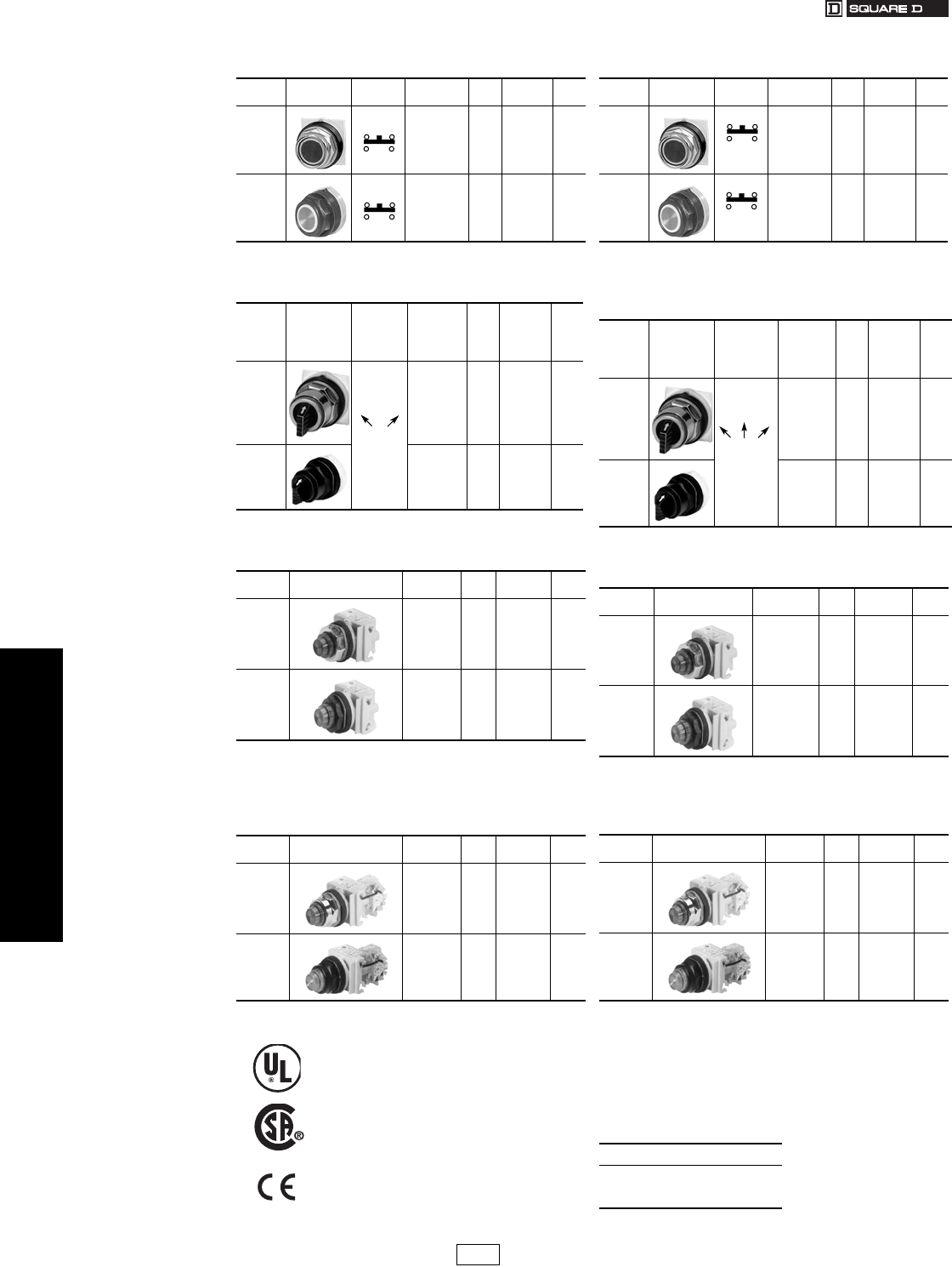
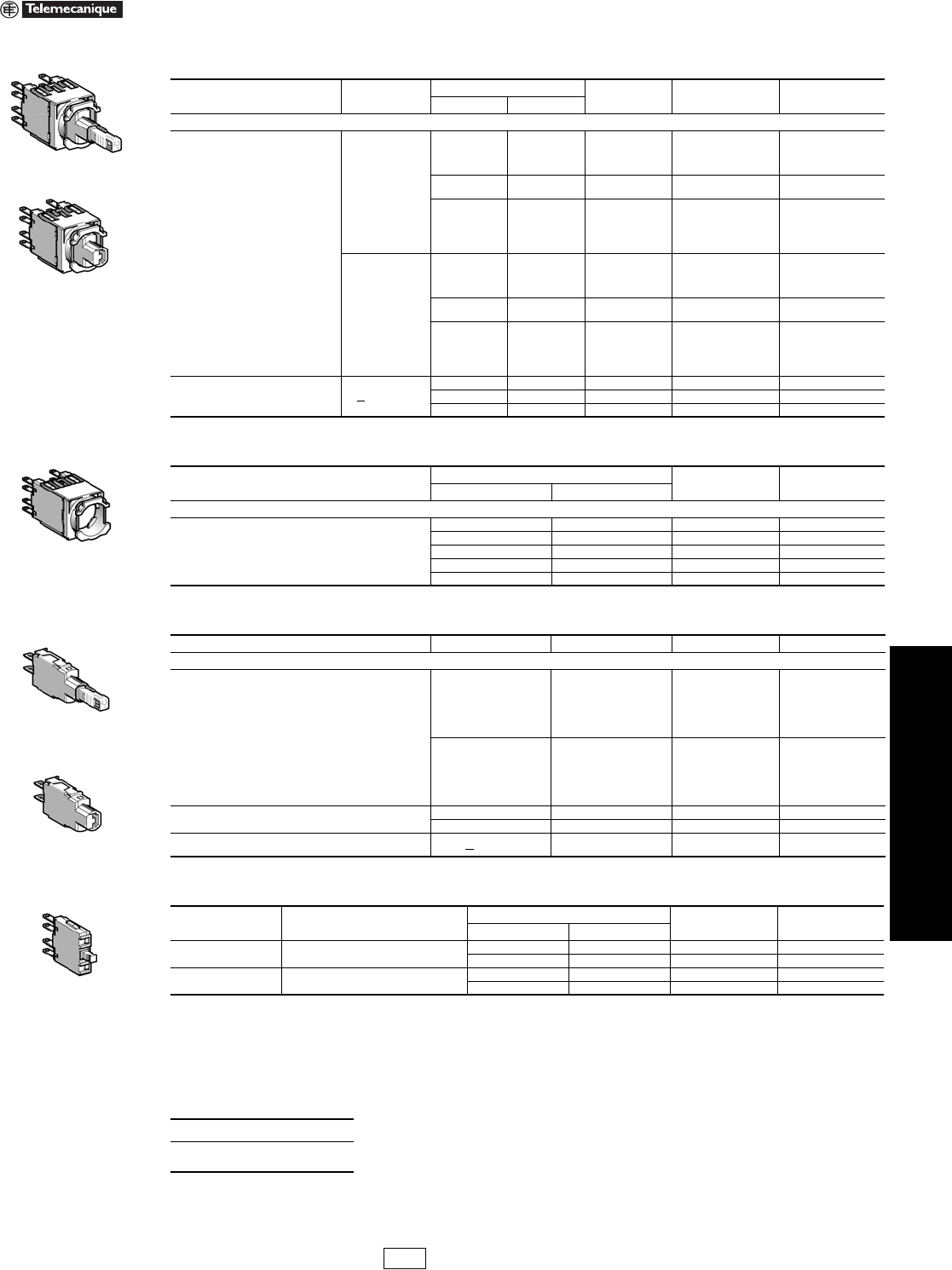
30 mm Push Buttons Type K, SK Common Operators, Complete with Contact Blocks
Class 9001 / Refer to Catalog 9001CT0001
Table 19.1: BLACK—Start Push Buttons
Operator
Style Description Contact
Block Type $ Price Legend
Plate $ Price
30 mm
Industrial
(Metal)
KR1BH13 54. KN201 2.90
30 mm
Corrosion
Resistant
(Non-
Metallic)
SKR1BH13 54. KN101SP 2.90
Table 19.2: BLACK—Off-On Selector Switch
Operator
Style Description
Contact
Sequence
(Contact
Block
Included)
Type $ Price Legend
Plate $ Price
30 mm
Industrial
(Metal)
KS11BH13 64. KN244 2.90
30 mm
Corrosion
Resistant
(Non-
Metallic)
SKS11BH13 64. KN144SP 2.90
Table 19.3: RED—120 Vac—On Pilot Light
Operator
Style Description Type $ Price Legend
Plate $ Price
30 mm
Industrial
(Metal)
KP1R31 102. KN203 2.90
30 mm
Corrosion
Resistant
(Non-
Metallic)
SKP1R31 102. KN103SP 2.90
Table 19.4: RED—120 Vac—On Push-To-Test
Pilot Light
Operator
Style Description Type $ Price Legend
Plate $ Price
30 mm
Industrial
(Metal)
KT1R31 131. KN203 2.90
30 mm
Corrosion
Resistant
(Non-
Metallic)
SKT1R31 131. KN103SP 2.90
File
CCN
E42259
NKCR
File
Class
LR 25490
3211 03
Marking
10
01
Table 19.5: RED—Stop Push Buttons
Operator
Style Description Contact
Block Type $ Price Legend
Plate $ Price
30 mm
Industrial
(Metal)
KR1RH13 54. KN202 2.90
30 mm
Corrosion
Resistant
(Non-
Metallic)
SKR1RH13 54. KN102RP 2.90
Table 19.6: BLACK—Hand-Off-Auto
Selector Switch
Operator
Style Description
Contact
Sequence
(Contact
Block
Included)
Type $ Price Legend
Plate $ Price
30 mm
Industrial
(Metal)
KS43BH13 64. KN260 2.90
30 mm
Corrosion
Resistant
(Non-
Metallic)
SKS43BH13 64. KN160SP 2.90
Table 19.7: GREEN—120 Vac—Off Pilot Light
Operator
Style Description Type $ Price Legend
Plate $ Price
30 mm
Industrial
(Metal)
KP1G31 102. KN204 2.90
30 mm
Corrosion
Resistant
(Non-
Metallic)
SKP1G31 102. KN104SP 2.90
Table 19.8: GREEN—120 Vac—Off Push-To-Test
Pilot Light
Operator
Style Description Type $ Price Legend
Plate $ Price
30 mm
Industrial
(Metal)
KT1G31 131. KN204 2.90
30 mm
Corrosion
Resistant
(Non-
Metallic)
SKT1G31 131. KN104RP 2.90
When ordering, please specify:
•Quantity
•Class Number (if appropriate)
•Type or Catalog Number
100
001
CP1 Discount
Schedule
www.us.schneider-electric.com
FOR CURRENT INFORMATION
19 PUSH BUTTONS AND
OPERATOR INTERFACE
© 2007 Schneider Electric
All Rights Reserved 19-3
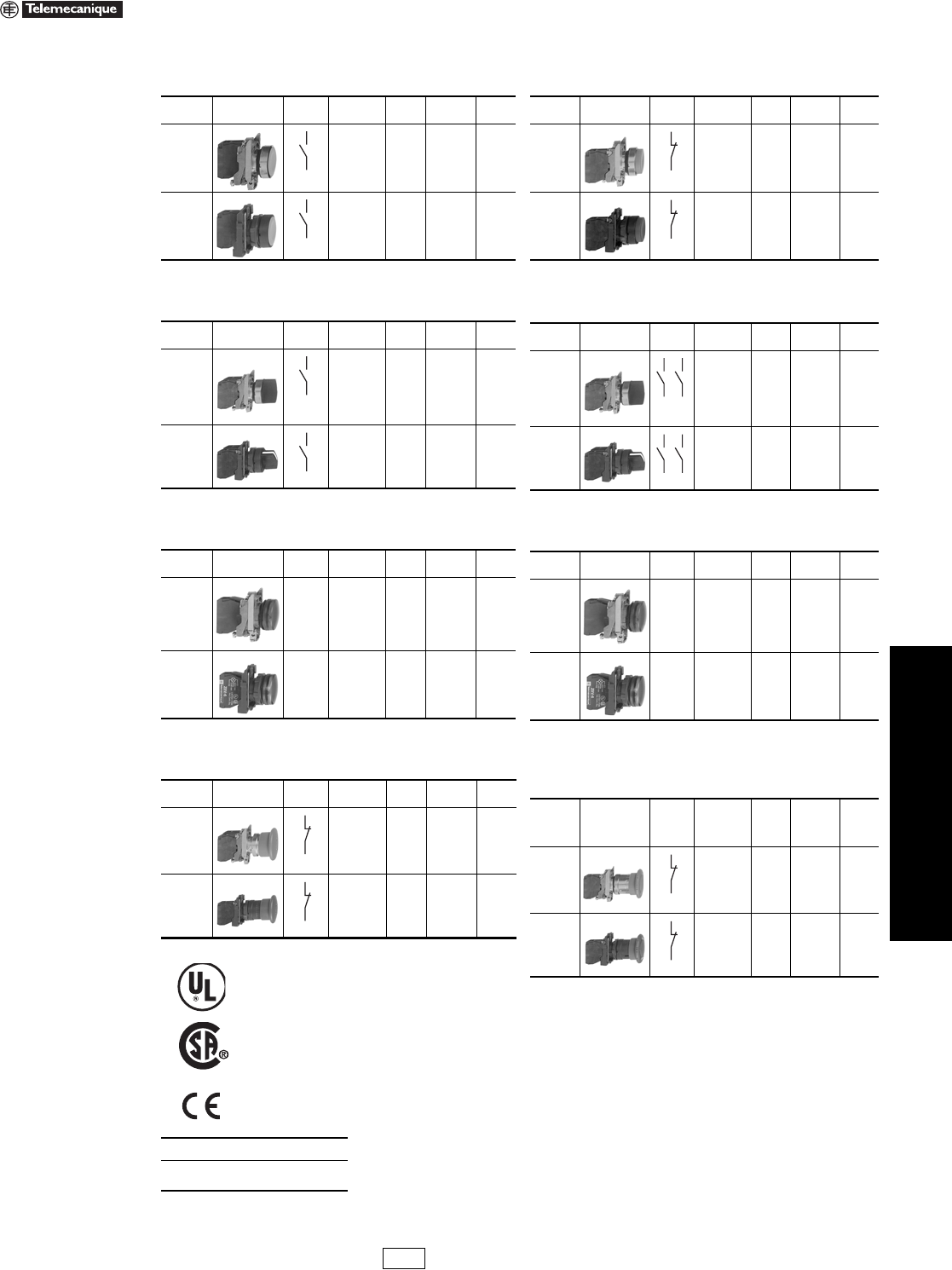
22 mm Push Buttons XB4–XB5 Common Operators, Complete with Contact Blocks
Refer to Catalog 9001CT0001
Table 19.9: BLACK—Start Push Buttons
(flush head)
Operator
Style Description Contact
Block Type $ Price Legend
Plate $ Price
XB4 Die
Cast
Chrome
1 N.O.
XB4BA21 35.00 ZBY2303 3.40
XB5
Double
Insulated
1 N.O.
XB5AA21 35.00 ZBY2303 3.40
Table 19.10: BLACK—Off-On Selector Switch
Operator
Style Description Contact
Block Type $ Price Legend
Plate $ Price
XB4 Die
Cast
Chrome 1 N.O.
XB4BD21 46.00 ZBY2367 3.40
XB5
Double
Insulated
1 N.O.
XB5AD21 46.00 ZBY2367 3.40
Table 19.11: RED—120 Vac LED—On Pilot Light
Operator
Style Description Light
Module Type $ Price Legend
Plate $ Price
XB4 Die
Cast
Chrome
120 Vac
Red LED XB4BVG4 65.00 ZBY2311 3.40
XB5
Double
Insulated
120 Vac
Red LED XB5AVG4 65.00 ZBY2311 3.40
Table 19.12: RED—40 mm Mushroom Emergency
Stop (Push-Pull)
Operator
Style Description Contact
Block Type $ Price Legend
Plate $ Price
XB4 Die
Cast
Chrome
1 N.C.
XB4BT42 62.00 ZBY9330 3.40
XB5
Double
Insulated
1 N.C.
XB5AT42 62.00 ZBY9330 3.40
File
CCN
E164353
NKCR
File
Class
LR 44087
3211 03
Marking
When ordering, please specify:
•Quantity
•Type or Catalog Number
Table 19.13: RED—Stop Push Buttons
(extended head)
Operator
Style Description Contact
Block Type $ Price Legend
Plate $ Price
XB4 Die
Cast
Chrome
1 N.C.
XB4BL42 35.00 ZBY2304 3.40
XB5
Double
Insulated
1 N.C.
XB5AL42 35.00 ZBY2304 3.40
Table 19.14: Hand-Off-Auto Selector Switch
Operator
Style Description Contact
Block Type $ Price Legend
Plate $ Price
XB4 Die
Cast
Chrome 1 N.O.
XB4BD33 62.00 ZBY2387 3.40
XB5
Double
Insulated
2 N.O.
XB5AD33 62.00 ZBY2387 3.40
Table 19.15: GREEN—120 Vac LED—Off Pilot Light
Operator
Style Description Light
Module Type $ Price Legend
Plate $ Price
XB4 Die
Cast
Chrome
120 Vac
Green
LED
XB4BVG3 65.00 ZBY2312 3.40
XB5
Double
Insulated
120 Vac
Green
LED
XB5AVG3 65.00 ZBY2312 3.40
Table 19.16: RED—40 mm Mushroom Emergency
Stop (Turn-To-Release)
Operator
Style Description Contact
Block Type $ Price
Legend
Plate
60 mm
Round
$ Price
XB4 Die
Cast
Chrome
1 N.C.
XB4BS542 100.00 ZBY9330 3.40
XB5
Double
Insulated
1 N.C.
XB5AS542 100.00 ZBY9330 3.40
IDiscount
Schedule
19-4 © 2007 Schneider Electric
All Rights Reserved
www.us.schneider-electric.com
FOR CURRENT INFORMATION
19 PUSH BUTTONS AND
OPERATOR INTERFACE
16 mm Push Buttons XB6 Characteristics and Complete Devices
Refer to Catalog 9001CT0001
Note: Illuminated Push Buttons 120 Vac LED are available as Complete Units with Quick Connectors/Solder Tabs. Use 12–24 V table above.
Change Voltage Code (2nd B) to “G”. Example: XB6DW1B1B (White 24 V, 1 N.O.) becomes XB6DW1G1B.
Legends . . . . . . . . . . . . . . . . . . . . . . . . . . . . . . . . . . . pages 19-12 and 19-13
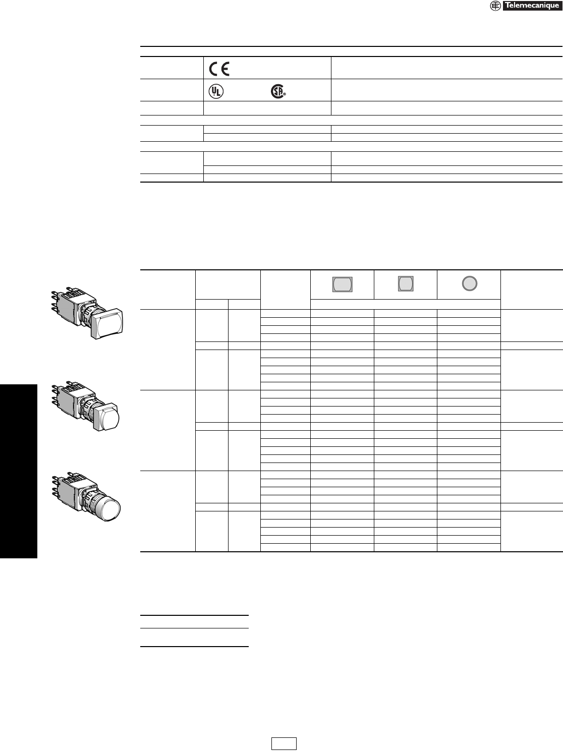
Table 19.17: Characteristics
Environment
Conforming to
standards
IEC 947-1, IEC 947-5-1, IEC 947-5-4, EN 60947-5-1, JIS C 4520 and 852, UL 508,
CSA C22.2 No. 14
Product certifications UL, CSA
ASE, BV, JIS, RINA, LROS, DNV, GL: pending
Degree of protection Conforming to IEC 529 & NF C 20-010
Conforming to UL 50 & CSA C22.2 No. 94
IP65
Type 1, 4, 4X and 12 (not for key selector switches)
Electrical characteristics of LED pilot lights
Voltage Limits, Current
Draw
12–24 V 6–30 Vac/dc, 15 mA
120 V 48–120 Vac, 20 mA
Electrical characteristics of contacts
Rated operational
characteristics
AC-15 B300, Ue = 240 Vac and Ie = 1.5 A or Ue 120 Vac and Ie = 3 A Continuous Thermal Current
5 A
DC-13 R300, Ue = 250 Vdc and Ie = 0.1 A or Ue = 125 Vdc and Ie = 0.22 A
Cabling By Quick Connectors/Solder tabs 0.11 x 0.02 in. (2.8 x 0.5 mm)
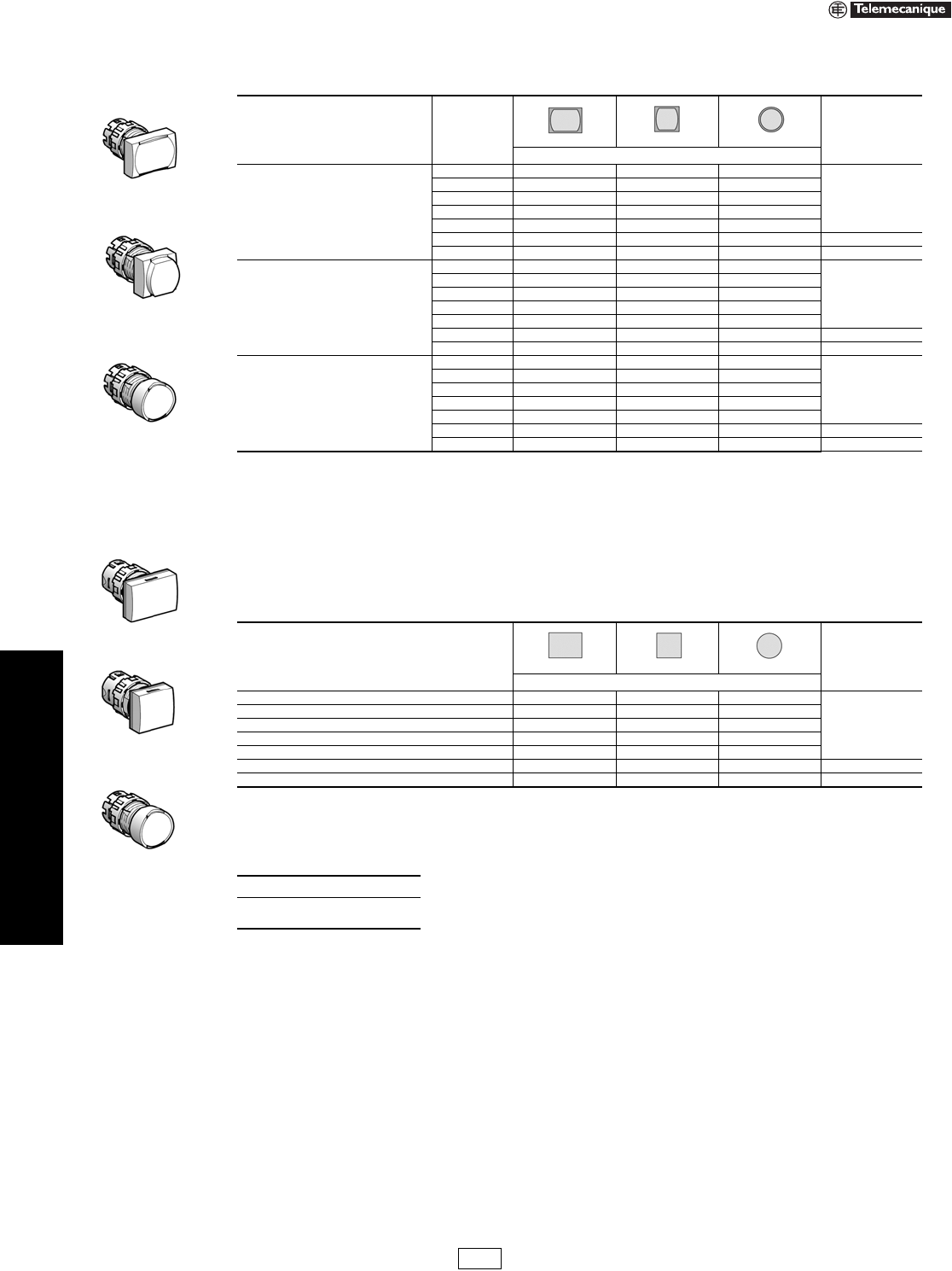
Table 19.18: Illuminated Push Buttons (12–24 Vac/Vdc LED included)
Complete Units with Quick Connectors/Solder Tabs
Type of Push Type of Contact Color Rectangular Square Round $ Price
N.O. N.C. Catalog Number
Flush,
spring return
1—
White XB6DW1B1B XB6CW1B1B XB6AW1B1B
40.40
Green XB6DW3B1B XB6CW3B1B XB6AW3B1B
Yellow XB6DW5B1B XB6CW5B1B XB6AW5B1B
Blue XB6DW6B1B XB6CW6B1B XB6AW6B1B
—1 Red XB6DW4B2B XB6CW4B2B XB6AW4B2B 40.40
11
White XB6DW1B5B XB6CW1B5B XB6AW1B5B
47.60
Green XB6DW3B5B XB6CW3B5B XB6AW3B5B
Red XB6DW4B5B XB6CW4B5B XB6AW4B5B
Yellow XB6DW5B5B XB6CW5B5B XB6AW5B5B
Blue XB6DW6B5B XB6CW6B5B XB6AW6B5B
Flush, maintained
1—
White XB6DF1B1B XB6CF1B1B XB6AF1B1B
40.40
Green XB6DF3B1B XB6CF3B1B XB6AF3B1B
Yellow XB6DF5B1B XB6CF5B1B XB6AF5B1B
Blue XB6DF6B1B XB6CF6B1B XB6AF6B1B
—1 Red XB6DF4B2B XB6CF4B2B XB6AF4B2B 40.40
11
White XB6DF1B5B XB6CF1B5B XB6AF1B5B
47.60
Green XB6DF3B5B XB6CF3B5B XB6AF3B5B
Red XB6DF4B5B XB6CF4B5B XB6AF4B5B
Yellow XB6DF5B5B XB6CF5B5B XB6AF5B5B
Blue XB6DF6B5B XB6CF6B5B XB6AF6B5B
Extended,
spring return
1—
White XB6DE1B1B XB6CE1B1B XB6AE1B1B
40.40
Green XB6DE3B1B XB6CE3B1B XB6AE3B1B
Yellow XB6DE5B1B XB6CE5B1B XB6AE5B1B
Blue XB6DE6B1B XB6CE6B1B XB6AE6B1B
—1 Red XB6DE4B2B XB6CE4B2B XB6AE4B2B 40.40
11
White XB6DE1B5B XB6CE1B5B XB6AE1B5B
47.60
Green XB6DE3B5B XB6CE3B5B XB6AE3B5B
Red XB6DE4B5B XB6CE4B5B XB6AE4B5B
Yellow XB6DE5B5B XB6CE5B5B XB6AE5B5B
Blue XB6DE6B5B XB6CE6B5B XB6AE6B5B
When ordering, please specify:
•Quantity
•Catalog Number
Marked
File E164353
CCN NKCR
File LR 44087
Class 3211 03
XB6DW•••B
XB6CE•••B
XB6AF•••B
IDiscount
Schedule

www.us.schneider-electric.com
FOR CURRENT INFORMATION
19 PUSH BUTTONS AND
OPERATOR INTERFACE
© 2007 Schneider Electric
All Rights Reserved 19-5
16 mm Push Buttons XB6 Complete Devices
Refer to Catalog 9001CT0001
aTrigger action mushroom heads are tamper proof in that a change of contact state is not possible by teasing or floating the operator.
Legends. . . . . . . . . . . . . . . . . . . . . . . . . . . . . . . . . . . pages 19-12 and 19-13
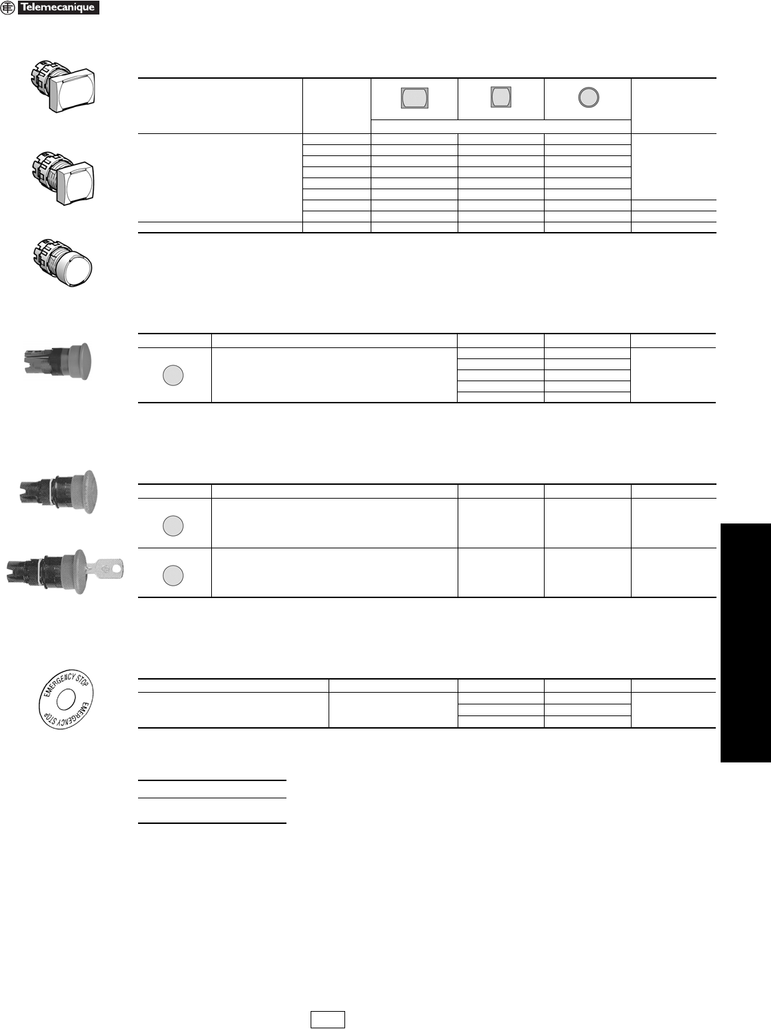
Table 19.19: Pilot Lights (12–24 Vac/dc LED included)
Complete Units with Quick Connectors/Solder Tabs
Color
Rectangular Square Round
$ Price
Catalog Number
White XB6DV1BB XB6CV1BB XB6AV1BB
24.80
Green XB6DV3BB XB6CV3BB XB6AV3BB
Red XB6DV4BB XB6CV4BB XB6AV4BB
Yellow XB6DV5BB XB6CV5BB XB6AV5BB
Blue XB6DV6BB XB6CV6BB XB6AV6BB
Table 19.20: Pilot Lights (120 Vac LED)
Complete Units with Quick Connectors/Solder Tabs
Color Rectangular Square Round $ Price
Catalog Number
White XB6DV1GB XB6CV1GB XB6AV1GB
24.80
Green XB6DV3GB XB6CV3GB XB6AV3GB
Red XB6DV4GB XB6CV4GB XB6AV4GB
Yellow XB6DV5GB XB6CV5GB XB6AV5GB
Blue XB6DV6GB XB6CV6GB XB6AV6GB
Table 19.21: Push Buttons (Non-Illuminated)
Complete Units with Quick Connectors/Solder Tabs
Type of Push Type of Contact Color Rectangular Square Round $ Price
N.O. N.C. Catalog Number
Flush, spring return
1—
White XB6DA11B XB6CA11B XB6AA11B
23.80
Black XB6DA21B XB6CA21B XB6AA21B
Green XB6DA31B XB6CA31B XB6AA31B
Yellow XB6DA51B XB6CA51B XB6AA51B
Blue XB6DA61B XB6CA61B XB6AA61B
—1 Black XB6DA22B XB6CA22B XB6AA22B 23.80
Red XB6DA42B XB6CA42B XB6AA42B
11
White XB6DA15B XB6CA15B XB6AA15B
31.00
Black XB6DA25B XB6CA25B XB6AA25B
Green XB6DA35B XB6CA35B XB6AA35B
Red XB6DA45B XB6CA45B XB6AA45B
Yellow XB6DA55B XB6CA55B XB6AA55B
Blue XB6DA65B XB6CA65B XB6AA65B
Table 19.22: Trigger Action Emergency Stop Mushroom Head Push Buttons (Color Red)a
Shape of Head Type of Push Type of Contact Diameter
of Head (mm) Catalog Number $ Price
N.O. N.C.
Turn-to-release
—1 30XB6AS8342B 59.00
11 30XB6AS8345B 66.00
Key release
—1 30XB6AS9342B 71.00
11 30XB6AS9345B 79.00
Table 19.23: Circular Legends, 45 mm
Description Color Text Catalog Number $ Price
Circular legends, 45 mm Yellow
Blank ZB6Y7001
3.40Emergency stop ZB6Y7330
Arrêt d’urgence ZB6Y7130
When ordering, please specify:
•Quantity
•Catalog Number
XB6DV••B
XB6CV••B
XB6AV••B
XB6DA••B
XB6CA••B
XB6AA••B
XB6AS8345B
XB6AS9345B
ZB6Y7330
IDiscount
Schedule

19-6 © 2007 Schneider Electric
All Rights Reserved
www.us.schneider-electric.com
FOR CURRENT INFORMATION
19 PUSH BUTTONS AND
OPERATOR INTERFACE
16 mm Push Buttons XB6 Complete Devices
Refer to Catalog 9001CT0001
Note: Indicates key withdrawal position.
aAs viewed from the front of the panel.
Legends . . . . . . . . . . . . . . . . . . . . . . . . . . . . . . . . . . . pages 19-12 and 19-13
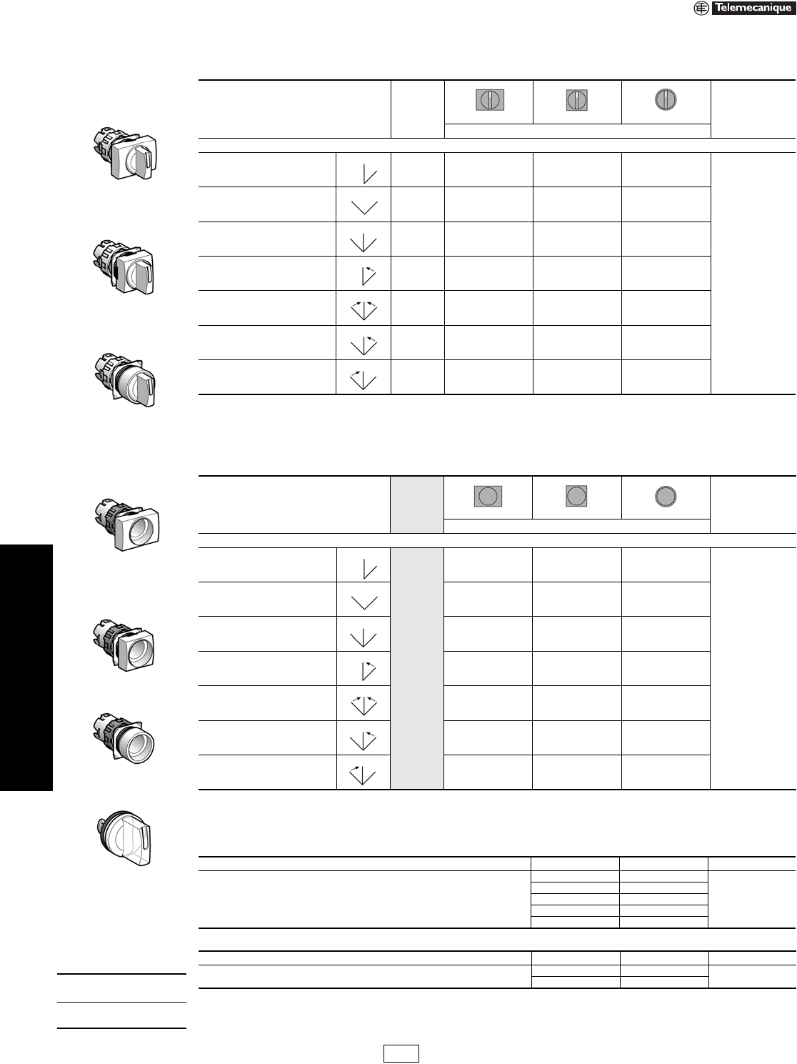
Table 19.24: Selector Switches (Switching Angle: Handle: 60o, Key: 70o)
Complete Units with Quick Connectors/Solder Tabs
Type of
Operator
Type of Contact Number and Type of
Positions Rectangular Square Round
$ Price
N.O. N.C. Catalog Number
Handle
1 — 2-maintained XB6DD221B XB6CD221B XB6AD221B 27.00
11
2-maintained XB6DD225B XB6CD225B XB6AD225B 34.20
3-maintained XB6DD235B XB6CD235B XB6AD235B 34.20
2 — 3-maintained XB6DD233B XB6CD233B XB6AD233B 34.20
Type of
Operator
Type of Contact Number and Type of
Positions Rectangular Square Round $ Price
N.O. N.C. Catalog Number
Key
11
2-maintained XB6DGC5B XB6CGC5B XB6AGC5B 62.00
2-maintained XB6DGB5B XB6CGB5B XB6AGB5B 62.00
3-maintained XB6DGH5B XB6CGH5B XB6AGH5B 62.00
2 — 3-maintained XB6DGH3B XB6CGH3B XB6AGH3B 62.00
Table 19.25: Selector Switch Sequence
2 Position Selector Switch
Contact block guide a
O X 1 N.O. (left or right)
X O 1 N.C. (left or right)
OX1 N.O.
and
XO1 N.C.
3 Position Selector Switch
Contact block guide a
O O X 1 N.O. (left)
X O X 2 N.O. wired in parallel (side by side)
X O O 1 N.O. (right)
O X X 1 N.C. (right)
X X O 1 N.C. (left)
O X O 2 N.C. wired in series (side by side)
When ordering, please specify:
•Quantity
•Catalog Number
XB6DD•••B
XB6CD•••B
XB6AD•••B
XB6DG••B
XB6CG••B
XB6AG••B
IDiscount
Schedule
www.us.schneider-electric.com
FOR CURRENT INFORMATION
19 PUSH BUTTONS AND
OPERATOR INTERFACE
© 2007 Schneider Electric
All Rights Reserved 19-7
16 mm Push Buttons XB6 Electrical Components
Refer to Catalog 9001CT0001
aIlluminated selector switches can be assembled by using a contact block/light module assembly in conjunction with a selector switch head, supplied
without handle, and a transparent handle. See page 19-10.
bThe LED must be the same color as the push button cap.
cThe LED must be the same color as the lens.
dOrder bulbs separately. See page 19-14.
eNeon bulb can only be used with a red, yellow, or white cap.
fElectrical components with connection by printed circuit board pins are available. Refer to Catalog 9001CT0001 for details.
Table 19.26: Contact Blocks and Light Modules for Illuminated Push Buttonsa
Description Supply Voltage Type of Contact Color of Light
Source Catalog Number $ Price
N.O. N.C.
Quick connectors/solder tabs
Integral LED b
12–24 Vac/Vdc
1—
White ZB6ZB11B
28.00
Green ZB6ZB31B
Ye l l o w ZB6ZB51B
Blue ZB6ZB61B
—1Red ZB6ZB42B 28.00
Ye l l o w ZB6ZB52B
11
White ZB6ZB15B
35.20
Green ZB6ZB35B
Red ZB6ZB45B
Ye l l o w ZB6ZB55B
Blue ZB6ZB65B
120 Vac
1—
White ZB6ZG11B
28.00
Green ZB6ZG31B
Ye l l o w ZB6ZG51B
Blue ZB6ZG61B
—1Red ZB6ZG42B 28.00
Ye l l o w ZB6ZG52B
11
White ZB6ZG15B
35.20
Green ZB6ZG35B
Red ZB6ZG45B
Ye l l o w ZB6ZG55B
Blue ZB6ZG65B
Direct for incandescent bulb
(not included)d< 24 Vac/Vdc
1— —ZB6ZH01B 23.80
—1 —ZB6ZH02B 23.80
11 —ZB6ZH05B 31.00
Table 19.27: Contact Blocks for Push Buttons and Selector Switches
Description Type of Contact Catalog Number $ Price
N.O. N.C.
Quick connectors/solder tabs
Contact blocks with mounting base
1—ZB6Z1B 9.40
—1ZB6Z2B 9.40
2—ZB6Z3B 16.60
—2ZB6Z4B 16.60
11ZB6Z5B 16.60
Table 19.28: Light Modules for Pilot Lights
Description Supply Voltage Color of Light Source Catalog Number $ Price
Quick connectors/solder tabsf
Integral LEDc
12–24 Vac/dc
White ZB6EB1B
16.60
Green ZB6EB3B
Red ZB6EB4B
Ye l l o w ZB6EB5B
Blue ZB6EB6B
120 Vac
White ZB6EG1B
16.60
Green ZB6EG3B
Red ZB6EG4B
Ye l l o w ZB6EG5B
Blue ZB6EG6B
With resistor for 95 V neon bulb (not included) de 110 Vac — ZB6EG0B 15.60
230 Vac — ZB6EM0B 15.60
Direct supply for 0.6 W max. incandescent bulb
(not included)d< 24 Vac/dc — ZB6EH0B 14.40
Table 19.29: Separate Contact Blocks (Maximum of 3 contacts per mounting base.)
Contact Material For use with mounting base Type of Contact Catalog Number $ Price
N.O. N.C.
Silver alloy Quick connectors/solder tabs 1—ZB6E1B 7.20
—1ZB6E2B 7.20
Gold flashed Quick connectors/solder tabs 1—ZB6E1E 12.40
—1ZB6E2E 12.40
When ordering, please specify:
•Quantity
•Catalog Number
ZB6ZB••B
ZB6ZH••B
ZB6Z•B
ZB6E••B
ZB6E•0B
ZB6E•B
IDiscount
Schedule
19-8 © 2007 Schneider Electric
All Rights Reserved
www.us.schneider-electric.com
FOR CURRENT INFORMATION
19 PUSH BUTTONS AND
OPERATOR INTERFACE
16 mm Push Buttons XB6 Illuminated Operators
Refer to Catalog 9001CT0001
aFive different color caps included with head (white, green, red, yellow, and blue).
bTo order push button caps separately, see page 19-12.
cFive different color caps included with head (white, green, red, yellow, and blue).
dTo order the caps or lenses separately, see page 19-12.
Legends . . . . . . . . . . . . . . . . . . . . . . . . . . . . . . . . . . . pages 19-12 and 19-13
Table 19.30: Heads for Illuminated Push Buttons
(To combine with complete bodies and contact blocks, see page 19-7)
Type of Push Color
Rectangular Square Round
$ Price
Catalog Number
Flush, spring return
White ZB6DW1 ZB6CW1 ZB6AW1
14.40
Green ZB6DW3 ZB6CW3 ZB6AW3
Red ZB6DW4 ZB6CW4 ZB6AW4
Ye l l o w ZB6DW5 ZB6CW5 ZB6AW5
Blue ZB6DW6 ZB6CW6 ZB6AW6
5 colors aZB6DW9 ZB6CW9 ZB6AW9 16.40
Without cap bZB6DW0 ZB6CW0 ZB6AW0 12.40
Flush, maintained
White ZB6DF1 ZB6CF1 ZB6AF1
14.40
Green ZB6DF3 ZB6CF3 ZB6AF3
Red ZB6DF4 ZB6CF4 ZB6AF4
Ye l l o w ZB6DF5 ZB6CF5 ZB6AF5
Blue ZB6DF6 ZB6CF6 ZB6AF6
5 colors aZB6DF9 ZB6CF9 ZB6AF9 16.40
Without capbZB6DF0 ZB6CF0 ZB6AF0 12.40
Extended, spring return
White ZB6DE1 ZB6CE1 ZB6AE1
14.40
Green ZB6DE3 ZB6CE3 ZB6AE3
Red ZB6DE4 ZB6CE4 ZB6AE4
Ye l l o w ZB6DE5 ZB6CE5 ZB6AE5
Blue ZB6DE6 ZB6CE6 ZB6AE6
5 colorsaZB6DE9 ZB6CE9 ZB6AE9 16.40
Without capbZB6DE0 ZB6CE0 ZB6AE0 12.40
Table 19.31: Heads for Pilot Lights
(To combine with light modules, see page 19-7.)
Color
Rectangular Square Round
$ Price
Catalog Number
White ZB6DV1 ZB6CV1 ZB6AV1
8.20
Green ZB6DV3 ZB6CV3 ZB6AV3
Red ZB6DV4 ZB6CV4 ZB6AV4
Yellow ZB6DV5 ZB6CV5 ZB6AV5
Blue ZB6DV6 ZB6CV6 ZB6AV6
5 colors cZB6DV9 ZB6CV9 ZB6AV9 10.20
Without lensdZB6DV0 ZB6CV0 ZB6AV0 6.20
When ordering, please specify:
•Quantity
•Catalog Number
ZB6DW•
ZB6CE•
ZB6AF•
ZB6DV•
ZB6CV•
ZB6AV•
IDiscount
Schedule
www.us.schneider-electric.com
FOR CURRENT INFORMATION
19 PUSH BUTTONS AND
OPERATOR INTERFACE
© 2007 Schneider Electric
All Rights Reserved 19-9
16 mm Push Buttons XB6 Non-Illuminated Operators
Refer to Catalog 9001CT0001
aFive different color caps included with head (white, green, red, yellow, and blue).
bTo order push button caps separately, see page 19-12.
cTrigger action mushroom heads are tamper proof in that a change of contact state is not possible by teasing or floating the operator.
Legends. . . . . . . . . . . . . . . . . . . . . . . . . . . . . . . . . . . pages 19-12 and 19-13
Table 19.32: Heads for Push Buttons
(To combine with complete bodies and contact blocks, see page 19-7.)
Type of Push Color Rectangular Square Round $ Price
Catalog Number
Flush, spring return
White ZB6DA1 ZB6CA1 ZB6AA1
14.40
Black ZB6DA2 ZB6CA2 ZB6AA2
Green ZB6DA3 ZB6CA3 ZB6AA3
Red ZB6DA4 ZB6CA4 ZB6AA4
Yellow ZB6DA5 ZB6CA5 ZB6AA5
Blue ZB6DA6 ZB6CA6 ZB6AA6
6 colorsaZB6DA9 ZB6CA9 ZB6AA9 16.40
Without cap bZB6DW0 ZB6CW0 ZB6AW0 12.40
Extended, spring return Red ZB6DL4 ZB6CL4 ZB6AL4 14.40
Table 19.33: Mushroom Heads for Push Buttons (24 mm)
Shape of Head Type of Push Color of Cap Catalog Number $ Price
Spring return
White ZB6AC1
24.80
Black ZB6AC2
Green ZB6AC3
Yellow ZB6AC5
Blue ZB6AC6
Table 19.34: Mushroom Heads for Trigger Action Push Buttons (30 mm)c
Shape of Head Type of Push Color of Cap Catalog Number $ Price
Turn-to-release Red ZB6AS834 49.60
Key release Red ZB6AS934 62.00
Table 19.35: Circular Legends, 45 mm
Description Color Text Catalog Number $ Price
Circular legends, 45 mm Yellow
Blank ZB6Y7001
3.40Emergency stop ZB6Y7330
Arrêt d’urgence ZB6Y7130
When ordering, please specify:
•Quantity
•Catalog Number
ZB6DA•
ZB6CA•
ZB6AA•
ZB6AC•
ZB6AS834
ZB6AS934
ZB6Y7330
IDiscount
Schedule
19-10 © 2007 Schneider Electric
All Rights Reserved
www.us.schneider-electric.com
FOR CURRENT INFORMATION
19 PUSH BUTTONS AND
OPERATOR INTERFACE
16 mm Push Buttons XB6 Selector Switches
Refer to Catalog 9001CT0001
aFor bodies with 2 contact blocks, maximum.
bSwitching angle: maintained positions 90o.
cSee selector switch sequence charts on page 19-11.
dOrder handle separately (see Tables 19.38 and 19.39), for bodies with a maximum of 2 contact blocks.
eSwitching angle: maintained positions 90o.
fSee selector switch sequence charts on page 19-11.
gFor use in conjunction with head without handle (see Tables 19.36 and 19.37) and body/contact assembly for illuminated push buttons (see page 19-7).
Legends . . . . . . . . . . . . . . . . . . . . . . . . . . . . . . . . . . . pages 19-12 and 19-13
Table 19.36: Heads for Non-Illuminated Selector Switchesac
(To combine with complete bodies and contact blocks, see page 19-7.)
Number and Type of Positions Color of
Handle Rectangular Square Round
$ Price
Catalog Number
Switching angle: maintained positions 60°, spring return positions 45°
2-maintained Black ZB6DD22 ZB6CD22 ZB6AD22
17.60
2-maintained Black ZB6DD28bZB6CD28bZB6AD28b
3-maintained Black ZB6DD23 ZB6CD23 ZB6AD23
2-spring return to center Black ZB6DD24 ZB6CD24 ZB6AD24
3-spring return to center Black ZB6DD25 ZB6CD25 ZB6AD25
3-spring return from right to center Black ZB6DD26 ZB6CD26 ZB6AD26
3-spring return from left to center Black ZB6DD27 ZB6CD27 ZB6AD27
Table 19.37: Heads for Illuminated Selector Switches df
(To combine with complete bodies and contact blocks, see page 19-7.)
Number and Type of Positions Rectangular Square Round $ Price
Catalog Number
Switching angle: maintained positions 60o, spring return positions 45o
2-maintained ZB6DD02 ZB6CD02 ZB6AD02
13.40
2-maintained ZB6DD08 eZB6CD08 eZB6AD08 e
3-maintained ZB6DD03 ZB6CD03 ZB6AD03
2-spring return to center ZB6DD04 ZB6CD04 ZB6AD04
3-spring return to center ZB6DD05 ZB6CD05 ZB6AD05
3-spring return from right to center ZB6DD06 ZB6CD06 ZB6AD06
3-spring return from left to center ZB6DD07 ZB6CD07 ZB6AD07
Table 19.38: Handles for Illuminated Selector Switches
Description Color Catalog Number $ Price
Handles for illuminated selector switches g
White ZB6YK1
4.20
Green ZB6YK3
Red ZB6YK4
Yellow ZB6YK5
Blue ZB6YK6
ZB6DD••
ZB6CD••
ZB6AD••
ZB6DD0•
ZB6CD0•
ZB6AD0•
When ordering,
please specify:
•Quantity
•Catalog Number
Table 19.39: Handles for Non-Illuminated Selector Switches
Description Color Catalog Number $ Price
Handles for non-illuminated selector switches Black ZB6YD2 4.20
Red ZB6YD4
ZB6YK•
IDiscount
Schedule
www.us.schneider-electric.com
FOR CURRENT INFORMATION
19 PUSH BUTTONS AND
OPERATOR INTERFACE
© 2007 Schneider Electric
All Rights Reserved 19-11
16 mm Push Buttons XB6 Keyed Selector Switches
Refer to Catalog 9001CT0001
Note: Indicates key withdrawal position.
aRonis 200 key standard. Other keys available, refer to Catalog 9001CT0001.
bAs viewed from the front of the panel.
Legends. . . . . . . . . . . . . . . . . . . . . . . . . . . . . . . . . . . pages 19-12 and 19-13
Table 19.40: Heads for Ronis Key Operated Selector Switches a
(To combine with complete bodies and contact blocks, see page 19-7.)
Number and Type of Positions Key Withdrawal
Rectangular Square Round
$ Price
Catalog Number
Switching angle: maintained positions 70o, spring return positions 45o
2-maintained
Right-hand position ZB6DGA ZB6CGA ZB6AGA
45.60
Center position ZB6DGB ZB6CGB ZB6AGB
Both positions ZB6DGC ZB6CGC ZB6AGC
2-spring return from right to center Center position ZB6DGL ZB6CGL ZB6AGL
3-maintained
Left-hand position ZB6DGD ZB6CGD ZB6AGD
Center position ZB6DGE ZB6CGE ZB6AGE
Left-hand and center positions ZB6DGF ZB6CGF ZB6AGF
Right-hand position ZB6DGG ZB6CGG ZB6AGG
All 3 positions ZB6DGH ZB6CGH ZB6AGH
Left-hand and right-hand positions ZB6DGJ ZB6CGJ ZB6AGJ
Right-hand and center positions ZB6DGK ZB6CGK ZB6AGK
3-spring return from left to center
Right-hand position ZB6DGM ZB6CGM ZB6AGM
Center position ZB6DGN ZB6CGN ZB6AGN
Right-hand and center positions ZB6DGP ZB6CGP ZB6AGP
3-spring return from right to center
Left-hand position ZB6DGQ ZB6CGQ ZB6AGQ
Center position ZB6DGR ZB6CGR ZB6AGR
Left-hand and center positions ZB6DGS ZB6CGS ZB6AGS
3-spring return to center Center position ZB6DGT ZB6CGT ZB6AGT
ZB6DG•
ZB6CG•
ZB6AG•
When ordering,
please specify:
•Quantity
•Catalog Number
Table 19.41: Selector Switch Sequence (using contact block assemblies, page 19-7)
2 Position Selector Switch
Contact block guide b
O X 1 N.O. (left or right)
X O 1 N.C. (left or right)
OX1 N.O.
and
XO1 N.C.
3 Position Selector Switch
Contact block guide b
O O X 1 N.O. (left)
X O X 2 N.O. wired in parallel (side by side)
X O O 1 N.O. (right)
O X X 1 N.C. (right)
XXO1 N.C. (left)
O X O 2 N.C. wired in series (side by side)
IDiscount
Schedule
www.us.schneider-electric.com
FOR CURRENT INFORMATION
19 PUSH BUTTONS AND
OPERATOR INTERFACE
19-12 © 2007 Schneider Electric
All Rights Reserved
16 mm Push Buttons XB6 Accessories
Refer to Catalog 9001CT0001
aAdditional legend plate sizes and markings are available in Catalog 9001CT0001.
Table 19.42: Push Button Caps—Unmarked
Application Color Rectangular Square Round $ Price
Catalog Number
Illuminated push buttons with
flush push
White ZB6YDW1 ZB6YCW1 ZB6YAW1
2.00
Green ZB6YDW3 ZB6YCW3 ZB6YAW3
Red ZB6YDW4 ZB6YCW4 ZB6YAW4
Ye l l o w ZB6YDW5 ZB6YCW5 ZB6YAW5
Blue ZB6YDW6 ZB6YCW6 ZB6YAW6
Illuminated push buttons with
extended push
White ZB6YDE1 ZB6YCE1 ZB6YAE1
2.00
Green ZB6YDE3 ZB6YCE3 ZB6YAE3
Red ZB6YDE4 ZB6YCE4 ZB6YAE4
Ye l l o w ZB6YDE5 ZB6YCE5 ZB6YAE5
Blue ZB6YDE6 ZB6YCE6 ZB6YAE6
Non-illuminated push buttons
White ZB6YDA1 ZB6YCA1 ZB6YAA1
2.00
Black ZB6YDA2 ZB6YCA2 ZB6YAA2
Green ZB6YDA3 ZB6YCA3 ZB6YAA3
Red ZB6YDA4 ZB6YCA4 ZB6YAA4
Ye l l o w Z B 6 Y DA 5 ZB6YCA5 ZB6YAA5
Blue ZB6YDA6 ZB6YCA6 ZB6YAA6
Table 19.43: Lens Caps
Application Color
Rectangular Square Round
$ Price
Catalog Number
Pilot lights
White ZB6YDV1 ZB6YCV1 ZB6YAV1
2.00
Green ZB6YDV3 ZB6YCV3 ZB6YAV3
Red ZB6YDV4 ZB6YCV4 ZB6YAV4
Yellow ZB6YDV5 ZB6YCV5 ZB6YAV5
Blue ZB6YDV6 ZB6YCV6 ZB6YAV6
Table 19.44: Standard Legend Plate (24 X 28 mm) for 8 X 21 mm Legend a
Description Background Color of Legend Catalog Number $ Price
Without legend insert — ZB6YD20 2.00
With blank legend insert White or yellow ZB6YD21 3.40
Black or red ZB6YD22 3.40
Table 19.45: 8 x 21 mm Marked Legends (for 24 x 28 mm legend holder ZB6YD20) a
Color Marking Catalog Number $ Price
White Text
Red Background (Stop and Fault)
Black Background (all others)
International
O-I ZB6Y2178
1.60
I-II ZB6Y2179
I-O-II ZB6Y2186
OZB6Y2190
English
HAND-O-AUTO ZB6Y2387
CLOSE ZB6Y2314
DOWN ZB6Y2308
FORWARD ZB6Y2305
FAULT ZB6Y2334
LEFT ZB6Y2310
OFF ZB6Y2312
ON ZB6Y2303
OPEN ZB6Y2313
RESET ZB6Y2323
REVERSE ZB6Y2306
RIGHT ZB6Y2309
RUN ZB6Y2311
STOP ZB6Y2304
UP ZB6Y2307
ZB6YDW•
ZB6YDE•
ZB6YDA•
ZB6YAW•ZB6YCW•
ZB6YCE• ZB6YAE•
ZB6YCA• ZB6YAA•
ZB6YAVZB6YDV• ZB6YCV•
ZB6YD20
ZB6Y2178
STOP
ZB6Y2304
When ordering, please specify:
•Quantity
•Catalog Number
IDiscount
Schedule
www.us.schneider-electric.com
FOR CURRENT INFORMATION
19 PUSH BUTTONS AND
OPERATOR INTERFACE
© 2007 Schneider Electric
All Rights Reserved 19-13
16 mm Push Buttons XB6 Accessories
Refer to Catalog 9001CT0001
Table 19.46: Push Button Caps—Marked
Ink Marking Color:
White on colored cap
Black on white cap
Color Rectangular Square Round $ Price
Catalog Number
For non-illuminated push buttons
0White ZB6YD100 ZB6YC100 ZB6YA100
4.20
Black ZB6YD200 ZB6YC200 ZB6YA200
1White ZB6YD101 ZB6YC101 ZB6YA101
Black ZB6YD201 ZB6YC201 ZB6YA201
2White ZB6YD102 ZB6YC102 ZB6YA102
Black ZB6YD202 ZB6YC202 ZB6YA202
3White ZB6YD103 ZB6YC103 ZB6YA103
Black ZB6YD203 ZB6YC203 ZB6YA203
4White ZB6YD104 ZB6YC104 ZB6YA104
Black ZB6YD204 ZB6YC204 ZB6YA204
5White ZB6YD105 ZB6YC105 ZB6YA105
Black ZB6YD205 ZB6YC205 ZB6YA205
6White ZB6YD106 ZB6YC106 ZB6YA106
Black ZB6YD206 ZB6YC206 ZB6YA206
7White ZB6YD107 ZB6YC107 ZB6YA107
Black ZB6YD207 ZB6YC207 ZB6YA207
8White ZB6YD108 ZB6YC108 ZB6YA108
Black ZB6YD208 ZB6YC208 ZB6YA208
9White ZB6YD109 ZB6YC109 ZB6YA109
Black ZB6YD209 ZB6YC209 ZB6YA209
ON White ZB6YD117 ZB6YC117 ZB6YA117
Green ZB6YD317 ZB6YC317 ZB6YA317
OFF Black ZB6YD224 ZB6YC224 ZB6YA224
Red ZB6YD424 ZB6YC424 ZB6YA424
IWhite ZB6YD111 ZB6YC111 ZB6YA111
Green ZB6YD311 ZB6YC311 ZB6YA311
OBlack ZB6YD210 ZB6YC210 ZB6YA210
Red ZB6YD410 ZB6YC410 ZB6YA410
RBlack ZB6YD226 ZB6YC226 ZB6YA226
Blue ZB6YD626 ZB6YC626 ZB6YA626
START White ZB6YD140 ZB6YC140 ZB6YA140
Green ZB6YD340 ZB6YC340 ZB6YA340
STOP Black ZB6YD241 ZB6YC241 ZB6YA241
Red ZB6YD441 ZB6YC441 ZB6YA441
II White ZB6YD112 ZB6YC112 ZB6YA112
Black ZB6YD212 ZB6YC212 ZB6YA212
III White ZB6YD113 ZB6YC113 ZB6YA113
Black ZB6YD213 ZB6YC213 ZB6YA213
+White ZB6YD114 ZB6YC114 ZB6YA114
Black ZB6YD214 ZB6YC214 ZB6YA214
-White ZB6YD115 ZB6YC115 ZB6YA115
Black ZB6YD215 ZB6YC215 ZB6YA215
UP White ZB6YD127 ZB6YC127 ZB6YA127
Black ZB6YD227 ZB6YC227 ZB6YA227
DOWN White ZB6YD128 ZB6YC128 ZB6YA128
Black ZB6YD228 ZB6YC228 ZB6YA228
CLOSE White ZB6YD132 ZB6YC132 ZB6YA132
Black ZB6YD232 ZB6YC232 ZB6YA232
White ZB6YD119 ZB6YC119 ZB6YA119
Black ZB6YD219 ZB6YC219 ZB6YA219
White ZB6YD120 ZB6YC120 ZB6YA120
Black ZB6YD220 ZB6YC220 ZB6YA220
White ZB6YD121 ZB6YC121 ZB6YA121
Black ZB6YD221 ZB6YC221 ZB6YA221
White ZB6YD122 ZB6YC122 ZB6YA122
Black ZB6YD222 ZB6YC222 ZB6YA222
When ordering, please specify:
•Quantity
•Catalog Number
ZB6YD•10
ZB6YC•10
ZB6YA•10
ZB6YD•17
ZB6YD•19
ZB6YC•19
ZB6YA•19
IDiscount
Schedule
www.us.schneider-electric.com
FOR CURRENT INFORMATION
19 PUSH BUTTONS AND
OPERATOR INTERFACE
19-14 © 2007 Schneider Electric
All Rights Reserved
16 mm Push Buttons XB6 Accessories
Refer to Catalog 9001CT0001
a28 V bulb supplied, for use on 24 V.
b95 V bulb supplied, for use on 110/230 V.
Table 19.47: Accessories
Description Application Catalog Number $ Price
Body Fitting contact blocks ZB6Y009 2.00
Bezel tightening tool + bulb extractor Fixing the switch and changing bulbs ZB6Y905 4.20
Cap extractor Changing caps ZB6Y016 4.20
Contact block removal tool Removing contact blocks ZB6Y018 4.20
Three piece tool kit — ZB6Y019 12.40
Nut Fixing head to panel ZB6Y002 2.00
Anti-rotation plate Selector switches, Emergency Stops ZB6Y003 2.00
Adaptor Flush mounting a circular head push button or
pilot light in Ø 22 mm cut-out ZB6YA002 6.20
Shroud Protecting contacts against touching ZB6Y001 3.40
Protective cover
Circular and square head push buttons and
switches ZB6YA001 16.60
Rectangular head push buttons and switches ZB6YD001 16.60
Female Quick connector/Solder tab Sold in lots of 100 pieces ZB6Y004 0.42
Blanking plug Plugging an unused knockout ZB6Y005 4.20
Ronis key, 2 pieces Key operated selector switches and
emergency stop mushroom ZB6Y007 6.20
Incandescent bulbs, bayonet T1 1/4
6 V ZB6YA006 2.00
12 V ZB6YJ012 2.00
28 VaZB6YB028 2.00
Neon bulbs 110/230 V bZB6YG095 4.20
Link Operation of 3rd contact ZB6Y017 1.00
SiS Label Software Legend Design Software:
English, French, German, Spanish, Italian XBY2U 104.00
Sheets of peel-off legends, 66 legends
per sheet. For use with SiS label, size A4
(297 mm x 210 mm)
Pilot lights, rectangular ZB6YD003
6.20
Pilot lights, square ZB6YC003
Pilot lights, circular ZB6YA003
Illuminated push buttons, rectangular ZB6YD013
Illuminated push buttons, square ZB6YC013
Illuminated push buttons, circular ZB6YA013
Adapter For mounting 16 mm into 22 mm hole ZB6Y020 15.00
Table 19.48: Circular Legends, 45 mm
Description Color Text Catalog Number $ Price
Circular legends, 45 mm Yellow
Blank ZB6Y7001
3.40Emergency stop ZB6Y7330
Arrêt d’urgence ZB6Y7130
When ordering, please specify:
•Quantity
•Catalog Number
ZB6Y009
ZB6Y905
ZB6Y002 ZB6Y003
ZB6Y001 ZB6YA001
ZB6YD001 ZB6Y005
ZB6Y007
ZB6Y7330
IDiscount
Schedule
www.us.schneider-electric.com
FOR CURRENT INFORMATION
19 PUSH BUTTONS AND
OPERATOR INTERFACE
© 2007 Schneider Electric
All Rights Reserved 19-15
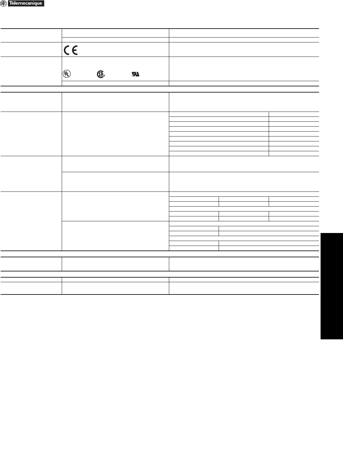
22 mm Push Buttons XB4 Characteristics
Refer to Catalog 9001CT0001
Table 19.49: Environment
Degree of protection Conforming to IEC 529 IP65, unless otherwise stated
IP66, for booted push button heads
Conforming to UL 50 and CSA C22.2 No. 94 Type 1, 2, 3, 4, 4X, 12, and 13, unless otherwise stated
Conforming to standards
IEC 947-1, IEC/EN 60947-5-1, IEC 947-5-4,
EN 60947-1, JIS C 4520,
UL 508, CSA C22.2 No. 14
Product certifications
UL Listed, CSA
Standard single contacts with screw clamp terminals: A600; Q600
Double contacts with screw clamp terminals: A600; Q600
Light modules with screw clamp terminals
JOYSTICK XD4-PA: A600; R300
BV, RINA, LROS, DNV, GL (pending) Standard single contacts and double contacts with screw clamp terminals
Electrical Characteristics of Operators and Contact Blocks
Cabling capacity Conforming to IEC 947-1
Screw and captive clamp terminals
Min: 1 x 24 AWG (0.22 mm2) without cable end 1 x 22 AWG (0.34 mm2) for linking
Max:2 x 16 AWG (1.5 mm2) with cable end 2 x 14 AWG (2.5 mm2) without cable ends
Cross headed screw (POZIDRIV type 1) slotted for flat 4 and 5.5 mm screwdriver
Maximum Contact Block Usage XB4/ZB4 Maximum Number of Blocks
Push buttons (Non-Illuminated) 9
Selector switches (Non-Illuminated) 6
Push buttons and selectors (Illuminated) 6
Mushrooms, Push Pull (Non-Illuminated) 6
Mushrooms, Push Pull (Illuminated) 4
Mushrooms, Turn-to-Release (Non-Illuminated) 6
Mushrooms, Trigger Action (Non-Illuminated) 4
Push-on/Push-off (Non-Illuminated) 3
Push-on/Push-off (Illuminated) 2
Rated operational
characteristics
Conforming to
IEC/EN 60947-5-1
AC supply:
Utilization category AC-15
Standard blocks (single or double) with screw clamp terminals:
A600: Ue = 600 Vac and le = 1.2 A or Ue = 240 Vac and le = 3 A
or Ue = 120 Vac and le = 6 A
Continuous Thermal Current: 10 A
DC supply:
Utilization category DC-13
Standard single or double blocks with screw clamp terminals:
Q600: Ue = 600 Vdc and le = 0.1 A or Ue = 250 Vdc and Ie = 0.27 A
or Ue = 125 Vdc and le = 0.55 A
Joystick XD4-PA:
R300: Ue = 125 Vdc and le = 0.22 A or Ue = 250 Vdc and le = 0.1 A
Electrical durability
Conforming to
IEC/EN 60947-5-1
Appendix C
Operating rate
3600 operating cycles/hour. Load
factor: 0.5
AC supply for 1 million operating cycles,
utilization category AC-15
Standard blocks for screw clamp terminals:
24 Vac 120 Vac 230 Vac
4 A 3 A 2 A
Standard double blocks with screw clamp terminals:
24 Vac 120 Vac 230 Vac
3 A 1.5 A 1 A
DC supply for 1 million operating cycles,
utilization category DC-13
Standard single blocks for screw clamp terminals:
24 Vdc 110 Vdc
0.5 A 0.2 A
Standard double blocks with screw clamp terminals:
24 Vdc 110 Vdc
0.4 A 0.15 A
Electrical Characteristics of Light Modules
Cabling capacity Conforming to IEC 947-1
Screw and captive clamp terminals
Min: 1 x 24 AWG (0.22 mm2) without cable end 1 x 22 AWG (0.34 mm2) for linking
Max:2 x 16 AWG (1.5 mm2) with cable end
Specific Characteristics of Protected LED® Light Modules Only
Voltage limits Nominal voltage 24 V: 19.2 to 30 Vdc, 21.6 to 26.4 Vac; 120 V: 102 to 132 Vac; 240 V: 195 to 264 Vac
Current consumption Applicable to all colors
24 Vac/dc supply blocks: 18 mA
120 Vac supply blocks: 14 mA
240 Vac supply blocks: 14 mA
Marked
File E164353
CCN NKCR
File LR 44087
Class 3211 03
File E164353
CCN NKCR 2
19-16 © 2007 Schneider Electric
All Rights Reserved
www.us.schneider-electric.com
FOR CURRENT INFORMATION
19 PUSH BUTTONS AND
OPERATOR INTERFACE
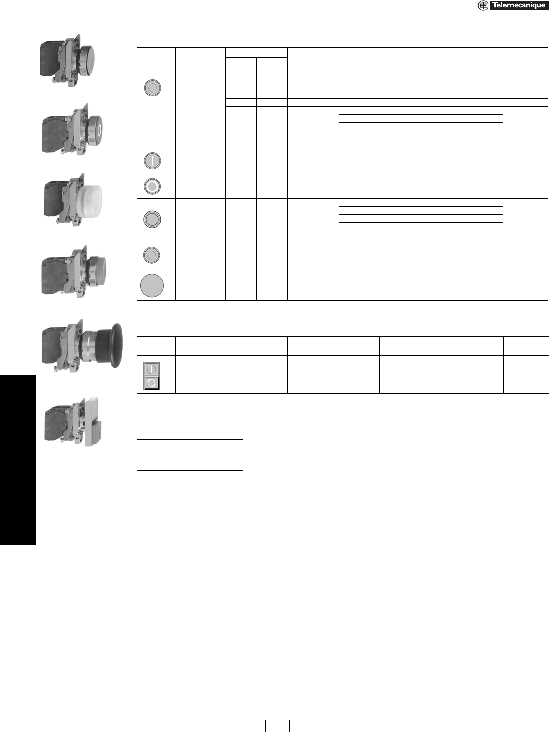
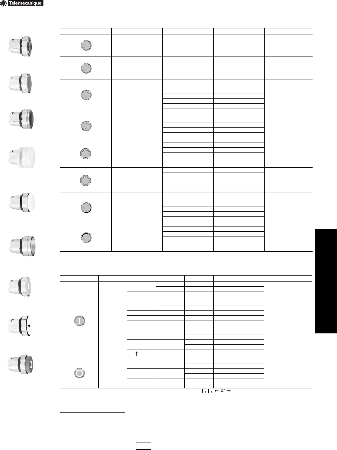
22 mm Push Buttons XB4 Complete Devices
Refer to Catalog 9001CT0001
Legends . . . . . . . . . . . . . . . . . . . . . . . . . . . . . . . . . . . . pages 19-29 to 19-31
Table 19.50: Non-Illuminated Push Buttons, Momentary (screw clamp terminal connections)
Shape of
Head Type of Push Type of Contact Marking Color of Cap Catalog Number (Components) $ Price
N.O. N.C.
Flush
1— —
Black XB4BA21 (ZB4BZ101 + ZB4BA2)
35.00
Green XB4BA31 (ZB4BZ101 + ZB4BA3)
Yellow XB4BA51 (ZB4BZ101 + ZB4BA5)
Blue XB4BA61 (ZB4BZ101 + ZB4BA6)
—1 — RedXB4BA42 (ZB4BZ102 + ZB4BA4) 35.00
11 —
Black XB4BA25 (ZB4BZ105 + ZB4BA2)
51.00
Green XB4BA35 (ZB4BZ105 + ZB4BA3)
Red XB4BA45 (ZB4BZ105 + ZB4BA4)
Yellow XB4BA55 (ZB4BZ105 + ZB4BA5)
Blue XB4BA65 (ZB4BZ105 + ZB4BA6)
Flush 1 — “I”
(white) Green XB4BA3311 (ZB4BZ101 + ZB4BA331) 40.60
Flush — 1 “O”
(white) Red XB4BA4322 (ZB4BZ102 + ZB4BA432) 40.60
Flush with clear
silicone boot
(color of pusher
unobscured)
1— —
Black XB4BP21 (ZB4BZ101 + ZB4BP2)
47.80
Green XB4BP31 (ZB4BZ101 + ZB4BP3)
Yellow XB4BP51 (ZB4BZ101 + ZB4BP5)
Blue XB4BP61 (ZB4BZ101 + ZB4BP6)
—1 — RedXB4BP42 (ZB4BZ102 + ZB4BP4) 47.80
Extended
—1 — Red XB4BL42 (ZB4BZ102 + ZB4BL4) 35.00
11 — RedXB4BL45 (ZB4BZ105 + ZB4BL4) 51.00
Mushroom head
Ø 40 mm 1— — BlackXB4BC21 (ZB4BZ101 + ZB4BC2) 51.00
Table 19.51: Two Button Push Buttons, Momentary (screw clamp terminal connections)
Shape of
Head Type of Push Type of Contact Degree of Protection Catalog Number (Components) $ Price
N.O. N.C.
One flush green
push
(marked “I”)
One extended
red push
(marked “O”)
11 IP40 XB4BL845 (ZB4BZ105 + ZB4BL8434) 63.00
When ordering, please specify:
•Quantity
•Catalog Number
XB4BA31
XB4BA4322
XB4BP51
XB4BL42
XB4BC21
XB4BL845
IDiscount
Schedule
www.us.schneider-electric.com
FOR CURRENT INFORMATION
19 PUSH BUTTONS AND
OPERATOR INTERFACE
© 2007 Schneider Electric
All Rights Reserved 19-17
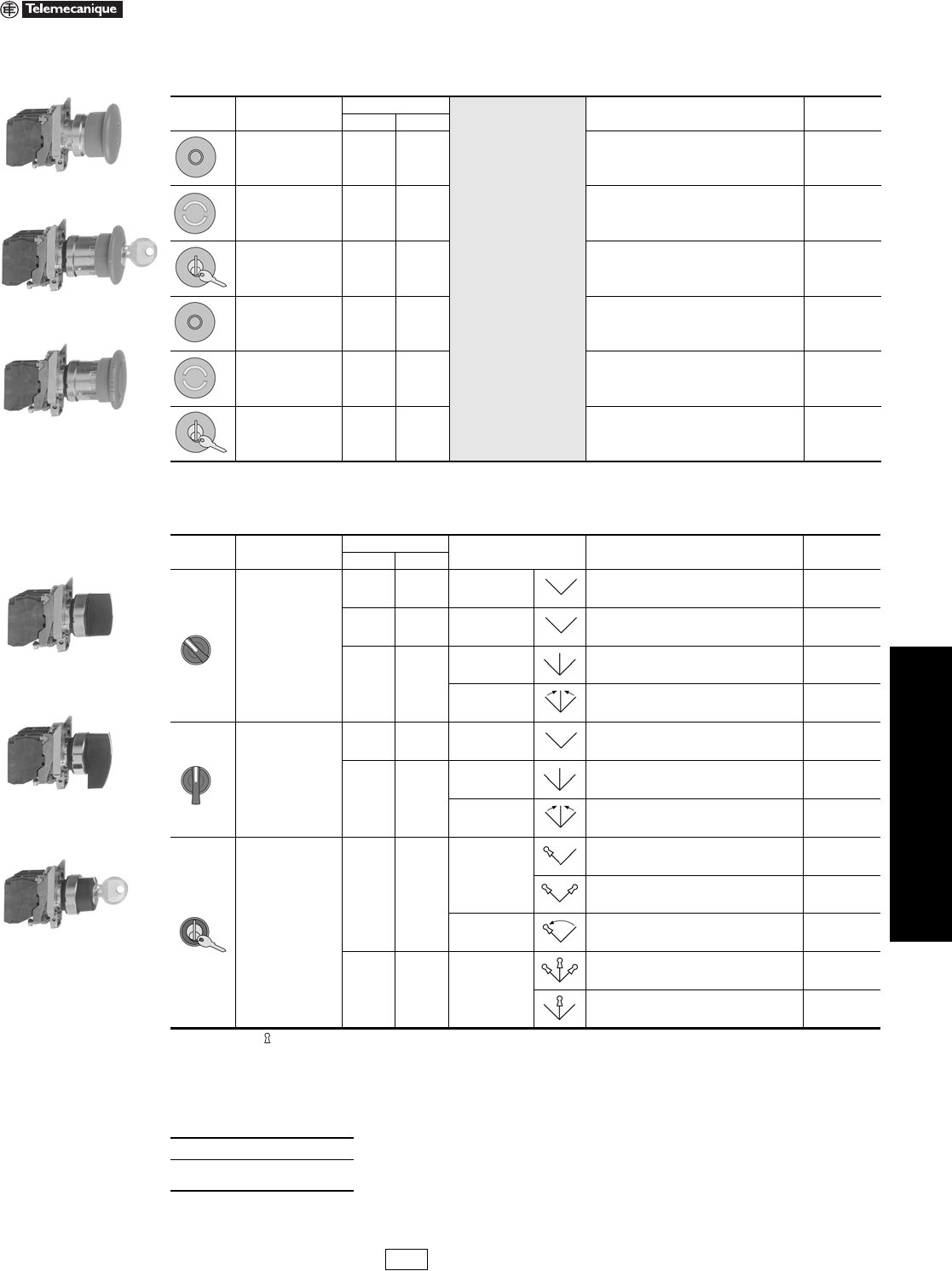
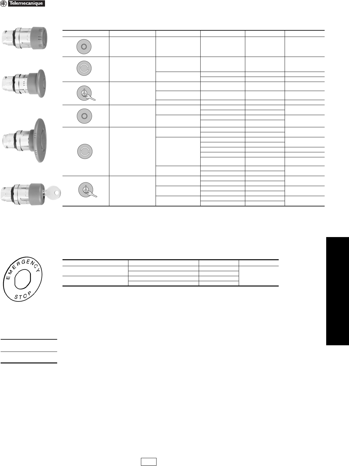
22 mm Push Buttons XB4 Complete Devices
Refer to Catalog 9001CT0001
aTrigger action mushroom heads are tamper proof in that a change of contact state is not possible by teasing or floating the operator.
Note: The symbol indicates key withdrawal position(s).
bSee page 19-22 for contact configurations.
Legends. . . . . . . . . . . . . . . . . . . . . . . . . . . . . . . . . . . . . pages 19-29 to 19-31
Table 19.52: Non-Illuminated Emergency Stop Mushroom Head Push Buttons, Ø 40 mm (Red)
(screw clamp terminal connections)
Shape of
Head Type of Push Type of Contact Catalog Number (Components) $ Price
N.O. N.C.
Trigger action
push-pulla11 XB4BT845 (ZB4BZ105 + ZB4BT84) 92.00
Trigger action
turn-to-releasea11 XB4BS8445 (ZB4BZ105 + ZB4BS844) 150.00
Trigger action
Key release a
(No. 455)
11 XB4BS9445 (ZB4BZ105 + ZB4BS944) 150.00
Push-pull — 1 XB4BT42 (ZB4BZ102 + ZB4BT4) 62.00
Turn-to-release — 1 XB4BS542 (ZB4BZ102 + ZB4BS54) 100.00
Key release
(No. 455) —1 XB4BS142 (ZB4BZ102 + ZB4BS14) 134.00
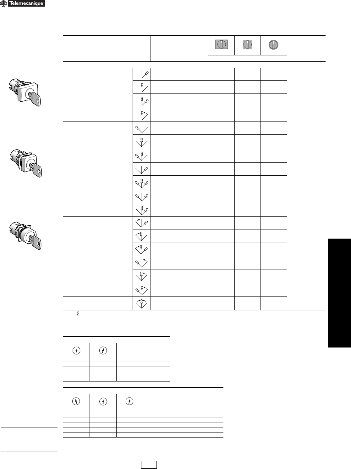
Table 19.53: Non-Illuminated Selector Switches and Key Switches (screw clamp terminal connections)b
Shape of
Head Type of Operator Type of Contact Number and Type of
Positions Catalog Number (Components) $ Price
N.O. N.C.
Standard lever, black
1 — 2-maintained XB4BD21 (ZB4BZ101 + ZB4BD2) 46.00
1 1 2-maintained XB4BD25 (ZB4BZ105 + ZB4BD2) 62.00
2—
3-maintained XB4BD33 (ZB4BZ103 + ZB4BD3) 62.00
3-momentary to
center XB4BD53 (ZB4BZ103 + ZB4BD5) 68.00
Extended lever, black
1 — 2-maintained XB4BJ21 (ZB4BZ101 + ZB4BJ2) 46.00
2—
3-maintained XB4BJ33 (ZB4BZ103 + ZB4BJ3) 62.00
3-momentary to
center XB4BJ53 (ZB4BZ103 + ZB4BJ5) 68.00
Key (No. 455)
1—
2-maintained
XB4BG21 (ZB4BZ101 + ZB4BG2) 112.00
XB4BG41 (ZB4BZ101 + ZB4BG4) 112.00
2-momentary to
left XB4BG61 (ZB4BZ101 + ZB4BG6) 112.00
2 — 3-maintained
XB4BG03 (ZB4BZ103 + ZB4BG0) 128.00
XB4BG33 (ZB4BZ103 + ZB4BG3) 128.00
When ordering, please specify:
•Quantity
•Catalog Number
XB4BT845
XB4BS9445
XB4BS542
XB4BG33
XB4BD33
XB4BJ33
IDiscount
Schedule
19-18 © 2007 Schneider Electric
All Rights Reserved
www.us.schneider-electric.com
FOR CURRENT INFORMATION
19 PUSH BUTTONS AND
OPERATOR INTERFACE
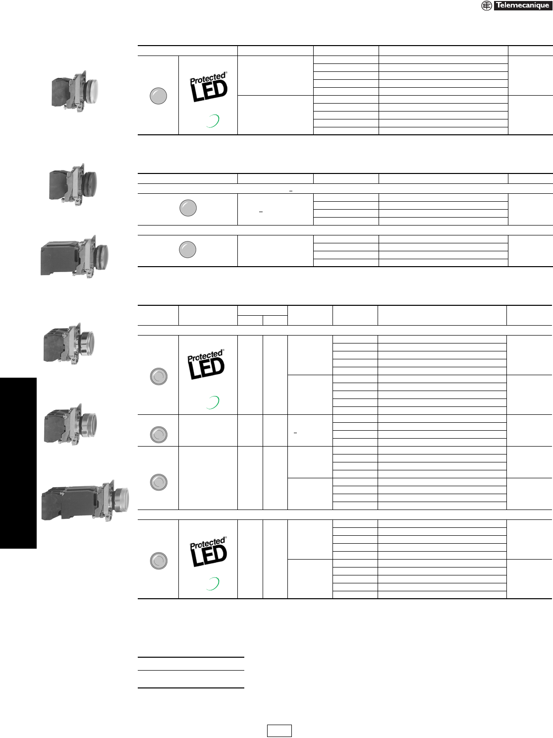
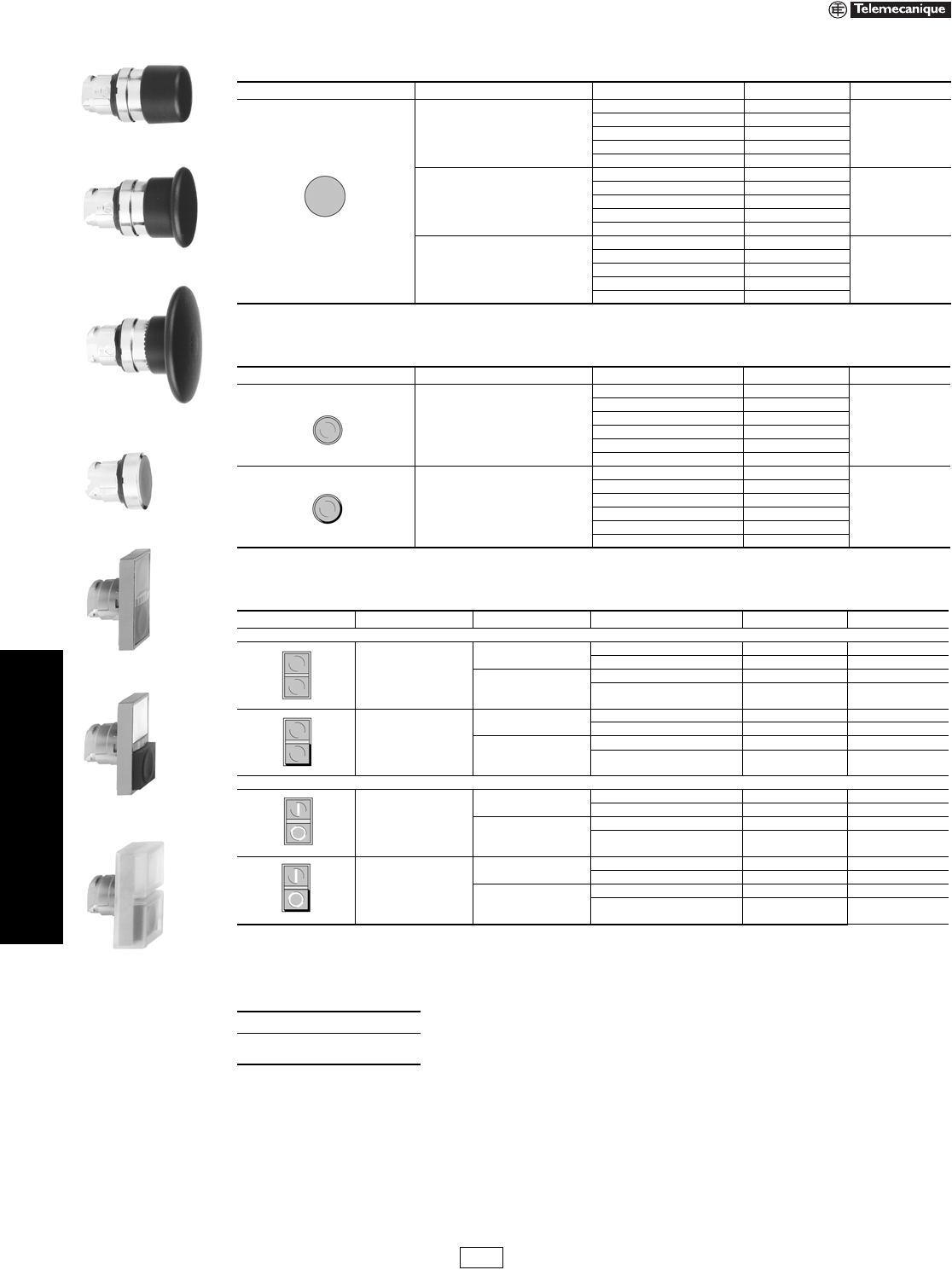
22 mm Push Buttons XB4 Complete Devices
Refer to Catalog 9001CT0001
aFor 240 V LED, replace the last “B” or “G” in the catalog number with an “M”. For example, XB4BVB1 (24 V) becomes XB4BVM1 (240 V).
Legends . . . . . . . . . . . . . . . . . . . . . . . . . . . . . . . . . . . . pages 19-29 to 19-31
Table 19.54: Pilot Lights with Protected LED® (screw clamp terminal connections) a
Shape of Head Supply Voltage Color Catalog Number (Components) $ Price
24 Vac/dc
White XB4BVB1 (ZB4BVB1 + ZB4BV013)
65.00
Green XB4BVB3 (ZB4BVB3 + ZB4BV033)
Red XB4BVB4 (ZB4BVB4 + ZB4BV043)
Ye l l o w XB4BVB5 (ZB4BVB5 + ZB4BV053)
Blue XB4BVB6 (ZB4BVB6 + ZB4BV063)
110–120 Vac
White XB4BVG1 (ZB4BVG1 + ZB4BV013)
65.00
Green XB4BVG3 (ZB4BVG3 + ZB4BV033)
Red XB4BVG4 (ZB4BVG4 + ZB4BV043)
Ye l l o w XB4BVG5 (ZB4BVG5 + ZB4BV053)
Blue XB4BVG6 (ZB4BVG6 + ZB4BV063)
Table 19.55: Pilot Lights for BA9s Bulb (screw clamp terminal connections)
Shape of Head Supply Voltage Color Catalog Number (Components) $ Price
Direct supply, for BA9s (incandescent, LED, neon) V < 250 V, 2.4 W bulb (bulb not included)
< 250 Vac/dc
White XB4BV61 (ZB4BV6 + ZB4BV01)
46.20
Green XB4BV63 (ZB4BV6 + ZB4BV03)
Red XB4BV64 (ZB4BV6 + ZB4BV04)
Ye l l o w XB4BV65 (ZB4BV6 + ZB4BV05)
Transformer type with 1.2 VA, 6 V secondary. BA9s incandescent bulb included
110–120 Vac
50/60 Hz
White XB4BV31 (ZB4BV3 + ZB4BV01)
106.00
Green XB4BV33 (ZB4BV3 + ZB4BV03)
Red XB4BV34 (ZB4BV3 + ZB4BV04)
Ye l l o w XB4BV35 (ZB4BV3 + ZB4BV05)
Table 19.56: Illuminated Push Buttons, Momentary (screw clamp terminal connections) a
Shape of Head Description Type of Contact Supply Voltage Color of Push Catalog Number (Components) $ Price
N.O. N.C.
Flush
11
24 Vac/dc
White XB4BW31B5 (ZB4BW0B15 + ZB4BW313)
108.00
Green XB4BW33B5 (ZB4BW0B35 + ZB4BW333)
Red XB4BW34B5 (ZB4BW0B45 + ZB4BW343)
Yellow XB4BW35B5 (ZB4BW0B55 + ZB4BW353)
Blue XB4BW36B5 (ZB4BW0B65 + ZB4BW363)
110–120 Vac
White XB4BW31G5 (ZB4BW0G15 + ZB4BW313)
108.00
Green XB4BW33G5 (ZB4BW0G35 + ZB4BW333)
Red XB4BW34G5 (ZB4BW0G45 + ZB4BW343)
Yellow XB4BW35G5 (ZB4BW0G55 + ZB4BW353)
Blue XB4BW36G5 (ZB4BW0G65 + ZB4BW363)
Direct supply
for BA9s
2.4 W max.
bulb not
included
11< 250 Vac/dc
White XB4BW3165 (ZB4BW065 + ZB4BW31)
90.00
Green XB4BW3365 (ZB4BW065 + ZB4BW33)
Red XB4BW3465 (ZB4BW065 + ZB4BW34)
Yellow XB4BW3565 (ZB4BW065 + ZB4BW35)
Transformer
type
1.2 VA, 6 V secondary.
BA9s incandescent
bulb
included
11
110–120 Vac
50/60 Hz
White XB4BW3135 (ZB4BW035 + ZB4BW31)
148.00
Green XB4BW3335 (ZB4BW035 + ZB4BW33)
Red XB4BW3435 (ZB4BW035 + ZB4BW34)
Yellow XB4BW3535 (ZB4BW035 + ZB4BW35)
230–240 Vac
50/60 Hz
White XB4BW3145 (ZB4BW045 + ZB4BW31)
148.00
Green XB4BW3345 (ZB4BW045 + ZB4BW33)
Red XB4BW3445 (ZB4BW045 + ZB4BW34)
Yellow XB4BW3545 (ZB4BW045 + ZB4BW35)
Extended
11
24 Vac/dc
White XB4BW11B5 (ZB4BW0B15 + ZB4BW113)
103.00
Green XB4BW13B5 (ZB4BW0B35 + ZB4BW133)
Red XB4BW14B5 (ZB4BW0B45 + ZB4BW143)
Yellow XB4BW15B5 (ZB4BW0B55 + ZB4BW153)
Blue XB4BW16B5 (ZB4BW0B65 + ZB4BW163)
110–120 Vac
White XB4BW11G5 (ZB4BW0G15 + ZB4BW113)
103.00
Green XB4BW13G5 (ZB4BW0G35 + ZB4BW133)
Red XB4BW14G5 (ZB4BW0G45 + ZB4BW143)
Yellow XB4BW15G5 (ZB4BW0G55 + ZB4BW153)
Blue XB4BW16G5 (ZB4BW0G65 + ZB4BW163)
When ordering, please specify:
•Quantity
•Catalog Number
XB4BVB5
New!
XB4BV64
XB4BV33
XB4BW33B5
XB4BW3465
XB4BW3545
New!
New!
IDiscount
Schedule
www.us.schneider-electric.com
FOR CURRENT INFORMATION
19 PUSH BUTTONS AND
OPERATOR INTERFACE
© 2007 Schneider Electric
All Rights Reserved 19-19
22 mm Push Buttons XB4 Operators
Refer to Catalog 9001CT0001
aColor cap to be ordered separately, see page 19-31.
bFor legend ordering information, see page 19-31.
cCap supplied not clipped-in, allowing orientation of arrow in any one of 4 directions:
Legends. . . . . . . . . . . . . . . . . . . . . . . . . . . . . . . . . . . . . pages 19-29 to 19-31
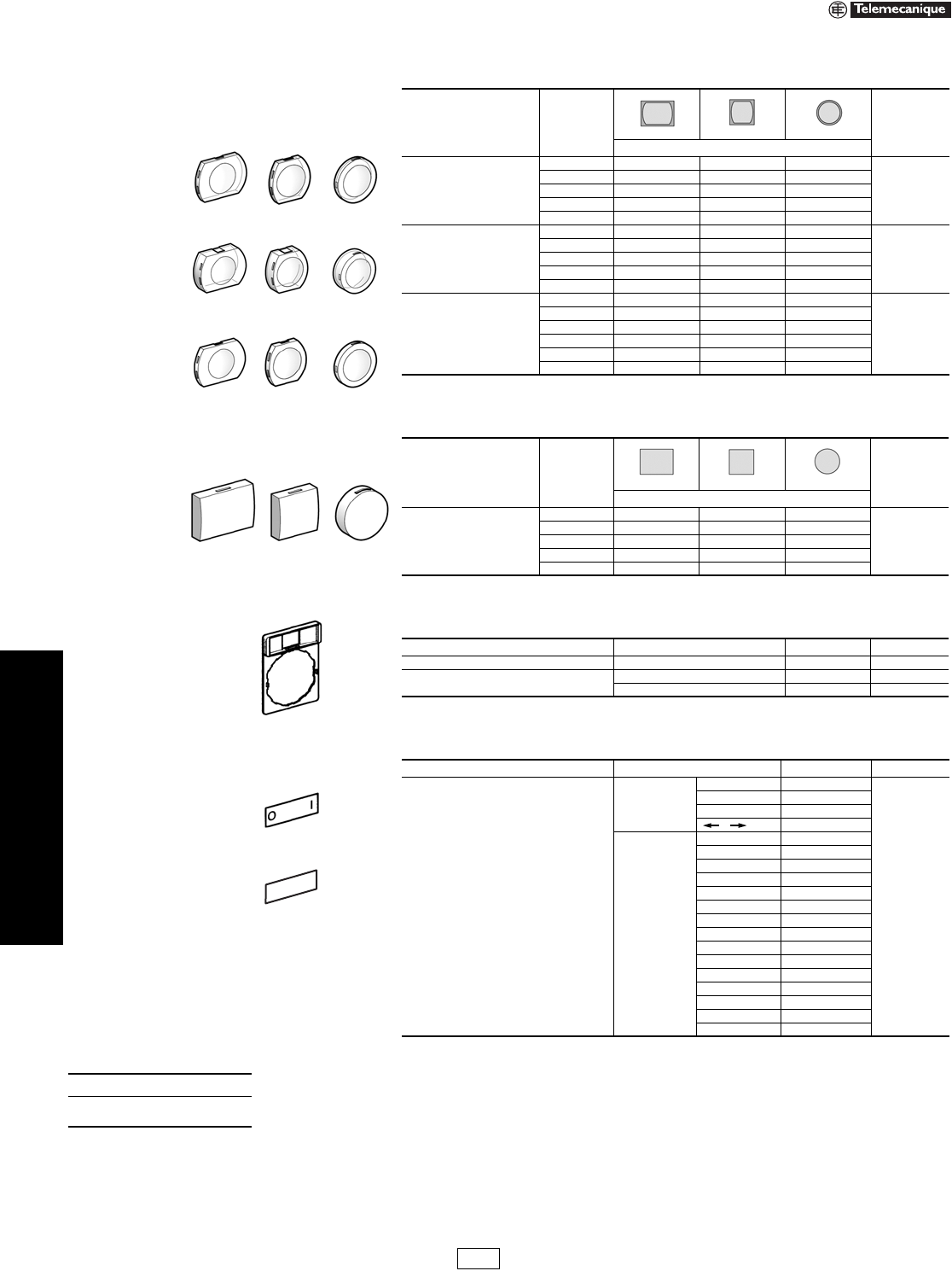
Table 19.57: Non-Illuminated Operators, Momentary—Unmarked
Shape of Head Type of Push Color of Cap Catalog Number $ Price
Flush, without color cap a—ZB4BA0 11.00
Flush, with set of 6 color caps
White
Black
Green
Red
Ye l l o w
Blue
ZB4BA9 13.00
Flush
White ZB4BA1
13.00
Black ZB4BA2
Green ZB4BA3
Red ZB4BA4
Ye l l o w ZB4BA5
Blue ZB4BA6
Gray ZB4BA8
Flush with transparent cap,
for insertion of legend b
White ZB4BA18
16.00
Green ZB4BA38
Red ZB4BA48
Ye l l o w ZB4BA58
Blue ZB4BA68
Booted (clear)
Color of cap unobscured
White ZB4BP1
25.80
Black ZB4BP2
Green ZB4BP3
Red ZB4BP4
Ye l l o w ZB4BP5
Blue ZB4BP6
Booted (clear)
for insertion of legend b
Color of cap unobscured
White ZB4BP18
29.00
Green ZB4BP38
Red ZB4BP48
Ye l l o w ZB4BP58
Blue ZB4BP68
Extended
White ZB4BL1
13.00
Black ZB4BL2
Green ZB4BL3
Red ZB4BL4
Ye l l o w ZB4BL5
Blue ZB4BL6
Guarded Head
White ZB4BA16
35.00
Black ZB4BA26
Green ZB4BA36
Red ZB4BA46
Ye l l o w ZB4BA56
Blue ZB4BA66
Table 19.58: Non-Illuminated Operators, Momentary—Premarked
Shape of Head Type of Push Marking Text Color Color of Cap Catalog Number $ Price
Flush
IWhite Green ZB4BA331
18.60
Black White ZB4BA131
START White Green ZB4BA333
Black White ZB4BA133
ON White Green ZB4BA341
Black White ZB4BA141
RESET White Black ZB4BA222
JOG White Black ZB4BA245
OWhite
Red ZB4BA432
Black ZB4BA232
STOP White Red ZB4BA434
Black ZB4BA234
OFF White Red ZB4BA435
Black ZB4BA235
cBlack White ZB4BA334
White Black ZB4BA335
Extended
OWhite
Red ZB4BL432
18.60
Black ZB4BL232
STOP White Red ZB4BL434
Black ZB4BL234
OFF White Red ZB4BL435
Black ZB4BL235
When ordering, please specify:
•Quantity
•Catalog Number
ZB4BA0
ZB4BP18
ZB4BL1
ZB4BA4
ZB4BA38
ZB4BA36
ZB4BA331
ZB4BA334
ZB4BL432
IDiscount
Schedule
19-20 © 2007 Schneider Electric
All Rights Reserved
www.us.schneider-electric.com
FOR CURRENT INFORMATION
19 PUSH BUTTONS AND
OPERATOR INTERFACE
22 mm Push Buttons XB4 Operators
Refer to Catalog 9001CT0001
aIP66 version utilizes boot (included).
Legends . . . . . . . . . . . . . . . . . . . . . . . . . . . . . . . . . . . . pages 19-29 to 19-31
Table 19.59: Mushroom Heads, Momentary
Shape of Head Diameter of Head Color of Head Catalog Number $ Price
30 mm
Black ZB4BC24
29.40
Green ZB4BC34
Red ZB4BC44
Ye l l o w ZB4BC54
Blue ZB4BC64
40 mm
Black ZB4BC2
29.40
Green ZB4BC3
Red ZB4BC4
Ye l l o w ZB4BC5
Blue ZB4BC6
60 mm
Black ZB4BR2
35.00
Green ZB4BR3
Red ZB4BR4
Ye l l o w ZB4BR5
Blue ZB4BR6
Table 19.60: Non-Illuminated Push-on/Push-off Operators
Shape of Head Type of Push Color of Push Catalog Number $ Price
Flush
White ZB4BH01
17.60
Black ZB4BH02
Green ZB4BH03
Red ZB4BH04
Yellow ZB4BH05
Blue ZB4BH06
Extended
White ZB4BH1
17.60
Black ZB4BH2
Green ZB4BH3
Red ZB4BH4
Yellow ZB4BH5
Blue ZB4BH6
Table 19.61: Two Head Operators, Momentary
Shape of Head Description Color of Pushers Degree of ProtectionaCatalog Number $ Price
No Marking
Two flush
Green IP40 ZB4BA8134 20.80
Red IP66 ZB4BA9134 37.20
White IP40 ZB4BA8112 20.80
Black IP66 ZB4BA9112 37.20
One flush
One extended
Green IP40 ZB4BL8334 20.80
Red IP66 ZB4BL9334 37.20
White IP40 ZB4BL8312 20.80
Black IP66 ZB4BL9312 37.20
Premarked
Two f l ush
(marked “I”)
(marked “O”)
Green IP40 ZB4BA8234 24.80
Red IP66 ZB4BA9234 41.40
White IP40 ZB4BA8212 24.80
Black IP66 ZB4BA9212 41.40
One flush
(marked “I”)
One extended
(marked “O”)
Green IP40 ZB4BL8434 24.80
Red IP66 ZB4BL9434 41.40
White IP40 ZB4BL8412 24.80
Black IP66 ZB4BL9412 41.40
When ordering, please specify:
•Quantity
•Catalog Number
ZB4BR2
ZB4BC24
ZB4BC2
ZB4BH02
ZB4BA8134
ZB4BL8312
ZB4BL9312
IDiscount
Schedule
www.us.schneider-electric.com
FOR CURRENT INFORMATION
19 PUSH BUTTONS AND
OPERATOR INTERFACE
© 2007 Schneider Electric
All Rights Reserved 19-21
22 mm Push Buttons XB4 Emergency Stop Operators
Refer to Catalog 9001CT0001
aTrigger action mushroom heads are tamper proof in that a change of contact state is not possible by teasing or floating the operator.
bOther key numbers:
—key no. 421E: add the suffix 12 to the catalog number.
—key no. 458A: add the suffix 10 to the catalog number.
—key no. 520E: add the suffix 14 to the catalog number.
—key no. 3131A: add the suffix 20 to the catalog number.
Example: The catalog number for a head with key No. 421E for a 2 position maintained, lockable selector switch, with key withdrawal from the left-hand
position, becomes: ZB4BG212.
Legends. . . . . . . . . . . . . . . . . . . . . . . . . . . . . . . . . . . . . pages 19-29 to 19-31
Table 19.62: Mushroom Heads for Maintained Push Buttons
Shape of Head Type of Push Diameter of Head Color Catalog Number $ Price
Trigger action
Push-pull a40 mm Red ZB4BT84 54.00
Trigger action
Turn-to-release a
30 mm Red ZB4BS834 112.00
40 mm Red ZB4BS844 112.00
Red marked “EMO” ZB4BS84430 118.00
Trigger action
Key release
(No. 455) a
30 mm Red ZB4BS934 112.00
40 mm Red ZB4BS944 b112.00
60 mm Red ZB4BS964 112.00
Push-pull
40 mm Black ZB4BT2 40.40
Red ZB4BT4
60 mm
Black ZB4BX2 46.00
Red ZB4BX4
Turn-to-release
30 mm Black ZB4BS42 78.00
Red ZB4BS44
40 mm
Black ZB4BS52 78.00
Red ZB4BS54
Red marked “EMO” ZB4BS5430 85.00
Ye l l o w ZB4BS55 78.00
Yellow marked
“Robot Stop” ZB4BS5550 85.00
60 mm Black ZB4BS62 90.00
Red ZB4BS64
Key release
(No. 455)
30 mm Black ZB4BS72 112.00
Red ZB4BS74
40 mm Black ZB4BS12 112.00
Red ZB4BS14 b
60 mm Black ZB4BS22 112.00
Red ZB4BS24
Table 19.63: Circular Legends for Emergency Stop Mushroom Heads (yellow background)
Diameter Text Catalog Number $ Price
60 mm Blank ZBY9101
3.40
EMERGENCY STOP ZBY9330
90 mm Blank ZBY8101
EMERGENCY STOP ZBY8330
ZB4BS834
ZB4BT4
ZB4BS64
ZB4BS74
ZBY9330
When ordering,
please specify:
•Quantity
•Catalog Number
IDiscount
Schedule
19-22 © 2007 Schneider Electric
All Rights Reserved
www.us.schneider-electric.com
FOR CURRENT INFORMATION
19 PUSH BUTTONS AND
OPERATOR INTERFACE
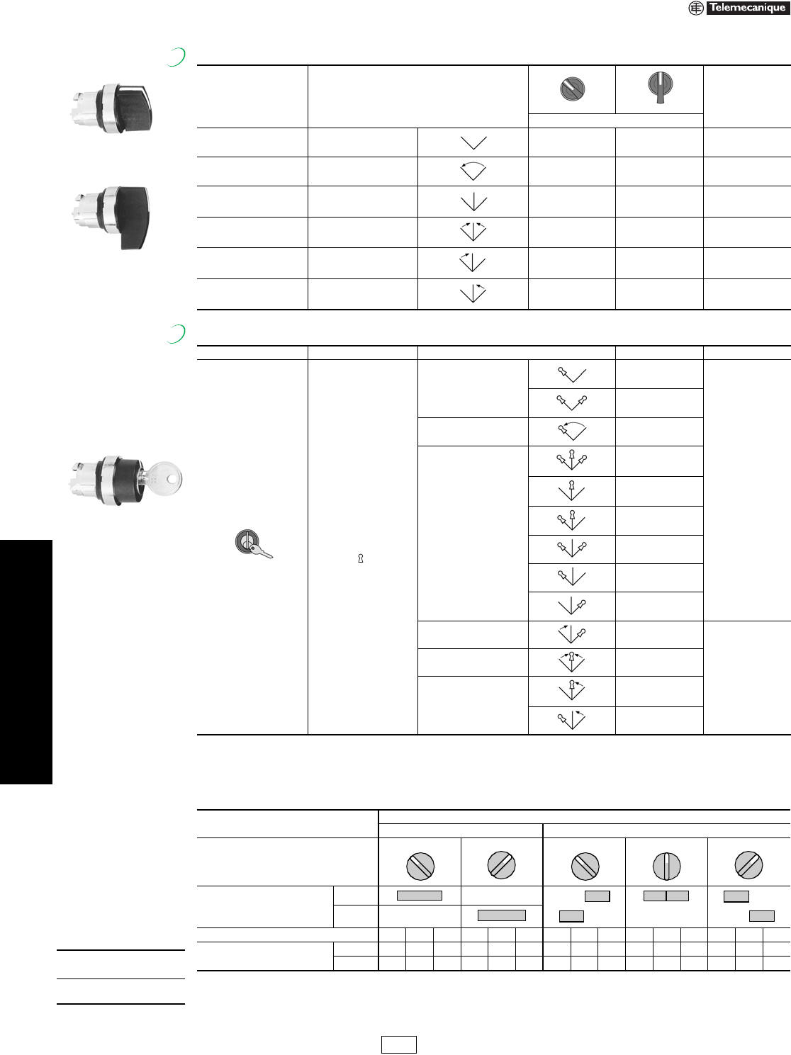
22 mm Push Buttons XB4 Selector Switches
Refer to Catalog 9001CT0001
aFor colored lever, add the following code to the end of part number: 01–white, 03–green, 04–red, 05–yellow, 06–blue (Example: ZB4BD204).
Legends . . . . . . . . . . . . . . . . . . . . . . . . . . . . . . . . . . . . pages 19-29 to 19-31
Table 19.64: Non-Illuminated Selector Switches b
Color Number and Type of Positions
Standard Lever aExtended Lever
$ Price
Catalog Number
Black 2-maintained ZB4BD2 ZB4BJ2 24.00
Black 2-momentary from
right to left ZB4BD4 ZB4BJ4 29.40
Black 3-maintained ZB4BD3 ZB4BJ3 24.00
Black 3-momentary to center ZB4BD5 ZB4BJ5 29.40
Black 3-momentary from
left to center ZB4BD7 ZB4BJ7 29.40
Black 3-momentary from
right to center ZB4BD8 ZB4BJ8 29.40
Table 19.65: Non-Illuminated Key Switches b
Shape of Head Type of Operator Number and Type of Positions Catalog Number $ Price
Key (No. 455) c
Note:
The symbol indicates the
key withdrawal position(s).
2-maintained
ZB4BG2
90.00
ZB4BG4
2-momentary from
right to left ZB4BG6
3-maintained
ZB4BG0
ZB4BG3
ZB4BG03
ZB4BG5
ZB4BG9
ZB4BG09
3-momentary from
left to center ZB4BG1
116.00
3-momentary to center ZB4BG7
3-momentary from right to
center
ZB4BG8
ZB4BG08
bSee Table 19.66 for contact configurations.
cOther key numbers: —key no. 421E: add the suffix 12 to the catalog number.
—key no. 458A: add the suffix 10 to the catalog number.
—key no. 520E: add the suffix 14 to the catalog number.
—key no. 3131A: add the suffix 20 to the catalog number.
Example: The catalog number for a head with key no. 421E for a 2 position maintained, lockable selector switch, with key withdrawal from the left-hand position,
becomes: ZB4BG212.
ZB4BD4
Standard Lever
ZB4BJ3
Extended Lever
New!
ZB4BG8
New!
When ordering,
please specify:
•Quantity
•Catalog Number
Table 19.66: Sequence of Contacts on Selector Switch Bodies
Unit Type Selector Switches
2-position 3-position
Operator Plunger Position
Up
Down
Contact Block Location L C R L C R L C R L C R L C R
Contacts N/O OOOXXXXXOOOOOXX
N/C XXXOOOOOXXXXXOO
Note: L=Left, C=Center, R=Right, O=Open, X=Closed
315° 45° 315° 0° 45°
IDiscount
Schedule
www.us.schneider-electric.com
FOR CURRENT INFORMATION
19 PUSH BUTTONS AND
OPERATOR INTERFACE
© 2007 Schneider Electric
All Rights Reserved 19-23
22 mm Push Buttons XB4 Specialty Operators
Refer to Catalog 9001CT0001
aDo not use standard contact blocks ZBE10• (single) or ZBE20• (double).
Legends. . . . . . . . . . . . . . . . . . . . . . . . . . . . . . . . . . . . . pages 19-29 to 19-31
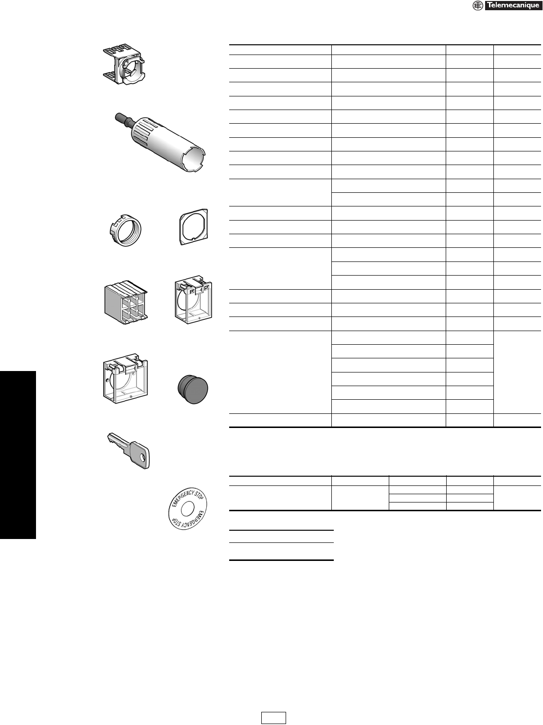
Table 19.67: Potentiometer Operator (with Mounting Collar)
Shape of Head Description Application Catalog Number $ Price
For potentiometer with
shaft length 1.73 to 1.97 in.
(44 to 50 mm)
(potentiometer not included)
For shaft Ø 1/4 in. (6.35 mm) ZB4BD922
142.00
For shaft Ø 0.24 in. (6 mm) ZB4BD912
Table 19.68: Joysticks (54 mm, Extended Operating Shaft) a
Description Contact Operation Action Catalog Number $ Price
2 direction 1 step 1 N.O. contact per direction
Maintained XD4PA12
250.00
Momentary XD4PA22
4 direction 1 step 1 N.O. contact per direction
Maintained XD4PA14
316.00
Momentary XD4PA24
Table 19.69: Legends for Joysticks
Description For use with Color Catalog Number $ Price
Legends
30 x 48 mm for customer engraving 2 direction
Black one side
Red reverse ZBG2201
3.40
White one side
Yellow reverse ZBG2401
Legends
48 x 48 mm for customer engraving 4 direction
Black one side
Red reverse ZBG4201
White one side
Yellow reverse ZBG4401
Table 19.70: Two Position Toggle Switch
Shape of Head Color Type of Positions Catalog Number $ Price
Black Maintained ZB4BD28
46.60
Black Momentary ZB4BD48
ZB4BD922
XD4PA12
ZB4BD28
XB4BA8•1
Table 19.71: Reset Operators, Flush, Adjustable Shaft
Shape of Head Travel Actuation Distance Color Catalog Number $ Price
in. mm in. mm
0.39 10
0.24–0.63 6–16
Black XB4BA821
27.40Red XB4BA841
Blue XB4BA861
0.63–1.02 16–26
Black XB4BA822
27.40Red XB4BA842
Blue XB4BA862
0.55 14
1.18–5.12 30–130
Black XB4BA921
32.80Red XB4BA941
Blue XB4BA961
5.12–10.12 130–257
Black XB4BA922
41.00Red XB4BA942
Blue XB4BA962
When ordering, please specify:
•Quantity
•Catalog Number
IDiscount
Schedule
19-24 © 2007 Schneider Electric
All Rights Reserved
www.us.schneider-electric.com
FOR CURRENT INFORMATION
19 PUSH BUTTONS AND
OPERATOR INTERFACE
22 mm Push Buttons XB4 Pilot Lights
Refer to Catalog 9001CT0001
aFor use in bright ambient conditions, for example, in sunlight.
bOrder bulb separately; see page 19-32. For BA9 LED, see page 19-120.
cFor 240 V LED, replace the last “B” or “G” in the catalog number with an “M”. For example, ZB4BVB1 (24 V) becomes ZB4BVM1 (240 V).
dFor Quick-Connect version, add “3” to the end of the catalog number Example: ZB4BVJ13 (Quick-Connect size 1 x 1/40" or 2 x 0.110").
Legends . . . . . . . . . . . . . . . . . . . . . . . . . . . . . . . . . . . . pages 19-29 to 19-31
Table 19.72: Pilot Light Heads
Shape of Head
For Use with Body
Comprising Light
Module Type
Color of Lens Catalog Number $ Price
Protected LED® only
White ZB4BV013
7.60
Green ZB4BV033
Red ZB4BV043
Yellow ZB4BV053
Blue ZB4BV063
Protected LED only
Fresnel (jeweled) lens a
White ZB4BV013S
7.60
Green ZB4BV033S
Red ZB4BV043S
Amber ZB4BV053S
Blue ZB4BV063S
For BA9s incandescent
bulb, neon or LED only b
White ZB4BV01
7.60
Green ZB4BV03
Red ZB4BV04
Yellow ZB4BV05
Blue ZB4BV06
Clear ZB4BV07
For BA9s incandescent
bulb, neon or LED
Fresnel (jeweled) lens b
White ZB4BV01S
7.60
Green ZB4BV03S
Red ZB4BV04S
Amber ZB4BV05S
Blue ZB4BV06S
Clear ZB4BV07S
Table 19.73: Complete Bodies (Mounting Collar + Light Module for BA9s Incandescent Bulb, Neon or LED)
Description Light Source Supply Voltage (V) Catalog Number $ Price
Screw clamp terminal connections
Direct supply BA9s bulb 2.4 W max.
Not included b<250 ZB4BV6 38.60
Direct supply BA9s incandescent
bulb included 24 v 2 Watt ZB4BV624 49.20
Direct supply BA9s incandescent
bulb included 120 v 2.4 Watt ZB4BV6120 49.20
Transformer type
1.2 VA, 6 V secondary
BA9s incandescent
bulb included
110–120 Vac
50/60 Hz ZB4BV3
98.00
230–240 Vac
50/60 Hz ZB4BV4
400–50 Hz ZB4BV5
440–480 Vac
60 Hz ZB4BV8
550–600 Vac
60 Hz ZB4BV9
Table 19.74: Complete Bodies (Mounting Collar + Light Module with Protected LED®) c
Light Source Supply Voltage Color of Light Source Catalog Number $ Price
Screw clamp terminal connections d
12 Vac/dc
White ZB4BVJ1
57.00
Green ZB4BVJ3
Red ZB4BVJ4
Yellow ZB4BVJ5
Blue ZB4BVJ6
24 Vac/dc
White ZB4BVB1
57.00
Green ZB4BVB3
Red ZB4BVB4
Yellow ZB4BVB5
Blue ZB4BVB6
24–120 Vac/dc
White ZB4BVBG1
57.00
Green ZB4BVBG3
Red ZB4BVBG4
Yellow ZB4BVBG5
Blue ZB4BVBG6
110–120 Vac
White ZB4BVG1
57.00
Green ZB4BVG3
Red ZB4BVG4
Yellow ZB4BVG5
Blue ZB4BVG6
Flashing 24 Vac/dc
White ZB4BV18B1
66.00
Green ZB4BV18B3
Red ZB4BV18B4
Yellow ZB4BV18B5
Blue ZB4BV18B6
110–120 Vac
White ZB4BV18G1
66.00
Green ZB4BV18G3
Red ZB4BV18G4
Yellow ZB4BV18G5
Blue ZB4BV18G6
When ordering, please specify:
•Quantity
•Catalog Number
ZB4BV063
ZB4BV04
ZB4BV043S
ZB4BV6
ZB4BV•
ZB4BV••
New!
IDiscount
Schedule
www.us.schneider-electric.com
FOR CURRENT INFORMATION
19 PUSH BUTTONS AND
OPERATOR INTERFACE
© 2007 Schneider Electric
All Rights Reserved 19-25
22 mm Push Buttons XB4 Illuminated Operators
Refer to Catalog 9001CT0001
Legends. . . . . . . . . . . . . . . . . . . . . . . . . . . . . . . . . . . . . pages 19-29 to 19-31
ZB4BW333
ZB4BW563
ZB4BW113
ZB4BW33
ZB4BW14
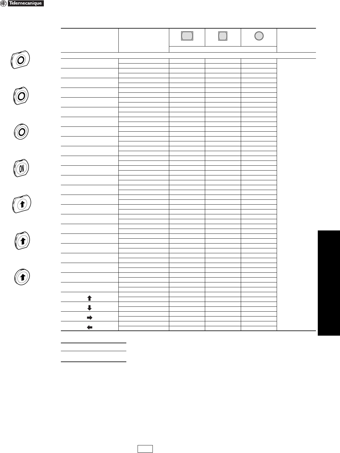
Table 19.75: Heads for Momentary Illuminated Push Buttons
Shape of Head Type of Push Color Catalog Number $ Price
Only use with Protected LED® light modules
Flush
White ZB4BW313
18.60
Green ZB4BW333
Red ZB4BW343
Ye l l o w ZB4BW353
Blue ZB4BW363
Flush with clear boot
White ZB4BW513
31.00
Green ZB4BW533
Red ZB4BW543
Ye l l o w ZB4BW553
Blue ZB4BW563
Flush for insertion of legend
White ZB4BA18
16.00
Green ZB4BA38
Red ZB4BA48
Ye l l o w ZB4BA58
Blue ZB4BA68
Extended
White ZB4BW113
13.00
Green ZB4BW133
Red ZB4BW143
Ye l l o w ZB4BW153
Blue ZB4BW163
Mushroom (40 mm)
Clear ZB4BW413
29.40
Green ZB4BW433
Red ZB4BW443
Ye l l o w ZB4BW453
Blue ZB4BW463
Only use with light modules for a BA9s incandescent bulb, neon or LED
Flush
White ZB4BW31
18.60
Green ZB4BW33
Red ZB4BW34
Ye l l o w ZB4BW35
Blue ZB4BW36
Clear ZB4BW37
Extended
White ZB4BW11
13.00
Green ZB4BW13
Red ZB4BW14
Ye l l o w ZB4BW15
Blue ZB4BW16
Clear ZB4BW17
ZB4BW643
Table 19.76: Heads for Maintained Illuminated Push Buttons
Shape of Head Type of Push Color of Lens Catalog Number $ Price
Only use with Protected LED light modules
Push/Pull Mushroom (40 mm)
Clear ZB4BW613
46.00
Green ZB4BW633
Red ZB4BW643
Ye l l o w ZB4BW653
Blue ZB4BW663
ZB4BH033
ZB4BH63
Table 19.77: Illuminated Push-On/Push-Off Operators
Shape of Head Type of Push Color of Lens Catalog Number $ Price
Only use with Protected LED light modules
Flush
White ZB4BH013
24.80
Green ZB4BH033
Red ZB4BH043
Yellow ZB4BH053
Blue ZB4BH063
Extended
White ZB4BH13
19.60
Green ZB4BH33
Red ZB4BH43
Yellow ZB4BH53
Blue ZB4BH63
When ordering, please specify:
•Quantity
•Catalog Number
IDiscount
Schedule
19-26 © 2007 Schneider Electric
All Rights Reserved
www.us.schneider-electric.com
FOR CURRENT INFORMATION
19 PUSH BUTTONS AND
OPERATOR INTERFACE
22 mm Push Buttons XB4 Illuminated Operators
Refer to Catalog 9001CT0001
aFor IP66 degree of protection, install clear sealing boot ZBW008, see page 19-33.
bDesignate color as follows: 1—white, 3—green, 4—red, 5—yellow, 6—blue.
Legends . . . . . . . . . . . . . . . . . . . . . . . . . . . . . . . . . . . . pages 19-29 to 19-31
ZB4BW812743
ZB4BW823743
ZB4BW841723
Table 19.78: Two Button with Clear Pilot Light, Momentary (IP40) a
Shape of Head Description Color of Pushers Catalog Number $ Price
Only use with Protected LED® light modules (Protected LED determines pilot light color)
1 flush
1 central pilot light
1 flush
Black ZB4BW812743
29.00
Red
Green ZB4BW813743
Red
White ZB4BW811723
Black
1 flush
1 central pilot light
1 extended
Black ZB4BW832743
29.00
Red
Green ZB4BW833743
Red
White ZB4BW831723
Black
Only use with Protected LED light modules (Protected LED determines pilot light color)—premarked
1 flush
(marked “I”)
1 central pilot light
1 flush
(marked “O”)
Black ZB4BW822743
33.20
Red
Green ZB4BW823743
Red
White ZB4BW821723
Black
1 flush
(marked “I”)
1 central pilot light
1 extended
(marked “O”)
Black ZB4BW842743
33.20
Red
Green ZB4BW843743
Red
White ZB4BW841723
Black
ZB4BK1343
Table 19.79: Illuminated Selector Switches, Standard Lever
Shape of Head Number and Type of Positions Catalog Number b$ Price
Only use with Protected LED light modules
2-maintained ZB4BK12•3 35.00
2-momentary from right to left ZB4BK14•3 51.00
3-maintained ZB4BK13•3 35.00
3-momentary to center ZB4BK15•3 51.00
3-momentary from right to center ZB4BK18•3 51.00
3-momentary from left to center ZB4BK17•3 51.00
Table 19.80: Sequence of Contacts on Illuminated Selector Switch Bodies
Unit Type Selector Switches
2-position 3-position
Operator Plunger Position
Up
Down
Contact Block Location LRLRLRLRLR
Contacts N/O OO XX XOOOO X
N/C XXOOOXXXXO
Note: L=Left, R=Right, O=Open, X=Closed
When ordering, please specify:
•Quantity
•Catalog Number
New!
315° 45° 315° 0° 45°
IDiscount
Schedule
www.us.schneider-electric.com
FOR CURRENT INFORMATION
19 PUSH BUTTONS AND
OPERATOR INTERFACE
© 2007 Schneider Electric
All Rights Reserved 19-27
22 mm Push Buttons XB4 Electrical Components
Refer to Catalog 9001CT0001
aFor Quick-Connect version add “3” to the end of the catalog number Example: ZB4BZ1013 (Quick-Connect size 1 x 0.250" or 2 x 0.110").
bFor Ring Tongue compatible blocks add “9” to the end of the catalog number (Example: ZB4BZ1029).
cElectrical components with connection by printed circuit board pins are available. Refer to Catalog 9001CT0001.
dElectrical components with connection by plug-in connector are available. Refer to Catalog 9001CT0001.
eCan be fitted with additional contact blocks, see page 19-28.
fFor 240V LED, replace the “B” or “G” with “M”. (Example: change “ZB4BW0B11 (24V) to ZB4BW0M11 (240V))
gOrder bulb separately, see page 19-32.
hCan be fitted with additional contact blocks, see page 19-28.
ZB4BZ101
Table 19.81: Contact Blocks (Mounting Collar with Contact Blocks)
Description Type of Contact Catalog Number $ Price
N.O. N.C.
Screw clamp terminal connections
1—ZB4BZ101 22.00
—1ZB4BZ102 22.00
2—ZB4BZ103 38.20
—2ZB4BZ104 38.20
11ZB4BZ105 38.20
12ZB4BZ141 55.00
ZB4BW0••3
Table 19.82: Complete Bodies
(Mounting Collar + Single Contact Block + Light Module with Protected LED®)
Light Source
Type of Contact e
Color
Supply Voltage f
$ Price
N.O. N.C. 24 Vac/dc 110–120 Vac
Catalog Number
Screw clamp terminal connections
1—
White ZB4BW0B11 ZB4BW0G11
73.00
Green ZB4BW0B31 ZB4BW0G31
Red ZB4BW0B41 ZB4BW0G41
Ye l l o w ZB4BW0B51 ZB4BW0G51
Blue ZB4BW0B61 ZB4BW0G61
—1
White ZB4BW0B12 ZB4BW0G12
73.00
Green ZB4BW0B32 ZB4BW0G32
Red ZB4BW0B42 ZB4BW0G42
Ye l l o w ZB4BW0B52 ZB4BW0G52
Blue ZB4BW0B62 ZB4BW0G62
2—
White ZB4BW0B13 ZB4BW0G13
90.00
Green ZB4BW0B33 ZB4BW0G33
Red ZB4BW0B43 ZB4BW0G43
Ye l l o w ZB4BW0B53 ZB4BW0G53
Blue ZB4BW0B63 ZB4BW0G63
11
White ZB4BW0B15 ZB4BW0G15
90.00
Green ZB4BW0B35 ZB4BW0G35
Red ZB4BW0B45 ZB4BW0G45
Ye l l o w ZB4BW0B55 ZB4BW0G55
Blue ZB4BW0B65 ZB4BW0G65
New!
ZB4BW06•
ZB4BW0•5
Table 19.83: Mounting Collar, Contact Block and Light Module (with screw clamp terminal connections) g
Supply Light Source Supply Voltage Type of Contact gColor of Light Source Catalog Number $ Price
N.O. N.C.
Screw clamp terminal connections
Direct supply
BA9s
2.4 W max. bulb
Not included g
< 250 Vac/dc
1— — ZB4BW061 55.00
—1 — ZB4BW062 55.00
2— — ZB4BW063 71.00
11 — ZB4BW065 71.00
Transformer type
1.2 VA, 6 V
secondary
BA9s
incandescent
bulb included
110–120 Vac
50/60 Hz
1— — ZB4BW031 114.00
11 — ZB4BW035 130.00
230–240 Vac
50/60 Hz
1— — ZB4BW041 114.00
11 — ZB4BW045 130.00
440–480 Vac
60 Hz
1— — ZB4BW081 114.00
11 — ZB4BW085 130.00
When ordering, please specify:
•Quantity
•Catalog Number
IDiscount
Schedule
19-28 © 2007 Schneider Electric
All Rights Reserved
www.us.schneider-electric.com
FOR CURRENT INFORMATION
19 PUSH BUTTONS AND
OPERATOR INTERFACE
22 mm Push Buttons XB4 Electrical Components
Refer to Catalog 9001CT0001
aFor Quick-Connect version add “3” to the end of the catalog number Example: ZBE1013 (Quick-Connect size 1 x 0.250" or 2 x 0.110").
bFor Ring Tongue compatible blocks add “9” to the end of the catalog number (Example: ZBE1029).
cCannot stack additional contact blocks onto these blocks.
dElectrical components with connection by printed circuit board pins are available. Refer to Catalog 9001CT0001 for more details.
eElectrical components with connection by plug-in connector are available. Refer to Catalog 9001CT0001 for more details.
fSee page 19-32 for bulb information.
ZB4BZ009
Table 19.84: Body/Mounting Collar
For use with Catalog Number $ Price
Electrical block (contact or light module) ZB4BZ009 5.40
ZBE101
ZBE203
Table 19.85: Add-On Contact Block (with screw clamp terminal connections) de
Description Type of Contact Catalog Number $ Price
N.O. N.C.
Standard single
contact blocksab
1—ZBE101 16.40
—1ZBE102 16.40
Standard double
contact blocksab
2—ZBE203 33.20
—2ZBE204 33.20
11ZBE205 33.20
Special contact blocks
(for low power switching
and dust protected) c
1—ZBE1016 32.80
—1ZBE1026 32.80
ZBVB•
Table 19.86: Light Modules (with screw clamp terminal connections) de
Description Supply Voltage Color of Light Source Catalog Number $ Price
12 Vac/dc
White ZBVJ1
52.00
Green ZBVJ3
Red ZBVJ4
Yellow ZBVJ5
Blue ZBVJ6
24 Vac/dc
White ZBVB1
52.00
Green ZBVB3
Red ZBVB4
Yellow ZBVB5
Blue ZBVB6
110–120 Vac
White ZBVG1
52.00
Green ZBVG3
Red ZBVG4
Yellow ZBVG5
Blue ZBVG6
24–120 Vac/dc
White ZBVBG1
52.00
Green ZBVBG3
Red ZBVBG4
Yellow ZBVBG5
Blue ZBVBG6
230–240 Vac
White ZBVM1
52.00
Green ZBVM3
Red ZBVM4
Yellow ZBVM5
Blue ZBVM6
Direct supply for BA9s
2.4 W max. bulb
Not included f
<250 Vac/dc — ZBV6 33.20
When ordering, please specify:
•Quantity
•Catalog Number
New!
IDiscount
Schedule

www.us.schneider-electric.com
FOR CURRENT INFORMATION
19 PUSH BUTTONS AND
OPERATOR INTERFACE
© 2007 Schneider Electric
All Rights Reserved 19-29
22 mm Push Buttons XB4 Legend Holders
Refer to Catalog 9001CT0001
aFor marked legends, see page 19-30.
bStart functions: white letters on black background. Stop functions: white letters on red background (unless otherwise specified above).
cFor custom Legends, see page 19-30.
ZBZ32
ZBY•101
ZBY2303
Table 19.87: Standard (30 x 40 mm) Legend Holders for 8 x 27 mm Legends
Description Legend Catalog Number $ Price
Color Text
Without legend a—— ZBZ32 2.00
With blank legend
(for engraving)
Black or red background — ZBY2101 3.40
White or yellow background — ZBY4101
Custom Legend
(Specify Engraving)
2 lines of 11 characters
(including spaces)
maximum per line
Black background White ZBY2002
14.20
Red background White ZBY2004
White background Black ZBY4001
Yellow background Black ZBY4005
With legend marked with
international language Black or red background b
O (black background) ZBY2146
3.40
O (red background) ZBY2931
IZBY2147
II ZBY2148
O-I ZBY2178
I-II ZBY2179
I-O-II ZBY2186
With legend marked with
English language Black or red backgroundb
AUTO ZBY2115
3.40
AUTO-HAND ZBY2364
AUTO-O-HAND ZBY2385
CLOSE ZBY2314
DOWN ZBY2308
EMERGENCY STOP ZBY2330
FAST ZBY2328
FORWARD ZBY2305
FOR-REV ZBY2371
HAND ZBY2316
HAND-OFF-AUTO ZBY2387
INCH ZBY2321
JOG ZBY2382
LEFT ZBY2310
OFF ZBY2312
OFF-ON ZBY2367
ON ZBY2311
OPEN ZBY2313
POWER ON ZBY2326
RESET (red background) ZBY2323
RESET (black background) ZBY2322
REVERSE ZBY2306
RIGHT ZBY2309
RUN ZBY2334
SLOW ZBY2327
START ZBY2303
STOP ZBY2304
STOP-START ZBY2366
UP ZBY2307
ZBZ33
ZBY610•
Table 19.88: Large (30 x 50 mm) Legend Holders for 18 x 27 mm Legends
Description cColor Catalog Number $ Price
Without legend insert —ZBZ33 2.00
With blank legend insert Black or red background ZBY6101 3.40
White or yellow background ZBY6102
When ordering, please specify:
•Quantity
•Catalog Number
IDiscount
Schedule
19-30 © 2007 Schneider Electric
All Rights Reserved
www.us.schneider-electric.com
FOR CURRENT INFORMATION
19 PUSH BUTTONS AND
OPERATOR INTERFACE
22 mm Push Buttons XB4 Legend Inserts Only
Refer to Catalog 9001CT0001
aStart functions: white letters on black background. Stop functions: white letters on red background (unless otherwise specified above).
ZBY02178
ZBY02303
Table 19.89: Marked Legends for 8 x 27 mm (for 30 x 40 mm legend holders ZBZ32)
Color Marking Text Catalog Number $ Price
Black or red background a
International
O (black background) ZBY02146
1.70
O (red background) ZBY02931
IZBY02147
II ZBY02148
O-I ZBY02178
I-II ZBY02179
I-O-II ZBY02186
English
AUTO ZBY02115
1.70
AUTO-HAND ZBY02364
AUTO-O-HAND ZBY02385
CLOSE ZBY02314
DOWN ZBY02308
EMERGENCY STOP ZBY02330
FAST ZBY02328
FORWARD ZBY02305
FOR-REV ZBY02371
HAND ZBY02316
HAND-OFF-AUTO ZBY02387
INCH ZBY02321
JOG ZBY02382
LEFT ZBY02310
OFF ZBY02312
OFF-ON ZBY02367
ON ZBY02311
OPEN ZBY02313
POWER ON ZBY02326
RESET (red background) ZBY02323
RESET (black background) ZBY02322
REVERSE ZBY02306
RIGHT ZBY02309
RUN ZBY02334
SLOW ZBY02327
START ZBY02303
STOP ZBY02304
STOP-START ZBY02366
UP ZBY02307
Table 19.90: Legends for Customer Engraving (inserts only)
Description For use with Color Catalog Number $ Price
8 x 27 mm 30 x 40 mm legend holders Black or red background ZBY0101
1.70
White or yellow background ZBY0102
18 x 27 mm 30 x 50 mm legend holders Black or red background ZBY5101
White or yellow background ZBY5102
Table 19.91: Legends for Factory Engraving (inserts only)
Description For use with Color Text Catalog Number $ Price
8 x 27 mm Custom Legend/Insert Only (Specify
Engraving) 2 lines of 11 characters (including
spaces) maximum per line
(Example: ZBY01002 marked “Robot”)
30 x 40 mm
legend holders
Black background White ZBY01002
12.20
Red background White ZBY01004
White background Black ZBY01001
Yellow background Black ZBY01005
18 x 27 mm Custom Legend/Insert Only (Specify
Engraving) 3 lines of 11 characters (including
spaces) maximum per line
(Example: ZBY05002 marked “Robot”)
30 x 50 mm
legend holders
Black background White ZBY05002
12.20
Red background White ZBY05004
White background Black ZBY05001
Yellow background Black ZBY05005
When ordering, please specify:
•Quantity
•Catalog Number
IDiscount
Schedule
www.us.schneider-electric.com
FOR CURRENT INFORMATION
19 PUSH BUTTONS AND
OPERATOR INTERFACE
© 2007 Schneider Electric
All Rights Reserved 19-31
22 mm Push Buttons XB4 Accessories
Refer to Catalog 9001CT0001
aSet of 6 different colored caps: white, black, green, red, yellow, blue.
bStart functions: white letters on black background. Stop functions: white letters on red background (unless otherwise specified).
cDouble injection molded marking.
dCap supplied not clipped-in, allowing orientation of arrow in any one of 4 directions:
ZBY1101
Table 19.92: Sheets of Legends for Push Buttons, Switches, and Pilot Lights
Description Marking Text Catalog Number $ Price
Sheets of 66 circular peel-off
transparent self-adhesive legends
Blank ZBY1101 6.20
International
OZBY1146
10.40
IZBY1147
II ZBY1148
III ZBY1149
STOP ZBY1304
ZBY1912
English
HAND ZBY1316
10.40
OFF ZBY1312
ON ZBY1311
START ZBY1303
SiS Label Software Legend Design Software: English, French, German, Spanish, Italian XBY2U 104.00
ZBA•
ZBL•
Table 19.93: Push Button Caps—Unmarked
For use with Type of Push Color Catalog Number $ Price
ZB4BA0
push button heads
Flush
White ZBA1
2.00
Black ZBA2
Green ZBA3
Red ZBA4
Yellow ZBA5
Blue ZBA6
6 colors aZBA9 4.20
Extended
White ZBL1
2.00
Black ZBL2
Green ZBL3
Red ZBL4
Yellow ZBL5
Blue ZBL6
6 colors aZBL9 4.20
ZBA•33
Table 19.94: Push Button Caps—Marked
For use with Type of Push Marking Color of Cap Catalog Number $ Price
Text bColor
ZB4BA0
push button heads Flush
I cWhite Green ZBA331
4.20
Black White ZBA131
START cWhite Green ZBA333
Black White ZBA133
ON White Green ZBA341
Black White ZBA141
UP cBlack White ZBA343
DOWN cWhite Black ZBA344
c
White Green ZBA345
c
White Black ZBA245
White Green ZBA346
Black White ZBA334 d
White Black ZBA335 d
O cWhite Red ZBA432
Black ZBA232
STOP cWhite Red ZBA434
Black ZBA234
OFF White Red ZBA435
Black ZBA235
R cWhite Blue ZBA639
When ordering, please specify:
•Quantity
•Catalog Number
IDiscount
Schedule
19-32 © 2007 Schneider Electric
All Rights Reserved
www.us.schneider-electric.com
FOR CURRENT INFORMATION
19 PUSH BUTTONS AND
OPERATOR INTERFACE
22 mm Push Buttons XB4 Accessories
Refer to Catalog 9001CT0001
aRequires a ZB4BZ009 body/mounting collar for mounting, see page 19-28.
bFor additional information, refer to publication 0106HO9802.
cStandard circular legends are not compatible with this product. Use special legends ZBY• •T listed above.
dOnly when mounted on control stations. Use special legends ZBY• •T.
Table 19.95: Accessories
Description Application Color Catalog Number $ Price
Padlocking kit
Conforming to EN 418/ISO 13850 c
(See legends below)
For Emergency Stop function only, with the following
Ø 40 trigger-action push buttons:
XB4BT8•
XB4BS8•
XB4BS9•
ZB4BT8•
ZB4BS8•
ZB4BS9•
Yellow ZBZ3605 108.00
Metal guards
Padlockable
For Emergency Stop function only with the
following Ø 40 mm trigger-action push buttons:
XB4BT8•
XB4BS8•
XB4BS9•
ZB4BT8•
ZB4BS8•
ZB4BS9•
Chromium Plated ZBZ1600
108.00
Black ZBZ1602
Red ZBZ1604
Yellow ZBZ1605
Blue ZBZ1606
Plastic guardsb
Round Guard for ZB4BS5430
EMO Mushroom Operators Yellow ZB4BZ1905
25.80
Narrow Flange Guard for ZB4BS5430 or
ZB4BS84430 EMO Mushroom Operators Yellow ZB4BZ2005
Trigger Action Guard for ZB4BS84430
EMO Mushroom Operators Yellow ZB4BZ2105
Padlockable flaps For push buttons Black ZB4BZ62 32.80
Red ZB4BZ64
Mounting kit For push buttons ZB4B• with flush mounting bezel head
For 30 mm mounting hole. Minimum quantity 10 ZB4BZ011 16.60
Metal blanking plug, round chromium
plated aFor Ø 22 mm control and signalling units ZB4SZ3 11.00
Plastic blanking plug, round black with
mounting nut For Ø 22 mm control and signalling units ZB5SZ3 11.00
Description Marking Color Catalog Number $ Price
Ø 60 mm Legend
for padlocking device ZBZ3605
Without Yellow ZBY9101T 3.40
EMERGENCY STOP Yellow ZBY9330T
ZB4BZ011
ZBZ160•
ZB4SZ3 ZB5SZ3
ZB4BZ6•
Ø 8 mm maximum
Ø 6 mm minimum
ZBZ3605
New!
DL1CE••
XBFX13
DL1CF•••
ZBZ8
Table 19.96: BA9s Bulbs and Associated Accessories
Description Characteristics Catalog Number $ Price
Replacement bulbs
(Type BA9s)
Incandescent
6 V, 1.2 W DL1CB006
11.00
12 V, 2 W DL1CE012
24 V, 2 W DL1CE024
120–130 V, 2.4 W DL1CE130
Neon bulbs 120–130 V DL1CF110 15.20
230–240 V DL1CF220
Bulb extractor — XBFX13 11.00
Lens cap tightening tool Illuminated push buttons with flush push ZBZ8 6.20
Power driver bits for mounting and wiring
(package of 5) Cross headed screw (POZIDRIV type 1) ZB4BZ905 52.00
Mounting Adapter For mounting 22 mm push button in 30 mm KO ZBZ41 10.40
ZBZ•8
Table 19.97: Bellows Seals for Harsh Environments (IP 69K) d
Description For use with Color &
Material
Sold in
Lots of Catalog Number $ Price
Bellows Seals for harsh environments
(Humidity, dust, high-pressure cleaning)
Any Harmony XB4 metal,
mushroom head push button d,
Ø 40 mm or Ø 60 mm (except ZB4BR•16)
Red 2ZBZ48
12.40
Silicone
Black 2ZBZ28
EPDM
New!
ZBG455
ZBG455P
Table 19.98: Replacement Keys
Description Key Number Catalog Number $ Price
Set of 2 keys
455 ZBG455
11.00
421E ZBG421E
458A ZBG458A
520E ZBG520E
3131A ZBG3131A
Set of 2 keys,
One of which is supplied booted (rubber boot)
455 ZBG455P
23.40
421E ZBG421EP
458A ZBG458AP
520E ZBG520EP
3131A ZBG3131AP
When ordering, please specify:
•Quantity
•Catalog Number
New!
IDiscount
Schedule
www.us.schneider-electric.com
FOR CURRENT INFORMATION
19 PUSH BUTTONS AND
OPERATOR INTERFACE
© 2007 Schneider Electric
All Rights Reserved 19-33
22 mm Push Buttons XB4 Accessories
Refer to Catalog 9001CT0001
ZBP0
ZBW008
Table 19.99: Clear Boots
Description For use with Material Catalog Number $ Price
Single boots Booted push buttons with circular head Neoprene ZBP0 12.40
Booted push buttons with circular head used in food industry applications Silicone ZBP0A 12.40
Double boots Double-headed push buttons, with or without pilot light Neoprene ZBW008 32.80
Double-headed push buttons used in food industry applications Silicone ZBW008A 32.80
ZBV01•3
ZBV01•
Table 19.100: Lens Caps
For use with Color Catalog Number $ Price
Lens caps for PROTECTED LED® light modules
Pilot lights
White ZBV0113
5.40
Green ZBV0133
Red ZBV0143
Ye l l o w ZBV0153
Blue ZBV0163
Illuminated push buttons with flush push
White ZBW9113
5.40
Green ZBW9133
Red ZBW9143
Ye l l o w ZBW9153
Blue ZBW9163
Illuminated push buttons with extended push
White ZBW9313
5.40
Green ZBW9333
Red ZBW9343
Ye l l o w ZBW9353
Blue ZBW9363
Lens caps for BA9 light modules
Pilot lights
White ZBV011
5.40
Green ZBV013
Red ZBV014
Ye l l o w ZBV015
Blue ZBV016
Clear ZBV017
Illuminated push buttons with flush push
White ZBW911
5.40
Green ZBW913
Red ZBW914
Ye l l o w ZBW915
Blue ZBW916
Clear ZBW917
Illuminated push buttons with extended push
White ZBW931
5.40
Green ZBW933
Red ZBW934
Ye l l o w ZBW935
Blue ZBW936
Clear ZBW937
When ordering, please specify:
•Quantity
•Catalog Number
IDiscount
Schedule
19-34 © 2007 Schneider Electric
All Rights Reserved
www.us.schneider-electric.com
FOR CURRENT INFORMATION
19 PUSH BUTTONS AND
OPERATOR INTERFACE
22 mm Push Buttons XB5 Characteristics
Refer to Catalog 9001CT0001
Table 19.101: Environment
Degree of protection Conforming to IEC 529 IP65, unless otherwise stated
IP66, for booted push button heads
Conforming to UL 50 and CSA C22.2 No. 94 Type 1, 2, 3, 4, 4X, 12, and 13, unless otherwise stated
Conforming to standards
IEC 947-1, IEC/EN 60947-5-1, IEC 947-5-4,
EN 60947-1, JIS C 4520,
UL 508, CSA C22.2 No. 14
Product certifications
UL Listed, CSA
Standard single contacts with screw clamp terminals: A600; Q600
Double contacts with screw clamp terminals: A600; Q600
Light modules with screw clamp terminals
JOYSTICK XD4-PA: A600; R300
BV, RINA, LROS, DNV, GL (pending) Standard single contacts and double contacts with screw clamp terminals
Electrical Characteristics of Operators and Contact Blocks
Cabling capacity Conforming to IEC 947-1
Screw and captive clamp terminals
Min: 1 x 24 AWG (0.22 mm2) without cable end
1 x 22 AWG (0.34 mm2) for linking
Max: 2 x 16 AWG (1.5 mm2) with cable end
2 x 14 AWG (2.5 mm2) without cable ends
Cross headed screw (POZIDRIV type 1) slotted for flat 4 and 5.5 mm screwdriver
Maximum Contact Block
Usage XB5/ZB5 Maximum Number of Blocks
Push buttons (Non-Illuminated) 9
Selector switches (Non-Illuminated) 6
Push buttons (Illuminated) 6
Selector Switches (Illuminated) 4
Mushrooms, Push Pull (Non-Illuminated) 6
Mushrooms, Push Pull (Illuminated) 4
Mushrooms, Turn-to-Release (Non-Illuminated) 6
Mushrooms, Trigger Action (Non-Illuminated) 4
Push-on/Push-off (Non-Illuminated) 3
Push-on/Push-off (Illuminated) 2
Rated operational
characteristics
Conforming to
IEC/EN 60947-5-1
AC supply:
Utilization category AC-15
Standard blocks (single or double) with screw clamp terminals:
A600: Ue = 600 Vac and le = 1.2 A or Ue = 240 Vac and le = 3 A
or Ue = 120 Vac and le = 6 A
Continuous Thermal Current 10 A
DC supply:
Utilization category DC-13
Standard single or double blocks with screw clamp terminals:
Q600: Ue = 600 Vdc and le = 0.1 A or Ue = 250 Vdc and Ie = 0.27 A
or Ue = 125 Vdc and le = 0.55 A
Joystick XD4PA:
R300: Ue = 125 Vdc and le = 0.22 A or Ue = 250 Vdc and le = 0.1 A
Electrical durability
Conforming to
IEC/EN 60947-5-1
Appendix C
Operating rate
3600 operating cycles/hour.
Load factor: 0.5
AC supply for 1 million operating cycles,
utilization category AC-15
Standard blocks for screw clamp terminals:
24 Vac 120 Vac 230 Vac
4 A 3 A 2 A
Standard double blocks with screw clamp terminals:
24 Vac 120 Vac 230 Vac
3 A 1.5 A 1 A
DC supply for 1 million operating cycles,
utilization category DC-13
Standard single blocks for screw clamp terminals:
24 Vdc 110 Vdc
0.5 A 0.2 A
Standard double blocks with screw clamp terminals:
24 Vdc 110 Vdc
0.4 A 0.15 A
Electrical Characteristics of Light Modules
Cabling capacity Conforming to IEC 947-1
Screw and captive clamp terminals
Min: 1 x 24 AWG (0.22 mm2) without cable end
1 x 22 AWG (0.34 mm2) for linking
Max: 2 x 16 AWG (1.5 mm2) with cable end
Specific Characteristics of PROTECTED LED® Light Modules Only
Voltage limits Nominal voltage
24 V: 19.2 to 30 Vdc, 21.6 to 26.4 Vac;
120 V: 102 to 132 Vac;
240 V: 195 to 264 Vac
Current consumption Applicable to all colors
24 Vac/Vdc supply blocks: 18 mA
120 Vac supply blocks: 14 mA
240 Vac supply blocks: 14 mA
Specific Characteristics of Hour Counters and Annunciators
Voltage limits Hour counter and annunciator ± 10% of nominal voltage
Current consumption Hour counter
XB5DSB: 7 to 15 mA
XB5DSG: 8 mA
XB5DSM: 8 mA
Annunciator 5 mA
Marked
File E164353
CCN NKCR
File LR 44087
Class 3211 03
File E164353
CCN NKCR 2
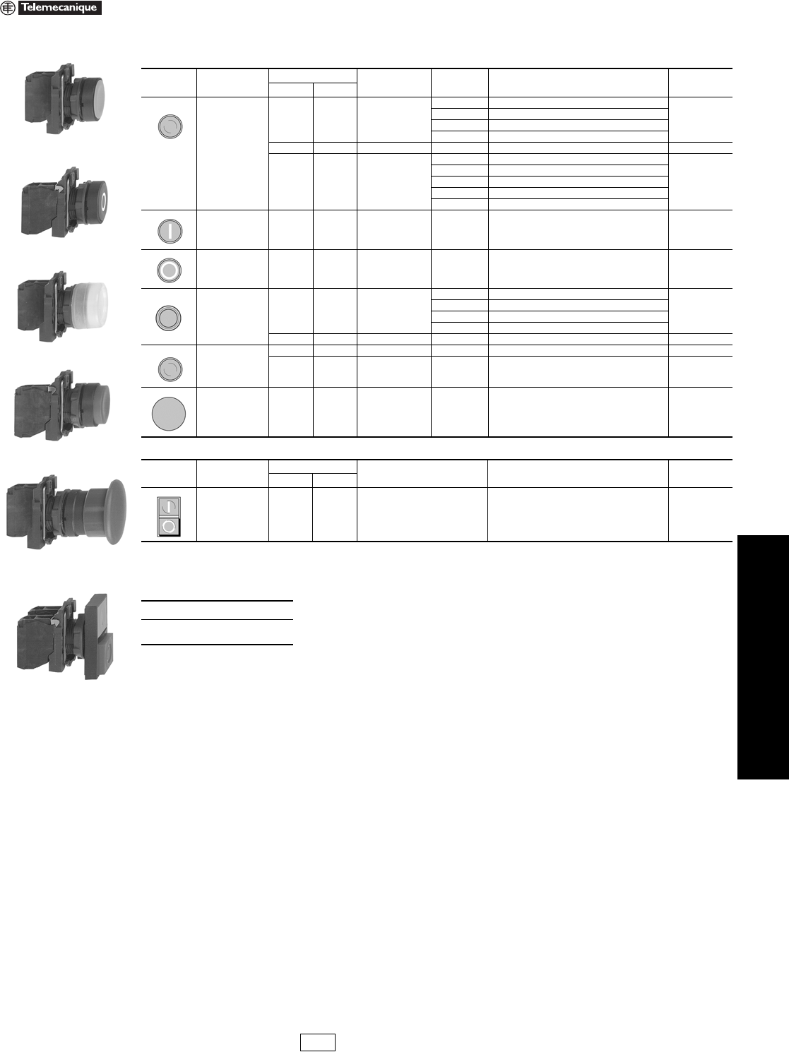
www.us.schneider-electric.com
FOR CURRENT INFORMATION
19 PUSH BUTTONS AND
OPERATOR INTERFACE
© 2007 Schneider Electric
All Rights Reserved 19-35
22 mm Push Buttons XB5 Complete Devices
Refer to Catalog 9001CT0001
Legends. . . . . . . . . . . . . . . . . . . . . . . . . . . . . . . . . . . . . pages 19-50 to 19-52
XB5AA31
XB5AA4322
XB5AP51
XB5AL42
XB5AC21
Table 19.102: Non-Illuminated Push Buttons, Momentary (screw clamp terminal connections)
Shape of
Head Type of Push Type of Contact Marking Color of Cap Catalog Number (Components) $ Price
N.O. N.C.
Flush
1— —
Black XB5AA21 (ZB5AZ101 + ZB5AA2)
35.00
Green XB5AA31 (ZB5AZ101 + ZB5AA3)
Yellow XB5AA51 (ZB5AZ101 + ZB5AA5)
Blue XB5AA61 (ZB5AZ101 + ZB5AA6)
—1 — Red XB5AA42 (ZB5AZ102 + ZB5AA4) 35.00
11 —
Black XB5AA25 (ZB5AZ105 + ZB5AA2)
51.00
Green XB5AA35 (ZB5AZ105 + ZB5AA3)
Red XB5AA45 (ZB5AZ105 + ZB5AA4)
Yellow XB5AA55 (ZB5AZ105 + ZB5AA5)
Blue XB5AA65 (ZB5AZ105 + ZB5AA6)
Flush 1 — “I”
(white) Green XB5AA3311 (ZB5AZ101 + ZB5AA331) 40.60
Flush — 1 “O”
(white) Red XB5AA4322 (ZB5AZ102 + ZB5AA432) 40.60
Flush with clear
silicone boot
(color of pusher
unobscured)
1— —
Black XB5AP21 (ZB5AZ101 + ZB5AP2)
47.80
Green XB5AP31 (ZB5AZ101 + ZB5AP3)
Yellow XB5AP51 (ZB5AZ101 + ZB5AP5)
Blue XB5AP61 (ZB5AZ101 + ZB5AP6)
—1 — Red XB5AP42 (ZB5AZ102 + ZB5AP4) 47.80
Extended
—1 — Red XB5AL42 (ZB5AZ102 + ZB5AL4) 35.00
11 — RedXB5AL45 (ZB5AZ105 + ZB5AL4) 35.00
Mushroom head
Ø 40 mm 1— — BlackXB5AC21 (ZB5AZ101 + ZB5AC2) 51.00
XB5AL845
Table 19.103: Two Button Push Buttons, Momentary (screw clamp terminal connections)
Shape of
Head Type of Push Type of Contact Degree of Protection Catalog Number (Components) $ Price
N.O. N.C.
One flush green
push (marked “I”)
One extended red
push (marked “O”)
11 IP40 XB5AL845 (ZB5AZ105 + ZB5AL8434) 63.00
When ordering, please specify:
•Quantity
•Catalog Number
IDiscount
Schedule Modified
4/20/09
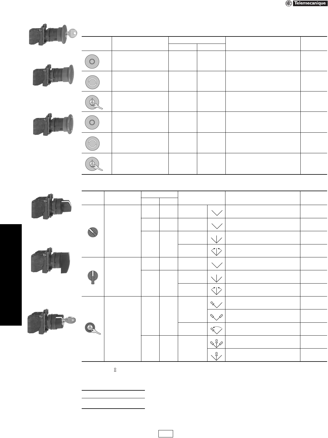
19-36 © 2007 Schneider Electric
All Rights Reserved
www.us.schneider-electric.com
FOR CURRENT INFORMATION
19 PUSH BUTTONS AND
OPERATOR INTERFACE
22 mm Push Buttons XB5 Complete Devices
Refer to Catalog 9001CT0001
aTrigger action mushroom heads are tamper proof in that a change of contact state is not possible by teasing or floating the operator.
bSee 19-42 for contact configurations.
Note: The symbol indicates key withdrawal position(s)
Legends . . . . . . . . . . . . . . . . . . . . . . . . . . . . . . . . . . . . pages 19-50 to 19-52
XB5AS9445
XB5AT42
XB5AS542
Table 19.104: Non-Illuminated Emergency Stop Mushroom Head Push Buttons, Ø 40 mm (Red)
(screw clamp terminal connections)
Shape of Head Type of Push
Type of Contact
Catalog Number (Components) $ Price
N.O. N.C.
Trigger action push-pulla11XB5AT845 (ZB5AZ105 + ZB5AT84) 92.00
Trigger action turn-to-releasea11XB5AS8445 (ZB5AZ105 + ZB5AS844) 150.00
Trigger action Key release
(No. 455)a11XB5AS9445 (ZB5AZ105 + ZB5AS944) 150.00
Push-pull — 1 XB5AT42 (ZB5AZ102 + ZB5AT4) 62.00
Turn-to-release — 1 XB5AS542 (ZB5AZ102 + ZB5AS54) 100.00
Key release (No. 455) — 1 XB5AS142 (ZB5AZ102 + ZB5AS14) 134.00
XB5AD33
XB5AJ33
XB5AG33
Table 19.105: Non-Illuminated Selector Switches and Key Switches (screw clamp terminal connections) b
Shape of
Head Type of Operator
Type of Contact Number and Type of
Positions Catalog Number (Components) $ Price
N.O. N.C.
Standard lever, black
1 — 2-maintained XB5AD21 (ZB5AZ101 + ZB5AD2) 46.00
1 1 2-maintained XB5AD25 (ZB5AZ105 + ZB5AD2) 62.00
2—
3-maintained XB5AD33 (ZB5AZ103 + ZB5AD3) 62.00
3-momentary to
center XB5AD53 (ZB5AZ103 + ZB5AD5) 68.00
Extended lever, black
1 — 2-maintained XB5AJ21 (ZB5AZ101 + ZB5AJ2) 46.00
2—
3-maintained XB5AJ33 (ZB5AZ103 + ZB5AJ3) 62.00
3-momentary to
center XB5AJ53 (ZB5AZ103 + ZB5AJ5) 68.00
Key (No. 455)
1—
2-maintained
XB5AG21 (ZB5AZ101 + ZB5AG2) 112.00
XB5AG41 (ZB5AZ101 + ZB5AG4) 112.00
2-momentary to
left XB5AG61 (ZB5AZ101 + ZB5AG6) 112.00
2 — 3-maintained
XB5AG03 (ZB5AZ103 + ZB5AG0) 128.00
XB5AG33 (ZB5AZ103 + ZB5AG3) 128.00
When ordering, please specify:
•Quantity
•Catalog Number
IDiscount
Schedule
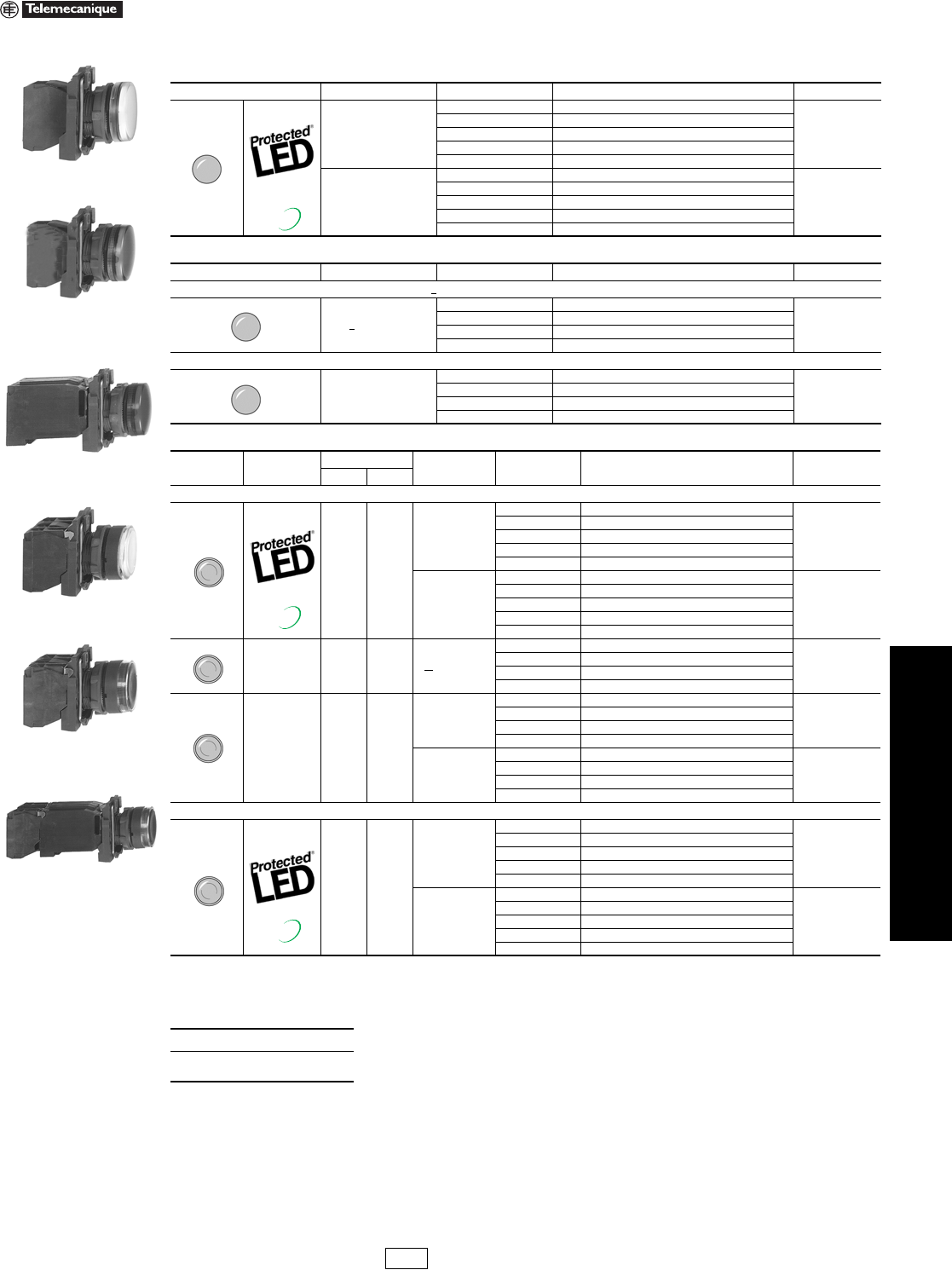
www.us.schneider-electric.com
FOR CURRENT INFORMATION
19 PUSH BUTTONS AND
OPERATOR INTERFACE
© 2007 Schneider Electric
All Rights Reserved 19-37
22 mm Push Buttons XB5 Complete Devices
Refer to Catalog 9001CT0001
aFor 240V LED, replace the “B” or “G” with “M”. (Example: XB5APVB1 (24V) to XB5APVM1 (240V))
bFor bulb information, refer to page 19-53
Legends. . . . . . . . . . . . . . . . . . . . . . . . . . . . . . . . . . . . . pages 19-50 to 19-52
XB5AVB1
XB5AV63
XB5AV34
Table 19.106: Pilot Lights with Protected LED® (screw clamp terminal connections) a
Shape of Head Supply Voltage Color Catalog Number (Components) $ Price
24 Vac/dc
White XB5AVB1 (ZB5AVB1 + ZB5AV013)
65.00
Green XB5AVB3 (ZB5AVB3 + ZB5AV033)
Red XB5AVB4 (ZB5AVB4 + ZB5AV043)
Yellow XB5AVB5 (ZB5AVB5 + ZB5AV053)
Blue XB5AVB6 (ZB5AVB6 + ZB5AV063)
110–120 Vac
White XB5AVG1 (ZB5AVG1 + ZB5AV013)
65.00
Green XB5AVG3 (ZB5AVG3 + ZB5AV033)
Red XB5AVG4 (ZB5AVG4 + ZB5AV043)
Yellow XB5AVG5 (ZB5AVG5 + ZB5AV053)
Blue XB5AVG6 (ZB5AVG6 + ZB5AV063)
Table 19.107: Pilot Lights for BA9s Bulb (screw clamp terminal connections)
Shape of Head Supply Voltage Color Catalog Number (Components) $ Price
Direct supply, for BA9s (incandescent, LED, neon) V < 250 V, 2.4 W bulb (bulb not included) b
<250 Vac/dc
White XB5AV61 (ZB5AV6 + ZB5AV01)
46.20
Green XB5AV63 (ZB5AV6 + ZB5AV03)
Red XB5AV64 (ZB5AV6 + ZB5AV04)
Yellow XB5AV65 (ZB5AV6 + ZB5AV05)
Transformer type with 1.2 VA, 6 V secondary. BA9s incandescent bulb included
110–120 Vac
50/60 Hz
White XB5AV31 (ZB5AV3 + ZB5AV01)
106.00
Green XB5AV33 (ZB5AV3 + ZB5AV03)
Red XB5AV34 (ZB5AV3 + ZB5AV04)
Yellow XB5AV35 (ZB5AV3 + ZB5AV05)
New!
XB5AW3465
XB5AW31B5
XB5AW3335
Table 19.108: Illuminated Push Buttons, Momentary (screw clamp terminal connections) a
Shape of Head Description Type of Contact Supply Voltage Color of Push Catalog Number (Components) $ Price
N.O. N.C.
Flush
11
24 Vac/dc
White XB5AW31B5 (ZB5AW0B15 + ZB5AW313)
108.00
Green XB5AW33B5 (ZB5AW0B35 + ZB5AW333)
Red XB5AW34B5 (ZB5AW0B45 + ZB5AW343)
Yellow XB5AW35B5 (ZB5AW0B55 + ZB5AW353)
Blue XB5AW36B5 (ZB5AW0B65 + ZB5AW363)
110–120 Vac
White XB5AW31G5 (ZB5AW0G15 + ZB5AW313)
108.00
Green XB5AW33G5 (ZB5AW0G35 + ZB5AW333)
Red XB5AW34G5 (ZB5AW0G45 + ZB5AW343)
Yellow XB5AW35G5 (ZB5AW0G55 + ZB5AW353)
Blue XB5AW36G5 (ZB5AW0G65 + ZB5AW363)
Direct supply for
BA9s
2.4 W max. bulb
not included
11< 250 Vac/dc
White XB5AW3165 (ZB5AW065 + ZB5AW31)
90.00
Green XB5AW3365 (ZB5AW065 + ZB5AW33)
Red XB5AW3465 (ZB5AW065 + ZB5AW34)
Yellow XB5AW3565 (ZB5AW065 + ZB5AW35)
Transformer type
1.2 VA, 6 V
secondary.
BA9s
incandescent
bulb included
11
110–120 Vac
50/60 Hz
White XB5AW3135 (ZB5AW035 + ZB5AW31)
148.00
Green XB5AW3335 (ZB5AW035 + ZB5AW33)
Red XB5AW3435 (ZB5AW035 + ZB5AW34)
Yellow XB5AW3535 (ZB5AW035 + ZB5AW35)
230–240 Vac
50/60 Hz
White XB5AW3145 (ZB5AW045 + ZB5AW31)
148.00
Green XB5AW3345 (ZB5AW045 + ZB5AW33)
Red XB5AW3445 (ZB5AW045 + ZB5AW34)
Yellow XB5AW3545 (ZB5AW045 + ZB5AW35)
Extended
11
24 Vac/dc
White XB5AW11B5 (ZB5AW0B15 + ZB5AW113)
103.00
Green XB5AW13B5 (ZB5AW0B35 + ZB5AW133)
Red XB5AW14B5 (ZB5AW0B45 + ZB5AW143)
Yellow XB5AW15B5 (ZB5AW0B55 + ZB5AW153)
Blue XB5AW16B5 (ZB5AW0B65 + ZB5AW163)
110–120 Vac
White XB5AW11G5 (ZB5AW0G15 + ZB5AW113)
103.00
Green XB5AW13G5 (ZB5AW0G35 + ZB5AW133)
Red XB5AW14G5 (ZB5AW0G45 + ZB5AW143)
Yellow XB5AW15G5 (ZB5AW0G55 + ZB5AW153)
Blue XB5AW16G5 (ZB5AW0G65 + ZB5AW163)
When ordering, please specify:
•Quantity
•Catalog Number
New!
New!
IDiscount
Schedule
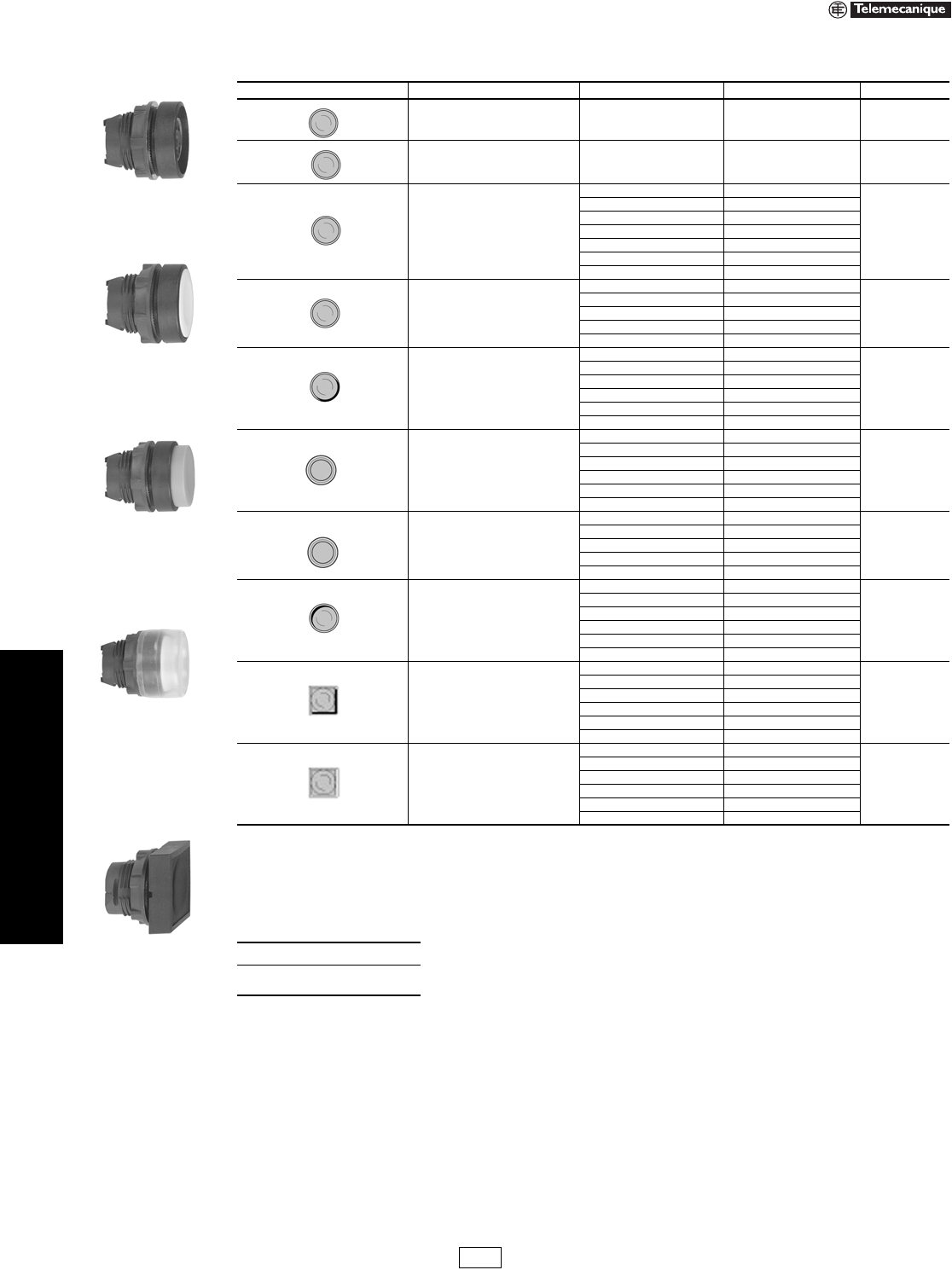
19-38 © 2007 Schneider Electric
All Rights Reserved
www.us.schneider-electric.com
FOR CURRENT INFORMATION
19 PUSH BUTTONS AND
OPERATOR INTERFACE
22 mm Push Buttons XB5 Non-Illuminated Operators
Refer to Catalog 9001CT0001
aOrder color cap separately, see page 19-52.
bSix colored caps included with head (white, black, green, red, yellow, blue).
cFor legend ordering information see page 19-52.
Legends . . . . . . . . . . . . . . . . . . . . . . . . . . . . . . . . . . . . pages 19-50 to 19-52
ZB5AA0
ZB5AA5
ZB5AL3
ZB5AP1
ZB5CA2
Table 19.109: Non-Illuminated Operators, Momentary—Unmarked
Shape of Head Type of Push Color of Cap Catalog Number $ Price
Flush, without color cap a—ZB5AA0 11.00
Flush, with set of 6 color caps 6 colors bZB5AA9 13.00
Flush
White ZB5AA1
13.00
Black ZB5AA2
Green ZB5AA3
Red ZB5AA4
Yellow ZB5AA5
Blue ZB5AA6
Gray ZB5AA8
Flush with transparent cap,
for insertion of legend c
White ZB5AA18
16.00
Green ZB5AA38
Red ZB5AA48
Yellow ZB5AA58
Blue ZB5AA68
Extended
White ZB5AL1
13.00
Black ZB5AL2
Green ZB5AL3
Red ZB5AL4
Yellow ZB5AL5
Blue ZB5AL6
Booted (clear)
Color of cap unobscured
White ZB5AP1
25.80
Black ZB5AP2
Green ZB5AP3
Red ZB5AP4
Yellow ZB5AP5
Blue ZB5AP6
Booted (clear)
for insertion of legend c
Color of cap unobscured
White ZB5AP18
29.00
Green ZB5AP38
Red ZB5AP48
Yellow ZB5AP58
Blue ZB5AP68
Flush Plunger
(with high guard)
White ZB5AA14
32.20
Black ZB5AA24
Green ZB5AA34
Red ZB5AA44
Yellow ZB5AA54
Blue ZB5AA64
Flush
White ZB5CA1
27.00
Black ZB5CA2
Green ZB5CA3
Red ZB5CA4
Yellow ZB5CA5
Blue ZB5CA6
Extended
White ZB5CL1
27.00
Black ZB5CL2
Green ZB5CL3
Red ZB5CL4
Yellow ZB5CL5
Blue ZB5CL6
When ordering, please specify:
•Quantity
•Catalog Number
IDiscount
Schedule
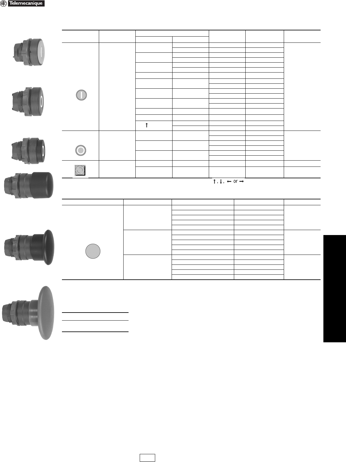
www.us.schneider-electric.com
FOR CURRENT INFORMATION
19 PUSH BUTTONS AND
OPERATOR INTERFACE
© 2007 Schneider Electric
All Rights Reserved 19-39
22 mm Push Buttons XB5 Non-Illuminated Operators
Refer to Catalog 9001CT0001
aCap supplied not clipped-in, allowing orientation of arrow in any one of 4 directions:
Legends. . . . . . . . . . . . . . . . . . . . . . . . . . . . . . . . . . . . . pages 19-50 to 19-52
ZB5AA331
ZB5AA432
ZB5AL232
Table 19.110: Non-Illuminated Operators, Momentary—Premarked
Shape of Head Type of Push Marking Color of Cap Catalog Number $ Price
Text Color
Flush
IWhite Green ZB5AA331
18.60
Black White ZB5AA131
START White Green ZB5AA333
Black White ZB5AA133
ON White Green ZB5AA341
Black White ZB5AA141
TWhite Green ZB5AA345
OWhite Red ZB5AA432
Black ZB5AA232
STOP White Red ZB5AA434
Black ZB5AA234
OFF White Red ZB5AA435
Black ZB5AA235
UP Black White ZB5AA343
DOWN White Black ZB5AA344
aBlack White ZB5AA334
White Black ZB5AA335
Extended
OWhite Red ZB5AL432
18.60
Black ZB5AL232
STOP White Red ZB5AL434
Black ZB5AL234
OFF White Red ZB5AL435
Black ZB5AL235
Flush
IWhite Green ZB5CA331 32.00
OWhite Red ZB5CA432 32.00
ZB5AC24
ZB5AC2
ZB5AR4
Table 19.111: Mushroom Heads, Momentary
Shape of Head Diameter of Head Color of Head Catalog Number $ Price
30 mm
Black ZB5AC24
29.40
Green ZB5AC34
Red ZB5AC44
Ye l l o w ZB5AC54
Blue ZB5AC64
40 mm
Black ZB5AC2
29.40
Green ZB5AC3
Red ZB5AC4
Ye l l o w ZB5AC5
Blue ZB5AC6
60 mm
Black ZB5AR2
35.00
Green ZB5AR3
Red ZB5AR4
Ye l l o w ZB5AR5
Blue ZB5AR6
When ordering, please specify:
•Quantity
•Catalog Number
IDiscount
Schedule
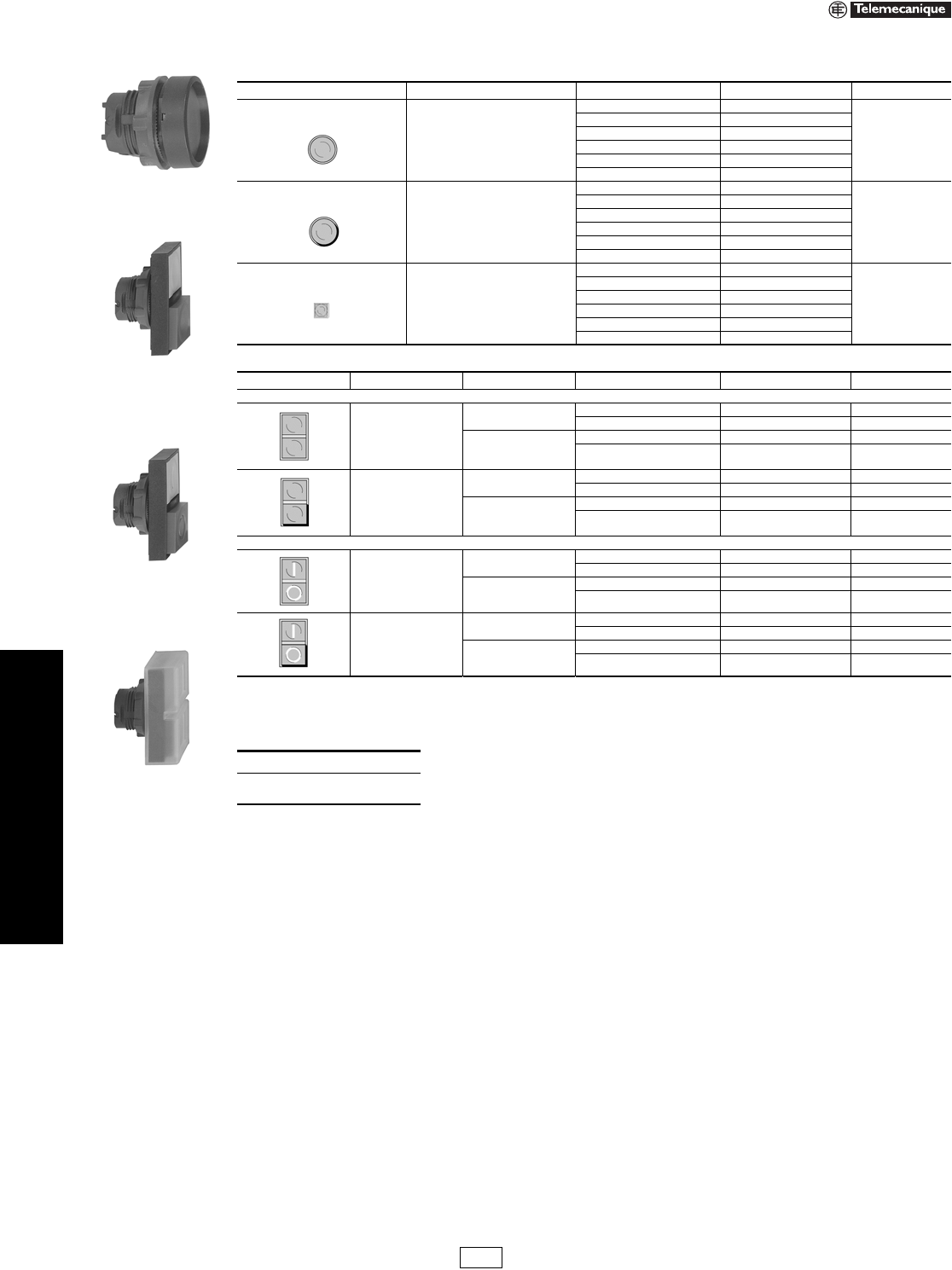
19-40 © 2007 Schneider Electric
All Rights Reserved
www.us.schneider-electric.com
FOR CURRENT INFORMATION
19 PUSH BUTTONS AND
OPERATOR INTERFACE
22 mm Push Buttons XB5 Non-Illuminated Operators
Refer to Catalog 9001CT0001
Legends . . . . . . . . . . . . . . . . . . . . . . . . . . . . . . . . . . . . pages 19-50 to 19-52
ZB5AH04
Table 19.112: Non-Illuminated Push-on/Push-off Operators
Shape of Head Type of Push Color of Push Catalog Number $ Price
Flush
White ZB5AH01
17.60
Black ZB5AH02
Green ZB5AH03
Red ZB5AH04
Ye l l o w ZB5AH05
Blue ZB5AH06
Extended
White ZB5AH1
17.60
Black ZB5AH2
Green ZB5AH3
Red ZB5AH4
Ye l l o w ZB5AH5
Blue ZB5AH6
Flush
White ZB5CH01
35.20
Black ZB5CH02
Green ZB5CH03
Red ZB5CH04
Ye l l o w ZB5CH05
Blue ZB5CH06
ZB5AL8334
ZB5AL8434
ZB5AL9334
Table 19.113: Two Head Operators, Momentary
Shape of Head Description Color of Pushers Degree of Protection Catalog Number $ Price
No Marking
Two flush
Green
Red
IP40 ZB5AA8134 20.80
IP66 ZB5AA9134 37.20
White
Black
IP40 ZB5AA8112 20.80
IP66 ZB5AA9112 37.20
One flush
One extended
Green
Red
IP40 ZB5AL8334 20.80
IP66 ZB5AL9334 37.20
White
Black
IP40 ZB5AL8312 20.80
IP66 ZB5AL9312 37.20
Premarked
Two f l ush
(marked “I”)
(marked “O”)
Green
Red
IP40 ZB5AA8234 24.80
IP66 ZB5AA9234 41.40
White
Black
IP40 ZB5AA8212 24.80
IP66 ZB5AA9212 41.40
One flush
(marked “I”)
One extended
(marked “O”)
Green
Red
IP40 ZB5AL8434 24.80
IP66 ZB5AL9434 41.40
White
Black
IP40 ZB5AL8412 24.80
IP66 ZB5AL9412 41.40
When ordering, please specify:
•Quantity
•Catalog Number
IDiscount
Schedule
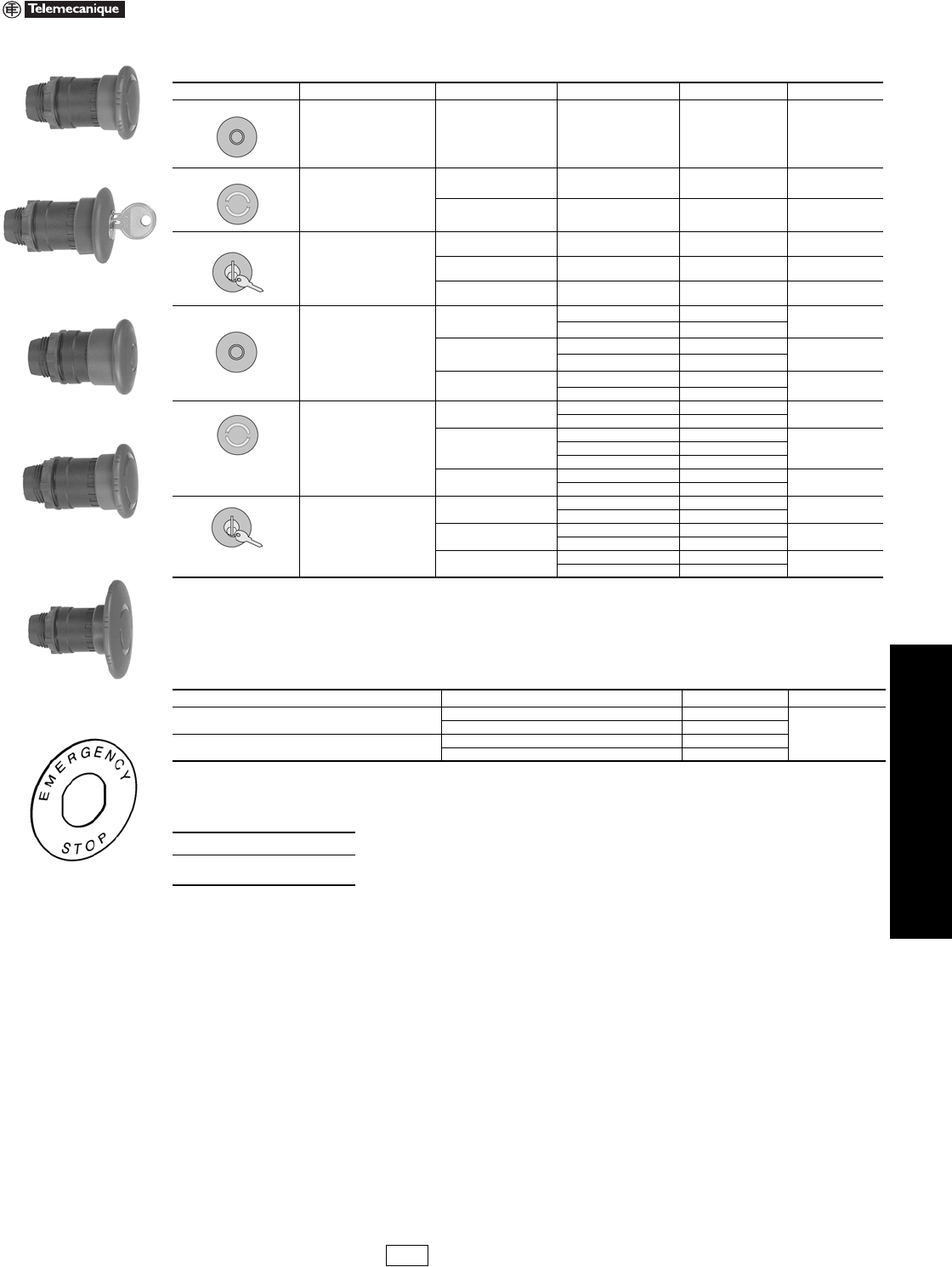
www.us.schneider-electric.com
FOR CURRENT INFORMATION
19 PUSH BUTTONS AND
OPERATOR INTERFACE
© 2007 Schneider Electric
All Rights Reserved 19-41
22 mm Push Buttons XB5 Emergency Stop Operators
Refer to Catalog 9001CT0001
aOther key numbers:
—key no. 421E: add the suffix 12 to the catalog number.
—key no. 458A: add the suffix 10 to the catalog number.
—key no. 520E: add the suffix 14 to the catalog number.
—key no. 3131A: add the suffix 20 to the catalog number.
Example: The catalog number for a Ø 40 mm red mushroom head for a trigger action, maintained push button, with release by
key no. 421E becomes: ZB5AS94412.
bTrigger action mushroom heads are tamper proof in that a change of contact state is not possible by teasing or floating the operator.
Legends. . . . . . . . . . . . . . . . . . . . . . . . . . . . . . . . . . . . . pages 19-50 to 19-52
ZB5AS844
ZB5AS934
ZB5AT4
ZB5AS54
ZB5AS64
Table 19.114: Mushroom Heads for Maintained Push Buttons
Shape of Head Type of Push Diameter of Head Color Catalog Number $ Price
Trigger action
Push-pull b40 mm Red ZB5AT84 54.00
Trigger action
Turn-to-release b
30 mm Red ZB5AS834 112.00
40 mm Red ZB5AS844 112.00
Trigger action
Key release
(No. 455) b
30 mm Red ZB5AS934 112.00
40 mm Red ZB5AS944 a112.00
60 mm Red ZB5AS964 112.00
Push-pull
30 mm Black ZB5AT24 40.40
Red ZB5AT44
40 mm Black ZB5AT2 40.40
Red ZB5AT4
60 mm Black ZB5AX2 46.00
Red ZB5AX4
Turn-to-release
30 mm Black ZB5AS42 78.00
Red ZB5AS44
40 mm
Black ZB5AS52
78.00Red ZB5AS54
Yellow ZB5AS55
60 mm Black ZB5AS62 90.00
Red ZB5AS64
Key release
(No. 455)
30 mm Black ZB5AS72 112.00
Red ZB5AS74
40 mm Black ZB5AS12 112.00
Red ZB5AS14 a
60 mm Black ZB5AS22 112.00
Red ZB5AS24
ZBY9330
Table 19.115: Circular Legends for Emergency Stop Mushroom Heads (yellow background)
Diameter Text Catalog Number $ Price
60 mm Blank ZBY9101
3.40
EMERGENCY STOP ZBY9330
90 mm Blank ZBY8101
EMERGENCY STOP ZBY8330
When ordering, please specify:
•Quantity
•Catalog Number
IDiscount
Schedule
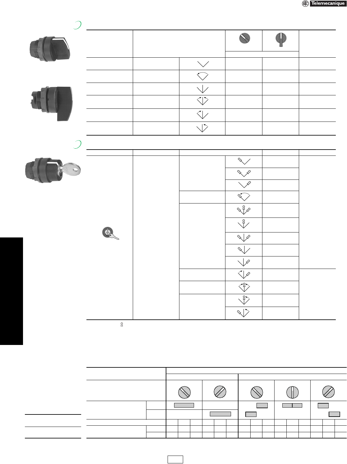
19-42 © 2007 Schneider Electric
All Rights Reserved
www.us.schneider-electric.com
FOR CURRENT INFORMATION
19 PUSH BUTTONS AND
OPERATOR INTERFACE
22 mm Push Buttons XB5 Selector Switches
Refer to Catalog 9001CT0001
aFor colored lever, add the following code to the end of catalog number: 01—white, 03—green, 04—red, 05—yellow, 06—blue (Example: ZB5AD204).
Note: The symbol indicates key withdrawal position(s).
bOther key numbers:
—key no. 421E: add the suffix 12 to the catalog number.
—key no. 458A: add the suffix 10 to the catalog number.
—key no. 520E: add the suffix 14 to the catalog number.
—key no. 3131A: add the suffix 20 to the catalog number.
—key no. 8D1: add the suffix D to the catalog number.
Example: The catalog number for a head with key no. 421E for a 2 position maintained, lockable selector switch, with key withdrawal from the left-hand
position, becomes: ZB5AG212
ZB5AD•
Standard Lever
ZB5AJX•
Extended Lever
Table 19.116: Non-Illuminated Selector Switches
Color Number and Type of Positions
Standard Lever aExtended Lever
$ Price
Catalog Number
Black 2-maintained ZB5AD2 ZB5AJ2 24.00
Black 2-momentary from
right to left ZB5AD4 ZB5AJ4 29.40
Black 3-maintained ZB5AD3 ZB5AJ3 24.00
Black 3-momentary to center ZB5AD5 ZB5AJ5 29.40
Black 3-momentary from
left to center ZB5AD7 ZB5AJ7 29.40
Black 3-momentary from
right to center ZB5AD8 ZB5AJ8 29.40
New!
ZB5AG•
Table 19.117: Non-Illuminated Key Switches
Shape of Head Type of Operator Number and Type of Positions Catalog Number b$ Price
Key (No. 455)
2-maintained
ZB5AG2
90.00
ZB5AG4
ZB5AG02
2-momentary from
right to left ZB5AG6
3-maintained
ZB5AG0
ZB5AG3
ZB5AG5
ZB5AG9
ZB5AG09
3-momentary from
left to center ZB5AG1
116.00
3-momentary to center ZB5AG7
3-momentary from right to
center
ZB5AG8
ZB5AG08
New!
When ordering,
please specify:
•Quantity
•Catalog Number
Table 19.118: Sequence of Contacts on Selector Switch Bodies
Unit Type Selector Switches
2-position 3-position
Operator Plunger Position
Up
Down
Contact Block Location L C R L C R L C R L C R L C R
Contacts N/O OOOXXXXXOOOOOXX
N/C XXXOOOOOXXXXXOO
Note: L=Left, C=Center, R=Right, O=Open, X=Closed
315° 45° 315° 0° 45°
IDiscount
Schedule
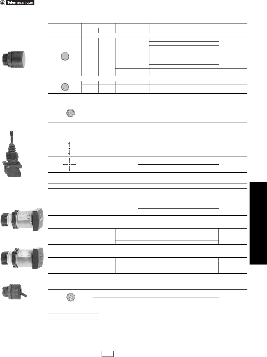
www.us.schneider-electric.com
FOR CURRENT INFORMATION
19 PUSH BUTTONS AND
OPERATOR INTERFACE
© 2007 Schneider Electric
All Rights Reserved 19-43
22 mm Push Buttons XB5 Specialty Operators
Refer to Catalog 9001CT0001
aDo not use standard contact blocks ZBE10• (single) or ZBE20• (double)
bUR E191025, XHNR2 and XHNR8.
Legends. . . . . . . . . . . . . . . . . . . . . . . . . . . . . . . . . . . . . pages 19-50 to 19-52
Table 19.119: Reset Operators
Shape of Head Actuation Distance Text Color Catalog Number $ Price
IN mm
Flush Adjustable Shaft
0.67–4.72 17–120
Without
Green XB5AA831
34.20Red XB5AA841
Blue XB5AA861
ORedXB5AA84101 41.40
RBlueXB5AA86102 41.40
4.72–10.12 120–257
Without
Green XB5AA832
39.40Red XB5AA842
Blue XB5AA862
ORedXB5AA84201 45.60
RBlueXB5AA86202 45.60
Extended
0.67–4.72 17–120 O Red XB5AL84101 41.40
4.72–10.12 120–257 O Red XB5AL84201 45.60
Table 19.120: Potentiometer Operator (with Mounting Collar)
Shape of Head Description Application Catalog Number $ Price
For potentiometer with
shaft length 1.73 to 1.97 in.
(44 to 50 mm)
(potentiometer not included)
For shaft Ø 0.25 in. (6.35 mm) ZB5AD922
142.00
For shaft Ø 0.24 in. (6 mm) ZB5AD912
Table 19.121: Joystick (54 mm, Extended Operating Shaft) a
Description Contact Operation Action Catalog Number $ Price
2 direction 1 step 1 N.O. contact
per direction
Maintained XD5PA12
250.00
Momentary XD5PA22
4 direction 1 step 1 N.O. contact
per direction
Maintained XD5PA14
316.00
Momentary XD5PA24
Table 19.122: Legends for Joystick
Description For use with Catalog Number $ Price
Legends
30 x 48 mm for engraving 2 direction
Black one side
Red reverse ZBG2201
3.40
White one side
Ye l l o w r e v e r s e ZBG2401
Legends
48 x 48 mm for engraving 4 direction
Black one side
Red reverse ZBG4201
White one side
Ye l l o w r e v e r s e ZBG4401
Table 19.123: Hour Counters b
Characteristics Supply Voltage Catalog Number $ Price
Indication 0–9999.9
12–24 Vdc or Vac, 50/60 Hz XB5DSB
348.00120 Vac, 60 Hz XB5DSG
230–240 Vac, 50 Hz XB5DSM
Table 19.124: Buzzer b
Characteristics Supply Voltage Catalog Number $ Price
85 db buzzer:4kHz, continuous or intermittent
(IP40 NEMA 1)
24 Vdc or Vac, 50/60 Hz XB5KSB
166.00120 Vac, 60 Hz XB5KSG
230–240 Vac, 50 Hz XB5KSM
Table 19.125: Two Position Toggle Switch
Shape of Head Color Type of Positions Catalog Number $ Price
Black Maintained ZB5AD28
46.60
Black Momentary ZB5AD48
When ordering, please specify:
•Quantity
•Catalog Number
XB5AA
XD5PA12
XB5DS•
XB5KS•
ZB5AD28
IDiscount
Schedule Modified
4/20/09
19-44 © 2007 Schneider Electric
All Rights Reserved
www.us.schneider-electric.com
FOR CURRENT INFORMATION
19 PUSH BUTTONS AND
OPERATOR INTERFACE
22 mm Push Buttons XB5 Pilot Lights
Refer to Catalog 9001CT0001
aFor use in bright ambient conditions (i.e., sunlight).
bOrder bulb separately; see page 19-32. For BA9 LED, see page 19-120.
Legends . . . . . . . . . . . . . . . . . . . . . . . . . . . . . . . . . . . . pages 19-50 to 19-52
ZB5AV053
ZB5AV01
ZB5CV063
Table 19.126: Pilot Light Heads
Shape of Head For use with Body Comprising Light Module Type Color of Lens Catalog Number $ Price
Protected LED® only
White ZB5AV013
7.60
Green ZB5AV033
Red ZB5AV043
Yellow ZB5AV053
Blue ZB5AV063
Protected LED only Fresnel (jeweled) lens a
White ZB5AV013S
7.60
Green ZB5AV033S
Red ZB5AV043S
Amber ZB5AV053S
Blue ZB5AV063S
For BA9s incandescent bulb, neon or LED only b
White ZB5AV01
7.60
Green ZB5AV03
Red ZB5AV04
Yellow ZB5AV05
Blue ZB5AV06
Clear ZB5AV07
For BA9s incandescent bulb, neon or LED Fresnel (jeweled)
lens b
White ZB5AV01S
7.60
Green ZB5AV03S
Red ZB5AV04S
Amber ZB5AV05S
Blue ZB5AV06S
Clear ZB5AV07S
Protected LED only
White ZB5CV013
27.00
Green ZB5CV033
Red ZB5CV043
Yellow ZB5CV053
Blue ZB5CV063
When ordering, please specify:
•Quantity
•Catalog Number
IDiscount
Schedule
www.us.schneider-electric.com
FOR CURRENT INFORMATION
19 PUSH BUTTONS AND
OPERATOR INTERFACE
© 2007 Schneider Electric
All Rights Reserved 19-45
22 mm Push Buttons XB5 Pilot Lights
Refer to Catalog 9001CT0001
aOrder bulb separately, see page 19-53.
bFor Quick-Connect version, add “3” to the end of the catalog number Example: ZB5AVJ13 (Quick-Connect size 1 x 0.250" or 2 x 0.110").
cFor 240 V LED, replace the “B” or “G” with “M”. (Example: ZB5AVB1 (24V) to ZB5AVM1 (240V))
ZB5AV6
ZB5AV3
Table 19.127: Complete Bodies (Mounting Collar + Light Module for BA9s Incandescent Bulb, Neon or LED)
Description Light Source Supply Voltage (V) Catalog Number $ Price
Screw clamp terminal connections
Direct supply BA9s bulb 2.4 W max.
Not included a<250 ZB5AV6 38.60
Direct supply BA9s incandescent
bulb included 24 V 2 W ZB5AV624 49.20
Direct supply BA9s incandescent
bulb included 120 V 2.4 W ZB5AV6120 49.20
Transformer type
1.2 VA, 6 V secondary
BA9s incandescent
bulb included
110–120 Vac
50/60 Hz ZB5AV3
98.00
230–240 Vac
50/60 Hz ZB5AV4
400–50 Hz ZB5AV5
440–480 Vac
60 Hz ZB5AV8
550–600 Vac
60 Hz ZB5AV9
ZB5AV••
Table 19.128: Complete Bodies (Mounting Collar + Light Module with Protected LED®) bc
Light Source Supply Voltage Color of Light Source Catalog Number $ Price
Screw clamp terminal connections
12 Vac/dc
White ZB5AVJ1
57.00
Green ZB5AVJ3
Red ZB5AVJ4
Yellow ZB5AVJ5
Blue ZB5AVJ6
24 Vac/dc
White ZB5AVB1
57.00
Green ZB5AVB3
Red ZB5AVB4
Yellow ZB5AVB5
Blue ZB5AVB6
24–120 Vac/dc
White ZB5AVBG1
57.00
Green ZB5AVBG3
Red ZB5AVBG4
Yellow ZB5AVBG5
Blue ZB5AVBG6
110–120 Vac
White ZB5AVG1
57.00
Green ZB5AVG3
Red ZB5AVG4
Yellow ZB5AVG5
Blue ZB5AVG6
Flashing
24 Vac/dc
White ZB5AV18B1
66.00
Green ZB5AV18B3
Red ZB5AV18B4
Yellow ZB5AV18B5
Blue ZB5AV18B6
110–120 Vac
White ZB5AV18G1
66.00
Green ZB5AV18G3
Red ZB5AV18G4
Yellow ZB5AV18G5
Blue ZB5AV18G6
When ordering, please specify:
•Quantity
•Catalog Number
New!
New!
IDiscount
Schedule

19-46 © 2007 Schneider Electric
All Rights Reserved
www.us.schneider-electric.com
FOR CURRENT INFORMATION
19 PUSH BUTTONS AND
OPERATOR INTERFACE
22 mm Push Buttons XB5 Illuminated Operators
Refer to Catalog 9001CT0001
Legends . . . . . . . . . . . . . . . . . . . . . . . . . . . . . . . . . . . . pages 19-50 to 19-52
ZB5AW313
ZB5AW363
ZB5AW143
ZB5CW313
ZB5AW33
Table 19.129: Heads for Momentary Illuminated Push Buttons
Shape of Head Type of Push Color Catalog Number $ Price
Only use with Protected LED® light modules
Flush
White ZB5AW313
18.60
Green ZB5AW333
Red ZB5AW343
Yellow ZB5AW353
Blue ZB5AW363
Flush with clear boot
White ZB5AW513
31.00
Green ZB5AW533
Red ZB5AW543
Yellow ZB5AW553
Blue ZB5AW563
Flush for insertion of legend
White ZB5AA18
16.00
Green ZB5AA38
Red ZB5AA48
Yellow ZB5AA58
Blue ZB5AA68
Extended
White ZB5AW113
13.00
Green ZB5AW133
Red ZB5AW143
Yellow ZB5AW153
Blue ZB5AW163
Flush for insertion of legend
White ZB5CW313
27.00
Green ZB5CW333
Red ZB5CW343
Yellow ZB5CW353
Blue ZB5CW363
Extended
White ZB5CW113
27.00
Green ZB5CW133
Red ZB5CW143
Yellow ZB5CW153
Blue ZB5CW163
Only use with light modules for a BA9s incandescent bulb, neon or LED
Flush
White ZB5AW31
18.60
Green ZB5AW33
Red ZB5AW34
Yellow ZB5AW35
Blue ZB5AW36
Clear ZB5AW37
Extended
White ZB5AW11
13.00
Green ZB5AW13
Red ZB5AW14
Yellow ZB5AW15
Blue ZB5AW16
Clear ZB5AW17
Table 19.130: Illuminated Push-on/Push-off Operators
Shape of Head Type of Push Color of Lens Catalog Number $ Price
Only use with Protected LED light modules
Flush
White ZB5AH013
24.80
Green ZB5AH033
Red ZB5AH043
Yellow ZB5AH053
Blue ZB5AH063
Extended
White ZB5AH13
19.60
Green ZB5AH33
Red ZB5AH43
Yellow ZB5AH53
Blue ZB5AH63
When ordering, please specify:
•Quantity
•Catalog Number
IDiscount
Schedule
www.us.schneider-electric.com
FOR CURRENT INFORMATION
19 PUSH BUTTONS AND
OPERATOR INTERFACE
© 2007 Schneider Electric
All Rights Reserved 19-47
22 mm Push Buttons XB5 Illuminated Operators
Refer to Catalog 9001CT0001
aFor IP66 degree of protection, install clear sealing boot ZBW008, see page 19-54.
bDesignate color as follows: 1—white, 3—green, 4—red, 5—yellow, 6—blue
Legends. . . . . . . . . . . . . . . . . . . . . . . . . . . . . . . . . . . . . pages 19-50 to 19-52
ZB5AW833743
ZB5AW823743
ZB5AW843743
Table 19.131: Two Button with Clear Pilot Light, Momentary (IP40) a
Shape of Head Description Color of Pushers Catalog Number $ Price
Only use with Protected LED® light modules (Protected LED determines pilot light color)
1 flush
1 central pilot light
1 flush
Black ZB5AW812743
29.00
Red
Green ZB5AW813743
Red
White ZB5AW811723
Black
1 flush
1 central pilot light
1 extended
Black ZB5AW832743
29.00
Red
Green ZB5AW833743
Red
White ZB5AW831723
Black
Only use with Protected LED light modules (Protected LED determines pilot light color)—premarked
1 flush
(marked “I”)
1 central pilot light
1 flush
(marked “O”)
Black ZB5AW822743
33.20
Red
Green ZB5AW823743
Red
White ZB5AW821723
Black
1 flush
(marked “I”)
1 central pilot light
1 extended
(marked “O”)
Black ZB5AW842743
33.20
Red
Green ZB5AW843743
Red
White ZB5AW841723
Black
ZB5AW7•
Table 19.132: Heads for Maintained Illuminated Push Buttons
Shape of Head Type of Push Color Catalog Number $ Price
Only use with Protected LED light modules
Turn-to-Release Mushroom (40 mm)
White ZB5AW713
63.00
Green ZB5AW733
Red ZB5AW743
Yellow ZB5AW753
Blue ZB5AW763
ZB5AK1213
ZB5AK1463
Table 19.133: Illuminated Selector Switches, Standard Lever
Shape of Head Number and Type of Positions Catalog Number b$ Price
Only use with Protected LED light modules
2-maintained ZB5AK12b335.00
2-momentary from right to left ZB5AK14b351.00
3-maintained ZB5AK13b335.00
3-momentary to center ZB5AK15b351.00
3-momentary from right to center ZB5AK18b351.00
3-momentary from left to center ZB5AK17b351.00
Table 19.134: Sequence of Contacts on Selector Switch Bodies
Unit Type Selector Switches
2-position 3-position
Operator Plunger Position
Up
Down
Contact Block Location L C R L C R L C R L C R L C R
Contacts N/O OOOXXXXXOOOOOX X
N/C XXXOOOOOXXXXXOO
Note: L=Left, C=Center, R=Right, O=Open, X=Closed
New!
315° 45° 315° 0° 45°
When ordering,
please specify:
•Quantity
•Catalog Number
IDiscount
Schedule
19-48 © 2007 Schneider Electric
All Rights Reserved
www.us.schneider-electric.com
FOR CURRENT INFORMATION
19 PUSH BUTTONS AND
OPERATOR INTERFACE
22 mm Push Buttons XB5 Electrical Components
Refer to Catalog 9001CT0001
aFor Quick-Connect version add “3” to the end of the catalog number Example: ZB5AZ1013 (Quick-Connect size 1 x 0.250" or 2 x 0.110").
bFor Ring Tongue compatible blocks add “9” to the end of the catalog number (Example: ZB5AZ1029).
cElectrical components with connection by printed circuit board pins are available. Refer to Catalog 9001CT0001 for more information.
dElectrical components with connection by plug-in connector are available. Refer to Catalog 9001CT0001 for more information.
eFor 240V LED, replace the “B” or “G” with “M”. (Example: change “ZB5AW0B11 (24V) to ZB5AW0M11 (240V))
fCan be fitted with additional contact blocks, see page 19-49.
gOrder bulb separately, see page 19-53.
ZB5AZ101
Table 19.135: Contact Blocks (Mounting Collar with Contact Blocks) abcd
Description Type of Contact Catalog Number $ Price
N.O. N.C.
Screw clamp terminal connections
1—ZB5AZ101 22.00
—1ZB5AZ102 22.00
2—ZB5AZ103 38.20
—2ZB5AZ104 38.20
11ZB5AZ105 38.20
12ZB5AZ141 55.00
ZB5AW0••1
Table 19.136: Complete Bodies
(Mounting Collar + Single Contact Block + Light Module with Protected LED®)
Light Source
Type of Contact
f
Color
Supply Voltage e
$ Price
N.O. N.C. 24 Vac/dc 110–120 Vac
Catalog Number
Screw clamp terminal connections
1—
White ZB5AW0B11 ZB5AW0G11
73.00
Green ZB5AW0B31 ZB5AW0G31
Red ZB5AW0B41 ZB5AW0G41
Yellow ZB5AW0B51 ZB5AW0G51
Blue ZB5AW0B61 ZB5AW0G61
—1
White ZB5AW0B12 ZB5AW0G12
73.00
Green ZB5AW0B32 ZB5AW0G32
Red ZB5AW0B42 ZB5AW0G42
Yellow ZB5AW0B52 ZB5AW0G52
Blue ZB5AW0B62 ZB5AW0G62
2—
White ZB5AW0B13 ZB5AW0G13
90.00
Green ZB5AW0B33 ZB5AW0G33
Red ZB5AW0B43 ZB5AW0G43
Yellow ZB5AW0B53 ZB5AW0G53
Blue ZB5AW0B63 ZB5AW0G63
11
White ZB5AW0B15 ZB5AW0G15
90.00
Green ZB5AW0B35 ZB5AW0G35
Red ZB5AW0B45 ZB5AW0G45
Yellow ZB5AW0B55 ZB5AW0G55
Blue ZB5AW0B65 ZB5AW0G65
New!
Table 19.137: Mounting Collar, Contact Block and Light Module (with screw clamp terminal connections) f
Supply Light Source Supply Voltage Type of Contact fColor of Light
Source Catalog Number $ Price
N.O. N.C.
Screw clamp terminal connections
Direct supply
BA9s
2.4 W max. bulb
Not included g
< 250 Vac/dc
1— — ZB5AW061 55.00
—1 — ZB5AW062 55.00
2— — ZB5AW063 71.00
11 — ZB5AW065 71.00
Transformer type
1.2 VA, 6 V
secondary
BA9s
incandescent
bulb included
110–120 Vac
50/60 Hz
1— — ZB5AW031 114.00
11 — ZB5AW035 130.00
230–240 Vac
50/60 Hz
1— — ZB5AW041 114.00
11 — ZB5AW045 130.00
440–480 Vac
60 Hz
1— — ZB5AW081 114.00
11 — ZB5AW085 130.00
When ordering, please specify:
•Quantity
•Catalog Number
ZB5AW065
ZB5AW035
IDiscount
Schedule
www.us.schneider-electric.com
FOR CURRENT INFORMATION
19 PUSH BUTTONS AND
OPERATOR INTERFACE
© 2007 Schneider Electric
All Rights Reserved 19-49
22 mm Push Buttons XB5 Electrical Components
Refer to Catalog 9001CT0001
aFor Quick-Connect version add “3” to the end of the catalog number (Example: ZBE1013) (Quick-Connect size 1 x 0.250" or 2 x 0.110").
bFor Ring Tongue compatible blocks add “9” to the end of the catalog number (Example: ZBE1029).
cCannot stack additional contact blocks onto these blocks.
dElectrical components with connection by printed circuit board pins are available. Refer to Catalog 9001CT0001 for more details.
eElectrical components with connection by plug-in connector are available. Refer to Catalog 9001CT0001 for more details.
ZB5AZ009
Table 19.138: Body/Mounting Collar
For use with Catalog Number $ Price
Electrical block (contact or light module) ZB5AZ009 5.40
ZBE101
ZBE203
Table 19.139: Add-On Contact Block (with screw clamp terminal connections) de
Description Type of Contact Catalog Number $ Price
N.O. N.C.
Standard single
contact blocksab
1—ZBE101 16.40
—1ZBE102 16.40
Standard double
contact blocksab
2—ZBE203 33.20
—2ZBE204 33.20
11ZBE205 33.20
Special contact blocks
(for low power switching
and dust protected) c
1—ZBE1016 32.80
—1ZBE1026 32.80
ZBVB•
Table 19.140: Light Modules (with screw clamp terminal connections)de
Description Supply Voltage Color of Light Source Catalog Number $ Price
12 Vac/dc
White ZBVJ1
52.00
Green ZBVJ3
Red ZBVJ4
Yellow ZBVJ5
Blue ZBVJ6
24 Vac/dc
White ZBVB1
52.00
Green ZBVB3
Red ZBVB4
Yellow ZBVB5
Blue ZBVB6
110–120 Vac
White ZBVG1
52.00
Green ZBVG3
Red ZBVG4
Yellow ZBVG5
Blue ZBVG6
24–120 Vac/dc
White ZBVBG1
52.00
Green ZBVBG3
Red ZBVBG4
Yellow ZBVBG5
Blue ZBVBG6
230–240 Vac
White ZBVM1
52.00
Green ZBVM3
Red ZBVM4
Yellow ZBVM5
Blue ZBVM6
Direct supply for BA9s
2.4 W max. bulb
Not included
See page 19-53
< 250 Vac/dc — ZBV6 33.20
When ordering, please specify:
•Quantity
•Catalog Number
New!
IDiscount
Schedule
19-50 © 2007 Schneider Electric
All Rights Reserved
www.us.schneider-electric.com
FOR CURRENT INFORMATION
19 PUSH BUTTONS AND
OPERATOR INTERFACE
22 mm Push Buttons XB5 Legend Holders
Refer to Catalog 9001CT0001
aFor legends, see page 19-51.
bStart functions: white letters on black background. Stop functions: white letters on red background (unless otherwise specified above).
cFor custom legends, please see page 19-51
ZBZ32
ZBY•101
ZBY2303
Table 19.141: Standard (30 x 40 mm) Legend Holders for 8 x 27 mm Legends
Description Legend Catalog Number $ Price
Color Text
Without legend insert a—— ZBZ32 2.00
With blank legend insert
(for engraving)
Black or red background — ZBY2101 3.40
White or yellow background — ZBY4101
Custom legend plate and insert
(specify engraving)
2 lines of 11 characters
(including spaces)
maximum per line
Black background White ZBY2002
14.20
Red background White ZBY2004
White background Black ZBY4001
Yellow background Black ZBY4005
With international language marked
legend Black or red backgroundb
O (black background) ZBY2146
3.40
O (red background) ZBY2931
IZBY2147
II ZBY2148
O-I ZBY2178
I-II ZBY2179
I-O-II ZBY2186
With English language
marked legend Black or red backgroundb
AUTO ZBY2115
3.40
AUTO-HAND ZBY2364
AUTO-O-HAND ZBY2385
CLOSE ZBY2314
DOWN ZBY2308
EMERGENCY STOP ZBY2330
FAST ZBY2328
FORWARD ZBY2305
FOR-REV ZBY2371
HAND ZBY2316
HAND-OFF-AUTO ZBY2387
INCH ZBY2321
JOG ZBY2382
LEFT ZBY2310
OFF ZBY2312
OFF-ON ZBY2367
ON ZBY2311
OPEN ZBY2313
POWER ON ZBY2326
RESET (red background) ZBY2323
RESET (black background) ZBY2322
REVERSE ZBY2306
RIGHT ZBY2309
RUN ZBY2334
SLOW ZBY2327
START ZBY2303
STOP ZBY2304
STOP-START ZBY2366
UP ZBY2307
ZBZ33 ZBY610•
Table 19.142: Large (30 x 50 mm) Legend Holders for 18 x 27 mm Legends
Description cFor use with Color Catalog Number $ Price
Without legend insert Circular and square heads — ZBZ33 2.00
With blank legend insert Circular and square heads Black or red background ZBY6101 3.40
White or yellow background ZBY6102
When ordering, please specify:
•Quantity
•Catalog Number
IDiscount
Schedule
www.us.schneider-electric.com
FOR CURRENT INFORMATION
19 PUSH BUTTONS AND
OPERATOR INTERFACE
© 2007 Schneider Electric
All Rights Reserved 19-51
22 mm Push Buttons XB5 Legends, Inserts Only
Refer to Catalog 9001CT0001
aStart functions: white letters on black background. Stop functions: white letters on red background (unless otherwise specified above).
ZBY02178
ZBY02303
Table 19.143: Marked Legends for 8 x 27 mm (for 30 x 40 mm legend holders ZBZ32)
Color Marking Text Catalog Number $ Price
Black or red backgrounda
International
O (black background) ZBY02146
1.70
O (red background) ZBY02931
IZBY02147
II ZBY02148
O-I ZBY02178
I-II ZBY02179
I-O-II ZBY02186
English
AUTO ZBY02115
1.70
AUTO-HAND ZBY02364
AUTO-O-HAND ZBY02385
CLOSE ZBY02314
DOWN ZBY02308
EMERGENCY STOP ZBY02330
FAST ZBY02328
FORWARD ZBY02305
FOR-REV ZBY02371
HAND ZBY02316
HAND-OFF-AUTO ZBY02387
INCH ZBY02321
JOG ZBY02382
LEFT ZBY02310
OFF ZBY02312
OFF-ON ZBY02367
ON ZBY02311
OPEN ZBY02313
POWER ON ZBY02326
RESET (red background) ZBY02323
RESET (black background) ZBY02322
REVERSE ZBY02306
RIGHT ZBY02309
RUN ZBY02334
SLOW ZBY02327
START ZBY02303
STOP ZBY02304
STOP-START ZBY02366
UP ZBY02307
Table 19.144: Legends for Customer Engraving (inserts only)
Description For use with Color Catalog Number $ Price
8 x 27 mm 30 x 40 mm legend holders Black or red background ZBY0101
1.70
White or yellow background ZBY0102
18 x 27 mm 30 x 50 mm legend holders Black or red background ZBY5101
White or yellow background ZBY5102
Table 19.145: Legends for Factory Engraving (inserts only)
Description For use with Color Text Catalog Number $ Price
8 x 27 mm
Custom legend/insert only
(specify engraving)
2 lines of 11 characters
(including spaces)
maximum per line
Example: ZBY01002 marked
“Robot”
30 x 40 mm legend holders
Black background White ZBY01002
12.20
Red background White ZBY01004
White background Black ZBY01001
Yellow background Black ZBY01005
18 x 27 mm
Custom legend/insert only
(specify engraving)
3 lines of 11 characters
(including spaces)
maximum per line
Example: ZBY05002 marked
“Robot”
30 x 50 mm legend holders
Black background White ZBY05002
12.20
Red background White ZBY05004
White background Black ZBY05001
Yellow background Black ZBY05005
When ordering, please specify:
•Quantity
•Catalog Number
IDiscount
Schedule

19-52 © 2007 Schneider Electric
All Rights Reserved
www.us.schneider-electric.com
FOR CURRENT INFORMATION
19 PUSH BUTTONS AND
OPERATOR INTERFACE
22 mm Push Buttons XB5 Accessories
Refer to Catalog 9001CT0001
aSet of 6 different colored caps: white, black, green, red, yellow, blue.
bDouble injection molded marking.
cCap supplied not clipped-in, allowing orientation of arrow in any one of 4 directions:
Table 19.146: Sheets of Legends for Push Buttons, Switches, and Pilot Lights
Description Marking Text Catalog Number $ Price
Sheets of 66 circular
peel-off transparent self-
adhesive legends
Blank–Round ZBY1101 6.20
Blank–Square legends ZBCY1101 6.20
International
OZBY1146
10.40
IZBY1147
II ZBY1148
III ZBY1149
STOP ZBY1304
ZBY1912
English
HAND ZBY1316
10.40
OFF ZBY1312
ON ZBY1311
START ZBY1303
SiS Label Software Legend Design Software: English, French, German, Spanish, Italian XBY2U 108.00
Table 19.147: Push Button Caps—Unmarked
For use with Type of Push Color Catalog Number $ Price
ZB5AA0 push button heads
Flush
White ZBA1
2.00
Black ZBA2
Green ZBA3
Red ZBA4
Ye l l o w ZBA5
Blue ZBA6
6 colors aZBA9 4.20
Extended
White ZBL1
2.00
Black ZBL2
Green ZBL3
Red ZBL4
Ye l l o w ZBL5
Blue ZBL6
6 colors aZBL9 4.20
Table 19.148: Push Button Caps—Marked
For use with Type of Push Marking Color of Cap Catalog Number $ Price
Text Color
ZB5AA0
push button heads Flush
I bWhite Green ZBA331
4.20
Black White ZBA131
START bWhite Green ZBA333
Black White ZBA133
ON White Green ZBA341
Black White ZBA141
UP bBlack White ZBA343
DOWNbWhite Black ZBA344
b
White Green ZBA345
White Black ZBA245
White Green ZBA346
Black White ZBA334c
White Black ZBA335c
ObWhite Red ZBA432
Black ZBA232
STOPbWhite Red ZBA434
Black ZBA234
OFF White Red ZBA435
Black ZBA235
RbWhite Blue ZBA639
When ordering, please specify:
•Quantity
•Catalog Number
ZBY1101
ZBA•
ZBL•
ZBA•33
IDiscount
Schedule Modified
4/20/09
www.us.schneider-electric.com
FOR CURRENT INFORMATION
19 PUSH BUTTONS AND
OPERATOR INTERFACE
© 2007 Schneider Electric
All Rights Reserved 19-53
22 mm Push Buttons XB5 Accessories
Refer to Catalog 9001CT0001
aMounting nut included with blanking plug.
bStandard circular legends are not compatible with this product. Use special legends ZBY• •T listed above.
cOnly when mounted on control stations. Use special legends ZBY• •T.
ZBZ160•
ZB4SZ3 ZB5SZ3
ZB4BZ6•
Ø 8 mm maximum
Ø 6 mm minimum
ZBZ3605
Table 19.149: Accessories
Description Application Color Catalog Number $ Price
Padlocking kit
Conforming to EN 418/ISO 13850 b
(See legends below)
For Emergency Stop function only, with the following
Ø40 mm trigger-action push buttons:
XB5AT8•
XB5AS8•
XB5AS9•
ZB5AT8•
ZB5AS8•
ZB5AS9•
Yellow ZBZ3605 108.00
Metal guards
Padlockable
For Emergency stop function only with the following
Ø40 mm trigger-action push buttons:
XB5AT8•
XB5AS8•
XB5AS9•
ZB5AT8•
ZB5AS8•
ZB5AS9•
Chromium Plated ZBZ1600
108.00
Black ZBZ1602
Red ZBZ1604
Yellow ZBZ1605
Blue ZBZ1606
Plastic guards
Round Guard for ZB5AS5430
EMO Mushroom Operators Yellow ZB4BZ1905
25.80
Narrow Flange Guard for ZB5AS5430 or ZB5AS84430
EMO Mushroom Operators Yellow ZB4BZ2005
Trigger Action Guard for ZB5AS84430
EMO Mushroom Operators Yellow ZB4BZ2105
Padlockable flaps For push buttons Black ZB4BZ62 32.80
Red ZB4BZ64
Plastic blanking plug, roundaFor Ø22 mm units with round heads Black ZB5SZ3 11.00
Plastic blanking plug, squareaFor Ø22 mm units with square heads Black ZB5SZ5 11.00
Square insert To give square appearance to ZB5A round heads Black ZB5AZ31 2.00
Mounting nut Operator — ZB5AZ901 4.40
Tool For tightening mounting nut ZB5AZ901 — ZB5AZ905 12.40
Plate Anti-rotation of head — ZB5AZ902 2.00
Description Marking Color Catalog Number $ Price
Ø60 mm Legend
for padlocking device ZBZ3605
Without Yellow ZBY9101T 3.40
EMERGENCY STOP Yellow ZBY9330T
New!
DLCE••• DL1CF•••
XBFX13 ZBZ8
Table 19.150: BA9s Bulbs and Associated Accessories
Description Characteristics Catalog Number $ Price
Replacement bulbs
(Type BA9s)
Incandescent
6 V, 1.2 W DL1CB006
11.00
12 V, 2 W DL1CE012
24 V, 2 W DL1CE024
120–130 V, 2.4 W DL1CE130
Neon bulbs 120–130 V DL1CF110 15.20
230–240 V DL1CF220
Bulb extractor — XBFX13 11.00
Lens cap tightening tool Illuminated push buttons with flush push ZBZ8 6.20
Power driver bits for mounting and wiring
(package of 5) Cross headed screw (POZIDRIV type 1) ZB4BZ905 52.00
Mounting Adapter For mounting 22 mm push button in 30 mm knockout ZBZ41 10.40
ZBZ•8
Table 19.151: Bellows Seals for Harsh Environments (IP 69K) c
Description For use with Color &
Material
Sold in
Lots of Catalog Number $ Price
Bellows Seals for harsh environments
(Humidity, dust, high-pressure cleaning)
XB5 plastic mushroom head push button c,
Ø40 mm or Ø60 mm (except ZB4BR•16)
Red 2ZBZ48
12.40
Silicone
Black 2ZBZ28
EPDM
New!
ZBG455
ZBG455P
Table 19.152: Replacement Keys
Description Key Number Catalog Number $ Price
Set of 2 keys
455 ZBG455
11.00
421E ZBG421E
458A ZBG458A
520E ZBG520E
3131A ZBG3131A
Set of 2 keys,
One of which is supplied booted (rubber boot)
455 ZBG455P
23.40
421E ZBG421EP
458A ZBG458AP
520E ZBG520EP
3131A ZBG3131AP
When ordering, please specify:
•Quantity
•Catalog Number
New!
IDiscount
Schedule Modified
4/20/09
19-54 © 2007 Schneider Electric
All Rights Reserved
www.us.schneider-electric.com
FOR CURRENT INFORMATION
19 PUSH BUTTONS AND
OPERATOR INTERFACE
22 mm Push Buttons XB5 Accessories
Refer to Catalog 9001CT0001
ZBP0
ZBW008
ZBV01•3
ZBV01•
Table 19.153: Clear Boots
Description For use with Material Catalog Number $ Price
Single boots
Booted push buttons with circular head Neoprene ZBP0 12.40
Booted push buttons with circular head used in food
industry applications Silicone ZBP0A 12.40
Double boots
Double-headed push buttons, with or without pilot light Neoprene ZBW008 32.80
Double-headed push buttons used in food industry
applications Silicone ZBW008A 32.80
Table 19.154: Lens Caps
For use with Color Catalog Number $ Price
Lens caps for Protected LED® light modules
Pilot lights
White ZBV0113
5.40
Green ZBV0133
Red ZBV0143
Ye l l o w ZBV0153
Blue ZBV0163
Illuminated push buttons with flush push
White ZBW9113
5.40
Green ZBW9133
Red ZBW9143
Ye l l o w ZBW9153
Blue ZBW9163
Illuminated push buttons with extended push
White ZBW9313
5.40
Green ZBW9333
Red ZBW9343
Ye l l o w ZBW9353
Blue ZBW9363
Circular lens caps for BA9s light modules
Pilot lights
White ZBV011
5.40
Green ZBV013
Red ZBV014
Ye l l o w ZBV015
Blue ZBV016
Clear ZBV017
Illuminated push buttons with flush push
White ZBW911
5.40
Green ZBW913
Red ZBW914
Ye l l o w ZBW915
Blue ZBW916
Clear ZBW917
Illuminated push buttons with extended push
White ZBW931
5.40
Green ZBW933
Red ZBW934
Ye l l o w ZBW935
Blue ZBW936
Clear ZBW937
Square lens caps for Protected LED light modules (ZB5C operators only)
Pilot lights White ZBCV0113
9.40
Green ZBCV0133
Red ZBCV0143
Ye l l o w ZBCV0153
Blue ZBCV0163
Illuminated push buttons with flush push White ZBCW9113
9.40
Green ZBCW9133
Red ZBCW9143
Ye l l o w ZBCW9153
Blue ZBCW9163
Illuminated push buttons with extended push White ZBCW9313
9.40
Green ZBCW9333
Red ZBCW9343
Ye l l o w ZBCW9353
Blue ZBCW9363
When ordering, please specify:
•Quantity
•Catalog Number
IDiscount
Schedule
www.us.schneider-electric.com
FOR CURRENT INFORMATION
19 PUSH BUTTONS AND
OPERATOR INTERFACE
© 2007 Schneider Electric
All Rights Reserved 19-55
30 mm Push Buttons Type K Heavy Duty Operators
Class 9001 / Refer to Catalog 9001CT0001
Table 19.155: Electrical characteristics
Rated operational characteristics a AC-15 3 A, 240 V
c DC-13 0.55 A, 125 V
Rated insulation voltage Conforming to IEC 947-1 V Ui = 250 degree of pollution 3 (except pilot lights with incandescent bulb: degree of pollution 2)
Rated impulse withstand voltage Conforming to IEC 947-1 kV Uimp = 2.5
Contact material Normal environment and usage Silver alloy
Contact operation N/C or N/O Slow break
Positive operation Conforming to IEC 947-5-2 N N/C contact(s) with positive opening operation
Short-circuit protection Conforming to IEC 947-5-1 A Cartridge fuse mounted upstream: 10
Cabling capacity Conforming to IEC 947-1 mm2
mm2
Screw clamp terminals (cross headed or slotted screw)
Minimum: 1 x 0.22
Maximum: 2 x 1.5
Recommended tightening torque: 0.8 N.m
Thermal current lth A 10
Maximum operation current
AC supply:
utilization category AC-15
V
A
VA
Contact making capacity
120
60
7200
240
30
7200
480
15
7200
600
12
7200
V
A
VA
Breaking capacity
120
6
720
240
3
720
480
1.5
720
600
1.2
720
DC supply:
utilization category DC-13 V
A
Contact making capacity and breaking capacity
125
0.55
250
0.27
600
0.1
Table 19.156: Environment
Conforming to standards IEC 947-1, IEC 947-5-1, IEC 947-5-4, EN 60947-5-1, JIS C 4520 and 852, UL 508, CSA C22-2 n° 14
Product certifications UL508, NEMA A600-Q600
Protective treatment standard version TC
Ambient air temperature around the
device
Storage °C - 40 to + 70
Operation °C - 25 to + 70
Vibration resistance Conforming to IEC 68-2-6 gn Frequency: 2 to 500 Hz: 7
Ford Standard EA-1
Shock resistance Conforming to IEC 68-2-27 gn Half sine wave: 50 gn
Electric shock protection Conforming to IEC 536 Class II
Degree of protection for the
metal bezel range
Conforming to IEC 529 and
NF C 20-010 IP 66
Conforming to NEMA Types 1, 2, 3, 3R, 4, 6, 12, and 13
Degree of protection for the
plastic bezel range
Conforming to IEC 529 and
NF C 20-010 IP 66
Conforming to NEMA Types 1, 2, 3, 3R, 4, 4X, 12, and 13
Mechanical life
(in millions of operating cycles)
Push buttons, spring return 5
Illuminated push buttons 5
Selector switches and key switches 0.5
Mounting position All positions
Approvals
Push Buttons and Selector Switches—
Pilot Lights and Illuminated Push Buttons
Full Voltage and Resistor (120 V max.);
Pilot Lights and Illuminated Push Buttons Transformer.
Push Buttons and Selector Switches—
Pilot Lights and Illuminated Push Buttons
Full Voltage and Resistor (120 V max.); Pilot Lights and
Illuminated Push Buttons Transformer.
File E42259
CCN NKCR
File LR25490
Class 3211 03 Marked
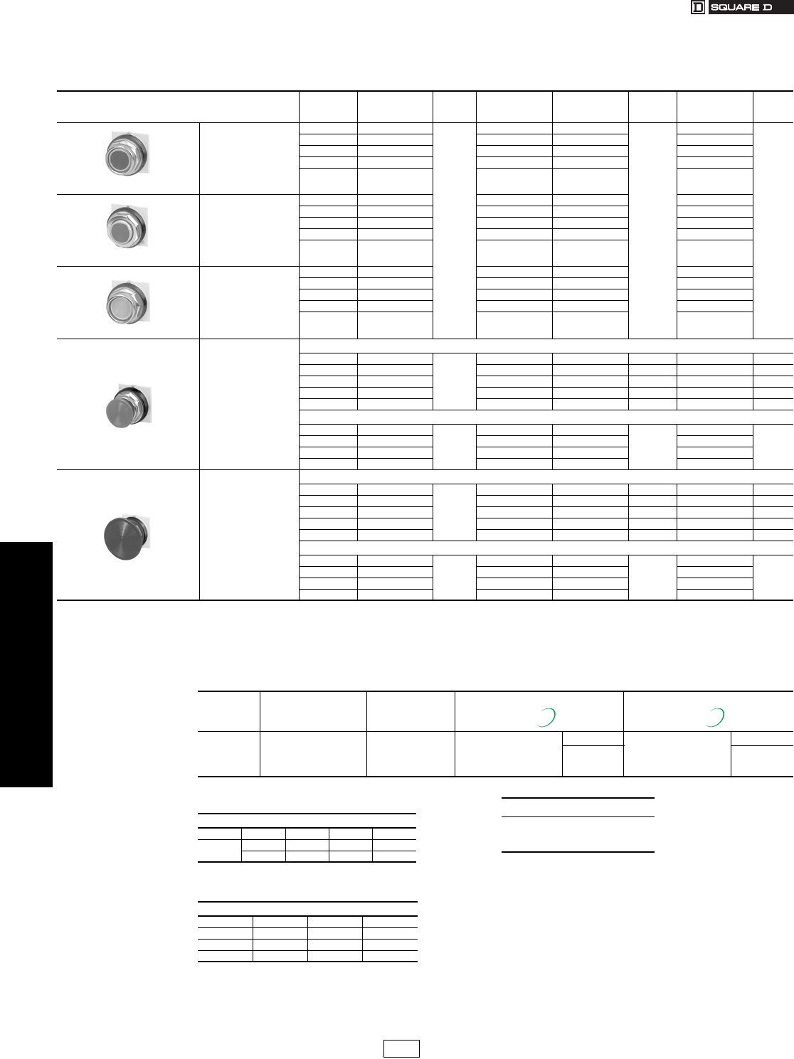
www.us.schneider-electric.com
FOR CURRENT INFORMATION
19 PUSH BUTTONS AND
OPERATOR INTERFACE
19-56 © 2007 Schneider Electric
All Rights Reserved
30 mm Push Buttons Type K Heavy Duty Operators
Class 9001 / Refer to Catalog 9001CT0001
Basic Operators . . . . . . . . . . . . . . . . . . . . . . . . . . . . . . . . . . . . . . . page 19-85
Light Modules . . . . . . . . . . . . . . . . . . . . . . . . . . . . . . . . . . . . . . . . page 19-77
Contact Blocks . . . . . . . . . . . . . . . . . . . . . . . . . . . . . . . . . . . . . . . . page 19-78
H Contact Block Assembly Codes . . . . . . . . . . . . . . . . . . . . . . . . page 19-80
Legend Plates . . . . . . . . . . . . . . . . . . . . . . . . . . . . . . . . . . . . . . . . page 19-81
Accessories . . . . . . . . . . . . . . . . . . . . . . . . . . . . . . . . . . . . . . . . . . page 19-83
Replacement Parts . . . . . . . . . . . . . . . . . . . . . . . . . . . . . . . . . . . . page 19-86
Table 19.157: Non-Illuminated Momentary Push Button Operators—UL Types 4, 13/NEMA 4, 13
For use in hazardous locations—See page 19-79.
Contact blocks and legend plate not included unless otherwise noted.
Description Color
Operator with
1 N.O. and 1 N.C.
Contact (KA1)
$ Price
Operator with
1 N.O. Contact
(KA2)
Operator with
1 N.C. Contact
(KA3)
$ Price
Operator Only
with No
Contacts
$ Price
9001KR1B
Full Guard
Black KR1BH13
54.00
KR1BH5 KR1BH6
39.90
KR1B
25.70
Red KR1RH13 KR1RH5 KR1RH6 KR1R
Green KR1GH13 KR1GH5 KR1GH6 KR1G
Universal aKR1UH13 KR1UH5 KR1UH6 KR1U
Other bKR1bH13 KR1bH5 KR1bH6 KR1b
9001KR3B
No Guard
Black KR3BH13 KR3BH5 KR3BH6 KR3B
Red KR3RH13 KR3RH5 KR3RH6 KR3R
Green KR3GH13 KR3GH5 KR3GH6 KR3G
Universal aKR3UH13 KR3UH5 KR3UH6 KR3U
Other bKR3bH13 KR3bH5 KR3bH6 KR3b
9001KR2B
Extended Guard
Black KR2BH13 KR2BH5 KR2BH6 KR2B
Red KR2RH13 KR2RH5 KR2RH6 KR2R
Green KR2GH13 KR2GH5 KR2GH6 KR2G
Universal aKR2UH13 KR2UH5 KR2UH6 KR2U
OtherbKR2bH13 KR2bH5 KR2bH6 KR2b
9001KR4B
1-3/8 in. (35 mm)
Diameter
Mushroom Button
Snap-In Mushroom Button
Black KR4BH13
83.00
KR4BH5 KR4BH6 68.00 KR4B 54.00
Red KR4RH13 KR4RH5 KR4RH6 68.00 KR4R 54.00
Red fKR4R05H13 KR4R05H5 KR4R05H6 72.00 KR4R05 57.00
Green KR4GH13 KR4GH5 KR4GH6 68.00 KR4G 54.00
Other dKR4dH13 KR4dH5 KR4dH6 68.00 KR4d54.00
Screw-On Mushroom Button With Set Screw Security e
Black KR24BH13
83.00
KR24BH5 KR24BH6
68.00
KR24B
54.00
Red KR24RH13 KR24RH5 KR24RH6 KR24R
Green KR24GH13 KR24GH5 KR24GH6 KR24G
OtherdKR24dH13 KR24dH5 KR24dH6 KR24d
9001KR5B
2-1/4 in. (57 mm)
Diameter
Mushroom Button
Snap-In Mushroom Button
Black KR5BH13
83.00
KR5BH5 KR5BH6 68.00 KR5B 54.00
Red KR5RH13 KR5RH5 KR5RH6 68.00 KR5R 54.00
Red fKR5R05H13 KR5R05H5 KR5R05H6 72.00 KR5R05 57.00
Green KR5GH13 KR5GH5 KR5GH6 68.00 KR5G 54.00
OtherdKR5dH13 KR5dH5 KR5dH6 68.00 KR5d54.00
Screw-On Mushroom Button With Set Screw Securitye
Black KR25BH13
83.00
KR25BH5 KR25BH6
68.00
KR25B
54.00
Red KR25RH13 KR25RH5 KR25RH6 KR25R
Green KR25GH13 KR25GH5 KR25GH6 KR25G
OtherdKR25dH13 KR25dH5 KR25dH6 KR25d
aThe universal push button operators contain one each of the following color inserts: black, red, green, yellow, orange, blue and white.
bSee Table 19.158 for color code.
cKnob has the words “Emergency Stop” in raised letters highlighted in white for readability.
dSee Table 19.158 for color code.
eSee Table 19.158 for Metal button price adder.
Table 19.158: Color Codes
Color
KR1, 2, 3
Place Color Code
in Type Number b
KR4, 5, 24, 25
Place Color Code
in Type Number d
For KR24R, G, B METAL Button eFor KR25R, G, B METAL Button e
Blue
Ye l l o w
White
Orange
Gray
L
Y
W
S
E
L
Y
—
S
—
Add “M” behind the Color
Code
Example: KR24RM
$ Price Adder Add “M” behind the Color
Code
Example: KR25RM
$ Price Adder
5.50 13.50
New! New!
Table 19.159: Contact Sequences (for page 19-57)
9001 KR8RH1 or H13
Pull Ctr Push
(KA1) KA3 X O O
KA2 O O X
9001 KR8RH25
Pull Ctr Push
KA3 X O O
KA5 X X O
KA2 O O X
When ordering, please specify:
•Quantity
•Class Number
•Type or Catalog Number
CP1 Discount
Schedule
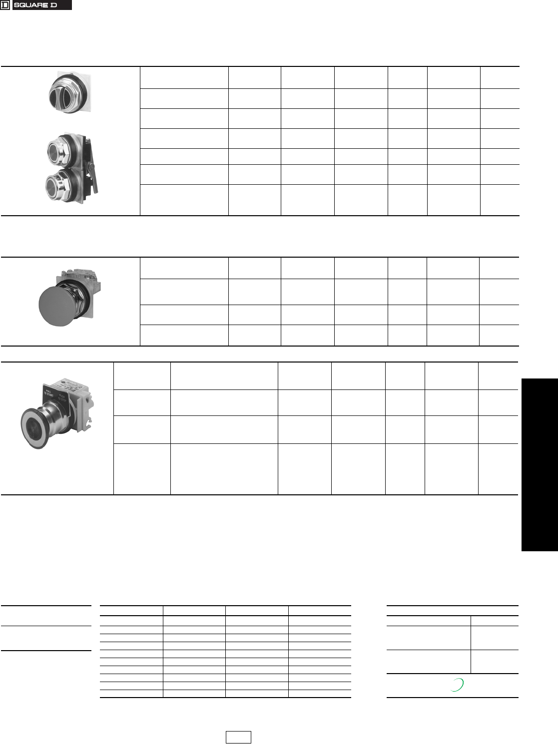
www.us.schneider-electric.com
FOR CURRENT INFORMATION
19 PUSH BUTTONS AND
OPERATOR INTERFACE
© 2007 Schneider Electric
All Rights Reserved 19-57
30 mm Push Buttons Type K Heavy Duty Operators
Class 9001 / Refer to Catalog 9001CT0001
.
Table 19.160: Illuminated and Non-Illuminated Multifunction Operators
Meets UL Type 13/NEMA 13 and UL Type 6/NEMA 6, which UL and NEMA consider an equivalent to UL Type 4/NEMA 4.
For use in hazardous locations—See page 19-79. Legend plate and contact blocks not included unless otherwise noted.
9001KR7U
9001KR11U
Description Color
With 2 N.O.
Contacts
(2 KA2)
With 1 N.O. &
1 N.C. Contact
(KA2, KA3)
$ Price Without
Contacts i$ Price
Momentary
Dual
Function
Universal a
Green-Red
Other b
KR6UH7
KR6GRH7
KR6bH7
KR6UH37
KR6GRH37
KR6bH37
83.
KR6U
KR6GR
KR6b
54.
Momentary
Interlocked
Dual Function
Universala
Green-Red
Other b
KR67UH7
KR6GRH7
KR67bH7
KR67UH37
KR6GRH37
KR67bH37
111.
KR67U
KR67GR
KR67b
83.
Maintained
Interlocked
Dual Function
Universal a
Green-Red
Other b
KR7UH7
KR6GRH7
KR7bH7
KR7UH37
KR6GRH37
KR7bH37
111.
KR7U
KR7GR
KR7b
83.
Description Color Contacts j (KA1) $ Price Without
Contacts i$ Price
Both Buttons
Maintained Interlocked
Assembly
Universal c
Other d—KR11UH1
KR11dH1 108. KR11U
KR11d80.
One Button Momentary
One Button Maintained
Interlocked Assembly
Universal c
Otherd—KR12UH1H1
KR12dH1H1 165. KR12U
KR12d108.
aUniversal for KR6, KR67, KR7 includes 2 inserts each of black, red and green.
bChoose one color for each button. R = red, G = green, B = Black. Example: A KR6 with left red and right black = KR6RB
cUniversal for KR11, KR12 includes 2 each of black, red, green, yellow, orange, blue, white.
dChoose one color for each button from table and insert color code in type number. Example: A KR11 with top button gray and bottom button orange = KR11ES
KR9R94H13
Set Screw Style
Description lColor
With 2 N.C.
Contacts
(1 KA3, 1 KA5)
With 1 N.O. &
1 N.C. Contact
(1 KA1)
$ Price Without
Contacts i$ Price
3 Position Non-Illuminated
Momentary Pull
Maintained Neutral
Momentary Push m
Red
Green
Other e
KR8RH25
KR8GH25
KR8eH25
—
—
—
86.
KR8R
KR8G
KR8e
57.
2 Position Non-Illuminated
Maintained Pull
Maintained Push n
Red k
Green
Other e
—
—
—
KR9RH13
KR9GH13
KR9eH13
114.
KR9R
KR9G
KR9e
86.
Set Screw Style Red — KR9R94H13 117. KR9R94 89.
9001KR9P1
1.625 in. Diameter Knob
For 1-3/8 in. or 2-1/4 in. Diameter Knob l
Includes Type KN379
Legend Plate Marked
Pull To Start Push To Stop
Description lVoltage
With Red Knob
and 2 N.C.
Contacts
(1 KA3, 1 KA5)
With Other
Color Knob and
2 N.C. Contacts
(1 KA3, 1 KA5)
$ Price
With Other Color
Knob Without
Contacts i
$ Price
3 Position Illuminated
Momentary Pull
Maintained Neutral
Momentary Pushm
110-120 V, 50-60 Hz
Other—Transformer, LED, Flashing g
Other—Full Voltage, Resistor, Neon h
KR8P1RH25
KR8PfRH25
KR8PfRH25
KR8P1eH25
KR8PfeH25
KR8PfeH25
162.
162.
143.
KR8P1e
KR8Pfe
KR8Pfe
134.
134.
114.
Description lVoltage
With Redk Knob
and 1 N.O. &
1 N.C. Contact
(KA1)
With Other Color
Knob and 1 N.O.
& 1 N.C. Contact
(KA1)
$ Price
With Other Color
Knob Without
Contacts
$ Price
2 Position Illuminated
Maintained Pull
Maintained Push
110–120 V, 50–60 Hz
Other—Transformer, LED, Flashing g
Other—Full Voltage, Resistor, Neon h
KR9P1RH13
KR9PfRH13
KR9PfRH13
KR9P1eH13
KR9PfeH13
KR9PfeH13
191.
191.
171.
KR9P1e
KR9Pfe
KR9Pfe
162.
162.
143.
eChoose one color from the Color Codes table below, and insert the color code in Type number. Example: KR9 with a yellow knob = KR9Y
fAdd the voltage assembly code as chosen from page 19-77. Example: KR8P with a 277 V 50–60 Hz voltage = KR8P8
gThe knob must be the same color as the LED light module chosen, for example, for a green LED, use a green knob.
hOn neon light modules, use clear knobs only.
iThese operators can be ordered complete with contact blocks. For maximum block usage, see page 19-80. Add the “H” number chosen from page 19-80 to the end of the operator Type
number and add the cost of the “H” number to the operator cost.
jKR11UH1 has 1 KA1 (1 N.O., 1 N.C.) and KR12UH1H1 has 2 KA1 (2 N.O., 2 N.C.).
kTo obtain a red knob with “Push Emergency Stop” printed on the red knob—substitute “R05” in place of “R” and add $2.10 to the price.
lFor 1-3/8 in. or 2-1/4 in. Dia. Knob:
a) Order Type -20 or -21 knob from page 19-84.
b) Order 9001K54 adapter (no charge)—allows Type -20 or -21 knob to fit on push pull operators. Voids UL and NEMA 6 rating.
c) Can order assembled operator by adding color code to Type -20 or -21. Example: 9001KR9R would be 9001KR9R20 or 9001KR9R21. No price adder.
mSee page 19-56 for contact sequences.
nSee Table 19.161 below.
When ordering, please
specify:
•Quantity
•Class Number
•Type or Catalog Number
Table 19.161: Other Color Code Selection
Color KR6, KR7, KR67 KR11, KR12 KR8, KR9 n For KR9R, G, Y (Non-III)
Black oBBB Description $ Price Adder
RedRRR Metal Button, 40 mm
Add M94 after KR9R, G, Y
Example: KR9RM94
27.40Green G G G
Blue L L
Ye l l o w — Y Y Metal Button, 60 mm
Add M95 after KR9R, G, Y
Example: KR9RM95
35.40White — W W
Orange o—S S
Clear — — C
Amber — — A
Gray — E —
oThese colors are not available on illuminated push-pull operators.
New!
CP1 Discount
Schedule
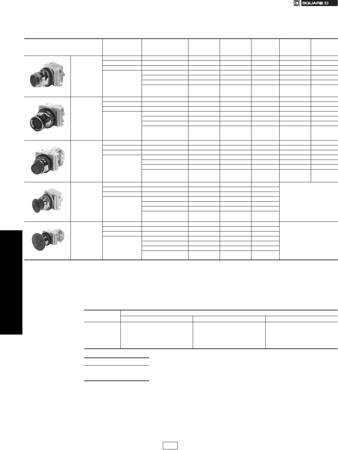
19-58 © 2007 Schneider Electric
All Rights Reserved
www.us.schneider-electric.com
FOR CURRENT INFORMATION
19 PUSH BUTTONS AND
OPERATOR INTERFACE
30 mm Push Buttons Type K Heavy Duty Operators
Class 9001 / Refer to Catalog 9001CT0001
Basic Operators . . . . . . . . . . . . . . . . . . . . . . . . . . . . . . . . . . . . . . . page 19-85
Light Modules . . . . . . . . . . . . . . . . . . . . . . . . . . . . . . . . . . . . . . . . page 19-77
Contact Blocks . . . . . . . . . . . . . . . . . . . . . . . . . . . . . . . . . . . . . . . . page 19-78
H Contact Block Assembly Codes . . . . . . . . . . . . . . . . . . . . . . . . page 19-80
Legend Plates . . . . . . . . . . . . . . . . . . . . . . . . . . . . . . . . . . . . . . . . page 19-81
Accessories . . . . . . . . . . . . . . . . . . . . . . . . . . . . . . . . . . . . . . . . . . page 19-83
Replacement Parts . . . . . . . . . . . . . . . . . . . . . . . . . . . . . . . . . . . . page 19-86
Table 19.162: Illuminated Momentary Push Button Operators—UL Types 4, 13/NEMA 4, 13
For use in hazardous locations—See page 19-79.
Legend plate and contact block not included unless otherwise noted.
Description
Volt age
and
Frequency
Style
With Red Color
Cap and 1 N.O.
and 1 N.C.
Contact (KA1)
With Green Color
Cap and 1 N.O.
and 1 N.C.
Contact (KA1)
$ Price g
With Other Color
Cap Without
Contact Block a
$ Price h
9001K1L1
Full Guard
Illuminated
Push Button
Clear Plastic Top
110–120 V, 50–60 Hz Transformer K1L1RH13 K1L1GH13 140. K1L1e111.
220–240 V, 50–60 Hz Transformer K1L7RH13 K1L7GH13 140. K1L7e111.
24–28 Vac/dc Full Voltage K1L35RH13 K1L35GH13 120. K1L35e92.
For other voltages
see Table b
Transformer or Flashing K1LbRH13 K1LbGH13 140. K1Lbe 111.
Full Voltage K1LbRH13 K1LbGH13 120. K1Lbe 92.
Resistor or NeoncK1LbRH13 K1LbGH13 120. K1Lbe 92.
LED dK1LbRH13 K1LbGH13 140. K1Lbe 111.
9001K3L1
Full Guard
Illuminated
Push Button
Metal Top
110–120 V, 50–60 Hz Transformer K3L1RH13 K3L1GH13 140. K3L1e111.
220–240 V, 50–60 Hz Transformer K3L7RH13 K3L7GH13 140. K3L7e111.
24–28 Vac/dc Full Voltage K3L35RH13 K3L35GH13 120. K3L35e92.
For other voltages
see Table b
Transformer or Flashing K3LbRH13 K3LbGH13 140. K3Lbe 111.
Full Voltage K3LbRH13 K3LbGH13 120. K3Lbe 92.
Resistor or Neon cK3LbRH13 K3LbGH13 120. K3Lbe 92.
LED dK3LbRH13 K3LbGH13 140. K3Lbe 111.
9001K2L1
No Guard
Illuminated
Push Button
110–120 V, 50–60 Hz Transformer K2L1RH13 K2L1GH13 131. K2L1e102.
220–240 V, 50–60 Hz Transformer K2L7RH13 K2L7GH13 131. K2L7e102.
24–28 Vac/dc Full Voltage K2L35RH13 K2L35GH13 111. K2L35e83.
For other voltages
see Table b
Transformer or Flashing K2LbRH13 K2LbGH13 131. K2Lbe 102.
Full Voltage K2LbRH13 K2LbGH13 111. K2Lbe 83.
Resistor or Neon cK2LbRH13 K2LbGH13 111. K2Lbe 83.
LED dK2LbRH13 K2LbGH13 131. K2Lbe 102.
9001K2LR20
1-3/8 in. (35 mm)
Illuminated
Mushroom
110–120 V, 50–60 Hz Transformer K2L1R20H13 K2L1G20H13 131.
Order K2L be
Above f
220–240 V, 50–60 Hz Transformer K2L7R20H13 K2L7G20H13 131.
24–28 Vac/dc Full Voltage K2L35R20H13 K2L35G20H13 111.
For other voltages
see Table b
Transformer or Flashing K2LbR20H13 K2LbG20H13 131.
Full Voltage K2LbR20H13 K2LbG20H13 111.
Resistor or Neon cK2LbR20H13 K2LbG20H13 111.
LED dK2LbR20H13 K2LbG20H13 131.
9001K2LR21
2-1/4 in. (57 mm)
Illuminated
Mushroom
110–120 V, 50–60 Hz Transformer K2L1R21H13 K2L1G21H13 131.
Order K2L be
Above f
220–240 V, 50–60 Hz Transformer K2L7R21H13 K2L7G21H13 131.
24–28 Vac/dc Full Voltage K2L35R21H13 K2L35G21H13 111.
For other voltages
see Table b
Transformer or Flashing K2LbR21H13 K2LbG21H13 131.
Full Voltage K2LbR21H13 K2LbG21H13 111.
Resistor or Neon cK2LbR21H13 K2LbG21H13 111.
LED dK2LbR21H13 K2LbG21H13 131.
aThese operators can be ordered complete with contact blocks. For maximum block usage, see page 19-85. Add the “H”
number chosen from page 19-80 to the end of the operator type number and add the cost of the “H” number to the operator cost.
bAdd the voltage assembly code as chosen from Table 19.219 or 19.220 on page 19-77. Example: K2La with 240 Vac/dc = K2L25
cOn neon light modules, use clear color caps only.
dThe cap must be the same color as the LED light module chosen, e.g., for red LED, use red color cap.
eAdd the color code as chosen from the color cap table. Example: K2L25c with a blue 13⁄8 mushroom button = K2L25L20
fThe only difference between a no guard (K2Lq) operator and mushroom button operator is the color cap.
gPrice includes operator, light module, contact block, and color cap.
hPrice includes operator, light module, and color cap.
Table 19.163: Color Caps
Color Color Codes
eK1L, K2L, K3L e 1-3/8 in. Mushroom e 2-1/4 in. Mushroom
Red
Green
Blue
Ye l l o w
White
Clear
Amber
R
G
L
Y
W
C
A
R20
G20
L20
Y20
W20
C20
A20
R21
G21
L21
Y21
W21
C21
A21
When ordering, please specify:
•Quantity
•Class Number
•Type or Catalog Number
CP1 Discount
Schedule
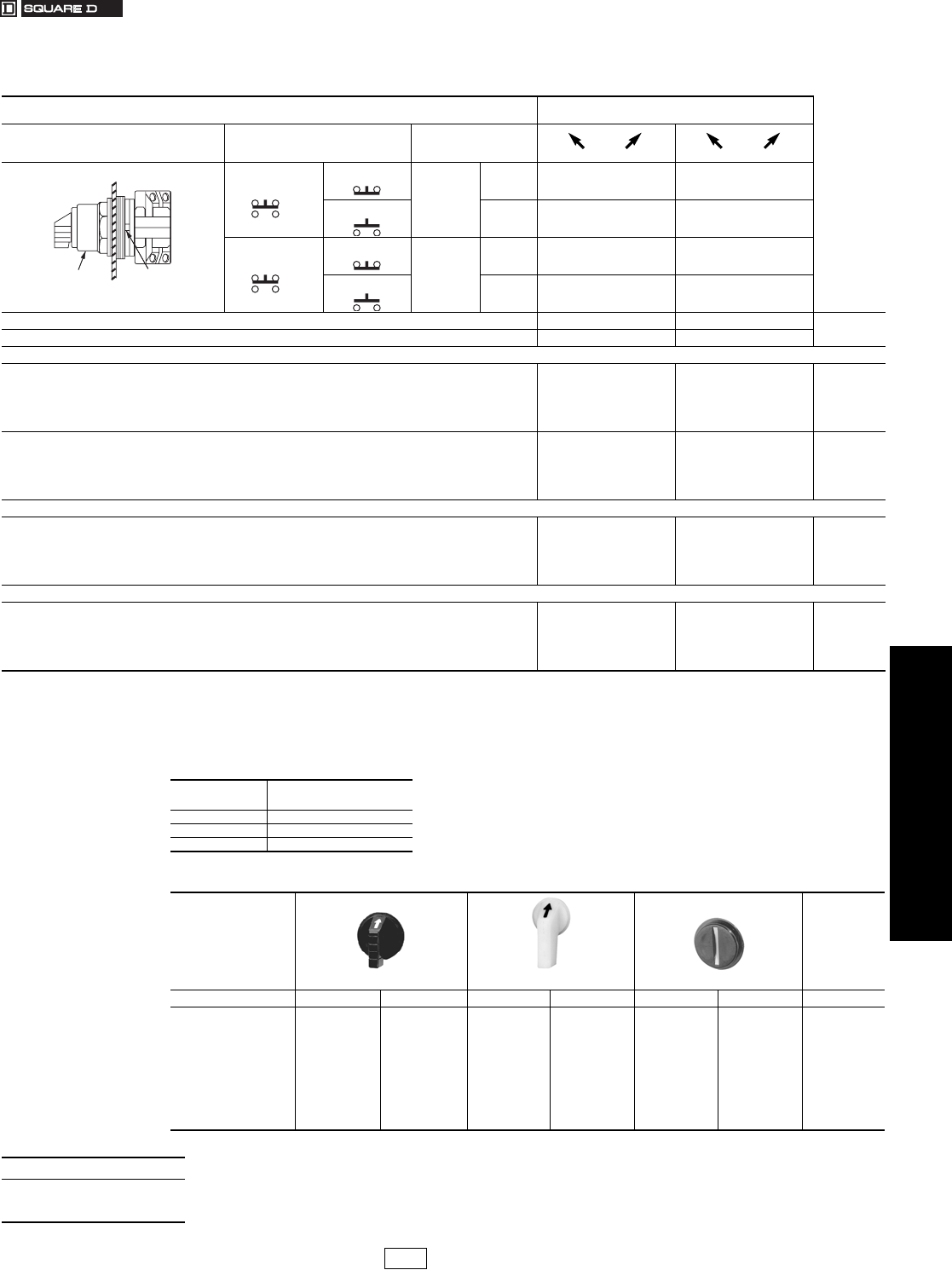
www.us.schneider-electric.com
FOR CURRENT INFORMATION
19 PUSH BUTTONS AND
OPERATOR INTERFACE
© 2007 Schneider Electric
All Rights Reserved 19-59
30 mm Push Buttons Type K Heavy Duty Selector Switches
Class 9001 / Refer to Catalog 9001CT0001
Table 19.164: Non-Illuminated 2 Position Selector Switch Operators—UL Types 4, 13/NEMA 4, 13
For use in hazardous locations—See page 19-79. Legend plate and contact block not included unless noted.
Contact Block Required 1—Contact Closed
0—Contact Open
Contact
Block
Position
Quantity
and
Type
Mount
on
Side Left Right Left Right
KA1
KA3
KA1
#2
KA3
#2 10 01
or or
KA2 KA2
#2 01 10
KA1
KA3
KA1
#1
KA3
#1 10 01
or or
KA2 KA2
#1 01 10
Cam (see page 19-64) E D $ Price
Non-Illuminated Operators Type Type
Manual Return
Operator Onlya
Without Knob KS11 KS12 28.50
With Standard Black Knob KS11B KS12B 35.10
With Other Color Knob (See Table 19.166)bKS11bKS12b35.10
Key Operated with E10 Key (Code 1, 2, 3)cd KS11KcKS12Kc92.00
With Contact Block(s)
With Standard Knob
With 1 KA1 on Side #2 KS11BH13 —64.00
With 1 KA1 on Side #1 KS11BH1 —64.00
With 1 KA1 on Side #1 and 1 KA1 on Side #2 KS11BH2 —92.00
Spring Return from Left
Operator Only a
Without Knob KS25 —47.60
With Standard Black Knob KS25B —54.00
With Other Color Knob (See Table 19.166) bKS25b—54.00
Key Operated with E10 Key (Code 2 only) cKS25K2 —111.00
Spring Return From Right
Operator Only a
Without Knob —KS34 47.60
With Standard Black Knob —KS34B 54.00
With Other Color Knob (See Table 19.166) b— KS34b54.00
Key Operated with E10 Key (Code 1 Only) c—KS34K1 111.00
aThese operators can be ordered complete with contact blocks. For maximum block usage, see page 19-85. Add the “H” number
chosen from page 19-80 to the end of the operator type number and add the cost of the “H” number to the operator cost.
bAdd the color code as chosen from knob color table at right. Example: KS11b with a green gloved-hand knob = KS11FG
cAdd the key withdrawal code from key withdrawal code table below. Example: KS11Kc with key withdrawal in the right position only = KS11K2
dAll key operated devices come standard with Square D key no. E10 (key only part no. is 2941101100, $6.60 per key).
Other key changes are available. For additional information, refer to Catalog 9001CT0001.
Top View
Side 2
Side 1
Operator Locating
Notch
Table 19.165: Key Withdrawal Code c
Code Position
1 Left Only
2Right Only
3 Left and Right
Table 19.166: Selector Switch Knobs
Standard Knob Gloved-Hand Knob Coin Operated
Color bKnob Code Type bKnob Code Type bKnob Code Type $ Price
Black B B11 FB B25 TB B18
6.60
Red R R8 FR R24 TR R16
Green G G8 FG G24 TG G16
Yellow Y Y8 FY Y24 TY Y16
Orange S S11 FS S25 ——
Blue L L8 FL L24 TL L16
White W W8 FW W24 ——
Amber A A8 FA A24 ——
Clear C C8 FC C24 TC C16
When ordering, please specify:
•Quantity
•Class Number
•Type or Catalog Number
CP1 Discount
Schedule
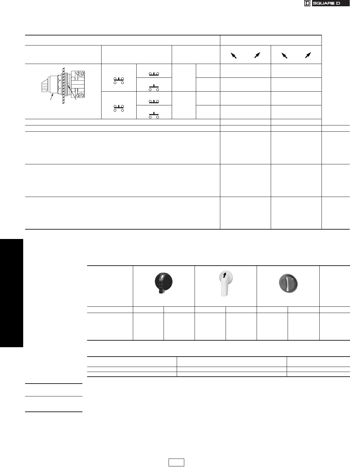
19-60 © 2007 Schneider Electric
All Rights Reserved
www.us.schneider-electric.com
FOR CURRENT INFORMATION
19 PUSH BUTTONS AND
OPERATOR INTERFACE
30 mm Push Buttons Type K Heavy Duty Selector Switches
Class 9001 / Refer to Catalog 9001CT0001
fAdd form number to standard Type number, e.g., Type K11J1 Form Y178.
Basic Operators . . . . . . . . . . . . . . . . . . . . . . . . . . . . . . . . . . . . . . . page 19-85
Light Modules . . . . . . . . . . . . . . . . . . . . . . . . . . . . . . . . . . . . . . . . page 19-77
Contact Blocks . . . . . . . . . . . . . . . . . . . . . . . . . . . . . . . . . . . . . . . . page 19-78
H Contact Block Assembly Codes . . . . . . . . . . . . . . . . . . . . . . . . page 19-80
Legend Plates . . . . . . . . . . . . . . . . . . . . . . . . . . . . . . . . . . . . . . . . page 19-81
Accessories . . . . . . . . . . . . . . . . . . . . . . . . . . . . . . . . . . . . . . . . . . page 19-83
Replacement Parts . . . . . . . . . . . . . . . . . . . . . . . . . . . . . . . . . . . . page 19-86
Table 19.167: Illuminated 2 Position Selector Switch Operators – UL Types 4, 13/NEMA 4, 13
For use in hazardous locations – See page 19-79. Legend plate and contact block not included unless noted.
Contact Block Required 1 — Contact Closed
0 — Contact Open
Contact
Block
Position
Quantity and Type
KA1 or KA2 or KA3
Mount on Side
KA1 or KA2 or KA3
Left Right Left Right
KA1
KA3
KA1
#2
KA3
#2 10 01
KA2 KA2
#2 01 10
KA1
KA3
KA1
#1
KA3
#1 10 01
KA2 KA2
#1 01 10
Cam (see page 19-64) E D
Illuminated Operators Type Type $ Price
Manual Return a
•Without Knob, 110–120 V 50–60 Hz Transformer
•With Standard Red Knob, 110–120 V 50–60 Hz Transformer
•Without Knob and Other Voltage Transformer, Flashing or LED d
•Without Knob, Full Voltage Neon or Resistore
•With Other Color Knob and Transformer, Flashing or LED d
•With Other Color Knob, Full Voltage Neon or Resistor e
K11J1
K11J1R
K11Jb
K11Jb
K11Jbc
K11Jbc
K12J1
K12J1R
K12Jb
K12Jb
K12Jbc
K12Jbc
105.
111.
105.
86.
111.
92.
Spring Return from Left a
•Without Knob, 110–120 V 50–60 Hz Transformer
•With Standard Red Knob, 110–120 V 50–60 Hz Transformer
•Without Knob and Other Voltage Transformer, Flashing or LED d
•Without Knob, Full Voltage Neon or Resistor e
•With Other Color Knob and Transformer, Flashing or LED d
•With Other Color Knob, Full Voltage Neon or Resistore
K25J1
K25J1R
K25Jb
K25Jb
K25Jbc
K25Jbc
—
—
—
—
—
—
123.
131.
123.
105.
131.
111.
Spring Return From Right a
•Without Knob, 110–120 V 50–60 Hz Transformer
•With Standard Red Knob, 110–120 V 50–60 Hz Transformer
•Without Knob and Other Voltage Transformer, Flashing or LED d
•Without Knob, Full Voltage Neon or Resistor e
•With Other Color Knob and Transformer, Flashing or LED d
•With Other Color Knob, Full Voltage Neon or Resistor e
—
—
—
—
—
—
K34J1
K34J1R
K34Jb
K34Jb
K34Jbc
K34Jbc
123.
131.
123.
105.
131.
111.
aThese operators can be ordered complete with contact blocks. For maximum block usage, see page 19-85. Add the “H” number
chosen from page 19-80 to the end of the operator type number and add the cost of the “H” number to the operator cost.
bAdd the voltage assembly code as chosen from page 19-77. Example: K25Jb with 208 Vac = K25J3.
cAdd the color code as chosen from Table 19.168. Example: K25J35c with a green knob = K25J35G.
dThe knob must be the same color as the LED light module chosen, for example, with a red LED, use a red knob.
eOn neon light modules, use clear knobs only.
Top View
Side 2
Side 1
Operator Locating
Notch
Table 19.168: Selector Switch Knobs
Standard Knob Gloved-Hand
Knob
Coin Operated
Color c Knob Code Type c Knob Code Type c Knob Code Type $ Price
Red
Green
Yellow
Blue
White
Amber
Clear
R
G
Y
L
W
A
C
R8
G8
Y8
L8
W8
A8
C8
FR
FG
FY
FL
FW
FA
FC
R24
G24
Y24
L24
W24
A24
C24
TR
TG
TY
TL
—
—
TC
R16
G16
Y16
L16
—
—
C16
6.60
Table 19.169: Two Color Selector Switch
Used to indicate red in left position and green in right position on illuminated operators.
Knob Factory Assembled
Form Number f$ Price Adder
Standard Y178 28.50
Gloved-Hand Y1781 28.50
When ordering,
please specify:
•Quantity
•Class Number
•Type or Catalog Number
CP1 Discount
Schedule
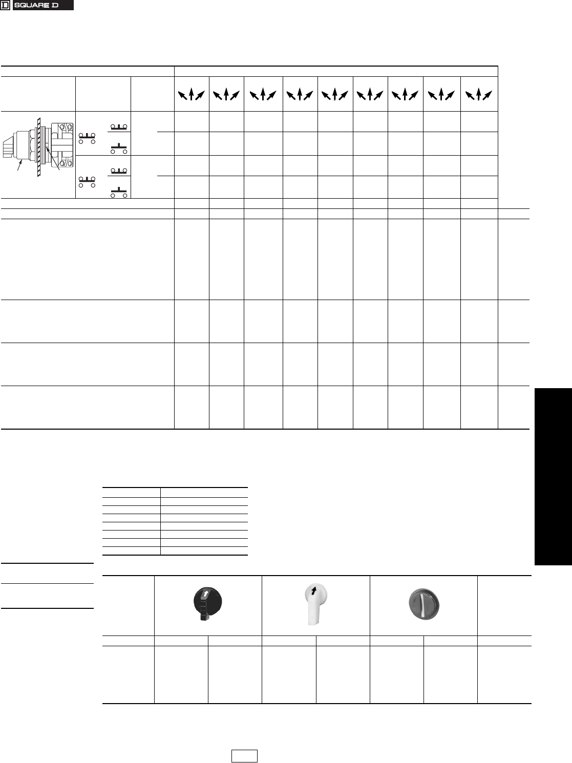
www.us.schneider-electric.com
FOR CURRENT INFORMATION
19 PUSH BUTTONS AND
OPERATOR INTERFACE
© 2007 Schneider Electric
All Rights Reserved 19-61
30 mm Push Buttons Type K Heavy Duty Selector Switches
Class 9001 / Refer to Catalog 9001CT0001
Table 19.170: Non-Illuminated 3 Position Selector Switch Operators—UL Types 4, 13/NEMA 4, 13
For use in hazardous locations—See page 19-79.
Legend plate and contact block not included unless noted.
Contact Block Required 1—Contact Closed 0—Contact Open
Contact
Block
Position
Quantity
and
Type
Mount
on
Side
Center
Left Right
Center
Left Right
Center
Left Right
Center
Left Right
Center
Left Right
Center
Left Right
Center
Left Right
Center
Left Right
Center
Left Right
KA1 or
KA3
KA1
#2 or
KA3
#2 100 100 001 100 100 100 100 010 110
KA2 KA2
#2 011 001 010 010 001 011 011 100 001
KA1 or
KA3
KA1
#1 or
KA3
#1 001 100 001 100 010 001 101 001 011
KA2 KA2
#1 110 001 010 010 001 100 010 010 100
Cam (see page 19-64) B C D E F G J L M
Non-Illuminated Operators Type Type Type Type Type Type Type Type Type $ Price
Manual Return
Operator Only a
•Without Knob
•With Standard Black Knob
•With Other Color Knob (See Table 19.172) b
•Key Operated with E10 Key (Code 4 through 10) cd
With Contact Block(s)
•With Standard Black Knob (For Other Colors, Replace B in
Type Number with Color Code from Table 19.172.)
•With 1 KA1 on side #2 (H13)
•With 1 KA1 on side #1 (H1)
•With 1 KA1 on side #1 and 1 KA1 on side #2 (H2)
KS42
KS42B
KS42b
KS42Kc
KS42BH13
KS42BH1
KS42BH2
KS43
KS43B
KS43b
KS43Kc
KS43BH13
KS43BH1
KS43BH2
KS44
KS44B
KS44b
KS44Kc
KS44BH13
KS44BH1
KS44BH2
KS45
KS45B
KS45b
KS45Kc
KS45BH13
KS45BH1
KS45BH2
KS46
KS46B
KS46b
KS46Kc
KS46BH13
KS46BH1
KS46BH2
KS47
KS47B
KS47b
KS47Kc
KS47BH13
KS47BH1
KS47BH2
KS49
KS49B
KS49b
KS49Kc
KS49BH13
KS49BH1
KS49BH2
KS401
KS401B
KS401b
KS401Kc
KS401BH13
KS401BH1
KS401BH2
KS402
KS402B
KS402b
KS402Kc
KS402BH13
KS402BH1
KS402BH2
28.50
35.10
35.10
92.00
64.00
64.00
92.00
Spring Return from Left to Center
Operator Only a
•Without Knob
•With Standard Black Knob
•With Other Color Knob (See Table 19.172) b
•Key Operated with E10 Key (Code 5, 6 or 9 only) cd
KS62
KS62B
KS62b
KS62Kc
KS63
KS63B
KS63b
KS63Kc
KS64
KS64B
KS64b
KS64Kc
KS65
KS65B
KS65b
KS65Kc
KS66
KS66B
KS66b
KS66Kc
KS67
KS67B
KS67b
KS67Kc
KS69
KS69B
KS69b
KS69Kc
KS601
KS601B
KS601b
KS601Kc
KS602
KS602B
KS602b
KS602Kc
47.60
54.00
54.00
111.00
Spring Return From Right to Center
Operator Only a
•Without Knob
•With Standard Black Knob
•With Other Color Knob (See Table 19.172) b
•Key Operated with E10 Key (Code 4, 5 or 7 Only) cd
KS72
KS72B
KS72b
KS72Kc
KS73
KS73B
KS73b
KS73Kc
KS74
KS74B
KS74b
KS74Kc
KS75
KS75B
KS75b
KS75Kc
KS76
KS76B
KS76b
KS76Kc
KS77
KS77B
KS77b
KS77Kc
KS79
KS79B
KS79b
KS79Kc
KS701
KS701B
KS701b
KS701Kc
KS702
KS702B
KS702b
KS702Kc
47.60
54.00
54.00
111.00
Spring Return Both Sides to Center
Operator Only a
•Without Knob
•With Standard Black Knob
•With Other Color Knob (See Table 19.172) b
•Key Operated with E10 Key (Code 5 Only) d
KS52
KS52B
KS52 b
KS52K5
KS53
KS53B
KS53b
KS53K5
KS54
KS54B
KS54b
KS54K5
KS55
KS55B
KS55b
KS55K5
KS56
KS56B
KS56b
KS56K5
KS57
KS57B
KS57b
KS57K5
KS59
KS59B
KS59b
KS59K5
KS501
KS501B
KS501b
KS501K5
KS502
KS502B
KS502b
KS502K5
47.60
54.00
54.00
111.00
aThese operators can be ordered complete with contact blocks. For maximum block usage, see page 19-85. Add the “H” number
chosen from page 19-80 to the end of the operator type number and add the cost of the “H” number to the operator cost.
bAdd the color code as chosen from Table 19.172. Example: KS43b with a green gloved-hand knob = KS43FG
cAdd the key withdrawal code from Table 19.171. Example: KS43Kc with key withdrawal in the right position only = KS43K6
dAll key operated devices come standard with Square D key no. E10 (key only part no. is 2941101100, $6.60 per key).
Other key changes are available. For additional information, refer to Catalog 9001CT0001.
Top View
Side 2
Side 1
Operator Locating
Notch
Table 19.171: cKey Withdrawal Codes
Code Position
4 Left Only
5 Center Only
6Right Only
7 Left and Center
8 Left and Right
9 Center and Right
10 Left, Center and Right
When ordering,
please specify:
•Quantity
•Class Number
•Type or Catalog Number
Table 19.172: Selector Switch Knobs
Standard Knob Gloved-Hand Knob Coin Operated
Color bKnob Code Type bKnob Code Type bKnob Code Type $ Price
Black
Red
Green
Yellow
Orange
Blue
White
Amber
Clear
B
R
G
Y
S
L
W
A
C
B11
R8
G8
Y8
S11
L8
W8
A8
C8
FB
FR
FG
FY
FS
FL
FW
FA
FC
B25
R24
G24
Y24
S25
L24
W24
A24
C24
TB
TR
TG
TY
—
TL
—
—
TC
B18
R16
G16
Y16
—
L16
—
—
C16
6.60
CP1 Discount
Schedule
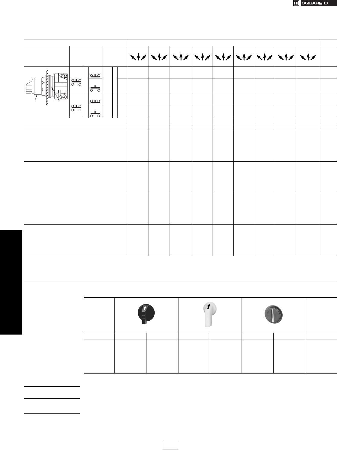
19-62 © 2007 Schneider Electric
All Rights Reserved
www.us.schneider-electric.com
FOR CURRENT INFORMATION
19 PUSH BUTTONS AND
OPERATOR INTERFACE
30 mm Push Buttons Type K Heavy Duty Selector Switches
Class 9001 / Refer to Catalog 9001CT0001
fNon-Illuminated only.
Basic Operators . . . . . . . . . . . . . . . . . . . . . . . . . . . . . . . . . . . . . . . page 19-85
Light Modules . . . . . . . . . . . . . . . . . . . . . . . . . . . . . . . . . . . . . . . . page 19-77
Contact Blocks . . . . . . . . . . . . . . . . . . . . . . . . . . . . . . . . . . . . . . . . page 19-78
H Contact Block Assembly Codes . . . . . . . . . . . . . . . . . . . . . . . . page 19-80
Legend Plates . . . . . . . . . . . . . . . . . . . . . . . . . . . . . . . . . . . . . . . . page 19-81
Accessories . . . . . . . . . . . . . . . . . . . . . . . . . . . . . . . . . . . . . . . . . . page 19-83
Replacement Parts . . . . . . . . . . . . . . . . . . . . . . . . . . . . . . . . . . . . page 19-86
Table 19.173: Illuminated 3 Position Selector Switch Operators
For use in hazardous locations—See page 19-79.
Legend plate and contact block not included unless noted.
CONTACT BLOCK REQUIRED 1 — Contact Closed 0 — Contact Open
Contact
Block
Position
Quantity
and
Type
Mount
on
Side
Center
Left Right
Center
Left Right
Center
Left Right
Center
Left Right
Center
Left Right
Center
Left Right
Center
Left Right
Center
Left Right
Center
Left Right
KA1 or
KA3
KA1
#2 or
KA3
#2 100 100 001 100 100 100 100 010 110
KA2 KA2
#2 011 001 010 010 001 011 011 100 001
KA1 or
KA3
KA1
#1 or
KA3
#1 001 100 001 100 010 001 101 001 011
KA2 KA2
#1 110 001 010 010 001 100 010 010 100
Cam (see page 19-64) B C D E F G J L M
Illuminated Operators Type Type Type Type Type Type Type Type Type $ Price
Manual Return a
Without Knob, 110–120 V 50–60 Hz Transformer
With Standard Red Knob, 110–120 V 50–60 Hz Transformer
Without Knob and Other Voltage Transformer, Flashing or LED d
Without Knob, Full Voltage Neon or Resistor e
With Other Color Knob and Transformer, Flashing or LED d
With Other Color Knob, Full Voltage Neon or Resistor e
K42J1
K42J1R
K42Jb
K42Jb
K42Jbc
K42Jbc
K43J1
K43J1R
K43Jb
K43Jb
K43Jbc
K43Jbc
K44J1
K44J1R
K44Jb
K44Jb
K44Jbc
K44Jbc
K45J1
K45J1R
K45Jb
K45Jb
K45Jbc
K45Jbc
K46J1
K46J1R
K46Jb
K46Jb
K46Jbc
K46Jbc
K47J1
K47J1R
K47Jb
K47Jb
K47Jbc
K47Jbc
K49J1
K49J1R
K49Jb
K49Jb
K49Jbc
K49Jbc
K401J1
K401J1R
K401Jb
K401Jb
K401Jbc
K401Jbc
K402J1
K402J1R
K402Jb
K402Jb
K402Jbc
K402Jbc
105.
111.
105.
86.
111.
92.
Spring Return Left To Center a
Without Knob, 110–120 V 50–60 Hz Transformer
With Standard Red Knob, 110–120 V 50–60 Hz Transformer
Without Knob and Other Voltage Transformer, Flashing or LED d
Without Knob, Full Voltage Neon or Resistor e
With Other Color Knob and Transformer, Flashing or LED d
With Other Color Knob, Full Voltage Neon or Resistor e
K62J1
K62J1R
K62Jb
K62Jb
K62Jbc
K62Jbc
K63J1
K63J1R
K63Jb
K63Jb
K63Jbc
K63Jbc
K64J1
K64J1R
K641b
K64Jb
K64Jbc
K64Jbc
K65J1
K65J1R
K65Jb
K65Jb
K65Jbc
K65Jbc
K66J1
K66J1R
K66Jb
K66Jb
K66Jbc
K66Jbc
K67J1
K67J1R
K67Jb
K67Jb
K67Jbc
K67Jbc
K69J1
K69J1R
K69Jb
K69Jb
K69Jbc
K69Jbc
K601J1
K601J1R
K601Jb
K601Jb
K601Jbc
K601Jbc
K602J1
K602J1R
K602Jb
K602Jb
K602Jbc
K602Jbc
123.
131.
123.
105.
131.
111.
Spring Return Right To Center a
Without Knob, 110–120 V 50–60 Hz Transformer
With Standard Red Knob, 110–120 V 50–60 Hz Transformer
Without Knob and Other Voltage Transformer, Flashing or LEDd
Without Knob, Full Voltage Neon or Resistore
With Other Color Knob and Transformer, Flashing or LED d
With Other Color Knob, Full Voltage Neon or Resistor e
K72J1
K72J1R
K72Jb
K72Jb
K72Jbc
K72Jbc
K73J1
K73J1R
K73Jb
K73Jb
K73Jbc
K73Jbc
K74J1
K74J1R
K74Jb
K74Jb
K74Jbc
K74Jbc
K75J1
K75J1R
K75Jb
K75Jb
K75Jbc
K75Jbc
K76J1
K76J1R
K76Jb
K76Jb
K76Jbc
K76Jbc
K77J1
K77J1R
K77Jb
K77Jb
K77Jbc
K77Jbc
K79J1
K79J1R
K79Jb
K79Jb
K79Jbc
K79Jbc
K701J1
K701J1R
K701Jb
K701Jb
K701Jbc
K701Jbc
K702J1
K702J1R
K702Jb
K702Jb
K702Jbc
K702Jbc
123.
131.
123.
105.
131.
111.
Spring Return Both Sides To Center a
Without Knob, 110–120 V 50–60 Hz Transformer
With Standard Red Knob, 110–120 V 50–60 Hz Transformer
Without Knob and Other Voltage Transformer, Flashing or LED d
Without Knob, Full Voltage Neon or Resistor e
With Other Color Knob and Transformer, Flashing or LED d
With Other Color Knob, Full Voltage Neon or Resistor e
K52J1
K52J1R
K52Jb
K52Jb
K52Jbc
K52Jbc
K53J1
K53J1R
K53Jb
K53Jb
K53Jbc
K53Jbc
K54J1
K54J1R
K54Jb
K54Jb
K54Jbc
K54Jbc
K55J1
K55J1R
K55Jb
K55Jb
K55Jbc
K55Jbc
K56J1
K56J1R
K56Jb
K56Jb
K56Jbc
K56Jbc
K57J1
K57J1R
K57Jb
K57Jb
K57Jbc
K57Jbc
K59J1
K59J1R
K59Jb
K59Jb
K59Jbc
K59Jbc
K501J1
K501J1R
K501Jb
K501Jb
K501Jbc
K501Jbc
K502J1
K502J1R
K502Jb
K502Jb
K502Jbc
K502Jbc
123.
131.
123.
105.
131.
111.
aThese operators can be ordered complete with contact blocks. For maximum block usage, see page 19-85. Add the “H”
number chosen from 19-80 to the end of the operator type number and add the cost of the “H” number to the operator cost.
bAdd the voltage assembly code as chosen from page 19-77. Example: K43Jb with 208 Vac = K43J3
cAdd the color code as chosen from Table 19.174. Example: K43J35c with a green knob = K43J35G
dThe knob must be the same color as the LED light module chosen, for example, for a red LED, use a red knob.
eOn neon light modules, use clear knobs only.
Top View
Side 2
Side 1
Operator Locating
Notch
Table 19.174: Selector Switch Knobs
Standard Knob Gloved-Hand Knob Coin Operated
Color Knob Code Type Knob Code Type Knob Code Type $ Price
Black f
Red
Green
Yellow
Orange f
Blue
White
Amber
Clear
B
R
G
Y
S
L
W
A
C
B11
R8
G8
Y8
S11
L8
W8
A8
C8
FB
FR
FG
FY
FS
FL
FW
FA
FC
B25
R24
G24
Y24
S25
L24
W24
A24
C24
TB
TR
TG
TY
—
TL
—
—
TC
B18
R16
G16
Y16
—
L16
—
—
C16
6.60
When ordering,
please specify:
•Quantity
•Class Number
•Type or Catalog Number
CP1 Discount
Schedule
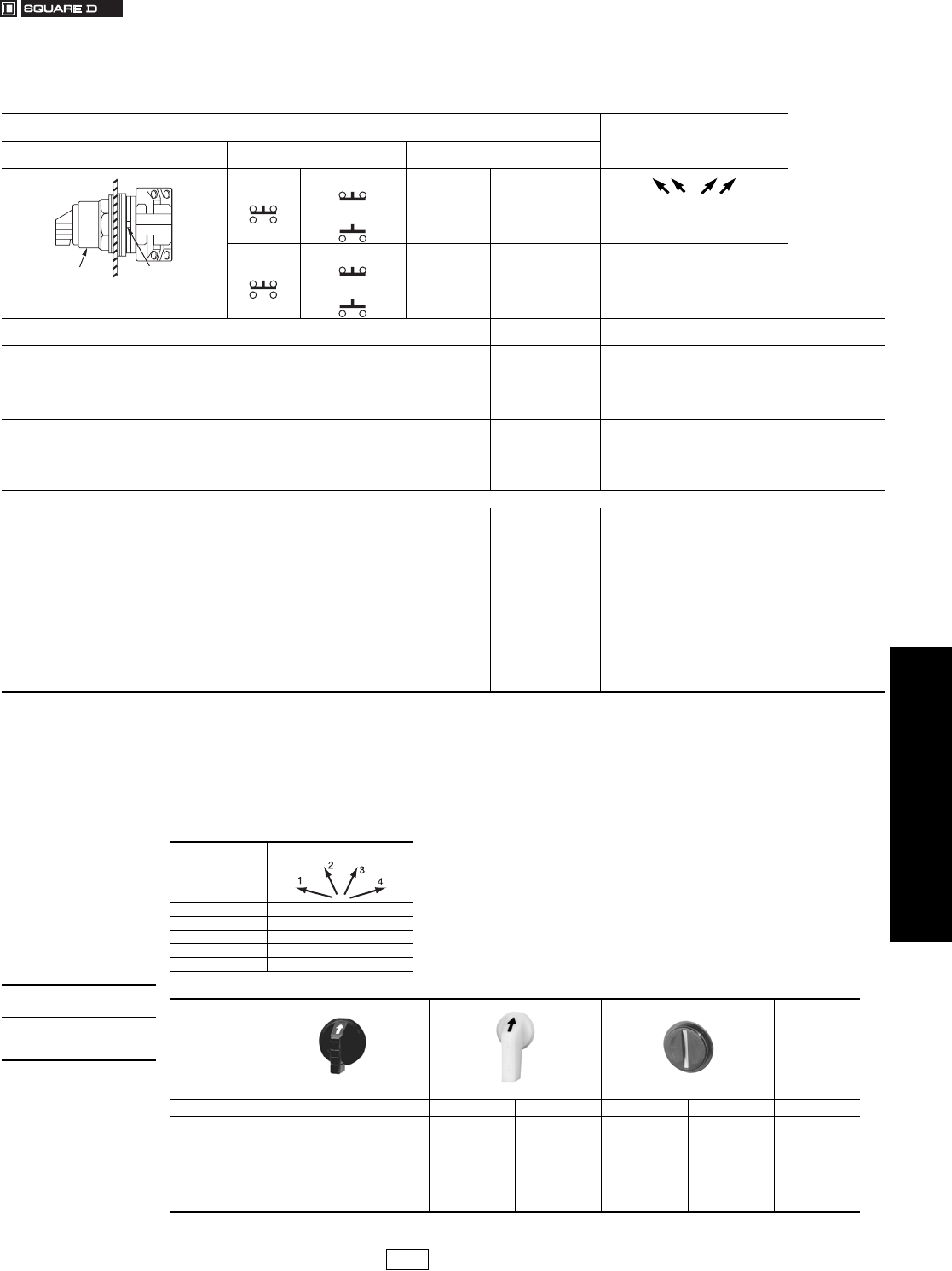
www.us.schneider-electric.com
FOR CURRENT INFORMATION
19 PUSH BUTTONS AND
OPERATOR INTERFACE
© 2007 Schneider Electric
All Rights Reserved 19-63
30 mm Push Buttons Type K Heavy Duty Selector Switches
Class 9001 / Refer to Catalog 9001CT0001
hNon-Illuminated only.
Table 19.175: Non-Illuminated and Illuminated 4 Position Selector Switch Operators
For use in hazardous locations—See page 19-79. UL Types 4, 13/NEMA 4, 13
Legend plate and contact block not included unless noted.
Contact Block Required 1—Contact Closed
0—Contact Open
Contact Block Position Quantity and Type
KA1 or KA2 or KA3
Mount on Side
KA1 or KA2 or KA3
KA1
KA3
KA1
#2
KA3
#2
1000
KA2 KA2
#2 0010
KA1
KA3
KA1
#1
KA3
#1 0001
KA2 KA2
#1 0100
Non-Illuminated Operators Cam
(see page 19-64) Type $ Price
Manual Return a
Operator Only a
•Without Knob
•With Standard Black Knob
•With Other Color Knob (See Table 19.177) b
•Key Operated with E10 Key (Codes 11, 12, 13, 14, 15) cd
H
H
H
H
KS88
KS88B
KS88b
KS88Kc
28.50
35.10
35.10
92.00
Spring Return From Left—Spring Return From Right—
Maintained in the Two Mid Positions
Operator Only a
•Without Knob
•With Standard Black Knob
•With Other Color Knob (See Table 19.177)b
H
H
H
KS89
KS89B
KS89b
47.60
54.00
54.00
Illuminated Operators
Manual Return a
•Without Knob, 110–120 V 50–60 Hz Transformer
•With Standard Red Knob, 110–120 V 50–60 Hz Transformer
•Without Knob and With Other Voltage Transformer, Flashing or LED f
•Without Knob, Full Voltage Neon or Resistor g
•With Other Color Knob and Transformer, Flashing or LED f
•With Other Color Knob, Full Voltage Neon or Resistor g
H
H
H
H
H
H
K88J1
K88J1R
K88Je
K88Je
K88Jeb
K88Jeb
105.00
111.00
105.00
86.00
111.00
92.00
Spring Return From Left—Spring Return From Right—
Maintained in the Two Mid Positions
•Without Knob, 110–120 V 50–60 Hz Transformer
•With Standard Red Knob, 110–120 V 50–60 Hz Transformer
•Without Knob and With Other Voltages Transformer, Flashing or LED f
•Without Knob, Full Voltage Neon or Resistor g
•With Other Color Knob and Transformer, Flashing or LED f
•With Other Color Knob, Full Voltage Neon or Resistor g
H
H
H
H
H
H
K89J1
K89J1R
K89Je
K89Je
K89Jeb
K89Jeb
123.00
131.00
123.00
105.00
131.00
111.00
aThese operators can be ordered complete with contact blocks. For maximum block usage, see 19-85. Add the “H” number
chosen from page 19-80 to the end of the operator type number and add the cost of the “H” number to the operator cost.
bAdd the color code as chosen from Table 19.177. Example: KS88b with a green gloved-hand knob = KS88FG.
cAdd the key withdrawal code from Table 19.176. Example: KS88Kc with key withdrawal in the right position only = KS88K12.
dAll key operated devices come standard with Square D key number E10 (key only part no. is 2941101100, $6.60 per key).
Other key changes are available at no extra cost. For additional information, refer to Catalog 9001CT0001.
eAdd the voltage assembly code as chosen from page 19-77. Example: K88Je with 208 Vac = K88J3
fThe knob must be the same color as the LED light module chosen, for example, for red LED, use red knob.
gOn neon light modules, use clear knobs only.
Top View
Side 2
Side 1
Operator Locating
Notch
Table 19.176: c Key Withdrawal Code
Code
Position
11 1 and 4
12 4 only
13 1 only
14 1, 2, 3 and 4
15 2, 3 and 4
When ordering,
please specify:
•Quantity
•Class Number
•Type or Catalog Number
Table 19.177: Selector Switch Knobs
Standard Knob Gloved-Hand Knob Coin Operated
Color bKnob Code Type bKnob Code Type bKnob Code Type $ Price
Black h
Red
Green
Ye l l o w
Orange h
Blue
White
Amber
Clear
B
R
G
Y
S
L
W
A
C
B11
R8
G8
Y8
S11
L8
W8
A8
C8
FB
FR
FG
FY
FS
FL
FW
FA
FC
B25
R24
G24
Y24
S25
L24
W24
A24
C24
TB
TR
TG
TY
—
TL
—
—
TC
B18
R16
G16
Y16
—
L16
—
—
C16
6.60
CP1 Discount
Schedule
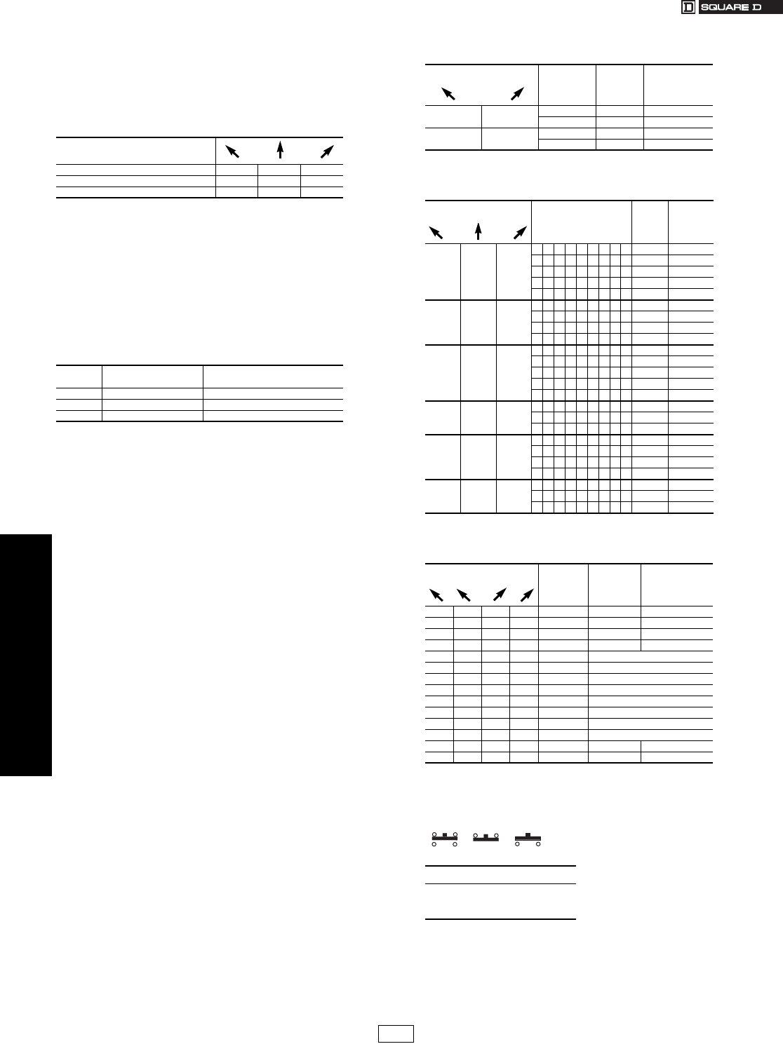
www.us.schneider-electric.com
FOR CURRENT INFORMATION
19 PUSH BUTTONS AND
OPERATOR INTERFACE
19-64 © 2007 Schneider Electric
All Rights Reserved
30 mm Push Buttons Type K, KX, and SK Selector Switch Guide
Class 9001 / Refer to Catalog 9001CT0001
Shown below is a simplified method of selecting a selector switch to
meet almost any combination of contact sequences.
Step No. 1
Determine the contact sequence(s) required. Set up a target table like
the one shown for the example below.
Step No. 2
Look for a cam type common to all sequences in table Table 19.178,
Table 19.179, or Table 19.180. For the example above, Table 19.179
would be used. For the contact sequences A (1 0 0), B (0 1 0) and
C (0 0 1) of the example above, cam types F and L are common to all
three sequences.
Step No. 3
Next, use the cam type common to all the sequences (if several cam
types are common, choose one) to find the operator type number. Go to
the proper page number as indicated in the table below:
If for the example above a manual return operator with a standard black
knob is required and:
The F cam type is chosen, the operator type number is:
•Type K—Class 9001 Type KS46B (from page 19-61)
•Type SK—Class 9001 Type SKS46B (from page 19-73)
•Type KX—Class 9001 Type KXSDFB (from page 19-89)
The L cam type is chosen, the operator type number is:
•Type K—Class 9001 Type KS401B (from page 19-61)
•Type SK—Class 9001 Type SKS401B (from page 19-73)
•Type KX—Class 9001 Type KXSDLB (from page 19-89)
Step No. 4:
Determine the contact blocks required by using the same table in Step
No. 2.
If, for the example above, the F cam type is chosen:
•Use a 9001KA3 mounted on side no. 2 for sequence A (1 0 0).
•Use a 9001KA3 mounted on side no. 1 for sequence B (0 1 0).
•Use a 9001KA2 mounted on side no. 1 or 2 for sequence C (0 0 1).
If, for the example above, the L cam type is chosen:
•Use a 9001KA2 mounted on side no. 2 for sequence A (1 0 0).
•Use a 9001KA2 mounted on side no. 1 or a 9001KA3 mounted on side no. 2
for sequence B (0 1 0).
•Use a 9001KA3 mounted on side no. 1 for sequence C (0 0 1).
One Type KA1 double circuit block can be used in place of one Type
KA2 single circuit block plus one Type KA3 single circuit block mounted
on the same side. aType KA5 must be the last block on either side. If more than one KA5 is required on either
side—contact your local Square D sales office.
Note: For Outline Dimensions see Catalog 9001CT0001
For “H” Numbers . . . . . . . . . . . . . . . . . . . . . . . . . . . . . . . . . . . . . . page 19-80
Contact Sequence
0—contact open 1—contact closed
A100
B010
C001
Number of
Positions Push Button Line Page Number
2 Type K, Type SK, Type KX 19-59 to 19-60, 19-71 to 19-72, 19-86
3 Type K, Type SK, Type KX 19-61 to 19-62, 19-73 to 19-74, 19-89
4 Type K, Type SK, Type KX 19-63, 19-75, 19-90
Table 19.178: 2 Position Selector Switch
If you require
contact sequence— Use Cam
Type
Use
Contact
Block Type
Mount on
side no.
(See page 19-80)
10EKA31 or 2
DKA21 or 2
01EKA21 or 2
DKA31 or 2
Table 19.179: 3 Position Selector Switch
If you require
contact sequence— Use Cam Type
Use
Contact
Block
Type
Mount on
side no.
(See page
19-80)
100
GMKA2 1
LKA2 2
CE KA3 1
BC EFGJ KA3 2
BGJKA5a2
010
DE J L KA2 1
DE KA2 2
FKA31
LKA3 2
001
CF KA21 or 2
BD GL KA3 1
DKA32
BKA5a1
MKA2 2
110
BKA21
CF KA5a1 or 2
MKA3 2
011
BGJKA22
GKA5a1
LKA5a2
MKA3 1
101
JKA31
DE J L KA5a1
DE KA5a2
Table 19.180: 4 Position Selector Switch
If you require
contact sequence— Use Cam
Type
Use Contact
Block Type
Mount on
side no.
(See page 19-80)
1 0 0 0 H (A) KA3 2
0 1 0 0 H (B) KA2 1
0010 H (C) KA2 2
0001 H (D) KA3 1
1 0 0 1 H A & D Wired in Parallel
1 1 0 0 H A & B Wired in Parallel
0 1 1 0 H B & C Wired in Parallel
0 0 1 1 H C & D Wired in Parallel
1 1 1 0 H A, B & C Wired in Parallel
0 1 1 1 H B, C & D Wired in Parallel
1 0 1 0 H A & C Wired in Parallel
0 1 0 1 H B & D Wired in Parallel
1101 H KA5a2
1011 H KA5a1
When ordering, please specify:
•Quantity
•Class Number
•Type or Catalog Number
KA1 KA3 KA2
=+
=+
CP1 Discount
Schedule
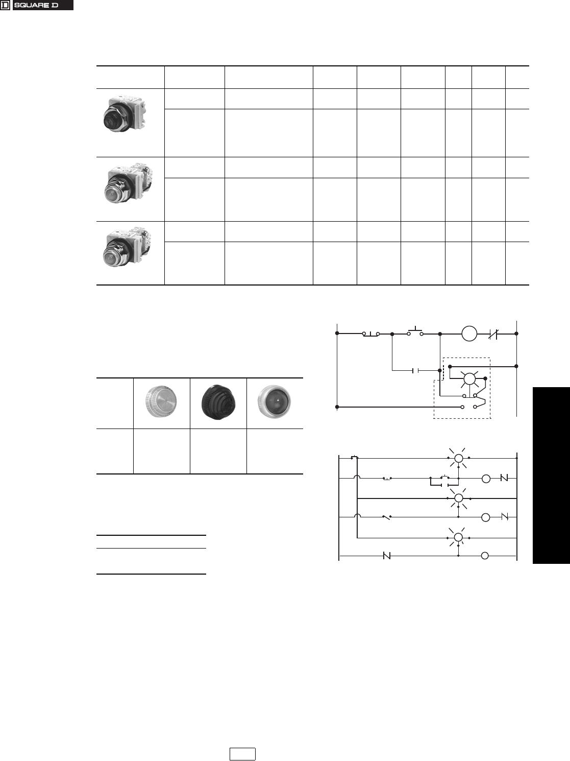
www.us.schneider-electric.com
FOR CURRENT INFORMATION
19 PUSH BUTTONS AND
OPERATOR INTERFACE
© 2007 Schneider Electric
All Rights Reserved 19-65
30 mm Push Buttons Type K Heavy Duty Pilot Lights
Class 9001 / Refer to Catalog 9001CT0001
aAdd the voltage assembly code as chosen from page 19-77.
EXAMPLE: KTaR31 with 60 Vac red LED = KT37LRR31
bAdd the color code as chosen from Table 19.182.
EXAMPLE: KP1b with a blue fresnel cap = KP1L31
cThe cap must be the same color as the LED light module chosen, e.g.,
for green LED, use green color cap.
dOn neon light modules, use clear color caps only.
eOn remote test pilot lights use only full voltage or resistor voltage
assembly codes.
Do not choose LED, neon or transformer codes. For AC use only.
Table 19.181: Pilot Lights—UL Types 4, 13/NEMA 4 & 13
For use in hazardous locations—See page 19-79.
Legend plates not included.
Description Voltage Style
With Red
Fresnel Color
Cap
With Green
Fresnel Color
Cap
With Other
Color Cap $ Price Without
Color Cap $ Price
Standard Pilot Light
(Plastic Fresnel Color
Cap Shown)
110–120 V, 50–60 Hz
220–240 V, 50–60 Hz
24–28 Vac/dc
Transformer
Transformer
Full Voltage
KP1R31
KP7R31
KP35R31
KP1G31
KP7G31
KP35G31
KP1b
KP7b
KP35b
102.
102.
83.
KP1
KP7
KP35
95.
95.
77.
For other voltages
see page 19-77.
Transformer, Flashing or LED c
Full Voltage, Neon or Resistor d
KPaR31
KPaR31
KPaG31
KPaG31
KPab
KPab
102.
83.
KPa
KPa
95.
77.
Push-To-Test Pilot Light
(Glass Color Cap Shown)
110–120 V, 50–60 Hz
220–240 V, 50–60 Hz
24–28 Vac/dc
Transformer
Transformer
Full Voltage
KT1R31
KT7R31
KT35R31
KT1G31
KT7G31
KT35G31
KT1b
KT7b
KT35b
131.
131.
111.
KT1
KT7
KT35
123.
123.
105.
For other voltages
see page 19-77.
Transformer, Flashing or LED c
Full Voltage, Neon or Resistor d
KTaR31
KTaR31
KTaG31
KTaG31
KTab
KTab
131.
111.
KTa
KTa
123.
105.
Remote Test Pilot Light
(Glass Color Cap Shown)
120 Vac Only
24–28 Vac Only
for other voltages
Resistor e
Full Voltage e
KTR38R31
KTR35R31
KTR38G31
KTR35G31
KTR38b
KTR35b
131.
131.
KTR38
KTR35
123.
123.
See page 19-77.eFull Voltage or Resistor eKTRaR31 KTRaG31 KTR ab 131. KTRa123.
Table 19.182: Color Caps
Color
b Plastic Fresnel b Plastic Domed b Glass
Amber
Blue
Clear
Green
Red
White
Ye l l o w
A31
L31
C31
G31
R31
W31
Y31
A9
L9
C9
G9
R9
W9
Y9
A6
L6
C6
G6
R6
W6
Y6
When ordering, please specify:
•Quantity
•Class Number
•Type or Catalog Number
R
M
MO.L.
L2
3
2
1
L1
STOP
START
L2
C
Test
L1
M
STOP
LSI
M3
(TEST) C
(TEST) C L2
L2
L1
(SIG) CR
M2
M1
L2
(TEST) C
START
TEST
BUTTON
L1 L2
L1
(SIG)
L1
(SIG)
Push-To-Test Pilot Light
Remote Test Pilot Light
Typical Wiring Diagrams
CP1 Discount
Schedule
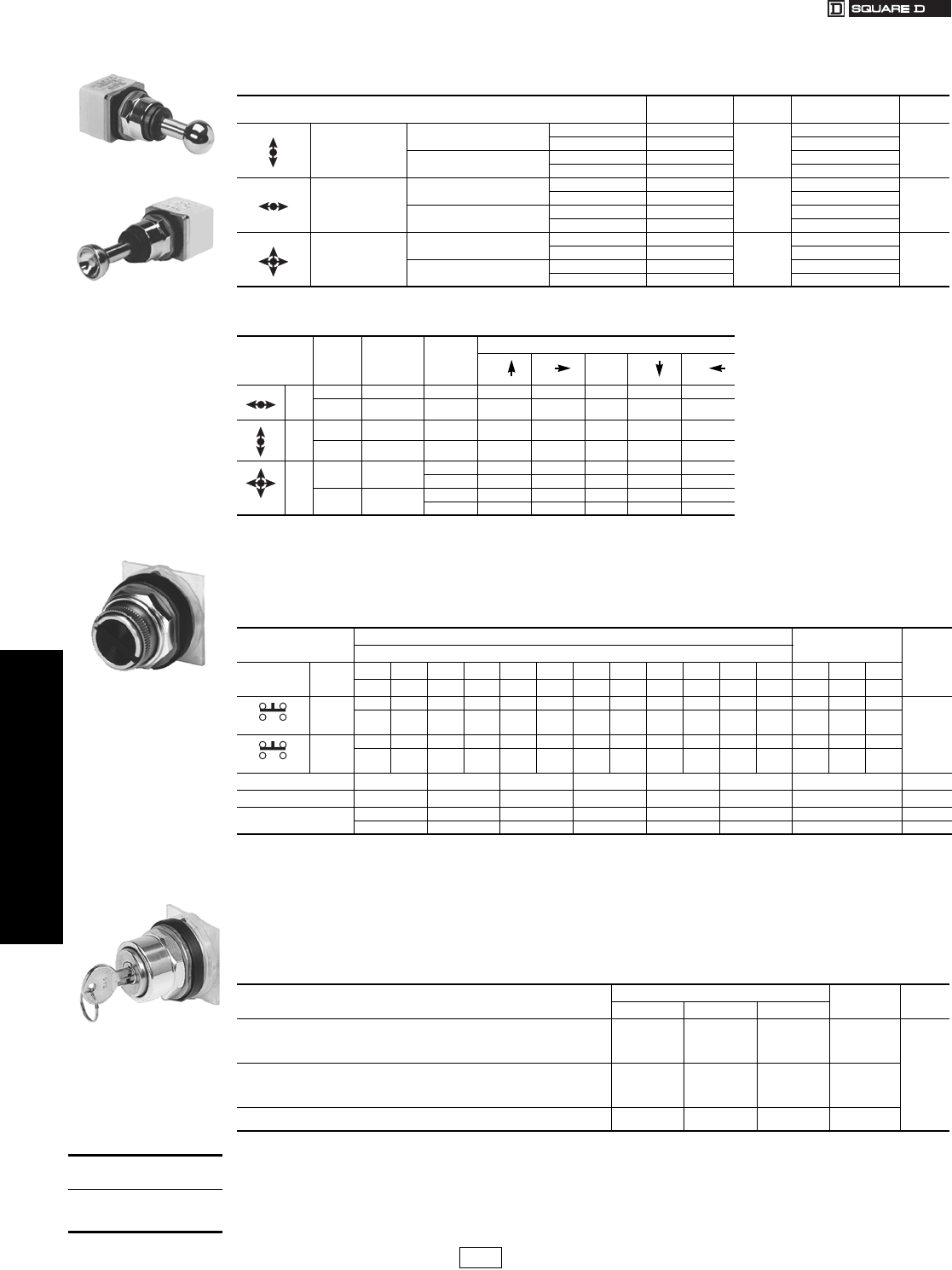
19-66 © 2007 Schneider Electric
All Rights Reserved
www.us.schneider-electric.com
FOR CURRENT INFORMATION
19 PUSH BUTTONS AND
OPERATOR INTERFACE
30 mm Push Buttons Type K Heavy Duty Specialty Operators
Class 9001 / Refer to Catalog 9001CT0001
aThese operators can be ordered complete with contact blocks—a total of four (4) contact blocks can be used. Add the “H” number chosen from page
19-80 to the operator type number and add the cost of the “H” number to the operator cost.
For use in hazardous locations—See page 19-79. Legend plate and contact block not included.
Inserts are field convertible. For colors not listed, order operator without insert, plus separate color insert from page 19-
84. Up to two Type KA contact blocks can be mounted in tandem (total of four blocks). Selector push buttons cannot be
illuminated.
bOrder color inserts from page 19-84.
cCams are not interchangeable.
dMaintained in right position only. Function in the right position is similar to a turn to release action. Refer to catalog 9001CT0001.
For use in hazardous locations. See page 19-79. Key operated push buttons are used wherever unauthorized use of a
push button is discouraged. Examples are locking a Start push button in the extended position or locking a Stop push
button in the depressed position. The operator can also be locked in the flush position—holding all contacts open. Up to
two Type KA contact blocks can be mounted in tandem (total of four blocks).
Legend Plate and Contact Block Not Included (“X” = locked position) e
eAll key operated push buttons are furnished as standard with Square D no. E10 key change. See catalog 9001CT0001 for other key changes.
Without Latch
With Latch
Table 19.183: Joy Stick Operators—UL Types 4, 13/NEMA 4, 13 for use in hazardous locations
See page 19-79. Contact blocks and legend plate not included unless noted.
Description Operator
With Contacts $ Price Operator
Without Contacts a$ Price
3 Position—
Center Off
Momentary Contact—
Spring Return to Center
Without Latch K71H7
197
K71
168.
With Latch K70H7 K70
Maintained Contact Without Latch K73H7 K73
With Latch K72H7 K72
3 Position—
Center Off
Momentary Contact—
Spring Return to Center
Without Latch K31H8
197
K31
168.
With Latch K30H8 K30
Maintained Contact Without Latch K33H8 K33
With Latch K32H8 K32
5 Position—
Center Off
Momentary Contact—
Spring Return to Center
Without Latch K35H2
263
K35
206.
With Latch K34H2 K34
Maintained Contact Without Latch K37H2 K37
With Latch K36H2 K36
Table 19.184: Contact Arrangements
Operator
Positions
Contact
Block
Type
Contact
Block
Location
Contact
Handle position (with reference to Nib)
The joy stick operator is ideal for applications
where only one circuit is to be energized at one
time. The three position joy stick closes one
circuit in each Up-Down or Right-Left position
with all circuits open in center position. The five
position operator closes one circuit in each Up,
Down, Left and Right position with all circuits
open in center position.
Momentary contact operators are spring return to
the center position. Maintained operators remain
in position and must be returned manually.
Operators with latch cannot be operated until the
latch button in center of handle is pressed.
OFF
3
KA3 POS 1 (3) A — 1 0 — 0
KA3 POS 2 (4) A — 0 0 — 1
3
KA2 POS 1 (3) B 1 — 0 0 —
KA2 POS 2 (4) B 0 — 0 1 —
5
KA1 POS 1 (3) A01000
B10000
KA1 POS 2 (4) A00001
B00010
(1) Contact Closed (0) Contact Open
Table 19.185: Selector Push Button Operators—UL Types 4, 13/NEMA 4, 13
Contact Block
Required
Two Position Operators Three Position
Operators
0—Contact Open 1—Contact Closed F—Free D—Depressed
Quantity
and Type
Mount
on Side
Left Right Left Right Left Right Left Right Left Right Left Right Left Center Right
FD FD FD FD FD FD FD FD FD FD FD FDdFD FD FD
1 KA1
#2
00 10 00 10 00 11 11 10 10 00 10 —0 10 10 11 Order
Contact
Blocks
From
Pages
19-78,
19-79.
01 01 01 00 01 00 00 01 01 01 01 —1 01 00 00
1 KA1
#1
00 11 00 10 11 00 10 11 11 00 10 —0 11 10 10
01 00 01 00 00 01 01 00 00 01 01 —1 00 00 01
Cam cPRSTYZ U
Color Insert Type Type Type Type Type Type Type $ Price
Without Insert b
Black
KQ11 KQ12 KQ13 KQ14 KQ15 KQ18 dKQ27 53.
KQ11B KQ12B KQ13B KQ14B KQ15B KQ18B dKQ27B 54.
Table 19.186: Key Operated Push Button – UL Types 4, 13/NEMA 4, 13
Description Lockable Positions Type $ Price
Extended Flush Depressed
Push button operable only with key in lock. Key is removable in locked position only.
X
—
—
X
—
X
—
X
—
—
X
X
KR131
KR132
KR133
KR137
83.
Push button operable with or without key in lock. Push button can be locked with key
only. Key removable in both locked or unlocked position.
X
—
—
X
—
X
—
X
—
—
X
X
KR141
KR142
KR143
KR147
To lock the unit, rotate the key with the button in the extended position. Then, push the
button to lock it in the position indicated at right. Key is removable only in this position.
—
—
X
—
—
X
KR152
KR153
12 3 4
Selector Push Button
9001KQ
Key Operated Push Button
9001KR
When ordering,
please specify:
•Quantity
•Class Number
•Type or Catalog Number
CP1 Discount
Schedule

www.us.schneider-electric.com
FOR CURRENT INFORMATION
19 PUSH BUTTONS AND
OPERATOR INTERFACE
© 2007 Schneider Electric
All Rights Reserved 19-67
30 mm Push Buttons Type K Heavy Duty Specialty Operators
Class 9001 / Refer to Catalog 9001CT0001
eFor enclosed versions see page 19-103.
Note: When mounted in top or bottom hole of a Type K enclosure, device
requires one additional space below or above operator. When mounted
other than in top or bottom hole, device may require two additional
spaces, one above and one below operator. Closing plates must be
installed on unused holes.
Potentiometer with Dial
Plate 9001K21
Table 19.187: Potentiometer d with Dial Plate a—NEMA 4, 13 (Not UL Listed)
Watts Description Type $ Price
2
Operator only—Single Pot K20 134.
Operator with Single Pot K21b191.
Operator only—Tandem Pot K22 209.
Operator with Tandem Pot K23 c266.
Table 19.188: Potentiometer Suffixes
Suffix bOhms Suffix bOhms Suffix bOhms Suffix cTandem Pots Ohms
Front Rear
01 50 07 5k 13 500k 82 1000 1000
02 100 08 10k 37 750k 83 5000 5000
38 200 40 15k 14 1.0 M 85 10k 10k
03 250 09 25k 15 2.5 M 88 50k 50k
04 500 35 35k 16 5.0 M 89 100k 100k
05 1000 10 50k 17 5.0 M
32 1500 36 75k
39 2000 11 100k
06 2500 12 250k
33 3500
aThe dial plate only catalog number is 6517512701. $2.90.
bFor complete Type number, add the suffix number from Table 19.188 to the Type number from Table 19.187. Example: Type K2105
cFor complete Type number, add the suffix number from Table 19.188 to the Type number from Table 19.187. Example: Type K2382
d1/4” diameter, 7/8” long shaft. +/- 10% accuracy.
Emergency Break-Glass
Operator 9001K15 Table 19.189: Emergency Break-Glass Operator—
UL 4, 13/NEMA 4, 13e
Type $ Price
K15 83.
Operator is held in a depressed position by a glass disc. When the glass disc
is broken with the hammer, button returns to a normal extended position.
Package of 5 discs included with operator.
Table 19.190: 9001K15 Replacement Parts
Description Part Number $ Price
Ye l l o w bu mp er 3105211101 9.50
Hammer and chain 3105206750 38.20
Lower ring nut 6512232801 11.10
Top ring nut 9001K40 2.90
Package of 5 replacement discs 9001K57 11.10
Clip to hold hammer 2540902240 1.70
Rocker Arm Operating
Lever 9001K50
Table 19.191: Rocker Arm Operating Lever
Type $ Price
K50 51.00
Allows two standard push buttons to be operated independently of each other. Price does not include push buttons or legend plates. Order push buttons and legend
plates from Pages 19-81, 19-82,and 19-56—specify which marking is to be inverted.
Push-on Push-off Module
9001K85
Table 19.192: Alternate Action—Push-on, Push-off Module
Type $ Price
K85 28.50
This module can be added to standard 9001 Type K, KX, SK or T momentary push button operators. Contact blocks mounted behind this module (maximum of 2) are
held in the depressed position when the operator is pressed once, and released to their normal position when the operator is pressed again. For a N.C. circuit, use a
9001KA3 or the N.C. contact of either a 9001KA1 or 9001KA4. For a N.O. circuit, use the N.O. contact of either a 9001KA4 or 9001KA6.
Time Delay Push Button
9001KRD
Table 19.193: Off Delay Push Button—
UL Types 4, 13/NEMA 4, 13
Description
Type (All Colors)
Full
Guard
Extended
Guard
No
Guard $ Price
Timed Contact
1 N.O. and 1 N.C.
KRD1UH1 KRD2UH1 KRD3UH1 168.
Timed Contact
2 N.O. and 2 N.C.
KRD1UH2 KRD2UH2 KRD3UH2 311.
Timing period is adjustable from 0.1 second to 60 seconds and begins after button
has been released. Devices include a pack of seven color inserts for color coding
the push button. See 19-84 for Universal color insert. Contacts are quick make-
quick break.
Table 19.194: Wobble Stick
For easy operation of any standard
push button.
Type $ Price
K8 28.50
When ordering, please specify:
•Quantity
•Class Number
•Type or Catalog Number
CP10 CP1 Discount
Schedule Modified
4/20/09
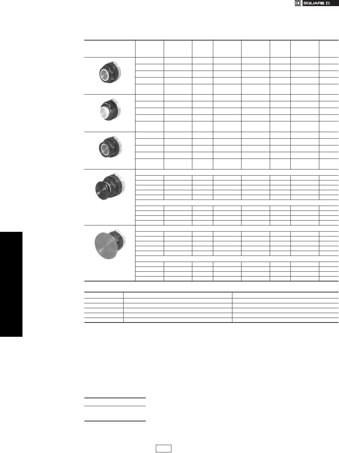
19-68 © 2007 Schneider Electric
All Rights Reserved
www.us.schneider-electric.com
FOR CURRENT INFORMATION
19 PUSH BUTTONS AND
OPERATOR INTERFACE
30 mm Push Buttons Type SK Corrosion Resistant Non-Illuminated Operators
Class 9001 / Refer to Catalog 9001CT0001
aThe universal push button operators include one each of the following color inserts: black, red, green, yellow, orange, blue and white.
bSee Table 19.196.
cKnob has the words “Emergency Stop” in raised letters highlighted in white for readability.
dSee Table 19.196.
eThese operators can be ordered complete with contact blocks. For maximum block usage, see page 19-85. Add the “H” number chosen from page 19-
80 to the end of the operator type number and add the cost of the “H” number to the operator cost.
Basic Operators . . . . . . . . . . . . . . . . . . . . . . . . . . . . . . . . . . . . . . . page 19-85
Light Modules . . . . . . . . . . . . . . . . . . . . . . . . . . . . . . . . . . . . . . . . page 19-77
Contact Blocks . . . . . . . . . . . . . . . . . . . . . . . . . . . . . . . . . . . . . . . . page 19-78
H Contact Block Assembly Codes . . . . . . . . . . . . . . . . . . . . . . . . page 19-80
Legend Plates . . . . . . . . . . . . . . . . . . . . . . . . . . . . . . . . . . . . . . . . page 19-81
Accessories . . . . . . . . . . . . . . . . . . . . . . . . . . . . . . . . . . . . . . . . . . page 19-83
Replacement Parts . . . . . . . . . . . . . . . . . . . . . . . . . . . . . . . . . . . . page 19-86
Table 19.195: Non-Illuminated Momentary Push Button Operators—UL Types 4, 4X, 13/NEMA 4, 4X, 13
For use in hazardous locations—See page 19-79.
Contact blocks and legend plate not included unless otherwise noted.
Description Color
Operator with
1 N.O. and
1 N.C. Contact
(KA1)
$ Price
Operator with
1 N.O. Contact
(KA2)
Operator with
1 N.C. Contact
(KA3)
$ Price Operator Only
No Contacts e$ Price
9001SKR1B
Full Guard
Black SKR1BH13 54.00 SKR1BH5 SKR1BH6 39.90 SKR1B 25.70
Red SKR1RH13 54.00 SKR1RH5 SKR1RH6 39.90 SKR1R 25.70
Green SKR1GH13 54.00 SKR1GH5 SKR1GH6 39.90 SKR1G 25.50
Universal aSKR1UH13 54.00 SKR1UH5 SKR1UH6 39.90 SKR1U 25.70
Other bSKR1bH13 54.00 SKR1bH5 SKR1bH6 39.90 SKR1b25.70
9001SKR3B
No Guard
Black SKR3BH13 54.00 SKR3BH5 SKR3BH6 39.90 SKR3B 25.70
Red SKR3RH13 54.00 SKR3RH5 SKR3RH6 39.90 SKR3R 25.70
Green SKR3GH13 54.00 SKR3GH5 SKR3GH6 39.90 SKR3G 25.70
Universal aSKR3UH13 54.00 SKR3UH5 SKR3UH6 39.90 SKR3U 25.70
Other bSKR3bH13 54.00 SKR3bH5 SKR3bH6 39.90 SKR3b25.70
9001SKR2B
Extended Guard
Black SKR2BH13 54.00 SKR2BH5 SKR2BH6 39.90 SKR2B 25.70
Red SKR2RH13 54.00 SKR2RH5 SKR2RH6 39.90 SKR2R 25.70
Green SKR2GH13 54.00 SKR2GH5 SKR2GH6 39.90 SKR2G 25.70
Universal aSKR2UH13 54.00 SKR2UH5 SKR2UH6 39.90 SKR2U 25.70
Other bSKR2b54.00 SKR2bH5 SKR2bH6 39.90 SKR2b25.70
9001SKR4B
1-3/8 in. (35 mm)
Mushroom Button
Snap-In Mushroom Button
Black SKR4BH13 83.00 SKR4BH5 SKR4BH6 68.00 SKR4B 54.00
Red SKR4RH13 83.00 SKR4RH5 SKR4RH6 68.00 SKR4R 54.00
Red cSKR4R05H13 86.00 SKR4R05H5 SKR4R05H6 72.00 SKR4R05 57.00
Green SKR4GH13 83.00 SKR4GH5 SKR4GH6 68.00 SKR4G 54.00
Other dSKR4dH13 83.00 SKR4dH5 SKR4dH6 68.00 SKR4d54.00
Screw-On Mushroom Button with Set Screw Security
Black SKR24BH13 83.00 SKR24BH5 SKR24BH6 68.00 SKR24B 54.00
Red SKR24RH13 83.00 SKR24RH5 SKR24RH6 68.00 SKR24R 54.00
Green SKR24GH13 83.00 SKR24GH5 SKR24GH6 68.00 SKR24G 54.00
Other dSKR24dH13 83.00 SKR24dH5 SKR24dH6 68.00 SKR24d54.00
9001SKR5
2-1/4 in. (57 mm)
Mushroom Button
Snap-In Mushroom Button
Black SKR5BH13 83.00 SKR5BH5 SKR5BH6 68.00 SKR5B 54.00
Red SKR5RH13 83.00 SKR5RH5 SKR5RH6 68.00 SKR5R 54.00
Red cSKR5R05H13 86.00 SKR5R05H5 SKR5R05H6 72.00 SKR5R05 57.00
Green SKR5GH13 83.00 SKR5GH5 SKR5GH6 68.00 SKR5G 54.00
Other dSKR5dH13 83.00 SKR5dH5 SKR5dH6 68.00 SKR5d54.00
Screw-On Mushroom Button with Set Screw Security
Black SKR25BH13 83.00 SKR25BH5 SKR25BH6 68.00 SKR25B 54.00
Red SKR25RH13 83.00 SKR25RH5 SKR25RH6 68.00 SKR25R 54.00
Green SKR25GH13 83.00 SKR25GH5 SKR25GH6 68.00 SKR25G 54.00
Other dSKR25dH13 83.00 SKR25dH5 SKR25dH6 68.00 SKR25d54.00
Table 19.196: Color Codes
Color b SKR1, 2, 3 Place Color Code in Type Number d SKR4, 5, 24, 25 Place Color Code in Type Number
Blue L L
Ye l l o w Y Y
White W —
Orange S S
Gray E —
When ordering, please specify:
•Quantity
•Class Number
•Type or Catalog Number
CP1 Discount
Schedule Modified
4/20/09
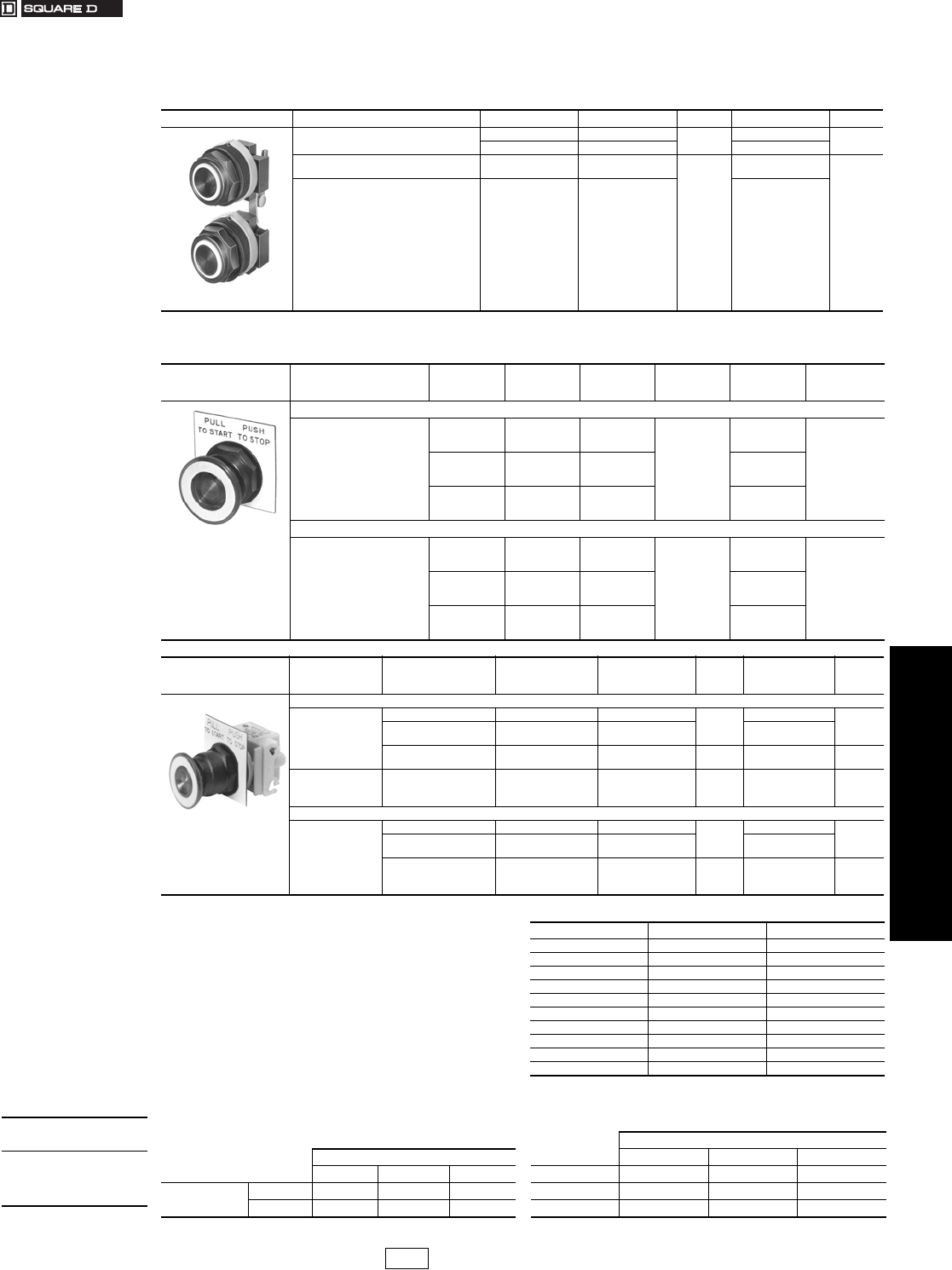
www.us.schneider-electric.com
FOR CURRENT INFORMATION
19 PUSH BUTTONS AND
OPERATOR INTERFACE
© 2007 Schneider Electric
All Rights Reserved 19-69
30 mm Push Buttons Type SK Corrosion Resistant Multifunction Operators
Class 9001 / Refer to Catalog 9001CT0001
cTo obtain a red knob with “Push Emergency Stop” printed on the red
knob—substitute R05 in place of “R” and add $2.10 to the price.
dChoose one color from Table 19.198 and insert the color code in the
Type number. Example: SKR9d with a yellow knob = SKR9Y
eAdd the voltage assembly code as chosen from page 19-77.
Example: SKR8Pe with 277 V 50–60 Hz = SKR8P8
fThe knob must be the same color as the LED light module chosen; e.g.,
for green LED, use green knob.
gOn neon light modules, use clear knobs only.
hThese operators can be ordered complete with contact blocks. For
maximum block usage, see page 19-85. Add the “H”
number chosen from page 19-80 to the end of the operator type number
and add the cost of the “H” number to the operator cost.
iSKR11UH1 has 1 KA1(1 N.O., 1 N.C.) and SKR12UH1H1 has 2 KA1
(2 N.O., 2 N.C.).
jFor positions, refer to Tables 19.199 and 19.200. kThese colors are not available on illuminated push-pull operators.
Table 19.197: Multifunction Operators—UL Types 4, 4X, 13/NEMA 4, 4X, 13
For use in hazardous locations—See page 19-79.
Legend plate and contact blocks not included unless otherwise noted.
Interlocked Assembly Description Color Contacts i$ Price Without Contacts h$ Price
9001SKR11U
Interlocked Assembly
Both Buttons Maintained
Universal aSKR11UH1 108. SKR11U 80.
Other bSKR11bH1 SKR11b
Interlocked Assembly
One Button Momentary Universal aSKR12UH1H1
165.
SKR12U
108.
Interlocked Assembly
One Button Maintained Other bSKR12bH1H1 SKR12b
aUniversal for SKR11,12 includes 2 each of black, red, green, yellow, orange, blue, white.
bChoose one color for each button from table and insert color code in type number, top button first.
Example: An SKR11 with top button gray and bottom button orange = SKR11ES
Non-Illuminated Description Color
With 2 N.C.
Contacts
(1 KA3, 1 KA5)
With 1 N.O. /1
N.C.
Contact (1 KA1)
$ Price Without
Contacts h$Price
9001SKR9R
Non-Illuminated
1-5/8 in. Diameter Knob
Includes Type KN179WP
Legend Plate Marked
Pull To Start Push To Stop
3 Position
Momentary Pull-
Maintained Neutral-
Momentary Push j
Red SKR8RH25 —
86.
SKR8R
57.Green SKR8GH25 —SKR8G
Other dSKR8dH25 — SKR8d
2 Positionc
Maintained Pull-
Maintained Push
Red — SKR9RH13
114.
SKR9R
86.Green — SKR9GH13 SKR9G
Other d—SKR9dH13 SKR9d
Illuminated Description Voltage
With Red Knob and 2
N.C. Contacts
(1 KA3, 1 KA5)
With Other Color
Knob and 2 N.C.
Contacts
$ Price
With Other Color
Knob Without
Contacts h
$ Price
9001SKR9P1
Illuminated
1-5/8 in. Diameter Knob
Includes Type KN179WP
Legend Plate Marked
Pull to Start Push To Stop
3 POSITION
Momentary Pull-
Maintained Neutral-
Momentary Push j
110–120 V, 50–60 Hz SKR8P1RH25 SKR8P1dH25
162.
SKR8P1d
134.
Other—Transformer, LED,
Flashing fSKR8PeRH25 SKR8PedH25 SKR8Ped
Other—Full Voltage,
Resistor, Neon gSKR8PeRH25 SKR8PedH25 143. SKR8Ped 114.
Description Voltage
With Red c Knob and
1 N.O. & 1 N.C.
Contact (KA1)
With Other Color
Knob and 1 N.O. & 1
N.C. Contact (KA1)
$ Price
With Other Color
Knob Without
Contacts
$ Price
2 POSITION
Maintained Pull-
Maintained Push
110–120 V, 50–60 Hz SKR9P1RH13 SKR9P1dH13
191.
SKR9P1d
162.
Other—Transformer,
L.E.D., Flashing fSKR9PeRH13 SKR9PedH13 SKR9Ped
Other—Full Voltage,
Resistor, Neon gSKR9PeRH13 SKR9PedH13 171. SKR9Ped 143.
Table 19.198: Color Codes
Color SKR11, SKR12bSKR8, SKR9
Black kBB
Red R R
Green G G
Blue L L
Yellow Y Y
White W W
Orange kSS
Clear — C
Amber — A
Gray E —
When ordering,
please specify:
•Quantity
•Class Number (if
appropriate)
•Type or Catalog Number
Table 19.199: Positions for 9001SKR8RH1 or H13 Table 19.200: Positions for 9001SKR8H25
9001SKR8H25
9001SKR8RH1 or H13 PULL CTR PUSH
PULL CTR PUSH KA3 XOO
(KA1) KA3 XOO KA5 XXO
KA2 OOX KA2 OOX
CP1 Discount
Schedule
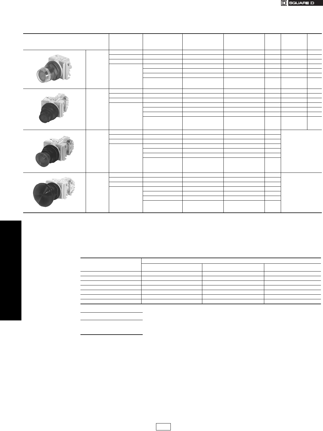
19-70 © 2007 Schneider Electric
All Rights Reserved
www.us.schneider-electric.com
FOR CURRENT INFORMATION
19 PUSH BUTTONS AND
OPERATOR INTERFACES
30 mm Push Buttons Type SK Corrosion Resistant Illuminated Operators
Class 9001 / Refer to Catalog 9001CT0001
aThese operators can be ordered complete with contact blocks. For maximum block usage, see page 19-85. Add the “H”
number chosen from page 19-80 to the end of the operator type number and add the cost of the “H” number to the operator cost.
bAdd the voltage assembly code as chosen from page 19-77. EXAMPLE: SK2Lb with 240 Vac/dc = SK2L25.
cOn neon light modules, use clear color caps only.
dThe cap must be the same color as the LED light module chosen e.g., for red LED, use red color cap.
eAdd the color code as chosen from the color cap table below. EXAMPLE: SK2L25e with a blue 1-3/8 in. mushroom button = SK2L25L20.
fThe only difference between a no guard (SK2L) operator and mushroom button operator is the color cap.
gPrice includes operator, light module, contact blocks and color cap.
hPrice includes operator, light module and color cap.
Basic Operators . . . . . . . . . . . . . . . . . . . . . . . . . . . . . . . . . . . . . . . page 19-85
Light Modules . . . . . . . . . . . . . . . . . . . . . . . . . . . . . . . . . . . . . . . . . page 19-77
Contact Blocks . . . . . . . . . . . . . . . . . . . . . . . . . . . . . . . . . . . . . . . . page 19-78
H Contact Block Assembly Codes. . . . . . . . . . . . . . . . . . . . . . . . . page 19-80
Legend Plates. . . . . . . . . . . . . . . . . . . . . . . . . . . . . . . . . . . . . . . . . page 19-81
Accessories . . . . . . . . . . . . . . . . . . . . . . . . . . . . . . . . . . . . . . . . . . page 19-83
Replacement Parts. . . . . . . . . . . . . . . . . . . . . . . . . . . . . . . . . . . . . page 19-86
Table 19.202: Illuminated Push Button Operators—UL Types 4, 4X, 13/NEMA 4, 4X, 13
For use in hazardous locations—See page 19-79. Legend plate not included unless otherwise noted.
Description Voltage and
Frequency Style
With Red Color Cap and
1 N.O. and 1 N.C. Contact
(KA1)
With Green Color Cap and
1 N.O.and 1 N.C. Contact
(KA1)
$ Price g
With Other Color
Cap Without
Contact Blocks
a
$ Price h
9001SK1L1
Full Guard
Illuminated
Push Button
110–120 V, 50–60 Hz Transformer SK1L1RH13 SK1L1GH13 140. SK1L1 111.
220–240 V, 50–60 Hz Transformer SK1L7RH13 SK1L7GH13 140. SK1L7 111.
24–28 Vac/dc Full Voltage SK1L35RH13 SK1L35GH13 120. SK1L35 92.
For other voltages
See Table b
Transformer, Flashing SK1LbRH13 SK1LbGH13 140. SK1L b111.
Full Voltage SK1LbRH13 SK1LbGH13 120. SK1L b92.
Resistor, Neon cSK1LbRH13 SK1LbGH13 120. SK1L b92.
LED eSK1LbRH13 SK1LbGH13 140. SK1L bd 111.
9001SK2L1
No Guard
Illuminated
Push Button
110–120 V, 50–60 Hz Transformer SK2L1RH13 SK2L1GH13 131. SK2L1 102.
220–240 V, 50–60 Hz Transformer SK2L7RH13 SK2L7GH13 131. SK2L7 102.
24–28 Vac/dc Full Voltage SK2L35RH13 SK2L35GH13 111. SK2L35 83.
For other voltages
See Table b
Transformer, Flashing SK2LbRH13 SK2LbGH13 131. SK2L b102.
Full Voltage SK2LbRH13 SK2LbGH13 111. SK2L b83.
Resistor, Neon cSK2LbRH13 SK2LbGH13 111. SK2L b83.
LEDeSK2LbRH13 SK2LbGH13 131. SK2L bd 102.
9001SK2L1R20
1-3/8 in.
(35 mm)
Illuminated
Mushroom
110–120 V, 50–60 Hz Transformer SK2L1R20H13 SK2L1G20H13 131.
Order SK2Lbdf
220–240 V, 50–60 Hz Transformer SK2L7R20H13 SK2L7G20H13 131.
24–28 Vac/dc Full Voltage SK2L35R20H13 SK2L35G20H13 111.
For other voltages
See Table b
Transformer, Flashing SK2LbR20H13 SK2LbG20H13 131.
Full Voltage SK2LbR20H13 SK2LbG20H13 111.
Resistor, Neon cSK2LbR20H13 SK2LbG20H13 111.
LED eSK2LbR20H13 SK2LbG20H13 131.
9001SK2L1R21
2-1/4 in.
(57 mm)
Illuminated
Mushroom
110–120 V, 50–60 Hz Transformer SK2L1R21H13 SK2L1G21H13 131.
Order SK2Lbdf
220–240 V, 50–60 Hz Transformer SK2L7R21H13 SK2L7G21H13 131.
24–28 Vac/dc Full Voltage SK2L35R21H13 SK2L35G21H13 111.
For other voltages
See Table b
Transformer, Flashing SK2LbR21H13 SK2LbG21H13 131.
Full Voltage SK2LbR21H13 SK2LbG21H13 111.
Resistor, Neon cSK2LbR21H13 SK2LbG21H13 111.
LED eSK2LbR21H13 SK2LbG21H13 131.
Table 19.203: Color Caps
Color
Color Codes
SK1L/SK2L 1-3/8 in. (35 mm) Mushroom 2-1/4 in. (57 mm) Mushroom
Red R R20 R21
Green G G20 G21
Blue L L20 L21
Yellow Y Y20 Y21
White W W20 W21
Clear C C20 C21
Amber A A20 A21
When ordering, please specify:
•Quantity
•Class Number
•Type or Catalog Number
CP1 Discount
Schedule
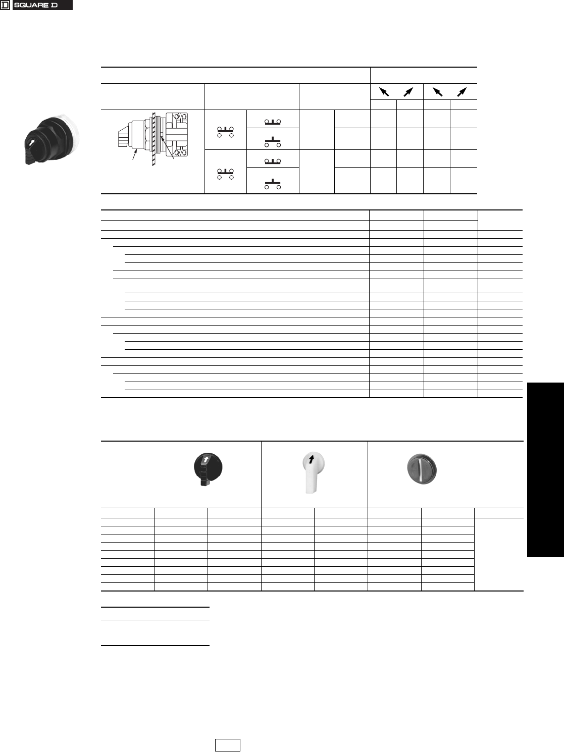
www.us.schneider-electric.com
FOR CURRENT INFORMATION
19 PUSH BUTTONS AND
OPERATOR INTERFACES
© 2007 Schneider Electric
All Rights Reserved 19-71
30 mm Push Buttons Type SK Corrosion Resistant Selector Switches
Class 9001 / Refer to Catalog 9001CT0001
aThese operators can be ordered complete with contact blocks. For maximum block usage, see page 19-85. Add the “H” number chosen from
page 19-80 to the end of the operator type number and add the cost of the “H” number to the operator cost. Example: SKS11FB + H13 = SKS11FBH13
bAdd the color code as chosen from knob color table below. Example: SKS11b with a green gloved-hand knob = SKS11FG
Table 19.204: Non-Illuminated 2-Position Selector Switch Operators—UL Types 4, 4X, 13/NEMA 4, 4X, 13
For use in hazardous locations—See page 19-79. Legend plate and contact block not included
unless noted.
Contact Block Required 1—Contact Closed
0—Contact Open
Contact Block Position Quantity and Type
KA1 or KA2 or KA3
Mount on Side
KA1 or KA2 or KA3 Left Right Left Right
Top View
KA1
KA3
KA1
#2
KA3
#2 1001
KA2 KA2
#2 0110
KA1
KA3
KA1
#1
KA3
#1 1001
KA2 KA2
#1 0110
Top View
Side 2
Side 1
Operator Locating
Notch
Standard Knob
Selector Switch 9001SKS
Cam (see page 19-64) E D $ Price
Non-Illuminated Operators Type Type
Manual Return
Operator Only a
Without Knob SKS11 SKS12 28.50
With Standard Black Knob SKS11B SKS12B 35.10
With Other Color Knob (See Knob Table) bSKS11 bSKS12 b35.10
With Contact Block(s)
With Standard Black Knob (From Table for Other Colors, Replace B in Type Number with Color
Code)
With 1 KA1 on Side #2 (H13) SKS11BH13 —64.00
With 1 KA1 on Side #1 (H1) SKS11BH1 —64.00
With 1 KA1 on Side #1 and 1 KA1 on Side #2 (H2) SKS11BH2 —92.00
Spring Return from Left
Operator Only a
Without Knob SKS25 —47.60
With Standard Black Knob SKS25B —54.00
With Other Color Knob (See Knob Table) bSKS25 b—54.00
Spring Return From Right
Operator Only a
Without Knob —SKS34 47.60
With Standard Black Knob —SKS34B 54.00
With Other Color Knob (See Knob Table) b—SKS34 b54.00
Table 19.205: Selector Switch Knobs
Standard Knob Gloved-Hand Knob Coin Operated
Color b Knob Code Type b Knob Code Type b Knob Code Type $ Price
Black B B11 FB B25 TB B18
6.60
Red R R8 FR R24 TR R16
Green G G8 FG G24 TG G16
Yellow Y Y8 FY Y24 TY Y16
Orange S S11 FS S25 ——
Blue L L8 FL L24 TL L16
White W W8 FW W24 ——
Amber A A8 FA A24 ——
Clear C C8 FC C24 TC C16
When ordering, please specify:
•Quantity
•Class Number
•Type or Catalog Number
CP1 Discount
Schedule Modified
4/20/09
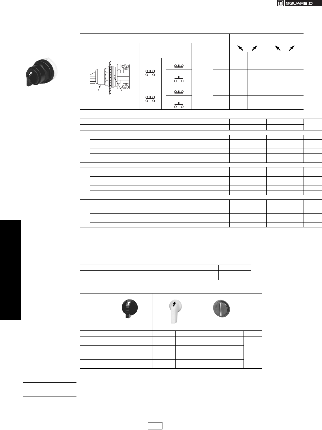
19-72 © 2007 Schneider Electric
All Rights Reserved
www.us.schneider-electric.com
FOR CURRENT INFORMATION
19 PUSH BUTTONS AND
OPERATOR INTERFACES
30 mm Push Buttons Type SK Corrosion Resistant Selector Switches
Class 9001 / Refer to Catalog 9001CT0001
aThese operators can be ordered complete with contact blocks. For maximum block usage, see page 19-85. Add the “H” number chosen
from page 19-80 to the end of the operator type number and add the cost of the “H” number to the operator cost.
bAdd the voltage assembly code as chosen from page 19-77.Example: SK25Jb with 208 Vac = SK25J3
cAdd the color code as chosen from Table 19.208. Example: SK25J35c with green knob = SK25J35G
dThe knob must be the same color as the LED light module chosen e.g., for a red LED, use a red knob.
eOn neon light modules, use clear knobs only.
fAdd form number to standard Type number, e.g., Type SK11J1 Form Y178.
Basic Operators . . . . . . . . . . . . . . . . . . . . . . . . . . . . . . . . . . . . . . . page 19-85
Light Modules . . . . . . . . . . . . . . . . . . . . . . . . . . . . . . . . . . . . . . . . . page 19-77
Contact Blocks . . . . . . . . . . . . . . . . . . . . . . . . . . . . . . . . . . . . . . . . page 19-78
H Contact Block Assembly Codes. . . . . . . . . . . . . . . . . . . . . . . . . page 19-80
Legend Plates. . . . . . . . . . . . . . . . . . . . . . . . . . . . . . . . . . . . . . . . . page 19-81
Accessories . . . . . . . . . . . . . . . . . . . . . . . . . . . . . . . . . . . . . . . . . . page 19-83
Replacement Parts. . . . . . . . . . . . . . . . . . . . . . . . . . . . . . . . . . . . . page 19-86
Table 19.206: Illuminated 2-Position Selector Switch Operators—UL Types 4, 4X, 13/NEMA 4, 4X, 13
For use in hazardous locations—See page 19-79. Legend plate and contact block not included unless noted.
Contact Block Required 1—Contact Closed
0—Contact Open
Contact Block Position Quantity and Type Mount on Side
Left Right Left Right
KA1
or
KA3
KA1
#2 or
KA3
#2 1001
KA2 KA2
#2 0110
KA1 or
KA3
KA1
#1 or
KA3
#1 1001
KA2 KA2
#1 0110
Cam (see page 19-64) E D $ Price
Illuminated Operators Type Type
Manual Return a
Without Knob, 110–120 V 50–60 Hz Transformer SK11J1 SK12J1 105.
With Standard Red Knob, 110–120 V 50–60 Hz Transformer SK11J1R SK12J1R 111.
Without Knob and Other Voltage Transformer, Flashing or LED dSK11J bSK12J b105.
Without Knob, Full Voltage Neon or Resistor eSK11J bSK12J b86.
With Other Color Knob and Transformer, Flashing or LED dSK11J bc SK12J bc 111.
With Other Color Knob, Full Voltage Neon or Resistor eSK11J bc SK12J bc 92.
Spring Return from Left a
Without Knob, 110–120 V 50–60 Hz Transformer SK25J1 —123.
With Standard Red Knob, 110–120 V 50–60 Hz Transformer SK25J1R —131.
Without Knob and Other Voltage Transformer, Flashing or LED dSK25J b—123.
Without Knob, Full Voltage Neon or Resistor eSK25J b—105.
With Other Color Knob and Transformer, Flashing or LED dSK25J bc —131.
With Other Color Knob, Full Voltage Neon or Resistor eSK25J bc —111.
Spring Return From Right a
Without Knob, 110–120 V 50–60 Hz Transformer — SK34J1 123.
With Standard Red Knob, 110–120 V 50–60 Hz Transformer — SK34J1R 131.
Without Knob and Other Voltage Transformer, Flashing or LED d—SK34J b123.
Without Knob, Full Voltage Neon or Resistor e—SK34J b105.
With Other Color Knob and Transformer, Flashing or LED d—SK34J bc 131.
With Other Color Knob, Full Voltage Neon or Resistor e—SK34J bc 111.
Table 19.207: Two Color Selector Switch
Used to indicate red in left position and green in right position on illuminated operators.
Knob Factory Assembled Form Number f$ Price Adder
Standard Y178 19.
Gloved-Hand Y1781 19.
Table 19.208: Selector Switch Knobs
Standard Knob Gloved-Hand Knob Coin Operated
Color c Knob Code Type c Knob Code Type c Knob Code Type $ Price
Red R R8 FR R24 TR R16
6.60
Green G G8 FG G24 TG G16
Yellow Y Y8 FY Y24 TY Y16
Blue L L8 FL L24 TL L16
White W W8 FW W24 ——
Amber A A8 FA A24 ——
Clear C C8 FC C24 TC C16
Standard Knob
Selector Switch
9001SKS Top View
Side 2
Side 1
Operator Locating
Notch
When ordering,
please specify:
•Quantity
•Class Number
•Type or Catalog Number
CP1 Discount
Schedule Modified
4/20/09
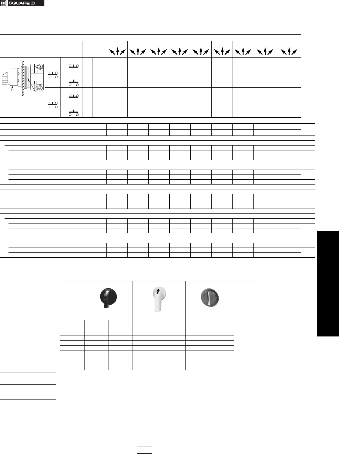
www.us.schneider-electric.com
FOR CURRENT INFORMATION
19 PUSH BUTTONS AND
OPERATOR INTERFACES
© 2007 Schneider Electric
All Rights Reserved 19-73
30 mm Push Buttons Type SK Corrosion Resistant Selector Switches
Class 9001 / Refer to Catalog 9001CT0001
aThese operators can be ordered complete with contact blocks. For maximum block usage, see page 19-85. Add the “H” number
chosen from page 19-80 to the end of the operator type number and add the cost of the “H” number to the operator cost.
bAdd the color code as chosen from knob color table below. Example: SKS43b with a green gloved-hand knob = SKS43FG.
Basic Operators. . . . . . . . . . . . . . . . . . . . . . . . . . . . . . . . . . . . . . . .page 19-85
Light Modules . . . . . . . . . . . . . . . . . . . . . . . . . . . . . . . . . . . . . . . . .page 19-77
Contact Blocks. . . . . . . . . . . . . . . . . . . . . . . . . . . . . . . . . . . . . . . . .page 19-78
H Contact Block Assembly Codes . . . . . . . . . . . . . . . . . . . . . . . . .page 19-80
Legend Plates . . . . . . . . . . . . . . . . . . . . . . . . . . . . . . . . . . . . . . . . .page 19-81
Accessories . . . . . . . . . . . . . . . . . . . . . . . . . . . . . . . . . . . . . . . . . . .page 19-83
Replacement Parts . . . . . . . . . . . . . . . . . . . . . . . . . . . . . . . . . . . . .page 19-86
Table 19.209: Non-Illuminated 3 Position Selector Switch Operators—UL Types 4, 4X, 13/NEMA 4, 4X, 13
For use in hazardous locations—See page 19-79. Legend plate and contact block not included unless noted.
CONTACT BLOCK REQUIRED 1 — Contact Closed 0 — Contact Open
Contact
Block
Position
Quantity
and
Type
Mount
on
Side
Center Center Center Center Center Center Center Center Center
KA1
or
KA3
KA1
#2 or
KA3
#2 1001000011001001001000 1 0 1 1 0
KA2 KA2
#2 0110010100100010110111 0 0 0 0 1
KA1
or
KA3
KA1
#1 or
KA3
#1 0011000011000100011010 0 1 0 1 1
KA2 KA2
#1 1100010100100011000100 1 0 1 0 0
Top View
Side 2
Side 1
Operator Locating
Notch
Cam (see page 19-64) B C D E F G J L M $ Price
Non-Illuminated Operators Type Type Type Type Type Type Type Type Type
Manual Return
Operator Only a
Without Knob SKS42 SKS43 SKS44 SKS45 SKS46 SKS47 SKS49 SKS401 SKS402 28.50
With Standard Black Knob SKS42B SKS43B SKS44B SKS45B SKS46B SKS47B SKS49B SKS401B SKS402B 35.10
With Other Color Knob (See Table 19.210) bSKS42bSKS43bSKS44bSKS45bSKS46bSKS47bSKS49bSKS401bSKS402b
With Contact Block(s)
With Standard Black Knob (For Other Colors: Replace B in the Type Number with the Color Code from Table 19.210)
With 1 KA1 on side #2 SKS42BH13 SKS43BH13 SKS44BH13 SKS45BH13 SKS46BH13 SKS47BH13 SKS49BH13 SKS401BH13 SKS402BH13 64.00
With 1 KA1 on side #1 SKS42BH1 SKS43BH1 SKS44BH1 SKS45BH1 SKS46BH1 SKS47BH1 SKS49BH1 SKS401BH1 SKS402BH1
With 1 KA1 on side #1 and 1 KA1 on side #2 (H2) SKS42BH2 SKS43BH2 SKS44BH2 SKS45BH2 SKS46BH2 SKS47BH2 SKS49BH2 SKS401BH2 SKS402BH2 92.00
Spring Return from Left to Center
Operator Only a
Without Knob SKS62 SKS63 SKS64 SKS65 SKS66 SKS67 SKS69 SKS601 SKS602 47.60
With Standard Black Knob SKS62B SKS63B SKS64B SKS65B SKS66B SKS67B SKS69B SKS601B SKS602B 54.00
With Other Color Knob (See Table 19.210) bSKS62bSKS63bSKS64bSKS65bSKS66bSKS67bSKS69bSKS601bSKS602b
Spring Return From Right to Center
Operator Only a
Without Knob SKS72 SKS73 SKS74 SKS75 SKS76 SKS77 SKS79 SKS701 SKS702 47.60
With Standard Black Knob SKS72B SKS73B SKS74B SKS75B SKS76B SKS77B SKS79B SKS701B SKS702B 54.00
With Other Color Knob (See Table 19.210) bSKS72bSKS73bSKS74bSKS75bSKS76bSKS77bSKS79bSKS701bSKS702b
Spring Return Both Sides to Center
Operator Only a
Without Knob SKS52 SKS53 SKS54 SKS55 SKS56 SKS57 SKS59 SKS501 SKS502 47.60
With Standard Black Knob SKS52B SKS53B SKS54B SKS55B SKS56B SKS57B SKS59B SKS501B SKS502B 54.00
With Other Color Knob (See Table 19.210) bSKS52bSKS53bSKS54bSKS55bSKS56bSKS57bSKS59bSKS501bSKS502b
Table 19.210: Selector Switch Knobs
Standard Knob Gloved-Hand Knob Coin Operated
Color b Knob Code Type b Knob Code Type b Knob Code Type $ Price
Black B B11 FB B25 TB B18
6.60
Red R R8 FR R24 TR R16
Green G G8 FG G24 TG G16
Ye l l o w Y Y8 FY Y24 TY Y16
Orange S S11 FS S25 ——
Blue L L8 FL L24 TL L16
White W W8 FW W24 ——
Amber A A8 FA A24 ——
Clear C C8 FC C24 TC C16
When ordering,
please specify:
•Quantity
•Class Number
•Type or Catalog Number
CP1 Discount
Schedule
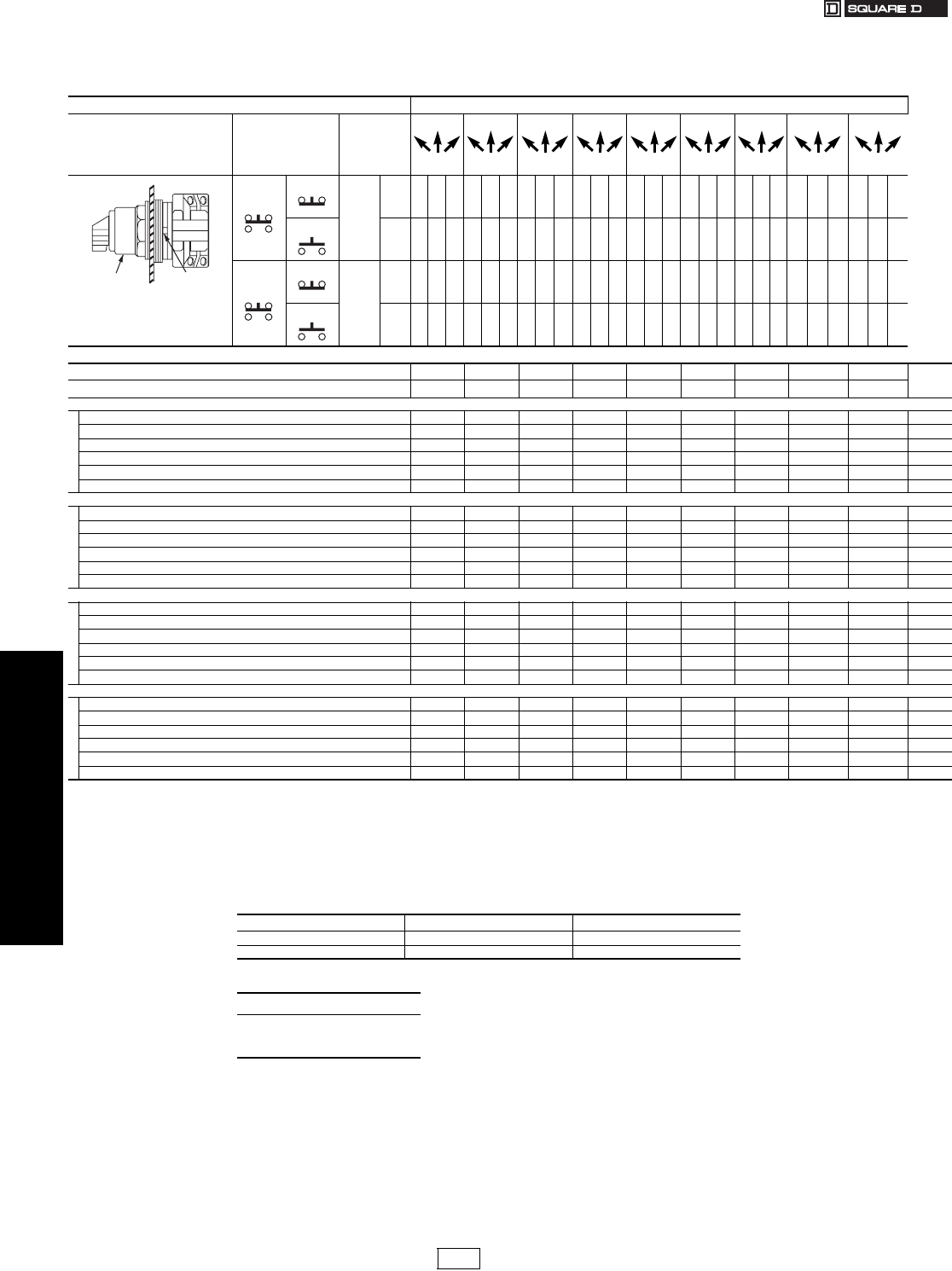
19-74 © 2007 Schneider Electric
All Rights Reserved
www.us.schneider-electric.com
FOR CURRENT INFORMATION
19 PUSH BUTTONS AND
OPERATOR INTERFACES
30 mm Push Buttons Type SK Corrosion Resistant Selector Switches
Class 9001 / Refer to Catalog 9001CT0001
aThese operators can be ordered complete with contact blocks. For maximum block usage, see page 19-85. Add the “H” number chosen from page 19-
80 to the end of the operator type number and add the cost of the “H” number to the operator cost.
bAdd the voltage assembly code as chosen from page 19-77.
Example: SK43Jb with 208 Vac = SK43J3.
cAdd the color as chosen from knob color table on page 19-75.
Example: SK43J35c with a green gloved-hand knob = SK43J35FG.
dThe knob must be the same color as the LED light module chosen, e.g., for red LED, use red knob.
eOn neon light modules, use clear knobs only.
fAdd form number to standard Type number, e.g., Type SK43J1 Form Y178.
Basic Operators . . . . . . . . . . . . . . . . . . . . . . . . . . . . . . . . . . . . . . . page 19-85
Light Modules . . . . . . . . . . . . . . . . . . . . . . . . . . . . . . . . . . . . . . . . . page 19-77
Contact Blocks . . . . . . . . . . . . . . . . . . . . . . . . . . . . . . . . . . . . . . . . page 19-78
H Contact Block Assembly Codes. . . . . . . . . . . . . . . . . . . . . . . . . page 19-80
Legend Plates. . . . . . . . . . . . . . . . . . . . . . . . . . . . . . . . . . . . . . . . . page 19-81
Accessories . . . . . . . . . . . . . . . . . . . . . . . . . . . . . . . . . . . . . . . . . . page 19-83
Replacement Parts. . . . . . . . . . . . . . . . . . . . . . . . . . . . . . . . . . . . . page 19-86
Table 19.211: Illuminated 3 Position Selector Switch Operators—UL Types 4, 4X, 13/NEMA 4, 4X, 13
For use in hazardous locations—See page 19-79. Legend plate and contact block not included unless noted.
CONTACT BLOCK REQUIRED 1—Contact Closed 0—Contact Open
Contact
Block
Position
Quantity and Type
KA1 or KA2 or KA3
Mount on Side
KA1 or KA2 or
KA3
Center Center Center Center Center Center Center Center Center
Left Right Left Right Left Right Left Right Left Right Left Right Left Right Left Right Left Right
KA1
KA3
KA1
#2
KA3
#2 1001000011001001001000 1 0 1 1 0
KA2 KA2
#2 0110010100100010110111 0 0 00 1
KA1
KA3
KA1
#1
KA3
#1 0011000011000100011010 0 1 0 1 1
KA2 KA2
#1 110001 010010001100 010 01 0 1 0 0
Top View
Side 2
Side 1
Operator Locating
Notch
Cam (seepage 19-64) B C D E F G J L M $ Price
Illuminated Operators Type Type Type Type Type Type Type Type Type
Manual Return a
Without Knob, 110–120 V 50–60 Hz Transformer SK42J1 SK43J1 SK44J1 SK45J1 SK46J1 SK47J1 SK49J1 SK401J1 SK402J1 105.
With Standard Red Knob, 110–120 V 50–60 Hz Transformer SK42J1R SK43J1R SK44J1R SK45J1R SK46J1R SK47J1R SK49J1R SK401J1R SK402J1R 111.
Without Knob and Other Voltage Transformer, Flashing or LED dSK42J bSK43J bSK44J bSK45J bSK46JbSK47J bSK49J bSK401JbSK402J b105.
Without Knob, Full Voltage Neon or Resistor eSK42J bSK43J bSK44J bSK45J bSK46JbSK47J bSK49J bSK401JbSK402J b86.
With Other Color Knob and Transformer, Flashing or LED dSK42J bc SK43J bc SK44J bc SK45J bc SK46Jbc SK47J bc SK49J bc SK401Jbc SK402J bc 111.
With Other Color Knob, Full Voltage Neon or Resistor eSK42J bc SK43J bc SK44J bc SK45J bc SK46Jbc SK47J bc SK49J bc SK401J bc SK402J bc 92.
Spring Return Left To Center a
Without Knob, 110–120 V 50–60 Hz Transformer SK62J1 SK63J1 SK64J1 SK65J1 SK66J1 SK67J1 SK69J1 SK601J1 SK602J1 123.
With Standard Red Knob, 110–120 V 50–60 Hz Transformer SK62J1R SK63J1R SK64J1R SK65J1R SK66J1R SK67J1R SK69J1R SK601J1R SK602J1R 131.
Without Knob and Other Voltage Transformer, Flashing or LED dSK62J bSK63J bSK64J bSK65J bSK66J bSK67J bSK69J bSK601J bSK602J b123.
Without Knob, Full Voltage Neon or Resistor eSK62J bSK63J bSK64J bSK65J bSK66J bSK67J bSK69J bSK601J bSK602J b105.
With Other Color Knob and Transformer, Flashing or LED dSK62J bc SK63J bc SK64J bc SK65J bc SK66J bc SK67J bc SK69J bc SK601J bc SK602J bc 131.
With Other Color Knob, Full Voltage Neon or Resistor eSK62J bc SK63J bc SK64J bc SK65J bc SK66J bc SK67J bc SK69J bc SK601J bc SK602J bc 111.
Spring Return Right To Center a
Without Knob, 110–120 V 50–60 Hz Transformer SK72J1 SK73J1 SK74J1 SK75J1 SK76J1 SK77J1 SK79J1 SK701J1 SK702J1 123.
With Standard Red Knob, 110–120 V 50–60 Hz Transformer SK72J1R SK73J1R SK74J1R SK75J1R SK76J1R SK77J1R SK79J1R SK701J1R SK702J1R 131.
Without Knob and Other Voltage Transformer, Flashing or LED dSK72J bSK73J bSK74J bSK75J bSK76J bSK77J bSK79J bSK701J bSK702J b123.
Without Knob, Full Voltage Neon or Resistor eSK72J bSK73J bSK74J bSK75J bSK76J bSK77J bSK79J bSK701J bSK702J b105.
With Other Color Knob and Transformer, Flashing or LED dSK72J bc SK73J bc SK74J bc SK75J bc SK76J bc SK77J bc SK79J bc SK701J bc SK702J bc 131.
With Other Color Knob, Full Voltage Neon or Resistor eSK72J bc SK73J bc SK74J bc SK75J bc SK76J bc SK77J bc SK79J bc SK701J bc SK702J bc 111.
Spring Return Both Sides To Center a
Without Knob, 110–120 V 50–60 Hz Transformer SK52J1 SK53J1 SK54J1 SK55J1 SK56J1 SK57J1 SK59J1 SK501J1 SK502J1 123.
With Standard Red Knob, 110–120 V 50–60 Hz Transformer SK52J1R SK53J1R SK54J1R SK55J1R SK56J1R SK57J1R SK59J1R SK501J1R SK502J1R 131.
Without Knob and Other Voltage Transformer, Flashing or LEDdSK52J bSK53J bSK54J bSK55J bSK56J bSK57J bSK59J bSK501J bSK502J b123.
Without Knob, Full Voltage Neon or Resistor eSK52J bSK53J bSK54J bSK55J bSK56J bSK57J bSK59J bSK501J bSK502J b105.
With Other Color Knob and Transformer, Flashing or LEDdSK52J bc SK53J bc SK54J bc SK55J bc SK56J bc SK57J bc SK59J bc SK501J bc SK502J bc 131.
With Other Color Knob, Full Voltage Neon or Resistor eSK52J bc SK53J bc SK54J bc SK55J bc SK56J bc SK57J bc SK59J bc SK501J bc SK502J bc 111.
Table 19.212: Two Color Selector Switch
Used to indicate red in left position and green in right position on illuminated operators.
Knob Factory Assembled Form Number f$ Price Adder
Standard Y178 19.
Gloved-Hand Y1781 19.
When ordering, please specify:
•Quantity
•Class Number
•Type or Catalog Number
CP1 Discount
Schedule Modified
4/20/09
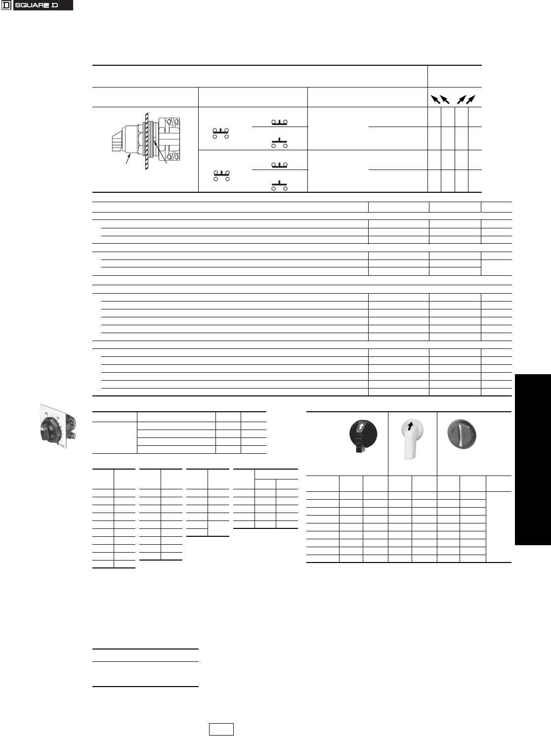
www.us.schneider-electric.com
FOR CURRENT INFORMATION
19 PUSH BUTTONS AND
OPERATOR INTERFACES
© 2007 Schneider Electric
All Rights Reserved 19-75
30 mm Push Buttons Type SK Corrosion Resistant Selector Switches
Class 9001 / Refer to Catalog 9001CT0001
Table 19.213: Non-Illuminated 4-Position Selector Switch Operators UL Types 4, 4X, 13/NEMA 4, 4X, 13
For use in hazardous locations—See page 19-79. Legend plate and contact block not included
unless noted.
CONTACT BLOCK REQUIRED
1 — Contact
Closed
0 — Contact Open
Contact Block Position Quantity and Type Mount on Side
KA1
or
KA3
KA1
#2
or
KA3
#2 1000
KA2 KA2
#2 0010
KA1
or
KA3
KA1
#1 or
KA3
#1 0001
KA2 KA2
#1 0100
Top View
Side 2
Side 1
Operator Locating
Notch
Non-Illuminated Operators Cam (see page 19-64) Type $ Price
Manual Return, Operator Only a
Without Knob HSKS88 28.50
With Standard Black Knob HSKS88B 34.50
With Other Color Knob (See Knob Table) bHSKS88b35.10
Spring Return From Left, Spring Return From Right, Maintained in the Two Mid Positions, Operator Only a
Without Knob HSKS89 47.60
With Standard Black Knob HSKS89B 54.00
With Other Color Knob (See Knob Table) bHSKS89b
Illuminated Operators
Manual Return a
Without Knob, 110-120 V 50-60 Hz Transformer H SK88J1 105.00
With Standard Red Knob, 110-120 V 50-60 Hz Transformer H SK88J1R 111.00
Without Knob and With Other Voltage Transformer, Flashing or LED dH SK88J c105.00
Without Knob, Full Voltage Neon or Resistor eH SK88J c86.00
With Other Color Knob and Transformer, Flashing or LED dH SK88J bc 111.00
With Other Color Knob, Full Voltage Neon or ResistoreH SK88J bc 92.00
Spring Return From Left, Spring Return From Right, Maintained in the Two Mid Positions, Operator Only a
Without Knob, 110-120 V 50-60 Hz Transformer H SK89J1 131.00
With Standard Red Knob, 110-120 V 50-60 Hz Transformer H SK89J1R 131.00
Without Knob and Other Voltage Transformer, Flashing or LED dH SK89J c123.00
Without Knob, Full Voltage Neon or Resistor eH SK89J c105.00
With Other Color Knob and Transformer, Flashing or LED dH SK89J bc 131.00
With Other Color Knob, Full Voltage Neon or ResistoreH SK89J bc 111.00
Table 19.214: Potentiometer (with Dial Plate f)
Watts Description Type $ Price
2
Operator only—Single Pot SK20 134.
Operator with Single Pot SK21 g 191.
Operator only—Tandem Pot SK22 209.
Operator with Tandem Pot SK23 h 266.
Table 19.215: Potentiometer Suffix
Suffix
gOhms Suffix
gOhms Suffix
gOhms Suffix
h
Ohms
Front Rear
01 50 07 5k 13 500k 82 1k 1k
02 100 08 10k 37 750k 83 5k 5k
38 200 40 15k 14 1.0M 85 10k 10k
03 250 09 25k 15 2.5M 88 50k 50k
04 500 35 35k 16 5.0M 89 100k 100k
05 1000 10 50k 17
32 1500 36 75k
39 2000 11 100k
06 2500 12 250k
33 3500
Table 19.216: Selector Switch Knobs
Standard Knob Gloved-Hand
Knob
Coin Operated
Color b Knob
Code Type b Knob
Code Type b Knob
Code Type $ Price
Black iBB11 FB B25 TB B18
6.60
Red R R8 FR R24 TR R16
Green G G8 FG G24 TG G16
Yellow Y Y8 FY Y24 TY Y16
Orange iSS11 FS S25 ——
Blue L L8 FL L24 TL L16
White W W8 FW W24 ——
Amber A A8 FA A24 TC —
Clear C C8 FC C24 C16
aThese operators can be ordered complete with contact blocks. For maximum block usage, see page 19-85. Add the “H” number chosen from page 19-80
to the end of the operator type number and add the cost of the “H” number to the operator cost.
bAdd the color code as chosen from Table 19.216. Example: SKS88b with a green gloved-hand knob = SKS88FG.
cAdd the voltage assembly code as chosen from page 19-77. Example: SK88Jc with 208 Vac = SK88J3.
dThe knob must be the same color as the LED light module chosen, e.g., for red LED, use red knob.
eOn neon light modules, use clear knobs only.
fThe catalog number for only the dial plate is 9001KN180WP—$2.90.
gFor complete Type number add suffix number from Table 19.215. Example: Type SK2105
hFor complete Type number add suffix number from Table 19.215. Example: Type SK2382
iBlack and orange are opaque and for use on non-illuminated operators only.
When ordering, please specify:
•Quantity
•Class Number
•Type or Catalog Number
CP1 Discount
Schedule Modified
4/20/09
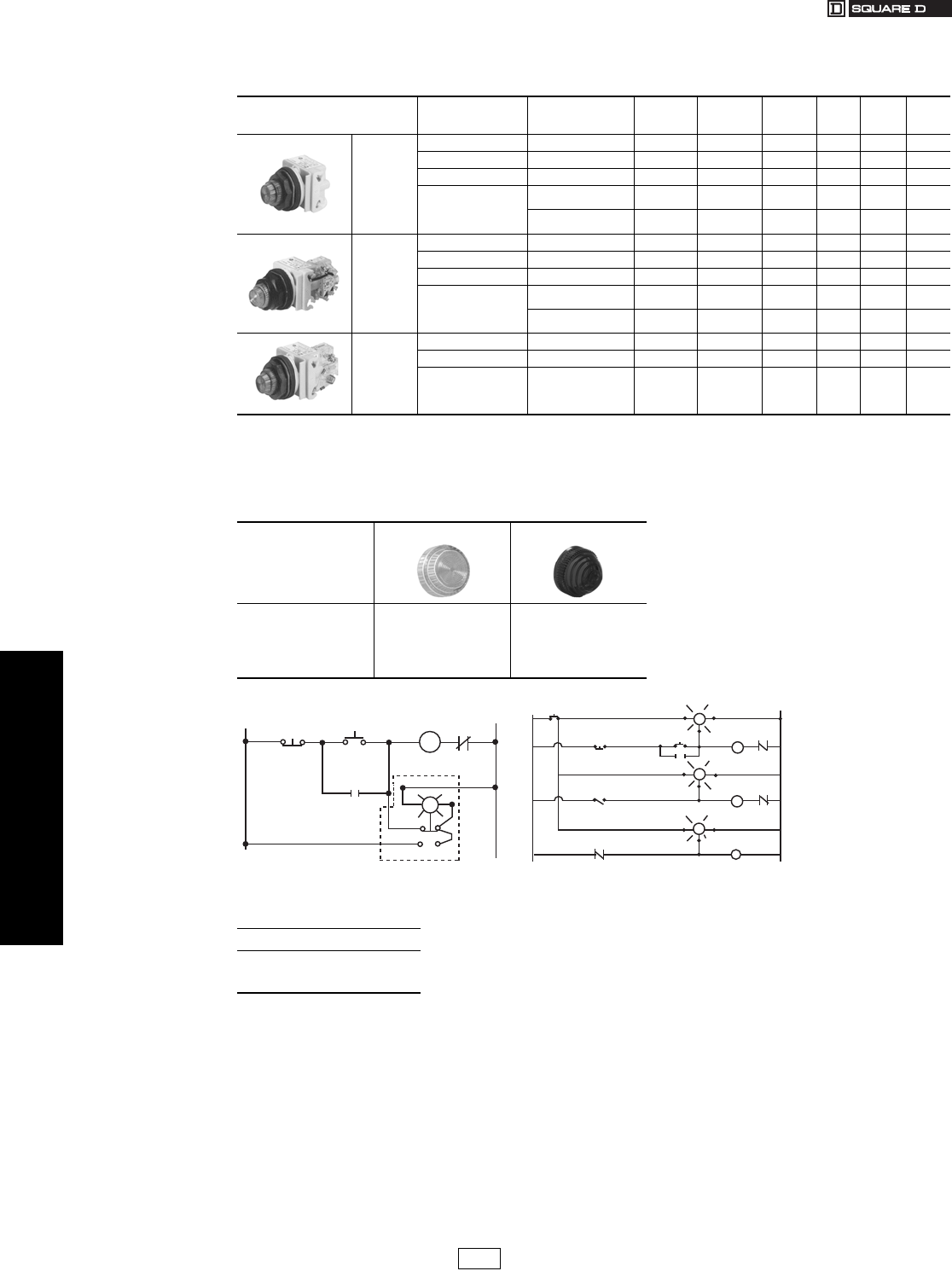
19-76 © 2007 Schneider Electric
All Rights Reserved
www.us.schneider-electric.com
FOR CURRENT INFORMATION
19 PUSH BUTTONS AND
OPERATOR INTERFACES
30 mm Push Buttons Type SK Corrosion Resistant Pilot Lights
Class 9001 / Refer to Catalog 9001CT0001
aAdd the voltage assembly code as chosen from table, page 19-77.
EXAMPLE: SKTqR31 with 208 Vac red LED voltage = SKT37LRR3.
bAdd the color code as chosen from the color cap table below.
EXAMPLE: SKP1c with a blue fresnel cap = SKP1L31.
cThe cap must be the same color as the LED light module chosen, e.g., for a green LED, use a green color cap.
dOn neon light modules, use clear color caps only.
eUse only full voltage or resistor voltage assembly codes on remote test pilot lights. Do not choose LED, neon or transformer codes. For AC use only.
Basic Operators . . . . . . . . . . . . . . . . . . . . . . . . . . . . . . . . . . . . . . . page 19-85
Light Modules . . . . . . . . . . . . . . . . . . . . . . . . . . . . . . . . . . . . . . . . . page 19-77
Contact Blocks . . . . . . . . . . . . . . . . . . . . . . . . . . . . . . . . . . . . . . . . page 19-78
H Contact Block Assembly Codes. . . . . . . . . . . . . . . . . . . . . . . . . page 19-80
Legend Plates. . . . . . . . . . . . . . . . . . . . . . . . . . . . . . . . . . . . . . . . . page 19-81
Accessories . . . . . . . . . . . . . . . . . . . . . . . . . . . . . . . . . . . . . . . . . . page 19-83
Replacement Parts. . . . . . . . . . . . . . . . . . . . . . . . . . . . . . . . . . . . . page 19-86
Table 19.217: Pilot Lights—UL Types 4, 4X, 13/NEMA 4, 4X, 13
For use in hazardous locations—See page 19-79. Legend plate not included.
Description Voltage Style
With Red
Fresnel Color
Cap
With Green
Fresnel Color
Cap
With Other
Color Cap $ Price Without
Color Cap $ Price
9001SKP1
Standard
Pilot Light
(Fresnel color
cap shown)
110–120 V, 50–60 Hz Transformer SKP1R31 SKP1G31 SKP1b102. SKP1 95.
220–240 V, 50–60 Hz Transformer SKP7R31 SKP7G31 SKP7b102. SKP7 95.
24–28 Vac/dc Full Voltage SKP35R31 SKP35G31 SKP35b83. SKP35 77.
For other voltages
see Table a
Transformer, Flashing
or LEDcSKPaR31 SKPaG31 SKPab 102. SKPa95.
Full Voltage, Neon or
ResistordSKPaR31 SKPaG31 SKPab 83. SKPa77.
9001SKT1
Push-To-Test
Pilot Light
(Fresnel color
cap shown)
110–120 V, 50–60 Hz Transformer SKT1R31 SKT1G31 SKT1b131. SKT1 123.
220–240 V, 50–60 Hz Transformer SKT7R31 SKT7G31 SKT7b131. SKT7 123.
24–28 Vac/dc Full Voltage SKT35R31 SKT35G31 SKT35b111. SKT35 105.
For other voltages
see Table a
Transformer, Flashing
or LEDcSKTaR31 SKTaG31 SKTab 131. SKTa123.
Full Voltage, Neon or
ResistordSKTaR31 SKTaG31 SKTab 111. SKTa105.
9001SKTR38
Remote Test
Pilot Light
(Fresnel color
cap shown)
120 Vac Only Resistor SKTR38R31 SKTR38G31 SKTR38b131. SKTR38 123.
24–28 Vac Only Full Voltage SKTR35R31 SKTR35G31 SKTR35b131. SKTR35 123.
For other voltages
see Tables abe
Full Voltage or Resistor
eSKTRaR31 SKTRaG31 SKTRab 131. SKTRa123.
Table 19.218: Color Caps
Color
b Plastic Fresnel b Plastic Domed
Amber
Blue
Clear
Green
Red
White
Yellow
A31
L31
C31
G31
R31
W31
Y31
A9
L9
C9
G9
R9
W9
Y9
When ordering, please specify:
•Quantity
•Class Number
•Type or Catalog Number
R
M
MO.L.
L2
3
2
1
L1
STOP
START
L2
C
Test
L1
M
Push-To-Test Pilot Light
Typical Wiring Diagram
STOP
LSI
M3
(TEST) C
(TEST) C L2
L2
L1
(SIG) CR
M2
M1
L2
(TEST) C
START
TEST
BUTTON
L1 L2
L1
(SIG)
L1
(SIG)
Remote Test Pilot Light
CP1 Discount
Schedule
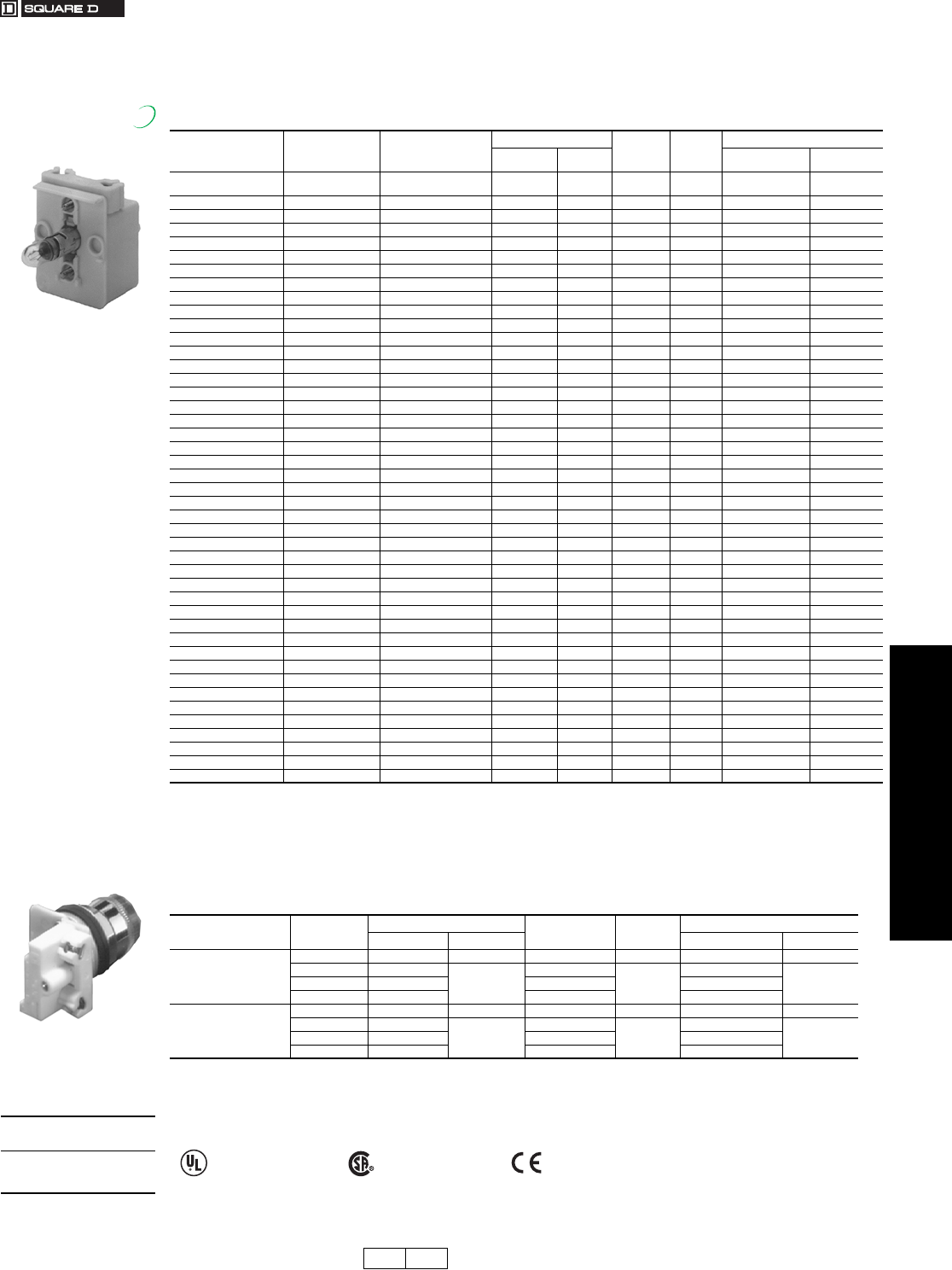
www.us.schneider-electric.com
FOR CURRENT INFORMATION
19 PUSH BUTTONS AND
OPERATOR INTERFACES
© 2007 Schneider Electric
All Rights Reserved 19-77
30 mm Push Buttons Type K, SK and KX Electrical Components
Class 9001 / Refer to Catalog 9001CT0001
For use in hazardous locations—See page 19-79.
•With neon type light modules, use a clear color cap only.
•With LED light modules, use either a clear color cap or a cap the same color as the LED.
NOTE: Light modules are available in other voltages. For additional information, refer to Catalog 9001CT0001.
For use in hazardous locations—See page 19-79.
•Reduces the depth of illuminated push buttons with contact blocks by over 33%.
•With LED light modules, use either a clear color cap or a cap the same color as the LED.
a9001K, SK, KX.
bDo not use on any remote test version pilot light.
cFor use with all operators except KX and remote test pilot.
dCheck light module label for series and replacement number.
Table 19.219: Standard Light Modules for Types K, SK, and KX Control Units c
Voltage Description
For Use With Single
Lamp Ill. Operators as
Indicated a
Light Module Vol t age
Assembly
Code
Rating
Replacement Lamp
Type $ Price Part Number c$ Price
All Full Voltage (without
Bayonet Base Lamp) All KM40 52. 40 — None —
6 Vac/dc Full Voltage All KM31 57. 31 .9 VA 2550101020 8.30
6 Vac/dc LED Red All Except b KM31LR 77. 31LR 6508805201 28.50
6 Vac/dc LED Green All Except b KM31LG 77. 31LG 6508805203 28.50
6 Vac/dc LED Yellow All Except b KM31LY 77. 31LY 6508805202 28.50
12–14 Vac/dc Full Voltage All KM32 57. 32 1.2 VA 2550101037 8.30
12–14 Vac/dc LED Red All Except b KM32LR 77. 32LR 6508805201 28.50
12–14 Vac/dc LED Green All Except b KM32LG 77. 32LG 6508805203 28.50
12–14 Vac/dc LED Yellow All Except b KM32LY 77. 32LY 6508805202 28.50
18 Vac/dc Resistor All KM33 57. 33 1.4 VA 2550101037 8.30
24–28 Vac/dc Full Voltage All KM35 57. 35 1.2 VA 2550101002 8.30
24–28 Vac/dc LED Red All ExceptbKM35LR 77. 35LR .28 VA 6508805210 28.50
24–28 Vac/dc LED Green All ExceptbKM35LG 77. 35LG .28 VA 6508805212 28.50
24–28 Vac/dc LED Yellow All ExceptbKM35LY 77. 35LY .28 VA 6508805211 28.50
24–28 Vac/dc LED White All ExceptbKM35LW 77. 35LW .28 VA 6508805214 28.50
24–28 Vac/dc LED Blue All ExceptbKM35LL 77. 35LL .28 VA 6508805213 28.50
48 Vac/dc Full Voltage All KM36 57. 36 2.6 VA 2550101025 8.30
110–120 V, 50–60 Hz LED Red All Except b KM1LR 95. 1LR 6508805201 28.50
110–120 V, 50–60 Hz LED Green All Except b KM1LG 95. 1LG 6508805203 28.50
110–120 V, 50–60 Hz LED Yellow All Except b KM1LY 95. 1LY 6508805202 28.50
110–120 V, 50–60 Hz Transformer All ExceptbKM1 77. 1 2.4 VA 2550101020 8.30
110–120 V, 50–60 Hz Flashing All ExceptbKMF1 77. F1 .85 VA 2550101036 11.00
120 Vac/dc Resistor All KM38 57. 38 3.0 VA 2550101027 8.30
120 Vac/dc Full Voltage All KM38 57. 38 3.0 VA 2550101027 8.30
120 Vac/dc Neon All ExceptbKM11 57. 11 0.2 VA 2550101013 21.90
120 Vac/dc LED Red All ExceptbKM38LR 77. 38LR 1.4 VA 6508805210 28.50
120 Vac/dc LED Green All ExceptbKM38LG 77. 38LG 1.4 VA 6508805212 28.50
120 Vac/dc LED Yellow All ExceptbKM38LY 77. 38LY 1.4 VA 6508805211 28.50
120 Vac/dc LED White All ExceptbKM38LW 77. 38LW 1.4 VA 6508805214 28.50
120 Vac/dc LED Blue All ExceptbKM38LL 77. 38LL 1.4 VA 6508805213 28.50
208–220 V, 50–60 Hz Transformer All ExceptbKM3 77. 3 2.5 VA 2550101020 8.30
208–220 V, 50–60 Hz LED Red All Except b KM3LR 95. 3LR 6508805201 28.50
208–220 V, 50–60 Hz LED Green All Except b KM3LG 95. 3LG 6508805203 28.50
208–220 V, 50–60 Hz LED Yellow All Except b KM3LY 95. 3LY 6508805202 28.50
220–240 V, 50–60 Hz Transformer All ExceptbKM7 77. 7 2.0 VA 2550101020 8.30
220–240 V, 50–60 Hz LED Red All Except b KM7LR 95. 7LR 6508805201 28.50
220–240 V, 50–60 Hz LED Green All Except b KM7LG 95. 7LG 6508805203 28.50
220–240 V, 50–60 Hz LED Yellow All Except b KM7LY 95. 7LY 6508805202 28.50
240 Vac/dc Resistor All ExceptbKM25 57. 25 6.0 VA 2550101027 8.30
240 Vac/dc Neon All Exceptb and KX KM12 57. 12 0.3 VA 2550101013 21.90
277 V, 50–60 Hz Transformer All ExceptbKM8 77. 8 2.4 VA 2550101020 8.30
380–480 V, 50–60 Hz Transformer All ExceptbKM5 77. 5 2.8 VA 2550101020 8.30
480 Vac/dc Neon All Exceptb and KX KM14 57. 14 0.5 VA 2550101013 21.90
550–600 V, 50–60 Hz Transformer All ExceptbKM6 77. 6 2.5 VA 2550101020 8.30
New!
Table 19.220: Shallow Depth Light Modules For Types K and SK Control Units c
Voltage Description Light Module Voltage Assembly
Code Rating Replacement Lamp
Type $ Price Part Number $ Price
24–28 Vac/dc
Full Voltage KM55 57.00 55 1.2 VA 2550101002 8.30
LED Red KM55LR
77.00
55LR
0.5 VA
6508805204 28.50
LED Green KM55LG 55LG 6508805206
LED Yellow KM55LY 55LY 6508805205
110–120 Vac/dc
Full Voltage KM58 57.00 58 3.0 VA 2550101027 8.30
LED Red KM58LR
77.00
58LR
0.5 VA
6508805204
28.50LED Green KM58LG 58LG 6508805206
LED Yellow KM58LY 58LY 6508805205
When ordering,
please specify:
•Quantity
•Class Number
•Type or Catalog Number
File
CCN
E42259
NKCR
File
Class
LR25490
3211 03 marked
CP10 CP1 Discount
Schedule
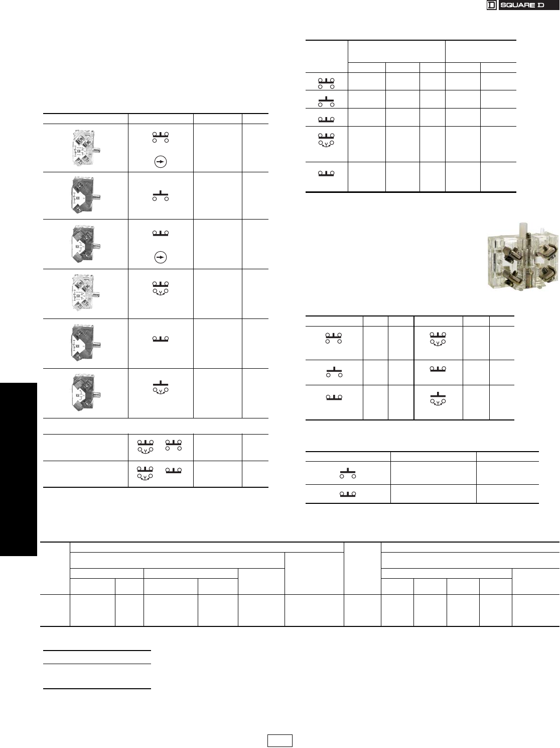
www.us.schneider-electric.com
FOR CURRENT INFORMATION
19 PUSH BUTTONS AND
OPERATOR INTERFACES
19-78 © 2007 Schneider Electric
All Rights Reserved
30 mm Push Buttons Type K, SK and KX Electrical Components
Class 9001 / Refer to Catalog 9001CT0001
The Class 9001 Type KA contact blocks are Fingersafe® contact blocks
(meeting VDE 0106 Part 100). They have one screw mounting and
captive (backed out) plus/minus terminal screws. These contact blocks
are double-break, direct-acting contacts. Because of the wiping action
of these contacts, they are suitable for use with programmable
controllers. All contact blocks listed below accept up to 2 #12–#24 AWG
solid or stranded wires. Recommended tightening torque for screw
terminals is 7 lb-in.
aFor push buttons or two-position selector switches only. For sequencing or overlapping
contacts on other operators, refer to catalog 9001CT0001.
bMinimum order quantity is 25. The price represents one individual contact block.
Contact blocks listed below are not Fingersafe, but provide:
•Terminals that accept ring tongue/fork tongue
connectors
•Short single circuit contact blocks (0.75" deep vs.
0.97" deep on the Fingersafe)
•Same as old style Series G product available prior
to March, 1989.
•For assembled operators, use form Y238 (add to
catalog number as suffix, for example:
9001KRU1H13Y238)
Dimensions . . . . . . . . . . . . . . . . . . . . . . . . . . . . . . . . . . Catalog 9001CT0001
Table 19.221: Standard Contact Blocks
Description Symbol Type $ Price
(Clear Cover)
Direct-Acting KA1 28.50
(Green Cover)
KA2 14.30
(Red Cover)
Direct-Acting KA3 14.30
(Clear Cover)
N.O. Contact
Early Closing
KA4 28.50
(Red Cover)
N.C. Contact
Late Opening
KA5 14.30
(Green Cover)
N.O. Contact
Early Closing
KA6 14.30
Table 19.222: Additional Circuit Arrangements
Sequencing a
N.O. Contact of KA4 closes
before N.O. Contact on KA1
KA4 KA1
Order One
Type KA4 and One
Type KA1
57.00
Overlapping a
N.O. Contact of KA4 closes
before N.C. Contact of KA5
Opens
KA4 KA5
Order One
Type KA4 and One
Type KA5
42.80
Symbol
Contact Blocks with
Binder Head Screws
(not Fingersafe)
Gold Flashed Contacts
with Standard
Pressure Wire Terminals
Type Quantityb$ Price Type $ Price
KA21 25–Up 28.50 KA31 47.60
KA22 25–Up 14.30 KA32 23.70
KA23 25–Up 14.30 KA33 23.70
N.O. Early
Closing
KA24 25–Up 28.50 KA34 47.60
N.C. Contact
Late Opening
KA25 25–Up 14.30 KA35 23.70
Table 19.223: Contact blocks (not Fingersafe)
Symbol Type $ Price Symbol Type $ Price
KA1G 28.50
N.O. Contact
Early Closing
KA4G 28.50
KA2G 14.30 N.C. Contact
Late Opening
KA5G 14.30
KA3G 14.30
N.O. Contact
Early Closing
KA6G 14.30
Table 19.224: Contact blocks with Quick-Connect terminals
(not Fingersafe)
Symbol Type $ Price
KA12 23.70
KA13 23.70
Table 19.225: Maximum Current Ratings for Control Circuit Contacts—Types KA1–KA6, KA21–KA25, KA31–KA35, KA1G–KA6G
V
AC
Volts
DC
Inductive (NEMA / UL Type A600)
35% Power Factor Resistive 75% Power
Factor Make, Break
and Continuous
Amperes
Inductive and Resistive
(NEMA Q600)
Make Break Continuous
Carrying
Amperes
Make and Break Continuous
Carrying
Amperes
Amperes VA Amperes VA KA1 KA2
KA3 KA4 KA5
KA6
120 60
7200
6.0
720 10 10
125
250
600
0.55
0.27
0.10
0.55
0.27
0.10
—
—
—
—
—
—
2.5
240 30 3.0
480 15 1.5
600 12 1.2
When ordering, please specify:
•Quantity
•Class Number
•Type or Catalog Number
CP1 Discount
Schedule
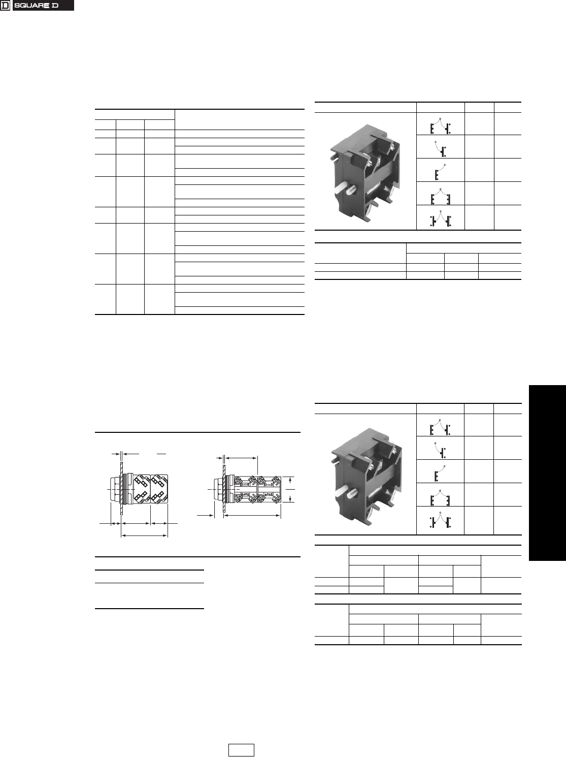
www.us.schneider-electric.com
FOR CURRENT INFORMATION
19 PUSH BUTTONS AND
OPERATOR INTERFACES
© 2007 Schneider Electric
All Rights Reserved 19-79
30 mm Push Buttons Type K, SK and KX Electrical Components
Class 9001 / Refer to Catalog 9001CT0001
Hazardous locations do not always require the use of
explosion-proof equipment like the Class 9001 Type BR
control stations. Selecting the most appropriate device for
the location can save you money. For more information on
the types of hazardous locations, contact your local
electrical inspector.
aAny Class 9001 Type K, SK or KX operator can be used in an area
classified as Class I, Division 2 hazardous locations, if:
1. Only logic (KA40 series) or power (KA50 series) reed contact blocks
are used.
2. All Type K and SK illuminated operators are UL approved for use in
Class I Division 2 areas. c
3. Type KX illuminated operators do not use 4 lamp light modules, or 2
lamp light modules other than the transformer type. c
4. The operators are mounted in any NEMA 4 & 13 enclosures.
bAny Class 9001 Type K, SK, or KX operator mounted in a Class 9001
Type KY, KYSS, KYAF, SKY enclosure may be used, except
potentiometer operators.
cAdd Form Y243 to single lamp Push-To-Test pilot lights.
Note: For a and b: UL Listed: File E10054(N), CCN NOIV.
NOTE: All contact blocks listed below accept #12–18
solid or stranded wire.
The maximum number of logic and/or power reed contact
blocks per operator is as indicated on individual selection
tables for standard contact blocks, except:
•On 3 position selector switches with cams C, D, E, F, G, L, or
M, mount reed blocks on one side only (either side), maximum
2 in tandem.
•On 4 position selector switches, mount reed blocks on one
side only (either side), maximum 2 in tandem.
•On joysticks or on Type KR8 or SKR8 push-pull operators,
mount reed blocks on one side only (either side), maximum 2
in tandem.
Note: The power reed contact blocks can be used with standard industrial
relays and starters through NEMA Size 4. Minimum voltage is 5 V and
the minimum current is 1 mA.
dInductive Rating—35% Power Factor.
eInductive and Resistive Ratings
fNot for use in pendant stations.
Table 19.226: Square D Offering According to
Class, Division, and Group
For Use
Class Division Group(s)
I 1 A 1. Intrinsically Safe System
I1B, C, D
1. 9001 BR station
2. Intrinsically Safe System
I2 A
1. 9001 K, SK, KX control stations
with restrictions a
2. Intrinsically Safe System
I2B, C, D
1. 9001 BR station
2. 9001 K, SK, KX control stations
with restrictions a
3. Intrinsically Safe System
II 1 E, F, G 1. 9001 BR station
2. Intrinsically Safe System
II 2 E, F
1. 9001 BR station
2. 9001 K, SK, KX control stations
with restrictions a
3. Intrinsically Safe System
II 2 G
1. 9001 BR station
2. 9001 K, SK, KX control stations
with restrictions b
3. Intrinsically Safe System
III 1, 2 —
1. 9001 BR Station
2. 9001 K, SK, KX control stations
with restrictions b
3. Intrinsically Safe System
Table 19.227: Dimensions When Using Contact
Blocks
Standard Blocks Reed Blocks
When ordering, please specify:
•Quantity
•Class Number
•Type or Catalog Number
.06
2
.25
6
min. max.
Panel Thickness
0.56
14
1.66
42
.97
25
2.63
67
2.10
53
0.56
14
1.60
41
3.66
93
Panel Thickness
1/16 min.-1/4 max.
Table 19.228: Hermetically Sealed Logic Reed
Contact Blocks f
Suitable for use on low energy level
circuits
Description Symbol Type $ Price
KA41 57.00
KA42 28.50
KA43 28.50
KA44 57.00
KA45 57.00
Max. Volts AC/DC Maximum Load
Resistive Inductive Continuous
32/30 .25 A .10 A .5 A
120/100 8 VA 3 VA .5 A
Table 19.229: Hermetically Sealed Power Reed
Contact Blocks f
Description Symbol Type $ Price
KA51 95.
KA52 67.
KA53 67.
KA54 95.
KA55 95.
Volt s
AC NEMA C300 d
Make Break Continuous
Carrying
Amperes
AVAAVA
120 10.00 1200 1.000 120 3.0
240 5.00 .500
Vol ts
DC NEMA Q150 e
Make Break Continuous
Carrying
Amperes
AVAAVA
115 .50 58 .50 58 3.0
CP1 Discount
Schedule
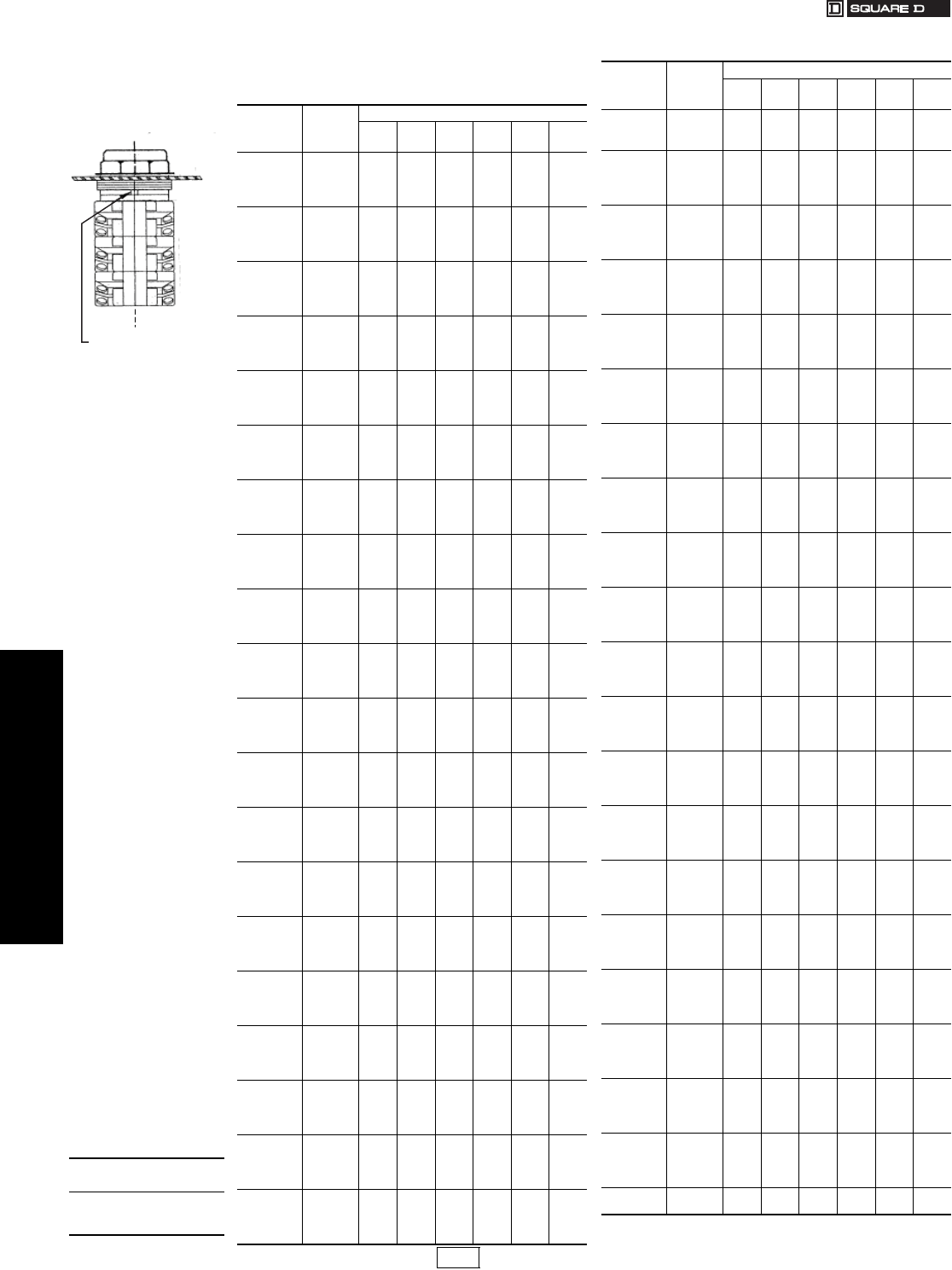
www.us.schneider-electric.com
FOR CURRENT INFORMATION
19 PUSH BUTTONS AND
OPERATOR INTERFACES
19-80 © 2007 Schneider Electric
All Rights Reserved
30 mm Push Buttons Type K, SK and KX Contact Block “H” Numbers
Class 9001 / Refer to Catalog 9001CT0001
The design of the Class 9001 Type KA contact blocks allows them to be mounted
side by side and/or in tandem. This enables you to specify an operator and a
particular arrangement of contact blocks (shipped completely assembled) with a
single Type number. See page 19-78 for a description of contact blocks.
Note: “H” Numbers not shown in their sequence are no longer used.
Example: A Type KR1B push
button with 2 Type KA1 contact
blocks would be Class 9001
Type KR1BH2.
Locating Nib
Side 2Side 1
POS 1
POS 2
POS 3
POS 4
POS 5
POS 6
Suffix No.
(Add to
Operator
Ty p e )
$ Price
Positions
123456
H1 28.50 KA1
H2 57.00 KA1 KA1
H3 86.00 KA1 KA1 KA1
H4 114.00 KA1 KA1 KA1 KA1
H5 14.30 KA2
H6 14.30 KA3
H7 28.50 KA2 KA2
H8 28.50 KA3 KA3
H9 57.00 KA4 KA1
H10 42.80 KA4 KA5
H11 86.00 KA1 KA1 KA1
H12 57.00 KA2 KA3 KA2 KA3
H13 28.50 KA1
H14 14.30 KA3
H15 42.80 KA2 KA3 KA2
H16 42.80 KA2 KA3 KA3
H17 71.00 KA1 KA1 KA2
H18 71.00 KA3 KA1 KA3 KA3
H19 143.00 KA1 KA1 KA1 KA1 KA1
H21 28.50 KA2 KA3
H23 171.00 KA1 KA1 KA1 KA1 KA1 KA1
H24 42.80 KA1 KA2
H25 28.50 KA5 KA3
H26 86.00 KA1 KA1 KA4
H27 42.80 KA3 KA3 KA3
H28 42.80 KA1 KA3
H29 143.00 KA1 KA4 KA1 KA5 KA1 KA3
H31 57.00 KA2 KA2 KA1
H32 57.00 KA1 KA1
H33 57.00 KA1 KA3 KA3
H34 42.80 KA5 KA1
H36 14.30 KA2
H37 28.50 KA3 KA2
H38 57.00 KA3 KA2 KA3 KA2
H39 57.00 KA5 KA1 KA3
H40 86.00 KA1 KA1 KA4
H41 42.80 KA3 KA2 KA2
H42 86.00 KA1 KA1 KA2 KA2
H43 42.80 KA2 KA2 KA2
H44 42.80 KA3 KA2 KA3
H45 71.00 KA1 KA2 KA3 KA2
H46 42.80 KA2 KA2 KA2
H47 86.00 KA5 KA3 KA3 KA5 KA3 KA3
H48 114.00 KA1 KA1 KA4 KA4
H50 59.00 KA5 KA3 KA3 KA3
H51 59.00 KA5 KA3 KA4
H52 59.00 KA3 KA1 KA3
H53 42.80 KA4 KA2
H54 59.00 KA4 KA5 KA2
H55 86.00 KA1 KA2 KA1
H56 59.00 KA2 KA2 KA2 KA2
H57 42.80 KA5 KA4
H58 14.30 KA5
H59 71.00 KA1 KA2 KA1
H60 86.00 KA1 KA2 KA1 KA3
H61 59.00 KA2 KA2 KA5 KA5
H62 59.00 KA1 KA2 KA3
H63 42.80 KA1 KA3
H64 42.80 KA3 KA2 KA2
H66 86.00 KA3 KA1 KA3 KA1
H71 59.00 KA3 KA3 KA3 KA3
H72 28.50 KA3 KA5
H73 71.00 KA1 KA1 KA3
H74 71.00 KA1 KA2 KA5 KA5
H75 86.00 KA1 KA3 KA3 KA3 KA3
H76 86.00 KA1 KA2 KA2 KA2 KA2
H77 59.00 KA1 KA1
H78 59.00 KA1 KA2 KA5
H79 42.80 KA3 KA3 KA5
H80 86.00 KA4 KA4 KA5 KA5
H81 86.00 KA1 KA1 KA2 KA3
H82 95.00 KA12 KA12 KA13 KA13
H83 47.60 KA35 KA33
H86 42.80 KA3 KA2 KA3
H87 71.00 KA3 KA2 KA3 KA2 KA3
H89 42.80 KA3 KA1
H90 100.00 KA1 KA1 KA3 KA3 KA3
H91 86.00 KA1 KA2 KA1 KA2
H92 86.00 KA1 KA2 KA3 KA2 KA3
H93 86.00 KA3 KA2 KA3 KA5 KA5 KA3
H94 128.00 KA1 KA1 KA1 KA3 KA3 KA3
H95 42.80 KA2 KA1
H97 59.00 KA1 KA3 KA2
H98 114.00 KA1 KA1 KA1 KA2 KA2
H99 71.00 KA2 KA2 KA2 KA2 KA2
H100 86.00 KA1 KA3 KA1 KA2
H101 86.00 KA2 KA2 KA2 KA2 KA2 KA2
H102 59.00 KA1 KA3 KA3
H103 86.00 KA1 KA1 KA3 KA3
H104 128.00 KA1 KA1 KA1 KA2 KA2 KA2
H105 47.60 KA31
H106 95.00 KA31 KA31
H107 43.50 KA3 KA2 KA5
H109 43.50 KA3 KA3 KA2
H110 86.00 KA3 KA3 KA3 KA3 KA3 KA3
H111 100.00 KA4 KA4 KA4 KA5
H112 47.60 KA33 KA33
H113 71.00 KA1 KA1 KA5
H114 28.50 KA21
H115 71.00 KA3 KA1 KA5 KA3
H116 71.00 KA3 KA1 KA3 KA2
H117 86.00 KA2 KA3 KA1 KA2 KA2
H118 42.80 KA1 KA5
H119 86.00 KA1 KA1 KA5 KA3
H120 57.00 KA3 KA4 KA3 KA5
H121 57.00 KA3 KA3 KA3 KA5
H122 57.00 KA1 KA3 KA5
H124 28.50 KA3 KA3
H125 42.80 KA5 KA5 KA3
H126 28.50 KA42
H127 28.50 KA43
H128 57.00 KA41
H129 28.50 KA2 KA2
H130 42.80 KA2 KA3 KA2
H131 42.80 KA2 KA3 KA2
H132 57.00 KA2 KA2 KA3 KA3
H133 28.50 KA3 KA2
H134 57.00 KA3 KA3 KA2 KA2
H135 57.00 KA3 KA2 KA2 KA2
H136 28.50 KA3 KA5
H137 228.00 KA45 KA45 KA44 KA44
H138 42.80 KA3 KA3 KA2
H139 28.50 KA5 KA5
H140 57.00 KA44
H141 57.00 KA43 KA43
H142 114.00 KA1 KA1 KA41
H143 57.00 KA3 KA1 KA5
H144 57.00 K85 KA4
H145 95.00 KA51
H146 134.00 KA53 KA52
H147 67.00 KA53
H148 189.00 KA51 KA51
H149 40.50 KA71
H150 40.50 KA71
H151 95.00 KA71 KA71
H152 57.00 KA1 KA2 KA2
H153 200.00 KA53 KA52 KA53
H154 42.80 KA4 KA5
H155 71.00 KA42 KA43 KA2
H156 143.00 KA1 KA1 KA1 KA1 KA2 KA2
H157 71.00 KA1 KA1 KA2
H158 71.00 KA1 KA2 KA3 KA3
H159 86.00 KA1 KA1 KA3 KA2
H161 67.00 KA52
H162 28.50 KA2 KA5
H163 57.00 KA85 KA4
H164 114.00 KA85 KA85 KA4 KA4
H165 95.00 KA55
H166 28.50 KA22 KA22
H167 14.30 KA23
H168 14.30 KA22
H170 285.00 KA54 KA51 KA51
H171 162.00 KA53 KA51
H172 28.50 KA23 KA23
H173 189.00 KA54 KA51
H174 86.00 KA1 KA3 KA1 KA3
H175 57.00 KA6 KA2 KA5 KA5
H176 28.50 KA4
H177 42.80 KA3 KA4
H178 42.80 KA85 KA3
H179 161.00 KA53 KA55
Suffix No.
(Add to
Operator
Ty p e )
$ Price
Positions
123456
When ordering,
please specify:
•Quantity
•Class Number
•Type or Catalog Number
CP1 Discount
Schedule Modified
4/20/09
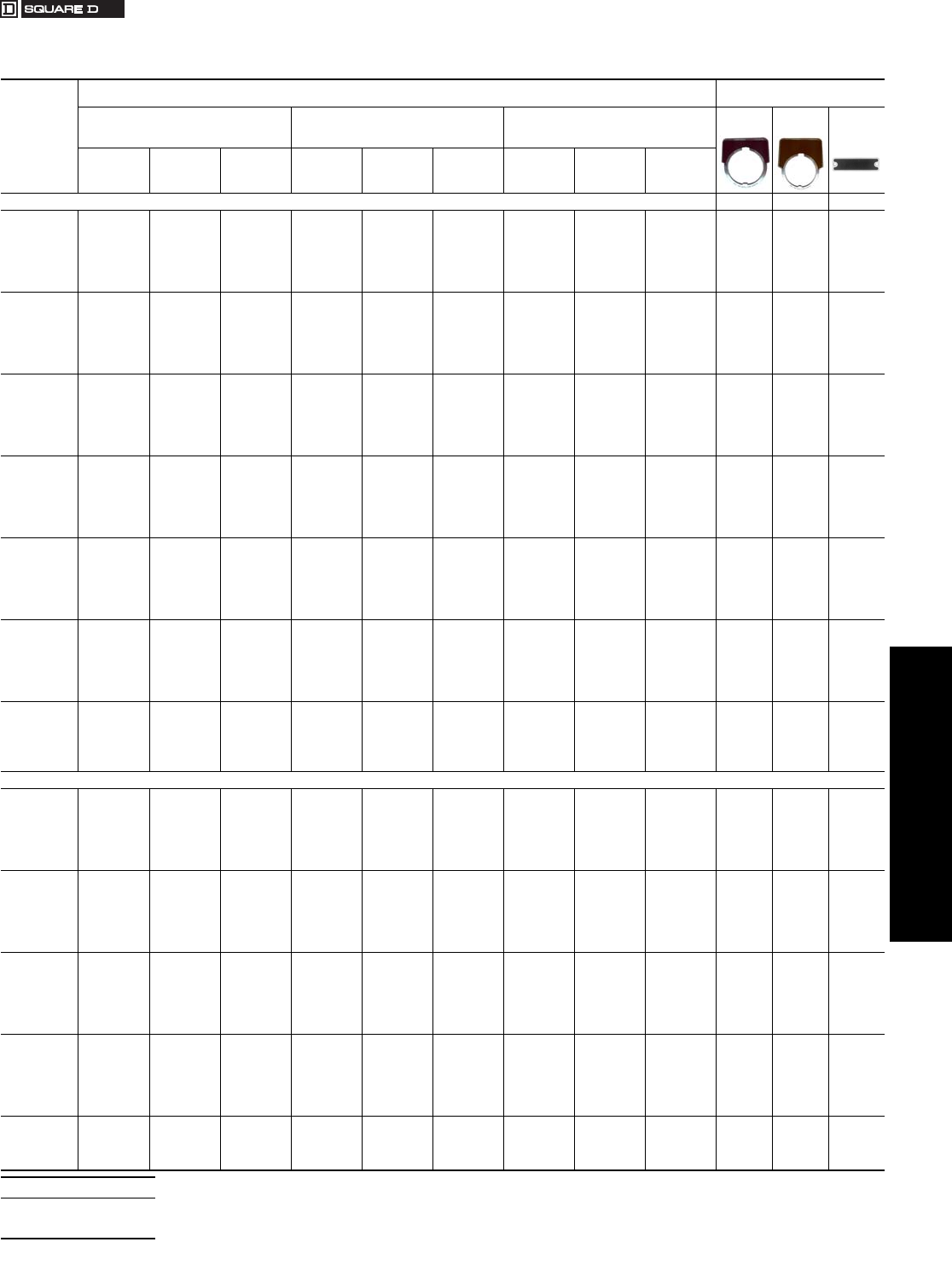
www.us.schneider-electric.com
FOR CURRENT INFORMATION
19 PUSH BUTTONS AND
OPERATOR INTERFACES
© 2007 Schneider Electric
All Rights Reserved 19-81
30 mm Push Buttons Type K and SK Accessories
Class 9001 / Refer to Catalog 9001CT0001
aLegend plate has red background with silver letters.
bLegend plate has red background with black letters.
For Pricing Information . . . . . . . . . . . . . . . . . . . . . . . . . . . . . . . . . .page 19-82
Table 19.230: Legend Plates
Standard
Markings
Plastic Legend Plates
for use with Types K and SK Operators
Aluminum Legend Plates
for use with Type K Operators
1-3/4" Square 2-1/4" Square 2-1/2" Square
Black
Legend
Black
Legend
Blue
Legend
Silver
Legend with
Black Letters
White
Legend with
Black Letters
Black
Legend with
White Letters
Silver
Legend with
Black Letters
White
Legend with
Black Letters
Black
Legend with
White Letters
Silver
Legend with
Black Letters
White
Legend with
Black Letters
Black
Legend with
White Letters
For Push Button or Pilot Light KN200 KN300 KN800
Blank KN200SP KN200WP KN200BP KN100SP KN100WP KN100BP KN700SP KN700WP KN700BP KN200 KN300 KN800
Blank (red) KN200RP bKN200RP bKN200RP bKN100RP bKN100RP bKN100RP bKN700RP bKN700RP bKN700RP bKN200R aKN300R aKN800R a
Start KN201SP KN201WP KN201BP KN101SP KN101WP KN101BP KN701SP KN701WP KN701BP KN201 KN301 KN801
Stop KN202RP bKN202RP bKN202RP bKN102RP bKN102RP bKN102RP bKN702RP bKN702RP bKN702RP bKN202 aKN302 aKN802 a
On KN203SP KN203WP KN203BP KN103SP KN103WP KN103BP KN703SP KN703WP KN703BP KN203 KN303 KN803
Off KN204RP bKN204RP bKN204RP bKN104RP bKN104RP bKN104RP bKN704RP bKN704RP bKN704RP bKN204 aKN304 aKN804 a
Emerg. Stop KN205RP bKN205RP bKN205RP bKN105RP bKN105RP bKN105RP bKN705RP bKN705RP bKN705RP bKN205 aKN305 aKN805 a
Forward KN206SP KN206WP KN206BP KN106SP KN106WP KN106BP KN706SP KN706WP KN706BP KN206 KN306 KN806
Reverse KN207SP KN207WP KN207BP KN107SP KN107WP KN107BP KN707SP KN707WP KN707BP KN207 KN307 KN807
Close KN208SP KN208WP KN208BP KN108SP KN108WP KN108BP KN708SP KN708WP KN708BP KN208 KN308 KN808
Open KN209SP KN209WP KN209BP KN109SP KN109WP KN109BP KN709SP KN709WP KN709BP KN209 KN309 KN809
Down KN210SP KN210WP KN210BP KN110SP KN110WP KN110BP KN710SP KN710WP KN710BP KN210 KN310 KN810
Up KN211SP KN211WP KN211BP KN111SP KN111WP KN111BP KN711SP KN711WP KN711BP KN211 KN311 KN811
Fast KN212SP KN212WP KN212BP KN112SP KN112WP KN112BP KN712SP KN712WP KN712BP KN212 KN312 KN812
Slow KN213SP KN213WP KN213BP KN113SP KN113WP KN113BP KN713SP KN713WP KN713BP KN213 KN313 KN813
High KN214SP KN214WP KN214BP KN114SP KN114WP KN114BP KN714SP KN714WP KN714BP KN214 KN314 KN814
Low KN215SP KN215WP KN215BP KN115SP KN115WP KN115BP KN715SP KN715WP KN715BP KN215 KN315 KN815
Inch KN216SP KN216WP KN216BP KN116SP KN116WP KN116BP KN716SP KN716WP KN716BP KN216 KN316 KN816
In KN217SP KN217WP KN217BP KN117SP KN117WP KN117BP KN717SP KN717WP KN717BP KN217 KN317 KN817
Jog KN218SP KN218WP KN218BP KN118SP KN118WP KN118BP KN718SP KN718WP KN718BP KN218 KN318 KN818
Jog For. KN219SP KN219WP KN219BP KN119SP KN119WP KN119BP KN719SP KN719WP KN719BP KN219 KN319 KN819
Jog Rev. KN220SP KN220WP KN220BP KN120SP KN120WP KN120BP KN720SP KN720WP KN720BP KN220 KN320 KN820
Lower KN221SP KN221WP KN221BP KN121SP KN121WP KN121BP KN721SP KN721WP KN721BP KN221 KN321 KN821
Out KN222SP KN222WP KN222BP KN122SP KN122WP KN122BP KN722SP KN722WP KN722BP KN222 KN322 KN822
Reset KN223SP KN223WP KN223BP KN123SP KN123WP KN123BP KN723SP KN723WP KN723BP KN223 KN323 KN823
Run KN224SP KN224WP KN224BP KN124SP KN124WP KN124BP KN724SP KN724WP KN724BP KN224 KN324 KN824
Start Jog KN225SP KN225WP KN225BP KN125SP KN125WP KN125BP KN725SP KN725WP KN725BP KN225 KN325 KN825
Test KN226SP KN226WP KN226BP KN126SP KN126WP KN126BP KN726SP KN726WP KN726BP KN226 KN326 KN826
Raise KN227SP KN227WP KN227BP KN127SP KN127WP KN127BP KN727SP KN727WP KN727BP KN227 KN327 KN827
Decrease KN228SP KN228WP KN228BP KN128SP KN128WP KN128BP KN728SP KN728WP KN728BP KN228 KN328 KN828
Increase KN229SP KN229WP KN229BP KN129SP KN129WP KN129BP KN729SP KN729WP KN729BP KN229 KN329 KN829
Left KN230SP KN230WP KN230BP KN130SP KN130WP KN130BP KN730SP KN730WP KN730BP KN230 KN330 KN830
Right KN231SP KN231WP KN231BP KN131SP KN131WP KN131BP KN731SP KN731WP KN731BP KN231 KN331 KN831
Cycle Start KN232SP KN232WP KN232BP KN132SP KN132WP KN132BP KN732SP KN732WP KN732BP KN232 KN332 KN832
Feed Start KN233SP KN233WP KN233BP KN133SP KN133WP KN133BP KN733SP KN733WP KN733BP KN233 KN333 KN833
Cycle Stop KN234SP KN234WP KN234BP KN134SP KN134WP KN134BP KN734SP KN734WP KN734BP KN234 KN334 KN834
Motor Run KN236SP KN236WP KN236BP KN136SP KN136WP KN136BP KN736SP KN736WP KN736BP KN236 KN336 KN836
Motor Stop KN237SP KN237WP KN237BP KN137SP KN137WP KN137BP KN737SP KN737WP KN737BP KN237 KN337 KN837
Power On KN238SP KN238WP KN238BP KN138SP KN138WP KN138BP KN738SP KN738WP KN738BP KN238 KN338 KN838
Pull To Start
Push To Stop N/A N/A N/A KN179SP KN179WP KN179BP KN779SP KN779WP KN779BP N/A KN379 N/A
For Selector Switch or Selector Push Button
For.-Rev. KN239SP KN239WP KN239BP KN139SP KN139WP KN139BP KN739SP KN739WP KN739BP KN239 KN339 KN839
Hand-Auto. KN240SP KN240WP KN240BP KN140SP KN140WP KN140BP KN740SP KN740WP KN740BP KN240 KN340 KN840
High-Low KN241SP KN241WP KN241BP KN141SP KN141WP KN141BP KN741SP KN741WP KN741BP KN241 KN341 KN841
Jog-Run KN242SP KN242WP KN242BP KN142SP KN142WP KN142BP KN742SP KN742WP KN742BP KN242 KN342 KN842
Man.-Auto. KN243SP KN243WP KN243BP KN143SP KN143WP KN143BP KN743SP KN743WP KN743BP KN243 KN343 KN843
Off-On KN244SP KN244WP KN244BP KN144SP KN144WP KN144BP KN744SP KN744WP KN744BP KN244 KN344 KN844
On-Off KN245SP KN245WP KN245BP KN145SP KN145WP KN145BP KN745SP KN745WP KN745BP KN245 KN345 KN845
Open-Close KN246SP KN246WP KN246BP KN146SP KN146WP KN146BP KN746SP KN746WP KN746BP KN246 KN346 KN846
Raise-Lower KN247SP KN247WP KN247BP KN147SP KN147WP KN147BP KN747SP KN747WP KN747BP KN247 KN347 KN847
Run-Jog KN248SP KN248WP KN248BP KN148SP KN148WP KN148BP KN748SP KN748WP KN748BP KN248 KN348 KN848
Slow-Fast KN250SP KN250WP KN250BP KN150SP KN150WP KN150BP KN750SP KN750WP KN750BP KN250 KN350 KN850
Start-Stop KN251SP KN251WP KN251BP KN151SP KN151WP KN151BP KN751SP KN751WP KN751BP KN251 KN351 KN851
Up-Down KN253SP KN253WP KN253BP KN153SP KN153WP KN153BP KN753SP KN753WP KN753BP KN253 KN353 KN853
Low-High KN254SP KN254WP KN254BP KN154SP KN154WP KN154BP KN754SP KN754WP KN754BP KN254 KN354 KN854
Stop-Start KN255SP KN255WP KN255BP KN155SP KN155WP KN155BP KN755SP KN755WP KN755BP KN255 KN355 KN855
Left-Right KN256SP KN256WP KN256BP KN156SP KN156WP KN156BP KN756SP KN756WP KN756BP KN256 KN356 KN856
On-Auto KN276SP KN276WP KN276BP KN176SP KN176WP KN176BP KN776SP KN776WP KN776BP KN276 KN376 KN876
Auto-Off-Hand KN258SP KN258WP KN258BP KN158SP KN158WP KN158BP KN758SP KN758WP KN758BP KN258 KN358 KN858
For.-Off-Rev. KN259SP KN259WP KN259BP KN159SP KN159WP KN159BP KN759SP KN759WP KN759BP KN259 KN359 KN859
Hand-Off-Auto. KN260SP KN260WP KN260BP KN160SP KN160WP KN160BP KN760SP KN760WP KN760BP KN260 KN360 KN860
Man.-Off-Auto. KN262SP KN262WP KN262BP KN162SP KN162WP KN162BP KN762SP KN762WP KN762BP KN262 KN362 KN862
Open-Off-Close KN263SP KN263WP KN263BP KN163SP KN163WP KN163BP KN763SP KN763WP KN763BP KN263 KN363 KN863
Up-Off-Down KN264SP KN264WP KN264BP KN164SP KN164WP KN164BP KN764SP KN764WP KN764BP KN264 KN364 KN864
Low-Off-High KN265SP KN265WP KN265BP KN165SP KN165WP KN165BP KN765SP KN765WP KN765BP KN265 KN365 KN865
Jog-Stop-Run KN267SP KN267WP KN267BP KN167SP KN167WP KN167BP KN767SP KN767WP KN767BP KN267 KN367 KN867
High-Low-Off KN270SP KN270WP KN270BP KN170SP KN170WP KN170BP KN770SP KN770WP KN770BP KN270 KN370 KN870
High-Off-Low KN277SP KN277WP KN277BP KN177SP KN177WP KN177BP KN777SP KN777WP KN777BP KN277 KN377 KN877
Auto-Man.-Off KN278SP KN278WP KN278BP KN178SP KN178WP KN178BP KN778SP KN778WP KN778BP KN278 KN378 KN878
When ordering, please specify:
•Quantity
•Class Number
•Type or Catalog Number
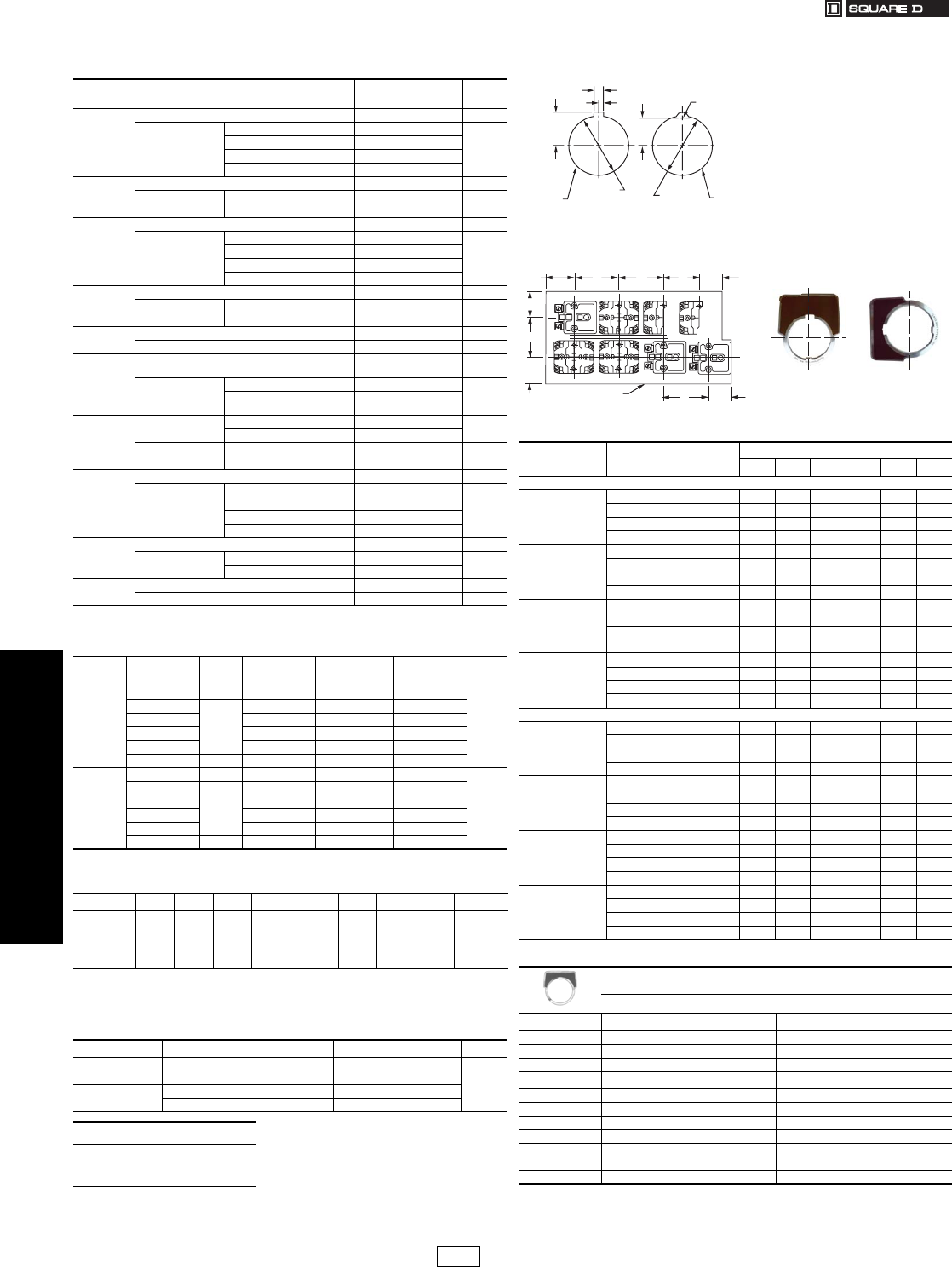
www.us.schneider-electric.com
FOR CURRENT INFORMATION
19 PUSH BUTTONS AND
OPERATOR INTERFACES
19-82 © 2007 Schneider Electric
All Rights Reserved
30 mm Push Buttons Type K and SK Accessories
Class 9001 / Refer to Catalog 9001CT0001
aOther colors available (see Table 19.232).
bSpecify marking required.
Note: The maximum number of characters and lines is a practical maximum, based on a
minimum size of characters to facilitate easy reading.
Mounting Hole for All Types K, SK, and KX Control Units
Hole Punch: Use Greenlee Tool #60242 to punch mounting hole and notch.
Table 19.231: Legend Plates–Special Marking
Legend
Plate Description Type $ Price
KN100( )P
(Plastic) a
2.25 in
Square
Standard Markings See page 19-81 2.90
Special Marking
b
Silver Field, Black Letters KN199SP
12.30
White Field, Black Letters KN199WP
Red Field, Black Letters KN199RP
Black Field, White Letters KN199BP
KN200
Aluminum
Standard Markings See page 19-81 2.90
Special Marking
b
Black Field KN299 12.30
Red Field KN299R
KN200( )P
(Plastic) a
1.7 in.
Square
Standard Markings See page 19-81 2.90
Special Marking
b
Silver Field, Black Letters KN299SP
12.30
White Field, Black Letters KN299WP
Red Field, Black Letters KN299RP
Black Field, White Letters KN299BP
KN300
Aluminum
Standard Markings See page 19-81 2.90
Special Marking
b
Black Field KN399 12.30
Red Field KN399R
KN400
Aluminum
Blank KN400 5.70
Any Marking b KN499 15.20
KN500
Aluminum
Standard Markings Select from
Table 19.236 2.90
Special Marking
b
Black Field KN599
12.30
Green Red
Field KN519
KN600
Aluminum
Blank Black Field KN600 6.60
Red Field KN600R
Any Marking
b
Black Field KN699 15.20
Red Field KN699R
KN700( )P
(Plastic) a
2.5 in.
Square
Standard Markings Select from page 19-81 2.90
Special Marking
b
Silver Field, Black Letters KN799SP
12.30
White Field, Black Letters KN799WP
Red Field, Black Letters KN799RP
Black Field, White Letters KN799BP
KN800
Aluminum
Standard Markings Select from page 19-81 2.90
Special Marking
b
Blue Field KN899 12.30
Red Field KN899R
KN900
Aluminum
Blank KN900 2.90
Any Marking b KN999 12.30
Table 19.232: Plastic Legend Plates—Other Colors
Plate Color Letter
Color 1.7 in. Square 2.25 in. Square 2.5 in. Square $ Price
Blank
Legend
Plates
Yellow Black KN200YP KN100YP KN700YP
2.90
Green
White
KN200GP KN100GP KN700GP
Blue KN200LP KN100LP KN700LP
Red KN200CP KN100CP KN700CP
Orange KN200AP KN100AP KN700AP
Burnt Orange Black KN200HP KN100HP KN700HP
Special
Engraved
Legend
Plates
Yellow Black KN299YP KN199YP KN799YP
12.30
Green
White
KN299GP KN199GP KN799GP
Blue KN299LP KN199LP KN799LP
Red KN299CP KN199CP KN799CP
Orange KN299AP KN199AP KN799AP
Burnt Orange Black KN299HP KN199HP KN799HP
Table 19.233: Maximum Number of Lines and Characters for
Type KN Legend Plates
Type KN100 KN200 KN300 KN400 KN500 KN600 KN700 KN800 KN900
Max. No. of
Characters
per Line
16 14 18 18 8
per field 22 17 18 18
per pos.
Max. No. of
Lines 2132 2
per field 422 1
per pos.
Table 19.234: Circular Legends for Emergency Stop Mushroom
Heads (yellow background)
Diameter Text Catalog Number $ Price
60 mm —9001KN9100
2.90
EMERGENCY STOP 9001KN9330
90 mm —9001KN8100
EMERGENCY STOP 9001KN8330
When ordering, please specify:
•Quantity
•Class Number
•Type or Catalog Number
Table 19.235: Min. Centerline Spacing, Type K & SK Control Units
Legend Plate Operator Centerline Spacing (in.)
ABCDEF
Legend Plate Orientation Position #1
KN2
KN5
Standard Push Button 1.75 1.31 1.44 2.25 1.69 0.88
1.375 in. Dia. Mushroom 1.75 1.31 1.44 2.25 1.69 0.88
2.25 in. Dia. Mushroom 2.25 1.31 1.44 2.25 2.25 1.12
Selector Switch Knobs 1.751.311.442.251.690.88
KN3
Standard Push Button 2.00 1.31 1.44 2.25 1.75 0.88
1.375 in. Dia. Mushroom 2.00 1.31 1.44 2.25 1.75 0.88
2.25 in. Dia. Mushroom 2.25 1.31 1.44 2.25 2.25 1.12
Selector Switch Knobs 2.001.311.442.251.750.88
KN4
Standard Push Button 1.94 1.31 1.44 2.25 1.62 0.88
1.375 in. Dia. Mushroom 1.94 1.31 1.44 2.25 1.62 0.88
2.25 in. Dia. Mushroom 2.25 1.31 1.44 2.25 2.25 1.12
Selector Switch Knobs 1.741.311.442.251.620.88
KN6
Standard Push Button 2.38 1.62 1.44 2.25 2.25 1.12
1.375 in. Dia. Mushroom 2.38 1.62 1.44 2.25 2.25 1.12
2.25 in. Dia. Mushroom 2.38 1.62 1.44 2.25 2.25 1.12
Selector Switch Knobs 2.381.621.442.252.251.12
Legend Plate Orientation Position #2
KN2
KN5
Standard Push Button 1.62 1.31 1.44 2.25 1.75 0.88
1.375 in. Dia. Mushroom 1.62 1.31 1.44 2.25 1.75 0.88
2.25 in. Dia. Mushroom 2.25 1.31 1.44 2.25 2.25 1.12
Selector Switch Knobs 1.621.311.442.251.750.88
KN3
Standard Push Button 1.75 1.31 1.44 2.25 2.00 0.88
1.375 in. Dia. Mushroom 1.75 1.31 1.44 2.25 2.00 0.88
2.25 in. Dia. Mushroom 2.25 1.31 1.44 2.25 2.25 1.12
Selector Switch Knobs 1.751.311.442.252.000.88
KN4
Standard Push Button 1.62 1.31 1.44 2.25 1.94 1.00
1.375 in. Dia. Mushroom 1.62 1.31 1.44 2.25 1.94 1.00
2.25 in. Dia. Mushroom 2.25 1.31 1.44 2.25 2.25 1.12
Selector Switch Knobs 1.621.311.442.251.941.00
KN6
Standard Push Button 2.25 1.31 1.62 2.38 2.38 0.88
1.375 in. Dia. Mushroom 2.25 1.31 1.62 2.38 2.38 0.88
2.25 in. Dia. Mushroom 2.25 1.31 1.62 2.38 2.38 1.12
Selector Switch Knobs 2.251.311.622.382.380.88
Table 19.236: Special Legend Plates
Type KN500
(For Use with Dual Function Operators: KR6, KR7 and KR67)
Standard Markings
Type Green Red
KN500 Blank Blank
KN501 Start Stop
KN502 On Off
Type Black Black
KN520 Blank Blank
KN521 Start Stop
KN522 On Off
KN523 Forward Reverse
KN524 Up Down
KN525 High Low
KN526 Open Close
.19
5.09
2.25 Dia.
6
*
1.22 Dia.
31
*
1.22 Dia.
31
.69
18 .56
14
Alternate
Cover Drilling
Preferred
Cover Drilling
*
Units also mount in 1.20 dia.
30
A30464-162
Dual Dimensions: INCHES
Millimeters
D30052-287
Enclosure or
Grounded Metal Part
E
D
D
D
A
F
B
C
1.13
1.31
Light
Module
Light
Module
Light
Module
KA KA KAKA
KAKA KA KA
UnitUnit
UnitUnit
Unit Unit Unit Unit
Legend Plate
Position #1
Legend Plate
Position #2
CP1 Discount
Schedule Modified
4/20/09
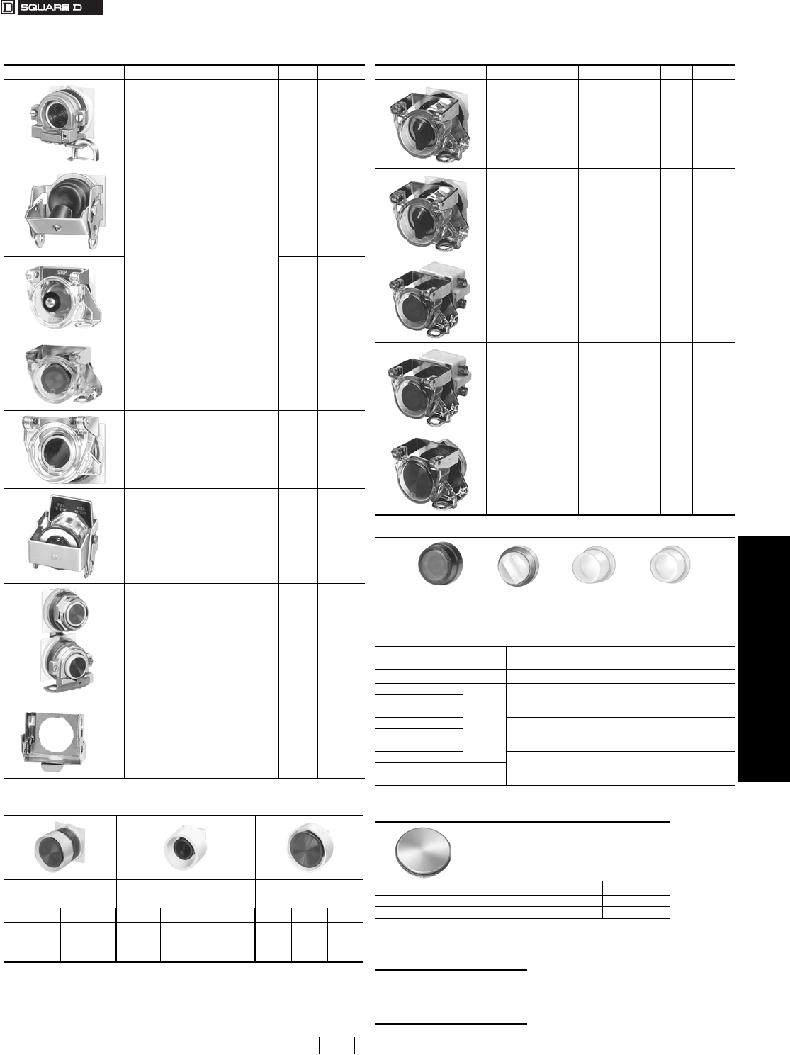
www.us.schneider-electric.com
FOR CURRENT INFORMATION
19 PUSH BUTTONS AND
OPERATOR INTERFACES
© 2007 Schneider Electric
All Rights Reserved 19-83
30 mm Push Buttons Type K and SK Accessories
Class 9001 / Refer to Catalog 9001CT0001
aThe mushroom guard has finger holes for push-pull operators.
bB=Black G=Green R=Red Y=Yellow
cR=Red Y=Yellow
dUse KU27 for maintained contact push buttons.
eMeets UL and NEMA 1, 2, 3, 4, 4X, 6, 12 and 13.
Dimensions see catalog 9001CT0001
Table 19.237: Padlock Attachments
Used On Description Type $ Price
Type K
non-illuminated
push button —
Standard or
mushroom (KR4,
KR5 mushroom
buttons only).
Holds button in
depressed position
and can be
padlocked.
K4 $28.50
Type K5
Types K and SK
non-illuminated
push buttons with or
without protective
boots.
Holds button in
depressed position
when padlocked.
K5 47.60
Type K97
K97 28.50
Types K and SK
non-illuminated
push buttons, cover
type attachment.
KR, SKR
Attachment can be
padlocked. Does not
hold button in
depressed position.
K6 28.50
Types K and SK
push buttons, cover
type attachment.
Spring loaded cover
cannot be
padlocked. Does not
hold button in
depressed position.
K60 38.00
Types K and SK
push-pull operator
and illuminated push
buttons. KR8, KR9
Holds button in
depressed position
and can be
padlocked.
K62 47.60
KR11U and KR12U
Interlocked
Assembly
Holds maintained
button in depressed
position and can be
padlocked.
K96 28.50
Type KR9 & SKR9
Push-Pull
operators—
Non-Illuminated
and Illuminated
Holds button in
depressed position.
Can be padlocked.
K162 39.00
Table 19.238: Mushroom Button Guards
Aluminum Mushroom Guard
for 1.375 in. Mushroom Button
Operator (KR4, KR24)
Yellow Plastic Extended Mushroom
Guard for 1.375 in. and 1.625 in.
Mushroom Button Operators
Aluminum Mushroom Guard
for 2.25 in. Mushroom Button
Operator
Type $ Price Type Used On $ Price Type Used On $ Price
K48 38.
K56bKR4,
SKR4 $38. K68 KR5 38.
K56cMaKR8, KR9,
SKR8, SKR9 45. K685 KR25 45.
Table 19.239: Padlock Attachments
Used On Description Type $ Price
Types K and SK
selector switches and
potentiometers (will not
work with gloved-hand
knob).
Cover type
attachment that can
be padlocked to keep
unauthorized
personnel from
tampering with the
operator.
K7 28.50
Types K and SK
selector switches and
potentiometers (will not
work with gloved-hand
knob).
Same as 9001K7 but
with spring loaded
lockout cover.
K107 37.50
Types K and SK
illuminated push buttons
(with or without guard)
and key operated push
buttons.
Cover type
attachment that can
be padlocked to keep
unauthorized
personnel from
tampering with the
operator.
K108 28.50
Types K and SK
illuminated push buttons
(with or without guard)
and key operated push
buttons.
Same as 9001K108
but with spring loaded
lockout cover.
K109 38.00
Types K and SK
maintained push-pull
operators using 1.375 in.
dia. mushroom buttons
(-20 series as shown on
page 19-84).
Cover type
attachment that holds
mushroom button in
depressed position
and can be
padlocked.
K110 36.00
Table 19.240: Protective Boots
Note: These Type KU protective boots are recommended for very dirty environments or severe
hose down, but they are not required for UL Type 4 rating on the Type K operators or UL
Type 4 or 4X rating on the Type SK operators. The K1 wrench (see page 19-86) is required
for installation of these boots.
For Non-Illuminated
Push ButtonsdClear Color for Type $ Price
Color Type $ Price Standard knob selector switch KU17 28.50
Black KU1
19.10
Gloved-hand cap for use on standard knob
selector switch KU18 28.50Red KU2
Blue KU3
Brown KU4 Standard pilot light and maintained contact
push buttons KU27 28.50Green KU5
Yellow KU6
Clear KU7 Push-to-test and illuminated push button
without guard KU37 28.50
Clear KU8 28.50
(Provides Full Guard) Illuminated push button with guard KU47 38.00
Table 19.241: Closing Plates
Round (1-1/2 in. Dia.)
Description Type $ Price
Gray K51e9.50
Chrome Plated K52e9.50
When ordering, please specify:
•Quantity
•Class Number
•Type or Catalog Number
KU1 KU17 KU37 KU27
CP1 Discount
Schedule
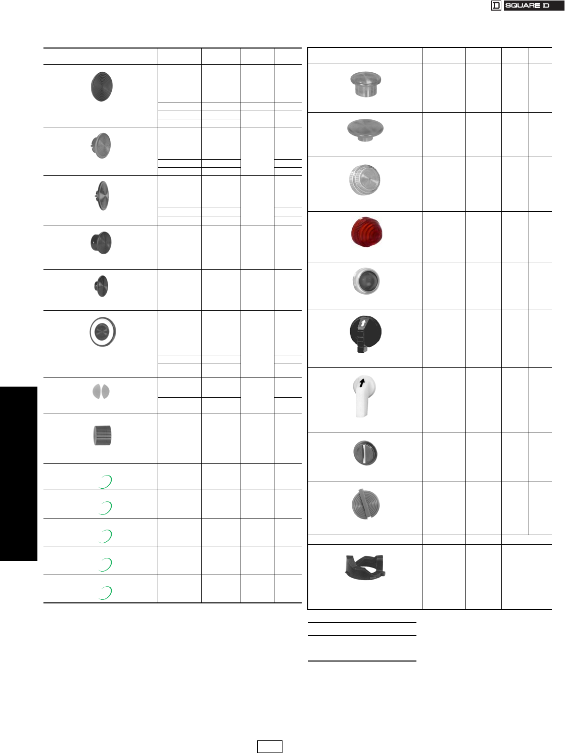
www.us.schneider-electric.com
FOR CURRENT INFORMATION
19 PUSH BUTTONS AND
OPERATOR INTERFACES
19-84 © 2007 Schneider Electric
All Rights Reserved
30 mm Push Buttons Type K and SK Accessories
Class 9001 / Refer to Catalog 9001CT0001
Table 19.242: Accessories
aIncludes one each of the following color inserts: Black, Red, Green, Yellow, Orange, Blue,
and White.
b“EMERGENCY STOP” is in raised letters and hot stamped white across the front of the
mushroom button.
cThe mushroom button cap listed here may be assembled to a 9001KR1U or SKR1U to
form a 9001KR4 or SKR4.
dThe mushroom button cap listed here may be assembled to a 9001KR1U or SKR1U to
form a 9001KR5 or SKR5.
eThe mushroom button cap listed here may be assembled to a 9001KR20 to form a
9001KR24 or SKR20 to form a 9001SKR24.
fThe mushroom button cap listed here may be assembled to a 9001KR20 to form a
9001KR25 or a SKR20 to form a 9001SKR25.
gThese color caps are opaque and are for use on non-illuminated operators only.
hIncludes two of each of the following color inserts: Black, Red, and Green.
iMay be used on KR8 and KR9 operators. Order mushroom button and K54 adapter (no
charge) from page 19-85. Using the K54 adapter voids Type 6 rating.
jRed knob with “Push Emergency Stop” marked on top of knob.
Description Color Type Package
Qty.
$ Price
Each
Color inserts for
KR1, KR2, KR3, SKR1, SKR2, SKR3, KR11,
KR12, SKR11, SKR12, KRD, T, TRD
Black
Blue
Gray
Green
Orange
Red
T8BK
T8BE
T8GY
T8GN
T8OE
T8RD
10 4.80
Universal aT8U 73.80
White T8WH 10 0.48
Yellow T8YW
1.375 in. Snap-in Mushroom knob for
KR4 and SKR4 c
Black
Blue
Green
Orange
Red
K16B
K16L
K16G
K16S
K16R 1
28.50
Red b K16R05 31.70
Yellow K16Y 28.50
2-1/4 in. Snap-in Mushroom knob for
KR5 and SKR5 d
Black
Blue
Green
Orange
Red
K17B
K17L
K17G
K17S
K17R 1
28.50
Red bK17R05 31.70
Yellow K17Y 28.50
1-3/8 in. Screw-on Mushroom knob for
KR24 and SKR24e
Black
Blue
Green
Orange
Red
Yellow
K92B
K92L
K92G
K92S
K92R
K92Y
128.50
2-1/4 in. Screw-on Mushroom knob for
KR25 and SKR25 f
Black
Blue
Green
Orange
Red
Yellow
K93B
K93L
K93G
K93S
K93R
K93Y
128.50
Push-Pull Knobs for
KR8, KR9, SKR8, SKR9 Operators
Amber
Black g
Blue
Clear
Green
Orange g
Red
A22
B23
L22
C22
G22
S23
R22
1
6.60
Red jR2205 10.50
White
Yellow
W22
Y22 6.60
Color Inserts for Dual Function
Operators KR6, KR7, KR67
Black
Green
Red
B19
G19
R19 10
0.95
Universal hU19 5.70
Standard Color
Caps for Illuminated Push Buttons
K1L, K2L, K3L, SK1L, SK2L
Amber
Blue
Clear
Green
Red
White
Yellow
A7
L7
C7
G7
R7
W7
Y7
16.60
Knob for KR9R94
Red R94 16.60
Metal Knob for KR24 Red
Green
Black
K92RM
K92GM
K92BM
134.00
Metal Knob for KR25 Red
Green
Black
K93RM
K93GM
K93BM
142.00
Metal Knob for KR9 (40 mm) Red
Green
Black
K94RM
K94GM
K94BM
134.00
Metal Knob for KR9 (60 mm) Red
Green
Black
K95RM
K95GM
K95BM
142.00
New!
New!
New!
New!
New!
Description Color Type Package
Qty.
$ Price
Each
1-3/8 in. Mushroom Knob for
Illuminated Push Buttons K2L, SK2L i
Amber
Blue
Clear
Green
Red
White
Yellow
A20
L20
C20
G20
R20
W20
Y20
16.60
2-1/4 in. Mushroom Knob for
Illuminated Push Buttons K2L, SK2L i
Amber
Blue
Clear
Green
Red
White
Yellow
A21
L21
C21
G21
R21
W21
Y21
16.60
Plastic Fresnel Pilot Light Lens for
KP, KT, SKP, SKT
Amber
Blue
Clear
Green
Red
White
Yellow
A31
L31
C31
G31
R31
W31
Y31
16.60
Domed Plastic Pilot Light Lens for
KP, KT, SKP, SKT
Amber
Blue
Clear
Green
Red
White
Yellow
A9
L9
C9
G9
R9
W9
Y9
16.60
Glass Pilot Light Lens for
KP, KT
Amber
Blue
Clear
Green
Red
White
Yellow
A6
L6
C6
G6
R6
W6
Y6
16.60
Standard Selector Switch Knob for
K and SK Selector Switches
Amber
Black g
Blue
Clear
Green
Orange g
Red
White
Yellow
A8
B11
L8
C8
G8
S11
R8
W8
Y8
16.60
Gloved-Hand Selector Switch Knob for
K and SK Selector Switches
Amber
Black g
Blue
Clear
Green
Orange g
Red
White
Yellow
A24
B25
L24
C24
G24
S25
R24
W24
Y24
16.60
Coin Operated Selector Switch Knob for
K and SK Selector Switches
Black g
Blue
Clear
Green
Red
Yellow
B18
L16
C16
G16
R16
Y16
16.60
Color Inserts for
KQ and TQ Selector Push Buttons
Black
Blue
Green
Orange
Red
White
Yellow
T5BK
T5BE
T5GN
T5OE
T5RD
T5WH
T5YW
10 0.95
Cam Type $ Price Each
Selector Switch Cams
B
C
D
E
F
G
H
J
L
M
K13B
K13C
K13D
K13E
K13F
K13G
K13H
K13J
K13L
K13M
4.20
When ordering, please specify:
•Quantity
•Class Number
•Type or Catalog Number
CP1 Discount
Schedule Modified
4/20/09
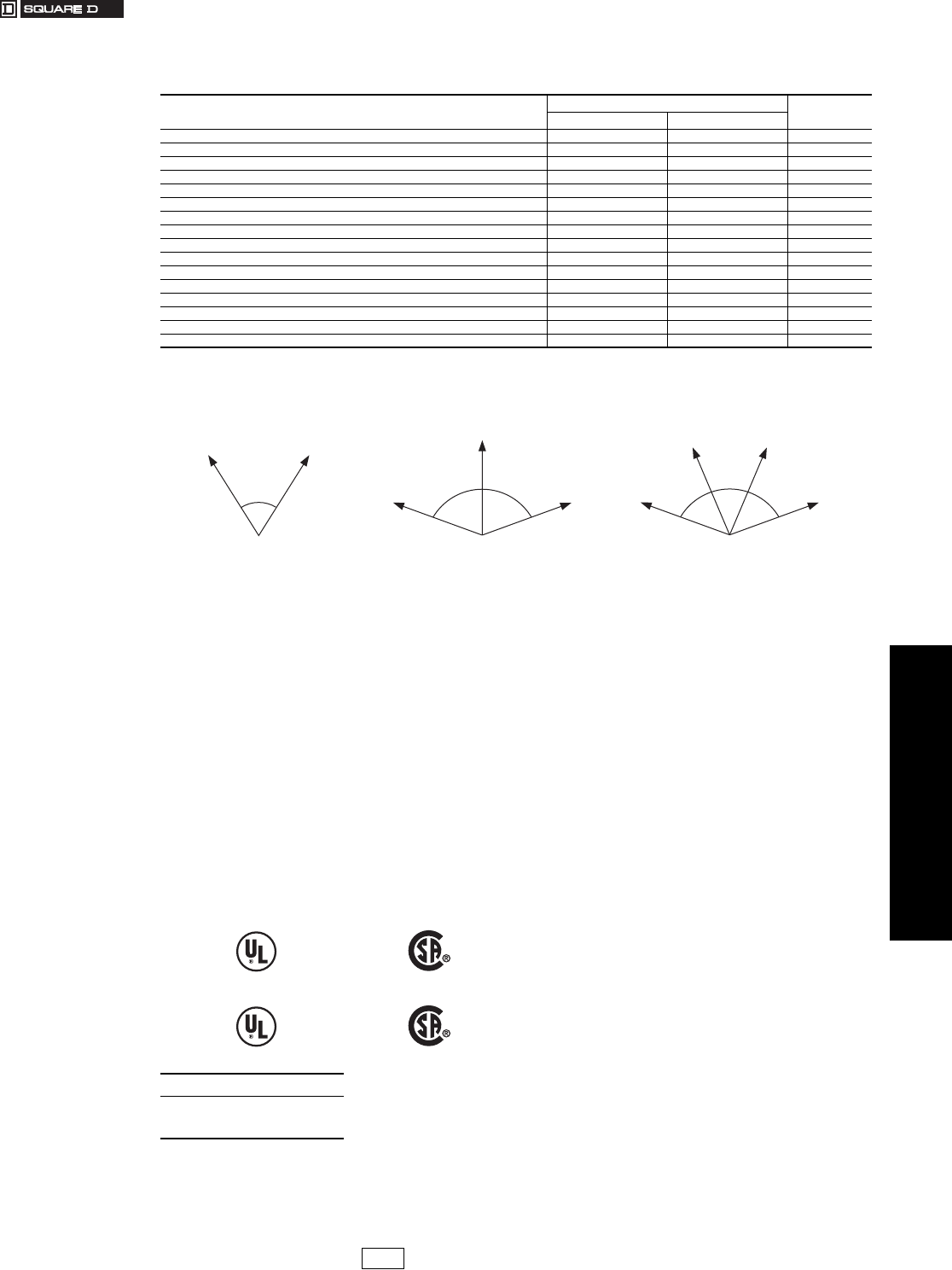
www.us.schneider-electric.com
FOR CURRENT INFORMATION
19 PUSH BUTTONS AND
OPERATOR INTERFACES
© 2007 Schneider Electric
All Rights Reserved 19-85
30 mm Push Buttons Type K, SK and KX Basic Operators, Application Data
Class 9001 / Refer to Catalog 9001CT0001
aOperator can be converted to an illuminated operator by removing the
liner (6512240601) and adding a light module.
bOperator can be converted to a non-illuminated operator by adding liner
(6512240601).
cOperator includes jumper wires for push-to-test conversion.
dThese operators can be supplied with 1-3/8 in or 2-1/4 in dia. mushroom
buttons. For 1-3/8 in.: add ( ) 20 to type number. The ( ) refers to the
color chosen—see page 19-84. For 2-1/4 in.: Add ( ) 21 to type number.
The ( ) refers to the color chosen—see page 19-84. Voids UL and
NEMA 6 Rating.
Maximum Contact Block Usage
(Includes Types K, SK and KX)
•2 blocks mounted side by side only: Any 2, 3 or 4 position
spring return selector switch (non-illuminated, illuminated or
keyed).
•2 blocks mounted in tandem on one side only: Any 2
operator interlocked push button.
•2 blocks mounted in tandem (total of four blocks): Any
selector push button, keyed push button, 2, 3, or 4 position
maintained selector switch (non-illuminated, illuminated or
keyed), push-pull operators (non-illuminated or illuminated),
joy stick, dual push button.
•3 blocks mounted in tandem (total of six blocks): Single
momentary push buttons (non-illuminated or illuminated).
Operator Service Temperature Range:
-22o to +140o Fahrenheit at 50% relative humidity
-30o to +60o Celsius
Environmental Ratings:
•Types K and KX: The Type K (Series H) and KX operators are
UL approved for use in Types 1, 2, 3, 3R, 4, 6, 12, and 13 flat
surface enclosures.
•Type SK: The Type SK operators are UL approved for use in
Types 1, 2, 3, 3R, 4, 4X, 6, 12, and 13 flat surface enclosures.
•Types K, SK and KX: For hazardous location use—see
page 19-79.
Dimensions:
Types K, SK and KX: See Catalog 9001CT0001.
Mounting Hole Dimensions:
See page 19-82.
Minimum Centerline Spacing:
Types K and SK: See page 19-82.
Type KX: See Catalog 9001CT0001.
Table 19.243: Basic Operators (Without Color Caps, Mushroom Buttons, Knobs, Selector Switch Cams, Contact
Blocks, Light Modules or Legend Plates)
Description For UL Types/NEMA $ Price
1, 3R, 4, 12, 13 4, 4X, 13
Non-Illuminated Push Button (Extended Guard) KR2 SKR2 25.70
Non-Illuminated Push Button (No Guard) KR3 SKR3 25.70
Non-Illuminated Push Button (Mushroom Button/Screw-On) KR20 SKR20 25.70
Non-Illuminated Dual Push Button (Momentary) KR6 —52.00
Non-Illuminated Dual Push Button (Momentary Interlocked) KR67 — 81.00
Non-Illuminated Dual Push Button (Maintained Interlocked) KR7 —81.00
Momentary Pull—Maintained Neutral—Momentary Push KR8 ad SKR8 a50.00
Maintained Pull—Maintained Push KR9 ad SKR9 a80.00
Illuminated Push Button (Full Guard—Plastic Top) K1L bSK1L b28.50
Illuminated Push Button and Push-To-Test (No Guard) K2L bc SK2Lbc 19.10
Illuminated Push Button (Full Guard—Metal Top) K3L b—28.50
Standard Pilot Light KP SKP 19.10
3 Position Maintained Selector Switch KS4 aSKS4 a24.20
3 Position Spring Return Both Sides To Center—Selector Switch KS5 aSKS5 a43.20
3 Position Spring Return Left To Center—Selector Switch KS6 aSKS6 a43.20
3 Position Spring Return Right To Center—Selector Switch KS7 aSKS7 a43.20
Table 19.244: Selector Switch Angular Travel (Types K, SK and KX)
2 Position 3 Position 4 Position
70
2 Position
70 70
3 Position
47 47
46
4 Position
Table 19.245: Non Hazardous Locations
Ty p e s K, S K
and KX
File
CCN
#42259
NKCR
File
Class
LR25490
3211 03
Table 19.246: Hazardous Locations (see page 19-79)
Ty p e s K, S K File
CCN
E10054(N)
NOIV
File
Class
LR26817
3218 02
When ordering, please specify:
•Quantity
•Class Number
•Type or Catalog Number
CP1 Discount
Schedule Modified
4/20/09
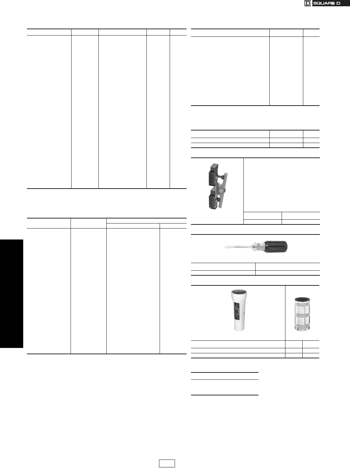
www.us.schneider-electric.com
FOR CURRENT INFORMATION
19 PUSH BUTTONS AND OPERATOR
INTERFACE
19-86 © 2007 Schneider Electric
All Rights Reserved
30 mm Push Buttons Type K and SK Replacement Parts
Class 9001 / Refer to Catalog 9001CT0001
aMaintained button of two button operator.
bMomentary button of two button operator.
cSecondary ring nut (holds knob on selector switch or potentiometer).
dGE44 and GE755 are interchangeable (GE755 gives longer life). If a GE44 lamp is
ordered, a GE755 (2550101020) will be substituted. For a replacement lamp in a current
series light module see the light module listing on page 19-77.
eAllows Type -20 and -21 mushroom color caps to be used on push-pull operators. Use of
9001K54 voids Type 6 rating.
Table 19.247: Ring Nuts
Used On Type Used On Type $ Price
K1L K44 SK1L SK44 12.30
K30-K37 K45 ——2.90
K70-K73 K45 ——2.90
K20, K21, K22, K23 K45 SK20, SK21, SK22, SK23 SK45 2.90
K20, K21, K22, K23 cSK46 SK20, SK21, SK22, SK23 cSK46 2.90
K2L K49 SK2L SK49 2.90
K3L (complete) K111 ——12.30
K3L (metal top only) 6515802701 ——43.60
KP, KTR K41 SKP, SKTR SK41 2.90
KR1 K41 SKR1 SK41 2.90
KR11 K42 SKR11 SK42 2.90
KR12 aK42 SKR12 aSK42 2.90
KR12 bK41 SKR12 bSK41 2.90
KR13, 14, 15 K55 ——2.90
KR2 K42 SKR2 SK42 2.90
KR20 K49 ——2.90
KR24 K49 ——2.90
KR25 K49 SKR25 SK49 2.90
KR3 K40 SKR3 SK40 2.90
KR4 K41 SKR4 SK41 2.90
KR5 K41 SKR5 SK41 2.90
KR6 K47 ——2.90
KR67 K47 ——2.90
KR7 K47 ——2.90
KR8 K58 SKR8 6509704401 2.90
KR9 K41 SKR9 SK41 2.90
KS K45 SKS SK45 2.90
KS cSK46
SKS c
SKRU11
SKRU1,2,3,4,5,10
SK46
SK41
SK40
2.90
2.90
2.90
KT K49 SKT SK49 2.90
Table 19.248: Replacement Lamps For Series A–F (black)
Light Modules
Light
Module Type
Lamp Number
(ANSI)
Square D Replacement Lamps
Part Number $ Price
KM1 GE44d——
KM2 GE1490 2550101003 8.30
KM3 GE44d——
KM4 GE1490 2550101003 8.30
KM5 GE44d——
KM6 GE44d——
KM7 GE44d——
KM8 GE44d——
KM9 GE755 2550101020 8.30
KM11 CMDK1A5 2550105014 22.00
KM12 CMDK1A5 2550105014 22.00
KM13 CMDK1A5 2550105014 22.00
KM14 CMDK1A5 2550105014 22.00
KM15 CMDK1A5 2550105014 22.00
KM21 SYL12PSB 2550105003 11.00
KM22 SYL12PSB 2550105003 11.00
KM23 SYL28PSB 2550105008 11.00
KM25 SYL120PSB 2550105005 11.00
KM31 SYL6PSB 2550105007 11.00
KM32 SYL12PSB 2550105003 11.00
KM34 SYL24PSB 2550105004 11.00
KM35 SYL28PSB 2550105008 11.00
KM36 SYL48PSB 2550105009 11.00
KM37 SYL60PSB 2550105010 11.00
KM38 SYL120PSB 2550105005 11.00
Table 19.249: Repair Parts
Description Part Number $ Price
E10 Key
Gray cap for KR11, KR12, SKR11, or SKR12
Clear plastic top (only) for 9001K44 & SK44
Ring Nut
Gasket for Type K and SK Push-Pull Knob
Gasket for Plastic Illuminated Lens
Gasket for Type K and SK selector switch knob
Black Compensating Gasket (Type K and SK
Operators
Liner for Non-Illuminated Operators
Locking Thrust Washer
Nylon Spacer
Locking Thrust Washer (Std. Type SK Operator)
Push-Pull Mushroom Adaptere
Rubber Boot for Joystick
Knob on Joysticks without latch
Knob for SK Potentiometer
Fingersafe Cover for 9001KM
2941101100
3105217001
4487D63X1
6509701801
6509701901
3105406401
6509702001
6509704901
6512231201
6509705001
6512240601
K54
6512243201
4458D20X3
3105404408
6508804101
6.60
9.20
5.30
1.30
2.60
1.30
2.60
N/C
2.60
3.40
2.60
N/C
4.80
8.60
7.10
2.00
Table 19.250: KU Replacement Ring Nuts
(Threaded Inside and Out)
Used On Part Number $ Price
KU1 through KU8, KU27, KU37, KU47 3105204101 2.90
KU17, KU18 3105205901 7.10
Table 19.251: Interlock
For mechanically interlocking two push buttons
so that only one button can be depressed at a
time. A Type K3 attachment is furnished with the
9001 KR11, KR12, SKR11,
SKR12, SKRU1 and SKRU11 operators.
However, these are maintained operators and
the K3 interlock serves to release one of the
buttons when the other is depressed. When
used with momentary contact buttons, the K3
interlock does not hold the buttons in the
depressed position. It simply prevents pushing
both buttons at the same time.
The Type K3 interlock is mounted behind the
operators. Operators not included.
Type $ Price
K3 19.10
Table 19.252: Screwdriver
Used to tighten mounting screws on
contact blocks and light modules.
Type $ Price
K69 23.70
Table 19.253: Wrenches
K95 K1
Where Used Type $ Price
For tightening ring nuts on 22 and 30 mm control units K95 28.50
For protective cap kits K1 47.60
When ordering, please specify:
•Quantity
•Class Number
•Type or Catalog Number
CP1 Discount
Schedule Modified
4/20/09
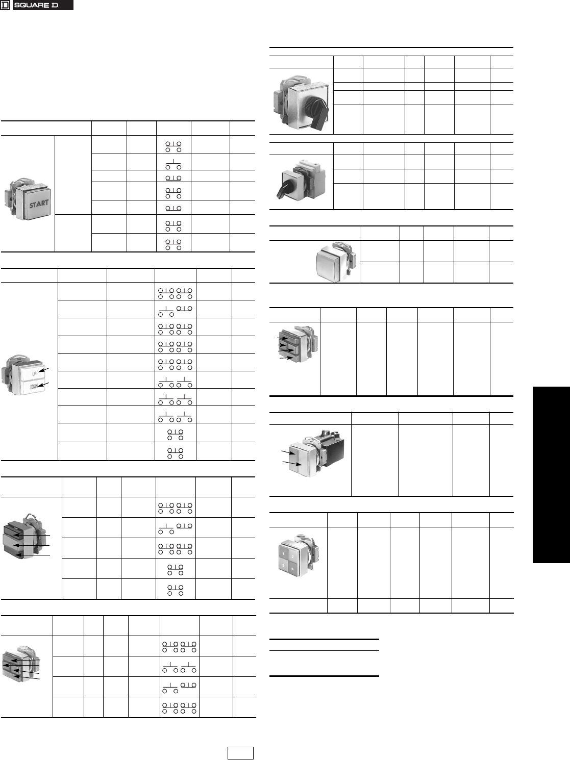
www.us.schneider-electric.com
FOR CURRENT INFORMATION
19 PUSH BUTTONS AND OPERATOR
INTERFACE
© 2007 Schneider Electric
All Rights Reserved 19-87
30 mm Push Buttons Type KX Square Multifunction Operators
Class 9001 / Refer to Catalog 9001CT0001
The operators listed below come complete with color caps, legend
inserts/plates, contact blocks, and light modules (illuminated operators
only) and can be ordered using the short type number. If the operator
you desire is not listed below, see pages 19-88 through 19-92. For a
component breakdown of each of the operators listed on this page, refer
to Product Data Bulletin M-603. UL Types 4, 4X, 13/NEMA 4, 4X, 13.
For use in hazardous locations—See page 19-79.
aButtons are mechanically interlocked
bIf all four lamps are illuminated at the same time continuously—do NOT operate above
120 Vac.
Table 19.254: Single Illuminated and Non-Illuminated Push
Buttons
Description Button
Color
Legend
Marking Contacts Type $ Price
Non-
Illuminated
Green
Red
Start
Stop
KXRA101
KXRA102 57.00
Green Start KXRA133 42.80
Red Stop KXRA134 42.80
Red
Mushroom
Emerg.
Stop KXRN105 86.00
Red
Mushroom
Emerg.
Stop KXRN135 71.00
Illuminated
110-120 V,
50-60 Hz
Tr a n s fo r m e r
Green
Red
Start
Stop
KXRB103
KXRB104 134.00
Red
Mushroom
Emerg.
Stop KXRP106 162.00
Table 19.255: Dual Push Buttons
Description Top Button (#1) Bottom Button
(#2) Contacts Type $ Price
Start
(Green-Mom.)
Stop
(Red-Mom.) KXRC111 114.
Start
(Green-Mom.)
Stop
(Red-Mom.) KXRC136 86.
Up
(Green-Mom.)a
Down
(Green-Mom.)aKXRD112 119.
Open
(Green-Mom.)a
Close
(Green-Mom.)aKXRD113 119.
Forward
(Green-Mom.)a
Reverse
(Green-Mom.)aKXRD114 119.
Up
(Green-Mom.)a
Down
(Green-Mom.)aKXRD140 90.
Open
(Green-Mom.)a
Close
(Green-Mom.)aKXRD141 90.
Forward
(Green-Mom.)a
Reverse
(Green-Mom.)aKXRD142 90.
Start
(Green-Maint.)a
Stop
(Red-Maint.)aKXRE115 114.
Reset
(Green-Mom.)a
Stop
(Red-Maint.)aKXRF116 114.
Table 19.256: Dual Push Button With One Pilot Light
Description
Top
Button
(#1)
Middle
Lens
(#2)
Bottom
Button
(#3)
Contacts Type $ Price
Pilot Light
at 110–120 V,
50–60 Hz
Tr a n s fo r m e r
Start
(Green-
Mom.)
On
(Red)
Stop
(Red-Mom.) KXRG117 209.
Start
(Green-
Mom.)
On
(Red)
Stop
(Red-Mom.) KXRG137 180.
Blank
(Green-
Mom.)a
Blank
(Red)
Blank
(Green-
Mom.)a
KXRH118 219.
Start
(Green-
Maint.)a
On
(Red)
Stop
(Red-
Maint.)a
KXRJ119 219.
Reset
(Green-
Mom.)a
On
(Red)
Stop
(Red-
Maint.)a
KXRK120 171.
Table 19.257: Dual Push Button With Dual Pilot Lights
Description
Top
Button
(#1)
Left
Lens
(#2)
Right
Lens
(#3)
Bottom
Button
(#4)
Contacts Type
Number $ Price
Pilot Lights
at 110–120 V,
50–60 Hz
Transformer
Start
(Green-
Mom.)
On
(Red)
Off
(Green)
Stop
(Red-Mom.) KXRL121 323.
Number 1
(White-
Mom.)
1
White
2
Blue
Number 2
(Blue-
Mom.)
KXRL132 333.
Start
(Green-
Mom.)
On
(Red)
Off
(Green)
Stop
(Red-Mom.) KXRL138 294.
Blank
(Green-
Mom.)a
Blank
(Red)
Blank
(Red)
Blank
(Green-
Mom.)a
KXRM122 351.
1
2
1
2
3
1
2
3
4
Table 19.258: Selector Switches
Non-Illuminated
Description Positions Legend Knob Contacts Type $ Price
2-Maint. Off-On Black 10
01 KXSA125 66.
2-Maint. Off-On Black 0 1 KXSA139 52.
3-Maint. Hand-Off-Auto. Black 100
001 KXSD126 66.
3-Maint. Hand-Off-Auto. Black
100
001
100
001
KXSD127 95.
Illuminated—110–120 V, 50–60 Hz, Transformer
Description Positions Legend Knob Contacts Type $ Price
2-Maint. Off-On Red 10
01 KXSJ128 143.
3-Maint. Hand-Off-Auto. Red 100
001 KXSM129 143.
3-Maint. Hand-Off-Auto. Red
100
001
100
001
KXSM130 171.
Table 19.259: Single Pilot Light
Description Lens
Color
Legend
Marking Type $ Price
110–120 V,
50–60 Hz
Transformer
Standard Red
Green
On
Off
KXPA107
KXPA108
105.
105.
Push-To-Test Red
Green
On
Off
KXTA109
KXTA110
134.
134.
Table 19.260: Dual Push-To-Test Pilot Light
(Pushing Button #1 Tests Pilot Light #2—Pushing Button #4 Tests Pilot Light #3)
Description Top
Button (#1)
Left
Lens (#2)
Right
Lens (#3)
Bottom
Button (#4) Type $ Price
Pilot Lights
at 110–120 V,
50–60 Hz
Tr a n s fo r m e r
Green
Blank
Red
Blank
Red
Blank
Green
Blank KXTC123 312.
Table 19.261: Dual Pilot Light
Description Left Lens (#1) Right Lens (#2) Type $ Price
110–120 V,
50–60 Hz. Transformer
Red
On
Green
Off KXPB124 191.
Table 19.262: Four-Field Pilot Light
Description Top
Left (#1)
Top
Right (#2)
Bottom
Left (#3)
Bottom
Right (#4)
Type
Number $ Price
110–120 V,
50–60 Hz
Transformer
White
Blank
Blue
Blank
Green
Blank
Red
Blank KXPC131 362.
Remote Testb
120 Vac Resistor
White
Blank
Blue
Blank
Green
Blank
Red
Blank KXTE150b399.
When ordering, please specify:
•Quantity
•Class Number
•Type or Catalog Number
1
2
3
4
1
2
CP1 Discount
Schedule
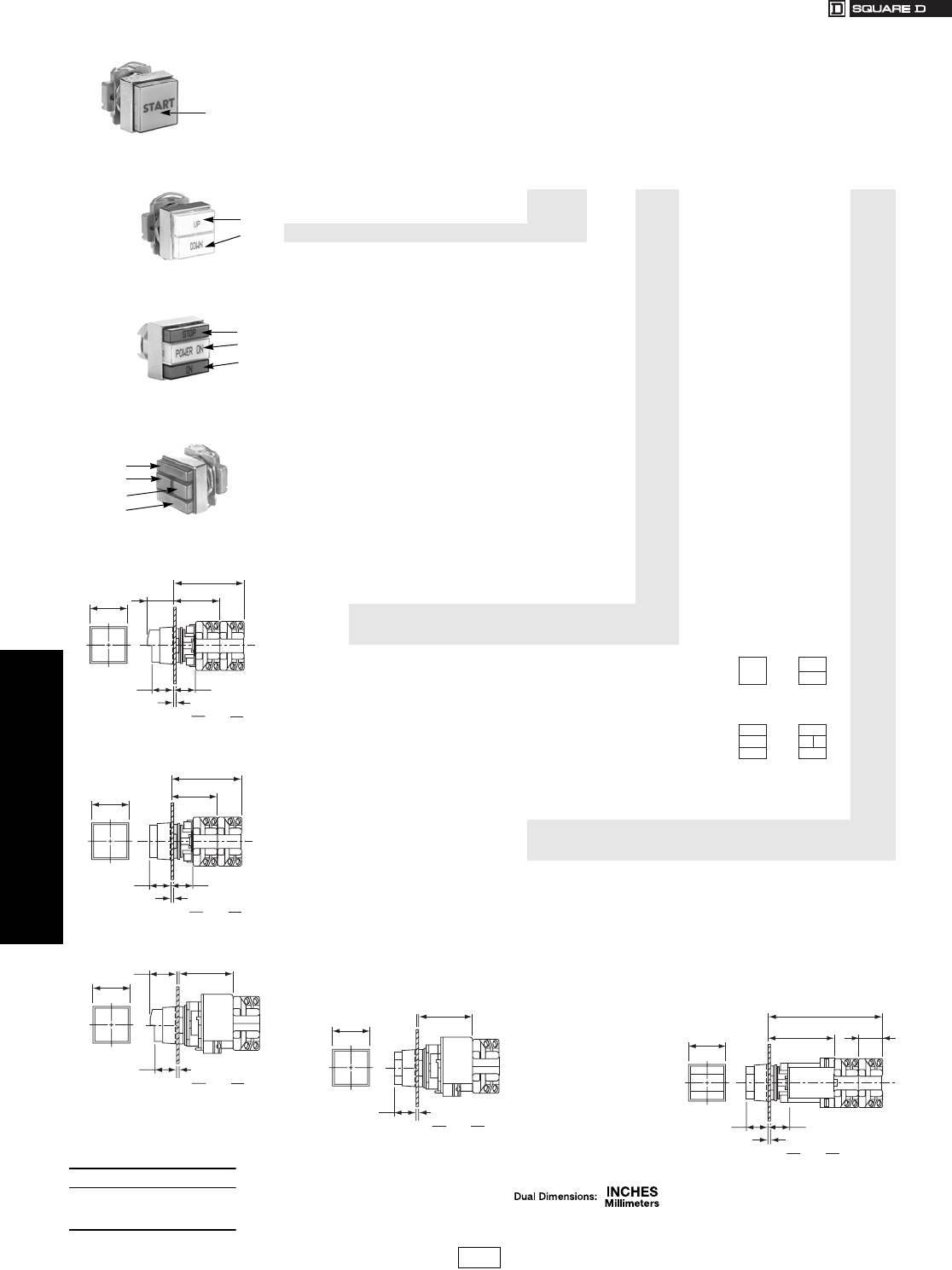
19-88 © 2007 Schneider Electric
All Rights Reserved
www.us.schneider-electric.com
FOR CURRENT INFORMATION
19 PUSH BUTTONS AND OPERATOR
INTERFACE
30 mm Push Buttons Type KX Square Multifunction Operators
Class 9001 / Refer to Catalog 9001CT0001
Push Button and Pilot Light Combinations—UL Types 4, 4X, 13/NEMA 4, 4X, 13
For use in hazardous locations—See page 19-79.
All illuminated push buttons are of the no guard type. To make them a full guard type (does not apply to the KXRN and
KXRP operators), add a shroud from page 19-94. If legend inserts must be assembled into the operators, see
instructions on page 19-93.
Single Button
Momentary
9001KXRA, KXRB
1
g 9001 KX _______ ______ ______ ______ ______ ______ ______
1234
(Lens Locations)
Square Multifunction
Single and Dual Push Button Codes $ Price
Standard Single Momentary (Non-Illuminated) RA 19.10
Standard Single Momentary (Illuminated)fRB 19.10
Two Momentary (Non-Illuminated) RC 38.00
Two Momentary with Interlock (Non-Illuminated) RD 42.80
Two Maintained with Interlock (Non-Illuminated) RE 66.00
One Momentary/One Maintained with Interlock
(Non-Illuminated) RF 66.00
Mushroom Single Momentary (Non-Illuminated) RN 42.80
Mushroom Single Momentary (Illuminated)fRP 42.80
Push Button and Pilot Light Combination Codes
Two Momentary Push Buttons with No Interlock
and a Single Pilot LightfRG 47.60
Two Momentary Push Buttons with Interlock and
a Single Pilot LightfRH 57.00
Two Maintained Push Buttons with Interlock and
a Single Pilot LightfRJ 86.00
One Momentary/One Maintained with Interlock
and a Single Pilot LightfRK 38.00
Two Momentary Push Buttons with No Interlock
and Dual Pilot LightseRL 77.00
Two Momentary Push Buttons with Interlock and
Dual Pilot LightseRM 105.00
Illuminated Operators Only: Add Voltage Assembly Code a
Non-Illuminated Operators Blank N/C
Color Codes bd
(Choose one lens color per lens location)
Leave blank if location does not exist or no lens is
required.
Amber A 6.60
Green G 6.60
Blue L 6.60
Red R 6.60
White W 6.60
No lens color or no location Blank N/C
“H” Code Contact Block Assembled to Operator c
No Contact Blocks Blank N/C
aChoose voltage assembly code from page 19-77. Price based on light module chosen.
bFor LEDs, match lens color with lamp color (green, red, yellow) or use a white lens. Note: Yellow = Amber
cSelect from “H” code table on page 19-80. Price based on total contact blocks.
dLens for Types KXRN and KXRP are $11.40
eChoose voltage assembly code from page 19-92. Price based on light module chosen.
fChoose voltage assembly code from page 19-77. Price based on light module chosen.
gFor complete operators, see page 19-87. If the desired operator is not listed, then use this table to develop a catalog number.
Dual Push Button
(Non-Illuminated Only)
9001KXRC, KXRD, KXRE, KXRF
1
2
Two Push Buttons (1 & 3)
One Pilot Light (2)
9001KXRG, KXRH, KXRJ, KXRK
1
2
3
Two Push Buttons (1 & 4)
Two Pilot Lights (2 & 3)
9001KXRL, KXRM
1
2
3
4
.06
2
.88
22
.87
22
.25
6
Min. Max.
Panel Thickness
1.07
27
1.47
37
1.85
47
2.82
72
KX RA
KX RN
Single Push Button Operator
Non-Illuminated
.06
2
.88
22
.87
22
.25
6
Min. Max.
Panel Thickness
1.47
37
1.85
47
2.82
72
KX RC
KX RD
KX RE
KX RF
Dual Push Button Operator
Non-Illuminated
.06
2
.90
23
1.07
27
.25
6
Min. Max.
Panel Thickness
1.47
37
2.00
51
KX RB
KX RP
KX TA
Side 2
Side 1
Single Push Button Operator
Illuminated
11
2
1
23
4
1
2
3
KXRA, KXRB
KXRN, KXRP
KXRG, KXRH
KXRJ, KXRK
KXRL
KXRM
KXRC, KXRD
KXRE, KXRF
.06
2
.87
22 .25
6
Min. Max.
Panel Thickness
1.47
37
2.00
51
KX RG
KX RH
KX RJ
KX RX
Side 2
Side 1
Dual Push Button Operator
Illuminated
.06
2
.85
22
.87
22
.25
6
Min. Max.
Panel Thickness
1.47
37
2.75
70
.97
25
4.69
119
KX RL
KX RM
KX TC
Dual Lamp Push Button Operator
When ordering, please specify:
•Quantity
•Class Number
•Type or Catalog Number
CP1 Discount
Schedule
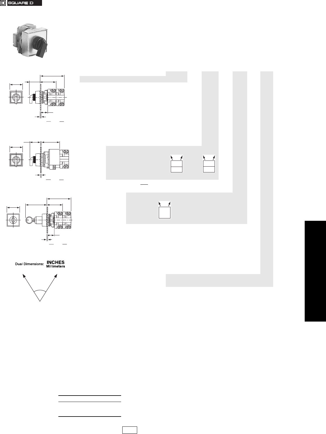
www.us.schneider-electric.com
FOR CURRENT INFORMATION
19 PUSH BUTTONS AND OPERATOR
INTERFACE
© 2007 Schneider Electric
All Rights Reserved 19-89
30 mm Push Buttons Type KX Square Multifunction Selector Switches
Class 9001 / Refer to Catalog 9001CT0001
Non-Illuminated and Illuminated 2 Position Selector Switch Operators—
UL Types 4, 4X, 13/NEMA 4, 4X, 13
For use in hazardous locations—See page 19-79.
Legend plate and contact block not included unless noted.
Boots . . . . . . . . . . . . . . . . . . . . . . . . . . . . . . . . . . . . . . . . . . . . . . . .page 19-94
Contact Blocks and Ratings . . . . . . . . . . . . . . . . . . . . . . page 19-78 to 19-79
“H” Contact Block Assembly Codes . . . . . . . . . . . . . . . . . . . . . . . .page 19-80
Legend Inserts. . . . . . . . . . . . . . . . . . . . . . . . . . . . . . . . . . . . . . . . .page 19-93
Lockouts. . . . . . . . . . . . . . . . . . . . . . . . . . . . . . . . . . . . . . . . . . . . . .page 19-94
Legend Plates . . . . . . . . . . . . . . . . . . . . . . . . . . . . . . . . . . . . . . . . .page 19-93
Replacement Parts . . . . . . . . . . . . . . . . . . . . . . . . . . . . . . . . . . . . .page 19-94
Cams . . . . . . . . . . . . . . . . . . . . . . . . . . . . . . . . . . . . . . . . . . . . . . . .page 19-84
9001KXS
d 9001 KX ______ _______ _____ _____ _____ _____ _____
Square Multifunction
Selector Switch Codes $ Price
Maintained (Non-Illuminated) fSA 24.20
Spring Return from Left to Right (Non-Illuminated) SB 43.20
Spring Return from Right to Left (Non-Illuminated) fSC 43.20
Maintained (Illuminated) SJ 24.20
Spring Return from Left to Right (Illuminated) SK 43.20
Spring Return from Right to Left (Illuminated) fSL 43.20
Key Operated—Maintained fSR 89.00
Key Operated—Spring Return from Left to Right SS 107.00
Key Operated—Spring Return from Right to Left fST 107.00
Cam Codes
(Choose one based on contact
closure sequence, refer to
page 19-64)
ED4.20
Illuminated Operator Only: Add Voltage Assembly Code a
Non-Illuminated Operators or Keyed Blank N/C
Key Withdrawal Codes (Keyed Operators Only)
(Choose one code) 1N/C
2N/C
3N/C
Color Codes b
Amber A 6.60
Black(Non-Illuminated only) B 6.60
Green G 6.60
Blue L 6.60
Red R 6.60
White W 6.60
No Color, Keyed, or Two Color Knob Blank N/C
“H” Code Contact Block Assembled to Operator c
No Contact Blocks Blank N/C
Two Color Selector Switch Knobe
Standard Y178 28.50
Non-Illuminated, Keyed or Not Desired Blank N/C
aChoose voltage assembly code from page 19-77. Price based on light module chosen.
bFor LEDs, match lens color with lamp color (green, red, yellow) or use a clear lens. Note: Yellow = Amber
cSelect from “H” code table on page 19-80. Maximum contact block usage: 2 blocks mounted in tandem (4 blocks total). Price based on
total contact blocks.
dFor complete operators, see page 19-87. If the desired operator is not listed, then use this table to develop a catalog number.
eTwo color knobs are used to indicate red in the left position and green in the right position on illuminated operators. Do not add knob
color code when using Form Y178.
fE Cam Only.
.06
2
.88
22
.25
6
Min. Max.
Panel Thickness
1.28
32
1.47
37
1.85
47
2.82
72
KX SA
KX SB
KX SC
KX SD
KX SE
KX SF
KX SG
KX SH
Selector Switch Operator
Non-Illuminated
.06
2
.25
6
Min. Max.
Panel Thickness
1.28
32
2.00
51
Side 2
Side 1
1.47
37
KX SJ
KX SK
KX SL
KX SM
KX SN
KX SO
KX SP
KX SQ
Selector Switch Operator Illuminated
.06
2
.88
22
.25
6
Min. Max.
Panel Thickness
1.47
37
1.85
47
2.54
65
2.82
72
KX SR
KX SS
KX ST
KX SV
KX SW
KX SX
KX SY
KX SZ
Key Operator Selector Switch
70
2 Position
01
10
01
10
01
10
01
10
Ye s
No
Ye s
No
Ye s
Ye s
When ordering, please specify:
•Quantity
•Class Number
•Type or Catalog Number
CP1 Discount
Schedule Modified
4/20/09
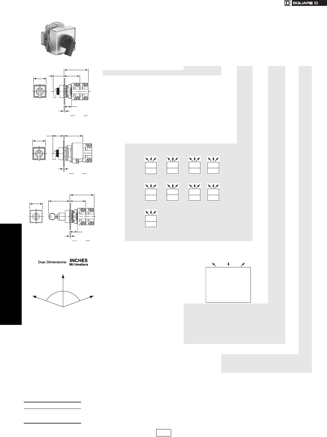
19-90 © 2007 Schneider Electric
All Rights Reserved
www.us.schneider-electric.com
FOR CURRENT INFORMATION
19 PUSH BUTTONS AND OPERATOR
INTERFACE
30 mm Push Buttons Type KX Square Multifunction Selector Switches
Class 9001 / Refer to Catalog 9001CT0001
Non-Illuminated and Illuminated 3 Position Selector Switch Operators –
UL Types 4, 4X, 13/NEMA 4, 4X, 13
For use in hazardous locations—See page 19-79. Legend plate and contact block not included unless noted.
9001KXS e 9001 KX ______ _____ _____ _____ ____ ____
Square Multifunction
3 Position Selector Switch Codes $ Price
Maintained (Non-Illuminated) SD 24.20
Spring Return Left to Center (Non-Illuminated) SE 43.20
Spring Return Right to Center (Non-Illuminated) SF 43.20
Spring Return Both Sides to Center (Non-Illuminated) SG 43.20
Maintained (Illuminated) SM 24.20
Spring Return Left to Center (Illuminated) SN 43.20
Spring Return Right to Center (Illuminated) SO 43.20
Spring Return Both Sides to Center (Illuminated) SP 43.20
aKey Operated—Maintained SV 89.00
aKey Operated—Spring Return Left to Center SW 107.00
aKey Operated—Spring Return Right to Center SX 107.00
aKey Operated—Spring Return Both Sides to Center SY 107.00
Switch Operation & Cam Codes
(Choose one based on contact closure sequence; see page 19-64)
Codes: B C D E 4.20
Codes: F G J L 4.20
Codes: M4.20
No Cam Blank N/C
Voltage Assembly or Key Withdrawal Code
Illuminated Operator: Add Voltage Assembly Code b
Non-Illuminated Operator Blank N/C
Key Withdrawal Codes
(Keyed Operators only;
choose one code.) 4 N/C
5N/C
6N/C
7N/C
8N/C
9N/C
10 N/C
Knob Color Codes
Amber A6.60
Black aB6.60
Green G6.60
Blue L6.60
Red R6.60
White W6.60
No Color, Keyed or Two Color Knob Blank N/C
“H” Suffix Number for Contact Blocks c
No Contact Blocks Blank N/C
Two Color Selector Switch Knob d
Standard Y178 28.50
Non-Illuminated, Keyed Operated or
Not Desired Blank N/C
aNot available in illuminated switches.
bChoose voltage assembly code from page 19-77. For neon light modules, use clear knob color only. For LED light modules, use a knob
color that matches the color of the LED (for example, a red LED uses a red knob) or use clear. Price based on light module chosen.
cSelect from “H” number table on page 19-80. Maximum contact block usage: 2 blocks mounted in tandem (4 blocks total). Price based
on total contact blocks.
dTwo color knobs are used to indicate red in the left position and green in the right position on illuminated operators.
Note: Do not add a knob color code when using Form Y178.
eFor complete operators, see page 19-85. If the desired operator is not listed, then use this table to develop a catalog number.
.06
2
.88
22
.25
6
Min. Max.
Panel Thickness
1.28
32
1.47
37
1.85
47
2.82
72
KX SA
KX SB
KX SC
KX SD
KX SE
KX SF
KX SG
KX SH
Selector Switch Operator
Non-Illuminated
.06
2
.25
6
Min. Max.
Panel Thickness
1.28
32
2.00
51
Side 2
Side 1
1.47
37
KX SJ
KX SK
KX SL
KX SM
KX SN
KX SO
KX SP
KX SQ
Selector Switch Operator
Illuminated
.06
2
.88
22
.25
6
Min. Max.
Panel Thickness
1.47
37
1.85
47
2.54
65
2.82
72
KX SR
KX SS
KX ST
KX SV
KX SW
KX SX
KX SY
KX SZ
Key Operator Selector Switch
70 70
3 Position
0
1
011
1
01
0
100
0
0
100
0
01
1
100
0
0
011
1
00
0
001
0
0
110
1
00
0
100
1
0
000
0
01
1
100
0
1
001
1
01
0
100
0
0
111
1
01
0
100
0
0
011
0
10
0
010
1
1
001
0
01
0
110
Ye s
No
No
Ye s
Ye s
No
Ye s
No
Ye s
No
Ye s
No
Ye s
Ye s
No
No
Ye s
No
Ye s
Ye s
Ye s
When ordering, please specify:
•Quantity
•Class Number
•Type or Catalog Number
CP1 Discount
Schedule
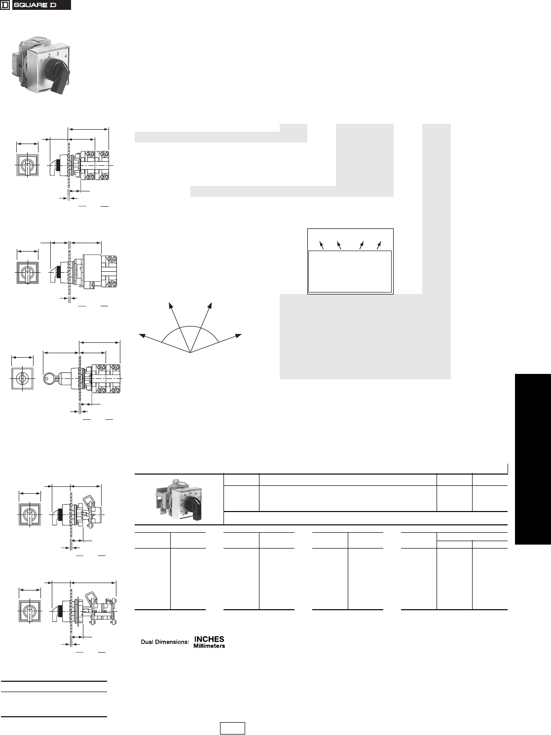
www.us.schneider-electric.com
FOR CURRENT INFORMATION
19 PUSH BUTTONS AND OPERATOR
INTERFACE
© 2007 Schneider Electric
All Rights Reserved 19-91
30 mm Push Buttons Type KX Square Multifunction Selector Switches
Class 9001 / Refer to Catalog 9001CT0001
Non-Illuminated and Illuminated 4 Position Selector Switch Operators
For use in hazardous locations—See page 19-79.
UL Types 4, 4X, 13/NEMA 4, 4X, 13
Legend plate and contact block not included unless noted.
9001KXS
c 9001 KX _____ _____ _____ _____ _____ _____
Square Multifunction
Selector Switch Codes $ Price
Maintained (Non-Illuminated) SH 24.20
Maintained (Illuminated) SQ 24.20
Key Operated—Maintained SZ 89.00
Cam Codes (Only H Cam is available, refer to page 19-84) H4.20
Voltage Assembly or Key Withdrawal Code
Illuminated Operator: Add Voltage Assembly Code a
Non-Illuminated Operators Blank N/C
Key Withdrawal Codes
(Keyed Operators only;
choose one code) 11 N/C
12 N/C
13 N/C
14 N/C
Knob Color Codes
Amber A6.60
Black dB6.60
Green G6.60
Blue L6.60
Red R6.60
White W6.60
No Color or Keyed Blank N/C
“H” Suffix Number for Contact Blocks b
No Contact Blocks Blank N/C
aChoose voltage assembly code from page 19-77. For neon light modules, use clear knob color only. For LED light modules, use a knob
color that matches the color of the LED (for example, a red LED uses a red knob) or use clear. Price based on light module chosen.
bSelect from “H” number table on page 19-80. Maximum contact block usage: 2 blocks mounted in tandem (4 blocks total). Price based
on total contact blocks.
cFor complete operators, see page 19-85. If the desired operator is not listed, then use this table to develop a catalog number.
dNot available in illuminated switches.
Table 19.263: Potentiometer (With Dial Plate) fg (Not UL Listed)
Watts Description Type $ Price
2
Operator only—Single Pot
Operator with Single Pot
Operator only—Tandem Pot
Operator with Tandem Pot
KXBA
KXBBe
KXBC
KXBDe
134.
191.
209.
266.
eFor complete Type number add suffix number from table below. Example: Type KXBB05
SuffixeOhms SuffixeOhms SuffixeOhms SuffixeTandem Pots Ohms
Front Rear
01
02
38
03
04
05
32
39
06
33
50
100
200
250
500
1000
1500
2000
3200
3500
07
08
40
09
35
10
36
11
5 K
10 K
15 K
25 K
35 K
50 K
75 K
100 K
12
13
37
14
15
16
250 k
500 k
750 k
1.1 M
2.2 M
5.0 M
82
83
85
88
89
1000
5000
10 K
50 K
100 K
1000
5000
10 K
50 K
100 K
fDial Plate only—Order Class 9001 Type KXN905. Price $2.90.
gUses same potentiometer as Class 9001 Type K and SK.
.06
2
.88
22
.25
6
Min. Max.
Panel Thickness
1.28
32
1.47
37
1.85
47
2.82
72
KX SA
KX SB
KX SC
KX SD
KX SE
KX SF
KX SG
KX SH
Selector Switch Operator
Non-Illuminated
.06
2
.25
6
Min. Max.
Panel Thickness
1.28
32
2.00
51
Side 2
Side 1
1.47
37
KX SJ
KX SK
KX SL
KX SM
KX SN
KX SO
KX SP
KX SQ
Selector Switch Operator
Illuminated
.06
2
.88
22
.25
6
Min. Max.
Panel Thickness
1.47
37
1.85
47
2.54
65
2.82
72
KX SR
KX SS
KX ST
KX SV
KX SW
KX SX
KX SY
KX SZ
Key Operator Selector Switch
Yes
No
Yes
Yes
No
No
No
Yes
No
No
No
Yes
Yes
Yes
No
Yes
47 47
46
4 Position
.06
2
.85
22
.25
6
Min. Max.
Panel Thickness
1.28
32
1.47
37
2.15
55
KX BA
KX BB
Single Pot Potentiometer Operator
.06
2
.85
22
.25
6
Min. Max.
Panel Thickness
1.28
32
1.47
37
3.20
81
KX BA
KX BB
Double Pot Potentiometer Operator
When ordering, please specify:
•Quantity
•Class Number
•Type or Catalog Number
CP1 Discount
Schedule
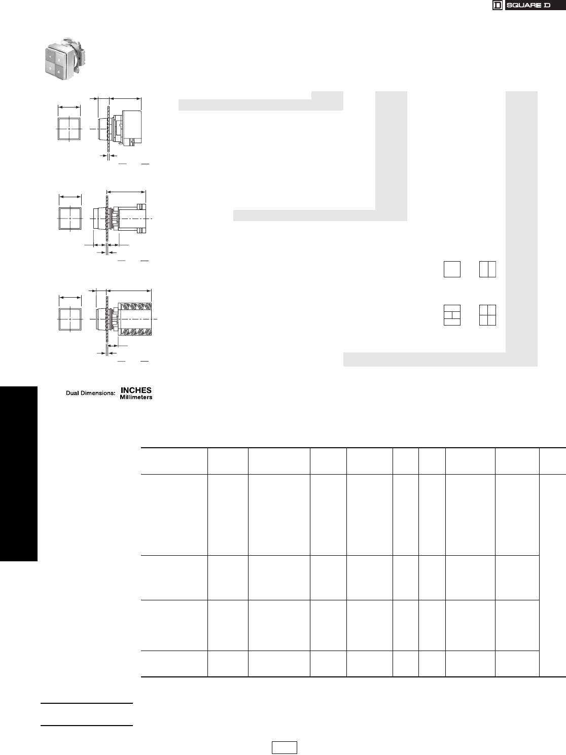
www.us.schneider-electric.com
FOR CURRENT INFORMATION
19 PUSH BUTTONS AND OPERATOR
INTERFACE
19-92 © 2007 Schneider Electric
All Rights Reserved
30 mm Push Buttons Type KX Square Multifunction Pilot Lights
Class 9001 / Refer to Catalog 9001CT0001
Pilot Lights—UL Types 4, 4X, 13/NEMA 4, 4X, 13
For use in hazardous locations—See page 19-79.
Lockout . . . . . . . . . . . . . . . . . . . . . . . . . . . . . . . . . . . . . . . . . . . . . . page 19-94
Lamp and Lens Removal Kit . . . . . . . . . . . . . . . . . . . . . . . . . . . . . page 19-94
Shroud . . . . . . . . . . . . . . . . . . . . . . . . . . . . . . . . . . . . . . . . . . . . . . page 19-94
Enclosures, use Class 9001 Type KYAF or KYSS . . . . . . . . . . . page 19-102
Contact Blocks and Ratings. . . . . . . . . . . . . . . . . . . . . . . . page 19-78, 19-79
Light Modules . . . . . . . . . . . . . . . . . . . . . . . . . . . . . . . . . . . . . . . . page 19-77
Legend Inserts . . . . . . . . . . . . . . . . . . . . . . . . . . . . . . . . . . . . . . . . page 19-93
“H” Contact Block Assembly Codes . . . . . . . . . . . . . . . . . . . . . . . page 19-80
Boots. . . . . . . . . . . . . . . . . . . . . . . . . . . . . . . . . . . . . . . . . . . . . . . . page 19-94
Four-Field
Pilot Light
9001KXPC
or
9001KXTE
e 9001 KX _______ _______ ______ ______ ______ ______ _______
1234
Square Multifunction (Lens Location)
Pilot Light Codes $ Price
Standard Single dPA 19.1 0
Standard DualfPB 25.60
Standard Four-FieldfPC 50.00
Single Push-To-Test c dTA 47 .60
Single Remote Test a c dTB 66.00
Dual Push-To-Test c fTC 134.00
Dual Remote Test a c fTD 83.00
Four-Field Remote Test c fTE 49.50
Voltage Assembly Code b
Color Codes
Choose one lens color per location.
Leave blank if location does not exist or no lens is required.g
Amber A 6.60
Green G 6.60
Blue L 6.60
Red R 6.60
White W 6.60
No Color or No Location Blank N/C
Contact Block (Push-To-Test Operators Only) H1 (KXTA)
H2 (KXTC)
N/C
N/C
aUse only full voltage or resistor light modules (AC only) on remote test pilot lights. Do not use LED, neon, or transformer.
bChoose voltage assembly code from page 19-77. Price based on light module chosen.
cPush-to-test pilot lights are preassembled with Type KA1 (1 N.O./1N.C.) contact blocks. Jumpers for each button and remote test pilot
lights are preassembled with one dummy contact block and diodes. No base operators available.
dChoose voltage assembly codes from page 19-77. Price based on light module chosen.
eFor complete operators, see page 19-85. If the desired operator is not listed, then use this table to develop a catalog number.
fChoose voltage assembly code from table below for the appropriate operator.
gAdd the color codes from the button cover table. Example: KXPB1tt with a white and blue button cover = KXPB1WL.
hOne $6.60 list price will cover both lens locations for KXPB and KXTD and all four lenses for KXPC and KXTE.
iEach lens location on the KXTC requires a $6.60 list price adder.
.06
2
.25
6
Min. Max.
Panel Thickness
.64
16
1.47
37
2.00
51
Single Pilot Light
.06
2
.85
22
.87
22
.25
6
Min. Max.
Panel Thickness
1.47
37
2.75
70
Dual Lamp Pilot Light
.06
2
.85
22
.64
16
.25
6
Min. Max.
Panel Thickness
1.47
37
3.10
79
Four Lamp Pilot Light
112
12
34
1
23
4
KXPA
KXTA
KXTB
KXTC KXPC
KXTE
KXPB
KXTD
h
hi
Voltage Description
For use with Dual
or Four Lamp
Operators As
Indicated
Assembly
Code f
Separate
Light Module
Type
$ Price Rated
VA/W
Lamp Number
(ANSI)
Lamp Part
Number $ Price
6 Vac/dc
12 Vac/dc
24 Vac/dc
28 Vac/dc
48 Vac/dc
60 Vac/dc
110–120 V, 50–60 Hz
120 Vac/dc
208–220 V, 50–60 Hz
220–240 V, 50–60 Hz
277 V, 50–60 Hz
380–480 V, 50–60 Hz
550–600 V, 50–60 Hz
Full Voltage
Resistor
Full Voltage
Full Voltage
Resistor
Resistor
Transformer
Resistor
Transformer
Transformer
Transformer
Transformer
Transformer
KXPB, KXRL
KXRM, KXTC
31
32
34
35
36
37
1
38
3
7
8
5
6
KXAKM231
KXAKM232
KXAKM234
KXAKM235
KXAKM236
KXAKM237
KXAKM21
KXAKM238
KXAKM23
KXAKM27
KXAKM28
KXAKM25
KXAKM26
114.
114.
114.
114.
114.
114.
152.
114.
152.
152.
152.
152.
152.
0.9
2.0
1.8
1.2
2.6
3.0
2.4
3.0
2.4
2.4
2.4
2.4
2.4
6PSB
12PSB
24PSB
28PSB
48PSB
60PSB
6PSB
120PSB
6PSB
6PSB
6PSB
6PSB
6PSB
2550105007
2550105003
2550105004
2550105008
2550105009
2550105010
2550105007
2550105005
2550105007
2550105007
2550105007
2550105007
2550105007
11.00
6 Vac
12 Vac
24 Vac
28 Vac
48 Vac
60 Vac
120 Vac
Full Voltage
Resistor
Full Voltage
Full Voltage
Resistor
Resistor
Resistor
KXTD
31
32
34
35
36
37
38
KXAKM231
KXAKM232
KXAKM234
KXAKM235
KXAKM236
KXAKM237
KXAKM238
114.
0.9
2.0
1.8
1.2
2.6
3.0
3.0
6PSB
12PSB
24PSB
28PSB
48PSB
60PSB
120PSB
2550105007
2550105003
2550105004
2550105008
2550105009
2550105010
2550105005
6 Vac/dc
12 Vac/dc
24 Vac/dc
28 Vac/dc
48 Vac/dc
60 Vac/dc
110–120 V, 50–60 Hz
120 Vac/dc
Full Voltage
Resistor
Resistor
Resistor
Resistor
Resistor
Transformer
Resistor
KXPC
31
32
34
35
36
37
1
38
KXAKM431
KXAKM432
KXAKM434
KXAKM435
KXAKM436
KXAKM437
KXAKM41
KXAKM438
228.
228.
228.
228.
228.
228.
311.
228.
0.9
2.0
1.8
1.2
2.6
3.0
2.4
3.0
6PSB
12PSB
24PSB
28PSB
48PSB
60PSB
6PSB
120PSB
2550105007
2550105003
2550105004
2550105008
2550105009
2550105010
2550105007
2550105005
6 Vac/dc
24 Vac/dc
28 Vac/dc
120 Vac/dc
Full Voltage
Resistor
Resistor
Resistor
KXTE
31
34
35
38
KXAKMR431
KXAKMR434
KXAKMR435
KXAKMR438
342.
0.9
1.8
1.2
3.0
6PSB
24PSB
28PSB
120PSB
2550105007
2550105004
2550105008
2550105005
When ordering, please specify:
•Quantity
•Class Number
•Type or Catalog Number
CP1 Discount
Schedule
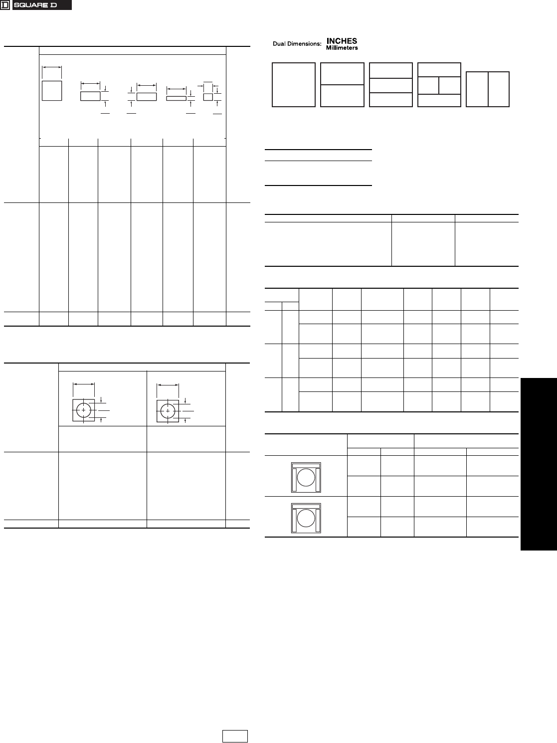
www.us.schneider-electric.com
FOR CURRENT INFORMATION
19 PUSH BUTTONS AND OPERATOR
INTERFACE
© 2007 Schneider Electric
All Rights Reserved 19-93
30 mm Push Buttons Type KX Accessories
Class 9001 / Refer to Catalog 9001CT0001
aThese legend inserts are for the pilot lights in the center of the operator.
bThese legend inserts are for the push button portion of the operator.
cThese legend inserts have vertical printing.
All Type KX push buttons and pilot lights have a blank insert as
standard. These blank inserts can be custom marked using a marking
pen, a mechanical lettering set, press letters, or a tape lettering
machine that marks a tape which can then be transferred to the blank
insert.
To have legend inserts installed into the operators, order the operator
as normal and then indicate where to install the legend inserts using the
numbered positions shown on the operator ordered.
Table 19.264: Legend Plates for Push Buttons or Pilot Lights
Marking
Used On
$ Price
AB C D E F
KXRA,
KXRB
KXRN,
KXRP
KXPA,
KXPC
KXTA,
KXTB
KXTE
KXRC,
KXRD
KXRE,
KXRF
KXPB
KXTD c
KXRG,
KXRH
KXRJ,
KXRKa
KXRG,
KXRH
KXRJ,
KXRK
KXRL,
KXRM
KXTCb
KXRL,
KXRM
KXTC a
Blank
Start
Stop
On
Off
Emerg. Stop
Forward
Reverse
Close
Open
Down
Up
Jog
Reset
Run
Cycle Start
Motor Run
Power On
KXN100
KXN101
KXN102
KXN103
KXN104
KXN105
KXN106
KXN107
KXN108
KXN109
KXN110
KXN111
KXN118
KXN123
KXN124
KXN132
KXN136
KXN138
KXN200
KXN201
KXN202
KXN203
KXN204
KXN205
KXN206
KXN207
KXN208
KXN209
KXN210
KXN211
KXN218
KXN223
KXN224
KXN232
KXN236
KXN238
KXN200
KXN201V
KXN202V
KXN203V
KXN204V
KXN205V
KXN206V
KXN207V
KXN208V
KXN209V
KXN210V
KXN211V
KXN218V
KXN223V
KXN224V
KXN232V
KXN236V
KXN238V
KXN300
KXN301
KXN302
KXN303
KXN304
KXN305
KXN306
KXN307
KXN308
KXN309
KXN310
KXN311
KXN318
KXN323
KXN324
KXN332
KXN336
KXN338
KXN400
KXN401
KXN402
KXN403
KXN404
KXN405
KXN406
KXN407
KXN408
KXN409
KXN410
KXN411
KXN418
KXN423
KXN424
KXN432
KXN436
KXN438
KXN500
KXN501
KXN502
KXN503
KXN504
KXN505
KXN506
KXN507
KXN508
KXN509
KXN510
KXN511
KXN518
KXN523
KXN524
KXN532
KXN536
KXN538
2.90
Special-
Marking KXN199 KXN299 KXN299V KXN399 KXN499 KXN599 12.30
Table 19.265: Legend Plates for Selector Switches
Used On
Marking
$ Price
KXSA, KXSB, KXSC, KXSD,
KXSE, KXSF, KXSG, KXSH,
KXSJ, KXSK, KXSL, KXSM,
KXSN, KXSO, KXSP, KXSQ
KXSR, KXSS, KXST,
KXSV, KXSW, KXSX,
KXSY, KXSZ
Blank
For.-Rev.
Hand-Auto
Man-Auto
Off-On
On-Off
Open-Close
Start-Stop
Auto-Off-Hand
Hand-Off-Auto
Man-Off-Auto
KXN600
KXN639
KXN640
KXN643
KXN644
KXN645
KXN646
KXN651
KXN658
KXN660
KXN662
KXN700
KXN739
KXN740
KXN743
KXN744
KXN745
KXN746
KXN751
KXN758
KXN760
KXN762
2.90
Special Marking KXN699 KXN799 12.30
1.23
31
1.23
31 1.23
31
0.56
14
0.56
14
1.23
31
0.48
12
0.43
11
0.26
7
Square
AB
C (vertical)
DE F
1.33
34
0.76
19
Square
KXN-600
1.33
34
0.76
19
Square
KXN-700
When ordering, please specify:
•Quantity
•Class Number
•Type or Catalog Number
Table 19.266: Letter Height For Standard Legends
in. mm
KXN100
KXN200
KXN300
KXN400
KXN500
KXN600
KXN700
1⁄4
3⁄16
3⁄16
3⁄16
3⁄16
1⁄8
1⁄8
6
4.75
4.75
4.75
4.75
3
3
Table 19.267: Maximum Number of Lines and Characters
For Type KXN Legend Inserts
Letter
Height Number
of … KXN199
KXN299
Horizontal
KXN299
Vertical KXN399 KXN499 KXN599in. mm
1⁄4 6
Characters
per Line 773773
Lines per
Legend
Insert
424111
3⁄16 4.75
Characters
per Line 994994
Lines per
Legend
Insert
526212
1⁄83
Characters
per Line 14 14 5 14 14 6
Lines per
Legend
Insert
849323
Table 19.268: Maximum Number of Lines and Characters
for Type KXN699 and KXN799 Legend Plates
Position
Letter
Height
Characters Per
Marking Area
in. mm A and C B
3⁄16 4.75 6 6
1⁄83 8 9
3⁄16 4.75 10 5
1⁄83 13 7
Example:
9001KXRL1GRGRH2 with a
9001KXN 401 in position 1
9001KXN 503 in position 2
9001KXN 504 in position 3
9001KXN 402 in position 4
KXN100
KXN200
(Pos. 1)
KXN400
(Pos. 1)
KXN300
(Pos. 2)
KXN400
(Pos. 3)
KXN400
(Pos. 1)
KXN400
(Pos. 4)
KXN-
500
(Pos. 2)
KXN-
500
(Pos. 3)
KXN200
(Pos. 2)
(Pos. 1)
(Pos. 1)
(Pos. 2)
K
X
N
2
0
0
K
X
N
2
0
0
KXRA, KXRB
KXRN, KXRP
KXPA, KXPC
KXTA, KXTB
KXRC, KXRD
KXRE, KXRF
KXRG, KXRH
KXRJ, KXRK
KXRL, KXRM
KXTC
KXPB, KXTD
B
AC
B
AC
CP1 Discount
Schedule
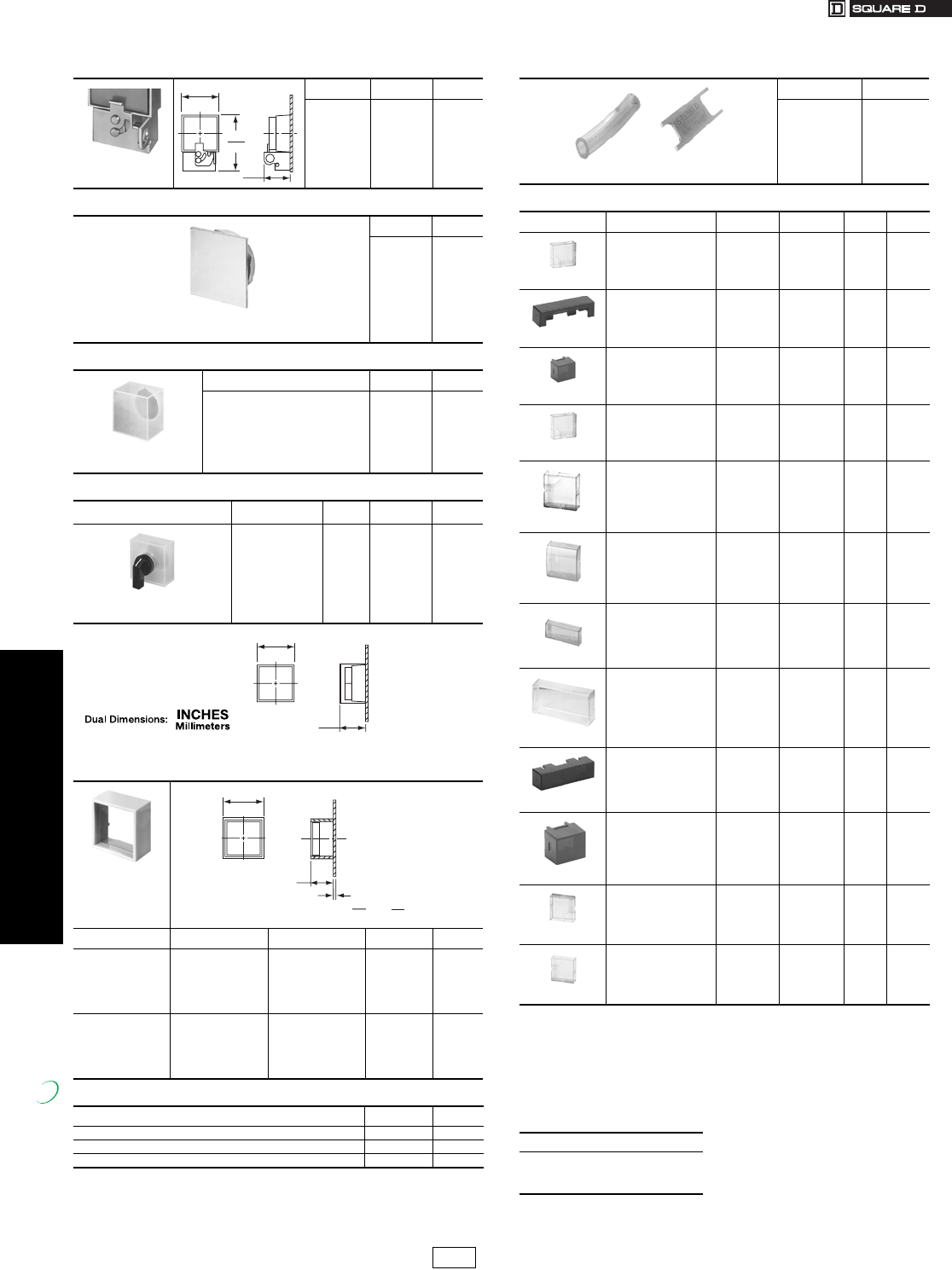
www.us.schneider-electric.com
FOR CURRENT INFORMATION
19 PUSH BUTTONS AND OPERATOR
INTERFACE
19-94 © 2007 Schneider Electric
All Rights Reserved
30 mm Push Buttons Type KX Accessories
Class 9001 / Refer to Catalog 9001CT0001
aEach KXAC28 includes a clear cover and 1 each of all colors. If the same color is required
for position #1and #2 of the KXPB operator, order 2 of Type KXAC28.
bWhen specifying color codes—the first will be installed in #1 and the second in #2. The
price for BOTH color codes is $6.60.
cEach KXAC48 includes a clear cover and 1 each of all colors. If the same color is required
for position #1and #2 of the KXPC operator, order 2 of Type KXAC48.
dWhen specifying color codes—the first will be installed in #1, the second in #2, the third
in #3 and the fourth in #4. The price for ALL FOUR color codes is $6.60.
eTwo required per operator. When ordering an assembled operator—specify two code
numbers.The first code will be assembled into #1 and the second code will be assembled
into #2.
Table 19.269: Lockout for Push Buttons
Holds button in
depressed position
Used On Type $ Price
KXRA-KXRC
KXRD-KXRE
KXRF-KXRG
KXRJ-KXRK
KXRL-KXRM
KXRH-KXRB
KXAK4 28.50
Table 19.270: Closing Plate
UL Types 4, 13/NEMA 4, 13
Square Closing Plate (Chrome Plated)
Same size as KX bezel
Type $ Price
KXAK52 9.50
Table 19.271: Boot for Push Buttons and Pilot Lights
Transparent boot used
to exclude harmful
contaminants
Used On Type $ Price
All KX
Push Buttons and
Pilot Lights
KXAKU7 19.10
Table 19.272: Boot For Selector Switches
Description Used On Knob
Color Type $ Price
Transparent boot with knob used
on selector switches to exclude
harmful contaminants
All KX selector
switches and
potentiometer
operators (except
key operated)
Black
Red
Green
KXAKU17B
KXAKU17R
KXAKU17G
28.50
Table 19.273: Shrouds (used to color code Type KX operators)
Type Used On Color Type $ Price
Full
Shroud
All Push
Buttons
and Pilot
Lights
Gray
Red
Green
Ye l l o w
Black
Blue
KXAK41E
KXAK41R
KXAK41G
KXAK41Y
KXAK41B
KXAK41L
4.80
Short
Shroud
Any
KX
Operator
Gray
Red
Green
Ye l l o w
Black
Blue
KXAK40E
KXAK40R
KXAK40G
KXAK40Y
KXAK40B
KXAK40L
4.80
Table 19.274: Other Accessories
Description Type $ Price
Liner 6508900401 N/C
Mounting Collar 6508903351 11.60
Mounting Ring Nut 6508901401 4.00
65075-183
1.08
27
1.47
37
2.28
58
65075-183
1.06
27
1.57
40
Boot
65075-183
.93
24
1.60
41
.06
2
.25
6
Min. Max.
Panel Thickness
New!
Table 19.275: Lamp and Lens Removal Kit
Used to remove lamp and lens on all
illuminated operators and pilot lights.
Type $ Price
KXALLRT 14.30
Table 19.276: Button Covers
Description For Use on Color Type Code $ Price
Includes
2-KXN200
KXPB
KXTD
Red
Green
Amber
Blue
White
KXAC28a
KXAC28a
KXAC28a
KXAC28a
KXAC28a
Rb
Gb
Ab
Lb
Wb
6.60
Includes
KXN400
KXTC (Position 1 & 4)
Red
Green
Amber
Blue
White
KXAR4
KXAG4
KXAA4
KXAL4
KXAW4
R
G
A
L
W
6.60
Includes
KXN500
KXTC (Position 2 & 3)
Red
Green
Amber
Blue
White
KXAR5
KXAG5
KXAA5
KXAL5
KXAW5
R
G
A
L
W
6.60
Includes
1–KXN100
KXPC
Red
Green
Amber
Blue
White
KXAC48c
KXAC48c
KXAC48c
KXAC48c
KXAC48c
Rd
Gd
Ad
Ld
Wd
6.60
Includes
KXN100
KXRA
KXRB
Red
Green
Amber
Blue
White
KXAR1
KXAG1
KXAA1
KXAL1
KXAW1
R
G
A
L
W
6.60
Includes
KXN100
KXRN
KXRP
Red
Green
Amber
Blue
White
KXARM1
KXAGM1
KXAAM1
KXALM1
KXAWM1
R
G
A
L
W
11.40
Includes
KXN200
KXRC
KXRD
KXRE
KXRF
Red
Green
Amber
Blue
White
KXAR2
KXAG2
KXAA2
KXAL2
KXAW2
R
G
A
L
W
6.60
Includes
KXN300
KXRG (Position 2)
KXRH (Position 2)
KXRJ (Position 2)
KXRK (Position 2)
Red
Green
Amber
Blue
White
KXAR3
KXAG3
KXAA3
KXAL3
KXAW3
R
G
A
L
W
6.60
Includes
KXN400
KXRG (Position 1 & 3)
KXRH (Position 1 & 3)
KXRJ (Position 1 & 3)
KXRK (Position 1 & 3)
KXRL (Position 1 & 4)
KXRM (Position 1 & 4)
Red
Green
Amber
Blue
White
KXAR4
KXAG4
KXAA4
KXAL4
KXAW4
R
G
A
L
W
6.60
Includes
KXN500
KXRL (Position 2 & 3)
KXRM (Position 2 & 3)
Red
Green
Amber
Blue
White
KXAR5
KXAG5
KXAA5
KXAL5
KXAW5
R
G
A
L
W
6.60
Includes
KXN100
KXPA
Red
Green
Amber
Blue
White
KXAR8
KXAG8
KXAA8
KXAL8
KXAW8
R
G
A
L
W
6.60
Includes
KXN100
KXTA
KXTB
Red
Green
Amber
Blue
White
KXAR1
KXAG1
KXAA1
KXAL1
KXAW1
R
G
A
L
W
6.60
When ordering, please specify:
•Quantity
•Class Number
•Type or Catalog Number
e
CP1 Discount
Schedule Modified
4/20/09
www.us.schneider-electric.com
FOR CURRENT INFORMATION
19 PUSH BUTTONS AND OPERATOR
INTERFACE
© 2007 Schneider Electric
All Rights Reserved 19-95
Control Stations and
Enclosures
XAL 22 mm Control Stations
Refer to Catalog 9001CT0001
Table 19.277: Environment
Degree of protection Conforming to IEC 529 IP65, unless otherwise stated
IP66, for booted push button heads
Conforming to UL 50, CSA C22.2 No. 94 Type 1, 4X, 12, and 13, unless otherwise stated
Conforming to standards
IEC 947-1, IEC/EN 60947-5-1, IEC 947-5-4,
EN 60947-1, JIS C 4520,
UL 508, CSA C22.2 No. 14
Product certifications
UL Listed, CSA
Standard single contacts with screw clamp terminals: A600; R300
Light blocks with screw clamp terminals
Table 19.278: Contact Block Characteristics
Electrical Characteristics
Cabling capacity Conforming to IEC 947-1
Screw and captive clamp terminals
Min: . . . . . . . . . . . . . . . . . . . .1 x 24 AWG (0.22 mm2) without cable end
1 x 22 AWG (0.34 mm2) for linking
Max:. . . . . . . . . . . . . . . . . . . . . . . 2 x 16 AWG (1.5 mm2) with cable end
Cross headed screw (POZIDRIV type 1) slotted for flat 4 and 5.5 mm screwdriver
Rated operational characteristics
Conforming to IEC/EN 60947-5-1
AC supply:
Utilization category AC-15
A600: Ue = 600 Vac and le = 1.2 A, or Ue = 240 Vac and le = 3 A,
or Ue = 120 Vac and le = 6 A. Continuous thermal current = 10 A.
DC supply:
Utilization category DC-13 R300: Ue = 250 Vdc and le = 0.1 A, or Ue = 125 Vdc and le = 0.22 A
Voltage limits of PROTECTED LED®Nominal voltage
24 V: 19.2 to 30 Vdc; 21.6 to 24.6 Vac
120 V: 102 to 132 Vac
240 V: 195 to 264 Vac
Current consumption of PROTECTED LED Applicable to all colors
24 Vac/dc supply blocks: 18 mA
120 Vac supply blocks: 14 mA
240 Vac supply blocks: 14 mA
Table 19.279: Start or Stop Function
Polycarbonate; Light gray base, RAL7035; Dark gray lid, RAL7016
Description Type of Push Type of Contact Marking Catalog Number $ Price
N.O. N.C.
Marking on Legend Holder
1 momentary
push button
Flush black 1 — Start XALD101 66.00
Flush red — 1 Stop XALD111 66.00
Marking on Legend Holder
1 mushroom head
push button Ø 40 mm,
momentary
Red — 1 Emergency stop on
red legend XALD164 76.00
Table 19.280: Emergency Stop Function
Polycarbonate; Light gray base, RAL7035; Yellow lid, RAL1012
Description Type Type of Contact Catalog Number $ Price
N.O. N.C.
1 mushroom head
push button Ø 40 mm, red
Turn-to-release
Standard — 1 XALK174 106.00
Trigger action — 1 XALK178 134.00
1 mushroom head
push button Ø 40 mm, red
Key release (Key No. 455)
Standard — 1 XALK184 134.00
Trigger action — 1 XALK188 134.00
1 mushroom head
push button Ø 40 mm, red
Push-pull
Standard — 1 XALK194 90.00
Table 19.281: Start-Stop Function
Polycarbonate; Light gray base, RAL7035; Dark gray lid, RAL7016
Description Type of Push Type of Contact Text Catalog Number $ Price
N.O. N.C.
2 momentary
push buttons
1 flush black 1 — Start XALD211 66.00
1 flush red — 1 Stop
1 flush black 1 — Forward XALD221 66.00
1 flush black 1 — Reverse
Table 19.282: Three Function
Polycarbonate; Light gray base, RAL7035; Dark gray lid, RAL7016
Description Type of Push Type of Contact Text Catalog Number $ Price
N.O. N.C.
3 momentary
push buttons
1 flush black
1 flush red
1 flush black
1—Open
XALD341 130.00—1Stop
1 — Close
1—Forward
XALD311 130.00—1Stop
1—Reverse
1—Up
XALD321 130.00—1Stop
1 — Down
When ordering, please specify:
•Quantity
•Type or Catalog Number
Marked
File E164353
CCN NKCR
File LR 44087
Class 3211 03
XALD101
XALK174
XALD211
XALD321
IDiscount
Schedule Modified
4/18/09
19-96 © 2007 Schneider Electric
All Rights Reserved
www.us.schneider-electric.com
FOR CURRENT INFORMATION
19 PUSH BUTTONS AND OPERATOR
INTERFACE
Control Stations and
Enclosures
XAL 22 mm Control Stations
Refer to Catalog 9001CT0001
aFor customer assembly using XB5 operators, see Push Buttons—ZB5 22 mm starting on page 19-38.
Table 19.283: Empty Enclosures a
Polycarbonate
Description Number of Holes Catalog Number $ Price
For normal environments, CSA approved and UL Listed (with stainless steel lid mounting screws)
Light gray base RAL7035
Dark gray lid RAL7016
1XALD01 32.80
2XALD02 38.20
3XALD03 49.00
4XALD04 71.00
5XALD05 87.00
Light gray base RAL7035
Yellow lid RAL1012 1XALK01 35.40
Table 19.284: Electrical Block and Accessories (for mounting on metal plate at back of enclosure) a
Description Type Color Catalog Number $ Price
Electrical blocks with screw clamp terminal connections
Standard contact blocks aN.O. contact — ZENL1111 16.60
N.C. contact — ZENL1121 16.40
Light blocks with
24 Vac/dc
White ZALVB1
52.00
Green ZALVB3
Red ZALVB4
Ye l l o w ZALVB5
Blue ZALVB6
120 Vac
White ZALVG1
52.00
Green ZALVG3
Red ZALVG4
Ye l l o w ZALVG5
Blue ZALVG6
230 Vac
White ZALVM1
52.00
Green ZALVM3
Red ZALVM4
Ye l l o w ZALVM5
Blue ZALVM6
Table 19.285: Accessories for electrical blocks
Description Application Catalog Number $ Price
Blanking plug Ø 22 mm units ZB5SZ3 11.00
Nut Head mounting ZB5AZ901 4.40
Grounding terminal Grounding XALZ09 5.40
Key For tightening nut ZB5AZ905 12.40
XALD02
ZENL1111
ZALV••
ZB5SZ3
ZB5AZ905
When ordering,
please specify:
•Quantity
•Type or Catalog Number
IDiscount
Schedule Modified
4/20/09
www.us.schneider-electric.com
FOR CURRENT INFORMATION
19 PUSH BUTTONS AND
OPERATOR INTERFACES
© 2007 Schneider Electric
All Rights Reserved 19-97
Control Stations and
Enclosures
XAP 22 mm Enclosures
Refer to Catalog 9001CT0001
Table 19.286: Specifications
Glass-reinforced polyester insulated enclosures XAPA
Material Glass-reinforced polyester
Approvals Special version: CSA Type 4 and 5 (undrilled version)
Protective treatment Standard version: “TC” and “TH” treatments
Ambient temperature Operation: -25 oC to +70 oC (-13 oF to +158 oF) Storage: -40 oC to +70 oC (-40 oF to +158 oF)
Degree of protection IP65 conforming to IEC 529 and IP657 conforming to NF C 20-010, Type 4, 4X, 12
Electric shock protection Class II conforming to IEC 536 and NF C 20-030
Flame resistance CSTB: M3, NF C 20-455: 850°C; IEC 92: 960 °C; UL 94: VO
Chemical resistance High degree of resistance to acids, bases, sea water, mineral salts, all solvents, petrol, diesel, oils and greases
Cable entry Undrilled
Die Cast metal enclosures XAPG
Material Zinc alloy (XAPG1-XAPG4), Aluminum (XAPG5)
Approvals Special version: CSA Type 4 and 5 (undrilled version); UL Type 1, 2, 4, and 12; Standard CSA Type 1, 4, 4X, and 12
Protective treatment Standard version: “TC” treatment. Special version: “TH” treatment
Ambient temperature Operation: -25 oC to +70 oC (-13 oF to +158 oF) Storage: -40 oC to +70 oC (-40 oF to +158 oF)
Degree of protection IP65 conforming to IEC 529 and IP657 conforming to NF C 20-010, UL Type 4, 12
Electric shock protection Class I conforming to IEC 536 and NF C 20-030
Chemical resistance Special treatments on request
Cable entry Tapped entries for cable glands
Flush mount enclosures XAPE
Material and color Anodized aluminum front plate. Insulated protective rear cover
Protective treatment Standard version: “TC” and “TH” treatments
Ambient temperature Operation: -25 oC to +70 oC (-13 oF to +158 oF) Storage: -40 oC to +70 oC (-40 oF to +158 oF)
Degree of protection IP65 conforming to IEC 529 and IP657 conforming to NF C 20-010, CSA Type 1, 4, 4X, and 12
Electric shock protection Class I conforming to IEC 536 and NF C 20-030
Chemical resistance High degree of resistance to organic acids, diluted mineral acids, salts, alcohol, acetone, chloride and fluoride solvents, oils
and petrol
Cable entry With rear cover: knock-out cable entries
File E164353
CCN NKCR
(XAPG only)
File LR 44087
Class 3211 03 Marked
Table 19.287: Undrilled Enclosures, Glass-Reinforced Polyester
Type H x W Dimensions Catalog Number $ Price
IN mm
NEMA 4, 4X, 13
Usable depth 3.27 in. (83 mm)
Without hinges
3.34 x 5.75 85 x 146 XAPA1100 110.00
3.34 x 8.90 85 x 226 XAPA2100 180.00
5.95 x 9.49 151 x 241 XAPA3100 284.00
With hinges 5.95 x 9.49 151 x 241 XAPA4100 378.00
Undrilled Grounding Plate Sheet steel with ground screw
For XAPA1100 XAPZ100 22.00
For XAPA2100 XAPZ200 24.60
For XAPA3100 and 4100 XAPZ300 55.00
Table 19.288: Drilled Insulated Enclosures, Glass-Reinforced Polyester
Type
Number of
Knockouts
22 mm
Number of Rows H x W Dimensions
Catalog Number $ Price
Vertical Horizontal IN mm
NEMA 4, 4X, 13
Usable depth
3.27 in. (83 mm)
1.58 in. (40 mm)
centerline
spacing of holes
1 1 1 3.35 X 5.75 85 X 146 XAPA1110 114.00
2 1 2 3.35 X 5.75 85 X 146 XAPA1120 114.00
4 2 2 3.35 X 5.75 85 X 146 XAPA1104 114.00
8 2 4 3.35 X 8.90 85 X 226 XAPA2108 182.00
16 4 4 5.94 X 9.49 151 X 241 XAPA3116 390.00
Drilled Grounding Plate Sheet steel with ground screw
For XAPA1110 XAPZ110 22.00
For XAPA1120 XAPZ120 22.00
For XAPA1104 XAPZ104 22.00
For XAPA2108 XAPZ208 24.60
For XAPA3116 XAPZ316 70.00
When ordering, please specify:
•Quantity
•Type or Catalog Number
XAPA1100
XAPA1104
IDiscount
Schedule Modified
4/20/09
19-98 © 2007 Schneider Electric
All Rights Reserved
www.us.schneider-electric.com
FOR CURRENT INFORMATION
19 PUSH BUTTONS AND
OPERATOR INTERFACES
Control Stations and
Enclosures
XAP 22 mm Enclosures and Accessories
Refer to Catalog 9001CT0001
Table 19.290: Undrilled Die Cast Enclosures (Painted Gray RAL7032)
Type Material Usable Depth H x W x D Dimensions Catalog Number $ Price
IN mm IN mm
NEMA 4, 13 Zinc
1.93 49
3.15 x 3.15 x 2.03 80 x 80 x 51.5 XAPG19100 110.00
5.12 x 3.15 x 2.03 130 x 80 x 51.5 XAPG29100 120.00
6.89 x 3.15 x 2.03 175 x 80 x 51.5 XAPG39100 142.00
2.93 74.5
3.15 x 3.15 x 3.03 80 x 80 x 77 XAPG19400 110.00
5.12 x 3.15 x 3.03 130 x 80 x 77 XAPG29400 120.00
6.89 x 3.15 x 3.03 175 x 80 x 77 XAPG39400 142.00
8.66 x 3.15 x 3.03 220 x 80 x 77 XAPG49400 174.00
Aluminum 2.93 2.93 12.20 x 3.35 x 3.03 310 x 85 x 77 XAPG59400 262.00
Table 19.291: Drilled Die Cast Enclosures (Painted Gray RAL7032)
Type Material
Usable Depth Number of
22 mm
holes
H x W x D Dimensions
Catalog Number $ Price
IN mm IN mm
NEMA 4, 13
1.18 in. (30 mm)
centerline
spacing of holes
for horizontal mount
Zinc
1.93 49
2 3.15 x 3.15 x 2.03 80 x 80 x 51.5 XAPG19702 120.00
3 5.12 x 3.15 x 2.03 130 x 80 x 51.5 XAPG29703 142.00
4 6.90 x 3.15 x 2.03 175 x 80 x 51.5 XAPG39704 174.00
2.93 74.5
2 3.15 x 3.15 x 3.03 80 x 80 x 77 XAPG19802 120.00
3 5.12 x 3.15 x 3.03 130 x 80 x 77 XAPG29803 142.00
4 6.90 x 3.15 x 3.03 175 x 80 x 77 XAPG39804 174.00
NEMA 4, 13
1.58 in. (40 mm)
centerline
spacing of holes
for vertical mount
Zinc
1.93 1.93
1 3.15 x 3.15 x 2.03 80 x 80 x 51.5 XAPG19201 110.00
2 5.12 x 3.15 x 2.03 130 x 80 x 51.5 XAPG29202 120.00
3 6.90 x 3.15 x 2.03 175 x 80 x 51.5 XAPG39203 142.00
2.93 74.5
1 3.15 x 3.15 x 3.03 80 x 80 x 77 XAPG19501 110.00
2 5.12 x 3.15 x 3.03 130 x 80 x 77 XAPG29502 120.00
3 6.90 x 3.15 x 3.03 175 x 80 x 77 XAPG39503 142.00
4 8.66 x 3.15 x 3.03 220 x 80 x 77 XAPG49504 174.00
Aluminum 2.93 74.5 5 12.20 x 3.35 x 3.03 310 x 85 x 77 XAPG59505 268.00
Table 19.292: Drilled Flush Plates
Type Material Number of
22 mm holes
H x W x D Dimensions Catalog Number $ Price
IN mm
NEMA 4, 13
1.18 in. (30 mm)
centerline spacing
of holes
Anodized
Aluminum
1 2.83 x 2.83 72 x 72 XAPE301 52.00
2 4.13 x 2.83 105 x 72 XAPE302 60.00
3 5.43 x 2.83 138 x 72 XAPE303 68.00
4 6.73 x 2.83 171 x 72 XAPE304 82.00
5 8.03 x 2.83 204 x 72 XAPE305 98.00
Table 19.293: Optional Back Box (for finger protection, if required)
Type Material For Use With Catalog Number $ Price
Protective rear covers Insulating Fiberglass
Flush plate XAPE301 XAPE901
32.80
Flush plate XAPE302 XAPE902
Flush plate XAPE303 XAPE903
Flush plate XAPE304 XAPE904
Flush plate XAPE305 XAPE905 60.00
When ordering, please specify:
•Quantity
•Type or Catalog Number
XAPG39400
XAPG29703
XAPE302
XAPE303
IDiscount
Schedule
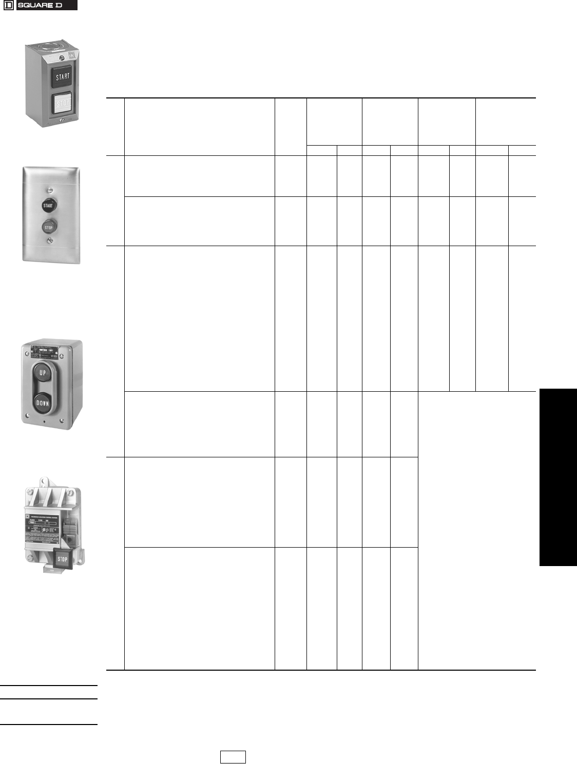
www.us.schneider-electric.com
FOR CURRENT INFORMATION
19 PUSH BUTTONS AND
OPERATOR INTERFACES
© 2007 Schneider Electric
All Rights Reserved 19-99
Control Stations and
Enclosures
Standard Duty Control Stations
Class 9001 / Refer to Catalog 9001CT0001
Standard duty control stations are designed for use with magnetic motor starters to govern the starting, stopping, or
reversing of all types of electric motors. Push buttons are momentary contact unless otherwise indicated. Selector
switches are maintained contact.
Accessories . . . . . . . . . . . . . . . . . . . . . . . . . . . . . . . . . . . . . . . . . .page 19-100
Replacement Parts . . . . . . . . . . . . . . . . . . . . . . . . . . . . .page 19-100, 19-101
Replacement Interiors. . . . . . . . . . . . . . . . . . . . . . . . . . . . . . . . . .page 19-101
Contact Symbols . . . . . . . . . . . . . . . . . . . . . . . . . . . . . . . . . . . . . .page 19-101
Table 19.294: Control Stations
Many items are stock or can be furnished as a quick ship using a “Universal” station plus
accessories.
No.
of
Units
Nameplate Markings and Features
Contact
Symbol
See
page
19-101
Surface
Mounting
NEMA 1c
Stainless Steel
Flush Plate
(Pullboxb
not included) c
Watertight and
Dusttight
NEMA 4c
For Hazardous
Locations
Class I, Div. I & II
Groups B, C and D
Class II Div. I & II
Groups E, F and G
NEMA 7 & 9c
Type $ Price Type $ Price Type $ Price Type $ Price
1
Start 1 BG101 57.00 BF101 77.00 BW146 180.00 BR101 242.00
Stop 3 BG102 57.00 BF102 77.00 BW147 180.00 ——
Stop (Mushroom Button) 3 BG103 66.00 ——BW151 191.00 BR103 252.00
Stop (Lockout) 3 BG104 86.00 ——BW148 180.00 BR104 242.00
Universal (w/o Legend Inserts) a16 BG107 55.00 BF107 74.00 BW159 179.00 BR107 240.00
Off-On (Selector Switch) 19 BG111 57.00 BF111 77.00 ——— —
Hand-Off-Auto (Selector Switch) 17 BG112 57.00 BF112 77.00 ——— —
Universal Selector Switch (w/o Legend Insert) a19 or 17 BG114 55.00 BF114 74.00 ——— —
Red Pilot Light: 120 Vac/dc 121 BG121 134.00 BF121 152.00 ——— —
Green Pilot Light: 120 Vac/dc 121 BG122 134.00 BF122 152.00 ——— —
Pilot Light (w/o Lens): 120 Vac/dc a121 BG123 126.00 BF123 146.00 ——— —
2
Start-Stop 145 BG201 57.00 BF201 77.00 BW240 180.00 BR204 242.00
Start-Stop (for Latching Applications) 146 BG202 71.00 BF202 90.00 BW252 180.00 BR202 242.00
Start-Stop (Mushroom on Stop) 145 BG203 66.00 ——BW250 191.00 BR203 252.00
Start-Stop (Lockout on Stop) 145 BG204 86.00 ——BW241 180.00 BR204 242.00
Start-Stop (Mushroom on Start and Stop) 145 BG205 77.00 ——BW246 200.00 BR205 261.00
Forward-Reverse 146 BG206 71.00 BF206 90.00 BW242 180.00 BR206 242.00
Open-Close 146 BG207 71.00 BF207 90.00 BW244 180.00 BR207 242.00
Up-Down 146 BG208 71.00 BF208 90.00 BW243 180.00 BR208 242.00
Raise-Lower 146 BG209 71.00 BF209 90.00 BW253 180.00 BR209 242.00
On-Off 145 BG210 57.00 BF210 77.00 BW245 180.00 BR210 242.00
On-Off 146 BG211 71.00 BF211 90.00 BW254 180.00 BR211 242.00
Universal (w/o Legend Inserts) a25 BG214 52.00 BF214 71.00 BW260 176.00 BR214 237.00
Start-Stop (Maintained Contact) 10 BG215 86.00 BF215 105.00 BW255 209.00 BR215 270.00
On-Off (Maintained Contact) 10 BG216 86.00 BF216 105.00 BW256 209.00 BR216 270.00
Hand-Auto (Maintained Contact) 10 BG217 86.00 BF217 105.00 BW257 209.00 BR217 270.00
Start-Stop
(Red Mushroom on Stop, Both Buttons Maintained) 10 — — — — — — BR219 294.00
Universal (Maintained Contact w/o Legend Inserts) a10 BG218 81.00 BF218 99.00 BW258 204.00 BR218 266.00
Off-On (Selector Switch), Red Pilot Light: 120 Vac/dc 19 & 121 BG221 209.00 BF221 228.00 a“Universal” designates control
stations without legend inserts,
lenses or accessory kits. Universal
stations plus separate legend
inserts and other accessories listed
on page 19-100 allow the user to
conveniently build up standard or
custom stations.
bUse standard 2.0 or 2.13 in. deep
wall boxes, single gang for Types
BF1 and BF2 and two gang for Type
BF3.
cFor replacement interiors, see page
19-101. Replacement enclosures
(case and/or cover) are not
available for Type BR devices.
Lockout must be factory installed on
NEMA 4 devices. However,
replacement covers are available
with the lockout feature as standard.
See page 19-100.
Hand-Off-Auto (Selector Switch),
Red Pilot Light: 120 Vac/dc 17 & 121 BG223 209.00 BF223 228.00
Universal Selector Switch & Pilot Light 120 Vac/dc
(w/o Legend Insert & w/o Lens) a
17 or 19
& 121 BG224 200.00 BF224 219.00
Hand-Off-Auto (Selector Switch) &
Start (Push Button) 17 & 1 BG225 86.00 BF225 105.00
Universal Selector Switch & Push Button
(w/o Legend Inserts) a
17 or 19
& 16 BG226 81.00 BF226 99.00
3
Fast-Slow-Stop 109 BG301 114.00 BF301 138.00
Forward-Reverse-Stop 109 BG302 114.00 BF302 138.00
Open-Close-Stop 109 BG303 114.00 BF303 138.00
Raise-Lower-Stop 109 BG304 114.00 BF304 138.00
Up-Down-Stop 109 BG305 114.00 BF305 138.00
High-Low-Stop 109 BG306 114.00 BF306 138.00
Start-Jog-Stop 109 BG316 114.00 ——
Forward-Reverse-Stop (Lockout on Stop) 109 BG322 143.00 ——
Up-Down-Stop (Lockout on Stop) 109 BG325 143.00 ——
High-Low-Stop (Lockout on Stop) 109 BG326 143.00 ——
Universal (w/o Legend Inserts) a8BG307 108.00 BF307 132.00
Start-Stop, Red Pilot Light: 120 Vac/dc 145 & 121 BG308 209.00 BF308 228.00
Universal Push Buttons (2) & Pilot Light: 120 Vac/dc 25 & 121 BG309 198.00 BF309 218.00
(w/o Legend Inserts & w/o Lens) a
Start-Stop (Maintained Contacts) & Red 10 & 121 BG310 228.00 BF310 248.00
Pilot Light: 120 Vac/dc
On-Off (Maintained Contact) & Red Pilot 10 & 121 BG311 228.00 BF311 248.00
Light: 120 Vac/dc
Hand-Auto (Maintained Contacts) & Red 10 & 121 BG312 228.00 BF312 248.00
Pilot Light: 120 Vac/dc
Universal Push Buttons (Maintained Contact) & Pilot 10 & 121 BG313 218.00 BF313 236.00
Light: 120 Vac/dc (w/o Legend Inserts & w/o Lens) a
Hand-Off-Auto (Selector Switch) & 17 & 145 BG314 114.00 BF314 134.00
Start-Stop (Push Buttons)
Universal Selector Switch & 2 Push 17 or 19 &
25 BG315 108.00 BF315 126.00
Buttons (w/o Legend Inserts) a
NEMA 1
Surface Mounting
Type BG201
NEMA 1
Flush Mounting
(w/o pullbox)
Type BF201
NEMA 4
Type BW243
NEMA 7 and 9
Type BR103
When ordering, please specify:
•Quantity
•Class Number
•Type or Catalog Number
CP1 Discount
Schedule Modified
4/20/09
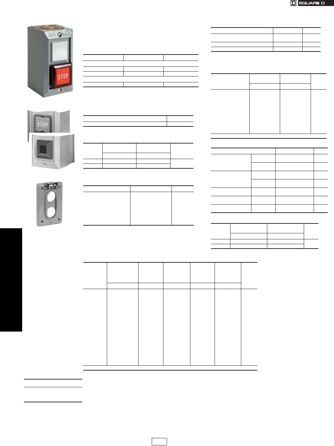
www.us.schneider-electric.com
FOR CURRENT INFORMATION
19 PUSH BUTTONS AND
OPERATOR INTERFACES
19-100 © 2007 Schneider Electric
All Rights Reserved
Control Stations and
Enclosures
Type B Standard Duty Control Stations—Accessories
Class 9001 / Refer to Catalog 9001CT0001
Kits do not include legend insert; order separate legend
insert from the tables below.
Ex: For red mushroom button marked STOP, order one
Class 9001 Type B301 plus one Class 9001 Type B102.
For NEMA 1 surface mounting stations, bottom unit only.
Can be used on either push button or on 2 or 3 position
selector switch. Lockout cannot be used with mushroom
cap.
aReplacement cover has factory installed lockout on cover.
Table 19.295: Mushroom Caps
Color Type $ Price
For NEMA 1 surface mounting stations
Red B301 9.50
Black B302 11.00
For NEMA 4
Red B303 9.50
Table 19.296: Lockout Kit
Type $ Price
B321 28.50
Table 19.297: Pilot Light Lenses
Color
For NEMA 1
Surface Mounting
For NEMA 1
Flush Mounting $ Price
Type Type
Red B331 B341 7.10
Green B332 B342
Table 19.298: Replacement Covers for BF and BW
For Types Types $ Price
BF101–BF123
BF201–BF226
BF301–BF315
BW146–BW147
BW148a
BW149–BW159
BW240
BW241a
BW242–BW260
3040000311
3040000302
3110104301
BWD108
BWD109
BWD108
BWD219
BWD220
BWD219
85.00
52.00
85.00
11.90
23.70
11.90
11.90
23.70
11.90
Table 19.299: Miscellaneous Accessories
Description Type $ Price
Selector switch knob for types BG & BF
selector switches 9001B351 7.10
Square D lamp (Sylvania lamp 120PSB) 2550105005 11.00
Replacement lamp holder BGC124 57.00
Table 19.300: Interchangeable Selector Switch
Legend Plates
Marking
For NEMA 1
Surface Mounting
For NEMA 1
Flush Mounting $ Price
Each
Type Type
Off-On
Hand-Off-Auto
Manual-Auto
Forward-Reverse
Open-Close
Open-Off-Close
Hand-Auto
Forward-Off-Reverse
Summer-Winter
Summer-Off-Winter
Low-Off-High
Up-Off-Down
B201
B202
B203
B204
B205
B206
B207
B208
B209
B210
B211
B212
B231
B232
B233
B234
B235
B236
B237
B238
B239
B240
B241
B242
2.40
Order in multiples of 10 only.
Table 19.301: Legend Insert Kits
Where Used: Type $ Price
For NEMA 1
Surface Mounting
Push Buttons B100 (Incl's 1 each
of B101 thru B119) 22.20
Selector
Switches
B200 (Incl's 1 each
of B201 thru B212) 40.90
For NEMA 1
Flush Mounting
Push Buttons B130 (Incl's 1 each
of B131 thru B149) 45.20
Selector
Switches
B230 (Incl's 1 each
of B231 thru B242) 28.50
For NEMA 4 and NEMA 7-
9 Lever Type, Square Push Button B160 (Incl's 1 each
of B161 thru B179) 45.20
For NEMA 4
Button Type, Round Push Button B250 (Incl's 1 each
of B253 thru B266) 33.30
For NEMA 4
Button Type
Mushroom
Button
B300 (Incl's 1 each
of B276 thru B289) 33.30
Table 19.302: Pilot Light Lenses
Color
For NEMA 1
Surface Mounting
For NEMA 1
Flush Mounting $ Price
Type Type
Red B331 B341 7.10
Green B332 B342
Table 19.303: Interchangeable Push Button Legend Inserts
Marking
For NEMA 1
Surface
Mounting
Push Button &
Mushroom Caps
For NEMA 1
Flush
Mounting
For NEMA 4
and NEMA 7-9
Lever Type
Square
For NEMA 4
Button Type
Round
For NEMA 4
Mushroom
Button
Inserts
$ Price
Each
Type Type Type Type Type
Start
Stop
Fast
Slow
Forward
Reverse
Open
Close
Raise
Lower
Up
Down
High
Low
On
Off
Hand
Auto
Jog
Blank-Black
Blank-Red
B101
B102
B103
B104
B105
B106
B107
B108
B109
B110
B111
B112
B113
B114
B115
B116
B117
B118
B119
B129
B129R
B131
B132
B133
B134
B135
B136
B137
B138
B139
B140
B141
B142
B143
B144
B145
B146
B147
B148
B149
B159
B159R
B161
B162
B163
B164
B165
B166
B167
B168
B169
B170
B171
B172
B173
B174
B175
B176
B177
B178
B179
B189
B189R
B259
B260
—
—
B255
B256
B263
B264
B261
B262
B253
B254
—
—
B257
B258
B265
B266
—
B251
B252
B282
B283
—
—
B278
B279
B286
B287
B284
B285
B276
B277
—
—
B280
B281
B288
B289
—
B251
B252
2.40
Order in multiples of 10 only.
When ordering, please specify:
•Quantity
•Class Number
•Type or Catalog Number
CP1 Discount
Schedule Modified
4/20/09
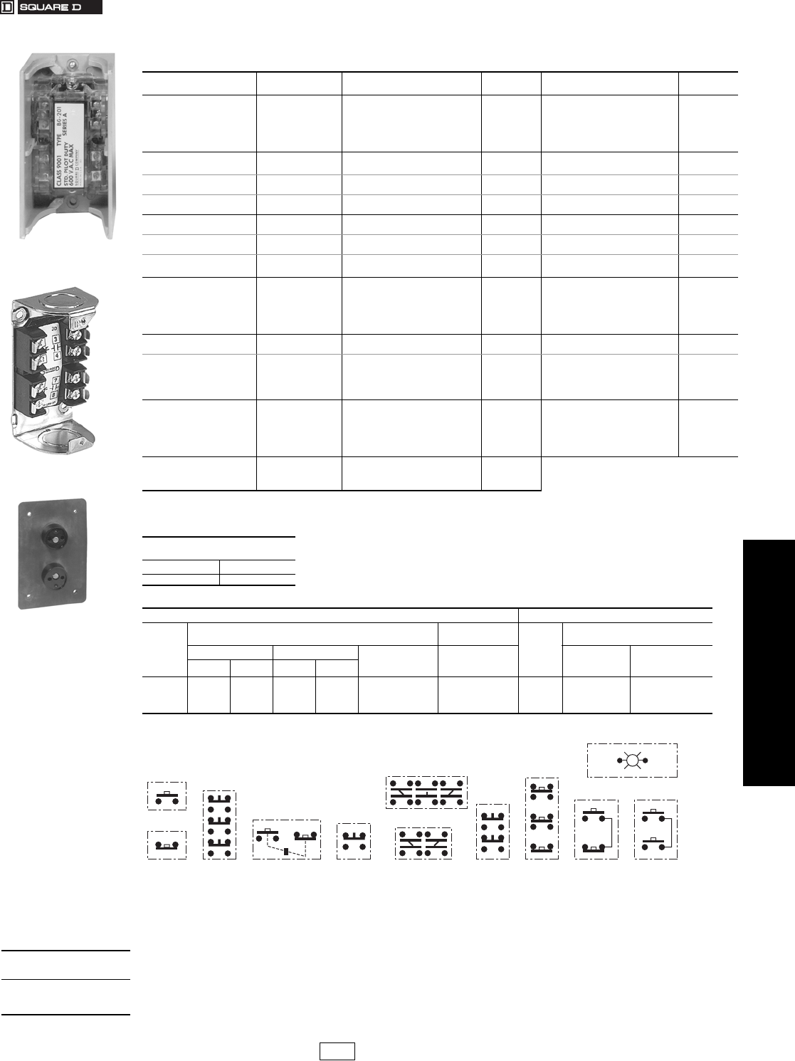
www.us.schneider-electric.com
FOR CURRENT INFORMATION
19 PUSH BUTTONS AND
OPERATOR INTERFACES
© 2007 Schneider Electric
All Rights Reserved 19-101
Control Stations and
Enclosures
Type B Standard Duty Control Stations—Replacement Parts
Class 9001 / Refer to Catalog 9001CT0001
Note: Contact block assemblies for all Type BG stations include cover and contact block. Replacement contact block assemblies and terminal block wiring
receptacles for push buttons have provision for 1 N.O. & 1 N.C. circuit on each button. Unneeded circuits need not be wired.
aOrder separate legend plates, if required, from listing on page 19-100.
Contact Symbols
Table 19.304: Replacement Interiors For Type B Standard Duty Push Button Stations
For Control Station
Types
Contact
Symbol
Contact Block Assembly q
Type $ Price Terminal Block Wiring Receptacle
Type $ Price
BF101–BF107 16 BOC107 26.10 BFB107 28.50
BF111–BF114 19 or 17 BOC114 26.10 BFB114 28.50
BF121–BF123 121 BOC123 98.00 BFB123 28.50
BF201–BF214 25 BOC214 23.70 BFB214 28.50
BF215–BF218 10 BOC218 52.00 BFB214 28.50
BF221–BF224 7 or 19 & 121 BOC224 156.00 BFB224 42.80
BF225–BF226 17 or 19 & 16 BOC226 38.00 BFB226 42.80
BF301–BF307 8 &
BOC214
BOC107
23.70
26.10 &
BFB214
BFB107
28.50
28.50
BF308–BF309 25
& 121 &
BOC214
BOC123
23.70
98.00 &
BFB214
BFB123
28.50
28.50
BF310–BF313 10 & 121 &
BOC218
BOC123
52.00
98.00 &
BFB214
BFB123
28.50
28.50
BF314–BF315 17 or 19 & 25 &
BOC214
BOC114
23.70
26.10 &
BFB214
BFB114
28.50
28.50
BG101–BG107 16 BGC107 26.10 BGB107 28.50
BG111–BG114 17 or 19 BGC114 26.10 BGB114 28.50
BG121–BG123 121 BGC123 98.00 BGB123 28.50
BG201–BG214 25 BGC214 23.70 BGB214 28.50
BG215–BG218 10 BGC218 52.00 BGB214 28.50
BG221–BG224 17 or 19 & 121 BGC224 156.00 BGB224 42.80
BG225–BG226 17 or 19 & 16 BGC226 38.00 BGB226 42.80
BG301–BG307
BG316–BG326 8BGC307 26.10 BGB307 57.00
BG308–BG309 25 & 121 BGC309 141.00 BGB309 57.00
BG310–BG313 10 & 121 BGC313 161.00 BGB309 57.00
BG314–BG315 17 or 19 & 25 BGC315 49.80 BGB315 57.00
BR101–BR107 16 BOC107 26.10 BFB107 28.50
BR202–BR214 25 BOC214 23.70 BFB214 28.50
BR215–BR219 10 BOC218 52.00 BFB214 28.50
BW101–BW107 16 BOC107 26.10 BFB107 28.50
BW202–BW214 25 BOC214 23.70 BFB214 28.50
BW215–BW218 10 BOC218 52.00 BFB214 28.50
BW146–BW159 16 BOC360 84.00
BW240–BW260 25 BOC361 84.00
BW255–BW258 10 BOC362 84.00
“C” Shaped Mounting Bracket
for 9001BR Interior
Catalog Number $ Price
3110112001 5.80
Table 19.305: Electrical Contact Ratings
AC—NEMA B600 DC—NEMA P600
Vol ts
Inductive
35% Power Factor
Resistive
75% Power Factor
Volt s
Inductive and Resistive
Make Break Continuous
Carrying
Amperes
Make, Break and
Continuous
Carrying Amperes
Make and Break
Amperes
Continuous
Carrying Amperes
AVAAVA
120
240
480
600
30.5
15
7.5
6
3600
3600
3600
3600
3.75
1.5
.75
.6
360
360
360
360
5
5
5
5
5
5
5
5
120
240
600
1.1
0.55
0.2
5
5
5
Type BGC214
(Type BGC contact block
assemblies include cover.)
Type BGB214
BOC361
10
17
1916
1
38 25 109 145 146
121
120 V Com
When ordering,
please specify:
•Quantity
•Class Number
•Type or Catalog Number
CP1 Discount
Schedule
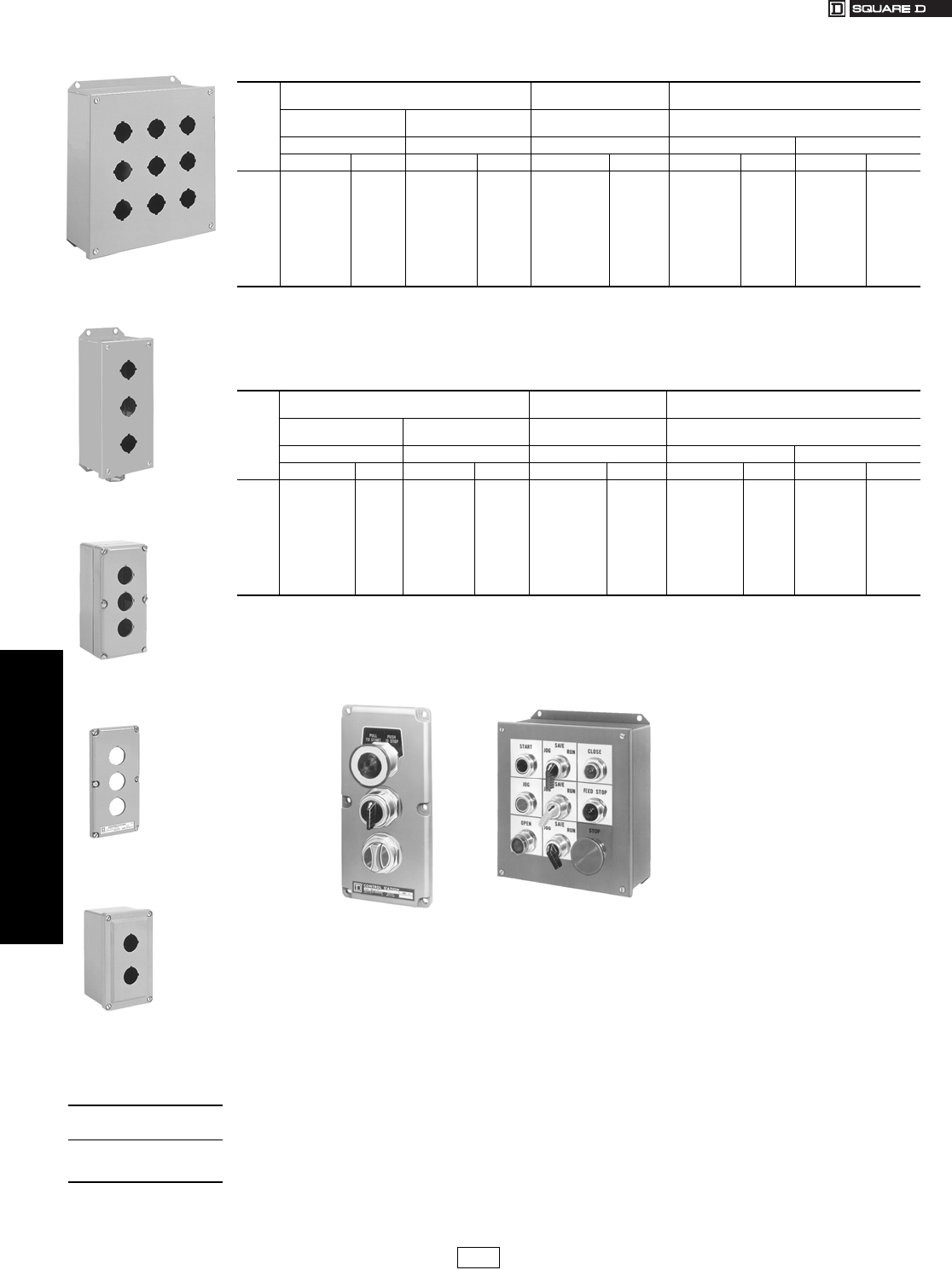
19-102 © 2007 Schneider Electric
All Rights Reserved
www.us.schneider-electric.com
FOR CURRENT INFORMATION
19 PUSH BUTTONS AND
OPERATOR INTERFACES
Control Stations and
Enclosures
Type KY and SKY 30 mm Industrial Duty Enclosures
Class 9001 / Refer to Catalog 9001CT0001
These catalog numbers include only the enclosure. A complete, assembled control station is the enclosure plus all
control units to be installed. Orders must be accompanied by a key sheet (M-7687) or a sketch showing all control
units in their desired locations. Specify the marking on the nameplates for the enclosure. The standard nameplate size
is 1.69 in. (43 mm) by 0.5 in. (13 mm). It has a black field with white letters.
aType K Series A through Series G operators are rated NEMA 1, 3, 12, and 13. Type K Series H operators are rated UL Types 1, 3, 4, 6, 12 and 13 /
NEMA 1, 3, 4, 6, 12, and 13. Type SK operators are rated UL Types 4, 4X, 13 / NEMA 4, 4X, 13.
bOnly KN200 series legend plates will fit upright on these enclosures with their long axis vertical.
cFor machine cavity mounting. Pull box not available.
dType KN1, KN6 and KN7 series legend plates will not fit on these enclosures.
Note: For closing plates, see page 19-83.
Table 19.306: Enclosures Only (For Customer Assembly)
No.
of
Units
UL Types 1, 3 and 13/NEMA 1, 3 and 13 UL Types 1, 3, 4 and 13
NEMA 1, 3, 4 and 13 a
UL Types 1, 3, 4, 4X and 13
NEMA 1, 3, 4, 4X and 13 a
Surface
Mounting
Flush Mounting
without Pullbox c d
Surface
Mounting Surface Mounting
Sheet Steel Die Cast Zinc Die Cast Zinc dStainless Steel (304) Polymeric (Plastic)
Type $ Price Type $ Price Type $ Price Type $ Price Type $ Price
1
2
3
4
6
9
12
16
20
25
30
KYAF1
KYAF2
KYAF3
KYAF4
KYAF6
KYAF9
KYAF12
KYAF16
KYAF20
KYAF25
KYAF30
95.00
105.00
123.00
152.00
191.00
248.00
333.00
428.00
531.00
654.00
783.00
KZ11
KZ21b
KZ31b
KZ41b
KZ6
KZ9
KZ12
KZ16
Not Available
Not Available
Not Available
57.00
57.00
66.00
95.00
134.00
180.00
257.00
351.00
—
—
—
KY1
KY2b
KY3b
KY4b
KY6
Not Available
KY12
KY16
Not Available
Not Available
Not Available
95.00
105.00
123.00
152.00
191.00
—
333.00
428.00
—
—
—
KYSS1
KYSS2
KYSS3
KYSS4
KYSS6
KYSS9
KYSS12
KYSS16
KYSS20
KYSS25
KYSS30
171.00
180.00
248.00
323.00
476.00
588.00
713.00
941.00
1044.00
1329.00
1566.00
SKY1
SKY2
SKY3
SKY4
SKY6
SKY9
SKY12
SKY16
SKY20
SKY25
Not Available
114.00
134.00
152.00
179.00
362.00
476.00
546.00
617.00
713.00
831.00
—
Table 19.307: Custom Built Control Stations
No.
of
Units
UL Types 1, 3 and 13/NEMA 1, 3 and 13 UL Types 1, 3, 4 and 13
NEMA 1, 3, 4 and 13 a
UL Types 1, 3, 4, 4X and 13
NEMA 1, 3, 4, 4X and 13 a
Surface
Mounting
Flush Mounting
without Pullbox c d
Surface
Mounting Surface Mounting
Sheet Steel Die Cast Zinc Die Cast Zinc dStainless Steel (304) Polymeric (Plastic)
Type $ Price Type $ Price Type $ Price Type $ Price Type $ Price
1
2
3
4
6
9
12
16
20
25
30
KYAF100
KYAF200
KYAF300
KYAF400
KYAF600
KYAF900
KYAF1200
KYAF1600
KYAF2000
KYAF2500
KYAF3000
95.00
105.00
123.00
152.00
191.00
248.00
333.00
428.00
531.00
654.00
783.00
KZ110
KZ210b
KZ310b
KZ410b
KZ60
KZ90
KZ120
KZ160
Not Available
Not Available
Not Available
57.00
57.00
66.00
95.00
134.00
180.00
257.00
351.00
—
—
—
KY10
KY20b
KY30b
KY40b
KY60
Not Available
KY120
KY160
Not Available
Not Available
Not Available
95.00
105.00
123.00
152.00
191.00
—
333.00
428.00
—
—
—
KYSS100
KYSS200
KYSS300
KYSS400
KYSS600
KYSS900
KYSS1200
KYSS1600
KYSS2000
KYSS2500
KYSS3000
171.00
180.00
248.00
323.00
476.00
588.00
713.00
941.00
1044.00
1329.00
1566.00
SKY100
SKY200
SKY300
SKY400
SKY600
SKY900
SKY1200
SKY1600
SKY2000
SKY2500
Not Available
114.00
134.00
152.00
179.00
362.00
476.00
546.00
617.00
713.00
831.00
—
Type KYAF9
Type KYSS3
Type KY3
Type KZ31
Type SKY2
Type KYAF900
Type KZ310
When ordering,
please specify:
•Quantity
•Class Number
•Type or Catalog Number
CP1 Discount
Schedule
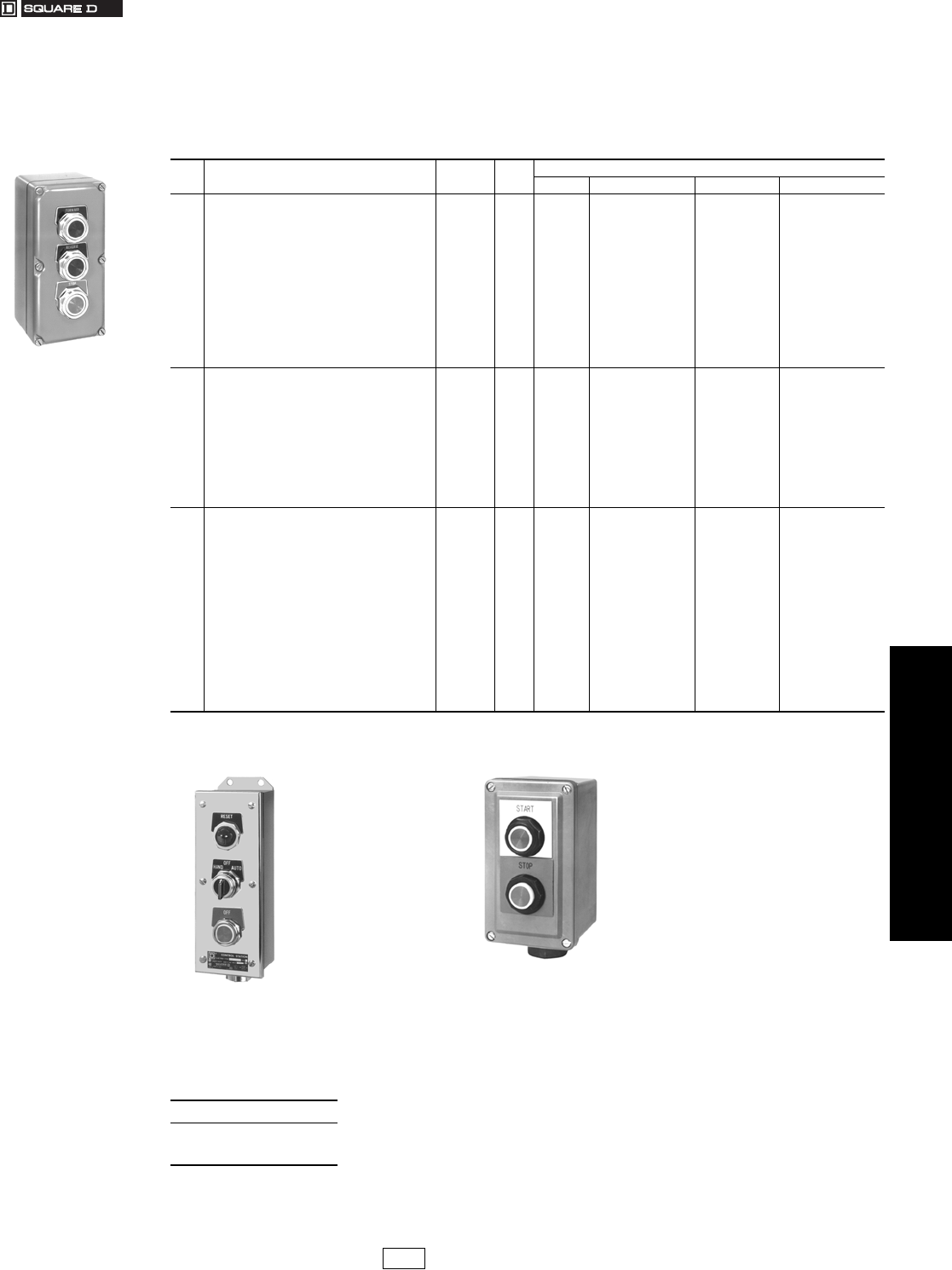
www.us.schneider-electric.com
FOR CURRENT INFORMATION
19 PUSH BUTTONS AND
OPERATOR INTERFACES
© 2007 Schneider Electric
All Rights Reserved 19-103
Control Stations and
Enclosures
Type KY 30 mm Control Stations
Class 9001 / Refer to Catalog 9001CT0001
Control Stations
Enclosures have sufficient depth to accommodate two contact blocks in tandem (total of four blocks) on non-illuminated
operators and two contact blocks side-by-side on illuminated operators.
aControl stations are UL Listed for use in areas classified as Class II Division 2 Group G and Class III.
bControl station consists of components that are UL Listed for use in Class I, Division 2, Groups A, B, C or D.
Note: Dimensions see catalog 9001CT0001
Type KYSS300 and SKY201 . . . . . . . . . . . . . . . . . . . . . . . . . . . .page 19-104
Standard Assembled Control Stations . . . . . . . . . . . . page 19-103 to 19-104
Custom Assembled Control Stations . . . . . . . . . . . . . . . . . . . . . .page 19-102
Table 19.308: Assembled Control Stations—
UL Types 1, 3, 4 and 13/NEMA 1, 3, 4 and 13 a Die Cast Zinc Enclosures
No of
Units
Legend Plate Marking
And Features Type $ Price Consists of
Enclosure Operators Contact Blocks Legend Plates
1
Hand-Off-Auto (Selector Switch)
Hand-Off-Auto (Sel. Switch) (With Sealed Contacts)
Jog-Run (Selector Switch)
Off-On (Selector Switch)
Off-On (Selector Switch) (With Sealed Contacts)
KYK111
KYK121 b
KYK18
KYK110
KYK122 b
162.00
228.00
162.00
162.00
228.00
KY1
KY1
KY1
KY1
KY1
KS43B
KS43B
KS11B
KS11B
KS11B
KA1
KA51
KA1
KA1
KA51
KN260
KN260
KN242
KN244
KN244
Red 120 Vac Pilot Light
Start
Start (With Sealed Contacts)
Start (Mushroom Button)
Stop
Stop (Mushroom Button)
KYK120 b
KYK11
KYK125 b
KYK12
KYK13
KYK14
180.00
152.00
219.00
180.00
152.00
180.00
KY1
KY1
KY1
KY1
KY1
KY1
KP1R31
KR1B
KR1B
KR4B
KR1R
KR4R
—
KA1
KA51
KA1
KA1
KA1
—
KN201
KN201
KN201
KN202
KN202
Stop (With Lockout)
Stop (With Sealed Contacts and Lockout)
Stop Mushroom (With Sealed Contacts and Lockout)
To Stop—Break Glass
To Stop—Break Glass (Red Enclosure)
KYK15
KYK124 b
KYK123 b
KYK116
KYK117
180.00
248.00
276.00
219.00
219.00
KY1
KY1
KY1
KY1
KY1S1
KR3R,K4
KR3R,K4
KR4R,K4
K15
K15
KA1
KA51
KA51
KA1
KA1
KN202
KN202
KN202
KN799RP
KN799RP
2
Forward-Reverse
Jog-Stop (Lockout on Stop)
On-Off
On-Off (With Sealed Contacts)
On-Off (Maintained Contact)
Open-Close
KYK24
KYK224
KYK218
KYK222 b
KYK221
KYK26
219.00
248.00
219.00
351.00
219.00
219.00
KY2
KY2
KY2
KY2
KY2
KY2
KR1B,KR1B
KR1B,KR3R,K4
KR1B,KR3R
KR1B,KR3R
KR11GR
KR1B,KR1B
KA1,KA1
KA1,KA1
KA1,KA1
KA51,KA51
KA1
KA1,KA1
KN206,KN207
KN218,KN202
KN203,KN204
KN203,KN204
KN203,KN204
KN209,KN208
Start-Stop
Start-Stop (With Sealed Contacts)
Start-Stop (Lockout on Stop)
Start-Stop (Maintained Contact)
Start-Stop (With Maintained Sealed Contacts)
Start-Stop (Mushroom on Stop)
Up-Down
KYK21
KYK223 b
KYK23
KYK27
KYK220 b
KYK22
KYK25
219.00
351.00
248.00
219.00
285.00
248.00
219.00
KY2
KY2
KY2
KY2
KY2
KY2
KY2
KR1B,KR3R
KR1B,KR3R
KR1B,KR3R,K4
KR11GR
KR11GR
KR1B,KR4R
KR1B,KR1B
KA1,KA1
KA51,KA51
KA1,KA1
KA1
KA51
KA1,KA1
KA1,KA1
KN201,KN202
KN201,KN202
KN201,KN202
KN201,KN202
KN201,KN202
KN201,KN202
KN211,KN210
3
Forward-Reverse-Start-Stop
Forward-Reverse-Stop
Forward-Reverse-Stop (Lockout on Stop)
Forward-Reverse-Stop (With Sealed Contacts and
Lockout on Stop)
High-Low-Stop
KYK35
KYK31
KYK326
KYK322 b
KYK34
305.00
294.00
323.00
522.00
294.00
KY3
KY3
KY3
KY3
KY3
KS11B,KR1B,KR3R
KR1B,KR1B,KR3R
KR1B,KR1B,KR3R,K4
KR1B,KR1B,KR3R,K4
KR1B,KR1B,KR3R
KA1,KA1,KA1
KA1,KA1,KA1
KA1,KA1,KA1
KA51,KA51,KA51
KA1,KA1,KA1
KN239,KN201,KN202
KN206,KN207,KN202
KN206,KN207,KN202
KN206,KN207,KN202
KN214,KN215,KN202
Jog/Run-Start-Stop
Open-Close-Stop
Open-Close-Stop (Lockout on Stop)
Open-Close-Stop (With Seated Contacts and
Lockout on Stop)
Red 120 Vac Pilot Light-Start-Stop
KYK36
KYK33
KYK327
KYK323 b
KYK317
305.00
294.00
323.00
522.00
314.00
KY3
KY3
KY3
KY3
KY3
KS11B,KR1B,KR3R
KR1B,KR1B,KR3R
KR1B,KR1B,KR3R,K4
KR1B,KR1B,KR3R,K4
KP1R31,KR1B,KR3R
KA1,KA1,KA1
KA1,KA1,KA1
KA1,KA1,KA1
KA51,KA51,KA51
KA2,KA3
KN242,KN201,KN202
KN209,KN208,KN202
KN209,KN208,KN202
KN209,KN208,KN202
KN200,KN201,KN202
Red 120 Vac Pilot Light-Start-Stop
(With Sealed Contacts)
Red 120 Vac/dc Pilot Light-Start-Stop
Up-Down-Stop
Up-Down-Stop (Lockout on Stop)
Up-Down-Stop (With Sealed Contacts and
Lockout on Stop)
KYK321 b
KYK324
KYK32
KYK325
KYK328 b
456.00
323.00
294.00
323.00
522.00
KY3
KY3
KY3
KY3
KY3
KP1R31,KR1B,KR3R
KP38R31,KR1B,KR3R
KR1B,KR1B,KR3R
KR1B,KR1B,KR3R,K4
KR1B,KR1B,KR3R,K4
KA51,KA51
KA1,KA1
KA1,KA1,KA1
KA1,KA1,KA1
KA51,KA51,KA51
KN200,KN201,KN202
KN200,KN201,KN202
KN211,KN210,KN202
KN211,KN210,KN202
KN211,KN210,KN202
When ordering, please specify:
•Quantity
•Class Number
•Type or Catalog Number
Type KYK31
Type SKY201
Type KYSS300
CP1 Discount
Schedule
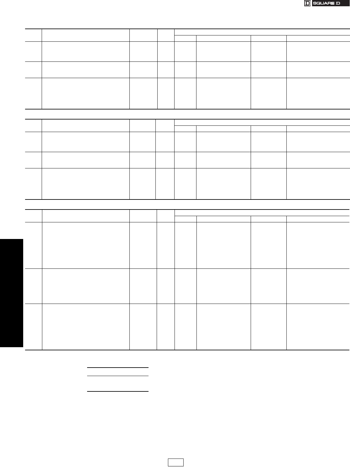
19-104 © 2007 Schneider Electric
All Rights Reserved
www.us.schneider-electric.com
FOR CURRENT INFORMATION
19 PUSH BUTTONS AND
OPERATOR INTERFACES
Control Stations and
Enclosures
Type KY and SKY 30 mm Control Stations
Class 9001 / Refer to Catalog 9001CT0001
aControl Stations are UL Listed for use in areas classified as Class II Division 2 Group G and Class III.
bControl Stations are UL Listed for use in areas classified as Class I Division 2 Groups A, B, C and D.
Table 19.309: Assembled Control Stations—UL Types 1, 3, 4, and 13/NEMA 1, 3, 4 and 13—Stainless Steel (304) a
No. of
Units
Legend Plate Marking
and Features Type $ Price Consists of
Enclosure Operators Contact Blocks Legend Plates
1
Start
Stop
Stop (Lockout)
Off/On (Selector Switch)
Hand/Off/Auto (Selector Switch)
KYSS101
KYSS103
KYSS105
KYSS110
KYSS111
228.00
213.00
261.00
237.00
237.00
KYSS1
KYSS1
KYSS1
KYSS1
KYSS1
KR1B
KR1B
KR3R with K5
KS11B
KS43B
KA1
KA3
KA3
KA1
KA1
KN101WP
KN102RP
KN102RP
KN144WP
KN160WP
2
Start/Stop
Start/Stop (Lockout on Stop)
Up/Down
Start/Stop (Maintained Contact)
KYSS201
KYSS203
KYSS205
KYSS210
281.00
327.00
294.00
294.00
KYSS2
KYSS2
KYSS2
KYSS2
KR1B, KR3R
KR1B, KR3R with K5
KR1B, KR1B
KR11U
KA1, KA3
KA1, KA3
KA1, KA1
KA1, KA1
KN101WP, KN102RP
KN101WP, KN102WP
KN111WP, KN110WP
KN101WP, KN102WP
3
Forward/Reverse/Stop
Up/Down/Stop
Open/Close/Stop
High/Low/Stop
Forward/Reverse/Stop (Lockout on Stop)
Up/Down/Stop (Lockout on Stop)
Open/Close/Stop (Lockout on Stop)
High/Low/Stop (Lockout on Stop)
KYSS301
KYSS302
KYSS303
KYSS304
KYSS308
KYSS309
KYSS310
KYSS311
404.00
404.00
404.00
404.00
452.00
452.00
452.00
452.00
KYSS3
KYSS3
KYSS3
KYSS3
KYSS3
KYSS3
KYSS3
KYSS3
KR1B, KR1B, KR3R
KR1B, KR1B, KR3R
KR1B, KR1B, KR3R
KR1B, KR1B, KR3R
KR1B, KR1B, KR3R w/K5
KR1B, KR1B, KR3R w/K5
KR1B, KR1B,KR3R w/K5
KR1B, KR1B, KR3R w/K5
KA1, KA1, KA3
KA1, KA1, KA3
KA1, KA1, KA3
KA1, KA1, KA3
KA1, KA1, KA3
KA1, KA1, KA3
KA1, KA1, KA3
KA1, KA1, KA3
KN106WP, KN107WP, KN102RP
KN111WP, KN110WP, KN102RP
KN109WP, KN108WP, KN102RP
KN114WP, KN115WP, KN102RP
KN106WP, KN107WP, KN102RP
KN111WP, KN110WP, KN102RP
KN109WP, KN108WP, KN102RP
KN114WP, KN115WP, KN102RP
Table 19.310: Assembled Control Stations—UL Types 1, 3, 4, 4X and 13/NEMA 1, 3, 4, 4X, and 13—Stainless Steel (304) a
No. of
Units
Legend Plate Marking
and Features Type $ Price Consists of
Enclosure Operators Contact Blocks Legend Plates
1
Start
Stop
Stop (Lockout)
Off/On (Selector Switch)
Hand/Off/Auto (Selector Switch)
KYSK101
KYSK103
KYSK105
KYSK110
KYSK111
228.00
213.00
261.00
237.00
237.00
KYSS1
KYSS1
KYSS1
KYSS1
KYSS1
SKR1B
SKR3R
SKR3R with K5
SKS11B
SKS43B
KA1
KA3
KA3
KA1
KA1
KN101WP
KN102RP
KN102RP
KN144WP
KN160WP
2
Start/Stop
Start/Stop (Lockout on Stop)
Up/Down
Start/Stop (Maintained Contact)
KYSK201
KYSK203
KYSK205
KYSK210
281.00
327.00
294.00
294.00
KYSS2
KYSS2
KYSS2
KYSS2
SKR1B, SKR3R
SKR1B, SKR3R with K5
SKR1B, SKR1B
SKR11U
KA1, KA3
KA1, KA3
KA1, KA1
KA1, KA1
KN101WP, KN102RP
KN101WP, KN102WP
KN111WP, KN110WP
KN101WP, KN102WP
3
Forward/Reverse/Stop
Up/Down/Stop
Open/Close/Stop
High/Low/Stop
Forward/Reverse/Stop (Lockout on Stop)
Up/Down/Stop (Lockout on Stop)
Open/Close/Stop (Lockout on Stop)
High/Low/Stop (Lockout on Stop)
KYSK301
KYSK302
KYSK303
KYSK304
KYSK308
KYSK309
KYSK310
KYSK311
404.00
404.00
404.00
404.00
452.00
452.00
452.00
452.00
KYSS3
KYSS3
KYSS3
KYSS3
KYSS3
KYSS3
KYSS3
KYSS3
SKR1B, SKR1B, SKR3R
SKR1B, SKR1B, SKR3R
SKR1B, SKR1B, SKR3R
SKR1B, SKR1B, SKR3R
SKR1B, SKR1B, SKR3R w/K5
SKR1B, SKR1B, SKR3R w/K5
SKR1B, SKR1B, SKR3R w/K5
SKR1B, SKR1B, SKR3R w/K5
KA1, KA1, KA3
KA1, KA1, KA3
KA1, KA1, KA3
KA1, KA1, KA3
KA1, KA1, KA3
KA1, KA1, KA3
KA1, KA1, KA3
KA1, KA1, KA3
KN106WP, KN107WP, KN102RP
KN111WP, KN110WP, KN102RP
KN109WP, KN108WP, KN102RP
KN114WP, KN115WP, KN102RP
KN106WP, KN107WP, KN102RP
KN111WP, KN110WP, KN102RP
KN109WP, KN108WP, KN102RP
KN114WP, KN115WP, KN102RP
Table 19.311: Assembled Control Stations —UL Types 1, 3, 4, 4X and 13/NEMA 1, 3, 4, 4X, and 13—Polymeric (Plastic) a
No. of
Units
Legend Plate Marking
and Features Type $ Price Consists of
Enclosure Operators Contact Blocks Legend Plates
1
Hand-Off-Auto (Sel. Switch with Sealed Contacts)
Hand-Off-Auto (Selector Switch)
Jog
Man-Auto (Selector Switch)
Off-On (Selector Switch with Sealed Contacts)
Off-On (Selector Switch)
Start
Start (With Sealed Contacts)
Stop
Stop (With Lockout)
Stop (With Sealed Contacts and Lockout)
SKY121b
SKY111
SKY107
SKY108
SKY122 b
SKY110
SKY101
SKY125 b
SKY103
SKY105
SKY124 b
249.00
180.00
171.00
180.00
248.00
180.00
171.00
237.00
156.00
204.00
285.00
SKY1
SKY1
SKY1
SKY1
SKY1
SKY1
SKY1
SKY1
SKY1
SKY1
SKY1
SKS43B
SKS43B
SKR1B
SKS11B
SKS11B
SKS11B
SKR1B
SKR1B
SKR3R
SKR3R, K5
SKR3R, K5
KA51
KA1
KA1
KA1
KA51
KA1
KA1
KA51
KA3
KA3
KA51
KN160WP
KN160WP
KN118WP
KN143WP
KN144WP
KN144WP
KN101WP
KN101WP
KN102RP
KN102RP
KN102RP
2
Forward-Reverse
On-Off
Open-Close
Start-Stop
Start-Stop (Lockout on Stop)
Start-Stop (With Maintained Sealed Contacts)
Start-Stop (With Sealed Contacts)
Up-Down
SKY204
SKY222 b
SKY206
SKY201
SKY203
SKY220 b
SKY223 b
SKY205
248.00
380.00
248.00
233.00
281.00
314.00
380.00
248.00
SKY2
SKY2
SKY2
SKY2
SKY2
SKY2
SKY2
SKY2
SKR1B, SKR1B
SKR1B, SKR3R
SKR1B, SKR1B
SKR1B, SKR3R
SKR1B, SKR1R, K5
SKR11GR
SKR1B, SKR3R
SKR1B, SKR1B
KA1, KA1
KA51, KA51
KA1, KA1
KA1, KA3
KA1, KA3
KA51
KA51, KA51
KA1, KA1
KN106WP, KN107WP
KN103WP, KN104RP
KN109WP, KN108WP
KN101WP, KN102RP
KN101WP, KN102RP
KN101WP, KN102RP
KN101WP, KN102RP
KN111WP, KN110WP
3
Forward-Reverse-Stop
Forward-Reverse-Stop (With Sealed Contacts
and Lockout on Stop)
High-Low-Stop
Open-Close-Stop
Open-Close-Stop (With Sealed Contacts)
Red 120 Vac Pilot Light-Start-Stop
Start-Jog-Stop
Up-Down-Stop
Up-Down-Stop (With Sealed Contacts
and Lockout on Stop)
SKY301
SKY322 b
SKY304
SKY303
SKY323 b
SKY315A
SKY305
SKY302
SKY328 b
309.00
522.00
309.00
309.00
522.00
354.00
309.00
309.00
522.00
SKY3
SKY3
SKY3
SKY3
SKY3
SKY3
SKY3
SKY3
SKY3
SKR1B, SKR1B, SKR3R
SKR1B, SKR1B, SKR3R
SKR1B, SKR1B, SKR3R
SKR1B, SKR1B, SKR3R
SKR1B, SKR1B, SKR3R
SKP1R31, SKR1B, SKR3R
SKR1B, SKR1B, SKR3R
SKR1B, SKR1B, SKR3R
SKR1B, SKR1B, SKR3R
KA1, KA1, KA3
KA51, KA51, KA51
KA1, KA1, KA3
KA1, KA1, KA3
KA51, KA51, KA51
KA1, KA3
KA1, KA1, KA3
KA1, KA1, KA3
KA51, KA51, KA51
KN106WP, KN107WP, KN102RP
KN106WP, KN107WP, KN102RP
KN114WP, KN115WP, KN102RP
KN109WP, KN108WP, KN102RP
KN109WP, KN108WP, KN102RP
KN101WP, KN102RP
KN101WP, KN118WP, KN102RP
KN111WP, KN110WP, KN102RP
KN111WP, KN110WP, KN102RP
When ordering, please specify:
•Quantity
•Class Number
•Type or Catalog Number
CP1 Discount
Schedule
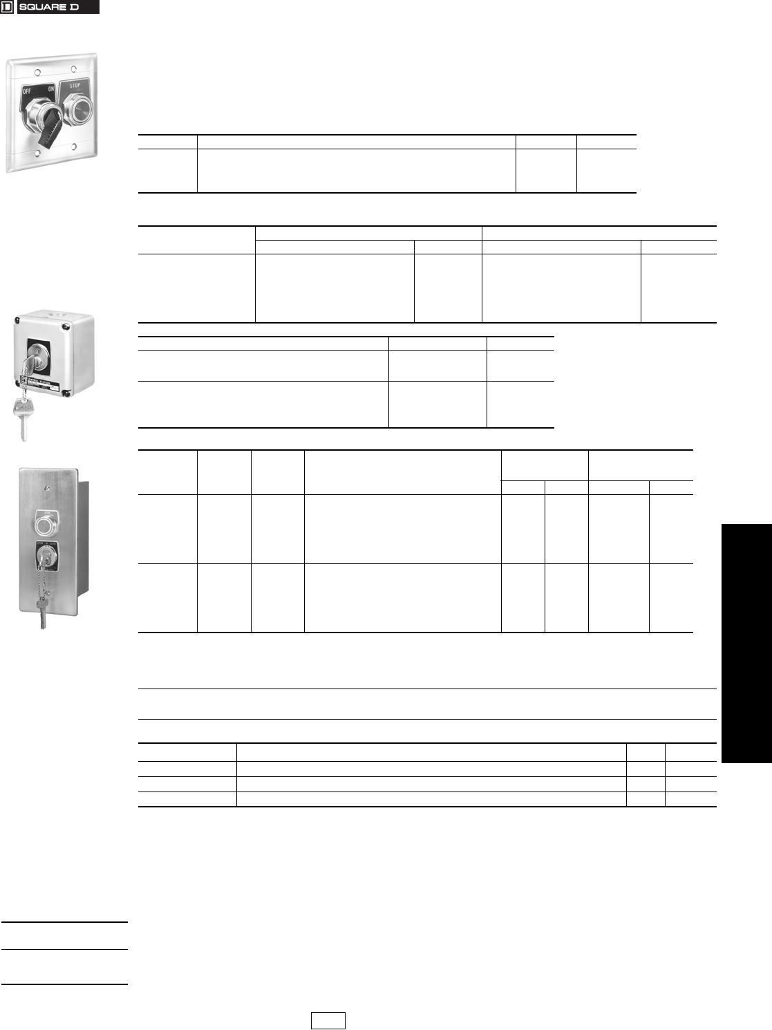
www.us.schneider-electric.com
FOR CURRENT INFORMATION
19 PUSH BUTTONS AND
OPERATOR INTERFACES
© 2007 Schneider Electric
All Rights Reserved 19-105
Control Stations and
Enclosures
Type K Security Control Stations & Stainless Steel Flush Plates
Class 9001 / Refer to Catalog 9001CT0001
These flush plates accept Type K, SK, and KX 30 mm operators and contact blocks and may be used with a standard 2 in.
x 3 in. general purpose switch box. A 2.5 in. deep box should be used with two Type K contact blocks mounted side by
side. If two Type K contact blocks mounted in tandem are needed, a 3.5 in. deep box should be used. Although
oiltight/watertight operators are used, an assembled station using the flush plates is not oiltight/watertight. The kits
include the stainless steel flush plate, cover screws and a set of liners. The liners must be used to maintain electrical
clearance.
NOTE: Replacement enclosures are not sold. Replacement core or cylinders are not sold.
Electrical Ratings
Key Operator: One Class 9007 Type AO2 snap switch is used for the OPEN position and one snap switch is used for
the CLOSE position. See page 21-4 for electrical ratings of the 9007AO2.
Stop Button: One Class 9001 Type KA1 contact block is used on the optional push button. See page 19-78 for
9001KA1 electrical ratings. (Note: The KA1 contact block has a maximum voltage rating of 300 V (NEMA A300) when
used in the Type KZC station.)
UL Listed File E42259
CNN NKCR
CSA Listed File LR25490 Class 321103
Table 19.312: Stainless Steel (302) NEMA 1 Flush Plates a
No. of Units Description Type $ Price
1 1 Unit flush plate, cover screws, insulating liners K25 19.10
2 2 Unit flush plate, cover screws, insulating liners K26 28.50
3 3 Unit flush plate, cover screws, insulating liners K27 38.00
4 4 Unit flush plate, cover screws, insulating liners K28 57.00
aCenter to center of operators is 1.812 in.
Table 19.313: General Purpose NEMA 1 Flush Mounting Control Station with Pull Box for Type K Control Units
Number of Units Enclosure Only, for Customer Assembly Custom-Built Factory-Assembled Control Stations
Type $ Price Type $ Price
1
2
3
4
5
6
7
8
KZP1
KZP2
KZP3
KZP4
KZP5
KZP6
KZP7
KZP8
123.00
143.00
180.00
191.00
228.00
237.00
314.00
323.00
KZP10
KZP20
KZP30
KZP40
KZP50
KZP60
KZP70
KZP80
123.00
143.00
180.00
191.00
228.00
237.00
314.00
323.00
Special Features Number of Units $ Price
Type 304 Stainless steel flush plate (Form Y242):
Add
1–4
5–8
208.00
265.00
Omit Pull Box (Form Y243):
Deduct
1–2
3–4
5–6
7–8
57.00
77.00
95.00
114.00
Table 19.314: 30 mm Security Control Stations
Description Type of
Cylinder
Cylinder
Finish Special Features
Cast Aluminum
Enclosureb
Satin Chrome Finish
Flush Mounted with Box
(304 Stainless Steel)
Type $ Price Type $ Price
Spring Return
Key
Operator
Only
Corbin
Ya l e
Best
Best
Best
Best
Schlage
Sargent
Chrome
Brass
Chrome
Chrome
Chrome
Chrome
Chrome
Chrome
Complete with Corec(6 Tumbler Pins)
Lock Cylinder Only—Core Omittedd(6 Tumbler Pins)
Complete with Corec(7 Tumbler Pins)
Lock Cylinder Only—Core Omittedd(7 Tumbler Pins)
Maximum Security Cylinder
KY198
KY199
KY197
KY196
KY195
KY194
KY193
KY192
356.00
356.00
498.00
428.00
498.00
428.00
356.00
594.00
KZC198
KZC199
KZC197
KZC196
KZC195
KZC194
KZC193
KZC192
452.00
452.00
594.00
522.00
594.00
522.00
452.00
689.00
Spring Return
Key
Operator
with
Stop
Button
Corbin
Ya l e
Best
Best
Best
Best
Schlage
Sargent
Chrome
Brass
Chrome
Chrome
Chrome
Chrome
Chrome
Chrome
Complete with Corec(6 Tumbler Pins)
Lock Cylinder Only—Core Omittedd(6 Tumbler Pins)
Complete with Corec(7 Tumbler Pins)
Lock Cylinder Only—Core Omittedd(7 Tumbler Pins)
6 Tumbler Pins
Maximum Security Cylinder
KY298
KY299
KY297
KY296
KY295
KY294
KY293
KY292
428.00
428.00
570.00
498.00
570.00
498.00
428.00
665.00
KZC298
KZC299
KZC297
KZC296
KZC295
KZC294
KZC293
KZC292
522.00
522.00
665.00
594.00
665.00
594.00
522.00
759.00
bMeets NEMA 3R requirements.
cWhen Best Lock stations are supplied with core, customer must contact local Best Lock representative to change core.
dWhen Best Lock stations are supplied without core, customers must purchase core separately from Best Lock, and customers can subsequently
change core at their convenience.
Refer to catalog
9001CT0001 if:
•Master keying is required.
•Station is to be keyed to a specific key number.
•Extra keys are required.
•Keying several stations alike is required.
•Nonstandard legend plates are required.
•A specific type of keyway is required.
Table 19.315: Repair Parts—Replacement or Duplicate Keys
Type Source $ Price Delivery
Corbin, Yale, or Schlage Schneider Electric, local distributor, hardware store, or lock shop that duplicates keys. 9.50 8 weeks
Best Must purchase from local Best Lock representative. — —
Sargent Schneider Electric. Keys supplied with our security control station are registered to Schneider Electric. 23.70 8 weeks
Two Unit
Type KZC299
Type KY192
When ordering,
please specify:
•Quantity
•Class Number
•Type or Catalog Number
CP1 Discount
Schedule
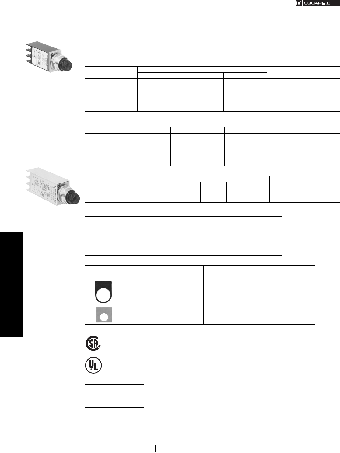
19-106 © 2007 Schneider Electric
All Rights Reserved
www.us.schneider-electric.com
FOR CURRENT INFORMATION
19 PUSH BUTTONS AND
OPERATOR INTERFACES
Pilot Lights Type J, NEMA 4, 13 Compact Pilot Lights
Class 9001 / Refer to Catalog 9001CT0001
Standard, Push-To-Test, and Remote Test Pilot Lights
Class 9001 Type J compact pilot lights are designed to be mounted in a 0.69 in. (11⁄16 in.) diameter mounting hole.
Each terminal accepts up to two 14 AWG wires (CU only). Type J compact pilot lights meet NEMA 4 (watertight) and
NEMA 13 (oiltight). Type JT push-to-test pilot lights have contacts built into the encapsulated body. Type JTR remote
test pilot lights have dual inputs for one push remote testing—all you need is a push button with a current rating equal
to or greater than the total lamp draw. Type JTR remote test pilot lights can also be energized from two separate input
signals of the same voltage and polarity. This is done by wiring the “test” terminal to the second input signal.
aOther voltages are available. Refer to Catalog 9001CT0001.
Table 19.316: Standard Pilot Light a
Style/Voltage Color Cap Lamp Replacement
Lamp $ Price
None $ Price Red Green Yellow $ Price
Transformer,
110–120 V, 50–60 Hz JP1 95.00 JP1R29 JP1G29 JP1Y29 102.00 6.3 V, 0.15 A 2550101020 8.30
Incandescent, 120 Vac/dc JP38 77.00 JP38R29 JP38G29 JP38Y29 84.00 120 V, 0.015 A 2550101040 8.40
Incandescent, 24–28 Vac/dc JP35 77.00 JP35R29 JP35G29 JP35Y29 84.00 28 V, 0.040 A 2550101024 8.30
LED, 24–28 Vac — — JP35LRR29 JP35LGG29 JP35LYY29 102.00 28 V, 0.03 A — —
LED, 24–28 Vdc — — JP35DRR29 JP35DGG29 JP35DYY29 102.00 28 V, 0.03 A — —
LED, 120 Vac — — JP38LRR29 JP38LGG29 JP38LYY29 102.00 28 V, 0.03 A — —
Table 19.317: Push-To-Test Pilot Light a
Style/Voltage Color Cap Lamp Replacement
Lamp $ Price
None $ Price Red Green Yellow $ Price
Transformer,
110–120 V, 50–60 Hz JT1 123.00 JT1R29 JT1G29 JT1Y29 130.00 6.3 V, 0.15 A 2550101020 8.30
Incandescent, 120 Vac/dc JT38 105.00 JT38R29 JT38G29 JT38Y29 112.00 120 V, 0.015 A 2550101040 8.40
Incandescent, 24-28 Vac/dc JT35 105.00 JT35R29 JT35G29 JT35Y29 112.00 28 V, 0.040 A 2550101024 8.30
LED, 24–28 Vac — — JT35LRR29 JT35LGG29 JT35LYY29 130.00 28 V, 0.03 A — —
LED, 24–28 Vdc — — JT35DRR29 JT35DGG29 JT35DYY29 130.00 28 V, 0.03 A — —
LED, 120 Vac — — JT38LRR29 JT38LGG29 JT38LYY29 130.00 28 V, 0.03 A — —
Table 19.318: Remote Test Pilot Light a
Style/Voltage Color Cap Lamp Replacement
Lamp $ Price
None $ Price Red Green Yellow $ Price
Incandescent, 120 Vac JTR38 123.00 JTR38R29 JTR38G29 JTR38Y29 130.00 120 V, 0.015 A 2550101040 8.40
Incandescent, 24–28 Vac JTR35 123.00 JTR35R29 JTR35G29 JTR35Y29 130.00 28 V, 0.040 A 2550101024 8.30
LED, 24–28 Vac — — JTR35LRR29 JTR35LGG29 JTR35LYY29 150.00 28 V, 0.03 A — —
Table 19.319: Color Caps, Class 9001 Type J
Color Replacement Color Caps
Plastic $ Price Glass $ Price
Red
Green
Amber
Blue
Clear
White
Yellow
R29
G29
A29
L29
C29
W29
Y29
6.60
R26
G26
A26
L26
C26
W26
Y26
6.60
Table 19.320: Legend Plates
Description
Maximum
Number of
Lines
Maximum
Number of
Characters
Type $ Price
Blank Black Field
Red Field
28
JN100
JN100R 2.90
Special Marking
(Specify Marking)
Black Field
Red Field
JN199
JN199R 12.30
Blank Aluminum Field
216
JN700 2.90
Special Marking
(Specify Marking) Aluminum Field JN799 12.30
File 25490C
Guide 184 N 13.1U
File E42259
Guide NKCR
When ordering, please specify:
•Quantity
•Class Number
•Type or Catalog Number
Type JP1R29
Type JTR1R29
CP1 Discount
Schedule Modified
4/20/09
www.us.schneider-electric.com
For the most up-to-date information
19 PUSH BUTTONS AND
OPERATOR INTERFACES
© 2007 Schneider Electric
All Rights Reserved 19-107
Pilot Lights Type O, NEMA 13—30 mm; XVL LED Accessories—22 mm
Class 9001 / Refer to Catalog 9001CT0001
Class 9001 Type O, NEMA 13 Pilot Lights
aQuick connects (2.8 x 0.5 mm).
bScrew termination.
Table 19.321: Instrument Type Incandescent Pilot Lights—Type O NEMA 13
Vol tag e
AC/DC
Avg. Current
(A)
Red
Lens
Type
Green
Lens
Type
Amber
Lens
Type
Clear
Lens
Type
Yellow
Lens
Type
White
Lens
Type
Fluted
Blue Lens
Type
$ Price
12 V .170 OR12 OG12 OA12 OC12 OY12 OW12 FB12
19.1024 V .073 OR24 OG24 OA24 OC24 OY24 OW24 FB24
120 V .025 OR120 OG120 OA120 OC120 OY120 OW120 FB120
Table 19.322: Replacement Lamps—Class 9001, Type O
Voltage Sylvania
Lamp Number
Square D
Part Number $ Price
12 V 12PSB 2550105003
11.0024 V 24PSB 2550105004
120 V 120PSB 2550105005
XVL Miniature LED
Table 19.323: Specifications
Conforming to standards IEC 337-2, NF C 63-140, VDE 0660-200
Degree of protection IP40 (IP65 with seal) conforming to IEC 529 and NF C 20-010
Current consumption 25 mA
Cabling XVLA1••, XVLA2••: tags for 2.8 x 0.5 mm Faston connectors, also for soldered connections.
XVLA3••: threaded connectors, clamping, capacity: min. 1 x 0.2 mm2, max. 1 x 1.5 mm2
Table 19.324: With Black Bezel, Raised LED
Description Supply Voltage DC Color Catalog Number $ Price Each
Ø 8 mm a
with integral ballast resistor
and reverse polarity protection diode
Degree of protection IP40
LED pilot lights Ø 8 mm, with black bezel,
visible LED XVLA1••
5 V
Green XVLA113
16.40
Red XVLA114
Amber XVLA115
12 V
Green XVLA123
Red XVLA124
Amber XVLA125
24 V
Green XVLA133
Red XVLA134
Amber XVLA135
48 V
Green XVLA143
Red XVLA144
Amber XVLA145
Table 19.325: With Integral Lens Cap, Covered LED
Description Supply Voltage DC Color Catalog Number $ Price Each
Ø 8 mma
with integral ballast resistor
and reverse polarity protection diode
Degree of protection IP40
Ø 8 mm, with lens incorporated,
LED XVLA2
5 V
Green XVLA213
16.40
Red XVLA214
Amber XVLA215
12 V
Green XVLA223
Red XVLA224
Amber XVLA225
24 V
Green XVLA233
Red XVLA234
Amber XVLA235
48 V
Green XVLA243
Red XVLA244
Amber XVLA245
Ø 12 mm b
with integral ballast resistor
and reverse polarity protection diode
Degree of protection IP40
Ø 12 mm, with lens incorporated,
LED XVLA3
5 V
Green XVLA313
26.00
Red XVLA314
Amber XVLA315
12 V
Green XVLA323
Red XVLA324
Amber XVLA325
24 V
Green XVLA333
Red XVLA334
Amber XVLA335
48 V
Green XVLA343
Red XVLA344
Amber XVLA345
Table 19.326: Accessories
Description Catalog Number $ Price Each
Tightening tools
(Sold singly)
For Ø 8 mm pilot lights XVLX08 18.60
For Ø 12 mm pilot lights XVLX12 24.00
Seals (IP65)
(Sold in lots of 10)
For Ø 8 mm pilot lights XVLZ911 0.65
For Ø 12 mm pilot lights XVLZ912
When ordering, please specify:
•Quantity
•Class Number (if appropriate)
•Type or Catalog Number
Type O
File E179183 Guide 001X
XVLA1••
XVLA2••
XVLA3••
XVLX••
XVLZ91•
CP1 I Discount
Schedule Modified
4/20/09
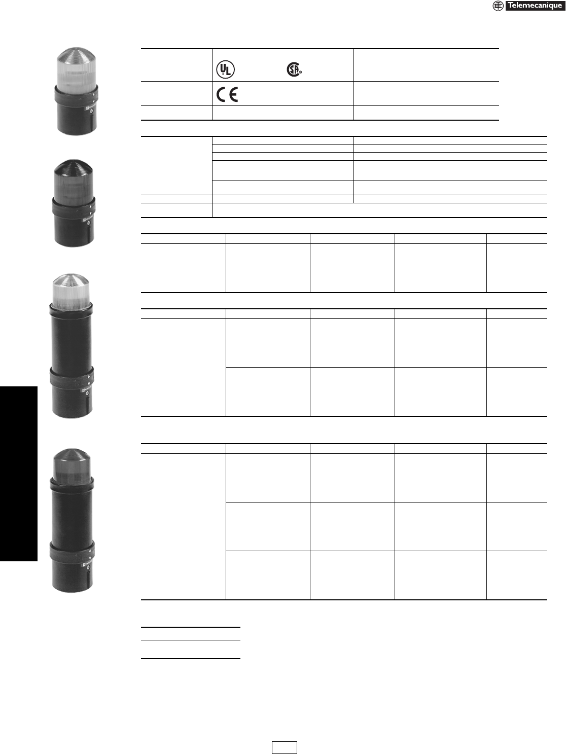
19-108 © 2007 Schneider Electric
All Rights Reserved
www.us.schneider-electric.com
FOR CURRENT INFORMATION
19 PUSH BUTTONS AND
OPERATOR INTERFACES
Illuminated Beacons and
Indicating Banks
XVB—70 mm Diameter
Refer to Catalog 9001CT0001
Note: For bulbs, see page 19-110.
aImportant: Discharge tube elements are not suitable for continuous-operation signaling due to temperature rise caused by the discharge tube.
bFor 5 Joule units, specify XVBL6••, instead of XVBL8•• ($190.00).
Note: There are no replacement lenses for strobes.
Table 19.327: Environment
Approvals
Standard version, CSA, UL
UL E164353 CCN NKCR, CSA LR 44087 Class 3211 03
Conforming to standards IEC/EN 60947-5-1, UL 508, CSA 22.2 No. 14
Degree of protection To IEC 529 and NF C 20-010
To UL 50 and CSA 22.2 No. 94
IP65
Type 1, 4X (indoor), and 12
Table 19.328: Electrical Characteristics
Consumption
LED unit
Steady 24 Vac/dc: < 80 mA; 120–230 Vac: < 30 mA.
Flashing 24 Vac or 24 Vdc: < 40 mA; 120–230 Vac: < 15 mA.
Unit with strobe (on energization)
24 Vac or 24 Vdc: 5 Joule unit: < 430 mA; 10 Joule unit: < 850 mA
120 Vac: 5 Joule unit: < 130 mA; 10 Joule unit: < 260 mA
230 Vac: 5 Joule unit: < 105 mA; 10 Joule unit: < 210 mA
Audible sounder units 12–48 Vac/dc: < 20 mA
120–230 Vac: < 50 mA
Cable size Maximum wire size 1 x 16 AWG (1.5 mm2) with cable end
Te r m i n a l s Screw and captive cable clamp terminals
Torque to 4.4 in-lb (0.5 N•m)
Table 19.329: Illuminated Beacons with Steady Light (2.75 in./70 mm diameter)
Description Light Source and Voltage Color Catalog Number $ Price
Complete unit, includes:
1 lens unit
1 base unit (direct or tube
mounting)
Bulb (10 W max)
not included
250 V max
Green XVBL33
76.00
Red XVBL34
Amber XVBL35
Blue XVBL36
Clear XVBL37
Ye l l o w XVBL38
Table 19.330: Illuminated Beacons with Flashing Light (2.75 in./70 mm diameter)
Description Light Source and Voltage Color Catalog Number $ Price
Complete unit, includes:
1 lens unit
1 base unit (direct or tube
mounting)
Bulb (10 W max)
not included
24 Vac
24–48 Vdc
Green XVBL4B3
129.00
Red XVBL4B4
Amber XVBL4B5
Blue XVBL4B6
Clear XVBL4B7
Yellow XVBL4B8
Bulb (10 W max)
not included
48–230 Vac
Green XVBL4M3
129.00
Red XVBL4M4
Amber XVBL4M5
Blue XVBL4M6
Clear XVBL4M7
Yellow XVBL4M8
Table 19.331: Illuminated Beacons with 10 Joule Strobe (2.75 in./70 mm diameter) a
Description Light Source and Voltage Color Catalog Number b$ Price
Complete unit, includes:
1 lens unit
1 base unit (direct or tube
mounting)
Strobe
24 Vac/dc
Green XVBL8B3
244.00
Red XVBL8B4
Amber XVBL8B5
Blue XVBL8B6
Clear XVBL8B7
Yellow XVBL8B8
Strobe
120 Vac
Green XVBL8G3
244.00
Red XVBL8G4
Amber XVBL8G5
Blue XVBL8G6
Clear XVBL8G7
Yellow XVBL8G8
Strobe
230 Vac
Green XVBL8M3
244.00
Red XVBL8M4
Amber XVBL8M5
Blue XVBL8M6
Clear XVBL8M7
Yellow XVBL8M8
When ordering, please specify:
•Quantity
•Catalog Number
File E164353
CCN NKCR File LR 44087
Class 3211 03
Marked
XVBL3•
XVBL4B•
XVBL6B•
5 Joule
XVBL8B•
10 Joule
XV Discount
Schedule
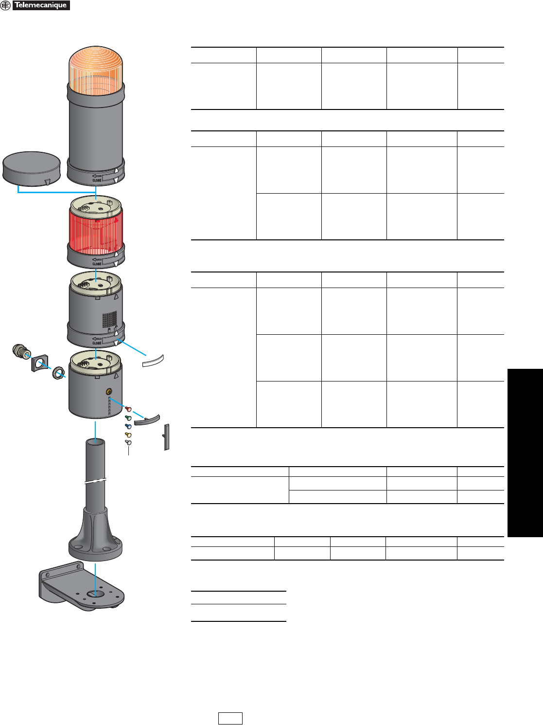
www.us.schneider-electric.com
FOR CURRENT INFORMATION
19 PUSH BUTTONS AND
OPERATOR INTERFACES
© 2007 Schneider Electric
All Rights Reserved 19-109
Illuminated Beacons and
Indicating Banks
XVB Components—70 mm Diameter
Refer to Catalog 9001CT0001
Note: For bulbs, see page 19-110.
aFor 5 Joule units, specify XVBC6••, instead of XVBC8•• ($155.00).
Note: There are no replacement lenses units for the XVBC strobe.
Table 19.332: Illuminated Lens Units with Steady Light (2.75 in./70 mm diameter)
Description Light Source and
Volt age Color Catalog Number $ Price
Illuminated lens unit
Bulb (10 W max)
not included
250 Vac/dc max
Green XVBC33
40.40
Red XVBC34
Orange XVBC35
Blue XVBC36
Clear XVBC37
Yellow XVBC38
Table 19.333: Illuminated Lens Unit with Flashing Light (2.75 in./70 mm diameter)
Description Light Source and
Vol tag e Color Catalog Number $ Price
Illuminated lens unit
Bulb (10 W max)
not included
24 Vac
24–48 Vdc
Green XVBC4B3
94.00
Red XVBC4B4
Orange XVBC4B5
Blue XVBC4B6
Clear XVBC4B7
Ye l l o w XVBC4B8
Bulb (10 W max)
not included
48–230 Vac
Green XVBC4M3
94.00
Red XVBC4M4
Orange XVBC4M5
Blue XVBC4M6
Clear XVBC4M7
Ye l l o w XVBC4M8
Table 19.334: Illuminated Lens Units with 10 Joule Strobe (2.75 in./70 mm diameter)
Description Light Source and
Vol tag e Color Catalog Number a$ Price
Illuminated lens units
Strobe
24 Vac/dc
Green XVBC8B3
209.00
Red XVBC8B4
Orange XVBC8B5
Blue XVBC8B6
Clear XVBC8B7
Ye l l o w XVBC8B8
Strobe
120 Vac
Green XVBC8G3
209.00
Red XVBC8G4
Orange XVBC8G5
Blue XVBC8G6
Clear XVBC8G7
Ye l l o w XVBC8G8
Strobe
230 Vac
Green XVBC8M3
209.00
Red XVBC8M4
Orange XVBC8M5
Blue XVBC8M6
Clear XVBC8M7
Yellow XVBC8M8
Table 19.335: Audible Sounder Units (2.75 in./70 mm diameter)
Description Supply Voltage Catalog Number $ Price
Sounder unit
90 dB at 1 m 12–48 Vac/dc XVBC9B 145.00
Adjustable from 75–90 dB
Continuous or intermittent modes 120–230 Vac XVBC9M 228.00
Table 19.336: Base Units + Cover
(for direct or tube mounting, 2.75 in. / 70 mm diameter)
Description For use with Type Catalog Number $ Price
Base unit + cover
for bottom or side cable entry Banks Standard XVBC21 40.40
When ordering, please specify:
•Quantity
•Catalog Number
XVBC6
XVB081
XVBC
XVBC9
XVBC1 XVBC07
XVBCY2
XVBC22
XVBC23
XVBZ0
XVBC12
XVB081 +
XVBC07 =
XVBC21
XV Discount
Schedule
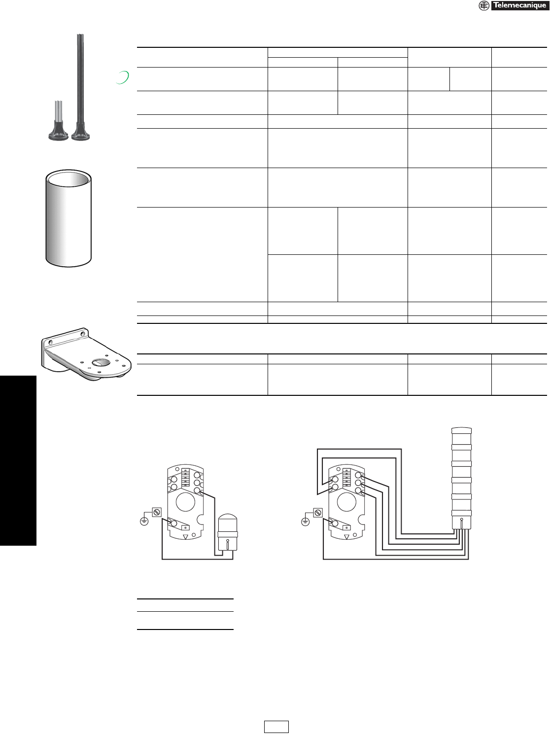
19-110 © 2007 Schneider Electric
All Rights Reserved
www.us.schneider-electric.com
FOR CURRENT INFORMATION
19 PUSH BUTTONS AND
OPERATOR INTERFACES
Illuminated Beacons and
Indicating Banks
XVB Accessories—70 mm
Refer to Catalog 9001CT0001
Wiring Diagrams, Base Units
Table 19.337: Accessories Common to Beacon and Indicating Banks
Description Characteristics Catalog Number $ Price
in. mm
Black tube with integral black plastic mounting base
4.72 120 XVBZ02 XVBZ02A a 12.50
15.75 400 XVBZ03 XVBZ03A a 25.00
31.50 800 XVBZ04 XVBZ04A a 50.00
Support tube concealment cover
3.94 100 XVBC020 7.80
15.75 400 XVBC030 23.00
31.50 800 XVBC040 41.40
Wall mount bracket For direct mounting on base unit or with tulip
XVBC11 + tube XVBC0• XVBC12 32.30
Incandescent bulbs
bayonet type BA 15d, 10 W
12 Vac/dc DL1BLJ
5.40
24 Vac/dc DL1BLB
48 Vac/dc DL1BLE
120 Vac/dc DL1BLG
230 Vac/dc DL1BLM
Incandescent bulbs
bayonet type BA 15d, 7 W
12 Vac/dc DL1BEJ
5.40
24 Vac/dc DL1BEB
48 Vac/dc DL1BEE
120 Vac/dc DL1BEG
230 Vac/dc DL1BEM
LEDs
bayonet type BA 15d
(sold singly)
b
24 Vac/dc
White DL1BDB1
72.00
Green DL1BDB3
Red DL1BDB4
Blue DL1BDB6
Ye l l o w DL1BDB8
Amber DL1BDB5
120 Vac
White DL1BDG1
72.00
Green DL1BDG3
Red DL1BDG4
Blue DL1BDG6
Ye l l o w DL1BDG8
Amber DL1BDG5
Adapter
for side entry through base unit
With CM12 (p. 13.5) cable gland, for cable size
of 0.4 to 0.55 in. (10 to 14 mm) diameter XVBC14 5.20
Conduit adapter 1/2 in. NPT (for customer supplied tubing) XVBC00 2.10
aAluminum tube.
bFor 240 Vac, replace the B or G in the catalog number with M—for example, DL1BDM1. For flashing LEDs, refer to catalog 9001CT0001.
Table 19.338: Accessories Specific to Indicating Banks
Description Characteristics Catalog Number $ Price
Set of colored markers 6 colors XVBC22 2.10
Set of 5 legend holders Identification of stacked units on base XVBC23 8.30
Sheet of 85 legends for legend holder (XVBC23) Identification of stacked units on base XVBCY1 3.10
Sheet of 52 legends Identification of stacked units on locking ring XVBCY2 3.10
When ordering, please specify:
•Quantity
•Catalog Number
XVBC020
XVBC12
XVBZ0
New!
4
2
5
3
1
C
1
4
2
5
3
1
C
1
2
3
4
5
Screw terminals
Torque to 4.4 in-lb (0.5 N•m)
2 x 16 AWG (1.5 mm2)
1 x 14 AWG (2.5 mm2)
XV Discount
Schedule
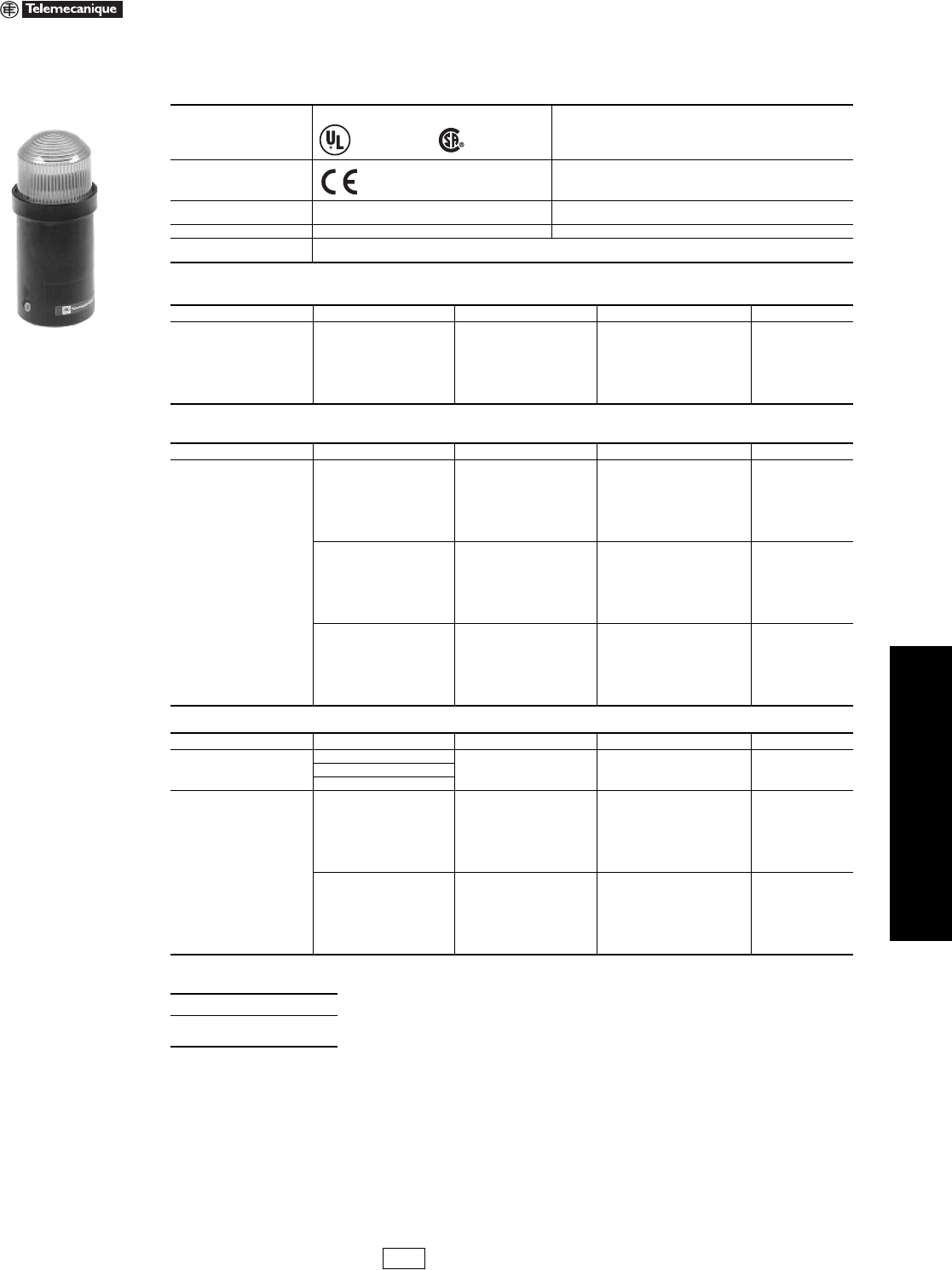
www.us.schneider-electric.com
FOR CURRENT INFORMATION
19 PUSH BUTTONS AND
OPERATOR INTERFACES
© 2007 Schneider Electric
All Rights Reserved 19-111
Illuminated Beacons and
Indicating Banks
XVDLS Mini Beacons, 45 mm Diameter
Refer to Catalog 9001CT0001
The XVDLS miniature illuminated beacons are designed for short distance signalling applications.
Note: The XVDL miniature illuminated beacon is designed for a maximum 5 W bulb.
aBulb type for use with direct supply: BA 15d base fitting, incandescent. Maximum lamp size is 5 W.
Table 19.339: Environment
Approvals
Standard version, CSA, UL
UL E164353 CCN NKCR, CSA LR 44087 Class 3211-03
Conforming to standards IEC/EN 60947-5-1, UL 508, CSA C22.2 No. 14
Degree of protection To UL 50, CSA C22.2 No. 94
To IEC 529 and NF C 20-010
Ty p e 1
IP40
Cable size Maximum wire size 1 x 16 AWG (1.5 mm2) with cable end
Te r m i n a l s Screw and captive cable clamp terminals
Torque to 4.4 in-lb (0.5 N•m)
Table 19.340: Illuminated Beacons with Steady Light (1.75 in./45 mm diameter)
Description Light Source Color Catalog Number $ Price
Complete unit, includes:
1 lens unit
1 base unit (direct mounting)
Incandescent bulb (5 W max) a
not included
250 V max
Green XVDLS33
33.10
Red XVDLS34
Orange XVDLS35
Blue XVDLS36
Clear XVDLS37
Ye l l o w XVDLS38
Table 19.341: Illuminated Beacons with 0.5 Joule Strobe (1.75 in./45 mm diameter)
Description Light Source Color Catalog Number $ Price
Complete unit, includes:
1 lens unit
1 base unit (direct mounting)
Strobe
24 Vac/dc
Green XVDLS6B3
83.00
Red XVDLS6B4
Orange XVDLS6B5
Blue XVDLS6B6
Clear XVDLS6B7
Ye l l o w XVDLS6B8
Strobe
120 Vac
Green XVDLS6G3
83.00
Red XVDLS6G4
Orange XVDLS6G5
Blue XVDLS6G6
Clear XVDLS6G7
Ye l l o w XVDLS6G8
Strobe
230 Vac
Green XVDLS6M3
83.00
Red XVDLS6M4
Orange XVDLS6M5
Blue XVDLS6M6
Clear XVDLS6M7
Ye l l o w XVDLS6M8
Table 19.342: Accessories
Description Supply Voltage Color Catalog Number $ Price
Incandescent bulbs
bayonet type BA 15d
(sold in lots of 10)
24 Vac/dc, 4 watts — DL1BEBS
4.10120 Vac/dc, 5 watts — DL1BEGS
230 Vac/dc, 5 watts — DL1BEMS
LEDs
bayonet type BA 15d
(sold singly)
b
24 Vac/dc
White DL1BDB1
72.00
Green DL1BDB3
Red DL1BDB4
Blue DL1BDB6
Yellow-orange DL1BDB8
Amber DL1BDB5
120 Vac
White DL1BDG1
72.00
Green DL1BDG3
Red DL1BDG4
Blue DL1BDG6
Yellow-orange DL1BDG8
Amber DL1BDG5
bFor 240 Vac, replace the B or G in the catalog number with M—for example, DL1BDM1. For flashing LEDs, refer to catalog 9001CT0001.
When ordering, please specify:
•Quantity
•Catalog Number
XVDLS••
File E164353
CCN NKCR File LR 44087
Class 3211 03
Marked
XV Discount
Schedule
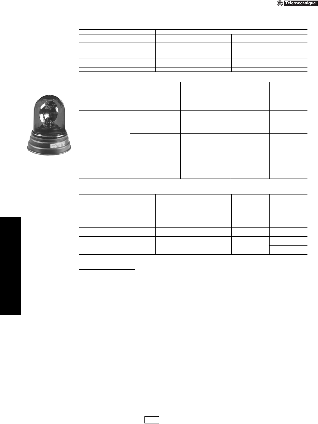
19-112 © 2007 Schneider Electric
All Rights Reserved
www.us.schneider-electric.com
FOR CURRENT INFORMATION
19 PUSH BUTTONS AND
OPERATOR INTERFACES
Illuminated Beacons and
Indicating Banks
XVR Rotating Lights
Refer to Catalog 9001CT0001
.
Table 19.343: Environment
Approvals Standard version, CSA, UL (Pending)
Degree of protection To IEC 529 and NF C 20-010
To UL 50 and CSA 22.2 No. 94
IP65
Type 4X (indoor)
Consumption
Halogen 24 Vac/dc: < 3100 mA
Incandescent
24 Vac/dc: < 1050 mA
120 Vac: < 210 mA
230 Vac: < 110 mA
Bulb type Halogen H1, maximum power 70 W
Incandescent Bayonet type BA 15d, maximum power 25 W
Wire size Maximum wire size 1 x 16 AWG (1.5 mm2) with cable end
Table 19.344: Rotating Mirror Beacon (6.5 in./165 mm diameter)
Light Source Supply Voltage Color Catalog Number $ Price
Halogen bulb
70 W 24 Vac/dc
Green XVR1B93
185.00
Red XVR1B94
Orange XVR1B95
Blue XVR1B96
Yellow XVR1B98
Incandescent bulb
25 W
24 Vac/dc
Green XVR1B03
168.00
Red XVR1B04
Orange XVR1B05
Blue XVR1B06
Yellow XVR1B08
120 Vac
Green XVR1G03
197.00
Red XVR1G04
Orange XVR1G05
Blue XVR1G06
Yellow XVR1G08
230 Vac
Green XVR1M03
197.00
Red XVR1M04
Orange XVR1M05
Blue XVR1M06
Yellow XVR1M08
Table 19.345: Accessories and Spare Parts
Description Characteristics Catalog Number $ Price
Domed replacement lens unit
Green XVR0153
65.00
Red XVR0154
Orange XVR0155
Blue XVR0156
Yellow XVR0158
Protective grill for domed lens unit — XVR016 21.50
Wall mount bracket for vertical surface — XVR012 21.50
Mounting tulip for tube (1/2" NPT) — XVR013 17.60
Halogen bulbs, H1, 70 W 24 Vac/dc DL1BRBH 39.80
Incandescent bulbs
bayonet type BA 15d, 25 W
(sold in lots of 10)
24 Vac/dc DL1BRB 14.00
120 Vac DL1BRG 14.00
230 Vac DL1BRM 14.10
When ordering, please specify:
•Quantity
•Catalog Number
XVR1•••
XV Discount
Schedule Modified
4/20/09
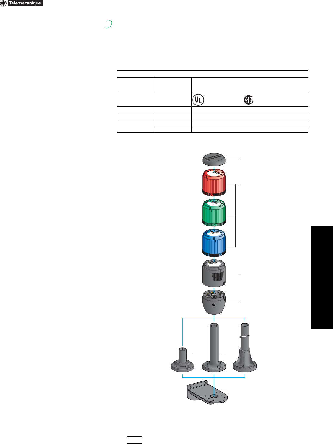
www.us.schneider-electric.com
FOR CURRENT INFORMATION
19 PUSH BUTTONS AND
OPERATOR INTERFACES
© 2007 Schneider Electric
All Rights Reserved 19-113
Illuminated Beacons and
Indicating Banks
XVE 70 mm Indicating Banks
Refer to Catalog 9001CT0408
The indicating banks of the XVE range are designed for remote signalling of the status of a
machine, equipment or specific application, either visually using illuminated units which are
visible throughout 360° or audibly using an 85 dB buzzer.The XVE range provides efficient
signalling (5 colors available), at medium range distances 98.4 ft (30 m), in indoor
environments.
The standard configuration of the indicating banks is NEMA and UL Type 12 (IP 42) degree
of protection, which is sufficient for the majority of indoor applications. Both pre-configured
beacons and indicating banks can be upgraded to IP 54 by using a sealing kit.
Indicating Bank
Table 19.346: Characteristics
Environment
Degree of protection Conforming to IEC
60529, and UL508
•NEMA and UL Type 12 (IP 42) in vertical position
•For all mounting positions using mounting base XVE Z13,
•Only in vertical position for other heights of mounting base
Product certifications
Approvals e
Conformity to standards IEC/EN 60947-1, IEC/EN 60947-5-1
Ambient air
temperature
Storage - 104 to +158 °F (- 40 to +70 °C)
Operation - 75 to +131 °F (- 25 to +55 °C)
New!
File E164353
CCN NKCR
File LR44087
Class 3211 03, and CCC
1
2
3
5 6
8
7
4
The indicating bank is a customer assembled
product using:
1. A snap on cover
2. 1 to 5 colored illuminated units (green, red, orange,
blue or clear) with a choice of 3 types of signalling
(steady, flashing or “strobe”).
3. 1 audible unit.
4. A base unit with terminal block and bottom cable entry.
5. A plastic mounting base, 0.78" (20 mm) high.
6. A plastic mounting base, 3.9" (100 mm) high.
7. An aluminium support tube, black or silver finish,
length: 3.1" (80 mm), 15.7" (400 mm), or 31.5" (800
mm), pre-fitted and glued into a mounting base.
To be ordered separately:
8. Base plate for mounting on vertical support.
XV Discount
Schedule Modified
4/18/09
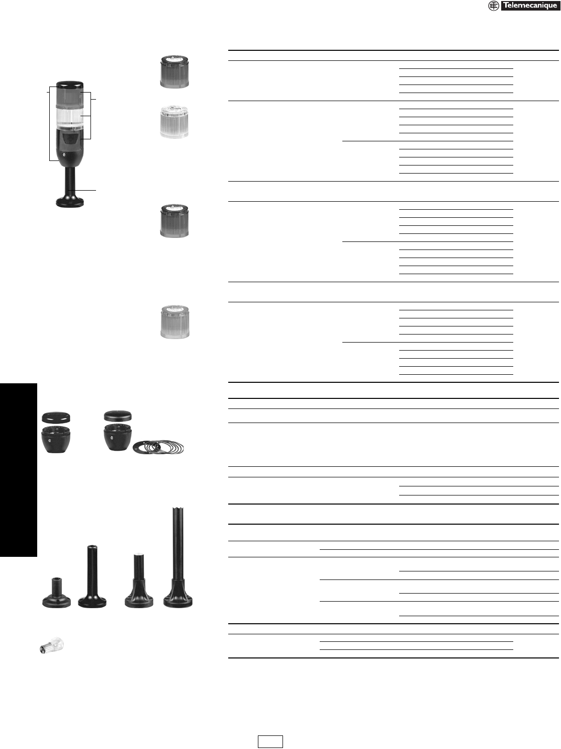
19-114 © 2007 Schneider Electric
All Rights Reserved
www.us.schneider-electric.com
FOR CURRENT INFORMATION
19 PUSH BUTTONS AND
OPERATOR INTERFACES
Illuminated Beacons and
Indicating Banks
XVE 70 mm Indicating Banks
Refer to Catalog 9001CT0408
Composition of an indicating bank:
1. Cover and base unit (+)
2. Illuminated or audible units
(5 units max.) (+)
3. Mounting base
Table 19.347: Illuminated Units with Steady Light
Description Light source Supply voltage Color of lens Catalog Number $ Price
Lens units only for
BA 15d base
fitting bulb
Bulb, not included,
5W max. z 240 Vac/dc max.
Green XVEC33
16.00
Red XVEC34
Orange XVEC35
Blue XVEC36
Clear XVEC37
Illuminated units Integral LED
z 24 Vac/dc
Green XVEC2B3
40.00
Red XVEC2B4
Orange XVEC2B5
Blue XVEC2B6
Clear XVEC2B7
a 120 Vac
Green XVEC2G3
Red XVEC2G4
Orange XVEC2G5
Blue XVEC2G6
Clear XVEC2G7
Table 19.348: Illuminated Units with Flashing LED
Illuminated units Integral LED
z 24 Vac/dc
Green XVEC5B3
60.00
Red XVEC5B4
Orange XVEC5B5
Blue XVEC5B6
Clear XVEC5B7
a 120 Vac
Green XVEC5G3
Red XVEC5G4
Orange XVEC5G5
Blue XVEC5G6
Clear XVEC5G7
Table 19.349: Illuminated Units with Strobe Light
Illuminated units Discharge tube,
1Joule
z 24 Vac/dc
Green XVEC6B3
70.00
Red XVEC6B4
Orange XVEC6B5
Blue XVEC6B6
Clear XVEC6B7
a 120 Vac
Green XVEC6G3
Red XVEC6G4
Orange XVEC6G5
Blue XVEC6G6
Clear XVEC6G7
Table 19.350: Audible Sounder Units, Base Units and Covers
Indicating bank usage Composition
NEMA and UL Type 12
(IP 42) Base unit and cover XVEC21 16.00
Additional protection (IP 54)
Base unit with seal
+ screw mounting cover
+ kit comprising 5 seals for lens units and buzzer
+ 1 seal for mounting base XVE Z13
XVEC21P 20.00
Description Supply Voltage Catalog Number Price
Audible Sounder Units 85dB
24 Vac/dc XVEC9B 60.00
120 Vac XVEC9G 60.00
230 Vac XVEC9M 60.00
Table 19.351: Mounting Components and Bulbs
Description Height under base unit
in. (mm) Color
Plastic mounting bases 0.78 (20) Black XVEZ13 8.00
3.93 (100) Black XVDC02 10.00
Mounting bases
comprising:
Ø 25 mm aluminium
support tube +
black plastic
mounting support
3.15 (80)
Black
aluminium XVBZ02 12.50
Aluminium XVBZ02A 12.50
15.7 (400)
Black
aluminium XVBZ03 25.00
Aluminium XVBZ03A 25.00
31.5 (800)
Black
aluminium XVBZ04 50.00
Aluminium XVBZ04A 50.00
Description Electrical characteristics
Clear incandescent bulbs with
BA 15d base fitting
for lens units type XVE C3p
5 W, z 24 Vac/dc DL1BEBS
4.105 W, z 120 Vac/dc DL1BEGS
5 W, z 230 Vac/dc DL1BEMS
1
3
2XVE C3p
XVE C2ppp
XVE C5ppp
XVE C6ppp
XVE C21 XVE C21P
XVB Z02XVE Z13 XVD C02 XVB Z03
DL1 BEpS
XV Discount
Schedule Modified
4/20/09
www.us.schneider-electric.com
FOR CURRENT INFORMATION
19 PUSH BUTTONS AND
OPERATOR INTERFACES
© 2007 Schneider Electric
All Rights Reserved 19-115
Illuminated Beacons and
Indicating Banks
XVP 50 mm Illuminated Indicating Banks—Components
Refer to Catalog 9001CT0001
Components
Table 19.352: Environment
Approvals
UL Listed, CSA Certified
Conforming to standards IEC/EN 60947-5-1, UL 508
Protective Treatment “TC”
Degree of protection To IEC 60529 and NF C 20-010
To UL 50 and CSA 22.2 No. 94
IP65
Type 1, 12 and 13
Table 19.353: Electrical Characteristics
Consumption
LED unit 24 Vac/dc: < 60 mA; 120–230 Vac: < 20 mA
Steady incandescent bulb 7 W 24 Vac/dc: < 300 mA; 120–230 Vac: 65–35 mA
Flashing 24 Vac or 24 Vdc: < 250 mA; 120–230 Vac: < 30 mA
Unit with strobe (on energization) 24 Vdc: 0.3 Joules, 40 mA; 120 Vac: 0.6 Joules, 20 mA;
230 Vac: 0.6 Joules, 11 mA
Audible sounder units 24 Vdc, 12 mA; 120 Vac, 15 mA; 230 Vac, 15 mA
Cable size Maximum wire size 2 x 16 AWG (1.5 mm2) with cable end
Terminals Torque requirement Removable and captive screw terminals: 4.4 in-lb (0.5 N•m)
Table 19.354: Base Units with Cover (for direct or tube mounting)
Description Color For use with Indicating Banks Catalog Number $ Price
50 mm base unit Black 50 mm diameter only XVPC21
32.0050 mm base unit Off-white 50 mm diameter only XVPC21W
50 mm base unit with ring-tongue compatible terminal 50 mm diameter only XVPC21WR
Table 19.355: Illuminated Lens Units
Description Ring Color Light Source and Voltage Lens Color Catalog Number $ Price
Steady or Flashing
50 mm steady lens unit
(See Table 19.358 on page 19-116 to
select steady or flashing mode)
Black
Bulb (7 W max)
not included
250 V max
Green
Red
Amber
Blue
Clear
Ye l l o w
XVPC33
XVPC34
XVPC35
XVPC36
XVPC37
XVPC38
29.00
Off-white
Bulb (7 W max)
not included
250 V max
Green
Red
Amber
Blue
Clear
Ye l l o w
XVPC33W
XVPC34W
XVPC35W
XVPC36W
XVPC37W
XVPC38W
29.00
Strobe
50 mm strobe lens unit
Black
Strobe 24 Vdc
0.3 Joule
Green
Red
Amber
Blue
Clear
Ye l l o w
XVPC6B3
XVPC6B4
XVPC6B5
XVPC6B6
XVPC6B7
XVPC6B8
124.00
Strobe 120 Vac
0.6 Joule
Green
Red
Amber
Blue
Clear
Ye l l o w
XVPC6G3
XVPC6G4
XVPC6G5
XVPC6G6
XVPC6G7
XVPC6G8
Off-white
Strobe 24 Vdc
0.3 Joule
Green
Red
Amber
Blue
Clear
Ye l l o w
XVPC6B3W
XVPC6B4W
XVPC6B5W
XVPC6B6W
XVPC6B7W
XVPC6B8W
Strobe 120 Vac
0.6 Joule
Green
Red
Amber
Blue
Clear
Ye l l o w
XVPC6G3W
XVPC6G4W
XVPC6G5W
XVPC6G6W
XVPC6G7W
XVPC6G8W
Table 19.356: Audible Sounder Units (must be the top unit)
Description Ring Color Supply Voltage Catalog Number $ Price
50 mm sounder unit
(IP40 NEMA 1)
Ten tone selections,
75–85 dB at 1 m
Black
24 Vdc XVPC09B
104.00
120 Vac XVPC09G
230 Vac XVPC09M
Off-white
24 Vdc XVPC09BW
120 Vac XVPC09GW
230 Vac XVPC09MW
When ordering, please specify:
•Quantity
•Class Number (if appropriate)
•Type or Catalog Number
File E164353
CCN NKCR File LR 44087
Class 3211 03
File E164353
CCN NKCR 2
Marked
XVPC21
Lens Unit
with Black Ring
XVPC09B
XV Discount
Schedule
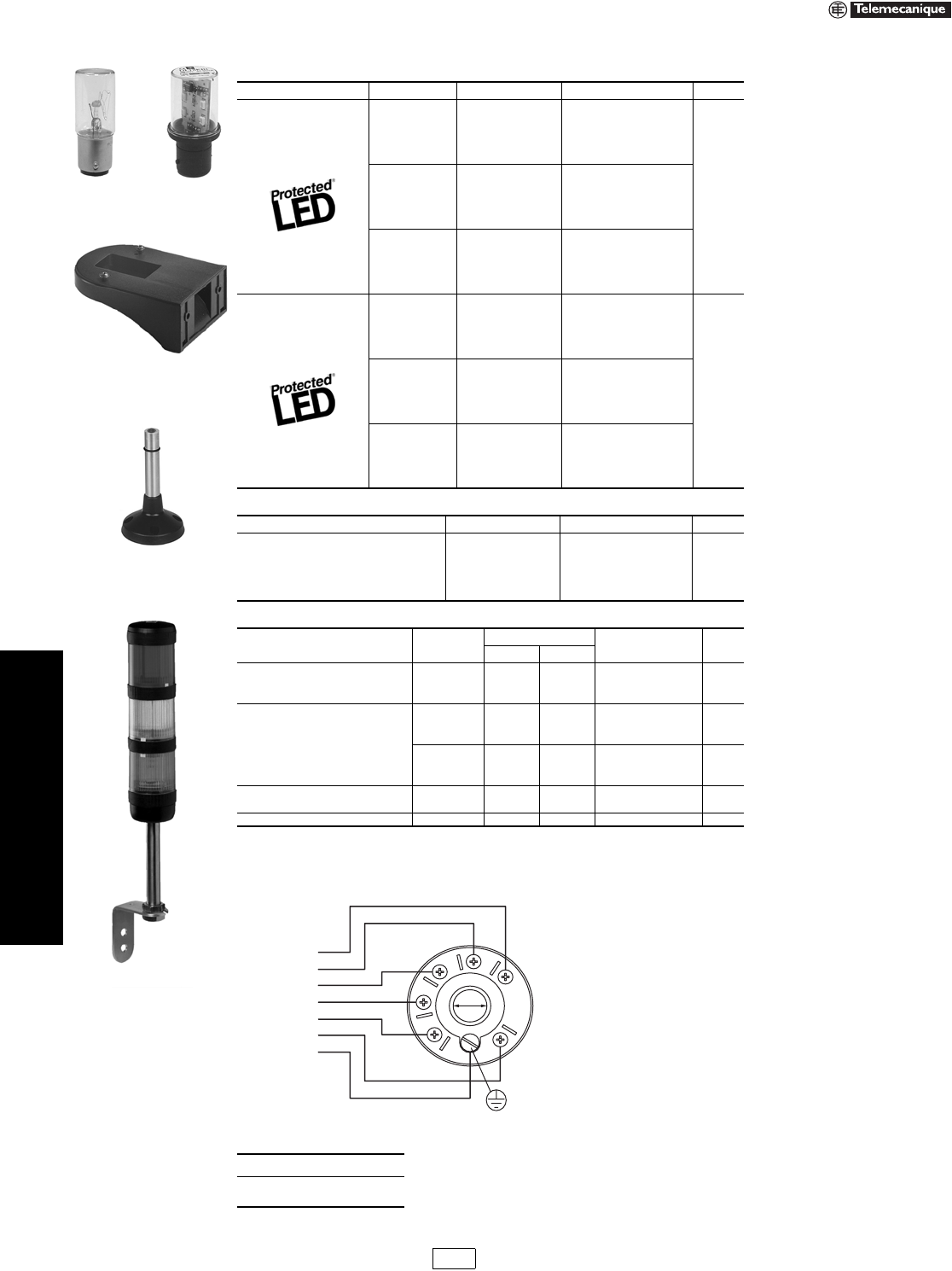
19-116 © 2007 Schneider Electric
All Rights Reserved
www.us.schneider-electric.com
FOR CURRENT INFORMATION
19 PUSH BUTTONS AND
OPERATOR INTERFACES
Illuminated Beacons and
Indicating Banks
XVP 50 mm Illuminated Indicating Banks—Accessories
Refer to Catalog 9001CT0001
Wiring Diagram
Cable Connections, Supply line maximum: 1.5 mm2 (16 AWG)
Table 19.358: LEDs
Description Voltage Color Catalog Number $ Price
Steady-On LEDs
24 Vac/dc
White
Green
Red
Amber
Blue
Ye l l o w
DL1BDB1
DL1BDB3
DL1BDB4
DL1BDB5
DL1BDB6
DL1BDB8
72.00120 Vac
White
Green
Red
Amber
Blue
Ye l l o w
DL1BDG1
DL1BDG3
DL1BDG4
DL1BDG5
DL1BDG6
DL1BDG8
230 Vac
White
Green
Red
Amber
Blue
Ye l l o w
DL1BDM1
DL1BDM3
DL1BDM4
DL1BDM5
DL1BDM6
DL1BDM8
Flashing LEDs
24 Vac/dc
White
Green
Red
Amber
Blue
Ye l l o w
DL1BKB1
DL1BKB3
DL1BKB4
DL1BKB5
DL1BKB6
DL1BKB8
93.00120 Vac
White
Green
Red
Amber
Blue
Ye l l o w
DL1BKG1
DL1BKG3
DL1BKG4
DL1BKG5
DL1BKG6
DL1BKG8
230 Vac
White
Green
Red
Amber
Blue
Ye l l o w
DL1BKM1
DL1BKM3
DL1BKM4
DL1BKM5
DL1BKM6
DL1BKM8
Table 19.359: Incandescent Bulbs
Description Voltage Catalog Number $ Price
Bayonet type BA 15d, 7 W
12 Vac/dc DL1BEJ
5.40
24 Vac/dc DL1BEB
48 Vac/dc DL1BEE
120 Vac/dc DL1BEG
230 Vac/dc DL1BEM
Table 19.360: Accessories
Description Color Characteristics Catalog Number $ Price
IN mm
Threaded tube with bracket Silver
4 100 XVPC02T 21.70
10 250 XVPC03T 26.90
16 400 XVPC04T 32.00
Tube with tulip base
Black
4100 XVPC02 21.70
10 250 XVPC03 32.00
16 400 XVPC04 32.00
Off-white
4100 XVPC02W 26.90
10 250 XVPC03W 26.90
16 400 XVPC04W 32.00
Wall mounting bracket Black — XVPC12 10.40
Off-white — XVPC12W
Bulb mounting and removal tool — — XVPCX13 5.20
When ordering, please specify:
•Quantity
•Catalog Number
DL1BDB1
DL1BEJ
XVPC02
XVPC12
XVPC03T
(With Base and Lenses)
Ø 12
0.47
+/5+/4
+/3
+/2
+/1
–/C
wire 5
wire 4
wire 3
wire 2
wire 1
wire 6
green-yellow
XV Discount
Schedule Modified
4/20/09
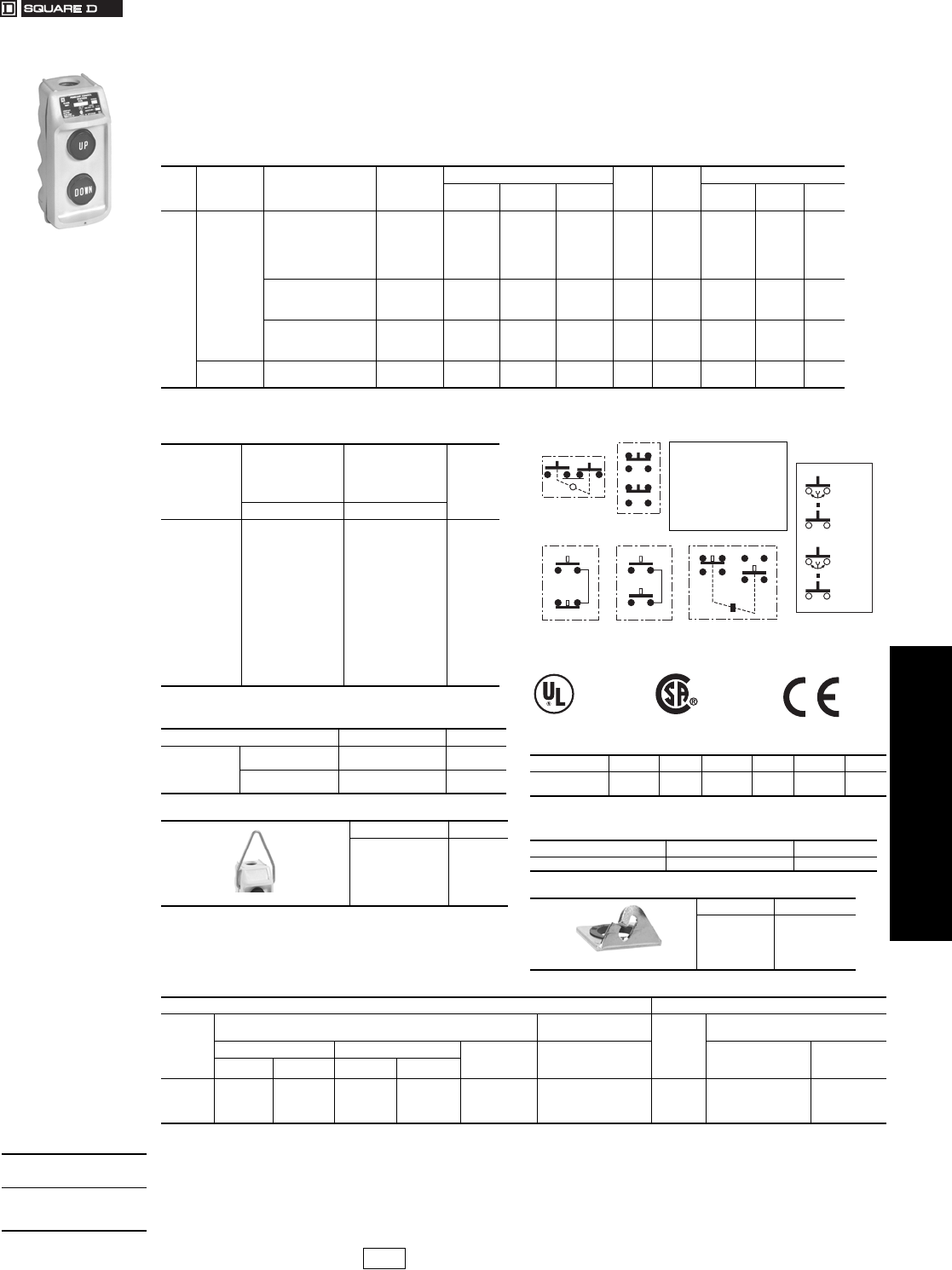
www.us.schneider-electric.com
FOR CURRENT INFORMATION
19 PUSH BUTTONS AND
OPERATOR INTERFACES
© 2007 Schneider Electric
All Rights Reserved 19-117
Pendant Stations Type BW
Class 9001 / Refer to Catalog 9001CT0001
The Class 9001 BW70 and BW80 pendant stations are
used for hoist applications, requiring either single speed or
two speed buttons. The thermoplastic enclosure has a
1/2 in. conduit entrance at top to accept a pendant cable
and has internal strain relief provided as standard. The
stations are rated NEMA 1, 3, 3R, 4 and 4X. The enclosure
is available in three colors. All universal stations have
double circuit blocks (1 N.O./1 N.C.) on each button and
come without legends so they can be assembled to fit the
application. For convenience, push buttons have
interchangeable legend inserts. The complete line is UL
listed and C.S.A. approved.
aMaintained contact
Note: Order must specify quantity of 10 or multiples of 10.
Contact Symbol
Table 19.361: BW70 and BW80 Pendant Stations
No.
of
Units
Description Legend Insert
Markings
Mechanical
Interlock
Enclosure Color
$ Price Contact
Symbol
Replacement Interior
Yellow Black Red 9001
Type
Contact
Symbol $ Price
2
Single
Speed
Up-Down Yes BW72Y BW72B BW72R 84.00 146 BOC368 146 60.00
Forward-Reverse Yes BW73Y BW73B BW73R 84.00 146 BOC368 146 60.00
On-OffaYe s BW74Y BW74B BW74R 113.00 10 BOC358 147 60.00
Start-Stop No BW75Y BW75B BW75R 84.00 145 BOC359 25 60.00
Start-StopaYe s BW76Y BW76B BW76R 113.00 10 BOC358 147 60.00
On-Off No BW77Y BW77B BW77R 84.00 146 BOC359 25 60.00
On-Off No BW79Y BW79B BW79R 84.00 145 BOC359 25 60.00
Up-Down Yes BW78Y BW78B —84.00 100 — — —
without Legend Inserts Yes BW70YU BW70BU BW70RU 80.00 147 BOC366 25 60.00
without Legend Inserts No BW71YU BW71BU BW71RU 80.00 25 BOC359 25 60.00
without Legend InsertsaYe s BW74YU BW74BU BW74RU 108.00 147 BOC358 147 60.00
Two
Speed
without Legend Inserts Yes BW80YU BW80BU BW80RU 123.00 150 BOC367 150 105.00
Up-Down Yes BW82Y BW82B BW82R 128.00 150 BOC367 150 105.00
Table 19.362: Interchangeable Push Button Legend
Inserts
Marking
For NEMA 4X
Type BW70s and
BW80s
Mushroom Button
Inserts for
NEMA 4X
Type BW70s
and BW80s
$ Price
Each
Type Type
Start
Stop
Forward
Reverse
Open
Close
Raise
Lower
Up
Down
On
Off
Hand
Auto
Blank-Black
Blank-Red
B259
B260
B255
B256
B263
B264
B261
B262
B253
B254
B257
B258
B265
B266
B251
B252
B282
B283
B278
B279
B286
B287
B284
B285
B276
B277
B280
B281
B288
B289
B251
B252
2.40
Table 19.363: Legend Insert Kit
Where Used: Type $ Price
For NEMA 4X
Type BW70s
and BW80s
Push Button B250 (Incl’s 1 each of
B253 thru B266) 68.00
Mushroom
Button
B300 (Incl’s 1 each of
B276 thru B289) 124.00
Table 19.364: Hanger Bracket
Form $ Price
Y236 7.00
Note: Addition of External hanger bracket (similar to the one used on Class
9001 Type SKYP Pendant Stations). Use when polymeric cord
connectors are required. Cannot be field installed.
Note: For Dimensions see catalog 9001CT0001
File E42259
CCN NKCR
FileLR25490
Class32 1103 Marking
Table 19.365: Replacement Enclosures
Description Yellow $ Price Red $ Price Black $ Price
Box & Cover
with 4 screws BWRY 36.00 BWRR 36.00 BWRB 36.00
Table 19.366: Mushroom Button (less button insert)—
For NEMA 4X, Type BW70 and BW80
Color Type $ Price
Red B303 9.50
Table 19.367: Hanger Bracket and Seal Kit
Type $ Price
B350 4.80
Speed 1
Speed 2
Speed 1
Speed 2
10
25 100
147 150
146
145
3
4
3
4
3
UP
DN
4
3
4
Each button has
1 N.O. contact
with 4 terminals.
Table 19.368: Electrical Contact Ratings (BW70s and BW80s)
AC—NEMA B600 DC—NEMA P600)
Volt s b
Inductive
35% Power Factor
Resistive
75% Power Factor
Vol ts
Inductive and Resistive
Make Break Continuous
Carrying
Amperes
Make, Break
and Continuous
Carrying Amperes
Make and Break
Amperes
Continuous
Carrying
Amperes
Amperes VA Amperes VA
120
240
480
600
30.
15.
7.5
.6
3600
3600
3600
3600
3.
1.5
.75
.6
360
360
360
360
5
5
5
5
5
5
5
5
120
240
600
1.1
.55
.2
5
5
5
bOSHA Regulation, Section 1910.70 Overhead and Gantry Cranes, limits the voltage at Pendant Push Buttons to 150 Vac or 300 Vdc.
When ordering,
please specify:
•Quantity
•Class Number
•Type or Catalog Number
CP1 Discount
Schedule Modified
4/20/09
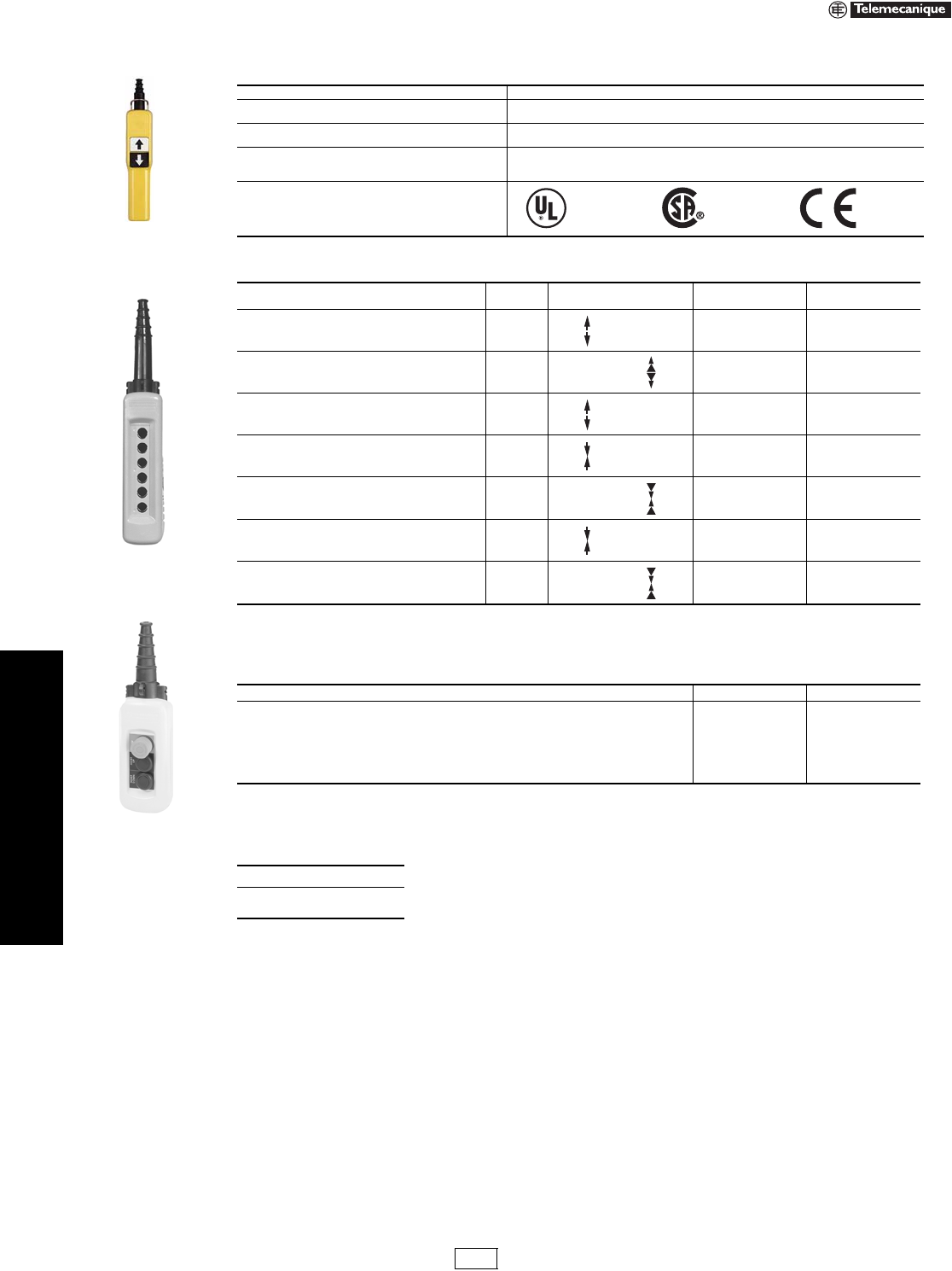
19-118 © 2007 Schneider Electric
All Rights Reserved
www.us.schneider-electric.com
FOR CURRENT INFORMATION
19 PUSH BUTTONS AND
OPERATOR INTERFACES
Pendant Stations XAC Standard Duty Pistol Grips, Enclosures, Contact Blocks
Refer to Catalog 9001CT0001
aThese units are available with factory installed E-stops. Add a “3” to the end of the catalog number for standard E-stop or add a “4” for a trigger action
E-stop. Consult your local Square D sales office for price adder.
bThese units are available with a factory installed E-stop. Use XACD22 ••• for a standard E-stop or XACD24••• for a trigger action E-stop.
cStandard enclosures include internal mounting plate, cable sleeve for 8 to 26 mm, internal cable clamp, suspension ring and cable tie.
dThe top hole accepts the 30 mm diameter mushroom head (E-stop) ZA2BS44.
Table 19.369: Specifications
Electrical ratings NEMA A600, Q600
EnclosureXACAO•NEMA 4, 4X (Indoor/Outdoor), 5
IP65
XACA2O• (Pistol grip) NEMA 4, 4X (Indoor), 5
IP65
Cabling
Screw and captive clamp terminals. Recommended torque 15.62 in-lb. Capacity: minimum 1 x
0.5 mm2 (20 AWG) solid or stranded, maximum with or without cable end: 2 x 1.5 mm2 (16
AWG) or 1 x 2.5 mm2 (14 AWG) or by cable clips conforming to NF C 20-120 (on request).
Approvals For XACA
Table 19.370: Pistol Grip Stations
Description Speeds Function
1 speed/2 speed Catalog Number $ Price
1 N.O. contact per operator
2 Mechanically interlocked operators 1XACA201a136.00
2 N.O. (staggered) contacts per operator
2 Mechanically interlocked operators 2XACA207a202.00
1 N.O. + 1 N.C.
2 Mechanically interlocked operators 1XACA205a170.00
1 N.O. contact per direction
1 Mechanically interlocked 2 way toggle 1XACD21A0101b152.00
1 N.O. + 1 N.O. staggered
1 Mechanically interlocked 2 way toggle 2XACD21A1231b410.00
1 N.O. & 1 N.C. contact per direction
1 Mechanically interlocked 2 way toggle 1XACD21A0105b184.00
1 N.C. + 1 N.O. + 1 N.O. staggered
1 Mechanically interlocked 2 way toggle 2XACD21A1241b436.00
Table 19.371: General Purpose Pendantsc
Enclosures Catalog Number $ Price
2 hole enclosure XACA02 192.00
3 hole enclosure XACA03 220.00
4 hole enclosure XACA04 250.00
6 hole enclosure XACA06 306.00
8 hole enclosure XACA08 382.00
12 hole enclosure XACA12 478.00
When ordering, please specify:
•Quantity
•Catalog Number
File E 164353
CCN NKCR
File LR 44087
Class 3211 03 Marked
XACA201
XACA06
XACA03
with
operators
IDiscount
Schedule
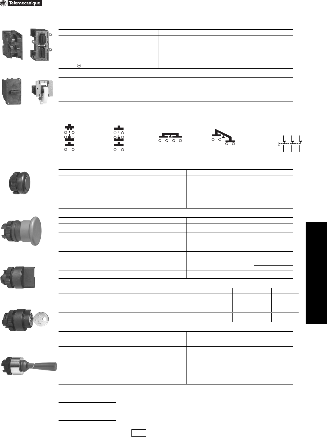
www.us.schneider-electric.com
FOR CURRENT INFORMATION
19 PUSH BUTTONS AND
OPERATOR INTERFACES
© 2007 Schneider Electric
All Rights Reserved 19-119
Pendant Stations XAC Standard Duty Pistol Grips, Enclosures, Contact Blocks
Refer to Catalog 9001CT0001
aCannot be used with XACA03 pendant.
Wiring Diagrams
bBooted push buttons are for cover mounting only. All other operators can be mounted on cover or bottom.
cTrigger action mushroom heads are tamper proof in that a change of contact state is not possible by teasing or floating the operator.
dNot for use with XEN G contact blocks.
Table 19.372: Contact Blocks for Operators in Cover
Description Wiring Diagram Catalog Number $ Price
1 N.O./spring return/1 speed — ZB2BE101 16.40
1 N.C./spring return/1 speed — ZB2BE102
1 N.O. early close & 1 N.C. & 1 N.O./spring return/2 speed Figure 1 XENG1191
49.00
1 N.C. & 2 N.O./spring return/1 speed Figure 2 XENG1491
1 N.O. & 1 N.O. latching/1 speed/interlocked Figure 3 XENG3781
1 N.O. & 1 N.C. latching/1 speed/interlocked Figure 4 XENG3791
3 N.C.—all direct acting Figure 5 XENT1192
Table 19.373: Contact Blocks for Operators in Base of Enclosure a
1 N.O./1 speed XACS101 28.60
1 N.C./1 speed XACS102 28.60
2 N.O./1 speed XACS103 38.20
2 N.C./1 speed XACS104 38.20
1 N.O. & 1 N.C./1 speed XACS105 38.20
Table 19.374: Operators b
Description Color Catalog Number $ Price
Booted push button
White XACA9411
8.20
Black XACA9412
Green XACA9413
Red XACA9414
Ye l l o w XACA9415
Blue XACA9416
Brown XACA9419
Table 19.375: Mushroom Operators
Description Mushroom Size Color Catalog Number $ Price
Mushroom head, momentary 30 mm Black ZA2BC24 36.80
Red ZA2BC44
Mushroom head, momentary 40 mm Black ZA2BC2 36.80
Red ZA2BC4
Mushroom head, push to maintain/turn-to-release 30 mm Red ZA2BS44 79.00
40 mm Red ZA2BS54 79.00
Mushroom head, push to maintain/turn-to-release
(trigger action)c
30 mm Red ZA2BS834 112.00
40 mm Red ZA2BS844 112.00
Mushroom head, push to maintain/key turn-to-release 30 mm Red ZA2BS74 112.00
40 mm Red ZA2BS14 112.00
Mushroom head, push to maintain/key turn-to-release
(trigger action)c40 mm Red ZA2BS944 112.00
Table 19.376: Selector Switches and Wobble Stick
Description Color Catalog Number $ Price
Selector switch/2 position—maintaineddBlack ZA2BD2 30.00
Selector switch/3 position—maintaineddBlack ZA2BD3 30.00
Selector switch/2 position—maintained key operated—key removal from LT or RT positiondNA ZA2BG4 112.00
Selector switch/3 position—maintained key operated—key removal from LT or RT positiondNA ZA2BG5 112.00
Wobble stick (bottom mounting recommended) Black ZA2BB2 102.00
Red ZA2BB4
Table 19.377: Pilot Light Components
Description Color Catalog Number $ Price
Direct supply base/without lamp (for 6 to 120 V applications) (AC/DC) — ZB2BV006 24.60
Resistor supply base/with 130 V lamp (for 220–240 V applications) (AC/DC) — ZB2BV007 52.00
Pilot light operators for incandescent lamps
Green ZA2BV03
9.60
Red ZA2BV04
Amber ZA2BV05
Blue ZA2BV06
Clear ZA2BV07
Pilot light operators for LED lamps
Green ZA2BV033
9.60Red ZA2BV043
Amber ZA2BV053
When ordering, please specify:
•Quantity
•Catalog Number
ZB2BE10 lXENG37l1
XENG1191 XACS10l
1314
21 22
33 34
1314
21 22
33 34
1314 1314 1314
11 12
N/C + N/C + N/C
with positive
opening operation
1112
2122
3132
Figure 1 Figure 3 Figure 4 Figure 2 Figure 5
Booted Push Button
Mushroom Head
Selector Switch
Selector Switch
(key operated)
Wobble Stick
IDiscount
Schedule
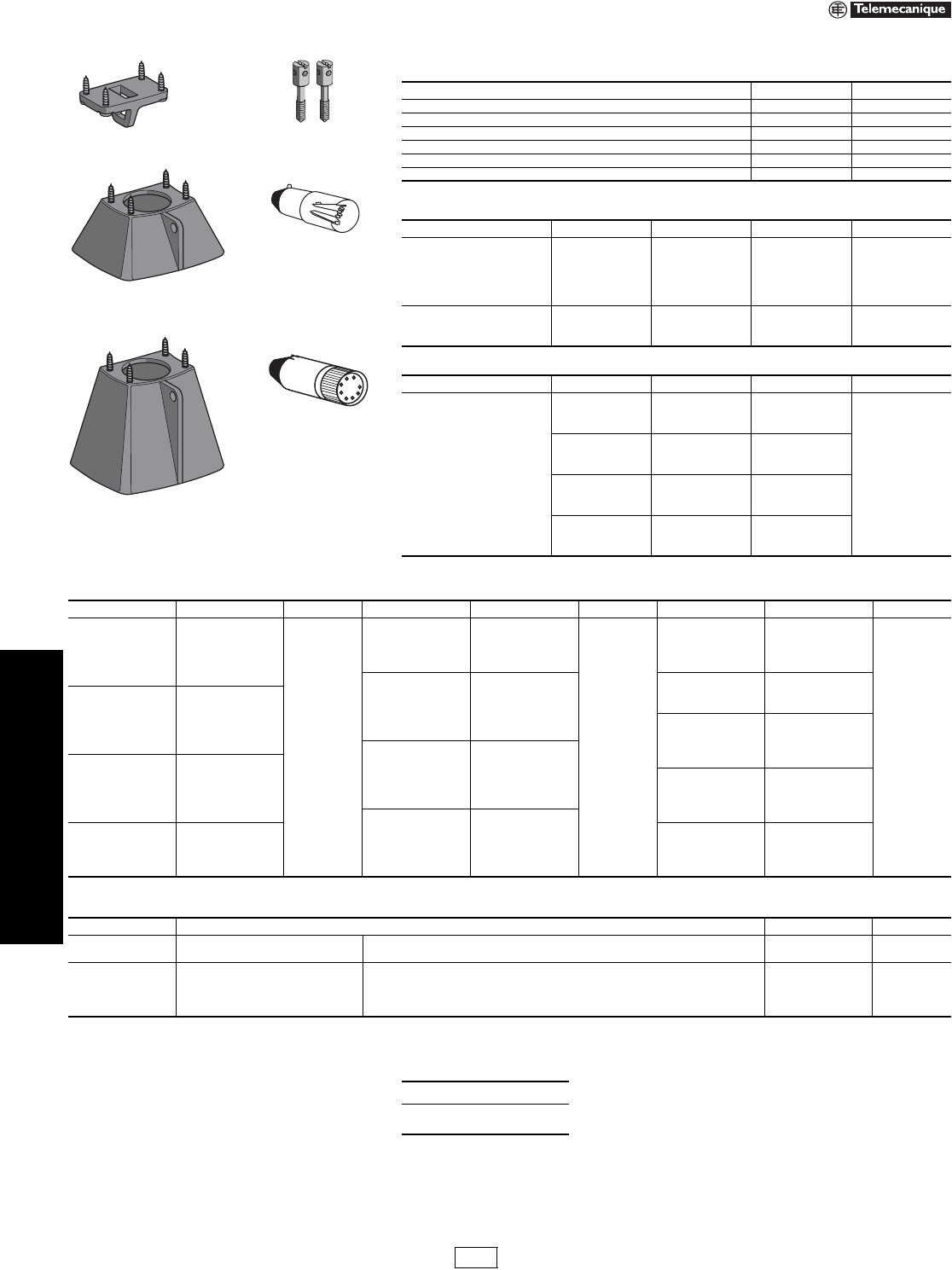
www.us.schneider-electric.com
FOR CURRENT INFORMATION
19 PUSH BUTTONS AND
OPERATOR INTERFACES
19-120 © 2007 Schneider Electric
All Rights Reserved
Pendant Stations XAC Standard Duty Operators—Accessories
Refer to Catalog 9001CT0001
Table 19.378: Enclosure Accessories
Description Catalog Number $ Price
Blank hole plug ZB2SZ3 13.60
Mechanical interlock (momentary). For use with XAC booted operators only XACA009 8.20
Screw adapter for self-supporting cable XACB961 6.80
Low suspension ring for single row station XACA971 19.20
Protective guard for bottom mounted mushroom head XACA982 19.20
Protective guard for bottom mounted selector switch or key switch XACA983 27.40
Table 19.379: Lamps
Type Voltage Watts Catalog Number $ Price
Replacement bulbs
(Type BA9s)
Incandescent
6 Vac/dc 1.2 DL1CB006
11.00
12 Vac/dc 2.0 DL1CE012
24 Vac/dc 2.0 DL1CE024
48 Vac/dc 2.4 DL1CE048
130 Vac/dc 2.6 DL1CE130
Neon
(use with direct supply light
module)
120 Vac/dc — NE51HRT120V
15.20220 Vac/dc — NE51HRT220V
380 Vac/dc — NE51HRT380V
Table 19.380: LED, BA9s Base
Type Color Voltage Catalog Number $ Price
LED, BA9s base for
Direct Supply blocks
Green 6 Vac/dc DL1CJUS0063
25.00
Red 6 Vac/dc DL1CJUS0064
Amber 6 Vac/dc DL1CJUS0065
Green 12 Vac/dc DL1CJUS0123
Red 12 Vac/dc DL1CJUS0124
Amber 12 Vac/dc DL1CJUS0125
Green 24 Vac/dc DL1CJUS0243
Red 24 Vac/dc DL1CJUS0244
Amber 24 Vac/dc DL1CJUS0245
Green 120 Vac/dc DL1CJUS1203
Red 120 Vac/dc DL1CJUS1204
Amber 120 Vac/dc DL1CJUS1205
XACA982
XACA971
XACA983
DL1CE0••
(Incandescent)
DL1CJUS••••
(LED)
XACB961
Table 19.381: PVC Standard Legend Plates 30 x 40 mm
TextaCatalog Number $ Price TextaCatalog Number $ Price TextaCatalog Number $ Price
Bridge Forward ZB2BY2343
4.20
Left ZB2BY2310
4.20
Stop ZB2BY2304
4.20
Bridge Reverse ZB2BY2344 Low ZB2BY2336 Stop Start ZB2BY2366
Close ZB2BY2314 Lower ZB2BY2337 Trolley Right ZB2BY2345
Down ZB2BY2308 Man Auto ZB2BY2372 Trolley Left ZB2BY2346
Emergency Stop ZB2BY2330 Off ZB2BY2312 Up ZB2BY2307
Fast ZB2BY2328 On ZB2BY2311 Up Down ZB2BY2370
Forward ZB2BY2305 Off On ZB2BY2367 Up-O-Down ZB2BY2389
For Rev ZB2BY23 Open ZB2BY2313 North 6516002379
For-O-Rev ZB2BY2384 Open Close ZB2BY2376 South 6516002380
Hand Off Auto ZB2BY2387 Open-O-Close ZB2BY2388 East 6516002381
High ZB2BY2338 Out ZB2BY2339 West 6516002382
High Low ZB2BY2369 Power On ZB2BY2326 Trolley North 6516002383
Hoist Down ZB2BY2342 Raise ZB2BY2335 Troll e y S ou t h 6516002384
Hoist Up ZB2BY2341 ResetaZB2BY2323 Trolley East 6516002385
In ZB2BY2503 Reverse ZB2BY2306 Trolley West 6516002386
Inch ZB2BY2321 Right ZB2BY2309 Bridge North 6516002387
Jog For ZB2BY2381 Run ZB2BY2334 Bridge South 6516002388
Jog Rev ZB2BY2380 Slow ZB2BY2327 Bridge East 6516002389
Jog Run ZB2BY2365 Start ZB2BY2303 Bridge West 6516002390
aAll nameplates are black with white lettering except “Stop”, “Emergency Stop” and “Reset” which are red with white lettering.
For black “Reset” change final digit of catalog number to 2.
Type Description Catalog Number $ Price
PVC blank legend Blank Black or red background—30 mm x 40 mm ZB2BY2101 4.20
Blank Yellow or white background—30 mm x 40 mm ZB2BY4101
PVC custom
engraved
Special engravingbBlack background, white letters—30 mm x 40 mm ZB2BY2002
17.80
Special engravingbRed background, white letters—30 mm x 40 mm ZB2BY2004
Special engravingbWhite background, black letters—30 mm x 40 mm ZB2BY4001
Special engravingbYellow background, black letters—30 mm x 40 mm ZB2BY4005
bPlease specify lettering when ordering. Two lines with 11 characters (including spaces) maximum on each plate.
When ordering, please specify:
•Quantity
•Catalog Number
IDiscount
Schedule
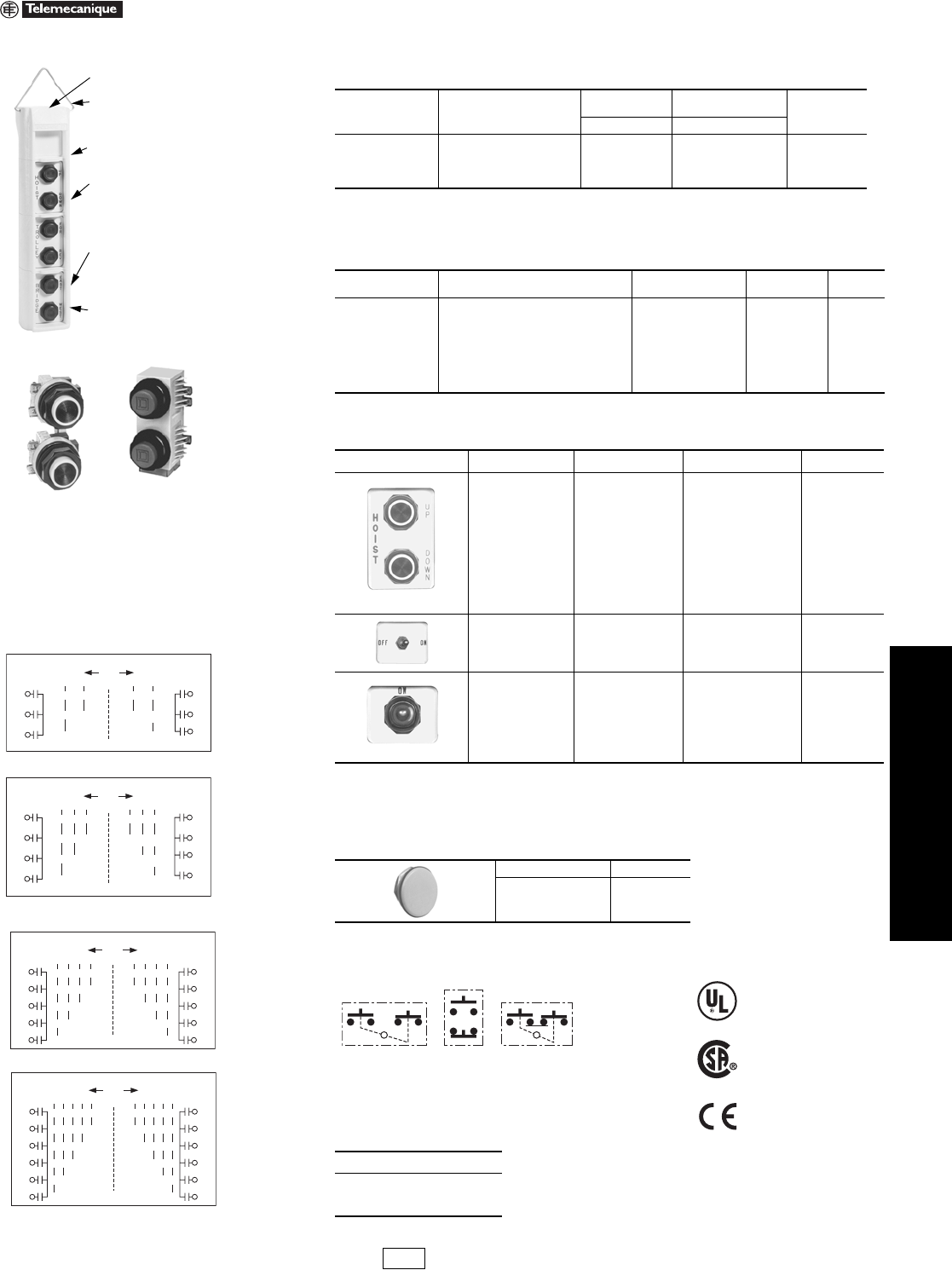
www.us.schneider-electric.com
FOR CURRENT INFORMATION
19 PUSH BUTTONS AND
OPERATOR INTERFACES
© 2007 Schneider Electric
All Rights Reserved 19-121
Pendant Stations Application and Ordering Information
Class 9001 / Refer to Catalog 9001CT0001
aClass 9001 SK push-to-test pilot lights, remote test pilot lights and potentiometers will not fit in these enclosures.
bAssembled pendant stations consist of an enclosure, operators and legend plates. The price of the total station
consists of the prices of the individual components - there is no charge for assembly. Example: 9001 SKYP20 plus
9001 SKRU5 plus 9001 SKN201; total price is $368.70. All custom orders must include pendant key sheet available
from Square D sales offices or distributors.
cTypes SKRU 1, 10 and 11 use Type KA contact blocks. Types SKRU 2 thru 5 are factory enclosed contact blocks.
dFor ring nuts see page 19-86. For protective boots, use 9001KU37 as shown on page 19-83.
eCan be supplied by Square D as Class 9001 Type SKSTS1 at $35.60—includes boot for NEMA 4X rating.
fSee Class 9001 Type SK, pages 19-68 to 19-86.
gIncludes legend plate, gasket and ground plate to be used with toggle switch.
hTri-laminated legend plate having a yellow or red background on a black core.
i19 characters each side max.
Single Speed Contact Symbols
Table 19.382: Enclosures (NEMA 1, 2, 3, 4, 4X, 12, 13)
Size Conduit Entrance Size
Enclosure
Onlyb
Enclosure for
Assembled Station a$ Price
Type Type
2 Button
4 Button
6 Button
8 Button
10 Button
.75 in.–14NPT
.74 in.–14 NPT
1 in. –11.5 NPT
1.25 in. –11.5 NPT
1.25 in.–11.5 NPT
SKYP2
SKYP4
SKYP6
SKYP8
SKYP10
SKYP20
SKYP40
SKYP60
SKYP80
SKYP100
126.00
159.00
191.00
237.00
285.00
Table 19.383: Push Button Unitsd
Number of Buttons
per Unit Description Contact Symbol—
See Below Typ e c$ Price
2 Single Speed—Momentary Interlocked 7 SKRU1 86.00
2 Single Speed—Momentary Non-Interlocked 5 SKRU10 71.00
2 Single Speed—Maintained Interlock 10 SKRU11 99.00
2 Two Speed—Momentary Interlocked 87 SKRU2 180.00
2 Three Speed—Momentary Interlocked 88 SKRU3 213.00
2 Four Speed—Momentary Interlocked 89 SKRU4 227.00
2 Five Speed—Momentary Interlocked 90 SKRU5 237.00
Table 19.386: Legend Plates
Where Used Marking Type $ Price
For SKRU1
through
SKRU11
Blank-Blank
Hoist: Up-Down
Trolley: East-West
Trolley: Fwd.-Rev.
Trolley: North-South
Bridge: Fwd.-Rev.
Bridge: East-West
Bridge: North-South
Start-Stop
Reset-Stop
Aux Hoist: Up-Down
Power: On-Off
Specify Marking
SKN200i
SKN201
SKN202
SKN203
SKN204
SKN205
SKN206
SKN207
SKN208
SKN209
SKN210
SKN211
SKN299
5.70
5.70
5.70
5.70
5.70
5.70
5.70
5.70
5.70
5.70
5.70
5.70
24.80
With Toggle
Switch e in
Top Space of
Enclosure
Blank
Off-On
On-Off
Specify Marking
SKN500g
SKN544g
SKN545g
SKN599g
8.60
8.60
8.60
18.00
With
Type SK
Operator or
Pilot Light f
in Top Space
of Enclosure
Blank
On
Off
Emerg. Stop
Run
Power On
Off-On
Specify Marking
SKN100h
SKN103
SKN104
SKN105
SKN124
SKN138
SKN144
SKN199h
2.90
2.90
2.90
2.90
2.90
2.90
2.90
12.30
Table 19.387: Closing Plate
Type $ Price
SK52 9.50
File
CCN
E42259
NKCR
File
Class
LR25490
321103
Marked
When ordering, please specify:
•Quantity
•Class Number
•Type or Catalog Number
Threaded conduit hole
Hanger bracket (Part no.
6509106101)
Space for toggle switch, a type SK
operator or pilot light. Use
appropriate legend plates.
Type SKYP enclosure
Type SKRU1 through SKRU11
operators. Any Type SK pilot
lightq or operator shown on
pages 19-68 to 19-86 can be
mounted in this enclosure. The
enclosure depth will
accommodate 1 Type KA1 thru
KA6 (total
of 2) contact blocks.
Type SKN2 legend plate
Multispeed
9001SKRU2
SKRU3
SKRU4
SKRU5
Single Speed
9001SKRU1
SKRU10
SKRU11
Table 19.384: Multispeed Contact
Symbols
Table 19.385: (“X”= Contact Closed)
Speed Position
Off
87
Terminals Terminals
C
1
2
C
1
2
X
X
X
2
X
X
X
X
X
X
X
112
2868-D30
Speed Position
Off
88
Terminals Terminals
C
1
2
3
C
1
2
3
X
X
X
X
3
X
X
X
2
X
X
X
X
X
X
X
X
X
X
X
1123
2868-D29
Speed Position
Off
89
Terminals Terminals
C
1
2
3
4
C
1
2
3
4
432
X
X
X
X
X
X
X
X
X
X
X
X
X
X
X
X
X
X
X
X
X
X
X
X
X
X
X
X
11234
2868-D31
Speed Position
Off
90
Terminals Terminals
C
1
2
3
4
5
C
1
2
3
4
5
X
X
X
X
X
X
5
X
X
X
X
X
4
X
X
X
X
3
X
X
X
2
X
X
X
X
X
X
X
X
X
X
X
X
X
X
X
X
X
X
X
X
X
X
1 12345
2868-D32
57 10
CP1 Discount
Schedule
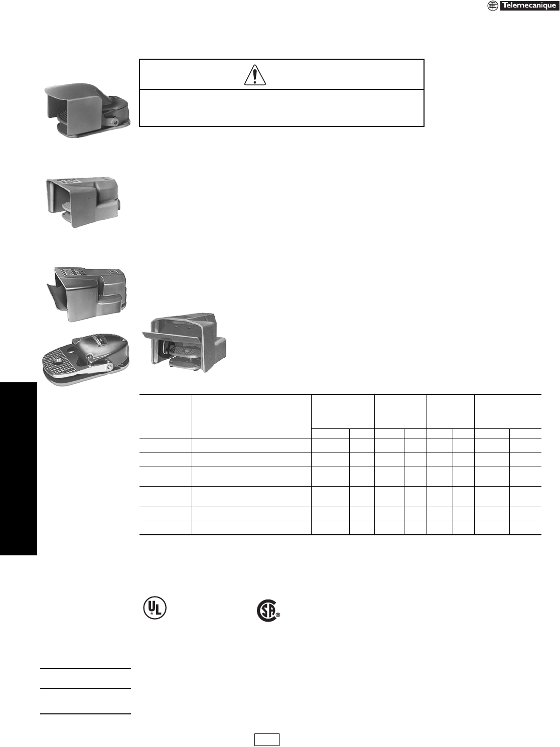
19-122 © 2007 Schneider Electric
All Rights Reserved
www.us.schneider-electric.com
FOR CURRENT INFORMATION
19 PUSH BUTTONS AND
OPERATOR INTERFACES
Foot Switches Type A
Class 9002
Heavy Duty Industrial Foot Switches—Oiltight, Watertight, Dusttight and Driptight Enclosure,
NEMA 2, 4 and 13
Foot Switch Selection
Foot switches are used to control many industrial processes, while leaving the operator's hands free to perform other
functions. The type or model of foot switch suitable for each application will vary depending on factors such as the
control function required, degree of protection required, production methods, unusual conditions, government
regulations, etc. In some applications more than one foot switch may be required, as when two or more persons are
operating a machine. In these cases, safe practice and regulations require that the foot switches be wired in series
making it necessary that each operator's foot switch be actuated before the machine will cycle.
Only the user can be aware of all the conditions and factors present during setup, operation and maintenance of the
machine; therefore, only the user can determine which foot switch(es) can be properly used. When selecting a foot
switch for a particular application, the user should refer to the applicable ANSI standards and OSHA regulations. The
National Safety Council's Accident Prevention Manual also provides much useful information.
In some applications, such as power presses, additional operator protection such as point-of-operation guarding must
be provided when a foot switch is used as an actuator. This is necessary since the operator's hands and other parts of
the body are free to enter the pinch point area and serious injury can occur. The shielding provided on foot switches
cannot protect an operator from injury. For this reason the foot switch cannot be substituted for or take the place of
point-of-operation protection.
A Trilingual Danger Sign regarding the need for point-of-operation protection is supplied with each foot switch. The sign
incorporates three languages: English, Spanish and French. Additional copies of the sign are available by contacting
your Square D sales office.
Type AW Fully Shielded Foot Switch with Oversized Pedal Shield, Side Shields and
Safety Door. The Safety Door is interlocked with the pedal to prevent operation due to
shock or vibration. It prevents accidental pedal operation by requiring a simple but
intentional motion to lift the door before inserting the foot.
a2 N.O. and 2 N.C. isolated, direct acting contacts.
bA single pole snap switch that contains two double break contact elements (1 N.O. and 1 N.C.) must be used on circuits of same polarity.
A double pole snap switch contains two electrically separated sets of contact elements allowing use on circuits of opposite polarity. Each set that contains
two double break contact elements (1 N.O. and 1 N.C.) must be used on circuits of same polarity.
cFor replacement cover drilled to accept latch. For Series C foot switches order AC9. Price is $182.00 No replacement cover available for Series A or
B devices drilled to accept latch. AC8 is spring return only.
dWARNING: These foot switches must not be used to operate machines or equipment where the possibility of operator injury exists. Typical uses
include Emergency Stop functions, “Dead Man” controls, signal functions (lights, bells, etc.).
For replacement parts for Class 9002 Type AW: See instruction bulletin 65013-010-31.
For contact symbol tables, see page 19-123
HAZARDOUS APPLICATIONS
Do not use foot switches on machines without point-of-operation protection.
Failure to follow this precaution will result in serious injury.
Table 19.388: Foot Switches
Description Features
Fully Shielded with
Oversized Pedal
Shield,
Side Shields and
Safety Door
With Oversized
Pedal Shield
and
Side Shields
With Pedal
Shield and
Side Shields
UNSHIELDED
(See Warning noted)
Type $ Price Type $ Price Type $ Price Type $ Price
Single Poleb
Double Throw
Spring Return
With Mechanical Latch
AW117
—
500.00
—
AW132
—
500.00
—
AW2
AW7
242.00
351.00
AW1
—
264.00
—
Two Pol e b
Double Throw
Spring Return
With Mechanical Latch
AW124 a
—
602.00
—
AW133
—
602.00
—
AW14
AW15
351.00
461.00
AW13
—
383.00
—
Two Stage b
(One Pole Each
Stage) Table 1
Spring Return
With Mechanical Latch in 1st Stage
With Mechanical Latch in 2nd Stage
AW119
—
—
620.00
—
—
AW134
—
—
620.00
—
—
AW6
AW9
AW10
362.00
470.00
470.00
AW5
—
—
393.00
—
—
Four Stage b
(One Pole Each
Stage) Table 2
Spring Return AW123 863.00 ——AW22 608.00 AW21 663.00
Single Pole
Single Throw Maintained Contact—Push On/Push Off — — — — AW12 351.00 AW11 383.00
Replacement
Cover Assembly —AC5 242.00 AC7 242.00 AC8c93.00 AC1 102.00
File
CCN
E42259
NKCR
File
Class
LR25490
184 N 13.1U
DANGER
Type AW Foot Switch with
Top Pedal Shield and Side
Shields
Type AW with Oversized
Pedal Shield and Side
Shields
Type AW Foot Switch
without Pedal Shield
When ordering,
please specify:
•Quantity
•Class Number
•Type or Catalog Number
CP1 Discount
Schedule Modified
4/20/09
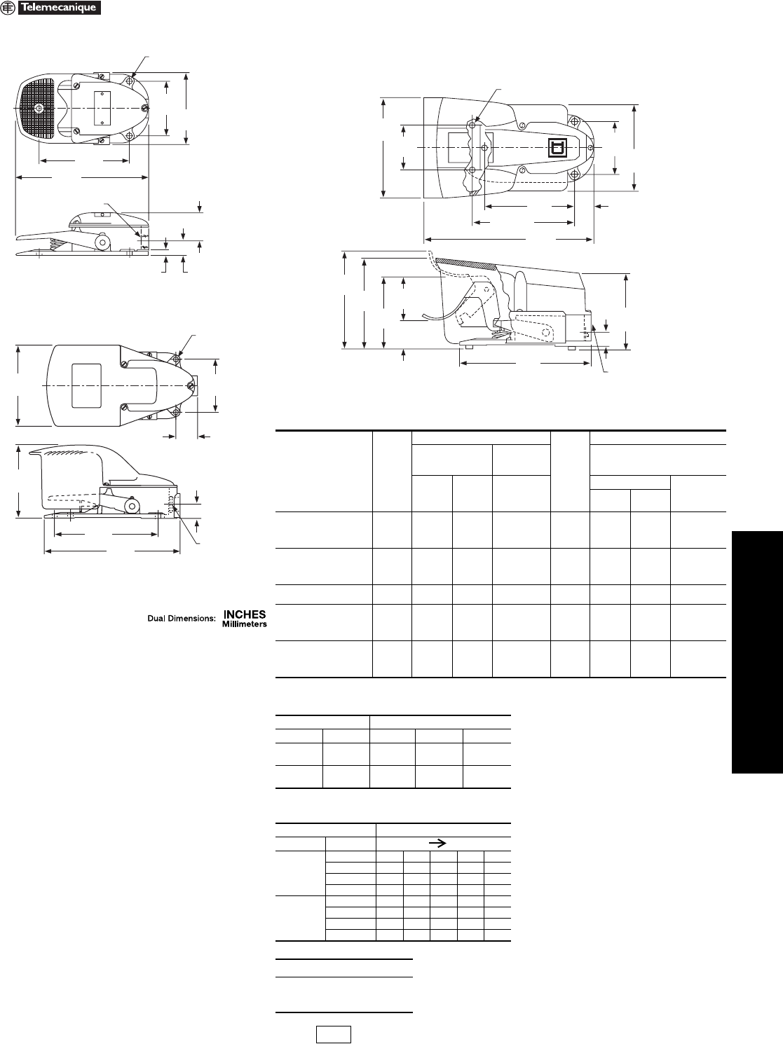
www.us.schneider-electric.com
FOR CURRENT INFORMATION
19 PUSH BUTTONS AND
OPERATOR INTERFACES
© 2007 Schneider Electric
All Rights Reserved 19-123
Foot Switches Type A
Class 9002
Approximate Dimensions
Note: Double throw switches are rated 250 Vdc maximum.
Note: 0 = Open 1 = Closed
Table 19.389: Maximum Current Ratings For Control Circuit Contacts
Type Volts
AC Amperes
Volt s
DC Amperes
Inductive
35% Power Factor
Resistive
75% Power
Factor
Inductive
and Resistive
Make Break
Make, Break
and
Continuous
Make and Break
Continuous
Single
Throw
Double
Throw
AW1 through AW10,
AW117, AW119,
AW132
120
240
480
600
40
20
10
8
15
10
6
5
15
10
6
5
125
250
600
2.0
0.5
0.1
0.5
0.2
0.02
15
15
15
AW13, AW14, AW15,
AW133
120
240
480
600
30
15
7.5
6
3
1.5
0.75
0.6
3
1.5
0.75
0.6
125
250
600
—
1.0
0.3
0.1
—
0.2
0.1
—
—
10
10
10
—
AW11, AW12 115
230
36
18
6
3
—
—
125
250
2.2
1.1
—
—
—
—
AW21, AW22,
AW123
120
240
480
600
15.0
7.5
3.75
3.0
1.5
0.75
0.375
0.3
10
10
10
10
—
—
—
—
—
—
—
—
—
—
—
—
—
—
—
—
AW124
120
240
480
600
60
30
15
12
6
3
1.5
1.2
10
10
10
10
120
240
600
1.1
0.55
0.2
—
—
—
10
10
10
Table 19.390: Contact Symbol—Two Stage
Snap Switch Pedal
Unit Circuit Up Half Down Full Down
1A1 0 1 1
B1 1 0 0
2A2 1 1 0
B2 0 0 1
Table 19.391: Contact Symbol—Four Stage
Snap Switch Pedal Position
Unit Circuit Up Down
1
1A1 00111
1B1 11000
2A1 01111
2B1 10000
2
1A2 11100
1B2 00011
2A2 11110
2B2 00001
When ordering, please specify:
•Quantity
•Class Number
•Type or Catalog Number
3.50
89
5.81
148
8.56
216
4.50
114
.38
10 .94
24
2.94
75
(3) .34 Dia. Mtg. Holes
9
3/4 14 Pipe Tap
Types AW1, AW5, AW11, AW13 and AW21
3/4-14 NPT
3.50
89
1.44
37
6.87
174
.94
24
9.00
229
5.38
137
4.84
123
(5) .34 Dia. Mtg. Hol
e
9
Types AW2, AW6, AW12, AW14 and AW22
3.50
89 5.63
143
5.81
147
5.02
128
.94
24
2.87
73
1.25
32
6.40
163
2.90
74
1.84
47
8.56
217
6.62 Typ.
168 11.13
283
(5) .34 Dia. Mtg. Holes
9
3/4 14 Pipe Tap
4.60
117
5.73
146
6.26
159
Types AW117, AW119, AW123, AW124
Types AW132, AW133 and AW134 (without safety door)
CP1 Discount
Schedule
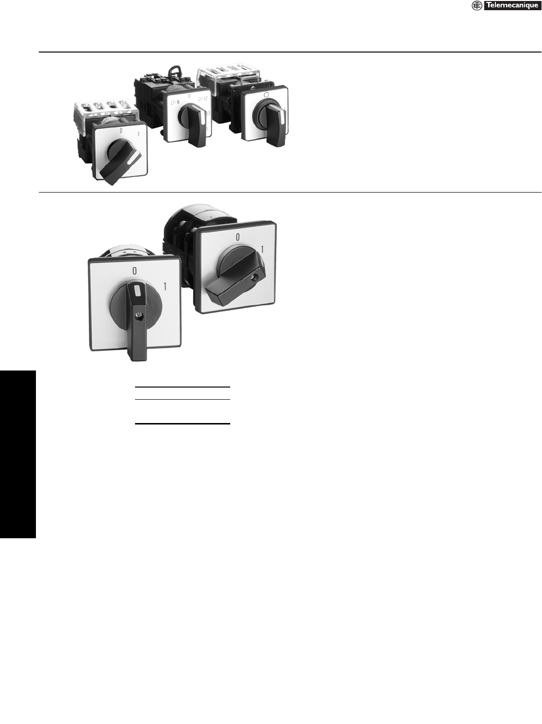
19-124 © 2007 Schneider Electric
All Rights Reserved
www.us.schneider-electric.com
FOR CURRENT INFORMATION
19 PUSH BUTTONS AND
OPERATOR INTERFACES
Rotary Cam Switches K2 Custom and K30–K150 Power Switching
Class 9003 / Refer to Catalog 9001CT0001
Table 19.392: Rotary Cam Switches
K2 Custom Cam Switches
•NEMA, A300, 300 V, 10 A
•Stepping, reversing, changeover
•Mounting by 22 mm or 4 holes
•Fast delivery of custom switches
•XB4 style handle available
K30–K150 Power Switching
•32 to 150 A (40 hp @ 480 V)
•Starting, reversing
•Mounting 48 x 48 or 64 x 64 mm
•Front plates 64 x 64 or 88 x 88 mm
•Fast delivery from global stock
•Complete with handle and legend
When ordering, please specify:
•Quantity
•Class Number
•Type or Catalog Number
