1000414729 Catalog
2016-07-29
: Pdf 1000414729-Catalog 1000414729-Catalog B2 unilog
Open the PDF directly: View PDF ![]() .
.
Page Count: 44
I-1www.hubbell-wiring.com Wiring Device-Kellems
®
LINKOSITY®
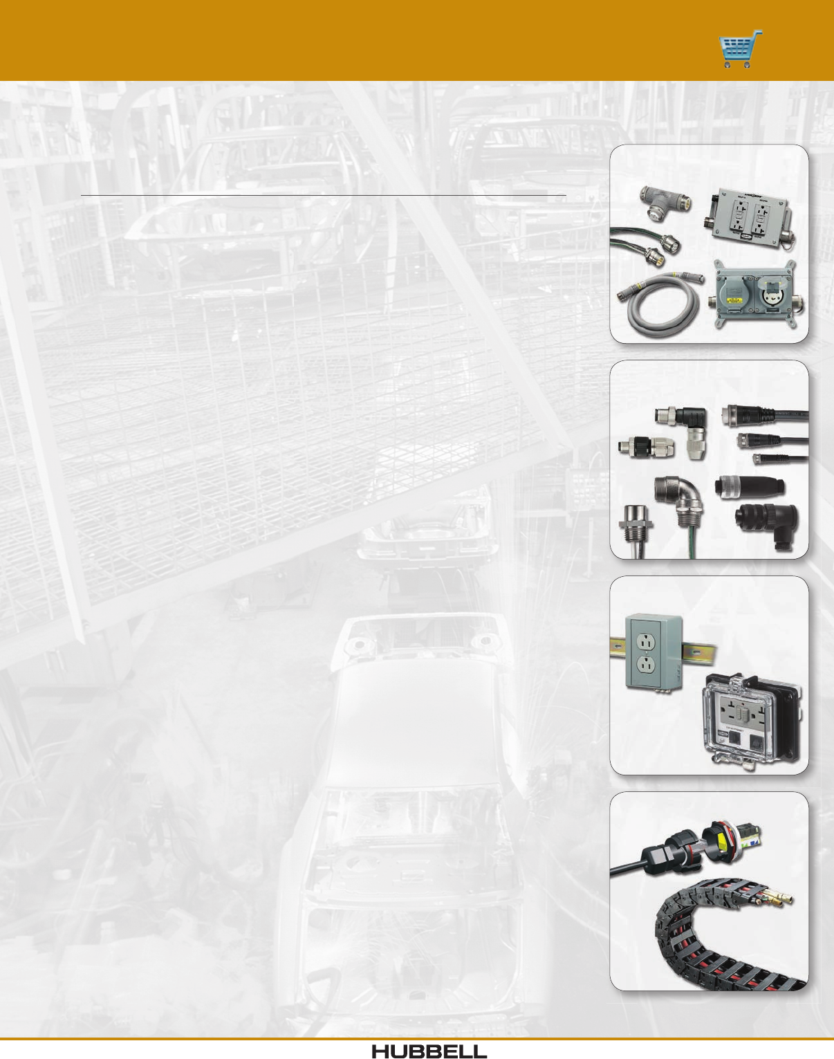
Power Components
DRUB and PANEL-SAFE®
Control Connectors Mini-,
Micro-, Nano- & Signal-Quick®
HI-Impact and CableTrak®
Index
Product Page
LINKOSITY® Power Components
Power Components ............................................I-2
Control Integration Components ..................................I-3
Power System Distribution Assemblies ............................I-4
MotorQuick® Disconnect Switches ................................I-7
Mini-Quick® Control Connectors ..................................I-8
2-6 Pole Plugs and Receptacles ..................................I-9
7-12 Pole Plugs and Receptacles ................................I-13
Field Attachable Connectors - Screw Terminal Style .................I-17
Micro-Quick® Control Connectors ................................I-18
Single Key 3-5 Pole Plugs and Receptacles ........................I-19
Dual Key 2-6 Pole Plugs and Receptacles .........................I-23
Field Attachable Connectors - Screw Terminal Style .................I-27
Field Attachable Connectors - IDC Style ..........................I-28
Nano-Quick® Control Connectors ................................I-29
3-4 Pole Plugs and Receptacles .................................I-30
Field Attachable Connectors - IDC Style ..........................I-32
Signal-Quick® Sensor Mounting Accessories
Cushioned Sensor Mounts .....................................I-33
Flat and Right Angle Adjustable and Fixed Brackets .................I-34
End Caps and Block Mounts ...................................I-35
Universal Aiming Brackets. . . . . . . . . . . . . . . . . . . . . . . . . . . . . . . . . . . . . . I-36
CableTrak® Hose and Cable Carrier System ........................I-37
CableTrak® Kit with and without Brackets .........................I-38
Accessories .................................................I-39
Mounting Options and Specifications .............................I-40
DIN Rail Utility Box
Power and Data ..............................................I-41
PANEL-SAFE® .................................................I-42
Power and Data Access Ports ..................................I-43
HI-Impact
Industrial Ethernet Connector and Harsh Environment Connectors .....I-44
Section I
Industrial Connectivity and Control Products
www.hubbell-wiring.comI-2 Wiring Device-Kellems
®
CCMBC
TX2304002304T00
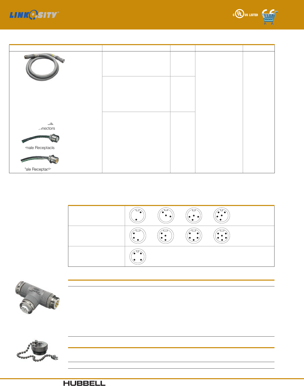
Cables and Receptacles
Device Type Ratings Wires Conductor Colors** Length (FT)
PH = Double Ended Cable with
Male/Female Straight
PM = Male Single Ended Straight
PN = Male Single Ended 90°
PF = Female Single Ended Straight
PG = Female Single Ended 90°
PQ = Double Ended Cable with Female 90°
PR = Double Ended Cable with Male 90°
PS = Double Ended Cable with
(2) 90° Connectors
RF = Female Receptacle*
RM = Male Receptacle (Inlet)*
20 =20A up to 600V
02
03
04
05 PA = Green/Yellow
Black (all others)
PB = Green/Yellow
White
Black (all others)
PE = All Blue***
001 = 1'
005 = 5'
010 = 10'
015 = 15'
020 = 20'
025 = 25'
030 = 30'
035 = 35'
040 = 40'
045 = 45'
050 = 50'
23 =
20A up to 600V
Specialty construction
(Includes isolated ground
on 6 wire and #10 AWG super
neutral conductor on 5 and
6 wire devices, PB color
code only)
03
04
05
06
30 =30A up to 600V 04
Example: PH 23 06 PB 005
Note: *½" NPT rear thread.
**Other color codes available upon request.
***Two wire only.
= Double Ended Cable with
(2) 90° Connectors
= Female Receptacle*
= Female Receptacle*
Male Receptacle (Inlet)*
= Female Receptacle*
Congurations (Male face view shown, female view is opposite)
20 AMP
20A SNIG
(with super neutral and IG)
30 AMP
Tees
Description Catalog Number
LINKOSITY® M/F/F Tee, 20A, 2P
LINKOSITY® M/F/F Tee, 20A, 3P
LINKOSITY® M/F/F Tee, 20A, 4P
LINKOSITY® M/F/F Tee, 20A, 5P
LINKOSITY® M/F/F Tee, 20A SNIG, 4P
LINKOSITY® M/F/F Tee, 20A SNIG, 6P
LINKOSITY® M/F/F Tee, 20A SNIG, A Phase Tap
LINKOSITY® M/F/F Tee, 20A SNIG, B Phase Tap
LINKOSITY® M/F/F Tee, 20A SNIG, C Phase Tap
LINKOSITY® M/F/F Tee, 30A, 4P
TX2002002002T00
TX2003002003T00
TX2004002004T00
TX2005002005T00
TX2304002304T00
TX2306002306T00
TX2306002304A00
TX2306002304B00
TX2306002304C00
TX3004003004T00
Closure Caps
Description
For use with
Female
Receptacle
Male
Inlet
20A and 30A Receptacle Closure Cap CCMBC CCFBC
Power Components - 20A, 30A Up To 600V
I-3www.hubbell-wiring.com Wiring Device-Kellems
®
CCFAC
TX1004001004T00
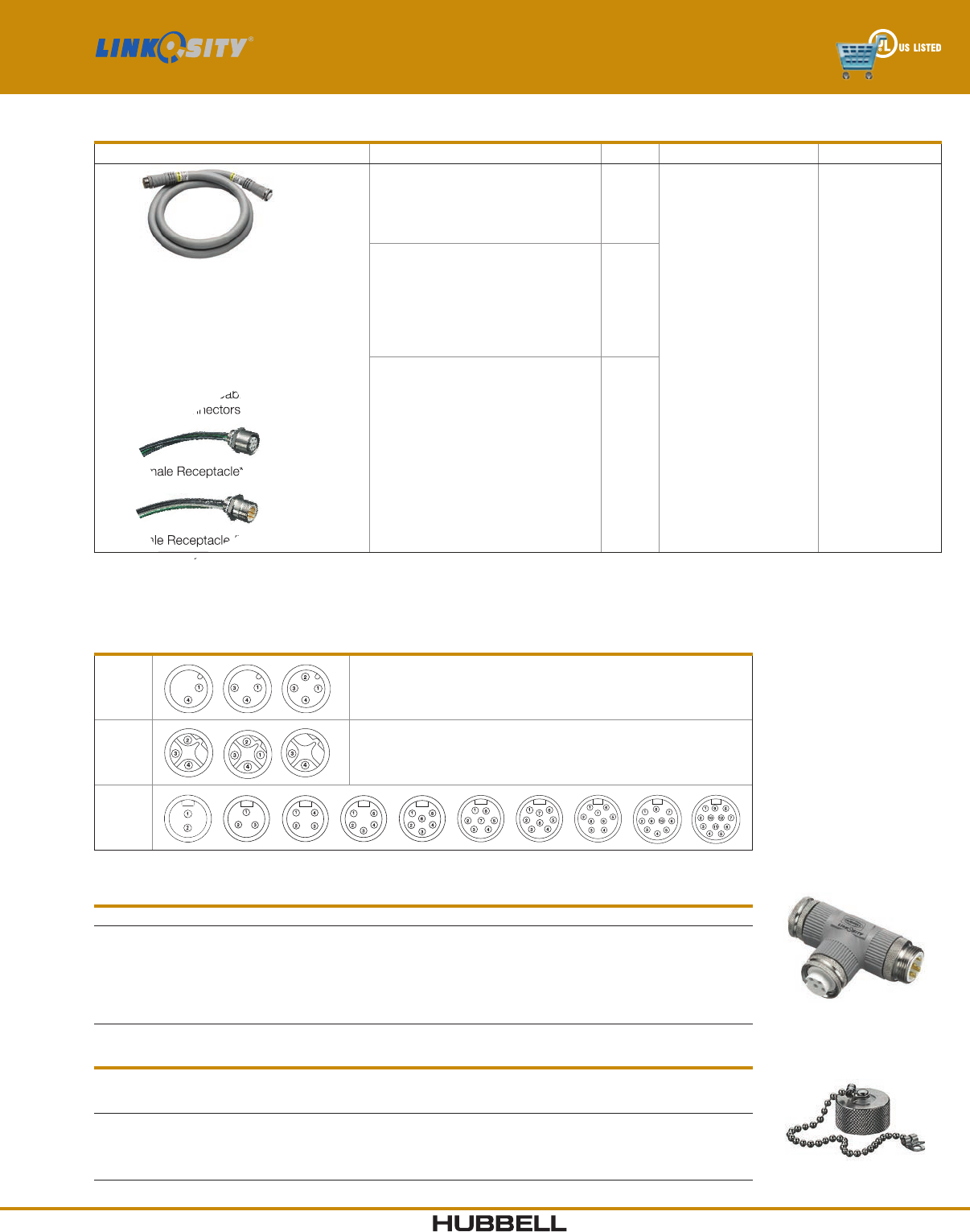
Cables and Receptacles
Device Type Ratings Wires Conductor Colors** Length (FT)
PH = Double Ended Cable with
Male/Female Straight
PM = Male Single Ended Straight
PN = Male Single Ended 90°
PF = Female Single Ended Straight
PG = Female Single Ended 90°
PQ = Double Ended Cable with Female 90°
PR = Double Ended Cable with Male 90°
PS = Double Ended Cable with
(2) 90° Connectors
RF = Female Receptacle*
RM = Male Receptacle (Inlet)*
03 =
3A - 2W, 3W
3A - 4W
up to 300V
02
03
04
PA = Green/Yellow
Black (all others)
PB = Green/Yellow
White
Black (all others)
PE = All Blue***
001 = 1'
005 = 5'
010 = 10'
015 = 15'
020 = 20'
025 = 25'
030 = 30'
035 = 35'
040 = 40'
045 = 45'
050 = 50'
R3 =
3A - 2W, 3W
3A - 4W
up to 300V
02
03
04
10 =
10A - 2W, 3W
10A - 4W
10A - 5W, 6W, 7W
10A - 8W, 9W
7A - 10W, 12W
up to 600V
02
03
04
05
06
07
08
09
10
12
Example: PH 10 06 PB 005
Note: *½" NPT rear thread.
**Other color codes available upon request.
***Two wire only.
Congurations (Male face view shown, female view is opposite)
03 Typically used for inputs in DC control circuits
R3 Typically used for outputs in DC control circuits
10
Splitters/Tees
Description Catalog Number
LINKOSITY® M/F/F Splitter, 3A/4W
LINKOSITY® M/F/F Tee, 10A, 2 Pole
LINKOSITY® M/F/F Tee, 10A, 3 Pole
LINKOSITY® M/F/F Tee, 10A, 4 Pole
LINKOSITY® M/F/F Tee, 10A, 5 Pole
LINKOSITY® M/F/F Tee, 10A, 6 Pole
TX0304000304T00
TX1002001002T00
TX1003001003T00
TX1004001004T00
TX1005001005T00
TX1006001006T00
Closure Caps
Description
For use with
Female
Receptacle
Male
Inlet
3A Closure Cap
10A Closure Cap, 2, 3, 4, 4, 5 and 6 Pole
10A Closure Cap, 7 and 8 Pole
10A Closure Cap, 9, 10, 12 Pole
CCM1C
CCMAC
CCMBC
CCMCC
CCF1C
CCFAC
CCFBC
CCFCC
= Double Ended Cable with
(2) 90° Connectors
= Female Receptacle*
= Female Receptacle*
Male Receptacle (Inlet)*
Example: PH
= Female Receptacle*
Control Integration Components - 3A Up To 300V, 10A Up To 600V
www.hubbell-wiring.comI-4 Wiring Device-Kellems
®
Device identification marking
Versatile mounting provision
Local or master switch
LINKOSITY® connection
Available with up to 5
receptacles, wide variety
of NEMA 5-20 receptacle
grades
Power pass thru option
16 gauge sheet metal
enclosure ANSI 61 gray
powder coat NEMA 1
Note: Accepts PH2304 series cables.
Straight Blade - UL Type 1
Device Type Switch Types # Receps Receptacle Type Receptacle Feature Pass-thru Custom Configurations*
M
SL =
SM =
00 =
Switch Local
Switch Master
No Switch
1
2
3
4
5
SG =
HG =
CR =
Spec Grade
Hospital Grade
Corrosion Resistant
IG =
GF =
SS =
00 =
Isolated Ground
Ground Fault
Surge Suppression
Standard
P =
0 =
Pass-thru**
No Pass-thru
D = 2 Circuit
A = A Phase
B = B Phase
C = C Phase
Example: M SL 1 SG 00 P
Twist-Lock® - UL Type 1
Device Type Switch Types # Receps Receptacle Type Receptacle Feature Pass-thru Custom Configurations*
M
SL =
SM =
00 =
Switch Local
Switch Master
No Switch
1
2
3
4
5
L1 = 15A
L2 = 20A
IG =
00 =
Isolated Ground
Standard
P =
0 =
Pass-thru
No Pass-thru 6 = 250v
Example: M 00 3 L1 IG 0
Note: Local switches control all receptacles in a box. Master switches control local and downstream receptacles. Consult factory for alternate wiring schemes.
*Consult factory for wiring specifications and connecting cables.
**Pass-thru on phase tap boxes are 3Ø.
Switch Only (On/Off) - UL Type 1
Device Type Switch Types Switch Style Poles
S
1 = 1 Gang
2 = 2 Gang
3 = 3 Gang
2W = On/Off 1P = Single Pole
DP = Two Pole
Example: S 1 2W 1P
Switch Only (4-Way) - UL Type 1
Device Type Switch Types Switch Style
S 1 = 1 Gang 4W = 4 Way
Example: S 1 4W
Features
Receptacle Types CR HG SG L1
00 Standard HBL53CM62 HBL8300GY 5362G HBL4700
IG Isolated Ground — — CR5352IGGY IG4700A
GF Ground Fault —GFR8300HGYTR GF20GYLA —
SS Surge Suppression —HBL8362GYSA HBL5362GYSA —
Switch Types CR HG SG L1
SL Local On/Off — — HBL12 21PL —
SM Master On/Off — — HBL12 21PL —
Switch Only (3-Way) - UL Type 1
Device Type Switch Types Switch Style Position
S 1 = 1 Gang 3W = 3 Way
M = Main
R = Remote
LM = Line to Main
LR = Load to Remote
Example: S 1 3W M
Note: For use with Px2304PBxxx series cables.
Power System Distribution Assemblies
I-5www.hubbell-wiring.com Wiring Device-Kellems
®
Device
Type Style Type
No. of
Poles Conductor Colors Pass - Thru
M4L -
LINKOSITY
20 - 20A
23 - 20A
Super Neutral
Isolated Ground
30 - 30A
02
03
04
05
06
PA - Green/Yellow
Black (all others)
PB - Green/Yellow
White
Black (all others)
P - Pass-Thru
0 - No Pass-Thru
Device
Type Style Type
No. of
Devices Device Type Pass-Thru
M L - LINKOSITY WF - Watertight
Safety-Shroud
Receptacle
WM - Watertight
Safety-Shroud
Inlet
201 - 20A 125V Straight Blade**
02 - 20A 125V Twist-Lock
03 - 20A 250V Twist-Lock
04 - 20A 277V Twist-Lock
05 - 30A 125V Twist-Lock
06 - 30A 250V Twist-Lock
07 - 20A 125/250V Twist-Lock
08 - 20A 3Ø 250V Twist-Lock
09 - 20A 3Ø 480V Twist-Lock
10 - 30A125/250V Twist-Lock
11 - 30A 3Ø 250V Twist-Lock
12 - 30A 3Ø 480V Twist-Lock
13 - 30A 3Ø 600V Twist-Lock
P - Pass-Thru
0 - No Pass-Thru
Device
Type Style Type
No. of
Devices Device Type Device Feature Pass-Thru
M3R - 3R Lids
3D - 3R Deep
Cover
SL - Switch
Local
SM - Switch
Master
00 - None
1
2
SG -
HG -
CR -
L1 -
Spec Grade
Hospital
Grade
Corrosion
Resistant
15A Locking
IG -
GF -
SI -
SS -
00 -
Isolated
Ground
Ground
Fault
Surge/IG
Surge
Standard
P - Pass-Thru
0 - No Pass-Thru
Device
Type Style Type
No. of
Devices NEMA Device Type Pass-Thru
MC - Conduit
Feed
WF - Watertight
Safety-Shroud
Receptacles
WM - Watertight
Safety-Shroud
Inlet
2 01 - 20A 125V Straight Blade
02 - 20A 125V Twist-Lock
03 - 20A 250V Twist-Lock
04 - 20A 277V Twist-Lock
05 - 30A 125V Twist-Lock
06 - 30A 250V Twist-Lock
07 - 20A 125/250V Twist-Lock
08 - 20A 3Ø 250V Twist-Lock
09 - 20A 3Ø 480V Twist-Lock
10 - 30A125/250V Twist-Lock
11 - 30A 3Ø 250V Twist-Lock
12 - 30A 3Ø 480V Twist-Lock
13 - 30A 3Ø 600V Twist-Lock
0 - No Pass-Thru
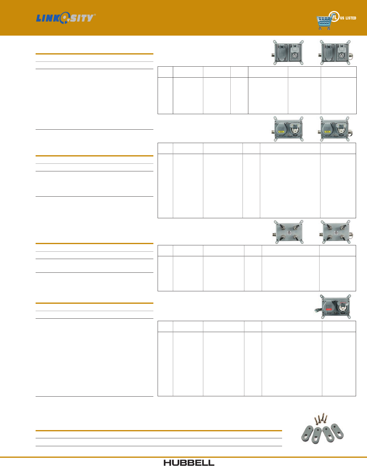
LINKOSITY® Feed - UL Type 3R Rated*
3R Rated Standard Items
Description Catalog Number
20A 125V Ground Fault
20A 125V Switched, Spec Grade
20A 125V Switched, Ground Fault
20A 125V Spec Grade
20A 125V Ground Fault, Pass-Thru
20A 125V Switched, Spec Grade,
Pass-Thru
20A 125V Switched, Ground Fault
Pass-Thru
Spec Grade, Pass-Thru
M3R002SGGF0
M3RSL1SG000
M3RSL1SGGF0
M3R002SG000
M3R002SGGFP
M3RSL1SG00P
M3RSL1SGGFP
M3R002SG00P
Note: *When cover closed.
Accepts PH2304 series cables.
LINKOSITY® Feed - UL Type 4X Rated*
4X Rated NEMA Standard Items
Description Catalog Number
20A 125V Straight Blade
20A 125V WTSSTL
20A 125V Straight Blade, Pass-Thru
20A 125V WTSSTL, Pass-Thru
MLWF2010
MLWF2020
MLWF201P
MLWF202P
Note: *Watertight Safety-Shroud® Twist-Lock® Plug required
when in use.
**Straight Blade are UL Type 4X when not in use only.
WTSSTL is an abbreviation for Watertight Safety-Shroud®
Twist-Lock®.
Accepts PH2304 series cables.
All LINKOSITY® - UL Type 4X Rated*
4X Rated LINKOSITY Standard Items
Description Catalog Number
20A 3W up to 600V, 4 Port
20A 3W up to 600V, 4 Port Pass-Thru
M4L2003PB0
M4L2003PBP
Note: *Closure Cap required when not in use.
Accepts PH2304 series cables.
Conduit Feed - UL Type 4X Rated*
Conduit Feed Standard Items
Description Catalog Number
20A 125V Straight Blade
20A 125V WTSSTL
20A 250V WTSSTL
20A 277V WTSSTL
30A 125V WTSSTL
30A 250V WTSSTL
20A 125/250V WTSSTL
20A 3Ø, 250V WTSSTL
20A 3Ø, 480V WTSSTL
30A 125/250V WTSSTL
30A 3Ø 250V WTSSTL
30A 3Ø 480V WTSSTL
30A 3Ø 600V WTSSTL
MCWF2010
MCWF2020
MCWF2030
MCWF2040
MCWF2050
MCWF2060
MCWF2070
MCWF2080
MCWF2090
MCWF2100
MCWF2110
MCWF2120
MCWF2130
Note: *Watertight Safety-Shroud® Twist-Lock® Plug required
when in use.
WTSSTL is an abbreviation for Watertight Safety-Shroud®
Twist-Lock®.
HBLRFT1
Replacement Mounting Feet
Description Catalog Number
For Power Distribution Assemblies. HBLRFT1∆
Note: ∆ Package of 10 mounting feet and 10 screws.
Power System Distribution Assemblies

www.hubbell-wiring.comI-6 Wiring Device-Kellems
®
LINKOSITY® Specications
Certifications
System Level ETL Classified to NEC
Component Assemblies (PSDA) UL Listed
Connecting Components Listed to UL2238 and UL 50
Cable (Up to #22 AWG) UL 300V Type ITC/PLTC 105ºC
Cable (#16 AWG and Up) UL 600V Type TC-ER, MTW 90ºC or STOOW 600V 105ºC
Cable Diameter
Amps Wires O.D.
20 3.59 5 (15.1)
20 4.645 (16.4)
20 5.710 (18.0)
20 6.760 (19.3)
30 4.710 (18.0)
Performance
Electrical
Voltage Up to 600V
Amperage Up to 30A
Environmental
Connectivity System Components
Moisture Resistance UL Type 4, 4X, 12 and 13
Ingress Protection IP66 Suitability
Flammability UL94HB Cables/UL94V-0 receptacles
Power System Distribution Assemblies
Moisture Resistance NEMA Type 1, Type 3R, Type 4X
Specifications
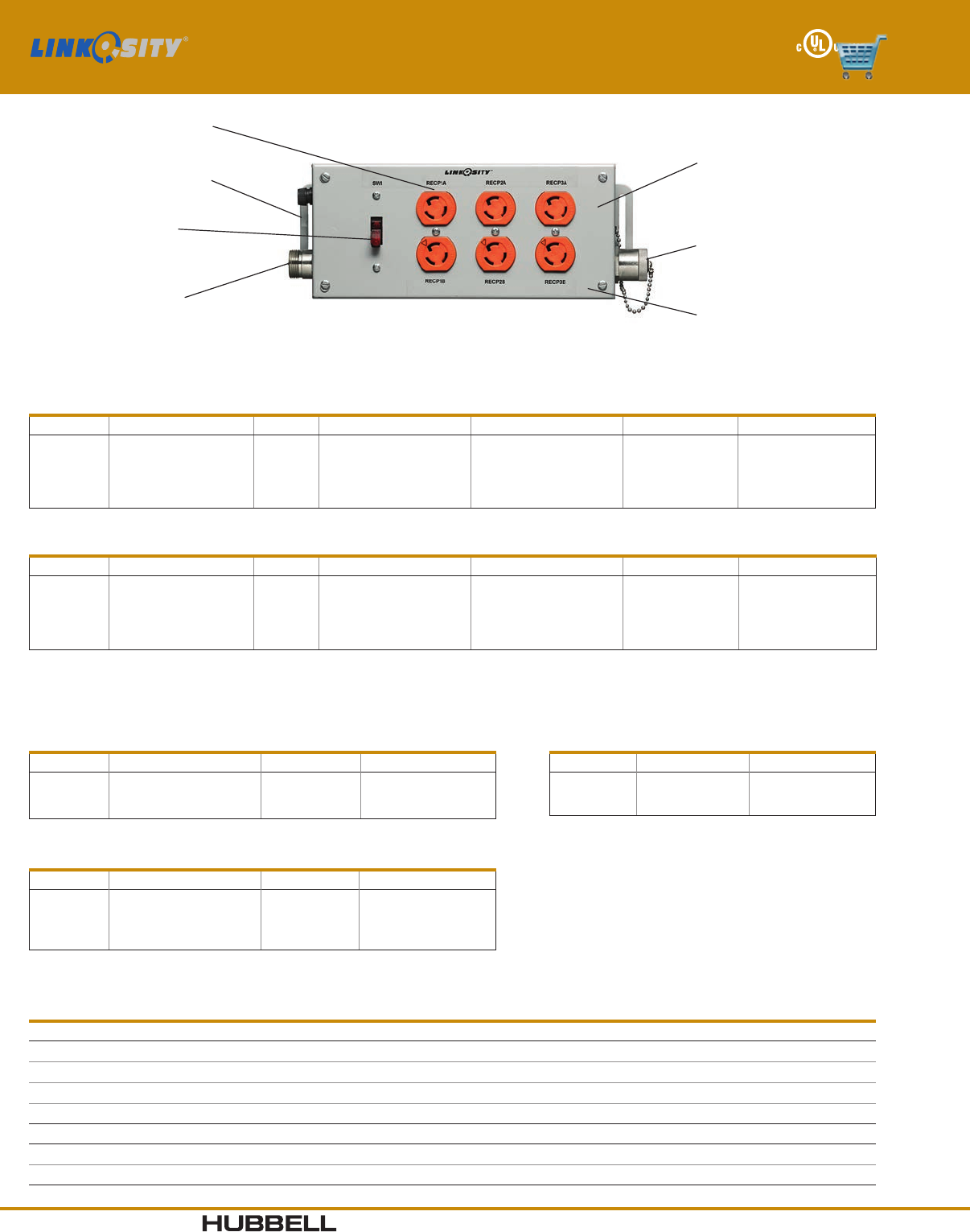
Add Label Only When
Assembled With Gfci
Receptacle
Do not connect
or disconnect
with power on
Power In
20 amps
CAUTION
FUSE
Not to exceed
Power Out
POWER OUT IS
NOT GFCI
PROTECTED
Do not connect
or disconnect
with power on
CAUTION
Wiring Device-Kellems
(2X) .218 X 3.270 Slot
Dim. 'D'
Dim. 'C'
Dim. 'A'
Dim. 'B'
RECP1A
Catalog Number M001****P Shown
RECP1B
Catalog Number Gangs Dimension 'A' Dimension 'B' Dimension 'C' Dimension 'D'
M001****P
M002****P
M003****P
M004****P
M005****P
1
2
3
4
5
5.50 (139.7)
7.50 (190.5)
9.50 (241.3)
11.50 (2 92.1)
13.50 (342.9)
4.75 (120.7)
6.75 (171.5)
8.75 (222.3)
10.75 (273 .1)
12.75 (323.9)
2.25 (57.2)
2.25 (57.2)
2.25 (57.2)
2.25 (57.2)
2.25 (57.2)
4.53 (115.1)
4.53 (115.1)
4.53 (115.1)
4.53 (115.1)
4.53 (115.1)
Dimensions in Inches (mm)
I-7www.hubbell-wiring.com Wiring Device-Kellems
®
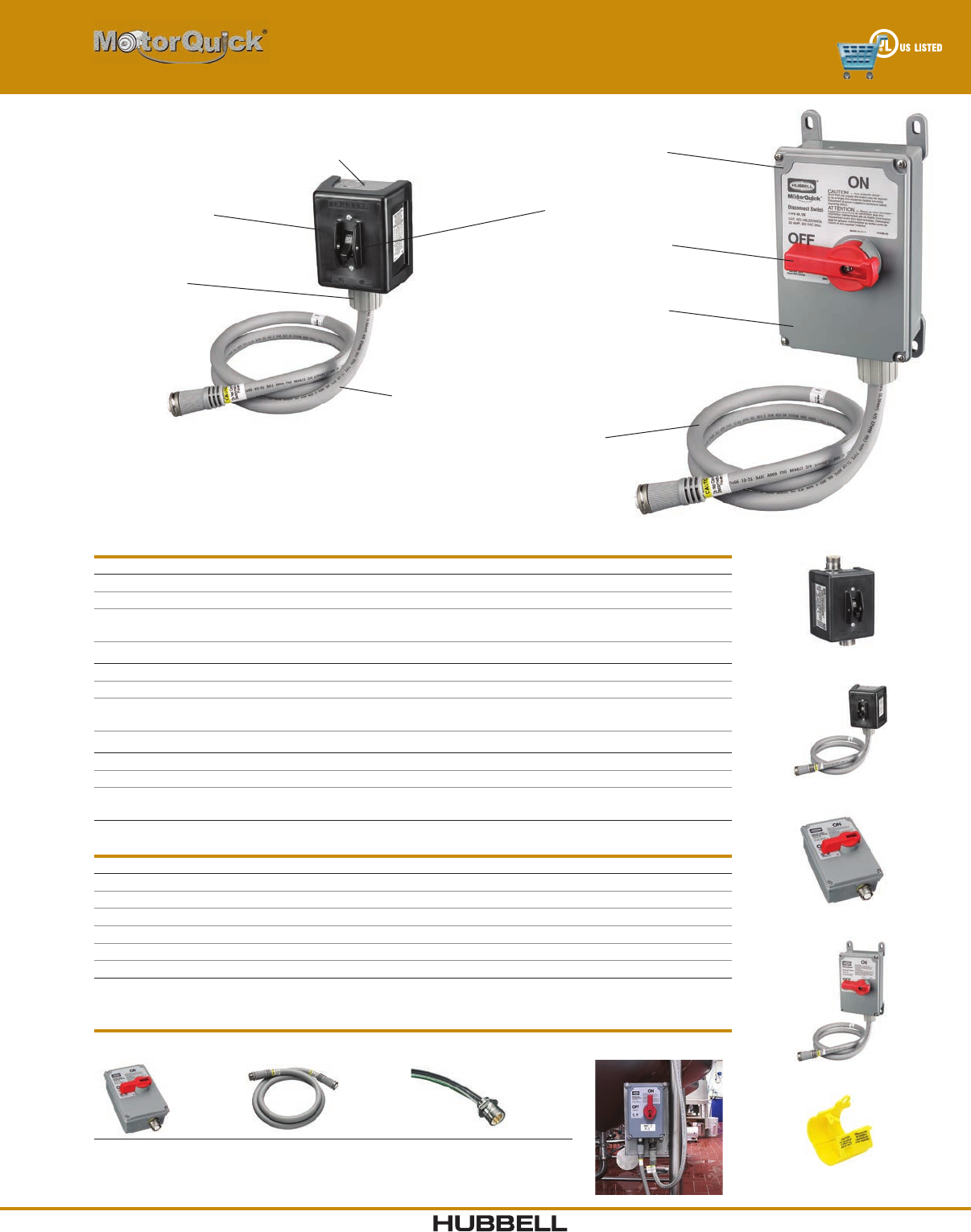
Disconnect Switches
HBL1389MQR2
HBL1389MQ5
HBLDS3MQR
HBLDS3MQ5
PH2030C
Quick Disconnect Switches
Type 1 Non-Metallic Enclosure 30A 3 Pole 600V AC Catalog Number
HBL1389D with one pre-wired LINKOSITY® female receptacle (load side). HBL13 89 MQR
HBL1389D with 5 foot pre-wired LINKOSITY® female cable (load side). HBL13 89 MQ5
HBL1389D with one pre-wired LINKOSITY® male receptacle (line side) and
one pre-wired LINKOSITY® female receptacle (load side).
HBL13 89 MQR2
Type 4X Non-Metallic Enclosure 30A 3 Pole 600V AC
HBLDS3 with one pre-wired LINKOSITY® female receptacle (load side). HBLDS3MQR
HBLDS3 with 5 foot pre-wired LINKOSITY® female cable (load side). HBLDS3MQ5
HBLDS3 with one pre-wired LINKOSITY® male receptacle (line side)
and one pre-wired LINKOSITY® female receptacle (load side).
HBLDS3MQR2
Type 4X Stainless Steel Enclosure 30A 3 Pole 600V AC
HBLDS3SS with one pre-wired LINKOSITY® female receptacle (load side). HBLDS3SSMQR
HBLDS3SS with 5 foot pre-wired LINKOSITY® female cable (load side). HBLDS3SSMQ5
HBLDS3SS with one pre-wired LINKOSITY® male receptacle (line side)
and one pre-wired LINKOSITY® female receptacle (load side).
HBLDS3SSMQR2
Accessories
Description Catalog Number
3P 4W LINKOSITY® male receptacle for installation on motor. RM3004PA001
3P 4W LINKOSITY® female receptacle for installation in switch. RF3004PA001
3P 4W LINKOSITY® double ended (male/female) 5-50 foot cable. PH3004PAxxx*
3P 4W LINKOSITY® single ended (female) 5-50 foot cable. PF3004PAxxx*
Cord connector, ¾ in. NPT .63–.75 in. (16.0–19.1) diameter. SHC1037CR
Lock-on cover for LINKOSITY® connections. PH2030C
Note: *Cables available from 5-50 feet in 5 foot increments. To purchase larger cable, replace the XXX with the required
length in feet. (Examples: PH3004PA005 = 5 foot cable, PH3004PA050 = 50 foot cable.)
Sample Set Up
(1) HBLDS3MQR + (1) PH3004PAxxx + (1) RM3004PA001 = Total Set Up**
+ + =
Note: ** Retrofit parts available for pre-existing disconnect switch installations.
Please consult factory for availability.
Valox® is a trademark of SABIC Innovative Plastics, acquired from General Electric Company.
Crush and Impact
Resistance of
MC Cable
Cable Ratings:
TC-ER, MTW, STOOW
Thermoplastic Cover
on Plated Steel Base
NEMA 1 Enclosure
Pre-wired with
LINKOSITY®
Components
Lockable Handle to
Meet OSHA Lockout/
Tagout Regulations
Type 4X Enclosure
High Impact Valox®
Enclosure
HBL13 89 MQ5
HBLDS3MQ5
www.hubbell-wiring.comI-8 Wiring Device-Kellems
®
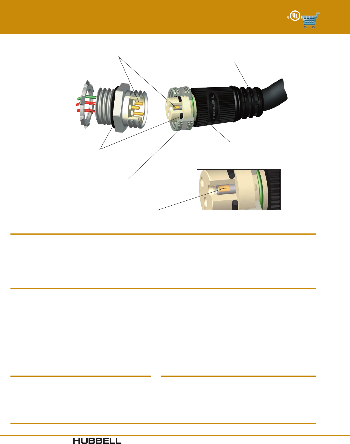
Hard Gold Over Palladium Nickel Contact Plating
Superior conductivity, extended contact life
Gated Strain Relief with Graduated Window Sizes
Improved flexibility and strength protects wire
terminations; superior arc of bend control
Anti-Vibration Coupling Nut
Prevents coupling nut from loosening
under harsh vibration conditions
Leaded Nickel Copper Sleeved Contact
Extended contact life and continuity
Indicator Ring
Ensures proper mating
O-Rings
Moisture protection
Mini-Quick® Control Connectors
Features and Benefits
Features Benefits
Cable #16 AWG SEOOW - TPE jacket, Black, PVC conductor
insulation, Stranding - 65/34
#18 AWG SEOOW - TPE jacket, Black, PVC conductor
insulation, Stranding - 41/34
#18 AWM2661 - PVC jacket, Black, PVC conductor
insulation, Stranding - 41/34
Strain Relief #16 AWG and #18 AWG - 30 pounds min per UL2238
Insulator Materials Nylon 6/6, White
Contact Materials Pins - Brass, Sockets
Leaded nickel copper w/ stainless
steel sleeve
Contact Plating Hard gold over palladium/nickel
Overmold Material Polyurethane, Black
Coupling Nut, Metallic Nickel plated brass
Coupling Nut, Nylon Nylon 6/6, Black
Receptacle Shell Nickel plated brass,
SST consult factory
Receptacle Shell, Nylon Nylon 6/6, Black
Receptacle Shell, Right Angle Nickel plated zinc alloy die cast,
SST consult factory
Material Specifications
Electrical Specifications
Voltage Rating 600V DC/600V AC
Amperage #16 AWG - 2&3P=15A, 4P=12A, 5&6P=10A
7P=10A, 8&9P=9A, 10&12P=8A
#18 AWG - 2&3P=11A, 4P=8A, 5&6P=7A
Contact Resistance ≤ 5 mΩ
Isolation Resistance ≥ 1000 MΩ
Environmental Specifications
Moisture Protection UL Type 4, 4X, 12 and 13
Ingress Protection IP66 Suitability
Operating Temperature AWM2661 cables: -20°C to 105° C
SEOOW cable: -40°C to 105° C
Corrosion Resistance 500 hours salt spray per MIL-STD-1344, Method 1001
Vibration Resistance 10 - 2,000 Hz @15g per MIL-STD-1344, Method 2005
Certifications
UL 2238 and UL50E, File No. E192071 CSA Certified, C22.2 No. 182.3 and CSA C22.2 No. 94.2-07
• Nickel plated brass coupling nuts and receptacle shells.
• Black overmold and cable.
• Insulgrip connector body design.
• UL Listed cable assemblies and receptacles.
• Plating resists corrosion in high abuse environments.
• Cable assembly resists dirt and blends with environment giving a
clean look to the installation.
• Ergonomic connector body has an industrial look.
• Third party certified for electrical, mechanical and environmental
performance.

I-9www.hubbell-wiring.com Wiring Device-Kellems
®
Choose the appropriate configuration from the Selector below.
Hubbell Logic Configurator
For example, catalog number HCMA05212 is derived as follows:
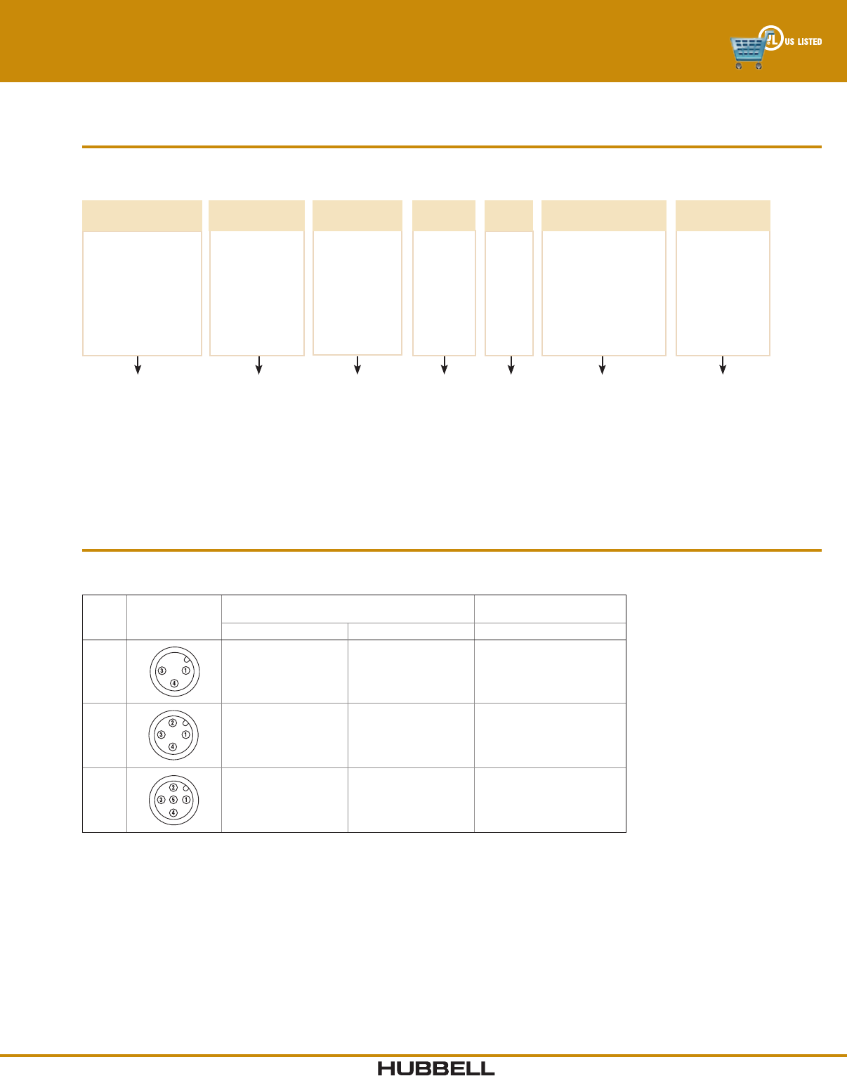
2 - 6 Pole Plugs
Catalog numbers using #16 AWG SEOOW cable are listed below. For #18 AWG SEOOW or #18 AWM2661 IEC cable, change the
conductor type per the Hubbell Logic chart above.
Poles
Male Face Shown
Female - mirror
image Cable Length
Female Plugs Male Plugs
Male/Female
JumperCables
Straight Right Angle Straight Right Angle Straight
21
2
3 ft (0.91m)
6 ft (1.83m)
12 ft (3.66m)
All other lengths
HCMS02103
HCMS02106
HCMS02112
HCMS021**
HCMA02103
HCMA02106
HCMA02112
HCMA021**
HPMS02103
HPMS02106
HPMS02112
HPMS021**
HPMA02103
HPMA02106
HPMA02112
HPMA021**
HJMS02103
HJMS02106
HJMS02112
HJMS021**
31
23
3 ft (0.91m)
6 ft (1.83m)
12 ft (3.66m)
All other lengths
HCMS03103
HCMS03106
HCMS03112
HCMS031**
HCMA03103
HCMA03106
HCMA03112
HCMA031**
HPMS03103
HPMS03106
HPMS03112
HPMS031**
HPMA03103
HPMA03106
HPMA03112
HPMA031**
HJMS03103
HJMS03106
HJMS03112
HJMS031**
41
2
4
3
3 ft (0.91m)
6 ft (1.83m)
12 ft (3.66m)
All other lengths
HCMS04103
HCMS04106
HCMS0 4112
HCMS041**
HCMA04103
HCMA04106
HCMA04112
HCMA041**
HPMS04103
HPMS04106
HPMS04112
HPMS041**
HPMA04103
HPMA04106
HPMA04112
HPMA041**
HJMS04103
HJMS04106
HJMS04112
HJMS041**
51
2
5
4
3
3 ft (0.91m)
6 ft (1.83m)
12 ft /3.66m)
All other lengths
HCMS05103
HCMS05106
HCMS05112
HCMS051**
HCMA05103
HCMA05106
HCMA05112
HCMA051**
HPMS05103
HPMS05106
HPMS05112
HPMS051**
HPMA05103
HPMA05106
HPMA05112
HPMA051**
HJMS05103
HJMS05106
HJMS05112
HJMS051**
61
24
5
6
3
3 ft/0.91m)
6 f t/1.83m)
12 ft /3.66m)
All other lengths
HCMS06103
HCMS06106
HCMS0 6112
HCMS061**
HCMA06103
HCMA06106
HCMA06112
HCMA061**
HPMS06103
HPMS06106
HPMS06112
HPMS061**
HPMA06103
HPMA06106
HPMA06112
HPMA061**
HJMS06103
HJMS06106
HJMS0 6112
HJMS061**
Note: Replace ** with length required in feet. For nylon coupling nuts, replace “M” with “N” per the ordering chart above.
Example: change HPMA05106 to HPNA05106.
Mini-Quick® Control Connectors
2 - 6 Pole Plugs
Note: Availability of specific items may vary. Consult factory for delivery. Consult the factory for additional cable lengths or cable types.
Available with metallic coupling nut only.
DEVICE
TYPE
HC = Plug, Female
HP= Plug, Male
HI = Plug, Male Inline
HE = Male/Female
Extension Cable
HJ = Male/Female
Jumper Cable
12HC M 05 1
CABLE
LENGTH (ft)
**
03
06
12
20
POLES
02
03
04
05
06
A
BODY
STYLE
A = Right Angle
S = Straight
CONDUCTOR
TYPE
1 = #16 AWG SEOOW Cable
3 = #18 AWM2661 IEC Cable*
4 = #18 AWG SEOOW Cable
COUPLING NUT
MATERIAL
M = Metallic
N = Nylon
*3 - 5 Pole Only
**Replace with
Length
www.hubbell-wiring.comI-10 Wiring Device-Kellems
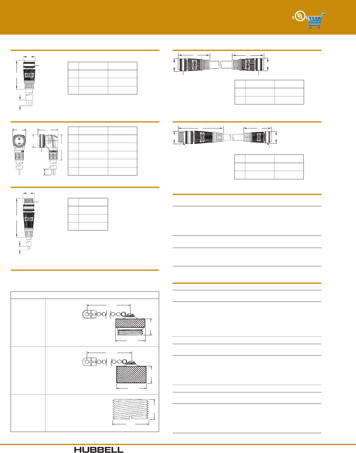
®
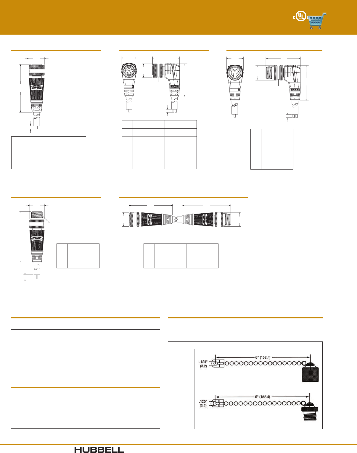
A
B
C
7/8 - 16
UN Thr
ead
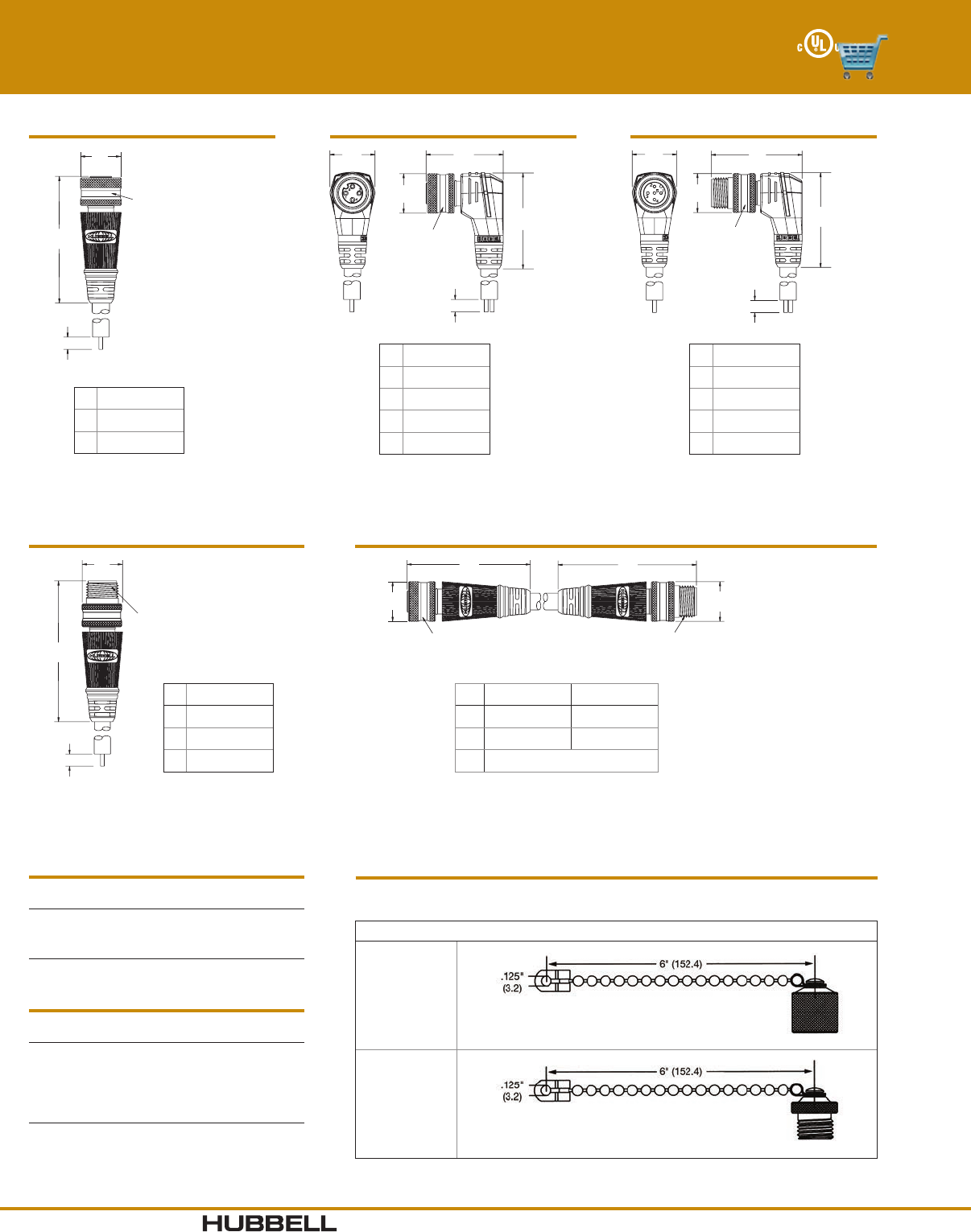
Straight Plug
MALE FEMALE
A0.99" (25.2) 0.99 (25.2)
B2.44" (62.0) 2.40 (61.0)
C2.75" (69.9) 2.75 (69.9)
Jumper Cable
7/8 - 16 UN Thread 7/8 - 16 UN Thread
A
B
A
B
MALE FEMALE
A0.99" (25.2) 0.99" (25.2)
B2.44" (62.0) 2.40" (61.0)
A
7/8 - 16 UN Thread
BB
A
7/8 - 16 UN Thread
Male/Female Extension Cable
MALE FEMALE
A0.99" (25.2) 0.99" (25.2)
B2.47" (62.7) 2.40" (61.0)
A
B
C
7/8 - 16
UN Thr
ead
Inline Plug
Right Angle version also available.
MALE
A0.99" (25.2)
B2.47" (62.8)
C2.75" (69.9)
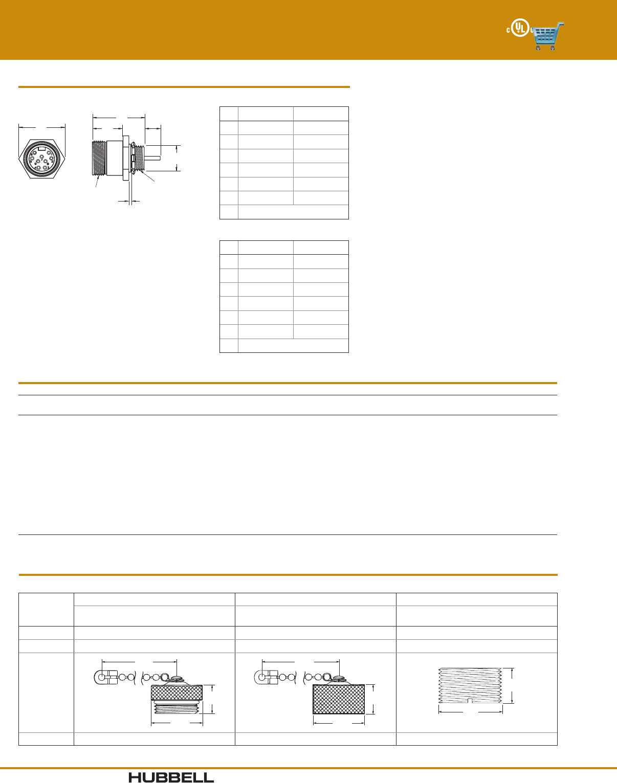
Mini-Quick® Control Connectors
2 - 6 Pole Plugs
Right Angle Plug
7/8 - 16 UN
Thread
DE
A
B
C
MALE FEMALE
A0.99" (25.2) 0.99" (25.2)
B2.14" (54.4) 2.14" (54.4)
C2.75" (69.9) 2.75" (69.9)
D1.03" (26.2) 1.03" (26.2)
E1.64" (40.6) 1.60" (40.6)
Accessories
Closure caps protect plugs and receptacles when not in use. Adapter
rings allow the mating of male and female plugs for in-line applications.
Shell size is 1, and the thread is 7/8-16 UN.
Description Catalog Number
Closure Cap
HPCAP1
1.12"
(28.5)
0.56"
(14.2)
6.00"
(152.4)
Closure Cap
HRCAP1
6.00"
(152.4)
1.13"
(28.6)
0.58"
(14.7)
Adapter Ring
HMQAR1
1.00"
(25.4)
0.48"
(12.3)
Cable Diameters By Cable Type
Number of #16 AWG #18 AWG
Conductors SEOOW SEOOW
2 0.37" (9.4) 0.35" (8.9)
3 0.39" (9.9) 0.37" (9.4)
4 0.42" (10.7) 0.39" (9.9)
5 0.50" (12.7) 0.47" (11.9)
6 0.52" (13.2) 0.48" (12.2)
Number of #18 AWM2661
Conductors IEC
3 0.26" (6.6)
4 0.26" (6.6)
5 0.26" (6.6)
Conductor Color Code
#16 AWG SEOOW Plugs
Contact 2 3 4 5 6
Number Pole Pole Pole Pole Pole
1 White Green Black White White
2 Black Black White Red Red
3 White Red Green Green
4 Green Orange Orange
5 Black Black
6 Blue
#18 AWG SEOOW Plugs
Contact 3 4 5
Number Pole Pole Pole
1 Green Black White
2 Black White Red
3 White Red Green
4 Green Orange
5 Black
#18 AWM 2661 IEC
Contact 3 4 5
Number Pole Pole Pole
1 Yellow/Green Black Black
2 Brown Blue Blue
3 Blue Brown Yellow/Green
4 White Brown
5 White
Dimensions in Inches (mm)

I-11www.hubbell-wiring.com Wiring Device-Kellems
®
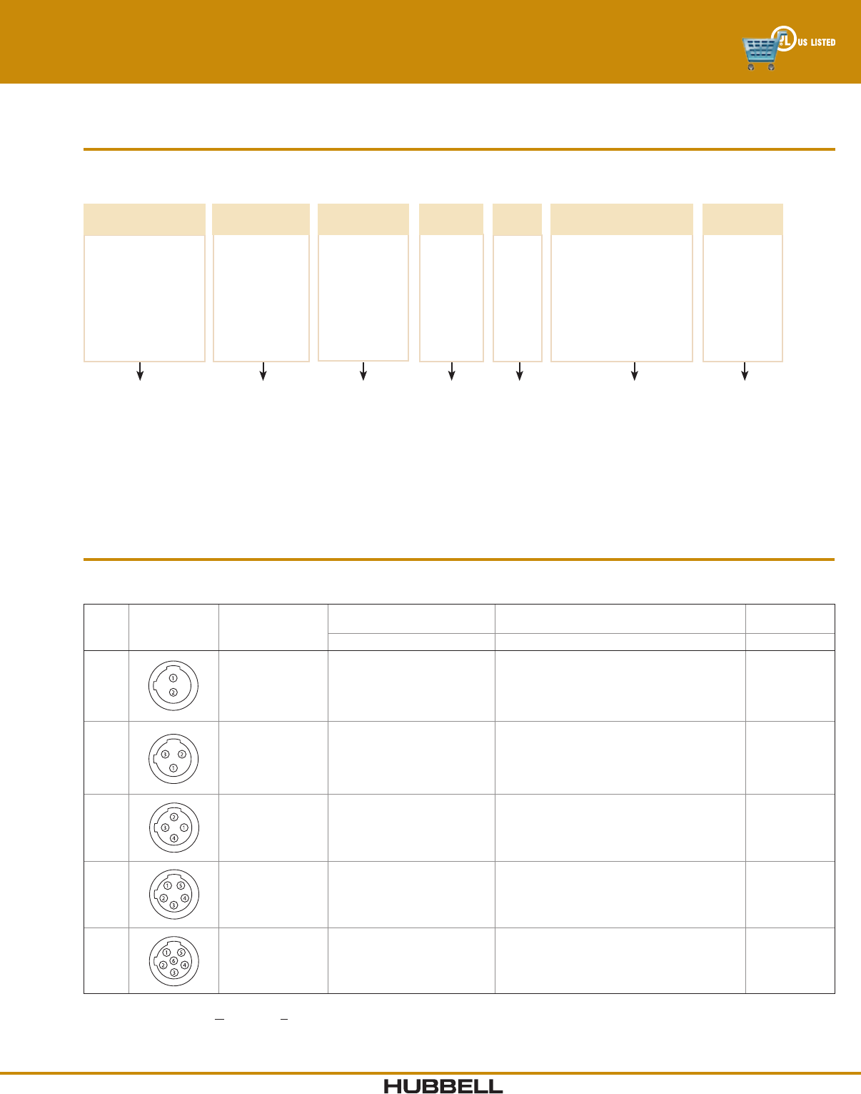
Choose the appropriate configuration from the Selector below.
Hubbell Logic Configurator
For example, catalog number HBMS05501 is derived as follows:
Mini-Quick® Control Connectors
2 - 6 Pole Receptacles
Note: Availability of specific items may vary. Consult factory for delivery. Use this chart to build receptacles to meet any application need.
Consult the factory for additional wire lengths or wire types.
DEVICE
TYPE
HR = Receptacle,
Female
HB = Receptacle,
Male
01HB M 05 5
LEAD WIRE
LENGTH (ft)
01*
**
POLES
02
03
04
05
06
S
BODY
STYLE
A = Right Angle*
S = Straight
F = Flange Mount*
CONDUCTOR
TYPE
5 = #16 AWG Discrete Wire
6 = #18 AWG IEC Discrete Wire
(IEC colors)*
SHELL
MATERIAL
M = Metallic
N = Nylon
*3 - 5 Pole Only
*1 Standard
Length
**Replace with
Length*Metallic Only
2 - 6 Pole Receptacles
#16 AWG Discrete Wire
Poles
Male Face
Shown Female -
mirror image
Female Receptacles Male Receptacles
Straight Nylon Right Angle Flange Mount Straight Nylon Right Angle Flange Mount
21
2
HRMS02501 HRNS02501 HRMA02501 HRMF02501 HBMS02501 HBNS02501 HBMA02501 HBMF02501
31
23
HRMS03501 HRNS03501 HRMA03501 HRMF03501 HBMS03501 HBNS03501 HBMA03501 HBMF03501
41
2
4
3HRMS04501 HRNS04501 HRMA04501 HRMF04501 HBMS04501 HBNS04501 HBMA04501 HBMF04501
51
2
5
4
3
HRMS05501 HRNS05501 HRMA05501 HRMF05501 HBMS05501 HBNS05501 HBMA05501 HBMF05501
61
24
5
6
3
HRMS06501 HRNS06501 HRMA06501 HRMF06501 HBMS06501 HBNS06501 HBMA06501 HBMF06501
Note: For #18 AWG IEC discrete wire, change the conductor type using the Hubbell Logic chart above.
www.hubbell-wiring.comI-12 Wiring Device-Kellems
®
Color Code By Wire Type
#16 AWG Receptacles
Contact 2 3 4 5 6
Number Pole Pole Pole Pole Pole
1 White Green Black White White
2 Black Black White Red Red
3 White Red Green Green
4 Green Orange Orange
5 Black Black
6 Blue
#18 AWG Receptacles
Contact 3 4 5
Number Pole Pole Pole
1 Yellow/Green Black Black
2 Brown Blue Blue
3 Blue Brown Yellow/Green
4 White Brown
5 White
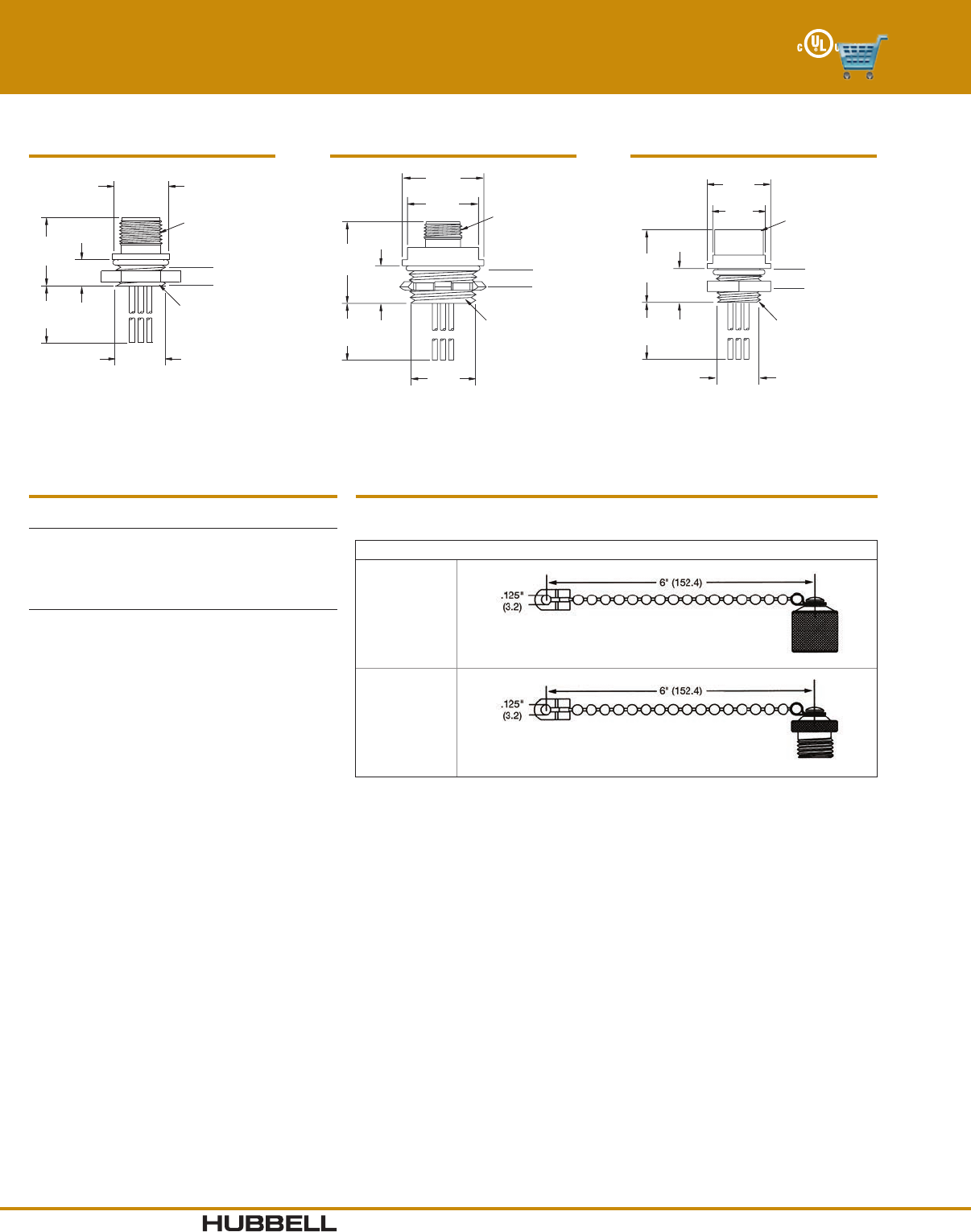
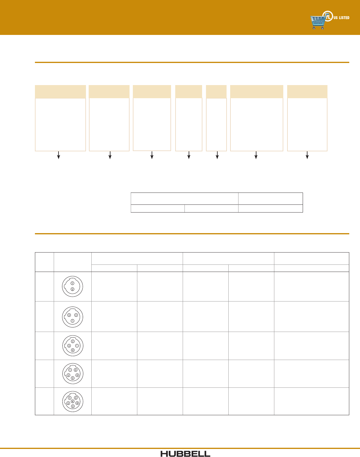
A
D
C
E
H
B
G
F
7/8 - 16 UN
Thread
½" NPT
Thread
Right Angle Receptacles
MALE FEMALE
A1.14" (29.0) 1.14" (29.0)
B1.76" (44.7) 1.76" (44.7)
C0.25" (6.4) 0.25" (6.4)
D12.0" (304.8) 12.0" (304.8)
E0.97" (24.6) 0.97" (24.6)
F0.83" (21.8) 0.83" (21.8)
G1.36" (34.5) 1.36" (34.5)
H1.26" (32.0) 1.26" (32.0)
A
G
CBD
F
½" NPT
Thread*
7/8 - 16 UN
Thread
Max panel thickness
Panel
cutout
Straight Receptacles
MALE FEMALE
A1.14" (29.0) 1.14" (29.0)
B1.11" (28.2) 1.11" (28.2)
C0.44" (11.2) 0.44" (11.2)
D12.0" (304.8) 12.0" (304.8)
F0.88" (22.4) 0.83" (22.4)
G0.25" (6.4) 0.25" (6.4)
Note: *IEC receptacle has PG13.5
rear thread.
A
G
I
B
CH
D
F
7/8 - 16 UN Thr
ead
A
G
Flange Mount Receptacles
MALE FEMALE
A1.25" (31.75) 1.25" (31.75)
B1.11" (28.19) 1.11" (28.19)
C0.44" (11.18) 0.44" (11.18)
D12.0" (304.8) 12.0" (304.8)
F0.75" (19.05) 0.75" (19.05)
G0.86" (21.84) 0.86" (21.84)
H0.45" (11.43) 0.45" (11.43)
I0.12" (03.02) 0.12" (03.02)
Mini-Quick® Control Connectors
2 - 6 Pole Receptacles
Accessories
Closure caps protect plugs and receptacles when not in use.
Shell size is 1, and the thread is 7/8-16 UN.
Description Catalog Number
Closure Cap HPCAP1
1.12"
(28.5)
0.56"
(14.2)
6.00"
(152.4)
Closure Cap HRCAP1
6.00"
(152.4)
1.13"
(28.6)
0.58"
(14.7)
Dimensions in Inches (mm)
I-13www.hubbell-wiring.com Wiring Device-Kellems
®
Choose the appropriate configuration from the Selector below.
Hubbell Logic Configurator
For example, catalog number HCMA08112 is derived as follows:
Mini-Quick® Control Connectors
7 - 12 Pole Plugs
Note: Availability of specific items may vary. Consult factory for delivery. Consult the factory for additional cable lengths or cable types.
DEVICE
TYPE
HC = Plug, Female
HP = Plug, Male
HJ = Male/Female
Jumper Cable
12HC M 08 1
CABLE
LENGTH (ft)
**
03
06
12
20
POLES
07
08
09
10
12
A
BODY
STYLE
A = Right Angle
S = Straight
CONDUCTOR
TYPE
1 = #16 AWG SEOOW Cable
COUPLING NUT
MATERIAL
M = Metallic
N = Nylon
**Replace with
Length
7 - 12 Pole Plugs
Catalog numbers using #16 AWG SEOOW cable are listed below.
Poles
Male Face Shown
Female - mirror
image Cable Length
Female Plugs Male Plugs
Male/Female
JumperCables
Straight Right Angle Straight Right Angle Straight
7
1
2
4
5
6
7
3
3 ft (0.91m)
6 ft (1.83m)
12 ft (3.66m)
All other lengths
HCMS07103
HCMS07106
HCMS07112
HCMS071**
HCMA07103
HCMA07106
HCMA07112
HCMA071**
HPMS07103
HPMS07106
HPMS07112
HPMS071**
HPMA07103
HPMA07106
HPMA07112
HPMA071**
HJMS07103
HJMS07106
HJMS07112
HJMS071**
8
1
2
4
5
6
8
7
3
3 ft (0.91m)
6 ft (1.83m)
12 ft (3.66m)
All other lengths
HCMS08103
HCMS08106
HCMS0 8112
HCMS081**
HCMA08103
HCMA08106
HCMA08112
HCMA081**
HPMS08103
HPMS08106
HPMS08112
HPMS081**
HPMA08103
HPMA08106
HPMA08112
HPMA081**
HJMS08103
HJMS08106
HJMS0 8112
HJMS081**
9
1
2
4
5
6
7
89
3
3 ft (0.91m)
6 ft (1.83m)
12 ft (3.66m)
All other lengths
HCMS09103
HCMS09106
HCMS0 9112
HCMS091**
HCMA09103
HCMA09106
HCMA09112
HCMA091**
HPMS09103
HPMS09106
HPMS09112
HPMS091**
HPMA09103
HPMA09106
HPMA09112
HPMA091**
HJMS09103
HJMS09106
HJMS0 9112
HJMS091**
10
1
2
45
6
7
8
9
10
3
3 ft (0.91m)
6 ft (1.83m)
12 ft /3.66m)
All other lengths
HCMS10103
HCMS10106
HCMS10112
HCMS101**
HCMA10103
HCMA10106
HCMA10112
HCMA101**
HPMS10103
HPMS10106
HPMS10112
HPMS101**
HPMA10103
HPMA10106
HPMA10112
HPMA101**
HJMS10103
HJMS10106
HJMS10112
HJMS101**
12
1
2
45
6
7
3
8
9
10
11
12
3 ft/0.91m)
6 f t/1.83m)
12 ft /3.66m)
All other lengths
HCMS12103
HCMS12106
HCMS12112
HCMS121**
HCMA12103
HCMA1210 6
HCMA12112
HCMA121**
HPMS12103
HPMS12106
HPMS12112
HPMS121**
HPMA12103
HPMA12106
HPMA12112
HPMA121**
HJMS12103
HJMS12106
HJMS12112
HJMS121**
Note: Replace ** with length required in feet. For nylon coupling nuts, replace “M” with “N” per the ordering chart above.
Example: change HPMA07106 to HPNA07106.
www.hubbell-wiring.comI-14 Wiring Device-Kellems
®
Cable Diameters
By Cable Type
Number of #16 AWG
Conductors STOOW
7 0.52" (13.2)
8 0.56" (14.2)
9 0.60" (15.2)
10 0.65" (16.7)
12 0.70" (17.7)
A
B
C
D
Straight Plug
MALE FEMALE
A 1.25" (31.8) 1.25" (31.8)
B 2.77" (70.4) 2.73" (69.3)
C 2.75" (69.9) 2.75" (69.9)
D 1 1/8 - 16 UN Thread
9 - 12 Pole
7 - 8 Pole
MALE FEMALE
A 1.12" (28.5) 1.12" (28.5)
B 2.53" (64.3) 2.49" (63.3)
C 2.75" (69.9) 2.75" (69.9)
D 1 - 16 UN Thread
AB
C
D
E
F
Right Angle Plug
MALE FEMALE
A1.14" (29.0) 1.14" (29.0)
B1.73" (43.9) 1.69" (42.9)
C1.12" (28.5) 1.12" (28.5)
D2.22" (56.4) 2.22" (56.4)
E2.75" (69.9) 2.75" (69.9)
F 1 - 16 UN Thread
MALE FEMALE
A1.25" (31.8) 1.25" (31.8)
B1.84" (47.0) 1.80" (45.7)
C1.25" (31.8) 1.25" (31.8)
D2.54" (64.5) 2.54" (64.5)
E2.75" (69.9) 2.75" (69.9)
F 1 1/8 - 16 UN Thread
7 - 8 Pole
9 - 12 Pole
Accessories
Closure caps protect plugs and receptacles when not in use. Adapter rings allow the mating of male and female plugs for in-line applications.
Description
Closure Cap Closure Cap Adapter Ring
Shell
Size Thread Size Catalog Number
Shell
Size Thread Size Catalog Number
Shell
Size Thread Size Catalog Number
7 to 8 Pole ll 1 - 16 UN HPCAP2 ll 1 - 16 UN HRCAP2 ll 1 - 16 UN HMQAR2
9 to 12 Pole lll 1 1/8 - 16UN HPCAP3 lll 1 1/8 - 16UN HRCAP3 lll 1 1/8 - 16UN HMQAR3
1.12"
(28.5)
0.56"
(14.2)
6.00"
(152.4)
6.00"
(152.4)
1.13"
(28.6)
0.58"
(14.7)
1.00"
(25.4)
0.48"
(12.3)
Cap Size II- 1.12" (28.5), III- 1.25" (31.8) II- 1.13" (28.6), III- 1.25" (31.8) II- 1.00" (25.4), III- 1.13" (28.6)
Mini-Quick® Control Connectors
7 - 12 Pole Plugs
Conductor Color Code
#16 AWG SEOOW Plugs
Contact 2 3 4 5 6 7 8 9 10 12
Number Pole Pole Pole Pole Pole Pole Pole Pole Pole Pole
1 White Green Black White White White/Black Orange Orange Orange Orange
2 Black Black White Red Red Black Blue Blue Blue Blue
3 White Red Green Green White White/Black Red/Black White/Black White/Black
4 Green Orange Orange Red Black Green/Black Red/Black Red/Black
5 Black Black Orange White White Green/Black Green/Black
6 Blue Blue Red Red Orange/Black Orange/Black
7 Green Green Green Red Blue/Black
8 Red/Black White/Black Green Black/White
9 Black Black Green
10 White Red
11 White
12 Black
A
B
A
B
CC
MALE FEMALE
A1.12" (28.5) 1.12" (28.5)
B2.53" (64.3) 2.49" (63.3)
C 1 - 16 UN Thread
7 - 8 Pole
MALE FEMALE
A1.25" (31.8) 1.25" (31.8)
B2.77" (70.4) 2.73" (69.3)
C 1 1/8 - 16 UN Thread
9 - 12 Pole
Jumper Cable
Dimensions in Inches (mm)
I-15www.hubbell-wiring.com Wiring Device-Kellems
®
Choose the appropriate configuration from the Selector below.
Hubbell Logic Configurator
For example, catalog number HRMS10501 is derived as follows:
Mini-Quick® Control Connectors
7 - 12 Pole Receptacles
Note: Availability of specific items may vary. Consult factory for delivery. Consult the factory for additional wire lengths or wire types.
DEVICE
TYPE
HR = Receptacle,
Female
HB = Receptacle,
Male
01HR M 10 5
LEAD WIRE
LENGTH (ft)
01*
**
POLES
07
08
09
10
12
S
BODY
STYLE
S = Straight
CONDUCTOR
TYPE
5 = #16 AWG Discrete Wire
SHELL
MATERIAL
M = Metallic
*1 Standard
Length
**Replace with
Length
7 - 12 Pole Receptacles
#16 AWG Discrete Wire
Poles
Male Face Shown
Female - mirror
image
Female
Receptacles
Male
Receptacles
7
1
2
4
5
6
7
3
HRMS07501 HBMS07501
8
1
2
4
5
6
8
7
3
HRMS08501 HBMS08501
9
1
2
4
5
6
7
89
3
HRMS09501 HBMS09501
10
1
2
45
6
7
8
9
10
3
HRMS10501 HBMS10501
12
1
2
45
6
7
3
8
9
10
11
12
HRMS12501 HBMS12501
www.hubbell-wiring.comI-16 Wiring Device-Kellems
®
Mini-Quick® Control Connectors
7 - 12 Pole Receptacles
A
B
CD
F
G
½" NPT
Thread
H
Max panel thickness
Panel
cutout
MALE FEMALE
A1.44" (36.6) 1.44" (36.6)
B1.62" (41.2) 1.62" (41.2)
C0.96" (24.4) 0.96" (24.4)
D12.0" (304.8) 12.0" (304.8)
F0.83" (21.1) 0.83" (21.1)
G0.25" (6.4) 0.25" (6.4)
H1 1/8 - 16 UN Thread
9 - 12 Pole
MALE FEMALE
A1.29" (32.8) 1.29" (32.8)
B1.44" (36.6) 1.44" (36.6)
C0.80" (20.3) 0.80" (20.3)
D12.0" (304.8) 12.0" (304.8)
F0.83" (21.1) 0.83" (21.1)
G0.25" (6.4) 0.25" (6.4)
H1 - 16 UN Thread
7 - 8 Pole
Straight Receptacles
Conductor Color Code
#16 AWG Receptacles
Contact 2 3 4 5 6 7 8 9 10 12
Number Pole Pole Pole Pole Pole Pole Pole Pole Pole Pole
1 White Green Black White White White/Black Orange Orange Orange Orange
2 Black Black White Red Red Black Blue Blue Blue Blue
3 White Red Green Green White White/Black Red/Black White/Black White/Black
4 Green Orange Orange Red Black Green/Black Red/Black Red/Black
5 Black Black Orange White White Green/Black Green/Black
6 Blue Blue Red Red Orange/Black Orange/Black
7 Green Green Green Red Blue/Black
8 Red/Black White/Black Green Black/White
9 Black Black Green
10 White Red
11 White
12 Black
Accessories
Closure caps protect plugs and receptacles when not in use. Adapter rings allow the mating of male and female plugs for in-line applications.
Description
Closure Cap Closure Cap Adapter Ring
Shell
Size Thread Size Catalog Number
Shell
Size Thread Size Catalog Number
Shell
Size Thread Size Catalog Number
7 to 8 Pole ll 1 - 16 UN HPCAP2 ll 1 - 16 UN HRCAP2 ll 1 - 16 UN HMQAR2
9 to 12 Pole lll 1 1/8 - 16UN HPCAP3 lll 1 1/8 - 16UN HRCAP3 lll 1 1/8 - 16UN HMQAR3
1.12"
(28.5)
0.56"
(14.2)
6.00"
(152.4)
6.00"
(152.4)
1.13"
(28.6)
0.58"
(14.7)
1.00"
(25.4)
0.48"
(12.3)
Cap Size II- 1.12" (28.5), III- 1.25" (31.8) II- 1.13" (28.6), III- 1.25" (31.8) II- 1.00" (25.4), III- 1.13" (28.6)
Dimensions in Inches (mm)
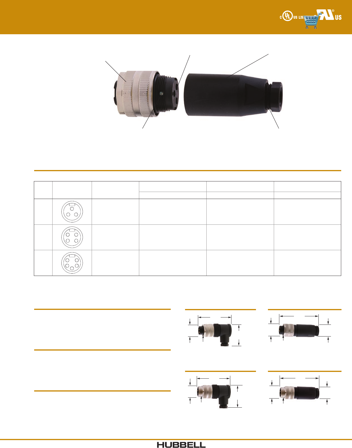
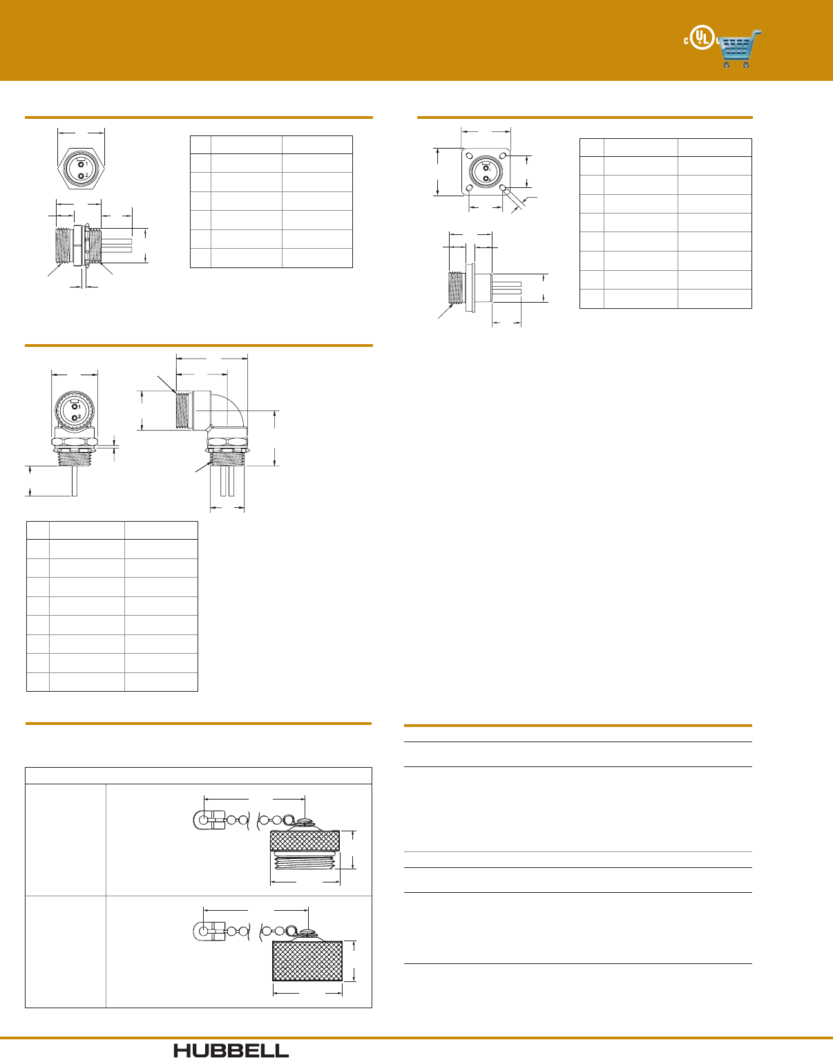
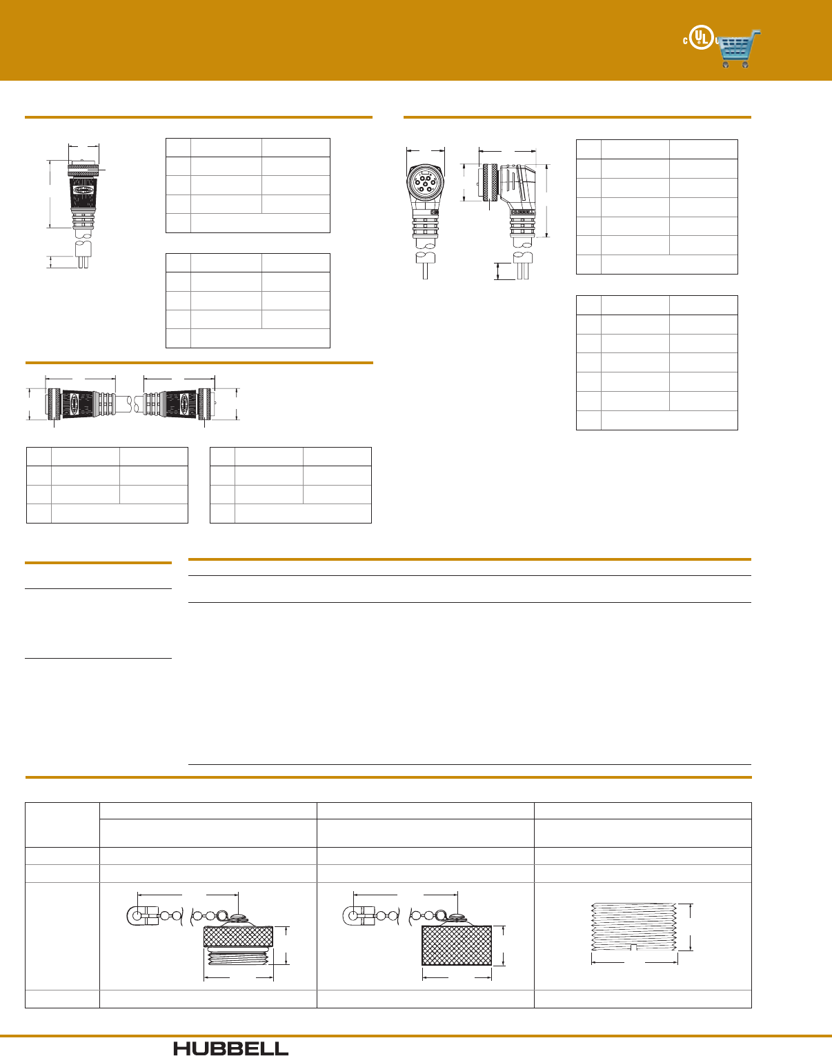
I-17www.hubbell-wiring.com Wiring Device-Kellems
®
Coupling Nut
Anodized Aluminum,
SST Option Consult Factory
Precision Wire Funnels
Eliminate Stray Strands
Body
High Impact Design
Superior Contact Design
Utilizing High Performance
Gold Over Palladium Nickel Plating
Strain Relief
Protects Terminations
Mini-Quick® Control Connectors
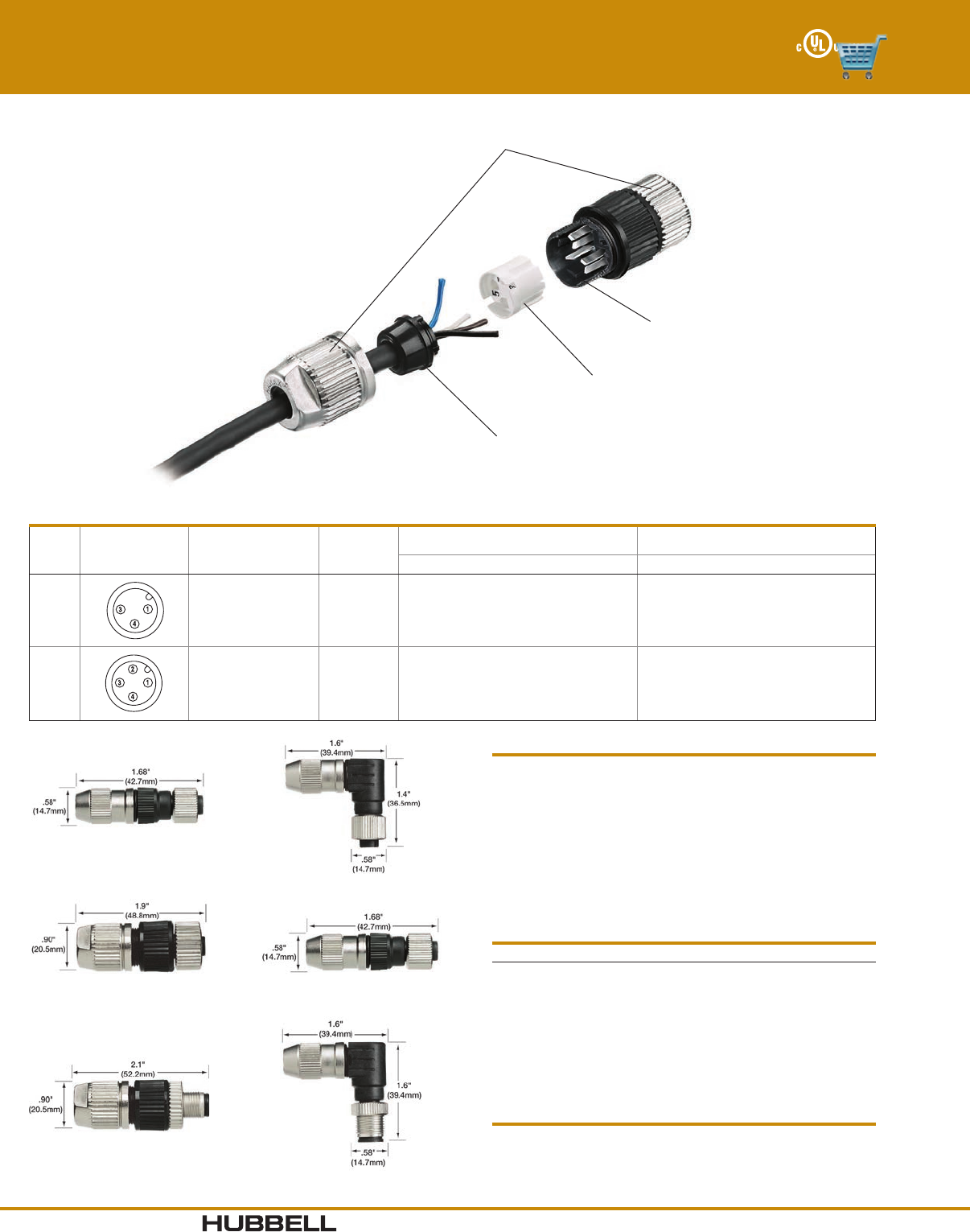
Field Attachable Connectors - Screw Terminal Style
1.10"
(28)
2.4"
(61.0)
2.0"
(50.8)
7/8"-16 UN
Female, Right Angle
Male, Right Angle
1.06"
(27)
3.1"
(78.7)
0.96"
(24.4)
7/8"-16 UN
Female, Straight
Male, Straight
1.10"
(28)
2.58"
(65.5)
2.0"
(50.8)
7/8"-16 UN
Male In-Line, Right Angle
1.06"
(27)
3.3"
(83.8)
0.96"
(24.4)
7/8"-16 UN
Male In-Line, Straight
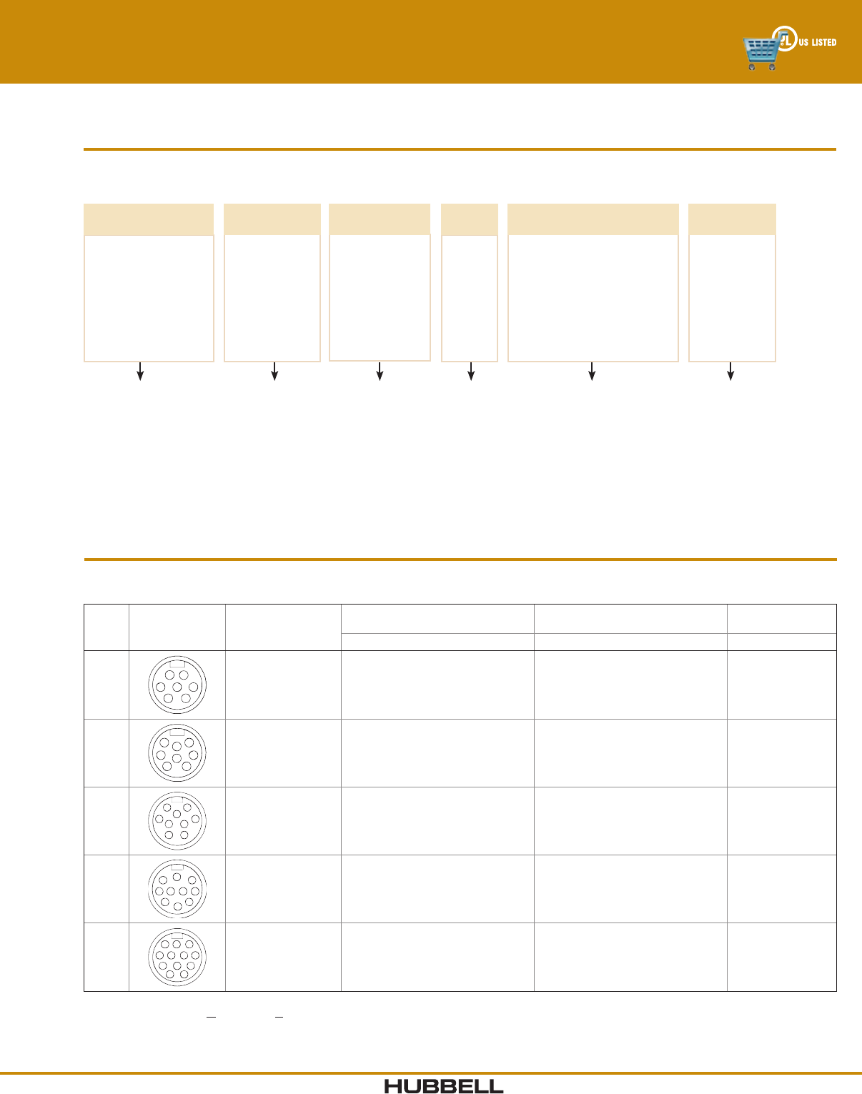
3 - 5 Pole Field Attachable Connectors
Poles
Male Face Shown
Female - mirror
image Cable Range
Female Connector Male In-Line Connector Male Connector
Straight Right Angle Straight Right Angle Straight Right Angle
31
23
.24"-. 32" (6.1- 8.1)
.39"-.47" (9.9-11.9)
.47"-. 5 5" (11.9 -13.1)
HCMS03F9
HCMS03F13
—
HCMA03F9
—
—
HIMS03F9
HIMS03F13
—
HIMA03F9
—
—
HPMS03F9
HPMS03F13
—
HPMA03F9
—
—
41
2
4
3
.24"-. 32" (6.1- 8.1)
.39"-.47" (9.9-11.9)
.47"-. 5 5" (11.9 -13.1)
HCMS04F9
HCMS04F13
HCMS04F16
HCMA04F9
—
—
HIMS04F9
HIMS04F13
HIMS04F16
HIMA04F9
—
—
HPMS04F9
HPMS04F13
HPMS04F16
HPMA04F9
—
—
51
2
5
4
3
.24"-. 32" (6.1- 8.1)
.39"-.47" (9.9-11.9)
.47"-. 5 5" (11.9 -13.1)
HCMS05F9
HCMS05F13
HCMS05F16
HCMA05F9
—
—
HIMS05F9
HIMS05F13
HIMS05F16
HIMA05F9
—
—
HPMS05F9
HPMS05F13
HPMS05F16
HPMA05F9
—
—
Electrical Specifications
Voltage Rating 250V
Amperage 3 Pin - 12A
4,5 Pin - 9A
Wire Size, Max #16 AWG
Mechanical Specifications
Coupling Nut Anodized aluminum, SST consult factory
Connector Shell PBT
Connector Insert PUR/PA
Contacts Brass, gold plate over palladium nickel
Environmental Specifications
Moisture Resistance IP66 Suitability
Operating Temperature -40°C to 85°C
Dimensions in Inches (mm)
www.hubbell-wiring.comI-18 Wiring Device-Kellems
®
Hard Gold over Palladium/
Nickel Contact Plating
High mating cycles and
longer contact life
Custom Knurled, Anti-
vibration Coupling Nut
Prevents loosening under
harsh vibration conditions
Gated Strain Relief with
Graduated Window Sizes
Distributes force away from
contacts to protect terminations
Indicator Ring
Ensures proper mating
Resilient Base Metal
Maintains socket contact shape
O-Rings
Moisture protection
Micro-Quick® Control Connectors
Features and Benefits
Cable #22 AWG - PVC jacket (black)
PVC conductor insulation
Copper braid - 85% coverage
Stranding - 19/34
#18 AWG - TPE jacket (black)
PVC conductor insulation
Stranding - 41/34
Strain Relief #22 AWG - 20 pounds min per UL2238
#18 AWG - 30 pounds min per UL 2238
Insulator Materials Nylon 6/6, White
Contact Materials Pins - Brass
Sockets - Beryllium copper
Contact Plating Hard gold over palladium/nickel
Overmold Material Glass filled polyurethane, Black
Coupling Nut, Metallic Nickel plated brass
Coupling Nut, Nylon Nylon 6/6, Black
Receptacle Shell Nickel plated brass
Material Specifications
Electrical Specifications
Voltage Rating 300V DC/300V AC
Amperage #22 AWG - 2&3P=5A, 4&5P=4A, 6P=3A
#18 AWG - 2&3P=8A, 4P=6A, 5P=5A
Contact Resistance ≤ 5 mΩ
Isolation Resistance ≥ 1000 MΩ
Environmental Specifications
Moisture Protection UL Type 4, 4X, 12 and 13
Ingress Protection IP66 Suitability
Operating Temperature #22 AWG PVC cable: -20°C to 105° C
#18 AWG TPE cable: -40°C to 105° C
Corrosion Resistance 500 hours salt spray per MIL-STD-1344,
Method 1001
Vibration Resistance 10 - 2,000 Hz @15g per MIL-STD-1344,
Method 2005
Certifications
UL 2238 and UL50E, File No. E192071 CSA Certified, C22.2 No. 182.3 and CSA C22.2 No. 94.2-07
Features Benefits
• Nickel plated brass coupling nuts and receptacle shells.
• Beryllium copper socket contacts.
• Standard #22 AWG cable 85% copper braid coverage.
• Black overmold and cable.
• Insulgrip connector body design.
• Plating resists corrosion in high abuse environments.
• Strong, resilient base metal ensures contacts maintain their shape
and continuity over time.
• Cable resists nicks and abrasions and provides shielding when
braid is terminated.
• Cable assembly resists dirt and blends with environment giving a
clean look to the installation.
• Ergonomic connector body has an industrial look.
I-19www.hubbell-wiring.com Wiring Device-Kellems
®
Choose the appropriate configuration from the Selector below.
Hubbell Logic Configurator
For example, catalog number MCMS1312 is derived as follows:
Micro-Quick® Control Connectors
Single Key 3 - 5 Pole Plugs
Note: Availability of specific items may vary. Consult factory for delivery. Consult the factory for additional cable lengths or cable types.
3 - 5 Pole Single Key Plugs
Catalog numbers using #22 AWG PVC cable are listed below. For #18 AWG TPE cable, change the conductor type per
the Hubbell Logic chart above.
Poles
Male Face Shown
Female - mirror
image Cable Length
Female Plugs Male In-Line Plugs
Male/Female
Extension Cables
Straight Right Angle Straight Straight
3
6.56 ft (2m)
13.12 ft (4m)
16.40 ft (5m)
All other lengths
MCMS1312
MCMS1314
MCMS1315
MCMS131**
MCMA1312
MCMA1314
MCMA1315
MCMA131**
MIMS1312
MIMS1314
MIMS1315
MIMS131**
MEMS1312
MEMS1314
MEMS1315
MEMS131**
4
6.56 ft (2m)
13.12 ft (4m)
16.40 ft (5m)
All other lengths
MCMS1412
MCMS1414
MCMS1415
MCMS141**
MCMA1412
MCMA1414
MCMA1415
MCMA141**
MIMS1412
MIMS1414
MIMS1415
MIMS141**
MEMS1412
MEMS1414
MEMS1415
MEMS141**
5
6.56 ft (2m)
13.12 ft (4m)
16.40 ft (5m)
All other lengths
MCMS1512
MCMS1514
MCMS1515
MCMS151**
MCMA1512
MCMA1514
MCMA1515
MCMA151**
MIMS1512
MIMS1514
MIMS1515
MIMS151**
MEMS1512
MEMS1514
MEMS1515
MEMS151**
Note: Replace ** with length required in meters. For nylon coupling nuts, replace “M” with “N” per the ordering chart above.
Example: change MCMA1412 to MCNA1412.
DEVICE
TYPE
MC = Plug, Female
MI = Plug, Male Inline
ME = Male/Female
Extension Cable
2MC M 3 1
CABLE
LENGTH (m)
**
2
4
5
POLES
3
4
5
S
BODY
STYLE
A = Right Angle
S = Straight
CONDUCTOR
TYPE
1 = #22 AWG PVC Cable
2 = #18 AWG TPE Cable*
COUPLING NUT
MATERIAL
M = Metallic
N = Nylon
**Replace with
Length
1
KEY
STYLE
1 = Single
*2 - 4 Pole Only
www.hubbell-wiring.comI-20 Wiring Device-Kellems
®
Micro-Quick® Control Connectors
Single Key 3 - 5 Pole Plugs
Drawings (in/mm)
Cable Diameters By Cable Type
Number of #22 AWG #18 AWG
Conductors PVC TPE
3 0.21" (5.3) 0.24" ( 6 .1)
4 0.22" (5.7) 0.26" (6.6)
5 0.26" (6.6) 0. 28 " ( 7.1)
Conductor Color Code
Contact 3 4 5
Number Pole Pole Pole
1 Brown Brown Brown
2 Not Used White White
3 Blue Blue Blue
4 Black Black Black
5 Not Used Not Used Gray
A
B
C
M12 x 1
Thread
A0.59" (15.0)
B1.83" (46.5)
C2.75" (69.9)
Straight Female Plug
D
A
E
B
C
M12 x 1
Thread
A0.59" (15.0)
B1.44" (36.6)
C2.75" (69.9)
D0.67" (17.0)
E1.15" (29.2)
Right Angle Female Plug
A
DE
B
C
M12 x 1
Thread
A0.59" (15.0)
B1.44" (36.6)
C2.75" (69.9)
D0.67" (17.0)
E1.38" (35.1)
Right Male In-Line Plug
A
B
C
M12 x 1
Thread
MALE
A0.59" (15.0)
B2.06" (52.3)
C2.75" (69.9)
Straight Male In-Line Plug
A
BB
A
CC
FEMALE MALE
A 0.59" (15.0) 0.59" (15.0)
B 1.83" (46.5) 2.06" (52.3)
C M12 x 1
Extension Cable
Accessories
Dust Caps
Closure caps protect plugs and receptacles when not in use. Thread is M12 x 1.
Catalog Number
MRCM1
MPCM1
Dimensions in Inches (mm)
I-21www.hubbell-wiring.com Wiring Device-Kellems
®
Choose the appropriate configuration from the Selector below.
Hubbell Logic Configurator
For example, catalog number MRMS13314 is derived as follows:
Micro-Quick® Control Connectors
Single Key 3 - 5 Pole Receptacles
Note: Availability of specific items may vary. Consult factory for delivery. Consult the factory for additional cable lengths or cable types.
DEVICE
TYPE
MB = Receptacle,
Male
MF = Receptacle,
Female Inverse
14MR M 3 3
POLES
3
4
5
S
BODY
STYLE
S = Straight
CONDUCTOR
TYPE
3 = #22 AWG PVC
Discrete Wire
4 = #18 AWG PVC
Discrete Wire*
COUPLING NUT
MATERIAL
M = Metallic
*MB Style Only
**MF Style Only
REAR
THREAD STYLE
14 = M14x1*
25 = ¼" NPT**
50 = ½" NPT*
1
KEY
STYLE
1 = Single
*3 - 4 Pole Only
3 - 5 Pole Single Key Receptacles- #22 AWG Discrete Wire*
Catalog numbers using #22 AWG PVC discrete wire are listed below. For #18 AWG PVC discrete wire, change the conductor type
per the Hubbell Logic chart above.
Poles
Male Face Shown
Female - mirror
image
Male Receptacle
Rear Thread Style
Female Inverse Receptacles
Rear Thread Style
M14 x 1 ½" NPT ¼" NPT
3
MBMS13314 MBMS13350 MFMS13325
4
MBMS14314 MBMS14350 MFMS14325
5
MBMS15314 MBMS15350 MFMS15325
Note: *For #18 AWG discrete wire, replace the conductor type per Hubbell Logic chart above.
All receptacles available in 1ft. length standard. For additional lengths, please consult factory.
www.hubbell-wiring.comI-22 Wiring Device-Kellems
®
Conductor Color Code - Single Key
Contact 3 4 5
Number Pole Pole Pole
1 Brown Brown Brown
2 Not Used White White
3 Blue Blue Blue
4 Black Black Black
5 Not Used Not Used Gray
Micro-Quick® Control Connectors
Single Key 3 - 5 Pole Receptacles
Drawings (in/mm)
M12 x 1
Thread
M14 x 1
Thread
Ø 0.63"
(16)
0.75"
(19.1)
12"
(304.8)
0.29"
(7.4)
Ø 0.63"
(16)
Panel Cutout
.050" (1.3)
Max panel thickness
Male Receptacle
Rear Thread - M14x1
½" NPT
Thread
1.0"
(25.4)
0.87"
(22.1)
1.0"
(25.4)
0.46"
(11.7)
12"
(304.8)
0.85"
(21.6)
.24" (6.1)
M12 x 1
Thread
Panel Cutout
Max panel thickness
Male Receptacle
Rear Thread - ½" NPT
¼" NPT
Thread
0.75"
(19.1)
0.62"
(15.8)
0.86"
(21.8)
12"
(304.8)
0.40"
(10.2)
0.56"
(14.2)
.15" (3.8)
Max panel thickness
M12 x 1
Thread
Panel Cutout
Female Inverse Receptacle
Rear Thread - ¼" NPT
Accessories
Dust Caps
Closure caps protect plugs and receptacles when not in use. Thread is M12 x 1.
Catalog Number
MRCM1
MPCM1
Dimensions in Inches (mm)
I-23www.hubbell-wiring.com Wiring Device-Kellems
®
Choose the appropriate configuration from the Selector below.
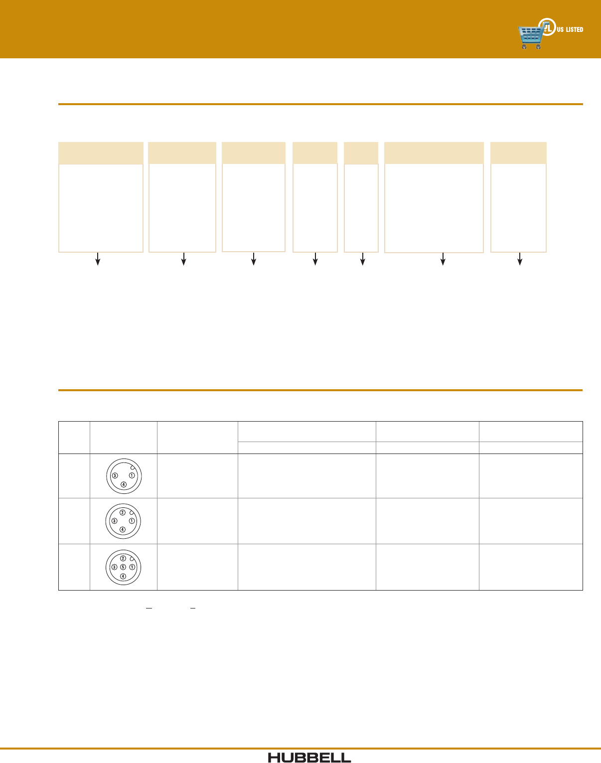
Hubbell Logic Configurator
For example, catalog number MPMS2512 is derived as follows:
Micro-Quick® Control Connectors
Dual Key 2 - 6 Pole Plugs
Note: Availability of specific items may vary. Consult factory for delivery. Consult the factory for additional cable lengths or cable types.
DEVICE
TYPE
MC = Plug, Female
MP = Plug, Male
MI = Plug, Male Inline
ME = Male/Female
Extension Cable
2MP M 5 1
CABLE
LENGTH (m)
**
2
4
5
POLES
2
3
4
5
6
S
BODY
STYLE
A = Right Angle
S = Straight
CONDUCTOR
TYPE
1 = #22 AWG PVC Cable
2 = #18 AWG TPE Cable*
COUPLING NUT
MATERIAL
M = Metallic
N = Nylon
**Replace with
Length
2
KEY
STYLE
2 = Dual
*2 - 5 Pole Only
2 - 6 Pole Dual Key Plugs
Catalog numbers using #22 AWG PVC cable are listed below. For #18 AWG TPE cable, change the conductor type per the
Hubbell Logic chart above.
Poles
Male Face Shown
Female - mirror
image Cable Length
Female Plugs Male Plugs
Male/Female
Extension Cables
Straight Right Angle Straight Right Angle In-Line Straight Straight
2
6.56 ft (2m)
13.12 ft (4m)
16.40 ft (5m)
All other lengths
MCMS2212
MCMS2214
MCMS2215
MCMS221**
MCMA2212
MCMA2214
MCMA2215
MCMA221**
MPMS2212
MPMS2214
MPMS2215
MPMS221**
MPMA2212
MPMA2214
MPMA2215
MPMA221**
MIMS2212
MIMS2214
MIMS2215
MIMS221**
MEMS2212
MEMS2214
MEMS2215
MEMS221**
3
6.56 ft (2m)
13.12 ft (4m)
16.40 ft (5m)
All other lengths
MCMS2312
MCMS2314
MCMS2315
MCMS231**
MCMA2312
MCMA2314
MCMA2315
MCMA231**
MPMS2312
MPMS2314
MPMS2315
MPMS231**
MPMA2312
MPMA2314
MPMA2315
MPMA231**
MIMS2312
MIMS2314
MIMS2315
MIMS231**
MEMS2312
MEMS2314
MEMS2315
MEMS231**
4
6.56 ft (2m)
13.12 ft (4m)
16.40 ft (5m)
All other lengths
MCMS2412
MCMS2414
MCMS2415
MCMS241**
MCMA2412
MCMA2414
MCMA2415
MCMA241**
MPMS2412
MPMS2414
MPMS2415
MPMS241**
MPMA2412
MPMA2414
MPMA2415
MPMA241**
MIMS2412
MIMS2414
MIMS2415
MIMS241**
MEMS2412
MEMS2414
MEMS2415
MEMS241**
5
6.56 ft (2m)
13.12 ft (4m)
16.40 ft (5m)
All other lengths
MCMS2512
MCMS2514
MCMS2515
MCMS251**
MCMA2512
MCMA2514
MCMA2515
MCMA251**
MPMS2512
MPMS2514
MPMS2515
MPMS251**
MPMA2512
MPMA2514
MPMA2515
MPMA251**
MIMS2512
MIMS2514
MIMS2515
MIMS251**
MEMS2512
MEMS2514
MEMS2515
MEMS251**
6
6.56 ft (2m)
13.12 ft (4m)
16.40 ft (5m)
All other lengths
MCMS2612
MCMS2614
MCMS2615
MCMS261**
MCMA2612
MCMA2614
MCMA2615
MCMA261**
MPMS2612
MPMS2614
MPMS2615
MPMS261**
MPMA2612
MPMA2614
MPMA2615
MPMA261**
MIMS2612
MIMS2614
MIMS2615
MIMS261**
MEMS2612
MEMS2614
MEMS2615
MEMS261**
Note: Replace ** with length required in meters. For nylon coupling nuts, replace “M” with “N” per the ordering chart above.
Example: change MCMS2314 to MCNS2314.
www.hubbell-wiring.comI-24 Wiring Device-Kellems
®
Conductor Color Code - Dual Key
Contact 2 3 4 5 6
Number Pole Pole Pole Pole Pole
1 Brown Green Red/Black Red/White Red/White
2 Blue Red/Black Red/White Red Red
3 Red/White Red Green Green
4 Green Re d/ Yell ow Re d/ Yel lo w
5 Red/Black Red/Black
6 Red/Blue
Cable Diameters By Cable Type
Number of #22 AWG #18 AWG
Conductors PVC TPE
2 0.20" (5.1) 0.23" (5.8)
3 0.21" (5.3) 0.24" (6.09)
4 0.22" (5.7) 0.26" (6.6)
5 0.26" (6.7) 0 . 28 " ( 7.1)
6 0.26" (6.5) –
Micro-Quick® Control Connectors
Dual Key 2 - 6 Pole Plugs
A
BB
A
1/2 - 20 UNF Thread 1/2 - 20 UNF Thread
MALE FEMALE
A0.59" (15.0) 0.59" (15.0)
B2.06" (52.3) 1.83" (46.5)
Extension Cable
A
B
C
1/2 - 20 UNF
Thread
A0.59" (15.0)
B2.06" (52.3)
C2.75" (69.9)
Male In-Line Plug
A
B
C
1/2 - 20 UNF
Thread
MALE FEMALE
A0.59" (15.0) 0.59" (15.0)
B1.83" (46.5) 1.83" (46.5)
C2.75" (69.9) 2.75" (69.9)
Straight Plug
D
A
E
B
C
1/2 - 20 UNF
Thread
MALE FEMALE
A0.59" (15.0) 0.59" (15.0)
B1.44" (36.6) 1.44" (36.6)
C2.75" (69.9) 2.75" (69.9)
D0.67" (17.0) 0.67" (17.0)
E1.15" (29.2) 1.15" (29.2)
Right Angle Plug
D
A
E
B
C
1/2 - 20 UNF
Thread
A0.59" (15.0)
B1.44" (36.6)
C2.75" (69.9)
D0.67" (17.0)
E1.38" (35.1)
Right Angle Male In-Line Plug
Accessories
Dust Caps
Closure caps protect plugs and receptacles when not in use.
Key style is for dual with thread of ½"-20 UNF.
Catalog Number
MRCM2
MPCM2
Dimensions in Inches (mm)
I-25www.hubbell-wiring.com Wiring Device-Kellems
®
Choose the appropriate configuration from the Selector below.
Hubbell Logic Configurator
For example, catalog number MRMS22325 is derived as follows:
Micro-Quick® Control Connectors
Dual Key 2 - 6 Pole Receptacles
Note: Availability of specific items may vary. Consult factory for delivery. Consult the factory for additional cable lengths or cable types.
DEVICE
TYPE
MR = Receptacle,
Female
MB = Receptacle,
Male
MF = Receptacle,
Female Inverse
25MR M 2 3
POLES
2
3
4
5
6
S
BODY
STYLE
S = Straight
CONDUCTOR
TYPE
3 = #22 AWG PVC
Discrete Wire
4 = #18 AWG PVC
Discrete Wire*
COUPLING NUT
MATERIAL
M = Metallic
*MF Style Only
REAR
THREAD STYLE
25 = ¼" NPT*
50 = ½" NPT
2
KEY
STYLE
2 = Dual
*2 - 5 Pole Only
2 - 6 Pole Dual Key Receptacles
Catalog numbers using #22 AWG PVC cable are listed below. For #18 AWG PVC discrete wire, change the conductor type per
the Hubbell Logic chart above.
Poles
Male Face Shown
Female - mirror
image
Female Receptacle
Rear Thread Style
Male Receptacle
Rear Thread Style
Female Inverse
Receptacles
¼" NPT ½" NPT ¼" NPT ½" NPT ¼" NPT
2MRMS22325 MRMS22350 MBMS22325 MBMS22350 MFMS22325
3MRMS23325 MRMS23350 MBMS23325 MBMS23350 MFMS23325
4MRMS24325 MRMS24350 MBMS24325 MBMS24350 MFMS24325
5MRMS25325 MRMS25350 MBMS25325 MBMS25350 MFMS25325
6MRMS26325 MRMS26350 MBMS26325 MBMS26350 MFMS26325
Male Receptacle
Rear Thread Style
Female Inverse Receptacles
Rear Thread Style
M14 X 1 ½" NPT ¼" NPT
www.hubbell-wiring.comI-26 Wiring Device-Kellems
®
A
E
B
FC
D
1/2 - 20 UNF
Thread
¼" NPT
Thread
Max panel thickness
G
Panel cutout
¼" NPT Rear Thread Receptacle
MALE FEMALE
A0.75" (19.1) 0.75" (19.1)
B0.75" (19.1) 0.86" (21.8)
C0.10" (2.5) 0.10" (2.5)
D12.0" (304.8) 12.0" (304.8)
E0.62" (15.8) 0.62" (15.8)
F0.35" (8.9) 0.38" (9.7)
G0.56" (14.2) 0.56" (14.2)
Micro-Quick® Control Connectors
Dual Key 2 - 6 Pole Receptacles
A
E
B
D
FC
1/2 - 20 UNF
Thread
½" NPT
Thread
G
Panel cutout
½" NPT Rear Thread Receptacle
MALE FEMALE
A1.00" (25.4) 1.00" (25.4)
B1.00" (25.4) 1.00" (25.4)
C0.24" (6.10) 0.24" (6.10)
D12.0" (304.8) 12.0" (304.8)
E0.87" (22.1) 0.87" (22.1)
F0.46" (11.7) 0.46" (11.7)
G0.85" (21.6) 0.85" (21.6)
A
E
B
F
D
C
1/2 - 20 UNF
Thread
¼" NPT
Thread
Max panel thickness
G
Panel cutout
Female Inverse Receptacle
¼" NPT Rear Thread
A0.75" (19.1)
B0.86" (21.8)
C0.15" (3.8)
D12.0" (304.8)
E0.62" (15.8)
F0.40" (10.2)
G0.56" (14.2)
Accessories
Dust Caps
Closure caps protect plugs and receptacles when not in use.
Key style is for dual with thread of ½"-20 UNF.
Catalog Number
MRCM2
MPCM2
Conductor Color Code - Dual Key
Contact 2 3 4 5 6
Number Pole Pole Pole Pole Pole
1 Brown Green Red/Black Red/White Red/White
2 Blue Red/Black Red/White Red Red
3 Red/White Red Green Green
4 Green Re d/ Yell ow Re d/ Yel lo w
5 Red/Black Red/Black
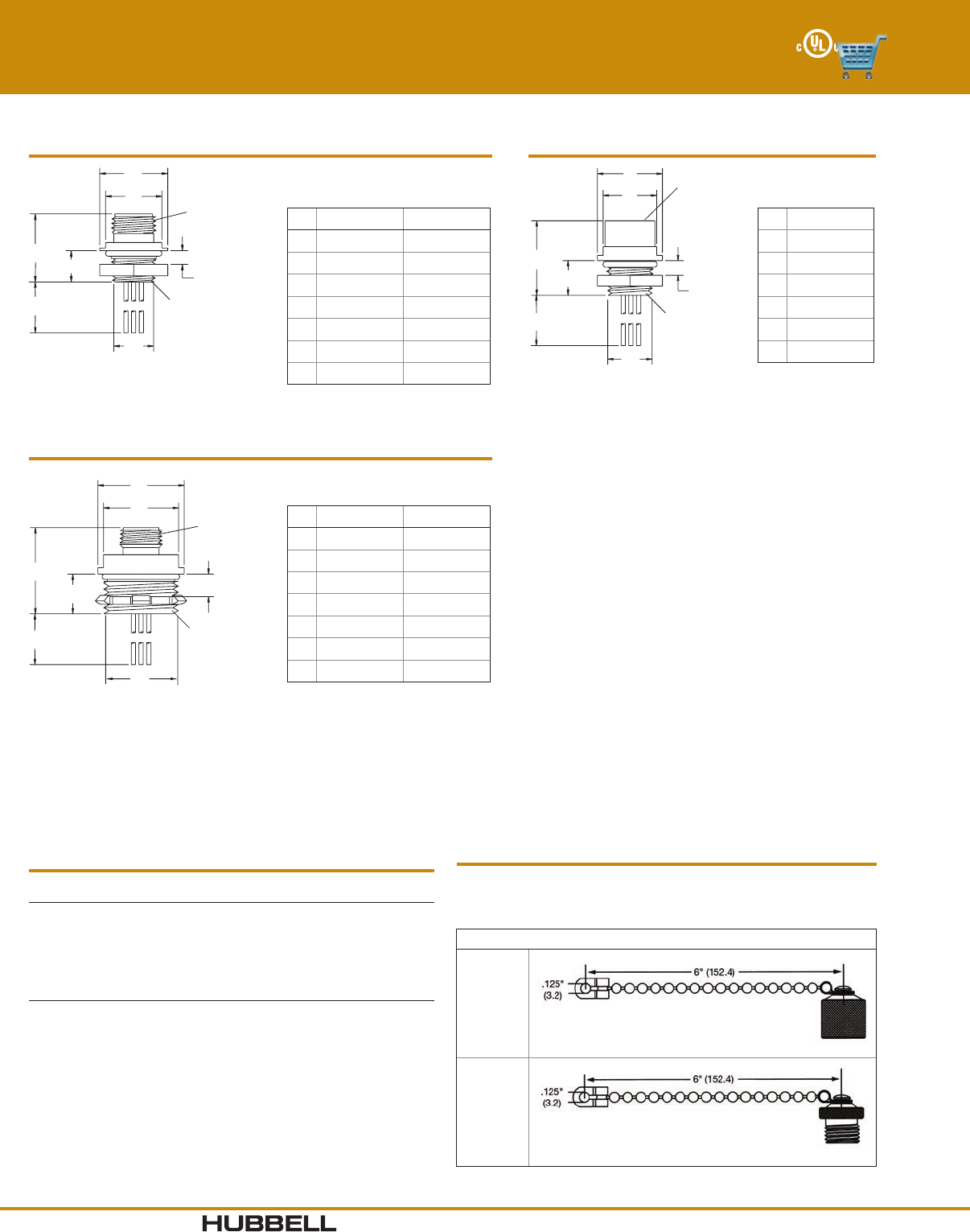
6 Red/Blue
Dimensions in Inches (mm)
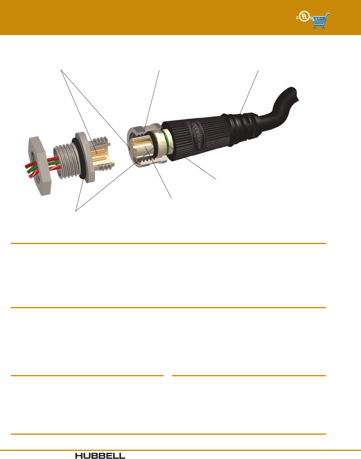
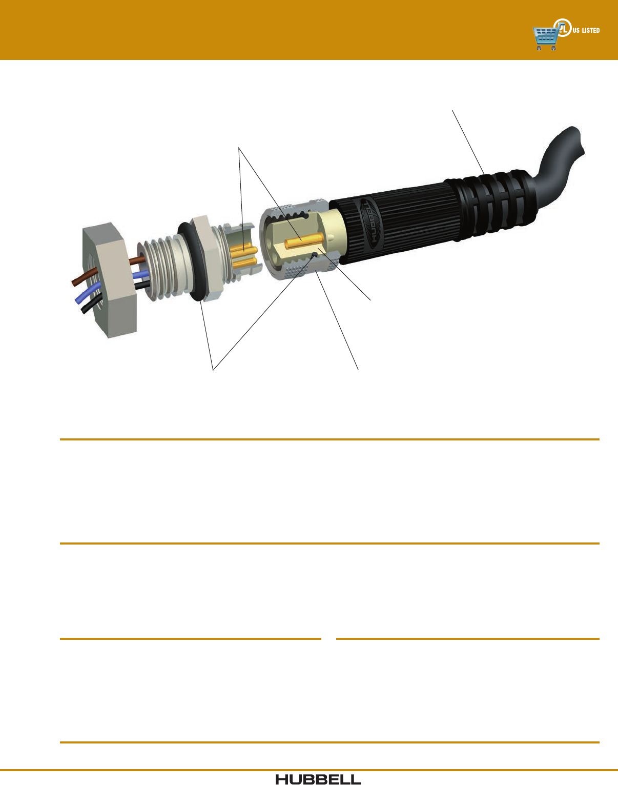
I-27www.hubbell-wiring.com Wiring Device-Kellems
®
Coupling Nut
Anodized Aluminum,
SST Option Consult Factory
Precision Wire Funnels
Eliminate Stray Strands
Body
High Impact Design
Superior Contact Design
Utilizing High Performance
Gold Over Palladium Nickel Plating
Strain Relief
Protects Terminations
0.79
"
(20)
0.81"
(20.5
)
1.38"
(35)
0.98"
(24.9)
0.58"
(14.7)
Female, Right Angle
0.79"
(20)
2.1"
(53.4)
Female, Straight
0.79"
(20)
0.81"
(20.5)
1.61"
(40.9)
0.58"
(14.7)
Male In-Line, Right Angle
2.4"
(60.9)
0.79"
(20)
Male In-Line, Straight
Micro-Quick® Control Connectors
Field Attachable Connectors - Screw Terminal Style
Electrical Specifications
Voltage Rating 250V
Amperage 4A
Wire Size, Max #18 AWG
Mechanical Specifications
Coupling Nut Nickel plated brass, SST consult factory
Connector Shell PBT
Connector Insert Nylon
Contacts Brass, gold plate over palladium nickel
Environmental Specifications
Moisture Resistance IP66 Suitability
Operating Temperature -40°C to 90°C
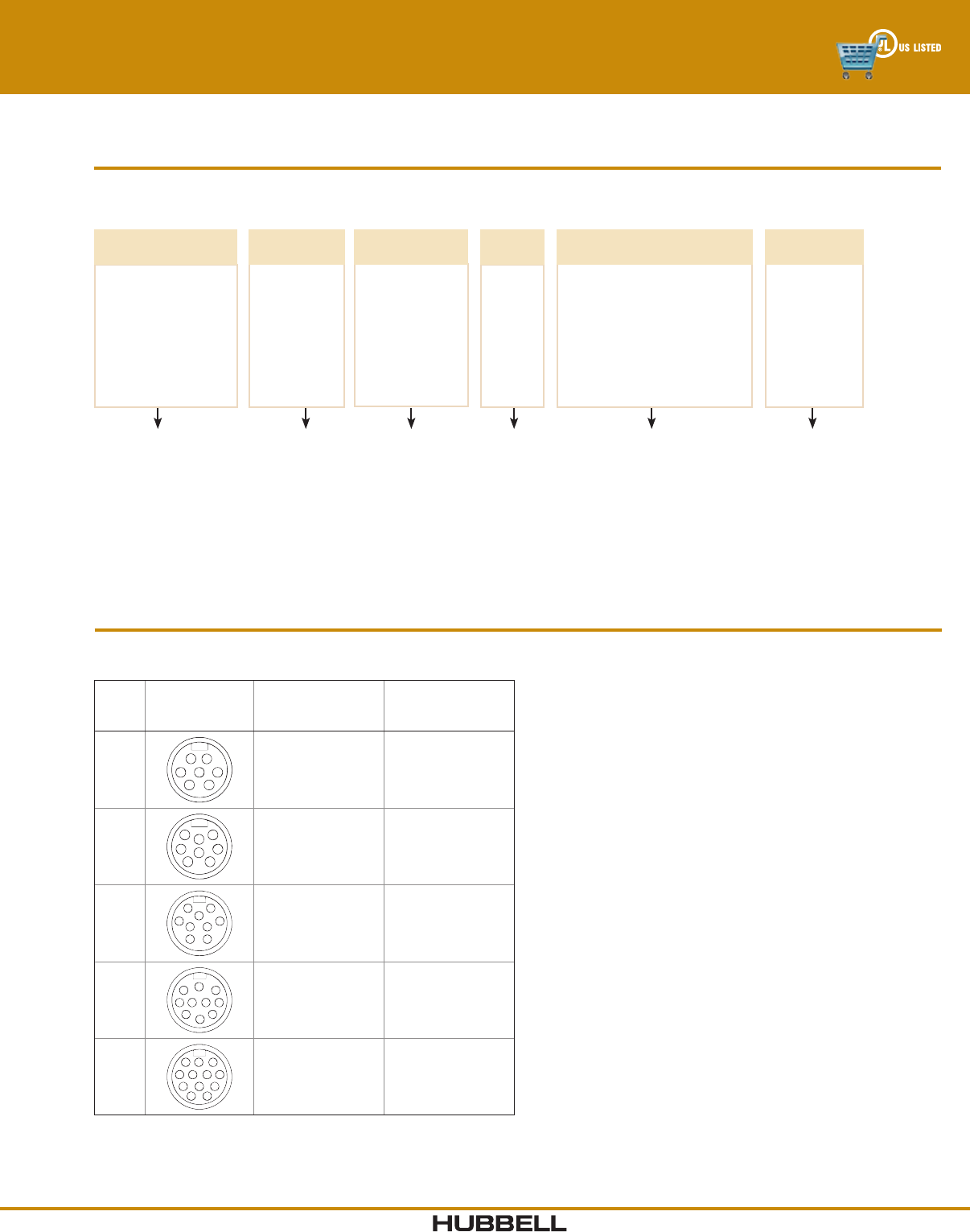
3 - 5 Pole Field Attachable Connectors
Poles
Male Face Shown
Female - mirror
image Cable Range
Female Connector Male In-Line Connector
Straight Right Angle Straight Right Angle
3.16"-. 24" (4.1-6.1)
.24"-. 32" (6.1- 8.1)
MCMS23F7
MCMS23F9
MCMA23F7
MCMA23F9
MIMS23F7
MIMS23F9
MIMA23F7
MIMA23F9
4.16"-. 24" (4.1-6.1)
.24"-. 32" (6.1- 8.1)
MCMS14F7
MCMS14F9
MCMA14F7
MCMA14F9
MIMS14F7
MIMS14F9
MIMA14F7
MIMA14F9
5.16"-. 24" (4.1-6.1)
.24"-. 32" (6.1- 8.1)
MCMS15F7
MCMS15F9
MCMA15F7
MCMA15F9
MIMS15F7
MIMS15F9
MIMA15F7
MIMA15F9
Dimensions in Inches (mm)
www.hubbell-wiring.comI-28 Wiring Device-Kellems
®
Rugged, Nickel-plated Hardware
Excellent corrosion and abuse resistance
Strain Relief Bushing
Protects terminations and provides IP66 ingress protection
Copper Alloy
Insulation displacement contacts
Wire Guide
For virtually toolless termination
Allows field installation of control
connector. Insulation Displacement
Contacts do not require stripped
conductors, greatly speeding
installation.
MCMS13IDC
MIMS13IDCMCMS13IDCL
MIMA13IDC
MIMS13IDCL
MCMA13IDC
Material Specifications
Housing Polyester Elastomer, Black
Wire Guide Nylon 6/6, Gray
Strain Relief Bushing Neoprene, Black
Contact Materials Copper Alloy
Contact Plating Tin over Nickel
Coupling Nut Zinc Alloy with Nickel Plating
O-ring Neoprene, Black
Cable Compression Nut Zinc Alloy with Nickel Plating
Electrical Specifications
Catalog Suffix IDC IDCL
Voltage Rating 32V AC/DC 50V AC/DC
Wire Range #22 AWG max., #18 AWG max.,
#24 AWG min. #22 AWG min.
Cable Diameters .160" to .211" .22" to .32"
(4.1 to 5.3 mm) (5.6 to 8.1 mm)
Amperage 3A 6A
Contact Res. < 5 mΩ < 5 mΩ
Environmental Specifications
Ingress Protection IP66 Suitability
Operating Temperature -20°C to 110°C
Micro-Quick® Control Connectors
Field Attachable Connectors - IDC Style
Micro-Quick® IDC
Poles
Male Face Shown
Female - mirror
image Cable Range Wire Gauge
Female Connector Male In-Line Connector
Straight Right Angle Straight Right Angle
3.16"-. 21" (4.1- 5.3)
.22"-.32" (5.6-8.1)
22 - 24
18 - 22
MCMS13IDC
MCMS13IDCL
MCMA13IDC
—
MIMS13IDC
MIMS13IDCL
MIMA13IDC
—
4.16"-. 21" (4.1- 5.3)
.22"-.32" (5.6-8.1)
22 - 24
18 - 22
MCMS14IDC
MCMS14IDCL
MCMA14IDC
—
MIMS14IDC
MIMS14IDCL
MIMA14IDC
—
Dimensions in Inches (mm)
I-29www.hubbell-wiring.com Wiring Device-Kellems
®
Hard Gold Over Palladium Nickel Contact Plating
Superior Conductivity, Extended Contact Life
Beryllium Copper Socket Contacts
Ensures contacts maintain their shape
and continuity
Anti-Vibration Coupling Nut
Prevents coupling nut from loosening under
harsh vibration conditions
O-Rings
Moisture Protection
Gated Strain Relief with Graduated Window Sizes
Improved Flexibility and Strength Protects Wire
Terminations Superior arc of bend control
Nano-Quick® Control Connectors
Features and Benefits
Cable #24 AWG - PVC jacket, Black, PVC conductor
insulation, Copper braid - 85% coverage,
Stranding 19/36
#24 AWG - TPE jacket, Black, PVC conductor
insulation, Stranding - 19/36
Strain Relief 20 pounds min per UL 2238
Insulator Materials Nylon 6/6, White
Contact Materials Pins - Brass, Sockets
Sockets - Beryllium copper
Contact Plating Hard gold over palladium/nickel
Overmold Material Polyurethane, Black
Coupling Nut, Metallic Nickel plated brass
Receptacle Shell Nickel plated brass
Material Specifications
Electrical Specifications
Voltage Rating 125V AC/75V DC
Amperage 3&4P=4A
Contact Resistance ≤ 5 mΩ
Isolation Resistance ≥ 1000 MΩ
Environmental Specifications
Moisture Protection UL Type 4, 4X, 12 and 13
Ingress Protection IP66 Suitability
Operating Temperature PVC Cable: -20° to 105° C
TPE Cable: -40°C to 105° C
Corrosion Resistance 500 hours salt spray per
MIL-STD-1344, Method 1001
Vibration Resistance 10 - 2,000 Hz @15g per MIL-STD1344,
Method 2005
Certifications
UL 2238 and UL50E, File No. E192071 CSA Certified, C22.2 No. 182.3 and CSA C22.2 No. 94.2-07
Features Benefits
• Nickel plated brass coupling nuts and receptacle shells.
• Black overmold and cable.
• Insulgrip connector body design.
• UL Listed cable assemblies and receptacles.
• Plating resists corrosion in high abuse environments.
• Strong, resilient base metal ensures contacts maintain their shape
and continuity over time.
• Ergonomic connector body has an industrial look.
• Third party certified for electrical, mechanical and environmental
performance.
• Cable assembly resists dirt and blends with environment
giving a clean look to the installation.
www.hubbell-wiring.comI-30 Wiring Device-Kellems
®
Hubbell Logic Configurator
For example, Catalog Number NBCS3D is derived as follows:
C
RETENTION
STYLE
C = Combination
D
CONDUCTOR
TYPE
D = 0.25m #24 AWG
discrete wire
S
BODY
STYLE
S = Straight
NB
DEVICE
TYPE
NB = Receptacle,
Male
3
POLES
3
4
Choose the appropriate configuration from the Selector below.
Hubbell Logic Configurator
For example, catalog number NCTA3105 is derived as follows:
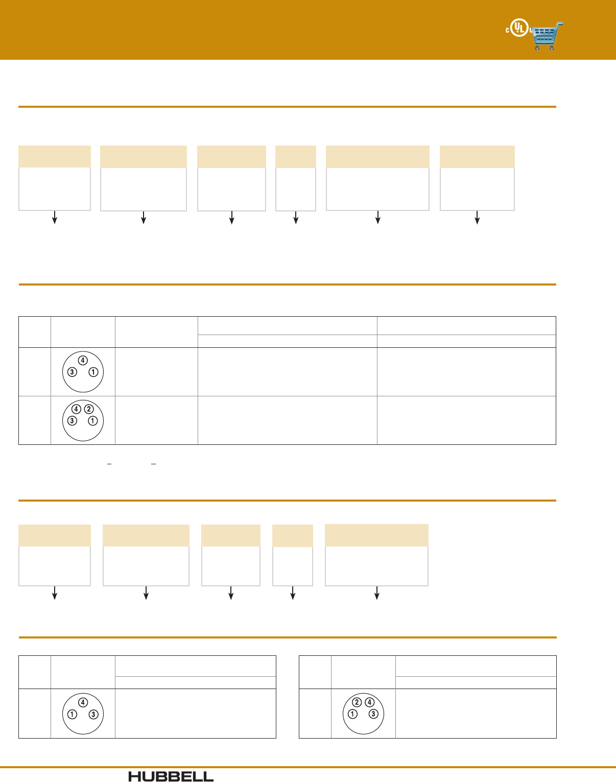
Nano-Quick® Control Connectors
3 - 4 Pole Plugs and Receptacles
3
POLES
3
4
Note: Availability of specific items may vary. Consult factory for delivery. Use this chart to build plugs to meet any application need. Consult the factory for
additional cable lengths or cable types.
NC
DEVICE
TYPE
NC = Plug,
Female
1
CABLE
TYPE
1 = #24 AWG PVC Cable
2 = #24 AWG TPE Cable
T
RETENTION
STYLE
T = Threaded,
Locking
S = Snap On
A
BODY
STYLE
A = Right Angle
S = Straight
05
CABLE
LENGTH (m)
**
02
05
**Replace with Length
3 - 4 Pole Female Plugs
Catalog numbers using #24 AWG PVC cable are listed below. For #24 AWG TPE cable, change the cable type per the Hubbell
Logic chart above.
Poles
Female Face
Shown Cable Length
Threaded, Locking Snap Together
Straight Right Angle Straight Right Angle
3
6.56 ft (2m)
16.40 ft (5m)
All other lengths
NCTS3102
NCTS3105
NCTS31**
NCTA3102
NCTA3105
NCTA31**
NCSS3102
NCSS3105
NCSS31**
NCSA3102
NCSA3105
NCSA31**
4
6.56 ft (2m)
16.40 ft (5m)
All other lengths
NCTS4102
NCTS4105
NCTS41**
NCTA4102
NCTA4105
NCTA41**
NCSS4102
NCSS4105
NCSS41**
NCSA4102
NCSA4105
NCSA41**
Note: Replace ** with length required in feet. For snap on retention style, replace “T” with “S” per the ordering chart above.
Example: change NCTA3105 to NCSA3105.
3 - 4 Pole Male Receptacles
Poles
Male Face
Shown
Male Receptacle
Rear Thread Style
Poles
Male Face
Shown
Male Receptacle
Rear Thread Style
M8 x 1 M8 x 1
3NBCS3D 4NBCS4D
Note: Replace ** with length required in feet.
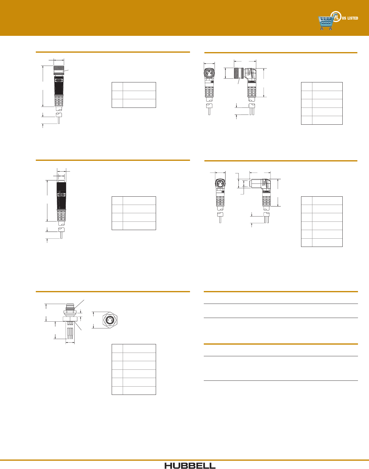
I-31www.hubbell-wiring.com Wiring Device-Kellems
®
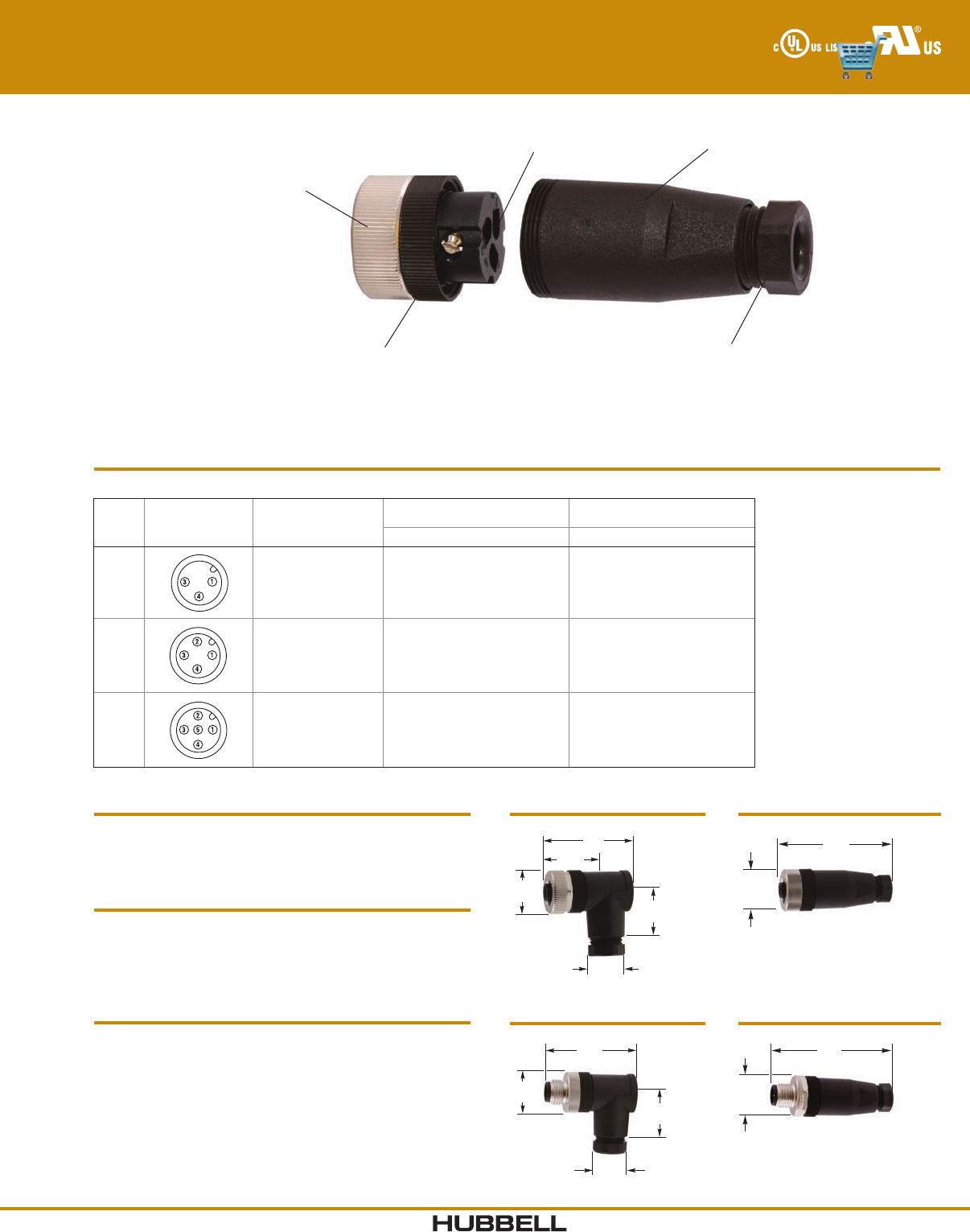
A
B
C
M8 x 1
Thr
ead
Straight Female Locking Plug
A0.38" (9.7)
B1.51" (38.4)
C2.75" (69.9)
A
E
D
B
C
M8 x 1
Thread
Right Angle Female Locking Plug
A0.39" (9.9)
B1.04" (26.4)
C2.75" (69.9)
D0.78" (19.8)
E0.38" (9.7)
A1
A2
B
C
Straight Female Snap Together Plug
A10.34" (8.6)
A20.22" (5.6)
B1.50" (38.1)
C2.75" (69.9)
A1A2
A3
D
B
C
Right Angle Female Snap Together Plug
A10.39" (9.9)
A20.38" (9.7)
A30.22" (5.6)
B1.04" (26.4)
C2.75" (69.9)
D0.79" (20.1)
Nano-Quick® Control Connectors
3 - 4 Pole Plugs and Receptacles
Cable Diameters By Cable Type
Number of #24 AWG #24 AWG
Conductors PVC TPE
3 0.21" (5.3) 0.21" (5.3)
4 0.21" (5.3) 0.21" (5.3)
Conductor Color Code
Contact 3 4
Number Pole Pole
1 Brown Brown
2 Not Used White
3 Blue Blue
4 Black Black
B
C
D
EF
M8 x 1
Thread
M8 x 1
Thread
Panel cutout
Max panel thickness
Male Combination Receptacle
A0.31" (7.9)
B0.63" (16.0)
C12.0" (304.8)
D0.35" (8.8)
E0.80" (2.0)
F0.59" (15.0)
Dimensions in Inches (mm)
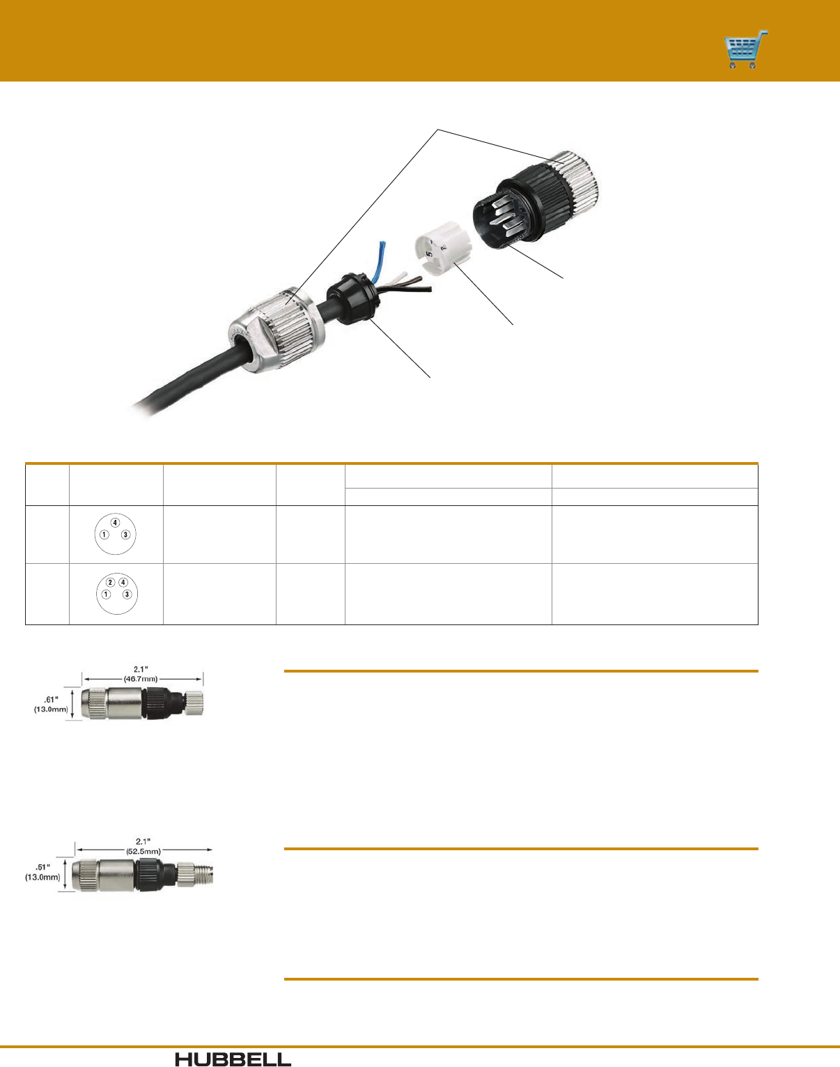
www.hubbell-wiring.comI-32 Wiring Device-Kellems
®
NCTS13IDC
NITS13IDC
Rugged, Nickel-plated Hardware
Excellent corrosion and abuse resistance
Strain Relief Bushing
Protects terminations and provides IP66 ingress protection
Copper Alloy
Insulation displacement contacts
Wire Guide
For virtually toolless termination
Allows field installation of control
connector. Insulation Displacement
Contacts do not require stripped
conductors, greatly speeding
installation.
Material Specifications
Housing Polyester Elasomer, Black
Wire Guide Nylon 6/6, Gray
Strain Relief Bushing Neoprene, Black
Contact Materials Copper Alloy
Contact Plating Tin over Nickel
Coupling Nut Zinc Alloy with Nickel Plating
O-ring Neoprene, Black
Cable Compression Nut Zinc Alloy with Nickel Plating
Electrical Specifications
Voltage Rating 32VAC/DC
Wire Range #22 AWG max., #24 AWG min.
Cable Diameters .13" to .21" (3.3 to 5.3 mm)
Amperage 3A
Contact Resistance < 5 mΩ
Environmental Specifications
Ingress Protection IP66 Suitability
Operating Temperature -20°C to 110°C
Nano-Quick® Control Connectors
Field Attachable Connectors - IDC Style
Nano-Quick® IDC
Poles
Male Face Shown
Female - mirror
image Cable Range Wire Gauge
Female Connector Male Connector
Straight Straight
3.13"-.21" (3.3-5.3) 22 - 24 NCTS13IDC NITS13IDC
4.13"-.21" (3.3-5.3) 22 - 24 NCTS14IDC NITS14IDC
Dimensions in Inches (mm)
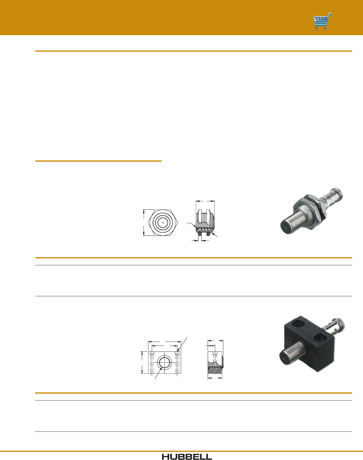
I-33www.hubbell-wiring.com Wiring Device-Kellems
®
E
A
C
H
B
L
K
M
E
A
B
H
C
Threaded Style
Block Style
Block Style
Catalog Number A B C E H K L M
BCSM8 M8 x 1 0.75" (19) 0.37" (9.5) 0.62" (15.8) 0.87" (22.1) 0.72" (18.4) 1.0" (25.4) 0.14" (3.6)
BCSM12 M12 x 1 0.75" (19) 0.37" (9.5) 1.0" (25.4) 0.87" (22.1) 0.98" (24.8) 1.5" (38.1) 0.20" (5.2)
BCSM18 M18 x 1 1.0" (25.4) 0.50" (12.7) 1.25" (31.7) 1.17" (29.7) 1.21" (30.7) 1.5" ( 38.1) 0.18" (4.6)
BCSM30 M30 x 1.5 1.38" (34.9) 0.68" (17.5) 2.0" (50.8) 1.47" (37.4) 2.03" (51.5) 2.5" (63.5) 0.26" (6.7)
Threaded Style
Catalog Number A B C E H
CSM8 M8 x 1 M16 x 1.5 0.12" ( 3.1) 0.87" (22.1) 0.87" (22.1)
CSM12LP M12 x 1 M18 x 1 0.16" (4.1) 0.95" (24) 0.83" (21.1)
CSM18 M18 x 1 M30 x 1.5 0.20" (5.1) 1.41" (35.8) 1.17" (2 9.7)
CSM30 M30 x 1.5 M47 x 1.5 0.20" (5.1) 2.01" (51) 1.47" (37.3)
Material Specifications
Material: Anodized aluminum housing
Zinc-plated brass jam nuts
CSM12LP is all Stainless Steel
Sensor Mounts
Install tubular proximity sensors with a Cushioned Sensor Mount and protect against over-travel damage.
Reduces replacement expenses and downtime. Hubbell’s Cushioned Sensor Mounts feature:
• Spring-loaded housing eliminates impact damage.
• Reduces downtime and replacement expenses.
• Reduces spare sensor inventories.
• Shielded and non-shielded end caps eliminate abrasion damage.
• Block style or threaded housing designs.
• Anodized aluminum or stainless steel.
When something out of the ordinary happens or targets over-travel, the sensor simply retracts to avoid damage.
The sensor returns to its original position and the equipment continues to operate.
Signal-Quick® Sensor Mounting Accessories
Cushioned Sensor Mounts
Dimensions in Inches (mm)
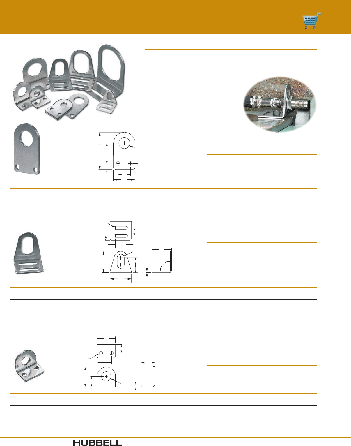
www.hubbell-wiring.comI-34 Wiring Device-Kellems
®
Sensor Mounting Brackets
Eliminate design time and fabrication expense. Choose the Hubbell Angle
Bracket or Flat Bracket to mount any tubular proximity sensor.
• Fixed mounting patterns or multi-slotted
for positioning versatility.
• Industry standard mounting footprints.
• Rapid installation.
• Immediately available from stock.
• Cost savings over “make your own”.
C
IG
F
D
E
A
B
H
Angle Brackets
Catalog
Number A B C D E F G H I
AB12
AB18
AB30
1.16"" ( 29.3)
1.47" (37.3)
2.13" (54.0 )
1.0"" (25.4)
1.0" (25.4)
1.50" (38.1)
1.25" (31.8)
1.38" (34.9)
2.00" (50.8)
0.48" (12.1)
0.48" (12.1)
1.19" (3 0.1)
0.53" (13.5)
0.53" (13.5)
1.13" (28.7)
0.53" (13.5)
0.78" (19.8)
1.13" (28.7)
0.75" (19.1)
1.0" (25.4)
1.25" (31.8)
0.12" (3 . 0 2)
1.12" (3.0 2)
0.12" (3 . 0 2)
0.22" (5.6)
0.24" (6.0)
0. 31" ( 7.9 )
Material Specifications
Material: Stainless Steel
C
G
F
B
D
A
E
Material Specifications
Material: Stainless Steel
Flat Brackets
Catalog Number A B C D E F G Thickness
FB12
FB18
FB30
0.48" (12.1)
0.72" (18.2)
1.19" (3 0.1)
1.95" (49.6)
2.27" (57.6)
3.42" (86.9)
1.25" (31.8)
1.38" (34.9)
2.0" (50.8)
0.86" (21.8)
1.36" (34.6)
2.05" (52)
0.47" (11.9)
0.22" (5.56)
0.37" (9.40)
0.22" (5.54)
0.24" (6.05)
0. 31" ( 7.9 4)
0.75" (19.1)
1.0" (25.4)
1.25" (31.8)
0.12" (3 . 0 2)
0.12" (3 . 0 2)
0.12" (3 . 0 2)
F
H
I
G
A
D
K
E
J
C
B
90-
Material Specifications
Material: Stainless steel
Zinc-plated steel (AAB47)
Adjustable Angle Brackets
Catalog
Number A B C D E F G H I J K
AAB08
AAB12
AAB18
AAB22
AAB30
1.0" (25.4)
1.5" ( 38.1)
2.0" (50.8)
2.0" (50.8)
2.5" (63.5)
1.25" (31.8)
1.37" (34.8)
1.37" (34.8)
1.37" (34.8)
1.75" (44.5)
1.25" (31.8)
1.5" ( 38.1)
1.75" (44.5)
1.75" (44.5)
2.25" (57.2)
0.34" (8.74)
0.50" (12.7)
0.72" (18.3)
0.88" (22.2)
1.19" (3 0.1)
0. 31 ( 7. 9 2)
0.55" (13.9)
0.75" (19.1)
0.69" (17.4)
0.91" (23)
0.22" (5.54)
0.22" (5.54)
0.22" (5.54)
0.22" (5.54)
0.28" (7.11)
0.62" (15.9)
0.75" (19.1)
1.0" (25.4)
1.0" (25.4)
1.37" (34.8)
0.46" (11.9)
0.56" (14.3)
0.56" (14.3)
0.56" (14.3)
0.81" (20.6)
0. 28 " ( 7.14 )
0. 31" ( 7.9 2)
0. 31" ( 7.9 2)
0. 31" ( 7.9 2)
0.41" (10.3)
0.07" (1.78)
0.07" (1.78)
0.07" (1.78)
0.07" (1.78)
0.09" (2.29)
0.38" (9.53)
0.50" (12.7)
0.63" (15.9)
0.63" (15.9)
0.75" (19.1)
Signal-Quick® Sensor Mounting Accessories
Flat and Right Angle Adjustable Brackets
Dimensions in Inches (mm)
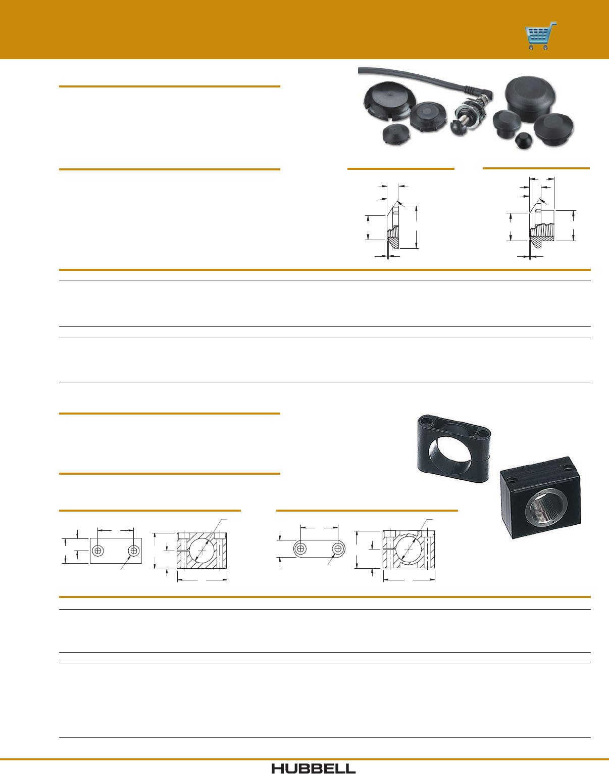
I-35www.hubbell-wiring.com Wiring Device-Kellems
®
Signal-Quick® Sensor Mounting Accessories
End Caps and Block Mounts
Block Mounts
Metallic Style A B C D E F
BM08M
BM12M
BM18M
BM30M
8mm
12mm
18mm
30mm
0.32" (8.05)
0.48" (12.1)
0.71" (18.1)
1.19" (3 0.1)
0.62" (15.8)
1.0" (25.4)
1.25" (31.7)
2.0" (50.8)
1.0" (25.4)
1.5" ( 38.1)
1.5" ( 38.1)
2.5" (63.5)
0.75" (19.0)
0.75" (19.0)
1.0" (25.4)
1.38" (34.9)
0.72" (18.4)
0.98" (24.9)
1.21" (30.7)
2.03" (51.5)
0.14" (3.58)
0.20" (5.08)
0.18" (4.58)
0.26" (6.73)
Nylon
BM08N
BM12N
BM16N
BM18N
BM20N
BM22N
BM30N
8mm
12mm
16mm
18mm
20mm
22mm
30mm
0.32" (8.05)
0.48" (12.1)
0.63" (16.1)
0.71" (18.1)
0.79" (20.1)
0.87" (22.1)
1.18" (3 0.1)
1.06" (27)
1.26" (32)
1.42" (36)
1.42" (36)
1.77" (45)
1.77" (45)
2.17" ( 55)
0.63" (16)
0.79" (20)
1.02" (26)
1.02" (26)
1.18" (30)
1.18" (30)
1.50" (38)
0.47" (12)
0.47" (12)
0.47" (12)
0.47" (12)
0.59" (15)
0.59" (15)
0.71" (18)
0.67" (17)
0.87" (22)
1.02" (26)
1.02" (26)
1.26" (32)
1.26" (32)
1.65" (42)
0.18" (4.5)
0.18" (4.5)
0.18" (4.5)
0.18" (4.5)
0.22" (5.5)
0.22" (5.5)
0.22" (5.5)
Block Mounts
Bond to sensor face with any epoxy.
• Use when threads are inaccessible.
• Reduces and/or eliminates abrasion damage.
• Reduces downtime and sensor replacement expenses.
Specifications
Material: Glass-filled Nylon
Anodized aluminum
End Caps
Shielded Style A B C D E Thread
EC08
EC12
EC18
EC30
8mm
12mm
18mm
30mm
0.21" (5.28)
0.25" (6.35)
0.33" (8.38)
0.30" (7.62)
0.60" (15.2)
0.96" (24.4)
1.23" (31.3)
1.72" (43.7)
0.015" (.38)
0.015" (.38)
0.03" (.76)
0.03" (.76)
0.25" (6.45)
0.45" (11.4)
0.73" (17.5)
1.13" (28.6)
N/A
N/A
N/A
N/A
M8 x 1
M12 x 1
M18 x 1
M30 x 1
Non-Shielded
EC08N
EC12N
EC18N
EC30N
8mm
12mm
18mm
30mm
0.20" (5.08)
0.25" (6.35)
0.33" (8.38)
0. 31" ( 7.87 )
0.57" (14.5)
0.90" (22.9)
1.34" (34.0)
1.75" (44.5)
0.015" (.38)
0.03" (.76)
0.025" (.64)
0.04" (1.02)
0.25" (6.45)
0.45" (11.4)
0.67" (17.0)
1.15" (2 9. 2)
0.37" (9.50)
0.68" (17.3)
0.70" (17.8)
0.90" (22.9)
M8 x 2
M12 x 1
M18 x 1
M30 x 1
Note: The wear surface thickness (Dimension C) does not reduce a sensor’s sensing range, but will consume an equal amount of the gap required between the sensor and target.
End Caps
• Use alone or with Cushioned Sensor Mount.
• Beveled edge deflects lateral impacts.
• Reduces and or eliminates abrasion damage.
• Reduces downtime and sensor replacement expenses.
Specifications
Material: Delrin (Non-Shielded)
Glass-filled Nylon (Shielded)
Polypropylene (EC30)
C
A
30°
D
B
Shielded
D
C
E
A
30°
B
Non-Shielded
D½ D
F
E
A
C
½ C
B
E
D
F
A
C
½ C
B
Metallic Nylon
Dimensions in Inches (mm)
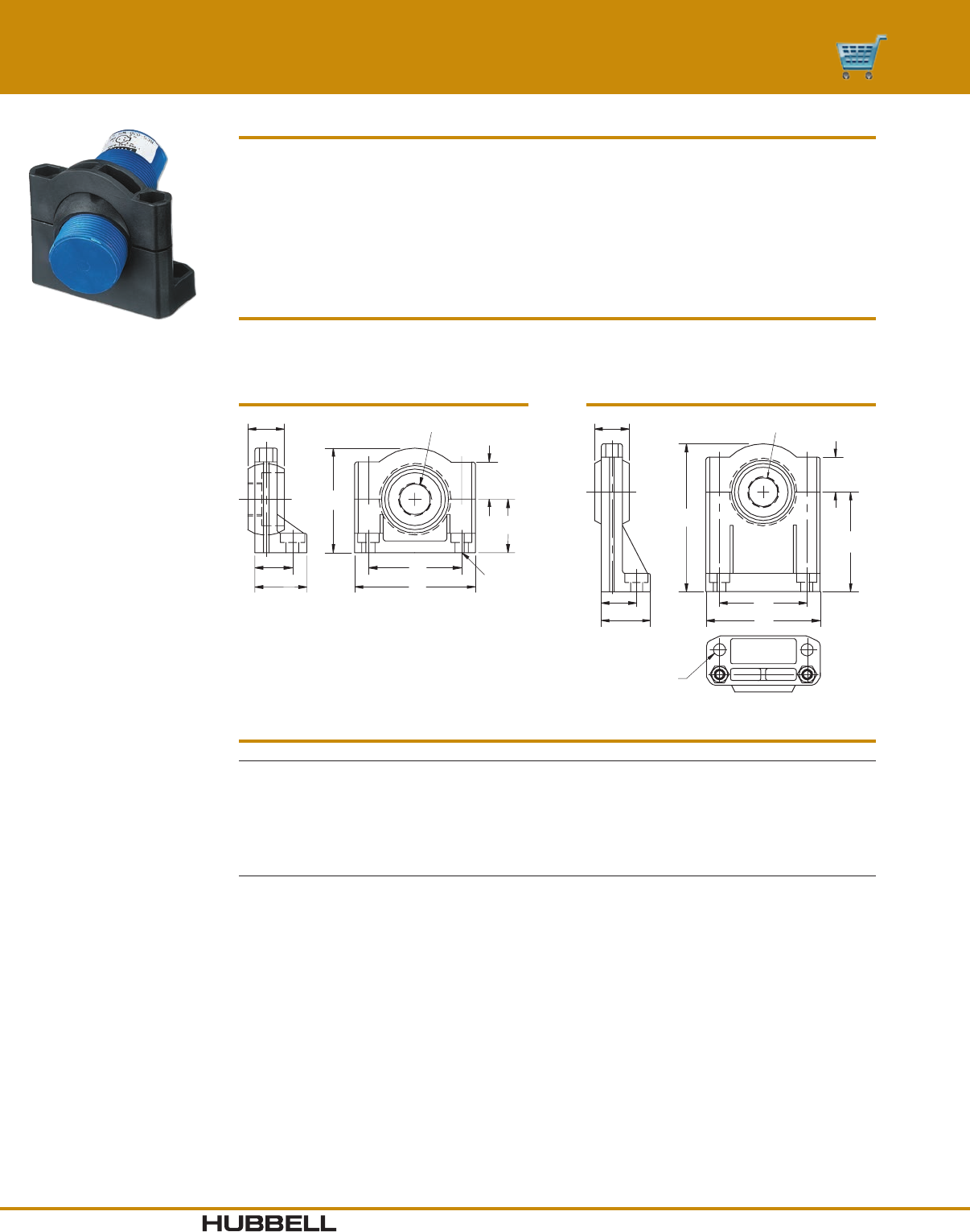
www.hubbell-wiring.comI-36 Wiring Device-Kellems
®
Universal Aiming Brackets
Catalog Number Style Description Thread
UB12
UB12E
UB18
UB18E
UB30
UB30E
12mm
12mm
18mm
18mm
30mm
30mm
Bracket
Bracket, Extended Base
Bracket
Bracket, Extended Base
Bracket
Bracket, Extended Base
M12 x 1
M12 x 1
M18 x 1
M18 x 1
M30 x 1.5
M30 x 1.5
Universal Aiming Brackets
Attach limit switch style (30mm threaded base) or threaded barrel photoelectric and ultrasonic sensors.
Achieve secure mounting quickly and with ease.
• Swivel action for aiming simplicity.
• Durable glass-filled nylon construction.
• Regular or extended base models.
• Sizes for 12, 18 and 30mm threaded sensors.
Material Specifications
Material: Glass-filled Nylon
0.79"
(20.1)
0.81"
(20.6)
1.12"
(28.6)
Ø 0.28"
(7.08)
2.0"
(50.8)
2.6"
(66.0)
0.80"
(20.3)
2.28"
(57.9)
3.38"
(85.9)
A
Bracket, Extended
0.79"
(20.1)
0.81"
(20.6)
1.12"
(28.6)
2.25"
(57.2)
2.6"
(66)
2.0"
(50.8) Ø 0.28"
(7.08)
1.15"
(29.2)
0.80"
(20.3)
A
Bracket, Standard
Signal-Quick® Sensor Mounting Accessories
Universal Aiming Brackets
Dimensions in Inches (mm)
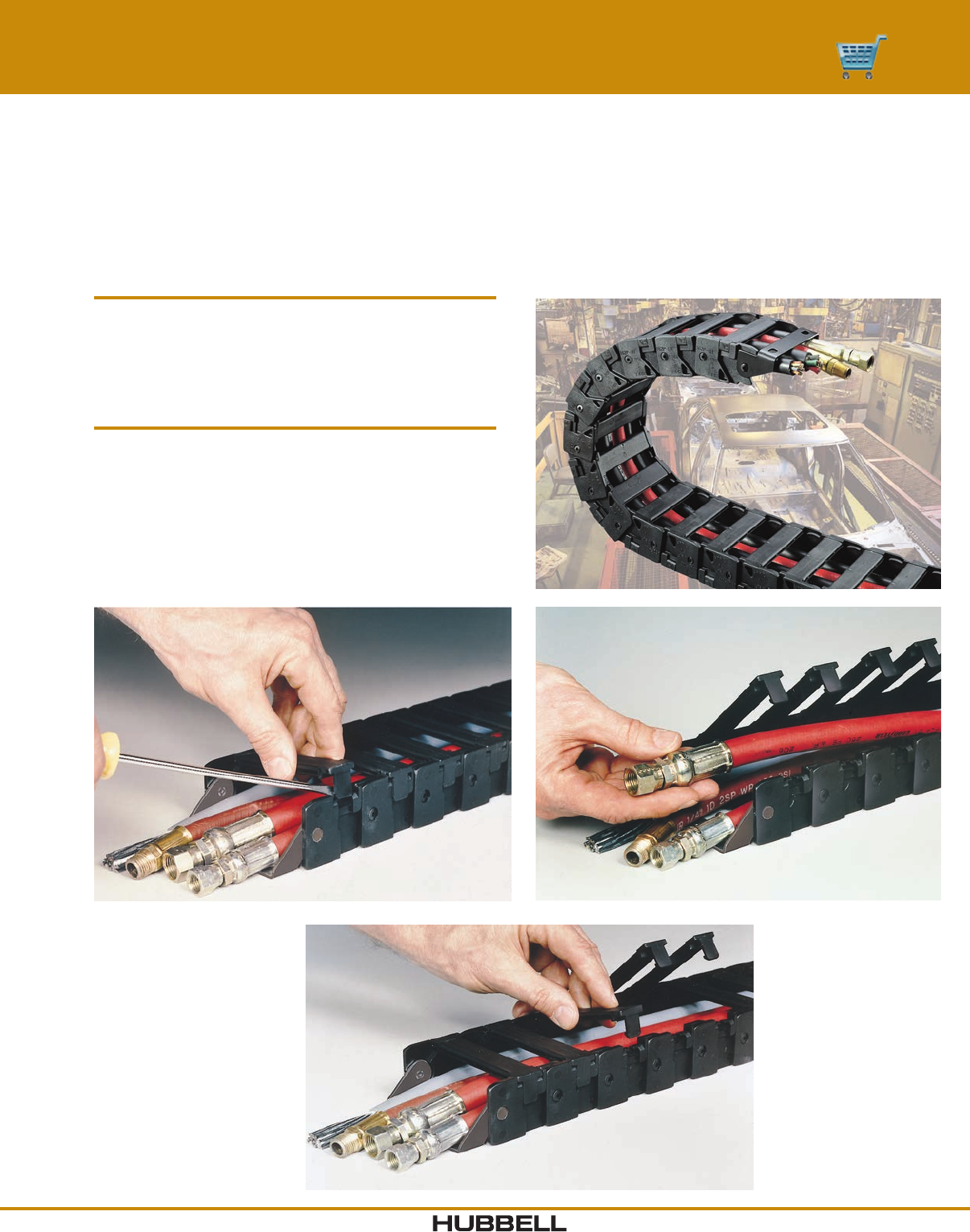
I-37www.hubbell-wiring.com Wiring Device-Kellems
®
The design of CableTrak carriers provides easy access to components during installation and repair. The track’s flip top design
allows the installer to lay cable and hose components directly into the track instead of pulling them through the length of the
track. Hubbell CableTrak carriers can be ordered as assembled kits with brackets or by the foot without brackets. The final
length of the track is easily customized by adding or removing sections of track or individual links with a flat head screwdriver.
CableTrak® Installation
1. Unlock Tab.
2. Locking tabs secure the retaining bar into place.
To unlock tabs, slide a flat head screwdriver
under the tab and release it with a twisting motion.
Access/Install Cables and Hoses
3. Easy access is important, especially for
pre-assembled cable/hose sets involving
large O.D. plugs, receptacles, and couplings.
4. Lock Tab.
5. To re-secure retaining bars, engage the hinge
and snap the locking tab into place.
CableTrak® Hose and Cable Carrier System
Assembly and Installation
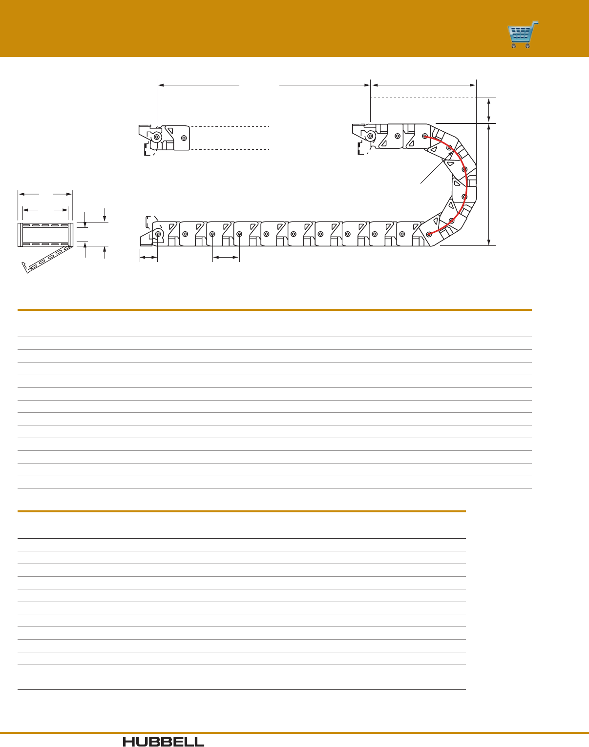
www.hubbell-wiring.comI-38 Wiring Device-Kellems
®
TRAVEL
K
C
B
R
PM
HO
V
W
End Mounting:
T
rack travel length = Machine travel length.
CableTrak
®
Kit without Brackets
Catalog Number
Track
Length
(ft)
W
Inner
Width
H
Inner
Height
A Max
Hose/Cab
O.D.
B Max
Component
Width
V Outer
Width
O Outer
Height
R Bend
Radius
B Bend
Height
C
Clearance
P
Pitch
L*
Curve
Length (ft)
HCT101141**
1.0' 0.59" 0.75" 0.286" 0.531" 1.03" 1.00" 1.44" 3.86" 2.00" 1.250" 1.000'
HCT102191**
1.0' 1.00" 0.75" 0.382" 0.900" 1.44" 1.00" 1.91" 4.82" 2.00" 1.250" 1.000'
HCT161191
1.0' 1.50" 1.00" 0.382" 1.350" 2.12" 1.62" 1.91" 5.44" 3.00" 1.812" 1.000'
HCT161341
1.0' 1.50" 1.00" 0.688" 1.350" 2.12" 1.62" 3.44" 8.50" 3.00" 1.812" 1.500'
HCT162191
1.0' 2.28" 1.00" 0.328" 2.052" 2.91" 1.62" 1.91" 5.44" 3.00" 1.812" 1.000'
HCT162341
1.0' 2.28" 1.00" 0.688" 2.052" 2.91" 1.62" 3.44" 8.50" 3.00" 1.812" 1.500'
HCT163341
1.0' 3.08" 1.00" 0.688" 2.772" 3.70" 1.62" 3.44" 8.50" 3.00" 1.812" 1.500'
HCT164341
1.0' 4.06" 1.00" 0.688" 3.654" 4.69" 1.62" 3.44" 8.50" 3.00" 1.812" 1.500'
HCT251341
1.0' 2.60" 1.75" 0.680" 2.340" 3.70" 2.50" 3.40" 9.30" 3.00" 2.500" 1.500'
HCT252341
1.0' 4.25" 1.75" 0.680" 3.825" 5.36" 2.50" 3.40" 9.30" 3.00" 2.500" 1.500'
HCT252471
1.0' 4.25" 1.75" 0.956" 3.825" 5.36" 2.50" 4.78" 12.06" 3.00" 2.500" 2.000'
HCT253471
1.0' 6.60" 1.75" 0.956" 5.940" 7. 70 " 2.50" 4.78" 12.06" 3.00" 2.500" 2.000'
Note: *L = Minimum length in feet to form CableTrak curve.
**These models do not have a flip top design and do not accept separators due to their small size.
CableTrak® Hose and Cable Carrier System
CableTrak® Kit With and Without Brackets
CableTrak® Kit with Brackets
Catalog Number
Track
Length
(ft)
W
Inner
Width
H
Inner
Height
A Max
Hose/Cab
O.D.
B Max
Component
Width
V Outer
Width
O Outer
Height
R Bend
Radius
B Bend
Height
C
Clearance
K
Min Brkt
to Bend
M
Brkt to
Pivot
P
Pitch
L*
Curve
Length (ft)
HCT10114K**
4.0' 0.59" 0.75" 0.286" 0.531" 1.03" 1.00" 1.44" 3.86" 2.00" 5.68" 1.33" 1.250" 1.000'
HCT10219K**
4.0' 1.00" 0.75" 0.382" 0.900" 1.44" 1.00" 1.91" 4.82" 2.00" 5.41" 1.33" 1.250" 1.000'
HCT16119 K
4.0' 1.50" 1.00" 0.382" 1.350" 2.12" 1.62" 1.91" 5.44" 3.00" 5.72" 1.19" 1.812" 1.000'
HCT16134K
4.5' 1.50" 1.0 0" 0.688" 1.350" 2.12 " 1.62" 3.44" 8.50" 3.00" 7. 8 5 " 1.19" 1.812" 1.500'
HCT16219K
4.0' 2.28" 1.00" 0.328" 2.052" 2.91" 1.62" 1.91" 5.44" 3.00" 5.72" 1.19" 1.812" 1.000'
HCT16234K
4.5' 2.28" 1.00" 0.688" 2.052" 2.91" 1.62" 3.44" 8.50" 3.00" 7. 8 5 " 1.19" 1.812" 1.500'
HCT16334K
4.5' 3.08" 1.00" 0.688" 2.772" 3.70" 1.62" 3.44" 8.50" 3.00" 7. 8 5 " 1.19" 1.812" 1.500'
HCT16434K
4.5' 4.06" 1.00" 0.688" 3.654" 4.69" 1.62" 3.44" 8.50" 3.00" 7. 8 5 " 1.19" 1.812" 1.500'
HCT25134K
4.5' 2.60" 1.75" 0.680" 2.340" 3.70" 2.50" 3.40" 9.30" 3.00" 8.31" 1.75" 2.500" 1.500'
HCT25234K
4.5' 4.25" 1.75" 0.680" 3.825" 5.36" 2.50" 3.40" 9.30" 3.00" 8.31" 1.75" 2.500" 1.500'
HCT25247K
5.0' 4.25" 1.75" 0.956" 3.825" 5.36" 2.50" 4.78" 12.06" 3.00" 10.52" 1.75" 2.500" 2.000'
HCT25347K
5.0' 6.60" 1.75" 0.956" 5.940" 7.70 " 2.50" 4.78" 12.06" 3.00" 10.52" 1.75" 2.500" 2.000'
Dimensions in Inches (mm)
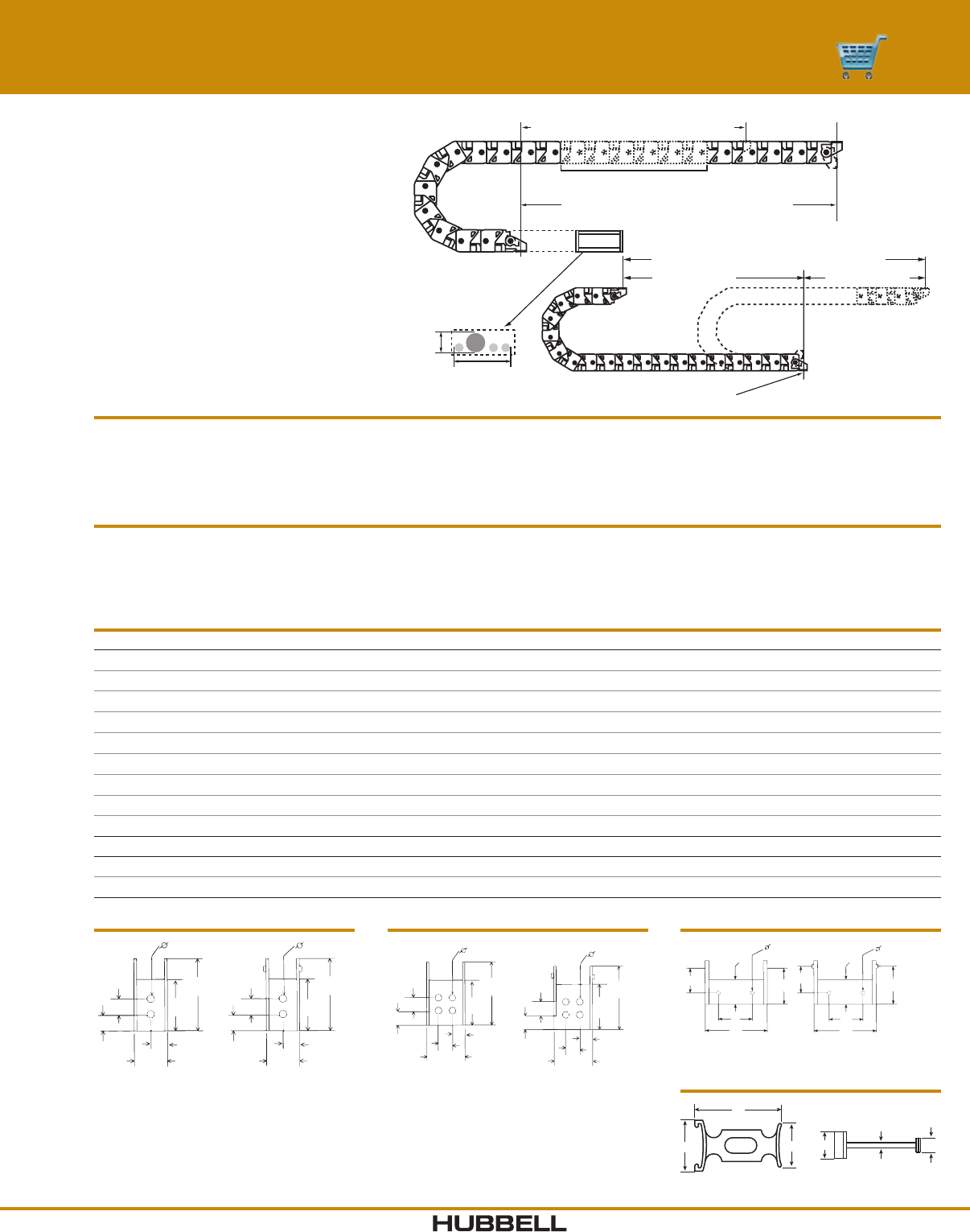
I-39www.hubbell-wiring.com Wiring Device-Kellems
®
SUM OF KITS SUM OF KITS
Fixed Point End/Center Mounting
Center Mount Travel = 2 x SUM of KITS
A
B
Window
Opening
EXTENDERS (D)
Track Travel of BASIC KIT (C) = 3 ft.
Track Travel with EXTENDERS (D) when
inserted increases travel by 1 ft.
Calculating
Center Mount (Stationary bracket mounted in center of travel range): Track Length = (MT/2) + L
End Mount (Stationary bracket mounted off center of travel range): Track Length = (MT/2) + L + offset from center in feet
MT = Total machine travel distance in feet
L = Length of track taken up by the bend radius
Customizing Track Length
Hubbell CableTrak is easily customized by adding or subtracting links to the track. CableTrak kits provide 4 to 5 feet of track with brackets
pre-installed. Track length can be increased by installing the required number of extenders to reach the required length. To further tune the
length of track, individual links can be added or removed. To determine the number of links to add or remove, divide the length in inches to
be added or subtracted by the pitch of the track and round up.
A
C
B
E
F
D
Separators
HCTBK102 – Brackets
.22"
(5.59)
1.33"
(33.78)
1.02"
(25.91)
.578"
(14.68)
.22"
(5.59)
C
D
A
B
.22"
(5.59)
1.33"
(33.78)
1.02"
(25.91)
.578"
(14.68)
.22"
(5.59) .40"
(10.16)
.40"
(10.16)
Female Male
H
G
F
E
A
B
H
G
F
E
C
D
Female Male
HCTBK161 – HCTGK253 BracketsHCTBK101 – Brackets
.22"
(5.59)
1.33"
(33.78)
1.02"
(25.91)
.578"
(14.68)
.22"
(5.59)
C
D
A
B
.22"
(5.59)
1.33"
(33.78)
1.02"
(25.91)
.578"
(14.68)
.22"
(5.59)
Female Male
CableTrak® Accessories
Bracket Kits For Use With A B C D E F G H
HCTBK101 HCT101 Series .40" (10.2) .81" (20.6) .47" (12.0) .94" (23.9) ––––
HCTBK102 HCT102 Series .44" (11. 2) 1.22" (31.0) .4 4" (11.2) 1.35" (34.3) ––––
HCTBK161 HCT161 Series .99" (25.2) 1.97" ( 50.1) .87" (22.1) 1.84" (46.7) 1.19 " (30. 2) . 2 81" ( 7.1) .75" (19.1) .81" (20.6)
HCTBK162 HCT162 Series 1.78" (45.2) 2.75" (69.9) 1.65" (41.9) 2.63" (66.8) 1.19 " (30. 2) . 2 81" ( 7.1) .75" (19.1) .81" (20.6)
HCTBK163 HCT163 Series 2.57" (65.3) 3.55" (90.2) 2.44" (62.0) 3.42" (86.9) 1.19 " (30. 2) . 2 81" ( 7.1) .75" (19.1) .81" (20.6)
HCTBK164 HCT164 Series 3.56" (90.4) 4.5 3" (115.1) 3.47 " (88 .1) 4.41" (112. 0 ) 1.19 " (3 0 . 2) . 2 81" ( 7.1) .75" (19.1) .81" (20.6)
HCTBK251 HCT251 Series 2.08" (52.8) 3.21" (81.5) 1.80" (45.7) 3.03" (77.0) 1.75" (44.5) .344" (8.7) 1.00" (25.4) 1.25" (31.8)
HCTBK252 HCT252 Series 3.74" (95.0) 4.87" (123.7) 3.4 6 " ( 87.9 ) 4.69" (119.1) 1.75" (44.5) .344" (8.7) 1.00" (25.4) 1.25" (31.8)
HCTBK253 HCT253 Series 6.08" (154.4) 7. 21" (18 3 .1) 5.80" (147.3) 7.0 3 " (178 .6 ) 1.75" (44.5) .344" (8.7) 1.00" (25.4) 1.25" (31.8)
Separators For Use With A B C D E F
HCTSP16PK12 HCT16 Series 1.24" (31.5) .82" (20.8) .94" (23.9) .27" (6.9) .14" (3.6 ) .50" (12.7)
HCTSP25PK12 HCT25 Series 2.03" (51.6) 1.00" (25.4) 1.19" ( 30. 2) .35" (8.9) .15" (3.8) .62" (15.8)
CableTrak® Hose and Cable Carrier System
Accessories
Center Mounting: Mounting the fixed
track end in the center of the machine travel
allows the track to travel beyond the fixed end.
Center mounting effectively doubles the travel
distance of the track requiring half the track
length of an end mounted application.
Dimensions in Inches (mm)
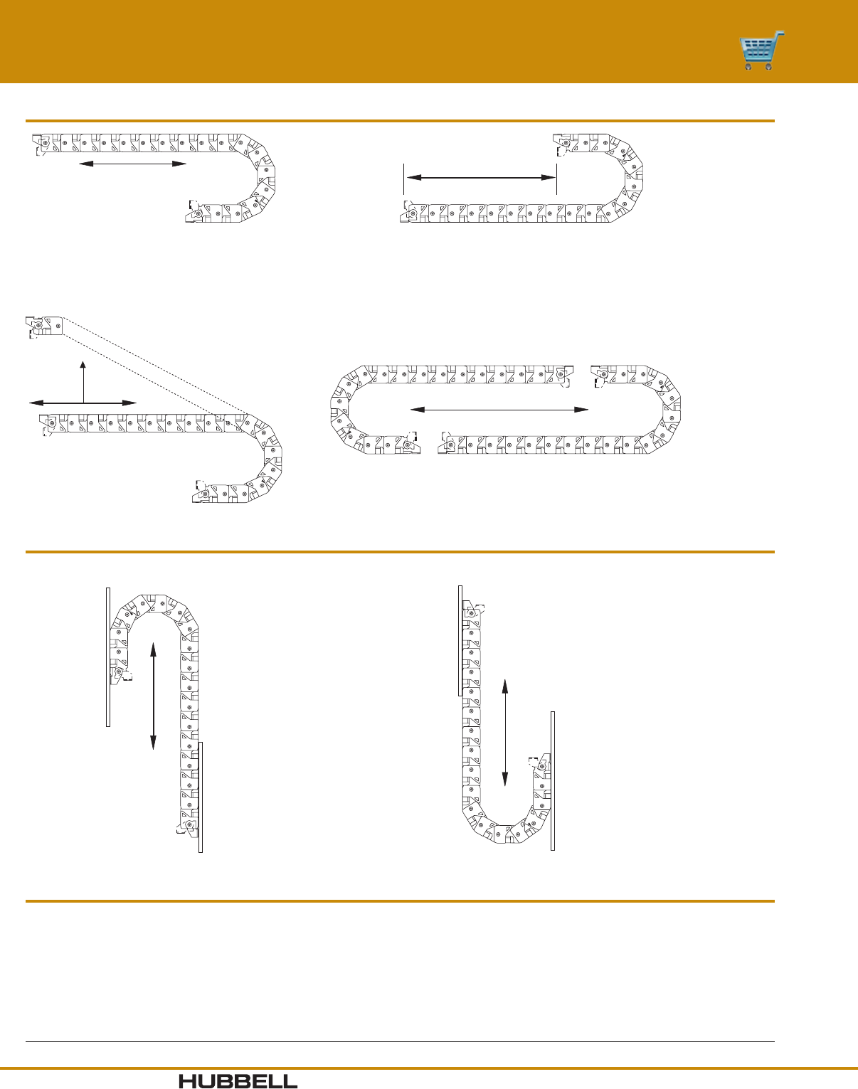
www.hubbell-wiring.comI-40 Wiring Device-Kellems
®
Horizontal Travel
Vertical Travel
Fixed
End
Fixed
End
Fixed
End
Back-Up
Surface
Back-Up
Plate
Combination
Horizontal & Vertical Travel
Curve Up
Fixed
Ends
Fixed
End
Back-Up
Surface
Back-Up
Plate
Fixed
End
Opposed Travel
Curve Down
Specications
Material Fiberglass reinforced nylon.
Operating Temperature Continuous +20°F to +100°F (-7°C to 38°C).
Intermittent* -40°F to +220°F (-40°C to 104°C).
Maximum Operating Speed 600 FPM (feet per minute), 180 MPM (meters per minute).
Operating speed is based on short lengths that are self supported (up to 9ft.).
Maximum Unsupported
Travel Distance HCT16 Series without sag 9 ft. (2.8 m) with sag 10.5 ft. (3.2 m).
HCT25 Series without sag 13.5 ft. (4.1 m) with sag 17 ft. (5.2 m).
Applications Machine tool, robotic automation, material handling.
Note: *Intermittent refers to the operating of the product outside the normal (continuous operating) temperature range momentarily before returning back to the normal range.
CableTrak® Hose and Cable Carrier System
Mounting Options and Specifications
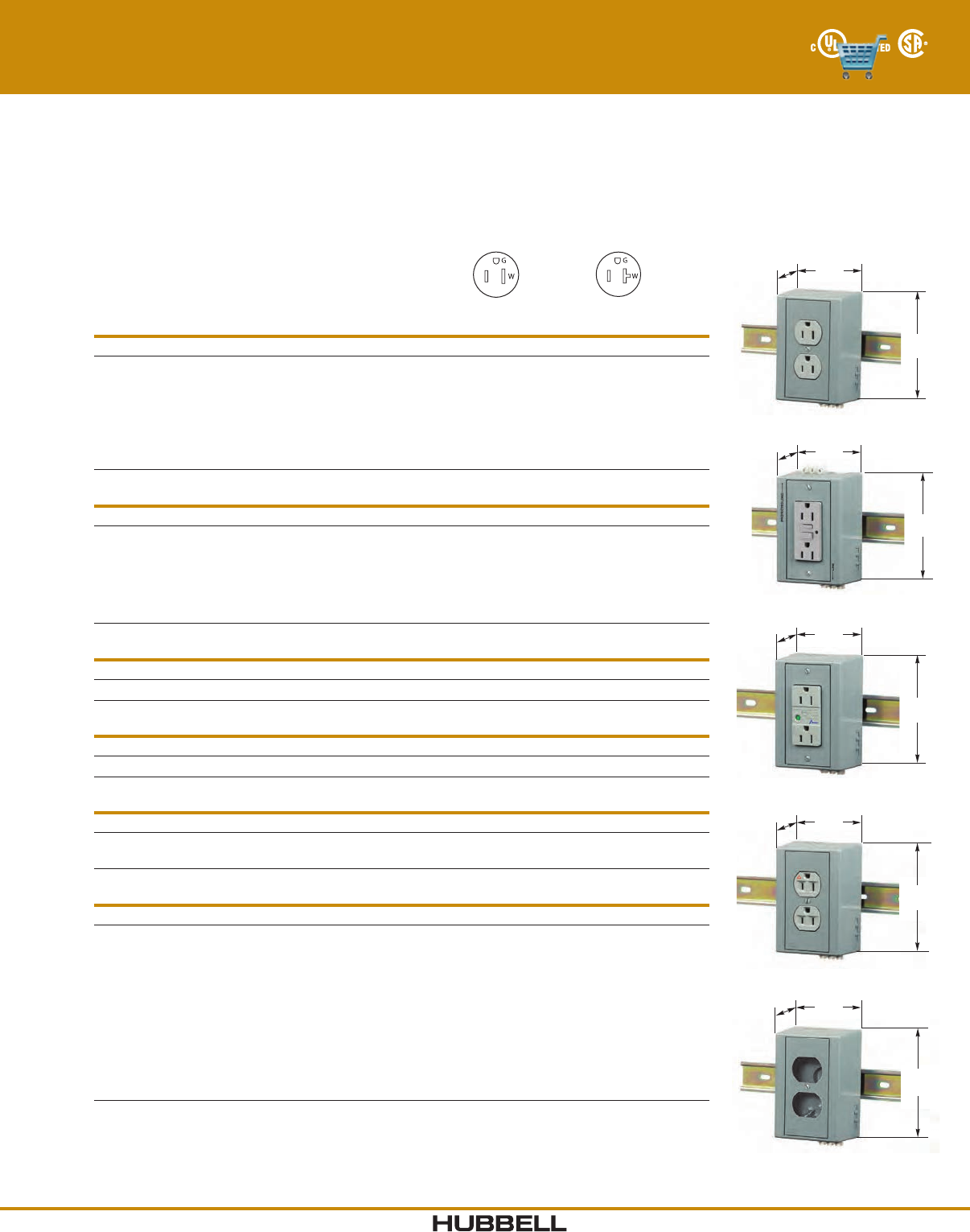
I-41www.hubbell-wiring.com Wiring Device-Kellems
®
15A 125V
NEMA 5-15R
UL CSA
0.5 HP
20A 125V
NEMA 5-20R
UL CSA
1 HP
DRUB15
4.97"
(126.2)
3.31"
(84.1)
2.54"
(64.5)
DRUBGFI15AC
4.97"
(126.2)
3.31"
(84.1)
2.54"
(64.5)
DRUBTVSS15
4.97"
(126.2)
3.31"
(84.1)
2.54"
(64.5)
HIDRUBCKIT
4.97"
(126.2)
3.31"
(84.1)
3.10"
(78.7)
DRUBIG15
4.97"
(126.2)
3.31"
(84.1)
2.54"
(64.5)
DIN Rail Utility Box
Power and Data
Complete Units and Component Parts
Hubbell’s DIN Rail Utility Box offers a labor saving way to provide utility power to any control cabinet. Installing the DIN Rail
Utility Box is as easy as snapping the box onto a 35mm DIN Rail and connecting the line, neutral and ground wires to the
terminal block. Utility power for fans, lights, laptop computers, testers or any other power requirement. If load limiting is a
concern, Hubbell’s “CB” version comes with a 5 Amp circuit breaker that provides over-current protection to make sure that
large loads are not drawn from the DIN Rail Utility Box. All Hubbell DIN Rail Utility Boxes may be mounted either vertically or
horizontally on the DIN Rail; the “H” version comes with the terminal block mounted for easy wiring when the DIN Rail Utility
Box is mounted horizontally.
Duplex Receptacles
Description Color Catalog Number
Complete unit.
Complete unit, horizontal mount.
Complete unit with 5A circuit breaker.
Complete unit with 5A circuit breaker, horizontal.
Complete unit with aux.
Complete unit with aux and 5A circuit breaker.
Complete unit with NEMA® 6-20R duplex (250V).
Gray
Gray
Gray
Gray
Gray
Gray
Gray
DRUB15
DRUB15H
DRUB15CB5
DRUB15HCB5
–
–
–
DRUB20
–
–
–
DRUB20AC
DRUB20ACCB5
DRUB5462*
GFCI Duplex Receptacles
Description Color Catalog Number
Complete unit.
Complete unit, horizontal.
Complete unit with 5A circuit breaker.
Complete unit with 5A circuit breaker, horizontal.
Complete unit with aux GFCI contacts.
Complete unit, faceless with aux GFCI contacts.
Gray
Gray
Gray
Gray
Gray
Gray
DRUBGFI15
DRUBGFI15H
DRUBGFI15CB5
DRUBGFI15HCB5
DRUBGFI15AC
–
DRUBGFI20
–
–
–
DRUBGFI20AC
DRUBGFI20BFAC
TVSS Duplex Receptacles
Description Color Catalog Number
Complete unit. Gray DRUBTVSS15 –
Isolated Ground Duplex Receptacles
Description Color Catalog Number
Complete unit. Gray DRUBIG15 –
Toggle Switch Unit
Description Color Catalog Number
Complete unit with HBL1221.
Complete unit with 15A 125V SW/REC.
Gray
Gray
DRUB1221AC
DRUB6404
DIN Rail Utility Box Components
Description Color Catalog Number
Pre-wired kit without circuit breaker.
Pre-wired kit with circuit breaker.
Pre-wired kit with aux.
Pre-wired kit with circuit breaker and aux.
Communications kit (unloaded).
(For use with Network Wiring frames in section W).
Switch plate only.
Rectangular opening plate only.
1.60 in. opening plate only.
1.40 in. opening plate only.
Duplex receptacle plate only.
Gray
Gray
Gray
Gray
Gray
Gray
Gray
Gray
Gray
Gray
DRUBKIT
DRUBKITCB5
DRUBKITAC
DRUBKITACCB5
HIDRUBCKIT
KP1GY**
KP26GY**
KP720GY**
KP7GY**
KP8GY**
Note: See section M for additional information on isolated ground devices.
*DRUB5462 configuration not pictured.
**UL Listed, CSA Certified.
NEMA® is a registered trademark of the National Electrical Manufacturers Association. Dimensions in Inches (mm)
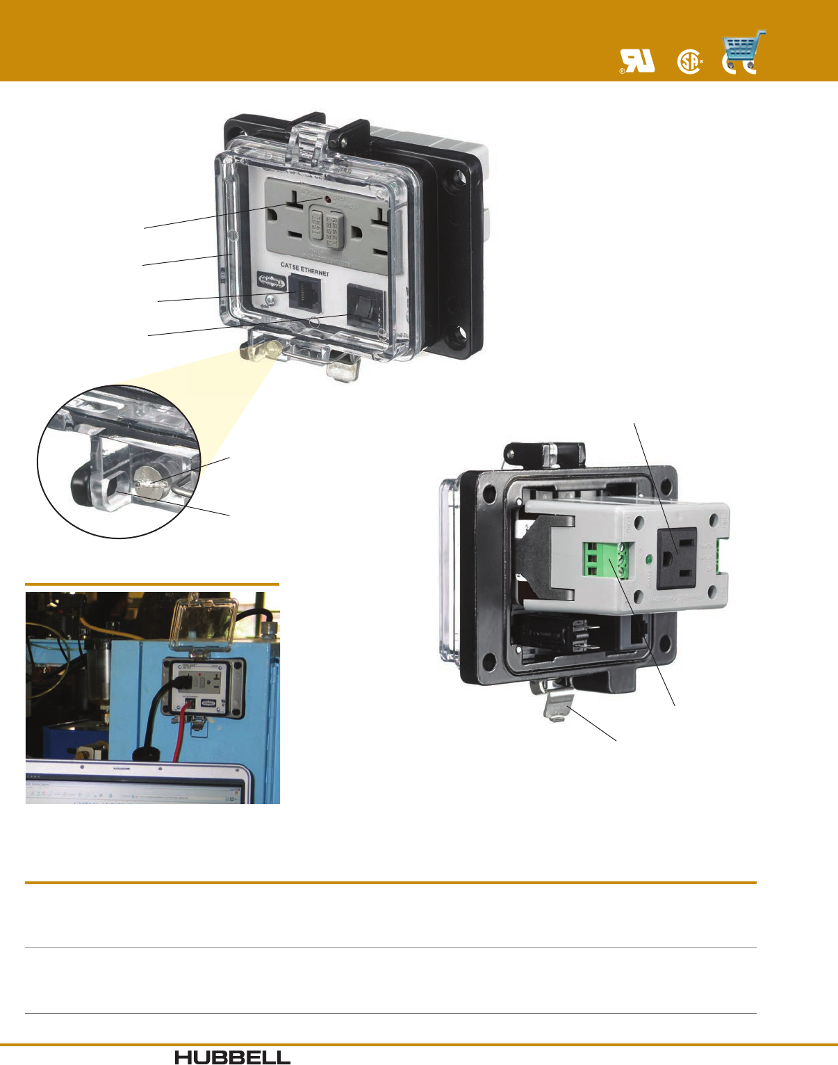
www.hubbell-wiring.comI-42 Wiring Device-Kellems
®
Hubbell GFCI with
Functionality Indicator
Protective clear cover
Cat. 5e Ethernet access*
Overcurrent protection
Supplemental “Tool”
entry screw closure
Locking Hasp
accepts ⁵⁄₃₂" padlock
Additional convenience
outlet on GFCI versions
Finger-safe contacts
Stainless steel snap latch
Available in
NEMA TYPE 4, 12 and
NEMA TYPE 4X Versions!
PANEL-SAFE®
Features and Benefits
Specications
Electrical GFCI - conforms to UL 943 2006 requirement
In-Cabinet Receptacle - GFCI protected
Data Jack - Cat. 5e
Circuit Breaker - 3A
Environmental Enclosure - NEMA Type 4, 12 and
NEMA Type 4X
Mechanical Cover - Clear Polycarbonate (UV Rated)
Housing - Cast Aluminum
Finish - Powder Coat
Latch - Stainless steel
Certification UL Recognized
CSA Certified
NFPA 70E Compliant
Note: *Additional computer interfaces and PLC connections available upon request.
Application
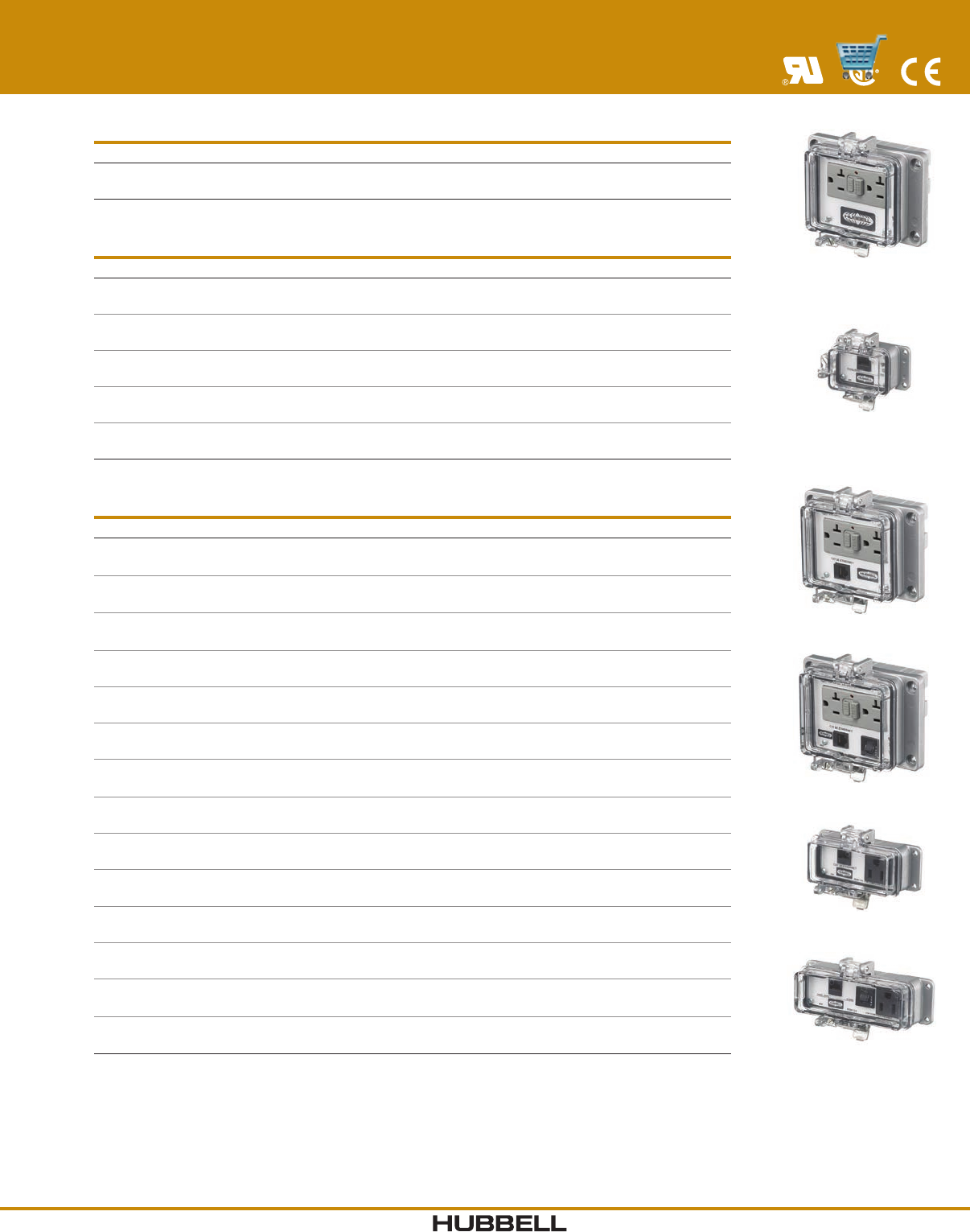
I-43www.hubbell-wiring.com Wiring Device-Kellems
®
PR20
P5E
PR205E
PR205EB
P155EB
P155E
NFPA 70E Compliant
PANEL-SAFE®
Power and Data Access Ports
Power Only
Description NEMA TYPE 4, 12 NEMA TYPE 4X
20A 125V GFCI with In-Cabinet Receptacle. PR20 —
Data Only
Description NEMA TYPE 4, 12 NEMA TYPE 4X
Cat. 5e Ethernet Access only. P5E P4X5E
DB9 Interface Connector only. PDB9 —
PANEL-SAFE Data Port with DB9 Connector. PDB9MF —
DH + Combo (DB9/8M Din) and Cat. 5e Ethernet. PDH5E —
PANEL-SAFE Data Port, 2 USBA, 3' Cable. — P4XUSBA2C3
Power and Data
Description NEMA TYPE 4, 12 NEMA TYPE 4X
20A 125V GFCI with In-Cabinet Receptacle
and Cat. 5e Ethernet Access.
PR205E PR4X205E
20A 125V GFCI with In-Cabinet Receptacle,
Cat. 5e Ethernet Access and 3A Circuit Breaker.
PR205EB PR4X205EB
PANEL-SAFE with 20A GFCI and Cat.5E, DB9
and 3A Circuit Breaker.
PR205EDB9B —
PANEL-SAFE with 20A GFCI and Cat.5E, 1 USB. PR205EUSBA —
PANEL-SAFE with 20A GFCI and Cat.5E, 2 USB. PR205EUSBA2 —
PANEL-SAFE Data Access Port. PR205EUSBA2VGA —
20A 125V GFCI Power and Cat. 5e Ethernet,
DH + Combo (DB9/8M Din).
P20DH5E —
PANEL-SAFE with 20A GFCI and Cat.5/DB9. P205EDB9 —
15A 125V Power and Cat. 5e Ethernet Access. P155E P4X155E
15A 125V Power, Cat. 5e Ethernet Access
and 3A Circuit Breaker.
P155EB P4X155EB
15A 125V Power and (2) Cat. 5e Ethernet Access. P155E2 —
15A 120V AC Power, NEMA 12/4, DB9 M/F, 10' Cable. P15DB9MFC10 —
15A 125V Power and DH485 Interface
(RJ-45F to RJ-45M, 10' Cable).
P15DH485C10 —
15A 125V Power and Micrologix 8M Din/F
to 8M Din/M, 10' Cable.
P15ML8F8MC10 —
Additional computer interfaces, PLC connections and congurations available
upon request. Consult factory for catalog number and availability.
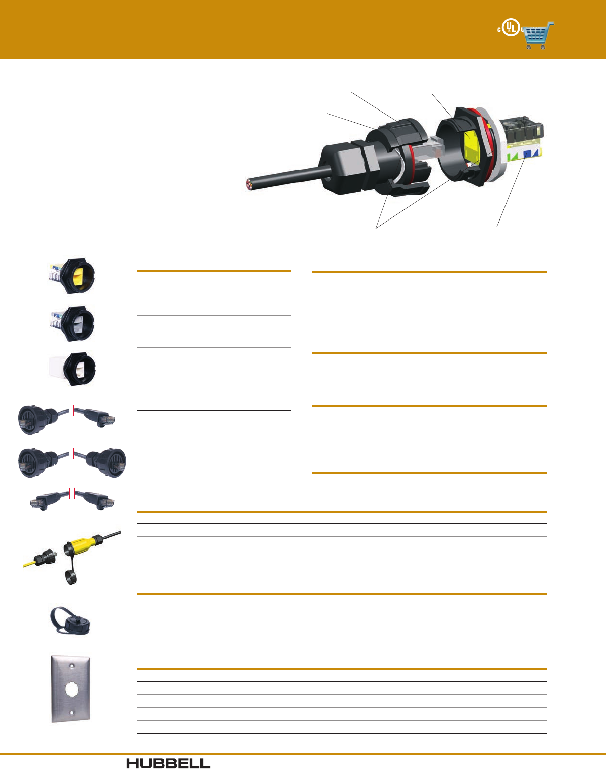
www.hubbell-wiring.comI-44 Wiring Device-Kellems
®
Standard Hubbell Keystone
Latching System
O-Rings for
moisture protection
Category 6 and 5e
component connectors
Housing made from
high impact polymer
IP67 rated - sealed
connection
EE
AE
AA
HIC
HISF11
HICH
Industrial Ethernet Connectors
Description Catalog Number
Cat. 5e Connector HI5E
Cat. 6 Connector HI6
Cat. 5e Inline
Coupler Connector
HI5EC
Cat. 6 Inline
Coupler Connector
HI6C
Environmental Specifications
Ingress Protection: NEMA TYPE 4X (connectors).
IP67 and IP66 (dust/water). IP55 (plates).
Corrosion: Resistant to most common chemicals,
oils and cleaning agents.
HI-Impact Housing: UV resistant.
HI-Impact Housing
Temperature Range: TIA/EIA-568-B.2 -25°C to 70°C.
Material
HI-Impact Housing: Valox®, UL 94V-0.
Nose Contacts: Beryllium copper with a minimum of
50 micro-inch gold plating over nickel
under plating.
Mechanical
Vibration
Frequency Range: 10-500Hz.
Acceleration: 5g (operational).
Mating Cycles: 750 minimum.
UL 1863 compliant.
Electrical
ANSI/TIA/EIA-568-B.2-1 (Cat. 6 and 5e). Supports TIA-1005
Industrial Telecommunications Infrastructure.
HI-Impact
Industrial Ethernet Connector and Harsh Environment Connectors
Industrial Ethernet Patch Cords and Plugs
Description Catalog Number
HI-Impact RJ-45 to standard RJ-45. HI6xxAE
HI-Impact RJ-45 on both ends. HI6xxEE
Standard RJ-45 on both ends. HI6xxAA
Note: Substitute “XX” with 03, 05, 07, 10, 15, 20, 25, 30, 35, 40, 45, 50 to indicate length in feet.
Coupler Housing and Connector Cap
Description Catalog Number
HI-Impact coupler housing is a perfect solution for temporary and
flexible work areas where single port drops are needed. Add any
HI-Impact connector to support your application.
HICH
Connector Cap HIC
HI-Impact Wallplates
Description Port Openings Gang Catalog Number
Stainless steel wallplate. 1 1 HISF11
Stainless steel wallplate. 2 1 HISF12
Stainless steel wallplate. 2 2 HISF22
Stainless steel wallplate. 4 2 HISF24
Valox® is a trademark of SABIC Innovative Plastics, acquired from General Electric Company.
Hubbell’s Industrial Ethernet System provides leading
edge Category 5e and 6 network transmission
performance suitable for industrial and other harsh
environments. This system incorporates the use of
our standard data connectivity jacks which feature
our keystone latching mechanism, in a rugged sealed
housing providing IP67 rated protection.
Extend your LAN to include automation equipment
and manufacturing or process control equipment.
Utilize the Hubbell system to provide added
protection in harsh environments such as convention
centers, food processing plants, outdoor billboards
and display screens, medical and other environments
which require added protection from moisture,
corrosion, dust-debris, vibration and chemicals.
