Metalux SKYBAR Single LED Low Bay Luminaire Specification Sheet 1000425627 Catalog
2016-10-06
: Pdf 1000425627-Catalog 1000425627-Catalog B5 unilog
Open the PDF directly: View PDF ![]() .
.
Page Count: 5
Metalux
The SkyBar™ series reimagines high bay and low bay lighting by
delivering a unique aesthetic with industry-first uplight and leading
performance. By providing multiple lumen packages and distributions,
the SkyBar gives the necessary optical freedom and flexibility to meet the
requirements for a wide variety of lighting applications. SkyBar utilizes
the advantages of the patented WaveStream™ technology to deliver a
stylish LED alternative to traditional high bay lighting for commercial and
industrial applications.
DESCRIPTION
SKYBAR
LED
2-7/8" X 48"
2-7/8" X 96"
LED Low Bay Luminaire
Catalog # Type
Date
Project
Comments
Prepared by
SPECIFICATION FEATURES
Construction
Channel is die formed cold
rolled steel with KOs for ease
of installation. Groove for Tong
Hanger. End plate quickly converts
to snap-in channel connector for
continuous row alignment.
Electrical
Long-Life LED system coupled with
electrical driver to deliver optimal
performance. LED’s available in
3500K, 4000K or 5000k with a CRI
<85. Electronic drivers are available
for 120-277V, 347V and 480V
applications.
Emergency Battery Pack Option
Optional 120v-277v integral
emergency battery pack is
available in 7-watts or 14-watts to
meet critical life-safety lighting
requirements. The 90-minute
batteries provide constant power to
the LED system, ensuring code-
compliance. A test switch/indicator
button can be tested safely from
the ground using a laser pointer,
while the patented EZ Key prevents
accidental discharge of the battery
during construction. See ordering
information for details.
Controls
Equipped standard with a 0-10V
continuous dimming driver that
works with any standard 0-10V
control/dimmer. Dimming range
is 10% to 100%; varies by control
device. Combine with energy-
saving products like occupancy
sensors, daylighting controls, and
lighting relay panels to maximize
energy savings.
Optics
Precision formed optical assembly
with positively retained high
optical grade acrylic lenses provide
a directed optical distribution using
WaveStream technology.
Mounting
Suspended using two V-hangers
(included). Optional Y-hook,
Y-Toggle or Surface/stem mount
bracket is also available. Available
continuous row mount. Mounting
hardware must be ordered
separately.
Warranty
SkyBar features a five-year limited
warranty.
PS519034EN
7-8-2016
COMPLIANCES
Luminaires are cULus listed for damp
Locations 1. 7°C-40°C (35°F-105°F)
ambient environments. (EL option up
to 35°C ambient)
ROHS Compliant, and LED modules
comply with IESNA LM79/LM80
standards
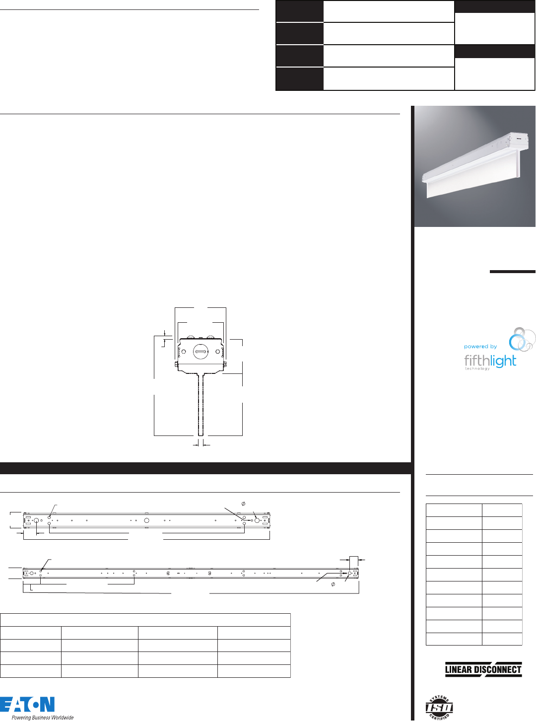
3"
[77mm]
2-11/16"
[69mm]
5-7/8"
[150mm] 3-11/16"
[94mm]
2"
[51mm]
X
Y
X=7/32"
[6mm]
Y=9/32"
[8mm]
Safe and convenient means of
disconnecting power
96" [2437mm]
K.O (2)
7/8" [22mm]
Hole for
Toggle
26-3/4" [680mm]
5" [127mm]
Ceiling Stand-off
Embossments
2-1/2"
[64mm]
8'
2-7/8"
[73mm]
48" [1219mm]
38" [965mm]
Ceiling Stand-off
Embossments
2-7/8"
[73mm]
K.O (3)
7/8" [22mm]
Hole for
Toggle
4'
2-1/2"
[64mm]
MOUNTING DATA
Catalog No. Input Watts
4SKBLED-LD1-
32
8
4SKBLED-LD1-
43
6
4SKBLED-LD1-
54
6
4SKBLED-LD1-
66
1
4SKBLED-LD1-
76
5
8SKBLED-LD1-
65
6
8SKBLED-LD1-
86
5
8SKBLED-LD1-10 84
8SKBLED-LD1-12 122
8SKBLED-LD1-14 129
ENERGY DATA
Metalux SkyBar-CCT Multiplier Table
CCT Multipliers from 3500K Multipliers from 4000KMultipliers from 5000K
3500K 1.000 0.0977 0.0936
4000K1.024 1.000 0.959
5000K1.068 1.043 1. 000
Specifications and
dimensions subject to
change without notice.
Eaton
1121 Highway 74 South
Peachtree City, GA 30269
P: 770-486-4800
www.eaton.com/lighting
SKBLED
PS519034EN
7-8-2016
4SKBLED-LD1-7-W-
UNV-L840-CD1-U
Electronic Driver
Linear LED 4000K
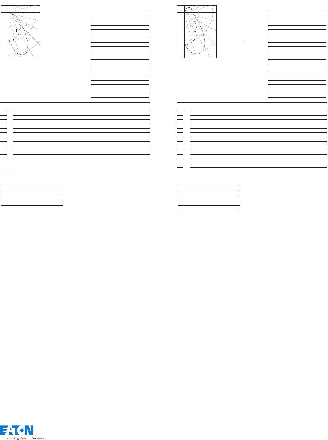
Spacing criterion:
(II) 1.1 x mounting
height, ( ) 1.6 x
mounting height
Lumens: 6490
Input Watts: 62.5W
Effi cacy: 103.8 lm/W
Test Report:
4SKBLED-LD1-7-W-
UNV-L840-CD1-U.IES
0
5
10
15
20
25
30
35
40
45
50
55
60
65
70
75
80
85
90
Candlepower
Angle Along II 45°Across ⊥
1464 1464 1464
1470 1588 1683
1440 1734 1869
1394 1811 1970
1315 1830 1997
1223 1779 1942
1111 1676 1807
981 1517 1609
835 1326 1381
679 11 35 1149
535 961 944
409 814 782
307 703 657
225 611 567
165 538 502
115 476 451
72 424 405
33 372 366
4 335 332
Coefficients of Utilization
Effective fl oor cavity refl ectance 20%
rc 80%70% 50%30% 10%0%
rw 70 50 30 10 70 50 30 10 50 30 10 50 30 10 50 30 10 0
RCR
0
1
2
3
4
5
6
7
8
9
10
114 114 114 114 109 109 109 109 99 99 99 91 91 91 82 82 82 79
103 97 93 88 98 93 89 85 85 81 78 77 75 72 70 68 66 63
93 85 78 72 89 81 75 69 74 69 64 68 63 60 62 58 55 52
85 74 66 60 81 71 64 58 65 59 54 60 55 51 55 51 47 44
78 66 57 51 74 63 55 49 58 52 46 53 48 44 49 44 41 38
72 59 50 44 68 57 49 43 52 45 40 48 42 38 44 39 36 33
66 53 45 38 63 51 43 37 47 40 35 44 38 33 40 35 31 29
61 48 40 34 58 47 39 33 43 36 31 40 34 30 37 32 28 26
57 44 36 30 54 42 35 29 39 33 28 37 31 27 34 29 25 23
53 40 32 27 51 39 32 26 36 30 25 34 28 24 31 26 23 21
50 37 30 24 48 36 29 24 34 27 23 31 26 22 29 24 21 19
Zonal Lumen Summary
Zone Lumens% Fixture
0-30
0-40
0-60
0-90
0-180
1438 22.2
2334 36.0
3807 58.7
5108 78.7
6490 100.0
650
0˚ 15˚ 30˚
45˚
60˚
75˚
90˚
1300
1950
4SKBLED-LD1-5-N-
UNV-L835-CD1-U
Electronic Driver
Linear LED 3500K
Spacing criterion:
(II) 1.2 x mounting
height, (⊥) 1.6 x
mounting height
Lumens: 5443
Input Watts: 45.7W
Effi cacy: 119.1 lm/W
Test Report:
4SKBLED-LD1-5-N-
UNV-L835-CD1-U.IES
0
5
10
15
20
25
30
35
40
45
50
55
60
65
70
75
80
85
90
Candlepower
Angle Along II 45°Across ⊥
1461 1461 1461
1466 1553 1658
1442 1793 2043
1406 2008 2288
1344 2119 2345
1274 2099 2311
11 89 2005 2051
1081 1795 1683
966 1545 1357
839 1290 1082
699 1053 868
555 843 691
413 662 534
283 511 399
178 384 289
104 280 201
52 199 131
18 135 83
2 97 54
Coefficients of Utilization
Effective fl oor cavity refl ectance 20%
rc 80%70% 50%30% 10%0%
rw 70 50 30 10 70 50 30 10 50 30 10 50 30 10 50 30 10 0
RCR
0
1
2
3
4
5
6
7
8
9
10
11 7 11 7 11 7 11 7 114 114 114 114 107 107 107 100 10 0 10 0 95 95 95 92
107 103 99 95 104 100 96 93 94 91 89 89 87 84 84 82 81 78
98 91 84 79 95 88 82 77 83 78 74 79 75 71 75 72 69 66
90 80 73 67 87 78 71 65 74 68 63 70 65 61 67 63 59 57
83 72 63 57 80 70 62 56 66 60 55 63 58 53 60 55 52 49
77 64 56 50 74 63 55 49 60 53 48 57 51 47 55 49 45 43
71 58 50 44 68 57 49 43 54 47 42 52 46 41 50 44 40 38
66 53 45 39 64 52 44 38 50 43 37 47 41 37 45 40 36 34
61 48 40 35 59 47 40 34 45 39 34 44 37 33 42 36 32 30
57 44 37 31 56 44 36 31 42 35 30 40 34 30 39 33 29 27
54 41 33 28 52 40 33 28 39 32 28 37 31 27 36 31 27 25
Zonal Lumen Summary
Zone Lumens % Fixture
0-30
0-40
0-60
0-90
0-180
1600 29.4
2610 47.9
4175 76.7
5011 92.1
5443 100.0
750
0˚ 15˚30˚
45˚
60˚
75˚
90˚
1500
2250
PHOTOMETRICS
Specifications and
dimensions subject to
change without notice.
Eaton
1121 Highway 74 South
Peachtree City, GA 30269
P: 770-486-4800
www.eaton.com/lighting
NOTES: (1)Voltage must be specified when ordered with plugs or emergency ballasts. (2)Not available with UNC and EL options together. (3)With integral test
switch/indicator/laser test. For approximate delivered lumens multiply the lumens per watt of the desired fixture by the wattage of the emergency battery pack (100
lm/W x 7=700 lumens). IES-format photometry for luminaire under emergency operation available. (4)For mounting heights up to 10 ft. (5)For mounting heights up to
30 ft. (6)EL option illuminates one 4 ft. section in 12,000 and 14,000 lumen packages. (7)Recommended for use with stand alone fixtures only. (8) Used to transfer
fixture to secondary power source for life-safety operation. When used with a dimming fixture, two devices are required to ensure control is disabled while operating
under emergency power.
Specifications and dimensions subject to change without notice. Consult your Eaton representative for availability and ordering information.
SAM P L E N U M B E R : SKBLED-LD1-14-W-UNV-L850-CD 2 - U
Lamp Type
LD1=LED 1.0
LED Lumen Output
4 ft.
3=3,000 Lumens
4=4,000 Lumens
5=5,000 Lumens
6=6,000 Lumens
7=7,000 Lumens
8 ft.
6=6,000 Lumens
8=8,000 Lumens
10=10,000 Lumens
12=12,000 Lumens
14=14,000 Lumens
Series
SKBLED=
WaveStream
Voltage(1)
120V=120 Volt
277V=277 Volt
347V=347 Volt
480V=480 Volt
UNC=Universal Voltage
347-480(2)
UNV=Universal Voltage
120-277
Distribution
N=Narrow
W=Wide
Options
RS=Reflector Shield
Packaging
U=Unit Pack
Driver Type
CD=0-10V Dimming
Driver
5LTD=Fifth Light
(DALI) Driver
Number of Drivers
1=1 Driver
2=2 Drivers (10,000, 12,000 and
14,000 lumen)
5LTD
1=1 Driver
2=2 Drivers (10,000, 12,000 and
14,000 lumen)
CCT
L835=3500K
L840=4000K
L850=5000K
Accessories (order separately)
AYC-Chain/Set=36" Chain Hanger
(Use 1 set per fixture)
SCF=Fixed Stem Set (Specify Length)
SCS=Swivel Stem Set (Specify Length)
SCA=Adjustable 48" Stem Set
EYE CHAIN SET/3FT=Eye Bolt Chain
(Use 1 set per fixture)
A1B/Spacer-U=Spacer 1-1/2" to 2-1/2" from ceiling
(Use 2 per fixture)
TOGGLE=Single Toggle No. 2 (Specify Length)
Y-TOGGLE=Y Toggle No. 2 (Specify Length)
SKBLED-CRA=Continuous Row Aligner
Motion Sensors
SVPD2=Integrated occupancy and daylight
dimming sensor, 900 sq. ft. coverage (4), (7)
SVPD3=Integrated occupancy and daylight
dimming sensor, 1200 sq. ft. coverage (5), (7)
LB-ERMS360=360° Low Bay Motion Sensor - End of Row
LB-MRMS360=360° Low Bay Motion Sensor - Middle of Row
HB-ERMS360=360° High Bay Motion Sensor - End of Row
HB-MRMS360=360° High Bay Motion Sensor - Middle of Row
Wiring
PI NG=Plug In System (1, 2, or 3 Circuit Capability),
No Ground (ground provided by fixture body)
PI WG=Plug In System (1, 2, or 3 Circuit Capability),
With Ground (separate ground wire in harness)
CPI NG=Crossover Plug In System (2 or 3 Circuit Capability)
No Ground (ground provided by fixture body)
CPI WG=Crossover Plug In System (2 or 3 Circuit Capability)
With Ground (separate ground wire in harness)
Length
4=4' Length
8=8' Length
Options
EL7W=7-watt, 120V-277V
emergency battery pack
installed (2), (3), (6)
EL14W=14-watt 120V-277V
emergency battery pack
installed (2), (3), (6)
GTD2 =Bodine Generator
Transfer Device (8)
ETS2 =IOTA Emergency
Transfer Switch (8)
Mounting Arrangement
[Blank]=Stand Alone
R=Continuous Row Mount
ORDER I NG I NFORMATI ON
SKB L E D
PS519034EN
7-8-2016
BLK=Black Hot
PI1= Single
Circuit
NG= No Ground (ground
provided by fixture body)
WG= With Ground
(separate ground wire
in harness)
P I 1 - S i n g l e C i r c u i t Pl u g - I n
SAMPLE NUMBER: P I1B L K-W G
BLK=Black Hot
BLU=Blue Hot
PI2= Two
Circuit
NG= No Ground (ground
provided by fixture body)
WG= With Ground (separate
ground wire in harness)
PI2 - Two Circuit Plug-In
SAM P L E NUMB E R : P I 2 BLK - W G
Leave Blank=Single
Neutral
/WHT=White Neutral
/GRY=Gray Neutral
Leave Blank=Single
Neutral
2NEU=Two Neutrals BLK=Black Hot
BLU=Blue Hot
RED=Red Hot
PI3= Three
Circuit
NG= No Ground (ground
provided by fixture body)
WG= With Ground (separate
ground wire in harness)
PI3 - Three Circuit Plug-In
SAMPLE NUMBER: P I 3BL K - W G
Leave Blank=Single
Neutral
/WHT=White Neutral
/GRY=Gray Neutral
Leave Blank=Single Neutral
2NEU=Two Neutrals
Specifications & dimensions subject to change without
notice. Consult your Eaton Representative for availability
and ordering information.
Catalog Circuit
Number Number of Wired To
Suffix Circuits Ballast
PI 1 BLK 1 Black
PI 2 BLU 2 Blue
PI 2 BLK 2 Black
PI 3 RED 3 Red
PI 3 BLU 3 Blue
PI 3 BLK 3 Black
Catalog Numbering System
The PI System is available in sections up to 8' in length for continuous row wiring by simply plugging the sections
together. Each PI section is factory wired to the ballast leads. Color coding of wires is as follows:
PI-1 = One Circuit - 2 Wires: one black, one white
PI-2 = Two Circuits - 3 Wires: one black, one blue, one white
PI-3 = Three Circuits - 4 wires: one black, one blue, one red, one white
When ordering the PI2/PI3 System it is necessary to specify the number of fixtures required for each circuit. Each circuit in
fixture must be ordered as a separate line item, with a different hot wire color specified. All wiring to external feeds, using
cord or cord & plug, are responsibility of installing licensed contractor. Cord and cord & plug sets must be ordered
separately if PI option is chosen.
PI O PT IO N ORDERING INFORMATIO N
Catalog No Wt.
4SKBLED-LD1-3 8 lbs.
4SKBLED-LD1-4 8 lbs.
4SKBLED-LD1-5 8 lbs.
4SKBLED-LD1-6 8 lbs.
4SKBLED-LD1-7 8 lbs.
8SKBLED-LD1-6 15 lbs.
8SKBLED-LD1-8 15 lbs.
8SKBLED-LD1-10 15 lbs.
8SKBLED-LD1-12 15 lbs.
8SKBLED-LD1-14 15 lbs.
SHIPPING DAT A
(9)
(9)Included when ordering the "R" mounting arrangement.

Specifications and
dimensions subject to
change without notice.
Eaton
1121 Highway 74 South
Peachtree City, GA 30269
P: 770-486-4800
www.eaton.com/lighting
SKBLED
PS519034EN
7-8-2016
Description
This innovative luminaire-integrated sensor control system optimized for code-compliant occupancy detection and daylight harvesting – all from within
the foot print of Metalux’s luminaires.
No New Wires
An in-place fixture retrofit is all that’s needed to meet most energy codes in commercial spaces. The sensor system is factory wired to the luminaire,
switching on or off based on occupancy, and dimming the light when enough daylight is available.
Sophisticated lighting control without commissioning
The luminaire-integrated sensor system offers out-of-the-box operation using thoughtful default settings.
Flexibility and Individual Control
When the application demands more, the sensor system has the option to make changes using a remote control. The remote allows changes from the
default settings for occupancy, target light level, preset lighting levels, and more.
Cost-effective, Stand-alone Operation
With a single product to mount and a single electrical connection to make, the Metalux luminaire with an integrated sensor system saves money on
the total installed cost when occupancy or daylight harvesting controls are needed. The integrated sensor system works stand-alone, without the need
for additional switches and dimmers. When manual-on, manual dimming or other code-required control schemes are needed, please see the
comprehensive offering of Greengate and Fifth Light solutions from Cooper Controls at www.coopercontrol.com.
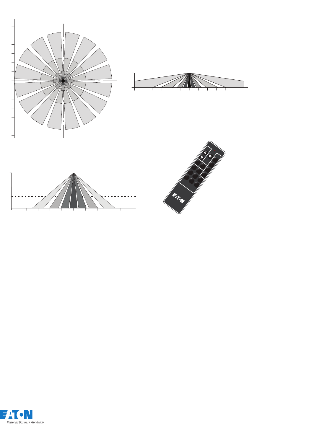
Metalux Integrated Sensor Sequence of Operation
The occupancy sensing portion of the sensor uses Passive Infrared (PIR) technology with Auto-on/Auto-off operation. The small lens in the center of the
sensor directs the view of a passive infrared occupancy detector to sense occupants moving through the room. To trigger the light on, an occupant
must cross at least two passive infrared beams. When motion in the coverage area ceases, the sensor logic concludes the room is unoccupied, and
begins a count-down timer. By default, the timer is factory-set to 20 minutes, and can be adjusted to 5, 10, 15 and 20 minutes using the optional
remote control, model number HHPRG-MS. Any motion detected during the count-down timer will cause the light to remain on and resets the timer.
When motion is detected, a red LED will blink. In addition to the default on/off functionality, the sensor has an Energy Saver feature, where the light
can be set to dim to a preset level after the sensor detects no occupancy for half of the count-down timer, when the timer is complete the lighting will
change to the unoccupied setting. The Energy Saver feature works when the count-down timer is set to at least 10 minutes, and the preset level and
feature are configured using the optional remote control. See the Sensor Programming Guide that comes with the HHPRG-MS remote for details on
this feature. The sensitivity of the occupancy detection can be adjusted, using the HHPRG-MS remote. By default, the sensor operates at the full
detection range shown on the coverage pattern diagram. Using the “LO” button on the HHPRG-MS remote, reduces the sensor detection range by
50%. Full coverage can be restored at any time by pressing the “HI” button on the remote. The red LED indicator will blink repeatedly to confirm any
programming change.
The dimming daylight harvesting portion of the sensor uses a small photo sensor located next to the occupancy sensing lens. The sensor continuously
measures the available light in the room, even when the fixture is turned off. This allows sensor to operate in one of three daylighting modes, where
the artificial light from the paired Metalux luminaire can adjust the light based on the amount of ambient light from surrounding natural and artificial
light sources. Since the sensor measures light from its luminaire along with other light sources, this sensor follows a closed-loop dimming daylight
harvesting style. The first mode, Daytime, is active when the sensor detects light of at least 10 0 lux in the room. In Daytime mode, when the light is
turned on after detecting occupancy, the sensor will begin balancing the luminaire light level relative to the total available light it measures. The default
light balancing target in daytime mode is 500 lux. This level can be adjusted higher or lower using the optional HHPRG-MS remote, and pressing
“SET” and then the “DO” (Daytime Occupied) button to store the new light level. Similarly, the Daytime Unoccupied, “DU” has a default of level of 0
lux, or off, but can be adjusted higher to prevent the lights from turning off completely when unoccupied. More details on this function are found in
the Sensor Programming Guide for the HHPRG-MS remote.
The next two modes, Twilight and Nighttime, function in a similar way, allowing the artificial light to adjust to different levels based on the
surroundings. While primarily for use in outdoor luminaires, these modes are available for use in areas with a wide range of natural light, including
atriums, day lit stairwells, and rooms with large or continuous windows. The Twilight mode is active when the sensor detects 50-100 lux in the off
position, and has a 300 lux default light balancing target. The Nighttime mode is active when the sensor detects less than 50 lux, and has a 250 lux
default light balancing target. Like the Daytime mode, there are separate settings for Tw ilight Occupied (“TO”), Twilight Unoccupied (“TU”), Nighttime
Occupied (“NO”) and Nighttime Unoccupied (“NU”) which can be adjusted and set using the optional HHPRG-MS remote.
In addition to programming the sensor, the optional HHPRG-MS remote can be used for personal control to adjust the lighting temporarily override the
functions of the sensor temporarily. The remote has raise/lower buttons to adjust the light level for special tasks, as well as a power button to turn the
lights on or off. Unless the SET button and another function is selected, any changes made using these buttons will revert to the programmed settings
after the sensor has detected no occupancy for its programmed time out, and turned off the lighting. The next time the sensor detects occupancy, it will
revert to its programmed settings for count-down timer and light balancing.
Coverage Patterns next page
INTEGRATED SENSOR
Specifications and
dimensions subject to
change without notice.
Eaton
1121 Highway 74 South
Peachtree City, GA 30269
P: 770-486-4800
www.eaton.com/lighting
SKBLED
PS519034EN
7-8-2016
C
L
Top View
9.1m
[30 ft.]
6.1m
[20 ft.]
4.5m
[15 ft.]
3m
[10 ft.]
1.5m
[5 ft.]
0
1.5m
[5 ft.]
3m
[10 ft.]
4.5m
[15 ft.]
6.1m
[20 ft.]
9.1m
[30 ft.]
Side View
0
2.4m
[8 ft.] 6.1m
[20 ft.]
4.5m
[15 ft.]
3m
[10 ft.]
1.5m
[5 ft.]
09.1m
[30 ft.]
6.1m
[20 ft.]
4.5m
[15 ft.]
3m
[10 ft.]
1.5m
[5 ft.]
Side View
0
6.1m
[20 ft.]
9.1m
[30 ft.] 12.2m
[40 ft.]
9.1m
[30 ft.]
6.1m
[20 ft.]
3m
[10 ft.]
012.2m
[40 ft.]
9.1m
[30 ft.]
6.1m
[20 ft.]
3m
[10 ft.]
SVPD2 Coverage Pattern
SVPD3 Coverage Pattern
Programming Remote
HHPRG-MS
Scenes:
To save scenes press SET
and select scene
Raise/
Lower
Time
Out
5
10
15
20
HI
LO
ES
SET
NO
TO
DO
NU
TU
DU
Optional Remote
Control
HHPRG-MS Remote
SENSOR DETAILS - SKYBAR SINGLE
