1000428607 Catalog
2016-07-29
: Pdf 1000428607-Catalog 1000428607-Catalog B2 unilog
Open the PDF directly: View PDF ![]() .
.
Page Count: 202 [warning: Documents this large are best viewed by clicking the View PDF Link!]
PHOTOELECTRIC
PHOTOELECTRIC
SAFETY SENSORS
Edition 2006
FABRIKAUTOMATION

6
Date of edition 05/17/2006
Subject to reasonable modifications due to technical advances. Copyright Pepperl+Fuchs, Printed in Germany
Pepperl+Fuchs Group • Tel.: Germany +49 621 776-0 • USA +1 330 4253555 • Singapore +65 67799091 • Internet http://www.pepperl-fuchs.com
Table of Contents

7
S
ubject to reasonable modifications due to technical advances. Copyright Pepperl+Fuchs, Printed in Germany
Pepperl+Fuchs Group • Tel.: Germany +49 621 776-0 • USA +1 330 4253555 • Singapore +65 67799091 • Internet http://www.pepperl-fuchs.com
Table of Contents
Date of edition 05/17/2006
Photoelectric safety sensors
Content Page
Worldwide presence of a strong product brand . . . . . . . . . . . . . . . . . . . . . . . . . . . . . . . . . . . . . . . 1
Overview . . . . . . . . . . . . . . . . . . . . . . . . . . . . . . . . . . . . . . . . . . . . . . . . . . . . . . . . . . . . . . . . . . . . . . . 9
Selection table based on model line. . . . . . . . . . . . . . . . . . . . . . . . . . . . . . . . . . . . . . . . . . . . . . . . . 12
The way to achieve correct electrosensitive protection equipment . . . . . . . . . . . . . . . . . . . . . . . . . 14
Technical data . . . . . . . . . . . . . . . . . . . . . . . . . . . . . . . . . . . . . . . . . . . . . . . . . . . . . . . . . . . . . . . . . . 25
Safety through beam sensors . . . . . . . . . . . . . . . . . . . . . . . . . . . . . . . . . . . . . . . . . . . . . . . . . . . . . 25
Safety light grids. . . . . . . . . . . . . . . . . . . . . . . . . . . . . . . . . . . . . . . . . . . . . . . . . . . . . . . . . . . . . . . . 45
Safety light grid with internal control unit . . . . . . . . . . . . . . . . . . . . . . . . . . . . . . . . . . . . . . . . . . . . . 55
Safety light curtains . . . . . . . . . . . . . . . . . . . . . . . . . . . . . . . . . . . . . . . . . . . . . . . . . . . . . . . . . . . . 101
Control units . . . . . . . . . . . . . . . . . . . . . . . . . . . . . . . . . . . . . . . . . . . . . . . . . . . . . . . . . . . . . . . . . . 127
Accessories . . . . . . . . . . . . . . . . . . . . . . . . . . . . . . . . . . . . . . . . . . . . . . . . . . . . . . . . . . . . . . . . . . . 168
Additional Information . . . . . . . . . . . . . . . . . . . . . . . . . . . . . . . . . . . . . . . . . . . . . . . . . . . . . . . . . . 188
Guidelines and standards. . . . . . . . . . . . . . . . . . . . . . . . . . . . . . . . . . . . . . . . . . . . . . . . . . . . . . . . 188
Protection types provided by housing . . . . . . . . . . . . . . . . . . . . . . . . . . . . . . . . . . . . . . . . . . . . . .190
Option list . . . . . . . . . . . . . . . . . . . . . . . . . . . . . . . . . . . . . . . . . . . . . . . . . . . . . . . . . . . . . . . . . . . . 191
Type code. . . . . . . . . . . . . . . . . . . . . . . . . . . . . . . . . . . . . . . . . . . . . . . . . . . . . . . . . . . . . . . . . . . . 192
Glossary . . . . . . . . . . . . . . . . . . . . . . . . . . . . . . . . . . . . . . . . . . . . . . . . . . . . . . . . . . . . . . . . . . . . . 194
Pepperl+Fuchs GmbH worldwide . . . . . . . . . . . . . . . . . . . . . . . . . . . . . . . . . . . . . . . . . . . . . . . . . 196
Alphabetical type index . . . . . . . . . . . . . . . . . . . . . . . . . . . . . . . . . . . . . . . . . . . . . . . . . . . . . . . . . 204
Additional catalogs for the Pepperl+Fuchs’factory automation division describe:
- Photoelectronic standard sensors
- Ultrasonic sensors
- Inductive, capacitive and magnetic sensors
- Position sensors
- Rotary encoders
- Counters, tachometers and switching mechanisms
- Sensor systems
AS interface
Identifikation systems
8
Date of edition 05/17/2006
Subject to reasonable modifications due to technical advances. Copyright Pepperl+Fuchs, Printed in Germany
Pepperl+Fuchs Group • Tel.: Germany +49 621 776-0 • USA +1 330 4253555 • Singapore +65 67799091 • Internet http://www.pepperl-fuchs.com
Global presence of a strong product brand
9
S
ubject to reasonable modifications due to technical advances. Copyright Pepperl+Fuchs, Printed in Germany
Pepperl+Fuchs Group • Tel.: Germany +49 621 776-0 • USA +1 330 4253555 • Singapore +65 67799091 • Internet http://www.pepperl-fuchs.com
Global presence of a strong product brand
Date of edition 05/17/2006
Visolux – synonym for photoelectric
competence
Visolux
Modern automation technology keeps changing our
lives. The effects reach from industrial manufacturing
and processing to daily life with the apparent
automatic opening of doors in department stores,
supermarkets and public transport.
A condition for most automation solutions is - besides
the achievements of microelectronics - a
correspondingly powerful sensor technology which
plays a key role in the background. Sensors constantly
provide current information on process states and
events to the controls. Most automation solutions
would be unthinkable without these important
components.
Whilst automation in the private sphere is usually to
provide comfort and ease, the automated operation in
the industrial environment tends to pay real money.
Costs for routine processes and monitoring tasks can
be reduced to a minimum and enable the efficient
operation which is indispensible today
Market leader expands offer
The VISOLUX brand name, in the Pepperl+Fuchs
business sector, stands for factory automation for all
photoelectric sensors, including door/gate/lift sensors
and sensors for safety applications. In an almost 60
year history our company has developed into one of
the most reputable sensor manufacturers with a global
presence. The company often takes the technological
lead.
Responsible for products, solutions, and questions
about photoelectric sensors, the VISOLUX division
was seamlessly integrated into the Pepperl+Fuchs
tradition and philosophy: with innovative and high-
quality development of rational automation solutions
making it possible for customers to gain decisive
advantages in global competition. Simultaneously, the
photoelectric sensor competence centre profits from
the global distribution network and world-wide
manufacturing facilities of the parent corporation, with
locations in all important industrial regions in Europe,
Asia, and America.
10
Date of edition 05/17/2006
Subject to reasonable modifications due to technical advances. Copyright Pepperl+Fuchs, Printed in Germany
Pepperl+Fuchs Group • Tel.: Germany +49 621 776-0 • USA +1 330 4253555 • Singapore +65 67799091 • Internet http://www.pepperl-fuchs.com
Global presence of a strong product brand
Photoelectronics with key importance
Photoelectronic sensors are of key importance today
when the goal is to detect or monitor objects without
touching them. They are used wherever e.g.
positioning, classification or counting is required. The
applications range from the automobile industry,
machine design, and assembly automation to
warehousing and conveyor systems, packaging
machines, the printing and paper industries,
surveillance and safety technology.
Extensive product line
With its extensive product line, Pepperl+Fuchs/
Visolux, as end-to-end supplier and market leader,
has correspondingly mature end products. So the
solutions of the photoelectronic specialists are always
easy to optimise for individual applications.
The spectrum includes standard light barriers in the
most varied designs, light scanners, colour sensors,
laser systems, and data transmission light barriers,
vision sensors, distance measurement devices,
barcode scanners, light curtains, light grids, and safety
light barriers. The latter can be used in non-contact
safety applications.
For applications in which a one-beam optical detector
is not sufficient, there is a broad spectrum of light grids
available. They are used for the profile control of
pallets, monitoring of lift doors or the paper tear
protection in printing machines and much more.
Data light barriers, finally, provide wireless data
transmission using light on linearly moving vehicles to
avoid stoppage from cable breaks or communications
errors from contact bounces with traditional sliding
contacts.
The comfortable and at the same time safe operation
11
S
ubject to reasonable modifications due to technical advances. Copyright Pepperl+Fuchs, Printed in Germany
Pepperl+Fuchs Group • Tel.: Germany +49 621 776-0 • USA +1 330 4253555 • Singapore +65 67799091 • Internet http://www.pepperl-fuchs.com
Global presence of a strong product brand
Date of edition 05/17/2006
of doors and gates is the subject of the industry-
specific sensor technology from
Pepperl+Fuchs/Visolux. Whether this is for opening
pulse generators, the monitoring and startup control of
escalators in public buildings, the control of the
approach area of industrial gates or the closing edge
protection of lift doors.
An assortment of different operating principles is
employed on this very wide range of special sensors
offered by Pepperl+Fuchs/Visolux to the manufacturer
and.
Need customer-specific solutions?
If the right sensor cannnot be found in the Visolux line,
or if problems crop up which cannot be solved with
standard products off the rack, the
Pepperl+Fuchs/Visolux development team is ready for
action. In numerous customer-specific solutions, the
photoelectronic specialists have already
demonstrated their flexibility and performance.
The potential ranges from the modification of designs
through the extension of individual functions to the
closer cooperation with customers in the development
of novel solution concepts.
Overview
12
Subject to reasonable modifications due to technical advances. Copyright Pepperl+Fuchs, Printed in Germany
Pepperl+Fuchs Group • Tel.: Germany +49 621 776-0 • USA +1 330 4253555 • Singapore +65 67799091 • Internet http://www.pepperl-fuchs.com
Date of edition 05/17/2006
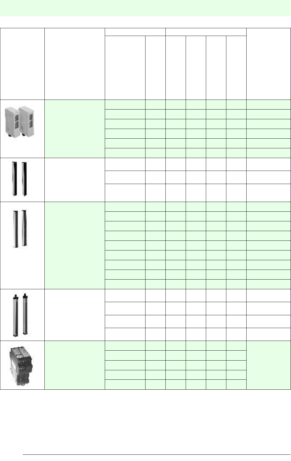
Selection table based on model line
Figure Model line Device design Principle of operation Limit detection
range
Series
Category
Safety through-beam sensors
Safety light grids
Safety light curtains
Safety control units
Safety through-beam sen-
sors for control units
SLA5 4O5 m
SL12 2O10 m
SLA12 4O10 m
SL29 2O65 m
SLA29 4O65 m
SLA40 4O4 m
control units SLP...-2 4O65 m
SLP...-3 4O65 m
SLP...-4 4O65 m
SLPC...-2 4O65 m
SLPC...-3 4O65 m
SLPC...-4 4O65 m
SLPCM...-2 4O65 m
SLPCM...-3 4O65 m
SLPCM...-4 4O65 m
SLC-2 4O20 m
SLC-3 4O20 m
SLC-4 4O20 m
Safety light curtains with
integrated control unit SLC14-... 4O5 m
SLC30-... 4O15 m
SLC60-... 4O15 m
SLC90-... 4O15 m
Control units SC2-2 2O
depends on the
optical barriers
used
SC4-2 4O
SB4 SafeBox O
integrated control unit
Safety light grids for
Safety light grids with

Overview
13
S
ubject to reasonable modifications due to technical advances. Copyright Pepperl+Fuchs, Printed in Germany
Pepperl+Fuchs Group • Tel.: Germany +49 621 776-0 • USA +1 330 4253555 • Singapore +65 67799091 • Internet http://www.pepperl-fuchs.com
Date of edition 05/17/2006
Safety through beam
sensors
Safety light gridsSafety light grids with
internal control unit
Safety light curtainsControl units
1) with SB4 Safebox control unit
Light type Operating
voltage
Output Connection Housing
material
Functions From
page
Red light
Infrared
24 V
115 V
230 V
Power supply via control unit
Relay
Semiconductor
Connector
Terminalcompartment/clamps
Fixed cable
Plastic
Metal
Pre-fault indication
Startup/restart interlock
Relay monitor
Muting
Emergency case muting
Double muting
O O O O O O 24
O O O O O O O
O O O O O O O
O O O O O O
O O O O O O
O O O O O O
OOOOO 44
OOOOO
OOOOO
O O O O O O O O O O 54
O O O O O O O O O O
O O O O O O O O O O
O O O O O O O O O O O O
O O O O O O O O O O O O
O O O O O O O O O O O O
O O O O O O O O O O O1) O1) O1)
O O O O O O O O O O O1) O1) O1)
O O O O O O O O O O O1) O1) O1)
OO OOOO OOOOO
1) O1) O1) 100
OO OOOO OOOOO
1) O1) O1)
OO OOOO OOOOO
1) O1) O1)
OO OOOO OOOOO
1) O1) O1)
O O O O O O O 126
O O O O O O O
O O O O O O O O O O O
14
Date of edition 05/17/2006
Subject to reasonable modifications due to technical advances. Copyright Pepperl+Fuchs, Printed in Germany
Pepperl+Fuchs Group • Tel.: Germany +49 621 776-0 • USA +1 330 4253555 • Singapore +65 67799091 • Internet http://www.pepperl-fuchs.com
The way to the right electro-sensitive protective equipment
General
The law prescribes protective measures wherever a machine in normal operation or the occurence of one or
several errors might cause pose a hazard to people or equipment.
These measures are based on European law (Directive 89/392/EC) and the Machinery Directive.
Thus, some considerations are necessary to determine the "right" protective equipment.
1. The risk analysis
1.1 Risk analysis according to EN 1050 (ISO 14121 A standard)
The basic idea of the European safety standardisation is to determine the risk of plant or a machine (risk analysis,
risk graph).
The risk assessment evaluates the complete or partial loss of the safety function, which is caused by errors.
This risk assessment is based on EN 1050.
Typical hazards include:
mechanical hazards
S Severity of the injury
- S1 Slight (usually reversible) injury
- S2 Serious (usually irreversible) injury, including death
F Frequency and/or duration of the exposure to hazard
- F1 Rarely to more often and/or short duration of the exposure
- F2 Frequently to continuously and/or long duration of the exposure
P Possibility to avoid the hazard
- P1 Possible under certain conditions
- P2 Hardly possible
Burns
The risk analysis is carried out according to the
following pattern:
Depending on the results of this analysis, the plant or
machine is assigned to a certain category. This has the
advantage that the requirements on the safety system
and its costs can be adpated to the actual risk.
Moreover, the assessment of a category depends on
the area of application.
For the process industrie, for instance, different
classifications apply than for machine engineering.
This is due to the fact that the consequences of an
accident in a chemical plant may be quite different
from that of an accident involving a press.
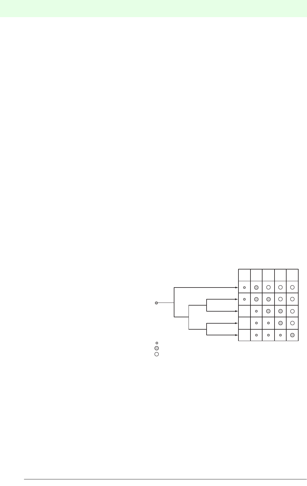
1.2 Risk assessment according to EN 954-
1(B standard)
As the risk assessment is often time-consuming and complex, many of these analyses for typical machines have
already been carried out and published as standards. These are referred to as C standards. Examples of C
standards are defined at the end of the catalogue under "Additional information".
If there are no corresponding C standards, EN 954-1, in which 5 categories are defined, applies to the machine.
Estimation of risk
Category
Possible category
Preferred category
Oversized method or measure
B1234
F1
F2
S1
S2
P2
P1
P1
P2

15
S
ubject to reasonable modifications due to technical advances. Copyright Pepperl+Fuchs, Printed in Germany
Pepperl+Fuchs Group • Tel.: Germany +49 621 776-0 • USA +1 330 4253555 • Singapore +65 67799091 • Internet http://www.pepperl-fuchs.com
The way to the right electro-sensitive protective equipment
Date of edition 05/17/2006
In the context of EN 954-1, the following requirements apply for safety-relevant parts of controls and components:
Category B : Use of tried and testen components and principles.
Category 1 : Use of intrinsic safety approved components and principles.
Category 2 : Use of testable components, cyclical testing.
Category 3 : Individual error is detected and does not result in the loss of the safety function.
Category 4 : Self-monitoring. No loss of the safety function if individual errors occur or in the case of
an accumulation of several errors.
1.3 Electro-sensitive protective equipment (ESPE)
The electro-sensitive protective equipment which is refererred to here includes photoelectric safety devices such
as safety light barriers, safety light grids, safety light curtains and the corresponding control units.
Usually, electro-sensitive protective equipment is divided into 2 categories:
ESPE-T Type 2, according to IEC/EN 61496-1
Inspection of the safety function by means of regular testing, category 2 of the
Machine Safety (EN 954-1).
ESPE-S Type 4, according to IEC/EN 61496-1
Self-monitoring, category 4 of the Machine Safety (EN 954-1).
According to the category, they contain one or two input signal switching devices (OSSD).
Additionally, special requirements for the optical properties of the sensor are defined.
Type 2 Opening angle 10°
Typ 4 Opening angle 5°
The photoelectric safety devices introduced in this catalogue either correspond to type 2 or type 4 and thus comply
with the highest safety requirements.
2. Definition of the detection characteristics
Photoelectric safety devices are used if larger distances or areas must be contactlessly monitored. The following
basic differentiations are made:
• Access protection (personal safety)
• Interference protection(hand, finger safety)
The optical characteristics (mainly range and resolution) dpend on this operational range.
2.1 Access protection
For personal safety mainly light barriers or light grids will be used.
Dependent on the hazard location to be monitored certain installation topologies are recommended or mandated.
• in EN 294 safety distances to prevent reaching hazard locations with the upper extremeties.
• in EN 811 definition of safety distances with regard to the reaching of operator limbs into
danger areas.
• in EN 999 determination of sufficient safety distances.
• C standards see chapter "Additional information".
16
Date of edition 05/17/2006
Subject to reasonable modifications due to technical advances. Copyright Pepperl+Fuchs, Printed in Germany
Pepperl+Fuchs Group • Tel.: Germany +49 621 776-0 • USA +1 330 4253555 • Singapore +65 67799091 • Internet http://www.pepperl-fuchs.com
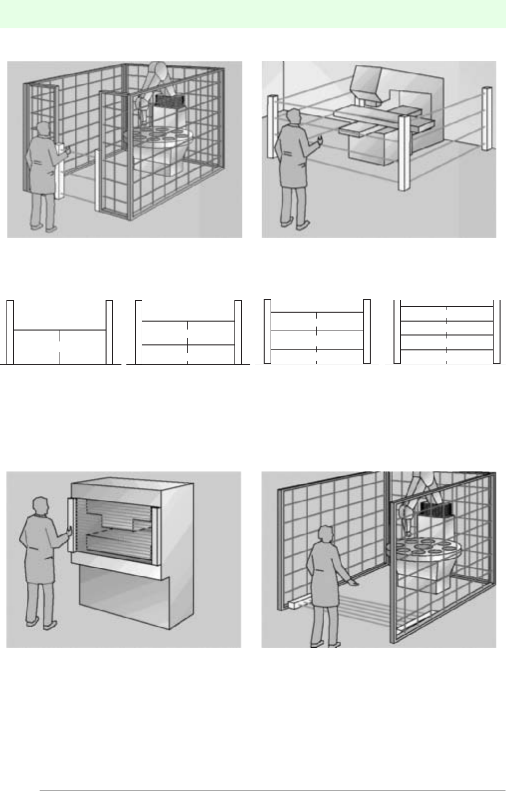
The way to the right electro-sensitive protective equipment
To ensure safety of personnel, combinations of mechanical and photoelectric safety devices are often used. In
addition, redirection mirrors offer multi-sided protection.
3 beam light grid protection multi-directional protection using redirection mirrors
Examples for beam distances above floor level in accordance with EN 999:
1 beam 2 beams 3 beams 4 beams
2.2 Protection against reaching
Light curtains are used predominantly to protect against reaching.
In this case a higher resolution is required, usually 14 mm (finger safety), 30 mm (hand safety), 60 mm and 90 mm
(bypass protection).
Reach protection through light curtain light curtain for bypass protection
750 mm
500 mm
400 mm
400 mm
400 mm
300 mm
300 mm
300 mm
300 mm
300 mm
17
S
ubject to reasonable modifications due to technical advances. Copyright Pepperl+Fuchs, Printed in Germany
Pepperl+Fuchs Group • Tel.: Germany +49 621 776-0 • USA +1 330 4253555 • Singapore +65 67799091 • Internet http://www.pepperl-fuchs.com
The way to the right electro-sensitive protective equipment
Date of edition 05/17/2006
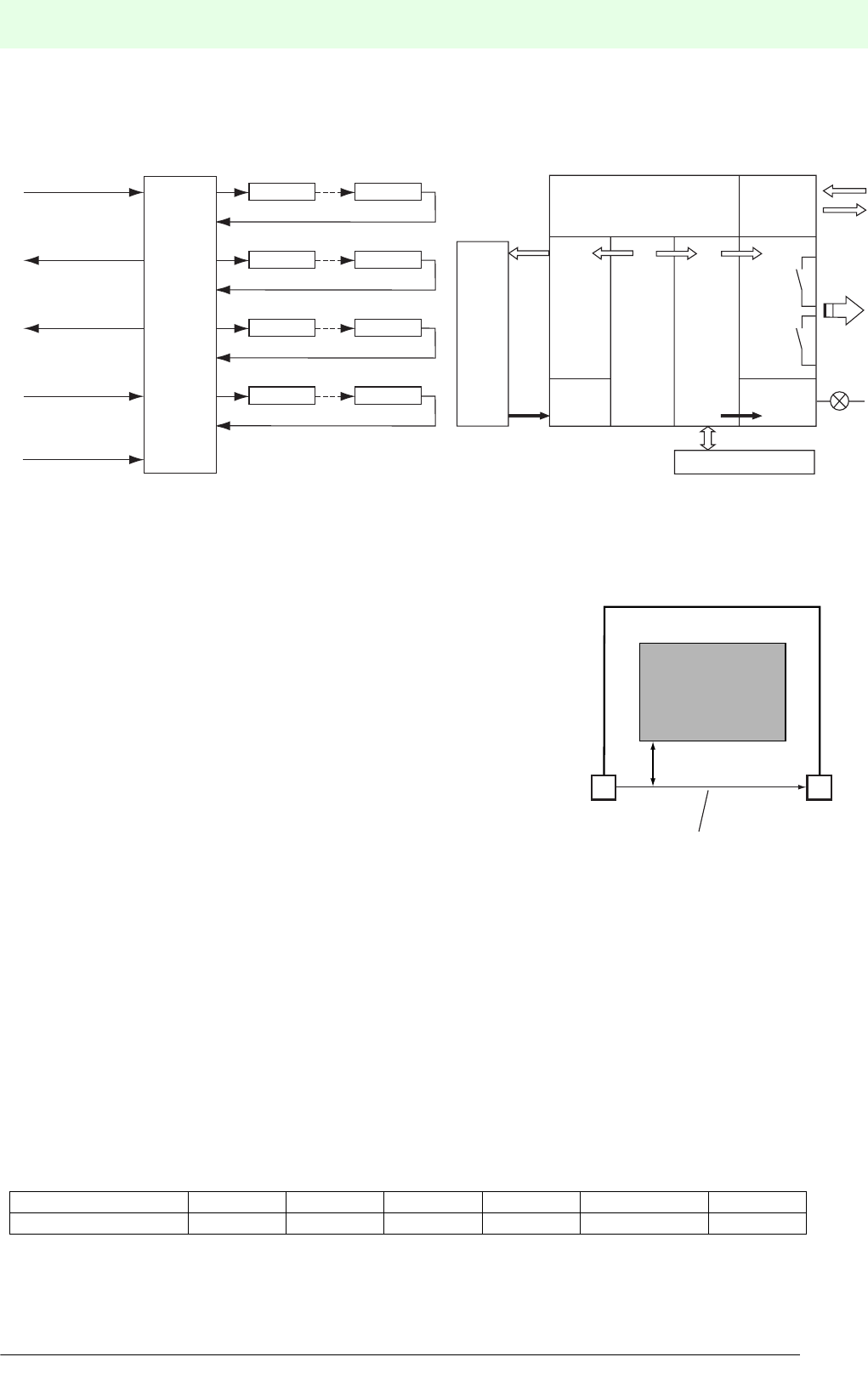
2.3 Signal Evaluation
The signal evaluation fo individual light barriers is normally located in a separate control unit.
For light grids both designs with integrated evaluation and with external signal evaluation are available. For light
curtains the evaluation is normally integrated.
Individual light barriers with separate evaluation Light grid/light curtain with integrated evaluation
3. Installation of the photoelectronic protection device
3.1 Determining the safety distance
When fitting an photoelectronic safety device to a hazard location, a
minimum distance between the protected area and the hazard location
must be observed. This distance is to ensure that the movement causing
the hazard will have come to rest before any person can touch it.
The distance is calculated from the after-running time of the machine, the
response time of the safety system and the speed of movement of the
person entering the danger area (EN 999, EN 294).
According to EN 999, the minimum distance can be calculated using the
formula:
Accordingly,
S: S minimum safety distance in mm, i.e. the distance from the hazardous area to the protected area
K: Constant in mm/s for the approach speed.
T: Total response time in s.
t1: Response time of the safety device
e.g. 20 ms (semiconducator OSSD) or.
40 ms (relay OSSD)
t2: Machine after-running time
C: additional distance according to the table.
*) provided the risk analysis permits a 1 beam protection.
Number of beams/resolution 14 mm 30 mm 60 mm 90 mm 2,3,4 beams 1 beam*)
C 0 mm 128 mm 850 mm 850 mm 850 mm 1200 mm
Voltage supply
Channel 1
Control
Unit
Restart input
Test input
Channel 4
OSSD-outputs
Channel 2
Status reports
Channel 3
Transmitter 1 Receiver 2
Transmitter 4 Receiver 4
Transmitter 2 Receiver 2
Transmitter 3 Receiver 3
Receiving unit
with integrated evaluation
Control
inputs
Message
outputs
Emitter
Sender
control
Protective
beams
OSSD-
Output
1+2
Control
Muting lamp
Muting sensors
Receiver
Control
and
monitoring
protective
beams
Muting
module Not-OF
F
0 V
Danger zone
Minimum interval S
Sending unit
Protective field
Receiving unit
SKT×C+=
Tt
1t2
+=
18
Date of edition 05/17/2006
Subject to reasonable modifications due to technical advances. Copyright Pepperl+Fuchs, Printed in Germany
Pepperl+Fuchs Group • Tel.: Germany +49 621 776-0 • USA +1 330 4253555 • Singapore +65 67799091 • Internet http://www.pepperl-fuchs.com
The way to the right electro-sensitive protective equipment
3.1.1 Safety distances for light curtains (EN 999)
Vertical approach
Calculation example:
With K = 2000 mm/s
and C = 0 mm for SLC 14...
or C = 128 mm for SLC 30...
the calculation formula for the distance S of 105 mm to
up to 500 mm is:
Note:
If S is greater than 500 mm, K = 1600 mm/s can be used.
S must be at least 500 mm. Smaller results must be corrected to a minimum distance of 500 mm.
Example: vertical layout
t1 = 50 ms, t2 = 300 ms
Hand protection C = 128 mm
The minimum distance from the protected field to the danger location must be 828 mm.
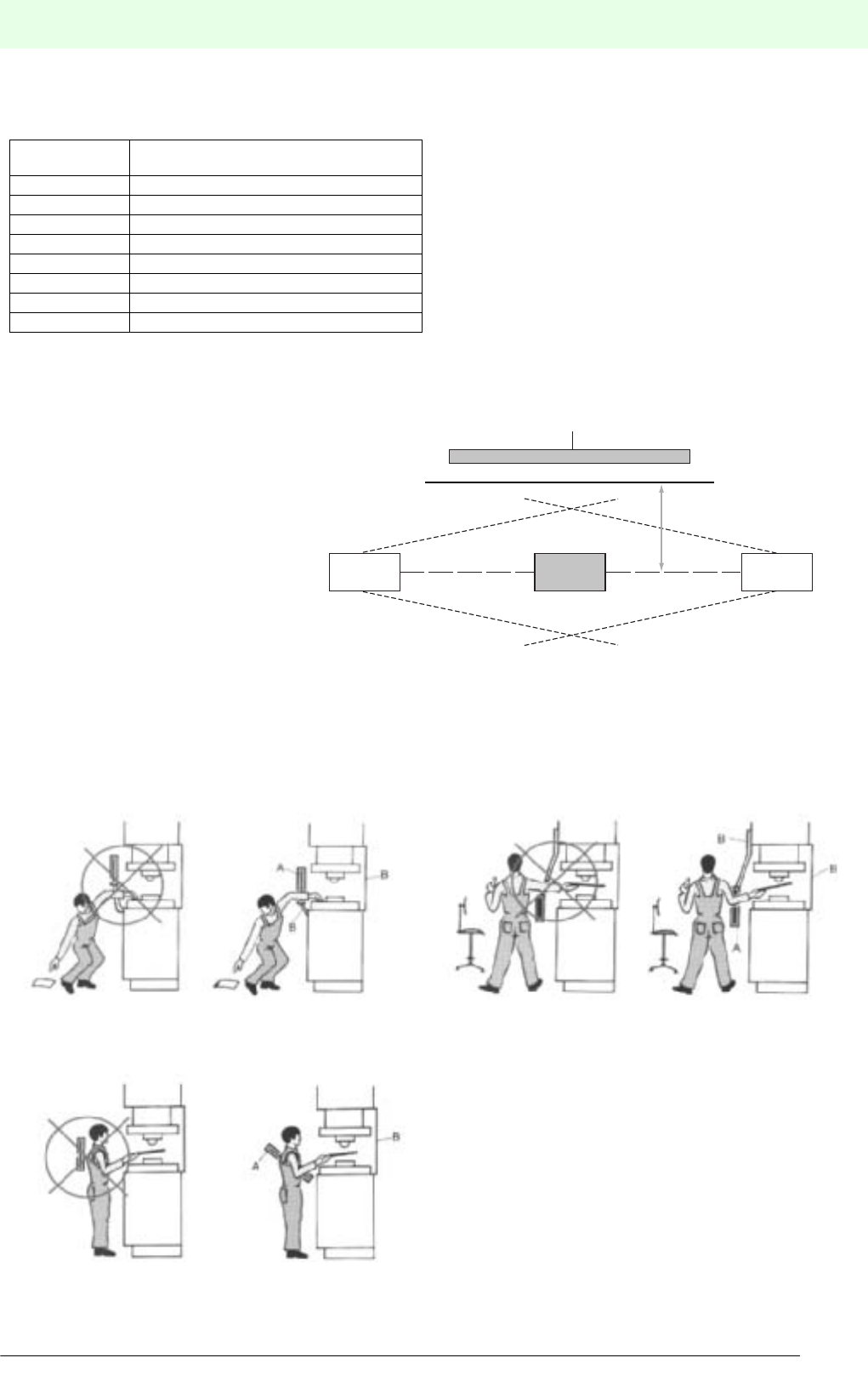
Parallel approach
For the horizontal layout of the safety light curtain the
safety distance S also depends on the height of the light
curtain above the floor. The maximum permitted height
H is1000 mm. At a height greater than 300 mm there is
a risk of access from below the safety light curtain. This
must be taken into account during the risk analysis;
alternatively additional barriers might be needed. The
safety distance can be calculated as follows:
where (1200 mm - 0.4 H) ≥ 850 mm (EN 999).
Distance S
Approach/
convergence
direction
Protective field
SLC
Danger
zone
S2000mm
s
---------t1t2
+()•C+=
S1600mm
s
---------t1t2
+()•C+=
S2000mm
s
---------350 10 3–
•s•128mm+=
S700mm 128mm+=
S828 mm=
Distance S
Approach/convergence
direction
H (height above ground)
Protective field
SLC
Danger
zone
S1600mm
s
---------t1t2
+()•1200mm 04H,–()+=
19
S
ubject to reasonable modifications due to technical advances. Copyright Pepperl+Fuchs, Printed in Germany
Pepperl+Fuchs Group • Tel.: Germany +49 621 776-0 • USA +1 330 4253555 • Singapore +65 67799091 • Internet http://www.pepperl-fuchs.com
The way to the right electro-sensitive protective equipment
Date of edition 05/17/2006
3.1.2 Safety beam distances for access protection
According to EN 999, the following heights are recommended for individual beams that are parallel to the floor:
3.1.3 Light beam reflection around an obstacle
It must be ensured that reflecting
objects which may cause a light
beam reflection around an obstacle
are not located within the
transmitting or receiving lobe (EN
61496-2).
3.2 Installation notes
The safety light curtain must be arranged in such a way that it is never possible to bypass the protective field from
above, below or behind. If the distance to the safety light curtain is too great, additional safety devices must be
fitted (see sample illustrations).
Number of
beams
Height above reference plane in mm
1 750
2 400, 900
3 300, 700, 1100
4 300, 600, 900, 1200
5
6 Lowest beam ≤300
7 Highest beam ≥900
8
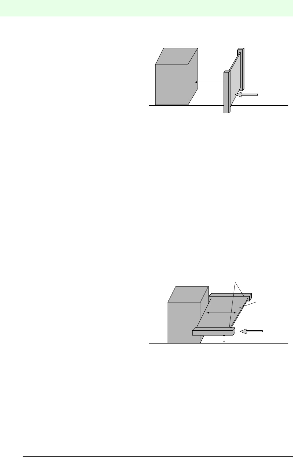
There must be no gap below the protective field through which it
is possible to reach into the danger area (A: protective field, B:
mechanical protection).
The operator must be prevented from reaching into the danger area
from above (A: protective field, B: mechanical protection).
The machine operator must not get between the light curtain and
the hazard location (A: protective field, B: mechanical protection).
Reflecting object outside beam area
Obstacle
Sending unit Receiving unit
Minimum interval a
20
Date of edition 05/17/2006
Subject to reasonable modifications due to technical advances. Copyright Pepperl+Fuchs, Printed in Germany
Pepperl+Fuchs Group • Tel.: Germany +49 621 776-0 • USA +1 330 4253555 • Singapore +65 67799091 • Internet http://www.pepperl-fuchs.com
The way to the right electro-sensitive protective equipment
4. Output switching
Pepperl+Fuchs/Visolux protection devices of type 4 are self-monitoring to type BWS-S and meet the requirements
of control category 4 (machine safety).
They feature two output signal switching devices OSSD (Output Signal Switching Device).
The switching devices are available either as semiconductors with separated potential or optionally with monitored
forced NO contacts.
5. Additional functions
5.1 Startup/restart lock
The startup/restart lock prevents the hazardous movement from automatically restarting after the protective field
has been penetrated.
The button for the startup/restart release must be positioned from where the danger area is easily visible and where
it is not possible to operate this button from within the danger area.
Startup release message:
To signal that all protective beams are clear after a beam interruption or after powering up, all BWS have an output
which is enabled if the protective field is clear. This function will only be enabled during operation with startup/
restart lock to notify the user that the startup release can be operated.
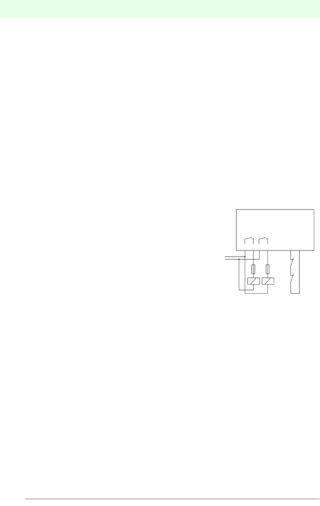
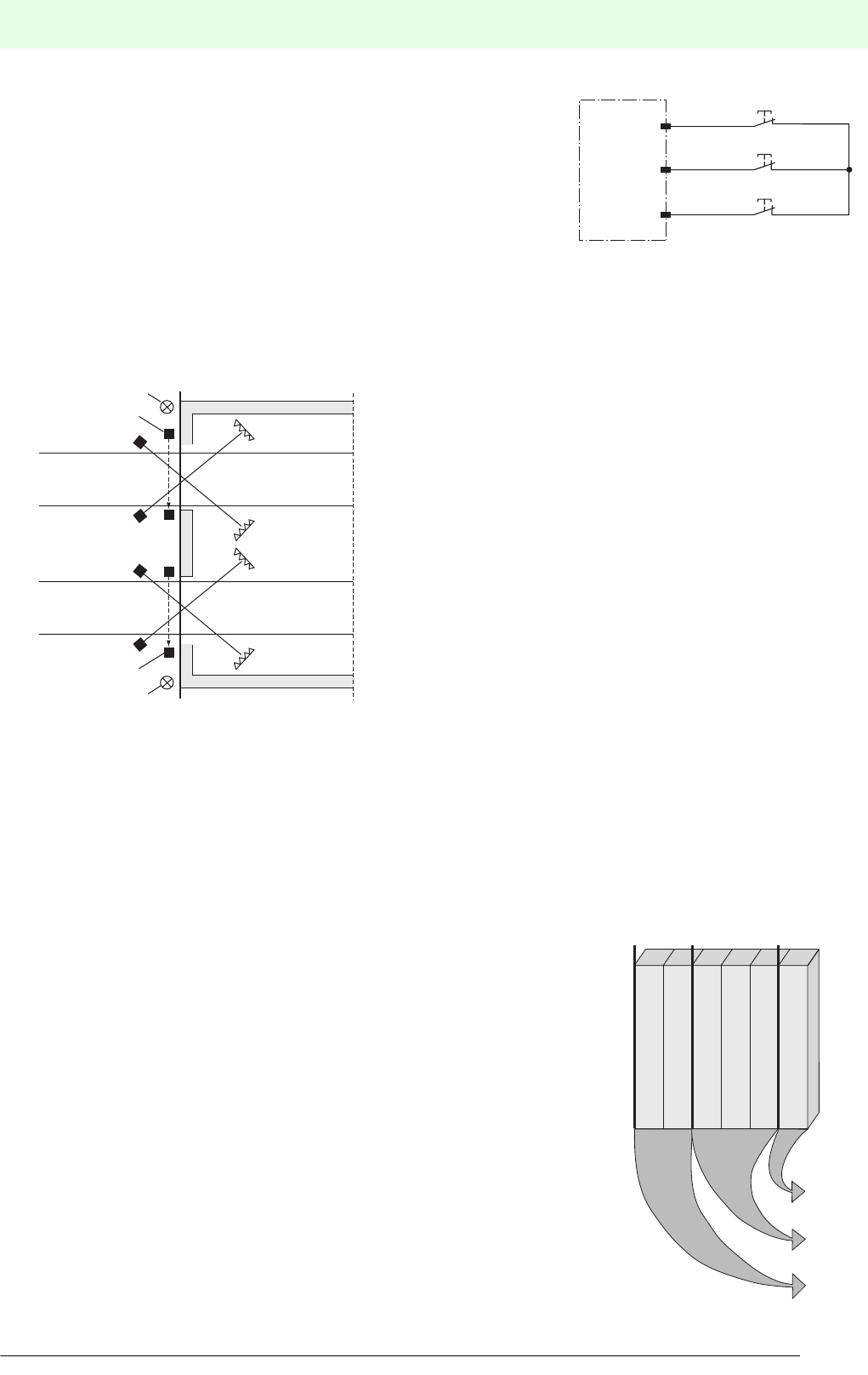
5.2 Relay monitor
The relay monitor is designed to monitor externally connected relays. The
relay monitor must be wired as shown here. Any number of NC contacts can
be switched by any number of relays. The minimum number of relays is,
however, 2.
K1 and K2 in the illustration are forced relays. The NC contacts K1K and
K2K (control contacts) must guarantee a safe contact at 24 V/5 mA. Add-on
auxiliary contacts or contacts of auxiliary relays normally meet this
requirement. Between the control contacts and other contacts under 230 V
alternating voltage a surge voltage resistance of 6 kV must be guaranteed
by the relay manufacturer. The operating circuit of the relay must be secured
with a fuse of a nominal rating of max. 60% of the load capacity of the relay
contacts. The relays are monitored with a delay of 200 ms after the switching
operation. If the new switching state has not been reached after 200 ms, the
ESPE enters into a locking state and indicates the error on the diagnostic display.
5.3 Muting
In the muting mode the protective function of a ESPE will be intentionally bridged. This function is necessary to
transport materials in or out of a danger area using an automatic conveying system. A precondition for this bridging
are at least 2 enabled muting sensors and a muting lamp.
The selection and layout of the muting sensors must ensure a differentiation between people and conveyed
material. Whilst the muting function is enabled the access to the danger area must be blocked, if necessary by the
conveyed material itself.
Various muting modes can be set at the muting-capable safety systems of Pepperl+Fuchs/Visolux to achieve an
adaptation to different applications. Different muting modes can bes set at the evaluation device Safebox or the
light grid SLPCM dependent on the actual application. Sequential and parallel muting are possible.
With dual muting two hazard locations can be monitored simultaneously.
5678 39
SLPC... /31
K1 K2
K1K
K2K
21
S
ubject to reasonable modifications due to technical advances. Copyright Pepperl+Fuchs, Printed in Germany
Pepperl+Fuchs Group • Tel.: Germany +49 621 776-0 • USA +1 330 4253555 • Singapore +65 67799091 • Internet http://www.pepperl-fuchs.com
The way to the right electro-sensitive protective equipment
Date of edition 05/17/2006
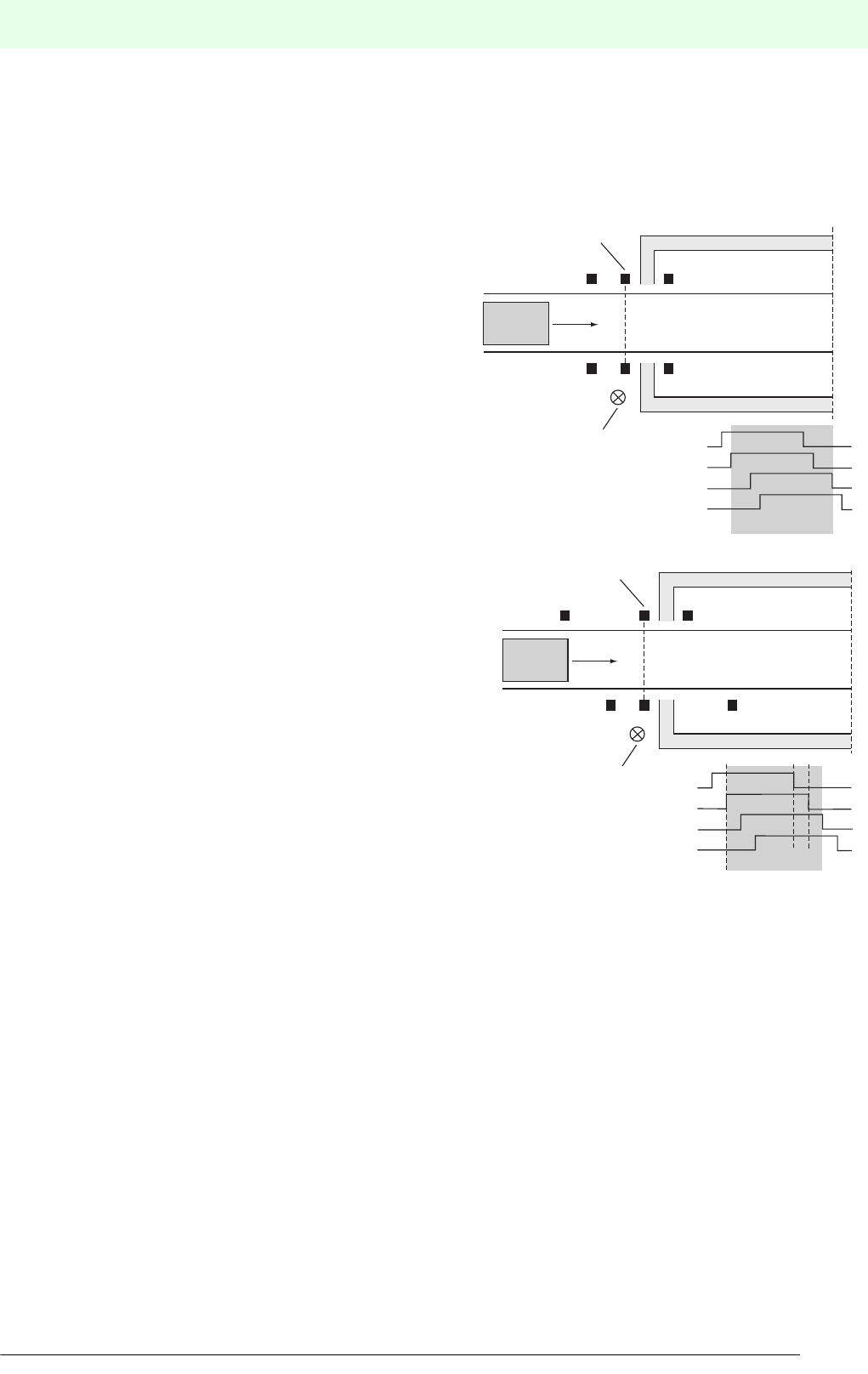
5.3.1 Mode of operation
Evaluation of the muting sensors
Depending on the arrangement, the muting sensors are activated within a short period of time or successively. The
sequence of the activation can be monitored by selecting between parallel and sequential muting.
Parallel muting
In the parallel muting operating mode, the muting sensor
arranged in pairs (MS1 and MS2 or MS3 and MS4) must be
activated within 2 s. If only one of the muting sensors has
been activated in this time, it will be locked. Locking will
block the muting from being enabled. This lock will only be
removed if the sensor is no longer active.
Sequential muting
In contrast to parallel muting where the activated sensors
MS1 and MS2 or MS3 t and MS4 fulfil the muting condition,
sequential muting also allows sensors MS2 and MS3 to
keep the muting condition.
The muting sensors are activated successively. The
arrangement of the sensors is to be selected in such a way
that a person cannot unintentionally activate 2 sensors.
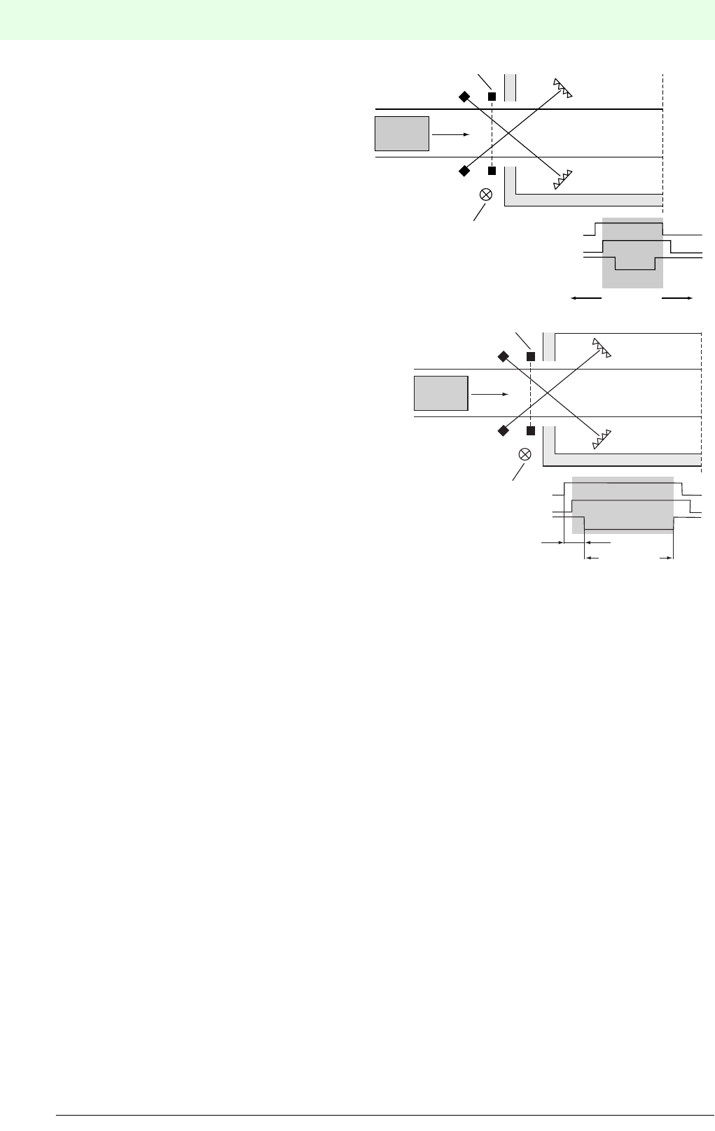
Muting monitoring
To avoid a dangerous continuous muting in the case of a failure of the muting sensors, muting is operated either
with a time window limit or a protection beam limit. Time window-limited muting should be used if the objects that
are supposed to pass the protection beams unhindered have crossed the protection beams within approx. 240 s.
If the muting process cannot be completed within this time window, protection beam limited muting can be used. It
must be ensured that muting is stopped approx. 115 ms after all protection beams have been released.
MS1
MS1
MS2
MS3
MS4
MS3
MS2 MS4
Protective field
Muting lamp
Muting active
Product
MS1
MS1
MS1+2 MS2+3 MS3+4
MS2
MS3
MS4
MS3
MS2 MS4
Protective field
Muting lamp
Muting active
Product
22
Date of edition 05/17/2006
Subject to reasonable modifications due to technical advances. Copyright Pepperl+Fuchs, Printed in Germany
Pepperl+Fuchs Group • Tel.: Germany +49 621 776-0 • USA +1 330 4253555 • Singapore +65 67799091 • Internet http://www.pepperl-fuchs.com
The way to the right electro-sensitive protective equipment
Time window-limited muting
If time window-limited muting is selected, each muting
sensor is monitored in terms of time. Each sensor may
only be activated for a maximum of 240 s. This means
that the muting object must have passed the sensor
within this period of time. If this time is exceeded, the
evaluation unit locks the sensor. If the sensor is locked,
muting can no longer be activated. The sensor can only
be released again after it has been deactivated.
Protection beam-limited muting
In the case of protection beam-limited muting, muting
sensors are evaluated with respect to time after their activation.
Two activated muting sensors initiate the muting procedure. At
the latest 240 s after activation (applies separately for each
muting sensor), at least one protection beam must be
interrupted. In contrast to time window-limited muting, the time
measurement is stopped, thus enabling muting with no time
limit. Approx. 115 ms after the protective field is evacuated (all
protective beams are clear) and the passage is clear again, the
muting process will finish.
5.3.2 Muting sensors
Muting sensors are supposed to detect the muting objects. If an object is detected, the output of the muting sensor
switches through its supply voltage. For this purpose, sensors with relay or pnp output are suitable. In a de-
energised state, the output of the muting sensor must not be active. The sensor output should be capable of reliably
switching a load current of 8 mA at 20 V.
As muting sensors, the following sensors can be used, for example:
• Reflective light barriers (light activation) with object-mounted reflector,
• Reflective light barriers (interrupt activation) with fixed reflector,
• Single-direction light barriers (interrupt activation),
• Optical sensors,
• Inductive sensors,
• Mechanical switches.
5.3.3 Muting lamp
When using muting a signal lamp for indicating the muting state with a minimum luminous area of 1 cm2 and a
minimum luminosity of 200 cd/m2 must be used. Monitoring the connected lamp ensures that the muting signal
lamp fulfils its function correctly. If the muting signal lamp is faulty the BWS enters into the locking state and
indicates the error on the display. During power-up, when executing the reset command and during the time the
muting is enabled, the muting lamp will be monitored.
To increase the system availability 2 muting signal lamps can be connected in parallel. This is conditional on both
signal lamps being visible simultaneously and in close proximity to each other during any approach to the access.
Without the use of muting muting signal lamps are not required.
MS1
MS1
MS2
MS2
Muting lamp
Muting active
max. 240 s
Product
Protective beams
MS1
MS1
MS2
MS2
Muting lamp
Muting active
max. 240 s
Unlimited
Product
Protective beams
23
S
ubject to reasonable modifications due to technical advances. Copyright Pepperl+Fuchs, Printed in Germany
Pepperl+Fuchs Group • Tel.: Germany +49 621 776-0 • USA +1 330 4253555 • Singapore +65 67799091 • Internet http://www.pepperl-fuchs.com
The way to the right electro-sensitive protective equipment
Date of edition 05/17/2006
5.3.4 Emergency muting
If the plant must be started up again for removing a blocking object from
the protected area and the muting sensors, the emergency muting
function is available. In the case of emergency muting, the locked muting
sensors are evaluated again for a duration of 3s ... 4 s. Consequently, the
OSSDs are switched on again for 3 s ... 4 s. Emergency muting is initiated
using the override push button. This initialisation can be retriggered, i.e.
by actuating the push button again within 3 s, the duration of the on status
of the OSSDs can always be extended until the object has left the muting
sensor area.
5.3.5 Double muting
If the double muting operating mode is selected, 2 entries to a hazardous area can be protected and muted using
one muting module and one sensor card module.
This operating mode divides the sensor inputs of the sensor card
module to the left of the muting module, the muting sensor inputs,
the muting lamps and the override inputs into 2 separate areas.
The two created muting areas work completely independently
from each another.
In the case of double muting, all other operating modes that can
be selected (e.g. protection beam limit or time limit) are effective
for both muting areas.
5.3.6 Grouping
There may be several switch groups in a Safebox. This makes sense if not the entire system is to be taken out of
operation in the case of an interruption of a safety device, but only the affected drive.
A special software is utilised for complex systems with grouping. This allows for several OSSD modules with stop
function category 0 to be operated in a Safebox. A SafeBox contains exactly as many shut-off groups as it has
OSSD modules with stop function 0. Each shut-off group may have sensor card modules, muting modules or OSSD
modules with a time-delay shut-off function. All modules to the right of an OSSD module form a group.
Arrangement of the modules
The following modules may belong to a group:
• Sensor card modules
• Muting modules
• Stop function cat.1 modules
• The OSSD modules set to stop function cat.1 are also assigned to a group.
These switch off with a delay after the OSSD module in stop function cat. 0
module of the group.
• Muting modules generate a muting procedure for the sensor module fitted
immediately to the left of the muting module.
• Additional sensor modules of the group are not influenced by the muting
module.
Control
Interface
Unit
Override
Reset
Restart
Muting lamp 1
Muting lamp 2
Safety light barrier
1 and 2
Safety light barrier
3 and 4
Muting sensor 1
Muting sensor 2
Muting sensor 3
Muting sensor 4
OSSD-R/
Supply module position 1
Sensor card module
4 channels position 2
Sensor card module
4 channels position 4
Muting module
position 5
OSSD-R/E-stop module
with stop function Cat. 0 position 5
OSSD-R/E-stop-module
with stop function Cat. 0 position 3
Group 3
Group 2
Group1
24
Date of edition 05/17/2006
Subject to reasonable modifications due to technical advances. Copyright Pepperl+Fuchs, Printed in Germany
Pepperl+Fuchs Group • Tel.: Germany +49 621 776-0 • USA +1 330 4253555 • Singapore +65 67799091 • Internet http://www.pepperl-fuchs.com
Safety light barriers
Safety light barriersSafety light gridsSafety light grids with
internal control unit
Safety light curtainsControl units
25
S
ubject to reasonable modifications due to technical advances. Copyright Pepperl+Fuchs, Printed in Germany
Pepperl+Fuchs Group • Tel.: Germany +49 621 776-0 • USA +1 330 4253555 • Singapore +65 67799091 • Internet http://www.pepperl-fuchs.com
Safety light barriers
Date of edition 05/17/2006
Safety light barriers
Safety light grids
Safety light grids with
internal control unit
Safety light curtains
Control units
Operating Type code Control unit Category Detection range Page
SLA5
SLA5/92
SafeBox 40 m ... 5 m 26
SLA5S
SLA5S/92
SafeBox 4 0 m ... 5 m 28
SL12 SafeBox / SC2 20 m ... 10 m 30
SLA12 SafeBox / SC4 4 0 m ... 10 m 32
SL29 SafeBox / SC2 20 m ... 65 m 34
SL29/116 SafeBox / SC2 2 0 m ... 65 m 36
SLA29 SafeBox / SC4 40 m ... 65 m 38
SLA29/116 SafeBox / SC4 4 0 m ... 65 m 40
SLA40
SLA40/92
SafeBox 40 m ... 4 m 42
Description
Single direction light barriers of type SL/SLA together with a control unit of series SafeBox or
SC form an photoelectronic protection device of category 2 or 4 (EN 954-1) or type 2 or 4
(according to IEC/EN 61496).
The protection device can be in single or multiple beam design.
A single direction light barrier consists of a sender and a receiver.
The single direction light barriers SL/SLA, the control unit SafeBox or SC, muting sensors and
other user-selectable safety devices (e.g. E-stop) combine into a modular protection system.
1 to 8 light barriers can be connected to a control unit. The light barriers can be mixed freely,
but a light barrier must consist of a sender and receiver of the same type.
The supply voltage required for the light barrier is provided by the control unit. The control unit
also triggers the sender and evaluates the signal transmitted by the receiver (e.g. light beam
interruption.
Series SL/SLA are available in different designs and ranges.
Dependent on the type of light barrier used the range can be up to 65 m.
Protection from several directions can be achieved with the use of redirection mirrors (extra).
Applications
Normally used for increased risk of injury. For example for access control of pallet systems,
robots, wood processing machines, packaging machines, overhead warehouse shelves and
machine lines.
Subject to reasonable modifications due to technical advances. Copyright Pepperl+Fuchs, Printed in Germany
Pepperl+Fuchs Group • Tel.: Germany +49 621 776-0 • USA +1 330 4253555 • Singapore +65 67799091 • Internet http://www.pepperl-fuchs.com
26
Technische DatenTechnical data
Features
Ordering code
Safety through beam
sensors
Safety light grids
Safety light grids with
internal control unit
Safety light curtains
Control units
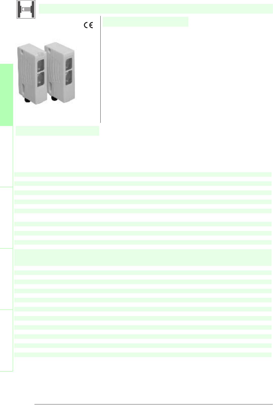
SLA5
SLA5/33 K=5m
SLA5/33 K=10m
SLA5/92
Construction type(S2) Rectangular type
X X X X
Effective detection range 0 ... 5 m
XXXX
Number of protective field beams 1
X X X X
Light source LED
XXXX
Approvals TÜV
X X X X
Tests IEC/EN 61496
XXXX
Marking CE
X X X X
Obstacle size static: 10 mm dynamic: 30 mm (at v = 1.6 m/s of the obstacle)
XXXX
Safety category according to IEC/EN 61496 4
X X X X
Light type red, modulated light
XXXX
Angle of divergence < 5 °
X X X X
Function display LED yellow/green in receiver:
off: Interruption
yellow: transmission
green: reception with sufficient stability control
XXXX
Pre-fault indication LED functional display yellow
X X X X
Operating voltage Power supply via control unit
XXXX
Ambient temperature -20 ... 60 °C (253 ... 333 K)
X X X X
Storage temperature -20 ... 70 °C (253 ... 343 K)
XXXX
Relative humidity max. 95 %, not condensing
X X X X
Protection degree IP65
XXXX
Connection
Fixed cable, 10 m; 0.25 mm
2
X
Fixed cable 2 m; 0.25 mm
2
X
Fixed cable, 5 m; 0.25 mm
2
X
M12 connector, 4-pin
X
Housing ABS plastic, RLA 1021 (yellow) painted
X X X X
Optical face Plastic lens
XXXX
Mass Per 95 g
X X X X
System components
Emitter
SLA5-T
X
SLA5-T/33 K=10m
X
SLA5-T/33 K=5m
X
SLA5-T/92
X
Receiver
SLA5-R
X
SLA5-R/33 K=10m
X
SLA5-R/33 K=5m
X
SLA5-R/92
X
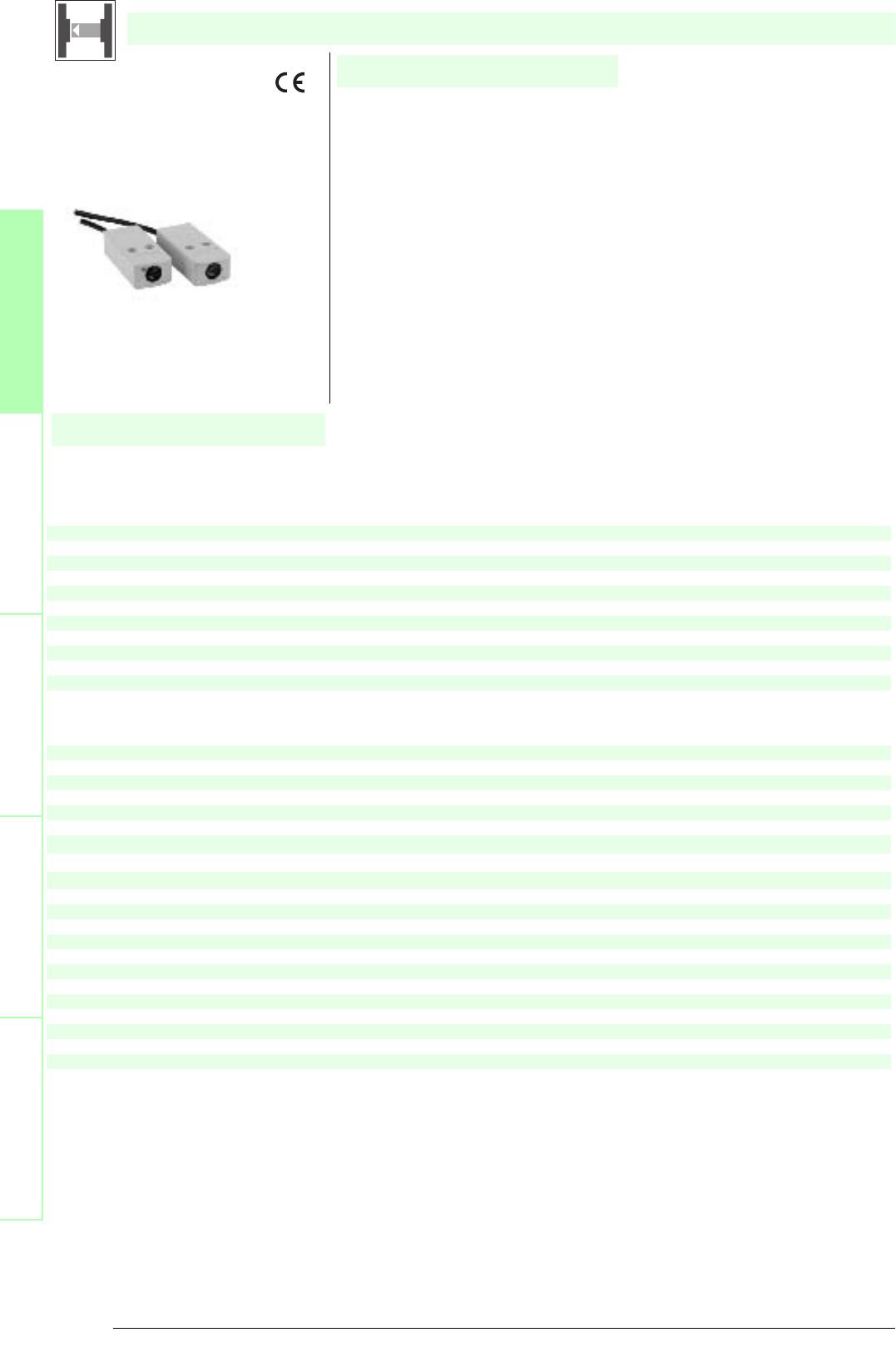
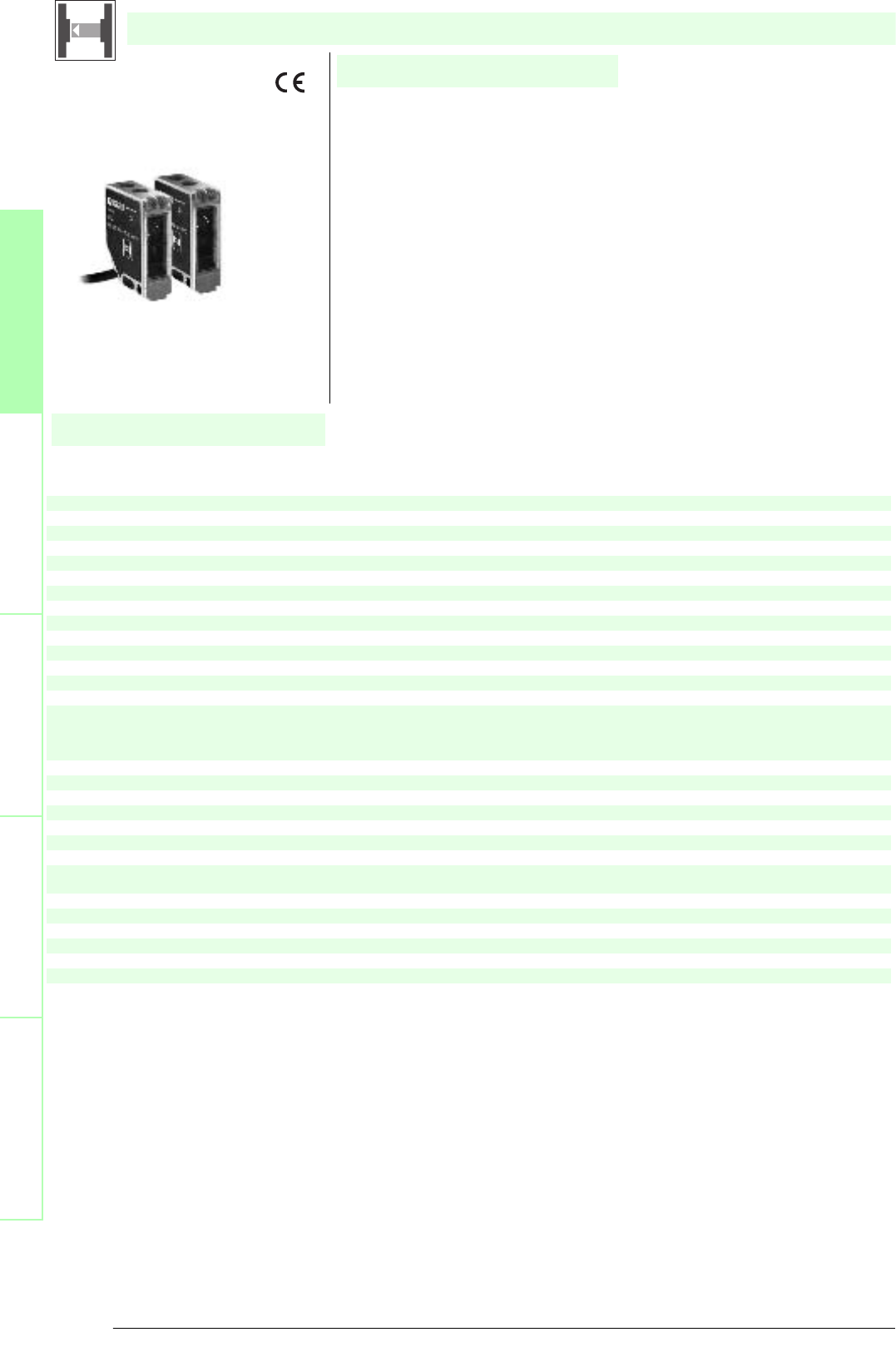
SLA5
• Self-monitoring (type 4 according to IEC/EN 61496-1)
• Red transmission light
• Clearly visible LED functional display and pre-fault indicator on the receiver
• Sturdy housing
• Operation on control units of SB4 (SafeBox)
Date of edition 05/17/2006
Safety through beam sensor
For required control units refer to chapter „Control units“
For suitable mounting aids and more refer to chapter „Accessories.
27
S
ubject to reasonable modifications due to technical advances. Copyright Pepperl+Fuchs, Printed in Germany
Pepperl+Fuchs Group • Tel.: Germany +49 621 776-0 • USA +1 330 4253555 • Singapore +65 67799091 • Internet http://www.pepperl-fuchs.com
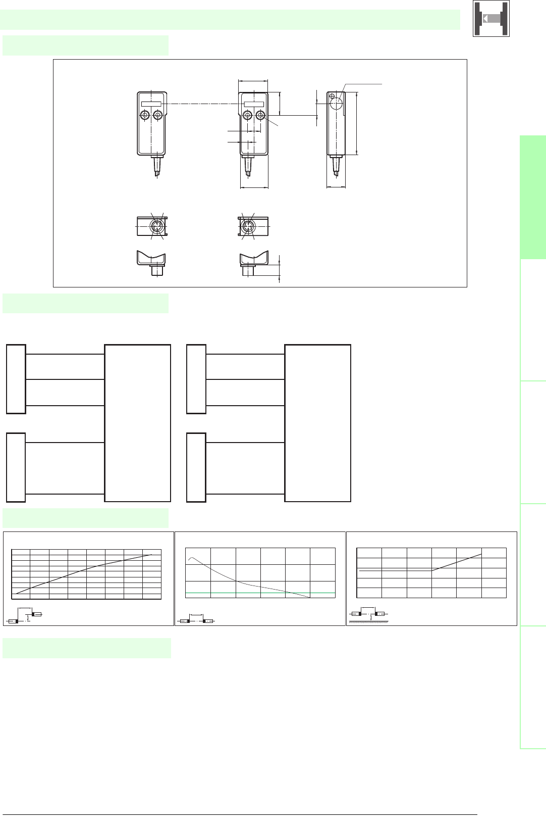
Diagrams
Electrical connection
Safety through beam
sensors
Safety light gridsSafety light grids with
internal control unit
Safety light curtainsControl units
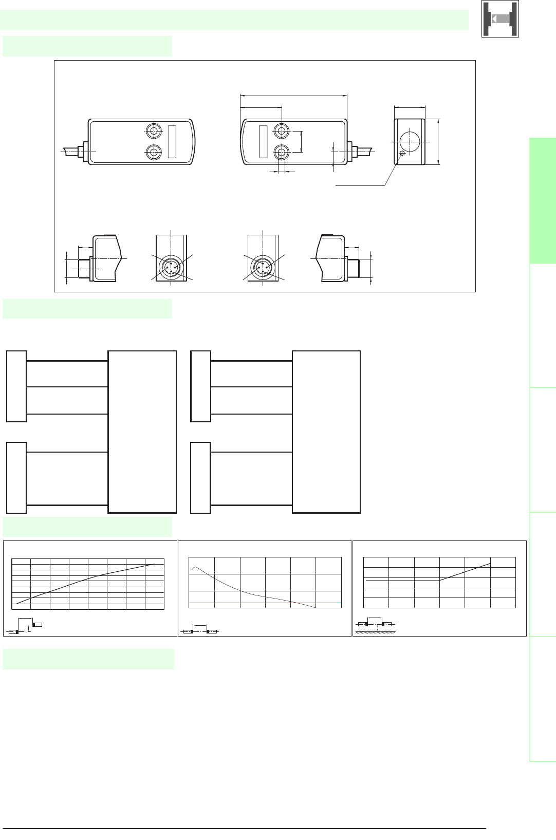
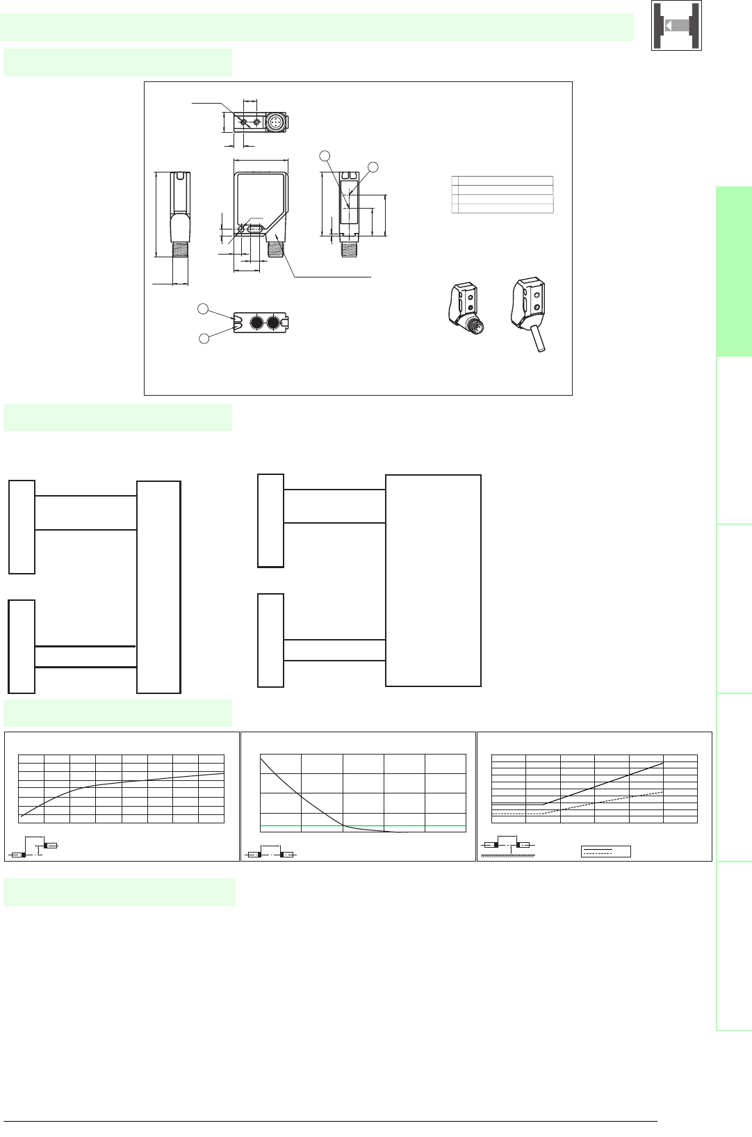
Dimensions
SLA5
x
y
SLA5 / SLA5S
Offset Y [mm]
Distance X [m]
Characteristic response curve
0
10
20
30
40
50
60
70
80
90
012345678
x
SLA5 / SLA5S
Distance X [m]
Stability control
Relative received light strength
1
10
100
1000
024681012
x
y
SLA5 / SLA5S
Distance X [m]
Lateral interval to mirroring surfaces
Minimum interval [m]
0
0.05
0.1
0.15
0.2
0.25
0123456
Date of edition 05/17/2006
Emitter:
Receiver:
Control Unit SafeBox module 4X
Design with fixed cable
receiver 0 V
receiver +24 V
receiver x input
emitter 0 V
emitter x output
BK
BN
BU
BK
BU
Emitter:
Receiver:
Control Unit SafeBox module 4X
Design with connector plug
receiver 0 V
receiver +24 V
receiver x input
emitter 0 V
emitter x output
BK
BN
BU
BK
BU
1
3
4
3
4
Emitter
Emitter
Receiver
Display LED
Receiver
(fixed cable)
(connector M12)
20
30
8.5
14
27
70
M12x1
10 10
M12x1
6
1
23
4
1
23
4
SLA5
SLA5/92
Safety through beam sensor
Control units
SB4 (SafeBox)
Cable sockets (only for option /92)
straight: V1-G-2M-PVC
V1-G-5M-PVC
V1-G-10M-PVC
angled: V1-W-2M-PVC
V1-W-5M-PVC
V1-W-10M-PVC
System accessories
Further accessories
Redirection mirror
SLA-1-M
Subject to reasonable modifications due to technical advances. Copyright Pepperl+Fuchs, Printed in Germany
Pepperl+Fuchs Group • Tel.: Germany +49 621 776-0 • USA +1 330 4253555 • Singapore +65 67799091 • Internet http://www.pepperl-fuchs.com
28
Technische DatenTechnical data
Features
Ordering code
Safety through beam
sensors
Safety light grids
Safety light grids with
internal control unit
Safety light curtains
Control units
SLA5S
SLA5S/33 K=5m
SLA5S/92
Construction type(S2) Rectangular type
X X X
Effective detection range 0 ... 5 m
XXX
Number of protective field beams 1
X X X
Light source LED
XXX
Approvals TÜV
X X X
Tests IEC/EN 61496
XXX
Marking CE
X X X
Obstacle size static: 10 mm dynamic: 30 mm (at v = 1.6 m/s of the obstacle)
XXX
Safety category according to IEC/EN 61496 4
X X X
Light type red, modulated light
XXX
Angle of divergence < 5 °
X X X
Function display LED yellow/green in receiver:
off: Interruption
yellow: transmission
green: reception with sufficient stability control
XXX
Pre-fault indication LED functional display yellow
X X X
Operating voltage Power supply via control unit
XXX
Ambient temperature -20 ... 60 °C (253 ... 333 K)
X X X
Storage temperature -20 ... 70 °C (253 ... 343 K)
XXX
Relative humidity max. 95 %, not condensing
X X X
Protection degree IP65
XXX
Connection
Fixed cable 2 m; 0.25 mm
2
X
Fixed cable, 5 m; 0.25 mm
2
X
M12 connector, 4-pin
X
Housing ABS plastic, RLA 1021 (yellow) painted
XXX
Optical face Plastic lens
X X X
Mass Per 95 g
XXX
System components
Emitter
SLA5S-T
X
SLA5S-T/33 K=5m
X
SLA5S-T/92
X
Receiver
SLA5S-R
X
SLA5S-R/33 K=5m
X
SLA5S-R/92
X
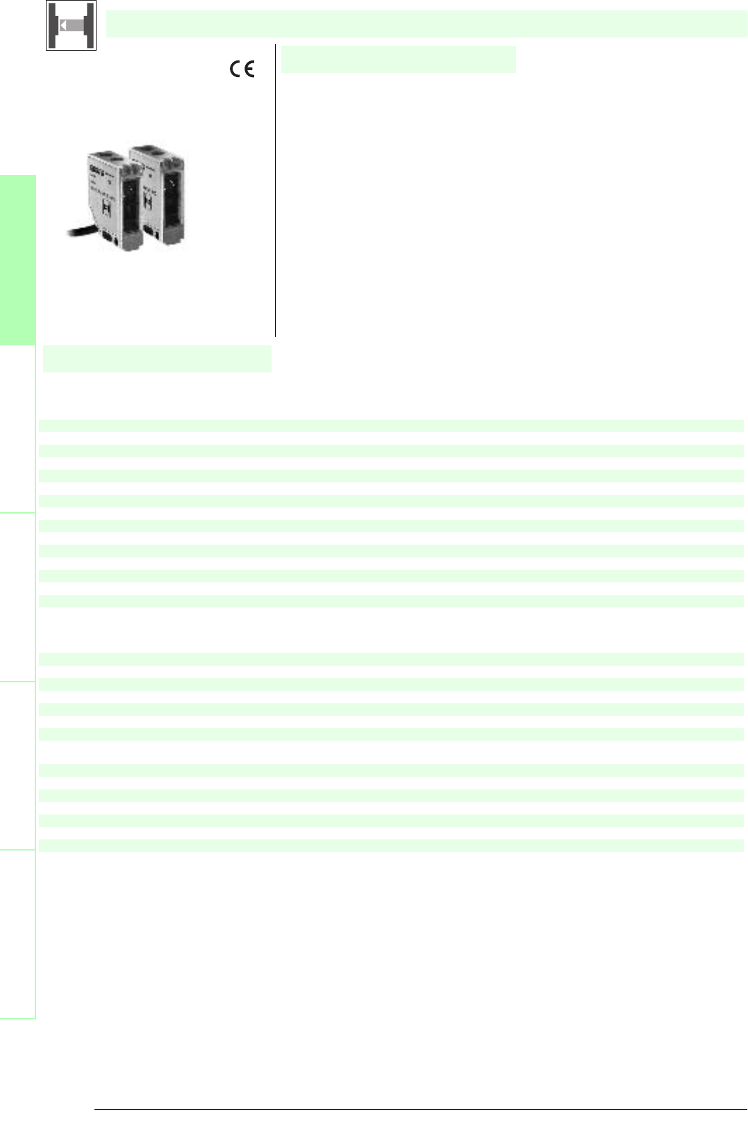
SLA5S
• Self-monitoring (type 4 according to IEC/EN 61496-1)
• Optical-system lateral
• Red transmission light
• Clearly visible LED functional display and pre-fault indicator on the receiver
• Sturdy housing
• Operation on control units of SB4 (SafeBox)
Date of edition 05/17/2006
Safety through beam sensor
For required control units refer to chapter „Control units“
For suitable mounting aids and more refer to chapter „Accessories.
29
S
ubject to reasonable modifications due to technical advances. Copyright Pepperl+Fuchs, Printed in Germany
Pepperl+Fuchs Group • Tel.: Germany +49 621 776-0 • USA +1 330 4253555 • Singapore +65 67799091 • Internet http://www.pepperl-fuchs.com
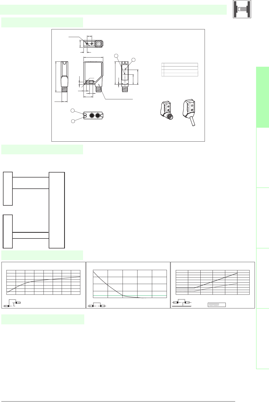
Diagrams
Electrical connection
Safety through beam
sensors
Safety light gridsSafety light grids with
internal control unit
Safety light curtainsControl units
Dimensions
SLA5S
x
y
SLA5 / SLA5S
Offset Y [mm]
Distance X [m]
Characteristic response curve
0
10
20
30
40
50
60
70
80
90
012345678
x
SLA5 / SLA5S
Distance X [m]
Stability control
Relative received light strength
1
10
100
1000
024681012
x
y
SLA5 / SLA5S
Distance X [m]
Lateral interval to mirroring surfaces
Minimum interval [m]
0
0.05
0.1
0.15
0.2
0.25
0123456
Date of edition 05/17/2006
Emitter:
Receiver:
Control Unit SafeBox module 4X
Design with fixed cable
receiver 0 V
receiver +24 V
receiver x input
emitter 0 V
emitter x output
BK
BN
BU
BK
BU
Emitter:
Receiver:
Control Unit SafeBox module 4X
Design with connector plug
receiver 0 V
receiver +24 V
receiver x input
emitter 0 V
emitter x output
BK
BN
BU
BK
BU
1
3
4
3
4
Emitter Receiver
Emitter Receiver
Display LED (fixed cable)
(connector M12)
12
8.5
14
20
30
32
68
25
12.5
ø4.5
32
1432
14
SLA5S
SLA5S/92
Safety through beam sensor
Control units
SB4 (SafeBox)
Cable sockets (only for option /92)
straight: V1-G-2M-PVC
V1-G-5M-PVC
V1-G-10M-PVC
angled: V1-W-2M-PVC
V1-W-5M-PVC
V1-W-10M-PVC
System accessories
Further accessories
Redirection mirror
SLA-1-M
Subject to reasonable modifications due to technical advances. Copyright Pepperl+Fuchs, Printed in Germany
Pepperl+Fuchs Group • Tel.: Germany +49 621 776-0 • USA +1 330 4253555 • Singapore +65 67799091 • Internet http://www.pepperl-fuchs.com
30
Technische DatenTechnical data
Features
Ordering code
Safety through beam
sensors
Safety light grids
Safety light grids with
internal control unit
Safety light curtains
Control units
SL12/124
SL12/115
Construction type(S2) Miniature housing
X X
Effective detection range 0.2 ... 10 m
XX
Threshold detection range 16 m
X X
Light source LED, 660 nm
XX
Approvals TÜV
X X
Tests IEC/EN 61496
XX
Marking CE
X X
Obstacle size static: 10 mm dynamic: 30 mm (at v = 1.6 m/s of the obstacle)
XX
Alignment aid LED red
X X
Safety category according to IEC/EN 61496 2
XX
Light type red, modulated light
X X
Angle of divergence < 10 °
XX
Series MLV12
X X
Operating display LED green
XX
Function display LED yellow:
1. LED lits constantly: signal > 2 x switching point (function reserve)
2. LED flashes: signal between 1 x switching point and 2 x switching point
3. LED off: signal < switching point
X X
Operating voltage Power supply via control unit
XX
Ambient temperature -20 ... 60 °C (253 ... 333 K)
X X
Storage temperature -20 ... 70 °C (253 ... 343 K)
XX
Relative humidity max. 95 %, not condensing
X X
Protection degree IP67 according to EN 60529
XX
Connection
2.5 m fixed cable, 5-core, Euronorm
X
connector, 5-pin with metal thread M12 x 1, may be rotated 90°
X
Housing Frame: die-cast zinc, nickel-plated
Laterals: plastic PC, glass-fiber reinforced
X X
Optical face Plastic pane
XX
Mass per device 60 g
X X
System components Ordering data
XX
Emitter
SL12-T/115
X
SL12-T/124
X
Receiver
SL12-R/115
X
SL12-R/124
X
SL12/...
• Detection range up to 10 m
• Test input (Type 2 according to IEC/EN 61496-1)
• Red transmission light
• Integrated alignment aid
• Clearly visible LED functional display and pre-fault indicator on the receiver
• Sturdy housing
• Waterproof, protection class IP67
• Operation on control units of series SC2-2
Date of edition 05/17/2006
Safety through beam sensor
For required control units refer to chapter „Control units“
For suitable mounting aids and more refer to chapter „Accessories.
31
S
ubject to reasonable modifications due to technical advances. Copyright Pepperl+Fuchs, Printed in Germany
Pepperl+Fuchs Group • Tel.: Germany +49 621 776-0 • USA +1 330 4253555 • Singapore +65 67799091 • Internet http://www.pepperl-fuchs.com
Diagrams
Electrical connection
Safety through beam
sensors
Safety light gridsSafety light grids with
internal control unit
Safety light curtainsControl units
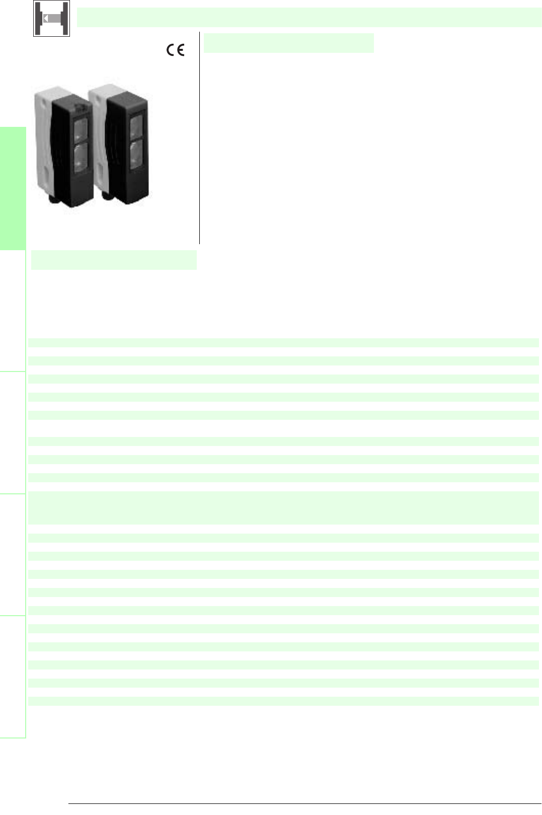
Dimensions
SL12/...
x
y
SL12..., SLA12...
Offset Y [mm]
Distance X [m]
Characteristic response curve
0
20
40
60
80
100
120
140
160
02 4 6 8 10121416
x
SL12..., SLA12...
Distance X [m]
Stability control
Relative received light strength
10
1
100
1000
10000
0 5 10 15 20 25 x
y
SL12..., SLA12...
SL12
SLA12
Distance X [m]
Lateral interval to mirroring surfaces
Minimum interval [m]
0 2 4 6 8 10 12
0
0.1
0.2
0.3
0.4
0.5
0.6
0.7
0.8
0.9
1.0
Date of edition 05/17/2006
Emitter:
Receiver:
Control Unit SC2-2
2
3
1
BU
BN
BK
BU
4
2
3
1
4
5
5
Rn
0 V
0 V
Tn
SL12/SLA12
M12x1
2
1
4
3
Connector 90˚ adjustable position
Connection options:
1 Operating display green
2 Switch state yellow
3 Optical axis emitter/Optical axis receiver
4 Alignment indicator red
M4 / 4 deep
Fixed cable
15
10
M12x1
7.5
41.5
5.3
65
5.5
19.5
7
ø4.5
49
21.3
31.8
2
Safety through beam sensor
Control units
SC2-2
Cable sockets (not for option /115)
straight: V15-G-2M-PVC
V15-G-5M-PVC
V15-G-10M-PVC
angled: V15-W-2M-PVC
V15-W-5M-PVC
V15-W-10M-PVC
System accessories
Mounting aids
OMH-06
OMH-MLV12-HWG
OMH-MLV12-HWK
OMH-K01
OMH-K02
Further accessories
Redirection mirror
SLA-1-M
Subject to reasonable modifications due to technical advances. Copyright Pepperl+Fuchs, Printed in Germany
Pepperl+Fuchs Group • Tel.: Germany +49 621 776-0 • USA +1 330 4253555 • Singapore +65 67799091 • Internet http://www.pepperl-fuchs.com
32
Technische DatenTechnical data
Features
Ordering code
Safety through beam
sensors
Safety light grids
Safety light grids with
internal control unit
Safety light curtains
Control units
SLA12/124
SLA12/115
Construction type(S2) Miniature housing
X X
Focke Ident-No.
Effective detection range 0.2 ... 10 m
X X
Threshold detection range 16 m
XX
Light source LED, 660 nm
X X
Approvals TÜV
XX
Tests IEC/EN 61496
X X
Marking CE
XX
Obstacle size static: 10 mm dynamic: 30 mm (at v = 1.6 m/s of the obstacle)
X X
Alignment aid LED red
XX
Safety category according to IEC/EN 61496 4
X X
Light type red, modulated light
XX
Angle of divergence < 5 °
X X
Series MLV12
XX
Operating display LED green
X X
Function display LED yellow:
1. LED lits constantly: signal > 2 x switching point (function reserve)
2. LED flashes: signal between 1 x switching point and 2 x switching point
3. LED off: signal < switching point
XX
Operating voltage Power supply via control unit
X X
Ambient temperature -20 ... 60 °C (253 ... 333 K)
XX
Storage temperature -20 ... 70 °C (253 ... 343 K)
X X
Relative humidity max. 95 %, not condensing
XX
Protection degree IP67 according to EN 60529
X X
Connection
2.5 m fixed cable, 5-core, Euronorm
X
connector, 5-pin with metal thread M12 x 1, may be rotated 90°
X
Housing Frame: die-cast zinc, nickel-plated
Laterals: plastic PC, glass-fiber reinforced RAL 1021 (yellow)
XX
Optical face Plastic pane
X X
Mass per device 60 g
XX
System components Ordering data
X X
Emitter
SLA12-T/115
X
SLA12-T/124
X
Receiver
SLA12-R/115
X
SLA12-R/124
X
SLA12/...
• Detection range up to 10 m
• Self-monitoring (type 4 according to IEC/EN 61496-1)
• Red transmission light
• Integrated alignment aid
• Clearly visible LED functional display and pre-fault indicator on the receiver
• Sturdy housing
• Waterproof, protection class IP67
• Operation on control units of series SB4 (SafeBox) and SC4-2
Date of edition 05/17/2006
Safety through beam sensor
For required control units refer to chapter „Control units“
For suitable mounting aids and more refer to chapter „Accessories.
33
S
ubject to reasonable modifications due to technical advances. Copyright Pepperl+Fuchs, Printed in Germany
Pepperl+Fuchs Group • Tel.: Germany +49 621 776-0 • USA +1 330 4253555 • Singapore +65 67799091 • Internet http://www.pepperl-fuchs.com
Diagrams
Electrical connection
Safety through beam
sensors
Safety light gridsSafety light grids with
internal control unit
Safety light curtainsControl units
Dimensions
SLA12/...
x
y
SL12..., SLA12...
Offset Y [mm]
Distance X [m]
Characteristic response curve
0
20
40
60
80
100
120
140
160
02 4 6 8 10121416
x
SL12..., SLA12...
Distance X [m]
Stability control
Relative received light strength
10
1
100
1000
10000
0 5 10 15 20 25 x
y
SL12..., SLA12...
SL12
SLA12
Distance X [m]
Lateral interval to mirroring surfaces
Minimum interval [m]
0 2 4 6 8 10 12
0
0.1
0.2
0.3
0.4
0.5
0.6
0.7
0.8
0.9
1.0
Date of edition 05/17/2006
Emitter:
Receiver:
Control Unit SC4-2
2
3
1
BU
BN
BK
BU
4
2
3
1
4
5
5
Rn
0 V
0 V
Tn
Emitter:
Receiver:
Control Unit
SafeBox module -4C(P) and -6C
receiver x +U
receiver x input
emitter x
emitter x +U
2
3
1
BU
BN
BK
BU
4
2
3
1
4
5
5
SL12/SLA12
M12x1
2
1
4
3
Connector 90˚ adjustable position
Connection options:
1 Operating display green
2 Switch state yellow
3 Optical axis emitter/Optical axis receiver
4 Alignment indicator red
M4 / 4 deep
Fixed cable
15
10
M12x1
7.5
41.5
5.3
65
5.5
19.5
7
ø4.5
49
21.3
31.8
2
Safety through beam sensor
Control units
SC4-2
SB4 (SafeBox)
Cable sockets (not for option /115)
straight: V15-G-2M-PVC
V15-G-5M-PVC
V15-G-10M-PVC
angled: V15-W-2M-PVC
V15-W-5M-PVC
V15-W-10M-PVC
System accessories
Mounting aids
OMH-06
OMH-MLV12-HWG
OMH-MLV12-HWK
OMH-K01
OMH-K02
Further accessories
Redirection mirror
SLA-1-M
Subject to reasonable modifications due to technical advances. Copyright Pepperl+Fuchs, Printed in Germany
Pepperl+Fuchs Group • Tel.: Germany +49 621 776-0 • USA +1 330 4253555 • Singapore +65 67799091 • Internet http://www.pepperl-fuchs.com
34
Technische DatenTechnical data
Features
Ordering code
Safety through beam
sensors
Safety light grids
Safety light grids with
internal control unit
Safety light curtains
Control units
SL29/105/106
SL29/35/105/106 R=65M
SL29/73c
SL29/35/73c R=65M
Construction type(S2) Rectangular type
X X X X
Effective detection range
0.2 ... 30 m
XX
6 ... 65 m
X X
Threshold detection range
40 m
XX
85 m
X X
Light source LED
XXXX
Approvals TÜV
X X X X
Tests IEC/EN 61496
XXXX
Marking CE
X X X X
Obstacle size static: 30 mm
dynamic: 40 mm (at v = 1.6 m/s of the obstacle)
XXXX
Alignment aid LED red
X X X X
Safety category according to IEC/EN 61496 2
XXXX
Light type red, modulated light
X X X X
Angle of divergence < 10 °
XXXX
Series 29
X X X X
Operating display LED green
XXXX
Function display LED yellow:
1. LED lits constantly: signal > 2 x switching point (function reserve)
2. LED flashes: signal between 1 x switching point and 2 x switching point
3. LED off: signal < switching point
X X X X
Operating voltage Power supply via control unit
XXXX
Ambient temperature
-20 ... 60 °C (253 ... 333 K)
X X
-35 ... 55 °C (238 ... 328 K) with heated optical face, fixed voltage 24 V DC ± 20 %/50 mA
XX
Storage temperature -20 ... 70 °C (253 ... 343 K)
X X X X
Relative humidity max. 95 %, not condensing
XXXX
Protection degree IP67 according to EN 60529
X X X X
Connection
M12 connector, 4-pin
XX
M12 connector, 5 pin
X X
Housing Plastic ABS, front part black, back part yellow (RAL1021)
XXXX
Optical face Plastic pane
X X X X
Mass per device 70 g
XXXX
System components Ordering data
X X X X
Emitter
SL29-T/105/106
X
SL29-T/35/105/106 R=65m
X
SL29-T/35/73c R=65m
X
SL29-T/73c
X
Receiver
SL29-R/105/106
X
SL29-R/35/105/106 R=65m
X
SL29-R/35/73c R=65m
X
SL29-R/73c
X
SL29/...
• Test input (Type 2 according to IEC/EN 61496-1)
• Red transmission light
• Integrated alignment aid
• Clearly visible LED functional display and pre-fault indicator on the receiver
• Sturdy housing
• Protection degree IP67
• Operation on control units of series SC2-2
• Extended temperature range up to -35 °C with heated front panel
SL29/105/106
SL29/35/105/106 R=65M
Date of edition 05/17/2006
Safety through beam sensor
For required control units refer to chapter „Control units“
For suitable mounting aids and more refer to chapter „Accessories.
35
S
ubject to reasonable modifications due to technical advances. Copyright Pepperl+Fuchs, Printed in Germany
Pepperl+Fuchs Group • Tel.: Germany +49 621 776-0 • USA +1 330 4253555 • Singapore +65 67799091 • Internet http://www.pepperl-fuchs.com
Diagrams
Electrical connection
Safety through beam
sensors
Safety light gridsSafety light grids with
internal control unit
Safety light curtainsControl units
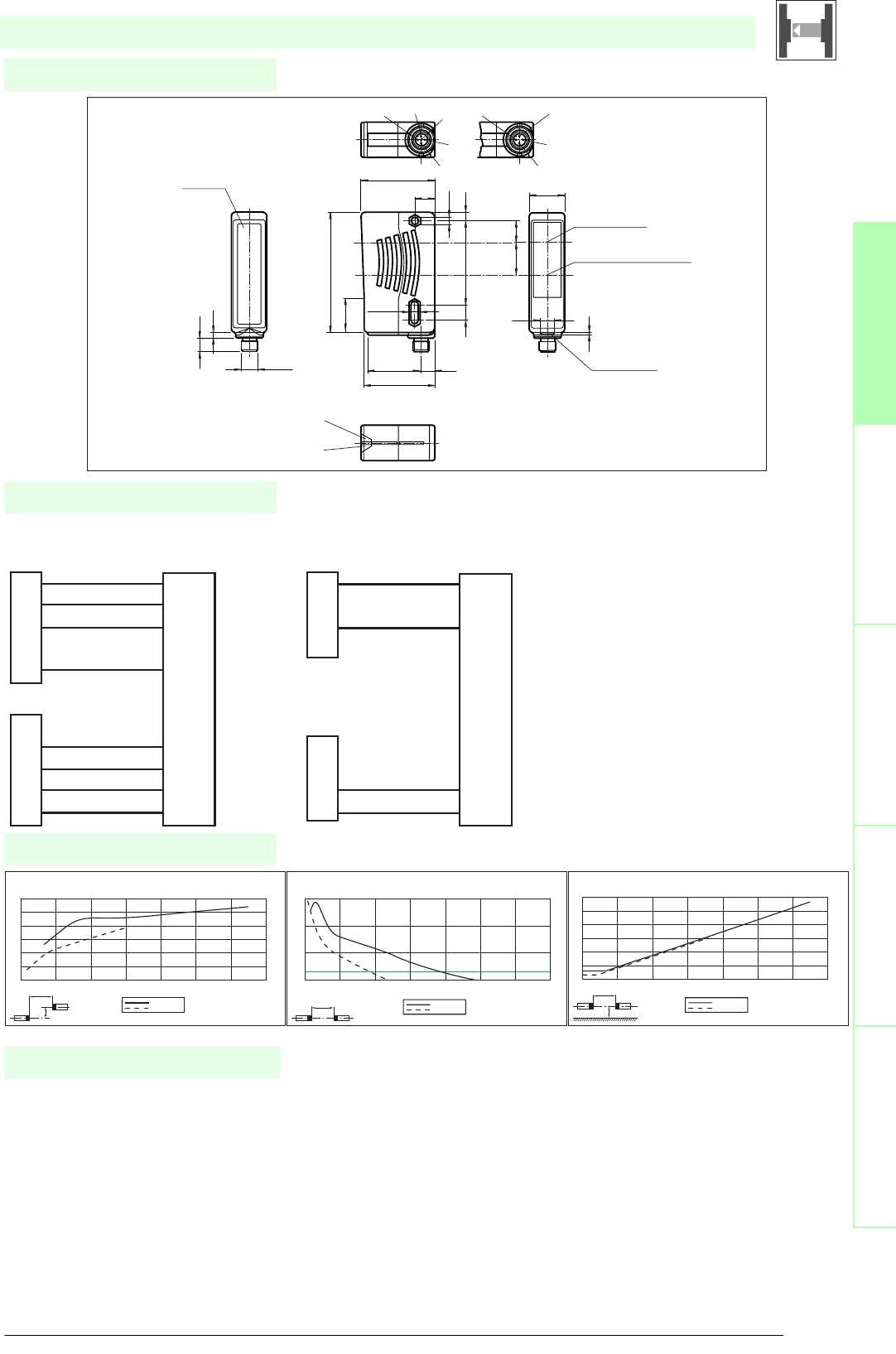
Dimensions
SL29/...
x
y
SL(A)29/35...
SL(A)29...
Offset Y [mm]
Distance X [m]
Characteristic response curve
0
50
100
150
200
250
300
0 10203040506070
xSL(A)29/35...
SL(A)29...
Distance X [m]
Stability control
Relative received light strength
1
10
100
1000
0 20 40 60 80 100 120 140
x
y
SL(A)29/35...
SL(A)29...
Distance X [m]
Lateral interval to mirroring surfaces
Minimum interval [m]
0 10203040506070
0
1
2
3
4
5
6
Date of edition 05/17/2006
Emitter:
Receiver:
Control Unit SC2-2
Design with connector (Option /106)
2
3
1
4
Rn
24 V
0 V
0 V
Tn
0 V
24 V
0 V
5
WH
BN
BU
GY
2
3
1
4
5
WH
BU
BK
GY
Emitter:
Receiver:
Control Unit SC2-2
Design with connector
2
3
1
4
Rn
0 V
0 V
Tn
BN
BU
2
3
1
4
BU
BK
15
4
3
21
4
3
2
Print
Type code
Center of emitter
or receiver
Center of indicator LED red
Adjustment aid
(in receiver only)
Dovetail mount
LED yellow
switching state
LED green
operation indicator
Option /73c
10
4
M12x1
88
25
10
39.3
51.8
62
11 6
ø5.5
1624
14,8
54.3
2
25.8
9,8
5.2-0,2
Safety through beam sensor
Control units
SC2-2
Cable sockets
Option /73c:
straight: V1-G-2M-PVC
V1-G-5M-PVC
V1-G-10M-PVC
angled: V1-W-2M-PVC
V1-W-5M-PVC
V1-W-10M-PVC
System accessories
Option /105:
straight: V15-G-2M-PVC
V15-G-5M-PVC
V15-G-10M-PVC
angled: V15-W-2M-PVC
V15-W-5M-PVC
V15-W-10M-PVC
Option /116: no
Mounting aids
OMH-21
OMH-22
OMH-05
OMH-MLV11-K
Further accessories
Laser alignment aid
BA SLA28
Redirection mirror
SLA-1-M

Subject to reasonable modifications due to technical advances. Copyright Pepperl+Fuchs, Printed in Germany
Pepperl+Fuchs Group • Tel.: Germany +49 621 776-0 • USA +1 330 4253555 • Singapore +65 67799091 • Internet http://www.pepperl-fuchs.com
36
Technische DatenTechnical data
Features
Ordering code
Safety through beam
sensors
Safety light grids
Safety light grids with
internal control unit
Safety light curtains
Control units
SL29/116
SL29/35/116 R=65m
SL29/106/116
SL29/35/106/116 R=65m
Construction type(S2) Rectangular type
X X X X
Effective detection range
0.2 ... 30 m
XX
6 ... 65 m
X X
Threshold detection range
40 m
XX
85 m
X X
Light source LED
XXXX
Approvals TÜV
X X X X
Tests IEC/EN 61496
XXXX
Marking CE
X X X X
Obstacle size static: 30 mm
dynamic: 40 mm (at v = 1.6 m/s of the obstacle)
XXXX
Alignment aid LED red
X X X X
Safety category according to IEC/EN 61496 2
XXXX
Light type red, modulated light
X X X X
Angle of divergence < 10 °
XXXX
Series 29
X X X X
Operating display LED green
XXXX
Function display LED yellow:
1. LED lits constantly: signal > 2 x switching point (function reserve)
2. LED flashes: signal between 1 x switching point and 2 x switching point
3. LED off: signal < switching point
X X X X
Operating voltage Power supply via control unit
XXXX
Ambient temperature
-20 ... 60 °C (253 ... 333 K)
X X
-35 ... 55 °C (238 ... 328 K) with heated optical face, fixed voltage 24 V DC ± 20 %/50 mA
XX
Storage temperature -20 ... 70 °C (253 ... 343 K)
X X X X
Relative humidity max. 95 %, not condensing
XXXX
Protection degree IP67 according to EN 60529
X X X X
Connection terminal compartment
XXXX
Housing Plastic ABS, front part black, back part yellow (RAL1021)
X X X X
Optical face Plastic pane
XXXX
Mass per device 70 g
X X X X
System components Ordering data
XXXX
Emitter
SL29-T/106/116
X
SL29-T/116
X
SL29-T/35/106/116 R=65m
X
SL29-T/35/116 R=65m
X
Receiver
SL29-R/106/116
X
SL29-R/116
X
SL29-R/35/106/116 R=65m
X
SL29-R/35/116 R=65m
X
SL29/.../116...
• Test input (Type 2 according to IEC/EN 61496-1)
• Red transmission light
• Integrated alignment aid
• Clearly visible LED functional display and pre-fault indicator on the receiver
• Sturdy housing
• Protection degree IP67
• Operation on control units of series SC2-2
• Extended temperature range up to -35 °C with heated front panel
SL29/106/116
SL29/35/106/116 R=65m
Date of edition 05/17/2006
Safety through beam sensor
For required control units refer to chapter „Control units“
For suitable mounting aids and more refer to chapter „Accessories.
37
S
ubject to reasonable modifications due to technical advances. Copyright Pepperl+Fuchs, Printed in Germany
Pepperl+Fuchs Group • Tel.: Germany +49 621 776-0 • USA +1 330 4253555 • Singapore +65 67799091 • Internet http://www.pepperl-fuchs.com
Diagrams
Electrical connection
Safety through beam
sensors
Safety light gridsSafety light grids with
internal control unit
Safety light curtainsControl units
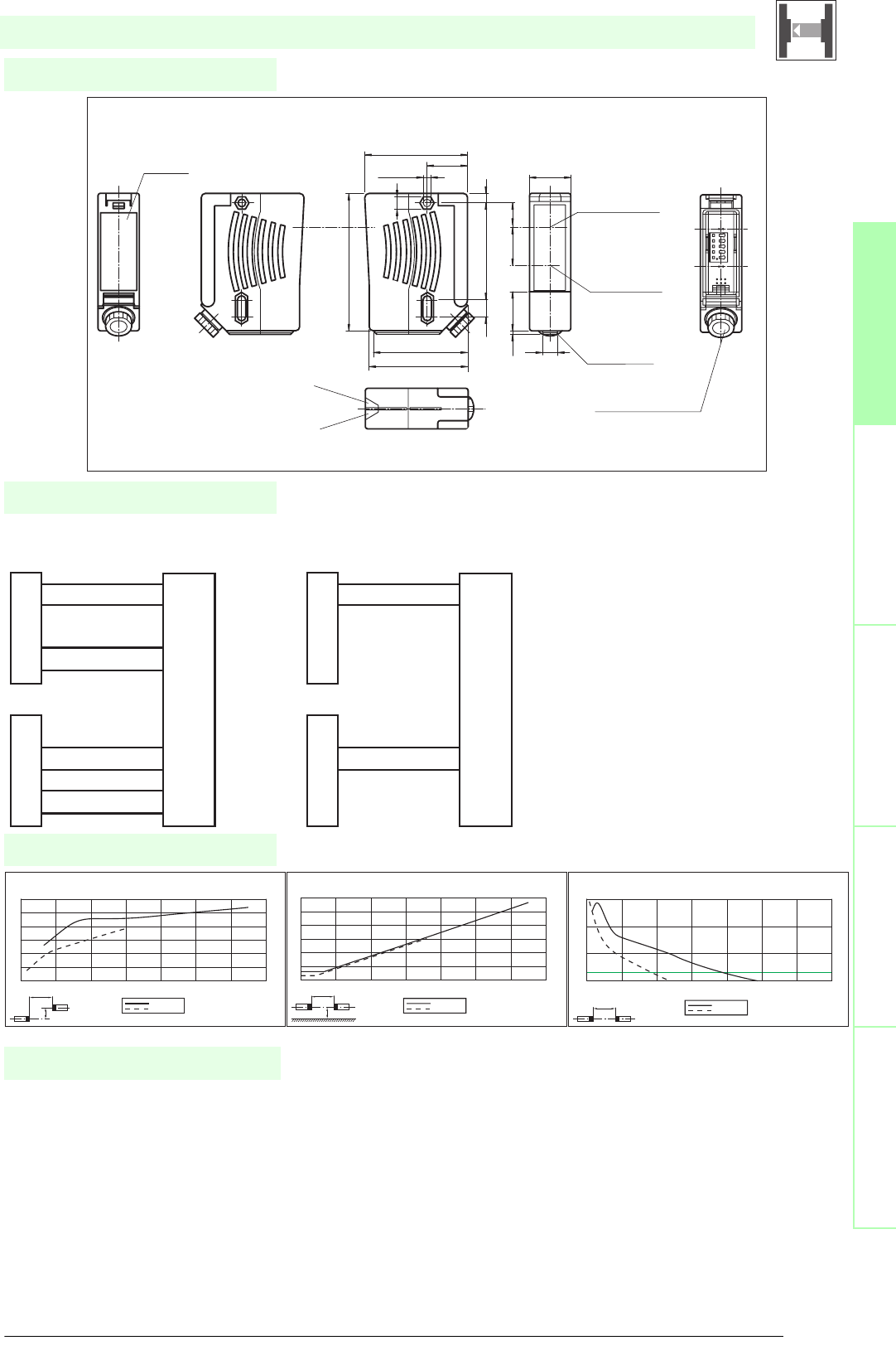
Dimensions
SL29/.../116...
x
y
SL(A)29/35...
SL(A)29...
Offset Y [mm]
Distance X [m]
Characteristic response curve
0
50
100
150
200
250
300
0 10203040506070
x
y
SL(A)29/35...
SL(A)29...
Distance X [m]
Lateral interval to mirroring surfaces
Minimum interval [m]
0 10203040506070
0
1
2
3
4
5
6
xSL(A)29/35...
SL(A)29...
Distance X [m]
Stability control
Relative received light strength
1
10
100
1000
0 20 40 60 80 100 120 140
Date of edition 05/17/2006
Emitter:
Receiver:
Control Unit SC2-2
Design with terminal compartment (Option /106)
BU
GY
OG
GY
Rn
0 V
24 V
0 V
24 V
0 V
0 V
Tn
GY
BU
GY
OG
GY
GY
Emitter:
Receiver:
Control Unit SC2-2
Design with terminal compartment
BU
GY
OG
GY
Rn
0 V
0 V
Tn
GY
BU
GY
OG
GY
GY
SLA28/116
SL(A)29/116
Terminal compartment
cable cross section
ø6...8 mm
Display LED red
Adjustment aid
(in receiver only)
Center of optical
axis
Print
Type code
Dovetail mount
LED yellow
Switching state
LED green
Operation indicator
Emitter Receiver
65.5
26
ø5.2-0.2
60.5
63
9.8
25.8
88
SW8
6
16
24
6211
25
2
Safety through beam sensor
Control units
SC2-2
Cable sockets
Option /73c:
straight: V1-G-2M-PVC
V1-G-5M-PVC
V1-G-10M-PVC
angled: V1-W-2M-PVC
V1-W-5M-PVC
V1-W-10M-PVC
System accessories
Option /105:
straight: V15-G-2M-PVC
V15-G-5M-PVC
V15-G-10M-PVC
angled: V15-W-2M-PVC
V15-W-5M-PVC
V15-W-10M-PVC
Option /116: no
Mounting aids
OMH-21
OMH-22
OMH-05
OMH-MLV11-K
Further accessories
Laser alignment aid
BA SLA28
Redirection mirror
SLA-1-M
Subject to reasonable modifications due to technical advances. Copyright Pepperl+Fuchs, Printed in Germany
Pepperl+Fuchs Group • Tel.: Germany +49 621 776-0 • USA +1 330 4253555 • Singapore +65 67799091 • Internet http://www.pepperl-fuchs.com
38
Technische DatenTechnical data
Features
Ordering code
Safety through beam
sensors
Safety light grids
Safety light grids with
internal control unit
Safety light curtains
Control units
SLA29/105/106
SLA29/35/105/106 R=65m
SLA29/73c
SLA29/35/73c R=65m
Construction type(S2) Rectangular type
X X X X
Effective detection range
0.2 ... 30 m
XX
6 ... 65 m
X X
Threshold detection range
40 m
XX
85 m
X X
Light source LED
XXXX
Approvals TÜV
X X X X
Tests IEC/EN 61496
XXXX
Marking CE
X X X X
Obstacle size static: 30 mm
dynamic: 40 mm (at v = 1.6 m/s of the obstacle)
XXXX
Alignment aid LED red in receiver
X X X X
Safety category according to IEC/EN 61496 4
XXXX
Light type red, modulated light
X X X X
Angle of divergence < 5 °
XXXX
Series 29
X X X X
Operating display LED green
XXXX
Function display LED yellow:
1. LED lits constantly: signal > 2 x switching point (function reserve)
2. LED flashes: signal between 1 x switching point and 2 x switching point
3. LED off: signal < switching point
X X X X
Operating voltage Power supply via control unit
XXXX
Ambient temperature
-20 ... 60 °C (253 ... 333 K)
X X
-35 ... 55 °C (238 ... 328 K) with heated optical face, fixed voltage 24 V DC ± 20 %/50 mA
XX
Storage temperature -20 ... 70 °C (253 ... 343 K)
X X X X
Relative humidity max. 95 %, not condensing
XXXX
Protection degree IP67 according to EN 60529
X X X X
Connection
M12 connector, 4-pin
XX
M12 connector, 5 pin
X X
Housing ABS plastic, RLA 1021 (yellow) painted
XXXX
Optical face Plastic pane
X X X X
Mass per device 70 g
XXXX
System components Ordering data
X X X X
Emitter
SLA29-T/105/106
X
SLA29-T/35/105/106 R=65m
X
SLA29-T/35/73c R=65m
X
SLA29-T/73c
X
Receiver
SLA29-R/105/106
X
SLA29-R/35/105/106 R=65m
X
SLA29-R/35/73c R=65m
X
SLA29-R/73c
X
SLA29/...
• Self-monitoring (type 4 according to IEC/EN 61496-1)
• Red transmission light
• Integrated alignment aid
• Clearly visible LED functional display and pre-fault indicator on the receiver
• Sturdy housing
• Waterproof, protection class IP67
• Operation on control units of series SB4 (SafeBox) and SC4-2
• Extended temperature range up to -35 °C with heated front panel
SLA29/105/106
SLA29/35/105/106 R=65m
Date of edition 05/17/2006
Safety through beam sensor
For required control units refer to chapter „Control units“
For suitable mounting aids and more refer to chapter „Accessories.
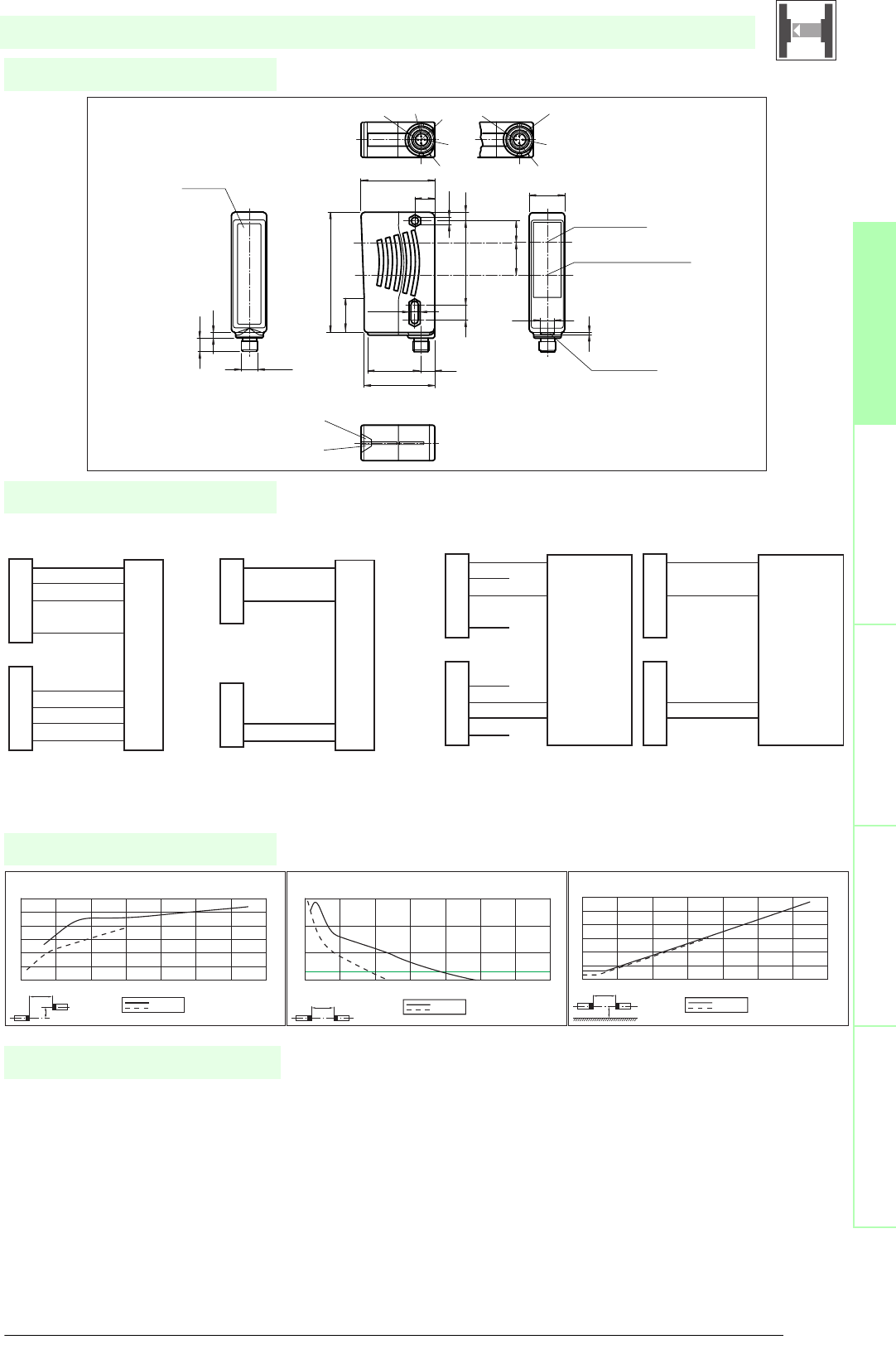
39
S
ubject to reasonable modifications due to technical advances. Copyright Pepperl+Fuchs, Printed in Germany
Pepperl+Fuchs Group • Tel.: Germany +49 621 776-0 • USA +1 330 4253555 • Singapore +65 67799091 • Internet http://www.pepperl-fuchs.com
Diagrams
Electrical connection
Safety through beam
sensors
Safety light gridsSafety light grids with
internal control unit
Safety light curtainsControl units
Dimensions
SLA29/...
x
y
SL(A)29/35...
SL(A)29...
Offset Y [mm]
Distance X [m]
Characteristic response curve
0
50
100
150
200
250
300
0 10203040506070
xSL(A)29/35...
SL(A)29...
Distance X [m]
Stability control
Relative received light strength
1
10
100
1000
0 20 40 60 80 100 120 140
x
y
SL(A)29/35...
SL(A)29...
Distance X [m]
Lateral interval to mirroring surfaces
Minimum interval [m]
0 10203040506070
0
1
2
3
4
5
6
Date of edition 05/17/2006
Emitter:
Receiver:
Control Unit SC4-2
Design with connector (Option /106)
2
3
1
4
Rn
24 V
0 V
0 V
Tn
0 V
24 V
0 V
5
WH
BN
BU
GR
2
3
1
4
5
WH
BU
BK
GR
Emitter:
Receiver:
Control Unit SC4-2
Design with connector
2
3
1
4
Rn
0 V
0 V
Tn
BN
BU
2
3
1
4
BU
BK
Emitter:
Receiver:
Control Unit
SafeBox module -4C(P) and -6C
Design with connector (Option /106)
receiver x +U
receiver x input
emitter x +U
emitter x
note: glass heater 24V at Pin2 and Pin5
2
3
1
4
24 V
0 V
0 V
24 V
5
WH
BN
BU
GR
2
3
1
4
5
WH
BU
BK
GR
Emitter:
Receiver:
Control Unit
SafeBox module -4C(P) and -6C
Design with connector
receiver x +U
receiver x input
emitter x +U
emitter x
2
3
1
4
5
BN
BU
2
3
1
4
5
BU
BK
15
4
3
21
4
3
2
Print
Type code
Center of emitter
or receiver
Center of indicator LED red
Adjustment aid
(in receiver only)
Dovetail mount
LED yellow
switching state
LED green
operation indicator
Option /73c
10
4
M12x1
88
25
10
39.3
51.8
62
11 6
ø5.5
1624
14,8
54.3
2
25.8
9,8
5.2-0,2
Safety through beam sensor
Control units
SC4-2
SB4 (SafeBox)
Cable sockets
Option /73c:
straight: V1-G-2M-PVC
V1-G-5M-PVC
V1-G-10M-PVC
angled: V1-W-2M-PVC
V1-W-5M-PVC
V1-W-10M-PVC
System accessories
Option /105:
straight: V15-G-2M-PVC
V15-G-5M-PVC
V15-G-10M-PVC
angled: V15-W-2M-PVC
V15-W-5M-PVC
V15-W-10M-PVC
Option /116: no
Mounting aids
OMH-21
OMH-22
OMH-05
OMH-MLV11-K
Further accessories
Laser alignment aid BA SLA28
Muting Set MS SLP/SLA28
Redirection mirror SLA-1-M
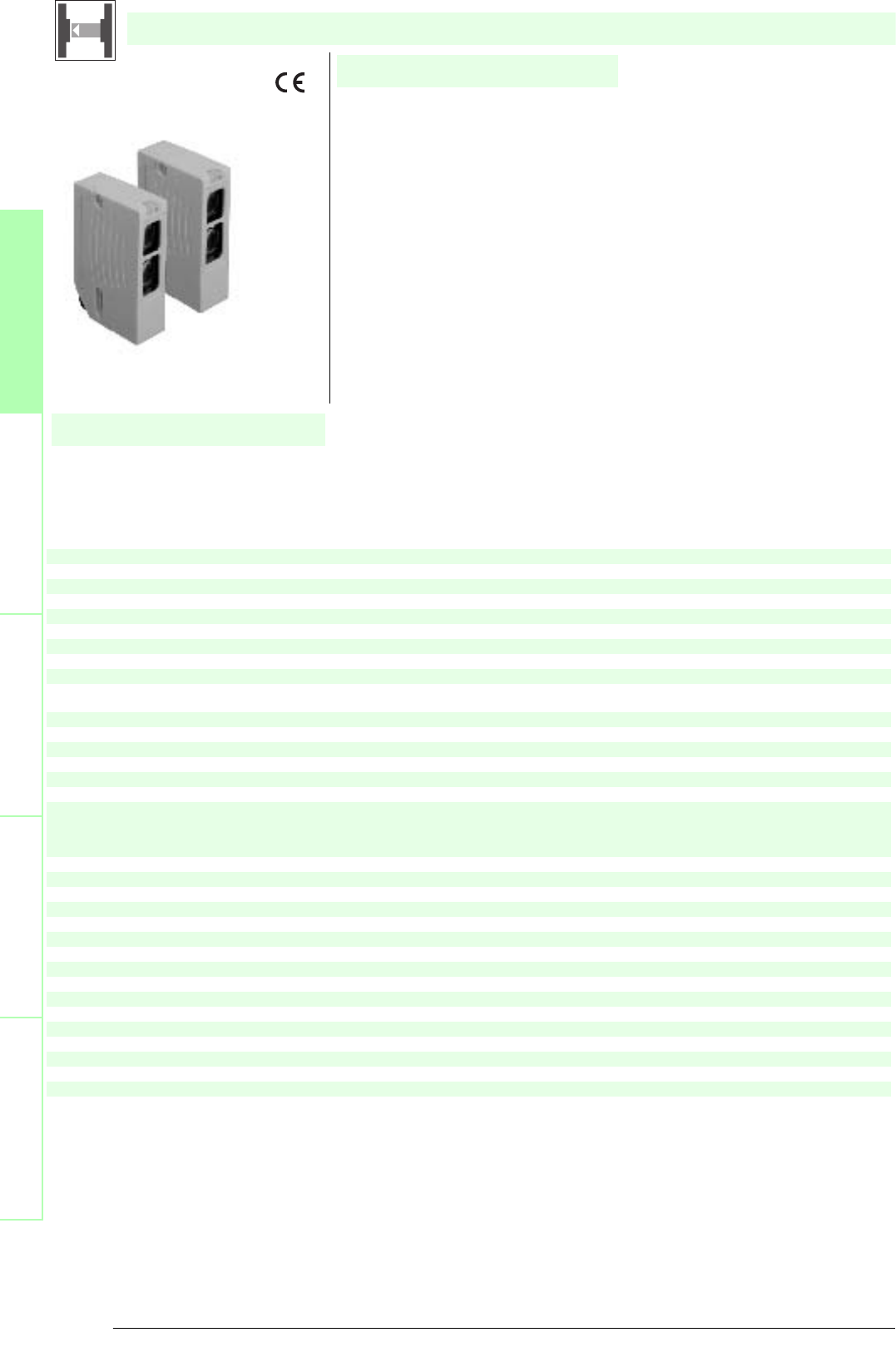
Subject to reasonable modifications due to technical advances. Copyright Pepperl+Fuchs, Printed in Germany
Pepperl+Fuchs Group • Tel.: Germany +49 621 776-0 • USA +1 330 4253555 • Singapore +65 67799091 • Internet http://www.pepperl-fuchs.com
40
Technische DatenTechnical data
Features
Ordering code
Safety through beam
sensors
Safety light grids
Safety light grids with
internal control unit
Safety light curtains
Control units
SLA29/116
SLA29/35/116 R=65m
SLA29/106/116
Construction type(S2) Rectangular type
X X X
Effective detection range
0.2 ... 30 m
XX
6 ... 65 m
X
Threshold detection range
40 m
XX
85 m
X
Light source LED
XXX
Approvals TÜV
X X X
Tests IEC/EN 61496
XXX
Marking CE
X X X
Obstacle size static: 30 mm
dynamic: 40 mm (at v = 1.6 m/s of the obstacle)
XXX
Alignment aid LED red in receiver
X X X
Safety category according to IEC/EN 61496 4
XXX
Light type red, modulated light
X X X
Angle of divergence < 5 °
XXX
Series 29
X X X
Operating display LED green
XXX
Function display LED yellow:
1. LED lits constantly: signal > 2 x switching point (function reserve)
2. LED flashes: signal between 1 x switching point and 2 x switching point
3. LED off: signal < switching point
X X X
Operating voltage Power supply via control unit
XXX
Ambient temperature
-20 ... 60 °C (253 ... 333 K)
X X
-35 ... 55 °C (238 ... 328 K) with heated optical face, fixed voltage 24 V DC ± 20 %/50 mA
X
Storage temperature -20 ... 70 °C (253 ... 343 K)
X X X
Relative humidity max. 95 %, not condensing
XXX
Protection degree IP67 according to EN 60529
X X X
Connection terminal compartment
XXX
Housing ABS plastic, RLA 1021 (yellow) painted
X X X
Optical face Plastic pane
XXX
Mass per device 70 g
X X X
System components Ordering data
XXX
Emitter
SLA29-T/106/116
X
SLA29-T/116
X
SLA29-T/35/116 R=65m
X
Receiver
SLA29-R/106/116
X
SLA29-R/116
X
SLA29-R/35/116 R=65m
X
SLA29/.../116...
• Self-monitoring (type 4 according to IEC/EN 61496-1)
• Red transmission light
• Integrated alignment aid
• Clearly visible LED functional display and pre-fault indicator on the receiver
• Sturdy housing
• Waterproof, protection class IP67
• Operation on control units of series SB4 (SafeBox) and SC4-2
• Extended temperature range up to -35 °C with heated front panel
SLA29/106/116
Date of edition 05/17/2006
Safety through beam sensor
For required control units refer to chapter „Control units“
For suitable mounting aids and more refer to chapter „Accessories.
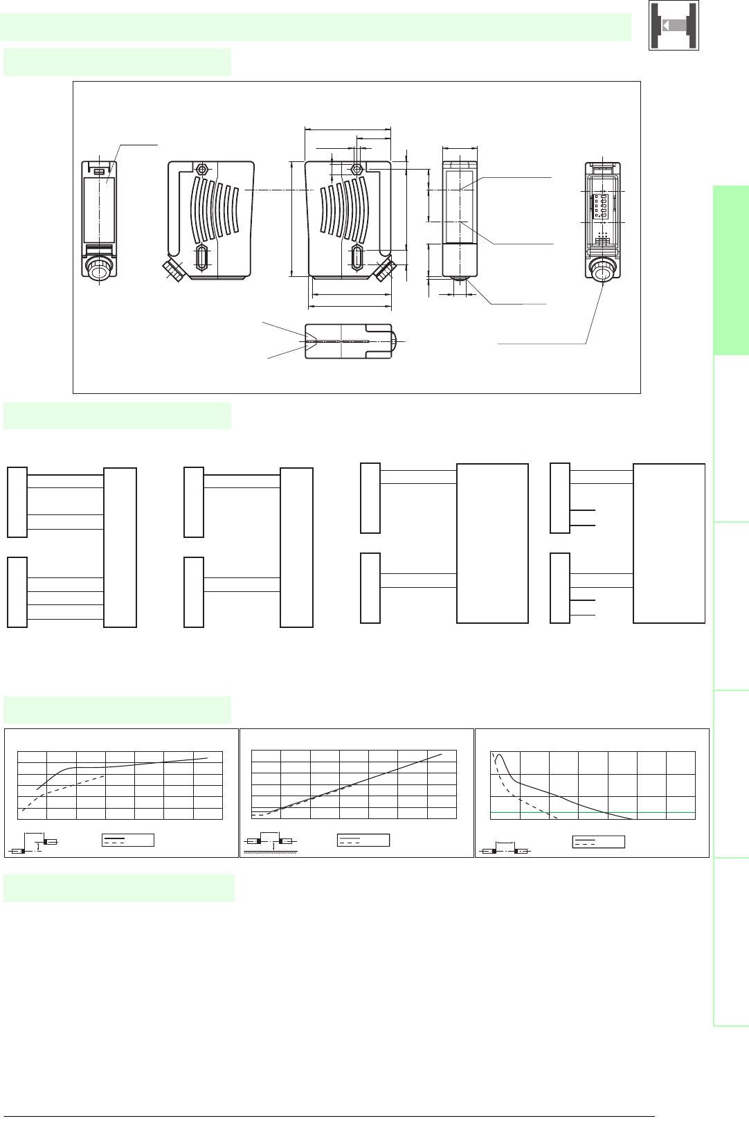
41
S
ubject to reasonable modifications due to technical advances. Copyright Pepperl+Fuchs, Printed in Germany
Pepperl+Fuchs Group • Tel.: Germany +49 621 776-0 • USA +1 330 4253555 • Singapore +65 67799091 • Internet http://www.pepperl-fuchs.com
Diagrams
Electrical connection
Safety through beam
sensors
Safety light gridsSafety light grids with
internal control unit
Safety light curtainsControl units
Dimensions
SLA29/.../116...
x
y
SL(A)29/35...
SL(A)29...
Offset Y [mm]
Distance X [m]
Characteristic response curve
0
50
100
150
200
250
300
0 10203040506070
x
y
SL(A)29/35...
SL(A)29...
Distance X [m]
Lateral interval to mirroring surfaces
Minimum interval [m]
0 10203040506070
0
1
2
3
4
5
6
xSL(A)29/35...
SL(A)29...
Distance X [m]
Stability control
Relative received light strength
1
10
100
1000
0 20 40 60 80 100 120 140
Date of edition 05/17/2006
Emitter:
Receiver:
Control Unit SC4-2
Design with terminal compartment (Option /106)
BU
GY
OG
GY
Rn
0 V
24 V
0 V
24 V
0 V
0 V
Tn
GY
BU
GY
OG
GY
GY
Emitter:
Receiver:
Control Unit SC4-2
Design with terminal compartment
BU
GY
OG
GY
Rn
0 V
0 V
Tn
GY
BU
GY
OG
GY
GY
Emitter:
Receiver:
Control Unit
SafeBox module -4C(P) and -6C
Design with terminal compartment
receiver x +U
receiver x input
emitter x
emitter x +U
BU
GY
OG
GY
GY
BU
GY
OG
GY
GY
Emitter:
Receiver:
Control Unit
SafeBox module -4C(P) and -6C
Design with terminal compartment (Option /106)
receiver x +U
receiver x input
emitter x
emitter x +U
note: glass heater 24V at terminals GY
BU
GY
OG
GY
GY
BU
GY
OG
GY
GY
24 V
0 V
24 V
0 V
SLA28/116
SL(A)29/116
Terminal compartment
cable cross section
ø6...8 mm
Display LED red
Adjustment aid
(in receiver only)
Center of optical
axis
Print
Type code
Dovetail mount
LED yellow
Switching state
LED green
Operation indicator
Emitter Receiver
65.5
26
ø5.2-0.2
60.5
63
9.8
25.8
88
SW8
6
16
24
6211
25
2
Safety through beam sensor
Control units
SC4-2
SB4 (SafeBox)
Cable sockets
Option /73c:
straight: V1-G-2M-PVC
V1-G-5M-PVC
V1-G-10M-PVC
angled: V1-W-2M-PVC
V1-W-5M-PVC
V1-W-10M-PVC
System accessories
Option /105:
straight: V15-G-2M-PVC
V15-G-5M-PVC
V15-G-10M-PVC
angled: V15-W-2M-PVC
V15-W-5M-PVC
V15-W-10M-PVC
Option /116: no
Mounting aids
OMH-21
OMH-22
OMH-05
OMH-MLV11-K
Further accessories
Laser alignment aid BA SLA28
Muting Set MS SLP/SLA28
Redirection mirror SLA-1-M
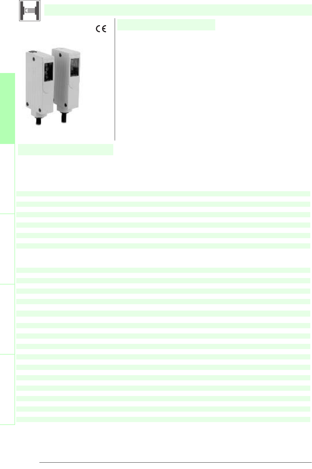
Subject to reasonable modifications due to technical advances. Copyright Pepperl+Fuchs, Printed in Germany
Pepperl+Fuchs Group • Tel.: Germany +49 621 776-0 • USA +1 330 4253555 • Singapore +65 67799091 • Internet http://www.pepperl-fuchs.com
42
Technische DatenTechnical data
Features
Ordering code
Safety through beam
sensors
Safety light grids
Safety light grids with
internal control unit
Safety light curtains
Control units
SLA40
SLA40-2442/33 K=2m
SLA40/33 K=5m
SLA40/33 K=10m
SLA40-2442
SLA40/92
Construction type(S2) Rectangular type
X X X X X X
Effective detection range 0 ... 4 m
XXXXXX
Light source LED
X X X X X X
Approvals TÜV
XXXXXX
Tests IEC/EN 61496
X X X X X X
Marking CE
XXXXXX
Obstacle size static: 10 mm dynamic: 30 mm (at v = 1.6 m/s of the obstacle)
X X X X X X
Safety category according to IEC/EN 61496 4
XXXXXX
Light type red, modulated light
X X X X X X
Angle of divergence < 5 °
XXXXXX
Series SLA
X X X X X X
Function display LED yellow/green in receiver:
off: Interruption
yellow: transmission
green: reception with sufficient stability control
XXXXXX
Pre-fault indication LED functional display yellow
X X X X X X
Operating voltage Power supply via control unit
XXXXXX
Ambient temperature -20 ... 60 °C (253 ... 333 K)
X X X X X X
Storage temperature -20 ... 70 °C (253 ... 343 K)
XXXXXX
Relative humidity max. 95 %, not condensing
X X X X X X
Protection degree
IP65
XXXX
IP67
X X
Connection
Fixed cable, 10 m; 0.25 mm
2
X
Fixed cable 2 m; 0.25 mm
2
X X
Fixed cable, 5 m; 0.25 mm
2
X
M12 connector, 4-pin
X X
Material
Housing aluminium pressure moulding, RLA 1021 (yellow) painted
X X X X X X
Optical face
Glass
XXXX
Plastic pane
X X
Mass Per 100 g
XXXXXX
System components
Emitter
SLA40-T
X
SLA40-T-2442
X
SLA40-T-2442 K=2m
X
SLA40-T/33 K=10m
X
SLA40-T/33 K=5m
X
SLA40-T/92
X
Receiver
SLA40-R
X
SLA40-R-2442
X
SLA40-R-2442 K=2m
X
SLA40-R/33 K=10m
X
SLA40-R/33 K=5m
X
SLA40-R/92
X
SLA40-...
• Detection range up to 4 m
• Self-monitoring (type 4 according to IEC/EN 61496-1)
• Red transmission light
• Clearly visible LED functional display and pre-fault indicator on the receiver
• Metal housing
• Connection via M12 connector or fixed cable
• Operation on control units of SB4 (SafeBox)
• Protection type IP67 optional
Date of edition 05/17/2006
Safety through beam sensor
For required control units refer to chapter „Control units“
For suitable mounting aids and more refer to chapter „Accessories.
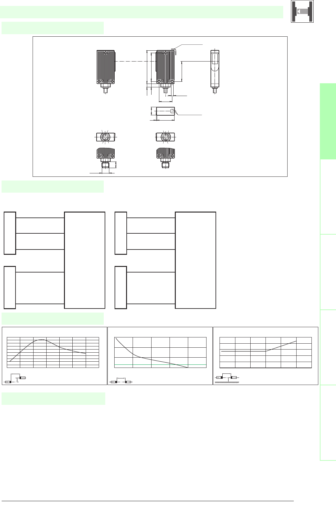
43
S
ubject to reasonable modifications due to technical advances. Copyright Pepperl+Fuchs, Printed in Germany
Pepperl+Fuchs Group • Tel.: Germany +49 621 776-0 • USA +1 330 4253555 • Singapore +65 67799091 • Internet http://www.pepperl-fuchs.com
Diagrams
Electrical connection
Safety through beam
sensors
Safety light gridsSafety light grids with
internal control unit
Safety light curtainsControl units
Dimensions
SLA40-...
x
y
SLA40
Offset Y [mm]
Distance X [m]
Characteristic response curve
0
5
10
15
20
25
30
35
40
45
50
01234567
x
SLA40
Distance X [m]
Stability control
Relative received light strength
1
10
100
1000
0246810
x
y
SLA40
Distance X [m]
Lateral interval to mirroring surfaces
Minimum interval [m]
0
0.05
0.1
0.15
0.2
0.25
0123456
Date of edition 05/17/2006
Emitter:
Receiver:
Control Unit SafeBox module 4X
Design with fixed cable
receiver 0 V
receiver +24 V
receiver x input
emitter 0 V
emitter x output
BK
BN
BU
BK
BU
Emitter:
Receiver:
Control Unit SafeBox module 4X
Design with connector plug
receiver 0 V
receiver +24 V
receiver x input
emitter 0 V
emitter x output
BK
BN
BU
BK
BU
1
3
4
3
4
SLA40
SLA40/92
14
3
2
1
4
32
Emitter Receiver
(fixed cable)
(connector M12)
Light exit
Display LED
Light exit
Display LED
56.5
48.6
3.7
5.8
34.1
4.2 (3x)
22.6
30
1
13.6
M12x1
10.5
Safety through beam sensor
Control units
SB4 (SafeBox)
Cable sockets (only option /92)
straight: V1-G-2M-PVC
V1-G-5M-PVC
V1-G-10M-PVC
angled: V1-W-2M-PVC
V1-W-5M-PVC
V1-W-10M-PVC
System accessories
Mounting aids
OMH-40
Further accessories
Redirection mirror
SLA-1-M
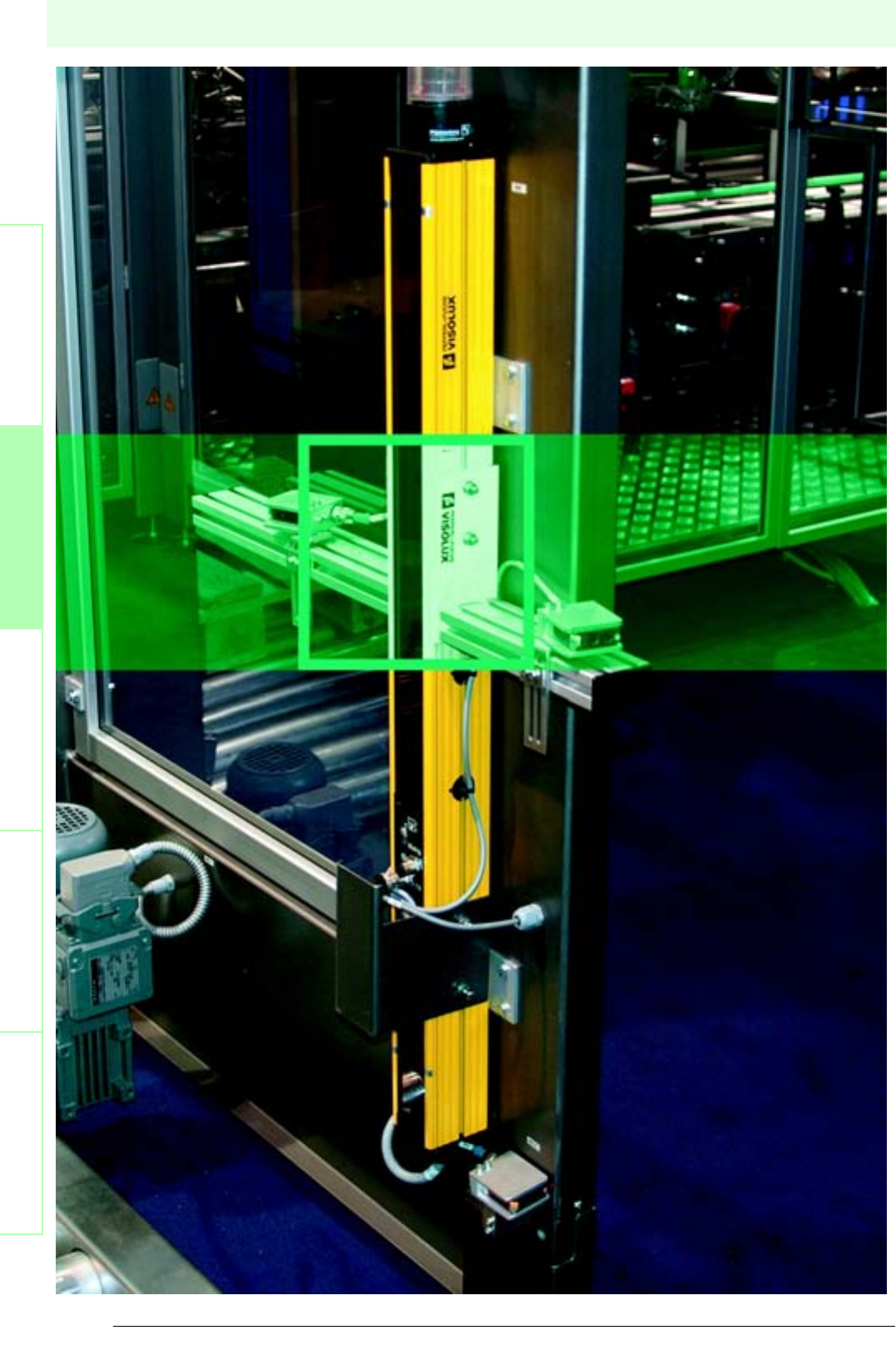
44
Date of edition 05/17/2006
Subject to reasonable modifications due to technical advances. Copyright Pepperl+Fuchs, Printed in Germany
Pepperl+Fuchs Group • Tel.: Germany +49 621 776-0 • USA +1 330 4253555 • Singapore +65 67799091 • Internet http://www.pepperl-fuchs.com
Safety light grids
Safety light barriersSafety light gridsSafety light grids with
internal control unit
Safety light curtainsControl units
SLP
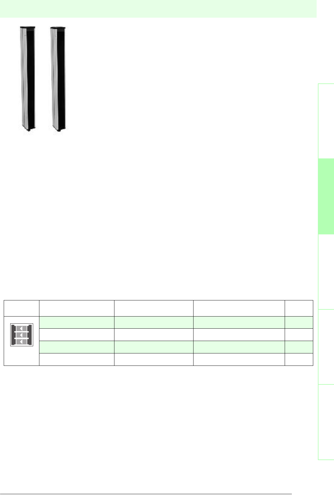
45
S
ubject to reasonable modifications due to technical advances. Copyright Pepperl+Fuchs, Printed in Germany
Pepperl+Fuchs Group • Tel.: Germany +49 621 776-0 • USA +1 330 4253555 • Singapore +65 67799091 • Internet http://www.pepperl-fuchs.com
Safety light grids
Date of edition 05/17/2006
Safety light barriers
Safety light grids
Safety light grids with
internal control unit
Safety light curtains
Control units
Operating
principle
Type code Number of beams Detection range Page
SLP8-2 20 m ... 8 m 46
SLP...-2 2 0 m ... 65 m 48
SLP...-3 30 m ... 65 m 50
SLP...-4 4 0 m ... 65 m 52
SLP Description
Safety light grids of type SLP combine with the control devices of series SafeBox into a
multi-beam photoelectronical protection device of category 4 (EN 954-1) or type 4 (according
to EN 61496). This is therefore a self-monitoring system.
A safety light grid consits of a sender SLP and a receiver SLP.
The safety light grids SLP, the control unit, muting sensors and other user-selectable safety
devices (e.g. E-stop) combine into a modular protection system.
Several safety light grids can be connected to a control unit. They can be mixed freely, but a
safety light grid must consist of a sender and receiver of the same type.
The supply voltage required for the safety light grid is provided by the control unit. The control
unit also triggers the sender and evaluates the signals transmitted by the receivers (e.g. light
beam interruption). Series SLP is available in different designs and ranges. Dependent on the
type of light grid used the range can be up to 65 m.
Protection from several directions can be achieved with the redirection mirrors of
series SLP-X-M.
Series SLP8-2 implements a 2 beam protection consisting of a transceiver (sender and
receiver in a single profile) and a mirror column. This layout means that the electrical connection is only necessary on one side.
Applications
Access and danger area protections for pallet systems, robots, wood processing machines, packaging machines, overhead
warehouse shelves and machine lines.

Subject to reasonable modifications due to technical advances. Copyright Pepperl+Fuchs, Printed in Germany
Pepperl+Fuchs Group • Tel.: Germany +49 621 776-0 • USA +1 330 4253555 • Singapore +65 67799091 • Internet http://www.pepperl-fuchs.com
46
Technische DatenTechnical data
Features
Ordering code:
Safety through beam
sensors
Safety light grids
Safety light grids with
internal control unit
Safety light curtains
Control units
SLP8-2
SLP8-2-L
Effective detection range 0.2 ... 8 m
X X
Number of beams 2
XX
Beam spacing 500 mm
X X
Obstacle size static: 32 mm
dynamic: 50 mm (at v = 1.6 m/s of the obstacle)
XX
Light source LED
X X
Light type red, modulated light
XX
Angle of divergence < 5 °
X X
Approvals TÜV
XX
Tests IEC/EN 61496
X X
Marking CE
XX
Safety category according to IEC/EN 61496 4
X X
Function display LED red: per receiver channel
off: Interruption
flashes: receiver
continuously on: reception with sufficient stability control
XX
Muting display
Indicator lamp
X
Pre-fault indication Functional display flashing
XX
Operating display LED red in transceiver
X X
Operating voltage Power supply via control unit
XX
Protection class III
X X
Ambient temperature -20 ... 60 °C (253 ... 333 K)
XX
Storage temperature -20 ... 70 °C (253 ... 343 K)
X X
Relative humidity max. 95 %, not condensing
XX
Protection degree IP65
X X
Connection Cable screwed connection M16 ,
terminal compartment
XX
Housing aluminium extruded structural profile, RAL 1021 (yellow) coated
X X
Optical face Plastic pane
XX
Mass Per 2100 g
X X
Connection options Further electrical connection options on request:
Plug connector DIN 43 651 Hirschmann, emitter: 6-pin+PE, receiver: 11-pin+PE
XX
System components
Transceiver
SLP8-2-A
X
SLP8-2-A-L
X
Mirror pillar SLP8-2-M
XX
SLP8-2-.
• Detection range 8 m
• Self-monitoring (type 4 according to IEC/EN 61496-1)
• 2-Radial design
• Beam spacing 500 mm
• Red transmission light
• Integrated function display
• Pre-fault indication
• Operation on control units of SB4 (SafeBox)
Date of edition 05/17/2006
Safety light grid
For required units refer to chapter „Control units“"
For suitable mounting aids and more refer to chapter „Accessories“
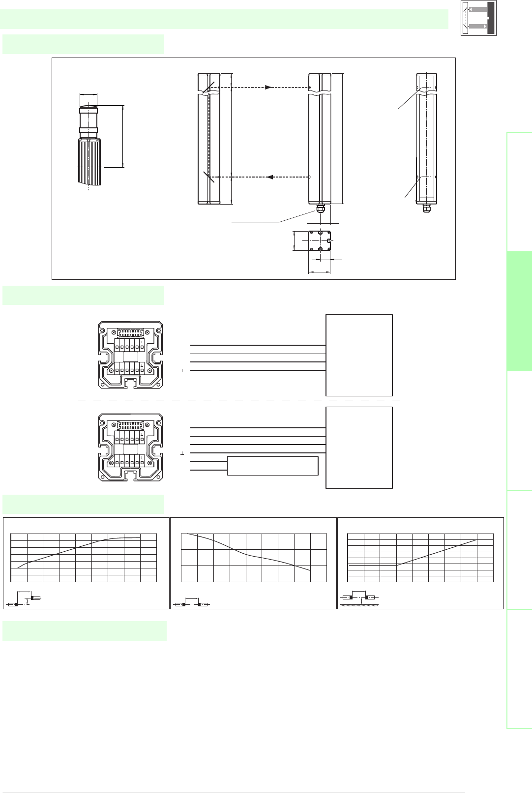
47
S
ubject to reasonable modifications due to technical advances. Copyright Pepperl+Fuchs, Printed in Germany
Pepperl+Fuchs Group • Tel.: Germany +49 621 776-0 • USA +1 330 4253555 • Singapore +65 67799091 • Internet http://www.pepperl-fuchs.com
Diagrams
Electrical connection
Dimensions
Safety through beam
sensors
Safety light gridsSafety light grids with
internal control unit
Safety light curtainsControl units
SLP8-2-.
x
y
SLP8
Offset Y [mm]
Distance X [m]
Characteristic response curve
0
10
20
30
40
50
60
70
0123456789
x
SLP8
Distance X [m]
Stability control
Relative received light strength
1
10
100
1000
0123456789
x
y
SLP8
Distance X [m]
Lateral interval to mirroring surfaces
Minimum interval [m]
0
0.05
0.1
0.15
0.2
0.25
0.3
0.35
0.4
0123456789
Date of edition 05/17/2006
Control
Unit
SafeBox Module 4X
Control
Unit
SafeBox Module 4X
Transceiver SLP8-2-A
Transceiver SLP8-2-A-L
muting lamp
muting lamp trigger
emitter x output
receiver x input
receiver +24 V
receiver 0 V
emitter x output
receiver x input
receiver +24 V
receiver 0 V
nc
nc
nc
T1
nc
nc
nc
nc
R1
+U
T1
R1
+U
nc
nc
nc
T1
nc
L-
L1
nc
R1
+U
T1
R1
+U
0 V
L-
L1
SB4
-4M
cable gland M16
Transceiver SLP8-2-A
Mirror SLP8-2-M
Status indicator
safety beam
Option -L with indicator lamp
(transceiver only)
indicator
lamp
topmost
beam
Operation display
64
32
70
33.5
636
90 500 46
197
ø 57
Safety light grid
• Control unit SafeBox
• Mounting set MS SLP
• Protective glass pieces for SLP (to protect the optically
functional surface)
• Ground pillar UC SLP/SLC
• Housing for pillar
Enclosure UC SLP/SLC
• Collision protector
Damping UC SLP/SLC
• Profile alignment aid
System accessories
• Laser alignment aid SLP
• Redirection mirror for multi-side protection of hazardous
areas
SLP-...-M
• Muting Set
MS SLP/SLA28
MS SLPCM

Subject to reasonable modifications due to technical advances. Copyright Pepperl+Fuchs, Printed in Germany
Pepperl+Fuchs Group • Tel.: Germany +49 621 776-0 • USA +1 330 4253555 • Singapore +65 67799091 • Internet http://www.pepperl-fuchs.com
48
Technische DatenTechnical data
Features
Ordering code:
Safety through beam
sensors
Safety light grids
Safety light grids with
internal control unit
Safety light curtains
Control units
SLP10-2
SLP10-2-L
SLP30-2
SLP65-2
Effective detection range
0.2 ... 10 m
X X
12 ... 65 m
X
6 ... 30 m
X
Number of beams 2
XXXX
Beam spacing 500 mm
X X X X
Obstacle size static: 32 mm
dynamic: 50 mm (at v = 1.6 m/s of the obstacle)
XXXX
Light source LED
X X X X
Light type red, modulated light
XXXX
Angle of divergence < 5 °
X X X X
Approvals TÜV
XXXX
Tests IEC/EN 61496
X X X X
Marking CE
XXXX
Safety category according to IEC/EN 61496 4
X X X X
Function display LED red: per receiver channel
off: Interruption
flashes: receiver
continuously on: reception with sufficient stability control
XXXX
Muting display
Indicator lamp
X
Pre-fault indication Functional display flashing
XXXX
Operating display LED red in receiver
X X X X
Operating voltage Power supply via control unit
XXXX
Protection class III
X X X X
Ambient temperature -20 ... 60 °C (253 ... 333 K)
XXXX
Storage temperature -20 ... 70 °C (253 ... 343 K)
X X X X
Relative humidity max. 95 %, not condensing
XXXX
Protection degree IP65
X X X X
Connection Cable screwed connection M16 ,
terminal compartment
XXXX
Housing aluminium extruded structural profile, RAL 1021 (yellow) coated
X X X X
Optical face Plastic pane
XXXX
Mass Per 2100 g
X X X X
Connection options Further electrical connection options on request:
Plug connector DIN 43 651 Hirschmann, emitter: 6-pin+PE, receiver: 11-pin+PE
XXXX
System components
Emitter
SLP10-2-T
XX
SLP30-2-T
X
SLP65-2-T
X
Receiver
SLP10-2-R
X
SLP10-2-R-L
X
SLP30-2-R
X
SLP65-2-R
X
SLP..-2
• Detection range up to 65 m
• Self-monitoring (type 4 according to IEC/EN 61496-1)
• 2-Radial design
• Beam spacing 500 mm
• Red transmission light
• Integrated function display
• Pre-fault indication
• Operation on control units of SB4 (SafeBox)
Date of edition 05/17/2006
Safety light grid
For required units refer to chapter „Control units“"
For suitable mounting aids and more refer to chapter „Accessories“
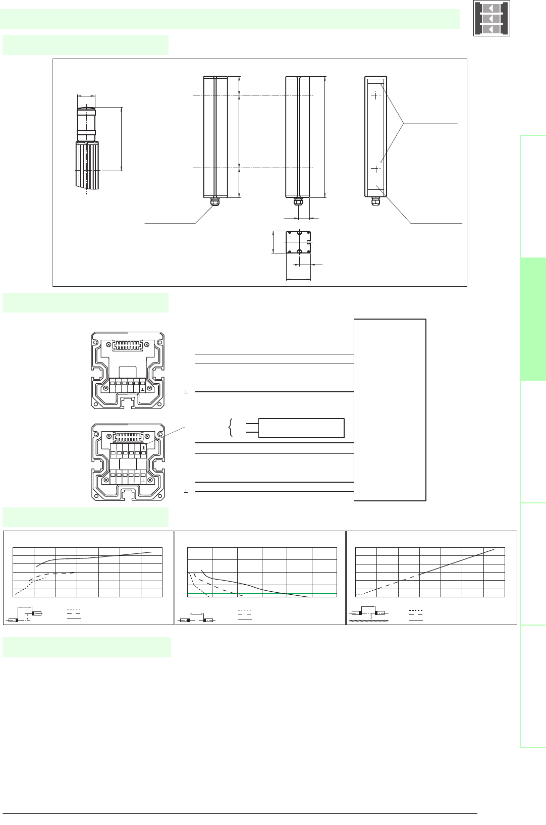
49
S
ubject to reasonable modifications due to technical advances. Copyright Pepperl+Fuchs, Printed in Germany
Pepperl+Fuchs Group • Tel.: Germany +49 621 776-0 • USA +1 330 4253555 • Singapore +65 67799091 • Internet http://www.pepperl-fuchs.com
Diagrams
Electrical connection
Dimensions
Safety through beam
sensors
Safety light gridsSafety light grids with
internal control unit
Safety light curtainsControl units
SLP..-2
x
y
SLP10
SLP30
SLP65
Offset Y [mm]
Distance X [m]
Characteristic response curve
0
50
100
150
200
250
300
0 10203040506070
xSLP10
SLP30
SLP65
Distance X [m]
Stability control
Relative received light strength
1
10
100
10000
1000
0 20 40 60 80 100 120
x
y
SLP10
SLP30
SLP65
Distance X [m]
Lateral interval to mirroring surfaces
Minimum interval [m]
0
0.5
1
1.5
2
2.5
3
0 10203040506070
Date of edition 05/17/2006
Emitter SLP
Receiver SLP (-L)
Control Unit SafeBox module 4X
only with option -L
(indicator lamp)
emitter x output
emitter x+1 output
emitter 0 V
receiver x+1 input
receiver x input
receiver +24 V
receiver 0 V
0 V Muting lamp
Muting lamp trigger
R1R2 R3 R4
+U
T1 T2 T3 T4
NC
T1
T2
R2
+U
R1
L-
L1
L- L1
NC NC NC
SB4
-4M
SLP...-2
Emitter Receiver
Option -L with indicator lamp
(receiver only)
Cable gland M16
Operating display
Receiver
Status indicator
of the particular
safety beam
first beam
second beam
Indicator
lamp
topmost
beam
64
32
70
33.5
636
90 500 46
197
ø 57
Safety light grid
• Control unit SafeBox
• Mounting set MS SLP
• Protective glass pieces for SLP (to protect the optically
functional surface)
• Ground pillar UC SLP/SLC
• Housing for pillar
Enclosure UC SLP/SLC
• Collision protector
Damping UC SLP/SLC
• Profile alignment aid
System accessories
• Laser alignment aid SLP
• Redirection mirror for multi-side protection of hazardous
areas
SLP-...-M
• Muting Set
MS SLP/SLA28
MS SLPCM
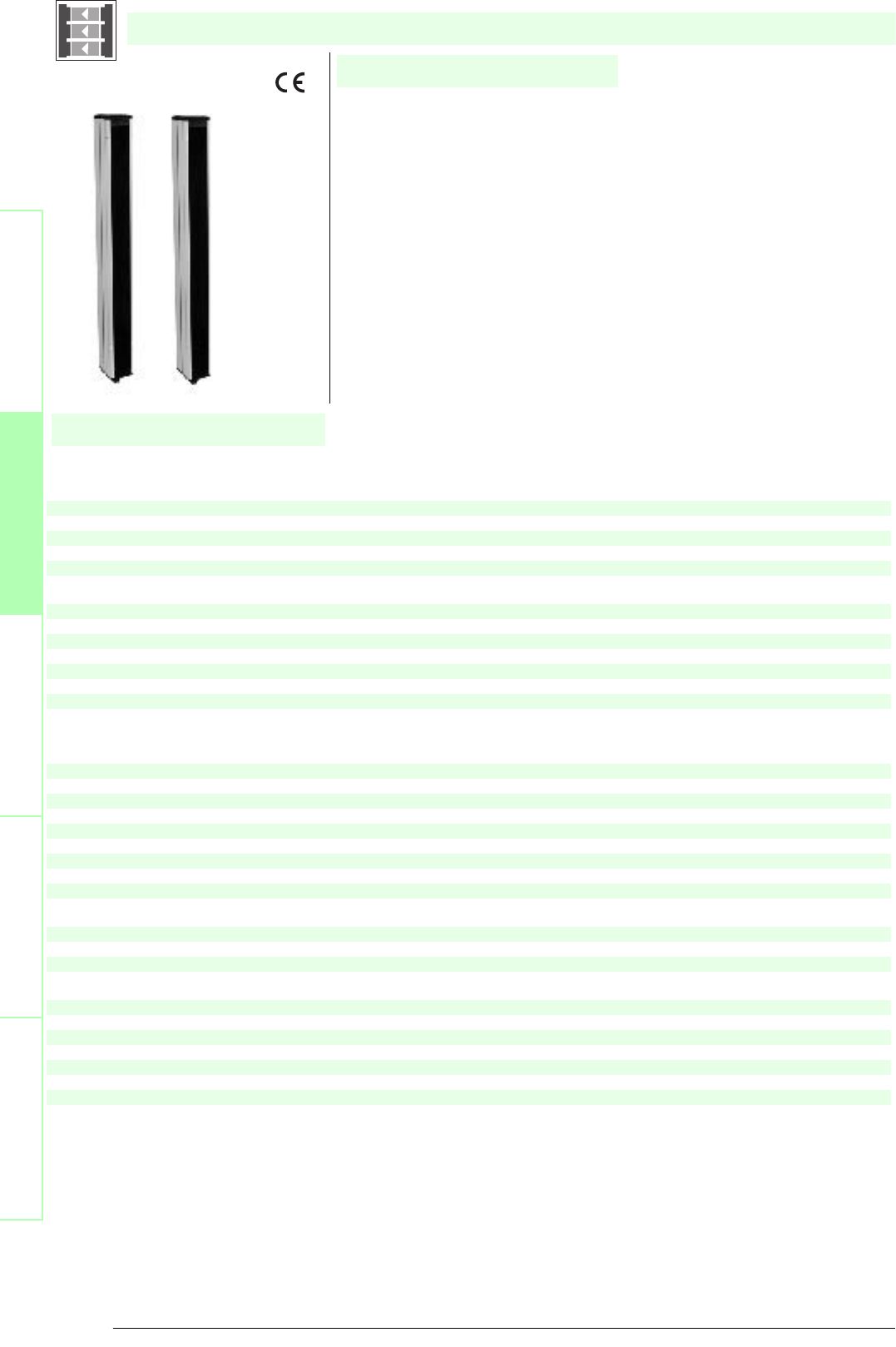
Subject to reasonable modifications due to technical advances. Copyright Pepperl+Fuchs, Printed in Germany
Pepperl+Fuchs Group • Tel.: Germany +49 621 776-0 • USA +1 330 4253555 • Singapore +65 67799091 • Internet http://www.pepperl-fuchs.com
50
Technische DatenTechnical data
Features
Ordering code:
Safety through beam
sensors
Safety light grids
Safety light grids with
internal control unit
Safety light curtains
Control units
SLP10-3
SLP10-3-L
SLP30-3
SLP65-3
Effective detection range
0.2 ... 10 m
X X
12 ... 65 m
X
6 ... 30 m
X
Number of beams 3
XXXX
Beam spacing 400 mm
X X X X
Obstacle size static: 32 mm
dynamic: 50 mm (at v = 1.6 m/s of the obstacle)
XXXX
Light source LED
X X X X
Light type red, modulated light
XXXX
Angle of divergence < 5 °
X X X X
Approvals TÜV
XXXX
Tests IEC/EN 61496
X X X X
Marking CE
XXXX
Safety category according to IEC/EN 61496 4
X X X X
Function display LED red: per receiver channel
off: Interruption
flashes: receiver
continuously on: reception with sufficient stability control
XXXX
Muting display
Indicator lamp
X
Pre-fault indication Functional display flashing
XXXX
Operating display LED red in receiver
X X X X
Operating voltage Power supply via control unit
XXXX
Protection class III
X X X X
Ambient temperature -20 ... 60 °C (253 ... 333 K)
XXXX
Storage temperature -20 ... 70 °C (253 ... 343 K)
X X X X
Relative humidity max. 95 %, not condensing
XXXX
Protection degree IP65
X X X X
Connection Cable screwed connection M16 ,
terminal compartment
XXXX
Housing aluminium extruded structural profile, RAL 1021 (yellow) coated
X X X X
Optical face Plastic pane
XXXX
Mass Per 3200 g
X X X X
Connection options Further electrical connection options on request:
Plug connector DIN 43 651 Hirschmann, emitter: 6-pin+PE, receiver: 11-pin+PE
XXXX
System components
Emitter
SLP10-3-T
XX
SLP30-3-T
X
SLP65-3-T
X
Receiver
SLP10-3-R
X
SLP10-3-R-L
X
SLP30-3-R
X
SLP65-3-R
X
SLP..-3
• Detection range up to 65 m
• Self-monitoring (type 4 according to IEC/EN 61496-1)
• 3-Radial design
• Beam spacing 400 mm
• Red transmission light
• Integrated function display
• Pre-fault indication
• Operation on control units of SB4 (SafeBox)
Date of edition 05/17/2006
Safety light grid
For required units refer to chapter „Control units“"
For suitable mounting aids and more refer to chapter „Accessories“
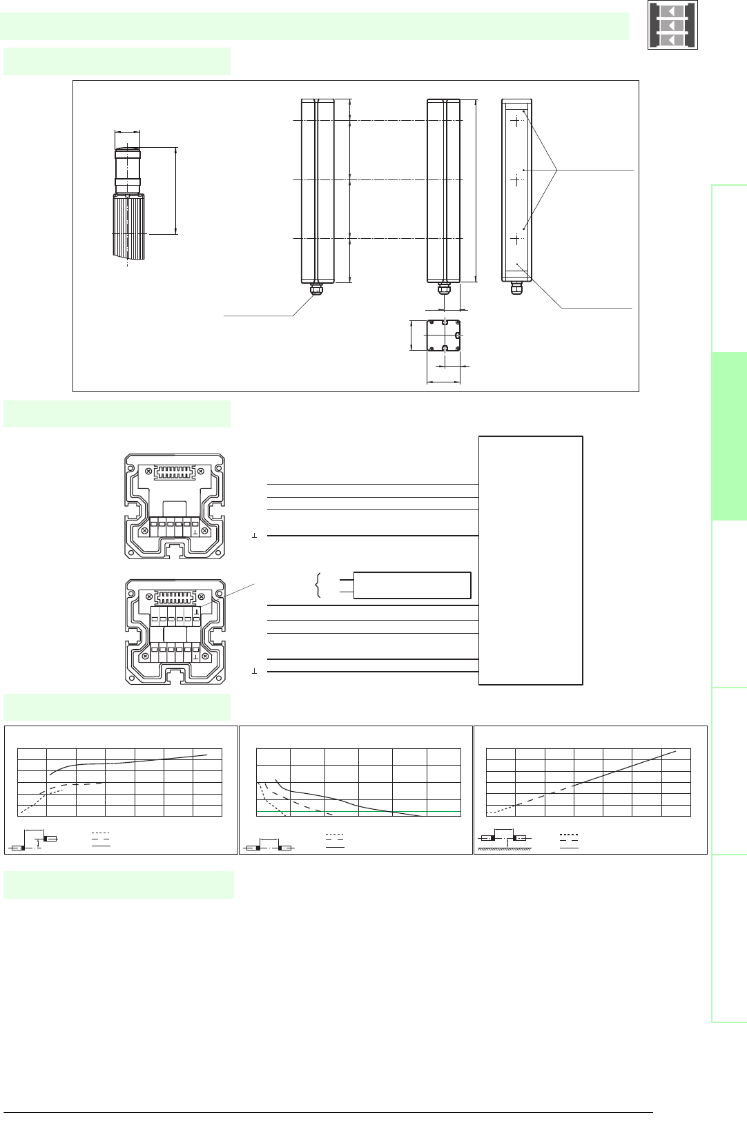
51
S
ubject to reasonable modifications due to technical advances. Copyright Pepperl+Fuchs, Printed in Germany
Pepperl+Fuchs Group • Tel.: Germany +49 621 776-0 • USA +1 330 4253555 • Singapore +65 67799091 • Internet http://www.pepperl-fuchs.com
Diagrams
Electrical connection
Dimensions
Safety through beam
sensors
Safety light gridsSafety light grids with
internal control unit
Safety light curtainsControl units
SLP..-3
x
y
SLP10
SLP30
SLP65
Offset Y [mm]
Distance X [m]
Characteristic response curve
0
50
100
150
200
250
300
0 10203040506070
xSLP10
SLP30
SLP65
Distance X [m]
Stability control
Relative received light strength
1
10
100
10000
1000
0 20 40 60 80 100 120
x
y
SLP10
SLP30
SLP65
Distance X [m]
Lateral interval to mirroring surfaces
Minimum interval [m]
0
0.5
1
1.5
2
2.5
3
0 10203040506070
Date of edition 05/17/2006
Emitter SLP
Receiver SLP (-L)
Control Unit SafeBox module 4X
only with option -L
(indicator lamp)
emitter x output
emitter x+1 output
emitter x+2 output
emitter 0 V
receiver x+1 input
receiver x input
receiver x+2 input
receiver 24 V
receiver 0 V
0 V Muting lamp
Muting lamp trigger
R1R2 R3 R4
+U
T1 T2 T3 T4
NC
T1
T2
T3
R2
R3
+U
R1
L-
L1
L- L1
NC NC NC
SB4
-4M
SLP...-3
Option -L with indicator lamp
(in receiver only)
Cable gland M16
Operating display
Receiver
Status indicator
of the particular
safety beam
first beam
second beam
Indicator
lamp
topmost
beam
third beam
Emitter Receiver
64
32
70
33.5
936
90 400 400 46
197
ø 57
Safety light grid
• Control unit SafeBox
• Mounting set MS SLP
• Protective glass pieces for SLP (to protect the optically
functional surface)
• Ground pillar UC SLP/SLC
• Housing for pillar
Enclosure UC SLP/SLC
• Collision protector
Damping UC SLP/SLC
• Profile alignment aid
System accessories
• Laser alignment aid SLP
• Redirection mirror for multi-side protection of hazardous
areas
SLP-...-M
• Muting Set
MS SLP/SLA28
MS SLPCM

Subject to reasonable modifications due to technical advances. Copyright Pepperl+Fuchs, Printed in Germany
Pepperl+Fuchs Group • Tel.: Germany +49 621 776-0 • USA +1 330 4253555 • Singapore +65 67799091 • Internet http://www.pepperl-fuchs.com
52
Technische DatenTechnical data
Features
Ordering code:
Safety through beam
sensors
Safety light grids
Safety light grids with
internal control unit
Safety light curtains
Control units
SLP10-4
SLP10-4-L
SLP30-4
SLP65-4
Effective detection range
0.2 ... 10 m
X X
12 ... 65 m
X
6 ... 30 m
X
Number of beams 4
XXXX
Beam spacing 300 mm
X X X X
Obstacle size static: 32 mm
dynamic: 50 mm (at v = 1.6 m/s of the obstacle)
XXXX
Light source LED
X X X X
Light type red, modulated light
XXXX
Angle of divergence < 5 °
X X X X
Approvals TÜV
XXXX
Tests IEC/EN 61496
X X X X
Marking CE
XXXX
Safety category according to IEC/EN 61496 4
X X X X
Function display LED red: per receiver channel
off: Interruption
flashes: receiver
continuously on: reception with sufficient stability control
XXXX
Muting display
Indicator lamp
X
Pre-fault indication Functional display flashing
XXXX
Operating display LED red in receiver
X X X X
Operating voltage Power supply via control unit
XXXX
Protection class III
X X X X
Ambient temperature -20 ... 60 °C (253 ... 333 K)
XXXX
Storage temperature -20 ... 70 °C (253 ... 343 K)
X X X X
Relative humidity max. 95 %, not condensing
XXXX
Protection degree IP65
X X X X
Connection Cable screwed connection M16 ,
terminal compartment
XXXX
Housing aluminium extruded structural profile, RAL 1021 (yellow) coated
X X X X
Optical face Plastic pane
XXXX
Mass Per 3500 g
X X X X
Connection options Further electrical connection options on request:
Plug connector DIN 43 651 Hirschmann, emitter: 6-pin+PE, receiver: 11-pin+PE
XXXX
System components
Emitter
SLP10-4-T
XX
SLP30-4-T
X
SLP65-4-T
X
Receiver
SLP10-4-R
X
SLP10-4-R-L
X
SLP30-4-R
X
SLP65-4-R
X
SLP..-4
• Detection range up to 65 m
• Self-monitoring (type 4 according to IEC/EN 61496-1)
• 4-Radial design
• Beam spacing 300 mm
• Red transmission light
• Integrated function display
• Pre-fault indication
• Operation on control units of SB4 (SafeBox)
Date of edition 05/17/2006
Safety light grid
For required units refer to chapter „Control units“"
For suitable mounting aids and more refer to chapter „Accessories“
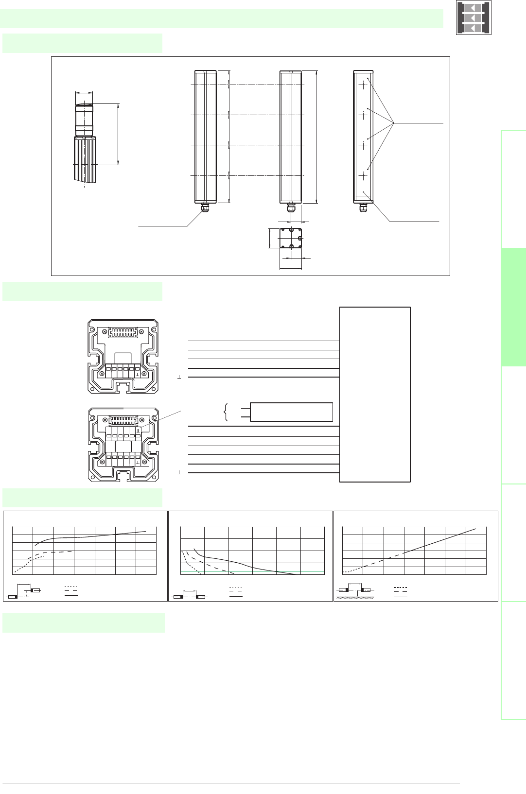
53
S
ubject to reasonable modifications due to technical advances. Copyright Pepperl+Fuchs, Printed in Germany
Pepperl+Fuchs Group • Tel.: Germany +49 621 776-0 • USA +1 330 4253555 • Singapore +65 67799091 • Internet http://www.pepperl-fuchs.com
Diagrams
Electrical connection
Dimensions
Safety through beam
sensors
Safety light gridsSafety light grids with
internal control unit
Safety light curtainsControl units
SLP..-4
x
y
SLP10
SLP30
SLP65
Offset Y [mm]
Distance X [m]
Characteristic response curve
0
50
100
150
200
250
300
0 10203040506070
xSLP10
SLP30
SLP65
Distance X [m]
Stability control
Relative received light strength
1
10
100
10000
1000
0 20 40 60 80 100 120
x
y
SLP10
SLP30
SLP65
Distance X [m]
Lateral interval to mirroring surfaces
Minimum interval [m]
0
0.5
1
1.5
2
2.5
3
0 10203040506070
Date of edition 05/17/2006
Emitter SLP
Receiver SLP (-L)
Control Unit SafeBox module 4X
only with option -L
(indicator lamp)
emitter x output
emitter x+1 output
emitter x+2 output
emitter x+3 output
emitter 0 V
receiver x+1 input
receiver x input
receiver x+2 input
receiver x+3 input
receiver 24 V
receiver 0 V
0 V Muting lamp
Muting lamp trigger
R1R2 R3 R4
+U
L- L1
NC NC NC
T1 T2 T3 T4
NC
T1
T2
T3
T4
R2
R3
R4
+U
R1
L-
L1
SB4
-4M
SLP...-4
Option -L with indicator lamp
(receiver only)
Cable gland M16
Operating display
Receiver
Status indicator
of the particular
safety beam
first beam
second beam
Indicator
lamp
topmost
beam
third beam
Emitter Receiver
fourth beam
64
32
70
33.5
1036
90 300 300 300 46
1036
197
ø 57
Safety light grid
• Control unit SafeBox
• Mounting set MS SLP
• Protective glass pieces for SLP (to protect the optically
functional surface)
• Ground pillar UC SLP/SLC
• Housing for pillar
Enclosure UC SLP/SLC
• Collision protector
Damping UC SLP/SLC
• Profile alignment aid
System accessories
• Laser alignment aid SLP
• Redirection mirror for multi-side protection of hazardous
areas
SLP-...-M
• Muting Set
MS SLP/SLA28
MS SLPCM
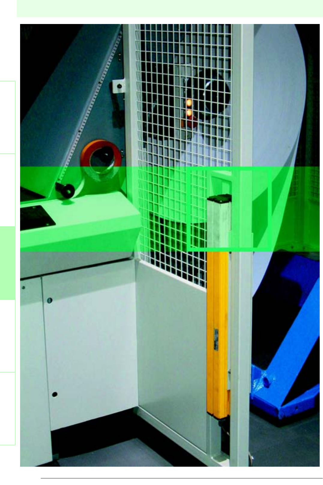
54
Date of edition 17.05.2006
Subject to reasonable modifications due to technical advances. Copyright Pepperl+Fuchs, Printed in Germany
Pepperl+Fuchs Group • Tel.: Germany +49 621 776-0 • USA +1 330 4253555 • Singapore +65 67799091 • Internet http://www.pepperl-fuchs.com
Safety light grids with internal control unit
Safety light barriersSafety light gridsSafety light grids with
internal control unit
Safety light curtainsControl units
SLP C
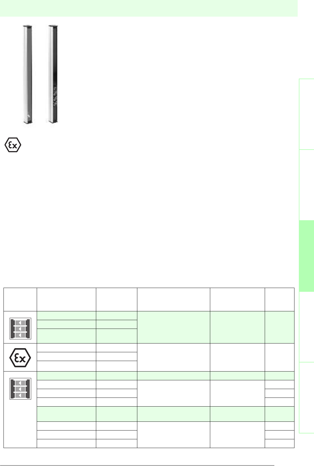
55
S
ubject to reasonable modifications due to technical advances. Copyright Pepperl+Fuchs, Printed in Germany
Pepperl+Fuchs Group • Tel.: Germany +49 621 776-0 • USA +1 330 4253555 • Singapore +65 67799091 • Internet http://www.pepperl-fuchs.com
Safety light grids with internal control unit
Date of edition 17.05.2006
Safety light barriers
Safety light grids
Safety light grids with
internal control unit
Safety light curtains
Control units
Operating
principle
Type code Number of
beams
Feature Operating range Beginning
on page
SLC-2 2internal
control unit
0.2 m ... 20 m 56
SLC-3 3
SLC-4 4
SLC-2/133 2 internal
control unit
for explosive areas in zone
2 and 22
0.2 m ... 20 m 58
SLC-3/133 3
SLC-4/133 4
SLPC 8-2 2internal control unit 0.2 m ... 8 m 60
SLPC...2 2 internal control unit 0.2 m ... 65 m 62
SLPC...3 3 68
SLPC...4 4 74
SLPCM 8-2 2internal control unit, with
muting
0.2 m ... 8 m 80
SLPCM...2 2 internal control unit, with
muting
0.2 m ... 65 m 82
SLPCM...3 3 88
SLPCM...4 4 94
The safety light grids SLPC/SLP, SLPCM/SLP and SLC are electro-sensitive equipment
devices of category 4 (EN 954-1) or type 4 (according to IEC/EN 61496). They are
self-monitoring systems.
Description safety light grid SLC
The safety light grid of series SLC consists of a sender SLC-x and the corresponding receiver
from series SLC. No external control unit is required. All evaluation functions (e.g.
startup/restart lock, relay monitor) are integrated in the receiver of the SLC. The safety
outputs (OSSD) are designed as either semiconductor outputs with separated potential or
monitored forced NO contacts.
A cable connection between sender and receiver is not required. A protection from several
directions can be achieved with redirection mirrors of series SLP-x-M. Muting applications can
be implemented in combination with the control unit SafeBox. The protection category IP67
provides safe protection against harmful environmental impact.
Use in explosive areas
These devices can now also be used in explosive areas of zone 2 and zone 22 (option /133).
This also complies with the specification that only devices and protection systems approved in accordance with
Directive 94/9/EC (ATEX) should be used in explosive areas.
Description SLPC
The safety light grid of series SLPC consists of a sender SLP and a corresponding receiver from series SLPC. No external
control unit is required. All evaluation functions (e.g. startup/restart lock, relay monitor) are integrated in the receiver of the
SLPC. The system is self-monitoring. The safety outputs (OSSD) are designed as either semiconductor outputs with separated
potential or monitored forced NO contacts.
Description SLPCM
The safety light grid of series SLPCM consists of a sender SLP and a corresponding receiver from series SLPCM. No external
control unit is required. All control functions, including for the operating modes muting and emergency muting, are integrated in
the receiver of the SLPCM. The system is self-monitoring. The safety outputs (OSSD) are designed as either semiconductor
outputs with separated potential or monitored forced NO contacts.
Applications
Access and danger area protections for pallet systems, robots, wood processing machines, packaging machines, overhead
warehouse shelves and machine lines.
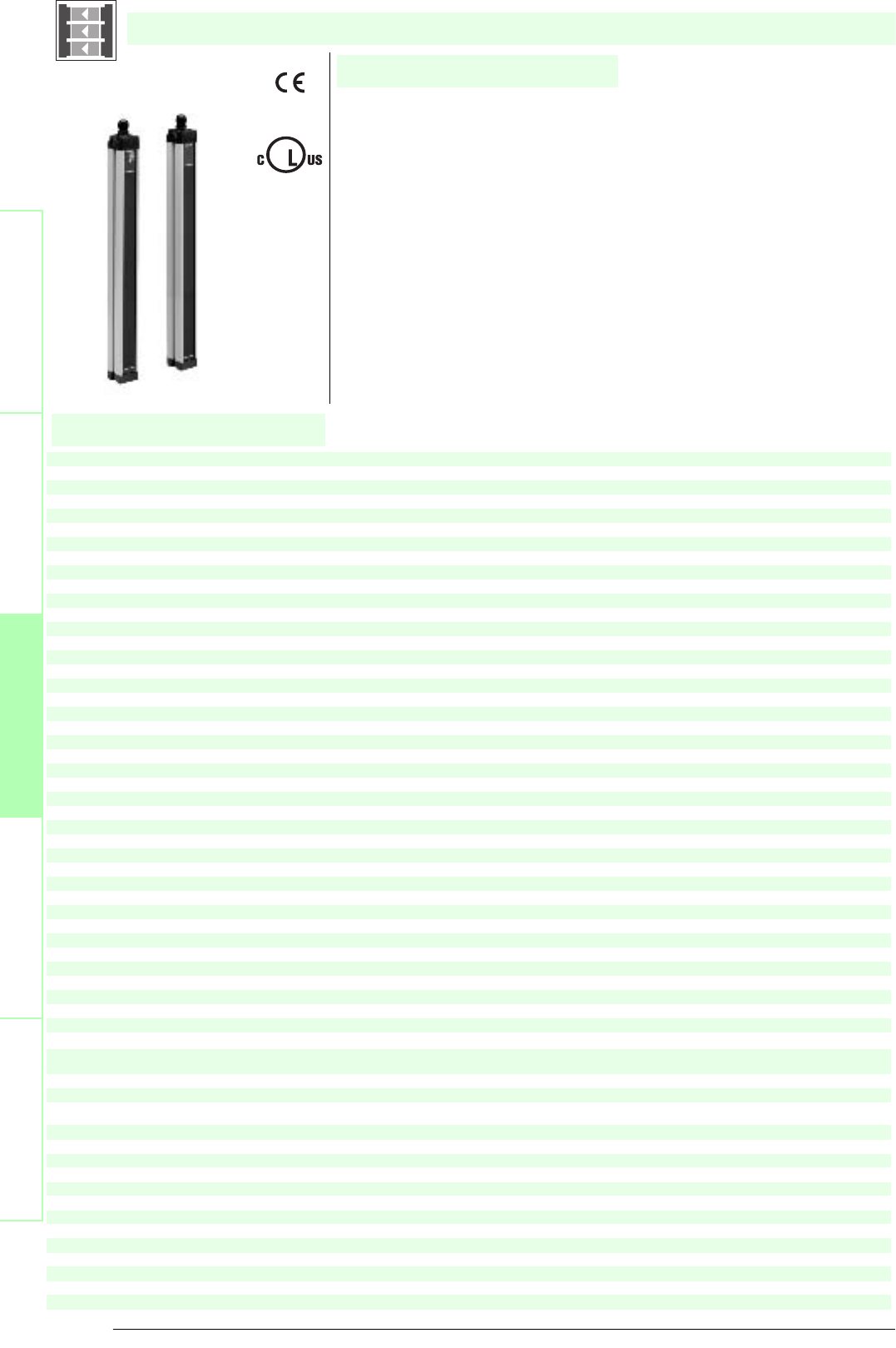
Subject to reasonable modifications due to technical advances. Copyright Pepperl+Fuchs, Printed in Germany
Pepperl+Fuchs Group • Tel.: Germany +49 621 776-0 • USA +1 330 4253555 • Singapore +65 67799091 • Internet http://www.pepperl-fuchs.com
56
Technische DatenTechnical data
Features
Ordering code:
Sicherheits-Lichtschranken
Sicherheits-Lichtgitter
Sicherheits-Lichtgitter mit
interner Auswerteeinheit
Sicherheits-Lichtvorhänge
Auswertegeräte Safety through beam
sensors
Safety light grids
Safety light grigs with
internal control unit
Safety light curtains
Control units
SLC-2
SLC-3
SLC-4
SLC-2/31
SLC-3/31
SLC-4/31
Effective detection range
0.2 ... 20 m
X X X X X X
Light source
IRED
XXXXXX
Approvals
TÜV, cULus
X X X X X X
Te s ts
IEC/EN 61496
XXXXXX
Marking
CE
X X X X X X
Obstacle size
50 mm
XXXXXX
Beam spacing
300 mm
X X
400 mm
XX
500 mm
X X
Number of beams
234234
Safety category according to IEC/EN 61496
4
X X X X X X
Operating mode
can be selected with or without start/restart disable
XXXXXX
Light type
infrared, modulated light
X X X X X X
Angle of divergence
< 5 °
XXXXXX
Operating display
7-segment display in emitter
X X X X X X
Diagnosis display
7-segment display in receiver
XXXXXX
Function display
in receiver: LED red: OSSD off; LED green: OSSD on; LED yellow: Protected area free, system start-ready
X X X X X X
Pre-fault indication
LED orange
XXXXXX
Operating elements
switch for start/restart disable, transmission coding
X X X X X X
Operating voltage
24 V DC (-30 %/+25 %)
XXX
24 V DC (-30 %/+25 %) / 24 V AC (-20 %/+10 %)
X X X
Protection class
III
XXXXXX
No-load supply current
Emitter: 100 mA , receiver 150 mA
X X X X X X
Activation current
approx. 10 mA
XXXXXX
Activation time
0.03 ... 1 s
X X X X X X
Te s t i np u t
Reset-input for system test
XXXXXX
Function input
Start release
X X X X X X
Safety output
2 separated fail safe semiconductor outputs
XXX
2 relay outputs, compelled connection NO-contact
X X X
Signal output
1 PNP each, max. 100 mA for start readiness and OSSD status
XXXXXX
Switching voltage
Operating voltage -2 V
X X X
50 V
XXX
Switching current
max. 0.5 A
X X X
max. 2 A
XXX
Switch power
100 VA
X X X
Response time
10 ms
XXX
30 ms
X X X
Ambient temperature
0 ... 55 °C (273 ... 328 K)
XXXXXX
Storage temperature
-25 ... 70 °C (248 ... 343 K)
X X X X X X
Relative humidity
max. 95 %, not condensing
XXXXXX
Protection degree
IP67
X X X X X X
Connection
Cable screwed connection M20 , terminal compartment with screw terminals, lead cross-section max. 1.5 mm2
XXXXXX
Connection options
Further electrical connection options on request: Plug connector M12, 8-pin, Plug connector DIN 43 651 Hirschmann, 6-pin+PE, Plug connector
M26x11 Hirschmann, 11-pin+PE
X X X X X X
Housing
aluminium extruded structural profile, RAL 1021 (yellow) coated
XXXXXX
Optical face
Plastic pane
X X X X X X
Mass
Per [g]
210
0
300
0
345
0
210
0
300
0
345
0
Dimensions
Length of housing 1007 mm
X X
Length of housing 1157 mm
XX
Length of housing 707 mm
X X
System components
Emitter
SLC-2-T
X X
SLC-3-T
XX
SLC-4-T
X X
Receiver
SLC-2-R
X
SLC-2-R/31
X
SLC-3-R
X
SLC-3-R/31
X
SLC-4-R
X
SLC-4-R/31
X
SLC-...
• Detection range up to 20 m
• 2, 3, and 4-beam design
• Beam distance 300, 400 and 500 mm
• Self-monitoring (type 4 according to IEC/EN 61496-1)
• Start/Restart disable
• Protection degree IP67
• 7-segment diagnostic display
• Pre-fault indication
• Safety outputs OSSD in potential-separated semiconductor design or with
monitored, compelled connection NC-contacts
• Optional with relay monitor (Option 129)
SLC-2/31
SLC-3/31
SLC-4/31
U
®
Date of edition 05/17/2006
Safety light grid with integrated control unit
For suitable cable sockets, mounting aids, redirection mirrors and more refer to chapter „Accessories“.
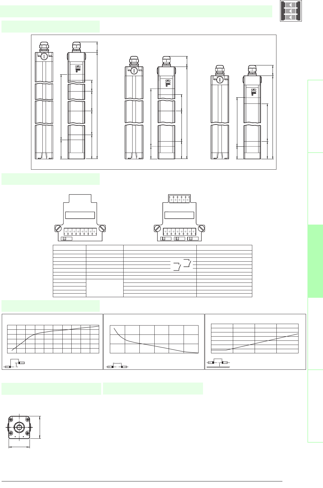
57
S
ubject to reasonable modifications due to technical advances. Copyright Pepperl+Fuchs, Printed in Germany
Pepperl+Fuchs Group • Tel.: Germany +49 621 776-0 • USA +1 330 4253555 • Singapore +65 67799091 • Internet http://www.pepperl-fuchs.com
Diagrams
Electrical connection
Dimensions
Safety through beam
sensors
Safety light gridsSafety light grids with
internal control unit
Safety light curtainsControl units
Profile dimensions, front view
Additional information
52
55
SLC-...
x
y
SLC-2 / SLC-3 / SLC-4
Distance X [m]
Offset Y [mm]
Characteristic response curve
0
50
100
150
200
250
300
0246 8101214161820
x
SLC-2 / SLC-3 / SLC-4
Distance X [m]
Stability control
Relative received light strength
1
10
100
1000
0 5 10 15 20 25 30
x
y
SLC-2 / SLC-3 / SLC-4
Distance X [m]
Lateral interval to mirroring surfaces
Minimum interval [m]
0 2 4 6 8 10 12
0
0.2
0.4
0.6
0.8
1
1.2
1.4
Date of edition 05/17/2006
Emitter: Receiver:
terminal emitter receiver (relay output) receiver (semiconductor output)
X1:1 Functional earth Functional earth Functional earth
X1:2 test (input) Test (input)
X1:3 OSSD2.2 (output) 0 V OSSD
X1:4 OSSD1.2 (output) 24 V OSSD
X1:5 OSSD2.1 (output) OSSD2 (output)
X1:6 OSSD1.1 (output) OSSD1 (output)
X1:7 0 V AC/DC 0 V AC/DC 0 V DC
X1:8 24 V AC/DC 24 V AC/DC 24 V DC
X2:1 Start release (output) Start release (output)
X2:2 Status OSSD (output) Status OSSD (output)
X2:3 not placed on board 24 V reference potential for I/O n. c.
X2:4 0 V reference potential for I/O n. c.
x2:5 Startup readiness (input) Startup readiness (input)
S1 S1 S2 S3
X1 X1
X2
87654321
123 4 5
575.3 (protective field height)
875.3 (protective field height)
975.3 (protective field height)
89.6
51.7
51.7
89.6
~ 35
1157
300300300139,6
101,7
~ 351007
400400
~ 35707
500
SLC-2SLC-3SLC-4
Safety light grid with integrated control unit
• Mounting set SLC
• Protective glass pieces for SLC (to
protect the optically functional sur-
face)
• Lateral screwed connection SLC
• Mirror 2, 3 or 4-beam for
SLC (for multi-side securing of haz-
ardous areas)
• Laser alignment aid BA SLC
System accessories • Profile alignment aid PA SLP/SLC
• Ground pillar UC SLP/SLC
• Housing for ground pillar
Enclosure UC SLP/SLC
• Collision protector
Damping UC SLP/SLC
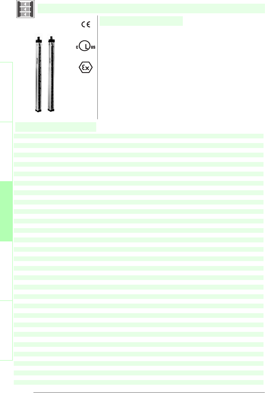
Subject to reasonable modifications due to technical advances. Copyright Pepperl+Fuchs, Printed in Germany
Pepperl+Fuchs Group • Tel.: Germany +49 621 776-0 • USA +1 330 4253555 • Singapore +65 67799091 • Internet http://www.pepperl-fuchs.com
58
Technische DatenTechnical data
Features
Ordering code:
Sicherheits-Lichtschranken
Sicherheits-Lichtgitter
Sicherheits-Lichtgitter mit
interner Auswerteeinheit
Sicherheits-Lichtvorhänge
Auswertegeräte Safety through beam
sensors
Safety light grids
Safety light grigs with
internal control unit
Safety light curtains
Control units
SLC-2/133
SLC-3/133
SLC-4/133
Effective detection range
0.2 ... 20 m
X X X
Light source
IRED
XXX
Approvals
TÜV, cULus
X X X
Tests
IEC/EN 61496
XXX
Marking
zone 2: ¬ II 3 G EEx nA II T4; Zone 22: ¬ II 3 D IP66 T 90°C
X X X
Obstacle size
50 mm
XXX
Beam spacing
300 mm
X
400 mm
X
500 mm
X
Number of beams
2
X
3
X
4
X
Safety category according to IEC/EN 61496
4
X X X
Operating mode
can be selected with or without start/restart disable
XXX
Light type
infrared, modulated light
X X X
Angle of divergence
< 5 °
XXX
Series
SLC
X X X
Operating display
7-segment display in emitter
XXX
Diagnosis display
7-segment display in receiver
X X X
Function display
in receiver: LED red: OSSD off, LED green: OSSD on, LED yellow: Protected area free, system start-ready
XXX
Pre-fault indication
LED orange
X X X
Operating elements
switch for start/restart disable, transmission coding
XXX
Operating voltage
24 V DC (-30 %/+25 %)
X X X
Protection class
III
XXX
No-load supply current
Emitter: 100 mA , receiver 150 mA
X X X
Activation current
approx. 10 mA
XXX
Activation time
0.03 ... 1 s
X X X
Test i np ut
Reset-input for system test
XXX
Function input
Start release
X X X
Safety output
2 separated fail safe semiconductor outputs
XXX
Signal output
1 PNP each, max. 100 mA for start readiness and OSSD status
X X X
Switching voltage
Operating voltage -2 V
XXX
Switching current
max. 0.5 A
X X X
Response time
10 ms
XXX
Ambient temperature
0 ... 55 °C (273 ... 328 K)
X X X
Storage temperature
-25 ... 70 °C (248 ... 343 K)
XXX
Relative humidity
max. 95 %, not condensing
X X X
Length of housing
1010 mm
X
1157 mm
X
707 mm
X
Housing width
52 mm
X X X
Housing depth
55 mm
XXX
Protection degree
IP66
X X X
Connection
Cable screwed connection M20 , terminal compartment with screw terminals, lead cross-section max. 1.5 mm2
XXX
Housing
aluminium extruded structural profile, RAL 1021 (yellow) coated
X X X
Optical face
Plastic pane
XXX
Mass
Per 2100 g
X
Per 3000 g
X
Per 3450 g
X
System components
Emitter
SLC-2-T/133
X
SLC-3-T/133
X
SLC-4-T/133
X
SLC-./133
• ATEX-approval for zone 2 and zone 22
• Self-monitoring (type 4 according to IEC/EN 61496-1)
• Safety outputs OSSD, external status displays OSSD
• Start/Restart disable
• 7-segment diagnostic display
• Pre-fault indication
• Protection degree IP66
• Beam spacing 300 mm
SLC-4/133
• Beam spacing 400 mm
SLC-3/133
• Beam spacing 500 mm
SLC-2/133
U
®
Date of edition 05/17/2006
Safety light grid with integrated control unit
For suitable cable sockets, mounting aids, redirection mirrors and more refer to chapter „Accessories“.
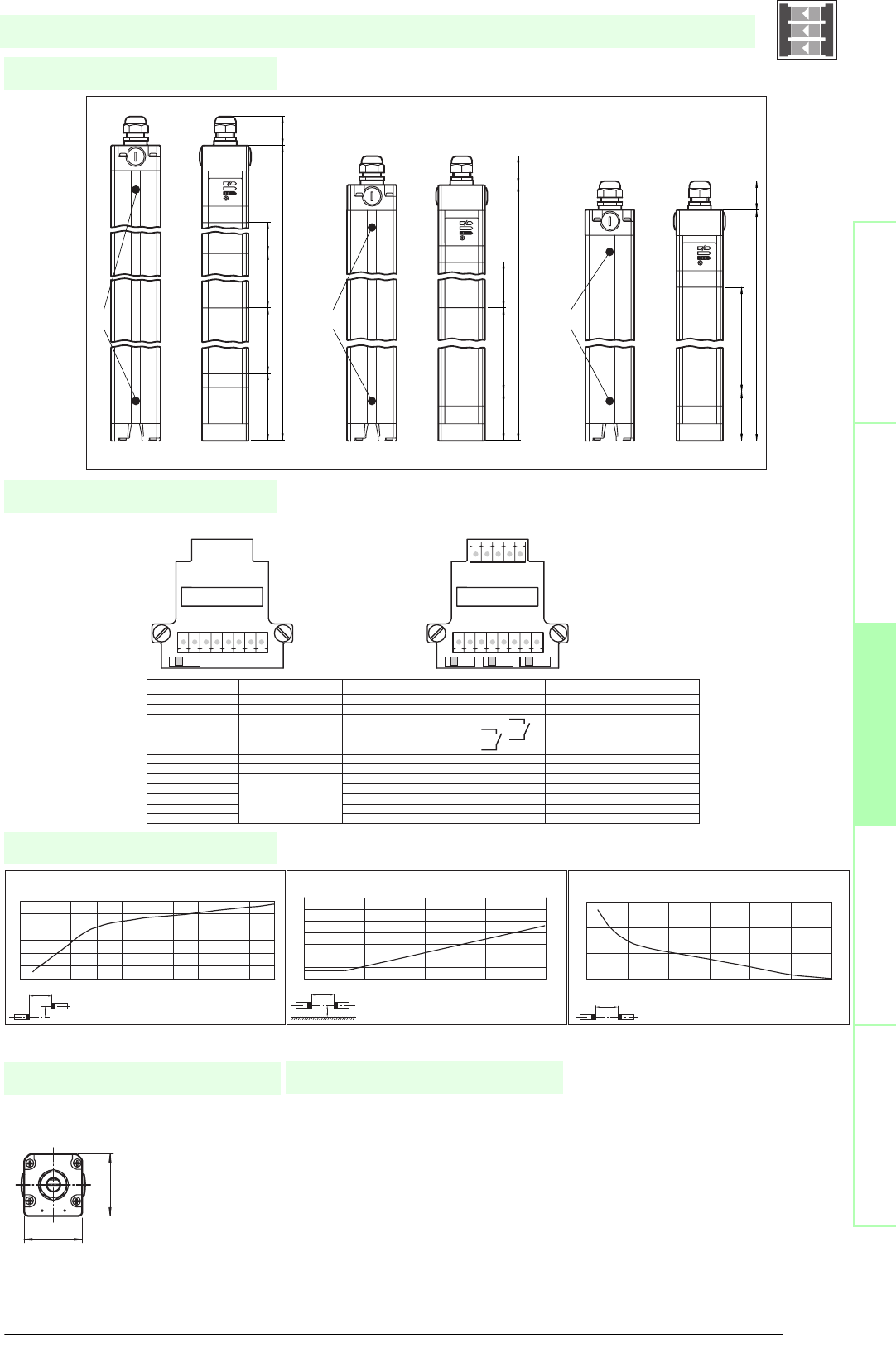
59
S
ubject to reasonable modifications due to technical advances. Copyright Pepperl+Fuchs, Printed in Germany
Pepperl+Fuchs Group • Tel.: Germany +49 621 776-0 • USA +1 330 4253555 • Singapore +65 67799091 • Internet http://www.pepperl-fuchs.com
Diagrams
Electrical connection
Dimensions
Safety through beam
sensors
Safety light gridsSafety light grids with
internal control unit
Safety light curtainsControl units
Profile dimensions, front view
Additional information
52
55
SLC-./133
x
y
SLC-2 / SLC-3 / SLC-4
Distance X [m]
Offset Y [mm]
Characteristic response curve
0
50
100
150
200
250
300
0246 8101214161820
x
y
SLC-2 / SLC-3 / SLC-4
Distance X [m]
Lateral interval to mirroring surfaces
Minimum interval [m]
0 2 4 6 8 10 12
0
0.2
0.4
0.6
0.8
1
1.2
1.4
x
SLC-2 / SLC-3 / SLC-4
Distance X [m]
Stability control
Relative received light strength
1
10
100
1000
0 5 10 15 20 25 30
Date of edition 05/17/2006
Emitter: Receiver:
terminal emitter receiver (relay output) receiver (semiconductor output)
X1:1 Functional earth Functional earth Functional earth
X1:2 test (input) Test (input)
X1:3 OSSD2.2 (output) 0 V OSSD
X1:4 OSSD1.2 (output) 24 V OSSD
X1:5 OSSD2.1 (output) OSSD2 (output)
X1:6 OSSD1.1 (output) OSSD1 (output)
X1:7 0 V AC/DC 0 V AC/DC 0 V DC
X1:8 24 V AC/DC 24 V AC/DC 24 V DC
X2:1 Start release (output) Start release (output)
X2:2 Status OSSD (output) Status OSSD (output)
X2:3 not placed on board 24 V reference potential for I/O n. c.
X2:4 0 V reference potential for I/O n. c.
x2:5 Startup readiness (input) Startup readiness (input)
S1 S1 S2 S3
X1 X1
X2
87654321
123 4 5
Ground clamp
Ground clamp
Ground clamp
89.6
89.6
~ 35
1157
300300300139,6
~ 351007
400400
~ 35707
500
SLC-2SLC-3SLC-4
Safety light grid with integrated control unit
• Mounting set SLC
• Protective glass pieces for SLC (to
protect the optically functional sur-
face)
• Lateral screwed connection SLC
• Mirror 2, 3 or 4-beam for
SLC (for multi-side securing of haz-
ardous areas)
• Laser alignment aid BA SLC
System accessories • Profile alignment aid PA SLP/SLC
• Ground pillar UC SLP/SLC
• Housing for ground pillar
Enclosure UC SLP/SLC
• Collision protector
Damping UC SLP/SLC

Subject to reasonable modifications due to technical advances. Copyright Pepperl+Fuchs, Printed in Germany
Pepperl+Fuchs Group • Tel.: Germany +49 621 776-0 • USA +1 330 4253555 • Singapore +65 67799091 • Internet http://www.pepperl-fuchs.com
60
Technische DatenTechnical data
Features
Ordering code:
Sicherheits-Lichtschranken
Sicherheits-Lichtgitter
Sicherheits-Lichtgitter mit
interner Auswerteeinheit
Sicherheits-Lichtvorhänge
Auswertegeräte Safety through beam
sensors
Safety light grids
Safety light grigs with
internal control unit
Safety light curtains
Control units
SLPC8-2
SLPC8-2/31
Focke Ident-No.
Effective detection range
0.2 ... 8 m
XX
Light source
LED
X X
Approvals
TÜV
XX
Tests
IEC/EN 61496
X X
Marking
CE
XX
Obstacle size
static: 32 mm
dynamic: 50 mm (at v = 1.6 m/s of the obstacle)
X X
Beam spacing
500 mm
XX
Number of beams
2
X X
Safety category according to IEC/EN 61496
4
XX
Operating mode
Start/restart disable, relay monitor,
X X
Light type
red, modulated light
XX
Angle of divergence
< 5 °
X X
Diagnosis display
7-segment display
XX
Function display
LED red: per receiver channel
off: interruption, flashes: receiver, continuously on: reception with sufficient stability control
on the front plate: LED red: OSSD off, LED green: OSSD on
X X
Pre-fault indication
LED red next to receiver flashes
XX
Operating elements
10 DIP switch in transceiver terminal compartment
X X
Operating voltage
24 V DC -15 % / +25 % , electrically isolated
XX
Protection class
III
X X
No-load supply current
max. 250 mA
XX
Activation current
approx. 10 mA
X X
Activation time
0.03 ... 1 s
XX
Test i n pu t
Reset-input for system test
X X
Function input
Relay monitor, start release
XX
Output of the pre-fault indication
1 PNP, +UB -2 V, max. 300 mA
X X
Safety output
2 separated fail safe semiconductor outputs
X
2 relay outputs, compelled connection NO-contact
X
Signal output
1 PNP each, max. 300 mA for start readiness, OSSD on, OSSD off
XX
Switching voltage
Operating voltage -2 V
X
20 ... 60 V DC, 12 ... 25 V AC rms
X
Switching current
max. 0.5 A
X
0.01 ... 2 A
X
Switch power
100 VA
X
Response time
20 ms
X
40 ms
X
Ambient temperature
0 ... 50 °C (273 ... 323 K)
XX
Storage temperature
-20 ... 70 °C (253 ... 343 K)
X X
Relative humidity
max. 95 %, not condensing
XX
Protection degree
IP65
X X
Connection
Cable screwed connection M16 , terminal compartment with cage-terminals
XX
Connection options
Further electrical connection options on request: Plug connector DIN 43 651 Hirschmann, emitter: 6-pin+PE, receiver: 11-pin+PE
X X
Housing
aluminium extruded structural profile, RAL 1021 (yellow) coated
XX
Optical face
Plastic pane
X X
Mass
Per 2300 g
XX
System components
Transceiver
SLPC8-2-A
X
SLPC8-2-A/31
X
Mirror pillar
SLP8-2-M
XX
SLPC8-2/..
• Detection range up to 8 m
• 2-Radial design
• Beam spacing 500 mm
• Self-monitoring (type 4 according to IEC/EN 61496-1)
• Minimum wiring expense due to transceiver with passive mirror column
• Red transmission light
• Usable with or without start/restart disable
• Integrated relay monitor
• 7-segment diagnostic display
• Pre-fault indication
• OSSD outputs as semiconductor or relay outputs
Date of edition 05/17/2006
Safety light grid with integrated control unit
For suitable cable sockets, mounting aids, redirection mirrors and more refer to chapter „Accessories“.
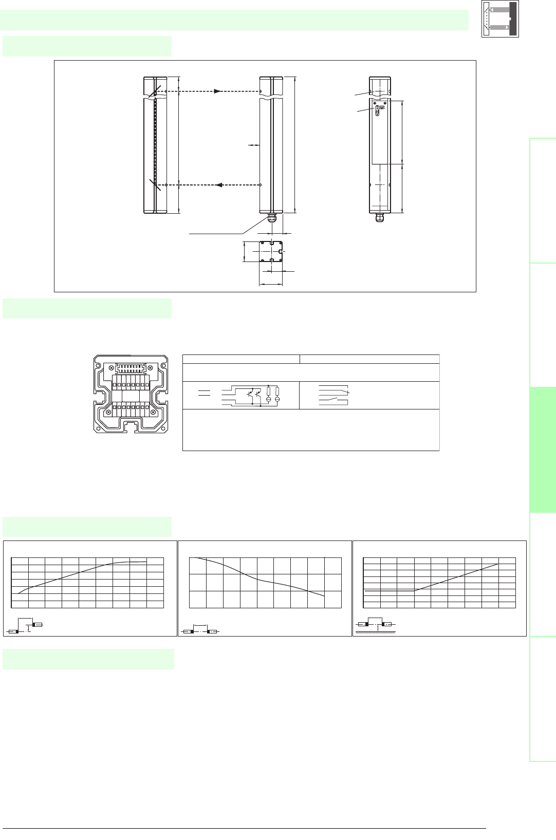
61
S
ubject to reasonable modifications due to technical advances. Copyright Pepperl+Fuchs, Printed in Germany
Pepperl+Fuchs Group • Tel.: Germany +49 621 776-0 • USA +1 330 4253555 • Singapore +65 67799091 • Internet http://www.pepperl-fuchs.com
Diagrams
Electrical connection
Dimensions
Safety through beam
sensors
Safety light gridsSafety light grids with
internal control unit
Safety light curtainsControl units
• Mounting set MS SLP
• Profile alignment aid PA SLP/SLC
• Laser alignment aid BA SLP
• Ground pillar UC SLP/SLC
• Housing for pillar
Enclosure UC SLP/SLC
• Collision protector
Damping UC SLP/SLC
• Redirection mirror for multi-side
protection of hazardous areas
SLP-2-M
System accessories
SLPC8-2/..
x
y
SLP8
Offset Y [mm]
Distance X [m]
Characteristic response curve
0
10
20
30
40
50
60
70
0123456789
x
SLP8
Distance X [m]
Stability control
Relative received light strength
1
10
100
1000
0123456789
x
y
SLP8
Distance X [m]
Lateral interval to mirroring surfaces
Minimum interval [m]
0
0.05
0.1
0.15
0.2
0.25
0.3
0.35
0.4
0123456789
Date of edition 05/17/2006
Transceiver SLPC8-2-A
Transceiver SLPC... (semiconductor output) Transceiver SLPC.../31 (relay output)
1 - Functional earth
2- 0 V
3 - 24 V
4 - n.c. 4
5- 5
6- 6
7 - OSSD 1 7
8 - OSSD 2 8
9 - Input, Relay monitor
10 - Input, Start release
11 - Input, Reset
12 - PNP-output, Soiled optics
13 - n.c.
14 - PNP-output, Startup readiness
15 - PNP-output, Indicator OSSD OFF
16 - PNP-output, Indicator OSSD ON
1 2 3 4 5 6 7 8
16
15
14
13
12
11
10
9
-
+
Cable gland M16
Transceiver SLPC8-2-A
Status indicator
safety beam
System status
indicator
Mirror SLP8-2-M
H
64
32
70
33.5
156 203
636
90 500 46
Safety light grid with integrated control unit

Subject to reasonable modifications due to technical advances. Copyright Pepperl+Fuchs, Printed in Germany
Pepperl+Fuchs Group • Tel.: Germany +49 621 776-0 • USA +1 330 4253555 • Singapore +65 67799091 • Internet http://www.pepperl-fuchs.com
62
Technische DatenTechnical data
Features
Ordering code:
Sicherheits-Lichtschranken
Sicherheits-Lichtgitter
Sicherheits-Lichtgitter mit
interner Auswerteeinheit
Sicherheits-Lichtvorhänge
Auswertegeräte Safety through beam
sensors
Safety light grids
Safety light grigs with
internal control unit
Safety light curtains
Control units
SLPC10-2
SLPC10-2/31
Effective detection range
0.2 ... 10 m
X X
Light source
LED
XX
Approvals
TÜV
X X
Tests
IEC/EN 61496
XX
Marking
CE
X X
Obstacle size
static: 32 mm
dynamic: 50 mm (at v = 1.6 m/s of the obstacle)
XX
Beam spacing
500 mm
X X
Number of beams
2
XX
Safety category according to IEC/EN 61496
4
X X
Operating mode
Start/restart disable, relay monitor,
XX
Light type
red, modulated light
X X
Angle of divergence
< 5 °
XX
Diagnosis display
7-segment display
X X
Function display
LED red: per receiver channel
off: interruption, flashes: receiver, continuously on: reception with sufficient stability control
on the front plate: LED red: OSSD off, LED green: OSSD on
XX
Pre-fault indication
LED red next to receiver flashes
X X
Operating elements
10 DIP switch in receiver terminal compartment
XX
Operating voltage
24 V DC -15 % / +25 % , electrically isolated
X X
Protection class
III
XX
No-load supply current
max. 250 mA
X X
Activation current
approx. 10 mA
XX
Activation time
0.03 ... 1 s
X X
Test i n pu t
Reset-input for system test
XX
Function input
Relay monitor, start release
X X
Output of the pre-fault indication
1 PNP, +UB -2 V, max. 300 mA
XX
Safety output
2 separated fail safe semiconductor outputs
X
2 relay outputs, compelled connection NO-contact
X
Signal output
1 PNP each, max. 300 mA for start readiness, OSSD on, OSSD off
X X
Switching voltage
Operating voltage -2 V
X
20 ... 60 V DC, 12 ... 25 V AC rms
X
Switching current
max. 0.5 A
X
0.01 ... 2 A
X
Switch power
100 VA
X
Response time
20 ms
X
40 ms
X
Ambient temperature
0 ... 50 °C (273 ... 323 K)
X X
Storage temperature
-20 ... 70 °C (253 ... 343 K)
XX
Relative humidity
max. 95 %, not condensing
X X
Protection degree
IP65
XX
Connection
Cable screwed connection M16 , terminal compartment with cage-terminals, M12-connector for emitter
X X
Connection options
Further electrical connection options on request: Plug connector DIN 43 651 Hirschmann, emitter: 6-pin+PE, receiver: 11-pin+PE
XX
Housing
aluminium extruded structural profile, RAL 1021 (yellow) coated
X X
Optical face
Plastic pane
XX
Mass
Per 2300 g
X X
System components
Emitter
SLP10-2-T
X X
Receiver
SLPC10-2-R
X
SLPC10-2-R/31
X
SLPC10-2/..
• Detection range up to 10 m
• 2-Radial design
• Beam spacing 500 mm
• Self-monitoring (type 4 according to IEC/EN 61496-1)
• Red transmission light
• Usable with or without start/restart disable
• Integrated relay monitor
• 7-segment diagnostic display
• Integrated function display
• Pre-fault indication
• OSSD outputs as semiconductor or relay outputs
Date of edition 05/17/2006
Safety light grid with integrated control unit
For suitable cable sockets, mounting aids, redirection mirrors and more refer to chapter „Accessories“.
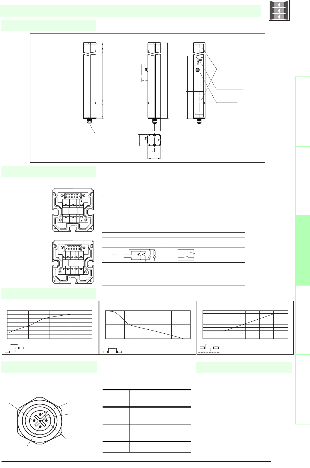
63
S
ubject to reasonable modifications due to technical advances. Copyright Pepperl+Fuchs, Printed in Germany
Pepperl+Fuchs Group • Tel.: Germany +49 621 776-0 • USA +1 330 4253555 • Singapore +65 67799091 • Internet http://www.pepperl-fuchs.com
Diagrams
Electrical connection
Dimensions
Safety through beam
sensors
Safety light gridsSafety light grids with
internal control unit
Safety light curtainsControl units
Socket assignment on the front side
of the device
Additional information
4
3
1
5
2
SLPC10-2/..
x
y
SLP10-x / SLPC10-x / SLPCM10-x
Offset Y [mm]
Distance X [m]
Characteristic response curve
0
20
40
60
80
100
120
140
0 5 10 15 20
x
SLP10-x / SLPC10-x / SLPCM10-x
Distance X [m]
Stability control
Relative received light strength
1
10
100
0 2 4 6 8 1012141618
x
y
SLP10-x / SLPC10-x / SLPCM10-x
Distance X [m]
Lateral interval to mirroring surfaces
Minimum interval [m]
0
0.05
0.1
0.15
0.2
0.25
0.3
0.35
0.4
0.45
0.5
0 2 4 6 8 10 12
Date of edition 05/17/2006
Emitter SLP
Receiver SLPC
T1 - Emitter channel 1
T2 - Emitter channel 2
-0 V
Receiver SLPC (semiconductor outputs) Receiver SLPC/31 (Relay outputs)
1 - Functional earth
2 - 0 V
3 - 24 V
4 - n.c. 4
5- 5
6- 6
7 - OSSD 1 7
8 - OSSD 2 8
9 - Input, Relay monitor
10 - Input, Start release
11 - Input, Reset
12 - PNP-output, Soiled optics
13 - n.c.
14 - PNP-output, Startup readiness
15 - PNP-output, Indicator OSSD OFF
16 - PNP-output, Indicator OSSD ON
1 2 3 4 5 6 7 8
16
15
14
13
12
11
10
9
T5 T6 T7 T8
NC
T1 T2 T3 T4
NC
-
+
SLPC...-2
T1-T4
Cable gland M16
Emitter SLP...-2-T
beam 2
beam 1
Receiver SLPC...-2-R
Status indicator
of the particular
safety beam
Status indicator
of the system
Connector
Emitter SLP
H
64
32
70
33.5
156 203
636
90 500 46
Safety light grid with integrated control unit
T1 - T4 transmitter control
Sock-
et
Function
1 Transmitter channel
1
2 Transmitter channel
2
30 V
• Mounting set MS SLP
• Profile alignment aid PA SLP/SLC
• Laser alignment aid BA SLP
• Ground pillar UC SLP/SLC
• Housing for pillar
Enclosure UC SLP/SLC
• Collision protector
Damping UC SLP/SLC
• Redirection mirror for multi-side
protection of hazardous areas
System accessories

Subject to reasonable modifications due to technical advances. Copyright Pepperl+Fuchs, Printed in Germany
Pepperl+Fuchs Group • Tel.: Germany +49 621 776-0 • USA +1 330 4253555 • Singapore +65 67799091 • Internet http://www.pepperl-fuchs.com
64
Technische DatenTechnical data
Features
Ordering code:
Sicherheits-Lichtschranken
Sicherheits-Lichtgitter
Sicherheits-Lichtgitter mit
interner Auswerteeinheit
Sicherheits-Lichtvorhänge
Auswertegeräte Safety through beam
sensors
Safety light grids
Safety light grigs with
internal control unit
Safety light curtains
Control units
SLPC30-2
SLPC30-2/31
Effective detection range
6 ... 30 m
X X
Light source
LED
XX
Approvals
TÜV
X X
Tests
IEC/EN 61496
XX
Marking
CE
X X
Obstacle size
static: 32 mm
dynamic: 50 mm (at v = 1.6 m/s of the obstacle)
XX
Beam spacing
500 mm
X X
Number of beams
2
XX
Safety category according to IEC/EN 61496
4
X X
Operating mode
Start/restart disable, relay monitor,
XX
Light type
red, modulated light
X X
Angle of divergence
< 5 °
XX
Diagnosis display
7-segment display
X X
Function display
LED red: per receiver channel
off: interruption, flashes: receiver, continuously on: reception with sufficient stability control
on the front plate: LED red: OSSD off, LED green: OSSD on
XX
Pre-fault indication
LED red next to receiver flashes
X X
Operating elements
10 DIP switch in receiver terminal compartment
XX
Operating voltage
24 V DC -15 % / +25 % , electrically isolated
X X
Protection class
III
XX
No-load supply current
max. 250 mA
X X
Activation current
approx. 10 mA
XX
Activation time
0.03 ... 1 s
X X
Test i n pu t
Reset-input for system test
XX
Function input
Relay monitor, start release
X X
Output of the pre-fault indication
1 PNP, +UB -2 V, max. 300 mA
XX
Safety output
2 separated fail safe semiconductor outputs
X
2 relay outputs, compelled connection NO-contact
X
Signal output
1 PNP each, max. 300 mA for start readiness, OSSD on, OSSD off
X X
Switching voltage
Operating voltage -2 V
X
20 ... 60 V DC, 12 ... 25 V AC rms
X
Switching current
max. 0.5 A
X
0.01 ... 2 A
X
Switch power
100 VA
X
Response time
20 ms
X
40 ms
X
Ambient temperature
0 ... 50 °C (273 ... 323 K)
X X
Storage temperature
-20 ... 70 °C (253 ... 343 K)
XX
Relative humidity
max. 95 %, not condensing
X X
Protection degree
IP65
XX
Connection
Cable screwed connection M16 , terminal compartment with cage-terminals, M12-connector for emitter
X X
Connection options
Further electrical connection options on request: Plug connector DIN 43 651 Hirschmann, emitter: 6-pin+PE, receiver: 11-pin+PE
XX
Housing
aluminium extruded structural profile, RAL 1021 (yellow) coated
X X
Optical face
Plastic pane
XX
Mass
Per 2300 g
X X
System components
Emitter
SLP30-2-T
X X
Receiver
SLPC30-2-R
X
SLPC30-2-R/31
X
SLPC30-2/..
• Detection range up to 30 m
• 2-Radial design
• Beam spacing 500 mm
• Self-monitoring (type 4 according to IEC/EN 61496-1)
• Red transmission light
• Usable with or without start/restart disable
• Integrated relay monitor
• 7-segment diagnostic display
• Integrated function display
• Pre-fault indication
• OSSD outputs as semiconductor or relay outputs
Date of edition 05/17/2006
Safety light grid with integrated control unit
For suitable cable sockets, mounting aids, redirection mirrors and more refer to chapter „Accessories“.
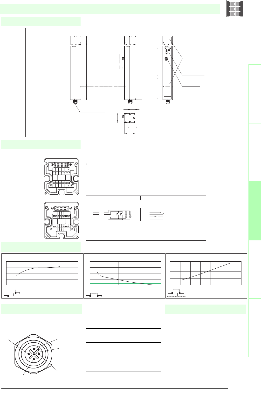
65
S
ubject to reasonable modifications due to technical advances. Copyright Pepperl+Fuchs, Printed in Germany
Pepperl+Fuchs Group • Tel.: Germany +49 621 776-0 • USA +1 330 4253555 • Singapore +65 67799091 • Internet http://www.pepperl-fuchs.com
Diagrams
Electrical connection
Dimensions
Safety through beam
sensors
Safety light gridsSafety light grids with
internal control unit
Safety light curtainsControl units
Socket assignment on the front side
of the device
Additional information
4
3
1
5
2
SLPC30-2/..
x
y
SLP30-x / SLPC30-x / SLPCM30-x
Offset Y [mm]
Distance X [m]
Characteristic response curve
0
50
100
150
200
010203040
x
SLP30-x / SLPC30-x / SLPCM30-x
Distance X [m]
Stability control
Relative received light strength
1
10
100
1000
10000
0 1020304050
x
y
SLP30-x / SLPC30-x / SLPCM30-x
Distance X [m]
Lateral interval to mirroring surfaces
Minimum interval [m]
0
0.2
0.4
0.6
0.8
1
1.2
1.4
0 5 10 15 20 25 30 35
Date of edition 05/17/2006
Emitter SLP
Receiver SLPC
T1 - Emitter channel 1
T2 - Emitter channel 2
-0 V
Receiver SLPC (semiconductor outputs) Receiver SLPC/31 (Relay outputs)
1 - Functional earth
2 - 0 V
3 - 24 V
4 - n.c. 4
5- 5
6- 6
7 - OSSD 1 7
8 - OSSD 2 8
9 - Input, Relay monitor
10 - Input, Start release
11 - Input, Reset
12 - PNP-output, Soiled optics
13 - n.c.
14 - PNP-output, Startup readiness
15 - PNP-output, Indicator OSSD OFF
16 - PNP-output, Indicator OSSD ON
1 2 3 4 5 6 7 8
16
15
14
13
12
11
10
9
T5 T6 T7 T8
NC
T1 T2 T3 T4
NC
-
+
SLPC...-2
T1-T4
Cable gland M16
Emitter SLP...-2-T
beam 2
beam 1
Receiver SLPC...-2-R
Status indicator
of the particular
safety beam
Status indicator
of the system
Connector
Emitter SLP
H
64
32
70
33.5
156 203
636
90 500 46
Safety light grid with integrated control unit
T1 - T4 transmitter control
Sock-
et
Function
1 Transmitter channel
1
2 Transmitter channel
2
30 V
• Mounting set MS SLP
• Profile alignment aid PA SLP/SLC
• Laser alignment aid BA SLP
• Ground pillar UC SLP/SLC
• Housing for pillar
Enclosure UC SLP/SLC
• Collision protector
Damping UC SLP/SLC
• Redirection mirror for multi-side
protection of hazardous areas
SLP-2-M
System accessories

Subject to reasonable modifications due to technical advances. Copyright Pepperl+Fuchs, Printed in Germany
Pepperl+Fuchs Group • Tel.: Germany +49 621 776-0 • USA +1 330 4253555 • Singapore +65 67799091 • Internet http://www.pepperl-fuchs.com
66
Technische DatenTechnical data
Features
Ordering code:
Sicherheits-Lichtschranken
Sicherheits-Lichtgitter
Sicherheits-Lichtgitter mit
interner Auswerteeinheit
Sicherheits-Lichtvorhänge
Auswertegeräte Safety through beam
sensors
Safety light grids
Safety light grigs with
internal control unit
Safety light curtains
Control units
SLPC65-2
SLPC65-2/31
Effective detection range
12 ... 65 m
X X
Light source
LED
XX
Approvals
TÜV
X X
Tests
IEC/EN 61496
XX
Marking
CE
X X
Obstacle size
static: 32 mm
dynamic: 50 mm (at v = 1.6 m/s of the obstacle)
XX
Beam spacing
500 mm
X X
Number of beams
2
XX
Safety category according to IEC/EN 61496
4
X X
Operating mode
Start/restart disable, relay monitor,
XX
Light type
red, modulated light
X X
Angle of divergence
< 5 °
XX
Diagnosis display
7-segment display
X X
Function display
LED red: per receiver channel
off: interruption, flashes: receiver, continuously on: reception with sufficient stability control
on the front plate: LED red: OSSD off, LED green: OSSD on
XX
Pre-fault indication
LED red next to receiver flashes
X X
Operating elements
10 DIP switch in receiver terminal compartment
XX
Operating voltage
24 V DC -15 % / +25 % , electrically isolated
X X
Protection class
III
XX
No-load supply current
max. 250 mA
X X
Activation current
approx. 10 mA
XX
Activation time
0.03 ... 1 s
X X
Test i n pu t
Reset-input for system test
XX
Function input
Relay monitor, start release
X X
Output of the pre-fault indication
1 PNP, +UB -2 V, max. 300 mA
XX
Safety output
2 separated fail safe semiconductor outputs
X
2 relay outputs, compelled connection NO-contact
X
Signal output
1 PNP each, max. 300 mA for start readiness, OSSD on, OSSD off
X X
Switching voltage
Operating voltage -2 V
X
20 ... 60 V DC, 12 ... 25 V AC rms
X
Switching current
max. 0.5 A
X
0.01 ... 2 A
X
Switch power
100 VA
X
Response time
20 ms
X
40 ms
X
Ambient temperature
0 ... 50 °C (273 ... 323 K)
X X
Storage temperature
-20 ... 70 °C (253 ... 343 K)
XX
Relative humidity
max. 95 %, not condensing
X X
Protection degree
IP65
XX
Connection
Cable screwed connection M16 , terminal compartment with cage-terminals, M12-connector for emitter
X X
Connection options
Further electrical connection options on request: Plug connector DIN 43 651 Hirschmann, emitter: 6-pin+PE, receiver: 11-pin+PE
XX
Housing
aluminium extruded structural profile, RAL 1021 (yellow) coated
X X
Optical face
Plastic pane
XX
Mass
Per 2300 g
X X
System components
Emitter
SLP65-2-T
X X
Receiver
SLPC65-2-R
X
SLPC65-2-R/31
X
SLPC65-2/..
• Detection range up to 65 m
• 2-Radial design
• Beam spacing 500 mm
• Self-monitoring (type 4 according to IEC/EN 61496-1)
• Red transmission light
• Usable with or without start/restart disable
• Integrated relay monitor
• 7-segment diagnostic display
• Integrated function display
• Pre-fault indication
• OSSD outputs as semiconductor or relay outputs
Date of edition 05/17/2006
Safety light grid with integrated control unit
For suitable cable sockets, mounting aids, redirection mirrors and more refer to chapter „Accessories“.
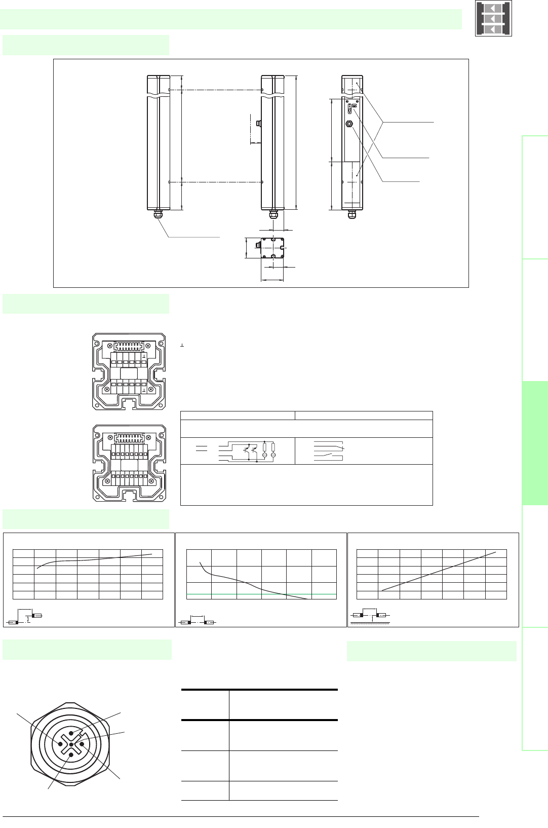
67
S
ubject to reasonable modifications due to technical advances. Copyright Pepperl+Fuchs, Printed in Germany
Pepperl+Fuchs Group • Tel.: Germany +49 621 776-0 • USA +1 330 4253555 • Singapore +65 67799091 • Internet http://www.pepperl-fuchs.com
Diagrams
Electrical connection
Dimensions
Safety through beam
sensors
Safety light gridsSafety light grids with
internal control unit
Safety light curtainsControl units
Socket assignment on the front side
of the device
Additional information
4
3
1
5
2
SLPC65-2/..
x
y
SLP65-x / SLPC65-x / SLPCM65-x
Offset Y [mm]
Distance X [m]
Characteristic response curve
0
50
100
150
200
250
300
0 10203040506070
x
SLP65-x / SLPC65-x / SLPCM65-x
Distance X [m]
Stability control
Relative received light strength
1
10
100
1000
0 20 40 60 80 100 120
x
y
SLP65-x / SLPC65-x / SLPCM65-x
Distance X [m]
Lateral interval to mirroring surfaces
Minimum interval [m]
0
0.5
1
1.5
2
2.5
3
0 10203040506070
Date of edition 05/17/2006
Emitter SLP
Receiver SLPC
T1 - Emitter channel 1
T2 - Emitter channel 2
-0 V
Receiver SLPC (semiconductor outputs) Receiver SLPC/31 (Relay outputs)
1 - Functional earth
2 - 0 V
3 - 24 V
4 - n.c. 4
5- 5
6- 6
7 - OSSD 1 7
8 - OSSD 2 8
9 - Input, Relay monitor
10 - Input, Start release
11 - Input, Reset
12 - PNP-output, Soiled optics
13 - n.c.
14 - PNP-output, Startup readiness
15 - PNP-output, Indicator OSSD OFF
16 - PNP-output, Indicator OSSD ON
1 2 3 4 5 6 7 8
16
15
14
13
12
11
10
9
T5 T6 T7 T8
NC
T1 T2 T3 T4
NC
-
+
SLPC...-2
T1-T4
Cable gland M16
Emitter SLP...-2-T
beam 2
beam 1
Receiver SLPC...-2-R
Status indicator
of the particular
safety beam
Status indicator
of the system
Connector
Emitter SLP
H
64
32
70
33.5
156 203
636
90 500 46
Safety light grid with integrated control unit
T1 - T4 transmitter control
Sock-
et
Function
1 Transmitter channel
1
2 Transmitter channel
2
30 V
• Mounting set MS SLP
• Profile alignment aid PA SLP/SLC
• Laser alignment aid BA SLP
• Ground pillar UC SLP/SLC
• Housing for pillar
Enclosure UC SLP/SLC
• Collision protector
Damping UC SLP/SLC
• Redirection mirror for multi-side
protection of hazardous areas
SLP-2-M
System accessories

Subject to reasonable modifications due to technical advances. Copyright Pepperl+Fuchs, Printed in Germany
Pepperl+Fuchs Group • Tel.: Germany +49 621 776-0 • USA +1 330 4253555 • Singapore +65 67799091 • Internet http://www.pepperl-fuchs.com
68
Technische DatenTechnical data
Features
Ordering code:
Sicherheits-Lichtschranken
Sicherheits-Lichtgitter
Sicherheits-Lichtgitter mit
interner Auswerteeinheit
Sicherheits-Lichtvorhänge
Auswertegeräte Safety through beam
sensors
Safety light grids
Safety light grigs with
internal control unit
Safety light curtains
Control units
SLPC10-3
SLPC10-3/31
Effective detection range
0.2 ... 10 m
X X
Light source
LED
XX
Approvals
TÜV
X X
Tests
IEC/EN 61496
XX
Marking
CE
X X
Obstacle size
static: 32 mm
dynamic: 50 mm (at v = 1.6 m/s of the obstacle)
XX
Beam spacing
400 mm
X X
Number of beams
3
XX
Safety category according to IEC/EN 61496
4
X X
Operating mode
Start/restart disable, relay monitor,
XX
Light type
red, modulated light
X X
Angle of divergence
< 5 °
XX
Diagnosis display
7-segment display
X X
Function display
LED red: per receiver channel
off: interruption, flashes: receiver, continuously on: reception with sufficient stability control
on the front plate: LED red: OSSD off, LED green: OSSD on
XX
Pre-fault indication
LED red next to receiver flashes
X X
Operating elements
10 DIP switch in receiver terminal compartment
XX
Operating voltage
24 V DC -15 % / +25 % , electrically isolated
X X
Protection class
III
XX
No-load supply current
max. 250 mA
X X
Activation current
approx. 10 mA
XX
Activation time
0.03 ... 1 s
X X
Test i n pu t
Reset-input for system test
XX
Function input
Relay monitor, start release
X X
Output of the pre-fault indication
1 PNP, +UB -2 V, max. 300 mA
XX
Safety output
2 separated fail safe semiconductor outputs
X
2 relay outputs, compelled connection NO-contact
X
Signal output
1 PNP each, max. 300 mA for start readiness, OSSD on, OSSD off
X X
Switching voltage
Operating voltage -2 V
X
20 ... 60 V DC, 12 ... 25 V AC rms
X
Switching current
max. 0.5 A
X
0.01 ... 2 A
X
Switch power
100 VA
X
Response time
20 ms
X
40 ms
X
Ambient temperature
0 ... 50 °C (273 ... 323 K)
X X
Storage temperature
-20 ... 70 °C (253 ... 343 K)
XX
Relative humidity
max. 95 %, not condensing
X X
Protection degree
IP65
XX
Connection
Cable screwed connection M16 , terminal compartment with cage-terminals, M12-connector for emitter
X X
Connection options
Further electrical connection options on request: Plug connector DIN 43 651 Hirschmann, emitter: 6-pin+PE, receiver: 11-pin+PE
XX
Housing
aluminium extruded structural profile, RAL 1021 (yellow) coated
X X
Optical face
Plastic pane
XX
Mass
Per 3400 g
X X
System components
Emitter
SLP10-3-T
X X
Receiver
SLPC10-3-R
X
SLPC10-3-R/31
X
SLPC10-3/..
• Detection range up to 10 m
• 3-Radial design
• Beam spacing 400 mm
• Self-monitoring (type 4 according to IEC/EN 61496-1)
• Red transmission light
• Usable with or without start/restart disable
• Integrated relay monitor
• 7-segment diagnostic display
• Integrated function display
• Pre-fault indication
• OSSD outputs as semiconductor or relay outputs
Date of edition 05/17/2006
Safety light grid with integrated control unit
For suitable cable sockets, mounting aids, redirection mirrors and more refer to chapter „Accessories“.
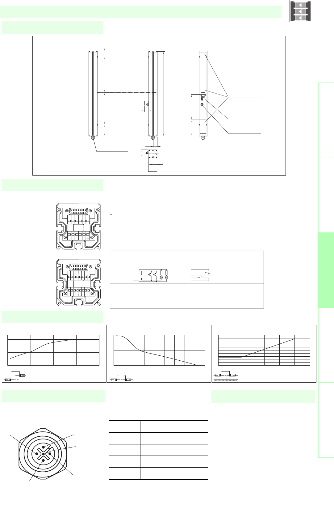
69
S
ubject to reasonable modifications due to technical advances. Copyright Pepperl+Fuchs, Printed in Germany
Pepperl+Fuchs Group • Tel.: Germany +49 621 776-0 • USA +1 330 4253555 • Singapore +65 67799091 • Internet http://www.pepperl-fuchs.com
Diagrams
Electrical connection
Dimensions
Safety through beam
sensors
Safety light gridsSafety light grids with
internal control unit
Safety light curtainsControl units
Socket assignment on the front side
of the device
Additional information
4
3
1
5
2
SLPC10-3/..
x
y
SLP10-x / SLPC10-x / SLPCM10-x
Offset Y [mm]
Distance X [m]
Characteristic response curve
0
20
40
60
80
100
120
140
0 5 10 15 20
x
SLP10-x / SLPC10-x / SLPCM10-x
Distance X [m]
Stability control
Relative received light strength
1
10
100
0 2 4 6 8 1012141618
x
y
SLP10-x / SLPC10-x / SLPCM10-x
Distance X [m]
Lateral interval to mirroring surfaces
Minimum interval [m]
0
0.05
0.1
0.15
0.2
0.25
0.3
0.35
0.4
0.45
0.5
0 2 4 6 8 10 12
Date of edition 05/17/2006
Emitter SLP
Receiver SLPC
T1 - Emitter channel 1
T2 - Emitter channel 2
T3 - Emitter channel 3
-0 V
Receicer SLPC (semiconductor outputs) Receiver SLPC/31 (Relay outputs)
1 - Functional earth
2 - 0 V
3 - 24 V
4 - n.c. 4
5- 5
6- 6
7 - OSSD 1 7
8 - OSSD 2 8
9 - input, Relay monitor
10 - input, Start release
11 - input, Reset
12 - PNP-output, Soiled optics
13 - n.c.
14 - PNP-output, Startup readiness
15 - PNP-output, Indicator OSSD OFF
16 - PNP-output, Indicator OSSD ON
1 2 3 4 5 6 7 8
16
15
14
13
12
11
10
9
T5 T6 T7 T8
NC
T1 T2 T3 T4
NC
-
+
SLPC...-3
T1-T4
Receiver SLPC...-3-R
Emitter SLP...-3-T
Connector
Emitter SLP
beam 2
beam 1
beam 3
Cable gland M16
Status indicator
of the particular
safety beam
Status indicator
of the system
H
64
32
70
33.5
156 203
936
90 400 400 46
Safety light grid with integrated control unit
T1 - T4 transmitter control
Socket Function
1 Transmitter channel 1
2 Transmitter channel 2
30 V
4 Transmitter channel 3
• Mounting set MS SLP
• Profile alignment aid PA SLP/SLC
• Laser alignment aid BA SLP
• Ground pillar UC SLP/SLC
• Housing for pillar
Enclosure UC SLP/SLC
• Collision protector
Damping UC SLP/SLC
• Redirection mirror for multi-side
protection of hazardous areas
SLP-3-M
System accessories

Subject to reasonable modifications due to technical advances. Copyright Pepperl+Fuchs, Printed in Germany
Pepperl+Fuchs Group • Tel.: Germany +49 621 776-0 • USA +1 330 4253555 • Singapore +65 67799091 • Internet http://www.pepperl-fuchs.com
70
Technische DatenTechnical data
Features
Ordering code:
Sicherheits-Lichtschranken
Sicherheits-Lichtgitter
Sicherheits-Lichtgitter mit
interner Auswerteeinheit
Sicherheits-Lichtvorhänge
Auswertegeräte Safety through beam
sensors
Safety light grids
Safety light grigs with
internal control unit
Safety light curtains
Control units
SLPC30-3
SLPC30-3/31
Effective detection range
6 ... 30 m
X X
Light source
LED
XX
Approvals
TÜV
X X
Tests
IEC/EN 61496
XX
Marking
CE
X X
Obstacle size
static: 32 mm
dynamic: 50 mm (at v = 1.6 m/s of the obstacle)
XX
Beam spacing
400 mm
X X
Number of beams
3
XX
Safety category according to IEC/EN 61496
4
X X
Operating mode
Start/restart disable, relay monitor,
XX
Light type
red, modulated light
X X
Angle of divergence
< 5 °
XX
Diagnosis display
7-segment display
X X
Function display
LED red: per receiver channel
off: interruption, flashes: receiver, continuously on: reception with sufficient stability control
on the front plate: LED red: OSSD off, LED green: OSSD on
XX
Pre-fault indication
LED red next to receiver flashes
X X
Operating elements
10 DIP switch in receiver terminal compartment
XX
Operating voltage
24 V DC -15 % / +25 % , electrically isolated
X X
Protection class
III
XX
No-load supply current
max. 250 mA
X X
Activation current
approx. 10 mA
XX
Activation time
0.03 ... 1 s
X X
Test i n pu t
Reset-input for system test
XX
Function input
Relay monitor, start release
X X
Output of the pre-fault indication
1 PNP, +UB -2 V, max. 300 mA
XX
Safety output
2 separated fail safe semiconductor outputs
X
2 relay outputs, compelled connection NO-contact
X
Signal output
1 PNP each, max. 300 mA for start readiness, OSSD on, OSSD off
X X
Switching voltage
Operating voltage -2 V
X
20 ... 60 V DC, 12 ... 25 V AC rms
X
Switching current
max. 0.5 A
X
0.01 ... 2 A
X
Switch power
100 VA
X
Response time
20 ms
X
40 ms
X
Ambient temperature
0 ... 50 °C (273 ... 323 K)
X X
Storage temperature
-20 ... 70 °C (253 ... 343 K)
XX
Relative humidity
max. 95 %, not condensing
X X
Protection degree
IP65
XX
Connection
Cable screwed connection M16 , terminal compartment with cage-terminals, M12-connector for emitter
X X
Connection options
Further electrical connection options on request: Plug connector DIN 43 651 Hirschmann, emitter: 6-pin+PE, receiver: 11-pin+PE
XX
Housing
aluminium extruded structural profile, RAL 1021 (yellow) coated
X X
Optical face
Plastic pane
XX
Mass
Per 3400 g
X X
System components
Emitter
SLP30-3-T
X X
Receiver
SLPC30-3-R
X
SLPC30-3-R/31
X
SLPC30-3/..
• Detection range up to 30 m
• 3-Radial design
• Beam spacing 400 mm
• Self-monitoring (type 4 according to IEC/EN 61496-1)
• Red transmission light
• Usable with or without start/restart disable
• Integrated relay monitor
• 7-segment diagnostic display
• Integrated function display
• Pre-fault indication
• OSSD outputs as semiconductor or relay outputs
Date of edition 05/17/2006
Safety light grid with integrated control unit
For suitable cable sockets, mounting aids, redirection mirrors and more refer to chapter „Accessories“.
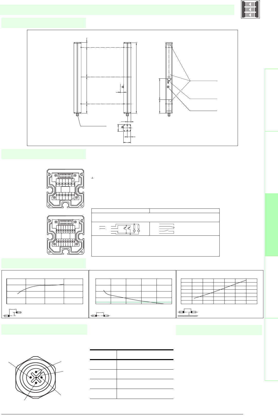
71
S
ubject to reasonable modifications due to technical advances. Copyright Pepperl+Fuchs, Printed in Germany
Pepperl+Fuchs Group • Tel.: Germany +49 621 776-0 • USA +1 330 4253555 • Singapore +65 67799091 • Internet http://www.pepperl-fuchs.com
Diagrams
Electrical connection
Dimensions
Safety through beam
sensors
Safety light gridsSafety light grids with
internal control unit
Safety light curtainsControl units
Socket assignment on the front side
of the device
Additional information
4
3
1
5
2
SLPC30-3/..
x
y
SLP30-x / SLPC30-x / SLPCM30-x
Offset Y [mm]
Distance X [m]
Characteristic response curve
0
50
100
150
200
010203040
x
SLP30-x / SLPC30-x / SLPCM30-x
Distance X [m]
Stability control
Relative received light strength
1
10
100
1000
10000
0 1020304050
x
y
SLP30-x / SLPC30-x / SLPCM30-x
Distance X [m]
Lateral interval to mirroring surfaces
Minimum interval [m]
0
0.2
0.4
0.6
0.8
1
1.2
1.4
0 5 10 15 20 25 30 35
Date of edition 05/17/2006
Emitter SLP
Receiver SLPC
T1 - Emitter channel 1
T2 - Emitter channel 2
T3 - Emitter channel 3
-0 V
Receicer SLPC (semiconductor outputs) Receiver SLPC/31 (Relay outputs)
1 - Functional earth
2 - 0 V
3 - 24 V
4 - n.c. 4
5- 5
6- 6
7 - OSSD 1 7
8 - OSSD 2 8
9 - input, Relay monitor
10 - input, Start release
11 - input, Reset
12 - PNP-output, Soiled optics
13 - n.c.
14 - PNP-output, Startup readiness
15 - PNP-output, Indicator OSSD OFF
16 - PNP-output, Indicator OSSD ON
1 2 3 4 5 6 7 8
16
15
14
13
12
11
10
9
T5 T6 T7 T8
NC
T1 T2 T3 T4
NC
-
+
SLPC...-3
T1-T4
Receiver SLPC...-3-R
Emitter SLP...-3-T
Connector
Emitter SLP
beam 2
beam 1
beam 3
Cable gland M16
Status indicator
of the particular
safety beam
Status indicator
of the system
H
64
32
70
33.5
156 203
936
90 400 400 46
Safety light grid with integrated control unit
T1 - T4 transmitter control
Socket Function
1 Transmitter channel 1
2 Transmitter channel 2
30 V
4 Transmitter channel 3
• Mounting set MS SLP
• Profile alignment aid PA SLP/SLC
• Laser alignment aid BA SLP
• Ground pillar UC SLP/SLC
• Housing for pillar
Enclosure UC SLP/SLC
• Collision protector
Damping UC SLP/SLC
• Redirection mirror for multi-side
protection of hazardous areas
SLP-3-M
System accessories

Subject to reasonable modifications due to technical advances. Copyright Pepperl+Fuchs, Printed in Germany
Pepperl+Fuchs Group • Tel.: Germany +49 621 776-0 • USA +1 330 4253555 • Singapore +65 67799091 • Internet http://www.pepperl-fuchs.com
72
Technische DatenTechnical data
Features
Ordering code:
Sicherheits-Lichtschranken
Sicherheits-Lichtgitter
Sicherheits-Lichtgitter mit
interner Auswerteeinheit
Sicherheits-Lichtvorhänge
Auswertegeräte Safety through beam
sensors
Safety light grids
Safety light grigs with
internal control unit
Safety light curtains
Control units
SLPC65-3
SLPC65-3/31
Effective detection range
12 ... 65 m
X X
Light source
LED
XX
Approvals
TÜV
X X
Tests
IEC/EN 61496
XX
Marking
CE
X X
Obstacle size
static: 32 mm
dynamic: 50 mm (at v = 1.6 m/s of the obstacle)
XX
Beam spacing
400 mm
X X
Number of beams
3
XX
Safety category according to IEC/EN 61496
4
X X
Operating mode
Start/restart disable, relay monitor,
XX
Light type
red, modulated light
X X
Angle of divergence
< 5 °
XX
Diagnosis display
7-segment display
X X
Function display
LED red: per receiver channel
off: interruption, flashes: receiver, continuously on: reception with sufficient stability control
on the front plate: LED red: OSSD off, LED green: OSSD on
XX
Pre-fault indication
LED red next to receiver flashes
X X
Operating elements
10 DIP switch in receiver terminal compartment
XX
Operating voltage
24 V DC -15 % / +25 % , electrically isolated
X X
Protection class
III
XX
No-load supply current
max. 250 mA
X X
Activation current
approx. 10 mA
XX
Activation time
0.03 ... 1 s
X X
Test i n pu t
Reset-input for system test
XX
Output of the pre-fault indication
1 PNP, +UB -2 V, max. 300 mA
X X
Safety output
2 separated fail safe semiconductor outputs
X
2 relay outputs, compelled connection NO-contact
X
Signal output
1 PNP each, max. 300 mA for start readiness, OSSD on, OSSD off, muting lamp
XX
Switching voltage
Operating voltage -2 V
X
20 ... 60 V DC, 12 ... 25 V AC rms
X
Switching current
max. 0.5 A
X
0.01 ... 2 A
X
Switch power
100 VA
X
Response time
20 ms
X
40 ms
X
Ambient temperature
0 ... 50 °C (273 ... 323 K)
XX
Storage temperature
-20 ... 70 °C (253 ... 343 K)
X X
Relative humidity
max. 95 %, not condensing
XX
Protection degree
IP65
X X
Connection
Cable screwed connection M16 , terminal compartment with cage-terminals, M12-connector for emitter
XX
Connection options
Further electrical connection options on request: Plug connector DIN 43 651 Hirschmann, emitter: 6-pin+PE, receiver: 11-pin+PE
X X
Housing
aluminium extruded structural profile, RAL 1021 (yellow) coated
XX
Optical face
Plastic pane
X X
Mass
Per 3400 g
XX
System components
Emitter
SLP65-3-T
XX
Receiver
SLPC65-3-R
X
SLPC65-3-R/31
X
SLPC65-3/..
• Detection range up to 65 m
• 3-Radial design
• Beam spacing 400 mm
• Self-monitoring (type 4 according to IEC/EN 61496-1)
• Red transmission light
• Usable with or without start/restart disable
• Integrated relay monitor
• 7-segment diagnostic display
• Integrated function display
• Pre-fault indication
• OSSD outputs as semiconductor or relay outputs
Date of edition 05/17/2006
Safety light grid with integrated control unit
For suitable cable sockets, mounting aids, redirection mirrors and more refer to chapter „Accessories“.
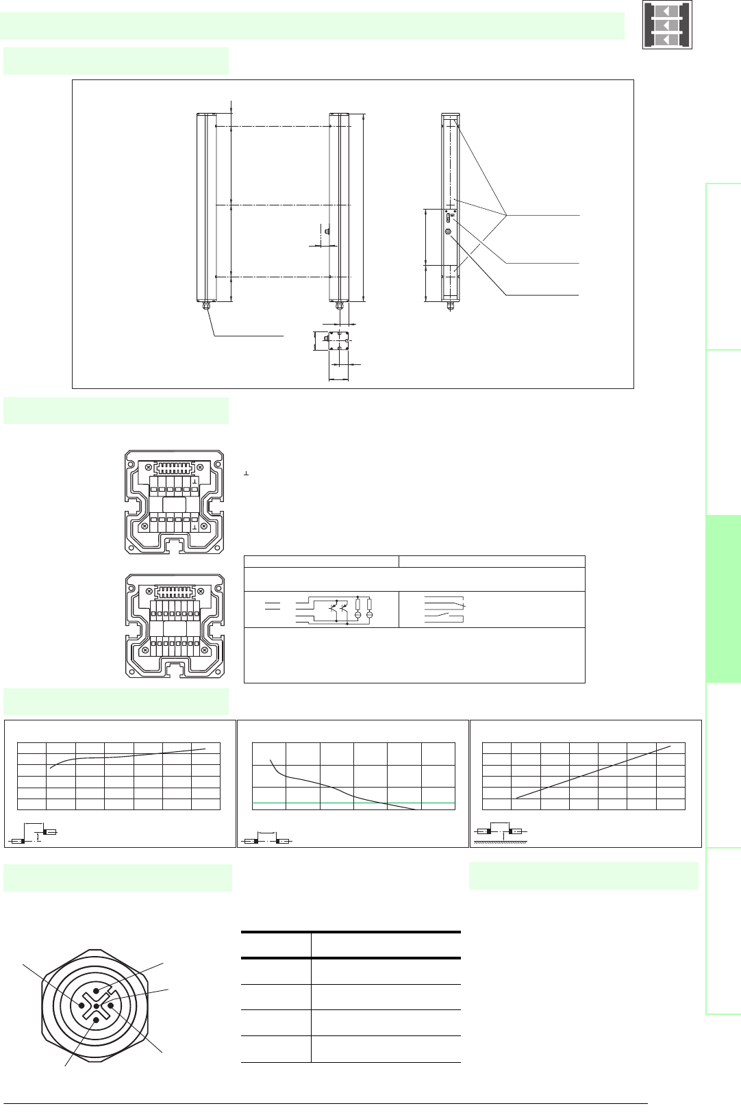
73
S
ubject to reasonable modifications due to technical advances. Copyright Pepperl+Fuchs, Printed in Germany
Pepperl+Fuchs Group • Tel.: Germany +49 621 776-0 • USA +1 330 4253555 • Singapore +65 67799091 • Internet http://www.pepperl-fuchs.com
Diagrams
Electrical connection
Dimensions
Safety through beam
sensors
Safety light gridsSafety light grids with
internal control unit
Safety light curtainsControl units
Socket assignment on the front side
of the device
Additional information
4
3
1
5
2
SLPC65-3/..
x
y
SLP65-x / SLPC65-x / SLPCM65-x
Offset Y [mm]
Distance X [m]
Characteristic response curve
0
50
100
150
200
250
300
0 10203040506070
x
SLP65-x / SLPC65-x / SLPCM65-x
Distance X [m]
Stability control
Relative received light strength
1
10
100
1000
0 20 40 60 80 100 120
x
y
SLP65-x / SLPC65-x / SLPCM65-x
Distance X [m]
Lateral interval to mirroring surfaces
Minimum interval [m]
0
0.5
1
1.5
2
2.5
3
0 10203040506070
Date of edition 05/17/2006
Emitter SLP
Receiver SLPC
T1 - Emitter channel 1
T2 - Emitter channel 2
T3 - Emitter channel 3
-0 V
Receicer SLPC (semiconductor outputs) Receiver SLPC/31 (Relay outputs)
1 - Functional earth
2 - 0 V
3 - 24 V
4 - n.c. 4
5- 5
6- 6
7 - OSSD 1 7
8 - OSSD 2 8
9 - input, Relay monitor
10 - input, Start release
11 - input, Reset
12 - PNP-output, Soiled optics
13 - n.c.
14 - PNP-output, Startup readiness
15 - PNP-output, Indicator OSSD OFF
16 - PNP-output, Indicator OSSD ON
1 2 3 4 5 6 7 8
16
15
14
13
12
11
10
9
T5 T6 T7 T8
NC
T1 T2 T3 T4
NC
-
+
SLPC...-3
T1-T4
Receiver SLPC...-3-R
Emitter SLP...-3-T
Connector
Emitter SLP
beam 2
beam 1
beam 3
Cable gland M16
Status indicator
of the particular
safety beam
Status indicator
of the system
H
64
32
70
33.5
156 203
936
90 400 400 46
Safety light grid with integrated control unit
T1 - T4 transmitter control
Socket Function
1 Transmitter channel 1
2 Transmitter channel 2
30 V
4 Transmitter channel 3
• Mounting set MS SLP
• Profile alignment aid PA SLP/SLC
• Laser alignment aid BA SLP
• Ground pillar UC SLP/SLC
• Housing for pillar
Enclosure UC SLP/SLC
• Collision protector
Damping UC SLP/SLC
• Redirection mirror for multi-side
protection of hazardous areas
SLP-3-M
System accessories

Subject to reasonable modifications due to technical advances. Copyright Pepperl+Fuchs, Printed in Germany
Pepperl+Fuchs Group • Tel.: Germany +49 621 776-0 • USA +1 330 4253555 • Singapore +65 67799091 • Internet http://www.pepperl-fuchs.com
74
Technische DatenTechnical data
Features
Ordering code:
Sicherheits-Lichtschranken
Sicherheits-Lichtgitter
Sicherheits-Lichtgitter mit
interner Auswerteeinheit
Sicherheits-Lichtvorhänge
Auswertegeräte Safety through beam
sensors
Safety light grids
Safety light grigs with
internal control unit
Safety light curtains
Control units
SLPC10-4
SLPC10-4/31
Effective detection range
0.2 ... 10 m
X X
Light source
LED
XX
Approvals
TÜV
X X
Tests
IEC/EN 61496
XX
Marking
CE
X X
Obstacle size
static: 32 mm
dynamic: 50 mm (at v = 1.6 m/s of the obstacle)
XX
Beam spacing
300 mm
X X
Number of beams
4
XX
Safety category according to IEC/EN 61496
4
X X
Operating mode
Start/restart disable, relay monitor,
XX
Light type
red, modulated light
X X
Angle of divergence
< 5 °
XX
Diagnosis display
7-segment display
X X
Function display
LED red: per receiver channel
off: interruption, flashes: receiver, continuously on: reception with sufficient stability control
on the front plate: LED red: OSSD off, LED green: OSSD on
XX
Pre-fault indication
LED red next to receiver flashes
X X
Operating elements
10 DIP switch in receiver terminal compartment
XX
Operating voltage
24 V DC -15 % / +25 % , electrically isolated
X X
Protection class
III
XX
No-load supply current
max. 250 mA
X X
Activation current
approx. 10 mA
XX
Activation time
0.03 ... 1 s
X X
Test i n pu t
Reset-input for system test
XX
Function input
Relay monitor, start release
X X
Output of the pre-fault indication
1 PNP, +UB -2 V, max. 300 mA
XX
Safety output
2 separated fail safe semiconductor outputs
X
2 relay outputs, compelled connection NO-contact
X
Signal output
1 PNP each, max. 300 mA for start readiness, OSSD on, OSSD off
X X
Switching voltage
Operating voltage -2 V
X
20 ... 60 V DC, 12 ... 25 V AC rms
X
Switching current
max. 0.5 A
X
0.01 ... 2 A
X
Switch power
100 VA
X
Response time
20 ms
X
40 ms
X
Ambient temperature
0 ... 50 °C (273 ... 323 K)
X X
Storage temperature
-20 ... 70 °C (253 ... 343 K)
XX
Relative humidity
max. 95 %, not condensing
X X
Protection degree
IP65
XX
Connection
Cable screwed connection M16 , terminal compartment with cage-terminals, M12-connector for emitter
X X
Connection options
Further electrical connection options on request: Plug connector DIN 43 651 Hirschmann, emitter: 6-pin+PE, receiver: 11-pin+PE
XX
Housing
aluminium extruded structural profile, RAL 1021 (yellow) coated
X X
Optical face
Plastic pane
XX
Mass
Per 3700 g
X X
System components
Emitter
SLP10-4-T
X X
Receiver
SLPC10-4-R
X
SLPC10-4-R/31
X
SLPC10-4/..
• Detection range up to 10 m
• 4-Radial design
• Beam spacing 300 mm
• Self-monitoring (type 4 according to IEC/EN 61496-1)
• Red transmission light
• Usable with or without start/restart disable
• Integrated relay monitor
• 7-segment diagnostic display
• Integrated function display
• Pre-fault indication
• OSSD outputs as semiconductor or relay outputs
Date of edition 05/17/2006
Safety light grid with integrated control unit
For suitable cable sockets, mounting aids, redirection mirrors and more refer to chapter „Accessories“.
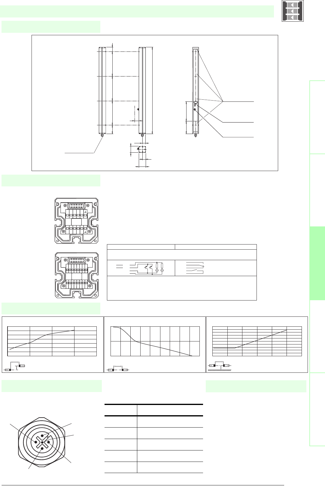
75
S
ubject to reasonable modifications due to technical advances. Copyright Pepperl+Fuchs, Printed in Germany
Pepperl+Fuchs Group • Tel.: Germany +49 621 776-0 • USA +1 330 4253555 • Singapore +65 67799091 • Internet http://www.pepperl-fuchs.com
Diagrams
Electrical connection
Dimensions
Safety through beam
sensors
Safety light gridsSafety light grids with
internal control unit
Safety light curtainsControl units
Socket assignment on the front side
of the device
Additional information
4
3
1
5
2
SLPC10-4/..
x
y
SLP10-x / SLPC10-x / SLPCM10-x
Offset Y [mm]
Distance X [m]
Characteristic response curve
0
20
40
60
80
100
120
140
0 5 10 15 20
x
SLP10-x / SLPC10-x / SLPCM10-x
Distance X [m]
Stability control
Relative received light strength
1
10
100
0 2 4 6 8 1012141618
x
y
SLP10-x / SLPC10-x / SLPCM10-x
Distance X [m]
Lateral interval to mirroring surfaces
Minimum interval [m]
0
0.05
0.1
0.15
0.2
0.25
0.3
0.35
0.4
0.45
0.5
0 2 4 6 8 10 12
Date of edition 05/17/2006
Emitter SLP
Receiver SLPC
T1 - Emitter channel 1
T2 - Emitter channel 2
T3 - Emitter channel 3
T4 - Emitter channel 4
-0 V
Receiver SLPC (semi-conductor outputs) Receiver SLPC/31 (relay output)
1 - Fuctional earth
2 - 0 V
3 - 24 V
4 - n.c. 4
5- 5
6- 6
7 - OSSD 1 7
8 - OSSD 2 8
9 - Input, Relay monitor
10 - Input, Start release
11 - Input, Reset
12 - PNP-Output, Soiled optics
13 - n.c.
14 - PNP-Output, Startup readiness
15 - PNP-Output, Indicator OSSD OFF
16 - PNP-Output, Indicator OSSD ON
1 2 3 4 5 6 7 8
16
15
14
13
12
11
10
9
T5 T6 T7 T8
NC
T1 T2 T3 T4
NC
-
+
T1-T4
SLPC...-4
beam 4
beam 3
beam 2
beam 1
cable gland M16
Emitter SLP...-4-T Receiver SLPC...-4-R
Connector
Emitter SLP
Status indicator
of the particular
safety beam
System status
indicator
H
156 203
64
32
70
33.5
1036
90 300 300 300 46
Safety light grid with integrated control unit
T1 - T4 transmitter control
Socket Function
1 Transmitter channel 1
2 Transmitter channel 2
30 V
4 Transmitter channel 3
5 Transmitter channel 4
• Mounting set MS SLP
• Profile alignment aid PA SLP/SLC
• Laser alignment aid BA SLP
• Ground pillar UC SLP/SLC
• Housing for pillar
Enclosure UC SLP/SLC
• Collision protector
Damping UC SLP/SLC
• Redirection mirror for multi-side
protection of hazardous areas
SLP-4-M
System accessories

Subject to reasonable modifications due to technical advances. Copyright Pepperl+Fuchs, Printed in Germany
Pepperl+Fuchs Group • Tel.: Germany +49 621 776-0 • USA +1 330 4253555 • Singapore +65 67799091 • Internet http://www.pepperl-fuchs.com
76
Technische DatenTechnical data
Features
Ordering code:
Sicherheits-Lichtschranken
Sicherheits-Lichtgitter
Sicherheits-Lichtgitter mit
interner Auswerteeinheit
Sicherheits-Lichtvorhänge
Auswertegeräte Safety through beam
sensors
Safety light grids
Safety light grigs with
internal control unit
Safety light curtains
Control units
SLPC30-4
SLPC30-4/31
Effective detection range
6 ... 30 m
X X
Light source
LED
XX
Approvals
TÜV
X X
Tests
IEC/EN 61496
XX
Marking
CE
X X
Obstacle size
static: 32 mm
dynamic: 50 mm (at v = 1.6 m/s of the obstacle)
XX
Beam spacing
300 mm
X X
Number of beams
4
XX
Safety category according to IEC/EN 61496
4
X X
Operating mode
Start/restart disable, relay monitor,
XX
Light type
red, modulated light
X X
Angle of divergence
< 5 °
XX
Diagnosis display
7-segment display
X X
Function display
LED red: per receiver channel
off: interruption, flashes: receiver, continuously on: reception with sufficient stability control
on the front plate: LED red: OSSD off, LED green: OSSD on
XX
Pre-fault indication
LED red next to receiver flashes
X X
Operating elements
10 DIP switch in receiver terminal compartment
XX
Operating voltage
24 V DC -15 % / +25 % , electrically isolated
X X
Protection class
III
XX
No-load supply current
max. 250 mA
X X
Activation current
approx. 10 mA
XX
Activation time
0.03 ... 1 s
X X
Test i n pu t
Reset-input for system test
XX
Function input
Relay monitor, start release
X X
Output of the pre-fault indication
1 PNP, +UB -2 V, max. 300 mA
XX
Safety output
2 separated fail safe semiconductor outputs
X
2 relay outputs, compelled connection NO-contact
X
Signal output
1 PNP each, max. 300 mA for start readiness, OSSD on, OSSD off
X X
Switching voltage
Operating voltage -2 V
X
20 ... 60 V DC, 12 ... 25 V AC rms
X
Switching current
max. 0.5 A
X
0.01 ... 2 A
X
Switch power
100 VA
X
Response time
20 ms
X
40 ms
X
Ambient temperature
0 ... 50 °C (273 ... 323 K)
X X
Storage temperature
-20 ... 70 °C (253 ... 343 K)
XX
Relative humidity
max. 95 %, not condensing
X X
Protection degree
IP65
XX
Connection
Cable screwed connection M16 , terminal compartment with cage-terminals, M12-connector for emitter
X X
Connection options
Further electrical connection options on request: Plug connector DIN 43 651 Hirschmann, emitter: 6-pin+PE, receiver: 11-pin+PE
XX
Housing
aluminium extruded structural profile, RAL 1021 (yellow) coated
X X
Optical face
Plastic pane
XX
Mass
Per 3700 g
X X
System components
Emitter
SLP30-4-T
X X
Receiver
SLPC30-4-R
X
SLPC30-4-R/31
X
SLPC30-4/..
• Detection range up to 30 m
• 4-Radial design
• Beam spacing 300 mm
• Self-monitoring (type 4 according to IEC/EN 61496-1)
• Red transmission light
• Usable with or without start/restart disable
• Integrated relay monitor
• 7-segment diagnostic display
• Integrated function display
• Pre-fault indication
• OSSD outputs as semiconductor or relay outputs
Date of edition 05/17/2006
Safety light grid with integrated control unit
For suitable cable sockets, mounting aids, redirection mirrors and more refer to chapter „Accessories“.
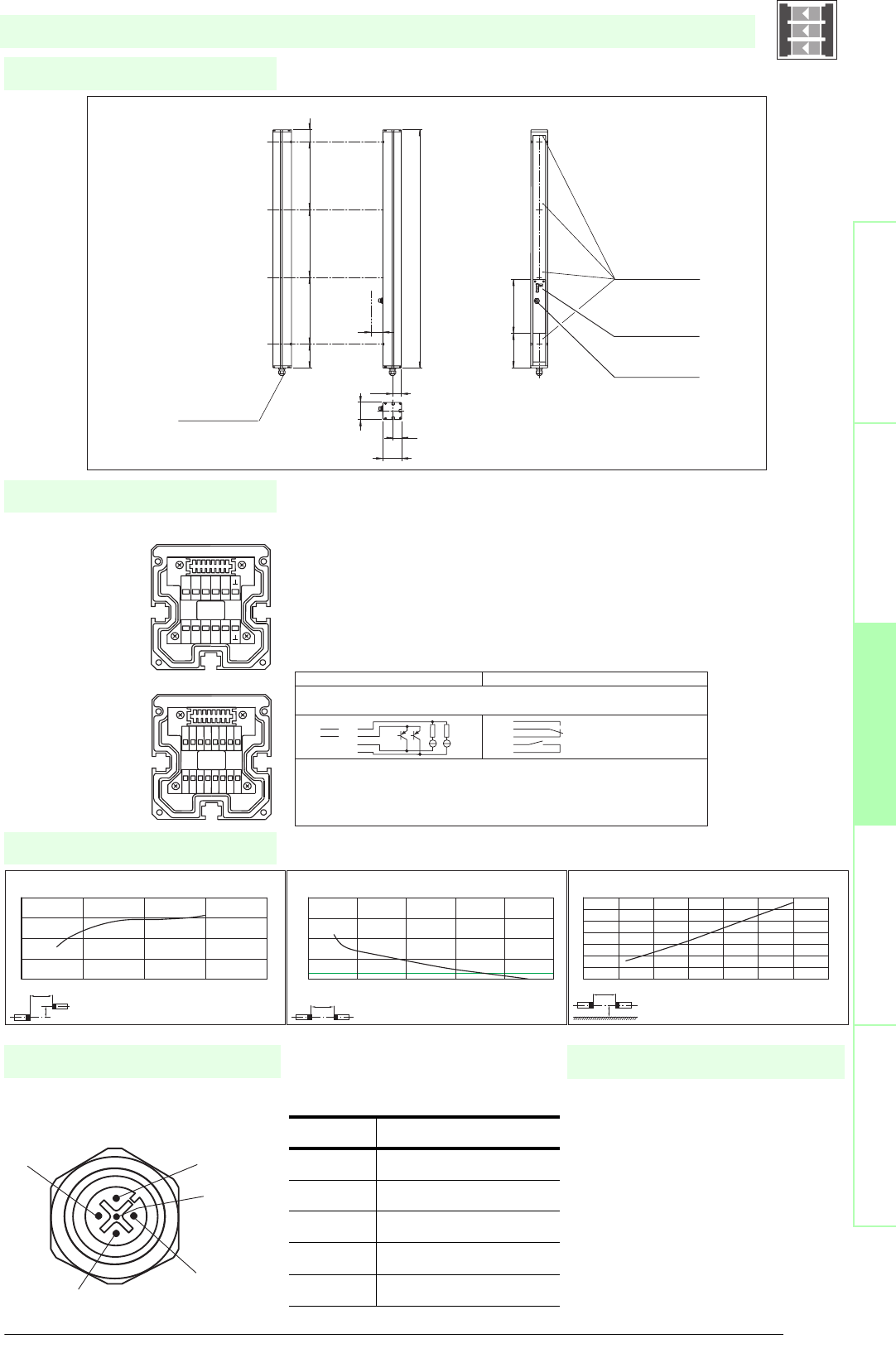
77
S
ubject to reasonable modifications due to technical advances. Copyright Pepperl+Fuchs, Printed in Germany
Pepperl+Fuchs Group • Tel.: Germany +49 621 776-0 • USA +1 330 4253555 • Singapore +65 67799091 • Internet http://www.pepperl-fuchs.com
Diagrams
Electrical connection
Dimensions
Safety through beam
sensors
Safety light gridsSafety light grids with
internal control unit
Safety light curtainsControl units
Socket assignment on the front side
of the device
Additional information
4
3
1
5
2
SLPC30-4/..
x
y
SLP30-x / SLPC30-x / SLPCM30-x
Offset Y [mm]
Distance X [m]
Characteristic response curve
0
50
100
150
200
010203040
x
SLP30-x / SLPC30-x / SLPCM30-x
Distance X [m]
Stability control
Relative received light strength
1
10
100
1000
10000
0 1020304050
x
y
SLP30-x / SLPC30-x / SLPCM30-x
Distance X [m]
Lateral interval to mirroring surfaces
Minimum interval [m]
0
0.2
0.4
0.6
0.8
1
1.2
1.4
0 5 10 15 20 25 30 35
Date of edition 05/17/2006
Emitter SLP
Receiver SLPC
T1 - Emitter channel 1
T2 - Emitter channel 2
T3 - Emitter channel 3
T4 - Emitter channel 4
-0 V
Receiver SLPC (semi-conductor outputs) Receiver SLPC/31 (relay output)
1 - Fuctional earth
2 - 0 V
3 - 24 V
4 - n.c. 4
5- 5
6- 6
7 - OSSD 1 7
8 - OSSD 2 8
9 - Input, Relay monitor
10 - Input, Start release
11 - Input, Reset
12 - PNP-Output, Soiled optics
13 - n.c.
14 - PNP-Output, Startup readiness
15 - PNP-Output, Indicator OSSD OFF
16 - PNP-Output, Indicator OSSD ON
1 2 3 4 5 6 7 8
16
15
14
13
12
11
10
9
T5 T6 T7 T8
NC
T1 T2 T3 T4
NC
-
+
T1-T4
SLPC...-4
beam 4
beam 3
beam 2
beam 1
cable gland M16
Emitter SLP...-4-T Receiver SLPC...-4-R
Connector
Emitter SLP
Status indicator
of the particular
safety beam
System status
indicator
H
156 203
64
32
70
33.5
1036
90 300 300 300 46
Safety light grid with integrated control unit
T1 - T4 transmitter control
Socket Function
1 Transmitter channel 1
2 Transmitter channel 2
30 V
4 Transmitter channel 3
5 Transmitter channel 4
• Mounting set MS SLP
• Profile alignment aid PA SLP/SLC
• Laser alignment aid BA SLP
• Ground pillar UC SLP/SLC
• Housing for pillar
Enclosure UC SLP/SLC
• Collision protector
Damping UC SLP/SLC
• Redirection mirror for multi-side
protection of hazardous areas
SLP-4-M
System accessories

Subject to reasonable modifications due to technical advances. Copyright Pepperl+Fuchs, Printed in Germany
Pepperl+Fuchs Group • Tel.: Germany +49 621 776-0 • USA +1 330 4253555 • Singapore +65 67799091 • Internet http://www.pepperl-fuchs.com
78
Technische DatenTechnical data
Features
Ordering code:
Sicherheits-Lichtschranken
Sicherheits-Lichtgitter
Sicherheits-Lichtgitter mit
interner Auswerteeinheit
Sicherheits-Lichtvorhänge
Auswertegeräte Safety through beam
sensors
Safety light grids
Safety light grigs with
internal control unit
Safety light curtains
Control units
SLPC65-4
SLPC65-4/31
Effective detection range
12 ... 65 m
X X
Light source
LED
XX
Approvals
TÜV
X X
Tests
IEC/EN 61496
XX
Marking
CE
X X
Obstacle size
static: 32 mm
dynamic: 50 mm (at v = 1.6 m/s of the obstacle)
XX
Beam spacing
300 mm
X X
Number of beams
4
XX
Safety category according to IEC/EN 61496
4
X X
Operating mode
Start/restart disable, relay monitor,
XX
Light type
red, modulated light
X X
Angle of divergence
< 5 °
XX
Diagnosis display
7-segment display
X X
Function display
LED red: per receiver channel off: interruption, flashes: receiver, continuously on: reception with sufficient stability control
on the front plate: LED red: OSSD off, LED green: OSSD on
XX
Pre-fault indication
LED red next to receiver flashes
X X
Operating elements
10 DIP switch in receiver terminal compartment
XX
Operating voltage
24 V DC -15 % / +25 % , electrically isolated
X X
Protection class
III
XX
No-load supply current
max. 250 mA
X X
Activation current
approx. 10 mA
XX
Activation time
0.03 ... 1 s
X X
Test i n pu t
Reset-input for system test
XX
Function input
Relay monitor, start release
X X
Output of the pre-fault indication
1 PNP, +UB -2 V, max. 300 mA
XX
Safety output
2 separated fail safe semiconductor outputs
X
2 relay outputs, compelled connection NO-contact
X
Signal output
1 PNP each, max. 300 mA for start readiness, OSSD on, OSSD off
X
1 PNP each, max. 300 mA for start readiness, OSSD on, OSSD off, muting lamp
X
Switching voltage
Operating voltage -2 V
X
20 ... 60 V DC, 12 ... 25 V AC rms
X
Switching current
max. 0.5 A
X
0.01 ... 2 A
X
Switch power
100 VA
X
Response time
20 ms
X
40 ms
X
Ambient temperature
0 ... 50 °C (273 ... 323 K)
XX
Storage temperature
-20 ... 70 °C (253 ... 343 K)
X X
Relative humidity
max. 95 %, not condensing
XX
Protection degree
IP65
X X
Connection
Cable screwed connection M16 , terminal compartment with cage-terminals, M12-connector for emitter
XX
Connection options
Further electrical connection options on request: Plug connector DIN 43 651 Hirschmann, emitter: 6-pin+PE, receiver: 11-pin+PE
X X
Housing
aluminium extruded structural profile, RAL 1021 (yellow) coated
XX
Optical face
Plastic pane
X X
Mass
Per 3700 g
XX
System components
Emitter
SLP65-4-T
XX
Receiver
SLPC65-4-R
X
SLPC65-4-R/31
X
SLPC65-4/..
• Detection range up to 65 m
• 4-Radial design
• Beam spacing 300 mm
• Self-monitoring (type 4 according to IEC/EN 61496-1)
• Red transmission light
• Usable with or without start/restart disable
• Integrated relay monitor
• 7-segment diagnostic display
• Integrated function display
• Pre-fault indication
• OSSD outputs as semiconductor or relay outputs
Date of edition 05/17/2006
Safety light grid with integrated control unit
For suitable cable sockets, mounting aids, redirection mirrors and more refer to chapter „Accessories“.
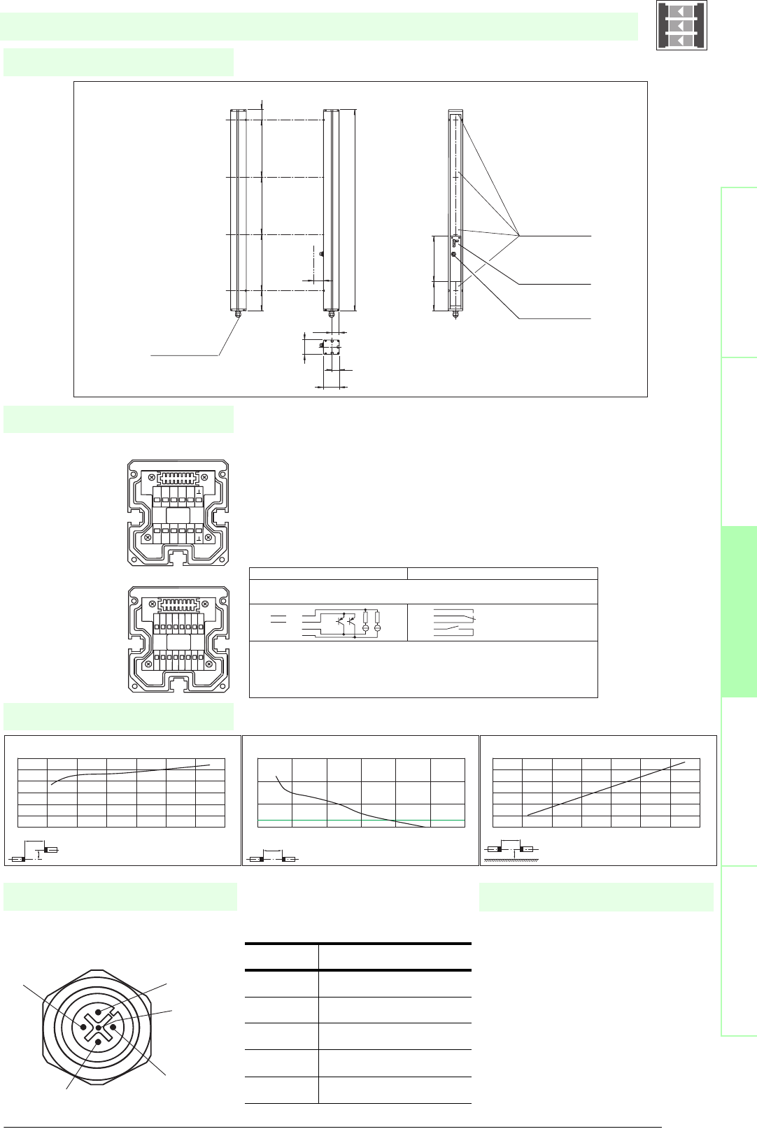
79
S
ubject to reasonable modifications due to technical advances. Copyright Pepperl+Fuchs, Printed in Germany
Pepperl+Fuchs Group • Tel.: Germany +49 621 776-0 • USA +1 330 4253555 • Singapore +65 67799091 • Internet http://www.pepperl-fuchs.com
Diagrams
Electrical connection
Dimensions
Safety through beam
sensors
Safety light gridsSafety light grids with
internal control unit
Safety light curtainsControl units
Socket assignment on the front side
of the device
Additional information
4
3
1
5
2
SLPC65-4/..
x
y
SLP65-x / SLPC65-x / SLPCM65-x
Offset Y [mm]
Distance X [m]
Characteristic response curve
0
50
100
150
200
250
300
0 10203040506070
x
SLP65-x / SLPC65-x / SLPCM65-x
Distance X [m]
Stability control
Relative received light strength
1
10
100
1000
0 20 40 60 80 100 120
x
y
SLP65-x / SLPC65-x / SLPCM65-x
Distance X [m]
Lateral interval to mirroring surfaces
Minimum interval [m]
0
0.5
1
1.5
2
2.5
3
0 10203040506070
Date of edition 05/17/2006
Emitter SLP
Receiver SLPC
T1 - Emitter channel 1
T2 - Emitter channel 2
T3 - Emitter channel 3
T4 - Emitter channel 4
-0 V
Receiver SLPC (semi-conductor outputs) Receiver SLPC/31 (relay output)
1 - Fuctional earth
2 - 0 V
3 - 24 V
4 - n.c. 4
5- 5
6- 6
7 - OSSD 1 7
8 - OSSD 2 8
9 - Input, Relay monitor
10 - Input, Start release
11 - Input, Reset
12 - PNP-Output, Soiled optics
13 - n.c.
14 - PNP-Output, Startup readiness
15 - PNP-Output, Indicator OSSD OFF
16 - PNP-Output, Indicator OSSD ON
1 2 3 4 5 6 7 8
16
15
14
13
12
11
10
9
T5 T6 T7 T8
NC
T1 T2 T3 T4
NC
-
+
T1-T4
SLPC...-4
beam 4
beam 3
beam 2
beam 1
cable gland M16
Emitter SLP...-4-T Receiver SLPC...-4-R
Connector
Emitter SLP
Status indicator
of the particular
safety beam
System status
indicator
H
156 203
64
32
70
33.5
1036
90 300 300 300 46
Safety light grid with integrated control unit
T1 - T4 transmitter control
Socket Function
1 Transmitter channel 1
2 Transmitter channel 2
30 V
4 Transmitter channel 3
5 Transmitter channel 4
• Mounting set MS SLP
• Profile alignment aid PA SLP/SLC
• Laser alignment aid BA SLP
• Ground pillar UC SLP/SLC
• Housing for pillar
Enclosure UC SLP/SLC
• Collision protector
Damping UC SLP/SLC
• Redirection mirror for multi-side
protection of hazardous areas
SLP-4-M
System accessories

Subject to reasonable modifications due to technical advances. Copyright Pepperl+Fuchs, Printed in Germany
Pepperl+Fuchs Group • Tel.: Germany +49 621 776-0 • USA +1 330 4253555 • Singapore +65 67799091 • Internet http://www.pepperl-fuchs.com
80
Technische DatenTechnical data
Features
Ordering code:
Sicherheits-Lichtschranken
Sicherheits-Lichtgitter
Sicherheits-Lichtgitter mit
interner Auswerteeinheit
Sicherheits-Lichtvorhänge
Auswertegeräte Safety through beam
sensors
Safety light grids
Safety light grigs with
internal control unit
Safety light curtains
Control units
SLPCM8-2
SLPCM8-2/31
SLPCM8-2-L
SLPCM8-2-L/31
Effective detection range
0.2 ... 8 m
X X X X
Light source
LED
XXXX
Approvals
TÜV
X X X X
Tests
IEC/EN 61496
XXXX
Marking
CE
X X X X
Obstacle size
static: 32 mm, dynamic: 50 mm (at v = 1.6 m/s of the obstacle)
XXXX
Beam spacing
500 mm
X X X X
Number of beams
2
XXXX
Safety category according to IEC/EN 61496
4
X X X X
Operating mode
Start/restart disable, relay monitor, muting operating modes
XXXX
Light type
red, modulated light
X X X X
Angle of divergence
< 5 °
XXXX
Diagnosis display
7-segment display
X X X X
Function display
LED red: per receiver channel off: interruption, flashes: receiver, continuously on: reception with sufficient stability control
on the front plate: LED red: OSSD off, LED green: OSSD on, LED yellow: types of muting operation
XXXX
Muting display
Indicator lamp
X X
Pre-fault indication
LED red next to receiver flashes
XXXX
Operating elements
10 DIP switch in transceiver terminal compartment
X X X X
Operating voltage
24 V DC -15 % / +25 % , electrically isolated
XXXX
Protection class
III
X X X X
No-load supply current
max. 250 mA
XXXX
Activation current
approx. 10 mA
X X X X
Activation time
0.03 ... 1 s
XXXX
Test input
Reset-input for system test
X X X X
Function input
Relay monitor, start release, muting sensors (max. 4)
XXXX
Output of the pre-fault indication
1 PNP, +UB -2 V, max. 300 mA
X X X X
Safety output
2 separated fail safe semiconductor outputs
XX
2 relay outputs, compelled connection NO-contact
X X
Signal output
1 PNP each, max. 300 mA for start readiness, OSSD on, OSSD off, muting lamp
XX
1 PNP each, max. 300 mA for startup readiness, OSSD on, OSSD off, muting lamp, signals in parallel in the lamp socket
X X
Switching voltage
Operating voltage -2 V
XX
20 ... 60 V DC, 12 ... 25 V AC rms
X X
Switching current
max. 0.5 A
XX
0.01 ... 2 A
X X
Switch power
100 VA
XX
Response time
20 ms
X X
40 ms
XX
Ambient temperature
0 ... 50 °C (273 ... 323 K)
X X X X
Storage temperature
-20 ... 70 °C (253 ... 343 K)
XXXX
Relative humidity
max. 95 %, not condensing
X X X X
Protection degree
IP65
XXXX
Connection
Cable screwed connection M16 , terminal compartment with cage terminals, M12 connector for muting lamp, etc, muting sensors, lamp socket
for muting lamp, etc.
X X
Cable screwed connection M16 , terminal compartment with cage-terminals, M12-connector for emitter, muting lamp as well as other muting
sensors
XX
Connection options
Further electrical connection options on request: Plug connector DIN 43 651 Hirschmann, emitter: 6-pin+PE, receiver: 11-pin+PE
X X X X
Housing
aluminium extruded structural profile, RAL 1021 (yellow) coated
XXXX
Optical face
Plastic pane
X X X X
Mass
Per 2300 g
XXXX
System components
Transceiver
SLPCM8-2-A
X
SLPCM8-2-A-L
X
SLPCM8-2-A-L/31
X
SLPCM8-2-A/31
X
Mirror pillar
SLP8-2-M
XXXX
SLPCM8-2-...
• Detection range up to 8 m
• 2-Radial design
• Beam spacing 500 mm
• Self-monitoring (type 4 according to IEC/EN 61496-1)
• Minimum wiring expense due to transceiver with passive mirror column
• Red transmission light
• Usable with or without start/restart disable
• Sequential and parallel muting in various operating modes
• Emergency muting for the correction of the material jam
• Integrated relay monitor
• 7-segment diagnostic display
• Pre-fault indication
Date of edition 05/17/2006
Safety light grid with integrated control unit
For suitable cable sockets, mounting aids, redirection mirrors and more refer to chapter „Accessories“.
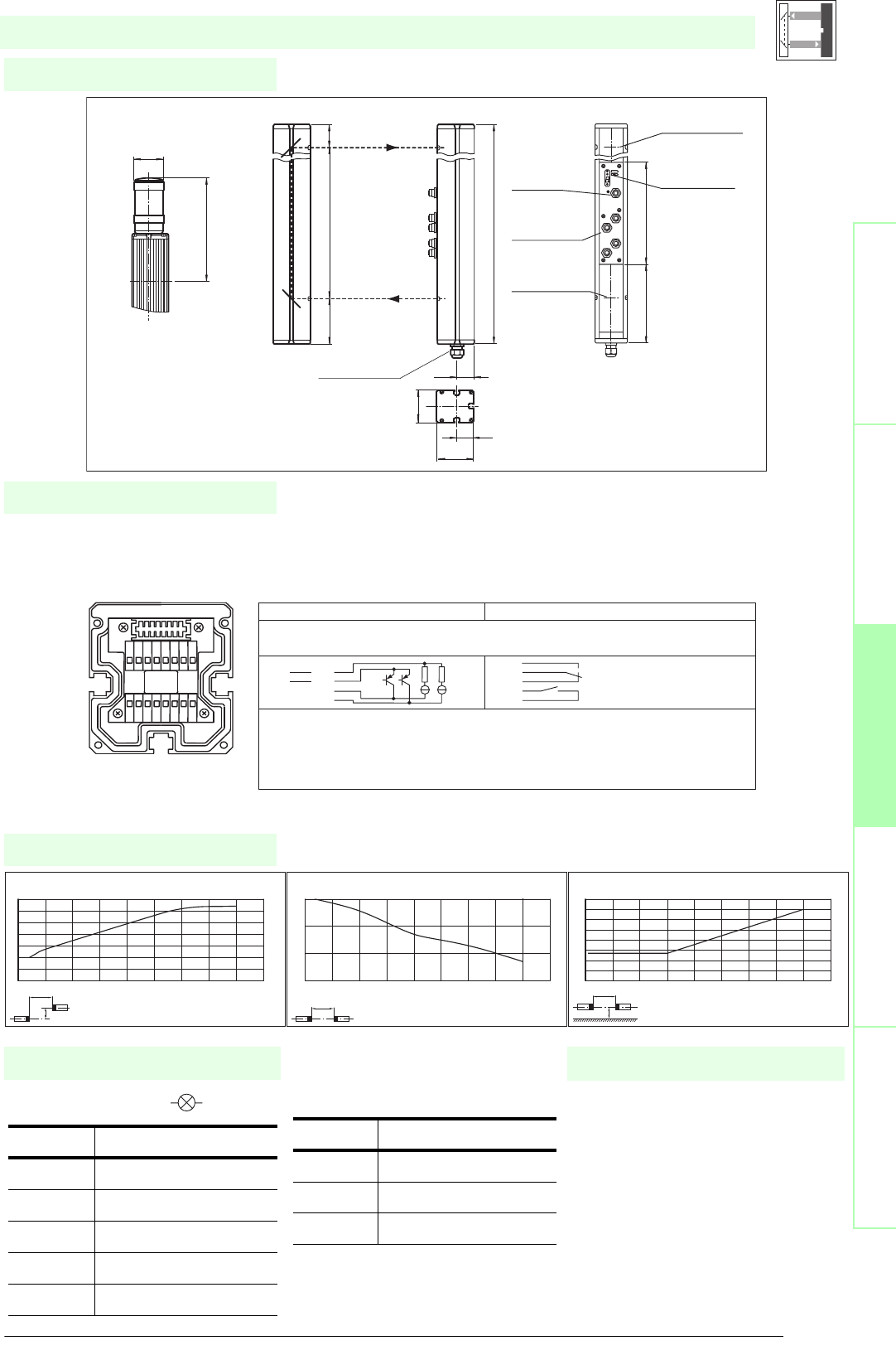
81
S
ubject to reasonable modifications due to technical advances. Copyright Pepperl+Fuchs, Printed in Germany
Pepperl+Fuchs Group • Tel.: Germany +49 621 776-0 • USA +1 330 4253555 • Singapore +65 67799091 • Internet http://www.pepperl-fuchs.com
Diagrams
Electrical connection
Dimensions
Safety through beam
sensors
Safety light gridsSafety light grids with
internal control unit
Safety light curtainsControl units
Indicator lamp control
Additional information
Socket Function
1 OSSD on
2 OSSD off
30 V
4 Readiness for startup
5 Muting (monitored)
SLPCM8-2-...
x
y
SLP8
Offset Y [mm]
Distance X [m]
Characteristic response curve
0
10
20
30
40
50
60
70
0123456789
x
SLP8
Distance X [m]
Stability control
Relative received light strength
1
10
100
1000
0123456789
x
y
SLP8
Distance X [m]
Lateral interval to mirroring surfaces
Minimum interval [m]
0
0.05
0.1
0.15
0.2
0.25
0.3
0.35
0.4
0123456789
Date of edition 05/17/2006
Transceiver SLPCM... (semiconductor output) Transceiver SLPCM.../31 (Relay output)
1 - Functional earth
2 - 0 V
3 - 24 V
4 - n.c. 4
5 - 5
6 - 6
7 - OSSD 1 7
8 - OSSD 2 8
9 - Input, Relay monitor
10 - Input, Start release
11 - Input, Reset
12 - PNP-output, Soiled optics
13 - PNP-output, Muting lamp
14 - PNP-output, Startup readiness
15 - PNP-output, Meldung OSSD AUS
16 - PNP-output, Indicator OSSD ON
Transceiver SLPCM8-2-A
1 2 3 4 5 6 7 8
16
15
14
13
12
11
10
9
-
+
Muting
MS3
MS4
MS1
MS2
Cable gland M16
Transceiver SLPCM8-2-A
Connector ext.
indicator lamp
Connector
muting sensors
MS1 ... MS4
Status indicator
safety beam
Status indicator
safety beam
Status indicator
of the system
Mirror SLP8-2-M
Option -L with indicator lamp
(transceiver only)
Indicator
lamp
topmost
beam
64
32
70
33.5
636
90 500 46
197
ø 57
156 203
Safety light grid with integrated control unit
Muting sensor inputs MS1 - MS4
Socket Function
1+ 24 V
30 V
4 Sensor signal
• Mounting set MS SLP
• Profile alignment aid PA SLP/SPC
• Laser alignment aid BA SLP
• Ground pillar UC SLP/SLC
• Housing for pillar
Enclosure UC SLP/SLC
• Collision protector
Damping UC SLP/SLC
• Redirection mirror SLP-2-M
System accessories
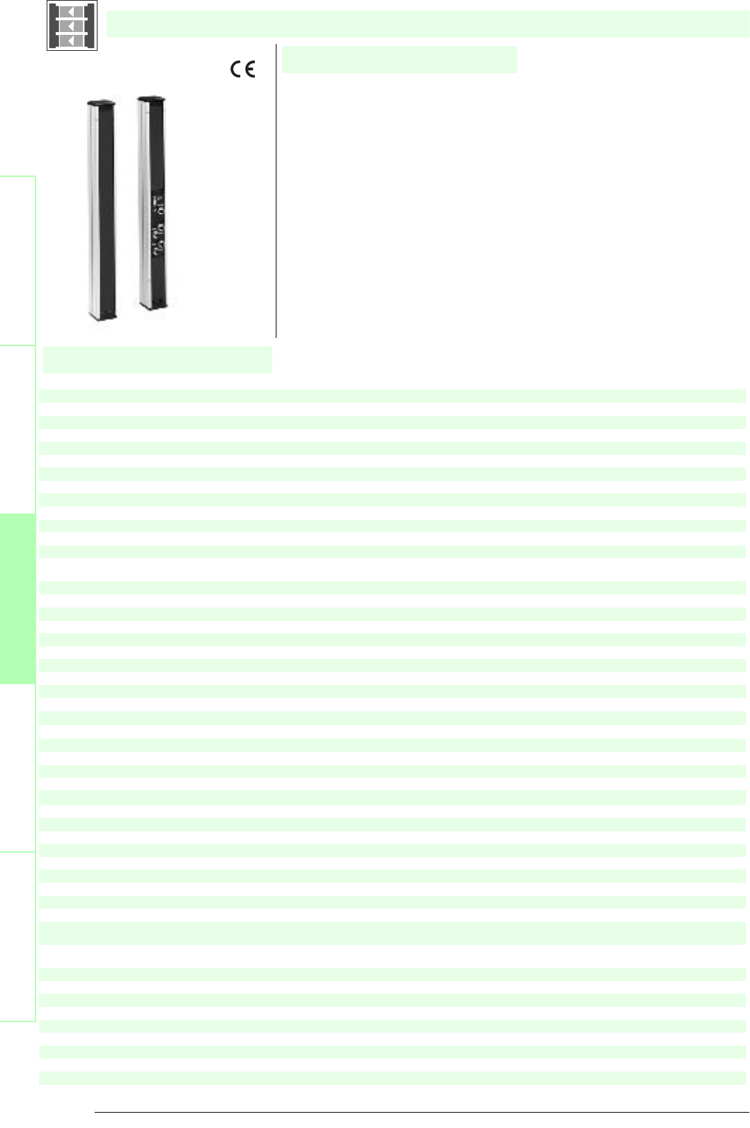
Subject to reasonable modifications due to technical advances. Copyright Pepperl+Fuchs, Printed in Germany
Pepperl+Fuchs Group • Tel.: Germany +49 621 776-0 • USA +1 330 4253555 • Singapore +65 67799091 • Internet http://www.pepperl-fuchs.com
82
Technische DatenTechnical data
Features
Ordering code:
Sicherheits-Lichtschranken
Sicherheits-Lichtgitter
Sicherheits-Lichtgitter mit
interner Auswerteeinheit
Sicherheits-Lichtvorhänge
Auswertegeräte Safety through beam
sensors
Safety light grids
Safety light grigs with
internal control unit
Safety light curtains
Control units
SLPCM10-2
SLPCM10-2/31
SLPCM10-2-L
SLPCM10-2-L/31
Effective detection range
0.2 ... 10 m
X X X X
Light source
LED
XXXX
Approvals
TÜV
X X X X
Tests
IEC/EN 61496
XXXX
Marking
CE
X X X X
Obstacle size
static: 32 mm, dynamic: 50 mm (at v = 1.6 m/s of the obstacle)
XXXX
Beam spacing
500 mm
X X X X
Number of beams
2
XXXX
Safety category according to IEC/EN 61496
4
X X X X
Operating mode
Start/restart disable, relay monitor, muting operating modes
XXXX
Light type
red, modulated light
X X X X
Angle of divergence
< 5 °
XXXX
Diagnosis display
7-segment display
X X X X
Function display
LED red: per receiver channel, off: interruption, flashes: receiver, continuously on: reception with sufficient stability control
on the front plate: LED red: OSSD off, LED green: OSSD on, LED yellow: types of muting operation
XXXX
Muting display
Indicator lamp
X X
Pre-fault indication
LED red next to receiver flashes
XXXX
Operating elements
10 DIP switch in receiver terminal compartment
X X X X
Operating voltage
24 V DC -15 % / +25 % , electrically isolated
XXXX
Protection class
III
X X X X
No-load supply current
max. 250 mA
XXXX
Activation current
approx. 10 mA
X X X X
Activation time
0.03 ... 1 s
XXXX
Test input
Reset-input for system test
X X X X
Function input
Relay monitor, start release, muting sensors (max. 4)
XXXX
Output of the pre-fault indication
1 PNP, +UB -2 V, max. 300 mA
X X X X
Safety output
2 separated fail safe semiconductor outputs
XX
2 relay outputs, compelled connection NO-contact
X X
Signal output
1 PNP each, max. 300 mA for start readiness, OSSD on, OSSD off, muting lamp
XX
1 PNP each, max. 300 mA for startup readiness, OSSD on, OSSD off, muting lamp, signals in parallel in the lamp socket
X X
Switching voltage
Operating voltage -2 V
XX
20 ... 60 V DC, 12 ... 25 V AC rms
X X
Switching current
max. 0.5 A
XX
0.01 ... 2 A
X X
Switch power
100 VA
XX
Response time
20 ms
X X
40 ms
XX
Ambient temperature
0 ... 50 °C (273 ... 323 K)
X X X X
Storage temperature
-20 ... 70 °C (253 ... 343 K)
XXXX
Relative humidity
max. 95 %, not condensing
X X X X
Protection degree
IP65
XXXX
Connection
Cable screwed connection M16 , terminal compartment with cage-terminals, M12-connector for emitter, muting lamp as well as other muting
sensors
X X
Cable screwed connection M16 , terminal compartment with cage terminals, M12 connector for transmitters, muting lamp, etc., muting sen-
sors, lamp socket for muting lamp, etc.
XX
Connection options
Further electrical connection options on request: Plug connector DIN 43 651 Hirschmann, emitter: 6-pin+PE, receiver: 11-pin+PE
X X X X
Housing
aluminium extruded structural profile, RAL 1021 (yellow) coated
XXXX
Optical face
Plastic pane
X X X X
Mass
Per 2300 g
XXXX
System components
Emitter
SLP10-2-T
XXXX
Receiver
SLPCM10-2-R
X
SLPCM10-2-R-L
X
SLPCM10-2-R-L/31
X
SLPCM10-2-R/31
X
SLPCM10-2-...
• Detection range up to 10 m
• 2-Radial design
• Beam spacing 500 mm
• Self-monitoring (type 4 according to IEC/EN 61496-1)
• Red transmission light
• Usable with or without start/restart disable
• Sequential and parallel muting in various operating modes
• Emergency muting for the correction of the material jam
• Integrated relay monitor
• 7-segment diagnostic display
• Integrated function display
• Pre-fault indication
• OSSD outputs as semiconductor or relay outputs
Date of edition 05/17/2006
Safety light grid with integrated control unit
For suitable cable sockets, mounting aids, redirection mirrors and more refer to chapter „Accessories“.
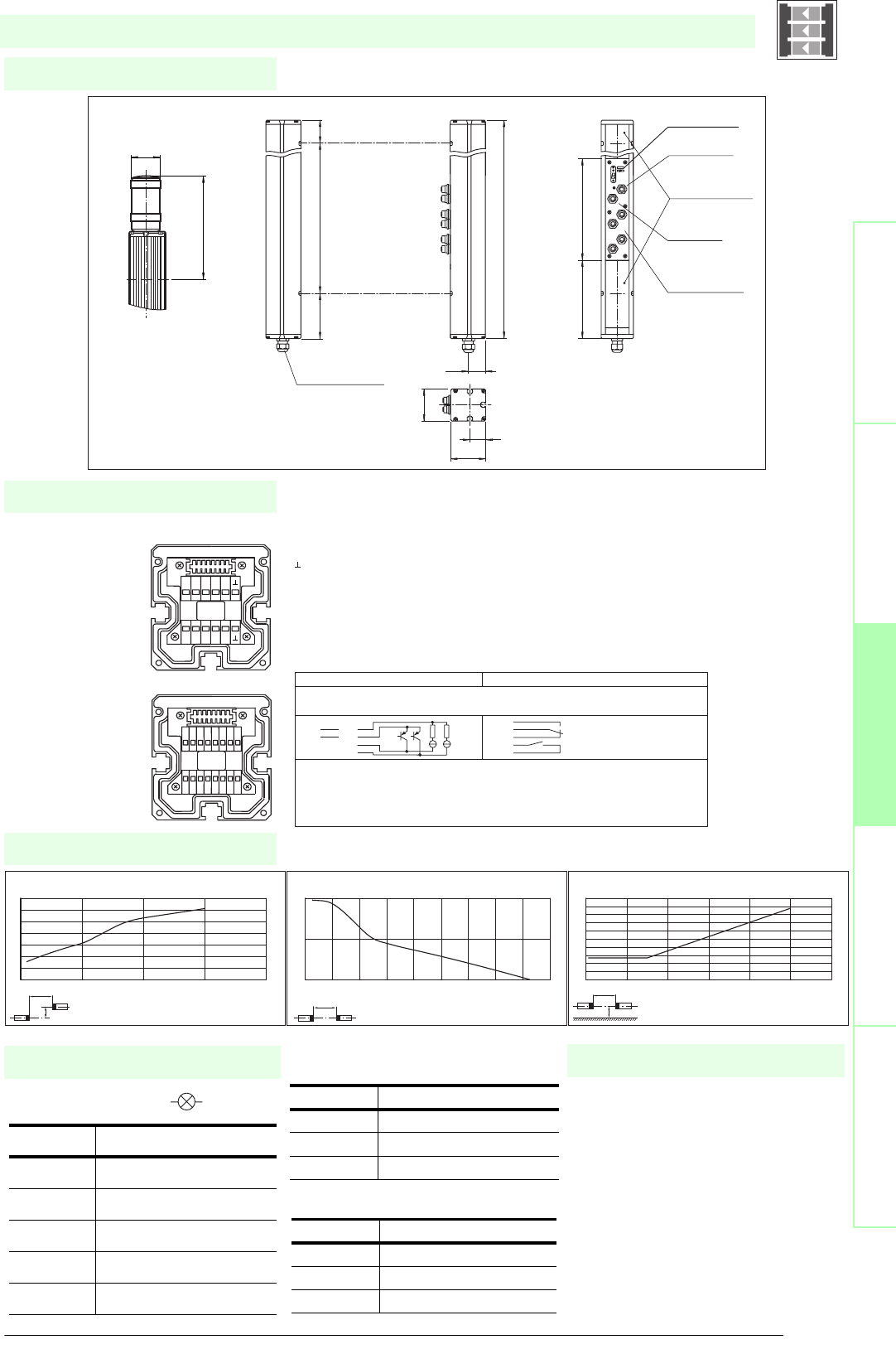
83
S
ubject to reasonable modifications due to technical advances. Copyright Pepperl+Fuchs, Printed in Germany
Pepperl+Fuchs Group • Tel.: Germany +49 621 776-0 • USA +1 330 4253555 • Singapore +65 67799091 • Internet http://www.pepperl-fuchs.com
Diagrams
Electrical connection
Dimensions
Safety through beam
sensors
Safety light gridsSafety light grids with
internal control unit
Safety light curtainsControl units
Indicator lamp control
Additional information
Socket Function
1 OSSD on
2 OSSD off
30 V
4 Readiness for startup
5 Muting (monitored)
SLPCM10-2-...
x
y
SLP10-x / SLPC10-x / SLPCM10-x
Offset Y [mm]
Distance X [m]
Characteristic response curve
0
20
40
60
80
100
120
140
0 5 10 15 20
x
SLP10-x / SLPC10-x / SLPCM10-x
Distance X [m]
Stability control
Relative received light strength
1
10
100
0 2 4 6 8 1012141618
x
y
SLP10-x / SLPC10-x / SLPCM10-x
Distance X [m]
Lateral interval to mirroring surfaces
Minimum interval [m]
0
0.05
0.1
0.15
0.2
0.25
0.3
0.35
0.4
0.45
0.5
0 2 4 6 8 10 12
Date of edition 05/17/2006
Emitter SLP
Receiver SLPCM
T1 - Emitter channel 1
T2 - Emitter channel 2
-0 V
Receiver SLPCM (semiconductor outputs) Receiver SLPCM/31 (relay outputs)
1 - Functional earth
2 - 0 V
3 - 24 V
4 - n.c. 4
5- 5
6- 6
7 - OSSD 1 7
8 - OSSD 2 8
9 - Input, Relay monitor
10 - Input, Start release
11 - Input, Reset
12 - PNP-output, Soiled optics
13 - PNP-output, Muting lamp
14 - PNP-output, Startup readiness
15 - PNP-output, Indicator OSSD OFF
16 - PNP-output, Indicator OSSD ON
1 2 3 4 5 6 7 8
16
15
14
13
12
11
10
9
T5 T6 T7 T8
NC
T1 T2 T3 T4
NC
-
+
Muting
T1-T4
MS3
MS4
MS1
MS2
Cable gland M16
Receiver SLPCM...-2-R
Connector
emitter
Connectors
muting sensors
MS1 ... MS4
Connector ext.
indicator lamp
System status
indicator
Emitter SLP...-2-TOption -L with indicator lamp
(receiver only)
beam 2
beam 1
Indicator
lamp
topmost
beam
Status indicator
of the particular
safety beam
64
32
70
33.5
636
90 500 46
197
ø 57
156 203
Safety light grid with integrated control unit
T1 - T4 transmitter control
Muting sensor inputs MS1 - MS4
Socket Function
1 Transmitter channel 1
2 Transmitter channel 2
30 V
Socket Function
1 + 24 V
30 V
4 Sensor signal
• Mounting set MS SLP
• Profile alignment aid PA SLP/SLC
• Laser alignment aid BA SLP
• Ground pillar UC SLP/SLC
• Housing for pillar
Enclosure UC SLP/SLC
• Collision protector
Damping UC SLP/SLC
• Redirection mirror SLP-2-M
System accessories

Subject to reasonable modifications due to technical advances. Copyright Pepperl+Fuchs, Printed in Germany
Pepperl+Fuchs Group • Tel.: Germany +49 621 776-0 • USA +1 330 4253555 • Singapore +65 67799091 • Internet http://www.pepperl-fuchs.com
84
Technische DatenTechnical data
Features
Ordering code:
Sicherheits-Lichtschranken
Sicherheits-Lichtgitter
Sicherheits-Lichtgitter mit
interner Auswerteeinheit
Sicherheits-Lichtvorhänge
Auswertegeräte Safety through beam
sensors
Safety light grids
Safety light grigs with
internal control unit
Safety light curtains
Control units
SLPCM30-2
SLPCM30-2/31
SLPCM30-2-L
SLPCM30-2-L/31
Effective detection range
6 ... 30 m
X X X X
Light source
LED
XXXX
Approvals
TÜV
X X X X
Tests
IEC/EN 61496
XXXX
Marking
CE
X X X X
Obstacle size
static: 32 mm, dynamic: 50 mm (at v = 1.6 m/s of the obstacle)
XXXX
Beam spacing
500 mm
X X X X
Number of beams
2
XXXX
Safety category according to IEC/EN 61496
4
X X X X
Operating mode
Start/restart disable, relay monitor, muting operating modes
XXXX
Light type
red, modulated light
X X X X
Angle of divergence
< 5 °
XXXX
Diagnosis display
7-segment display
X X X X
Function display
LED red: per receiver channel, off: interruption, flashes: receiver, continuously on: reception with sufficient stability control
on the front plate: LED red: OSSD off, LED green: OSSD on, LED yellow: types of muting operation
XXXX
Muting display
Indicator lamp
X X
Pre-fault indication
LED red next to receiver flashes
XXXX
Operating elements
10 DIP switch in receiver terminal compartment
X X X X
Operating voltage
24 V DC -15 % / +25 % , electrically isolated
XXXX
Protection class
III
X X X X
No-load supply current
max. 250 mA
XXXX
Activation current
approx. 10 mA
X X X X
Activation time
0.03 ... 1 s
XXXX
Test input
Reset-input for system test
X X X X
Function input
Relay monitor, start release, muting sensors (max. 4)
XXXX
Output of the pre-fault indication
1 PNP, +UB -2 V, max. 300 mA
X X X X
Safety output
2 separated fail safe semiconductor outputs
XX
2 relay outputs, compelled connection NO-contact
X X
Signal output
1 PNP each, max. 300 mA for start readiness, OSSD on, OSSD off, muting lamp
XX
1 PNP each, max. 300 mA for startup readiness, OSSD on, OSSD off, muting lamp, signals in parallel in the lamp socket
X X
Switching voltage
Operating voltage -2 V
XX
20 ... 60 V DC, 12 ... 25 V AC rms
X X
Switching current
max. 0.5 A
XX
0.01 ... 2 A
X X
Switch power
100 VA
XX
Response time
20 ms
X X
40 ms
XX
Ambient temperature
0 ... 50 °C (273 ... 323 K)
X X X X
Storage temperature
-20 ... 70 °C (253 ... 343 K)
XXXX
Relative humidity
max. 95 %, not condensing
X X X X
Protection degree
IP65
XXXX
Connection
Cable screwed connection M16 , terminal compartment with cage-terminals, M12-connector for emitter, muting lamp as well as other muting
sensors
X X
Cable screwed connection M16 , terminal compartment with cage terminals, M12 connector for transmitters, muting lamp, etc., muting sen-
sors, lamp socket for muting lamp, etc.
XX
Connection options
Further electrical connection options on request: Plug connector DIN 43 651 Hirschmann, emitter: 6-pin+PE, receiver: 11-pin+PE
X X X X
Housing
aluminium extruded structural profile, RAL 1021 (yellow) coated
XXXX
Optical face
Plastic pane
X X X X
Mass
Per 2300 g
XXXX
System components
Emitter
SLP30-2-T
XXXX
Receiver
SLPCM30-2-R
X
SLPCM30-2-R-L
X
SLPCM30-2-R-L/31
X
SLPCM30-2-R/31
X
SLPCM30-2-...
• Detection range up to 30 m
• 2-Radial design
• Beam spacing 500 mm
• Self-monitoring (type 4 according to IEC/EN 61496-1)
• Red transmission light
• Usable with or without start/restart disable
• Sequential and parallel muting in various operating modes
• Emergency muting for the correction of the material jam
• Integrated relay monitor
• 7-segment diagnostic display
• Integrated function display
• Pre-fault indication
• OSSD outputs as semiconductor or relay outputs
Date of edition 05/17/2006
Safety light grid with integrated control unit
For suitable cable sockets, mounting aids, redirection mirrors and more refer to chapter „Accessories“.
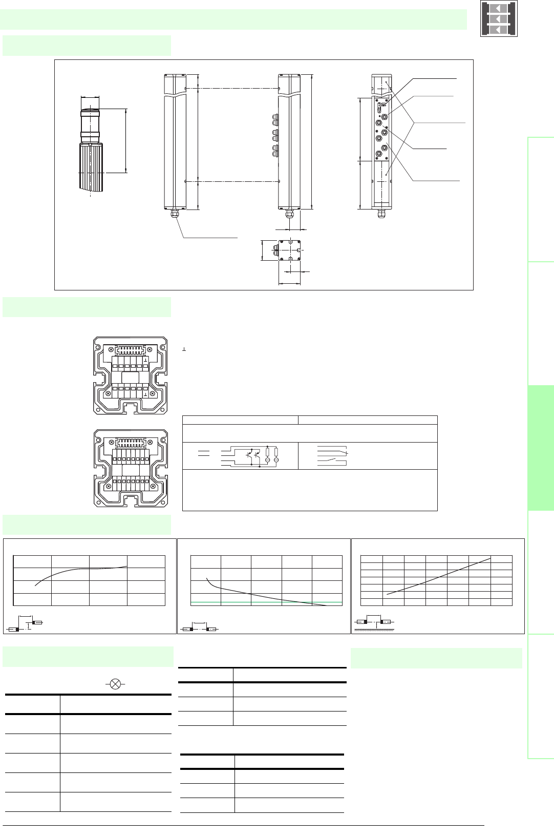
85
S
ubject to reasonable modifications due to technical advances. Copyright Pepperl+Fuchs, Printed in Germany
Pepperl+Fuchs Group • Tel.: Germany +49 621 776-0 • USA +1 330 4253555 • Singapore +65 67799091 • Internet http://www.pepperl-fuchs.com
Diagrams
Electrical connection
Dimensions
Safety through beam
sensors
Safety light gridsSafety light grids with
internal control unit
Safety light curtainsControl units
Indicator lamp control
Additional information
Socket Function
1 OSSD on
2 OSSD off
30 V
4 Readiness for startup
5 Muting (monitored)
SLPCM30-2-...
x
y
SLP30-x / SLPC30-x / SLPCM30-x
Offset Y [mm]
Distance X [m]
Characteristic response curve
0
50
100
150
200
010203040
x
SLP30-x / SLPC30-x / SLPCM30-x
Distance X [m]
Stability control
Relative received light strength
1
10
100
1000
10000
0 1020304050
x
y
SLP30-x / SLPC30-x / SLPCM30-x
Distance X [m]
Lateral interval to mirroring surfaces
Minimum interval [m]
0
0.2
0.4
0.6
0.8
1
1.2
1.4
0 5 10 15 20 25 30 35
Date of edition 05/17/2006
Emitter SLP
Receiver SLPCM
T1 - Emitter channel 1
T2 - Emitter channel 2
-0 V
Receiver SLPCM (semiconductor outputs) Receiver SLPCM/31 (relay outputs)
1 - Functional earth
2 - 0 V
3 - 24 V
4 - n.c. 4
5- 5
6- 6
7 - OSSD 1 7
8 - OSSD 2 8
9 - Input, Relay monitor
10 - Input, Start release
11 - Input, Reset
12 - PNP-output, Soiled optics
13 - PNP-output, Muting lamp
14 - PNP-output, Startup readiness
15 - PNP-output, Indicator OSSD OFF
16 - PNP-output, Indicator OSSD ON
1 2 3 4 5 6 7 8
16
15
14
13
12
11
10
9
T5 T6 T7 T8
NC
T1 T2 T3 T4
NC
-
+
Muting
T1-T4
MS3
MS4
MS1
MS2
Cable gland M16
Receiver SLPCM...-2-R
Connector
emitter
Connectors
muting sensors
MS1 ... MS4
Connector ext.
indicator lamp
System status
indicator
Emitter SLP...-2-TOption -L with indicator lamp
(receiver only)
beam 2
beam 1
Indicator
lamp
topmost
beam
Status indicator
of the particular
safety beam
64
32
70
33.5
636
90 500 46
197
ø 57
156 203
Safety light grid with integrated control unit
T1 - T4 transmitter control
Muting sensor inputs MS1 - MS4
Socket Function
1 Transmitter channel 1
2 Transmitter channel 2
30 V
Socket Function
1 + 24 V
30 V
4 Sensor signal
• Mounting set MS SLP
• Profile alignment aid PA SLP/SLC
• Laser alignment aid BA SLP
• Ground pillar UC SLP/SLC
• Housing for pillar
Enclosure UC SLP/SLC
• Collision protector
Damping UC SLP/SLC
• Redirection mirror SLP-2-M
System accessories
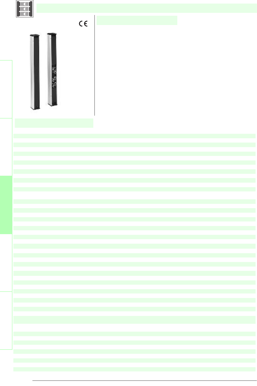
Subject to reasonable modifications due to technical advances. Copyright Pepperl+Fuchs, Printed in Germany
Pepperl+Fuchs Group • Tel.: Germany +49 621 776-0 • USA +1 330 4253555 • Singapore +65 67799091 • Internet http://www.pepperl-fuchs.com
86
Technische DatenTechnical data
Features
Ordering code:
Sicherheits-Lichtschranken
Sicherheits-Lichtgitter
Sicherheits-Lichtgitter mit
interner Auswerteeinheit
Sicherheits-Lichtvorhänge
Auswertegeräte Safety through beam
sensors
Safety light grids
Safety light grigs with
internal control unit
Safety light curtains
Control units
SLPCM65-2
SLPCM65-2/31
SLPCM65-2-L
SLPCM65-2-L/31
Effective detection range
12 ... 65 m
X X X X
Light source
LED
XXXX
Approvals
TÜV
X X X X
Tests
IEC/EN 61496
XXXX
Marking
CE
X X X X
Obstacle size
static: 32 mm, dynamic: 50 mm (at v = 1.6 m/s of the obstacle)
XXXX
Beam spacing
500 mm
X X X X
Number of beams
2
XXXX
Safety category according to IEC/EN 61496
4
X X X X
Operating mode
Start/restart disable, relay monitor, muting operating modes
XXXX
Light type
red, modulated light
X X X X
Angle of divergence
< 5 °
XXXX
Diagnosis display
7-segment display
X X X X
Function display
LED red: per receiver channel, off: interruption, flashes: receiver, continuously on: reception with sufficient stability control
on the front plate: LED red: OSSD off, LED green: OSSD on, LED yellow: types of muting operation
XXXX
Muting display
Indicator lamp
X X
Pre-fault indication
LED red next to receiver flashes
XXXX
Operating elements
10 DIP switch in receiver terminal compartment
X X X X
Operating voltage
24 V DC -15 % / +25 % , electrically isolated
XXXX
Protection class
III
X X X X
No-load supply current
max. 250 mA
XXXX
Activation current
approx. 10 mA
X X X X
Activation time
0.03 ... 1 s
XXXX
Test input
Reset-input for system test
X X X X
Function input
Relay monitor, start release, muting sensors (max. 4)
XXXX
Output of the pre-fault indication
1 PNP, +UB -2 V, max. 300 mA
X X X X
Safety output
2 separated fail safe semiconductor outputs
XX
2 relay outputs, compelled connection NO-contact
X X
Signal output
1 PNP each, max. 300 mA for start readiness, OSSD on, OSSD off, muting lamp
XX
1 PNP each, max. 300 mA for startup readiness, OSSD on, OSSD off, muting lamp, signals in parallel in the lamp socket
X X
Switching voltage
Operating voltage -2 V
XX
20 ... 60 V DC, 12 ... 25 V AC rms
X X
Switching current
max. 0.5 A
XX
0.01 ... 2 A
X X
Switch power
100 VA
XX
Response time
20 ms
X X
40 ms
XX
Ambient temperature
0 ... 50 °C (273 ... 323 K)
X X X X
Storage temperature
-20 ... 70 °C (253 ... 343 K)
XXXX
Relative humidity
max. 95 %, not condensing
X X X X
Protection degree
IP65
XXXX
Connection
Cable screwed connection M16 , terminal compartment with cage-terminals, M12-connector for emitter, muting lamp as well as other muting
sensors
X X
Cable screwed connection M16 , terminal compartment with cage terminals, M12 connector for transmitters, muting lamp, etc., muting sen-
sors, lamp socket for muting lamp, etc.
XX
Connection options
Further electrical connection options on request: Plug connector DIN 43 651 Hirschmann, emitter: 6-pin+PE, receiver: 11-pin+PE
X X X X
Housing
aluminium extruded structural profile, RAL 1021 (yellow) coated
XXXX
Optical face
Plastic pane
X X X X
Mass
Per 2300 g
XXXX
System components
Emitter
SLP65-2-T
XXXX
Receiver
SLPCM65-2-R
X
SLPCM65-2-R-L
X
SLPCM65-2-R-L/31
X
SLPCM65-2-R/31
X
SLPCM65-2-...
• Detection range up to 65 m
• 2-Radial design
• Beam spacing 500 mm
• Self-monitoring (type 4 according to IEC/EN 61496-1)
• Red transmission light
• Usable with or without start/restart disable
• Sequential and parallel muting in various operating modes
• Emergency muting for the correction of the material jam
• Integrated relay monitor
• 7-segment diagnostic display
• Integrated function display
• Pre-fault indication
• OSSD outputs as semiconductor or relay outputs
Date of edition 05/17/2006
Safety light grid with integrated control unit
For suitable cable sockets, mounting aids, redirection mirrors and more refer to chapter „Accessories“.
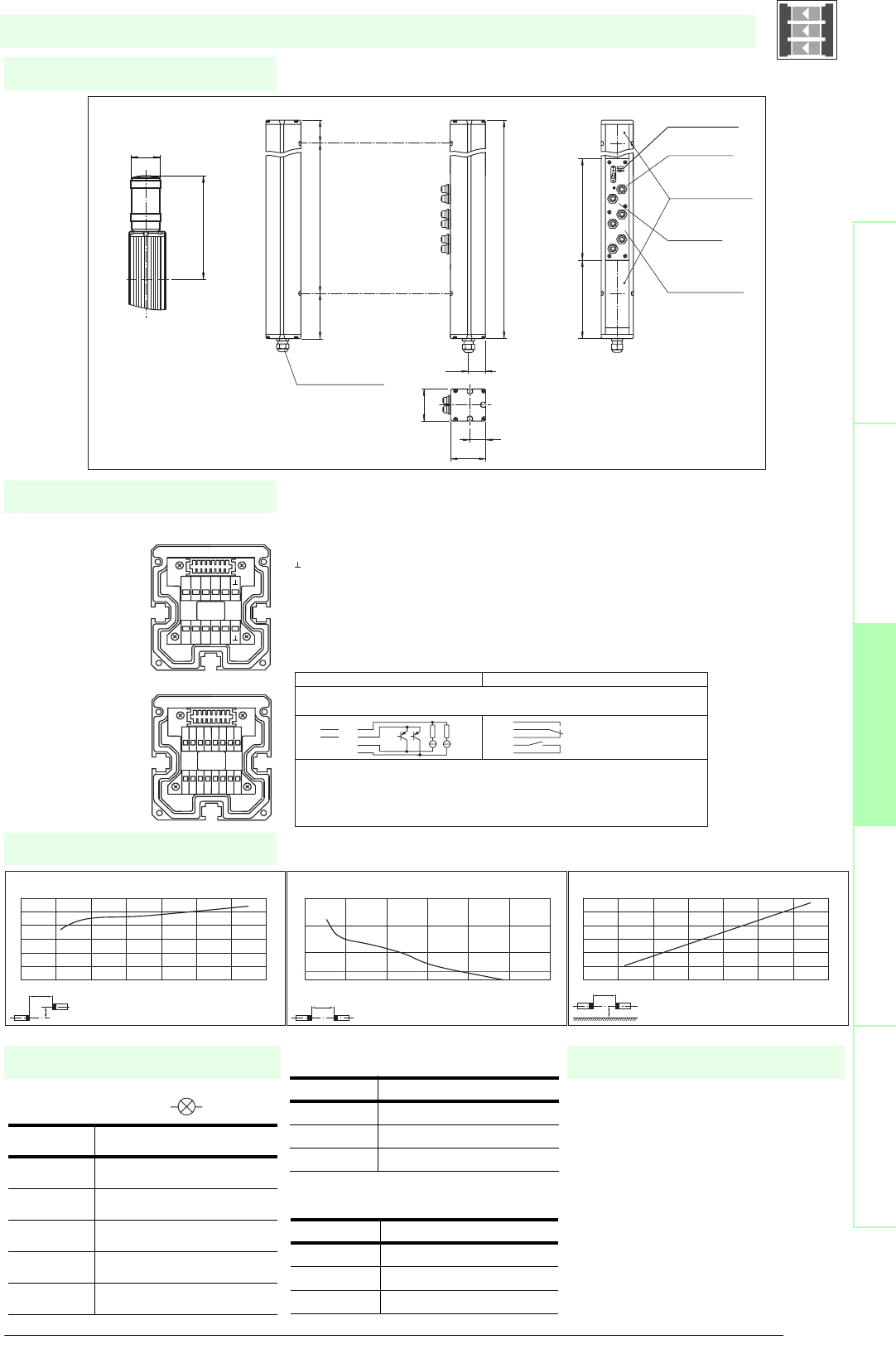
87
S
ubject to reasonable modifications due to technical advances. Copyright Pepperl+Fuchs, Printed in Germany
Pepperl+Fuchs Group • Tel.: Germany +49 621 776-0 • USA +1 330 4253555 • Singapore +65 67799091 • Internet http://www.pepperl-fuchs.com
Diagrams
Electrical connection
Dimensions
Safety through beam
sensors
Safety light gridsSafety light grids with
internal control unit
Safety light curtainsControl units
Indicator lamp control
Additional information
Socket Function
1 OSSD on
2 OSSD off
30 V
4 Readiness for startup
5 Muting (monitored)
SLPCM65-2-...
x
y
SLP65-x / SLPC65-x / SLPCM65-x
Offset Y [mm]
Distance X [m]
Characteristic response curve
0
50
100
150
200
250
300
0 10203040506070
x
SLP65-x / SLPC65-x / SLPCM65-x
Distance X [m]
Stability control
Relative received light strength
1
10
100
1000
0 20 40 60 80 100 120
x
y
SLP65-x / SLPC65-x / SLPCM65-x
Distance X [m]
Lateral interval to mirroring surfaces
Minimum interval [m]
0
0.5
1
1.5
2
2.5
3
0 10203040506070
Date of edition 05/17/2006
Emitter SLP
Receiver SLPCM
T1 - Emitter channel 1
T2 - Emitter channel 2
-0 V
Receiver SLPCM (semiconductor outputs) Receiver SLPCM/31 (relay outputs)
1 - Functional earth
2 - 0 V
3 - 24 V
4 - n.c. 4
5- 5
6- 6
7 - OSSD 1 7
8 - OSSD 2 8
9 - Input, Relay monitor
10 - Input, Start release
11 - Input, Reset
12 - PNP-output, Soiled optics
13 - PNP-output, Muting lamp
14 - PNP-output, Startup readiness
15 - PNP-output, Indicator OSSD OFF
16 - PNP-output, Indicator OSSD ON
1 2 3 4 5 6 7 8
16
15
14
13
12
11
10
9
T5 T6 T7 T8
NC
T1 T2 T3 T4
NC
-
+
Muting
T1-T4
MS3
MS4
MS1
MS2
Cable gland M16
Receiver SLPCM...-2-R
Connector
emitter
Connectors
muting sensors
MS1 ... MS4
Connector ext.
indicator lamp
System status
indicator
Emitter SLP...-2-TOption -L with indicator lamp
(receiver only)
beam 2
beam 1
Indicator
lamp
topmost
beam
Status indicator
of the particular
safety beam
64
32
70
33.5
636
90 500 46
197
ø 57
156 203
Safety light grid with integrated control unit
T1 - T4 transmitter control
Muting sensor inputs MS1 - MS4
Socket Function
1 Transmitter channel 1
2 Transmitter channel 2
30 V
Socket Function
1 + 24 V
30 V
4 Sensor signal
• Mounting set MS SLP
• Profile alignment aid PA SLP/SLC
• Laser alignment aid BA SLP
• Ground pillar UC SLP/SLC
• Housing for pillar
Enclosure UC SLP/SLC
• Collision protector
Damping UC SLP/SLC
• Redirection mirror SLP-2-M
System accessories

Subject to reasonable modifications due to technical advances. Copyright Pepperl+Fuchs, Printed in Germany
Pepperl+Fuchs Group • Tel.: Germany +49 621 776-0 • USA +1 330 4253555 • Singapore +65 67799091 • Internet http://www.pepperl-fuchs.com
88
Technische DatenTechnical data
Features
Ordering code:
Sicherheits-Lichtschranken
Sicherheits-Lichtgitter
Sicherheits-Lichtgitter mit
interner Auswerteeinheit
Sicherheits-Lichtvorhänge
Auswertegeräte Safety through beam
sensors
Safety light grids
Safety light grigs with
internal control unit
Safety light curtains
Control units
SLPCM10-3
SLPCM10-3/31
SLPCM10-3-L
SLPCM10-3-L/31
Effective detection range
0.2 ... 10 m
X X X X
Light source
LED
XXXX
Approvals
TÜV
X X X X
Tests
IEC/EN 61496
XXXX
Marking
CE
X X X X
Obstacle size
static: 32 mm, dynamic: 50 mm (at v = 1.6 m/s of the obstacle)
XXXX
Beam spacing
400 mm
X X X X
Number of beams
3
XXXX
Safety category according to IEC/EN 61496
4
X X X X
Operating mode
Start/restart disable, relay monitor, muting operating modes
XXXX
Light type
red, modulated light
X X X X
Angle of divergence
< 5 °
XXXX
Diagnosis display
7-segment display
X X X X
Function display
LED red: per receiver channel, off: interruption, flashes: receiver, continuously on: reception with sufficient stability control
on the front plate: LED red: OSSD off, LED green: OSSD on, LED yellow: types of muting operation
XXXX
Muting display
Indicator lamp
X X
Pre-fault indication
LED red next to receiver flashes
XXXX
Operating elements
10 DIP switch in receiver terminal compartment
X X X X
Operating voltage
24 V DC -15 % / +25 % , electrically isolated
XXXX
Protection class
III
X X X X
No-load supply current
max. 250 mA
XXXX
Activation current
approx. 10 mA
X X X X
Activation time
0.03 ... 1 s
XXXX
Test input
Reset-input for system test
X X X X
Function input
Relay monitor, start release, muting sensors (max. 4)
XXXX
Output of the pre-fault indication
1 PNP, +UB -2 V, max. 300 mA
X X X X
Safety output
2 separated fail safe semiconductor outputs
XX
2 relay outputs, compelled connection NO-contact
X X
Signal output
1 PNP each, max. 300 mA for start readiness, OSSD on, OSSD off, muting lamp
XX
1 PNP each, max. 300 mA for startup readiness, OSSD on, OSSD off, muting lamp, signals in parallel in the lamp socket
X X
Switching voltage
Operating voltage -2 V
XX
20 ... 60 V DC, 12 ... 25 V AC rms
X X
Switching current
max. 0.5 A
XX
0.01 ... 2 A
X X
Switch power
100 VA
XX
Response time
20 ms
X X
40 ms
XX
Ambient temperature
0 ... 50 °C (273 ... 323 K)
X X X X
Storage temperature
-20 ... 70 °C (253 ... 343 K)
XXXX
Relative humidity
max. 95 %, not condensing
X X X X
Protection degree
IP65
XXXX
Connection
Cable screwed connection M16 , terminal compartment with cage-terminals, M12-connector for emitter, muting lamp as well as other muting
sensors
X X
Cable screwed connection M16 , terminal compartment with cage terminals, M12 connector for transmitters, muting lamp, etc., muting sen-
sors, lamp socket for muting lamp, etc.
XX
Connection options
Further electrical connection options on request: Plug connector DIN 43 651 Hirschmann, emitter: 6-pin+PE, receiver: 11-pin+PE
X X X X
Housing
aluminium extruded structural profile, RAL 1021 (yellow) coated
XXXX
Optical face
Plastic pane
X X X X
Mass
Per 3400 g
XXXX
System components
Emitter
SLP10-3-T
XXXX
Receiver
SLPCM10-3-R
X
SLPCM10-3-R-L
X
SLPCM10-3-R-L/31
X
SLPCM10-3-R/31
X
SLPCM10-3-...
• Detection range up to 10 m
• 3-Radial design
• Beam spacing 400 mm
• Self-monitoring (type 4 according to IEC/EN 61496-1)
• Red transmission light
• Usable with or without start/restart disable
• Sequential and parallel muting in various operating modes
• Emergency muting for the correction of the material jam
• Integrated relay monitor
• 7-segment diagnostic display
• Integrated function display
• Pre-fault indication
• OSSD outputs as semiconductor or relay outputs
Date of edition 05/17/2006
Safety light grid with integrated control unit
For suitable cable sockets, mounting aids, redirection mirrors and more refer to chapter „Accessories“.
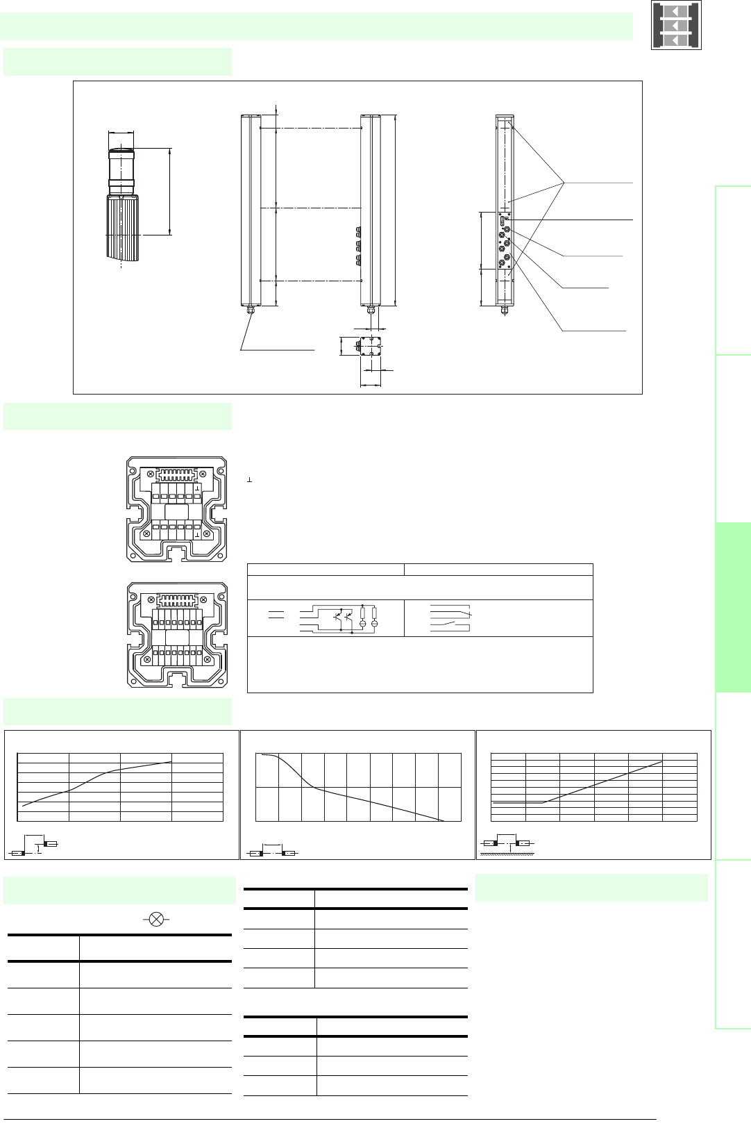
89
S
ubject to reasonable modifications due to technical advances. Copyright Pepperl+Fuchs, Printed in Germany
Pepperl+Fuchs Group • Tel.: Germany +49 621 776-0 • USA +1 330 4253555 • Singapore +65 67799091 • Internet http://www.pepperl-fuchs.com
Diagrams
Electrical connection
Dimensions
Safety through beam
sensors
Safety light gridsSafety light grids with
internal control unit
Safety light curtainsControl units
Indicator lamp control
Additional information
Socket Function
1 OSSD on
2 OSSD off
30 V
4 Readiness for startup
5 Muting (monitored)
SLPCM10-3-...
x
y
SLP10-x / SLPC10-x / SLPCM10-x
Offset Y [mm]
Distance X [m]
Characteristic response curve
0
20
40
60
80
100
120
140
0 5 10 15 20
x
SLP10-x / SLPC10-x / SLPCM10-x
Distance X [m]
Stability control
Relative received light strength
1
10
100
0 2 4 6 8 1012141618
x
y
SLP10-x / SLPC10-x / SLPCM10-x
Distance X [m]
Lateral interval to mirroring surfaces
Minimum interval [m]
0
0.05
0.1
0.15
0.2
0.25
0.3
0.35
0.4
0.45
0.5
0 2 4 6 8 10 12
Date of edition 05/17/2006
Emitter SLP
Receiver SLPCM
T1 - Emitter channel 1
T2 - Emitter channel 2
T3 - Emitter channel 3
-0 V
Receiver SLPCM (semiconductor outputs) Receiver SLPCM/31 (Relay outputs)
1 - Functional earth
2 - 0 V
3 - 24 V
4 - n.c. 4
5- 5
6- 6
7 - OSSD 1 7
8 - OSSD 2 8
9 - Input, Relay monitor
10 - Input, Start release
11 - Input, Reset
12 - PNP-output, Soiled optics
13 - PNP-output, Muting lamp
14 - PNP-output, Startup readiness
15 - PNP-output, Indicator OSSD OFF
16 - PNP-output, Indicator OSSD ON
1 2 3 4 5 6 7 8
16
15
14
13
12
11
10
9
T5 T6 T7 T8
NC
T1 T2 T3 T4
NC
-
+
Muting
SLPCM...-3
T1-T4
MS3
MS4
MS1
MS2
Cable gland M16
Receiver SLPCM...-3-R
Connector ext.
indicator lamp
Connector
Emitter
Connector
muting sensors
MS1 ... MS4
Emitter SLP...-3-T
beam 2
beam 1
beam 3
Option -L with indicator lamp
(receiver only)
Indicator
lamp
topmost
beam
Status indicator
of the particular
safety beam
Status indicator
of the system
64
32
70
33.5
936
90 400 400 46
197
ø 57
156 203
Safety light grid with integrated control unit
T1 - T4 transmitter control
Muting sensor inputs MS1 - MS4
Socket Function
1 Transmitter channel 1
2 Transmitter channel 2
30 V
4 Transmitter channel 3
Socket Function
1 + 24 V
30 V
4 Sensor signal
• Mounting set MS SLP
• Profile alignment aid PA SLP/SLC
• Laser alignment aid BA SLP
• Ground pillar UC SLP/SLC
• Housing for pillar
Enclosure UC SLP/SLC
• Collision protector
Damping UC SLP/SLC
• Redirection mirror SLP-3-M
System accessories

Subject to reasonable modifications due to technical advances. Copyright Pepperl+Fuchs, Printed in Germany
Pepperl+Fuchs Group • Tel.: Germany +49 621 776-0 • USA +1 330 4253555 • Singapore +65 67799091 • Internet http://www.pepperl-fuchs.com
90
Technische DatenTechnical data
Features
Ordering code:
Sicherheits-Lichtschranken
Sicherheits-Lichtgitter
Sicherheits-Lichtgitter mit
interner Auswerteeinheit
Sicherheits-Lichtvorhänge
Auswertegeräte Safety through beam
sensors
Safety light grids
Safety light grigs with
internal control unit
Safety light curtains
Control units
SLPCM30-3
SLPCM30-3/31
SLPCM30-3-L
SLPCM30-3-L/31
Effective detection range
6 ... 30 m
X X X X
Light source
LED
XXXX
Approvals
TÜV
X X X X
Tests
IEC/EN 61496
XXXX
Marking
CE
X X X X
Obstacle size
static: 32 mm, dynamic: 50 mm (at v = 1.6 m/s of the obstacle)
XXXX
Beam spacing
400 mm
X X X X
Number of beams
3
XXXX
Safety category according to IEC/EN 61496
4
X X X X
Operating mode
Start/restart disable, relay monitor, muting operating modes
XXXX
Light type
red, modulated light
X X X X
Angle of divergence
< 5 °
XXXX
Diagnosis display
7-segment display
X X X X
Function display
LED red: per receiver channel, off: interruption, flashes: receiver, continuously on: reception with sufficient stability control
on the front plate: LED red: OSSD off, LED green: OSSD on, LED yellow: types of muting operation
XXXX
Muting display
Indicator lamp
X X
Pre-fault indication
LED red next to receiver flashes
XXXX
Operating elements
10 DIP switch in receiver terminal compartment
X X X X
Operating voltage
24 V DC -15 % / +25 % , electrically isolated
XXXX
Protection class
III
X X X X
No-load supply current
max. 250 mA
XXXX
Activation current
approx. 10 mA
X X X X
Activation time
0.03 ... 1 s
XXXX
Test input
Reset-input for system test
X X X X
Function input
Relay monitor, start release, muting sensors (max. 4)
XXXX
Output of the pre-fault indication
1 PNP, +UB -2 V, max. 300 mA
X X X X
Safety output
2 separated fail safe semiconductor outputs
XX
2 relay outputs, compelled connection NO-contact
X X
Signal output
1 PNP each, max. 300 mA for start readiness, OSSD on, OSSD off, muting lamp
XX
1 PNP each, max. 300 mA for startup readiness, OSSD on, OSSD off, muting lamp, signals in parallel in the lamp socket
X X
Switching voltage
Operating voltage -2 V
XX
20 ... 60 V DC, 12 ... 25 V AC rms
X X
Switching current
max. 0.5 A
XX
0.01 ... 2 A
X X
Switch power
100 VA
XX
Response time
20 ms
X X
40 ms
XX
Ambient temperature
0 ... 50 °C (273 ... 323 K)
X X X X
Storage temperature
-20 ... 70 °C (253 ... 343 K)
XXXX
Relative humidity
max. 95 %, not condensing
X X X X
Protection degree
IP65
XXXX
Connection
Cable screwed connection M16 , terminal compartment with cage-terminals, M12-connector for emitter, muting lamp as well as other muting
sensors
X X
Cable screwed connection M16 , terminal compartment with cage terminals, M12 connector for transmitters, muting lamp, etc., muting sen-
sors, lamp socket for muting lamp, etc.
XX
Connection options
Further electrical connection options on request: Plug connector DIN 43 651 Hirschmann, emitter: 6-pin+PE, receiver: 11-pin+PE
X X X X
Housing
aluminium extruded structural profile, RAL 1021 (yellow) coated
XXXX
Optical face
Plastic pane
X X X X
Mass
Per 3400 g
XXXX
System components
Emitter
SLP30-3-T
XXXX
Receiver
SLPCM30-3-R
X
SLPCM30-3-R-L
X
SLPCM30-3-R-L/31
X
SLPCM30-3-R/31
X
SLPCM30-3-...
• Detection range up to 30 m
• 3-Radial design
• Beam spacing 400 mm
• Self-monitoring (type 4 according to IEC/EN 61496-1)
• Red transmission light
• Usable with or without start/restart disable
• Sequential and parallel muting in various operating modes
• Emergency muting for the correction of the material jam
• Integrated relay monitor
• 7-segment diagnostic display
• Integrated function display
• Pre-fault indication
• OSSD outputs as semiconductor or relay outputs
Date of edition 05/17/2006
Safety light grid with integrated control unit
For suitable cable sockets, mounting aids, redirection mirrors and more refer to chapter „Accessories“.
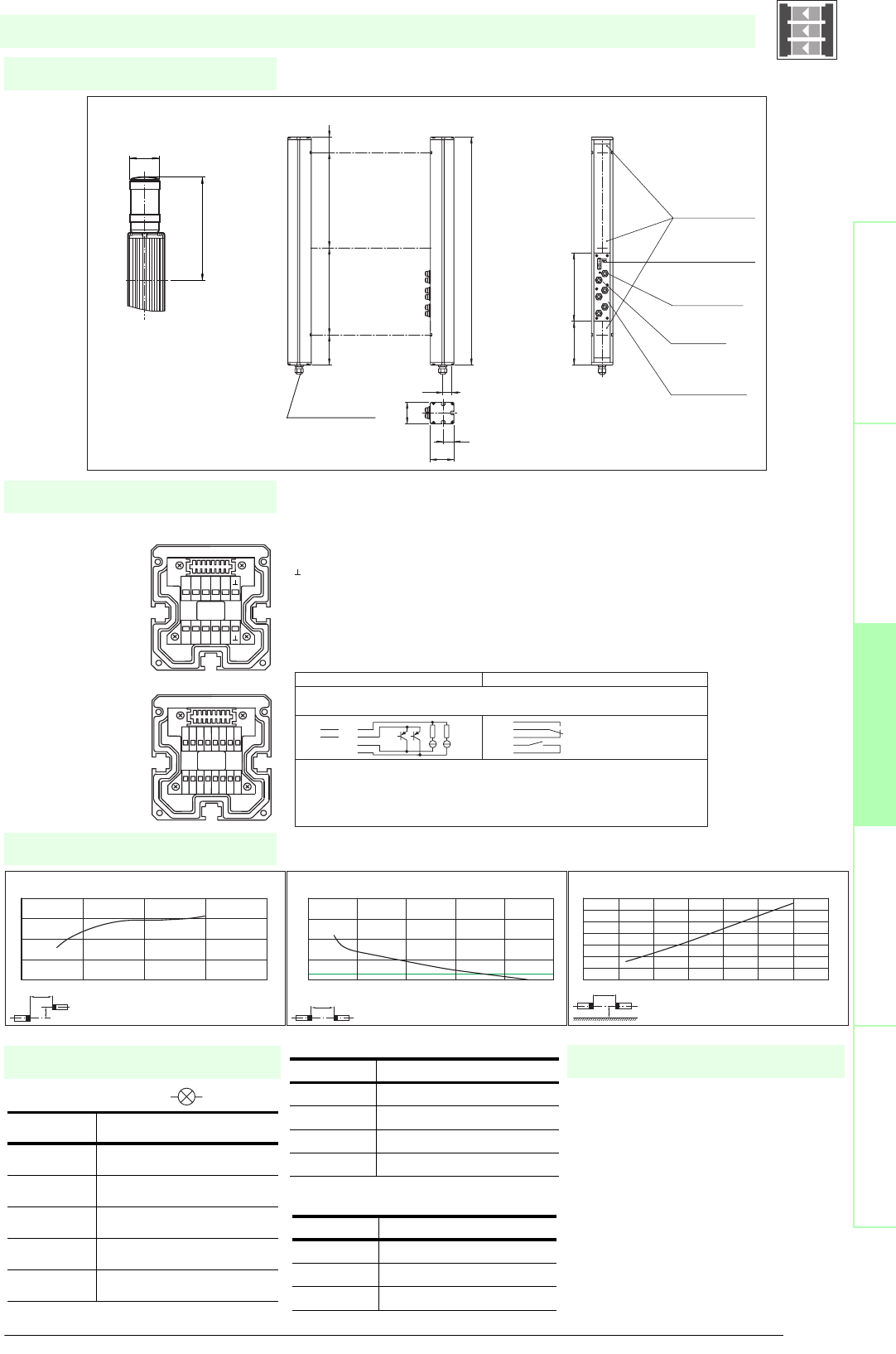
91
S
ubject to reasonable modifications due to technical advances. Copyright Pepperl+Fuchs, Printed in Germany
Pepperl+Fuchs Group • Tel.: Germany +49 621 776-0 • USA +1 330 4253555 • Singapore +65 67799091 • Internet http://www.pepperl-fuchs.com
Diagrams
Electrical connection
Dimensions
Safety through beam
sensors
Safety light gridsSafety light grids with
internal control unit
Safety light curtainsControl units
Indicator lamp control
Additional information
Socket Function
1 OSSD on
2 OSSD off
30 V
4 Readiness for startup
5 Muting (monitored)
SLPCM30-3-...
x
y
SLP30-x / SLPC30-x / SLPCM30-x
Offset Y [mm]
Distance X [m]
Characteristic response curve
0
50
100
150
200
010203040
x
SLP30-x / SLPC30-x / SLPCM30-x
Distance X [m]
Stability control
Relative received light strength
1
10
100
1000
10000
0 1020304050
x
y
SLP30-x / SLPC30-x / SLPCM30-x
Distance X [m]
Lateral interval to mirroring surfaces
Minimum interval [m]
0
0.2
0.4
0.6
0.8
1
1.2
1.4
0 5 10 15 20 25 30 35
Date of edition 05/17/2006
Emitter SLP
Receiver SLPCM
T1 - Emitter channel 1
T2 - Emitter channel 2
T3 - Emitter channel 3
-0 V
Receiver SLPCM (semiconductor outputs) Receiver SLPCM/31 (Relay outputs)
1 - Functional earth
2 - 0 V
3 - 24 V
4 - n.c. 4
5- 5
6- 6
7 - OSSD 1 7
8 - OSSD 2 8
9 - Input, Relay monitor
10 - Input, Start release
11 - Input, Reset
12 - PNP-output, Soiled optics
13 - PNP-output, Muting lamp
14 - PNP-output, Startup readiness
15 - PNP-output, Indicator OSSD OFF
16 - PNP-output, Indicator OSSD ON
1 2 3 4 5 6 7 8
16
15
14
13
12
11
10
9
T5 T6 T7 T8
NC
T1 T2 T3 T4
NC
-
+
Muting
SLPCM...-3
T1-T4
MS3
MS4
MS1
MS2
Cable gland M16
Receiver SLPCM...-3-R
Connector ext.
indicator lamp
Connector
Emitter
Connector
muting sensors
MS1 ... MS4
Emitter SLP...-3-T
beam 2
beam 1
beam 3
Option -L with indicator lamp
(receiver only)
Indicator
lamp
topmost
beam
Status indicator
of the particular
safety beam
Status indicator
of the system
64
32
70
33.5
936
90 400 400 46
197
ø 57
156 203
Safety light grid with integrated control unit
T1 - T4 transmitter control
Muting sensor inputs MS1 - MS4
Socket Function
1 Transmitter channel 1
2 Transmitter channel 2
30 V
4 Transmitter channel 3
Socket Function
1 + 24 V
30 V
4 Sensor signal
• Mounting set MS SLP
• Profile alignment aid PA SLP/SLC
• Laser alignment aid BA SLP
• Ground pillar UC SLP/SLC
• Housing for pillar
Enclosure UC SLP/SLC
• Collision protector
Damping UC SLP/SLC
• Redirection mirror SLP-3-M
System accessories

Subject to reasonable modifications due to technical advances. Copyright Pepperl+Fuchs, Printed in Germany
Pepperl+Fuchs Group • Tel.: Germany +49 621 776-0 • USA +1 330 4253555 • Singapore +65 67799091 • Internet http://www.pepperl-fuchs.com
92
Technische DatenTechnical data
Features
Ordering code:
Sicherheits-Lichtschranken
Sicherheits-Lichtgitter
Sicherheits-Lichtgitter mit
interner Auswerteeinheit
Sicherheits-Lichtvorhänge
Auswertegeräte Safety through beam
sensors
Safety light grids
Safety light grigs with
internal control unit
Safety light curtains
Control units
SLPCM65-3
SLPCM65-3/31
SLPCM65-3-L
SLPCM65-3-L/31
Effective detection range
12 ... 65 m
X X X X
Light source
LED
XXXX
Approvals
TÜV
X X X X
Tests
IEC/EN 61496
XXXX
Marking
CE
X X X X
Obstacle size
static: 32 mm, dynamic: 50 mm (at v = 1.6 m/s of the obstacle)
XXXX
Beam spacing
400 mm
X X X X
Number of beams
3
XXXX
Safety category according to IEC/EN 61496
4
X X X X
Operating mode
Start/restart disable, relay monitor, muting operating modes
XXXX
Light type
red, modulated light
X X X X
Angle of divergence
< 5 °
XXXX
Diagnosis display
7-segment display
X X X X
Function display
LED red: per receiver channel, off: interruption, flashes: receiver, continuously on: reception with sufficient stability control
on the front plate: LED red: OSSD off, LED green: OSSD on, LED yellow: types of muting operation
XXXX
Muting display
Indicator lamp
X X
Pre-fault indication
LED red next to receiver flashes
XXXX
Operating elements
10 DIP switch in receiver terminal compartment
X X X X
Operating voltage
24 V DC -15 % / +25 % , electrically isolated
XXXX
Protection class
III
X X X X
No-load supply current
max. 250 mA
XXXX
Activation current
approx. 10 mA
X X X X
Activation time
0.03 ... 1 s
XXXX
Test input
Reset-input for system test
X X X X
Function input
Relay monitor, start release, muting sensors (max. 4)
XXXX
Output of the pre-fault indication
1 PNP, +UB -2 V, max. 300 mA
X X X X
Safety output
2 separated fail safe semiconductor outputs
XX
2 relay outputs, compelled connection NO-contact
X X
Signal output
1 PNP each, max. 300 mA for start readiness, OSSD on, OSSD off, muting lamp
XX
1 PNP each, max. 300 mA for startup readiness, OSSD on, OSSD off, muting lamp, signals in parallel in the lamp socket
X X
Switching voltage
Operating voltage -2 V
XX
20 ... 60 V DC, 12 ... 25 V AC rms
X X
Switching current
max. 0.5 A
XX
0.01 ... 2 A
X X
Switch power
100 VA
XX
Response time
20 ms
X X
40 ms
XX
Ambient temperature
0 ... 50 °C (273 ... 323 K)
X X X X
Storage temperature
-20 ... 70 °C (253 ... 343 K)
XXXX
Relative humidity
max. 95 %, not condensing
X X X X
Protection degree
IP65
XXXX
Connection
Cable screwed connection M16 , terminal compartment with cage-terminals, M12-connector for emitter, muting lamp as well as other muting
sensors
X X
Cable screwed connection M16 , terminal compartment with cage terminals, M12 connector for transmitters, muting lamp, etc., muting sen-
sors, lamp socket for muting lamp, etc.
XX
Connection options
Further electrical connection options on request: Plug connector DIN 43 651 Hirschmann, emitter: 6-pin+PE, receiver: 11-pin+PE
X X X X
Housing
aluminium extruded structural profile, RAL 1021 (yellow) coated
XXXX
Optical face
Plastic pane
X X X X
Mass
Per 3400 g
XXXX
System components
Emitter
SLP65-3-T
XXXX
Receiver
SLPCM65-3-R
X
SLPCM65-3-R-L
X
SLPCM65-3-R-L/31
X
SLPCM65-3-R/31
X
SLPCM65-3-...
• Detection range up to 65 m
• 3-Radial design
• Beam spacing 400 mm
• Self-monitoring (type 4 according to IEC/EN 61496-1)
• Red transmission light
• Usable with or without start/restart disable
• Sequential and parallel muting in various operating modes
• Emergency muting for the correction of the material jam
• Integrated relay monitor
• 7-segment diagnostic display
• Integrated function display
• Pre-fault indication
• OSSD outputs as semiconductor or relay outputs
Date of edition 05/17/2006
Safety light grid with integrated control unit
For suitable cable sockets, mounting aids, redirection mirrors and more refer to chapter „Accessories“.
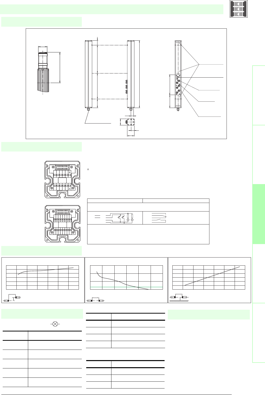
93
S
ubject to reasonable modifications due to technical advances. Copyright Pepperl+Fuchs, Printed in Germany
Pepperl+Fuchs Group • Tel.: Germany +49 621 776-0 • USA +1 330 4253555 • Singapore +65 67799091 • Internet http://www.pepperl-fuchs.com
Diagrams
Electrical connection
Dimensions
Safety through beam
sensors
Safety light gridsSafety light grids with
internal control unit
Safety light curtainsControl units
Indicator lamp control
Additional information
Socket Function
1 OSSD on
2 OSSD off
30 V
4 Readiness for startup
5 Muting (monitored)
SLPCM65-3-...
x
y
SLP65-x / SLPC65-x / SLPCM65-x
Offset Y [mm]
Distance X [m]
Characteristic response curve
0
50
100
150
200
250
300
0 10203040506070
x
SLP65-x / SLPC65-x / SLPCM65-x
Distance X [m]
Stability control
Relative received light strength
1
10
100
1000
0 20 40 60 80 100 120
x
y
SLP65-x / SLPC65-x / SLPCM65-x
Distance X [m]
Lateral interval to mirroring surfaces
Minimum interval [m]
0
0.5
1
1.5
2
2.5
3
0 10203040506070
Date of edition 05/17/2006
Emitter SLP
Receiver SLPCM
T1 - Emitter channel 1
T2 - Emitter channel 2
T3 - Emitter channel 3
-0 V
Receiver SLPCM (semiconductor outputs) Receiver SLPCM/31 (Relay outputs)
1 - Functional earth
2 - 0 V
3 - 24 V
4 - n.c. 4
5- 5
6- 6
7 - OSSD 1 7
8 - OSSD 2 8
9 - Input, Relay monitor
10 - Input, Start release
11 - Input, Reset
12 - PNP-output, Soiled optics
13 - PNP-output, Muting lamp
14 - PNP-output, Startup readiness
15 - PNP-output, Indicator OSSD OFF
16 - PNP-output, Indicator OSSD ON
1 2 3 4 5 6 7 8
16
15
14
13
12
11
10
9
T5 T6 T7 T8
NC
T1 T2 T3 T4
NC
-
+
Muting
SLPCM...-3
T1-T4
MS3
MS4
MS1
MS2
Cable gland M16
Receiver SLPCM...-3-R
Connector ext.
indicator lamp
Connector
Emitter
Connector
muting sensors
MS1 ... MS4
Emitter SLP...-3-T
beam 2
beam 1
beam 3
Option -L with indicator lamp
(receiver only)
Indicator
lamp
topmost
beam
Status indicator
of the particular
safety beam
Status indicator
of the system
64
32
70
33.5
936
90 400 400 46
197
ø 57
156 203
Safety light grid with integrated control unit
T1 - T4 transmitter control
Muting sensor inputs MS1 - MS4
Socket Function
1 Transmitter channel 1
2 Transmitter channel 2
30 V
4 Transmitter channel 3
Socket Function
1+ 24 V
30 V
4 Sensor signal
• Mounting set MS SLP
• Profile alignment aid PA SLP/SLC
• Laser alignment aid BA SLP
• Ground pillar UC SLP/SLC
• Housing for pillar
Enclosure UC SLP/SLC
• Collision protector
Damping UC SLP/SLC
• Redirection mirror SLP-3-M
System accessories

Subject to reasonable modifications due to technical advances. Copyright Pepperl+Fuchs, Printed in Germany
Pepperl+Fuchs Group • Tel.: Germany +49 621 776-0 • USA +1 330 4253555 • Singapore +65 67799091 • Internet http://www.pepperl-fuchs.com
94
Technische DatenTechnical data
Features
Ordering code:
Sicherheits-Lichtschranken
Sicherheits-Lichtgitter
Sicherheits-Lichtgitter mit
interner Auswerteeinheit
Sicherheits-Lichtvorhänge
Auswertegeräte Safety through beam
sensors
Safety light grids
Safety light grigs with
internal control unit
Safety light curtains
Control units
SLPCM10-4
SLPCM10-4/31
SLPCM10-4-L
SLPCM10-4-L/31
Effective detection range
0.2 ... 10 m
X X X X
Light source
LED
XXXX
Approvals
TÜV
X X X X
Tests
IEC/EN 61496
XXXX
Marking
CE
X X X X
Obstacle size
static: 32 mm, dynamic: 50 mm (at v = 1.6 m/s of the obstacle)
XXXX
Beam spacing
300 mm
X X X X
Number of beams
4
XXXX
Safety category according to IEC/EN 61496
4
X X X X
Operating mode
Start/restart disable, relay monitor, muting operating modes
XXXX
Light type
red, modulated light
X X X X
Angle of divergence
< 5 °
XXXX
Diagnosis display
7-segment display
X X X X
Function display
LED red: per receiver channel, off: interruption, flashes: receiver, continuously on: reception with sufficient stability control
on the front plate: LED red: OSSD off, LED green: OSSD on, LED yellow: types of muting operation
XXXX
Muting display
Indicator lamp
X X
Pre-fault indication
LED red next to receiver flashes
XXXX
Operating elements
10 DIP switch in receiver terminal compartment
X X X X
Operating voltage
24 V DC -15 % / +25 % , electrically isolated
XXXX
Protection class
III
X X X X
No-load supply current
max. 250 mA
XXXX
Activation current
approx. 10 mA
X X X X
Activation time
0.03 ... 1 s
XXXX
Test input
Reset-input for system test
X X X X
Function input
Relay monitor, start release, muting sensors (max. 4)
XXXX
Output of the pre-fault indication
1 PNP, +UB -2 V, max. 300 mA
X X X X
Safety output
2 separated fail safe semiconductor outputs
XX
2 relay outputs, compelled connection NO-contact
X X
Signal output
1 PNP each, max. 300 mA for start readiness, OSSD on, OSSD off, muting lamp
XX
1 PNP each, max. 300 mA for startup readiness, OSSD on, OSSD off, muting lamp, signals in parallel in the lamp socket
X X
Switching voltage
Operating voltage -2 V
XX
20 ... 60 V DC, 12 ... 25 V AC rms
X X
Switching current
max. 0.5 A
XX
0.01 ... 2 A
X X
Switch power
100 VA
XX
Response time
20 ms
X X
40 ms
XX
Ambient temperature
0 ... 50 °C (273 ... 323 K)
X X X X
Storage temperature
-20 ... 70 °C (253 ... 343 K)
XXXX
Relative humidity
max. 95 %, not condensing
X X X X
Protection degree
IP65
XXXX
Connection
Cable screwed connection M16 , terminal compartment with cage-terminals, M12-connector for emitter, muting lamp as well as other muting
sensors
X X
Cable screwed connection M16 , terminal compartment with cage terminals, M12 connector for transmitters, muting lamp, etc., muting sen-
sors, lamp socket for muting lamp, etc.
XX
Connection options
Further electrical connection options on request: Plug connector DIN 43 651 Hirschmann, emitter: 6-pin+PE, receiver: 11-pin+PE
X X X X
Housing
aluminium extruded structural profile, RAL 1021 (yellow) coated
XXXX
Optical face
Plastic pane
X X X X
Mass
Per 3700 g
XXXX
System components
Emitter
SLP10-4-T
XXXX
Receiver
SLPCM10-4-R
X
SLPCM10-4-R-L
X
SLPCM10-4-R-L/31
X
SLPCM10-4-R/31
X
SLPCM10-4-...
• Detection range up to 10 m
• 4-Radial design
• Beam spacing 300 mm
• Self-monitoring (type 4 according to IEC/EN 61496-1)
• Red transmission light
• Usable with or without start/restart disable
• Sequential and parallel muting in various operating modes
• Emergency muting for the correction of the material jam
• Integrated relay monitor
• 7-segment diagnostic display
• Integrated function display
• Pre-fault indication
• OSSD outputs as semiconductor or relay outputs
Date of edition 05/17/2006
Safety light grid with integrated control unit
For suitable cable sockets, mounting aids, redirection mirrors and more refer to chapter „Accessories“.
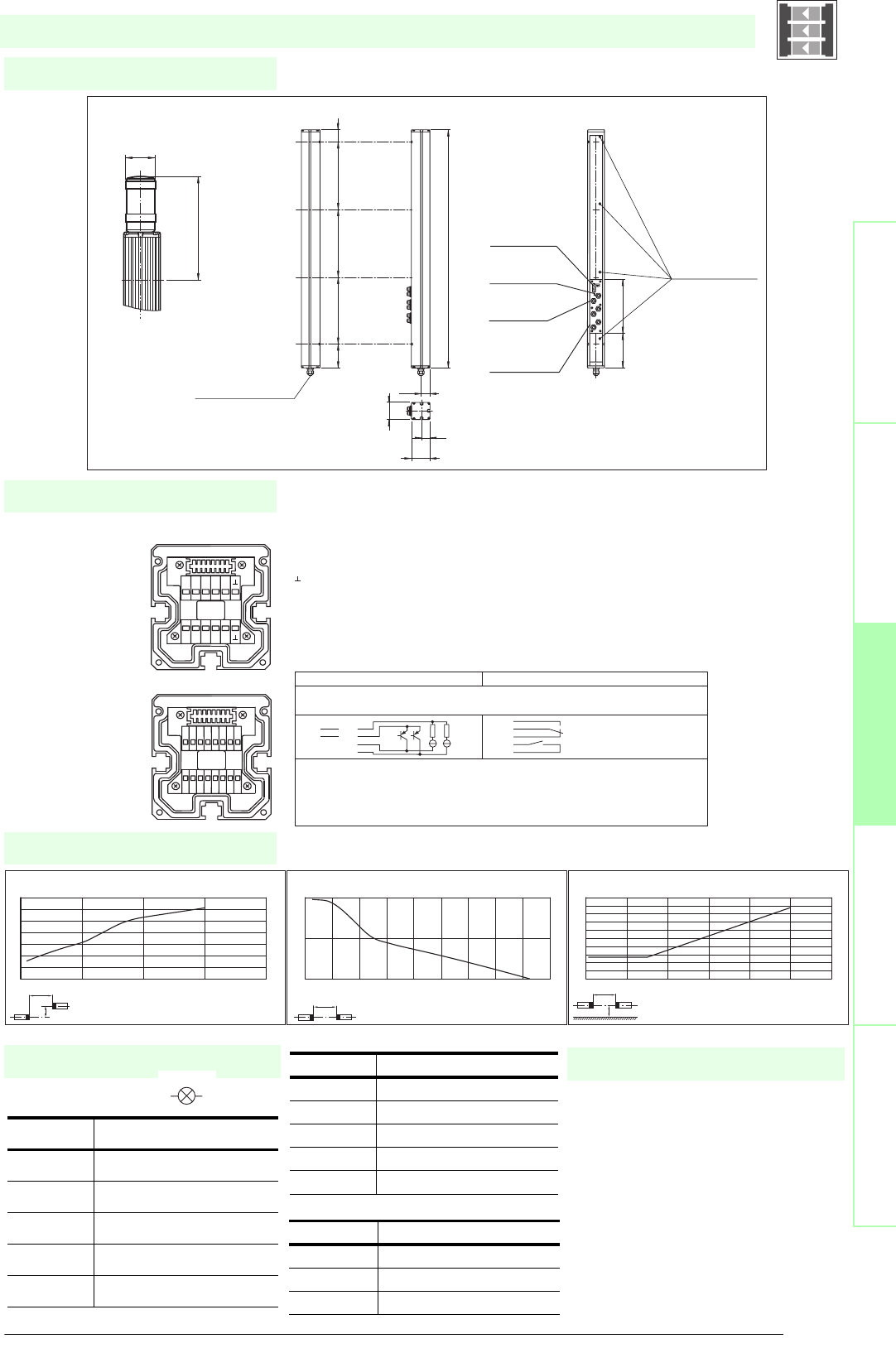
95
S
ubject to reasonable modifications due to technical advances. Copyright Pepperl+Fuchs, Printed in Germany
Pepperl+Fuchs Group • Tel.: Germany +49 621 776-0 • USA +1 330 4253555 • Singapore +65 67799091 • Internet http://www.pepperl-fuchs.com
Diagrams
Electrical connection
Dimensions
Safety through beam
sensors
Safety light gridsSafety light grids with
internal control unit
Safety light curtainsControl units
Indicator lamp control
Additional information
Socket Function
1 OSSD on
2 OSSD off
30 V
4 Readiness for startup
5 Muting (monitored)
SLPCM10-4-...
x
y
SLP10-x / SLPC10-x / SLPCM10-x
Offset Y [mm]
Distance X [m]
Characteristic response curve
0
20
40
60
80
100
120
140
0 5 10 15 20
x
SLP10-x / SLPC10-x / SLPCM10-x
Distance X [m]
Stability control
Relative received light strength
1
10
100
0 2 4 6 8 1012141618
x
y
SLP10-x / SLPC10-x / SLPCM10-x
Distance X [m]
Lateral interval to mirroring surfaces
Minimum interval [m]
0
0.05
0.1
0.15
0.2
0.25
0.3
0.35
0.4
0.45
0.5
0 2 4 6 8 10 12
Date of edition 05/17/2006
Emitter SLP
Receiver SLPCM
T1 - Emitter channel 1
T2 - Emitter channel 2
T3 - Emitter channel 3
T4 - Emitter channel 4
-0 V
Receiver SLPCM (semiconductor outputs) Receiver SLPCM/31 (Relay outputs)
1 - Functional earth
2 - 0 V
3 - 24 V
4 - n.c. 4
5- 5
6- 6
7 - OSSD 1 7
8 - OSSD 2 8
9 - Input, Relay monitor
10 - Input, Start release
11 - Input, Reset
12 - PNP-output, Soiled optics
13 - PNP-output, Muting lamp
14 - PNP-output, Startup readiness
15 - PNP-output, Indicator OSSD OFF
16 - PNP-output, Indicator OSSD ON
1 2 3 4 5 6 7 8
16
15
14
13
12
11
10
9
T5 T6 T7 T8
NC
T1 T2 T3 T4
NC
-
+
Muting
Muting
T1-T4
T1-T4
MS3
MS3
MS4
MS4
MS1
MS1
MS2
MS2
beam 4
beam 3
beam 2
beam 1
Cable gland M16
Emitter SLP...-4-T Receiver SLPCM...-4-R
Status indicator
of the system
Connector
indicator lamp
Connector
emitter
Connector
muting sensors
MS1 ... Ms4
SLPCM...-4
Option -L with indicator lamp
(receiver only)
Indicator
lamp
topmost
beam
Status indicator
of the particular
safety beam
156 203
64
32
70
33.5
1036
90 300 300 300 46
197
ø 57
Safety light grid with integrated control unit
T1 - T4 transmitter control
Muting sensor inputs MS1 - MS4
Socket Function
1 Transmitter channel 1
2 Transmitter channel 2
30 V
4 Transmitter channel 3
5 Transmitter channel 4
Socket Function
1 + 24 V
30 V
4 Sensor signal
• Mounting set MS SLC
• Profile alignment aid PA SLP/SLC
• Laser alignment aid BA SLP
• Ground pillar UC SLP/SLC
• Housing for pillar
Enclosure UC SLP/SLC
• Collision protector
Damping UC SLP/SLC
• Redirection mirror SLP-4-M
System accessories

Subject to reasonable modifications due to technical advances. Copyright Pepperl+Fuchs, Printed in Germany
Pepperl+Fuchs Group • Tel.: Germany +49 621 776-0 • USA +1 330 4253555 • Singapore +65 67799091 • Internet http://www.pepperl-fuchs.com
96
Technische DatenTechnical data
Features
Ordering code:
Sicherheits-Lichtschranken
Sicherheits-Lichtgitter
Sicherheits-Lichtgitter mit
interner Auswerteeinheit
Sicherheits-Lichtvorhänge
Auswertegeräte Safety through beam
sensors
Safety light grids
Safety light grigs with
internal control unit
Safety light curtains
Control units
SLPCM30-4
SLPCM30-4/31
SLPCM30-4-L
SLPCM30-4-L/31
Effective detection range
6 ... 30 m
X X X X
Light source
LED
XXXX
Approvals
TÜV
X X X X
Tests
IEC/EN 61496
XXXX
Marking
CE
X X X X
Obstacle size
static: 32 mm, dynamic: 50 mm (at v = 1.6 m/s of the obstacle)
XXXX
Beam spacing
300 mm
X X X X
Number of beams
4
XXXX
Safety category according to IEC/EN 61496
4
X X X X
Operating mode
Start/restart disable, relay monitor, muting operating modes
XXXX
Light type
red, modulated light
X X X X
Angle of divergence
< 5 °
XXXX
Diagnosis display
7-segment display
X X X X
Function display
LED red: per receiver channel, off: interruption, flashes: receiver, continuously on: reception with sufficient stability control
on the front plate: LED red: OSSD off, LED green: OSSD on, LED yellow: types of muting operation
XXXX
Muting display
Indicator lamp
X X
Pre-fault indication
LED red next to receiver flashes
XXXX
Operating elements
10 DIP switch in receiver terminal compartment
X X X X
Operating voltage
24 V DC -15 % / +25 % , electrically isolated
XXXX
Protection class
III
X X X X
No-load supply current
max. 250 mA
XXXX
Activation current
approx. 10 mA
X X X X
Activation time
0.03 ... 1 s
XXXX
Test input
Reset-input for system test
X X X X
Function input
Relay monitor, start release, muting sensors (max. 4)
XXXX
Output of the pre-fault indication
1 PNP, +UB -2 V, max. 300 mA
X X X X
Safety output
2 separated fail safe semiconductor outputs
XX
2 relay outputs, compelled connection NO-contact
X X
Signal output
1 PNP each, max. 300 mA for start readiness, OSSD on, OSSD off, muting lamp
XX
1 PNP each, max. 300 mA for startup readiness, OSSD on, OSSD off, muting lamp, signals in parallel in the lamp socket
X X
Switching voltage
Operating voltage -2 V
XX
20 ... 60 V DC, 12 ... 25 V AC rms
X X
Switching current
max. 0.5 A
XX
0.01 ... 2 A
X X
Switch power
100 VA
XX
Response time
20 ms
X X
40 ms
XX
Ambient temperature
0 ... 50 °C (273 ... 323 K)
X X X X
Storage temperature
-20 ... 70 °C (253 ... 343 K)
XXXX
Relative humidity
max. 95 %, not condensing
X X X X
Protection degree
IP65
XXXX
Connection
Cable screwed connection M16 , terminal compartment with cage-terminals, M12-connector for emitter, muting lamp as well as other muting
sensors
X X
Cable screwed connection M16 , terminal compartment with cage terminals, M12 connector for transmitters, muting lamp, etc., muting sen-
sors, lamp socket for muting lamp, etc.
XX
Connection options
Further electrical connection options on request: Plug connector DIN 43 651 Hirschmann, emitter: 6-pin+PE, receiver: 11-pin+PE
X X X X
Housing
aluminium extruded structural profile, RAL 1021 (yellow) coated
XXXX
Optical face
Plastic pane
X X X X
Mass
Per 3700 g
XXXX
System components
Emitter
SLP30-4-T
XXXX
Receiver
SLPCM30-4-R
X
SLPCM30-4-R-L
X
SLPCM30-4-R-L/31
X
SLPCM30-4-R/31
X
SLPCM30-4-...
• Detection range up to 30 m
• 4-Radial design
• Beam spacing 300 mm
• Self-monitoring (type 4 according to IEC/EN 61496-1)
• Red transmission light
• Usable with or without start/restart disable
• Sequential and parallel muting in various operating modes
• Emergency muting for the correction of the material jam
• Integrated relay monitor
• 7-segment diagnostic display
• Integrated function display
• Pre-fault indication
• OSSD outputs as semiconductor or relay outputs
Date of edition 05/17/2006
Safety light grid with integrated control unit
For suitable cable sockets, mounting aids, redirection mirrors and more refer to chapter „Accessories“.
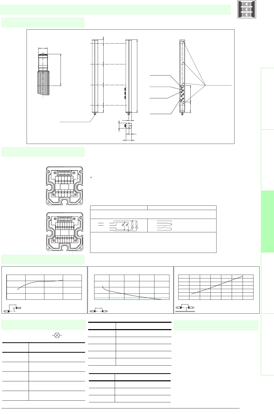
97
S
ubject to reasonable modifications due to technical advances. Copyright Pepperl+Fuchs, Printed in Germany
Pepperl+Fuchs Group • Tel.: Germany +49 621 776-0 • USA +1 330 4253555 • Singapore +65 67799091 • Internet http://www.pepperl-fuchs.com
Diagrams
Electrical connection
Dimensions
Safety through beam
sensors
Safety light gridsSafety light grids with
internal control unit
Safety light curtainsControl units
Indicator lamp control
Additional information
Socket Function
1 OSSD on
2 OSSD off
30 V
4 Readiness for startup
5 Muting (monitored)
SLPCM30-4-...
x
y
SLP30-x / SLPC30-x / SLPCM30-x
Offset Y [mm]
Distance X [m]
Characteristic response curve
0
50
100
150
200
010203040
x
SLP30-x / SLPC30-x / SLPCM30-x
Distance X [m]
Stability control
Relative received light strength
1
10
100
1000
10000
0 1020304050
x
y
SLP30-x / SLPC30-x / SLPCM30-x
Distance X [m]
Lateral interval to mirroring surfaces
Minimum interval [m]
0
0.2
0.4
0.6
0.8
1
1.2
1.4
0 5 10 15 20 25 30 35
Date of edition 05/17/2006
Emitter SLP
Receiver SLPCM
T1 - Emitter channel 1
T2 - Emitter channel 2
T3 - Emitter channel 3
T4 - Emitter channel 4
-0 V
Receiver SLPCM (semiconductor outputs) Receiver SLPCM/31 (Relay outputs)
1 - Functional earth
2 - 0 V
3 - 24 V
4 - n.c. 4
5- 5
6- 6
7 - OSSD 1 7
8 - OSSD 2 8
9 - Input, Relay monitor
10 - Input, Start release
11 - Input, Reset
12 - PNP-output, Soiled optics
13 - PNP-output, Muting lamp
14 - PNP-output, Startup readiness
15 - PNP-output, Indicator OSSD OFF
16 - PNP-output, Indicator OSSD ON
1 2 3 4 5 6 7 8
16
15
14
13
12
11
10
9
T5 T6 T7 T8
NC
T1 T2 T3 T4
NC
-
+
Muting
Muting
T1-T4
T1-T4
MS3
MS3
MS4
MS4
MS1
MS1
MS2
MS2
beam 4
beam 3
beam 2
beam 1
Cable gland M16
Emitter SLP...-4-T Receiver SLPCM...-4-R
Status indicator
of the system
Connector
indicator lamp
Connector
emitter
Connector
muting sensors
MS1 ... Ms4
SLPCM...-4
Option -L with indicator lamp
(receiver only)
Indicator
lamp
topmost
beam
Status indicator
of the particular
safety beam
156 203
64
32
70
33.5
1036
90 300 300 300 46
197
ø 57
Safety light grid with integrated control unit
T1 - T4 transmitter control
Muting sensor inputs MS1 - MS4
Socket Function
1 Transmitter channel 1
2 Transmitter channel 2
30 V
4 Transmitter channel 3
5 Transmitter channel 4
Socket Function
1 + 24 V
30 V
4 Sensor signal
• Mounting set MS SLC
• Profile alignment aid PA SLP/SLC
• Laser alignment aid BA SLP
• Ground pillar UC SLP/SLC
• Housing for pillar
Enclosure UC SLP/SLC
• Collision protector
Damping UC SLP/SLC
• Redirection mirror SLP-4-M
System accessories

Subject to reasonable modifications due to technical advances. Copyright Pepperl+Fuchs, Printed in Germany
Pepperl+Fuchs Group • Tel.: Germany +49 621 776-0 • USA +1 330 4253555 • Singapore +65 67799091 • Internet http://www.pepperl-fuchs.com
98
Technische DatenTechnical data
Features
Ordering code:
Sicherheits-Lichtschranken
Sicherheits-Lichtgitter
Sicherheits-Lichtgitter mit
interner Auswerteeinheit
Sicherheits-Lichtvorhänge
Auswertegeräte Safety through beam
sensors
Safety light grids
Safety light grigs with
internal control unit
Safety light curtains
Control units
SLPCM65-4
SLPCM65-4/31
SLPCM65-4-L
SLPCM65-4-L/31
Effective detection range
12 ... 65 m
X X X X
Light source
LED
XXXX
Approvals
TÜV
X X X X
Tests
IEC/EN 61496
XXXX
Marking
CE
X X X X
Obstacle size
static: 32 mm, dynamic: 50 mm (at v = 1.6 m/s of the obstacle)
XXXX
Beam spacing
300 mm
X X X X
Number of beams
4
XXXX
Safety category according to IEC/EN 61496
4
X X X X
Operating mode
Start/restart disable, relay monitor, muting operating modes
XXXX
Light type
red, modulated light
X X X X
Angle of divergence
< 5 °
XXXX
Diagnosis display
7-segment display
X X X X
Function display
LED red: per receiver channel off: interruption, flashes: receiver, continuously on: reception with sufficient stability control
on the front plate: LED red: OSSD off, LED green: OSSD on, LED yellow: types of muting operation
XXXX
Muting display
Indicator lamp
X X
Pre-fault indication
LED red next to receiver flashes
XXXX
Operating elements
10 DIP switch in receiver terminal compartment
X X X X
Operating voltage
24 V DC -15 % / +25 % , electrically isolated
XXXX
Protection class
III
X X X X
No-load supply current
max. 250 mA
XXXX
Activation current
approx. 10 mA
X X X X
Activation time
0.03 ... 1 s
XXXX
Test input
Reset-input for system test
X X X X
Function input
Relay monitor, start release, muting sensors (max. 4)
XXXX
Output of the pre-fault indication
1 PNP, +UB -2 V, max. 300 mA
X X X X
Safety output
2 separated fail safe semiconductor outputs
XX
2 relay outputs, compelled connection NO-contact
X X
Signal output
1 PNP each, max. 300 mA for start readiness, OSSD on, OSSD off, muting lamp
XX
1 PNP each, max. 300 mA for startup readiness, OSSD on, OSSD off, muting lamp, signals in parallel in the lamp socket
X X
Switching voltage
Operating voltage -2 V
XX
20 ... 60 V DC, 12 ... 25 V AC rms
X X
Switching current
max. 0.5 A
XX
0.01 ... 2 A
X X
Switch power
100 VA
XX
Response time
20 ms
X X
40 ms
XX
Ambient temperature
0 ... 50 °C (273 ... 323 K)
X X X X
Storage temperature
-20 ... 70 °C (253 ... 343 K)
XXXX
Relative humidity
max. 95 %, not condensing
X X X X
Protection degree
IP65
XXXX
Connection
Cable screwed connection M16 , terminal compartment with cage-terminals, M12-connector for emitter, muting lamp as well as other muting
sensors
X X
Cable screwed connection M16 , terminal compartment with cage terminals, M12 connector for transmitters, muting lamp, etc., muting sen-
sors, lamp socket for muting lamp, etc
XX
Connection options
Further electrical connection options on request: Plug connector DIN 43 651 Hirschmann, emitter: 6-pin+PE, receiver: 11-pin+PE
X X X X
Housing
aluminium extruded structural profile, RAL 1021 (yellow) coated
XXXX
Optical face
Plastic pane
X X X X
Mass
Per 3700 g
XXXX
System components
Emitter
SLP65-4-T
XXXX
Receiver
SLPCM65-4-R
X
SLPCM65-4-R-L
X
SLPCM65-4-R-L/31
X
SLPCM65-4-R/31
X
SLPCM65-4-...
• Detection range up to 65 m
• 4-Radial design
• Beam spacing 300 mm
• Self-monitoring (type 4 according to IEC/EN 61496-1)
• Red transmission light
• Usable with or without start/restart disable
• Sequential and parallel muting in various operating modes
• Emergency muting for the correction of the material jam
• Integrated relay monitor
• 7-segment diagnostic display
• Integrated function display
• Pre-fault indication
• OSSD outputs as semiconductor or relay outputs
Date of edition 05/17/2006
Safety light grid with integrated control unit
For suitable cable sockets, mounting aids, redirection mirrors and more refer to chapter „Accessories“.
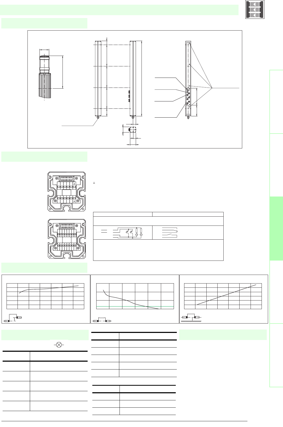
99
S
ubject to reasonable modifications due to technical advances. Copyright Pepperl+Fuchs, Printed in Germany
Pepperl+Fuchs Group • Tel.: Germany +49 621 776-0 • USA +1 330 4253555 • Singapore +65 67799091 • Internet http://www.pepperl-fuchs.com
Diagrams
Electrical connection
Dimensions
Safety through beam
sensors
Safety light gridsSafety light grids with
internal control unit
Safety light curtainsControl units
Indicator lamp control
Additional information
Socket Function
1 OSSD on
2 OSSD off
30 V
4 Readiness for startup
5 Muting (monitored)
SLPCM65-4-...
x
y
SLP65-x / SLPC65-x / SLPCM65-x
Offset Y [mm]
Distance X [m]
Characteristic response curve
0
50
100
150
200
250
300
0 10203040506070
x
SLP65-x / SLPC65-x / SLPCM65-x
Distance X [m]
Stability control
Relative received light strength
1
10
100
1000
0 20 40 60 80 100 120
x
y
SLP65-x / SLPC65-x / SLPCM65-x
Distance X [m]
Lateral interval to mirroring surfaces
Minimum interval [m]
0
0.5
1
1.5
2
2.5
3
0 10203040506070
Date of edition 05/17/2006
Emitter SLP
Receiver SLPCM
T1 - Emitter channel 1
T2 - Emitter channel 2
T3 - Emitter channel 3
T4 - Emitter channel 4
-0 V
Receiver SLPCM (semiconductor outputs) Receiver SLPCM/31 (Relay outputs)
1 - Functional earth
2 - 0 V
3 - 24 V
4 - n.c. 4
5- 5
6- 6
7 - OSSD 1 7
8 - OSSD 2 8
9 - Input, Relay monitor
10 - Input, Start release
11 - Input, Reset
12 - PNP-output, Soiled optics
13 - PNP-output, Muting lamp
14 - PNP-output, Startup readiness
15 - PNP-output, Indicator OSSD OFF
16 - PNP-output, Indicator OSSD ON
1 2 3 4 5 6 7 8
16
15
14
13
12
11
10
9
T5 T6 T7 T8
NC
T1 T2 T3 T4
NC
-
+
Muting
Muting
T1-T4
T1-T4
MS3
MS3
MS4
MS4
MS1
MS1
MS2
MS2
beam 4
beam 3
beam 2
beam 1
Cable gland M16
Emitter SLP...-4-T Receiver SLPCM...-4-R
Status indicator
of the system
Connector
indicator lamp
Connector
emitter
Connector
muting sensors
MS1 ... Ms4
SLPCM...-4
Option -L with indicator lamp
(receiver only)
Indicator
lamp
topmost
beam
Status indicator
of the particular
safety beam
156 203
64
32
70
33.5
1036
90 300 300 300 46
197
ø 57
Safety light grid with integrated control unit
T1 - T4 transmitter control
Muting sensor inputs MS1 - MS4
Socket Function
1 Transmitter channel 1
2 Transmitter channel 2
30 V
4 Transmitter channel 3
5 Transmitter channel 4
Socket Function
1 + 24 V
30 V
4 Sensor signal
• Mounting set MS SLC
• Profile alignment aid PA SLP/SLC
• Laser alignment aid BA SLP
• Ground pillar UC SLP/SLC
• Housing for pillar
Enclosure UC SLP/SLC
• Collision protector
Damping UC SLP/SLC
• Redirection mirror SLP-4-M
System accessories
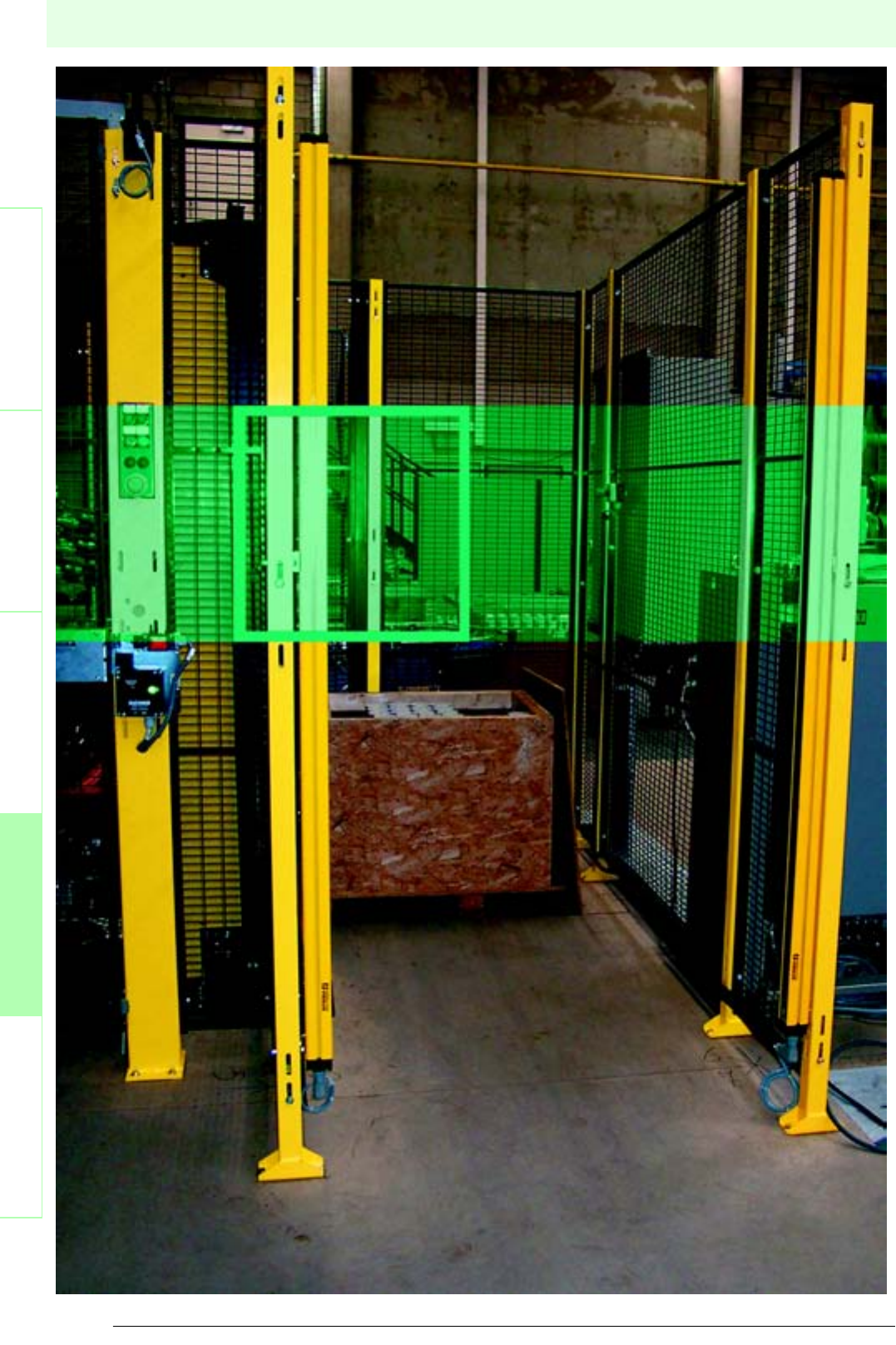
100
Date of edition 05/17/2006
Subject to reasonable modifications due to technical advances. Copyright Pepperl+Fuchs, Printed in Germany
Pepperl+Fuchs Group • Tel.: Germany +49 621 776-0 • USA +1 330 4253555 • Singapore +65 67799091 • Internet http://www.pepperl-fuchs.com
Safety light curtains
Safety light barriersSafety light gridsSafety light grids with
internal control unit
Safety light curtainsControl units
SLC
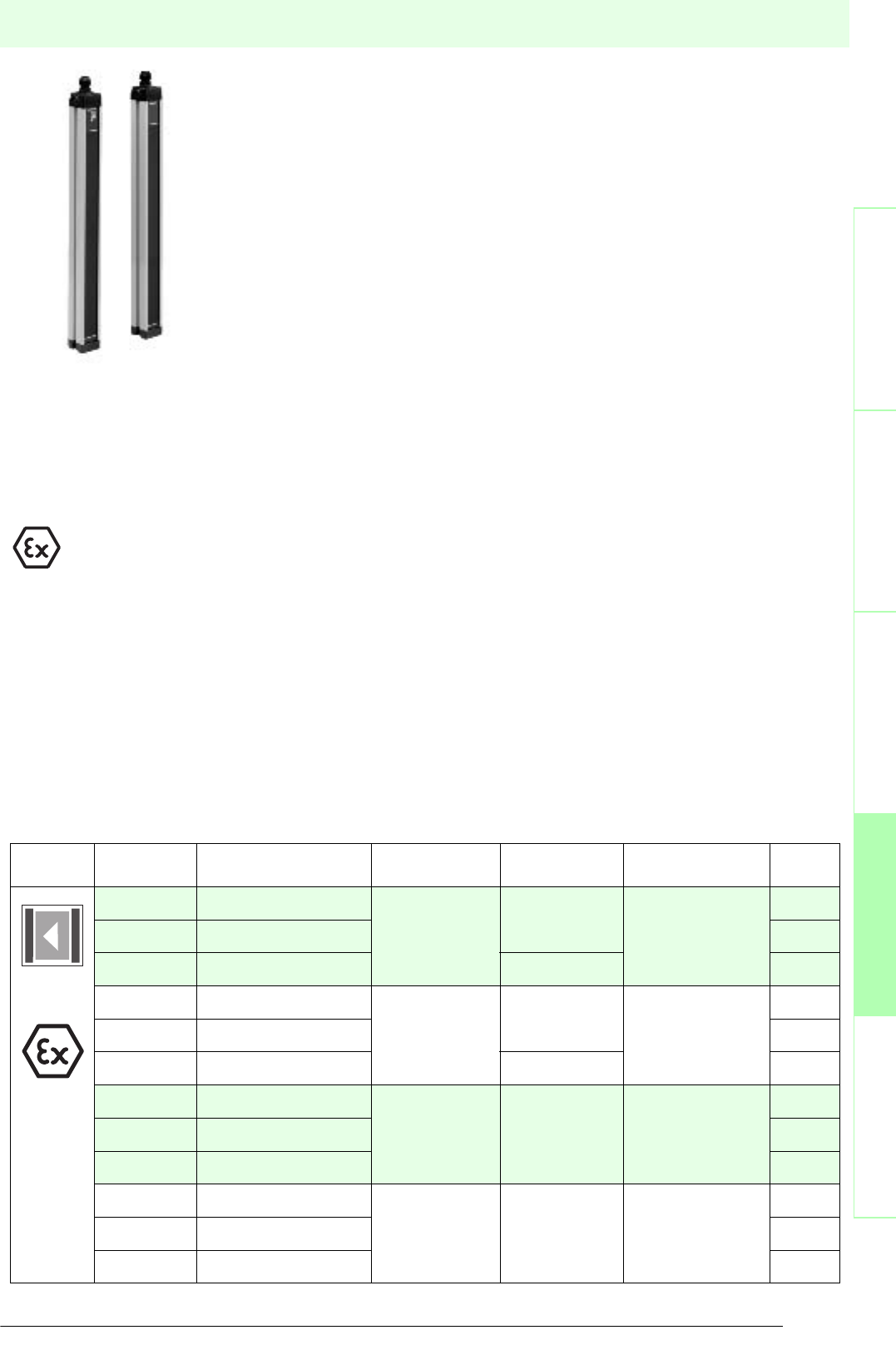
101
S
ubject to reasonable modifications due to technical advances. Copyright Pepperl+Fuchs, Printed in Germany
Pepperl+Fuchs Group • Tel.: Germany +49 621 776-0 • USA +1 330 4253555 • Singapore +65 67799091 • Internet http://www.pepperl-fuchs.com
Safety light curtains
Date of edition 05/17/2006
Safety light barriers
Safety light grids
Safety light grids with
internal control unit
Safety light curtains
Control units
Operating
principle Type Function Resolution Protection field
height Operating range Page
(Option /133)
SLC14-... with semiconductor output
14 mm
finger protection
up to 1800 mm
0.2 m ... 5 m
102
SLC14-.../31 with relay output 104
SLC14-...-S slave component up to 750 mm 106
SLC30-... with semiconductor output
30 mm
hand protection
up to 1800 mm
0.2 m ... 15 m
108
SLC30-.../31 with relay output 110
SLC30-...-S slave component up to 1650 mm 112
SLC60-... with semiconductor output
60 mm
bypass
protection
up to 1800 mm 0.2 m ... 15 m
114
SLC60-.../31 with relay output 116
SLC60-...-S slave component 118
SLC90-... with semiconductor output
90 mm
bypass
protection
up to 1800 mm 0.2 m ... 15 m
120
SLC90-.../31 with relay output 122
SLC90-...-S slave component 124
SLC light curtain description
The safety light curtain SLC consists of a sender and receiver unit forming an photoelectronic
protection device of category 4 (EN 954-1) or type 4 (according to IEC/EN 61496). It is a
self-monitoring system.
The protective field is created by infrared light beams. The minimum resolution of an object
to be safely detected within the whole protective field area depends on the distance between
the individual light beams. Resolutions of 14 mm, 30 mm, 60 mm and 90 mm are available.
The detection capability can thus be adapted to the most varied applications. Depending on
the degree of resolution ranges up to 15 m and protective field heights up to 1800 mm can be
achieved. Higher protective fields upon request.
All evaluation functions (e.g. startup/restart lock) are integrated in the receiver of the SLC.
There is no need for an electrical connection between sender and receiver. The safety
outputs (OSSD) in the receiver are either semiconductor outputs with separated potential or
monitored forced NO contacts.
In addition to the typcial sender/receiver configuration master/slave combinations can also be
installed. This means that one or two sender slaves can be allocated to each sender master
and one or two receiver slaves to each receiver master. This makes it possible to implement
parallel horizontal and vertical layouts. The resolution between master and slaves may differ. The sum of the protection beams
of master and slaves must not exceed the maximum number of 96.
A protection from several directions can be achieved with mirrors of the series SLC-XXX-M.
Muting applications can be implemented in combination with the control unit SafeBox.
The protection category IP67 ensures safe protection against harmful environmental impact.
Use in explosive areas
These devices can also be used in explosive areas of zone 2 and zone 22 (option /133).
This also complies with the specification that only devices and protection systems approved in accordance with
Directive 94/9/EC (ATEX) should be used in explosive areas.
Applications
The safety light curtain SLC can, for example, be used to protect entry points to danger areas e.g. automatic handling machines,
robots, and welding or assembly lines. A vertical/horizontal hazard protection can, for example, provide for a combined reach
and bypass protection.

Subject to reasonable modifications due to technical advances. Copyright Pepperl+Fuchs, Printed in Germany
Pepperl+Fuchs Group • Tel.: Germany +49 621 776-0 • USA +1 330 4253555 • Singapore +65 67799091 • Internet http://www.pepperl-fuchs.com
102
Technische DatenTechnical data
Features
Ordering code
Safety through beam
sensors
Safety light grids
Safety light grids with
internal control unit
Safety light curtains
Control units
SLC14-150
SLC14-300
SLC14-450
SLC14-600
SLC14-750
SLC14-900
SLC14-1050/130
SLC14-1200/130
SLC14-1350/130
SLC14-1500/130
SLC14-1650/130
SLC14-1800/130
Effective detection range
0.2 ... 5 m
X X X X X X X X X X X X
Light source
IRED
XXXXXXXXXXXX
Approvals
TÜV, UL
X X X X X X X X X X X X
Tes ts
IEC/EN 61496
XXXXXXXXXXXX
Marking
CE
X X X X X X X X X X X X
Width of protected area
0.2 ... 5 m
XXXXXXXXXXXX
Height of the protected area
[mm]
150 300 450 600 750 900 1050 1200 1350 1500 16501800
Number of beams
16 32 48 64 80 96 112 128 144 160 176 192
Safety category according to IEC/EN 61496
4
X X X X X X X X X X X X
Operating mode
can be selected with or without start/restart disable
XXXXXXXXXXXX
Light type
infrared, modulated light
X X X X X X X X X X X X
Optical resolution
14 mm
XXXXXXXXXXXX
Angle of divergence
< 5 °
X X X X X X X X X X X X
Operating display
7-segment display in emitter
XXXXXXXXXXXX
Diagnosis display
7-segment display in receiver
X X X X X X X X X X X X
Function display
in receiver: LED red: OSSD off, LED green: OSSD on[cr]LED yellow: Protected area free, system start-ready
XXXXXXXXXXXX
Pre-fault indication
LED orange
X X X X X X X X X X X X
Operating elements
switch for start/restart disable, transmission coding
XXXXXXXXXXXX
Operating voltage
24 V DC (-30 %/+25 %)
X X X X X X X X X X X X
Protection class
III
XXXXXXXXXXXX
No-load supply current
Emitter: ≤ 100 mA receiver: ≤ 150 mA
X X X X X X X X X X X X
Activation current
approx. 10 mA
XXXXXXXXXXXX
Activation time
0.03 ... 1 s
X X X X X X X X X X X X
Test input
Reset-input for system test
XXXXXXXXXXXX
Function input
Start release
X X X X X X X X X X X X
Safety output
2 separated fail safe semiconductor outputs
XXXXXXXXXXXX
Signal output
1 PNP each, max. 100 mA for start readiness and OSSD status
X X X X X X X X X X X X
Switching voltage
Operating voltage -2 V
XXXXXXXXXXXX
Switching current
max. 0.5 A
X X X X X X X X X X X X
Response time
[ms]
10 14 18 22 26 30 22 25 28 31 34 36
Ambient temperature
0 ... 55 °C (273 ... 328 K)
X X X X X X X X X X X X
Storage temperature
-25 ... 70 °C (248 ... 343 K)
XXXXXXXXXXXX
Relative humidity
max. 95 %, not condensing
X X X X X X X X X X X X
Length of housing L
[mm]
260 410 560 710 860 1010116013101460 1610 17601910
Protection degree
IP67
X X X X X X X X X X X X
Connection
Cable screwed connection M20 ,terminal compartment with screw terminals, lead cross-section max. 1.5 mm2
XXXXXXXXXXXX
Connection options
Further electrical connection options on request: Plug connector M12, 8-pin, Plug connector DIN 43 651
Hirschmann, 6-pin+PE, Plug connector M26x11 Hirschmann, 11-pin+PE
X X X X X X X X X X X X
Housing
aluminium extruded structural profile, RAL 1021 (yellow) coated
XXXXXXXXXXXX
Optical face
Plastic pane
X X X X X X X X X X X X
Mass
Per [g]
750 1200 1650 210025503000345039004350 480052505700
System components
Emitter
SLC 14 - 1050 -T/ 130
X
SLC 14 - 1200 -T/ 130
X
SLC 14 - 1350 -T/ 130
X
SLC 14 - 1500 -T/ 130
X
SLC 14 - 1650 -T/ 130
X
SLC 14 - 1800 -T/ 130
X
SLC14-150-T
X
SLC14-300-T
X
SLC14-450-T
X
SLC14-600-T
X
SLC14-750-T
X
SLC14-900-T
X
Receiver
SLC 14 - 1050 -R/ 130
X
SLC 14 - 1200 -R/ 130
X
SLC 14 - 1350 -R/ 130
X
SLC 14 - 1500 -R/ 130
X
SLC 14 - 1650 -R/ 130
X
SLC 14 - 1800 -R/ 130
X
SLC14-150-R
X
SLC14-300-R
X
SLC14-450-R
X
SLC14-600-R
X
SLC14-750-R
X
SLC14-900-R
X
SLC14-...
• Detection range up to 5 m
• Resolution 14 mm (finger protection)
• Protective field height up to 1800 mm
• Self-monitoring (type 4 according to IEC/EN 61496-1)
• Master/Slave detection, Plug and Play
• Start/Restart disable
• Protection degree IP67
• Integrated function display
• Pre-fault indication
• Safety outputs OSSD in potential-separated semiconductor design or with
monitored, compelled connection NC-contacts
U
®
Date of edition 05/17/2006
Safety light curtain
For suitable cable sockets, mounting aids, redirection mirrors and more refer to chapter „Accessories.
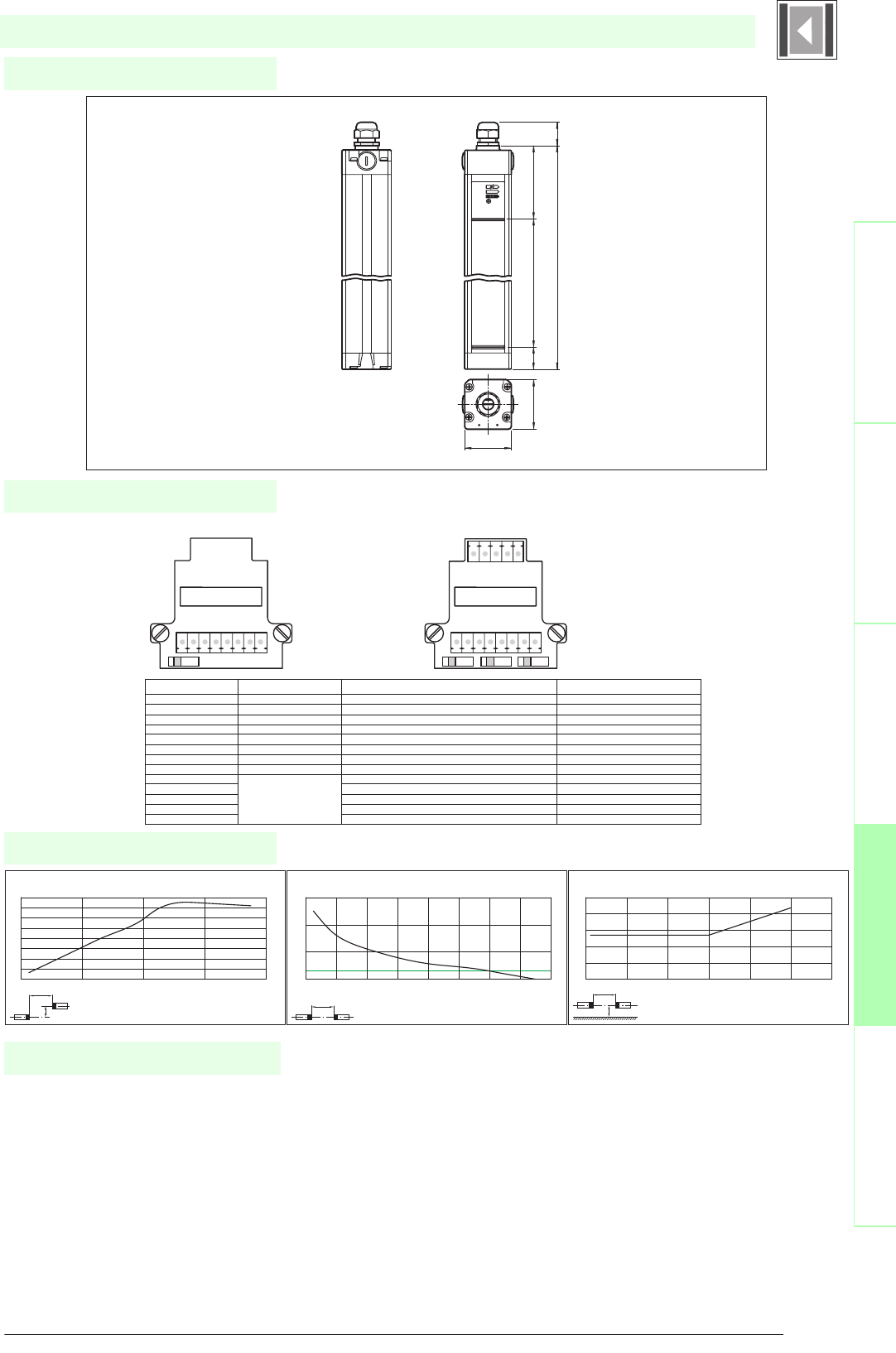
103
S
ubject to reasonable modifications due to technical advances. Copyright Pepperl+Fuchs, Printed in Germany
Pepperl+Fuchs Group • Tel.: Germany +49 621 776-0 • USA +1 330 4253555 • Singapore +65 67799091 • Internet http://www.pepperl-fuchs.com
Diagrams
Electrical connection
Dimensions
Safety through beam
sensors
Safety light gridsSafety light grids with
internal control unit
Safety light curtainsControl units
SLC14-...
x
y
SLC14
Offset Y [mm]
Distance X [m]
Characteristic response curve
0
20
40
60
80
100
120
140
160
02468
x
SLC14
Distance X [m]
Stability control
Relative received light strength
1
10
100
1000
012345678
x
y
SLC14
Distance X [m]
Lateral interval to mirroring surfaces
Minimum interval [m]
0
0.05
0.1
0.15
0.2
0.25
0123456
Date of edition 05/17/2006
Emitter: Receiver:
Terminal Emitter Receiver SLC...-R (semiconductor output) Receiver SLC...-R/129 (Relay monitor)
X1:1 Functional earth Functional earth Functional earth
X1:2 Test (input) Relay monitor
X1:3 0 V OSSD 0 V OSSD
X1:4 24 V OSSD 24 V OSSD
X1:5 OSSD2 (output) OSSD2 (output)
X1:6 OSSD1 (output) OSSD1 (output)
X1:7 0 V AC/DC 0 V DC 0 V DC
X1:8 24 V AC/DC 24 V DC 24 V DC
X2:1 Start release (output) Start release (output)
X2:2 Status OSSD (output) Status OSSD (output)
X2:3 Not placed on board n.c. n.c.
X2:4 n.c. n.c.
x2:5 Startup readiness (input) Startup readiness (input)
S1: Beam coding S1/S2: Startup/restart interlock
S3: Beam coding
S1 S1 S2 S3
X1 X1
X2
8765432187654321
123 4 5
Housing length
Height of the protected area
52
55
28
85
27
Safety light curtain
• Mounting set SLC
• Test rods SLC14/SLC30/SLC60
• Protective glass pieces for SLC (to protect the optically
functional surface)
• Lateral screwed connection SLC
• Profile alignment aid
• Laser alignment aid SLC
• Mirror for SLC (for securing hazardous areas on multiple
sides)
• Ground pillar UC SLP/SLC
System accessories
• Housing for pillar
Enclosure UC SLP/SLC
• Collision protector
Damping UC SLP/SLC
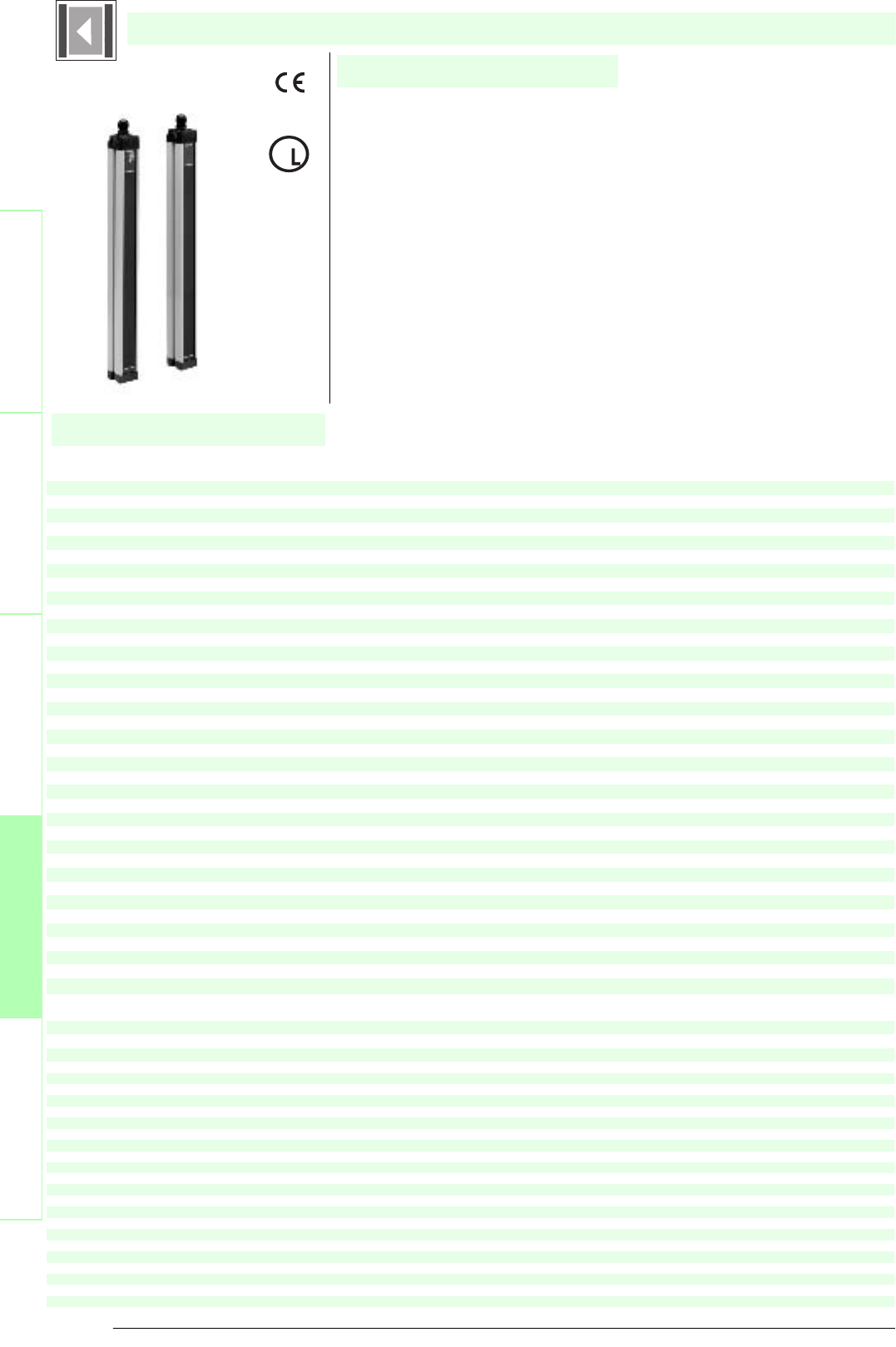
Subject to reasonable modifications due to technical advances. Copyright Pepperl+Fuchs, Printed in Germany
Pepperl+Fuchs Group • Tel.: Germany +49 621 776-0 • USA +1 330 4253555 • Singapore +65 67799091 • Internet http://www.pepperl-fuchs.com
104
Technische DatenTechnical data
Features
Ordering code
Safety through beam
sensors
Safety light grids
Safety light grids with
internal control unit
Safety light curtains
Control units
SLC14-150/31
SLC14-300/31
SLC14-450/31
SLC14-600/31
SLC14-750/31
SLC14-900/31
SLC14-1050/31/130
SLC14-1200/31/130
SLC14-1350/31/130
SLC14-1500/31/130
SLC14-1650/31/130
SLC14-1800/31/130
Effective detection range
0.2 ... 5 m
X X X X X X X X X X X X
Light source
IRED
XXXXXXXXXXXX
Approvals
TÜV, UL
X X X X X X X X X X X X
Tes ts
IEC/EN 61496
XXXXXXXXXXXX
Marking
CE
X X X X X X X X X X X X
Width of protected area
0.2 ... 5 m
XXXXXXXXXXXX
Height of the protected area
[mm]
150 300 450 600 750 900 1050 1200 1350 150016501800
Number of beams
16 32 48 64 80 96 112 128 144 160 176 192
Safety category according to IEC/EN 61496
4
X X X X X X X X X X X X
Operating mode
can be selected with or without start/restart disable
XXXXXXXXXXXX
Light type
infrared, modulated light
X X X X X X X X X X X X
Optical resolution
14 mm
XXXXXXXXXXXX
Angle of divergence
< 5 °
X X X X X X X X X X X X
Operating display
7-segment display in emitter
XXXXXXXXXXXX
Diagnosis display
7-segment display in receiver
X X X X X X X X X X X X
Function display
in receiver: LED red: OSSD off, LED green: OSSD on,LED yellow: Protected area free, system start-ready
XXXXXXXXXXXX
Pre-fault indication
LED orange
X X X X X X X X X X X X
Operating elements
switch for start/restart disable, transmission coding
XXXXXXXXXXXX
Operating voltage
24 V DC (-30 %/+25 %) / 24 V AC (-20 %/+10 %)
X X X X X X X X X X X X
Protection class
III
XXXXXXXXXXXX
No-load supply current
Emitter: ≤ 100 mA receiver: ≤ 150 mA
X X X X X X X X X X X X
Activation current
approx. 10 mA
XXXXXXXXXXXX
Activation time
0.03 ... 1 s
X X X X X X X X X X X X
Test input
Reset-input for system test
XXXXXXXXXXXX
Function input
Start release
X X X X X X X X X X X X
Safety output
2 relay outputs, compelled connection NO-contact
XXXXXXXXXXXX
Signal output
1 PNP each, max. 100 mA for start readiness and OSSD status
X X X X X X X X X X X X
Switching voltage
50 V
XXXXXXXXXXXX
Switching current
max. 2 A
X X X X X X X X X X X X
Switch power
100 VA
XXXXXXXXXXXX
Response time
[ms]
30 34 38 42 46 50 42 45 48 51 54 56
Ambient temperature
0 ... 55 °C (273 ... 328 K)
XXXXXXXXXXXX
Storage temperature
-25 ... 70 °C (248 ... 343 K)
X X X X X X X X X X X X
Relative humidity
max. 95 %, not condensing
XXXXXXXXXXXX
Length of housing L
[mm]
260 410 560 710 860 1010 1160 1310 1460 161017601910
Protection degree
IP67
XXXXXXXXXXXX
Connection
Cable screwed connection M20, terminal compartment with screw terminals, lead cross-section max. 1.5 mm2
X X X X X X X X X X X X
Connection options
Further electrical connection options on request: Plug connector M12, 8-pin, Plug connector DIN 43 651
Hirschmann, 6-pin+PE, Plug connector M26x11 Hirschmann, 11-pin+PE
XXXXXXXXXXXX
Housing
aluminium extruded structural profile, RAL 1021 (yellow) coated
X X X X X X X X X X X X
Optical face
Plastic pane
XXXXXXXXXXXX
Mass
Per [g]
750 1200 1650210025503000 3450 3900 4350 480052505700
System components
Emitter
SLC 14 - 1050 -T/ 130
X
SLC 14 - 1200 -T/ 130
X
SLC 14 - 1350 -T/ 130
X
SLC 14 - 1500 -T/ 130
X
SLC 14 - 1650 -T/ 130
X
SLC 14 - 1800 -T/ 130
X
SLC14-150-T
X
SLC14-300-T
X
SLC14-450-T
X
SLC14-600-T
X
SLC14-750-T
X
SLC14-900-T
X
Receiver
SLC 14 - 1050 -R/ 31 / 130
X
SLC 14 - 1200 -R/ 31 / 130
X
SLC 14 - 1350 -R/ 31 / 130
X
SLC 14 - 1500 -R/ 31 / 130
X
SLC 14 - 1650 -R/ 31 / 130
X
SLC 14 - 1800 -R/ 31 / 130
X
SLC14-150-R/31
X
SLC14-300-R/31
X
SLC14-450-R/31
X
SLC14-600-R/31
X
SLC14-.../31/...
• Detection range up to 5 m
• Resolution 14 mm (finger protection)
• Protective field height up to 1800 mm
• Self-monitoring (type 4 according to IEC/EN 61496-1)
• Master/Slave detection, Plug and Play
• Start/Restart disable
• Protection degree IP67
• Integrated function display
• Pre-fault indication
• Safety outputs OSSD in potential-separated semiconductor design or with
monitored, compelled connection NC-contacts
• Optional with relay monitor (Option 129)
• Very short response time
U
®
Date of edition 05/17/2006
Safety light curtain
For suitable cable sockets, mounting aids, redirection mirrors and more refer to chapter „Accessories.

105
S
ubject to reasonable modifications due to technical advances. Copyright Pepperl+Fuchs, Printed in Germany
Pepperl+Fuchs Group • Tel.: Germany +49 621 776-0 • USA +1 330 4253555 • Singapore +65 67799091 • Internet http://www.pepperl-fuchs.com
Diagrams
Electrical connection
Dimensions
Safety through beam
sensors
Safety light gridsSafety light grids with
internal control unit
Safety light curtainsControl units
SLC14-.../31/...
x
y
SLC14
Offset Y [mm]
Distance X [m]
Characteristic response curve
0
20
40
60
80
100
120
140
160
02468
x
SLC14
Distance X [m]
Stability control
Relative received light strength
1
10
100
1000
012345678
x
y
SLC14
Distance X [m]
Lateral interval to mirroring surfaces
Minimum interval [m]
0
0.05
0.1
0.15
0.2
0.25
0123456
Date of edition 05/17/2006
Emitter: Receiver:
terminal emitter receiver SLC...-R/31 (relay output) receiver SLC...-R/31 (Relay monitor)
X1:1 Functional earth Functional earth Functional earth
X1:2 test (input) Relay monitor
X1:3 OSSD2.2 (output) OSSD2.2 (output)
X1:4 OSSD1.2 (output) OSSD1.2 (output)
X1:5 OSSD2.1 (output) OSSD2.1 (output)
X1:6 OSSD1.1 (output) OSSD1.1 (output)
X1:7 0 V AC/DC 0 V AC/DC 0 V AC/DC
X1:8 24 V AC/DC 24 V AC/DC 24 V AC/DC
X2:1 Start release (output) Start release (output)
X2:2 Status OSSD (output) Status OSSD (output)
X2:3 Not placed on board 24 V reference potential for I/O 24 V reference potential for I/O
X2:4 0 V reference potential for I/O 0 V reference potential for I/O
x2:5 Startup readiness (input) Startup readiness (input)
S1: Beam coding S1/S2: Startup/restar interlock
S3: Beam coding
S1 S1 S2 S3
X1 X1
X2
8765432187654321
123 4 5
Housing length
Height of the protected area
52
55
28
85
27
Safety light curtain
1
• Mounting set SLC
• Test rods SLC14/SLC30/SLC60
• Protective glass pieces for SLC (to protect the optically
functional surface)
• Lateral screwed connection SLC
• Profile alignment aid
• Laser alignment aid SLC
• Mirror for SLC (for securing hazardous areas on multiple
sides)
• Ground pillar UC SLP/SLC
System accessories
• Housing for pillar
Enclosure UC SLP/SLC
• Collision protector
Damping UC SLP/SLC
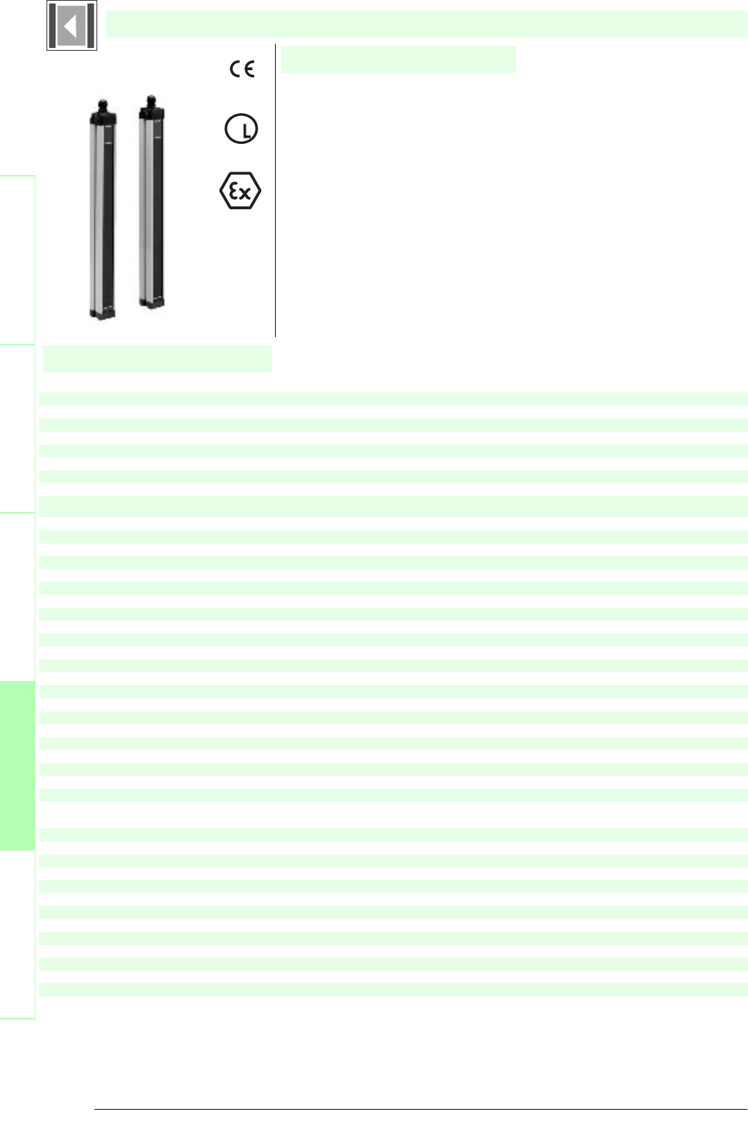
Subject to reasonable modifications due to technical advances. Copyright Pepperl+Fuchs, Printed in Germany
Pepperl+Fuchs Group • Tel.: Germany +49 621 776-0 • USA +1 330 4253555 • Singapore +65 67799091 • Internet http://www.pepperl-fuchs.com
106
Technische DatenTechnical data
Features
Ordering code
Safety through beam
sensors
Safety light grids
Safety light grids with
internal control unit
Safety light curtains
Control units
SLC14-150-S
SLC14-300-S
SLC14-450-S
SLC14-600-S
SLC14-750-S
Effective detection range
0.2 ... 5 m
X X X X X
Light source
IRED
XXXXX
Approvals
TÜV, UL
X X X X X
Test s
IEC/EN 61496
XXXXX
Marking
CE
X X X X X
Width of protected area
0.2 ... 5 m
XXXXX
Height of the protected area
[mm]
150 300 450 600 750
Number of beams
16 32 48 64 80
Safety category according to IEC/EN
61496
4
X X X X X
Operating mode
in the master device
XXXXX
Light type
infrared, modulated light
X X X X X
Optical resolution
14 mm
XXXXX
Angle of divergence
[klein] 5 °
X X X X X
Operating display
in the master device
XXXXX
Diagnosis display
in the master device
X X X X X
Function display
in the master device
XXXXX
Pre-fault indication
in the master device
X X X X X
Operating elements
in the master device
XXXXX
Operating voltage
from master
X X X X X
Protection class
III
XXXXX
No-load supply current
from master
X X X X X
Test i np ut
in the master device
XXXXX
Function input
in the master device
X X X X X
Safety output
in the master device
XXXXX
Signal output
in the master device
X X X X X
Response time
depends on height of protective field
XXXXX
Ambient temperature
0 ... 55 °C (273 ... 328 K)
X X X X X
Storage temperature
-25 ... 70 °C (248 ... 343 K)
XXXXX
Relative humidity
max. 95 %, not condensing
X X X X X
Length of housing L
[mm]
260 410 560 710 860
Protection degree
IP67
X X X X X
Connection
Cable screwed connection M20 ,[cr]terminal compartment with screw terminals, lead cross-section
max. 1.5 mm2
XXXXX
Housing
aluminium extruded structural profile, RAL 1021 (yellow) coated
X X X X X
Optical face
Plastic pane
XXXXX
Mass
Per [g]
750 1200 1650 2100 2550
System components
Emitter
SLC14-150-T-S
X
SLC14-300-T-S
X
SLC14-450-T-S
X
SLC14-600-T-S
X
SLC14-750-T-S
X
Receiver
SLC14-150-R-S
X
SLC14-300-R-S
X
SLC14-450-R-S
X
SLC14-600-R-S
X
SLC14-750-R-S
X
SLC14-...-S
• Detection range up to 5 m
• Resolution 14 mm (finger protection)
• Protection field height up to 750 mm
• Self-monitoring (type 4 according to IEC/EN 61496-1)
• Master/Slave detection, Plug and Play
• Start/Restart disable
• Protection degree IP67
• Integrated function display
• Pre-fault indication
• Safety outputs OSSD in potential-separated semiconductor design or with
monitored, compelled connection NC-contacts
• Optional with ATEX certificates for zone 2 and 22 and protection degree IP66
(Option 133)
U
®
Date of edition 05/17/2006
Safety light curtain
For suitable cable sockets, mounting aids, redirection mirrors and more refer to chapter „Accessories.
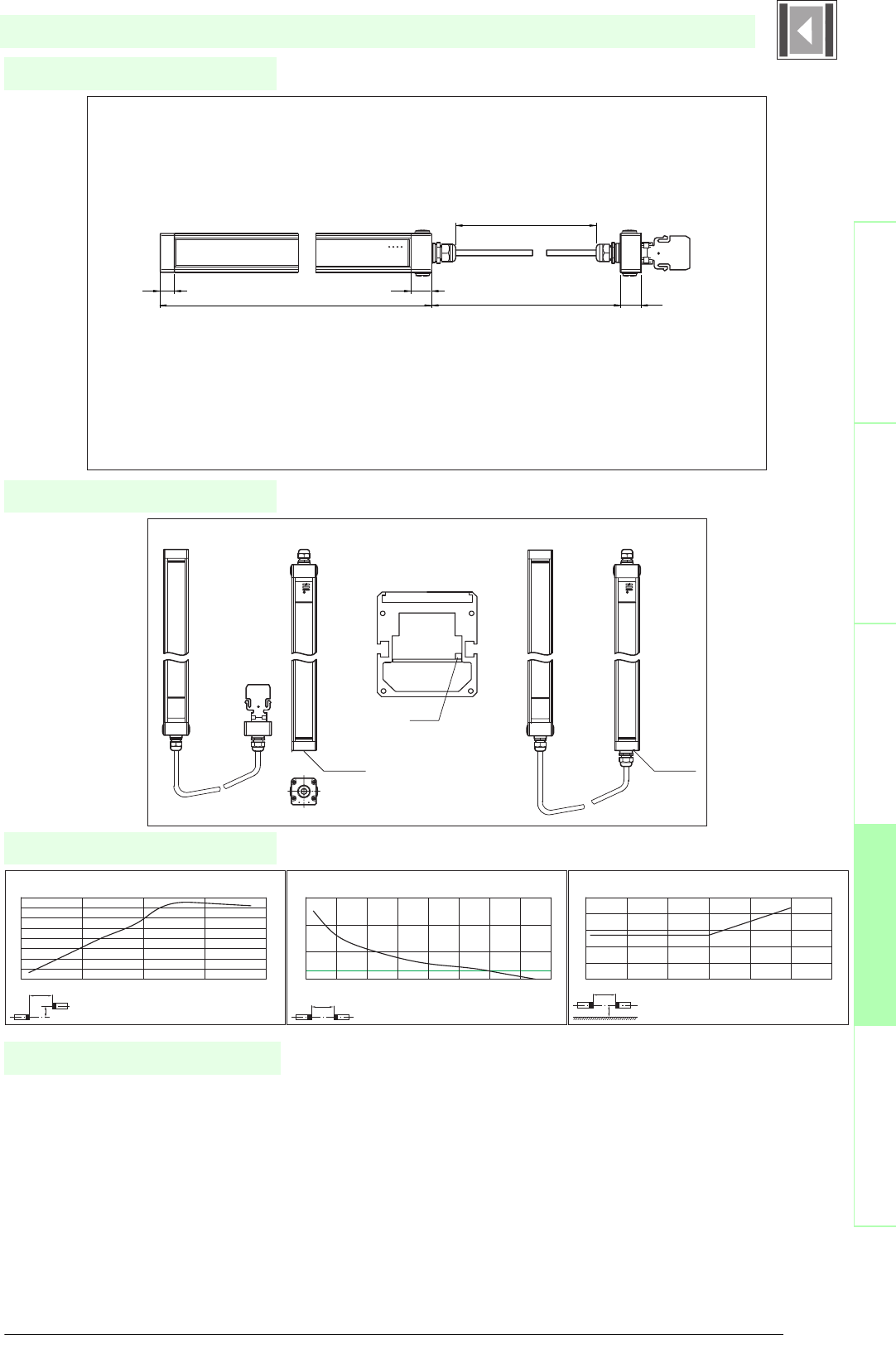
107
S
ubject to reasonable modifications due to technical advances. Copyright Pepperl+Fuchs, Printed in Germany
Pepperl+Fuchs Group • Tel.: Germany +49 621 776-0 • USA +1 330 4253555 • Singapore +65 67799091 • Internet http://www.pepperl-fuchs.com
Diagrams
Electrical connection
Dimensions
Safety through beam
sensors
Safety light gridsSafety light grids with
internal control unit
Safety light curtainsControl units
SLC14-...-S
x
y
SLC14
Offset Y [mm]
Distance X [m]
Characteristic response curve
0
20
40
60
80
100
120
140
160
02468
x
SLC14
Distance X [m]
Stability control
Relative received light strength
1
10
100
1000
012345678
x
y
SLC14
Distance X [m]
Lateral interval to mirroring surfaces
Minimum interval [m]
0
0.05
0.1
0.15
0.2
0.25
0123456
Date of edition 05/17/2006
Slave Master
Remove cap
Remove
jumper
Insert circuit
board and
screw it
Slave Master
Height of the protected area + 107 28
L + 64
28
19
L ~ 540
Safety light curtain
• Mounting set SLC
• Test rods SLC14/SLC30/SLC60
• Protective glass pieces for SLC (to protect the optically
functional surface)
• Lateral screwed connection SLC
• Profile alignment aid
• Laser alignment aid SLC
• Mirror for SLC (for securing hazardous areas on multiple
sides)
• Ground pillar UC SLP/SLC
System accessories
• Housing for pillar
Enclosure UC SLP/SLC
• Collision protector
Damping UC SLP/SLC
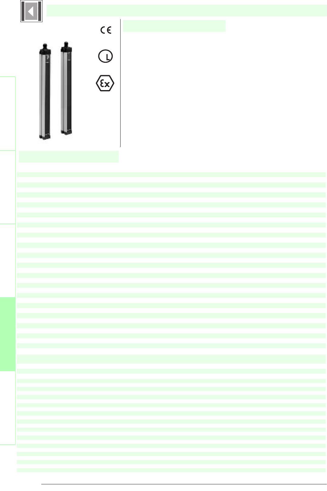
Subject to reasonable modifications due to technical advances. Copyright Pepperl+Fuchs, Printed in Germany
Pepperl+Fuchs Group • Tel.: Germany +49 621 776-0 • USA +1 330 4253555 • Singapore +65 67799091 • Internet http://www.pepperl-fuchs.com
108
Technische DatenTechnical data
Features
Ordering code
Safety through beam
sensors
Safety light grids
Safety light grids with
internal control unit
Safety light curtains
Control units
SLC30-150
SLC30-300
SLC30-450
SLC30-600
SLC30-750
SLC30-900
SLC30-1200
SLC30-1350
SLC30-1500
SLC30-1650
SLC30-1800
Effective detection range
0.2 ... 15 m
X X X X X X X X X X X
Light source
IRED
XXXXXXXXXXX
Approvals
TÜV, UL
X X X X X X X X X X X
Te s ts
IEC/EN 61496
XXXXXXXXXXX
Marking
CE
X X X X X X X X X X X
Width of protected area
0.2 ... 15 m
XXXXXXXXXXX
Height of the protected area
[mm]
150 300 450 600 750 900 12001350 1500 1650 1800
Number of beams
8 16243240486472808896
Safety category according to IEC/EN 61496
4
X X X X X X X X X X X
Operating mode
can be selected with or without start/restart disable
XXXXXXXXXXX
Light type
infrared, modulated light
X X X X X X X X X X X
Optical resolution
30 mm
XXXXXXXXXXX
Angle of divergence
[klein] 5 °
X X X X X X X X X X X
Operating display
7-segment display in emitter
XXXXXXXXXXX
Diagnosis display
7-segment display in receiver
X X X X X X X X X X X
Function display
in receiver: LED red: OSSD off, LED green: OSSD on, LED yellow: Protected area free, system start-ready
XXXXXXXXXXX
Pre-fault indication
LED orange
X X X X X X X X X X X
Operating elements
switch for start/restart disable, transmission coding
XXXXXXXXXXX
Operating voltage
24 V DC (-30 %/+25 %)
X X X X X X X X X X X
Protection class
III
XXXXXXXXXXX
No-load supply current
Emitter: ≤ 100 mA receiver: ≤ 150 mA
X X X X X X X X X X X
Activation current
approx. 10 mA
XXXXXXXXXXX
Activation time
0.03 ... 1 s
X X X X X X X X X X X
Te s t inp ut
Reset-input for system test
XXXXXXXXXXX
Function input
Start release
X X X X X X X X X X X
Safety output
2 separated fail safe semiconductor outputs
XXXXXXXXXXX
Signal output
1 PNP each, max. 100 mA for start readiness and OSSD status
X X X X X X X X X X X
Switching voltage
Operating voltage -2 V
XXXXXXXXXXX
Switching current
max. 0.5 A
X X X X X X X X X X X
Response time
[ms]
10 10 12 14 16 18 22 24 26 28 30
Ambient temperature
0 ... 55 °C (273 ... 328 K)
X X X X X X X X X X X
Storage temperature
-25 ... 70 °C (248 ... 343 K)
XXXXXXXXXXX
Relative humidity
max. 95 %, not condensing
X X X X X X X X X X X
Length of housing L
[mm]
260 410 560 710 860 101013101460 1610 1760 1910
Protection degree
IP67
X X X X X X X X X X X
Connection
Cable screwed connection M20 , terminal compartment with screw terminals, lead cross-section max. 1.5 mm2
XXXXXXXXXXX
Connection options
Further electrical connection options on request: Plug connector M12, 8-pin, Plug connector DIN 43 651 Hirsch-
mann, 6-pin+PE, Plug connector M26x11 Hirschmann, 11-pin+PE
X X X X X X X X X X X
Housing
aluminium extruded structural profile, RAL 1021 (yellow) coated
XXXXXXXXXXX
Optical face
Plastic pane
X X X X X X X X X X X
Mass
Per [g]
750 1200 1650 2100 25503000390043504800 5250 5700
System components
Emitter
SLC30-1200-T
X
SLC30-1350-T
X
SLC30-150-T
X
SLC30-1500-T
X
SLC30-1650-T
X
SLC30-1800-T
X
SLC30-300-T
X
SLC30-450-T
X
SLC30-600-T
X
SLC30-750-T
X
SLC30-900-T
X
Receiver
SLC30-1200-R
X
SLC30-1350-R
X
SLC30-150-R
X
SLC30-1500-R
X
SLC30-1650-R
X
SLC30-1800-R
X
SLC30-300-R
X
SLC30-450-R
X
SLC30-600-R
X
SLC30-750-R
X
SLC30-900-R
X
SLC30-...
• Detection range up to 15 m
• Resolution 30 mm (hand protection)
• Protective field height up to 1800 mm
• Self-monitoring (type 4 according to IEC/EN 61496-1)
• Master/Slave detection, Plug and Play
• Start/Restart disable
• Protection degree IP67
• Integrated function display
• Pre-fault indication
• Safety outputs OSSD in potential-separated semiconductor design or with
monitored, compelled connection NC-contacts
• Optional with relay monitor (Option 129)
• Optional with ATEX certificates for zone 2 and 22 and protection degree
IP66 (Option 133)
U
®
Date of edition 05/17/2006
Safety light curtain
For suitable cable sockets, mounting aids, redirection mirrors and more refer to chapter „Accessories.

109
S
ubject to reasonable modifications due to technical advances. Copyright Pepperl+Fuchs, Printed in Germany
Pepperl+Fuchs Group • Tel.: Germany +49 621 776-0 • USA +1 330 4253555 • Singapore +65 67799091 • Internet http://www.pepperl-fuchs.com
Diagrams
Electrical connection
Dimensions
Safety through beam
sensors
Safety light gridsSafety light grids with
internal control unit
Safety light curtainsControl units
SLC30-...
x
y
SLC30 / SLC60 / SLC90
Offset Y [mm]
Distance X [m]
Characteristic response curve
0
50
100
150
200
250
300
0 2 4 6 8 10 12 14 16
x
SLC30 / SLC60 / SLC90
Distance X [m]
Stability control
Relative received light strength
1
10
100
1000
0 5 10 15 20 25
x
y
SLC30 / SLC60 / SLC90
Distance X [m]
Lateral interval to mirroring surfaces
Minimum interval [m]
0
0.1
0.2
0.3
0.4
0.5
0.6
0.7
0246810121416
Date of edition 05/17/2006
Emitter: Receiver:
Terminal Emitter Receiver SLC...-R (semiconductor output) Receiver SLC...-R/129 (Relay monitor)
X1:1 Functional earth Functional earth Functional earth
X1:2 Test (input) Relay monitor
X1:3 0 V OSSD 0 V OSSD
X1:4 24 V OSSD 24 V OSSD
X1:5 OSSD2 (output) OSSD2 (output)
X1:6 OSSD1 (output) OSSD1 (output)
X1:7 0 V AC/DC 0 V DC 0 V DC
X1:8 24 V AC/DC 24 V DC 24 V DC
X2:1 Start release (output) Start release (output)
X2:2 Status OSSD (output) Status OSSD (output)
X2:3 Not placed on board n.c. n.c.
X2:4 n.c. n.c.
x2:5 Startup readiness (input) Startup readiness (input)
S1: Beam coding S1/S2: Startup/restart interlock
S3: Beam coding
S1 S1 S2 S3
X1 X1
X2
8765432187654321
123 4 5
Housing length
Height of the protected area
52
55
28
85
27
Safety light curtain
• Mounting set SLC
• Test rods SLC14/SLC30/SLC60
• Protective glass pieces for SLC (to protect the optically
functional surface)
• Lateral screwed connection SLC
• Profile alignment aid
• Laser alignment aid SLC
• Mirror for SLC (for securing hazardous areas on multiple
sides)
• Ground pillar UC SLP/SLC
System accessories
• Housing for pillar
Enclosure UC SLP/SLC
• Collision protector
Damping UC SLP/SLC

Subject to reasonable modifications due to technical advances. Copyright Pepperl+Fuchs, Printed in Germany
Pepperl+Fuchs Group • Tel.: Germany +49 621 776-0 • USA +1 330 4253555 • Singapore +65 67799091 • Internet http://www.pepperl-fuchs.com
110
Technische DatenTechnical data
Features
Ordering code
Safety through beam
sensors
Safety light grids
Safety light grids with
internal control unit
Safety light curtains
Control units
SLC30-150/31
SLC30-300/31
SLC30-450/31
SLC30-600/31
SLC30-750/31
SLC30-900/31
SLC30-1050/31
SLC30-1200/31
SLC30-1350/31
SLC30-1500/31
SLC30-1650/31
SLC30-1800/31
Effective detection range
0.2 ... 15 m
X X X X X X X X X X X X
Light source
IRED
XXXXXXXXXXXX
Approvals
TÜV, UL
X X X X X X X X X X X X
Tes ts
IEC/EN 61496
XXXXXXXXXXXX
Marking
CE
X X X X X X X X X X X X
Width of protected area
0.2 ... 15 m
XXXXXXXXXXXX
Height of the protected area
[mm]
150 300 450 600 750 900 10501200 1350 1500 1650 1800
Number of beams
8 1624324048566472808896
Safety category according to IEC/EN 61496
4
X X X X X X X X X X X X
Operating mode
can be selected with or without start/restart disable
XXXXXXXXXXXX
Light type
infrared, modulated light
X X X X X X X X X X X X
Optical resolution
30 mm
XXXXXXXXXXXX
Angle of divergence
[klein] 5 °
X X X X X X X X X X X X
Operating display
7-segment display in emitter
XXXXXXXXXXXX
Diagnosis display
7-segment display in receiver
X X X X X X X X X X X X
Function display
in receiver:[cr]LED red: OSSD off, LED green: OSSD on,LED yellow: Protected area free, system start-ready
XXXXXXXXXXXX
Pre-fault indication
LED orange
X X X X X X X X X X X X
Operating elements
switch for start/restart disable, transmission coding
XXXXXXXXXXXX
Operating voltage
24 V DC (-30 %/+25 %) / 24 V AC (-20 %/+10 %)
X X X X X X X X X X X X
Protection class
III
XXXXXXXXXXXX
No-load supply current
Emitter: ≤ 100 mA receiver: ≤ 150 mA
X X X X X X X X X X X X
Activation current
approx. 10 mA
XXXXXXXXXXXX
Activation time
0.03 ... 1 s
X X X X X X X X X X X X
Test input
Reset-input for system test
XXXXXXXXXXXX
Function input
Start release
X X X X X X X X X X X X
Safety output
2 relay outputs, compelled connection NO-contact
XXXXXXXXXXXX
Signal output
1 PNP each, max. 100 mA for start readiness and OSSD status
X X X X X X X X X X X X
Switching voltage
50 V
XXXXXXXXXXXX
Switching current
max. 2 A
X X X X X X X X X X X X
Switch power
100 VA
XXXXXXXXXXXX
Response time
[ms]
30 30 32 34 36 38 40 42 44 46 48 50
Ambient temperature
0 ... 55 °C (273 ... 328 K)
XXXXXXXXXXXX
Storage temperature
-25 ... 70 °C (248 ... 343 K)
X X X X X X X X X X X X
Relative humidity
max. 95 %, not condensing
XXXXXXXXXXXX
Length of housing L
[mm]
260 410 560 710 860 101011601310 1460 1610 1760 1910
Protection degree
IP67
XXXXXXXXXXXX
Connection
Cable screwed connection M20,terminal compartment with screw terminals, lead cross-section max. 1.5 mm2
X X X X X X X X X X X X
Connection options
Further electrical connection options on request: Plug connector M12, 8-pin,Plug connector DIN 43 651
Hirschmann, 6-pin+PE,Plug connector M26x11 Hirschmann, 11-pin+PE
XXXXXXXXXXXX
Housing
aluminium extruded structural profile, RAL 1021 (yellow) coated
X X X X X X X X X X X X
Optical face
Plastic pane
XXXXXXXXXXXX
Mass
Per [g]
750 1200 1650 2100 2550 300034503900 4350 4800 5250 5700
System components
Emitter
SLC30-1050-T
X
SLC30-1200-T
X
SLC30-1350-T
X
SLC30-150-T
X
SLC30-1500-T
X
SLC30-1650-T
X
SLC30-1800-T
X
SLC30-300-T
X
SLC30-450-T
X
SLC30-600-T
X
SLC30-750-T
X
SLC30-900-T
X
Receiver
SLC30-1050-R/31
X
SLC30-1200-R/31
X
SLC30-1350-R/31
X
SLC30-150-R/31
X
SLC30-1500-R/31
X
SLC30-1650-R/31
X
SLC30-1800-R/31
X
SLC30-300-R/31
X
SLC30-450-R/31
X
SLC30-600-R/31
X
SLC30-750-R/31
X
SLC30-900-R/31
X
SLC30-.../31
• Detection range up to 15 m
• Resolution 30 mm (hand protection)
• Protective field height up to 1800 mm
• Self-monitoring (type 4 according to IEC/EN 61496-1)
• Master/Slave detection, Plug and Play
• Start/Restart disable
• Protection degree IP67
• Integrated function display
• Pre-fault indication
• Safety outputs OSSD in potential-separated semiconductor design or with
monitored, compelled connection NC-contacts
• Optional with relay monitor (Option 129)
U
®
Date of edition 05/17/2006
Safety light curtain
For suitable cable sockets, mounting aids, redirection mirrors and more refer to chapter „Accessories.

111
S
ubject to reasonable modifications due to technical advances. Copyright Pepperl+Fuchs, Printed in Germany
Pepperl+Fuchs Group • Tel.: Germany +49 621 776-0 • USA +1 330 4253555 • Singapore +65 67799091 • Internet http://www.pepperl-fuchs.com
Diagrams
Electrical connection
Dimensions
Safety through beam
sensors
Safety light gridsSafety light grids with
internal control unit
Safety light curtainsControl units
SLC30-.../31
x
y
SLC30 / SLC60 / SLC90
Offset Y [mm]
Distance X [m]
Characteristic response curve
0
50
100
150
200
250
300
0 2 4 6 8 10 12 14 16
x
SLC30 / SLC60 / SLC90
Distance X [m]
Stability control
Relative received light strength
1
10
100
1000
0 5 10 15 20 25
x
y
SLC30 / SLC60 / SLC90
Distance X [m]
Lateral interval to mirroring surfaces
Minimum interval [m]
0
0.1
0.2
0.3
0.4
0.5
0.6
0.7
0246810121416
Date of edition 05/17/2006
Emitter: Receiver:
terminal emitter receiver SLC...-R/31 (relay output) receiver SLC...-R/31 (Relay monitor)
X1:1 Functional earth Functional earth Functional earth
X1:2 test (input) Relay monitor
X1:3 OSSD2.2 (output) OSSD2.2 (output)
X1:4 OSSD1.2 (output) OSSD1.2 (output)
X1:5 OSSD2.1 (output) OSSD2.1 (output)
X1:6 OSSD1.1 (output) OSSD1.1 (output)
X1:7 0 V AC/DC 0 V AC/DC 0 V AC/DC
X1:8 24 V AC/DC 24 V AC/DC 24 V AC/DC
X2:1 Start release (output) Start release (output)
X2:2 Status OSSD (output) Status OSSD (output)
X2:3 Not placed on board 24 V reference potential for I/O 24 V reference potential for I/O
X2:4 0 V reference potential for I/O 0 V reference potential for I/O
x2:5 Startup readiness (input) Startup readiness (input)
S1: Beam coding S1/S2: Startup/restar interlock
S3: Beam coding
S1 S1 S2 S3
X1 X1
X2
8765432187654321
123 4 5
Housing length
Height of the protected area
52
55
28
85
27
Safety light curtain
• Mounting set SLC
• Test rods SLC14/SLC30/SLC60
• Protective glass pieces for SLC (to protect the optically
functional surface)
• Lateral screwed connection SLC
• Profile alignment aid
• Laser alignment aid SLC
• Mirror for SLC (for securing hazardous areas on multiple
sides)
• Ground pillar UC SLP/SLC
System accessories
• Housing for pillar
Enclosure UC SLP/SLC
• Collision protector
Damping UC SLP/SLC

Subject to reasonable modifications due to technical advances. Copyright Pepperl+Fuchs, Printed in Germany
Pepperl+Fuchs Group • Tel.: Germany +49 621 776-0 • USA +1 330 4253555 • Singapore +65 67799091 • Internet http://www.pepperl-fuchs.com
112
Technische DatenTechnical data
Features
Ordering code
Safety through beam
sensors
Safety light grids
Safety light grids with
internal control unit
Safety light curtains
Control units
SLC30-150-S
SLC30-300-S
SLC30-450-S
SLC30-600-S
SLC30-750-S
SLC30-900-S
SLC30-1050-S
SLC30-1200-S
SLC30-1350-S
SLC30-1500-S
SLC30-1650-S
Effective detection range
0.2 ... 15 m
X X X X X X X X X X X
Light source
IRED
XXXXXXXXXXX
Approvals
TÜV, UL
X X X X X X X X X X X
Tes ts
IEC/EN 61496
XXXXXXXXXXX
Marking
CE
X X X X X X X X X X X
Width of protected area
0.2 ... 15 m
XXXXXXXXXXX
Height of the protected area
[mm]
150 300 450 600 750 900 1050 1200 135015001650
Number of beams
8 16243240485664728088
Safety category according to IEC/EN 61496
4
X X X X X X X X X X X
Operating mode
in the master device
XXXXXXXXXXX
Light type
infrared, modulated light
X X X X X X X X X X X
Optical resolution
30 mm
XXXXXXXXXXX
Angle of divergence
[klein] 5 °
X X X X X X X X X X X
Operating display
in the master device
XXXXXXXXXXX
Diagnosis display
in the master device
X X X X X X X X X X X
Function display
in the master device
XXXXXXXXXXX
Pre-fault indication
in the master device
X X X X X X X X X X X
Operating elements
in the master device
XXXXXXXXXXX
Operating voltage
from master
X X X X X X X X X X X
Protection class
III
XXXXXXXXXXX
No-load supply current
from master
X X X X X X X X X X X
Test input
in the master device
XXXXXXXXXXX
Function input
in the master device
X X X X X X X X X X X
Safety output
in the master device
XXXXXXXXXXX
Signal output
in the master device
X X X X X X X X X X X
Response time
depends on height of protective field
XXXXXXXXXXX
Ambient temperature
0 ... 55 °C (273 ... 328 K)
X X X X X X X X X X X
Storage temperature
-25 ... 70 °C (248 ... 343 K)
XXXXXXXXXXX
Relative humidity
max. 95 %, not condensing
X X X X X X X X X X X
Length of housing L
[mm]
260 410 560 710 860 10101160 1310 146016101760
Protection degree
IP67
X X X X X X X X X X X
Connection
Cable screwed connection M20 ,[cr]terminal compartment with screw terminals, lead cross-section max. 1.5 mm2
XXXXXXXXXXX
Housing
aluminium extruded structural profile, RAL 1021 (yellow) coated
X X X X X X X X X X X
Optical face
Plastic pane
XXXXXXXXXXX
Mass
Per [g]
750 1200165021002550 3000 3450 3900 435048005250
System components
Emitter
SLC30-1050-T-S
X
SLC30-1200-T-S
X
SLC30-1350-T-S
X
SLC30-150-T-S
X
SLC30-1500-T-S
X
SLC30-1650-T-S
X
SLC30-300-T-S
X
SLC30-450-T-S
X
SLC30-600-T-S
X
SLC30-750-T-S
X
SLC30-900-T-S
X
Receiver
SLC30-1050-R-S
X
SLC30-1200-R-S
X
SLC30-1350-R-S
X
SLC30-150-R-S
X
SLC30-1500-R-S
X
SLC30-1650-R-S
X
SLC30-300-R-S
X
SLC30-450-R-S
X
SLC30-600-R-S
X
SLC30-7500-R-S
X
SLC30-900-R-S
X
SLC30-...-S
• Detection range up to 15 m
• Resolution 30 mm (hand protection)
• Protection field height up to 1650 mm
• Self-monitoring (type 4 according to IEC/EN 61496-1)
• Master/Slave detection, Plug and Play
• Start/Restart disable
• Protection degree IP67
• Integrated function display
• Pre-fault indication
• Safety outputs OSSD in potential-separated semiconductor design or with
monitored, compelled connection NC-contacts
• Optional with ATEX certificates for zone 2 and 22 and protection degree IP66
(Option 133)
U
®
Date of edition 05/17/2006
Safety light curtain
For suitable cable sockets, mounting aids, redirection mirrors and more refer to chapter „Accessories.
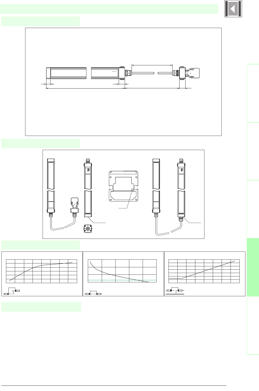
113
S
ubject to reasonable modifications due to technical advances. Copyright Pepperl+Fuchs, Printed in Germany
Pepperl+Fuchs Group • Tel.: Germany +49 621 776-0 • USA +1 330 4253555 • Singapore +65 67799091 • Internet http://www.pepperl-fuchs.com
Diagrams
Electrical connection
Dimensions
Safety through beam
sensors
Safety light gridsSafety light grids with
internal control unit
Safety light curtainsControl units
SLC30-...-S
x
y
SLC30 / SLC60 / SLC90
Offset Y [mm]
Distance X [m]
Characteristic response curve
0
50
100
150
200
250
300
0 2 4 6 8 10 12 14 16
x
SLC30 / SLC60 / SLC90
Distance X [m]
Stability control
Relative received light strength
1
10
100
1000
0 5 10 15 20 25
x
y
SLC30 / SLC60 / SLC90
Distance X [m]
Lateral interval to mirroring surfaces
Minimum interval [m]
0
0.1
0.2
0.3
0.4
0.5
0.6
0.7
0246810121416
Date of edition 05/17/2006
Slave Master
Remove cap
Remove
jumper
Insert circuit
board and
screw it
Slave Master
Height of the protected area + 107 28
L + 64
28
19
L ~ 540
Safety light curtain
• Mounting set SLC
• Test rods SLC14/SLC30/SLC60
• Protective glass pieces for SLC (to protect the optically
functional surface)
• Lateral screwed connection SLC
• Profile alignment aid
• Laser alignment aid SLC
• Mirror for SLC (for securing hazardous areas on multiple
sides)
• Ground pillar UC SLP/SLC
System accessories
• Housing for pillar
Enclosure UC SLP/SLC
• Collision protector
Damping UC SLP/SLC
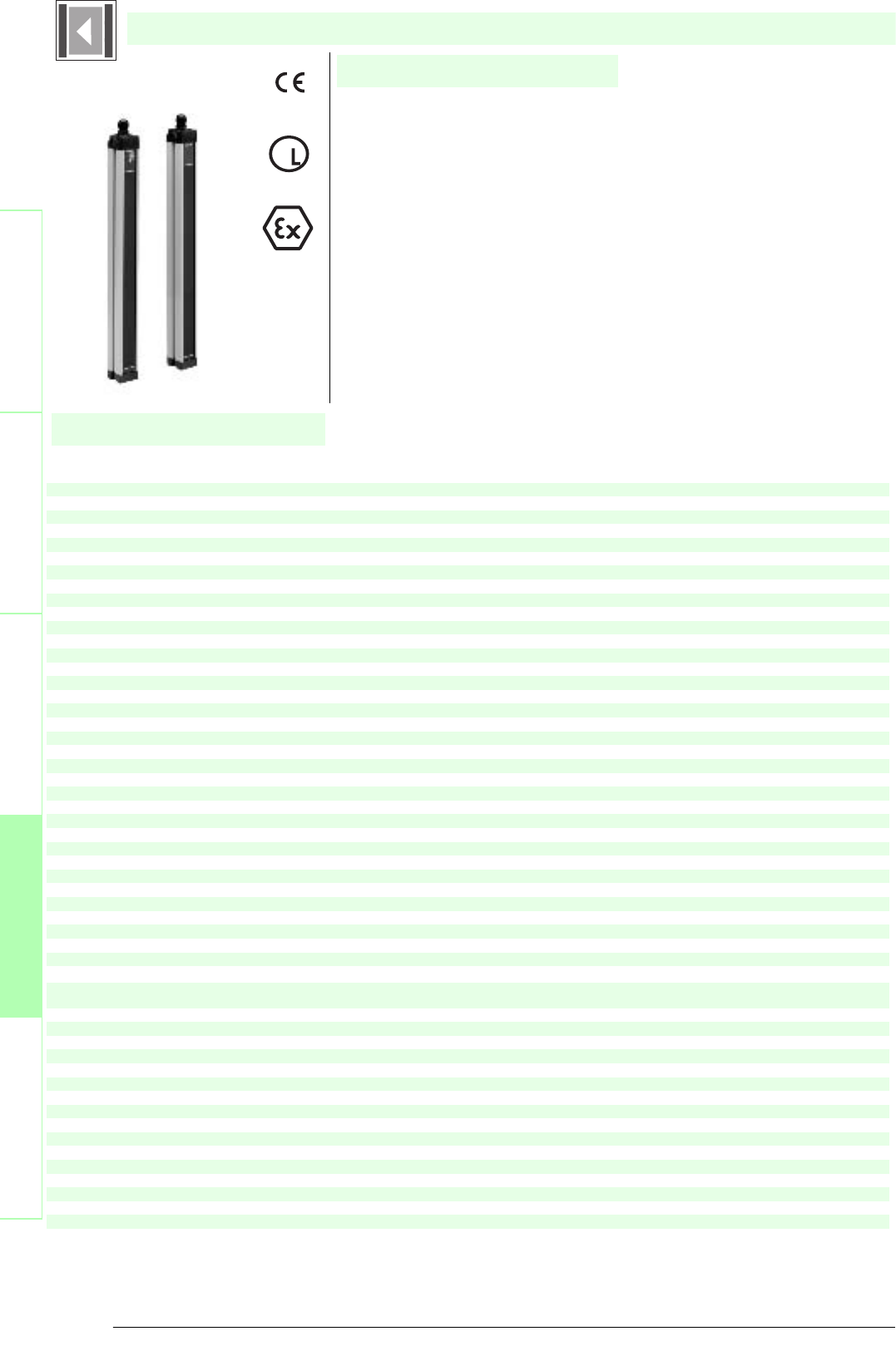
Subject to reasonable modifications due to technical advances. Copyright Pepperl+Fuchs, Printed in Germany
Pepperl+Fuchs Group • Tel.: Germany +49 621 776-0 • USA +1 330 4253555 • Singapore +65 67799091 • Internet http://www.pepperl-fuchs.com
114
Technische DatenTechnical data
Features
Ordering code
Safety through beam
sensors
Safety light grids
Safety light grids with
internal control unit
Safety light curtains
Control units
SLC60-300
SLC60-600
SLC60-900
SLC60-1200
SLC60-1500
SLC60-1800
Effective detection range
0.2 ... 15 m
X X X X X X
Light source
IRED
XXXXXX
Approvals
TÜV, UL
X X X X X X
Tes ts
IEC/EN 61496
XXXXXX
Marking
CE
X X X X X X
Width of protected area
0.2 ... 15 m
XXXXXX
Height of the protected area
[mm]
300 600 900 1200 1500 1800
Number of beams
8 1624324048
Safety category according to IEC/EN 61496
4
X X X X X X
Operating mode
can be selected with or without start/restart disable
XXXXXX
Light type
infrared, modulated light
X X X X X X
Optical resolution
60 mm
XXXXXX
Angle of divergence
< 5 °
X X X X X X
Operating display
7-segment display in emitter
XXXXXX
Diagnosis display
7-segment display in receiver
X X X X X X
Function display
in receiver: LED red: OSSD off, LED green: OSSD on, LED yellow: Protected area free, system start-ready
XXXXXX
Pre-fault indication
LED orange
X X X X X X
Operating elements
switch for start/restart disable, transmission coding
XXXXXX
Operating voltage
24 V DC (-30 %/+25 %)
X X X X X X
Protection class
III
XXXXXX
No-load supply current
Emitter: ≤ 100 mA receiver: ≤ 150 mA
X X X X X X
Activation current
approx. 10 mA
XXXXXX
Activation time
0.03 ... 1 s
X X X X X X
Test input
Reset-input for system test
XXXXXX
Function input
Start release
X X X X X X
Safety output
2 separated fail safe semiconductor outputs
XXXXXX
Signal output
1 PNP each, max. 100 mA for start readiness and OSSD status
X X X X X X
Switching voltage
Operating voltage -2 V
XXXXXX
Switching current
max. 0.5 A
X X X X X X
Response time
[ms]
10 10 12 14 16 18
Ambient temperature
0 ... 55 °C (273 ... 328 K)
X X X X X X
Storage temperature
-25 ... 70 °C (248 ... 343 K)
XXXXXX
Relative humidity
max. 95 %, not condensing
X X X X X X
Length of housing L
[mm]
410 710 1010 1310 1610 1910
Protection degree
IP67
X X X X X X
Connection
Cable screwed connection M20 ,[cr]terminal compartment with screw terminals, lead cross-section max. 1.5 mm2
XXXXXX
Connection options
Further electrical connection options on request: Plug connector M12, 8-pin, Plug connector DIN 43 651 Hirschmann, 6-pin+PE,
Plug connector M26x11 Hirschmann, 11-pin+PE
X X X X X X
Housing
aluminium extruded structural profile, RAL 1021 (yellow) coated
XXXXXX
Optical face
Plastic pane
X X X X X X
Mass
Per [g]
1200 2100 3000 3900 4800 5700
System components
Emitter
SLC60-1200-T
X
SLC60-1500-T
X
SLC60-1800-T
X
SLC60-300-T
X
SLC60-600-T
X
SLC60-900-T
X
Receiver
SLC60-1200-R
X
SLC60-1500-R
X
SLC60-1800-R
X
SLC60-300-R
X
SLC60-600-R
X
SLC60-900-R
X
SLC60-...
• Detection range up to 15 m
• Resolution 60 mm (protection against access from the rear)
• Protective field height up to 1800 mm
• Self-monitoring (type 4 according to IEC/EN 61496-1)
• Master/Slave detection, Plug and Play
• Start/Restart disable
• Protection degree IP67
• Integrated function display
• Pre-fault indication
• Safety outputs OSSD in potential-separated semiconductor design or with
monitored, compelled connection NC-contacts
• Optional with relay monitor (Option 129)
• Optional with ATEX certificates for zone 2 and 22 and protection degree IP66
U
®
Date of edition 05/17/2006
Safety light curtain
For suitable cable sockets, mounting aids, redirection mirrors and more refer to chapter „Accessories.

115
S
ubject to reasonable modifications due to technical advances. Copyright Pepperl+Fuchs, Printed in Germany
Pepperl+Fuchs Group • Tel.: Germany +49 621 776-0 • USA +1 330 4253555 • Singapore +65 67799091 • Internet http://www.pepperl-fuchs.com
Diagrams
Electrical connection
Dimensions
Safety through beam
sensors
Safety light gridsSafety light grids with
internal control unit
Safety light curtainsControl units
SLC60-...
x
y
SLC30 / SLC60 / SLC90
Offset Y [mm]
Distance X [m]
Characteristic response curve
0
50
100
150
200
250
300
0 2 4 6 8 10 12 14 16
x
SLC30 / SLC60 / SLC90
Distance X [m]
Stability control
Relative received light strength
1
10
100
1000
0 5 10 15 20 25
x
y
SLC30 / SLC60 / SLC90
Distance X [m]
Lateral interval to mirroring surfaces
Minimum interval [m]
0
0.1
0.2
0.3
0.4
0.5
0.6
0.7
0246810121416
Date of edition 05/17/2006
Emitter: Receiver:
Terminal Emitter Receiver SLC...-R (semiconductor output) Receiver SLC...-R/129 (Relay monitor)
X1:1 Functional earth Functional earth Functional earth
X1:2 Test (input) Relay monitor
X1:3 0 V OSSD 0 V OSSD
X1:4 24 V OSSD 24 V OSSD
X1:5 OSSD2 (output) OSSD2 (output)
X1:6 OSSD1 (output) OSSD1 (output)
X1:7 0 V AC/DC 0 V DC 0 V DC
X1:8 24 V AC/DC 24 V DC 24 V DC
X2:1 Start release (output) Start release (output)
X2:2 Status OSSD (output) Status OSSD (output)
X2:3 Not placed on board n.c. n.c.
X2:4 n.c. n.c.
x2:5 Startup readiness (input) Startup readiness (input)
S1: Beam coding S1/S2: Startup/restart interlock
S3: Beam coding
S1 S1 S2 S3
X1 X1
X2
8765432187654321
123 4 5
Housing length
Height of the protected area
52
55
28
85
27
Safety light curtain
• Mounting set SLC
• Test rods SLC14/SLC30/SLC60
• Protective glass pieces for SLC (to protect the optically
functional surface)
• Lateral screwed connection SLC
• Profile alignment aid
• Laser alignment aid SLC
• Mirror for SLC (for securing hazardous areas on multiple
sides)
• Ground pillar UC SLP/SLC
System accessories
• Housing for pillar
Enclosure UC SLP/SLC
• Collision protector
Damping UC SLP/SLC

Subject to reasonable modifications due to technical advances. Copyright Pepperl+Fuchs, Printed in Germany
Pepperl+Fuchs Group • Tel.: Germany +49 621 776-0 • USA +1 330 4253555 • Singapore +65 67799091 • Internet http://www.pepperl-fuchs.com
116
Technische DatenTechnical data
Features
Ordering code
Safety through beam
sensors
Safety light grids
Safety light grids with
internal control unit
Safety light curtains
Control units
SLC60-300/31
SLC60-600/31
SLC60-900/31
SLC60-1200/31
SLC60-1500/31
SLC60-1800/31
Effective detection range
0.2 ... 15 m
X X X X X X
Light source
IRED
XXXXXX
Approvals
TÜV, UL
X X X X X X
Tes ts
IEC/EN 61496
XXXXXX
Marking
CE
X X X X X X
Width of protected area
0.2 ... 15 m
XXXXXX
Height of the protected area
[mm]
300 600 900 1200 1500 1800
Number of beams
8 1624324048
Safety category according to IEC/EN 61496
4
X X X X X X
Operating mode
can be selected with or without start/restart disable
XXXXXX
Light type
infrared, modulated light
X X X X X X
Optical resolution
60 mm
XXXXXX
Angle of divergence
< 5 °
X X X X X X
Operating display
7-segment display in emitter
XXXXXX
Diagnosis display
7-segment display in receiver
X X X X X X
Function display
in receiver:LED red: OSSD off, LED green: OSSD on, LED yellow: Protected area free, system start-ready
XXXXXX
Pre-fault indication
LED orange
X X X X X X
Operating elements
switch for start/restart disable, transmission coding
XXXXXX
Operating voltage
24 V DC (-30 %/+25 %) / 24 V AC (-20 %/+10 %)
X X X X X X
Protection class
III
XXXXXX
No-load supply current
Emitter: ≤ 100 mA receiver: ≤ 150 mA
X X X X X X
Activation current
approx. 10 mA
XXXXXX
Activation time
0.03 ... 1 s
X X X X X X
Test input
Reset-input for system test
XXXXXX
Function input
Start release
X X X X X X
Safety output
2 relay outputs, compelled connection NO-contact
XXXXXX
Signal output
1 PNP each, max. 100 mA for start readiness and OSSD status
X X X X X X
Switching voltage
50 V
XXXXXX
Switching current
max. 2 A
X X X X X X
Switch power
100 VA
XXXXXX
Response time
[ms]
30 30 32 34 36 38
Ambient temperature
0 ... 55 °C (273 ... 328 K)
XXXXXX
Storage temperature
-25 ... 70 °C (248 ... 343 K)
X X X X X X
Relative humidity
max. 95 %, not condensing
XXXXXX
Length of housing L
[mm]
410 710 1010 1310 1610 1910
Protection degree
IP67
XXXXXX
Connection
Cable screwed connection M20 , terminal compartment with screw terminals, lead cross-section max. 1.5 mm2
X X X X X X
Connection options
Further electrical connection options on request: Plug connector M12, 8-pin Plug connector DIN 43 651 Hirschmann, 6-pin+PE Plug
connector M26x11 Hirschmann, 11-pin+PE
XXXXXX
Housing
aluminium extruded structural profile, RAL 1021 (yellow) coated
X X X X X X
Optical face
Plastic pane
XXXXXX
Mass
Per [g]
1200 2100 3000 3900 4800 5700
System components
Emitter
SLC60-1200-T
X
SLC60-1500-T
X
SLC60-1800-T
X
SLC60-300-T
X
SLC60-600-T
X
SLC60-900-T
X
Receiver
SLC60-1200-R/31
X
SLC60-1500-R/31
X
SLC60-1800-R/31
X
SLC60-300-R/31
X
SLC60-600-R/31
X
SLC60-900-R/31
X
SLC60-.../31
• Detection range up to 15 m
• Resolution 60 mm (protection against access from the rear)
• Protective field height up to 1800 mm
• Self-monitoring (type 4 according to IEC/EN 61496-1)
• Master/Slave detection, Plug and Play
• Start/Restart disable
• Protection degree IP67
• Integrated function display
• Pre-fault indication
• Safety outputs OSSD in potential-separated semiconductor design or with
monitored, compelled connection NC-contacts
• Optional with relay monitor (Option 129)
U
®
Date of edition 05/17/2006
Safety light curtain
For suitable cable sockets, mounting aids, redirection mirrors and more refer to chapter „Accessories.

117
S
ubject to reasonable modifications due to technical advances. Copyright Pepperl+Fuchs, Printed in Germany
Pepperl+Fuchs Group • Tel.: Germany +49 621 776-0 • USA +1 330 4253555 • Singapore +65 67799091 • Internet http://www.pepperl-fuchs.com
Diagrams
Electrical connection
Dimensions
Safety through beam
sensors
Safety light gridsSafety light grids with
internal control unit
Safety light curtainsControl units
SLC60-.../31
x
y
SLC30 / SLC60 / SLC90
Offset Y [mm]
Distance X [m]
Characteristic response curve
0
50
100
150
200
250
300
0 2 4 6 8 10 12 14 16
x
SLC30 / SLC60 / SLC90
Distance X [m]
Stability control
Relative received light strength
1
10
100
1000
0 5 10 15 20 25
x
y
SLC30 / SLC60 / SLC90
Distance X [m]
Lateral interval to mirroring surfaces
Minimum interval [m]
0
0.1
0.2
0.3
0.4
0.5
0.6
0.7
0246810121416
Date of edition 05/17/2006
Emitter: Receiver:
terminal emitter receiver SLC...-R/31 (relay output) receiver SLC...-R/31 (Relay monitor)
X1:1 Functional earth Functional earth Functional earth
X1:2 test (input) Relay monitor
X1:3 OSSD2.2 (output) OSSD2.2 (output)
X1:4 OSSD1.2 (output) OSSD1.2 (output)
X1:5 OSSD2.1 (output) OSSD2.1 (output)
X1:6 OSSD1.1 (output) OSSD1.1 (output)
X1:7 0 V AC/DC 0 V AC/DC 0 V AC/DC
X1:8 24 V AC/DC 24 V AC/DC 24 V AC/DC
X2:1 Start release (output) Start release (output)
X2:2 Status OSSD (output) Status OSSD (output)
X2:3 Not placed on board 24 V reference potential for I/O 24 V reference potential for I/O
X2:4 0 V reference potential for I/O 0 V reference potential for I/O
x2:5 Startup readiness (input) Startup readiness (input)
S1: Beam coding S1/S2: Startup/restar interlock
S3: Beam coding
S1 S1 S2 S3
X1 X1
X2
8765432187654321
123 4 5
Housing length
Height of the protected area
52
55
28
85
27
Safety light curtain
• Mounting set SLC
• Test rods SLC14/SLC30/SLC60
• Protective glass pieces for SLC (to protect the optically
functional surface)
• Lateral screwed connection SLC
• Profile alignment aid
• Laser alignment aid SLC
• Mirror for SLC (for securing hazardous areas on multiple
sides)
• Ground pillar UC SLP/SLC
System accessories
• Housing for pillar
Enclosure UC SLP/SLC
• Collision protector
Damping UC SLP/SLC

Subject to reasonable modifications due to technical advances. Copyright Pepperl+Fuchs, Printed in Germany
Pepperl+Fuchs Group • Tel.: Germany +49 621 776-0 • USA +1 330 4253555 • Singapore +65 67799091 • Internet http://www.pepperl-fuchs.com
118
Technische DatenTechnical data
Features
Ordering code
Safety through beam
sensors
Safety light grids
Safety light grids with
internal control unit
Safety light curtains
Control units
SLC60-300-S
SLC60-600-S
SLC60-900-S
SLC60-1200-S
SLC60-1500-S
SLC60-1800-S
Effective detection range
0.2 ... 15 m
X X X X X X
Light source
IRED
XXXXXX
Approvals
TÜV, UL
X X X X X X
Test s
IEC/EN 61496
XXXXXX
Marking
CE
X X X X X X
Width of protected area
0.2 ... 15 m
XXXXXX
Height of the protected area
[mm]
300 600 900 1200 1500 1800
Number of beams
8 1624324048
Safety category according to IEC/EN
61496
4
X X X X X X
Operating mode
in the master device
XXXXXX
Light type
infrared, modulated light
X X X X X X
Optical resolution
60 mm
XXXXXX
Angle of divergence
< 5 °
X X X X X X
Operating display
in the master device
XXXXXX
Diagnosis display
in the master device
X X X X X X
Function display
in the master device
XXXXXX
Pre-fault indication
in the master device
X X X X X X
Operating elements
in the master device
XXXXXX
Operating voltage
from master
X X X X X X
Protection class
III
XXXXXX
No-load supply current
from master
X X X X X X
Test i np ut
in the master device
XXXXXX
Function input
in the master device
X X X X X X
Safety output
in the master device
XXXXXX
Signal output
in the master device
X X X X X X
Response time
depends on height of protective field
XXXXXX
Ambient temperature
0 ... 55 °C (273 ... 328 K)
X X X X X X
Storage temperature
-25 ... 70 °C (248 ... 343 K)
XXXXXX
Relative humidity
max. 95 %, not condensing
X X X X X X
Length of housing L
[mm]
410 710 1010 1310 1610 1910
Protection degree
IP67
X X X X X X
Connection
Cable screwed connection M20 , terminal compartment with screw terminals, lead cross-section max. 1.5 mm2
XXXXXX
Housing
aluminium extruded structural profile, RAL 1021 (yellow) coated
X X X X X X
Optical face
Plastic pane
XXXXXX
Mass
Per [g]
1200 2100 3000 3900 4800 5700
System components
Emitter
SLC60-1200-T-S
X
SLC60-1500-T-S
X
SLC60-1800-T-S
X
SLC60-300-T-S
X
SLC60-600-T-S
X
SLC60-900-T-S
X
Receiver
SLC60-1200-R-S
X
SLC60-1500-R-S
X
SLC60-1800-R-S
X
SLC60-300-R-S
X
SLC60-600-R-S
X
SLC60-900-R-S
X
SLC60-...-S
• Detection range up to 15 m
• Resolution 60 mm (protection against access from the rear)
• Protective field height up to 1800 mm
• Self-monitoring (type 4 according to IEC/EN 61496-1)
• Master/Slave detection, Plug and Play
• Start/Restart disable
• Protection degree IP67
• Integrated function display
• Pre-fault indication
• Safety outputs OSSD in potential-separated semiconductor design or with
monitored, compelled connection NC-contacts
• Optional with ATEX certificates for zone 2 and 22 and protection degree IP66
(Option 133)
U
®
Date of edition 05/17/2006
Safety light curtain
For suitable cable sockets, mounting aids, redirection mirrors and more refer to chapter „Accessories.

119
S
ubject to reasonable modifications due to technical advances. Copyright Pepperl+Fuchs, Printed in Germany
Pepperl+Fuchs Group • Tel.: Germany +49 621 776-0 • USA +1 330 4253555 • Singapore +65 67799091 • Internet http://www.pepperl-fuchs.com
Diagrams
Electrical connection
Dimensions
Safety through beam
sensors
Safety light gridsSafety light grids with
internal control unit
Safety light curtainsControl units
SLC60-...-S
x
y
SLC30 / SLC60 / SLC90
Offset Y [mm]
Distance X [m]
Characteristic response curve
0
50
100
150
200
250
300
0 2 4 6 8 10 12 14 16
x
SLC30 / SLC60 / SLC90
Distance X [m]
Stability control
Relative received light strength
1
10
100
1000
0 5 10 15 20 25
x
y
SLC30 / SLC60 / SLC90
Distance X [m]
Lateral interval to mirroring surfaces
Minimum interval [m]
0
0.1
0.2
0.3
0.4
0.5
0.6
0.7
0246810121416
Date of edition 05/17/2006
Slave Master
Remove cap
Remove
jumper
Insert circuit
board and
screw it
Slave Master
Height of the protected area + 107 28
L + 64
28
19
L ~ 540
Safety light curtain
• Mounting set SLC
• Test rods SLC14/SLC30/SLC60
• Protective glass pieces for SLC (to protect the optically
functional surface)
• Lateral screwed connection SLC
• Profile alignment aid
• Laser alignment aid SLC
• Mirror for SLC (for securing hazardous areas on multiple
sides)
• Ground pillar UC SLP/SLC
System accessories
• Housing for pillar
Enclosure UC SLP/SLC
• Collision protector
Damping UC SLP/SLC
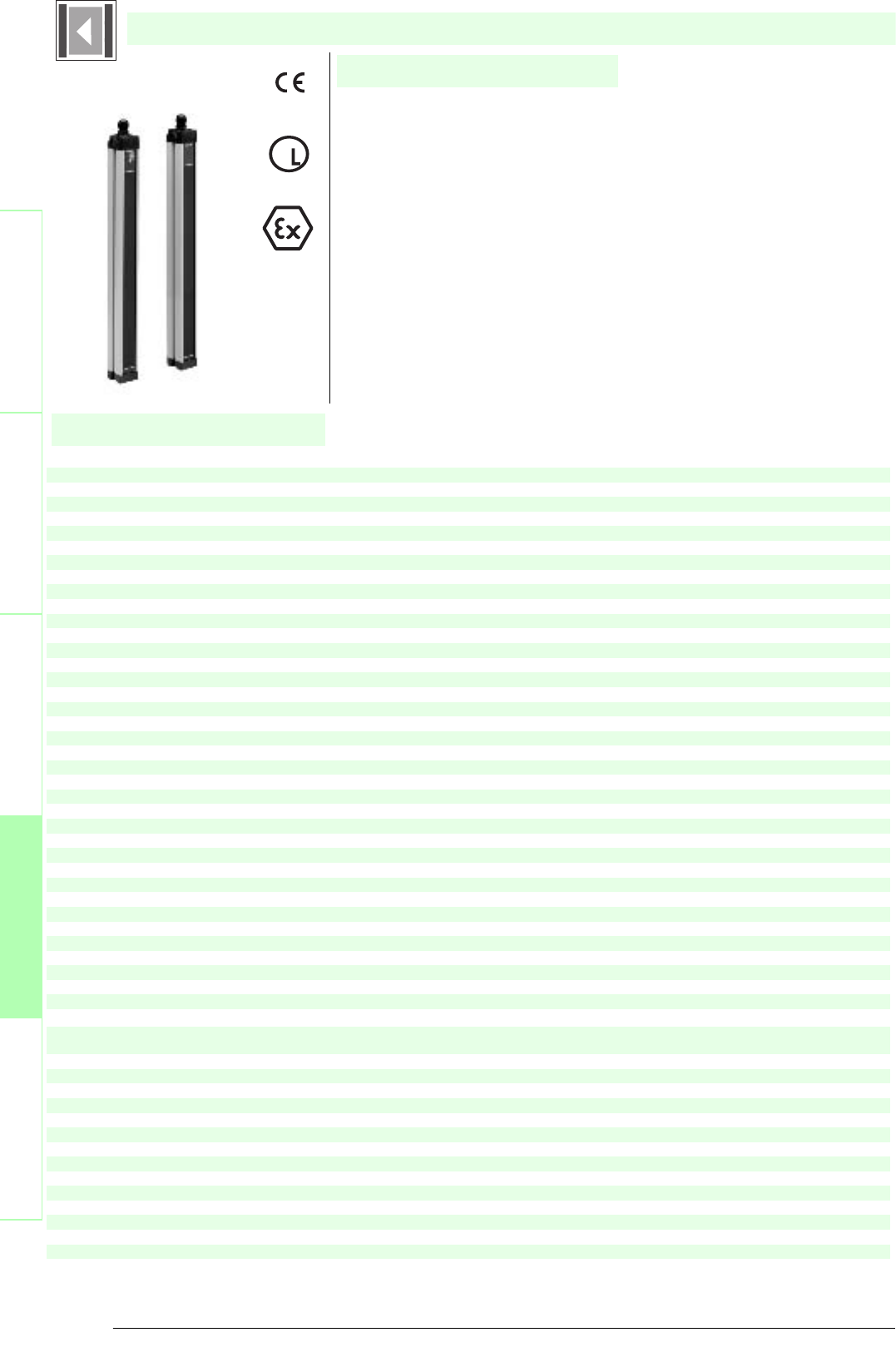
Subject to reasonable modifications due to technical advances. Copyright Pepperl+Fuchs, Printed in Germany
Pepperl+Fuchs Group • Tel.: Germany +49 621 776-0 • USA +1 330 4253555 • Singapore +65 67799091 • Internet http://www.pepperl-fuchs.com
120
Technische DatenTechnical data
Features
Ordering code
Safety through beam
sensors
Safety light grids
Safety light grids with
internal control unit
Safety light curtains
Control units
SLC90-600
SLC90-900
SLC90-1200
SLC90-1500
SLC90-1800
Effective detection range
0.2 ... 15 m
X X X X X
Light source
IRED
XXXXX
Approvals
TÜV, UL
X X X X X
Tests
IEC/EN 61496
XXXXX
Marking
CE
X X X X X
Width of protected area
0.2 ... 15 m
XXXXX
Height of the protected area
[mm]
600 900 1200 1500 1800
Number of beams
8 12162024
Safety category according to IEC/EN 61496
4
X X X X X
Operating mode
can be selected with or without start/restart disable
XXXXX
Light type
infrared, modulated light
X X X X X
Optical resolution
90 mm
XXXXX
Angle of divergence
< 5 °
X X X X X
Operating display
7-segment display in emitter
XXXXX
Diagnosis display
7-segment display in receiver
X X X X X
Function display
in receiver: LED red: OSSD off, LED green: OSSD on, LED yellow: Protected area free, system start-ready
XXXXX
Pre-fault indication
LED orange
X X X X X
Operating elements
switch for start/restart disable, transmission coding
XXXXX
Operating voltage
24 V DC (-30 %/+25 %)
X X X X X
Protection class
III
XXXXX
No-load supply current
Emitter: ≤ 100 mA receiver: ≤ 150 mA
X X X X X
Activation current
approx. 10 mA
XXXXX
Activation time
0.03 ... 1 s
X X X X X
Test in pu t
Reset-input for system test
XXXXX
Function input
Start release
X X X X X
Safety output
2 separated fail safe semiconductor outputs
XXXXX
Signal output
1 PNP each, max. 100 mA for start readiness and OSSD status
X X X X X
Switching voltage
Operating voltage -2 V
XXXXX
Switching current
max. 0.5 A
X X X X X
Response time
10 ms
XXX
11 ms
X
12 ms
X
Ambient temperature
0 ... 55 °C (273 ... 328 K)
X X X X X
Storage temperature
-25 ... 70 °C (248 ... 343 K)
XXXXX
Relative humidity
max. 95 %, not condensing
X X X X X
Length of housing L
[mm]
710 1010 1310 1610 1910
Protection degree
IP67
X X X X X
Connection
Cable screwed connection M20 , terminal compartment with screw terminals, lead cross-section max. 1.5 mm2
XXXXX
Connection options
Further electrical connection options on request: Plug connector M12, 8-pin, Plug connector DIN 43 651 Hirschmann, 6-pin+PE,
Plug connector M26x11 Hirschmann, 11-pin+PE
X X X X X
Housing
aluminium extruded structural profile, RAL 1021 (yellow) coated
XXXXX
Optical face
Plastic pane
X X X X X
Mass
Per [g]
2100 3000 3900 4800 5700
System components
Emitter
SLC90-1200-T
X
SLC90-1500-T
X
SLC90-1800-T
X
SLC90-600-T
X
SLC90-900-T
X
Receiver
SLC90-1200-R
X
SLC90-1500-R
X
SLC90-1800-R
X
SLC90-600-R
X
SLC90-900-R
X
SLC90-...
• Detection range up to 15 m
• Resolution 90 mm (protection against access from the rear)
• Protective field height up to 1800 mm
• Self-monitoring (type 4 according to IEC/EN 61496-1)
• Master/Slave detection, Plug and Play
• Start/Restart disable
• Protection degree IP67
• Integrated function display
• Pre-fault indication
• Safety outputs OSSD in potential-separated semiconductor design or with
monitored, compelled connection NC-contacts
• Optional with relay monitor (Option 129)
• Optional with ATEX certificates for zone 2 and 22 and protection degree IP66
(Option 133)
U
®
Date of edition 05/17/2006
Safety light curtain
For suitable cable sockets, mounting aids, redirection mirrors and more refer to chapter „Accessories.
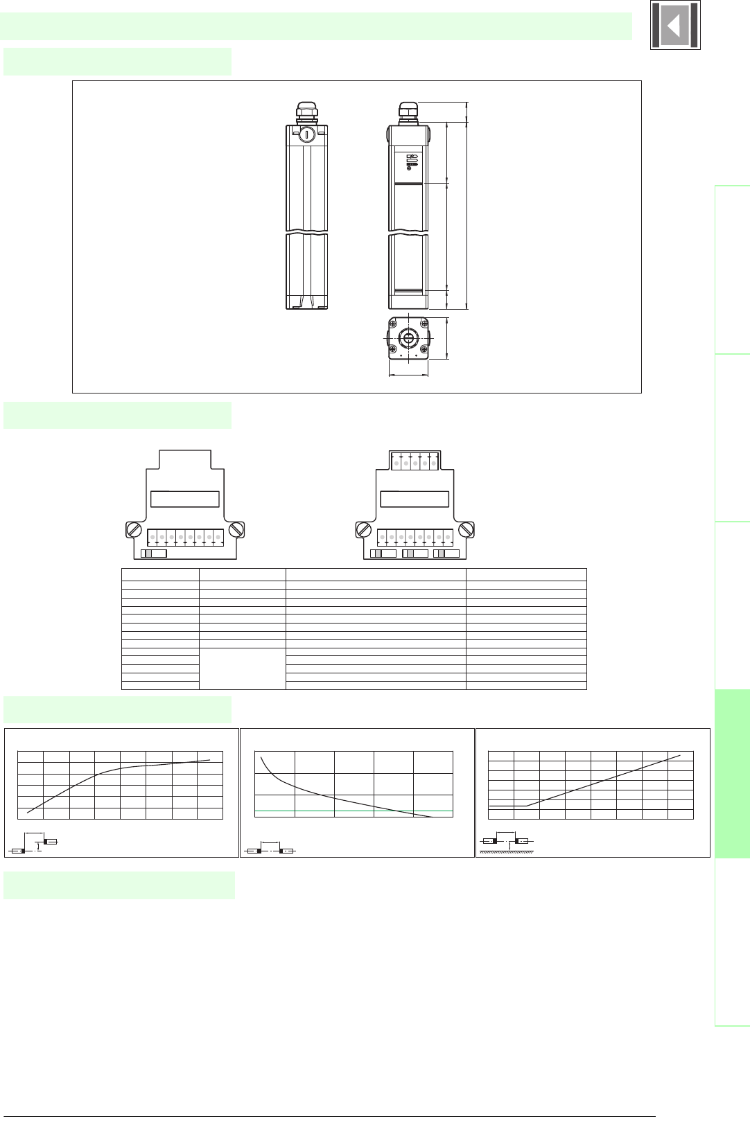
121
S
ubject to reasonable modifications due to technical advances. Copyright Pepperl+Fuchs, Printed in Germany
Pepperl+Fuchs Group • Tel.: Germany +49 621 776-0 • USA +1 330 4253555 • Singapore +65 67799091 • Internet http://www.pepperl-fuchs.com
Diagrams
Electrical connection
Dimensions
Safety through beam
sensors
Safety light gridsSafety light grids with
internal control unit
Safety light curtainsControl units
SLC90-...
x
y
SLC30 / SLC60 / SLC90
Offset Y [mm]
Distance X [m]
Characteristic response curve
0
50
100
150
200
250
300
0 2 4 6 8 10 12 14 16
x
SLC30 / SLC60 / SLC90
Distance X [m]
Stability control
Relative received light strength
1
10
100
1000
0 5 10 15 20 25
x
y
SLC30 / SLC60 / SLC90
Distance X [m]
Lateral interval to mirroring surfaces
Minimum interval [m]
0
0.1
0.2
0.3
0.4
0.5
0.6
0.7
0246810121416
Date of edition 05/17/2006
Emitter: Receiver:
Terminal Emitter Receiver SLC...-R (semiconductor output) Receiver SLC...-R/129 (Relay monitor)
X1:1 Functional earth Functional earth Functional earth
X1:2 Test (input) Relay monitor
X1:3 0 V OSSD 0 V OSSD
X1:4 24 V OSSD 24 V OSSD
X1:5 OSSD2 (output) OSSD2 (output)
X1:6 OSSD1 (output) OSSD1 (output)
X1:7 0 V AC/DC 0 V DC 0 V DC
X1:8 24 V AC/DC 24 V DC 24 V DC
X2:1 Start release (output) Start release (output)
X2:2 Status OSSD (output) Status OSSD (output)
X2:3 Not placed on board n.c. n.c.
X2:4 n.c. n.c.
x2:5 Startup readiness (input) Startup readiness (input)
S1: Beam coding S1/S2: Startup/restart interlock
S3: Beam coding
S1 S1 S2 S3
X1 X1
X2
8765432187654321
123 4 5
Housing length
Height of the protected area
52
55
28
85
27
Safety light curtain
• Mounting set SLC
• Test rods SLC14/SLC30/SLC60
• Protective glass pieces for SLC (to protect the optically
functional surface)
• Lateral screwed connection SLC
• Profile alignment aid
• Laser alignment aid SLC
• Mirror for SLC (for securing hazardous areas on multiple
sides)
• Ground pillar UC SLP/SLC
System accessories
• Housing for pillar
Enclosure UC SLP/SLC
• Collision protector
Damping UC SLP/SLC

Subject to reasonable modifications due to technical advances. Copyright Pepperl+Fuchs, Printed in Germany
Pepperl+Fuchs Group • Tel.: Germany +49 621 776-0 • USA +1 330 4253555 • Singapore +65 67799091 • Internet http://www.pepperl-fuchs.com
122
Technische DatenTechnical data
Features
Ordering code
Safety through beam
sensors
Safety light grids
Safety light grids with
internal control unit
Safety light curtains
Control units
SLC90-600/31
SLC90-900/31
SLC90-1200/31
SLC90-1500/31
SLC90-1800/31
Effective detection range3
0.2 ... 15 m
X X X X X
Light source
IRED
XXXXX
Approvals
TÜV, UL
X X X X X
Tests
IEC/EN 61496
XXXXX
Marking
CE
X X X X X
Width of protected area
0.2 ... 15 m
XXXXX
Height of the protected area
[mm]
600 900 1200 1500 1800
Number of beams
8 12162024
Safety category according to IEC/EN 61496
4
X X X X X
Operating mode
can be selected with or without start/restart disable
XXXXX
Light type
infrared, modulated light
X X X X X
Optical resolution
90 mm
XXXXX
Angle of divergence
< 5 °
X X X X X
Operating display
7-segment display in emitter
XXXXX
Diagnosis display
7-segment display in receiver
X X X X X
Function display
in receiver: LED red: OSSD off, LED green: OSSD on, LED yellow: Protected area free, system start-ready
XXXXX
Pre-fault indication
LED orange
X X X X X
Operating elements
switch for start/restart disable, transmission coding
XXXXX
Operating voltage
24 V DC (-30 %/+25 %) / 24 V AC (-20 %/+10 %)
X X X X X
Protection class
III
XXXXX
No-load supply current
Emitter: ≤ 100 mA receiver: ≤ 150 mA
X X X X X
Activation current
approx. 10 mA
XXXXX
Activation time
0.03 ... 1 s
X X X X X
Test in pu t
Reset-input for system test
XXXXX
Function input
Start release
X X X X X
Safety output
2 relay outputs, compelled connection NO-contact
XXXXX
Signal output
1 PNP each, max. 100 mA for start readiness and OSSD status
X X X X X
Switching voltage
50 V
XXXXX
Switching current
max. 2 A
X X X X X
Switch power
100 VA
XXXXX
Response time
30 ms
X X X
31 ms
X
32 ms
X
Ambient temperature
0 ... 55 °C (273 ... 328 K)
XXXXX
Storage temperature
-25 ... 70 °C (248 ... 343 K)
X X X X X
Relative humidity
max. 95 %, not condensing
XXXXX
Length of housing L
[mm]
710 1010 1310 1610 1910
Protection degree
IP67
XXXXX
Connection
Cable screwed connection M20 , terminal compartment with screw terminals, lead cross-section max. 1.5 mm2
X X X X X
Connection options
Further electrical connection options on request: Plug connector M12, 8-pin, Plug connector DIN 43 651 Hirschmann, 6-pin+PE,
Plug connector M26x11 Hirschmann, 11-pin+PE
XXXXX
Housing
aluminium extruded structural profile, RAL 1021 (yellow) coated
X X X X X
Optical face
Plastic pane
XXXXX
Mass
Per [g]
2100 3000 3900 4800 5700
System components
Emitter
SLC90-1200-T
X
SLC90-1500-T
X
SLC90-1800-T
X
SLC90-600-T
X
SLC90-900-T
X
Receiver
SLC90-1200-R/31
X
SLC90-1500-R/31
X
SLC90-1800-R/31
X
SLC90-600-R/31
X
SLC90-900-R/31
X
SLC90-.../31
• Detection range up to 15 m
• Resolution 90 mm (protection against access from the rear)
• Protective field height up to 1800 mm
• Self-monitoring (type 4 according to IEC/EN 61496-1)
• Master/Slave detection, Plug and Play
• Start/Restart disable
• Protection degree IP67
• Integrated function display
• Pre-fault indication
• Safety outputs OSSD in potential-separated semiconductor design or with
monitored, compelled connection NC-contacts
• Optional with relay monitor (Option 129)
U
®
Date of edition 05/17/2006
Safety light curtain
For suitable cable sockets, mounting aids, redirection mirrors and more refer to chapter „Accessories.

123
S
ubject to reasonable modifications due to technical advances. Copyright Pepperl+Fuchs, Printed in Germany
Pepperl+Fuchs Group • Tel.: Germany +49 621 776-0 • USA +1 330 4253555 • Singapore +65 67799091 • Internet http://www.pepperl-fuchs.com
Diagrams
Electrical connection
Dimensions
Safety through beam
sensors
Safety light gridsSafety light grids with
internal control unit
Safety light curtainsControl units
SLC90-.../31
x
y
SLC30 / SLC60 / SLC90
Offset Y [mm]
Distance X [m]
Characteristic response curve
0
50
100
150
200
250
300
0 2 4 6 8 10 12 14 16
x
SLC30 / SLC60 / SLC90
Distance X [m]
Stability control
Relative received light strength
1
10
100
1000
0 5 10 15 20 25
x
y
SLC30 / SLC60 / SLC90
Distance X [m]
Lateral interval to mirroring surfaces
Minimum interval [m]
0
0.1
0.2
0.3
0.4
0.5
0.6
0.7
0246810121416
Date of edition 05/17/2006
Emitter: Receiver:
terminal emitter receiver SLC...-R/31 (relay output) receiver SLC...-R/31 (Relay monitor)
X1:1 Functional earth Functional earth Functional earth
X1:2 test (input) Relay monitor
X1:3 OSSD2.2 (output) OSSD2.2 (output)
X1:4 OSSD1.2 (output) OSSD1.2 (output)
X1:5 OSSD2.1 (output) OSSD2.1 (output)
X1:6 OSSD1.1 (output) OSSD1.1 (output)
X1:7 0 V AC/DC 0 V AC/DC 0 V AC/DC
X1:8 24 V AC/DC 24 V AC/DC 24 V AC/DC
X2:1 Start release (output) Start release (output)
X2:2 Status OSSD (output) Status OSSD (output)
X2:3 Not placed on board 24 V reference potential for I/O 24 V reference potential for I/O
X2:4 0 V reference potential for I/O 0 V reference potential for I/O
x2:5 Startup readiness (input) Startup readiness (input)
S1: Beam coding S1/S2: Startup/restar interlock
S3: Beam coding
S1 S1 S2 S3
X1 X1
X2
8765432187654321
123 4 5
Housing length
Height of the protected area
52
55
28
85
27
Safety light curtain
• Mounting set SLC
• Test rods SLC14/SLC30/SLC60
• Protective glass pieces for SLC (to protect the optically
functional surface)
• Lateral screwed connection SLC
• Profile alignment aid
• Laser alignment aid SLC
• Mirror for SLC (for securing hazardous areas on multiple
sides)
• Ground pillar UC SLP/SLC
System accessories
• Housing for pillar
Enclosure UC SLP/SLC
• Collision protector
Damping UC SLP/SLC

Subject to reasonable modifications due to technical advances. Copyright Pepperl+Fuchs, Printed in Germany
Pepperl+Fuchs Group • Tel.: Germany +49 621 776-0 • USA +1 330 4253555 • Singapore +65 67799091 • Internet http://www.pepperl-fuchs.com
124
Technische DatenTechnical data
Features
Ordering code
Safety through beam
sensors
Safety light grids
Safety light grids with
internal control unit
Safety light curtains
Control units
SLC90-600-S
SLC90-900-S
SLC90-1200-S
SLC90-1500-S
SLC90-1800-S
Effective detection range
0.2 ... 15 m
X X X X X
Light source
IRED
XXXXX
Approvals
TÜV, UL
X X X X X
Test s
IEC/EN 61496
XXXXX
Marking
CE
X X X X X
Width of protected area
0.2 ... 15 m
XXXXX
Height of the protected area
[mm]
600 900 1200 1500 1800
Number of beams
8 12162024
Safety category according to IEC/EN
61496
4
X X X X X
Operating mode
in the master device
XXXXX
Light type
infrared, modulated light
X X X X X
Optical resolution
90 mm
XXXXX
Angle of divergence
< 5 °
X X X X X
Operating display
in the master device
XXXXX
Diagnosis display
in the master device
X X X X X
Function display
in the master device
XXXXX
Pre-fault indication
in the master device
X X X X X
Operating elements
in the master device
XXXXX
Operating voltage
from master
X X X X X
Protection class
III
XXXXX
No-load supply current
from master
X X X X X
Test i np ut
in the master device
XXXXX
Function input
in the master device
X X X X X
Safety output
in the master device
XXXXX
Signal output
in the master device
X X X X X
Response time
depends on height of protective field
XXXXX
Ambient temperature
0 ... 55 °C (273 ... 328 K)
X X X X X
Storage temperature
-25 ... 70 °C (248 ... 343 K)
XXXXX
Relative humidity
max. 95 %, not condensing
X X X X X
Length of housing L
[mm]
710 1010 1310 1610 1910
Protection degree
IP67
X X X X X
Connection
Cable screwed connection M20 , terminal compartment with screw terminals, lead cross-section max. 1.5 mm2
XXXXX
Housing
aluminium extruded structural profile, RAL 1021 (yellow) coated
X X X X X
Optical face
Plastic pane
XXXXX
Mass
Per [g]
2100 3000 3900 4800 5700
System components
Emitter
SLC90-1200-T-S
X
SLC90-1500-T-S
X
SLC90-1800-T-S
X
SLC90-600-T-S
X
SLC90-900-T-S
X
Receiver
SLC90-1200-R-S
X
SLC90-1500-R-S
X
SLC90-1800-R-S
X
SLC90-600-R-S
X
SLC90-900-R-S
X
SLC90-...-S
• Detection range up to 15 m
• Resolution 90 mm (protection against access from the rear)
• Protective field height up to 1800 mm
• Self-monitoring (type 4 according to IEC/EN 61496-1)
• Master/Slave detection, Plug and Play
• Start/Restart disable
• Protection degree IP67
• Integrated function display
• Pre-fault indication
• Safety outputs OSSD in potential-separated semiconductor design or with
monitored, compelled connection NC-contacts
• Optional with ATEX certificates for zone 2 and 22 and protection degree IP66
(Option 133)
U
®
Date of edition 05/17/2006
Safety light curtain
For suitable cable sockets, mounting aids, redirection mirrors and more refer to chapter „Accessories.

125
S
ubject to reasonable modifications due to technical advances. Copyright Pepperl+Fuchs, Printed in Germany
Pepperl+Fuchs Group • Tel.: Germany +49 621 776-0 • USA +1 330 4253555 • Singapore +65 67799091 • Internet http://www.pepperl-fuchs.com
Diagrams
Electrical connection
Dimensions
Safety through beam
sensors
Safety light gridsSafety light grids with
internal control unit
Safety light curtainsControl units
SLC90-...-S
x
y
SLC30 / SLC60 / SLC90
Offset Y [mm]
Distance X [m]
Characteristic response curve
0
50
100
150
200
250
300
0 2 4 6 8 10 12 14 16
x
SLC30 / SLC60 / SLC90
Distance X [m]
Stability control
Relative received light strength
1
10
100
1000
0 5 10 15 20 25
x
y
SLC30 / SLC60 / SLC90
Distance X [m]
Lateral interval to mirroring surfaces
Minimum interval [m]
0
0.1
0.2
0.3
0.4
0.5
0.6
0.7
0246810121416
Date of edition 05/17/2006
Slave Master
Remove cap
Remove
jumper
Insert circuit
board and
screw it
Slave Master
Height of the protected area + 107 28
L + 64
28
19
L ~ 540
Safety light curtain
• Mounting set SLC
• Test rods SLC14/SLC30/SLC60
• Protective glass pieces for SLC (to protect the optically
functional surface)
• Lateral screwed connection SLC
• Profile alignment aid
• Laser alignment aid SLC
• Mirror for SLC (for securing hazardous areas on multiple
sides)
• Ground pillar UC SLP/SLC
System accessories
• Housing for pillar
Enclosure UC SLP/SLC
• Collision protector
Damping UC SLP/SLC
126
Date of edition 05/17/2006
Subject to reasonable modifications due to technical advances. Copyright Pepperl+Fuchs, Printed in Germany
Pepperl+Fuchs Group • Tel.: Germany +49 621 776-0 • USA +1 330 4253555 • Singapore +65 67799091 • Internet http://www.pepperl-fuchs.com
Control units
Safety light barriersSafety light gridsSafety light grids with
internal control unit
Safety light curtainsControl units
Control units
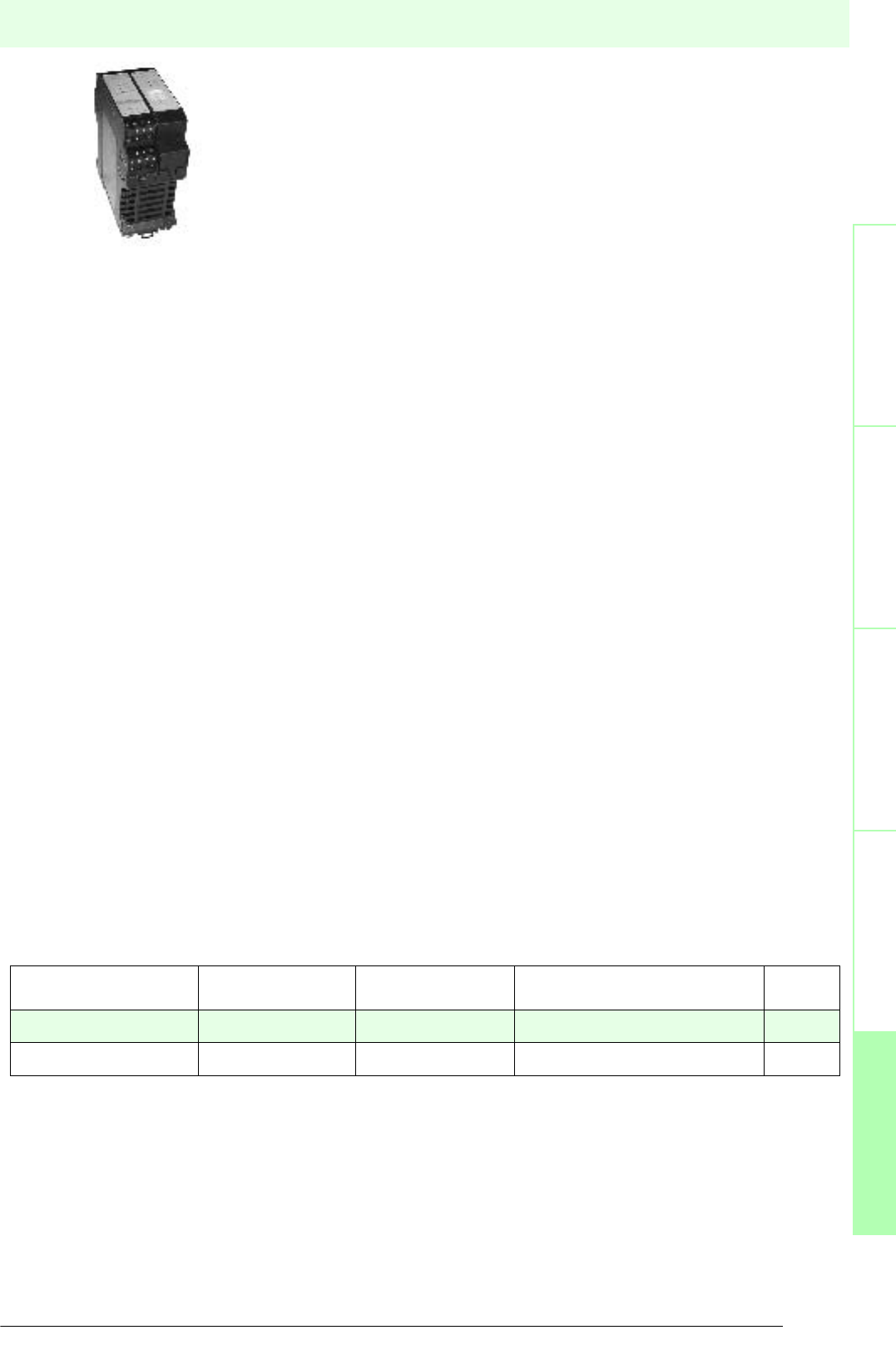
127
S
ubject to reasonable modifications due to technical advances. Copyright Pepperl+Fuchs, Printed in Germany
Pepperl+Fuchs Group • Tel.: Germany +49 621 776-0 • USA +1 330 4253555 • Singapore +65 67799091 • Internet http://www.pepperl-fuchs.com
Control units
Date of edition 05/17/2006
Safety light barriers
Safety light grids
Safety light grids with
internal control unit
Safety light curtains
Control units
Type code Number of channels Category acc. to EN
954-1
Operating voltage Page
SC2-2 2 2 24 V DC 128
SC4-2 2 4 24 V DC 130
Description
System SC2/SC4
The SC2/SC4 is a control unit for a safety light barrier system with 1 or 2 single direction
light barriers (consisting of a sender and receiver) of category 2 or 4 (EN 954-1) or of
type 2 or 4 (IEC 61496).
Together the control unit and the single direction light barriers of series SL or SLA 12/29
form a modular protection system.
The SC2/SC4 produces the required supply voltages, triggers the light senders and
evaluates the signals transmitted by the receivers. A corresponding safety-relevant
control signal (two forced relays) will then be available at the output. Dependent on the
type of light barriers used the range can be up to 65 m.
Operating modes like relays monitor and startup/restart locking ensure that the required
tasks will be met. The operating modes can be adjusted and modified by the user
according to the application.
Applications
Normally used for increased risk of injury. For example for access control of pallet
systems, robots, wood processing machines, packaging machines, overhead ware-
house shelves and machine lines.
Subject to reasonable modifications due to technical advances. Copyright Pepperl+Fuchs, Printed in Germany
Pepperl+Fuchs Group • Tel.: Germany +49 621 776-0 • USA +1 330 4253555 • Singapore +65 67799091 • Internet http://www.pepperl-fuchs.com
128
Technische DatenTechnical data
Features
Safety through beam
sensors
Safety light grids
Safety light grids with
internal control unit
Safety light curtains
Control units
General specifications
Approvals TÜV
Tests IEC/EN 61496
Marking CE
Safety category according to IEC/EN 61496 2
Indicators/operating means
Diagnosis display 2 LEDs red for error display
Function display LED red: OSSD OFF
LED green: OSSD ON LED yellow : Start readiness LED yellow (2x): indicator lamp channel 1 ... 2
Pre-fault indication LED yellow flashing: Indicator lamp channel 1 ... 2
Operating elements DIP-switch
Electrical specifications
Operating voltage 24 V DC, -15 %/+20 %
No-load supply current I0160 mA
Input
Activation current approx. 10 mA
Activation time 0.05 ... 1 s
Test input Input for system test
Output
Safety output 2 relay outputs, compelled connection NO-contact
Signal output Output for displaying the switching state of the OSSDs
Switching voltage 20 ... 230 V AC/DC
Switching current AC: max. 3.5 A ; DC, max. 3.5 A ( Limit switching power 60 W )
Response time 30 ms
Ambient conditions
Ambient temperature 0 ... 50 °C (273 ... 323 K)
Storage temperature -20 ... 70 °C (253 ... 343 K)
Mechanical specifications
Protection degree IP20
Connection screw terminals , lead cross section 0.2 ... 2 mm2
Material
Housing Polyamide (PA)
Mass 230 g
SC2-2 24VDC
Date of edition 05/17/2006
Control unit
For suitable cable sockets, mounting aids, redirection mirrors and more refer to chapter „Accessories.
• Evaluation device for safety through-beam sensors SL12 and SL29
• Test input (Type 2 according to IEC/EN 61496-1)
• Operating mode can be selected by means of DIP switches
• Start/Restart disable
• Relay monitor
• Pre-fault indication
• Safety outputs OSSD, external status displays OSSD
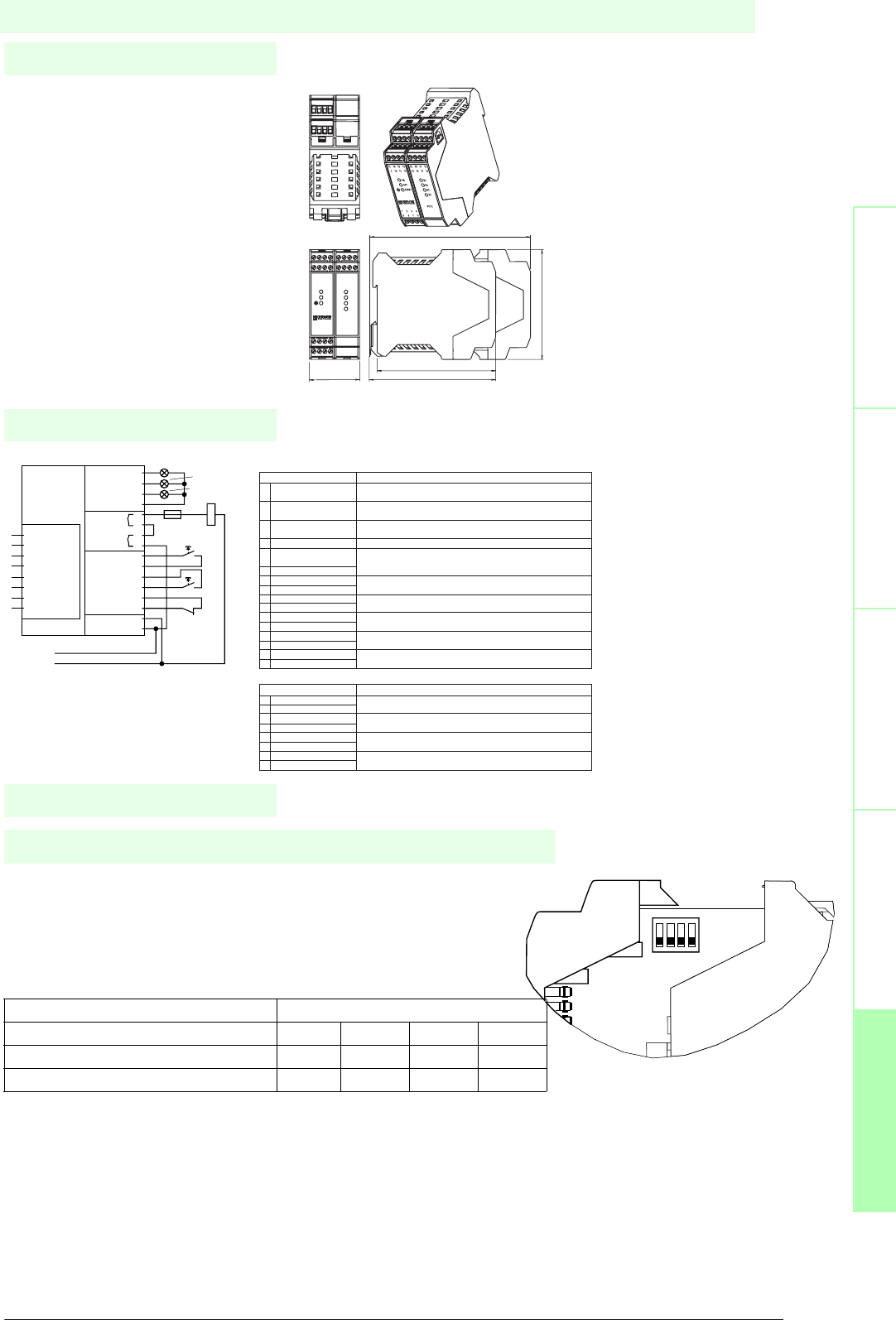
129
S
ubject to reasonable modifications due to technical advances. Copyright Pepperl+Fuchs, Printed in Germany
Pepperl+Fuchs Group • Tel.: Germany +49 621 776-0 • USA +1 330 4253555 • Singapore +65 67799091 • Internet http://www.pepperl-fuchs.com
Notes
Electrical connection
Safety through beam
sensors
Safey light gridsSafety light grids with
internal control unit
Safety light curtainsControl units
Dimensions
The operating modes of the SC2 can be adjusted using DIP switches. Two
switches must be activated to set an operating mode. The DIP switches are
located inside the housing of the light barrier module.
When the control unit is delivered, the relay monitor (RM) is turned off and
start / restart interlock (RI) is turned on.
Operating modes
DIP-switch
1234
Start/restart interlock (RI) XX
Relay monitor (RM) XX
ON
1234
Restart 1
OSSD OFF 2
OSSD ON 3
0 V 4
13
14
15
16
Test +U 11
Test 12
Restart 5
Restart +U 6
RM 7
RM +U 8
Supply 24 V 9
Supply 0 V 10
ready to restart (yellow)
OFF (red)
ON (green)
K1
F1
Test
K1K
0 V
+ 24 V DC
Restart
Indicator
Output
OSSD
Input
Sensor
25 LS2-T
26 LS2-T 0 V
27 LS2-R 0 V
28 LS2-R
29 LS1-T
30 LS1-T 0 V
31 LS1-R 0 V
32 LS1-R
Terminal/Assignment Function
1 PNP output readiness Option for connecting external indicator lamps to indicate restart (start)
for startup message or error message
2 PNP output OSSD reporting Option for connecting external indicator lamps to indicate the OSSD state Off
OFF
3 PNP output OSSD reporting Option for connecting external indicator lamps to indicate the OSSD state On
ON
4 0 V internal Reference point for pnp outputs
5 Startup enable for input (RI) Normally open contact for start/restart interlock.
It should be wired in if no function is activated
6 24 V internal
7 Relay monitor input (RM) Relay monitor input.
8 24 V internal It should be wired in if no function is activated (see section 3.2)
9 24 V DC Supply voltage connection, protected from reverse polarity
10 0 V
11 24 V internal Normally open contact for testing or error enable
12 Test input
13 OSSD1.1 OSSD relay output 1 NO (normally open)
14 OSSD1.2
15 OSSD2.1 OSSD relay output 2 NO
16 OSSD2.2
Terminal/Assignment Function
25 LS2-T2 Transmitter 2 connection
26 LS2-T 0 V
27 LS2-R 0 V Receiver 2 connection
28 LS2-R
29 LS1-T Transmitter 1 connection
30 LS1-T 0 V
31 LS1-R 0 V Receiver 1 connection
32 LS1-R
Connections of the OSSD module
Connections for light barrier module
Control unit
Date of edition 05/17/2006
SC2-2 24VDC
CPU-Print up to grating: approx. 145
45.2
99
113.6
107
13 14 15
16
1 2 3
4
29 30 31
32
R1
R2
E1
E2
ON
OFF
START
SC2-2
Subject to reasonable modifications due to technical advances. Copyright Pepperl+Fuchs, Printed in Germany
Pepperl+Fuchs Group • Tel.: Germany +49 621 776-0 • USA +1 330 4253555 • Singapore +65 67799091 • Internet http://www.pepperl-fuchs.com
130
Technische DatenTechnical data
Features
Safety through beam
sensors
Safety light grids
Safety light grids with
internal control unit
Safety light curtains
Control units
General specifications
Approvals TÜV
Tests IEC/EN 61496
Marking CE
Safety category according to IEC/EN 61496 4
Indicators/operating means
Diagnosis display 7-segment display
Function display LED red: OSSD OFF
LED green: OSSD ON LED yellow : Start readiness LED yellow (2x): indicator lamp channel 1 ... 2
Pre-fault indication LED yellow flashing: Indicator lamp channel 1 ... 2
Operating elements DIP-switch
Electrical specifications
Operating voltage 24 V DC, -15 %/+20 %
No-load supply current I0160 mA
Input
Activation current approx. 10 mA
Activation time 0.05 ... 1 s
Test input Reset-input for system test
Output
Safety output 2 relay outputs, compelled connection NO-contact
Signal output Output for displaying the switching state of the OSSDs
Switching voltage 20 ... 230 V AC/DC
Switching current AC: 0.01 ... 2 A DC see diagram of limit load curve
Response time 30 ms
Ambient conditions
Ambient temperature 0 ... 50 °C (273 ... 323 K)
Storage temperature -20 ... 70 °C (253 ... 343 K)
Mechanical specifications
Protection degree IP20
Connection screw terminals , lead cross section 0.2 ... 2 mm2
Material
Housing Polyamide (PA)
Mass 230 g
SC4-2 24VDC
Date of edition 05/17/2006
Control unit
For suitable cable sockets, mounting aids, redirection mirrors and more refer to chapter „Accessories.
• Evaluation device for safety through-beam sensors SLA12 and SLA29
• Self-monitoring (type 4 according to IEC/EN 61496-1)
• Operating mode can be selected by means of DIP switches
• Start/Restart disable
• Relay monitor
• Pre-fault indication
• Clearly visible LED functional display
• 7-segment diagnostic display
• Safety outputs OSSD, external status displays OSSD
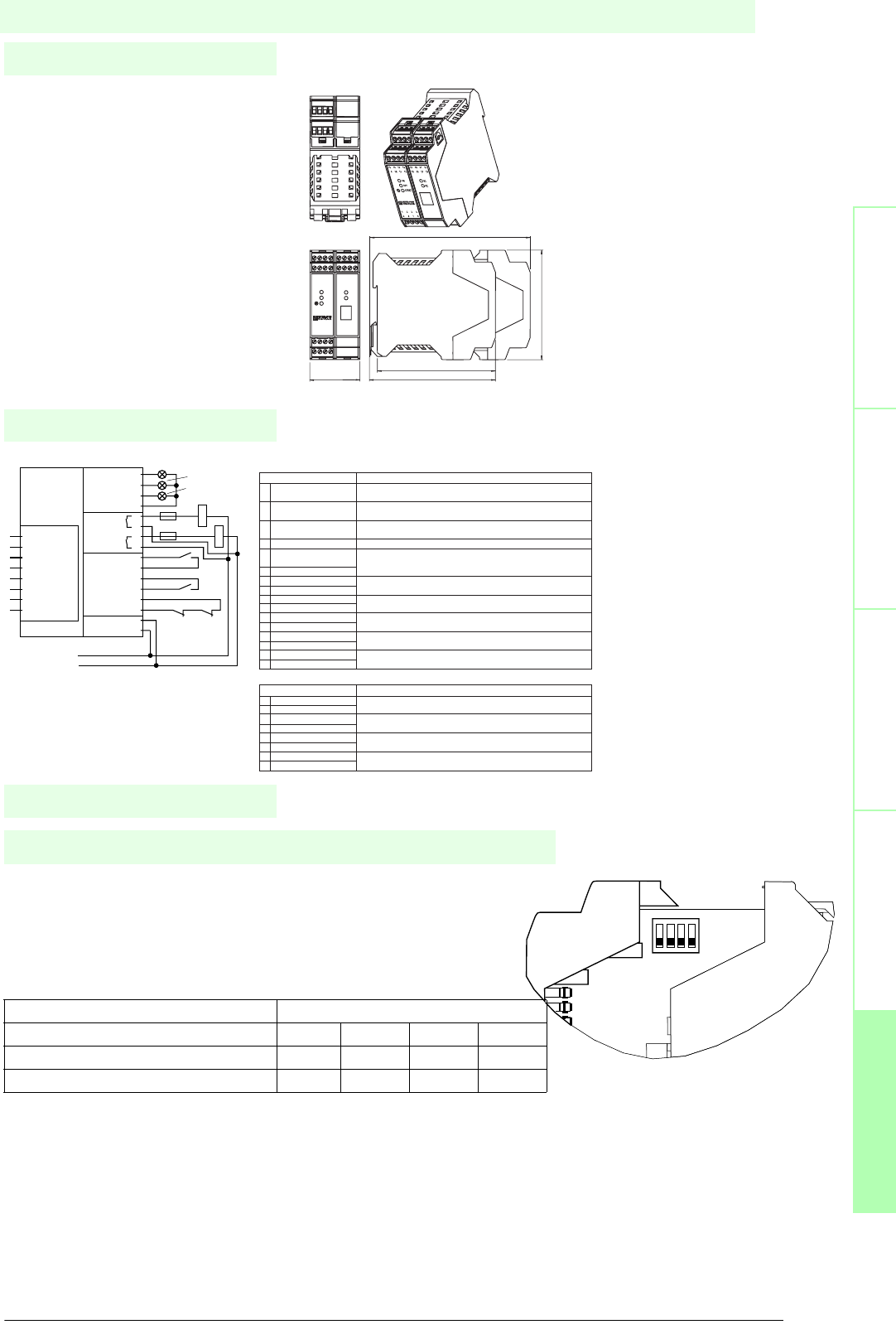
131
S
ubject to reasonable modifications due to technical advances. Copyright Pepperl+Fuchs, Printed in Germany
Pepperl+Fuchs Group • Tel.: Germany +49 621 776-0 • USA +1 330 4253555 • Singapore +65 67799091 • Internet http://www.pepperl-fuchs.com
Notes
Electrical connection
Safety through beam
sensors
Safey light gridsSafety light grids with
internal control unit
Safety light curtainsControl units
Dimensions
The operating modes of the SC2 can be adjusted using DIP switches. Two
switches must be activated to set an operating mode. The DIP switches are
located inside the housing of the light barrier module.
When the control unit is delivered, the relay monitor (RM) is turned off and
start / restart interlock (RI) is turned on.
Operating modes
DIP-switch
1234
Start/restart interlock (RI) XX
Relay monitor (RM) XX
ON
1234
Terminal/Assignment Function
1 PNP output readiness Option for connecting external indicator lamps to indicate restart (start)
for startup message or error message
2 PNP output OSSD reporting Option for connecting external indicator lamps to indicate the OSSD state Off
OFF
3 PNP output OSSD reporting Option for connecting external indicator lamps to indicate the OSSD state On
ON
4 0 V internal Reference point for pnp outputs
5 Startup enable for input (RI) Normally open contact for start/restart interlock.
It should be wired in if no function is activated
6 24 V internal
7 Relay monitor input (RM) Relay monitor input.
8 24 V internal It should be wired in if no function is activated (see section 3.2)
9 24 V DC Supply voltage connection, protected from reverse polarity
10 0 V
11 24 V internal Normally open contact for testing or error enable
12 Test input
13 OSSD1.1 OSSD relay output 1 NO (normally open)
14 OSSD1.2
15 OSSD2.1 OSSD relay output 2 NO
16 OSSD2.2
Terminal/Assignment Function
25 LS2-T2 Transmitter 2 connection
26 LS2-T 0 V
27 LS2-R 0 V Receiver 2 connection
28 LS2-R
29 LS1-T Transmitter 1 connection
30 LS1-T 0 V
31 LS1-R 0 V Receiver 1 connection
32 LS1-R
Connections of the OSSD module
Connections for light barrier module
ready to restart (yellow)
OFF (red)
ON (green)
K1
F1
F2
K1K K2K
0 V
+ 24 V DC
Restart
Test/Reset
Restart 1
OSSD OFF 2
OSSD ON 3
0 V 4
13
14
15
16
Test +U 11
Test 12
Restart 5
Restart +U 6
RM 7
RM +U 8
Supply 24 V 9
Supply 0 V 10
Indicator
Output
OSSD
Input
Sensor
25 LS2-T
26 LS2-T 0 V
27 LS2-R 0 V
28 LS2-R
29 LS1-T
30 LS1-T 0 V
31 LS1-R 0 V
32 LS1-R
K2
Control unit
Date of edition 05/17/2006
SC4-2 24VDC
CPU-Print up to grating: approx. 145
45.2
99
113.6
107
13 14 15
16
1 2 3
4
29 30 31
32
ON
OFF
START
SC4-2
R1
R2
SC4-2
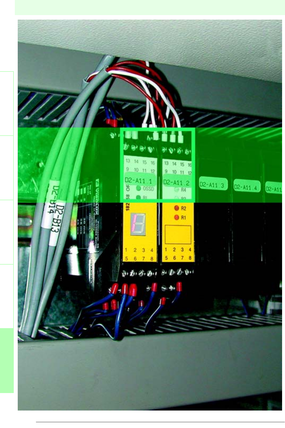
132
Date of edition 05/17/2006
Subject to reasonable modifications due to technical advances. Copyright Pepperl+Fuchs, Printed in Germany
Pepperl+Fuchs Group • Tel.: Germany +49 621 776-0 • USA +1 330 4253555 • Singapore +65 67799091 • Internet http://www.pepperl-fuchs.com
Control units
Safety light barriersSafety light gridsSafety light grids with
internal control unit
Safety light curtainsControl units
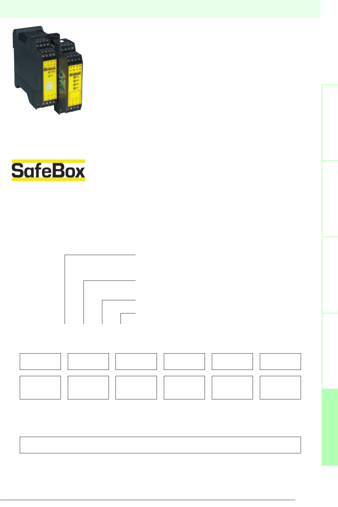
133
S
ubject to reasonable modifications due to technical advances. Copyright Pepperl+Fuchs, Printed in Germany
Pepperl+Fuchs Group • Tel.: Germany +49 621 776-0 • USA +1 330 4253555 • Singapore +65 67799091 • Internet http://www.pepperl-fuchs.com
Control units
Date of edition 05/17/2006
Safety light barriersSafety light gridsSafety light grids with
internal control unit
Safety light curtainsControl units
Description
System SafeBox
The safety solution permits the connection of all components of a machine protection
system to a single control unit and can be configured flexibly due to its modular design.
The SafeBox is suitable for connection and control of photoelectric safety sensors,
mechanical safety systems, and safety switches in Category 1 through 4 as in EN 954-1.
The system is approved in accordance with IEC 61496-1 and EN 61508 (SIL3) and thus
features the device approval based on the new standard.
Besides connecting the numerous safety sensors it also supports e.g. the emergency stop
functions of categories 0 and 1 as well as the various muting modes.
The SafeBox complies with protection category IP20 and has been designed for switch
cabinet installation.
The basis of each SafeBox consists of a robust component rack with backplane taking
between two and eight extension modules. The backplane is used for the mechanical and
electrical connection and responsible for the power supply to the individual modules.
Amongst the available module types are OSSD modules (output signal switching device),
4-channel CPU modules (4CP, 4XP, 4CG, 4XG), sensor card modules for 4 and for 6
channels, muting modules, E-stop modules and blind modules.
In total the SafeBox thereby enables the connection of light barriers, light grids and light
curtains for:
• electro-sensitive protective equipment (ESPE)
• of emergency stop buttons
• position switches
• switching pads and switching panels
• magnetic switches
• door contacts and other one and two channel safety elements.
Type code
The identification of the individual SafeBox versions is structured in such a way that the device structure can be recognised
immediately. For each assembly used, the module type of the respective assembly is stated starting from the left.
SafeBox design
SB4 -SAFEBOX category 4
SB4 Housing Backplane provides 2 ... 8 slots for plug-in cards.
Supplies the individual modules with voltage
Connects the modules mechanically and electrically
Assembly slot 1, OSSD-R/supply module
Minimum configuration: 2 relay OSSDs with operating mode adjustment
(restart, monitor) and 7 segment LED display, LEDs red/green, yellow
Assembly slot 2, sensor card module 4 channels (with CPU)
Minimum configuration: 4 sensor channels with LED status display
Assembly slot 3 to 8 (variable)
Variable configuration of the module types
SB4 - OR - 4CP - xx
OR 4CP; 4XP,
4CG; 4XG 4C; 6C; 4X 4M; 4MD 2E B
OSSD
module R
CPU
module 4K
Module
sensor
channels
Muting
module
E-stop
cat. 0/1
Blind
module
||||||
||||||
||||||
||||||
Back plane = SB4 housing
Minimum 2 2 slots ............... maximum 8 slots
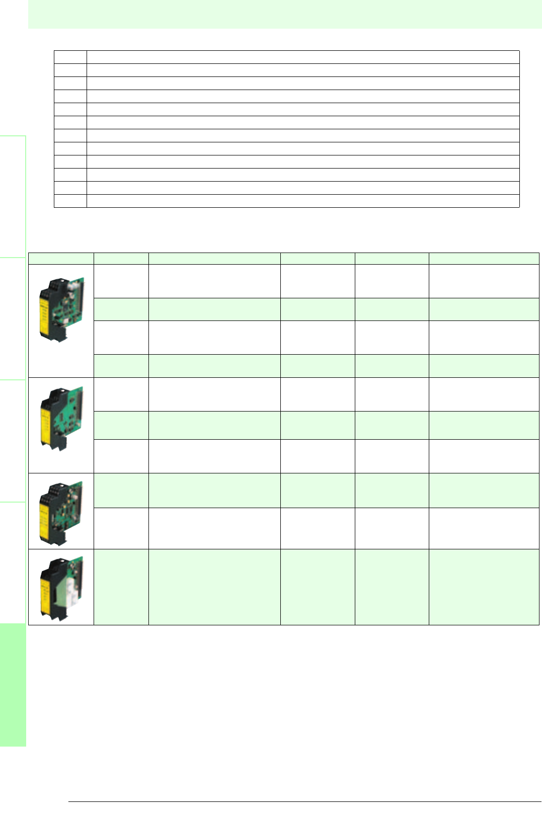
134
Date of edition 05/17/2006
Subject to reasonable modifications due to technical advances. Copyright Pepperl+Fuchs, Printed in Germany
Pepperl+Fuchs Group • Tel.: Germany +49 621 776-0 • USA +1 330 4253555 • Singapore +65 67799091 • Internet http://www.pepperl-fuchs.com
Control units
Safety light barriersSafety light gridsSafety light grids with
internal control unit
Safety light curtainsControl units
Module types:
Matrix Safebox module types
OR OSSD module relay
4CP Sensor card module with 4 channels with CPU
4CG Sensor card module with 4 channels with CPU (for several separate shut-off circuits within one SafeBox)
4C Sensor card module with 4 channels
4XP Sensor card module with 4 channels with CPU
4XG Sensor card module with 4 channels with CPU (for several separate shut-off circuits within one SafeBox)
4X Sensor card module with 4 channels
6C Sensor card module with 6 channels
4M Muting module with 4 channels
4MD Muting module with 4 channels for permanent muting
2E OSSD-E stop module with preset stop function cat. 0 and activated 2 sensor inputs
B Blind module
module Light barrier type Light grid Light curtains Safety device
4CP SLA12, SLA29 -
E-stop, switching
panels, magnetic
scwitches
4XP SLA5(S); SLA40 SLP... SLC E-stop, switching pad
4CG SLA12, SLA29 -
E-stop, switching
panels, magnetic
scwitches
4XG SLA5(S); SLA40 SLP... SLC E-stop, switching pad
4C SLA12, SLA29 -
E-stop, switching
panels, magnetic
scwitches
4X SLA5(S); SLA40 SLP... SLC Switching pads
E-stop
6C SLA12, SLA29 -
E-stop, switching
pads, magnetic
scwitches
4M Muting sensors
4MD Muting sensors
2E 1 channel E-stop (2x)
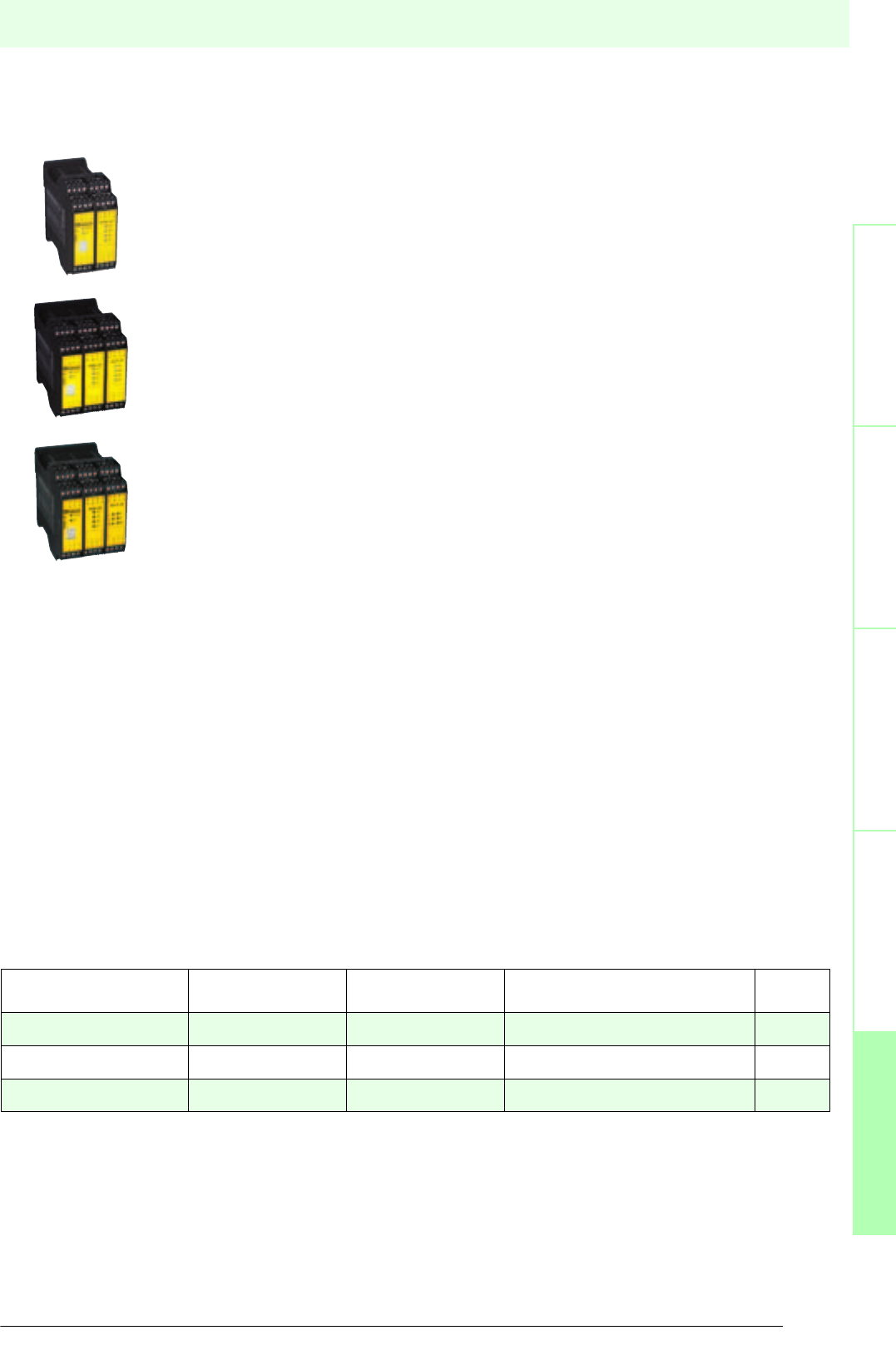
135
S
ubject to reasonable modifications due to technical advances. Copyright Pepperl+Fuchs, Printed in Germany
Pepperl+Fuchs Group • Tel.: Germany +49 621 776-0 • USA +1 330 4253555 • Singapore +65 67799091 • Internet http://www.pepperl-fuchs.com
Control units
Date of edition 05/17/2006
Safety light barriersSafety light gridsSafety light grids with
internal control unit
Safety light curtainsControl units
Standard device variants
For realising typical ESPE applications, there are SB4 control units which are predefined for these applications. They are
suitable for access protection at one or more access points of hazardous areas.
SB4-OR-4CP : 4 channel control unit
A maximum of 4 safety light barriers can be connected to this control unit. Instead of the light barriers,
other contact safety equipment can be connected. By default, the restart interlock is activated.
SB4-OR-4CP-4C : 8 channel control unit
The SB4-OR-4CP-4C can be used for connecting 1 to 8 safety light barriers.
The large number of sensor channels makes this control unit suitable for protecting several entries.
Instead of the light barriers, other contact safety equipment can be connected. By default, the restart
interlock is activated.
SB4-OR-4CP-4M : 4 channel control unit for muting applications
This control unit can be used for muting applications of 1 to 4 safety light barriers. Due to the adjustment
options via the DIP switches of the muting module, an optimum adaptation to the applications is possible.
For example, if two entries to the protected area, which are protected by 2 protection beams, are to be
equipped with muting, this protection can be realised by the double muting operating mode with an
control unit. The startup/restart lock has been enabled at factory.
Additional application examples:
SB4-OR-4CP-6C-4C-2E : Modular control unit with a time-delayed output signal
Monitoring of 4 safety light barriers, 3 emergency stop buttons (dual-channel) and 2 protective door contacts. In the case of a
beam interruption, the system is switched off with a delay.
SB4-OR-4CG-2E-4C-2E-B-B : Modular control unit for group formation
4 sensor channels for safety devices of group 1 and 4 sensor channels for safety devices with muting function and time-delay
shut-off in group 2.
2 blind caps as optional extension options e.g. for group 3.
SB4-OR-4XP-4M : Modular control unit 4 channel with 4 additional muting channels
4 sensor channels for 2 safety light curtains and 2 times 2 muting channels for double muting.
Easy to configure and flexible, we adapt the SafeBox to your application.
Please enquire!
Type code Sensor channel
number
Muting channel
number
Operating voltage Page
SB4-OR-4CP 4 0 24 V DC 136
SB4-OR-4CP-4C 8 0 24 V DC 138
SB4-OR-4CP-4M 4 4 24 V DC 140

Subject to reasonable modifications due to technical advances. Copyright Pepperl+Fuchs, Printed in Germany
Pepperl+Fuchs Group • Tel.: Germany +49 621 776-0 • USA +1 330 4253555 • Singapore +65 67799091 • Internet http://www.pepperl-fuchs.com
136
Technische DatenTechnical data
Features
Safety through beam
sensors
Safety light grids
Safety light grids with
internal control unit
Safety light curtains
Control units
General specifications
Approvals TÜV
Tests IEC/EN 61496 IEC 61508
Marking CE
Safety category according to IEC/EN 61496 4
Indicators/operating means
Diagnosis display 7-segment display
Function display LED red: OSSD OFF
LED green: OSSD ON
Yellow LED: start readiness channel 1 - 4
LED yellow: switching state (receiver)
Pre-fault indication LED yellow flashing: Indicator lamp channel 1 ... 4
Electrical specifications
Operating voltage 24 V DC, ± 20 %
No-load supply current I0max. 500 mA
Input
Activation current approx. 7 mA
Activation time 0.4 ... 1.2 s
Test input Reset-input for system test
Output
Safety output 2 relay outputs, compelled connection NO-contact
Signal output Output for displaying the switching state of the OSSDs
Switching voltage 10 V ... 250 V AC/DC
Switching current min. 10 mA , max. 6 A AC/DC
Switch power DC: max. 24 VA
AC: max. 230 VA
Response time 30 ms
Ambient conditions
Ambient temperature 0 ... 50 °C (273 ... 323 K)
Storage temperature -20 ... 70 °C (253 ... 343 K)
Mechanical specifications
Protection degree IP20
Connection screw terminals , lead cross section 0.2 ... 2 mm2
Material
Housing Polyamide (PA)
Mass 320 g
SB4-OR-4CP
U
®
Date of edition 05/17/2006
Control unit
For suitable cable sockets, mounting aids, redirection mirrors and more refer to chapter „Accessories.
• Evaluation device for safety through-beam sensors SLA12 and SLA29 and
for 2 channel safety devices (emergency off)
• 4 sensor channels
• Self-monitoring (type 4 according to IEC/EN 61496-1)
• Operating mode can be selected by means of DIP switches
• Start/Restart disable
• Relay monitor
• Pre-fault indication
• Clearly visible LED functional display
• 7-segment diagnostic display
• Safety outputs OSSD, external status displays OSSD
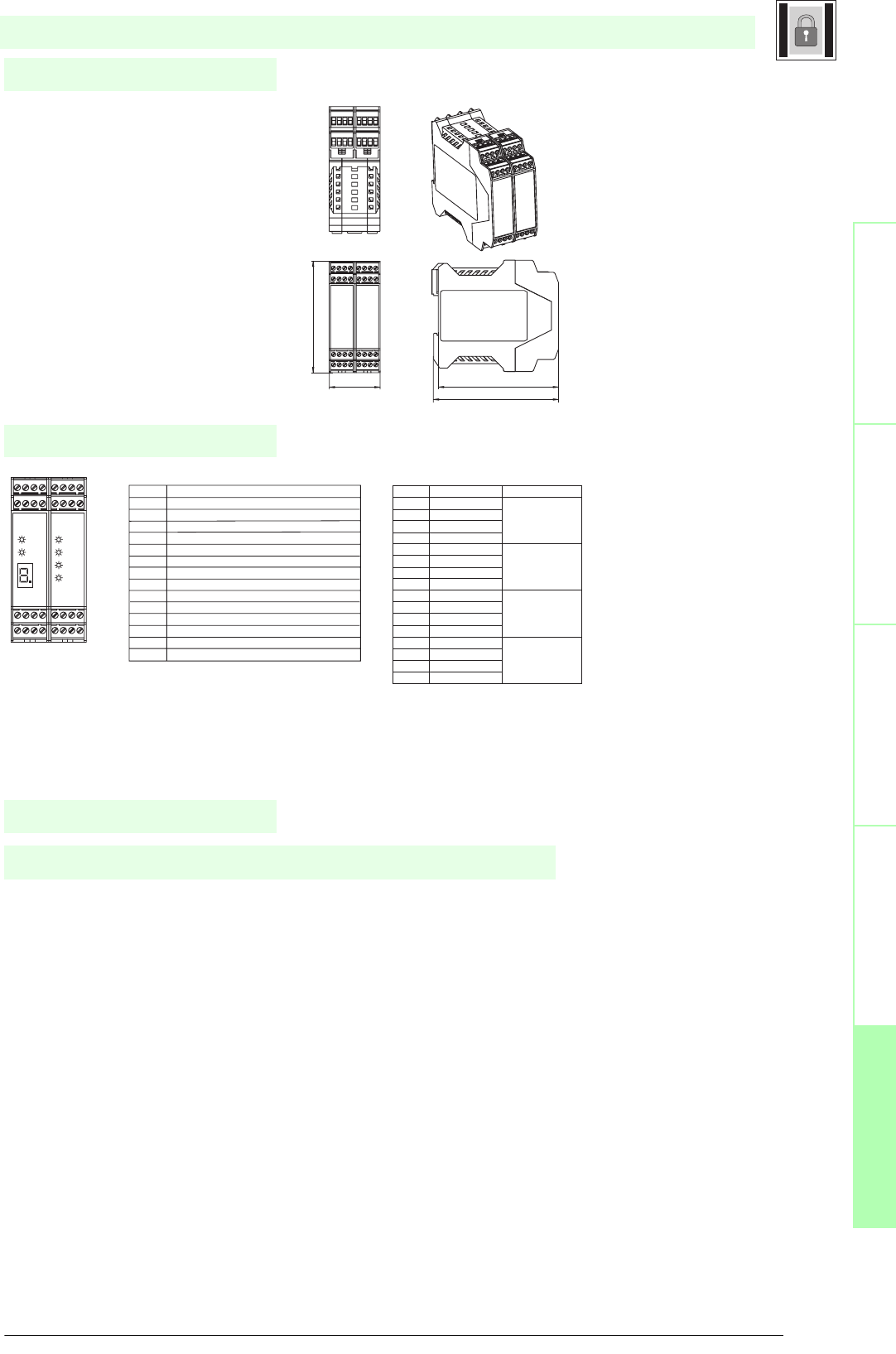
137
S
ubject to reasonable modifications due to technical advances. Copyright Pepperl+Fuchs, Printed in Germany
Pepperl+Fuchs Group • Tel.: Germany +49 621 776-0 • USA +1 330 4253555 • Singapore +65 67799091 • Internet http://www.pepperl-fuchs.com
Notes
Electrical connection
Safety through beam
sensors
Safey light gridsSafety light grids with
internal control unit
Safety light curtainsControl units
Dimensions
The evaluation system SB4 is an ESPE of type 4 (EN 61496-1 or IEC 61496-1) or category 4 (EN 954-1). This system is also
designed and tested according to IEC 61508. It meets the requirements for the SIL3.
The operating instructions supplied with the device must be observed for planning, installation and operation.
A maximum of 4 safety light barriers can be connected to the evaluation device. Instead of the light barriers, other contact safety
equipment can be connected.
Function
Terminal Function
1 Reset input; normally closed contact
2 Restart input (RI); normally closed contact
3 24 V DC connection for reset, restart and RM
4 Relay monitor (RM)
5 - 6 OSSD1; potential free relay contact; normally open contact
7 - 8 OSSD2; potential free relay contact; normally open contact
9 Signal output OSSD OFF
10 Signal output OSSD ON
11 Signal output restart
12 Leave free (n.c.)
13 +24 V DC supply voltage
14 0 V DC supply voltage
15 Earth
16 Leave free (n.c.)
Terminal Slot 1 Terminal Slot 2
Slot 1 Slot 2
Terminal
Function Channel assignment
1 Receiver 2 input Input
2 Receiver 2 +U Channel 2
3 Transmitter 2 +U
4 Transmitter 2 output Output
5 Receiver 1 input Input
6 Receiver 1 +U Channel 1
7 Transmitter 1 +U
8 Transmitter 1 output Output
9 Transmitter 3 output Output
10 Transmitter 3 +U Channel 3
11 Receiver 3 +U
12 Receiver 3 input Input
13 Transmitter 4 output Output
14 Transmitter 4 +U Channel 4
15 Receiver 4 +U
16 Receiver 4 input Input
13 14 15 16
9 10 11 12
13 14 15 16
9 10 11 12
1 2 3 4
5 6 7 8 1 2 3 4
5 6 7 8
OSSD
RI
R4
R3
R2
R1
Control unit
Date of edition 05/17/2006
SB4-OR-4CP
45.2
112.7
99
107
13 14 15 16
9 10 11 12
13 14 15 16
9 10 11 12
13 14 15 16
9 10 11 12
1 2 3 4
5 6 7 8
1 2 3 4
5 6 7 8
13 14 15 16
9 10 11 12
1 2 3 4
5 6 7 8
1 2 3 4
5 6 7 8
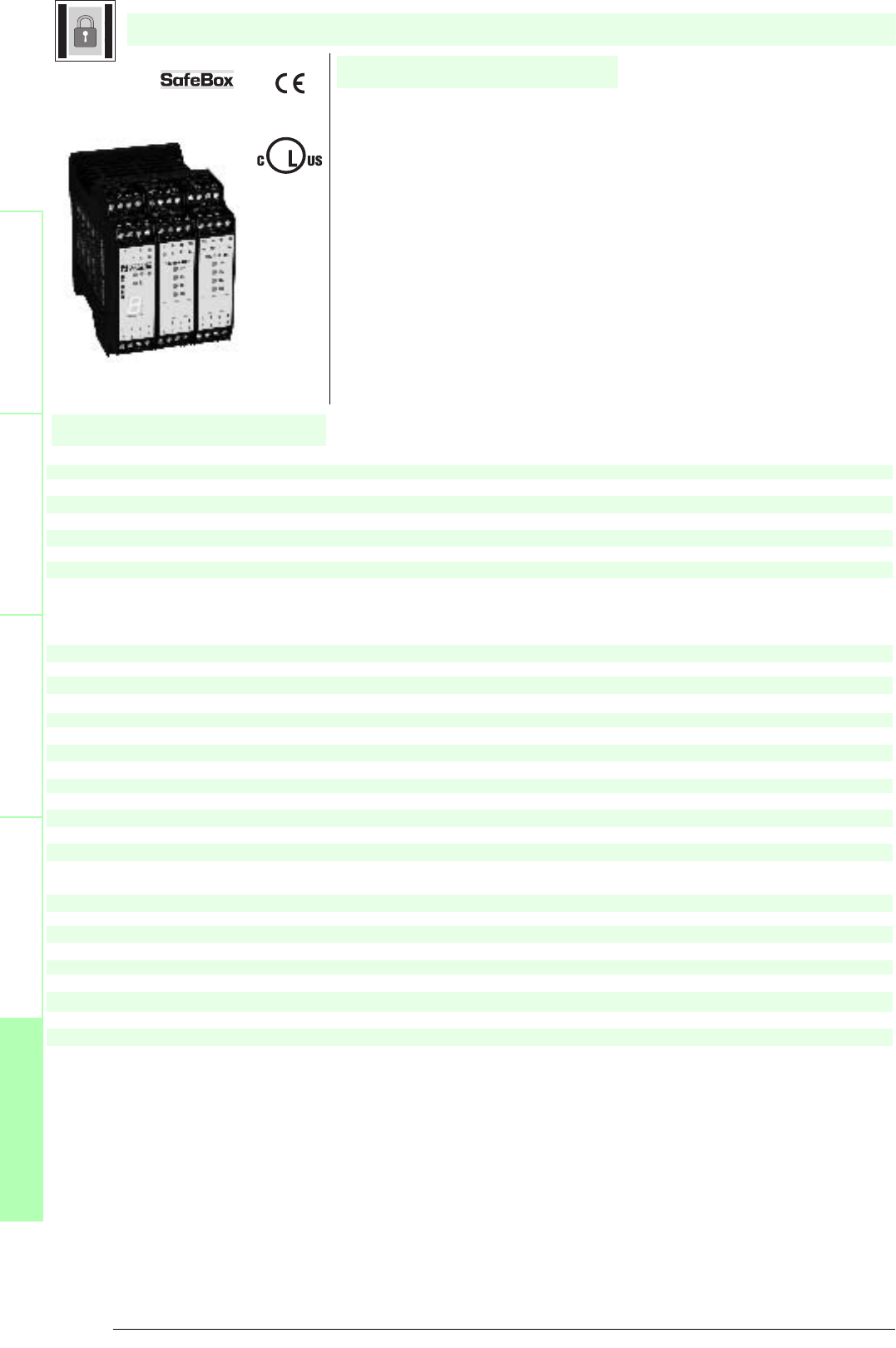
Subject to reasonable modifications due to technical advances. Copyright Pepperl+Fuchs, Printed in Germany
Pepperl+Fuchs Group • Tel.: Germany +49 621 776-0 • USA +1 330 4253555 • Singapore +65 67799091 • Internet http://www.pepperl-fuchs.com
138
Technische DatenTechnical data
Features
Safety through beam
sensors
Safety light grids
Safety light grids with
internal control unit
Safety light curtains
Control units
General specifications
Approvals TÜV
Tests IEC/EN 61496 IEC 61508
Marking CE
Safety category according to IEC/EN 61496 4
Indicators/operating means
Diagnosis display 7-segment display
Function display LED red: OSSD OFF
LED green: OSSD ON
Yellow LED: start readiness channel 1 - 8
LED yellow: switching state (receiver)
Pre-fault indication LED yellow flashing: Indicator lamp channel 1 ... 8
Electrical specifications
Operating voltage 24 V DC, ± 20 %
No-load supply current I0max. 500 mA
Input
Activation current approx. 7 mA
Activation time 0.4 ... 1.2 s
Test input Reset-input for system test
Output
Safety output 2 relay outputs, compelled connection NO-contact
Signal output Output for displaying the switching state of the OSSDs
Switching voltage 10 V ... 250 V AC/DC
Switching current min. 10 mA , max. 6 A AC/DC
Switch power DC: max. 24 VA
AC: max. 230 VA
Response time 38 ms
Ambient conditions
Ambient temperature 0 ... 50 °C (273 ... 323 K)
Storage temperature -20 ... 70 °C (253 ... 343 K)
Mechanical specifications
Protection degree IP20
Connection screw terminals , lead cross section 0.2 ... 2 mm2
Material
Housing Polyamide (PA)
Mass 430 g
SB4-OR-4CP-4C
U
®
Date of edition 05/17/2006
Control unit
For suitable cable sockets, mounting aids, redirection mirrors and more refer to chapter „Accessories.
• Evaluation device for safety through-beam sensors SLA12 and SLA29 and
for 2 channel safety devices (emergency off)
• 8 sensor channels
• Self-monitoring (type 4 according to IEC/EN 61496-1)
• Operating mode can be selected by means of DIP switches
• Start/Restart disable
• Relay monitor
• Pre-fault indication
• Clearly visible LED functional display
• 7-segment diagnostic display
• Safety outputs OSSD, external status displays OSSD
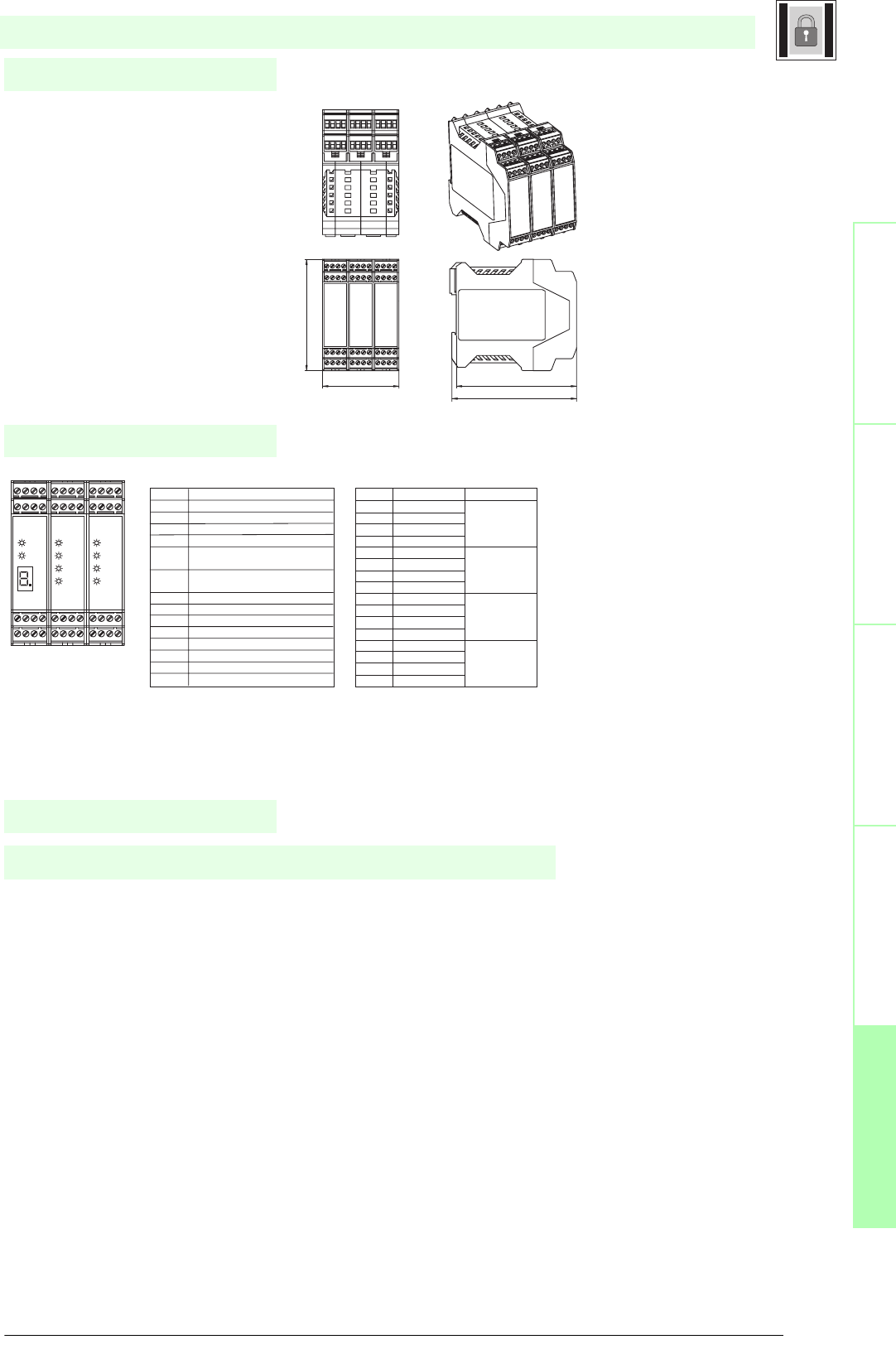
139
S
ubject to reasonable modifications due to technical advances. Copyright Pepperl+Fuchs, Printed in Germany
Pepperl+Fuchs Group • Tel.: Germany +49 621 776-0 • USA +1 330 4253555 • Singapore +65 67799091 • Internet http://www.pepperl-fuchs.com
Notes
Electrical connection
Safety through beam
sensors
Safey light gridsSafety light grids with
internal control unit
Safety light curtainsControl units
Dimensions
The evaluation system SB4 is an ESPE of type 4 (EN 61496-1 or IEC 61496-1) or category 4 (EN 954-1). This system is also
designed and tested according to IEC 61508. It meets the requirements for the SIL3.
The operating instructions supplied with the device must be observed for planning, installation and operation.
A maximum of 8 safety light barriers can be connected to the evaluation device. Instead of the light barriers, other contact safety
equipment can be connected.
Function
Slot 1 Slot 2 Slot 3
Terminal Slot 2 and Slot 3
Terminal
Function Channel assignment
1 Receiver 2 input Input
2 Receiver 2 +U Channel 2
3 Transmitter 2 +U
4 Transmitter 2 output Output
5 Receiver 1 input Input
6 Receiver 1 +U Channel 1
7 Transmitter 1 +U
8 Transmitter 1 output Output
9 Transmitter 3 output Output
10 Transmitter 3 +U Channel 3
11 Receiver 3 +U
12 Receiver 3 input Input
13 Transmitter 4 output Output
14 Transmitter 4 +U Channel 4
15 Receiver 4 +U
16 Receiver 4 input Input
Terminal Function
1 Reset input; normally closed contact
2 Restart input (RI); normally closed contact
3 24 V DC connection for reset, restart and RM
4 Relay monitor (RM)
5 - 6 OSSD1; potential free relay contact;
normally open contact
7 - 8 OSSD2; potential free relay contact;
normally open contact
9 Signal output OSSD OFF
10 Signal output OSSD ON
11 Signal output restart
12 Leave free (n.c.)
13 +24 V DC supply voltage
14 0 V DC supply voltage
15 Earth
16 Leave free (n.c.)
Terminal Slot 1
13 14 15 16
9 10 11 12
13 14 15 16
9 10 11 12
1 2 3 4
5 6 7 8 1 2 3 4
5 6 7 8
OSSD
RI
R4
R3
R2
R1
13 14 15 16
9 10 11 12
1 2 3 4
5 6 7 8
R4
R3
R2
R1
Control unit
Date of edition 05/17/2006
SB4-OR-4CP-4C
107.5
112.7
67.8
99
13 14 15 16
9 10 11 12
13 14 15 16
9 10 11 12
1 2 3 4
5 6 7 8
1 2 3 4
5 6 7 8
13 14 15 16
9 10 11 12
1 2 3 4
5 6 7 8
13 14 15 16
9 10 11 12
1 2 3 4
5 6 7 8
1 2 3 4
5 6 7 8
13 14 15 16
9 10 11 12
1 2 3 4
5 6 7 8
13 14 15 16
9 10 11 12

Subject to reasonable modifications due to technical advances. Copyright Pepperl+Fuchs, Printed in Germany
Pepperl+Fuchs Group • Tel.: Germany +49 621 776-0 • USA +1 330 4253555 • Singapore +65 67799091 • Internet http://www.pepperl-fuchs.com
140
Technische DatenTechnical data
Features
Safety through beam
sensors
Safety light grids
Safety light grids with
internal control unit
Safety light curtains
Control units
General specifications
Approvals TÜV
Tests IEC/EN 61496 IEC 61508
Marking CE
Safety category according to IEC/EN 61496 4
Indicators/operating means
Diagnosis display 7-segment display
Function display LED red: OSSD OFF
LED green: OSSD ON
Yellow LED: start readiness channel 1 - 4
LED yellow: switching state (receiver)
Pre-fault indication LED yellow flashing: Indicator lamp channel 1 ... 4
Electrical specifications
Operating voltage 24 V DC, ± 20 %
No-load supply current I0500 mA
Input
Activation current approx. 7 mA
Activation time 0.4 ... 1.2 s
Test input Reset-input for system test
Output
Safety output 2 relay outputs, compelled connection NO-contact
Signal output 1 PNP each, max. 300 mA for start readiness, OSSD on, OSSD off, muting lamp
Switching voltage 10 V ... 250 V AC/DC
Switching current min. 10 mA , max. 6 A AC/DC
Switch power DC: max. 24 VA
AC: max. 230 VA
Response time 38 ms
Ambient conditions
Ambient temperature 0 ... 50 °C (273 ... 323 K)
Storage temperature -20 ... 70 °C (253 ... 343 K)
Mechanical specifications
Protection degree IP20
Connection screw terminals , lead cross section 0.2 ... 2 mm2
Material
Housing Polyamide (PA)
Mass 430 g
SB4-OR-4CP-4M
U
®
Date of edition 05/17/2006
Control unit
For suitable cable sockets, mounting aids, redirection mirrors and more refer to chapter „Accessories.
• Evaluation device for safety through-beam sensors SLA12 and SLA29 and
for 2 channel safety devices (emergency off)
• 4 sensor channels
• Self-monitoring (type 4 according to IEC/EN 61496-1)
• Operating mode can be selected by means of DIP switches
• Start/Restart disable
• Relay monitor
• Sequential and parallel muting in various operating modes
• Double muting
• Emergency muting for the correction of the material jam
• Pre-fault indication
• Clearly visible LED functional display
• 7-segment diagnostic display
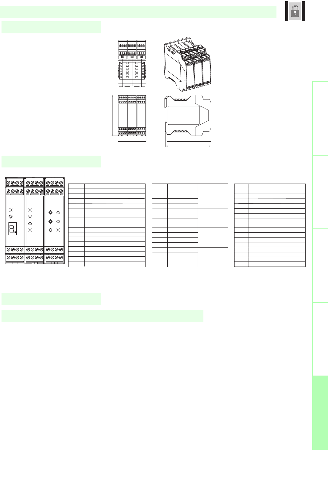
141
S
ubject to reasonable modifications due to technical advances. Copyright Pepperl+Fuchs, Printed in Germany
Pepperl+Fuchs Group • Tel.: Germany +49 621 776-0 • USA +1 330 4253555 • Singapore +65 67799091 • Internet http://www.pepperl-fuchs.com
Notes
Electrical connection
Safety through beam
sensors
Safey light gridsSafety light grids with
internal control unit
Safety light curtainsControl units
Dimensions
The evaluation system SB4 is an ESPE of type 4 (EN 61496-1 or IEC 61496-1) or category 4 (EN 954-1). This system is also
designed and tested according to IEC 61508. It meets the requirements for the SIL3.
The operating instructions supplied with the device must be observed for planning, installation and operation.
A maximum of 4 safety light barriers can be connected to the evaluation device. Instead of the light barriers, other contact safety
equipment can be connected.
The module on slot 3 realises the muting function. Detailed notes on the functions can be found in the instruction manual.
The user has to ensure that he only connects to the sensor card, which is assigned to the muting module, those sensors for
which muting is required. These are, for example, light barriers and light grids.
Function
Slot 1 Slot 2 Slot 3
Terminal Function
1 Reset input; normally closed contact
2 Restart input (RI); normally closed contact
3 24 V DC connection for reset, restart and RM
4 Relay monitor (RM)
5 - 6 OSSD1; potential free relay contact;
normally open contact
7 - 8 OSSD2; potential free relay contact;
normally open contact
9 Signal output OSSD OFF
10 Signal output OSSD ON
11 Signal output restart
12 Leave free (n.c.)
13 +24 V DC supply voltage
14 0 V DC supply voltage
15 Earth
16 Leave free (n.c.)
Terminal Slot 1 Terminal Slot 2
Terminal
Function Channel assignment
1 Receiver 2 input Input
2 Receiver 2 +U Channel 2
3 Transmitter 2 +U
4 Transmitter 2 output Output
5 Receiver 1 input Input
6 Receiver 1 +U Channel 1
7 Transmitter 1 +U
8 Transmitter 1 output Output
9 Transmitter 3 output Output
10 Transmitter 3 +U Channel 3
11 Receiver 3 +U
12 Receiver 3 input Input
13 Transmitter 4 output Output
14 Transmitter 4 +U Channel 4
15 Receiver 4 +U
16 Receiver 4 input Input
Terminal
Function
1 24 V sensor supply
2 Sensor 2 IN
3 Sensor 4 IN
4 0 V sensor supply
5 24 V sensor supply
6 Sensor 1 IN
7 Sensor 3 IN
8 0 V sensor supply
9 Input override 1
10 24 V override 1
11 24 V override 2
12 Input override 2
13 +24 V DC supply voltage for muting lamps
14 0 V DC supply voltage for muting lamps
15 Output muting lamp 1
16 Output muting lamp 2
Terminal Slot 3
13 14 15 16
9 10 11 12
13 14 15 16
9 10 11 12
1 2 3 4
5 6 7 8 1 2 3 4
5 6 7 8
OSSD
RI
R4
R3
R2
R1
13 14 15 16
9 10 11 12
1 2 3 4
5 6 7 8
I1
I2
M1
I3
I4
M2
Control unit
Date of edition 05/17/2006
SB4-OR-4CP-4M
107.5
112.7
67.8
99
13 14 15 16
9 10 11 12
13 14 15 16
9 10 11 12
1 2 3 4
5 6 7 8
1 2 3 4
5 6 7 8
13 14 15 16
9 10 11 12
1 2 3 4
5 6 7 8
13 14 15 16
9 10 11 12
1 2 3 4
5 6 7 8
1 2 3 4
5 6 7 8
13 14 15 16
9 10 11 12
1 2 3 4
5 6 7 8
13 14 15 16
9 10 11 12
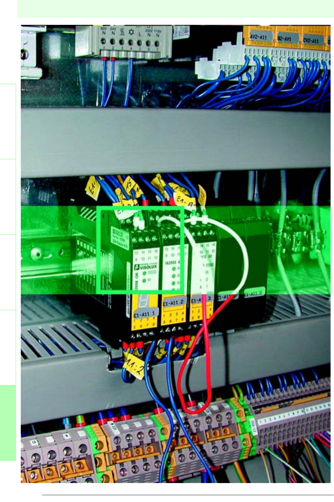
142
Date of edition 05/17/2006
Subject to reasonable modifications due to technical advances. Copyright Pepperl+Fuchs, Printed in Germany
Pepperl+Fuchs Group • Tel.: Germany +49 621 776-0 • USA +1 330 4253555 • Singapore +65 67799091 • Internet http://www.pepperl-fuchs.com
Control units
Safety light barriersSafety light gridsSafety light grids with
internal control unit
Safety light curtainsControl units
Control units
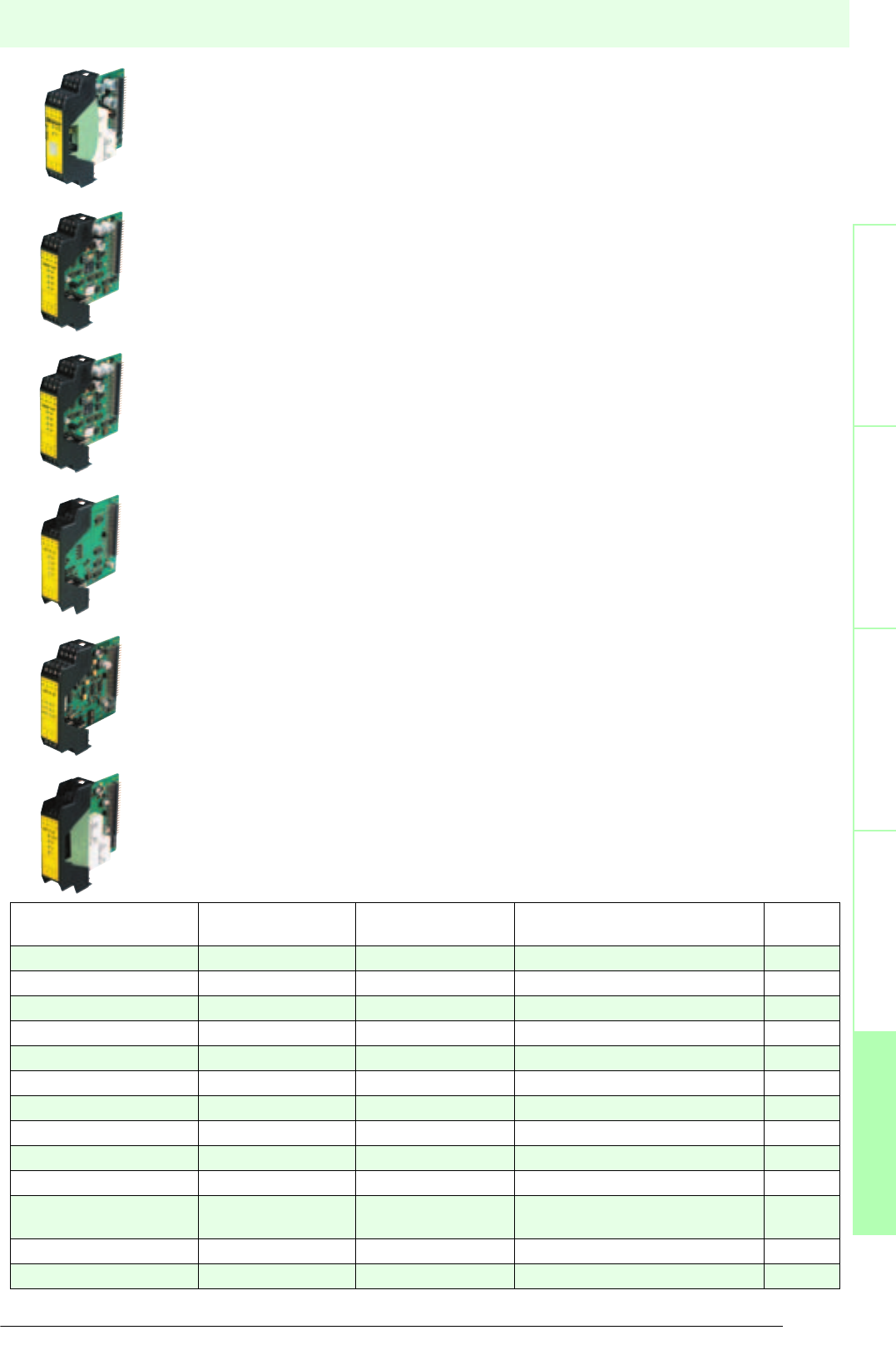
143
S
ubject to reasonable modifications due to technical advances. Copyright Pepperl+Fuchs, Printed in Germany
Pepperl+Fuchs Group • Tel.: Germany +49 621 776-0 • USA +1 330 4253555 • Singapore +65 67799091 • Internet http://www.pepperl-fuchs.com
Control units
Date of edition 05/17/2006
Safety light barriersSafety light gridsSafety light grids with
internal control unit
Safety light curtainsControl units
SafeBox module types
SB4 MODULES OR - OSSD-R/Supply module
The OSSD-R/supply module contains the power supply of the SafeBox, 2 OSSDs, the relay monitor
and the restart connection. This module is located in slot 1 and only exists once.
SB4 MODULES 4CP or 4XP - 4 channel sensor module with microcontroller
The 4 channel sensor card modules facilitate the connection of safety devices in one or two channel
design. They contain the microcontroller of the SafeBox. Only one of these modules is contained in
each Safebox SB4 and is located in slot 2.
SB4 MODULES 4CG or 4XG - 4 channel sensor module with microcontroller for grouping
The 4 channel sensor card modules facilitate the connection of safety devices in one or two channel
design. They contain the microcontroller of the SafeBox. Only one of these modules is contained in
each Safebox SB4 and is located in slot 2.
This module permits several separate shut-off circuits within one Safebox.
SB4 MODULES 4C or 4X - 4 channel sensor modules
SB4 MODULES 6C or 6X - 6 channel sensor modules
The 4- or 6-channel sensor card modules make it possible to connect safety devices in single-channel
or dual-channel design.
SB4 MODULES 4M and 4MD - muting modules
The muting module realises the muting functions for the sensor channels of the four to six channel
sensor card module immediately to the right of the module.
SB4 MODULES 2E - E-Stop module
The OSSD-R/E-Stop module is a module of the emergency stop category 1 and permits the
time-delayed shut-down of one or several plant components (0 s ... 10 s). It can also be used as an
independent E-stop module of category 0 (grouping).
Type code Sensor channels Category acc. to EN
954-1
Usage Page
SB4 Module OR 2 relays OSSD 4OSSD module 144
SB4 Module 4CP 4 4 Sensor module 146
SB4 Module 4XP 4 4 Sensor module 148
SB4 Module 4CG 4 4 Sensor module 150
SB4 Module 4XG 4 4 Sensor module 152
SB4 Module 4C 4 4 Sensor module 154
SB4 Module 4X 4 4 Sensor module 156
SB4 Module 6C 6 4 Sensor module 158
SB4 Module 4M 4 Muting 4Muting module 160
SB4 Module 4MD 4 Muting 4 Muting module 162
SB4 Module 2E 2
2 relays OSSD
4E-Stop module 164
SB4 Cape Blind cap for unused slots 166
SB4 Housing Housing for SafeBox modules 167
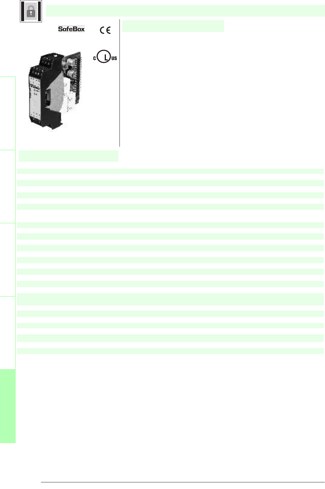
Subject to reasonable modifications due to technical advances. Copyright Pepperl+Fuchs, Printed in Germany
Pepperl+Fuchs Group • Tel.: Germany +49 621 776-0 • USA +1 330 4253555 • Singapore +65 67799091 • Internet http://www.pepperl-fuchs.com
144
Technische DatenTechnical data
Features
Safety through beam
sensors
Safety light grids
Safety light grids with
internal control unit
Safety light curtains
Control units
General specifications
Approvals TÜV
Tests IEC/EN 61496 IEC 61508
Marking CE
Safety category according to IEC/EN 61496 4
Indicators/operating means
Diagnosis display 7-segment display
Function display LED red: OSSD OFF
LED green: OSSD ON Yellow LED: start readiness
Operating elements DIP-switch
Electrical specifications
Operating voltage 24 V DC ± 20 % , via SB4 Housing
Input
Activation current approx. 7 mA
Activation time 0.4 ... 1.2 s
Test input Reset-input for system test
Output
Safety output 2 relay outputs, compelled connection NO-contact
Signal output Output for displaying the switching state of the OSSDs
Switching voltage 10 V ... 250 V AC/DC
Switching current min. 10 mA , max. 6 A AC/DC
Switch power max. DC
24 VA , AC 230 VA
Ambient conditions
Ambient temperature 0 ... 50 °C (273 ... 323 K)
Storage temperature -20 ... 70 °C (253 ... 343 K)
Mechanical specifications
Protection degree IP20
Connection screw terminals , lead cross section 0.2 ... 2 mm2
Material
Housing Polyamide (PA)
Mass approx. 150 g
SB4 Module OR
U
®
Date of edition 05/17/2006
SafeBox module
For suitable cable sockets, mounting aids, redirection mirrors and more refer to chapter „Accessories.
• OSSD-R/Supply-module
• Safety outputs OSSD, external status displays OSSD
• Start/Restart disable
• Operating mode can be selected by means of DIP switches
• Relay monitor
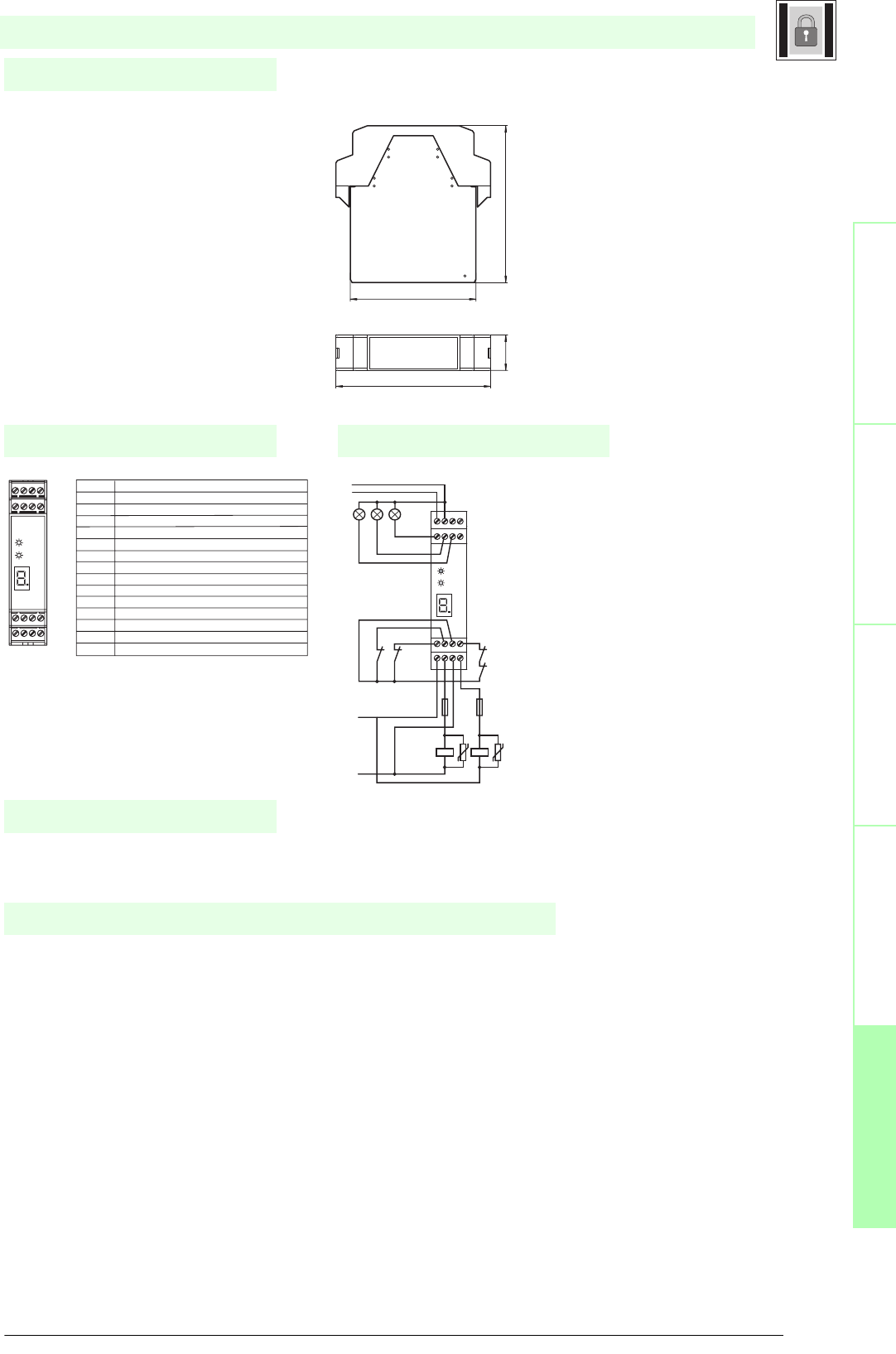
145
S
ubject to reasonable modifications due to technical advances. Copyright Pepperl+Fuchs, Printed in Germany
Pepperl+Fuchs Group • Tel.: Germany +49 621 776-0 • USA +1 330 4253555 • Singapore +65 67799091 • Internet http://www.pepperl-fuchs.com
Notes
Electrical connection
Safety through beam
sensors
Safey light gridsSafety light grids with
internal control unit
Safety light curtainsControl units
Dimensions
Connection example
This module can only be operated within an evaluation device of the SafeBox SB4 type.
The SafeBox instruction manual should be observed.
The OSSD-R/supply module contains the power supply of the SafeBox, 2 OSSDs, the relay monitor and the restart connection.
This module is located in slot 1 of the SafeBox and only exists once.
The OSSDs are designed as potential free connection NO contacts. The module can be operated with or without restart inter-
lock. Also, monitoring of the externally connected switching elements can be activated (relay monitor). The OSSD On or Off
statuses are indicated via a short-circuit-proof pnp signal output. The restart output is used for indication of the start readiness
status. In the case of an error, this output oscillates with 1 Hz.
Function
relay monitor
Reset
Restart
Terminal Function
1 Reset input; normally closed contact
2 Restart input (RI); normally closed contact
3 24 V DC connection for reset, restart and RM
4 Relay monitor (RM)
5 - 6 OSSD1; potential free relay contact; normally open contact
7 - 8 OSSD2; potential free relay contact; normally open contact
9 Signal output OSSD OFF
10 Signal output OSSD ON
11 Signal output restart
12 Leave free (n.c.)
13 +24 V DC supply voltage
14 0 V DC supply voltage
15 Earth
16 Leave free (n.c.)
- U
+ U
- Urel
+ Urel
K2.1
F2
K1.1
F1
K2K1
13 14 15
9 10 11 12
1 2 3 4
5 6 7 8
OSSD
RI
16
OSSD
RI
13 14 15 16
9 10 11 12
1 2 3 4
5 6 7 8
SafeBox module
Date of edition 05/17/2006
SB4 Module OR
100.522.6
80.3
99
13 14 15 16
9 10 11 12
1 2 3 4
5 6 7 8

Subject to reasonable modifications due to technical advances. Copyright Pepperl+Fuchs, Printed in Germany
Pepperl+Fuchs Group • Tel.: Germany +49 621 776-0 • USA +1 330 4253555 • Singapore +65 67799091 • Internet http://www.pepperl-fuchs.com
146
Technische DatenTechnical data
Features
Safety through beam
sensors
Safety light grids
Safety light grids with
internal control unit
Safety light curtains
Control units
General specifications
Approvals TÜV
Tests IEC/EN 61496 IEC 61508
Marking CE
Safety category according to IEC/EN 61496 4
Indicators/operating means
Function display LED yellow (4x): indicator lamp channel 1 ... 4
Pre-fault indication LED yellow flashing: Indicator lamp channel 1 ... 4
Operating elements DIP-switch
Electrical specifications
Operating voltage Power supply via control unit SB4
Input
Activation current approx. 7 mA
Ambient conditions
Ambient temperature 0 ... 50 °C (273 ... 323 K)
Storage temperature -20 ... 70 °C (253 ... 343 K)
Mechanical specifications
Protection degree IP20
Connection screw terminals , lead cross section 0.2 ... 2 mm2
Material
Housing Polyamide (PA)
Mass approx. 150 g
SB4 Module 4CP
U
®
Date of edition 05/17/2006
SafeBox module
For suitable cable sockets, mounting aids, redirection mirrors and more refer to chapter „Accessories.
• Sensor module
• 4 sensor channels
• Single module for safety through-beam sensors SLA12 and SLA29 and for 2
channel safety devices (emergency off)
• Micro-Controller controls
• Operating mode can be selected by means of DIP switches
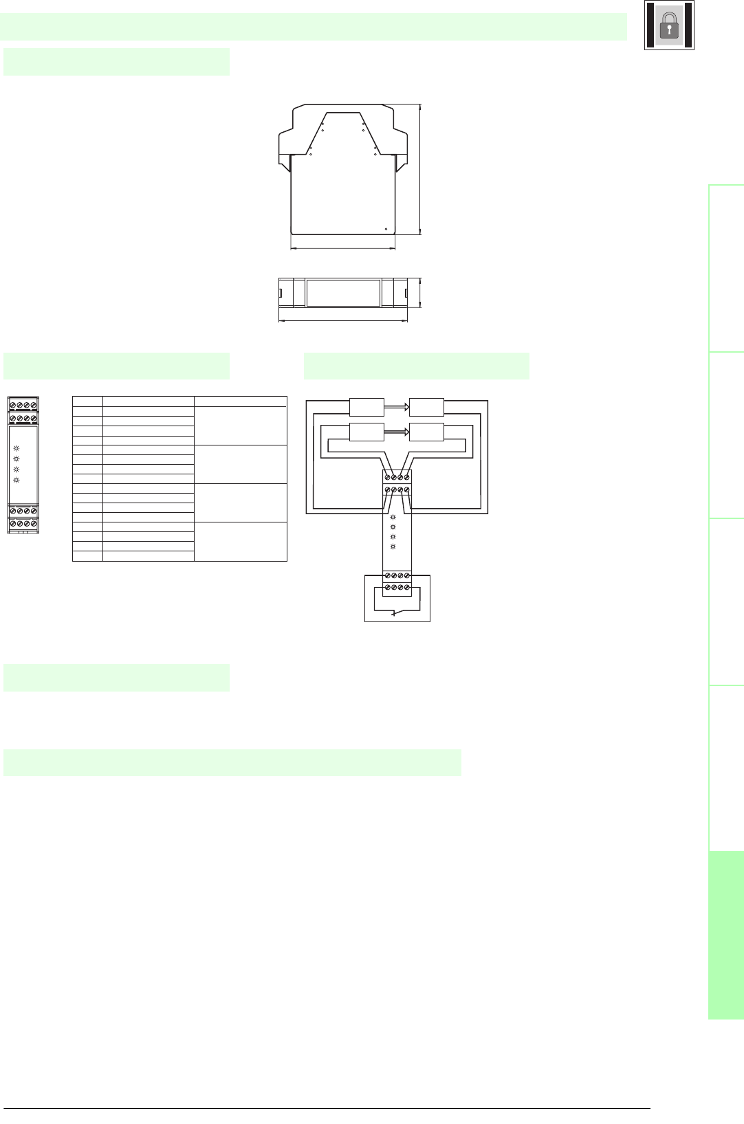
147
S
ubject to reasonable modifications due to technical advances. Copyright Pepperl+Fuchs, Printed in Germany
Pepperl+Fuchs Group • Tel.: Germany +49 621 776-0 • USA +1 330 4253555 • Singapore +65 67799091 • Internet http://www.pepperl-fuchs.com
Notes
Electrical connection
Safety through beam
sensors
Safey light gridsSafety light grids with
internal control unit
Safety light curtainsControl units
Dimensions
Connection example
The operation of this module is possible only within a control unit of the type SafeBox SB4.
Is the operating instruction of the SafeBox pay attention.
The 4-channel sensor card module SB4-4CP makes it possible to connect light barriers or light grids or contact safety sensors
in a one or two-channel version. In addition it contains the Micro-Controller controls of the SafeBox.
This version only exists once in a system and is always located in slot 2 of the SafeBox. The module is supplied with plug-in
jumper. If additional modules are used, this plug-in jumper must be moved.
There is a plug-in jumper on the module. If the system contains further units, this plug-in jumper onto the last slot must be
moved.
When the system is switched on, the software determines whether a light barrier or a contact safety sensor is switched on at a
channel and monitors its presence during operation. Safety sensors with switching contacts, which are connected to the Safe-
Box, must operate in the switching mode "normally closed". An open contact means "safe status".
The channels 1 and 2 as well as 3 and 4 (and 5 and 6) can be monitored for simultaneousness or antivalence. If simultaneous-
ness monitoring is activated, 2 channel safety equipment is monitored for simultaneous opening or changing of the signals. The
monitoring time is 2 s.
Antivalence monitoring expects the normally closed contact at channel 1 or 3 (or 5) and the normally open contact at channel
2 or 4 (or 6). If antivalence monitoring is performed without simultaneousness monitoring, an incorrect contact position causes
a switch-off and the error message 7 after approx. 60 s .
Function
Terminal
Function Channel assignment
1 Receiver 2 input Input
2 Receiver 2 +U Channel 2
3 Transmitter 2 +U
4 Transmitter 2 output Output
5 Receiver 1 input Input
6 Receiver 1 +U Channel 1
7 Transmitter 1 +U
8 Transmitter 1 output Output
9 Transmitter 3 output Output
10 Transmitter 3 +U Channel 3
11 Receiver 3 +U
12 Receiver 3 input Input
13 Transmitter 4 output Output
14 Transmitter 4 +U Channel 4
15 Receiver 4 +U
16 Receiver 4 input Input
Connection example
(LSS = transmitter of light barrier;
LSE = receiver of light barrier)
BK
BU LSS BN
BU
3
4LSS 3
1
LSE
R4
R3
R2
R1
13 14 15 16
1 2 3 4
5 6 7 8
9 10 11 12
LSE
R4
R3
R2
R1
13 14 15 16
9 10 11 12
1 2 3 4
5 6 7 8
SafeBox module
Date of edition 05/17/2006
SB4 Module 4CP
100.522.6
80.3
99
13 14 15 16
9 10 11 12
1 2 3 4
5 6 7 8
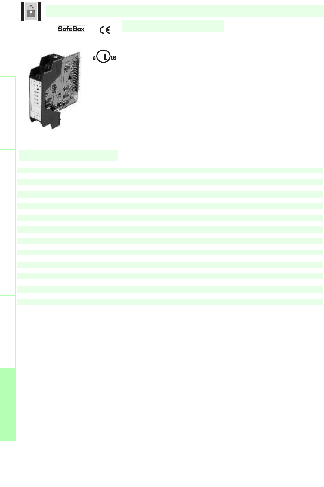
Subject to reasonable modifications due to technical advances. Copyright Pepperl+Fuchs, Printed in Germany
Pepperl+Fuchs Group • Tel.: Germany +49 621 776-0 • USA +1 330 4253555 • Singapore +65 67799091 • Internet http://www.pepperl-fuchs.com
148
Technische DatenTechnical data
Features
Safety through beam
sensors
Safety light grids
Safety light grids with
internal control unit
Safety light curtains
Control units
General specifications
Approvals TÜV
Tests IEC/EN 61496 IEC 61508
Marking CE
Safety category according to IEC/EN 61496 4
Indicators/operating means
Function display LED yellow (4x): indicator lamp channel 1 ... 4
Pre-fault indication LED yellow flashing: Indicator lamp channel 1 ... 4
Operating elements DIP-switch
Electrical specifications
Operating voltage Power supply via control unit SB4
Input
actuating voltage approx. 10 V
Activation current approx. 4 ... 20 mA
Ambient conditions
Ambient temperature 0 ... 50 °C (273 ... 323 K)
Storage temperature -20 ... 70 °C (253 ... 343 K)
Mechanical specifications
Protection degree IP20
Connection screw terminals , lead cross section 0.2 ... 2 mm2
Material
Housing Polyamide (PA)
Mass approx. 150 g
SB4 Module 4XP
U
®
Date of edition 05/17/2006
SafeBox module
For suitable cable sockets, mounting aids, redirection mirrors and more refer to chapter „Accessories.
• Sensor module
• 4 sensor channels
• Single module for safety through-beam sensors SLA5(S) and SLA40; for
SLP safety light barriers; for SLC safety light curtains; for switch mats and
Emergency-Stop switches in categories 2 and 4.
• Micro-Controller controls
• Operating mode can be selected by means of DIP switches
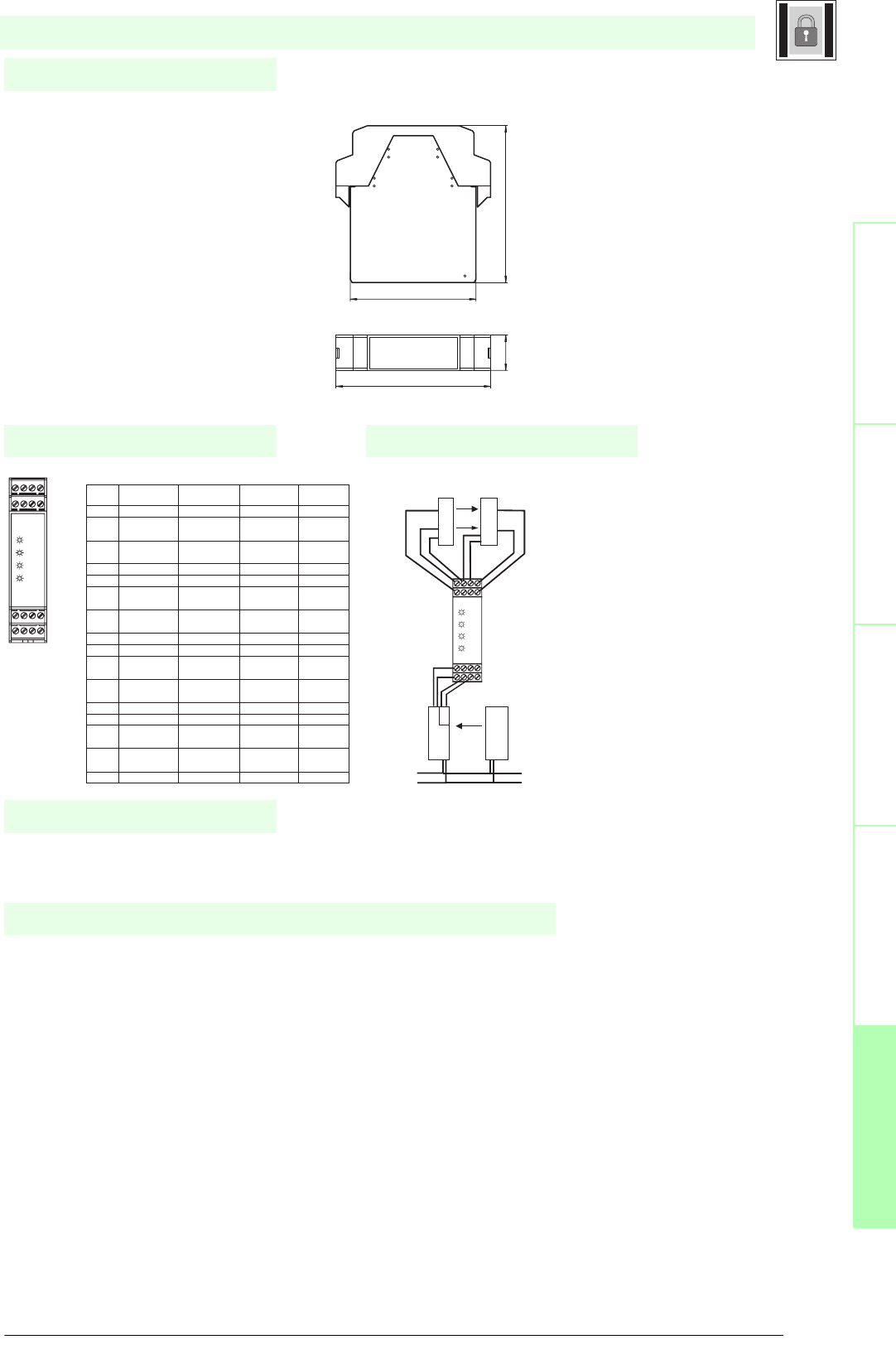
149
S
ubject to reasonable modifications due to technical advances. Copyright Pepperl+Fuchs, Printed in Germany
Pepperl+Fuchs Group • Tel.: Germany +49 621 776-0 • USA +1 330 4253555 • Singapore +65 67799091 • Internet http://www.pepperl-fuchs.com
Notes
Electrical connection
Safety through beam
sensors
Safey light gridsSafety light grids with
internal control unit
Safety light curtainsControl units
Dimensions
Connection example
The operation of this module is only possible within an interface device Type SB4 SafeBox.
The operating instruction for the SafeBox must be followed.
The 4-channel sensor card module SB4-4XP facilitates the connection of "3-wire" light barriers and light grids in the SLA and
SLP families, light curtains with semiconductor switch outputs (SLC family), switch mats based on the 4-conductor principle and
safety sensors with contacts in a single or two-channel version.
In addition, it contains the SafeBox microcontroller control system. A SafeBox contains only one of these modules and it must
be plugged-in at position 2.
There is a plug-in jumper on the module. If the system contains additional assemblies, then the plug-in jumper must be plugged
into the last plug-in position.
"3-wire" light barriers and light grids in the SLA and SLP families can be connected on channels 1 to 4. If the requirement is to
connect single-channel safety sensors with contacts, then a "3-wire" light barrier must be connected on the neighbouring chan-
nel. The neighbouring channels are channels 1 and 2 or 3 and 4.
On switching on the system the software determines whether a light barrier or a safety sensor with contacts is connected on a
channel and then monitors its presence during operation.
Safety sensors with contacts, which are connected to the SafeBox, must operate in accordance with the normally-closed prin-
ciple. An open contact signifies a "Safe condition".
Light curtains with semiconductor switch outputs and safety sensors with contacts in a two-channel version are monitored for
concurrence. The connection takes place on channels 1 and 2 or 3 and 4.
Function
terminal Function Connecting circuit Connecting circuit Connecting circuit
light beam switch/Light grid light curtain switching pad
1 Receiver input 2 Receiver output 2 OSSD-Output 1.2
2 + 24 V DC 24 V Receiver 2 24 V SLC1-
Power supply OSSD
3 0 V DC 0 V Emitter 2 and 0 V SLC1-
Receiver 2 Power supply OSSD
4 Emitter output 2 Emitter input 2 switching pad 1.3
5 Receiver input 1 Receiver output 1 OSSD-Output 1.1 switching pad 1.2
6 + 24 V DC 24 V Receiver 1 24 V SLC1-
Power supply OSSD
7 0 V DC 0 V Emitter 1 and 0 V SLC1-
Receiver 1 Power supply OSSD
8 Emitter output 1 Emitter input 1 switching pad 1.1
9 Emitter output 3 Emitter input 3 switching pad 2.1
10 0 V DC 0 V Emitter 3 and 0 V SLC2-
Receiver 3 Power supply OSSD
11 + 24 V DC 24 V Receiver 3 24 V SLC2-
Power supply OSSD
12 Receiver input 3 Receiver output 3 OSSD-Output 2.1 switching pad 2.2
13 Emitter output 4 Emitter input 4 switching pad 2.3
14 0 V DC 0 V Emitter 4 and 0 V SLC2-
Receiver 4 Power supply OSSD
15 + 24 V DC 24 V Receiver 4 24 V SLC2-
Power supply OSSD
16 Receiver input 4 Receiver output 4 OSSD-Output 2.2 switching pad 2.4
Galv. Getrennte 24V DC
Versorgung
E2
E1
S2
S1
GND GND
24V DC
24V DC
GND
Q1
Q2
light curtain SLC
Light grid SLP
Receiver Emitter
R4
R3
R2
R1
13 14 15 16
9 10 11 12
1 2 3 4
5 6 7 8
13
1
4
15
16
9 1
0
11 12
1 2 3 4
5 6 7 8
R4
R3
R2
R1
24V DC
GND
24V DC
GND
24V DC
GND
SafeBox module
Date of edition 05/17/2006
SB4 Module 4XP
100.522.6
80.3
99
13 14 15 16
9 10 11 12
1 2 3 4
5 6 7 8
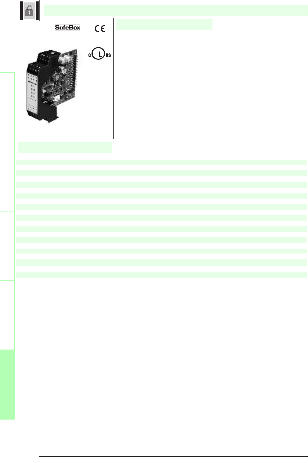
Subject to reasonable modifications due to technical advances. Copyright Pepperl+Fuchs, Printed in Germany
Pepperl+Fuchs Group • Tel.: Germany +49 621 776-0 • USA +1 330 4253555 • Singapore +65 67799091 • Internet http://www.pepperl-fuchs.com
150
Technische DatenTechnical data
Features
Safety through beam
sensors
Safety light grids
Safety light grids with
internal control unit
Safety light curtains
Control units
General specifications
Approvals TÜV
Tests IEC/EN 61496 IEC 61508
Marking CE
Safety category according to IEC/EN 61496 4
Indicators/operating means
Function display LED yellow (4x): indicator lamp channel 1 ... 4
Pre-fault indication LED yellow flashing: Indicator lamp channel 1 ... 4
Operating elements DIP-switch
Electrical specifications
Operating voltage Power supply via control unit SB4
Input
Activation current approx. 7 mA
Ambient conditions
Ambient temperature 0 ... 50 °C (273 ... 323 K)
Storage temperature -20 ... 70 °C (253 ... 343 K)
Mechanical specifications
Protection degree IP20
Connection screw terminals , lead cross section 0.2 ... 2 mm2
Material
Housing Polyamide (PA)
Mass approx. 150 g
SB4 Module 4CG
U
®
Date of edition 05/17/2006
SafeBox module
For suitable cable sockets, mounting aids, redirection mirrors and more refer to chapter „Accessories.
• Sensor module
• 4 sensor channels
• Single module for safety through-beam sensors SLA12 and SLA29 and for 2
channel safety devices (emergency off)
• Micro-Controller controls
• Operating mode can be selected by means of DIP switches
• Connection of a number of separate trip circuits

151
S
ubject to reasonable modifications due to technical advances. Copyright Pepperl+Fuchs, Printed in Germany
Pepperl+Fuchs Group • Tel.: Germany +49 621 776-0 • USA +1 330 4253555 • Singapore +65 67799091 • Internet http://www.pepperl-fuchs.com
Notes
Electrical connection
Safety through beam
sensors
Safey light gridsSafety light grids with
internal control unit
Safety light curtainsControl units
Dimensions
Connection example
The operation of this module is only possible within an interface device Type SB4 SafeBox.
The operating instruction for the SafeBox must be followed.
The 4-channel sensor card module SB4-4CG facilitates the connection of light barriers or light grids and safety sensors with
contacts in a single or two-channel version. It also contains the microcontroller control system for the SafeBox. Only one of these
modules is contained in a SafeBox SB4 and it must be plugged-in at position 2.
There is a plug-in jumper on the module.If the system contains additional assemblies, then this plug-in jumper must be plugged-
in to the last plug-in position.
This module enables a number of separate trip circuits to be installed in one SafeBox.
On switching on the system the software determines whether a light barrier or a safety sensor with contacts is connected on a
channel and then monitors its presence during operation.
Safety sensors with contacts, which are connected to the SafeBox, must operate in accordance with the normally-closed prin-
ciple. An open contact signifies a "Safe condition".
Channels 1 and 2 and 3 and 4 can be monitored for concurrence and antivalence. During activated concurrence monitoring 2-
channel safety devices are monitored for simultaneous opening and changeover of the signals. The monitoring is carried out
over a period of 2 s.
Antivalence monitoring awaits the normally-closed contact on channel 1 or channel 3 and the normally-open contact on channel
2 or 4. If the antivalence monitoring is operated without concurrence monitoring, then an incorrect contact setting leads to switch
off and error signal 7 after approx. 60 s.
Function
Terminal
Function Channel assignment
1 Receiver 2 input Input
2 Receiver 2 +U Channel 2
3 Transmitter 2 +U
4 Transmitter 2 output Output
5 Receiver 1 input Input
6 Receiver 1 +U Channel 1
7 Transmitter 1 +U
8 Transmitter 1 output Output
9 Transmitter 3 output Output
10 Transmitter 3 +U Channel 3
11 Receiver 3 +U
12 Receiver 3 input Input
13 Transmitter 4 output Output
14 Transmitter 4 +U Channel 4
15 Receiver 4 +U
16 Receiver 4 input Input
Connection example
(LSS = transmitter of light barrier;
LSE = receiver of light barrier)
BK
BU LSS BN
BU
3
4LSS 3
1
LSE
R4
R3
R2
R1
13 14 15 16
1 2 3 4
5 6 7 8
9 10 11 12
LSE
R4
R3
R2
R1
13 14 15 16
9 10 11 12
1 2 3 4
5 6 7 8
SafeBox module
Date of edition 05/17/2006
SB4 Module 4CG
100.522.6
80.3
99
13 14 15 16
9 10 11 12
1 2 3 4
5 6 7 8

Subject to reasonable modifications due to technical advances. Copyright Pepperl+Fuchs, Printed in Germany
Pepperl+Fuchs Group • Tel.: Germany +49 621 776-0 • USA +1 330 4253555 • Singapore +65 67799091 • Internet http://www.pepperl-fuchs.com
152
Technische DatenTechnical data
Features
Safety through beam
sensors
Safety light grids
Safety light grids with
internal control unit
Safety light curtains
Control units
General specifications
Approvals TÜV
Tests IEC/EN 61496 IEC 61508
Marking CE
Safety category according to IEC/EN 61496 4
Indicators/operating means
Function display LED yellow (4x): indicator lamp channel 1 ... 4
Pre-fault indication LED yellow flashing: Indicator lamp channel 1 ... 4
Operating elements DIP-switch
Electrical specifications
Operating voltage Power supply via control unit SB4
Input
actuating voltage approx. 10 V
Activation current approx. 4 ... 20 mA
Ambient conditions
Ambient temperature 0 ... 50 °C (273 ... 323 K)
Storage temperature -20 ... 70 °C (253 ... 343 K)
Mechanical specifications
Protection degree IP20
Connection screw terminals , lead cross section 0.2 ... 2 mm2
Material
Housing Polyamide (PA)
Mass approx. 150 g
SB4 Module 4XG
U
®
Date of edition 05/17/2006
SafeBox module
For suitable cable sockets, mounting aids, redirection mirrors and more refer to chapter „Accessories.
• Sensor module
• 4 sensor channels
• Single module for safety through-beam sensors SLA5(S) and SLA40; for
SLP safety light barriers; for SLC safety light curtains; for switch mats and
Emergency-Stop switches in categories 2 and 4.
• Micro-Controller controls
• Operating mode can be selected by means of DIP switches
• Connection of a number of separate trip circuits
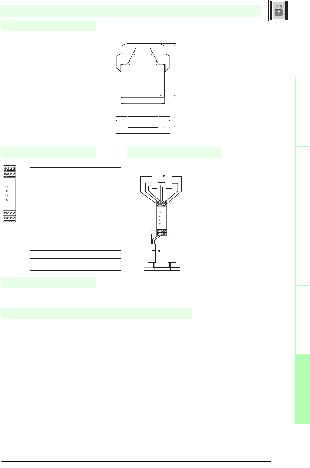
153
S
ubject to reasonable modifications due to technical advances. Copyright Pepperl+Fuchs, Printed in Germany
Pepperl+Fuchs Group • Tel.: Germany +49 621 776-0 • USA +1 330 4253555 • Singapore +65 67799091 • Internet http://www.pepperl-fuchs.com
Notes
Electrical connection
Safety through beam
sensors
Safey light gridsSafety light grids with
internal control unit
Safety light curtainsControl units
Dimensions
Connection example
The operation of this module is only possible within an interface device Type SB4 SafeBox.
The operating instruction for the SafeBox must be followed.
The 4-channel sensor card module SB4-4XG facilitates the connection of "3-wire" light barriers and light grids in the SLA and
SLP families, light curtains with semiconductor switch outputs (SLC family), switch mats based on the 4-conductor principle and
safety sensors with contacts in a single or two-channel version.
In addition it contains the microcontroller control system for the SafeBox. A SafeBox contains only one of these modules and
it must be plugged-in at position 2.
There is a plug-in jumper on the module. If the system contains additional assemblies, then the plug-in jumper must be plugged
into the last plug-in position
This module enables a number of separate trip circuits to be contained in one SafeBox.
3-wire" light barriers and grids in the SLA and SLP families can be connected on channels 1 to 4. If the requirement is to con-
nect single-channel safety sensors with contacts, then a "3-wire" light barrier must be connected on the neighbouring channel.
The neighbouring channels are channels 1 and 2 and 3 and 4.
On switching on the system the software determines whether a light barrier or a safety sensor with contacts is connected on a
channel and then monitors its presence during operation.
Safety sensors with contacts, which are connected to the SafeBox, must operate in accordance with the normally-closed prin-
ciple. An open contact signifies a "Safe condition".
Light curtains with semiconductor switch outputs and safety sensors with contacts in a two-channel version are monitored for
concurrence. Connection takes place on channels 1 and 2 and 3 and 4.
Function
terminal Function Connecting circuit Connecting circuit Connecting circuit
light beam switch/Light grid light curtain switching pad
1 Receiver input 2 Receiver output 2 OSSD-Output 1.2
2 + 24 V DC 24 V Receiver 2 24 V SLC1-
Power supply OSSD
3 0 V DC 0 V Emitter 2 and 0 V SLC1-
Receiver 2 Power supply OSSD
4 Emitter output 2 Emitter input 2 switching pad 1.3
5 Receiver input 1 Receiver output 1 OSSD-Output 1.1 switching pad 1.2
6 + 24 V DC 24 V Receiver 1 24 V SLC1-
Power supply OSSD
7 0 V DC 0 V Emitter 1 and 0 V SLC1-
Receiver 1 Power supply OSSD
8 Emitter output 1 Emitter input 1 switching pad 1.1
9 Emitter output 3 Emitter input 3 switching pad 2.1
10 0 V DC 0 V Emitter 3 and 0 V SLC2-
Receiver 3 Power supply OSSD
11 + 24 V DC 24 V Receiver 3 24 V SLC2-
Power supply OSSD
12 Receiver input 3 Receiver output 3 OSSD-Output 2.1 switching pad 2.2
13 Emitter output 4 Emitter input 4 switching pad 2.3
14 0 V DC 0 V Emitter 4 and 0 V SLC2-
Receiver 4 Power supply OSSD
15 + 24 V DC 24 V Receiver 4 24 V SLC2-
Power supply OSSD
16 Receiver input 4 Receiver output 4 OSSD-Output 2.2 switching pad 2.4
Galv. Getrennte 24V DC
Versorgung
E2
E1
S2
S1
GND GND
24V DC
24V DC
GND
Q1
Q2
light curtain SLC
Light grid SLP
Receiver Emitter
R4
R3
R2
R1
13 14 15 16
9 10 11 12
1 2 3 4
5 6 7 8
13
1
4
15
16
9 1
0
11 12
1 2 3 4
5 6 7 8
R4
R3
R2
R1
24V DC
GND
24V DC
GND
24V DC
GND
SafeBox module
Date of edition 05/17/2006
SB4 Module 4XG
100.522.6
80.3
99
13 14 15 16
9 10 11 12
1 2 3 4
5 6 7 8
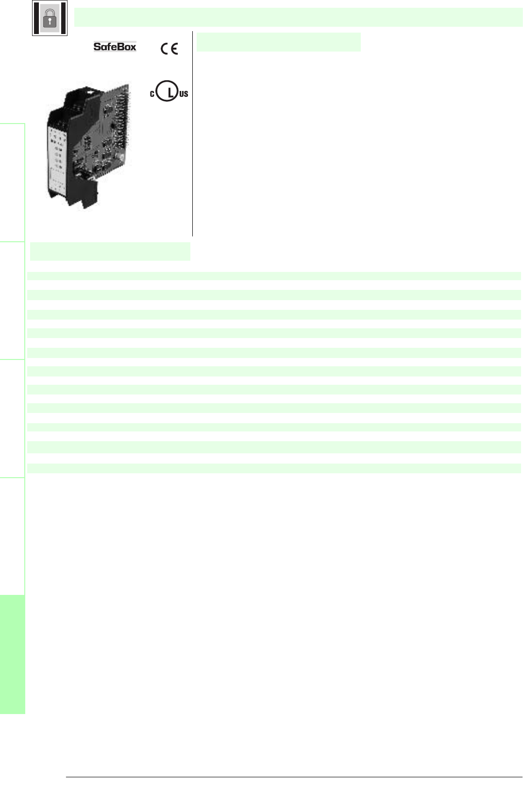
Subject to reasonable modifications due to technical advances. Copyright Pepperl+Fuchs, Printed in Germany
Pepperl+Fuchs Group • Tel.: Germany +49 621 776-0 • USA +1 330 4253555 • Singapore +65 67799091 • Internet http://www.pepperl-fuchs.com
154
Technische DatenTechnical data
Features
Safety through beam
sensors
Safety light grids
Safety light grids with
internal control unit
Safety light curtains
Control units
General specifications
Approvals TÜV
Tests IEC/EN 61496 IEC 61508
Marking CE
Safety category according to IEC/EN 61496 4
Indicators/operating means
Function display LED yellow (4x): indicator lamp channel 1 ... 4
Pre-fault indication LED yellow flashing: Indicator lamp channel 1 ... 4
Operating elements DIP-switch
Electrical specifications
Operating voltage Power supply via control unit SB4
Input
Activation current approx. 7 mA
Ambient conditions
Ambient temperature 0 ... 50 °C (273 ... 323 K)
Storage temperature -20 ... 70 °C (253 ... 343 K)
Mechanical specifications
Protection degree IP20
Connection screw terminals , lead cross section 0.2 ... 2 mm2
Material
Housing Polyamide (PA)
Mass approx. 150 g
SB4 Module 4C
U
®
Date of edition 05/17/2006
SafeBox module
For suitable cable sockets, mounting aids, redirection mirrors and more refer to chapter „Accessories.
• Sensor module
• 4 sensor channels
• Single module for safety through-beam sensors SLA12 and SLA29 and for 2
channel safety devices (emergency off)
• Operating mode can be selected by means of DIP switches

155
S
ubject to reasonable modifications due to technical advances. Copyright Pepperl+Fuchs, Printed in Germany
Pepperl+Fuchs Group • Tel.: Germany +49 621 776-0 • USA +1 330 4253555 • Singapore +65 67799091 • Internet http://www.pepperl-fuchs.com
Notes
Electrical connection
Safety through beam
sensors
Safey light gridsSafety light grids with
internal control unit
Safety light curtainsControl units
Dimensions
Connection example
The operation of this module is possible only within a control unit of the type SafeBox SB4.
The operating instruction of the SafeBox has to be observed.
The 4-channel sensor card module SB4-4C makes it possible to connect light barriers or light grids or contact safety sensors in
a one or two-channel version.
When the system is switched on, the software determines whether a light barrier or a contact safety sensor is switched on at a
channel and monitors its presence during operation. Safety sensors with switching contacts, which are connected to the Safe-
Box, must operate in the switching mode "normally closed". An open contact means "safe status".
The channels 1 and 2 as well as 3 and 4 can be monitored for simultaneousness or antivalence. If simultaneousness monitoring
is activated, 2 channel safety equipment is monitored for simultaneous opening or changing of the signals. The monitoring time
is 2 s.
Antivalence monitoring expects the normally closed contact at channel 1 or 3 and the normally open contact at channel 2 or 4.
If antivalence monitoring is performed without simultaneousness monitoring, an incorrect contact position causes a switch-off
and the error message 7 after approx. 60 s .
Function
Terminal
Function Channel assignment
1 Receiver 2 input Input
2 Receiver 2 +U Channel 2
3 Transmitter 2 +U
4 Transmitter 2 output Output
5 Receiver 1 input Input
6 Receiver 1 +U Channel 1
7 Transmitter 1 +U
8 Transmitter 1 output Output
9 Transmitter 3 output Output
10 Transmitter 3 +U Channel 3
11 Receiver 3 +U
12 Receiver 3 input Input
13 Transmitter 4 output Output
14 Transmitter 4 +U Channel 4
15 Receiver 4 +U
16 Receiver 4 input Input
Connection example
(LSS = transmitter of light barrier;
LSE = receiver of light barrier)
BK
BU LSS BN
BU
3
4LSS 3
1
LSE
R4
R3
R2
R1
13 14 15 16
1 2 3 4
5 6 7 8
9 10 11 12
LSE
R4
R3
R2
R1
13 14 15 16
9 10 11 12
1 2 3 4
5 6 7 8
SafeBox module
Date of edition 05/17/2006
SB4 Module 4C
100.522.6
80.3
99
13 14 15 16
9 10 11 12
1 2 3 4
5 6 7 8
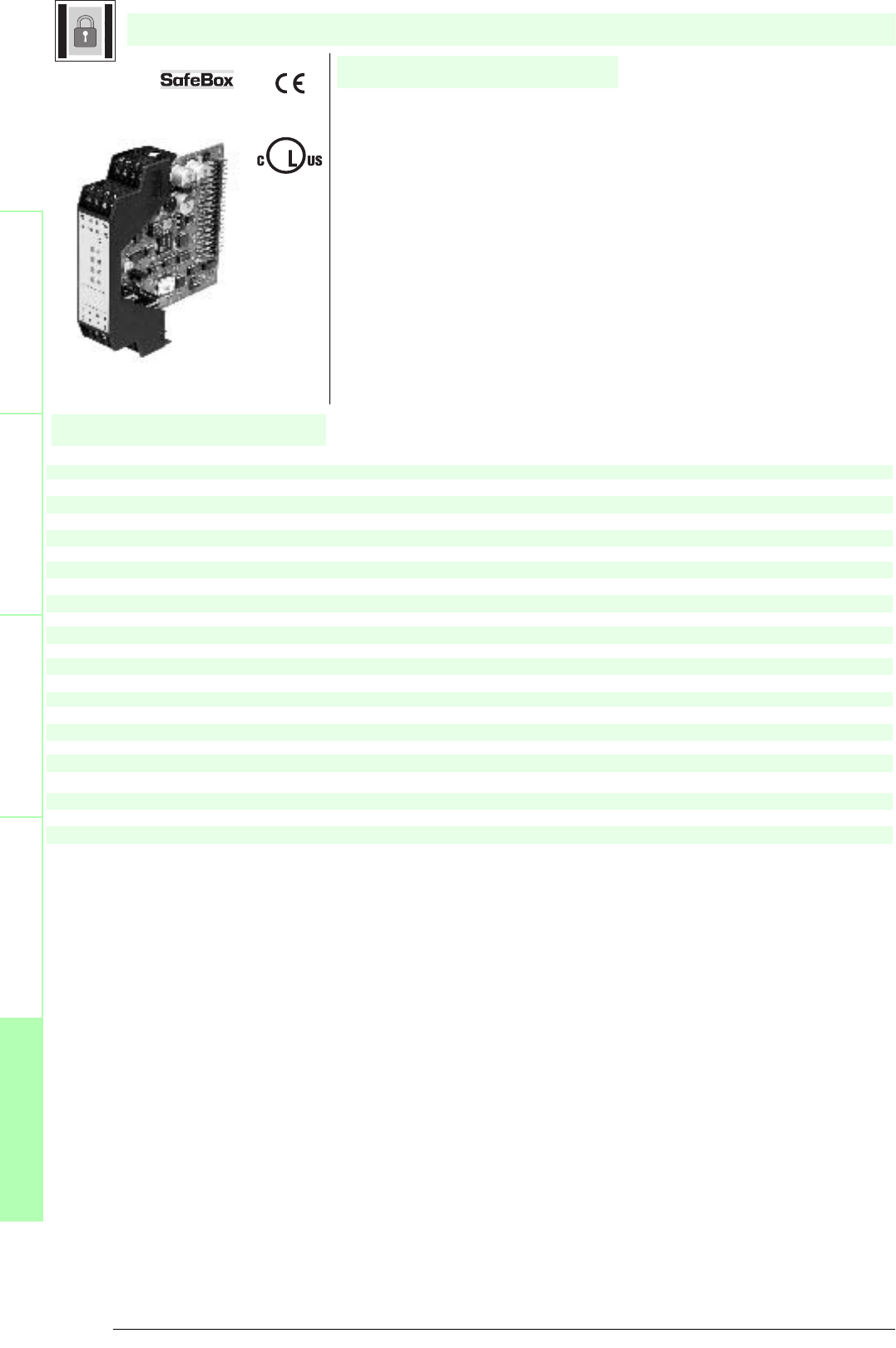
Subject to reasonable modifications due to technical advances. Copyright Pepperl+Fuchs, Printed in Germany
Pepperl+Fuchs Group • Tel.: Germany +49 621 776-0 • USA +1 330 4253555 • Singapore +65 67799091 • Internet http://www.pepperl-fuchs.com
156
Technische DatenTechnical data
Features
Safety through beam
sensors
Safety light grids
Safety light grids with
internal control unit
Safety light curtains
Control units
General specifications
Approvals TÜV
Tests IEC/EN 61496 IEC 61508
Marking CE
Safety category according to IEC/EN 61496 4
Indicators/operating means
Function display LED yellow (4x): indicator lamp channel 1 ... 4
Pre-fault indication LED yellow flashing: Indicator lamp channel 1 ... 4
Operating elements DIP-switch
Electrical specifications
Operating voltage Power supply via control unit SB4
Input
actuating voltage approx. 10 V
Activation current approx. 4 ... 20 mA
Ambient conditions
Ambient temperature 0 ... 50 °C (273 ... 323 K)
Storage temperature -20 ... 70 °C (253 ... 343 K)
Mechanical specifications
Protection degree IP20
Connection screw terminals , lead cross section 0.2 ... 2 mm2
Material
Housing Polyamide (PA)
Mass approx. 150 g
SB4 Module 4X
U
®
Date of edition 05/17/2006
SafeBox module
For suitable cable sockets, mounting aids, redirection mirrors and more refer to chapter „Accessories.
• Sensor module
• 4 sensor channels
• Single module for safety through-beam sensors SLA5(S) and SLA40; for
SLP safety light barriers; for SLC safety light curtains; for switch mats and
Emergency-Stop switches in categories 2 and 4.
• Operating mode can be selected by means of DIP switches

157
S
ubject to reasonable modifications due to technical advances. Copyright Pepperl+Fuchs, Printed in Germany
Pepperl+Fuchs Group • Tel.: Germany +49 621 776-0 • USA +1 330 4253555 • Singapore +65 67799091 • Internet http://www.pepperl-fuchs.com
Notes
Electrical connection
Safety through beam
sensors
Safey light gridsSafety light grids with
internal control unit
Safety light curtainsControl units
Dimensions
Connection example
The operation of this module is only possible within an interface device Type SB4 SafeBox.
The operating instruction for the SafeBox must be followed.
The 4-channel sensor card module SB4-4X facilitates the connection of "3-wire" light barriers and light grids in the SLA and SLP
families, light curtains with semiconductor switch outputs (SLC family), switch mats based on the 4-conductor principle and safe-
ty sensors with contacts in a single or two-channel version.
"3-wire" light barriers and grids in the SLA and SLP families can be connected on channels 1 to 4. If the requirement is to con-
nect single-channel safety sensors with contacts, then a "3-wire" light barrier must be connected on the neighbouring channel.
The neighbouring channels are channels 1 and 2 or 3 and 4.
On switching on the system the software determines whether a light barrier or a safety sensor with contacts is connected on a
channel and then monitors its presence during operation.
Safety sensors with contacts, which are connected to the SafeBox, must operate in accordance with the normally-closed prin-
ciple. An open contact signifies a "Safe condition".
Light curtains with semiconductor switch outputs and safety sensors with contacts in a two-channel version are monitored for
concurrence. Connection takes place on channels 1 and 2 or 3 and 4.
Switch mats based on the 4-conductor principle are connected on channels 1 and 2 or 3 and 4. The connection position of the
switch mats is configured by means of the DIP switches.
Function
terminal Function Connecting circuit Connecting circuit Connecting circuit
light beam switch/Light grid light curtain switching pad
1 Receiver input 2 Receiver output 2 OSSD-Output 1.2
2 + 24 V DC 24 V Receiver 2 24 V SLC1-
Power supply OSSD
3 0 V DC 0 V Emitter 2 and 0 V SLC1-
Receiver 2 Power supply OSSD
4 Emitter output 2 Emitter input 2 switching pad 1.3
5 Receiver input 1 Receiver output 1 OSSD-Output 1.1 switching pad 1.2
6 + 24 V DC 24 V Receiver 1 24 V SLC1-
Power supply OSSD
7 0 V DC 0 V Emitter 1 and 0 V SLC1-
Receiver 1 Power supply OSSD
8 Emitter output 1 Emitter input 1 switching pad 1.1
9 Emitter output 3 Emitter input 3 switching pad 2.1
10 0 V DC 0 V Emitter 3 and 0 V SLC2-
Receiver 3 Power supply OSSD
11 + 24 V DC 24 V Receiver 3 24 V SLC2-
Power supply OSSD
12 Receiver input 3 Receiver output 3 OSSD-Output 2.1 switching pad 2.2
13 Emitter output 4 Emitter input 4 switching pad 2.3
14 0 V DC 0 V Emitter 4 and 0 V SLC2-
Receiver 4 Power supply OSSD
15 + 24 V DC 24 V Receiver 4 24 V SLC2-
Power supply OSSD
16 Receiver input 4 Receiver output 4 OSSD-Output 2.2 switching pad 2.4
Galv. Getrennte 24V DC
Versorgung
E2
E1
S2
S1
GND GND
24V DC
24V DC
GND
Q1
Q2
light curtain SLC
Light grid SLP
Receiver Emitter
R4
R3
R2
R1
13 14 15 16
9 10 11 12
1 2 3 4
5 6 7 8
13
1
4
15
16
9 1
0
11 12
1 2 3 4
5 6 7 8
R4
R3
R2
R1
24V DC
GND
24V DC
GND
24V DC
GND
SafeBox module
Date of edition 05/17/2006
SB4 Module 4X
100.522.6
80.3
99
13 14 15 16
9 10 11 12
1 2 3 4
5 6 7 8
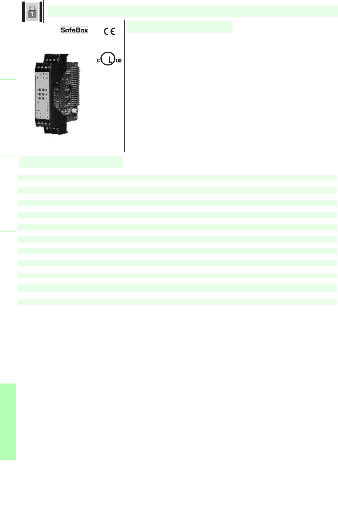
Subject to reasonable modifications due to technical advances. Copyright Pepperl+Fuchs, Printed in Germany
Pepperl+Fuchs Group • Tel.: Germany +49 621 776-0 • USA +1 330 4253555 • Singapore +65 67799091 • Internet http://www.pepperl-fuchs.com
158
Technische DatenTechnical data
Features
Safety through beam
sensors
Safety light grids
Safety light grids with
internal control unit
Safety light curtains
Control units
General specifications
Approvals TÜV
Tests IEC/EN 61496 IEC 61508
Marking CE
Safety category according to IEC/EN 61496 4
Indicators/operating means
Function display LED yellow (6x): indicator lamp channel 1 ... 6
Pre-fault indication LED yellow flashing: Indicator lamp channel 1 ... 6
Operating elements DIP-switch
Electrical specifications
Operating voltage Power supply via control unit SB4
Input
Activation current approx. 7 mA
Ambient conditions
Ambient temperature 0 ... 50 °C (273 ... 323 K)
Storage temperature -20 ... 70 °C (253 ... 343 K)
Mechanical specifications
Protection degree IP20
Connection screw terminals , lead cross section 0.2 ... 2 mm2
Material
Housing Polyamide (PA)
Mass approx. 150 g
SB4 Module 6C
U
®
Date of edition 05/17/2006
SafeBox module
For suitable cable sockets, mounting aids, redirection mirrors and more refer to chapter „Accessories.
• Sensor module
• 6 sensor channels
• Single module for safety through-beam sensors SLA12 and SLA29 and for 2
channel safety devices (emergency off)
• Operating mode can be selected by means of DIP switches
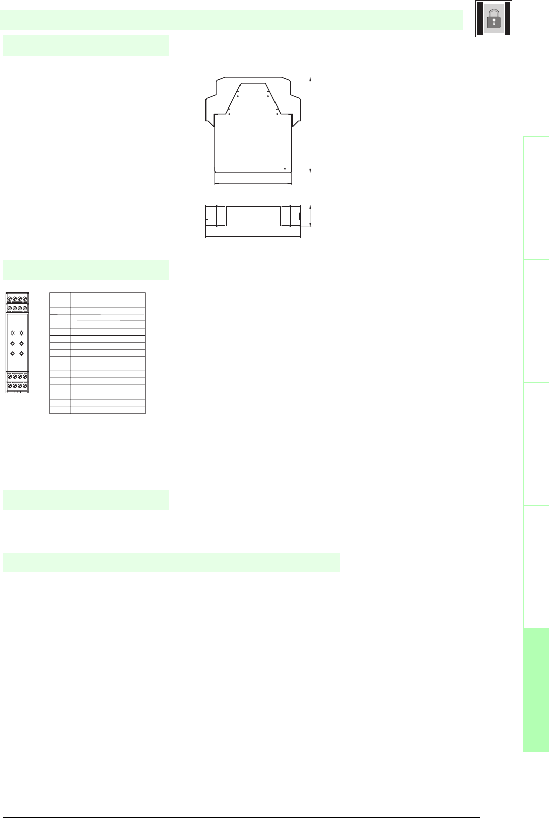
159
S
ubject to reasonable modifications due to technical advances. Copyright Pepperl+Fuchs, Printed in Germany
Pepperl+Fuchs Group • Tel.: Germany +49 621 776-0 • USA +1 330 4253555 • Singapore +65 67799091 • Internet http://www.pepperl-fuchs.com
Notes
Electrical connection
Safety through beam
sensors
Safey light gridsSafety light grids with
internal control unit
Safety light curtainsControl units
Dimensions
The operation of this module is possible only within a control unit of the type SafeBox SB4.
The operating instruction of the SafeBox has to be observed.
The 6-channel sensor card module SB4-6C makes it possible to connect light barriers or light grids or contact safety sensors in
a one or two-channel version.
When the system is switched on, the software determines whether a light barrier or a contact safety sensor is switched on at a
channel and monitors its presence during operation. Safety sensors with switching contacts, which are connected to the Safe-
Box, must operate in the switching mode "normally closed". An open contact means "safe status".
The channels 1 and 2, 3 and 4 as well as 5 and 6 can be monitored for simultaneousness or antivalence. If simultaneousness
monitoring is activated, 2 channel safety equipment is monitored for simultaneous opening or changing of the signals. The mo-
nitoring time is 2 s.
Antivalence monitoring expects the normally closed contact at channel 1, 3 or 5 and the normally open contact at channel 2, 4
or 6. If antivalence monitoring is performed without simultaneousness monitoring, an incorrect contact position causes a switch-
off and the error message 7 after approx. 60 s .
Function
Terminal Function
1 Transmitter 1 output
2 Transmitter 2 output
3 Transmitter 3 output
4 Transmitter 1...3 +U
5 Transmitter 4 output
6 Transmitter 5 output
7 Transmitter 6 output
8 Transmitter 4...6 +U
9 Receiver 1 input
10 Receiver 2 input
11 Receiver 3 input
12 Receiver 1...3 +U
13 Receiver 4 input
14 Receiver 5 input
15 Receiver 6 input
16 Receiver 4...6 +U
R5
R3
R1
R6
R4
R2
13 14 15 16
9 10 11 12
1 2 3 4
5 6 7 8
SafeBox module
Date of edition 05/17/2006
SB4 Module 6C
100.522.6
80.3
99
13 14 15 16
9 10 11 12
1 2 3 4
5 6 7 8
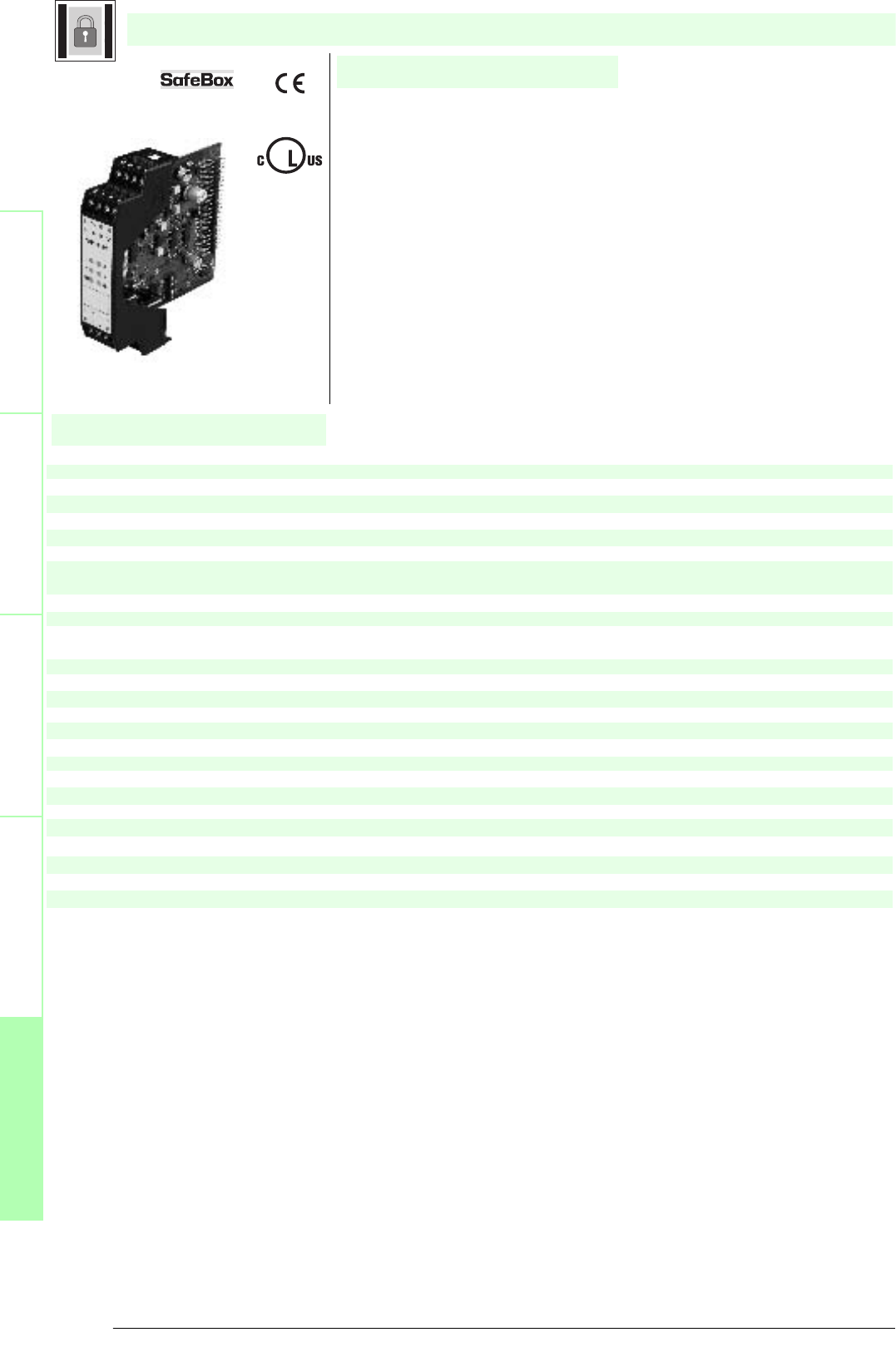
Subject to reasonable modifications due to technical advances. Copyright Pepperl+Fuchs, Printed in Germany
Pepperl+Fuchs Group • Tel.: Germany +49 621 776-0 • USA +1 330 4253555 • Singapore +65 67799091 • Internet http://www.pepperl-fuchs.com
160
Technische DatenTechnical data
Features
Safety through beam
sensors
Safety light grids
Safety light grids with
internal control unit
Safety light curtains
Control units
General specifications
Approvals TÜV
Tests IEC/EN 61496 IEC 61508
Marking CE
Safety category according to IEC/EN 61496 4
Indicators/operating means
Function display LED yellow (4x): indicator lamp muting sensor 1 ... 4
LED white (2x): status muting lamp
Operating elements DIP-switch
Electrical specifications
Operating voltage Power supply via control unit SB4
separate power supply for muting lamp
Input
Activation current approx. 10 mA
Activation time Override-Input 0.4 ... 1.2 s
Output
Switching voltage 24 V
Switching current 7.5 mA ... 500 mA
Ambient conditions
Ambient temperature 0 ... 50 °C (273 ... 323 K)
Storage temperature -20 ... 70 °C (253 ... 343 K)
Mechanical specifications
Protection degree IP20
Connection screw terminals , lead cross section 0.2 ... 2 mm2
Material
Housing Polyamide (PA)
Mass approx. 150 g
SB4 Module 4M
U
®
Date of edition 05/17/2006
SafeBox module
For suitable cable sockets, mounting aids, redirection mirrors and more refer to chapter „Accessories.
• Muting module
• 4 sensor channels
• Double muting
• Emergency muting for the correction of the material jam
• Operating mode can be selected by means of DIP switches

161
S
ubject to reasonable modifications due to technical advances. Copyright Pepperl+Fuchs, Printed in Germany
Pepperl+Fuchs Group • Tel.: Germany +49 621 776-0 • USA +1 330 4253555 • Singapore +65 67799091 • Internet http://www.pepperl-fuchs.com
Notes
Electrical connection
Safety through beam
sensors
Safey light gridsSafety light grids with
internal control unit
Safety light curtainsControl units
Dimensions
Connection example
This module can only be operated within an evaluation device of the SafeBox SB4 type.
The SafeBox instruction manual should be observed.
The muting module realises the muting function for the sensor channels of the four to six channel sensor card module immedi-
ately to the right of the module.
The user must make sure to only connect sensors that can be muted to the sensor card that is assigned to the muting module.
These are, for example, light barriers or light grids.
Muting sensors
Muting sensors are supposed to detect the muting objects. If an object is detected, the output of the muting sensor switches
through its supply voltage. For this purpose, sensors with relay or pnp output are suitable. In a de-energised state, the output
of the muting sensor must not be active. The sensor output should be capable of reliably switching a load current of 8 mA at 20
V. Muting sensors with a current consumption of a maximum of 30 mA can be supplied directly from the muting module. Sensors
with a higher current consumption require an external power supply. Muting sensors must be selected such that they also work
at a supply voltage of at least 12 V.
The cables to the muting sensors must be laid in such a way that no short circuits are possible between the muting sensors.
As muting sensors, the following sensors can be used, for example:
· Retro-reflective sensors dark on or light on (in this case reflector at the object),
· Photoelectric sensors (light on),
· Inductive sensors, mechanical switches.
Function
Terminal
Function
1 24 V sensor supply
2 Sensor 2 IN
3 Sensor 4 IN
4 0 V sensor supply
5 24 V sensor supply
6 Sensor 1 IN
7 Sensor 3 IN
8 0 V sensor supply
9 Input override 1
10 24 V override 1
11 24 V override 2
12 Input override 2
13 +24 V DC supply voltage for muting lamps
14 0 V DC supply voltage for muting lamps
15 Output muting lamp 1
16 Output muting lamp 2
Override 1
Override 2 Muting
lamp 2
Muting
lamp 1
Muting sensor 3
Muting sensor 1
Muting sensor 4
Muting sensor 2
I1
I2
M1
I3
I4
M2
13 14 15 16
9 10 11 12
1 2 3 4
5 6 7 8
I1
I2
M1
I3
I4
M2
- U
+ U
13 14 15 16
9 10 11 12
1 2 3 4
5 6 7 8
SafeBox module
Date of edition 05/17/2006
SB4 Module 4M
100.522.6
80.3
99
13 14 15 16
9 10 11 12
1 2 3 4
5 6 7 8

Subject to reasonable modifications due to technical advances. Copyright Pepperl+Fuchs, Printed in Germany
Pepperl+Fuchs Group • Tel.: Germany +49 621 776-0 • USA +1 330 4253555 • Singapore +65 67799091 • Internet http://www.pepperl-fuchs.com
162
Technische DatenTechnical data
Features
Safety through beam
sensors
Safety light grids
Safety light grids with
internal control unit
Safety light curtains
Control units
General specifications
Approvals TÜV
Tests IEC/EN 61496 IEC 61508
Marking CE
Safety category according to IEC/EN 61496 4
Indicators/operating means
Function display LED yellow (4x): indicator lamp muting sensor 1 ... 4
LED white (2x): status muting lamp
Operating elements DIP-switch
Electrical specifications
Operating voltage Power supply via control unit SB4
separate power supply for muting lamp
Input
Activation current approx. 10 mA
Activation time Override-Input 0.4 ... 1.2 s
Output
Switching voltage 24 V
Switching current 7.5 mA ... 500 mA
Ambient conditions
Ambient temperature 0 ... 50 °C (273 ... 323 K)
Storage temperature -20 ... 70 °C (253 ... 343 K)
Mechanical specifications
Protection degree IP20
Connection screw terminals , lead cross section 0.2 ... 2 mm2
Material
Housing Polyamide (PA)
Mass approx. 150 g
SB4 Module 4MD
U
®
Date of edition 05/17/2006
SafeBox module
For suitable cable sockets, mounting aids, redirection mirrors and more refer to chapter „Accessories.
• Muting module
• 4 sensor channels
• Double muting
• Continuous muting with no time limit
• Emergency muting for the correction of the material jam
• Operating mode can be selected by means of DIP switches
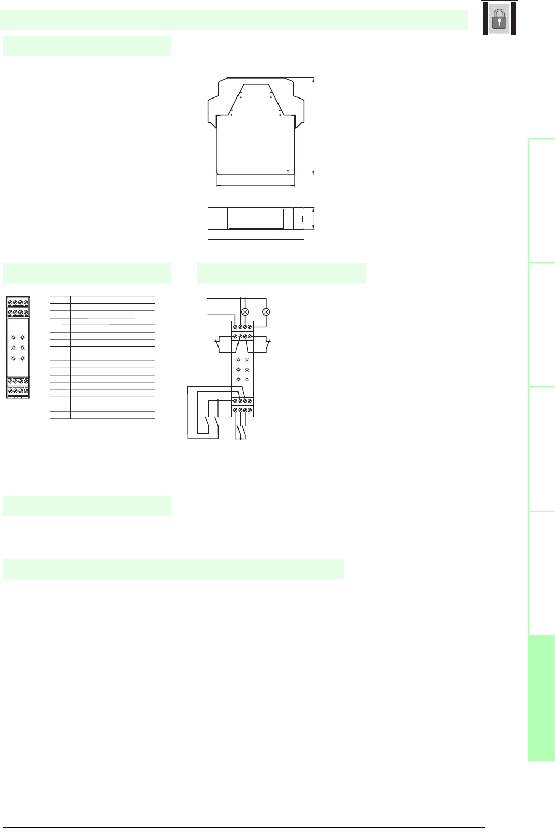
163
S
ubject to reasonable modifications due to technical advances. Copyright Pepperl+Fuchs, Printed in Germany
Pepperl+Fuchs Group • Tel.: Germany +49 621 776-0 • USA +1 330 4253555 • Singapore +65 67799091 • Internet http://www.pepperl-fuchs.com
Notes
Electrical connection
Safety through beam
sensors
Safey light gridsSafety light grids with
internal control unit
Safety light curtainsControl units
Dimensions
Connection example
This module can only be operated within an evaluation device of the SafeBox SB4 type.
The SafeBox instruction manual should be observed.
The muting module realises the muting function for the sensor channels of the four to six channel sensor card module immedi-
ately to the right of the module.
The user must make sure to only connect sensors that can be muted to the sensor card that is assigned to the muting module.
These are, for example, light barriers or light grids.
This muting module does not monitor the activation time of the muting sensors.
The following must be observed for the application:
The basis of the assessment of the safety category is that every muting sensor is activated at least once per day (the activation
is triggered when the muting procedure is not interrupted).
A detailed description of the muting operating modes can be found in the instruction manual.
Muting sensors
Muting sensors are supposed to detect the muting objects. If an object is detected, the output of the muting sensor switches
through its supply voltage. For this purpose, sensors with relay or pnp output are suitable. In a de-energised state, the output
of the muting sensor must not be active. The sensor output should be capable of reliably switching a load current of 8 mA at 20
V. Muting sensors with a current consumption of a maximum of 30 mA can be supplied directly from the muting module. Sensors
with a higher current consumption require an external power supply. Muting sensors must be selected such that they also work
at a supply voltage of at least 12 V.
Function
Terminal
Function
1 24 V sensor supply
2 Sensor 2 IN
3 Sensor 4 IN
4 0 V sensor supply
5 24 V sensor supply
6 Sensor 1 IN
7 Sensor 3 IN
8 0 V sensor supply
9 Input override 1
10 24 V override 1
11 24 V override 2
12 Input override 2
13 +24 V DC supply voltage for muting lamps
14 0 V DC supply voltage for muting lamps
15 Output muting lamp 1
16 Output muting lamp 2
Override 1
Override 2 Muting
lamp 2
Muting
lamp 1
Muting sensor 3
Muting sensor 1
Muting sensor 4
Muting sensor 2
I1
I2
M1
I3
I4
M2
13 14 15 16
9 10 11 12
1 2 3 4
5 6 7 8
I1
I2
M1
I3
I4
M2
- U
+ U
13 14 15 16
9 10 11 12
1 2 3 4
5 6 7 8
SafeBox module
Date of edition 05/17/2006
SB4 Module 4MD
100.522.6
80.3
99
13 14 15 16
9 10 11 12
1 2 3 4
5 6 7 8
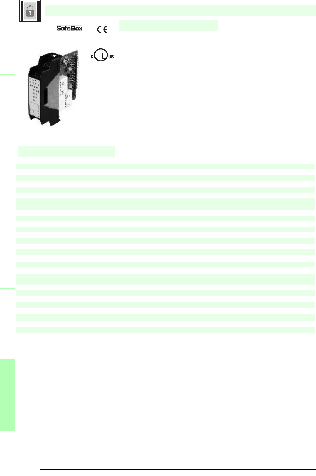
Subject to reasonable modifications due to technical advances. Copyright Pepperl+Fuchs, Printed in Germany
Pepperl+Fuchs Group • Tel.: Germany +49 621 776-0 • USA +1 330 4253555 • Singapore +65 67799091 • Internet http://www.pepperl-fuchs.com
164
Technische DatenTechnical data
Features
Safety through beam
sensors
Safety light grids
Safety light grids with
internal control unit
Safety light curtains
Control units
General specifications
Approvals TÜV
Tests IEC/EN 61496 IEC 61508
Marking CE
Safety category according to IEC/EN 61496 4
Indicators/operating means
Function display LED red: OSSD OFF
LED green: OSSD ON Yellow LED: start readiness LED yellow (2x): indicator lamp channel 1 ... 2
Operating elements DIP-switch
Electrical specifications
Operating voltage Power supply via control unit SB4
Input
Activation current approx. 7 mA
Test input Reset-input for system test
Output
Safety output 2 relay outputs, compelled connection NO-contact
Signal output Output for displaying the switching state of the OSSDs
Switching voltage 10 V ... 250 V AC/DC
Switching current min. 10 mA , max. 6 A AC/DC
Switch power max. DC
24 VA , AC 230 VA
Ambient conditions
Ambient temperature 0 ... 50 °C (273 ... 323 K)
Storage temperature -20 ... 70 °C (253 ... 343 K)
Mechanical specifications
Protection degree IP20
Connection screw terminals , lead cross section 0.2 ... 2 mm2
Material
Housing Polyamide (PA)
Mass approx. 150 g
SB4 Module 2E
U
®
Date of edition 05/17/2006
SafeBox module
For suitable cable sockets, mounting aids, redirection mirrors and more refer to chapter „Accessories.
• OSSD-R/E-stop-module
• Safety outputs OSSD, external status displays OSSD
• 2 sensor channels
• Operating mode can be selected by means of DIP switches
• Start/Restart disable
• Relay monitor
• Stop function Cat.0 or Cat.2
• Time function
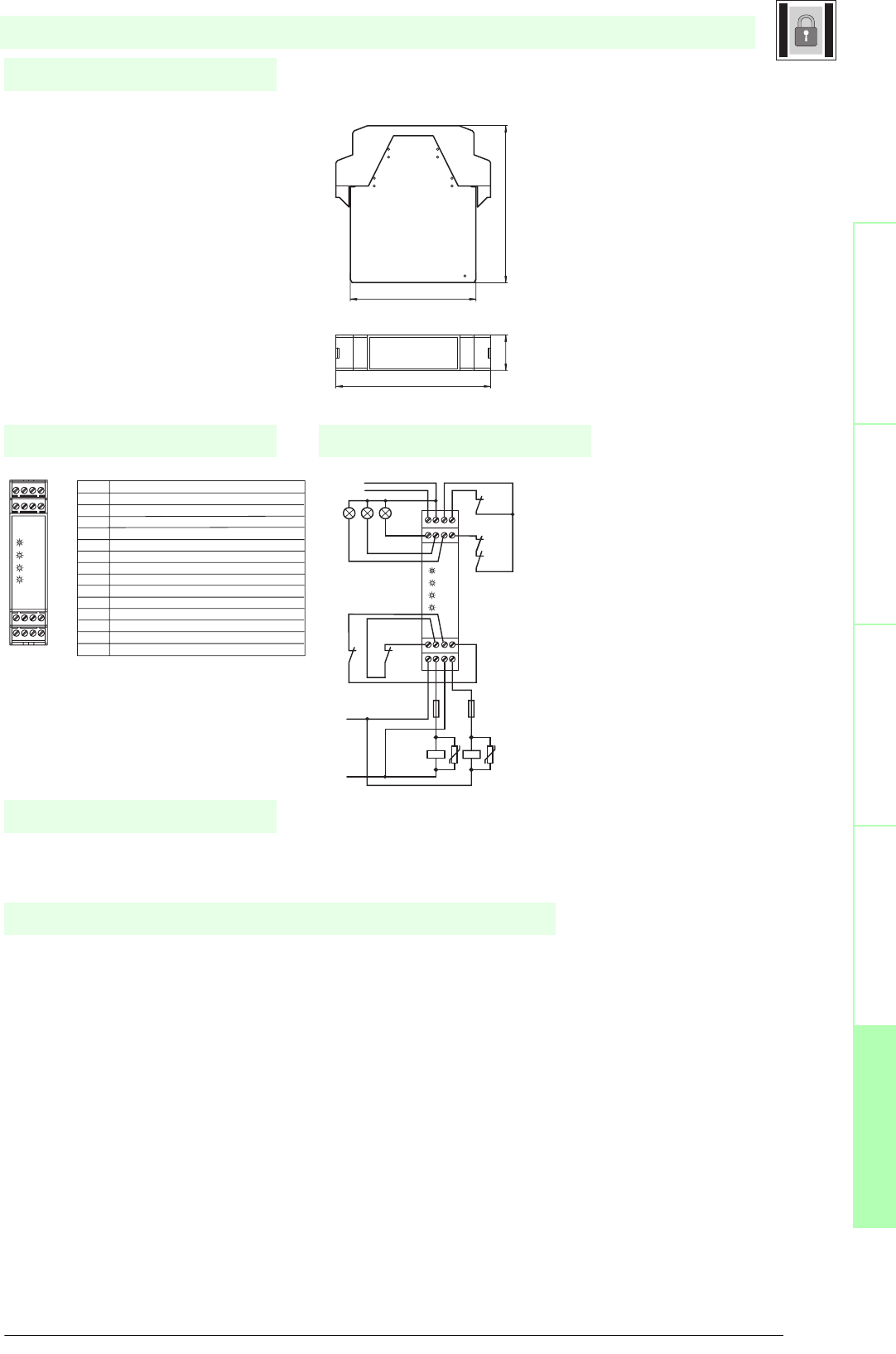
165
S
ubject to reasonable modifications due to technical advances. Copyright Pepperl+Fuchs, Printed in Germany
Pepperl+Fuchs Group • Tel.: Germany +49 621 776-0 • USA +1 330 4253555 • Singapore +65 67799091 • Internet http://www.pepperl-fuchs.com
Notes
Electrical connection
Safety through beam
sensors
Safey light gridsSafety light grids with
internal control unit
Safety light curtainsControl units
Dimensions
Connection example
This module can only be operated within an evaluation device of the SafeBox SB4 type.
The SafeBox instruction manual should be observed.
The OSSD-R/E stop module contains 2 OSSDs, the relay monitor, the restart connection and 2 connections for contact safety
signals, (e.g. emergency off button). From position 3 on, this module may exist several times in the SafeBox and may perform
different functions depending on the switch position.
The OSSDs are designed as potential free connection NO contacts. The module can be operated with or without restart inter-
lock. Also, monitoring of the externally connected switching elements can be activated (relay monitor). The OSSD On or Off
statuses are indicated via a short-circuit-proof pnp signal output. The restart output is used for indication of the start readiness
status. In the case of an error, this output oscillates with 1 Hz.
The module can work in stop function cat. 0 or cat.1.
Function
relay monitor
Restart
Terminal Function
1 Sensor 1 Out
2 Sensor 1 In
3 Sensor 2 Out
4 Sensor 2 In
5 - 6 OSSD1; potential free relay contact; normally open contact
7 - 8 OSSD2; potential free relay contact; normally open contact
9 Signal output OSSD off
10 Signal output OSSD on
11 Signal output restart
12 Relay monitor (RM)
13 +24 V DC supply voltage
14 0 V DC supply voltage
15 24 V DC connection restart and RM
16 Restart input (RI); normally closed contact
yellow
green
red
Safety
element 2
Safety
element 1
- U
+ U
OSSD
RI
I2
I1
K2.1
K1.1
OSSD
RI
I2
I1
- Urel
+ Urel
F2F1
K2K1
13 14 15 16
9 10 11 12
1 2 3 4
5 6 7 8
13 14 15 16
9 10 11 12
1 2 3 4
5 6 7 8
SafeBox module
Date of edition 05/17/2006
SB4 Module 2E
100.522.6
80.3
99
13 14 15 16
9 10 11 12
1 2 3 4
5 6 7 8
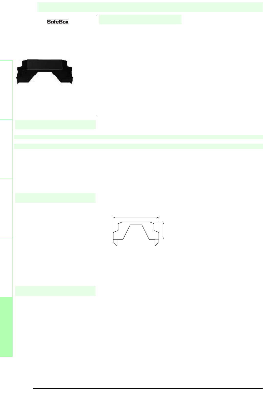
Subject to reasonable modifications due to technical advances. Copyright Pepperl+Fuchs, Printed in Germany
Pepperl+Fuchs Group • Tel.: Germany +49 621 776-0 • USA +1 330 4253555 • Singapore +65 67799091 • Internet http://www.pepperl-fuchs.com
166
Technische DatenTechnical data
Features
Safety through beam
sensors
Safety light grids
Safety light grids with
internal control unit
Safety light curtains
Control units
Dimensions
Notes
Mechanical specifications
Material Polyamide (PA)
Dimensions 99 mm x 38,5 mm x 22,6 mm
SB4 Cape
Date of edition 05/17/2006
Accessories
For suitable cable sockets, mounting aids, redirection mirrors and more refer to chapter „Accessories.
• Cover for unused plug-in stations of the Safebox
38.5
99
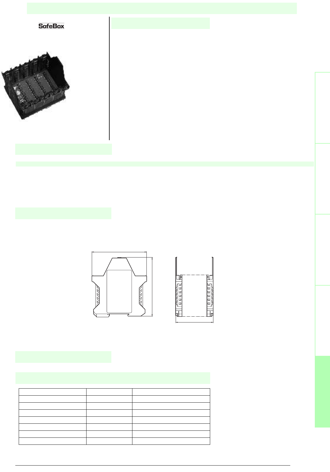
Safety through beam
sensors
Safey light grids
Safety light grids with
internal control unit
Safety light curtains
Control units
S
ubject to reasonable modifications due to technical advances. Copyright Pepperl+Fuchs, Printed in Germany
Pepperl+Fuchs Group • Tel.: Germany +49 621 776-0 • USA +1 330 4253555 • Singapore +65 67799091 • Internet http://www.pepperl-fuchs.com
Technische DatenTechnical data
Features
Dimensions
Notes
167
Mechanical specifications
Material Polyamide (PA)
SB4 Housing
Date of edition 05/17/2006
Accessories
For suitable cable sockets, mounting aids, redirection mirrors and more refer to chapter „Accessories.
• Housing of the SafeBox with backplane for completion
.
Model number
Number of plug-in stations Description Housing width (mm)
2 SB4 Housing 2 45.2
3 SB4 Housing 3 67.8
4 SB4 Housing 4 90.4
5 SB4 Housing 5 113.0
6 SB4 Housing 6 135.6
7 SB4 Housing 7 158.2
8 SB4 Housing 8 180.8
45.2 up to 180.8
2 - 8 connection sites
99
108

Accessories
Date of edition 05/17/2006
Subject to reasonable modifications due to technical advances. Copyright Pepperl+Fuchs, Printed in Germany
Pepperl+Fuchs Group • Tel.: Germany +49 621 776-0 • USA +1 330 4253555 • Singapore +65 67799091 • Internet http://www.pepperl-fuchs.com
168
Accessories
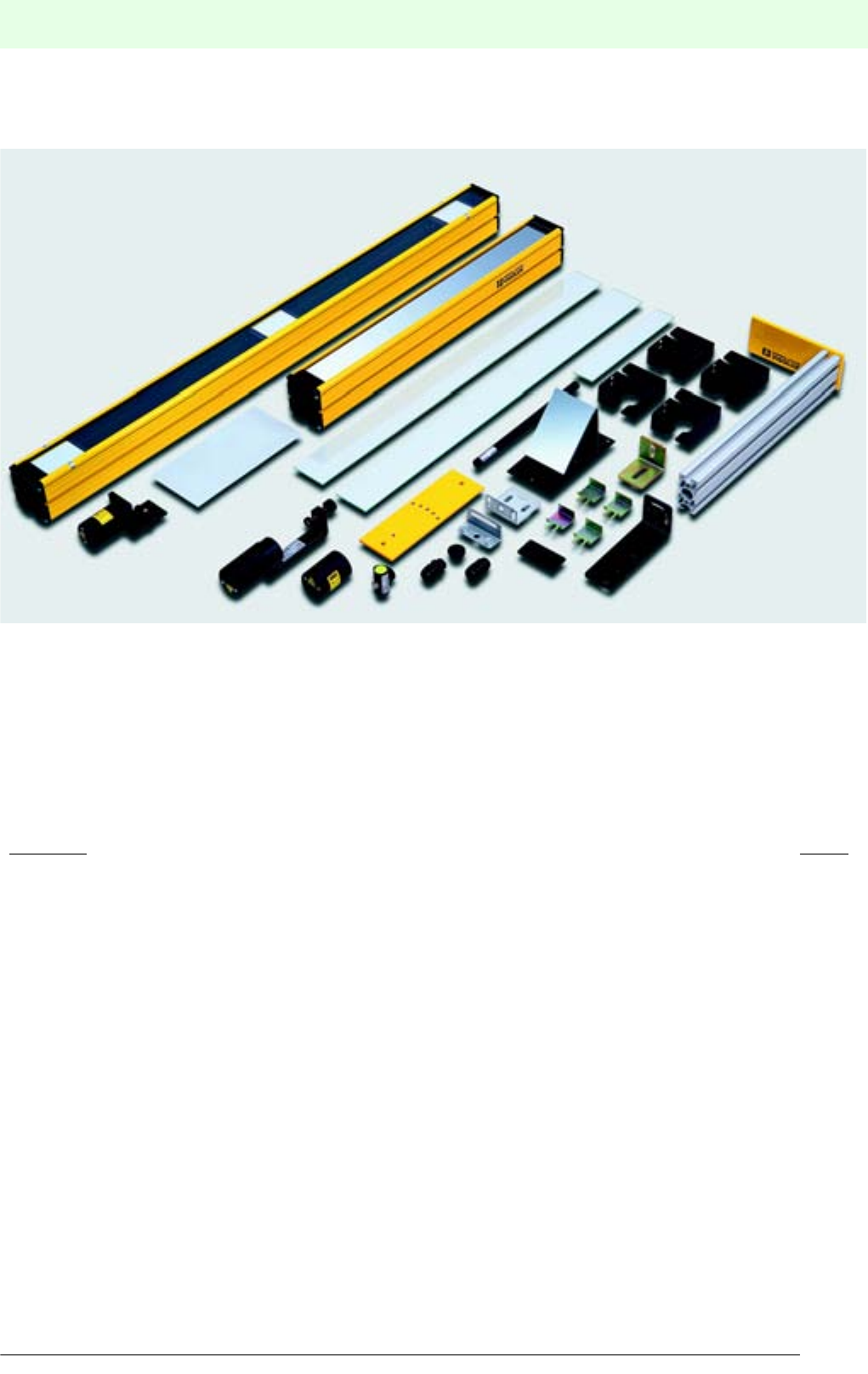
Accessories
Date of edition 05/17/2006
S
ubject to reasonable modifications due to technical advances. Copyright Pepperl+Fuchs, Printed in Germany
Pepperl+Fuchs Group • Tel.: Germany +49 621 776-0 • USA +1 330 4253555 • Singapore +65 67799091 • Internet http://www.pepperl-fuchs.com
169
Content Page
Cables and sockets . . . . . . . . . . . . . . . . . . . . . . . . . . . . . . . . . . . . . . . . . . . . . . . . . . . . . 170
Accessories overview . . . . . . . . . . . . . . . . . . . . . . . . . . . . . . . . . . . . . . . . . . . . . . . . . . . 174
Redirection mirror . . . . . . . . . . . . . . . . . . . . . . . . . . . . . . . . . . . . . . . . . . . . . . . . . . . . . . 176
Assembly aids and mounting sets . . . . . . . . . . . . . . . . . . . . . . . . . . . . . . . . . . . . . . . . . 178
Protective glass panes and holders . . . . . . . . . . . . . . . . . . . . . . . . . . . . . . . . . . . . . . . . 182
Alignment aids . . . . . . . . . . . . . . . . . . . . . . . . . . . . . . . . . . . . . . . . . . . . . . . . . . . . . . . . . 183
Other accessories. . . . . . . . . . . . . . . . . . . . . . . . . . . . . . . . . . . . . . . . . . . . . . . . . . . . . . . 184
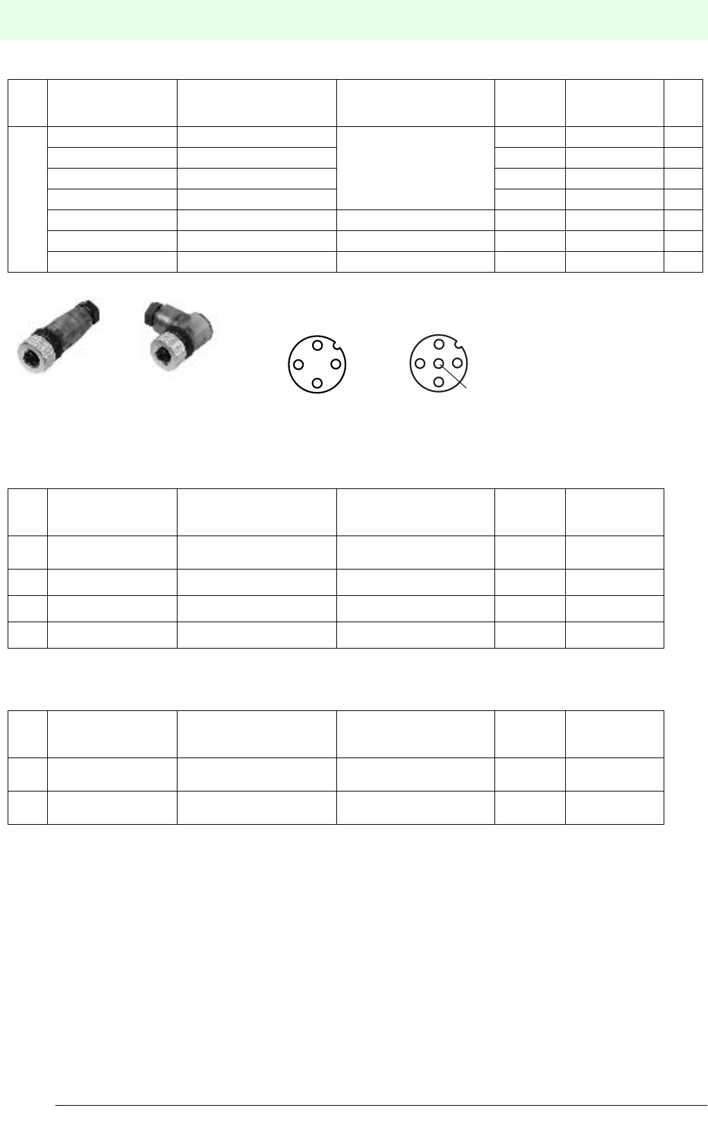
Mating connectors and cableAccessories
Date of edition 05/17/2006
Subject to reasonable modifications due to technical advances. Copyright Pepperl+Fuchs, Printed in Germany
Pepperl+Fuchs Group • Tel.: Germany +49 621 776-0 • USA +1 330 4253555 • Singapore +65 67799091 • Internet http://www.pepperl-fuchs.com
170
Mating connectors and c abl e
Pre-manufactured connector M12 for safety light barriers
Special accessories for safety light grid SLPC/SLPCM
Special accessories for safety light curtain SLC/SLP
Design
Model number Design Connector type Number of
pins
Strand size
(mm2)Fig.
M12
V1-G Socket, straight
Screw terminal, PG7 screw
4-pin max. 2.5 1
V1-W Socket, angled 4-pin max. 2.5 2
V1S-G Connector, straight 4-pin max. 2.5 -
V1S-W Connector, angled 4-pin max. 2.5 -
V1-G-Q2 Socket, straight Insulation piercing 4-pin 0.34 ... 0.75 -
V1S-G-Q2 Connector, straight Insulation piercing 4-pin 0.34 ... 0.75 -
V15-W-PG9 Socket, straight Screw terminal 5-pin max. 0.75 -
Design
Model number Design Connector type Number of
pins
Strand size
(mm2)
M12
V1S-WM-VIS Connector, angled Mains plug without cablel 4-pin max. 2.5
V15S-WM-VIS Connector, angled Mains plug without cablel 5-pin max. 2.5
V1S-WM-2M-PUR-VIS Connector, angled Right angle plug with cable 4-pin max. 2.5
V15S-WM-2M-PUR-VIS Connector, angled Right angled plug with cable 5-pin 0.34 ... 0.75
Design
Model number Design Connector type Number of
pins
Strand size
(mm2)
M12
V17...... Connector, straight Insulation piercing 8-pin max. 2.5
M18
V16 ...... Socket, straight Insulation piercing 6-pin max. 2.5
Fig. 1 Fig. 2
Plug connector -V1
(Circular connection M12)
1
42
3
Plug connector -V15
(Circular connection M12)
1
42
35
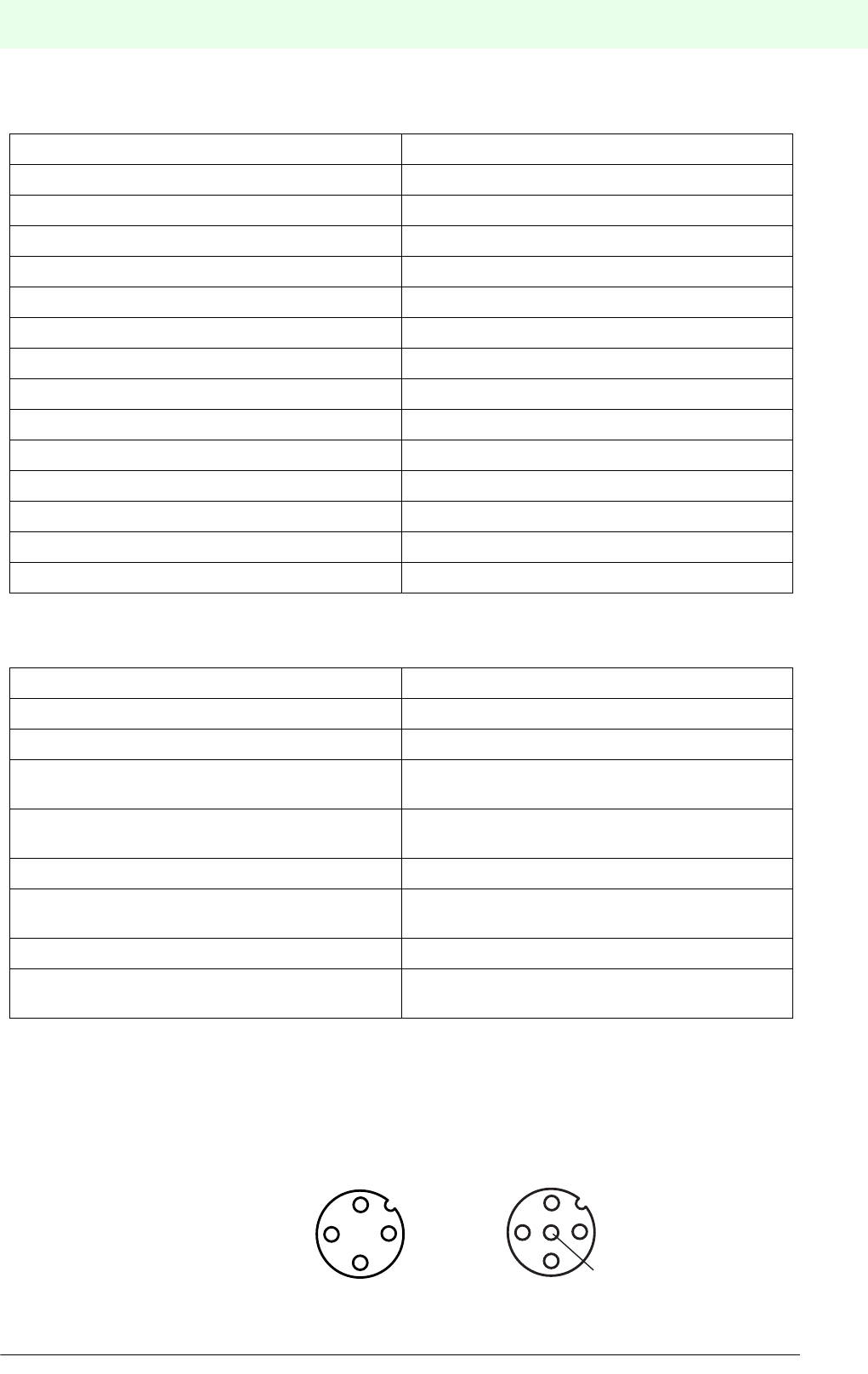
Mating connectors and cableAccessories
Date of edition 05/17/2006
Subject to reasonable modifications due to technical advances. Copyright Pepperl+Fuchs, Printed in Germany
Pepperl+Fuchs Group • Tel.: Germany +49 621 776-0 • USA +1 330 4253555 • Singapore +65 67799091 • Internet http://www.pepperl-fuchs.com
171
Technical data for connectors with sprayed cables
Male and female connectors
Cable
1) Please note reduced mechanical values for PUR cables at temperatures over +80 °C.
Strand colours and plug layout (EN 60947-5-2)
Colour allocation of pre-
manifactured cable sockets V1, V15:
Pin Colour Abbreviation
1BrownBN
2WhiteWH
3BlueBU
4BlackBK
5GreyGR
Number of pins 4 or 5 pins
Locking Screw lock
Self-locking via O-ring in cap nut
Grip color green
Grip material PUR
Contact material CuSn/Au
Contact surface material Au
Cap nut material CuSn/Ni
Gasket material NBR
DIN 40050 protection class IP68 when screwed down
Max. operating voltage 60 V DC or 250 V AC (for V13-... types)
Max. operating current 4A
Volume resistance < 5 mΩ
Insulation resistance as specified in VDE 0295
Test voltage 1500 Veff. AC, 50 Hz
Cable structure fine wire, flexible
Wire size Cables for M12 connection: 0.34 mm2
Sleeve colour black
Temperature range for PVC cables moving: -5 °C to +70 °C
non-moving: -30 °C to +80 °C
Temperature range for PUR cables 1) moving: -5 °C to +70 °C
non-moving: -30 °C to +100 °C
Minimum permissible bending radius > 10 x cable diameter
Sheath diameter ∅4.8 mm for 4 pin design
∅5.2 mm for 5 pin design
Strand insulation material PVC
Wire colours as specified in VDE 293 4-pin BN, BU, BK, WH
5-pin BN, BU, BK, WH, GR
Plug connector -V1
(Circular connection M12)
1
42
3
Plug connector -V15
(Circular connection M12)
1
42
35
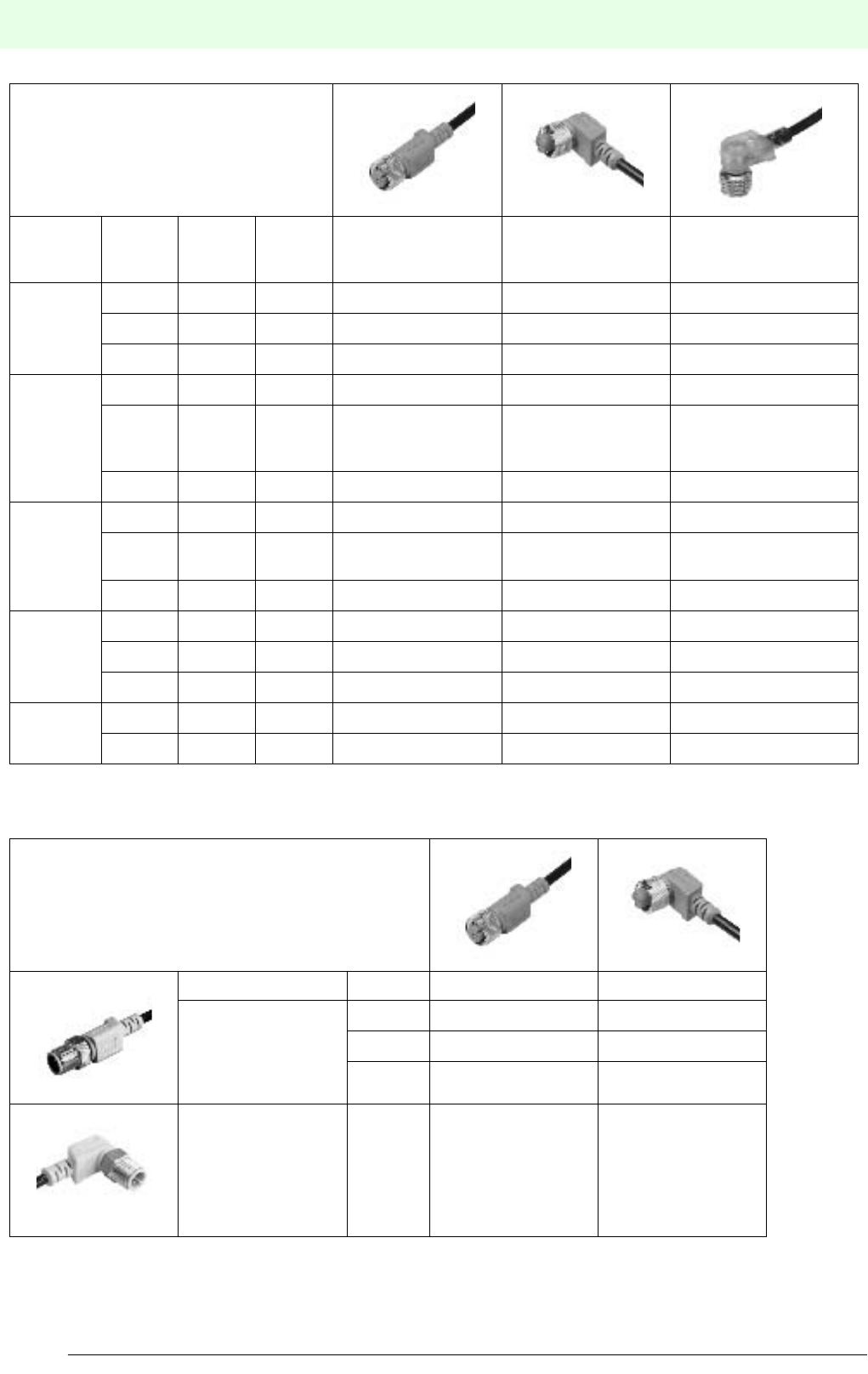
Mating connectors and cableAccessories
Date of edition 05/17/2006
Subject to reasonable modifications due to technical advances. Copyright Pepperl+Fuchs, Printed in Germany
Pepperl+Fuchs Group • Tel.: Germany +49 621 776-0 • USA +1 330 4253555 • Singapore +65 67799091 • Internet http://www.pepperl-fuchs.com
172
Plugs in M12 style for DC sensors
For pin layout see page Seite 171
M12 connection cable in PUR 4 x 0.34 mm2, sleeve colour black
For pin layout see page 171
These connector cables can be used together with 2-, 3-, and 4-wire DC proximity switches.
Suitable for 2-, 3-, and
4-wire DC sensors
Cable
sheath Length
Numbe
r of
strands
Ø
(mm2)
Design
straight
Design
angled
Design
angled
with 2 LEDs
PVC,
black
2 m 4 0.34 V1-G-2M-PVC V1-W-2M-PVC
5 m 4 0.34 V1-G-5M-PVC V1-W-5M-PVC
10 m 4 0.34 V1-G-10M-PVC V1-W-10M-PVC
PUR,
black
2 m 4 0.34 V1-G-2M-PUR V1-W-2M-PUR V1-W-A2-2M-PUR
5 m 4 0.34 V1-G-5M-PUR V1-W-5M-PUR
V1-W-A2-5M-PUR
V1-A0-5M-PUR
V1-W-E2/E3-5M-PUR
10 m 4 0.34 V1-G-10M-PUR V1-W-10M-PUR V1-W-A2-10M-PUR
PUR,
black
2 m 3 0.34 V1-W-E2-2M-PUR
5 m 3 0.34 V1-W-E2-5M-PUR
V1-W-E-5M-PUR
10 m 3 0.34 V1-W-E2-10M-PUR
PVC,
black
2 m 5 0.34 V15-G-2M-PVC V15-W-2M-PVC
5 m 5 0.34 V15-G-5M-PVC V15-W-5M-PVC
10 m 5 0.34 V15-G-10M-PVC V15-W-10M-PVC
PUR,
black
2 m 5 0.25 V15-W-2M-PUR
5 m 5 0.25 V15-W-5M-PUR
Suitable for
all 2-, 3-, and 4-wire DC sensors
Length Socket, straight Socket, angled
1 m V1-G-1M-PUR-V1-G V1-W-1M-PUR-V1-G
Connector, straight 2 m V1-G-2M-PUR-V1-G V1-W-2M-PUR-V1-G
5 m V1-G-5M-PUR-V1-G V1-W-5M-PUR-V1-G
Connector, angled 1 m - V1-W-1M-PUR-V1-W
Mating connectors and cableAccessories
Date of edition 05/17/2006
S
ubject to reasonable modifications due to technical advances. Copyright Pepperl+Fuchs, Printed in Germany
Pepperl+Fuchs Group • Tel.: Germany +49 621 776-0 • USA +1 330 4253555 • Singapore +65 67799091 • Internet http://www.pepperl-fuchs.com
173
V1-W-2M-PVC – Cable material
– Cable length
– Cable outlet
– Connection type
–PVC
–PUR
–2 m
–5 m
– other lengths on request
– W angled
– G straight
– WM angled, cap nut
– WR angled, ratchet lock
– GR straight, ratchet lock
– V1 M12 x 1, 4-pin, DC
– V1S M12 x 1, 4-pin, DC, connector
– V15 M12 x 1, 5-pin, DC
Model key for cable sockets
Connection cable type key
V1-G-5M-PUR-V1-G –G straight
– W angled
– V1 plug M12 x 1, 4 pin
– Cable material
– Cable length
–G straight
– W angled
– V1 socket M12 x 1, 4 pin
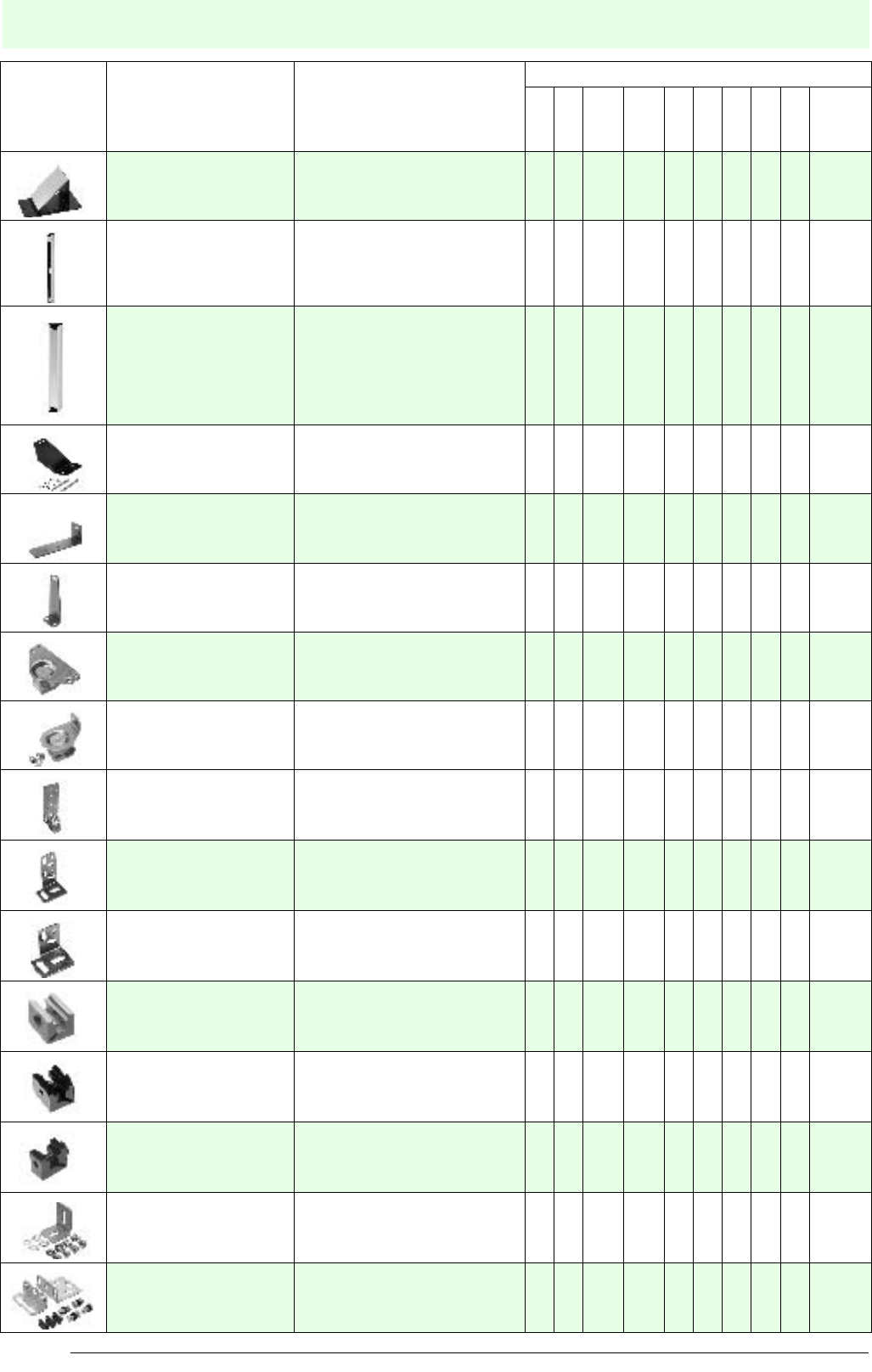
OverviewAccessories
Date of edition 05/17/2006
Subject to reasonable modifications due to technical advances. Copyright Pepperl+Fuchs, Printed in Germany
Pepperl+Fuchs Group • Tel.: Germany +49 621 776-0 • USA +1 330 4253555 • Singapore +65 67799091 • Internet http://www.pepperl-fuchs.com
174
Overview
Illustration Description Order number: Series
SL
SLA
SL12
SLA12
SL29
SLA29
SLA40
SLP
SLPC
SLPCM
SLC
SLC-2
SLC-3
SLC-4
Mirror 1 beam SLA-1-M O O O O O
Mirror multiple beam
SLP-2-M
SLP-3-M
SLP-4-M
OOO
Mirror multiple beam
SLC-350-M
SLC-500-M
SLC-800-M
SLC-1000-M
SLC-1300-M
SLC-1600-M
O O
Assembly aid OMH-21 O
Assembly aid OMH-22 O
Assembly aid OMH-40 O
Assembly aid OMH-05 O
Assembly aid OMH-06 O
Assembly aid OMH-07 O
Assembly aid OMH-MLV12-HWG O
Assembly aid OMH-MLV12-HWK O
Assembly aid OMH-MLV11-K O
Assembly aid OMH-K01 O
Assembly aid OMH-K02 O
Mounting set MS SLC OO
Mounting set MS SLP O O O
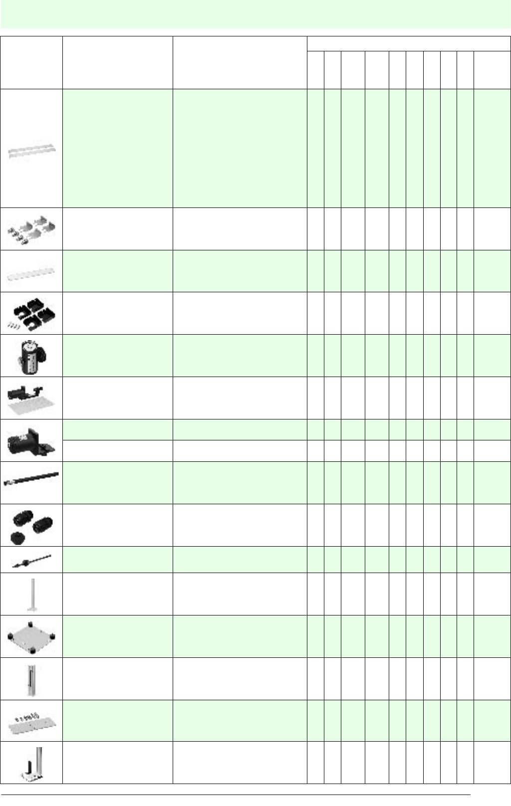
OverviewAccessories
Date of edition 05/17/2006
S
ubject to reasonable modifications due to technical advances. Copyright Pepperl+Fuchs, Printed in Germany
Pepperl+Fuchs Group • Tel.: Germany +49 621 776-0 • USA +1 330 4253555 • Singapore +65 67799091 • Internet http://www.pepperl-fuchs.com
175
Illustration Description Order number: Series
SL
SLA
SL12
SLA12
SL29
SLA29
SLA40
SLP
SLPC
SLPCM
SLC
SLC-2
SLC-3
SLC-4
Protective glass panes
SLC
PG SLC-150
PG SLC-300
.
.
.
.
.
PG SLC-1650
PG SLC-1800
O O
Holder for protective
glass panes PG Holder SLC OO
Protective glass panes
SLP
PG SLP-2
PG SLP-3
PG SLP-4
O
Holder for protective
glass panes PG Holder SLP O
Profile alignment aid PA SLP/SLC O O O O O
Laser alignment aid BA SLA28 O
Laser alignment aid BA SLP O O O
Laser alignment aid BA SLC OO
Test rods
TR SLC14
TR SLC30
TR SLC60
O
Screw connection TC SLC(M16) OO
Cable ties Binder SLPC/M O O O O O
Floor stand UC SLP/SLC
UC SLP/SLC 1530 mm OOOO O
Start-up protection Damping UC SLP/SLC O O O O O
Housing Enclosure UC SLP/SLC OOOO O
Muting mounting set MS SLP/SLA28 O
Muting mounting set MS SLPCM OO
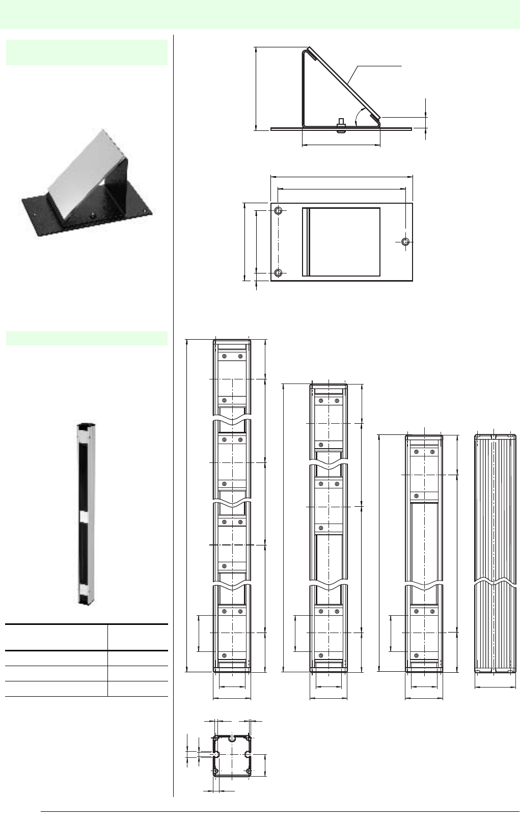
Redirection mirrorAccessories
Date of edition 05/17/2006
Subject to reasonable modifications due to technical advances. Copyright Pepperl+Fuchs, Printed in Germany
Pepperl+Fuchs Group • Tel.: Germany +49 621 776-0 • USA +1 330 4253555 • Singapore +65 67799091 • Internet http://www.pepperl-fuchs.com
176
R edirection mir ror
Redirection mirror for one beam
redirection of the protection beam of
safety light barriers SL and SLA.
Redirection mirror for multi-directional
protection of danger areas using our
safety light grids SLP, SLPC and
SLPCM
Mirror 1 beam for SLA
SLA-1-M
Mirror for SLP/SLC
Model number Number of
beams
SLP-2-M 2
SLP-3-M 3
SLP-4-M 4
approx. 86.5
Mirror 103 x 70
3x Thread M
10.5
80
64
8
146
131
80
45˚
9.5
10.5
6.5
5.5
300
300
300
400
400
636
1036
936
68
68
60
70
64
46
68
68
60
38
2
64
46
68
60
64
46
500
68
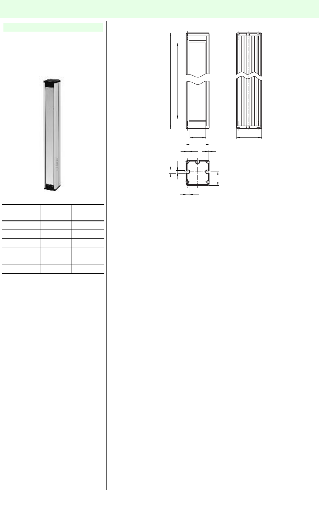
Redirection mirrorAccessories
Date of edition 05/17/2006
S
ubject to reasonable modifications due to technical advances. Copyright Pepperl+Fuchs, Printed in Germany
Pepperl+Fuchs Group • Tel.: Germany +49 621 776-0 • USA +1 330 4253555 • Singapore +65 67799091 • Internet http://www.pepperl-fuchs.com
177
Redirection mirror for multi-directional
protection of danger areas using our
safety light curtains SLC and safety light
grids SLP-2, SLP-3 and SLP-4.
Mirror for SLC / SLP
Order
number
Mirror
height H
Housing
length L
SLC-350-M 350 mm 406 mm
SLC-500-M 500 mm 556 mm
SLC-800-M 800 mm 856 mm
SLC-1000-M 1000 mm 1056 mm
SLC-1300-M 1300 mm 1356 mm
SLC-1600-M 1600 mm 1656 mm
Height of mirror H
9.5
10.5
6.5
5.5
70
38
2
64
44
H + 56
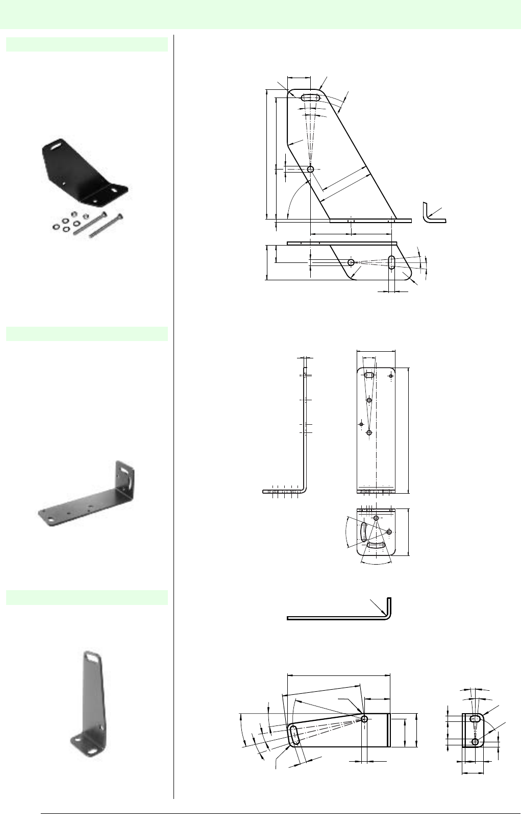
Assembly aids and mounting setsAccessories
Date of edition 05/17/2006
Subject to reasonable modifications due to technical advances. Copyright Pepperl+Fuchs, Printed in Germany
Pepperl+Fuchs Group • Tel.: Germany +49 621 776-0 • USA +1 330 4253555 • Singapore +65 67799091 • Internet http://www.pepperl-fuchs.com
178
A ssembly aids and mount ing sets
Suitable for safety light barriers
•SLA28
• SL29, SLA29
Material: Anodised aluminium
Mounting angle for safety light barriers
of series SLA28 / SL29 / SLA29
mainly for installation on aluminium
profile (see muting set MS SLPCM on
page 186).
Material: Aluminium, black anodised
Mounting angle for safety light barriers
of series SLA40.
Material: Nickel-plated sheet metal
Installation aid OMH-21
Installation aid OMH-22
Installation aid OMH-40
5.3
R3.5
5.3
5.3
5.3
15
30
50
43
112
62
43
60˚
3
35 35
20
R10
5˚
R10
R10
R6
5˚
R6
5˚
5˚
40˚
50 135
44
310˚
40˚
4.3
19.5
23.5
4.3
49.9
54.2
71.1
4.3
4.3
3.7
6
2
15
18
R4
R2
R4
R16
R4
R4
8˚
13˚
5˚
5˚
5˚
5˚
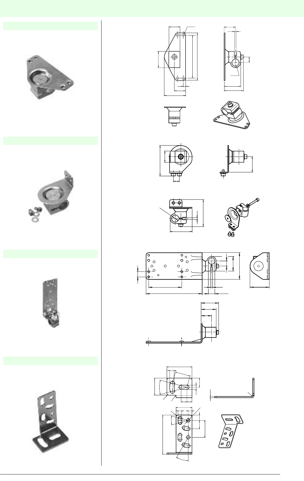
Assembly aids and mounting setsAccessories
Date of edition 05/17/2006
S
ubject to reasonable modifications due to technical advances. Copyright Pepperl+Fuchs, Printed in Germany
Pepperl+Fuchs Group • Tel.: Germany +49 621 776-0 • USA +1 330 4253555 • Singapore +65 67799091 • Internet http://www.pepperl-fuchs.com
179
Assembly aid for safety light barriers of
series SLA28, SL29 and SLA29
Material:
Top: Sheet metal
Clamping block:Aluminium
Assembly aid for safety light barriers of
series SLA12 and SL12
Material:
Top: Sheet metal
Clamping block:Aluminium
Assembly aid for safety light barriers
Material:
Top: Sheet metal
Clamping block:Aluminium
Mounting angle, large, for safety light
barriers of series SL12 and SLA12
Material: Nickel-plated sheet metal
Installation aid OMH-05
Installation aid OMH-06
Installation aid OMH-07
Assembly aid OMH-MLV12-HWG
27.6
9.5
3.2
ø 12.2
19.1
27,5
32
4
M4 (4x)
19
36
81
73
19
26
51.5
19
ø12.2
37
10
3.2
45.5
30
18
R2
5.3
19
4.5
4.3
6.5
10
30˚
76
20.5
30˚
5.1
11
1.5
R0,5
R1
30˚
46.5
R2
ø4.1
20
ø 12.2
27.5
9.5
3.2
32.9
28.1
19.6
9.7
50
36
105
62
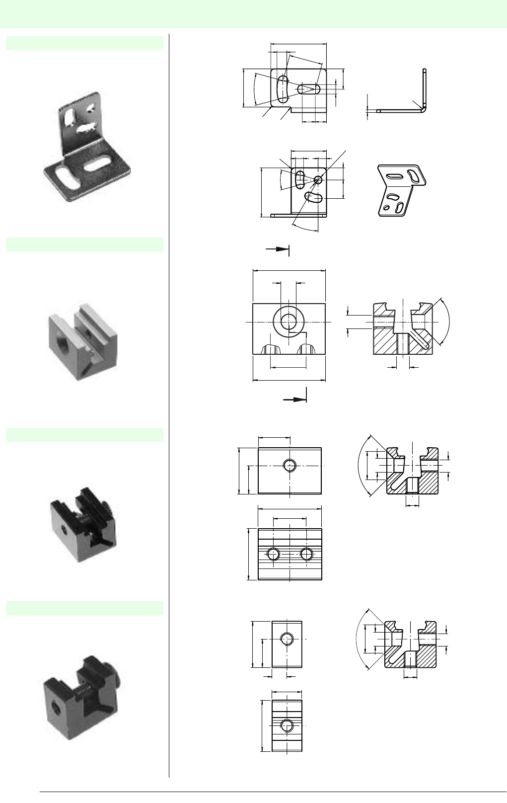
Assembly aids and mounting setsAccessories
Date of edition 05/17/2006
Subject to reasonable modifications due to technical advances. Copyright Pepperl+Fuchs, Printed in Germany
Pepperl+Fuchs Group • Tel.: Germany +49 621 776-0 • USA +1 330 4253555 • Singapore +65 67799091 • Internet http://www.pepperl-fuchs.com
180
Mounting angle, small, for safety light
barriers of series SL12 and SLA12
Material: Nickel-plated sheet metal
Clamping body for safety light barriers of
series SLA28, SL29 and SLA29
Material: Aluminium
Clamping body for safety light barriers of
series SL12 and SLA12
Material: Anodised aluminium
Clamping body for safety light barriers of
series SL12 and SLA12
Material: Anodised aluminium
Assembly aid OMH-MLV12-HWK
OMH-MLV11-K
Installation aid OMH-K01
Installation aid OMH-K02
30
18
R2
5.3
19
4.5
4.3
6.5
10
30˚
26.5
76
20.5
30˚
5.1
11
1.5
R0,5
R1
30˚
R2
ø4.1
90˚
M4
M4
ø8.5
ø4.2
20
10
M4
M4
ø8.5
ø4.2
90˚
15.5 8.6
14
9.5
19
10
M4
M4
ø8.5
ø4.2
4.5
9
15.5 8.6
14
90˚
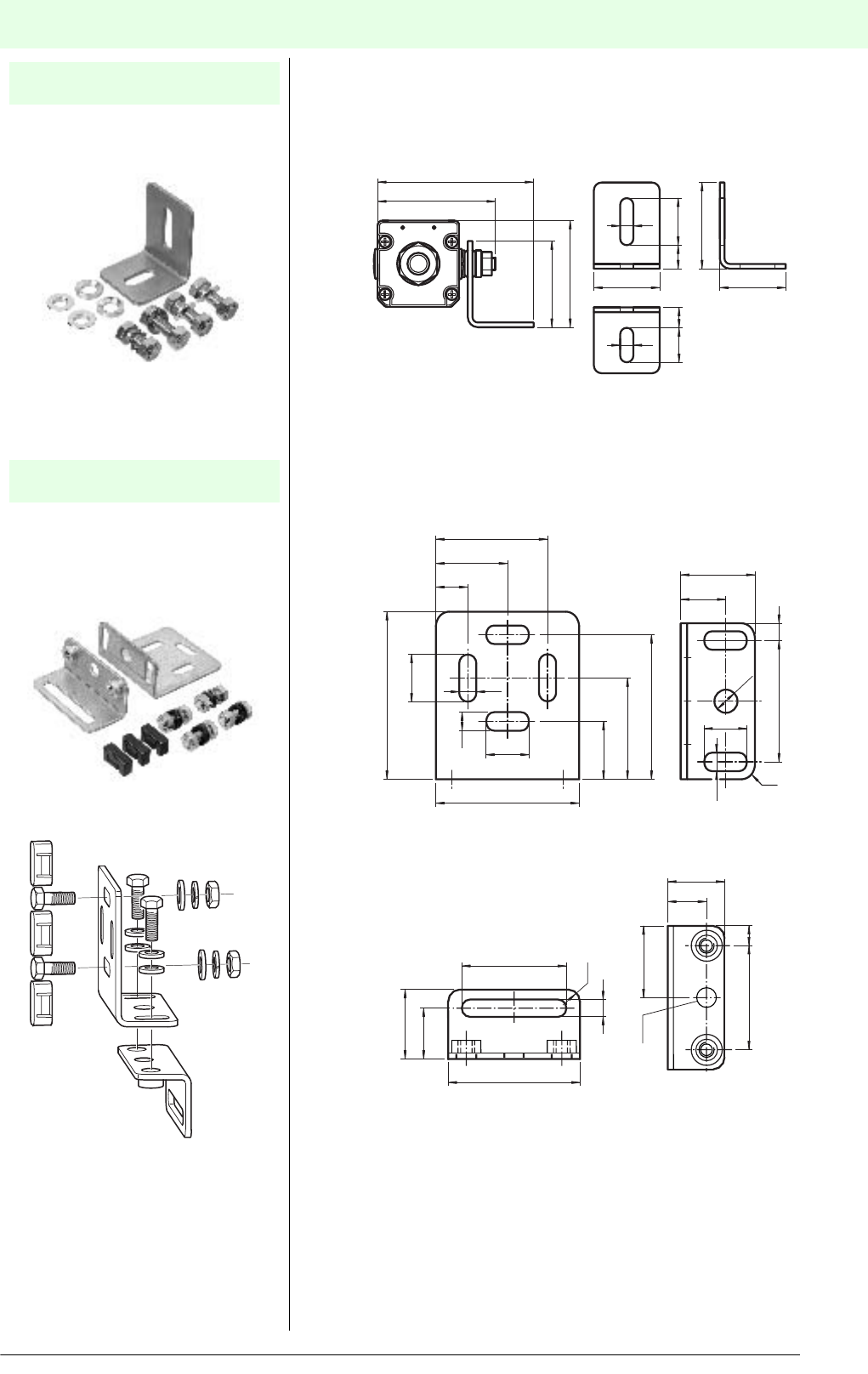
Assembly aids and mounting setsAccessories
Date of edition 05/17/2006
S
ubject to reasonable modifications due to technical advances. Copyright Pepperl+Fuchs, Printed in Germany
Pepperl+Fuchs Group • Tel.: Germany +49 621 776-0 • USA +1 330 4253555 • Singapore +65 67799091 • Internet http://www.pepperl-fuchs.com
181
Mounting angle for safety light curtains
SLC and safety light grids SLC.
Material: Nickel-plated sheet metal
Mounting kit for safety light grids SLP,
SLPC and SLPCM and mirrors for SLP
and mirrors for SLC.
Material: Nickel-plated sheet metal
Mounting set
MS SLC
Mounting set
MS SLP
55
55-68
55
13
22 30
15
8.4
8.4
4242
77
102
20.5
ø 8.5
8
42
17
25
29
7
R5
58
28
46
ø 8.5
42 6
16.4
28
17
6.4
6.4
16.4
54
50
35
20
58
16.4
42
27
12
R5
6.4
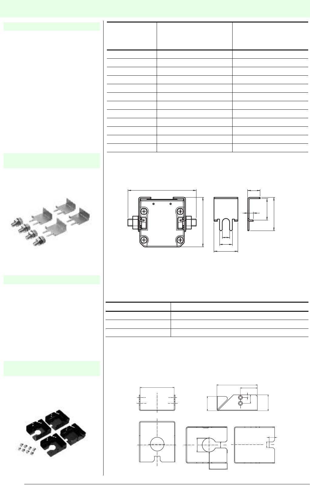
Protective glass panes and holderAccessories
Date of edition 05/17/2006
Subject to reasonable modifications due to technical advances. Copyright Pepperl+Fuchs, Printed in Germany
Pepperl+Fuchs Group • Tel.: Germany +49 621 776-0 • USA +1 330 4253555 • Singapore +65 67799091 • Internet http://www.pepperl-fuchs.com
182
Protective gla ss panes and hol der
Mineral glass panes for the protection of
the light emission area of safety light
curtains (Example: Use near welding
robots to protect against sparks).
One packing unit contains 2 glass panes
(one each for sender and receiver).
Above 1050 mm protection field height
the protective glass panes are divided.
For the attachment of the protective
glass panes protective glass holder SLC
is required.
Support angle for installing the
protective glass panes at our safety light
curtains SLC.
The required number of packing units
can be found in the table above.
Material: Nickel-plated sheet metal
Mineral glass panes for the protection of
the light emission area of safety light
grids SLP
(Example: Use near welding robots to
protect against sparks).
One packing unit contains 2 glass panes
(one each for sender and receiver).
For the attachment of the protective
glass panes protective glass holder SLP
is required.
Support angle for installing the
protective glass panes at our safety light
grids SLP.
Material: Nickel-plated sheet metal
Protective glass panes for SLC
Holder for protective glass
panes PG Holder SLC
Protective glass panes for SLP
Holder for protective glass
panes PG Holder SLP
Safety light
curtain
Order number of
corresponding protective
glass pane
Recommended number of
protective glass holders
SLC
(both sender and receiver)
SLCxx-150... PG SLC-150 2*
SLCxx-300... PG SLC-300 2*
SLCxx-450... PG SLC-450 2*
SLCxx-600... PG SLC-600 3*
SLCxx-750... PG SLC-750 3*
SLCxx-900... PG SLC-900 3*
SLCxx-1050... PG SLC-1050 5*
SLCxx-1200... PG SLC-1200 5*
SLCxx-1350... PG SLC-1350 5*
SLCxx-1500... PG SLC-1500 5*
SLCxx-1650... PG SLC-1650 6*
SLCxx-1800... PG SLC-1800 6*
7
28
15
9
15
80
58
25
39
Material strength 1.5
Safety light grids Order number of corresponding protective glass
SLPxx-2 PG SLP-2
SLPxx-3... PG SLP-3
SLPxx-4... PG-SLP-4
76.5
64.6
10.5
16
32
30
1
27
5
1
26
33.5
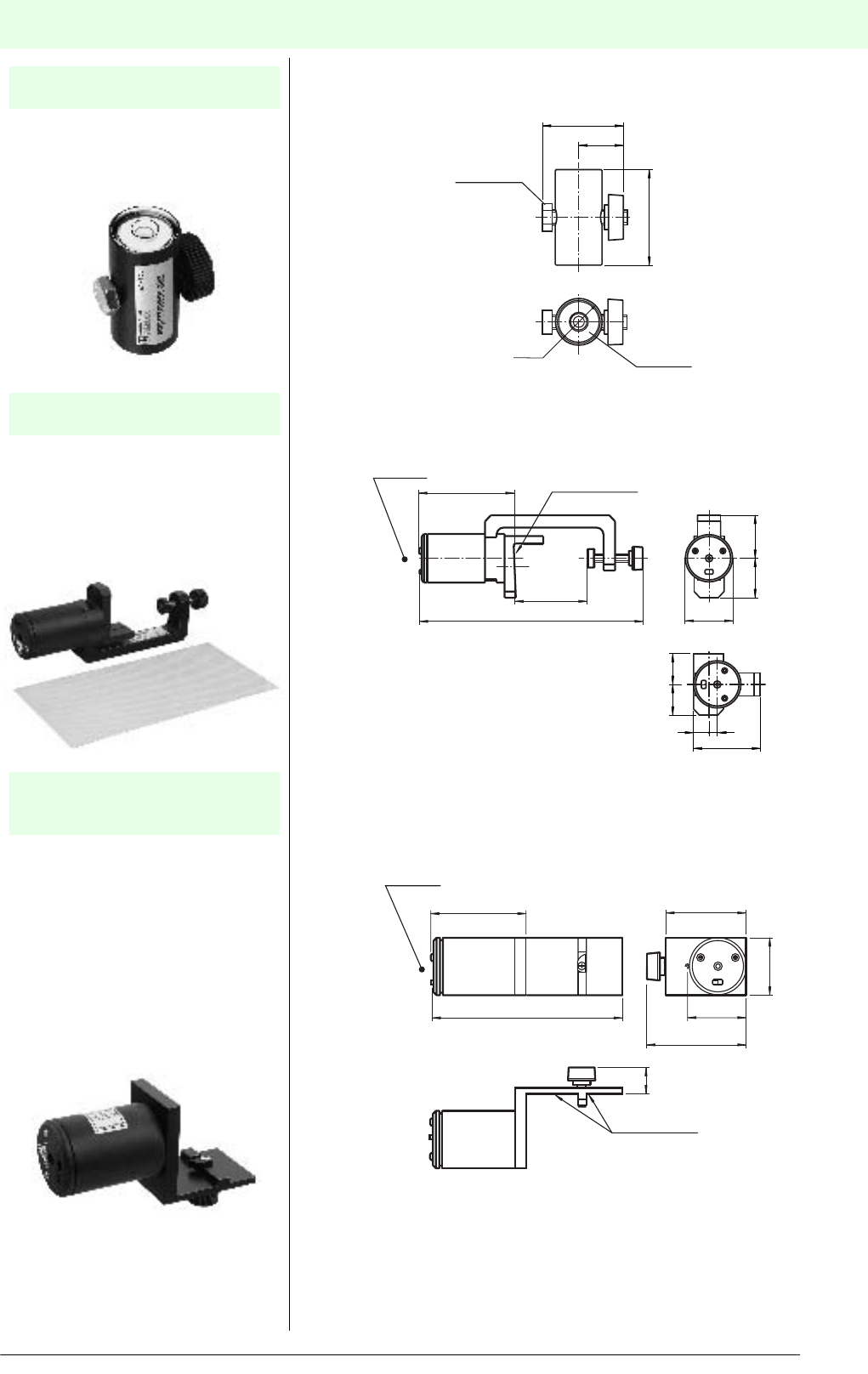
Alignment aidsAccessories
Date of edition 05/17/2006
S
ubject to reasonable modifications due to technical advances. Copyright Pepperl+Fuchs, Printed in Germany
Pepperl+Fuchs Group • Tel.: Germany +49 621 776-0 • USA +1 330 4253555 • Singapore +65 67799091 • Internet http://www.pepperl-fuchs.com
183
Alignment aids
This small spirit level is ideal for aligning
the profiles of product groups SLP and
SLC vertically and horizontally.
Laser alignment aid for safety light
barriers of series SLA28, SL29 and
SLA29
Included in the scope of delivery are the
base unit, the corresponding adapter
and the foil reflector.
Laser alignment aid for safety light grids
and safety light curtains in the profiles
SLP and SLC.
Included in the scope of delivery are the
base unit and the corresponding
adapter.
Dimensions:
Laser alignment aid SLP: L = 131 mm
Laser alignment aid SLC: L = 117 mm
Profile alignment aid
PA SLP/SLC
Laser alignment aid
BA SLA28
Laser alignment aid
BA SLP
BA SLC
Socket level
ø 19.5
34
40
19
M6x30 (SW10)
System surface for
SLA25 housing
Laser beam
Stirrup 90˚ rotated
39.6
80.9
55
13 7
25
25
35
32
181 ... 201
52 ... 72
System surface for
SLC or SLP profile
Laser beam
ø 39.6
63.7
17
69
40
56
L
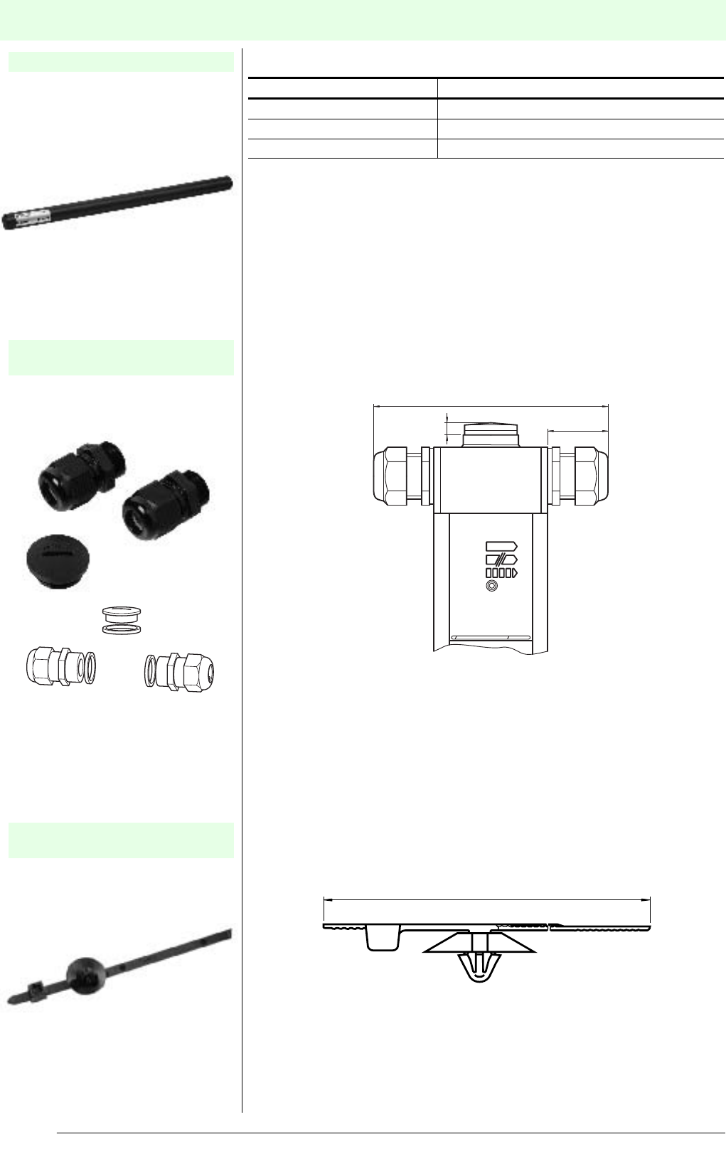
MiscellaneousAccessories
Date of edition 05/17/2006
Subject to reasonable modifications due to technical advances. Copyright Pepperl+Fuchs, Printed in Germany
Pepperl+Fuchs Group • Tel.: Germany +49 621 776-0 • USA +1 330 4253555 • Singapore +65 67799091 • Internet http://www.pepperl-fuchs.com
184
Misce llaneous
Test rods for checking the resolution of
our safety light curtains.
Material: plastic
M16 screw connection for the lateral
cable feed to safety light curtains SLC.
Included in the scope of delivery are
2 screw connections and 1 blind cap.
Cable ties for the fastening and safe
laying of connection cables, especially
the connected muting sensors
Length L: 180 mm
Packing unit: 10 pieces
Test rods for SLC
Lateral screw connection
TC SLC(M16)
Cable ties
Binder SLPC/M
Safety light curtain Order number of the required test rod
SLC14-... TR SLC14
SLC30-... TR SLC30
SLC60-... TR SLC60
VISOLUX
5
28
108
L
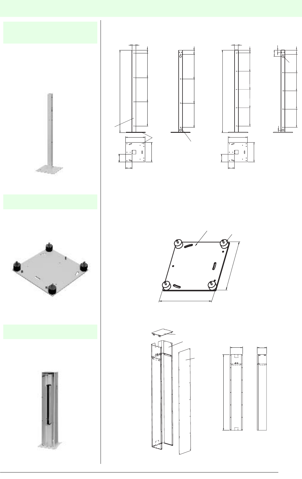
MiscellaneousAccessories
Date of edition 05/17/2006
S
ubject to reasonable modifications due to technical advances. Copyright Pepperl+Fuchs, Printed in Germany
Pepperl+Fuchs Group • Tel.: Germany +49 621 776-0 • USA +1 330 4253555 • Singapore +65 67799091 • Internet http://www.pepperl-fuchs.com
185
Floor stand for all SLP/SLC variants.
Height: 1186 mm
Order number: UC SLP/SLC
Height: 1530 mm
Order number: <NewLine/>UC SLP/
SLC 1530 mm
The mounting set is included in the
scope of delivery.
Oscillation damper as start-up
protection for floor stand UC SLP/SLC
for all SLP/SLC variants.
The mounting set is included in the
scope of delivery.
Housing for floor stand.
Suited for all SLP/SLC variants with a
maximum protection field height of 1050
mm.
Illustration with light grid and stand
Floor stand
UC SLP/SLC
UC SLP/SLC 1530 mm
Start-up protection
Damping UC SLP/SLC
Housing
Enclosure UC SLP/SLC
Ground plate
Profile
9 mm bore hole (8x)
93.5
120
300
300
1186
45
395
745
1095
60
410
760
1110
60
00
93.5
120
300
300
1530
45
350
350
350
60
350
350
350
60
00
350
350
90
30
30
ø 30
Ground plate Shock absorber
300
300
Cover
Glass
Housing
1300
173
228
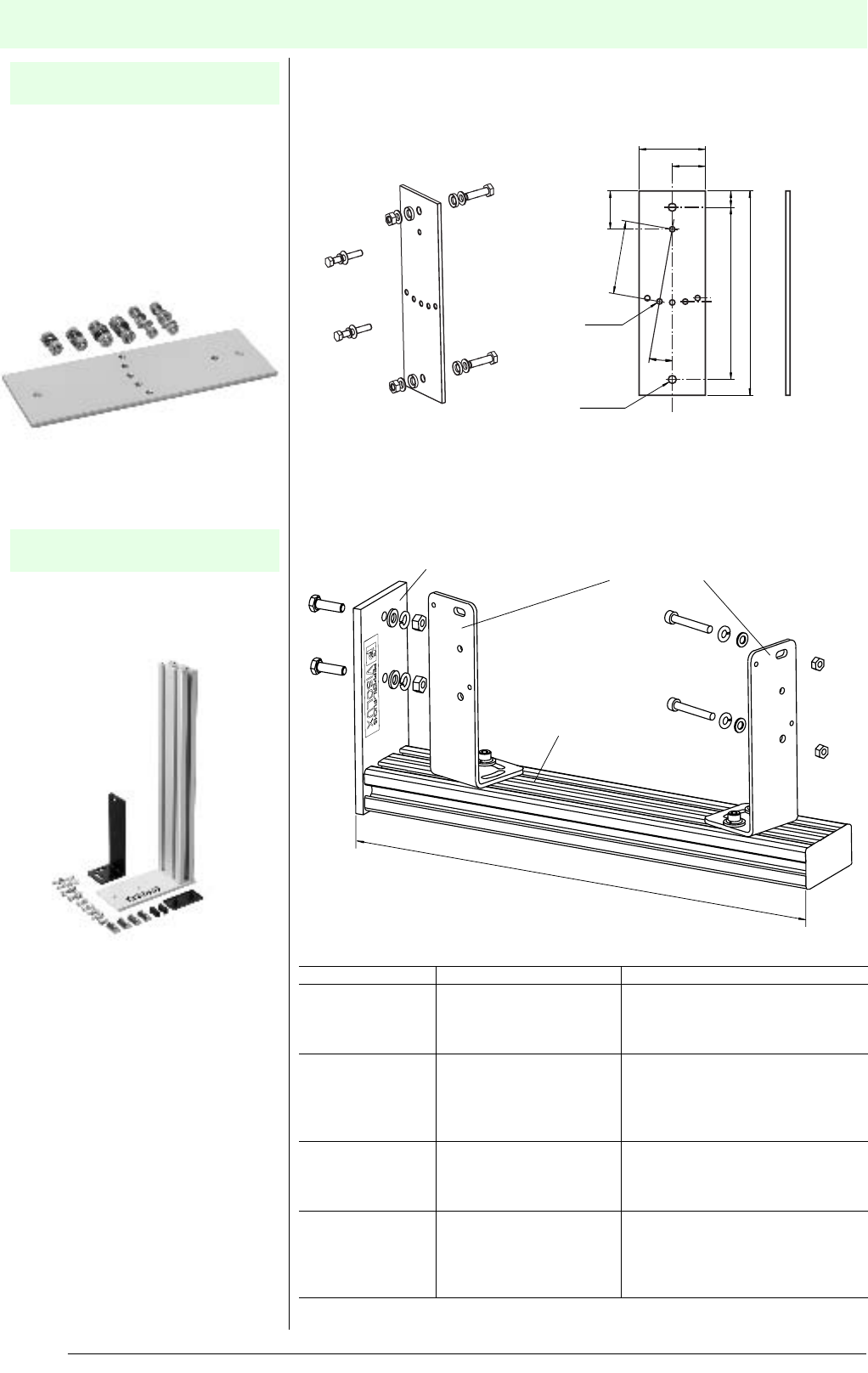
MiscellaneousAccessories
Date of edition 05/17/2006
Subject to reasonable modifications due to technical advances. Copyright Pepperl+Fuchs, Printed in Germany
Pepperl+Fuchs Group • Tel.: Germany +49 621 776-0 • USA +1 330 4253555 • Singapore +65 67799091 • Internet http://www.pepperl-fuchs.com
186
Sheet metal for Mounting the safety light
barriers SLA28 to the profiles of the
safety light grids SLP for the operating
mode muting.
Material: Sheet metal
Surface: Powder coating, yellow
RAL 1021
Supplied with fixings
Mounting angle for muting applications
with light grids SLPCM for the operating
mode muting.
Only a single assembly aid OMH-22 is
included in the scope of delivery.
Muting Set
MS SLP/SLA28
Muting Set
MS SLPCM
ø6.4 (2x)
M5 (6x)
157 15
187
35
30
60
67
10˚
Ground plate
Profile
Mounting bracket OMH-22
350 (30x60)
Order number Description Scope of delivery
MS Muting Set A Muting Set for SLPCM,
completely pre-assembled
for fitting to SLPCM
4x MS SLPCM
2x reflective light barrier RL28-55
2x connector V1
2x reflector C110
MS Muting Set B Muting Set for SLPCM,
completely pre-assembled
for fitting to SLPCM
4x MS SLPCM
4x reflective light barrier RL28-55
4x connector V1
4x reflector C110
4x mounting angle OMH-22
MS Muting Set C Muting Set for SLPCM, com-
pletely preassembled for
SLPCM for parallel pro tection
beam limited cross muting
4x MS SLPCM
2x reflective light barrier RL28-55
2x connector V1
2x reflector C110
MS Muting Set D Muting Set for SLPCM,
completely pre-assembled
for SLPCM for parallel
protection beam limited
cross muting
4x MS SLPCM
4x reflective light barrier RL28-55
4x connector V1
4x reflector C110
4x mounting angle OMH-22
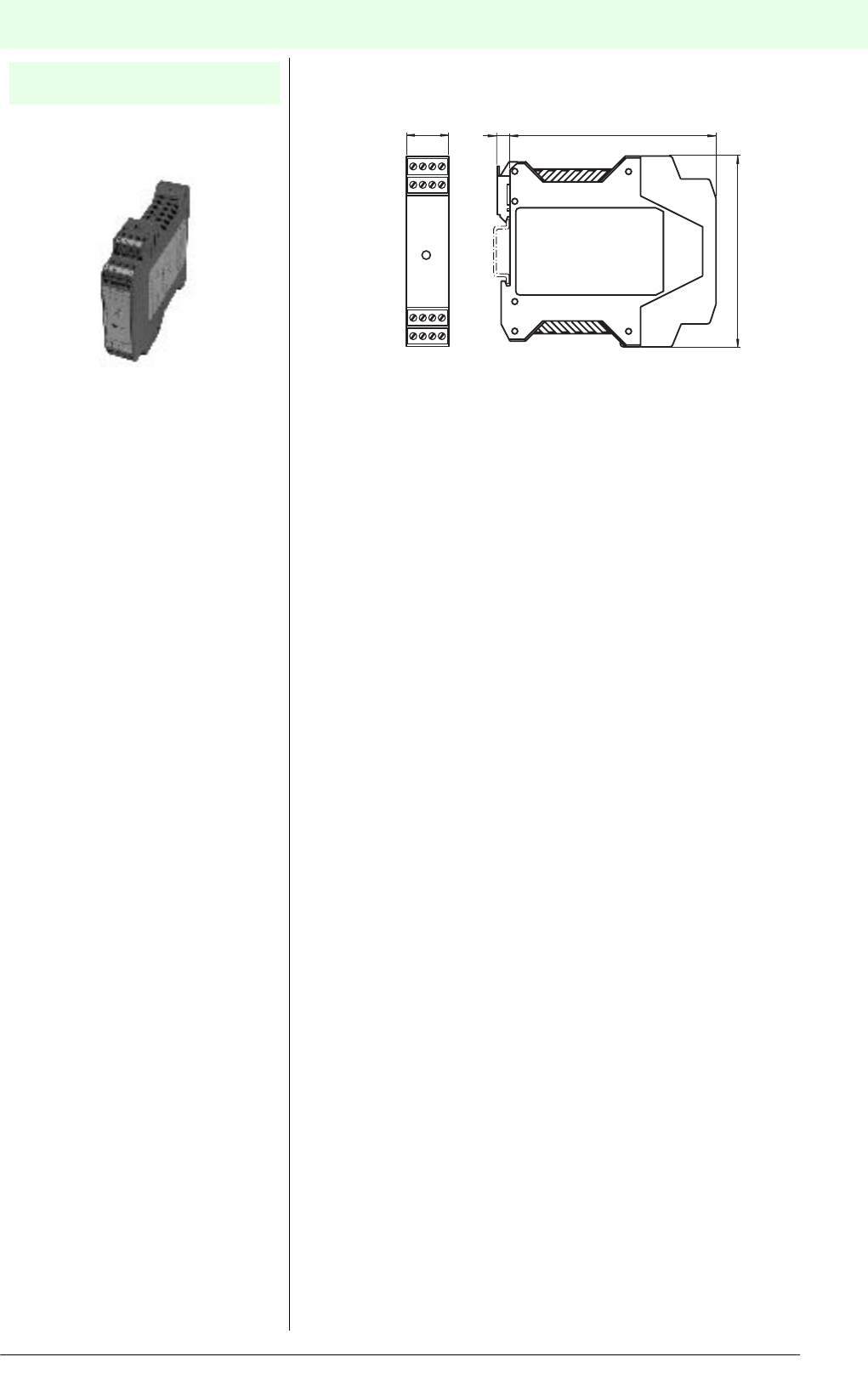
MiscellaneousAccessories
Date of edition 05/17/2006
S
ubject to reasonable modifications due to technical advances. Copyright Pepperl+Fuchs, Printed in Germany
Pepperl+Fuchs Group • Tel.: Germany +49 621 776-0 • USA +1 330 4253555 • Singapore +65 67799091 • Internet http://www.pepperl-fuchs.com
187
Power unit for control units with
alternating voltage provision.
Power unit
SC PS 120-240VAC
22.5 1077
99

Guidelines and standards
Additional Information
Date of edition 05/17/2006
Subject to reasonable modifications due to technical advances. Copyright Pepperl+Fuchs, Printed in Germany
Pepperl+Fuchs Group • Tel.: Germany +49 621 776-0 • USA +1 330 4253555 • Singapore +65 67799091 • Internet http://www.pepperl-fuchs.com
188
Guideli nes a nd standards
Directives and standardisation
Machine directive
One of the basic requirements of the European Com-
munity, which is firmly established in the Roman con-
tracts, is to ensure the free flow of goods within
Europe. This means that a machine that complies with
national specifications and standards may be market-
ed without restrictions within Europe.
In order for this requirement to be met, all national
standards everywhere in Europe must be the same
(harmonised).
The European community has passed directives that
should be seen as "supreme laws" for national legisla-
tion. These "supreme laws" must be adopted into na-
tional law and country-specific safety requirements
and approval requirements must be revised accord-
ingly.
Directive 89/392/EEC "Basic health and safety re-
quirements for the construction and manufacture of
machines and safety components“ applies to ma-
chines. This directive became part of the Device Safe-
ty Law in Germany with the 9th decree.
CE marking
Every manufacturer should be concerned with all de-
tails related to the Machine Directive. Manufacturers
should be familiar with and use the appropriate harmo-
nised standards for their machines. In addition, it is
possible that other guidelines may apply to a manufac-
turer's products (for example the low-voltage direc-
tive), which must also be taken into consideration.
After implementing the required measures, the manu-
facturer issues an EU declaration of conformity for
each machine and affixes the CE symbol. This symbol
indicates that the machine so designated is in con-
formity with requirements that apply to it. Since this
declaration is issued on the manufacturer's own re-
sponsibility, the manufacturer bears the entire respon-
sibility for the safety of the machine and, in the case of
a safety defect, is also liable (product liability).
Standardisation
So as not to impede further technical development,
guidelines contain only general or basic requirements.
Detailed requirements may be found in standards. Eu-
ropean standards are adopted by each member as
part of the national structure of standards. Observ-
ance of the applicable standards is sufficient grounds
to assume that the machine satisfies the requirements
of the corresponding guidelines. Use of standards is
not compulsory. What is important is simply that the
required safety goal be achieved. Only in the case
where no standards are used must the manufacturer
perform a complete risk analysis and identify and im-
plement the necessary measures. These are tasks
that may be highly complex.
If no EN standards are available, national standards
may be used.
Safety standards are classified as follows:
Type A:
Basic requirements, valid for all machines; example:
General design aspects
Type B:
Group standards to be used for different machine
groups; examples: Risk evaluation, constructional as-
pects, distances and speeds, surface temperatures ...
Type C:
Product standards, applicable to defined types of ma-
chines. Safety-related equipment is defined in stand-
ards of this type. It can thus be directly tested;
example: hydraulic presses, packaging machines, pal-
let loaders etc.
Overview of standards (not complete)
Type A standards
• DIN EN 292 Safety of machines, basic concepts,
leading design principles
Part 1: Basic terminology
Part 2: Main technical principles and specifications
Type B standards
B standards are subdivided into B1 (higher-order safe-
ty aspects) and B2 (description of general safety
equipment).
B1 standards
• DIN EN 294 Safety distances to prevent persons
from reaching hazardous locations with the upper
limbs.
• DIN EN 547 Human body dimensions
Part 1: Basic principles for determining dimensions
of entire-body access
Part 2: Basic principles for measuring access open-
ings
• EN 999 Layout of safety equipment in respect to ap-
proach speeds of body parts
• DIN EN 349 Minimum distances for preventing body
parts from being jammed
• DIN EN 811 Safety distances to prevent persons
from reaching hazardous locations with the lower
limbs.
• DIN EN 626 Reducing the health hazard from haz-
ardous substances that emerge from the machine
Part 1: Basic principles and determinations for ma-
chine manufacturers
Part 2: Methodology for setting up verification pro-
cedures
• DIN EN 954 Safety-related parts of machines
Part 1: General principles of design
• DIN EN 60 204 Electrical equipment for machines
Part 1: General design principles

Guidelines and standards
Additional Information
Date of edition 05/17/2006
S
ubject to reasonable modifications due to technical advances. Copyright Pepperl+Fuchs, Printed in Germany
Pepperl+Fuchs Group • Tel.: Germany +49 621 776-0 • USA +1 330 4253555 • Singapore +65 67799091 • Internet http://www.pepperl-fuchs.com
189
B2 standards
• DIN EN 1088 Locking equipment used in combina-
tion with protective devices – Main principles for de-
sign and selection
• DIN EN 953 General requirements for design and
construction of movable protective equipment (fixed
and movable)
• DIN EN 61496 No-contact safety equipment
• DIN EN 418 EMERGENCY OFF equipment, func-
tional aspects, main design principles
• DIN EN 574 Two-handed switching, functional as-
pects, main design principles
• DIN EN 1037 Avoiding unexpected startup
Type C standards
Because of the great volume of "Type C“ standards,
only a few excerpts of the types of machines that are
covered are listed.
• Elevators/hoisting devices
• Construction and construction equipment machines
• Printing and paper machines
• Flat conveyor vehicles
• Tanning machines
• Foundry machines
• Rubber and plastic machines
• Woodworking
• Industrial robots
• Industrial centrifuges
• Compressors
• Cranes
• Agricultural and forestry machines
• Lasers and laser systems
• Food products machines
• Sewing machines
• Surface processing equipment
• Shelf loading and unloading equipment
• Footwear and leatherwear machines
• Continuous conveyors
• Textile machines
• Thermoprocess systems
• Packaging machines
• Heat pumps, refrigeration systems
• Tool machines
Additional information
You can find additional information on the Internet un-
der the following addresses:
Source Internet address
Beuth Verlag beuth.de
DIN din.de
DKE dke.de
CENELEC cenelec.org
IEC iec.ch
Accident prevention
requirements
bc-verlag.de/uvven
European directives europa.eu.int/eur-lex/de/oj
List of standards
under the respective
European directives:
europa.eu.int/comm/enter-
prise/newapproach/
index.htm

Protection types provided by housing
Additional Information
Date of edition 05/17/2006
Subject to reasonable modifications due to technical advances. Copyright Pepperl+Fuchs, Printed in Germany
Pepperl+Fuchs Group • Tel.: Germany +49 621 776-0 • USA +1 330 4253555 • Singapore +65 67799091 • Internet http://www.pepperl-fuchs.com
190
Protectio n types provided by housi ng
Protection types provided by housing
(DIN VDE 0470 Part 1, EN 60529)
Notes:
• If an identifying number is not required, please use the letter "X" in its place.
• Devices identified with a second digit 7 or 8 do not have to fulfil the requirements of the second digits 5 or 6 unless they have
a double identification (e.g. IPX6/IPX7).
Degree of protection against contact and foreign bodies Degree of protection against water
0 - Not protected 0 - Not protected
1 - Protected against contact with hazardous components
with the backs of the hand
- Protected against solid foreign bodies with a size and
diameter 50 mm and above
1 - Protected against dripping water
2 - Protected against contact with hazardous
components with fingers
- Protected against solid foreign bodies
with a size and diameter of 12.5 mm or above
2 - Protected against dripping water
when housing is tilted up to 15°
3 - Protected against contact with hazardous components
with a tool
- Protected against solid foreign bodies with a size and
diameter of 2.5 mm or above
3 - Protected against sprayed water
4 - Protected against contact with hazardous
components with a wire
- Protected against solid foreign bodies with a size and
diameter of 1.0 mm or above
4 - Protected against splash water
5 - Protected against contact with hazardous parts
with a wire
- Protection from dust
5 - Protected against water jets
6 - Protected against contact with hazardous
components with a wire
- Protected against dust
6 - Protected against strong water jets
7 - Protected against temporary
submersion in water
8 - Protected against continuous
submersion in water
9 - protected from water at high pressure/steam
jet cleaning
IP 6 7
Devices options
Additional Information
Date of edition 05/17/2006
S
ubject to reasonable modifications due to technical advances. Copyright Pepperl+Fuchs, Printed in Germany
Pepperl+Fuchs Group • Tel.: Germany +49 621 776-0 • USA +1 330 4253555 • Singapore +65 67799091 • Internet http://www.pepperl-fuchs.com
191
Devices options
Device options
To ensure the best possible adaptation to your application, specific products are available, in addition to there se-
ries designs, also in various electrical designs with different types of connectors or additional useful options.
In the following table, you will find a list of options offered for special products. These device options are appended
to the description of the device as numeric codes in ascending order separated by a frontslash (/) (example: SLA28/
106/116).
Example for device options:
SLA28/35/106/116 R=65m
Detection range = 65 m
Electrical connection in the terminal compartment
Design for the extended temperature range -35 °C ... 55 °C
with heated front panel
Device design with detection range deviating from the series
Series
Option Description
/31 Relay output instead of transistor output.
/33 Length of the cable connector deviating from the series design.
Preferred lengths: 5 m and 10 m.
The length of the cable is specified at the end of the type code in plain text.
Example: K=5m.
/35 Detection or sensing range that deviates from the series.
The detection range is specified at the end of the type code in plain text.
Example: R=65m.
/60 Connection option plastic connector, 6-pin + earth ground wire.
Unassembled angled mating connector included with delivery.
/73c Connection option plastic connector, 4-pin with M12 threading.
Assignment in accordance with European standard. Cable connector not included with
delivery.
/92 Connection option metal connector, 4-pin with M12 threading.
Assignment in accordance with European standard.
/105 Connection option plastic connector, 5-pin with M12 threading.
Assignment in accordance with European standard. Cable connector not included with
delivery.
/106 Extended temperature range -35 °C ... 55 °C with heated front panel.
The electrical connections of the front panel heater are separate. Operation is based on a
fixed voltage of 24 V DC ±20 %.
/116 Connection option - terminal compartment.
/129 With contactor monitor/relay monitor
/130 With reduced response time
/133 For use in hazardous area, zone 2
/151 Connection option metal connector, 8-pin with M12 threading.
/152 Muting lamp LED, 24 V DC ... 28 V DC

Type code
Additional Information
Date of edition 05/17/2006
Subject to reasonable modifications due to technical advances. Copyright Pepperl+Fuchs, Printed in Germany
Pepperl+Fuchs Group • Tel.: Germany +49 621 776-0 • USA +1 330 4253555 • Singapore +65 67799091 • Internet http://www.pepperl-fuchs.com
192
Type c ode
SLA5S-R/92 K=5m
Specified in plain text
For option 33: K = cable length
For option 35: R = detection range
device option
/ = Options follow after the front slash (see device options)
T = Transmitter
R = Receiver
Special design - lateral light exit
Series
Design
Design SLA:
Safety through beam sensors for operation on control units SLVA and SC4-8
Special designs:
-2442: Seal test for protection class IP67, cast.
SLPC10-3-T-L/31
/ = Options follow after the front slash (see device options)
L = Lamp
T = Transmitter
R = Receiver
Number of beams
Detection range in m
Design
Safety through beam sensors
Safety light grid
Designs
SLP Safety light grid for external control units
SLPC Safety light grid with internal control unit
SLPCM Safety light grid with internal control unit, with muting
SLC Safety light grid with internal control unit in the SLC profile
Designs
-T Transmitter
-R Receiver
-A Active transmitter and receiver (transceiver)
-M Mirror pillar (mirror)

Type code
Additional Information
Date of edition 05/17/2006
S
ubject to reasonable modifications due to technical advances. Copyright Pepperl+Fuchs, Printed in Germany
Pepperl+Fuchs Group • Tel.: Germany +49 621 776-0 • USA +1 330 4253555 • Singapore +65 67799091 • Internet http://www.pepperl-fuchs.com
193
SLC14-600-T-S/31
/ = Options follow after the front slash
(See device options)
S = Slave
T = Transmitter
R = Receiver
M = Mirror (mirror pillar)
Protective field height in mm
Size of obstruction in mm
Design o SLC safety light curtain
SB4-OR-4CP-xx
Assembly slot 3 to 8 (variable)
Variable configuration of the module types
Assembly slot 2, sensor card module 4 channels (with CPU)
Minimum configuration: 4 sensor channels with LED status display
Assembly slot 1, OSSD-R/supply-module
Minimum configuration: 2 relay OSSDs with operating mode adjustment
(restart, monitor) and 7 segment LED display, LEDs red/green, yellow
SB4 -SAFEBOX category 4
SB4 Housing Backplane provides 2 ... 8 slots for plug-in cards
Supplies the individual modules with voltage
Connects the modules mechanically and electrically
Safety light curtain
Control units SafeBox

Glossary
Additional Information
Date of edition 05/17/2006
Subject to reasonable modifications due to technical advances. Copyright Pepperl+Fuchs, Printed in Germany
Pepperl+Fuchs Group • Tel.: Germany +49 621 776-0 • USA +1 330 4253555 • Singapore +65 67799091 • Internet http://www.pepperl-fuchs.com
194
Glossary
Glossary
Activation current
The current that must be flowing to
change the signal input to activat-
ed status.
Activation time
The time or period of time within
which an input must be activated
to initiate the desired function.
Alignment aid
Combination of all measures that
support the optical alignment of a
sensor. Laser alignment aid, align-
ment aids for profiles here.
Ambient temperature (operating)
⇒ Operating temperature
Ambient temperature (storage)
⇒ Storage temperature
Angle of divergence
The maximum angular divergence
from the optical axis of the light
emitted from the transmitter and
the light received by the receiver in
which the optical sensor works
during normal operation.
Approvals
Permission to operate the sensor
under defined ambient conditions.
Different approval conditions must
be fulfilled for different countries.
Beam distance
Indicates the distance between
two transmitter beams with light
grids.
Connection
Type of connection of the sensor
to the consumer and power sup-
ply.
Connector, cable, terminals.
Diagnostic display
Display of status, operating hours,
functions and error states.
EDM
External Device Monitoring, nor-
mally closed contact of safety
components downstream in the
circuit that indicates when switch-
ing has been performed for a haz-
ardous action; also relay monitor.
Effective operating distance
Detection range with sufficient sta-
bility control.
Function display
A display of the switching state of
an optical sensor by an integrated
LED.
Height of the protected area
The vertical range in which a pro-
tective field is set up with the aid of
a photoelectronic protective de-
vice between the transmitter and
the receiver.
Laser class
Categorisation of a sensor de-
pending on the output intensity of
the emitted laser light. For exam-
ple, laser class I designates sen-
sors with the lowest level of
emission. These sensors are
therefore referred to as safe for the
eye.
Light transmitter
Describes the light-emitting com-
ponent (for example a laser diode,
IRED).
Light type
The type of emitted light, for exam-
ple red or infrared.
Muting
Bypass of the protective function
of no-contact safety equipment, in
accordance with requirements.
No load current
Current consumption of a device to
which no additional devices draw-
ing power are connected.
Electrosensitive protection equip-
ment
German: BWS
Normal muting
Muting initiated by pressing a but-
ton to eliminate a backup of mate-
rial, also includes override.
Number of beams
Indicates the number of transmitter
beams of a sensor. The number of
beams is especially relevant for
light grids and curtains.
Operating components
Adjustment components (for ex-
ample push buttons) for adjusting
the detection range or time range.
Components for changing param-
eters of the device (for example
mode of operation, time range, de-
tection range, etc.).
Operating display
The component (LED, 7-segment
display) that indicates whether the
operating voltage is present.
Operating temperature
Indicates the temperature range in
which the sensor may be operated
while maintaining the rest of the
technical data.
Operating voltage
The voltage for which the sensor is
designed (without residual ripple).
Optical outlet material
Identifies the material of which the
sensors light exit surface is made
(for example glass or plastic).
Optical surface
The surface through which the
emitted light leaves the housing or
through which the received light
enters the housing of the sensor.
OSSD
Output switching components of
the safety circuit of the electrosen-
sitive protection equipment, output
signal switching device in accord-
ance with EN 61496-1.
Output of the pre-fault indication
The output switches before failure
of the sensor because of insuffi-
cient signal reserve due to dirt or
improper adjustment.
Parallel muting
Simultaneously activated muting
sensors jointly trigger muting.
Pre-fault indicator
Indicates insufficient signal re-
serve because of dirt or improper
adjustment before the failure of the
sensor. It can therefore be used as
an aid in adjustment as well.

Glossary
Additional Information
Date of edition 05/17/2006
S
ubject to reasonable modifications due to technical advances. Copyright Pepperl+Fuchs, Printed in Germany
Pepperl+Fuchs Group • Tel.: Germany +49 621 776-0 • USA +1 330 4253555 • Singapore +65 67799091 • Internet http://www.pepperl-fuchs.com
195
Protection class
EN40050 classifies protection of
electrical equipment against con-
tact, ingress of objects or water
through the housing, coverings,
etc.
The IP abbreviation consists of the
letters IP (International Protection)
and two numbers:
1. Number: Level of protection
against contact and foreign bodies
2. Number: Level of protection
against ingress of water.
Protection class
Housing and insulation class is
subdivided into different classes.
Protection class 0:
No longer permitted in Germany
for about 30 years. Still permitted
in some countries of the EC in
some cases. Protection against
electrical shock is based on basic
insulation; a protective conductor
cannot be connected. Protection
against failure of the basic insula-
tion must be ensured by the envi-
ronment.
Protection class I:
Protection is based not only on ba-
sic insulation, but also on the fact
that all parts (bodies) capable of
conducting a current must be con-
nected with the protective conduc-
tor of the fixed installation.
Protection is based on the use of
low protective voltage.
Protection class II:
Protection is based not only on
basic insulation, but also on the
fact double or reinforced insulation
is arranged so as to satisfy the
condition for protective insulation.
Protection class III:
Protection is based on the use of
protective low voltage. The nomi-
nal voltage must not exceed 50 V~
or 120 V-.
Protective beam limited muting
If all protective beams are free,
muting is terminated.
Protective field width
The horizontal range in which a
protective field is set up with the
aid of a photoelectronic protective
device between the transmitter
and the receiver.
Reset
Reset of the electrosensitive pro-
tection equipment to the starting
status.
Resolution
Minimum required size of an object
to be reliably detected in the entire
protective field range.
Response time:
Time between the interruption of
the light beam and the signal
change at the output (OSSD).
Restart
Enabling the startup of the no-con-
tact safety equipment from the
startup/restart interlock status.
Safety output
Switch output on which a moni-
tored switch signal may be provid-
ed (OSSD, output signal switching
device). A special test is conduct-
ed to determine whether the output
is capable of interrupting the cir-
cuit. For example, two force direct-
ed relay contacts relay contacts or
monitored semiconductor outputs
can be safety outputs.
Sequential muting
Muting sensors activated one after
the other jointly trigger muting.
Signal outputs
Switch output of a device.
Size of the obstruction
The minimum required size of an
object in order to interrupt a single
beam.
Stability control
The distance of the receiver signal
from the optical barrier before the
lower limit of the switching point of
the optical barrier.
Startup/restart interlock
Device that prevents OSSDs from
turning on after the protective field
has become free.
Storage temperature
Indicates the temperature range in
which the sensor may be stored.
Switching current
The maximum current that can be
switched through the signal out-
put.
Switching power
The maximum power that can be
switched through the signal out-
put.
Switching voltage
The maximum voltage that can be
switched through the signal out-
put.
Test input
Depending on the design, the sen-
sor function can be verified exter-
nally via the test input with either
UB+ or 0V. If the test is successful,
a signal change will occur at the
time of the test.
Time-window limited muting
If a muting sensor is activated for
longer than a specified time span,
the OSSDs are turned off.

Subject to reasonable modifications due to technical advances. Copyright Pepperl+Fuchs, Printed in Germany
Pepperl+Fuchs Group • Tel.: Germany +49 621 776-0 • USA +1 330 4253555 • Singapore +65 67799091 • Internet http://www.pepperl-fuchs.com
Date of edition 05/17/2006
196
Pepperl+Fuchs GmbH worldwide
Pepperl+Fuchs GmbH worldwide
Austria
Pepperl+Fuchs GmbH
Industriestraße B 13
2345 BRUNN/GEB.
Telephone +43-2236-33441
Telefax +43-2236-31682
info@at.pepperl-fuchs.com
Bahrain
Texas Technical Services
(FA + PA Representation)
P.O. Box: 11302
MANAMA
Telephone +973-17789555
Telefax +973-17789666
textech@batelco.com.bh
Baltic States
ELEKOMS Ltd.
(PA Distributor)
Turaidas Str. 10
LV-1012 RIGA, Latvija
Telephone +371-7336444
Telefax +371-7336448
elekoms@apollo.lv
Belgium
Pepperl+Fuchs N.V.
Metropoolstraat 11
2900 SCHOTEN
Telephone +32-3-6442500
Telefax +32-3-6442441
sales@be.pepperl-fuchs.com
Bulgaria
Process Control
(PA Distributor)
Tzarichina Str. 1
1505 SOFIA
Telephone +359-2-703549
Telefax +359-2-703549
processcontrol@bulmail.net
Croatia
EL-PRO D.O.O.
(FA + PA Distributor)
Fallerovo Setaliste 22
10000 ZAGREB
Telephone +385-1-3680047
Telefax +385-1-3667428
el-pro@htnet.hr
Czech Republic
Pepperl+Fuchs s.r.o.
Sokolovská 79
18600 PRAG 8
Telephone +420-221115-540
Telefax +420-221115-550
info@cz.pepperl-fuchs.com
Denmark
Pepperl+Fuchs A/S
Stamholmen 173
2650 HVIDOVRE
Telephone +45-70104210
Telefax +45-70104211
info@dk.pepperl-fuchs.com
Egypt
Pepperl+Fuchs Egypt (LLC)
(FA + PA Office)
9 Abd Al Hamied Lotfy Street, Zone 8
Nasr City
CAIRO
Telephone +20-2-2721097
Telefax +20-2-2756096
mesmat@pepperl-fuchs.com.eg
Finland
SensoNor Oy
Kartanontie 20
00330 HELSINKI
Telephone +358-9-4777200
Telefax +358-9-47772020
joel.patrikka@sensonor.fi
France
Pepperl+Fuchs SARL
12 Avenue des Tropiques
91955 COURTABOEUF CEDEX
Telephone +33-1-60921313
Telefax +33-1-60921325
commercial@fr.pepperl-fuchs.com
Germany
Pepperl+Fuchs Drehgeber GmbH
Föhrenstraße 33
78532 TUTTLINGEN
Telephone +49-7461-9298-0
Telefax +49-7461-9298-22
ygrabowski@de.pepperl-fuchs.com
Pepperl+Fuchs EXTEC GmbH
Schorndorfer Straße 55
73730 ESSLINGEN
Telephone +49-711-313455-0
Telefax +49-711-315455-29
info@extec.de
Omnitron AG
Aktiengesellschaft für
optoelektronische Geräte
Im Leuschnerpark 4
64347 GRIESHEIM
Telephone +49-6155-605314
Telefax +49-6155-874012
Visolux, Zweigniederlassung
der Pepperl+Fuchs GmbH
Prinzenstraße 85
10969 BERLIN
Telephone +49-30-61672-0
Telefax +49-30-61672-468
Great Britain
Pepperl+Fuchs GB Ltd.
(FA + PA Distributor)
77 Ripponden Road
OLDHAM OL1 4EL, Lancashire
Telephone +44-161-6336431
Telefax +44-161-6246537
sales@gb.pepperl-fuchs.com
Greece
Uteco A.B.E.E.
5, Mavrogenous Street
18542 PIRAEUS
Telephone +30-104210050
Telefax +30-104212033
uteco@uteco.gr
Hungary
Pepperl+Fuchs Kft.
(FA)
Kistó Utca 16-18
8200 VESZPRÉM
Telephone +36-88-590100
Telefax +36-88-590133
mpozsgai@hu.pepperl-fuchs.com
Iceland
Tölvusalan ehf.
Suourlandsbraut 20
P.O. Box 8960
128 REYKJAVIK
Telephone +354-5-500450
Telephone +354-5-500454
Telefax +354-5-500402
Zentrale weltweit
Worldwide Head Office
Pepperl+Fuchs GmbH
Königsberger Allee 87
68307 MANNHEIM
Telephone +49-621-776-0
Telefax +49-621-776-1000
info@de.pepperl-fuchs.com

Pepperl+Fuchs GmbH worldwide
S
ubject to reasonable modifications due to technical advances. Copyright Pepperl+Fuchs, Printed in Germany
Pepperl+Fuchs Group • Tel.: Germany +49 621 776-0 • USA +1 330 4253555 • Singapore +65 67799091 • Internet http://www.pepperl-fuchs.com
Date of edition 05/17/2006
197
Iran
Asan Sazan Farayand
(FA + PA Representation)
Unit No. 17, No. 7, Taghavi Street
Soherevardi Shomali Ave.
15686 TEHRAN
Telephone +98-21-8458401
Telefax +98-21-8440915
Ireland
Insteco Ltd.
The Coach House
Slane
Co Meath
Telephone +353-41-9884288
Telefax +353-41-9884292
Israel
Kama Ltd.
(FA + PA Distributor)
20 Hametsuda St.
58190 AZOR
Telephone +972-3-5567747
Telefax +972-3-5567548
Kama@netvision.net.il
Italy
Pepperl+Fuchs ELCON SRL
Via delle Arti e Mestieri, 4
20050 SULBIATE (Milano)
Telephone +39-039-62921
Telefax +39-039-6292240
info@it.pepperl-fuchs.com
Kenya
Shankan Enterprises Ltd.
P. O. Box 44432
NAIROBI
Telephone +254-2-440093
Telefax +254-2-441820
dks@kenyaonline.com
Kuwait
Almeer Technical Services
Co. W.L.L.
(FA + PA Representation)
P.O. Box 9240
61003 AHMDAI
Telephone +965-3986594
Telefax +965-3980682
talal@almeer.com
Netherlands
Pepperl+Fuchs B.V.
Het Wielsem 10
5231 BW‘s-HERTOGENBOSCH
Telephone +31-73-6409388
Telefax +31-73-6444749
sales@nl.pepperl-fuchs.com
Norway
Elteco A/S
Postboks 96
Floodmyrveien 24
3901 PORSGRUNN
Telephone +47-35-573800
Telefax +47-35-573849
firmapost@elteco.no
Oman
Riyam Engineering & Services L.L.C
(FA + PA Representation)
P.O. Box: 1931
112 RUWI
Telephone +968-594960
Telefax +968-595536
riyam@omantel.net.om
Pakistan
Techno-Commercial
Engineers-Representations
18-24, Farid Plaza - Shadman 65
G.P.O. Box 937
54000 LAHORE
Telephone +92-42-7584390
Telefax +92-42-7581771
eswaat@brain.net.pk
Tariq Electric House
1, Wahab Arcade, Near Denso Hall
M. A. Jinnah Road
74200 KARACHI
Telephone +92-21-2628409
Telefax +92-21-2624460
teh@super.net.pk
Poland
INTEX Sp.zo.o.
(PA Distributor)
ul. W. Pola 16
44-100 GLIWICE
Telephone +48-32-2307516
Telefax +48-32-2307517
intex@intex.com.pl
Portugal
Pepperl+Fuchs, S.A.
Txori-Erri Etorbidea, 46
Polígono Izarza
48150 SONDIKA (Vizcaya) (Spain)
Telephone +349-4-4535020
Telefax +349-4-4535180
sov@es.pepperl-fuchs.com
Qatar
Doha Petroleum Construction
Co. Ltd. (DOPET)
(FA + PA Representation)
P.O. Box 1744
DOHA
Telephone +974-4600350
Telefax +974-4606347
bhargav@dopet.com
Romania
Syscom 18 Srl.
(FA + PA Distributor)
Calea Plevnei 139B, Sector 6
060011 BUCHAREST
Telephone +40-21-3102678
Telefax +40-21-2229176
syscom@syscom.ro
Russia
Pepperl+Fuchs Russia
(FA + PA Office)
Ul. 4-aya Magistralnaya, 11
Bld. 1, 8 Floor
123007 MOSCOW
Telephone +7-095-9958842
Telefax +7-095-2595872
info@pepperl-fuchs.ru
Prosoft Ltd.
(FA + PA Distributor)
108 Profsoyznaya Str.
119313 MOSCOW
Telephone +7-095-2340636
Telefax +7-095-9783934
root@prosoft.ru
Saudi Arabia
GAS Arabian Services Est.
(FA + PA Representation)
P. O. Box 10487
31961 AL-JUBAIL
Telephone +966-3-3472696
Telefax +966-3-3473480
Slovakia
Pepperl+Fuchs s.r.o.
Sokolovská 79
18600 PRAG 8
(Czech Republic)
Telephone +420-221115-540
Telefax +420-221115-550
info@cz.pepperl-fuchs.com
South Africa
P & F Products cc
P.O. Box 2809
60, Fourth Ave.
EDENVALE 1610
Telephone +27-11-6098188
Telefax +27-11-4522026
info@pandf.co.za
Spain
Pepperl+Fuchs, S.A.
Head Office
Txori-Erri Etorbidea, 46
Polígono Izarza
48150 SONDIKA (Vizcaya)
Telephone +349-4-4535020
Telefax +349-4-4535180
sov@es.pepperl-fuchs.com

Subject to reasonable modifications due to technical advances. Copyright Pepperl+Fuchs, Printed in Germany
Pepperl+Fuchs Group • Tel.: Germany +49 621 776-0 • USA +1 330 4253555 • Singapore +65 67799091 • Internet http://www.pepperl-fuchs.com
Date of edition 05/17/2006
198
Pepperl+Fuchs GmbH worldwide
Sweden
Pepperl+Fuchs AB
Bultgatan 40 b
442 40 KUNGÄLV
Telephone +46-303-246070
Telefax +46-303-246089
info@se.pepperl-fuchs.com
Switzerland
Pepperl+Fuchs AG
Sägeweg 7
2557 STUDEN/BE
Telephone +41-32-3747676
Telefax +41-32-3747678
info@ch.pepperl-fuchs.com
Turkey
Net Muhendislik A.S.
(FA Representation)
Perpa Ticaret Merkezi A
Blok kat: 5 No: 174/176
Okmeydani ISTANBUL
Telephone +90-212-2109354
Telefax +90-212-2109359
info@netmuh.com.tr
STOKS Ltd.
(PA Representation)
Zümrütevler Mah. Visne Sokak No. 5
Maltepe
34852 ISTANBUL
Telephone +90-216-4417009
Telefax +90-216-4591290
United Arab Emirates
Pepperl+Fuchs (M.E.) FZE
P.O. Box 61398
CA-1, Near Round About 8
Jebel Ali Free Zone
DUBAI
Telephone +971-4-8838378
Telefax +971-4-8838627
info@ae.pepperl-fuchs.com
United Eastern Group
(FA + PA Representation)
P. O. Box 7615
ABU DHABI
Telephone +971-2-6272737
Telefax +971-2-6270048
kanone@ueg.co.ae
Nils & Abbas Trading Co. L.L.C.
P. O. Box 26564
DUBAI
Telephone +971-4-3390044
Telefax +971-4-3388732
jens@nilsabbas.com

Pepperl+Fuchs GmbH worldwide
S
ubject to reasonable modifications due to technical advances. Copyright Pepperl+Fuchs, Printed in Germany
Pepperl+Fuchs Group • Tel.: Germany +49 621 776-0 • USA +1 330 4253555 • Singapore +65 67799091 • Internet http://www.pepperl-fuchs.com
Date of edition 05/17/2006
199
Anguilla
Address see
USA Head Office
Pepperl+Fuchs Inc.
Antigua
Address see
USA Head Office
Pepperl+Fuchs Inc.
Argentina
Bruno Schillig S.A.
Arenales (Dip. Ortiz) 4030
1602 Florida,
BUENOS AIRES
Telephone +54-11-47301100
Telefax +54-11-47617244
schillig@schillig.com.ar
Aruba
Address see
USA Head Office
Pepperl+Fuchs Inc.
Bahamas
Address see
USA Head Office
Pepperl+Fuchs Inc.
Barbados
Address see
USA Head Office
Pepperl+Fuchs Inc.
Belize
JR Controls Industrial & Automation
(FA Representation)
100 Metros Norte de la Cruz
Roja Desamparados
SAN JOSE (Costa Rica)
Telephone +506-2597904
Telefax +506-2504558
Bermuda
Address see
USA Head Office
Pepperl+Fuchs Inc.
Bolivia
Hiller Electric SA
Av. El Trompillo 573
Casilla 370
SANTA CRUZ
Telephone +591-3-3524484
Telefax +591-3-3526404
mail@hillerelectric.com.bo
Brazil
Pepperl+Fuchs Ltda.
Rua Agostino Pelosini, 73/81
Vila Olga
CEP 09720-220 SAO BERNARDO
DO CAMPO
Telephone +55-11-43399935
Telefax +55-11-43387547
vendas@br.pepperl-fuchs.com
British Virgin Islands
Address see
USA Head Office
Pepperl+Fuchs Inc.
Canada
Address see
USA Head Office
Pepperl+Fuchs Inc.
Cayman Islands
Address see
USA Head Office
Pepperl+Fuchs Inc.
Chile
Desimat Ingenieria Ltda.
(FA Representation)
Rut.: 78.131.420-K
Av. Puerto Vespucio 9670
Loteo Industrial Puerto Santiago
PUDAHUEL-SANTIAGO
Telephone +56-2-7470152
Telefax +56-2-7470153
importaciones@desimat.cl
INECO Ltda.
Avda Ejercito 16, Piso 4
6510449 SANTIAGO DE CHILE
Telephone +56-2-4638600
Telefax +56-2-4411023
industrial@ineco.cl
Colombia
Instrumentos & Controles
(PA Representation)
Calle 39 No. 22 - 45
BOGOTA, D.C.
Telephone +57-1-2088080
Telefax +57-1-2088060
cgomez@iycsa.com.co
Sensortec
(FA + PA Distributor)
Calle 95
#9A-08
BOGOTA, D.C.
Telephone +57-14007018
Telefax +57-14006945
Alfatecnica Export
(FA + PA Distributor)
Calle 95
#9A-08
BOGOTA, D.C.
Telephone +57-14007018
Telefax +57-14006945
H & D Export
(FA + PA Distributor)
Calle 95
#9A-08
BOGOTA, D.C.
Telephone +57-14007018
Telefax +57-14006945
Costa Rica
Elvatron S.A.
(PA Representation)
400 Metros Norte de la Agencia
del Banco de Costa Rica
La Uruca SAN JOSE
Telephone +506-2961060
Telefax +506-2190298
elkin.suarez@elvatron.com
Euro-Tec S.A.
(PA Distributor)
Apartado Postal 477-1250
SAN JOSE
Telephone +506-3847869
Telefax +506-2961542
eurotec@sol.racsa.co.cr
JR Controls Industrial & Automation
(FA Representation)
100 Metros Norte de la Cruz
Roja Desamparados
SAN JOSE
Telephone +506-2597904
Telefax +506-2504558
Cuba
Address see
USA Head Office
Pepperl+Fuchs Inc.
Zentrale USA
USA Head Office
Pepperl+Fuchs Inc.
1600 Enterprise Parkway
TWINSBURG OHIO, 44087
Telephone +1-330-4253555
Telefax +1-330-4254607
sales@us.pepperl-fuchs.com

Subject to reasonable modifications due to technical advances. Copyright Pepperl+Fuchs, Printed in Germany
Pepperl+Fuchs Group • Tel.: Germany +49 621 776-0 • USA +1 330 4253555 • Singapore +65 67799091 • Internet http://www.pepperl-fuchs.com
Date of edition 05/17/2006
200
Pepperl+Fuchs GmbH worldwide
Dominica
Address see
USA Head Office
Pepperl+Fuchs Inc.
Dominican Republic
Garlas Controls
(FA Distributor)
Euclides Morillo No. 55 Aroyo Hondo
SANTO DOMINGO
Telephone +1-809-5633226
Telefax +1-809-5633498
garlas.control@codetel.net.do
P.A.S. Technologies
(PA Representation)
Julio N. Matos/Industrial Park
Ed. Rona #22, Local
00987 CAROLINA (Puerto Rico)
Telephone +1-787-7522370
Telefax +1-787-7683260
Ecuador
Alfatecnica S.A.
Cll 93 No. 19-75
SANTAFE DE BOGOTA D.C.
(Colombia)
Telephone +57-1-5300808
Telefax +57-1-538388
sales@us.pepperl-fuchs.com
Soltec
(FA + PA Distributor)
Condominios Luluncoto
Bloque Illiniza A Depto 102
QUITO
Telephone +593-22607096
Telefax +593-22607096
Sistemas y Equipos Industriales S.A.
(PA Representation)
Rumipamba E2-64 y Av. República
Ed. Alex. Ofic. 202
QUITO
Telephone +593-22459859
Telefax +593-22444278
El Salvador
Proyect Asesoria Industrial
S.A. de C.V.
(FA + PA Distributor)
Av. Los Diplomáticos 1318
Barrio San Jacinto
SAN SALVADOR
Telephone +503-2802221
Telefax +503-2701731
ElSalvador@GrupoProyect.com
Elvatron S.A.
(PA Representation)
400 Metros Norte de la Agencia
del Banco de Costa Rica, La Uruca
SAN JOSE (Costa Rica)
Telephone +506-2961060
Telefax +506-2190298
elkin.suarez@elvatron.com
JR Controls Industrial & Automation
(FA Representation)
100 Metros Norte de la Cruz
Roja Desamparados
SAN JOSE (Costa Rica)
Telephone +506-2597904
Telefax +506-2504558
Grenada
Address see
USA Head Office
Pepperl+Fuchs Inc.
Guatemala
Proyect Asesoria Industrial
S.A. de C.V.
(FA + PA Distributor)
43 Calle A 5-01 Zona 12
Col. Monte Maria II
GUATEMALA
Telephone +502-4794120
Telefax +502-4791430
guatemala@grupoproyect.com
Prysa
(FA + PA Distributor)
Km 16.3 Carretera El Salvador
SANTA CATARINA PINULA
Telephone +502-6373229
Telefax +502-6373228
alvaromonzon@yahoo.com
Esinsa
(PA Representation)
20 Calle 9-63 Z. 11
MARISCAL
Telephone +502-4424606
Telefax +502-4424605
jorge.minoz@esinsa.com
JR Controls Industrial & Automation
(FA Representation)
100 Metros Norte de la Cruz
Roja Desamparados
SAN JOSE (Costa Rica)
Telephone +506-2597904
Telefax +506-2504558
Haiti
Address see
USA Head Office
Pepperl+Fuchs Inc.
Honduras
Proyect Asesoria Industrial
S.A. de C.V.
(PA Distributor)
43 Calle A 5-01 Zona 12
Col. Monte Maria II
GUATEMALA
Telephone +502-4794120
Telefax +502-4791430
proyect@navegante.com.sv
Cilasa
(FA + PA Distributor)
Barrio los andes entre 14 y 15
avenida 7, calle A, contiguo a
PecosBill
SAN PEDRO ZULA
Telephone +504-5571146
Telefax +504-5571149
remorale@mayanet.hn
Inelsa
(FA + PA Distributor)
Colonia San Carlos de Sula
Casa #18 Bloque 33
SAN PEDRO ZULA
Telephone +504-5540988
mianzel@sulanet.net
JR Controls Industrial & Automation
(FA Representation)
100 Metros Norte de la Cruz
Roja Desamparados
SAN JOSE (Costa Rica)
Telephone +506-2597904
Telefax +506-2504558
Jamaica
Address see
USA Head Office
Pepperl+Fuchs Inc.
Martinique
Address see
USA Head Office
Pepperl+Fuchs Inc.
Mexiko
Pepperl+Fuchs México, S.A. de C.V.
(Head Quarter)
Blvd. Xola 613, Ph-4
Col. Del Valle
03100 MEXICO D.F.
Telephone +52-55-56391951
Telefax +52-55-56398865
pfmexico@mpsnet.com.mx
Montserrat
Address see
USA Head Office
Pepperl+Fuchs Inc.

Pepperl+Fuchs GmbH worldwide
S
ubject to reasonable modifications due to technical advances. Copyright Pepperl+Fuchs, Printed in Germany
Pepperl+Fuchs Group • Tel.: Germany +49 621 776-0 • USA +1 330 4253555 • Singapore +65 67799091 • Internet http://www.pepperl-fuchs.com
Date of edition 05/17/2006
201
Nicaragua
Elvatron S.A.
(PA Representation)
400 Metros Norte de la Agencia
del Banco de Costa Rica La Uruca
SAN JOSE (Costa Rica)
Telephone +506-2961060
Telefax +506-2190298
elkin.suarez@elvatron.com
Proyect Asesoria Industrial
S.A. de C.V.
(PA Distributor)
Calle 27 de mayode Montoya
50 varas arriba
MANAGUA
Telephone +503-2802221
Telefax +503-2701731
proyect@navegante.com.sv
JR Controls Industrial & Automation
(FA Representation)
100 Metros Norte de la Cruz
Roja Desamperados
SAN JOSE (Costa Rica)
Telephone +506-2597904
Telefax +506-2504558
Panama
JR Controls Industrial & Automation
(FA Representation)
100 Metros Norte de la Cruz
Roja Desamparados
SAN JOSE (Costa Rica)
Telephone +506-2597904
Telefax +506-2504558
Peru
Desimat Peru S.A.
(FA Representation)
Av. Enrique Salazar Barreto 280
LIMA
Telephone +51-1-2731892
Telefax +51-1-2720054
ventasperu1@desimat.cl
Puerto Rico
Hi-Tech Products
(FA Representation/PA Distributor)
Ave Sanchez Osorio #2
00983 CAROLINA PR
Telephone +1-787-2571707
Telefax +1-787-2761888
hi-tech@hi-techproducts.com
P.A.S. Technologies
(PA Representation)
Julia N. Matos/Industrial Park
Ed. Rona #22, Local
00987 CAROLINA PR
Telephone +1-787-7522370
Telefax +1-787-7683260
St. Kitts & Navis
Address see
USA Head Office
Pepperl+Fuchs Inc.
St. Lucia
Address see
USA Head Office
Pepperl+Fuchs Inc.
St. Martin
Address see
USA Head Office
Pepperl+Fuchs Inc.
St. Vincent
Address see
USA Head Office
Pepperl+Fuchs Inc.
Trinidad & Tobago
Industrial System & Controls
(FA + PA Representation)
Isaac Street
COUVA
Telephone +1-868-6369704
Telefax +1-868-6360948
Turks & Caicos
Address see
USA Head Office
Pepperl+Fuchs Inc.
Venezuela
Empresas Norte-Sur C. A.
Innovantis Technologies
(PA Representation)
Ave. Rio Caura Torre Humbolt
Of. 12-12, Prados del Este
CARACAS
Telephone +58-212-9750355
Telefax +58-212-9750082
ruben.fabbro@innovantis.biz
GPM Instrumentación
(FA + PA Distributor)
Urbanización Unare II Paseo
Caroni Torre INCA, Piso 2 Off 3
PUERTO ORDAZ
Telephone +58-286-9524884
Telefax +58-286-9524796
gpmins@telcel.net.ve
Suplidora Instrumatic C.A.
(FA Representation)
Urb Industrial Carabobo
Avenida Norte 17-18 #86-41
VALENCIA
Telephone +58-241-8327311
Telefax +58-241-8329819
Virgin Islands
P.A.S. Technologies
(PA Representation)
Julia N. Matos
Park Ed. Rona #22, Local
00987 CAROLINA (Puerto Rico)
Telephone +1-787-7522370
Telefax +1-787-7683260

Subject to reasonable modifications due to technical advances. Copyright Pepperl+Fuchs, Printed in Germany
Pepperl+Fuchs Group • Tel.: Germany +49 621 776-0 • USA +1 330 4253555 • Singapore +65 67799091 • Internet http://www.pepperl-fuchs.com
Date of edition 05/17/2006
202
Pepperl+Fuchs GmbH worldwide
Australia
Pepperl+Fuchs Australia Pty Ltd.
Unit 7/72-74 Chifley Drive
PRESTON, VICTORIA 3072
Telephone +61-3-94958600
Telefax +61-3-94846366
sales@au.pepperl-fuchs.com
China
Pepperl+Fuchs Automation Co. Ltd.
Shanghai (FA Head Office)
No. 9, Lane 163 Tan Jia Qiao Road
200070 SHANGHAI
Telephone +86-21-56525989
Telefax +86-21-56527164
info@cn.pepperl-fuchs.com
Pepperl+Fuchs Beijing Rep. Office
(PA Head Office)
Prime Tower, Room 2007
No. 22 Chao Yang Men Wai Street
BEIJING 100020
Telephone +86-10-65885143
Telefax +86-10-65885144
pf-china@public3.bta.net.cn
Pepperl+Fuchs Pte. Ltd.
Shanghai Representation Office
(PA Rep. Office)
218 Tainmu West Road, Room 2509
Kerry Everbright City Tower 1
200070 SHANGHAI
Telephone +86-21-63542910
Telefax +86-21-63546536
pfshapa@public8.sta.net.cn
Unicorn International Trading Co.
(FA Representation)
Room 1208 Shui On Centre
6-8 Harbour Road
WANCHAI, Hong Kong
Telephone +852-25283558
Telefax +852-25289371
fooberhk@netvigator.com
Pepperl+Fuchs Automation Co. Ltd.
Guangzhou Office of Shanghai
(PA & FA Office)
Room G 13/F, No. 1 Building
No. 445 Tian He Bei Road,
Tianhe District
510062 GUANGZHOU
Telephone +86-20-38805159
Telefax +86-20-38808505
pfgzoo@public.guangzhou.gd.cn
India
Pepperl+Fuchs (India) Pvt. Ltd.
(Head Office)
Plot No. 10, 3rd Main, 1st Stage
Peenya Industrial Estate
BANGALORE 560058
Telephone +91-80-28378030
Telefax +91-80-28378031
info@in.pepperl-fuchs.com
Pepperl+Fuchs (India) Pvt. Ltd.
(Regional Sales Office - North)
305, Ansal Chamber II
6, Bhikaji Cama Place
NEW DELHI 110066
Telephone +91-11-26170207
Telefax +91-11-26166291
nro@in.pepperl-fuchs.com
Pepperl+Fuchs (India) Pvt. Ltd.
(Vadodara Area Sales Office)
UG28 Upper Ground Floor
"Concorde" R.C. Dutt Road
Opp. Alkapuri Petrol Pump,
Alkapuri Vadodara
GUJARAT 390005
Telephone +91-26-55522516
Telefax +91-26-55522516
vadodara@in.pepperl-fuchs.com
Pepperl+Fuchs (India) Pvt. Ltd.
(Pune Area Sales Office)
Roof & Services, Ground Floor
Veer Savarkar Udyog Bhavan
Shivaji Nagar, Maharashtra
PUNE 411005
Telephone +91-20-25538658
Telefax +91-20-25538757
pune@in.pepperl-fuchs.com
Pepperl+Fuchs (India) Pvt. Ltd.
(Regional Sales Office - South)
(Karnataka & Andhra Pradesh)
C-328, 3rd Main, 1st Stage,
Peenya Industrial Estate
BANGALORE 560058
Telephone +91-80-28371225
Telefax +91-80-28378031
info@in.pepperl-fuchs.com
Pepperl+Fuchs (India) Pvt. Ltd.
(Regional Sales Office - South)
(Tamilnadu & Kerala)
No. 4, First Floor, X 70,
Sindur Shopping Complex,
2nd Avenue, Anna Nagar
CHENNAI 600040
Telephone +91-44-26212265
Telefax +91-44-26190129
cro@in.pepperl-fuchs.com
Pepperl+Fuchs (India) Pvt. Ltd.
(Regional Sales Office - East)
Room No. 221, II Floor "LORDS"
7/1, Lord Sinha Road
KOLKATA 700071
Telephone +91-33-22828539
Telefax +91-33-22828777
ero@in.pepperl-fuchs.com
Pepperl+Fuchs (India) Pvt. Ltd.
(Regional Sales Office - West)
No. 401, A-Wing, Subham Ctr. 1, 4th fl.
Cardinal Gracias Road, Chakala
Andheri (East)
MUMBAI - 400099
Telephone +91-22-28231946
Telefax +91-22-28231947
wro@in.pepperl-fuchs.com
Pepperl+Fuchs India Pvt. Ltd.
(Hyderabad Area Sales Office)
Hi Tech Business Centre, 4th Floor,
Topaz Bldg.
Amrutha Hills, Punjagutta
HYDERABAD 500082
Telephone +91-40-23407053
Telefax +91-40-23407093
hyderabad@in.pepperl-fuchs.com
Pepperl+Fuchs (India) Pvt. Ltd.
(Coimbatore Area Sales Office)
43A, 1st Floor
7th Street, K. K. Pudur, Tamilnadu
COIMBATORE 641038
Telephone +91-42-22450727
Telefax +91-42-22450727
coimbatore@in.pepperl-fuchs.com
Pepperl + Fuchs (India) Pvt. Ltd.
(Jamshedpur Resident Office)
FA/23, Sindhu Block, Siroman Nagar
Binda Apartment, Dimna Road,
Mango
Jharkhand JAMSHEDPUR 830018
Telephone +91-65-72363146
Telefax +91-65-72363146
jamshedpur@in.pepperl-fuchs.com
Zentrale Asien
Asia Pacific Head Office
Pepperl+Fuchs PTE Ltd.
P+F Building
18 Ayer Rajah Crescent
139942 SINGAPORE
Company registration no.
199003130E
Telephone +65-67799091
Telefax +65-68731637
sales@sg.pepperl-fuchs.com

Pepperl+Fuchs GmbH worldwide
S
ubject to reasonable modifications due to technical advances. Copyright Pepperl+Fuchs, Printed in Germany
Pepperl+Fuchs Group • Tel.: Germany +49 621 776-0 • USA +1 330 4253555 • Singapore +65 67799091 • Internet http://www.pepperl-fuchs.com
Date of edition 05/17/2006
203
Indonesia
PT Himalaya Everest Jaya
(FA Representation)
Jln. Daan Mogot Km. 10,
No. 151 Pesing Poglar
11710 JAKARTA Barat
Telephone +62-21-5448956
Telefax +62-21-6194658
himalaya@indosat.net.id
PT Binakarya Sentosaprima
(PA Representation)
Citra Garden 1 Blok C-2/24
11840 JAKARTA
Telephone +62-21-5451136
Telefax +61-21-5403647
ptbina@cbn.net.id
PT Pepperl and Fuchs Bintan
SD 56, 57 Lobam
Bintan Industrial Estate
PULAU BINTAN, RIAU
Telephone +62-770-696675
Telefax +62-770-696677
Japan
Pepperl+Fuchs K.K.
German Industry Center 401
18-2 Hakusan 1-Chome, Midori-Ku
226-0006 YOKOHAMA
Telephone +81-45-9397802
Telefax +81-45-9397804
sales@jp.pepperl-fuchs.com
Korea
Pepperl+Fuchs Korea Ltd.
Bum-Yang Bang-Bae Bldg.
5th Floor, #811-6, Bang Bae-dong
Seo Cho-Ku
137060 SEOUL
Telephone +82-2-34819494
Telefax +82-2-34819495
info@kr.pepperl-fuchs.com
Malaysia
Industrial Automation (M) SDN BHD
(Kuala Lumpur Office FA)
30-3 & 30-4, Jalan Loke Yew
55200 KUALA LUMPUR
Telephone +60-03-92210511
Telefax +60-03-92212330
iakl@tm.net.my
Miran Engineering Sdn Bhd
(PA Representation)
No. 16 Jalan Astaka U8/82
Bukit Jelutong Commercial Area
40150 SHAH ALAM SELANGOR
Telephone +60-03-78473278
Telefax +60-03-78475236
zainuddin@trisys.com.my
New Zealand
Unilink Automation Ltd.
(FA Representation)
PO Box 300785, Albany
10E Vega Place, Mairangi Bay
1130 AUCKLAND
Telephone +64-9-4760286
Telefax +64-9-4760267
sales@unilink.co.nz
Custom Control Ltd.
(PA Representation)
16 Mahunga Drive, Mangere Bridge
Private Bag 92902
ONEHUNGA, AUCKLAND 6
Telephone +64-9-6341391
Telefax +64-9-6365976
jneville@customcontrols.co.nz
Philippines
Jaylan Mill Trades Inc.
(FA Representation for Visayas +
Mindanao)
Ground Floor D&C National Highway
MANDAUE CITY CEBU
Telephone +63-32-3442651
Telefax +63-32-3460763
jaylancbu@skyinet.net
Multiplex Instrumentation & Control
Equipment Services
(PA Representation)
3378 A Ibarra Street
PALANAN MAKATI CITY
Telephone +63-2-5501473
Telefax +63-2-5501475
multiplex@quickweb.com.ph
Process Innovations, Inc.
(FA Representation for Luzon)
W-11 Guadalupe Arcadia Square
J. P. Rizal Ext.
CEMBO MAKATI CITY
Telephone +63-2-8826411
Telefax +63-2-8826357
pi-filters@surfshop.net.ph
Sri Lanka
Nikini Automation Systems (Pvt) Ltd.
(FA Representation)
247/249 High Level Road, Kirulapone
COLOMBO 5
Telephone +94-1-826894
Telefax +94-1-826252
sales@nikiniautomation.com
Taiwan
Kawa Kami Enterprise Corp.
(FA Representation)
1F, No. 41, Lane 76,
Jui Kuang Road, Neihu District
TAIPEI 114
Telephone +886-2-27920078
Telefax +886-2-87917969
kawa.kami@msa.hinet.net
Globe Royal Cavalier Corp.
(PA Representation)
6th Floor, 23 Jen Ai Road, Sec. 3
TAIPEI
Telephone +886-2-27718246
Telefax +886-2-27519032
grcc@ms19.hinet.net
Thailand
Industrial Electrical Co., Ltd.
(FA Representation)
85/3 Soi Sot Phin San
Rang Nam Road, Rajthevee
BANGKOK 10400
Telephone +66-2-6427887
Telefax +66-2-6424249
iecl@ie.co.th
Delta Elmech Co., Ltd.
(PA Representation)
72 Soi Pattanakarn 53,
(Muangthong 2/3)
Pattanakarn Road, Suanluang
BANGKOK 10250
Telephone +66-2-3225423
Telefax +66-2-3221762
deltabkk@deltaelmech.co.th
Vietnam
Provina Technology Co. Ltd.
(FA Representation)
148B Nam Ky Khoi Nghia
Q1 TP
HO CHI MINH CITY
Telephone +84-8-8298901
Telefax +84-8-8295486
provina@hcm.vnn.cn

204
Date of edition 05/17/2006
Subject to reasonable modifications due to technical advances. Copyright Pepperl+Fuchs, Printed in Germany
Pepperl+Fuchs Group • Tel.: Germany +49 621 776-0 • USA +1 330 4253555 • Singapore +65 67799091 • Internet http://www.pepperl-fuchs.com
Alphabetical type index
Model number...................................................Page Model number .................................................. Page
SB4 Cape............................................................... 166
SB4 Housing .......................................................... 167
SB4 Module 2E ...................................................... 164
SB4 Module 4C ...................................................... 154
SB4 Module 4CG ................................................... 150
SB4 Module 4CP.................................................... 146
SB4 Module 4M...................................................... 160
SB4 Module 4MD ................................................... 162
SB4 Module 4X ...................................................... 156
SB4 Module 4XG.................................................... 152
SB4 Module 4XP.................................................... 148
SB4 Module 6C ...................................................... 158
SB4 Module OR ..................................................... 144
SB4-OR-4CP.......................................................... 136
SB4-OR-4CP-4C.................................................... 138
SB4-OR-4CP-4M.................................................... 140
SC2-2 24VDC......................................................... 128
SC4-2 24VDC......................................................... 130
SL12/115 ................................................................. 30
SL12/124 ................................................................. 30
SL29/105/106 .......................................................... 34
SL29/106/116 .......................................................... 36
SL29/116 ................................................................. 36
SL29/35/105/106 R=65M ........................................ 34
SL29/35/106/116 R=65m ........................................ 36
SL29/35/116 R=65m ............................................... 36
SL29/35/73c R=65M ............................................... 34
SL29/73c ................................................................. 34
SLA12/115 .............................................................. 32
SLA12/124 .............................................................. 32
SLA29/105/106 ....................................................... 38
SLA29/106/116 ....................................................... 40
SLA29/116 .............................................................. 40
SLA29/35/105/106 R=65m ...................................... 38
SLA29/35/116 R=65m ............................................. 40
SLA29/35/73c R=65m ............................................. 38
SLA29/73c ............................................................... 38
SLA40 ..................................................................... 42
SLA40/33 K=10m .................................................... 42
SLA40/33 K=5m ...................................................... 42
SLA40/92 ................................................................ 42
SLA40-2442 ............................................................ 42
SLA40-2442/33 K=2m ............................................. 42
SLA5 ....................................................................... 26
SLA5/33 K=10m ...................................................... 26
SLA5/33 K=5m ........................................................ 26
SLA5/92 .................................................................. 26
SLA5S ..................................................................... 28
SLA5S/33 K=5m ...................................................... 28
SLA5S/92 ................................................................ 28
SLC14-1050/130 ................................................... 102
SLC14-1050/31/130 .............................................. 104
SLC14-1200/130 ................................................... 102
SLC14-1200/31/130 .............................................. 104
SLC14-1350/130 ................................................... 102
SLC14-1350/31/130 .............................................. 104
SLC14-150 ............................................................ 102
SLC14-150/31 ....................................................... 104
SLC14-1500/130 ................................................... 102
SLC14-1500/31/130 .............................................. 104
SLC14-150-S .........................................................106
SLC14-1650/130 ....................................................102
SLC14-1650/31/130 ...............................................104
SLC14-1800/130 ....................................................102
SLC14-1800/31/130 ...............................................104
SLC14-300 .............................................................102
SLC14-300/31 ........................................................104
SLC14-300-S .........................................................106
SLC14-450 .............................................................102
SLC14-450/31 ........................................................104
SLC14-450-S .........................................................106
SLC14-600 .............................................................102
SLC14-600/31 ........................................................104
SLC14-600-S .........................................................106
SLC14-750 .............................................................102
SLC14-750/31 ........................................................104
SLC14-750-S .........................................................106
SLC14-900 .............................................................102
SLC14-900/31 ........................................................104
SLC-2 .......................................................................56
SLC-2/133 ................................................................58
SLC-2/31 ..................................................................56
SLC-3 .......................................................................56
SLC-3/133 ................................................................58
SLC-3/31 ..................................................................56
SLC30-1050/31 ......................................................110
SLC30-1050-S .......................................................112
SLC30-1200 ...........................................................108
SLC30-1200/31 ......................................................110
SLC30-1200-S .......................................................112
SLC30-1350 ...........................................................108
SLC30-1350/31 ......................................................110
SLC30-1350-S .......................................................112
SLC30-150 .............................................................108
SLC30-150/31 ........................................................110
SLC30-1500 ...........................................................108
SLC30-1500/31 ......................................................110
SLC30-1500-S .......................................................112
SLC30-150-S .........................................................112
SLC30-1650 ...........................................................108
SLC30-1650/31 ......................................................110
SLC30-1650-S .......................................................112
SLC30-1800 ...........................................................108
SLC30-1800/31 ......................................................110
SLC30-300 .............................................................108
SLC30-300/31 ........................................................110
SLC30-300-S .........................................................112
SLC30-450 .............................................................108
SLC30-450/31 ........................................................110
SLC30-450-S .........................................................112
SLC30-600 .............................................................108
SLC30-600/31 ........................................................110
SLC30-600-S .........................................................112
SLC30-750 .............................................................108
SLC30-750/31 ........................................................110
SLC30-750-S .........................................................112
SLC30-900 .............................................................108
SLC30-900/31 ........................................................110
SLC30-900-S .........................................................112
SLC-4 .......................................................................56

205
S
ubject to reasonable modifications due to technical advances. Copyright Pepperl+Fuchs, Printed in Germany
Pepperl+Fuchs Group • Tel.: Germany +49 621 776-0 • USA +1 330 4253555 • Singapore +65 67799091 • Internet http://www.pepperl-fuchs.com
Alphabetical type index
Date of edition 05/17/2006
Model number................................................... Page Model number .................................................. Page
SLC-4/133 ................................................................58
SLC-4/31 ..................................................................56
SLC60-1200 ...........................................................114
SLC60-1200/31 ......................................................116
SLC60-1200-S .......................................................118
SLC60-1500 ...........................................................114
SLC60-1500/31 ......................................................116
SLC60-1500-S .......................................................118
SLC60-1800 ...........................................................114
SLC60-1800/31 ......................................................116
SLC60-1800-S .......................................................118
SLC60-300 .............................................................114
SLC60-300/31 ........................................................116
SLC60-300-S .........................................................118
SLC60-600 .............................................................114
SLC60-600/31 ........................................................116
SLC60-600-S .........................................................118
SLC60-900 .............................................................114
SLC60-900/31 ........................................................116
SLC60-900-S .........................................................118
SLC90-1200 ...........................................................120
SLC90-1200/31 ......................................................122
SLC90-1200-S .......................................................124
SLC90-1500 ...........................................................120
SLC90-1500/31 ......................................................122
SLC90-1500-S .......................................................124
SLC90-1800 ...........................................................120
SLC90-1800/31 ......................................................122
SLC90-1800-S .......................................................124
SLC90-600 .............................................................120
SLC90-600/31 ........................................................122
SLC90-600-S .........................................................124
SLC90-900 .............................................................120
SLC90-900/31 ........................................................122
SLC90-900-S .........................................................124
SLP10-2 ...................................................................48
SLP10-2-L ................................................................48
SLP10-3 ...................................................................50
SLP10-3-L ................................................................50
SLP10-4 ...................................................................52
SLP10-4-L ................................................................52
SLP30-2 ...................................................................48
SLP30-3 ...................................................................50
SLP30-4 ...................................................................52
SLP65-2 ...................................................................48
SLP65-3 ...................................................................50
SLP65-4 ...................................................................52
SLP8-2 .....................................................................46
SLP8-2-L ..................................................................46
SLPC10-2 .................................................................62
SLPC10-2/31 ............................................................62
SLPC10-3 .................................................................68
SLPC10-3/31 ............................................................68
SLPC10-4 .................................................................74
SLPC10-4/31 ............................................................74
SLPC30-2 ................................................................ 64
SLPC30-2/31 ...........................................................64
SLPC30-3 ................................................................ 70
SLPC30-3/31 ...........................................................70
SLPC30-4 ................................................................ 76
SLPC30-4/31 ...........................................................76
SLPC65-2 ................................................................ 66
SLPC65-2/31 ...........................................................66
SLPC65-3 ................................................................ 72
SLPC65-3/31 ...........................................................72
SLPC65-4 ................................................................ 78
SLPC65-4/31 ...........................................................78
SLPC8-2 ..................................................................60
SLPC8-2/31 .............................................................60
SLPCM10-2 .............................................................82
SLPCM10-2/31 ........................................................82
SLPCM10-2-L ..........................................................82
SLPCM10-2-L/31 .....................................................82
SLPCM10-3 .............................................................88
SLPCM10-3/31 ........................................................88
SLPCM10-3-L ..........................................................88
SLPCM10-3-L/31 .....................................................88
SLPCM10-4 .............................................................94
SLPCM10-4/31 ........................................................94
SLPCM10-4-L ..........................................................94
SLPCM10-4-L/31 .....................................................94
SLPCM30-2 .............................................................84
SLPCM30-2/31 ........................................................84
SLPCM30-2-L ..........................................................84
SLPCM30-2-L/31 .....................................................84
SLPCM30-3 .............................................................90
SLPCM30-3/31 ........................................................90
SLPCM30-3-L ..........................................................90
SLPCM30-3-L/31 .....................................................90
SLPCM30-4 .............................................................96
SLPCM30-4/31 ........................................................96
SLPCM30-4-L ..........................................................96
SLPCM30-4-L/31 .....................................................96
SLPCM65-2 .............................................................86
SLPCM65-2/31 ........................................................86
SLPCM65-2-L ..........................................................86
SLPCM65-2-L/31 .....................................................86
SLPCM65-3 .............................................................92
SLPCM65-3/31 ........................................................92
SLPCM65-3-L ..........................................................92
SLPCM65-3-L/31 .....................................................92
SLPCM65-4 .............................................................98
SLPCM65-4/31 ........................................................98
SLPCM65-4-L ..........................................................98
SLPCM65-4-L/31 .....................................................98
SLPCM8-2 ...............................................................80
SLPCM8-2/31 ..........................................................80
SLPCM8-2-L ............................................................80
SLPCM8-2-L/31 ....................................................... 80

FACTORY AUTOMATION – SENSING YOUR NEEDS
For half a century, Pepperl+Fuchs have been continually providing new stimuli for the world of automation. The company is also
setting standards in quality and innovative technology. We develop, produce and distribute electronic sensors and interface
modules on a global scale. By means of our world-wide presence and our high flexibility in production and customer service
we are able to individually offer complete solutions – right where you need us. We know what we are talking about –
Pepperl+Fuchs have established a good reputation in supplying the world’s biggest offer of industrial sensor technology for a
large scale of applications. Our signals move the world.
Mannheim
Twinsburg
Singapore
www.pepperl-fuchs.com
Subject to reasonable modifications due to technical advances · Copyright PEPPERL+FUCHS · Printed in Germany · Part. No. 116 045 05/06 05
Worldwide Headquarters
Pepperl+Fuchs GmbH
68307 Mannheim · Germany
Tel. +49 621776-0
E-Mail: info@de.pepperl-fuchs.com
USA Headquarters
Pepperl+Fuchs Inc.
Twinsburg, Ohio 44087 · USA
Tel. +1 330 4253555
E-Mail: sales@us.pepperl-fuchs.com
Asia Pacific Headquarters
Pepperl+Fuchs Pte Ltd. · Singapore 139942
Company Registration No. 199003130E
Tel. +65 6779-9091
E-Mail: sales@sg.pepperl-fuchs.com
