Modicon TM3 Expansion Modules Programming Guide 12/2014 1000431785 Catalog
2016-10-06
: Pdf 1000431785-Catalog 1000431785-Catalog B5 unilog
Open the PDF directly: View PDF ![]() .
.
Page Count: 100
- Modicon TM3
- Table of Contents
- Safety Information
- About the Book
- I/O Configuration General Information
- TM3 Digital I/O Modules Configuration
- TM3 Analog I/O Modules Configuration
- TM3 Expert I/O Modules Configuration
- TM3 Safety Modules Configuration
- TM3 Transmitter and Receiver I/O Modules Configuration
- Glossary
- Index

EIO0000001402.04
www.schneider-electric.com
Modicon T M3
EIO0000001402 12/2014
Modicon TM3
Expansion Modules
Programming Guide
12/2014

2EIO0000001402 12/2014
The information provided in this documentation contains general descriptions and/or technical
characteristics of the performance of the products contained herein. This documentation is not
intended as a substitute for and is not to be used for determining suitability or reliability of these
products for specific user applications. It is the duty of any such user or integrator to perform the
appropriate and complete risk analysis, evaluation and testing of the products with respect to the
relevant specific application or use thereof. Neither Schneider Electric nor any of its affiliates or
subsidiaries shall be responsible or liable for misuse of the information contained herein. If you
have any suggestions for improvements or amendments or have found errors in this publication,
please notify us.
No part of this document may be reproduced in any form or by any means, electronic or
mechanical, including photocopying, without express written permission of Schneider Electric.
All pertinent state, regional, and local safety regulations must be observed when installing and
using this product. For reasons of safety and to help ensure compliance with documented system
data, only the manufacturer should perform repairs to components.
When devices are used for applications with technical safety requirements, the relevant
instructions must be followed.
Failure to use Schneider Electric software or approved software with our hardware products may
result in injury, harm, or improper operating results.
Failure to observe this information can result in injury or equipment damage.
© 2014 Schneider Electric. All rights reserved.

EIO0000001402 12/2014 3
Table of Contents
Safety Information . . . . . . . . . . . . . . . . . . . . . . . . . . . . . 5
About the Book. . . . . . . . . . . . . . . . . . . . . . . . . . . . . . . . 7
Chapter 1 I/O Configuration General Information. . . . . . . . . . . . . 11
I/O Configuration General Practices . . . . . . . . . . . . . . . . . . . . . . . . . . 12
General Description. . . . . . . . . . . . . . . . . . . . . . . . . . . . . . . . . . . . . . . 13
Adding an Expansion Module . . . . . . . . . . . . . . . . . . . . . . . . . . . . . . . 22
Chapter 2 TM3 Digital I/O Modules Configuration . . . . . . . . . . . . 25
Configuring the TM3 Digital I/O Modules. . . . . . . . . . . . . . . . . . . . . . . 25
Chapter 3 TM3 Analog I/O Modules Configuration . . . . . . . . . . . . 27
3.1 TM3 Analog Input Modules . . . . . . . . . . . . . . . . . . . . . . . . . . . . . . . . . 28
TM3AI2H / TM3AI2HG . . . . . . . . . . . . . . . . . . . . . . . . . . . . . . . . . . . . 29
TM3AI4 / TM3AI4G . . . . . . . . . . . . . . . . . . . . . . . . . . . . . . . . . . . . . . . 31
TM3AI8 / TM3AI8G . . . . . . . . . . . . . . . . . . . . . . . . . . . . . . . . . . . . . . . 33
TM3TI4 / TM3TI4G . . . . . . . . . . . . . . . . . . . . . . . . . . . . . . . . . . . . . . . 35
TM3TI8T / TM3TI8TG . . . . . . . . . . . . . . . . . . . . . . . . . . . . . . . . . . . . . 39
3.2 TM3 Analog Output Modules. . . . . . . . . . . . . . . . . . . . . . . . . . . . . . . . 45
TM3AQ2 / TM3AQ2G . . . . . . . . . . . . . . . . . . . . . . . . . . . . . . . . . . . . . 46
TM3AQ4 / TM3AQ4G . . . . . . . . . . . . . . . . . . . . . . . . . . . . . . . . . . . . . 48
3.3 TM3 Analog Mixed Input/Output Modules . . . . . . . . . . . . . . . . . . . . . . 50
TM3AM6 / TM3AM6G . . . . . . . . . . . . . . . . . . . . . . . . . . . . . . . . . . . . . 51
TM3TM3 / TM3TM3G . . . . . . . . . . . . . . . . . . . . . . . . . . . . . . . . . . . . . 54
3.4 TM3 Analog I/O Modules Diagnostic . . . . . . . . . . . . . . . . . . . . . . . . . . 58
Analog I/O Modules Diagnostic . . . . . . . . . . . . . . . . . . . . . . . . . . . . . . 58
Chapter 4 TM3 Expert I/O Modules Configuration . . . . . . . . . . . . 61
TM3XTYS4 Module Overview . . . . . . . . . . . . . . . . . . . . . . . . . . . . . . . 62
TM3XTYS4 Module Configuration. . . . . . . . . . . . . . . . . . . . . . . . . . . . 63
FB_TesysU Function Block . . . . . . . . . . . . . . . . . . . . . . . . . . . . . . . . . 65
Chapter 5 TM3 Safety Modules Configuration . . . . . . . . . . . . . . . 67
5.1 Configuration: TM3 Safety Modules . . . . . . . . . . . . . . . . . . . . . . . . . . 68
Configuring the TM3 Safety Modules . . . . . . . . . . . . . . . . . . . . . . . . . 68
5.2 General Principles: TM3 Safety Functionality Modes . . . . . . . . . . . . . 69
Interlock . . . . . . . . . . . . . . . . . . . . . . . . . . . . . . . . . . . . . . . . . . . . . . . . 70
Start . . . . . . . . . . . . . . . . . . . . . . . . . . . . . . . . . . . . . . . . . . . . . . . . . . . 71
External Device Monitoring (EDM) . . . . . . . . . . . . . . . . . . . . . . . . . . . 74
Synchronization Time Monitoring for TM3SAK6R / TM3SAK6RG . . . 76

4EIO0000001402 12/2014
5.3 General Principles: TM3 Safety Operation Modes . . . . . . . . . . . . . . . 78
Power-On Condition. . . . . . . . . . . . . . . . . . . . . . . . . . . . . . . . . . . . . . . 79
Enable Condition . . . . . . . . . . . . . . . . . . . . . . . . . . . . . . . . . . . . . . . . . 80
Output Response Time . . . . . . . . . . . . . . . . . . . . . . . . . . . . . . . . . . . . 81
On Delay and Restart Delay . . . . . . . . . . . . . . . . . . . . . . . . . . . . . . . . 82
5.4 I/O Mapping: TM3 Safety Modules . . . . . . . . . . . . . . . . . . . . . . . . . . . 83
TM3SAC5R / TM3SAC5RG I/O Mapping . . . . . . . . . . . . . . . . . . . . . . 84
TM3SAF5R / TM3SAF5RG I/O Mapping . . . . . . . . . . . . . . . . . . . . . . . 85
TM3SAFL5R / TM3SAFL5RG I/O Mapping . . . . . . . . . . . . . . . . . . . . . 87
TM3SAK6R / TM3SAK6RG I/O Mapping. . . . . . . . . . . . . . . . . . . . . . . 89
5.5 Function Blocks: TM3 Safety Modules. . . . . . . . . . . . . . . . . . . . . . . . . 91
TM3 Safety Modules Function Blocks . . . . . . . . . . . . . . . . . . . . . . . . . 91
Chapter 6 TM3 Transmitter and Receiver I/O Modules
Configuration . . . . . . . . . . . . . . . . . . . . . . . . . . . . . . . . . 93
Configuring the TM3 Transmitter and Receiver I/O Modules. . . . . . . . 94
Behavior of the TM3 Transmitter and Receiver Modules. . . . . . . . . . . 95
Glossary . . . . . . . . . . . . . . . . . . . . . . . . . . . . . . . . . . . . . . . . . 97
Index . . . . . . . . . . . . . . . . . . . . . . . . . . . . . . . . . . . . . . . . . 99
EIO0000001402 12/2014 5
Safety Information
Important Information
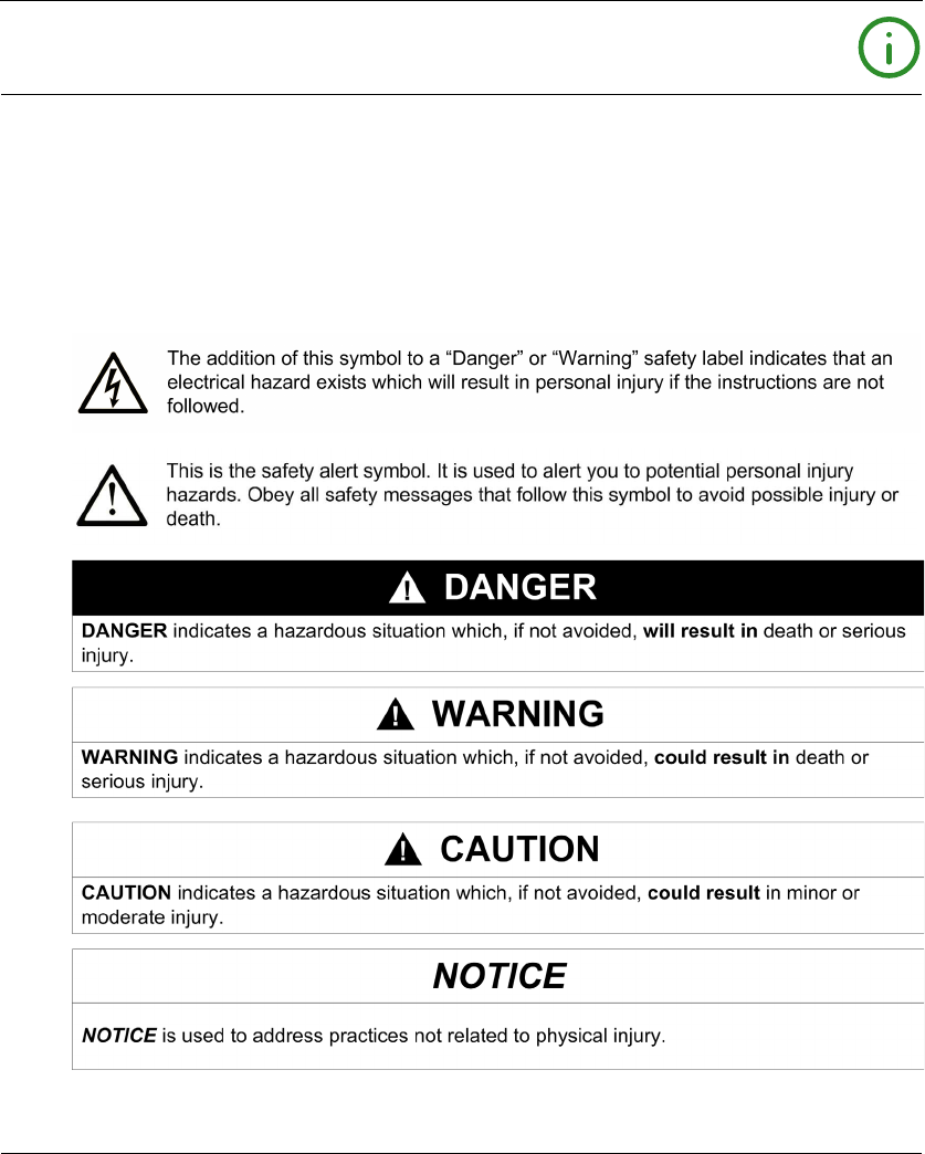
NOTICE
Read these instructions carefully, and look at the equipment to become familiar with the device
before trying to install, operate, or maintain it. The following special messages may appear
throughout this documentation or on the equipment to warn of potential hazards or to call attention
to information that clarifies or simplifies a procedure.

6EIO0000001402 12/2014
PLEASE NOTE
Electrical equipment should be installed, operated, serviced, and maintained only by qualified
personnel. No responsibility is assumed by Schneider Electric for any consequences arising out of
the use of this material.
A qualified person is one who has skills and knowledge related to the construction and operation
of electrical equipment and its installation, and has received safety training to recognize and avoid
the hazards involved.

EIO0000001402 12/2014 7
About the Book
At a Glance
Document Scope
This document describes the configuration of the TM3 expansion modules for SoMachine. For
further information, refer to the separate documents provided in the SoMachine online help.
Validity Note
This document has been updated with the release of SoMachine V4.1 SP1.
Related Documents
Title of Documentation Reference Number
TM3 Digital I/O Modules - Hardware Guide EIO0000001408 (ENG)
EIO0000001409 (FRA)
EIO0000001410 (GER)
EIO0000001411 (SPA)
EIO0000001412 (ITA)
EIO0000001413 (CHS)
EIO0000001376 (POR)
EIO0000001377 (TUR)
TM3 Analog I/O Modules - Hardware Guide EIO0000001414 (ENG)
EIO0000001415 (FRA)
EIO0000001416 (GER)
EIO0000001417 (SPA)
EIO0000001418 (ITA)
EIO0000001419 (CHS)
EIO0000001378 (POR)
EIO0000001379(TUR)
TM3 Expert Modules - Hardware Guide EIO0000001420 (ENG)
EIO0000001421 (FRA)
EIO0000001422 (GER)
EIO0000001423 (SPA)
EIO0000001424 (ITA)
EIO0000001425 (CHS)
EIO0000001380 (POR)
EIO0000001381 (TUR)

8EIO0000001402 12/2014
You can download these technical publications and other technical information from our website
at www.schneider-electric.com.
TM3 Safety Modules - Hardware Guide EIO0000001831 (ENG)
EIO0000001832 (FRA)
EIO0000001833 (GER)
EIO0000001834 (SPA)
EIO0000001835 (ITA)
EIO0000001836 (CHS)
EIO0000001837 (POR)
EIO0000001838 (TUR)
TM3 Transmitter and Receiver Modules - Hardware Guide EIO0000001426 (ENG)
EIO0000001427 (FRA)
EIO0000001428 (GER)
EIO0000001429 (SPA)
EIO0000001430 (ITA)
EIO0000001431 (CHS)
EIO0000001382 (POR)
EIO0000001383 (TUR)
Title of Documentation Reference Number
EIO0000001402 12/2014 9
Product Related Information
1 For additional information, refer to NEMA ICS 1.1 (latest edition), "Safety Guidelines for the
Application, Installation, and Maintenance of Solid State Control" and to NEMA ICS 7.1 (latest
edition), "Safety Standards for Construction and Guide for Selection, Installation and Operation of
Adjustable-Speed Drive Systems" or their equivalent governing your particular location.
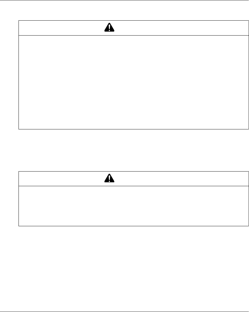
WARNING
LOSS OF CONTROL
-The designer of any control scheme must consider the potential failure modes of control paths
and, for certain critical control functions, provide a means to achieve a safe state during and
after a path failure. Examples of critical control functions are emergency stop and overtravel
stop, power outage and restart.
-Separate or redundant control paths must be provided for critical control functions.
-System control paths may include communication links. Consideration must be given to the
implications of unanticipated transmission delays or failures of the link.
-Observe all accident prevention regulations and local safety guidelines.1
-Each implementation of this equipment must be individually and thoroughly tested for proper
operation before being placed into service.
Failure to follow these instructions can result in death, serious injury, or equipment
damage.
WARNING
UNINTENDED EQUIPMENT OPERATION
-Only use software approved by Schneider Electric for use with this equipment.
-Update your application program every time you change the physical hardware configuration.
Failure to follow these instructions can result in death, serious injury, or equipment
damage.

10 EIO0000001402 12/2014
EIO0000001402 12/2014 11
Modicon TM3
I/O Configuration General Information
EIO0000001402 12/2014
I/O Configuration General Information
Chapter 1
I/O Configuration General Information
Introduction
This chapter provides general information to help you configure TM3 expansion modules for
SoMachine.
What Is in This Chapter?
This chapter contains the following topics:
Topic Page
I/O Configuration General Practices 12
General Description 13
Adding an Expansion Module 22
I/O Configuration General Information
12 EIO0000001402 12/2014
I/O Configuration General Practices
Match Software and Hardware Configuration
The I/O that may be embedded in your controller is independent of the I/O that you may have
added in the form of I/O expansion. It is important that the logical I/O configuration within your
program matches the physical I/O configuration of your installation. If you add or remove any
physical I/O to or from the I/O expansion bus, update your application configuration (this is also
true for any field bus devices you may have in your installation). Otherwise, there is the potential
that the expansion bus or field bus will no longer function while the embedded I/O that may be
present in your controller will continue to operate.
Use the GetRightBusStatus function regularly to monitor the expansion bus status.
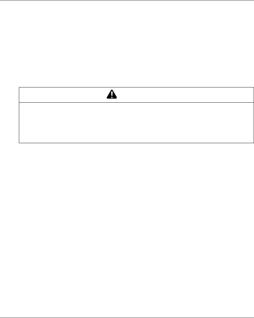
WARNING
UNINTENDED EQUIPMENT OPERATION
Update the configuration of your program each time you add or delete an I/O expansion, or you
add or delete any devices on your field bus.
Failure to follow these instructions can result in death, serious injury, or equipment
damage.

I/O Configuration General Information
EIO0000001402 12/2014 13
General Description
Introduction
The range of TM3 expansion modules includes:
-Digital modules, classified as follows:
-Input modules (see page 13)
-Output modules (seepage14)
-Mixed input/output modules (see page 15)
-Analog modules, classified as follows:
-Input modules (see page 16)
-Output modules (seepage17)
-Mixed input/output modules (see page 18)
-Expert modules (see page 19)
-Safety modules (seepage19)
-Transmitter and receiver modules (see page 21)
TM3 Digital Input Modules
The following table shows the TM3 digital input expansion modules, with corresponding channel
type, nominal voltage/current, and terminal type. For information on configuration of these
modules, refer to the TM3 Digital I/O Modules Configuration (see page 25) section.
Reference Channels Channel Type Voltage
Current
Terminal Type /
Pitch
TM3DI8A 8 Regular inputs 120 Vac
7.5 mA
Removable screw
terminal block /
5.08 mm
TM3DI8 8 Regular inputs 24 Vdc
7mA
Removable screw
terminal block /
5.08 mm
TM3DI8G 8 Regular inputs 24 Vdc
7mA
Removable spring
terminal block /
5.08 mm
TM3DI16 16 Regular inputs 24 Vdc
7mA
Removable screw
terminal block /
3.81 mm
TM3DI16G 16 Regular inputs 24 Vdc
7mA
Removable spring
terminal block /
3.81 mm
TM3DI16K 16 Regular inputs 24 Vdc
5mA
HE10 (MIL 20)
connector
TM3DI32K 32 Regular inputs 24 Vdc
5mA
HE10 (MIL 20)
connector

I/O Configuration General Information
14 EIO0000001402 12/2014
TM3 Digital Output Modules
The following table shows the TM3 digital output modules, with corresponding channel type,
nominal voltage/current, and terminal type. For information on configuration of these modules,
refer to the TM3 Digital I/O Modules Configuration (see page 25) section.
Reference Channels Channel Type Voltage
Current
Terminal Type / Pitch
TM3DQ8R 8 Relay outputs 24 Vdc / 240 Vac
7 A maximum per
common line / 2 A
maximum per output
Removable screw
terminal block / 5.08 mm
TM3DQ8RG 8 Relay outputs 24 Vdc / 240 Vac
7 A maximum per
common line / 2 A
maximum per output
Removable spring
terminal block / 5.08 mm
TM3DQ8T 8 Regular transistor
outputs (source)
24 Vdc
4 A maximum per
common line/0.5 A
maximum per output
Removable screw
terminal block / 5.08 mm
TM3DQ8TG 8 Regular transistor
outputs (source)
24 Vdc
4 A maximum per
common line/0.5 A
maximum per output
Removable spring
terminal block / 5.08 mm
TM3DQ8U 8 Regular transistor
outputs (sink)
24 Vdc
4 A maximum per
common line/0.5 A
maximum per output
Removable screw
terminal block / 5.08 mm
TM3DQ8UG 8 Regular transistor
outputs (sink)
24 Vdc
4 A maximum per
common line/0.5 A
maximum per output
Removable spring
terminal block / 5.08 mm
TM3DQ16R 16 Relay outputs 24 Vdc / 240 Vac
8 A maximum per
common line / 2 A
maximum per output
Removable screw
terminal block / 3.81 mm
TM3DQ16RG 16 Relay outputs 24 Vdc / 240 Vac
8 A maximum per
common line / 2 A
maximum per output
Removable spring
terminal block / 3.81 mm
TM3DQ16T 16 Regular transistor
outputs (source)
24 Vdc
4 A maximum per
common line / 0.5 A
maximum per output
Removable screw
terminal block / 3.81 mm

I/O Configuration General Information
EIO0000001402 12/2014 15
TM3 Digital Mixed Input/Output Modules
This following table shows the TM3 mixed I/O modules, with corresponding channel type, nominal
voltage/current, and terminal type. For information on configuration of these modules, refer to the
TM3 Digital I/O Modules Configuration (see page 25) section.
TM3DQ16TG 16 Regular transistor
outputs (source)
24 Vdc
4 A maximum per
common line / 0.5 A
maximum per output
Removable spring
terminal block / 3.81 mm
TM3DQ16U 16 Regular transistor
outputs (sink)
24 Vdc
2 A maximum per
common line / 0.4 A
maximum per output
Removable screw
terminal block / 3.81 mm
TM3DQ16UG 16 Regular transistor
outputs (sink)
24 Vdc
2 A maximum per
common line / 0.4 A
maximum per output
Removable spring
terminal block / 3.81 mm
TM3DQ16TK 16 Regular transistor
outputs (source)
24 Vdc
2 A maximum per
common line / 0.1 A
maximum per output
HE10 (MIL 20) connector
TM3DQ16UK 16 Regular transistor
outputs (sink)
24 Vdc
2 A maximum per
common line / 0.1 A
maximum per output
HE10 (MIL 20) connector
TM3DQ32TK 32 Regular transistor
outputs (source)
24 Vdc
2 A maximum per
common line / 0.1 A
maximum per output
HE10 (MIL 20) connector
TM3DQ32UK 32 Regular transistor
outputs (sink)
24 Vdc
2 A maximum per
common line / 0.1 A
maximum per output
HE10 (MIL 20) connector
Reference Channels Channel Type Voltage
Current
Terminal Type / Pitch
Reference Channels Channel Type Voltage
Current
Terminal Type / Pitch
TM3DM8R 4 Regular inputs 24 Vdc
7mA
Removable screw
terminal block / 5.08 mm
4 Relay outputs 24 Vdc / 240 Vac
7 A maximum per
common line / 2 A
maximum per output

I/O Configuration General Information
16 EIO0000001402 12/2014
TM3 Analog Input Modules
The following table shows the TM3 analog input expansion modules, with corresponding channel
type, nominal voltage/current, and terminal type. For information on configuration of these
modules, refer to the TM3 Analog Input Modules Configuration (see page 28) section.
TM3DM8RG 4 Regular inputs 24 Vdc
7mA
Removable spring
terminal block /5.08 mm
4 Relay outputs 24 Vdc / 240 Vac
7 A maximum per
common line / 2 A
maximum per output
TM3DM24R 16 Regular inputs 24 Vdc
7mA
Removable screw
terminal block / 3.81 mm
8 Relay outputs 24 Vdc / 240 Vac
7 A maximum per
common line / 2 A
maximum per output
TM3DM24RG 16 Regular inputs 24 Vdc
7mA
Removable spring
terminal block / 3.81 mm
8 Relay outputs 24 Vdc / 240 Vac
7 A maximum per
common line / 2 A
maximum per output
Reference Channels Channel Type Voltage
Current
Terminal Type / Pitch
Reference Resolution Channels Channel
Type
Mode Terminal Type /
Pitch
TM3AI2H 16 bit, or
15 bit + sign
2 inputs 0...10 Vdc
-10…+10 Vdc
0...20 mA
4...20 mA
Removable screw
terminal block /
5.08 mm
TM3AI2HG 16 bit, or
15 bit + sign
2 inputs 0...10 Vdc
-10…+10 Vdc
0...20 mA
4...20 mA
Removable spring
terminal block /
5.08 mm
TM3AI4 12 bit, or
11 bit + sign
4 inputs 0...10 Vdc
-10…+10 Vdc
0...20 mA
4...20 mA
Removable screw
terminal block /
3.81 mm
TM3AI4G 12 bit, or
11 bit + sign
4 inputs 0...10 Vdc
-10…+10 Vdc
0...20 mA
4...20 mA
Removable spring
terminal blocks /
3.81 mm

I/O Configuration General Information
EIO0000001402 12/2014 17
TM3 Analog Output Modules
The following table shows the TM3 analog output modules, with corresponding channel type,
nominal voltage/current, and terminal type. For information on configuration of these modules,
refer to the TM3 Analog Output Modules Configuration (see page 45) section.
TM3AI8 12 bit, or
11 bit + sign
8 inputs 0...10 Vdc
-10…+10 Vdc
0...20 mA
4...20 mA
Removable screw
terminal block /
3.81 mm
TM3AI8G 12 bit, or
11 bit + sign
8 inputs 0...10 Vdc
-10…+10 Vdc
0...20 mA
4...20 mA
Removable spring
terminal blocks /
3.81 mm
TM3TI4 16 bit, or
15 bit + sign
4 inputs 0...10 Vdc
-10…+10 Vdc
0...20 mA
4...20 mA
Thermocouple
PT100/1000
NI100/1000
Removable screw
terminal block /
3.81 mm
TM3TI4G 16 bit, or
15 bit + sign
4 inputs 0...10 Vdc
-10…+10 Vdc
0...20 mA
4...20 mA
Thermocouple
PT100/1000
NI100/1000
Removable spring
terminal blocks /
3.81 mm
TM3TI8T 16 bit, or
15 bit + sign
8 inputs Thermocouple
NTC/PTC
Removable screw
terminal block /
3.81 mm
TM3TI8TG 16 bit, or
15 bit + sign
8 inputs Thermocouple
NTC/PTC
Removable spring
terminal blocks /
3.81 mm
Reference Resolution Channels Channel
Type
Mode Terminal Type /
Pitch
Reference Resolution Channels Channel
Type
Mode Terminal Type /
Pitch
TM3AQ2 12 bit, or
11 bit + sign
2 outputs 0...10 Vdc
-10…+10 Vdc
0...20 mA
4...20 mA
Removable screw
terminal block /
5.08 mm

I/O Configuration General Information
18 EIO0000001402 12/2014
TM3 Analog Mixed Input/Output Modules
This following table shows the TM3 analog mixed I/O modules, with corresponding channel type,
nominal voltage/current, and terminal type. For information on configuration of these modules,
refer to the TM3 Analog Mixed I/O Modules Configuration (see page 50) section.
TM3AQ2G 12 bit, or
11 bit + sign
2 outputs 0...10 Vdc
-10…+10 Vdc
0...20 mA
4...20 mA
Removable spring
terminal block /
5.08 mm
TM3AQ4 12 bit, or
11 bit + sign
4 outputs 0...10 Vdc
-10…+10 Vdc
0...20 mA
4...20 mA
Removable screw
terminal block /
5.08 mm
TM3AQ4G 12 bit, or
11 bit + sign
4 outputs 0...10 Vdc
-10…+10 Vdc
0...20 mA
4...20 mA
Removable spring
terminal block /
5.08 mm
Reference Resolution Channels Channel
Type
Mode Terminal Type /
Pitch
Reference Resolution Channels Channel
Type
Mode Terminal Type / Pitch
TM3AM6 12 bit, or
11 bit + sign
4 inputs 0...10 Vdc
-10...+10 Vdc
0...20 mA
4...20 mA
Removable screw
terminal block /
3.81 mm
2 outputs
TM3AM6G 12 bit, or
11 bit + sign
4 inputs 0...10 Vdc
-10...+10 Vdc
0...20 mA
4...20 mA
Removable spring
terminal block /
3.81 mm
2 outputs
TM3TM3 16 bit, or
15 bit + sign
2 inputs 0...10 Vdc
-10...+10 Vdc
0...20 mA
4...20 mA
Thermocouple
PT100/1000
NI100/1000
Removable screw
terminal block /
5.08 mm
12 bit, or
11 bit + sign
1 output 0...10 Vdc
-10...+10 Vdc
0...20 mA
4...20 mA

I/O Configuration General Information
EIO0000001402 12/2014 19
TM3 Expert Modules
The following table shows the TM3 expert expansion modules, with corresponding terminal type.
For information on configuration of these modules, refer to the TM3 Expert I/O Modules
Configuration (see page 61) section.
TM3 Safety Modules
This table contains the TM3 safety modules (see Modicon TM3, Safety Modules, Hardware
Guide), with the corresponding channel type, nominal voltage/current, and terminal type:
TM3TM3G 16 bit, or
15 bit + sign
2 inputs 0...10 Vdc
-10...+10 Vdc
0...20 mA
4...20 mA
Thermocouple
PT100/1000
NI100/1000
Removable spring
terminal block /
5.08 mm
12 bit, or
11 bit + sign
1 output 0...10 Vdc
-10...+10 Vdc
0...20 mA
4...20 mA
Reference Resolution Channels Channel
Type
Mode Terminal Type / Pitch
Reference Description Terminal Type / Pitch
TM3XTYS4 TeSys module 4 front connectors RJ-45
1 removable power supply connector /
5.08 mm
Reference Function
Category
Channels Channel type Voltage
Current
Terminal type
TM3SAC5R 1 function,
up to
category 3
1 or 2 (1) Safety input 24 Vdc
100 mA maximum
3.81 mm (0.15 in.) and
5.08 mm (0.20 in.),
removable screw
terminal block
Start (2) Input
3 in parallel Relay outputs
Normally open
24 Vdc / 230 Vac
6 A maximum per output
TM3SAC5RG 1 function,
up to
category 3
1 or 2 (1) Safety input 24 Vdc
100 mA maximum
3.81 mm (0.15 in.) and
5.08 mm (0.20 in.),
removable spring
terminal block
Start (2) Input
3 in parallel Relay outputs
Normally open
24 Vdc / 230 Vac
6 A maximum per output
(1) Depending on external wiring
(2) Non-monitored start

I/O Configuration General Information
20 EIO0000001402 12/2014
For more information on the terms methods used concerning functional safety as they apply to the
TM3 Safety Modules, refer to the sections TM3 Safety Functionality modes (seepage69) and TM3
Safety Operation Modes (seepage78).
TM3SAF5R 1 function,
up to
category 4
2 (1) Safety inputs 24 Vdc
100 mA maximum
3.81 mm (0.15 in.) and
5.08 mm (0.20 in.),
removable screw
terminal block
Start Input
3 in parallel Relay outputs
Normally open
24 Vdc / 230 Vac
6 A maximum per output
TM3SAF5RG 1 function,
up to
category 4
2 (1) Safety inputs 24 Vdc
100 mA maximum
3.81 mm (0.15 in.) and
5.08 mm (0.20 in.),
removable spring
terminal block
Start Input
3 in parallel Relay outputs
Normally open
24 Vdc / 230 Vac
6 A maximum per output
TM3SAFL5R 2 functions,
up to
category 3
2 (1) Safety inputs 24 Vdc
100 mA maximum
3.81 mm (0.15 in.) and
5.08 mm (0.20 in.),
removable screw
terminal block
Start Input
3 in parallel Relay outputs
Normally open
24 Vdc / 230 Vac
6 A maximum per output
TM3SAFL5RG 2 functions,
up to
category 3
2 (1) Safety inputs 24 Vdc
100 mA maximum
3.81 mm (0.15 in.) and
5.08 mm (0.20 in.),
removable spring
terminal block
Start Input
3 in parallel Relay outputs
Normally open
24 Vdc / 230 Vac
6 A maximum per output
TM3SAK6R 3 functions,
up to
category 4
1 or 2 (1) Safety inputs 24 Vdc
100 mA maximum
3.81 mm (0.15 in.) and
5.08 mm (0.20 in.),
removable screw
terminal block
Start Input
3 in parallel Relay outputs
Normally open
24 Vdc / 230 Vac
6 A maximum per output
TM3SAK6RG 3 functions,
up to
category 4
1 or 2 (1) Safety inputs 24 Vdc
100 mA maximum
3.81 mm (0.15 in.) and
5.08 mm (0.20 in.),
removable spring
terminal block
Start Input
3 in parallel Relay outputs
Normally open
24 Vdc / 230 Vac
6 A maximum per output
Reference Function
Category
Channels Channel type Voltage
Current
Terminal type
(1) Depending on external wiring
(2) Non-monitored start

I/O Configuration General Information
EIO0000001402 12/2014 21
TM3 Transmitter and Receiver Modules
The following table shows the TM3 transmitter and receiver expansion modules, with
corresponding terminal type. For information on configuration of these modules, refer to the TM3
Transmitter and Receiver I/O Modules Configuration (see page 93) section.
Reference Description Terminal Type / Pitch
TM3XTRA1 Data transmitter module for remote I/O 1 front connector RJ-45
1 screw for functional ground
connection
TM3XREC1 Data receiver module for remote I/O 1 front connector RJ-45
1 removable power supply
connector / 5.08 mm
I/O Configuration General Information
22 EIO0000001402 12/2014
Adding an Expansion Module
Adding a Module
To add an expansion module to your controller, select the expansion module in the Hardware
Catalog, drag it to the Devices tree, and drop it on one of the highlighted nodes.
For more information on adding a device to your project, refer to:
• Using the Drag-and-drop Method (see SoMachine, Programming Guide)
• Using the Contextual Menu or Plus Button (see SoMachine, Programming Guide)
I/O Configuration
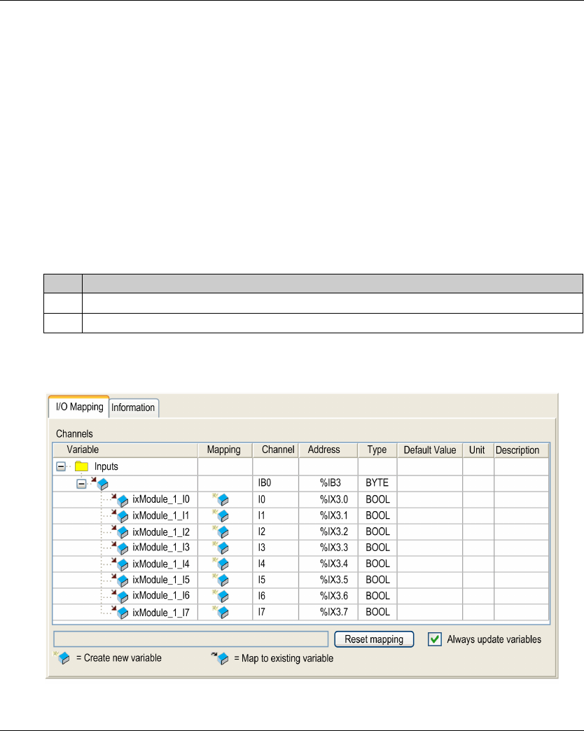
The I/O mapping of an expansion module is carried out through the I/O Mapping tab of the
expansion module configuration.
This table describes how to configure an expansion module:
I/O Mapping Tab Description
This figure shows the I/O Mapping tab:
Step Action
1 Double-click the expansion module node in the Devices tree to display the I/O Mapping tab.
2 Edit the parameters of the I/O Mapping tab to configure the expansion module.
I/O Configuration General Information
EIO0000001402 12/2014 23
This table describes each parameter of the I/O Mapping tab:
Parameter Description
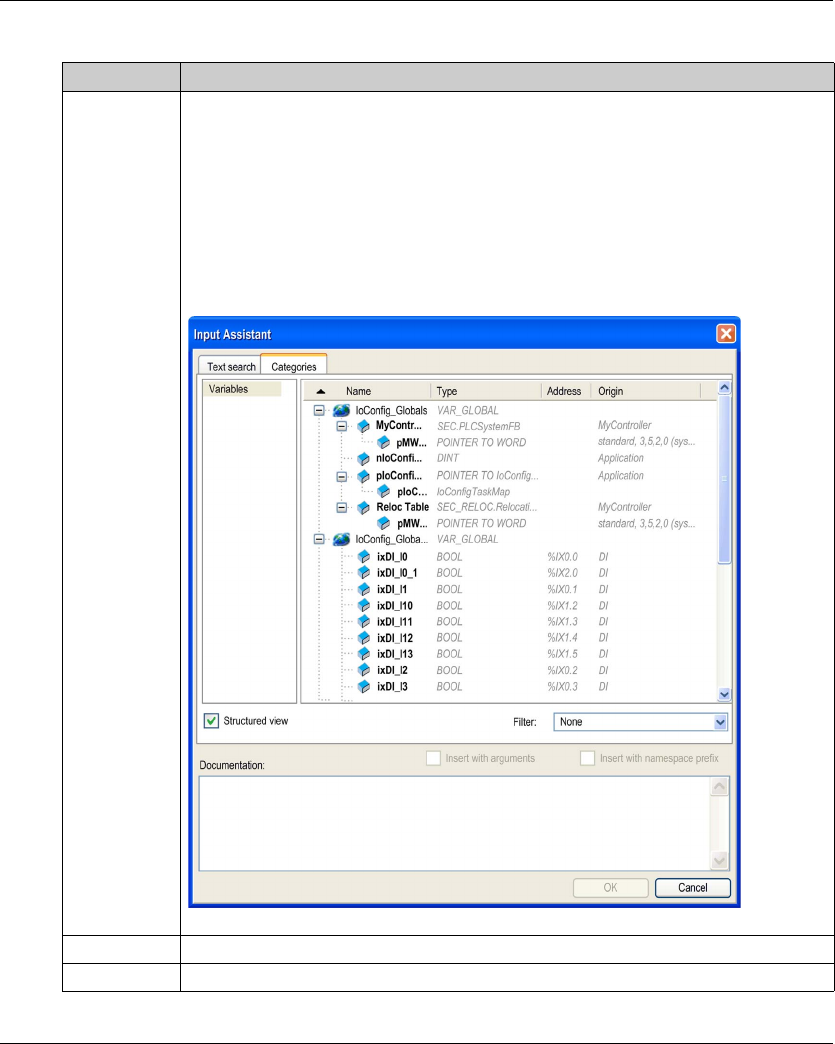
Variable Allows you to map the channel on a variable.
NOTE: Expand the list of variables from the category Inputs or Outputs.
You can map a channel by either creating a new variable or mapping to an existing variable.
Create new variable:
Double-click the variable to enter the new variable name. A new variable is created if the
variable does not already exist.
Map to existing variable:
Double-click the variable and click [...] to open the Input Assistant window. Select the
variable from the list and press OK.
This figure shows the Input Assistant window:
Mapping Indicates whether the channel is mapped on a new variable or an existing variable.
Channel Displays the channel name of the device.

I/O Configuration General Information
24 EIO0000001402 12/2014
Address Displays the address of the channel.
NOTE: If the channel is mapped to an existing variable, corresponding address appears as
strikethrough text in the table.
Type Displays the data type of the channel.
Default Value Indicates the value taken by the output when the controller is in a STOPPED or HALT state.
Double-click the cell to change the default value.
You can toggle between the following values:
-No value (empty cell)
-TRUE
-FALSE
Unit Displays the unit of the channel value.
Description Allows you to enter a short description of the channel.
Parameter Description

EIO0000001402 12/2014 25
Modicon TM3
TM3 Digital I/O Modules Configuration
EIO0000001402 12/2014
TM3 Digital I/O Modules Configuration
Chapter 2
TM3 Digital I/O Modules Configuration
Configuring the TM3 Digital I/O Modules
Introduction
The range of TM3 digital I/O expansion modules includes:
-TM3 Digital Input Modules (see page 13)
-TM3 Digital Output Modules (seepage14)
-TM3 Digital Mixed Input/Output Modules (seepage15)
Configuring the Modules
Refer to the I/O Configuration (see page 22) for detailed information on the configuration of the
digital I/O expansion modules in SoMachine.

TM3 Digital I/O Modules Configuration
26 EIO0000001402 12/2014
EIO0000001402 12/2014 27
Modicon TM3
TM3 Analog I/O Modules Configuration
EIO0000001402 12/2014
TM3 Analog I/O Modules Configuration
Chapter 3
TM3 Analog I/O Modules Configuration
Introduction
This chapter describes how to configure the TM3 analog I/O modules.
The range of TM3 analog I/O expansion modules includes:
-TM3 Analog Input Modules (see page 16)
-TM3 Analog Output Modules (see page 17)
-TM3 Analog Mixed Input/Output Modules (see page 18)
What Is in This Chapter?
This chapter contains the following sections:
Section Topic Page
3.1 TM3 Analog Input Modules 28
3.2 TM3 Analog Output Modules 45
3.3 TM3 Analog Mixed Input/Output Modules 50
3.4 TM3 Analog I/O Modules Diagnostic 58


TM3 Analog I/O Modules Configuration
EIO0000001402 12/2014 29
TM3AI2H / TM3AI2HG
Introduction
The TM3AI2H (screw terminal block) / TM3AI2HG (spring terminal block) expansion module
feature 2 analog input channels with 16-bit resolution.
The channel input types are:
-0...10 V
--10...+10 V
-0...20 mA
-4...20 mA
For further hardware information, refer to TM3AI2H / TM3AI2HG (see Modicon TM3,
Analog I/O Modules, Hardware Guide).
NOTE: For example, if you have physically wired the analog channel for a voltage signal and you
configure the channel for a current signal in SoMachine, you may damage the analog circuit.
Configuring the Module
For each input, you can define:
NOTICE
INOPERABLE EQUIPMENT
Verify that the physical wiring of the analog circuit is compatible with the software configuration
for the analog channel.
Failure to follow these instructions can result in equipment damage.
Parameter Value Default Value Description
Type Not used
0 - 10 V
-10 - +10 V
0 - 20 mA
4 - 20 mA
Not used Choose the mode of the channel.
Min. 0 - 10 V -32768...32767 0 Specifies the lower measurement limit.
-10 - +10 V -10000
0 - 20 mA 0
4 - 20 mA 4000
Max. 0 - 10 V -32768...32767 10000 Specifies the upper measurement limit.
-10 - +10 V 10000
0 - 20 mA 20000
4 - 20 mA 20000

TM3 Analog I/O Modules Configuration
30 EIO0000001402 12/2014
I/O Mapping Tab
Variables can be defined and named in the I/O Mapping tab. Additional information such as
topological addressing is also provided in this tab.
This table describes the I/O Mapping tab:
For further generic descriptions, refer to I/O Mapping Tab Description (see page 22).
Input Filter 0...1000 0 Specifies the filtering time (0...10 s) by
increment of 10 ms.
Sampling 1ms/Channel 1ms/Channel Specifies the sampling period of the
channel.
Status Enabled Yes
No
Yes Enables the diagnostic byte of each
channel.
If the status is disabled (value = No), the
status bytes IBStatusIW0 and
IBStatusIW1 do not contain relevant
information.
Parameter Value Default Value Description
Variable Channel Type Description
Inputs IW0 INT Current value of the input 0
IW1 INT Current value of the input 1
Diagnostic IBStatusIW0 BYTE Status of input 0 (see page 58)
IBStatusIW1 BYTE Status of input 1 (see page 58)
TM3 Analog I/O Modules Configuration
EIO0000001402 12/2014 31
TM3AI4 / TM3AI4G
Introduction
The TM3AI4 (screw terminal block) / TM3AI4G (spring terminal block) expansion module feature
4 analog input channels with 12-bit resolution.
The channel input types are:
-0...10 V
--10...+10 V
-0...20 mA
-4...20 mA
For further hardware information, refer to TM3AI4 / TM3AI4G (see Modicon TM3,
Analog I/O Modules, Hardware Guide).
NOTE: For example, if you have physically wired the analog channel for a voltage signal and you
configure the channel for a current signal in SoMachine, you may damage the analog circuit.
Configuring the Module
For each input, you can define:
NOTICE
INOPERABLE EQUIPMENT
Verify that the physical wiring of the analog circuit is compatible with the software configuration
for the analog channel.
Failure to follow these instructions can result in equipment damage.
Parameter Value Default Value Description
Type Not used
0 - 10 V
-10 - +10 V
0 - 20 mA
4 - 20 mA
Not used Choose the mode of the channel.
Min. 0 - 10 V -32768...3276710 Specifies the lower measurement limit.
-10 - +10 V -10000
0 - 20 mA 0
4 - 20 mA 4000
Max. 0 - 10 V -32768...32767110000 Specifies the upper measurement limit.
-10 - +10 V 10000
0 - 20 mA 20000
4 - 20 mA 20000

TM3 Analog I/O Modules Configuration
32 EIO0000001402 12/2014
1 The 12-bit data (0 to 4095) processed in the analog I/O module can be linear-converted to a value
between -32768 and 32767.
I/O Mapping Tab
Variables can be defined and named in the I/O Mapping tab. Additional information such as
topological addressing is also provided in this tab.
This table describes the I/O Mapping tab:
For further generic descriptions, refer to I/O Mapping Tab Description (see page 22).
Input Filter 0...1000 0 Specifies the filtering time (0...10 s) by
increment of 10 ms.
Sampling 1ms/Channel
10ms/Channel
1ms/Channel Specifies the sampling period of the
channel.
Status Enabled Yes
No
Yes Enables the diagnostic byte of each
channel.
If the status is disabled (value = No), the
status bytes IBStatusIWx do not contain
relevant information.
Parameter Value Default Value Description
Variable Channel Type Description
Inputs IW0 INT Current value of the input 0
IW1 INT Current value of the input 1
IW2 INT Current value of the input 2
IW3 INT Current value of the input 3
Diagnostic IBStatusIW0 BYTE Status of input 0 (see page 58)
IBStatusIW1 BYTE Status of input 1 (see page 58)
IBStatusIW2 BYTE Status of input 2 (see page 58)
IBStatusIW3 BYTE Status of input 3 (see page 58)

TM3 Analog I/O Modules Configuration
EIO0000001402 12/2014 33
TM3AI8 / TM3AI8G
Introduction
The TM3AI8 (screw terminal block) / TM3AI8G (spring terminal block) expansion module feature
8 analog input channels with 12-bit resolution.
The channel input types are:
-0...10 V
--10...+10 V
-0...20 mA
-4...20 mA
For further hardware information, refer to TM3AI8 / TM3AI8G (see Modicon TM3,
Analog I/O Modules, Hardware Guide).
NOTE: For example, if you have physically wired the analog channel for a voltage signal and you
configure the channel for a current signal in SoMachine, you may damage the analog circuit.
Configuring the Module
For each input, you can define:
NOTICE
INOPERABLE EQUIPMENT
Verify that the physical wiring of the analog circuit is compatible with the software configuration
for the analog channel.
Failure to follow these instructions can result in equipment damage.
Parameter Value Default Value Description
Type Not used
0 - 10 V
-10 - +10 V
0 - 20 mA
4 - 20 mA
Not used Choose the mode of the channel.
Min. 0 - 10 V -32768...3276710 Specifies the lower measurement limit.
-10 - +10 V -10000
0 - 20 mA 0
4 - 20 mA 4000
Max. 0 - 10 V -32768...32767110000 Specifies the upper measurement limit.
-10 - +10 V 10000
0 - 20 mA 20000
4 - 20 mA 20000

TM3 Analog I/O Modules Configuration
34 EIO0000001402 12/2014
1 The 12-bit data (0 to 4095) processed in the analog I/O module can be linear-converted to a value
between -32768 and 32767.
I/O Mapping Tab
Variables can be defined and named in the I/O Mapping tab. Additional information such as
topological addressing is also provided in this tab.
This table describes the I/O Mapping tab:
For further generic descriptions, refer to I/O Mapping Tab Description (see page 22).
Input Filter 0...1000 0 Specifies the filtering time (0...10 s) by
increment of 10 ms.
Sampling 1ms/Channel
10ms/Channel
1ms/Channel Specifies the sampling period of the
channel.
Status Enabled Yes
No
Yes Enables the diagnostic byte of each
channel.
If the status is disabled (value = No), the
status bytes IBStatusIWx do not contain
relevant information.
Parameter Value Default Value Description
Variable Channel Type Description
Inputs IW0 INT Current value of the input 0
IW1 INT Current value of the input 1
IW2 INT Current value of the input 2
IW3 INT Current value of the input 3
IW4 INT Current value of the input 4
IW5 INT Current value of the input 5
IW6 INT Current value of the input 6
IW7 INT Current value of the input 7
Diagnostic IBStatusIW0 BYTE Status of input 0 (see page 58)
IBStatusIW1 BYTE Status of input 1 (see page 58)
IBStatusIW2 BYTE Status of input 2 (see page 58)
IBStatusIW3 BYTE Status of input 3 (see page 58)
IBStatusIW4 BYTE Status of input 4 (see page 58)
IBStatusIW5 BYTE Status of input 5 (see page 58)
IBStatusIW6 BYTE Status of input 6 (see page 58)
IBStatusIW7 BYTE Status of input 7 (see page 58)

TM3 Analog I/O Modules Configuration
EIO0000001402 12/2014 35
TM3TI4 / TM3TI4G
Introduction
The TM3TI4 (screw terminal block) / TM3TI4G (spring terminal block) expansion module feature 4
analog input channels with 16-bit resolution.
The channel input types are:
-0...10 V
--10...+10 V
-0...20 mA
-4...20 mA
-K thermocouple
-J thermocouple
-R thermocouple
-S thermocouple
-B thermocouple
-E thermocouple
-T thermocouple
-N thermocouple
-C thermocouple
-PT100
-PT1000
-NI100
-NI1000
For further hardware information, refer to TM3TI4 / TM3TI4G (see Modicon TM3,
Analog I/O Modules, Hardware Guide).
NOTE: For example, if you have physically wired the analog channel for a voltage signal and you
configure the channel for a current signal in SoMachine, you may damage the analog circuit.
NOTICE
INOPERABLE EQUIPMENT
Verify that the physical wiring of the analog circuit is compatible with the software configuration
for the analog channel.
Failure to follow these instructions can result in equipment damage.

TM3 Analog I/O Modules Configuration
36 EIO0000001402 12/2014
Configuring the Module
For each input, you can define:
Parameter Value Default Value Description
Type Not used
0 - 10 V
-10 - +10 V
0 - 20 mA
4 - 20 mA
K Thermocouple
J Thermocouple
R Thermocouple
S Thermocouple
B Thermocouple
E Thermocouple
T Thermocouple
N Thermocouple
C Thermocouple
PT100
PT1000
NI100
NI1000
Not used Choose the mode of the channel.
Scope Customized
Celsius (0.1°C)
Fahrenheit (0.1°F)
Fahrenheit (0.2°F)*
Customized The range of values for a channel.
* Only for B and C thermocouples.
Min. 0 - 10 V -32768...32767 0 Specifies the lower measurement limit.
-10 - +10 V -10000
0 - 20 mA 0
4 - 20 mA 4000
Temperature See the table below
Max. 0 - 10 V -32768...32767 10000 Specifies the upper measurement limit.
-10 - +10 V 10000
0 - 20 mA 20000
4 - 20 mA 20000
Temperature See the table below
Input Filter 0...1000 0 Specifies the filtering time (0...10 s) by
increment of 10 ms.

TM3 Analog I/O Modules Configuration
EIO0000001402 12/2014 37
I/O Mapping Tab
Variables can be defined and named in the I/O Mapping tab. Additional information such as
topological addressing is also provided in this tab.
This table describes the I/O Mapping tab:
Sampling 10ms/Channel
100ms/Channel
100ms/Channel Specifies the sampling period of the
channel.
Status Enabled Yes
No
Yes Enables the diagnostic byte of each
channel.
If the status is disabled (value = No), the
status bytes IBStatusIWx do not
contain relevant information.
Parameter Value Default Value Description
Type Customized Celsius (0.1 °C) Fahrenheit
Minimum Maximum Minimum Maximum Minimum Maximum Unit
K Thermocouple -32768 32767 -2000 13000 -3280 23720 0.1 °F
J Thermocouple -32768 32767 -2000 10000 -3280 18320 0.1 °F
R Thermocouple -32768 32767 0 17600 320 32000 0.1 °F
S Thermocouple -32768 32767 0 17600 320 32000 0.1 °F
B Thermocouple -32768 32767 0 18200 160 16540 0.2 °F
E Thermocouple -32768 32767 -2000 8000 -3280 14720 0.1 °F
T Thermocouple -32768 32767 -2000 4000 -3280 7520 0.1 °F
N Thermocouple -32768 32767 -2000 13000 -3280 23720 0.1 °F
C Thermocouple -32768 32767 0 23150 160 20995 0.2 °F
PT100 -32768 32767 -2000 8500 -3280 15620 0.1 °F
PT1000 -32768 32767 -2000 6000 -3280 11120 0.1 °F
NI100 -32768 32767 -600 1800 -760 3560 0.1 °F
NI1000 -32768 32767 -600 1800 -760 3560 0.1 °F
Variable Channel Type Description
Inputs IW0 INT Current value of the input 0
IW1 INT Current value of the input 1
IW2 INT Current value of the input 2
IW3 INT Current value of the input 3

TM3 Analog I/O Modules Configuration
38 EIO0000001402 12/2014
For further generic descriptions, refer to I/O Mapping Tab Description (see page 22).
Diagnostic IBStatusIW0 BYTE Status of input 0 (see page 58)
IBStatusIW1 BYTE Status of input 1 (see page 58)
IBStatusIW2 BYTE Status of input 2 (see page 58)
IBStatusIW3 BYTE Status of input 3 (see page 58)
Variable Channel Type Description

TM3 Analog I/O Modules Configuration
EIO0000001402 12/2014 39
TM3TI8T / TM3TI8TG
Introduction
The TM3TI8T (screw terminal block) / TM3TI8TG (spring terminal block) expansion module feature
8 analog input channels with 16-bit resolution.
The channel input types are:
-K thermocouple
-J thermocouple
-R thermocouple
-S thermocouple
-B thermocouple
-E thermocouple
-T thermocouple
-N thermocouple
-C thermocouple
-NTC thermistor
-PTC thermistor
-Ohmmeter
For further hardware information, refer to TM3TI8T / TM3TI8TG (see Modicon TM3,
Analog I/O Modules, Hardware Guide).
NOTE: For example, if you have physically wired the analog channel for a voltage signal and you
configure the channel for a current signal in SoMachine, you may damage the analog circuit.
NOTICE
INOPERABLE EQUIPMENT
Verify that the physical wiring of the analog circuit is compatible with the software configuration
for the analog channel.
Failure to follow these instructions can result in equipment damage.

TM3 Analog I/O Modules Configuration
40 EIO0000001402 12/2014
Configuring the Module
For each input, you can define:
Parameter Value Default Value Description
Type
-Not used
-Not used Choose the parameter type and scope
value for the channel.
Type
-K Thermocouple
-J Thermocouple
-R Thermocouple
-S Thermocouple
-E Thermocouple
-T Thermocouple
-N Thermocouple
-NTC Thermistor
Scope
-Customized
-Celsius (0.1°C)
-Fahrenheit
(0.1°F)
Celsius (0.1°C)
Type
-B Thermocouple
-C Thermocouple
Scope
-Customized
-Celsius (0.1°C)
-Fahrenheit
(0.2°F)
Celsius (0.1°C)
Type
-PTC Thermistor
Scope
-Customized
-Threshold
Threshold
Type
-Ohmmeter
Scope
-Resistance (Ω)
Resistance
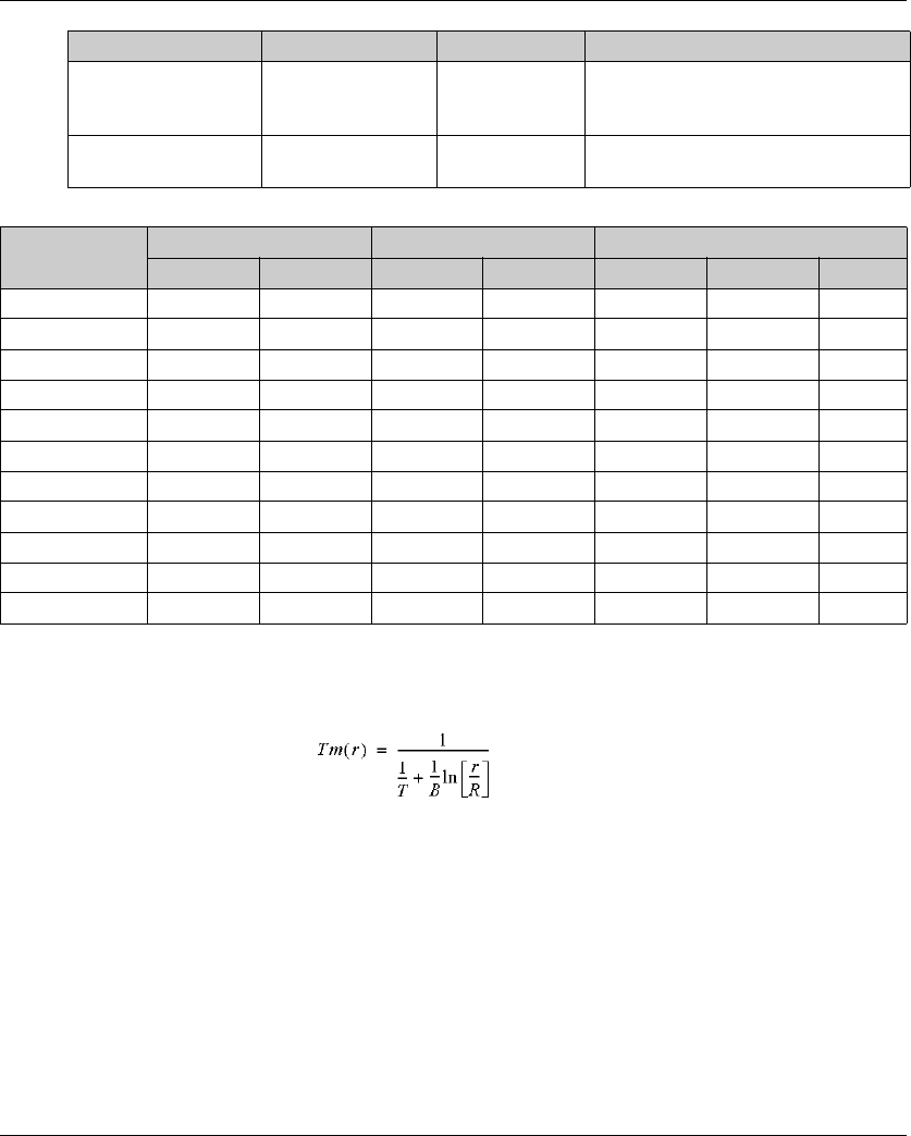
Minimum See the table below Specifies the lower measurement limit.
Maximum See the table below Specifies the upper measurement limit.
Rref (used only with
NTC probe
(seepage41))
1...65535 330 Reference resistance in Ohm at
temperature Tref.
Tref (used only with
NTC probe)
1...1000 25 Reference temperature value in Celsius.
Beta (used only with
NTC probe)
1...32767 3569 Sensitivity of NTC probe in Kelvin.
Input Filter 0...1000 0 Specifies the filtering time (0...10 s) by
increment of 10 ms.
Sampling 100ms/Channel 100ms/Channel Specifies the sampling period of the
channel.
Status Enabled Yes
No
Yes Enables the diagnostic byte of each
channel.
If the status is disabled (value = No), the
status bytes IBStatusIWx do not
contain relevant information.
TM3 Analog I/O Modules Configuration
EIO0000001402 12/2014 41
NTC Probe
The temperature (Tm) varies in relation to the resistance (r) following the equation below:
Where:
-Tm = temperature measured by the probe, in Kelvin
-r = physical value of the resistance in Ohm
-R = reference resistance in Ohm at temperature T
-T = reference temperature in Kelvin
-B = sensitivity of the NTC probe in Kelvin
R,T, and B must be greater or equal to 1.
NOTE: 25 °C = 77 °F = 298.15 K
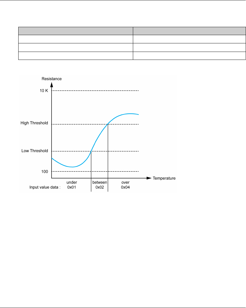
High Threshold (used
only with PTC probe
(seepage42))
100...10000 3100 Activation threshold
Low Threshold (used
only with PTC probe)
100...10000 1500 Reactivation threshold
Parameter Value Default Value Description
Type Customized Celsius (0.1 °C) Fahrenheit
Minimum Maximum Minimum Maximum Minimum Maximum Unit
K Thermocouple -32768 32767 -2000 13000 -3280 23720 0.1 °F
J Thermocouple -32768 32767 -2000 10000 -3280 18320 0.1 °F
R Thermocouple -32768 32767 0 17600 320 32000 0.1 °F
S Thermocouple -32768 32767 0 17600 320 32000 0.1 °F
B Thermocouple -32768 32767 0 18200 160 16540 0.2 °F
E Thermocouple -32768 32767 -2000 8000 -3280 14720 0.1 °F
T Thermocouple -32768 32767 -2000 4000 -3280 7520 0.1 °F
N Thermocouple -32768 32767 -2000 13000 -3280 23720 0.1 °F
C Thermocouple -32768 32767 0 23150 160 20995 0.2 °F
NTC Thermistor -32768 32767 -900 1500 -1300 3020 0.1 °F
PTC Thermistor -32768 32767 – – – – –
TM3 Analog I/O Modules Configuration
42 EIO0000001402 12/2014
PTC Probe
This table shows the read value according to the resistance:
This figure shows the threshold operation:
Resistance Value Read Value
Less than low threshold 1
Between thresholds 2
Greater than high threshold 4

TM3 Analog I/O Modules Configuration
EIO0000001402 12/2014 43
This figure shows an example hysteresis curve :
Ohmmeter
This table shows the minimum and maximum values:
Parameter Value
Minimum 100 Ω
Maximum 32 kΩ

TM3 Analog I/O Modules Configuration
44 EIO0000001402 12/2014
I/O Mapping Tab
Variables can be defined and named in the I/O Mapping tab. Additional information such as
topological addressing is also provided in this tab.
This table describes the I/O Mapping tab:
For further generic descriptions, refer to I/O Mapping Tab Description (see page 22).
Variable Channel Type Description
Inputs IW0 INT Current value of the input 0
IW1 INT Current value of the input 1
IW2 INT Current value of the input 2
IW3 INT Current value of the input 3
IW4 INT Current value of the input 4
IW5 INT Current value of the input 5
IW6 INT Current value of the input 6
IW7 INT Current value of the input 7
Diagnostic IBStatusIW0 BYTE Status of input 0 (see page 58)
IBStatusIW1 BYTE Status of input 1 (see page 58)
IBStatusIW2 BYTE Status of input 2 (see page 58)
IBStatusIW3 BYTE Status of input 3 (see page 58)
IBStatusIW4 BYTE Status of input 4 (see page 58)
IBStatusIW5 BYTE Status of input 5 (see page 58)
IBStatusIW6 BYTE Status of input 6 (see page 58)
IBStatusIW7 BYTE Status of input 7 (see page 58)


TM3 Analog I/O Modules Configuration
46 EIO0000001402 12/2014
TM3AQ2 / TM3AQ2G
Introduction
The TM3AQ2 (screw terminal block) / TM3AQ2G (spring terminal block) expansion module feature
2 analog output channels with 12-bit resolution.
The channel output types are:
-0...10 V
--10...+10 V
-0...20 mA
-4...20 mA
For further hardware information, refer to TM3AQ2 / TM3AQ2G (see Modicon TM3,
Analog I/O Modules, Hardware Guide).
NOTE: For example, if you have physically wired the analog channel for a voltage signal and you
configure the channel for a current signal in SoMachine, you may damage the analog circuit.
Configuring the Module
For each output, you can define:
NOTICE
INOPERABLE EQUIPMENT
Verify that the physical wiring of the analog circuit is compatible with the software configuration
for the analog channel.
Failure to follow these instructions can result in equipment damage.
Parameter Value Default Value Description
Type Not used
0 - 10 V
-10 - +10 V
0 - 20 mA
4 - 20 mA
Not used Choose the mode of the channel.
Min. 0 - 10 V -32768...3276710 Specifies the lower measurement limit.
-10 - +10 V -10000
0 - 20 mA 0
4 - 20 mA 4000
Max. 0 - 10 V -32768...32767110000 Specifies the upper measurement limit.
-10 - +10 V 10000
0 - 20 mA 20000
4 - 20 mA 20000

TM3 Analog I/O Modules Configuration
EIO0000001402 12/2014 47
1 The 12-bit data (0 to 4095) processed in the analog I/O module can be linear-converted to a value
between -32768 and 32767.
I/O Mapping Tab
Variables can be defined and named in the I/O Mapping tab. Additional information such as
topological addressing is also provided in this tab.
This table describes the I/O Mapping tab:
For further generic descriptions, refer to I/O Mapping Tab Description (see page 22).
Status Enabled Yes
No
Yes Enables the diagnostic byte of each
channel.
If the status is disabled (value = No), the
status bytes IBStatusQWx do not contain
relevant information.
Parameter Value Default Value Description
Variable Channel Type Default Value Description
Outputs QW0 INT -32768...32767 Command word of the output 0
QW1 INT -32768...32767 Command word of the output 1
Diagnostic IBStatusQW0 BYTE - Status of output 0 (see page 59)
IBStatusQW1 BYTE - Status of output 1 (see page 59)
TM3 Analog I/O Modules Configuration
48 EIO0000001402 12/2014
TM3AQ4 / TM3AQ4G
Introduction
The TM3AQ4 (screw terminal block) / TM3AQ4G (spring terminal block) expansion module feature
4 analog output channels with 12-bit resolution.
The channel output types are:
-0...10 V
--10...+10 V
-0...20 mA
-4...20 mA
For further hardware information, refer to TM3AQ4 / TM3AQ4G (see Modicon TM3,
Analog I/O Modules, Hardware Guide).
NOTE: For example, if you have physically wired the analog channel for a voltage signal and you
configure the channel for a current signal in SoMachine, you may damage the analog circuit.
Configuring the Module
For each output, you can define:
NOTICE
INOPERABLE EQUIPMENT
Verify that the physical wiring of the analog circuit is compatible with the software configuration
for the analog channel.
Failure to follow these instructions can result in equipment damage.
Parameter Value Default Value Description
Type Not used
0 - 10 V
-10 - +10 V
0 - 20 mA
4 - 20 mA
Not used Choose the mode of the channel.
Scope Customized Customized The range of values for a channel.
Min. 0 - 10 V -32768...3276710 Specifies the lower measurement limit.
-10 - +10 V -10000
0 - 20 mA 0
4 - 20 mA 4000

TM3 Analog I/O Modules Configuration
EIO0000001402 12/2014 49
1 The 12-bit data (0 to 4095) processed in the analog I/O module can be linear-converted to a value
between -32768 and 32767.
I/O Mapping Tab
Variables can be defined and named in the I/O Mapping tab. Additional information such as
topological addressing is also provided in this tab.
This table describes the I/O Mapping tab:
For further generic descriptions, refer to I/O Mapping Tab Description (see page 22).
Max. 0 - 10 V -32768...32767110000 Specifies the upper measurement limit.
-10 - +10 V 10000
0 - 20 mA 20000
4 - 20 mA 20000
Status Enabled Yes
No
Yes Enables the diagnostic byte of each
channel.
If the status is disabled (value = No), the
status bytes IBStatusQWx do not contain
relevant information.
Parameter Value Default Value Description
Variable Channel Type Default Value Description
Outputs QW0 INT -32768...32767 Command word of the output 0
QW1 INT -32768...32767 Command word of the output 1
QW2 INT -32768...32767 Command word of the output 2
QW3 INT -32768...32767 Command word of the output 3
Diagnostic IBStatusQW0 BYTE - Status of output 0 (see page 59)
IBStatusQW1 BYTE - Status of output 1 (see page 59)
IBStatusQW2 BYTE - Status of output 2 (see page 59)
IBStatusQW3 BYTE - Status of output 3 (see page 59)


TM3 Analog I/O Modules Configuration
EIO0000001402 12/2014 51
TM3AM6 / TM3AM6G
Introduction
The TM3AM6 (screw terminal block) / TM3AM6G (spring terminal block) expansion module feature
4 analog input channels and 2 analog output channels with 12-bit resolution.
The channel input types are:
-0...10 V
--10...+10 V
-0...20 mA
-4...20 mA
The channel output types are:
-0...10 V
--10...+10 V
-0...20 mA
-4...20 mA
For further hardware information, refer to TM3AM6 / TM3AM6G (see Modicon TM3,
Analog I/O Modules, Hardware Guide).
NOTE: For example, if you have physically wired the analog channel for a voltage signal and you
configure the channel for a current signal in SoMachine, you may damage the analog circuit.
Configuring the Module
For each input, you can define:
NOTICE
INOPERABLE EQUIPMENT
Verify that the physical wiring of the analog circuit is compatible with the software configuration
for the analog channel.
Failure to follow these instructions can result in equipment damage.
Parameter Value Default Value Description
Type Not used
0 - 10 V
-10 - +10 V
0 - 20 mA
4 - 20 mA
Not used Choose the mode of the channel.
Min. 0 - 10 V -32768...3276710 Specifies the lower measurement limit.
-10 - +10 V -10000
0 - 20 mA 0
4 - 20 mA 4000

TM3 Analog I/O Modules Configuration
52 EIO0000001402 12/2014
1 The 12-bit data (0 to 4095) processed in the analog I/O module can be linear-converted to a value
between -32768 and 32767.
For each output, you can define:
1 The 12-bit data (0 to 4095) processed in the analog I/O module can be linear-converted to a value
between -32768 and 32767.
Max. 0 - 10 V -32768...32767110000 Specifies the upper measurement limit.
-10 - +10 V 10000
0 - 20 mA 20000
4 - 20 mA 20000
Input Filter 0...1000 0 Specifies the filtering time (0...10 s) by
increment of 10 ms.
Sampling 1ms/Channel
10ms/Channel
1ms/Channel Specifies the sampling period of the
channel.
Status Enabled Yes
No
Yes Enables the diagnostic byte of each
channel.
If the status is disabled (value = No), the
status bytes IBStatusIWx do not contain
relevant information.
Parameter Value Default Value Description
Type Not used
0 - 10 V
-10 - +10 V
0 - 20 mA
4 - 20 mA
Not used Choose the mode of the channel.
Min. 0 - 10 V -32768...3276710 Specifies the lower measurement limit.
-10 - +10 V -10000
0 - 20 mA 0
4 - 20 mA 4000
Max. 0 - 10 V -32768...32767110000 Specifies the upper measurement limit.
-10 - +10 V 10000
0 - 20 mA 20000
4 - 20 mA 20000
Status Enabled Yes
No
Yes Enables the diagnostic byte of each
channel.
If the status is disabled (value = No), the
status bytes IBStatusQWx do not contain
relevant information.
Parameter Value Default Value Description

TM3 Analog I/O Modules Configuration
EIO0000001402 12/2014 53
I/O Mapping Tab
Variables can be defined and named in the I/O Mapping tab. Additional information such as
topological addressing is also provided in this tab.
This table describes the I/O Mapping tab:
For further generic descriptions, refer to I/O Mapping Tab Description (see page 22).
Variable Channel Type Default Value Description
Inputs IW0 INT - Current value of the input 0
IW1 INT - Current value of the input 1
IW2 INT - Current value of the input 2
IW3 INT - Current value of the input 3
Outputs QW0 INT -32768...32767 Command word of the output 0
QW1 INT -32768...32767 Command word of the output 1
Diagnostic IBStatusIW0 BYTE - Status of input 0 (see page 58)
IBStatusIW1 BYTE - Status of input 1 (see page 58)
IBStatusIW2 BYTE - Status of input 2 (see page 58)
IBStatusIW3 BYTE - Status of input 3 (see page 58)
IBStatusQW0 BYTE - Status of output 0 (see page 59)
IBStatusQW1 BYTE - Status of output 1 (see page 59)

TM3 Analog I/O Modules Configuration
54 EIO0000001402 12/2014
TM3TM3 / TM3TM3G
Introduction
The TM3TM3 (screw terminal block) / TM3TM3G (spring terminal block) expansion module feature
2 analog input channels with 16-bit resolution and 1 analog output with 12-bit resolution.
The channel input types are:
-0...10 V
--10...+10 V
-0...20 mA
-4...20 mA
-K thermocouple
-J thermocouple
-R thermocouple
-S thermocouple
-B thermocouple
-E thermocouple
-T thermocouple
-N thermocouple
-C thermocouple
-PT100
-PT1000
-NI100
-NI1000
The channel output types are:
-0...10 V
--10...+10 V
-0...20 mA
-4...20 mA
For further hardware information, refer to TM3TM3 / TM3TM3G (see Modicon TM3,
Analog I/O Modules, Hardware Guide).
NOTE: For example, if you have physically wired the analog channel for a voltage signal and you
configure the channel for a current signal in SoMachine, you may damage the analog circuit.
NOTICE
INOPERABLE EQUIPMENT
Verify that the physical wiring of the analog circuit is compatible with the software configuration
for the analog channel.
Failure to follow these instructions can result in equipment damage.

TM3 Analog I/O Modules Configuration
EIO0000001402 12/2014 55
Configuring the Module
For each input, you can define:
Parameter Value Default Value Description
Type Not used
0 - 10 V
-10 - +10 V
0 - 20 mA
4 - 20 mA
K Thermocouple
J Thermocouple
R Thermocouple
S Thermocouple
B Thermocouple
E Thermocouple
T Thermocouple
N Thermocouple
C Thermocouple
PT100
PT1000
NI100
NI1000
Not used Choose the mode of the channel.
Scope Customized
Celsius (0.1°C)
Fahrenheit (0.1°F)
Fahrenheit (0.2°F)*
Customized The range of values for a channel.
* Only for B and C thermocouples.
Min. 0 - 10 V -32768...32767 0 Specifies the lower measurement limit.
-10 - +10 V -10000
0 - 20 mA 0
4 - 20 mA 4000
Temperature See the table below
Max. 0 - 10 V -32768...32767 10000 Specifies the upper measurement limit.
-10 - +10 V 10000
0 - 20 mA 20000
4 - 20 mA 20000
Temperature See the table below
Input Filter 0...1000 0 Specifies the filtering time (0...10 s) by
increment of 10 ms.

TM3 Analog I/O Modules Configuration
56 EIO0000001402 12/2014
For the output, you can define:
Sampling 10ms/Channel
100ms/Channel
100ms/Channel Specifies the sampling period of the
channel.
Status Enabled Yes
No
Yes Enables the diagnostic byte of each
channel.
If the status is disabled (value = No), the
status bytes IBStatusIWx do not
contain relevant information.
Parameter Value Default Value Description
Type Customized Celsius (0.1 °C) Fahrenheit
Minimum Maximum Minimum Maximum Minimum Maximum Unit
K Thermocouple -32768 32767 -2000 13000 -3280 23720 0.1 °F
J Thermocouple -32768 32767 -2000 10000 -3280 18320 0.1 °F
R Thermocouple -32768 32767 0 17600 320 32000 0.1 °F
S Thermocouple -32768 32767 0 17600 320 32000 0.1 °F
B Thermocouple -32768 32767 0 18200 160 16540 0.2 °F
E Thermocouple -32768 32767 -2000 8000 -3280 14720 0.1 °F
T Thermocouple -32768 32767 -2000 4000 -3280 7520 0.1 °F
N Thermocouple -32768 32767 -2000 13000 -3280 23720 0.1 °F
C Thermocouple -32768 32767 0 23150 160 20995 0.2 °F
PT100 -32768 32767 -2000 8500 -3280 15620 0.1 °F
PT1000 -32768 32767 -2000 6000 -3280 11120 0.1 °F
NI100 -32768 32767 -600 1800 -760 3560 0.1 °F
NI1000 -32768 32767 -600 1800 -760 3560 0.1 °F
Parameter Value Default Value Description
Type Not used
0 - 10 V
-10 - +10 V
0 - 20 mA
4 - 20 mA
Not used Choose the mode of the channel.
Min. 0 - 10 V -32768...3276710 Specifies the lower measurement limit.
-10 - +10 V -10000
0 - 20 mA 0
4 - 20 mA 4000

TM3 Analog I/O Modules Configuration
EIO0000001402 12/2014 57
1 The 12-bit data (0 to 4095) processed in the analog I/O module can be linear-converted to a value
between -32768 and 32767.
I/O Mapping Tab
Variables can be defined and named in the I/O Mapping tab. Additional information such as
topological addressing is also provided in this tab.
This table describes the I/O Mapping tab:
For further generic descriptions, refer to I/O Mapping Tab Description (see page 22).
Max. 0 - 10 V -32768...32767110000 Specifies the upper measurement limit.
-10 - +10 V 10000
0 - 20 mA 20000
4 - 20 mA 20000
Status Enabled Yes
No
Yes Enables the diagnostic byte of each
channel.
If the status is disabled (value = No), the
status byte IBStatusQW0 does not contain
relevant information.
Parameter Value Default Value Description
Variable Channel Type Default Value Description
Inputs IW0 INT - Current value of the input 0
IW1 INT - Current value of the input 1
Outputs QW0 INT -32768...32767 Command word of the output 0
Diagnostic IBStatusIW0 BYTE - Status of input 0 (see page 58)
IBStatusIW1 BYTE - Status of input 1 (see page 58)
IBStatusQW0 BYTE - Status of output 0
(see page 59)

TM3 Analog I/O Modules Configuration
58 EIO0000001402 12/2014
TM3 Analog I/O Modules Diagnostic
Section 3.4
TM3 Analog I/O Modules Diagnostic
Analog I/O Modules Diagnostic
Introduction
The operating status of each I/O channel is given by the diagnostic bytes in the I/O Mapping tab:
-IBStatusIWx for input channel x
-IBStatusQWx for output channel x
NOTE: If the Status Enabled parameter in the I/O Configuration tab is deactivated, it is possible
to update the value of the diagnostic bytes by calling the TM3_GetModuleInternalStatus
function.
For more information about TM3_GetModuleInternalStatus function:
-Refer to M241 Controller PLCSystem Library Guide for Modicon M241 Logic Controller.
-Refer to M251 Controller PLCSystem Library Guide for Modicon M251 Logic Controller.
Input Diagnostic Byte Description
This table describes the IBStatusIWx diagnostic byte:
Byte value Description
0Normal
1 Undefined
2 Undefined
3 Configuration error detected
4 External power supply error detected
5 Wiring error detected (high limit exceeded)
6 Wiring error detected (low limit exceeded)
7 General hardware error detected
8...255 Undefined

TM3 Analog I/O Modules Configuration
EIO0000001402 12/2014 59
Output Diagnostic Byte Description
This table describes the IBStatusQWx diagnostic byte:
Byte value Description
0Normal
1 Undefined
2 Undefined
3 Configuration error detected
4 External power supply error detected
5 Undefined
6 Undefined
7 General hardware error detected
8...255 Undefined

TM3 Analog I/O Modules Configuration
60 EIO0000001402 12/2014
EIO0000001402 12/2014 61
Modicon TM3
TM3 Expert I/O Modules Configuration
EIO0000001402 12/2014
TM3 Expert I/O Modules Configuration
Chapter 4
TM3 Expert I/O Modules Configuration
Introduction
This chapter describes how to configure the TM3 expert I/O modules (see page 19).
What Is in This Chapter?
This chapter contains the following topics:
Topic Page
TM3XTYS4 Module Overview 62
TM3XTYS4 Module Configuration 63
FB_TesysU Function Block 65

TM3 Expert I/O Modules Configuration
62 EIO0000001402 12/2014
TM3XTYS4 Module Overview
Introduction
The TeSys expansion module TM3XTYS4 is equipped with:
-4 RJ-45 connectors to connect to Tesys starter motor devices
-2 digital inputs for each channel:
-Forward
-Reverse
-3 digital outputs for each channel:
-Ready
-Run
-Trip
-Removable 24 Vdc power supply
The TeSys expansion module is connected to the logic controller through the TM3 bus. TM3XTYS4
expansion modules can be connected to the logic controller in any order.
Adding and Configuring the TM3XTYS4 Module
To add a TM3XTYS4 module to a project:
1. Add the expansion module (see page 22) to your logic controller.
2. Configure the expansion module inputs and outputs.
3. Insert a channel (see page 64) that is connected to the device.
4. Select the device type (see page 64) that is associated with the channel.
5. Add the FB_TeSysU function block (see page 65) to your application and configure it in order
to control the device directly from the application.

TM3 Expert I/O Modules Configuration
EIO0000001402 12/2014 63
TM3XTYS4 Module Configuration
Introduction
This chapter describes how to configure the TM3 expert I/O modules (see page 19).
Configuring the Module
Configuration of the TM3XTYS4 module is carried out through the I/O Mapping tab of the module.
In the Devices tree, double-click the Module_n subnode of the module, where n is the unique
identifier of the module. The I/O Mapping tab appears.
The digital inputs of this module are:
The digital outputs of this module are:
Channel Address Description
CH1_Ready %IXx.0 Input active if the selector of TeSys is in the ON position.
CH1_Run %IXx.1 Input active if the power contacts of TeSys are closed.
CH1_Trip %IXx.2 Input active if the selector of TeSys is in the TRIP position.
CH2_Ready %IXx.3 Input active if the selector of TeSys is in the ON position.
CH2_Run %IXx.4 Input active if the power contacts of TeSys are closed.
CH2_Trip %IXx.5 Input active if the selector of TeSys is in the TRIP position.
CH3_Ready %IXx.6 Active if the selector of TeSys is in the ON position.
CH3_Run %IXx.7 Input active if the power contacts of TeSys are closed.
CH3_Trip %IXx.8 Input active if the selector of TeSys is in the TRIP position.
CH4_Ready %IXx.9 Input active if the selector of TeSys is in the ON position.
CH4_Run %IXx.10 Input active if the power contacts of TeSys are closed.
CH4_Trip %IXx.11 Input active if the selector of TeSys is in the TRIP position.
Error %IXx.12 Over current error flag of protect source outputs (0:Error,
1:Normal).
Tesys Address Description
CH1_Dir1Control %QXx.0 This 24 V output drives the direct (forward) command of the
motor.
CH1_Dir2Control %QXx.1 This 24 V output drives the reverse (backward) command of the
motor.
CH2_Dir1Control %QXx.2 This 24 V output drives the direct (forward) command of the
motor.
CH2_Dir2Control %QXx.3 This 24 V output drives the reverse (backward) command of the
motor.

TM3 Expert I/O Modules Configuration
64 EIO0000001402 12/2014
Inserting a Channel
Each channel connected to a device can be separately configured.
To add channels to the configuration:
Selecting the Associated Device Type
To configure the type of device associated with a channel:
CH3_Dir1Control %QXx.4 This 24 V output drives the direct (forward) command of the
motor.
CH3_Dir2Control %QXx.5 This 24 V output drives the reverse (backward) command of the
motor.
CH4_Dir1Control %QXx.6 This 24 V output drives the direct (forward) command of the
motor.
CH4_Dir2Control %QXx.7 This 24 V output drives the reverse (backward) command of the
motor.
Tesys Address Description
Step Action
1
Select the Module_x node in the Devices tree and click , or right-click the module node
and select Add Device from the context menu.
Result: The Add Device dialog box is displayed.
2 Select the channel to insert in the Name list.
3 Click Add Device.
Result: The selected channel is added to the project and displayed in the Devices tree as a
new Tesys_Channel_x subnode of the expansion module.
The Add Device dialog box remains open. You can do the following:
-Add another channel by repeating step 2 of this procedure.
-Or, click the Close button.
Step Action
1 Double-click the Tesys_Channel_x node in the Devices tree.
2 On the I/O Configuration tab, double-click in the Value column and select the type of Tesys
starter motor connected to the channel.
TM3 Expert I/O Modules Configuration
EIO0000001402 12/2014 65
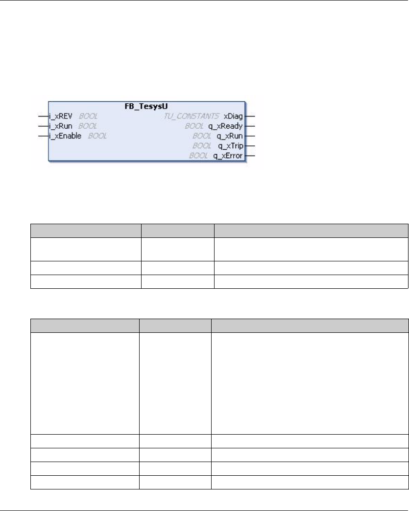
FB_TesysU Function Block
Overview
The FB_TeSysU function block is included in the TM3 library.
Graphical Representation
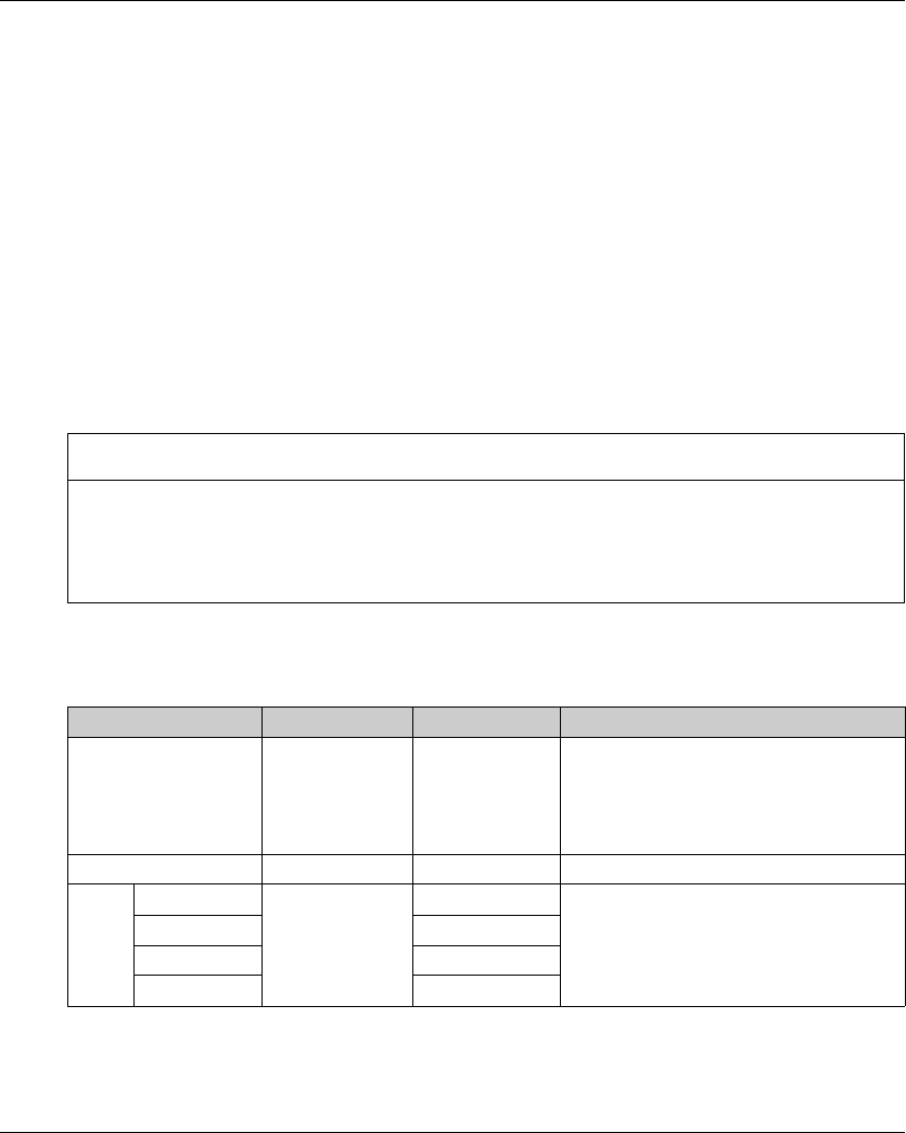
I/O Variable Description
This table describes the input variables:
This table describes the output variables:
Input Type Comment
xRev BOOL True sets the direct (forward) command. False sets the
reverse (backward) command
xRun BOOL True starts the function block.
xEnable BOOL True enables the function block.
Output Type Comment
xDiag TU_CONSTANTS The current status when q_xError is set to True:
-TU_STDBY. Tesys: off, xRun: on
-TU_OFF. Tesys: off, xRun: off
-TU_RUN. Tesys: on, xRun: on
-TU_RDY. Tesys: on, xRun: on
-TU_TRIP. Tesys: on, xRun: on
-TU_ERR_REV_ON_DOL. Tesys: on, xRun: on
-TU_ERR_REV_AT_RUN. Tesys: on, xRun: on
-TU_ERR_OVERCURRENT. Tesys: on, xRun: on
-FB_DISABLED. Tesys: on, xRun: on
q_xReady BOOL True sets the selector of the module to the ON position
q_xRun BOOL True closes the power contacts of the module.
q_xTrip BOOL True sets the selector of the module to the TRIP position
q_xError BOOL True retrieves the current detected error status.

TM3 Expert I/O Modules Configuration
66 EIO0000001402 12/2014
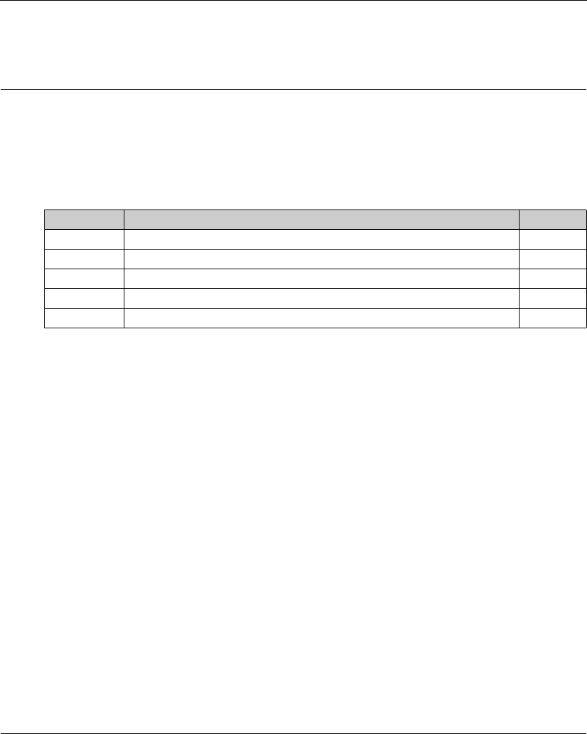
EIO0000001402 12/2014 67
Modicon TM3
TM3 Safety Modules Configuration
EIO0000001402 12/2014
TM3 Safety Modules Configuration
Chapter 5
TM3 Safety Modules Configuration
Introduction
This chapter describes how to configure the TM3 Safety Modules (see page 19).
What Is in This Chapter?
This chapter contains the following sections:
Section Topic Page
5.1 Configuration: TM3 Safety Modules 68
5.2 General Principles: TM3 Safety Functionality Modes 69
5.3 General Principles: TM3 Safety Operation Modes 78
5.4 I/O Mapping: TM3 Safety Modules 83
5.5 Function Blocks: TM3 Safety Modules 91

TM3 Safety Modules Configuration
68 EIO0000001402 12/2014
Configura tion: TM3 Safety Mo dules
Section 5.1
Configuration: TM3 Safety Modules
Configuring the TM3 Safety Modules
Introduction
For more information on the terms methods used concerning functional safety as they apply to the
TM3 Safety Modules, refer to the TM3 Safety Modules Hardware Guide (see Modicon TM3, Safety
Modules, Hardware Guide).
Configuring the Modules
Refer to the I/O Configuration (see page 22) for detailed information on the configuration of the
safety expansion modules in SoMachine.
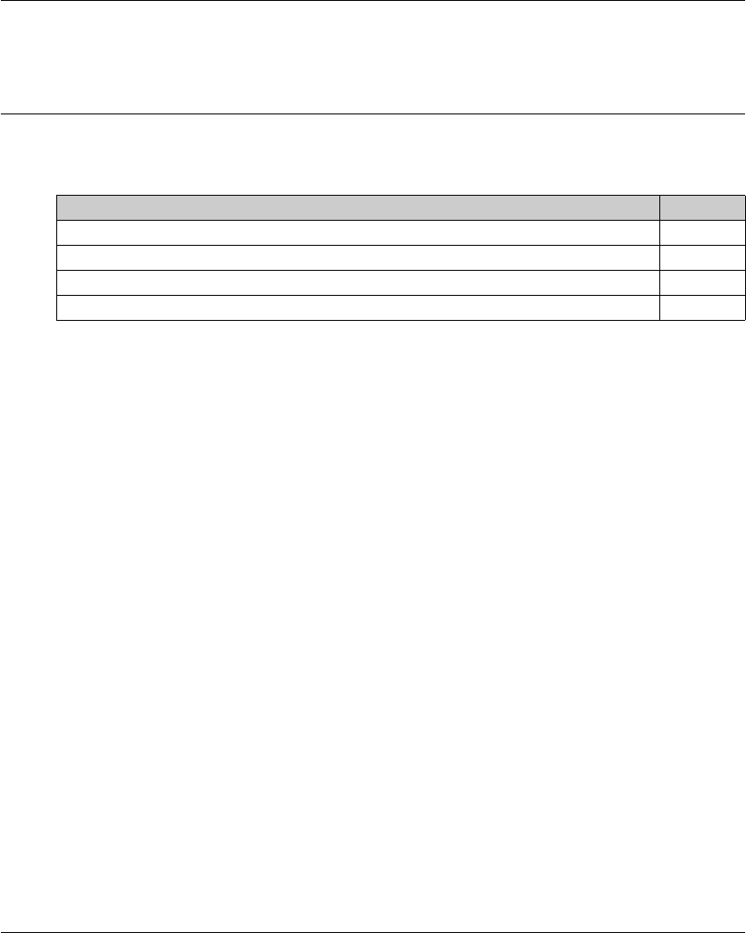
TM3 Safety Modules Configuration
EIO0000001402 12/2014 69
General Principles: TM3 Safety Functionality Modes
Section 5.2
General Principles: TM3 Safety Functionality Modes
What Is in This Section?
This section contains the following topics:
Topic Page
Interlock 70
Start 71
External Device Monitoring (EDM) 74
Synchronization Time Monitoring for TM3SAK6R / TM3SAK6RG 76

TM3 Safety Modules Configuration
70 EIO0000001402 12/2014
Interlock
Description
In 2 channel operation, both inputs related to both channels must be seen open before a safety
cycle can be started and the output can be closed. This functionality ensures that the output circuit
cannot be activated if one of the input channels is not able to be open (for example in case of
contact malfunction or short circuit).
The interlock function checks if both K1 and K2 relays are open before the safety cycle. In case of
short power-supply interruption, one of the relays may be off while the other remains on. To allow
the operation of the module on power return, the power-supply interruption should be at least
100 ms in duration.
Power Cycle
The interlock condition is reset by a power cycle. Information about a possible malfunction
detected, provided by the interlock, is interrupted and not recovered before the next safety cycle.
Reset
The logic controller can request to reset the safety module by communicating with the safety
module on the TM3 Bus.
When the reset signal is active, both safety module internal relays are deactivated.
The reset signal can be used to reset the module after the activation of the interlock function.
NOTE: The reset signal overwrites an activated interlock function. Information about a possible
malfunction detected, provided by the interlock, is interrupted and not recovered before the next
safety cyle.
The interruption of the interlock function could lead to the degradation of the safety level of the
system. The reset of this function should only be done manually after verification of the intended
functionality.
WARNING
UNINTENDED EQUIPMENT OPERATION
-Do not use the reset function to reset an interlock programmatically.
-Always verify the interlock notification before using the reset function.
Failure to follow these instructions can result in death, serious injury, or equipment
damage.

TM3 Safety Modules Configuration
EIO0000001402 12/2014 71
Start
Description
Two modes are available for the start functionality:
Non-monitored start: When non-monitored, the start mode can be:
-Manually controlled (conditioned by the input state)
-Automatic (hardwired)
Monitored start: When monitored, the start mode is manually controlled (conditioned by the input
edge).
This figure represents the events sequence for the two start modes available:
Events description:
1. Monitored start condition is triggered by a falling edge on the start input.
2. Non-monitored start condition is available as long as the start input is on.
The start condition can be valid before the safety-related input.
3. The outputs get activated only if start + safety-related input conditions are valid.
NOTE: For a monitored start, the falling edge on the start input must appear within 20 seconds
(± 5 seconds) after activation of the start input at nominal supply voltage.
Both the safety conditions and the start conditions must be valid before allowing the activation of
outputs.
WARNING
UNINTENDED EQUIPMENT OPERATION
Do not use either the monitored start or the non-monitored start as a safety function.
Failure to follow these instructions can result in death, serious injury, or equipment
damage.
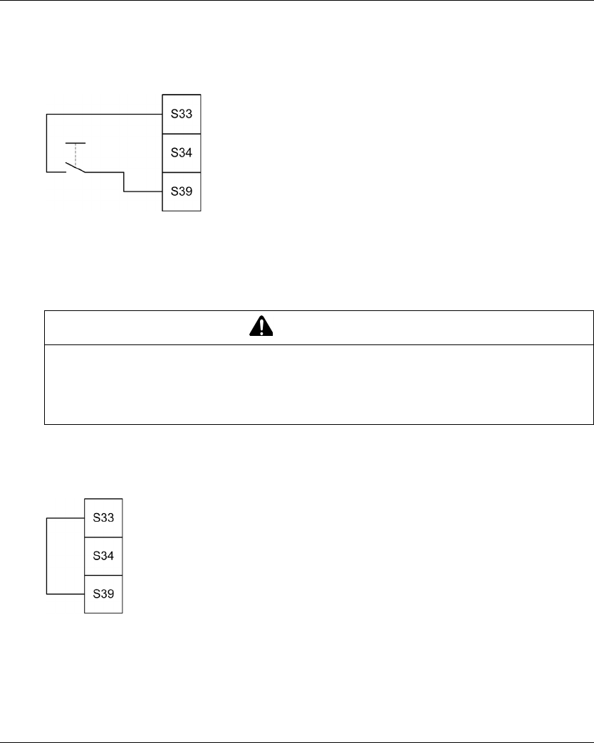
TM3 Safety Modules Configuration
72 EIO0000001402 12/2014
Manual Non-Monitored Start
The start condition is valid when the start input is closed (start switch is pressed).
This figure represents how to connect a switch on a TM3 safety module to configure a manual non-
monitored start:
Automatic Start
There is no start interlock when automatic start is used. After a power cycle, the output behavior
depends solely on the state of the inputs.
The module is in automatic start mode if the start input is permanently closed (hardwired).
This figure represents how to connect a switch on a TM3 safety module to configure an automatic
start:
NOTE: There is no start interlock in automatic start after a power cycle.
WARNING
UNINTENDED EQUIPMENT OPERATION
Do not use automatic start if a start interlock is required in your application after a power cycle.
Failure to follow these instructions can result in death, serious injury, or equipment
damage.

TM3 Safety Modules Configuration
EIO0000001402 12/2014 73
Monitored Start
In monitored start mode, the outputs are activated when:
-All required inputs are closed
-A falling edge is applied to the start input. A falling edge means that the start switch is pressed
and released again.
At nominal supply voltage, the start switch must be released within 20 seconds (± 5 seconds) after
it has been closed. The exact delay depends on supply voltage and ambient temperature.
This figure represents how to connect a switch on a TM3 safety module to configure a monitored
start (when available on the module):
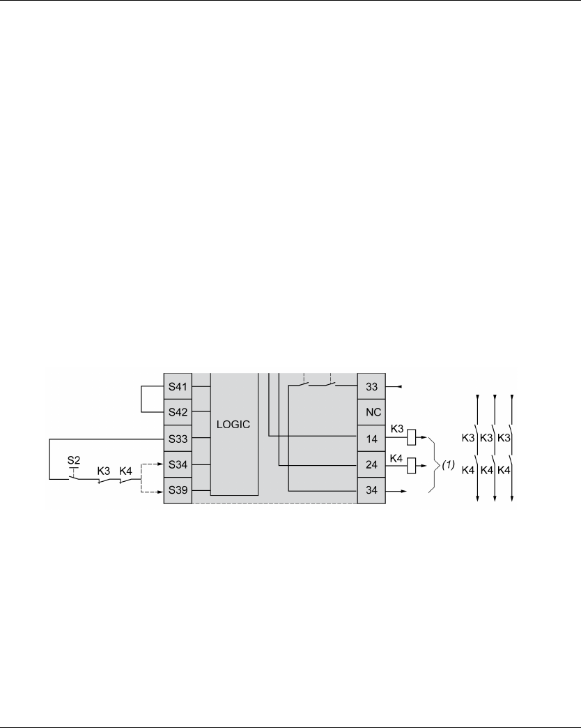
TM3 Safety Modules Configuration
74 EIO0000001402 12/2014
External Device Monitoring (EDM)
Description
External device monitoring functionality is used to ensure that external contactors controlled by the
safety module outputs are able to interrupt the safety circuit. This functionality is implemented by
adding the external contactor feedback to the start condition of the safety module.
The external contactor must provide a feedback through a normally closed auxiliary contact forcibly
guided by its normally open safety contact. The start condition is valid only when the external
feedback (normally closed) is closed.
External device monitoring can be performed on:
-1 channel.
External feedback is provided to the start condition.
-2 channels for short circuit detection.
External feedback is provided to the start condition and to the S4 input.
NOTE: The state of the external device is only monitored when the safety module is analyzing the
start condition validity. When outputs are activated, the external device is not monitored.
EDM Configuration With One Channel
This figure shows an example of 1 channel EDM with the external feedback (K3 and K4) added to
the start condition, and S41 directly connected to S42:
K3 External contactor with a normally closed feedback and normally open safety contact
K4 External contactor with a normally closed feedback and normally open safety contact
S2 Start switch
(1) Safety outputs

TM3 Safety Modules Configuration
EIO0000001402 12/2014 75
EDM Configuration With Two Channels
This figure shows an example of 2 channels EDM with one external feedback added to the start
condition (K3), and the other feedback (K4) connected to S41 and S42:
K3 External contactor with a normally closed feedback and normally open safety contact
K4 External contactor with a normally closed feedback and normally open safety contact
S2 Start switch
(1) Safety outputs
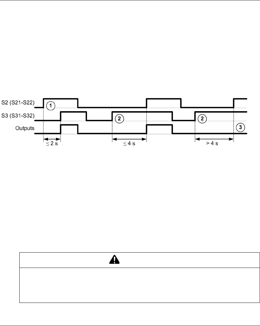
TM3 Safety Modules Configuration
76 EIO0000001402 12/2014
Synchronization Time Monitoring for TM3SAK6R / TM3SAK6RG
Description
The synchronization time monitoring is relevant for 2 channel applications. It monitors both inputs
to determine that they are activated simultaneously (within a defined time).
When the synchronization time monitoring is enabled, the outputs are allowed to be activated if
both input S2 (S21-S22) and input S3 (S31-S32) are activated within 2 or 4 seconds. The defined
time depends on which input is activated first as explained in the following figure. The outputs are
not activated if the synchronization time is expired.
This figure represents the synchronization time monitoring chronogram on a TM3SAK6R• module
in a 2 channel application:
Events description:
1. S2 operated before S3
2. S3 operated before S2
3. Outputs are not activated because the synchronization time is expired.
The synchronization time monitoring allows to detect a closed input without intention (short circuit)
before the activation of the other input.
Synchronization Time Monitoring Control
The synchronization time monitoring is enabled or disabled by the system logic controller through
a communication with the safety module on the TM3 Bus.
The synchronization time monitoring is an additional feature that contributes to the safety system,
but cannot itself provide for functional safety.
WARNING
MISUSE OF THE INTERNAL SYNCHRONIZATION TIME CONDITION
Do not use the synchronization time monitoring to control safety-related operations.
Failure to follow these instructions can result in death, serious injury, or equipment
damage.

TM3 Safety Modules Configuration
EIO0000001402 12/2014 77
When enabled, the synchronization time is monitored by the module internal safety-related
microcontroller.
In a 2 channel application, S2 and S3 simultaneous activation is monitored if SyncOn bit is set to 1.
For more information, refer to the TM3 Programming Guide.

TM3 Safety Modules Configuration
78 EIO0000001402 12/2014
General P rinciple s: TM3 Saf ety Oper ation Modes
Section 5.3
General Principles: TM3 Safety Operation Modes
What Is in This Section?
This section contains the following topics:
Topic Page
Power-On Condition 79
Enable Condition 80
Output Response Time 81
On Delay and Restart Delay 82
TM3 Safety Modules Configuration
EIO0000001402 12/2014 79
Power-On Condition
Description
When applying power to the safety module, the outputs are activated only if these four conditions
are fulfilled:
-The start condition (seepage71) is valid.
-The safety conditions (safety-related inputs) indicate to activate the outputs.
-The internal enable (seepage80) condition is valid.
WARNING
UNINTENDED EQUIPMENT OPERATION
Do not use automatic start if a start interlock is required in your application after a power cycle.
Failure to follow these instructions can result in death, serious injury, or equipment
damage.

TM3 Safety Modules Configuration
80 EIO0000001402 12/2014
Enable Condition
Description
The enable condition is a module internal control required to allow the internal relays to be switched
on. The internal relays can only be switched on if the following conditions are fulfilled:
-The start condition (seepage71) is valid.
-The safety conditions (safety-related inputs) indicate to activate the outputs.
-The internal enable condition is valid.
Once the safety outputs are activated, they are deactivated if either the enable condition is not valid
or the safety conditions are no longer valid.
Enable Condition
The enable condition is set by the logic controller through a communication with the safety module
on the TM3 Bus.
The enable condition is enabled by the system logic controller through a communication on the
TM3 Bus.
The enable condition is disabled by:
-The system logic controller through a communication on the TM3 Bus.
-The module internal safety-related microcontroller when:
-The synchronization time (see page 76) is enabled and a time-out occurs.
-The TM3 Bus time-out occurs.
WARNING
MISUSE OF THE INTERNAL ENABLE CONDITION
Do not use the internal enable condition, transacted over the TM3 Bus, to control safety-related
operations.
Failure to follow these instructions can result in death, serious injury, or equipment
damage.

TM3 Safety Modules Configuration
EIO0000001402 12/2014 81
Output Response Time
Description
This figure represents the response time (tr) between the opening of one input (safety condition
invalid) and all outputs deactivation:
NOTE: tr≤20 ms

TM3 Safety Modules Configuration
82 EIO0000001402 12/2014
On Delay and Restart Delay
On Delay Description
On delay represents the time elapsed between the enabling of the condition for activation and the
activation of the outputs.
NOTE: On delay ≤100 ms
Restart Delay Description
Restart delay represents the time required to reactivate internal relays after their deactivation.
NOTE: Restart delay ≤300 ms

TM3 Safety Modules Configuration
EIO0000001402 12/2014 83
I/O Mapping: TM3 Safety Modules
Section 5.4
I/O Mapping: TM3 Safety Modules
What Is in This Section?
This section contains the following topics:
Topic Page
TM3SAC5R / TM3SAC5RG I/O Mapping 84
TM3SAF5R / TM3SAF5RG I/O Mapping 85
TM3SAFL5R / TM3SAFL5RG I/O Mapping 87
TM3SAK6R / TM3SAK6RG I/O Mapping 89

TM3 Safety Modules Configuration
84 EIO0000001402 12/2014
TM3SAC5R / TM3SAC5RG I/O Mapping
I/O Mapping Tab
Variables are defined and named in the I/O Mapping tab. Additional information such as
topological addressing is also provided in this tab.
This table describes the I/O Mapping tab:
For further generic descriptions, refer to I/O Configuration Tab Description (seepage22).
Variable Channel Type Description
Diagnostics IW0 WORD -
ixModule_x_OutputOn Bit 0 OutputOn BOOL Safety output on
ixModule_x_Supply Bit 1 Supply BOOL Supply available (A1/A2)
ixModule_x_SupplyFail Bit 2 SupplyFail BOOL Supply out of tolerance
Acceptable range: 20.4...28.8 Vdc
- Bit 3 Not applicable BOOL Not valid as a TM3 safety function
block output
- Bit 4 Not applicable BOOL Not valid as a TM3 safety function
block output
ixModule_x_Start Bit 5 Start BOOL Start active
ixModule_x_K1 Bit 6 K1 BOOL Relay K1 activated
ixModule_x_K2 Bit 7 K2 BOOL Relay K2 activated
-Bit
8...11
Not applicable BOOL Not valid as a TM3 safety function
block outputs
ixModule_x_WaitingForS
tart
Bit 12 WaitingForStart BOOL Waiting for start condition
(see page 71)
- Bit 13 Not applicable BOOL Not valid as a TM3 safety function
block output
- Bit 14,
bit 15
Reserved BOOL -
Outputs QB0 BYTE -
qxModule_x_Enable Bit 0 Enable BOOL TRUE enables the activation of
safety outputs.
qxModule_x_ResetModule Bit 1 ResetModule BOOL TRUE resets the module: current
source switched off, outputs
deactivated, and interlock reset.
qxModule_x_KeepAlive Bit 2 KeepAlive BOOL TRUE defines the safety function
remains active even when the TM3
bus is unavailable.

TM3 Safety Modules Configuration
EIO0000001402 12/2014 85
TM3SAF5R / TM3SAF5RG I/O Mapping
I/O Mapping Tab
Variables are defined and named in the I/O Mapping tab. Additional information such as
topological addressing is also provided in this tab.
This table describes the I/O Mapping tab:
Variable Channel Type Description
Diagnostics IW0 WORD -
ixModule_x_OutputOn Bit 0 OutputOn BOOL Safety output on
ixModule_x_Supply Bit 1 Supply BOOL Supply available (A1/A2)
ixModule_x_SupplyFail Bit 2 SupplyFail BOOL Supply out of tolerance
Acceptable range:
20.4...28.8 Vdc
ixModule_x_CH1 Bit 3 CH1 BOOL Channel 1 active
ixModule_x_CH2 Bit 4 CH2 BOOL Channel 2 active
ixModule_x_Start Bit 5 Start BOOL Start active
ixModule_x_K1 Bit 6 K1 BOOL Relay K1 activated
ixModule_x_K2 Bit 7 K2 BOOL Relay K2 activated
- Bit 8 Not applicable BOOL Not valid as a TM3 safety
function block output
ixModule_x_S1 Bit 9 S1 BOOL S1 active
ixModule_x_S2 Bit 10 S2 BOOL S2 active
ixModule_x_S4 Bit 11 S4 BOOL S4 active
ixModule_x_WaitingForStart Bit 12 WaitingForStart BOOL Waiting for start condition
(see page 71)
- Bit 13 Not applicable BOOL Not valid as a TM3 safety
function block output
- Bit 14,
bit 15
Reserved BOOL -
Outputs QB0 BYTE -
qxModule_x_Enable Bit 0 Enable BOOL TRUE enables the activation of
safety outputs.

TM3 Safety Modules Configuration
86 EIO0000001402 12/2014
For further generic descriptions, refer to I/O Configuration Tab Description (seepage22).
qxModule_x_ResetModule Bit 1 ResetModule BOOL TRUE resets the module:
current source switched off,
outputs deactivated, and
interlock reset.
qxModule_x_KeepAlive Bit 2 KeepAlive BOOL TRUE defines the safety
function remains active even
when the TM3 bus is
unavailable.
Variable Channel Type Description

TM3 Safety Modules Configuration
EIO0000001402 12/2014 87
TM3SAFL5R / TM3SAFL5RG I/O Mapping
I/O Mapping Tab
Variables are defined and named in the I/O Mapping tab. Additional information such as
topological addressing is also provided in this tab.
This table describes the I/O Mapping tab:
Variable Channel Type Description
Diagnostics IW0 WORD -
ixModule_x_OutputOn Bit 0 OutputOn BOOL Safety output on
ixModule_x_Supply Bit 1 Supply BOOL Supply available (A1/A2)
ixModule_x_SupplyFail Bit 2 SupplyFail BOOL Supply out of tolerance
Acceptable range:
20.4...28.8 Vdc
ixModule_x_CH1 Bit 3 CH1 BOOL Channel 1 active
ixModule_x_CH2 Bit 4 CH2 BOOL Channel 2 active
ixModule_x_Start Bit 5 Start BOOL Start active
ixModule_x_K1 Bit 6 K1 BOOL Relay K1 activated
ixModule_x_K2 Bit 7 K2 BOOL Relay K2 activated
ixModule_x_S1 Bit 8 S1 BOOL S1 active
- Bit 9 Not applicable BOOL Not valid as a TM3 safety
function block output
ixModule_x_S2 Bit 10 S2 BOOL S2 active
ixModule_x_S4 Bit 11 S4 BOOL S4 active
ixModule_x_WaitingForStart Bit 12 WaitingForStart BOOL Waiting for start condition
(see page 71)
- Bit 13 Not applicable BOOL Not valid as a TM3 safety
function block output
- Bit 14,
bit 15
Reserved BOOL -
Outputs QB0 BYTE -
qxModule_x_Enable Bit 0 Enable BOOL TRUE enables the activation of
safety outputs.
qxModule_x_ResetModule Bit 1 ResetModule BOOL TRUE resets the module:
current source switched off,
outputs deactivated, and
interlock reset.

TM3 Safety Modules Configuration
88 EIO0000001402 12/2014
For further generic descriptions, refer to I/O Configuration Tab Description (seepage22).
qxModule_x_KeepAlive Bit 2 KeepAlive BOOL TRUE defines the safety
function remains active even
when the TM3 bus is
unavailable.
Variable Channel Type Description

TM3 Safety Modules Configuration
EIO0000001402 12/2014 89
TM3SAK6R / TM3SAK6RG I/O Mapping
I/O Mapping Tab
Variables are defined and named in the I/O Mapping tab. Additional information such as
topological addressing is also provided in this tab.
This table describes the I/O Mapping tab:
Variable Channel Type Description
Diagnostics IW0 WORD -
ixModule_x_OutputOn Bit 0 OutputOn BOOL Safety output on
ixModule_x_Supply Bit 1 Supply BOOL Supply available (A1/A2)
ixModule_x_SupplyFail Bit 2 SupplyFail BOOL Supply out of tolerance
Acceptable range:
20.4...28.8 Vdc
ixModule_x_CH1 Bit 3 CH1 BOOL Channel 1 active
ixModule_x_CH2 Bit 4 CH2 BOOL Channel 2 active
ixModule_x_Start Bit 5 Start BOOL Start active
ixModule_x_K1 Bit 6 K1 BOOL Relay K1 activated
ixModule_x_K2 Bit 7 K2 BOOL Relay K2 activated
ixModule_x_S1 Bit 8 S1 BOOL S1 active
ixModule_x_S2 Bit 9 S2 BOOL S2 active
ixModule_x_S3 Bit 10 S3 BOOL S3 active
ixModule_x_S4 Bit 11 S4 BOOL S4 active
ixModule_x_WaitingForStart Bit 12 WaitingForStart BOOL Waiting for start condition
(see page 71)
ixModule_x_SyncFailure Bit 13 SyncFailure BOOL Synchronization time expired
(see page 76)
Outputs QB0 BYTE -
qxModule_x_Enable Bit 0 Enable BOOL TRUE enables the activation
of safety outputs.
qxModule_x_ResetModule Bit 1 ResetModule BOOL TRUE resets the module:
current source switched off,
outputs deactivated, and
interlock reset.
qxModule_x_KeepAlive Bit 2 KeepAlive BOOL TRUE defines the safety
function remains active even
when the TM3 bus is
unavailable.

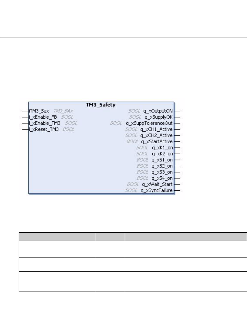
TM3 Safety Modules Configuration
EIO0000001402 12/2014 91
Function Blocks: T M3 Safety Modules
Section 5.5
Function Blocks: TM3 Safety Modules
TM3 Safety Modules Function Blocks
Overview
The TM3_Safety function block is included in the TM3 Safety library.
Graphical Representation
I/O Variable Description
This table describes the input variables:
Input Type Comment
iTM3_Sax TM3_SAx Reference to the local TM3 safety modules.
i_xEnable_FB BOOL TRUE enables the function block.
i_xEnable_TM3 BOOL TRUE enables the activation of the hardware module
outputs.
i_xReset_TM3 BOOL TRUE deactivates the module: the current source is
switched off, the outputs are deactivated, and the
interlock is reset.

TM3 Safety Modules Configuration
92 EIO0000001402 12/2014
This table describes the output variables:
NOTE: Not all outputs are valid for all TM3 safety module references. To determine which outputs
are valid for which TM3 safety module references, see the I/O mapping for the individual
references (see page 83).
Output Type Comment
q_xOutputON BOOL 0: safety output is off.
1: safety output is on.
q_xSupplyOK BOOL Supply is available.
q_xSuppToleranceOut BOOL Supply is out of tolerance.
q_xCH1_Active BOOL Channel 1 is active.
q_xCH2_Active BOOL Channel 2 is active.
q_xStartActive BOOL Start is active.
q_xK1_on BOOL Relay K1 is activated.
q_xK2_on BOOL Relay K2 is activated.
q_xS1_on BOOL S1 is active.
q_xS2_on BOOL S2 is active.
q_xS3_on BOOL S3 is active.
q_xS4_on BOOL S4 is active.
q_xWait_Start BOOL Waiting for start condition (see page 71).
q_xSyncFailure BOOL Synchronization time expired (see page 76).
EIO0000001402 12/2014 93
Modicon TM3
TM3 Expert I/O Modules Configuration
EIO0000001402 12/2014
TM3 Transmitter and Receiver I/O Modules Configuration
Chapter 6
TM3 Transmitter and Receiver I/O Modules Configuration
Introduction
This chapter describes how to configure the TM3 transmitter and receiver I/O modules
(seepage21).
What Is in This Chapter?
This chapter contains the following topics:
Topic Page
Configuring the TM3 Transmitter and Receiver I/O Modules 94
Behavior of the TM3 Transmitter and Receiver Modules 95

TM3 Expert I/O Modules Configuration
94 EIO0000001402 12/2014
Configuring the TM3 Transmitter and Receiver I/O Modules
Introduction
The TM3XTRA1 transmitter module is equipped with:
-1 RJ-45 connector
-1 functional ground screw
-2 status LEDs (link and power)
The TM3XREC1 receiver module is equipped with:
-1 RJ-45 connector
-2 status LEDs (link and power)
-Removable 24 Vdc power supply
The transmitter expansion module is connected to the logic controller through the TM3 bus.The
transmitter must be the last physical module directly connected to the logic controller.
The receiver module is connected to the transmitter module using a specific cable
(VDIP1845460••).
Additional TM3 modules can then be connected to the receiver module through the extended TM3
bus.
NOTE: You cannot use TM2 expansion modules in configurations that include the TM3
transmitter/receiver modules.
Configuring the Modules
The TM3XTRA1 and TM3XREC1 expansion modules have no configurable properties in
SoMachine.

TM3 Expert I/O Modules Configuration
EIO0000001402 12/2014 95
Behavior of the TM3 Transmitter and Receiver Modules
Overview
The following exceptional behaviors can occur with TM3 transmitter and receiver modules:
-Transmitter/receiver cable disconnected or broken during operation
-Removing receiver module power during operation
-Receiver module disconnected during startup
-Receiver module powered on after the controller
The TM3 modules before the transmitter module are called "Local", and those after the receiver
module are called "Remote".
The I/O that may be embedded in your controller is independent of the I/O that you may have
added in the form of I/O expansion. It is important that the logical I/O configuration within your
program matches the physical I/O configuration of your installation. If you add or remove any
physical I/O to or from the I/O expansion bus, update your application configuration (this is also
true for any field bus devices you may have in your installation). Otherwise, there is the potential
that the expansion bus or field bus will no longer function while the embedded I/O that may be
present in your controller will continue to operate.
Transmitter/Receiver Cable Disconnected or Broken During Operation
The logic controller continuously retries to access the modules attached to the receiver module.
When the receiver module detects cable disconnection:
-All local modules continue operating.
-All remote modules are put into the Reset state.
-I/O LED is on, and TM3 status bit (plc_r.i_lwSystemFault_1.1) is set to 0.
-Diagnostic information for the remote modules is available in the TM3_MODULE_R array.
-In SoMachine a red sign appears in front of the TM3 module with detected errors.
Reconnecting the cable does not restore normal operation. Only a logic controller power cycle or
reset restores normal operation after disconnecting and then reconnecting the cable.
WARNING
UNINTENDED EQUIPMENT OPERATION
Update the configuration of your program each time you add or delete an I/O expansion, or you
add or delete any devices on your field bus.
Failure to follow these instructions can result in death, serious injury, or equipment
damage.

TM3 Expert I/O Modules Configuration
96 EIO0000001402 12/2014
Removing Receiver Module Power During Operation
When the receiver module detects cable disconnection:
-All local modules continue operating.
-I/O LED is on, and TM3 status bit (plc_r.i_lwSystemFault_1.1) is set to 0.
-Diagnostic information for the remote modules is available in the TM3_MODULE_R array.
-In SoMachine a red sign appears in front of the TM3 module with detected errors.
Restoring power results in the TM3 modules attached to the receiver module assuming a Reset
state. Only a logic controller power cycle or reset restores normal operation.
Receiver Module Disconnected During Start-up
If the receiver module was not connected at logic controller start-up, nothing happens because the
TM3 bus is not started.
Receiver Module Powered on After the Controller
If two separate power supplies are used for the receiver module and the controller, the power
supply of the receiver module must be switched on before the controller power supply. The TM3
bus does not start if the correct order of power application is not respected, and all modules are in
Reset state (all outputs are forced to 0).
If the receiver module and the logic controller are supplied by the same power supply, the whole
configuration starts operating.
If only the receiver module is powered (logic controller not supplied), the TM3 modules after the
receiver module are in Reset state (all outputs are forced to 0).

EIO0000001402 12/2014 97
Modicon TM3
Glossary
EIO0000001402 12/2014
Glossary
D
digital I/O
(digital input/output) An individual circuit connection at the electronic module that corresponds
directly to a data table bit. The data table bit holds the value of the signal at the I/O circuit. It gives
the control logic digital access to I/O values.
E
expansion bus
An electronic communication bus between expansion I/O modules and a controller.
F
function
A programming unit that has 1 input and returns 1 immediate result. However, unlike FBs, it is
directly called with its name (as opposed to through an instance), has no persistent state from one
call to the next and can be used as an operand in other programming expressions.
Examples: boolean (AND) operators, calculations, conversions (BYTE_TO_INT)
H
HE10
Rectangular connector for electrical signals with frequencies below 3 MHz, complying with IEC
60807-2.
R
RJ-45
A standard type of 8-pin connector for network cables defined for Ethernet.
T
terminal block
(terminal block) The component that mounts in an electronic module and provides electrical
connections between the controller and the field devices.

Glossary
98 EIO0000001402 12/2014

EIO0000001402 12/2014 99
Modicon T M3
Index
EIO0000001402 12/2014
Index
A
analog input modules
specifications, 16
analog mixed I/O modules
specifications, 18
analog output modules
specifications, 17
automatic
start, 71
C
configuration, 25, 68, 94
D
delay
on, 82
restart, 82
digital I/O modules
specifications, 13, 14, 15, 19, 21
E
EDM
external device monitoring, 74
enable, 80
expansion modules
adding, 22
configuration, 22
properties, 22
Expert modules, 62
external device monitoring
EDM, 74
I
I/O configuration general information, 13
interlock, 70
M
monitored
start, 71
N
non-monitored
start, 71
O
on
delay, 82
output
response time, 81
P
power-on, 79
R
regular inputs, 13, 14, 15, 19, 21
regular transistor outputs, 13, 14, 15, 19, 21
relay outputs, 13, 14, 15, 19, 21
reset, 70
response time
output, 81
restart
delay, 82
S
specifications
analog input modules, 16
analog mixed I/O modules, 18
analog output modules, 17
digital I/O modules, 13, 14, 15, 19, 21

Index
100 EIO0000001402 12/2014
start
automatic, 71
monitored, 71
non-monitored, 71
synchronization time, 76
T
TeSys module, 62
TM3, 11
TM3 analog I/O modules
diagnostic, 58
TM3AI2H / TM3AI2HG , 29
TM3AI4 / TM3AI4G , 31
TM3AI8 / TM3AI8G , 33
TM3AM6 / TM3AM6G , 51
TM3AQ2 / TM3AQ2G , 46
TM3AQ4 / TM3AQ4G , 48
TM3TI4 / TM3TI4G , 35
TM3TI8T / TM3TI8TG , 39
TM3TM3 / TM3TM3G , 54
TM3 digital, 11
TM3 digital I/O expansion modules
TM3, 25
TM3 expert I/O expansion modules
TM3, 94
TM3XTYS4, 62, 63
TM3 safety expansion modules
TM3, 68
TM3 safety modules
TM3SAC5R / TM3SAC5RG , 84
TM3SAF5R / TM3SAF5RG , 85
TM3SAFL5R / TM3SAFL5RG, 87
TM3SAK6R / TM3SAK6RG , 89
