Definite Purpose Control, Catalog 8910CT9301 Brochure
1000471368-Catalog 1000471368-Catalog 1000471368-Catalog B4 unilog cesco-content
1000477486-Brochure 1000477486-Brochure 1000477486-Brochure B4 unilog cesco-content
111019-Brochure 111019-Brochure 111019-Brochure B4 unilog cesco-content
1000516564-Brochure 1000516564-Brochure 1000516564-Brochure B4 unilog cesco-content
103259-Catalog 103259-Catalog 103259-Catalog 785901 Batch10 unilog cesco-content
2016-07-04
: Pdf 1000432235-Brochure 1000432235-Brochure B1 unilog
Open the PDF directly: View PDF ![]() .
.
Page Count: 16
™
Definite Purpose Control
Catalog
8910CT9301R12/13
2014
Class 8910, 8911, 8965, 9998, 9999
CONTENTS
Description . . . . . . . . . . . . . . . . . . . . . . . . . . . . . . . . . . . . . . . . . . . . . Page
Contactors, Class 8910 Types DP and DPA . . . . . . . . . . . . . . . . . . . . . . . .3
Starters, Class 8911 Types DPS and H–M. . . . . . . . . . . . . . . . . . . . . . . . . .7
Reversing/Hoist Contactors, Class 8965 Type DPR . . . . . . . . . . . . . . . . . .8
Reversing/Hoist Contactors, Class 8965 Type R . . . . . . . . . . . . . . . . . . . . 11
Contact Kits and Replacement Parts Kits, Class 9998. . . . . . . . . . . . . . . .13
External Auxiliary Contacts, Class 9999 . . . . . . . . . . . . . . . . . . . . . . . . . .14
Definite Purpose Control
Contactors, Class 8910 Types DP and DPA
3
04/2014
™
© 1998–2014 Schneider Electric
All Rights Reserved
Contactors, Class 8910 Types DP and DPA
Definite purpose contactors are ideal for heating, air conditioning, refrigeration, data processing, and food
service equipment. Compact 1- and 2-pole contactors are available, as well as full-size devices with 2, 3, or
4 poles.
Features
•Quick connect terminals and binder head screws allow for easy wiring.
•Box lugs are standard on contactors 40 A and larger.
•An exclusive DIN track mounting option may reduce installation costs.
•Coils can be changed quickly, without a tool, on the Type DPA, 50–90 A contactors.
•Auxiliary contact modules snap on either side of the Type DPA contactors.
To order, specify the Class, Type, and Voltage Code (where indicated).
[1] Add the voltage code suffix from Table 7 on page 4.
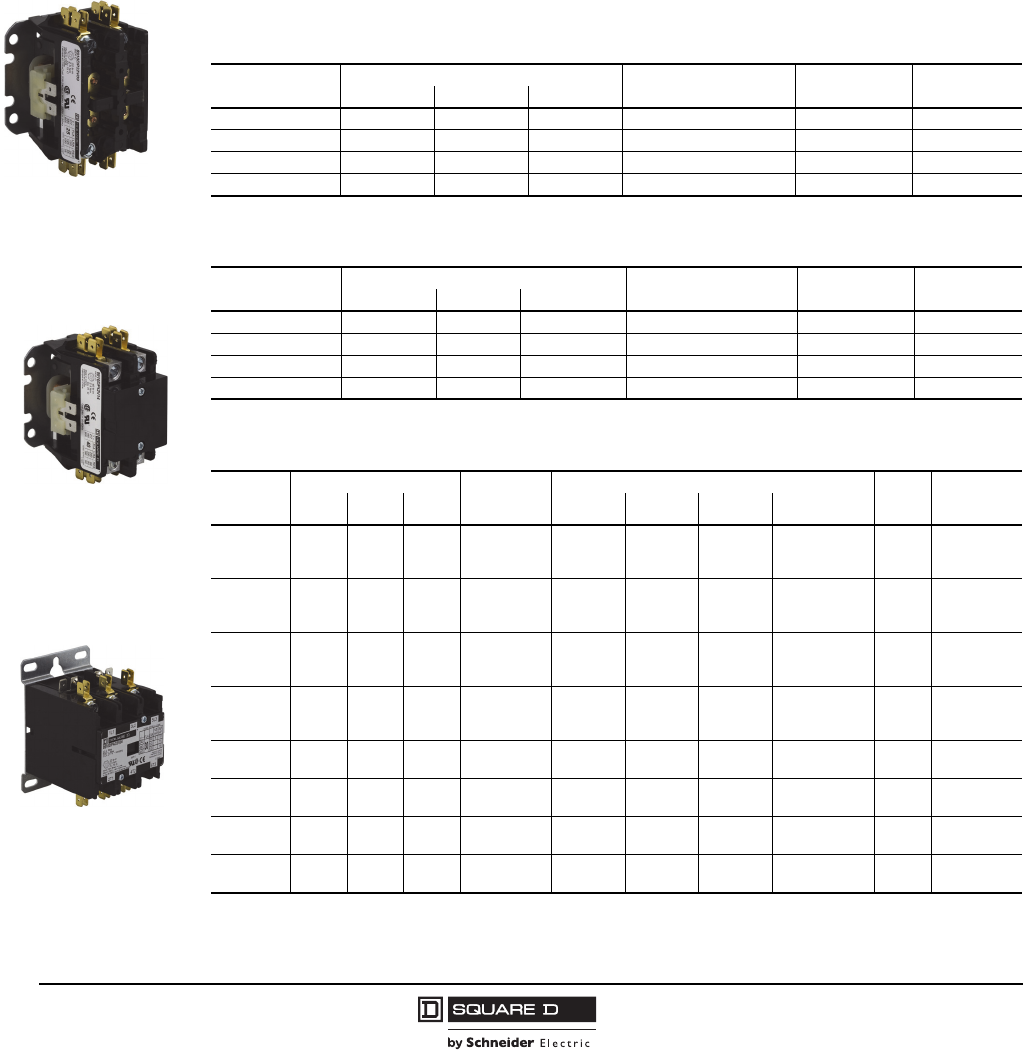
Table 1: Compact 1-Pole Contactors—600 Vac Maximum
Full Load
Amperes
Locked Rotor Amperes Resistive Load
Amperes N.O. Poles Class 8910
Type [1]
277 V 460 V 575 V
20 120 100 80 30 1 DP11
25 150 125 100 35 1 DP21
30 150 125 100 40 1 DP31
40 240 200 160 40 (50 for 277 V) 1 DP41
Table 2: Compact 2-Pole Contactors—600 Vac Maximum
Above 240 V, all lines must be switched.
Full Load
Amperes
Locked Rotor Amperes Resistive Load
Amperes N.O. Poles Class 8910
Type [1]
277 V 460 V 575 V
20 120 100 80 30 2 DP12
25 150 125 100 35 2 DP22
30 150 125 100 40 2 DP32
40 240 200 160 50 2 DP42
Table 3: 2, 3, and 4-Pole Contactors—600 Vac Maximum
Above 240 V, all lines must be switched.
Full Load
Amperes
Locked Rotor Amperes Resistance
Load
Amperes
Horsepower Ratings N.O.
Poles
Class 8910
Type [1]
230 V 460 V 575 V 115 V, 1Ø 230 V, 1Ø 230 V, 3Ø 460/575 V, 3Ø
20 120 100 80 30 1.5 3 7.5 7.5
2
3
4
DPA12
DPA13
DPA14
25 150 125 100 35 2 5 10 15/20
2
3
4
DPA22
DPA23
DPA24
30 180 150 120 40 2 5 10 15/20
2
3
4
DPA32
DPA33
DPA34
40 240 200 160 50 3 7.5 10 20/25
2
3
4
DPA42
DPA43
DPA44
50 300 250 200 62 3 10 15 30 2
3
DPA52
DPA53
60 360 300 240 75 5 10 25 30 2
3
DPA62
DPA63
75 450 375 300 94 5 15 25 40 2
3
DPA72
DPA73
90 540 450 360 120 7.5 20 30 50 2
3
DPA92
DPA93
Type DPA33V04
3 pole
Type DP22V09
2 pole
Type DP42V14
2 pole
Definite Purpose Control
Contactors, Class 8910 Types DP and DPA
4
04/2014
™
© 1998–2014 Schneider Electric
All Rights Reserved
Table 4: 2 N.O. and 2 N.C. 4-Pole Contactors
600 Vac Maximum
Above 240 V, all lines must be switched.
Full Load
Amperes
Resistive
Load
Amperes
Poles Contactors
Class 8910
N.O. N.C. [1] Type [2] Form
20 25 2 2 DPA14 Y392
25 35 2 2 DPA24 Y392
30 40 2 2 DPA34 Y392
[1] The N.C. poles are on the outside.
The N.C. poles open before the N.O. poles close.
[2] Add the voltage code suffix from Table 7. Add the Form after
the voltage code (example: 8910DPA14V02Y392).
Table 5: Auxiliary Contacts
For Use with
Class 8910 Type
Contact
Arrangement
Auxiliary Contacts
Class 9999 Type
20–40 A 50–90 A
DPA
1 N.O. DD10 D10
1 N.C. DD01 D01
1 N.O. / 1 N.C. DD11 D11
2 N.O. DD20 D20
Table 6: NEMA Type 1 General Purpose Enclosures for Type DP and DPA Contactors
For Contactors, Class 8910 Type Full Load Amperes Poles Enclosures, Class 9991 Type
DP 20–40 1 and 2 DPG1
DPA
20–40 2 and 3 DPG1
4DPG2
50 2 and 3 DPG2
60–75 2 and 3 DPG3
90 2 and 3 DPG4
Table 7: Coil Voltage Codes
Voltage Voltage Code
Type DP, DPA
60 Hz 50 Hz
24 24 V14
24 — —
120 110 V02
208 — —
208–240 220 V09
230–240 220 —
277 — V04
480 440 V06
600 550 V07 (not available for Type DP, 1-pole and 2-pole devices)
Table 8: Types DP and DPA Specifications
Mechanical Life 500,000 operations (actual product life will vary based on electrical load, duty cycle,
application, and environmental conditions)
Electrical Life Type DP 100,000 operations
Type DPA 200,000 operations
Duty Cycle Continuous
Operating Temperature 0–65 °C (32–149 °F)
Slip-on Connector Rating 30 A, 75 °C wire
Approvals
UL Recognized
File E3190
CCN NLDX2
CSA Certified
File LR25490
Class 3211 04
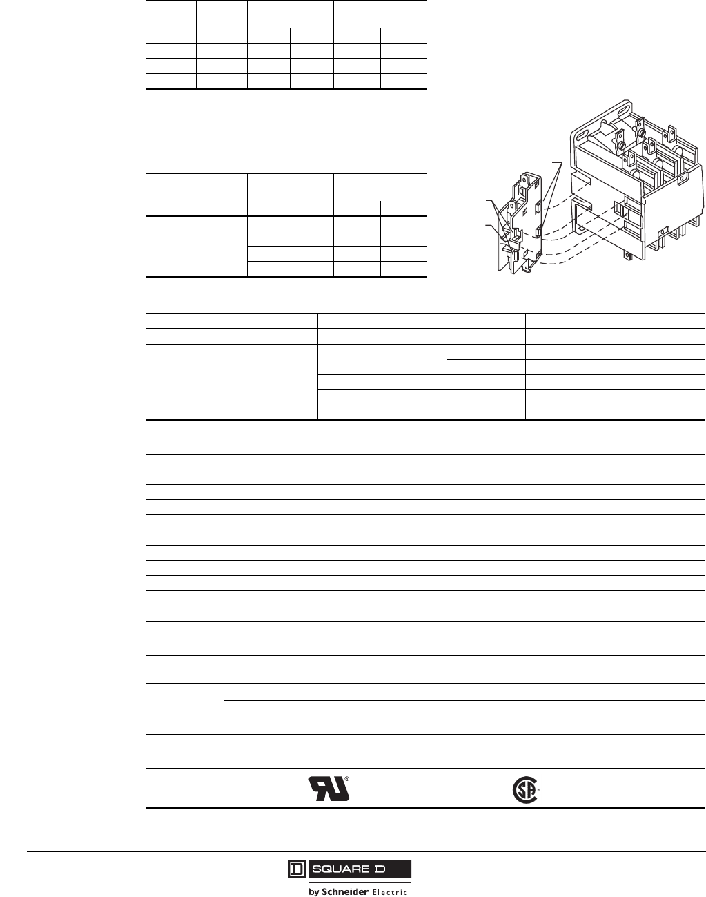
Bottom Tabs
Top
Hooks
Operating
Ta b
Contactor
Figure 1: Auxiliary Contact Installation,
50–90 A (no tools required)
Definite Purpose Control
Contactors, Class 8910 Types DP and DPA
5
04/2014
™
© 1998–2014 Schneider Electric
All Rights Reserved
Factory Modifications
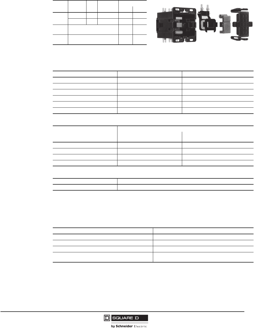
Table 9: Replacement Coils for
Class 8910 Type DPA
Figure 2: Coil Replacement, 50–60 A
(no tools required)
For
Types
Full Load
Amperes Poles Class 9998
Type [1]
Volt-Amperes
Inrush Sealed
DP 50–60 2, 3 DA2 109 10
75–90 2, 3 DA3 214 19
DP11–
DP32 Coils are not replaceable. 33 8
DPA12–
DPA44 Coils are not replaceable. 60 6
[1] Add the voltage code suffix from Table 10.
For example, a 120 V, 60 Hz coil for an 8910DPA53V02
contactor is 9998DA2V02.
Table 10: Type DPA Coil Voltage Codes
Voltage, 60 Hz Voltage, 50 Hz Voltage Code
24 24 V14
120 110 V02
208–240 220 V09
277 — V04
480 440 V06
600 550 V07 (Type DPA contactors only)
Table 11: Power Terminals
Full Load Amperes
Power Terminals
Type of Lug Wire Range, AWG
solid or stranded copper wire only
20–30 binder head 16 – 8
40 box lug 14 – 4
50–60 box lug 14 – 2
75–90 box lug 14 – 1/0
Table 12: Mounting Attachment
Description Class 9999 Type
DIN mounting bracket attachment DMB1
Table 13: Factory Modifications
Modification Form (add to the catalog number after the voltage code)
Factory installed auxiliary contacts Contact your local Schneider Electric office.
Pressure wire connectors (20–30 A) Y122
Box lugs (20–30 A) Y239
DIN mounting bracket attached, 35 mm style
(available for 20–60 A devices only) Y135
Definite Purpose Control
Contactors, Class 8910 Types DP and DPA
6
04/2014
™
© 1998–2014 Schneider Electric
All Rights Reserved
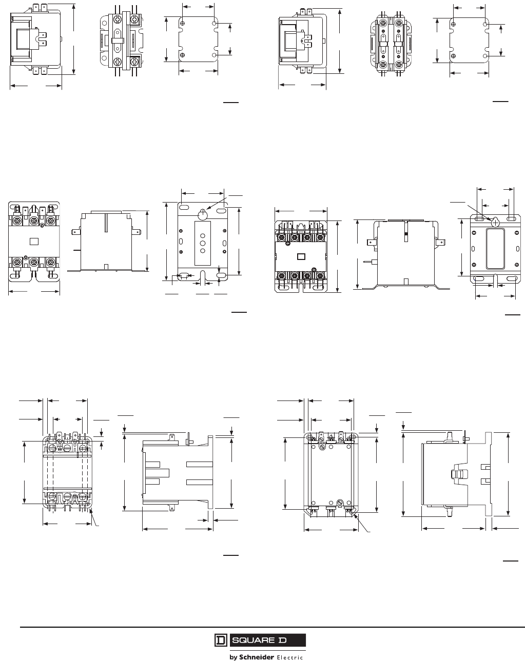
Figure 3: Type DP, 1 Pole
20–40 Full Load Amperes
Figure 4: Type DP, 2 Pole
20–40 Full Load Amperes
Figure 5: Type DPA, 2 and 3 Pole
20–40 Full Load Amperes
Figure 6: Type DPA, 4 Pole
20–40 Full Load Amperes
Figure 7: Type DPA, 2 and 3 Pole
50 and 60 Full Load Amperes
Figure 8: Type DPA, 2 and 3 Pole
75 and 90 Full Load Amperes
3.29
83.60
2.38
60.50
1.62
41.20
2.00
50.80
2.31
58.70
1.62
41.20
Dimensions: in.
mm
3.32
84.30
2.45
62.20
1.62
41.20
2.00
50.80
2.31
58.70
1.62
41.20
Dimensions: in.
mm
2.37
60.2
2.90
76.00
3.25
82.50
2.00
50.80 0.50
12.70
0.20
5.00
0.20
5.00
0.20
5.00
2.31
58.70
Dimensions: in.
mm
2.75
69.80
3.77
95.80
3.00
77.00
1.47
37.30
2.00
51.50
3.13
79.50
2.18
55.50
0.45
11.50
0.21
5.33
Dimensions: in.
mm
0.24
6.00
2.11
54.00
1.54
39.00
4.06
103.00
3.27
83.00
2.56
85.00
0.23
6.00
0.23
6.00
0.51
13.00
Provisions
for (4) #10
or M5 Mounting Screws
0.07
2.00 0.09
2.00
3.72
94.00
3.67
93.00
Dimensions: in.
mm
2.87
73.00
2.50
64.00
Provisions for
(4) #10 or M5
Mounting Screws
3.39
86.00
4.44
113.00
4.37
111.00
0.39
10.00
4.63
118.00
5.20
132.00
0.06
2.00
5.12
130.00
0.44
11.00
0.26
7.00
0.26
7.00
Dimensions: in.
mm
Definite Purpose Control
Starters, Class 8911 Types DPS and H–M
7
04/2014
™
© 1998–2014 Schneider Electric
All Rights Reserved
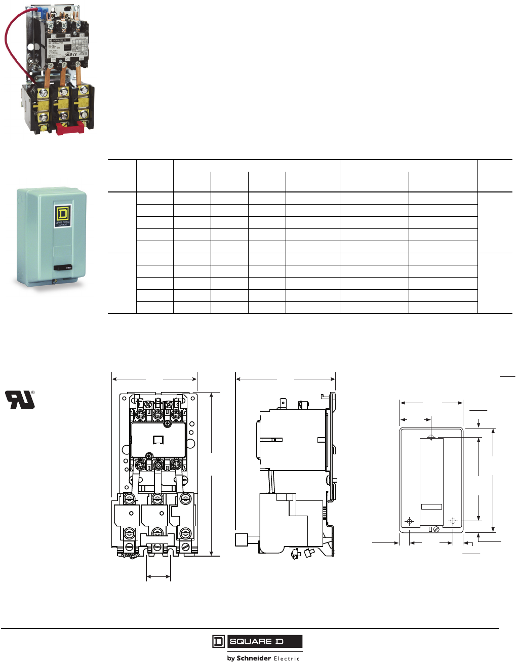
Starters, Class 8911 Types DPS and H–M
Class 8911 definite purpose starters are economical starters for applications with relatively low duty
cycles. Typical applications include air compressors, agricultural equipment, pumps, and HVAC
equipment. Definite purpose starters offer the following:
•Low cost
•Small size
•Melting-alloy overload block
•Trip-free reset mechanism
•Open style or enclosed option
•500,000 mechanical operations (typical)
To order, specify the Class, Type, and Voltage Code (where indicated).
[1] Holding circuit contacts do not come standard; refer to the instruction bulletin supplied with the contactor.
[2] Add the voltage code suffix from Table 22 on page 10.
[3] See the instruction label for selection information.
Figure 9: Approximate Dimensions
Table 14: 2, 3, and 4-Pole Starters–—600 Vac Maximum
No. of
Poles
Full Load
Amperes
Horsepower Ratings Class 8911 Type [1] [2] No. of
Thermal
Units [3]
115 V, 1Ø 230 V, 1Ø 230 V, 3Ø 460/575 V, 3Ø Open Style NEMA Type 1
Enclosed
2-pole
single
phase
20 1.5 3 — — DPSO12 DPSG12
1
25 2 5 — — DPSO22 DPSG22
30 2 5 — — DPSO32 DPSG32
40 3 7.5 — — DPSO42 DPSG42
50 3 10 — — DPSO52 DPSG52
3-pole
poly-
phase
20 1.5 3 7.5 7.5 DPSO13 DPSG13
3
25 2 5 10 15/20 DPSO23 DPSG23
30 2 5 10 15/20 DPSO33 DPSG33
40 3 7.5 10 20/25 DPSO43 DPSG43
50 3 10 15 30 DPSO53 DPSG53
8911DPSO33V02
8911DPSG12V02
Approvals
UL Recognized
File E3190
CCN NLDX2
Reset
6.00
152.00
3.00
76.00
0.88
22.00
10.00
254.00
8.13
207.00
1.00
25.00
0.94
24.00
0.94
24.00 4.13
105.00
3.50
89.00
4.09
104.00
0.98
25.00
6.73
171.00
LABEL POSITION
THIS ORIENTATION
Dimensions: in.
mm
Type DPSO, 2 and 3 Pole
20–50 Full Load Amperes
Type DPSG, 2 and 3 Pole
20–40 Full Load Amperes
Definite Purpose Control
Reversing/Hoist Contactors, Class 8965 Type DPR
8
04/2014
™
© 1998–2014 Schneider Electric
All Rights Reserved
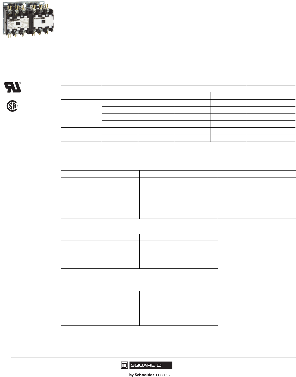
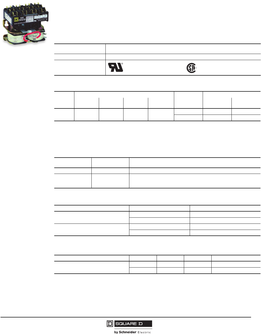
Reversing/Hoist Contactors, Class 8965 Type DPR
Class 8965 Type DPR reversing/hoist contactors are designed for the control of motors in hoists,
overhead doors, small elevators, commercial laundry equipment, and other related products that use
reversing motors. They are rated to perform in the short periods of jogging experienced in hoist service.
The coils are designed to operate on line voltages of 85–110% of rated voltage, at 50 or 60 Hz only.
Coils are easily replaced by removing the external base. Auxiliary contacts can be field-installed on
any Class 8965 reversing contactor.
Type DPR contactors accept one auxiliary contact module with up to two isolated circuits per side (two
modules per device). Typically, when separate auxiliary contacts are ordered, two modules are used
for each device—one for forward and one for reverse.
To order, specify the Class, Type, and Voltage Code (where indicated).
[1] For rapid operation (jogging duty), use the next larger size contactor.
[2] Add the voltage code suffix from Table 16.
[1] Order two modules for Type DPR—one for each side.
[1] Add to the catalog number after the voltage code.
Table 15: Reversing/Hoist Contactors—600 Vac Maximum
No. of
Poles
Horsepower Ratings [1] Open Style
115 V, 1Ø 230 V, 1Ø 230 V, 3Ø 460/575 V, 3Ø Class 8965 Type [2]
3-pole
polyphase
1.5 3 7.5 7.5 DPR13
2 5 10 15/20 DPR23
2 5 10 15/20 DPR33
3 7.5 10 20/25 DPR43
4-pole
polyphase
2 5 10 15/20 DPR34
3 7.5 10 20/25 DPR44
Table 16: Coil Voltage Codes
Volts, 60 Hz Volts, 50 Hz Voltage Code
24 24 V14
120 110 V02
208–240 220 V09
277 — V04
480 440 V06
600 550 V07
Table 17: Auxiliary Contacts, Separate Module
Description Class 9999 Type [1]
1 N.O. DD10
1 N.C. DD01
1 N.O. / 1 N.C. DD11
2 N.O. DD20
Table 18: Auxiliary Contacts, Factory Installed
Description Form [1]
1 N.O. each side X1010
1 N.C. each side X0101
1 N.O. / 1 N.C. each side X1111
2 N.O. each side X2020
Type DPR33V02
Approvals
UL Recognized
File E3190
CCN NLDX2
CSA Certified
File LR25490
Class 3211 04
Definite Purpose Control
Reversing/Hoist Contactors, Class 8965 Type DPR
9
04/2014
™
© 1998–2014 Schneider Electric
All Rights Reserved
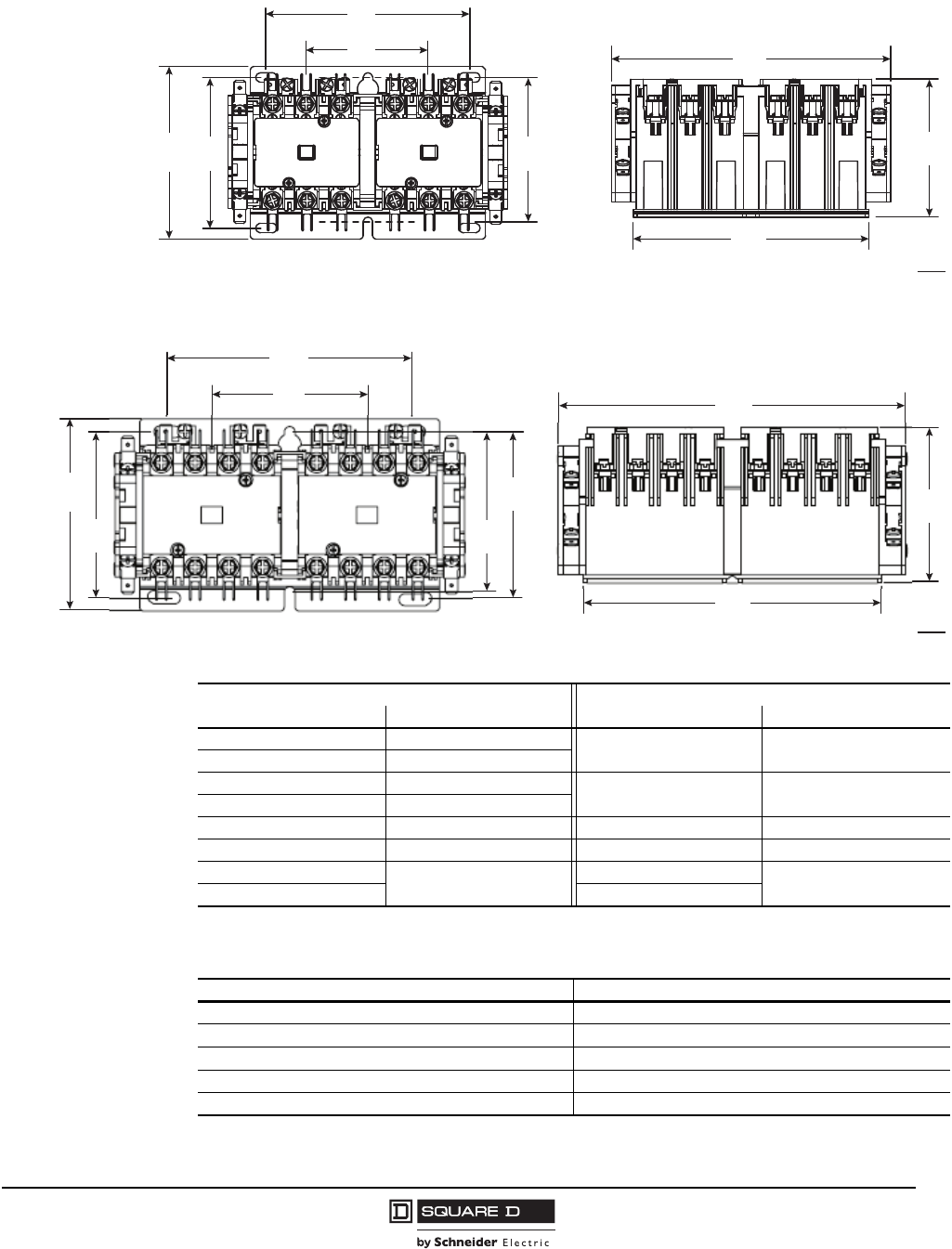
Figure 10: Type DPR 3-Pole Reversing/Hoist Contactors, Approximate Dimensions
Figure 11: Type DPR 4-Pole Reversing/Hoist Contactors, Approximate Dimensions
[1] A Type DPS 4-pole starter is not available. The 3-pole device with auxiliary contact is recommended.
[1] Use for 20–40 A starters; for larger sizes, contact your local Schneider Electric office.
These kits include the support bracket for the operator and slip-on connectors where required.
4.39
111.60
2.64
67.10
3.73
94.70
3.25
82.60
3.12
79.20
6.03
153.20
2.98
75.70
5.08
129.00
Dimensions: in.
mm
4.77
121.20
3.02
76.80 6.80
172.80
3.04
77.30
5.84
148.30
3.77
95.80
3.26
82.80
3.14
79.80
3.27
82.10
Dimensions: in.
mm
Table 19: Cross-Reference of Existing to Replacement Devices, Class 8911
Class 8911 Type Class 8911 Type
Existing Device Replacement Device Existing Device Replacement Device
HO33 DPSO13 LO33 DPSO43
HG33 DPSG13
JO33 DPSO23 LG33 DPSG43
JG33 DPSG23
KO33 DPSO33 MO33 DPSO53
KG33 DPSG33 MG33 DPSG53
KO43 [1] MO43 [1]
KG43 MG43
Table 20: Parts and Accessories
Description Class and Type
Start-Stop push button kit [1] 8911DPB1
Hand-Off-Auto selector switch kit [1] 8911DSS1
Standard N.C. overload relay contact 9998SO1
N.C. and N.O. isolated overload relay alarm contacts 9999SO4
Overload relay jumper strap 9998SO31
Definite Purpose Control
Reversing/Hoist Contactors, Class 8965 Type DPR
10
04/2014
™
© 1998–2014 Schneider Electric
All Rights Reserved
[1] Add the voltage code suffix from Table 22.
Table 21: Class 8911 Replacement Coils
Full Load Amperes Poles Class 9998
Type [1]
Volt-Amperes
Inrush Sealed
50 2 and 3 DA2 109 10
Table 22: Coil Voltage Codes
Voltage, 60 Hz Voltage, 50 Hz Voltage Code
24 24 V14
120 110 V02
208–240 220 V09
277 — V04
480 440 V06
600 550 V07
Table 23: Auxiliary Contacts for Type DPS Starters
Auxiliary contacts must be field installed. Contact your local Schneider Electric office.
Description Class 9999
20–40 A 50 A
1 N.O. DD10 D10
1 N.C. DD01 D01
1 N.O. / 1 N.C. DD11 D11
2 N.O. DD20 D20
Table 24: Ratings—Overload Contacts and Auxiliary Contacts
Device Vac Pilot Duty—AC Only (35% Power Factor) Continuous
Current Rating
Make Carry and Break
9998SO1 120 or less 30 A 3 A 5 A
9999SO4
9999 R10, R11, R12, R13
9999 D10, D01, D11, D20
9999 DD10, DD01, DD11, DD20
120–600 3600 VA 360 VA 5 A
Definite Purpose Control
Reversing/Hoist Contactors, Class 8965 Type R
11
04/2014
™
© 1998–2014 Schneider Electric
All Rights Reserved
Reversing/Hoist Contactors, Class 8965 Type R
Class 8965 reversing/hoist contactors meet the small space requirements found in electrical hoists,
light duty cranes, door operators, and related products. They are designed to perform in the short
periods of jogging experienced in hoist service. Note that these contactors must be mounted upright on
the vertical plane; the contactors will not operate properly when mounted in any other position.
To order, specify the Class, Type, and Voltage Code (where indicated).
[1] Add the voltage code suffix from Table 29.
[2] Jumper straps connect the line side power terminals of the same phase between the forward (up) and reverse (down) contactors
in common; for example, L1 to L1, L2 to L2, and L3 to L3.
[3] Coils rated 120 Vac or less are available with quick connect terminals only.
Table 25: Application Data
Coils Duty: Hoist Duty, H4 Intermittent
Voltage Range: AC coils only +10%, –15% of nominal
Burden Inrush 76 VA, Sealed 27 VA
Approvals
UL Recognized
File E3190
CCN NLDX2
CSA Certified
File LR60905
Class 3211 04
Table 26: AC Reversing/Hoist Contactors—600 Vac Maximum
No. of
Poles
Horsepower Ratings Power
Terminals
Open Style, Class 8965 Type [1]
115 V, 1Ø 230 V, 1Ø 230 V, 3Ø 460/575 V, 3Ø With [2]
Jumper Straps
Without [2]
Jumper Straps
3-pole
polyphase 11.53 3
Quick connect RO10 RO11
Pressure wire [3] RO12 RO13
Table 27: Hoist Contactor Kits
For Use with
Class 8965 Type Description Catalog Number
RO10 Armature kit 9998RP1
RO11
RO12
RO13
Contact carrier 31002-060-50
Table 28: Auxiliary Contacts Separate Module
Description Terminals Class 9999 Type
1 N.O. each side Quick connect R10
Screw R12
1 N.C. each side Quick connect R11
Screw R13
Table 29: Replacement Coils
Description Voltage, 60 Hz Voltage, 50 Hz Voltage Code Replacement Part Number
Tape wound coils, two per package 24 — V01 31002-403-19
120 110 V02 31002-403-40
Type RO10V02
Definite Purpose Control
Reversing/Hoist Contactors, Class 8965 Type R
12
04/2014
™
© 1998–2014 Schneider Electric
All Rights Reserved
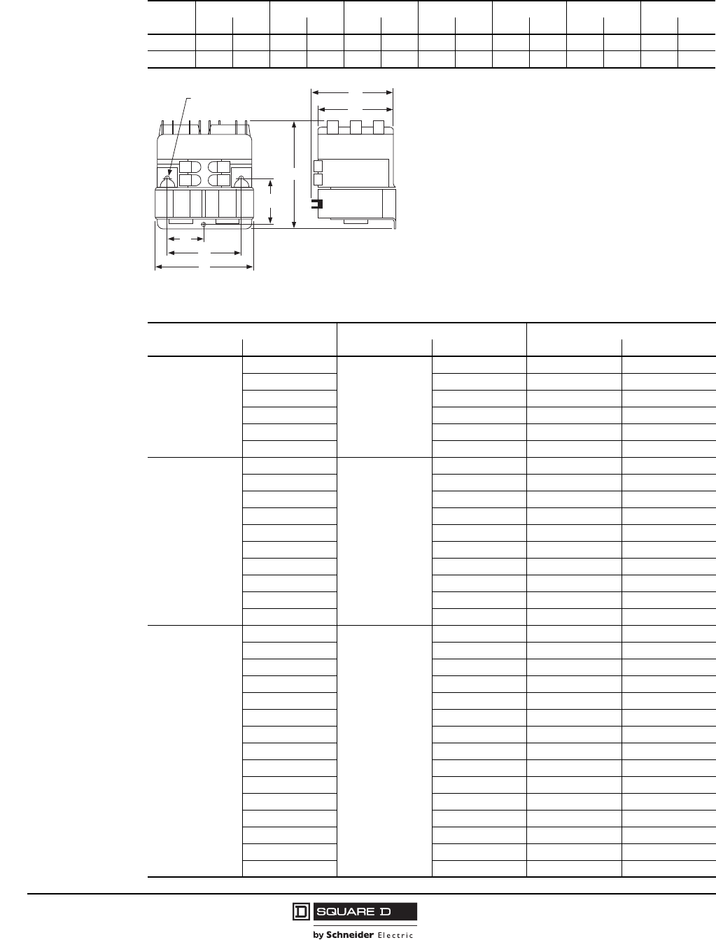
Table 30: Approximate Dimensions (3 Poles per Contactor)
Type ABCDEFG
in.mmin.mmin.mmin.mmin.mmin.mmin.mm
RO10, 11 3.31 84 3.31 84 3.03 77 2.69 68 1.34 34 1.56 40 2.66 68
RO12, 13 3.31 84 3.69 94 2.69 68 2.69 68 1.34 34 1.56 40 2.66 68
Table 31: Cross Reference—Obsolete Devices
Obsolete Device Replacement Device Auxiliary Contact Required
Class Type Class Type Class Type
8702
or
8965
HO3
8965
RO12 — —
HO4 RO12 9999 R12
HO5 RO12 9999 R13
HO6 RO12 — —
HO7 RO12 9999 R12
HO8 RO12 9999 R13
8965
RG2S1
8965
RO10 9999 R10
RG5S1 RO12 9999 R12
RG5S2 RO12 9999 R12
RO1 RO10 — —
RO1S1 RO11 — —
RO1S2 RO10 — —
RO1S3 RO11 — —
RO1S4 RO10 — —
RO1S5 RO10 — —
RO1S6 RO10 — —
8965
RO2
8965
RO10 9999 R10
RO2S1 RO11 9999 R10
RO2S2 RO10 9999 R10
RO3 RO10 9999 R11
RO3S1 RO11 9999 R11
RO3S2 RO10 9999 R11
RO3S3 RO10 9999 R11
RO4 RO12 — —
RO4S1 RO13 — —
RO5 RO12 9999 R12
RO5S1 RO13 9999 R12
RO5S2 RO12 9999 R12
RO6 RO12 9999 R13
RO6S1 RO13 9999 R13
RO6S2 RO12 9999 R13
A
D
E
F
B
G
C
Provisions for
(3) #8 Mounting Screws
Definite Purpose Control
Replacement Parts Kits, Class 9998
13
04/2014
™
© 1998–2014 Schneider Electric
All Rights Reserved
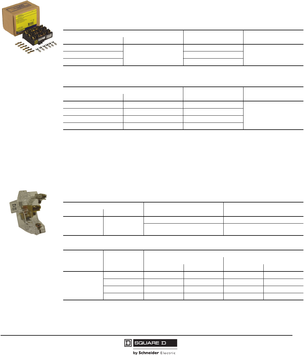
Replacement Parts Kits, Class 9998
Class 9998 replacement parts kits are available for servicing Square D™ contactors.
Replacement Contact Kits
Each Class 9998 replacement contact kit contains the necessary movable and stationary contacts,
contact springs, and additional hardware required to service the devices listed below.
Contact Units for Melting Alloy Overload Relays
One N.C. contact, Class 9998 Type SO1, is provided in each overload relay block on Class 8911
Type DPS starters. Replacement contact modules are listed in Table 34.
Isolated overload relay alarm circuit contacts are available as an optional feature. A pilot light or
audible alarm can be wired in series with this contact to indicate that the overload relay has tripped.
‘
Table 32: Class 9998 Replacement Contact Kits for
Class 8965 Reversing/Hoist Contactors
Device To Be Serviced Contact Kit
Class 9998 Type Quantity
Contactor, Class 8965 Type Series
RO10
All
RA10
One kit services three polesRO11 RA11
RO12 RA12
Table 33: Class 9998 Replacement Contact Kits for
Class 8910 Definite Purpose Contactors
Device To Be Serviced Contact Kit
Class 9998 Type Quantity
Contactor, Class 8910 Type Series
DPA5 A, B DRC5
One kit per pole
DPA6 A, B DRC6
DPA7 A DRC7
DPA9 A DRC9
Table 34: Class 9998 Replacement Contact Modules
Magnetic Starter Description Parts Kit
Class 9998 Type
Size Type
20–90 A DPS
Standard N.C. contact unit SO1
N.O. isolated alarm contact and
standard N.C. overload contact SO4
Table 35: DP Type SO1 Contact Ratings
NEMA
Contact Rating
Volts
(110 V Minimum
Recommended)
Inductive 35% Power Factor
Make Break
AVAAVA
B600
120 30 3600 3 360
240 15 3600 1.5 360
480 7.5 3600 0.75 360
600 6 3600 0.6 360
Class 9998
Type RA10
Class 9998
Type SO1
Definite Purpose Control
External Auxiliary Contacts, Class 9999
14
04/2014
™
© 1998–2014 Schneider Electric
All Rights Reserved
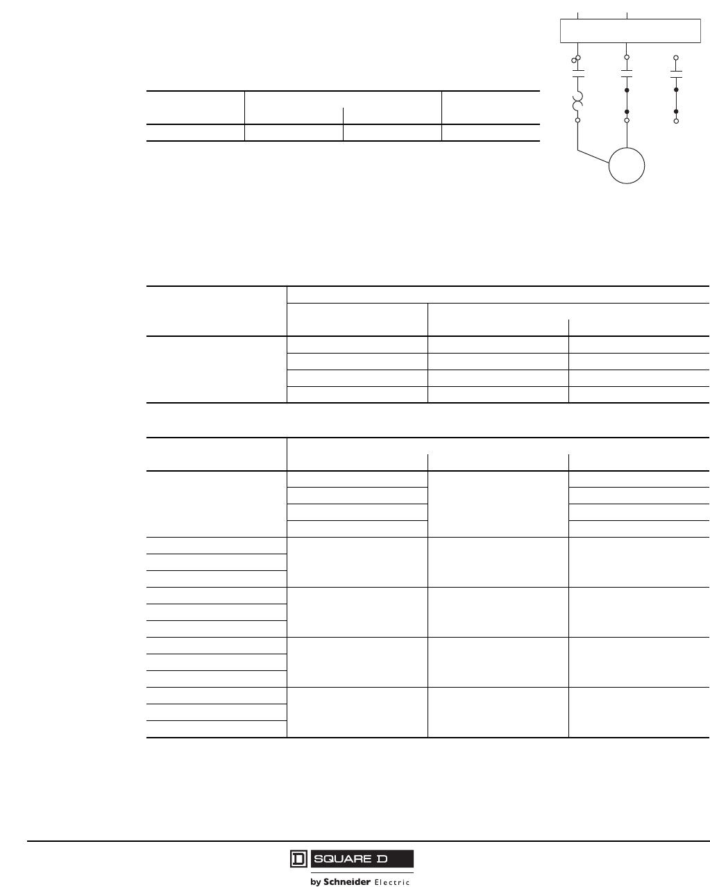
External Auxiliary Contacts, Class 9999
Melting Alloy Overload Relay Jumper Strap Kits
Jumper strap kits are used only on three-phase magnetic starters with
melting alloy overload relays, where a three-phase starter is used to
control a single-phase motor. These kits include two jumper straps, a
wiring diagram showing how to wire a three-phase starter to control a
single-phase motor, and thermal unit selection tables for single-phase
operation.
Table 36: Melting Alloy Overload Relay Jumper Strap Kits
Class For Starter Parts Kit
Class 9998 Type
Size Type
All 20–50 A DPS SO31
Table 37: Class 8910 and 8911 Definite Purpose Contactors and Starters—Auxiliary Contacts
Device to be Serviced
Class 8910 or 8911
Type
Auxiliary Contact Kit
Contact Arrangement Class 9999 Type
20–40 A 50–90 A
DPA
DPS
1 N.O. DD10 D10
1 N.C. DD01 D01
1 N.O. / 1 N.C. DD11 D11
2 N.O. DD20 D20
Table 38: Class 8965 Reversing/Hoist Contactors—Auxiliary Contacts
Device to be Serviced
Class 8965 Type
Auxiliary Contact Kit
Contact Arrangement Type of Connector Class 9999 Type
DPR
1 N.O.
screw/
quick connect
DD10
1 N.C. DD01
1 N.O. / 1 N.C. DD11
2 N.O. DD20
RO2 and RG2
1 N.O. each side slip-on R10RO10 Form X1
RO11 Form X1
RO3 and RG3
1 N.C. each side slip-on R11RO10 Form X2
RO11 Form X2
RO5 and RG5
1 N.O. each side screw R12RO12 Form X1
RO13 Form X1
RO6 and RG6
1 N.C. each side screw R13RO12 Form X2
RO13 Form X2
L1 L2
1L1 L2 L3
T1
T1
T2
T2
T3
Motor
Disconnecting means, provided
by user, or with controller
Figure 12: Three-phase
starter wiring to control a
single-phase motor

04/2014
Schneider Electric USA, Inc.
1415 S. Roselle Road
Palatine, IL 60067 USA
1-888-778-2733
www.schneider-electric.us
© 1998–2014 Schneider Electric All Rights Reserved
All trademarks are owned by Schneider Electric Industries SAS or its affiliated companies.
8910CT9301R12/13 Replaces 8910CT9301R04/10 dated 04/2011
