P0025rev8 09 Installation Directions
2016-08-17
: Pdf 1000434263-Installationsheet 1000434263-InstallationSheet B3 unilog
Open the PDF directly: View PDF ![]() .
.
Page Count: 2

1. Read all instructions.
2. Do not conceal or extend exposed con-
ductors through a building wall.
3. To reduce the risk of fire and burns, do
not install this lighting system where the
exposed bare connectors can be shorted
or contact any conductive materials.
4. To reduce the risk of fire and overheat-
ing, make sure all connections are tight.
5. Do not install any luminaire closer than 6
inches (15.25cm) from any curtain, or
similar combustible material.
6. Turn off electrical power before modify-
ing the lighting system in any way.
7. These transformers are intended for use
with Juno Flex 12 Series or Trac 12/25
Series low voltage lighting system only.
8. Install transformer on a wall or other ver-
tical surface.
9. Do not install in confined or unventilated
areas that may entrap heat.
10. Do not allow transformer to come in con-
tact with insulation.
11. Do not install in wet or damp locations or
outdoors.
12. Do not install in a non-accessible loca-
tion. Units are equipped with a manually
resettable circuit breaker that will trip in
the event of a short circuit or overload
condition.
13. Use only 10 or 8 gauge wire to connect
the transformer output to the Trac.
14. TF5150BL-277, TF5300BL-277 and
TF5600BL-277 transformers should be
dimmed only with dimmers specifically
designed for use with magnetic trans-
formers and rated for 277 volts. When
used in conjunction with a non-resistive
LED load, these transformers should be
dimmed using only dimmers qualified for
this application by Juno Lighting Group
as listed on Juno specification sheet,
which can be accessed at www.juno-
lightinggroup.com. Use of dimmers not
qualified by Juno Lighting Group for this
application can result in flicker, reduced
dimming range and erratic performance.
The dimmer must only be connected to
the 277 volt input wires providing power
to the transformer.
15. All units are equipped with a terminal
block. The inputs are labeled PRI and the
outputs labeled SEC.
16. The TF5150BL-277 transformer has one
output capable of delivering 12.5 amps or
150 watts. The TF5300BL-277 trans-
former has one output, while the
TF5600BL-277 has two outputs, each
capable of delivering 25 amps or 300
watts at 12 volts. The first output consists
of two terminals labeled 12VAC SEC and
COM SEC. The second output consists of
two additional terminals labeled 12VAC
SEC 2 and COM SEC 2.
17. The maximum load applied to each output
must not exceed the transfomer rating for
each circuit. The load does not need to be
balanced on the transformer with two out-
puts. Since lighter loads result in higher
lamp voltage, and lamp voltage should
never exceed 11.8 volts, the total load on
the transformer typically should not be
less than 1/2 of its maximum rated capac-
ity.
18. Connect ground wire to the GND terminal.
19. Applying 277 volts across the COM PRI
and 277VAC PRI input terminals will pro-
vide nominal 12 volts across the output
terminals. Applying 277 volts across the
COM PRI and BOOST PRI input termi-
nals will provide nominal 13 volts across
the output terminals. Use boost connec-
tion only if the voltage at the first lamp is
less than 11.0 volts.
20. Do not apply 277 volts across the
277VAC PRI and BOOST PRI input
terminals.
INSTALLATION
1. Select a mounting location for the trans-
former, taking care to observe the above
listed safety / operating instructions.
2. Choose the appropriate wire gauge, and
determine the proper wire length and
transformer input, based on the desired
lamp load and the table on the back of this
sheet.
3. Mount the transformer and Trac to the
desired surface. Run AC power lines to the
transformer and output wires from the
transformer to the Trac.
4. In order to avoid nuisance tripping of the
panel circuit breaker, it is recommended
that the use of a high magnetic type circuit
breaker be selected for this and all high
power, magnetic type transformer loads.
5. Connect the input and output wires to the
transformer per the diagram on the case,
information provided on this sheet and
local electrical codes.
6. Connect the other end of the output wires
to the Trac Feed.
7. Ensure that all electrical connections are
tight. This step is essential for a reliable
installation.
8. Install the lamps into the fixtures and the
fixtures onto the Trac.
9. Apply AC power. Confirm that all fixtures
function acceptably. Measure the voltage
at the first lamp. Confirm that this voltage
is between 11.0 and 11.8 volts.
IMPORTANT SAFEGUARDS:
When using electrical equipment, always adhere to basic safety precautions including the following:
IMPORTANT SAFETY / OPERATING INSTRUCTIONS
INSTALLATION INSTRUCTIONS
Magnetic Remote Mounted Transformers
TF5150BL-277 12 volt, 150 watt, single output
TF5300BL-277 12 volt, 300 watt, single output
TF5600BL-277 12 volt, 600 watt, dual output
SAVE THESE INSTRUCTIONS
WARRANTY
Juno Lighting Group warrants that its products are free from defects in material and workmanship. Juno Lighting Group’s obligation
is expressly limited to repair or replacement, without charge, at Juno Lighting Group’s factory after prior written return authorization has been
granted. This warranty shall not apply to products which have been altered or repaired outside of Juno Lighting Group’s factory. This warranty is in
lieu of all other warranties, expressed or implied, and without limiting the generality of the foregoing phrase, excludes any implied warranty of mer-
chantability. Also, there are no warranties which extend beyond the description of the product on the company’s literature setting forth terms of
sale.
Product Services Phone (888) 387-2212
1300 S. Wolf Rd • Des Plaines, IL 60018 • Phone: 800-323-5068 • www.junolightinggroup.com
© 2009 Juno Printed in USA Rev 8/09 P0025 pg 1 of 2
INSTALLATION INSTRUCTIONS
Rev 8/09 P0025 pg 2 of 2
GUIDELINES FOR A TROUBLE-FREE LOW VOLTAGE INSTALLATION
1. IMPROPER WIRE GAUGE OR POOR WIRE CONNECTIONS CAN RESULT IN PRODUCT FAILURE.
These transformers reduce the line voltage by a factor of 23. To achieve the same power levels at the lamp, the output current is increased by
the same factor of 23. To accommodate these high current levels, heavy gauge wire and secure connections are essential, or product
failure can result.
300 WATTS = 277 VOLTS x 1.08 AMPS 300 WATTS = 12 VOLTS x 25 AMPS
2. LAMP VOLTAGE CAN BE AFFECTED BY NUMEROUS FACTORS.
Many factors will affect the voltage delivered to the load. Below is a list of these factors and examples of their affects:
A. Variations in transformer input voltage. 11.7V @ 277V input 12.3V @ 291V input (+5%)
B. Using the “277V” or “BOOST” transformer input. 11.7V (277V input) 12.5V (BOOST input)
C. Use of a dimmer to control the transformer. 11.7V (no dimmer) 11.1V (with dimmer set at maximum)
D. The amount of load applied to the transformer. 11.7V @ 300W 12.3V @ 150W
E. Length of wire between transformer and trac. 11.7V @ 5 feet (#10) 10.4V @ 30 feet (#10)
F. Gauge of wire between transformer and trac. 11.1V (#8 @ 30 feet) 10.4V (#10 @ 30 feet)
G. Transformer operating temperature. 11.7V room temp. 11.4V max. temp.
3. EXCESSIVE LAMP VOLTAGE AND TEMPERATURE CAN DRASTICALLY REDUCE LAMP LIFE.
Lamp life is directly affected by the applied voltage. Excess voltage as little as 1/4 volt over 12 volts can reduce lamp life by as much as 40%.
Some of the factors listed above can be chosen, while others cannot, and therefore must be compensulated for.
4. CHOOSE THE CORRECT PARAMETERS FOR THE APPLICATIONS
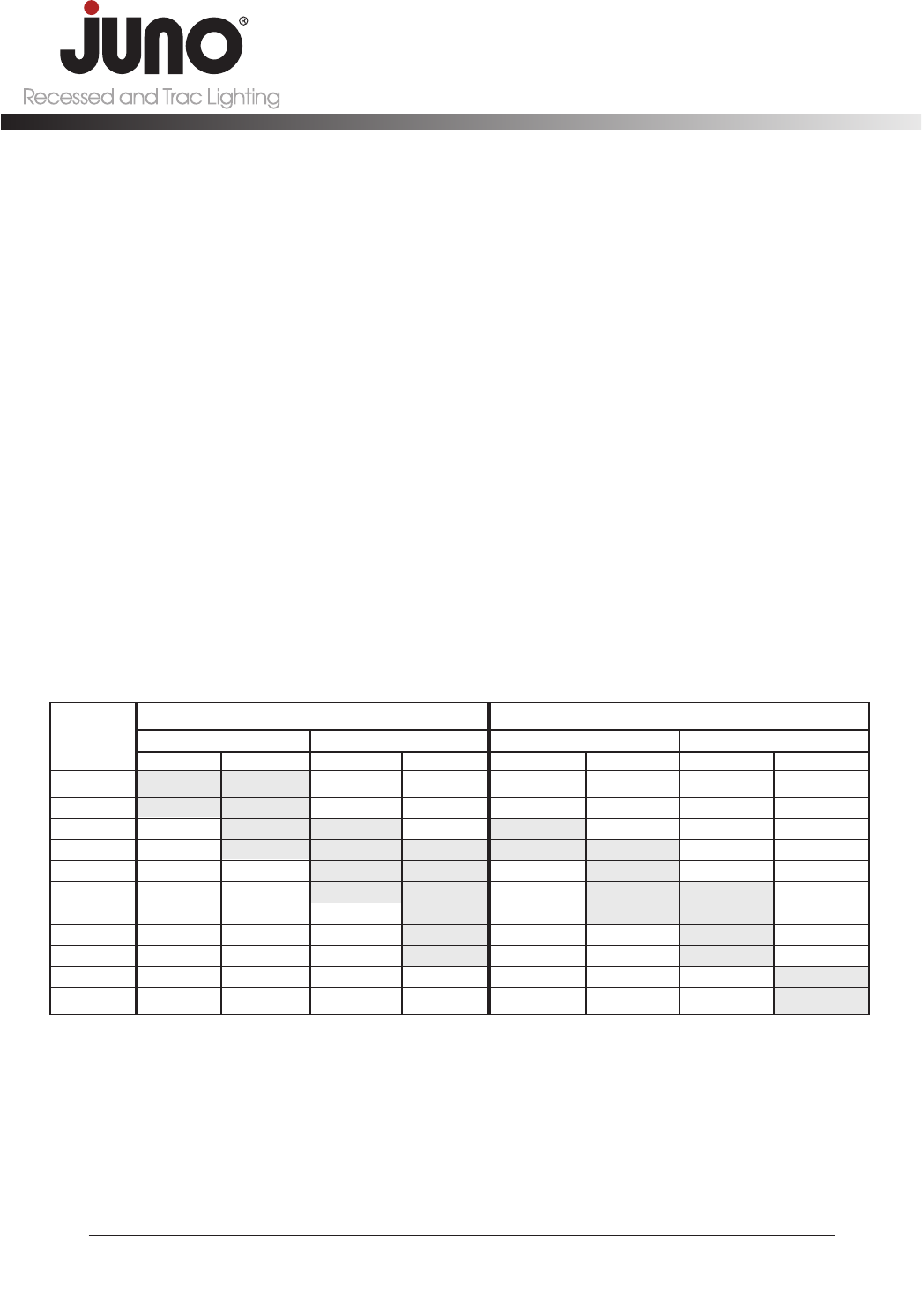
In general, for a fully loaded transformer, use the 277V input and 10 guage wire for runs up to 15 feet. For runs from 15 to 25 feet, use the
BOOST input and 10 guage wire. For longer runs, use 8 gauge wire and/or decrease the load as decribed in the table below.
5 11.740 11.854 12.270 12.327 12.540 12.654 13.170 13.227
15 11.220 11.563 12.010 12.181 12.020 12.363 12.910 13.081
20 10.960 11.417 11.880 12.109 11.760 12.217 12.780 13.009
30 10.440 11.126 11.620 11.963 11.240 11.926 12.520 12.863
40 9.920 10.834 11.360 11.817 10.720 11.634 12.260 12.717
50 9.400 10.543 11.100 11.671 10.200 11.343 12.000 12.571
60 8.880 10.251 10.840 11.526 9.680 11.051 11.740 12.426
70 8.360 9.960 10.580 11.380 9.160 10.760 11.480 12.280
80 7.840 9.668 10.320 11.234 8.640 10.468 11.220 12.134
100 6.800 9.085 9.800 10.943 7.600 9.885 10.700 11.796
150 4.200 7.628 8.500 10.214 5.000 8.428 9.400 11.114
The shaded areas represent the suggested operating range of 11.0 to 12.0 volts at the first lamp on the trac. Juno suggests that
the voltage measured at the first lamp be between 11.0 and 11.8 volts for 12V incandescent lamps and between 11.4 and 12.0
volts for 12V LED fixtures. Do not exceed 12 volts. A voltmeter should be used to confirm that the proper voltage is present.
277V INPUT
12V, 25A, 300W 12V, 12.5A, 150W 12V, 25A, 300W 12V, 20.5A, 150W
TABLE PREDICTING VOLTAGE AT FIRST LAMP FOR VARIOUS WIRE LENGTHS, GUAGES, INPUT AND LOADS
Distance from
Transformer
to 1st Lamp
BOOST INPUT
5. A VOLTMETER SHOULD BE USED TO CONFIRM THAT THE PROPER VOLTAGE IS PRESENT
After the installation is complete, a voltmeter should be used to insure that suggested lamp voltages are not being exceeded. The voltage
should be measured at the first lamp on the trac. Since some of the factors listed above are constantly changing some allowance should be
made for variations in voltage.
Juno suggests that the voltage measured at the first lamp be between 11.0 and 11.8 volts for 12V incandescent lamps
(between 11.4 and 12.0 volts for 12V LED fixtures).
#10 #8 #10 #8 #10 #8 #10 #8
