AB1 Terminal Blocks, 9080CT9901 1000436881 Catalog
1000438899-Catalog 1000438899-Catalog 1000438899-Catalog B5 unilog cesco-content
2016-09-04
: Pdf 1000436881-Catalog 1000436881-Catalog B4 unilog
Open the PDF directly: View PDF ![]() .
.
Page Count: 160 [warning: Documents this large are best viewed by clicking the View PDF Link!]
- Spring technology, type AB1RRN
- Screw clamp technology, type AB1VV
- Insulation displacement technology, type AB1AA
- Product certifications
- Spring technology
- Screw clamp technology
- Passthrough
- Grounding type
- Blade disconnect type
- Component, for diode or resistor
- Fused disconnect
- Disconnect (removable carrier), for diode, resistor, or cylindrical fuse
- Fixed carrier, for cylindrical fuse
- Screw-clip type
- Double deck, multi-pole
- For 3-wire proximity sensors
- Multifunction
- For neutral conductors
- Lug-lug type
- Lug-clamp type
- Miniature passthrough
- Miniature grounding
- Insulation displacement technology
- Marking accessories
- Mounting track
- End clamps
- Circuit protectors, 9080GCB
- Circuit protectors, GB2
- Technical information
Terminal Blocks
Type AB1
Catalog
9080CT9901R7/07
07
1 – General overview . . . . . . . . . . . . . . . . . . . . . . . . . . .1/1
2 – Spring technology . . . . . . . . . . . . . . . . . . . . . . . . . .2/1
3 – Screw clamp technology . . . . . . . . . . . . . . . . . . . . .3/1
4 – Insulation displacement technology . . . . . . . . . . . . .4/1
5 – Mounting and marking accessories . . . . . . . . . . . . .5/1
6 – Circuit protectors. . . . . . . . . . . . . . . . . . . . . . . . . . . .6/1
7 – Appendices . . . . . . . . . . . . . . . . . . . . . . . . . . . . . . . .7/1
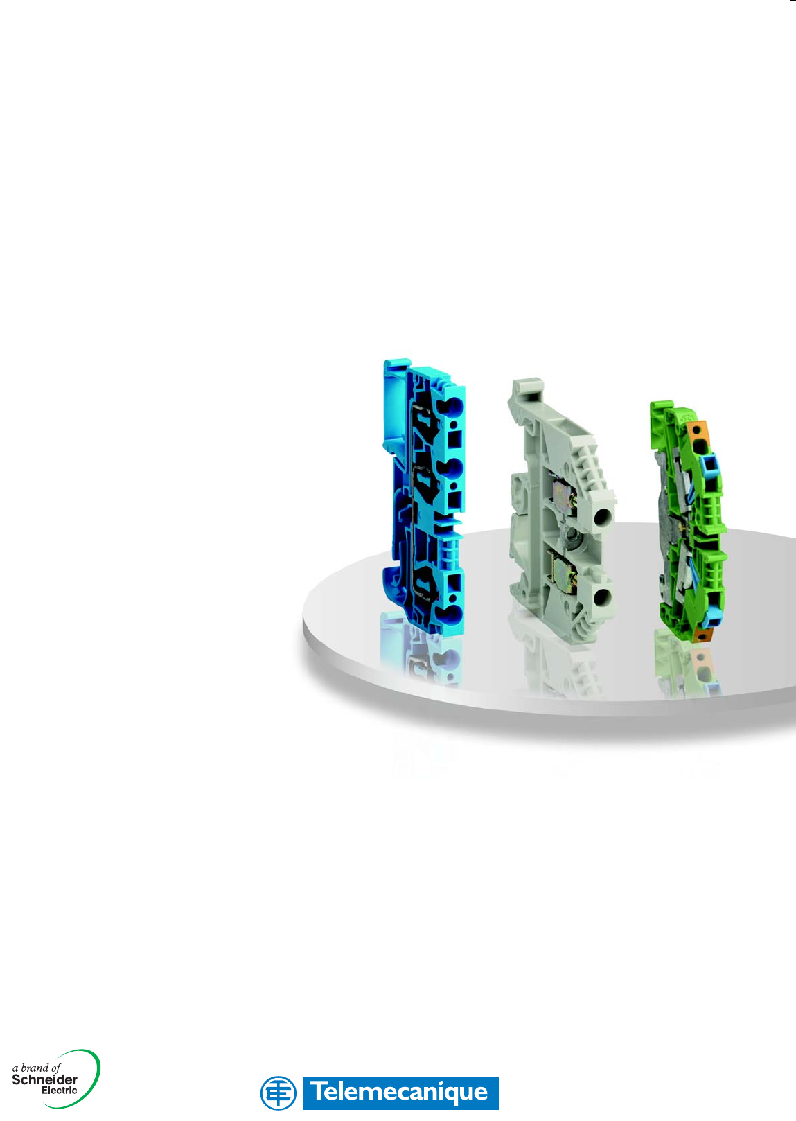
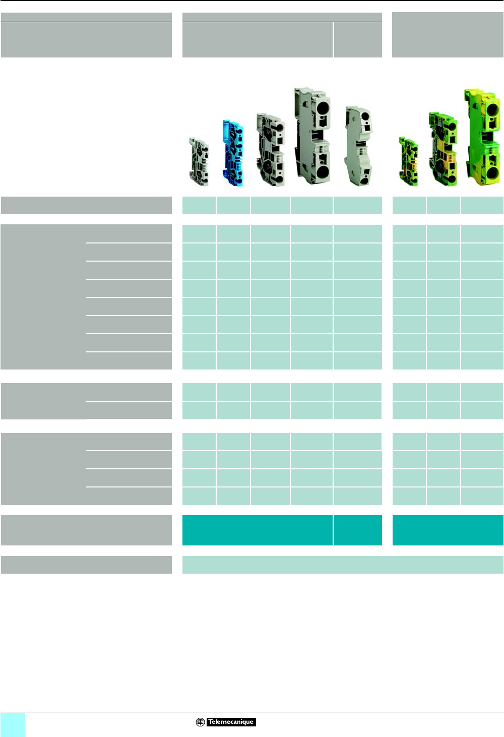
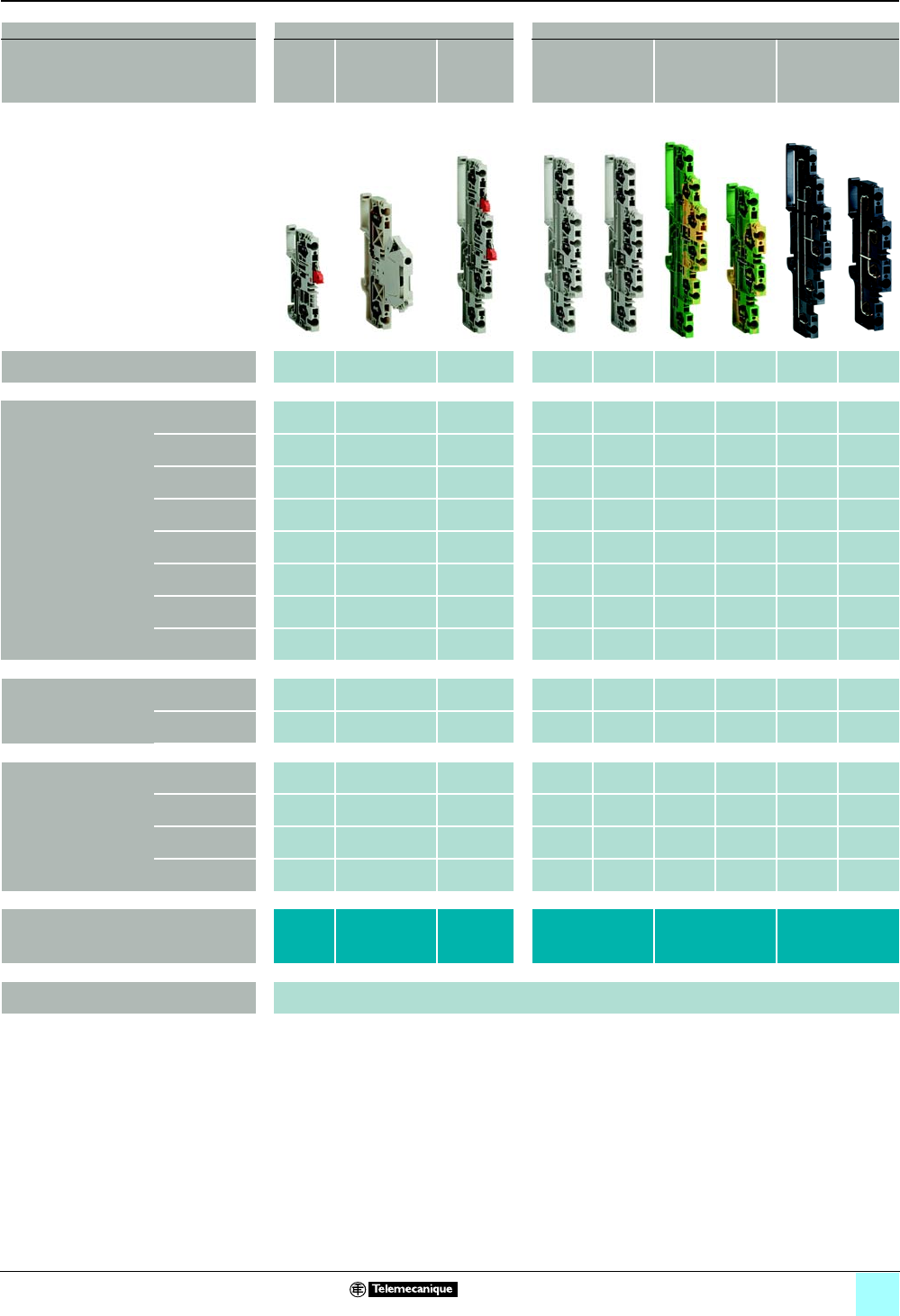
Product Overview
0
3
Terminal Blocks, Type AB1
Specifications
Materials
Block Housing Nylon 6-6
Clamp Zinc-plated steel with chromate film
Bus Bar Zinc-plated steel
Screws Zinc-plated steel with chromate film
Temperature Rating Ambient Temperature -40 to 221 °F (-40 to 105 °C)
Flammability Rating Gray Blocks UL 94V-0
All other colors UL 94V-2
Dielectric Strength 80 kV/mm
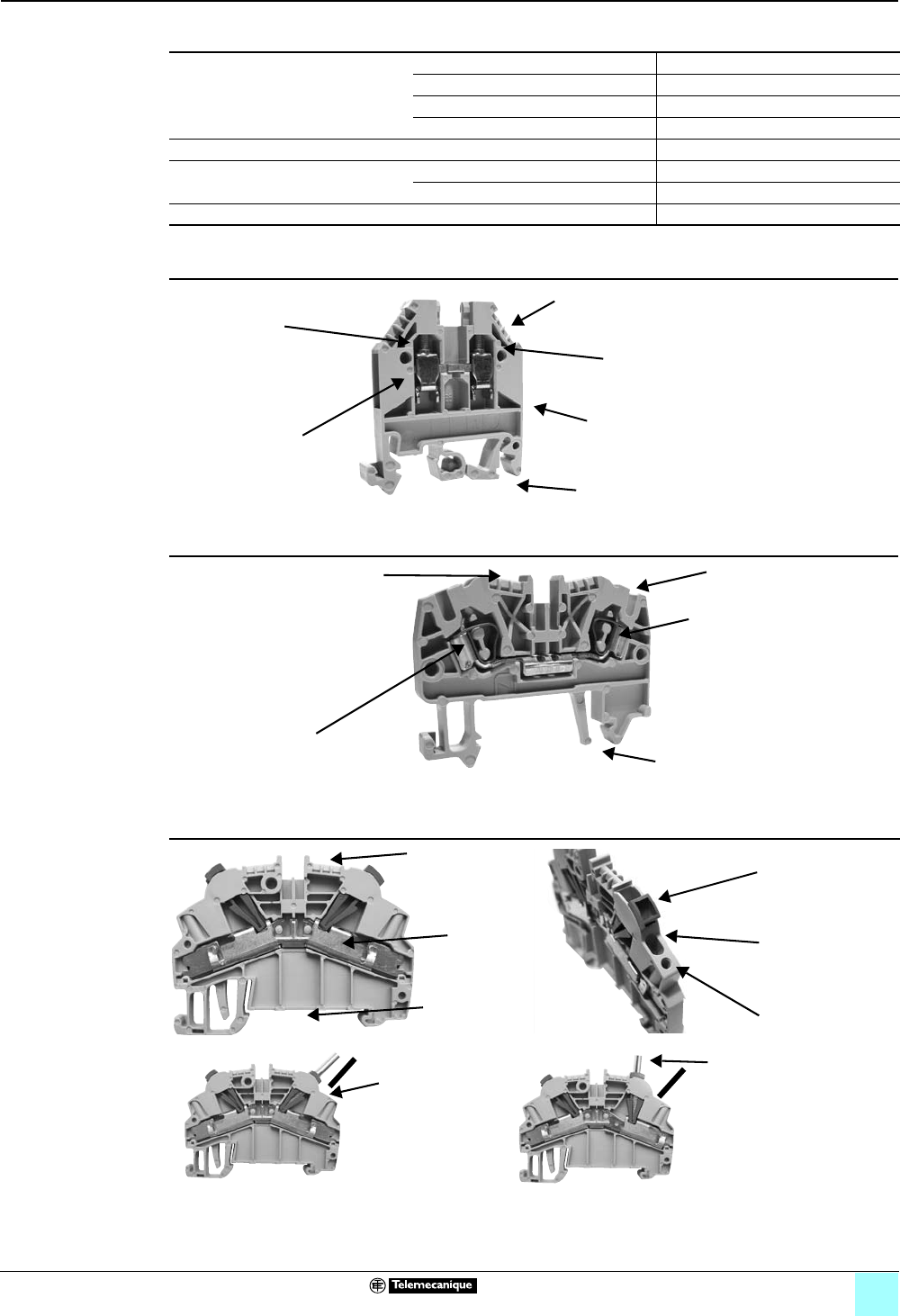
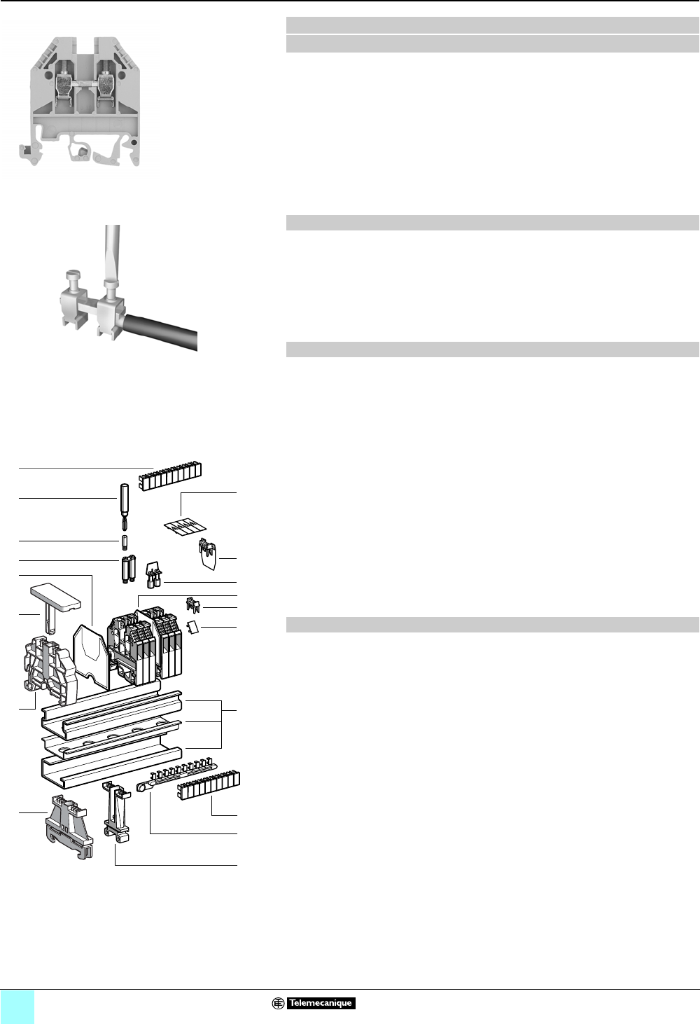
Box Lug Termination
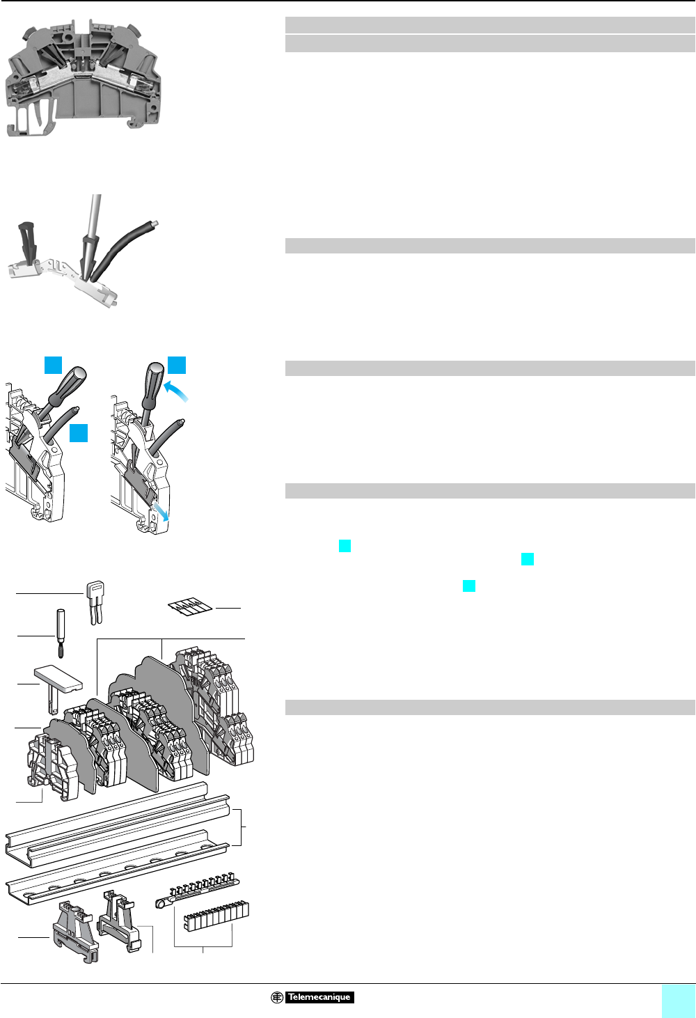
Spring Clip Termination
Insulation Displacement Termination
Screws shipped
backed out to save
installation time
Reliable box lug
termination
Recessed hardware
Four-sided wire entry
Marking area
Mounts on DIN 1 and
35 mm DIN 3 track
Reliable
spring clip
termination
Recessed hardware
R
oun
d
,
f
unne
l
-s
h
ape
d
w
i
re entry
Marking area
Mounts on
35 mm DIN 3 track
Recessed
hardware
Marking area
Mounts on
35 mm DIN 3
track
Wire entry
Screwdriver access
Test probe access
Wire entry
(no need to
strip the wire)
Moving the screwdriver
secures the wire

1/0

1/2
Product Description
0
Terminal Blocks, Type AB11 0
Spring technology, type AB1RRN
All electrical equipment or installations require the connection of cables or wires to
ensure the flow of very low to very high currents.
Depending on the application, there are several types of connection:
bSpring terminal
bScrew terminal
bInsulation displacement
The new AB1RRN terminal blocks use spring technology, the most cost-effective
connection technique on the market. Compared with screw clamp technology, this
technique significantly reduces wiring time. It could also eliminate the need for
regular retightening.
By virtue of their spring technology, the AB1RRN terminal blocks offer the versatility
of accepting:
bStranded wire
bStranded wire with cable ends
bSolid wire
The material used (polyamide 6.6) provides better resistance at high temperatures.
The flammability rating of these products is V0 according to UL 94.
Spring technology offers the following advantages:
bResistance to vibration and jolts
bWide range of wire sizes
bPossibility of distributing the potential with use of jumpers
bSeveral surfaces available for marking
bPossibility of testing all the terminal blocks
bNumerous certifications (see the tables beginning on page 1/10).
The following products are available, depending on the application:
bPassthrough
bGrounding
bDisconnect
bDouble deck disconnect
bPlug-in disconnect
bDouble deck
bDouble deck for grounding
bDouble deck with vertical connection
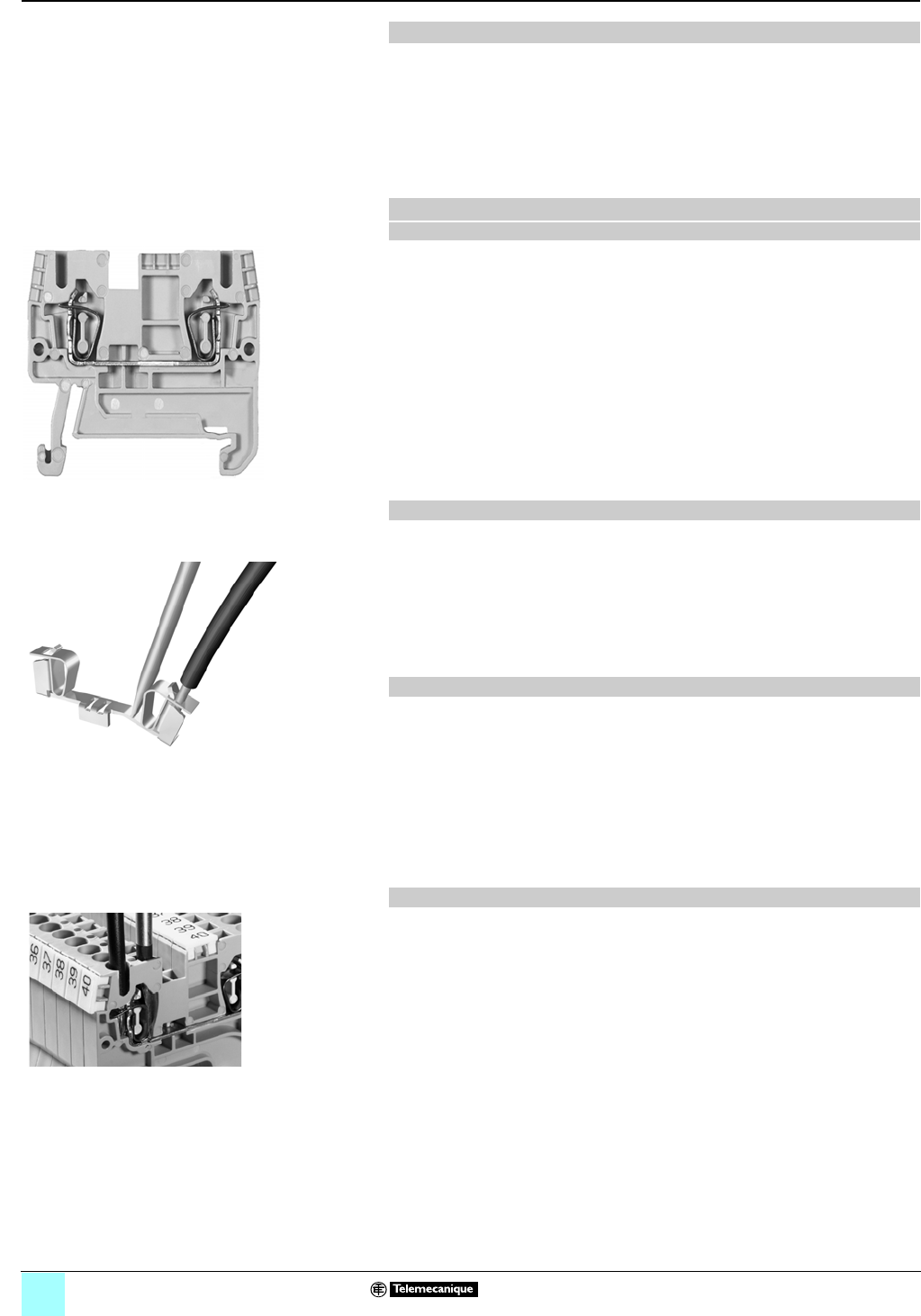
Installation of spring technology terminal blocks is quick and simple. A screwdriver is
used to open the connection point so that the conductor can be inserted into the
cage. As soon as the screwdriver is pulled out, spring pressure automatically makes
the contact.
General
New spring technology terminal blocks
Description of new terminal blocks AB1RRN
Advantages of this technology
Connection functions
Installation of AB1RRN spring technology terminal blocks
Terminal block type AB1RRN
Principle of spring technology
Simplified installation
1/3
Product Description
(continued)
0
Terminal Blocks, Type AB1 0
Spring technology, type AB1RRN
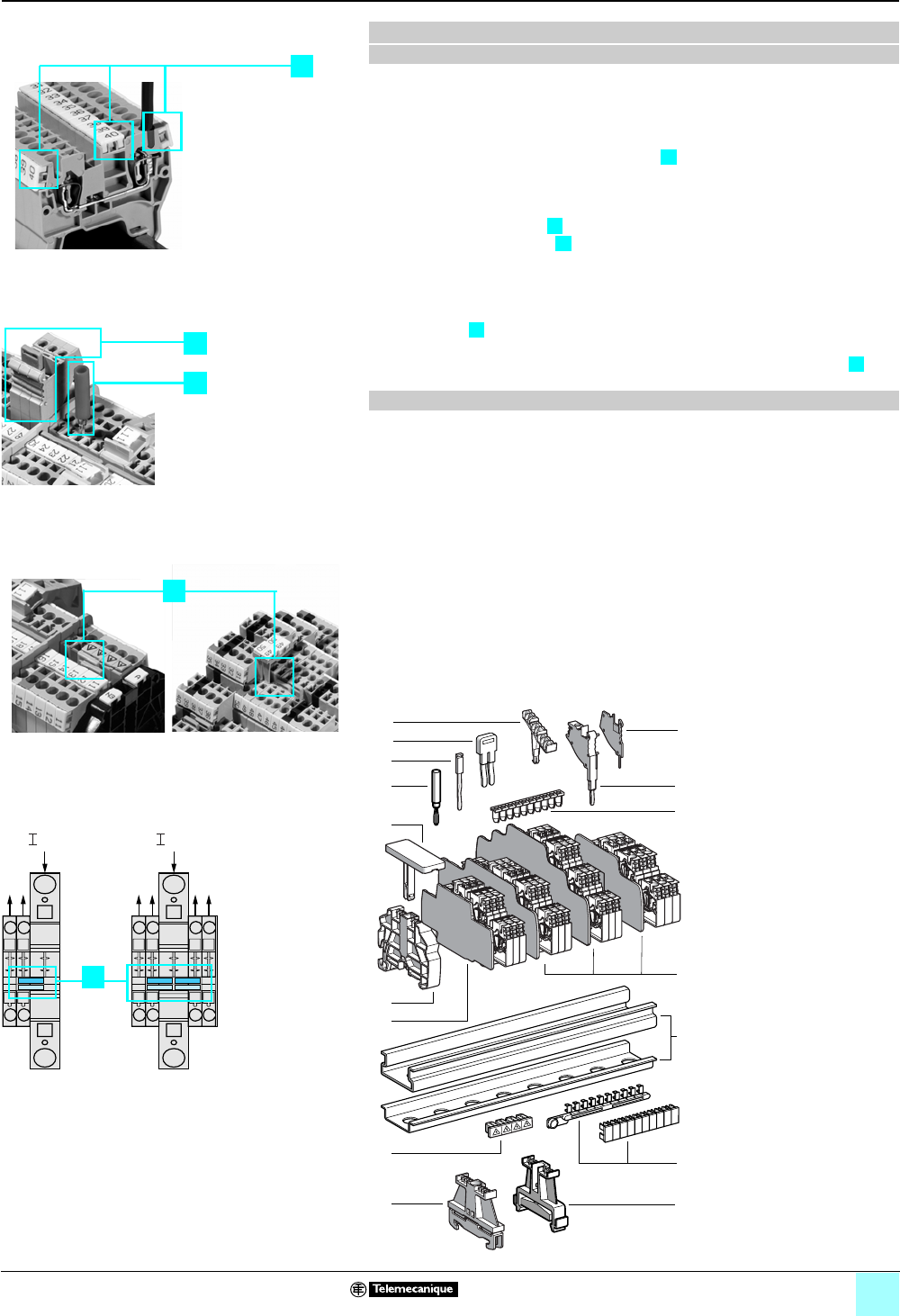
The AB1RRN range includes a series of accessories, which allow:
bquick and easy marking
The availability of clear and legible marking facilities is essential for completing an
installation in a minimum amount of time. The AB1RRN range allows easy marking
in the center and on the sides of the products .
btesting and adaptation
Each terminal block in the AB1RRN range can be fitted with a test plug in direct
contact with the conductors .
With modular test connectors , on the other hand, test adapters can be assembled
individually; they also provide a marking facility.
binterconnection of the terminal blocks
Insulated jumpers (2- to 10-pole) make it possible to jumper a large number of
terminal blocks : this significantly reduces wiring time.
You can also interconnect terminals with a large wire size (16 mm²) and those with
a small wire size (2.5 and 4 mm²) via the potential distribution terminal block .
The following accessories can be used with AB1RRN terminal blocks:
New spring technology terminal blocks (continued)
Mounting accessories
Typical scheme of a spring connection with its accessories
11 or 7 35 mm DIN3 rail
(7.5 and 15 mm high)
2Plastic end clamp with screw
3Metal end clamp with screw
4Clip-on plastic end clamp
5Marker tag holder for clip-on plastic end
clamp
6End plate (thickness 1.5 mm)
7Partition plate (thickness 1.5 mm)
9Insulated jumper
10 Wire guide entry strip
11 Modular test connector
12 Modular test connector end
plate (gray)
13 Test plug (red)
14 Terminal cover
15 Marker tag holder
16 Marking accessories
1
23
4
5
Marking facilities
1
3
2
s
Testing and adaptation
4
Interconnection by jumpers
In In In
max max
5
Interconnection by
potential distribution terminal block
13
4
6
8
5
1
12
11
10
7
9
15
14
3
10
9
8
7
6
5
4
3
2
1
987654321
10
2
16
1/4
Product Description
(continued)
0
Terminal Blocks, Type AB1 0
Screw clamp technology, type AB1VV
AB1VV screw clamp technology terminal blocks are well known and widely used
throughout the world. They are suitable for the vast majority of connection
applications, thanks to their wide range of functions and connection options.
AB1VV terminal blocks improve the quality, safety, and operational availability of
equipment. They also optimize the setup and operation of installations, thanks to
their simplicity and integrated functions.
The material used (polyamide 6.6) provides better resistance at high temperatures.
The flammability rating of these products is V0 according to UL 94.
Screw clamp technology offers the following advantages:
bNumerous connection functions
bWide range of wire sizes
bSeveral surfaces available for marking
bTest facility
bNumerous certifications (see the tables beginning on page 1/10).
The following products are available, depending on the application:
bPassthrough
bGrounding
bBlade disconnect
bFused disconnect
bDisconnect (removable carrier), for diode, resistor, or cylindrical fuse
bDisconnect (fixed carrier), for diode, resistor, or cylindrical fuse
bFixed carrier, for cylindrical fuse
bDouble deck, multi-pole
bDouble deck
bFor 3-wire proximity sensors
bMultifunction
bFor neutral conductors
bPassthrough with Telequick universal foot
bLug-lug type
bLug-clamp type
bMiniature passthrough
The following accessories can be used with AB1VV terminal blocks:
11 or 7 35 mm DIN3 rail (7.5 and 15 mm high)
2Plastic end clamp with screw
3Metal end clamp with screw
4Clip-on plastic end clamp
5Marker tag holder for clip-on plastic end clamp
6End plate (thickness 1.5 mm)
7Partition plate (thickness 1.5 mm)
8Jumpers with screws
9Jumpers for 2 blocks
10 Socket for test plug
11 Test plug
12 Terminal covers
13/15 Marking accessories
16 Yellow partition plate
17/18 Yellow protective cover
Screw clamp technology terminal blocks
Description
Advantages of this technology
Connection functions
Mounting accessories (for AB1VV screw clamp terminal blocks, 2.5 mm2)
Terminal block type AB1VV
Principle of screw clamp technology
10
9
8
7
6
5
4
3
2
1
987654321
10
18
5
1
7
14
15
13
8
17
16
11
10
9
6
4
3
12
2
1/5
Product Description
(continued)
0
Terminal Blocks, Type AB1 0
Insulation displacement technology,
type AB1AA
AB1AA terminal blocks use insulation displacement technology, which eliminates the
need to strip wires prior to assembly.
AB1AA terminal blocks are made of polyamide 6.6, the same material as screw and
spring terminal blocks.
Two widths are available :
b5 mm for a wire size of 18–30 AWG (0.2–1 mm²)
b6 mm for a wire size of 14–18 AWG (1–2.5 mm²)
Various colors are available—red, blue, black, and yellow/green—depending on the
application where the terminal block is used.
Insulation displacement technology offers the following advantages:
b Fast installation: 60% time savings
b No need to strip or crimp wires
b No special tools required
b Resistance to vibrations, since the technology does not rely on screws that can
come loose
The following products are available, depending on the application:
b Passthrough
b Grounding
b Double deck
b Blade disconnect
b Plug-in disconnect
Installation of these terminal blocks is carried out in three stages:
bCutting the wire to the required length and, without stripping it, inserting it into the
wire guide .
bInserting a screwdriver into the hole provided .
bLifting the screwdriver toward the center of the terminal block. The test point
checks that contact has been made .
Recommendations for installation :
bUse a 3–3.5 mm standard, flat screwdriver.
bInsert the screwdriver fully into its guide.
bCut off the end of the wire if a new connection is to be made.
bUL 1059 specifies that insulation displacement terminal blocks may be reused
10 times.
AB1AA insulation displacement terminal blocks use the same accessories as spring
terminal blocks:
11 or 7 35 mm DIN3 rail (7.5 and 15 mm high)
2Plastic end clamp with screw
3Metal end clamp with screw
4Clip-on plastic end clamp
5Marker tag holder for clip-on plastic end clamp
6End plate (thickness 1.5 mm)
7Partition plate (thickness 1.5 mm)
8Insulated jumpers
9Test plug (red)
10 Terminal covers
11 Marking accessories
Insulation displacement technology terminal blocks
Description
Advantages of this technology
Connection function
Installation
Mounting accessories
12
3
Terminal block type AB1AA
Principle of insulation displacement technology
1
23
Installation of insulation displacement technology
10
9
8
7
6
5
4
3
2
1
987654321
10
1
11
2
9
8
10
7
5
3
4
6
1/6
Characteristics and
Specifications
0
Terminal Blocks, Type AB1 0
Spring technology
Screw clamp technology
Insulation displacement technology
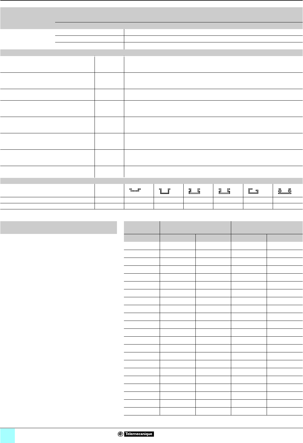
General characteristics
Terminal blocks Technology Spring Insulation displacement Screw
Catalog number AB1RRN••• AB1AA••• AB1VV•••
Component materials Insulating case Polyamide 6.6
Connector and screw Zinc chromated steel
Jumper Copper or brass
Electrical and thermal characteristics of insulating case (polyamide 6.6)
Dielectric strength Conforming to
VDE 0303-T21
and IEC60243-1
kV/mm 80/65
Dielectric loss
Tan coefficient at 1 MHz
Conforming to
VDE0303-T4
and IEC60250
—0.01
Dielectric constant at 1 MHz — 3.7
Resistivity Conforming to
VDE0303-T30
and IEC60093
Ω.cm 1012
Surface resistance Conforming to
VDE0303-T30
and IEC60093
Ω 1010
Creep resistance Conforming to
VDE0303-T30
and IEC60093
CTI (kB) 500 (> 400)
Ambient air temperature Conforming to
VDE0304-T21
and IEC60216-1
°F (°C) Operation: -40…+266 (-40…+130)
Flammability rating Conforming to
UL 94
Class/mm
thickness
V-0 / 0.8
Mounting rail characteristics
Mounting rail type
Dimensions, width x depth x thickness mm 35 x 7.5 x 1 35 x 15 x 1.5 35 x 15 x 1 35 x 15 x 1.5 32 x 15 x 1.5 35 x 16 x 1.8
Material Steel Steel Steel Steel Steel Aluminium
Nominal wire sizes ISO
metric size
U.S. wire size Diameter
mm² AWG kcmil in. mm
0.13 24 — 0.02 0.20
0.25 22 — 0.03 0.33
0.5 20 — 0.04 1.02
0.75 18 — 0.05 1.28
1 ————
1.5 16 — 0.06 1.6
2.5 14 — 0.08 2.08
4 12 — 0.11 2.7
6 10 — 0.12 3.09
10 8 — 0.13 3.36
16 6 — 0.17 4.32
25 4 — 0.23 5.73
35 2 — 0.29 7.26
50 (1/0) 0 — 0.48 12.08
70 (2/0) 00 — 0.53 13.54
95 (3/0) 000 — 0.60 15.33
— (4/0) 0000 — 0.68 17.22
120 — 250 0.75 19.01
150 — 300 0.81 20.48
185 — 350 0.87 22.05
240 — 500 1.05 26.57
300 — 600 1.18 30.03
1/7
Characteristics and
Specifications (continued)
0
Terminal Blocks, Type AB1 0
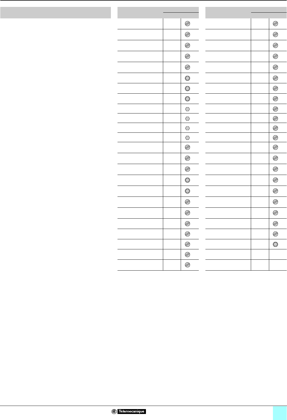
Screw clamp technology
Terminal screw type Catalog number Screws Catalog number Screws
∅Type ∅Type
AB1VV235••• M2.5 AB1FUSE435•••• M3
AB1VV435••• M3 AB1FV135U M3
AB1VV635••• M3.5 AB1NEN435U M3
AB1VVN1035••• M3.5 AB1SC435•••• M3
AB1VVN1635••• M6 AB1TP215 M3
AB1VVN3535••• M6 AB1TP435U M3
AB1VVN7035••• M8 AB1TRNN435 M3
AB1VVN15035••• M10 AB1TRPN435 M3
AB1B•9535 M12 AB1TRPN435UFM M3
AB1B•15035 M12 AB1TRSN435 M3
AB1B•18535 M12 AB1VV415 M3
AB1B•24035 M12 AB1ET435U•••• M3
AB1VV215•• M2.5 AB1TP635U M4
AB1DDP235••• M2.5 AB1FU10135U• M5
AB1ET3235•••• M2.5 AB1FU10235U M5
AB1BD101 M3 AB1FU10335U M5
AB1BD102 M3 AB1FU10435U•• M5
AB1D11435U M3 AB1NEN1035U M5
AB1ET435•••• M3 AB1TP1035U M5
AB1ETN235U M3 AB1NEN1635U M6
AB1ETN335U M3 AB1TP1635U M5
AB1ETN435U M3 AB1TP3535U M6
AB1ETNTP435U M3 AB1AB8M35 ——
AB1FC335U M3 AB1AB8P35 ——

1/8
Certifications
0
Terminal Blocks, Type AB1 0
Product certifications
In some countries, certification of certain electrical components is required by law. In
this case, a certificate of conformity must be issued by an official test body. Each
certified device must bear the relevant certification symbols when these are
mandatory.
In general, prior approval (= certification) by certain marine classification authorities
is required for electrical equipment intended for use on board merchant vessels.
The tables beginning on page 1/10 show the status of certifications for terminal
blocks as of December 31, 2006. An up-to-date list of certifications for
Telemecanique® products is available on our website, www.Telemecanique.com.
All devices and equipment intended for use in potentially explosive atmospheres
created by the presence of flammable gas, vapor, or dust must conform to the
requirements of European Directive 94/9/e, more generally known as the ATEX
100a directive. “ATEX” is derived from the French term “ATmosphère EXplosible”
(explosive atmosphere).
Standards EN 50014, EN 50019 and EN 50281-1-1 apply to terminal blocks in
hazardous areas, requiring increased safety (EEx e).
In compliance with the ATEX 100a directive, the markings on Telemecanique
terminal blocks have the following meaning:
Product certifications Introduction
Code Certification body Country
ASEV Schweizerischer Elektrotechnischer Verein Switzerland
CSA Canadian Standards Association Canada
KEMA Keuring van Electrotechnische Materialen Netherlands
UL Underwriters Laboratories United States
VDE Verband Deutscher Elektrotechniker Germany
ATEX See “ATEX Directive” below Europe
FM Factory Mutual United States
UL ex Underwriters Laboratories United States
CSA ex Canadian Standards Association Canada
Code Marine classification authority Country
BV Bureau Veritas France
DNV Det Norske Veritas Norway
GL Germanischer Lloyd Germany
LR Lloyd’s Register Great Britain
RINA Registro Italiano Navale Italy
The ATEX Directive
Meaning of markings
XXX Identification number of the Notified Body
Ex Use of the equipment in a potentially explosive atmosphere
II Device group: II = Surface industries
2Device category: 2 = Zone 1 (gas) / Zone 21 (dust)
GD Type of explosive atmosphere: G = (gas), D = (dust)
EEx Equipment conforming to the type of protection specified by
CENELEC
eType of protection: e = increased safety

1/9
Certifications (continued)
0
Terminal Blocks, Type AB1 0
Product certifications
In addition to the ATEX, KEMA 01ATEX2087U, KEMA 02ATEX2113U and
KEMA 02ATEX2114U certificates issued for Telemecanique terminal blocks, these
blocks have also been certified by the following bodies for Hazardous Locations:
For EEx e applications (applications in explosive atmospheres requiring increased
safety) the following installation precautions must be taken:
bIf terminal blocks are installed next to terminal blocks of a different size, or next to
terminal blocks for grounding, the open side of a group of terminal blocks of the same
type must be closed off with an end plate or a partition plate.
bTo maintain the required clearances when adjacent terminal blocks are connected
by a jumper, a partition plate must be inserted between each group of terminal
blocks, at the beginning and end of each group of jumpered blocks.
bThe terminal blocks must only be used inside enclosures that have a degree of
protection not less than IP54.
Introduction (continued)
Factory Mutual, U.S.
Class I, Zone 1 Zone classification
AEx Equipment conforming to national standards (United States)
e Type of protection: e = increased safety
II Gas group
T6 Temperature class: T6 = 185 °F (85 °C)
CSA-Ex, Canada
Class I, Zone 1 Zone classification
Ex Equipment conforming to Canadian standards
e Type of protection: e = increased safety
II Gas group
T6 Temperature class: T6 = 185 °F (85 °C)
Installation recommendations for EEx e applications
1/10
Certifications (continued)
0
Terminal Blocks, Type AB1 0
Product certifications
(1) Certification pending
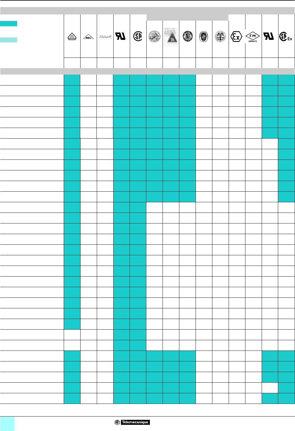
Product certifications
Marine classification authorities
Certifications held by
Schneider Electric
VDE ASEV KEMA UL CSA GL LR DNV BV RINA ATEX FM UL-Ex CSA-
Ex
Certifications held by
the manufacturer
Ger-
many
Switz-
erland
Nether-
lands
United
States
Canada Ger-
many
Great
Britain
Norway France Italy Europe United
States
United
States
Canada
Spring technology
AB1RRN235U2BL (1)
AB1RRN235U2GR (1)
AB1RRN235U3BL (1)
AB1RRN235U3GR (1)
AB1RRN235U4BL (1)
AB1RRN235U4GR (1)
AB1RRN435U2BL (1)
AB1RRN435U2GR (1)
AB1RRN435U3BL (1)
AB1RRN435U3GR (1)
AB1RRN435U4BL (1)
AB1RRN435U4GR (1)
AB1RRN635U2BL (1)
AB1RRN635U2GR (1)
AB1RRN635U3BL (1)
AB1RRN635U3GR (1)
AB1RRN1035U2BL (1)
AB1RRN1035U2GR (1)
AB1RRN1035U3BL (1)
AB1RRN1035U3GR (1)
AB1RRN1635U2BL (1)
AB1RRN1635U2GR (1)
AB1RRN1635U3BL (1)
AB1RRN1635U3GR (1)
AB1RRN3535U2BL
AB1RRN3535U2GR
AB1RRNET235T6 (1) (1)
AB1RRNET235U4 (1)
AB1RRNET235U6 (1)
AB1RRNET435U4 (1)
AB1RRNETP235T6 (1)
1/11
Certifications (continued)
0
Terminal Blocks, Type AB1 0
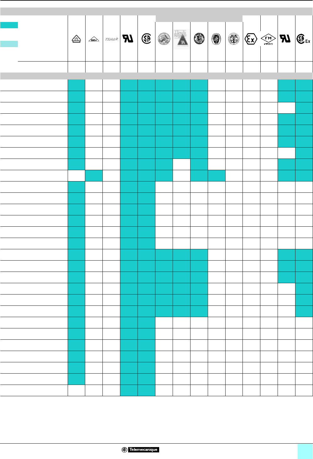
Product certifications
(1) Certification pending
Product certifications (continued)
Marine classification authorities
Certifications held by
Schneider Electric
VDE ASEV KEMA UL CSA GL LR DNV BV RINA ATEX FM UL-Ex CSA-
Ex
Certifications held by
the manufacturer
Ger-
many
Switz-
erland
Nether-
lands
United
States
Canada Ger-
many
Great
Britain
Norway France Italy Europe United
States
United
States
Canada
Spring technology (continued)
AB1RRNETP235U4 (1)
AB1RRNETP235U6 (1) (1)
AB1RRNETP435U4 (1)
AB1RRNETV235T6 (1)
AB1RRNETV235U4 (1)
AB1RRNETV235U6 (1) (1)
AB1RRNETV435U4 (1)
AB1RRNP235UNO (1)
AB1RRNR1635UGR (1) (1) (1)
AB1RRNSC235U2 (1)
AB1RRNSC235U3 (1)
AB1RRNSC235U4 (1)
AB1RRNSCE235U4 (1)
AB1RRNSCE235U5 (1)
AB1RRNSF435UGR (1) (1) (1)
AB1RRNTP235U2 (1)
AB1RRNTP235U3 (1)
AB1RRNTP235U4 (1)
AB1RRNTP435U2 (1)
AB1RRNTP435U3 (1)
AB1RRNTP435U4 (1)
AB1RRNTP635U2 (1)
AB1RRNTP635U3 (1)
AB1RRNTP1035U2 (1)
AB1RRNTP1035U3 (1)
AB1RRNTP1635U2 (1)
AB1RRNTP1635U3 (1)
AB1RRNTP3535U2
1/12
Certifications (continued)
0
Terminal Blocks, Type AB1 0
Product certifications
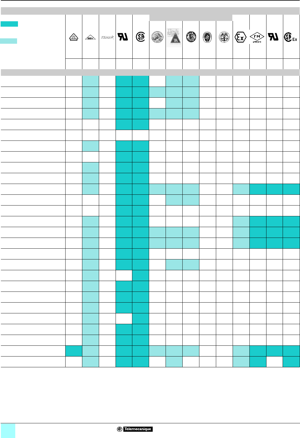
Product certifications (continued)
Marine classification authorities
Certifications held by
Schneider Electric
VDE ASEV KEMA UL CSA GL LR DNV BV RINA ATEX FM UL-Ex CSA-
Ex
Certifications held by
the manufacturer
Ger-
many
Switz-
erland
Nether-
lands
United
States
Canada Ger-
many
Great
Britain
Norway France Italy Europe United
States
United
States
Canada
Screw clamp technology
AB1BB•••35
AB1BB9535
AB1BC••035
AB1BC9535
AB1BD10•
AB1D11435U
AB1DDP235T••
AB1DDP235U
AB1DDP235U••
AB1ET3235U•••
AB1ET435U
AB1ET435U2
AB1ET435U2DRO/UBGE/
UBHGE/UBRO/UBVE/UHBRO
AB1ET435UTP
AB1ETN435U
AB1ETNTP435U
AB1F••35U
AB1FU10•35U
AB1FU10135UB/UU
AB1FU10435UB/UFS
AB1FUSE435U•••
AB1FV135U
AB1NEN•••••
AB1SC435U•••••
AB1SF435U
AB1TP1•35U
AB1TP215
1/13
Certifications (continued)
0
Terminal Blocks, Type AB1 0
Product certifications
(1) Certification pending
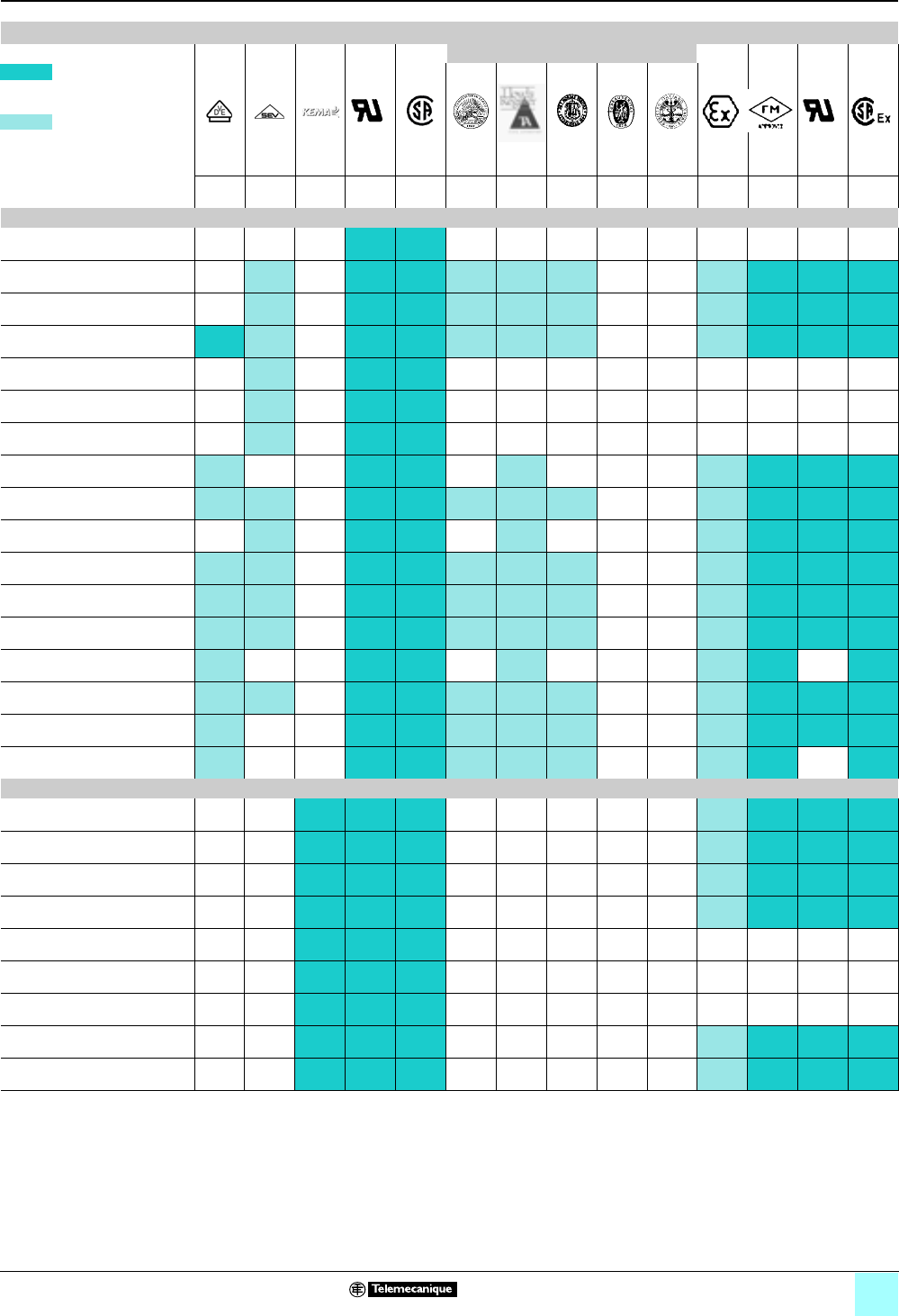
Product certifications (continued)
Marine classification authorities
Certifications held by
Schneider Electric
VDE ASEV KEMA UL CSA GL LR DNV BV RINA ATEX FM UL-Ex CSA-
Ex
Certifications held by
the manufacturer
Ger-
many
Switz-
erland
Nether-
lands
United
States
Canada Ger-
many
Great
Britain
Norway France Italy Europe United
States
United
States
Canada
Screw clamp technology (continued)
AB1TP235U
AB1TP3535U
AB1TP435U
AB1TP635U
AB1TRNN435
AB1TRPN435•••
AB1TRSN435
AB1VV215••
AB1VV235U••
AB1VV415
AB1VV435U•••
AB1VV635U•••
AB1VVN1035U••
AB1VVN15035U••
AB1VVN1635U••
AB1VVN3535U••
AB1VVN7035U••
Insulation displacement technology
AB1AA135U•••
AB1AA235U•••
AB1AAET135UGR
AB1AAET235UGR
AB1AAET235UBGE/UBRO/
UGE/URO
AB1AASC•35U••
AB1AASF•35UGR
AB1AATP135U•
AB1AATP235U•

2/0
0

2/1
Contents
0
2 - Terminal Blocks, Type AB1
Spring Technology
Page
Selection guide. . . . . . . . . . . . . . . . . . . . . . . . . . . . . 2/2
Passthrough type terminal blocks . . . . . . . . . . . 2/4
bPassthrough distribution. . . . . . . . . . . . . . . . . . . . . . . . . . . 2/11
Grounding type terminal blocks . . . . . . . . . . . . . 2/19
Disconnect type terminal blocks
bBlade type . . . . . . . . . . . . . . . . . . . . . . . . . . . . . . . . . . . . . 2/32
bPlug-in type . . . . . . . . . . . . . . . . . . . . . . . . . . . . . . . . . . . . 2/35
bDouble deck blade type . . . . . . . . . . . . . . . . . . . . . . . . . . . 2/36
Double deck terminal blocks . . . . . . . . . . . . . . . 2/38
2/2
Selection Guide
0
Terminal Blocks, Type AB1 0
Spring technology
Applications (connection) Passthrough Grounding
Passthrough Distribution
(1)
Nominal wire size,
AWG (mm2)
12
(2.5)
10
(4)
8–4
(6–16)
2
(35)
4
(16)
12–16
(2.5–4)
8–4
(6–16)
2
(35)
Number of poles 1 - 1 x 1 • • • • • • • •
1 - 1 x 2 • • • – – • • –
1 - 2 x 2 • • – – – • – –
1 - 2 x 4 – – – – – – – –
1 - 3 x 3 – – – – – – – –
2 - 1 x 1 • – – – – – – –
2 - 1 x 2 – – – – – – – –
3 - 1 x 1 – – – – – – – –
Clip-on mounting on 35 mm 5 • • • • • • • •
35 mm 1 • • • • • • • •
Colors Gray • • • • • – – –
Blue • • • • – – – –
Green/yellow – – – – – • • •
Black • – – – – – – –
Catalog numbers AB1RRN••35U•••
AB1RRNP235UNO
AB1RRNR AB1RRNTP
Pages Marking accessories See pages 5/2 and 5/3.
(1) Potential distribution terminal block: allows interconnection of terminals with a large wire size
(16 mm2) and those with a small wire size (2.5 mm2 and 4 mm2).
2/3
Selection Guide
0
Terminal Blocks, Type AB1 0
Spring technology
Applications (connection) Disconnect Double deck
Blade
type
Plug-in type,
for diode
or cylindrical
fuse
Double
deck, blade
type
Double deck Grounding With vertical
connection
Nominal wire size,
AWG (mm2)
12
(2.5)
10
(4)
12
(2.5)
12
(2.5)
10
(4)
12
(2.5)
10
(4)
12
(2.5)
10
(4)
Number of poles 1 - 1 x 1 • – – – – – – – –
1 - 1 x 2 • – – – – – – – –
1 - 2 x 2 – • – – – • • • •
1 - 2 x 4 – – – – – • – • –
1 - 3 x 3 – – – – – • – • –
2 - 1 x 1 – – • • • – – – –
2 - 1 x 2 – – • • – – – – –
3 - 1 x 1 – – – • – – – – –
Clip-on mounting on 35 mm 5•• • ••••••
35 mm 1•• • ••••••
Colors Gray • • • • • – – – –
Blue –– – ––––––
Green/yellow – – – – – • • – –
Black – – – – – – – • •
Catalog numbers AB1
RRNSC
AB1
RRNSF
AB1
RRNSCE
AB1RRNET AB1RRNETP AB1RRNETV
Pages Marking
accessories
See pages 5/2 and 5/3.
2/4
0
Terminal Blocks, Type AB1 0
Spring technology
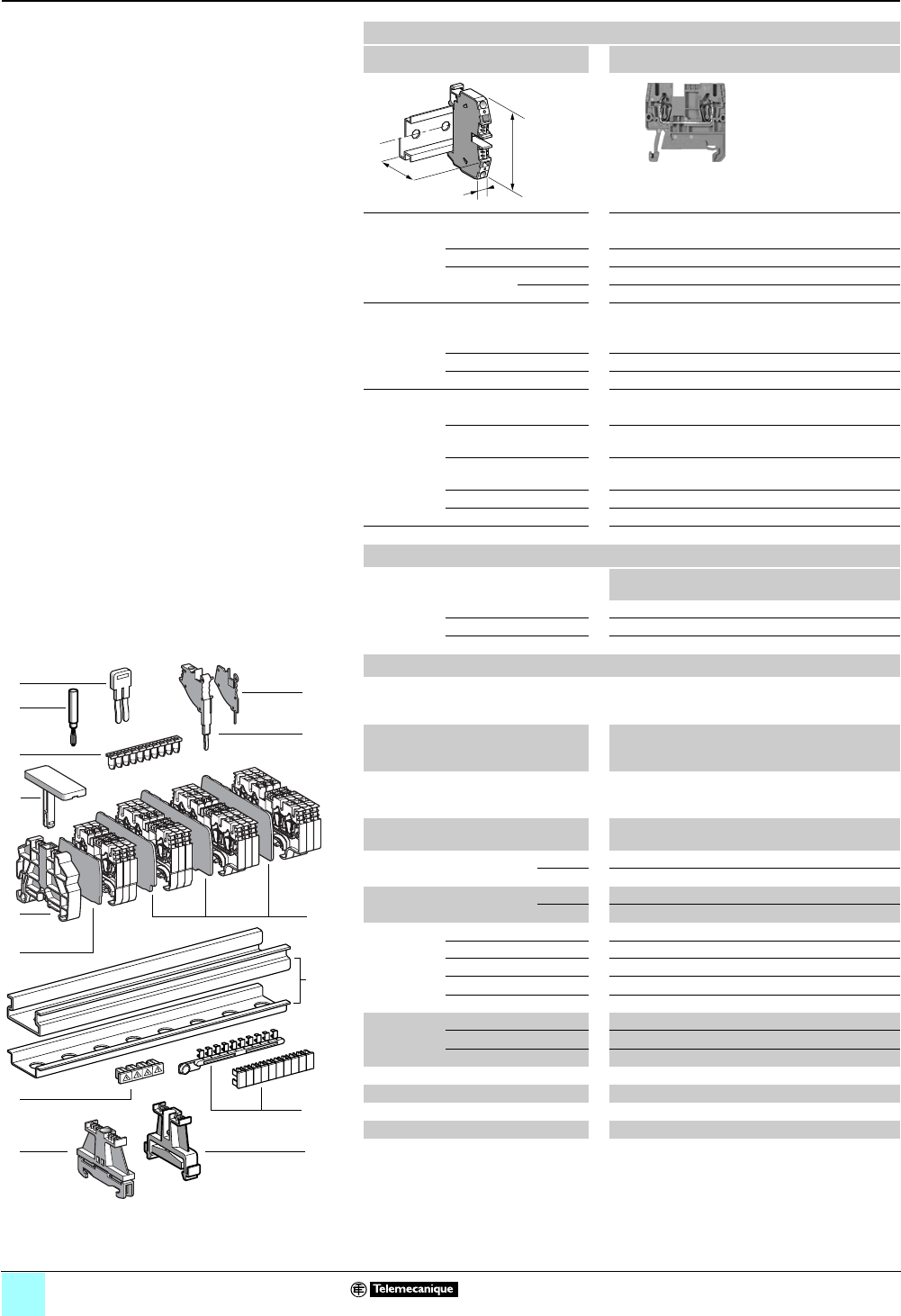
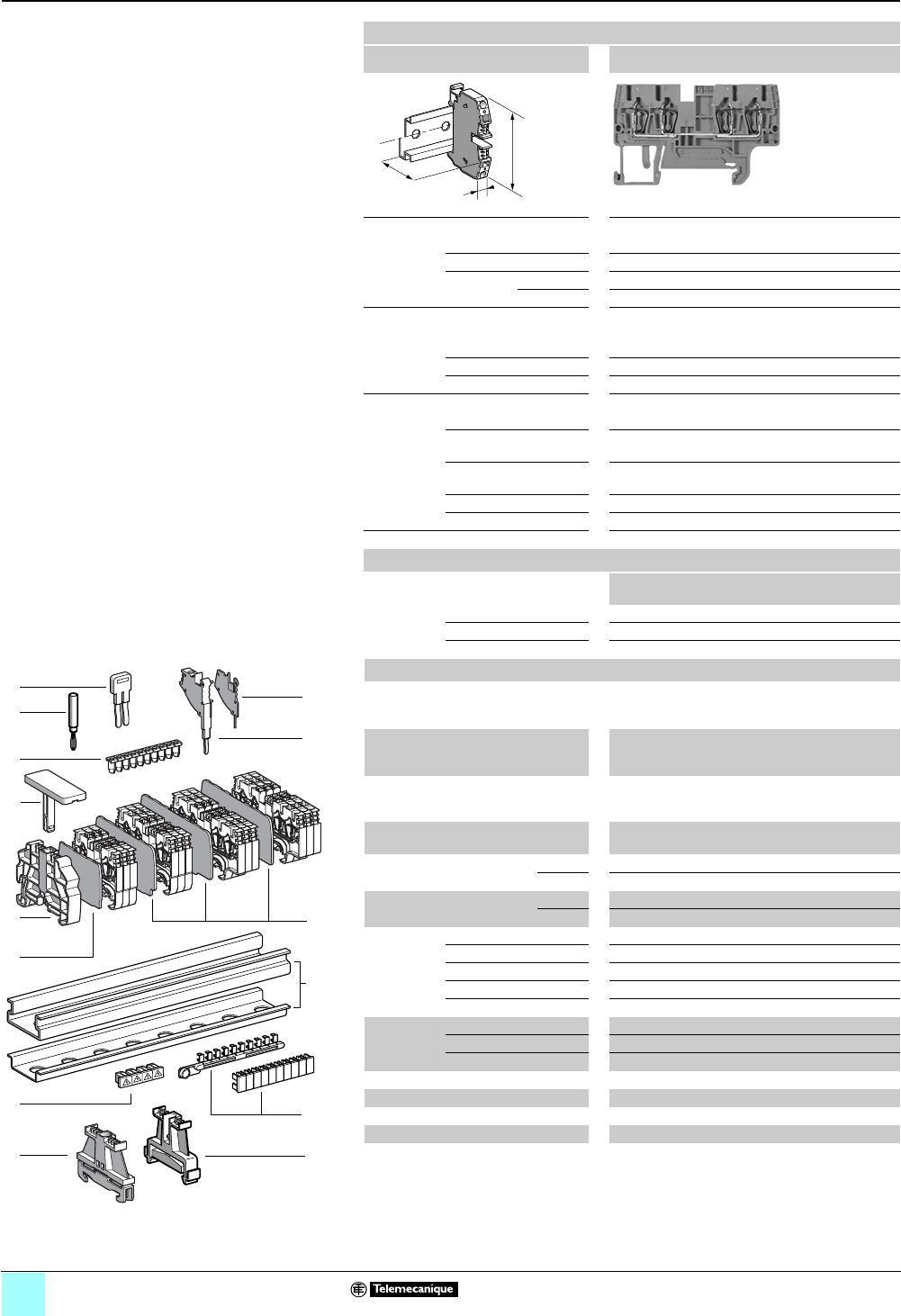
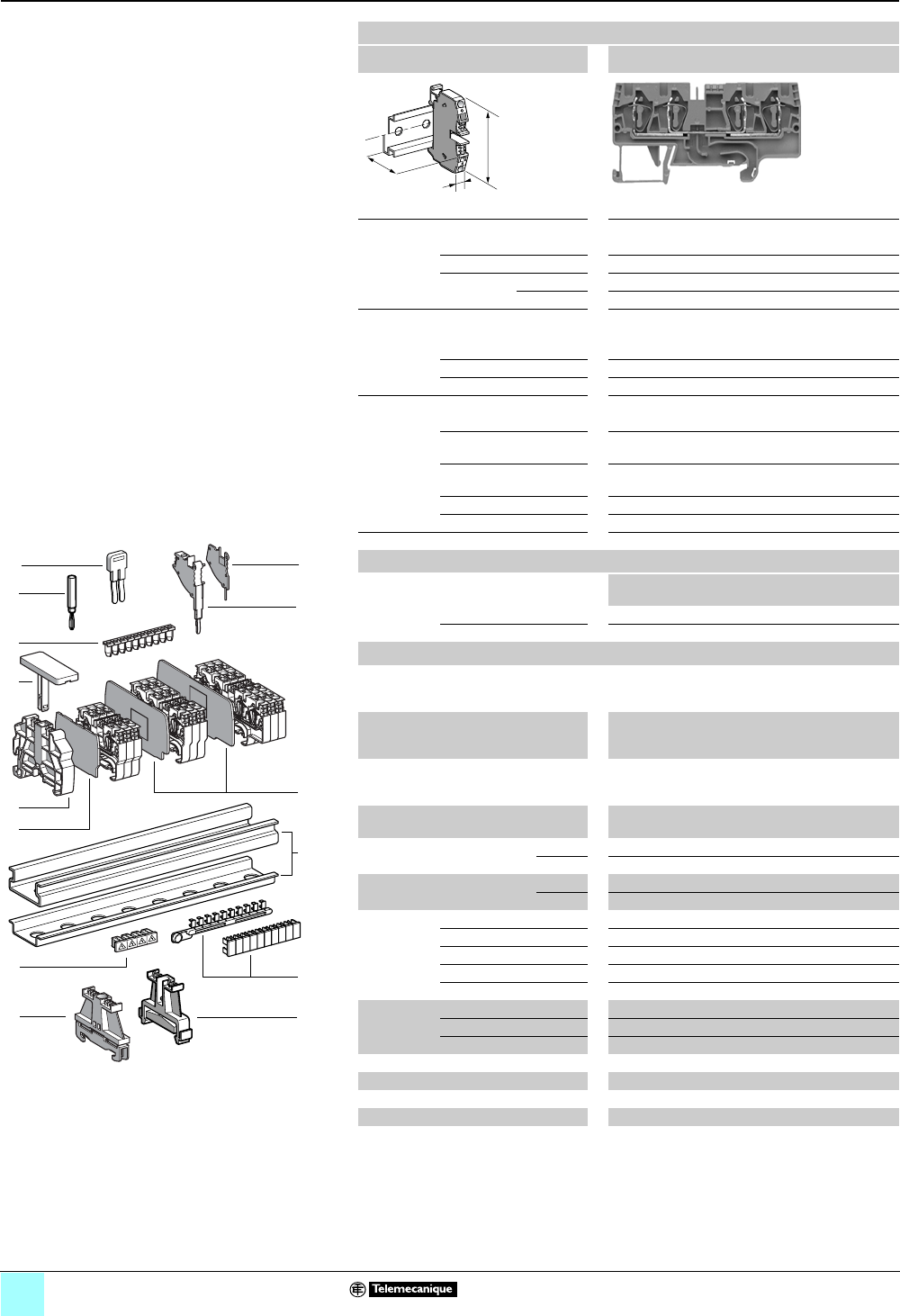
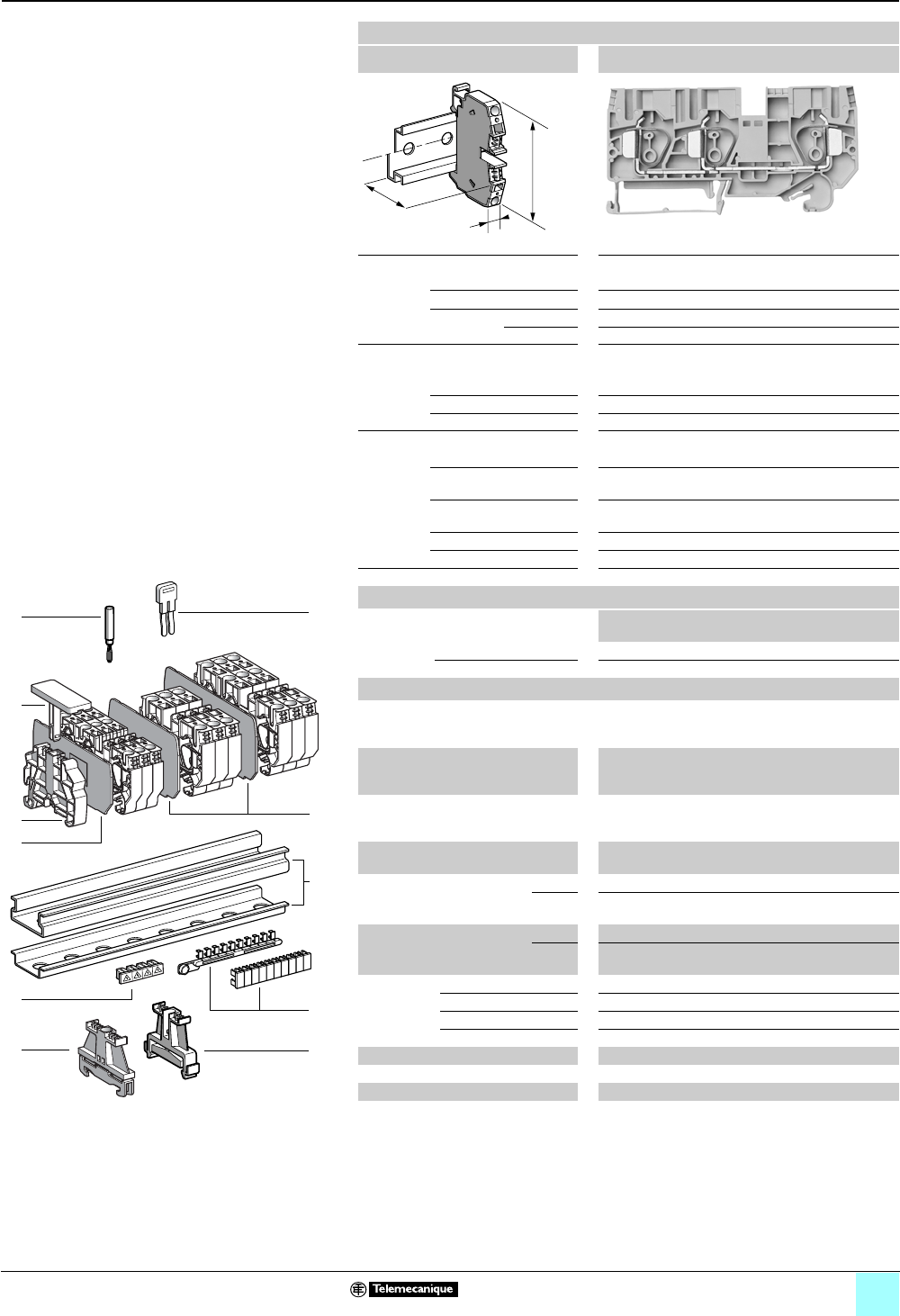
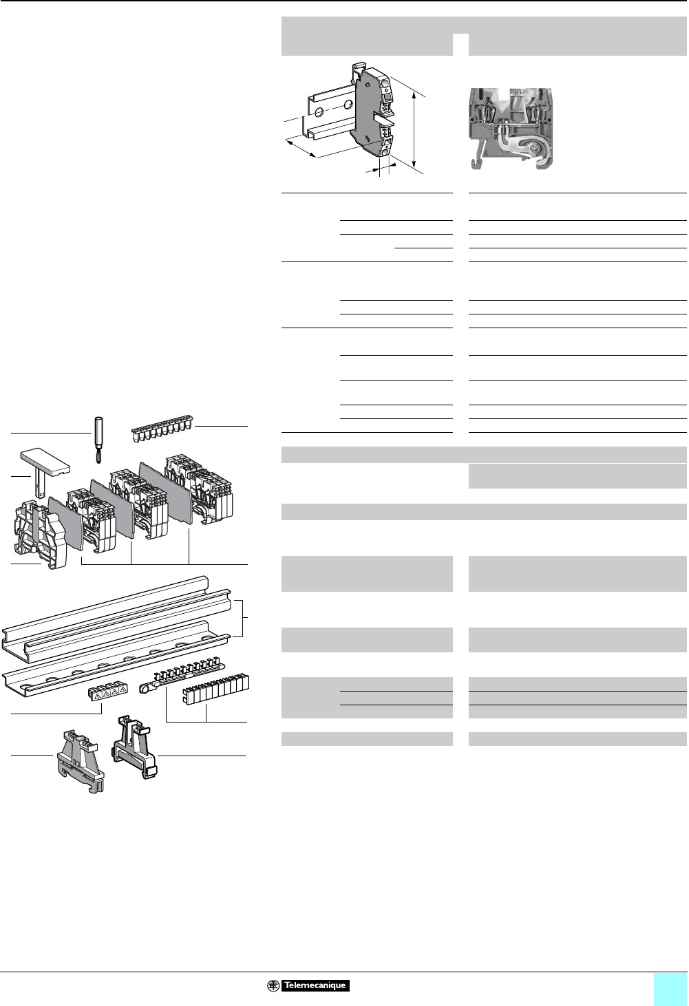
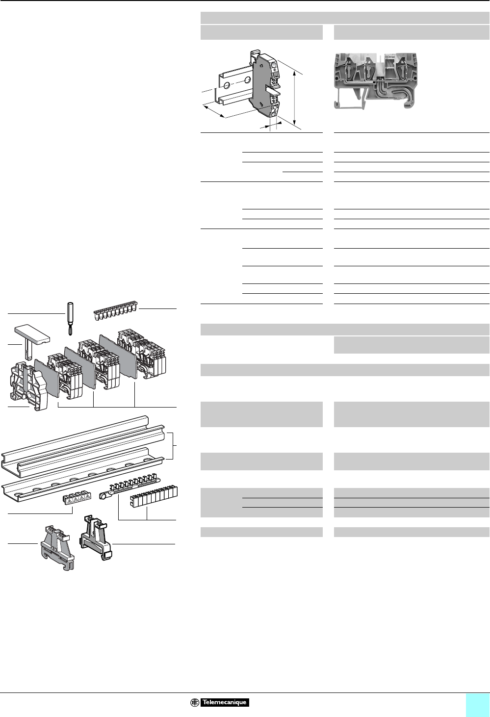
Passthrough
Clip-on mounting on 35 mm 1 7 rails
Nominal wire size 2.5 mm2
AB1RRN235U2••
Approximate dimensions, in. (mm)
Length (a) 1.85 (47.1)
Width (b) 0.20 (5)
1Height (H)
with
1 rail 1.80 (45.6)
7 rail 1.50 (38.1)
Wire size, mm2
Stranded without
cable end
0.13–2.5
Stranded with cable end 0.5–2.5
Solid 0.13–4
Nominal electrical values
IEC/EN 60947-7-1 800 V / 8 kV / 3–24 A
UL File E164359
CCN XCFR2
22–12 AWG, 600 V, 20 A
CSA File 702070
Class 6228 01
24–12 AWG, 600 V, 24 A
UTE, category C —
VDE, group C 800 V / 24 A
Certifications See the tables beginning on page 1/10.
Terminal Blocks
No.
points
Sold in
lots of
Catalog number Weight
oz (g)
Gray 2100 AB1RRN235U2GR 0.19 (5.5)
Blue 2100 AB1RRN235U2BL 0.19 (5.5)
Black — — — —
Accesories
2 Plastic
end clamp
with screw
Width 0.3 in. (8 mm)
on 1 or 7 —100 AB1AB8P35 0.21 (5.9)
3Metal
end clamp
with screw
Width 0.3 in. (8 mm)
on 1 or 7—100 AB1AB8M35 0.52 (14.8)
4 Clip-on
plastic
end clamp
Width 0.3 in. (8 mm)
on 1 or 7—100 AB1AB8R35 0.21 (5.9)
5Marker tag holder for
clip-on plastic end clamp
—10 AB1SB4 0.11 (3.1)
6 End plate
thickness 0.06 in. (1.5 mm)
Gray — 10 AB1RRNAC242GR 0.08 (2.3)
Blue —10 AB1RRNAC242BL 0.08 (2.3)
7Partition plate
thickness 0.06 in. (1.5 mm)
Gray —10 AB1RRNAS242GR 0.10 (2.9)
Blue —10 AB1RRNAS242BL 0.10 (2.9)
8 Insulated
jumper
2-pole —10 AB1RRAL22 0.04 (1.1)
3-pole —10 AB1RRAL23 0.06 (1.7)
4-pole —10 AB1RRAL24 0.08 (2.2)
5-pole —10 AB1RRAL25 0.10 (2.8)
10-pole —20 AB1RRAL210 0.20 (5.6)
9Wire guide
entry strip
0.13–0.2 mm2 White —100 AB1RRNGF01 0.03 (0.9)
0.25–0.5 mm2 Gray —100 AB1RRNGF02 0.03 (0.9)
0.75–1 mm2 Black —100 AB1RRNGF03 0.03 (0.9)
10 Modular test connector Gray —10 AB1AT3 0.08 (2.4)
11 Modular test connector end plate —10 AB1AC3 0.01 (0.4)
12 Test plug Red —10 AB1AT1 0.07 (1.9)
13 Terminal cover 410 AB1RRNCS2 0.01 (0.3)
14 Marking accessories See pages 5/2 and 5/3.
a
b
H
9
5
4
6
12
1
13
3
10
9
8
7
6
5
4
3
2
1
987654321
10
2
14
11
10
7
8
2/5
0
Terminal Blocks, Type AB1 0
Spring technology
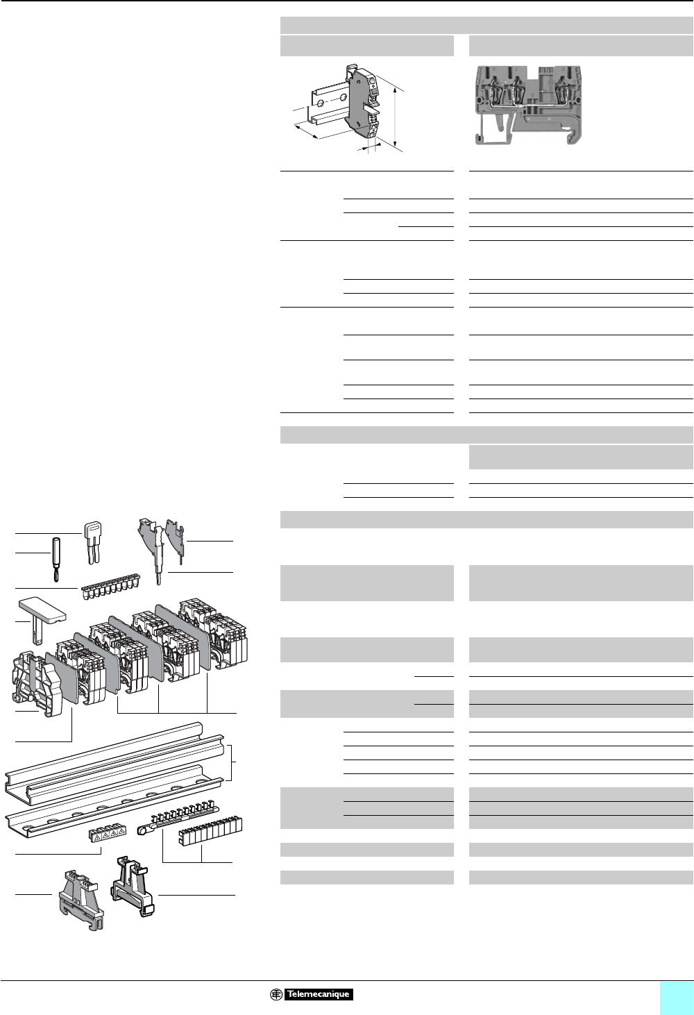
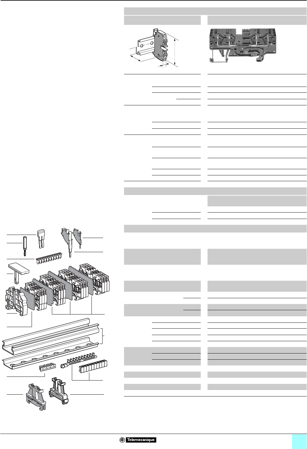
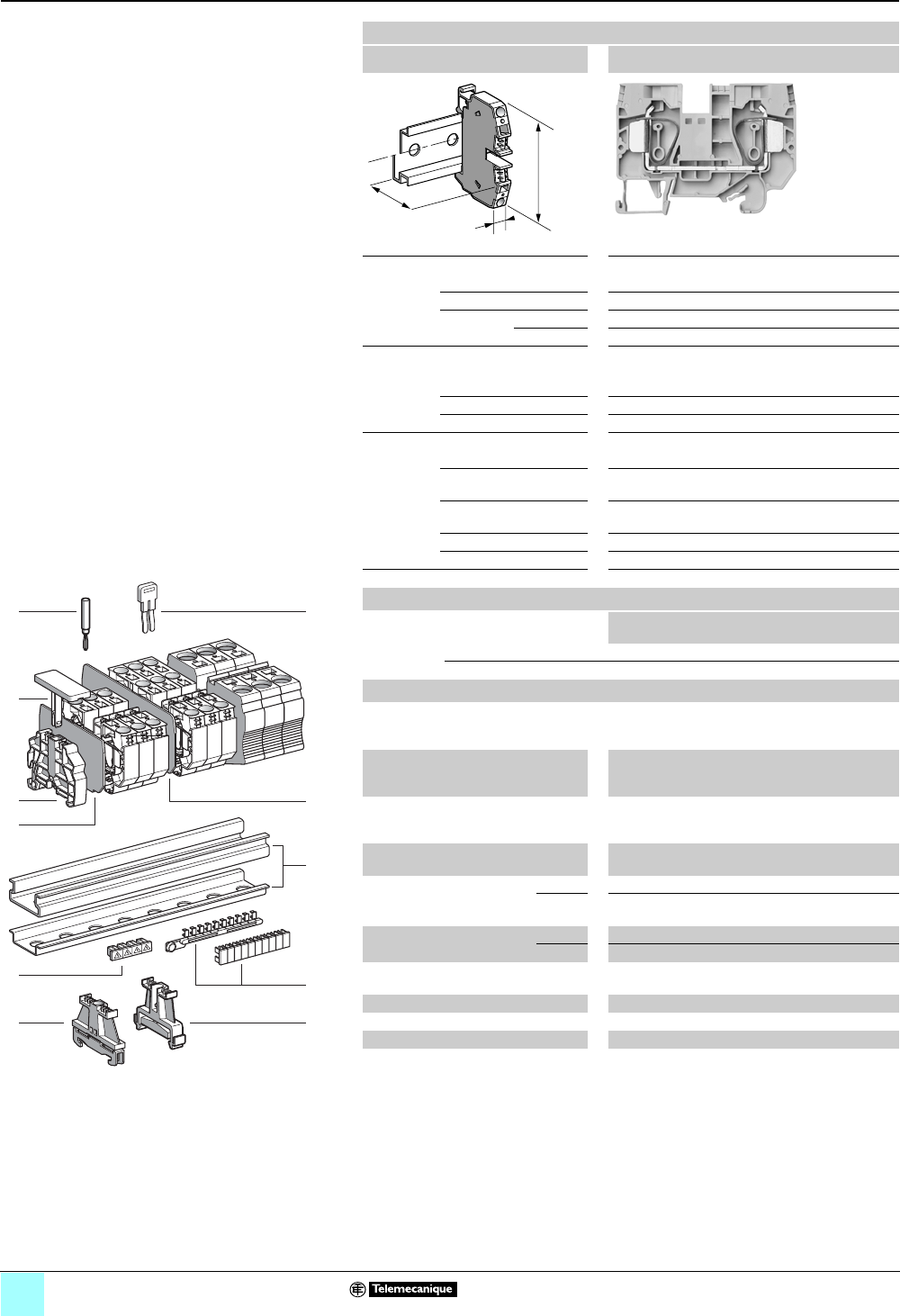
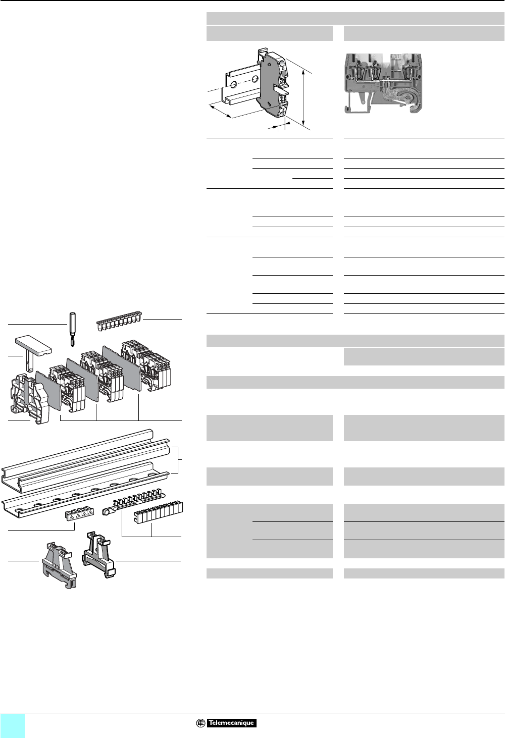
Passthrough
Clip-on mounting on 35 mm 1 7 rails
Nominal wire size 2.5 mm2
AB1RRN235U3••
Approximate dimensions, in. (mm)
Length (a) 2.35 (59.7)
Width (b) 0.20 (5)
1 Height (H)
with
1 rail 1.80 (45.6)
7 rail 1.50 (38.1)
Wire size, mm2
Stranded without
cable end
0.13–2.5
Stranded with cable end 0.5–2.5
Solid 0.13–4
Nominal electrical values
IEC/EN 60947-7-1 800 V / 8 kV / 3–24 A
UL File E164359
CCN XCFR2
22–12 AWG, 600 V, 20 A
CSA File 702070
Class 6228 01
24–12 AWG, 600 V, 24 A
UTE, category C —
VDE, group C 800 V / 24 A
Certifications See the tables beginning on page 1/10.
Terminal Blocks
No.
points
Sold in
lots of
Catalog number Weight
oz (g)
Gray 3100 AB1RRN235U3GR 0.26 (7.4)
Blue 3100 AB1RRN235U3BL 0.26 (7.4)
Black — — — —
Accesories
2 Plastic
end clamp
with screw
Width 0.3 in. (8 mm)
on 1 or 7 —100 AB1AB8P35 0.21 (5.9)
3Metal
end clamp
with screw
Width 0.3 in. (8 mm)
on 1 or 7—100 AB1AB8M35 0.52 (14.8)
4 Clip-on
plastic
end clamp
Width 0.3 in. (8 mm)
on 1 or 7—100 AB1AB8R35 0.21 (5.9)
5Marker tag holder for
clip-on plastic end clamp
—10 AB1SB4 0.11 (3.1)
6 End plate
thickness 0.06 in. (1.5 mm)
Gray —10 AB1RRNAC243GR 0.10 (2.8)
Blue —10 AB1RRNAC243BL 0.10 (2.8)
7Partition plate
thickness 0.06 in. (1.5 mm)
Gray —10 AB1RRNAS243GR 0.12 (3.4)
Blue —10 AB1RRNAS243BL 0.12 (3.4)
8 Insulated
jumper
2-pole —10 AB1RRAL22 0.04 (1.1)
3-pole —10 AB1RRAL23 0.10 (2.7)
4-pole —10 AB1RRAL24 0.08 (2.2)
5-pole —10 AB1RRAL25 0.10 (2.8)
10-pole —20 AB1RRAL210 0.20 (5.6)
9Wire guide
entry strip
0.13–0.2 mm2 White —100 AB1RRNGF01 0.03 (0.9)
0.25–0.5 mm2 Gray —100 AB1RRNGF02 0.03 (0.9)
0.75–1 mm2 Black —100 AB1RRNGF03 0.03 (0.9)
10 Modular test connector Gray —10 AB1AT3 0.08 (2.4)
11 Modular test connector end plate —10 AB1AC3 0.01 (0.4)
12 Test plug 410 AB1AT1 0.07 (1.9)
13 Terminal cover 410 AB1RRNCS2 0.01 (0.3)
14 Marking accessories See pages 5/2 and 5/3.
a
b
H
9
5
4
6
12
1
13
3
10
9
8
7
6
5
4
3
2
1
987654321
10
2
14
11
10
7
8
2/6
0
Terminal Blocks, Type AB1 0
Spring technology
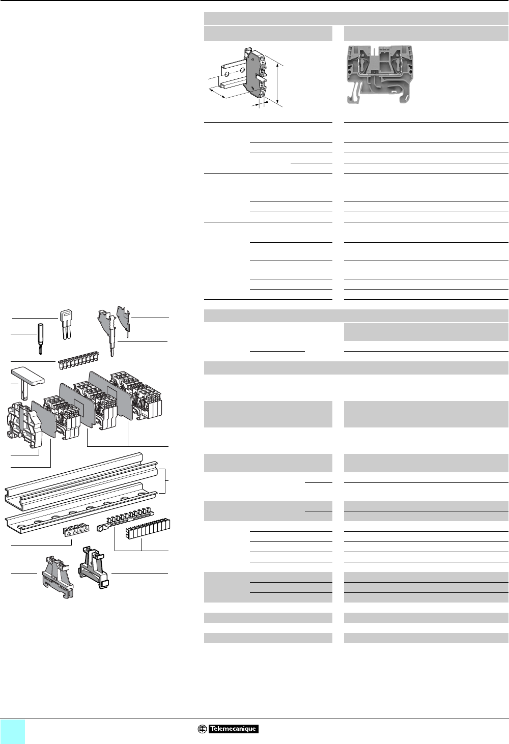
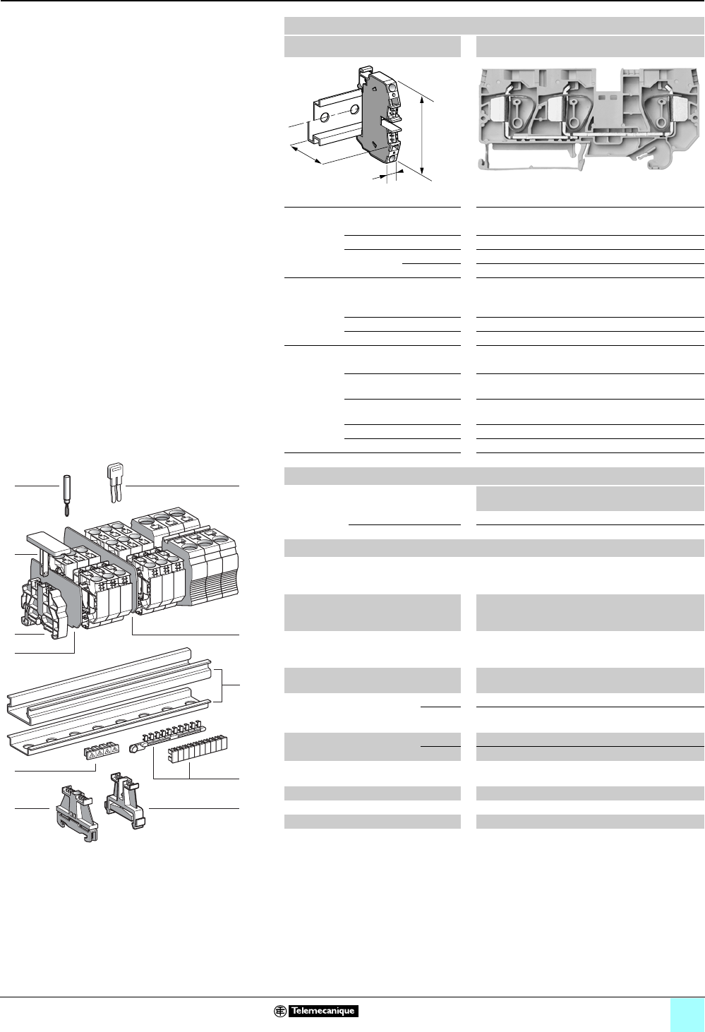
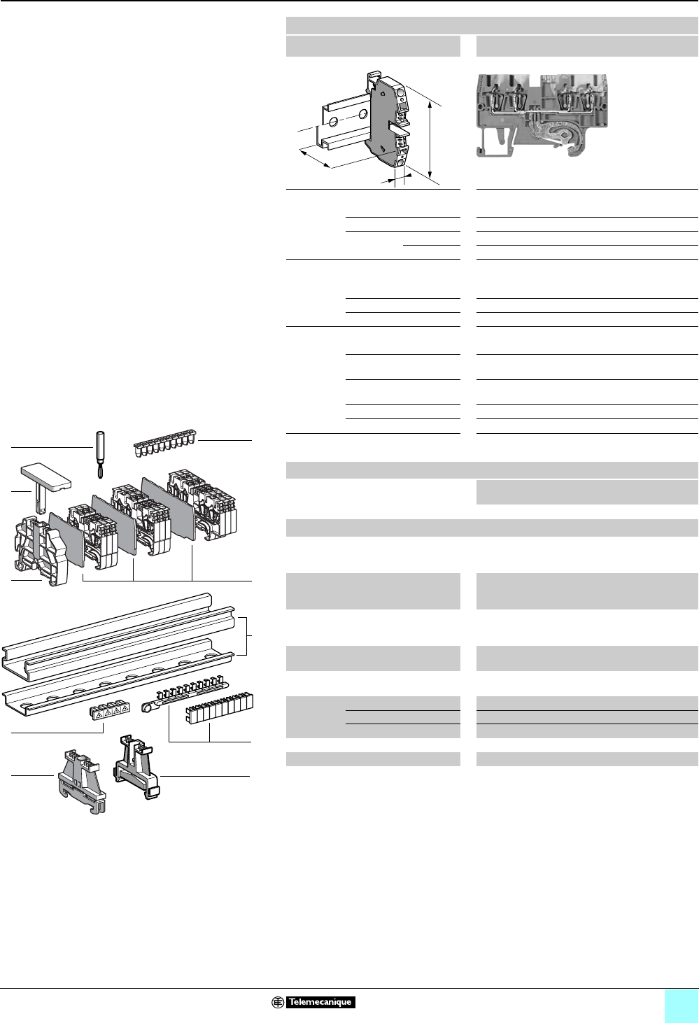
Passthrough
Clip-on mounting on 35 mm 1 7 rails
Nominal wire size 2.5 mm2
AB1RRN235U4••
Approximate dimensions, in. (mm)
Length (a) 2.85 (72.4)
Width (b) 0.20 (5)
1 Height (H)
with
1 rail 1.80 (45.6)
7 rail 1.50 (38.1)
Wire size, mm2
Stranded without
cable end
0.13–2.5
Stranded with cable end 0.5–2.5
Solid 0.13–4
Nominal electrical values
IEC/EN 60947-7-1 800 V / 8 kV / 3–24 A
UL File E164359
CCN XCFR2
22–12 AWG, 600 V, 20 A
CSA File 702070
Class 6228 01
24–12 AWG, 600 V, 24 A
UTE, category C —
VDE, group C 800 V / 24 A
Certifications See the tables beginning on page 1/10.
Terminal Blocks
No.
points
Sold in
lots of
Catalog number Weight
oz (g)
Gray 4100 AB1RRN235U4GR 0.32 (9.1)
Blue 4100 AB1RRN235U4BL 0.32 (9.1)
Black — — — —
Accesories
2 Plastic
end clamp
with screw
Width 0.3 in. (8 mm)
on 1 or 7 —100 AB1AB8P35 0.21 (5.9)
3Metal
end clamp
with screw
Width 0.3 in. (8 mm)
on 1 or 7—100 AB1AB8M35 0.52 (14.8)
4 Clip-on
plastic
end clamp
Width 0.3 in. (8 mm)
on 1 or 7—100 AB1AB8R35 0.21 (5.9)
5Marker tag holder for
clip-on plastic end clamp
—10 AB1SB4 0.11 (3.1)
6 End plate
thickness 0.06 in. (1.5 mm)
Gray —10 AB1RRNAC244GR 0.12 (3.4)
Blue —10 AB1RRNAC244BL 0.12 (3.4)
7Partition plate
thickness 0.06 in. (1.5 mm)
Gray —10 AB1RRNAS244GR 0.15 (4.2)
Blue —10 AB1RRNAS244BL 0.15 (4.2)
8 Insulated
jumper
2-pole —10 AB1RRAL22 0.04 (1.1)
3-pole —10 AB1RRAL23 0.06 (1.7)
4-pole —10 AB1RRAL24 0.08 (2.2)
5-pole —10 AB1RRAL25 0.10 (2.8)
10-pole —20 AB1RRAL210 0.20 (5.6)
9Wire guide
entry strip
0.13–0.2 mm2 White —100 AB1RRNGF01 0.03 (0.9)
0.25–0.5 mm2 Gray —100 AB1RRNGF02 0.03 (0.9)
0.75–1 mm2 Black —100 AB1RRNGF03 0.03 (0.9)
10 Modular test connector Gray —10 AB1AT3 0.08 (2.4)
11 Modular test connector end plate —10 AB1AC3 0.01 (0.4)
12 Test plug Red 410 AB1AT1 0.07 (1.9)
13 Terminal cover 410 AB1RRNCS2 0.01 (0.3)
14 Marking accessories See pages 5/2 and 5/3.
a
b
H
9
5
4
6
12
1
13
3
10
9
8
7
6
5
4
3
2
1
987654321
10
2
14
11
10
7
8
2/7
0
Terminal Blocks, Type AB1 0
Spring technology
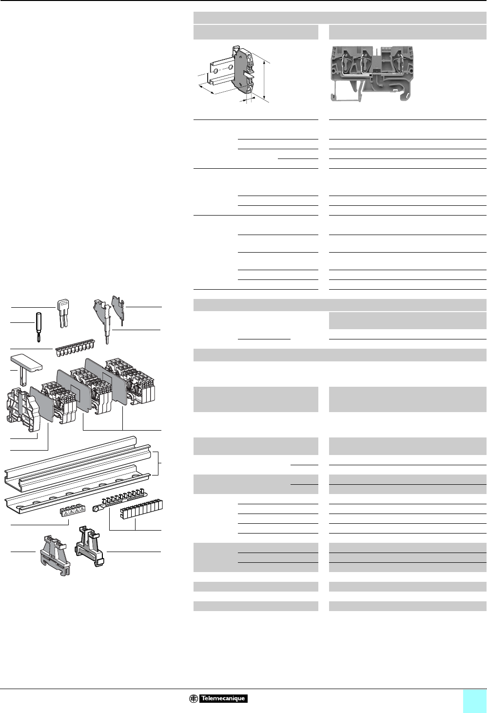
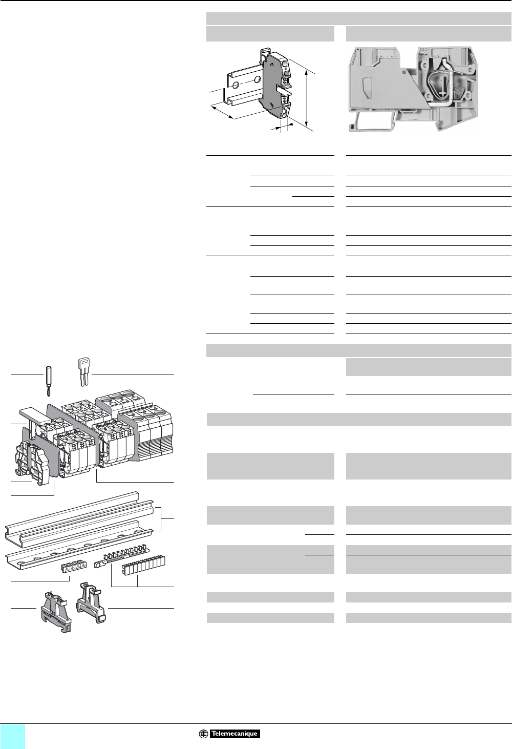
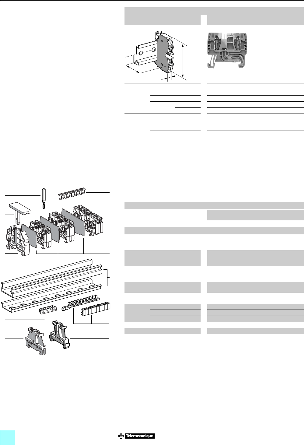
Passthrough
Clip-on mounting on 35 mm 1 7 rails
Nominal wire size 2.5 mm2 (1)
AB1RRNP235UNO
Approximate dimensions, in. (mm)
Length (a) 2.85 (72.4)
Width (b) 0.20 (5)
1 Height (H)
with
1 rail 1.80 (45.6)
7 rail 1.50 (38.1)
Wire size, mm2
Stranded without
cable end
0.13–2.5
Stranded with cable end 0.5–2.5
Solid 0.13–4
Nominal electrical values
IEC/EN 60947-7-1 800 V / 8 kV / 3–24 A
UL File E164359
CCN XCFR2
22–12 AWG, 600 V, 20 A
CSA File 702070
Class 6228 01
24–12 AWG, 600 V, 24 A
UTE, category C —
VDE, group C 800 V / 24 A
Certifications See the tables beginning on page 1/10.
Terminal Blocks
No.
points
Sold in
lots of
Catalog number Weight
oz (g)
Gray — — — —
Blue — — — —
Black 2/2 100 AB1RRNP235UNO 0.32 (9.0)
Accesories
2 Plastic
end clamp
with screw
Width 0.3 in. (8 mm)
on 1 or 7 —100 AB1AB8P35 0.21 (5.9)
3Metal
end clamp
with screw
Width 0.3 in. (8 mm)
on 1 or 7—100 AB1AB8M35 0.52 (14.8)
4 Clip-on
plastic
end clamp
Width 0.3 in. (8 mm)
on 1 or 7—100 AB1AB8R35 0.21 (5.9)
5Marker tag holder for
clip-on plastic end clamp
—10 AB1SB4 0.11 (3.1)
6 End plate
thickness 0.06 in. (1.5 mm)
Gray —10 AB1RRNAC244GR 0.12 (3.4)
Blue ——— —
7Partition plate
thickness 0.06 in. (1.5 mm)
Gray —10 AB1RRNAS244GR 0.15 (4.2)
Blue ——— —
8 Insulated
jumper
2-pole ——— —
3-pole ——— —
4-pole ——— —
5-pole ——— —
10-pole ——— —
9Wire guide
entry strip
0.13–0.2 mm2 White —100 AB1RRNGF01 0.03 (0.9)
0.25–0.5 mm2 Gray —100 AB1RRNGF02 0.03 (0.9)
0.75–1 mm2 Black —100 AB1RRNGF03 0.03 (0.9)
10 Modular test connector Gray ——— —
11 Modular test connector end plate ——— —
12 Test plug Red 410 AB1AT1 0.07 (1.9)
13 Terminal cover 410 AB1RRNCS2 0.01 (0.3)
14 Marking accessories See pages 5/2 and 5/3.
(1) Terminal blocks with a discontinuous conductor bar, which allows two terminal blocks to be
placed on the same level.
a
b
H
9
5
4
6
12
1
13
3
10
9
8
7
6
5
4
3
2
1
987654321
10
2
14
11
10
7
8
2/8
0
Terminal Blocks, Type AB1 0
Spring technology
Passthrough
Clip-on mounting on 35 mm 1 7 rails
Nominal wire size 4 mm2
AB1RRN435U2••
Approximate dimensions, in. (mm)
Length (a) 2.01 (51)
Width (b) 0.24 (6)
1Height (H)
with
1 rail 1.80 (45.65)
7 rail 1.50 (38.15)
Wire size, mm2
Stranded without
cable end
0.13–4
Stranded with cable end 0.5–4
Solid 0.13–6
Nominal electrical values
IEC/EN 60947-7-1 800 V / 8 kV / 3–32 A
UL File E164359
CCN XCFR2
24–10 AWG, 600 V, 30 A
CSA File 702070
Class 6228 01
24–10 AWG, 600 V, 32 A
UTE, category C —
VDE, group C 800 V / 32 A
Certifications See the tables beginning on page 1/10.
Terminal blocks
No.
points
Sold in
lots of
Catalog number Weight
oz (g)
Gray 2100 AB1RRN435U2GR 0.26 (7.5)
Blue 2100 AB1RRN435U2BL 0.26 (7.5)
Accessories
2 Plastic
end clamp
with screw
Width 0.3 in. (8 mm)
on 1 or 7 —100 AB1AB8P35 0.21 (5.9)
3Metal
end clamp
with screw
Width 0.3 in. (8 mm)
on 1 or 7 — 100 AB1AB8M35 0.52 (14.8)
4 Clip-on
plastic
end clamp
Width 0.3 in. (8 mm)
on 1 or 7—100 AB1AB8R35 0.21 (5.9)
5Marker tag holder for
clip-on plastic end clamp
—10 AB1SB4 0.11 (3.1)
6 End plate
thickness 0.06 in. (1.5 mm)
Gray —10 AB1RRNAC442GR 0.09 (2.5)
Blue —10 AB1RRNAC442BL 0.09 (2.5)
7Partition plate
thickness 0.06 in. (1.5 mm)
Gray —10 AB1RRNAS442GR 0.11 (3.2)
Blue —10 AB1RRNAS442BL 0.11 (3.2)
8Insulated
jumper
2-pole —10 AB1RRAL42 0.06 (1.7)
3-pole —10 AB1RRAL43 0.09 (2.5)
4-pole —10 AB1RRAL44 0.12 (3.3)
5-pole —10 AB1RRAL45 0.14 (4.1)
10-pole —20 AB1RRAL410 0.29 (8.3)
9Wire guide
entry strip
0.13–0.2 mm2White —100 AB1RRNGF11 0.03 (0.8)
0.25–0.5 mm2Gray —100 AB1RRNGF22 0.03 (0.8)
0.75–1 mm2Black —100 AB1RRNGF33 0.03 (0.8)
10 Modular test connector Gray —10 AB1AT3 0.08 (2.4)
11 Modular test connector end plate —10 AB1AC3 0.01 (0.4)
12 Test plug Red —10 AB1AT1 0.07 (1.9)
13 Terminal cover 4100 AB1RRCS4 0.01 (0.4)
14 Marking accessories See pages 5/2 and 5/3.
a
b
H
9
4
6
12
5
1
11
10
7
8
13
3
10
9
8
7
6
5
4
3
2
1
987654321
10
2
14
2/9
0
Terminal Blocks, Type AB1 0
Spring technology
Passthrough
Clip-on mounting on 35 mm 1 7 rails
Nominal wire size 4 mm2
AB1RRN435U3••
Approximate dimensions, in. (mm)
Length (a) 2.62 (66.6)
Width (b) 0.24 (6)
1Height (H)
with
1 rail 1.80 (45.65)
7 rail 1.50 (38.15)
Wire size, mm2
Stranded without
cable end
0.13–4
Stranded with cable end 0.5–4
Solid 0.13–6
Nominal electrical values
IEC/EN 60947-7-1 800 V / 8 kV / 3–32 A
UL File E164359
CCN XCFR2
24–10 AWG, 600 V, 30 A
CSA File 702070
Class 6228 01
24–10 AWG, 600 V, 32 A
UTE, category C —
VDE, group C 800 V / 32 A
Certifications See the tables beginning on page 1/10.
Terminal blocks
No.
points
Sold in
lots of
Catalog number Weight
oz (g)
Gray 3100 AB1RRN435U3GR 0.36 (10.3)
Blue 3100 AB1RRN435U3BL 0.36 (10.3)
Accessories
2 Plastic
end clamp
with screw
Width 0.3 in. (8 mm)
on 1 or 7 —100 AB1AB8P35 0.21 (5.9)
3Metal
end clamp
with screw
Width 0.3 in. (8 mm)
on 1 or 7 — 100 AB1AB8M35 0.52 (14.8)
4 Clip-on
plastic
end clamp
Width 0.3 in. (8 mm)
on 1 or 7—100 AB1AB8R35 0.21 (5.9)
5Marker tag holder for
clip-on plastic end clamp
—10 AB1SB4 0.11 (3.1)
6 End plate
thickness 0.06 in. (1.5 mm)
Gray —10 AB1RRNAC443GR 0.11 (3.2)
Blue —10 AB1RRNAC443BL 0.11 (3.2)
7Partition plate
thickness 0.06 in. (1.5 mm)
Gray —10 AB1RRNAS443GR 0.14 (3.9)
Blue —10 AB1RRNAS443BL 0.14 (3.9)
8 Insulated
jumper
2-pole —10 AB1RRAL42 0.06 (1.7)
3-pole —10 AB1RRAL43 0.09 (2.5)
4-pole —10 AB1RRAL44 0.12 (3.3)
5-pole —10 AB1RRAL45 0.14 (4.1)
10-pole —20 AB1RRAL410 0.29 (8.3)
9Wire guide
entry strip
0.13–0.2 mm2White —100 AB1RRNGF11 0.03 (0.8)
0.25–0.5 mm2Gray —100 AB1RRNGF22 0.03 (0.8)
0.75–1 mm2Black —100 AB1RRNGF33 0.03 (0.8)
10 Modular test connector Gray —10 AB1AT3 0.08 (2.4)
11 Modular test connector end plate —10 AB1AC3 0.01 (0.4)
12 Test plug Red —10 AB1AT1 0.07 (1.9)
13 Terminal cover 4100 AB1RRCS4 0.01 (0.4)
14 Marking accessories See pages 5/2 and 5/3.
a
b
H
9
4
6
12
5
1
11
10
7
8
13
3
10
9
8
7
6
5
4
3
2
1
987654321
10
2
14
2/10
0
Terminal Blocks, Type AB1 0
Spring technology
Passthrough
Clip-on mounting on 35 mm 1 7 rails
Nominal wire size 4 mm2
AB1RRN435U4••
Approximate dimensions, in. (mm)
Length (a) 3.24 (82.2)
Width (b) 0.24 (6)
1Height (H)
with
1 rail 1.80 (45.65)
7 rail 1.50 (38.15)
Wire size, mm2
Stranded without
cable end
0.13–4
Stranded with cable end 0.5–4
Solid 0.13–6
Nominal electrical values
IEC/EN 60947-7-1 800 V / 8 kV / 3–32 A
UL File E164359
CCN XCFR2
24–10 AWG, 600 V, 30 A
CSA File 702070
Class 6228 01
24–10 AWG, 600 V, 32 A
UTE, category C —
VDE, group C 800 V / 32 A
Certifications See the tables beginning on page 1/10.
Terminal blocks
No.
points
Sold in
lots of
Catalog number Weight
oz (g)
Gray 4100 AB1RRN435U4GR 0.46 (13.1)
Blue 4100 AB1RRN435U4BL 0.46 (13.1)
Accessories
2 Plastic
end clamp
with screw
Width 0.3 in. (8 mm)
on 1 or 7 —100 AB1AB8P35 0.21 (5.9)
3Metal
end clamp
with screw
Width 0.3 in. (8 mm)
on 1 or 7 — 100 AB1AB8M35 0.52 (14.8)
4 Clip-on
plastic
end clamp
Width 0.3 in. (8 mm)
on 1 or 7—100 AB1AB8R35 0.21 (5.9)
5Marker tag holder for
clip-on plastic end clamp
—10 AB1SB4 0.11 (3.1)
6 End plate
thickness 0.06 in. (1.5 mm)
Gray —10 AB1RRNAC444GR 0.13 (3.8)
Blue —10 AB1RRNAC444BL 0.13 (3.8)
7Partition plate
thickness 0.06 in. (1.5 mm)
Gray —10 AB1RRNAS444GR 0.17 (4.8)
Blue —10 AB1RRNAS444BL 0.17 (4.8)
8 Insulated
jumper
2-pole —10 AB1RRAL42 0.06 (1.7)
3-pole —10 AB1RRAL43 0.09 (2.5)
4-pole —10 AB1RRAL44 0.12 (3.3)
5-pole —10 AB1RRAL45 0.14 (4.1)
10-pole —20 AB1RRAL410 0.29 (8.3)
9Wire guide
entry strip
0.13–0.2 mm2White —100 AB1RRNGF11 0.03 (0.8)
0.25–0.5 mm2Gray —100 AB1RRNGF22 0.03 (0.8)
0.75–1 mm2Black —100 AB1RRNGF33 0.03 (0.8)
10 Modular test connector Gray —10 AB1AT3 0.08 (2.4)
11 Modular test connector end plate —10 AB1AC3 0.01 (0.4)
12 Test plug Red —10 AB1AT1 0.07 (1.9)
13 Terminal cover 4100 AB1RRCS4 0.01 (0.4)
14 Marking accessories See pages 5/2 and 5/3.
a
b
H
9
4
6
12
5
1
11
10
7
8
13
3
10
9
8
7
6
5
4
3
2
1
987654321
10
2
14

2/11
0
Terminal Blocks, Type AB1 0
Spring technology
Passthrough-distribution
Clip-on mounting on 35 mm 1 7 rails
Nominal wire size 16 mm2
AB1RRNR1635UGR
Approximate dimensions, in. (mm)
Length (a) 3.20 (82)
Width (b) 0.47 (12)
1Height (H)
with
1 rail 2.06 (52.2)
7 rail 1.88 (47.7)
Wire size, mm2
Stranded without
cable end
4–16
Stranded with cable
end
4–16
Solid 4–16
Nominal electrical values
IEC/EN 60947-7-1 800 V / 8 kV / 3–76 A
UL File E164359
CCN XCFR2
24–4 AWG, 600 V, 75 A
CSA File 702070
Class 6228 01
12–4 AWG, 600 V, 78 A
UTE, category C —
VDE, group C 800 V / 76 A
Certifications See the tables beginning on page 1/10.
Terminal blocks
No.
points
Sold in
lots of
Catalog number Weight
oz (g)
Gray 220 AB1RRNR1635UGR 1.10 (31.1)
Blue — — ——
In In In
max max
1
Potential distribution terminal block allowing interconnection
of terminals with a large wire size (16 mm2) and those with a
small wire size (2.5 and 4 mm2).
Option to distribute the potential not only on one or both sides
(different or identical wire size on each side) but also on one
or both shunt lines using insulated jumpers .
Connection on one side Single Double
Nominal wire size (mm2)2.5 42.5 4
Imax 48 64 68 76
INblock 24 32 24 32
Connection on both sides Single Double
Imax 72 76 76 76
INblock 24 32 24 32
Imax = ΣIn ≤ ΣINblock
1
a
b
H
Accessories
2 Plastic
end clamp
with screw
Width 0.3 in. (8 mm)
on 1 or 7 —100 AB1AB8P35 0.21 (5.9)
3Metal
end clamp
with screw
Width 0.3 in. (8 mm)
on 1 or 7100 AB1AB8M35 0.52 (14.8)
4 Clip-on
plastic
end clamp
Width 0.3 in. (8 mm)
on 1 or 7—100 AB1AB8R35 0.21 (5.9)
5Marker tag holder for
clip-on plastic end clamp
—10 AB1SB4 0.11 (3.1)
6 Insulated
jumper
2-pole 2.5 mm2—10 AB1RRAL22 0.04 (1.1)
4 mm2—10 AB1RRAL42 0.06 (1.7)
3-pole 2.5 mm2—10 AB1RRAL23 0.06 (1.7)
4 mm2—10 AB1RRAL43 0.09 (2.5)
4-pole 2.5 mm2—10 AB1RRAL24 0.08 (2.2)
4 mm2—10 AB1RRAL44 0.12 (3.3)
5-pole 2.5 mm2—10 AB1RRAL25 0.10 (2.8)
4 mm2—10 AB1RRAL45 0.14 (4.1)
2.5 mm2 — 20 AB1RRAL210 0.20 (5.6)
4 mm220 AB1RRAL410 0.29 (8.3)
7Test plug Red —10 AB1AT1 0.07 (1.9)
8 Terminal cover 410 AB1RRCS16 0.04 (1.2)
9Marking accessories See pages 5/2 and 5/3.
4
5
7
1
6
8
3
10
9
8
7
6
5
4
3
2
1
987654321
10
2
9
2/12
0
Terminal Blocks, Type AB1 0
Spring technology
Passthrough
Clip-on mounting on 35 mm 1 7 rails
Nominal wire size 6 mm2
AB1RRN635U2••
Approximate dimensions, in. (mm)
Length (a) 2.60 (66)
Width (b) 0.31 (8)
1Height (H)
with
1 rail 2.05 (52.05)
7 rail 1.75 (44.5)
Wire size, mm2
Stranded without
cable end
0.2–6
Stranded with cable end 0.2–6
Solid 0.2–10
Nominal electrical values
IEC/EN 60947-7-1 800 V / 8 kV / 3–41 A
UL File E164359
CCN XCFR2
24–8 AWG, 600 V, 50 A
CSA File 702070
Class 6228 01
24–8 AWG, 600 V, 41 A
UTE, category C —
VDE, group C 800 V / 41 A
Certifications See the tables beginning on page 1/10.
a
b
H
Terminal blocks
No.
points
Sold in
lots of
Catalog number Weight
oz (g)
Gray 250 AB1RRN635U2GR 0.56 (15.8)
Blue 250 AB1RRN635U2BL 0.56 (15.8)
Accessories
2Plastic
end clamp
with screw
Width 0.3 in. (8 mm)
on 1 or 7—100 AB1AB8P35 0.21 (5.9)
3Metal
end clamp
with screw
Width 0.3 in. (8 mm)
on 1 or 7—100 AB1AB8M35 0.52 (14.8)
4 Clip-on
plastic
end clamp
Width 0.3 in. (8 mm)
on 1 or 7—100 AB1AB8R35 0.21 (5.9)
5Marker tag holder for
clip-on plastic end clamp
—10 AB1SB4 0.11 (3.1)
6 End plate
thickness 0.06 in. (1.5 mm)
Gray —10 AB1RRNAC642GR 0.14 (4.0)
Blue —10 AB1RRNAC642BL 0.14 (4.0)
7Partition plate
thickness 0.06 in. (1.5 mm)
Gray —10 AB1RRNAS642GR 0.18 (5.0)
Blue —10 AB1RRNAS642BL 0.18 (5.0)
8 Insulated
jumper
2-pole —10 AB1RRNAL62 0.14 (4.0)
3-pole —10 AB1RRNAL63 0.21 (6.0)
4-pole —10 AB1RRNAL64 0.28 (8.0)
5-pole —10 AB1RRNAL65 0.35 (10.0)
9Test plug Red —10 AB1AT1 0.07 (1.9)
10 Terminal cover 410 AB1RRCS6 0.01 (0.4)
11 Marking accessories See pages 5/2 and 5/3.
4
5
9
1
7
8
6
10
3
10
9
8
7
6
5
4
3
2
1
987654321
10
2
11
524040
2/13
0
Terminal Blocks, Type AB1 0
Spring technology
Passthrough
Clip-on mounting on 35 mm 1 7 rails
Nominal wire size 6 mm2
AB1RRN635U3••
Approximate dimensions, in. (mm)
Length (a) 3.54 (90)
Width (b) 0.31 (8)
1Height (H)
with
1 rail 2.05 (52.05)
7 rail 1.75 (44.55)
Wire size, mm2
Stranded without
cable end
0.2–6
Stranded with cable end 0.2–6
Solid 0.2–10
Nominal electrical values
IEC/EN 60947-7-1 800 V / 8 kV / 3–41 A
UL File E164359
CCN XCFR2
24–8 AWG, 600 V, 50 A
CSA File 702070
Class 6228 01
24–8 AWG, 600 V, 41 A
UTE, category C —
VDE, group C 800 V / 41 A
Certifications See the tables beginning on page 1/10.
a
b
H
Terminal blocks
No.
points
Sold in
lots of
Catalog number Weight
oz (g)
Gray 350 AB1RRN635U3GR 0.82 (23.3)
Blue 350 AB1RRN635U3BL 0.82 (23.3)
Accessories
2Plastic
end clamp
with screw
Width 0.3 in. (8 mm)
on 1 or 7 —100 AB1AB8P35 0.21 (5.9)
3Metal
end clamp
with screw
Width 0.3 in. (8 mm)
on 1 or 7—100 AB1AB8M35 0.52 (14.8)
4 Clip-on
plastic
end clamp
Width 0.3 in. (8 mm)
on 1 or 7—100 AB1AB8R35 0.21 (5.9)
5Marker tag holder
for clip-on plastic end clamp
—10 AB1SB4 0.11 (3.1)
6 End plate
thickness 0.06 in. (1.5 mm)
Gray —10 AB1RRNAC643GR 0.18 (5.2)
Blue —10 AB1RRNAC643BL 0.18 (5.2)
7Partition plate
thickness 0.06 in. (1.5 mm)
Gray —10 AB1RRNAS643GR 0.22 (6.3)
Blue —10 AB1RRNAS643BL 0.22 (6.3)
8 Insulated
jumper
2-pole — 10 AB1RRNAL62 0.14 (4.0)
3-pole — 10 AB1RRNAL63 0.21 (6.0)
4-pole — 10 AB1RRNAL64 0.28 (8.0)
5-pole — 10 AB1RRNAL65 0.35 (10.0)
9Test plug Red —10 AB1AT1 0.07 (1.9)
10 Terminal cover 410AB1RRCS6 0.01 (0.4)
11 Marking accessories See pages 5/2 and 5/3.
9
6
5
4
1
7
8
10
3
10
9
8
7
6
5
4
3
2
1
987654321
10
2
11
2/14
0
Terminal Blocks, Type AB1 0
Spring technology
Passthrough
Clip-on mounting on 35 mm 1 7 rails
Nominal wire size 10 mm2
AB1RRN1035U2••
Approximate dimensions, in. (mm)
Length (a) 2.85 (72.5)
Width (b) 0.39 (10)
1Height (H)
with
1 rail 2.28 (58)
7 rail 1.99 (50.5)
Wire size, mm2
Stranded without
cable end
0.2–10
Stranded with cable end 0.2–10
Solid 0.2–16
Nominal electrical values
IEC/EN 60947-7-1 800 V / 8 kV / 3–57 A
UL File E164359
CCN XCFR2
16–6 AWG, 600 V, 60 A
CSA File 702070
Class 6228 01
16–6 AWG, 600 V, 65 A
UTE, category C —
VDE, group C 800 V / 57 A
Certifications See the tables beginning on page 1/10.
Terminal blocks
No.
points
Sold in
lots of
Catalog number Weight
oz (g)
Gray 250 AB1RRN1035U2GR 0.86 (24.5)
Blue 250 AB1RRN1035U2BL 0.86 (24.5)
Accessories
2Plastic
end clamp
with screw
Width 0.3 in. (8 mm)
on 1 or 7 —100 AB1AB8P35 0.21 (5.9)
3Metal
end clamp
with screw
Width 0.3 in. (8 mm)
on 1 or 7—100 AB1AB8M35 0.52 (14.8)
4 Clip-on
plastic
end clamp
Width 0.3 in. (8 mm)
on 1 or 7—100 AB1AB8R35 0.21 (5.9)
5Marker tag holder
for clip-on plastic end clamp
—10 AB1SB4 0.11 (3.1)
6 End plate
thickness 0.06 in.
(1.5 mm)
Gray —10 AB1RRNAC1042GR 0.18 (5.1)
Blue —10 AB1RRNAC1042BL 0.18 (5.1)
7Partition plate
thickness 0.06 in. (1.5 mm)
Gray —10 AB1RRNAS1042GR 0.22 (6.1)
Blue —10 AB1RRNAS1042BL 0.22 (6.1)
8 Insulated
jumper
2-pole —10 AB1RRAL102 0.11 (3.0)
3-pole — — — —
4-pole — — — —
5-pole — — — —
9Test plug Red —10 AB1AT1 0.07 (1.9)
10 Terminal cover 410 AB1RRCS10 0.03 (0.8)
11 Marking accessories See pages 5/2 and 5/3.
a
b
H
9
6
5
4
1
7
8
10
3
10
9
8
7
6
5
4
3
2
1
987654321
10
2
11
2/15
0
Terminal Blocks, Type AB1 0
Spring technology
Passthrough
Clip-on mounting on 35 mm 1 7 rails
Nominal wire size 10 mm2
AB1RRN1035U3••
Approximate dimensions, in. (mm)
Length (a) 3.86 (98)
Width (b) 0.39 (10)
1Height (H)
with
1 rail 2.28 (58)
7 rail 1.99 (50.5)
Wire size, mm2
Stranded without
cable end
0.2–10
Stranded with cable end 0.2–10
Solid 0.2–16
Nominal electrical values
IEC/EN 60947-7-1 800 V / 8 kV / 3–57 A
UL File E164359
CCN XCFR2
16–6 AWG, 600 V, 60 A
CSA File 702070
Class 6228 01
16–6 AWG, 600 V, 65 A
UTE, category C —
VDE, group C 800 V / 57 A
Certifications See the tables beginning on page 1/10.
a
b
H
Terminal blocks
No.
points
Sold in
lots of
Catalog number Weight
oz (g)
Gray 350 AB1RRN1035U3GR 1.20 (35.4)
Blue 350 AB1RRN1035U3BL 1.20 (35.4)
Accessories
2 Plastic
end clamp
with screw
Width 0.3 in. (8 mm)
on 1 or 7 —100 AB1AB8P35 0.21 (5.9)
3Metal
end clamp
with screw
Width 0.3 in. (8 mm)
on 1 or 7—100 AB1AB8M35 0.52 (14.8)
4 Clip-on
plastic
end clamp
Width 0.3 in. (8 mm)
on 1 or 7—100 AB1AB8R35 0.21 (5.9)
5Marker tag holder
for clip-on plastic end clamp
—10 AB1SB4 0.11 (3.1)
6 End plate
thickness 0.06 in. (1.5 mm)
Gray —10 AB1RRNAC1043GR 0.24 (6.7)
Blue —10 AB1RRNAC1043BL 0.24 (6.7)
7Partition plate
thickness 0.06 in. (1.5 mm)
Gray —10 AB1RRNAS1043GR 0.28 (7.8)
Blue —10 AB1RRNAS1043BL 0.28 (7.8)
8 Insulated
jumper
2-pole —10 AB1RRAL102 0.11 (3.0)
3-pole — — — —
4-pole — — — —
5-pole — — — —
9Test plug Red —10 AB1AT1 0.07 (1.9)
10 Terminal cover 410 AB1RRCS10 0.03 (0.8)
11 Marking accessories See pages 5/2 and 5/3.
9
6
5
4
1
7
8
10
3
10
9
8
7
6
5
4
3
2
1
987654321
10
2
11
2/16
0
Terminal Blocks, Type AB1 0
Spring technology
Passthrough
Clip-on mounting on 35 mm 1 7 rails
Nominal wire size 16 mm2
AB1RRN1635U2••
Approximate dimensions, in. (mm)
Length (a) 3.11 (79.1)
Width (b) 0.47 (12)
1Height (H)
with
1 rail 2.28 (58)
7 rail 1.99 (50.5)
Wire size, mm2
Stranded without
cable end
0.2–16
Stranded with cable end 0.2–16
Solid 0.2–25
Nominal electrical values
IEC/EN 60947-7-1 800 V / 8 kV / 3–76 A
UL File E164359
CCN XCFR2
16–4 AWG, 600 V, 85 A
CSA File 702070
Class 6228 01
16–4 AWG, 600 V, 85 A
UTE, category C —
VDE, group C 800 V / 76 A
Certifications See the tables beginning on page 1/10.
Terminal blocks
No.
points
Sold in
lots of
Catalog number Weight
oz (g)
Gray 250 AB1RRN1635U2GR 1.30 (35.8)
Blue 250 AB1RRN1635U2BL 1.30 (35.8)
Accessories
2 Plastic
end clamp
with screw
Width 0.3 in. (8 mm)
on 1 or 7 —100 AB1AB8P35 0.21 (5.9)
3Metal
end clamp
with screw
Width 0.3 in. (8 mm)
on 1 or 7—100 AB1AB8M35 0.52 (14.8)
4 Clip-on
plastic end
clamp
Width 0.3 in. (8 mm)
on 1 or 7—100 AB1AB8R35 0.21 (5.9)
5Marker tag holder
for clip-on plastic end clamp
—10 AB1SB4 0.11 (3.1)
6 End plate
thickness 0.06 in. (1.5 mm)
Gray —10 AB1RRNAC1642GR 0.19 (5.5)
Blue —10 AB1RRNAC1642BL 0.19 (5.5)
7Partition plate
thickness 0.06 in. (1.5 mm)
Gray —10 AB1RRNAS1642GR 0.23 (6.6)
Blue —10 AB1RRNAS1642BL 0.23 (6.6)
8 Insulated
jumper
2-pole —10 AB1RRAL162 0.32 (9.0)
9Test plug Red —10 AB1AT1 0.07 (1.9)
10 Terminal cover 410 AB1RRCS16 0.04 (1.2)
11 Marking accessories See pages 5/2 and 5/3.
a
b
H
6
9
1
10
3
10
9
8
7
6
5
4
3
2
1
987654321
10
2
8
7
11
4
5
2/17
0
Terminal Blocks, Type AB1 0
Spring technology
Passthrough
Clip-on mounting on 35 mm 1 7 rails
Nominal wire size 16 mm 2
AB1RRN1635U3••
Approximate dimensions, in. (mm)
Length (a) 4.20 (106.7)
Width (b) 0.47 (12)
1Height (H)
with
1 rail 2.28 (58)
7 rail 1.99 (50.5)
Wire size, mm2
Stranded without
cable end
0.2–16
Stranded with cable end 0.2–16
Solid 0.2–25
Nominal electrical values
IEC/EN 60947-7-1 800 V / 8 kV / 3–76 A
UL File E164359
CCN XCFR2
16–4 AWG, 600 V, 85 A
CSA File 702070
Class 6228 01
16–4 AWG, 600 V, 85 A
UTE, category C —
VDE, group C 800 V / 76 A
Certifications See the tables beginning on page 1/10.
Terminal blocks
No.
points
Sold in
lots of
Catalog number Weight
oz (g)
Gray 325 AB1RRN1635U3GR 1.90 (53.3)
Blue 325 AB1RRN1635U3BL 1.90 (53.3)
Accessories
2 Plastic
end clamp
with screw
Width 0.3 in. (8 mm)
on 1 or 7 —100 AB1AB8P35 0.21 (5.9)
3Metal
end clamp
with screw
Width 0.3 in. (8 mm)
on 1 or 7—100 AB1AB8M35 0.52 (14.8)
4 Clip-on
plastic end
clamp
Width 0.3 in. (8 mm)
on 1 or 7—100 AB1AB8R35 0.21 (5.9)
5Marker tag holder
for clip-on plastic end clamp
—10 AB1SB4 0.11 (3.1)
6 End plate
thickness 0.06 in. (1.5 mm)
Gray —10 AB1RRNAC1643GR 0.26 (7.3)
Blue —10 AB1RRNAC1643BL 0.26 (7.3)
7Partition plate
thickness 0.06 in. (1.5 mm)
Gray —10 AB1RRNAS1643GR 0.30 (8.6)
Blue —10 AB1RRNAS1643BL 0.30 (8.6)
8Insulated
jumper
2-pole —10 AB1RRAL162 0.32 (9.0)
9Test plug Red —10 AB1AT1 0.07 (1.9)
10 Terminal cover 410 AB1RRCS16 0.04 (1.2)
11 Marking accessories See pages 5/2 and 5/3.
a
b
H
6
9
1
10
3
10
9
8
7
6
5
4
3
2
1
987654321
10
2
8
7
11
4
5
2/18
0
Terminal Blocks, Type AB1 0
Spring technology
Passthrough
Clip-on mounting on 35 mm 1 7 rails
Nominal wire size 35 mm2
AB1RRN3535U2••
Approximate dimensions, in. (mm)
Length (a) 3.93 (99.9)
Width (b) 0.63 (16)
1Height (H)
with
1 rail 2.63 (66.7)
7 rail 2.33 (59.2)
Wire size, mm2
Stranded without
cable end
2.5–35
Stranded with cable end 2.5–35
Solid 2.5–35
Nominal electrical values
IEC/EN 60947-7-1 800 V / 8 kV / 3–125 A
UL File E164359
CCN XCFR2
14–2 AWG, 600 V,115 A
CSA File 702070
Class 6228 01
14–2 AWG, 600 V,115 A
UTE, category C —
VDE, group C 800 V / 120 A
Certifications See the tables beginning on page 1/10.
Terminal blocks
No.
points
Sold in
lots of
Catalog number Weight
oz (g)
Gray 210 AB1RRN3535U2GR 4.30
(122.5)
Blue 210 AB1RRN3535U2BL 4.30
(122.5)
Accessories
2Plastic
end clamp
with screw
Width 0.3 in. (8 mm)
on 1 or 7 —100 AB1AB8P35 0.21 (5.9)
3Metal
end clamp
with screw
Width 0.3 in. (8 mm)
on 1 or 7—100 AB1AB8M35 0.52 (14.8)
4 Clip-on
plastic end
clamp
Width 0.3 in. (8 mm)
on 1 or 7—100 AB1AB8R35 0.21 (5.9)
5Marker tag holder
for clip-on plastic end clamp
—10 AB1SB4 0.11 (3.1)
6 End plate
thickness 0.06 in. (1.5 mm)
Gray — — ——
Blue — — ——
7Partition plate
thickness 0.06 in. (1.5 mm)
Gray — — ——
Blue — — ——
8 Insulated
jumper
2-pole —10 AB1RRAL352 0.61 (17.2)
9Test plug Red —10 AB1AT1 0.07 (1.9)
10 Terminal cover 410 AB1RRCS35 0.01 (0.2)
11 Marking accessories See pages 5/2 and 5/3.
a
b
H
6
9
1
10
3
10
9
8
7
6
5
4
3
2
1
987654321
10
2
8
7
11
4
5
2/19
0
Terminal Blocks, Type AB1 0
Spring technology
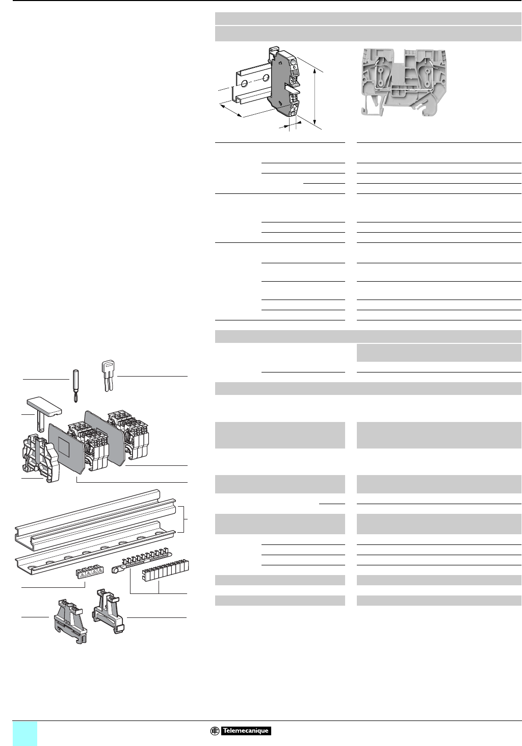
Grounding type
Clip-on mounting on 35 mm 1 7 rails
Nominal wire size 2.5 mm2
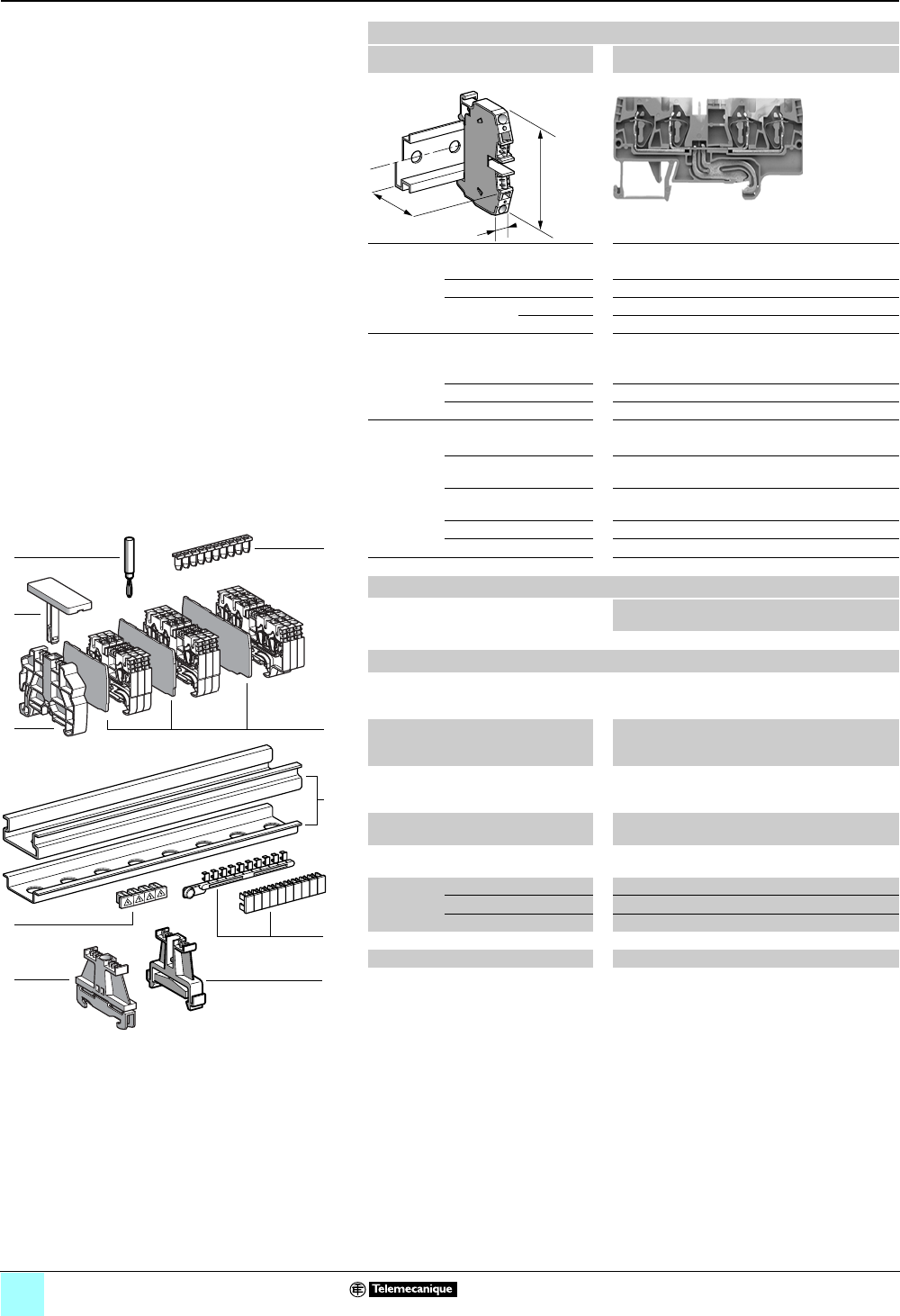
AB1RRNTP235U2
Approximate dimensions, in. (mm)
Length (a) 1.85 (47.1)
Width (b) 0.20 (5)
1Height (H)
with
1 rail 1.80 (45.6)
7 rail 1.50 (38.1)
Wire size, mm2
Stranded without
cable end
0.13–2.5
Stranded with cable end 0.5–2.5
Solid 0.13–4
Nominal electrical values
IEC/EN 60947-7-1 800 V / 8 kV / 3–24 A
UL File E164359
CCN XCFR2
22–12 AWG, 600 V, 20 A
CSA File 702070
Class 6228 01
24–12 AWG, 600 V, 25 A
UTE, category C —
VDE, group C 800 V, 24 A
Certifications See the tables beginning on page 1/10.
a
b
H
Terminal blocks
No. of
points
Sold in
lots of
Catalog
number
Weight
oz (g)
Green/yellow 2 100 AB1RRNTP235U2 0.27 (7.6)
Accessories
7
8
4
5
1
6
9
3
10
9
8
7
6
5
4
3
2
1
987654321
10
2
10
524013
2 Plastic
end clamp
with screw
Width 0.3 in. (8 mm)
on 1 or 7
—100AB1AB8P35 0.21 (5.9)
3Metal
end clamp
with screw
Width 0.3 in. (8 mm)
on 1 or 7
—100 AB1AB8M35 0.52 (14.8)
4 Clip-on
plastic
end clamp
Width 0.3 in. (8 mm)
on 1 or 7—100AB1AB8R35 0.21 (5.9)
5Marker tag holder
for clip-on plastic end clamp
—10 AB1SB4 0.11 (3.1)
6 End plate
thickness 0.06 in. (1.5 mm)
Green — 10 AB1RRNTPAC242 0.08 (2.3)
7Wire guide
entry strip
0.13–0.2 mm2White —100 AB1RRNGF01 0.03 (0.9)
0.25–0.5 mm2Gray —100 AB1RRNGF02 0.03 (0.9)
0.75–1 mm2Black —100 AB1RRNGF03 0.03 (0.9)
8 Test plug Red — 10 AB1AT1 0.07 (1.9)
9Terminal cover 410 AB1RRNCS2 0.01 (0.3)
10 Marking accessories See pages 5/2 and 5/3.
2/20
0
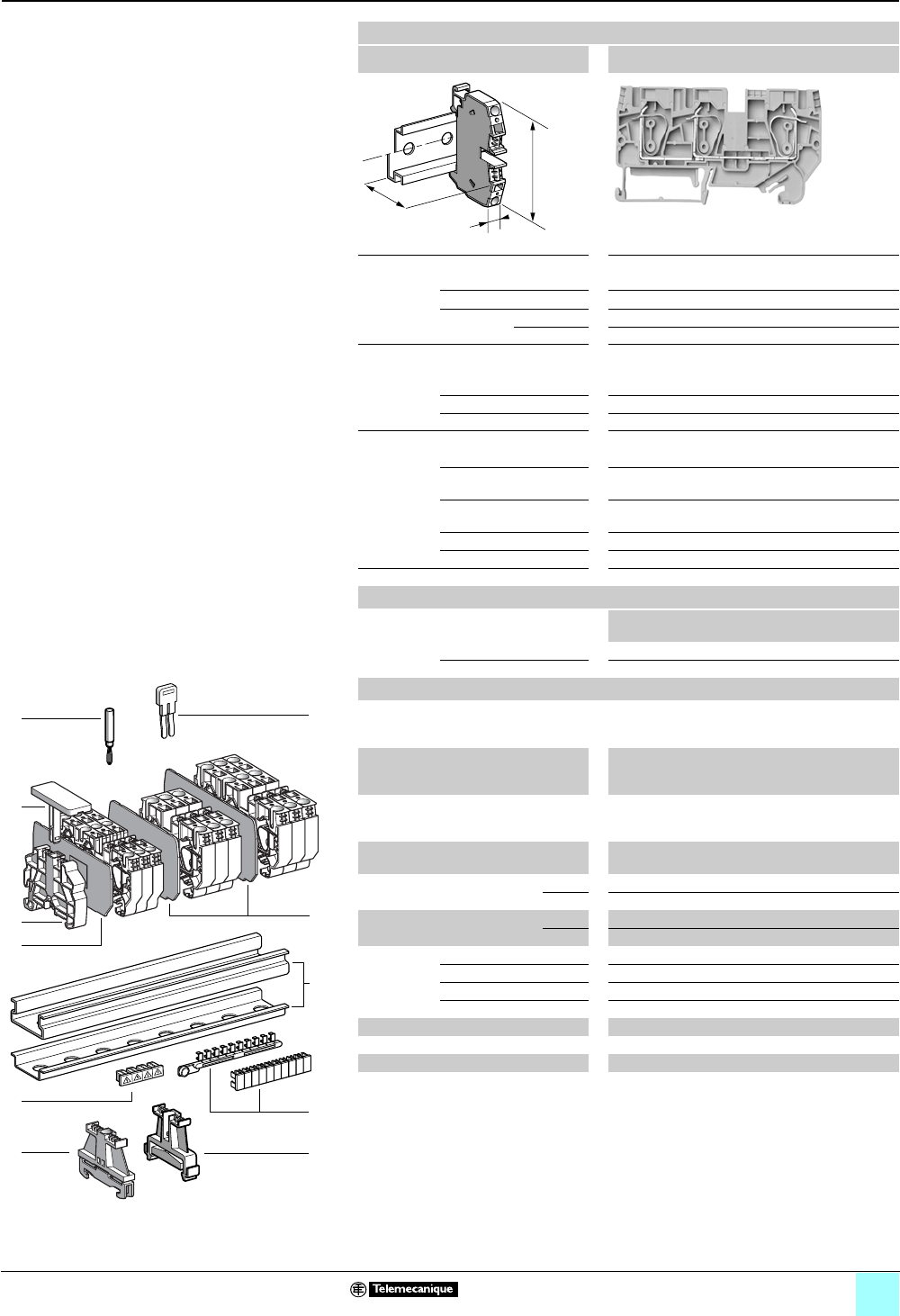
Terminal Blocks, Type AB1 0
Spring technology
Grounding type
Clip-on mounting on 35 mm 1 7 rails
Nominal wire size 2.5 mm2
AB1RRNTP235U3
Approximate dimensions, in. (mm)
Length (a) 0.35 (59.7)
Width (b) 0.20 (5)
1Height (H)
with
1 rail 1.80 (45.6)
7 rail 1.50 (38.1)
Wire size, mm2
Stranded without
cable end
0.13–2.5
Stranded with cable end 0.5–2.5
Solid 0.13–4
Nominal electrical values
IEC/EN 60947-7-1 800 V / 8 kV / 3–24 A
UL File E164359
CCN XCFR2
22–12 AWG, 600 V, 20 A
CSA File 702070
Class 6228 01
24–12 AWG, 600 V, 25 A
UTE, category C —
VDE, group C 800 V, 24 A
Certifications See the tables beginning on page 1/10.
Terminal blocks
No. of
points
Sold in
lots of
Catalog number Weight
oz (g)
Green/yellow 3 100 AB1RRNTP235U3 0.34 (9.5)
Accessories
2 Plastic
end clamp
with screw
Width 0.3 in. (8 mm)
on 1 or 7
— 100 AB1AB8P35 0.21 (5.9)
3Metal
end clamp
with screw
Width 0.3 in. (8 mm)
on 1 or 7
—100 AB1AB8M35 0.52 (14.8)
4 Clip-on
plastic
end clamp
Width 0.3 in. (8 mm)
on 1 or 7— 100 AB1AB8R35 0.21 (5.9)
5Marker tag holder
for clip-on plastic end clamp
—10 AB1SB4 0.11 (3.1)
6 End plate Green, thickness
0.06 in. (1.5 mm)
—10 AB1RRNTPAC243 0.10 (2.8)
7Wire guide
entry strip
0.13–0.2 mm2White —100 AB1RRNGF01 0.03 (0.9)
0.25–0.5 mm2Gray —100 AB1RRNGF02 0.03 (0.9)
0.75–1 mm2Black —100 AB1RRNGF03 0.03 (0.9)
8 Test plug Red — 10 AB1AT1 0.07 (1.9)
9Terminal cover 410 AB1RRNCS2 0.01 (0.3)
10 Marking accessories See pages 5/2 and 5/3.
a
b
H
7
8
4
5
1
6
9
3
10
9
8
7
6
5
4
3
2
1
987654321
10
2
10
524013
2/21
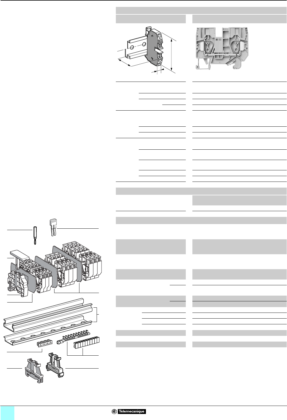
Terminal Blocks, Type AB1 0
Spring technology
Grounding type
Clip-on mounting on 35 mm 1 7 rails
Nominal wire size 2.5 mm2
AB1RRNTP235U4
Approximate dimensions, in. (mm)
Length (a) 2.85 (72.4)
Width (b) 0.20 (5)
1Height (H)
with
1 rail 1.80 (45.6)
7 rail 1.50 (38.1)
Wire size, mm2
Stranded without
cable end
0.13–2.5
Stranded with cable end 0.5–2.5
Solid 0.13–4
Nominal electrical values
IEC/EN 60947-7-1 800 V / 8 kV / 3–24 A
UL File E164359
CCN XCFR2
22–12 AWG, 600 V, 20 A
CSA File 702070
Class 6228 01
24–12 AWG, 600 V, 25 A
UTE, category C —
VDE, group C 800 V, 24 A
Certifications See the tables beginning on page 1/10.
Terminal blocks
No. of
points
Sold in
lots of
Catalog
number
Weight
oz (g)
Green/yellow 4 100 AB1RRNTP235U4 0.40 (11.2)
Accessories
2 Plastic
end clamp
with screw
Width 0.3 in. (8 mm)
on 1 or 7
— 100 AB1AB8P35 0.21 (5.9)
3Metal
end clamp
with screw
Width 0.3 in. (8 mm)
on 1 or 7
—100 AB1AB8M35 0.52 (14.8)
4 Clip-on
plastic
end clamp
Width 0.3 in. (8 mm)
on 1 or 7— 100 AB1AB8R35 0.21 (5.9)
5Marker tag holder
for clip-on plastic end clamp
—10 AB1SB4 0.11 (3.1)
6 End plate
thickness 0.06 in. (1.5 mm)
Green — 10 AB1RRNTPAC244 0.12 (3.4)
7Wire guide
entry strip
0.13–0.2 mm2White —100 AB1RRNGF01 0.03 (0.9)
0.25–0.5 mm2Gray —100 AB1RRNGF02 0.03 (0.9)
0.75–1 mm2Black —100 AB1RRNGF03 0.03 (0.9)
8 Test plug Red — 10 AB1AT1 0.07 (1.9)
9Terminal cover 410 AB1RRNCS2 0.01 (0.3)
10 Marking accessories See pages 5/2 and 5/3.
a
b
H
7
8
4
5
1
6
9
3
10
9
8
7
6
5
4
3
2
1
987654321
10
2
10
524013
2/22
0
Terminal Blocks, Type AB1 0
Spring technology
Grounding type
Clip-on mounting on 35 mm 1 7 rails
Nominal wire size 4 mm2
AB1RRNTP435U2
Approximate dimensions, in. (mm)
Length (a) 2.01 (51)
Width (b) 0.24 (6)
1Height (H)
with
1 rail 1.80 (45.65)
7 rail 1.50 (38.15)
Wire size, mm2
Stranded without
cable end
0.13–4
Stranded with cable end 0.5–4
Solid 0.13–6
Nominal electrical values
IEC/EN 60947-7-1 800 V / 8 kV / 3–32 A
UL File E164359
CCN XCFR2
24–10 AWG, 600 V, 30 A
CSA File 702070
Class 6228 01
24–10 AWG, 600 V, 32 A
UTE, category C —
VDE, group C 800 V, 32 A
Certifications See the tables beginning on page 1/10.
Terminal blocks
No. of
points
Sold in
lots of
Catalog
number
Weight
oz (g)
Green/yellow 2 100 AB1RRNTP435U2 0.34 (9.5)
Accessories
2 Plastic
end clamp
with screw
Width 0.3 in. (8 mm)
on 1 or 7—100AB1AB8P35 0.21 (5.9)
3Metal
end clamp
with screw
Width 0.3 in. (8 mm)
on 1 or 7—100 AB1AB8M35 0.52 (14.8)
4 Clip-on
plastic
end clamp
Width 0.3 in. (8 mm)
on 1 or 7—100AB1AB8R35 0.21 (5.9)
5Marker tag holder
for clip-on plastic end clamp
—10 AB1SB4 0.11 (3.1)
6 End plate
thickness 0.06 in. (1.5 mm)
Green — 10 AB1RRNTPAC442 0.09 (2.5)
7Wire guide
entry strip
0.13–0.2 mm2White —100 AB1RRNGF11 0.03 (0.8)
0.25–0.5 mm2Gray —100 AB1RRNGF22 0.03 (0.8)
0.75–1 mm2Black —100 AB1RRNGF33 0.03 (0.8)
8 Test plug Red — 10 AB1AT1 0.07 (1.9)
9Terminal cover 4100 AB1RRCS4 0.01 (0.4)
10 Marking accessories See pages 5/2 and 5/3.
a
b
H
7
8
4
5
1
6
9
3
10
9
8
7
6
5
4
3
2
1
987654321
10
2
10
524013
2/23
0
Terminal Blocks, Type AB1 0
Spring technology
Grounding type
Clip-on mounting on 35 mm 1 7 rails
Nominal wire size 4 mm2
AB1RRNTP435U3
Approximate dimensions, in. (mm)
Length (a) 2.62 (66.6)
Width (b) 0.24 (6)
1Height (H)
with
1 rail 1.80 (45.65)
7 rail 1.50 (38.15)
Wire size, mm2
Stranded without
cable end
0.13–4
Stranded with cable end 0.5–4
Solid 0.13–6
Nominal electrical values
IEC/EN 60947-7-1 800 V / 8 kV / 3–32 A
UL File E164359
CCN XCFR2
24–10 AWG, 600 V, 30 A
CSA File 702070
Class 6228 01
24–10 AWG, 600 V, 32 A
UTE, category C —
VDE, group C 800 V, 32 A
Certifications See the tables beginning on page 1/10.
Terminal blocks
No. of
points
Sold in
lots of
Catalog
number
Weight
oz (g)
Green/yellow 3 100 AB1RRNTP435U3 0.43 (12.3)
Accessories
2 Plastic
end clamp
with screw
Width 0.3 in. (8 mm)
on 1 or 7— 100 AB1AB8P35 0.21 (5.9)
3Metal
end clamp
with screw
Width 0.3 in. (8 mm)
on 1 or 7—100 AB1AB8M35 0.52 (14.8)
4 Clip-on
plastic
end clamp
Width 0.3 in. (8 mm)
on 1 or 7— 100 AB1AB8R35 0.21 (5.9)
5Marker tag holder
for clip-on plastic end clamp
—10 AB1SB4 0.11 (3.1)
6 End plate
thickness 0.06 in. (1.5 mm)
Green — 10 AB1RRNTPAC443 0.11 (3.2)
7Wire guide
entry strip
0.13–0.2 mm2White —100 AB1RRNGF11 0.03 (0.8)
0.25–0.5 mm2Gray —100 AB1RRNGF22 0.03 (0.8)
0.75–1 mm2Black —100 AB1RRNGF33 0.03 (0.8)
8 Test plug Red — 10 AB1AT1 0.07 (1.9)
9Terminal cover 4100 AB1RRCS4 0.01 (0.4)
10 Marking accessories See pages 5/2 and 5/3.
a
b
H
7
8
4
5
1
6
9
3
10
9
8
7
6
5
4
3
2
1
987654321
10
2
10
524013
2/24
0
Terminal Blocks, Type AB1 0
Spring technology
Grounding type
Clip-on mounting on 35 mm 1 7 rails
Nominal wire size 4 mm2
AB1RRNTP435U4
Approximate dimensions, in. (mm)
Length (a) 3.24 (82.2)
Width (b) 0.24 (6)
1Height (H)
with
1 rail 1.80 (45.65)
7 rail 1.50 (38.15)
Wire size, mm2
Stranded without
cable end
0.13–4
Stranded with cable end 0.5–4
Solid 0.13–6
Nominal electrical values
IEC/EN 60947-7-1 800 V / 8 kV / 3–32 A
UL File E164359
CCN XCFR2
24–10 AWG, 600 V, 30 A
CSA File 702070
Class 6228 01
24–10 AWG, 600 V, 32 A
UTE, category C —
VDE, group C 800 V, 32 A
Certifications See the tables beginning on page 1/10.
Terminal blocks
No. of
points
Sold in
lots of
Catalog
number
Weight
oz (g)
Green/yellow 4 100 AB1RRNTP435U4 0.53 (15.1)
Accessories
2 Plastic
end clamp
with screw
Width 0.3 in. (8 mm)
on 1 or 7— 100 AB1AB8P35 0.21 (5.9)
3Metal
end clamp
with screw
Width 0.3 in. (8 mm)
on 1 or 7—100 AB1AB8M35 0.52 (14.8)
4 Clip-on
plastic
end clamp
Width 0.3 in. (8 mm)
on 1 or 7— 100 AB1AB8R35 0.21 (5.9)
5Marker tag holder
for clip-on plastic end clamp
—10 AB1SB4 0.11 (3.1)
6 End plate
thickness 0.06 in. (1.5 mm)
Green — 10 AB1RRNTPAC444 0.13 (3.8)
7Wire guide
entry strip
0.13–0.2 mm2White —100 AB1RRNGF11 0.03 (0.8)
0.25–0.5 mm2Gray —100 AB1RRNGF22 0.03 (0.8)
0.75–1 mm2Black —100 AB1RRNGF33 0.03 (0.8)
8 Test plug Red — 10 AB1AT1 0.07 (1.9)
9Terminal cover 4100 AB1RRCS4 0.01 (0.4)
10 Marking accessories See pages 5/2 and 5/3.
a
b
H
7
8
4
5
1
6
9
3
10
9
8
7
6
5
4
3
2
1
987654321
10
2
10
524013
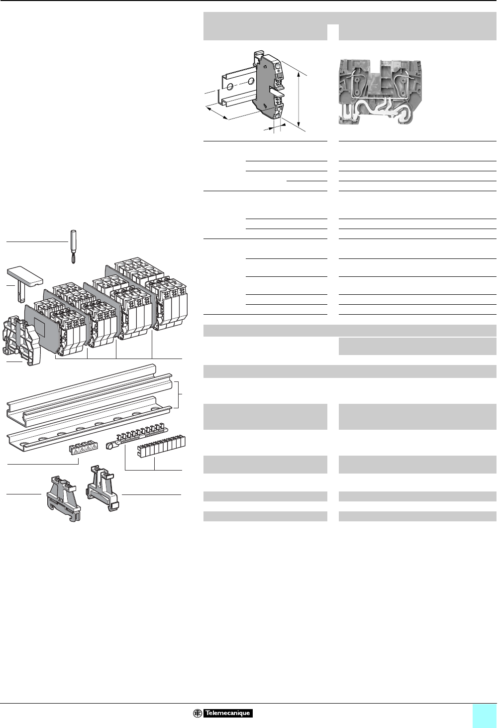
2/25
0
Terminal Blocks, Type AB1 0
Spring technology
Grounding type
Clip-on mounting on 35 mm 1 7 rails
Nominal wire size 6 mm2
AB1RRNTP635U2
Approximate dimensions, in. (mm)
Length (a) 2.60 (66)
Width (b) 0.31 (8)
1Height (H)
with
1 rail 2.05 (52.05)
7 rail 1.75 (44.55)
Wire size, mm2
Stranded without
cable end
0.2–6
Stranded with cable end 0.2–6
Solid 0.2–10
Nominal electrical values
IEC/EN 60947-7-1 800 V / 8 kV / 41 A
UL File E164359
CCN XCFR2
24–8 AWG, 600 V, 50 A
CSA File 702070
Class 6228 01
24–8 AWG, 600 V, 41 A
UTE, category C —
VDE, group C 800 V, 41 A
Certifications See the tables beginning on page 1/10.
Terminal blocks
No. of
points
Sold in
lots of
Catalog
number
Weight
oz (g)
Green/yellow 2 50 AB1RRNTP635U2 0.71 (20.2)
Accessories
2 Plastic
end clamp
with screw
Width 0.3 in. (8 mm)
on 1 or 7 —100AB1AB8P35 0.21 (5.9)
3Metal
end clamp
with screw
Width 0.3 in. (8 mm)
on 1 or 7—100 AB1AB8M35 0.52 (14.8)
4 Clip-on
plastic
end clamp
Width 0.3 in. (8 mm)
on 1 or 7—100AB1AB8R35 0.21 (5.9)
5Marker tag holder
for clip-on plastic end clamp
—10 AB1SB4 0.11 (3.1)
6 End plate
thickness 0.06 in. (1.5 mm)
Green — 10 AB1RRNTPAC642 0.14 (4.0)
7Test plug Red —10 AB1AT1 0.07 (1.9)
8 Terminal cover 410AB1RRCS6 0.01 (0.4)
9Marking accessories See pages 5/2 and 5/3.
a
b
H
5
4
7
1
6
8
3
10
9
8
7
6
5
4
3
2
1
987654321
10
2
9
524042
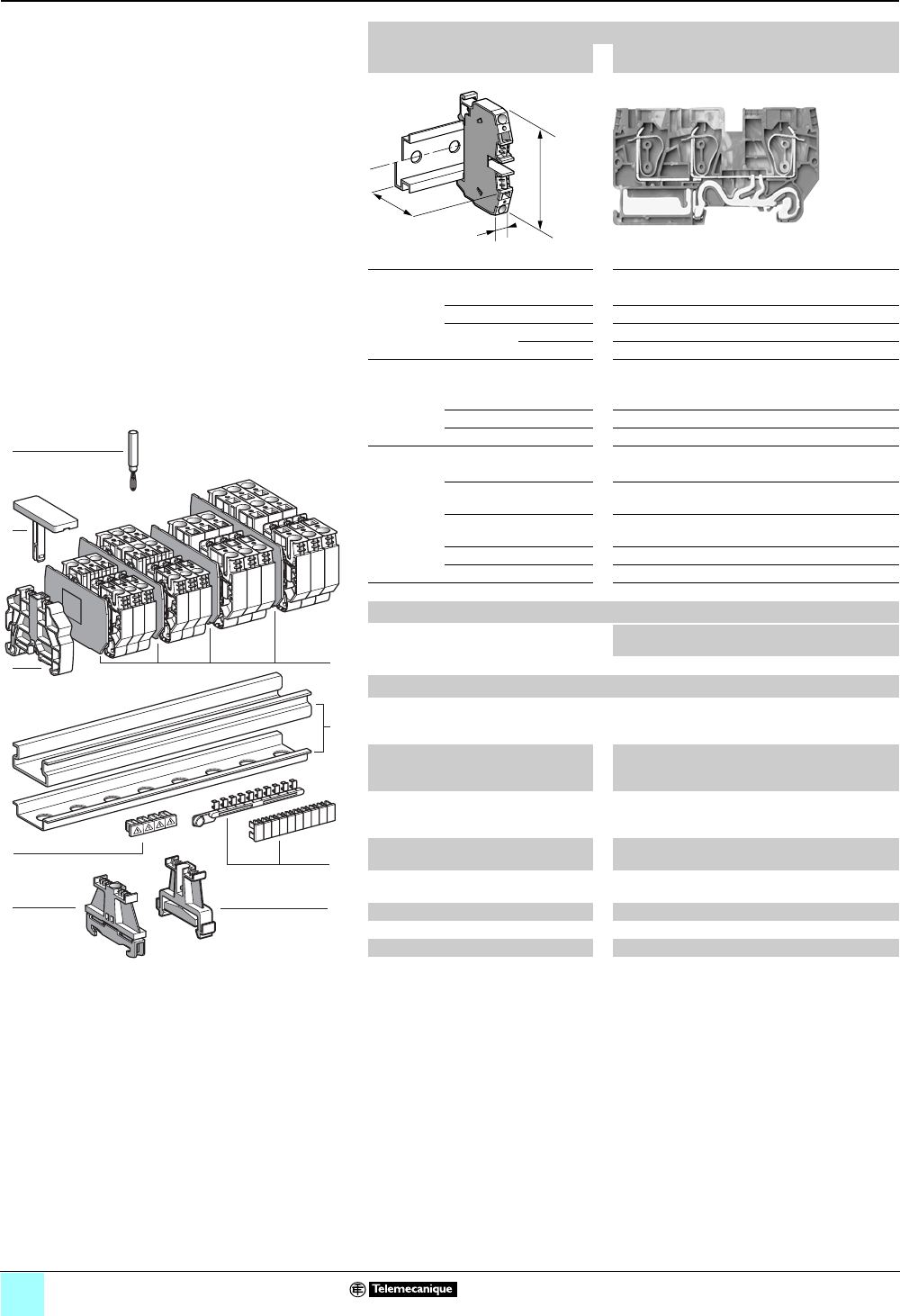
2/26
0
Terminal Blocks, Type AB1 0
Spring technology
Grounding type
Clip-on mounting on 35 mm 1 7 rails
Nominal wire size 6 mm2
AB1RRNTP635U3
Approximate dimensions, in. (mm)
Length (a) 3.54 (90)
Width (b) 0.31 (8)
1Height (H)
with
1 rail 2.05 (52.05)
7 rail 1.75 (44.55)
Wire size, mm2
Stranded without
cable end
0.2–6
Stranded with cable end 0.2–6
Solid 0.2–10
Nominal electrical values
IEC/EN 60947-7-1 800 V / 8 kV / 41 A
UL File E164359
CCN XCFR2
24–8 AWG, 600 V, 50 A
CSA File 702070
Class 6228 01
24–8 AWG, 600 V, 41 A
UTE, category C —
VDE, group C 800 V, 41 A
Certifications See the tables beginning on page 1/10.
a
b
H
Terminal blocks
No. of
points
Sold in
lots of
Catalog
number
Weight
oz (g)
Green/yellow 3 50 AB1RRNTP635U3 0.98 (27.8)
Accessories
2 Plastic
end clamp
with screw
Width 0.3 in. (8 mm)
on 1 or 7 —100AB1AB8P35 0.21 (5.9)
3Metal
end clamp
with screw
Width 0.3 in. (8 mm)
on 1 or 7—100 AB1AB8M35 0.52 (14.8)
4 Clip-on
plastic
end clamp
Width 0.3 in. (8 mm)
on 1 or 7—100AB1AB8R35 0.21 (5.9)
5Marker tag holder
for clip-on plastic end clamp
—10 AB1SB4 0.11 (3.1)
6 End plate
thickness 0.06 in. (1.5 mm)
Green — 10 AB1RRNTPAC643 0.18 (5.2)
7Test plug Red —10 AB1AT1 0.07 (1.9)
8 Terminal cover 410AB1RRCS6 0.01 (0.4)
9Marking accessories See pages 5/2 and 5/3.
5
4
7
1
6
8
3
10
9
8
7
6
5
4
3
2
1
987654321
10
2
9
524042
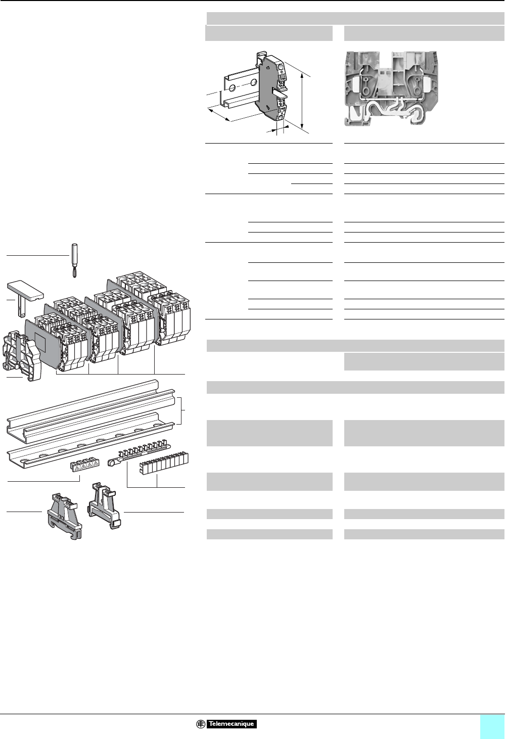
2/27
0
Terminal Blocks, Type AB1 0
Spring technology
Grounding type
Clip-on mounting on 35 mm 1 7 rails
Nominal wire size 10 mm2
AB1RRNTP1035U2
Approximate dimensions, in. (mm)
Length (a) 2.85 (72.5)
Width (b) 0.39 (10)
Height (H)
with
1 rail 2.28 (58)
7 rail 1.99 (50.5)
Wire size, mm2
Stranded without
cable end
0.2–10
Stranded with cable end 0.2–10
Solid 0.2–16
Nominal electrical values
IEC/EN 60947-7-1 800 V / 8 kV / 57 A
UL File E164359
CCN XCFR2
16–6 AWG, 600 V, 60 A
CSA File 702070
Class 6228 01
16–6 AWG, 600 V, 65 A
UTE, category C —
VDE, group C 800 V, 57 A
Certifications See the tables beginning on page 1/10.
Terminal blocks
No. of
points
Sold in
lots of
Catalog
number
Weight,
g (oz)
Green/yellow 2 50 AB1RRNTP1035U2 1.18 (33.5)
Accessories
2 Plastic
end clamp
with screw
Width 0.3 in. (8 mm)
on 1 or 7 — 100 AB1AB8P35 0.21 (5.9)
3Metal
end clamp
with screw
Width 0.3 in. (8 mm)
on 1 or 7—100 AB1AB8M35 0.52 (14.8)
4 Clip-on
plastic
end clamp
Width 0.3 in. (8 mm)
on 1 or 7— 100 AB1AB8R35 0.21 (5.9)
5Marker tag holder
for clip-on plastic end clamp
—10 AB1SB4 0.11 (3.1)
6 End plate
thickness 0.06 in. (1.5 mm)
Green — 10 AB1RRNTPAC1042 0.18 (5.1)
7Test plug Red —10 AB1AT1 0.07 (1.9)
8 Terminal cover 4 100 AB1RRCS10 0.03 (0.8)
9Marking accessories See pages 5/2 and 5/3.
a
b
H
5
4
7
1
6
8
3
10
9
8
7
6
5
4
3
2
1
987654321
10
2
9
524042
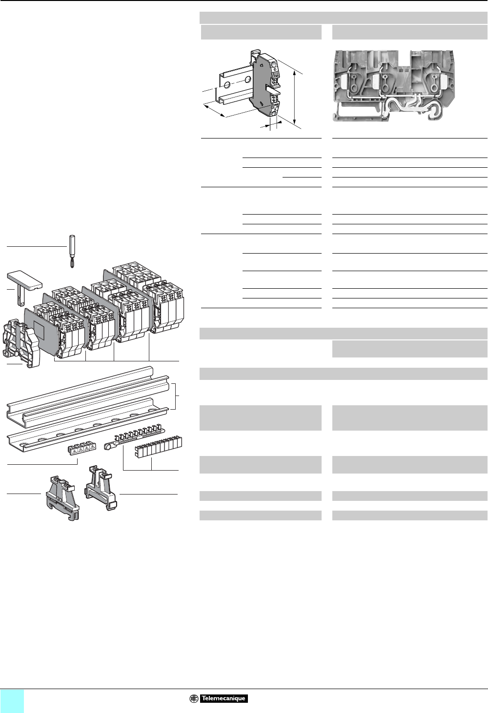
2/28
Terminal Blocks, Type AB1 0
Spring technology
Grounding type
Clip-on mounting on 35 mm 1 7 rails
Nominal wire size 10 mm2
AB1RRNTP1035U3
Approximate dimensions, in. (mm)
Length (a) 3.86 (98)
Width (b) 0.39 (10)
Height (H)
with
1 rail 2.28 (58)
7 rail 1.99 (50.5)
Wire size, mm2
Stranded without
cable end
0.2–10
Stranded with cable end 0.2–10
Solid 0.2–16
Nominal electrical values
IEC/EN 60947-7-1 800 V / 8 kV / 57 A
UL File E164359
CCN XCFR2
16–6 AWG, 600 V, 60 A
CSA File 702070
Class 6228 01
16–6 AWG, 600 V, 65 A
UTE, category C —
VDE, group C 800 V, 57 A
Certifications See the tables beginning on page 1/10.
Terminal blocks
No. of
points
Sold in
lots of
Catalog
number
Weight
oz (g)
Green/yellow 3 50 AB1RRNTP1035U3 1.57 (44.4)
Accessories
2 Plastic
end clamp
with screw
Width 0.3 in. (8 mm)
on 1 or 7 — 100 AB1AB8P35 0.21 (5.9)
3Metal
end clamp
with screw
Width 0.3 in. (8 mm)
on 1 or 7—100 AB1AB8M35 0.52 (14.8)
4 Clip-on
plastic
end clamp
Width 0.3 in. (8 mm)
on 1 or 7— 100 AB1AB8R35 0.21 (5.9)
5Marker tag holder
for clip-on plastic end clamp
—10 AB1SB4 0.11 (3.1)
6 End plate thickness 0.06
in. (1.5 mm)
Green — 10 AB1RRNTPAC1043 0.24 (6.7)
7Test plug Red —10 AB1AT1 0.07 (1.9)
8 Terminal cover 410AB1RRCS10 0.03 (0.8)
9Marking accessories See pages 5/2 and 5/3.
a
b
H
5
4
7
1
6
8
3
10
9
8
7
6
5
4
3
2
1
987654321
10
2
9
524042
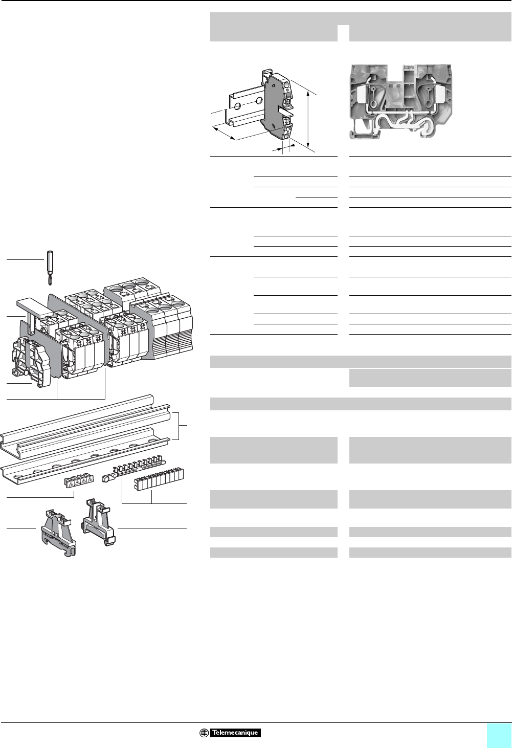
2/29
0
Terminal Blocks, Type AB1 0
Spring technology
Grounding type
Clip-on mounting on 35 mm 1 7 rails
Nominal wire size 16 mm2
AB1RRNTP1635U2
Approximate dimensions, in. (mm)
Length (a) 3.11 (79.1)
Width (b) 0.47 (12)
1Height (H)
with
1 rail 2.28 (58)
7 rail 1.99 (50.5)
Wire size, mm2
Stranded without
cable end
0.2–16
Stranded with cable end 0.2–16
Solid 0.2–25
Nominal electrical values
IEC/EN 60947-7-1 800 V / 8 kV / 76 A
UL File E164359
CCN XCFR2
16–4 AWG, 600 V, 85 A
CSA File 702070
Class 6228 01
16–4 AWG, 600 V, 85 A
UTE, category C —
VDE, group C 800 V, 76 A
Certifications See the tables beginning on page 1/10.
Terminal blocks
No. of
points
Sold in
lots of
Catalog
number
Weight
oz (g)
Green/yellow 2 50 AB1RRNTP1635U2 1.56 (44.1)
Accessories
2 Plastic
end clamp
with screw
Width 0.3 in. (8 mm)
on 1 or 7
— 100 AB1AB8P35 0.21 (5.9)
3Metal
end clamp
with screw
Width 0.3 in. (8 mm)
on 1 or 7
—100 AB1AB8M35 0.52 (14.8)
4 Clip-on
plastic
end clamp
Width 0.3 in. (8 mm)
on 1 or 7— 100 AB1AB8R35 0.21 (5.9)
5Marker tag holder
for clip-on plastic end clamp
—10 AB1SB4 0.11 (3.1)
6 End plate
thickness 0.06 in. (1.5 mm)
Green — 10 AB1RRNTPAC1642 0.19 (5.5)
7Test plug Red —10 AB1AT1 0.07 (1.9)
8 Terminal cover 410AB1RRCS16 0.04 (1.2)
9Marking accessories See pages 5/2 and 5/3.
a
b
H
6
7
1
8
3
10
9
8
7
6
5
4
3
2
1
987654321
10
2
9
4
5
524066
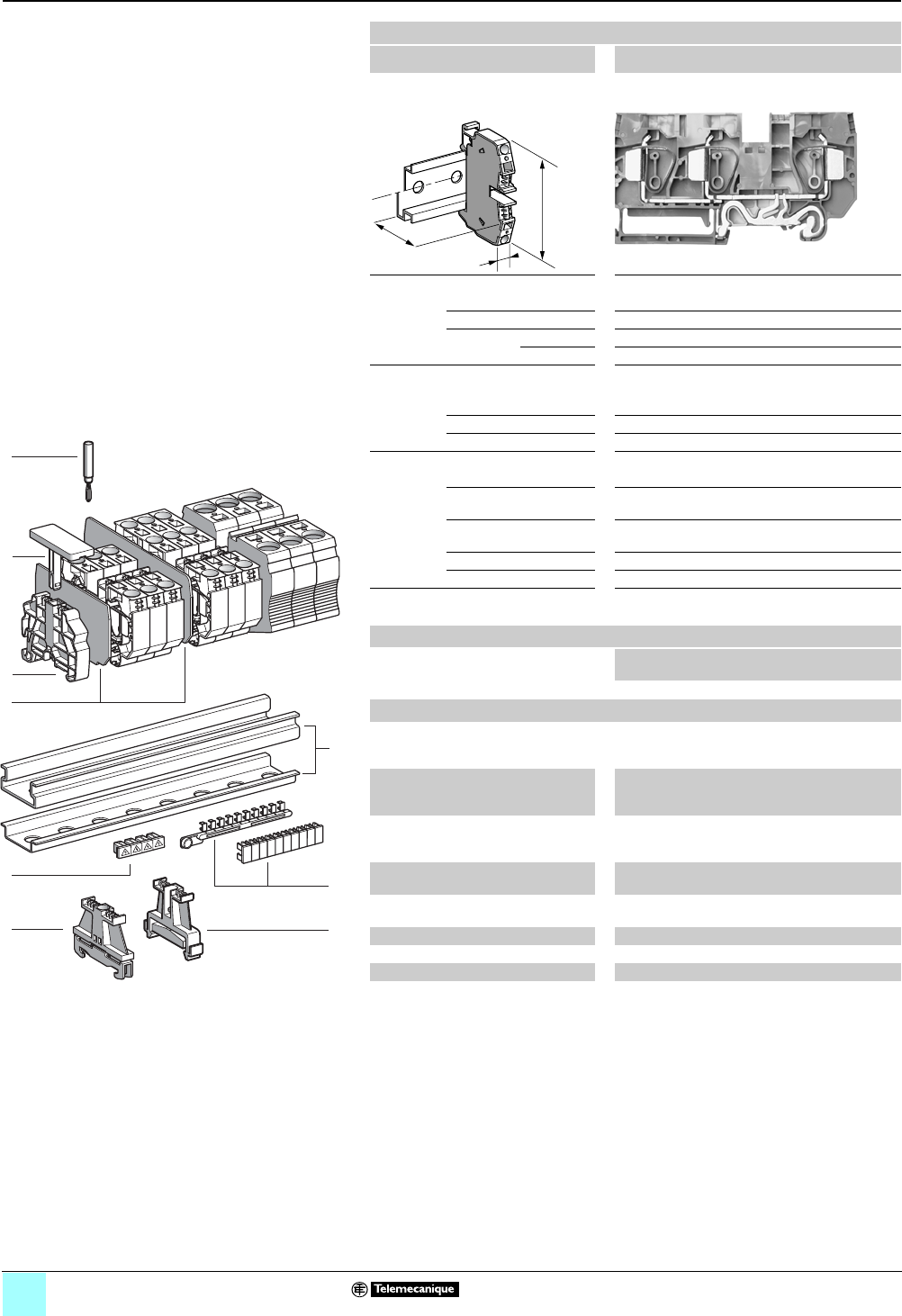
2/30
0
Terminal Blocks, Type AB1 0
Spring technology
Grounding type
Clip-on mounting on 35 mm 1 7 rails
Nominal wire size 16 mm2
AB1RRNTP1635U3
Approximate dimensions, in. (mm)
Length (a) 4.2 (106.7)
Width (b) 0.47 (12)
1Height (H)
with
1 rail 2.28 (58)
7 rail 1.99 (50.5)
Wire size, mm2
Stranded without
cable end
0.2–16
Stranded with cable end 0.2–16
Solid 0.2–25
Nominal electrical values
IEC/EN 60947-7-1 800 V / 8 kV / 76 A
UL File E164359
CCN XCFR2
16–4 AWG, 600 V, 85 A
CSA File 702070
Class 6228 01
16–4 AWG, 600 V, 85 A
UTE, category C —
VDE, group C 800 V, 76 A
Certifications See the tables beginning on page 1/10.
Terminal blocks
No. of
points
Sold in
lots of
Catalog
number
Weight
oz (g)
Green/yellow 3 25 AB1RRNTP1635U3 2.21 (62.6)
Accessories
2 Plastic
end clamp
with screw
Width 0.3 in. (8 mm)
on 1 or 7
— 100 AB1AB8P35 0.21 (5.9)
3Metal
end clamp
with screw
Width 0.3 in. (8 mm)
on 1 or 7
—100 AB1AB8M35 0.52 (14.8)
4 Clip-on
plastic
end clamp
Width 0.3 in. (8 mm)
on 1 or 7— 100 AB1AB8R35 0.21 (5.9)
5Marker tag holder
for clip-on plastic end clamp
—10 AB1SB4 0.11 (3.1)
6 End plate
thickness 0.06 in. (1.5 mm)
Green — 10 AB1RRNTPAC1643 0.26 (7.3)
7Test plug Red —10 AB1AT1 0.07 (1.9)
8 Terminal cover 410AB1RRCS16 0.04 (1.2)
9Marking accessories See pages 5/2 and 5/3.
a
b
H
6
7
1
8
3
10
9
8
7
6
5
4
3
2
1
987654321
10
2
9
4
5
524066
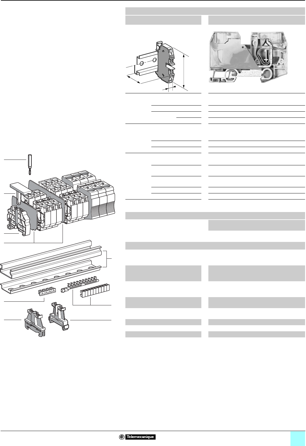
2/31
0
Terminal Blocks, Type AB1 0
Spring technology
Grounding type
Clip-on mounting on 35 mm 1 7 rails
Nominal wire size 35 mm2
AB1RRNTP3535U2
Approximate dimensions, in. (mm)
Length (a) 3.93 (99.9)
Width (b) 0.63 (16)
1Height (H)
with
1 rail 2.63 (66.7)
7 rail 2.33 (59.2)
Wire size, mm2
Stranded without
cable end
2.5–35
Stranded with cable end 2.5–35
Solid 2.5–35
Nominal electrical values
IEC/EN 60947-7-1 800 V / 8 kV / 3–125 A
UL File E164359
CCN XCFR2
14–2 AWG, 600 V, 120 A
CSA File 702070
Class 6228 01
14–2 AWG, 600 V, 120 A
UTE, category C —
VDE, group C 800 V, 120 A
Certifications See the tables beginning on page 1/10.
Terminal blocks
No. of
points
Sold in
lots of
Catalog
number
Weight
oz (g)
Green/yellow 2 10 AB1RRNTP3535U2 5.24
(148.5)
Accessories
2 Plastic
end clamp
with screw
Width 0.3 in. (8 mm)
on 1 or 7
— 100 AB1AB8P35 0.21 (5.9)
3Metal
end clamp
with screw
Width 0.3 in. (8 mm)
on 1 or 7
—100 AB1AB8M35 0.52 (14.8)
4 Clip-on
plastic
end clamp
Width 0.3 in. (8 mm)
on 1 or 7— 100 AB1AB8R35 0.21 (5.9)
5Marker tag holder
for clip-on plastic end clamp
—10 AB1SB4 0.11 (3.1)
6 End plate
thickness 0.06 in. (1.5 mm)
Green — — ——
7Test plug Red —10 AB1AT1 0.07 (1.9)
8 Terminal cover 410AB1RRCS35 0.01 (0.2)
9Marking accessories See pages 5/2 and 5/3.
a
b
H
6
7
1
8
3
10
9
8
7
6
5
4
3
2
1
987654321
10
2
9
4
5
524066
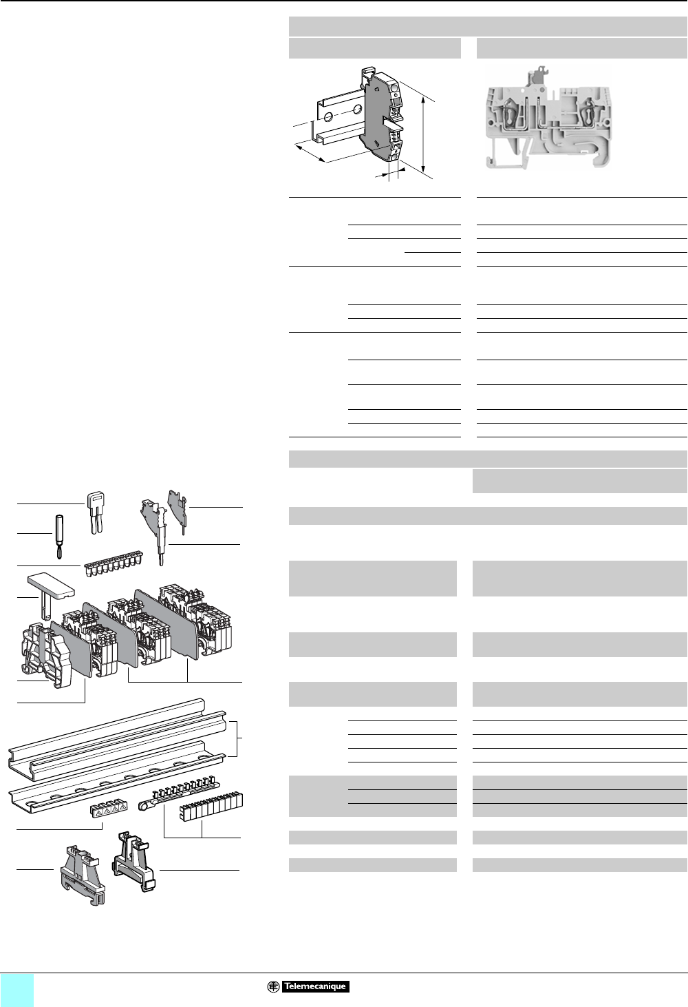
2/32
0
Terminal Blocks, Type AB1 0
Spring technology
Blade disconnect type
Clip-on mounting on 35 mm 1 7 rails
Nominal wire size 2.5 mm2
AB1RRNSC235U2
Approximate dimensions, in. (mm)
Length (a) 2.85 (59.75)
Width (b) 0.20 (5)
1Height (H)
with
1 rail 1.8 (45.6) + 0.38 (9.6) for open switch
7 rail 1.5 (38.1) + 0.38 (9.6) for open switch
Wire size, mm2
Stranded without
cable end
0.13–2.5
Stranded with cable end 0.5–2.5
Solid 0.13–4
Nominal electrical values
IEC/EN 60947-7-1 630 V / 6 kV / 3–20 A
UL File E164359
CCN XCFR2
24–12 AWG, 300 V, 19 A
CSA File 702070
Class 6228 01
24–12 AWG, 300 V, 20 A
UTE, category C —
VDE, group C 630 V / 20 A
Certifications See the tables beginning on page 1/10.
Terminal blocks
No.
points
Sold in
lots of
Catalog number Weight
oz (g)
Gray 2 100 AB1RRNSC235U2 0.27 (7.7)
Accessories
2 Plastic
end clamp
with screw
Width 0.3 in. (8 mm)
on 1 or 7 —100 AB1AB8P35 0.21 (5.9)
3Metal
end clamp
with screw
Width 0.3 in. (8 mm)
on 1 or 7—100 AB1AB8M35 0.52 (14.8)
4 Clip-on
plastic
end clamp
Width 0.3 in. (8 mm)
on 1 or 7—100 AB1AB8R35 0.21 (5.9)
5Marker tag holder
for clip-on plastic end clamp
—10 AB1SB4 0.11 (3.1)
6 End plate
thickness 0.06 in. (1.5 mm)
Gray —10 AB1RRNAC243GR 0.10 (2.8)
7Partition plate
thickness 0.06 in. (1.5 mm)
Gray —10 AB1RRNAS243GR 0.12 (3.4)
8 Insulated
jumper
2-pole —10 AB1RRAL22 0.04 (1.1)
3-pole —10 AB1RRAL23 0.06 (1.7)
4-pole —10 AB1RRAL24 0.08 (2.2)
5-pole —10 AB1RRAL25 0.10 (2.8)
10-pole —20 AB1RRAL210 0.20 (5.6)
9Wire guide
entry strip
0.13–0.2 mm2White —100 AB1RRNGF01 0.03 (0.9)
0.25–0.5 mm2Gray —100 AB1RRNGF02 0.03 (0.9)
0.75–1 mm2Black —100 AB1RRNGF03 0.03 (0.9)
10 Modular test connector Gray —10 AB1AT3 0.08 (2.4)
11 Modular test connector end plate —10 AB1AC3 0.01 (0.4)
12 Test plug Red —10 AB1AT1 0.07 (1.9)
13 Terminal cover 410 AB1RRNCS2 0.01 (0.3)
14 Marking accessories See pages 5/2 and 5/3.
a
b
H
9
6
12
5
4
1
11
10
7
8
13
3
10
9
8
7
6
5
4
3
2
1
987654321
10
2
14
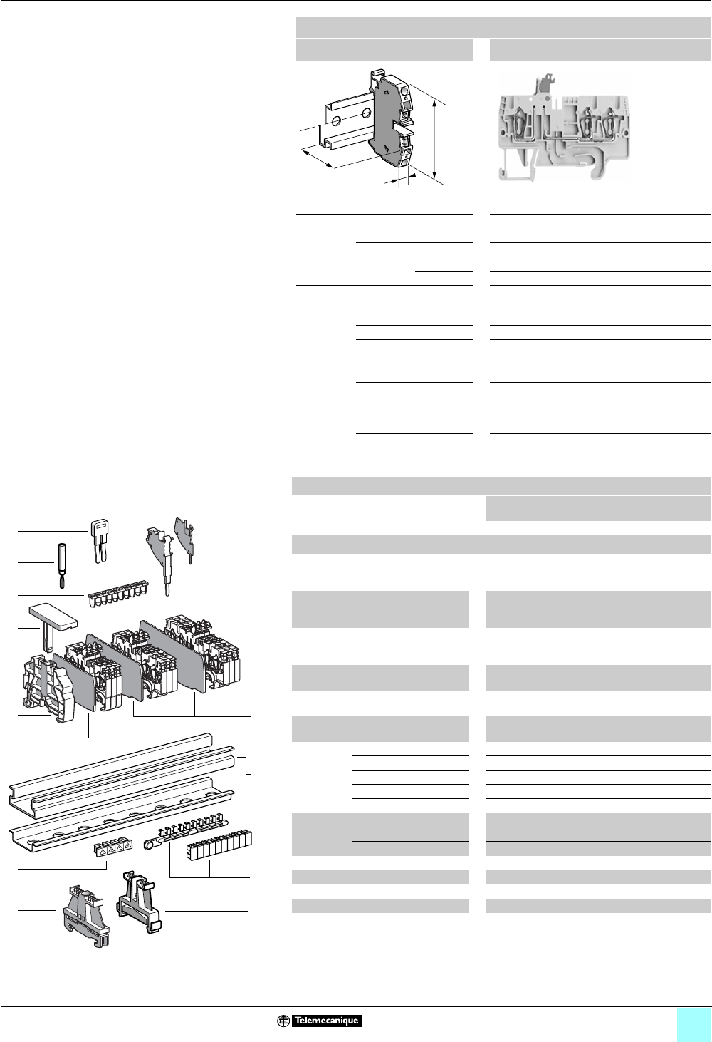
2/33
0
Terminal Blocks, Type AB1 0
Spring technology
Blade disconnect type
Clip-on mounting on 35 mm 1 7 rails
Nominal wire size 2.5 mm2
AB1RRNSC235U3
Approximate dimensions, in. (mm)
Length (a) 2.85 (72.4)
Width (b) 0.20 (5)
1Height (H)
with
1 rail 1.8 (45.6) + 0.38 (9.6) for open switch
7 rail 1.5 (38.1) + 0.38 (9.6) for open switch
Wire size, mm2
Stranded without
cable end
0.13–2.5
Stranded with cable end 0.5–2.5
Solid 0.13–4
Nominal electrical values
IEC/EN 60947-7-1 630 V / 6 kV / 3–20 A
UL File E164359
CCN XCFR2
24–12 AWG, 300 V, 19 A
CSA File 702070
Class 6228 01
24–12 AWG, 300 V, 20 A
UTE, category C —
VDE, group C 630 V / 20 A
Certifications See the tables beginning on page 1/10.
a
b
H
Terminal blocks
No.
points
Sold in
lots of
Catalog number Weight
oz (g)
Gray 3 100 AB1RRNSC235U3 0.33 (9.3)
Accessories
2 Plastic
end clamp
with screw
Width 0.3 in. (8 mm)
on 1 or 7 —100 AB1AB8P35 0.21 (5.9)
3Metal
end clamp
with screw
Width 0.3 in. (8 mm)
on 1 or 7—100 AB1AB8M35 0.52 (14.8)
4 Clip-on
plastic
end clamp
Width 0.3 in. (8 mm)
on 1 or 7—100 AB1AB8R35 0.21 (5.9)
5Marker tag holder
for clip-on plastic end clamp
—10 AB1SB4 0.11 (3.1)
6 End plate
thickness 0.06 in. (1.5 mm)
Gray 10 AB1RRNAC244GR 0.12 (3.4)
7Partition plate
thickness 0.06 in. (1.5 mm)
Gray —10 AB1RRNAS244GR 0.13 (3.6)
8 Insulated
jumper
2-pole — 10 AB1RRAL22 0.04 (1.1)
3-pole — 10 AB1RRAL23 0.06 (1.7)
4-pole — 10 AB1RRAL24 0.08 (2.2)
5-pole — 10 AB1RRAL25 0.10 (2.8)
10-pole — 20 AB1RRAL210 0.20 (5.6)
9Wire guide
entry strip
0.13–0.2 mm2White —100 AB1RRNGF01 0.03 (0.9)
0.25–0.5 mm2Gray —100 AB1RRNGF02 0.03 (0.9)
0.75–1 mm2Black —100 AB1RRNGF03 0.03 (0.9)
10 Modular test connector Gray — 10 AB1AT3 0.08 (2.4)
11 Modular test connector end plate —10 AB1AC3 0.01 (0.4)
12 Test plug Red — 10 AB1AT1 0.07 (1.9)
13 Terminal cover 410 AB1RRNCS2 0.01 (0.3)
14 Marking accessories See pages 5/2 and 5/3.
9
6
12
5
4
1
11
10
7
8
13
3
10
9
8
7
6
5
4
3
2
1
987654321
10
2
14
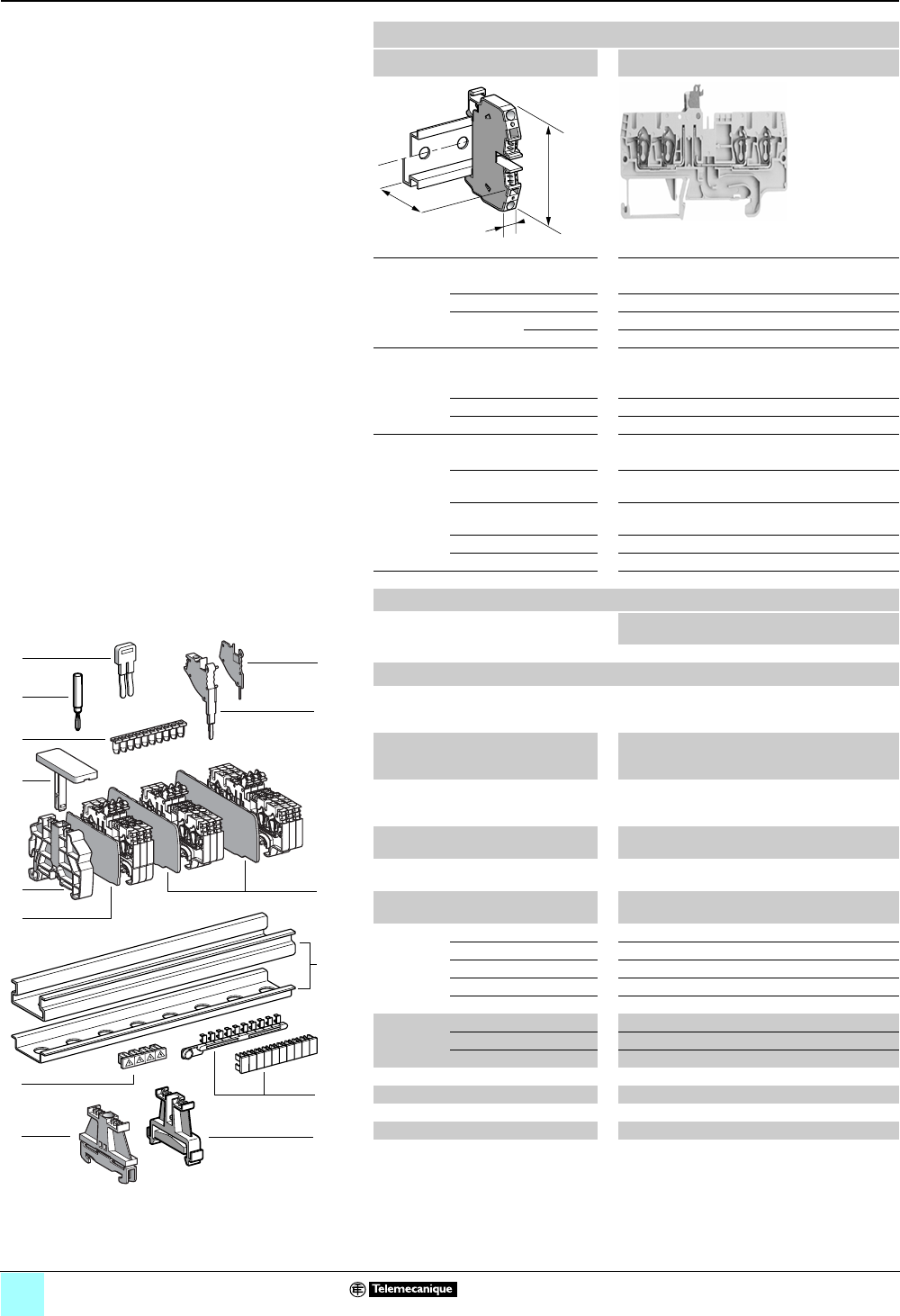
2/34
0
Terminal Blocks, Type AB1 0
Spring technology
Blade disconnect type
Clip-on mounting on 35 mm 1 7 rails
Nominal wire size 2.5 mm2
AB1RRNSC235U4
Approximate dimensions, in. (mm)
Length (a) 3.35 (85.1)
Width (b) 0.20 (5)
1Height (H)
with
1 rail 1.8 (45.6) + 0.38 (9.6) for open switch
7 rail 1.5 (38.1) + 0.38 (9.6) for open switch
Wire size, mm2
Stranded without
cable end
0.13–2.5
Stranded with cable end 0.5–2.5
Solid 0.13–4
Nominal electrical values
IEC/EN 60947-7-1 630 V / 6 kV / 3–20 A
UL File E164359
CCN XCFR2
24–12 AWG, 300 V, 19 A
CSA File 702070
Class 6228 01
24–12 AWG, 300 V, 20 A
UTE, category C —
VDE, group C 630 V / 20 A
Certifications See the tables beginning on page 1/10.
Terminal blocks
No.
points
Sold in
lots of
Catalog number Weight
oz (g)
Gray 4 100 AB1RRNSC235U4 0.39 (11.0)
Accessories
2 Plastic
end clamp
with screw
Width 0.3 in. (8 mm)
on 1 or 7 —100 AB1AB8P35 0.21 (5.9)
3Metal
end clamp
with screw
Width 0.3 in. (8 mm)
on 1 or 7—100 AB1AB8M35 0.52 (14.8)
4 Clip-on
plastic
end clamp
Width 0.3 in. (8 mm)
on 1 or 7—100 AB1AB8R35 0.21 (5.9)
5Marker tag holder
for clip-on plastic end clamp
—10 AB1SB4 0.11 (3.1)
6 End plate
thickness 0.06 in. (1.5 mm)
Gray 10 AB1RRNAC245GR 0.14 (3.9)
7Partition plate
thickness 0.06 in. (1.5 mm)
Gray —10 AB1RRNAS245GR 0.17 (4.8)
8 Insulated
jumper
2-pole — 10 AB1RRAL22 0.04 (1.1)
3-pole — 10 AB1RRAL23 0.06 (1.7)
4-pole — 10 AB1RRAL24 0.08 (2.2)
5-pole — 10 AB1RRAL25 0.10 (2.8)
10-pole — 20 AB1RRAL210 0.20 (5.6)
9Wire guide
entry strip
0.13–0.2 mm2White —100 AB1RRNGF01 0.03 (0.9)
0.25–0.5 mm2Gray —100 AB1RRNGF02 0.03 (0.9)
0.75–1 mm2Black —100 AB1RRNGF03 0.03 (0.9)
10 Modular test connector Gray — 10 AB1AT3 0.08 (2.4)
11 Modular test connector end plate —10 AB1AC3 0.01 (0.4)
12 Test plug Red — 10 AB1AT1 0.07 (1.9)
13 Terminal cover 410 AB1RRNCS2 0.01 (0.3)
14 Marking accessories See pages 5/2 and 5/3.
a
b
H
9
6
12
5
4
1
11
10
7
8
13
3
10
9
8
7
6
5
4
3
2
1
987654321
10
2
14
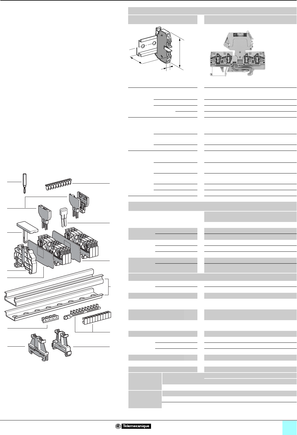
2/35
0
Terminal Blocks, Type AB1 0
Spring technology
Disconnect (removable carrier)
for diode or cylindrical fuse
Clip-on mounting on 35 mm 1 7 rails
Nominal wire size 4 mm2
AB1RRNSF435UGR
Approximate dimensions, in. (mm)
Length (a) 3.24 (82.2)
Width (b) 0.24 (6)
1Height (H)
with
1 rail 1.80 (45.65)
7 rail 1.50 (38.15)
Wire size, mm2
Stranded without
cable end
0.13–4
Stranded with
cable end
0.5–4
Solid 0.13–6
Nominal electrical values (1), (2)
IEC/EN 60947-7-1 500 V / 6 kV
UL File E164359
CCN XCFR2
Pending
CSA File 702070
Class 6228 01
Pending
UTE, category C —
VDE, group C —
Certifications See the tables beginning on page 1/10.
Terminal Blocks (3)
No.
points
Sold in
lots of
Catalog number Weight
oz (g)
Gray 4100 AB1RRNSF435UGR 0.46 (13.1)
8Removable
carrier
For diode or resistor —100 AB1SV1 0.16 (4.5)
With diode 1N4007.1 —100 AB1SV2 0.17 (4.7)
Removable
carrier (for
5x20 fuse)
For fuse only —100 AB1SF520 0.16 (4.4)
With 24 V red LED —100 AB1SF520B 0.17 (4.7)
With 220 V red LED —100 AB1SF520M 0.17 (4.7)
Removable
carrier
and pivoting
For 5 x 20 fuse —100 AB1SF520D 0.21 (6.0)
For 6.3 x 32 fuse —100 AB1SF6332D 0.29 (8.2)
Accessories
2 End clamp +
screw (4)
Plastic — 100 AB1AB8P35 0.21 (5.9)
3Metal — 100 AB1AB8M35 0.52 (14.8)
4Clip-on plastic end clamp (4) —100 AB1AB8R35 0.21 (5.9)
5 Marker tag holder
for clip-on plastic end clamp
—10AB1SB4 0.11 (3.1)
6End plate
thickness 0.06 in. (1.5 mm)
Gray —10 AB1RRNAC444GR 0.13 (3.8)
7 Partition plate
thickness 0.06 in. (1.5 mm)
Gray — 10 AB1RRNAS444GR 0.17 (4.8)
9Insulated jumper (5) ——AB1RRAL4• —
10 Wire guide
entry strip
0.13–0.2 mm2 White — 100 AB1RRNGF11 0.03 (0.8)
0.25–0.5 mm2 Gray — 100 AB1RRNGF22 0.03 (0.8)
0.75–1 mm2 Black — 100 AB1RRNGF33 0.03 (0.8)
11 Test plug Red —50 AB1AT1 0.07 (1.9)
12 Terminal cover 4100AB1RRCS4 0.01 (0.4)
13 Marking accessories See pages 5/2 and 5/3.
Carrier
characteristics
Nominal voltage
(Power loss 1.5 W)
Position of terminal block
End Juxtaposed
250 V 6.3 A 4 A
Blown fuse
indicator
characteristics
Catalog number Nominal voltage Current consumption
AB1SF520B 24 V 10.3 mA
AB1SF520M 220–250 V 0.3 mA
a
b
H
8
11
1
12
3
10
9
8
7
6
5
4
3
2
1
987654321
10
2
6
10
9
13
5
4
7
Table Footnotes:
(1) The voltage/current carrying capacity is determined by the
component (fuse and/or diode) used.
(2) Repetitive peak reverse voltage for diodes is 1000 V.
(3) Fuses and diodes not included, except for AB1SV2.
(4) Width 0.3 in. (8 mm) on 1 or 7
(5) Replace the • symbol with the number of poles (2, 3, 4, 5, or
10), for example, AB1RRAL45 (5-pole).
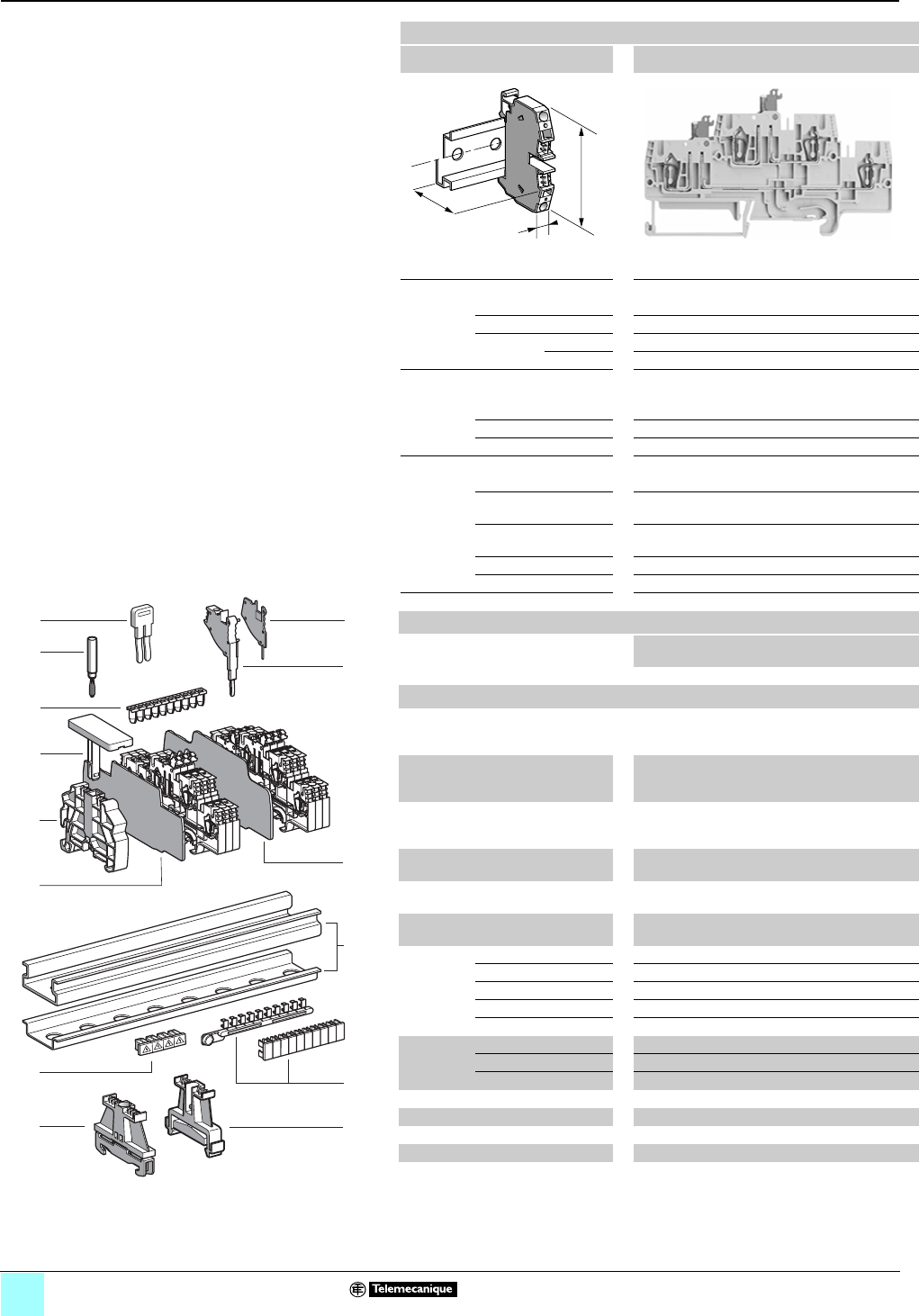
2/36
0
Terminal Blocks, Type AB1 0
Spring technology
Double deck blade disconnect type
Clip-on mounting on 35 mm 1 7 rails
Nominal wire size 2.5 mm2
AB1RRNSCE235U4
Approximate dimensions, in. (mm)
Length (a) 4.23 (107.5)
Width (b) 0.20 (5)
1Height (H)
with
1 rail 2.20 (55.9) + 0.38 (9.6) for open switch
7 rail 1.91 (48.5) + 0.38 (9.6) for open switch
Wire size, mm2
Stranded without
cable end
0.5–2.5
Stranded with cable end 0.5–2.5
Solid 0.5–4
Nominal electrical values
IEC/EN 60947-7-1 500 V / 8 kV / 3–19 A
UL File E164359
CCN XCFR2
24–12 AWG, 300 V, 19 A
CSA File 702070
Class 6228 01
24–12 AWG, 300 V, 19 A
UTE, category C —
VDE, group C 500 V / 19 A
Certifications See the tables beginning on page 1/10.
Terminal blocks
No.
points
Sold in
lots of
Catalog number Weight
oz (g)
Gray 2/2 50 AB1RRNSCE235U4 0.57 (16.2)
Accessories
2 Plastic
end clamp
with screw
Width 0.3 in. (8 mm)
on 1 or 7 —100 AB1AB8P35 0.21 (5.9)
3Metal
end clamp
with screw
Width 0.3 in. (8 mm)
on 1 or 7—100 AB1AB8M35 0.52 (14.8)
4 Clip-on
plastic
end clamp
Width 0.3 in. (8 mm)
on 1 or 7—100 AB1AB8R35 0.21 (5.9)
5Marker tag holder for
clip-on plastic end clamp
—10 AB1SB4 0.11 (3.1)
6 End plate
thickness 0.06 in. (1.5 mm)
Gray —10 AB1RRNACE246 0.20 (5.7)
7Partition plate
thickness 0.06 in. (1.5 mm)
Gray —10 AB1RRNASE246 0.35 (9.8)
8 Insulated
jumper
2-pole —10 AB1RRAL22 0.04 (1.1)
3-pole —10 AB1RRAL23 0.06 (1.7)
4-pole —10 AB1RRAL24 0.08 (2.2)
5-pole —10 AB1RRAL25 0.10 (2.8)
10-pole —20 AB1RRAL210 0.20 (5.6)
9Wire guide
entry strip
0.13–0.2 mm2White —100 AB1RRNGF01 0.03 (0.9)
0.25–0.5 mm2Gray —100 AB1RRNGF02 0.03 (0.9)
0.75–1 mm2Black —100 AB1RRNGF03 0.03 (0.9)
10 Modular test connector Gray —10 AB1AT3 0.08 (2.4)
11 Modular test connector end plate —10 AB1AC3 0.01 (0.4)
12 Test plug Red —10 AB1AT1 0.07 (1.9)
13 Terminal cover 410 AB1RRNCS2 0.01 (0.3)
14 Marking accessories See pages 5/2 and 5/3.
a
b
H
9
6
4
5
12
1
11
10
8
7
13
3
10
9
8
7
6
5
4
3
2
1
987654321
10
2
14
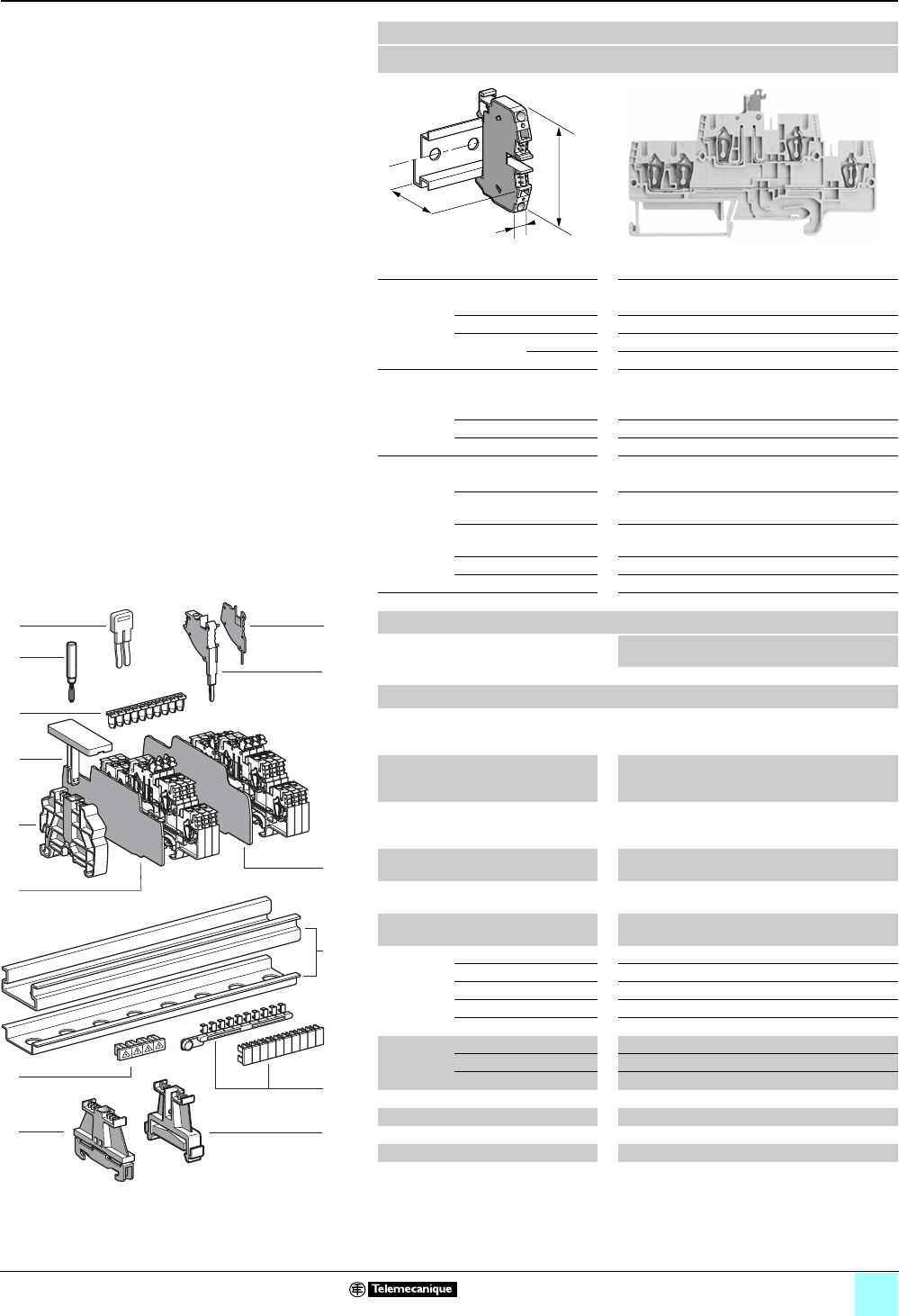
2/37
0
Terminal Blocks, Type AB1 0
Spring technology
Double deck blade disconnect type
Clip-on mounting on 35 mm 1 7 rails
Nominal wire size 2.5 mm2
AB1RRNSCE235U5
Approximate dimensions, in. (mm)
Length (a) 4.23 (107.5)
Width (b) 0.20 (5)
1Height (H)
with
1 rail 2.20 (55.9) + 0.38 (9.6) for open switch
7 rail 1.91 (48.5) + 0.38 (9.6) for open switch
Wire size, mm2
Stranded without
cable end
0.5–2.5
Stranded with cable end 0.5–2.5
Solid 0.5–4
Nominal electrical values
IEC/EN 60947-7-1 800 V / 8 kV / 3–20 A
UL File E164359
CCN XCFR2
24–12 AWG, 300 V, 19 A
CSA File 702070
Class 6228 01
24–12 AWG, 300 V, 20 A
UTE, category C —
VDE, group C 500 V / 20 A
Certifications See the tables beginning on page page 1/10.
Terminal blocks
No.
points
Sold in
lots of
Catalog number Weight
oz (g)
Gray 2/3 50 AB1RRNSCE235U5 0.56 (15.9)
Accessories
2Plastic
end clamp
with screw
Width 0.3 in. (8 mm)
on 1 or 7 —100 AB1AB8P35 0.21 (5.9)
3Metal
end clamp
with screw
Width 0.3 in. (8 mm)
on 1 or 7—100 AB1AB8M35 0.52 (14.8)
4Clip-on
plastic
end clamp
Width 0.3 in. (8 mm)
on 1 or 7—100 AB1AB8R35 0.21 (5.9)
5Marker tag holder
for clip-on plastic end clamp
—10 AB1SB4 0.11 (3.1)
6End plate
thickness 0.06 in. (1.5 mm)
Gray 10 AB1RRNACE246 0.20 (5.7)
7Partition plate
thickness 0.06 in. (1.5 mm)
Gray —10 AB1RRNASE246 0.35 (9.8)
8 Insulated
jumper
2-pole —10 AB1RRAL22 0.04 (1.1)
3-pole —10 AB1RRAL23 0.06 (1.7)
4-pole —10 AB1RRAL24 0.08 (2.2)
5-pole —10 AB1RRAL25 0.10 (2.8)
10-pole —20 AB1RRAL210 0.20 (5.6)
9Wire guide
entry strip
0.13–0.2 mm2White —100 AB1RRNGF01 0.03 (0.9)
0.25–0.5 mm2Gray —100 AB1RRNGF02 0.03 (0.9)
0.75–1 mm2Black —100 AB1RRNGF03 0.03 (0.9)
10 Modular test connector Gray —10 AB1AT3 0.08 (2.4)
11 Modular test connector end plate —10 AB1AC3 0.01 (0.4)
12 Test plug Red —10 AB1AT1 0.07 (1.9)
13 Terminal cover 410 AB1RRNCS2 0.01 (0.3)
14 Marking accessories See pages 5/2 and 5/3.
a
b
H
9
6
4
5
12
1
11
10
8
7
13
3
10
9
8
7
6
5
4
3
2
1
987654321
10
2
14
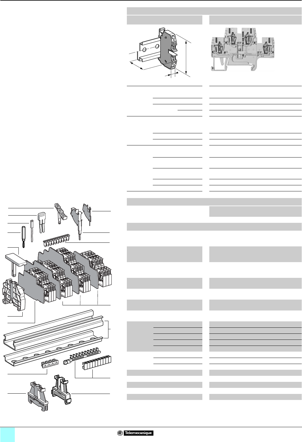
2/38
0
Terminal Blocks, Type AB1 0
Spring technology
Double deck
Clip-on mounting on 35 mm 1 7 rails
Nominal wire size 2.5 mm2
AB1RRNET235U4
Approximate dimensions, in. (mm)
Length (a) 3.24 (82.2)
Width (b) 0.20 (5)
1Height (H)
with
1 rail 2.20 (55.9)
7 rail 1.91 (48.4)
Wire size, mm2
Stranded without
cable end
0.13–2.5
Stranded with cable end 0.5–2.5
Solid 0.13–4
Nominal electrical values
IEC/EN 60947-7-1 500 V / 6 kV / 24 A
UL File E164359
CCN XCFR2
22–12 AWG, 300 V, 20 A
CSA File 702070
Class 6228 01
24–12 AWG, 300 V, 24 A
UTE, category C —
VDE, group C 500 V / 24 A
Certifications See the tables beginning on page 1/10.
Terminal blocks
No.
points
Sold in
lots of
Catalog number Weight
oz (g)
Gray 2/2 100 AB1RRNET235U4 0.40 (11.4)
Accessories
2Plastic
end clamp
with screw
Width 0.3 in. (8 mm)
on 1 or 7 —100AB1AB8P35 0.21 (5.9)
3Metal
end clamp
with screw
Width 0.3 in. (8 mm)
on 1 or 7—100 AB1AB8M35 0.52 (14.8)
4 Clip-on
plastic
end clamp
Width 0.3 in. (8 mm)
on 1 or 7—100AB1AB8R35 0.21 (5.9)
5Marker tag holder for
clip-on plastic end clamp
—10 AB1SB4 0.11 (3.1)
6 End plate
thickness 0.06 in. (1.5 mm)
Gray — 10 AB1RRNACE244 0.18 (4.6)
7Partition plate
thickness 0.06 in. (1.5 mm)
Gray —10 AB1RRNASE244 0.22 (5.5)
8Vertical
jumper
1-pole — 20 AB1RRAL1 0.03 (0.7)
9Insulated
jumper
2-pole —10 AB1RRAL22 0.04 (1.1)
3-pole —10 AB1RRAL23 0.06 (1.7)
4-pole —10 AB1RRAL24 0.08 (2.2)
5-pole —10 AB1RRAL25 0.10 (2.8)
10-pole —20 AB1RRAL210 0.20 (5.6)
10 Wire guide
entry strip
0.13–0.2 mm2White — 100 AB1RRNGF01 0.03 (0.9)
0.25–0.5 mm2Gray — 100 AB1RRNGF02 0.03 (0.9)
0.75–1 mm2Black — 100 AB1RRNGF03 0.03 (0.9)
11 Modular test connector —10 AB1AT3 0.08 (2.4)
12 Modular test connector end plate —10AB1AC3 0.01 (0.4)
13 Test plug Red —10 AB1AT1 0.07 (1.9)
14 Terminal cover 410AB1RRNCS2 0.01 (0.3)
15 Marker tag holder —100 AB1SB5 0.01 (0.4)
16 Marking accessories See pages 5/2 and 5/3.
a
b
H
13
4
6
8
5
1
12
11
10
7
9
15
14
3
10
9
8
7
6
5
4
3
2
1
987654321
10
2
16
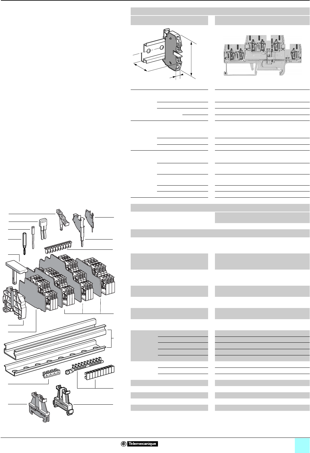
2/39
0
Terminal Blocks, Type AB1 0
Spring technology
Double deck
Clip-on mounting on 35 mm 1 7 rails
Nominal wire size 2.5 mm2
AB1RRNET235U6
Approximate dimensions, in. (mm)
Length (a) 4.23 (107.5)
Width (b) 0.20 (5)
1Height (H)
with
1 rail 2.20 (55.9)
7 rail 1.91 (48.4)
Wire size, mm2
Stranded without
cable end
0.13–2.5
Stranded with cable end 0.5–2.5
Solid 0.13–4
Nominal electrical values
IEC/EN 60947-7-1 500 V / 6 kV / 22 A
UL File E164359
CCN XCFR2
22–12 AWG, 300 V, 20 A
CSA File 702070
Class 6228 01
24–12 AWG, 300 V, 24 A
UTE, category C —
VDE, group C 500 V / 22 A
Certifications See the tables beginning on page 1/10.
Terminal blocks
No.
points
Sold in
lots of
Catalog number Weight
oz (g)
Gray 3/3 50 AB1RRNET235U6 0.69 (19.7)
Accessories
2Plastic
end clamp
with screw
Width 0.3 in. (8 mm)
on 1 or 7 —100 AB1AB8P35 0.21 (5.9)
3Metal
end clamp
with screw
Width 0.3 in. (8 mm)
on 1 or 7—100 AB1AB8M35 0.52 (14.8)
4 Clip-on
plastic
end clamp
Width 0.3 in. (8 mm)
on 1 or 7—100 AB1AB8R35 0.21 (5.9)
5Marker tag holder for
clip-on plastic end clamp
—10 AB1SB4 0.11 (3.1)
6 End plate
thickness 0.06 in. (1.5 mm)
Gray —10 AB1RRNACE246 0.20 (5.7)
7Partition plate
thickness 0.06 in. (1.5 mm)
Gray —10 AB1RRNASE246 0.35 (9.8)
8Vertical
jumper
1-pole —20 AB1RRAL1 0.03 (0.7)
9Insulated
jumper
2-pole —10 AB1RRAL22 0.04 (1.1)
3-pole —10 AB1RRAL23 0.06 (1.7)
4-pole —10 AB1RRAL24 0.08 (2.2)
5-pole —10 AB1RRAL25 0.10 (2.8)
10-pole —20 AB1RRAL210 0.20 (5.6)
10 Wire guide
entry strip
0.13–0.2 mm2White —100 AB1RRNGF01 0.03 (0.9)
0.25–0.5 mm2Gray —100 AB1RRNGF02 0.03 (0.9)
0.75–1 mm2Black —100 AB1RRNGF03 0.03 (0.9)
11 Modular test connector —10 AB1AT3 0.08 (2.4)
12 Modular test connector end plate —10 AB1AC3 0.01 (0.4)
13 Test plug Red —10 AB1AT1 0.07 (1.9)
14 Terminal cover 410 AB1RRNCS2 0.01 (0.3)
15 Marker tag holder —100 AB1SB5 0.01 (0.4)
16 Marking accessories See pages 5/2 and 5/3.
a
b
H
13
4
6
8
5
1
12
11
10
7
9
15
14
3
10
9
8
7
6
5
4
3
2
1
987654321
10
2
16
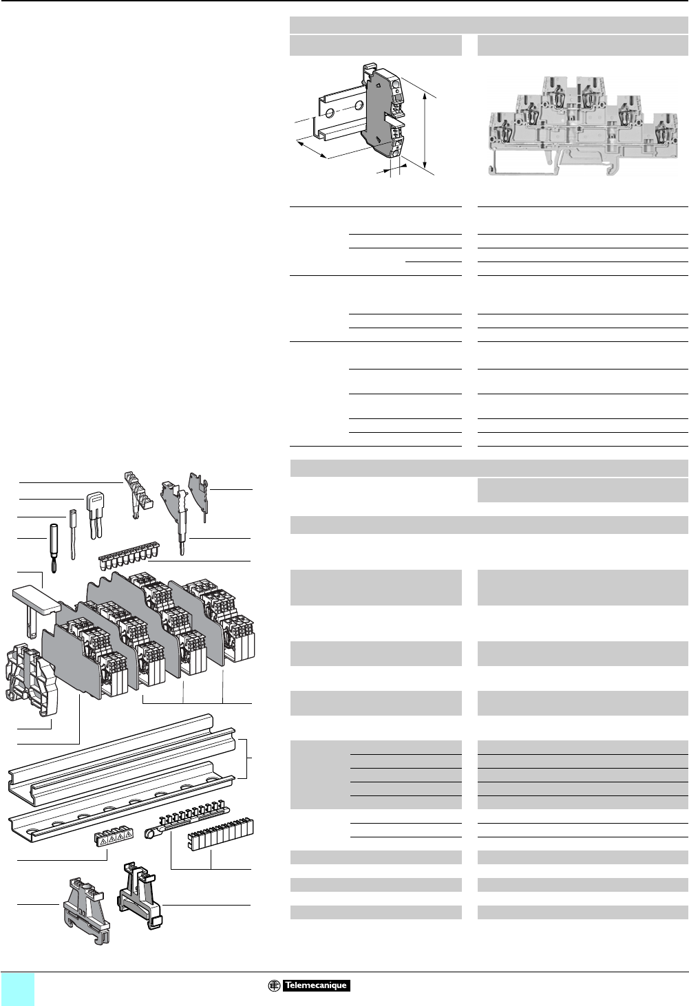
2/40
0
Terminal Blocks, Type AB1 0
Spring technology
Three Tier
Clip-on mounting on 35 mm 1 7 rails
Nominal wire size 2.5 mm2
AB1RRNET235T6
Approximate dimensions, in. (mm)
Length (a) 4.85 (123.1)
Width (b) 0.20 (5)
1Height (H)
with
1 rail 2.60 (66.2)
7 rail 2.31 (58.7)
Wire size, mm2
Stranded without
cable end
0.13–2.5
Stranded with cable end 0.5–2.5
Solid 0.13–4
Nominal electrical values
IEC/EN 60947-7-1 500 V / 6 kV / 20 A
UL File E164359
CCN XCFR2
22–12 AWG, 300 V, 20 A
CSA File 702070
Class 6228 01
24–12 AWG, 300 V, 24 A
UTE, category C —
VDE, group C 500 V / 20 A
Certifications See the tables beginning on page 1/10.
Terminal blocks
No.
points
Sold in
lots of
Catalog number Weight
oz (g)
Gray 2/2/2 50 AB1RRNET235T6 0.49 (14.0)
Accessories
2Plastic
end clamp
with screw
Width 0.3 in. (8 mm)
on 1 or 7 —100 AB1AB8P35 0.21 (5.9)
3Metal
end clamp
with screw
Width 0.3 in. (8 mm)
on 1 or 7—100 AB1AB8M35 0.52 (14.8)
4Clip-on
plastic
end clamp
Width 0.3 in. (8 mm)
on 1 or 7—100 AB1AB8R35 0.21 (5.9)
5Marker tag holder for
clip-on plastic end clamp
—10 AB1SB4 0.11 (3.1)
6End plate
thickness 0.06 in. (1.5 mm)
Gray —10 AB1RRNACTE246 0.27 (7.6)
7Partition plate
thickness 0.06 in. (1.5 mm)
Gray —10 AB1RRNASTE246 0.30 (8.6)
8 Vertical
jumper
1-pole —20 AB1RRAL1 0.03 (0.7)
9Insulated
jumper
2-pole —10 AB1RRAL22 0.04 (1.1)
3-pole —10 AB1RRAL23 0.06 (1.7)
4-pole —10 AB1RRAL24 0.08 (2.2)
5-pole —10 AB1RRAL25 0.10 (2.8)
10-pole —20 AB1RRAL210 0.20 (5.6)
10 Wire guide
entry strip
0.13–0.2 mm2White —100 AB1RRNGF01 0.03 (0.9)
0.25–0.5 mm2Gray —100 AB1RRNGF02 0.03 (0.9)
0.75–1 mm2Black —100 AB1RRNGF03 0.03 (0.9)
11 Modular test connector —10 AB1AT3 0.08 (2.4)
12 Modular test connector end plate —10 AB1AC3 0.01 (0.4)
13 Test plug Red —10 AB1AT1 0.07 (1.9)
14 Terminal cover 410 AB1RRNCS2 0.01 (0.3)
15 Marker tag holder —100 AB1SB6 0.01 (0.3)
16 Marking accessories See pages 5/2 and 5/3.
a
b
H
13
4
6
8
5
1
12
11
10
7
9
15
14
3
10
9
8
7
6
5
4
3
2
1
987654321
10
2
16
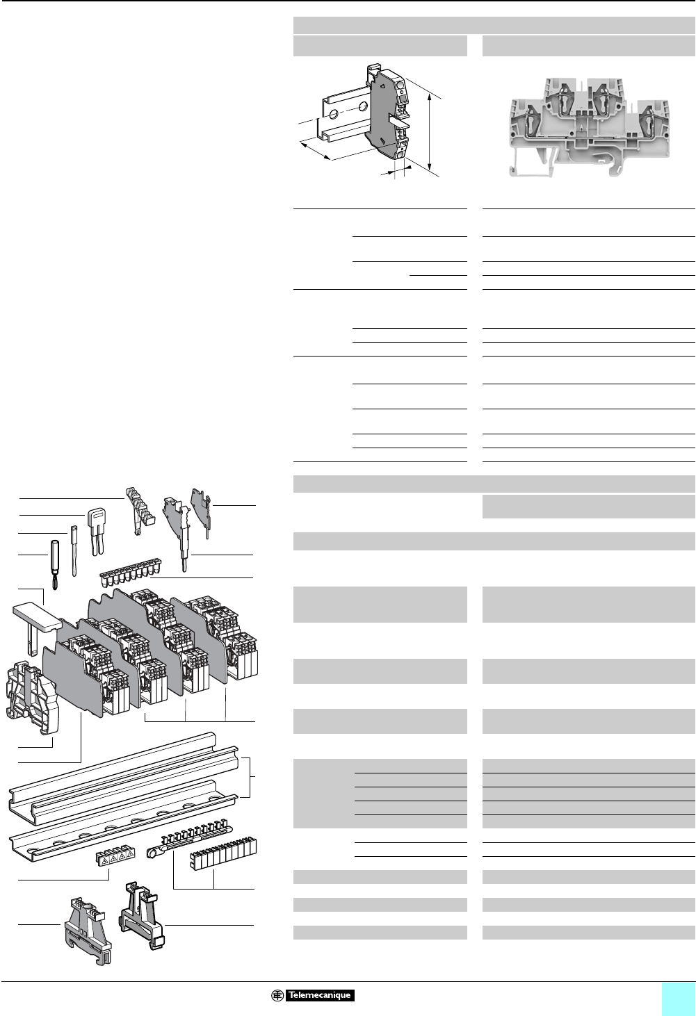
2/41
0
Terminal Blocks, Type AB1 0
Spring technology
Double deck
Clip-on mounting on 35 mm 1 7 rails
Nominal wire size 4 mm2
AB1RRNET435U4
Approximate dimensions, in. (mm)
Length (a) 3.55 (90.1)
Width (b) 0.24 (6)
1Height (H)
with
1 rail 2.20 (55.95)
7 rail 1.91 (48.45)
Wire size, mm2
Stranded without
cable end
0.13–4
Stranded with cable end 0.5–4
Solid 0.13–6
Nominal electrical values
IEC/EN 60947-7-1 500 V / 6 kV / 32 A
UL File E164359
CCN XCFR2
24–10 AWG, 300 V, 30 A
CSA File 702070
Class 6228 01
24–10 AWG, 300 V, 32 A
UTE, category C —
VDE, group C 500 V / 32 A
Certifications See the tables beginning on page 1/10.
Terminal blocks
No.
points
Sold in
lots of
Catalog number Weight
oz (g)
Gray 2/2 100 AB1RRNET435U4 0.57 (16.1)
Accessories
2Plastic
end clamp
with screw
Width 0.3 in. (8 mm)
on 1 or 7 —100 AB1AB8P35 0.21 (5.9)
3Metal
end clamp
with screw
Width 0.3 in. (8 mm)
on 1 or 7—100 AB1AB8M35 0.52 (14.8)
4 Clip-on
plastic
end clamp
Width 0.3 in. (8 mm)
on 1 or 7—100 AB1AB8R35 0.21 (5.9)
5Marker tag holder for
clip-on plastic end clamp
—10 AB1SB4 0.11 (3.1)
6 End plate
thickness 0.06 in. (1.5 mm)
Gray —10 AB1RRNACE444 0.18 (5.2)
7Partition plate
thickness 0.06 in. (1.5 mm)
Gray —10 AB1RRNASE444 0.22 (6.2)
8Vertical
jumper
1-pole —20 AB1RRAL1 0.03 (0.7)
9Insulated
jumper
2-pole —10 AB1RRAL42 0.06 (1.7)
3-pole —10 AB1RRAL43 0.09 (2.5)
4-pole —10 AB1RRAL44 0.12 (3.3)
5-pole —10 AB1RRAL45 0.14 (4.1)
10-pole —20 AB1RRAL410 0.29 (8.3)
10 Wire guide
entry strip
0.13–0.2 mm2White —100 AB1RRNGF11 0.03 (0.8)
0.25–0.5 mm2Gray —100 AB1RRNGF22 0.03 (0.8)
0.75–1 mm2Black —100 AB1RRNGF33 0.03 (0.8)
11 Modular test connector —10 AB1AT3 0.08 (2.4)
12 Modular test connector end plate —10 AB1AC3 0.01 (0.4)
13 Test plug Red —10 AB1AT1 0.07 (1.9)
14 Terminal cover 4100 AB1RRCS4 0.01 (0.4)
15 Marker tag holder —100 AB1SB5 0.01 (0.4)
16 Marking accessories See pages 5/2 and 5/3.
a
b
H
13
4
6
8
5
1
12
11
10
7
9
15
14
3
10
9
8
7
6
5
4
3
2
1
987654321
10
2
16
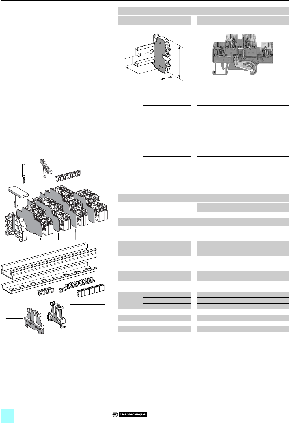
2/42
0
Terminal Blocks, Type AB1 0
Spring technology
Double deck—grounding block
Clip-on mounting on 35 mm 1 7 rails
Nominal wire size 2.5 mm2
AB1RRNETP235U4
Approximate dimensions, in. (mm)
Length (a) 3.24 (82.2)
Width (b) 0.20 (5)
1Height (H)
with
1 rail 2.20 (55.9)
7 rail 1.91 (48.4)
Wire size, mm2
Stranded without
cable end
0.13–2.5
Stranded with cable end 0.5–2.5
Solid 0.13–4
Nominal electrical values
IEC/EN 60947-7-1 500 V / 6 kV / 24 A
UL File E164359
CCN XCFR2
22–12 AWG, 600 V, 20 A
CSA File 702070
Class 6228 01
24–12 AWG, 600 V, 24 A
UTE, category C —
VDE, group C 500 V / 24 A
Certifications See the tables beginning on page 1/10.
a
b
H
Terminal blocks
No.
points
Sold in
lots of
Catalog number Weight
oz (g)
Gray 4100 AB1RRNETP235U4 0.49 (14.0)
Accessories
2 Plastic
end clamp
with screw
Width 0.3 in. (8 mm)
on 1 or 7 — 100 AB1AB8P35 0.21 (5.9)
3Metal
end clamp
with screw
Width 0.3 in. (8 mm)
on 1 or 7—100 AB1AB8M35 0.52 (14.8)
4 Clip-on
plastic
end clamp
Width 0.3 in. (8 mm)
on 1 or 7— 100 AB1AB8R35 0.21 (5.9)
5Marker tag holder for
clip-on plastic end clamp
—10 AB1SB4 0.11 (3.1)
6 End plate
thickness 0.06 in. (1.5 mm)
Gray — 10 AB1RRNACETP244 0.16 (4.6)
7Wire guide
entry strip
0.13–0.2 mm2White —100 AB1RRNGF01 0.03 (0.9)
0.25–0.5 mm2Gray —100 AB1RRNGF02 0.03 (0.9)
0.75–1 mm2Black —100 AB1RRNGF03 0.03 (0.9)
8 Test plug Red — 10 AB1AT1 0.07 (1.9)
9Terminal cover 410 AB1RRNCS2 0.01 (0.3)
10 Marker tag holder —100 AB1SB5 0.01 (0.4)
11 Marking accessories See pages 5/2 and 5/3.
4
5
7
8
1
10
6
9
3
10
9
8
7
6
5
4
3
2
1
987654321
10
2
11
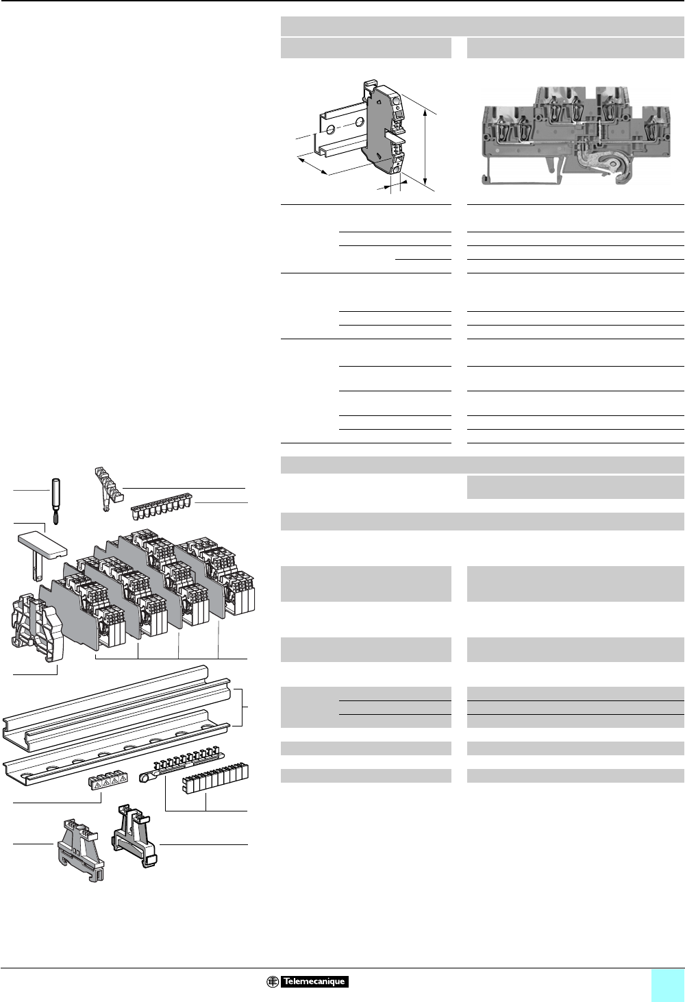
2/43
0
Terminal Blocks, Type AB1 0
Spring technology
Double deck—grounding block
Clip-on mounting on 35 mm 1 7 rails
Nominal wire size 2.5 mm2
AB1RRNETP235U6
Approximate dimensions, in. (mm)
Length (a) 4.23 (107.5)
Width (b) 0.20 (5)
1Height (H)
with
1 rail 2.20 (55.9)
7 rail 1.91 (48.4)
Wire size, mm2
Stranded without
cable end
0.13–2.5
Stranded with cable end 0.5–2.5
Solid 0.13–4
Nominal electrical values
IEC/EN 60947-7-1 500 V / 6 kV / 22 A
UL File E164359
CCN XCFR2
22–12 AWG, 600 V, 20 A
CSA File 702070
Class 6228 01
24–12 AWG, 600 V, 24 A
UTE, category C —
VDE, group C 500 V / 22 A
Certifications See the tables beginning on page 1/10.
a
b
H
Terminal blocks
No.
points
Sold in
lots of
Catalog number Weight
oz (g)
Gray 650 AB1RRNETP235U6 0.69 (19.7)
Accessories
2Plastic
end clamp
with screw
Width 0.3 in. (8 mm)
on 1 or 7 —100 AB1AB8P35 0.21 (5.9)
3Metal
end clamp
with screw
Width 0.3 in. (8 mm)
on 1 or 7—100 AB1AB8M35 0.52 (14.8)
4 Clip-on
plastic
end clamp
Width 0.3 in. (8 mm)
on 1 or 7—100 AB1AB8R35 0.21 (5.9)
5Marker tag holder for
clip-on plastic end clamp
—10 AB1SB4 0.11 (3.1)
6 End plate
thickness 0.06 in. (1.5 mm)
Gray —10 AB1RRNACETP246 0.20 (5.7)
7Wire guide
entry strip
0.13–0.2 mm2White —100 AB1RRNGF01 0.03 (0.9)
0.25–0.5 mm2Gray —100 AB1RRNGF02 0.03 (0.9)
0.75–1 mm2Black —100 AB1RRNGF03 0.03 (0.9)
8 Test plug Red —10 AB1AT1 0.07 (1.9)
9Terminal cover 410 AB1RRNCS2 0.01 (0.3)
10 Marker tag holder —100 AB1SB5 0.01 (0.4)
11 Marking accessories See pages 5/2 and 5/3.
4
5
7
8
1
10
6
9
3
10
9
8
7
6
5
4
3
2
1
987654321
10
2
11
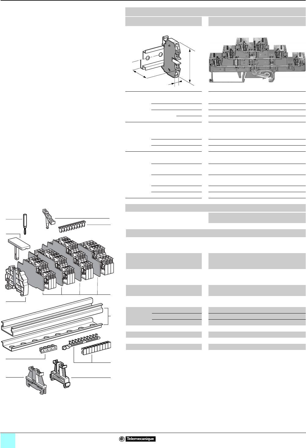
2/44
0
Terminal Blocks, Type AB1 0
Spring technology
Three tier—grounding block
Clip-on mounting on 35 mm 1 7 rails
Nominal wire size 2.5 mm2
AB1RRNETP235T6
Approximate dimensions, in. (mm)
Length (a) 4.85 (123.1)
Width (b) 0.20 (5)
1Height (H)
with
1 rail 2.61 (66.2)
7 rail 2.31 (58.7)
Wire size, mm2
Stranded without
cable end
0.13–2.5
Stranded with cable end 0.5–2.5
Solid 0.13–4
Nominal electrical values
IEC/EN 60947-7-1 500 V / 6 kV / 20 A
UL File E164359
CCN XCFR2
22–12 AWG, 600 V, 20 A
CSA File 702070
Class 6228 01
24–12 AWG, 600 V, 24 A
UTE, category C —
VDE, group C 500 V / 20 A
Certifications See the tables beginning on page 1/10.
Terminal blocks
No.
points
Sold in
lots of
Catalog number Weight
oz (g)
Gray 650 AB1RRNETP235T6 0.78 (22.2)
Accessories
2 Plastic
end clamp
with screw
Width 0.3 in. (8 mm)
on 1 or 7 —100 AB1AB8P35 0.21 (5.9)
3Metal
end clamp
with screw
Width 0.3 in. (8 mm)
on 1 or 7—100 AB1AB8M35 0.52 (14.8)
4 Clip-on
plastic
end clamp
Width 0.3 in. (8 mm)
on 1 or 7—100 AB1AB8R35 0.21 (5.9)
5Marker tag holder for
clip-on plastic end clamp
—10 AB1SB4 0.11 (3.1)
6 End plate
thickness 0.06 in. (1.5 mm)
Gray —10 AB1RRNACTETP246 0.27 (7.6)
7Wire guide
entry strip
0.13–0.2 mm2White —100 AB1RRNGF01 0.03 (0.9)
0.25–0.5 mm2Gray —100 AB1RRNGF02 0.03 (0.9)
0.75–1 mm2Black —100 AB1RRNGF03 0.03 (0.9)
8 Test plug Red —10 AB1AT1 0.07 (1.9)
9Terminal cover 410 AB1RRNCS2 0.01 (0.3)
10 Marker tag holder —100 AB1SB6 0.01 (0.3)
11 Marking accessories See pages 5/2 and 5/3.
a
b
H
4
5
7
8
1
10
6
9
3
10
9
8
7
6
5
4
3
2
1
987654321
10
2
11
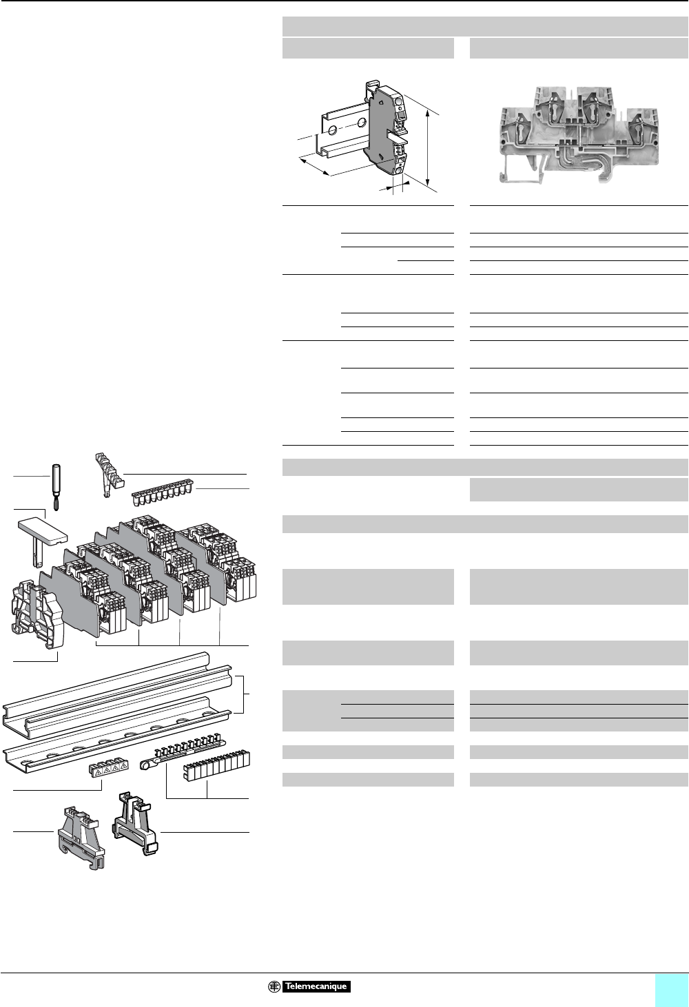
2/45
0
Terminal Blocks, Type AB1 0
Spring technology
Double deck
Clip-on mounting on 35 mm 1 7 rails
Nominal wire size 4 mm2
AB1RRNETP435U4
Approximate dimensions, in. (mm)
Length (a) 3.55 (90.1)
Width (b) 0.24 (6)
1Height (H)
with
1 rail 2.20 (55.95)
7 rail 1.91 (48.45)
Wire size, mm2
Stranded without
cable end
0.13–4
Stranded with cable end 0.5–4
Solid 0.13–6
Nominal electrical values
IEC/EN 60947-7-1 500 V / 6 kV / 32 A
UL File E164359
CCN XCFR2
24–10 AWG, 600 V, 30 A
CSA File 702070
Class 6228 01
24–10 AWG, 600 V, 32 A
UTE, category C —
VDE, group C 500 V / 32 A
Certifications See the tables beginning on page 1/10.
a
b
H
Terminal blocks
No.
points
Sold in
lots of
Catalog number Weight
oz (g)
Gray 4100 AB1RRNETP435U4 0.66 (18.7)
Accessories
2Plastic
end clamp
with screw
Width 0.3 in. (8 mm)
on 1 or 7 —100 AB1AB8P35 0.21 (5.9)
3Metal
end clamp
with screw
Width 0.3 in. (8 mm)
on 1 or 7—100 AB1AB8M35 0.52 (14.8)
4 Clip-on
plastic
end clamp
Width 0.3 in. (8 mm)
on 1 or 7—100 AB1AB8R35 0.21 (5.9)
5Marker tag holder for
clip-on plastic end clamp
—10 AB1SB4 0.11 (3.1)
6 End plate
thickness 0.06 in. (1.5 mm)
Gray —10 AB1RRNACETP444 0.18 (5.2)
7Wire guide
entry strip
0.13–0.2 mm2White —100 AB1RRNGF11 0.03 (0.8)
0.25–0.5 mm2Gray —100 AB1RRNGF22 0.03 (0.8)
0.75–1 mm2Black —100 AB1RRNGF33 0.03 (0.8)
8 Test plug Red —10 AB1AT1 0.07 (1.9)
9Terminal cover 4100 AB1RRCS4 0.01 (0.4)
10 Marker tag holder —100 AB1SB5 0.01 (0.4)
11 Marking accessories See pages 5/2 and 5/3.
4
5
7
8
1
10
6
9
3
10
9
8
7
6
5
4
3
2
1
987654321
10
2
11
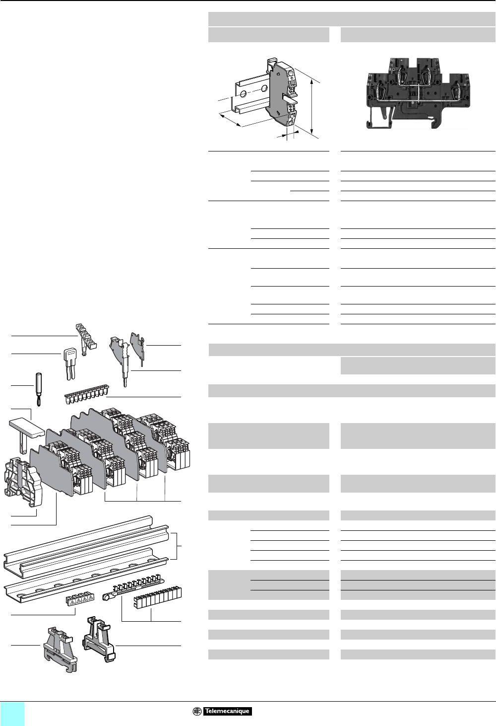
2/46
0
Terminal Blocks, Type AB1 0
Spring technology
Double deck, with vertical connection
Clip-on mounting on 35 mm 1 7 rails
Nominal wire size 2.5 mm2
AB1RRNETV235U4
Approximate dimensions, in. (mm)
Length (a) 3.24 (82.2)
Width (b) 0.20 (5)
1Height (H)
with
1 rail 2.20 (55.9)
7 rail 1.91 (48.4)
Wire size, mm2
Stranded without
cable end
0.13–2.5
Stranded with cable end 0.5–2.5
Solid 0.13–4
Nominal electrical values
IEC/EN 60947-7-1 500 V / 6 kV / 24 A
UL File E164359
CCN XCFR2
22–12 AWG, 600 V, 20 A
CSA File 702070
Class 6228 01
22–12 AWG, 600 V, 24 A
UTE, category C —
VDE, group C 500 V / 24 A
Certifications See the tables beginning on page 1/10.
Terminal blocks
No.
points
Sold in
lots of
Catalog number Weight
oz (g)
Gray 4100 AB1RRNETV235U4 0.41 (11.7)
Accessories
2Plastic
end clamp
with screw
Width 0.3 in. (8 mm)
on 1 or 7 —100 AB1AB8P35 0.21 (5.9)
3Metal
end clamp
with screw
Width 0.3 in. (8 mm)
on 1 or 7—100 AB1AB8M35 0.52 (14.8)
4Clip-on
plastic
end clamp
Width 0.3 in. (8 mm)
on 1 or 7—100 AB1AB8R35 0.21 (5.9)
5Marker tag holder for
clip-on plastic end clamp
—10 AB1SB4 0.11 (3.1)
6End plate
thickness 0.06 in. (1.5 mm)
Gray —10 AB1RRNACE244 0.16 (4.6)
7Partition plate Gray —10 AB1RRNASE244 0.19 (5.5)
8 Insulated
jumper
2-pole —10 AB1RRAL22 0.04 (1.1)
3-pole —10 AB1RRAL23 0.06 (1.7)
4-pole —10 AB1RRAL24 0.08 (2.2)
5-pole —10 AB1RRAL25 0.10 (2.8)
10-pole —20 AB1RRAL210 0.20 (5.6)
9Wire guide
entry strip
0.13–0.2 mm2White —100 AB1RRNGF01 0.03 (0.9)
0.25–0.5 mm2Gray —100 AB1RRNGF02 0.03 (0.9)
0.75–1 mm2Black —100 AB1RRNGF03 0.03 (0.9)
10 Modular test connector —10 AB1AT3 0.08 (2.4)
11 Modular test connector end plate —10 AB1AC3 0.01 (0.4)
12 Test plug Red —10 AB1AT1 0.07 (1.9)
13 Terminal cover 410 AB1RRNCS2 0.01 (0.3)
14 Marker tag holder —100 AB1SB5 0.01 (0.4)
15 Marking accessories See pages 5/2 and 5/3.
a
b
H
4
5
6
12
1
11
10
9
14
8
7
13
3
10
9
8
7
6
5
4
3
2
1
987654321
10
2
15

2/47
0
Terminal Blocks, Type AB1 0
Spring technology
Double deck, with vertical connection
Clip-on mounting on 35 mm 1 7 rails
Nominal wire size 2.5 mm2
AB1RRNETV235U6
Approximate dimensions, in. (mm)
Length (a) 4.23 (107.5)
Width (b) 0.20 (5)
1Height (H)
with
1 rail 2.20 (55.9)
7 rail 1.91 (48.4)
Wire size, mm2
Stranded without
cable end
0.13–2.5
Stranded with cable end 0.5–2.5
Solid 0.13–4
Nominal electrical values
IEC/EN 60947-7-1 500 V / 6 kV / 22 A
UL File E164359
CCN XCFR2
22–12 AWG, 600 V, 20 A
CSA File 702070
Class 6228 01
22–12 AWG, 600 V, 24 A
UTE, category C —
VDE, group C 500 V / 22 A
Certifications See the tables beginning on page 1/10.
Terminal blocks
No.
points
Sold in
lots of
Catalog number Weight
oz (g)
Gray 650AB1RRNETV235U6 0.61 (17.2)
Accessories
2 Plastic
end clamp
with screw
Width 0.3 in. (8 mm)
on 1 or 7 —100 AB1AB8P35 0.21 (5.9)
3Metal
end clamp
with screw
Width 0.3 in. (8 mm)
on 1 or 7—100 AB1AB8M35 0.52 (14.8)
4 Clip-on
plastic
end clamp
Width 0.3 in. (8 mm)
on 1 or 7—100 AB1AB8R35 0.21 (5.9)
5Marker tag holder for
clip-on plastic end clamp
—10 AB1SB4 0.11 (3.1)
6 End plate
thickness 0.06 in. (1.5 mm)
Gray —10 AB1RRNACE246 0.20 (5.7)
7Partition plate Gray 10 AB1RRNASE246 0.35 (9.8)
8 Insulated
jumper
2-pole —10 AB1RRAL22 0.04 (1.1)
3-pole —10 AB1RRAL23 0.06 (1.7)
4-pole —10 AB1RRAL24 0.08 (2.2)
5-pole —10 AB1RRAL25 0.10 (2.8)
10-pole —20 AB1RRAL210 0.20 (5.6)
9Wire guide
entry strip
0.13–0.2 mm2White —100 AB1RRNGF01 0.03 (0.9)
0.25–0.5 mm2Gray —100 AB1RRNGF02 0.03 (0.9)
0.75–1 mm2Black —100 AB1RRNGF03 0.03 (0.9)
10 Modular test connector —10 AB1AT3 0.08 (2.4)
11 Modular test connector end plate —10 AB1AC3 0.01 (0.4)
12 Test plug Red —10 AB1AT1 0.07 (1.9)
13 Terminal cover 410 AB1RRNCS2 0.01 (0.3)
14 Marker tag holder —100 AB1SB5 0.01 (0.4)
15 Marking accessories See pages 5/2 and 5/3.
a
b
H
4
5
6
12
1
11
10
9
14
8
7
13
3
10
9
8
7
6
5
4
3
2
1
987654321
10
2
15
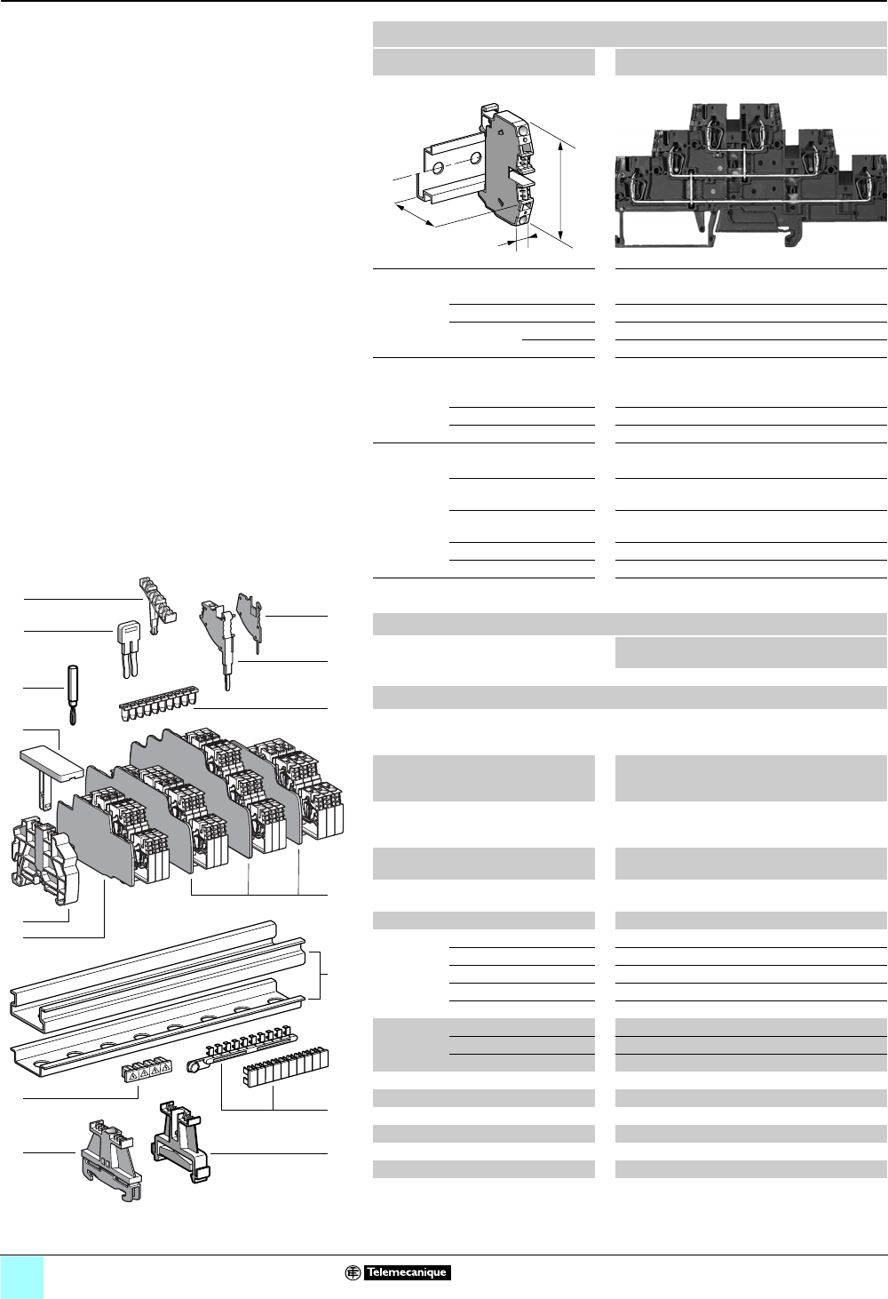
2/48
0
Terminal Blocks, Type AB1 0
Spring technology
Double deck, with vertical connection
Clip-on mounting on 35 mm 1 7 rails
Nominal wire size 2.5 mm2
AB1RRNETV235T6
Approximate dimensions, in. (mm)
Length (a) 4.85 (123.1)
Width (b) 0.20 (5)
1Height (H)
with
1 rail 2.61 (66.2)
7 rail 2.31 (58.7)
Wire size, mm2
Stranded without
cable end
0.13–2.5
Stranded with cable end 0.5–2.5
Solid 0.13–4
Nominal electrical values
IEC/EN 60947-7-1 500 V / 6 kV / 20 A
UL File E164359
CCN XCFR2
22–12 AWG, 600 V, 20 A
CSA File 702070
Class 6228 01
22–12 AWG, 600 V, 24 A
UTE, category C —
VDE, group C 500 V / 20 A
Certifications See the tables beginning on page 1/10.
Terminal blocks
No.
points
Sold in
lots of
Catalog number Weight
oz (g)
Gray 650AB1RRNETV235T6 0.72 (20.3)
Accessories
2 Plastic
end clamp
with screw
Width 0.3 in. (8 mm)
on 1 or 7 —100 AB1AB8P35 0.21 (5.9)
3Metal
end clamp
with screw
Width 0.3 in. (8 mm)
on 1 or 7—100 AB1AB8M35 0.52 (14.8)
4 Clip-on
plastic
end clamp
Width 0.3 in. (8 mm)
on 1 or 7—100 AB1AB8R35 0.21 (5.9)
5Marker tag holder for
clip-on plastic end clamp
—10 AB1SB4 0.11 (3.1)
6 End plate
thickness 0.06 in. (1.5 mm)
Gray —10 AB1RRNACTE246 0.27 (7.6)
7Partition plate Gray 10 AB1RRNASTE246 0.30 (8.6)
8 Insulated
jumper
2-pole —10 AB1RRAL22 0.04 (1.1)
3-pole —10 AB1RRAL23 0.06 (1.7)
4-pole —10 AB1RRAL24 0.08 (2.2)
5-pole —10 AB1RRAL25 0.10 (2.8)
10-pole —20 AB1RRAL210 0.20 (5.6)
9Wire guide
entry strip
0.13–0.2 mm2White —100 AB1RRNGF01 0.03 (0.9)
0.25–0.5 mm2Gray —100 AB1RRNGF02 0.03 (0.9)
0.75–1 mm2Black —100 AB1RRNGF03 0.03 (0.9)
10 Modular test connector —10 AB1AT3 0.08 (2.4)
11 Modular test connector end plate —10 AB1AC3 0.01 (0.4)
12 Test plug Red —10 AB1AT1 0.07 (1.9)
13 Terminal cover 4100 AB1RRNCS2 0.01 (0.3)
14 Marker tag holder —100 AB1SB6 0.01 (0.3)
15 Marking accessories See pages 5/2 and 5/3.
a
b
H
4
5
6
12
1
11
10
9
14
8
7
13
3
10
9
8
7
6
5
4
3
2
1
987654321
10
2
15
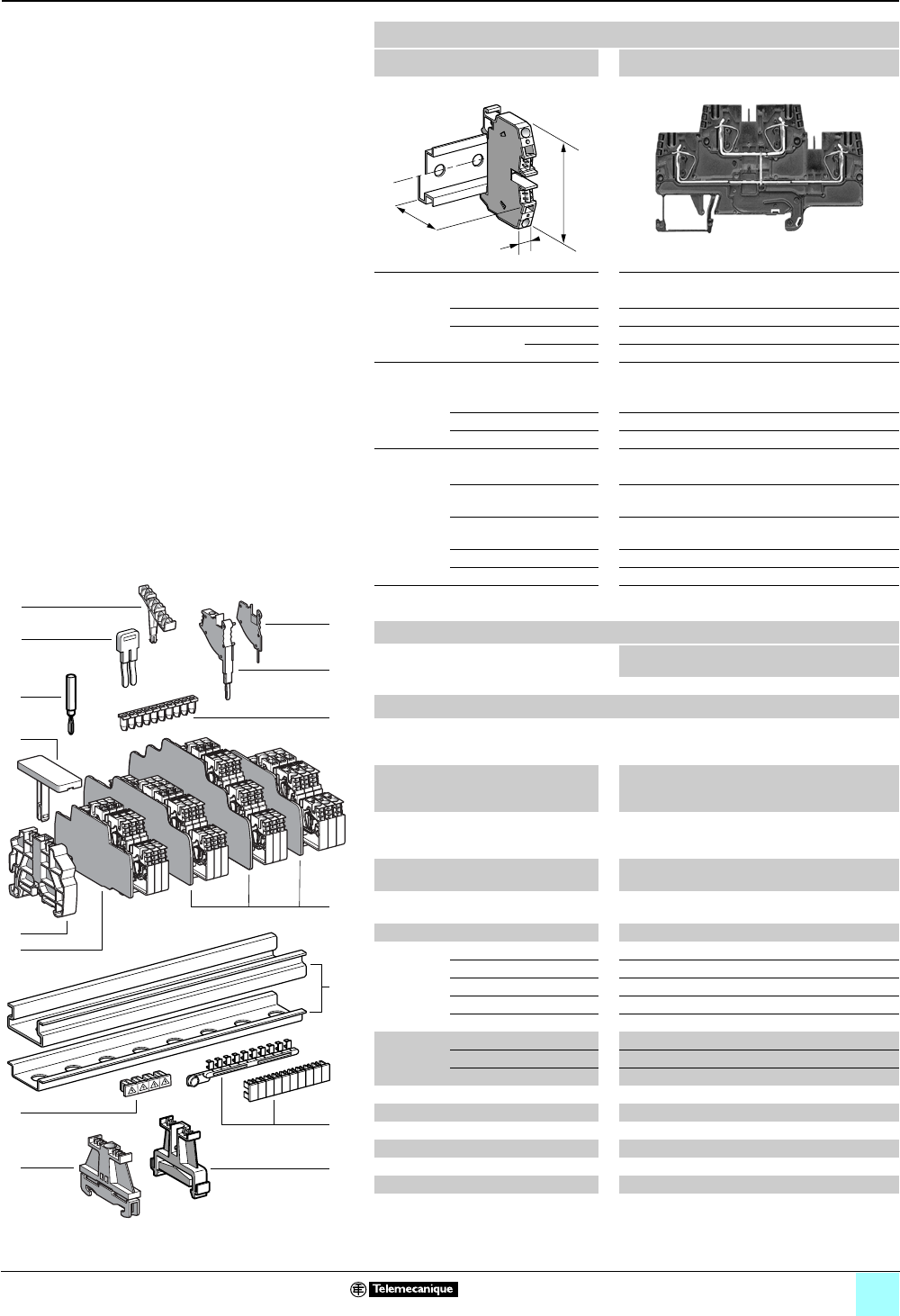
2/49
0
Terminal Blocks, Type AB1 0
Spring technology
Double deck, with vertical connection
Clip-on mounting on 35 mm 1 7 rails
Nominal wire size 4 mm2
AB1RRNETV435U4
Approximate dimensions, in. (mm)
Length (a) 3.55 (90.1)
Width (b) 0.24 (6)
1Height (H)
with
1 rail 2.20 (55.95)
7 rail 1.91 (48.45)
Wire size, mm2
Stranded without
cable end
0.13–4
Stranded with cable end 0.5–4
Solid 0.13–6
Nominal electrical values
IEC/EN 60947-7-1 500 V / 6 kV / 32 A
UL File E164359
CCN XCFR2
24–10 AWG, 600 V, 30 A
CSA File 702070
Class 6228 01
24–10 AWG, 300 V, 32 A
UTE, category C —
VDE, group C 500 V / 32 A
Certifications See the tables beginning on page 1/10.
Terminal blocks
No.
points
Sold in
lots of
Catalog number Weight
oz (g)
Gray 4100AB1RRNETV435U4 0.59 (16.6)
Accessories
2 Plastic
end clamp
with screw
Width 0.3 in. (8 mm)
on 1 or 7—100 AB1AB8P35 0.21 (5.9)
3Metal
end clamp
with screw
Width 0.3 in. (8 mm)
on 1 or 7—100 AB1AB8M35 0.52 (14.8)
4 Clip-on
plastic
end clamp
Width 0.3 in. (8 mm)
on 1 or 7—100 AB1AB8R35 0.21 (5.9)
5Marker tag holder for
clip-on plastic end clamp
—10 AB1SB4 0.11 (3.1)
6End plate
thickness 0.06 in. (1.5 mm)
Gray —10 AB1RRNACE444 0.18 (5.2)
7Partition plate Gray —10 AB1RRNASE444 0.22 (6.2)
8 Insulated
jumper
2-pole —10 AB1RRAL42 0.06 (1.7)
3-pole —10 AB1RRAL43 0.09 (2.5)
4-pole —10 AB1RRAL44 0.12 (3.3)
5-pole —10 AB1RRAL45 0.14 (4.1)
10-pole —20 AB1RRAL410 0.29 (8.3)
9Wire guide
entry strip
0.13–0.2 mm2White —100 AB1RRNGF11 0.03 (0.8)
0.25–0.5 mm2Gray —100 AB1RRNGF22 0.03 (0.8)
0.75–1 mm2Black —100 AB1RRNGF33 0.03 (0.8)
10 Modular test connector —10 AB1AT3 0.08 (2.4)
11 Modular test connector end plate —10 AB1AC3 0.01 (0.4)
12 Test plug Red —10 AB1AT1 0.07 (1.9)
13 Terminal cover 4100 AB1RRCS4 0.01 (0.4)
14 Marker tag holder —100 AB1SB5 0.01 (0.4)
15 Marking accessories See pages 5/2 and 5/3.
a
b
H
4
5
6
12
1
11
10
9
14
8
7
13
3
10
9
8
7
6
5
4
3
2
1
987654321
10
2
15

3/0

3/1
Contents
0
3 - Terminal Blocks, Type AB1
Screw Clamp Technology
Page
Selection guide . . . . . . . . . . . . . . . . . . . . . . . . . . . . . . . . . . 3/2
Passthrough type terminal blocks . . . . . . . . . . . . . . 3/4
Grounding type terminal blocks . . . . . . . . . . . . . . . 3/12
Disconnect type terminal blocks . . . . . . . . . . . . . . 3/18
Component type terminal blocks . . . . . . . . . . . . . . 3/19
Fuse blocks . . . . . . . . . . . . . . . . . . . . . . . . . . . . . . . . . . . 3/20
Screw/slip-on type terminal blocks . . . . . . . . . . . . 3/23
Double deck terminal blocks . . . . . . . . . . . . . . . . . . 3/24
Terminal blocks for proximity sensors . . . . . . . . 3/27
Multifunction terminal blocks . . . . . . . . . . . . . . . . . 3/32
Terminal blocks for neutral conductors . . . . . . . 3/36
Lug-lug type terminal blocks . . . . . . . . . . . . . . . . . . 3/39
Lug-clamp type terminal blocks . . . . . . . . . . . . . . . 3/42
Miniature terminal blocks . . . . . . . . . . . . . . . . . . . . . 3/45
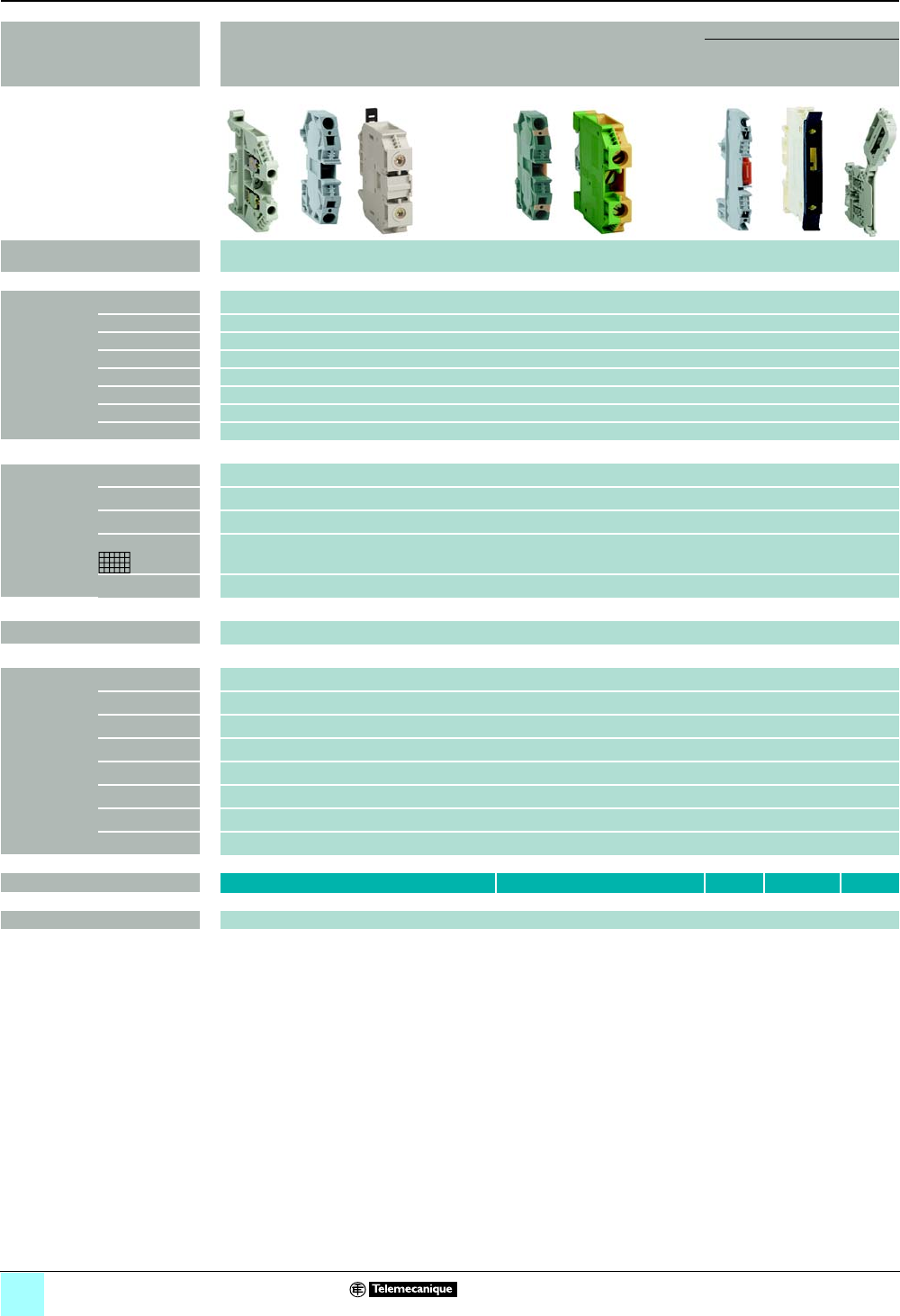
3/2
Selection Guide
0
Terminal Blocks, Type AB1 0
Screw clamp technology
Applications (connection) Passthrough Grounding Disconnect
Blade
type
Fused Remo-
vable
carrier
Nominal wire
size
AWG
(mm2)
12
(2.5)
10
(4)
8
(6)
6–350 kcmil
(10–150)
12
(2.5)
10
(4)
8–2
(6–35)
10
(4)
10
(4)
10
(4)
Number of
poles
1 - 1 x 1 • • • • • • • • • •
2 - 1 x 1 — — — — — — — — — —
3 - 1 x 1 — — — — — — — — — —
5 - 1 x 1 — — — — — — — — — —
10 - 1 x 1 — — — — — — — — — —
1 - 1 x 2 — — — — — — — — — —
1 - 2 x 2 — — — — — — — — — —
With grounding — — — — — — — — — —
Clip-on,
mounting
on:
35 mm 5• • • • • • • • • •
35 mm 1• • • • • • • • • •
35 mm 4• • • • • • • • • •
35 mm — — — — — — — — — —
15 mm 5••— — — •— — — —
Display — — — — — — — — • •
Colors Gray •••• — — — • • •
Blue •••• — — — •— —
Green/yellow ———— • • • — — —
Orange •••— — — — — — —
Red —•— — — — — — — —
Green —•— — — — — — — —
White —•— — — — — — — —
Black —•— — — — — — — —
Catalog numbers AB1VV AB1TP AB1SC AB1FUSE AB1SF
Marking accessories See pages 5/2 and 5/3
p
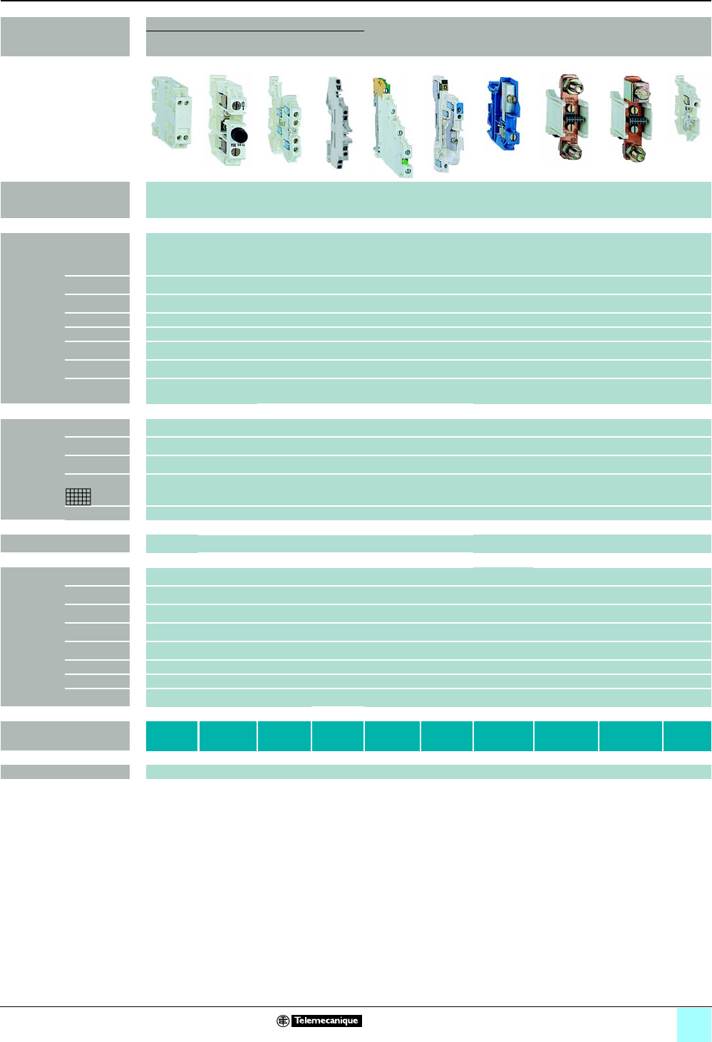
3/3
Selection Guide
0
Terminal Blocks, Type AB1 0
Screw clamp technology
Applications (connection) Fixed component Double deck For
proximity
sensors
Multi-
function
For
neutral
conductors
Lug-connector Screw-
clip
For
diode
For
fuse
Multi-
pole
Double
deck
Nominal
wire size
AWG
(mm2)
12
(2.5)
6
(10)
10
(4)
10
(4)
12
(2.5)
10
(4)
10–4
(4–16)
350–500
kcmil
(95/185/240)
350–500
kcmil
(95/150/240)
10
(4)
Number of
poles
1 - 1 x 1 —•— — •
+ 2 or 3
poles
—• • • •
2 - 1 x 1 •—• • —•— — — —
3 - 1 x 1 — — — — •— — — — —
5 - 1 x 1 — — — — — — — — — —
10 - 1 x 1 — — — — — — — — — —
1 - 1 x 2 — — •— — — — — — —
1 - 2 x 2 — — • • —•— — — —
With
grounding
— — • • • • — — — —
Clip-on,
mounting
on:
35 mm 5• • • • • • • • • •
35 mm 1• • • • • • • • • •
35 mm 4• • • • • —•— — •
35 mm — — — — — — — — — —
15 mm 5— — — — — — — — — —
Display —• • • • • — — — —
Colors Gray • • • • • • —• • •
Blue — — — — — — •— — —
Green/yellow — — • • — — — — — —
Orange — — — •— — — — — —
Red — — — •— — — — — —
Green — — — — — — — — — —
White — — — — — — — — — —
Black — — — •— — — — — —
Catalog numbers AB1D11 AB1FU10 AB1ETN AB1ET4 AB1DDP
AB1ET3
AB1TR AB1NEN AB1BB AB1BC AB1FV
AB1FC
Marking accessories See pages 5/2 and 5/3.
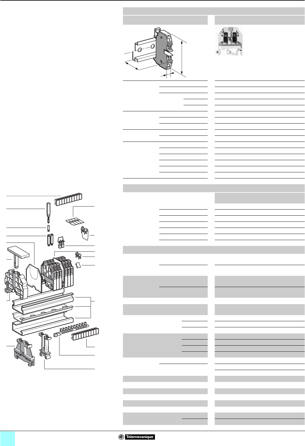
3/4
Terminal Blocks, Type AB1 0
Screw clamp technology
Passthrough
Clip-on mounting on 35 mm 1 7 4 rails
Nominal wire size 2.5 mm2
AB1VV235U••
Approximate
dimensions,
in. (mm)
Length (a) 1.57 (40)
Width (b) 0.20 (5)
Height (H)
with
1 rail 2.20 (56)
1 7 rail 1.91 (48.5)
4 rail 2.09 (53)
Wire size,
mm2Stranded w/o cable end 0.5–2.5
Stranded + cable end 0.5–1.5
Solid 0.5–4
Tightening
torque
IEC 0.4–0.6 N•m
UL 8.0 lbf-in
Nominal
electrical
values
IEC/EN 60947-7-1 (1) 800 V / 8 kV / 3–24 A
UL (4) 22–12 AWG, 600 V, 20 A
CSA (5) 24–12 AWG, 600 V, 25 A
UTE, category C 500 Vac, 500 Vdc
VDE, group C 750 Vac, 900 Vdc, 26 A
ATEX - EEx eII II 2GD 2.5 mm2, 750 V, 23 A, KEMA 02 ATEX 2114 U
Certifications See the tables beginning on page 1/12.
a
b
H
Terminal blocks
No.
points
Sold in
lots of
Catalog
number
Weight
oz (g)
Gray 2100 AB1VV235U 0.23 (6.5)
Blue 2100 AB1VV235UBL 0.23 (6.5)
Orange 2100 AB1VV235UGE 0.23 (6.5)
Red — — — —
Green — — — —
White — — — —
Black — — — —
Accessories
2Plastic end
clamp with
screw
Width 0.3 in. (7.5 mm)
on 4
—100 AB1AB7P32 0.15 (4.2)
Width 0.3 in. (8 mm)
on 1 or 7—100 AB1AB8P35 0.21 (5.9)
3Metal end clamp
with screw
Width 0.4 in. (10 mm)
on 4—100 AB1AB10M32 0.23 (6.5)
Width 0.3 in. (8 mm)
on 1 or 7—100 AB1AB8M35 0.52 (14.8)
4Clip-on plastic end clamp (2) —100 AB1AB8R35 0.21 (5.9)
5Marker holder
for clip-on plastic end clamp
—10 AB1SB4 0.11 (3.1)
6End plate
thickness 0.06 in. (1.5 mm)
Gray —50 AB1AC24 0.07 (1.9)
Blue —50 AB1AC24BL 0.07 (1.9)
Orange —50 AB1AC24GE 0.07 (1.9)
7Partition plate
thickness 0.06 in. (1.5 mm)
Gray —50 AB1AS24 0.09 (2.6)
Blue —50 AB1AS24BL 0.09 (2.6)
Red — — — —
Black — — — —
8Jumper with
screws
Non-insulated 80 10 AB1AL2 3.7 (105.0)
Insulated (3) 210 AB1ALN22 0.07 (2.0)
10 10 AB1ALN210 0.35 (10.0)
9Jumper for 2 blocks (1) 250 AB1BL2 0.35 (10.0)
10 Socket for test plug, ∅ 0.09 in.(2.3 mm) —50 AB1A2 0.018 (0.5)
11 Test plug Red —50 AB1AT1 0.06 (1.7)
12 Terminal cover 4100 AB1CS2 0.007 (0.2)
13/15 Marking accessories See pages 5/2 and 5/3.
16 Yellow partition plate 1100 AB1CJ2 0.011 (0.3)
17/18 Yellow protective cover Single point 1100 AB1CA2 0.004 (0.1)
10 points — — — —
10
9
8
7
6
5
4
3
2
1
987654321
10
18
5
1
7
14
15
13
8
17
16
11
10
9
6
4
3
12
2
Table Footnotes:
(1) When using jumpers, the rated voltage is reduced
to 400 V/6 kV/3.
(2) Width 0.3 in. (8 mm)on 1 or 7.
(3) Depending on the size of the terminal block, other
jumpers between 2 and 12 points may be available.
(4) File E164359 CCN XCFR2.
(5) File 702070 Class 6228 01.
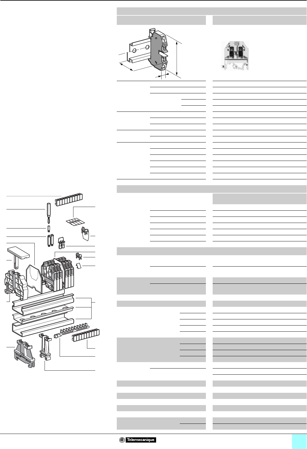
3/5
Terminal Blocks, Type AB1 0
Screw clamp technology
Passthrough
Clip-on mounting on 35 mm 1 7 4 rails
Nominal wire size 4 mm2
AB1VV435U••
Approximate
dimensions,
in. (mm)
Length (a) 1.57 (40)
Width (b) 0.24 (6)
Height (H)
with
1 rail 2.20 (56)
1 7 rail 1.91 (48.5)
4 rail 2.09 (53)
Wire size,
mm2Stranded w/o cable end 0.5–4
Stranded + cable end 0.5–2.5
Solid 0.5–6
Tightening
torque
IEC 0.5–0.7 N•m
UL 8.0 lbf-in
Nominal
electrical
values
IEC/EN 60947-7-1 (1) 800 V / 8 kV / 3–32 A
UL (4) 22–10 AWG, 600 V, 30 A
CSA (5) 24–10 AWG, 600 V, 40 A
UTE, category C 500 Vac, 500 Vdc
VDE, group C 750 Vac, 900 Vdc, 34 A
ATEX - EEx eII II 2GD 4 mm2, 750 V, 14/27 A, KEMA 02 ATEX 2114 U
Certifications See the tables beginning on page 1/12.
Terminal blocks
No.
points
Sold in
lots of
Catalog number Weight
oz (g)
Gray 2100 AB1VV435U 0.28 (7.8)
Blue 2100 AB1VV435UBL 0.28 (7.8)
Orange 2100 AB1VV435UGE 0.28 (7.8)
Red 2100 AB1VV435URO 0.28 (7.8)
Green 2100 AB1VV435UVE 0.28 (7.8)
White 2100 AB1VV435UBLA 0.28 (7.8)
Black 2100 AB1VV435UNO 0.28 (7.8)
Accessories
2Plastic end
clamp with
screw
Width 0.3 in. (7.5 mm)
on 4
—100 AB1AB7P32 0.15 (4.2)
Width.3 in (8 mm)
on 1 or 7—100 AB1AB8P35 0.21 (5.9)
3Metal end
clamp with
screw
Width 0.4 in. (10 mm) on 4—100 AB1AB10M32 0.23 (6.5)
Width 0.3 in. (8 mm)
on 1 or 7—100 AB1AB8M35 0.52 (14.8)
4Clip-on plastic end clamp (2) —100 AB1AB8R35 0.21 (5.9)
5Marker holder for clip-on plastic end clamp —10 AB1SB4 0.11 (3.1)
6End plate
thickness 0.06 in. (1.5 mm)
Gray —50 AB1AC24 0.07 (1.9)
Blue —50 AB1AC24BL 0.07 (1.9)
Orange —50 AB1AC24GE 0.07 (1.9)
Red —50 AB1AC24RO 0.07 (1.9)
Black —50 AB1AC24NO 0.07 (1.9)
7Partition plate
thickness 0.06 in. (1.5 mm)
Gray —50 AB1AS24 0.09 (2.6)
Blue —50 AB1AS24BL 0.09 (2.6)
Red —50 AB1AS24RO 0.09 (2.6)
Black —50 AB1AS24NO 0.09 (2.6)
8Jumper with
screws
Non-insulated 70 10 AB1AL4 5.10 (145.0)
Insulated (3) 210 AB1ALN42 0.10 (2.9)
10 10 AB1ALN410 0.63 (18.0)
9Jumper for 2 blocks (1) 250 AB1BL4 0.42 (12.0)
10 Socket for test plug, ∅ 0.09 in. (2.3 mm) —50 AB1A4 0.19 (5.4)
11 Test plug Red —50 AB1AT1 0.06 (1.7)
12 Terminal cover 1100 AB1CS4 0.028 (0.8)
13/15 Marking accessories See pages 5/2 and 5/3.
16 Yellow partition plate 1100 AB1CJ4 0.032 (0.9)
17/18 Yellow protective cover Single point 1100 AB1CA4 0.004 (0.1)
10 points 10 50 AB1CA410ET 0.035 (1.0)
a
b
H
10
9
8
7
6
5
4
3
2
1
987654321
10
18
5
1
7
14
15
13
8
17
16
11
10
9
6
4
3
12
2
Table Footnotes:
(1) When using jumpers, the rated voltage is reduced
to 400 V/6 kV/3.
(2) Width 0.3 in. (8 mm)on 1 or 7.
(3) Depending on the size of the terminal block, other
jumpers between 2 and 12 points may be
available.
(4) File E164359 CCN XCFR2.
(5) File 702070 Class 6228 01.
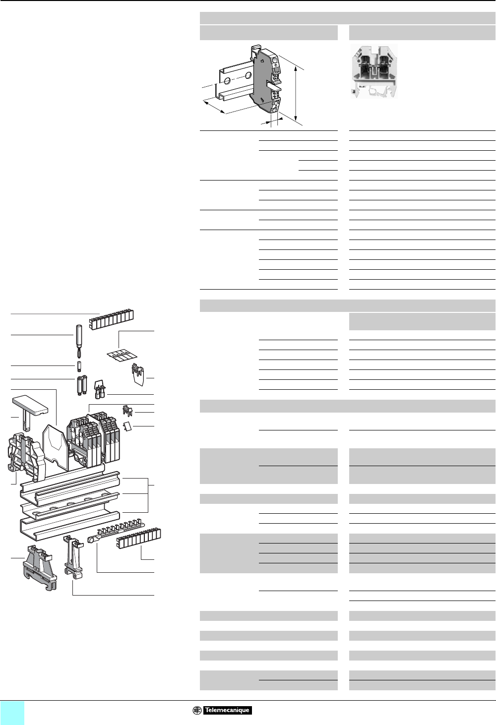
3/6
Terminal Blocks, Type AB1 0
Screw clamp technology
Passthrough
Clip-on mounting on 35 mm 1 7 4 rails
Nominal wire size 6 mm2
AB1VV635U••
Approximate
dimensions
in. (mm)
Length (a) 1.81 (46)
Width (b) 0.31 (8)
Height (H)
with
1 rail 2.40 (61)
1 7 rail 2.11 (53.5)
4 rail 2.28 (58)
Wire size,
mm2Stranded w/o cable end 0.5–6
Stranded + cable end 0.5–6
Solid 0.5–10
Tightening
torque
IEC 1.2–1.6 N•m
UL 20.0 lbf-in
Nominal
electrical
values
IEC/EN 60947-7-1 (1) 800 V / 8 kV / 3–41 A
UL (4) 22–8 AWG, 600 V, 50 A
CSA (5) 24–8 AWG, 600 V, 45 A
UTE, category C 500 Vac, 500 Vdc
VDE, group C 750 Vac, 900 Vdc, 44 A
ATEX - EEx eII II 2GD 6 mm2, 750 V, 35/38 A, KEMA 02 ATEX 2114 U
Certifications See the tables beginning on page 1/12.
a
b
H
Terminal blocks
No.
points
Sold in
lots of
Catalog
number
Weight
oz (g)
Gray 2100 AB1VV635U 0.52 (14.8)
Blue 2100 AB1VV635UBL 0.52 (14.8)
Orange 2100 AB1VV635UGE 0.52 (14.8)
Red — — — —
Green — — — —
White — — — —
Black — — — —
Accessories
2Plastic end
clamp with
screw
Width 0.3 in. (7.5 mm)
on 4
—100 AB1AB7P32 0.15 (4.2)
Width 0.3 in (8 mm)
on 1 or 7—100 AB1AB8P35 0.21 (5.9)
3Metal end clamp
with screw
Width 0.4 in. (10 mm)
on 4—100 AB1AB10M32 0.23 (6.5)
Width 0.3 in. (8 mm)
on 1 or 7—100 AB1AB8M35 0.52 (14.8)
4Clip-on plastic end clamp (2) —100 AB1AB8R35 0.21 (5.9)
5Marker holder for clip-on plast. end clamp —10 AB1SB4 0.11 (3.1)
6End plate
thickness 0.06 in.
(1.5 mm)
Gray —50 AB1AC6 0.09 (2.6)
Blue —50 AB1AC6BL 0.09 (2.6)
Orange —50 AB1AC6GE 0.09 (2.6)
7Partition plate
thickness 0.06 in.
(1.5 mm)
Gray —50 AB1AS6 0.12 (3.3)
Blue —50 AB1AS6BL 0.12 (3.3)
Red — — — —
Black — — — —
8Jumper with
screws
Non-insulated 80 10 AB1AL6 8.40
(237.0)
Insulated (3) 210 AB1ALN62 0.22 (6.1)
10 10 AB1ALN610 1.10 (30.5)
9Jumper for 2 blocks (1) 250 AB1BL6 0.56 (16.0)
10 Socket for test plug, ∅ 0.16 in. (4 mm) —50 AB1A6 0.035 (1.0)
11 Test plug Black —50 AB1AT2 0.06 (1.7)
12 Terminal cover 4100 AB1CS6 0.05 (1.5)
13/15 Marking accessories See pages 5/2 and 5/3.
16 Yellow partition plate 1100 AB1CJ6 0.018 (0.5)
17/18 Yellow
protective cover
Single point 1100 AB1CA6 0.007 (0.2)
10 points — — — —
10
9
8
7
6
5
4
3
2
1
987654321
10
18
5
1
7
14
15
13
8
17
16
11
10
9
6
4
3
12
2
Table Footnotes:
(1) When using jumpers, the rated voltage is
reduced to 400 V/6 kV/3.
(2) Width 0.3 in. (8 mm)on 1 or 7.
(3) Depending on the size of the terminal block,
other jumpers between 2 and 12 points may be
available.
(4) File E164359 CCN XCFR2.
(5) File 702070 Class 6228 01.
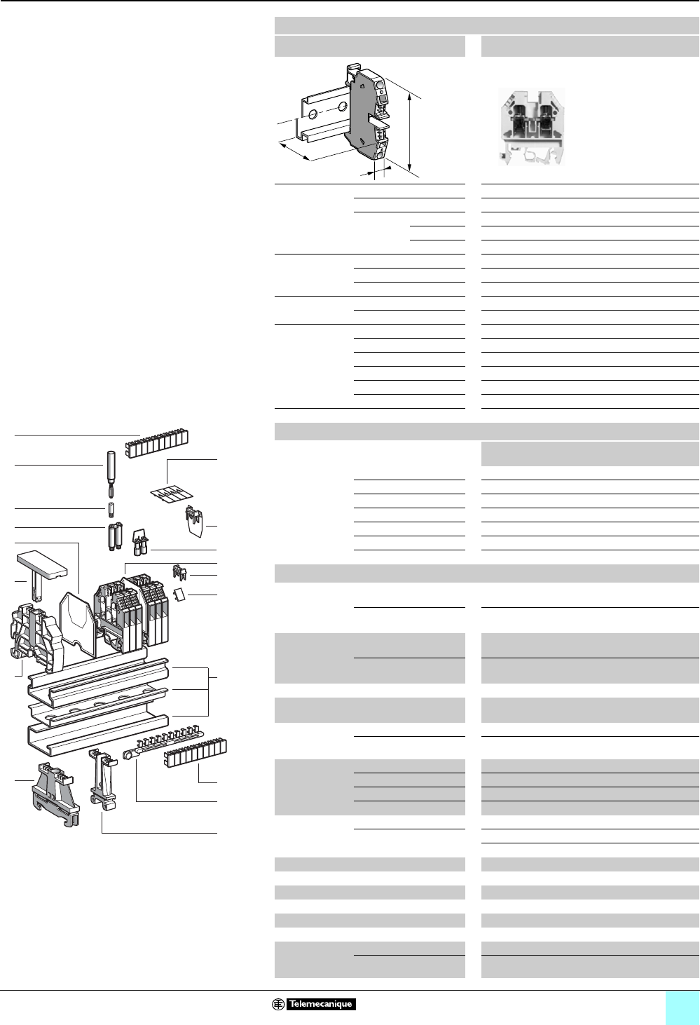
3/7
Terminal Blocks, Type AB1 0
Screw clamp technology
Passthrough
Clip-on mounting on 35 mm 1 7 4 rails
Nominal wire size 10 mm2
AB1VVN1035U••
Approximate
dimensions
in. (mm)
Length (a) 2.01 (51)
Width (b) 0.39 (10)
Height (H)
with
1 rail 2.46 (62.5)
1 7 rail 2.17 (55)
4 rail 2.34 (59.5)
Wire size,
mm2Stranded w/o cable end 2.5–10
Stranded + cable end 2.5–10
Solid 6–16
Tightening
torque
IEC 2.0–2.5 N•m
UL 35.0 lbf-in
Nominal
electrical
values
IEC/EN 60947-7-1 (1) 800 V / 8 kV / 3–57 A
UL (4) 16–6 AWG, 600 V, 65 A
CSA (5) 16–6 AWG, 600 V, 70 A
UTE, category C 500 Vac, 500 Vdc
VDE, group C 750 Vac, 900 Vdc, 63 A
ATEX - EEx eII II 2GD 10 mm2, 750 V, 43 / 56 A, KEMA 02 ATEX 2114 U
Certifications See the tables beginning on page 1/12.
a
b
H
Terminal blocks
No.
points
Sold in
lots of
Catalog number Weight
oz (g)
Gray 250 AB1VVN1035U 0.92 (26.0)
Blue 250 AB1VVN1035UBL 0.92 (26.0)
Orange — — — —
Red — — — —
Green — — — —
White — — — —
Black — — — —
Accessories
2 Plastic end
clamp with
screw
Width 0.3 in. (7.5 mm)
on 4
—100 AB1AB7P32 0.15 (4.2)
Width.3 in (8 mm)
on 1 or 7—100 AB1AB8P35 0.21 (5.9)
3Metal end
clamp with
screw
Width 0.4 in. (10 mm) on
4—100 AB1AB10M32 0.23 (6.5)
Width 0.3 in. (8 mm) on
1 or 7—100 AB1AB8M35 0.52 (14.8)
4 Clip-on plastic end clamp (2) —100 AB1AB8R35 0.23 (5.9)
5Marker holder
for clip-on plastic end clamp
—10 AB1SB4 0.21 (3.1)
6End plate
thickness 0.06
in. (1.5 mm)
Gray —10 AB1ACN10 0.13 (3.7)
Blue —10 AB1ACN10BL 0.13 (3.7)
7Partition plate
thickness 0.06
in. (1.5 mm)
Gray —10 AB1ASN10 0.16 (4.5)
Blue — — — —
Red — — — —
Black — — — —
8Jumper with
screws
Non-insulated 40 10 AB1ALN10 6.30 (4.5)
Insulated (3) 210 AB1ALN102 0.41 (11.6)
10 10 AB1ALN1010 2.05 (58.0)
9Jumper for 2 blocks (1) 250 AB1BL10 0.78 (22.0)
10 Socket for test plug, ∅ 0.16 (4 mm) —50 AB1A10 0.035 (1.0)
11 Test plug Black —50 AB1AT2 0.06 (1.7)
12 Terminal cover 4100 AB1CSN10 0.05 (1.4)
13/15 Marking accessories See pages 5/2 and 5/3.
16 Yellow partition plate 1100 AB1CJN10 0.025 (0.7)
17/18 Yellow
protective
cover
Single point 1100 AB1CA10 0.011 (0.3)
10 points — — — —
10
9
8
7
6
5
4
3
2
1
987654321
10
18
5
1
7
14
15
13
8
17
16
11
10
9
6
4
3
12
2
Table Footnotes:
(1) When using jumpers, the rated voltage is reduced
to 400 V/6 kV/3.
(2) Width 0.3 in. (8 mm)on 1 or 7.
(3) Depending on the size of the terminal block, other
jumpers between 2 and 12 points may be
available.
(4) File E164359 CCN XCFR2.
(5) File 702070 Class 6228 01.
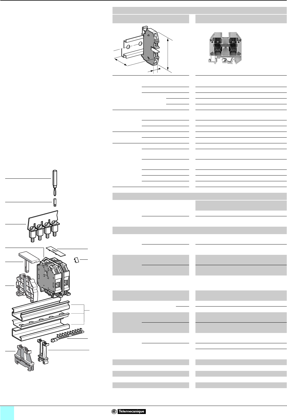
3/8
Terminal Blocks, Type AB1 0
Screw clamp technology
Passthrough
Clip-on mounting on 35 mm 1 7 4 rails
Nominal wire size 16 mm2
AB1VVN1635U••
Approximate dimensions, in. (mm)
Length (a) 2.26 (57.5)
Width (b) 0.47 (12)
1Height (H)
with
1 rail 2.56 (65)
7 rail 2.26 (57.5)
4 rail 2.44 (62)
Wire size,
mm2Stranded without
cable end
4–16
Stranded with cable end 4–16
Solid 10–25
Tightening
torque
IEC 2.5–3.0 N•m
UL 35.0 lbf-in
Nominal
electrical
values
IEC/EN 60947-7-1 800 V / 8 kV / 3–76 A
UL File E164359
CCN XCFR2
12–4 AWG, 600 V, 85 A
CSA File 702070
Class 6228 01
14–4 AWG, 600 V, 95 A
UTE, category C 500 Vac, 500 Vdc
VDE, group C 750 Vac, 900 Vdc, 85 A
ATEX - EEx eII II 2GD 16 mm2, 750 V, 66 / 71 A, KEMA 02 ATEX 2114 U
Certifications See the tables beginning on page 1/12.
a
b
H
Terminal blocks
No.
points
Sold in
lots of
Catalog number Weight
oz (g)
Gray 250 AB1VVN1635U 1.41 (40.0)
Blue 250 AB1VVN1635UBL 1.41 (40.0)
Accessories
2Plastic
end clamp
with screw
Width 0.3 in. (7.5 mm)
on 4
—100 AB1AB7P32 0.15 (4.2)
Width 0.3 in. (8 m )
on 1 or 7—100 AB1AB8P35 0.21 (5.9)
3Metal
end clamp
with screw
Width 0.4 in. (10 mm)
on 4—100 AB1AB10M32 0.23 (6.5)
Width 0.3 in. (8 mm)
on 1 or 7—100 AB1AB8M35 0.52 (14.8)
4Clip-on
plastic end
clamp
Width 0.3 in. (8 mm)
on 1 or 7—100 AB1AB8R35 0.21 (5.9)
5Marker tag holder
for clip-on plastic end clamp
10 AB1SB4 0.11 (3.1)
End plate
thickness 0.06 in. (1.5 mm)
Gray —10 AB1ACN16 0.19 (5.4)
Blue —10 AB1ACN16BL 0.19 (5.4)
6Partition plate
thickness 0.06
in. (1.5 mm)
Width 0.08 in.
(2.0 mm)
Gray —10 AB1ASN16 0.23 (6.4)
Width 0.12 in.
(3.0 mm)
Gray — — — —
7 Jumper with
screws
Non-insulated 30 10 AB1ALN16 11.29
(320.0)
Insulated (1) 210 AB1ALN162 0.88 (25.0)
10 10 AB1ALN1610 4.41
(125.0)
8Socket for test plug, ∅ 0.16 (4 mm) —50 AB1A16 0.035 (1.0)
9 Test plug Black — 50 AB1AT2 0.06 (1.7)
10 Terminal cover 410 AB1CSN16 0.05 (1.4)
11/12 Marking accessories See pages 5/2 and 5/3.
Yellow partition plate 110 AB1CJN16 0.011 (0.3)
Yellow protective cover 1100 AB1CA16 0.018 (0.5)
987654321
10
3
5
4
7
6
8
9
11
10
1
2
12
Table Footnote:
(1) Depending on the size of the terminal block,
other jumpers between 2 and 12 points may be
available.
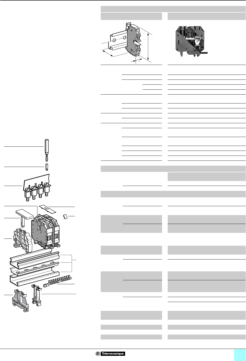
3/9
Terminal Blocks, Type AB1 0
Screw clamp technology
Passthrough
Clip-on mounting on 35 mm 1 7 4 rails
Nominal wire size 35 mm2
AB1VVN3535U••
Approximate dimensions, in. (mm)
Length (a) 2.48 (63)
Width (b) 0.63 (16)
1Height (H)
with
1 rail 2.96 (75.1)
7 rail 2.66 (67.6)
4 rail 2.72 (69)
Wire size,
mm2Stranded without
cable end
10–35
Stranded with cable end 10–35
Solid 10–50
Tightening
torque
IEC 2.5–3.0 N•m
UL 50 lbf-in
Nominal
electrical
values
IEC/EN 60947-7-1 800 V / 8 kV / 3–125 A
UL File E164359
CCN XCFR2
10–2 AWG, 600 V, 95 A
CSA File 702070
Class 6228 01
12–2 AWG, 600 V, 110 A
UTE, category C 500 Vac, 500 Vdc
VDE, group C 750 Vac, 900 Vdc, 138 A
ATEX - EEx eII II 2GD 35 mm2, 750 V, 86 / 124 A, KEMA 02 ATEX 2114 U
Certifications See the tables beginning on page 1/12.
a
b
H
Terminal blocks
No.
points
Sold in
lots of
Catalog number Weight
oz (g)
Gray 220 AB1VVN3535U 2.50 (71.0)
Blue 220 AB1VVN3535UBL 2.50 (71.0)
Accessories
2 Plastic
end clamp
with screw
Width 0.3 in. (7.5 mm)
on 4
—100 AB1AB7P32 0.15 (4.2)
Width 0.3 in. (8 mm)
on 1 or 7—100 AB1AB8P35 0.21 (5.9)
3Metal
end clamp
with screw
Width 0.4 in. (10 mm)
on 4—100 AB1AB10M32 0.23 (6.5)
Width 0.3 in. (8 mm)
on 1 or 7—100 AB1AB8M35 0.52 (14.8)
4 Clip-on
plastic end
clamp
Width 0.3 in. (8 mm)
on 1 or 7—100 AB1AB8R35 0.21 (5.9)
5Marker tag holder
for clip-on plastic end clamp
—10 AB1SB4 0.11 (3.1)
End plate
thickness
0.06 in.
(1.5 mm)
Gray — — — —
Blue — — — —
6Partition
plate
thickness
0.06 in.
(1.5 mm)
Gray, width .08 in.
(2.0 mm)
—10 AB1ASN35 0.25 (7.0)
Gray, width 1.9 in.
(3.0 mm)
— — — —
7 Jumper with
screws
Non-insulated — — — —
Insulated (1) 210 AB1ALN352 0.99 (28.0)
20 10 AB1ALN35 10.02
(284.0)
8Socket for test plug
∅ 0.16 in. (4 mm)
—50 AB1A35 0.10 (2.7)
9 Test plug Black — 50 AB1AT2 0.06 (1.7)
10 Terminal cover 410 AB1CSN35 0.05 (1.4)
11/12 Marking accessories See pages 5/2 and 5/3.
Yellow partition plate — — — —
Yellow protective cover 150AB1CA35 0.025 (0.7)
987654321
10
3
5
4
7
6
8
9
11
10
1
2
12
Table Footnote:
(1) Depending on the size of the terminal block,
other jumpers between 2 and 12 points may be
available.
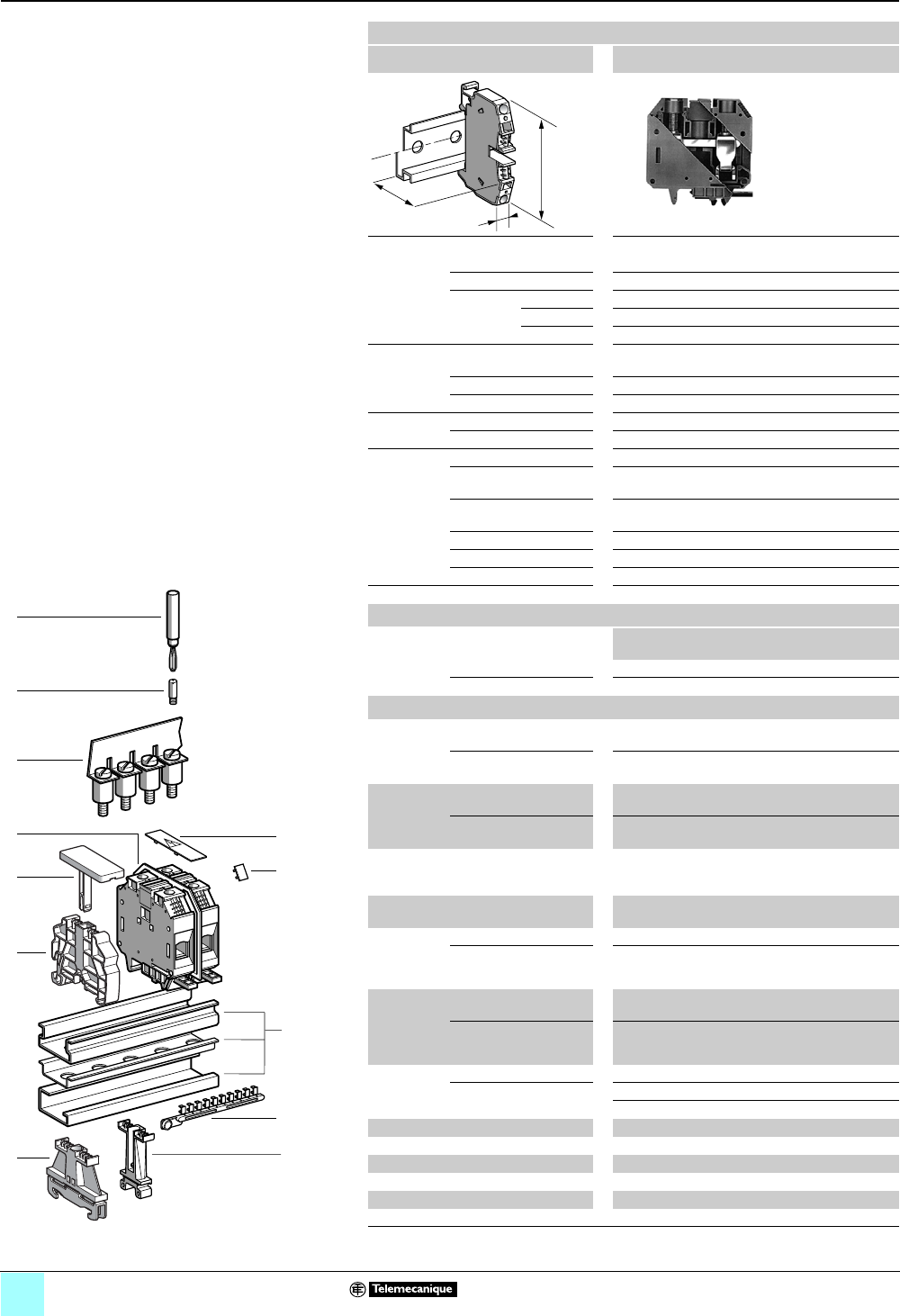
3/10
Terminal Blocks, Type AB1 0
Screw clamp technology
Passthrough
Clip-on mounting on 35 mm 1 7 4 rails
Nominal wire size 70 mm2
AB1VVN7035U••
Approximate dimensions, in. (mm)
Length (a) 2.96 (75.2)
Width (b) 0.94 (24)
1Height (H)
with
1 rail 3.49 (88.7)
7 rail 3.20 (81.2)
4 rail 3.26 (82.7)
Wire size,
mm2Stranded without
cable end
10–70
Stranded with cable end 10–70
Solid 16–95
Tightening
torque
IEC 6–10 N•m
UL 150 lbf-in
Nominal
electrical
values
IEC/EN 60947-7-1 800 V / 8 kV / 3–192 A
UL File E164359
CCN XCFR2
6–2/0 AWG, 600 V, 175 A
CSA File 702070
Class 6228 01
6–2/0 AWG, 600 V, 170 A
UTE, category C 500 Vac, 500 Vdc
VDE, group C 750 Vac, 900 Vdc, 213 A
ATEX - EEx eII II 2GD 70 mm2, 750 V, 179 A, KEMA 02 ATEX 2114 U
Certifications See the tables beginning on page 1/12.
a
b
H
Terminal blocks
No.
points
Sold in
lots of
Catalog number Weight
oz (g)
Gray 220 AB1VVN7035U 6.10 (173.0)
Blue 220 AB1VVN7035UBL 6.10 (173.0)
Accessories
2 Plastic
end clamp
with screw
Width 0.3 in. (7.5 mm)
on 4
—100 AB1AB7P32 0.15 (4.2)
Width 0.3 in. (8 m )
on 1 or 7—100 AB1AB8P35 0.21 (5.9)
3Metal
end clamp
with screw
Width 0.4 in. (10 mm)
on 4—100 AB1AB10M32 0.23 (6.5)
Width 0.3 in. (8 mm)
on 1 or 7—100 AB1AB8M35 0.52 (14.8)
4Clip-on
plastic end
clamp
Width 0.3 in. (8 mm)
on 1 or 7—100 AB1AB8R35 0.21 (5.9)
5Marker tag holder
for clip-on plastic end clamp
—10 AB1SB4 0.11 (3.1)
End plate
thickness
0.06 in.
(1.5 mm)
Gray — — — —
Blue — — — —
6Partition
plate
thickness
0.06 in.
(1.5 mm)
Gray, width .08 in
(2.0 mm)
— — — —
Gray, width 0.12 in.
(3.0 mm)
—10 AB1ASN70 0.78 (22.0)
7 Jumper with
screws
Non-insulated 210 AB1ALN702 0.79 (22.3)
Insulated (1) — — — —
— — — —
8Socket for test plug, ∅ 0.16 (4 mm) — — — —
9 Test plug Black — — — —
10 Terminal cover 410 AB1CSN10 0.05 (1.4)
11/12 Marking accessories See pages 5/2 and 5/3.
Yellow partition plate — — — —
Yellow protective cover — — — —
(1) Depending on the size of the terminal block, other jumpers between 2 and 12 points may be
available.
987654321
10
3
5
4
7
6
8
9
11
10
1
2
12
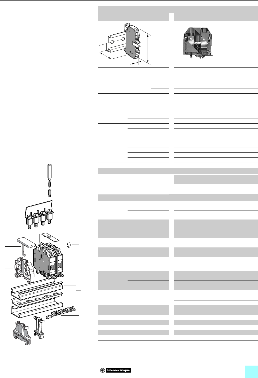
3/11
Terminal Blocks, Type AB1 0
Screw clamp technology
Passthrough
Clip-on mounting on 35 mm 1 7 4 rails
Nominal wire size 150 mm2
AB1VVN15035U••
Approximate
dimensions,
in. (mm)
Length (a) 3.61 (91.7)
Width (b) 1.10 (28)
1Height (H)
with
1 rail 4.18 (106.1)
7 rail 3.88 (98.6)
4 rail 100.1 (3.94)
Wire size,
mm2Stranded without
cable end
35–150
Stranded with cable end 35–150
Solid 35–185
Tightening
torque
IEC 10–15 N•m
UL 150 lbf-in
Nominal
electrical
values
IEC/EN 60947-7-1 1000 V / 8 kV / 3–309 A
UL File E164359
CCN XCFR2
2/0 AWG – 350 kcmil, 600 V, 335 A
CSA File 702070
Class 6228 01
2/0 AWG – 300 kcmil, 600 V, 300 A
UTE, category C 500 Vac, 500 Vdc
VDE, group C 750 Vac, 900 Vdc, 344 A
ATEX - EEx eII II 2GD 150 mm2, 750 V, 290 / 309 A, KEMA 02 ATEX 2114 U
Certifications See the tables beginning on page 1/12.
Terminal blocks
No.
points
Sold in
lots of
Catalog number Weight
oz (g)
Gray 210 AB1VVN15035U 9.43 (267.2)
Blue 210 AB1VVN15035UBL 9.43 (267.2)
Accessories
2 Plastic
end clamp with
screw
Width 0.3 in. (7.5 mm)
on 4
—100 AB1AB7P32 1.5 (4.2)
Width 0.3 in. (8 m )
on 1 or 7—100 AB1AB8P35 0.21 (5.9)
3Metal
end clamp with
screw
Width 0.4 in. (10 mm)
on 4—100 AB1AB10M32 0.23 (6.5)
Width 0.3 in. (8 mm)
on 1 or 7—100 AB1AB8M35 0.52 (14.8)
4Clip-on plastic
end clamp
Width 0.3 in. (8 mm)
on 1 or 7—100 AB1AB8R35 0.21 (5.9)
5Marker tag holder
for clip-on plastic end clamp
—10 AB1SB4 0.11 (3.1)
End plate
thickness
0.06 in. (1.5 mm)
Gray — — — —
Blue — — — —
6Partition plate
thickness 0.06
in. (1.5 mm)
Gray, width 0.08 in
(2.0 mm)
— — — —
Gray, width 0.12 in.
(3.0 mm)
— — — —
7 Jumper with
screws
Non-insulated 210 AB1ALN1502 5.15 (146.0)
Insulated (1) — — — —
— — — —
8Socket for test plug
∅ 0.16 in. (4 mm)
— — — —
9 Test plug Black — — — —
10 Terminal cover 410 AB1CSN150 0.11 (3.2)
11/12 Marking accessories See pages 5/2 and 5/3.
Yellow partition plate — — — —
Yellow protective cover ——— —
(1) Depending on the size of the terminal block, other jumpers between 2 and 12 points may be
available.
a
b
H
987654321
10
3
5
4
7
6
8
9
11
10
1
2
12
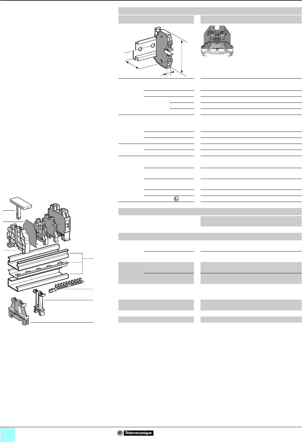
3/12
Terminal Blocks, Type AB1 0
Screw clamp technology
Grounding type
Clip-on mounting on 35 mm 1 7 4 rails
Nominal wire size 2.5 mm2
AB1TP 235U
Approximate dimensions, in. (mm)
Length (a) 1.91 (48.6)
Width (b) 0.20 (5.1)
1Height (H)
with
1 rail 1.91 (48.5)
7 rail 2.20 (56)
4 rail 2.39 (60.5)
Wire size, mm2
Stranded without
cable end
0.5–2.5
Stranded with cable end 0.5–2.5
Solid 0.5–4
Tightening
torque
IEC 0.4–0.6 N•m
UL 8.0 lbf-in
Nominal electrical values
IEC/EN 60947-7-1 500 V / 6kV / 3
UL File E164359
CCN XCFR2
22–12 AWG
CSA File 702070
Class 6228 01
24–12 AWG
VDE, group C —
ATEX - EEx eII II 2GD —
Certifications See the tables beginning on page 1/12.
Terminal blocks
No.
points
Sold in
lots of
Catalog number Weight
oz (g)
Green/yellow 2 100 AB1TP235U 0.46 (12.9)
Accessories
2Plastic
end clamp
with screw
Width 0.3 in. (7.5 mm)
on 4
—100 AB1AB7P32 0.15 (4.2)
Width 0.3 in. (8 mm)
on 1 or 7—100 AB1AB8P35 0.21 (5.9)
3Metal
end clamp
with screw
Width 0.3 in. (7.5 mm)
on 4
—100 AB1AB10M32 0.23 (6.5)
Width 0.3 in. (8 mm)
on 1 or 7—100 AB1AB8M35 0.52 (14.8)
4Clip-on
plastic
end clamp
Width 0.3 in. (8 mm)
on 1 or 7—100 AB1AB8R35 0.21 (5.9)
5Marker tag holder
for clip-on end clamp
—10 AB1SB4 0.11 (3.1)
6End plate —10 AB1AC25 0.07 (1.9)
7Marking accessories See pages 5/2 and 5/3
a
b
H
987654321
10
1
7
2
4
5
6
3
524050
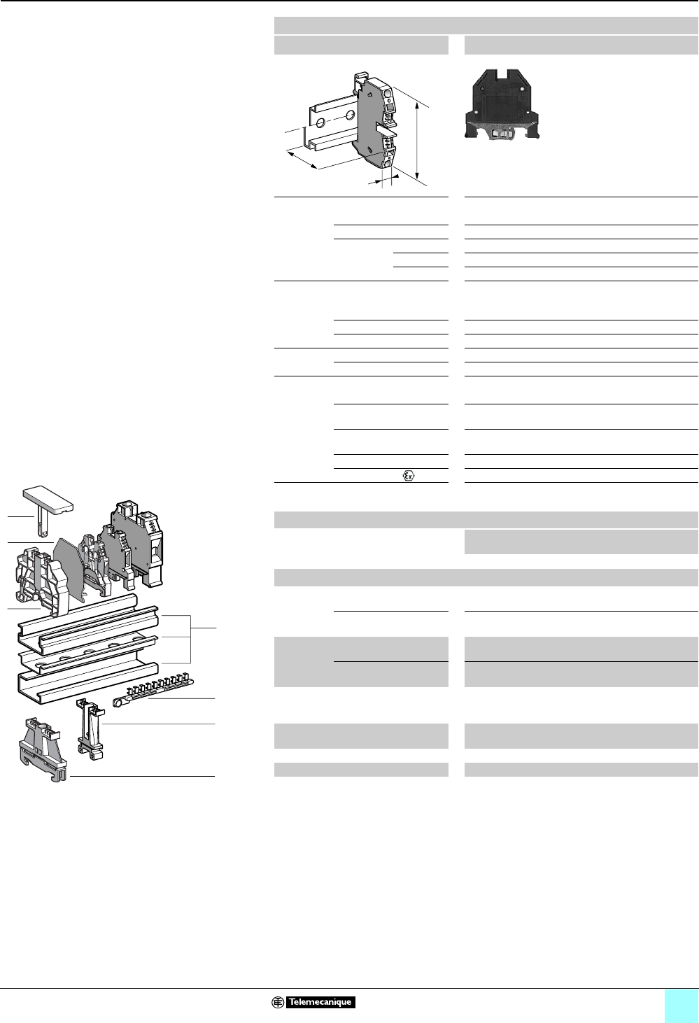
3/13
0
Terminal Blocks, Type AB1 0
Screw clamp technology
Grounding type
Clip-on mounting on 35 mm 1 7 4 rails
Nominal wire size 4 mm2
AB1TP435U
Approximate dimensions, in. (mm)
Length (a) 2.01 (51)
Width (b) 0.24 (6)
1Height (H)
with
1 rail 2.20 (56)
7 rail 1.91 (48.5)
4 rail 2.09 (53)
Wire size, mm2
Stranded without
cable end
0.5–4
Stranded with cable end 0.5–2.5
Solid 0.5–6
Tightening
torque
IEC 0.5–0.7 N•m
UL 8.0 lbf-in
Nominal electrical values
IEC/EN 60947-7-1 800 V / 8 kV / 3–32 A
UL File E164359
CCN XCFR2
22–10 AWG, 600 V
CSA File 702070
Class 6228 01
20–10 AWG, 600 V
VDE, group C 750 Vac, 900 Vdc, 35 A
ATEX - EEx eII II 2GD 4 mm2, KEMA 02 ATEX 2114 U
Certifications See the tables beginning on page 1/12.
Terminal blocks
No.
points
Sold in
lots of
Catalog number Weight
oz (g)
Green/yellow 2100AB1TP435U 0.88 (25.0)
Accessories
2Plastic
end clamp
with screw
Width 0.3 in. (7.5 mm)
on 4
—100AB1AB7P32 0.15 (4.2)
Width 0.3 in. (8 mm)
on 1 or 7—100AB1AB8P35 0.21 (5.9)
3Metal
end clamp
with screw
Width 0.3 in. (7.5 mm)
on 4
—100 AB1AB10M32 0.23 (6.5)
Width 0.3 in. (8 mm)
on 1 or 7—100 AB1AB8M35 0.52 (14.8)
4Clip-on
plastic
end clamp
Width 0.3 in. (8 mm)
on 1 or 7—100 AB1AB8R35 0.21 (5.9)
5Marker tag holder
for clip-on end clamp
—10 AB1SB4 0.11 (3.1)
6End plate — — — —
7Marking accessories See pages 5/2 and 5/3
a
b
H
987654321
10
1
7
2
4
5
6
3
524050
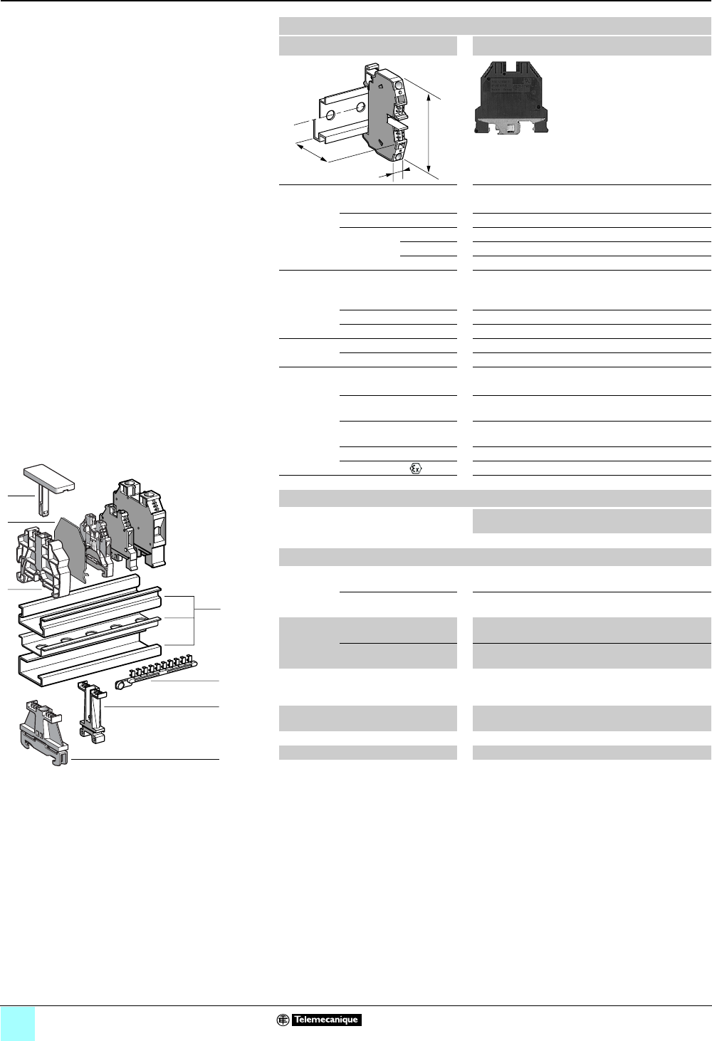
3/14
Terminal Blocks, Type AB1 0
Screw clamp technology
Grounding type
Clip-on mounting on 35 mm 1 7 4 rails
Nominal wire size 6 mm2
AB1TP635U
Approximate dimensions, in. (mm)
Length (a) 2.13 (54)
Width (b) 0.31 (8)
1Height (H)
with
1 rail 2.40 (61)
7 rail 2.11 (53.5)
4 rail 2.28 (58)
Wire size, mm2
Stranded without
cable end
0.5–6
Stranded with cable end 0.5–6
Solid 0.5–10
Tightening
torque
IEC 1.2–1.6 N•m
UL 20 lbf-in
Nominal electrical values
IEC/EN 60947-7-1 800 V / 8 kV / 3–41 A
UL File E164359
CCN XCFR2
22–8 AWG, 600 V
CSA File 702070
Class 6228 01
24–8 AWG, 600 V
VDE, group C 750 Vac, 900 Vdc, 46 A
ATEX - EEx eII II 2GD 6 mm2, KEMA 02 ATEX 2114 U
Certifications See the tables beginning on page 1/12.
Terminal blocks
No.
points
Sold in
lots of
Catalog number Weight
oz (g)
Green/yellow 2 50 AB1TP635U 2.68 (76.0)
Accessories
2Plastic
end clamp
with screw
Width 0.3 in. (7.5 mm)
on 4
—100 AB1AB7P32 0.15 (4.2)
Width 0.3 in. (8 mm)
on 1 or 7—100 AB1AB8P35 0.21 (5.9)
3Metal
end clamp
with screw
Width 0.3 in. (7.5 mm)
on 4
—100 AB1AB10M32 0.23 (6.5)
Width 0.3 in. (8 mm)
on 1 or 7—100 AB1AB8M35 0.52 (14.8)
4Clip-on
plastic
end clamp
Width 0.3 in. (8 mm)
on 1 or 7—100 AB1AB8R35 0.21 (5.9)
5Marker tag holder
for clip-on end clamp
—10 AB1SB4 0.11 (3.1)
6End plate — — — —
7Marking accessories See pages 5/2 and 5/3
a
b
H
987654321
10
1
7
2
4
5
6
3
524050

3/15
0
Terminal Blocks, Type AB1 0
Screw clamp technology
Grounding type
Clip-on mounting on 35 mm 1 7 4 rails
Nominal wire size 10 mm2
AB1TP1035U
Approximate dimensions, in. (mm)
Length (a) 2.13 (54)
Width (b) 0.39 (10)
1Height (H)
with
1 rail 2.46 (62.5)
7 rail 2.17 (55)
4 rail 2.34 (59.5)
Wire size, mm2
Stranded without
cable end
2.5–10
Stranded with cable end 2.5–10
Solid 6–16
Tightening
torque
IEC 2.0–2.5 N•m
UL 35 lbf-in
Nominal electrical values
IEC/EN 60947-7-1 800 V / 8 kV / 3–57 A
UL File E164359
CCN XCFR2
16–6 AWG, 600 V
CSA File 702070
Class 6228 01
16–6 AWG, 600 V
VDE, group C 750 Vac, 900 Vdc, 63 A
ATEX Exe II II 2 GD 10 mm2, KEMA 02 ATEX 2114 U
Certifications See the tables beginning on page 1/12.
Terminal blocks
No.
points
Sold in
lots of
Catalog number Weight
oz (g)
Green/yellow 2 50 AB1TP1035U 2.01 (57.0)
Accessories
2Plastic
end clamp
with screw
Width 0.3 in. (7.5 mm)
on 4
—100 AB1AB7P32 0.15 (4.2)
Width 0.3 in. (8 mm)
on 1 or 7—100 AB1AB8P35 0.21 (5.9)
3Metal
end clamp
with screw
Width 0.3 in. (7.5 mm)
on 4
—100 AB1AB10M32 0.23 (6.5)
Width 0.3 in. (8 mm)
on 1 or 7—100 AB1AB8M35 0.52 (14.8)
4Clip-on
plastic
end clamp
Width 0.3 in. (8 mm)
on 1 or 7—100 AB1AB8R35 0.21 (5.9)
5Marker tag holder
for clip-on end clamp
—10 AB1SB4 0.11 (3.1)
6 Marking accessories See pages 5/2 and 5/3
a
b
H
987654321
10
1
6
2
4
5
3
524050
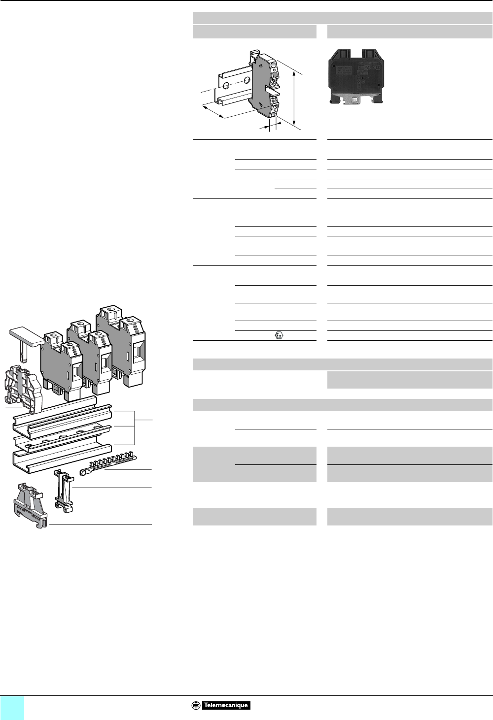
3/16
0
Terminal Blocks, Type AB1 0
Screw clamp technology
Grounding type
Clip-on mounting on 35 mm 1 7 4 rails
Nominal wire size 16 mm2
AB1TP1635U
Approximate dimensions, in. (mm)
Length (a) 2.26 (57.5)
Width (b) 0.47 (12)
1Height (H)
with
1 rail 2.56 (65)
7 rail 2.26 (57.5)
4 rail 2.44 (62)
Wire size, mm2
Stranded without
cable end
4–16
Stranded with cable end 4–16
Solid 10–25
Tightening
torque
IEC 2.5–3.0 N•m
UL 35 lbf-in
Nominal electrical values
IEC/EN 60947-7-1 800 V / 8 kV / 3–76 A
UL File E164359
CCN XCFR2
12–4 AWG, 600 V
CSA File 702070
Class 6228 01
14–4 AWG, 600 V
VDE, group C 750 Vac, 900 Vdc, 85 A
ATEX Exe II II 2 GD 16 mm2, KEMA 02 ATEX 2114 U
Certifications See the tables beginning on page 1/12.
Terminal blocks
No.
points
Sold in
lots of
Catalog number Weight
oz (g)
Green/yellow 2 50 AB1TP1635U 2.68 (76.0)
Accessories
2Plastic
end clamp
with screw
Width 0.3 in. (7.5 mm)
on 4
—100AB1AB7P32 0.15 (4.2)
Width 0.3 in. (8 mm)
on 1 or 7—100AB1AB8P35 0.21 (5.9)
3Metal
end clamp
with screw
Width 0.3 in. (7.5 mm)
on 4
—100 AB1AB10M32 0.23 (6.5)
Width 0.3 in. (8 mm)
on 1 or 7—100 AB1AB8M35 0.52 (14.8)
4Clip-on
plastic
end clamp
Width 0.3 in. (8 mm)
on 1 or 7—100 AB1AB8R35 0.21 (5.9)
5Marker tag holder
for clip-on end clamp
—10 AB1SB4 0.11 (3.1)
6 Marking accessories See pages 5/2 and 5/3
a
b
H
987654321
10
1
6
2
4
5
3
524050
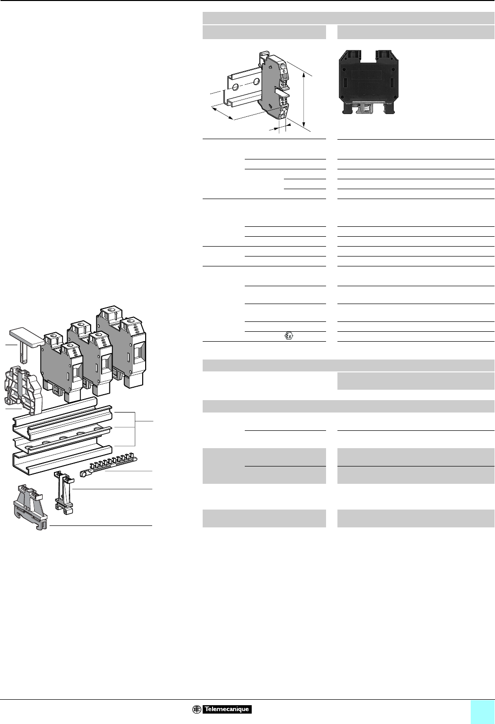
3/17
0
Terminal Blocks, Type AB1 0
Screw clamp technology
Grounding type
Clip-on mounting on 35 mm 1 7 4 rails
Nominal wire size 35 mm2
AB1TP3535U
Approximate dimensions, in. (mm)
Length (a) 2.48 (63)
Width (b) 0.63 (16)
1Height (H)
with
1 rail 2.96 (75.1)
7 rail 2.66 (67.6)
4 rail 2.72 (69)
Wire size, mm2
Stranded without
cable end
10–35
Stranded with cable end 10–35
Solid 10–50
Tightening
torque
IEC 2.5–3.0 N•m
UL 50 lbf-in
Nominal electrical values
IEC/EN 60947-7-1 800 V / 8 kV / 3–125 A
UL File E164359
CCN XCFR2
10–2 AWG, 600 V
CSA File 702070
Class 6228 01
10–2 AWG, 600 V
VDE, group C 750 Vac, 900 Vdc, 138 A
ATEX Exe II II 2 GD 35 mm2, KEMA 02 ATEX 2114 U
Certifications See the tables beginning on page 1/12.
Terminal blocks
No.
points
Sold in
lots of
Catalog number Weight
oz (g)
Green/yellow 2 20 AB1TP3535U 4.48 (127.0)
Accessories
2 Plastic
end clamp
with screw
Width 0.3 in. (7.5 mm)
on 4
— 100 AB1AB7P32 0.15 (4.2)
Width 0.3 in. (8 mm)
on 1 or 7— 100 AB1AB8P35 0.21 (5.9)
3Metal
end clamp
with screw
Width 0.3 in. (7.5 mm)
on 4
—100 AB1AB10M32 0.23 (6.5)
Width 0.3 in. (8 mm)
on 1 or 7—100 AB1AB8M35 0.52 (14.8)
4 Clip-on
plastic
end clamp
Width 0.3 in. (8 mm)
on 1 or 7—100 AB1AB8R35 0.21 (5.9)
5Marker tag holder
for clip-on end clamp
—10 AB1SB4 0.11 (3.1)
6 Marking accessories See pages 5/2 and 5/3
a
b
H
987654321
10
1
6
2
4
5
3
524050
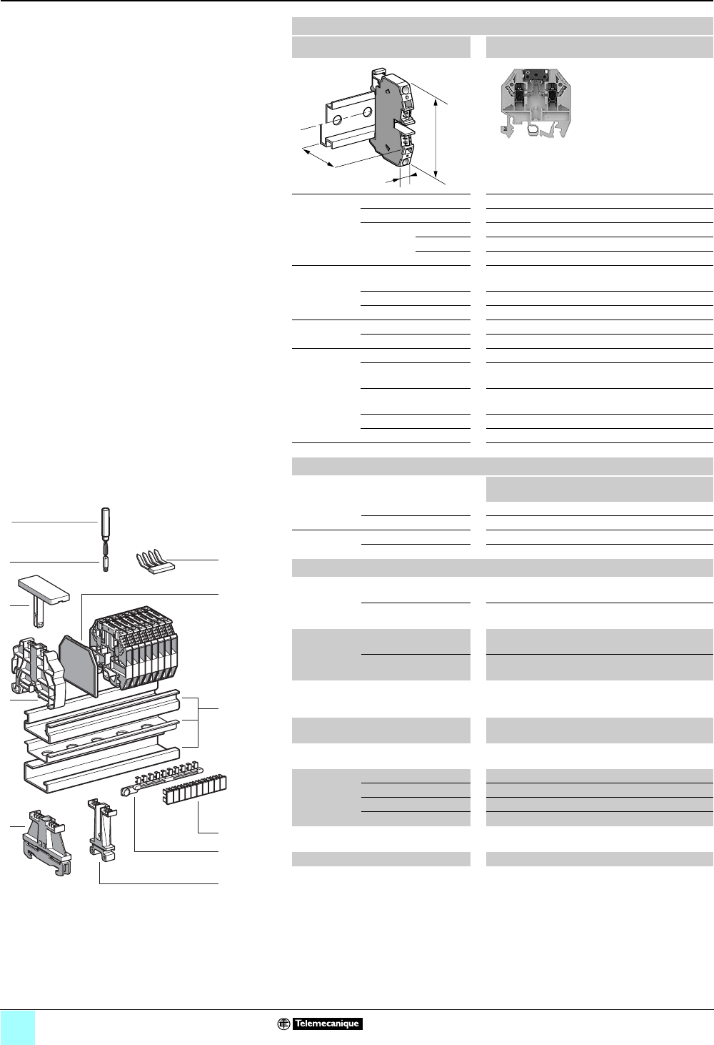
3/18
Terminal Blocks, Type AB1 0
Screw clamp technology
Blade disconnect type
Clip-on mounting on 35 mm 1 7 4 rails
Nominal wire size 4 mm2
AB1SC435U•••••
Approximate
dimensions,
in. (mm)
Length (a) 1.89 + 0.44 (48 + 11.2) for open switch
Width (b) 0.24 (6)
1Height (H)
with
1 rail 2.24 (57)
7 rail 1.95 (49.5)
4 rail 2.13 (54)
Wire size,
mm2Stranded without
cable end
0.5–4
Stranded with cable end 0.5–2.5
Solid 0.5–6
Tightening
torque
IEC 0.5–0.7 N•m
UL 8.0 lbf-in
Nominal
electrical
values
IEC/EN 60947-7-1 800 V / 8 kV / 3 -20 A
UL File E164359
CCN XCFR2
22–10 AWG, 600 V, 20 A
CSA File 702070
Class 6228 01
22–10 AWG, 600 V, 20 A
UTE, category C 500 Vac
VDE, group C 750 Vac, 900 Vdc, 20 A
Certifications See the tables beginning on page 1/12.
a
b
H
Terminal blocks
No.
points
Sold in
lots of
Catalog number Weight
oz (g)
Gray 2100 AB1SC435U 0.42 (12.0)
Blue 2100 AB1SC435UBL 0.42 (12.0)
With 2 test
sockets
Gray 2100 AB1SC435U2PT 0.42 (12.0)
Blue 2100 AB1SC435U2PTBL 0.42 (12.0)
Accessories
2 Plastic
end clamp
with screw
Width 0.3 in (7.5 mm)
on 4
—100 AB1AB7P32 0.15 (4.2)
Width 0.3 in. (8 mm)
on 1 or 7—100 AB1AB8P35 0.21 (5.9)
3Metal
end clamp
with screw
Width 0.4 in. (10 mm)
on 4—100 AB1AB10M32 0.23 (6.5)
Width 0.3 in. (8 mm)
on 1 or 7—100 AB1AB8M35 0.52 (14.8)
4 Clip-on
plastic
end clamp
Width 0.3 in. (8 mm)
on 1 or 7—100 AB1AB8R35 0.21 (5.9)
5Marker tag holder for
clip-on plastic end clamp
—10 AB1SB4 0.11 (3.1)
6 End plate Gray, thickness
0.06 in. (1.5 mm)
—10 AB1PS4 0.05 (1.5)
7Jumpers 2-pole 2100 AB1CC42SC 0.032 (0.9)
3-pole 3100 AB1CC43SC 0.05 (1.4)
4-pole 4100 AB1CC44SC 0.07 (1.9)
10-pole 10 10 AB1CC410SC 0.17 (4.8)
8 Socket for test plug,
∅ 0.09 in. (2.3 mm)
—50 AB1A4 0.018 (0.5)
9Test plug Red —50 AB1AT1 0.06 (1.7)
10/11 Marking accessories See pages 5/2 and 5/3.
1
7
6
10
9
8
7
6
5
4
3
2
1
987654321
10
9
8
5
4
310
11
2
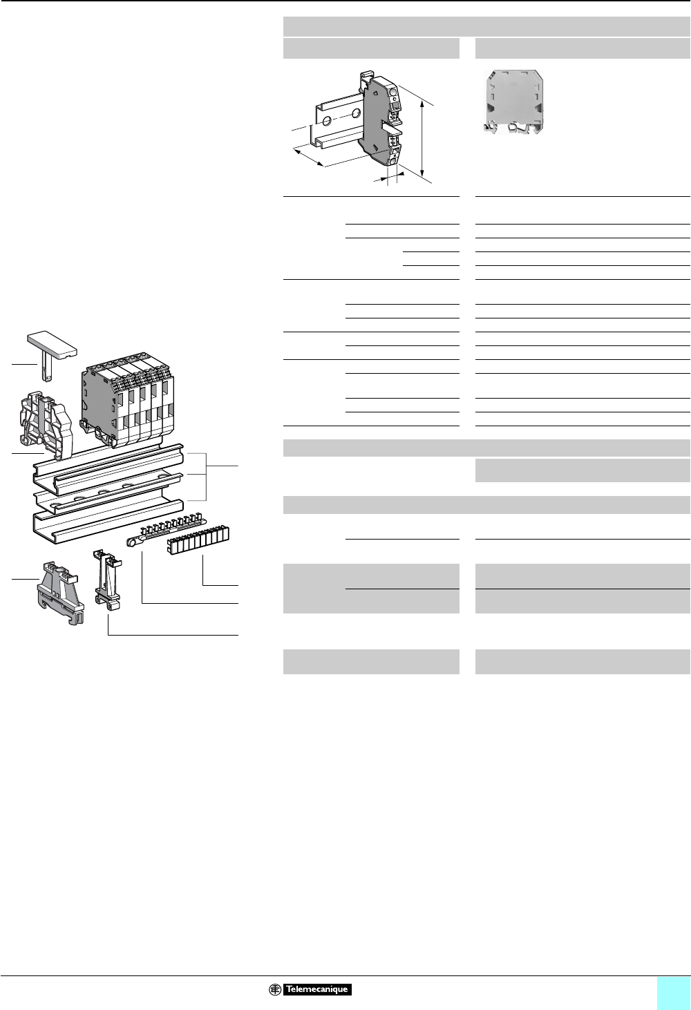
3/19
Terminal Blocks, Type AB1 0
Screw clamp technology
Component, for diode or resistor
Clip-on mounting on 35 mm 1 7 4 rails
Nominal wire size 2.5 mm2
AB1D11435
Approximate dimensions, in. (mm)
Length (a) 1.92 (49)
Width (b) 0.47 (12)
1Height (H)
with
1 rail 2.58 (65.5)
7 rail 2.28 (58)
4 rail 2.46 (62.5)
Wire size,
mm2Stranded without
cable end
0.5–2.5
Stranded with cable end 0.5–1.5
Solid 0.5–2.5
Tightening
torque
IEC 0.5–0.7 N•m
UL 8.0 lbf-in
Nominal
electrical
values
IEC/EN 60947-7-2 800 V / 8 kV / 3 -26 A
UL File E164359
CCN XCFR2
22–14 AWG, 300 V, 6 A
UTE, category C 125 Vac, 125 Vdc
VDE, group C 750 Vac, 900 Vdc, 24A
Certifications See the tables beginning on page 1/12.
a
b
H
Terminal blocks, fixed carrier
No.
points
Sold in
lots of
Catalog number Weight
oz (g)
2 I, 2 O Gray 2/2 50 AB1D11435U 0.88 (25.0)
Accessories
2 Plastic
end clamp
with screw
Width 0.3 in. (7.5 mm)
on 4
—100 AB1AB7P32 0.15 (4.2)
Width 0.3 in. (8 mm)
on 1 or 7—100 AB1AB8P35 0.21 (5.9)
3Metal
end clamp
with screw
Width 0.4 in. (10 mm)
on 4—100 AB1AB10M32 0.23 (6.5)
Width 0.3 in. (8 mm)
on 1 or 7—100 AB1AB8M35 0.52 (14.8)
4 Clip-on
plastic
end clamp
Width 0.3 in. (8 mm)
on 1 or 7—100 AB1AB8R35 0.21 (5.9)
5Marker tag holder
for clip-on plastic end clamp
—10 AB1SB4 0.11 (3.1)
6/7 Marking accessories See pages 5/2 and 5/3.
10
9
8
7
6
5
4
3
2
1
987654321
10
1
5
4
3
6
7
2
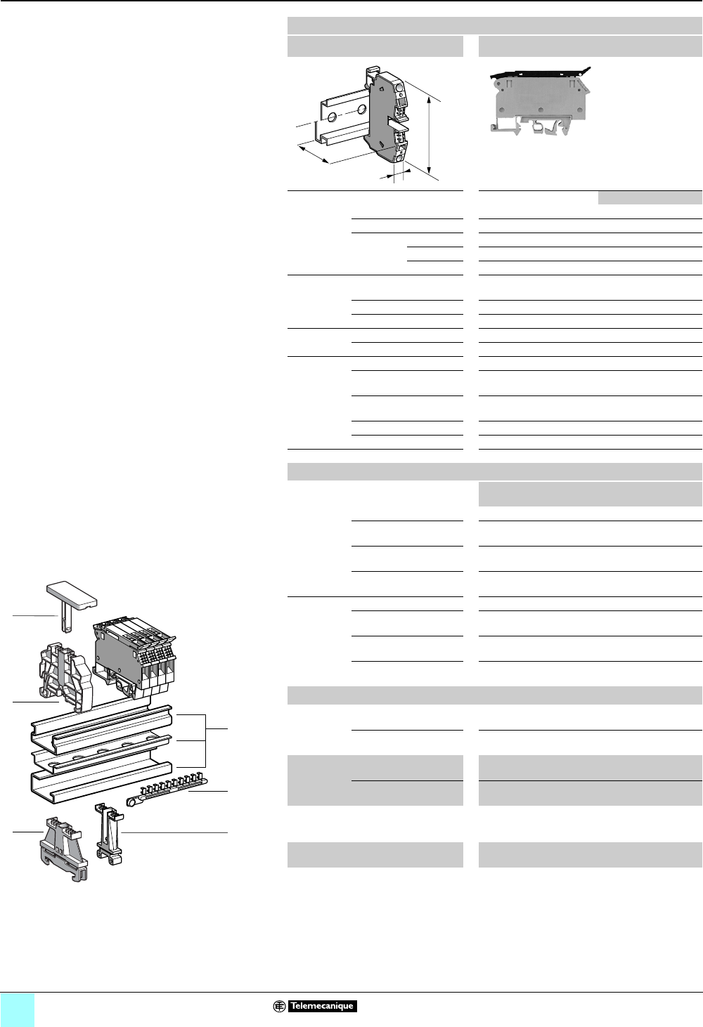
3/20
Terminal Blocks, Type AB1 0
Screw clamp technology
Fused disconnect
Clip-on mounting on 35 mm 1 7 4 rails
Nominal wire size 4 mm2
AB1FUSE435U•••
Approximate dimensions, in. (mm) …U5X …U6X
Length (a) 3.04 (77.2)
Width (b) 0.31 (8) 0.39 (10)
1Height (H)
with
1 rail 2.44 (62)
7 rail 2.15 (54.5)
4 rail 2.32 (59)
Wire size,
mm2Stranded without
cable end
0.5–4
Stranded with cable end 0.5–2.5
Solid 0.5–6
Tightening
torque
IEC 0.5–0.7 N•m
UL 7.0 lbf-in
Nominal
electrical
values
IEC/EN 60947-7-1 800 V / 8 kV / 3 A 6.3 A 10 A
UL File E164359
CCN XCFR2
22–10 AWG, 600 V 15 A 15 A
CSA File 702070
Class 6228 01
20–10 AWG, 600 V 6.3 A 10 A
UTE, category C 500 Vac
VDE, group C 750 Vac, 900 Vdc 6.3 A 10 A
Certifications See the tables beginning on page 1/12.
a
b
H
Terminal blocks
No.
points
Sold in
lots of
Catalog number Weight
oz (g)
5 x 20 or 5 x 25 fuse (gray) —50 AB1FUSE435U5X 0.56 (16.0)
With 5-12 V LED (red)
(2.3.–7 mA)
—50 AB1FUSE435U5XJ 0.56 (16.0)
With 12-24 V LED (red)
(2.8–6.2 mA)
—50 AB1FUSE435U5XB 0.56 (16.0)
With 110-250 V neon
(0.13–0.55 mA)
—50 AB1FUSE435U5XM 0.56 (16.0)
6.3 x 32 fuse (gray) —50 AB1FUSE435U6X 0.88 (25.0)
With 5-12 V LED (red)
(2.3–7 mA)
—50 AB1FUSE435U6XJ 0.88 (25.0)
With 12-24 V LED (red)
(2.8–6.2 mA)
—50 AB1FUSE435U6XB 0.88 (25.0)
With 110-250 V neon
(0.13–0.55 mA)
—50 AB1FUSE435U6XM 0.88 (25.0)
Accessories
2 Plastic
end clamp
with screw
Width 0.3 in. (7.5 mm )
on 4
—100 AB1AB7P32 0.15 (4.2)
Width 0.3 in. (8 mm )
on 1 or 7—100 AB1AB8P35 0.21 (5.9)
3Metal
end clamp
with screw
Width 0.4 in. (10 mm)
on 4—100 AB1AB10M32 0.23 (6.5)
Width 0.3 in. (8 mm)
on 1 or 7—100 AB1AB8M35 0.52 (14.8)
4Clip-on
plastic
end clamp
Width 0.3 in. (8 mm)
on 1 or 7—100 AB1AB8R35 0.21 (5.9)
5Marker tag holder for
clip-on plastic end clamp
—10 AB1SB4 0.11 (3.1)
6 Marking accessories See pages 5/2 and 5/3.
1
6
23
987654321
10
4
5
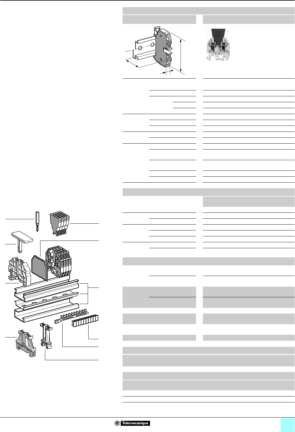
3/21
Terminal Blocks, Type AB1 0
Screw clamp technology
Disconnect (removable carrier), for diode, resistor,
or cylindrical fuse
Clip-on mounting on 35 mm 1 7 4 rails
Nominal wire size 4 mm2
AB1SF435U
Approximate dimensions, in. (mm)
Length (a) 1.89 (48)
Width (b) 0.24 (6)
1Height (H)
with
1 rail 2.24 (57) + 0.75 (19) for carrier
7 rail 1.95 (49.5) + 0.75 (19) for carrier
4 rail 2.13 (54) + 0.75 (19) for carrier
Wire size,
mm2Stranded w/o cable end 0.5–4
Stranded + cable end 0.5–2.5
Solid 0.5–6
Tightening
torque
IEC 0.5–0.7 N•m
UL 8.0 lbf-in
Nominal
electrical
values
(1) (2)
IEC/EN 60947-7-2 800 V / 8 kV / 3 -6.3 A
UL File E164359
CCN XCFR2
22–10 AWG, 300 V, 10 A
CSA File 702070
Class 6228 01
22–10 AWG, 250 V, 6.3 A
UTE, category C 500 Vac, 500 Vdc
VDE, group C 750 Vac, 900 Vdc, 10 A
Certifications See the tables beginning on page 1/12.
Terminal blocks, removable carrier (3)
No.
points
Sold in
lots of
Catalog number Weight
oz (g)
Gray 2100 AB1SF435U 0.32 (9.0)
10 Removable
carrier
For diode or resistor —100 AB1SV1 0.16 (4.5)
With diode 1N4007.1 —100 AB1SV2 0.16 (4.5)
Removable
carrier (for
5 x 20 fuse)
Fuse only —100 AB1SF520 0.16 (4.5)
With 24 V red LED —100 AB1SF520B 0.16 (4.5)
With 220 V red LED —100 AB1SF520M 0.16 (4.5)
Removable
and pivoting
carrier
For 5 x 20 fuse —100 AB1SF520D 0.21 (6.0)
For 6.3 x 32 fuse —100 AB1SF6332D 0.29 (8.2)
Accessories
2Plastic
end clamp
with screw
Width 0.3 in. (7.5 mm)
on 4
—100 AB1AB7P32 0.15 (4.20)
Width 0.3 in. (8 mm)
on 1 or 7—100 AB1AB8P35 0.21 (5.9)
3Metal
end clamp
with screw
Width 0.4 in. (10 mm)
on 4—100 AB1AB10M32 0.23 (6.5)
Width 0.3 in. (8 mm)
on 1 or 7—100 AB1AB8M35 0.52 (14.8)
4 Clip-on plastic end clamp (4) —100 AB1AB8R35 0.21 (5.9)
5Marker tag holder for
clip-on plastic end clamp
—10 AB1SB4 0.11 (3.1)
6 End plate Gray, thickness
0.06 in. (1.5 mm)
—50 AB1PS4 0.05 (1.5)
7Test plug Red —50 AB1AT1 0.07 (1.9)
8/9 Marking accessories See pages 5/2 and 5/3.
a
b
H
1
3
4
5
7
10
9
8
7
6
5
4
3
2
1
987654321
10
10
6
8
9
2
Table Footnotes:
(1) The voltage/current carrying capacity is determined by
the component (fuse and/or diode) used.
(2) Repetitive peak reverse voltage for diodes is 1000 V.
(3) Fuses and diodes not included, except for AB1SV2.
(4) Width 0.3 in. (8 mm) on
1
or
7
.
Carrier characteristics
Nominal voltage Position of terminal block
(Power loss 1.5 W) end juxtaposed
250 V 6.3 A 4 A
Blown fuse indicator characteristics
Catalog number Nominal
voltage
Current
consumption
AB1SF520B 24 V 10.3 mA
AB1SF520M 220–250 V 0.3 mA
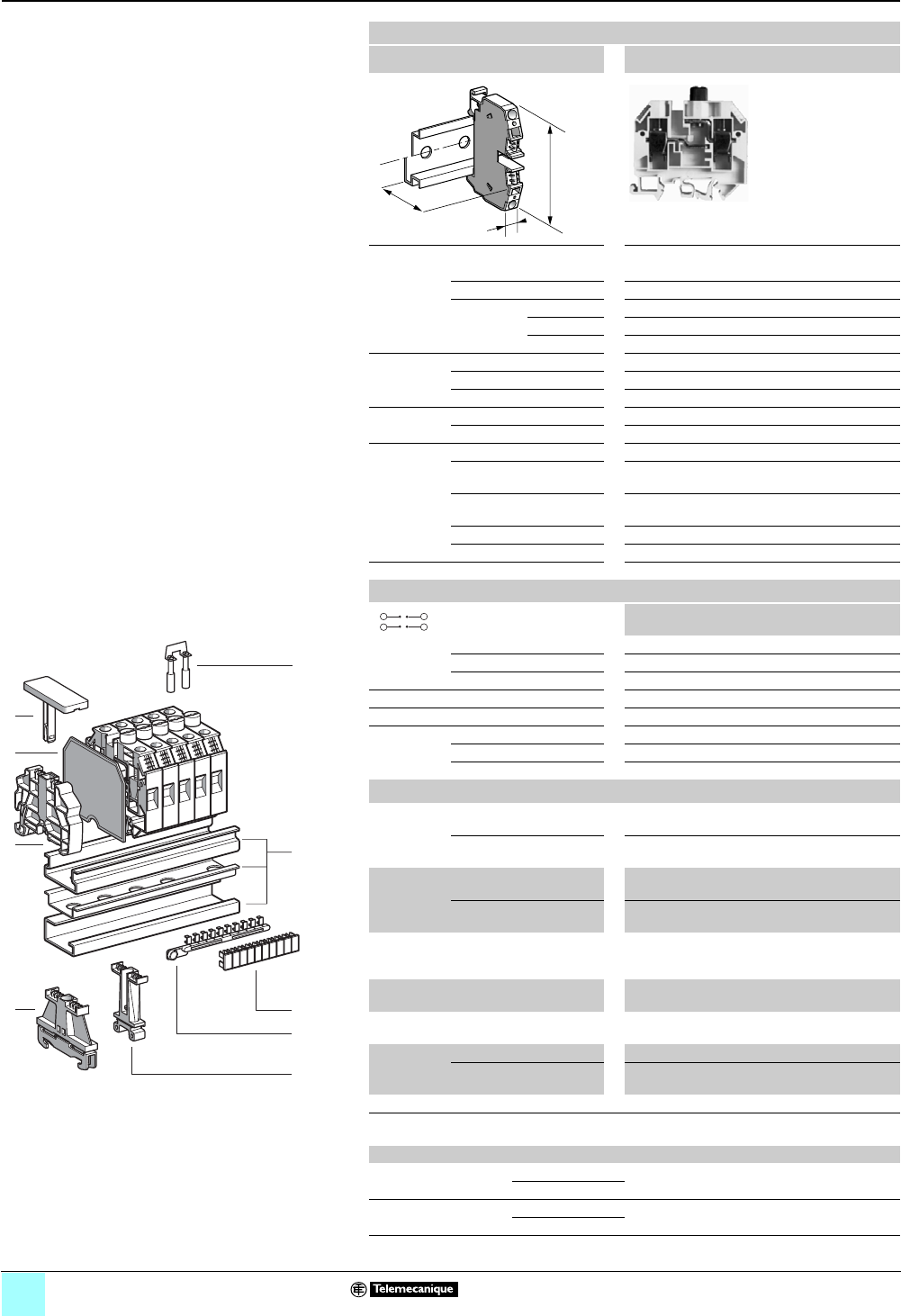
3/22
Terminal Blocks, Type AB1 0
Screw clamp technology
Fixed carrier, for cylindrical fuse
Clip-on mounting on 35 mm 1 7 4 rails
Nominal wire size 10 mm2
AB1FU10•35U••
Approximate dimensions, in. (mm)
Length (a) 2.56 (65)
Width (b) 0.47 (12)
1Height (H)
with
1 rail 2.60 (66) + 0.43 (10.8) for fuse cap
7 rail 2.30 (58.5) + 0.43 (10.8) for fuse cap
4 rail 2.48 (63) + 0.43 (10.8) for fuse cap
Wire size,
mm2Stranded w/o cable end 1–10
Stranded + cable end 1–10
Solid 10–16
Tightening
torque
IEC 2.0–2.5 N•m
UL 35 lbf-in
Nominal
electrical
values (1)
IEC/EN 60947-7-1 500 V / 6 kV / 3 A
UL (2) File E164359
CCN XCFR2
22–6 AWG, 600 V, 15 A
CSA (2) File 702070
Class 6228 01
16–6 AWG, 600 V,15 A
UTE, category C 400 Vac, 250 Vdc, 10 A
VDE, group C (2) 500 Vac, 600 Vdc, 15 A
Certifications See the tables beginning on page 1/12.
a
b
H
Terminal blocks (3)
No.
points
Sold in
lots of
Catalog Number Weight
oz (g)
5 x 20 fuse
gray
Without indicator lamp —50 AB1FU10135U 1.38 (39.0)
With 28 V yellow LED —50 AB1FU10135UB 1.38 (39.0)
With 250 V red LED —50 AB1FU10135UU 1.38 (39.0)
5 x 25 fuse, gray, without indicator lamp —50 AB1FU10235U 1.38 (39.0)
5 x 30 fuse, gray, without indicator lamp —50 AB1FU10335U 1.38 (39.0)
6.3 x 32 fuse
gray
Without indicator lamp —50 AB1FU10435U 1.38 (39.0)
With 28 V yellow LED —50 AB1FU10435UB 1.38 (39.0)
With 250 V red Neon —50 AB1FU10435UFS 1.38 (39.0)
Accessories
2 Plastic end
clamp with
screw
Width 0.3 in. (7.5 mm)
on 4
—100 AB1AB7P32 0.15 (4.2)
Width 0.3 in. (8 mm)
on 1 or 7—100 AB1AB8P35 0.21 (5.9)
3Metal
end clamp
with screw
Width 0.4 in. (10 mm)
on 4—100 AB1AB10M32 0.23 (6.5)
Width 0.3 in. (8 mm)
on 1 or 7—100 AB1AB8M35 0.52 (14.8)
4 Clip-on
plastic end
clamp
Width 0.3 in. (8 mm)
on 1 or 7—100 AB1AB8R35 0.21 (5.9)
5Marker tag holder for
clip-on plastic end clamp
—10 AB1SB4 0.11 (3.1)
6 End plate
gray, thickness 0.08 in. (2 mm)
50 AB1TF 0.17 (4.8)
7Jumpers
with screws
2 poles (non-insulated) 250 AB1BF2 0.17 (4.7)
30 poles
(non-insulated)
30 10 AB1BF 0.44 (12.5)
8/9 Marking accessories See pages 5/2 and 5/3.
10
9
8
7
6
5
4
3
2
1
987654321
10
7
1
3
4
5
6
9
8
2
(1) Voltage and current are determined by the fuse used.
(2) Nominal electrical values according to the type of fuse used:
Nominal electrical values UL VDE CSA
Current consumption:
24 mA
AB1FU10435UB 28 V 28 V 28 V
AB1FU10135UB
Current consumption:
0.16 -0.8 mA
AB1FU10435UFS 150 V 110 -500 V 500 V
AB1FU10135UU
(3) Fuses not included.
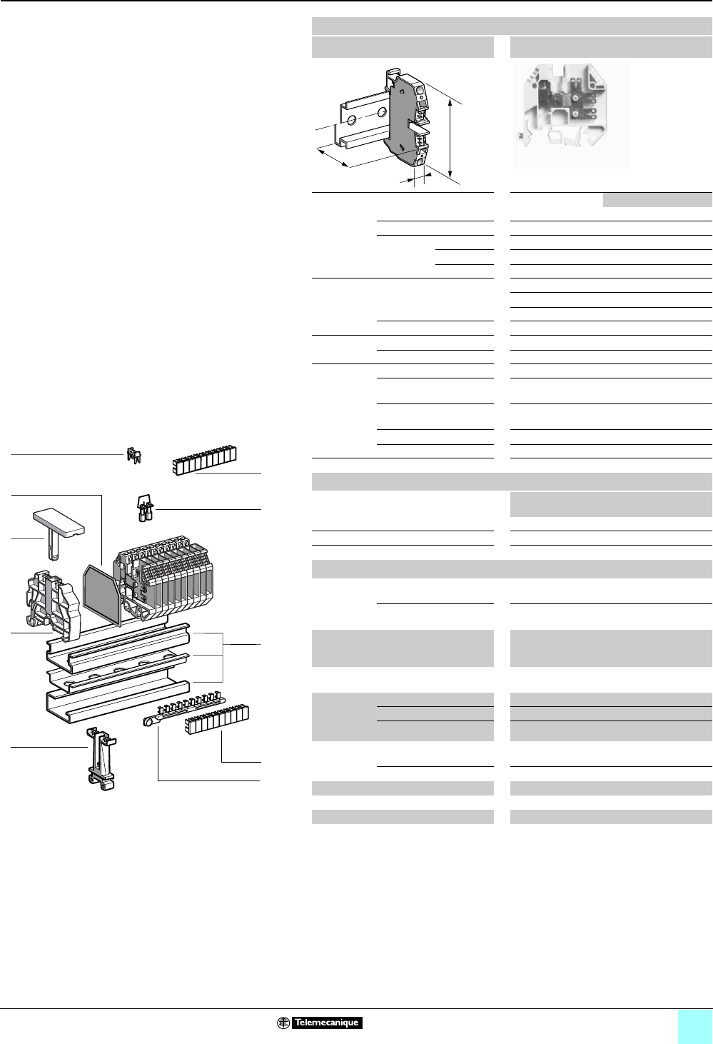
3/23
Terminal Blocks, Type AB1 0
Screw clamp technology
Screw-clip type
Clip-on mounting on 35 mm 1 7 4 rails
Nominal wire size 4 mm2
AB1F••35U
Approximate dimensions, in. (mm) AB1FV AB1FC
Length (a) 1.89 (48) 2.68 (68)
Width (b) 0.24 (6)
1Height (H)
with
1 rail 2.30 (58.5) 2.62 (66.5)
7 rail 1.93 (49)
4 rail 2.13 (54)
Wire size,
mm2Stranded
without cable end
0.5–4 (screw)
0.5–2.5 [3 clips, 0.25 x 0.03 (6.3 x 0.8)]
0.5–1.5 [6 clips, 0.11 x 0.03 (2.8 x 0.8)]
Solid 0.5–6
Tightening
torque
IEC 0.5–0.7 N•m
UL 4.0 lbf-in
Nominal
electrical
values
IEC/EN 60947-7-1 800 V / 8 kV / 3–20 A
UL File E164359
CCN XCFR2
22–12 AWG, 300 V, 10 A
CSA File 702070
Class 6228 01
22–12 AWG, 300 V, 10 A
UTE, category C 400 Vac, 250 Vdc
VDE, group C 750 Vac, 900 Vdc, 20 A
Certifications See the tables beginning on page 1/12.
Terminal blocks
No.
points
Sold in
lots of
Catalog
number
Weight
oz (g)
Screw-clip, top and side access, gray —100 AB1FV135U 0.41 (11.5)
Screw-clip, top access, gray —100 AB1FC335U 0.41 (11.5)
Clip-clip, top access, gray —100 AB1FF235U 0.41 (11.5)
Accessories
2Plastic
end clamp
with screw
Width 0.3 in. (7.5 mm)
on 4
—100 AB1AB7P32 0.15 (4.2)
Width 0.3 in. (8 mm)
on 1 or 7—100 AB1AB8P35 0.21 (5.9)
3Clip-on
plastic
end clamp
Width 0.3 in. (8 mm)
on 1 or 7—100 AB1AB8R35 0.21 (5.9)
4 Marker tag holder for
clip-on plastic end clamp
—10 AB1SB4 0.11 (3.1)
5End plate
thickness
0.06 in.
(1.5 mm)
AB1FV —50 AB1TC01 0.09 (2.5)
AB1FC —50 AB1TC3 0.09 (2.6)
AB1FF —50 AB1TC02 0.09 (2.6)
6Jumpers Non-insulated —10 AB1AL4 5.11
(145.0)
Insulated 210 AB1ALN42 0.06 (1.7)
7Protective cover (single-pole link) —100 AB1CA4 0.004 (0.1)
8 Protective cover (10-pole link) —50 AB1CA410ET 0.04 (1.0)
10/11 Marking accessories See pages 5/2 and 5/3.
a
b
H
10
9
8
7
6
5
4
3
2
1
987654321
10
7
5
8
6
1
4
3
2
11
10
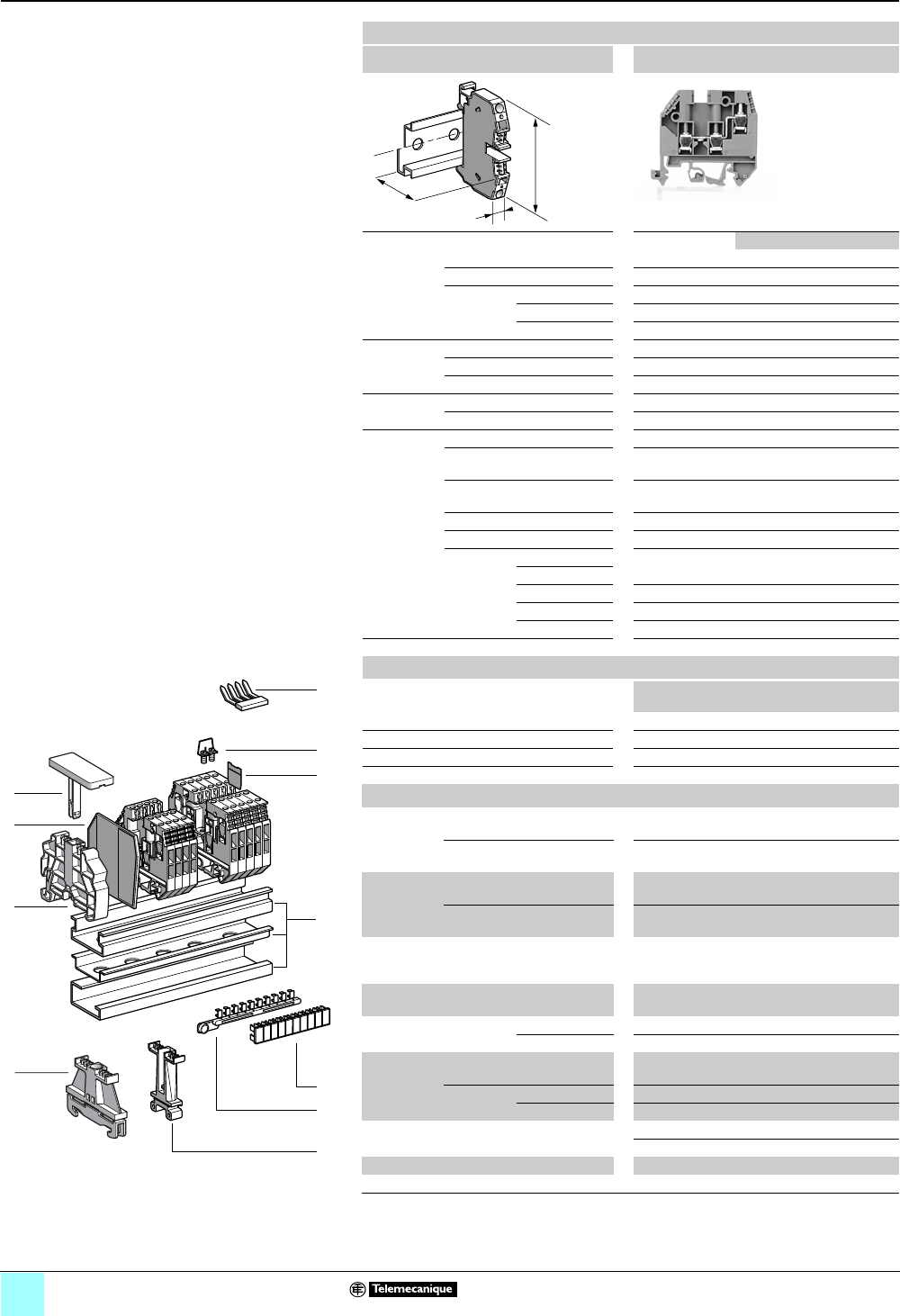
3/24
Terminal Blocks, Type AB1 0
Screw clamp technology
Double deck, multi-pole
Clip-on mounting on 35 mm 1 7 4 rails
Nominal wire size 4 mm2
AB1ETN•35U
Approximate dimensions, in. (mm) ETN235 / 435 ETN335
Length (a) 2.19 (55.6) 1.88 (47.8)
Width (b) 0.24 (6 )
1Height (H)
with
1 rail 2.20 (56)
7 rail 1.91 (48.5)
4 rail 2.09 (53)
Wire size,
mm2Stranded without cable end 0.5–4
Stranded with cable end 0.5–2.5
Solid 0.5–6
Tightening
torque
IEC 0.5–0.7 N•m
UL 6.0 lbf-in
Nominal
electrical
values
IEC/EN 60947-7-1 800 V / 8 kV / 3–32 A
UL File E164359
CCN XCFR2
22–10 AWG, 300 V, 30 A
CSA File 702070
Class 6228 01
20–10 AWG, 300 V, 10 A
UTE, category C 400 Vac, 250 Vdc
VDE, group C 380 Vac, 450 Vdc, 34 A
ATEX Exe II II 2 GD:
4 mm2AB1ETN235U 275 V, 22 A, KEMA 02 ATEX 2114 U
AB1ETN335U 420 V, 30 A, KEMA 02 ATEX 2114 U
AB1ETN435U 420 V, 29 / 30 A, KEMA 02 ATEX 2114 U
AB1ETNTP43U KEMA 02 ATEX 2114 U
Certifications See the tables beginning on page 1/12.
a
b
H
Terminal blocks
No.
points
Sold in
lots of
Catalog
Number
Weight
oz (g)
2 I, 2 O Gray 2/2 100 AB1ETN235U 0.53 (15.1)
3I/O Gray 3100 AB1ETN335U 0.53 (15.1)
4I/O Gray 4100 AB1ETN435U 0.53 (15.1)
With grounding Green/Yellow 4100 AB1ETNTP435U 0.56 (16.0)
Accessories
2Plastic
end clamp
with screw
Width 0.3 in. (7.5 mm)
on 4 —100 AB1AB7P32 0.15 (4.2)
Width 0.3 in. (8 mm)
on 1 or 7—100 AB1AB8P35 0.21 (5.9)
3Metal
end clamp
with screw
Width 0.4 in. (10 mm)
on 4—100 AB1AB10M32 0.23 (6.5)
Width 0.3 in. (8 mm)
on 1 or 7—100 AB1AB8M35 0.52 (14.8)
4Clip-on
plastic
end clamp
Width 0.3 in. (8 mm)
on 1 or 7—100 AB1AB8R35 0.21 (5.9)
5Marker tag holder for
clip-on plastic end clamp
—10 AB1SB4 0.11 (3.1)
6End plate, thickness
0.06 in. (1.5 mm)
ETN235 / 435 —10 AB1TEN4 0.021 (0.6)
ETN335 —10 AB1TEN3 0.021 (0.6)
7Jumper
with
screws
Non-
insulated
ETN235 70 10 AB1BE 5.11
(145.0)
Insulated
(1)
ETN235 210 AB1BE2 0.032 (0.9)
ETN335 / 435 12 10 AB1ALN412 0.63 (18.0)
8Insulated jumper 650 AB1CC42RO 0.56 (16.0)
10 100 AB1CC410RO 0.56 (16.0)
9Partition plate (yellow) 1100 AB1CJ3 0.011 (0.3)
10/11 Marking accessories See pages 5/2 and 5/3.
(1) Depending on the size of the terminal block, other jumpers between 2 and 12 points may be
available.
1
9
7
8
10
9
8
7
6
5
4
3
2
1
987654321
10
3
4
5
6
10
11
2
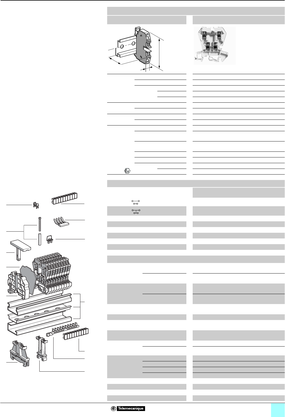
3/25
Terminal Blocks, Type AB1 0
Screw clamp technology
Double deck
Clip-on mounting on 35 mm 1 7 4 rails
Nominal wire size 4 mm2
AB1ET435U••••
Approximate
dimensions,
in. (mm)
Length (a) 2.43 (61.6)
Width (b) 0.24 (6)
1Height (H)
with
1 rail 2.78 (70.5)
7 rail 2.48 (63)
7 rail 2.66 (67.5)
Wire size
(mm2)
Stranded 0.5–4 (no cable end), 0.5–2.5 (with cable end)
Solid 0.5–4
Tightening
torque
IEC 0.5–0.7 N•m
UL 6.0 lbf-in
Nominal
electrical
values
IEC/EN 60947-7-1 400 V / 6 kV / 3–32 A
UL File E164359
CCN XCFR2
22–10 AWG, 300 V, 20 A
CSA File 702070
Class 6228 01
20–12 AWG, 300 V, 10 A
UTE, category C 400 Vac, 250 Vdc
VDE, group C 380 Vac, 450 Vdc, 34 A
ATEX Exe II
II 2 GD
AB1ET435U 4 mm2, 275 V, 24 A, KEMA 02 ATEX 2114 U
AB1ET435UTP 4 mm2, KEMA 02 ATEX 2114 U
Certifications See the tables beginning on page 1/12.
Terminal blocks
No. Sold in
lots of
Catalog number Weight
oz (g)
2 I , 2 O Gray 2/2 100 AB1ET435U 0.53 (15.1)
4 I/O Black 4100 AB1ET435U2 0.53 (15.1)
Grounding type Green/Yellow 4100 AB1ET435UTP 0.53 (15.1)
24 V red LED Red 4100 AB1ET435UBRO 0.56 (16.0)
24 V green LED Red 4100 AB1ET435UBVE 0.53 (15.1)
24 V red LED Orange 4100 AB1ET435UBGE 0.53 (15.1)
Diode, uppr-lowr. Red 4100 AB1ET435UHBRO 0.53 (15.1)
Diode, lowr-uppr. Orange 4100 AB1ET435UBHGE 0.56 (16.0)
2 diodes Red 4100 AB1ET435U2DRO 0.53 (15.1)
Accessories
2 Plastic end clamp
with screw
Width 0.3 in. (7.5 mm)
on 4
—100 AB1AB7P32 0.15 (4.2)
Width 0.3 in. (8 mm)
on 1 or 7—100 AB1AB8P35 0.21 (5.9)
3Metal end clamp
with screw
Width 0.4 in. (10 mm)
on 4
—100 AB1AB10M32 0.23 (6.5)
Width 0.3 in. (8 mm)
on 1 or 7—100 AB1AB8M35 0.52 (14.8)
4Clip-on plastic
end clamp
Width 0.3 in. (8 mm)
on 1 or 7—100 AB1AB8R35 0.21 (5.9)
5Marker tag holder for clip-on end clamp —10 AB1SB4 0.11 (3.1)
6 End plate Gray, thickness
0.06 in. (1.5 mm)
—50 AB1TE 0.12 (3.5)
Partition plate Gray, thickness
0.06 in. (1.5 mm)
—50 AB1AS4ET 0.12 (3.3)
7Jumper,
non-isolated
with screw
2-pole 210 AB1BE2 0.032 (0.9)
70-pole 70 10 AB1BE 5.11 (145.0)
8Jumper Lower, 2 poles 2100 AB1CC42INFRO 0.032 (0.9)
Lower, 6 poles 6100 AB1CC46INFRO 0.11 (3.0)
Upper, 2 poles 2100 AB1CC42SUPRO 0.032 (0.9)
Upper, 6 poles 6100 AB1CC46SUPRO 0.11 (3.0)
9 Jumper between 2 decks —50 AB1L2ET 0.09 (2.5)
10 Protective cover (single-pole link) 1100 AB1CA4 0.004 (0.1)
11 Protective cover (10-pole link) 10 50 AB1CA410ET 0.035 (1.0)
12/13 Marking accessories See pages 5/2 and 5/3.
a
b
H
1
9
7
987654321
10
10
9
8
7
6
5
4
3
2
1
8
3
4
5
6
13
12
2
10 11
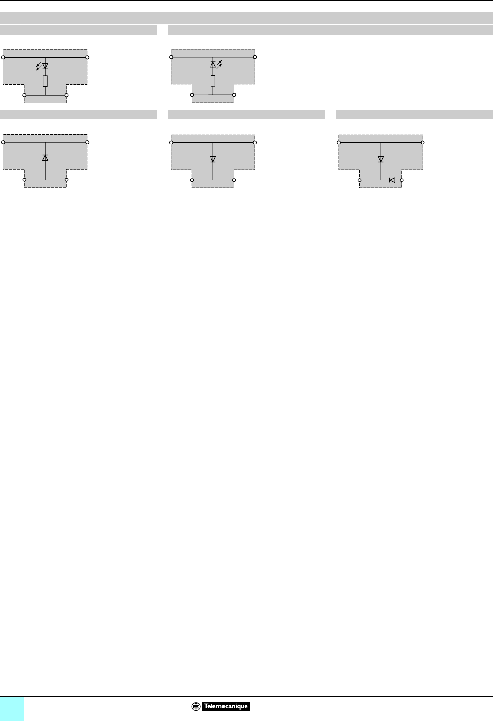
3/26
Terminal Blocks, Type AB1 0
Screw clamp technology
Double deck
Wiring Diagrams
AB1ET435UBRO/BVE AB1ET435UBGE
(Resistance = 2.2 kΩ, 0.35 W) (Resistance = 2.2 kΩ, 0.35 W)
AB1ET435UHBRO AB1ET435UBHGE AB1ET435U2DRO
(1 A / 1000 V) (1 A / 1000 V) (1 A / 1000 V)

3/27
Terminal Blocks, Type AB1 0
Screw clamp technology
For 3-wire proximity sensors
Clip-on mounting on 35 mm 1 7 4 rails
Nominal wire size 2.5 mm2
AB1DDP235U••
Approximate dimensions, in. (mm)
Length (a) 2.10 (53.4)
Width (b) 0.24 (6)
1Height (H)
with
1 rail 3.00 (76.1)
7 rail 2.70 (68.6)
4 rail 2.88 (73.1)
Wire size,
mm2Stranded without
cable end
0.5–2.5
Stranded with cable end 0.5–1.5
Solid 0.5–4
Tightening
torque
IEC 0.4–0.6 N•m
UL 8.0 lbf-in
Nominal
electrical
values (1)
IEC/EN 60947-7-1 250 V / 4 kV / 3–24 A
UL File E164359
CCN XCFR2
22–12 AWG, 300 V, 25 A
CSA File 702070
Class 6228 01
20–12 AWG, 300 V, 25 A
VDE, group C 250 Vac, 300 Vdc, 26 A
Certifications See the tables beginning on page 1/12.
a
b
H
Terminal blocks (2)
No.
points
Sold in
lots of
Catalog number Weight
oz (g)
Without LED Gray 1100 AB1DDP235U 0.35 (10.0)
NPN 24 V LED (+) (green) Gray 1100 AB1DDP235ULP 0.35 (10.0)
PNP 24V LED (-) (green) Gray 1100 AB1DDP235ULM 0.35 (10.0)
Accessories
2 Plastic
end clamp
with screw
Width 0.3 in. (7.5 mm)
on 4 —100 AB1AB7P32 0.15 (4.2)
Width 0.3 in. (8 mm)
on 1 or 7—100 AB1AB8P35 0.21 (5.9)
3Metal
end clamp
with screw
Width 0.4 in. (10 mm)
on 4—100 AB1AB10M32 0.23 (6.5)
Width 0.3 in. (8 mm)
on 1 or 7—100 AB1AB8M35 0.52 (14.8)
4 Clip-on
plastic
end clamp
Width 0.3 in. (8 mm)
on 1 or 7—100 AB1AB8R35 0.21 (5.9)
5Marker tag holder
for clip-on plastic end clamp
—10 AB1SB4 0.11 (3.1)
6 Partition,
thickness 0.08 in. (2 mm)
Gray —10 AB1ACD2 0.18 (5.0)
7Insulated jumper Red 12 10 AB1ALD12R 0.19 (5.5)
Blue 12 10 AB1ALD12B 0.18 (5.0)
Red 70 10 AB1ALD100R 6.00
(170.0)
Blue 70 10 AB1ALD100B 6.00
(170.0)
8/9 Marking accessories See pages 5/2 and 5/3.
(1) 24 Vdc with LED.
(2) For recommended operating and connection diagrams, see page 3/31.
1
10
9
8
7
6
5
4
3
2
1
987654321
10
3
4
5
7
6
9
8
2
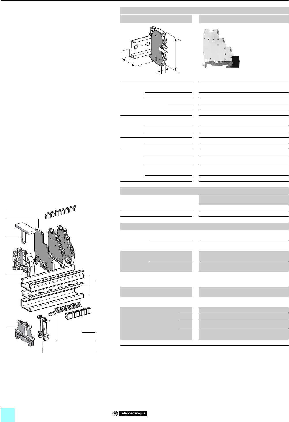
3/28
Terminal Blocks, Type AB1 0
Screw clamp technology
For 3-wire proximity sensors
Clip-on mounting on 35 mm 1 7 4 rails
Nominal wire size 2.5 mm2
AB1DDP235T••
Approximate dimensions, in. (mm)
Length (a) 2.52 (64)
Width (b) 0.24 (6)
1Height (H)
with
1 rail 3.00 (76.1)
7 rail 2.70 (68.6)
4 rail —
Wire size,
mm2Stranded without
cable end
0.5–2.5
Stranded with cable end 0.5–1.5
Solid 0.5–4
Tightening
torque
IEC 0.4–0.6 N•m
UL 8.0 lbf-in
Nominal
electrical
values (1)
IEC/EN 60947-7-1 250 V / 4 kV / 3–24 A
UL File E164359
CCN XCFR2
22–12 AWG, 300 V, 25 A
CSA File 702070
Class 6228 01
22–12 AWG, 300 V, 25 A
VDE, group C 250 Vac, 300 Vdc, 26 A
Certifications See the tables beginning on page 1/12.
a
b
H
Terminal blocks (2)
No.
points
Sold in
lots of
Catalog number Weight
oz (g)
Without LED Gray 1100 AB1DDP235T 0.53 (15.0)
NPN 24 V LED (+) (green) Gray 1100 AB1DDP235TLP 0.53 (15.0)
PNP 24V LED (-) (green) Gray 1100 AB1DDP235TLM 0.53 (15.0)
Accessories
2Plastic
end clamp
with screw
Width 0.3 in. (7.5 mm)
on 4 — — — —
Width 0.3 in. (8 mm)
on 1 or 7—100 AB1AB8P35 0.21 (5.9)
3Metal
end clamp
with screw
Width 0.4 in. (10 mm)
on 4— — — —
Width 0.3 in. (8 mm)
on 1 or 7—100 AB1AB8M35 0.52 (14.8)
4Clip-on
plastic
end clamp
Width 0.3 in. (8 mm)
on 1 or 7—100 AB1AB8R35 0.21 (5.9)
5Marker tag holder for
clip-on plastic end clamp
—10 AB1SB4 0.11 (3.1)
6 Partition,
thickness 0.08 in. (2 mm)
Gray —10 AB1ACD2 0.18 (5.0)
7Insulated jumper Red 12 10 AB1ALD12R 0.18 (5.0)
Blue 12 10 AB1ALD12B 0.18 (5.0)
Red 70 10 AB1ALD100R 6.00
(170.0)
Blue 70 10 AB1ALD100B 6.00
(170.0)
8/9 Marking accessories See pages 5/2 and 5/3.
(1) 24 Vdc with LED.
(2) For recommended operating and connection diagrams, see page 3/31.
1
10
9
8
7
6
5
4
3
2
1
987654321
10
3
4
5
7
6
9
8
2
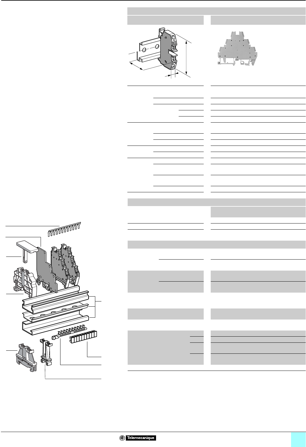
3/29
Terminal Blocks, Type AB1 0
Screw clamp technology
For 3-wire proximity sensors
Clip-on mounting on 35 mm 1 7 4 rails
Nominal wire size 2.5 mm2
AB1ET3235U
Approximate dimensions, in. (mm)
Length (a) 3.13 (79.4)
Width (b) 0.24 (6)
1Height (H)
with
1 rail 3.00 (76.1)
7 rail 2.70 (68.6)
4 rail 2.88 (73.1)
Wire size,
mm2Stranded without
cable end
0.5–2.5
Stranded with cable end 0.5–1.5
Solid 0.5–4
Tightening
torque
IEC 0.4–0.6 N•m
UL 8.0 lbf-in
Nominal
electrical
values (1)
IEC/EN 60947-7-1 400 V / 6 kV / 3–24 A
UL File E164359
CCN XCFR2
22–12 AWG, 300 V, 25 A
CSA File 702070
Class 6228 01
22–12 AWG, 300 V, 25 A
VDE, group C 250 Vac, 300 Vdc, 26 A
Certifications See the tables beginning on page 1/12.
a
b
H
Terminal blocks (2)
No.
points
Sold in
lots of
Catalog number Weight
oz (g)
Without LED Gray 1100 AB1ET3235U 0.39 (11.0)
NPN 24 V LED (+) (green) Gray — — — —
PNP 24V LED (-)
(green)
Gray — — — —
Accessories
2Plastic
end clamp
with screw
Width 0.3 in. (7.5 mm)
on 4 —100 AB1AB7P32 0.15 (4.2)
Width 0.3 in. (8 mm)
on 1 or 7—100 AB1AB8P35 0.21 (5.9)
3Metal
end clamp
with screw
Width 0.4 in. (10 mm)
on 4—100 AB1AB10M32 0.23 (6.5)
Width 0.3 in. (8 mm)
on 1 or 7—100 AB1AB8M35 0.52 (14.8)
4 Clip-on
plastic
end clamp
Width 0.3 in. (8 mm)
on 1 or 7—100 AB1AB8R35 0.21 (5.9)
5Marker tag holder
for clip-on plastic end clamp
—10 AB1SB4 0.11 (3.1)
6 Partition,
thickness 0.08 in. (2 mm)
Gray — — — —
7Insulated jumper Red 12 10 AB1ALD12R 0.18 (5.0)
Blue 12 10 AB1ALD12B 0.18 (5.0)
Red 70 10 AB1ALD100R 6.00
(170.0)
Blue 70 10 AB1ALD100B 6.00
(170.0)
8/9 Marking accessories See pages 5/2 and 5/3.
(1) 24 Vdc with LED.
(2) For recommended operating and connection diagrams, see page 3/31.
1
10
9
8
7
6
5
4
3
2
1
987654321
10
3
4
5
7
6
9
8
2
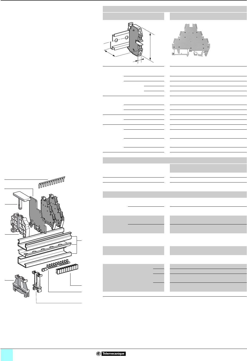
3/30
Terminal Blocks, Type AB1 0
Screw clamp technology
For 3-wire proximity sensors
Clip-on mounting on 35 mm 1 7 4 rails
Nominal wire size 2.5 mm2
AB1ET3235UT••
Approximate dimensions, in. (mm)
Length (a) 3.13 (79.4)
Width (b) 0.24 (6)
1Height (H)
with
1 rail 3.00 (76.1)
7 rail 2.70 (68.6)
4 rail 2.88 (73.1)
Wire size,
mm2Stranded without
cable end
0.5–2.5
Stranded with cable end 0.5–1.5
Solid 0.5–4
Tightening
torque
IEC 0.4–0.6 N•m
UL 8.0 lbf-in
Nominal
electrical
values (1)
IEC/EN 60947-7-1 400 V / 6 kV / 3–24 A
UL File E164359
CCN XCFR2
22–12 AWG, 300 V, 25 A
CSA File 702070
Class 6228 01
22–12 AWG, 300 V, 25 A
VDE, group C 250 Vac, 300 Vdc, 26 A
Certifications See the tables beginning on page 1/12.
a
b
H
Terminal blocks (2)
No.
points
Sold in
lots of
Catalog number Weight
oz (g)
Without LED Gray 1100 AB1ET3235UT 0.56 (16.0)
NPN 24 V LED (+) (green) Gray 1100 AB1ET3235UTLP 0.56 (16.0)
PNP 24V LED (-)
(green)
Gray 1100 AB1ET3235UTLM 0.56 (16.0)
Accessories
2Plastic
end clamp
with screw
Width 0.3 in. (7.5 mm)
on 4 — — — —
Width 0.3 in. (8 mm)
on 1 or 7—100 AB1AB8P35 0.21 (5.9)
3Metal
end clamp
with screw
Width 0.4 in. (10 mm)
on 4— — — —
Width 0.3 in. (8 mm)
on 1 or 7—100 AB1AB8M35 0.52 (14.8)
4Clip-on
plastic
end clamp
Width 0.3 in. (8 mm)
on 1 or 7—100 AB1AB8R35 0.21 (5.9)
5Marker tag holder
for clip-on plastic end clamp
—10 AB1SB4 0.11 (3.1)
6 Partition,
thickness 0.08 in. (2 mm)
Gray — — — —
7Insulated jumper Red 12 10 AB1ALD12R 0.18 (5.0)
Blue 12 10 AB1ALD12B 0.18 (5.0)
Red 70 10 AB1ALD100R 6.00
(170.0)
Blue 70 10 AB1ALD100B 6.00
(170.0)
8/9 Marking accessories See pages 5/2 and 5/3.
(1) 24 Vdc with LED.
(2) For recommended operating and connection diagrams, see page 3/31.
1
10
9
8
7
6
5
4
3
2
1
987654321
10
3
4
5
7
6
9
8
2
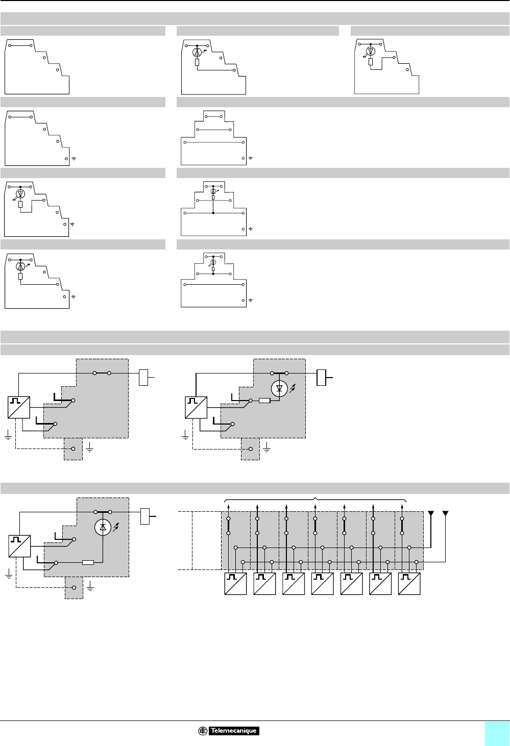
3/31
Terminal Blocks, Type AB1 0
Screw clamp technology
For 3-wire proximity sensors
Wiring diagrams
AB1DDP235U AB1DDP235ULP (Resistance = 2.2 kΩ, 0.35 W) AB1DDP235ULM (Resistance = 2.2 kΩ, 0.35 W)
AB1DDP235T AB1DDP235TPL (Resistance = 2.2 kΩ, 0.35 W)
AB1DDP235TLM (Resistance = 2.2 kΩ, 0.35 W) AB1ET3235U (2), AB1ET3235UT
AB1ET3235UTLP (Resistance = 2.2 kΩ, 0.35 W) AB1ET3235UTLM (Resistance = 2.2 kΩ, 0.35 W)
(1) Grounding connection with AB1ET322UT only.
Connections
AB1DDP235U, AB1DDP235T AB1DDP25ULM, AB1DDP235TLM
(1) PNP type sensor.
AB1DDP235ULP, AB1DDP235TLP
(1) NPN type sensor.
-
+
-
+
-
+
-
+
-
+
-
+
-
+
-
+
-
+
–
+
PE
+/
–
_
+
(1)
+
PE
+
–
(1)
––+
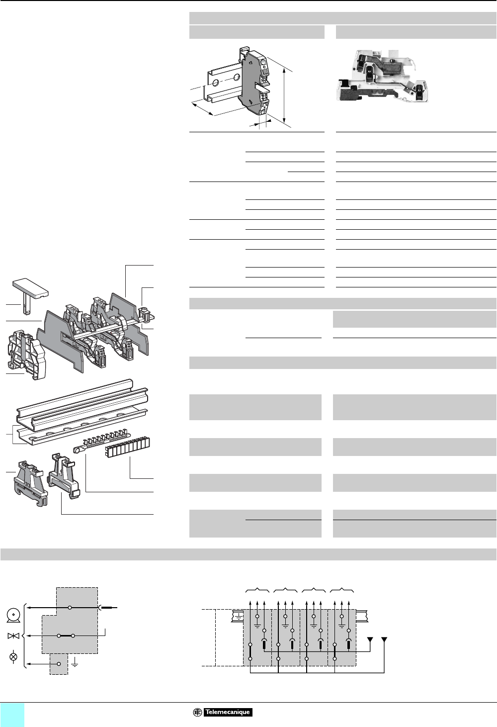
3/32
Terminal Blocks, Type AB1 0
Screw clamp technology
Multifunction
Clip-on mounting on 35 mm 1 7 rails
Nominal wire size 4 mm2
AB1TRSN435
Approximate dimensions, in. (mm)
Length (a) 3.19 (90.3)
Width (b) 0.21 (6)
1Height (H)
with
1 rail 2.08 (59)
7 rail 1.82 (51.5)
Wire size, mm2Stranded without
cable end
0.5–4
Stranded with cable end 0.5–2.5
Solid 0.5–6
Tightening
torque
IEC 0.5–0.7 N•m
UL 6.0 lbf-in
Nominal
electrical
values
IEC/EN 60947-7-1 400 V / 6 kV / 3–24 A
UL File E164359
CCN XCFR2
22–10 AWG, 300 V, 20 A
UTE, category C 250 Vac, 250 Vdc
VDE, group C 380 Vac, 450 Vdc, 26 A
Certifications See the tables beginning on page 1/12.
Terminal blocks
No.
points
Sold in
lots of
Catalog number Weight
oz (g)
Gray — 50 AB1TRSN435 0.99 (28.0)
Characteristics Disconnectable neutral (blue).
Grounding (green/yellow) and screw bar clamp
Accessories
2 Plastic
end clamp
with screw
Width 0.3 in. (8 mm)
on 1 or 7 — 100 AB1AB8P35 0.21 (5.9)
3Metal
end clamp
with screw
Width 0.3 in. (8 mm)
on 1 or 7—100 AB1AB8M35 0.52 (14.8)
4 Clip-on plastic
end clamp
Width 0.3 in. (8 mm)
on 1 or 7—100 AB1AB8R35 0.21 (5.9)
5Marker tag holder for
clip-on plastic end clamp
—10 AB1SB4 0.11 (3.1)
6 End plate Gray, thickness
0.08 in. (2 mm)
—25 AB1TM1N 0.13 (3.7)
7Partition plate Gray, thickness
0.06 in. (1.5 mm)
—25 AB1SM1N 0.11 (3.1)
8 Copper neutral bar
length 39.37 in. (1000 mm)
—10 AB1PC3 10.51
(298.0)
9Terminal clamp
for bar 0.39 x
0.12 (10 x 3)
16 mm2, pitch 0.33 (8.4 ) —10 AB1EBN16 0.31 (8.9)
35 mm2, pitch 0.67 (17)
[dimensions = in. (mm)]
—10 AB1EBN35 0.69 (19.5)
10/11 Marking accessories See pages 5/2 and 5/3.
Connections
AB1TRSN435 Example: wiring several AB1TRSN435 terminal blocks
a
b
H
536380
1
9
7
8
987654321
10
10
9
8
7
6
5
4
3
2
1
3
4
5
6
10
11
2
T
N
Ph
N
Ph
Ph T N
D
Ph T N
D
Ph T N
DD
N
Ph
Ph T N
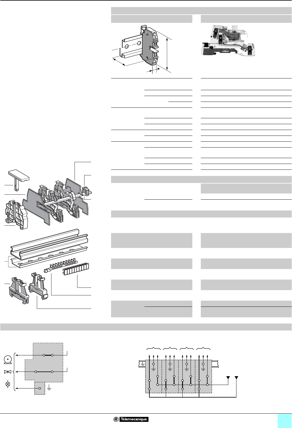
3/33
Terminal Blocks, Type AB1 0
Screw clamp technology
Multifunction
Clip-on mounting on 35 mm 1 7 rails
Nominal wire size 4 mm2
AB1TRPN435
Approximate dimensions, in. (mm)
Length (a) 3.19 (90.3)
Width (b) 0.21 (6)
1Height (H)
with
1 rail 2.08 (59)
7 rail 1.82 (51.5)
Wire size, mm2Stranded without
cable end
0.5–4
Stranded with cable end 0.5–2.5
Solid 0.5–6
Tightening
torque
IEC 0.5–0.7 N•m
UL 6.0 lbf-in
Nominal
electrical
values
IEC/EN 60947-7-1 400 V / 6 kV / 3–26 A
UL File E164359
CCN XCFR2
22–10 AWG, 300 V, 20 A
UTE, category C 250 Vac, 250 Vdc
VDE, group C 380 Vac, 450 Vdc, 26 A
Certifications See the tables beginning on page 1/12.
Terminal blocks
No.
points
Sold in
lots of
Catalog number Weight
oz (g)
Gray — 50 AB1TRPN435 0.99 (28.0)
Characteristics Two phases + grounding terminal
(green/yellow) and screw bar clamp
Accessories
2 Plastic
end clamp with
screw
Width 0.3 in. (8 mm)
on 1 or 7 —100AB1AB8P35 0.21 (5.9)
3Metal
end clamp with
screw
Width 0.3 in. (8 mm)
on 1 or 7—100 AB1AB8M35 0.52 (14.8)
4 Clip-on plastic
end clamp
Width 0.3 in. (8 mm)
on 1 or 7—100 AB1AB8R35 0.21 (5.9)
5Marker tag holder
for clip-on plastic end clamp
—10 AB1SB4 0.11 (3.1)
6 End plate Gray, thickness
0.08 in. (2 mm)
—25AB1TM1N 0.13 (3.7)
7Partition plate Gray, thickness
0.06 in. (1.5 mm)
—25 AB1SM1N 0.11 (3.1)
8 Copper neutral bar
length 39.37 in. (1000 mm)
—10AB1PC3 10.51
(298.0)
9Terminal clamp
for bar 0.39 x
0.12 (10 x 3)
16 mm2, pitch 0.33 (8.4 ) —10 AB1EBN16 0.31 (8.9)
35 mm2, pitch 0.67 (17)
[dimensions = in. (mm)]
—10 AB1EBN35 0.69 (19.5)
10/11 Marking accessories See pages 5/2 and 5/3.
Connections
AB1TRPN435 Example: wiring several terminal blocks, AB1TRNN435 or AB1TRPN435
a
b
H
536380
1
9
7
8
987654321
10
10
9
8
7
6
5
4
3
2
1
3
4
5
6
10
11
2
Ph
Ph
T
Ph
Ph
Ph
Ph T Ph/N
EE E E
Ph ou N
Ph T Ph/N Ph T Ph/N Ph T Ph/N

3/34
0
Terminal Blocks, Type AB1 0
Screw clamp technology
Multifunction
Clip-on mounting on 35 mm 1 7 rails
Nominal wire size 4 mm2
AB1TRNN435
Approximate dimensions, in. (mm)
Length (a) 3.19 (90.3)
Width (b) 0.21 (6)
1Height (H)
with
1 rail 2.08 (59)
7 rail 1.82 (51.5)
Wire size, mm2Stranded without
cable end
0.5–4
Stranded with cable end 0.5–2.5
Solid 0.5–6
Tightening
torque
IEC 0.5–0.7 N•m
UL 6.0 lbf-in
Nominal
electrical
values
IEC/EN 60947-7-1 400 V / 6 kV / 3–24 A
UL File E164359
CCN XCFR2
22–10 AWG, 300 V, 20 A
UTE, category C 250 Vac, 250 Vdc
VDE, group C 380 Vac, 450 Vdc, 26 A
Certifications See the tables beginning on page 1/12.
Terminal blocks
No.
points
Sold in
lots of
Catalog number Weight
oz (g)
Gray — 50 AB1TRNN435 0.99 (28.0)
Characteristics Neutral (blue), phase, grounding (green/ yellow)
and screw bar clamp
Accessories
2 Plastic
end clamp with
screw
Width 0.3 in. (8 mm)
on 1 or 7 — 100 AB1AB8P35 0.21 (5.9)
3Metal
end clamp with
screw
Width 0.3 in. (8 mm)
on 1 or 7—100 AB1AB8M35 0.52 (14.8)
4 Clip-on plastic
end clamp
Width 0.3 in. (8 mm)
on 1 or 7—100 AB1AB8R35 0.21 (5.9)
5Marker tag holder for
clip-on plastic end clamp
—10 AB1SB4 0.11 (3.1)
6 End plate Gray, thickness
0.08 in. (2 mm)
—25AB1TM1N 0.13 (3.7)
7Partition plate Gray, thickness
0.06 in. (1.5 mm)
—25 AB1SM1N 0.11 (3.1)
8 Copper neutral bar
length 39.37 in. (1000 mm)
—10AB1PC3 10.51
(298.0)
9Terminal clamp
for bar 0.39 x
0.12 (10 x 3)
16 mm2, pitch 0.33 (8.4 ) —10 AB1EBN16 0.31 (8.9)
35 mm2, pitch 0.67 (17)
[dimensions = in. (mm)]
—10 AB1EBN35 0.69 (19.5)
10/11 Marking accessories See pages 5/2 and 5/3.
Wiring diagrams
AB1TRNN435 Example: wiring several terminal blocks, AB1TRNN435 or AB1TRPN435
a
b
H
536380
1
9
7
8
987654321
10
10
9
8
7
6
5
4
3
2
1
3
4
5
6
10
11
2
N
Ph
T
Ph
N
Ph
Ph T Ph/N
EE E E
Ph ou N
Ph T Ph/N Ph T Ph/N Ph T Ph/N
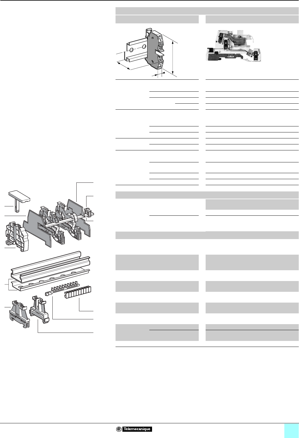
3/35
0
Terminal Blocks, Type AB1 0
Screw clamp technology
Multifunction
Clip-on mounting on 35 mm 1 7 rails
Nominal wire size 4 mm2
AB1TRPN435UFM
Approximate dimensions, in. (mm)
Length (a) 3.19 (90.3)
Width (b) 0.21 (6)
1Height (H)
with
1 rail 2.08 (59)
7 rail 1.82 (51.5)
Wire size, mm2
Stranded without
cable end
0.5–4
Stranded with cable end 0.5–2.5
Solid 0.5–6
Tightening
torque
IEC 0.4–0.6 N•m
UL 8.0 lbf-in
Nominal electrical values
IEC/EN 60947-7-1 400 V / 6 kV / 3–24 A
UL File E164359
CCN XCFR2
22–10 AWG
UTE, category C 250 Vac, 250 Vdc
VDE, group C 380 Vac, 450 Vdc, 26 A
Certifications See the tables beginning on page 1/12.
Terminal blocks
No.
points
Sold in
lots of
Catalog number Weight
oz (g)
Gray — 50 AB1TRPN435UFM 0.99 (28.0)
Characteristics Neutral (blue), phase, grounding (green/ yellow)
and screw bar clamp with phase/neutral Fault
indicator diode (1)
Accessories
2 Plastic
end clamp with
screw
Width 0.3 in. (8 mm)
on 1 or 7 —100AB1AB8P35 0.21 (5.9)
3Metal
end clamp with
screw
Width 0.3 in. (8 mm)
on 1 or 7—100 AB1AB8M35 0.52 (14.8)
4 Clip-on plastic
end clamp
Width 0.3 in. (8 mm)
on 1 or 7—100 AB1AB8R35 0.21 (5.9)
5Marker tag holder for
clip-on plastic end clamp
—10 AB1SB4 0.11 (3.1)
6 End plate Gray, thickness
0.08 in. (2 mm)
—25AB1TM1N 0.13 (3.7)
7Partition plate Gray, thickness
0.06 in. (1.5 mm)
—25 AB1SM1N 0.11 (3.1)
8 Copper neutral bar
length 39.37 in. (1000 mm)
—10AB1PC3 10.51
(298.0)
9Terminal clamp
for bar 0.39 x
0.12 (10 x 3)
16 mm2, pitch 0.33 (8.4 ) —10 AB1EBN16 0.31 (8.9)
35 mm2, pitch 0.67 (17)
[dimensions = in. (mm)]
—10 AB1EBN35 0.69 (19.5)
10/11 Marking accessories See pages 5/2 and 5/3.
(1) Neon lamp voltage indicator, 110-220 V.
a
b
H
536380
1
9
7
8
987654321
10
10
9
8
7
6
5
4
3
2
1
3
4
5
6
10
11
2
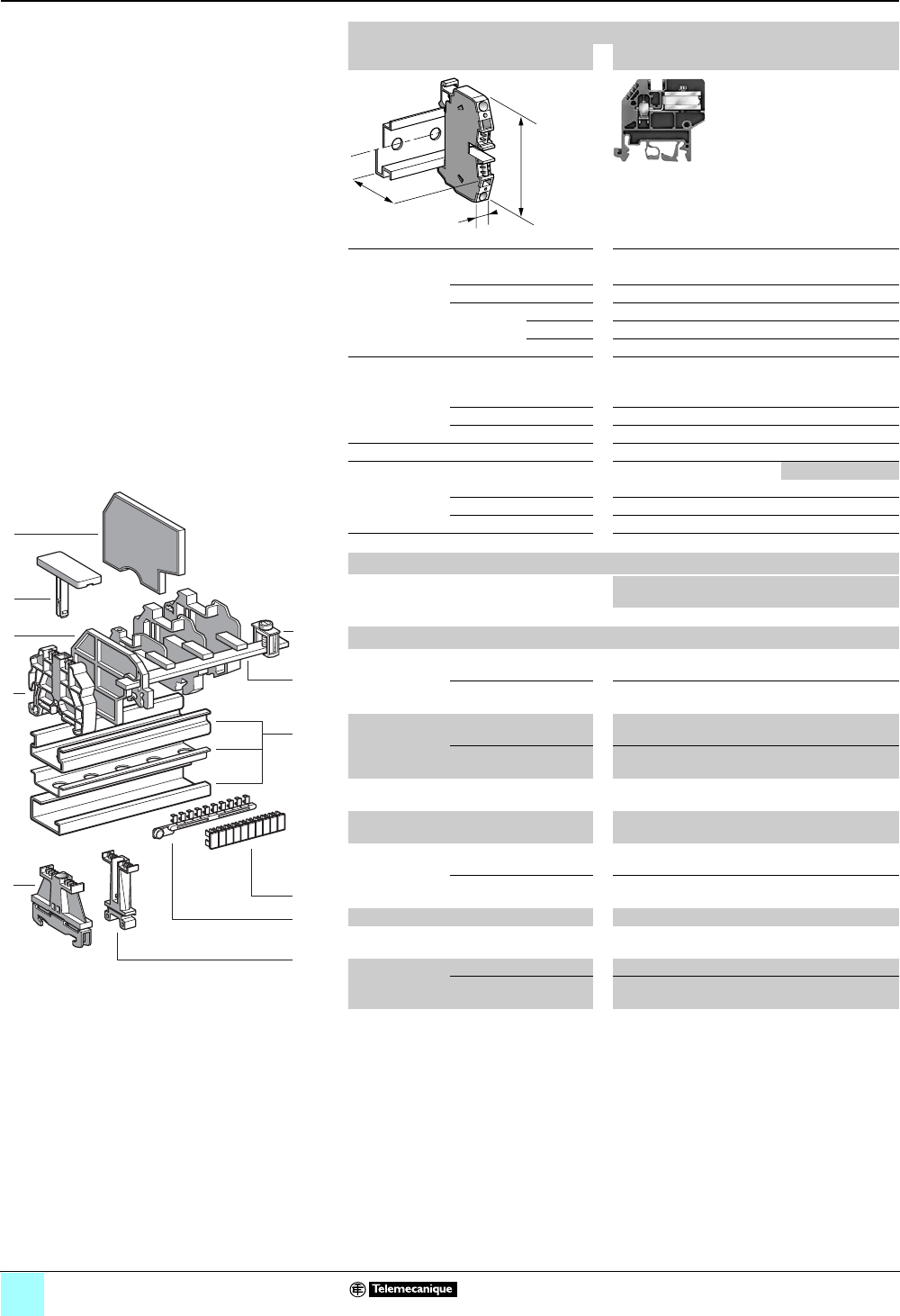
3/36
Terminal Blocks, Type AB1 0
Screw clamp technology
For neutral conductors
Clip-on mounting on 35 mm 1 7 4 rails
Nominal wire size 4 mm2
AB1NEN435U
Approximate dimensions, in. (mm)
Length (a) 1.92 (48.75)
Width (b) 0.24 (6)
1Height (H)
with
1 rail 2.20 (56)
7 rail 1.91 (48.5)
4 rail 2.09 (53)
Wire size, mm2
Stranded without
cable end
0.5–4
Stranded with cable end 0.5–2.5
Solid 0.5–6
Tightening torque IEC 0.5–0.7 N•m
Nominal electrical values 4 mm26 mm2
IEC/EN 60947-7-1 800 V / 8 kV / 3–32 A
UTE, category C 250 Vac , 250 Vdc
VDE, group C 380 Vac, 450 Vdc 25 A 30 A
Certifications See the tables beginning on page 1/12.
Terminal blocks
No.
points
Sold in
lots of
Catalog number Weight
oz (g)
Blue — 100 AB1NEN435U 0.52 (14.7)
Accessories
2 Plastic
end clamp with
screw
Width 0.3 in. (7.5 mm)
on 4 —100AB1AB7P32 0.15 (4.2)
Width 0.3 in. (8 mm)
on 1 or 7—100AB1AB8P35 0.21 (5.9)
3Metal
end clamp with
screw
Width 0.4 in. (10 mm)
on 4—100 AB1AB10M32 0.23 (6.5)
Width 0.3 in. (8 mm)
on 1 or 7—100 AB1AB8M35 0.52 (14.8)
4 Clip-on plastic
end clamp
Width 0.3 in. (8 mm)
on 1 or 7—100 AB1AB8R35 0.21 (5.9)
5Marker tag holder for
clip-on plastic end clamp
—10 AB1SB4 0.11 (3.1)
6 End plate Blue, thickness 0.06 in.
(1.5 mm)
—10AB1TNN4 0.09 (2.5)
Blue, thickness 0.08 in.
(2 mm)
——— —
7Terminal clamp for bar —10 AB1SBN 0.18 (5.2)
8 Copper neutral bar
length 39.37 in. (1000 mm)
—10AB1PC3 10.51
(298.0)
9Terminal clamp
for bar 0.39 x
0.12 (10 x 3)
16 mm2, pitch 0.33 (8.5) —10 AB1EBN16 0.31 (8.9)
35 mm2, pitch 0.56 (14.3)
[dimensions = in. (mm)]
—10 AB1EBN35 0.69 (19.5)
10/11 Marking accessories See pages 5/2 and 5/3.
a
b
H
1
9
8
4
5
10
9
8
7
6
5
4
3
2
1
987654321
10
6
3
7
10
11
2
523970
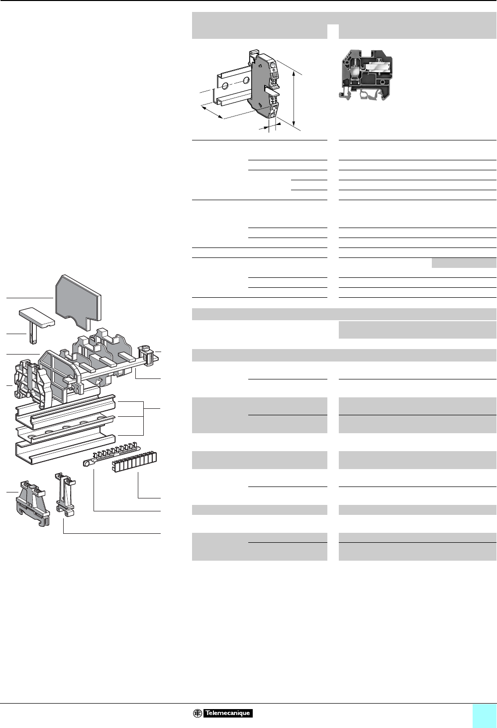
3/37
0
Terminal Blocks, Type AB1 0
Screw clamp technology
For neutral conductors
Clip-on mounting on 35 mm 1 7 4 rails
Nominal wire size 10 mm2
AB1NEN1035U
Approximate dimensions, in. (mm)
Length (a) 2.14 (54.25)
Width (b) 0.39 (10)
1Height (H)
with
1 rail 2.46 (62.5)
7 rail 2.17 (55)
4 rail 2.34 (59.5)
Wire size, mm2
Stranded without
cable end
1–10
Stranded with cable end 1–10
Solid 10–16
Tightening torque IEC 2.0–2.5 N•m
Nominal electrical values 10 mm216 mm2
IEC/EN 60947-7-1 800 V / 8 kV / 3–41 A
UTE, category C 250 Vac, 250 Vdc
VDE, group C 380 Vac, 450 Vdc 45 A 50 A
Certifications See the tables beginning on page 1/12.
Terminal blocks
No.
points
Sold in
lots of
Catalog number Weight
oz (g)
Blue — 50 AB1NEN1035U 1.12 (31.7)
Accessories
2 Plastic
end clamp with
screw
Width 0.3 in. (7.5 mm)
on 4 —100AB1AB7P32 0.15 (4.2)
Width 0.3 in. (8 mm)
on 1 or 7—100AB1AB8P35 0.21 (5.9)
3Metal
end clamp with
screw
Width 0.4 in. (10 mm)
on 4—100 AB1AB10M32 0.23 (6.5)
Width 0.3 in. (8 mm)
on 1 or 7—100 AB1AB8M35 0.52 (14.8)
4 Clip-on plastic
end clamp
Width 0.3 in. (8 mm)
on 1 or 7—100 AB1AB8R35 0.21 (5.9)
5Marker tag holder for
clip-on plastic end clamp
—10 AB1SB4 0.11 (3.1)
6 End plate Blue, thickness 0.06 in.
(1.5 mm)
—10AB1TNN10 0.09 (2.5)
Blue, thickness 0.08 in.
(2 mm)
——— —
7Terminal clamp for bar —10 AB1SBN 0.18 (5.2)
8 Copper neutral bar
length 39.37 in. (1000 mm)
—10AB1PC3 10.51
(298.0)
9Terminal clamp
for bar 0.39 x
0.12 (10 x 3)
16 mm2, pitch 0.33 (8.5) —10 AB1EBN16 0.31 (8.9)
35 mm2, pitch 0.56 (14.3)
[dimensions = in. (mm)]
—10 AB1EBN35 0.69 (19.5)
10/11 Marking accessories See pages 5/2 and 5/3
a
b
H
1
9
8
4
5
10
9
8
7
6
5
4
3
2
1
987654321
10
6
3
7
10
11
2
523970
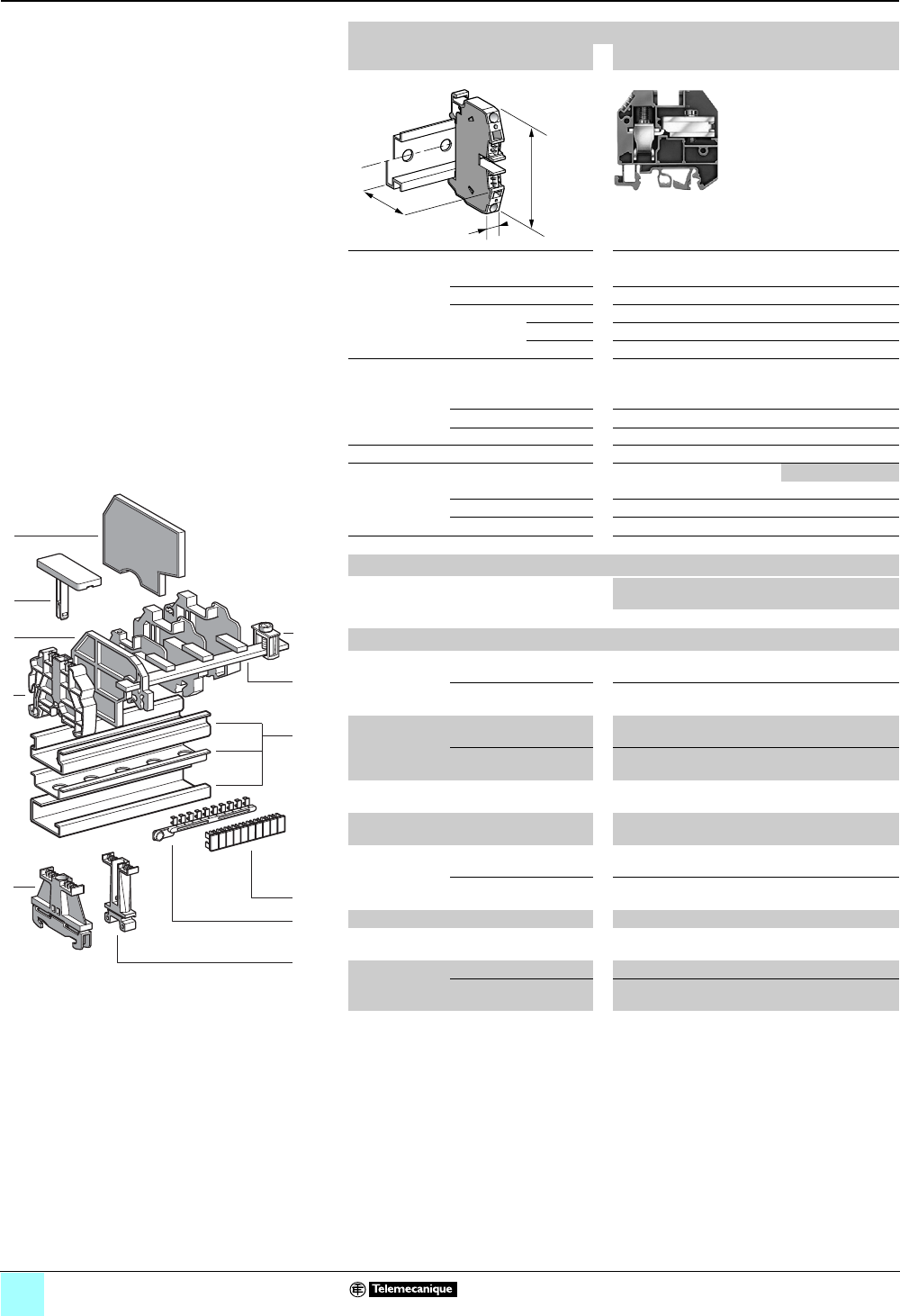
3/38
0
Terminal Blocks, Type AB1 0
Screw clamp technology
For neutral conductors
Clip-on mounting on 35 mm 1 7 4 rails
Nominal wire size 16 mm2
AB1NEN1635U
Approximate dimensions, in. (mm)
Length (a) 2.26 (57.5)
Width (b) 0.47 (12)
1Height (H)
with
1 rail 2.56 (65)
7 rail 2.26 (57.5)
4 rail 2.44 (62)
Wire size, mm2
Stranded without
cable end
1–16
Stranded with cable end 1–16
Solid 10–25
Tightening torque IEC 2.5–3.0 N•m
Nominal electrical values 16 mm225 mm2
IEC/EN 60947-7-1 800 V / 8 kV / 3
UTE, category C 250 Vac, 250 Vdc
VDE, group C 380 Vac, 450 Vdc 62 A 67 A
Certifications See the tables beginning on page 1/12.
Terminal blocks
No.
points
Sold in
lots of
Catalog number Weight
oz (g)
Blue — 50 AB1NEN1635U 1.59 (45.2)
Accessories
2 Plastic
end clamp with
screw
Width 0.3 in. (7.5 mm)
on 4 —100AB1AB7P32 0.15 (4.2)
Width 0.3 in. (8 mm)
on 1 or 7—100AB1AB8P35 0.21 (5.9)
3Metal
end clamp with
screw
Width 0.4 in. (10 mm)
on 4—100 AB1AB10M32 0.23 (6.5)
Width 0.3 in. (8 mm)
on 1 or 7—100 AB1AB8M35 0.52 (14.8)
4 Clip-on plastic
end clamp
Width 0.3 in. (8 mm)
on 1 or 7—100 AB1AB8R35 0.21 (5.9)
5Marker tag holder for
clip-on plastic end clamp
—10 AB1SB4 0.11 (3.1)
6 End plate Blue, thickness 0.06 in.
(1.5 mm)
——— —
Blue, thickness 0.08 in.
(2 mm)
—10AB1TNN16 0.12 (3.4)
7Terminal clamp for bar —10 AB1SBN 0.18 (5.2)
8 Copper neutral bar
length 39.37 in. (1000 mm)
—10AB1PC3 10.51
(298.0)
9Terminal clamp
for bar 0.39 x
0.12 (10 x 3)
16 mm2, pitch 0.33 (8.5) —10 AB1EBN16 0.31 (8.9)
35 mm2, pitch 0.56 (14.3)
[dimensions = in. (mm)]
—10 AB1EBN35 0.69 (19.5)
10/11 Marking accessories See pages 5/2 and 5/3
a
b
H
1
9
8
4
5
10
9
8
7
6
5
4
3
2
1
987654321
10
6
3
7
10
11
2
523970
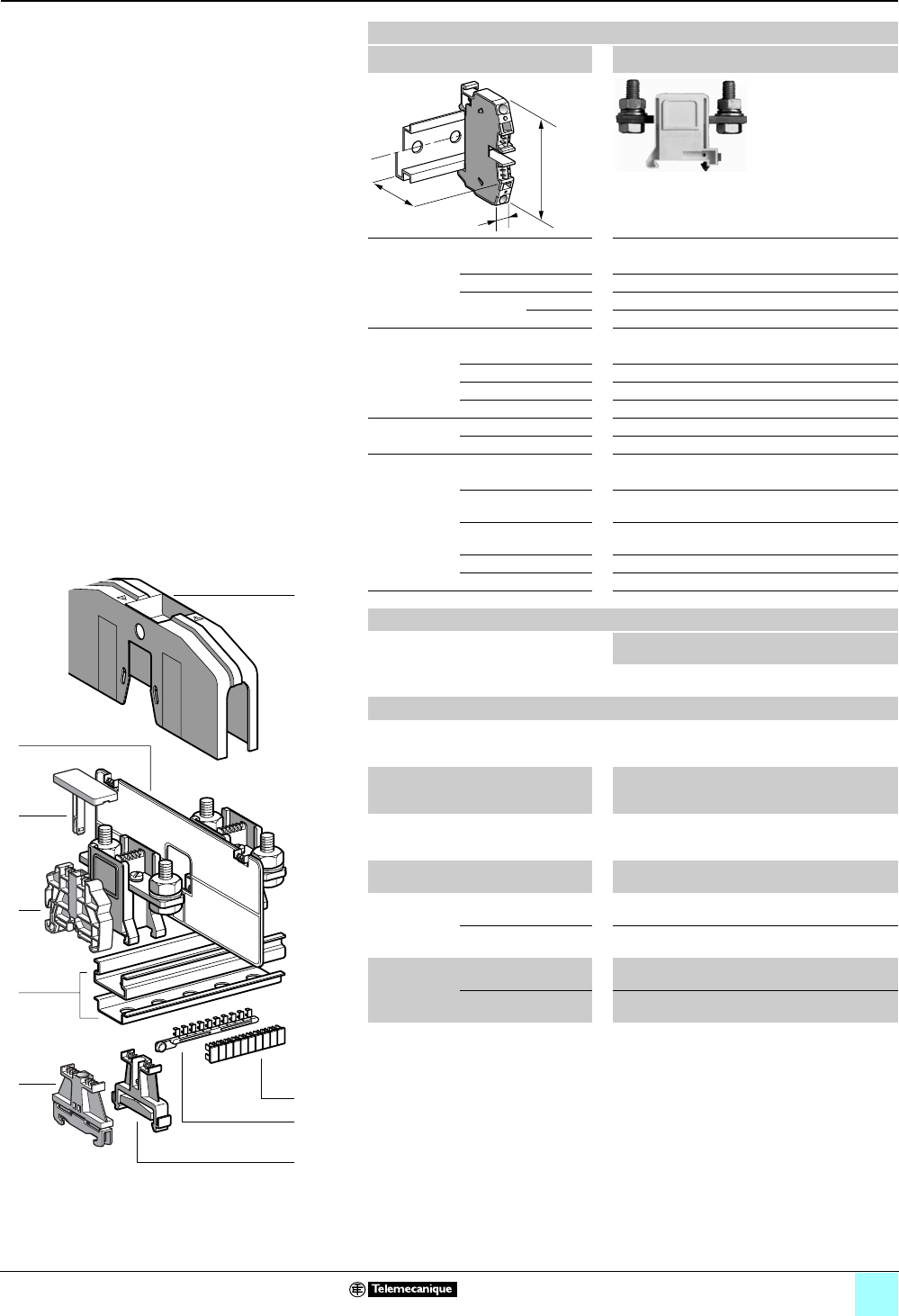
3/39
Terminal Blocks, Type AB1 0
Screw clamp technology
Lug-lug type
Clip-on mounting on 35 mm 1 7 rails
Nominal wire size 95 mm2
AB1BB9535
Approximate dimensions, in. (mm)
Length (a) 3.62 (92)
Width (b) 1.26 (32)
1Height (H)
with
1 rail 2.76 (70); with protective cover: 3.41 (86.5)
7 rail 2.46 (62.5); with protective cover: 3.11 (79)
Wire size, mm2
Stranded Up to 95
Solid Up to 95
Fixing bolt M10
Bar 0.20 x 0.71 in. (5 x 18 mm)
Tightening
torque
IEC 10 N•m
UL 250 lbf-in
Nominal electrical values
IEC/EN 60947-7-1 1000 V / 8 kV / 3–225 A
UL File E164359
CCN XCFR2
0 AWG – 350 kcmil, 600 V, 230 A
CSA File 702070
Class 6228 01
0 AWG – 350 kcmil, 600 V, 230 A
UTE, category C 500 Vac, 500 Vdc
VDE, group C 1000 Vac, 1200 Vdc, 250 A
Certifications See the tables beginning on page 1/12.
a
b
H
Terminal blocks
No.
points
Sold in
lots of
Catalog number Weight
oz (g)
Gray 210 AB1BB9535 5.96
(169.0)
Accessories
2 Plastic
end clamp
with screw
Width 0.3 in. (8 mm)
on 1 or 7 —100 AB1AB8P35 0.21 (5.9)
3Metal
end clamp
with screw
Width 0.3 in. (8 mm)
on 1 or 7—100 AB1AB8M35 0.52 (14.8)
4Clip-on
plastic
end clamp
Width 0.3 in. (8 mm)
on 1 or 7—100 AB1AB8R35 0.21 (5.9)
5Marker tag holder for
clip-on plastic end clamp
—10 AB1SB4 0.11 (3.1)
6 End plate
gray, thickness
0.11 in.
(2.8 mm)
2.76 x 6.85 x 1.26 in.
(70 x 180 x 4.5 mm)
—50 AB1CT1 1.20 (34.0)
2.76 x 7.87 x 1.26 in.
(70 x 200 x 4.5 mm)
— — — —
7Terminal
cover
yellow
2.72 x 6.85 x 1.26 in.
(69 x 174 x 32 mm)
—10 AB1CP1 1.94 (55.0)
3.66 x 7.64 x 1.65 in.
(93 x 194 x 42 mm)
— — — —
8/9 Marking accessories See pages 5/2 and 5/3.
10
9
8
7
6
5
4
3
2
1
987654321
10
6
7
1
4
5
3
9
8
2
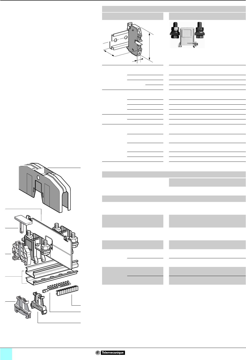
3/40
Terminal Blocks, Type AB1 0
Screw clamp technology
Lug-lug type
Clip-on mounting on 35 mm 1 7 rails
Nominal wire size 185 mm2
AB1BB18535
Approximate dimensions, in. (mm)
Length (a) 3.62 (92)
Width (b) 1.65 (42)
1Height (H)
with
1 rail 2.83 (72); with protective cover: 4.35 (110.5)
7 rail 2.54 (64.5); with protective cover: 4.06 (103)
Wire size, mm2
Stranded Up to 185
Solid Up to 185
Fixing bolt M12
Bar 0.24 x 1.02 in. (6 x 26 mm)
Tightening
torque
IEC 14 N•m
UL 325 lbf-in
Nominal electrical values
IEC/EN 60947-7-1 1000 V / 8 kV / 3–353 A
UL File E164359
CCN XCFR2
0 AWG – 400 kcmil, 600 V, 375 A
CSA File 702070
Class 6228 01
0 AWG – 400 kcmil, 600 V, 375 A
UTE, category C 500 Vac, 500 Vdc
VDE, group C 1000 Vac, 1200 Vdc, 392 A
Certifications See the tables beginning on page 1/12.
Terminal blocks
No.
points
Sold in
lots of
Catalog number Weight
oz (g)
Gray 210 AB1BB18535 8.82
(250.0)
a
b
H
Accessories
2Plastic
end clamp
with screw
Width 0.3 in. (8 mm)
on 1 or 7 —100 AB1AB8P35 0.21 (5.9)
3Metal
end clamp
with screw
Width 0.3 in. (8 mm)
on 1 or 7—100 AB1AB8M35 0.52 (14.8)
4Clip-on
plastic
end clamp
Width 0.3 in. (8 mm)
on 1 or 7—100 AB1AB8R35 0.21 (5.9)
5Marker tag holder for
clip-on plastic end clamp
—10 AB1SB4 0.11 (3.1)
6 End plate
gray, thickness
0.11 in.
(2.8 mm)
2.76 x 6.85 x 1.26 in.
(70 x 180 x 4.5 mm)
— — — —
2.76 x 7.87 x 1.26 in.
(70 x 200 x 4.5 mm)
—50 AB1CT2 1.31 (37.0)
7Terminal
cover
yellow
2.72 x 6.85 x 1.26 in.
(69 x 174 x 32 mm)
— — — —
3.66 x 7.64 x 1.65 in.
(93 x 194 x 42 mm)
—10 AB1CP2 3.17 (90.0)
8/9 Marking accessories See pages 5/2 and 5/3.
10
9
8
7
6
5
4
3
2
1
987654321
10
6
7
1
4
5
3
9
8
2
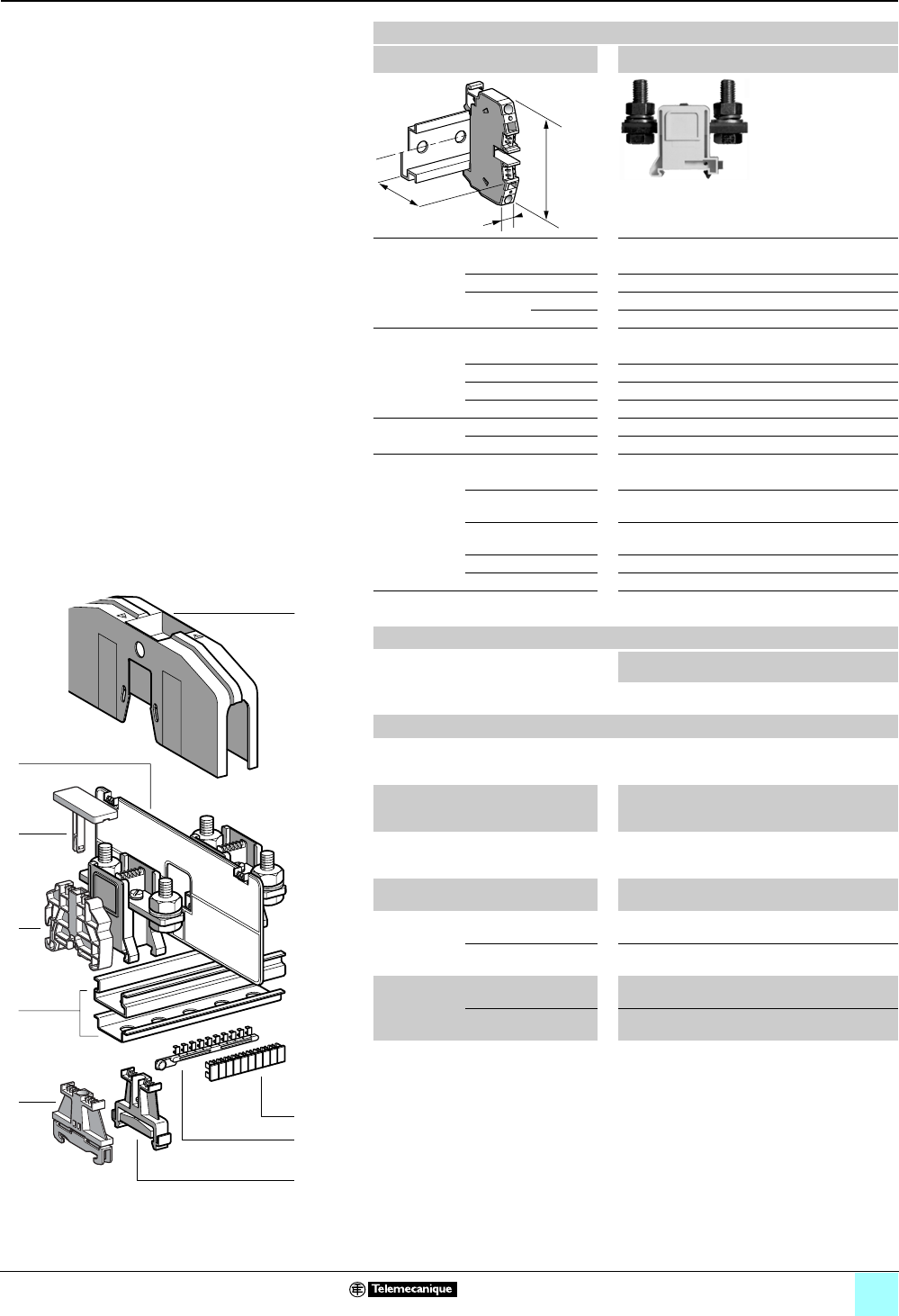
3/41
Terminal Blocks, Type AB1 0
Screw clamp technology
Lug-lug type
Clip-on mounting on 35 mm 1 7 rails
Nominal wire size 240 mm2
AB1BB24035
Approximate dimensions, in. (mm)
Length (a) 3.62 (92)
Width (b) 1.65 (42)
1Height (H)
with
1 rail 3.07 (78); with protective cover: 4.35 (110.5)
7 rail 2.78 (70.5); with protective cover: 4.06 (103)
Wire size, mm2
Stranded Up to 240
Solid Up to 240
Fixing bolt M12
Bar 0.31 x 1.02 in. (8 x 26 mm)
Tightening
torque
IEC 14 N•m
UL 375 lbf-in
Nominal electrical values
IEC/EN 60947-7-1 1000 V / 8 kV / 3–415 A
UL File E164359
CCN XCFR2
0 AWG – 500 kcmil, 600 V, 375 A
CSA File 702070
Class 6228 01
3/0 AWG – 500 kcmil, 600 V, 425 A
UTE, category C 500 Vac, 500 Vdc
VDE, group C 1000 Vac, 1200 Vdc, 461 A
Certifications See the tables beginning on page 1/12.
Terminal blocks
No.
points
Sold in
lots of
Catalog number Weight
oz (g)
Gray 210 AB1BB24035 9.35
(265.0)
a
b
H
Accessories
2Plastic
end clamp
with screw
Width 0.3 in. (8 mm)
on 1 or 7 —100 AB1AB8P35 0.21 (5.9)
3Metal
end clamp
with screw
Width 0.3 in. (8 mm)
on 1 or 7—100 AB1AB8M35 0.52 (14.8)
4Clip-on
plastic
end clamp
Width 0.3 in. (8 mm)
on 1 or 7—100 AB1AB8R35 0.21 (5.9)
5Marker tag holder for
clip-on plastic end clamp
—10 AB1SB4 0.11 (3.1)
6 End plate
gray, thickness
0.11 in.
(2.8 mm)
2.76 x 6.85 x 1.26 in.
(70 x 180 x 4.5 mm)
— — — —
2.76 x 7.87 x 1.26 in.
(70 x 200 x 4.5 mm)
—50 AB1CT2 1.31 (37.0)
7Terminal
cover
yellow
2.72 x 6.85 x 1.26 in.
(69 x 174 x 32 mm)
— — — —
3.66 x 7.64 x 1.65 in.
(93 x 194 x 42 mm)
—10 AB1CP2 3.17 (90.0)
8/9 Marking accessories See pages 5/2 and 5/3.
10
9
8
7
6
5
4
3
2
1
987654321
10
6
7
1
4
5
3
9
8
2
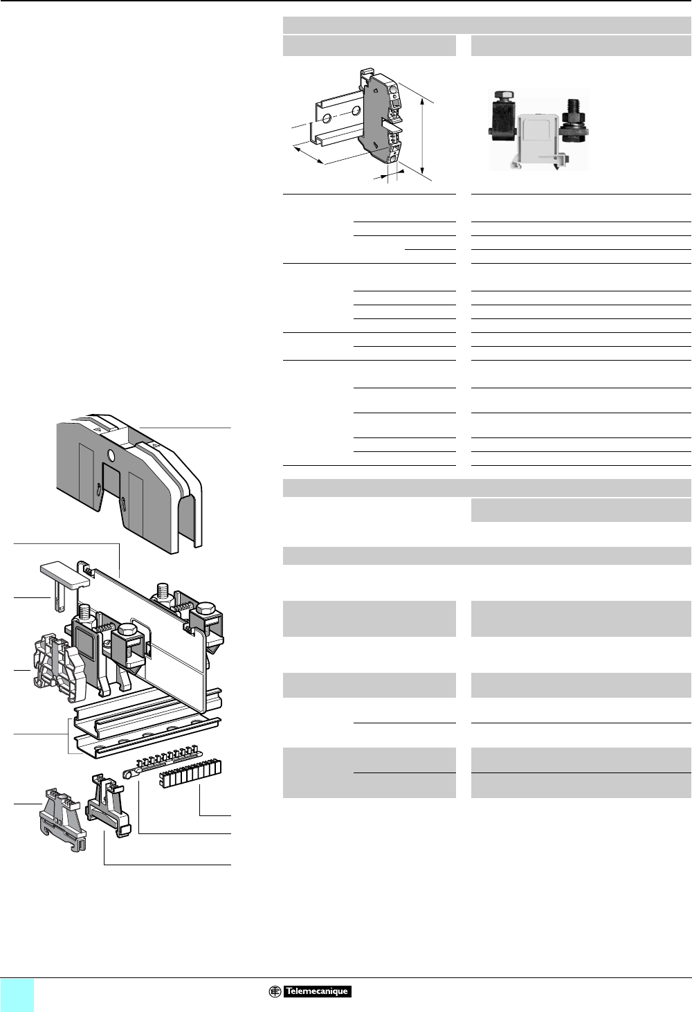
3/42
Terminal Blocks, Type AB1 0
Screw clamp technology
Lug-clamp type
Clip-on mounting on 35 mm 1 7 rails
Nominal wire size 95 mm2
AB1BC9535
Approximate dimensions, in. (mm)
Length (a) 3.62 (92)
Width (b) 1.26 (32)
1Height (H)
with
1 rail 3.11 (79); with protective cover: 3.41 (86.5)
7 rail 2.81 (71.5); with protective cover: 3.11 (79)
Wire size, mm2
Stranded 16–95
Solid 16–95
Fixing bolt M10
Bar 0.20 x 0.71 in. (5 x 18 mm)
Tightening
torque
IEC 10 N•m
UL 250 lbf-in
Nominal electrical values
IEC/EN 60947-7-1 1000 V / 8 kV / 3–225 A
UL File E164359
CCN XCFR2
0 AWG – 350 kcmil, 600 V, 230 A
CSA File 702070
Class 6228 01
0 AWG – 350 kcmil, 600 V, 200 A
UTE, category C 500 Vac, 500 Vdc
VDE, group C 1000 Vac, 1200 Vdc, 250 A
Certifications See the tables beginning on page 1/12.
a
b
H
Terminal blocks
No.
points
Sold in
lots of
Catalog number Weight
oz (g)
Gray 210 AB1BC9535 8.32
(236.0)
Accessories
2 Plastic
end clamp
with screw
Width 0.3 in. (8 mm)
on 1 or 7 —100 AB1AB8P35 0.21 (5.9)
3Metal
end clamp
with screw
Width 0.3 in. (8 mm)
on 1 or 7—100 AB1AB8M35 0.52 (14.8)
4Clip-on
plastic
end clamp
Width 0.3 in. (8 mm)
on 1 or 7—100 AB1AB8R35 0.21 (5.9)
5Marker tag holder for
clip-on plastic end clamp
—10 AB1SB4 0.11 (3.1)
6 End plate
gray, thickness
0.11 in.
(2.8 mm)
2.76 x 7.09 x 0.18 in.
(70 x 180 x 4.5 mm)
—50 AB1CT1 1.20 (34.0)
2.76 x 7.87 x 0.18 in.
(70 x 200 x 4.5 mm)
— — — —
7Terminal
cover
yellow
2.72 x 6.85 x 1.26 in.
(69 x 174 x 32 mm)
—10 AB1CP1 1.94 (55.0)
3.66 x 7.64 x 1.65 in.
(93 x 194 x 42 mm)
— — — —
8/9 Marking accessories See pages 5/2 and 5/3.
10
9
8
7
6
5
4
3
2
1
987654321
10
6
7
1
4
5
3
8
9
2

3/43
Terminal Blocks, Type AB1 0
Screw clamp technology
Lug-clamp type
Clip-on mounting on 35 mm 1 7 rails
Nominal wire size 150 mm2
AB1BC15035
Approximate dimensions, in. (mm)
Length (a) 3.62 (92)
Width (b) 1.65 (42)
1Height (H)
with
1 rail 3.27 (83); with protective cover: 4.35 (110.5)
7 rail 2.97 (75.5); with protective cover: 4.06 (103)
Wire size, mm2
Stranded 25–150
Solid 25–150
Fixing bolt M12
Bar 0.24 x 1.02 in. (6 x 26 mm)
Tightening
torque
IEC 14 N•m
UL 250 lbf-in
Nominal electrical values
IEC/EN 60947-7-1 1000 V / 8 kV / 3–300 A
UL File E164359
CCN XCFR2
0 AWG – 400 kcmil, 600 V, 325 A
CSA File 702070
Class 6228 01
0 AWG – 400 kcmil, 600 V, 325 A
UTE, category C 500 Vac, 500 Vdc
VDE, group C 1000 Vac, 1200 Vdc, 335 A
Certifications See the tables beginning on page 1/12.
a
b
H
Terminal blocks
No.
points
Sold in
lots of
Catalog number Weight
oz (g)
Gray 210 AB1BC15035 9.77
(277.0)
Accessories
2 Plastic
end clamp
with screw
Width 0.3 in. (8 mm)
on 1 or 7 —100 AB1AB8P35 0.21 (5.9)
3Metal
end clamp
with screw
Width 0.3 in. (8 mm)
on 1 or 7—100 AB1AB8M35 0.52 (14.8)
4Clip-on
plastic
end clamp
Width 0.3 in. (8 mm)
on 1 or 7—100 AB1AB8R35 0.21 (5.9)
5Marker tag holder for
clip-on plastic end clamp
—10 AB1SB4 0.11 (3.1)
6 End plate
gray, thickness
0.11 in.
(2.8 mm)
2.76 x 7.09 x 0.18 in.
(70 x 180 x 4.5 mm)
— — — —
2.76 x 7.87 x 1.26 in.
(70 x 200 x 4.5 mm)
—50 AB1CT2 1.31 (37.0)
7Terminal
cover
yellow
2.72 x 6.85 x 1.26 in.
(69 x 174 x 32 mm)
— — — —
3.66 x 7.64 x 1.65 in.
(93 x 194 x 42 mm)
—10 AB1CP2 3.17 (90.0)
8/9 Marking accessories See pages 5/2 and 5/3.
10
9
8
7
6
5
4
3
2
1
987654321
10
6
7
1
4
5
3
8
9
2
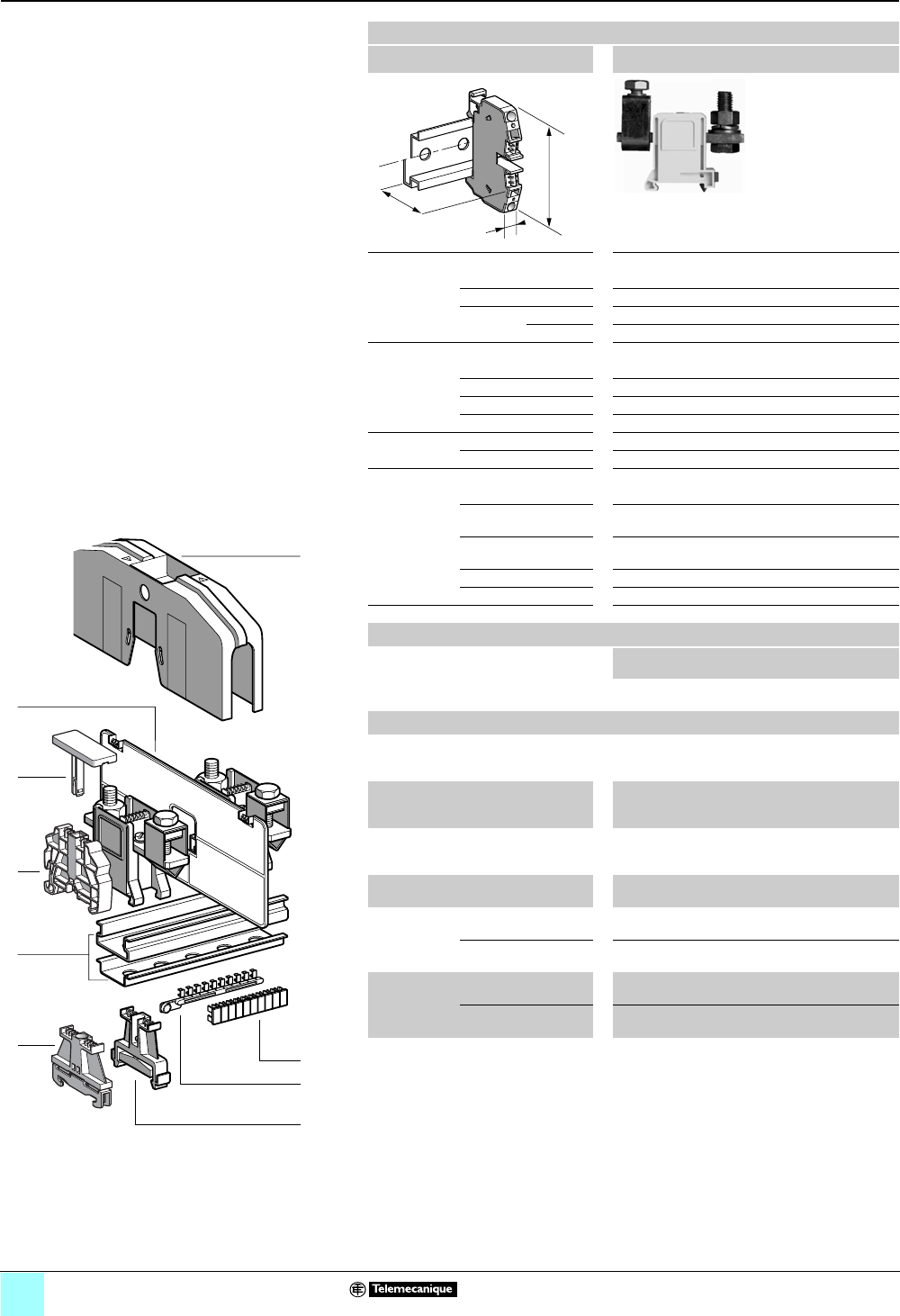
3/44
Terminal Blocks, Type AB1 0
Screw clamp technology
Lug-clamp type
Clip-on mounting on 35 mm 1 7 rails
Nominal wire size 240 mm2
AB1BC24035
Approximate dimensions, in. (mm)
Length (a) 4.02 (102)
Width (b) 1.65 (42)
1Height (H)
with
1 rail 3.94 (100); with protective cover: 4.35 (110.5)
7 rail 3.64 (92.5); with protective cover: 4.06 (103)
Wire size, mm2
Stranded 35–240
Solid 35–240
Fixing bolt M12
Bar 0.31 x 1.02 in. (8 x 26 mm)
Tightening
torque
IEC 14 N•m
UL 375 lbf-in
Nominal electrical values
IEC/EN 60947-7-1 1000 V / 8 kV / 3–415 A
UL File E164359
CCN XCFR2
0 AWG – 500 kcmil, 600 V, 375 A
CSA File 702070
Class 6228 01
3/0 AWG – 500 kcmil, 600 V, 425 A
UTE, category C 500 Vac, 500 Vdc
VDE, group C 1000 Vac, 1200 Vdc, 453 A
Certifications See the tables beginning on page 1/12.
a
b
H
Terminal blocks
No.
points
Sold in
lots of
Catalog number Weight
oz (g)
Gray 210 AB1BC24035 10.10
(287.0)
Accessories
2 Plastic
end clamp
with screw
Width 0.3 in. (8 mm)
on 1 or 7 —100 AB1AB8P35 0.21 (5.9)
3Metal
end clamp
with screw
Width 0.3 in. (8 mm)
on 1 or 7—100 AB1AB8M35 0.52 (14.8)
4Clip-on
plastic
end clamp
Width 0.3 in. (8 mm)
on 1 or 7—100 AB1AB8R35 0.21 (5.9)
5Marker tag holder for
clip-on plastic end clamp
—10 AB1SB4 0.11 (3.1)
6 End plate
gray, thickness
0.11 in.
(2.8 mm)
2.76 x 7.09 x 0.18 in.
(70 x 180 x 4.5 mm)
— — — —
2.76 x 7.87 x 1.26 in.
(70 x 200 x 4.5 mm)
—50 AB1CT2 1.31 (37.0)
7Terminal
cover
yellow
2.72 x 6.85 x 1.26 in.
(69 x 174 x 32 mm)
— — — —
3.66 x 7.64 x 1.65 in.
(93 x 194 x 42 mm)
—10 AB1CP2 3.17 (90.0)
8/9 Marking accessories See pages 5/2 and 5/3.
10
9
8
7
6
5
4
3
2
1
987654321
10
6
7
1
4
5
3
8
9
2
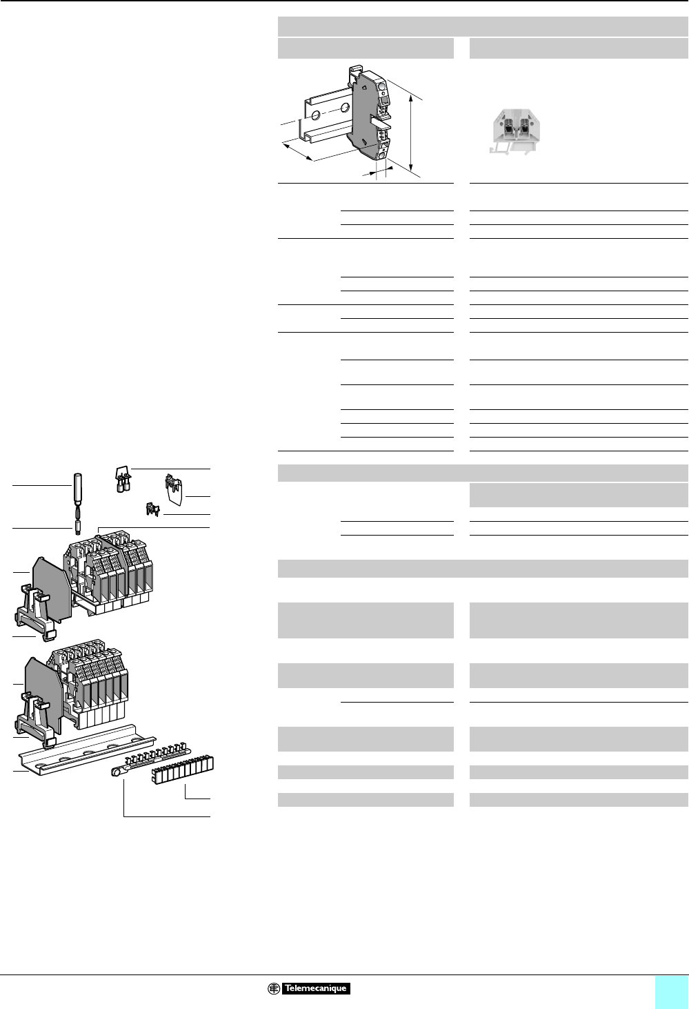
3/45
Terminal Blocks, Type AB1 0
Screw clamp technology
Miniature passthrough
Clip-on mounting on 15 mm 7 rail
Nominal wire size 2.5 mm2
AB1VV215••
Approximate dimensions, in. (mm)
Length (a) 1.12 (28.5)
Width (b) 0.20 (5)
Height (H) with 7 rail 1.26 (32)
Wire size, mm2
Stranded without
cable end
0.5–2.5
Stranded with cable end 0.5–1.5
Solid 0.5–4
Tightening
torque
IEC 0.4–0.6 N•m
UL 6.0 lbf-in
Nominal electrical values
IEC/EN 60947-7-1 500 V / 6 kV / 3–24 A
UL File E164359
CCN XCFR2
22–14 AWG, 150 V, 10 A
CSA File 702070
Class 6228 01
22–12 AWG, 600 V, 25 A
UTE, category C 500 Vac, 500 Vdc
VDE, group C 500 Vac, 600 Vdc, 26 A
ATEX Exe II II 2 GD 2.5 mm2, 275 V, 20 A, KEMA 02 ATEX 2114 U
Certifications See the tables beginning on page 1/12.
a
b
H
Terminal blocks
No.
points
Sold in
lots of
Catalog number Weight
oz (g)
Gray 210 AB1VV215 0.15 (4.2)
Blue 2100 AB1VV215BL 0.15 (4.2)
Grounding
type
Green/Yellow 2 — — —
Accessories
1 Rail, 15 x 5, length 1000 —10 AB1PC15 4.94
(140.0)
2Plastic
end clamp
with screw
Width 0.3 in. (7.5 mm) —100 AB1AB715 0.08 (2.2)
3 End plate Gray, thickness
0.06 in. (1.5 mm)
—50 AB1AC2 0.05 (1.3)
4Partition
plate
Gray, thickness
0.06 in. (1.5 mm)
—50 AB1AS2 0.06 (1.7)
5 Jumper with
screws
2-pole (Non-insulated) 250 AB1B22 0.06 (1.6)
60-pole (Non-insulated) 60 10 AB1B15 3.70
(105.0)
6Socket for
test plug
∅ 0.09 in.(2.3 mm) —50 AB1A2 0.018 (0.5)
7 Test plug Red —50 AB1AT1 0.06 (1.7)
8Yellow partition plate 1100 AB1CJ215 0.021 (0.6)
9 Yellow protective cover 1100 AB1CA215 0.014 (0.4)
10/11 Marking accessories See pages 5/2 and 5/3.
10
9
8
7
6
5
4
3
2
1
987654321
10
1
3
3
5
6
7
8
9
4
2
2
10
11
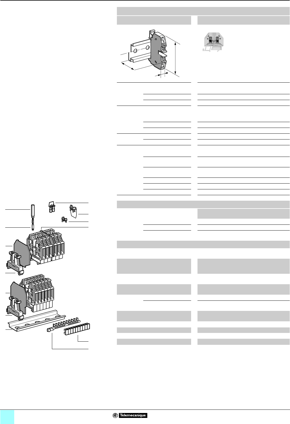
3/46
Terminal Blocks, Type AB1 0
Screw clamp technology
Miniature passthrough
Clip-on mounting on 15 mm 7 rail
Nominal wire size 4 mm2
AB1VV415
Approximate dimensions, in. (mm)
Length (a) 1.12 (28.5)
Width (b) 0.24 (6)
Height (H) with 7 rail 1.26 (32)
Wire size, mm2
Stranded without
cable end
0.5–4
Stranded with cable end 0.5–2.5
Solid 0.5–6
Tightening
torque
IEC 0.5–0.7 N•m
UL 8.0 lbf-in
Nominal electrical values
IEC/EN 60947-7-1 500 V / 6 kV / 3–34 A
UL File E164359
CCN XCFR2
22–14 AWG, 150 V, 10 A
CSA File 702070
Class 6228 01
22–12 AWG
UTE, category C 500 Vac, 500 Vdc
VDE, group C 500 Vac, 600 Vdc, 34 A
ATEX Exe II II 2 GD 4 mm2, 275 V, 21 / 27 A, KEMA 02 ATEX 2114 U
Certifications See the tables beginning on page 1/12.
a
b
H
Terminal blocks
No.
points
Sold in
lots of
Catalog number Weight
oz (g)
Gray 2100 AB1VV415 0.19 (5.5)
Blue — — — —
Grounding
type
Green/Yellow — — — —
Accessories
1 Rail, 15 x 5, length 1000 —10 AB1PC15 4.94
(140.0)
2Plastic
end clamp
with screw
Width 0.3 in. (7.5 mm) —100 AB1AB715 0.08 (2.2)
3 End plate Gray, thickness
0.06 in. (1.5 mm)
—50 AB1AC2 0.05 (1.3)
4Partition
plate
Gray, thickness
0.06 in. (1.5 mm)
—50 AB1AS2 0.06 (1.7)
5 Jumper with
screws
2-pole (Non-insulated) 250 AB1B22 0.06 (1.6)
60-pole (Non-insulated) 60 10 AB1B15 3.70
(105.0)
6Socket for
test plug
∅ 0.09 in.(2.3 mm) —50 AB1A2 0.018 (0.5)
7 Test plug Red —50 AB1AT1 0.06 (1.7)
8Yellow partition plate 1100 AB1CJ3 0.021 (0.6)
9 Yellow protective cover 1100 AB1CA3 0.014 (0.4)
10/11 Marking accessories See pages 5/2 and 5/3.
10
9
8
7
6
5
4
3
2
1
987654321
10
1
3
3
5
6
7
8
9
4
2
2
10
11
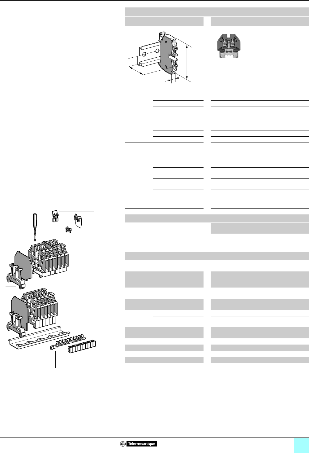
3/47
Terminal Blocks, Type AB1 0
Screw clamp technology
Miniature grounding
Clip-on mounting on 15 mm 7 rail
Nominal wire size 2.5–4 mm2
AB1TP215
Approximate dimensions, in. (mm)
Length (a) 1.12 (28.5)
Width (b) 0.24 (6)
Height (H) with 7 rail 1.26 (32)
Wire size, mm2
Stranded without
cable end
0.5–4
Stranded with cable end 0.5–2.5
Solid 0.5–6
Tightening
torque
IEC 0.5–0.7 N•m
UL 6.0 lbf-in
Nominal electrical values
IEC/EN 60947-7-1 500 V / 6 kV / 3–34 A
UL File E164359
CCN XCFR2
22–14 AWG, 150 V, 10 A
CSA File 702070
Class 6228 01
22–12 AWG
UTE, category C 500 Vac, 500 Vdc
VDE, group C 500 Vac, 600 Vdc, 34 A
ATEX Exe II II 2 GD 4 mm2, KEMA 02 ATEX 2114 U
Certifications See the tables beginning on page 1/12.
a
b
H
Terminal blocks
No.
points
Sold in
lots of
Catalog number Weight
oz (g)
Gray — — — —
Blue — — — —
Grounding Green/Yellow 2100 AB1TP215 0.41 (11.7)
Accessories
1 Rail, 15 x 5, length 1000 —10 AB1PC15 4.94
(140.0)
2Plastic
end clamp
with screw
Width 0.3 in. (7.5 mm) —100 AB1AB715 0.08 (2.2)
3 End plate Gray, thickness
0.06 in. (1.5 mm)
—50 AB1CT215 0.07 (2.0)
4Partition
plate
Gray, thickness
0.06 in. (1.5 mm)
— — — —
5 Jumper with
screws
2-pole (Non-insulated) — — — —
60-pole (Non-insulated) — — — —
6Socket for
test plug
∅ 0.09 in.(2.3 mm) — — — —
7 Test plug Red — — — —
8Yellow partition plate — — — —
9 Yellow protective cover — — — —
10/11 Marking accessories See pages 5/2 and 5/3.
10
9
8
7
6
5
4
3
2
1
987654321
10
1
3
3
5
6
7
8
9
4
2
2
10
11

4/0

4/1
Contents 4 - Terminal Blocks, Type AB1
Insulation displacement technology
Page
Selection guide . . . . . . . . . . . . . . . . . . . . . . . . . . . . . . . . . . . 4/2
Passthrough type terminal blocks . . . . . . . . . . . . . . . . . . . 4/4
Terminal blocks for grounding . . . . . . . . . . . . . . . . . . 4/10
Disconnect type terminal blocks . . . . . . . . . . . . . . . . 4/16
Double deck terminal blocks . . . . . . . . . . . . . . . . . . . . 4/20
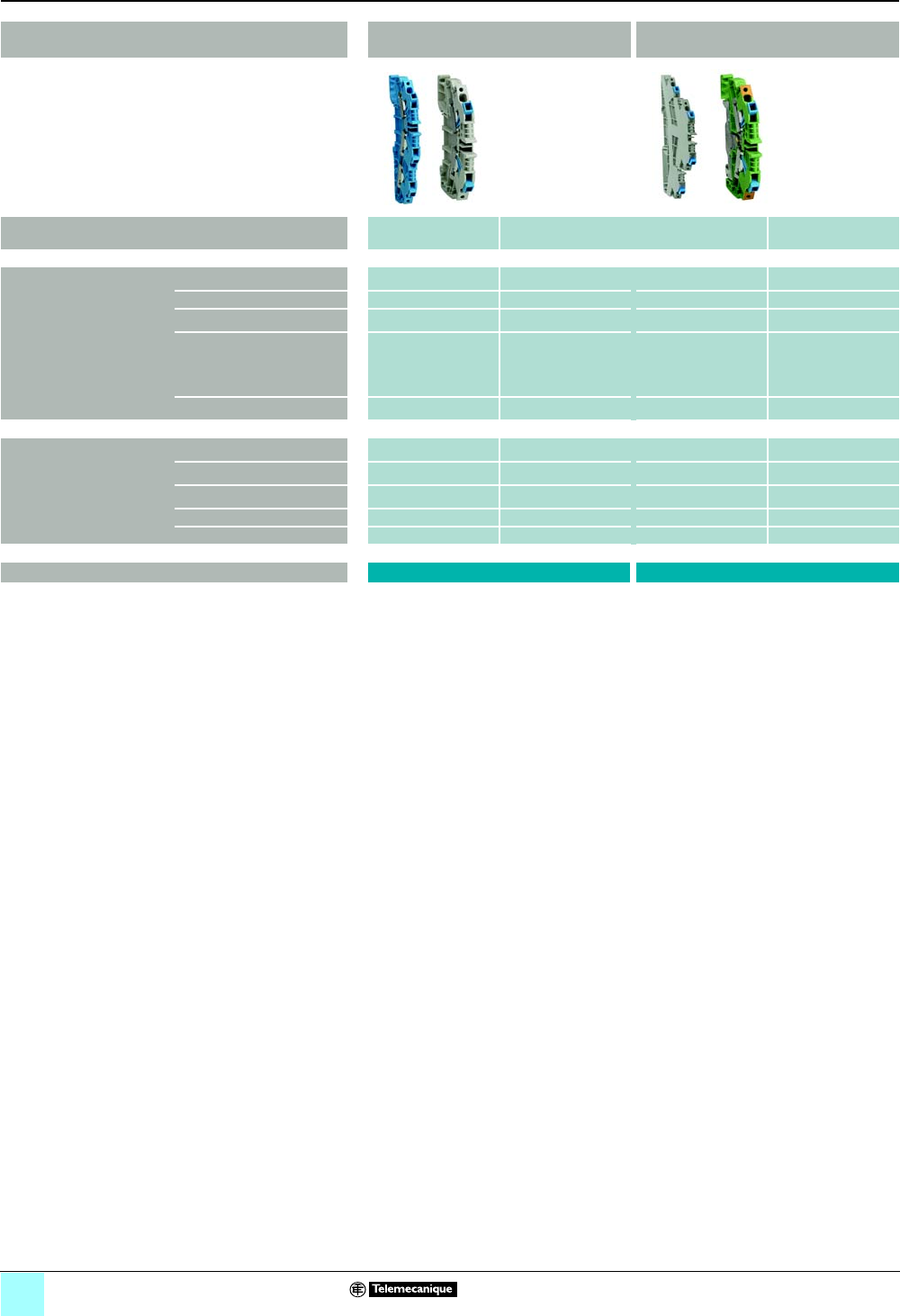
4/2
Terminal Blocks, Type AB1 0
Insulation displacement technology
Applications (connection) Passthrough Grounding
Nominal wire size AWG
(mm2)
18
(1)
12
(2.5)
18
(1)
12
(2.5)
Number of poles 1 - 1 x 1 • • • •
2 - 1 x 1 — — — —
1 - 1 x 2 • • • •
1 - 2 x 2 • • • •
Clip-on mounting on 35 mm 5• • • •
35 mm 7• • • •
Colors Gray • • — —
Blue • • — —
Green/yellow — — • •
Orange — — — —
Red — — — —
Catalog numbers AB1AA••• AB1AATP•••
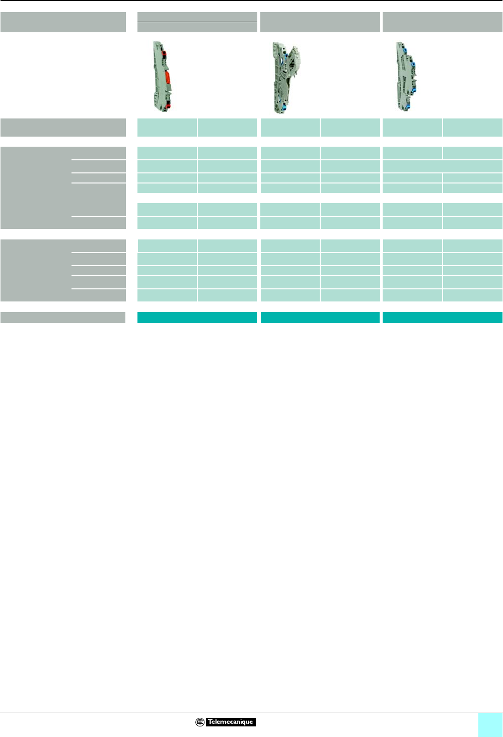
4/3
Terminal Blocks, Type AB1 0
Insulation displacement technology
Applications (connection) Disconnect Removable carrier,
for diode or cylindrical fuse
Double deck
Blade type
Nominal wire size AWG
(mm2)
18
(1)
14
(2.5)
18
(1)
14
(2.5)
18
(1)
14
(2.5)
Number of poles 1 - 1 x 1 • • • • — —
2 - 1 x 1 — — — — • •
1 - 1 x 2 — — — — — —
1 - 2 x 2 — — — — — —
Clip-on mounting
on
35 mm 5• • • • • •
35 mm 7• • • • • •
Colors Gray • • • • • •
Blue • • — — — —
Green/yellow — — — — — —
Orange — — — — — •
Red — — — — — •
Catalog numbers AB1AASC••• AB1AASF••• AB1AAET•••
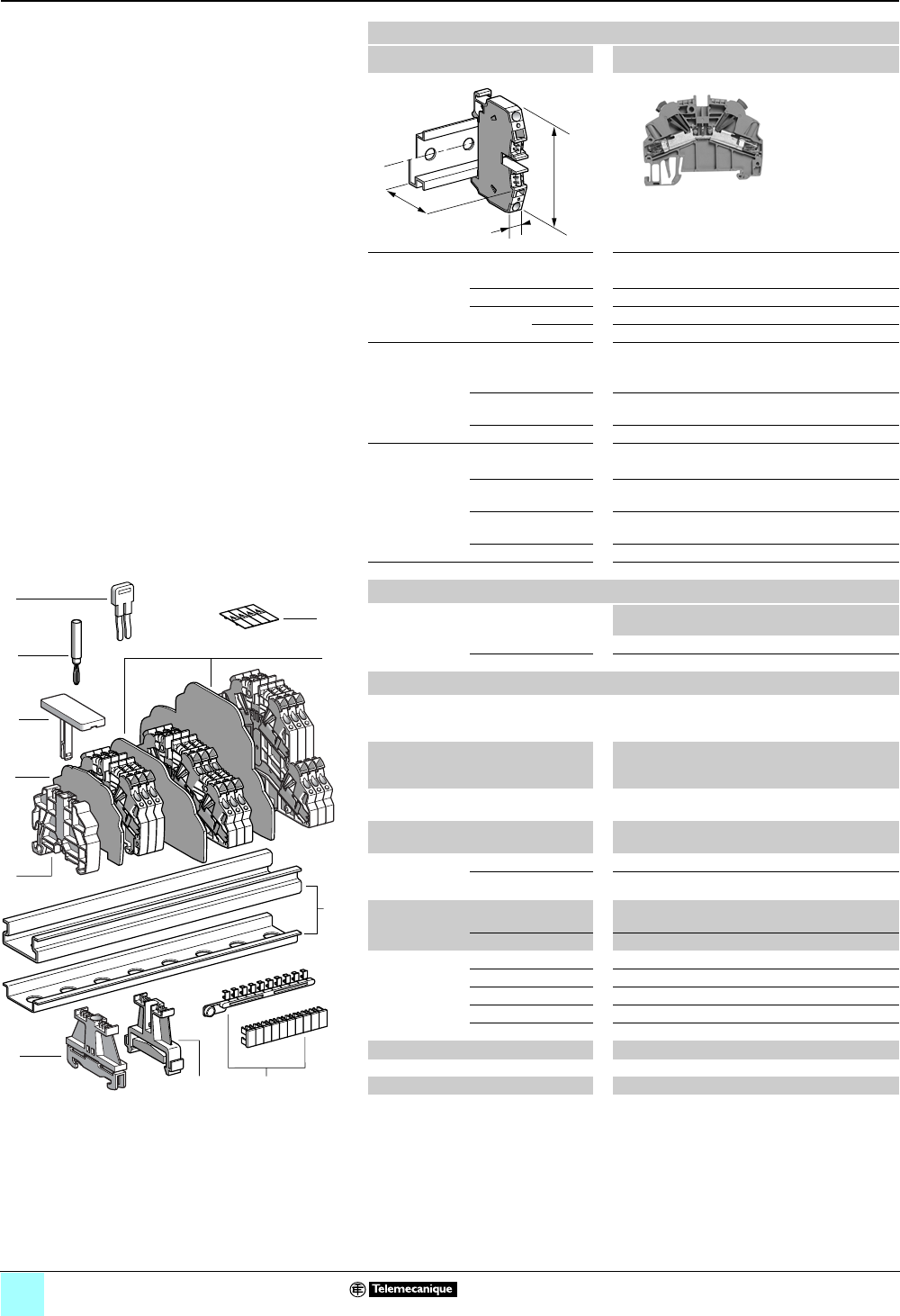
4/4
Terminal Blocks, Type AB1 0
Insulation displacement technology
Passthrough
Clip-on mounting on 35 mm 1 7 rails
Nominal wire size 1 mm2
AB1AA135U2••
Approximate dimensions, in. (mm)
Length (a) 2.64 (67)
Width (b) 0.20 (5)
1Height (H)
with
1 rail 2.26 (57.5)
7 rail 1.97 (50)
Wire size, mm2
Stranded without
cable end
0.2–1
Stranded with cable
end
—
Solid 0.2–1
Nominal electrical values
IEC/EN 60947-7-1 800 V / 8 kV / 3–13.5 A
UL File E164359
CCN XCFR2
30–18 AWG Cu, 600 V, 13 A
CSA File 702070
Class 6228 01
24–18 AWG Cu, 600 V, 7 A
ATEX Exe II II 2 GD 1 mm2, 750 V, 13.5 A, KEMA 02 ATEX 2113 U
Certifications See the table on page 1/13.
a
b
H
Terminal blocks
No.
points
Sold in
lots of
Catalog number Weight
oz (g)
Gray 2100 AB1AA135U2GR 0.44 (12.6)
Blue 2100 AB1AA135U2BL 0.44 (12.6)
Accessories
2 Plastic
end clamp
with screw
Width 0.3 in. (8 mm)
on 1 or 7 —100 AB1AB8P35 0.21 (5.9)
3Metal
end clamp
with screw
Width 0.3 in. (8 mm)
on 1 or 7—100 AB1AB8M35 0.52 (14.8)
4Clip-on plastic
end clamp
Width 0.3 in. (8 mm)
on 1 or 7—100 AB1AB8R35 0.21 (5.9)
5Marker tag holder
for clip-on plastic end clamp
—10 AB1SB4 0.11 (3.1)
6 End plate
thickness
0.06 in. (1.5 mm)
Gray —10 AB1AAAC122GR 0.16 (4.4)
Blue —10 AB1AAAC122BL 0.16 (4.4)
7Partition plate
thickness
0.06 in. (1.5 mm)
Gray —10 AB1AAAS122GR 0.19 (5.3)
Blue —10 AB1AAAS122BL 0.19 (5.3)
8 Insulated
jumper
2-pole —10 AB1RRAL22 0.04 (1.1)
3-pole —10 AB1RRAL23 0.06 (1.7)
4-pole —10 AB1RRAL24 0.08 (2.2)
5-pole —10 AB1RRAL25 0.10 (2.8)
10-pole —20 AB1RRAL210 0.20 (5.6)
9Test plug Red —50 AB1AT1 0.07 (1.9)
10 Terminal cover 410 AB1AACS1JA 0.014 (0.4)
11 Marking accessories See pages 5/2 and 5/3.
10
9
8
7
6
5
4
3
2
1
987654321
10
1
11
2
9
8
10
7
5
3
4
6
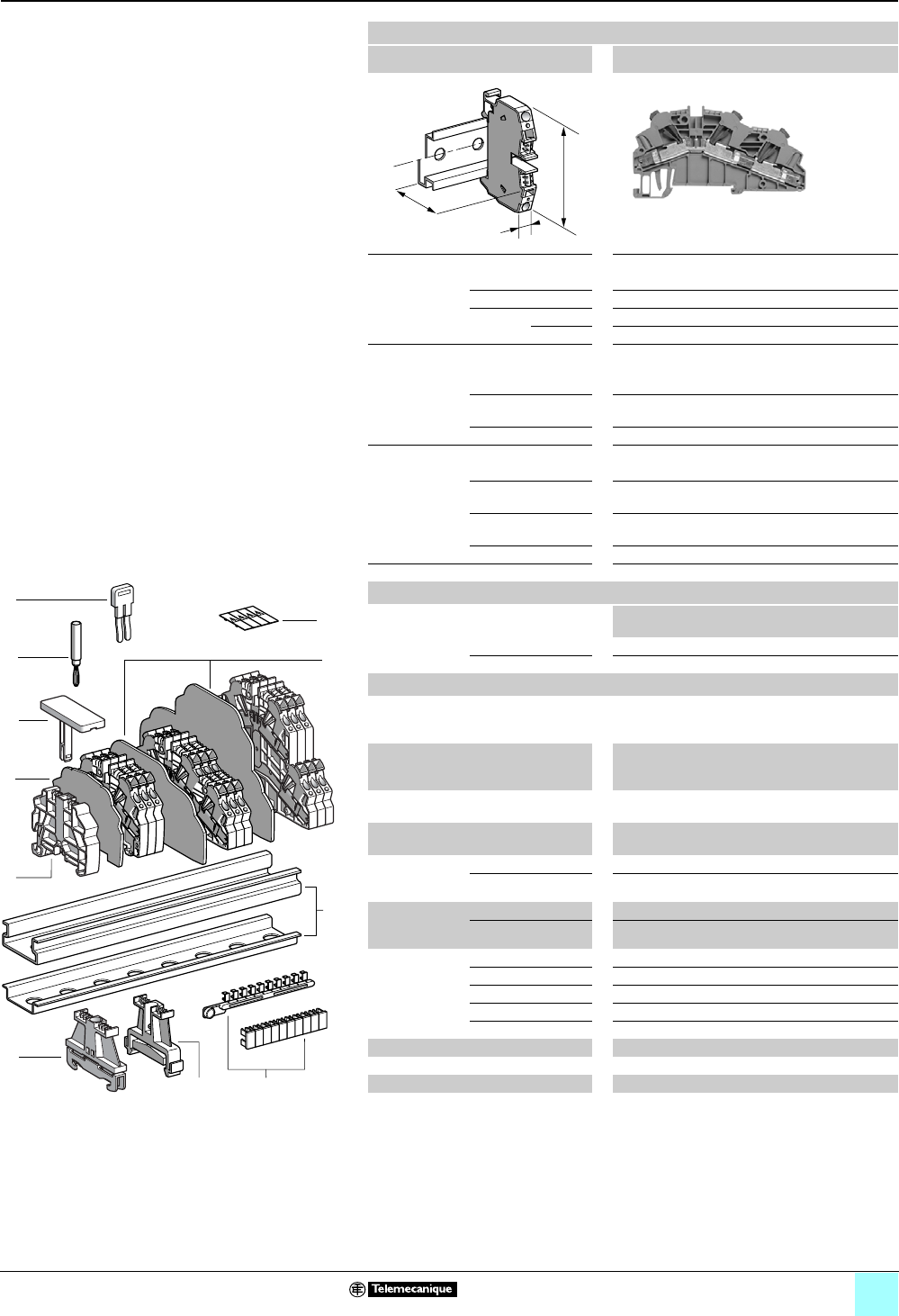
4/5
Terminal Blocks, Type AB1 0
Insulation displacement technology
Passthrough
Clip-on mounting on 35 mm 1 7 rails
Nominal wire size 1 mm2
AB1AA135U3••
Approximate dimensions, in. (mm)
Length (a) 3.63 (92.1)
Width (b) 0.20 (5)
1Height (H)
with
1 rail 2.26 (57.5)
7 rail 1.97 (50)
Wire size, mm2
Stranded without
cable end
0.2–1
Stranded with cable
end
—
Solid 0.2–1
Nominal electrical values
IEC/EN 60947-7-1 800 V / 8 kV / 3–13.5 A
UL File E164359
CCN XCFR2
30–18 AWG Cu, 600 V, 10 A
CSA File 702070
Class 6228 01
24–18 AWG Cu, 600 V, 7 A
ATEX Exe II II 2 GD 1 mm2, 750 V, 13.5 A, KEMA 02 ATEX 2113 U
Certifications See the table on 1/13.
a
b
H
Terminal blocks
No.
points
Sold in
lots of
Catalog number Weight
oz (g)
Gray 350 AB1AA135U3GR 0.62 (17.5)
Blue 350 AB1AA135U3BL 0.62 (17.5)
Accessories
2 Plastic
end clamp
with screw
Width 0.3 in. (8 mm)
on 1 or 7 —100 AB1AB8P35 0.21 (5.9)
3Metal
end clamp
with screw
Width 0.3 in. (8 mm)
on 1 or 7100 AB1AB8M35 0.52 (14.8)
4Clip-on plastic
end clamp
Width 0.3 in. (8 mm)
on 1 or 7—100 AB1AB8R35 0.21 (5.9)
5Marker tag holder
for clip-on plastic end clamp
—10 AB1SB4 0.11 (3.1)
6 End plate
thickness
0.06 in. (1.5 mm)
Gray — 10 AB1AAAC123GR 0.20 (5.7)
Blue — 10 AB1AAAC123BL 0.20 (5.7)
7Partition plate
thickness
0.06 in. (1.5 mm)
Gray —10 AB1AAAS123GR 0.25 (7.1)
Blue —10 AB1AAAS123BL 0.25 (7.1)
8 Insulated
jumper
2-pole — 10 AB1RRAL22 0.04 (1.1)
3-pole — 10 AB1RRAL23 0.08 (2.2)
4-pole — 10 AB1RRAL24 0.10 (2.8)
5-pole — 10 AB1RRAL25 0.20 (5.6)
10-pole — 20 AB1RRAL210 0.07 (1.9)
9Test plug Red —50 AB1AT1 0.06 (1.7)
10 Terminal cover 410AB1AACS1JA 0.014 (0.4)
11 Marking accessories See pages 5/2 and 5/3.
10
9
8
7
6
5
4
3
2
1
987654321
10
1
11
2
9
8
10
7
5
3
4
6
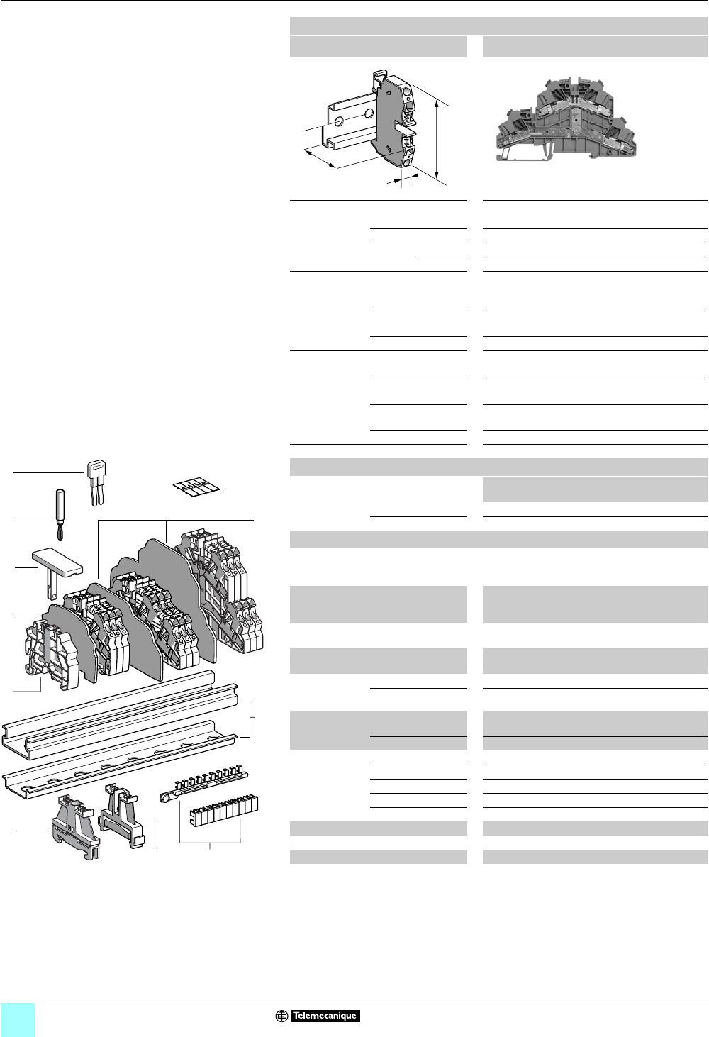
4/6
Terminal Blocks, Type AB1 0
Insulation displacement technology
Passthrough
Clip-on mounting on 35 mm 1 7 rails
Nominal wire size 1 mm2
AB1AA135U4••
Approximate dimensions, in. (mm)
Length (a) 4.71 (119.7)
Width (b) 0.20 (5)
1Height (H)
with
1 rail 3.13 (79.5)
7 rail 2.83 (72)
Wire size, mm2
Stranded without
cable end
0.2–1
Stranded with cable
end
—
Solid 0.2–1
Nominal electrical values
IEC/EN 60947-7-1 500 V / 6 kV / 3–13.5 A
UL File E164359
CCN XCFR2
30–18 AWG Cu, 600 V, 10 A
CSA File 702070
Class 6228 01
24–18 AWG Cu, 600 V, 7 A
ATEX Exe II II 2 GD 1 mm2, 550 V, 13.5 A, KEMA 02 ATEX 2113 U
Certifications See the table on 1/13.
a
b
H
Terminal blocks
No.
points
Sold in
lots of
Catalog number Weight
oz (g)
Gray 450 AB1AA135U4GR 1.08 (30.7)
Blue 450 AB1AA135U4BL 1.08 (30.7)
Accessories
2 Plastic
end clamp
with screw
Width 0.3 in. (8 mm)
on 1 or 7 —100 AB1AB8P35 0.21 (5.9)
3Metal
end clamp
with screw
Width 0.3 in. (8 mm)
on 1 or 7—100 AB1AB8M35 0.52 (14.8)
4Clip-on plastic
end clamp
Width 0.3 in. (8 mm)
on 1 or 7— 100 AB1AB8R35 0.21 (5.9)
5Marker tag holder
for clip-on plastic end clamp
—10 AB1SB4 0.11 (3.1)
6 End plate
thickness
0.06 in. (1.5 mm)
Gray — 10 AB1AAAC124GR 0.36 (10.3)
Blue — 10 AB1AAAC124BL 0.36 (10.3)
7Partition plate
thickness
0.06 in. (1.5 mm)
Gray —10 AB1AAAS124GR 0.41 (11.5)
Blue —10 AB1AAAS124BL 0.41 (11.5)
8 Insulated
jumper
2-pole — 10 AB1RRAL22 0.04 (1.1)
3-pole — 10 AB1RRAL23 0.08 (2.2)
4-pole — 10 AB1RRAL24 0.10 (2.8)
5-pole — 10 AB1RRAL25 0.20 (5.6)
10-pole — 20 AB1RRAL210 0.07 (1.9)
9Test plug Red —50 AB1AT1 0.06 (1.7)
10 Terminal cover 410AB1AACS1JA 0.014 (0.4)
11 Marking accessories See pages 5/2 and 5/3.
10
9
8
7
6
5
4
3
2
1
987654321
10
1
11
2
9
8
10
7
5
3
4
6
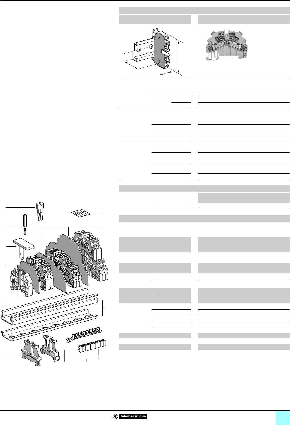
4/7
Terminal Blocks, Type AB1 0
Insulation displacement technology
Passthrough
Clip-on mounting on 35 mm 1 7 rails
Nominal wire size 2.5 mm2
AB1AA235U2••
Approximate dimensions, in. (mm)
Length (a) 2.64 (67)
Width (b) 0.24 (6)
1Height (H)
with
1 rail 2.26 (57.5)
7 rail 1.97 (50)
Wire size, mm2
Stranded without
cable end
1–2.5
Stranded with cable
end
—
Solid 1–2.5
Nominal electrical values
IEC/EN 60947-7-1 800 V / 8 kV / 3–24 A
UL File E164359
CCN XCFR2
18–14 AWG Cu, 600 V, 13 A
CSA File 702070
Class 6228 01
16–14 AWG Cu, 600 V, 20 A
ATEX Exe II II 2 GD 2.5 mm2, 750 V, 24 A, KEMA 02 ATEX 2113 U
Certifications See the table on 1/13.
a
b
H
Terminal blocks
No.
points
Sold in
lots of
Catalog number Weight
oz (g)
Gray 2100 AB1AA235U2GR 0.50 (14.1)
Blue 2100 AB1AA235U2BL 0.50 (14.1)
Accessories
2 Plastic
end clamp
with screw
Width 0.3 in. (8 mm)
on 1 or 7 —100 AB1AB8P35 0.21 (5.9)
3Metal
end clamp
with screw
Width 0.3 in. (8 mm)
on 1 or 7—100 AB1AB8M35 0.52 (14.8)
4 Clip-on plastic
end clamp
Width 0.3 in. (8 mm)
on 1 or 7—100 AB1AB8R35 0.21 (5.9)
5Marker tag holder for
clip-on plastic end clamp
—10 AB1SB4 0.11 (3.1)
6 End plate
thickness
0.06 in. (1.5 mm)
Gray —10 AB1AAAC122GR 0.16 (4.4)
Blue —10 AB1AAAC122BL 0.16 (4.4)
7Partition plate
thickness
0.06 in. (1.5 mm)
Gray —10 AB1AAAS122GR 0.19 (5.3)
Blue —10 AB1AAAS122BL 0.19 (5.3)
8 Insulated
jumper
2-pole —10 AB1RRAL42 0.06 (1.6)
3-pole —10 AB1RRAL43 0.06 (1.7)
4-pole —10 AB1RRAL44 0.10 (2.8)
5-pole —10 AB1RRAL45 0.20 (5.6)
10-pole —20 AB1RRAL410 0.07 (1.9)
9Test plug Red —50 AB1AT1 0.06 (1.7)
10 Terminal cover 410AB1AACS1JA 0.014 (0.4)
11 Marking accessories See pages 5/2 and 5/3.
10
9
8
7
6
5
4
3
2
1
987654321
10
1
11
2
9
8
10
7
5
3
4
6
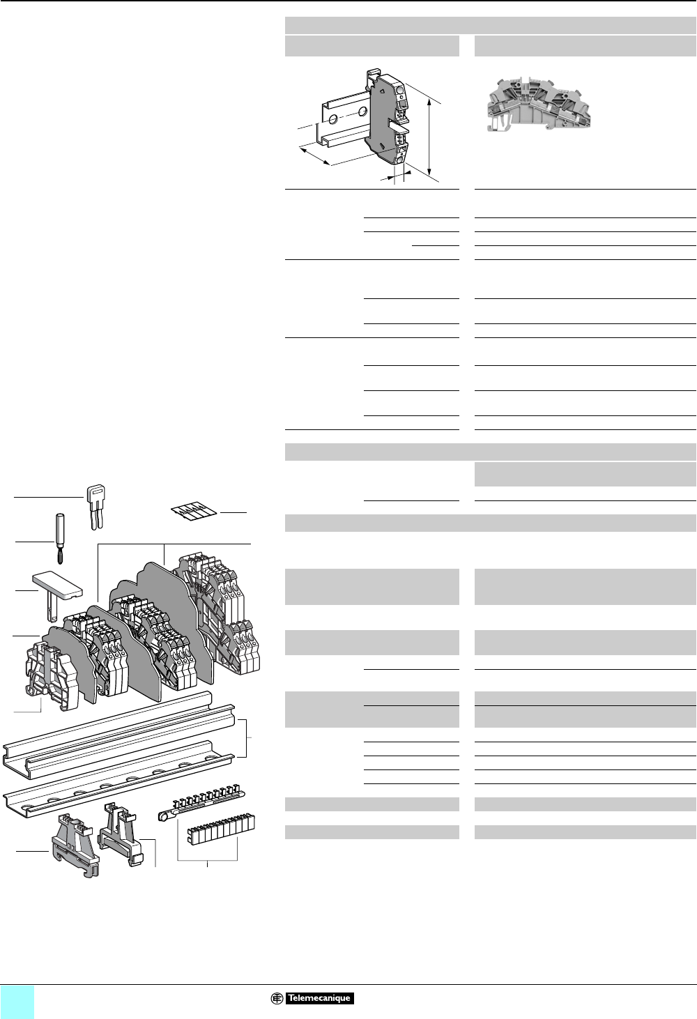
4/8
Terminal Blocks, Type AB1 0
Insulation displacement technology
Passthrough
Clip-on mounting on 35 mm 1 7 rails
Nominal wire size 2.5 mm2
AB1AA235U3••
Approximate dimensions, in. (mm)
Length (a) 3.63 (92.1)
Width (b) 0.24 (6)
1Height (H)
with
1 rail 2.26 (57.5)
7 rail 1.97 (50)
Wire size, mm2
Stranded without
cable end
1–2.5
Stranded with cable
end
—
Solid 1–2.5
Nominal electrical values
IEC/EN 60947-7-1 800 V / 8 kV / 3–24 A
UL File E164359
CCN XCFR2
18–14 AWG Cu, 600 V, 10 A
CSA File 702070
Class 6228 01
16–14 AWG Cu, 600 V, 20 A
ATEX Exe II II 2 GD 2.5 mm2, 750 V, 24 A, KEMA 02 ATEX 2113 U
Certifications See the table on 1/13.
a
b
H
Terminal blocks
No.
points
Sold in
lots of
Catalog number Weight
oz (g)
Gray 350 AB1AA235U3GR 0.69 (19.5)
Blue 350 AB1AA235U3BL 0.69 (19.5)
Accessories
2 Plastic
end clamp
with screw
Width 0.3 in. (8 mm)
on 1 or 7 —100 AB1AB8P35 0.21 (5.9)
3Metal
end clamp
with screw
Width 0.3 in. (8 mm)
on 1 or 7—100 AB1AB8M35 0.52 (14.8)
4 Clip-on plastic
end clamp
Width 0.3 in. (8 mm)
on 1 or 7—100 AB1AB8R35 0.21 (5.9)
5Marker tag holder for
clip-on plastic end clamp
—10 AB1SB4 0.11 (3.1)
6 End plate
thickness
0.06 in. (1.5 mm)
Gray —10 AB1AAAC123GR 0.20 (5.7)
Blue —10 AB1AAAC123BL 0.20 (5.7)
7Partition plate
thickness
0.06 in. (1.5 mm)
Gray —10 AB1AAAS123GR 0.25 (7.1)
Blue —10 AB1AAAS123BL 0.25 (7.1)
8 Insulated
jumper
2-pole —10 AB1RRAL42 0.06 (1.6)
3-pole —10 AB1RRAL43 0.08 (2.4)
4-pole —10 AB1RRAL44 0.11 (3.2)
5-pole —10 AB1RRAL45 0.14 (4.0)
10-pole —20 AB1RRAL410 0.28 (8.0)
9Test plug Red —50 AB1AT1 0.06 (1.7)
10 Terminal cover 410 AB1AACS1JA 0.014 (0.4)
11 Marking accessories See pages 5/2 and 5/3.
10
9
8
7
6
5
4
3
2
1
987654321
10
1
11
2
9
8
10
7
5
3
4
6
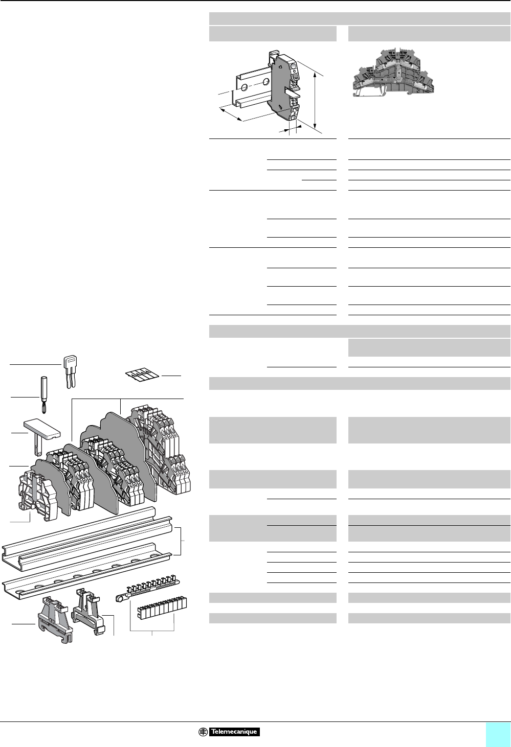
4/9
Terminal Blocks, Type AB1 0
Insulation displacement technology
Passthrough
Clip-on mounting on 35 mm 1 7 rails
Nominal wire size 2.5 mm2
AB1AA235U4••
Approximate dimensions, in. (mm)
Length (a) 4.71 (119.7)
Width (b) 0.24 (6)
1Height (H)
with
1 rail 3.13 (79.5)
7 rail 2.83 (72)
Wire size, mm2
Stranded without
cable end
1–2.5
Stranded with cable
end
—
Solid 1–2.5
Nominal electrical values
IEC/EN 60947-7-1 500 V / 6 kV / 3–24 A
UL File E164359
CCN XCFR2
18–14 AWG Cu, 600 V, 10 A
CSA File 702070
Class 6228 01
16–14 AWG Cu, 600 V, 20 A
ATEX Exe II II 2 GD 2.5 mm2, 550 V, 24 A, KEMA 02 ATEX 2113 U
Certifications See the table on 1/13.
a
b
H
Terminal blocks
No.
points
Sold in
lots of
Catalog number Weight
oz (g)
Gray 450 AB1AA235U4GR 1.20 (34.1)
Blue 450 AB1AA235U4BL 1.20 (34.1)
Accessories
2 Plastic
end clamp
with screw
Width 0.3 in. (8 mm)
on 1 or 7 —100 AB1AB8P35 0.21 (5.9)
3Metal
end clamp
with screw
Width 0.3 in. (8 mm)
on 1 or 7—100 AB1AB8M35 0.52 (14.8)
4 Clip-on plastic
end clamp
Width 0.3 in. (8 mm)
on 1 or 7—100 AB1AB8R35 0.21 (5.9)
5Marker tag holder for
clip-on plastic end clamp
—10 AB1SB4 0.11 (3.1)
6 End plate
thickness
0.06 in. (1.5 mm)
Gray —10 AB1AAAC124GR 0.36 (10.3)
Blue —10 AB1AAAC124BL 0.36 (10.3)
7Partition plate
thickness
0.06 in. (1.5 mm)
Gray —10 AB1AAAS124GR 0.41 (11.5)
Blue —10 AB1AAAS124BL 0.41 (11.5)
8 Insulated
jumper
2-pole —10 AB1RRAL42 0.06 (1.6)
3-pole —10 AB1RRAL43 0.08 (2.4)
4-pole —10 AB1RRAL44 0.11 (3.2)
5-pole —10 AB1RRAL45 0.14 (4.0)
10-pole —20 AB1RRAL410 0.28 (8.0)
9Test plug Red —50 AB1AT1 0.06 (1.7)
10 Terminal cover 410 AB1AACS1JA 0.014 (0.4)
11 Marking accessories See pages 5/2 and 5/3.
10
9
8
7
6
5
4
3
2
1
987654321
10
1
11
2
9
8
10
7
5
3
4
6
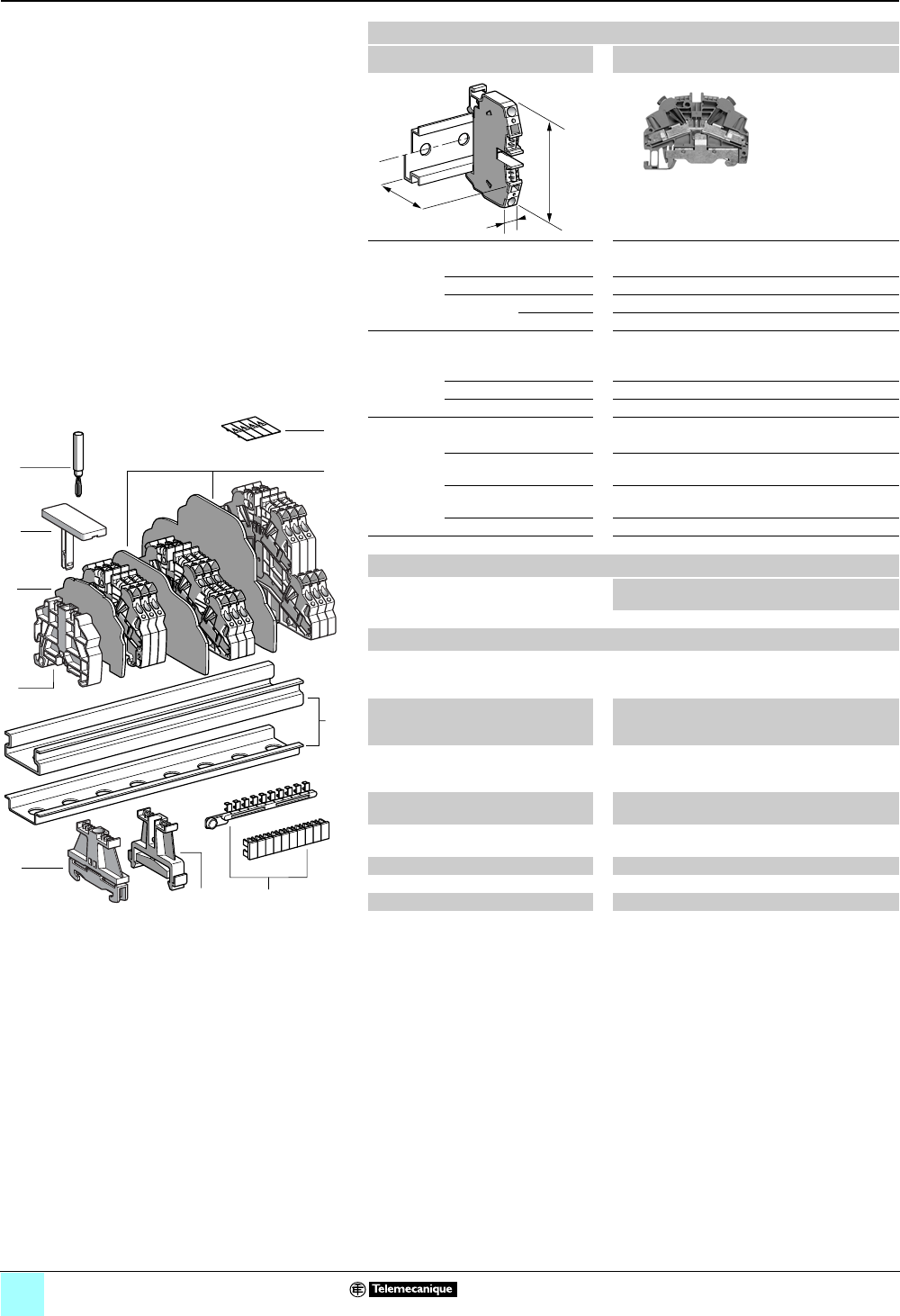
4/10
Terminal Blocks, Type AB1 0
Insulation displacement technology
Grounding type
Clip-on mounting on 35 mm 1 7 rails
Nominal wire size 1 mm2
AB1AATP135U2••
Approximate dimensions, in. (mm)
Length (a) 2.64 (67)
Width (b) 0.20 (5)
1Height (H)
with
1 rail 2.26 (57.5)
7 rail 1.97 (50)
Wire size, mm2
Stranded without
cable end
0.2–1
Stranded with cable end —
Solid 0.2–1
Nominal electrical values
IEC/EN 60947-7-1 800 V / 8 kV / 3–13.5 A
UL File E164359
CCN XCFR2
30–18 AWG Cu, 600 V, 13 A
CSA File 702070
Class 6228 01
24–18 AWG Cu, 600 V, 120 A
ATEX - EEx eII II 2 GD 1 mm2, KEMA 02 ATEX 2113 U
Certifications See the table on page 1/13.
a
b
H
Terminal blocks
No.
points
Sold in
lots of
Catalog number Weight
oz (g)
Green/yellow 2100 AB1AATP135U2 0.64 (18.1)
Accessories
2 Plastic
end clamp
with screw
Width 0.3 in. (8 mm)
on 1 or 7 —100 AB1AB8P35 0.21 (5.9)
3Metal
end clamp
with screw
Width 0.3 in. (8 mm)
on 1 or 7—100 AB1AB8M35 0.52 (14.8)
4 Clip-on
plastic
end clamp
Width 0.3 in. (8 mm)
on 1 or 7—100 AB1AB8R35 0.21 (5.9)
5Marker tag holder for
clip-on plastic end clamp
—10 AB1SB4 0.11 (3.1)
6 End
plate
Green, thickness
0.06 in. (1.5 mm)
—10 AB1AAAC122VE 0.11 (3.2)
7Test plug Red —50 AB1AT1 0.06 (1.7)
8 Terminal cover 410 AB1AACS1JA 0.014 (0.4)
9Marking accessories See pages 5/2 and 5/3.
10
9
8
7
6
5
4
3
2
1
987654321
10
1
92
7
8
6
5
3
4
6
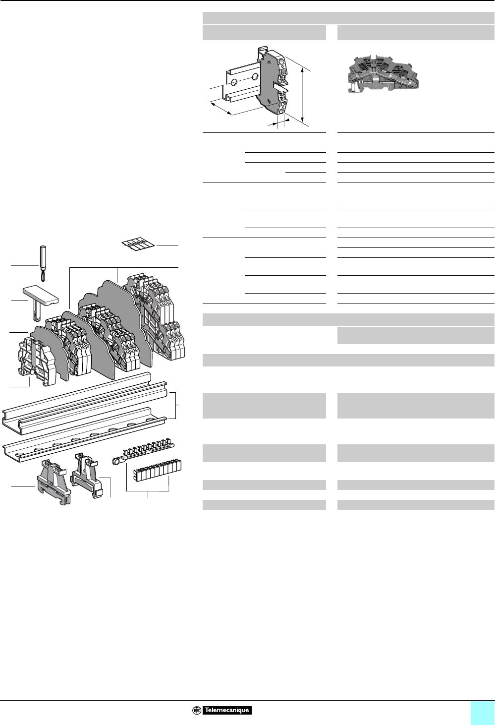
4/11
Terminal Blocks, Type AB1 0
Insulation displacement technology
Grounding type
Clip-on mounting on 35 mm 1 7 rails
Nominal wire size 1 mm2
AB1AATP135U3
Approximate dimensions, in. (mm)
Length (a) 3.63 (92.1)
Width (b) 0.20 (5)
1Height (H)
with
1 rail 2.26 (57.5)
7 rail 1.97 (50)
Wire size, mm2
Stranded without
cable end
0.2–1
Stranded with cable end —
Solid 0.2–1
Nominal electrical values
IEC/EN 60947-7-1 800 V / 8 kV / 3–13.5 A
UL File E164359
CCN XCFR2
30–18 AWG Cu, 600 V, 10 A
CSA File 702070
Class 6228 01
24–18 AWG Cu, 120 A
ATEX - EEx eII II 2 GD 1 mm2, KEMA 02 ATEX 2113 U
Certifications See the table on page 1/13.
a
b
H
Terminal blocks
No.
points
Sold in
lots of
Catalog number Weight
oz (g)
Green/yellow 350 AB1AATP135U3 0.82 (23.2)
Accessories
2 Plastic
end clamp
with screw
Width 0.3 in. (8 mm)
on 1 or 7 —100 AB1AB8P35 0.21 (5.9)
3Metal
end clamp
with screw
Width 0.3 in. (8 mm)
on 1 or 7—100 AB1AB8M35 0.52 (14.8)
4 Clip-on
plastic
end clamp
Width 0.3 in. (8 mm)
on 1 or 7—100 AB1AB8R35 0.21 (5.9)
5Marker tag holder for
clip-on plastic end clamp
—10 AB1SB4 0.11 (3.1)
6 End
plate
Green, thickness
0.06 in. (1.5 mm)
—10 AB1AAAC123VE 0.20 (5.7)
7Test plug Red —50 AB1AT1 0.06 (1.7)
8 Terminal cover 410 AB1AACS1JA 0.014 (0.4)
9Marking accessories See pages 5/2 and 5/3.
10
9
8
7
6
5
4
3
2
1
987654321
10
1
92
7
8
6
5
3
4
6
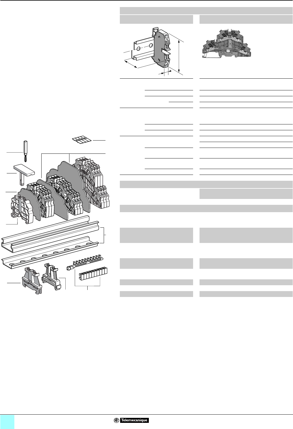
4/12
Terminal Blocks, Type AB1 0
Insulation displacement technology
Grounding type
Clip-on mounting on 35 mm 1 7 rails
Nominal wire size 1 mm2
AB1AATP135U4
Approximate dimensions, in. (mm)
Length (a) 4.71 (119.7)
Width (b) 0.20 (5)
1Height (H)
with
1 rail 3.13 (79.5)
7 rail 2.83 (72)
Wire size, mm2
Stranded without
cable end
0.2–1
Stranded with cable end —
Solid 0.2–1
Nominal electrical values
IEC/EN 60947-7-1 500 V / 6 kV / 3–13.5 A
UL File E164359
CCN XCFR2
30–18 AWG Cu, 600 V, 10 A
CSA File 702070
Class 6228 01
24–18 AWG Cu, 120 A
ATEX - EEx eII II 2 GD 1 mm2, KEMA 02 ATEX 2113 U
Certifications See the table on page 1/13.
a
b
H
Terminal blocks
No.
points
Sold in
lots of
Catalog number Weight
oz (g)
Green/yellow 450 AB1AATP135U4 1.28 (36.2)
Accessories
2 Plastic
end clamp
with screw
Width 0.3 in. (8 mm)
on 1 or 7 —100 AB1AB8P35 0.21 (5.9)
3Metal
end clamp
with screw
Width 0.3 in. (8 mm)
on 1 or 7—100 AB1AB8M35 0.52 (14.8)
4 Clip-on
plastic
end clamp
Width 0.3 in. (8 mm)
on 1 or 7—100 AB1AB8R35 0.21 (5.9)
5Marker tag holder for
clip-on plastic end clamp
—10 AB1SB4 0.11 (3.1)
6 End
plate
Green, thickness
0.06 in. (1.5 mm)
—10 AB1AAAC124VE 0.36 (10.3)
7Test plug Red —50 AB1AT1 0.06 (1.7)
8 Terminal cover 410 AB1AACS1JA 0.014 (0.4)
9Marking accessories See pages 5/2 and 5/3.
10
9
8
7
6
5
4
3
2
1
987654321
10
1
92
7
8
6
5
3
4
6
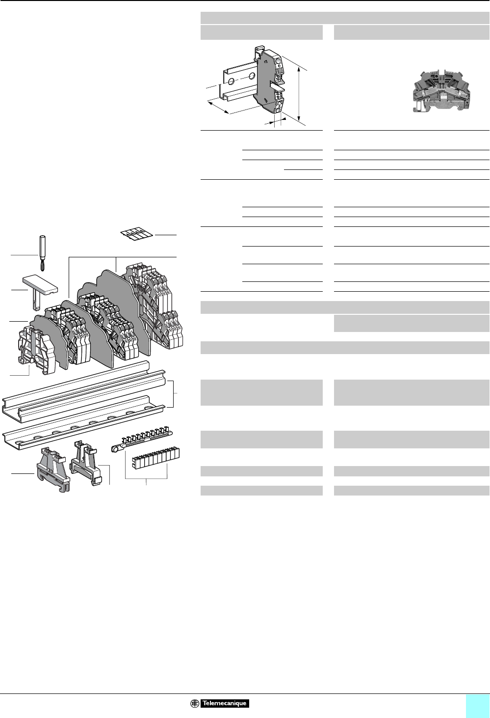
4/13
Terminal Blocks, Type AB1 0
Insulation displacement technology
Grounding type
Clip-on mounting on 35 mm 1 7 rails
Nominal wire size 2.5 mm2
AB1AATP235U2
Approximate dimensions, in. (mm)
Length (a) 2.64 (67)
Width (b) 0.24 (6)
1Height (H)
with
1 rail 2.26 (57.5)
7 rail 1.97 (50)
Wire size, mm2
Stranded without
cable end
1–2.5
Stranded with cable end —
Solid 1–2.5
Nominal electrical values
IEC/EN 60947-7-1 800 V / 8 kV / 3–24 A
UL File E164359
CCN XCFR2
18–14 AWG Cu, 600 V, 13 A
CSA File 702070
Class 6228 01
16–14 AWG Cu, 300 A
ATEX - EEx eII II 2 GD 2.5 mm2, KEMA 02 ATEX 2113 U
Certifications See the table on page 1/13.
Terminal blocks
No.
points
Sold in
lots of
Catalog number Weight
oz (g)
Green/Yellow 2100 AB1AATP235U2 0.71 (20.0)
Accessories
2 Plastic
end clamp
with screw
Width 0.3 in. (8 mm)
on 1 or 7 —100 AB1AB8P35 0.21 (5.9)
3Metal
end clamp
with screw
Width 0.3 in. (8 mm)
on 1 or 7—100 AB1AB8M35 0.52 (14.8)
4 Clip-on
plastic
end clamp
Width 0.3 in. (8 mm)
on 1 or 7—100 AB1AB8R35 0.21 (5.9)
5Marker tag holder for
clip-on plastic end clamp
—10 AB1SB4 0.11 (3.1)
6 End plate Green, thickness
0.06 in. (1.5 mm)
—10 AB1AAAC122VE 0.16 (4.4)
7Test plug Red —50 AB1AT1 0.06 (1.7)
8 Terminal cover 410 AB1AACS1JA 0.014 (0.4)
9Marking accessories See pages 5/2 and 5/3.
a
b
H
10
9
8
7
6
5
4
3
2
1
987654321
10
1
92
7
8
6
5
3
4
6

4/14
Terminal Blocks, Type AB1 0
Insulation displacement technology
Grounding type
Clip-on mounting on 35 mm 1 7 rails
Nominal wire size 2.5 mm2
AB1AATP235U3
Approximate dimensions, in. (mm)
Length (a) 3.63 (92.1)
Width (b) 0.24 (6)
1Height (H)
with
1 rail 2.26 (57.5)
7 rail 1.97 (50)
Wire size, mm2
Stranded without
cable end
1–2.5
Stranded with cable end —
Solid 1–2.5
Nominal electrical values
IEC/EN 60947-7-1 800 V / 8 kV / 3–24 A
UL File E164359
CCN XCFR2
18–14 AWG Cu, 600V, 10 A
CSA File 702070
Class 6228 01
16–14 AWG Cu, 300 A
ATEX - EEx eII II 2 GD 2.5 mm2, KEMA 02 ATEX 2113 U
Certifications See the table on page 1/13.
Terminal blocks
No.
points
Sold in
lots of
Catalog number Weight
oz (g)
Green/Yellow 350 AB1AATP235U3 0.87 (24.8)
Accessories
2 Plastic
end clamp
with screw
Width 0.3 in. (8 mm)
on 1 or 7 —100 AB1AB8P35 0.21 (5.9)
3Metal
end clamp
with screw
Width 0.3 in. (8 mm)
on 1 or 7—100 AB1AB8M35 0.52 (14.8)
4 Clip-on
plastic
end clamp
Width 0.3 in. (8 mm)
on 1 or 7—100 AB1AB8R35 0.21 (5.9)
5Marker tag holder for
clip-on plastic end clamp
—10 AB1SB4 0.11 (3.1)
6 End plate Green, thickness
0.06 in. (1.5 mm)
—10 AB1AAAC123VE 0.20 (5.7)
7Test plug Red —50 AB1AT1 0.06 (1.7)
8 Terminal cover 410 AB1AACS1JA 0.014 (0.4)
9Marking accessories See pages 5/2 and 5/3.
a
b
H
10
9
8
7
6
5
4
3
2
1
987654321
10
1
92
7
8
6
5
3
4
6
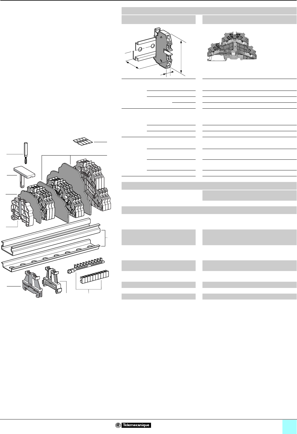
4/15
Terminal Blocks, Type AB1 0
Insulation displacement technology
Grounding type
Clip-on mounting on 35 mm 1 7 rails
Nominal wire size 2.5 mm2
AB1AATP235U4
Approximate dimensions, in. (mm)
Length (a) 4.71 (119.7)
Width (b) 0.24 (6)
1Height (H)
with
1 rail 3.13 (79.5)
7 rail 2.83 (72)
Wire size, mm2
Stranded without
cable end
1–2.5
Stranded with cable end —
Solid 1–2.5
Nominal electrical values
IEC/EN 60947-7-1 500 V / 6 kV / 3–24 A
UL File E164359
CCN XCFR2
18–14 AWG Cu, 600 V, 10 A
CSA File 702070
Class 6228 01
16–14 AWG Cu, 300 A
ATEX - EEx eII II 2 GD 2.5 mm2, KEMA 02 ATEX 2113 U
Certifications See the table on page 1/13.
Terminal blocks
No.
points
Sold in
lots of
Catalog number Weight
oz (g)
Green/Yellow 450 AB1AATP235U4 1.40 (39.7)
Accessories
2 Plastic
end clamp
with screw
Width 0.3 in. (8 mm)
on 1 or 7 —100 AB1AB8P35 0.21 (5.9)
3Metal
end clamp
with screw
Width 0.3 in. (8 mm)
on 1 or 7—100 AB1AB8M35 0.52 (14.8)
4 Clip-on
plastic
end clamp
Width 0.3 in. (8 mm)
on 1 or 7—100 AB1AB8R35 0.21 (5.9)
5Marker tag holder for
clip-on plastic end clamp
—10 AB1SB4 0.11 (3.1)
6 End plate Green, thickness
0.06 in. (1.5 mm)
—10 AB1AAAC124VE 0.36 (10.3)
7Test plug Red —50 AB1AT1 0.06 (1.7)
8 Terminal cover 410 AB1AACS1JA 0.014 (0.4)
9Marking accessories See pages 5/2 and 5/3.
a
b
H
10
9
8
7
6
5
4
3
2
1
987654321
10
1
92
7
8
6
5
3
4
6
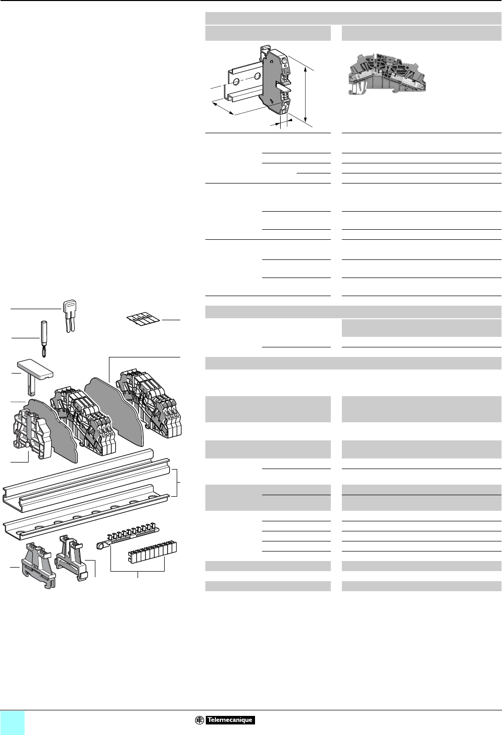
4/16
Terminal Blocks, Type AB1 0
Insulation displacement technology
Blade disconnect type
Clip-on mounting on 35 mm 1 7 rails
Nominal wire size 1 mm2
AB1AASC135U••
Approximate dimensions, in. (mm)
Length (a) 3.63 (92.1)
Width (b) 0.24 (6)
1Height (H)
with
1 rail 2.26 (57.5)
7 rail 1.97 (50)
Wire size, mm2
Stranded without
cable end
0.2–1
Stranded with
cable end
—
Solid 0.2–1
Nominal electrical values
IEC/EN 60947-7-1 800 V / 8 kV / 3–13.5 A
UL File E164359
CCN XCFR2
30–18 AWG Cu, 600 V, 10 A
CSA File 702070
Class 6228 01
24–18 AWG Cu, 300V, 7A
Certifications See the table on page 1/13.
a
b
H
Terminal blocks
No.
points
Sold in
lots of
Catalog number Weight
oz (g)
Gray 250 AB1AASC135UGR 0.67 (19.1)
Blue 250 AB1AASC135UBL 0.67 (19.1)
Accessories
2 Plastic end
clamp with
screw
Width 0.3 in. (8 mm)
on 1 or 7 —100 AB1AB8P35 0.21 (5.9)
3Metal end
clamp with
screw
Width 0.3 in. (8 mm)
on 1 or 7—100 AB1AB8M35 0.52 (14.8)
4 Clip-on plastic
end clamp
Width 0.3 in. (8 mm)
on 1 or 7—100 AB1AB8R35 0.21 (5.9)
5Marker tag holder
for clip-on plastic end clamp
—10 AB1SB4 0.11 (3.1)
6 End plate
thickness
0.06 in. (1.5 mm)
Gray —10 AB1AAAC123GR 0.20 (5.7)
Blue —10 AB1AAAC123BL 0.20 (5.7)
7Partition plate
thickness
0.06 in. (1.5 mm)
Gray —10 AB1AAAS123GR 0.25 (7.1)
Blue —10 AB1AAAS123BL 0.25 (7.1)
8 Insulated
jumper
2-pole —10 AB1RRAL42 0.06 (1.7)
3-pole —10 AB1RRAL43 0.09 (2.5)
4-pole —10 AB1RRAL44 0.12 (3.3)
5-pole —10 AB1RRAL45 0.14 (4.1)
10-pole —20 AB1RRAL410 0.29 (8.3)
9Test plug Red —50 AB1AT1 0.07 (1.9)
10 Terminal cover 410 AB1AACS1JA 0.014 (0.4)
11 Marking accessories See pages 5/2 and 5/3.
10
9
8
7
6
5
4
3
2
1
987654321
10
1
211
9
8
4
10
7
6
3
5
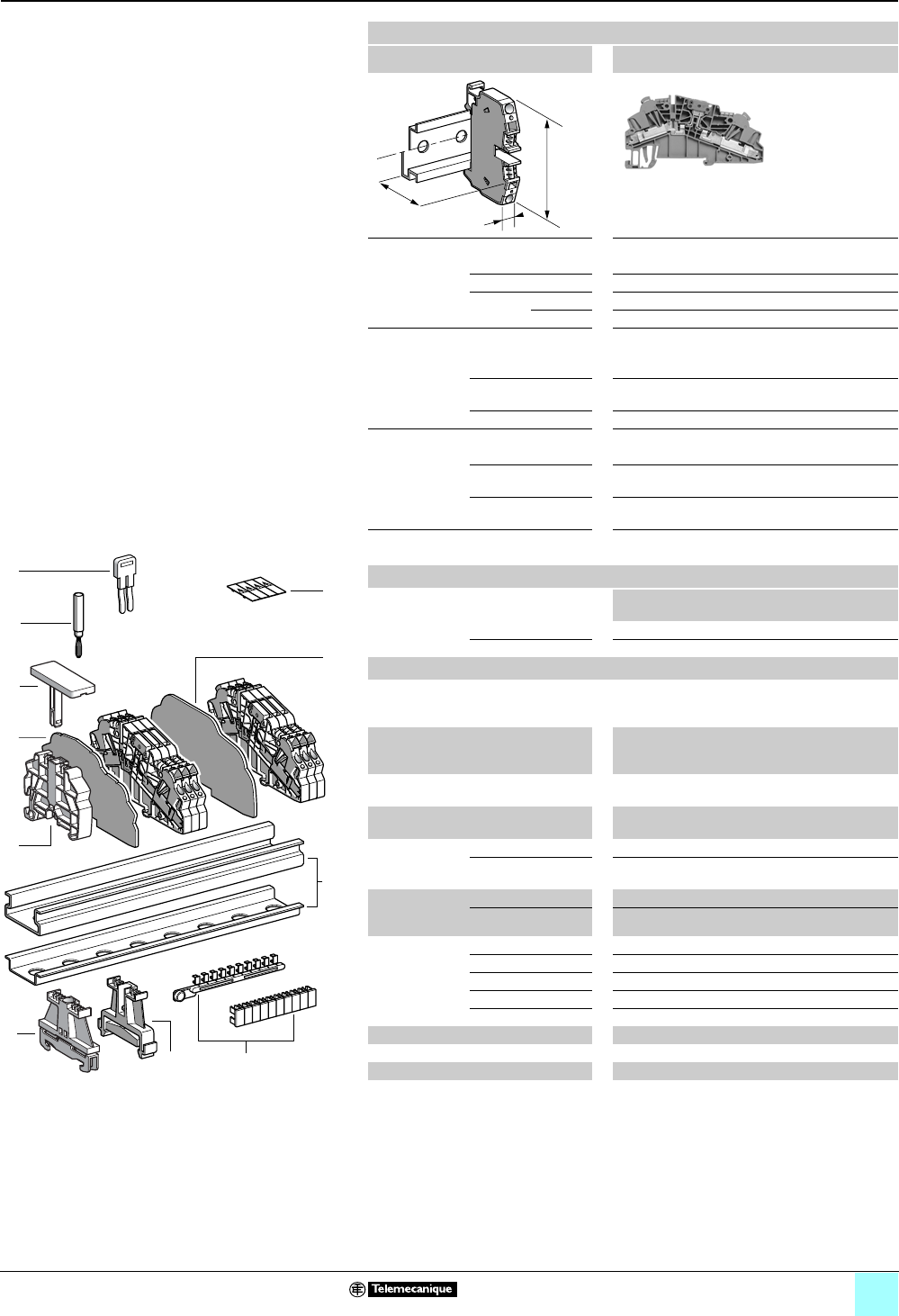
4/17
Terminal Blocks, Type AB1 0
Insulation displacement technology
Blade disconnect type
Clip-on mounting on 35 mm 1 7 rails
Nominal wire size 2.5 mm2
AB1AASC235U••
Approximate dimensions, in. (mm)
Length (a) 3.63 (92.1)
Width (b) 0.24 (6)
1Height (H)
with
1 rail 2.26 (57.5)
7 rail 1.97 (50)
Wire size, mm2
Stranded without
cable end
1–2.5
Stranded with cable
end
—
Solid 1–2.5
Nominal electrical values
IEC/EN 60947-7-1 800 V / 8 kV / 3–20 A
UL File E164359
CCN XCFR2
18–14 AWG Cu, 600 V, 10 A
CSA File 702070
Class 6228 01
16–14 AWG Cu, 300 V, 17 A
Certifications See the table on page 1/13.
a
b
H
Terminal blocks
No.
points
Sold in
lots of
Catalog number Weight
oz (g)
Gray 250 AB1AASC235UGR 0.69 (19.7)
Blue 250 AB1AASC235UBL 0.69 (19.7)
Accessories
2 Plastic
end clamp
with screw
Width 0.3 in. (8 mm)
on 1 or 7 —100 AB1AB8P35 0.21 (5.9)
3Metal
end clamp
with screw
Width 0.3 in. (8 mm)
on 1 or 7—100 AB1AB8M35 0.52 (14.8)
4 Clip-on plastic
end clamp
Width 0.3 in. (8 mm)
on 1 or 7—100 AB1AB8R35 0.21 (5.9)
5Marker tag holder
for clip-on plastic end clamp
—10 AB1SB4 0.11 (3.1)
6 End plate
thickness
0.06 in. (1.5 mm)
Gray —10 AB1AAAC123GR 0.20 (5.7)
Blue —10 AB1AAAC123BL 0.20 (5.7)
7Partition plate
thickness
0.06 in. (1.5 mm)
Gray —10 AB1AAAS123GR 0.25 (7.1)
Blue —10 AB1AAAS123BL 0.25 (7.1)
8 Insulated
jumper
2-pole —10 AB1RRAL42 0.06 (1.6)
3-pole —10 AB1RRAL43 0.08 (2.4)
4-pole —10 AB1RRAL44 0.11 (3.2)
5-pole —10 AB1RRAL45 0.14 (4.0)
10-pole —20 AB1RRAL410 0.28 (8.0)
9Test plug Red —50 AB1AT1 0.06 (1.7)
10 Terminal cover 410 AB1AACS1JA 0.014 (0.4)
11 Marking accessories See pages 5/2 and 5/3.
10
9
8
7
6
5
4
3
2
1
987654321
10
1
211
9
8
4
10
7
6
3
5
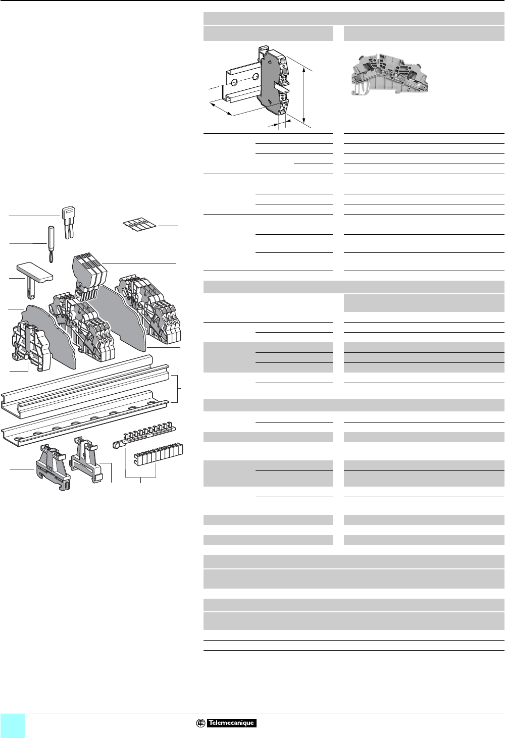
4/18
Terminal Blocks, Type AB1 0
Insulation displacement technology
Disconnect (removable carrier) for diode or
cylindrical fuse
Clip-on mounting on 35 mm 1 7 rails
Nominal wire size 1 mm2
AB1AASF135UGR
Approximate
dimensions,
in. (mm)
Length (a) 3.63 (92.1)
Width (b) 0.24 (6)
Height (H)
with
1 rail 2.26 (57.5) + 0.75 (19) for carrier
1 7 rail 1.97 (50) + 0.75 (19) for carrier
Wire size, mm2
Stranded w/o cable end 0.2–1
Stranded + cable end —
Solid 0.2–1
Nominal electrical values (1), (2)
IEC/EN 60947-7-1 800 V / 8 kV / 3–13.5 A
UL File E164359
CCN XCFR2
30–18 AWG Cu, 600 V, 6.3 A
CSA File 702070
Class 6228 01
24–18 AWG Cu, 600V, 10 A
Certifications See the table on page 1/13.
Terminal blocks (3)
No.
points
Sold in
lots of
Catalog number Weight
oz (g)
Gray 250 AB1AASF135UGR 0.62 (17.6)
10 Removable
carrier
For diode or resistor — 100 AB1SV1 0.16 (4.5)
With diode 1N4007.1 — 100 AB1SV2 0.17 (4.7)
Removable
carrier (for
5x20 fuse)
With fuse only —100 AB1SF520 0.16 (4.4)
With 24 V red LED —100 AB1SF520B 0.17 (4.7)
With 220 V red LED —100 AB1SF520M 0.17 (4.7)
Carrier,
removable
& pivoting
For 5 x 20 fuse — 10 AB1SF520D 0.21 (6.0)
For 6.3 x 32 fuse — 10 AB1SF6332D 0.29 (8.2)
Accessories
2 End clamp
with screw (4)
Plastic — 100 AB1AB8P35 0.21 (5.9)
3Metal — 100 AB1AB8M35 0.52 (14.8)
4Clip-on plastic end clamp(4) —100 AB1AB8R35 0.21 (5.9)
5 Marker tag holder for
clip-on plastic end clamp
—10AB1SB4 0.11 (3.1)
6End plate
thickness 0.06
in. (1.5 mm)
Gray —10 AB1AAAC123GR 0.20 (5.7)
Blue —10 AB1AAAC123BL 0.20 (5.7)
7 Partition plate
thickness 0.06
in. (1.5 mm)
Gray — 10 AB1AAAS123GR 0.25 (7.1)
Blue — 10 AB1AAAS123BL 0.25 (7.1)
8Insulated jumper (5) — — AB1RRAL4• —
9 Test plug Red — 50 AB1AT1 0.07 (1.9)
11 Terminal cover 410 AB1AACS1JA 0.014 (0.4)
12 Marking accessories See pages 5/2 and 5/3.
a
b
H
1
9
5
6
8
4
11
7
10
987654321
10
212
3
10
9
8
7
6
5
4
3
2
1
(1) The voltage/current carrying capacity is determined by
the component (fuse and/or diode) used.
(2) Repetitive peak reverse voltage for diodes is 1000 V.
(3) Fuses and diodes not included, except for AB1SV2.
(4) Width 0.3 in. (8 mm) on 1 or 7.
(5) Replace the • symbol with the number of poles (2, 3, 4,
5, or 10), for example, AB1RRAL45 (5-pole).
Carrier characteristics
Nominal voltage Position of terminal block
(Power loss 1.5 W) end juxtaposed
250 V 6.3 A 4 A
Blown fuse indicator characteristics
Catalog number Nominal
voltage
Current
consumption
AB1SF520B 24 V 10.3 mA
AB1SF520M 220–250 V 0.3 mA
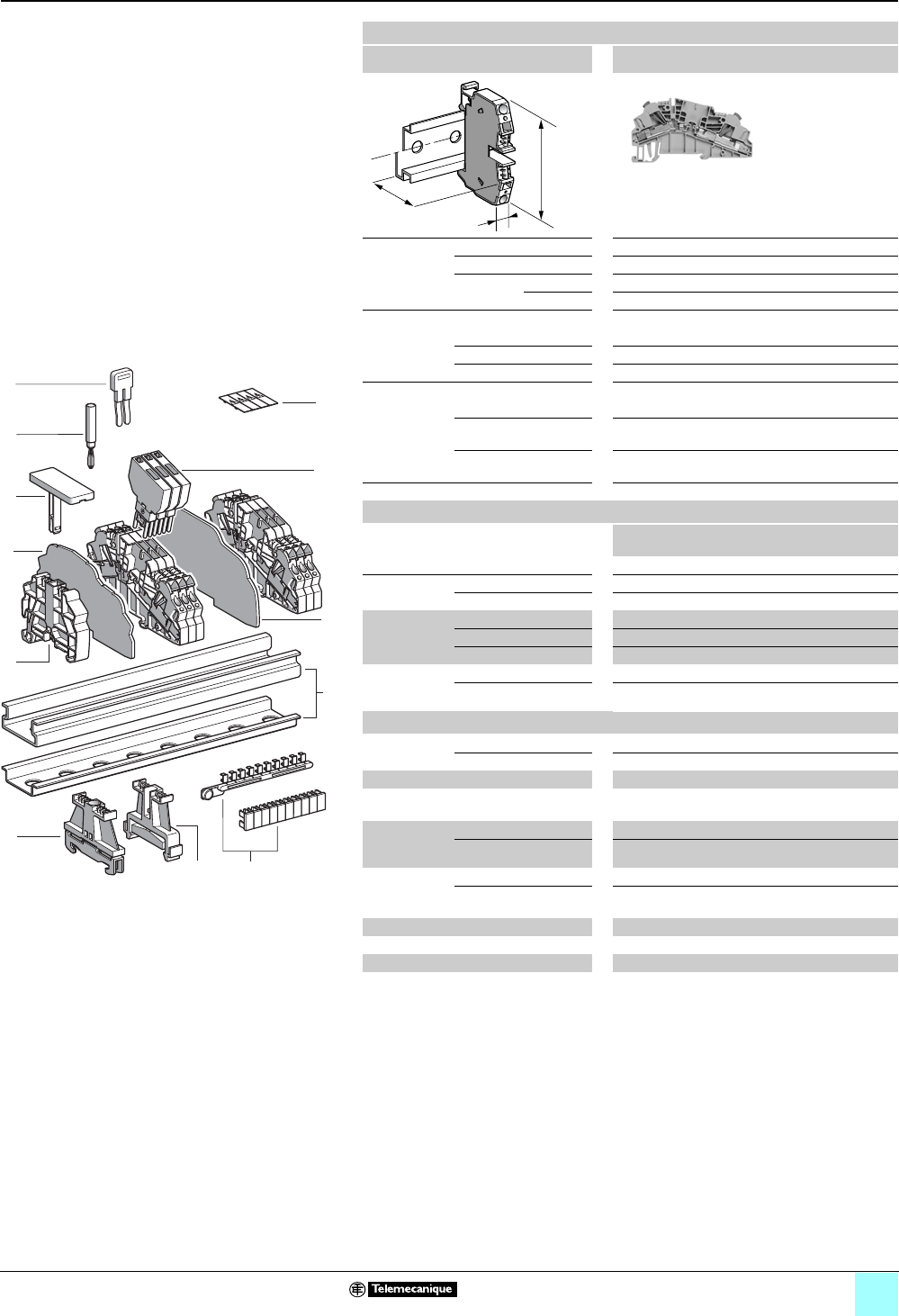
4/19
Terminal Blocks, Type AB1 0
Insulation displacement technology
Disconnect (removable carrier) for diode or
cylindrical fuse
Clip-on mounting on 35 mm 1 7 rails
Nominal wire size 2.5 mm2
AB1AASF235UGR
Approximate
dimensions,
in. (mm)
Length (a) 3.63 (92.1)
Width (b) 0.24 (6)
Height (H)
with
1 rail 2.26 (57.5) + 0.75 (19) for carrier
1 7 rail 1.97 (50) + 0.75 (19) for carrier
Wire size, mm2
Stranded w/o cable end 1–2.5
Stranded + cable end —
Solid 1–2.5
Nominal electrical values (1), (2)
IEC/EN 60947-7-1 800 V / 8 kV / 3–20 A
UL File E164359
CCN XCFR2
18–14 AWG Cu, 600 V, 6.3 A
CSA File 702070
Class 6228 01
16–14 AWG Cu, 600 V, 10 A
Certifications See the table on page 1/13.
Terminal blocks (3)
No.
points
Sold in
lots of
Catalog number Weight
oz (g)
Gray 2 50 AB1AASF235UGR 0.61 (17.2)
10 Removable
carrier
For diode or resistor — 100 AB1SV1 0.16 (4.5)
With diode 1N4007.1 — 100 AB1SV2 0.17 (4.7)
Removable
carrier (for
5x20 fuse)
With fuse only —100 AB1SF520 0.16 (4.4)
With 24 V red LED —100 AB1SF520B 0.17 (4.7)
With 220 V red LED —100 AB1SF520M 0.17 (4.7)
Carrier,
removable
& pivoting
For 5 x 20 fuse — 10 AB1SF520D 0.21 (6.0)
For 6.3 x 32 fuse — 10 AB1SF6332D 0.29 (8.2)
Accessories
2 End clamp
with screw (4)
Plastic — 100 AB1AB8P35 0.21 (5.9)
3Metal — 100 AB1AB8M35 0.52 (14.8)
4Clip-on plastic end clamp(4) —100 AB1AB8R35 0.21 (5.9)
5 Marker tag holder for
clip-on plastic end clamp
—10AB1SB4 0.11 (3.1)
6End plate
thickness 0.06
in. (1.5 mm)
Gray —10 AB1AAAC123GR 0.20 (5.7)
Blue —10 AB1AAAC123BL 0.20 (5.7)
7 Partition plate
thickness 0.06
in. (1.5 mm)
Gray — 10 AB1AAAS123GR 0.25 (7.1)
Blue — 10 AB1AAAS123BL 0.25 (7.1)
8Insulated jumper (5) — — AB1RRAL4• —
9 Test plug Red — 50 AB1AT1 0.07 (1.9)
11 Terminal cover 410 AB1AACS1JA 0.014 (0.4)
12 Marking accessories See pages 5/2 and 5/3.
a
b
H
1
9
5
6
8
4
11
7
10
987654321
10
212
3
10
9
8
7
6
5
4
3
2
1
(1) The voltage/current carrying capacity is determined by
the component (fuse and/or diode) used.
(2) Repetitive peak reverse voltage for diodes is 1000 V.
(3) Fuses and diodes not included, except for AB1SV2.
(4) Width 0.3 in. (8 mm) on 1 or 7.
(5) Replace the • symbol with the number of poles (2, 3, 4,
5, or 10), for example, AB1RRAL45 (5-pole).
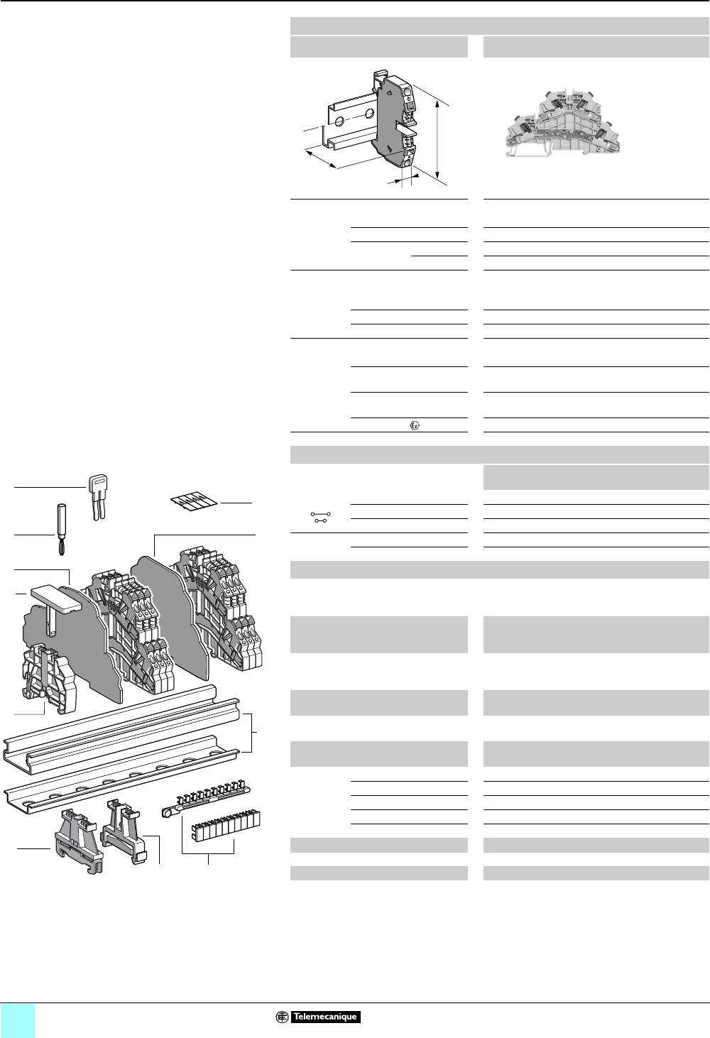
4/20
Terminal Blocks, Type AB1 0
Insulation displacement technology
Double deck
Clip-on mounting on 35 mm 1 7 rails
Nominal wire size 1 mm2
AB1AAET135UGR
Approximate dimensions, in. (mm)
Length (a) 4.71 (119.7)
Width (b) 0.20 (5)
1Height (H)
with
1 rail 3.13 (79.5)
7 rail 2.83 (72)
Wire size, mm2
Stranded without
cable end
0.2–1
Stranded with cable end —
Solid 0.2–1
Nominal electrical values (1)
IEC/EN 60947-7-1 500 V / 6 kV / 3–13.5 A
UL File E164359
CCN XCFR2
30–18 AWG Cu, 600 V, 13 A
CSA File 702070
Class 6228 01
24–18 AWG Cu, 600 V, 7 A
ATEX Exe II II 2 GD 1 mm2, 550 / 420 V, 13.5 A, KEMA 02 ATEX 2113 U
Certifications See the table on page 1/13.
a
b
H
Terminal blocks
No.
points
Sold in
lots of
Catalog number Weight
oz (g)
2 I, 2 O Gray 2/2 50 AB1AAET135UGR 1.01 (28.6)
Red — — — —
Orange — — — —
24 V
red LED
Red — — — —
Orange — — — —
Accessories
2 Plastic
end clamp
with screw
Width 0.3 in. (8 mm)
on 1 or 7 —100 AB1AB8P35 0.21 (5.9)
3Metal
end clamp
with screw
Width 0.3 in. (8 mm)
on 1 or 7—100 AB1AB8M35 0.52 (14.8)
4 Clip-on
plastic
end clamp
Width 0.3 in. (8 mm)
on 1 or 7—100 AB1AB8R35 0.21 (5.9)
5Marker tag holder
for clip-on plastic end clamp
—10 AB1SB4 0.11 (3.1)
6 End plate Gray, thickness 0.06 in.
(1.5 mm)
—10 AB1AAAC124GR 0.36 (10.3)
7Partition
plate
Gray, thickness 0.06 in.
(1.5 mm)
—10 AB1AAAS124GR 0.41 (11.5)
8 Insulated
jumper
2-pole —10 AB1RRAL22 0.04 (1.1)
3-pole —10 AB1RRAL23 0.06 (1.6)
4-pole —10 AB1RRAL24 0.07 (2.1)
5-pole —10 AB1RRAL25 0.10 (2.7)
10-pole —20 AB1RRAL210 0.19 (5.4)
9Test plug Red —50 AB1AT1 0.06 (1.7)
10 Terminal cover 410 AB1AACS1JA 0.014 (0.4)
11 Marking accessories See pages 5/2 and 5/3.
(1) The voltage/current carrying capacity is determined by the component (fuse and/or diode)
used.
1
5
8
10
7
9
6
4
10
9
8
7
6
5
4
3
2
1
987654321
10
112
3
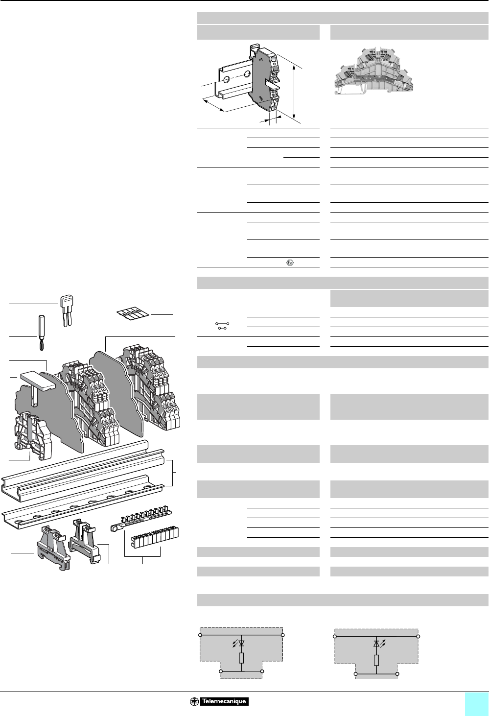
4/21
Terminal Blocks, Type AB1 0
Insulation displacement technology
Double deck
Clip-on mounting on 35 mm 1 7 rails
Nominal wire size 2.5 mm2
AB1AAET235U•••
Approximate
dimensions,
in. (mm)
Length (a) 4.71 (119.7)
Width (b) 0.24 (6)
1Height (H)
with
1 rail 3.13 (79.5)
7 rail 2.83 (72)
Wire size,
mm2Stranded without
cable end
1–2.5
Stranded with cable
end
—
Solid 1–2.5
Nominal
electrical
values (1)
IEC/EN 60947-7-1 500 V / 6 kV / 3–24 A
UL File E164359
CCN XCFR2
18–14 AWG Cu, 600 V, 22 A
CSA File 702070
Class 6228 01
16–14 AWG Cu, 600 V, 20 A
ATEX Exe II II 2 GD 2.5 mm2, 550 / 420 V, 21.5 A, KEMA 02 ATEX 2113 U
Certifications See the table on page 1/13.
a
b
H
Terminal blocks
No.
points
Sold in
lots of
Catalog number Weight
oz (g)
2 I, 2 O Gray 2/2 50 AB1AAET235UGR 1.15 (32.5)
Red 2/2 50 AB1AAET235URO 1.15 (32.5)
Orange 2/2 50 AB1AAET235UGE 1.15 (32.5)
24 V
red LED
Red 450 AB1AAET235UBRO 1.11 (31.5)
Orange 450 AB1AAET235UBGE 1.11 (31.5)
Accessories
2 Plastic
end clamp
with screw
Width 0.3 in. (8 mm)
on 1 or 7 —100 AB1AB8P35 0.21 (5.9)
3Metal
end clamp
with screw
Width 0.3 in. (8 mm)
on 1 or 7—100 AB1AB8M35 0.52 (14.8)
4 Clip-on
plastic
end clamp
Width 0.3 in. (8 mm)
on 1 or 7—100 AB1AB8R35 0.21 (5.9)
5Marker tag holder
for clip-on plastic end clamp
—10 AB1SB4 0.11 (3.1)
6 End plate Gray, thickness 0.06 in.
(1.5 mm)
—10 AB1AAAC124GR 0.36 (10.3)
7Partition
plate
Gray, thickness 0.06 in.
(1.5 mm)
—10 AB1AAAS124GR 0.41 (11.5)
8Insulated
jumper
2-pole —10 AB1RRAL42 0.06 (1.6)
3-pole —10 AB1RRAL43 0.08 (2.4)
4-pole —10 AB1RRAL44 0.11 (3.2)
5-pole —10 AB1RRAL45 0.14 (4.0)
10-pole —20 AB1RRAL410 0.28 (8.0)
9Test plug Red —50 AB1AT1 0.06 (1.7)
10 Terminal cover 410 AB1AACS1JA 0.014 (0.4)
11 Marking accessories See pages 5/2 and 5/3.
(1) The voltage/current carrying capacity is determined by the component (fuse and/or diode)
used.
1
5
8
10
7
9
6
4
10
9
8
7
6
5
4
3
2
1
987654321
10
112
3
Wiring diagrams
AB1AAET235UBRO
Resistance = 2.2 kΩ, 0.35 W, 24 Vdc)
AB1AAET235UBGE
Resistance = 2.2 kΩ, 0.35 W, 24 Vdc

5/0

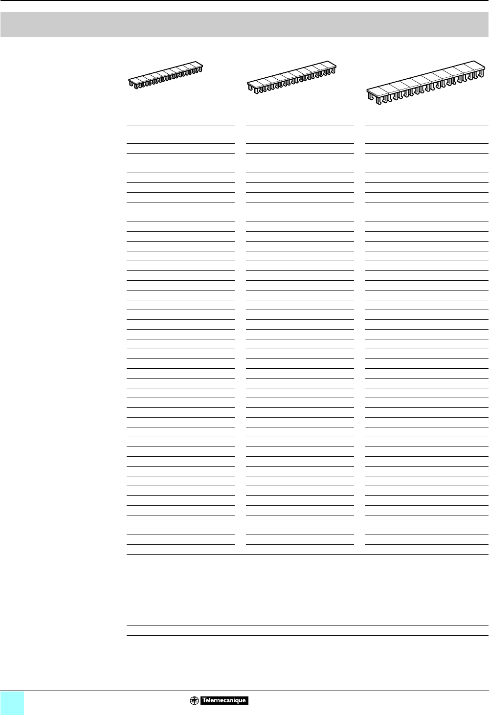
5/2
Catalog numbers
0
Terminal Blocks, Type AB1 0
Marking accessories
Clip-in marker strips
Description 10 consecutive figures or numbers
For complete catalog numbers,
see below.
AB1B5••• AB1B6••• AB1B8•••
Characteristics:
Material: 6-6 polyamide
Color: black markings on white
background
Width 5 mm / 2.5 mm2Width 6 mm / 4 mm2Width 0.3 in. (8 mm) / u 6 mm2
Sold in lots of
25 identical strips
Sold in lots of
25 identical strips
Sold in lots of
25 identical strips
Unit weight: 0.6 g Unit weight: 0.7 g Unit weight: 0.7 g
Marking Strip catalog
number
Marking Strip catalog
number
Marking Strip catalog
number
Blank AB1BV5 Blank AB1BV6 Blank AB1BV8
1…10 AB1B510 1…10 AB1B610 1…10 AB1B810
11…20 AB1B520 11…20 AB1B620 11…20 AB1B820
21…30 AB1B530 21…30 AB1B630 21…30 AB1B830
31…40 AB1B540 31…40 AB1B640 31…40 AB1B840
41…50 AB1B550 41…50 AB1B650 41…50 AB1B850
51…60 AB1B560 51…60 AB1B660 51…60 AB1B860
61…70 AB1B570 61…70 AB1B670 61…70 AB1B870
71…80 AB1B580 71…80 AB1B680 71…80 AB1B880
81…90 AB1B590 81…90 AB1B690 81…90 AB1B890
91…100 AB1B5100 91…100 AB1B6100 91…100 AB1B8100
L1 AB1B6L1
L2 AB1B6L2
L3 AB1B6L3
+ Red AB1BV6RP
– Blue AB1BV6BM
Mounting options
bTerminal blocks with widths of 0.20, 0.24, or 0.31 in. (5, 6 or 8 mm):
Using marker strips that are the same width as the terminal block enables rapid marking in groups of 10.
bTerminal blocks with widths of 0.39 in. (10 mm) and above:
Marker strips can also be used by detaching the marker and clipping it into the terminal block.
Note: Each side of the terminal block can be fitted with a marker (1 to 3 figures).
Other versions Marker strips available with number ranges from 101–110 up to 991–999
1
2
3
4
5
6
7
8
9
10
1
2
3
4
5
6
7
8
9
10
1
2
3
4
5
6
7
8
9
10
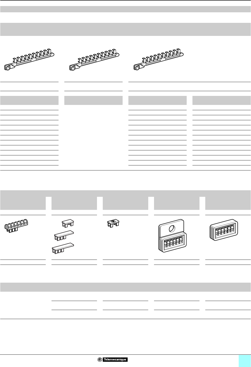
5/3
Catalog numbers (continued)
0
Terminal Blocks, Type AB1 0
Marking accessories
Applications
These marking accessories are for terminal block types AB1 or DB6, but they can also be used with other Telemecanique brand products such
as thermal-magnetic protectors, modular contactors, and model D or F contactors.
Strips of clip-in markers
10 identical numbers or symbols 10 numbers 0 to 9 10 identical capital letters
AB1R•• AB1R11 AB1G•
Sold in lots of
25 identical strips
Sold in lots of
25 identical strips
Sold in lots of
25 identical strips
Unit weight: 2 g Unit weight: 2 g Unit weight: 2 g
Marking Catalog number of
10-number tag strip
Marking Catalog number of
10-number tag strip
Marking Catalog number of
10-letter tag strip
Marking Catalog number of
10-letter tag strip
Blank AB1RV 0…9 AB1R11 AAB1GA NAB1GN
1AB1R1 BAB1GB OAB1GO
2AB1R2 CAB1GC PAB1GP
3AB1R3 DAB1GD QAB1GQ
4AB1R4 EAB1GE RAB1GR
5AB1R5 FAB1GF SAB1GS
6AB1R6 GAB1GG TAB1GT
7AB1R7 HAB1GH UAB1GU
8AB1R8 IAB1GI VAB1GV
9AB1R9 JAB1GJ WAB1GW
0AB1R0 KAB1GK XAB1GX
+ AB1R12 LAB1GL YAB1GY
–AB1R13 MAB1GM ZAB1GZ
Note:
bDimensions: The dimensions of the clip-in markers on the strips are 0.18 x 0.11 in. (4.5 x 2.7 mm).
bMounting options: Each side of the terminal block can be fitted with 4 markers (each 1 number or letter) or, alternatively, 6 AB1R or AB1G
markers (see above), by using holder AB1SR6.
Marking components
Holder for 6 markers Blank clip-on marker Clip-on marker with
ground symbol t
(black on white background)
Marker holder for
screw fixing to
any type of support
Adhesive marker holder
for fixing to any type
of support
AB1SR6 AB1SA• AB1RT AR1SB2 AR1SB3
Sold in lots of 200 Sold in lots of 500 Sold in lots of 500 Sold in lots of 100 Sold in lots of 50
Unit weight: 0.6 g Unit weight:
0.3 g (AB1SA1, AB1SA2)
0.4 g (AB1SA3)
Unit weight: 0.3 g Unit weight: 1 g Unit weight: 1 g
Holder for up to 6 markers Size
in. (mm)
Catalog
number
Size
in. (mm)
Catalog
number
Size
in. (mm)
Catalog
number
Size
in. (mm)
Catalog
number
AB1R or AB1G 0.18 x 0.33
(4.5 x 8.3)
AB1SA1 0.18 x 0.33
(4.5 x 8.3)
AB1RT 0.79 x 0.79
(20 x 20)
AR1SB2 0.79 x 0.39
20 x 10
AR1SB3
0.18 x 0.55
(4.5 x 14)
AB1SA2 ———
0.18 x 0.75
(4.5 x 19)
AB1SA3 ———
2222222222
0987654321
AAAAAAA A AA
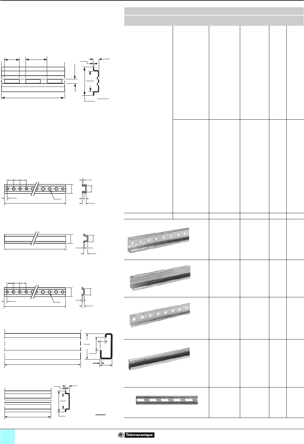
5/4
Catalog numbers
0
Terminal Blocks, Type AB1 0
Mounting track
Mounting Track
Description Length
in. (m)
Catalog
Number
Std. k
Pack
Weight
lb (kg)
Class 9080
Type MH•••
Symmetrical rail
1.38 x 0.30 in.
(35 x 7.5 mm)
in compliance with
EN50022 standard
(DIN 46277-3)
Galvanized steel
(no mounting
holes)
3 (0.08)
4 (0.10)
5 (0.13)
6 (0.15)
7 (0.18)
8 (0.20)
9 (0.23)
10 (0.25)
11 (0.28)
12 (0.30)
13 (0.33)
14 (0.36)
15 (0.38)
16 (0.41)
17 (0.43 )
18 (0.46)
19.68 (0.50)
39.37 (1)
78.74 (2)
9080MH203
9080MH204
9080MH205
9080MH206
9080MH207
9080MH208
9080MH209
9080MH210
9080MH211
9080MH212
9080MH213
9080MH214
9080MH215
9080MH216
9080MH217
9080MH218
9080MH220
9080MH239
9080MH279
10 —
Galvanized steel,
prepunched
3 (0.08)
4 (0.10)
5 (0.13)
6 (0.15)
7 (0.18)
8 (0.20)
9 (0.23)
10 (0.25)
11 (0.28)
12 (0.30)
13 (0.33)
14 (0.36)
15 (0.38)
16 (0.41)
17 (0.43 )
18 (0.46)
19.68 (0.50)
39.37 (1)
78.74 (2)
9080MH303
9080MH304
9080MH305
9080MH306
9080MH307
9080MH308
9080MH309
9080MH310
9080MH311
9080MH312
9080MH313
9080MH314
9080MH315
9080MH316
9080MH317
9080MH318
9080MH320
9080MH339
9080MH379
10 —
High rise track Aluminum 39.37 (1) 9080MH439 2—
DIN3
15 mm depth, 1 mm steel, zinc chromated
78.74 (2) AM1ED200 10 2.9
(1.31)
15 mm depth, 1.5 mm steel, zinc chromated
78.74 (2) AM1DE200 10 2.0
(0.90)
7.5 mm depth, 1 mm steel, zinc chromated
EN50022 & NF C63-015
78.74 (2) AM1DP200 10 1.4
(0.65)
DIN1
Asymmetrical 32 mm track
1.5 mm steel, zinc chromated
EN50035 & NF C63-018
78.74 (2) DZ5MB201 10 3.3
(1.50)
DIN2
Symmetrical 15 mm track
EN50045
39.37 (1) AB1PC15 10 0.3
(0.14)
k Orders must specify standard packages or multiples of that quantity.
6
.25
18
.71
25
.98
"A"
7.5
.30
1
.04
25
.98
35
1.38
mm
inches
1.5
.06
1.38
35
78.74
2000
15
.59
1.06
27
35
15
.59
1.06
27
.04
1
.28
7
25
.98
12.5
1.38
78.74
2000
25
.49
.98
25
.98
1000
39.37
5
.20
1
.04
8.5
.34
15
.59
6
.24
16.5
.65
32
1.26
1.5
.06 15
.59
2000
78.74
.28
7
25
.98
12.5
1.38
35
78.74
2000 7.5
.30
1.06
27
1
.04
25
.49
.98
25
.98
mm
in.
AM1DE200
AM1ED200
AM1DP200
AB1PC15
DZ5MB201
9080MH3••
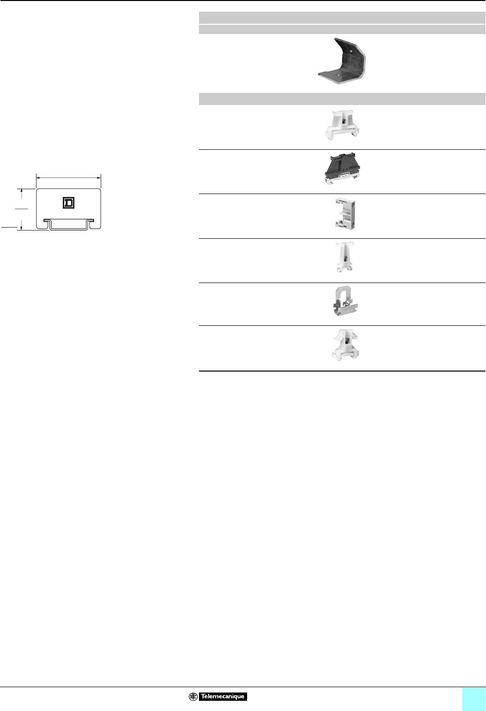
5/5
Catalog numbers
0
Terminal Blocks, Type AB1 0
End clamps
Angle bracket kit
Catalog number Sold in lots of
For mounting 9080GH or 9080MH
track to a panel at 45° angle. Includes
2 brackets and hardware for mounting
the track to the brackets.
9080MH82 1
End clamps
Plastic end clamp for 35 mm DIN 3
track, 8 mm (0.31 in.) wide
AB1AB8P35 100
Metal end clamp for 35 mm DIN 3
track, 8 mm (0.31 in.) wide
AB1AB8M35 100
Polycarbonate end clamp for 35 mm
DIN 3 track, 8 mm (0.31 in.) wide
9080MHA10 50
Plastic end clamp for 32 mm DIN 1
track, 7.5 mm (0.30 in.) wide
AB1AB7P32 100
Metal end clamp for 32 mm DIN 1
track, 7.5 mm (0.30 in.) wide
AB1AB10M32 100
Plastic end clamp for 15 mm DIN 2
track, 7.5 mm (0.30 in.) wide
AB1AB715 100
1.80
46
1.17
30
mm
inches
9080MHA10

6/0

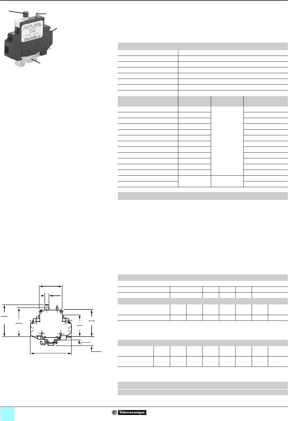
6/2
Catalog numbers
0
Terminal Blocks, Type AB1 0
Circuit protectors, 9080GCB
One-pole, thermal-magnetic control
9080GCB••• circuit protectors:
bHave solderless box lugs.
bAccept one #10–16 AWG Cu wire.
bCome with track adapter 9080GH64 for mounting on 9080GH track.
Remove this adapter for mounting on 9080MH2••, MH3••, and AM1 track.
Use mounting adapter 9080MH62 for the DZ5MB201 DIN1 track.
To properly select a Class 9080 Type GCB circuit protector:
1. Determine the inrush correction factor from Table A.
2. Determine the temperature correction factor from Table B.
3. Determine the sealed current of the load that is being protected.
4. Multiply the sealed current by the two correction factors and choose the closest
circuit protector.
Example: Solenoid with a sealed current of 0.75 A, with an inrush ratio of 1:6, and in
an ambient temperature of 85 °F (29.4 °C).
0.75 x 1.5 x 1.05 = 1.18
Choose the 1.2 A protector
Note: Choosing a circuit protector with a value lower than the calculated value might
result in nuisance tripping, while choosing the larger might provide a protector that
will not properly protect the load.
Technical data
Maximum interrupting rating 200 A, but not exceeding 10,000% (100 x) rated current
Dielectric strength 1500 Vac
Insulation resistance 100 MΩ
Weight 2.2 oz (62.4 g)
Terminals Box lug type
Tightening torque 8–10 lb-in (0.91–1.1 N•m)
Approvals File E152841 CCN QVNU2, File LR25490
Fingersafe per DIN 57470 Yes
Maximum Current (A) kInternal
Resistance (Ω)
Maximum
voltage
Catalog Number
0.1 1.33 250 Vac
65 Vdc
9080GCB01
0.5 6.6 9080GCB05
0.8 2.55 9080GCB08
1.0 1.97 9080GCB10
1.2 1.22 9080GCB12
1.5 0.86 9080GCB15
2.0 0.49 9080GCB20
2.5 0.31 9080GCB25
3.0 0.20 9080GCB30
4.0 0.10 9080GCB40
5.0 0.08 9080GCB50
7.0 0.03 9080GCB70
10.0 < 0.02 125 Vac
65 Vdc
9080GCB100
15.0 9080GCB150
Selection
Table A: Inrush ratio correction
Note: For resistive loads, use an inrush correction factor of 1.0.
Inrush ratio 1:1 to 1:4 1:5 1:6 1:7 1:8
Correction factor 1.3 1.4 1.5 1.6 1.7
Table B: Ambient temperature correction
Ambient
temperature
°F
°C
70
21.1
100
37.8
120
48.9
140
60
160
71.1
180
82.2
200
93.3
Correction factor 1.0 1.1 1.2 1.3 1.4 1.5 1.6
Tripping time of the circuit protector is determined from Table C below. Divide the
circuit protector value by the temperature correction factor from Table B above to
determine actual rated current referenced in Table C.
Table C: Tripping times in seconds @ 70 °F (21.1 °C)
Percent of
rated current
100% 200% 300% 400% 500% 600% 1000% 2000% &
greater
Trip time
(seconds)
no trip 10-40 38 1.5-9 0.8-6 0.003-4 0.003-2 0.02
max.
Note: When several protectors are channel mounted adjacent to each other, the No Trip current
will be 80% of rated current at 70 °F (21.1 °C).
Track Adapter
Description Catalog Number
For mounting 9080GCB circuit protectors
on DZ5MB201 track or DIN1 track
9080MH62
(D) (C)
(A,B)
(E)
A. Thermal-magnetic circuit protector
B. 14 stocked current ratings, from 0.1 to 15 A
C. On-Off switch
D. Visible trip indication
E. Mounts on Class 9080 Type GH track
and on 35 mm DIN3 mounting track.
kThese maximum current values assume the use of
insulated copper conductors with 75 °C temperature
rating, and are calculated based on NEC Article 310,
Table 310-16. In most cases this value is the maximum
ampacity of that wire or combination of wires (as listed in
the table to the right) which has the greatest current
carrying capacity. The actual allowable current for a
particular application depends on the number, size,
insulation class, and other characteristics of the wires
used.
44
1.75
8
0.33
53
2.08
43
1.69
6
0.25
21
0.82
80
3.15
ON
58
2.29
OFF
64
2.53
Dimensions
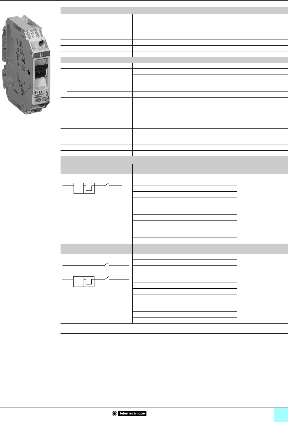
6/3
Catalog numbers
0
Terminal Blocks, Type AB1 0
Circuit protectors, GB2
One-pole and two-pole, thermal-magnetic control
Specifications
Conformity to standards UL File # E164873 CCN QVNU2 tested per UL standard 1077 supplemental protectors
CSA Class 3215 01
IEC 157-1
VDE 0660
Protective treatment Tropical climate finish
Enclosure rating IP201 conforming to IEC 144 finger safe terminals
Ambient temperature –4 to 140 °F (–20 to 60 °C) mounted in open air
Operating position ±30° from the vertical plane
Technical characteristics
Rated insulation voltage 300 Vac max
Thermal ratings 0.5A, 1A, 2A, 3A, 4A, 5A, 6A, 8A, 10A, 12A, 16A, 20A
Rating selection according to average ambient temperature
Average ambient temperature °C –20 –10 0 +10 +20 +30 +40 +50 +60
°F –4 +14 +32 +50 +68 +86 +104 +122 +140
Correction factor 1.20 1.15 1.10 1.05 1.00 0.95 0.90 0.85 0.80
Breaking capacity 1.5 kA/220V conforming to IEC 157-1 (P1)
Operating current of magnetic trips GB2CB 12 to 16 times thermal rating
GB2CD 12 to 16 times thermal rating
GB2DB 12 to 16 times thermal rating
GB2CS 5 to 7 times thermal rating
Mechanical life 8,000 operations
Maximum wire sizes Number of conductors
(flexible)
1
4 mm2 (12 AWG)
2
1 to 2.5 mm2 (16 AWG)
Recommended tightening torque 11 lb-in (1.2 N•m)
Mounting 35 mm DIN 3 or DIN 1
Markings Use AB1R and AB1G markers (see pages 5/2 and 5/3)
Selection
One-Pole Thermal Magnetic Control
Circuit Protectors
Thermal Rating (A) Catalog Number Standard Pack ■
0.5 GB2CB05 6
1GB2CB06
2GB2CB07
3GB2CB08
4GB2CB09
5GB2CB10
6GB2CB12
8GB2CB14
10 GB2CB16
12 GB2CB20
16 GB2CB21
20 GB2CB22
Two-Pole Thermal Magnetic Control
Circuit Protectors
Thermal Rating (A) Catalog Number Standard Pack ■
0.5 GB2CD05 6
1GB2CD06
2GB2CD07
3GB2CD08
4GB2CD09
5GB2CD10
6GB2CD12
8GB2CD14
10 GB2CD16
12 GB2CD20
16 GB2CD21
20 GB2CD22
■ Must order in multiples of the standard pack.
For markers, see pages 5/2 and 5/3.
GB2CB06
I>
2/T1 1/L1
I>
2/T1 1/L1
4/T2 (14) 3/L2 (13)
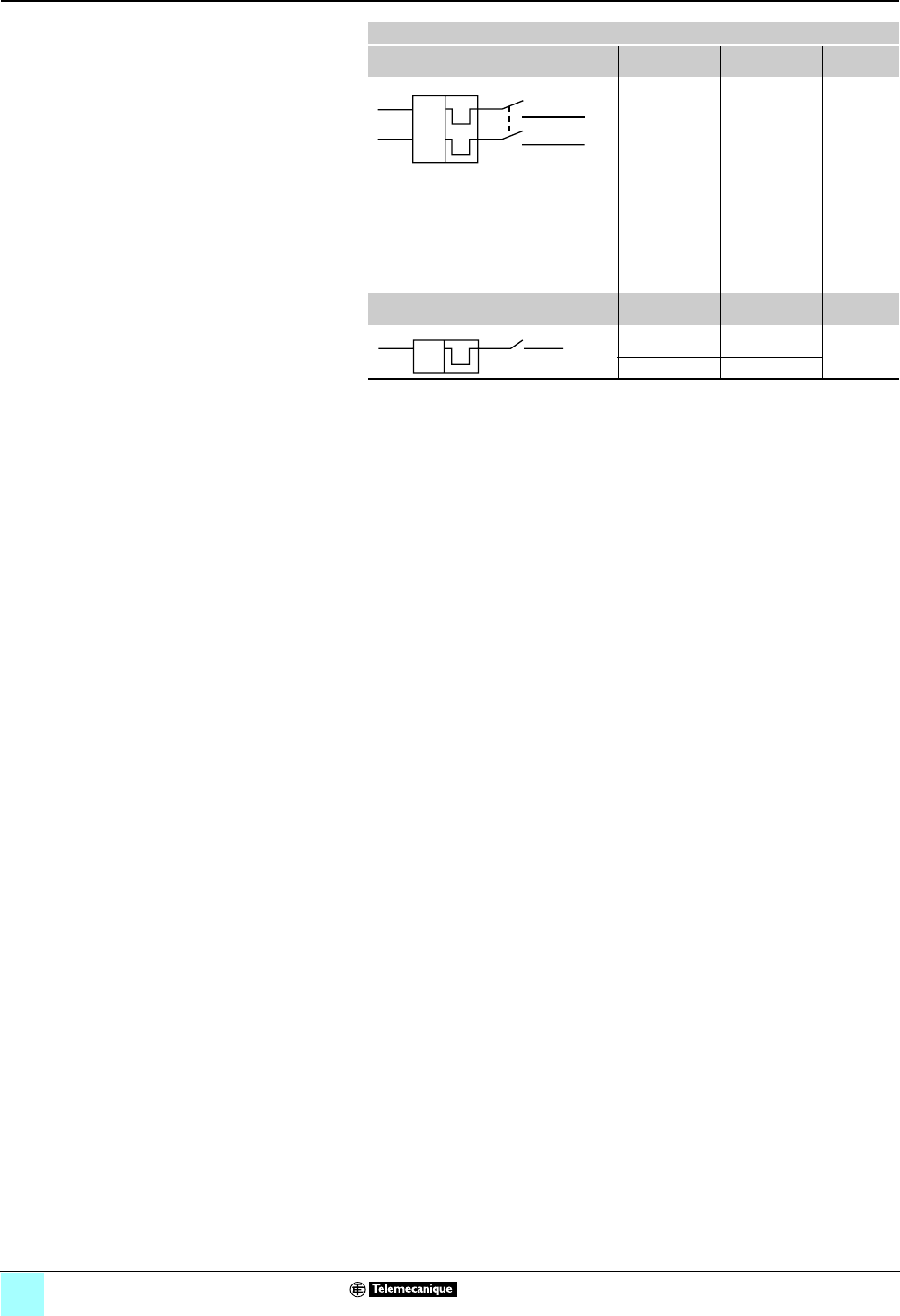
6/4
Catalog numbers
0
Terminal Blocks, Type AB1 0
Circuit protectors, GB2
One-pole and two-pole, thermal-magnetic control
Selection
Two-pole, thermal-magnetic control
circuit protectors
Thermal rating
(A)
Catalog
number
Standard
pack ■
0.5 GB2DB05 3
1GB2DB06
2GB2DB07
3GB2DB08
4GB2DB09
5GB2DB10
6GB2DB12
8GB2DB14
10 GB2DB16
12 GB2DB20
16 GB2DB21
20 GB2DB22
One-pole, thermal-magnetic control
circuit protectors
Thermal rating
(A)
Catalog
number
Standard
pack ■
0.5 GB2CS05 6
1GB2CS06
I>
4/T2
1/L1
2/T1
3/L2
I>
X
X
I>
2/T1 1/L1
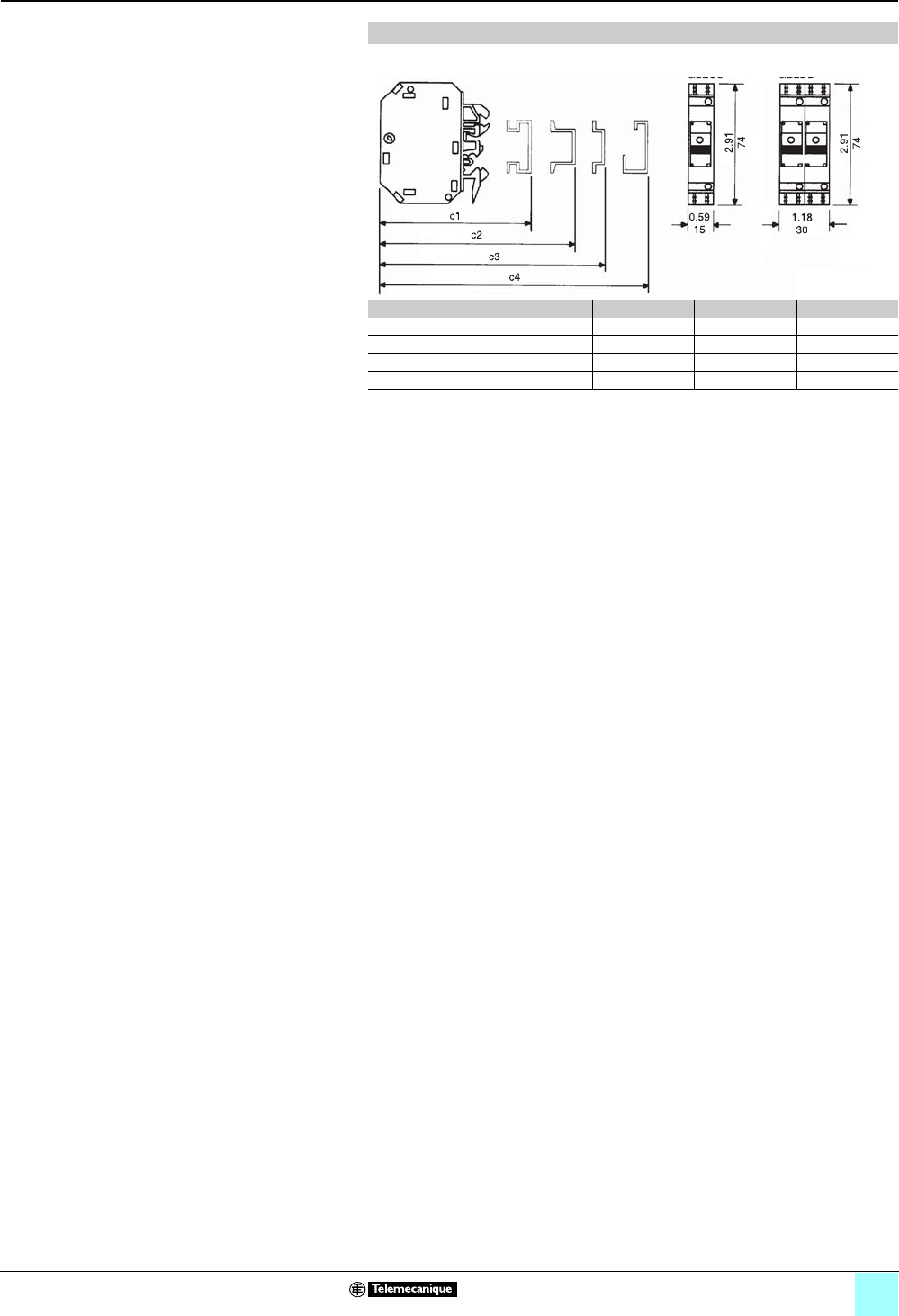
6/5
Approximate dimensions
0
Terminal Blocks, Type AB1 0
Circuit protectors, GB2
One-pole and two-pole, thermal-magnetic control
Approximate Dimensions, in. (mm)
Catalog number c1 c2 c3 c4
GB2CB 3.23 (82) 3.23 (82) 2.95 (75) 3.11 (79)
GB2CD 3.23 (82) 3.23 (82) 2.95 (75) 3.11 (79)
GB2CS 3.23 (82) 3.23 (82) 2.95 (75) 3.11 (79)
GB2DB 3.35 (85) 3.35 (85) 3.07 (78) 3.23 (82)
G
B2
CB
GB2CS
G
B2
CD
GB2DB

7/0


7/2
9080GCB . . . . . . . . . . . . . . . . . . . .6/2
9080MH . . . . . . . . . . . . . . . . . . . . .5/4
AB1A10 . . . . . . . . . . . . . . . . . . . . . .3/7
AB1A16 . . . . . . . . . . . . . . . . . . . . . .3/8
AB1A2 . . . . . . . . . . . . . . . . . . . . . .3/4
AB1A35 . . . . . . . . . . . . . . . . . . . . . .3/9
AB1A4 . . . . . . . . . . . . . . . . . . . . . .3/5
AB1A6 . . . . . . . . . . . . . . . . . . . . . .3/6
AB1AA . . . . . . . . . . . . . . . . . . . . . .1/5
AB1AA135U . . . . . . . . . . . . . . . . . .4/4
AB1AA235U . . . . . . . . . . . . . . . . . .4/7
AB1AAAC122BL . . . . . . . . . . . . . . .4/4
AB1AAAC122GR . . . . . . . . . . . . . . .4/4
AB1AAAC122VE . . . . . . . . . . . . . .4/10
AB1AAAC123BL . . . . . . . . . . . . . . .4/5
AB1AAAC123GR . . . . . . . . . . . . . . .4/5
AB1AAAC123VE . . . . . . . . . . . . . .4/11
AB1AAAC124BL . . . . . . . . . . . . . . .4/6
AB1AAAC124GR . . . . . . . . . . . . . . .4/6
AB1AAAC124VE . . . . . . . . . . . . . .4/12
AB1AAAS122BL . . . . . . . . . . . . . . .4/4
AB1AAAS122GR . . . . . . . . . . . . . . .4/4
AB1AAAS123BL . . . . . . . . . . . . . . .4/5
AB1AAAS123GR . . . . . . . . . . . . . . .4/5
AB1AAAS124BL . . . . . . . . . . . . . . .4/6
AB1AAAS124GR . . . . . . . . . . . . . . .4/6
AB1AACS1JA . . . . . . . . . . . . . . . . .4/4
AB1AAET . . . . . . . . . . . . . . . . . . .4/20
AB1AASC . . . . . . . . . . . . . . . . . . .4/16
AB1AASF . . . . . . . . . . . . . . . . . . .4/18
AB1AATP . . . . . . . . . . . . . . . . . . .4/10
AB1AB10M32 . . . . . . . . . . . . . . . . .3/4
AB1AB715 . . . . . . . . . . . . . . . . . . . .5/5
AB1AB7P32 . . . . . . . . . . . . . . . . . .5/5
AB1AB8 . . . . . . . . . . . . . . . . . . . . .5/5
AB1AC2 . . . . . . . . . . . . . . . . . . . .3/45
AB1AC24 . . . . . . . . . . . . . . . . . . . .3/4
AB1AC25 . . . . . . . . . . . . . . . . . . .3/12
AB1AC3 . . . . . . . . . . . . . . . . . . . . .2/4
AB1AC6 . . . . . . . . . . . . . . . . . . . . .3/6
AB1ACD2 . . . . . . . . . . . . . . . . . . .3/27
AB1ACN . . . . . . . . . . . . . . . . . . . . .3/7
AB1AL2 . . . . . . . . . . . . . . . . . . . . . .3/4
AB1AL4 . . . . . . . . . . . . . . . . . . . . . .3/5
AB1AL6 . . . . . . . . . . . . . . . . . . . . . .3/6
AB1ALD . . . . . . . . . . . . . . . . . . . .3/27
AB1ALN10 . . . . . . . . . . . . . . . . . . .3/7
AB1ALN15 . . . . . . . . . . . . . . . . . .3/11
AB1ALN16 . . . . . . . . . . . . . . . . . . .3/8
AB1ALN2 . . . . . . . . . . . . . . . . . . . .3/4
AB1ALN3 . . . . . . . . . . . . . . . . . . . .3/9
AB1ALN4 . . . . . . . . . . . . . . . . . . . .3/5
AB1ALN6 . . . . . . . . . . . . . . . . . . . .3/6
AB1ALN7 . . . . . . . . . . . . . . . . . . .3/10
AB1AS2 . . . . . . . . . . . . . . . . . . . .3/45
AB1AS24 . . . . . . . . . . . . . . . . . . . .3/4
AB1AS4ET . . . . . . . . . . . . . . . . . .3/25
AB1AS6 . . . . . . . . . . . . . . . . . . . . .3/6
AB1ASN10 . . . . . . . . . . . . . . . . . . .3/7
AB1ASN16 . . . . . . . . . . . . . . . . . . .3/8
AB1ASN35 . . . . . . . . . . . . . . . . . . .3/9
AB1ASN70 . . . . . . . . . . . . . . . . . .3/10
AB1AT1 . . . . . . . . . . . . . . . . . . . . .2/4
AB1AT2 . . . . . . . . . . . . . . . . . . . . .3/6
AB1AT3 . . . . . . . . . . . . . . . . . . . . .2/4
AB1B15 . . . . . . . . . . . . . . . . . . . . .3/45
AB1B22 . . . . . . . . . . . . . . . . . . . . .3/45
AB1B5 . . . . . . . . . . . . . . . . . . . . . .5/2
AB1B6 . . . . . . . . . . . . . . . . . . . . . .5/2
AB1B8 . . . . . . . . . . . . . . . . . . . . . .5/2
AB1BB . . . . . . . . . . . . . . . . . . . . . 3/39
AB1BC . . . . . . . . . . . . . . . . . . . . . 3/42
AB1BE . . . . . . . . . . . . . . . . . . . . . 3/24
AB1BF . . . . . . . . . . . . . . . . . . . . . 3/22
AB1BL10 . . . . . . . . . . . . . . . . . . . . 3/7
AB1BL2 . . . . . . . . . . . . . . . . . . . . . 3/4
AB1BL4 . . . . . . . . . . . . . . . . . . . . . 3/5
AB1BL6 . . . . . . . . . . . . . . . . . . . . . 3/6
AB1BV5 . . . . . . . . . . . . . . . . . . . . . 5/2
AB1BV6 . . . . . . . . . . . . . . . . . . . . . 5/2
AB1BV8 . . . . . . . . . . . . . . . . . . . . . 5/2
AB1CA1 . . . . . . . . . . . . . . . . . . . . . 3/7
AB1CA2 . . . . . . . . . . . . . . . . . . . . . 3/4
AB1CA3 . . . . . . . . . . . . . . . . . . . . . 3/9
AB1CA4 . . . . . . . . . . . . . . . . . . . . . 3/5
AB1CA6 . . . . . . . . . . . . . . . . . . . . . 3/6
AB1CC . . . . . . . . . . . . . . . . . . . . . 3/18
AB1CJ2 . . . . . . . . . . . . . . . . . . . . . 3/4
AB1CJ215 . . . . . . . . . . . . . . . . . . 3/45
AB1CJ3 . . . . . . . . . . . . . . . . . . . . 3/24
AB1CJ4 . . . . . . . . . . . . . . . . . . . . . 3/5
AB1CJ6 . . . . . . . . . . . . . . . . . . . . . 3/6
AB1CJN10 . . . . . . . . . . . . . . . . . . . 3/7
AB1CJN16 . . . . . . . . . . . . . . . . . . . 3/8
AB1CP1 . . . . . . . . . . . . . . . . . . . . 3/39
AB1CP2 . . . . . . . . . . . . . . . . . . . . 3/40
AB1CS2 . . . . . . . . . . . . . . . . . . . . . 3/4
AB1CS4 . . . . . . . . . . . . . . . . . . . . . 3/5
AB1CS6 . . . . . . . . . . . . . . . . . . . . . 3/6
AB1CSN10 . . . . . . . . . . . . . . . . . . . 3/7
AB1CSN150 . . . . . . . . . . . . . . . . . 3/11
AB1CSN16 . . . . . . . . . . . . . . . . . . . 3/8
AB1CSN35 . . . . . . . . . . . . . . . . . . . 3/9
AB1CT1 . . . . . . . . . . . . . . . . . . . . 3/39
AB1CT2 . . . . . . . . . . . . . . . . . . . . 3/40
AB1CT215 . . . . . . . . . . . . . . . . . . 3/47
AB1D11435U . . . . . . . . . . . . . . . . 3/19
AB1DDP . . . . . . . . . . . . . . . . . . . . 3/27
AB1EBN . . . . . . . . . . . . . . . . . . . . 3/32
AB1ET3235 . . . . . . . . . . . . . . . . . 3/30
AB1ET3235U . . . . . . . . . . . . . . . . 3/29
AB1ET435 . . . . . . . . . . . . . . . . . . 3/25
AB1ETN . . . . . . . . . . . . . . . . . . . . 3/24
AB1FC . . . . . . . . . . . . . . . . . . . . . 3/23
AB1FF . . . . . . . . . . . . . . . . . . . . . 3/23
AB1FU1 . . . . . . . . . . . . . . . . . . . . 3/22
AB1FUSE . . . . . . . . . . . . . . . . . . . 3/20
AB1FV . . . . . . . . . . . . . . . . . . . . . 3/23
AB1GA–AB1GZ . . . . . . . . . . . . . . . . 5/3
AB1L2ET . . . . . . . . . . . . . . . . . . . 3/25
AB1NEN . . . . . . . . . . . . . . . . . . . . 3/36
AB1PC15 . . . . . . . . . . . . . . . . . . . . 5/4
AB1PC3 . . . . . . . . . . . . . . . . . . . . 3/32
AB1PS4 . . . . . . . . . . . . . . . . . . . . 3/18
AB1R0–AB1R13 . . . . . . . . . . . . . . . 5/3
AB1RRAL1 . . . . . . . . . . . . . . . . . . 2/14
AB1RRAL2 . . . . . . . . . . . . . . . . . . . 2/4
AB1RRAL3 . . . . . . . . . . . . . . . . . . 2/18
AB1RRAL4 . . . . . . . . . . . . . . . . . . . 2/8
AB1RRCS10 . . . . . . . . . . . . . . . . . 2/14
AB1RRCS16 . . . . . . . . . . . . . . . . . 2/11
AB1RRCS35 . . . . . . . . . . . . . . . . . 2/18
AB1RRCS4 . . . . . . . . . . . . . . . . . . . 2/8
AB1RRCS6 . . . . . . . . . . . . . . . . . . 2/12
AB1RRN1 . . . . . . . . . . . . . . . . . . . 2/14
AB1RRN2 . . . . . . . . . . . . . . . . . . . . 2/4
AB1RRN3 . . . . . . . . . . . . . . . . . . . 2/18
AB1RRN4 . . . . . . . . . . . . . . . . . . . . 2/8
AB1RRN6 . . . . . . . . . . . . . . . . . . . 2/12
AB1RRNAC1 . . . . . . . . . . . . . . . . 2/14
AB1RRNAC2 . . . . . . . . . . . . . . . . . 2/4
AB1RRNAC4 . . . . . . . . . . . . . . . . . 2/8
AB1RRNAC6 . . . . . . . . . . . . . . . . 2/12
AB1RRNACE, AB1RRNACTE . . . . 2/36
AB1RRNAL . . . . . . . . . . . . . . . . . 2/12
AB1RRNAS1 . . . . . . . . . . . . . . . . 2/14
AB1RRNAS2 . . . . . . . . . . . . . . . . . 2/4
AB1RRNAS4 . . . . . . . . . . . . . . . . . 2/8
AB1RRNAS6 . . . . . . . . . . . . . . . . 2/12
AB1RRNASE, AB1RRNASTE . . . . 2/36
AB1RRNCS2 . . . . . . . . . . . . . . . . . 2/4
AB1RRNET . . . . . . . . . . . . . . . . . 2/38
AB1RRNGF0 . . . . . . . . . . . . . . . . . 2/4
AB1RRNGF11, AB1RRNGF22,
AB1RRNGF33 . . . . . . . . . . . . . . 2/8
AB1RRNP235UNO . . . . . . . . . . . . . 2/7
AB1RRNR1635UGR . . . . . . . . . . . 2/11
AB1RRNSC235U2 . . . . . . . . . . . . 2/32
AB1RRNSC235U3 . . . . . . . . . . . . 2/33
AB1RRNSC235U4 . . . . . . . . . . . . 2/34
AB1RRNSCE235U4 . . . . . . . . . . . 2/36
AB1RRNSCE235U5 . . . . . . . . . . . 2/37
AB1RRNSF435UGR . . . . . . . . . . . 2/35
AB1RRNTP1035U2 . . . . . . . . . . . 2/27
AB1RRNTP1035U3 . . . . . . . . . . . 2/28
AB1RRNTP1635U2 . . . . . . . . . . . 2/29
AB1RRNTP1635U3 . . . . . . . . . . . 2/30
AB1RRNTP235U2 . . . . . . . . . . . . 2/19
AB1RRNTP235U3 . . . . . . . . . . . . 2/20
AB1RRNTP235U4 . . . . . . . . . . . . 2/21
AB1RRNTP3535U2 . . . . . . . . . . . 2/31
AB1RRNTP435U2 . . . . . . . . . . . . 2/22
AB1RRNTP435U3 . . . . . . . . . . . . 2/23
AB1RRNTP435U4 . . . . . . . . . . . . 2/24
AB1RRNTP635U2 . . . . . . . . . . . . 2/25
AB1RRNTP635U3 . . . . . . . . . . . . 2/26
AB1RRNTPAC1042 . . . . . . . . . . . 2/27
AB1RRNTPAC1043 . . . . . . . . . . . 2/28
AB1RRNTPAC1642 . . . . . . . . . . . 2/29
AB1RRNTPAC1643 . . . . . . . . . . . 2/30
AB1RRNTPAC242 . . . . . . . . . . . . 2/19
AB1RRNTPAC243 . . . . . . . . . . . . 2/20
AB1RRNTPAC244 . . . . . . . . . . . . 2/21
AB1RRNTPAC442 . . . . . . . . . . . . 2/22
AB1RRNTPAC443 . . . . . . . . . . . . 2/23
AB1RRNTPAC444 . . . . . . . . . . . . 2/24
AB1RRNTPAC642 . . . . . . . . . . . . 2/25
AB1RRNTPAC643 . . . . . . . . . . . . 2/26
AB1RV . . . . . . . . . . . . . . . . . . . . . 5/3
AB1SB4 . . . . . . . . . . . . . . . . . . . . . 2/4
AB1SB5 . . . . . . . . . . . . . . . . . . . . 2/38
AB1SB6 . . . . . . . . . . . . . . . . . . . . 2/40
AB1SBN . . . . . . . . . . . . . . . . . . . 3/36
AB1SC . . . . . . . . . . . . . . . . . . . . 3/18
AB1SF435U . . . . . . . . . . . . . . . . . 3/21
AB1SF520 . . . . . . . . . . . . . . . . . . 2/35
AB1SF6332D . . . . . . . . . . . . . . . . 2/35
AB1SM1N . . . . . . . . . . . . . . . . . . 3/32
AB1SR6 . . . . . . . . . . . . . . . . . . . . 5/3
AB1SV . . . . . . . . . . . . . . . . . . . . 2/35
AB1TC . . . . . . . . . . . . . . . . . . . . 3/23
AB1TE . . . . . . . . . . . . . . . . . . . . 3/25
AB1TEN4 . . . . . . . . . . . . . . . . . . 3/24
AB1TF . . . . . . . . . . . . . . . . . . . . . 3/22
AB1TM1N . . . . . . . . . . . . . . . . . . 3/32
AB1TNN10 . . . . . . . . . . . . . . . . . 3/37
AB1TNN16 . . . . . . . . . . . . . . . . . 3/38
AB1TNN4 . . . . . . . . . . . . . . . . . . 3/36
AB1TP1035U . . . . . . . . . . . . . . . . 3/15
AB1TP1635U . . . . . . . . . . . . . . . . 3/16
Terminal Blocks, Type AB1
0
Product catalog number index
0

7/3
Terminal Blocks, Type AB1
0
Product catalog number index
0
(continued)
0
Note: This index lists the page number of the first or most significant occurrence of the product catalog number in the document.
It does not list all occurrences of that catalog number.
AB1TP215 . . . . . . . . . . . . . . . . . . 3/47
AB1TP235U . . . . . . . . . . . . . . . . . 3/12
AB1TP3535U . . . . . . . . . . . . . . . . 3/17
AB1TP435U . . . . . . . . . . . . . . . . . 3/13
AB1TP635U . . . . . . . . . . . . . . . . . 3/14
AB1TRNN435 . . . . . . . . . . . . . . . . 3/33
AB1TRPN435 . . . . . . . . . . . . . . . . 3/33
AB1TRPN435UFM . . . . . . . . . . . . . 3/35
AB1TRSN435 . . . . . . . . . . . . . . . . 3/32
AB1VV215 . . . . . . . . . . . . . . . . . . 3/45
AB1VV235 . . . . . . . . . . . . . . . . . . . 3/4
AB1VV415 . . . . . . . . . . . . . . . . . . 3/46
AB1VV435 . . . . . . . . . . . . . . . . . . . 3/5
AB1VV635 . . . . . . . . . . . . . . . . . . . 3/6
AB1VVN1035 . . . . . . . . . . . . . . . . . 3/7
AB1VVN15035 . . . . . . . . . . . . . . . 3/11
AB1VVN1635 . . . . . . . . . . . . . . . . . 3/8
AB1VVN3535 . . . . . . . . . . . . . . . . . 3/9
AB1VVN7035 . . . . . . . . . . . . . . . .3/10
AM1DE200 . . . . . . . . . . . . . . . . . . .5/4
AM1DP200 . . . . . . . . . . . . . . . . . . .5/4
AM1ED200 . . . . . . . . . . . . . . . . . . .5/4
DZ5MB201 . . . . . . . . . . . . . . . . . . .5/4
GB2CB . . . . . . . . . . . . . . . . . . . . . .6/3
GB2CD . . . . . . . . . . . . . . . . . . . . . .6/3
GB2CS . . . . . . . . . . . . . . . . . . . . . .6/4
GB2DB . . . . . . . . . . . . . . . . . . . . . .6/4
7/4
Terminal Blocks, Type AB1 0
Technical information
Protective treatment of equipment
according to climate
To make the correct choice of protective finish, remember the following two points:
bThe prevailing climate of the country is never the only criterion.
bOnly the atmosphere in the immediate vicinity of the equipment needs to be
considered.
This is the standard treatment for Telemecanique brand equipment and is suitable
for the vast majority of applications. It is the equivalent of treatments described as
“Klimafest,” or “Climateproof.”
In particular, it meets the requirements specified in the following publications:
bPublication UTE C 63-100 (method l), successive cycles of humid heat at:
+40 °C and 95% relative humidity.
bDIN 50016 - Variations of ambient conditions within a climatic chamber:
+23 °C and 83% relative humidity,
+40 °C and 92% relative humidity.
It also meets the requirements of the following marine classification societies:
BV-LR-GL-DNV-RINA.
bSteel components are usually treated with zinc. When they have a mechanical
function, they may also be painted.
bInsulating materials are selected for their high electrical, dielectric, and mechanical
characteristics.
bMetal enclosures have a heat-treated paint finish applied over a primary
phosphate protective coat, or are galvanized (e.g., some prefabricated busbar
trunking components).
b“TC” treatment is suitable for the following temperatures and humidity:
“TC” treatment is therefore suitable for all latitudes, including tropical and equatorial
regions, when the equipment is mounted in normally ventilated industrial premises.
Being sheltered from external climatic conditions, temperature variations are small,
the risk of condensation is minimized, and the risk of dripping water is virtually non-
existent.
In cases where the humidity around the equipment exceeds the conditions described
above, or in equatorial regions if the equipment is mounted outdoors, or if it is placed
in a very humid location (laundries, sugar refineries, steam rooms, etc.), “TC”
treatment can still be used if the following precautions are taken:
bThe enclosure in which the equipment is mounted must be protected with a “TH”
finish (see next page) and must be well ventilated to avoid condensation and dripping
water (e.g. enclosure base plate mounted on spacers).
bComponents mounted inside the enclosure must have a “TC” finish.
bIf the equipment is to be switched off for long periods, a heater must be provided
(0.2 to 0.5 kW per square decimeter of enclosure), that switches on automatically
when the equipment is turned off. This heater keeps the inside of the enclosure at a
temperature slightly higher than the outside surrounding temperature, thereby
avoiding any risk of condensation and dripping water (the heat produced by the
equipment itself during normal running is sufficient to provide this temperature
difference).
bSpecial considerations for Operator Dialog and Detection products:
for certain pilot devices, the use of “TC” treatment can be extended to outdoor use
provided their enclosure is made of light alloys, zinc alloys, or plastic material. In this
case, it is also essential to ensure that the degree of protection against penetration
of liquids and solid objects is suitable for the applications involved.
Protective treatment according to
climate
Depending on the climatic and environmental conditions in which the equipment is
placed, Schneider Electric can offer specially adapted products to meet your
requirements.
All climates treatment “TC”
Characteristics
Limits for use of “TC” (All climates) treatment
Temperature Relative humidity
68 °F (20 °C) 95%
104 °F (40 °C) 80%
122 °F (50 °C) 50%
Extension of use of “TC” (All climates) treatment
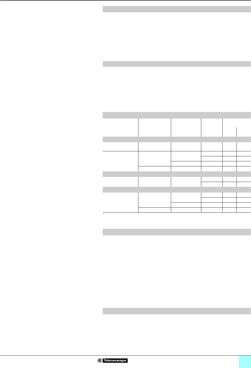
7/5
Terminal Blocks, Type AB1 0
Technical information
Protective treatment of equipment
according to climate
This treatment is suitable for hot and humid atmospheres where installations are
regularly subject to condensation, dripping water, and the risk of fungi.
In addition, the plastic insulating components are resistant to attacks from insects
such as termites and cockroaches. These properties have often led to this treatment
being described as “Tropical Finish,” but this does not mean that all equipment
installed in tropical and equatorial regions must systematically have undergone “TH”
treatment. Conversely, certain operating conditions in temperate climates may
require the use of “TH” treated equipment (see limitations for use of “TC” treatment).
bAll insulating components are made of materials which are either resistant to fungi
or treated with a fungicide, and which have increased resistance to creepage
(Standards IEC60112, NF C 26-220, DIN5348).
bMetal enclosures receive a top-coat of heat-treated, fungicidal paint, applied over
a rust inhibiting undercoat. Components with a “TH” treatment may be subject to a
surcharge; please consult your local sales office. (A large number of the
Telemecanique brand products are “TH” treated as standard, so they are not subject
to a surcharge.)
These treatments cover, in particular, the applications defined by methods I and II of
guide UTE C 63-100.
Electronic products always meet the requirements of “TC” treatment. A number of
them are “TH” treated as standard.
Some electronic products (for example, programmable controllers, flush-mountable
type CCX controllers, and flush-mountable type XBT operator terminals) require the
use of an enclosure providing a degree of protection to at least IP54, as defined by
standards IEC 60664 and NF C 20 040, for use in industrial applications or in
environmental conditions requiring “TH” treatment.
These electronic products, including flush-mountable products, must have a degree
of protection to at least IP20 (provided either by their own enclosure or by their
installation method) for restricted access locations where the degree of pollution
does not exceed 2 (for example, a test booth not containing machinery or other dust-
producing activities).
For particularly harsh industrial environments, Schneider Electric is able to offer
special protective treatments. Please consult your local sales office.
“TH” treatment for hot and humid environments
Special characteristics of “TH” treatment
Protective treatment selection guide
Surrounding
environment
Duty cycle Internal heating
of enclosure
when not in use
Type of
climate
Protective
treatment of:
equip-
ment
enclo-
sure
Indoors
No dripping water
or condensation
Unimportant Not necessary Unimportant “TC” “TC”
Presence of dripping
water or
condensation
Frequent switching
off for periods of
more than 1 day
No Temperate “TC” “TH”
Equatorial “TH” “TH”
Yes Unimportant “TC” “TH”
Continuous Not necessary Unimportant “TC” “TH”
Outdoors (sheltered)
No dripping water
or dew
Unimportant Not necessary Temperate “TC” “TC”
Equatorial “TH” “TH”
Exposed outdoors or near the sea
Frequent and regular
presence of dripping
water or dew
Frequent switching
off for periods of
more than 1 day
No Temperate “TC” “TH”
Equatorial “TH” “TH”
Yes Unimportant “TC” “TH”
Continuous Not necessary Unimportant “TC” “TH”
Special precautions for electronic equipment
Special treatments
7/6
Terminal Blocks, Type AB1 0
Technical information
Product standards and certifications
These are technical specifications established in conjunction with, and with approval of, the
relative bodies within the various CENELEC member countries (European Union, European Free
Trade Association, and many central and eastern European countries having Member or
Affiliated status). Prepared in accordance with the principle of consensus, the European
standards are the result of a weighted majority vote. Such adopted standards are then integrated
into the national collection of standards, and contradictory national standards are withdrawn.
European standards incorporated within the French collection of standards carry the prefix
NFEN. At the Union Technique de l’Electricité (UTE, or Technical Union of Electricity), the French
version of a corresponding European standard carries a dual number: European reference
(NFEN …) and classification index (C …).
Therefore, standard NF EN 60947-4-1, relating to motor contactors and starters, effectively
constitutes the French version of European standard EN 60947-4-1 and carries the UTE
classification C 63-110.
This standard is identical to the British standard BS EN 60947-4-1 or the German standard DIN
EN 60947-4-1.
Whenever reasonably practical, European standards reflect international standards (IEC).
With regard to automation system components and distribution equipment, in addition to
complying with the requirements of French NF standards, Telemecanique brand components
conform to the standards of all other major industrial countries.
Opening up of European markets assumes harmonization of the regulations pertaining to each
of the member countries of the European Union.
The purpose of the European Directive is to eliminate obstacles hindering the free circulation of
goods within the European Union, and it must be applied in all member countries. Member
countries are obliged to transcribe each Directive into their national legislation and to
simultaneously withdraw any contradictory regulations. The Directives, in particular those of a
technical nature which concern us, only establish the objectives to be achieved, referred to as
“essential requirements.”
The manufacturer must take all the necessary measures to ensure that its products conform to
the requirements of each Directive applicable to its production.
As a general rule, the manufacturer certifies conformity to the essential requirements of the
Directive(s) for the product by affixing the e mark.
The e mark is affixed to the Telemecanique brand products concerned, to comply with French
and European regulations.
Significance of the e mark
bThe e mark affixed to a product signifies that the manufacturer certifies that the product
conforms to the relevant European Directive(s) which concern it; this condition must be met to
allow free distribution and circulation within the countries of the European Union of any product
subject to one or more of the E.U. Directives.
bThe e mark is intended solely for national market control authorities.
bThe e mark must not be confused with a conformity marking.
Standardization Conformity to standards
Note: For further details on a specific product,
please refer to the selection page for that product.
Telemecanique brand products satisfy, in the majority of cases, the following types of standards:
bnational (for example, BS in Great Britain, NF in France, DIN in Germany)
bEuropean (for example, CENELEC)
binternational (IEC)
These product standards precisely define the performance of the designated products (such as
IEC 60947 for low voltage equipment).
When used correctly, as designated by the manufacturer and in accordance with regulations and
correct practices, these products will allow users to build equipment, machine systems, or
installations that conform to their appropriate standards (for example: IEC60204-1, relating to
electrical equipment used on industrial machines).
Schneider Electric is able to provide proof of conformity of its production to the standards it has
chosen to comply with, through its quality assurance system.
On request, and depending on the situation, Schneider Electric can provide the following:
bA declaration of conformity
bA certificate of conformity (ASEFA/LOVAG)
bA homologation certificate or approval, in the countries where this procedure is required or for
particular specifications, such as those existing in the merchant navy
Code Certification authority Country
Name Abbreviation
ANSI American National Standards Institute ANSI USA
BS British Standards Institution BSI Great Britain
CEI Comitato Elettrotecnico Italiano CEI Italy
DIN/VDE Verband Deutscher Electrotechniker VDE Germany
EN Comité Européen de Normalisation Electrotechnique CENELEC Europe
GOST Gosudarstvenne Komitet Standartov GOST Russia
IEC International Electrotechnical Commission IEC Worldwide
JIS Japanese Industrial Standard JISC Japan
NBN Institut Belge de Normalisation IBN Belgium
NEN Nederlands Normalisatie Institut NNI Netherlands
NF Union Technique de l’Electricité UTE France
SAA Standards Association of Australia SAA Australia
UNE Asociacion Española de Normalizacion y Certificacion AENOR Spain
European EN standards
Regulations European Directives
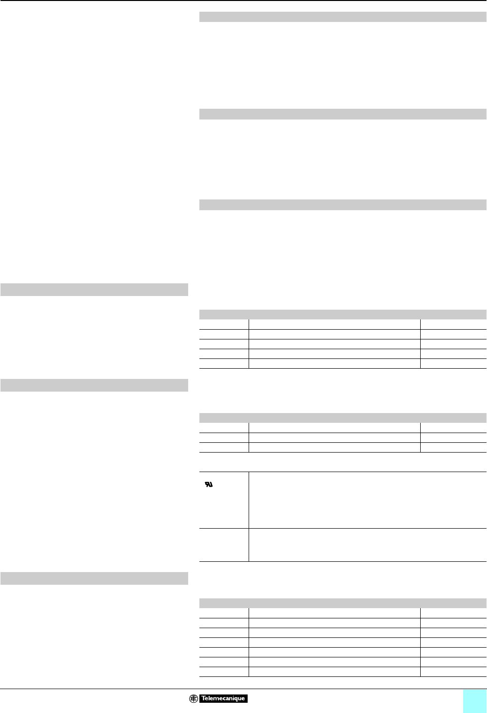
7/7
Terminal Blocks, Type AB1 0
Technical information
Product standards and certifications
For electrical equipment, only conformity to standards signifies that the product is suitable for its
designated function, and only the guarantee of an established manufacturer can provide a high
level of quality assurance.
For Telemecanique brand products, one or several Directives are likely to be applicable,
depending on the product, and in particular:
bThe Low Voltage Directive 73/23/EEC amended by Directive 93/68/EEC: the e mark relating
to this Directive has been compulsory since January 1, 1997
bThe Electromagnetic Compatibility Directive 89/336/EEC, amended by Directives 92/31/EEC
and 93/68/EEC: the e mark on products covered by this Directive has been compulsory since
January 1, 1996
RoHS, European Union Directive 2002/95/EC, restricts the use of certain hazardous substances
in electrical equipment sold in Europe on or after July 1, 2006. The scope of this directive is
primarily for consumable electrical and electronic products. In general, industrial control products
are not within this scope; however, in some applications, terminal blocks can fall within this
scope. The AB1 terminal blocks comply with the RoHS Directive.
To learn more, visit our RoHS website at www.rohs.Schneider-Electric.com, or enter through the
RoHS icon at www.us.Schneider-Electric.com. If you have a question about a specific catalog
number, use the Check a Product link to determine the current status of any product. If you have
additional questions, contact your nearest Schneider Electric sales office for assistance.
The function of ASEFA (Association des Stations d’Essais Française d’Appareils électriques, or
Association of French Testing Stations for Low Voltage Industrial Electrical Equipment) is to carry
out tests of conformity to standards and to issue certificates of conformity and test reports.
ASEFA laboratories are authorized by the French authorization committee (COFRAC).
ASEFA is now a member of the European agreement group LOVAG (Low Voltage Agreement
Group). This means that any certificates issued by LOVAG/ASEFA are recognized by all the
authorities which are members of the group and carry the same validity as those issued by any
of the member authorities.
European Directives (continued)
RoHS Compliance
ASEFA-LOVAG certification
Quality labels When components can be used in domestic and similar applications, it is sometimes
recommended that a “Quality label” be obtained, which is a form of certification of conformity.
Code Quality label Country
CEBEC Comité Electrotechnique Belge Belgium
KEMA-KEUR Keuring van Electrotechnische Materialen Netherlands
NF Union Technique de l’Electricité France
ÖVE Österreichischer Verband für Electrotechnik Austria
SEMKO Svenska Electriska Materiel Kontrollanatalten Sweden
Product certifications In some countries, the certification of certain electrical components is a legal requirement. In this
case, a certificate of conformity to the standard is issued by the official test authority.
Each certified device must bear the relevant certification symbols when these are mandatory:
Code Certification authority Country
CSA Canadian Standards Association Canada
UL Underwriters Laboratories USA
CCC China Compulsory Certification China
On certifications issued by the Underwriters Laboratories (UL), there are two levels of approval:
“Recognized”
()
The component is fully approved for inclusion in equipment built in a workshop,
where the operating limits are known by the equipment manufacturer and
where its use within such limits is acceptable by the Underwriters Laboratories.
The component is not approved as a “Product for general use” because its
manufacturing characteristics are incomplete or its application possibilities are
limited.
A “Recognized” component does not necessarily carry the certification symbol.
“Listed” (UL) The component conforms to all the requirements of the classification
applicable to it and may therefore be used both as a “Product for general use”
and as a component in assembled equipment. A “Listed” component must
carry the certification symbol.
Marine classification societies Prior approval (= certification) by certain marine classification societies is generally required for
electrical equipment which is intended for use on board merchant vessels.
Code Classification authority Country
BV Bureau Veritas France
DNV Det Norske Veritas Norway
GL Germanischer Lloyd Germany
LR Lloyd’s Register Great Britain
NKK Nippon Kaiji Kyokaï Japan
RINA Registro Italiano Navale Italy
RRS Register of Shipping Russia

Mounting systems
Detection
Automation Motor control
Systems & architectures
Software tools
Power supplies
Interfaces and I/O
Operator dialog
Motion & Drives
September 2007
Schneider Electric USA
The efficiency of Telemecanique
branded solutions
Used in combination, Telemecanique products provide quality solutions,
meeting all the requirements of your Automation & Control application.
Aworldwide presence
Constantly available
b
More than 5,000 points of sale in 130 countries.
b
You can be sure to find the range of products that are right for you and that
comply fully with the standards in the country where they are used.
Technical assistance wherever you are
b
Our technicians are at your disposal to assist you in finding the optimum
solution for your particular needs.
b
Schneider Electric provides you with all necessary technical assistance
throughout the world.
Simply Smart !
8001 Knightdale Blvd.
Knightdale, NC 27545
1-888-Square D
1-888-778-2733
www.schneider-electric.com
www.us.Telemecanique.com 9080CT9901R7/07 © 1999–2007 Schneider Electric All Rights Reserved
Replaces 9080CT9901R5/02 dated 7/2002
www.telemecanique.com
