Installation Directions
2016-08-17
: Pdf 1000437367-Installationsheet 1000437367-InstallationSheet B3 unilog
Open the PDF directly: View PDF ![]() .
.
Page Count: 2
IMPORTANT SAFETY INSTRUCTIONS
Read All Instructions Before Installation
When installing or using this trac system, basic safety precautions
should always be followed, including the following:
1. Read all of these installation instructions before installing the
Juno TEK HD Commercial Trac System.
2. The Juno TEK HD Commercial Trac System is intended for use
with Juno TEK HD Commercial Trac components and fixtures.
To reduce risk of fire and electric shock, do not use other com-
ponents as part of this system.
3. Trac installation is to only be performed by a certified electrician
in accordance with the National Electrical Code and all local
codes and ordinances.
4. Designed to be fed by two branch circuits rated 120VAC, 20A,
eg. the system is a two-circuit / two-neutral trac and care must
be taken to keep circuits designated as Circuit 1 and Circuit 2
separate.
5. Do not install the trac in damp or wet locations.
6. Do not install any parts of the trac system less than 8 feet
above the floor.
7. Do not install any fixtures closer than 6 inches from combustible
materials.
8. Do not use this trac with a power supply cord or convenience
receptacle adapter.
9. Do not install the trac with electric power connected. Similarly,
disconnect electricity when installing or removing fixtures or
components or changing the configuration of the trac.
10. Do not attempt to energize anything other than Juno TEK HD
Commercial Trac fixtures on this trac. To reduce the risk of fire
and electrical shock, do not attempt to connect power tools,
extension cords, appliances and the like to the trac.
JUNO 120V (TEK) HD COMMERCIAL TRAC SYSTEM INSTALLATION INSTRUCTIONS
©2016 Acuity Brands Lighting, Inc. Rev 1/14 P3221 pg 1 of 2
1300 South Wolf Road • Des Plaines, IL 60018
PHONE (847) 827-9880 • FAX (847) 827-2925
www.junolightinggroup.com
SAVE THESE INSTRUCTIONS FOR
FUTURE REFERENCE WHEN ADDING
FIXTURES OR CHANGING THE TRAC
CONFIGURATION
ELECTRICAL CONNECTION
Ground
Line2
Line1
Neutral2
Neutral1
120V~ Max. 20A/cct
Max. 20A
Max. 20A
FIELD CUTTING OF TRAC TO LENGTH
The standard length TEK trac is supplied with the conductor ends
factory bent to allow for proper connection of fittings. However, the
trac can be field cut to different lengths with a hacksaw or a circu-
lar saw intended for cutting aluminum. After cutting, the conductor
ends must be bent in the field with the XTSV12 Bending Tool.
STEP 1. Carefully cut the trac to length using a hacksaw or other
metal saw. Ensure that the cut is clean and straight.
STEP 2. Insert the bending tool so that the trac conductor fits in
the outermost slot at the tip of the bending tool.
STEP 3. Rotate the bending tool 90 degrees upward maintaining
constant force perpendicular to the inside wall of the trac
extrusion. Repeat steps 2 and 3 for all conductors.
STEP 4. Bent conductors should look similar to the factory
finished ends, as shown. The ends of the conductors
should have spacing of 1/16˝ following bending or the
system connectors will not fit.
STEP 5. Confirm correct bending by inserting the opposite end of
the tool in the end of the trac as shown.
FIELD DRILLING OF MOUNTING HOLES
If trac is field cut, it may become necessary to drill new mounting
holes. if so, use one of the cut-off pieces with existing mounting
hole as a template for new hole to be drilled. The drill bit should be
no larger than ¼˝ in diameter. The hole should be centered in the
groove in the bottom of the trac. Remove burrs after drilling. Hole
location should be in accordance with the note below.
NOTE: A single section of the trac that is 4 feet or less in length
must have one mounting opening spaced a maximum of 6 inches
from each end of trac section. Additional openings may be
provided. A single section of the trac that is greater than 4 feet
in length is to be provided with mounting openings spaced a
maximum of 6 inches from each end of trac section with additional
openings provided a minimum of every 4 feet along the length of
the trac section.
FEEDING TRAC AT A CORNER CONNECTION
Juno TEK HD Commercial Trac can be fed at the following
corners and trac intercept connectors.
When feeding at one of the above connectors, follow the feeding
instructions as shown under “INSTALLATION OF TEK TRAC TO
AN OUTLET BOX”.
NOTE: The trac is polarized, so connectors can only be installed
in the trac in one direction. Middle Feeds, L, T and X-connectors
are pre-wired, and should not be re-configured in the field. When
requiring a turn in a different direction, or an opposite T-connector
is required, remove the cover and turn the connector as shown
above.
INSTALLING CONNECTORS
1. Select the correct connector to fit the end of the trac.
2. Align the guide lug of the connector with the groove on the trac.
3. Insert the connector into the end of the trac, ensuring that the
guide lug enters the groove in the base of the trac.
4. If the connection is too tight, loosen the lock screw until the con-
nector slides in.
5. Once the connector is correctly inserted, tighten the lock screw.
TEK39 T-connecto
r
TEK40 T-connecto
r
TEK38 X-connector TEK34 L-connector
TEK14 Middle Feed
NOTE: Dark line
directs polarity
ridge on trac.
TEK21 Straight Connector
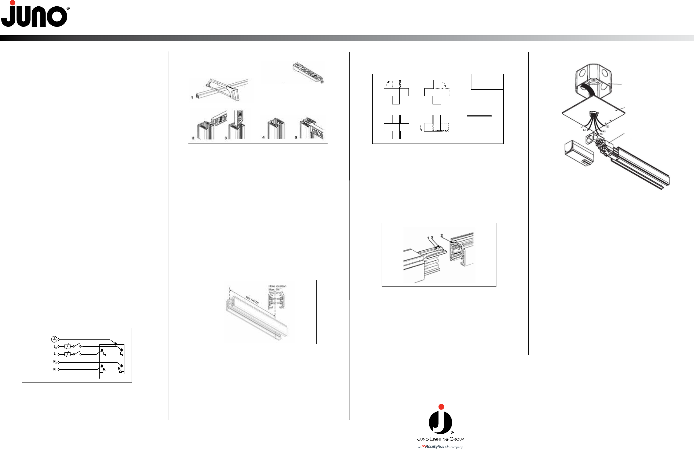
INSTALLATION OF TEK TRAC TO AN OUTLET BOX
STEP 1. Remove the knock-out hole provided on the back side of
the feed connector. Remove feed connector cover.
STEP 2. Pass the supply, neutral and ground wires through the
backplate.
STEP 3. Attach feed connector to trac (NOTE: trac is polarized
and feed connector will only fit one end of trac). Pass
wires through hole on feed and mount trac to ceiling
using toggle bolts or screws.
STEP 4. ALWAYS CONNECT GROUND WIRE TO GREEN
GROUND TERMINAL. Connect live conductors to the
appropriate terminal marked “L1” or “L2”. Connect neutral
conductors to the appropriate terminal marked “N1” or
“N2”.
STEP 5. Replace feed connector cover.
Outlet Box
Outlet Box Canopy Cover
(GES15)
Ground
Feeds
TEK11, 12, 14,
34, 39, 40, 38
Bending Tool
XTSV12

JUNO 120V (TEK) HD COMMERCIAL TRAC SYSTEM INSTALLATION INSTRUCTIONS
MOUNTING THE TRAC
NOTE: The trac should be securely mounted at the maximum intervals of 4 feet, and must be mounted in accordance with all applicable codes and standards.
Trac support using Pendant Stem Kit,
Catalog Numbers SPUS
1. Secure mounting bracket to ceiling using hardware provided or other appropriate fasteners.
2. Thread one nut on upper end of stem. Attach upper threaded portion of stem to mounting
bracket and secure second nut tightly.
3. Loosen lock screw and slide canopy up stem, taking care not to scratch the surface finish.
Tighten canopy once in position.
4. Remove plastic cover from SP4P mounting bracket. Using a sharp knife, cut-out the
top protrusion to allow the stem to pass through cover. Slide cover up stem while completing
remaining connections.
5. Thread SP4P metal bracket onto stem and tighten.
6. Secure mounting bracket to back of trac, fastening the set screws.
7. Slide mounting bracket cover down the stem and over the mounting bracket.
Thread:
3/8 inch - 18 IP
SPUS Stem Kit
Pendant Suspension
Mechanical pendant support detail
SPUS Stem Kit
2 Lock nuts
Metal
bracket
Metal
bracket
Thread:
3/8 inch - 18 IP
2 Lock nuts
Max. 4 ft interval Max. 6”
SP4P Universal
Suspension
Coupler
Ceiling Mounting Options
Instructions for each option:
A. Using the factory provided mounting holes, use
appropriate screw or toggle bolt for securing
the trac to the ceiling.
B. Mark the location of the centerline of the trac
on the ceiling. Using an appropriate screw or
toggle bolt, secure SKB10 mounting clips at
the correct position on ceiling. Loosen the set
screw on the side of the clips and insert the
trac, tightening the set screws while holding
the trac in position.
C. Use the SKBT12 for securing the trac to 15/16˝
flush T-bar ceiling grids. Snap the clips onto
the grid in the correct locations, then insert the
trac, tightening the set screws while holding
the trac in position.
D. Use the SKBX12 for 15/16˝ recessed ceiling
grids. Follow the same procedure as C above.
SKB10
SKBT12
SKBX12
©2016 Acuity Brands Lighting, Inc. Rev 1/14 P3221 pg 2 of 2
1300 South Wolf Road • Des Plaines, IL 60018
PHONE (847) 827-9880 • FAX (847) 827-2925
www.junolightinggroup.com
