RFB119 Series Floor Box Installation Instructions Directions
1000359217-Installationsheet 1000359217-InstallationSheet 1000359217-InstallationSheet B2 unilog cesco-content
1000325512-Installationsheet 1000325512-InstallationSheet 1000325512-InstallationSheet B5 unilog cesco-content
114182-Installationsheet 114182-InstallationSheet 114182-InstallationSheet 786564 Batch6 unilog cesco-content
109354-Installationsheet 109354-InstallationSheet 109354-InstallationSheet 786776 Batch6 unilog cesco-content
2016-06-25
: Pdf 1000438317-Installationsheet 1000438317-InstallationSheet B1 unilog
Open the PDF directly: View PDF ![]() .
.
Page Count: 8
RFB 119 Series Floor Box
I N S T A L L A T I O N I N S T R U C T I O N S
Installation Instruction No.: 1 003 189R1 – Updated April 2011
Products Covered: Floor Box Cat. Nos.: RFB9, RFB11,
Floor Box Covers: RFB119CTC, RFB119BTC
Floor Box Device Plates: RFB119 (suffix)
CAUTION: Do not operate tile stripper or resurfacing equipment over top of covers. This may result in damage to the surface finish
of the product.
CAUTION: When used in bare concrete or terrazzo floors, use part number: RFB119-PAN (Sold separately).
CAUTION: Box has no post pour adjustment.
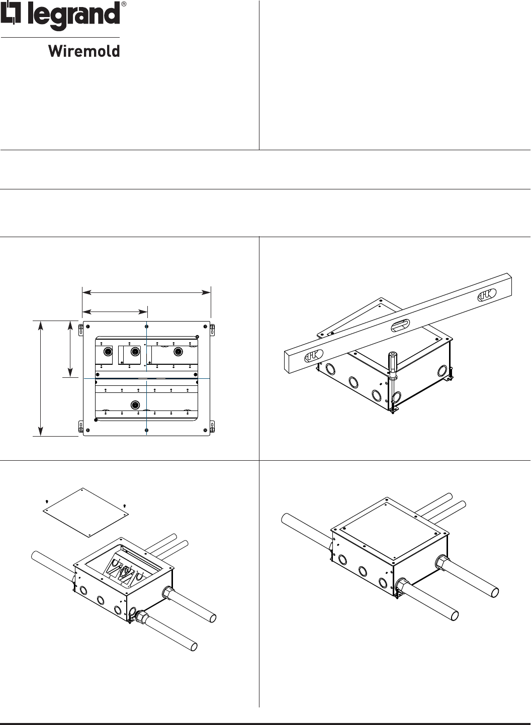
Step 1 Locate and position box in accordance to floor
plans or blueprint.
6 5/16"
[161mm]
7"
[178mm]
14"
[356mm]
12 5/8"
[321mm]
Step 2 Level & anchor box. Top of box must be flush with
concrete pour. Use screws, nails, or wire to prevent
box from floating during pour.
Step 3 Remove mudcap and attach conduit. Step 4 Reinstall mudcap.
Legrand/Wiremold electrical systems conform to and should be properly
grounded in compliance with requirements of the current National
Electrical Code or codes administered by local authorities.
All electrical products may present a possible shock or fire
hazard if improperly installed or used. Legrand/Wiremold electrical
products may bear the mark of a Nationally Recognized Testing
Laboratory (NRTL) and should be installed in conformance with current
local and/or the National Electrical Code.
IMPORTANT: Please read all instructions
before beginning.
NOTE: For use in bare concrete or terrazzo floors, replace
mudcap with part number: RFB119-PAN. (Sold
separately.) (See Step 19.)
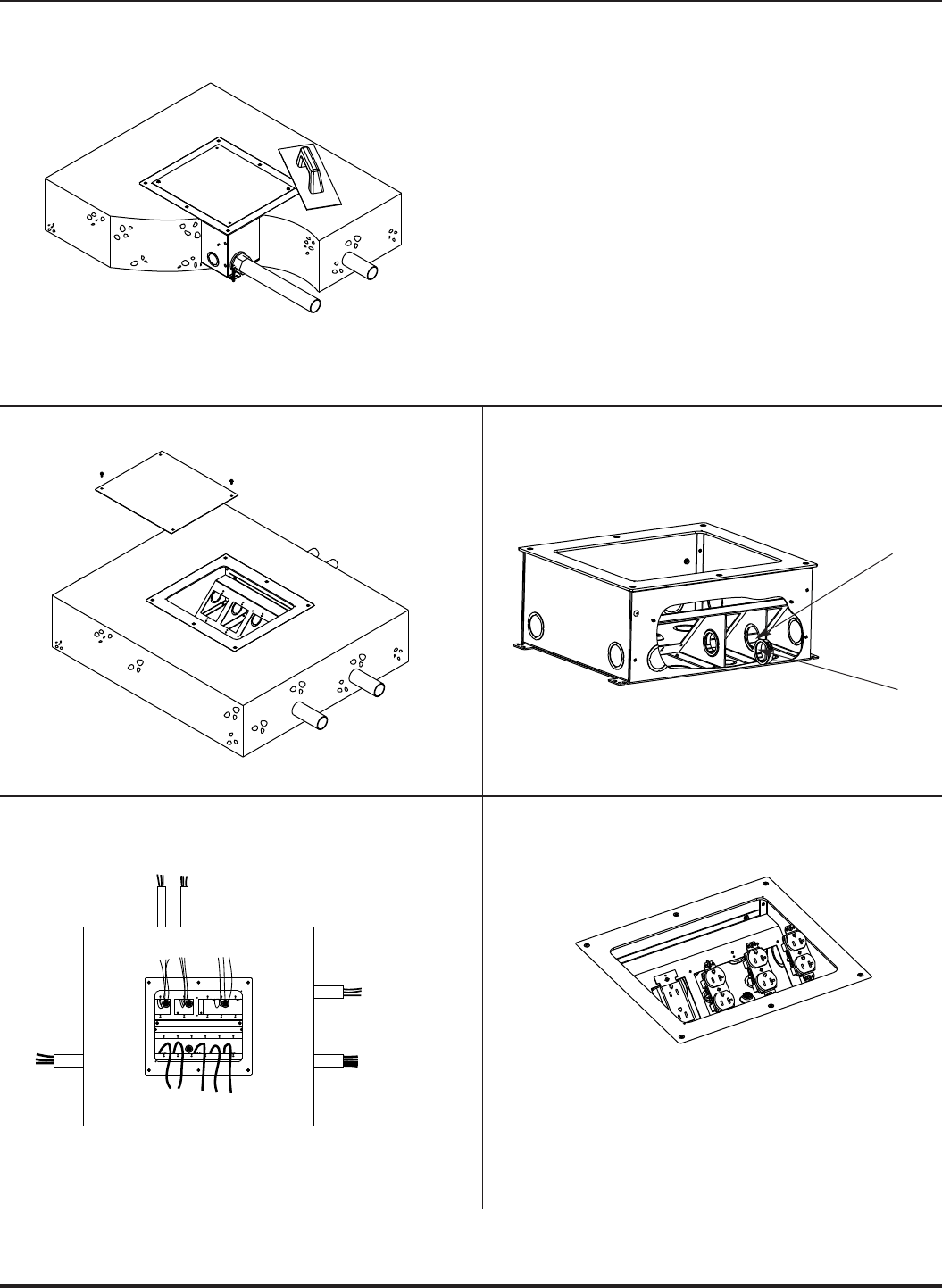
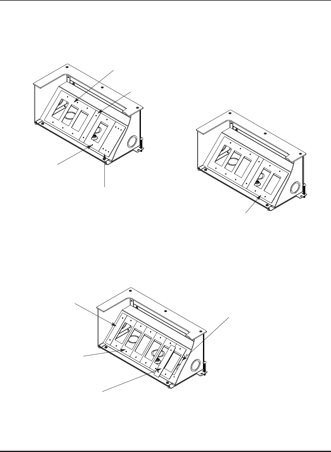
2
KO between
compartments
Grommet
(not supplied)
Step 5 Screed to top of box surface. Hand troweling
recommended near box edges.
Step 7 If service access between adjacent compartments
is required, remove KO between compartments
and add grommet (not included).
Step 9 Terminate and mount devices.
Step 8 Locate and pull wires and cables.
Step 6 Remove mudcap.
CAUTION: Do not dislodge or shift box with jobsite traffic
or concrete vibrations.
NOTE: If box is over-poured or the top plate is below
the concrete surface, follow these steps:
1. Remove and retain mudcap and mudcap
mounting screws. If mudcap is bent during
removal, flatten within reason.
2. Install one or more 1/8" thick spacers, Cat No.
RFB119-TS (available separately), until the top
one is flush with the concrete surface.
See Step 19 for illustration.
3. Replace mudcap on top of spacers and secure
with mounting screws. Duct tape any cracks or
seams where concrete may enter.
4. Pour concrete patch around the perimeter of
the spacers and level with the concrete floor.
5. Complete installation following the
remaining steps.
NOTE: Wire devices (not included) in accordance with National
Electrical Code or any local code that applies. Make sure
that any grounding conductors are connected to the
grounding screws.
3
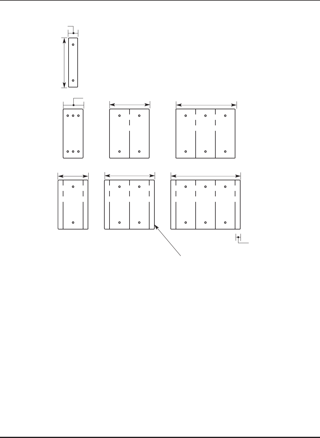
Step 10 Determine device plate selection based on sizes illustrated below.
7/8"
[22mm]
4 1/2"
[114mm]
Spacer Plate
Cat No. RFB119-SPACER
Used to close off space adjacent
to standard plates when used on
multi-gang mounting brackets.
Standard Plates extend 15/32"
[11.9mm] on each side wider
than sectional plates.
1, 2, and 3 Gang
Sectional Plates
1, 2, and 3 Gang
Standard Plates
1 13/16"
[46mm] 3 5/8"
[92mm]
5 7/16"
[138mm]
2 3/4"
[70mm]
4 9/16"
[116mm] 6 3/8"
[162mm]
15/32"
[11.9mm]
4
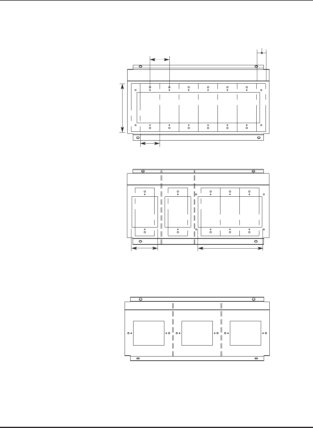
Step 11 Determine device plate required to close off wiring compartments. Sectional (1-13/16" [46mm] wide) or standard device
plates may be used with multi-gang mounting plates.
NOTE: Standard width device plates extend into adjacent gangs, preventing the mounting of other device
plates. Resulting gap should be closed with a spacer plate or single gang sectional plate.
1 13/16" [46mm]
spacing between gangs
4 1/2"
[114mm]
6-Gang Mounting Bracket
3-Gang & (2) Single Gangs (Vertical)
Mounting Bracket (RFB11)
7/8"
[22mm]
1 13/16" [46mm] wide
sectional device plate
2 7/16"
[62mm]
6"
[152mm]
(3) Single Gangs (Horizontal)
Mounting Bracket (RFB9)
5
Step 12 Mount blanking plates and spacers between standard size plates to close off any gaps or openings. Typical layouts are
illustrated below.
6-GANG MOUNTING BRACKETS USED WITH STANDARD DEVICE PLATES
3-Gang Standard Plate
(6 3/8" x 4 1/2"
[162mm x 114m])
1-Gang Standard Plate
(2 3/4" x 4 1/2"
[70mm x 114m])
Cat. No. RFB119-SB
Single-gang Sectional Blank
Plate (mounted off-center)
Cat. No. RFB119-SPACER
Used to close gap between standard
single and multi-gang plates
2-Gang Standard Plate
(4 9/16" x 4 1/2"
[116mm x 114m])
6-GANG MOUNTING BRACKETS USED WITH SECTIONAL DEVICE PLATES
Cat. No. RFB119-SPACER
Used to close gap between standard
single and multi-gang plates
(6) 1-Gang Sectional Plates
(1 13/16" x 4 1/2"
[46mm x 114m])
Existing opening when not covered
with Cat. No. RFB119-SPACER
Cat. No. RFB119-SPACER
6
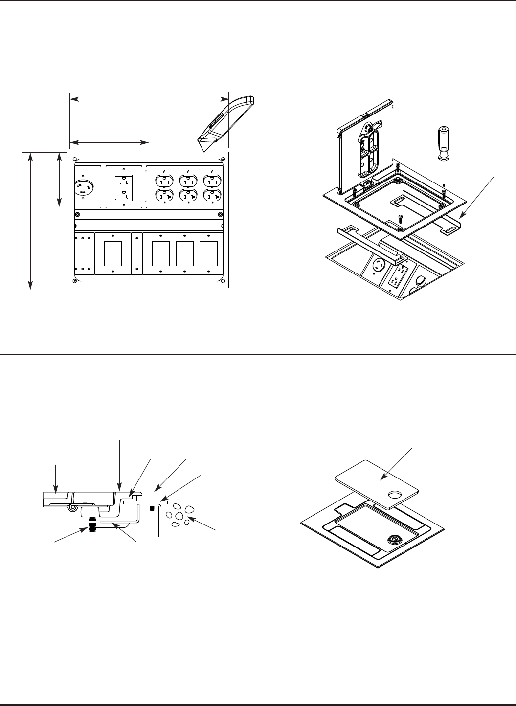
CARPET INSTALLATIONS
Step 13 Install carpet and cut 12 1/16" x 10 5/16" [262mm
x 306mm] rectangular opening over box opening.
Step 14 Open cover lid and position in box opening.
Position (2) mounting brackets under box opening
as shown in Step 15 and secure lid to brackets.
Step 15 Tighten mounting bracket screws securing flange
into box top cover plate.
Step 16 Cut carpet insert and mount inside lid. Use
enclosed template for dimensions.
5 1/8"
[131mm]
6"
[153mm]
12 1/16"
[306mm]
10 5/16"
[262mm]
Carpet
(Lid insert) Carpet
Box Top
Cover Plate
Concrete
Cover
Flange
Flange
Gasket
Mounting
Bracket
Mounting
Bracket Screw
Carpet
Insert
Mounting
Bracket
7
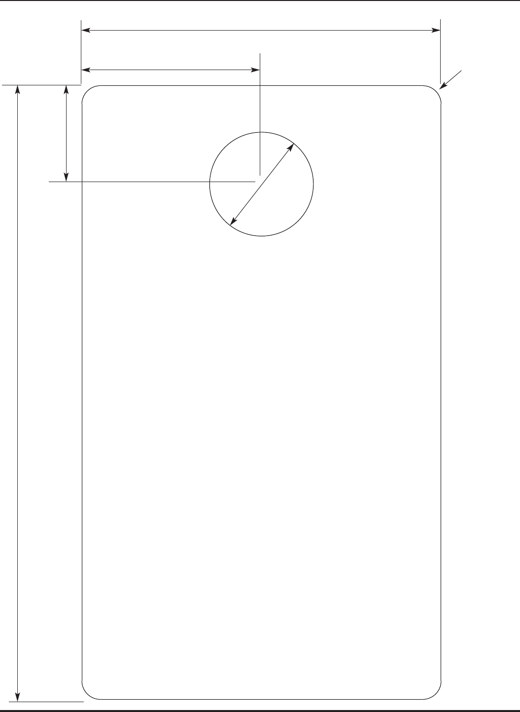
CARPET INSERT TEMPLATE
CAUTION: When printing copies of
this template please be
sure template is scaled
correctly and is the
correct size once it
is printed.
5 1/16"
[129mm]
Radius
1/4"
[7mm]
2 1/2"
[64mm]
1 3/8"
[35mm]
9 5/8"
[219mm]
Diameter
1 7/16"
[37mm]
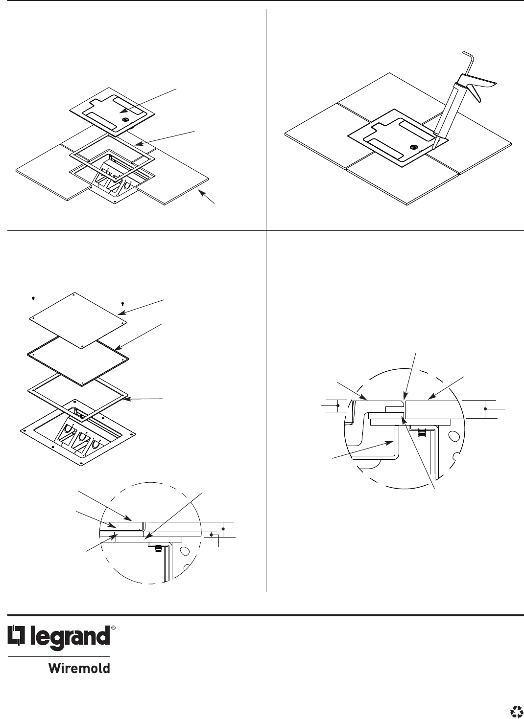
TILE INSTALLATIONS
Step 17 Cover flange is 1/4" thick. Use 1/8" spacer, Cat.
No. RFB119-TS, for 3/8" tile installations. Use two
spacers for 1/2" tile installations. Mount cover to
box as shown in Steps 14 and 15. See illustration
in Step 20
Step 18 Use grout and/or silicone caulk between edges
of flange and tile.
BARE CONCRETE & TERRAZZO INSTALLATIONS
Step 19 Install pan prior to pouring floor. Pan is 1/4" tall.
Use in conjunction with spacers to obtain 3/8"
and 1/2" heights.
Step 20 After concrete or terrazzo has cured, mount cover
to box as shown in Steps 14 and 15. Apply
sealing compound around perimeter of cover, as
shown in Step 18.
Cat. No.
RFB119-BTC
Cover
Cat. No.
RFB119-PAN
1/4" tall
Cat. No.
RFB119-TS
1/8" thick
Original mudcap
placed inside
terrazzo pan
Top of box
(flush with
concrete)
3/8"
1/8"
3/8" Tile
Cat. No.
RFB119-TS
(1/8" Thick)
Sold Separately.
Not required for
1/4" tile.
Original mudcap and
(2) mounting screws
Cat. No. RFB119-PAN
(sold Separately) 1/4"
tall. Used to dam
opening for installation
of cover during terrazzo
pour. Use RFB119-TS
spacers for floors
greater than 1/4" thick
Cat. No. RFB119-TS
(sold Separately) 1/8"
thick. Not required for
1/4" terrazzo. Use (1)
for 3/8" and (2) for 1/2"
thick floors.
NOTE: Remains in place during
cover installation
Seal edge of
cover with
silicone or caulk
Cover
Mounting
Bracket
Cover Flange Terrazzo/Tile
1/8" Spacer
1/4"
3/8"
DETAIL VIEW OF FINISHED INSTALLATION
WIREMOLD
U.S. and International:
60 Woodlawn Street • West Hartford, CT 06110
1-800-621-0049 • FAX 860-232-2062 • Outside U.S.: 860-233-6251
Canada:
570 Applewood Crescent • Vaughan, Ontario L4K 4B4
1-800-723-5175 • FAX 905-738-9721
1 003 189R1 0411
© Copyright 2011 Legrand/Wiremold All Rights Reserved
