1000441739 Catalog
1000471922-Catalog 1000471922-Catalog 1000471922-Catalog B5 unilog cesco-content
2016-09-04
: Pdf 1000441739-Catalog 1000441739-Catalog B4 unilog
Open the PDF directly: View PDF ![]() .
.
Page Count: 242 [warning: Documents this large are best viewed by clicking the View PDF Link!]
Catalogue
2014
Preventa solutions
for efficient machine safety
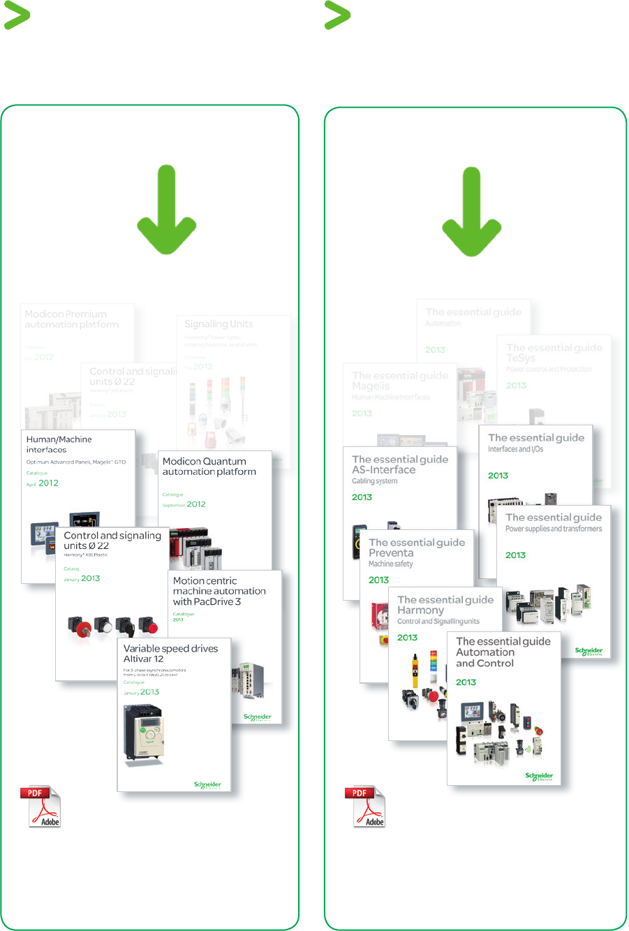
How to find the
“Automation and Control” products
Catalogs
Complete product ranges
Essential guides
Selection of the top selling
products

1
General contents Preventa solutions for
efcient machine safety
General presentation . . . . . . . . . . . . . . . . . . . . .
Safety chain solution, Safety functions . . . .
Safety products ...........................
2
1
3
4
5
6
7
8
9
10
2
1
3
4
5
6
7
8
9
10

Chapter 1
General
presentation
bAll technical information about products listed in this catalog
are available on: www.schneider-electric.com

2
1
3
4
5
6
7
8
9
10
1/1
Contents General presentation
bSchneider Electric Safety Approach
vProduct Approach .................................................................................. page 1/2
vSolution Approach ................................................................................. page 1/3
bServices we provide
vMachine Solutions Services & Support ............................................... page 1/4
vSchneider Electric Library for SISTEMA ............................................. page 1/5
bSafety Legislation and Standards
vIndustrial accidents ............................................................................... page 1/6
vEuropean legislation .............................................................................. page 1/7
vCertication and e marking ................................................................. page 1/8
vStandards .............................................................................................. page 1/10
vStandards to be applied
>The process ......................................................................................page 1/11
>Standard to be applied according to the design selected
for the safety-related machine control system ............................page 1/11
vRisk and Safety ..................................................................................... page 1/12
vRisk Assessment
>Assessment of machinery related risk ......................................... page 1/13
>Risk estimation ............................................................................... page 1/14
vHow to choose between EN/ISO 13849 and EN/IEC 62061 ............... page 1/15
vStandard EN/ISO 13849-1 .................................................................... page 1/16
vStandard EN/IEC 62061 ........................................................................ page 1/20
2
1
3
4
5
6
7
8
9
10
2
1
3
4
5
6
7
8
9
10
1/2
Presentation General presentation
Schneider safety approach
Schneider Electric Safety Approach
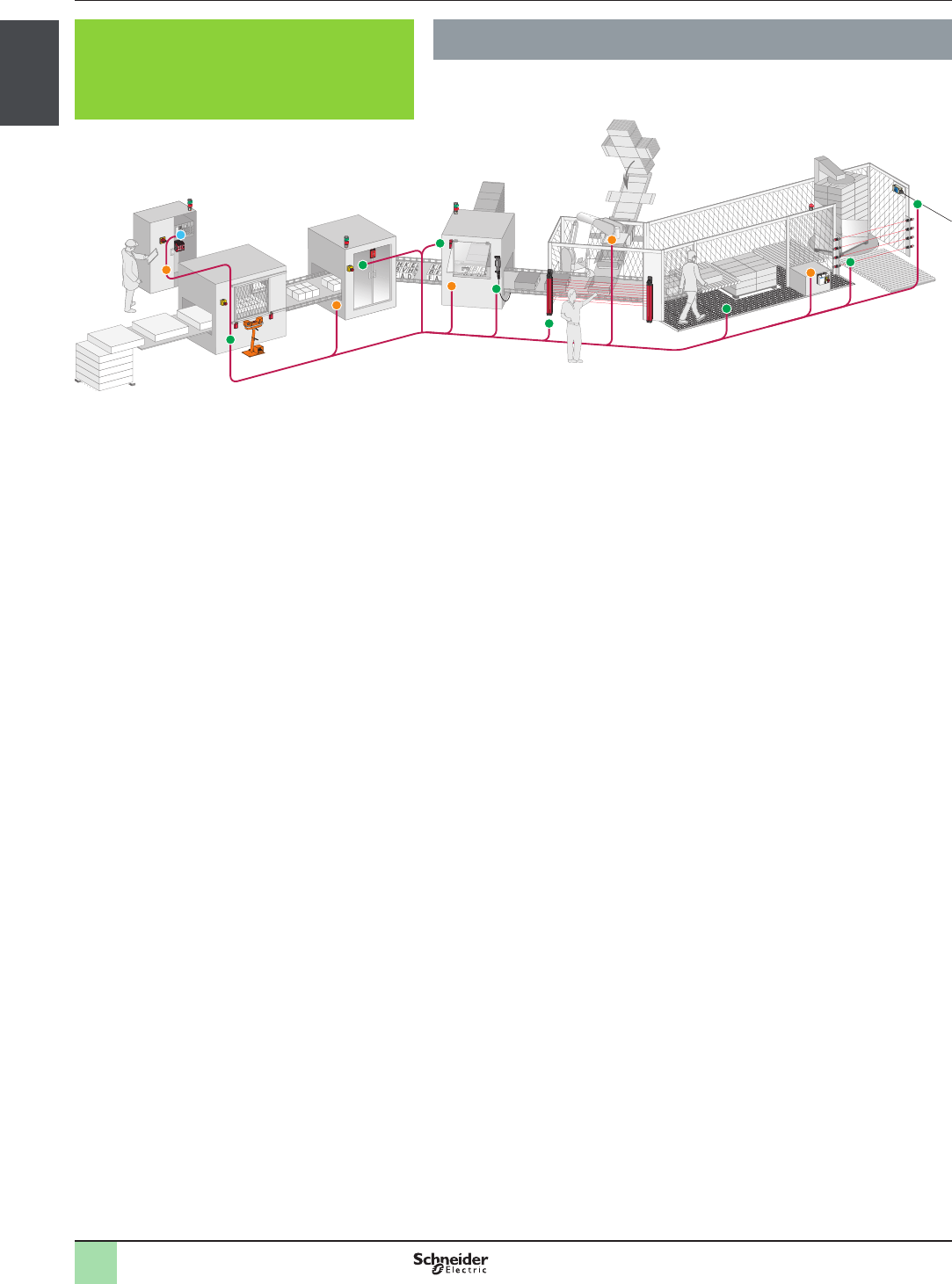
Schneider Electric is one provider of the complete safety chain.
In addition to moral obligation and economic consequences, the law requires that
machinery operates safely in the interests of accident prevention. Preventa offers
an extensive range of safety products, compliant with international standards,
designed to provide the most comprehensive protection for personnel and
equipment.
Aquire the information
>Generic protective measures - Emergency stop
>Two hand control stations and enabling switches for starting and enabling of
dangerous movements
>Protective guard devices used as part of safeguarding systems to control the
access under specic conditions of reduced risk
>Light curtains to detect approach to dangerous and limited areas
Monitor and processing
>Safety modules manage one safety function, monitoring inputs from safety
devices and managing the outputs to contactors and drives
>Safety controllers: congurable safety device capable of managing multiple
safety functions simultaneously
>Safety PLCs: programmable electronic systems for complex distributed safety
applications
Stop the machine
>Contactors to cut-off the electrical power supply to the motors with mechanically
linked mirror auxiliary contacts integrated for the feedback loop diagnosis used
by the safety modules, controller and PLCs
>Variable speed drives and servo drives provide controlled stopping of the
machine by using embedded safety functions
>Rotary switch disconnectors: for equipment isolation from the electrical supply
and for emergency stop by direct interruption of the power supply
Product Approach
2
1
3
4
5
6
7
8
9
10
2
1
3
4
5
6
7
8
9
10
1/3
Presentation General presentation
Schneider safety approach
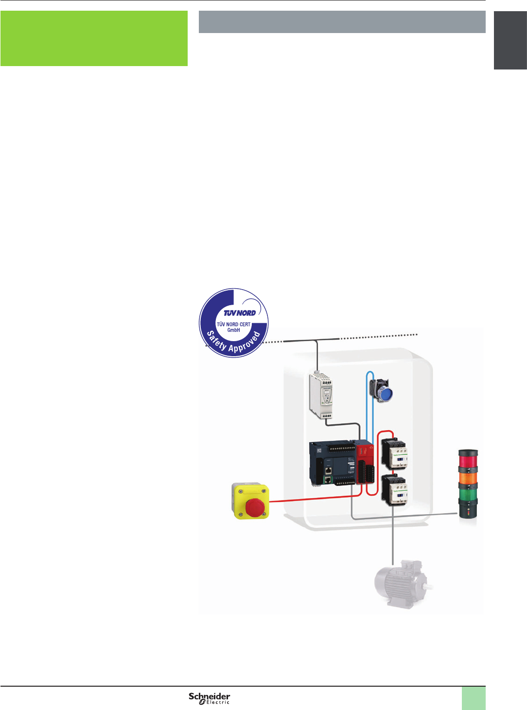
Schneider Electric Safety Approach
One provider for the complete safety chain
>Emergency stop
>Perimeter guarding
>Guard monitoring
>Enabling movement
>Speed monitoring
>Position monitoring
The Safety Chain Solutions are TüV certied safety architectures based upon the
most common safety functions required on and around a machine. The safety
chain solutions enable you to save time and costs when designing and
manufacturing your machine in accordance with the European Machinery
Directive.
Each solution comes with:
>Bill of materials and the system description le
>Wiring diagram
>Layout of solution indicating performance level (PL) and safety integrity level
(SIL)
>Description of the Performance Level and Safety Integrity Level calculation for
the safety function
>Sistema Library le with corresponding solution
>TüV certication
Solution Approach
2
1
3
4
5
6
7
8
9
10
2
1
3
4
5
6
7
8
9
10
1/4
Presentation General presentation
Service we provide
Service and support that are behind you all the way
We nd the best solution for your needs
>Based on your needs, System and Architecture Experts and Application Design
Experts (SAE/ADE) work out innovative technical solutions including
>Co-engineering
>Tests
>Validation
We understand your pain points
>Consulting
We execute the solution with a full service agreement
>Our solution design and project centers (Flex-Centres) are committed to quality
and results and provide:
>Project and program management
>Software and hardware engineering
>Tests, validation, and commissioning
We improve your team’s competencies
> In class training and on site training
We ensure the delivery of your solution
>Availability of components through a large worldwide network of distributors
>Collaboration, management, and delivery through local partners
>With Schneider Electric as your turnkey solution partner we include in our solutions:
>Project management and responsibility
>Engineered systems
>Third-party components management
We provide on-site services and support
>Qualied personnel to deliver on-site engineering and technical services
We improve your service team’s competencies
>Service and commissioning training
We provide international sales and after-sales services for you and your
customers
>Maintenance contracts
>Spares parts
>Repairs
>Normal and express deliveries
>Service expertise:
>Error diagnosis and repair
>Environmental measurements ( EMC, eld bus, thermography, power quality
analyses, etc.)
>Customer International Support (CIS) as a single point of contact:
>A network of 190 dedicated local country experts
>A web-based collaborative platform for efcient communication
Improve your machine ranges
>Consulting
We improve your customer’s machines in their production line
>Audits
>Retrotting
>Migration and upgrade
>Training
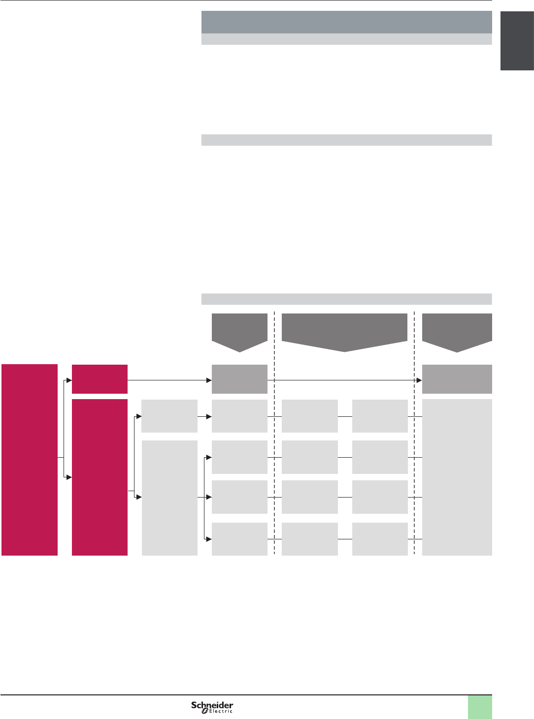
Machine Solutions Services & Support
Operate
Build
Improve
Design
2
1
3
4
5
6
7
8
9
10
2
1
3
4
5
6
7
8
9
10
1/5
Presentation General presentation
Service we provide
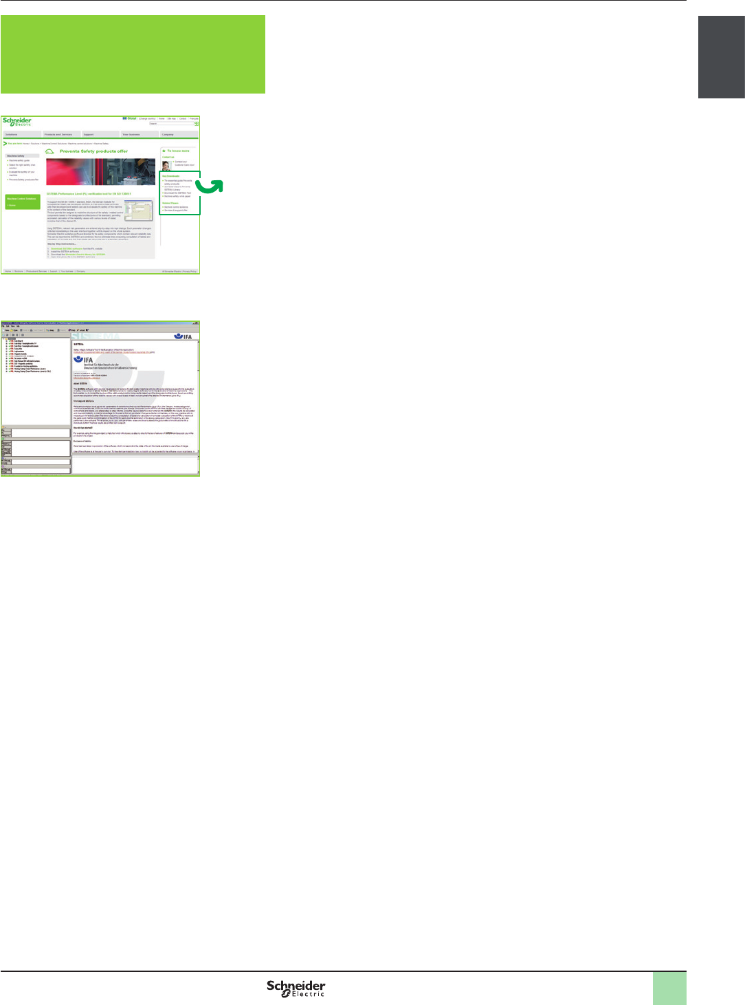
To support the EN/ISO 13849-1 standard, IFA, the German Institute for
Occupational Health, has developed SISTEMA, a free-to-download software
utility that designers and veriers can use to evaluate the safety of the
machine in the context of the standard.
The tool permits the designer to model the structure of the safety-related control
components based on the designated architectures of the standard, permitting
automated calculation of the reliability values with various levels of detail, including
that of the attained PL.
Using SISTEMA, relevant risk parameters are entered step-by-step into input
dialogs. Each parameter change is reected immediately on the user interface
together with its impact on the whole system.
Schneider Electric publishes software libraries for its safety components which
contain relevant reliability data. This can be imported into SISTEMA and combined,
the two eliminate time-consuming consultation of tables and calculation of
formulae and the nal results can be printed out in a summary document.
Schneider Electric Library for
SISTEMA
SISTEMA software
Schneider Electric library for SISTEMA
Download
2
1
3
4
5
6
7
8
9
10
2
1
3
4
5
6
7
8
9
10
1/6
Presentation General presentation
Safety Legislation and Standards
An industrial accident occurs through work or in the workplace and causes
minor to serious injury to a person using a machine, feeding it or carrying
out special work on it (tter, operator, maintenance personnel, etc.).
Causes of accidents in the workplace
>Human-related factors (designers, users):
>poor grasp of machine design
>over-familiarity with danger through habit and failure to take dangerous
situations seriously
>underestimation of hazards, causing people to ignore safe working procedure
>loss of concentration on tasks to be performed (e.g. fatigue)
>failure to comply with procedures
>stressful working conditions (noise, work rates, etc.)
>uncertainty of employment which can lead to inadequate training
>inadequate or bad maintenance, generating unsuspected hazards
>Machine-related factors:
>inadequate guards
>inherent machine hazards (e.g. reciprocal motion of a machine, unexpected
starting or stopping)
>machines not suited to the application or environment (e.g. sound alarms
deadened by the noise of surrounding machinery)
>Plant-related factors:
>movement of personnel from machine to machine (automated production line)
>machinery from different manufacturers and using different technologies
>ow of materials or products between machines
Consequences
>Risk of varying degrees of physical injury to the user
>stoppage of the machine involved
>stoppage of similar machine installations for inspection, for example by health
and safety inspectors
>if necessary, modications to make machinery safe
>change of personnel and training new personnel for the job
>damage to the company brand image
Conclusion
Damages for physical injuries are equivalent to about 20 thousand million euro
paid out each year in the European Union. Decisive action is required to reduce the
number of accidents in the workplace. The rst essentials are adequate company
policies and efcient organisation.
Reducing the number of industrial accidents and injuries depends on the safety of
machines and equipment.
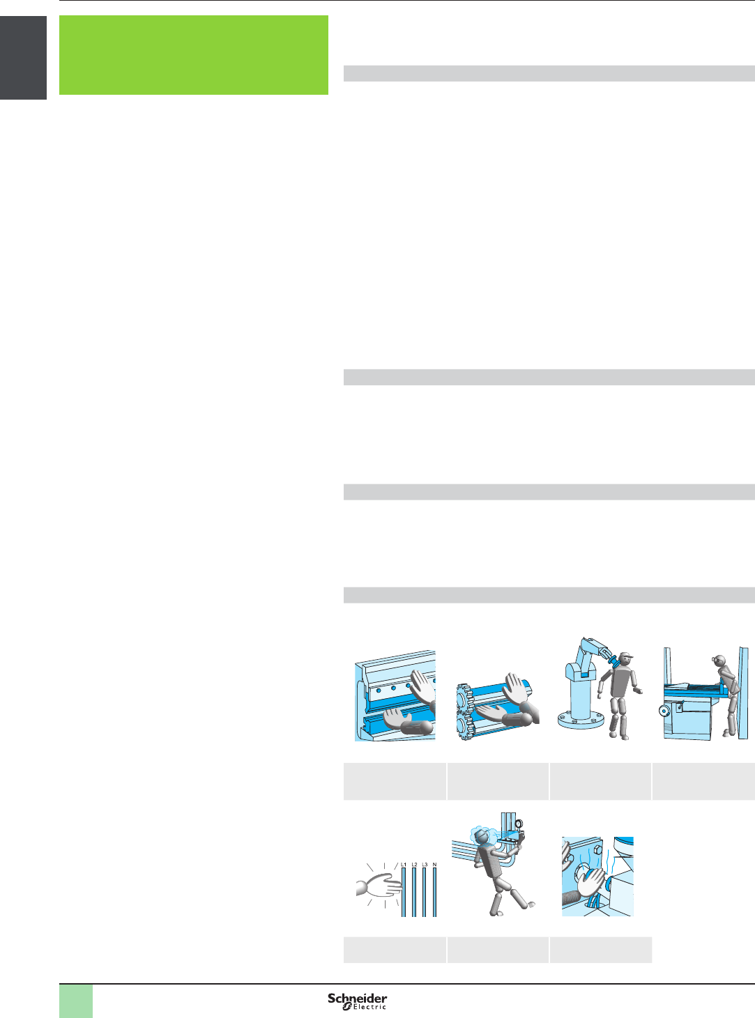
Types of potential hazard
The potential hazards of a machine can be classied into three main groups, as
illustrated below:
Mechanical hazards
Puncturing, cutting,
shearing, fractures,
severing
Catching,
entanglement,
drawing in, trapping
Impact Crushing
Electrical hazards Physical and chemical hazards
Electric shock,
electrocution, burns
Discharge of
dangerous substances
Burns
Industrial accidents

2
1
3
4
5
6
7
8
9
10
2
1
3
4
5
6
7
8
9
10
1/7
Presentation General presentation
Safety Legislation and Standards
Safety has become a key issue for businesses. Social developments in
association with technological progress have had a profound impact on
legislation and on regulations for the use of building electrical automation
equipment.
Social issues
The safety-conscious nature of our western societies has led the legislature to
increase the number of requirements and establish stricter rules, while the high
cost of accidents has prompted companies to make efforts in the same direction.
Technological issues
Increasing levels of automation have led to new restrictions. In some case it is
difcult, if not dangerous, to stop a machine suddenly and it is necessary to
perform a safe shut down sequence before allowing personnel to enter into a
production cell. The increasingly widespread use of electronics and software has
required a different approach to the solutions adopted; empirical rules are no
longer enough. Selection includes a reliability calculation to determine the
behavior of the system. In this context, the specication and design phase are
crucial. Studies show that more than 2/3rds of incidents are due to bad design and
inadequate specications. At this stage it is therefore necessary to estimate
potential risks and select the most appropriate solutions to reduce their
consequences. Standards are available to assist and guide the designer.
Manufacturers of components and solutions help their customers by offering
complete, ready-to-use functions which, when combined in accordance with the
regulations, satisfy the customer’s needs and meet legislative requirements. In this
chapter, we will present a simplied process. To make a choice, the customer will
then be able to refer to the safety functions chapter and to the safety products
chapters.
European legislation requires that preventive action be taken to preserve and
protect the quality of the environment and human health. To achieve these
objectives, European Directives have been prepared which must be applied by
plant operators and by manufacturers of equipment and machines. It also assigns
responsibility for possible accidents.
>Notwithstanding the constraints, machine safety has the following positive
repercussions:
> prevention of industrial accidents
> protection of workers and personnel by means of suitable safety measures
that take into account the machine’s application and the local environment
>This makes it possible to reduce direct and indirect related costs:
> by reducing physical harm
> by reducing insurance premiums
> by reducing production losses and possible delay penalties
> by limiting damages and costs for maintenance
>Safe operation involves two principles: safety and reliability of the process:
> safety is the ability of a device to keep the risk incurred by persons within
acceptable limits
> reliability of operation is the ability of a system or device to perform its function
at any moment in time and for a specied duration
>Safety must be taken into account right from the beginning of the design stage
and kept in place throughout all stages of a machine’s life cycle: transport,
installation, commissioning, maintenance, dismantling
The main purpose of the Machinery Directive 2006/42/EC is to compel
manufacturers to guarantee a minimum safety level for machinery and equipment
sold within the European Union. This version has been replacing the 98/37/EC
version since January 2010.
To allow free circulation of machinery within the European Union, the e marking
must be applied to the machine and an EC declaration of conformity is issued to
the purchaser. This directive came into effect in January 1995 and has been
enforced since January 1997 for all machines.
The user has obligations dened by the Use of Work Equipment directive
89/655/EEC which can in most cases be met by using machinery compliant with
relevant standards.
These standards are complex. After a brief presentation of the structure of the
standards system, we will provide the practical guide to the typical standards to be
applied according to the selected control system design.
European legislation

2
1
3
4
5
6
7
8
9
10
2
1
3
4
5
6
7
8
9
10
1/8
Presentation General presentation
Safety Legislation and Standards
Certication and e marking
There are 6 stages in the process for certication and afxing of the e marking on
machines:
1 Apply all the relevant directives
2 Conform to the essential health and safety requirements
3 Draw up the technical documentation
4 If applicable proceed with the conformity examination
5 Draw up the Declaration of Conformity
6 Afx the e marking
The Machinery Directive
The Machinery Directive is an example of the “New approach” for the
harmonization of products in terms of technical specications and standards.
It is based on:
>Essential health and safety requirements which must be complied with before
the machine is put on the market
>A voluntary harmonization process of standards undertaken by the European
Standards Committee (CEN) and the European committee for electro-technical
standardization (CENELEC)
>Conformity of evaluation procedures adapted to the types of risk and associated
with machine types
>The e marking, afxed by the manufacturer to indicate that the machine
conforms to the applicable directives; machines bearing this marking can
circulate freely within the European Union
The directive has considerably simplied the multiple national legislations which
were in force and has therefore removed many barriers which made trading
difcult in the European Union. This has also made it possible to reduce the social
cost of accidents. The directives do not apply to pre-existing machines within the
EU unless they are substantially modied. A list of the machines requiring special
attestation procedures can be found in the Machinery Directive Annex 4.
The essential requirements
Annexe I of the Machinery Directive groups together the essential health and
safety requirements, for putting machines and safety components on the market
and into service in Europe.
It follows that:
>If all the requirements of the directive are complied with, no member state of the
European Union can oppose circulation of this product
>If the requirements of the directive are not complied with, putting the product on
the market may be prohibited or withdrawal of the product from the market may
be required
In the European Union, this concerns not only manufacturers or their distributors,
but also importers and resellers who import these machines or put them into
service. Second-hand machines within the EU are not covered, but used machines
that have been modied or refurbished can be considered to be new machines.
The harmonized standards
The simplest way to demonstrate conformity with the directives is to conform to the
European Harmonized Standards. When, for a product listed in Annex 4 of the
Machinery Directive, there is no harmonized standard, or the existing standards
are not relevant to cover the essential health and safety requirements, or if the
manufacturer considers that these standards are not applicable to their product,
they can apply for approval by an outside Notied Body.
These bodies are approved by the Member States after having shown that they
have the recognized expertise to give such an opinion (TÜV, BGIA, INRS, BSI
Product Services, etc.).
Although the Notied Body has a certain number of responsibilities under the
Directive, it is always the manufacturer or their representative who remain
responsible for conformity of the product.
Certication and e marking
2
1
3
4
5
6
7
8
9
10
2
1
3
4
5
6
7
8
9
10
1/9
Presentation General presentation
Safety Legislation and Standards
Certication and e marking (continued)
Declaration of conformity
In accordance with Article 1 of the Machinery Directive, the manufacturer or their
authorized representative established in the European Union must draw up a
European Declaration of Conformity for each machine (or safety component). This
is in order to certify that the machine or safety component conforms to the
Directive.
Before putting a product on the market, the manufacturer or their representative
must prepare a technical le.
e marking
Finally, the e mark must be afxed to the machine by the manufacturer or their
authorized representative in the European Union. This marking has been
obligatory since 1st January 1995 and can only be afxed if the machine conforms
to all the applicable directives, such as:
>The Machinery Directive 2006/42/ECC
>The Electromagnetic Compatibility (EMC) directive 2004/108/EC
>The Low Voltage Directive 2006/95/EC
There are other directives such as the protection of persons, lifts, medical
equipment, etc., which may also be applicable.
The e marking is the machine’s passport in the European Union, which allows it to
be marketed in all countries within the Union without taking into account
regulations in each individual country.
e marking procedure
Machine
Listed in
Annex 4
Not listed in
Annex 4
Prepare le
according to
Annex 5
Draw up
EC declaration of
conformity and affix
the e marking
Only partly
conforming to the
standards
Manufactured
according to
harmonised
standards
Submit example
and le according
to Annex 6
Forward le
according to
Annex 6
Submit example
and le according
to Annex 6
Submit le
according to
Annex 6
Proceed with
conformity
examination of
the sample
Register the le
Verify correct
application of the
standards
Proceed with
conformity
examination of
the sample
Draw up the
conformity
examination
certicate
Acknowledge
receipt
Draw up a
certicate of
adequacy
Draw up the
conformity
examination
certicate
Draw up
EC declaration of
conformity and afx
the e marking
Manufacturer Notied Body Manufacturer
2
1
3
4
5
6
7
8
9
10
2
1
3
4
5
6
7
8
9
10
1/10
Presentation General presentation
Safety Legislation and Standards
Introduction
The harmonized European safety standards establish technical specications
which comply with the minimum safety requirements dened in the related
directives. Compliance with all applicable harmonized European standards can be
assumed to ensure compliance with the related directives. The main purpose is to
guarantee a minimum safety level for machinery and equipment sold within the EU
market and allow the free circulation of machinery within the European Union.
The 3 groups of European standards
>Type A standards
Basic safety standards which specify the basic concepts, design principles and
general aspects valid for all types of machine: e.g. EN/ISO 12100
>Type B standards
Standards relating to specic aspects of safety or to a particular device that can
be used on a wide range of machines
>Type B1 standards
Standards relating to specic safety aspects of machines: e.g. EN/IEC 60204-1
Electrical equipment of machines
>Type B2 standards
Standards relating to specic products such as two-hand control stations (EN 574),
guard switches (EN 1088/ISO 14119), emergency stops (EN/ISO 13850), etc
>Type C standards
Standards relating to various families or groups of machines (e.g.: hydraulic
presses EN 693, robots, etc) and giving detailed applicable requirements
Standards
A selection of standards
Standards Type Subject
EN/ISO 12100 AMachinery safety - General principles for design, risk assessment and risk reduction
EN 574 BTwo-hand control devices - Functional aspects and design principles
EN/ISO 13850 BEmergency stop - Principles for design
EN/IEC 62061 BFunctional safety of safety-related electrical, electronic and electronic programmable control systems
EN/ISO 13849-1 BMachinery safety - Safety-related parts of control systems - Part 1 General principles for design
EN/ISO 13849-2 BMachinery safety - Safety-related parts of control systems - Part 2 Validation
EN 349 BMinimum gaps to avoid crushing parts of the human body
EN 294 BSafety distances to prevent hazardous zones being reached by upper limbs
EN 811 BSafety distances to prevent hazardous zones being reached by lower limbs
EN/IEC 60204-1 BMachinery safety - Electrical equipment of machines - Part 1: general requirements
EN 999/ISO 13855 BPositioning of protective equipment in respect of approach speeds of body parts
EN 1088/ISO 14119 BInterlocking devices associated with guards - Principles for design and selection
EN/IEC 61496-1 BElectro-sensitive protective equipment
EN/IEC 60947-5-1 BElectromechanical control circuit devices
EN 842 BVisual danger signals - General requirements, design and testing
EN 1037 BPrevention of unexpected start-up
EN 953 BGeneral requirements for the design and construction of xed and movable guards
EN/IEC 61800-5-2 BAdjustable speed electrical power drive systems. Part 5-2: Safety requirements – Functional
EN 201 CMachinery for plastics and rubber - Injection moulding machines – Safety requirements
EN 692 CMechanical presses - Safety requirements
EN 693 CHydraulic presses - Safety requirements
EN 289 CMachinery for plastics and rubber - Presses - Safety requirements
EN 422 CBlow moulding machines for producing hollow parts - Design and construction requirements
EN/ISO 10218-1 CManipulating industrial robots - Safety requirements
EN 415-4 CSafety of packaging machines - Part 4: palletisers and depalletisers
EN 619 CSafety and EMC requirements for equipment for mechanical handling of unit loads
EN 620 CSafety and EMC requirements for xed belt conveyors for bulk material
EN 746-3 CIndustrial thermo processing equipment - Part 3: safety requirements for the generation and use of
atmosphere gases
2
1
3
4
5
6
7
8
9
10
2
1
3
4
5
6
7
8
9
10
1/11
Presentation General presentation
Safety Legislation and Standards
The process
European Machinery Directive 2006/42/EC
Compliance with the following standards ensure compliance with the Machinery
Directive (this new version of the Machinery Directive 2006/42/EC has been
replacing 98/37/EC since January 2010).
EN/ISO 12100: 2010: General principles for design, risk assessment and risk
reduction.
The purpose of this standard is to provide designers with an overall framework and
guidance to enable them to produce machines that are safe for their intended use.
Standards to be apply according to the design selected for the safety-related
machine control system.
Remarks:
The use of either the EN/ISO 13849 or EN/IEC 62061 standards gives presumption
of conformity to the new 2006/42/EC directive.
EN/IEC 60204-1: Electrical equipment of machines
Standard EN/IEC 60204-1 completes the safety standards by giving setting-up
rules for each component of a machine’s electrical functions.
It species, amongst other things:
>the type of connection terminals and disconnection and breaking devices
>the type of electric shock protection
>the type of control circuits
>the type of conductors and wiring rules
>the type of motor protection
Standard to be applied according to the design selected for the
safety related machine control system
Safety standards to be applied according to type of architecture selected
Based on the generic denition of the risk, the standards classify necessary safety
levels in different discrete levels corresponding for each one to a probability of
dangerous failure per hour:
>PL (Performance Level) for standard EN/ISO 13849-1
>SIL (Safety Integrity Level) for standard EN/IEC 62061
Standards to be applied
European Machinery Directive 2006/42/EC
EN/ISO 13849-1
EN/ISO 13849-2
Machinery safety
Safety-related parts of
control systems
Machinery safety
General principles for design, risk assessment
and risk reduction
EN/ISO 12100: 2010
EN/IEC 62061
Machinery safety
Functional safety of
safety-related electrical,
electronic and
programmable electronic
control systems
Machinery safety
EN/IEC 60204-1
Electrical equipment of machines
Certication and e marking in accordance with the
Machinery Directive
Standards to be applied for the design of machines
2
1
3
4
5
6
7
8
9
10
2
1
3
4
5
6
7
8
9
10
1/12
Presentation General presentation
Safety Legislation and Standards
Safety is the absence of risks which could cause injury to or damage the health of
persons. Functional safety is a part of safety that depends on the correct operation
of safety functions.
According to the requirements of standard EN/ISO 12100: 2010, the machine
designer’s job is to reduce all risks to a value lower than the acceptable risk. For
more details concerning the sources of accidents and risk prevention, the reader is
referred on page 1/6.
This standard recognizes two sources of hazardous phenomena:
>Moving transmission parts
>Moving parts contributing to the work
It gives guidelines for the selection and installation of devices which can be used to
protect persons and identies those measures that are implemented by the
machine designer and those dependent on its user.
The measures taken by the machine designer may be:
>Inherent in the design
>Selection of guards and additional measures, including control systems
>Information for the user
The measures taken by the user may be (non-exhaustive list):
>Organization, procedures, etc.
>Personal protective equipment
>Training
Risk and safety
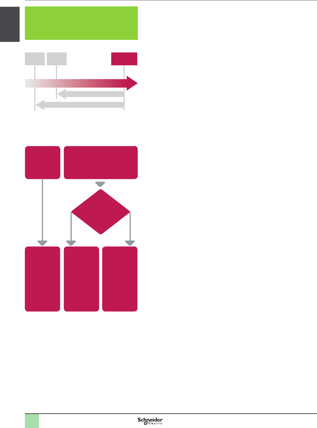
Residual
risk
Acceptable
risk
Initial
risk
Level of risk
Risk reduction necessary
Actual risk reduction
Achieved by design measures, safety-related systems and by
external risk reduction devices
Reduction of risk to an acceptable level
Can these elements
be made completely
inaccessible while
working?
Fixed guards or
interlocking
movable guards
with or without
guard locking
Fixed guards or
xed guards
associated with
an interlocking
device or
protective device
Fixed or movable
guards in zones
where persons
do not work and
adjustable
guards in work
zones
Yes No
Selection of the protection system
(EN/ISO 12100: 2010)
Moving
transmission
parts
Moving parts
contributing to the work
(e.g. : tools)
2
1
3
4
5
6
7
8
9
10
2
1
3
4
5
6
7
8
9
10
1/13
Presentation General presentation
Safety Legislation and Standards
Risk Assessment Assessment of machinery related risk
European legislation
Machines are sources of potential risk and the Machinery Directive requires
a risk assessment to ensure that any potential risk is reduced to less than
the acceptable risk.
Standard EN/ISO 12100 denes risk as follows: risk is the severity multiplied by the
possibility of occurrence. It denes an iterative process for achieving machine
safety, which states that the risks for each potential hazard can be determined in
four stages. This method provides the basis for the requisite risk reduction.
Risk assessment
>Risk assessment consists of a series of logic steps which make it possible to
systematically analyze and evaluate machinery-related risks
>Risk assessment is followed, whenever necessary, by a reduction of the risk.
This denition taken from standard EN/ISO 12100 is based on an iterative
process represented in the diagram opposite
Determination of machine limits
Risk assessment starts by determining the limits of the machine at all stages
of its life cycle:
>Transport, assembly, installation
>Commissioning
>Use
>De-commissioning, dismantling
The use limitations must then be specied:
>Operating modes
>Level of training required
>Space limits (amplitude, movement)
>Time limits (life cycle, frequency of maintenance)
Identication of the potential hazard
If a potential hazard exists, a hazardous phenomenon will cause harm if
measures are not taken.
All the tasks associated with the machine’s life cycle must be identied,
such as:
>Assembly, transport and installation
>Adjustment, testing
>Learning, programming
>Tool changing
>Feeding, removal of product from the machine
>Starting, stopping
>Emergency Stops, restarting after an unexpected stop
>Maintenance, cleaning, etc.
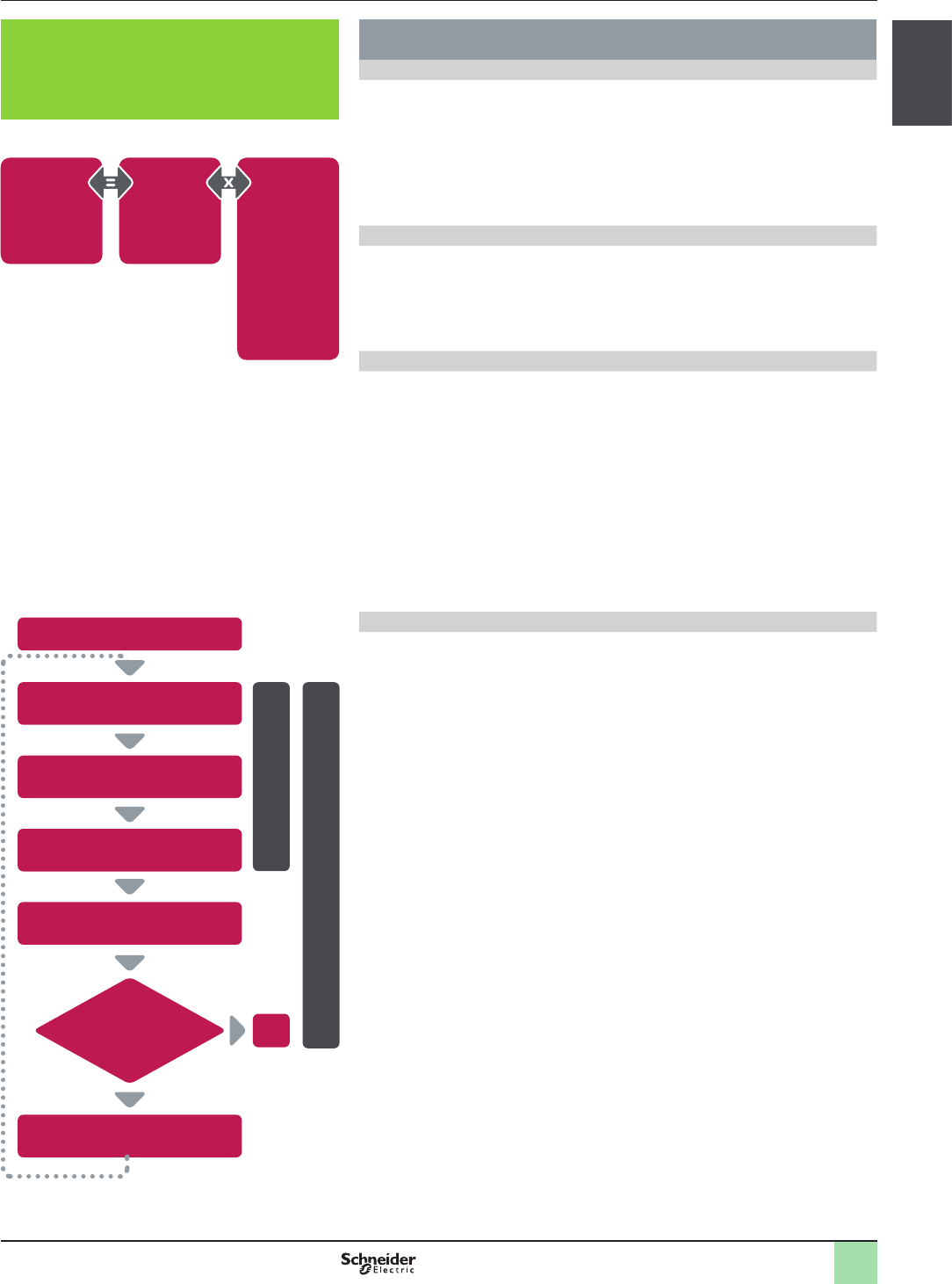
End
Risk evaluation
Risk analysis
Start
Is the machine safe?
No
Yes
Risk evaluation
Determination of
machine limits
Identication
of the potential hazards
Risk estimation
Risk reduction
Logic steps for risk analysis
Risk related
to the
potential
hazard
Severity
of the
potential
harm
Probability of
occurence
Frequency and
duration of
exposure
Possibility of
avoiding or
limiting the
probability of the
occurence of an
event that could
cause harm
Denition of risk
2
1
3
4
5
6
7
8
9
10
2
1
3
4
5
6
7
8
9
10
1/14
Presentation General presentation
Safety Legislation and Standards
Risk estimation
The risk is a function of the severity of the harm and the probability that this
harm will occur.
>The severity of the harm takes into account:
>The severity of injuries (slight, serious, death)
>The extent of the harm (number of persons)
>The probability of the harm occurring takes into account:
>Exposure to the hazard (nature of access, time spent in the hazardous zone,
number of persons exposed, frequency of access, etc.)
>The occurrence of a hazardous event (accident history, comparison of risks,
etc.)
>The possibility of avoiding or limiting the harm (experience, awareness of the
risk, etc.)
Risk assessment
On the basis of the risk assessment, the designer has to dene the safety
related control system.
To achieve that, the designer will choose one of the two standards
appropriate to the application:
>either standard EN/ISO 13849-1, which denes performance levels (PL)
>or standard EN/IEC 62061, which denes safety integrity level (SIL)
Risk reduction
The process of risk reduction for dangerous events starts by:
>Intrinsic prevention (inherently safe design)
>Denition of the appropriate protective means (guards, carters, x fences, etc.)
>Personal training
If the selected preventive measure depends on a safety related control
system, the designer has to perform an iterative process for the design of
the safety relative control system.
> The rst stage is to dene the necessary safety-related control functions:
>either through the choice of components
>or by adapting the control system architecture. Redundancy (double circuit
components), for example, signicantly increases the reliability of the solution
>Once the limits of available technologies have been reached, it will not be
possible to further reduce the rate of dangerous failures. To achieve the required
level of safety, it will be necessary to use a diagnostic system that allows
dangerous failures to be detected
Risk Severity
of
harm
Probability of
harm occuring
Exposure of
the person or
persons to
hazardous
events
Occurrence of a
hazardous
event
Possibility of
avoiding or
limiting the
harm
Elements of the risk
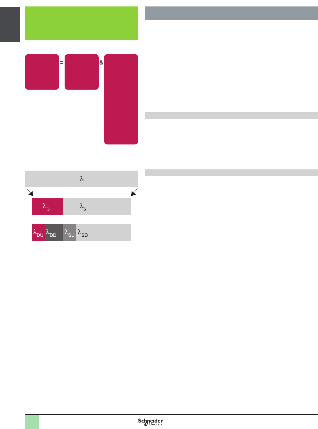
λ rate of control system failures
λD rate of dangerous failures
λDU rate of undetected dangerous failures
λDD rate of detected dangerous failures
λS rate of safe failures
λSU rate of undetected safe failures
λSD rate of detected safe failures
Breakdown of the probability of failures
Risk Assessment

2
1
3
4
5
6
7
8
9
10
2
1
3
4
5
6
7
8
9
10
1/15
Presentation General presentation
Safety Legislation and Standards
How to choose between EN/ISO 13849 and
EN/IEC 62061
Select the applicable standard
Based on the generic denition of the risk, the standards classify necessary safety
levels in different discrete levels corresponding for each one to a probability of
dangerous failure per hour:
>PL (Performance Level) for standard EN/ISO 13849-1
>SIL (Safety Integrity Level) for standard EN/IEC 62061
The table below gives the relationship between the performance level (PL) and the
Safety Integrity Level (SIL).
PL ISL Probability of dangerous failures per hour 1/h
a No correspondance u 10-5 … < 10-4
b 1 u 3 x 10⁻⁶ … < 10-5
c 1 u 10-6 … < 3 x 10⁻⁶
d 2 u 10-7 … < 10-6
e 3 u 10-8 … < 10-7
Recommended application of IEC 62061 and ISO 13849-1
Annex Technology
implementing the
safety related
control fuction (S)
ISO 13849-1 IEC 62061
A Non electrical, e.g. hydralics X Not covered
B Electromechanical, e.g.
relays, or non-complex
electronics
Restricted to designated
architectures (see Note 1)
and up to PL=e
All architectures and
up to SIL 3
C Complex electronics, e.g.
programmable
Restricted to designated
architectures (see Note 1)
and up to PL=d
All architectures and
up to SIL 3
D A combined with B Restricted to designated
architectures (see Note 1)
and up to PL=e
X
see Note 3
E C combined with B Restricted to designated
architectures (see Note 1)
and up to PL=d
All architectures and
up to SIL 3
F C combined with A, or
C combined with A and B
X
see Note 2
X
see Note 3
“X” indicates that this item is dealt with by the standard shown in the column heading.
Note 1 Designated architecture are dened in Annex B of EN/ISO 13849-1 to give a simplied
approach for qualication of performance level
Note 2 For complex electronics: use of designated architecture according to EN/ISO 13849-1
up to PL=d or any architecture according to EN/IEC 62061
Note 3 For non-electrical technology use parts according to EN/ISO 13849-1 as subsystems.
For building specic complex sub-systems or for higher level requirements
including software, standard EN/IEC 61508 relating to systems must be used.
2
1
3
4
5
6
7
8
9
10
2
1
3
4
5
6
7
8
9
10
1/16
Presentation General presentation
Safety Legislation and Standards
Standard EN/ISO 13849-1
Standards to be applied according to
the design selected for the safety-
related machine control system
Introduction to Functional Safety of Machinery
The functional safety standards are intended to encourage designers to
focus more on the functions that are necessary to reduce each individual
risk, and on the performance required for each function, rather than simply
relying on particular components. These standards make it possible to
achieve greater levels of safety throughout the machine’s life.
>Under the previous standard, EN 954-1, categories (B, 1, 2, 3 and 4) dictated
how a safety-related electrical control circuit must behave under fault conditions.
Designers can follow either EN/ISO 13849-1 or EN/IEC 62061 to demonstrate
conformity with the Machinery Directive. These two standards consider not only
whether a fault will occur, but also how likely it is to occur
>This means there is a quantiable, probabilistic element in compliance: machine
builders must be able to determine whether their safety circuit meets the
required safety integrity level (SIL) or performance level (PL). Panel builders and
designers should be aware that manufacturers of the components used in safety
circuits (such as safety detection components, safety logic solvers and output
devices like contactors) must provide detailed data on their products
Standard EN/ISO 13849-1
Machinery safety - Safety-related parts of control systems
Standard EN/ISO 13849-1 is an evolution of standard EN 954-1.
Field of application of the standard
This standard gives safety requirements and advice relating to principles for the
design and integration of safety-related parts of control systems (SRP/CS),
including software design. For these parts, it species the characteristics, including
the performance level, needed to achieve these safety functions. It applies to the
SRP/CS of all types of machine, regardless of the technology and type of energy
used (electric, hydraulic, pneumatic, mechanical, etc.).
Process
Risk assessment as dened in standard EN/ISO 12100 leads to decisions on risk
reduction measures.
If these measures depend on a control system, then EN/ISO 12100 can apply. It denes
a 6-stage design process:
1 - Selection of the essential safety functions that SRP/CS must perform. For each
safety function, specify the required characteristics
2 - Determine the required performance level (PLr)
3 - Design and technical creation of safety functions: identify the parts that perform
the safety function
4 - Evaluate the performance level PL for each safety-related part
5 - Check that the performance level PL achieved is greater than or equal to the
required level (PLr)
6 - Check that all requirements are satised
We will now illustrate these stages, taking as an example a safety function where a
severe injury can be caused by a trolley not stopping at the end of the Jib and thus
causing the trolley to fall. A person can be exposed to this dangerous situation
around the hoisting machine.
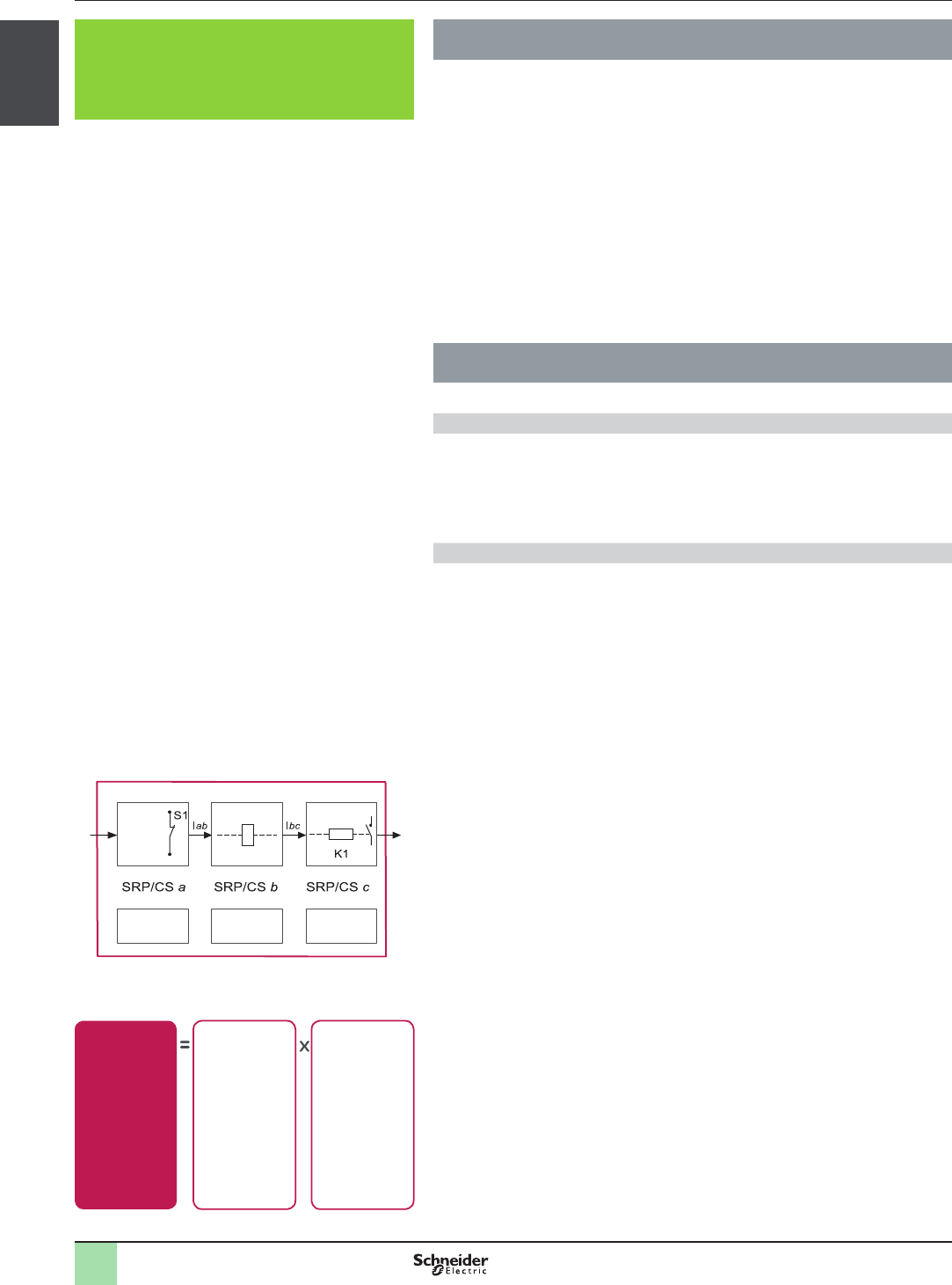
Stage 1 - Selection of safety functions
The diagram opposite shows a safety function which consists of several parts:
>The input actuated by opening of the guard (SRP/CSa)
>The control logic, limited in this example to opening or closing of a contactor
coil (SRP/CSb)
>The power output that controls the motor (SRP/CSc)
>The connections (Iab, Ibc)
Stage 2 - Estimation of required performance level (PLr)
Considering our example of the person coming into area where the dangerous
hoisting machine is operating we now estimate the risk using the risk graph.
The parameters to be considered are:
>S Severity of the injury
>S1 Slight injury, normally reversible
>S2 Serious, normally irreversible, including death
>F Frequency and/or duration of exposure to the hazardous phenomenon
>F1 Rare to fairly frequent and/or short duration of exposure
>F2 Frequent to permanent and/or long duration of exposure
>P Possibility of avoiding the hazardous phenomena or limiting the harm
>P1 Possible under certain circumstances
>P2 Virtually impossible
Representation of the safety function
L
Safety functions
Guard
contact
Logic Contactor
Inputs Processing Outputs
Event: limit switch
Action: motor stop
Risk analysis
Risk related
to the
potential
hazard
Severity
of the potential
harm
Probability of
occurrence:
- Frequency and
duration of
exposure
- Possibility of
avoiding or
limiting the
probability of the
occurrence of an
event that could
cause the harm
2
1
3
4
5
6
7
8
9
10
2
1
3
4
5
6
7
8
9
10
1/17
Presentation General presentation
Safety Legislation and Standards
Standard EN/ISO 13849-1
Machinery safety - Safety-related parts of control systems (continued)
Process (continued)
Stage 2 - Estimation of required performance level (PLr) (continued)
For our example: a serious injury S1 can be caused by being exposed near the hoisting
machine as if there is no safe guarding to ensure the trolley stops the load and trolley will
fall. After considering the severity of the injury we investigate the frequency and/or
duration of the possible entry to the dangerous area. Here we dene the frequency of
exposure to the hazard is low F1 (occasional presence) as there are restrictions to enter
the area. The last step is based upon the possibility to avoid the hazard and limiting the
harm. To evaluate this we take into consideration that it is possible to avoid the harm as
the visibility around the dangerous machine is monitored by the operator and in this case
there is a possibility to avoid the harm under certain conditions so we dene it as P1.
The result of the estimation gives a required performance level PLr = c.
Stage 3 - Design and creation of the safety functions
At this point, we need to describe the PL calculation method.
For a SRP/CS (or a combination of SRP/CS), PL could be estimated with the gure
shown on page 1/19, after estimation of several factors such as :
>Hardware and software system structure (categories)
>Mechanism of failures, diagnostic coverage (DC)
>Components reliability, Mean Time To dangerous Failure (MTTFd)
>Common Cause Failure (CCF)
>Categories (Cat.) and designated architectures
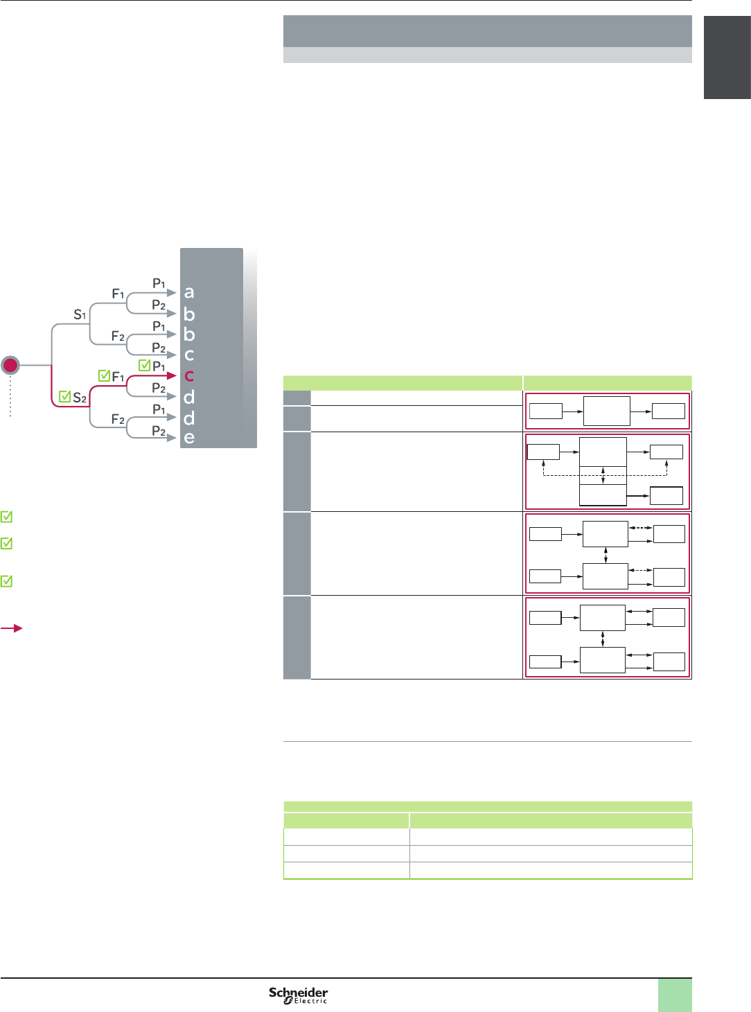
The table below summarises system behaviour in the event of a failure and the
principles used to achieve the safety, for the 5 categories dened:
Cat. System behaviour Designated architectures
BA fault can lead to loss of the safety function
I
i
L O
mi
m
1As for category B but the probability of this
occurence is lower than for the category B
2A fault can lead to loss of the safety function
between two periodic inspections and loss of the
safety function is detected by the control system
at the next test.
I
i L
TE OTE
O
m
m
i
m
i
m
3For a single fault, the safety function is always
ensured. Only some faults will be detected. The
accumulation of undetected faults can lead to
loss of the safety function.
I1 L1 O1
i
m
i
m
i
mm
I2 L2 O2
c
m
4When faults occur, the safety function is always
ensured. Faults will be detected in time to
prevent loss of the safety function
I1 i L1 O1
mi
m
i
mi
m
m
I2 L2 O2
c
m
Key:
im: Interconnecting means m: Monitoring
c: Cross monitoring O, O1, O2: Output device, e.g. main contactor
I, I1, I2: Input device, e.g. sensor TE: Test equipment
L, L1, L2: Logic OTE: Output of TE
>MTTFd (Mean Time To dangerous Failure)
The value of the MTTFd of each channel is given in 3 levels (see table below) and
shall be taken into account for each channel (e.g. single channel, each channel of a
redundant system) individually.
Reliability levels of components
Index Range
Low 3 years y MTTFd < 10 years
Medium 10 years y MTTFd< 30 years
High 30 years y MTTFd < 100 years
A MTTFd of less than 3 years should never be found, because this would mean that
after one year in operation, 30% of all those components in use would have failed
to a dangerous state. The maximum value is limited to 100 years because devices
dealing with a signicant risk should not depend on the reliability of a single
component. Additional measures such as redundancy and tests are required.
S = Severity of injury
S1 = Slight (normally reversible injury)
S2 = Serious (normally irreversible) injury including death
F = Frequency and/or exposure time to the hazard
F1 = Seldom to less often and/or the exposure time is short
F2 = Frequent to continuous and/or the exposure time is long
P = Possibility of avoiding the hazard or limiting the harm
P1 = Possible under specic conditions
P2 = Scarcely possible
L = Low contribution to risk reduction
H = High contribution to risk reduction
Estimation
L
H
Required
performance
level PLr:
Starting point for the
evaluation of the
contribution to the risk
reduction of a safety
function
Estimation of required performance level
2
1
3
4
5
6
7
8
9
10
2
1
3
4
5
6
7
8
9
10
1/18
Presentation General presentation
Safety Legislation and Standards
Standard EN/ISO 13849-1
Machinery safety - Safety-related parts of control systems (continued)
Process (continued)
Stage 3- (continued)
>Diagnostic coverage (DC): this term is expressed as a percentage and quanties
the ability to diagnose a dangerous failure
For example, in the event of welding of a N/C contact in a relay, the state of the N/O
contact could incorrectly indicate the opening of the circuit, unless the relay has
mechanically linked N/O and N/C contacts, when the fault can be detected.
The standard recognises four levels:
Diagnostic coverage (DC)
Denotation Range
Nil DC < 60%
Low 60% y DC < 90%
Medium 90% y DC < 99%
High 99% y DC
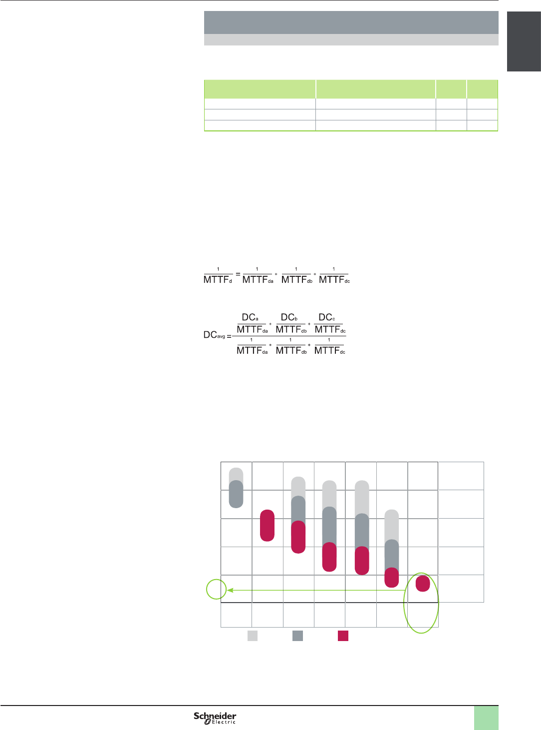
>Relationship between Categories, DC and MTTFd of each channel and the PL
MTTFd:low medium high
Cat. B Cat. 1 Cat. 2 Cat. 2 Cat. 3 Cat. 3 Cat. 4
DCavg =
0 (nil)
DCavg =
0 (nil)
DCavg =
low
DCavg =
medium
DCavg =
low
DCavg =
medium
DCavg =
high
Performance level PL
a
b
c
d
e
PFHD
u 10-6 … < 10-5
u 10-6 … < 10-5
u 10-7 … < 10-6
u 10-8 … < 10-7
>Using the above chart we can now select the most appropriate architecture, the required
Diagnostic coverage as well as ensure the products selected have the right MTTFd
values
>As we require PL= “c” the chart states as a minimum a category 1 architecture with a
Diagnostic coverage of 0 (Nil) and a MTTFd of High is required. It is possible to use
architectures with higher categories to solve the safety function needs
>We start with determining the architecture required to solve the function. We use the
following Category 1 architecture (see page 1/19)
>In our example, to reach the PL = e, the solution will therefore have to
correspond to category 4 with redundant circuit; the function scheme is shown
opposite with two channels in parallel
>a high diagnostic capability
>a high MTTFd
For our application, we could suggest a redundant relay scheme but it is nowadays
easier to use safety function blocks. The solution is illustrated below.
Application scheme of the example
Closed
Open
The process suggested by the standard is iterative and a few estimations are
therefore necessary in order to obtain the expected result. In view of the required
performance level, we have chosen a solution with redundant circuit.
Functional diagram of the example
Event:
door opening
Action: motor stop
Input 1 Processing 1 Output 1
Input 2 Processing 2 Output 2
Channel 1
Channel 2
Standard EN/ISO 13849-1
Standards to be applied according to
the design selected for the safety-
related machine control system
2
1
3
4
5
6
7
8
9
10
2
1
3
4
5
6
7
8
9
10
1/19
Presentation General presentation
Safety Legislation and Standards
Standard EN/ISO 13849-1
Machinery safety - Safety-related parts of control systems (continued)
Process (continued)
Stage 4 - Evaluate the performance level PL for each safety-related part
Based on the information in the supplier’s catalogue and Annex E of the standard,
we obtain the following values:
Example B10 (number of operations) / %
dangerous failure MTTFdDC
SRP/CSa: Safety limit switches 10.000.000 / 20% dangerous failure 7102 99%
SRP/CSb: XPS AK safety module - 154.5 99.99%
SRP/CSc: LCK contactor 1.000.000 / 73% dangerous failure 194 99%
For electromechanical products,
the MTTFd is calculated on the basis of the total number of operations that the
product can perform, using B10d values:
In our case, the machine operates for 220 days per year, 8 hours per day with a
cycle of 90 s.
N = 220 x 8 x (3600 / 90) = 70 400 operations/year
MTTFd = B10d / (0.1 x N) and B10d = B10 / % dangerous failure.
For the safety switches,
the MTTFd= (1 / 0.20 x 10 000 000) / (0.1) x 70 400 = 7102 years
For the contactors,
the MTTFd = (1 / 0.73 x 1 000 000) / (0.1) x 70 400 = 194 years
The MTTFd for each channel will then be calculated using the formula:
i.e. 85 years for each channel.
A similar formula is used to calculate the diagnostic capability
The result of the calculation in our example gives a value of 99%
Stage 5 - Checking that required performance level is achieved
The result of the above calculations is summarised below:
>a redundant architecture: category 4
>a mean time to failure > 30 years: high MTTFd
>a diagnostic capability of 99%: high DC
Looking at this table, we conrm that PL level e is achieved:
MTTFd:low medium high
Performance level PL
a
b
c
d
e
Cat. B Cat. 1 Cat. 2 Cat. 2 Cat. 3 Cat. 3 Cat. 4
DCavg =
0 (nil)
DCavg =
0 (nil)
DCavg =
low
DCavg =
medium
DCavg =
low
DCavg =
medium
DCavg =
high
PFHD
u 10-6 … < 10-5
u 10-6 … < 10-5
u 10-7 … < 10-6
u 10-8 … < 10-7
Checking the PL
Stage 6 - Validation of the required performance level
The design of SRP/CS must be validated and must show that the combination of
SRP/CS performing each safety function satises all the applicable requirements
of EN/ISO 13849.

2
1
3
4
5
6
7
8
9
10
2
1
3
4
5
6
7
8
9
10
1/20
Presentation General presentation
Safety Legislation and Standards
Standard EN/IEC 62061
Standards to be applied according to
the design selected for the safety-
related machine control system
Standard EN/IEC 62061
Machinery safety - Safety-Related Electrical Control systems (SRECS)
Functional Safety of safety-related electrical, electronic and electronic
programmable control systems
Field of application of the standard
Safety-related electrical control systems in machines (SRECS) are playing an
increasing role in ensuring the overall safety of machines and are more and more
frequently using complex electronic technology.
This standard is specic to the machine sector within the framework of EN/
IEC 61508. It gives rules for the integration of sub-systems designed in
accordance with EN/ISO 13849. It does not specify the operating requirements
of non-electrical control components in machines (for example: hydraulic,
pneumatic).
Functional approach to safety
As with EN/ISO 13849-1, the process using the EN/IEC 62061 starts with analysis of
the risks (EN/ISO 12100) in order to be able to determine the safety requirements.
A particular feature of this standard is that it prompts the user to make a
functional analysis of the architecture, then split it into sub-functions and
analyse their interactions before deciding on a hardware solution for them
(the SRECS).
>A functional safety plan must be drawn up and documented for each design
project. It must include:
>A specication of the safety requirements for the safety functions (SRCF) that
is in two parts:
>Description of the functions and interfaces, operating modes, function
priorities, frequency of operation, etc.
>Specication of the safety integrity requirements for each function, expressed
in terms of SIL (Safety Integrity Level)
>The structured and documented design process for electrical control systems
(SRECS)
>The procedures and resources for recording and maintaining appropriate
information
>The process for management and modication of the conguration, taking into
account organisation and authorised personnel
>The verication and validation plan
>Functional safety
The decisive advantage of this approach is that of being able to offer a failure
calculation method that incorporates all the parameters that can affect the
reliability of electrical systems, whatever the technology used.
The method consists of assigning a SIL to each function, taking into account the
following parameters:
>The probability of a dangerous failure of the components (PFHd)
>The type of architecture; with or without redundancy, with or without diagnostic
device making it possible to avoid some of the dangerous failures
>Common cause failures (power cuts, overvoltage, loss of communication
network, etc.) (CCF)
>The probability of a dangerous transmission error where digital
communication is used
>Electromagnetic interference (EMC)
2
1
3
4
5
6
7
8
9
10
2
1
3
4
5
6
7
8
9
10
1/21
Presentation General presentation
Safety Legislation and Standards
Standard EN/IEC 62061
Machinery safety - Safety-Related Electrical Control systems (SRECS) (continued)
Process
Designing a system is split into 5 stages after having drawn up the functional safety
plan:
1 - Based on the safety requirements specication (SRS), assign a safety level
(SIL) and identify the basic structure of the electrical control system (SRECS),
describe each related function (SRCF)
2 - Break down each function into a function block structure (FB)
3 - List the safety requirements for each function block and assign the function
blocks to the sub-systems within the architecture
4 - Select the components for each sub-system
5 - Design the diagnostic function and check that the specied safety level (SIL) is
achieved.
Stage 1 - Assign a safety integrity level (SIL) and identify the structure of the
SRECS
Based on the risk assessment performed in accordance with standard
EN/ISO 12100, estimation of the required SIL is performed for each hazardous
phenomenon and is broken down into parameters, see illustration opposite.
>Severity Se
The severity of injuries or damage to health can be estimated by taking into account
reversible injuries, irreversible injuries and death.
The classication is shown in the table below:
Consequence Severity Se
Irreversible: death, loss of an eye or an arm 4
Irreversible: shattered limb, loss of a nger 3
Reversible: requires the attention of a medical practitioner 2
Reversible: requires rst aid 1
>Probability of the harm occurring
Each of the three parameters Fr, Pr, Av must be estimated separately using the
most unfavourable case. It is strongly recommended that a task analysis model be
used in order to ensure that estimation of the probability of the harm occurring is
correctly taken into account.
>Frequency and duration of exposure Fr
The level of exposure is linked to the need to access the hazardous zone (normal
operation, maintenance, ...) and the type of access (manual feeding, adjustment,
...). It must then be possible to estimate the average frequency of exposure and its
duration.
The classication is shown in the table below:
Frequency of dangerous exposure Fr
y 1 hour 5
>1 hour... y 1 day 5
> 1 day... y 2 weeks 4
2 weeks... y 1 year 3
> 1 year 2
>Probability of occurrence of a hazardous event Pr.
Two basic concepts must be taken into account:
>the predictability of the dangerous components in the various parts of the
machine in its various operating modes (normal, maintenance,
troubleshooting), paying particular attention to unexpected restarting
>behaviour of the persons interacting with the machine, such as stress, fatigue,
inexperience, etc.
Probability of occurrence of a dangerous event Pr
Very high 5
Probable 4
Possible 3
Almost impossible 2
Negligible 1
Output
Stage 1: Basic structure of the electrical control system
SRECS: Safety-related control system
Sub-systems
Sub-system components
Input Processing
Risk
related to the
hazardous
phenomenon
identied
Probability of
the harm
occurring
Probability of
avoiding or
limiting the
harm Av
Probability of
an event
occurring
Pr
Frequency
and duration
of exposure
Fr
Severity
of the potential
harm
Se
2
1
3
4
5
6
7
8
9
10
2
1
3
4
5
6
7
8
9
10
1/22
Presentation General presentation
Safety Legislation and Standards
Standard EN/IEC 62061
Standards to be applied according to
the design selected for the safety-
related machine control system
Standard EN/IEC 62061
Machinery safety - Safety-Related Electrical Control systems (SRECS) (continued)
Process (continued)
Stage 1 -(continued)
>Probability of avoiding or limiting the harm Av
This parameter is linked to the design of the machine. It takes into account the
suddenness of the occurrence of the hazardous event, the nature of the dangerous
component (cutting, temperature, electrical) and the possibility for a person to
identify a hazardous phenomenon.
Probability of avoiding or limiting the harm Av
Impossible 5
Almost impossible 3
Probable 1
>Assignment of the SIL
Estimation is made with the help of the table below.
In our example, the degree of severity is 3 because there is a risk of a nger being
amputated; this value is shown in the rst column of the table.
All the other parameters must be added together in order to select one of the
classes (vertical columns in the table below), which gives us:
>Fr = 5 accessed several times a day
>Pr = 4 hazardous event probable
>Av = 3 probability of avoiding almost impossible
Therefore a class CI = 5 + 4 + 3 = 12
A level of SIL 2 must be achieved by the safety-related electrical control system(s)
(SRECS) on the machine.
Estimation of the SIL
Se Class CI
3-4 5-7 8-10 11-13 14-15
4SIL 2 SIL 2 SIL 2 SIL 3 SIL 3
3- - SIL 1 SIL 2 SIL 3
2- - - SIL 1 SIL 2
1- - - - SIL 1
>Basic structure of the SRECS
Without going into detail about the hardware components to be used, the system is
broken down into sub-systems. In our case, we nd the 3 sub-systems that will
perform the input, processing and output functions. The gure opposite illustrates
this stage, using the terminology given in the standard.
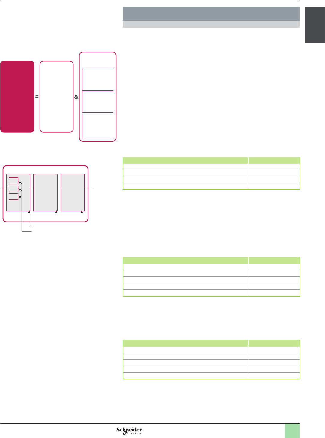
Stage 2 - Break down each function into a function block structure (FB)
A function block (FB) is the result of a detailed break down of a safety-related
function.
The function block structure gives an initial concept of the SRECS architecture.
The safety requirements of each block are deduced from the specication of the
safety requirements of the system’s function.
Stage 3 - List the safety requirements for each function block and assign the
function blocks to the sub-systems within the architecture
Each function block is assigned to a sub-system in the SRECS architecture. A
failure of any sub-system will lead to the failure of the safety-related control
function. More than one function block may be assigned to each sub-system. Each
sub-system may include sub-system elements and, if necessary, diagnostic
functions in order to ensure that anomalies can be detected and the appropriate
action taken.
These diagnostic functions (D) are considered as separate functions; they may be
performed within the sub-system, by another internal or external sub-system.
Stage 2: Break down into function blocks
SRECS
Objective SIL 2
Input Processing Output
Guard
detection
Logic Motor
control
Function
block
FB1
Function
block
FB2
Function
block
FB3
Stage 3: Assignment of function blocks
SRECS
Sub-system
1
Guard
detection
Contactor 1
Sub-system
2
Sub-system
3
Logic Motor
control
Contactor 2
Safety limit
switch 1
Safety limit
switch 2
Sub-system components
2
1
3
4
5
6
7
8
9
10
2
1
3
4
5
6
7
8
9
10
1/23
Presentation General presentation
Safety Legislation and Standards
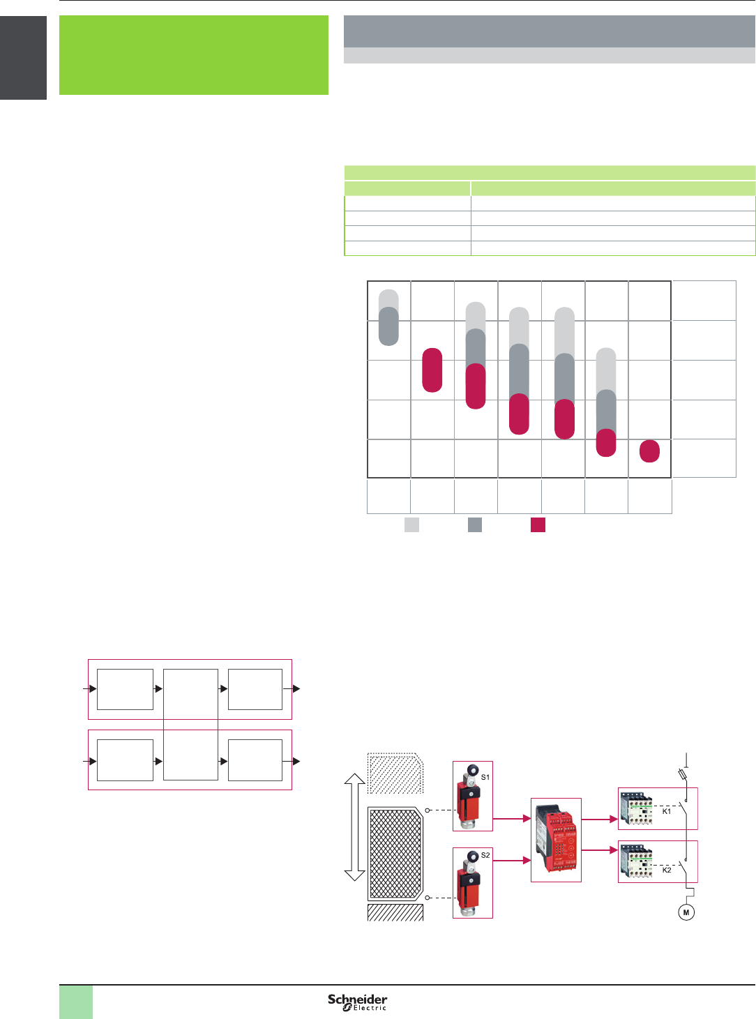
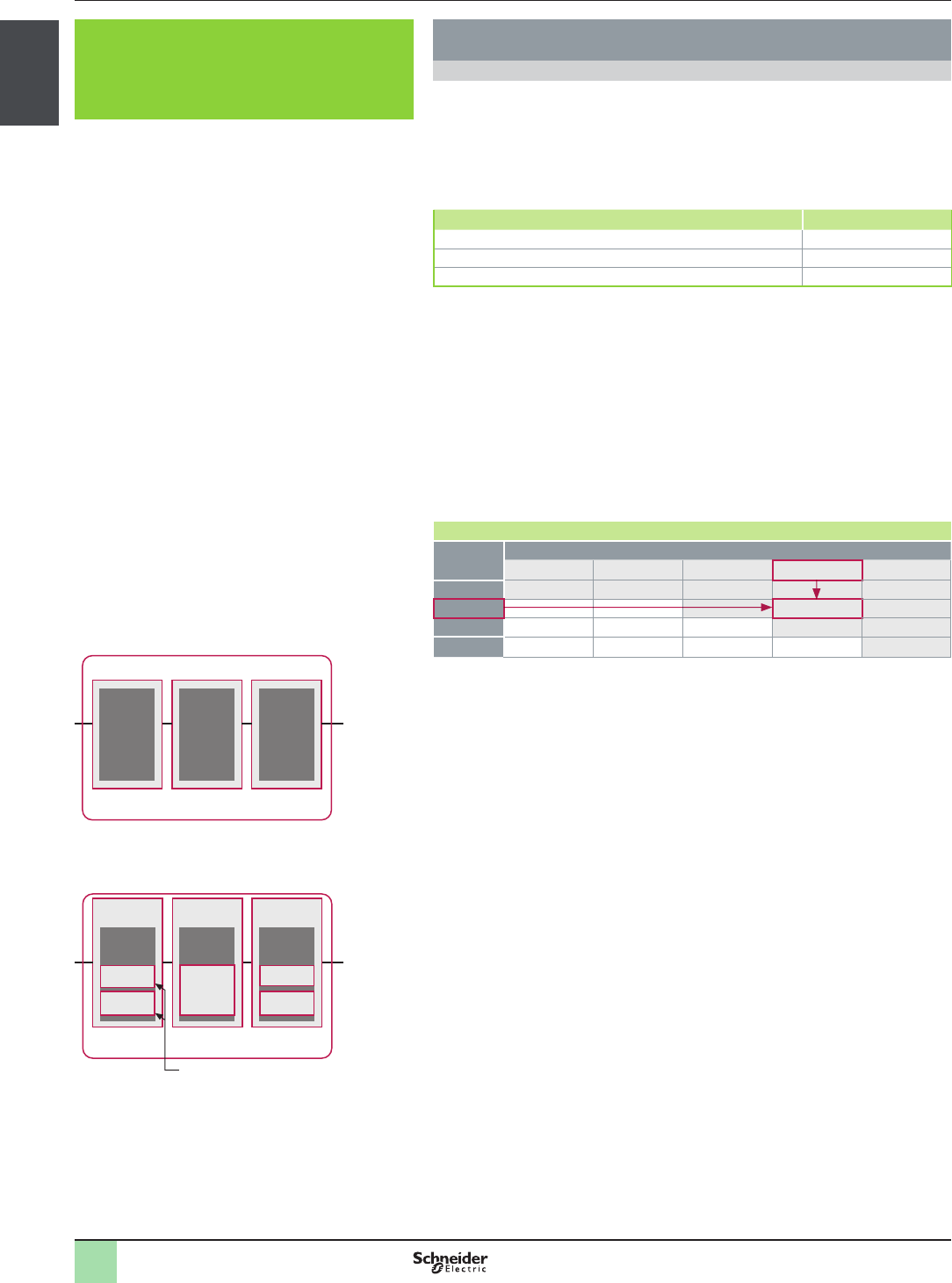
Stage 4: Component selection
Detection
SS1
Sub-system 1
Logic
SS2
Sub-system 2
Motor
control
SS3
Sub-system 3
SS1.1
SS1.2
SS3.1
SS3.2
Types of sub-system architecture
Sub-system type A
Sub-system type B
Sub-system type C
Sub-system type D
Sub-system
element 1
Sub-system
element n
Sub-system
element 1
Sub-system
element 2
Common cause
failure
Sub-system
element 1
Sub-system
element n
Diagnostic function(s)
Sub-system
element 1
Sub-system
element 2
Diagnostic function(s) Common cause
failure
Standard EN/IEC 62061
Machinery safety - Safety-Related Electrical Control systems (SRECS) (continued)
Process (continued)
Stage 4 - Select the components for each sub-system
The products shown in the illustration opposite are selected. If the sensors and
contactors are the same as in the previous example, a safety module XPS AK will
be chosen. In this example, we take a cycle of 450s which means the duty cycle C
is 8 operations per hour.
As the safety integrity level required for the entire system is SIL 2, each of the
components must achieve this level.
The manufacturer’s catalogue gives the following values:
Safety limit switches 1 and 2: B10 = 10 000 000 operations, the proportion of
dangerous failures is 20%, lifetime is 10 years.
>Safety module: PFHd = 7.389 10-9
>Contactors 1 and 2: B10 = 1 000 000 operations, the proportion of dangerous
failures = 73%, lifetime is 20 years
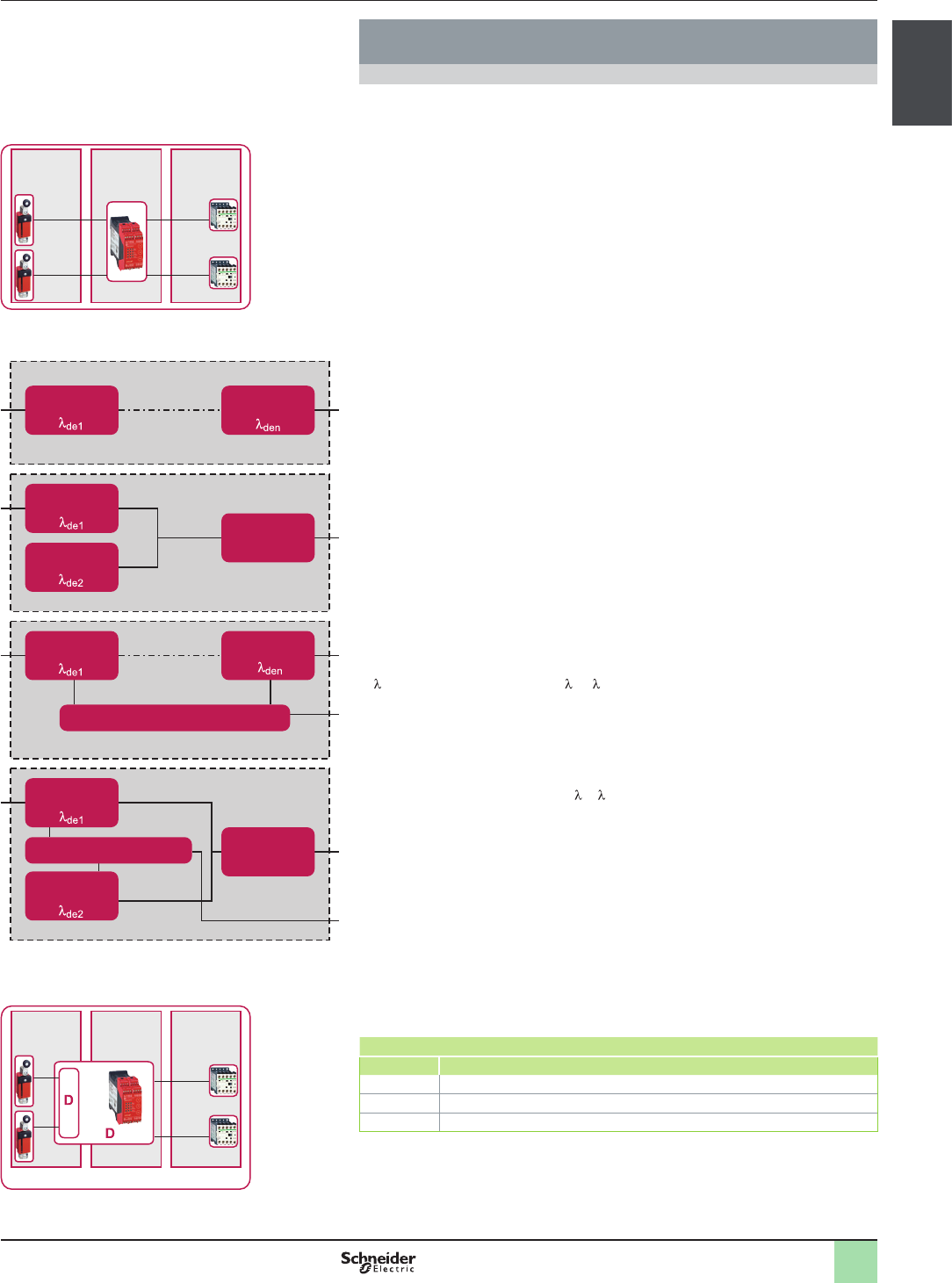
Stage 5 - Design the diagnostic function
The SIL of the sub-system depends not only on the components, but also on the
architecture selected. For our example, we will choose architectures B and D of the
standard.
In our architecture, the safety module performs diagnostics not only on itself, but
also on the safety limit switches.
We have three sub-systems for which the safety levels must be determined:
>SS1: two redundant safety limit switches in a sub-system with a type D
architecture
>SS2: a SIL 3 safety module (obtained on the basis of the PFH provided by the
manufacturer)
>SS3: two redundant contactors built in accordance with a type B architecture
The calculation method can be found in the machine safety guide, so we will only
give the nal result. This method takes into account the following parameters:
>B10: number of operations at which 10% of the population fail
>C: Duty cycle (number of operations per hour)
>D: rate of dangerous failures ( D = x portion of dangerous failures in %)
>β: common cause failure coefcient, which is 10 % here and 10% is the worst
case: see Annex F
>T1: Proof Test Interval or life time whichever is smaller, as provided by the
supplier
>T2: diagnostic test interval
>DC: Diagnostic coverage rate = DD/D, ratio between the rate of detected
failures and the rate of dangerous failures
We obtain:
>for SS1 PFHd = 1.6 E-9
>for SS3 PFHd = 1.06 E-7
The total probability of dangerous failures per hour is:
>PFHDSRECS = PFHDSS1+ PFHDSS2 + PFHDSS3
>PFHDSRECS = 1.6 10-9 + 7,38 10-9 + 1.06 E-7 = 1.15 E-7
Which corresponds to the expected result (table below) of a SIL = 2 .
Comment: A level of SIL 3 could have been achieved by using mirror contacts to
create a feedback loop on the contactors, i.e. a sub-system architecture type D.
Checking the required SIL
SIL Probability of dangerous failures per hour (PFHd)
3u 10-8 ... < 10-7
2u 10-7 ... < 10-6
1u 10-6 ... < 10-5
Stage 5: Design of the diagnostic function
Detection
SS1
Sub-system 1
Logic
SS2
Sub-system 2
SS
1.1
SS
1.2
SS3.1
SS3.2
Architecture DArchitecture B
Motor
control
SS3
Sub-system 3

Chapter 2
Safety chain
solution
bAll technical information about products listed in this catalog
are available on: www.schneider-electric.com

2
1
3
4
5
6
7
8
9
10
2/1
Contents Safety chain solutions
Safety functions
bSafety chain solutions
vSelection guide .......................................................................................page 2/2
vFunctions ................................................................................................page 2/3
bSafety functions with detailed description
vEmergency stop
>Explanation of function ..................................................................page 2/26
>Typical architecture ........................................................................page 2/26
vGuard monitoring
>Explanation of function ..................................................................page 2/27
>Typical architecture ........................................................................page 2/28
vPerimeter guarding
>Explanation of function ..................................................................page 2/29
>Typical architecture ........................................................................page 2/29
vEnabling movement
>Explanation of function ..................................................................page 2/30
>Typical architecture ........................................................................page 2/30
vSpeed monitoring
>Explanation of function ..................................................................page 2/31
>Typical architecture ........................................................................page 2/32
vPosition monitoring
>Explanation of function ..................................................................page 2/33
>Typical architecture ........................................................................page 2/33
2
1
3
4
5
6
7
8
9
10
2
1
3
4
5
6
7
8
9
10
2/2
Selection guide Safety chain solutions
Emergency Stop with Embedded Safety Module Emergency Stop Pushbutton / Contactor Cat.3 PL d, SIL 2 / Stop Category 0
see page 2/3
Emergency Stop Pushbutton / Contactor Cat.4 PL e, SIL 3 / Stop Category 0
see page 2/4
with Embedded Safety PLC Emergency Stop Push Button / PacDrive 3 Drive Cat.4 PL e, SIL 3 / Stop Category 0
see page 2/5
Guard Monitoring with Safety Module Limit switch / Contactor Cat.3 PL d, SIL 2 / Stop Category 0
see page 2/6
Coded Magnetic Switch / Variable Speed Drive Cat.4 PL e, SIL 3 / Stop Category 1
see page 2/7
Guard switch with lock / Variable Speed Drive Cat.3 PL d, SIL 2 / Stop Category 1
see page 2/8
Coded Magnetic Switch / Servo Drive Cat.3 PL d, SIL 2 / Stop Category 1
see page 2/9
Guard switch with lock / Contactor Cat.4 PL e, SIL 3 / Stop Category 0
see page 2/10
Coded Magnetic Switch / Contactor Cat.4 PL e, SIL 3 / Stop Category 0
see page 2/11
with Embedded Safety Module Guard switch with lock / Contactor Cat.4 PL e, SIL 3 / Stop Category 0
see page 2/12
with Safety Controller Limit Switch / Contactor Cat.4 PL e, SIL 3 / Stop Category 0
see page 2/13
with Embedded Safety PLC Guard Switch with lock/ PacDrive 3 Drive Cat.4 PL e, SIL 3 / Stop Category 1
see page 2/14
with Embedded Safety Servo Drive Coded Magnetic Switch / Embedded Safety Servo
Drive
Cat.4 PL e, SIL 3 / Stop Category 2
see page 2/15
with Well Tried Components Limit Switch / Motor Starter Cat.3 PL c, SIL 1 / Stop Category 0
see page 2/16
Enabling movement with Safety Controller Two Hand Control Station / Contactor Cat.4 PL e, SIL 3 / Stop Category 0
see page 2/17
Speed Monitoring with Safety Module Remanent Voltage detection and limit switch and
Guard switch with lock / Contactor
Cat.4 PL e, SIL 3 / Stop Category 0
see page 2/18
with Embedded Safety PLC Selector Switch / PacDrive 3 Drive Cat.4 PL e, SIL 3 / Safe Limited
Speed
see page 2/19
Position Monitoring with Embedded Safety PLC Limit Switch / PacDrive 3 Drive Cat.4 PL e, SIL 3 / Stop Category 2
see page 2/20
Perimeter Guarding with Safety Module Safety Mat / Contactor Cat.3 PL d, SIL 2 / Stop Category 0
see page 2/21
Single Beam Light curtains / Contactor Cat.3 PL c, SIL 1 / Stop Category 0
see page 2/22
with Embedded Safety Module Light curtain / Contactor Cat.4 PL e, SIL 3 / Stop Category 0
see page 2/23
Light curtain / Variable Speed Drive Cat.3 PL d, SIL 2 / Stop Category 1
see page 2/24
Function Processing device Input / Output Cat. PL, SIL / Stop Cat.
see page
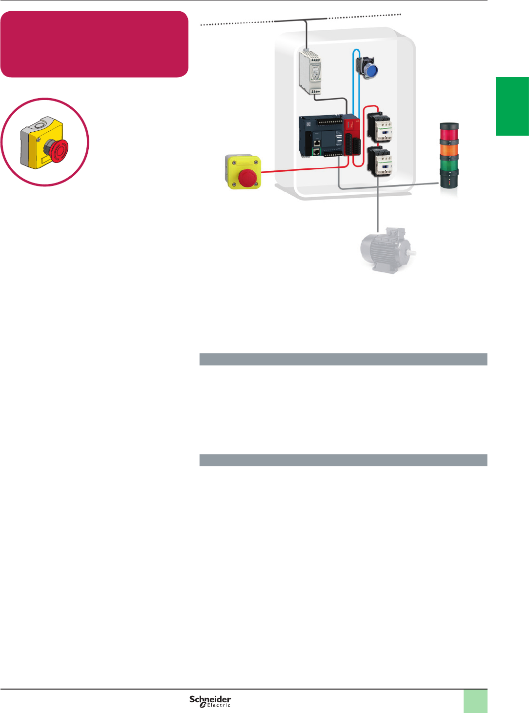
2
1
3
4
5
6
7
8
9
10
2
1
3
4
5
6
7
8
9
10
2/3
Emergency Stop with Embedded Safety
Module
Emergency Stop Pushbutton / Contactor
Cat.3 PL d, SIL 2 / Stop Category 0
Related Products
vSwitches, pushbuttons, emergency stop - Harmony XB4
vSwitch mode Power supply - Phaseo ABL8
vSafety Module - Modicon TM3SAC5R(G)
vSafety switches - Preventa XCS
vContactor - TeSys D
vModular beacon and tower light - Harmony XVB
Function
Safety-related stop function initiated by Emergency stop push button to minimize
the consequences of possibly harmfull event.
The pushing of emergency stop push button is detected from opening contacts,
which are checked by the safety module.
Opening these contacts causes the deactivation of the safety module outputs (stop
category 0 according to EN/IEC 60204-1), which results in a switch-off of the motor
power supply to minimize hazard in case of emergency by means of the contactors
(K1 and K2).
Typical applications
>Machine-tools or similar machines with low inertia (no rundown time), where the
access to the hazardous area is limited to maintenance interventions
Function Safety chain solutions
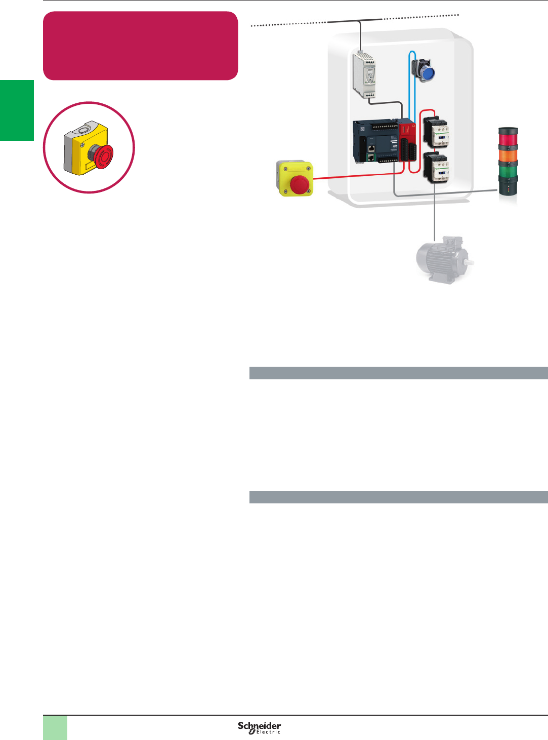
2
1
3
4
5
6
7
8
9
10
2
1
3
4
5
6
7
8
9
10
2/4
Emergency Stop with Embedded Safety
Module
Emergency Stop Pushbutton / Contactor
Cat.4 PL e, SIL 3 / Stop Category 0
Related Products
vSwitches, pushbuttons, emergency stop - Harmony XB4
vSwitch mode Power supply - Phaseo ABL8
vSafety Module - Modicon TM3SAF5R(G)
vSafety switches - Preventa XCS
vContactor - TeSys D
vModular beacon and tower light - Harmony XVB
Function
Safety-related stop function initiated by Emergency stop push button to minimize
the consequences of possibly harmfull event.
The pushing of emergency stop push button is detected from opening contacts,
which are checked by the safety module.
Opening these contacts causes the deactivation of the safety module outputs (stop
category 0 according to EN/IEC 60204-1), which results in a switch-off of the motor
power supply to minimize hazard in case of emergency by means of the contactors
(K1 and K2).
The main contactors are monitored by the safety module to detect e.g. contact
welding, by means of their mirror contacts.
Typical applications
>Machine-tools or similar machines with low inertia (no rundown time), where the
access to the hazardous area is limited to maintenance interventions
Function Safety chain solutions
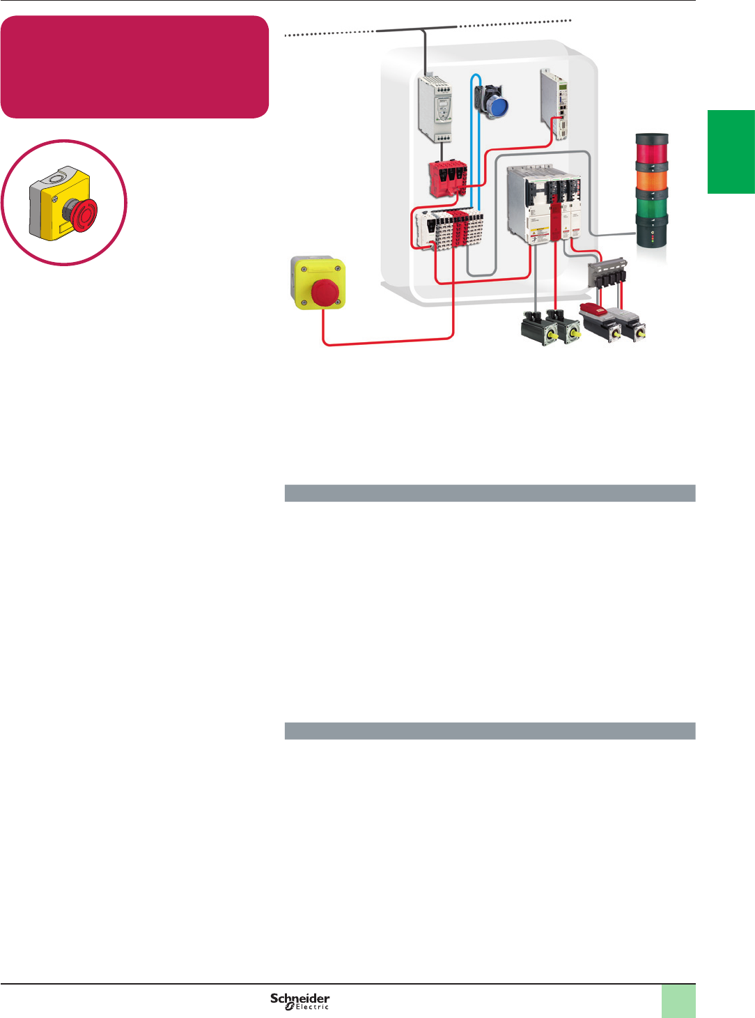
2
1
3
4
5
6
7
8
9
10
2
1
3
4
5
6
7
8
9
10
2/5
Emergency Stop with Embedded Safety
PLC
Emergency Stop Push Button / PacDrive 3
Drive
Cat.4 PL e, SIL 3 / Stop Category 0
Related Products
vSwitches, pushbuttons, emergency stop - Harmony XB4
vSwitch mode Power supply - Phaseo ABL8
vPreventa Safety PLC TM5SLCpp (TM5SPS, SDIO, BC)
vSafety switches - Preventa XCS
vPacDrive 3
vHarmony XVB
Function
Safety-related stop function initiated by any stop or emergency stop command to
halt the machine and to unlock the moveable guard that prevents the access to the
hazardous area before the machine comes to a standstill.
Emergency stop command is detected by using an emergency stop push button in
positive actuation mode, which are then checked by the safety PLC allowing
detection of the opening contacts.
Actuation of the emergency stop or stop contacts initiates the functional stopping of
the machine by cutting-off torque from the motor. As electric motors run down, a
remanent voltage is produced in the windings of the motor due to residual
magnetism. This voltage is measured so as to detect the stopped condition of the
motor, providing the unlock signal for the electrically locked movable guard and for
engaging brakes after the motor has come to a standstill.
The continuity of the wiring between the motor windings and the inputs of the safety
modules are also monitored to prevent a cable breakage or fault being seen as a
stopped motor.
Typical applications
>Machine tools, robots, production test equipment, test benches
>Papermaking machines, textile production machines, calendars in the rubber
industry
>Process lines in plastics, chemicals or metal production, rolling-mills
>Cement crushing machines, cement kilns, mixers, centrifuges, extrusion
machines
>Drilling machines
>Conveyors, materials handling machines, hoisting equipment (cranes, gantries,
etc.)
>Pumps, fans, etc.
Function Safety chain solutions
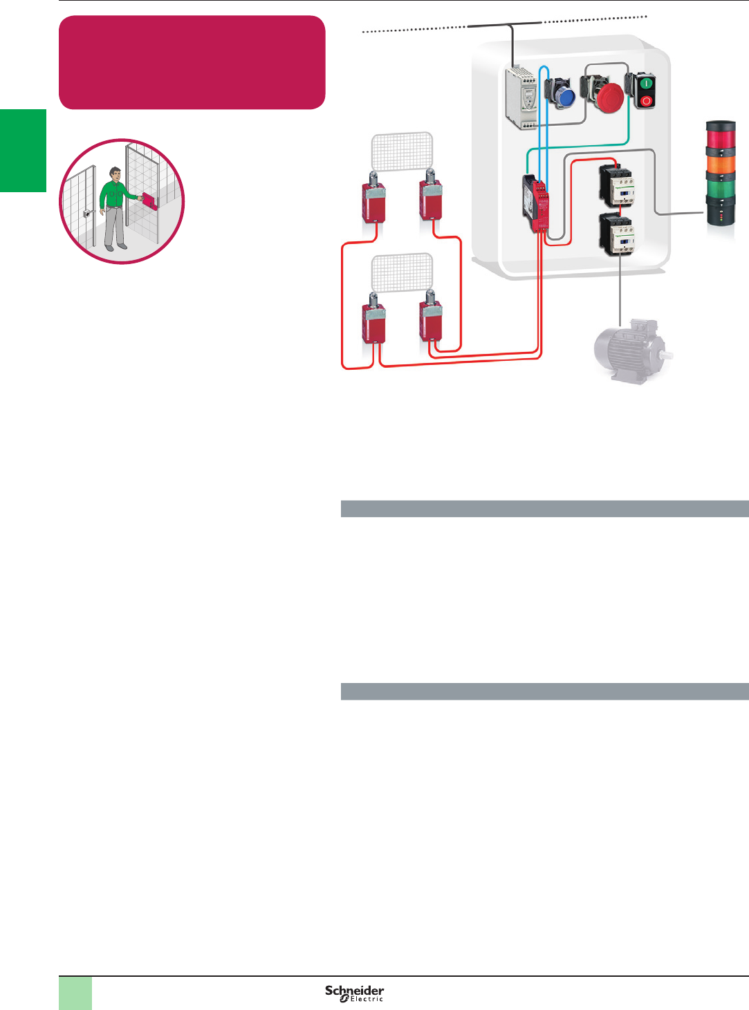
2
1
3
4
5
6
7
8
9
10
2
1
3
4
5
6
7
8
9
10
2/6
Function Safety chain solutions
Guard Monitoring with Safety Module
Limit switch / Contactor
Cat.3 PL d, SIL 2 / Stop Category 0
Related Products
vSwitches, pushbuttons, emergency stop - Harmony XB4
vSwitch mode Power supply - Phaseo ABL8
vSafety Module - Preventa XPSAC
vSafety switches - Preventa XCS
vContactor - TeSys D
vModular beacon and tower light - Harmony XVB
Function
Safety-related stop function initiated by the moveable guards designed to help
protecting from the the access to a hazardous zone. The opening of each guard is
detected by using two limit switches in combination mode (positive mode +
negative mode), which are checked by the safety module allowing detection of the
opening or the removal of the protective guard.
Opening of any of these guards causes the deactivation of the safety module
outputs (stop category 0 according to EN/IEC 60204-1), which results in a
switch-off of the motor power supply to prevent possible hazardous movements or
states by means of the contactors (K1 and K2).
The main contactors are monitored by the safety module to detect e.g. contact
welding, by means of their mirror contacts.
Typical applications
>Assembling, textile, printing or similar machines where the access to the
hazardous area is limited to maintenance interventions
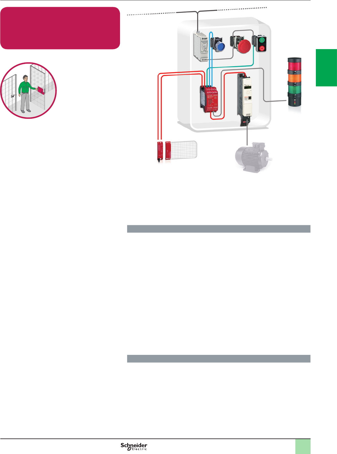
2
1
3
4
5
6
7
8
9
10
2
1
3
4
5
6
7
8
9
10
2/7
Guard Monitoring with Safety Module
Coded Magnetic Switch -
Variable Speed Drive
Cat.4 PL e, SIL 3 / Stop Category 1
Function Safety chain solutions
Related Products
vSwitches, pushbuttons, emergency stop - Harmony XB4
vSafety Module - Preventa XPSAV
vCoded magnetic switches - Preventa XCSDM
vVariable speed drive - Altivar 32
vModular beacon and tower lights -Harmony XVB
vSwitch mode Power supply - Phaseo ABL8
Function
Safety-related stop function initiated by a moveable guard that helps protecting
from the access to the hazardous area.
Controlled stopping with power maintained to the actuator (drive) to achieve
stopping (i.e. braking), then cut-off of power when standstill is reached (Safe Stop 1).
The hazardous movement is interrupted either if the stop button (S2) or the
emergency stop device (S3) is actuated.
Opening of this guard is detected by a magnetic switch, which initiates the
functional stopping of the drive, i.e. by a braking ramp (stop category 1 in
accordance with EN/IEC 60204-1).
After the delay time monitored by the safety module has elapsed, the safety
delayed outputs are deactivated. The drive is then halted, by the “safe torque off”
(STO) safety function integrated within it, which prevents the motor from restarting
unintentionally.
The switching of the STO and LI3 input is monitored by the drive. The power stage
is disabled if the time offset is exceeded. The motor can no longer generate torque
and coasts down without braking.
The safety module also monitors the consistent actuation of the redundant coded
magnetic switch contacts to detect possible failure, before restart of the machine
movement is permitted.
Typical applications
>Machines that use drives in their movements due to high speed and precision
needed (i.e. textile, wood-working or simple packaging machines), when the
delayed initiation of the stopping in the event of a fault must not involve an
unacceptably high residual risk
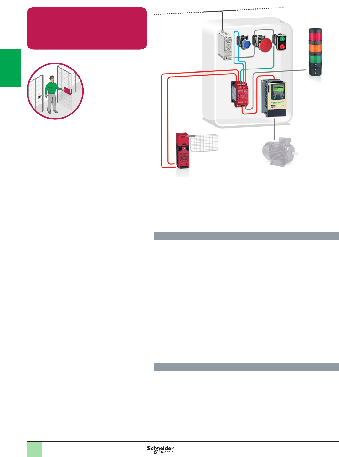
2
1
3
4
5
6
7
8
9
10
2
1
3
4
5
6
7
8
9
10
2/8
Guard Monitoring with Safety Module
Guard switch with lock / Variable Speed
Drive
Cat.3 PL d, SIL 2 / Stop Category 1
Related Products
vSwitches, pushbuttons, emergency stop - Harmony XB4
vEmergency stop function - Harmony XALK
vSwitch mode Power supply - Phaseo ABL8
vSafety Guard switches - Preventa XCSB, XCS
vSafety module - Preventa XPSATE
vVariable speed drive - Altivar 71
vModular beacon and tower lights - Harmony XVB
Function
Safety-related stop function initiated by a moveable guard that helps protecting
from the access to the hazardous area.
Controlled stopping with power maintained to the actuator (drive) to achieve
stopping (i.e. braking), then cut-off of power when standstill is reached (Safe Stop 1).
The hazardous movement is interrupted either if the stop button (S2) or the
emergency stop device (S3) is actuated. (*)
Opening of this guard is detected by a safety guard switch, which initiates the
functional stopping of the drive, i.e. by a braking ramp (stop category 1 in
accordance with EN/IEC 60204-1).
After the delay time monitored by the safety module has elapsed, the safety
delayed outputs are deactivated. The drive is then halted, by the “safe torque off”
(STO) safety function integrated within it, which prevents the motor from restarting
unintentionally.
The safety module also monitors the consistent actuation of the redundant guard
switch contacts to detect possible failure, before restart of the machine movement
is permitted.
(*) The function for stopping in an emergency is a protective measure which
complements the safety functions for the safeguarding of hazardous zones
according to EN/ISO 12100-2.
Typical applications
>Machines that use drives in their movements due to high speed and precision
needed (i.e. stacker-cranes used on automatic storage and retrieval systems),
when the delayed initiation of the stopping in the event of a fault must not involve
an unacceptably high residual risk
Function Safety chain solutions
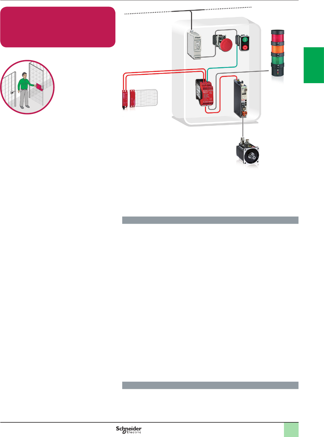
2
1
3
4
5
6
7
8
9
10
2
1
3
4
5
6
7
8
9
10
2/9
Guard Monitoring with Safety Module
Coded Magnetic Switch / Servo Drive
Cat.3 PL d, SIL 2 / Stop Category 1
Related Products
vSwitches, pushbuttons, emergency stop - Harmony XB4
vSwitch mode Power supply - Phaseo ABL8
vCoded magnetic system - Preventa XCSDM
vSafety Module - Preventa XPSAV
vServo Drive - Lexium 32
vModular beacon and tower lights - Harmony XVB
Function
Safety-related stop function initiated by any of the moveable guards that helps
protecting from the access to the hazardous area.
Controlled stop with power available to the actuators (servo-drive) to achieve the
stop (i.e. by controlled braking). Power is not interrupted until the stop is achieved
(Safe Stop 1).
After activating the function, the servo motor is braked in a controlled manner,
maintaining the power on the actuators. The power is then cut after the machine
has come to a halt.
Opening of a guard is detected by a coded magnetic switch system that activates
via the safety module the “Halt” function on the servo-drive; any active movement
is decelerated via the adjusted ramp.
After the delay time monitored by the safety module has elapsed, the safety
delayed outputs (stop category 1 in accordance with EN/IEC 60204-1) are
deactivated. The servo-drive power stage is then disabled, via the “safe torque off”
(STO) safety function integrated within it, which prevents the servo-motor from
restarting unintentionally.
The switching of the two redundant STO inputs is monitored by the servo-drive.
The power stage is disabled and an error message is generated if the time offset (<
1 sec) is exceeded. The servo-motor can no longer generate torque and coasts
down without braking.
The safety module also monitors the consistent actuation of the magnetic switch
contacts to detect possible failure, before restart of the machine movement is
permitted.
Opening or removal of the protective guard is detected by means of the coded
magnetic switch system, which are particularly usable for guards without accurate
guidance and for use in difcult environments (dust, liquids, etc.).
Typical applications
>Packaging, printing, or similar machines that use servo-drives in their
movements due to high speed and precision needed, on which non-braking
stopping would result in a impermissibly long run-down of the hazardous tool
movements
Function Safety chain solutions
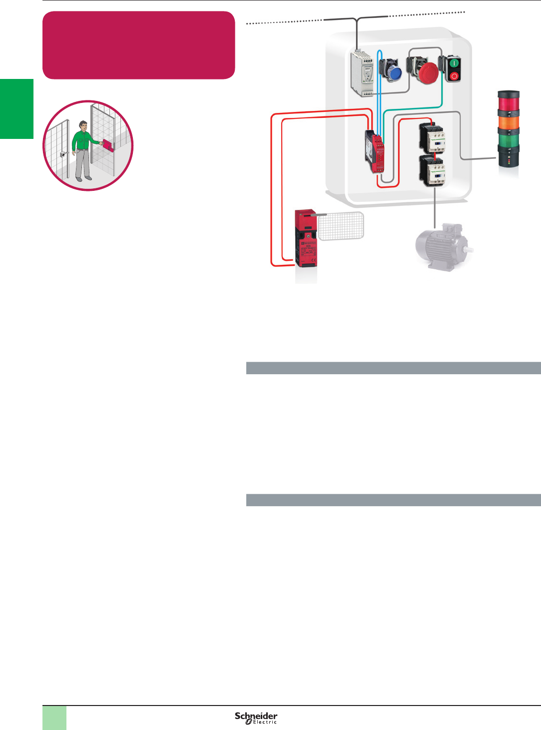
2
1
3
4
5
6
7
8
9
10
2
1
3
4
5
6
7
8
9
10
2/10
Guard Monitoring with Safety Module
Guard switch with lock / Contactor
Cat.4 PL e, SIL 3 / Stop Category 0
Related Products
vSwitches, pushbuttons, emergency stop - Harmony XB4
vSwitch mode Power supply - Phaseo ABL8
vSafety Module - Preventa XPSAF
vSafety Guard switches - Preventa XCSB, XCS
vContactor - TeSys D
vModular beacon and tower light - Harmony XVB
Function
Safety-related stop function initiated by a moveable guard designed to help
protecting from the access to a hazardous zone.
The opening of this guard is detected by using a guard switch, which is checked by
the safety module allowing detection of the opening or the removal of the protective
guard according to EN1088.
Opening of this guard causes the deactivation of the safety module outputs (stop
category 0 according to EN/IEC 60204-1), which results in a switch-off of the motor
power supply to prevent possible hazardous movements or states by means of the
contactors (K1 and K2).
The main contactors are monitored by the safety module to detect e.g. contact
welding, by means of their mirror contacts.
Typical applications
>Assembling, machining centers or similar machines tools, where the access to
the hazardous area is frequent or with long exposure time
Function Safety chain solutions
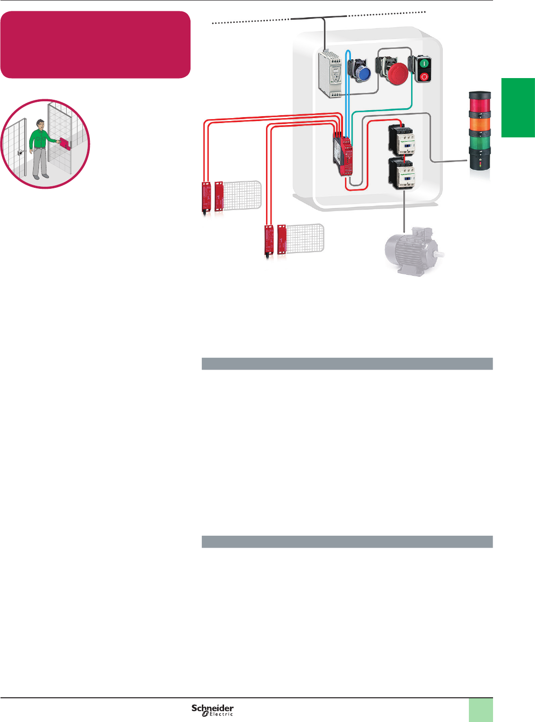
2
1
3
4
5
6
7
8
9
10
2
1
3
4
5
6
7
8
9
10
2/11
Guard Monitoring with Safety Module
Coded Magnetic Switch / Contactor
Cat.4 PL e, SIL 3 / Stop Category 0
Related Products
vSwitches, pushbuttons, emergency stop - Harmony XB4
vSwitch mode Power supply - Phaseo ABL8
vSafety Module - Preventa XPSDM
vCoded magnetic system - Preventa XCSDM
vContactor - TeSys D
vModular beacon and tower light - Harmony XVB
Function
Safety-related stop function initiated by any of the moveable guards that helps
protecting from the access to the hazardous area.
The opening of each guard is detected by using magnetic switches, which are
checked by the safety module by means of a combination of contacts (normally
closed and normally open).
Opening of any of these guards causes the deactivation of the safety module
outputs, which results in the switching-off of the motor power supply by means of
the contactors K1 and K2 (stop category 0 according to EN/IEC 60204-1) to help
prevent possible hazardous movements or states.
The main contactors are monitored by the safety module to detect contact welding
by means of the mirror contacts.
The safety module also monitors the consistent actuation of the magnetic switch
contacts to detect any failure, before restart of the machine movement is permitted.
Opening or removal of the protective guard is detected by means of the coded
magnetic switches, which are particularly useful for guards without accurate
guidance and for use in difcult environments (dust, liquids, etc.).
Typical applications
>Assembling, packaging or similar compacted machines with a short rundown
time and where the access to the hazardous area is very frequent
Function Safety chain solutions
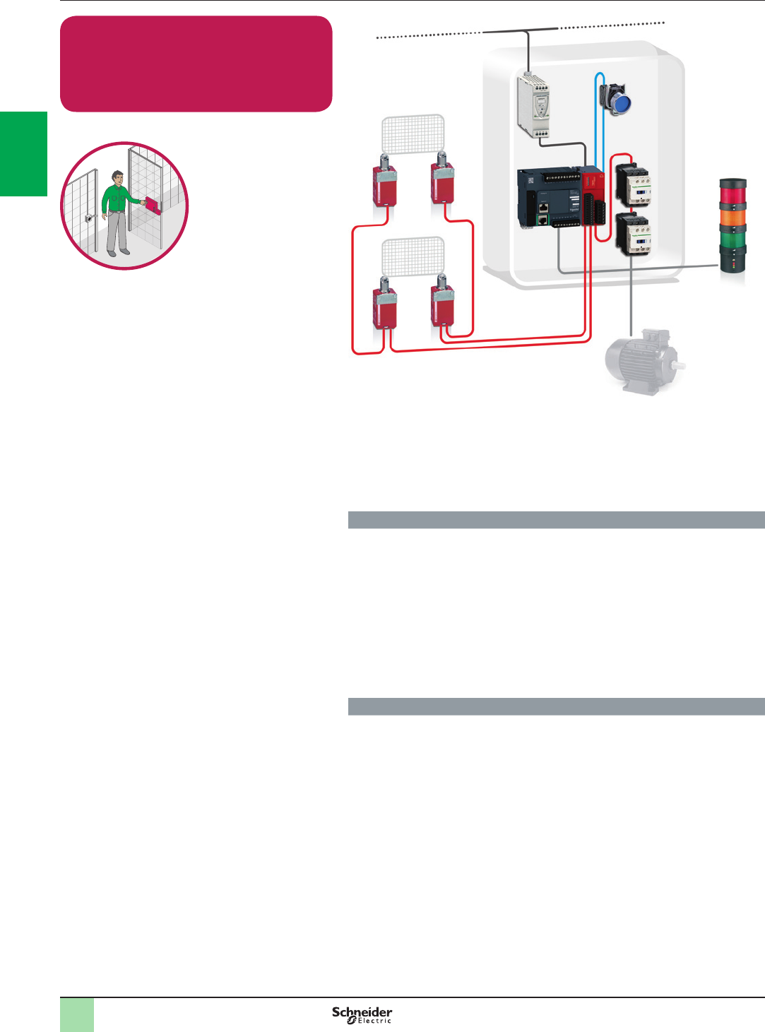
2
1
3
4
5
6
7
8
9
10
2
1
3
4
5
6
7
8
9
10
2/12
Guard Monitoring with Embedded Safety
Module
Guard switch with lock / Contactor
Cat.4 PL e, SIL 3 / Stop Category 0
Related Products
vSwitches, pushbuttons, emergency stop - Harmony XB4
vSwitch mode Power supply - Phaseo ABL8
vSafety Module - Modicon TM3SAF5R(G)
vSafety switches - Preventa XCS
vContactor - TeSys D
vModular beacon and tower light - Harmony XVB
Function
Safety-related stop function initiated by a moveable guard designed to help
protecting from the access to a hazardous zone.
The opening of this guard is detected by using a guard switch, which is checked by
the safety module allowing detection of the opening or the removal of the protective
guard according to EN1088.
Opening of this guard causes the deactivation of the safety module outputs (stop
category 0 according to EN/IEC 60204-1), which results in a switch-off of the motor
power supply to prevent possible hazardous movements or states by means of the
contactors (K1 and K2).
The main contactors are monitored by the safety module to detect e.g. contact
welding, by means of their mirror contacts.
Typical applications
>Assembling, machining centers or similar machines tools, where the access to
the hazardous area is frequent or with long exposure time
Function Safety chain solutions
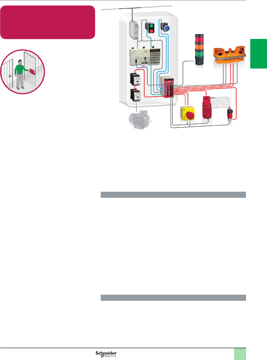
2
1
3
4
5
6
7
8
9
10
2
1
3
4
5
6
7
8
9
10
2/13
Guard Monitoring with Safety Controller
Limit Switch / Contactor
Cat.4 PL e, SIL 3 / Stop Category 0
Related Products
vSwitches, pushbuttons - Harmony XB4
vEmergency stop control station - Harmony XALK
vTwo-Hand control station - Preventa XY2 SB
vSwitch mode Power supply - Phaseo ABL8
vLogic controller - Modicon M258
vGuard interlock switch and safety
vswiitches - Preventa XCS
vSafety Controller - Preventa XPS MC
vContactor - TeSys D
vModular beacon and tower light - Harmony XVB
Function
Safety-related stop function initiated by a moveable guard that helps protecting
from the access to a hazardous zone.
The guard opening is detected by using a solenoid locked switch in combination
with a limit switch in positive operating mode, which are checked by the safety
module allowing detection of the opening or removal of the protective guard.
Opening of the moveable guard causes the deactivation of the safety module
outputs which results in switching-off the motor power supply by means of the
contactors K1 and K2 to help prevent possible hazardous movements (stop
category 0 according to EN/IEC 60204-1).
The motor can be also de-energized when the emergency stop device (S1) is
actuated.(*)
The main contactors are monitored by the safety controller to detect for example
contact welding, by means of the mirror contacts.
The safety controller also monitors the consistent actuation of the limit switch
contacts to detect failure, before restart of the machine movement is permitted.(*)
(*) The function for stopping in an emergency is a protective measure which
complements the safety functions for the safeguarding of hazardous zones
according to EN/ISO 12100-2.
Typical applications
>Plastic injection, eccentric press or similar complex machines with 4 or more
safety functions included, where a centralized safety controller would be
required
Function Safety chain solutions

2
1
3
4
5
6
7
8
9
10
2
1
3
4
5
6
7
8
9
10
2/14
Guard Monitoring with Embedded Safety
PLC
Guard Switch with lock/ PacDrive 3 Drive
Cat.4 PL e, SIL 3 / Stop Category 1
Related Products
vSwitches, pushbuttons, emergency stop - Harmony XB4
vSwitch mode Power supply - Phaseo ABL8
vPreventa Safety PLC TM5SLCpp (TM5 Slices > SPS, SDIO, BC)
vSafety switches - Preventa XCS
vPacDrive 3
vHarmony XVB
Function
Safety-related stop function initiated by a moveable guard that helps preventing
access to the hazardous area.
Controlled stopping with power maintained to the actuator (drive) to achieve
stopping (i.e. braking), then cut-off of power when standstill is reached (Safe Stop 1).
The hazardous movement is interrupted either if the stop button or the emergency
stop device is actuated. Opening of this guard is detected by limit switches, which
initiates the functional stopping of the drive, i.e. by a braking ramp (stop category 1
in accordance with EN/IEC 60204-1).
After the delay time monitored by the drive has elapsed, drive halts itself, by the
“safe torque off” (STO) safety function integrated within it, which prevents the motor
from restarting unintentionally. The switching of the STO and input is monitored by
the drive. When the motor can no longer generate torque, the safety PLC is notied
and it can provide the unlock signal for the electrically locked movable guard or
engaging brakes.
The safety module also monitors the consistent actuation of the redundant limit
switch contacts to detect possible failure, before restart of the machine movement
is permitted.
Typical applications
>Machine tools, robots, production test equipment, test benches
>Papermaking machines, textile production machines, calendars in the rubber
industry
>Process lines in plastics, chemicals or metal production, rolling-mills
>Cement crushing machines, cement kilns, mixers, centrifuges, extrusion
machines
>Drilling machines
>Conveyors, materials handling machines, hoisting equipment (cranes, gantries,
etc.)
>Pumps, fans, etc.
Function Safety chain solutions
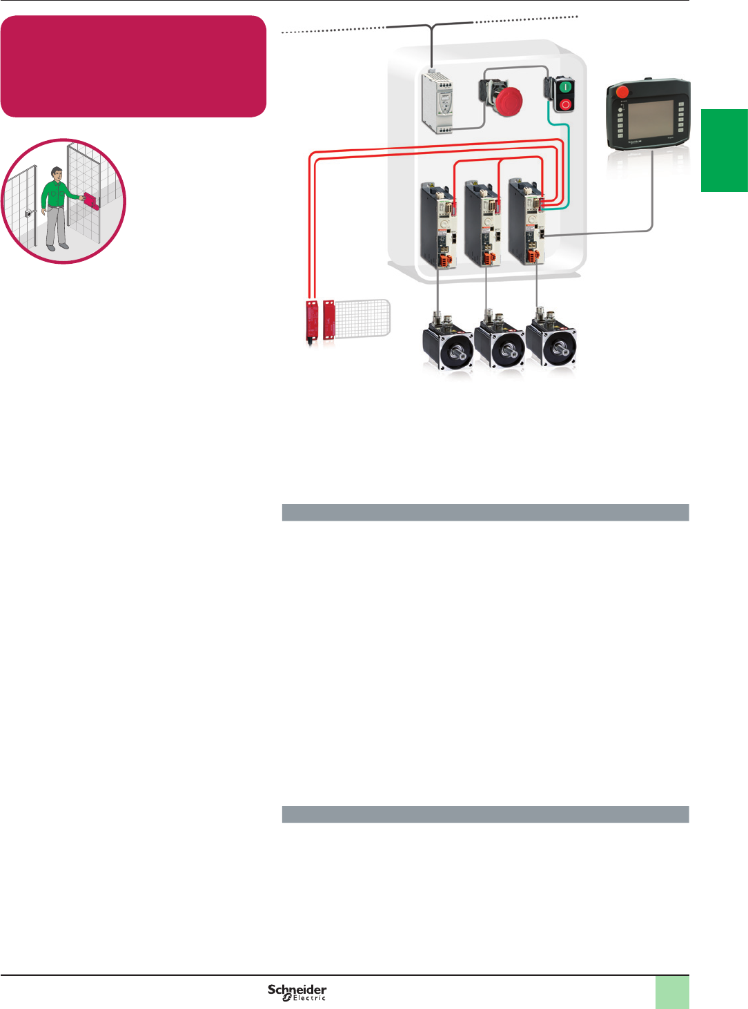
2
1
3
4
5
6
7
8
9
10
2
1
3
4
5
6
7
8
9
10
2/15
Guard Monitoring with Embedded Safety
Servo Drive
Coded Magnetic Switch / Embedded Safety
Servo Drive
Cat.4 PL e, SIL 3 / Stop Category 2
Related Products
vSwitches, pushbuttons, emergency stop - Harmony XB4
vGuard switches - Preventa XCSLE
vEnhanced Safety Module (eSM) - Lexium 32M
vServo drive - Lexium 32M
vHuman machine interface - Magelis XBT GH
vModular beacon and tower lights - Harmony XVB
vSwitch mode Power supply - Phaseo ABL8
Function
Safety-related stop function realized by a moveable guard that helps protecting
from the access to the hazardous area.
The hazardous movement is interrupted either if the stop button (S2) or the
emergency stop device (S3) is actuated, which initiates the functional stopping of
the servo-drive, i.e. by a deceleration ramp.
The Safe Stop 2 safety function is used to achieve a category 2 safe stop in
accordance with EN/IEC 61800-5-2, where the servo motor is braked in a
controlled manner, maintaining the power on the actuators.
The safety function SS2 (Safe Stop 2), integrated in the enhanced safety module
(eSM) card, monitors the deceleration and the standstill position.
When the SS2 function is triggered, a deceleration of movement is monitored with
the specied monitoring ramp up to standstill. The motor is then immobilized by the
“safe operating stop” (SOS) function, which is used to monitor any deviation from
the standstill position.
If the monitored deceleration ramp is violated or the monitored standstill position is
not maintained, the drive is halted by the “safe torque off” (STO) function, which
prevents the motor from restarting unintentionally.
The eSM card also monitors the consistent actuation of the redundant switch
contacts from the magnetic switch to detect possible failure, before restart of the
machine movement is permitted.
Typical applications
>Packaging, printing, or similar machines that use servo-drives in their
movements due to high speed and precision needed, on which non-braking
stopping would result in a impermissibly long run-down of the hazardous tool
movements
Function Safety chain solutions
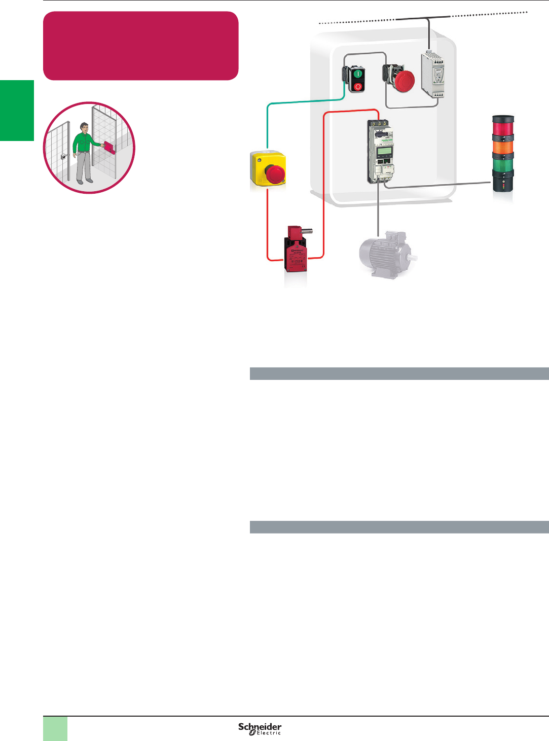
2
1
3
4
5
6
7
8
9
10
2
1
3
4
5
6
7
8
9
10
2/16
Guard Monitoring with Well Tried
Components
Limit Switch / Motor Starter
Cat.3 PL c, SIL 1 / Stop Category 0
Related Products
vSwitches, pushbuttons, emergency stop - Harmony XB4
vEmergency stop function - Harmony XALK
vSwitch mode Power supply - Phaseo ABL8
vMotor starter - TeSys U
vSafety Guard switches - Preventa XCS
vModular beacon and tower lights - Harmony XVB
Function
Stop function initiated by a moveable protective guard.
Opening of this guard is detected by a guard switch, which interrupts the control
voltage of the motor starter (stop category 0 according to EN/IEC 60204-1) to help
preventing possible hazardous movements.
The break contact of this guard switch interrupts the control circuit directly when
the protective guard is not in the safe position.
The motor is also de-energized when either of the emergency stop devices (S1 or
S2) are actuated.(*)
The safety function is fully dependent upon the reliability of the components.
(*) The function for stopping in an emergency is a protective measure which
complements the safety functions for the safeguarding of hazardous zones
according to EN/ISO 12100-2.
Typical applications
>Machine-tools or similar machines with low inertia (no rundown time), where the
access to the hazardous area is limited to maintenance interventions
Function Safety chain solutions
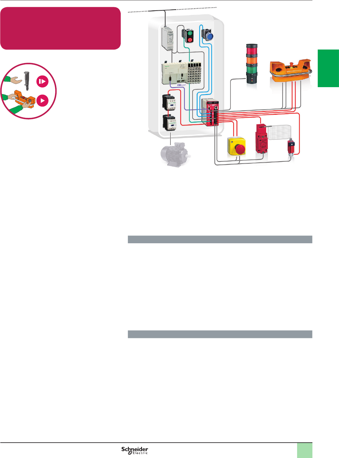
2
1
3
4
5
6
7
8
9
10
2
1
3
4
5
6
7
8
9
10
2/17
Enabling movement with Safety Controller
Two Hand Control Station / Contactor
Cat.4 PL e, SIL 3 / Stop Category 0
Related Products
vSwitches, pushbuttons - Harmony XB4
vEmergency stop control station - Harmony XALK
vTwo-Hand control station - Preventa XY2SB
vSwitch mode Power supply - Phaseo ABL8
vLogic controller - Modicon M258
vGuard interlock switch - Preventa XCS
vSafety Controller - Preventa XPS MC
vContactor - TeSys D
vModular beacon and tower light - Harmony XVB
Function
Safety-related function to help control the location of the operator’s hands outside
the hazardous area during a hazardous movement of the machine.
To initiate a movement, both actuators (two-hand control pushbuttons S3 and S4)
must be activated synchronously (within an interval less than 0,5 sec.) to energize
the contactors (K1 and K2). When at least one of the two pushbuttons is released,
the energization is cancelled and remains blocked until both pushbuttons are
released and pressed again synchronously.
The logic device (Safety Controller) monitors operation of the actuators
(pushbuttons). Faults in the actuating mechanism as well as the cable wiring are
detected in S3/S4 by the use of two contacts employing a normally open (NO) and
normally closed (NC) combination.
Faults in K1/K2 (with mirror contacts) are detected in the safety controller and lead
to de-energization of the contactors (K1 and K2).
Typical applications
>Hydraulic, eccentric press or similar complex machines with 4 or more safety
functions included, where a centralized safety controller would be required
Function Safety chain solutions
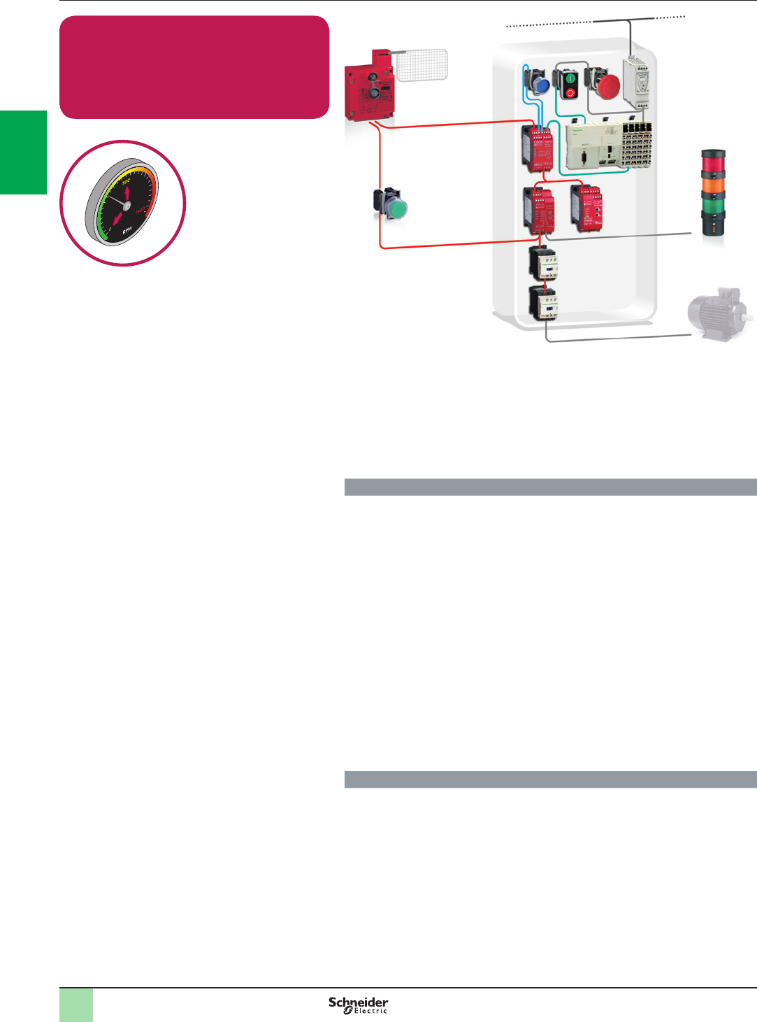
2
1
3
4
5
6
7
8
9
10
2
1
3
4
5
6
7
8
9
10
2/18
Speed Monitoring with Safety Module
Remanent Voltage detection and limit
switch and Guard switch with lock /
Contactor
Cat.4 PL e, SIL 3 / Stop Category 0
Related Products
vSwitches, pushbuttons, emergency stop - Harmony XB4
vSwitch mode Power supply - Phaseo ABL8
vLogic controller - Modicon M258
vGuard lock switch - Preventa XCSE
vSafety Module - Preventa XPS
vContactor - TeSys D
vModular beacon and tower lights - Harmony XVB
Function
Safety-related stop function initiated by any stop or emergency stop command to
halt the machine and to unlock the moveable guard that prevents the access to the
hazardous area before the machine comes to a standstill.
Guard opening is detected by using a solenoid locking guard switch in combination
with a limit switch in positive actuation mode, which are then checked by the safety
module allowing detection of the opening or removal of the protective guard.
Actuation of the emergency stop or stop contacts initiates the functional stopping of
the machine by switching-off the motor power supply. As electric motors run down,
a remanent voltage is produced in the windings of the motor due to residual
magnetism.
This voltage is measured so as to detect the stopped condition of the motor,
providing the unlock signal for the electrically locked movable guard and for
engaging brakes after the motor has come to a standstill.
The continuity of the wiring between the motor windings and the inputs of the safety
module is also monitored to prevent a cable breakage or fault being seen as a
stopped motor The main contactors are monitored by the safety modules by means
of the mirror contacts to detect e.g. contact welding.
The safety modules also monitor the consistent actuation of the limit switch
contacts to detect failure, before restart of the machine movement is permitted.
Typical applications
>On metal, wood work or similar high inertia machines with a long run-down of the
hazardous tool movements, and where an electronically interlock guard is used
to protect the hazardous area
Function Safety chain solutions
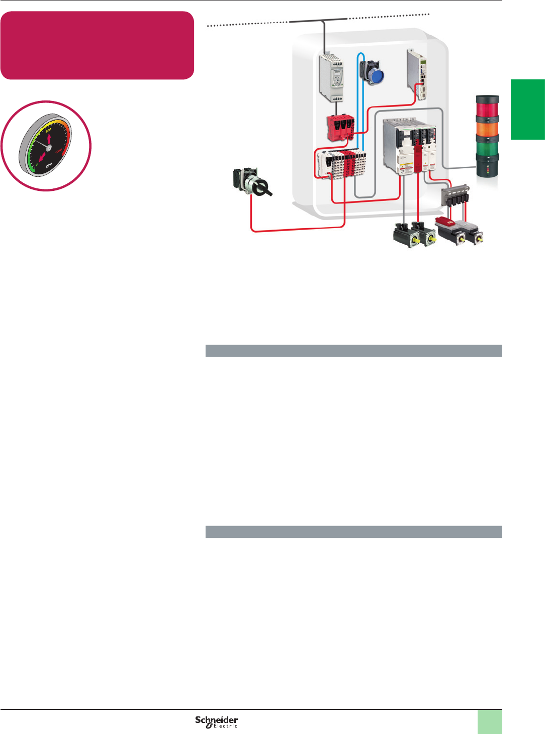
2
1
3
4
5
6
7
8
9
10
2
1
3
4
5
6
7
8
9
10
2/19
Speed Monitoring with Embedded Safety
PLC
Selector Switch / PacDrive 3 Drive
Cat.4 PL e, SIL 3 / Safe Limited Speed
Related Products
vSwitches, pushbuttons, emergency stop - Harmony XB4
vSwitch mode Power supply - Phaseo ABL8
vPreventa Safety PLC TM5SLCpp (TM5 Slices> SPS, SDIO, BC)
vSafety switches - Preventa XCS
vPacDrive 3
vHarmony XVB
Function
Safety-related Speed monitoring function initiated by a safe command to control
the machine and to unlock the moveable guard that prevents the access to the
hazardous area before the machine comes to a safe speed.
Selector switch status change is detected by using a selector switch or standard
PLC signal for change in operating mode, which are then checked by the safety
PLC allowing detection of the change in operating mode of the machine.
Actuation of the selector switch or standard PLC signal initiates the control
rampdown of the machine by drive controller. As electric motors run down,
monitored by built in encoder, then speed will be continuosly monitored. If at any
time the speed of the motor exceeds the specied limit, SS1 or STO function is
initiated for monitored stop or free whiling stop.
The continuity of the wiring between the motor windings and the inputs of the safety
modules are also monitored to prevent a cable breakage or fault being seen as a
stopped motor.
The safety modules also monitor the consistent actuation of the limit switch
contacts to detect failure, before restart of the machine movement is permitted.
Typical applications
>Machine tools, robots, production test equipment, test benches
>Papermaking machines, textile production machines, calendars in the rubber
industry
>Process lines in plastics, chemicals or metal production, rolling-mills
>Cement crushing machines, cement kilns, mixers, centrifuges, extrusion
machines
>Drilling machines
>Conveyors, materials handling machines, hoisting equipment (cranes, gantries,
etc.)
>Pumps, fans, etc.
Function Safety chain solutions
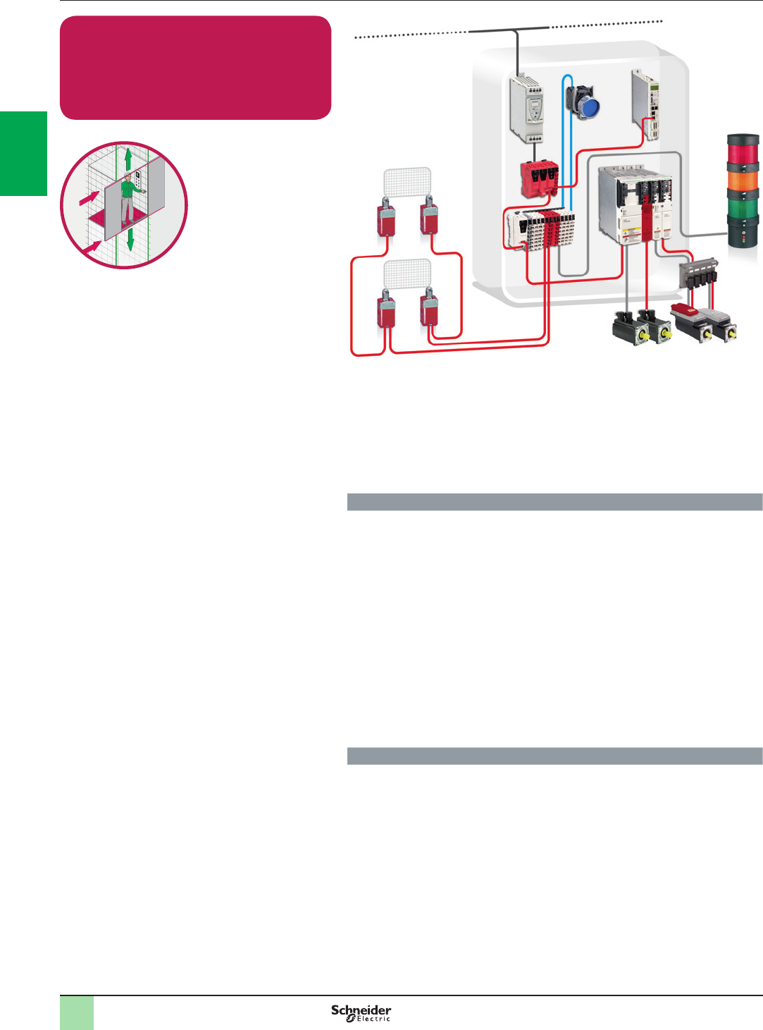
2
1
3
4
5
6
7
8
9
10
2
1
3
4
5
6
7
8
9
10
2/20
Position Monitoring with Embedded Safety
PLC
Limit Switch / PacDrive 3 Drive
Cat.4 PL e, SIL 3 / Stop Category 2
Related Products
vSwitches, pushbuttons, emergency stop - Harmony XB4
vSwitch mode Power supply - Phaseo ABL8
vPreventa Safety PLC TM5SLCp p (TM5 Slices> SPS, SDIO, BC)
vSafety Switches - Preventa XCS
vPacDrive 3
vHarmony XVB
Function
Safety-related stop function initiated by any stop or emergency stop command to
halt the machine and to unlock the moveable guard that prevents the access to the
hazardous area before the machine comes to a standstill.
Guard opening is detected by using a Coded magnetic switch, which are then
checked by the safety PLC allowing detection of the opening or removal of the
protective guard.
Actuation of the stop contacts initiates the functional stopping of the machine by
control ramp down of the motor then monitor the motor position, for the stand still. If
the position of the motor is violated the SS1 or STO will be initiated.
The continuity of the wiring between the motor windings and the inputs of the safety
modules are also monitored to prevent a cable breakage or fault being seen as a
stopped motor. The main contactors are monitored by the safety modules by
means of the mirror contacts to detect e.g. contact welding.
The safety modules also monitor the consistent actuation of the coded magnetic
switch contacts to detect failure, before restart of the machine movement is
permitted.
Typical applications
>Machine tools, robots, production test equipment, test benches
>Papermaking machines, textile production machines, calendars in the rubber
industry
>Process lines in plastics, chemicals or metal production, rolling-mills
>Cement crushing machines, cement kilns, mixers, centrifuges, extrusion
machines
>Drilling machines
>Conveyors, materials handling machines, hoisting equipment (cranes, gantries,
etc.)
>Pumps, fans, etc.
Function Safety chain solutions
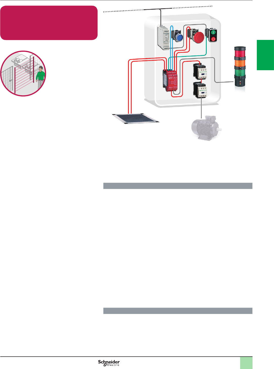
2
1
3
4
5
6
7
8
9
10
2
1
3
4
5
6
7
8
9
10
2/21
Perimeter Guarding with Safety Module
Safety Mat / Contactor
Cat.3 PL d, SIL 2 / Stop Category 0
Related Products
vSwitches, pushbuttons, emergency stop - Harmony XB4
vSwitch mode Power supply - Phaseo ABL8
vSafety Module - Preventa XPSAK
vSafety Mats - Preventa XY2TP
vContactor - Tesys D
vModular beacon and tower lights - Harmony XVB
Function
Safety-related stop function initiated by any of the safety mats installed around the
different potentially hazardous zones dened by the dangerous movement of the
machine.
The hazardous movement is interrupted either if the emergency stop device (S1) or
any of the safety mats (SM1 or SM2) is actuated.
Stepping on the safety mat deactivates the safety module outputs, which results in
the switching-off of the motor power supply by means of the contactors K1 and K2
(stop category 0 in accordance with EN/IEC 60204-1) in order to prevent possible
hazardous movements or states.
The safety mat provides a protection zone between machine operator and any
dangerous movements and enables free access for the loading and unloading of
the machine.
The safety module monitors the consistent actuation of the redundant safety mat
contacts to detect possible failures.
The main contactors are also monitored by the safety module by means of the
mirror contacts, to detect contact welding.
The resetting of the function can be performed manually or automatically,
depending on the conguration of the safety module, before renewed start-up of
the machine movement. (*)
(*) The function for stopping in an emergency is a protective measure which
complements the safety functions for the safeguarding of hazardous zones
according to EN/ISO 12100-2.
Typical applications
>Machines which use a free and very frequent access to the hazardous area,
where a high number of interventions are needed
Function Safety chain solutions
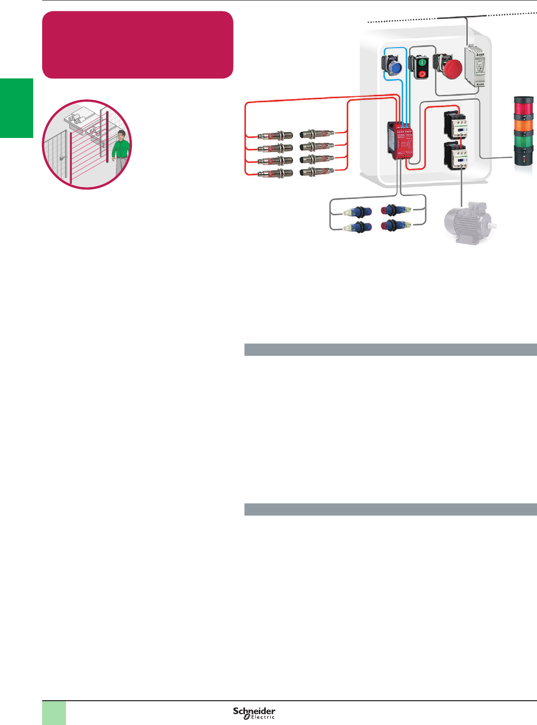
2
1
3
4
5
6
7
8
9
10
2
1
3
4
5
6
7
8
9
10
2/22
Perimeter Guarding with Safety Module
Single Beam Light curtains / Contactor
Cat.3 PL c, SIL 1 / Stop Category 0
Related Products
vSwitches, pushbutton, emergency stop - Harmony XB4
vSwitch mode Power supply - Phaseo ABL8
vSafety light curtains, single-beam for body detections - Preventa XU2S
vPhoto-electric sensors - OsiSense XU
vSafety Module - Preventa XPSCM
vContactor - Tesys D
vModular beacon and tower lights - Harmony XVB
Function
Safety-related stop function initiated by several single-beam photo-electric devices
used as protective equipment (ESPE Type 2 according to EN/IEC 61496-1 and
EN/IEC 61496-2).
An interruption of the detection eld causes the safety outputs to open. The
deactivation of the safety outputs results in the switching-off of the motor power
supply by means of the contactor (K1) to help to prevent possible hazardous
movements or states The photo-electric devices (B1...B4) are cyclically tested and
monitored by the safety module to detect possible failures.
A muting function can be enabled by means of photo-electric sensors (A1, A2). It
allows the light curtain’s detection function to be temporary inhibited without
triggering the stop function.
During the muting time interval, materials can be transported through the
hazardous area and the muting indicator light (H1) indicates to the operator this
temporary disabling of protection.
Typical applications
>Palletizing stations with automatic control system where pallets would pass
frequently through the hazardous area
Function Safety chain solutions
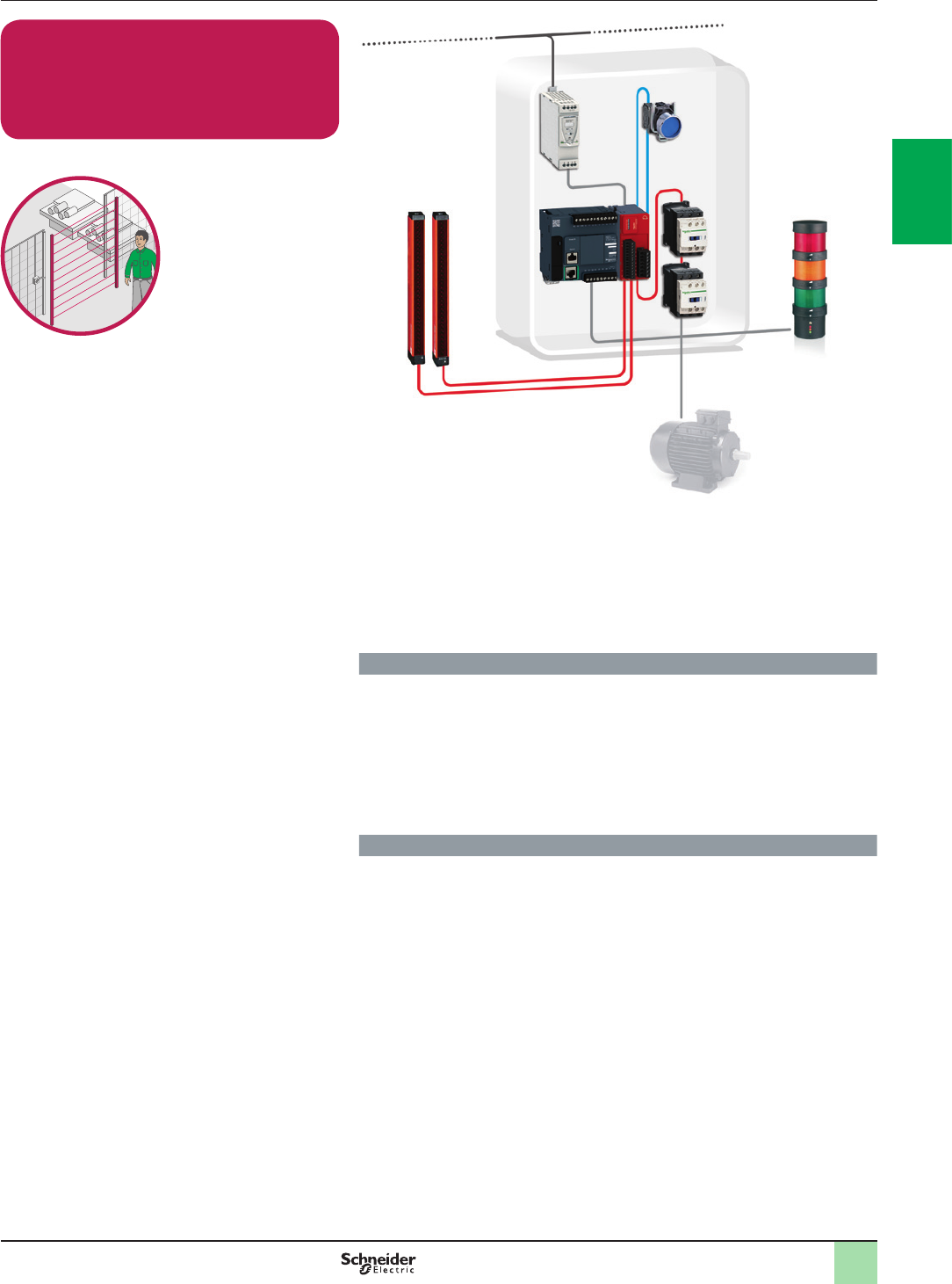
2
1
3
4
5
6
7
8
9
10
2
1
3
4
5
6
7
8
9
10
2/23
Perimeter Guarding with Embedded Safety
Module
Light curtain / Contactor
Cat.4 PL e, SIL 3 / Stop Category 0
Related Products
vSwitches, pushbuttons, emergency stop - Harmony XB4
vSwitch mode Power supply - Phaseo ABL8
vSafety light curtains, single-beam for body detections - Preventa XU2S
vPhoto-electric sensors - OsiSense XU
vSafety Module - Modicon TM3SAFL5R(G)
vContactor - Tesys D
vModular beacon and tower lights - Harmony XVB
Function
Safety-related stop function initiated by safety light curtain (ESPE Type 4 according
to EN/IEC 61496-1 and EN/IEC 61496-2).
An interruption of the detection eld causes the safety outputs to open. The
deactivation of the safety outputs results in the switching-off of the motor power
supply by means of the contactor (K1) to help to prevent possible hazardous
movements or states.
The safety light curtain receivers and outputs are cyclically tested and monitored
by the safety light curtain to detect possible failures.
Typical applications
>Palletizing stations with automatic control system where pallets would pass
frequently through the hazardous area
Function Safety chain solutions
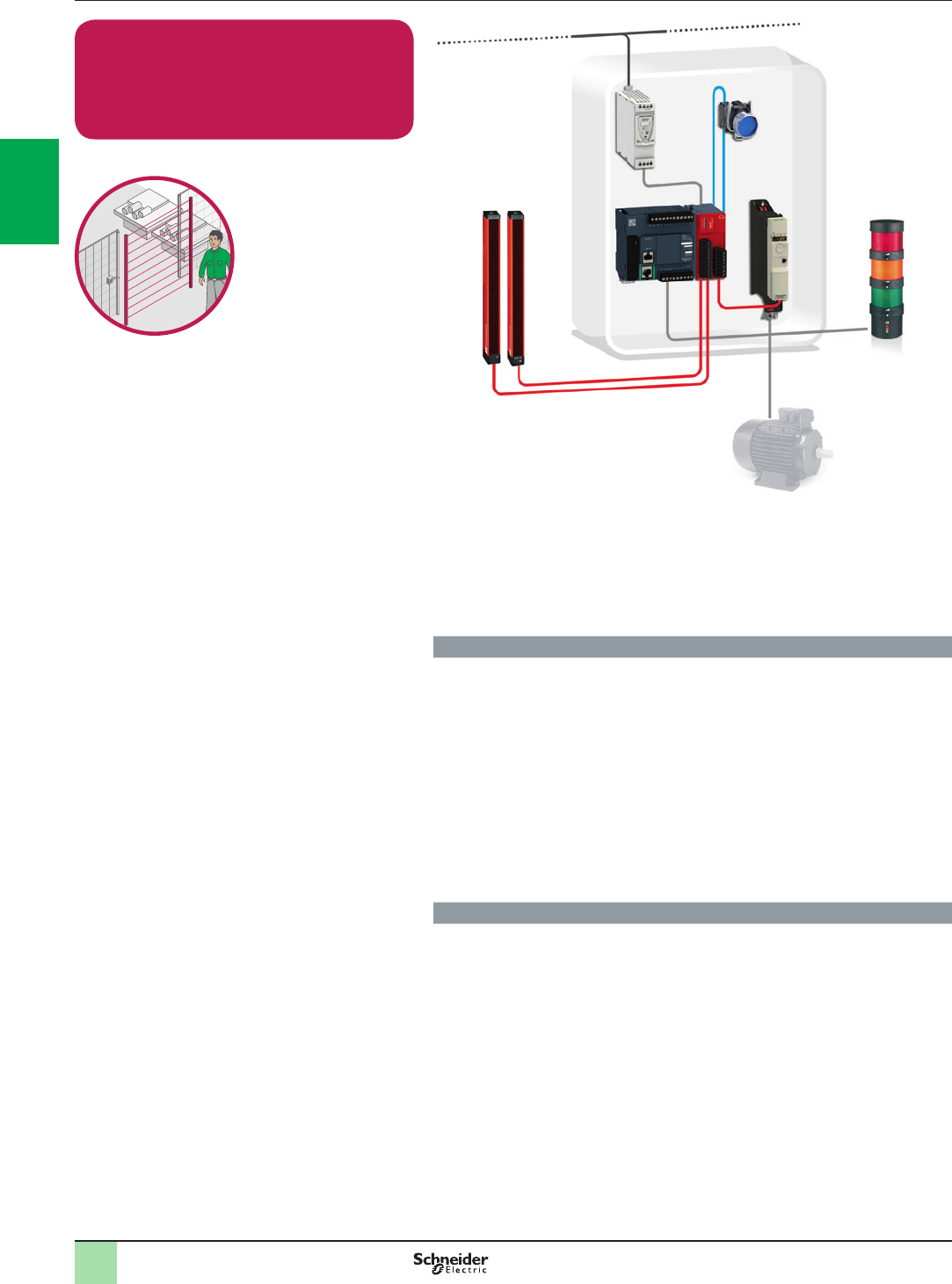
2
1
3
4
5
6
7
8
9
10
2
1
3
4
5
6
7
8
9
10
2/24
Perimeter Guarding with Embedded Safety
Module
Light curtain / Variable Speed Drive
Cat.3 PL d, SIL 2 / Stop Category 1
Related Products
vSwitches, pushbuttons, emergency stop - Harmony XB4
vSwitch mode Power supply - Phaseo ABL8
vSafety Module - Modicon TM3SAK5R(G)
vSafety light curtains
vVariable speed drive - Altivar 32
vModular beacon and tower lights - Harmony XVB
Function
Safety-related stop function initiated by a safety light curtain (ESPE Type 4
according to EN/IEC 61496-1 and EN/IEC 61496-2). Controlled stopping with
power maintained to the drive to achieve stopping (i.e. braking), then cut-off of
power when standstill is reached (Safe Stop 1).
The hazardous movement is interrupted either if the stop button (S2) or the
emergency stop device (S3) is actuated. An interruption of the detection eld
initiates the functional stopping of the drive, i.e. by a braking ramp (stop category 1
in accordance with EN/IEC 60204-1).
After the delay time monitored by the drive has elapsed, the drive is halted, by the
“safe torque off” (STO) safety function integrated within it, which prevents the motor
from restarting unintentionally.
The switching of the LI3 input is monitored by the drive. The power stage is
disabled when the time offset is exceeded.
Typical applications
>Machines that use drives in their movements due to high speed and precision
needed (i.e. textile, wood-working or simple packaging machines), when the
delayed initiation of the stopping in the event of a fault must not involve an
unacceptably high residual risk
Function Safety chain solutions

2
1
3
4
5
6
7
8
9
10
2
1
3
4
5
6
7
8
9
10
2/25
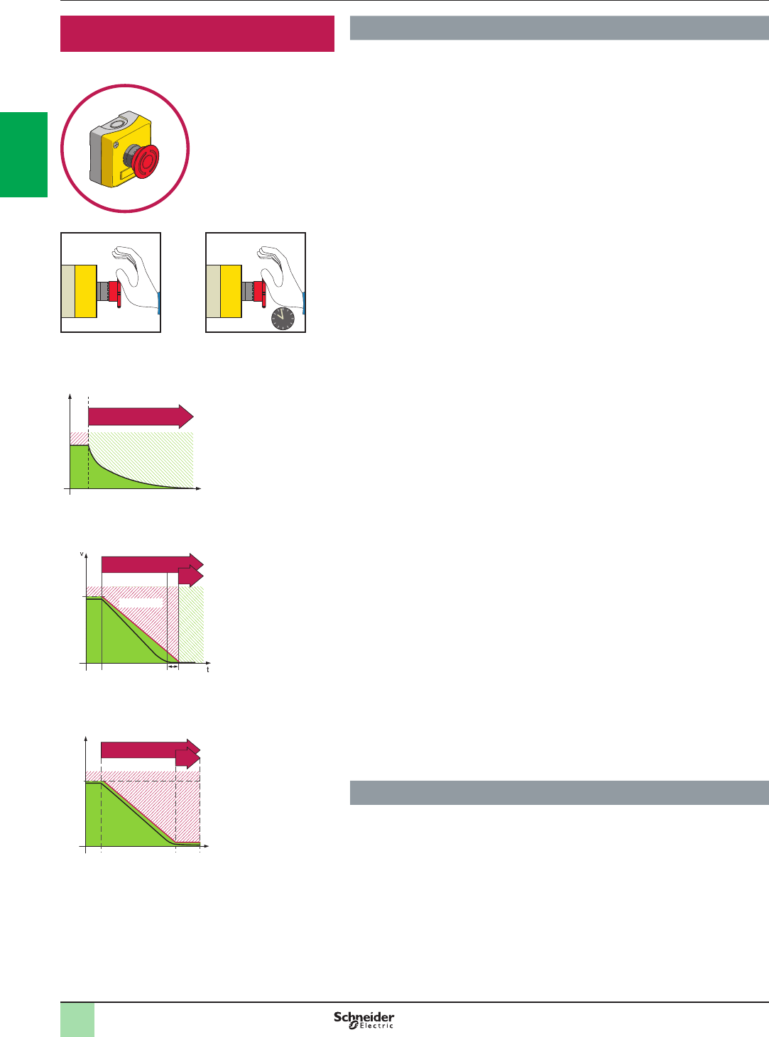
2
1
3
4
5
6
7
8
9
10
2
1
3
4
5
6
7
8
9
10
2/26
Detailed description Safety functions
Emergency stop
Explanation of function
International standard EN/ISO 13850 (replaces standard EN 418) species
the functional requirements and design principles of emergency stop
devices.
Stop types:
Stop category 0 and/or stop category 1 and/or stop category 2 stop functions shall
be provided as indicated by the risk assessment and the functional requirements of
the machine:
Stop Category 0:
Stopping by immediate removal of power to the machine actuators (i.e. an
uncontrolled stop – stopping of machine motion by removing electrical power to the
machine actuators)
Stop Category 1:
A controlled stop (stopping of machine motion with electrical power to the machine
actuators maintained during the stopping process) with power available to the
machine actuators to achieve the stop and then removal of power when the stop is
achieved
Stop Category 2:
A controlled stop with power left available to the machine actuators
For the Emergency stop function either Stop Category 0 or Stop Category 1 is
chosen according to the risk assessment results.
It applies to all machines, whatever type of energy is used to control this function.
When the emergency stop instruction ceases, the effect must be maintained until it
is reset. Manual resetting must only be possible in the location where the
instruction was given. Resetting must not start the machine, but simply enable the
starting cycle.
Restarting of the machine must not be possible until the emergency stop has been
reset.
Where required, facilities to connect protective devices and interlocks shall be
provided. If such a protective device or interlock causes a stop of the machine, it
may be necessary for that condition to be signalled to the logic of the control
system. The reset of the stop function shall not initiate any hazardous situation.
Where more than one control station is provided, stop commands from any control
station shall be effective when required by the risk assessment of the machine.
In addition to the requirements for the emergency stop function has the following
requirements:
vIt shall override all other functions and operations in all modes
vPower to the machine actuators that can cause a hazardous situation(s) shall be
either removed immediately (stop category 0) or shall be controlled in such a way
to stop the hazardous motion as quickly as possible (stop category 1) without
creating other hazards
vReset shall not initiate a restart
The choice between these two stopping methods is determined by an evaluation of
the machine-related risks.
This function includes several sub-functions either Safe Torque off (stop category
0), Safe Stop 1 (stop category 1) or Safe Stop 2 (stop category 2) and is
represented by the drawings opposite.
The operator interface may be:
vPushbutton equipped with a mushroom head
vCable actuated switch
vFoot switch
Typical architecture
Safety chain solution:
>Emergency Stop with Embedded Safety Module / Emergency Stop Pushbutton /
Contactor / Cat.3 PL d, SIL2, Stop Category 0
>Emergency Stop with Embedded Safety Module / Emergency Stop Pushbutton /
Contactor / Cat.4 PL e, SIL3, Stop Category 0
>Emergency Stop with Modular Safety Controller / Emergency Stop Pushbutton /
Contactor / Cat.4 PL e, SIL3, Stop Category 0
>Emergency Stop with Embedded Safety PLC / Emergency Stop Pushbutton /
PacDrive 3 drive STO / Cat.4 PL e, SIL3 / Stop Category 0
Emergency stop
Stop category 0:
Emergency stop function
Stop category 1
STO: Safe Torque Off
v
STO
t
0
SS1: Safe Stop 1, STO: Safe Torque Off
SS1
dec_Qstop
STO
vmax
0v=0 200ms
SS2: Safe Stop 2, SOS: Safe Operating Stop
vmax
v
t
0
SS2
SOS
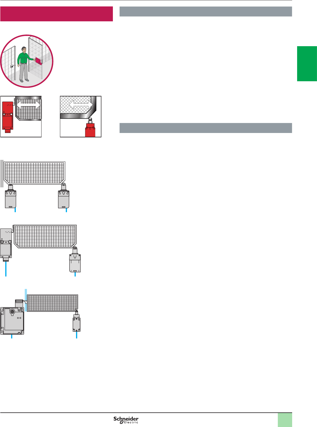
2
1
3
4
5
6
7
8
9
10
2
1
3
4
5
6
7
8
9
10
2/27
Detailed description Safety functions
Guard monitoring
Guard with guard locking
device
Guard without guard
locking device
System with two
safety limit switches
Combination of actuator
operated guard switches
and safety limit switches
Guard monitoring Explanation of function
Guards without guard locking device
On a large number of potentially dangerous machines, the operator must be kept at
a distance during operation, but needs to take action when the machine is stopped
to position a part, remove a product or adjust a tool.
An effective means of protection is to install a guard which, according to the type of
installation, will cut-off the power to the motor if an attempt is made to open it during
the machine operating phase.
In all cases, it must not be possible to restart the machine until the guard is closed.
Depending on the level of protection required, the system will comprise two
conventional limit switches or a combination of protected, actuator operated guard
switches to prevent tampering.
Guards with guard locking device
This type of guard is necessary for potentially dangerous machines with high
inertia (long rundown time).
The guard is interlocked (by a solenoid for example); it cannot be opened until the
machine has come to a complete standstill.
Typical architecture
Safety chain solution:
>Guard Monitoring with Well Tried Components / Limit switch / Motor Starter /
Cat.3 PL c, SIL 1 / Stop Category 0
>Guard Monitoring with Safety Module / Limit switch / Contactor /
Cat.3 PL d, SIL 2 / Stop Category 0
>Guard Monitoring with Safety Module / Guard switch with lock / Contactor /
Cat.4 PL e, SIL 3 / Stop Category 0
>Guard Monitoring with Safety Module / Guard switch with lock /
Variable speed drive / Cat.3 PL d, SIL 2 / Stop Category 1
>Guard Monitoring with Embedded Safety Module / Guard switch with lock /
Contactor / Cat.4 PL e, SIL 3 / Stop Category 0
>Guard Monitoring with Safety Controller / Limit switch / Contactor /
Cat.4 PL e, SIL 3 / Stop Category 0
>Guard Monitoring with Modular Safety Controller / Guard switch with lock /
Contactor / Cat.4 PL e, SIL 3 / Stop Category 0
>Guard Monitoring with Embedded Safety PLC / Guard switch with lock /
PacDrive 3 Drive SS1 / Cat.4 PL e, SIL 3 / Stop Category 1
Combination of actuator
operated guard switches
with guard locking and
safety limit switches
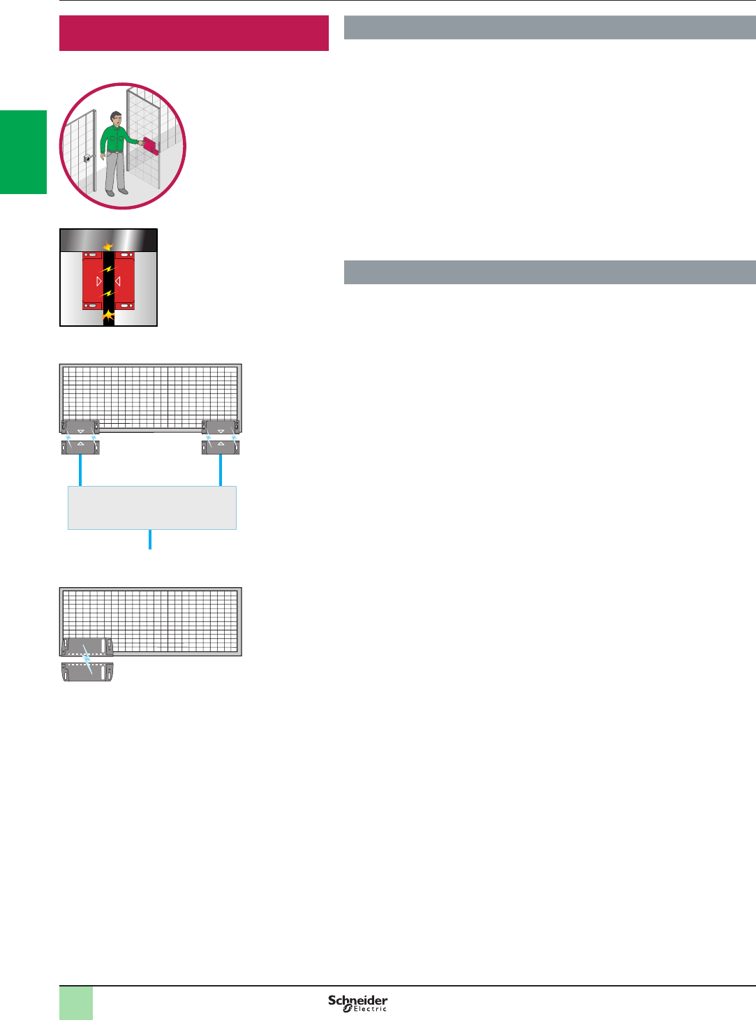
2
1
3
4
5
6
7
8
9
10
2
1
3
4
5
6
7
8
9
10
2/28
Detailed description Safety functions
Guard Monitoring
Functions of a coded magnetic guard switch system
Self-contained coded magnetic system
(integral processing)
Processing of the signal
Coded magnetic
guard switches
Functions of coded magnetic guard switches
Coded magnetic guard switch
Guard Monitoring Explanation of function
Coded magnetic guard switch and system
A non-contact solution is often used on industrial machines tted with a door or
guards with imprecise guiding.
It is particularly suitable for machines subjected to frequent washing or splashing of
liquids as well as small machines with a single guard for self-contained systems.
Depending on the models used, the sensing distance will be between 5 and 10 mm.
The reed contacts used for the coded magnetic switches cannot withstand short
circuits and the switches always incorporate a resistor in series. Their operation
can therefore only be guaranteed with the associated processing module.
The Hall-effect self-contained systems with integral processing do not require any
further processing of the signal.
The illustrations opposite show the functions of coded magnetic guard switches
and of a system.
Typical architecture
Safety chain solution:
>Guard Monitoring with Safety Module / Coded Magnetic switch / Contactor /
Cat.4 PL e, SIL 3 / Stop Category 0
>Guard Monitoring with Safety Module / Coded Magnetic switch /
Variable speed drive / Cat.4 PL e, SIL 3 / Stop Category 1
>Guard Monitoring with Safety Module / Coded Magnetic switch / Servos drive /
Cat.4 PL e, SIL 3 / Stop Category 1
>Guard Monitoring with Embedded Safety Servo Drive / Coded Magnetic switch /
Embedded Safety Servo drive / Cat.4 PL e, SIL 3 / Stop Category 2
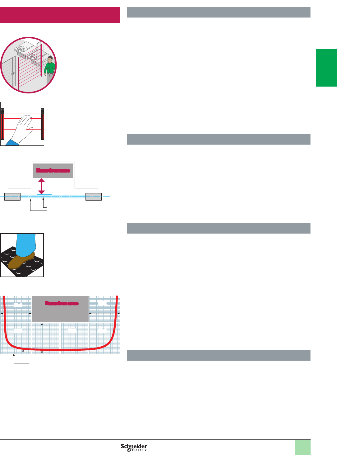
2
1
3
4
5
6
7
8
9
10
2
1
3
4
5
6
7
8
9
10
2/29
Detailed description Safety functions
Perimeter guarding
Safety light curtain
Safety distance
Hazardous zone
Transmitter
Light curtain
Optical axis Receiver
Perimeter guarding Explanation of function
Safety light curtains
Safety light curtains are electro-sensitive systems (Electro-Sensitive Protective
Equipment) designed to protect persons working in the vicinity of machinery, by
stopping dangerous movements when a light beam is broken.
The absence of a door or guard reduces loading, inspection or tool changing times.
This type of system, dened by standards EN/IEC 61496-1 and EN/IEC 61496-2, is
frequently used with machines such as:
vpresses
vmachine tools
vassembly lines, etc.
The machine must be designed so that it is impossible to gain access to dangerous
movements without breaking one or more of the light beams.
In addition, the movement must be stopped whatever the entry speed of the
operator into the hazardous zone.
The diagram opposite illustrates the operation of a light curtain.
Typical architecture
Safety chain solution:
>Perimeter Guarding with Safety Module / Single beam Light Curtains / Contactor
/ Cat.3 PL c, SIL 1 / Stop Category 0
>Perimeter Guarding with Embedded Safety Module / Light Curtain /
Contactor / Cat.4 PL e, SIL 3 / Stop Category 0
>Perimeter Guarding with Embedded Safety Module / Light Curtain /
Variable Speed Drive / Cat .3 PL d, SIL 2 / Stop Category 1
>Perimeter Guarding with Modular Safety Controller / Light Curtain /
Contactor / Cat.4 PL e, SIL 3 / Stop Category 0
Explanation of function
Safety mats
Safety mats are used to detect persons walking across or standing on the mat or
objects falling onto the mat.
Standards EN 1760-1/ISO 13856 dene their performance.
Any detection of an object on the mat initiates stopping of any dangerous machine
movement.
Restarting can be controlled manually or automatically, depending on the
conguration of the associated processing unit.
When pressure is applied, the mat distorts locally and the integrated sensors are
short-circuited.
The special design of these sensors requires that the mat and the detection module
be matched.
In general, several mats are used to cover the safety zone.
The safety distance S, dened by the standard, takes into account the speed at
which a person can cross the safety zone to reach the hazardous zone.
Typical architecture
Safety chain solution:
>Perimeter Guarding with Safety Module / Safety Mat / Contactor /
Cat.3 PL d, SIL2 / Stop Category 0
Example of a safety mat application
Hazardous zone
Mat
Mat Mat Mat
Mat
S S
S
Sensing limit
Safety zone
Safety mat
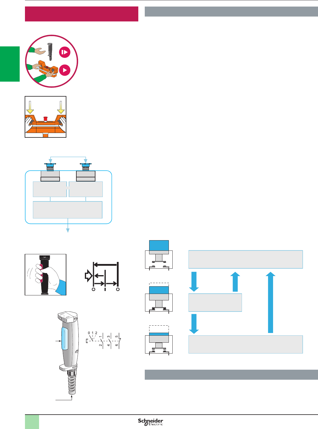
2
1
3
4
5
6
7
8
9
10
2
1
3
4
5
6
7
8
9
10
2/30
Detailed description Safety functions
Enabling movement
Functions of a two-hand control station
Input signal
Signal generator
Output signal
Signal conversion
Enabling Switch
Marking identifying
an enabling switch
Enabling switch XY2 AU1:
2 enabling functions, 3 positions + 1 N/C
3-position enabling
switch
Connection to
control circuit
Enabling movement Explanation of function
Two-hand control stations
Standards ISO 13851 and EN 574 dene this device. It requires simultaneous
operation by both hands in order to start and maintain operation of a machine. It
therefore provides protection exclusively for the person operating it.
A diagram representing the function is given opposite; it must meet the following
requirements:
>Concurrent, maintained operation of the two input controls for the same period of
time
>Synchronous operation; the delay between the two signals must not exceed 0.5 s
>Prevention of accidental operation (mechanical guard)
>Protection against tampering
Enabling switches, allow authorized personnel to carry out maintenance,
adjustment or programming operations within hazardous zones of machines,
provided certain conditions are met. These devices conform to standards EN/IEC
60947-5-8 and EN/IEC 60204-1. In effect, to gain access, these operations, often
performed at reduced speed, must be selected by authorized personnel using
selectors with key or equivalent.
Important note: the enabling switch alone must not lead to the actuation of any
dangerous movements associated with the machine; a secondary, intentional,
control action is required from the operator. All devices which conform to the
standard must be identied by the marking scheme shown opposite.
Enabling Switch
Operating principle
The three possible states are:
>Position 0: contact open (control operator at rest)
>Position 1: contact closed (control operator depressed to normal enabling
position)
>Position 2: contact open (control operator fully depressed)
When the switch is depressed in position 1, it must return to position 0 when
released. The switch must change from position 1 to position 2 when pressed more
rmly. When it is released from position 2 to position 0, the switching contact must
not close.
Typical architecture
Safety chain solution:
>Enable Machine Movement with Safety Controller / Two Hand Control Station /
Contactor / Cat.4 PL e, SIL 3
>Enable Machine Movement with Modular Safety Controller /
Two Hand Control Station / Contactor / Cat.4 PL e, SIL 3
Position 0
Position 1
Position 2
Moderate
pressure
Firm pressure
Open state
Release
Release
Closed state
Open state
Operating principle of an enabling switch
Two-hand control stations
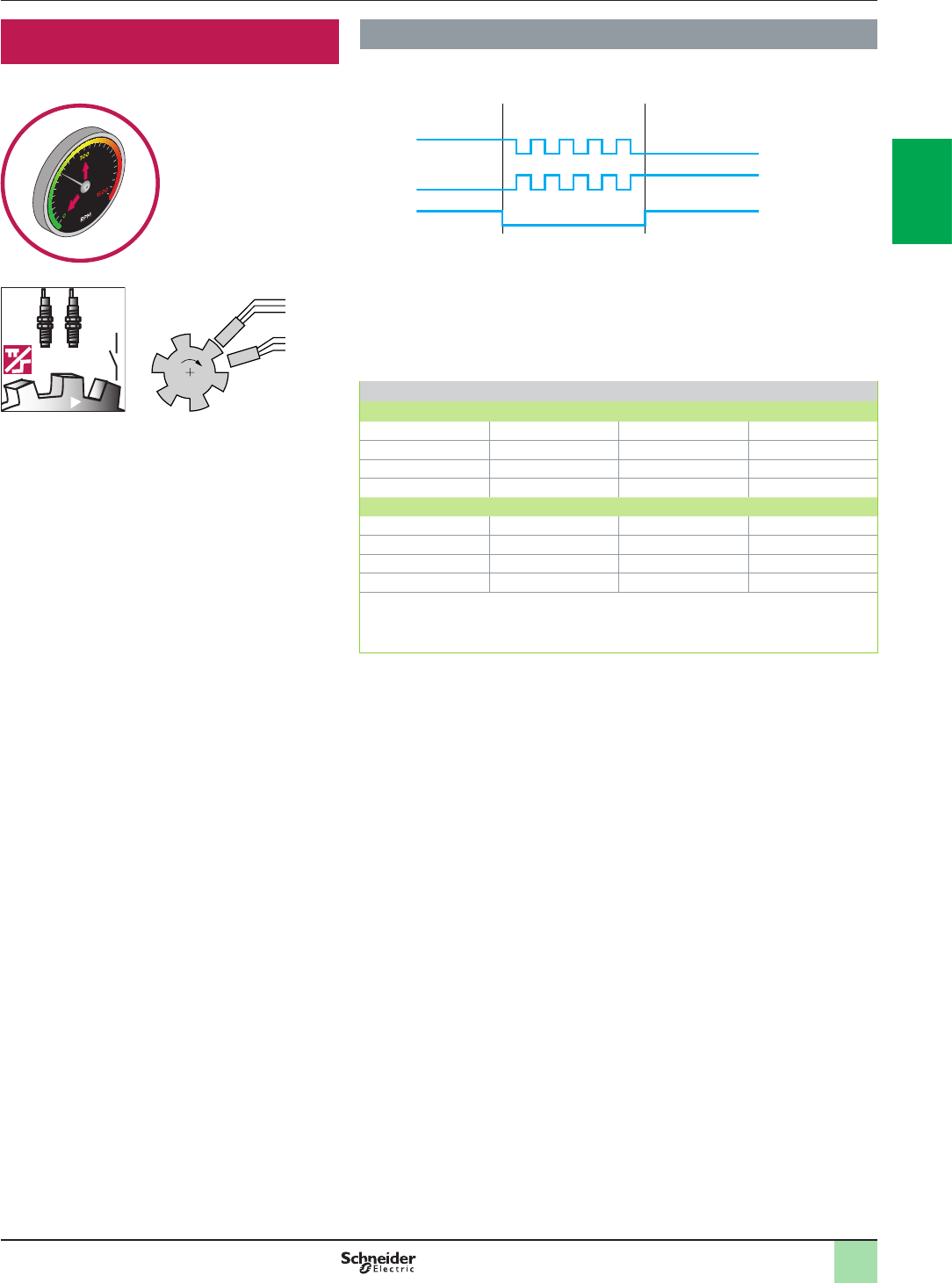
2
1
3
4
5
6
7
8
9
10
2
1
3
4
5
6
7
8
9
10
2/31
Speed monitoring Explanation of function
Zero speed monitoring
Detection principle
The two sensors to be arranged that only one sensor is activated at any given time.
If the inputs are in the low state, the zero speed signal will disappear after t=1/f
seconds and an open-circuit will be indicated. If the 2 inputs are in the high state,
the zero speed signal will disappear after t=1/f seconds and a short-circuit will be
indicated. If the 2 inputs are in the high or low state after starting, no enabling will
take place.
Sensor States and Behavior
Switch-on Sequence
State of Sensor 1 0 0 (1) 1
State of Sensor 2 0 1 (1) 1
Behavior Error Message Zero Speed Notication (2)
Output 0 1 0
Operation
State of Sensor 1 0 0 (1) 1
State of Sensor 2 0 1 (1) 1
Behavior Error Message Zero Speed Notication
Output 0 1 1
(1) If the state of the sensors is inverse (0/1, 1/0), the behavior is identical.
(2) If the rmware version is earlier than 2.34 an error message (short circuit between inputs)
appears instead of a notication. This error message must be acknowledged with the reset
button.
Detection principle 2
Preventa safety modules XPSVNE for zero speed detection are used to detect the
stop condition of electric motors. Their most common applications include:
providing the unlock signal for electrically interlocked sliding or removable machine
guards, controlling rotation direction signals for reversing motors and engaging
locking brakes after a motor has come to a standstill.
As electric motors run down, a remanent voltage is produced in the windings of the
motor due to residual magnetism. This voltage is proportional to the speed of the
motor and, therefore, decreases as the motor comes to a standstill.
This remanent voltage is measured in a redundant manner so as to detect the stop
condition of the motor. The cabling between the motor windings and the inputs of
the XPSVNE module is also monitored to prevent a cabling breakage or fault being
seen as a stopped motor.
A transformer should not be used to connect the motor to terminals Z1, Z2 and Z3
since there is no monitoring of the connection with the motor winding via the
resistance monitoring.
Modules XPSVNE are suitable for detecting the stop condition of all types of AC
or DC motor driven machines which, when the motor runs down, produce a
remanent voltage in the windings due to residual magnetism. These machines can
be controlled by electronic devices, such as variable speed drives or DC injection
brakes. The input lters for standard XPSVNE modules are designed for a frequency
of up to 60 Hz.
For motors operating at a frequency higher than 60 Hz, which therefore produce a
high frequency remanent voltage, special modules XPSVNEppppHS should be
used. Modules XPSVNE have t2 potentiometers mounted on the front face of the
module which allow independent adjustment of the switching threshold for each
input circuit. This allows adjustment for different types of motors and application
requirements. To aid diagnostics, modules XPSVNE have 4 LEDs and 2 solid-state
outputs to provide information on the status of the zero speed detection circuit.
Detailed description Safety functions
Speed monitoring
Input 1 (I1)
Sensor B1
Input 2 (I2)
Sensor B2
Output
Zero speed
f1, f2 < f max.
Rotation
f1, f2 > f max.
Zero speed
f1, f2 < f max.
Sensor control
Sensor B1
Sensor B2
Speed monitoring
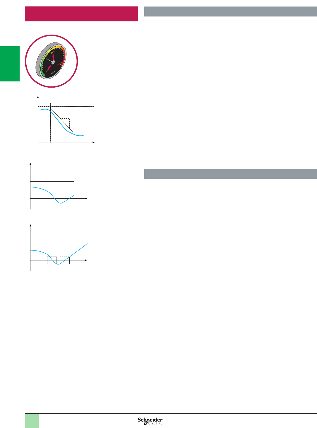
2
1
3
4
5
6
7
8
9
10
2
1
3
4
5
6
7
8
9
10
2/32
Detailed description Safety functions
Speed monitoring
Speed monitoring Explanation of function
Motion safety functions
Safety-limited speed
The SLS function prevents the motor from exceeding the specied speed limit.
When this function is initiated the machine starts to decelerate to the specied safe
speed v2 with in the specied time t2. Once the machine reaches the safe speed
v2 then the function will monitor the speed stays below safe speed v2.
In case of speed exceeding specied speed during time t2 and further, safety
function will initiate either SS1 or STO to stop the machine in minimum time.
Safe maximum speed
The SMS function provides a safe output signal to indicate whether the motor
speed is below a specied limit.
This safety function is an optional function to set an upper limit parameter for
continuous monitoring. If the speed of the machine exceeds the specied value
then specied safe output will change its state.
Safe direction
The SDI function prevents the motor shaft from moving in the unintended direction.
Typical architecture
Safety chain solution:
>Speed Monitoring with Safety Module / Remanent Voltage detection and limit
switch and Guard switch with lock / Contactor / Cat.4 PL e, SIL 3 /
Stop Category 0
>Speed Monitoring with Modular Safety Controller / Safety Encoder / Contactor /
Cat.4 PL e, SIL 3 / Stop Category 0
>Speed Monitoring with Embedded Safety PLC / Selector Switch /
PacDrive 3 Drive SLS / Cat.4 PL e, SIL 3 / Safe Limited Speed
Speed
t/ms
t1 t2
v1
v2
Safety-limited speed
t/ms
t1
v
Safe maximum speed
t/ms
t1
v
Safe direction
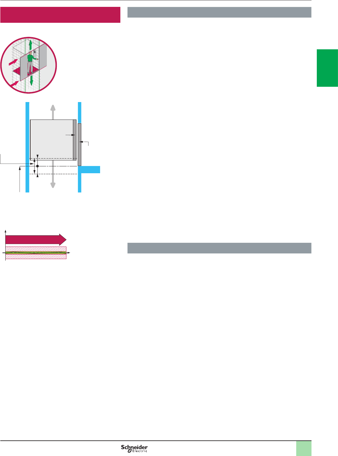
2
1
3
4
5
6
7
8
9
10
2
1
3
4
5
6
7
8
9
10
2/33
Position monitoring Explanation of function
Vertical position monitoring
When the cabin is parked at a landing, with the doors open, some lifts automatically
correct their level (isolevelling) in relation to the landing in order to compensate for
any differences generated by modication of the load in the cabin.
During this operation, European standard EN-81 recommends that the presence of
the cabin be checked within a zone of +/- 0.2 m around the landing (door unlocking
zone), by means of a safety circuit which will cause the cabin to stop if it moves out
of the specied zone.
The use of the safety module XPS EDA, which checks the presence of the cabin in
the specied zone at two points, meets this requirement.
The module incorporates two safety outputs and two solid-state outputs for
signaling functions. Four LEDs on the front face of the module provide visual
indication of the status of the safety circuit.
The position of the cabin in relation to the landing is detected by two limit switches
in the lift shaft. It is also possible to use non-contact sensors (magnetic sensors
with reed contact).
When the cabin reaches the preset position and when it is within the permissible
tolerances in relation to the landing, the two safety circuits in safety module XPS
EDA close and allow isolevelling of the cabin with the doors open. Any change in
one of the input signals (cabin outside the specied zone) or detection of a fault
(break in the wiring, short-circuit, etc.) causes immediate opening of the safety
outputs in the XPS EDA module and subsequent stopping of the cabin.
Motion safety function:
Safe operating stop (SOS)
The SOS function prevents the motor from deviating more than a dened amount
from the stopped position. The drive provides energy to the motor to enable it to
resist external forces. The Safe Operating Stop function is most commonly used in
conjunction with the Safe Stop 2 function where the machine movement enters into
zero speed the Safe Operating Stop is enabled.
Typical architecture
Safety chain solution:
>Position Monitoring with Embedded Safety PLC / Coded Magnetic Switch /
PacDrive 3 Drive SS2 / Cat.4 PL e, SIL 3 / Stop Category 2
Detailed description Safety functions
Position monitoring
+ 0,2 m (+7.88 in.)
- 0,2 m (-7.88 in.)
Door
unlocking
zone
Landing indicator
(stop reference point)
Cabin doors
Landing
Cabin
Landing
doors
Vertical position monitoring
Safe operating stop (SOS)
t
s
0
SOS

Chapter 3
Preventa
safety product
offer
bAll technical information about products listed in this catalog
are available on: www.schneider-electric.com

2
1
3
4
5
6
7
8
9
10
bAquire the information
vControl and signaling units
General selection guide ...................................................................page 3/2
Harmony® XB4, metal Pushbuttons,
switches and pilot lights ...........................................................page 3/4 to 3/15
Harmony® XB5, plastic Pushbuttons,
switches and pilot lights .........................................................page 3/16 to 3/27
Body/contact assemblies .................................................................. page 3/28
vControl units for safety application . . . . . . . . . . . . . . . . . . . . . . . . .
page
3/30
Control station .................................................................................. page 3/32
Enabling grip..................................................................................... page 3/54
Two hand control station ................................................................... page 3/56
bMonitor and processing
vPreventa safety relays
Selection guide ............................................................................... page 3/62
Preventa safety relays ...................................................................... page 3/68
vModicon TM3 safety modules
General presentation ........................................................................ page 3/88
Selection guide ............................................................................... page 3/90
Modicon TM3 safety modules ........................................................... page 3/92
vPreventa Safety controllers
Selection guide ............................................................................... page 3/96
Preventa Safety controllers XPSMP ................................................. page 3/98
Preventa Safety controllers XPSMC ............................................... page 3/100
vPreventa Safety PLCs
General presentation ...................................................................... page 3/106
Selection guide ............................................................................. page 3/108
Preventa Safety PLCs XPSMF ....................................................... page 3/106
bStop the Machine
vSignalling units for safety applications
Selection guide ............................................................................. page 3/138
Illuminated beacons........................................................................ page 3/140
Rotating beacons............................................................................ page 3/148
Sirens & alarms .............................................................................. page 3/150
vMini-VARIO and VARIO switch disconnectors
Selection guide ............................................................................. page 3/152
Mini-VARIO switch disconnectors for standard applications ........... page 3/154
VARIO switch disconnectors for high performance applications ....... page 3/156
Mini-VARIO and VARIO switch disconnectors. ............................... page 3/158
VARIO enclosed switch disconnectors, pre-assembled .................. page 3/162
VARIO enclosed switch disconnectors, Add-on modules ................ page 3/164
vTeSys D low consumption contactors . . . . . . . . . . . . . . . . . . . . . . .page 3/166
vTeSys contactors 5, from 6 to 16 A . . . . . . . . . . . . . . . . . . . . . . . . . .page 3/168
vTeSys protection components . . . . . . . . . . . . . . . . . . . . . . . . . . . . .page 3/170
vVariable speed drives ....................................page 3/172
vMotion control Lexium 32, Lexium 28 . . . . . . . . . . . . . . . . . . . . . . .page 3/174
Contents Preventa safety product offer
3/1
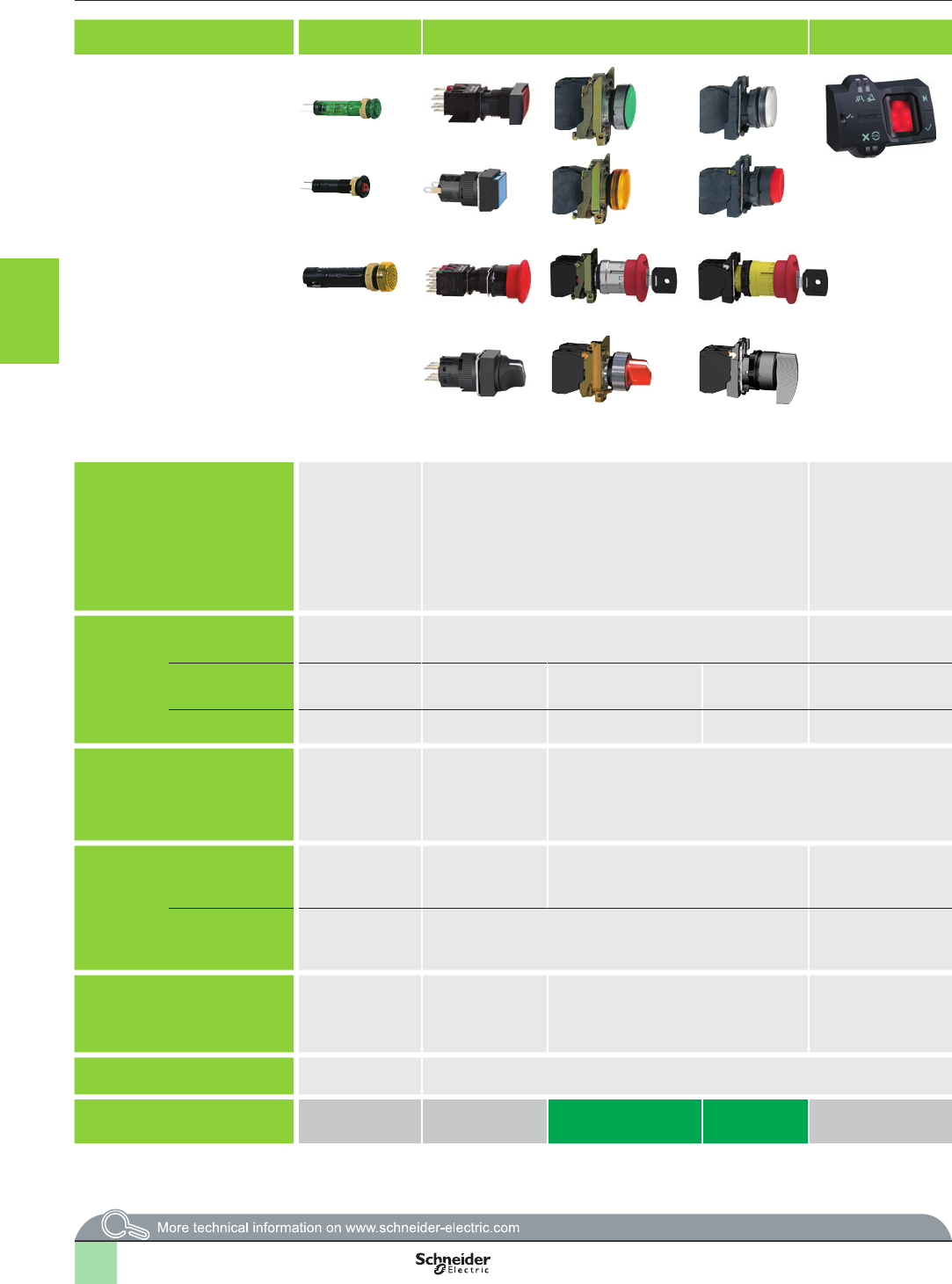
3/2
Type of products Pilot lights Pushbuttons, selector switches and pilot lights
Biometric switches
Wireless and batteryless
pushbuttons
Pushbuttons, selector
switches and pilot lights
Joystick controllers Pushbuttons, selector
switches and pilot lights
Cam switches
Description of range
b LED pilot lights b Pushbuttons
b Multiple-headed pushbuttons
b Emergency Stop pushbuttons
b Selector switches and key switches
b Illuminated pushbuttons
b Pilot lights
Fingerprint readers
24V c
b Stand-alone
biometric switches
b Stand-alone USB
biometric switches
b USB biometric
switches dedicated
to Schneider HMI (1)
b Wireless and
batteryless
pushbuttons and rope
pull switch
b Congurable receivers
b Access point
b Relay-antenna
b Mobile handy box or
plastic boxes for wall
mounting
b Pushbuttons
b Emergency Stop and
Emergency switching off
pushbuttons
b Selector switches and key
switches
b Illuminated pushbuttons
b Pilot lights
b 2 or 4 direction
b Stay put or spring return
b Pushbuttons
b Emergency Stop buttons
b Selector switches and key
switches
b Illuminated pushbuttons
b Pilot lights
b Switches
b Stepping switches
b Reversing and changeover
switches
b Ammeter switches
b Voltmeter switches
b Reversing switches
b Star-delta and reversing
star-delta switches
b Pole change switches
Features Products Monolithic, compact,
low consumption
Complete units or sub-assemblies (body + head) Monolithic Ready-to-use packs (2)
and “components” range
Monolithic Complete units or sub-assemblies
(body + head with lever)
Complete units or
sub-assemblies
(body + head)
Complete units or sub-
assemblies (body + front panel
+ head)
Bezel Double insulated Double insulated (3) Metal, chromium plated or
black
Double insulated Double insulated,
dark grey
Metal, chromium plated or
double insulated, black
Double insulated, dark grey
(or white for pilot lights)
Metal, chromium plated Double
insulated,
black
Metal, chromium plated or double insulated, black
Shape of head Circular Circular, square
or rectangular
Circular Circular or square – Transmitter with circular
head
Circular Circular Hexagonal Square
Drilling or cut-out for xing
Ø 8 mm and Ø 12
mm/0.315 in. and
0.472 in.
Ø 16 mm/0.630 in. Ø 22 mm/0.866 in. Ø 22 mm/0.866 in. Ø 30 mm/1.181 in. Ø 16 or Ø 22 mm/0.630 or
0.866 in.: series K10
Ø 22 mm/0.866 in. and multixing:
series K1/K2
4 holes, 48 or 68 centres: series
K30…K150
Degree of
protection
Conforming to
IEC 60529
IP 40
IP 65 with seal
IP 65 IP 66
IP 69K (
Selector switches and key switches,
multiple-headed pushbuttons and Emergency
Stop pushbuttons with
bellows)
IP 65 (control button)
IP 65 IP 65 (control buttons and
pilot lights)
IP 54 (Emergency switching
off pushbuttons)
IP 65 IP 66 IP 65 IP 66 IP 65: series K10
IP 40, IP 65 with seal: series
K1/K2
IP 40: series K30…K150
Conforming to
UL 508 and
CSA C22-2 N° 14
–
Enclosure type 4, 4X and 13
Enclosure type 12 Enclosure type 12 Enclosure type 3
(pushbuttons and
Emergency stop)
and 4 (pilot lights)
Enclosure type 4, 4X and 13
Enclosure type 4 and 13
(9001K)
Enclosure type 4, 4X, 13
(9001SK)
–
Cabling
Tags for
2.8 x 0.5 mm/0.110 x
0.020 in. connectors
or threaded
connector
Faston connectors
Solder pins for printed
circuit boards (3)
Fast connector
socket (4)
Spring clamp terminal connections
Screw clamp terminal connections
Faston connectors
Connector
With adaptor for printed circuit board
Cable or connectors Wireless (transmitter)
Through cable (receiver)
Screw and captive clamp
terminal connections
Faston clip connections (pilot
lights)
Screw and captive clamp terminal connections
Mounting Panel thickness 1…8 mm/
0.039…0.315 in.
1…6 mm/0.039…0.236 in. 1…6 mm/0.039…0.236 in.
0.5…6 mm/0.020…0.236 in.
(depending on model)
Type references XVLA XB6, XB6E XB4 XB5 XB5S XB5R, XB4R XB7 XD4PA XD2GA XD5PA 9001K, 9001SK K10, K1, K2, K30, K50,
K63, K115, K150
(1) Compatible with Magelis iPC, STU, OT, GXO, GT (except GT1000 series), GK, GH, and GTO models.
(2) Wireless and batteryless pushbutton and receiver ready-paired at the factory.
(3) For Harmony® XB6 only.
(4) For Harmony® XB6E only.
Aquire the information
Control and signaling units
Selection guide
2
1
3
4
5
6
7
8
9
10
2
1
3
4
5
6
7
8
9
10
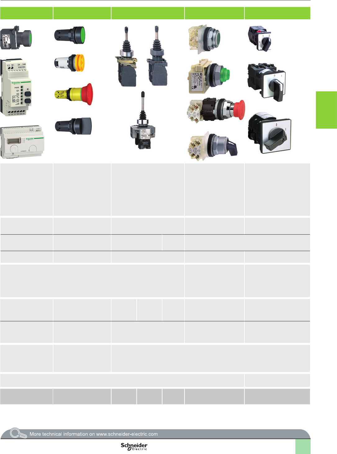
3/3
Type of products Pilot lights Pushbuttons, selector switches and pilot lights
Biometric switches
Wireless and batteryless
pushbuttons
Pushbuttons, selector
switches and pilot lights
Joystick controllers Pushbuttons, selector
switches and pilot lights
Cam switches
Description of range
b LED pilot lights b Pushbuttons
b Multiple-headed pushbuttons
b Emergency Stop pushbuttons
b Selector switches and key switches
b Illuminated pushbuttons
b Pilot lights
Fingerprint readers
24V c
b Stand-alone
biometric switches
b Stand-alone USB
biometric switches
b USB biometric
switches dedicated
to Schneider HMI (1)
b Wireless and
batteryless
pushbuttons and rope
pull switch
b Congurable receivers
b Access point
b Relay-antenna
b Mobile handy box or
plastic boxes for wall
mounting
b Pushbuttons
b Emergency Stop and
Emergency switching off
pushbuttons
b Selector switches and key
switches
b Illuminated pushbuttons
b Pilot lights
b 2 or 4 direction
b Stay put or spring return
b Pushbuttons
b Emergency Stop buttons
b Selector switches and key
switches
b Illuminated pushbuttons
b Pilot lights
b Switches
b Stepping switches
b Reversing and changeover
switches
b Ammeter switches
b Voltmeter switches
b Reversing switches
b Star-delta and reversing
star-delta switches
b Pole change switches
Features Products Monolithic, compact,
low consumption
Complete units or sub-assemblies (body + head) Monolithic Ready-to-use packs (2)
and “components” range
Monolithic Complete units or sub-assemblies
(body + head with lever)
Complete units or
sub-assemblies
(body + head)
Complete units or sub-
assemblies (body + front panel
+ head)
Bezel Double insulated Double insulated (3) Metal, chromium plated or
black
Double insulated Double insulated,
dark grey
Metal, chromium plated or
double insulated, black
Double insulated, dark grey
(or white for pilot lights)
Metal, chromium plated Double
insulated,
black
Metal, chromium plated or double insulated, black
Shape of head Circular Circular, square
or rectangular
Circular Circular or square – Transmitter with circular
head
Circular Circular Hexagonal Square
Drilling or cut-out for xing
Ø 8 mm and Ø 12
mm/0.315 in. and
0.472 in.
Ø 16 mm/0.630 in. Ø 22 mm/0.866 in. Ø 22 mm/0.866 in. Ø 30 mm/1.181 in. Ø 16 or Ø 22 mm/0.630 or
0.866 in.: series K10
Ø 22 mm/0.866 in. and multixing:
series K1/K2
4 holes, 48 or 68 centres: series
K30…K150
Degree of
protection
Conforming to
IEC 60529
IP 40
IP 65 with seal
IP 65 IP 66
IP 69K (
Selector switches and key switches,
multiple-headed pushbuttons and Emergency
Stop pushbuttons with
bellows)
IP 65 (control button)
IP 65 IP 65 (control buttons and
pilot lights)
IP 54 (Emergency switching
off pushbuttons)
IP 65 IP 66 IP 65 IP 66 IP 65: series K10
IP 40, IP 65 with seal: series
K1/K2
IP 40: series K30…K150
Conforming to
UL 508 and
CSA C22-2 N° 14
–
Enclosure type 4, 4X and 13
Enclosure type 12 Enclosure type 12 Enclosure type 3
(pushbuttons and
Emergency stop)
and 4 (pilot lights)
Enclosure type 4, 4X and 13
Enclosure type 4 and 13
(9001K)
Enclosure type 4, 4X, 13
(9001SK)
–
Cabling
Tags for
2.8 x 0.5 mm/0.110 x
0.020 in. connectors
or threaded
connector
Faston connectors
Solder pins for printed
circuit boards (3)
Fast connector
socket (4)
Spring clamp terminal connections
Screw clamp terminal connections
Faston connectors
Connector
With adaptor for printed circuit board
Cable or connectors Wireless (transmitter)
Through cable (receiver)
Screw and captive clamp
terminal connections
Faston clip connections (pilot
lights)
Screw and captive clamp terminal connections
Mounting Panel thickness 1…8 mm/
0.039…0.315 in.
1…6 mm/0.039…0.236 in. 1…6 mm/0.039…0.236 in.
0.5…6 mm/0.020…0.236 in.
(depending on model)
Type references XVLA XB6, XB6E XB4 XB5 XB5S XB5R, XB4R XB7 XD4PA XD2GA XD5PA 9001K, 9001SK K10, K1, K2, K30, K50,
K63, K115, K150
(1) Compatible with Magelis iPC, STU, OT, GXO, GT (except GT1000 series), GK, GH, and GTO models.
(2) Wireless and batteryless pushbutton and receiver ready-paired at the factory.
(3) For Harmony® XB6 only.
(4) For Harmony® XB6E only.
2
1
3
4
5
6
7
8
9
10
2
1
3
4
5
6
7
8
9
10

3/4
General
Presentation
The Harmony® XB4 range of metal control and signaling units combines simplicity
of installation, exibility and robustness. It meets the requirements of the majority of
industrial applications.
bThis range includes:
vPushbuttons and switches designed for Start/Stop control of machines and
installations, adjustment and parametering (contact functions): Pushbuttons,
selector/key switches, Emergency stop or Emergency switching off pushbuttons,
multiple-headed pushbuttons
vPilot lights designed for visual signaling (signaling functions)
vIlluminated pushbuttons designed for control and signaling
(contact functions + signaling functions)
bThese products are shown on the following pages in two forms:
vComplete units with chromium plated metal bezel
vSub-assemblies for user assembly (body sub-assemblies and head sub-
assemblies with chromium plated or black metal bezel)
bThe pushbutton and switch control offer (illuminated and non-illuminated) is both
broad and comprehensive:
vFlush, projecting, recessed, booted, spring return, push-pull, marked or
unmarked pushbuttons
vEmergency stop trigger action and mechanically latching pushbuttons
(conforming to standards EN/IEC 60204-1 and EN/ISO 13850)
vEmergency switching off mechanically latching pushbuttons (conforming to
standard IEC 60364-5-53)
vSelector switches with standard, long handle or knurled knob, key switches
vControllers
vWide choice of legends and legend holders
vWide choice of head colors
vWide choice of accessories and spare parts
bThe pilot light signaling offer includes pilot lights with integral LED and pilot lights
for BA 9s base tting bulbs. The two types of pilot lights are for direct supply or via
integral transformer.
bInnovative complementary offers are also available:
vMultiple-headed pushbuttons
vControl and signaling units for severe applications
vWireless and batteryless pushbuttons
vBiometric switches (see the Harmony® XB5 offer)
Installation
bHarmony® XB4 products are both simple and quick to install:
vMounting by single installer (self-maintaining of the head in its cut-out)
vClip-together component system (head, body, contact blocks and LED)
vFixing by a single locking screw
vAnti-loosening system for screw clamp terminals of contact blocks.
bVarious types of connection are available: Screw clamp, connector, Faston
connector, spring terminal or for printed circuit board.
Environment
bThe performance features of the Harmony® XB4 range meet the most demanding
international standards and approvals:
vEN/IEC 60947-1, EN/IEC 60947-5-1, EN/IEC 60947-5-4 and EN/IEC 60947-5-5
vUL 508, CSA C22-2 n° 14, GB 14048.5
vInternational certications: UL, CSA, CCC, GOST
vMarine certications: BV, RINA, LROS, DNV, GL
bThe range includes products for use in difcult industrial environments, due to:
vTheir high degree of protection for harsh environments (IP 66 / IP 69K)
vTheir resistance to high pressure cleaning
vTheir “all climates” TH compatibility
vA wide choice of contact blocks with various breaking capacities (low, standard or
high power switching)
For more technical information, please refer to our website www.schneider-electric.com.
Aquire the information
Control and signaling units Ø 22
Harmony® XB4, metal
Pushbuttons, switches and pilot lights
1
2
3
4
5
6
7
8
9
10
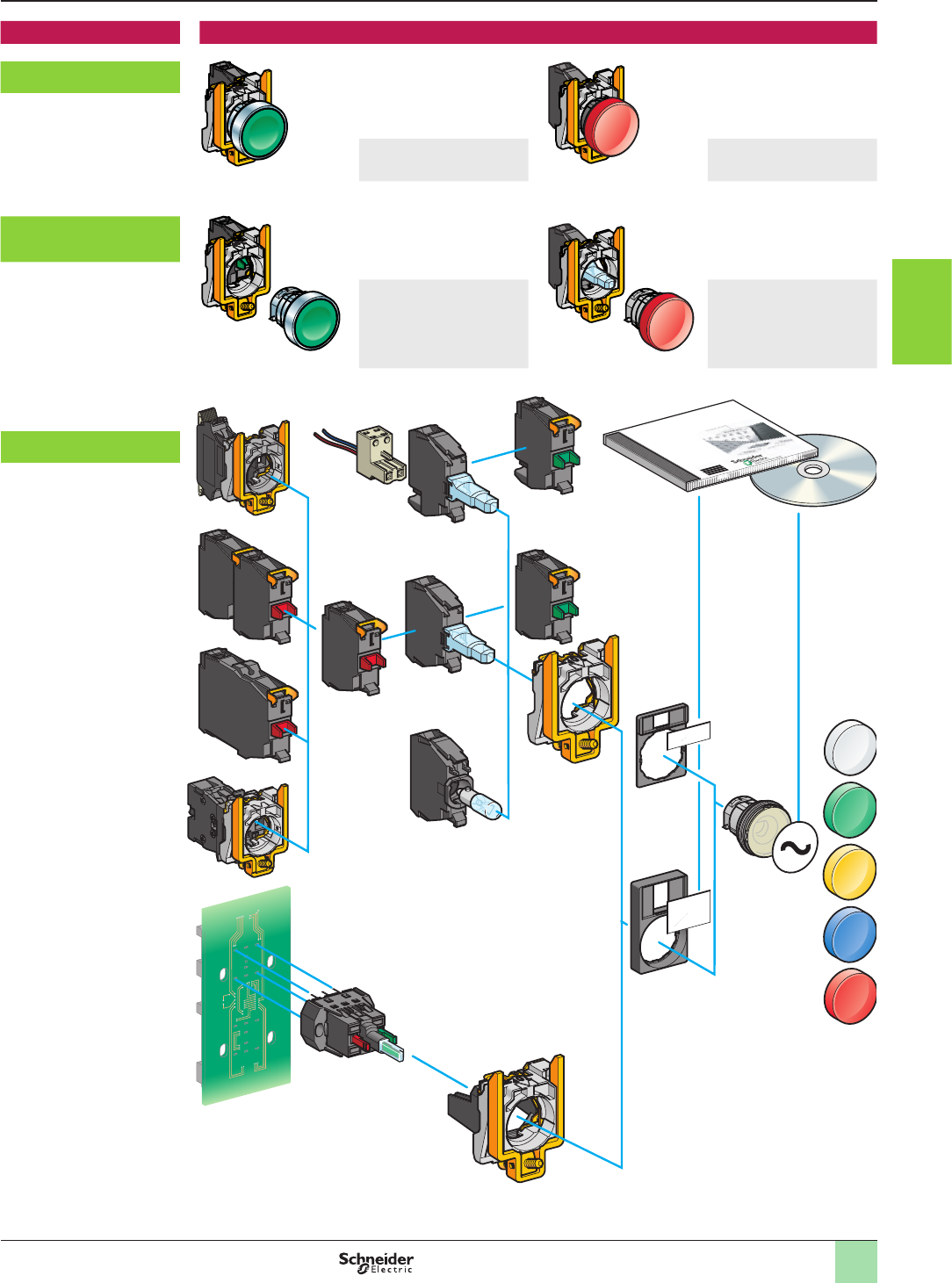
3/5
General (continued)
Description The Ø 22 mm/0.866 in. range of metal control and signaling units comprises:
Complete units XB4B, with
chromium plated metal bezel
Pushbuttons and switches Pilot lights
Sub-assemblies ZB4B, with
chromium plated or black
metal bezel
Pushbuttons and switches:
body + head
sub-assemblies
Pilot lights:
body + head
sub-assemblies
Component parts and
accessories, ZB
Labelling software
Logiciel de création d'étiquettes
Beschriftungssoftware
Software para crear etiquetas
Software per la creazione di etichette
SIS-Label
Merlin Gerin
Modicon
Square D
Telemecanique
Aquire the information
Control and signaling units Ø 22
Harmony® XB4, metal
Pushbuttons, switches and pilot lights
1
2
3
4
5
6
7
8
9
10
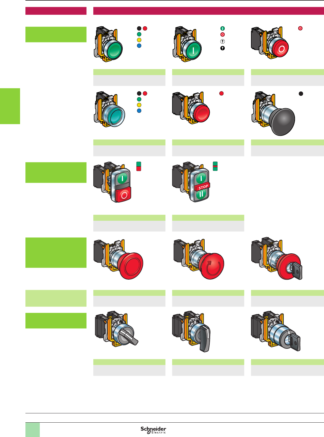
3/6
General
Complete units Contact functions
Pushbuttons, spring return,
with chromium plated metal
bezel
Flush push, unmarked Flush push, with marking Projecting push, with marking
XB4BAp1/BA42
(1)
XB4BA3311
(1)
XB4BL4322
(1)
Booted ush push Projecting push, unmarked Mushroom head
XB4BPp1/BP42
(1)
XB4BL42
(1)
XB4BC21
see page 3/12
Multiple-headed
pushbuttons, spring return,
with chromium plated metal
bezel
Double-headed Triple-headed
XB4BL73415
(1)
XB4BA731327/XB4BA711237
(1)
Emergency Stop or
Emergency switching off
mushroom head
pushbuttons, Ø 40 mm/1.57
in., with chromium plated
metal bezel
Emergency stop trigger
action and mechanical
latching
Push-pull (EN/ISO 13850) Turn to release (EN/ISO 13850) Key release (EN/ISO 13850)
XB4BT845
see page 3/14
XB4BS844p
see page 3/14
XB4BS9445
see page 3/14
Selector switches and key
switches, with chromium
plated metal bezel
Standard handle, black Long handle, black Key switch
XB4BDpp
(1)
XB4BJpp
(1)
XB4BGpp
(1)
Ø 40 mm/
1.57 in.
Ø 40 mm/
1.57 in.
Ø 40 mm/
1.57 in.
Ø 40 mm/
1.57 in.
Aquire the information
Control and signaling units Ø 22
Harmony® XB4, metal
Pushbuttons, switches and pilot lights:
complete units, XB4B
(1) Please refer to our website www.schneider-electric.com
1
2
3
4
5
6
7
8
9
10
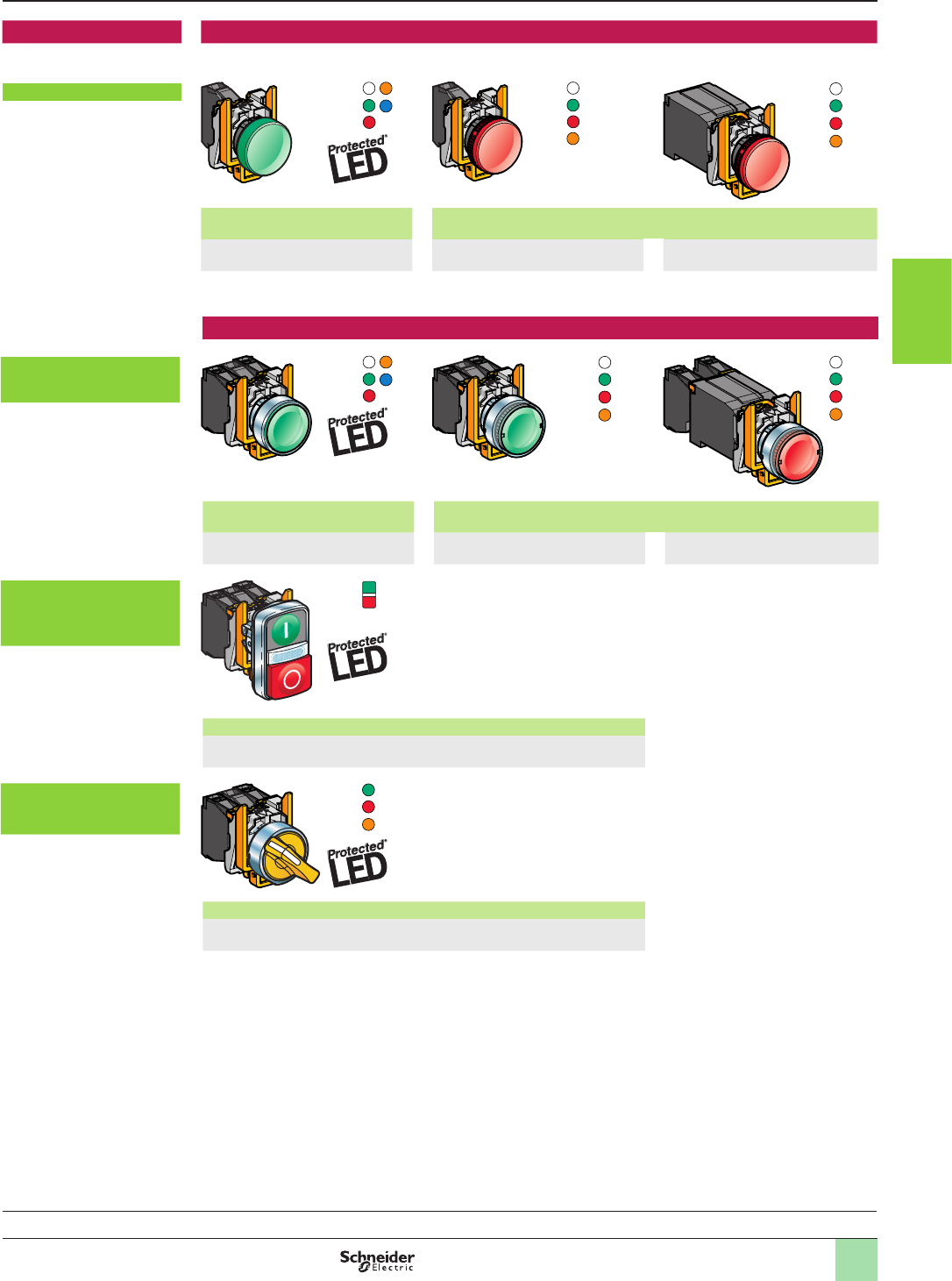
3/7
General (continued)
Complete units Signaling functions
Pilot lights
Integral LED For bulb with BA 9s base tting
Direct supply
Via integral transformer with secondary
XB4BVBp/BVGp/BVMp
(1)
XB4BV6p
(1)
XB4BV3p/BV4p
(1)
Combined functions (contact and signaling)
Illuminated pushbuttons,
spring return, ush push,
chromium plated metal bezel
Integral LED For bulb with BA 9s base tting
Direct supply
Via integral transformer
XB4BW3pB5/BW3pG5/BW3pM5
(1)
XB4BW3p65
(1)
XB4BW3p35/BW3p45
(1)
Double-headed pushbuttons
+ pilot light block, spring
return, chromium plated
metal bezel
Integral LED
XB4BW73731p5
(1)
Illuminated selector switches
with standard handle,
chromium plated metal bezel
Integral LED
XB4BK12pp5, XB4BK13pp5
(1)
Aquire the information
Control and signaling units Ø 22
Harmony® XB4, metal
Pushbuttons, switches and pilot lights:
complete units, XB4B
(1) Please refer to our website www.schneider-electric.com
1
2
3
4
5
6
7
8
9
10
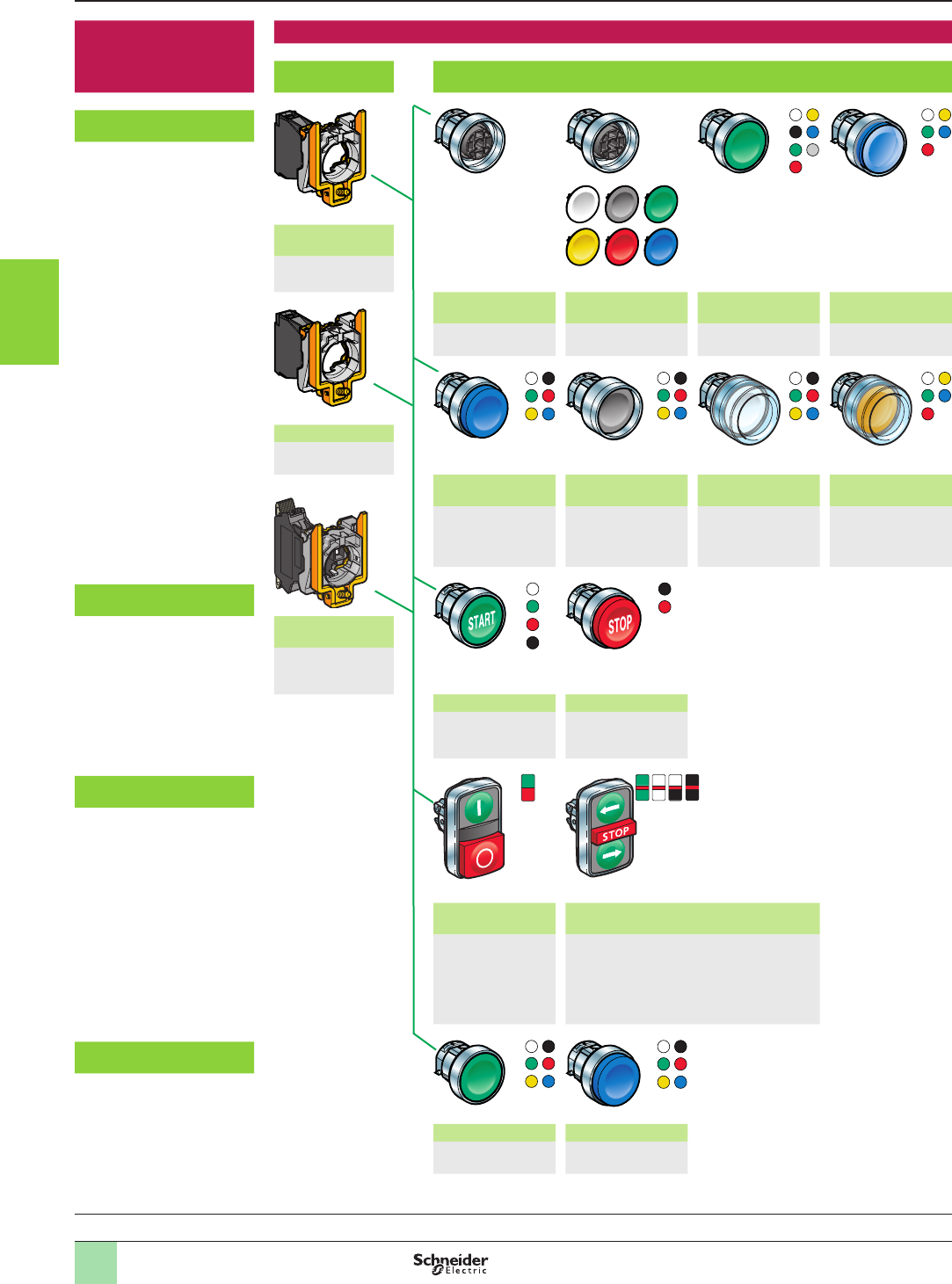
3/8
Non illuminated units
for user assembly
Contact functions
Body
sub-assemblies
Head sub-assemblies, chromium plated or black metal bezel
For pushbuttons,
spring return, unmarked
Screw clamp
terminals
ZB4BZ10p/BZ141
see page 3/28
Flush push
without cap
Flush push
with set of 6 caps
Flush push Flush push for
insertion of legend
ZB4BA0
(1)
ZB4BA9
(1)
ZB4BAp
(1)
ZB4BAp8
(1)
Faston
ZB4BZ10p3
(1)
Projecting push Recessed push Booted ush/
projecting push
Booted ush push
for insertion of legend
ZB4BLp
(1)
ZB4BAp6
(1)
ZB4BPp/ BPpS
(1)
ZB4BPp8
(1)
For pushbuttons,
spring return, with marking
Spring clamp
terminals
ZBE10p5
ZB4BZ10p5
(1)
Flush push Projecting push
ZB4BA
p
3
p
/BA
p
4
p
ZB4BA334/335
(1)
ZB4BLp3p
(1)
For multiple-headed
pushbuttons, spring return
Double-headed
pushbuttons
Triple-headed pushbuttons
ZB4BA7
ppp
ZB4BA79
ZB4BL734
p
(1)
ZB4BA7313
p
ZB4BA711
pp
ZB4BA72124
ZB4BA791
(1)
For “push-push to release”
pushbuttons
Flush push Projecting push
ZB4BH0
p
(1)
ZB4BHp
(1)
General Aquire the information
Control and signaling units Ø 22
Harmony® XB4, metal
Pushbuttons, switches and pilot lights:
sub-assemblies, ZB4B
(1) Please refer to our website www.schneider-electric.com
1
2
3
4
5
6
7
8
9
10
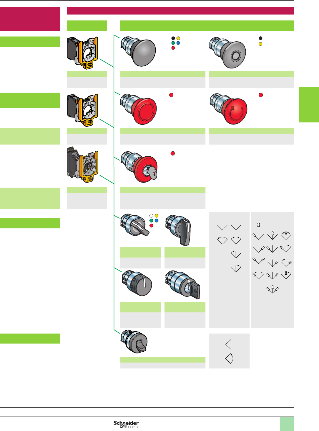
3/9
Ø 30
Ø 40
Ø 60
Ø 30
Ø 40
Ø 60
Non illuminated units
for user assembly
(continued)
Contact functions
Body
sub-assemblies
Head sub-assemblies, chromium plated or black metal bezel
For mushroom head
pushbuttons
Screw clamp terminals Spring return Latching
ZB4BZ10p/BZ141
see page 3/28
ZB4BCp/BRp
see page 3/12
ZB4Bp2/BSp2/BS55
see page 3/13
For Emergency Stop or
Emergency switching off
mushroom head pushbuttons
Emergency stop trigger
action and mechanical
latching
Faston Push-pull (EN/ISO 13850) Turn to release (EN/ISO 13850)
ZB4BZ10p3
(1)
ZB4BT84
see page 3/14
ZB4BS8p4
see page 3/14
Emergency stop trigger
action and mechanical
latching
Spring clamp terminals
Key release (EN/ISO 13850)
ZBE10p5
ZB4BZ10p5
(1)
ZB4BS9
p
4
see page 3/14
(2) Switch handle
and knob positions
(3) Key switch
positions
Key withdrawal
positions
For selector switches
and key switches
Standard black
handle (2)
Long black handle
(2)
ZB4BD
p
(1)
ZB4BJp
(1)
Knurled black knob
(2)
Key switch (3)
ZB4BDp9
(1)
ZB4BGpp/
BGpTEC10
(1)
For toggle switches (4) Lever positions
2-position lever (4)
ZB4BDp8,
(1)
General (continued)
Ø 30
Ø 40
Ø 60
Ø 30
Ø 40
Ø 60
Ø 30
Ø 40
Ø 60
Ø 30 mm/1.181 in.
Ø 40 mm/1.575 in.
Ø 60 mm/2.362 in.
Ø 30 mm/1.181 in.
Ø 40 mm/1.575 in.
Ø 60 mm/2.362 in.
Ø 30 mm/1.181 in.
Ø 40 mm/1.575 in.
Ø 60 mm/2.362 in.
Ø 30 mm/1.181 in.
Ø 40 mm/1.575 in.
Ø 60 mm/2.362 in.
Ø 30 mm/1.181 in.
Ø 40 mm/1.575 in.
Ø 60 mm/2.362 in.
Aquire the information
Control and signaling units Ø 22
Harmony® XB4, metal
Pushbuttons, switches and pilot lights:
sub-assemblies, ZB4B
(1) Please refer to our website www.schneider-electric.com
1
2
3
4
5
6
7
8
9
10
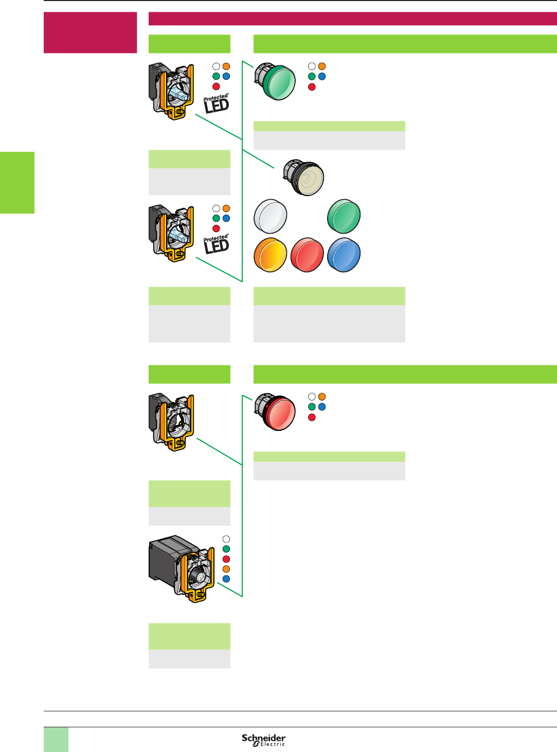
3/10
Pilot lights
for user assembly
Signaling functions
Body sub-assemblies
with integral LED
Head sub-assemblies
With lens tted
ZB4BV0p3
(1)
Connection: screw
clamp terminals
ZB4BVJp/BVBp/BVGp/
BVMp
(1)
Connection: plug-in
connector
With 5 separate lenses, not tted
ZB4BVBp4/BVGp4/
BVMp4
ZB4BV003
(1)
please consult our
Customer Care Centre
Body sub-assemblies
for BA 9s bulb
Head sub-assemblies
With lens tted
ZB4BV0p, ZB4BV0pS
(1)
Direct supply
Connection: screw
clamp terminals
ZB4BV6
(1)
Via integral transformer
Connection: screw clamp
terminals
ZB4BVpDp
(1)
General (continued) Aquire the information
Control and signaling units Ø 22
Harmony® XB4, metal
Pushbuttons, switches and pilot lights:
sub-assemblies, ZB4B
(1) Please refer to our website www.schneider-electric.com
1
2
3
4
5
6
7
8
9
10
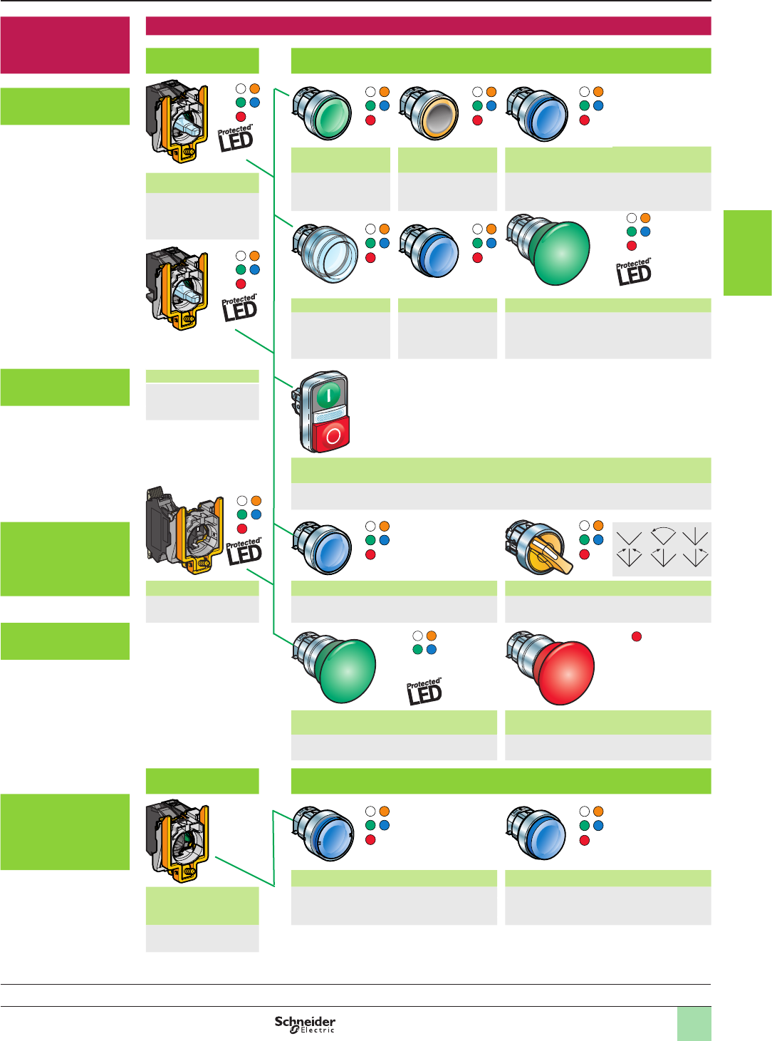
3/11
Illuminated
pushbuttons
for user assembly
Combined functions (contact and signaling)
Body sub-assemblies
with integral LED
Head sub-assemblies, chromium plated or black metal bezel
For illuminated
pushbuttons,
spring return
Flush push Flush push with
illuminated ring
Flush push for insertion of legend
Screw clamp terminals ZB4BW3p3
(1)
ZB4BW9p3
(1)
ZB4BAp8
(1)
ZB4BW0Bpp/BW0Gpp/
BW0Mpp
(1)
Booted ush push Projecting push Mushroom head, spring return
ZB4BW5p3
(1)
ZB4BW1p3,
ZB4BW1p3S
(1)
ZB4BW4p3
(1)
For illuminated double-
headed pushbuttons,
spring return
Plug-in connector
ZB4BW0Bpp4
please consult our
Customer Care Centre
Double-headed (ush/ush push) + central pilot light
Double-headed (ush/projecting push) + central pilot light
ZB4BW7A17
pp
/ ZB4BW7A374
p
/
ZB4BW7A9
, (1)
ZB4BW7L374
p, (1)
For illuminated
“push-push to release”
pushbuttons and
illuminated selector
switches with standard
handle Spring clamp terminals Flush or projecting “push-push to release” Selector switches with standard handle
ZBVppp
(1)
ZB4BH0p3/BHp3
(1)
ZB4BK1pp3
(1)
For illuminated
mushroom head
pushbuttons
Mushroom head, latching Emergency switching off,
mechanical latching, push-pull
ZB4BW6p3
(1)
ZB4BW643
see page 3/14
Body sub-assemblies
for BA 9s bulb
Head sub-assemblies, chromium plated or black metal bezel
For illuminated
pushbuttons,
spring return
Flush push Projecting push
Direct supply or via
integral transformer
Screw clamp terminals
ZB4BW3p,
ZB4BW3pS
(1)
ZB4BW1p,
ZB4BW1pS
(1)
ZB4BW0ppp
(1)
General (continued) Aquire the information
Control and signaling units Ø 22
Harmony® XB4, metal
Pushbuttons, switches and pilot lights:
sub-assemblies, ZB4B
(1) Please refer to our website www.schneider-electric.com
1
2
3
4
5
6
7
8
9
10
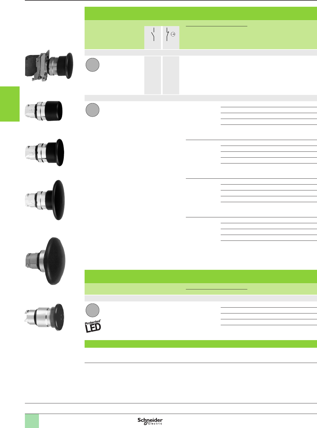
3/12
Mushroom head pushbuttons (1) (2)
Screw clamp terminal connections (Schneider Electric anti-loosening system)
Shape
of head
Type
of push
Type of contact Push Reference Weight
kg/lb
Ø (mm/in.) Color
N/O N/C
Complete units
Mushroom head 1 –
40/1.575 Black XB4BC21
(ZB4BZ101 + ZB4BC2)
0.122/0.269
Heads only
Mushroom head 30/1.181 Black ZB4BC24 0.075/0.165
Green ZB4BC34 0.075/0.165
Red ZB4BC44 0.075/0.165
Yellow ZB4BC54 0.075/0.165
Blue
ZB4BC64 0.075/0.165
40/1.575 Black ZB4BC2 0.074/0.163
Green ZB4BC3 0.074/0.163
Red ZB4BC4 0.074/0.163
Yellow ZB4BC5 0.074/0.163
Blue
ZB4BC6 0.074/0.163
60/2.362 Black ZB4BR2 0.093/0.205
Green ZB4BR3 0.093/0.205
Red ZB4BR4 0.093/0.205
Yellow ZB4BR5 0.093/0.205
Blue
ZB4BR6 0.093/0.205
60/2.362 (3)
Hemispherical
Black ZB4BR216 0.054/0.119
Green ZB4BR316 0.054/0.119
Red ZB4BR416 0.054/0.119
Yellow ZB4BR516 0.054/0.119
Blue
ZB4BR616 0.054/0.119
Illuminated mushroom head pushbuttons (1) (2)
Integral LED
Shape
of head
Type
of push
Push Reference Weight
kg/lb
Ø (mm/in.) Color
Heads only (4)
Mushroom head 40/1.575 White ZB4BW413 0.051/0.112
Green ZB4BW433 0.051/0.112
Red ZB4BW443 0.051/0.112
Orange ZB4BW453 0.051/0.112
Blue
ZB4BW463 0.051/0.112
Heads with black metal bezel
To order, add a gure 7 to the references selected above.
Example: ZB4BC24 becomes ZB4BC247.
(1) These pushbuttons and heads cannot be used for an Emergency Stop function.
Therefore, it is recommended that a legend with a black or white background is used.
(2) Recommended maximum number of contacts constituting the body (xing collar + contact) associated with the head,
“Please refer to our website www.schneider-electric.com”
(3) Ergonomic product used in two-handed control applications. Recommended maximum number of contacts constituting the
body (xing collar + contact) associated with the head: 6.
(4) Only for use with bodies comprising a light block with integral LED.
References
814088
XB4BC21
814166
ZB4BC24
814167
ZB4BC2
814168
ZB4BR2
103543
ZB4BR216
ZB4BW443
General:
page 3/4
103544
Aquire the information
Control and signaling units Ø 22
Harmony® XB4, metal
Mushroom head pushbuttons, spring return
1
2
3
4
5
6
7
8
9
10
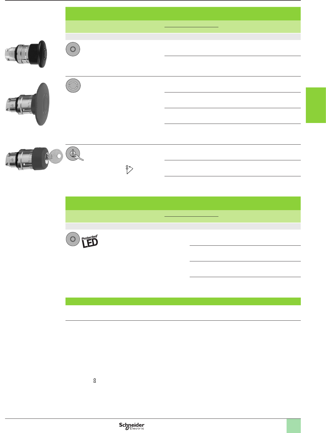
3/13
References
Mushroom head pushbuttons (1) (2)
Shape
of head
Type
of reset
Push Reference Weight
Ø (mm/in.) Color kg/lb
Heads only
Push-pull 40/1.575 Black
ZB4BT2 0.077/0.170
60/2.362 Black
ZB4BX2 0.095/0.209
Turn to release 30/1.181 Black
ZB4BS42 0.066/0.146
40/1.575 Black
ZB4BS52 0.070/0.154
40/1.575 Yellow
ZB4BS55 0.070/0.154
60/2.362 Black
ZB4BS62 0.090/0.198
Key release
(key n° 455)
(2 keys included
with head) (3)
(5)
30/1.181 Black
ZB4BS72 0.066/0.146
40/1.575 Black
ZB4BS12 (4) 0.070/0.154
60/2.362 Black
ZB4BS22 0.090/0.198
Illuminated mushroom head pushbuttons (1) (2)
Integral LED
Shape
of head
Type
of reset
Push Reference Weight
Ø (mm/in.) Color kg/lb
Heads only
Mushroom head 40/1.575 White
ZB4BW613 0.051/0.112
Green
ZB4BW633 0.051/0.112
Orange
ZB4BW653 0.051/0.112
Blue
ZB4BW663 0.051/0.112
Heads with black metal bezel
To order, add a gure 7 to the references selected above.
Example: ZB4BT2 becomes ZB4BT27.
(1) These pushbuttons and heads cannot be used for an Emergency Stop function.
Therefore, it is recommended that a legend with a black or white background is used.
(2) Recommended maximum number of contacts constituting the body (xing collar + contact) associated with the head,
“Please refer to our website www.schneider-electric.com”
(3) For specic keys with other numbers, please consult our Customer Care Centre.
(4) Other key numbers:
- key n° 421E: add sufx 12 to the reference.
- key n° 458A: add sufx 10 to the reference.
- key n° 520E: add sufx 14 to the reference.
- key n° 3131A: add sufx 20 to the reference.
Example: To order a Ø 40 black mushroom head for a latching pushbutton, with release by key n° 421E, the reference
becomes: ZB4BS1212.
(5) The symbol indicates key withdrawal position(s).
523766
ZB4BS72
523765
ZB4BS62
110130
ZB4BT2
Aquire the information
Control and signaling units Ø 22
Harmony® XB4, metal
Mushroom head pushbuttons, latching
1
2
3
4
5
6
7
8
9
10
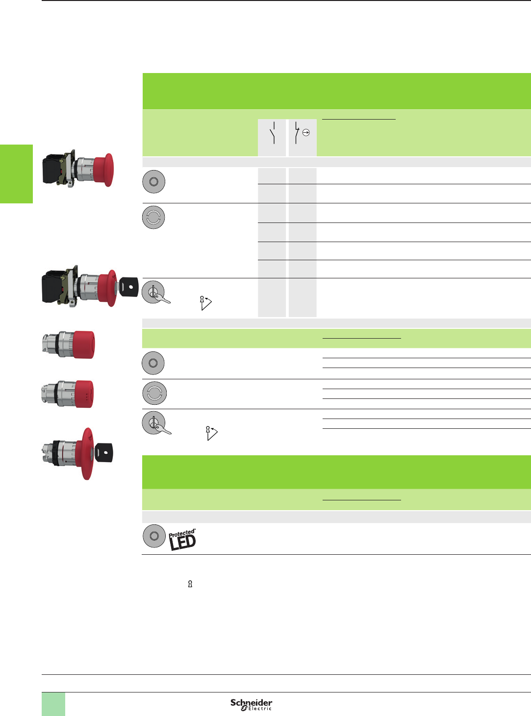
3/14
Emergency stop function: Mushroom head Emergency stop trigger action and mechanical latching pushbuttons
conform to standards EN/IEC 60204-1 and EN/ISO 13850, to Machinery Directive 2006/42/EC and to standard
EN/IEC 60947-5-5.
Emergency switching off function: Mushroom head switching off mechanical latching pushbuttons conform to
standards IEC 60364-5-53 and EN/IEC 60947-5-5.
Please consult our Customer Care Centre for a full explanation of these standards and directives.
Emergency stop and switching off pushbuttons with trigger action and mechanical
latching (1) (2)
Screw clamp terminal connections (Schneider Electric anti-loosening system)
Shape
of head
Type
of reset
Type of contact Push Reference Weight
kg/lb
Ø (mm)/in.Color
N/O N/C
Complete units
Push-pull – 1 40/1.575 Red
XB4BT842
(ZB4BZ105 + ZB4BT84)
0.125/0.276
1 1 40/1.575 Red XB4BT845
(ZB4BZ105 + ZB4BT84)
0.136/0.300
Turn to release – 1 40/1.575 Red
XB4BS8442
(ZB4BZ102 + ZB4BS844)
0.118/0.260
1 1 40/1.575 Red XB4BS8445
(ZB4BZ105 + ZB4BS844)
0.130/0.287
– 2 40/1.575 Red
XB4BS8444
(ZB4BZ104 + ZB4BS844)
0.130/0.287
1 2 40/1.575 Red
XB4BS84441
(ZB4BZ141 + ZB4BS844)
0.140/0.309
Key release
(key n° 455) (3)
1 1 40/1.575 Red XB4BS9445
(ZB4BZ105 + ZB4BS944)
0.170/0.375
Heads only
Shape
of head
Type
of reset
Push Reference Weight
Ø (mm)/in. Color kg/lb
Push-pull 30/1.181 Red ZB4BT844 0.078/0.172
40/1.575 Red ZB4BT84 0.078/0.172
60/2.362 Red ZB4BX84 0.098/0.216
Turn to release 30/1.181 Red ZB4BS834 0.068/0.150
40/1.575 Red ZB4BS844 0.073/0.161
60/2.362 Red ZB4BS864 0.093/0.205
Key release (key n° 455)
2 keys included with head (5) (3)
30/1.181 Red ZB4BS934 0.094/0.207
40/1.575 Red ZB4BS944 (4) 0.098/0.216
60/2.362 Red ZB4BS964 0.118/0.260
Illuminated Emergency switching off function only, mechanical latching
pushbuttons (1)
Screw clamp terminal connections (Schneider Electric anti-loosening system)
Shape
of head
Type
of reset
Push Reference Weight
kg/lb
Ø (mm)/in.Color
Heads only (6)
Push-pull 40/1.575 Red ZB4BW643 0.051/0.112
(1) Recommended maximum number of contacts constituting the body (xing collar + contact) associated with the head,
“Please refer to our website www.schneider-electric.com”
(2) It is recommended that a legend or yellow background is used.
(3) The symbol indicates key withdrawal position(s).
(4) Other key numbers:
- key n° 421E: add sufx 12 to the reference.
- key n° 458A: add sufx 10 to the reference.
- key n° 520E: add sufx 14 to the reference.
- key n° 3131A: add sufx 20 to the reference.
- key n° 4A185: add sufx D to the reference.
Example: To order a Ø 40 red mushroom head for a trigger action and mechanical latching Emergency stop pushbutton, with
release by key n° 421E, the reference becomes: ZB4BS94412.
(5) For specic keys with other numbers, please consult our Customer Care Centre.
(6) Only for use with bodies comprising a light source with integral LED.
References
BS5 aruØ40 .EPS
BS1 aruØ40.EPS
BT aruØ40 .EPS
General:
page 3/4
PF512504
XB4BT845
PF512505
XB4BS9445
ZB4BT844
PF512506
ZB4BS834
PF512507
ZB4BS964
PF512508
Aquire the information
Control and signaling units Ø 22
Harmony® XB4, metal
Emergency stop and Emergency switching off functions
Conforming to EN/IEC 60204-1, 60364-5-53,
EN/ISO 13850 and Machinery Directive 2006/42/EC
1
2
3
4
5
6
7
8
9
10
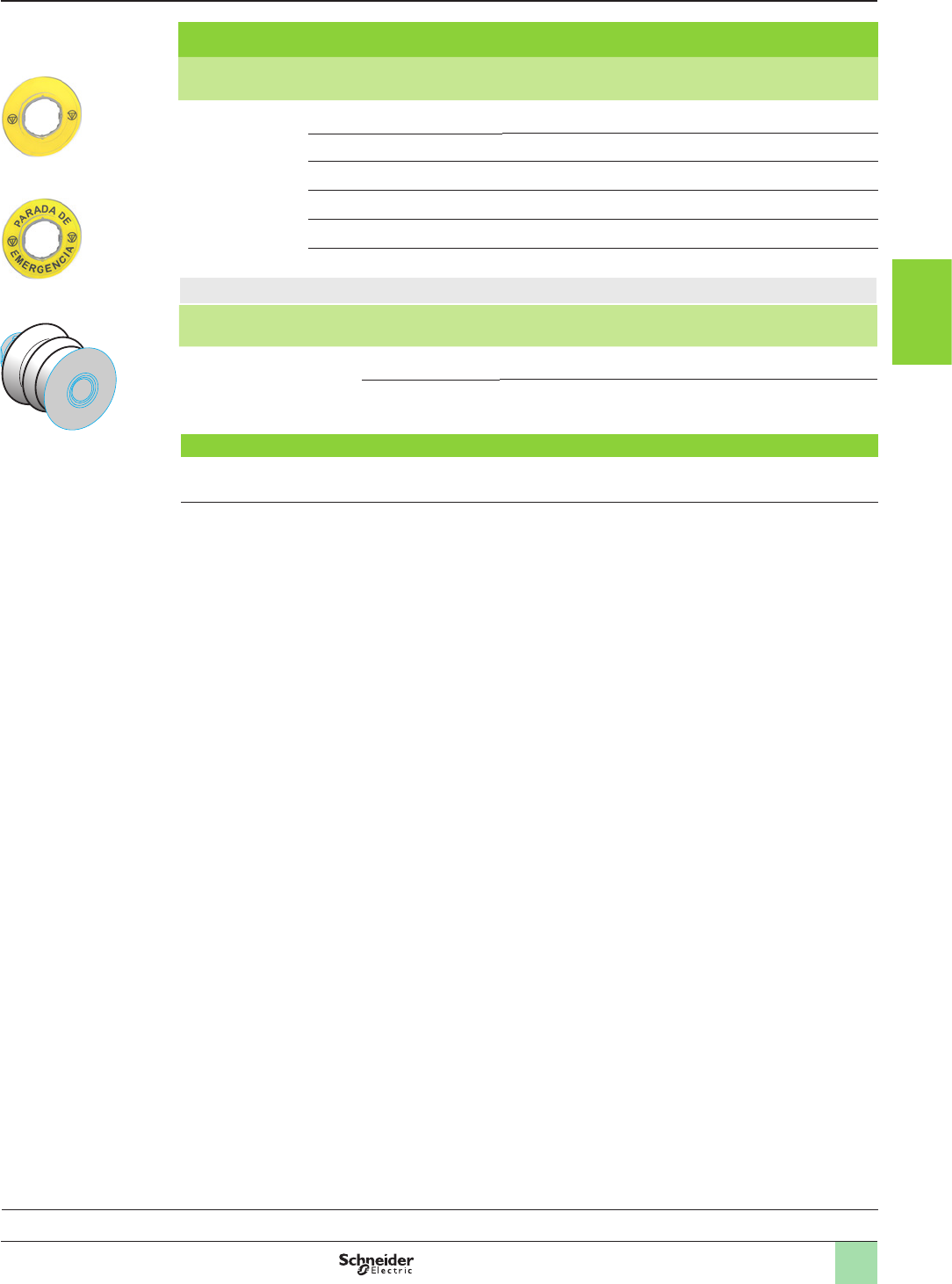
3/15
Circular yellow legends for Emergency stop (1)
Description Marking Color Reference Weight
kg/lb
Ø 60 mm/2.362 in.
legend for
Emergency stop
function
- Yellow ZBY9121 0.007/0.015
EMERGENCY STOP Yellow ZBY9320 0.007/0.015
ARRET D’URGENCE Yellow ZBY9120 0.007/0.015
NOT HALT Yellow ZBY9220 0.007/0.015
PARADA DE EMERGENCIA Yellow ZBY9420 0.007/0.015
ARRESTO DI EMERGENZA Yellow ZBY9620 0.007/0.015
Bellows for harsh environments (IP 69K) (2)
For use in Material For use with Color Sold in
lots of
Unit
reference
Weight
kg/lb
Environments
subject to
humidity, dust, high
pressure
cleaning, etc.
Silicone Emergency stop /
Switching off function
Yellow 2ZBZ28 0.009/0.020
Other functions Black 2ZBZ58 0.009/0.020
Heads with black metal bezel
To order, add a gure 7 to the references selected above.
Example: ZB4BT844 becomes ZB4BT8447.
(1) Other legend models for Emergency stop and Emergency switching off function “Please refer to our website
www.schneider-electric.com”
(2) Not compatible with Ø 30 pushbutton.
References
General:
page 3/4
ZBZp8
DF524008
ZBY9121
PF131618A
ZBY9420
PF131622A
Aquire the information
Control and signaling units Ø 22
Harmony® XB4, metal
Emergency stop and Emergency switching off functions
Conforming to EN/IEC 60204-1, 60364-5-53,
EN/ISO 13850 and Machinery Directive 2006/42/EC
1
2
3
4
5
6
7
8
9
10

3/16
General Aquire the information
Control and signaling units Ø 22
Harmony® XB5, plastic
Pushbuttons, switches and pilot lights
Presentation
The Harmony® XB5 range of plastic control and signaling units combines simplicity
of installation and exibility. It provides a solution for industrial applications
demanding a high resistance to chemical agents and also provides double
electrical insulation.
b This range includes:
v Pushbuttons and switches designed for Start/Stop control of machines and
installations, adjustment and parametering (contact functions): Pushbuttons,
selector/key switches, Emergency stop or Emergency switching off pushbuttons,
multiple-headed pushbuttons
v Pilot lights designed for visual signaling (signaling functions)
v Illuminated pushbuttons designed for control and signaling (contact functions +
signaling functions)
b These products are shown on the following pages in two forms:
v Complete units with black plastic bezel
v Sub-assemblies for user assembly (body sub-assemblies and head
sub-assemblies with black plastic bezel
b The pushbutton and switch control offer (illuminated and non-illuminated) is both
broad and comprehensive:
v Flush, projecting, recessed, booted, spring return, push-pull, marked or
unmarked pushbuttons
v Emergency stop trigger action and mechanically latching pushbuttons
(conforming to standards EN/IEC 60204-1 and EN/ISO 13850)
v Emergency switching off mechanically latching pushbuttons (conforming to
standard IEC 60364-5-53)
v Selector switches with standard handle, long handle or knurled knob, key switches
v Controllers
v Wide choice of legends and legend holders
v Wide choice of head colors
v Wide choice of accessories and spare parts
b The pilot light signaling offer includes pilot lights with integral LED and pilot lights
for BA 9s base tting bulbs. The two types of pilot light are for direct supply or via
integral transformer.
b The XB5 range also includes innovative complementary offers:
v Multiple-headed pushbuttons
v Control and signaling units for harsh applications
v Wireless and batteryless pushbuttons
v Biometric switches
Installation
b Harmony® XB5 products are both simple and quick to install:
v Mounting by single installer (self-maintaining of the head in its cut-out)
v Clip-together component system (head, body, contact blocks and LED)
v Fixing by a single nut (anti-rotation plate)
v Anti-loosening system for screw clamp terminals of contact blocks (thus avoiding
frequent checking/retightening).
b Various types of connection are available: Screw clamp, connector, Faston
connector, spring terminal or for printed circuit board.
Environment
b The performance features of the Harmony® XB5 range meet the most demanding
international standards and approvals:
v EN/IEC 60947-1, EN/IEC 60947-5-1, EN/IEC 60947-5-4 and EN/IEC 60947-5-5
v UL 508, CSA C22-2 n° 14, GB 14048.5
v International certications: UL, CSA, CCC, GOST
v Marine certications: BV, RINA, LROS, DNV, GL
b The range includes products for use in difcult industrial environments, due to:
v Their high degree of protection for severe environments (IP 66/IP 69K)
v Their resistance to high pressure cleaning
v Their “all climates” TH compatibility
v A wide choice of contact blocks with various breaking capacities (low, standard or
high power switching)
For more technical information, please refer to our website www.schneider-electric.com.
1
2
3
4
5
6
7
8
9
10
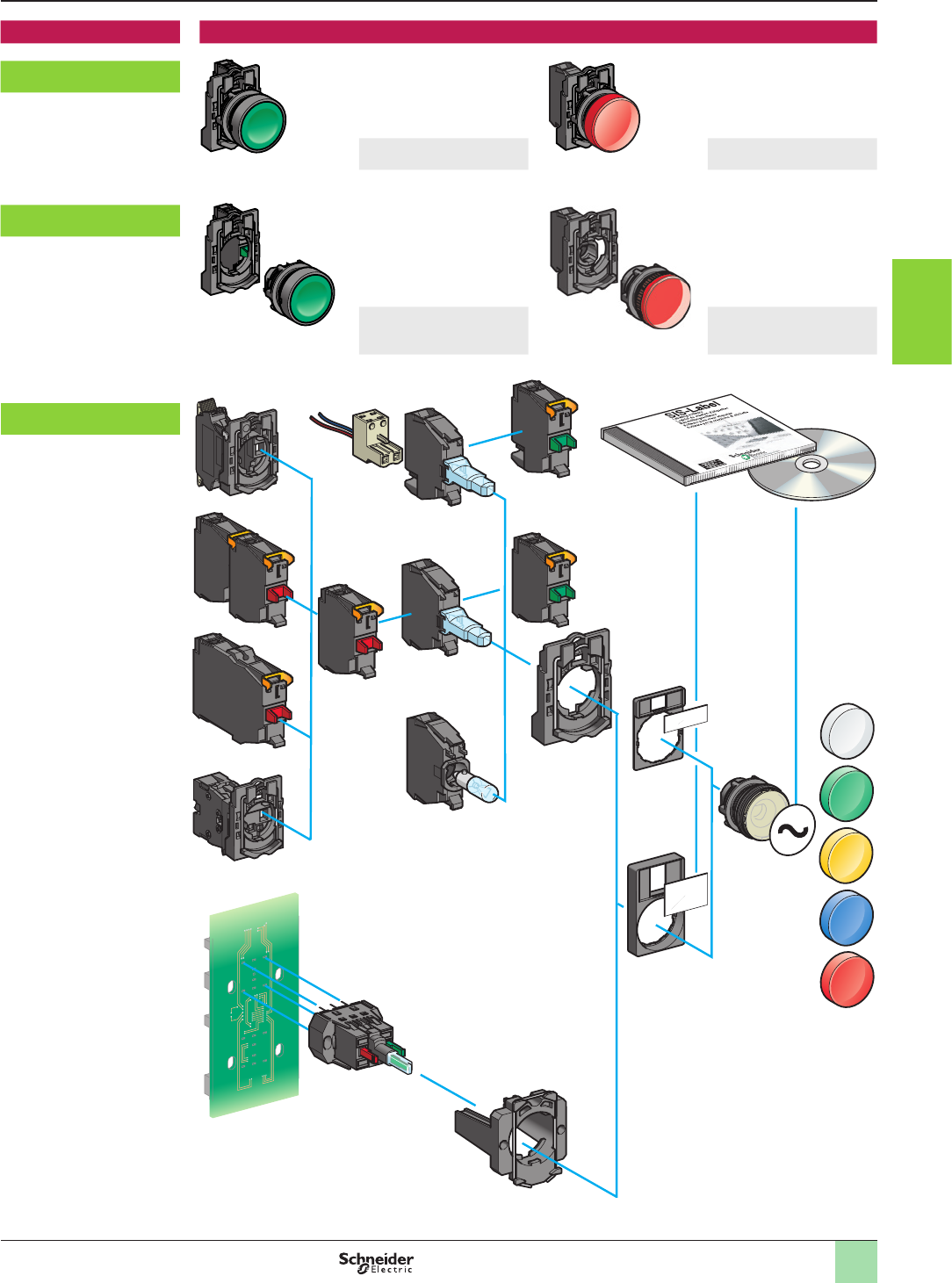
3/17
Description The Ø 22 range of plastic (double insulated) control and signaling units comprises:
Complete units, XB5A
Pushbuttons and switches Pilot lights
Sub-assemblies, ZB5A
Pushbuttons and switches:
body + head
sub-assemblies
Pilot lights:
body + head
sub-assemblies
Component parts and
accessories, ZB
General (continued) Aquire the information
Control and signaling units Ø 22
Harmony® XB5, plastic
Pushbuttons, switches and pilot lights
1
2
3
4
5
6
7
8
9
10
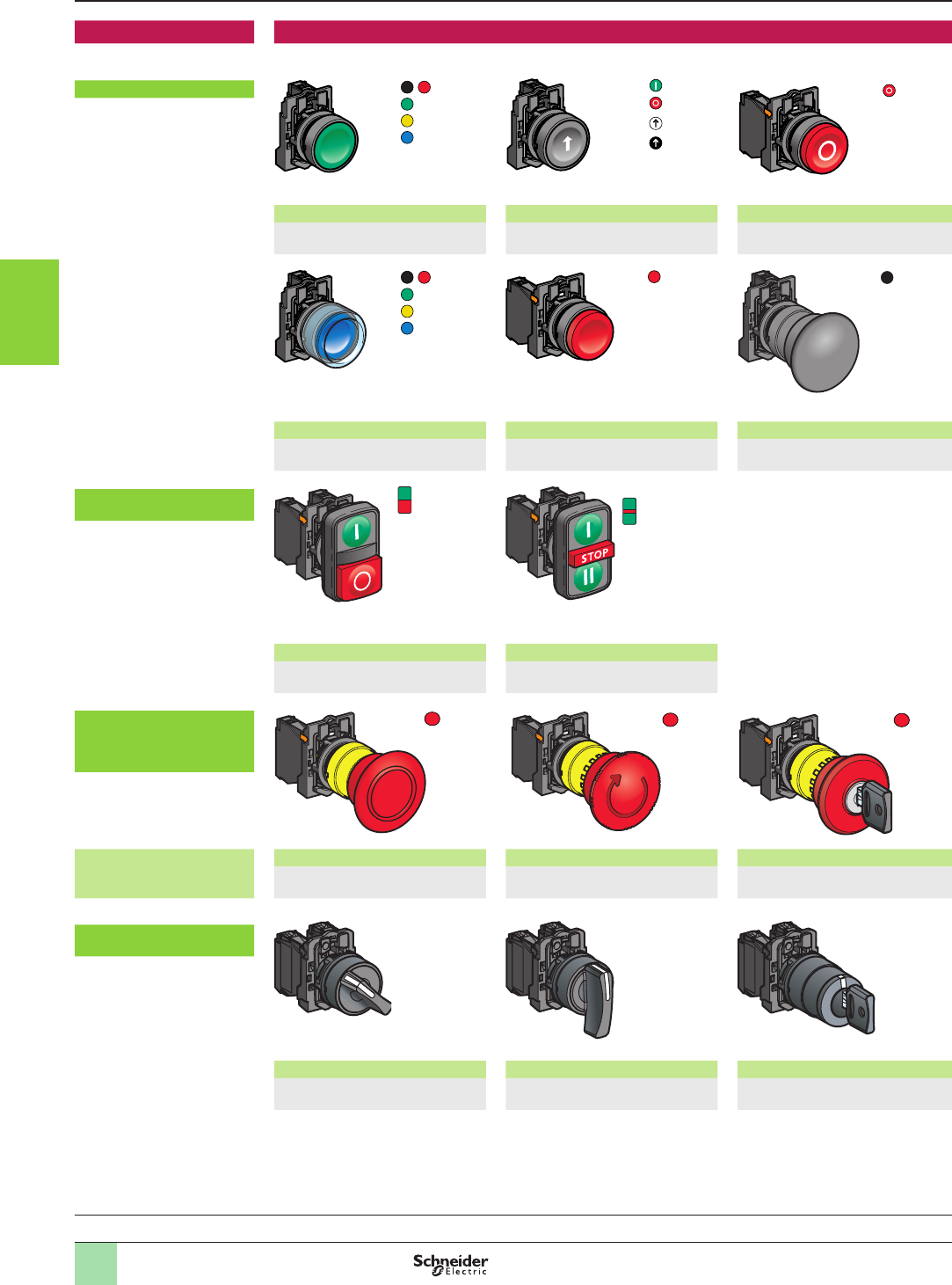
3/18
Complete units Contact functions
Pushbuttons, spring return
Flush push, unmarked Flush push, marked Projecting push, marked
XB5AAp1/AA42
(1)
XB5AA3311/AA33p1
(1)
XB5AL4322
(1)
Booted ush push Projecting push, unmarked Mushroom head
XB5APp1/AP42
(1)
XB5AL42
(1)
XB5AC21
(1)
Multiple-headed
pushbuttons, spring return
Double-headed Triple-headed
XB5AL73415
(1)
XB5AA731327/XB5AA711237
(1)
Emergency Stop or
Emergency switching off
mushroom head
pushbuttons, Ø 40/1.575 in.
Emergency stop trigger
action and mechanical
latching
Push-pull (EN/ISO 13850) Turn to release (EN/ISO 850) Key release (EN/ISO 13850)
XB5AT845
see page 3/26
XB5AS8p4
see page 3/26
XB5AS9445
see page 3/26
Selector switches
and key switches
Standard handle, black Long handle, black Key switch
XB5ADpp
(1)
XB5AJpp
(1)
XB5AGpp
(1)
General
Ø 40
/1.575 in.
Ø 40
/1.575 in.
Ø 40
/1.575 in.
Ø 40
/1.575 in.
Aquire the information
Control and signaling units Ø 22
Harmony® XB5, plastic
Pushbuttons, switches and pilot lights:
complete units, XB5A
(1) Please refer to our website www.schneider-electric.com
1
2
3
4
5
6
7
8
9
10
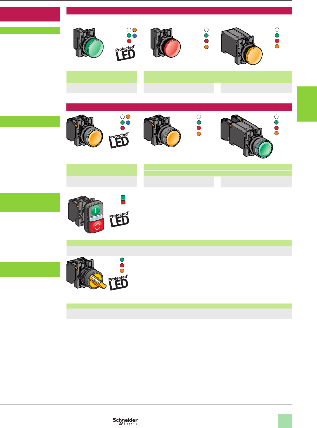
3/19
Complete units
(continued)
Signaling functions
Pilot lights
Integral LED For bulb with BA 9s base tting
Direct supply Via integral transformer
XB5AVBp/AVGp/AVMp
(1)
XB5AV6p
(1)
XB5AV3p/AV4p
(1)
Combined functions (contact and signaling)
Illuminated pushbuttons,
spring return, ush push
Integral LED For bulb with BA 9s base tting
Direct supply Via integral transformer
XB5AW3pB5/AW3pG5/AW3pM5
(1)
XB5AW3p65
(1)
XB5AW3p35/AW3p45
(1)
Double-headed pushbuttons,
spring return, and pilot light
block
Integral LED
XB5AW73731p5
(1)
Illuminated selector
switches, standard handle
Integral LED
XB5AK12pp5, XB5AK13pp5
(1)
General (continued) Aquire the information
Control and signaling units Ø 22
Harmony® XB5, plastic
Pushbuttons, switches and pilot lights:
complete units, XB5A
(1) Please refer to our website www.schneider-electric.com
1
2
3
4
5
6
7
8
9
10
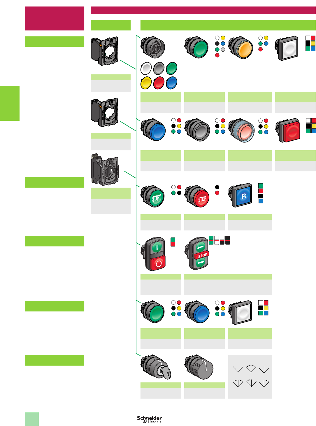
3/203/20
Non illuminated units
for user assembly
Contact functions
Body
sub-assemblies
Head sub-assemblies
For pushbuttons,
spring return, unmarked
Screw clamp terminals
ZB5AZ10p/AZ141
see page 3/28
Flush push without
cap/with set of 6 caps
Flush push Flush push for
insertion of legend
Flush push, cap
mounted/not mounted
ZB5AA0/AA9
(1)
ZB5AAp
(1)
ZB5AAp8
(1)
ZB5CA0/CAp
(1)
Faston
ZB5AZ10p3
(1)
Projecting Recessed push Booted ush push,
for insertion of legend
Projecting or
recessed push
ZB5ALp
(1)
ZB5AAp
(1)
ZB5APpp/APpS
(1)
ZB5CAp/CLp
(1)
For pushbuttons,
spring return, marked
Spring clamp
terminals
ZBE10p5
ZB5AZ10p5
(1)
Flush push Projecting push Flush push
ZB5AA
p
3
p
/
AAp4p
(1)
ZB5ALp
(1)
ZB5CAp3p
/
CAp9p
(1)
For multiple-headed
pushbuttons, spring return
Double-headed Triple-headed
ZB5AA7ppp /AA79
ZB5AL734p
(1)
ZB5AA7313p, ZB5AA711pp
ZB5AA72124, ZB5AA791
(1)
For “push-push to release”
pushbuttons
Flush push (caps
mounted/not mounted)
Projecting push Flush push (caps
mounted/not mounted)
ZB5AH
pp/CHpp
(1)
ZB5AHp
(1)
ZB5CH0/CH0p
(1)
For “push-turn to release”
pushbuttons
(2) Knob positions
Key switches Knurled knob (2)
ZB5AFD
p
(1)
ZB5AF
(1)
General Aquire the information
Control and signaling units Ø 22
Harmony® XB5, plastic
Pushbuttons, switches and pilot lights:
sub-assemblies, ZB5A
(1) Please refer to our website www.schneider-electric.com
1
2
3
4
5
6
7
8
9
10
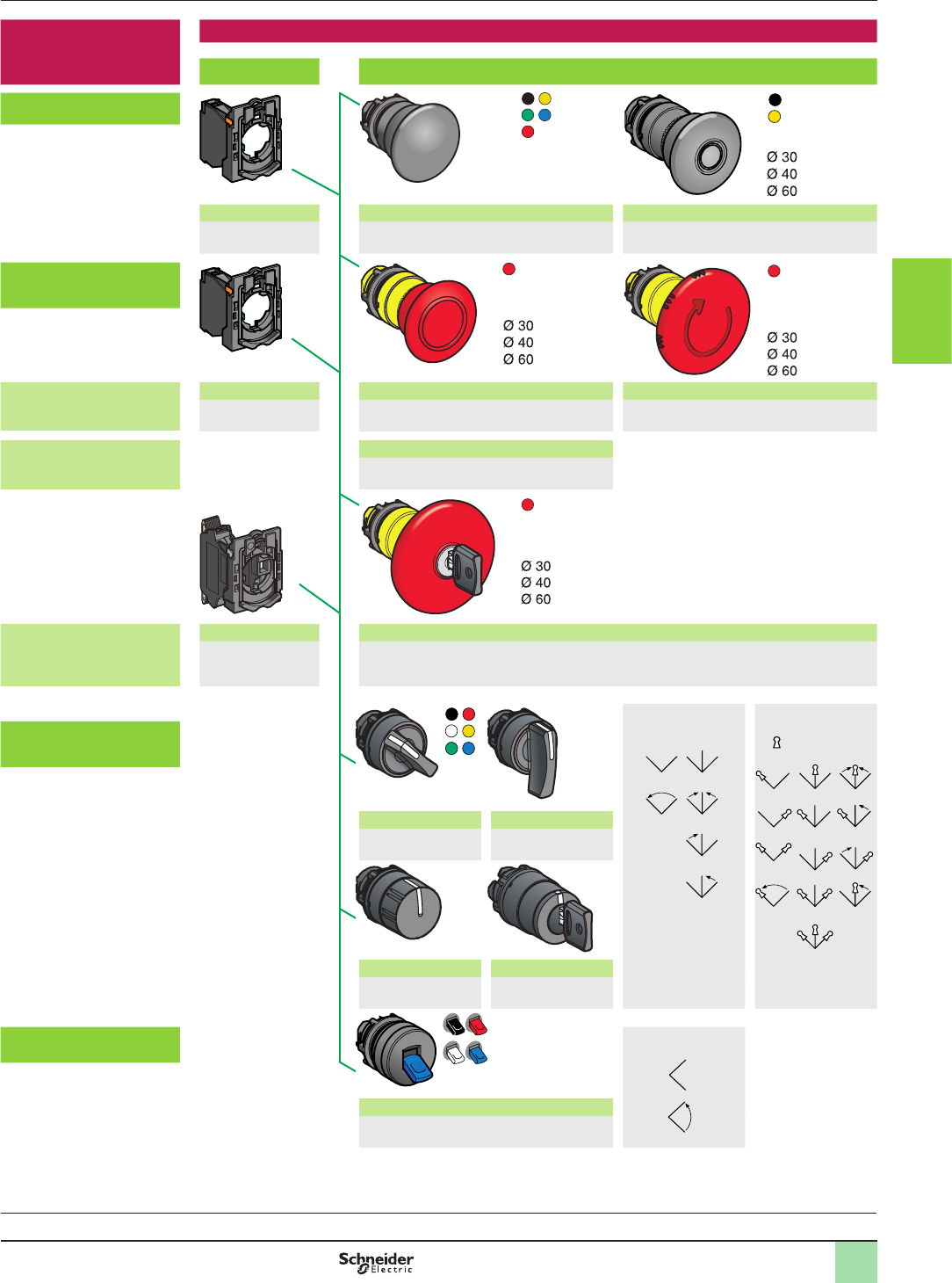
3/213/21
Non illuminated units
for user assembly
(continued)
Contact functions (continued)
Body sub-assemblies Head sub-assemblies
For mushroom head
pushbuttons
Screw clamp terminals Spring Latching
ZB5AZ10p/AZ141
see page 3/28
ZB5ACp/ARp
see page 3/24
ZB5Ap2/ASp2/AS55
see page 3/25
For Emergency Stop or
Emergency switching off
mushroom head pushbuttons
Emergency stop trigger
action and mechanical
latching
Faston Push-pull (EN/ISO 13850) Turn to release (EN/ISO 13850)
ZB5AZ10p3
(1)
ZB5AT84
see page 3/26
ZB5AS8p4
see page 3/26
Emergency switching off
mechanical latching
Push-pull (IEC 60364-5-53)
ZB5ATp/AXp
see page 3/27
Emergency stop trigger
action and mechanical
latching
Spring clamp terminals Key release (EN/ISO 13850)
ZBE10p5
ZB5AZ10p5
(1)
ZB5AS9
p
4/AS9
4
4D,
see page 3/26
(2) Switch handle
and knob
positions
(3) Key switch
positions
Key withdrawal
positions
For selector switches
and key switches
Standard handle (2) Long black handle (2)
ZB5ADp
(1)
ZB5AJp
(1)
Knurled black knob (2) Key switch (3)
ZB5ADp9
(1)
ZB5AGpp
(1)
For toggle switches (4) Lever positions
2-position lever (4)
ZB5ADp8
(1)
General (continued)
Ø 30
Ø 40
Ø 60
Aquire the information
Control and signaling units Ø 22
Harmony® XB5, plastic
Pushbuttons, switches and pilot lights:
sub-assemblies, ZB5A
(1) Please refer to our website www.schneider-electric.com
1
2
3
4
5
6
7
8
9
10
3/22
Pilot lights
for user assembly
Signaling functions
Body sub-assemblies
with integral LED
Head sub-assemblies
Connection: screw clamp terminals With lens tted (insertion of legend) With lens tted
ZB5AVBp/AVGp/AVMp
(1)
ZB5AV0p3/AV0p3E, (1) ZB5CV0p3, (1)
Connection: plug-in connector With 5 lens caps (not tted) for insertion of legend With 5 separate lens caps, not tted
Please consult our Customer Care
Centre
ZB5AV003/AV0p3p, (1) ZB5CV003, (1)
Body sub-assemblies for BA 9s bulb Head sub-assemblies
Direct supply
Connection: screw clamp terminals
With lens tted
ZB5AV0p, (1)
ZB5AV6, (1)
Via integral transformer
Connection: screw clamp terminals
ZB5AVp/AV3Dp/AV5Dp
(1)
Illuminated
pushbuttons
for user assembly
Combined functions (contact and signaling)
Body sub-assemblies for BA 9s bulb Head sub-assemblies
For illuminated pushbuttons,
spring return
Flush
Direct supply
Connection: screw clamp terminals
ZB5AW3p/AW3pS, (1)
ZB5AW06p, (1)
Via integral transformer
Connection: screw clamp terminals
Projecting
ZB5AW03p/ AW04p/AW05p
(1)
ZB5AW1p/AW1pS, (1)
General (continued) Aquire the information
Control and signaling units Ø 22
Harmony® XB5, plastic
Pushbuttons, switches and pilot lights:
sub-assemblies, ZB5A
(1) Please refer to our website www.schneider-electric.com
1
2
3
4
5
6
7
8
9
10
3/23
Illuminated
pushbuttons
for user assembly
Combined functions (contact and signaling) (continued)
Body sub-assemblies
with integral LED
Head sub-assemblies
For illuminated
pushbuttons, spring return
Flush push
Flush push with illuminated ring
Flush push
for insertion of legend
Booted ush push
Connection: screw clamp
terminals
ZB5AW3p3/AW3p3S/AW9p3
(1)
ZB5AAp8
(1)
ZB5AW5p3
(1)
ZB5AW0Bpp/AW0Gpp/
AW0Mpp
(1)
Projecting push Flush or projecting push
Flush or projecting push for insertion of legend
ZB5AW1p3/AW1p3S
(1)
ZB5CW3p3/CW1p3
(1)
For double-headed
pushbuttons, spring return,
with pilot light
Connection: plug-in
connector
Please consult our
Customer Care Centre
Double-headed (ush/ush push) + central pilot light
Double-headed (ush/projecting push) + central pilot light
ZB5AW7A17pp, ZB5AW7A374p, ZB5AW7A9, (1)
ZB5AW7L374p, (1)
For illuminated, mushroom
head pushbuttons, latching
Connection: spring clamp
terminals
ZBVpp5
(1)
Turn to release
ZB5AW7p3, see page 3/25
For illuminated mushroom
head pushbuttons
b Emergency Stop with
trigger action and
mechanical latching
or
b Emergency switching off
with mechanical latching
only
Push-pull with mechanical state
indicator (EN/ISO 13850)
Turn to release
(IEC 60364-5-53)
ZB5AT8643M
see page 3/26
ZB5AW743
see page 3/27
For illuminated “push-push
to release” pushbuttons
For illuminated selector
switches, standard handle
Flush or projecting “push-push to
release”
Flush “Push-push to
release”
Standard handle (2)
ZB5AH0p3/AHp3
(1)
ZB5CH3p3
(1)
ZB5AK1pp3
(1)
(2) Handle positions
General (continued)
Ø 40
Ø 40
Aquire the information
Control and signaling units Ø 22
Harmony® XB5, plastic
Pushbuttons, switches and pilot lights:
sub-assemblies, ZB5A
(1) Please refer to our website www.schneider-electric.com
1
2
3
4
5
6
7
8
9
10
3/24
Aquire the information
Control and signaling units Ø 22
Harmony® XB5, plastic
Mushroom head pushbuttons, spring return
References
Mushroom head pushbuttons (1) (2)
Screw clamp terminal connections (Schneider Electric anti-loosening system)
Shape
of head
Type
of push
Type of contact Push Reference Weight
kg/lb
Ø (mm)/in. Color
N/O N/C
Complete units
Mushroom head 1 –
40/1.575 Black XB5AC21
(ZB5AZ101 + ZB5AC2)
0.062/0.137
Heads only
Mushroom head 30/1.181 Black ZB5AC24 0.027/0.060
Green ZB5AC34 0.027/0.060
Red ZB5AC44 0.027/0.060
Yellow ZB5AC54 0.027/0.060
Blue
ZB5AC64 0.027/0.060
40/1.575 Black ZB5AC2 0.046/0.101
Green ZB5AC3 0.046/0.101
Red ZB5AC4 0.046/0.101
Yellow ZB5AC5 0.046/0.101
Blue
ZB5AC6 0.046/0.101
60/2.362 Black ZB5AR2 0.065/0.143
Green ZB5AR3 0.065/0.143
Red ZB5AR4 0.065/0.143
Yellow ZB5AR5 0.065/0.143
Blue
ZB5AR6 0.065/0.143
60/2.362 (3)
Hemispherical
Black ZB5AR216 0.048/0.106
Green ZB5AR316 0.048/0.106
Red ZB5AR416 0.048/0.106
Yellow ZB5AR516 0.048/0.106
Blue
ZB5AR616 0.048/0.106
(1) These pushbuttons and heads cannot be used for an Emergency Stop function.
Therefore, it is recommended that a legend with a Black or White background is used.
(2) Recommended maximum number of contacts constituting the body (xing collar and contact) associated with the head,
“Please refer to our website www.schneider-electric.com”
(3) Ergonomic product used in two-handed control applications. Recommended maximum number of contacts constituting the
body (xing collar and contact) associated with the head: 6.
540160
ZB5AR216
814446
ZB5AR4
814445
ZB5AC2
814444
ZB5AC24
563459
XB5AC21
General:
page 3/16
1
2
3
4
5
6
7
8
9
10
3/25
Aquire the information
Control and signaling units Ø 22
Harmony® XB5, plastic
Mushroom head pushbuttons, latching
References
Mushroom head pushbuttons (1) (2)
Shape
of head
Type
of reset
Push Reference Weight
kg/lb
Ø (mm)/in. Color
Heads only
Push-pull 30/1.181 Black
ZB5AT24 0.044/0.097
40/1.575 Black
ZB5AT2 0.049/0.108
60/2.362 Black
ZB5AX2 0.067/0.148
Turn to release 30/1.181 Black
ZB5AS42 0.040/0.088
40/1.575 Black
ZB5AS52 0.044/0.097
40/1.575 Yellow
ZB5AS55 0.044/0.097
60/2.362 Black
ZB5AS62 0.064/0.141
Key release
(key n° 455)
(2 keys included
with head) (3) (5)
30/1.181 Black
ZB5AS72 0.040/0.088
40/1.575 Black
ZB5AS12 (4) 0.044/0.097
60/2.362 Black
ZB5AS22 0.064/0.141
Illuminated mushroom head pushbuttons (2)
Shape
of head
Type
of reset
Push Reference Weight
kg/lb
Ø (mm)/in. Color
Heads only (6)
Turn to release 40/1.575 White ZB5AW713 0.022/0.049
Green ZB5AW733 0.022/0.049
Orange ZB5AW753 0.022/0.049
Blue ZB5AW763 0.022/0.049
(1) These pushbuttons and heads cannot be used for an Emergency Stop function.
Therefore, it is recommended that a legend with a Black or White background is used.
(2) Recommended maximum number of contacts constituting the body (xing collar and contact) associated with the head,
“Please refer to our website www.schneider-electric.com”
(3) For specic keys with other numbers, please consult our Customer Care Centre.
(4) Other key numbers:
- key n° 421E: add sufx 12 to the reference.
- key n° 458A: add sufx 10 to the reference.
- key n° 520E: add sufx 14 to the reference.
- key n° 3131A: add sufx 20 to the reference.
Example: To order a Ø 40mm/1.575 in. Black mushroom head for a latching pushbutton, with release by key n° 421E, the
reference becomes:
ZB5AS1212.
(5) The symbol indicates key withdrawal position(s).
(6) Only for use with bodies comprising a light source with integral LED.
103547
ZB5AW733
523835
ZB5AS72
53558
ZB5AS62
110354
ZB5AT2
1
2
3
4
5
6
7
8
9
10
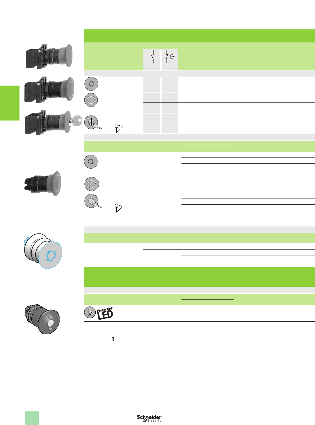
3/26
Mushroom head Emergency stop trigger action and mechanical latching pushbuttons conform to standards
EN/IEC 60204-1 and EN/ISO 13850, to Machinery Directive 2006/42/EC and to standard EN/IEC 60947-5-5.
Please consult our Customer Care Centre for a full explanation of these standards and directives.
Emergency stop trigger action and mechanical latching pushbuttons (1) (2)
Screw clamp terminal connections (Schneider Electric anti-loosening system)
Shape
of head
Type
of reset
Type of contact Push Reference Weight
kg
Ø (mm) Color
N/O N/C
Complete units
Push-pull 1 1 40 Red
XB5AT845
(ZB5AZ105 + ZB5AT84)
0.076
Turn to
release
1 1 40 Red XB5AS8445
(ZB5AZ105 + ZB5AS844)
0.072
– 2 40 Red XB5AS8444
(ZB5AZ104 + ZB5AS844)
0.072
Key release
(key n° 455)
(3)
1 1 40 Red XB5AS9445
(ZB5AZ105 + ZB5AS944)
0.112
Heads only
Shape
of head
Type
of reset
Push Reference Weight
kg
Ø (mm) Color
Push-pull 30 Red ZB5AT844 0.050
40 Red ZB5AT84 0.050
60 Red ZB5AX84 0.050
Turn to release 30 Red ZB5AS834 0.042
40 Red ZB5AS844 0.046
Key release (key n° 455)
2 keys included with head (5)
(3)
30 Red ZB5AS934 0.068
40 Red ZB5AS944 (4) 0.071
60 Red ZB5AS964 0.092
Key release (key n° 4A185) (5) 40 Red ZB5AS944D 0.071
Bellows for harsh environments (IP 69K) (6)
For use in Material Color Sold in
lots of
Unit
reference
Weight
kg
Environments subject to
humidity, dust, high pressure
cleaning, etc.
Silicone Red 2ZBZ48 0.009
EPDM Black 2ZBZ28 0.009
Yellow 2ZBZ58 0.009
Illuminated Emergency stop trigger action and mechanical latching pushbuttons
with mechanical state indicator (1)
For elevator inspection box applications
Heads only (7)
Shape
of head
Type
of reset
Push Reference Weight
kg
Ø (mm) Color
Push-pull (8) 40 Red ZB5AT8643M 0.034
(1) Recommended maximum number of contacts constituting the body (xing collar + contact) associated with the head,
“Please refer to our website www.schneider-electric.com”
(2) It is recommended that a legend or yellow background is used.
(3) The symbol indicates key withdrawal position(s).
(4) Other key numbers:
- key n° 421E: add sufx 12 to the reference.
- key n° 458A: add sufx 10 to the reference.
- key n° 520E: add sufx 14 to the reference.
- key n° 3131A: add sufx 20 to the reference.
- key n° 4A185: add sufx D to the reference.
Example: To order a Ø 40 red mushroom head for a trigger action and mechanical latching Emergency stop pushbutton, with
release by key n° 421E, the reference becomes: ZB5AS94412.
(5) For specic keys with other numbers, please consult our Customer Care Centre.
(6) Not compatible with Ø 30 pushbuttons.
(7) Only for use with bodies comprising a light source with integral LED.
(8) Cannot be used with metal guards ZBZ160p.
Aquire the information
Control and signaling units Ø 22
Harmony® XB5, plastic: Emergency stop devices
Conforming to EN/IEC 60204-1 and
EN/ISO 13850 and Machinery Directive 2006/42/EC
References
523854
ZB5AT8643M
ZBZp8
523853
ZB5AS844
BT aruØ40 .EPS
563449
XB5AS9445
BS1 aruØ40.EPS
523852
XB5AS8445
BS5 aruØ40 .EPS
107183
XB5AT845
1
2
3
4
5
6
7
8
9
10
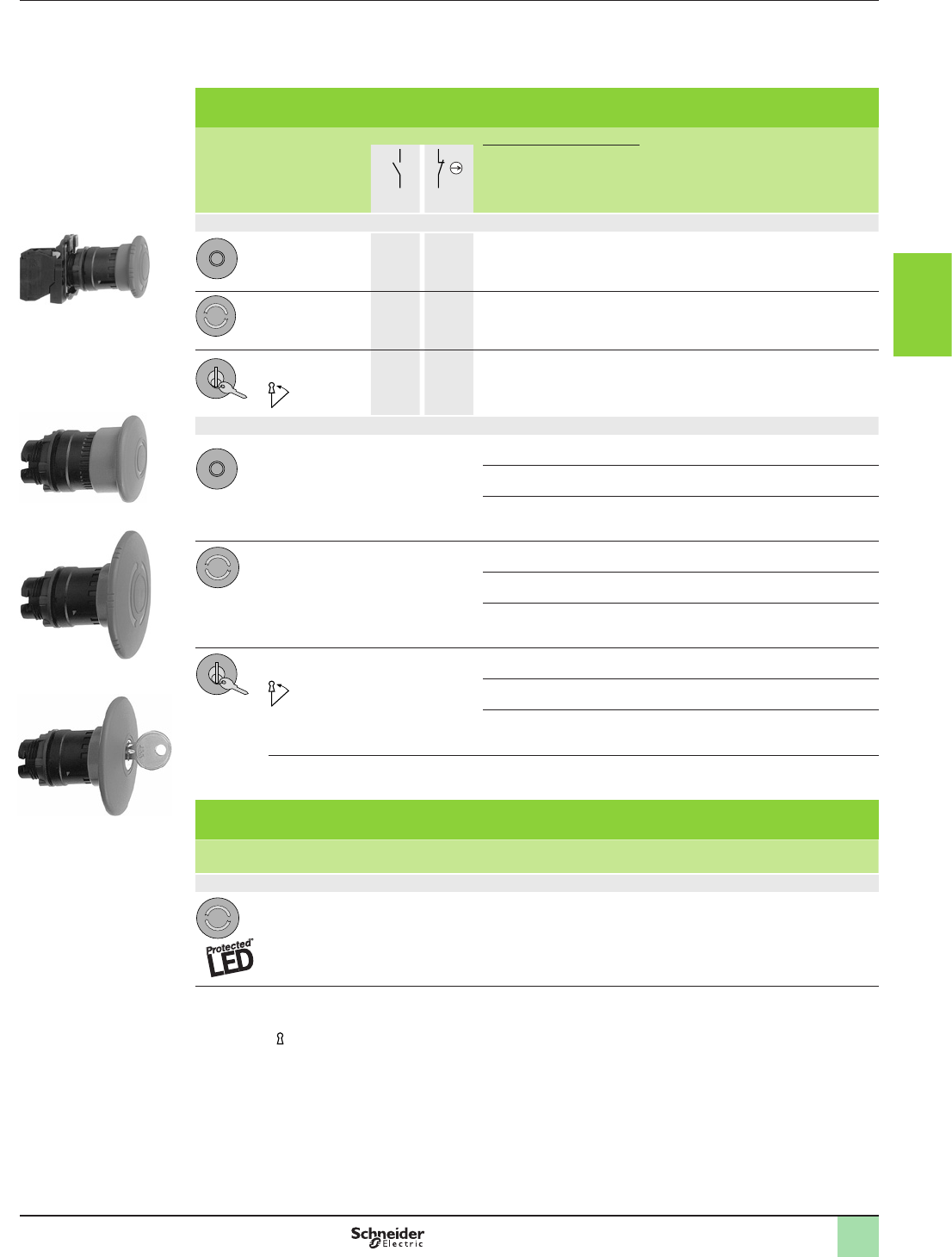
3/27
Mushroom head switching off mechanical latching pushbuttons conform to standards IEC 60364-5-53 and
EN/IEC 60947-5-5. Please consult our Customer Care Centre for a full explanation of these standards and
directives.
Emergency switching off, mechanical latching pushbuttons (1) (2)
Screw clamp terminal connections (Schneider Electric anti-loosening system)
Shape
of head
Type
of reset
Type of contact Push Reference Weight
kg
Ø mm Color
N/O N/C
Complete units
Push-pull – 1 40 Red
XB5AT42
(ZB5AZ102 + ZB5AT4)
0.065
Turn to release – 1 40 Red
XB5AS542
(ZB5AZ102 + ZB5AS54)
0.060
Key release
(key n° 455)
(3)
– 1 40 Red XB5AS142
(ZB5AZ102 + ZB5AS14)
0.075
Heads only
Push-pull 30 Red ZB5AT44 0.049
40 Red ZB5AT4 0.049
60 Red
ZB5AX4 0.067
Turn to release 30 Red ZB5AS44 0.040
40 Red ZB5AS54 0.044
60 Red
ZB5AS64 0.064
Key release (key n° 455)
2 keys included with head) (5)
(3)
30 Red ZB5AS74 0.040
40 Red ZB5AS14 (4) 0.044
60 Red ZB5AS24 0.060
Key release (key n° 4A185) 40 Red
ZB5AS14D 0.044
Illuminated Emergency switching off, mechanical latching pushbuttons (1)
Screw clamp terminal connections (Schneider Electric anti-loosening system)
Shape
of head
Type
of reset
Push Color Reference Weight
kg
Ø (mm)
Heads only (6)
Turn to release 40 Red ZB5AW743 0.022
(1) Recommended maximum number of contacts constituting the body (xing collar + contact) associated with the head,
“Please refer to our website www.schneider-electric.com”
(2) It is recommended that a legend or yellow background is used.
(3) The symbol indicates key withdrawal position(s).
(4) Other key numbers:
- key n° 421E: add sufx 12 to the reference.
- key n° 458A: add sufx 10 to the reference.
- key n° 520E: add sufx 14 to the reference.
- key n° 3131A: add sufx 20 to the reference.
Example: To order a Ø 40 red mushroom head for a mechanical latching Emergency switching off pushbutton, with release by
key n° 421E, the reference becomes: ZB5AS1412.
(5) For specic keys with other numbers, please consult our Customer Care Centre.
(6) Only for use with bodies comprising a light source with integral LED.
Aquire the information
Control and signaling units Ø 22
Harmony® XB5, plastic: Emergency switching off
devices
Conforming to IEC 60364-5-53
References
107192
ZB5AS24
107189
ZB5AS64
107185
ZB5AT4
BS1 aruØ40.EPS
563451
XB5AS542
BS5 aruØ40 .EPS
1
2
3
4
5
6
7
8
9
10
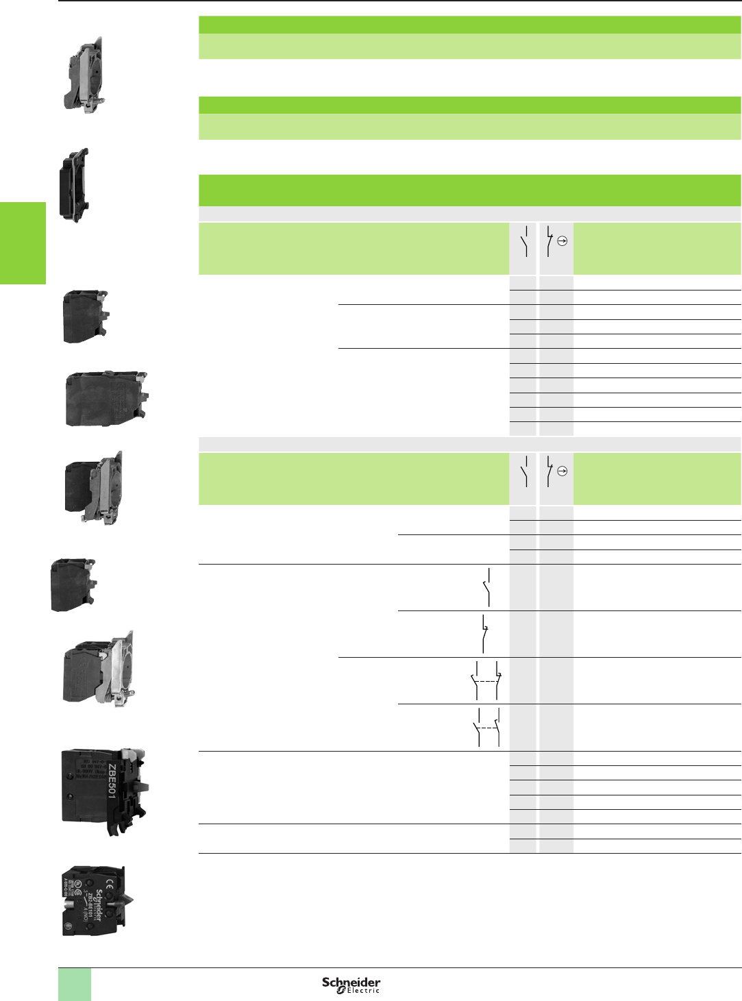
3/28
References Aquire the information
Control and signaling units Ø 22
Harmony® XB4, metal and Harmony® XB5, plastic
Body/contact assemblies - Screw clamp terminal connections
ZBE201
814265
ZBE501
PF080706
ZBE101
814265
ZB2BE101
PG114156SE 814264
ZB4BZ009
ZBE203
814267
814133
ZB4BZ101
ZB4BZ106
814346
814588
ZB5AZ009
Body/xing collar for XB4
For use with Sold in lots of Unit reference Weight
kg/lb
Electrical block (contact or light) 10 ZB4BZ009 0.038/0.084
Body/xing collar for XB5
For use with Sold in lots of Unit reference Weight
kg/lb
Electrical block (contact or light) 10 ZB5AZ009 0.006/0.013
Contact functions (1)
Screw clamp terminal connections (Schneider Electric anti-loosening system)
Contacts for standard applications
Description Type of contact
Sold in
lots of
Unit
reference
Weight
kg/lb
N/O N/C
Contact blocks Single 1 – 5ZBE101 0.011/0.024
– 1 5ZBE102 0.011/0.024
Double 2 – 5ZBE203 0.020/0.044
– 2 5ZBE204 0.020/0.044
1 1 5ZBE205 0.020/0.044
Single with body/xing collar 1 – 1ZB4BZ101 0.053/0.117
– 1 1ZB4BZ102 0.053/0.117
2 – 1ZB4BZ103 0.062/0.137
– 2 1ZB4BZ104 0.062/0.137
1 1 1ZB4BZ105 0.062/0.137
1 2 1ZB4BZ141 0.072/0.159
Contacts for specic applications
Application Type of
contact
Description
Sold in
lots of
Unit
reference
Weight
kg/lb
N/O N/C
Low power switching Single Standard 1 – 5ZBE1016 0.012/0.026
– 1 5ZBE1026 0.012/0.026
Dusty environment (2)
(IP5X, 50 μm dust)
1 – 5ZBE1016P 0.012/0.026
– 1 5ZBE1026P 0.012/0.026
Staggered contacts Single Early make
N/O
1 – 5ZBE201 0.011/0.024
Late break
N/C
– 1 5ZBE202 0.011/0.024
Single with
body/xing
collar
Overlapping
N/O+N/C
1 1 5ZB4BZ106 0.062/0.137
Staggered
N/O+N/O
2 – 5ZB4BZ107 0.062/0.137
High power switching Single Standard (3) 1 – 1ZBE501 0.020/0.044
– 1 1ZBE502 0.020/0.044
2 – 1ZBE503 0.032/0.071
– 2 1ZBE504 0.032/0.071
1 1 1ZBE505 0.032/0.071
Additional contact blocks for
high power switching
Single Standard (4) 1 – 1ZB2BE101 0.020/0.044
– 1 1ZB2BE102 0.020/0.044
(1) The contact blocks enable variable composition of body/contact assemblies. Maximum number of rows possible: 3. Either
3 rows of 3 single contacts or 1 row of 3 double contacts + 1 row of 3 single contacts (double contacts occupy the rst 2 rows
(2) It is not possible to t an additional contact block on the back of these contact blocks.
(3) It is not possible to use these contacts with light blocks.
(4) To be tted on the back of ZBE50p contacts.
1
2
3
4
5
6
7
8
9
10

3/29
References (continued) Aquire the information
Control and signaling units Ø 22
Harmony® XB4, metal and Harmony® XB5, plastic
Body/contact assemblies - Screw clamp terminal connections
ZBZ001-PRO-3-M
814262
ZBZ001
Clip-on legend holder, sheet of blank legends and labelling software
Description Sold in
lots of
Unit reference Weight
kg/lb
Clip-on legend-holder for electrical blocks with screw clamp terminal
connections (1). For identication of an XB4B control or signaling unit
10 ZBZ001 0.001/0.002
Sheet of 50 blank legends for legend holder ZBZ001 10 ZBY001 0.023/0.051
«SIS Label» labelling software for legend design (ZBY001 legends)
(for design of legends in English, French, German, Italian, Spanish)
1XBY2U 0.100/0.220
(1) This legend holder is not compatible with high power switching contacts
.
1
2
3
4
5
6
7
8
9
10
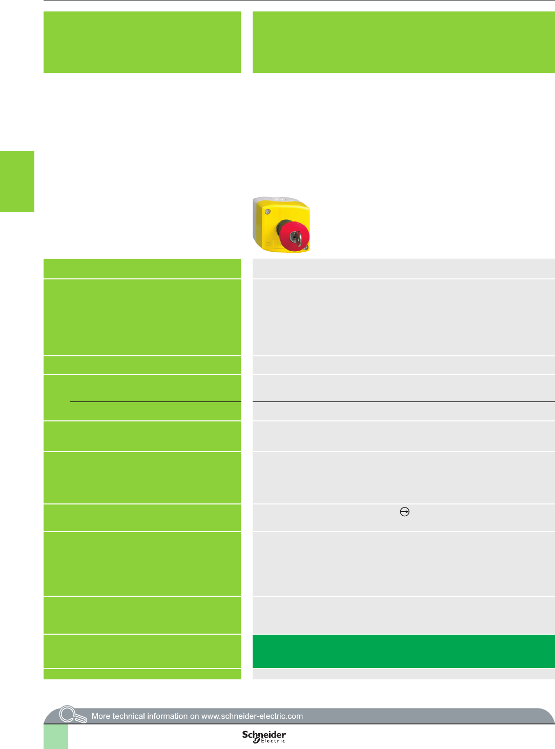
3/30
Selection guide Aquire the information
Control units for safety applications
Applications Control stations for:
- assembly and packaging machines,
- paper, cardboard and woodworking machines,
- food/beverage processing, chemical and automobile industries, mechanical presses
Enabling grip switch for:
- robots,
- machine tools,
- labellers
Ergonomic two-hand control stations for machine tool control
Features Plastic enclosure Plastic enclosure 2 control pushbuttons and 1 Emergency stop pushbutton
Conformity to standards EN/IEC 60947-1,
EN/IEC 60947-5-1,
EN/IEC 60947-5-4,
EN/IEC 60947-5-5,
EN/ISO 13850 and EN/IEC 60204-1 (Emergency Stop trigger action and mechanical latching
mushroom head pushbuttons),
IEC 60364-5-53 (Emergency switching off mechanical latching mushroom head pushbuttons)
CSA C22-2 n° 14, UL 508 and GB 14048.5
EN/IEC 60947-1,
EN/IEC 60947-5-1,
EN/IEC 60204-1,
cUL us 508,
CSA C22-2 n° 14
EN/IEC 60947-5-1,
EN 574/ISO 13851
Protective treatment Standard version, “TH” Standard version, “TC” Standard version, “TC”
Ambient temperature
- 25…+ 70 °C - 10…+ 60 °C - 25…+ 70 °C
For operation
For storage - 40…+ 70 °C - 40…+ 70 °C - 40…+ 70 °C
Electric shock protection conforming to IEC 61140 Class II Class II Class I
Degree of protection
conforming to IEC 60529, UL 508 and CSA C22-2 n° 14
IP 66
Enclosure type 4, 4X and 13
IP 66
IP 65 with pushbutton
IP 65
Positive operation
conf. to EN/IEC 60947-5-1 Appendix K N/C contacts with positive opening operation 2-contact, 3-position with positive opening operation N/C contacts with positive opening operation
Rated insulation voltage Standard single and double blocks with screw clamp terminals:
Ui = 600 V, degree of pollution 3
Blocks for plug-in connector or Faston connectors,
standard blocks for printed circuit board connection,
contact blocks for high power switching: Ui = 250 V, degree of pollution 3 conforming to EN/
IEC 60947-1
Ui = 250 V
Ui = 125 V for pushbutton
conforming to EN/IEC 60947-1
Ui = 600 V, degree of pollution 3 conforming to EN/IEC 60947-1
Rated impulse withstand voltage
conforming to
EN/IEC 60947-1
Standard single and double blocks with screw clamp terminals: Uimp = 6 kV
Blocks for plug-in connector: Uimp = 4 kV
Standard blocks for printed circuit board connection: Uimp = 4 kV
Contact blocks for high power switching: Uimp = 4 kV
Uimp = 2.5 kV Uimp = 6 kV
Type references XALK XY2AU XY2SB
Pages 3/32 3/54 3/56
2
1
3
4
5
6
7
8
9
10
2
1
3
4
5
6
7
8
9
10
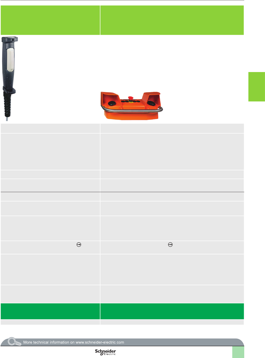
3/31
Applications Control stations for:
- assembly and packaging machines,
- paper, cardboard and woodworking machines,
- food/beverage processing, chemical and automobile industries, mechanical presses
Enabling grip switch for:
- robots,
- machine tools,
- labellers
Ergonomic two-hand control stations for machine tool control
Features Plastic enclosure Plastic enclosure 2 control pushbuttons and 1 Emergency stop pushbutton
Conformity to standards EN/IEC 60947-1,
EN/IEC 60947-5-1,
EN/IEC 60947-5-4,
EN/IEC 60947-5-5,
EN/ISO 13850 and EN/IEC 60204-1 (Emergency Stop trigger action and mechanical latching
mushroom head pushbuttons),
IEC 60364-5-53 (Emergency switching off mechanical latching mushroom head pushbuttons)
CSA C22-2 n° 14, UL 508 and GB 14048.5
EN/IEC 60947-1,
EN/IEC 60947-5-1,
EN/IEC 60204-1,
cUL us 508,
CSA C22-2 n° 14
EN/IEC 60947-5-1,
EN 574/ISO 13851
Protective treatment Standard version, “TH” Standard version, “TC” Standard version, “TC”
Ambient temperature
- 25…+ 70 °C - 10…+ 60 °C - 25…+ 70 °C
For operation
For storage - 40…+ 70 °C - 40…+ 70 °C - 40…+ 70 °C
Electric shock protection conforming to IEC 61140 Class II Class II Class I
Degree of protection
conforming to IEC 60529, UL 508 and CSA C22-2 n° 14
IP 66
Enclosure type 4, 4X and 13
IP 66
IP 65 with pushbutton
IP 65
Positive operation
conf. to EN/IEC 60947-5-1 Appendix K N/C contacts with positive opening operation 2-contact, 3-position with positive opening operation N/C contacts with positive opening operation
Rated insulation voltage Standard single and double blocks with screw clamp terminals:
Ui = 600 V, degree of pollution 3
Blocks for plug-in connector or Faston connectors,
standard blocks for printed circuit board connection,
contact blocks for high power switching: Ui = 250 V, degree of pollution 3 conforming to EN/
IEC 60947-1
Ui = 250 V
Ui = 125 V for pushbutton
conforming to EN/IEC 60947-1
Ui = 600 V, degree of pollution 3 conforming to EN/IEC 60947-1
Rated impulse withstand voltage
conforming to
EN/IEC 60947-1
Standard single and double blocks with screw clamp terminals: Uimp = 6 kV
Blocks for plug-in connector: Uimp = 4 kV
Standard blocks for printed circuit board connection: Uimp = 4 kV
Contact blocks for high power switching: Uimp = 4 kV
Uimp = 2.5 kV Uimp = 6 kV
Type references XALK XY2AU XY2SB
Pages 3/32 3/54 3/56
2
1
3
4
5
6
7
8
9
10
2
1
3
4
5
6
7
8
9
10
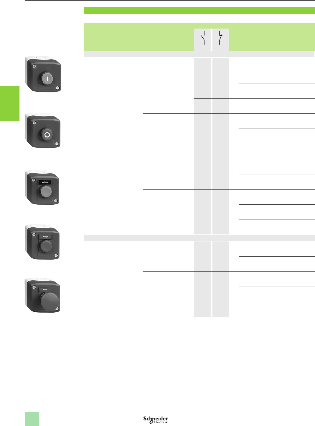
3/32
References
Start or Stop function
b Light grey “RAL 7035” base, dark grey “RAL 7016” lid
Description Type of
push
Dimensions
(1)
w x h x d
mm
Type of contact Marking Reference Weight
kg
N/O N/C
Marking on pushbutton
1 spring return pushbutton Flush,
green
68 x 68 x 62 1 – I XALD102 0.135
Marche XALD104 0.156
Start XALD103 0.156
1 1 I XALD102E 0.165
Flush,
red
68 x 68 x 62 – 1 O XALD112 0.156
Arrêt XALD117 0.156
Stop XALD114 0.165
1 1 O XALD112E 0.165
Stop XALD114E 0.165
Projecting,
red
68 x 68 x 66.5 – 1 O XALD115 0.157
Arrêt XALD118 0.157
Stop XALD116 0.157
Marking on legend holder and legend below head
1 spring return pushbutton Flush,
green
68 x 68 x 62 1 – Marche XALD101 0.157
Start XALD101H29 0.157
Flush,
red
68 x 68 x 62 – 1 Arrêt XALD111 0.157
Stop XALD111H29 0.157
1 mushroom head
pushbutton, Ø 40 mm,
spring return
Red 68 x 68 x 86 – 1 Arrêt XALD164 0.182
(1) Please consult our site www.schneider-electric.com for more precise information about dimensions of components.
Aquire the information
Control stations and enclosures
Plastic control stations XALD and XALK
For Harmony
®
Ø 22 control and signalling units XB5
Complete stations (screw clamp terminal connections)
815193
XALD164
815192
XALD111
815191
XALD101
815190
XALD115
815189
XALD102
1
2
3
4
5
6
7
8
9
10
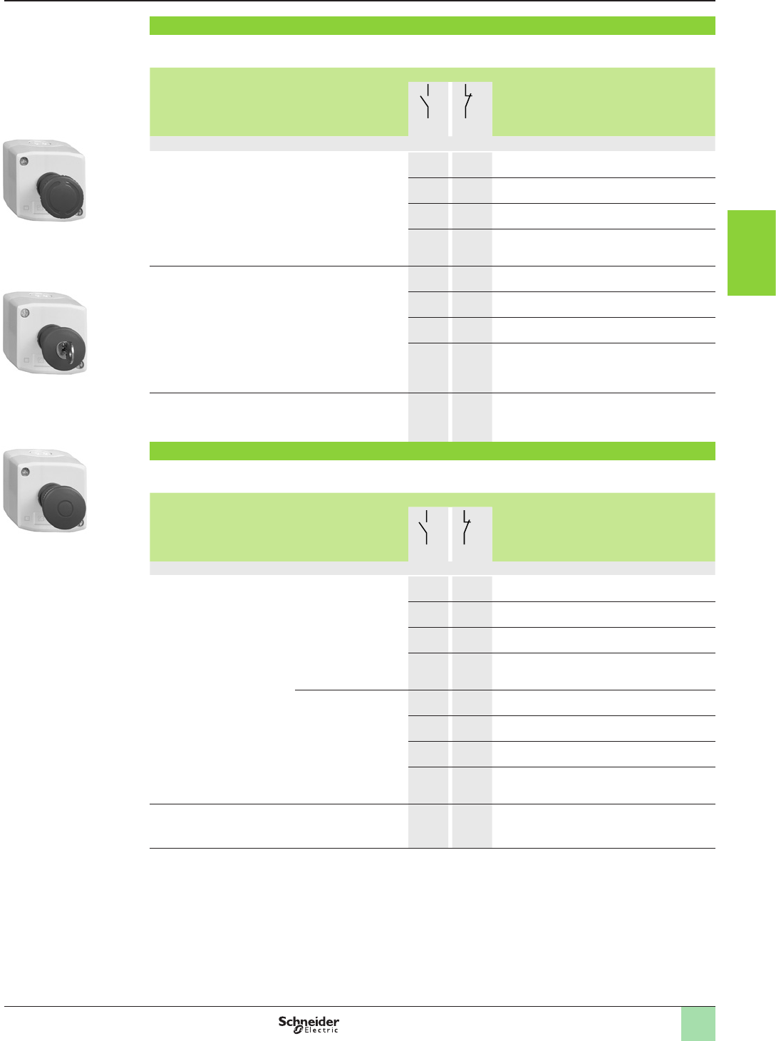
3/33
2
Emergency stop function, with trigger action and mechanical latching
b Light grey “RAL 7035” base, yellow “RAL 1021” lid
b Conformity to standards EN/IEC 60204-1, EN/ISO 13850 (1), EN/IEC 60947-5-5 and to Machinery directive 2006/42/CE (2)
Description Dimensions (3)
w x h x d
mm
Type of contact Reference Weight
kg
“F” “O”
Unmarked
1 mushroom head
pushbutton, Ø 40 mm, red
Turn to release
68 x 68 x 92.5 – 1 XALK178 0.194
– 2 XALK178F 0.194
1 1 XALK178E 0.194
1 2 XALK178G 0.194
1 mushroom head
pushbutton, Ø 40 mm, red
Key release (key n° 455)
68 x 68 x 114.5 – 1 XALK188
0.188
– 2 XALK188F
0.188
1 1 XALK188E 0.188
1 2 XALK188G 0.188
1 mushroom head
pushbutton, Ø 40 mm, red
Push-pull
68 x 68 x 91.5 – 1 XALK198 0.193
Emergency switching off function, with mechanical latching
b Light grey “RAL 7035” base, yellow “RAL 1021” lid
b Conformity to standards IEC 60364-5-53 and EN/IEC 60947-5-5 (2)
Description Dimensions (3)
w x h x d
mm
Type of contact Reference Weight
kg
“F” “O”
Unmarked
1 mushroom head
pushbutton, Ø 40 mm, red
Key release (key n° 455)
68 x 68 x 87.5 – 1 XALK174 0.178
– 2 XALK174F 0.188
1 1 XALK174E 0.188
1 2 XALK174G 0.197
68 x 68 x 109.5 – 1 XALK184 0.178
– 2 XALK184F 0.188
1 1 XALK184E 0.188
1 2 XALK184G 0.197
1 mushroom head
pushbutton, Ø 40 mm, red
Push-pull
68 x 68 x 91.5 – 1 XALK194 0.183
(1) Your Customer Care Centre may provide a control station type XALK1p8 with marking of the Emergency stop
function and of the symbol in conformity with the requirements of EN/ISO 13850 standard.
(2) Please consult your Customer Care Centre for full details of these standards and directives.
(3)
Please consult our site www.schneider-electric.com for more precised information about dimensions of components.
References (continued) Aquire the information
Control stations and enclosures
Plastic control stations XALD and XALK
For Harmony® Ø 22 control and signalling units XB5
Complete stations (screw clamp terminal connections)
815195
XALK198
815197
XALK188p
815196
XALK178p
1
2
3
4
5
6
7
8
9
10
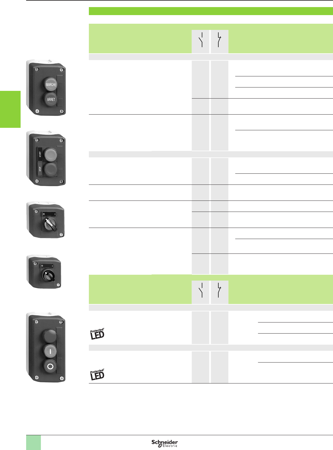
3/34
References (continued)
Start-Stop function
b Light grey “RAL 7035” base, Dark grey “RAL 7016“ lid
Description Dimensions (3)
w x h x d
mm
Type of contact Marking Reference Weight
kg
N/O N/C
Marking on pushbutton (2)
2 spring return pushbuttons:
- 1 ush, green
- 1 ush, red
68 X 106 X 62 1
–
–
1
I
O
XALD213 0.233
Marche
Arrêt
XALD224 0.233
Start
Stop
XALD215 0.233
1
1
1
1
I
O
XALD213E 0.252
2 spring return pushbuttons:
- 1 ush, green
- 1 projecting, red
68 X 106 X 66,5 1
–
–
1
I
O
XALD214 0.234
Start
Stop
XALD225 0.234
Marking on legend holder and legend below head
2 spring return pushbuttons:
- 1 ush, green
- 1 projecting, red
68 X 106 X 62 1
–
–
1
Marche
Arrêt
XALD211 0.233
Start
Stop
XALD211H29 0.233
2 spring return pushbuttons,
ush type, green
68 X 106 X 62 1
1
–
–
Ouverture
Fermeture
XALD241 0.233
1 selector switch with
standard handle
2-position stay put
68 X 106 X 80 1 – O-I XALD134 0.163
1 – Arrêt-Marche XALD132 0.163
1 key switch (key n° 455), key
withdrawal from left-hand
position
68 X 106 X 105.5 1 – O-I XALD144 0.187
Arrêt-Marche XALD142 0.196
1 1 O-I XALD144E 0.196
Description Dimensions (3)
w x h x d
mm
Type of contact Marking Pilot
light
supply
V
Reference Weight
kg
N/O N/C
With pilot light and marking on pushbutton (2)
2 spring return pushbuttons
and 1 pilot light with integral
red LED
68 X 136 X 64.5 1
–
–
1
I
O
z 24 XALD363B 0.261
a 120 XALD363G 0.261
a 230 XALD363M 0.261
With pilot light and marking on legend holder and legend below head
2 spring return pushbuttons
and 1 pilot light with integral
red LED
68 X 136 X 64.5 1
–
–
1
Marche
Arrêt
z 24 XALD361B 0.261
a 230 XALD361M 0.261
(1) Please consult our site www.schneider-electric.com for more precised information about dimensions of components.
(2) Push supplied with cap not clipped-in, allowing orientation through 90° in 360° steps.
Aquire the information
Control stations and enclosures
Plastic control stations XALD and XALK
For Harmony® Ø 22 control and signalling units XB5
Complete stations
(screw clamp terminal connections)
815199
XALD363B
106614
XALD144
106613
XALD134
815202
XALD211H29
815203
XALD224
1
2
3
4
5
6
7
8
9
10
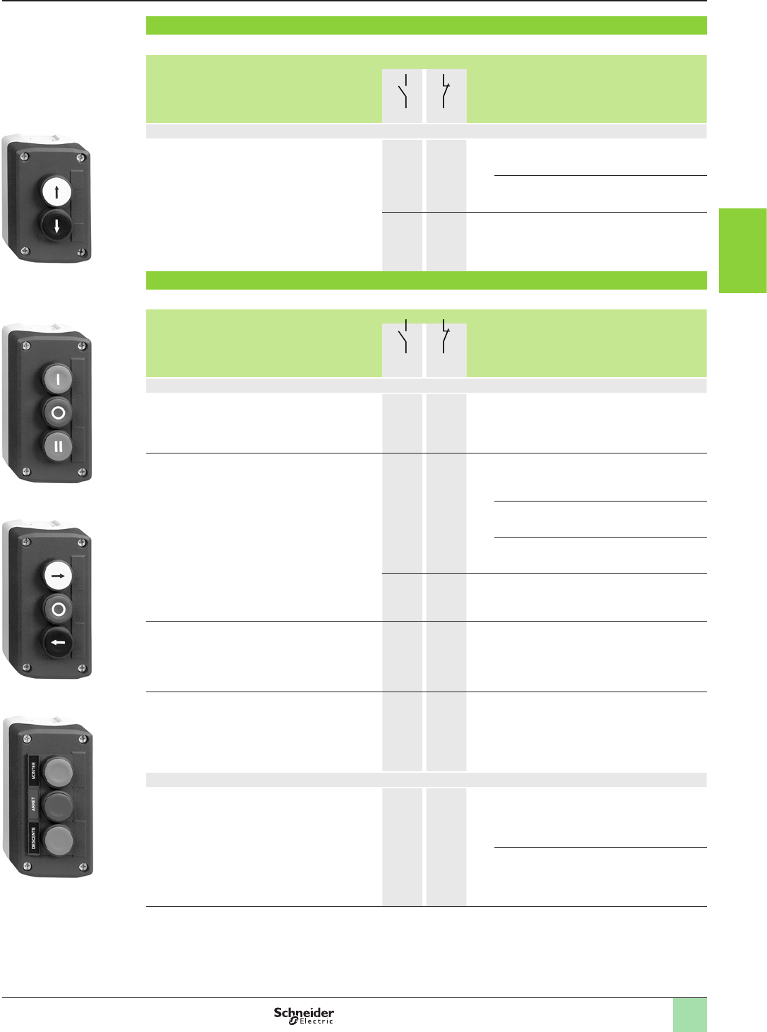
3/35
2
References (continued)
Two function
b Light grey “RAL 7035” base, Dark grey “RAL 7016“ lid
Description Dimensions (1)
w x h x d
mm
Type of contact Marking Reference Weight
kg
N/O N/C
Marking on pushbutton (2)
2 spring return pushbuttons:
- 1ush, white
- 1 ush, black
68 X 106 X 62 1
1
–
–
A
RXALD222 0.233
V
BXALD223 0.233
1
1
1
1
A
RXALD222E 0.233
Three function
b Light grey “RAL 7035” base, Dark grey “RAL 7016“ lid
Description Dimensions (1)
w x h x d
mm
Type of contact Marking Reference Weight
kg
N/O N/C
Marking on pushbutton (2)
3 spring return pushbuttons:
- 1 ush, green
- 1 ush, red
- 1 ush, green
68 X 136 X 62 1
–
1
–
1
–
I
O
II
XALD339 0.298
3 spring return pushbuttons:
- 1 ush, white
- 1 ush, red
- 1 ush, black
68 X 136 X 62 1
–
1
–
1
–
A
O
R
XALD324 0.298
A
Stop
R
XALD326 0.298
V
O
B
XALD334 0.298
1
1
1
1
1
1
A
O
R
XALD324E 0.317
3 spring return pushbuttons:
- 1 ush, white
- 1 projecting, red
- 1 ush, black
68 X 136 X 62 1
–
1
–
1
–
A
O
R
XALD325 0.299
2 spring return + 1 mushroom
head pushbuttons:
- 1 ush, white
- 1 mushroom head, red (3)
- 1 ush, black
68 X 136 X 87.5 1
–
1
–
1
–
A
O
R
XALD328 0.317
Marking on legend holder and legend below head
3 spring return pushbuttons:
- 1 ush, green
- 1 ush, red
- 1 ush, green
68 X 136 X 62 1
–
–
–
1
–
Avant
Arrêt
Arrière
XALD311 0.299
Montée
Arrêt
Descente
XALD321 0.299
(1) Please consult our site www.schneider-electric.com for more precised information about dimensions of components.
(2) Push supplied with cap not clipped-in, allowing orientation through 90° in 360° steps.
(3) Standard turn to release, latching, Ø 30 mm.
Aquire the information
Control stations and enclosures
Plastic control stations XALD and XALK
For Harmony
®
Ø 22 control and signalling units XB5
Complete stations (screw clamp terminal connections)
815207
XALD321
815208
XALD334
815209
XALD339
815206
XALD222
1
2
3
4
5
6
7
8
9
10
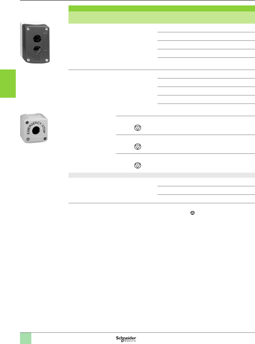
3/36
References (continued)
XALK01H29
PF540623
Empty control stations (lid xing screws and nut material: stainless steel type A4, AISI 316)
Description Text and symbol Dimensions (1)
w x h x d
mm
Number of
cut-outs
Reference Weight
kg
Light grey “RAL 7035” base
Dark grey “RAL 7016” lid
Without 68 x 68 x 53 1 XALD01 0.136
68 x 106 x 53 2 XALD02 0.193
68 x 136 x 53 3 XALD03 0.238
68 x 166 x 53 4 XALD04 0.278
68 x 196 x 53 5
XALD05 0.322
Light grey “RAL 7035” base
Yellow “RAL 1021” lid
For Emergency stop function
Without 68 x 68 x 53 1 XALK01 0.136
68 x 106 x 53 2 XALK02 0.193
68 x 136 x 53 3 XALK03 0.238
68 x 166 x 53 4 XALK04 0.278
68 x 196 x 53 5
XALK05 0.322
With text
«ARRET D’URGENCE» (2)
and symbol
(3)
68 x 68 x 53 1XALK01HFR 0.136
With text
«EMERGENCY STOP» (2)
and symbol
(3)
68 x 68 x 53 1XALK01H29 0.136
With text
«NOT HALT» (2)
and symbol
(3)
68 x 68 x 53 1XALK01H44 0.136
CSA + UL certied (4)
Light grey “RAL 7035”base
Dark grey “RAL 7016” lid
Without 68 x 68 x 53 1 XALD01H7 0.136
68 x 106 x 53 2 XALD02H7 0.205
68 x 136 x 53 3 XALD03H7 0.238
(1)
Please consult our site www.schneider-electric.com for more precise information about dimensions of components.
(2) For supply of the text in an other language, please consult your customer care centre.
(3) For comformity with ISO 13850 standard, Emergency Stop function symbol has been added.
(4) Volt-free commoning/earth terminal included.
Aquire the information
Control stations and enclosures
Plastic control stations XALD and XALK
For Harmony® Ø 22 control and signalling units XB5
Stations for customer assembly: empty enclosures
815211
XALD02
1
2
3
4
5
6
7
8
9
10
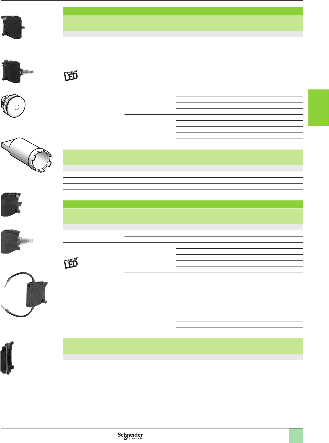
3/37
2
References (continued)
Electrical blocks and accessories for mounting in back of enclosure
Description Description Colour Sold in
lots of
Unit reference Weight
kg
Electrical blocks with screw clamp terminal connections
Standard contact blocks (1) N/O contact – 5ZENL1111 0.015
N/C contact – 5ZENL1121 0.015
Light blocks with integral
LED (1)
z 24 V White 5ZALVB1 0.015
Green 5ZALVB3 0.015
Red 5ZALVB4 0.015
Yellow 5ZALVB5 0.015
Blue 5ZALVB6 0.015
a 110…120 V White 5 ZALVG1 0.015
Green 5ZALVG3 0.015
Red 5ZALVG4 0.015
Yellow 5ZALVG5 0.015
Blue 5ZALVG6 0.015
a 230…240 V White 5ZALVM1 0.015
Green 5ZALVM3 0.015
Red 5ZALVM4 0.015
Yellow 5ZALVM5 0.015
Blue 5ZALVM6 0.015
Description For use with Sold in
lots of
Unit reference Weight
kg
Accessories for electrical blocks
Blanking plug Ø 22 mm units 10 ZB5SZ3 0.008
Nut Head xing 10 ZB5AZ901 0.002
Volt-free terminal Commoning/earth 10 XALZ09 0.003
Bezel tool For tightening nut ZB5AZ901 1ZB5AZ905 0.016
Electrical blocks and accessories for mounting beneath heads
Description Description Colour Sold in
lots of
Unit reference Weight
kg
Electrical blocks with screw clamp terminal connections (2) (for use with body/xing collar ZB5AZ009)
Standard contact blocks N/O contact – 5ZBE101 0.016
N/C contact – 5ZBE102 0.016
Light blocks with integral
LED
z 24 V White 5ZBVB1 0.016
Green 5ZBVB3 0.016
Red 5ZBVB4 0.016
Yellow 5ZBVB5 0.016
Blue 5ZBVB6 0.016
a 110…120 V White 5 ZBVG1 0.016
Green 5ZBVG3 0.016
Red 5ZBVG4 0.016
Yellow 5ZBVG5 0.016
Blue 5ZBVG6 0.016
a 230…240 V White 5ZBVM1 0.016
Green 5ZBVM3 0.016
Red 5ZBVM4 0.016
Yellow 5ZBVM5 0.016
Blue 5ZBVM6 0.016
Description For use with Voltage Level of
protection
Unit reference Weight
kg
Accessories for electrical blocks
LED suppressors
for high powers (u 30 VA)
Electrical light blocks with
integral LED
a 120 V 25…120 VA ZBZVG 0.010
a 230 V 30…230 VA ZBZVM 0.010
Body/xing collar
Sold in lots of 10
Electrical blocks
(contact or light)
– – ZB5AZ009 0.006
(1) A maximum of 3 electrical blocks can be tted per associated head.
(2) For electrical blocks for printed circuit board connection: please consult your customer care centre.
Aquire the information
Control stations and enclosures
Plastic control stations XALD and XALK
For Harmony
®
Ø 22 control and signalling units XB5
Stations for customer assembly: electrical blocks
815216
ZB5AZ009
815220
ZBVVp
815215
ZBVBp
815214
ZBE101
ZB5AZ905-PRO-3-M
815212
ZB5AZ905
ZB5SZ3-PRO-3-M
815213
ZB5SZ3
815217
ZALVBp
815218
ZENL1111
1
2
3
4
5
6
7
8
9
10
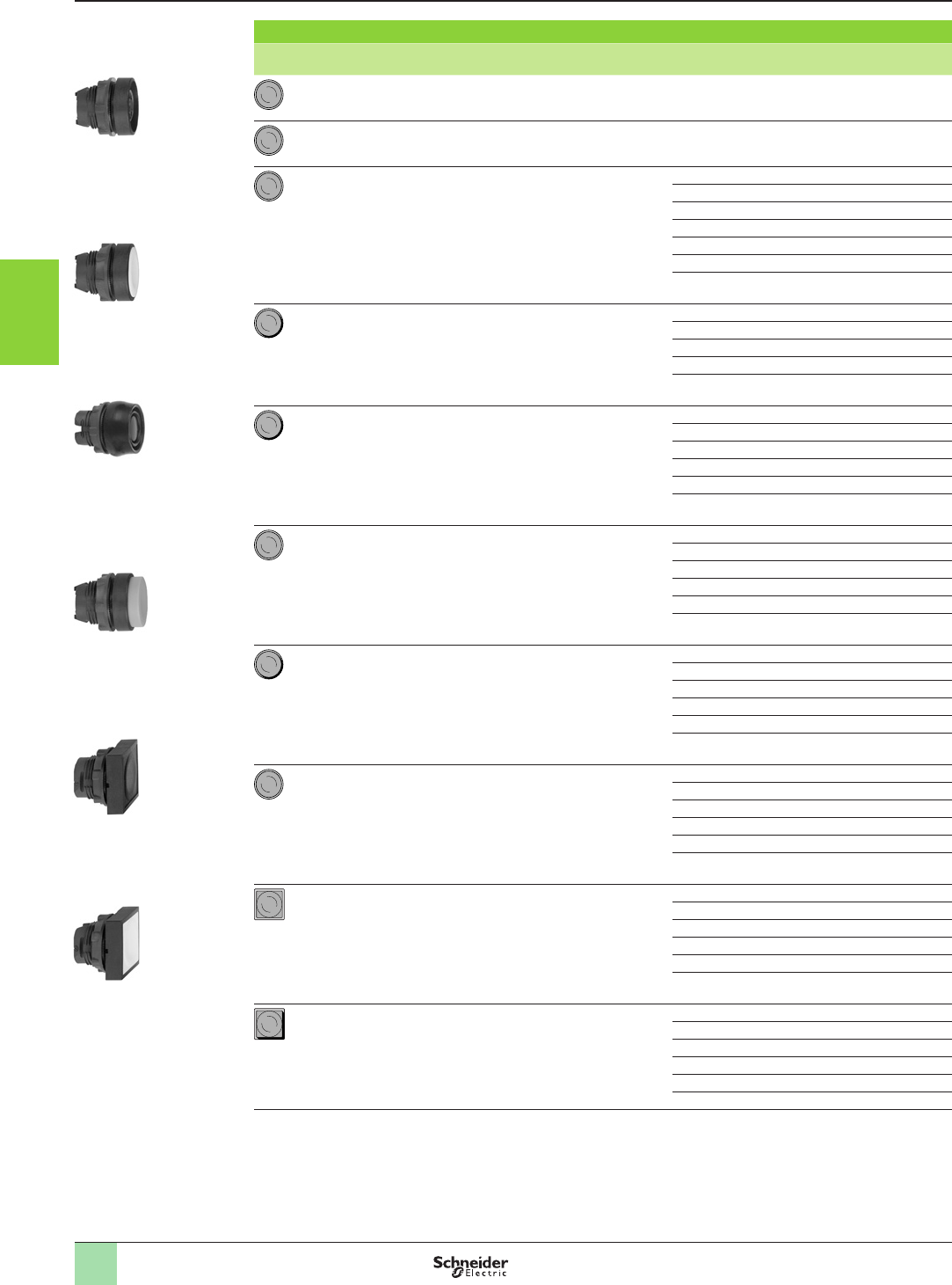
3/38
References (continued)
Heads for spring return pushbuttons - unmarked
Shape of head Type of push Colour of cap Reference Weight
kg
Without cap (1) –ZB5AA0 0.022
Flush, with set of 6 coloured caps 6 colours (2) ZB5AA9 0.027
Flush White ZB5AA1 0.018
Black ZB5AA2 0.018
Green ZB5AA3 0.018
Red ZB5AA4 0.018
Yellow ZB5AA5 0.018
Blue ZB5AA6 0.018
Grey ZB5AA8 0.018
Flush with transparent cap, for
insertion of legend (3)
White ZB5AA18 0.018
Green ZB5AA38 0.018
Red ZB5AA48 0.018
Yellow ZB5AA58 0.018
Blue ZB5AA68 0.018
Boot (coloured silicone)
can be replaced without dismantling the
head
White ZB5AP1S 0.014
Black ZB5AP2S 0.014
Green ZB5AP3S 0.014
Red ZB5AP4S 0.014
Yellow ZB5AP5S 0.014
Blue ZB5AP6S 0.014
Projecting White ZB5AL1 0.019
Black ZB5AL2 0.019
Green ZB5AL3 0.019
Red ZB5AL4 0.019
Yellow ZB5AL5 0.019
Blue ZB5AL6 0.019
Flush
(high guard)
White ZB5AA14 0.020
Black ZB5AA24 0.020
Green ZB5AA34 0.020
Red ZB5AA44 0.020
Yellow ZB5AA54 0.020
Blue ZB5AA64 0.020
Recessed
(high guard)
White ZB5AA16 0.019
Black ZB5AA26 0.019
Green ZB5AA36 0.019
Red ZB5AA46 0.019
Yellow ZB5AA56 0.019
Blue ZB5AA66 0.019
Flush White ZB5CA1 0.019
Black ZB5CA2 0.019
Green ZB5CA3 0.019
Red ZB5CA4 0.019
Yellow ZB5CA5 0.019
Blue ZB5CA6 0.019
Projecting White ZB5CL1 0.021
Black ZB5CL2 0.021
Green ZB5CL3 0.021
Red ZB5CL4 0.021
Yellow ZB5CL5 0.021
Blue ZB5CL6 0.021
(1) Cap to be ordered separately, Please consult our website www.schneider-electric.com.
(2) Head supplied with 6 different coloured caps (white, black, green, red, yellow, blue).
(3) For legend ordering information, Please consult our website www.schneider-electric.com.
Aquire the information
Control stations and enclosures
Plastic control stations XALD and XALK
For Harmony
®
Ø 22 control and signalling units XB5
Stations for customer assembly: heads
CL Carre Depass.EPS
815228
ZB5CA5
815227
ZB5CA2
CA Carre Affleur.EPS
BA Rond AFLEUR.EPS
BL Rond DEPASS.EPS
815226
ZB5AL3
BA Rond AFLEUR.EPS
103545_2
ZB5AP2S
BL Rond DEPASS.EPS
BL Rond DEPASS.EPS
815224
ZB5AA5
BA Rond AFLEUR.EPS
BA Rond AFLEUR.EPS
815224
ZB5AA0
BA Rond AFLEUR.EPS
1
2
3
4
5
6
7
8
9
10
3/39
2
References (continued)
Heads for spring return pushbuttons - marked
Shape of
head
Type of push Marking Colour of cap Reference Weight
kg
Text Colour
Flush (1) I White Green ZB5AA331 0.018
Black White ZB5AA131 0.018
II White Green ZB5AA336 0.018
Black White ZB5AA136 0.018
START White Green ZB5AA333 0.018
Black White ZB5AA133 0.018
ON White Green ZB5AA341 0.018
Black White ZB5AA141 0.018
MARCHE White Green ZB5AA342 0.018
Black White ZB5AA142 0.018
White Black ZB5AA245 0.018
Black White ZB5AA145 0.018
O White Red ZB5AA432 0.018
Black ZB5AA232 0.018
ARRET White Red ZB5AA433 0.018
Black ZB5AA233 0.018
STOP White Red ZB5AA434 0.018
Black ZB5AA234 0.018
OFF White Red ZB5AA435 0.018
Black ZB5AA235 0.018
UP Black White ZB5AA343 0.018
DOWN White Black ZB5AA344 0.018
AWhite Black ZB5AA335 0.018
Black White ZB5AA334 0.018
Projecting (1) O White Red ZB5AL432 0.019
Black ZB5AL232 0.019
ARRET White Red ZB5AL433 0.019
Black ZB5AL233 0.019
STOP White Red ZB5AL434 0.019
Black ZB5AL234 0.019
OFF White Red ZB5AL435 0.019
Black ZB5AL235 0.019
Flush (1) I White Green ZB5CA331 0.019
O White Red ZB5CA432 0.019
+White Black ZB5CA2934 0.019
AWhite Black ZB5CA2912 0.019
R White Blue ZB5CA6939 0.019
Mushroom heads for spring return pushbuttons
Shape of head Diameter of pushbutton Colour of pushbutton Reference Weight
kg
mm
30 Black ZB5AC24 0.027
Green ZB5AC34 0.027
Red ZB5AC44 0.027
Yellow ZB5AC54 0.027
Blue ZB5AC64 0.027
40 Black ZB5AC2 0.046
Green ZB5AC3 0.046
Red ZB5AC4 0.046
Yellow ZB5AC5 0.046
Blue ZB5AC6 0.046
(1) Push supplied with cap not clipped-in, allowing orientation through 90° in 360° steps.
Aquire the information
Control stations and enclosures
Plastic control stations XALD and XALK
For Harmony
®
Ø 22 control and signalling units XB5
Stations for customer assembly: heads
815237
ZB5AC2
815236
ZB5AC24
BC coup poing Ø40.EPS
CL Carre Depass.EPS
815235
ZB5AL232
BL Rond depass O .EPS
815234
ZB5AA432
815233
ZB5AA331
BA Rond AFLEUR I .EPS
1
2
3
4
5
6
7
8
9
10
3/40
Emergency stop trigger action and mechanical latching red mushroom heads
Shape of head Type of pushbutton Diameter
of pushbutton
mm
Colour
of pushbutton
Reference Weight
kg
Trigger action
Push-pull
30 Red ZB5AT844 (1) 0.050
40 Red ZB5AT84 (1) 0.050
Trigger action
Turn to release
30 Red ZB5AS834 (1) 0.042
40 Red ZB5AS844 (1) 0.046
Trigger action
Key release (key n° 4A185)
30 Red ZB5AS934 (1) (4) 0.068
40 Red ZB5AS944 (1) 0.071
60 Red ZB5AS964 (1) 0.092
Trigger action
Key release (key n° 4A185)
40 Red ZB5AS944D (1) 0.071
Emergency switching off mushroom heads, with mechanical latching
Shape of head Type of pushbutton Diameter
of pushbutton
mm
Colour
of pushbutton
Reference Weight
kg
Push-pull 30 Black ZB5AT24 (2) 0.044
Red ZB5AT44 (2) 0.044
40 Black ZB5AT2 (2) 0.049
Red ZB5AT4 (2) 0.049
Turn to release 30 Black ZB5AS42 (2) 0.040
Red ZB5AS44 (2) 0.040
40 Black ZB5AS52 (2) 0.044
Red ZB5AS54 (2) 0.044
Yellow ZB5AS55 (2) 0.044
Key release (key n° 4A185)
(3)
30 Black ZB5AS72 (2) 0.040
Red ZB5AS74 (2) 0.040
40 Black ZB5AS12 (2) 0.044
Red ZB5AS14 (2) (3) 0.044
Trigger action
Key release (key n° 4A185)
40 Red ZB5AS14D (2) 0.044
(1) Mushroom head Emergency stop trigger action and mechanical latching pushbuttons conform to standards EN/IEC 60204-1
and EN/ISO 13850, to Machinery Directive 2006/42/EC and to standard EN/IEC 60947-5-5.
(2) Mushroom head switching off mechanical latching pushbuttons conform to standards IEC 60364-5-53 and EN/IEC 60947-5-5.
Please consult your customer care centre for full details of these standards and directives.
(3) For specic keys with other numbers, please consult your customer care centre.
(4) Other key numbers:
- key n° 421E: add sufx 12 to the reference.
- key n° 458A: add sufx 10 to the reference.
- key n° 520E: add sufx 14 to the reference.
- key n° 3131A: add sufx 20 to the reference.
Example: The reference for a Ø 40 mushroom head for a trigger action latching pushbutton with release by key n° 421E
becomes: ZB5AS94412.
References (continued) Aquire the information
Control stations and enclosures
Plastic control stations XALD and XALK
For Harmony
®
Ø 22 control and signalling units XB5
Stations for customer assembly: heads
AruØ40 cle dom.EPS
BS1 aruØ40.EPS
815245
ZB5AS54
815244
ZB5AT44
BS5 aruØ40 .EPS
BT aruØ40 .EPS
AruØ40 cle dom.EPS
815246
ZB5AS934
BS1 aruØ40.EPS
BS5 aruØ40 .EPS
815243
ZB5AS844
BT aruØ40 .EPS
1
2
3
4
5
6
7
8
9
10
3/41
2
Heads for selector switches (1)
Shape of head Type of operator Number and type of positions Reference Weight
kg
Standard handle,
black
2 - stay put ZB5AD2 0.017
2 - spring return from right
to left
ZB5AD4 0.020
3 - stay put ZB5AD3 0.017
3 - spring return to centre ZB5AD5 0.017
3 - spring return from left
to centre
ZB5AD7 0.017
3 - spring return from right
to centre
ZB5AD8 0.017
Standard handle,
white
2 - stay put ZB5AD201 0.017
2 - spring return from right
to left
ZB5AD401 0.020
3 - stay put ZB5AD301 0.017
3 - spring return to centre ZB5AD501 0.017
3 - spring return from left
to centre
ZB5AD701 0.017
3 - spring return from right
to centre
ZB5AD801 0.017
Standard handle,
green
2 - stay put ZB5AD203 0.017
2 - spring return from right
to left
ZB5AD403 0.020
3 - stay put ZB5AD303 0.017
3 - spring return to centre ZB5AD503 0.017
3 - spring return from left
to centre
ZB5AD703 0.017
3 - spring return from right
to centre
ZB5AD803 0.017
(1) Can only be used for actuation of end of row (side) mounted contacts.
References (continued) Aquire the information
Control stations and enclosures
Plastic control stations XALD and XALK
For Harmony
®
Ø 22 control and signalling units XB5
Stations for customer assembly: heads
106215
ZB5AD2
1
2
3
4
5
6
7
8
9
10
3/42
Heads for selector switches (1) (continued)
Shape of head Type of operator Number and type of positions Reference Weight
kg
Standard handle,
red
2 - stay put ZB5AD204 0.017
2 - spring return from right
to left
ZB5AD404 0.020
3 - stay put ZB5AD304 0.017
3 - spring return to centre ZB5AD504 0.017
3 - spring return from left
to centre
ZB5AD704 0.017
3 - spring return from right
to centre
ZB5AD804 0.017
Standard handle,
yellow
2 - stay put ZB5AD205 0.017
2 - spring return from right
to left
ZB5AD405 0.020
3 - stay put ZB5AD305 0.017
3 - spring return to centre ZB5AD505 0.017
3 - spring return from left
to centre
ZB5AD705 0.017
3 - spring return from right
to centre
ZB5AD805 0.017
Standard handle,
blue
2 - stay put ZB5AD206 0.017
2 - spring return from right
to left
ZB5AD406 0.020
3 - stay put ZB5AD306 0.017
3 - spring return to centre ZB5AD506 0.017
3 - spring return from left
to centre
ZB5AD706 0.017
3 - spring return from right
to centre
ZB5AD806 0.017
Long handle,
black
2 - stay put ZB5AJ2 0.017
2 - spring return from right
to left
ZB5AJ4 0.020
3 - stay put ZB5AJ3 0.017
3 - spring return to centre ZB5AJ5 0.017
3 - spring return from left
to centre
ZB5AJ7 0.017
3 - spring return from right
to centre
ZB5AJ8 0.017
(1) Can only be used for actuation of end of row (side) mounted contacts.
References (continued) Aquire the information
Control stations and enclosures
Plastic control stations XALD and XALK
For Harmony
®
Ø 22 control and signalling units XB5
Stations for customer assembly: heads
106219
ZB5AJp
106215
ZB5ADppp
1
2
3
4
5
6
7
8
9
10
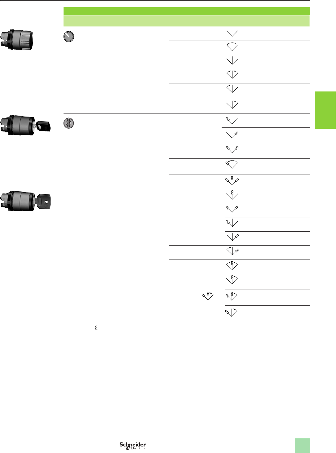
3/43
2
Heads for selector switches (1) (continued)
Shape of head Type of operator Number and type of positions
(2)
Reference Weight
kg
Knurled knob,
black
2 - stay put ZB5AD29 0.020
2 - spring return from right
to left
ZB5AD49 0.024
3 - stay put ZB5AD39 0.020
3 - spring return to centre ZB5AD59 0.020
3 - spring return from left
to centre
ZB5AD79 0.020
3 - spring return from right
to centre
ZB5AD89 0.020
Key switch with
key n° 455 (3) (4)
2 - stay put ZB5AG2 0.057
ZB5AG02 0.057
ZB5AG4 0.057
2 - spring return from right
to left
ZB5AG6 0.061
3 - stay put ZB5AG0 0.057
ZB5AG3 0.057
ZB5AG5 0.057
ZB5AG9 0.057
ZB5AG09 0.057
3 - spring return from left
to centre
ZB5AG1 0.057
3 - spring return to centre ZB5AG7 0.057
3 - spring return from right
to centre
ZB5AG8 0.057
ZB5AG05 0.057
ZB5AG08 0.057
(1) Can only be used for actuation of end of row (side) mounted contacts.
(2) The symbol “ ” indicates key withdrawal position(s).
(3) Other key numbers:
- key n° 421E: add sufx 12 to the reference,
- key n° 458A: add sufx 10 to the reference,
- key n° 520E: add sufx 14 to the reference,
- key n° 3131A: add sufx 20 to the reference.
Example:
For a key switch head with key n° 421E, 2-position stay put with key withdrawal from the left-hand position, the reference
becomes: ZB5AG212.
(4) For specic keys with other numbers, please consult your customer care centre.
References (continued) Aquire the information
Control stations and enclosures
Plastic control stations XALD and XALK
For Harmony
®
Ø 22 control and signalling units XB5
Stations for customer assembly: heads
106223
ZB5AG3
106224
ZB5AG2
106221
ZB5AD39
1
2
3
4
5
6
7
8
9
10
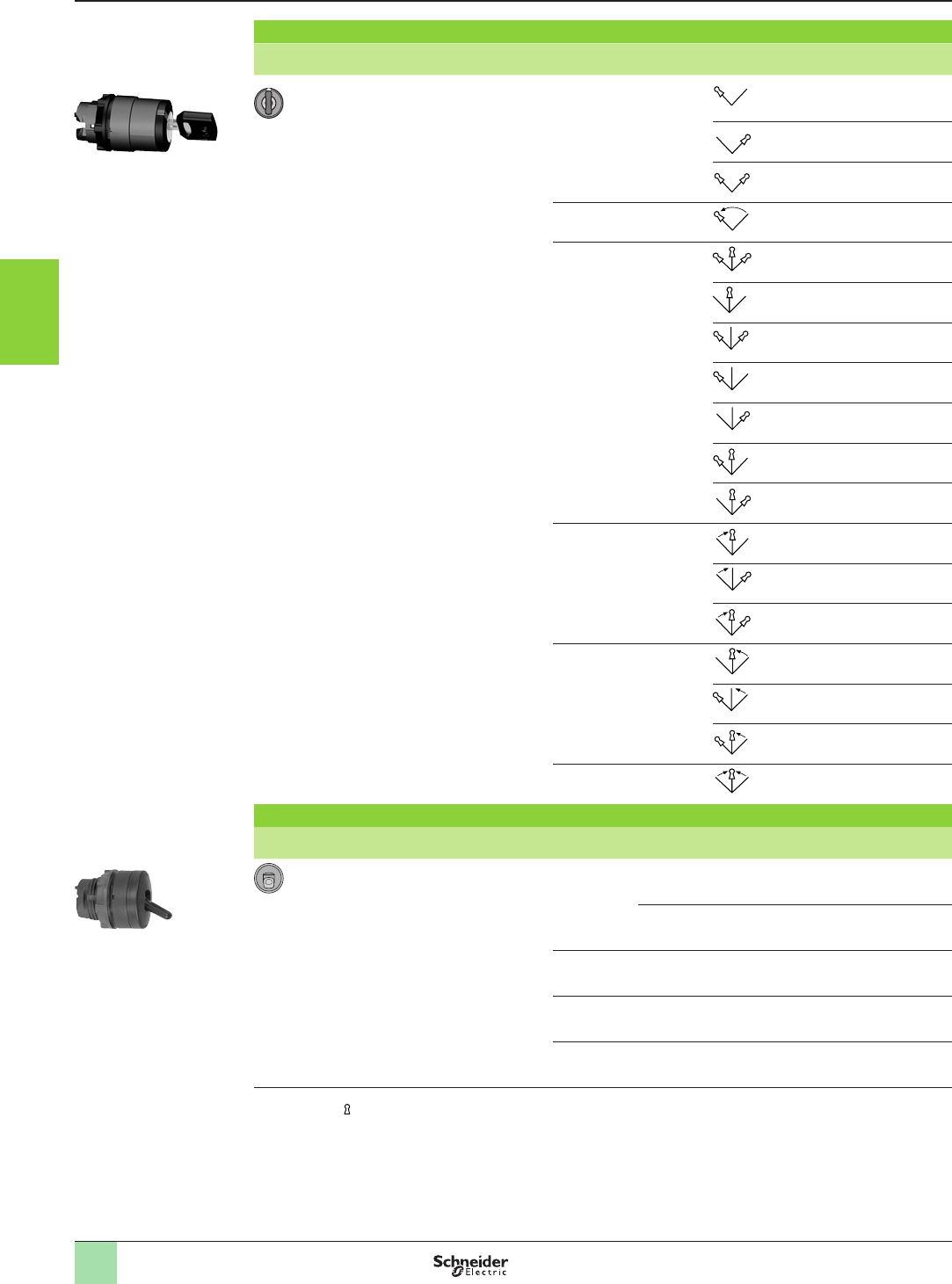
3/44
Heads for selector switches (1) (continued)
Shape of head Type of operator Number and type of positions
(2)
Reference Weight
kg
Key switch with
key n° 8D1
2 - stay put ZB5AG2D 0.057
ZB5AG02D 0.057
ZB5AG4D 0.057
2 - spring return from right
to left
ZB5AG6D 0.061
3 - stay put ZB5AG0D 0.057
ZB5AG3D 0.057
ZB5AG5D 0.057
ZB5AG9D 0.057
ZB5AG09D 0.057
ZB5AG03D 0.057
ZB5AG04D 0.057
3 - spring return from left
to centre
ZB5AG06D 0.057
ZB5AG1D 0.057
ZB5AG07D 0.057
3 - spring return from right
to centre
ZB5AG8D 0.057
ZB5AG08D 0.057
ZB5AG05D 0.057
3 - spring return to centre ZB5AG7D 0.057
Heads for toggle switches
Shape of head Description Lever Type of position Reference Weight
kg
2-position Black Stay put ZB5AD28 0.023
Spring return ZB5AD48 0.023
White Stay put ZB5AD2801 0.023
Red Stay put ZB5AD2804 0.023
Blue Stay put ZB5AD2806 0.023
(1) Can only be used for actuation of end of row (side) mounted contacts.
(2) The symbol “ ” indicates key withdrawal position(s).
References (continued) Aquire the information
Control stations and enclosures
Plastic control stations XALD and XALK
For Harmony
®
Ø 22 control and signalling units XB5
Stations for customer assembly: heads
815307
ZB5AD28
BD•8 basculeur.EPS
106224
ZB5AGpp
1
2
3
4
5
6
7
8
9
10
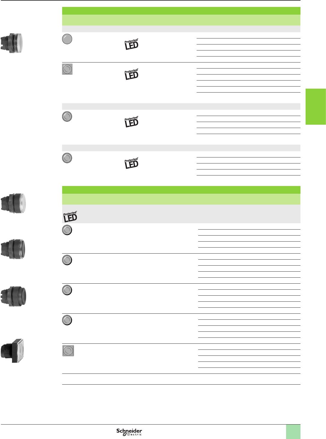
3/45
2
Heads for pilot lights
Shape of head For use with body comprising
light source type
Colour of lens Reference Weight
kg
With plain lens
With integral LED White ZB5AV013 0.017
Green ZB5AV033 0.017
Red ZB5AV043 0.017
Yellow ZB5AV053 0.017
Blue ZB5AV063 0.017
With integral LED White ZB5CV013 0.020
Green ZB5CV033 0.020
Red ZB5CV043 0.020
Yellow ZB5CV053 0.020
Blue ZB5CV063 0.020
5 colours (1) ZB5CV003 0.028
With plain lens, for insertion of legend (2)
With integral LED White ZB5AV013E 0.017
Green ZB5AV033E 0.017
Red ZB5AV043E 0.017
Yellow ZB5AV053E 0.017
Blue ZB5AV063E 0.017
With grooved lens (3)
With integral LED White ZB5AV013S 0.017
Green ZB5AV033S 0.017
Red ZB5AV043S 0.017
Yellow ZB5AV053S 0.017
Blue ZB5AV063S 0.017
Heads for spring return illuminated pushbuttons
Shape of head Type of push Colour Reference Weight
kg
Only for use with bodies comprising a light source with integral LED
Flush, plain lens White ZB5AW313 0.017
Green ZB5AW333 0.017
Red ZB5AW343 0.017
Yellow ZB5AW353 0.017
Blue ZB5AW363 0.017
Flush, grooved lens (3) White ZB5AW313S 0.016
Green ZB5AW333S 0.016
Red ZB5AW343S 0.016
Yellow ZB5AW353S 0.016
Blue ZB5AW363S 0.016
Flush for insertion of legend (1) White ZB5AA18 0.018
Green ZB5AA38 0.018
Red ZB5AA48 0.018
Yellow ZB5AA58 0.018
Blue ZB5AA68 0.018
Projecting White ZB5AW113 0.018
Green ZB5AW133 0.018
Red ZB5AW143 0.018
Yellow ZB5AW153 0.018
Blue ZB5AW163 0.018
Flush for insertion of legend (1) White ZB5CW313 0.023
Green ZB5CW333 0.023
Red ZB5CW343 0.023
Yellow ZB5CW353 0.023
Blue ZB5CW363 0.023
Other versions Heads for ush pushbuttons with illuminated ring.
Please consult your customer care centre.
(1) Head supplied with 5 different coloured lenses (white, green, red, yellow, blue) for insertion of legend. For legend ordering
information: Please consult our website www.schneider-electric.com.
(2) For legend ordering information: Please consult our website www.schneider-electric.com.
(3) For use in bright ambient light conditions (outdoors in sunlight, for example).
References (continued) Aquire the information
Control stations and enclosures
Plastic control stations XALD and XALK
For Harmony
®
Ø 22 control and signalling units XB5
Stations for customer assembly: heads
815318
ZB5CW313
815317
ZB5AW143
BW pous lumi Rond depass
BW pous lumi Rond depass
BW pous lumi Rond depass
815316
ZB5AW363
815315
ZB5AW313
BW pous lumi Rond depass
BW pous lumi Rond afleur.EPS
BW pous lumi Rond afleur.EPS
CW3 Carre Affleur Lumin.EPS
815314
ZB5AV053
BV Rond voy.EPS
1
2
3
4
5
6
7
8
9
10
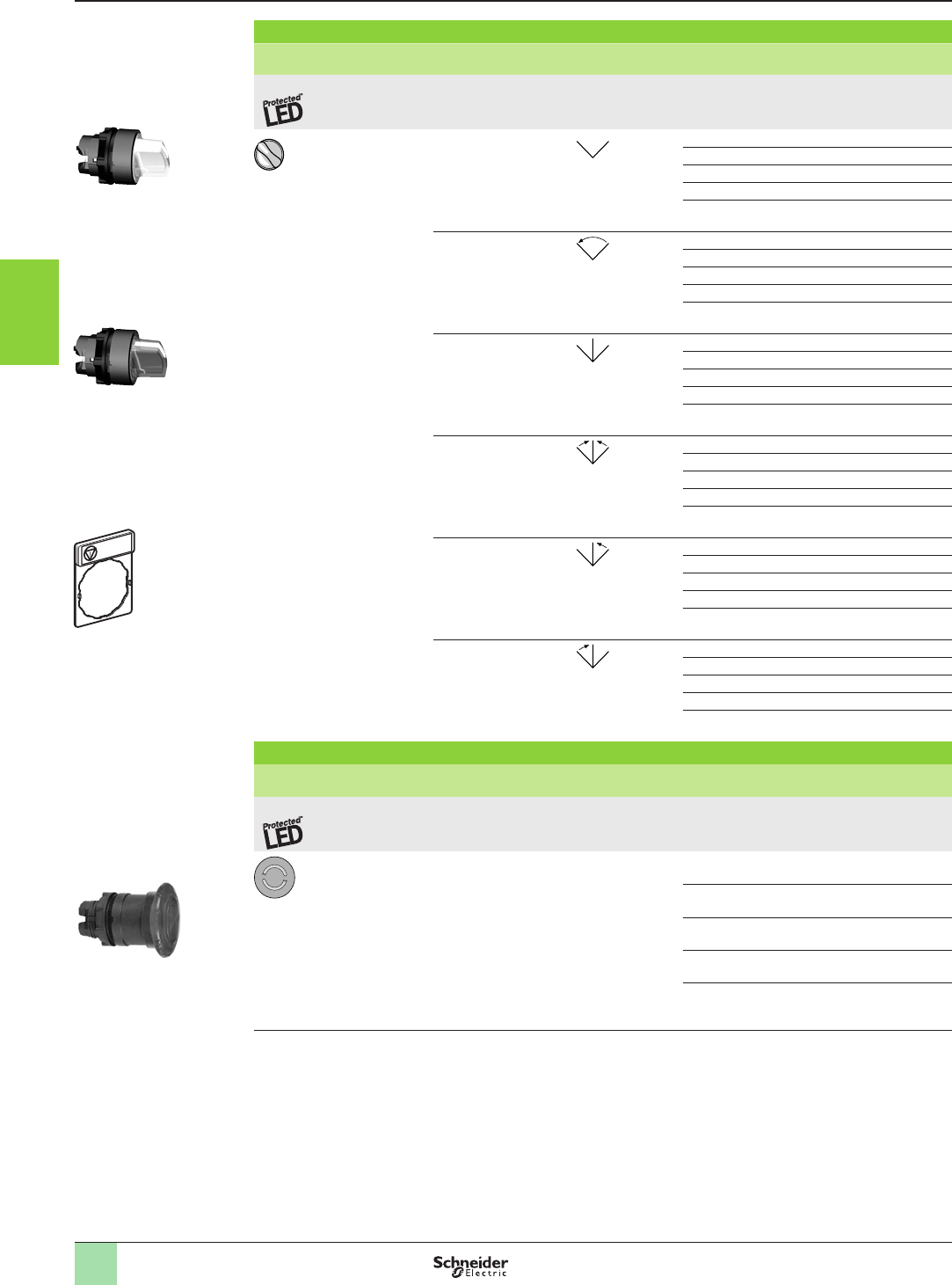
3/46
Heads for illuminated selector switches with standard handle
Shape of head Number and type of positions Colour of
handle
Reference Weight
kg
Only for use with bodies comprising a light source with integral LED
2 - stay put White ZB5AK1213 0.021
Green ZB5AK1233 0.021
Red ZB5AK1243 0.021
Yellow ZB5AK1253 0.021
Blue ZB5AK1263 0.021
2 - spring return from
right to left
White ZB5AK1413 0.021
Green ZB5AK1433 0.021
Red ZB5AK1443 0.021
Yellow ZB5AK1453 0.021
Blue ZB5AK1463 0.021
3 - stay put White ZB5AK1313 0.021
Green ZB5AK1333 0.021
Red ZB5AK1343 0.021
Yellow ZB5AK1353 0.021
Blue ZB5AK1363 0.021
3 - spring return to
centre
White ZB5AK1513 0.021
Green ZB5AK1533 0.021
Red ZB5AK1543 0.021
Yellow ZB5AK1553 0.021
Blue ZB5AK1563 0.021
3 - spring return from
right to centre
White ZB5AK1813 0.021
Green ZB5AK1833 0.021
Red ZB5AK1843 0.021
Yellow ZB5AK1853 0.021
Blue ZB5AK1863 0.021
3 - spring return from
left to centre
White ZB5AK1713 0.021
Green ZB5AK1733 0.021
Red ZB5AK1743 0.021
Yellow ZB5AK1753 0.021
Blue ZB5AK1763 0.021
Heads for Ø 40 illuminated, latching, mushroom head pushbuttons (1)
Shape of head Type of push Colour of push Reference Weight
kg
Only for use with bodies comprising a light source with integral LED
Turn to release White ZB5AW713 0.022
Green ZB5AW733 0.022
Red ZB5AW743 0.022
Yellow ZB5AW753 0.022
Blue ZB5AW763 0.022
(1) Use electrical blocks type ZBE10p, specically designed for “mounting beneath heads”, Please consult our website www.
schneider-electric.com.
DF540628
ZBY4140
Aquire the information
Control stations and enclosures
Plastic control stations XALD and XALK
For Harmony
®
Ø 22 control and signalling units XB5
Stations for customer assembly: heads
103547
ZB5AW743
BS5 aruØ40 .EPS
106227
ZB5AK1463
106225
ZB5AK1263
References (continued)
1
2
3
4
5
6
7
8
9
10
3/47
2
Standard (30 x 40 mm) legend holders for 8 x 27 mm legends (1)
Description Legend Sold in
lots of
Unit reference Weight
kg
Colour Marking
Without legend – – 10 ZBZ32 0.001
With blank legend
(for engraving)
Black or red background
–10 ZBY2101 0.002
White or yellow
background
–10 ZBY4101 0.002
With 8 x 27 mm legend
(with international marking)
Black or red
background
O (black background) 1ZBY2146 0.002
O (red background) 1ZBY2931 0.002
I1ZBY2147 0.002
II 1ZBY2148 0.002
O-I 1ZBY2178 0.002
I-II 1ZBY2179 0.002
I-O-II 1ZBY2186 0.002
AUTO 1ZBY2115 0.002
STOP 1ZBY2304 0.002
Yellow
background
1ZBY4140 (2) 0.002
With 8 x 27 mm legend
(with French language marking)
Black or red
background (3)
ARRET (red background) 1 ZBY2104 0.002
ARRET (black background) 1ZBY0104 0.002
ARRET GENERAL 1ZBY2129 0.002
ARRET REARMEMENT 1ZBY2133 0.002
ARRET MARCHE 1ZBY2166 0.002
ARRIERE 1ZBY2106 0.002
AUTO CYCLE-CYCLE 1ZBY2198 0.002
AUTO CYCLE-MAIN 1ZBY2199 0.002
AUTO-MAIN 1ZBY2164 0.002
AUTO-O-MAIN 1ZBY2185 0.002
AVANT 1ZBY2105 0.002
AVANT-O-ARRIERE 1ZBY2184 0.002
C-P-C NORMAL 1ZBY2165 0.002
CYCLE-MAIN 1ZBY2197 0.002
DECLENCHEMENT 1ZBY2132 0.002
DEFAUT (black background) 1ZBY2134 0.002
DEFAUT (red background) 1ZBY2135 0.002
DEPART CYCLE 1ZBY2195 0.002
DESCENTE 1ZBY2108 0.002
DROITE 1ZBY2109 0.002
ENCLENCHEMENT 1ZBY2131 0.002
EN SERVICE 1ZBY2111 0.002
FERMETURE 1ZBY2114 0.002
GAUCHE 1ZBY2110 0.002
HORS SERVICE 1ZBY2112 0.002
HORS-EN 1ZBY2167 0.002
LENT 1ZBY2127 0.002
MAIN 1ZBY2116 0.002
MARCHE 1ZBY2103 0.002
MONTEE 1ZBY2107 0.002
OUVERTURE 1ZBY2113 0.002
PHASE / PHASE 1ZBY2196 0.002
REARMEMENT (red bckgrnd.)
1ZBY2123 0.002
REARMEMENT (black bckgrnd.)
1ZBY0123 0.002
SOUS TENSION 1ZBY2126 0.002
VITE 1ZBY2128 0.002
Red background ARRET D’URGENCE 1ZBY2130 (2) 0.002
30 x 40 mm legend holders (ush mounting with bezel) for 8 x 27 mm legends
Description For use with Colour Sold in
lots of
Unit reference Weight
kg
Without legend Circular heads – 10 ZBZ34 0.003
Square heads – 10 ZBCZ34 0.002
With blank legend Circular heads Black or red background 10 ZBY2H101 0.004
White or yellow background
10 ZBY4H101 0.004
Square heads Black or red background 10 ZBCY2H101 0.002
White or yellow background
10 ZBCY4H101 0.002
(1) Legends: Please consult our website www.schneider-electric.com
(2) For complying with ISO 13850 standard, Emergency Stop function symbol has been added.
(3) “Start” functions: white characters on black background. “Stop” functions: white characters on red background (unless
otherwise stated above).
Aquire the information
Control stations and enclosures
Plastic control stations XALD and XALK
For Harmony
®
Ø 22 control and signalling units XB5
Stations for customer assembly: accessories
815338
ZBYpH101
815333
ZBY2107
815332
ZBYp101
ZBZ32-PRO-3-M
815331
ZBZ32
ZBZ34-PRO-3-M
815337
ZBZ34
References (continued)
1
2
3
4
5
6
7
8
9
10
3/48
Standard (30 x 40 mm) legend holders with 8 x 27 mm legend (continued)
Description Legend Reference Weight
Colour Marking kg
With 8 x 27 mm legend
(with English marking)
Black or red
background
(1)
AUTO-HAND ZBY2364 0.002
AUTO-O-HAND ZBY2385 0.002
CLOSE ZBY2314 0.002
DOWN ZBY2308 0.002
FAST ZBY2328 0.002
FORWARD ZBY2305 0.002
HAND ZBY2316 0.002
HAND-OFF-AUTO ZBY2387 0.002
INCH ZBY2321 0.002
LEFT ZBY2310 0.002
OFF ZBY2312 0.002
OFF-ON ZBY2367 0.002
ON ZBY2311 0.002
OPEN ZBY2313 0.002
POWER ON ZBY2326 0.002
RESET (red background) ZBY2323 0.002
RESET (black background) ZBY2322 0.002
REVERSE ZBY2306 0.002
RIGHT ZBY2309 0.002
RUN ZBY2334 0.002
SLOW ZBY2327 0.002
START ZBY2303 0.002
STOP-START ZBY2366 0.002
UP ZBY2307 0.002
Red background EMERGENCY STOP ZBY2330 (2) 0.002
With 8 x 27 mm legend
(with German marking)
Black or red
background
(1)
AB ZBY2208 0.002
AUF ZBY2207 0.002
AUS ZBY2204 0.002
AUS-EIN ZBY2266 0.002
AUS-IN BETRIEB ZBY2267 0.002
AUS-RUCKSTELLUND ZBY2233 0.002
AUSSCHALTEN ZBY2232 0.002
AUTO-HAND ZBY2364 0.002
AUTO-O-HAND ZBY2385 0.002
AUTOZYKL-HAND ZBY2299 0.002
AUTOZYKL-1 ZYKL ZBY2298 0.002
C-P-C-NORMAL ZBY2265 0.002
EIN ZBY2203 0.002
EINSCHALTEN ZBY2231 0.002
HAND ZBY2316 0.002
LANGSAM ZBY2227 0.002
LINKS ZBY2210 0.002
NOT-AUS (red background) ZBY2230 0.002
ÖFFNEN ZBY2213 0.002
RECHTS ZBY2209 0.002
RUCKSTELLUNG ZBY2223 0.002
SCHLIESSEN ZBY2214 0.002
SCHNELL ZBY2228 0.002
SPANNUNG EIN ZBY2226 0.002
STEUERUNG AUS ZBY2212 0.002
STEUERUNG EIN ZBY2211 0.002
STORUNG (black background) ZBY2234 0.002
STORUNG (red background) ZBY2235 0.002
VOR ZBY2205 0.002
VOR-O-ZURUCK ZBY2284 0.002
ZURUCK ZBY2206 0.002
ZYKLUS-HAND ZBY2297 0.002
ZYKLUS-START ZBY2295 0.002
Red background NOT-HALT ZBY2229 (2) 0.002
Yellow background NOT-HALT ZBY22420001 (2) 0.002
(1) “Start” functions: white characters on black background. “Stop” functions: white characters on red background (unless
otherwise stated above).
(2) For complying with ISO 13850 standard, Emergency Stop function symbol has been added.
ZBY0140
DF540629
Aquire the information
Control stations and enclosures
Plastic control stations XALD and XALK
For Harmony
®
Ø 22 control and signalling units XB5
Stations for customer assembly: accessories
815335
ZBY2228
815334
ZBY2303
References (continued)
1
2
3
4
5
6
7
8
9
10
3/49
2
Legends (30 x 42 mm) for engraving
Description Colour of background Sold in lots of Unit reference Weight
kg
Legends for engraving
2 lines of text
Black or red 10 ZALY2 0.001
White or yellow 10 ZALY4 0.001
Legends (8 x 27 mm) for engraving
For use with Colour of background Sold in lots of Unit reference Weight
kg
30 x 40 mm legend holder Black or red 10 ZBY0101 0.001
White or yellow
10 ZBY0102 0.001
Yellow
10 ZBY0140 (1) 0.001
Sheets of 76 (8 x 27 mm) peel-off legends
For use with Supplied with Sold in lots of Unit reference Weight
kg
30 x 40 mm legend holders
ZBZ32 and ZBZ34
Backing board and
protective transparent lid
10 ZBY4100 0.043
8 x 27 mm marked legends (for 30 x 40 mm legend holders ZBZ32 and ZBZ34)
Language Colour of background Marking Reference Weight
kg
International Black or red (2) O (black background) ZBY02146 0.001
O (red background) ZBY02931 0.001
IZBY02147 0.001
II ZBY02148 0.001
O-I ZBY02178 0.001
I-II ZBY02179 0.001
I-O-II ZBY02186 0.001
AUTO ZBY02115 0.001
STOP ZBY02304 0.001
French Black or red (2) ARRET (red background) ZBY02104 0.001
ARRET (black background) ZBY00104 0.001
ARRET GENERAL ZBY02129 0.001
ARRET REARMEMENT ZBY02133 0.001
ARRET-MARCHE ZBY02166 0.001
ARRIERE ZBY02106 0.001
AUTO CYCLE-CYCLE ZBY02198 0.001
AUTO CYCLE-MAIN ZBY02199 0.001
AUTO-MAIN ZBY02164 0.001
AUTO-O-MAIN ZBY02185 0.001
AVANT ZBY02105 0.001
AVANT-O-ARRIERE ZBY02184 0.001
C-P-C-NORMAL ZBY02165 0.001
CYCLE-MAIN ZBY02197 0.001
DECLENCHEMENT ZBY02132 0.001
DEFAUT (black background) ZBY02134 0.001
DEFAUT (red background) ZBY02135 0.001
DEPART CYCLE ZBY02195 0.001
DESCENTE ZBY02108 0.001
DROITE ZBY02109 0.001
ENCLENCHEMENT ZBY02131 0.001
EN SERVICE ZBY02111 0.001
FERMETURE ZBY02114 0.001
GAUCHE ZBY02110 0.001
HORS SERVICE ZBY02112 0.001
HORS-EN ZBY02167 0.001
LENT ZBY02127 0.001
MAIN ZBY02116 0.001
MARCHE ZBY02103 0.001
MONTEE ZBY02107 0.001
OUVERTURE ZBY02113 0.001
PHASE / PHASE ZBY02196 0.001
REARMEMENT (red background) ZBY02123 0.001
REARMEMENT (black background) ZBY00123 0.001
SOUS TENSION ZBY02126 0.001
VITE ZBY02128 0.001
Red ARRET D’URGENCE ZBY02130 (1) 0.001
(1) For complying with ISO 13850 standard, Emergency Stop function symbol has been added.
(2) “Start” functions: white characters on black background. “Stop” functions: white characters on red background (unless
otherwise stated above).
Aquire the information
Control stations and enclosures
Plastic control stations XALD and XALK
For Harmony
®
Ø 22 control and signalling units XB5
Stations for customer assembly: accessories
815340
ZBY0p104
815339
ZBY02178
522035
ZALY4
References (continued)
1
2
3
4
5
6
7
8
9
10
3/50
8 x 27 mm marked legends (for 30 x 40 mm legend holders ZBZ32 and ZBZ34) (continued)
Language Colour of background Marking Reference Weight
kg
English Black or red (1) AUTO-HAND ZBY02364 0.001
AUTO-O-HAND ZBY02385 0.001
CLOSE ZBY02314 0.001
DOWN ZBY02308 0.001
FAST ZBY02328 0.001
FORWARD ZBY02305 0.001
HAND ZBY02316 0.001
HAND-OFF-AUTO ZBY02387 0.001
INCH ZBY02321 0.001
LEFT ZBY02310 0.001
OFF ZBY02312 0.001
OFF-ON ZBY02367 0.001
ON ZBY02311 0.001
OPEN ZBY02313 0.001
POWER ON ZBY02326 0.001
RESET (red background) ZBY02323 0.001
RESET (black background) ZBY02322 0.001
REVERSE ZBY02306 0.001
RIGHT ZBY02309 0.001
RUN ZBY02334 0.001
SLOW ZBY02327 0.001
START ZBY02303 0.001
STOP-START ZBY02366 0.001
UP ZBY02307 0.001
Red EMERGENCY STOP ZBY02330 (2) 0.001
German Black or red (1) AB ZBY02208 0.001
AUF ZBY02207 0.001
AUS ZBY02204 0.001
AUS-EIN ZBY02266 0.001
AUS-IN BETRIEB ZBY02267 0.001
AUS-RUCKSTELLUNG ZBY02233 0.001
AUSSCHALLEN ZBY02232 0.001
AUTO-HAND ZBY02364 0.001
AUTO-O-HAND ZBY02385 0.001
AUTOZYKL-HAND ZBY02299 0.001
AUTOZYKL- 1 ZYKL ZBY02298 0.001
C-P-C-NORMAL ZBY02265 0.001
EIN ZBY02203 0.001
EINSCHALTEN ZBY02231 0.001
HAND ZBY02316 0.001
LANGSAM ZBY02227 0.001
LINKS ZBY02210 0.001
NOT-AUS (red background) ZBY02230 0.001
ÖFFNEN ZBY02213 0.001
RECHTS ZBY02209 0.001
RUCKSTELLUNG ZBY02223 0.001
SCHLIESSEN ZBY02214 0.001
SCHNELL ZBY02228 0.001
SPANNUNG EIN ZBY02226 0.001
STEUERUNG AUS ZBY02212 0.001
STEUERUNG EIN ZBY02211 0.001
STORUNG (black background) ZBY02234 0.001
STORUNG (red background) ZBY02235 0.001
VOR ZBY02205 0.001
VOR-O-ZURUCK ZBY02284 0.001
ZURUCK ZBY02206 0.001
ZYKLUS-HAND ZBY02297 0.001
ZYKLUS-START ZBY02295 0.001
Red NOT-HALT ZBY02229 (2) 0.001
Yellow NOT-HALT ZBY022420001 (2) 0.001
(1) “Start” functions: white characters on black background. “Stop” functions: white characters on red background (unless
otherwise stated above).
(2) For complying with ISO 13850 standard, Emergency Stop function symbol has been added.
Aquire the information
Control stations and enclosures
Plastic control stations XALD and XALK
For Harmony
®
Ø 22 control and signalling units XB5
Stations for customer assembly: accessories
815342
ZBY02228
815341
ZBY02303
References (continued)
1
2
3
4
5
6
7
8
9
10
3/51
2
Legends for pushbuttons, switches and pilot lights XB5A
Description Marking Sold in
lots of
Unit reference Weight
kg
Sheets of 66 circular peel-off
transparent self-adhesive
legends
Without 10 ZBY1101 0.017
International O 10 ZBY1146 0.017
I10 ZBY1147 0.017
II 10 ZBY1148 0.017
III 10 ZBY1149 0.017
AUTO 10 ZBY1115 0.017
STOP 10 ZBY1304 0.017
A10 ZBY1912 0.017
French ARRET 10 ZBY1104 0.017
ARRIERE 10 ZBY1106 0.017
AVANT 10 ZBY1105 0.017
AUTO 10 ZBY1115 0.017
DESCENTE 10 ZBY1108 0.017
MAIN 10 ZBY1116 0.017
MARCHE 10 ZBY1103 0.017
MONTEE 10 ZBY1107 0.017
English HAND 10 ZBY1316 0.017
OFF 10 ZBY1312 0.017
ON 10 ZBY1311 0.017
START 10 ZBY1303 0.017
German AB 10 ZBY1208 0.017
AUF 10 ZBY1207 0.017
AUS 10 ZBY1204 0.017
EIN 10 ZBY1203 0.017
ZU 10 ZBY1214 0.017
Strip of 66 square peel-off
transparent self-adhesive legends
Without 10 ZBCY1101 0.017
“SIS Label” labelling software (for legend sheets ZBY1101, ZBY4100 and ZBCY1101)
Application Reference Weight
kg
Legend design for English, French, German,
Italian and Spanish
ZBY001, ZBY0101, ZBY0102,
ZBY1101, ZBY4100, ZBY5100,
ZBY5101 AND ZBY5102
XBY2U 0.100
Circular yellow legends for mushroom head pushbuttons
Used for “Emergency stop” function
Diameter
mm
Conforming
to standards
Marking on yellow background Reference (1) Weight
kg
60 EN/IEC 60204-1 and
EN/ISO 13850
–ZBY9140 0.004
ARRET D’URGENCE ZBY9130 0.004
EMERGENCY STOP ZBY9330 0.004
NOT-HALT ZBY9230 0.004
PARADA DE EMERGENCIA ZBY9430 0.004
ARRESTO DE EMERGENZA ZBY9630 0.004
90 EN/IEC 60204-1 and
EN/ISO 13850
–ZBY8140 0.008
ARRET D’URGENCE ZBY8130 0.008
EMERGENCY STOP ZBY8330 0.008
NOT-HALT ZBY8230 0.008
PARADA DE EMERGENCIA ZBY8430 0.008
ARRESTO DE EMERGENZA ZBY8630 0.008
Used for “Emergency switching off” function
60 EN/IEC 60204-1 –ZBY9101 0.004
COUPURE D’URGENCE ZBY9160 0.004
EMERGENCY SWITCHING OFF ZBY9360 0.004
NOT-AUS ZBY9260 0.004
DESCONEXION DE EMERGENCIA ZBY9460 0.004
INTERRUZIONE DI EMERGENZA ZBY9660 0.004
90 EN/IEC 60204-1 –ZBY8101 0.008
COUPURE D’URGENCE ZBY8160 0.008
EMERGENCY SWITCHING OFF ZBY8360 0.008
NOT-AUS ZBY8260 0.008
DESCONEXION DE EMERGENCIA ZBY8460 0.008
INTERRUZIONE DI EMERGENZA ZBY8660 0.008
(1) For complying with ISO 13850 standard, Emergency Stop function symbol has been added.
Aquire the information
Control stations and enclosures
Plastic control stations XALD and XALK
For Harmony
®
Ø 22 control and signalling units XB5
Stations for customer assembly: accessories
DF540548
Labelling software
Logiciel de création d'étiquettes
Beschriftungssoftware
Software para crear etiquetas
Software per la creazione di etichette
SIS-Label
Merlin Gerin
Modicon
Square D
Telemecanique
XBY2U
DF539642
ZBY9160
DF539640
ZBY9130
815344
ZBY1ppp
References (continued)
1
2
3
4
5
6
7
8
9
10
3/52
Metal guards (1)
Description For use with Colour Reference Weight
kg
Metal guards
Padlockable
Emergency stop function
only with the following
Ø 40 trigger action
pushbuttons:
XB5AT8p,
XB5AS8p,
XB5AS9p,
ZB5AT8p,
ZB5AS8p,
ZB5AS9p.
Chromium plated ZBZ1600 0.046
Black ZBZ1602 0.046
Red ZBZ1604 0.046
Blue ZBZ1605 0.046
Pushbutton caps - unmarked
For use with Cap Sold in
lots of
Unit reference Weight
Type Colour kg
Circular pushbutton heads
ZB5AA supplied without cap
Flush White 10 ZBA1 0.001
Black 10 ZBA2 0.001
Green 10 ZBA3 0.001
Red 10 ZBA4 0.001
Yellow 10 ZBA5 0.001
Blue 10 ZBA6 0.001
6 colours (2) 1ZBA9 0.006
Projecting White 10 ZBL1 0.001
Black 10 ZBL2 0.001
Green 10 ZBL3 0.001
Red 10 ZBL4 0.001
Yellow 10 ZBL5 0.001
Blue 10 ZBL6 0.001
6 colours (2) 1ZBL9 0.006
Pushbutton caps - marked (3) (sold in lots of 10)
For use with Type
of push
Marking Colour
of cap
Unit reference Weight
Text Colour kg
Circular pushbutton heads
ZB5AA supplied without cap
Flush I White Green ZBA331 0.001
Black White ZBA131 0.001
II White Green ZBA336 0.001
Black White ZBA136 0.001
III White Green ZBA337 0.001
Black White ZBA137 0.001
IV White Green ZBA338 0.001
Black White ZBA138 0.001
START White Green ZBA333 0.001
Black White ZBA133 0.001
ON White Green ZBA341 0.001
Black White ZBA141 0.001
MARCHE White Green ZBA342 0.001
Black White ZBA142 0.001
White Black ZBA245 0.001
Black White ZBA145 0.001
UP Black White ZBA343 0.001
DOWN White Black ZBA344 0.001
AWhite Black ZBA335 0.001
Black White ZBA334 0.001
O White Red ZBA432 0.001
Black ZBA232 0.001
ARRET White Red ZBA433 0.001
Black ZBA233 0.001
STOP White Red ZBA434 0.001
Black ZBA234 0.001
OFF White Red ZBA435 0.001
Black ZBA235 0.001
White Green ZBA346 0.001
R White Blue ZBA639 0.001
+White Black ZBA2934 0.001
-White Black ZBA2935 0.001
(1)
These guards can be used in conjunction with a legend holder, but only those for mounting directly beneath the head.
Please consult
our website www.schneider-electric.com
.
(2) Set of 6 different coloured caps: white, black, green, red, yellow, blue.
(3) Can be clipped-in at 90° steps through 360°.
Aquire the information
Control stations and enclosures
Plastic control stations XALD and XALK
For Harmony
®
Ø 22 control and signalling units XB5
Stations for customer assembly: accessories
Ø 6
815197
ZBZ160p
ZBA•••-PRO-3-M
815349
ZBA333
ZBL•-PRO-3-M
815348
ZBLp
ZBA•-PRO-3-M
815347
ZBAp
References (continued)
1
2
3
4
5
6
7
8
9
10
3/53
2
Coloured boots
Description Colour Sold in
lots of
Unit reference Weight
kg
Coloured boots
(can be replaced without
dismantling the head)
Black 10 ZB2BP012 0.003
Green 10 ZB2BP013 0.003
Red 10 ZB2BP014 0.003
Yellow 10 ZB2BP015 0.003
Blue 10 ZB2BP016 0.003
Lens caps
Circular lens caps for light sources with integral LED
Pilot lights White 10 ZBV0113 0.002
Green 10 ZBV0133 0.002
Red 10 ZBV0143 0.002
Yellow 10 ZBV0153 0.002
Blue 10 ZBV0163 0.002
5 different coloured grooved lenses (1) 1 ZBV0103S 0.010
Illuminated pushbuttons,
with ush pushbutton
White 10 ZBW9113 0.002
Green 10 ZBW9133 0.002
Red 10 ZBW9143 0.002
Yellow 10 ZBW9153 0.002
Blue 10 ZBW9163 0.002
Illuminated pushbuttons,
with projecting pushbutton
White 10 ZBW9313 0.002
Green 10 ZBW9333 0.002
Red 10 ZBW9343 0.002
Yellow 10 ZBW9353 0.002
Blue 10 ZBW9363 0.002
Square lens caps for light sources with integral LED
Pilot lights White 10 ZBCV0113 0.002
Green 10 ZBCV0133 0.002
Red 10 ZBCV0143 0.002
Yellow 10 ZBCV0153 0.002
Blue 10 ZBCV0163 0.002
Illuminated pushbuttons,
with ush pushbutton
White 10 ZBCW9113 0.002
Green 10 ZBCW9133 0.002
Red 10 ZBCW9143 0.002
Yellow 10 ZBCW9153 0.002
Blue 10 ZBCW9163 0.002
Illuminated pushbuttons,
with projecting pushbutton
White 10 ZBCW9313 0.002
Green 10 ZBCW9333 0.002
Red 10 ZBCW9343 0.002
Yellow 10 ZBCW9353 0.002
Blue 10 ZBCW9363 0.002
Miscellaneous accessories
Description For use with Sold in
lots of
Colour Unit reference Weight
kg
Bezel tool ZB5AZ901 head 10 –ZB5AZ905 0.016
Plastic blanking plugs
(with xing nut)
Square shape for
Ø 22 units
(2) 10 Black ZB5SZ5 0.009
Circular shape for
Ø 22 units
10 Black ZB5SZ3 0.009
Terminal branch XALD and XALK control stations 10 XALZ09 0.003
Bellow seals (IP 69K)
(3)
Control station with 1 cut-out, installed in
harsh environment + Emergency Stop
pushbutton type ZB5
2Red ZBZ48 0.009
Black ZBZ28 0.009
Yellow ZBZ58 0.009
Replacement keys for Emergency stop key release heads and key switches
Description Key number Reference Weight
kg
Set of 2 keys 455 ZBG455 0.013
421E ZBG421E 0.014
458A ZBG458A 0.014
520E ZBG520E 0.014
3131A ZBG3131A 0.014
(1) Set of 5 different coloured lenses: white, green, red, yellow and blue.
(2) Body/xing collar ZB5AZ009 necessary for xation, to be ordered separately.
(3) Not compatible with
Ø 30 mm
Emergency Stop heads
.
Aquire the information
Control stations and enclosures
Plastic control stations XALD and XALK
For Harmony
®
Ø 22 control and signalling units XB5
Stations for customer assembly: accessories
PF100885
ZBG455
ZBV01•3-PRO-3M
815354
ZBV01p3
501578
ZB2BP01p
References (continued)
DF540815
ZB5AZ905
DF540770
ZB5SZ3
ZBZp8
DF540008
1
2
3
4
5
6
7
8
9
10
3/54
Operating principle,
characteristics
Operating principle
Enabling switches, comprising an XY2AU grip and an XPSVC monitoring module, allow
authorised personnel to undertake adjustment, programming or maintenance operations
near machine equipment hazardous zones, providing certain conditions are met.
To gain access, these operations, often performed at reduced speed, must
be selected by authorised personnel using selectors, with or without keys. Once
selection is made, the enabling switch temporarily assumes control of the hazardous
zone’s usual protection measures. Important note: the enabling switch alone must
not lead to the actuation of any dangerous movements associated with the machine;
a secondary, intentional control action is required from the operator. In addition, each
person in the hazardous zone must be provided with an enabling switch to ensure
their own safety.
Environment
Conforming to standards Products IEC/EN 60947-1 , IEC/EN 60947-5-1, cUL us 508 and CSA C22-2 n° 14 ,
IEC/EN 60947-5-8
Machine assemblies IEC/EN 60204-1
Maximum safety level (1) PL e, category 4 conforming to EN/ISO 13849-1 and SIL 3 conforming to EN/IEC 61508
Reliability data B10d 5,000,000 (data value for a service life of 10 years: can be limited by contact and
mechanical wear)
Protective treatment Standard version: “TC”
Ambient air temperature Operation °C - 10…+ 60
Storage °C - 40…+70
Vibration resistance 6 gn (5…55 Hz) conforming to IEC 60068-2-6
Shock resistance 10 gn (11 ms) conforming to IEC 60068-2-27
Electric shock protection Class II conforming to IEC/EN 61140
Degree of protection IP 66 conforming to IEC 60529, IP 65 with a pushbutton, IK 06 conforming to EN 50102
Mechanical durability Op.
cycles
1 million
Enclosure Double insulated enclosure made of PA66
Cable diameter mm 7…13
Contact block characteristics
Rated operational characteristics a AC-15 : C300 or Ue = 250 V, Ie = 1.5 A or Ue = 125 V, Ie = 0.75 A
c DC-13 : R300 or Ue = 250 V, Ie = 0.1 A or Ue = 125 V, Ie = 0.22 A
conforming to IEC 60947-5-1 Appendix A
Thermal current (Ithe) A5
Rated insulation voltage (Ui) V250, degree of pollution III (II inside) conforming to IEC 60947-1
125, contact 7-8
Rated impulse withstand voltage (Uimp) kV 2.5 conforming to EN 60947-1
Positive operation 2 3-position contacts with positive opening operation conforming to IEC 60947-5-1
Contact operation Slow break
Resistance across terminals mW≤ 50
Actuation force 1…2: 12 N
2…3: 50 N
Terminal referencing Numbered conforming to CENELEC EN 50013
Short-circuit protection 4 A cartridge fuse type gG (gl)
Connection mm2Terminal block, 1 x 0.34…1 x 1.5
(1) Using an appropriate and correctly connected control system.
Aquire the information
Enabling switches
For safety circuits
1
2
3
4
5
6
7
8
9
10
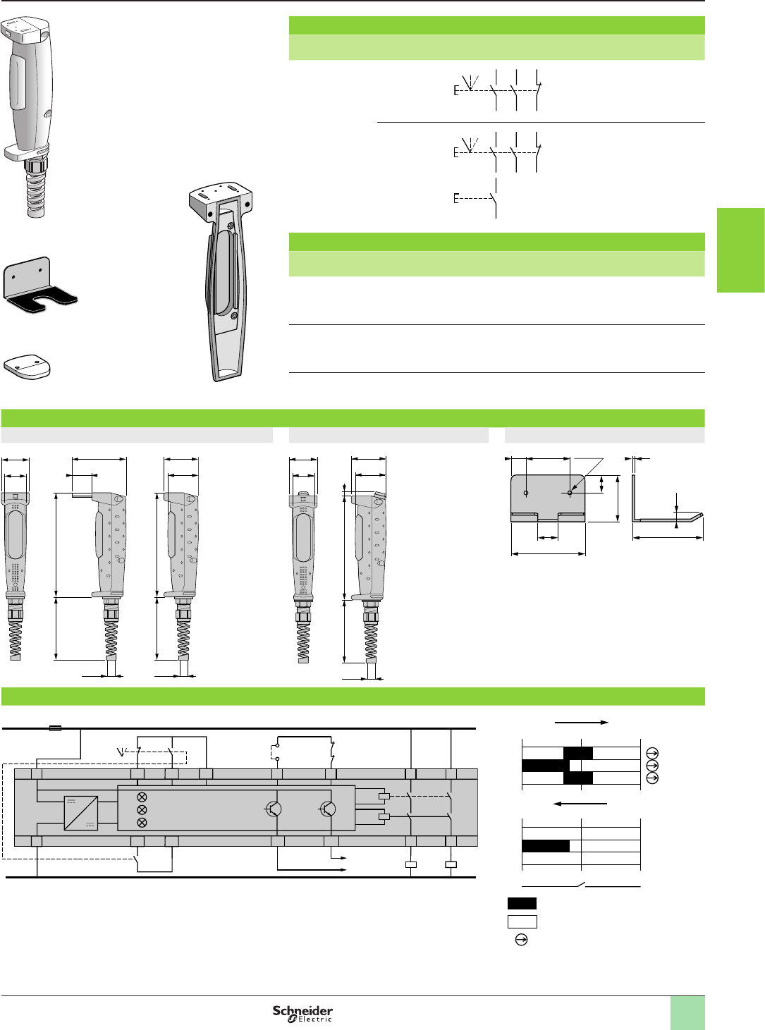
3/55
XY2AUp
References,
dimensions,
connections
References
Number
of contacts
Contact
type
Contact
blocks and scheme
Reference Weight
kg
32 enabling
3 positions
+ 1 N/C
XY2AU1 0.310
2 enabling
3 positions
+ 1 N/C
+ 1 N/O
supplementary
contact
XY2AU2 0.320
Separate components and spare parts
Description Reference Weight
kg
Grip support
XY2AZ1 0.215
Cover kit for key actuator XCSZ01 or XCSZ11
only applicable to XY2AU1
XY2AZ2 0.015
Cover
XY2AZ3 0.060
Dimensions
XY2AU1 XY2AU2 XY2AZ1
Connection example
With XPSVC safety module State of XY2AUp contacts
6 5
20
12
1
34
6 5
20
12
1
34
78
XY2AZ1
XY2AZ2 XY2AZ3
32
46
33
91
51
58
174
87
Ø 13,5
174
87
Ø 13,5
32
46
51
58
174
87 8
Ø 13,5
84
33
50 2xØ4,417
20
53
81
3
10
A1 Y1 Y2 13S12 S13
S1
K4
K3
K1
K3
K2
K1/K2
K4
A2 Y34 Y44 14
23
24S21 S23
K1/K2
XPS VC
S11
ESC
F1
+ 24 V
0 V
4 3
S1
2 1
6 5
2
01
2 solid-state outputs 2 safety outputs
ESC : external start conditions
To
PLC
Logic
Supply A1/A2
Fault Fault
0 1 2
1-2
5-6
3-4
0 1 2
1-2
5-6
3-4
7 8
Contact closed
Contact open
Only
applicable to
XY2AU2
N/C contact with positive opening
operation
Aquire the information
Enabling switches
For safety circuits
1
2
3
4
5
6
7
8
9
10
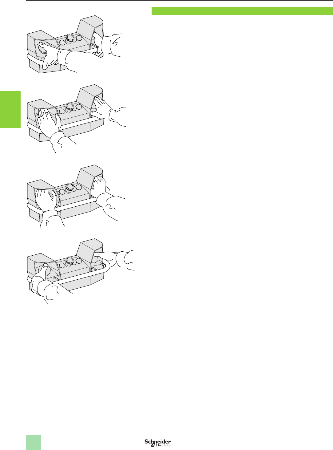
3/56
Aquire the information
Two-hand ergonomic control stations
With Harmony XB4B control units
Presentation
Presentation
The design of the control station incorporates features to signicantly reduce
occupational illnesses associated with repetitive movements of the hands,
particularly “carpal tunnel syndrome”.
The health and comfort of the machine operator is assured by:
b the numerous alternative hand positions for operating the 2 pushbutton actuators,
see diagrams to left,
b a hand rail,
b simple and fast adjustments of control station position.
This two-hand control station protects machine operators against both industrial
accidents and illnesses related to their occupation.
It conforms to the following European safety standards:
b EN 574/ISO 13851 (two-hand control),
b EN 999 (approach speeds of parts of the human body and positioning of safety
devices).
The control station can be mounted:
b directly on the machine housing,
b on a pedestal, enabling 3 directional adjustment:
v height,
v rake,
v skew.
The use of a two-hand control station in conjunction with a safety module type
XPSBCE or XPSBF provides type IIIC two-hand control conforming to EN 574/ISO
13851 and PLe / Category 4 according to EN/ISO 13859-1.
The range comprises:
b two-hand control stations with or without pre-wired terminal blocks,
b kits (control station + pedestal), with or without pre-wired terminal blocks.
The products are supplied with an installation manual, which is also available as a
separate item.
803047
803045803046803044
1
2
3
4
5
6
7
8
9
10
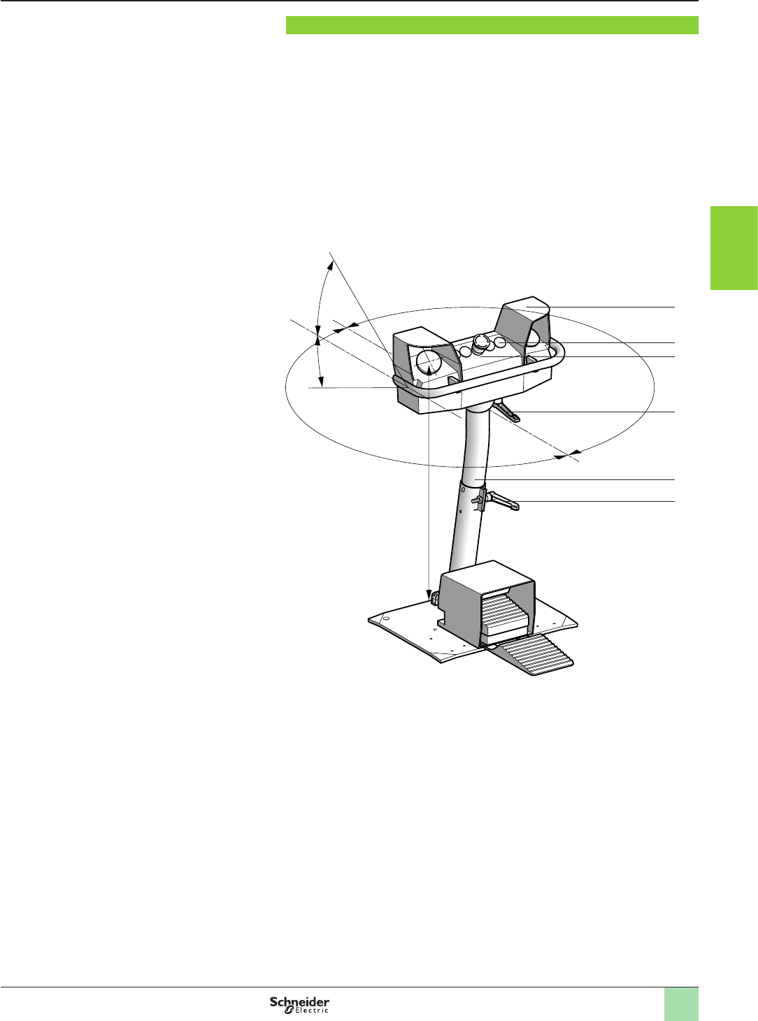
3/57
Description
Description
The control station
1
has ve cut-outs (Ø 22 mm)
2
as standard. Five additional
cut-outs are possible
3
.
Its pedestal
5
enables the following quick and simple adjustments:
b Control station rake (± 30°) using handle
4
.
b Control station skew (± 180°) using handle
6
.
b Control station height (835 to 1170 mm) using handle
6
.
835...1170
30˚
180˚
30˚
580807
1
2
4
5
6
3
Aquire the information
Two-hand ergonomic control stations
With Harmony XB4B control units
1
2
3
4
5
6
7
8
9
10
3/58
Aquire the information
Two-hand ergonomic control stations
With Harmony XB4B control units
Characteristics
Characteristics
Environment
Conformity to standards EN/IEC 60947-5-1, EN 574/ISO 13851
Maximum safety level (1) PL e, category 4 conforming to EN/ISO 13849-1 and SIL 3 conforming to EN/IEC 61508
Reliability data B10d Contact block Harmony XB4B 25,000,000 (data value for a service life of 10 years: can be limited by contact and
mechanical wear)
Colour Orange RAL 2008
Protective treatment Standard version “TC”
Ambient air temperature For operation °C - 25…+ 70
For storage °C - 40…+ 70
Vibration resistance Conforming to
EN/IEC 60068-2-6
5 gn (2…500 Hz)
Shock resistance Conforming to
EN/IEC 60068-2-27
10 gn (duration 11 ms)
Electric shock protection Conforming to EN/IEC 61140 Class I
Degree of protection Conforming to EN/IEC 60529 IP 65
Mechanical life Number of operating cycles 1 million
Cable entries See dimensions, page
3/61
Contact block characteristics
Rated operational
characteristics
a AC-15 A600 or Ue = 240 V and Ie = 3 A
c DC-13 Q600 or Ue = 250 V and Ie = 0.27 A conforming to EN/IEC 60947-5-1 Appendix A
Rated insulation voltage Conforming to EN/IEC 60947-1 VUi = 600, degree of pollution 3
Conforming to UL 508 and
CSA C22-2 n° 14
VUi = 600
Rated impulse withstand
voltage
Conforming to
EN/IEC 60947-1
kV Uimp = 6
Contact operation Slow break, with positive
opening operation
N/C + N/O break before make on each black actuator pushbutton
N/C + N/C simultaneous on Emergency stop pushbutton
N/C + N/O break before make on Lock out pushbutton
Positive operation Conforming to
EN/IEC 60947-5-1 Appendix K
N/C contact with positive opening operation
Terminal referencing Conforming to CENELEC EN 50013
Short-circuit protection Conforming to EN/IEC 269 10 A cartridge fuse type gG (gl)
Connection Screw clamp terminals mm2Minimum clamping capacity: 1 x 0.22 or 1 x 0.22 + 1 x 0.34
Maximum clamping capacity: 1 x 2.5 or 2 x 1.5
Electrical durability
Conforming to
EN/IEC 60947-5-1 Appendix C
Operating rate: 3600 operating
cycles/hour.
Load factor: 0.5
a.c. supply for 1 million
operating cycles
utilisation category AC-15
V24 120 230
A432
d.c. supply for 1 million
operating cycles
utilisation category DC-13
V24 110
A0.5 0.2
Electrical reliability Failure rate
According to EN/IEC 60947-5-4
At 17 V and 5 mA, λ < 10-8
At 5 V and 1 mA, λ < 10-6
(1) Using an appropriate and correctly connected control system.
1
2
3
4
5
6
7
8
9
10
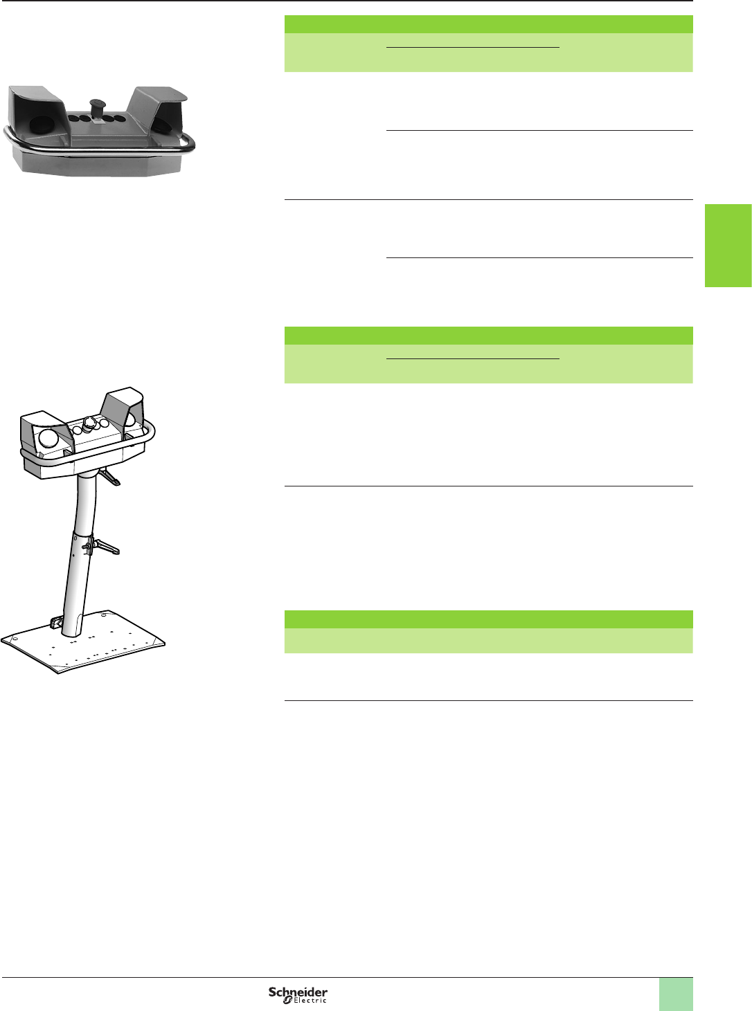
3/59
References
Two-hand control stations - painted
Description Mushroom head Reference Weight
kg
Function and
colour
Contacts
2 control
pushbuttons with
N/C + N/O break
before make
contacts and
1 mushroom head
pushbutton
Emergency stop
Red
N/C + N/C
slow break
XY2SB71 4.000
Lock out
(Schaltsperre)
Yellow
N/C + N/O
break before make
XY2SB75 4.000
2 control
pushbuttons with
N/C + N/O break
before make
contacts and
1 mushroom head
pushbutton, with
pre-wired terminal
block
Emergency stop
Red
N/C + N/C
slow break
XY2SB72 4.000
Lock out
(Schaltsperre)
Yellow
N/C + N/O
break before make
XY2SB76 4.000
Kits (control station + pedestal)
Description Mushroom head Reference Weight
kg
Function and
colour
Contacts
2 control
pushbuttons and
1 mushroom head
Emergency stop
pushbutton
+ pedestal XY2SB90
Emergency stop
Red
N/C + N/C
slow break
XY2SB714 17.000
2 control
pushbuttons and
1 mushroom head
Emergency stop
pushbutton, with
pre-wired terminal
block
+ pedestal XY2SB90
Emergency stop
Red
N/C + N/C
slow break
XY2SB724 17.000
Documentation
Description For use with Reference Weight
kg
Installation manual All control stations XY2SB7pp XCOM2514 0.200
XY2SB7p
803051
XY2SB7p4
803052
Aquire the information
Two-hand ergonomic control stations
With Harmony XB4B control units
1
2
3
4
5
6
7
8
9
10
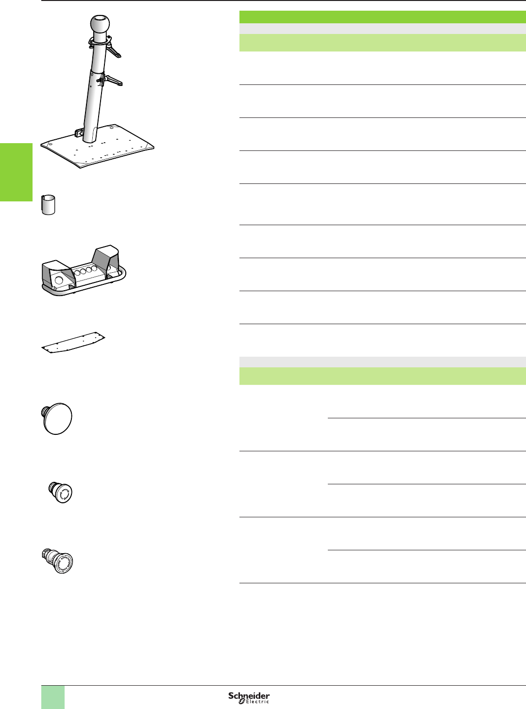
3/60
Aquire the information
Two-hand ergonomic control stations
With Harmony XB4B control units
Separate components and spare parts
Various accessories
Description For use with Colour Unit reference Weight
kg
Metal pedestal
adjustable height
XY2SBpp Orange XY2SB90 13.000
Collar for guard rail
(welded xing)
XY2SB90 Orange XY2SB98 0.800
Control station top
without control devices
– Orange XY2SB511 2.500
Control station base – Orange XY2SB531 1.200
Double protective metal
cover
Metal pedestal
XY2SB90 and
foot switches
type XPER
Orange XY2SB96 4.370
Replacement handle
(sold in lots of 5)
Metal pedestal
XY2SB90
Black XY2SB93 0.155
Replacement seals
– – XY2SB99 0.300
Adaptor
(sold in lots of 5)
ISO M25 – DE9RA2125 0.010
Fixing nut
(sold in lots of 5)
Adaptor – DE9EC21 0.005
Control units (1)
Description Component part Colour Reference Weight
kg
Pushbutton
actuator
Ø 60 mm
mushroom head
Black ZB4BR216 0.095
N/C + N/O
body/contact
assembly
–ZB4BZ105 0.055
Emergency stop
pushbutton
Ø 40 mm
mushroom head
Red ZB4BS844 0.060
N/C + N/C
body/contact
assembly
–ZB4BZ104 0.055
Lock out
pushbutton
Ø 40 mm
mushroom head
Yellow,
marked
“Schaltsperre”
ZB4BS845S 0.060
N/C + N/O
body/contact
assembly
–ZB4BZ105 0.055
(1) Other XB4B control and signalling units are suitable for use on the control stations. Please
refer to our “Human Machine Interface catalogue”.
Constituants pour applications de sécurité
Pupitres de commande bimanuelle ergonomique
Avec boutonnerie XB2-B
Références
XY2SB90
803059_1
XY2SB98
803057_1
XY2SB511
803058_1
XY2SB99
522964
ZB4BR216
803054_1
ZB4BS844
803055_1
ZB4BS845S
503745
References (continued)
1
2
3
4
5
6
7
8
9
10
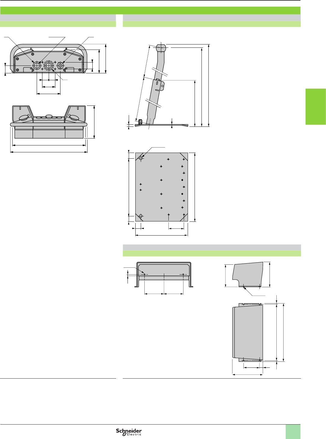
3/61
Aquire the information
Two-hand ergonomic control stations
With Harmony XB4B control units
Dimensions
Dimensions
Control station Pedestal
XY2SB7pXY2SB90
Double protective cover
XY2SB96
(1) 2 plain holes for n° 13 (PG13.5) or ISO M20 cable gland.
(2) Ø 56 mm knock-out specically for mounting on pedestral.
(3) 1 plain hole for n° 21 (PG21) cable gland. For ISO M25, use
adaptator DE9RA2125 and xing nut DE9EC21.
(1) Adjustable height of pedestal 720 to 1060 mm.
=
75
430
2xØ28,5
(3) (1)
(2)
455
188,5
136,2
40
137
=
44,5
170
34
330
372 == 12
6
440 455
450 242
696
720
(1)
2xØ16
100
100 10
190
155
369
139
10
353= =
4xØ6,5
2xØ5
123123
1
2
3
4
5
6
7
8
9
10
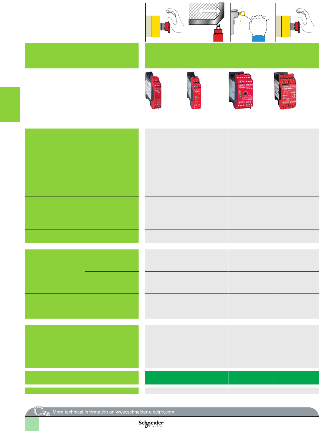
2
1
3
4
5
6
7
8
9
10
3/62
Selection guide Monitor and Processing
Preventa safety modules
Applications
Modules For Emergency stop and switch monitoring For Emergency stop
and protective guard
applications
For Emergency stop and switch monitoring For Emergency stop, switch or solid-state output
safety light curtain monitoring
For Emergency stop,
switch, sensing mat/
edges or solid-state
output safety light
curtain monitoring
Maximum achievable safety level PLe/Category 4
conforming
to EN/ISO 13849-1,
SILCL3 conforming
to EN/IEC 61508
and EN/IEC 62061
PLe/Category 4
conforming
to EN/ISO 13849-1,
SILCL3 conforming
to EN/IEC 61508
and EN/IEC 62061
PLe/Category 4
(instantaneous safety
outputs) and PLd/
Category 3 (time delay
safety
outputs) conforming to
EN/ISO 13849-1,
SILCL3 (instantaneous
safety outputs) and
SILCL2 (time delay
safety outputs)
conforming to
EN/IEC 61508
and EN/IEC 62061
PLe/Category 4
conforming to EN
ISO 13849-1,
SILCL3 conforming to
EN/IEC 62061
PLe/Category 4
conforming to
EN/ISO 13849-1,
SILCL3 conforming
to EN/IEC 61508
and EN/IEC 62061
PLe/Category 4
(instantaneous safety
outputs) and
PLd/Category 3 (time
delay safety outputs)
conforming to
EN/ISO 13849-1,
SILCL3 (instantaneous
safety outputs) and
SILCL2 (time delay
safety outputs)
conforming to
EN/IEC 61508
and EN/IEC 62061
PLe/Category 4
conforming to
EN/ISO 13849-1,
SILCL3 conforming
to EN/IEC 61508
and EN/IEC 62061
PLe/Category 4
conforming to
EN/ISO 13849-1,
SILCL3 conforming
to EN/IEC 61508
and EN/IEC 62061
PLe/Category 4
conforming to
EN/ISO 13849-1,
SILCL3 conforming
to EN/IEC 61508
and EN/IEC 62061
PLe/Category 4
conforming to
EN/ISO 13849-1,
SILCL3 conforming
to EN/IEC 61508
and EN/IEC 62061
Conformity to standards EN/IEC 60204-1,
EN 1088/ISO 14119,
EN/ISO 13850,
EN/IEC 60947-1,
EN/IEC 60947-5-1
EN/IEC 60204-1,
EN 1088/ISO 14119,
EN/ISO 13850,
EN/IEC 60947-1,
EN/IEC 60947-5-1
EN/IEC 60204-1,
EN/ISO 13850,
EN 1088/ISO 14119,
EN/IEC 60947-1,
EN/IEC 60947-5-1
EN 62061
EN ISO 13849-1
EN 50156-1
EN 60204-1
EN/IEC 61496-1
EN/IEC 60947-5-1
EN/IEC 60204-1,
EN 1088/ISO 14119,
EN/ISO 13850,
EN/IEC 60947-1,
EN/IEC 60947-5-1
EN/IEC 60204-1,
EN/IEC 60947-1,
EN/IEC 60947-5-1,
EN/ISO 13850,
EN 1088/ISO 14119
EN/IEC 60204-1,
EN 1088/ISO 14119,
EN/ISO 13850,
EN/IEC 60947-1,
EN/IEC 60947-5-1
EN/IEC 60204-1,
EN 1088/ISO 14119,
EN/ISO 13850,
EN/IEC 60947-1,
EN/IEC 60947-5-1,
EN/IEC 61496-1 (type 4)
EN/IEC 60204-1,
EN 1088/ISO 14119,
EN/ISO 13850,
EN/IEC 60947-1,
EN/IEC 60947-5-1
EN/IEC 60204-1,
EN 1088/ISO 14119,
EN/ISO 13850,
EN/IEC 60947-1,
EN/IEC 60947-5-1
Product certications UL, CSA, TÜV UL, CSA, BG UL, CSA, TÜV UL, CSA, TÜV UL, CSA, TÜV UL, CSA, BG UL, CSA, TÜV UL, CSA, TÜV UL, CSA, TÜV UL, CSA, TÜV
Number of circuits
Safety 3 NO 3 NO 2 NO instantaneous
+ 3 NO time delay
3 NO instantaneous
+ 3 NO time delay
3 NO instantaneous
+ 3 NO time delay
2 NO instantaneous
+ 1 NO time delay
3 NO 7 NO 3 NO instantaneous
Additional 1 solid-state output
for signalling to PLC
1 relay output for
signalling
to PLC
4 solid-state outputs for
signalling to PLC
1 NC 3 solid-state outputs for
signalling to PLC
– – 2 NC + 4 solid-state
outputs for signalling
to PLC
1 NC + 4 solid-state
outputs for signalling
to PLC
Display 2 LEDs 2 LEDs 4 LEDs 5 LEDs 11 LEDs 3 LEDs 3 LEDs 4 LEDs 4 LEDs
Supply voltage a and 24 V c
48 V a
115 V a
230 V a
a and 24 V c a and 24 V c
115 V a
230 V a
c 24 V
a 115…230 V
24 V c24 V c a and 24 V c a and 24 V c
115 V a and 24 V c
230 V a and 24 V c
a and 24 V c
48 V a
110 V a and 24 V c
120 V a and 24 V c
230 V a and 24 V c
Synchronisation time between inputs Unlimited Unlimited 75 ms (automatic start) 1 Unlimited or 1.5 s
(depending on wiring)
Unlimited Unlimited Unlimited or 2 s, 4 s
(depending on wiring)
Input channel voltage
24 V/48 V version a and 24 V c/48 V
a24 V c24 V c/– 24 V c/– 24 V c/– 24 V c/– c 24 V/– 24 V c/– 24 V c/–
24 V/48 V or
110 V/120 V/230 V version
115 V a/230 V
–
–48 V a/48 V
–
24 V c/– –
–
–
–
–
–
24 V a/24 V
–
–
24 V c/24 V/24 V
Module type XPSAC XPSAXE XPSATE XPSATR XPSAV XPSABV XPSAF XPSAFL XPSAR XPSAK
Pages 3/68 3/68 3/69 3/70 3/69 3/69 3/71 3/72 3/73 3/74
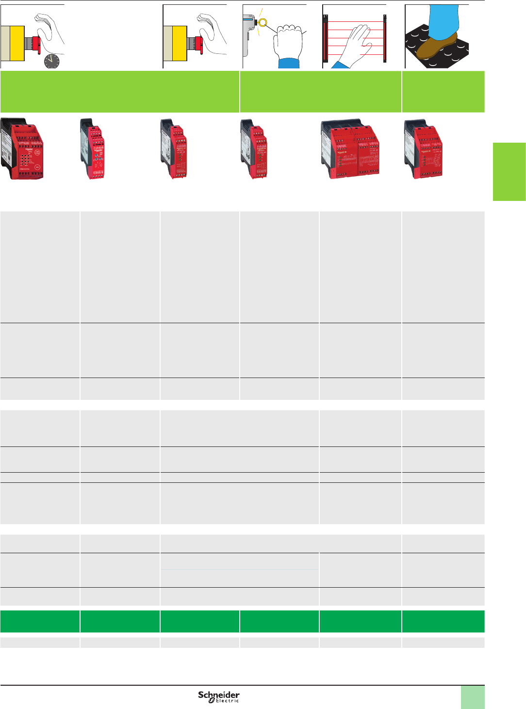
2
1
3
4
5
6
7
8
9
10
3/63
Applications
Modules For Emergency stop and switch monitoring For Emergency stop
and protective guard
applications
For Emergency stop and switch monitoring For Emergency stop, switch or solid-state output
safety light curtain monitoring
For Emergency stop,
switch, sensing mat/
edges or solid-state
output safety light
curtain monitoring
Maximum achievable safety level PLe/Category 4
conforming
to EN/ISO 13849-1,
SILCL3 conforming
to EN/IEC 61508
and EN/IEC 62061
PLe/Category 4
conforming
to EN/ISO 13849-1,
SILCL3 conforming
to EN/IEC 61508
and EN/IEC 62061
PLe/Category 4
(instantaneous safety
outputs) and PLd/
Category 3 (time delay
safety
outputs) conforming to
EN/ISO 13849-1,
SILCL3 (instantaneous
safety outputs) and
SILCL2 (time delay
safety outputs)
conforming to
EN/IEC 61508
and EN/IEC 62061
PLe/Category 4
conforming to EN
ISO 13849-1,
SILCL3 conforming to
EN/IEC 62061
PLe/Category 4
conforming to
EN/ISO 13849-1,
SILCL3 conforming
to EN/IEC 61508
and EN/IEC 62061
PLe/Category 4
(instantaneous safety
outputs) and
PLd/Category 3 (time
delay safety outputs)
conforming to
EN/ISO 13849-1,
SILCL3 (instantaneous
safety outputs) and
SILCL2 (time delay
safety outputs)
conforming to
EN/IEC 61508
and EN/IEC 62061
PLe/Category 4
conforming to
EN/ISO 13849-1,
SILCL3 conforming
to EN/IEC 61508
and EN/IEC 62061
PLe/Category 4
conforming to
EN/ISO 13849-1,
SILCL3 conforming
to EN/IEC 61508
and EN/IEC 62061
PLe/Category 4
conforming to
EN/ISO 13849-1,
SILCL3 conforming
to EN/IEC 61508
and EN/IEC 62061
PLe/Category 4
conforming to
EN/ISO 13849-1,
SILCL3 conforming
to EN/IEC 61508
and EN/IEC 62061
Conformity to standards EN/IEC 60204-1,
EN 1088/ISO 14119,
EN/ISO 13850,
EN/IEC 60947-1,
EN/IEC 60947-5-1
EN/IEC 60204-1,
EN 1088/ISO 14119,
EN/ISO 13850,
EN/IEC 60947-1,
EN/IEC 60947-5-1
EN/IEC 60204-1,
EN/ISO 13850,
EN 1088/ISO 14119,
EN/IEC 60947-1,
EN/IEC 60947-5-1
EN 62061
EN ISO 13849-1
EN 50156-1
EN 60204-1
EN/IEC 61496-1
EN/IEC 60947-5-1
EN/IEC 60204-1,
EN 1088/ISO 14119,
EN/ISO 13850,
EN/IEC 60947-1,
EN/IEC 60947-5-1
EN/IEC 60204-1,
EN/IEC 60947-1,
EN/IEC 60947-5-1,
EN/ISO 13850,
EN 1088/ISO 14119
EN/IEC 60204-1,
EN 1088/ISO 14119,
EN/ISO 13850,
EN/IEC 60947-1,
EN/IEC 60947-5-1
EN/IEC 60204-1,
EN 1088/ISO 14119,
EN/ISO 13850,
EN/IEC 60947-1,
EN/IEC 60947-5-1,
EN/IEC 61496-1 (type 4)
EN/IEC 60204-1,
EN 1088/ISO 14119,
EN/ISO 13850,
EN/IEC 60947-1,
EN/IEC 60947-5-1
EN/IEC 60204-1,
EN 1088/ISO 14119,
EN/ISO 13850,
EN/IEC 60947-1,
EN/IEC 60947-5-1
Product certications UL, CSA, TÜV UL, CSA, BG UL, CSA, TÜV UL, CSA, TÜV UL, CSA, TÜV UL, CSA, BG UL, CSA, TÜV UL, CSA, TÜV UL, CSA, TÜV UL, CSA, TÜV
Number of circuits
Safety 3 NO 3 NO 2 NO instantaneous
+ 3 NO time delay
3 NO instantaneous
+ 3 NO time delay
3 NO instantaneous
+ 3 NO time delay
2 NO instantaneous
+ 1 NO time delay
3 NO 7 NO 3 NO instantaneous
Additional 1 solid-state output
for signalling to PLC
1 relay output for
signalling
to PLC
4 solid-state outputs for
signalling to PLC
1 NC 3 solid-state outputs for
signalling to PLC
– – 2 NC + 4 solid-state
outputs for signalling
to PLC
1 NC + 4 solid-state
outputs for signalling
to PLC
Display 2 LEDs 2 LEDs 4 LEDs 5 LEDs 11 LEDs 3 LEDs 3 LEDs 4 LEDs 4 LEDs
Supply voltage a and 24 V c
48 V a
115 V a
230 V a
a and 24 V c a and 24 V c
115 V a
230 V a
c 24 V
a 115…230 V
24 V c24 V c a and 24 V c a and 24 V c
115 V a and 24 V c
230 V a and 24 V c
a and 24 V c
48 V a
110 V a and 24 V c
120 V a and 24 V c
230 V a and 24 V c
Synchronisation time between inputs Unlimited Unlimited 75 ms (automatic start) 1 Unlimited or 1.5 s
(depending on wiring)
Unlimited Unlimited Unlimited or 2 s, 4 s
(depending on wiring)
Input channel voltage
24 V/48 V version a and 24 V c/48 V
a24 V c24 V c/– 24 V c/– 24 V c/– 24 V c/– c 24 V/– 24 V c/– 24 V c/–
24 V/48 V or
110 V/120 V/230 V version
115 V a/230 V
–
–48 V a/48 V
–
24 V c/– –
–
–
–
–
–
24 V a/24 V
–
–
24 V c/24 V/24 V
Module type XPSAC XPSAXE XPSATE XPSATR XPSAV XPSABV XPSAF XPSAFL XPSAR XPSAK
Pages 3/68 3/68 3/69 3/70 3/69 3/69 3/71 3/72 3/73 3/74
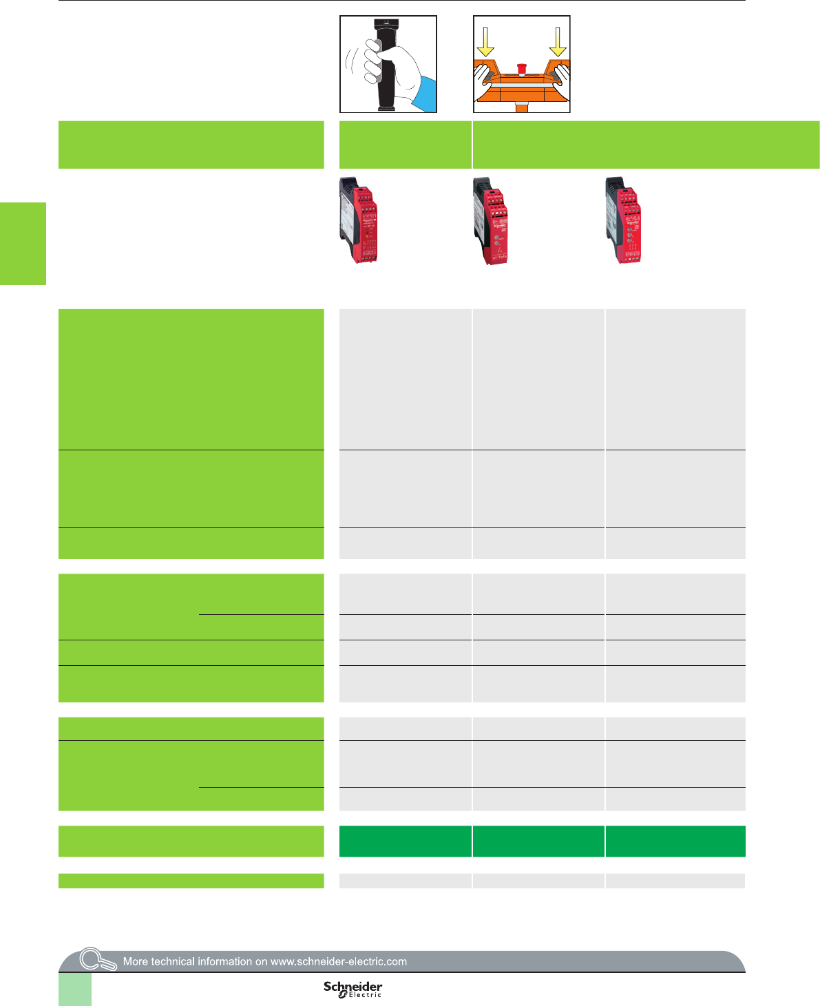
2
1
3
4
5
6
7
8
9
10
3/64
Selection guide (continued) Monitor and Processing
Preventa safety modules
Applications
Modules For enabling switch
monitoring
For electrical monitoring of two-hand control stations For control of 1 to 4
single-beam photo-electric
sensors XU2 S (transmitter-
receiver pair)
For monitoring type 2 and
type 4 light curtains
Compact and slim ranges
For extending the number of safety contacts
Maximum achievable safety level PLe/Category 4 conforming to
EN/ISO 13849-1,
SILCL3 conforming to EN/
IEC 61508
and EN/IEC 62061
PLc/Category 1 conforming to
EN/ISO 13849-1
SILCL1 conforming to EN/IEC
62061
PLe/Category 4 conforming to
EN/ISO 13849-1,
SILCL3 conforming to
EN/IEC 61508
and EN/IEC 62061
PLe/Category 4 conforming to
EN/ISO 13849-1,
SILCL3 conforming to
EN/IEC 61508
and EN/IEC 62061
PLc/Category 2 conforming to
EN/ISO 13849-1,
SILCL1 conforming to
EN/IEC 61508
and EN/IEC 62061
PLe/Category 4 conforming to
EN/ISO 13849-1,
SILCL3 conforming to
EN/IEC 61508
and EN/IEC 62061
PLe/Category 4 conforming
to EN/ISO 13849-1,
SILCL3 conforming to
EN/IEC 61508
and EN/IEC 62061 (when
connected to the appropriate
module)
PLe/Category 4 conforming to
EN/ISO 13849-1, SILCL3
conforming
to EN/IEC 61508
and EN/IEC 62061 (when
connected to the appropriate
module)
Conformity to standards EN/IEC 60204-1,
EN 61326,
EN/IEC 60947-1,
EN/IEC 60947-5-1
EN 574 type III A,
EN/IEC 60204-1,
EN/IEC 60947-5-1,
EN 62061
EN/IEC 60204-1,
EN/IEC 60947-1,
EN/IEC 60947-5-1,
EN 574 type III C/ISO 13851
EN/IEC 60204-1,
EN/IEC 60947-1,
EN/IEC 60947-5-1,
EN 574 type III C/ISO 13851
EN/IEC 61496-1,
EN/IEC 61496-2,
EN/IEC 60204-1,
EN/IEC 60947-1,
EN/IEC 60947-5-1
EN/IEC 61496-1,
EN/IEC 61496-2,
EN/IEC 60204-1,
EN/IEC 60947-1,
EN/IEC 60947-5-1
EN/IEC 60204-1,
EN/IEC 60947-1,
EN/IEC 60947-5-1
EN/IEC 60204-1,
EN/IEC 60947-1,
EN/IEC 60947-5-1
Product certications UL, CSA, TÜV UL, CSA, TÜV UL, CSA, BG UL, CSA, TÜV UL, CSA, IFA UL, CSA, TÜV UL, CSA, BG UL, CSA, TÜV
Number of circuits
Safety 2 NO 1 NO 2 NO 2 NO 2 NO 2 solid-state 4 NO 8 NO
Additional 2 solid-state outputs for
signalling to PLC
1 NC 1 NC 2 solid-state outputs for
signalling to PLC
4 solid-state PNP NO outputs
for signalling to PLC
1 PNP + 1 NPN output for
signalling to PLC
2 NC 1 NC
Display 3 LEDs 2 LEDs 3 LEDs 3 LEDs 4 LEDs 14 LEDs + 2-digit display 2 LEDs 3 LEDs
Supply voltage 24 V c a and 24 V c
115/230 V a
a and 24 V c
115/120 V a
230 V a
24 V c24 V c 24 V c a and 24 V c a and 24 V c
115 V a
230 V a
Synchronisation time between inputs –500 ms 500 ms 500 ms –3 s or innite – –
Input channel voltage
24 V/48 V version 24 V/– 24 V c/– 24 V c24 V c/– – – – –
115 V/230 V version – 24 V a/24 V – – – – – –
Module type XPSVC XPSBAE XPSBCE XPSBF XPSCM XPSLCM XPSECME XPSECPE
Pages 3/75 3/76 3/76 3/76 3/77 3/78 3/79 3/79
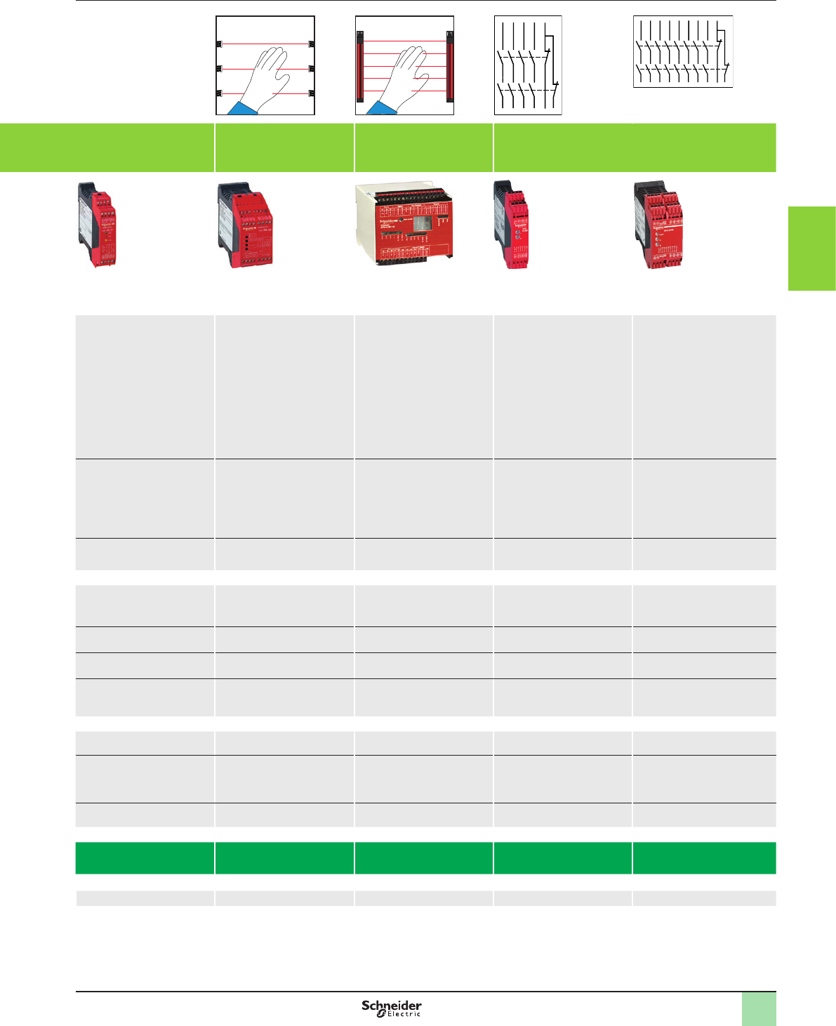
2
1
3
4
5
6
7
8
9
10
3/65
Applications
Modules For enabling switch
monitoring
For electrical monitoring of two-hand control stations For control of 1 to 4
single-beam photo-electric
sensors XU2 S (transmitter-
receiver pair)
For monitoring type 2 and
type 4 light curtains
Compact and slim ranges
For extending the number of safety contacts
Maximum achievable safety level PLe/Category 4 conforming to
EN/ISO 13849-1,
SILCL3 conforming to EN/
IEC 61508
and EN/IEC 62061
PLc/Category 1 conforming to
EN/ISO 13849-1
SILCL1 conforming to EN/IEC
62061
PLe/Category 4 conforming to
EN/ISO 13849-1,
SILCL3 conforming to
EN/IEC 61508
and EN/IEC 62061
PLe/Category 4 conforming to
EN/ISO 13849-1,
SILCL3 conforming to
EN/IEC 61508
and EN/IEC 62061
PLc/Category 2 conforming to
EN/ISO 13849-1,
SILCL1 conforming to
EN/IEC 61508
and EN/IEC 62061
PLe/Category 4 conforming to
EN/ISO 13849-1,
SILCL3 conforming to
EN/IEC 61508
and EN/IEC 62061
PLe/Category 4 conforming
to EN/ISO 13849-1,
SILCL3 conforming to
EN/IEC 61508
and EN/IEC 62061 (when
connected to the appropriate
module)
PLe/Category 4 conforming to
EN/ISO 13849-1, SILCL3
conforming
to EN/IEC 61508
and EN/IEC 62061 (when
connected to the appropriate
module)
Conformity to standards EN/IEC 60204-1,
EN 61326,
EN/IEC 60947-1,
EN/IEC 60947-5-1
EN 574 type III A,
EN/IEC 60204-1,
EN/IEC 60947-5-1,
EN 62061
EN/IEC 60204-1,
EN/IEC 60947-1,
EN/IEC 60947-5-1,
EN 574 type III C/ISO 13851
EN/IEC 60204-1,
EN/IEC 60947-1,
EN/IEC 60947-5-1,
EN 574 type III C/ISO 13851
EN/IEC 61496-1,
EN/IEC 61496-2,
EN/IEC 60204-1,
EN/IEC 60947-1,
EN/IEC 60947-5-1
EN/IEC 61496-1,
EN/IEC 61496-2,
EN/IEC 60204-1,
EN/IEC 60947-1,
EN/IEC 60947-5-1
EN/IEC 60204-1,
EN/IEC 60947-1,
EN/IEC 60947-5-1
EN/IEC 60204-1,
EN/IEC 60947-1,
EN/IEC 60947-5-1
Product certications UL, CSA, TÜV UL, CSA, TÜV UL, CSA, BG UL, CSA, TÜV UL, CSA, IFA UL, CSA, TÜV UL, CSA, BG UL, CSA, TÜV
Number of circuits
Safety 2 NO 1 NO 2 NO 2 NO 2 NO 2 solid-state 4 NO 8 NO
Additional 2 solid-state outputs for
signalling to PLC
1 NC 1 NC 2 solid-state outputs for
signalling to PLC
4 solid-state PNP NO outputs
for signalling to PLC
1 PNP + 1 NPN output for
signalling to PLC
2 NC 1 NC
Display 3 LEDs 2 LEDs 3 LEDs 3 LEDs 4 LEDs 14 LEDs + 2-digit display 2 LEDs 3 LEDs
Supply voltage 24 V c a and 24 V c
115/230 V a
a and 24 V c
115/120 V a
230 V a
24 V c24 V c 24 V c a and 24 V c a and 24 V c
115 V a
230 V a
Synchronisation time between inputs –500 ms 500 ms 500 ms –3 s or innite – –
Input channel voltage
24 V/48 V version 24 V/– 24 V c/– 24 V c24 V c/– – – – –
115 V/230 V version – 24 V a/24 V – – – – – –
Module type XPSVC XPSBAE XPSBCE XPSBF XPSCM XPSLCM XPSECME XPSECPE
Pages 3/75 3/76 3/76 3/76 3/77 3/78 3/79 3/79
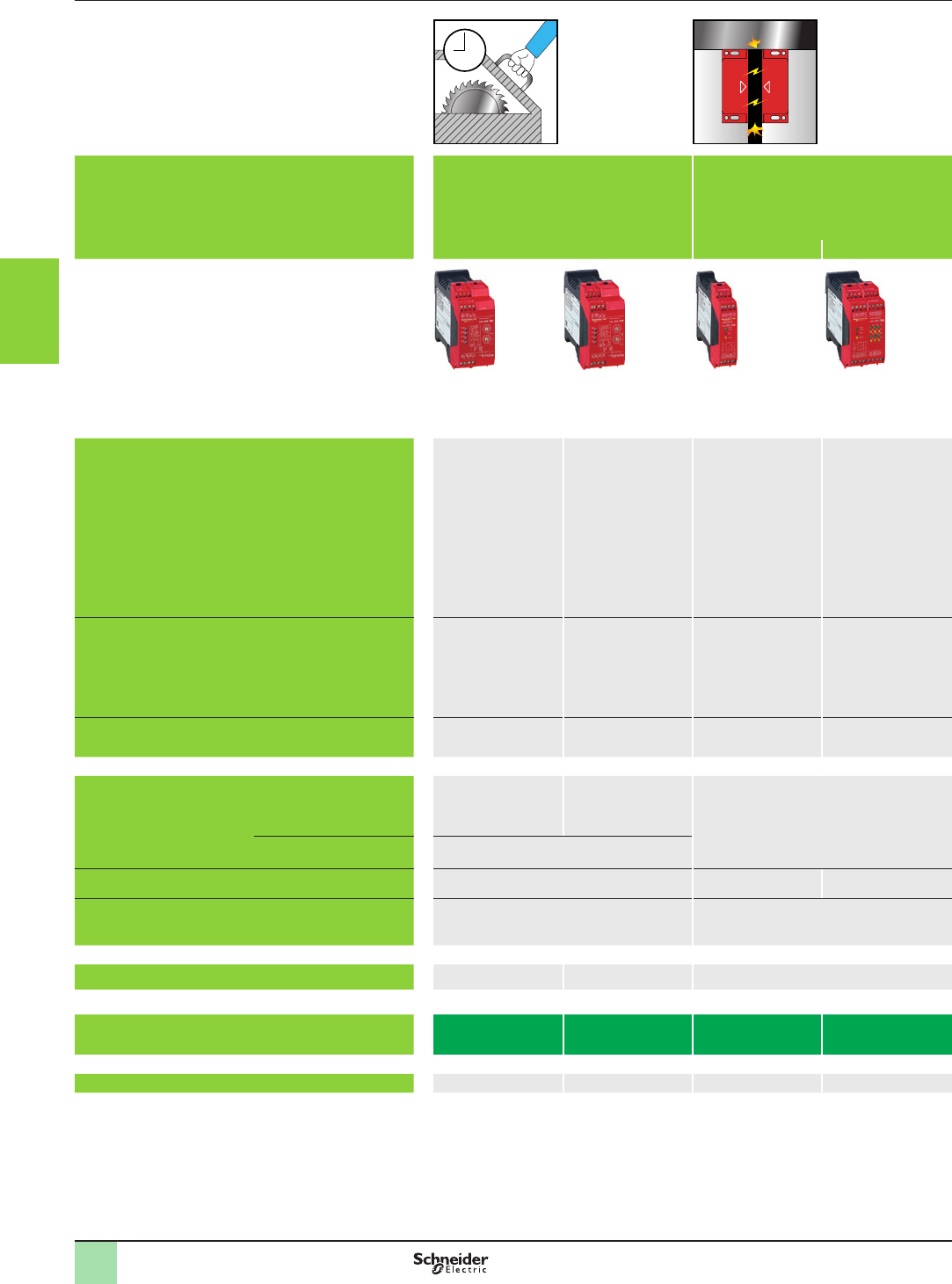
2
1
3
4
5
6
7
8
9
10
3/66
Selection guide (continued) Monitor and Processing
Preventa safety modules
Applications
Modules For the monitoring of applications
requiring safety time delays
For coded magnetic switch monitoring For zero speed detection of
AC or DC motors which
produce a remanent voltage
in their windings due to
residual magnetism
For lift control For dynamic monitoring of
hydraulic valves on linear
presses
For dynamic monitoring of
double-bodied solenoid
valves
For safety stop at top dead
centre with automatic
overtravel monitoring and
control
For 2 max. For 6 max.
Maximum achievable safety level PL d/Category 3
conforming
to EN/ISO 13849-1,
SILCL 2 conforming to
EN/IEC 62061
PL d/Category 3
conforming
to EN/ISO 13849-1,
SILCL 2 conforming to
EN/IEC 62061
PL e/Category 4
conforming
to EN/ISO 13849-1
SILCL 3 conforming to
EN/IEC 62061
PL e/Category 4
conforming
to EN/ISO 13849-1
SILCL 3 conforming to
EN/IEC 62061
PL d/Category 3 conforming
to EN/ISO 13849-1,
SILCL 2 conforming to EN/
IEC 62061,
PL e/Category 4 conforming
to EN/ISO 13849-1,
SILCL 3 conforming to EN/
IEC 62061
PL e/Category 4 conforming to
EN/ISO 13849-1,
SILCL 3 conforming to EN/
IEC 62061
PL e/Category 4 conforming
to EN/ISO 13849-1,
SILCL 3 conforming to EN/
IEC 62061
PL e/Category 4 conforming
to EN/ISO 13849-1,
SILCL 3 conforming to EN/
IEC 62061
Conformity to standards EN/IEC 60204-1,
EN/IEC 60947-1,
EN/IEC 60947-5-1
EN/IEC 60204-1,
EN/IEC 60947-1,
EN/IEC 60947-5-1
EN/IEC 60204-1,
EN 1088/ISO 14119,
EN/IEC 60947-1,
EN/IEC 60947-5-1,
EN/IEC 60947-5-3
EN/IEC 60204-1,
EN 1088/ISO 14119,
EN/IEC 60947-1,
EN/IEC 60947-5-1,
EN/IEC 60947-5-3
EN/IEC 60204-1,
EN/IEC 60947-1,
EN/IEC 60947-5-1
EN 81-1,
EN 81-2,
EN/IEC 60947-5-1,
EN 12015,
EN 12016
EN 693,
EN/IEC 60204-1,
EN/IEC 60947-1,
EN/IEC 60947-5-1
EN 692,
EN/IEC 60204-1,
EN/IEC 60947-1,
EN/IEC 60947-5-1
EN 692,
EN/IEC 60204-1,
EN/IEC 60947-1,
EN/IEC 60947-5-1
Product certications UL, CSA, TÜV UL, CSA, TÜV UL, CSA, TÜV UL, CSA, TÜV UL, CSA, TÜV TÜV UL, CSA, TÜV UL, CSA, TÜV UL, CSA, TÜV
Number of circuits
Safety 1 NO time delayed 1 NO pulse type 2 NO 1 NO + 1 NC 2 NO 2 NO + 1 NC 1 NO + 1 NC 3 NO
Additional 2 NC + 2 solid-state outputs for signalling to
PLC
2 solid-state outputs for signalling to PLC 2 solid-state outputs for signalling to PLC – 4 solid-state outputs for signalling to PLC
Display 4 LEDs 3 LEDs 15 LEDs 4 LEDs 4 LEDs 8 LEDs
Supply voltage a and 24 V c
115 V a
230 V a
c 24 V 24 V c
115 V a
230 V a
a and 24 V c24 V c 24 V c
115 V a
230 V a
–
115 V a
230 V a
Synchronisation time between inputs ––500 ms –Innite –––
Module type XPSTSA XPSTSW XPSDMB XPSDME XPSVNE XPSEDA XPSPVT XPSPVK XPSOT
Pages 3/80 3/80 3/81 3/81 3/82 3/83 3/84 3/85 3/87
2
1
3
4
5
6
7
8
9
10
3/67
Applications
Modules For the monitoring of applications
requiring safety time delays
For coded magnetic switch monitoring For zero speed detection of
AC or DC motors which
produce a remanent voltage
in their windings due to
residual magnetism
For lift control For dynamic monitoring of
hydraulic valves on linear
presses
For dynamic monitoring of
double-bodied solenoid
valves
For safety stop at top dead
centre with automatic
overtravel monitoring and
control
For 2 max. For 6 max.
Maximum achievable safety level PL d/Category 3
conforming
to EN/ISO 13849-1,
SILCL 2 conforming to
EN/IEC 62061
PL d/Category 3
conforming
to EN/ISO 13849-1,
SILCL 2 conforming to
EN/IEC 62061
PL e/Category 4
conforming
to EN/ISO 13849-1
SILCL 3 conforming to
EN/IEC 62061
PL e/Category 4
conforming
to EN/ISO 13849-1
SILCL 3 conforming to
EN/IEC 62061
PL d/Category 3 conforming
to EN/ISO 13849-1,
SILCL 2 conforming to EN/
IEC 62061,
PL e/Category 4 conforming
to EN/ISO 13849-1,
SILCL 3 conforming to EN/
IEC 62061
PL e/Category 4 conforming to
EN/ISO 13849-1,
SILCL 3 conforming to EN/
IEC 62061
PL e/Category 4 conforming
to EN/ISO 13849-1,
SILCL 3 conforming to EN/
IEC 62061
PL e/Category 4 conforming
to EN/ISO 13849-1,
SILCL 3 conforming to EN/
IEC 62061
Conformity to standards EN/IEC 60204-1,
EN/IEC 60947-1,
EN/IEC 60947-5-1
EN/IEC 60204-1,
EN/IEC 60947-1,
EN/IEC 60947-5-1
EN/IEC 60204-1,
EN 1088/ISO 14119,
EN/IEC 60947-1,
EN/IEC 60947-5-1,
EN/IEC 60947-5-3
EN/IEC 60204-1,
EN 1088/ISO 14119,
EN/IEC 60947-1,
EN/IEC 60947-5-1,
EN/IEC 60947-5-3
EN/IEC 60204-1,
EN/IEC 60947-1,
EN/IEC 60947-5-1
EN 81-1,
EN 81-2,
EN/IEC 60947-5-1,
EN 12015,
EN 12016
EN 693,
EN/IEC 60204-1,
EN/IEC 60947-1,
EN/IEC 60947-5-1
EN 692,
EN/IEC 60204-1,
EN/IEC 60947-1,
EN/IEC 60947-5-1
EN 692,
EN/IEC 60204-1,
EN/IEC 60947-1,
EN/IEC 60947-5-1
Product certications UL, CSA, TÜV UL, CSA, TÜV UL, CSA, TÜV UL, CSA, TÜV UL, CSA, TÜV TÜV UL, CSA, TÜV UL, CSA, TÜV UL, CSA, TÜV
Number of circuits
Safety 1 NO time delayed 1 NO pulse type 2 NO 1 NO + 1 NC 2 NO 2 NO + 1 NC 1 NO + 1 NC 3 NO
Additional 2 NC + 2 solid-state outputs for signalling to
PLC
2 solid-state outputs for signalling to PLC 2 solid-state outputs for signalling to PLC – 4 solid-state outputs for signalling to PLC
Display 4 LEDs 3 LEDs 15 LEDs 4 LEDs 4 LEDs 8 LEDs
Supply voltage a and 24 V c
115 V a
230 V a
c 24 V 24 V c
115 V a
230 V a
a and 24 V c24 V c 24 V c
115 V a
230 V a
–
115 V a
230 V a
Synchronisation time between inputs ––500 ms –Innite –––
Module type XPSTSA XPSTSW XPSDMB XPSDME XPSVNE XPSEDA XPSPVT XPSPVK XPSOT
Pages 3/80 3/80 3/81 3/81 3/82 3/83 3/84 3/85 3/87
3/68
Operating principle,
references
Monitor and Processing
Preventa safety modules types XPSAC,
XPSAXE
For Emergency stop and switch monitoring
Operating principle
Safety modules XPSAC and XPSAXE are used for monitoring Emergency stop
circuits conforming to standards EN/ISO 13850 and EN/IEC 60204-1 and also
meet the safety requirements for the electrical monitoring of switches in protective
devices conforming to standard EN/ISO 14119. They provide protection for both the
machine operator and the machine by immediately stopping the dangerous
movement on receipt of a stop instruction from the operator, or on detection of a
fault in the safety circuit itself.
To aid diagnostics, the modules have LEDs which provide information on the
monitoring circuit status.
bThe XPSAC module has 3 safety outputs and a solid-state output for signalling to
the PLC.
bThe XPSAXE module has 3 safety outputs and a relay output for signalling to the
PLC
References
Description Connection Number of
instantaneous
opening
safety circuits
Additional
outputs
Supply Reference Weight
kg/
lb
Safety modules for
Emergency stop and switch
monitoring
Captive screw
clamp terminals
Terminal block
integrated
in module
3 1 solid-state a and c 24 V
XPSAC5121
0.160/
0.353
a 48 V
XPSAC1321
0.210/
0.463
a 115 V
XPSAC3421
0.210/
0.463
a 230 V
XPSAC3721
0.210/
0.463
Captive screw clamp
terminals
Terminal block
removable from
module
3 1 solid-state a and
c 24 V
XPSAC5121P
0.160/
0.353
a 48 V
XPSAC1321P
0.210/
0.463
a 115 V
XPSAC3421P
0.210/
0.463
a 230 V
XPSAC3721P
0.210/
0.463
1 relay a and
c 24 V
XPSAXE5120P
0.229/
0.505
Spring terminals
Terminal block
removable from
module
3 1 relay a and
c 24 V
XPSAXE5120C
0.229/
0.505
XPSAXE5120P
XPSAXE5120C
XPSACppppP
XPSACpppp
2
1
3
4
5
6
7
8
9
10
2
1
3
4
5
6
7
8
9
10
3/69
Operating principle,
references
Monitor and Processing
Preventa safety modules types XPSAV,
XPSABV, XPSATE
For Emergency stop and switch monitoring
Operating principle
Safety modules XPSAV, XPSABV and XPSATE are used for monitoring Emergency stop circuits conforming
to standards EN/ISO 13850 and EN/IEC 60204-1 and also meet the safety requirements for the electrical
monitoring
of switches in protection devices conforming to standard EN/ISO 14119.
They provide protective for both the machine operator and the machine by immediately stopping the dangerous
movement on receipt of a stop instruction from the operator, or on detection of a fault in the safety circuit itself.
In addition to the stop category 0 instantaneous opening safety outputs (3 for XPSAV, 2 for XPSABV and 2 for
XPSATE), the modules incorporate stop category 1 time delay outputs (3 for XPSAV, 1 for XPSABV and 3 for
XPSATE) which allow for controlled deceleration of the motor components until a complete stop is achieved (for
example, motor braking by variable speed drive).
At the end of the preset delay, the supply is disconnected by opening the time delay output circuits.
bFor module XPSAV, the time delay of the 3 output circuits is adjustable, in 15 preset values, between 0 and 300
seconds using selector buttons.
bFor module XPSABV, the time delay of the 3 output circuits is adjustable between 0.15 and 3 seconds or 1.5
and 30 seconds, depending on the model, using a selector switch.
bFor module XPSATE, the time delay of the 3 output circuits is adjustable between 0 and 30 seconds using a
12-position selector switch.
Module XPSAV also incorporates 3 solid-state signalling outputs for signalling to the process PLC.
Module XPSATE incorporates 4 solid-state signalling outputs for signalling to the process PLC.
To aid diagnostics, the modules have LEDs which provide information on the monitoring circuit status.
The Start button monitoring function is congurable depending on the wiring.
References
Description Connection Number of
safety circuits
Additional
outputs
Setting range
of time delay
Supply Reference Weight
kg/
lb
Safety
modules for
Emergency
stop and
switch
monitoring
Captive screw clamp
terminals
Terminal block
integrated in module
6 NO
(3 NO time delay)
3 solid-state 0…300 s c 24 V
XPSAV11113
0.320/
0.705
Captive screw clamp
terminals
Terminal block
removable from module
6 NO
(3 NO time delay)
3 solid-state 0…300 s c 24 V
XPSAV11113P
0.320/
0.705
Captive screw clamp
terminals
Terminal block
integrated in module
6 NO
(3 NO time delay)
3 solid-state 0…300 s
(Start delay 0,5 s)
c 24 V
XPSAV11113T050
0.320/
0.705
6 NO
(3 NO time delay)
3 solid-state 0.1 …2 s c 24 V
XPSAV11113Z002
0.320/
0.705
3 NO
(1 NO time delay)
–0,15…3 s c 24 V
XPSABV1133P
0.280/
0.617
Captive screw clamp
terminals
Terminal block
removable from module
Spring terminals
Terminal block
removable from module
3 NO
(1 NO time delay)
–0,15…3 s c 24 V
XPSABV1133C
0.275/
0.606
Captive screw clamp
terminals
Terminal block
removable from module
3 NO
(1 NO time delay)
–1,5…30 s c 24 V
XPSABV11330P
0.280/
0.617
Spring terminals
Terminal block
removable from module
3 NO
(1 NO time delay)
–1,5…30 s c 24 V
XPSABV11330C
0.275/
0.606
Captive screw clamp
terminals
Terminal block
integrated in module
5 NO
(3 NO time delay)
4 solid-state 0…30 s a and
c 24 V
XPSATE5110
0.280/
0.617
Captive screw clamp
terminals
Terminal block
removable from module
5 NO
(3 NO time delay)
4 solid-state 0…30 s a and
c 24 V
XPSATE5110P
0.280/
0.617
Captive screw clamp
terminals
Terminal block
integrated in module
5 NO
(3 NO time delay)
4 solid-state 0…30 s a 115 V
XPSATE3410
0.380/
0.838
Captive screw clamp
terminals
Terminal block
removable from module
5 NO
(3 NO time delay)
4 solid-state 0…30 s a 115 V
XPSATE3410P
0.380/
0.838
Captive screw clamp
terminals
Terminal block
integrated in module
5 NO
(3 NO time delay)
4 solid-state 0…30 s a 230 V
XPSATE3710
0.380/
0.838
Captive screw clamp
terminals
Terminal block
removable from module
5 NO
(3 NO time delay)
4 solid-state 0…30 s a 230 V
XPSATE3710P
0.380/
0.838
XPSABVppppP
XPSABVppppC
XPSAV11113
XPSAV11113P
XPSATE5110
2
1
3
4
5
6
7
8
9
10
2
1
3
4
5
6
7
8
9
10
3/70
Operating principle,
references
Monitor and Processing
Preventa safety module type XPSATR
For Emergency stop and protective guard applications
Operating principle
Safety modules XPSATR meet the requirements of Performance Level PL e/Category 4
conforming to standard
EN ISO 13849-1
.
Safety modules XPSATR are electronic, redundant and self-monitoring devices with
positively driven relays.
They are used for monitoring Emergency stop circuits (single or two-channel) and
protective guard applications.
The modules are conforming to standards EN/ISO 13850 and EN 60204-1.
They provide protection for both the machine operator and the machine by
immediately stopping the dangerous movement on receipt of a stop instruction from
the operator, or on detection of a fault in the safety circuit itself.
XPSATR incorporate 3 NO and 1 NC not delayed contacts and 3 delayed NO
contacts.
To aid diagnostics, the modules have 5 LEDs on the front face which provide
information on the monitoring circuit status.
References
Description Connection Number of
safety circuits
Additional
outputs
Time
setting
range
Supply Reference Weight
kg/
lb
Safety
modules for
emergency
stop
and safety
guards
monitoring
Captive screw
clamp terminals
Terminal block
removable from
module
3 NO
+ 3 NO time delay
1 NC 0.1…3 s c 24 V
XPSATR1153P
0.330/
0.728
0.1…3 s a 115…230 V
XPSATR3953P
0.350/
0.772
0…30 s c 24 V
XPSATR11530P
0.330/
0.728
0…30 s a 115…230 V
XPSATR39530P
0.350/
0.772
Cage clamp
terminals
Terminal block
removable from
module
3 NO
+ 3 NO time delay
1 NC 0.1…3 s c 24 V
XPSATR1153C
0.330/
0.728
0.1…3 s a 115…230 V
XPSATR3953C
0.350/
0.772
0…30 s c 24 V
XPSATR11530C
0.330/
0.728
0…30 s a 115…230 V
XPSATR39530C
0.350/
0.772
XPSATRppppP
XPSATRppppC
2
1
3
4
5
6
7
8
9
10
2
1
3
4
5
6
7
8
9
10
3/71
Operating principle,
references
Monitor and Processing
Preventa safety modules type XPSAF
For Emergency stop and switch monitoring
Operating principle
Safety modules XPSAF meet the requirements of Performance Level PL e/Category 4
conforming to standard EN/ISO 13849-1.
They are used for:
b Monitoring Emergency stop circuits conforming to standards EN/ISO 13850 and
EN/IEC 60204-1.
b Electrical monitoring of switches activated by protection devices conforming
to standard EN/ISO 14119.
Housed in a compact enclosure, the modules have 3 safety outputs.
Preventa safety modules XPSAFppppP incorporate removable terminal blocks, thus
optimising machine maintenance.
To aid diagnostics, the modules have 3 LEDs on the front face which provide
information on the monitoring circuit status.
The Start button monitoring function is congurable depending on the wiring.
References
Description Connection Number of safety
circuits
Supply Reference Weight
kg/
lb
Safety modules for
Emergency stop and switch
monitoring
Captive screw clamp terminals
Terminal block integrated
in module
3a and
c 24 V
XPSAF5130
0.250/
0.551
Captive screw clamp terminals
Terminal block removable from
module
3a and
c 24 V
XPSAF5130P
0.250/
0.551
XPSAF5130
2
1
3
4
5
6
7
8
9
10
2
1
3
4
5
6
7
8
9
10
3/72
Operating principle,
references
Monitor and Processing
Preventa safety modules type XPSAFL
For Emergency stop, switch and safety light curtain
monitoring
Operating principle
Safety modules XPSAFL meet the requirements of Performance Level
PL e/Category 4 conforming to standard EN/ISO 13849-1.
They are used for:
bMonitoring Emergency stop circuits conforming to standards EN/ISO 13850 and
EN/IEC 60204-1.
bElectrical monitoring of switches activated by protection devices conforming to
standard EN/ISO 14119.
They can also be used for monitoring type 4 light curtains conforming to EN 61496-1
that have solid-state safety outputs (for example, light curtains type XUSL.
This system conforms to Performance Level PL e/Category 4 in accordance with
EN/ISO 13849-1.
Housed in a compact enclosure, the modules have 3 safety outputs.
Preventa safety modules XPSAFLppppP incorporate removable terminal blocks,
thus optimising machine maintenance.
To aid diagnostics, the modules have 3 LEDs on the front face which provide
information on the monitoring circuit status.
The Start button monitoring function is congurable depending on the wiring.
References
Description Connection Number of
safety circuits
Supply Reference Weight
kg/
lb
Safety modules for
Emergency stop,
switch and safety light curtain
monitoring
Captive screw clamp terminals
Terminal block integrated in module
3a and
c 24 V
XPSAFL5130
0.250/
0.551
Captive screw clamp terminals
Terminal block removable from
module
3a and
c 24 V
XPSAFL5130P
0.250/
0.551
XPSAFL5130
2
1
3
4
5
6
7
8
9
10
2
1
3
4
5
6
7
8
9
10
3/73
Operating principle,
references
Monitor and Processing
Preventa safety modules type XPSAR
For Emergency stop, switch or safety light curtain
monitoring
Operating principle
Safety modules XPSAR meet the requirements of Performance Level PL e/
Category 4 conforming to standard EN/ISO 13849-1 and are designed for the
following safety applications:
b Monitoring Emergency stop circuits conforming to EN/ISO 13850 and
EN/IEC 60204-1.
b Electrical monitoring of switches activated by protection devices conforming
to standard EN/ISO 14119.
b Monitoring type 4 light curtains conforming to EN/IEC 61496-1 that have
solid-state safety outputs with test function (light curtains XUS L).
In addition to 7 safety outputs, modules XPSAR incorporate 2 relay signalling
outputs and 4 solid-state signalling outputs for signalling to the process PLC.
Safety modules XPSARppppppP incorporate removable terminal blocks, thus
optimising machine maintenance.
To aid diagnostics, the modules have 4 LEDs on the front face which provide
information on the monitoring circuit status.
The Start button monitoring function is congurable depending on the wiring.
References
Description Connection Number
of
safety circuits
Additional
outputs/
solid-state
outputs to PLC
Supply Reference Weight
kg/
lb
Safety modules for
Emergency stop, switch
or safety light curtain
monitoring
Captive screw
clamp
terminals,
Terminal block
integrated
in module
7 2 / 4 a and c 24 V
XPSAR311144
0.300/
0.661
a 115 V
c 24 V
XPSAR351144
0.400/
0.882
a 230 V
c 24 V
XPSAR371144
0.400/
0.882
Captive screw
clamp
terminals,
Terminal block
removable from
module
7 2 / 4 a and c 24 V
XPSAR311144P
0.300/
0.661
a 115 V
c 24 V
XPSAR351144P
0.400/
0.882
a 230 V
c 24 V
XPSAR371144P
0.400/
0.882
XPSAR3p1144
2
1
3
4
5
6
7
8
9
10
2
1
3
4
5
6
7
8
9
10
3/74
Operating principle,
references
Monitor and Processing
Preventa safety modules type XPSAK
For Emergency stop, switch, sensing mat/edges
or safety light curtain monitoring
Operating principle
Safety modules XPSAK meet the requirements of Performance Level PL e/Category 4
conforming to standard EN/ISO 13849-1.
They are used for:
b Monitoring Emergency stop circuits conforming to standards EN/ISO 13850 and
EN/IEC 60204-1.
b Electrical monitoring of switches activated by protection devices, with optional
selection of synchronisation time between signals.
b Monitoring 4-wire sensing mats or edges.
b Monitoring type 4 light curtains conforming to EN/IEC 61496-1 which have
solid-state safety outputs with test function (light curtains XUSL).
Housed in a compact enclosure, the modules have 3 safety outputs, a relay signalling
output and 4 solid-state signalling outputs for signalling to the process PLC.
Preventa safety modules XPSAKppppP incorporate removable terminal blocks,
thus optimising machine maintenance.
To aid diagnostics, the modules have 4 LEDs on the front face which provide
information on the monitoring circuit status.
The Start button monitoring function is congurable depending on the wiring.
References
Description Connection Number
of safety
circuits
Additional
outputs /
Solid-state
outputs for PLC
Supply Reference Weight
kg/
lb
Safety modules for
Emergency stop, switch,
sensing mat/edges or safety
light curtain monitoring
Captive screw
clamp terminals
Terminal block
integrated in
module
3 1 / 4 a and
c 24 V
XPSAK311144
0.300/
0.661
a 110 V
c 24 V
XPSAK361144
0.400/
0.882
a 120 V
c 24 V
XPSAK351144
0.400/
0.882
a 230 V
c 24 V
XPSAK371144
0.400/
0.882
Captive screw
clamp terminals
Terminal block
removable from
module
3 1 / 4 a and
c 24 V
XPSAK311144P
0.300/
0.661
a 48 V
XPSAK331144P
0.300/
0.661
a 110 V
c 24 V
XPSAK361144P
0.400/
0.882
a 120 V
c 24 V
XPSAK351144P
0.400/
0.882
a 230 V
c 24 V
XPSAK371144P
0.400/
0.882
XPSAK3p1144
2
1
3
4
5
6
7
8
9
10
2
1
3
4
5
6
7
8
9
10
3/75
Operating principle,
references
Monitor and Processing
Preventa safety modules type XPSVC
For enabling switch monitoring
Operating principle
The enabling grip switch system, comprising an enabling switch XY2AU and a monitoring
module XPSVC, enables authorised personnel to carry out adjustment, programming
or maintenance operations within hazardous zones of machines providing certain
conditions are met.
To be accessible, such operations are often carried out at reduced speed, and must
be intentionally selected by authorised persons by means of a selector switch or key
switch. Once the selection is made, the enabling switch system temporarily takes over
from the hazardous zone’s usual protection measures.
Caution: The enabling switch system alone must not cause dangerous movements of
the machine to be activated; a second intentional control action on the part of the
operator is required. In addition, each person remaining in the hazardous zone must
be provided with an individual enabling switch to ensure their own safety.
References
Description Connection Number of
safety circuits
Solid-state
outputs for PLC
Supply Reference Weight
kg/
lb
Safety modules for enabling
switch monitoring
Captive screw
clamp terminals
Terminal block
integrated in
module
2 NO 2 c 24
XPSVC1132
0.250/
0.551
Captive screw
clamp terminals
Terminal block
removable from
module
2 NO 2 c 24
XPSVC1132P
0.250/
0.551
XPSVC1132
2
1
3
4
5
6
7
8
9
10
2
1
3
4
5
6
7
8
9
10
3/76
Operating principle
Two-hand control stations are designed to provide protection against hand injury.
They require machine operators to keep their hands clear of the dangerous movement zone.
The use of two-hand control is an individual protective measure, which can safely protect only one operator.
Separate two-hand control stations must be provided for each operator in a multiple-worker environment.
Safety modules XPSBAE, BCE and BF for two-hand control stations comply with the requirements of European
standard EN 574/ISO 13851 for two-hand control systems.
The control stations must be designed and installed such that they cannot be activated involuntarily or easily
rendered inoperative. Depending on the application, the requirements of type C standards specic to the
machinery involved must be met (additional personal protection methods may have to be considered).
To initiate a dangerous movement, both operators (two-hand control pushbuttons) must be activated within an
interval y 0.5 s (synchronous activation). If one of the two pushbuttons is released during a dangerous operation,
the control sequence is cancelled. Resumption of the dangerous operation is possible only if both pushbuttons
are returned to their initial position and reactivated within the required time interval.
The safety distance between the control units and the hazardous zone must be sufcient to ensure that when only
one operator is released, the hazardous zone cannot be reached before the dangerous movement has been
completed or stopped.
Selection
Requirements of standard EN 574/ISO 13851 Type I Type II Type III
ABC
Standard EN 574/
ISO 13851 denes the
selection of two-hand
controls according to its
behavior.
The following table details
the 3 types of two-hand
control conforming to EN
574/ISO 13851.
For each type, it lists the
operating characteristics
and minimum requirements.
Use of both hands (simultaneous action)
Link between input and output signals
Output signal inhibited
Prevention of accidental operation
Tamper-proof
Output signal reinitialised
Synchronous action (specied time limit)
Use of proven components
(Category 1 conforming to EN/ISO 13849-1)
XPSBAE
Redundancy with partial error detection
(Category 3 conforming to EN/ISO 13849-1)
XPSBCE
XPSBF
Redundancy + Self-monitoring
(Category 4 conforming to EN/ISO 13849-1)
XPSBCE
XPSBF
Two-hand control station XY2SBpp
Conforming to standard EN/ISO 13849-1 Meets the requirements of standard EN
574/ISO 13851
References
Description Type
conforming
to standard
EN 574
Connection Number of
safety
circuits
Additional
outputs
Supply Reference Weight
kg/
lb
Safety
modules for
electrical
monitoring
of two-hand
control
stations
III A Captive screw clamp
terminals
Terminal block
removable from
module
1 NO 1 NC a and 24 V c
XPSBAE5120P
0.100/
0.220
a 115/230V
XPSBAE3920P
0.100/
0.220
Spring terminals
Terminal block
removable from
module
1 NO 1 NC a and 24 V c
XPSBAE5120C
0.100/
0.220
a 115/230V
XPSBAE3920C
0.100/
0.220
III C Captive screw clamp
terminals
Terminal block
removable from
module
2 NO 1 NC relay a and 24 V c
XPSBCE3110P
0.272/
0.600
a 115/120 V
XPSBCE3410P
0.322/
0.710
a 230 V
XPSBCE3710P
0.322/
0.710
Spring terminals
Terminal block
removable from
module
2 NO 1 NC relay a and 24 V c
XPSBCE3110C
0.272/
0.600
a 115 /120 V
XPSBCE3410C
0.322/
0.710
a 230 V
XPSBCE3710C
0.322/
0.710
Captive screw clamp
terminals
Terminal block
removable from
module
2 NO 2 solid-state c 24 V
XPSBF1132
0.150/
0.331
2 NO 2 solid-state c 24 V
XPSBF1132P
0.150/
0.331
Operating principle,
selection,
references
Monitor and Processing
Preventa safety modules types XPSBAE,
XPSBCE, XPSBF
For electrical monitoring of two-hand control stations
XPSBCEppppP
XPSBCEppppC
XPSBF1132
XPSBAEppppP
XPSBAEppppC
2
1
3
4
5
6
7
8
9
10
2
1
3
4
5
6
7
8
9
10
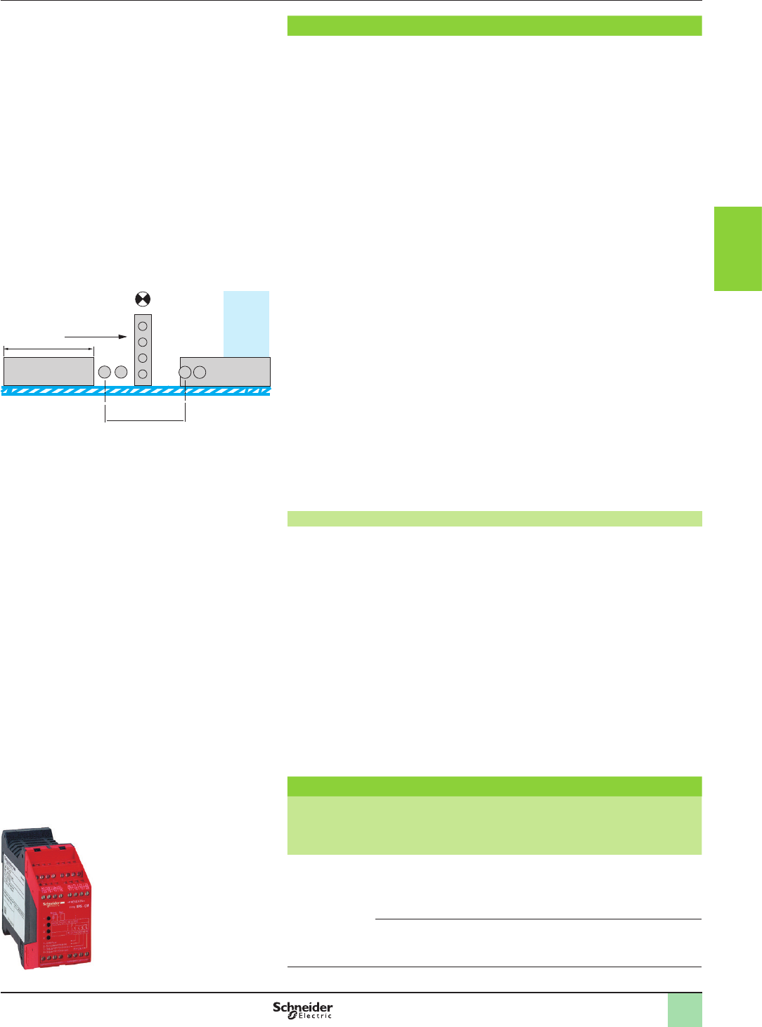
3/77
Operating principle
XPSCM safety modules used in conjunction with XU2S single-beam photo-electric
sensors (periodically tested), establish a category 2 light curtain conforming
to IEC/EN 61496 parts 1 and 2.
The connection of 1 to 4 pairs of XU2S photo-electric sensors makes it possible
to create a protected zone up to 1200 mm high conforming to EN 999/ISO 13855
and 8 m long.
The built-in “muting” function allows the automatic passage of parts to be machined,
or loaded pallets, without interrupting the transportation movement.
When the system is switched on by the start command (in series with the main circuit
feedback loop) and the light protection is not interrupted, the main circuit is closed
by the two safety relays of the XPSCM module.
An interruption of the protective eld causes the safety outputs to open instantaneously,
and the process PLC receives a stop command. The LED on the XPSCM front panel
changes from green to red. The “open” state is maintained until the module is restarted
using the start button.
The “muting” function allows the light curtain protection to be inhibited. This can be
used to authorise the passage of a materials trolley through the light curtain without
tripping the main circuit. The “muting” function cannot be activated by supplying the
inhibition sensors unless the safety outputs have been switched on beforehand.
To trigger the “muting” function, the inhibition devices must be activated within the
3 second time interval. This synchronisation time for the two inhibition inputs can be
deactivated by connecting two conguration terminals. The “muting” cycle has a maximum
duration of 60 seconds. During this period, materials can be transported through the
protection eld without deactivating the safety outputs. The 60 second limit value of the
“muting” cycle may be made innite by connecting two conguration terminals.
During the “muting” process, a light indicating the “muting” status is controlled by the
XPSCM module. An fault at indicator light level (short-circuit, open circuit) will be
immediately recognised and deactivate the “muting” function. The indicator light
comes on when a “muting” signal is generated and indicates the inhibition of the
protection function.
Conditions to be observed for the “muting” function
b The “muting” sensors must either be:
vThru-beam type, sensing distance 8 m: XU2S18PP340L5 (or XU2S18PP340D).
vThru-beam type, sensing distance 15 m: XUB2BKSNL2T (or XUB2BKSNM12T)
+ XUB2BPANL2R (or XUB2BPANM12R).
vPolarised reex type, sensing distance 2 m: XUB9BPNAL2 (or XUB9BPNAM12)
+ XUZC50.
vPolarised reex type, sensing distance 5 m: XUM9APCNL2 (or XUM9APCNM8)
or XUM9BPANL2 + XUZC50.
vLimit switches.
b dM y m to obtain continuous validation of the “muting” function.
b Avoid the intrusion of persons during the “muting” phase. This phase is indicated
by the indicator light connected to the “muting” indicator output of the XPSCM module.
b A materials trolley must provide the “muting” signal before entering the protection
eld and cease it once it has cleared all the sensors of the protection eld on exiting.
References
Description Type of
terminal
block
connection
Number
of safety
circuits
Additional
outputs
Supply Reference Weight
kg/
lb
Safety modules
for monitoring
single-beam
photo-electric
sensors, with a
built-in “muting”
function
Integrated
in module
2 4 24 V c
XPSCM1144
0.350/
0.772
Removable
from module
2 4 24 V c
XPSCM1144P
0.350/
0.772
Operating principle,
references
Monitor and Processing
Preventa safety modules and single-beam
photo-electric sensors
With a test input associated with a built-in “muting” function
D1, D2, D3, D4: monitoring photo-electric sensors.
MA1, MB1, MA2, MB2: “muting” photo-electric sensors.
m = trolley length (including material)
dM = distance between MA1, MB1 and MA2, MB2.
m
dM
D4
D2
MA1 MB1
D3
D1
MA2MB2
Entry direction
“Muting”
indication
Hazardous
zone
Materials trolley
Materials trolley
XPSCM1144p
2
1
3
4
5
6
7
8
9
10
2
1
3
4
5
6
7
8
9
10
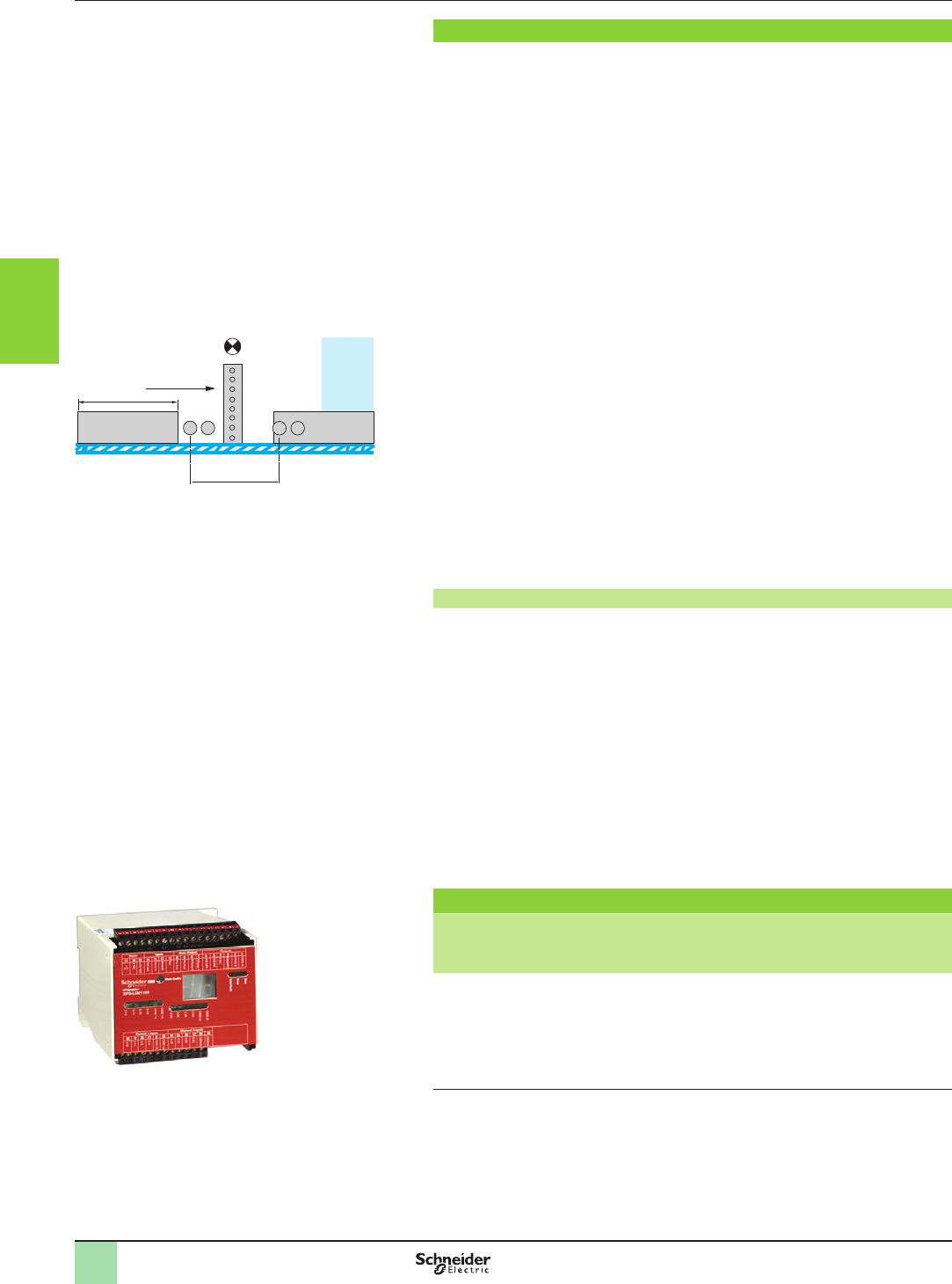
3/78
Operating principle
XPSLCM safety modules are used with type 4 light curtains conforming to EN/
IEC 61496-1 to provide a system inhibiting the light curtain protection, i.e. “muting”.
This function enables the automatic passage of parts for machining or loaded
pallets, without interrupting the transportation movement within the zone protected
by the electro-sensitive protection equipment (ESPE) system. In addition to the
electro-sensitive protection and XPSLCM safety modules, the system comprises
4 to 8 inhibition sensors, 2 indicator lights and a key switch to reset the system to the
initial state in the event of a sequence error.
When the system is switched on by the start command and the light curtain
protection not interrupted, the main circuit is closed by the safety outputs of the
XPSLCM modules (solid-state safety outputs). In addition to safety outputs, the
modules incorporate signalling outputs for sending system status information to the
PLC. Either 5 or 14 LEDs and a 2-digit display, mounted on the front face of the
module, provide information on the safety circuit status.
An interruption of the protection eld monitored by the electro-sensitive protection
equipment causes instantaneous opening of the safety outputs; the process PLC
receives a stop command and the LED display mounted on the front face indicates
the change of state of the safety circuits. The “open” state is maintained until the
module is restarted using the Start button.
The “muting” function cannot be activated by supplying the inhibition sensors unless
the safety outputs have been switched on beforehand. To trigger the “muting”
function, the inhibition devices must be activated within the 3 second time interval.
During the activated “muting” phase, materials can be transported through the
protection eld without deactivating the safety outputs. In the event of intrusion into
the hazardous zone, a person cannot activate the inhibition sensors in the same way
and the system stops.
Whilst the “muting” function is activated, a “muting” status indicator light is controlled
by the XPSLCM module. A fault at indicator light level (short-circuit, open circuit)
is immediately recognised and deactivates the “muting” function. The indicator light
only illuminates when a “muting” signal is generated and indicates the inhibition
of the protection function.
Conditions to be observed for the “muting” function
b The “muting” sensors must either be:
vThru-beam type, sensing distance 15 m: XUM2APCNL2 (or XUM2APCNM8) or
XUM2BPANL2 or XUM2BPBNL2.
vPolarised reex type, sensing distance 5 m: XUM9APCNL2 (or XUM9APCNM8)
or XUM9BPANL2 or XUM9BPBNL2 + XUZC50.
vPolarised reex type, sensing distance 11 m: XUX9APANT16 (or XUX9APANM12)
or XUX9APBNT16 (or XUX9APBNM12) + XUZC50.
vLimit switches
b dM y m to obtain continuous validation of the “muting” function.
b Avoid the intrusion of persons during the
“muting”
phase. This phase is indicated
by the indicator light connected to the
“muting”
indicator output of the XPSLCM module.
b A materials trolley must provide the “muting” signal before entering the protection
eld and cease it once it has cleared all the sensors of the protection eld on exiting.
References
Description Type of
terminal
block
connection
Number of
safety
circuits
Auxiliary
outputs
Supply Reference Weight
kg/
lb
Safety module
for “muting”
function
Removable
from module
2 PNP 1 PNP + 1 NPN 24 V c
XPSLCM1150
0.660/
1.455
Operating principle,
references
Monitor and Processing
Safety monitoring module
Preventa XPSLCM
for the “muting” function of type 2 and type 4 safety
light curtains
m
dM
A B C D
Entry direction
“Muting” indication
Hazardous
zone
Materials
trolley
Materials
trolley
ESPE
(Light curtain)
ESPE: electro-sensitive protection equipment (light curtain).
A, B, D, C: “muting” sensors.
m: trolley length and dM = distance between A, B and D, C.
XPSLCM1150
2
1
3
4
5
6
7
8
9
10
2
1
3
4
5
6
7
8
9
10
3/79
Operating principle,
references
Monitor and Processing
Preventa safety modules types XPSECME,
XPSECPE
For extending the number of safety contacts
Operating principle
Safety modules XPSECME and XPSECPE, for extending the number of safety contacts, are available as
additions to Preventa XPSbase modules (Emergency stop, limit switch, two-hand control, etc.).
They are used to extend the number of safety output contacts of the base modules.
References
Description Connection Number of
safety
circuits
Additional
outputs
Supply Reference Weight
kg/
lb
Safety modules for extending
the number of safety contacts,
for use with XPSbase modules
Captive screw
clamp terminals
Terminal block
removable from
module
4 2 a and
c 24 V
XPSECME5131P
0.270/
0.595
Spring terminals
Terminal block
removable from
module
4 2 a and
c 24 V
XPSECME5131C
0.270/
0.595
Captive screw
clamp terminals
Terminal block
removable from
module
81a and
c 24 V
XPSECPE5131P
0.550/
1,213
Spring terminals
Terminal block
removable from
module
81a and
c 24 V
XPSECPE5131C
0.650/
1.433
Captive screw
clamp terminals
Terminal block
removable from
module
81a 115…230 V
XPSECPE3910P
0.650/
1.433
Spring terminals
Terminal block
removable from
module
81a 115…230 V
XPSECPE3910C
0.650/
1.433
XPSECME5131P
XPSECPE5131C
XPSECPE5131P
XPSECME5131C
2
1
3
4
5
6
7
8
9
10
2
1
3
4
5
6
7
8
9
10
3/80
Operating principle,
references
Monitor and Processing
Preventa safety modules types XPSTSA,
XPSTSW
For safety time delays
Operating principle
Safety modules XPSTSA and XPSTSW are used in applications requiring safety
time delays:
b modules XPSTSA in applications with interlocking on high inertia machines with
long rundown time (guards unlocked after safety time delay has elapsed),
b modules XPSTSW in applications with a safety switchover contact (shunting
contact in association with XPSVN modules for zero speed detection, solenoid valve
monitoring, etc.).
The time delay of safety circuits can be set to 16 preset values, using 2 selectors
located on the front face of the modules.
To aid diagnostics, the modules have LEDs which provide information on the
monitoring circuit status and 2 solid-state outputs for signalling to the process PLC.
In addition, their removable terminal blocks optimise machine maintenance.
References
Description Connection Number of
safety circuits
Additional
outputs /
Solid-state
outputs to PLC
Supply Reference Weight
kg/
lb
Safety modules for
applications with interlocking
on high inertia machines
Captive screw
clamp terminals
Terminal block
removable from
module
1 delayed 2 NC / 2 a and c 24 V
XPSTSA5142P
0.250/
0.551
a 115 V
XPSTSA3442P
0.360/
0.774
a 230 V
XPSTSA3742P
0.360/
0.774
Safety modules for
applications with safety
switchover contact
Captive screw
clamp terminals
Terminal block
removable from
module
1 pulse type 2 NC / 2 a and c 24 V
XPSTSW5142P
0.250/
0.551
a 115 V
XPSTSW3442P
0.360/
0.774
a 230 V
XPSTSW3742P
0.360/
0.774
XPSTSAppppP
XPSTSWppppP
2
1
3
4
5
6
7
8
9
10
2
1
3
4
5
6
7
8
9
10
3/81
Operating principle,
references
Monitor and Processing
Preventa safety modules types XPSDMB,
XPSDME
For coded magnetic switch monitoring
Operating principle
Safety modules XPSDMB and XPSDME are specically designed for monitoring
coded magnetic safety switches. They incorporate two safety outputs and two
solid-state outputs for signalling to the process PLC. Conforming to Performance
Level PL e/Category 4 conforming to EN/ISO 13849-1, modules XPSDMB can
monitor two independent sensors and modules XPSDME can monitor up to six
independent sensors.
To monitor a higher number of magnetic switches using these safety modules,
the magnetic switches can be connected in series parallel, while meeting the
requirements of Performance Level PL d/Category 3 conforming to standard
EN/ISO 13849-1.
Safety modules XPSDMpppppP incorporate removable terminal blocks, thus
optimising machine maintenance.
To aid diagnostics, the modules have LEDs on the front face which provide
information on the monitoring circuit status.
References
Description Connection Number
of safety
circuits
Synchro
time
between
inputs
Solid-
state
outputs
for PLC
Supply Reference Weight
kg/
lb
Safety module for
monitoring 2 coded
magnetic switches
Captive screw
clamp terminals
Terminal block
integrated
in module
2 NO < 0.5 s 2c 24 V
XPSDMB1132
0.250/
0.551
Safety module for
monitoring 6 coded
magnetic switches
Captive screw
clamp terminals
Terminal block
integrated
in module
2 NO < 0.5 s 2c 24 V
XPSDME1132
0.300/
0.661
Safety module for
monitoring 2 coded
magnetic switches
Captive screw
clamp terminals
Terminal block
removable from
module
2 NO < 0.5 s 2 c 24 V
XPSDMB1132P
0.250/
0.551
Safety module for
monitoring 6 coded
magnetic switches
Captive screw
clamp terminals
Terminal block
removable from
module
2 NO < 0.5 s 2c 24 V
XPSDME1132P
0.300/
0.661
Safety module for
monitoring 6 coded
magnetic switches
Captive screw
clamp terminals
Terminal block
integrated
in module
2 NO < 2.2 s 2 c 24 V
XPSDME1132TS220
0.300/
0.661
XPSDMB1132
XPSDME1132
2
1
3
4
5
6
7
8
9
10
2
1
3
4
5
6
7
8
9
10
3/82
Operating principle,
references
Monitor and Processing
Preventa safety modules type XPSVNE
For zero speed detection
XPSVNEppppp
Operating principle
Preventa safety modules XPSVNE for zero speed detection are used to detect the
stop condition of electric motors. Their most common applications include: providing
the unlock signal for electrically interlocked sliding or removable machine guards,
controlling rotation direction signals for reversing motors and engaging locking
brakes after a motor has come to a standstill.
As electric motors run down, a remanent voltage is produced in the windings of the
motor due to residual magnetism. This voltage is proportional to the speed of the
motor and, therefore, decreases as the motor comes to a standstill.
This remanent voltage is measured in a redundant manner so as to detect the stop
condition of the motor. The cabling between the motor windings and the inputs of the
XPSVNE module is also monitored to prevent a cabling breakage or fault being seen
as a stopped motor.
A transformer should not be used to connect the motor to terminals Z1, Z2 and Z3
since there is no monitoring of the connection with the motor winding via the
resistance monitoring.
Modules XPSVNE are suitable for detecting the stop condition of all types of AC
or DC motor driven machines which, when the motor runs down, produce a remanent
voltage in the windings due to residual magnetism. These machines can be controlled
by electronic devices, such as variable speed drives or DC injection brakes.
The input lters for standard XPSVNE modules are designed for a frequency
of up to 60 Hz.
For motors operating at a frequency higher than 60 Hz, which therefore produce a high
frequency remanent voltage, special modules XPSVNEppppHS should be used.
Modules XPSVNE have 2 potentiometers mounted on the front face of the module
which allow independent adjustment of the switching threshold for each input circuit.
This allows adjustment for different types of motors and application requirements.
To aid diagnostics, modules XPSVNE have 4 LEDs and 2 solid-state outputs to provide
information on the status of the zero speed detection circuit.
References
Description Connection Number of
safety circuits/
Solid-state
outputs for PLC
Supply Frequency
of motor power
supply
Reference Weight
kg/
lb
Safety modules for zero
speed detection
Captive screw
clamp
terminals
Terminal block
removable from
module
2/
2
c 24 V y 60 Hz
XPSVNE1142P
0.500/
1.102
> 60 Hz
XPSVNE1142HSP
0.500/
1.102
a 115 V y 60 Hz
XPSVNE3442P
0.600/
1.333
> 60 Hz
XPSVNE3442HSP
0.600/
1.323
a 230 V y 60 Hz
XPSVNE3742P
0.600/
1.323
> 60 Hz
XPSVNE3742HSP
0.600/
1.323
2
1
3
4
5
6
7
8
9
10
2
1
3
4
5
6
7
8
9
10
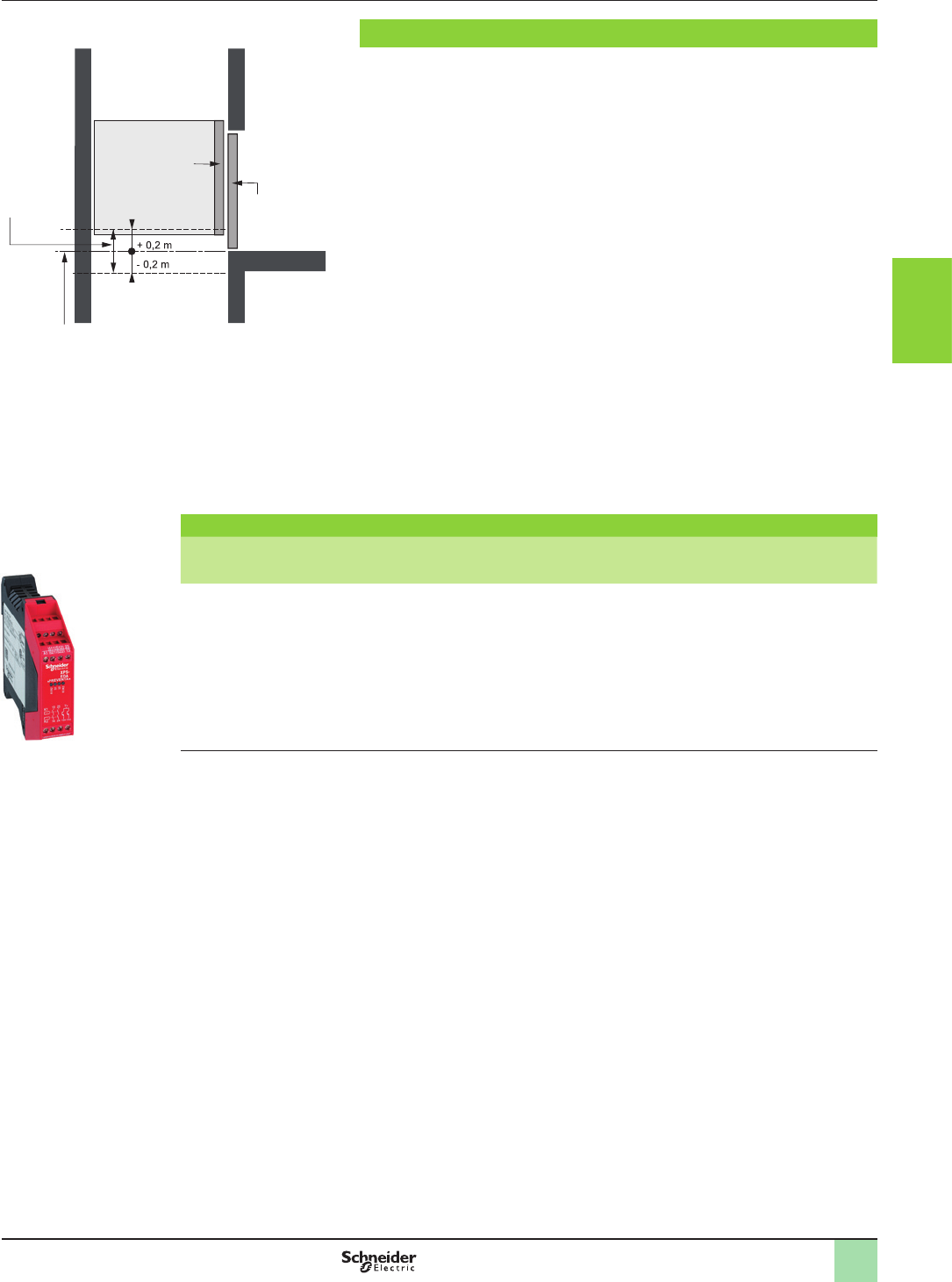
3/83
Operating principle,
references
Monitor and Processing
Preventa safety module type XPSEDA
For lift control
Operating principle
When the cabin is parked at a landing, with the doors open, some lifts automatically
correct their level (isolevelling) in relation to the landing in order to compensate for
any differences generated by modication of the load in the cabin.
During this operation, European standardEN/IEC 81 recommends that the presence
of the cabin be checked within a zone of +/- 0.2 m around the landing (door
unlocking zone), by means of a safety circuit which will cause the cabin to stop if it
moves out of the specied zone.
The use of the safety module XPSEDA, which checks the presence of the cabin in
the specied zone at two points, meets this requirement.
The module incorporates two safety outputs and two solid-state outputs for signalling
functions. Four LEDs on the front face of the module provide visual indication of the
status of the safety circuit.
The position of the cabin in relation to the landing is detected by two limit switches in
the lift shaft. It is also possible to use non-contact sensors (magnetic sensors with
reed contact).
When the cabin reaches the preset position and when it is within the permissible
tolerances in relation to the landing, the two safety circuits in safety module XPSEDA
close and allow isolevelling of the cabin with the doors open. Any change in one of
the input signals (cabin outside the specied zone) or detection of a fault (break in
the wiring, short-circuit, etc.) causes immediate opening of the safety outputs in the
XPSEDA module and subsequent stopping of the cabin.
References
Description Connection Number of
safety circuits
Solid-state
outputs for PLC
Supply Reference Weight
kg/
lb
Safety module for lift control Captive screw
clamp terminals
Terminal block
integrated
in module
2 2 a and
c 24 V
XPSEDA5142
0.180/
0.397
Cabin
Cabin doors
Landing doors
Landing
Landing indicator
(stop reference point)
Door unlocking
zone
XPSEDA5142
2
1
3
4
5
6
7
8
9
10
2
1
3
4
5
6
7
8
9
10
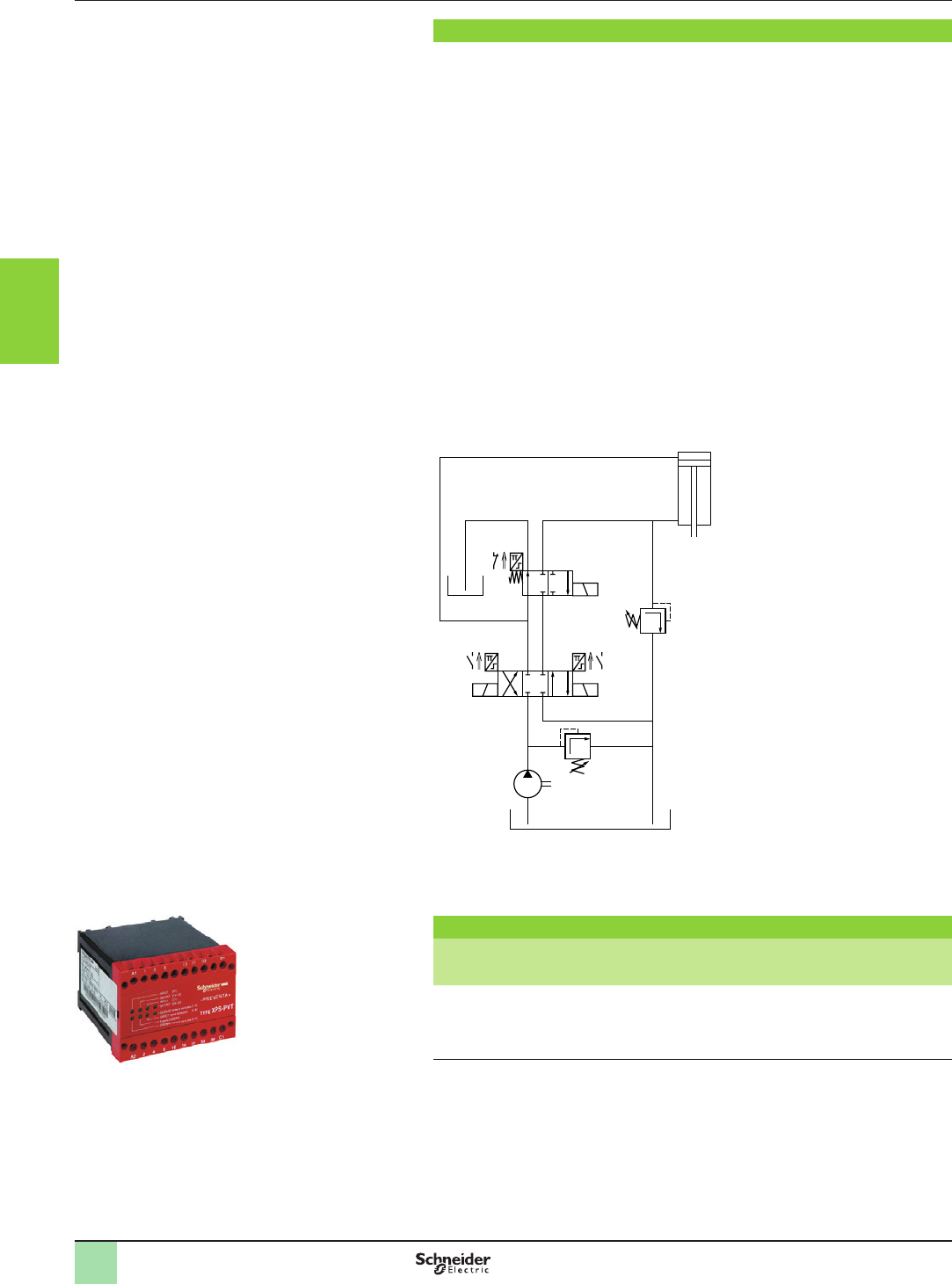
3/84
XPSPVT1180
Operating principle Monitor and Processing
Preventa safety module type XPSPVT
For dynamic monitoring of hydraulic valves on
linear presses
Operating principle
Safety module XPSPVT is specically designed for monitoring hydraulic safety
system valves which control the movements of potentially dangerous machines.
The operating principle of this module is explained in the circuit diagram
of a hydraulic safety system for linear presses (see below).
This hydraulic safety system features a 3 position piston which controls the up and
down stroke of the operating cylinder. The circuit is equipped with a safety valve
to complete the redundant system. This circuit must be activated to enable the
up and down stroke of the cylinder.
If either of the 2 pistons becomes defective (for example, due to a broken spring
or to oil contamination), and the valve piston shifts from its normal position towards
the open position, the XPSPVT module will detect it and prevent resumption of the
piston stroke.
Proximity sensors integrated in the valve to detect the piston positions and
connected to the XPSPVT module must be damped when the valve coils are in the
de-energised state (zero position).
The sensor circuits of the XPSPVT module are designed to allow connection of NPN
and PNP proximity sensors or sensing components. Either 2-wire or 3-wire types
can be used.
Hydraulic safety system circuit operating on a linear press.
Monitoring of valves in position 0.
(1) 3 position hydraulic valve.
(2) 2 position hydraulic valve.
S3
A B
P
(2)
Y3
(1)
S2
Y2
S1
Y1
A B
P T
Pressure
release valve
Opening
Pressure
release
valve
Pump
Closing +
opening
Closing
Reference
Description Display Supply Reference Weight
kg/
lb
Safety module for
dynamic monitoring of
hydraulic valves on
linear presses
8 LEDs 24 V c
XPSPVT1180
0.540/
1.190
2
1
3
4
5
6
7
8
9
10
2
1
3
4
5
6
7
8
9
10
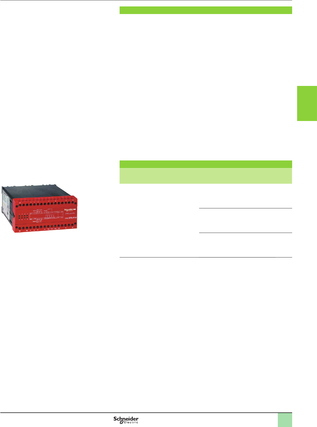
3/85
Operating principle
Safety module XPSPVK is specially designed for dynamic monitoring of the safety
valves in eccentric presses, conforming to European standard EN 692.
This standard establishes the specications related to safety control systems for
presses equipped with friction clutches.
To meet the requirements of this standard, the clutch/brake control must be monitored
dynamically.
This function is provided by a double-bodied solenoid valve (safety valve for presses)
which performs the functions of two valves mounted in one body.
The position of the two valve pistons can be monitored by proximity sensors, mechanical
limit switches or pressure switches.
Module XPSPVK checks for the correct operation of the double-bodied safety valves
at 3 points in the cycle.
b Start at top dead centre: checks the rest position of the two valves.
b Take-on point (transfer function): checks that the two valves are in the “activated”
(energised) position.
b Press stop trigger point: checks that the two valves return to the rest position.
Return must be simultaneous for both valves within a dened time period.
To set up an automatic disconnect of the XPSPVK module at the rst machine stroke,
a NC auxiliary contact mounted on the main control contactor or on another contactor/
relay, activated at the same time, can be wired to terminals 7 and 8 in parallel with the
RESET button.
If a fault is detected during the cycle, the XPSPVK module will stop the slide stroke
and will also inhibit the start of another cycle.
Operating principle,
references
Monitor and Processing
Preventa safety modules type XPSPVK
For dynamic monitoring of double-bodied solenoid
valves
XPSPVK
References
Description Display Supply Reference Weight
kg/
lb
Safety modules for
dynamic monitoring
of double-bodied
solenoid valves
8 LEDs 24 V c
XPSPVK1184
0.700/
1.543
115 V a
XPSPVK3484
0.900/
1.984
230 V a
XPSPVK3784
0.900/
1.984
2
1
3
4
5
6
7
8
9
10
2
1
3
4
5
6
7
8
9
10

3/86
Operating principle Monitor and Processing
Preventa safety modules type XPSOT
For safety stop with automatic overtravel monitoring
and control
Operating principle
Safety module XPSOT is used on eccentric presses to monitor overtravel and
ensure that the press slide stops in a non-dangerous position, i.e. top dead centre
(TDC), during normal (non-emergency) operation.
Use of this module, designed in accordance with standard EN 692 relating to
mechanical press safety, makes it possible to create a redundant, self-monitoring
control system.
The two essential functions of this safety module are to:
bTrigger the end of cycle stop sequences slightly before top dead centre
(at point A) so as to come to a complete stop at TDC.
After TDC, the permissible overtravel is approximately 10°. The safety module
immediately detects any overtravel. Overtravel is indicative of braking device
deterioration and, in this case, jog mode must be used to move the slide back
to TDC. The next cycle will be inhibited to allow maintenance to be performed
on the braking device (cam 1).
bTake over control monitoring during the dangerous part of the cycle (slide
downstroke). Any stop instruction issued between TDC (0°) and point C
(approximately 150° after TDC) causes an immediate stop of the press.
This approximate value of 150° corresponds to the 8 mm tool closure
dimension (safety point).
When a stop instruction is issued after this safety point, the press completes the
cycle and comes to a complete stop at TDC (cam 2).
Control of the dangerous part of the cycle (generally the slide downstroke) is
usually activated from a two-hand control station associated with a safety module
(type XPSBCE).
Overtravel monitoring is performed on each cycle by safety module XPSOT.
2
1
3
4
5
6
7
8
9
10
2
1
3
4
5
6
7
8
9
10
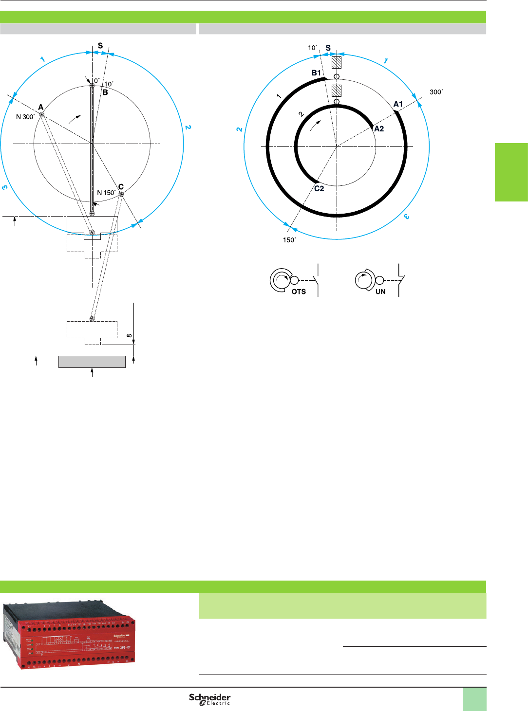
3/87
Operating principle
(continued),
references
Monitor and Processing
Preventa safety modules type XPSOT
For safety stop with automatic overtravel monitoring
and control
Operating principle (continued)
Press diagram Control cams diagram
1 Permissible overtravel zone.
2 Dangerous zone (usually slide downstroke).
3 Non-dangerous zone (usually slide upstroke).
S Permissible overtravel.
A Press stop trigger point.
B Point at which permissible overtravel is exceeded (a stop instruction issued after point B will
lock up the press).
C Takeover point, beyond which the press will complete its cycle up to TDC.
TDC Top dead centre, actual stopping zone of the press.
BDC Bottom dead centre.
Cam operation
Cam 1 is associated with the OTS, limit switch (LS), cam 2 with the UN limit switch (the limit
switches must be located on different cams for safety reasons).
The OTS limit switch is deactivated at TDC, at which point the UN limit switch
is activated.
Point A1 of cam 1 is located approximately 300° after TDC and, when reached,
the press stops and comes to a standstill: A1 is the press stop trigger point.
Point B1, located approximately 10° after TDC, constitutes the end of cam 1: If B1
is exceeded during stopping, the overtravel is abnormally long, the press locks up and the
next cycle is inhibited.
Point A2 of cam 2 functions like point A1 on cam 1 (contact state of the UN limit switch reversed
in relation to the state of the OTS limit switch).
Point C2, located approximately 150° after TDC, corresponds to the 8 mm tool closing
dimension. Stop instructions issued after C2 is reached are not executed until point A2 is
reached.
Top Dead Centre
Bottom dead centre
Die
mm Max.
TDC
BDC
TDC Stop and overtravel monitoring Restart + Stop
approx.
approx.
approx.
Cam
Cam
Limit
switch
OTS
Limit
switch
UN
References
Description Display Supply Reference Weight
kg/
lb
Safety modules for
safety stop with
automatic overtravel
monitoring and control
4 LEDs 115 V a
XPSOT3444
1.100/
2.425
230 V a
XPSOT3744
1.100/
2.425
XPSOT
2
1
3
4
5
6
7
8
9
10
2
1
3
4
5
6
7
8
9
10
3/88
Presentation Monitor and Processing
Modicon TM3 expansion modules
Presentation of the range
Digital I/O modules
Analog I/O modules
Expert I/O modules
Functional Safety modules
Bus expansion modules
Presentation
The Modicon TM3 expansion module offer provides an opportunity to enhance the
capabilities of Modicon M221, M241 and M251 logic controllers:
vDigital I/O modules which can be used to create congurations with up to
264 digital I/O (according to the controller). These modules are available with the
same connections as the controllers.
vAnalog I/O modules which can be used to create congurations with up to
114 analog I/O (according to the controller) and are designed to receive, amongst
other things, position, temperature or speed sensor signals. They are also capable
of controlling variable speed drives or any device equipped with a current or
voltage input.
vExpert modules for control of TeSys motor starters which simplify wiring up the
control section due to connection with RJ45 cables.
vFunctional Safety modules which simplify wiring and can be congured in the
SoMachine Basic software.
In addition, the TM3 expansion system is exible due to the possibility of remotely
locating some of the TM3 modules in the enclosure or another cabinet (up to
5 meters (16.404 ft.) away, using a bus expansion system.
The Modicon TM3 expansion system is common to the whole range of Modicon
M221, M241 and M251 logic controllers, meaning that the model of controller can be
revised without changing expansion module.
Modicon TM3 range
Digital
I/O modules
vmodules with 8 to 32 inputs/outputs:
- 24 V or 120 V c 50/60 Hz inputs
- relay or transistor outputs
Analog I/O
modules
vmodules with 2 to 8 inputs/outputs:
- current/voltage or temperature inputs
- current/voltage outputs
Expert module vmodule for control of between one and four TeSys
motor starters
Functional Safety
modules
vmodules designed using Preventa technology for
integral machine safety:
- control of emergency stops
- control of switches
- control of light curtains
- control of pressure-sensitive mats or edges
Bus expansion
system
vtransmitter module
vreceiver module
vbus expansion cable
Specic features
Modicon TM3 expansion modules have been designed with a simple interlocking
assembly mechanism. A bus expansion connector is used to distribute data and the
power supply when assembling the Modicon TM3 expansion modules with logic
controllers.
Connections
A wide choice of connections is available depending on the model of Modicon TM3
module:
vremovable screw terminal blocks (1)
vremovable spring terminal blocks (1)
vHE 10 connector, to be used with HE 10 cables/bare wires or HE 10/HE 10 and
Telefast sub-bases (2)
The connectors (screw terminal blocks, spring terminal blocks, HE 10 connector,
RJ 45) are located on the front of the TM3 expansion modules and are therefore
accessible.
(1) The terminal blocks are supplied with Modicon TM3 expansion modules.
(2) Telefast Modicon ABE7 pre-wired system to be ordered separately.
Compatibility of offers
Modicon TM3 expansion modules
>Modicon M221 logic controllers
>Modicon M221 Book logic controllers
>Modicon M241 logic controllers
>Modicon M251 logic controllers
>SoMachine Basic software
>SoMachine software
>Modicon TM2 expansion modules
2
1
3
4
5
6
7
8
9
10
2
1
3
4
5
6
7
8
9
10
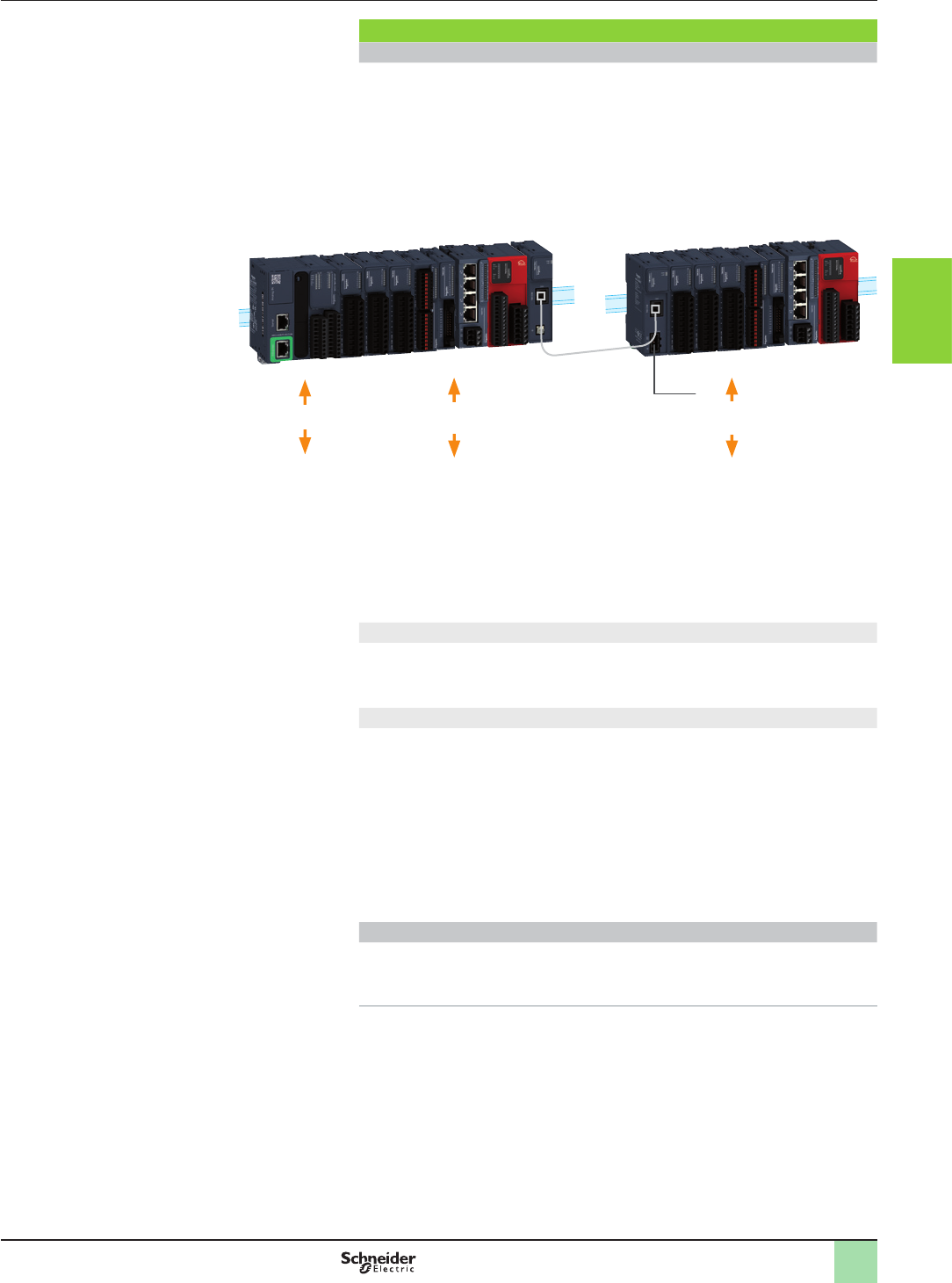
3/89
Presentation Monitor and Processing
Modicon TM3 expansion modules
Bus expansion system
Presentation
Modicon TM3 bus expansion system
A PLC conguration consists of a controller with its embedded input and output
channels, used in conjunction with local or remote expansion modules which are
used to increase the number of channels and/or functions.
vExpansion modules are connected directly by simple interlocking with the
controller (local I/O) or remotely (remote I/O) with a TM3 bus expansion cable, up
to 5 meters (16.404 ft.) away.
vThe bus expansion connector, located on the side of the controllers and on each
side of the Modicon TM3 expansion modules, transmits and synchronizes data.
2
1
55
4
23
36
6
47
Local I/O
< 7 modules max. (1) >
Embedded I/O Remote I/O
< 7 modules max. >
24 V c
1 Logic controller (M221, M221 Book, M241, M251)
2 Modicon TM3 digital I/O modules.
3 Modicon TM3 analog I/O modules.
4 Modicon TM3 expert module: control of TeSys motor starters.
5 Modicon TM3 functional safety modules.
6 Modicon TM3 bus expansion module (transmitter and receiver).
7 TM3 bus expansion cable.
bLocal I/O
Maximum conguration: 7 Modicon TM3 expansion modules associated with an
M2pp logic controller.
With limited number of relay or transistor outputs.
bRemote I/O
Maximum conguration: 14 Modicon TM3 expansion modules (7 local modules + 7
remote modules) with the use of Modicon TM3 bus expansion system (transmitter
and receiver modules).
The transmitter and receiver bus expansion modules can be used to:
vincrease from 7 to 14 the number of I/O expansion modules that can be connected
to an M2pp logic controller
vlocate Modicon TM3 expansion modules remotely, up to 5 meters (16.404 ft.)
away
The transmitter module and receiver module are physically linked by a
VDIP184546ppp bus expansion cable.
Mounting
vModicon TM3 expansion modules are mounted on a 5 symmetrical rail. They
have a locking clip on the top of their casing.
vFor plate or panel mounting, use the TMAM2 kit.
(1) Depending on type of TM3 module used.
2
1
3
4
5
6
7
8
9
10
2
1
3
4
5
6
7
8
9
10
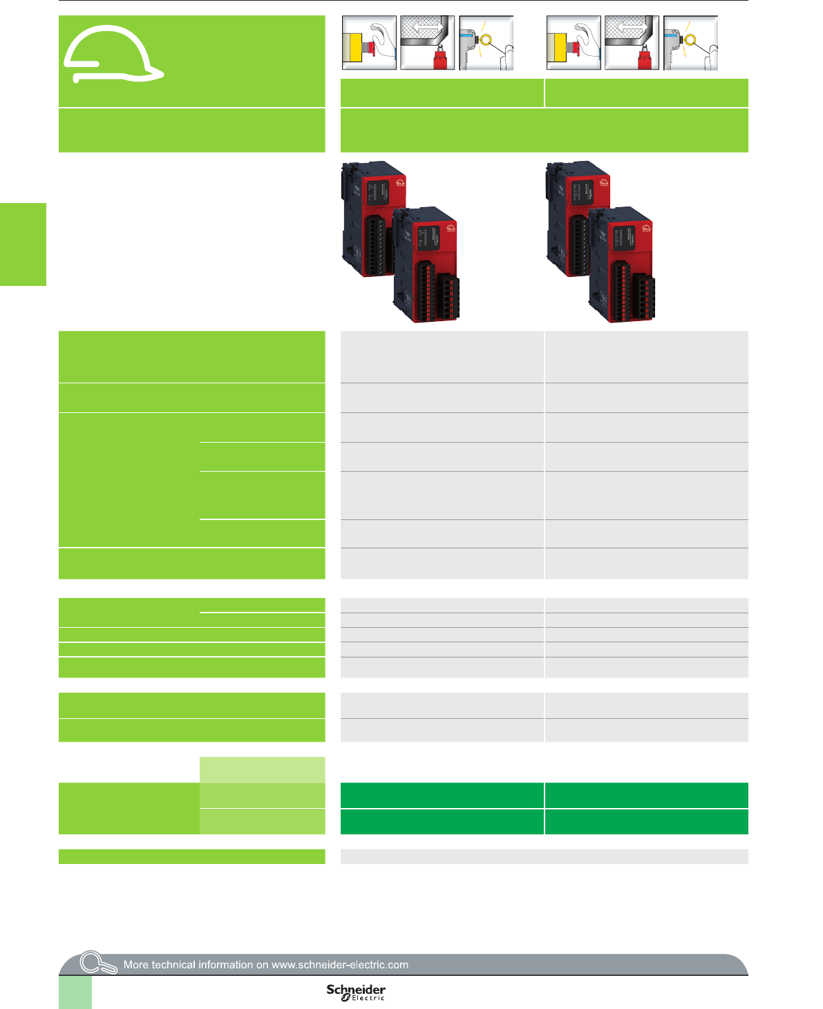
3/90
Selection guide Monitor and Processing
Modicon TM3 functional safety modules
(Powered by Preventa technology)
Safety application
Control of Emergency stop and switches Control of Emergency stop and switches Control of Emergency stop, switches or solid-state output safety light
curtains
Control of Emergency stop, switches, pressure-sensitive mats and edges
or solid-state output safety light curtains
Compatibility bModicon M221 and Modicon M221 Book logic controllers
bModicon M241 logic controllers
bModicon M251 logic controllers
bModicon M221 and Modicon M221 Book logic controllers
bModicon M241 logic controllers
bModicon M251 logic controllers
Maximum achievable safety level PLd/Category 3 conforming to
EN/ISO 13849-1
SILCL2 conforming to EN/IEC 61508 and
EN/IEC 62061
PLe/Category 4 conforming to
EN/ISO 13849-1
SILCL3 conforming to EN/IEC 61508 and
EN/IEC 62061
PLd / Category 3 conforming to EN/ISO 13849-1
SILCL2 conforming to EN/IEC 61508 and EN/IEC 62061
PLe/Category 4 conforming to EN/ISO 13849-1
SILCL3 conforming to EN/IEC 61508 and EN/IEC 62061
Standards (product) EN/IEC 60947-1
EN/IEC 60947-5-1
EN/IEC 60947-1
EN/IEC 60947-5-1
EN/IEC 60947-1
EN/IEC 60947-5-1
EN/IEC 60947-1
EN/IEC 60947-5-1
Standards (machine
assembly)
Emergency stop circuits EN/IEC 60204-1
EN/ISO 13850
EN/IEC 60204-1
EN/ISO 13850
EN/IEC 60204-1
EN/ISO 13850
EN/IEC 60204-1
EN/ISO 13850
Switches in protective
devices
EN/ISO 14119 EN/ISO 14119 EN/ISO 14119 EN/ISO 14119
Type 4 light curtains
equipped with solid-state
safety outputs with test
function
– – Also designed for use with equipment conforming to EN/IEC 61496-1 up to
type 4
Also designed for use with equipment conforming to EN/IEC 61496-1 up to
type 4
4-wire pressure-sensitive
mats or edges –––Also designed for use with equipment conforming to standard EN 1760-1
Product certications UL, CSA, TÜV, CCC UL, CSA, TÜV, CCC UL, CSA, TÜV, CCC UL, CSA, TÜV, CCC
Safety circuits Number 3 NO 3 NO 3 NO 3 NO
Type Instantaneous opening relay Instantaneous opening relay Instantaneous opening relay Instantaneous opening relay
Module fuse protection Internal, electronic Internal, electronic Internal, electronic Internal, electronic
LEDs 6 LEDs 6 LEDs 6 LEDs 6 LEDs
Power supply 24 V c24 V c24 V c24 V c
Synchronization time between inputs Unlimited Unlimited Unlimited Unlimited or 2 s, 4 s (depending on wiring), can be congured in the software
Input channel voltage 24 V c24 V c24 V c24 V c
Channels and power supply
connected:
Safety module type
with removable screw
terminals
TM3SAC5R TM3SAF5R TM3SAFL5R TM3SAK6R
with removable spring
terminal blocks
TM3SAC5RG TM3SAF5RG TM3SAFL5RG TM3SAK6RG
Page 3/93 3/93
2
1
3
4
5
6
7
8
9
10
2
1
3
4
5
6
7
8
9
10
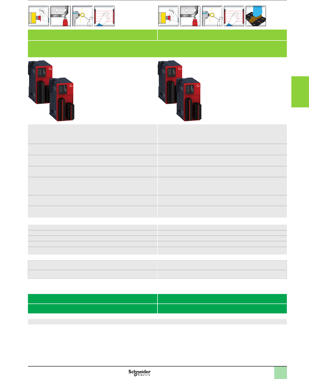
3/91
Safety application
Control of Emergency stop and switches Control of Emergency stop and switches Control of Emergency stop, switches or solid-state output safety light
curtains
Control of Emergency stop, switches, pressure-sensitive mats and edges
or solid-state output safety light curtains
Compatibility bModicon M221 and Modicon M221 Book logic controllers
bModicon M241 logic controllers
bModicon M251 logic controllers
bModicon M221 and Modicon M221 Book logic controllers
bModicon M241 logic controllers
bModicon M251 logic controllers
Maximum achievable safety level PLd/Category 3 conforming to
EN/ISO 13849-1
SILCL2 conforming to EN/IEC 61508 and
EN/IEC 62061
PLe/Category 4 conforming to
EN/ISO 13849-1
SILCL3 conforming to EN/IEC 61508 and
EN/IEC 62061
PLd / Category 3 conforming to EN/ISO 13849-1
SILCL2 conforming to EN/IEC 61508 and EN/IEC 62061
PLe/Category 4 conforming to EN/ISO 13849-1
SILCL3 conforming to EN/IEC 61508 and EN/IEC 62061
Standards (product) EN/IEC 60947-1
EN/IEC 60947-5-1
EN/IEC 60947-1
EN/IEC 60947-5-1
EN/IEC 60947-1
EN/IEC 60947-5-1
EN/IEC 60947-1
EN/IEC 60947-5-1
Standards (machine
assembly)
Emergency stop circuits EN/IEC 60204-1
EN/ISO 13850
EN/IEC 60204-1
EN/ISO 13850
EN/IEC 60204-1
EN/ISO 13850
EN/IEC 60204-1
EN/ISO 13850
Switches in protective
devices
EN/ISO 14119 EN/ISO 14119 EN/ISO 14119 EN/ISO 14119
Type 4 light curtains
equipped with solid-state
safety outputs with test
function
– – Also designed for use with equipment conforming to EN/IEC 61496-1 up to
type 4
Also designed for use with equipment conforming to EN/IEC 61496-1 up to
type 4
4-wire pressure-sensitive
mats or edges –––Also designed for use with equipment conforming to standard EN 1760-1
Product certications UL, CSA, TÜV, CCC UL, CSA, TÜV, CCC UL, CSA, TÜV, CCC UL, CSA, TÜV, CCC
Safety circuits Number 3 NO 3 NO 3 NO 3 NO
Type Instantaneous opening relay Instantaneous opening relay Instantaneous opening relay Instantaneous opening relay
Module fuse protection Internal, electronic Internal, electronic Internal, electronic Internal, electronic
LEDs 6 LEDs 6 LEDs 6 LEDs 6 LEDs
Power supply 24 V c24 V c24 V c24 V c
Synchronization time between inputs Unlimited Unlimited Unlimited Unlimited or 2 s, 4 s (depending on wiring), can be congured in the software
Input channel voltage 24 V c24 V c24 V c24 V c
Channels and power supply
connected:
Safety module type
with removable screw
terminals
TM3SAC5R TM3SAF5R TM3SAFL5R TM3SAK6R
with removable spring
terminal blocks
TM3SAC5RG TM3SAF5RG TM3SAFL5RG TM3SAK6RG
Page 3/93 3/93
2
1
3
4
5
6
7
8
9
10
2
1
3
4
5
6
7
8
9
10
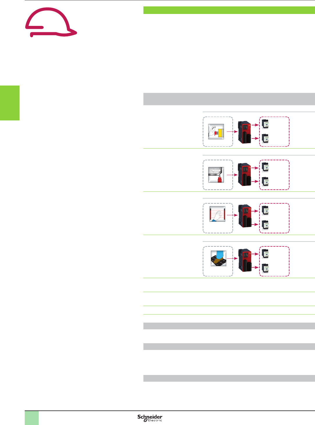
3/92
Presentation Monitor and Processing
Modicon TM3 functional safety modules
(Powered by Preventa technology)
Presentation
Modicon TM3 functional safety modules are designed using Preventa technology.
They can be used to incorporate machine safety into the overall machine control.
Data acquisition: control of safety products
vEmergency stop button: complementary protection measures
vMonitoring devices used in protective systems to control access to hazardous
areas
vLight curtains and safety mats to detect intrusion into hazardous areas
Monitoring and processing
vModicon TM3 functional safety modules control the input signals from monitoring
devices and act as an interface with contactors and variable speed drives, causing
the machine to stop.
vModicon TM3 functional safety modules complement the embedded I/O on M221,
M221 Book, M241 and M251 logic controllers.
Modicon TM3 functional
safety modules
Safety system/Performance level reached
For control of
emergency stops
Category 3/PLd, SIL2 architecture
Contactor 1
CON 1
Emergency stop
Contactor 2
CON 2
Input Outputs
For control of switches Category 4/PLe, SIL3 architecture
Contactor 2
CON 2
Switch
Contactor 1
CON 1
Input Outputs
For control of type 4
light curtains
Category 3/PLd, SIL2 architecture
Contactor 2
CON 2
Type 4 light
curtains
Contactor 1
CON 1
Input Outputs
For control of pressure-
sensitive mats or edges
Category 4/PLe, SIL3 architecture
Contactor 2
CON 2
Pressure-
sensitive mats
or edges
Contactor 1
CON 1
Input Outputs
vThe safety outputs available on the 4 modules are relay type, guided by
microprocessor technology.
vDiagnostic utilities use LEDs, found on the module front face. They provide
information on the monitoring circuit status.
vThe diagnostic information is shared via the TM3 bus.
vThe Start button monitoring function is congurable depending on the wiring.
Connections
Equipped, depending on the model, with removable screw or spring-type terminals
for connecting the safety channels.
Conguration
Modicon TM3 functional safety modules connect to M221, M221 Book, M241 and
M251 logic controllers according to the general rules for the TM3 system: 7 modules
max. and 14 modules max. with the use of Modicon TM3 bus expansion system
(transmitter and receiver).
Mounting
vModicon TM3 functional safety modules are mounted on a 5 symmetrical rail.
vFor plate or panel mounting, use the TMAM2 kit.
2
1
3
4
5
6
7
8
9
10
2
1
3
4
5
6
7
8
9
10
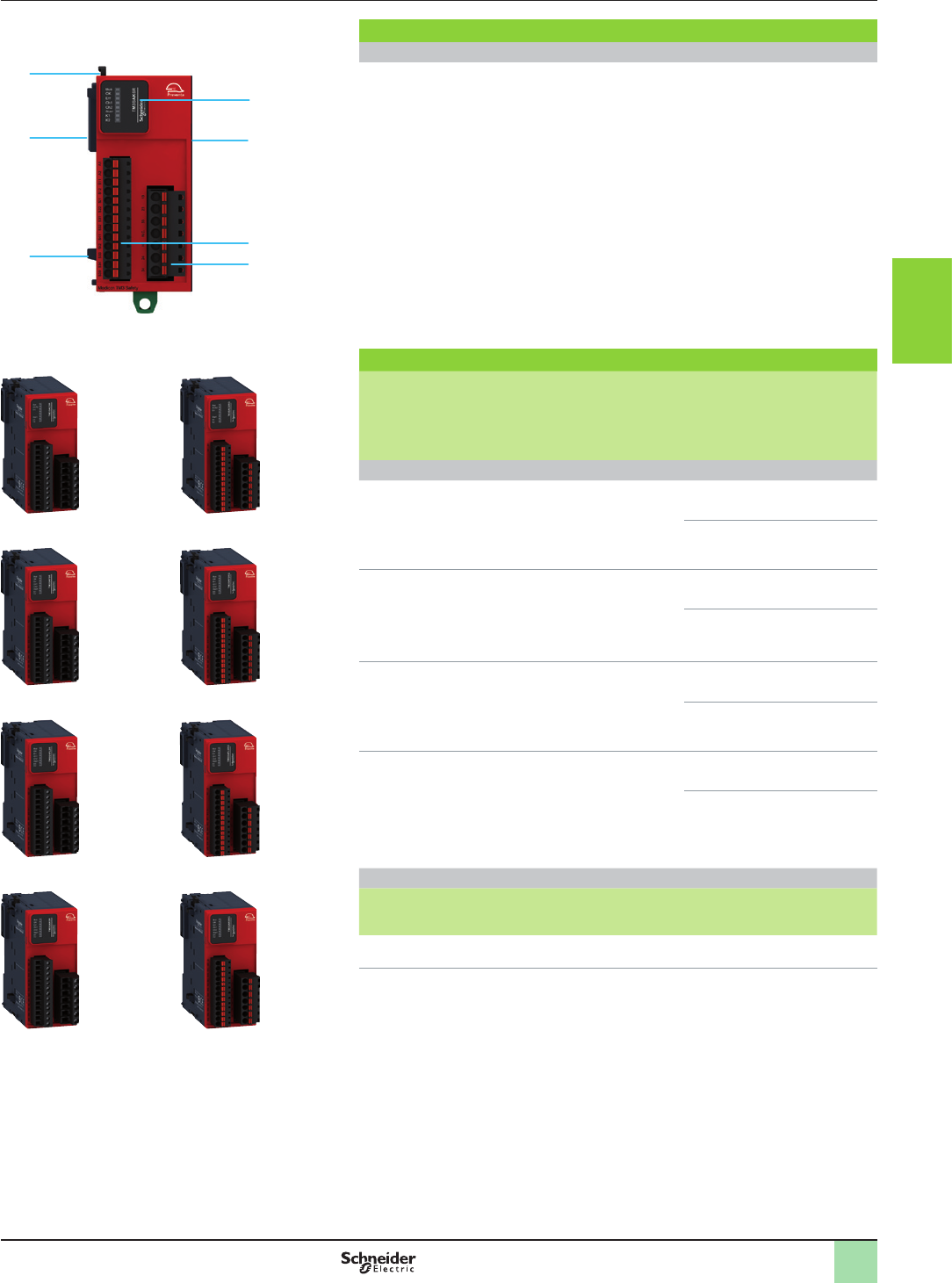
3/93
Presentation,
description,
references
Monitor and Processing
Modicon TM3 functional safety modules
(Powered by Preventa technology)
Description
Modicon TM3 functional safety modules
1 Adjacent module locking catch.
2 TM3 bus connectors (one on each side). These are designed to provide
continuity of the link between connected modules.
3 5 symmetrical rail locking clip.
4 Display block (6 LEDs - green, red) for the module channels and diagnostics.
5 Removable spring or screw-type terminal blocks (depending on the model) for
connecting the safety channels and the power supply.
References
Designation Maximum achievable
safety level
Term.
block
for
input
conn.
(1)
Reference Weight
kg
lb
24 V c power supply
Functional Safety modules for
control of
vemergency stops
vswitches
PLd/Category 3
conforming to
EN/ISO 13849-1
SILCL2 conforming to
EN/IEC 61508 and
EN/IEC 62061
screw TM3SAC5R 0.190
0.420
spring TM3SAC5RG 0.190
0.420
Functional Safety modules for
control of
vemergency stops
vswitches
PLe/Category 4
conforming to EN/
ISO 13849-1
SILCL3 conforming to
EN/IEC 61508 and
EN/IEC 62061
screw TM3SAF5R 0.190
0.420
spring TM3SAF5RG 0.190
0.420
Functional Safety modules for
control of
vemergency stops
vswitches
vsafety light curtains with
solid-state outputs
PLd / Category 3
conforming to EN/ISO
13849-1
SILCL2 conforming to EN/
IEC 61508 and EN/IEC
62061
screw TM3SAFL5R 0.190
0.420
spring TM3SAFL5RG 0.190
0.420
Functional Safety modules for
control of
vemergency stops
vswitches
vsafety light curtains with
solid-state outputs
vpressure-sensitive mats or
edges
PLe/Category 4
conforming to
EN/ISO 13849-1
SILCL3 conforming to
EN/IEC 61508 and
EN/IEC 62061
screw TM3SAK6R 0.190
0.420
spring TM3SAK6RG 0.190
0.420
Separate parts
Designation Description Reference Weight
kg
lb
Mounting kit
Sold in lots of 10
For mounting Functional Safety
modules on a plate or panel
TMAM2 0.065
0.143
(1) Removable terminal blocks equipped with screw terminals or spring terminals, supplied with
the controller.
TM3SAC5R TM3SAC5RG
TM3SAF5R TM3SAF5RG
TM3SAFL5R TM3SAFL5RG
TM3SAK6R TM3SAK6RG
2
5
5
3
2
1
4
2
1
3
4
5
6
7
8
9
10
2
1
3
4
5
6
7
8
9
10
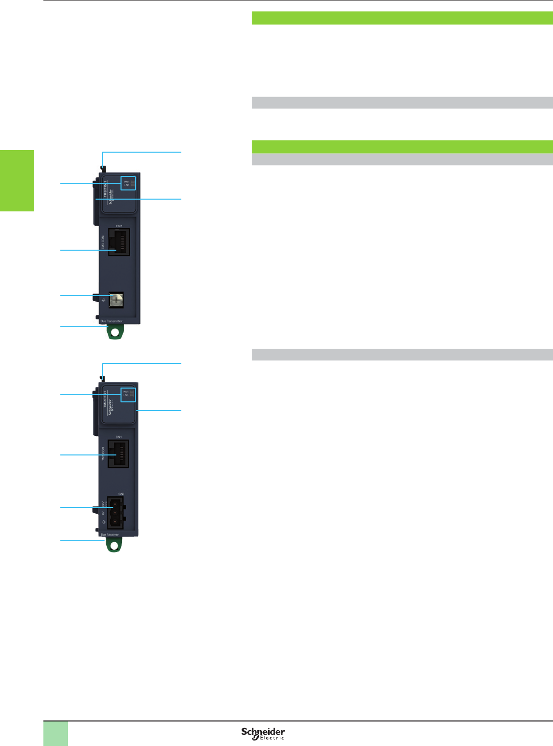
3/94
Presentation,
description
Monitor and Processing
Modicon TM3 bus expansion system
Transmitter module and receiver module
Presentation
Modicon TM3 transmitter and receiver modules can be used to:
vincrease from 7 to 14 the number of I/O expansion modules that can be connected
to an M2pp logic controller
vlocate Modicon TM3 expansion modules remotely, up to 5 m (16.404 ft.) away
The transmitter and receiver modules are physically linked by a VDIP184546ppp
bus expansion cable.
Mounting
vTM3 bus expansion modules are mounted on a 5 symmetrical rail.
vFor plate or panel mounting, use the TMAM2 kit.
Description
TM3XTRA1 transmitter module
1 Block with 2 LEDs displaying the communication status and power supply status.
2 RJ 45 connector for connecting the VDIP184546ppp bus expansion cable.
3 Screw terminal for the functional ground (FG) connection.
4 5 symmetrical rail locking clip.
5 TM3 bus connector providing continuity of the link with the connected module.
6 Adjacent module locking catch.
TM3XREC1 receiver module
1 Block with 2 LEDs displaying the communication status and power supply status.
2 RJ 45 connector for connecting the VDIP184546ppp bus expansion cable.
3 Screw terminal block for connecting the power supply.
4 5 symmetrical rail locking clip.
5 TM3 bus connector providing continuity of the link with the connected module.
6 Adjacent module locking catch.
4
5
6
3
2
1
TM3XTRA1
4
5
6
3
2
1
TM3XREC1
2
1
3
4
5
6
7
8
9
10
2
1
3
4
5
6
7
8
9
10
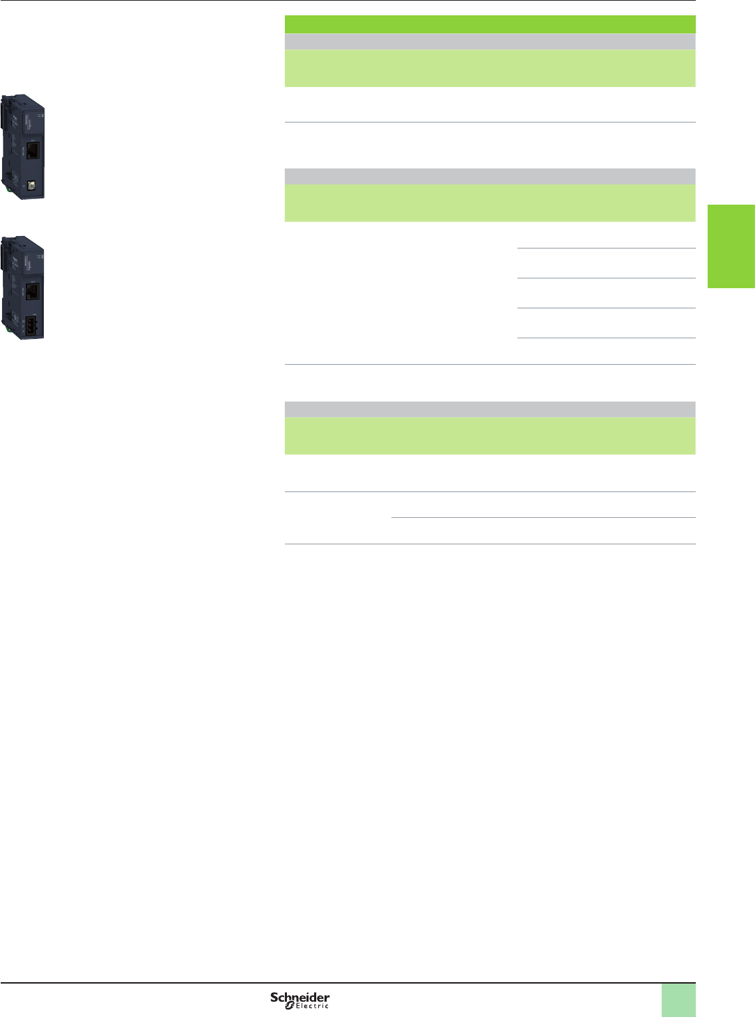
3/95
References Monitor and Processing
Modicon TM3 bus expansion system
Transmitter module and receiver module
References
Modicon TM3 bus expansion system
Designation Characteristics Reference Weight
kg
lb
Transmitter module Data transmission module
Power supply: using the TM3 bus
TM3XTRA1 0.065
0.143
Receiver module Data reception module
Power supply: 24 V c
(with external power supply)
TM3XREC1
(1)
0.075
0.165
Cordsets
Designation Used for Length Reference Weight
kg
lb
Shielded category 5E
TM3 bus expansion
cables
TM3 bus expansion by
linking transmitter and
receiver modules
Equipped with an RJ 45
connector at each end
0.5 m
1.64 ft
VDIP184546005 –
1 m
3.28 ft
VDIP184546010 –
2 m
6.56 ft
VDIP184546020 –
3 m
9.84 ft
VDIP184546030 –
5 m
16.40 ft
VDIP184546050 –
Functional ground
cable
Functional ground for the
TM3XTRA1 transmitter
module
0.12 m
0.39 ft
Cable supplied with the
TM3XTRA1 transmitter
module
Spare parts
Designation Description Unit reference Weight
kg
lb
Mounting kit
Sold in lots of 10
For mounting bus expansion
modules on a plate or panel
TMAM2 0.065
0.143
Set of terminal blocks
for connecting the
power supply
8 removable terminal blocks with screw
terminals
TMAT2PSET 0.127
0.280
8 removable terminal blocks with
spring terminals
TMAT2PSETG 0.127
0.280
(1) The TM3XREC1 module is supplied with a removable screw terminal block for connecting the
power supply.
TM3XTRA1
TM3XREC1
2
1
3
4
5
6
7
8
9
10
2
1
3
4
5
6
7
8
9
10
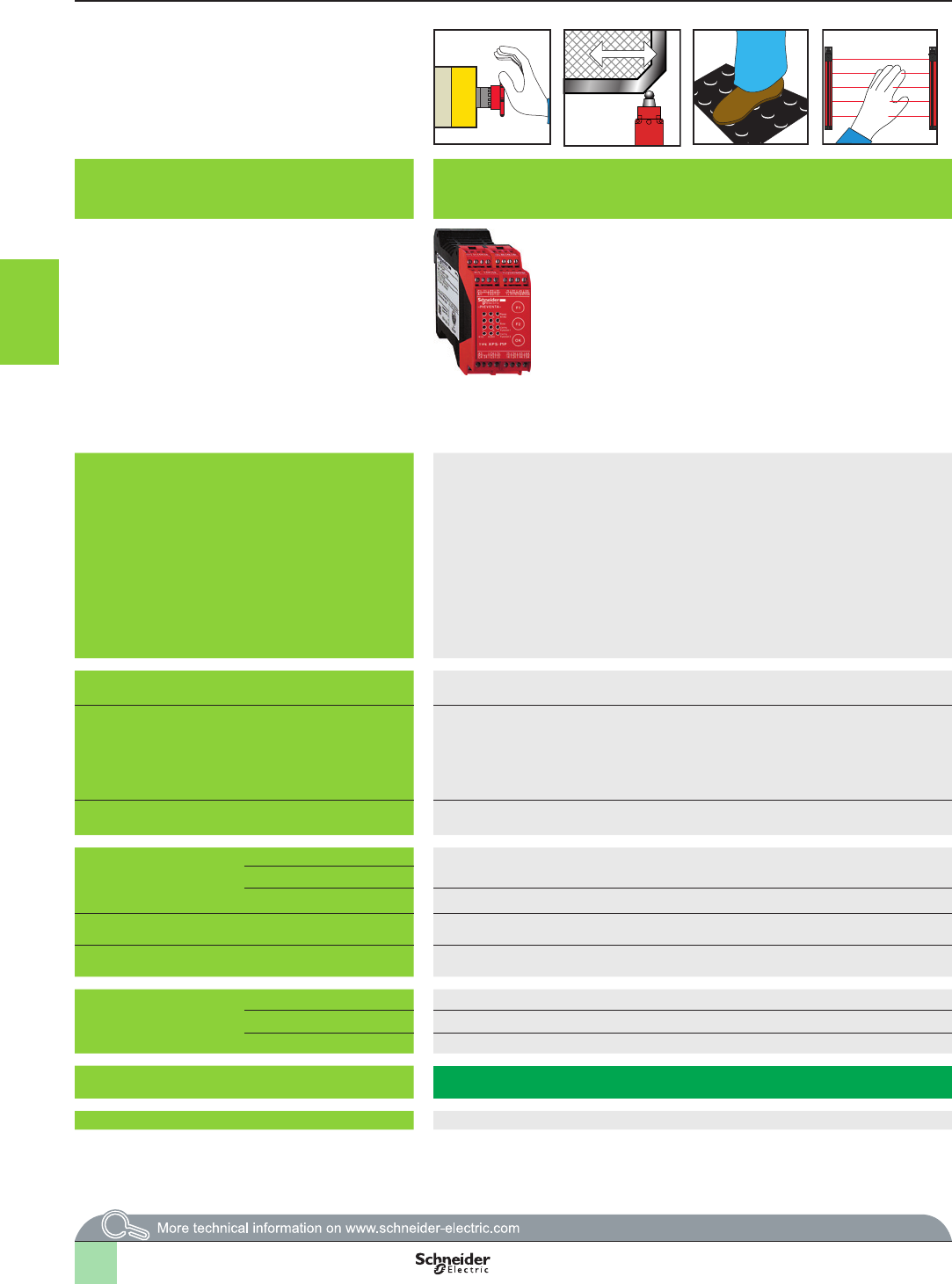
3/96
Applications
Modules
Controllers for monitoring 2 independent safety functions simultaneously.
User selection of 2 functions from a choice of 15, programmable from front face of
controller.
Congurable controllers using software, for several independent safety functions: selection of safety functions using conguration software running
on Windows (16 or 32 inputs and 8 independent safety outputs)
Functions v Emergency stop monitoring
v Switch monitoring
v Enabling switch monitoring
v Sensing mat or edges monitoring
v Light curtain monitoring, relay output type
v etc.
v Emergency stop monitoring
v Limit switch monitoring
v Two-hand control monitoring
v Safety light curtain monitoring, with or without "muting" function
v Enabling switch monitoring, coded magnetic switch monitoring
v Safety mat monitoring
v Hydraulic press solenoid valve monitoring
v Eccentric press safety stop at top dead centre monitoring. Zero speed detection
v Hydraulic press monitoring
v Eccentric press monitoring
v Foot switch monitoring
v Chain shaft breakage monitoring
v Safe tool
v Position selector
Maximum achievable safety level PL e/Category 4 conforming EN ISO 13849-1,
SILCL 3 conforming to EN/IEC 61508 and EN/IEC 62061
PL e/Category 4 conforming to EN ISO 13849-1,
SILCL 3 conforming to EN/IEC 61508 and EN/IEC 62061
Conformity to standards EN/IEC 60204-1,
EN/IEC 60947-1,
EN/IEC 60947-5-1
EN/IEC 60204-1,
EN 1760-1/ISO 13856-1,
EN/IEC 61496-1,
EN 574/ISO 13851,
EN/IEC 60947-1,
EN/IEC 60947-5-1
Product certications UL, CSA, TÜV UL, CSA, TÜV
Number of circuits
Safety 6 NO (3 NO per function) 4 NO (2 NO per function) + 6 solid-state
Additional 3 solid-state outputs for signalling to PLC 1 "muting" signalling output
Display 12 LEDs LED display on front face
Supply voltage 24 V c 24 V c
Communication CANopen bus – Via SUB-D 9-pin male connector, only on XPSMC16ZC and XPSMC32ZC
Probus bus –Via SUB-D 9-pin female connector, only on XPSMC16ZP and XPSMC32ZP
Modbus bus – Via RJ45 connector, on all controllers XPS MCppZp
Module type XPSMP XPSMC
Pages 3/98 3/100
Selection guide Monitor and Processing
Preventa safety controllers
1
2
3
4
5
6
7
8
9
10
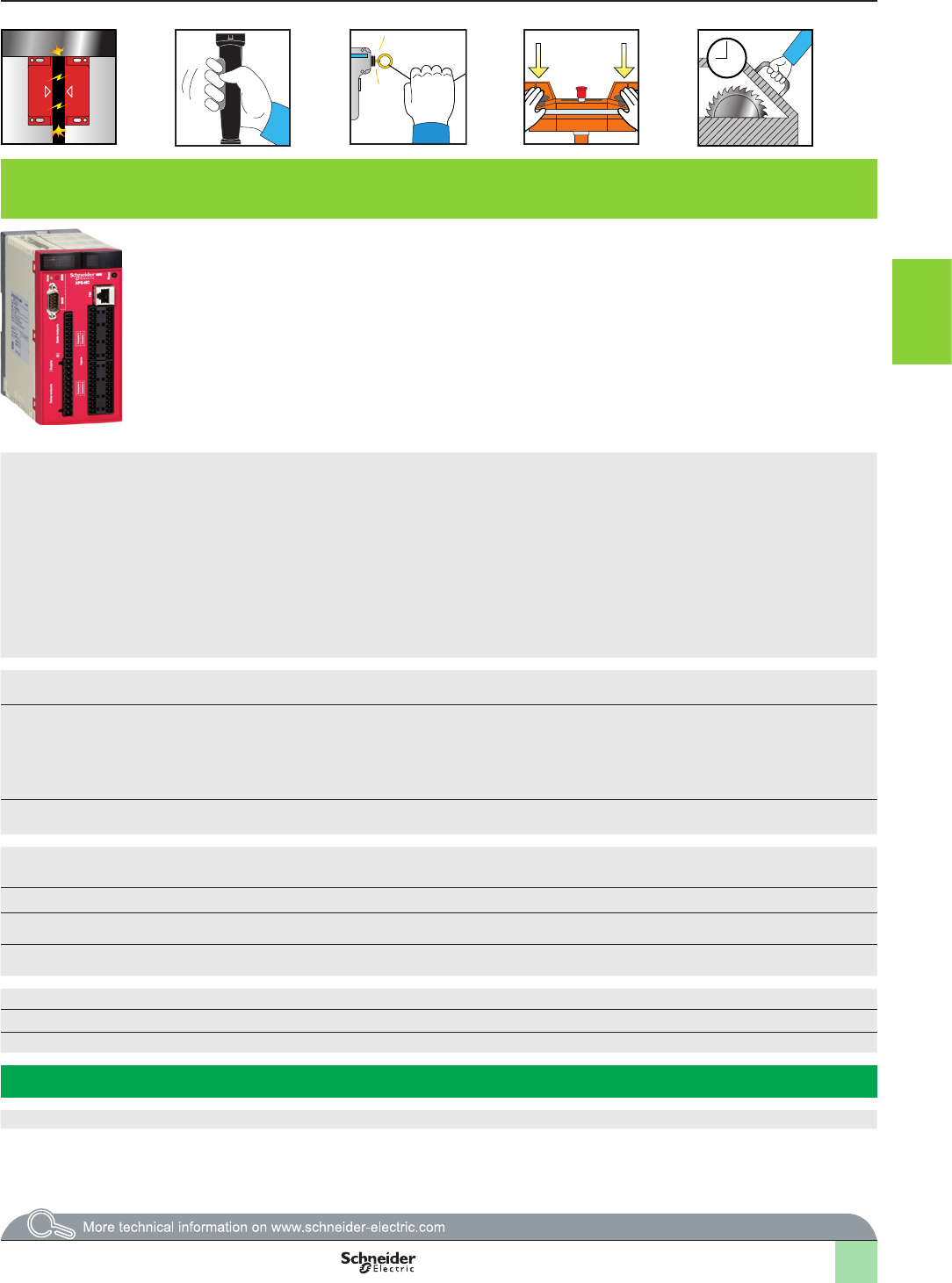
3/97
Applications
Modules
Controllers for monitoring 2 independent safety functions simultaneously.
User selection of 2 functions from a choice of 15, programmable from front face of
controller.
Congurable controllers using software, for several independent safety functions: selection of safety functions using conguration software running
on Windows (16 or 32 inputs and 8 independent safety outputs)
Functions v Emergency stop monitoring
v Switch monitoring
v Enabling switch monitoring
v Sensing mat or edges monitoring
v Light curtain monitoring, relay output type
v etc.
v Emergency stop monitoring
v Limit switch monitoring
v Two-hand control monitoring
v Safety light curtain monitoring, with or without "muting" function
v Enabling switch monitoring, coded magnetic switch monitoring
v Safety mat monitoring
v Hydraulic press solenoid valve monitoring
v Eccentric press safety stop at top dead centre monitoring. Zero speed detection
v Hydraulic press monitoring
v Eccentric press monitoring
v Foot switch monitoring
v Chain shaft breakage monitoring
v Safe tool
v Position selector
Maximum achievable safety level PL e/Category 4 conforming EN ISO 13849-1,
SILCL 3 conforming to EN/IEC 61508 and EN/IEC 62061
PL e/Category 4 conforming to EN ISO 13849-1,
SILCL 3 conforming to EN/IEC 61508 and EN/IEC 62061
Conformity to standards EN/IEC 60204-1,
EN/IEC 60947-1,
EN/IEC 60947-5-1
EN/IEC 60204-1,
EN 1760-1/ISO 13856-1,
EN/IEC 61496-1,
EN 574/ISO 13851,
EN/IEC 60947-1,
EN/IEC 60947-5-1
Product certications UL, CSA, TÜV UL, CSA, TÜV
Number of circuits
Safety 6 NO (3 NO per function) 4 NO (2 NO per function) + 6 solid-state
Additional 3 solid-state outputs for signalling to PLC 1 "muting" signalling output
Display 12 LEDs LED display on front face
Supply voltage 24 V c 24 V c
Communication CANopen bus – Via SUB-D 9-pin male connector, only on XPSMC16ZC and XPSMC32ZC
Probus bus –Via SUB-D 9-pin female connector, only on XPSMC16ZP and XPSMC32ZP
Modbus bus – Via RJ45 connector, on all controllers XPS MCppZp
Module type XPSMP XPSMC
Pages 3/98 3/100
1
2
3
4
5
6
7
8
9
10

3/98
Monitor and Processing
Preventa safety controllers type XPSMP
With pre-dened functions
Presentation
Presentation
Operating principle
Preventa safety controller modules XPSMP are designed for a Performance Level of
up to PL e/Category 4 conforming to standard EN/ISO 13849-1.
They enable two independent safety functions (selected from a choice of 15
pre-dened congurations) to be performed using the same product. Conguration
selection is easily made using 3 buttons on the front face of the module.
These 15 pre-programmed safety functions provide a solution for the majority
of safety applications, for example: monitoring Emergency stops, limit switches,
safety mats and sensing edges, enabling switches, coded magnetic switches,
type 4 safety light curtains conforming to EN/IEC 61496-1.
Safety controllers XPSMP incorporate 6 safety outputs (3 per function) and 3
solid-state signalling outputs for signalling to the process PLC.
To aid diagnostics, the modules have LEDs on the front face which provide
information on the monitoring circuit status. They also indicate and assist selection
of the 2 required congurations.
Conguration Synchronisation
time
Type of start (1) Start test Notes
Automatic or
unmonitored
Monitored
Functions disabled 0– – – – Factory setting
Emergency stop monitoring,
1-channel wiring (category 2)
1– X – – –
2– – X – –
Emergency stop monitoring,
2-channel wiring, or guard
monitoring (category 4)
3Unlimited X – X –
4Unlimited – X X –
51.5 s X – X –
61.5 s – X X –
7Unlimited X – – –
8Unlimited – X – –
Guard monitoring for injection
press or blowing machine
(category 4)
91.5 s – X X Uses both safety
outputs (2)
Enabling grip switch monitoring
(3 position switch) (category 4)
10 – X – X The start button
acts as start-up
preparation
Sensing mat and edges monitoring
(category 3)
11 – X – – Mats with circuit
making contacts
12 – – X –
Relay output safety light curtain
monitoring (category 4)
13 0.5 s – X X –
Coded magnetic switch
monitoring (category 4)
14 1.5 s X – – Magnetic switches
with 2 contacts,
1 NO and 1 NC
15 1.5 s – X –
(1) Automatic start: there is no contact or it is shunted.
Unmonitored start: The output is activated on closing of the start contact.
Monitored start: the start input is monitored so that there is no start-up in the event of the start contact being shunted or the start circuit being closed for more than
10 seconds.
Start-up is triggered following activation of the start button (push-release function) on opening of the contact.
(2) Tool zone guard with 3rd switch.
Additional rear guard (optional) with automatic start. The opening of the guard cuts all outputs.
1
2
3
4
5
6
7
8
9
10

3/99
Monitor and Processing
Preventa safety controllers type XPSMP
With pre-dened functions
References
XPSMP11123P
XPSMP11123
References
Description Type of
terminal block
connection
Number of
safety circuits
Additional outputs Supply Reference Weight
kg
Modules for 2 independent
safety functions
Integrated
in module
3 NO per
function
(6 NO total)
3 solid-state 24 V c XPSMP11123 0.320
Removable
from module
3 NO per
function
(6 NO total)
3 solid-state 24 V cXPSMP11123P 0.320
1
2
3
4
5
6
7
8
9
10
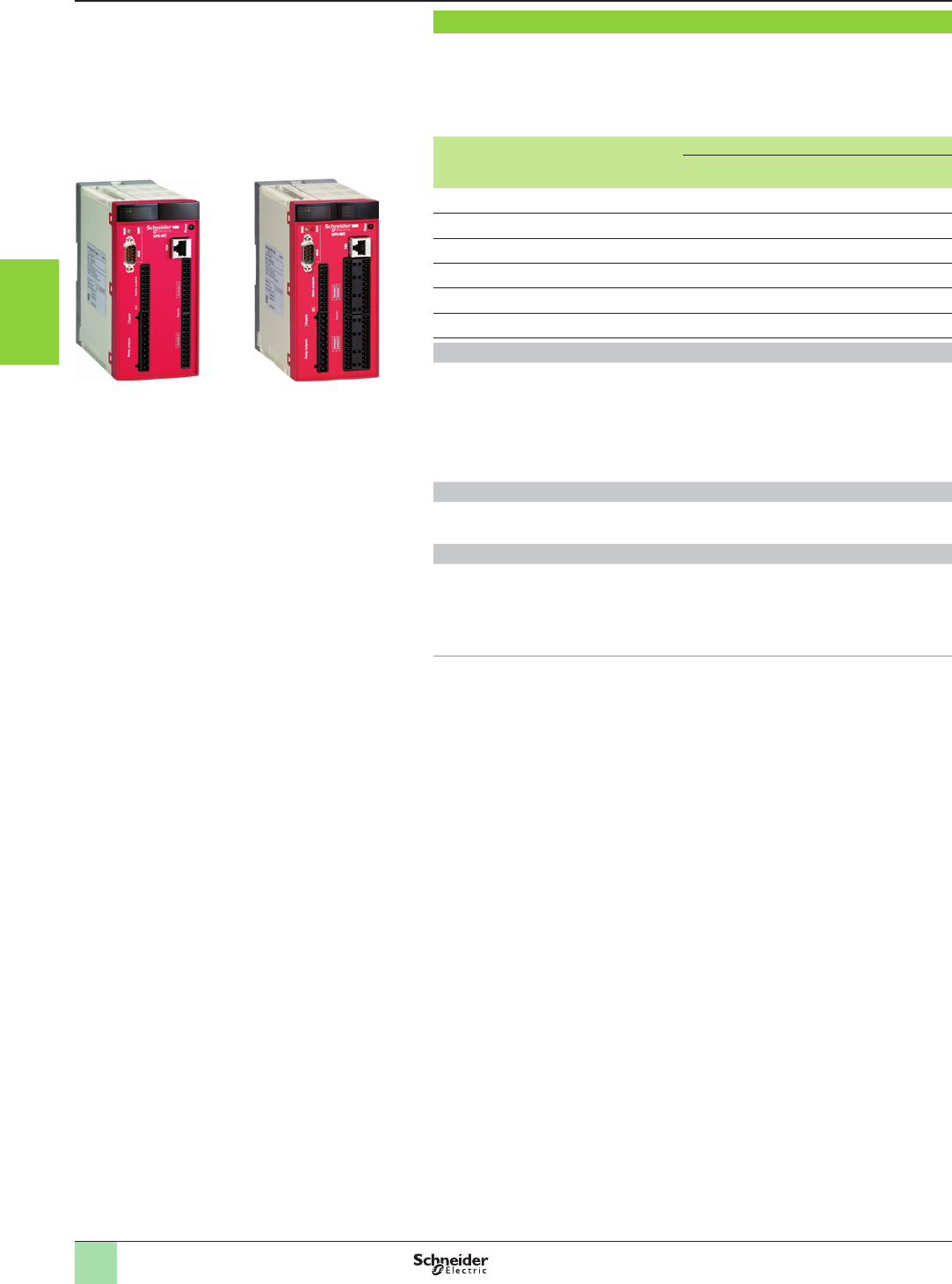
3/100
Monitor and Processing
Preventa congurable safety controllers
Type XPSMC
Presentation
XPSMC16ZC XPSMC32ZC
Presentation
Congurable safety controllers XPSMCppZp are designed to provide a solution for safety
applications requiring conformity to Performance Level PL e/Category 4 EN/ISO 13849-1
and SIL 3 EN/IEC 61508.
The range of congurable safety controllers comprises 6 products, each with different
technical characteristics.
Congurable
controllers
Safety
inputs
Safety
outputs (1)
Communication via
CANopen
bus
Probus
bus
Modbus serial
link
XPSMC16Z 16 6 + 2 x 2 – – Yes, slave
XPSMC16ZC 16 6 + 2 x 2 Yes, slave – Yes, slave
XPSMC16ZP 16 6 + 2 x 2 – Yes, slave Yes, slave
XPSMC32Z 32 6 + 2 x 2 – – Yes, slave
XPSMC32ZC 32 6 + 2 x 2 Yes, slave – Yes, slave
XPSMC32ZP 32 6 + 2 x 2 – Yes, slave Yes, slave
Line control
The safety inputs are supplied by the various control outputs (2), in such a manner
so as to monitor for short-circuits between the inputs, short-circuits between each
input and earth or the presence of residual voltages.
The controller, assisted by the control outputs, continuously tests all the connected
inputs. As soon as an error is detected on an input, all the outputs associated with this
input are disconnected. Safety outputs associated with other inputs remain active.
Conguration
Safety controllers XPSMCppZp are congurable and addressable using software
XPSMCWIN running on a PC. Connection accessories required: see page 3/105.
Connections
For connection of safety inputs and outputs, safety controllers XPSMCppZp can be
tted with a choice of:
v screw connectors type XPSMCTSpp, or
v spring clip connectors type XPSMCTCpp.
These connectors are to be ordered separately, see page 3/105.
(1) 8 independent safety outputs = 6 solid-state safety outputs + 2 x 2 relay outputs (4 relay
outputs with mechanically linked contacts).
(2) 8 control outputs are available but they are not safety outputs.
1
2
3
4
5
6
7
8
9
10

3/101
Monitor and Processing
Preventa congurable safety controllers
Type XPSMC
Presentation (continued)
Safety functions
Conguration of the safety functions is carried out using software XPSMCWIN which
is available on the Safety Suite V2 CD-ROM.
30 certied safety functions are available with this software and they are easily
assignable to the safety outputs. The safety functions have multiple combination
possibilities and various starting conditions.
The safety functions are:
v certied in accordance with EN/ISO 13849-1 and IEC 61508,
v congurable in controller XPSMC using software XPSMCWIN which is available
on the Safety Suite V2 software pack.
All 8 safety outputs are suitable for use in safety related parts of control systems
conforming to Performance Level PL e/Category 4 in accordance to EN/ISO 13849-1.
Main safety functions
b Emergency stop monitoring, with or without time delay, 1 or 2-channel wiring
b Two-hand control (type III- A and C conforming to EN 574/ISO 13851)
b Guard monitoring with 1 or 2 limit switches
b Guard monitoring for injection presses and blowing machines
b Magnetic switch monitoring
b Sensing mat monitoring
b Light curtain (type 4 conforming to EN/IEC 61496, relay or solid-state output)
monitoring
b Zero speed detection
b Dynamic monitoring of hydraulic valves on linear presses
b Monitoring safety stop at top dead centre on eccentric press
b Safety time delays
b “Muting” function of light curtains
b Enabling switch monitoring, 2 or 3 contact
b Hydraulic press
b Eccentric press
b Foot switch monitoring
b Chain shaft breakage monitoring
b Position selector
Application schemes and functional diagrams
See instruction sheet on www.schneider-electric.com
1
2
3
4
5
6
7
8
9
10
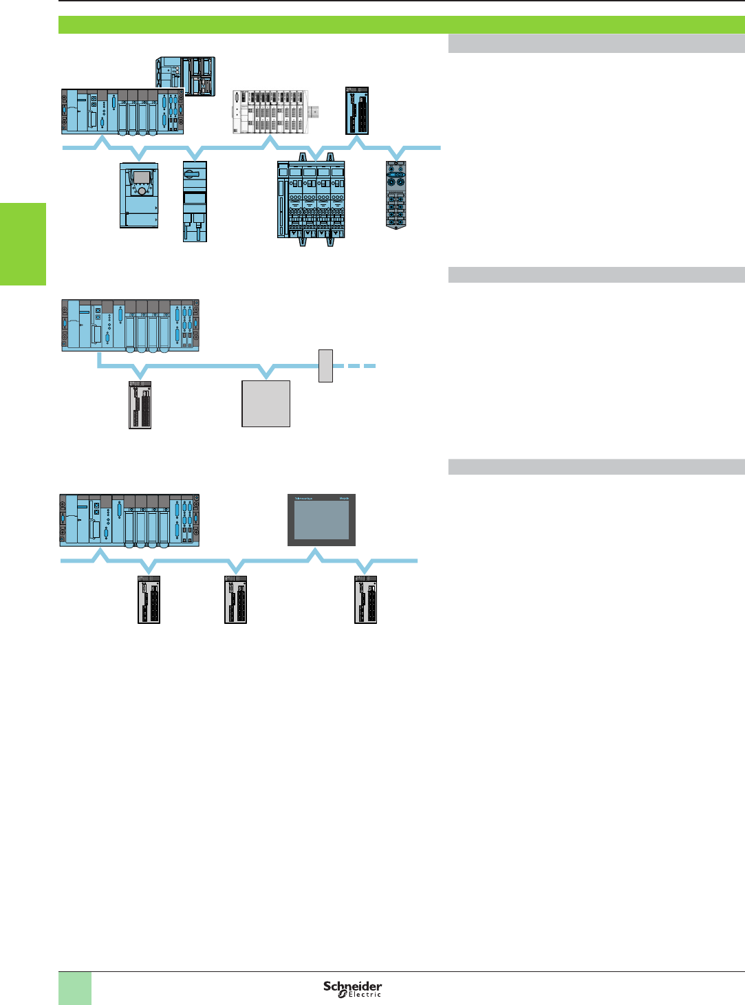
3/102
Monitor and Processing
Preventa congurable safety controllers
Type XPSMC
Presentation
Communication
CANopen eldbus
Modicon STB
Premium automation
platform
CANopen bus
Congurable
controllers
XPSMC16ZC,
MC32ZC
Micro automation platform
ATV71
TeSys Quickt
FTB1CN
TeSys U
Congurable safety controllers XPSMCppZC incorporate
a SUB-D 9-pin male connector for direct connection on
CANopen bus.
CANopen bus is a open bus that ensures deterministic and
reliable access to the real-time data of automation equipment.
The bus uses a shielded dual twisted pair on which a maximum
of 127 devices can be connected by chaining.
The baud rate varies between 10 Kbps and 1Mbps depending
on the length of the bus (5000 m to 20 m).
Probus bus
Probus bus
Premium automation platform
Third-party
products
Congurable controller
XPSMC16ZP, MC32ZP
Repeater
(3 max.)
Congurable safety controllers XPSMCppZP incorporate
a SUB-D 9-pin male connector for connection on Probus bus.
Congurable safety controllers XPSMCppZP are slaves
on the Probus bus.
Probus bus is a eldbus that meets industrial communication
requirements. The topology of the Probus bus is of the linear
type with a centralised master/slave type access procedure.
The physical link is a single shielded twisted pair.
Modbus serial link
Magelis graphic terminalPremium automation platform
Congurable controllers XPSMC16Zp/MC32Zp,
slaves of the Modbus serial link
Modbus serial link
Congurable safety controllers XPSMCppZp incorporate
a Modbus communication interface (RJ45 connector) for
conguration and diagnostics.
This interface enables connection of the controllers to:
v a PC (conguration),
v a PLC (diagnostics), or
v an operator dialogue terminal (diagnostics).
The Modbus serial link comprises a master station (Premium
automation platform) and slave stations (congurable
controllers XPSMC16/32Zp).
Two exchange mechanisms are possible:
b Question/response: the questions from the master are
addressed to a given slave. The response is expected by
return from the interrogated slave.
b Distribution: the master distributes a message to all the
stations of the Modbus serial link. The latter execute the order
without transmitting a reply.
1
2
3
4
5
6
7
8
9
10
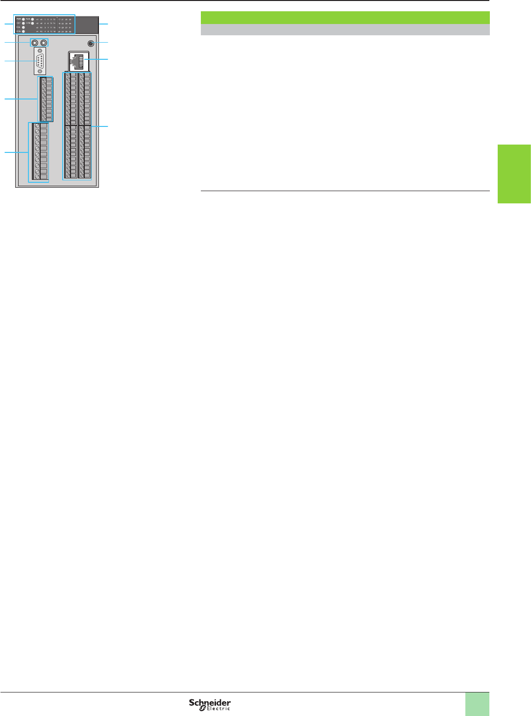
3/103
Monitor and Processing
Preventa congurable safety controllers
Type XPSMC
Description
1
2
3
4
5
9
7
8
6
Description
Congurable safety controllers XPSMCppZp
Front face of controllers:
1 LED display and system diagnostics.
2 Two LEDs for CANopen or Probus (1) connection status.
3 SUB-D 9-pin male connector for connection on CANopen bus (XPSMC16ZC/
MC32ZC) or SUB-D 9-pin female connector for connection on Probus bus
(XPSMC16ZP/MC32ZP).
4 Solid-state safety output and "muting" indicator light terminals.
5 Power supply (24 V c) and relay safety output terminals.
6
Control output terminals for power supply to safety inputs and safety input terminals.
7 RJ45 connector for connection on Modbus serial link.
8 RESET button (resetting of controller).
Rear face of controllers:
9 Fixing plate for mounting on rail.
Congurable safety controller XPSMCppZp,
with screw connectors
(1) Depending on controller model.
1
2
3
4
5
6
7
8
9
10
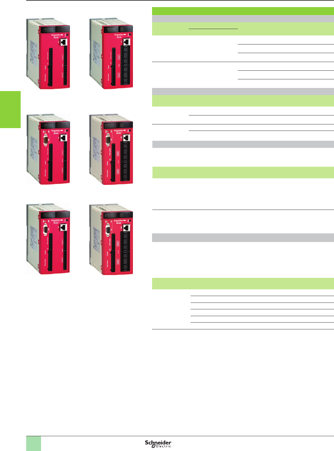
3/104
Monitor and Processing
Preventa congurable safety controllers
Type XPSMC
References
References
Congurable safety controllers (connector not included)
Number of
inputs
Number of outputs Communication
(Link and bus)
Reference Weight
kg
Relay
Solid-state
16 4 (2 x 2) 6Modbus XPSMC16Z 0.820
Modbus, CANopen XPSMC16ZC 0.820
Modbus, Probus XPSMC16ZP 0.820
32 4 (2 x 2) 6Modbus XPSMC32Z 0.840
Modbus, CANopen XPSMC32ZC 0.840
Modbus, Probus XPSMC32ZP 0.840
Plug-in connectors for congurable safety controllers (1)
Description For use with Reference Weight
kg
Screw
connectors
XPSMC16Z, MC16ZC, MC16ZP XPSMCTS16 0.080
XPSMC32Z, MC32ZC, MC32ZP XPSMCTS32 0.110
Spring clip
connectors
XPSMC16Z, MC16ZC, MC16ZP XPSMCTC16 0.080
XPSMC32Z, MC32ZC, MC32ZP XPSMCTC32 0.110
Conguration software
b Reference XPSMCWIN is the full version of conguration software XPSMCWIN
version 2.4 and must be installed if no previous version of this software has been
installed.
Description Operating system
Languages
Reference Weight
kg
Conguration
software for
controllers
XPSMCppZp
CD-ROM + user
manual
Windows 2000,
Windows XP
FR,
EN,
DE,
IT,
ES,
PT
XPSMCWIN 0.520
XPSMCWIN
software update
CD-ROM + user
manual
Windows 2000,
Windows XP
Software update available on
www.schneider-electric.com
Starter packs
The Starter packs contain the necessary components to start using the safety controller
containing:
b Safety controller (pack reference designates type of safety controller)
b XPSMCWIN conguration software
b Congurations cable
b Connectors
Description Controller included in the pack Reference Weight
kg
Starter packs XPSMC16Z XPSMC16ZPACK –
XPSMC16ZC XPSMC16ZCPACK –
XPSMC16ZP XPSMC16ZPPACK –
XPSMC32Z XPSMC32ZPACK –
XPSMC32ZC XPSMC32ZCPACK –
XPSMC32ZP XPSMC32ZPPACK –
(1) To be ordered separately to the controllers.
XPSMC16Z XPSMC32Z
XPSMC16ZC XPSMC32ZC
XPSMC16ZP XPSMC32ZP
1
2
3
4
5
6
7
8
9
10
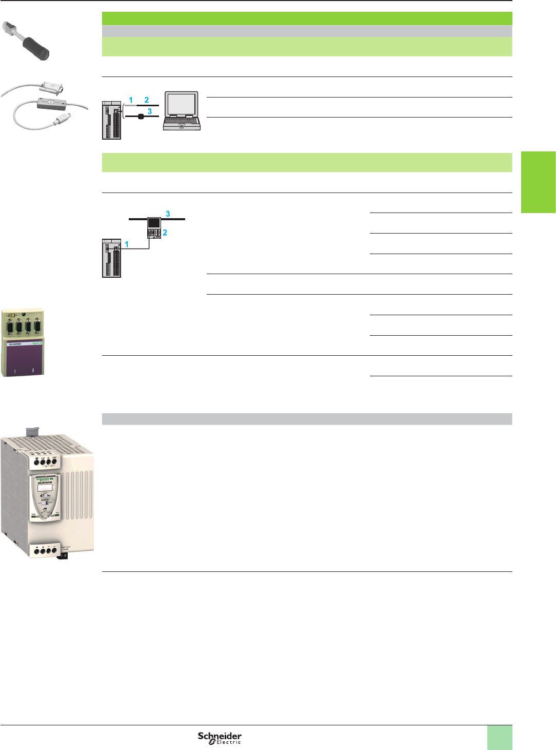
3/105
Monitor and Processing
Preventa congurable safety controllers
Type XPSMC
References
References
Connecting cables (1)
Function Length
m
Reference Weight
kg
Diagnostics using Magelis operator dialogue terminal type XBTGT 3VW3A8306R30 1.130
Conguration software 1 Adaptor: RJ45 socket/PC connection cables –XPSMCCPC 0.011
2Cable to PC serial port (type SUB-D9) 2.5 TSXPCX1031 0.170
3USB / RJ45 cable: used to connect the
controller to a PC
Equipped with a USB connector (PC end) and
an RJ45 connector (controller end)
2.5 TCSMCNAM3M002P –
Function Medium Length
m
Reference Weight
kg
Modbus serial link access Premium automation platform TSXSCY21601 –XPSMCSCY –
CANopen bus access
1 CANopen connection cables
(tted with: 1 SUB-D 9-pin female connector
at each end)
0.3 TSXCANCADD03 –
1TSXCANCADD1 –
3TSXCANCADD3 –
5TSXCANCADD5 –
2 CANopen tap-off box – TSCCANTDM4 –
3 Standard CANopen cables 50 TSXCANCA50 –
100 TSXCANCA100 –
300 TSXCANCA300 –
Probus bus access 100 TSXPBSCA100 –
400 TSXPBSCA400 –
Accessories (1)
Regulated switch mode
power supply, single-phase
Output voltage: 24…28.8 V c
Nominal current: 10 A
Nominal power: 240 W
ABL8RPS24100 1.000
(1) To be ordered separately.
TSXPCX1031
XPSMCCPC
ABL8RPS24100
TSXCANTDM4
1
2
3
4
5
6
7
8
9
10
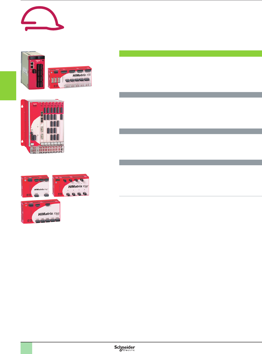
3/106
General presentation Monitor and Processing
Preventa safety PLCs type XPSMF, compact
and modular
Safety remote input/output modules type
XPSMF1/2/3
Compact safety PLCs
Modular safety PLCs
Safety remote input/output modules
Preventa compact/Modular Safety PLCs and remote I/O enable the monitoring
of simple to complex safety functions for all industrial applications relating to
the protection of personnel and machine safety.
Designed for use with numerous machine safety functions, these safety PLCs and
remote I/O are intended for use in safety related parts of control systems.
They can manage up to category 4 performance level e EN/ISO 13849-1,
SIL 3 (safety integrity level) EN/IEC 61508 or EN/IEC 62061.
Safety PLCs
In order to meet safety requirements, the compact/modular safety PLCs incorporate
two essential functions (Redundancy and Self-monitoring).
In addition uses SafeEthernet safe communications protocol between the safety
PLCs and safe remote I/O modules.
Redundancy
>The double or triple (1) processors integrated in the compact and modular safety
PLCs analyses and compares the data received from the safety inputs and
outputs.
>The incoming and outgoing data (programmed values and received values) are
received in parallel by the processors and compared in real-time.
Self-monitoring (Watchdog)
The safety PLCs and remote I/O continuously monitor the data processing cycle and
the execution of tasks, and intervenes if the cycle time does not conform to the
predened values.
Integrated switch
The integrated switch stores for a very short time and sends at very high speed the
data provided by the inputs and outputs of the safety PLCs and remote I/O on the
Ethernet network, whilst avoiding signal collisions and excessive amounts of data on
the network.
(1) With XPSMF40 PLC only
2
1
3
4
5
6
7
8
9
10
2
1
3
4
5
6
7
8
9
10

3/107
General presentation Monitor and Processing
Preventa safety PLCs type XPSMF, compact
and modular
Safety remote input/output modules type
XPSMF1/2/3
Line control for safety PLCs and safety remote I/O modules
Line control is a means of short circuit and line break monitoring. Using line control
outputs enables category 4 performance level e EN/ISO 13849-1, SIL 3 (safety
integrity level) EN/IEC 61508 or EN/IEC 62061 to be achieved.
The line control outputs provide a high signal with a very short low signal enabling a
wiring fault (short-circuit, line break) to be identied on the inputs of the safety PLCs
and safety remote I/O.
Programming automated safety functions
Software XPSMFWIN (reference SSV1XPSMFWIN) running on a PC enables the
programming of all safety remote I/O modules and safety PLCs, as well as
conguration of the communication settings.
2
1
3
4
5
6
7
8
9
10
2
1
3
4
5
6
7
8
9
10
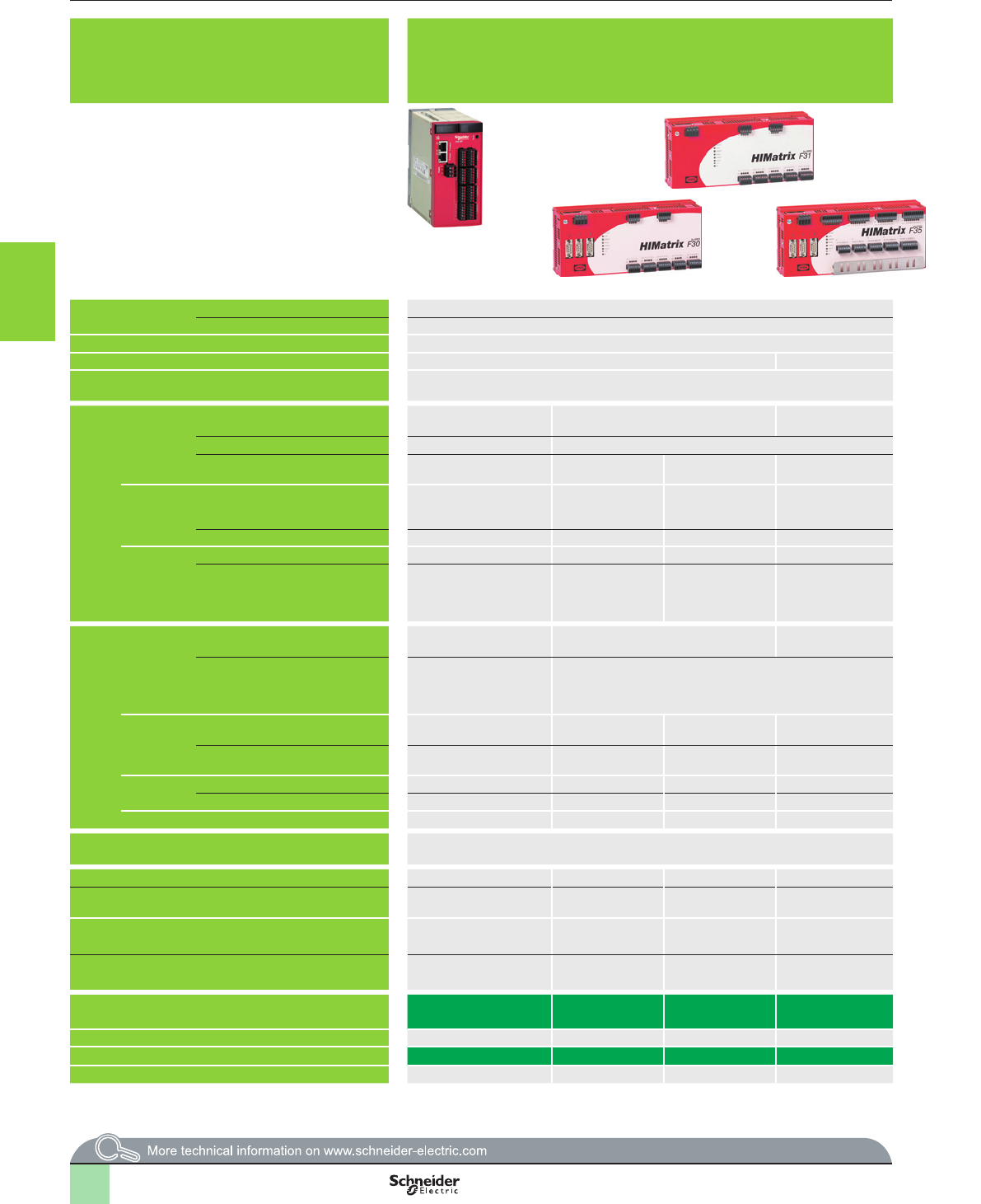
3/108
Selection guide Monitor and Processing
Preventa safety PLCs
Compact and modular, XPSMF
Presentation Compact PLCs:
bDesigned for use with numerous machine safety functions and for the protection of personnel.
bDesigned for use in safety related parts of control systems up to category 4, performance
level “e” EN/ISO 13849-1, and up to SIL 3 EN/IEC 61508 or EN/IEC 62061
Modular PLC XPSMF60: metal rack XPSMFGEH01 with slots for power supply module XPSMFPS01, central processing unit XPSMFCPU22 and six “in rack” I/O
cards.
bDesigned for use with numerous machine safety functions and for the protection of personnel.
bDesigned for use in safety related parts of control systems up to category 4, performance level “e” EN/ISO 13849-1, and up to SIL 3 EN/IEC 61508 or EN/IEC 62061
Products referenced XPSMF31222, XPSMF3022 and XPSMF35pp are
marked HIMatrix F31, HIMatrix F30 and HIMatrix F35.
User memory Application 250 kB 500 kB
Data 250 kB 500 kB
Response time Depending on size of application Depending on size of application
Maximum consumption 8 A 9 A 30 A max., 32 A external fuse
Supply External c 24 V supply (with separate protection conforming to EN/IEC 60950, SELV (Safety
Extra Low Voltage) or PELV (Protection Extra Low Voltage) rated)
External c 24 V supply (with separate protection conforming to EN/IEC 60950, SELV (Safety Extra Low Voltage) or PELV (Protection Extra Low Voltage) rated)
Inputs Digital Number of channels 24, congurable, not
electrically isolated
20, not electrically isolated 24, not electrically
isolated
– ––24, electrically
isolated
32 (2), electrically
isolated
24 (2), electrically
isolated
–
Current at state 0 1.5 mA max. at c 24 V 1.5 mA max., 1.25 mA at 5 V – – – – 1 mA at 5 V 1 mA at 5 V –
Current at state 1 3.5 mA at c 24 V
4.5 mA at c 30 V
u 2 mA at c 15 V > 2 mA at c 15 V 3.5 mA at c 24 V
4.5 mA at c 30 V
– ––u 2.2 mA at 79 V 2 mA at c 10 V,
5 mA at c 24 V
2 mA at c 10 V,
5 mA at c 24 V
–
Analogue Number of channels – – – 8, single-pole 8 single-pole or 4 2-pole,
congurable, electrically
isolated
––––––
Range: voltage/current – – – 0…10 V/0…20 mA (1) - 10…+ 10 V/0…20 mA (1) ––––––
Counting Number of channels – – – 2–2––––
Current – – – 1.4 mA at c 5 V,
6.5 mA at c 24 V
– – 0.8 A at c 3.3 V
0.1 A at c 5 V
0.1 A + output
current at c 24 V
––––
Outputs Digital Number of channels 24, congurable, not
electrically isolated
8 (2), not electrically isolated 8, not electrically
isolated
– – 4––16 (3), electrically
isolated
–
Output current
Chnls. 1 to 3, 5 to 7, 9 to 11, 13 to
15, 17 to 19, 21 to 23: 0.5 A at 60°C
Channels 4, 8, 12, 16, 20 and 24:
1 A at 60 °C, 2 A at 50°C
Channels 1 to 3 and 5 to 7: 0.5 A at 60 °C
Channels 4 and 8: 1 A at 60 °C, 2 A at 50 °C
– – 0.5 A per channel,
2 A max. per
“in rack” card
– – 2 A per channel at
30 °C,
8 A max. at 30 °C per
“in rack” card
–
Analogue Number of channels – – – – – 8, electrically
isolated
–––––
Range: voltage/current – – – – – - 10…10 V /
0…20 mA
–––––
Relay Number – – – – – – – – – – 8
Switching voltage – – – – – – – – – – z 6…250 V
Line control 2 x 4 (2) (2) – – ––––(3) –
Input/output connections Removable screw terminals are provided with all Safety compact PLCs
Reference XPSMF40pp is also provided with cage clamp terminal
Removable screw terminals are provided with “in rack” I/O cards and Power supply module
bSafe communication using SafeEthernet protocol yes yes yes yes yes
bNon safe communication using Modbus TCP/IP
protocol, server (slave)
yes
(XPSMF4002/4022/4042)
yes (XPSMF31222) yes (XPSMF3022) yes (XPSMF3502/
MF3522/MF3542)
yes
Communication on eldbus
Non safety using Modbus RTU protocol, slave (RS 485) yes (XPSMF4020/4022) – yes (XPSMF3022) yes (XPSMF3522) yes
Non safety using PROFIBUS DP protocol, (V0 slave) yes (XPSMF4040/4042 – – yes (XPSMF3542) yes
oui (XPSMF4040/4042 – – oui (XPSMF3542) oui
Safety PLC type XPSMF400p/MF402p/
MF404p)
XPSMF31222 XPSMF3022 XPSMF3502/
MF3522/MF3542
XPSMFGEH01 (rack) + XPSMFPS01 (power supply) + XPSMFCPU22 (central processing unit) + “in rack” I/O cards (to be selected
from below)
See page 3/110 3/113 3/113 3/113 3/114
“In rack” card type – – – – XPSMFAI801 XPSMFAO801 XPSMFCIO2401 XPSMFDI2401 XPSMFDI3201 XPSMFDIO241601 XPSMFDO801
See page – – – – 3/118 3/119 3/119 3/120 3/120 3/121 3/121
(1) With shunt 500 W.
(2) Digital inputs can be supplied by the line control outputs of the same I/O card.
(1) With 250 W or 500 W shunt. (2) Digital inputs can be supplied by the line control outputs of the same I/O card. (3) The digital outputs (n° 1… n° 16) can be
congured as line control outputs.
2
1
3
4
5
6
7
8
9
10
2
1
3
4
5
6
7
8
9
10
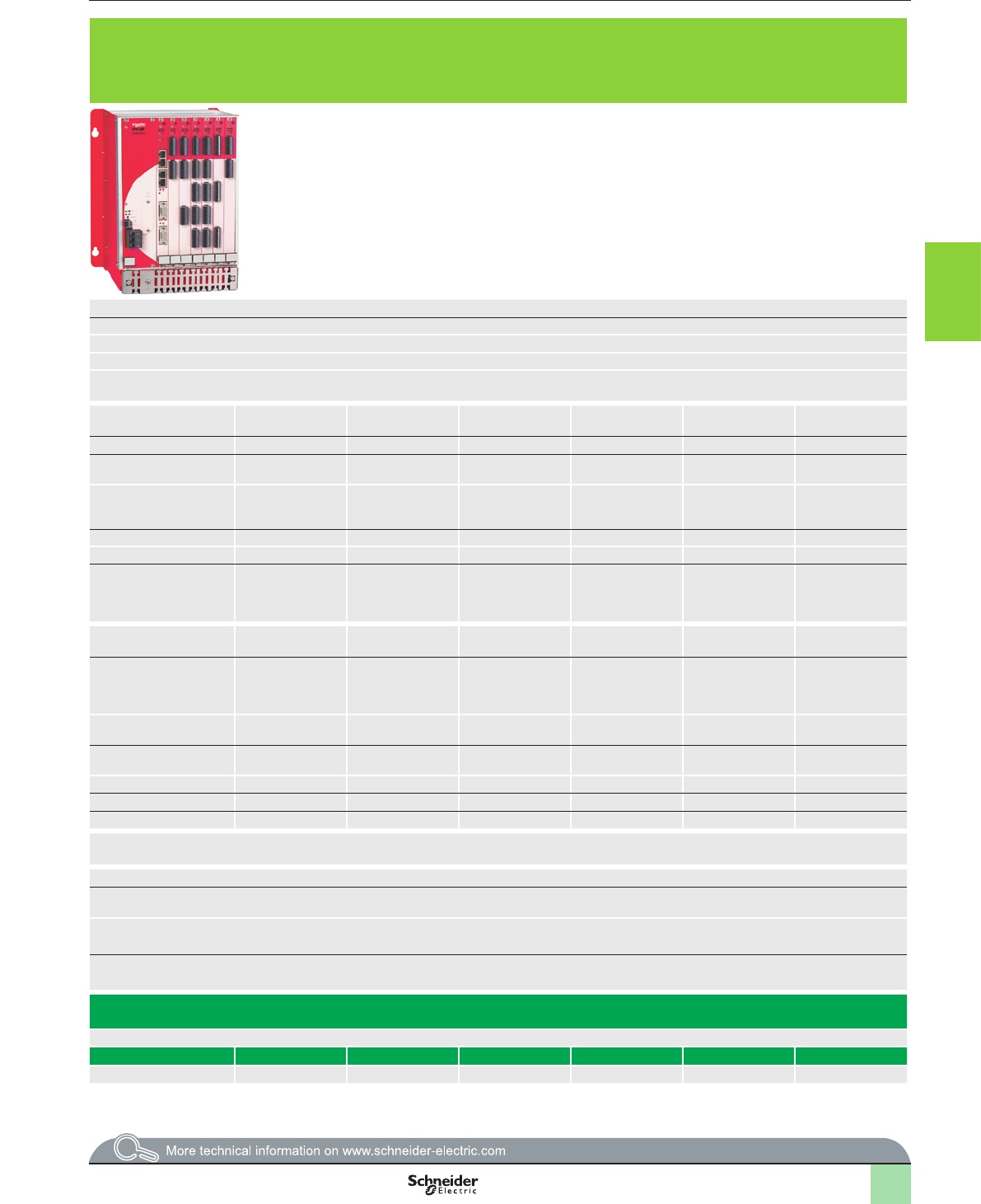
3/109
Presentation Compact PLCs:
bDesigned for use with numerous machine safety functions and for the protection of personnel.
bDesigned for use in safety related parts of control systems up to category 4, performance
level “e” EN/ISO 13849-1, and up to SIL 3 EN/IEC 61508 or EN/IEC 62061
Modular PLC XPSMF60: metal rack XPSMFGEH01 with slots for power supply module XPSMFPS01, central processing unit XPSMFCPU22 and six “in rack” I/O
cards.
bDesigned for use with numerous machine safety functions and for the protection of personnel.
bDesigned for use in safety related parts of control systems up to category 4, performance level “e” EN/ISO 13849-1, and up to SIL 3 EN/IEC 61508 or EN/IEC 62061
Products referenced XPSMF31222, XPSMF3022 and XPSMF35pp are
marked HIMatrix F31, HIMatrix F30 and HIMatrix F35.
User memory Application 250 kB 500 kB
Data 250 kB 500 kB
Response time Depending on size of application Depending on size of application
Maximum consumption 8 A 9 A 30 A max., 32 A external fuse
Supply External c 24 V supply (with separate protection conforming to EN/IEC 60950, SELV (Safety
Extra Low Voltage) or PELV (Protection Extra Low Voltage) rated)
External c 24 V supply (with separate protection conforming to EN/IEC 60950, SELV (Safety Extra Low Voltage) or PELV (Protection Extra Low Voltage) rated)
Inputs Digital Number of channels 24, congurable, not
electrically isolated
20, not electrically isolated 24, not electrically
isolated
– ––24, electrically
isolated
32 (2), electrically
isolated
24 (2), electrically
isolated
–
Current at state 0 1.5 mA max. at c 24 V 1.5 mA max., 1.25 mA at 5 V – – – – 1 mA at 5 V 1 mA at 5 V –
Current at state 1 3.5 mA at c 24 V
4.5 mA at c 30 V
u 2 mA at c 15 V > 2 mA at c 15 V 3.5 mA at c 24 V
4.5 mA at c 30 V
– ––u 2.2 mA at 79 V 2 mA at c 10 V,
5 mA at c 24 V
2 mA at c 10 V,
5 mA at c 24 V
–
Analogue Number of channels – – – 8, single-pole 8 single-pole or 4 2-pole,
congurable, electrically
isolated
––––––
Range: voltage/current – – – 0…10 V/0…20 mA (1) - 10…+ 10 V/0…20 mA (1) ––––––
Counting Number of channels – – – 2–2––––
Current – – – 1.4 mA at c 5 V,
6.5 mA at c 24 V
– – 0.8 A at c 3.3 V
0.1 A at c 5 V
0.1 A + output
current at c 24 V
––––
Outputs Digital Number of channels 24, congurable, not
electrically isolated
8 (2), not electrically isolated 8, not electrically
isolated
– – 4––16 (3), electrically
isolated
–
Output current
Chnls. 1 to 3, 5 to 7, 9 to 11, 13 to
15, 17 to 19, 21 to 23: 0.5 A at 60°C
Channels 4, 8, 12, 16, 20 and 24:
1 A at 60 °C, 2 A at 50°C
Channels 1 to 3 and 5 to 7: 0.5 A at 60 °C
Channels 4 and 8: 1 A at 60 °C, 2 A at 50 °C
– – 0.5 A per channel,
2 A max. per
“in rack” card
– – 2 A per channel at
30 °C,
8 A max. at 30 °C per
“in rack” card
–
Analogue Number of channels – – – – – 8, electrically
isolated
–––––
Range: voltage/current – – – – – - 10…10 V /
0…20 mA
–––––
Relay Number – – – – – – – – – – 8
Switching voltage – – – – – – – – – – z 6…250 V
Line control 2 x 4 (2) (2) – – ––––(3) –
Input/output connections Removable screw terminals are provided with all Safety compact PLCs
Reference XPSMF40pp is also provided with cage clamp terminal
Removable screw terminals are provided with “in rack” I/O cards and Power supply module
bSafe communication using SafeEthernet protocol yes yes yes yes yes
bNon safe communication using Modbus TCP/IP
protocol, server (slave)
yes
(XPSMF4002/4022/4042)
yes (XPSMF31222) yes (XPSMF3022) yes (XPSMF3502/
MF3522/MF3542)
yes
Communication on eldbus
Non safety using Modbus RTU protocol, slave (RS 485) yes (XPSMF4020/4022) – yes (XPSMF3022) yes (XPSMF3522) yes
Non safety using PROFIBUS DP protocol, (V0 slave) yes (XPSMF4040/4042 – – yes (XPSMF3542) yes
oui (XPSMF4040/4042 – – oui (XPSMF3542) oui
Safety PLC type XPSMF400p/MF402p/
MF404p)
XPSMF31222 XPSMF3022 XPSMF3502/
MF3522/MF3542
XPSMFGEH01 (rack) + XPSMFPS01 (power supply) + XPSMFCPU22 (central processing unit) + “in rack” I/O cards (to be selected
from below)
See page 3/110 3/113 3/113 3/113 3/114
“In rack” card type – – – – XPSMFAI801 XPSMFAO801 XPSMFCIO2401 XPSMFDI2401 XPSMFDI3201 XPSMFDIO241601 XPSMFDO801
See page – – – – 3/118 3/119 3/119 3/120 3/120 3/121 3/121
(1) With shunt 500 W.
(2) Digital inputs can be supplied by the line control outputs of the same I/O card.
(1) With 250 W or 500 W shunt. (2) Digital inputs can be supplied by the line control outputs of the same I/O card. (3) The digital outputs (n° 1… n° 16) can be
congured as line control outputs.
2
1
3
4
5
6
7
8
9
10
2
1
3
4
5
6
7
8
9
10
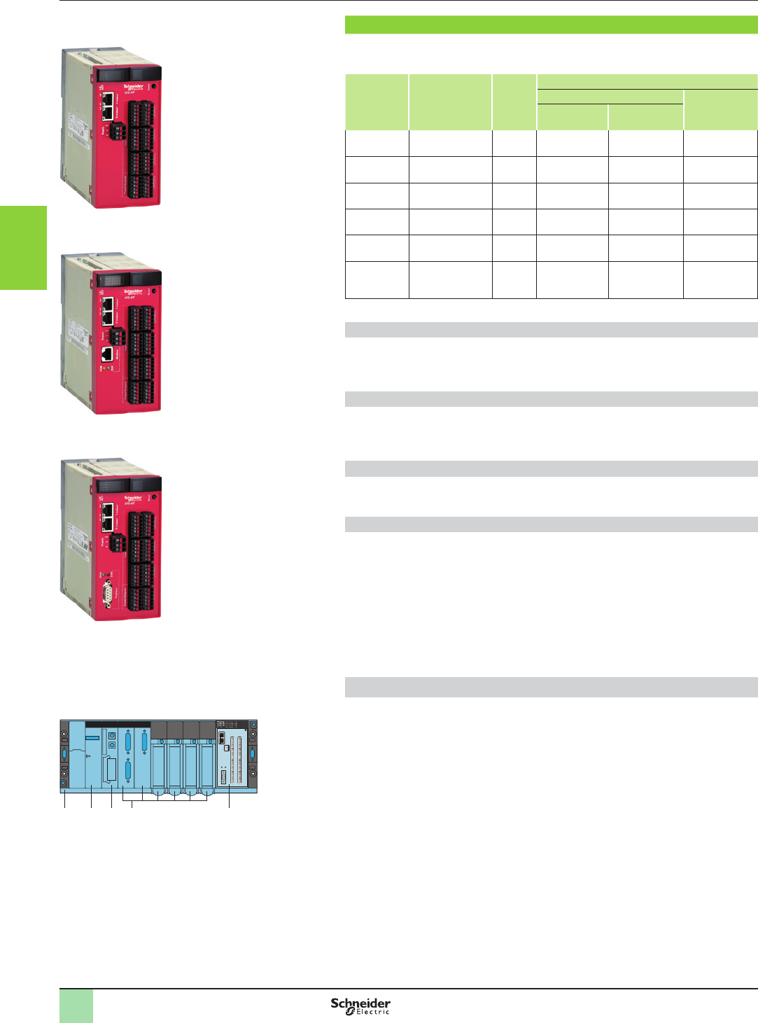
3/110
Presentation Monitor and Processing
Preventa safety PLCs
Compact, XPSMF40
Presentation
The compact safety PLC range XPSMF40pp comprises of 6 versions that are
differentiated by their non safety related communication protocols.
Compact
PLCs
Digital
Inputs/Outputs
Line
control
outputs
Communication
On Ethernet network On eldbus
Safety
protocol
Non safety
protocol
XPSMF4000 24, congurable 8 SafeEthernet – –
XPSMF4002 24, congurable 8 SafeEthernet Modbus TCP/IP
Server
–
XPSMF4020 24, congurable 8 SafeEthernet – Modbus serial
Slave (RTU)
XPSMF4022 24, congurable 8 SafeEthernet Modbus TCP/IP
Server
Modbus serial
Slave (RTU)
XPSMF4040 24, congurable 8 SafeEthernet – PROFIBUS DP
V0 slave
XPSMF4042 24, congurable 8 SafeEthernet Modbus TCP/IP
Server
PROFIBUS DP
V0 slave
Digital inputs
Compact safety PLCs XPSMF40pp incorporate up to 24 digital inputs for the
connection of safety related input devices, such as emergency stop contacts,
magnetic switches, light curtains, etc.
Digital outputs
Compact safety PLCs XPSMF40pp incorporate up to 24 digital outputs for the
connection of safety related output devices, such as contactors, illuminated
beacons, sirens, etc.
Line control outputs
Compact safety PLCs XPSMF40 incorporate 8 lign control ouputs for short-circuits
and line break monitoring.
Remote inputs and outputs
In addition to the inputs/outputs integrated as standard, compact safety PLCs
XPSMF40pp can be connected to safety remote input modules XPSMF1 and/or
safety remote output modules XPSMF2 and/or safety remote mixed I/O modules
XPSMF3.
The safety remote input, output and mixed I/O modules can be located within the
vicinity of the machines to be monitored, thus reducing cabling.
Communication between these safety remote I/O modules and safety PLCs
XPSMF40pp is performed on an Ethernet network using the SafeEthernet safety
protocol, via the integrated RJ45 switched Ethernet communications ports.
Integrating safety PLCs XPSMF40 on a Premium automation platform
Designed for mechanical integration on a Premium automation platform, safety
PLCs XPSMF40pp occupy 2 slots on the Premium rack TSXRKY.
There is interaction between the two programming environments (Unity and
XPSMFWIN): the variables dened using software XPSMFWIN can be retrieved by
Unity (platform programming software) by using a tool included in the software.
XPSMF4000
XPSMF4002
XPSMF4020
XPSMF4022
XPSMF4040
XPSMF4042
Example of mechanical integration of a compact safety PLC
XPSMF40 on a Premium automation platform.
1 Premium rack
2 Power supply module
3 Premium processor module
4 Other Premium modules (communication, I/O)
5 Compact safety PLC XPSMF40
1 2 3 54
2
1
3
4
5
6
7
8
9
10
2
1
3
4
5
6
7
8
9
10
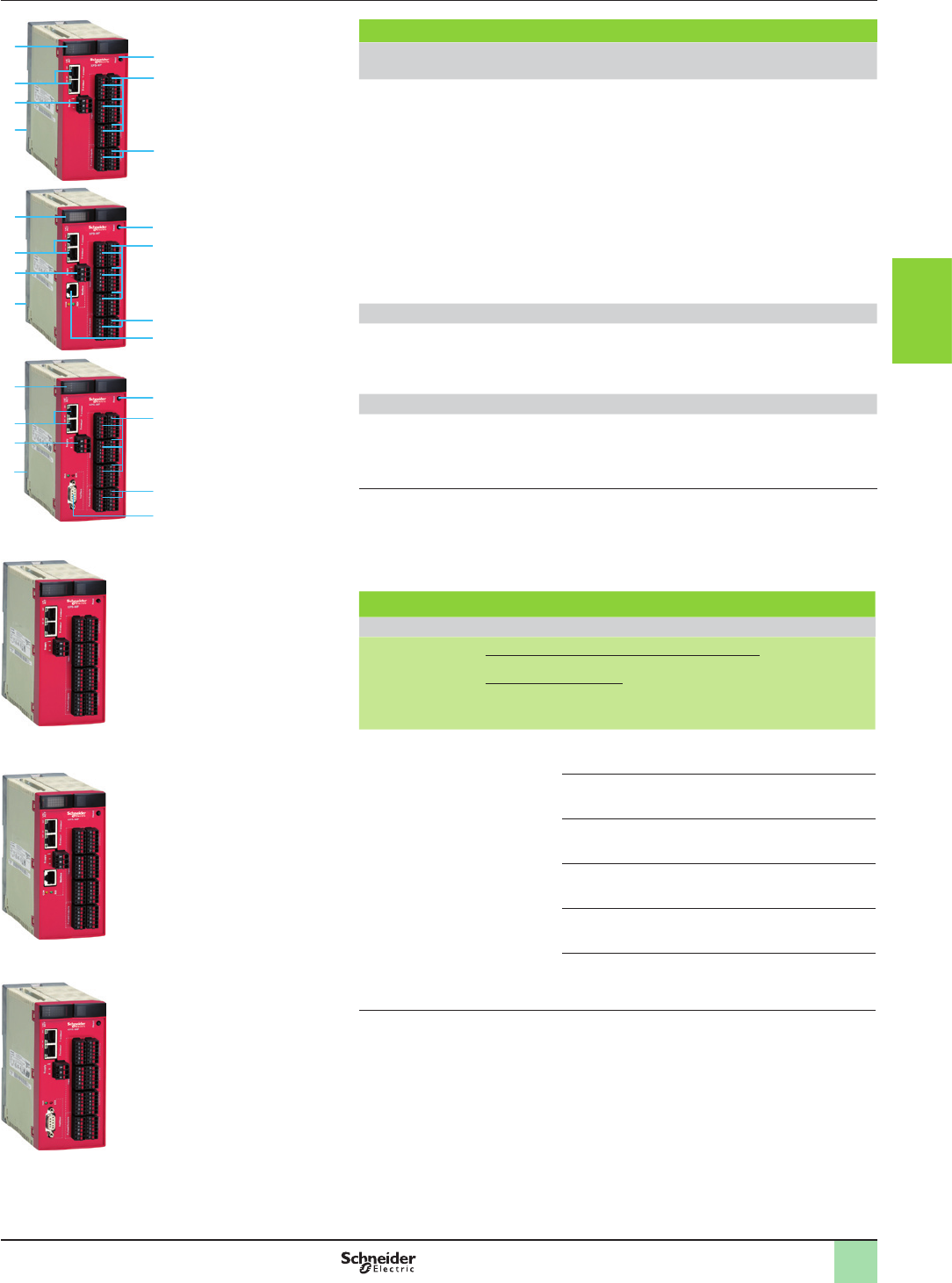
3/111
Description,
references
Monitor and Processing
Preventa safety PLCs
Compact, XPSMF40
Description
Safety PLCs XPS
XPSMF4000/MF4002/ MF4020/MF4022/ MF4040/MF4042
On the front face of the enclosure:
1 One terminal block (1) for c 24 V supply.
2 Two integrated RJ45 (type 10BASE-T/100BASE-TX) switched ports for
programming, and for Safety and non-safety related communication on Ethernet
(safety related using SafeEthernet protocol and Non-safety related using
Modbus TCP/IP server protocol).
3 Process status LEDs.
4 One “Reset” button.
5 Six terminal blocks (1) for connection of congurable digital I/Os.
6 Two terminal blocks (1) for connection of line control outputs.
7 On the rear face: one removable plate with spring xing for mounting on
35 mm 5 rail.
Safety PLCs XPSMF4020/MF4022
On the front face of the enclosure:
8 One RJ45 connector for connection on Modbus serial (RTU), with 2 process
status LEDs.
Safety PLCs XPSMF4040/MF4042
On the front face of the enclosure:
9 One SUB-D (9-pin female) connector for connection on PROFIBUS DP, with 2
process status LEDs.
(1) Removable Screw and Cage clamp terminals are provided with compact safety PLCs XPSMF40.
2
1
3
4
5
6
7
8
2
1
34
5
6
7
9
Compact safety PLCs
c 24 V supply
Digital
Inputs or
Outputs
Line
control
outputs
Communication on Reference Weight
kg/
lb
Ethernet network Modbus
serial
(RTU)
PROFIBUS DP
SafeEthernet
protocol
Modbus
TCP/IP
protocol
0…24
congurable
channels
2 x 4 Yes – – – XPSMF4000 1.000/
2.205
Yes, server – – XPSMF4002 1.000/
2.205
– Yes,
slave
–XPSMF4020 1.000/
2.205
Yes, server Yes,
slave
–XPSMF4022 1.000/
2.205
– – Yes,
V0 slave
XPSMF4040 1.000/
2.205
Yes, server – Yes,
V0 slave
XPSMF4042 1.000/
2.205
XPSMF4000
XPSMF4002
XPSMF4020
XPSMF4022
XPSMF4040
XPSMF4042
2
1
3
4
5
6
7
2
1
3
4
5
6
7
8
9
10
2
1
3
4
5
6
7
8
9
10
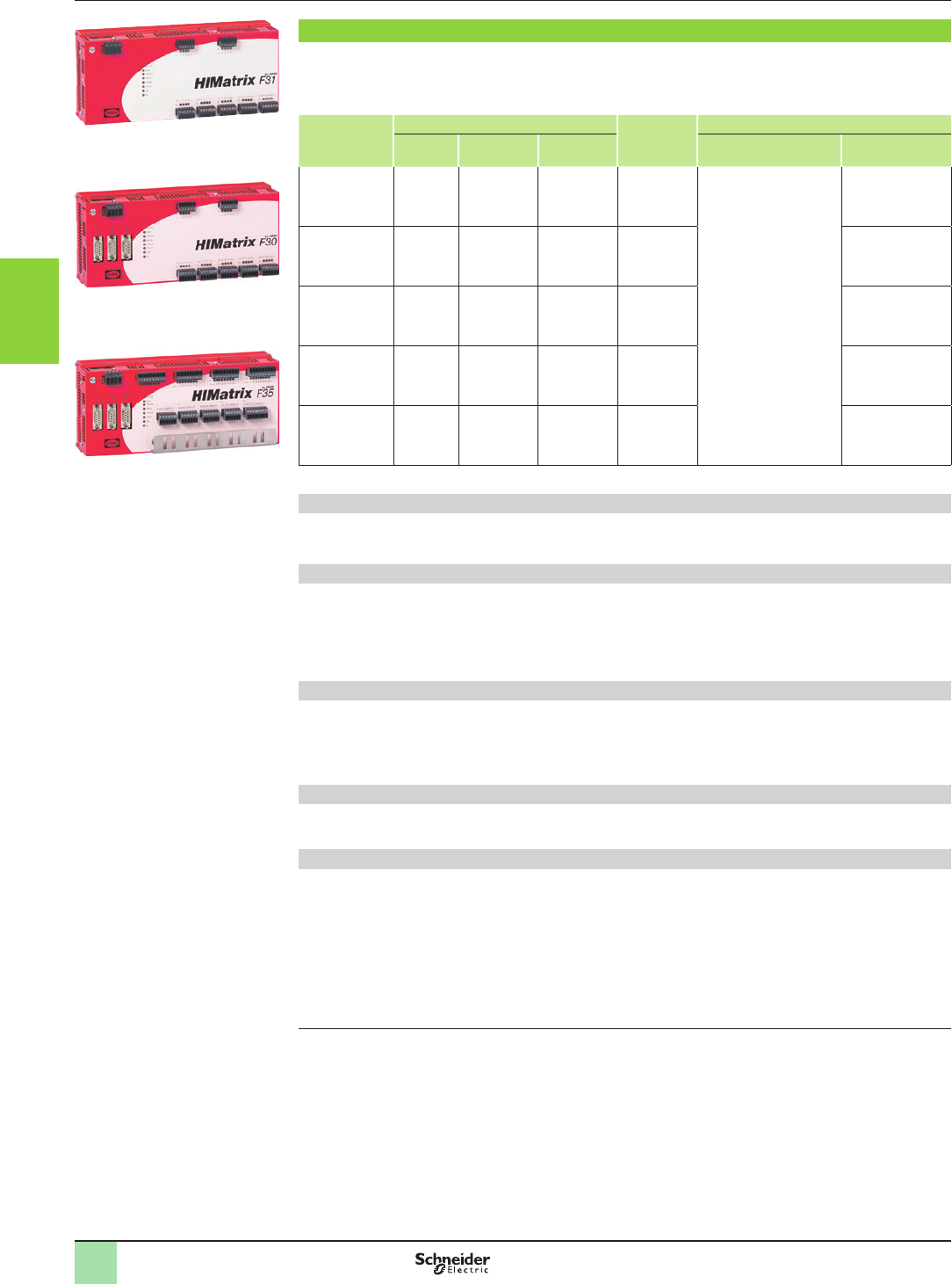
3/112
Presentation Monitor and Processing
Preventa safety PLCs
Compact, XPSMF31/30/35
Products referenced XPSMF31222,
XPSMF3022 and XPSMF35pp are
marked HIMatrix F31, HIMatrix F30
and HIMatrix F35
XPSMF31222
XPSMF3022
XPSMF35pp
Presentation
The compact safety PLC range XPSMF31/30/35 comprises 5 versions that are differentiated by their
characteristics, detailed below. Compact safety PLCs XPSMF3pppp incorporate up to 24 digital inputs for
the connection of safety related input devices.
Compact PLCs Inputs Outputs
Digital
Communication
Digital Analogue Counter On Ethernet network On eldbus
XPSMF31222 20 ––8 (1) For all compact PLCs
XPSMF31/30/35 using
SafeEthernet safety
protocol, and with non
safety protocol Modbus
TCP/IP server
–
XPSMF3022 20 ––8 (1) Modbus serial
Slave (RTU)
XPSMF3502 24 828–
XPSMF3522 24 828Modbus serial
Slave (RTU)
XPSMF3542 24 828PROFIBUS DP
V0 slave
Digital inputs
Compact safety PLCs XPSMF3pppp incorporate up to 24 digital inputs for the connection of safety related
input devices.
Analogue inputs
Compact safety PLCs XPSMF35pp incorporate 8 analogue measuring inputs that receive analogue safety
related signals from the machines to be monitored (1).
bClosed circuit scanning of input channels,
bSingle-pole measuring of 0 to 10 V voltages,
bMeasuring 0 to 20 mA currents using shunt
Counter inputs
Compact safety PLCs XPSMF3502, XPSMF3522, XPSMF3542 incorporate 2 independent and
congurable counting channels:
bIncremental encoders (c 5 V),
bSensors, 2/3-wire PNP/NPN (c 24 V).
Digital outputs
Each compact safety PLC XPSMFpppp incorporate 8 digital outputs for connection to signalling equipment
and machines to be controlled (2).
Remote inputs and outputs
In addition to the inputs/outputs integrated as standard, compact safety PLCs XPSMF31/30/35 can be
connected to safety remote input modules XPSMF1 and/or safety remote output modules XPSMF2 and/or
safety remote mixed I/O modules XPSMF3.
The safety remote input, output and mixed I/O modules can be located within the vicinity of the machines to be
monitored, thus reducing cabling.
Communication between these safety remote I/O modules and compact safety PLCs XPSMF31/30/35 is
performed on an Ethernet network using the SafeEthernet safety protocol, via the Integrated RJ45 switched
Ethernet communications ports.
(1) Digital outputs can be congured for line control.
(2) Use shielded dual twisted pair cables, maximum length 300 m, short-circuit unused analogue inputs.
2
1
3
4
5
6
7
8
9
10
2
1
3
4
5
6
7
8
9
10
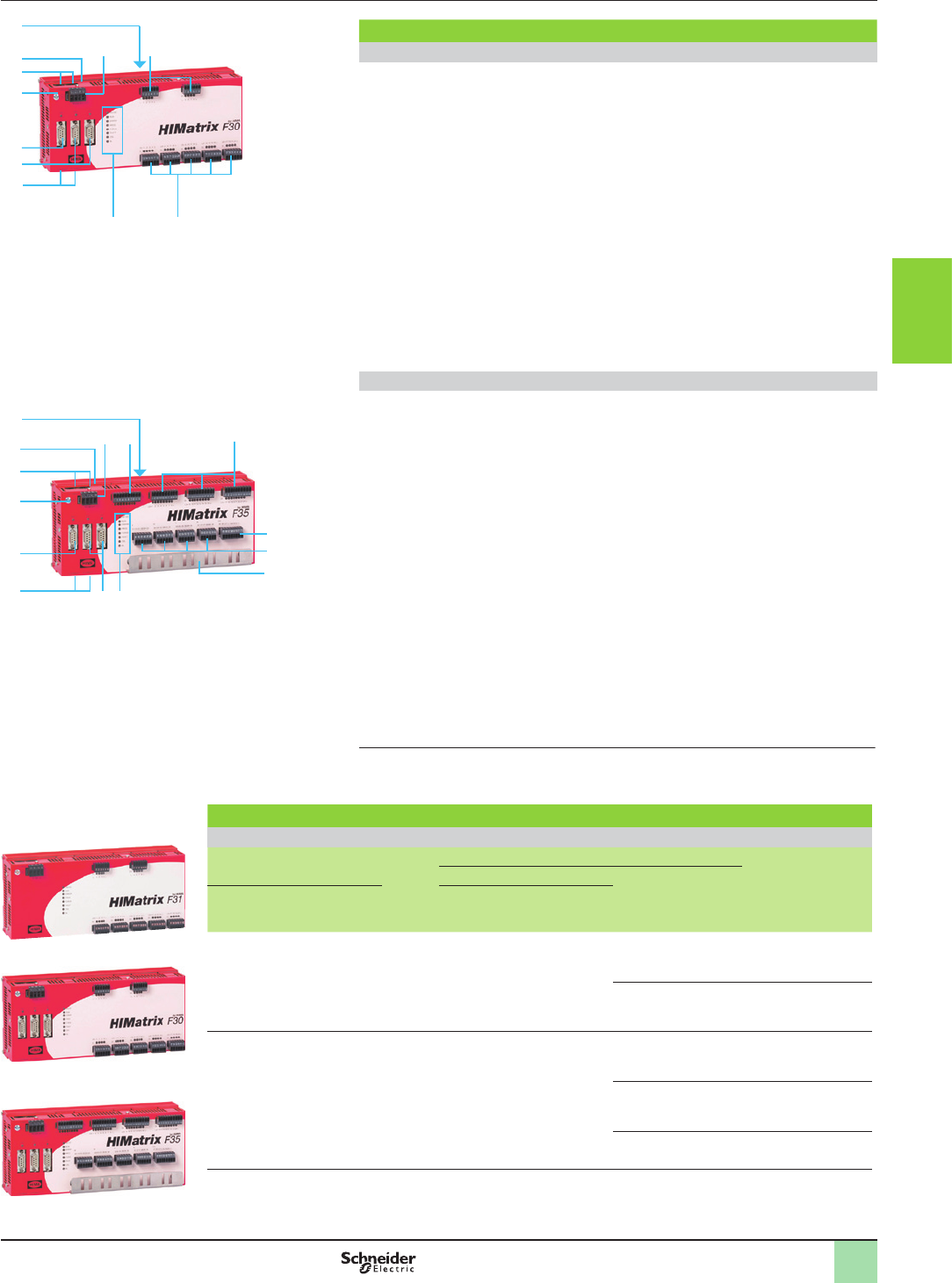
3/113
Description,
references
Monitor and Processing
Preventa safety PLCs
Compact, XPSMF31/30/35
Description
Safety PLCs XPSMF31222 and XPSMF3022
On the front face of the metal enclosure:
1 One terminal block (1) for c 24 V supply.
2 Two terminal blocks (1) for connection of digital outputs, with output status LED
(four LEDs per terminal block).
3 Five terminal blocks (1) for connection of digital inputs, with input status LED (four
LEDs per terminal block).
4 Eight process status LEDs.
5 Four integrated RJ45 (type 10BASE-T/100BASE-TX) switched ports for
programming, and for Safety and non-safety related communication on Ethernet
(safety related using SafeEthernet protocol and Non-safety related using Modbus
TCP/IP server protocol).
6 On XPSMF3022 only: two unused SUB-D connectors (FB1 and FB2).
7 On XPSMF3022 only: one SUB-D 9-pin connector for connection on Modbus
serial (RTU) (FB3).
8 One earth connection screw.
9 On the top: one “Reset” button.
10 On the rear face:
one spring operated xing device for mounting on 35 mm 5 rail.
Safety PLCs XPSMF35pp
On the front face of the metal enclosure:
1 One terminal block (1) for c 24 V supply.
2 One terminal block (1) for connection of digital outputs, with four digital output
status LEDs.
3 Three terminal blocks (1) for connection of digital inputs, with input status LED
(eight LEDs per terminal block).
4 One terminal block (1) for connection of 2 counting input channels.
5 Four terminal blocks (1) for connection of analogue inputs.
6 One plate for securing shielded analogue input connection cables.
7 Eight process status LEDs.
8 Two unused SUB-D connectors (FB1 and FB2).
9 Four integrated RJ45 (type 10BASE-T/100BASE-TX) switched ports for
programming, and for Safety and non-safety related communication on Ethernet
(safety related using SafeEthernet protocol and Non-safety related using Modbus
TCP/IP server protocol).
10 One type SUB-D 9-pin connector (FB3) for connection on PROFIBUS DP (XPSMF3542) or
Modbus serial (RTU) (XPSMF3522).
11 One earth connection screw.
12 On the top: one “Reset” button.
13 On the rear face:
one spring operated xing device for mounting on 35 mm 5 rail.
(1) Removable screw terminals are provided with compact safety PLCs XPSMF31/30/35.
XPSMF31222
XPSMF3022
XPSMF35pp
5
5
1
7
6
4 3
8
2
9
10
1 2 3
4
5
6
78
9
10
11
9
12
13
Compact safety PLCs
c 24 V supply
Inputs Outputs
Digital
Communication on Reference Weight
kg/
lb
Ethernet network Modbus
serial
(RTU)
PROFIBUS
DP
Digital Analogue Counting Safe Ethernet
protocol
Modbus
TCP/IP server
protocol
20 – – 8Yes Yes – – XPSMF31222 1,000/
2.205
Yes
Slave
–XPSMF3022 1.200/
2.646
24 828Yes Yes –
–XPSMF3502 1.200/
2.646
Yes
Slave
–XPSMF3522 1.200/
2.646
– Yes
V0 slave
XPSMF3542 1.200/
2.646
Products referenced XPSMF31222, XPSMF3022 and XPSMF35pp are marked HIMatrix F31, HIMatrix F30 and
HIMatrix F35.
2
1
3
4
5
6
7
8
9
10
2
1
3
4
5
6
7
8
9
10
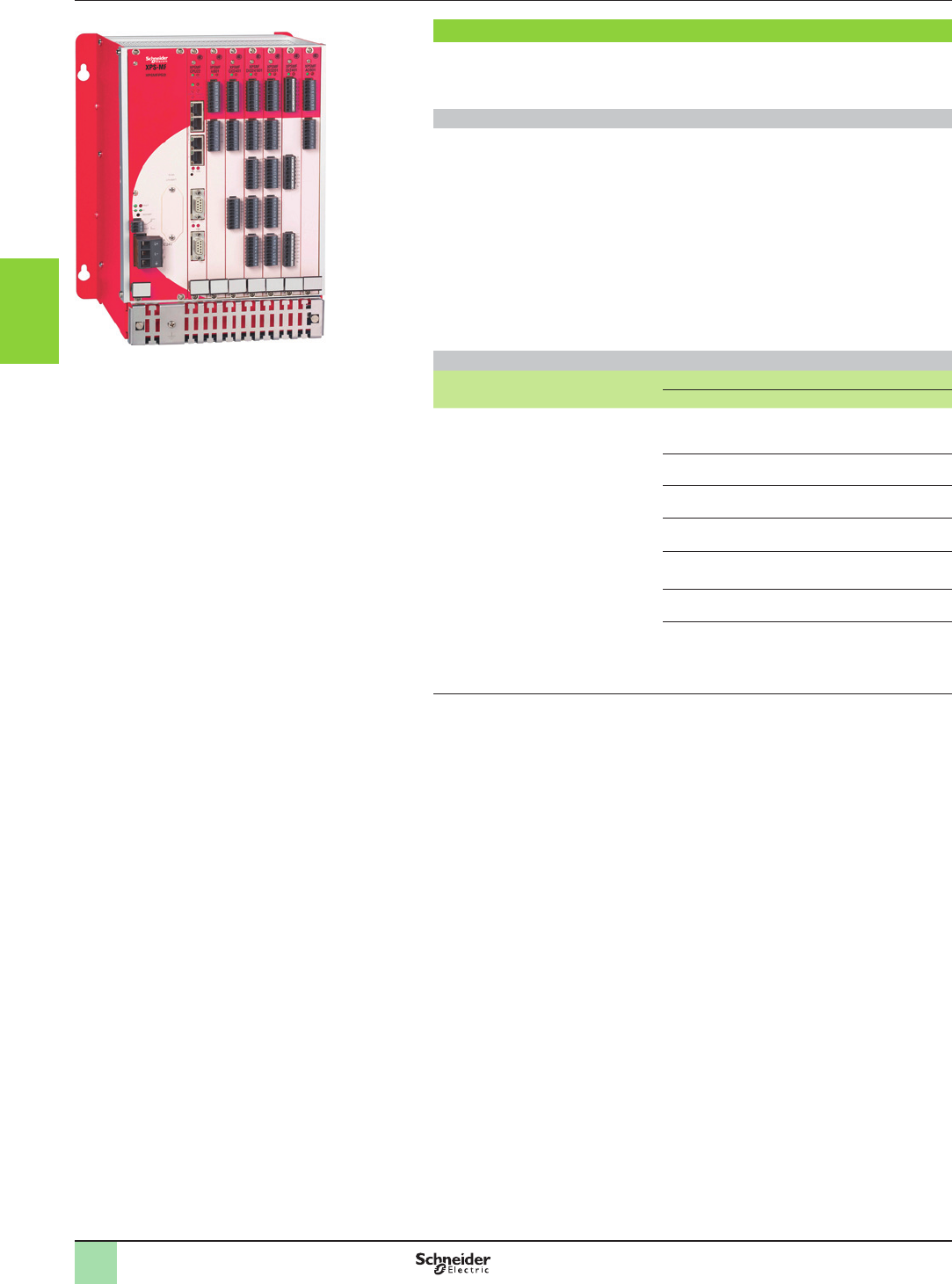
3/114
Presentation Monitor and Processing
Preventa safety PLCs
Modular, XPSMF60
Rack, power supply and CPU
XPSMF60
Presentation
Safety PLC XPSMF60 offers a modular solution for monitoring simple to complex
safety functions for all industrial applications relating to the protection of personnel
and machine safety.
Modularity
The safety PLC XPSMF60 is a modular system comprising a metal housing or rack,
tted with a power supply module, a CPU and “in rack” I/O cards.
b Various types of “in rack” I/O cards are catalogue listed and are selected
according to the application.
b Mounting the “in rack” cards is a simple operation using the guide rails (6 slots).
Electrical connection is automatic and assured by the back plane bus of the rack.
b The mounting order of the “in rack” I/O cards is open to the user, but the order,
however, must correspond to the programming software.
b The removal of the “in rack” cards, performed with the supply switched-off, is
facilitated by a grip at the base of the cards.
b Covering plates for unused “in rack” I/O card slots are available to protect the
system in polluted environments.
Composition of the modular safety PLC XPSMF60
Minimum basic equipment Optional “in rack” I/O cards
Type Details
Metal rack XPSMFGEH01
with back plane bus assuring electrical
connection of components installed +
metal securing plate for shielded cables
(EMC),
two cooling fans
+
a power supply module (c 24 V)
XPSMFPS01,
+ a central processing unit
XPSMFCPU22
with 4 x RJ45 integrated switched
Ethernet ports for Programming, and for
Safety and non-safety related
communication on Ethernet (safety
related using SafeEthernet protocol and
Non-safety related using Modbus TCP/IP
server protocol) and in addition a SUB-D
(FB2) connector for communication on
Modbus serial (RTU)
XPSMFAI801 8 single-pole analogue inputs
or 4 2-pole analogue inputs
XPSMFAO801 8 analogue outputs
XPSMFCIO2401 2 counting inputs,
4 digital outputs
XPSMFDI2401 24 digital inputs
(c 110 V / a 127 V)
XPSMFDI3201 32 digital inputs
XPSMFDIO241601 24 digital inputs,
16 digital outputs
XPSMFDO801 8 relay outputs
(z 6…250 V)
2
1
3
4
5
6
7
8
9
10
2
1
3
4
5
6
7
8
9
10
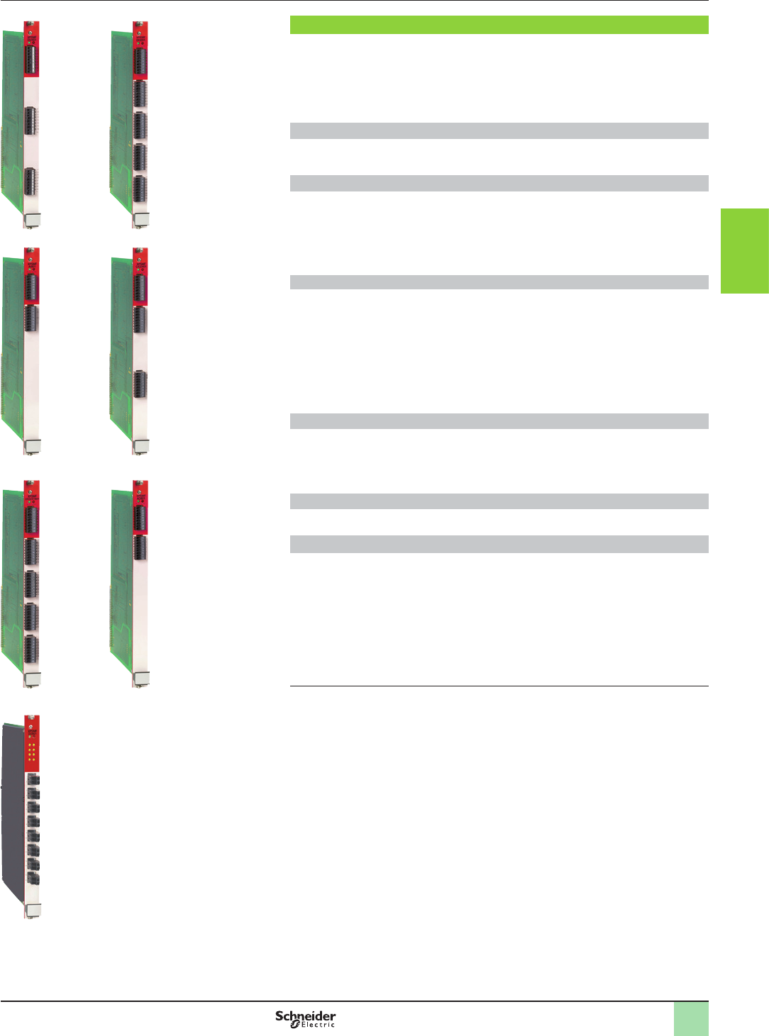
3/115
Presentation Monitor and Processing
Preventa safety PLCs
Modular, XPSMF60
I/O cards
XPSMFDI2401 XPSMFDI3201
XPSMFAI801 XPSMFCIO2401
XPSMFAO801XPSMFDIO241601
XPSMFDO801
Safety inputs and outputs
The modularity of the PLC XPSMF60 allows the user to select and install, in the six
slots of the rack, various input, output and input/output cards to alter the number and
type of safety inputs and/or outputs to be monitored.
6 identical cards can be installed in the same rack.
The cards listed below indicate the number of inputs and outputs available for
connection to the machines to be monitored.
Digital inputs cards (1)
bXPSMFDI2401: 24 Digital inputs
bXPSMFDI3201: 32 Digital inputs
Analogue input card (1) (2)
bXPSMFAI801: 8 single-pole or 4 2-pole:
vClosed circuit scanning of input channels,
vSingle-pole measuring of 0 to 10 V voltages,
v2-pole measuring of -10 to +10 V voltages,
vSingle-pole measuring of 0 to 20 mA currents
Mixed I/O cards (1)
bXPSMFCIO2401:
v2 Counting inputs
- Incremental encoders (c 5 V),
- Sensors 2/3-wire PNP/NPN (c 24 V)
v4 Digital outputs
bXPSMFDIO241601:
v24 digital outputs
v16 digital outputs
Analogue output card (1) (2)
bXPSMFAO801: 8 analog outputs for function:
vClosed circuit scanning of output channels,
vSingle-pole measuring of 0 to 10 V voltages,
vMeasuring, using shunt, 0/4 to 20 mA currents (with 500 W external resistor)
Relay output card (1) (2)
bXPSMFDO801: 8 relay outputs
Remote inputs and outputs
In addition to the inputs/outputs available as standard on the optional “in rack” cards,
the modular safety PLC XPSMF60 can be connected to safety remote input
modules XPSMF1 and/or safety remote output modules XPSMF2 and/or safety
remote mixed I/O modules XPSMF3. The safety remote input, output and mixed I/O
modules can be located within the vicinity of the machines to be monitored, thus
reducing cabling.
Communication between these safety modules and the safety PLC XPSMF60 is
performed on an Ethernet network using the SafeEthernet safety protocol, via the
integrated RJ45 switched Ethernet communications ports.
(1) Removable screw terminal blocks are provided with the power supply and “in rack” I/O cards.
(2) Use shielded dual twisted pair cables, maximum length 300 m, short-circuit unused analogue
inputs.
2
1
3
4
5
6
7
8
9
10
2
1
3
4
5
6
7
8
9
10
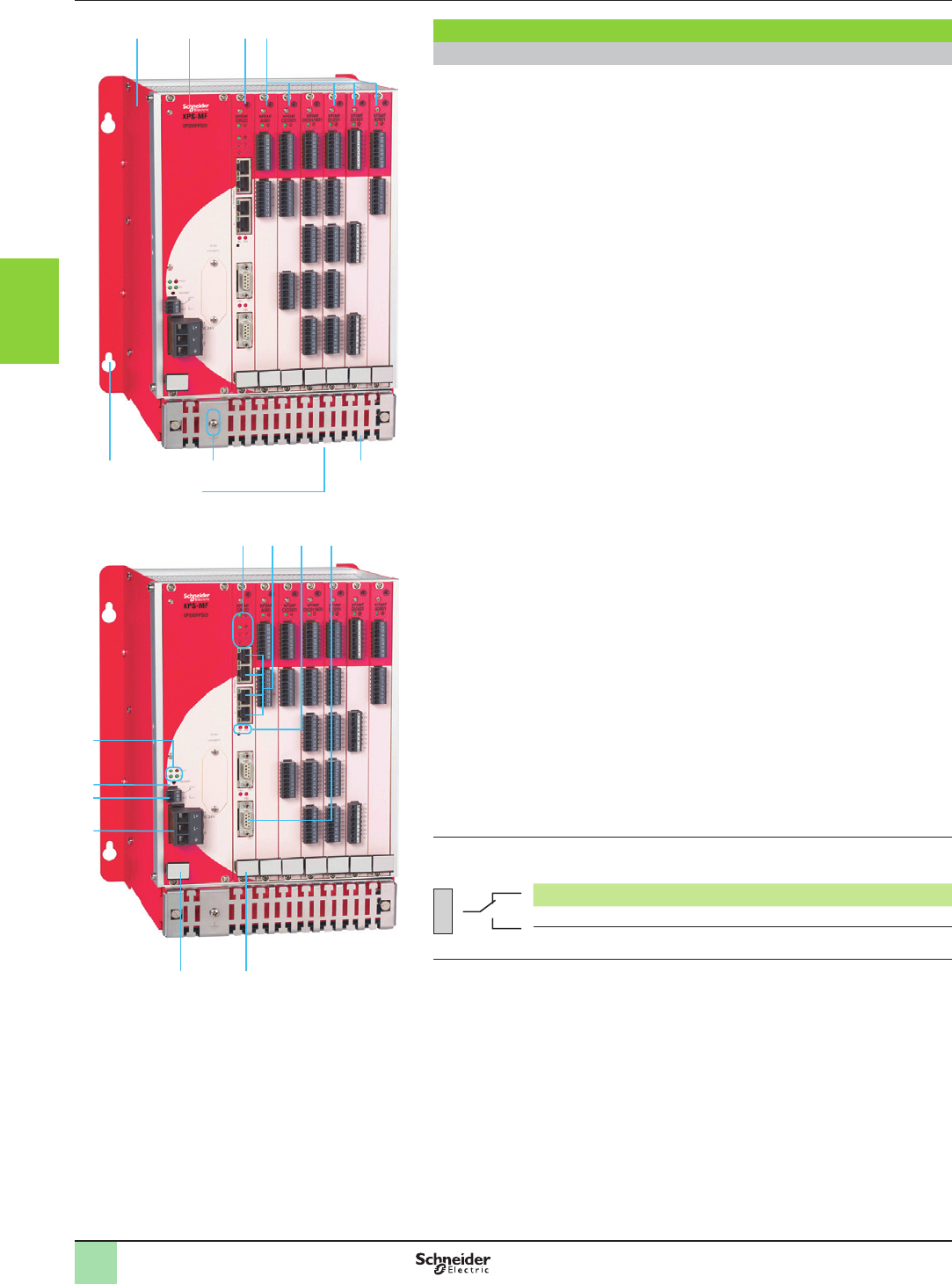
3/116
Description Monitor and Processing
Preventa safety PLCs
Modular, XPSMF60
Rack, power supply and CPU
Description
Modular safety PLC
Modular assembly comprising:
1 A metal rack XPSMFGEH01.
2 A c 24 V power supply module XPSMFPS01.
3 A central processing unit XPSMFCPU22.
4 Six optional “in rack” I/O cards (back plane bus assures the electrical connection
of “in rack” cards installed, the power supply module and the CPU).
5 A metal plate for securing shielded analogue input connection cables (EMC),
6 One earth connection screw.
7 Two cooling fans (beneath the metal rack).
8 Four Ø 14 mm elongated holes for mounting the rack on a vertical support.
Power supply module XPSMFPS01 and Central processing unit XPSMFCPU22
comprising:
1 Four voltage status LEDs (FAULT, 24 V, 3.3 V or 5 V).
2 A RESTART button (accessible using ne pointed tool).
3 A 3-pole terminal block (3 captive screws) for “Fault contact” function (1).
4 A c 24 V supply terminal block, including earth connection (2).
5 A grip to assist installation/removal of the power supply module.
6 Seven process status LEDs.
7 Four integrated RJ45 (type 10BASE-T/100BASE-TX) switched ports for
Programming, and for Safety and non-safety related communication on Ethernet.
(safety related using SafeEthernet protocol and Non-safety related using Modbus
TCP server protocol).
8 Two process status LEDs.
9 A SUB-D 9-pin connector (FB2) for connection on Modbus serial (RTU) (FB1 not
used), with process status LED.
10 A grip to assist installation/removal of the CPU
(1) “Fault contact” function: the power supply module incorporates a volt-free changeover
contact. Operating errors occurring in the system are read and displayed by the LEDs. The errors
are analysed on the programming PC:
01
02
03 FAULT
Contact positions Status
1-2 closed (2-3 open) Normal operation of the PLC.
1-2 open (2-3 closed) Absence of supply to the PLC or the CPU is in
ERROR STOP mode.
(2) Removable screw terminal blocks are provided with the power supply and “in rack” I/O cards.
2 3 4
5
7
68
1
1
2
3
4
5
678 9
10
2
1
3
4
5
6
7
8
9
10
2
1
3
4
5
6
7
8
9
10
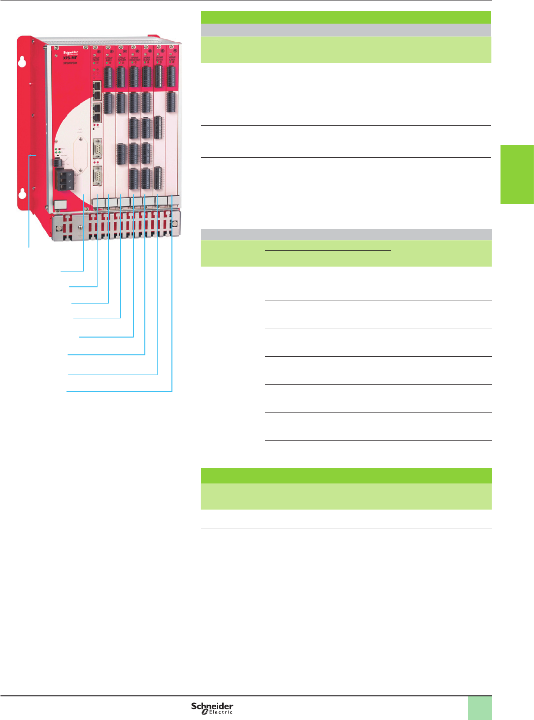
3/117
References Monitor and Processing
Preventa safety PLCs
Modular, XPSMF60
Rack, power supply and CPU
XPSMFAO801
XPSMFAI801
XPSMFCIO2401
XPSMFDIO241601
XPSMFDI3201
XPSMFDI2401
XPSMFCPU22
XPSMFPS01
XPSMFGEH01
Modular PLC (c 24 V supply)
Minimum basic equipment
Description Reference Weight
kg/
lb
Metal rack (1) tted with:
va back plane bus, assuring electrical connection of
components installed: power supply module, CPU and “in
rack” cards
vtwo cooling fans
va metal securing plate for shielded cables (EMC)
XPSMFGEH01 –
c 24 V power supply module (1) XPSMFPS01 0.820/
1.808
CPU (1) tted with:
v4 x integrated RJ45 (type 10BASE-T/100BASE-TX)
switched ports for Programming, and for Safety and
non-safety related communication on Ethernet. (safety
related using SafeEthernet protocol and Non-safety
related using Modbus TCP/IP server protocol
v1 x SUB-D 9-pin port (FB2) for access to Modbus serial
(RTU)
XPSMFCPU22 0.280/
0.617
Optional “in rack” I/O cards
Description Functions Reference Weight
kg/
lb
Inputs Outputs
“In rack” I/O card
(1)
Analogue:
8 single-pole
or 4 2-pole,
congurable
–XPSMFAI801 0.240/
0.529
–8 analogue XPSMFAO801 0.280/
0.617
2 counting 4 digital XPSMFCIO2401 0.260/
0.573
24 digital
(c 110 V / a 127 V)
–XPSMFDI2401 0.260/
0.573
32 digital – XPSMFDI3201 0.260/
0.573
24 digital 16 digital
(2)
XPSMFDIO241601 0.260/
0.573
–8 relay
z 6…250 V
XPSMFDO801 0.600/
1.323
Accessories for modular PLC
Description For use with Reference Weight
kg/
lb
Covering plate Unused “in rack” I/O card slots XPSMFBLK –
(1) Removable screw terminal blocks are provided with the power supply and “in rack” I/O cards.
(2) Congurable for line control.
2
1
3
4
5
6
7
8
9
10
2
1
3
4
5
6
7
8
9
10
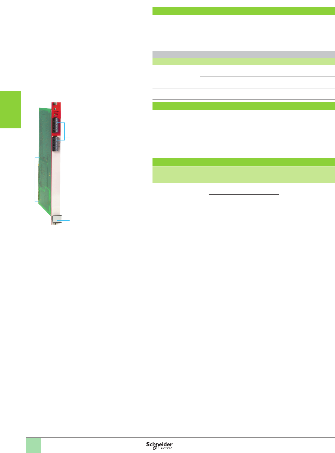
3/118
Presentation,
description,
references,
Monitor and Processing
Preventa safety PLCs
Modular, XPSMF60
“In rack” analogue input card
4
1
2
3
XPSMFAI801
Presentation
The “in rack” analogue input card XPSMFAI801 incorporates 8 analogue inputs:
velectrically isolated from the back plane bus of rack XPSMFGEH01,
vcongured by choice of connection for managing eight single-pole or four 2-pole
functions.
The card can be installed in rack XPSMFGEH01 as many times as required in the six
slots available.
Input values (1)
Number Type Voltage Current Value range Example
8 inputs Single-pole ± 10 V –± 1000 Single-pole measuring of
0 to 10 V voltages
–0...20 mA 0...1000 (2)
0...2000 (3)
Measuring 0 to 20 mA
currents using shunt
4 inputs 2-pole ± 10 V –± 1000 Closed circuit scanning of
input channels
Description
On the front face of the card:
1 Two process status LEDs (RUN, ERR).
2 Two removable screw terminal blocks (9 terminals per block) for connection of
inputs (4).
3 Grip to assist installation/removal.
4 On the rear: terminals for automatic electrical connection to the back plane bus of
rack XPSMFGEH01.
References
Description Number of
channels
Voltage
Current
Reference Weight
kg/
lb
Analogue input card 8 single-pole ± 10 V
0...20 mA (1)
XPSMFAI801 0.240/
0.529
4 2-pole ± 10 V
(1) The unused input channels must be short-circuited on the reference pole (L-).
(2) With 250 W external shunt.
(3) With 500 W external shunt.
(4) Removable screw terminals are provided with the “in rack” card XPSMFAI801.
2
1
3
4
5
6
7
8
9
10
2
1
3
4
5
6
7
8
9
10
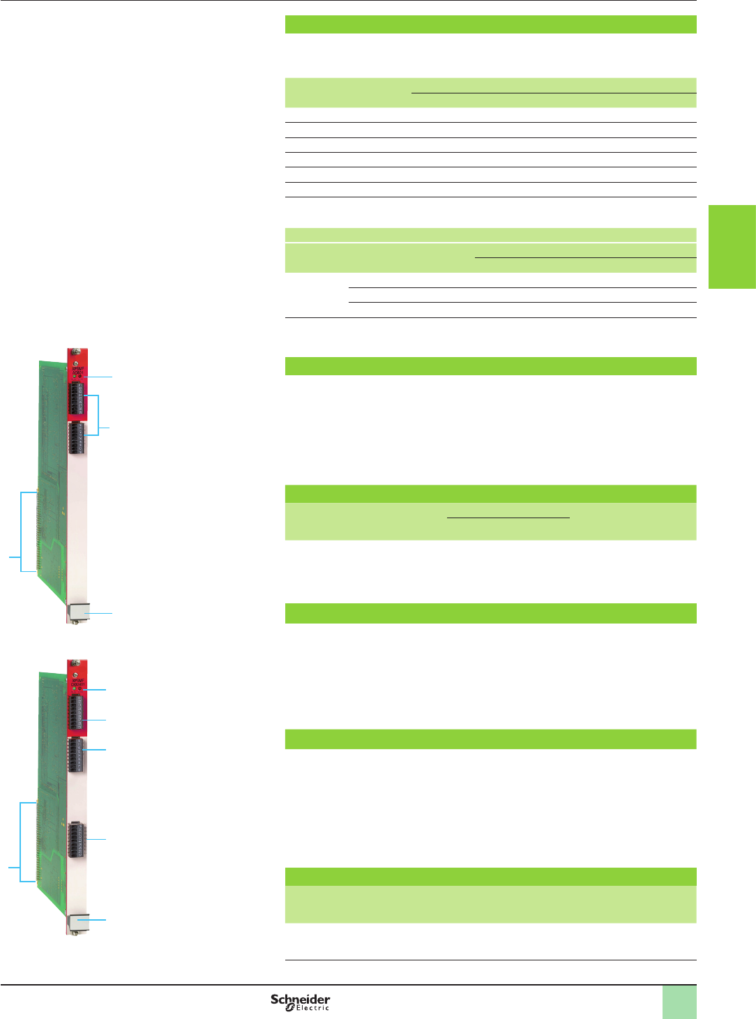
3/119
Presentation,
description,
references
Monitor and Processing
Preventa safety PLCs
Modular, XPSMF60
“In rack” analogue output card
“In rack” mixed card: counting inputs/digital outputs
4
1
2
3
XPSMFAO801
Presentation
The analogue output card XPSMFAO801 incorporates 8 congurable analogue outputs
(0…20 mA, 0…+ 10 V ou - 10…+ 10 V) for selection of the type of voltage/current
measurement: a switch enables selection of 6 functions for each output channel.
Switch position Outputs
Voltage ± 10 V Current 0…+ 20 mA
1 – On
2 – On
3 – On
4 On –
5 On –
6 On –
vSelection of measuring scale using software XPSMFWIN: the “Properties”
sub-menu displays the scale options in the “Type” window (…FS1000 or …FS2000).
Congurable output values
Type Voltage Current Value range
Half scale (FS1000) Full scale (FS2000)
8 analogue
outputs
–0…20 mA 0...+ 1000 0...+ 2000
0…+ 10 V –0...+ 1000 0…+ 2000
- 10...+ 10 V –- 1000...+ 1000 - 2000...+ 2000
The card can be installed in rack XPSMFGEH01 as many times as required in the six
slots available.
Description
On the front face of the card:
1 Two process status LEDs (RUN, ERR).
2 Two removable screw terminal blocks (9 terminals per block) for connection of
outputs (1).
3 Grip to assist installation/removal.
4 On the rear: terminals for automatic electrical connection to the back plane bus of
rack XPSMFGEH01.
References
Description Number
of channels
Conguration Reference Weight
kg/
lb
Current Voltage
Analogue output
card
8 0...20 mA - 10…+ 10 V XPSMFAO801 0.280/
0.617
Presentation
The mixed counting input and digital output card XPSMFCIO2401 incorporates:
v2x 24-bit independent and congurable counting channels (one channel for
counting and one channel for increasing or decreasing counting direction). They are
congured using software XPSMFWIN.
v4 digital outputs.
The card can be installed in rack XPSMFGEH01 as many times as required in the six
slots available.
Description
On the front face of the card:
1 Two process status LEDs (RUN, ERR).
2 Two removable screw terminal blocks (9 terminals per block) for connection of inputs (1)
.
3 One removable screw terminal block (9 terminals) for connection of outputs (1)
with four output status LEDs.
4 Grip to assist installation/removal.
5 On the rear: terminals for automatic electrical connection to the back plane bus
of rack XPSMFGEH01.
References
Description Characteristics Reference Weight
kg/
lb
Mixed I/O card b2 x 24-bit counting inputs,
congurable: 5 V…24 V
b4 digital outputs
XPSMFCIO2401 0.260/
0.573
(1) Removable screw terminals are provided with the “in rack” card.
5
1
2
4
3
XPSMFCIO2401
2
2
1
3
4
5
6
7
8
9
10
2
1
3
4
5
6
7
8
9
10
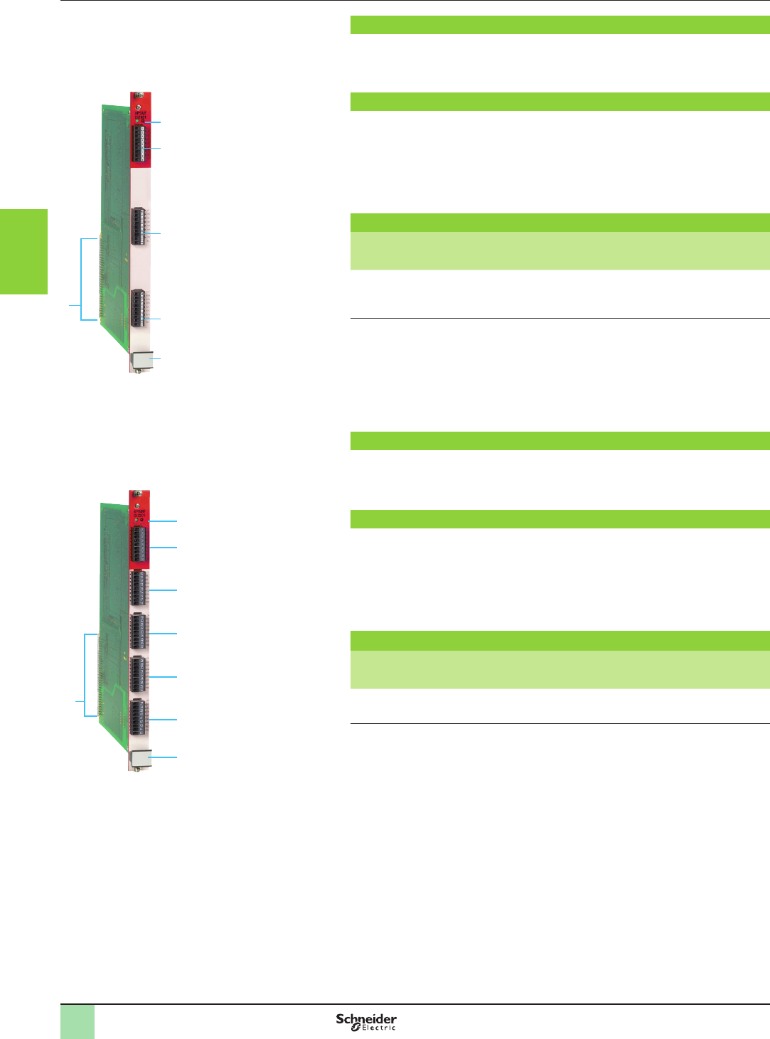
3/120
Presentation,
description,
references
Monitor and Processing
Preventa safety PLCs
Modular, XPSMF60
“In rack” digital input cards
4
1
2
3
2
2
XPSMFDI2401
Presentation
The digital input card XPSMFDI2401 incorporates 24 c 110 / a 127 V digital inputs
that are congurable using software XPSMFWIN.
The card can be installed in rack XPSMFGEH01 as many times as required in the
six slots available.
Description
On the front face of the card:
1 Two process status LEDs (RUN, ERR).
2 Three removable terminal blocks (9 terminals per block) for connection of inputs
(1)
, each with eight input status LEDs.
3 Grip to assist installation/removal.
4 On the rear: terminals for automatic electrical connection to the back plane bus
of rack XPSMFGEH01.
References
Description Characteristics Reference Weight
kg/
lb
Input card 24 digital inputs
c 110 V / a 127 V
XPSMFDI2401 0.260/
0.573
Presentation
The digital input card XPSMFDI3201 incorporates 32 digital inputs that are
congurable using programming software XPSMFWIN.
The card can be installed in rack XPSMFGEH01 as many times as required in the six
slots available.
Description
On the front face of the card:
1 Two process status LEDs (RUN, ERR).
2 Five removable terminal blocks (9 terminals per block) for connection of inputs
(1), with a status LED for each input terminal.
3 Grip to assist installation/removal.
4 On the rear: terminals for automatic electrical connection to the back plane bus
of rack XPSMFGEH01.
References
Description Characteristics Reference Weight
kg/
lb
Input card 32 digital inputs XPSMFDI3201 0.260/
0.573
(1) Removable screw terminals are provided with the “in rack” card.
4
1
2
3
2
2
2
2
XPSMFDI3201
2
1
3
4
5
6
7
8
9
10
2
1
3
4
5
6
7
8
9
10
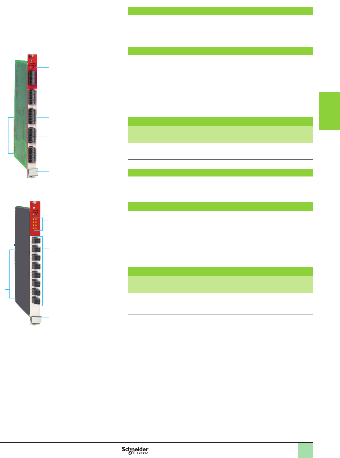
3/121
Presentation
The digital I/O card XPSMFDIO241601 incorporates 24 digital inputs and 16 digital
outputs.
The card can be installed in rack XPSMFGEH01 as many times as required in the six
slots available.
Description
On the front face of the card:
1 Two process status LEDs (RUN, ERR).
2 Three removable terminal blocks (9 terminals per block) for connection of inputs
(1), each with eight input status LEDs.
3 Two removable screw terminal blocks (9 terminals per block) for connection of
outputs
(1)
, each with eight output status LEDs.
4 Grip to assist installation/removal.
5 On the rear: terminals for automatic electrical connection to the back plane bus
of rack XPSMFGEH01
References
Description Characteristics Reference Weight
kg/
lb
I/O card b24 digital inputs
b16 digital outputs, congurable for
line control
XPSMFDIO241601 0.260/
0.573
Presentation
The relay output card XPSMFDO801 incorporates 8 relay safety outputs (3.15 A
fuse) that are congurable using software XPSMFWIN.
The card can be installed in rack XPSMFGEH01 as many times as required in the
six slots available.
Description
On the front face of the card:
1 Two process status LEDs (RUN, ERR).
2 Eight output status LEDs.
3 Eight removable screw terminal blocks (2 terminals per block) for connection of
outputs (1).
4 Grip to assist installation/removal.
5 On the rear: terminals for automatic electrical connection to the back plane bus
of rack XPSMFGEH0.
References
Description Characteristics Reference Weight
kg/
lb
Output card 8 relay outputs
z 6 V…250 V
XPSMFDO801 0.600/
1.323
(1) Removable screw terminals are provided with the “in rack” card.
5
1
2
4
2
3
3
2
XPSMFDIO241601
Presentation,
description,
references
Monitor and Processing
Preventa safety PLCs
Modular, XPSMF60
“In rack” digital I/O card
“In rack” relay output card
5
1
2
3
4
XPSMFDO801
2
1
3
4
5
6
7
8
9
10
2
1
3
4
5
6
7
8
9
10
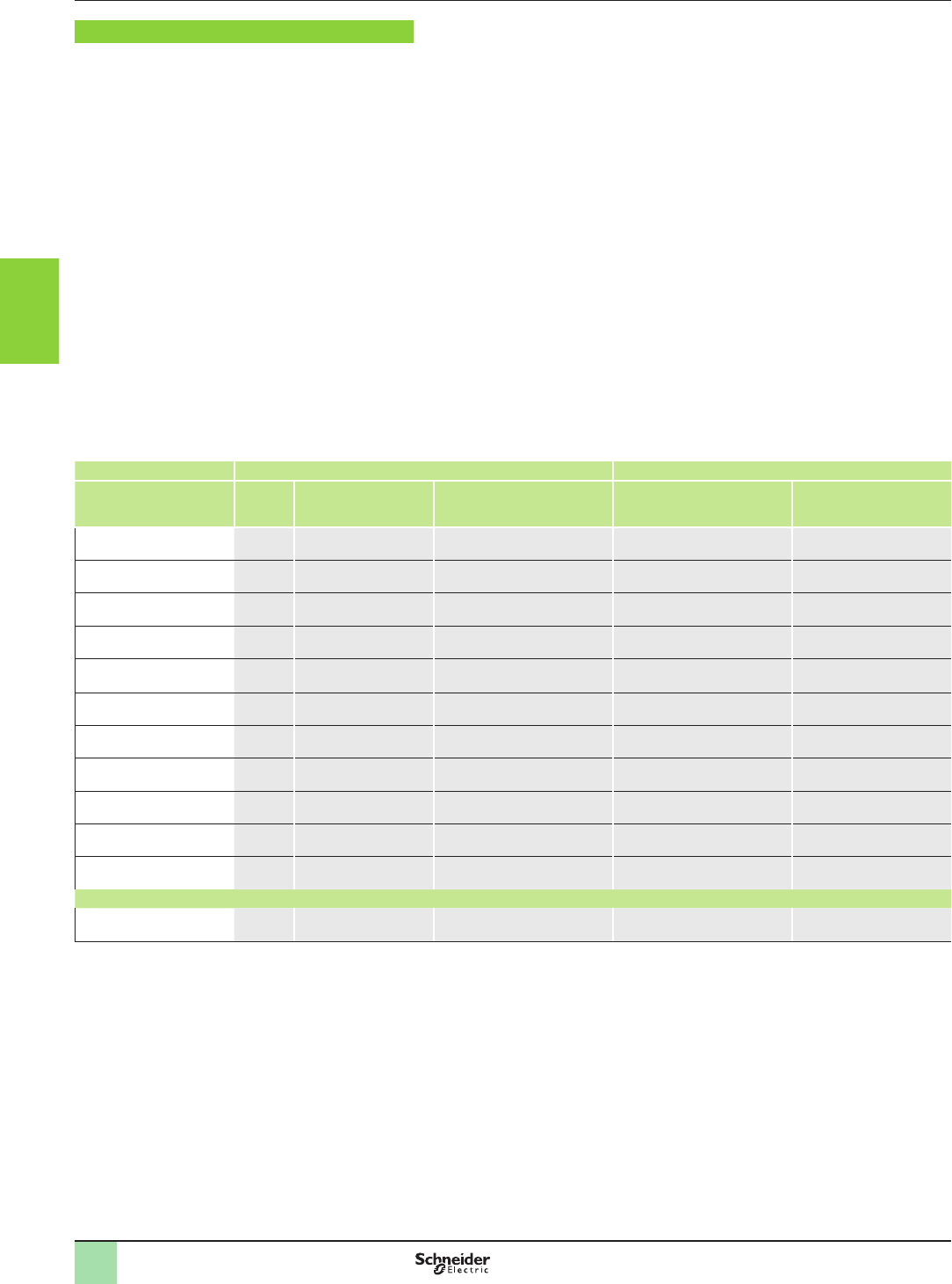
3/122
Presentation Monitor and Processing
Preventa safety PLCs
Compact and modular, XPSMF
Communication on network and bus
Presentation To communicate, Preventa compact and modular safety PLCs XPSMF are tted
with:
bIntegrated 2 or 4 RJ45 Ethernet switched ports for transfer Safety and Non-
safety related data (Safety Related using SafeEthernet protocol, Non-Safety Related
using Modbus TCP/IP protocol),
band/or serial communication ports for transferring non safety related data.
Safety communication on a single network
The Ethernet network supports the SafeEthernet protocol: physically, a single
network is possible for communication between:
vsafety products (SafeEthernet protocol),
vnon safety related products (Modbus TCP/IP and other protocols),
vsafety related and non safety related products (Modbus TCP/IP protocol).
Communication on more than one network: a minimum of two separate
cabling systems are established.
vAn Ethernet network with Modbus TCP/IP protocol is used for communication
between non safety related products and the safety PLCs.
vAn Ethernet network with SafeEthernet protocol is used for communication
between the safety PLCs XPSMF and safety remote I/O modules XPSMF1/2/3.
vA Modbus serial network with Modbus serial (RTU) protocol is used for
communication between the safety PLCs XPSMF and non safety related products.
vA PROFIBUS DP network with PROFIBUS protocol is used for communication
between the safety PLCs XPSMF and non safety related products.
Safety PLCs Communication on Ethernet network Communication on eldbus
Compact Port
(number x
type)
SafeEthernet protocol:
safe communication
Modbus TCP/IP protocol: non
safe communication
Modbus serial (RTU) protocol PROFIBUS DP protocol
XPSMF31222 4 x RJ45 yes yes no no
XPSMF3022 4 x RJ45 yes yes yes (slave) / 1 x SUB-D
(9-pin)
no
XPSMF3502 4 x RJ45 yes yes no no
XPSMF3522 4 x RJ45 yes yes yes (slave) / 1 x SUB-D
(9-pin)
no
XPSMF3542 4 x RJ45 yes yes no yes (slave) / 1 x SUB-D
(9-pin)
XPSMF4000 2 x RJ45 yes no no no
XPSMF4002 2 x RJ45 yes yes no no
XPSMF4020 2 x RJ45 yes no yes (slave) / 1 x RJ45 no
XPSMF4022 2 x RJ45 yes yes yes (slave) / 1 x RJ45 no
XPSMF4040 2 x RJ45 yes no no yes (slave) / 1 x SUB-D
(9-pin)
XPSMF4042 2 x RJ45 yes yes no yes (slave) / 1 x SUB-D
(9-pin)
Modular
XPSMFCPU22
(central processing unit)
4 x RJ45 yes yes yes (slave) / 1 x SUB-D
(9-pin)
no
2
1
3
4
5
6
7
8
9
10
2
1
3
4
5
6
7
8
9
10
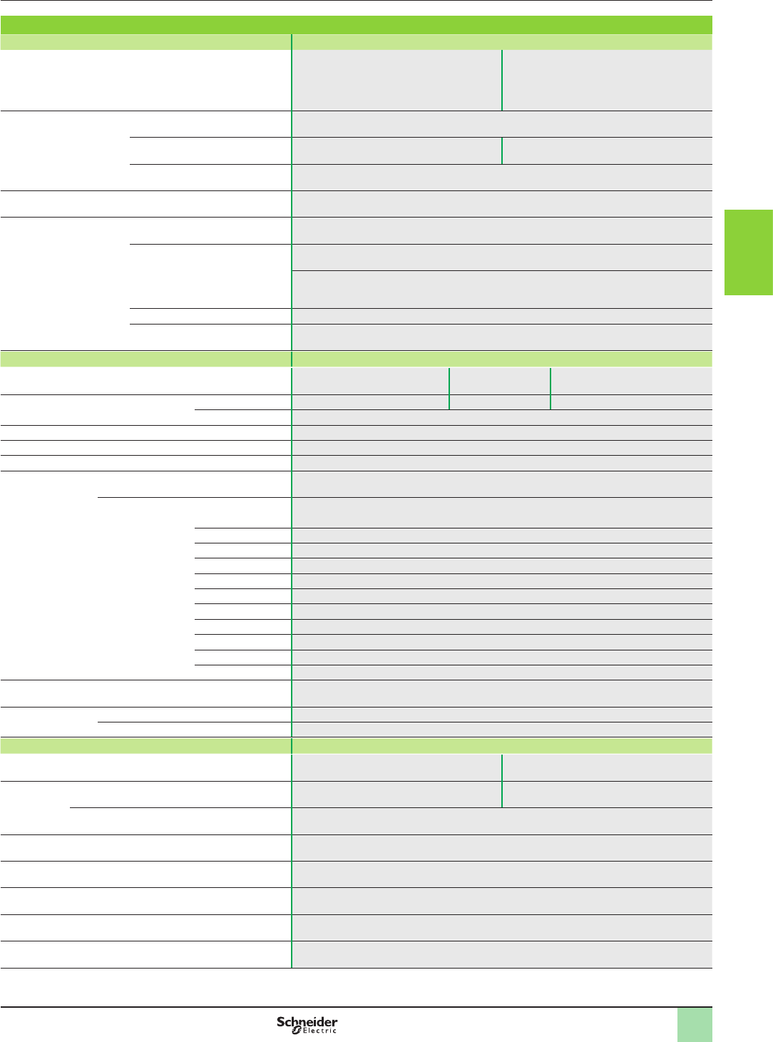
3/123
Characteristics Monitor and Processing
Preventa safety PLCs
Compact and modular, XPSMF
Communication on network and bus
Characteristics
Protocol SafeEthernet
Compatibility with compact and modular safety PLCs XPSMF4000, XPSMF4002,
XPSMF4020, XPSMF4022,
XPSMF4040, XPSMF4042
XPSMF31222,
XPSMF3022,
XPSMF3502, XPSMF3522, XPSMF3542,
XPSMFCPU22 (central processing unit of
modular PLC XPSMF60)
Transmission Speed (Baud rate) 100 Mbps Half duplex, 10 Mbps Full duplex, Autonegotiation
Communication ports Integrated 2 RJ45 switched Ethernet
communications ports
Integrated 4 RJ45 switched Ethernet
communications ports
Medium Dual twisted pair cable, category 5D or better
Structure 10BASE-T/100BASE-TX
Transparent Ready
service
Class A10
Standard Ethernet TCP/IP
communication services (supported
by compact and modular safety
PLCs)
Modbus TCP/IP
Modbus TCP/IP messaging (reading/writing of data words)
Modbus identication requests
TCP port Standard 502
Max. number of TCP/IP connections 1 to 20
Bus type Modbus serial (RTU)
Compatibility with compact and modular safety PLCs XPSMF3022, XPSMF3522 XPSMF4020,
XPSMF4022
XPSMFCPU22 (CPU of modular
PLCXPSMF60)
Serial link port Number and type 1 x SUB-D 9-pin female (FB3) 1 x RJ45 (Modbus) 1 x SUB-D 9-pin female (FB2)
Master/Slave Slave
Addressing 122 slave addresses. Addressing range: 1…247
Medium Shielded twisted pair cable
Physical layer RS 485
Services 13 Modbus functions (reading/writing of bits and words, event counters, connection events,
diagnostics, identication)
Functions Code Modbus slave
01 Reading n bits of output
02 Reading n bits of inputs
03 Reading n words of output
04 Reading n words of inputs
23 Reading/writing variables
15 Writing bit variables
16 Writing word variables
05 Writing 1 bit of output
06 Writing 1 word of output
08 Diagnostics
43 Reading equipment identication
Transmission Binary transfer rate (bps) 115 200, 76 800, 62 500, 57 600, 38 400, 19 200, 9600, 4800, 2400, 1200, 600, 300.
Default value: 57 600
Elements Parity None. Odd. Even. Default value: even
Stop bit Standard. 1 stop bit. 2 stop bits. Default value: standard
Bus type PROFIBUS DP
Compatibility with compact safety PLCs XPSMF3542 XPSMF4040, XPSMF4042
Serial port Number and type 1 x SUB-D 9-pin female (FB3) 1 x SUB-D 9-pin female (PROFIBUS)
Master/Slave Slave, V0
Physical layer RS 485
Topology Linear, with line terminators at each end
Medium Shielded twisted pair cable
Number of slaves 32 slaves on each segment, 126 slaves maximum with repeaters
Data exchange speed 9.6 kbps…12 Mbps, depending on the length of the segment (1200 m…100 m)
2
1
3
4
5
6
7
8
9
10
2
1
3
4
5
6
7
8
9
10
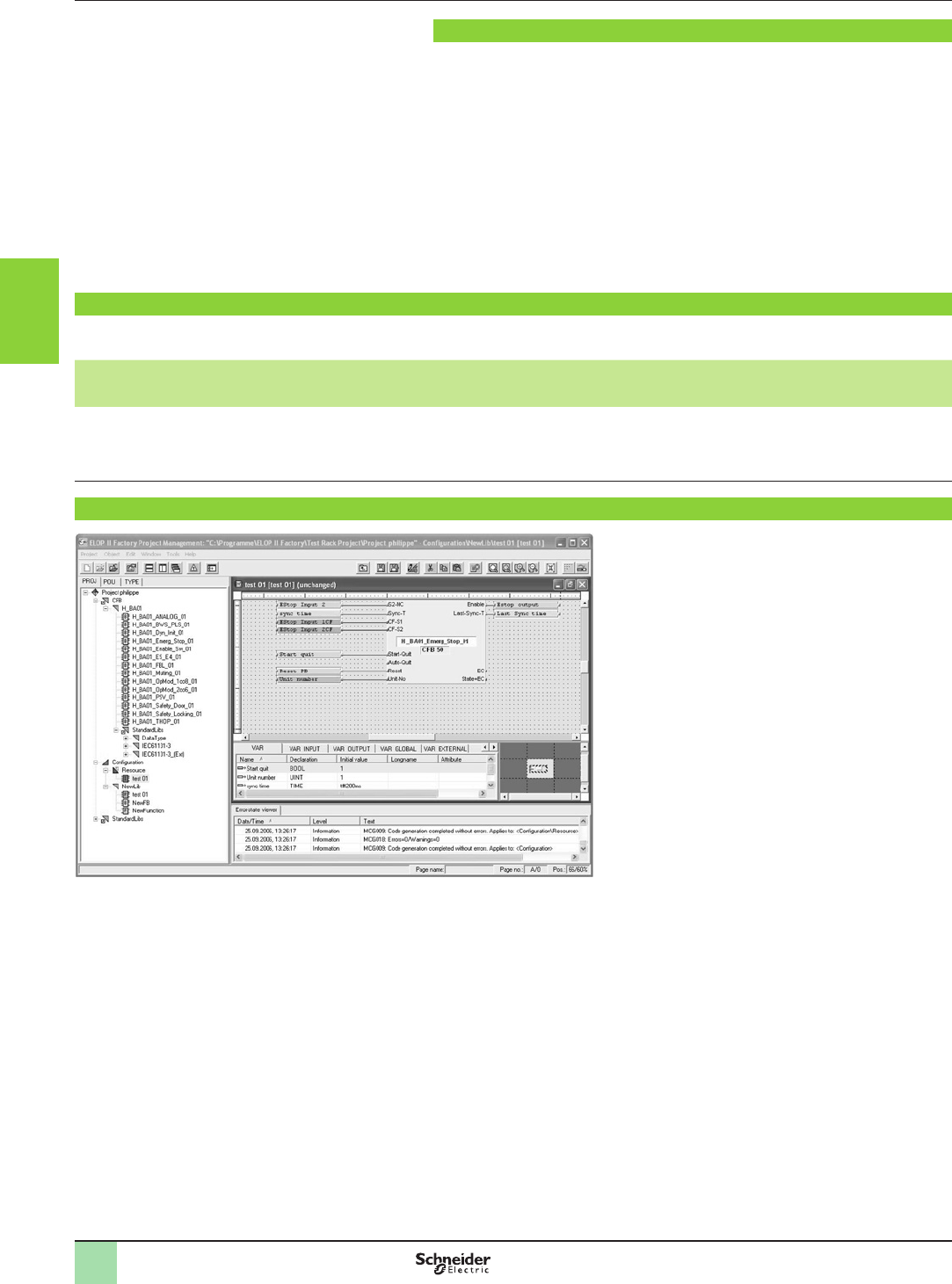
3/124
Presentation,
references
Monitor and Processing
Programming software XPSMFWIN
for Preventa compact and modular
safety PLCs XPSMF
Presentation
Conforming to standard IEC 61131-3, programming software XPSMFWIN is
designed for programming all safety PLCs XPSMF and safety remote I/O modules.
To create a program the user can use predened function blocks, such as the
elementary logic functions and certied function blocks, by dragging the blocks into
the software programming area.
The “drag and drop” operation of the Windows programming environment enables
quick and simple creation of congurations.
Using the XPSMFWIN software, it is possible to program complete systems
comprising several safety PLCs and safety remote I/O modules.
The conditions detailed in the software manual must be adhered to and a complete
report accompanying the certicate should be established.
Reference
bReference SSV1XPSMFWIN is the full version of software XPSMFWIN version 4.1 and must be installed if no previous version of this software has
been installed.
Description Operating system Composition Language Reference Weight
kg/
lb
Conguration software XPSMFWIN
for programming compact
XPSMF40pp, XPSMF3p and modular
XPSMF60 safety PLCs
Windows 2000,
Windows XP
CD-ROM + user manual English,
German,
French
SSV1XPSMFWIN 0.520/
1.146
Installation
Software XPSMFWIN uses an electronic key (dongle)
for protection against unauthorised use.
A USB dongle is available. It must be connected to the
PC before the software is installed.
Drivers must also be installed on the computer to
recognise the dongle. These drivers are included with
software XPSMFWIN and are automatically installed
during installation.
To install software XPSMFWIN:
vConnect the dongle.
vInsert the SSV1XPSMFWIN software CD-ROM into
the computer.
vLaunch installation.
vSelect the preferred language from the
conguration menu.
vFollow the guided installation procedure for the
software.
vRestart the computer.
vLaunch the software by clicking on the Safety Suite
icon on the desktop.
The computer hardware requirements are as
follows:
bProcessor (Intel Pentium II 400 MHz minimum, Intel
Pentium III 800 MHz recommended).
bRAM (128 Mb minimum, 256 Mb recommended).
bGraphics card (2 Mb XGA, 1024 x 768, 256 colours
minimum, 8 Mb XGA, 1280 x 1024 True colour
recommended).
bHard disk (1 Gigabyte minimum).
bOperating system:
vWindows 2000 Professional with Service Pack 1 or
higher.
vWindows XP with Service pack 1.
Software XPSMFWIN: project management
2
1
3
4
5
6
7
8
9
10
2
1
3
4
5
6
7
8
9
10
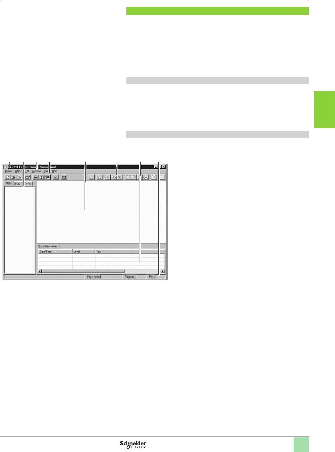
3/125
Presentation Monitor and Processing
Programming software XPSMFWIN
for Preventa compact and modular
safety PLCs XPSMF
Interface
XPSMFWIN features two distinct windows, one for internal conguration and
one for hardware management.
bProject management
This window enables creation, archiving and recalling of all the user programs. It
contains all the logic functions and predened certied function blocks.
bHardware management
This window enables all hardware specic data, inputs and outputs and signal
transfer between safety controllers to be dened, as well as the various safety PLCs
being used or safety remote I/O modules.
Items included in the XPSMFWIN interface
bMenu and title bar
bToolbar and status bar
bWindows layout, structure window and work space
bError display window
XPSMFWIN is a program offering numerous functions and features intuitive,
Windows style, operation, making it a very user-friendly programming environment.
Project Management window layout
On launching software XPSMFWIN, the standard screen shown below opens.
This screen generally includes the following items:
1 2 3 4 5 6 7 8
1 Title bar.
2 Structure window.
3 Menu bar.
4 Project management toolbar.
5 Work space.
6 FBD (Function Block Diagram) editor toolbar.
7 Error display window.
8 Status bar with coordinate information of the function plan
editor.
2
1
3
4
5
6
7
8
9
10
2
1
3
4
5
6
7
8
9
10

3/126
Presentation Monitor and Processing
Programming software XPSMFWIN
for Preventa compact and modular
safety PLCs XPSMF
Structure window
1
2
3
4
5
5
7
6
1 Conguration.
2 Resource folder.
3 Communication protocols.
4 Remote I/O folder.
5 Remote I/O type.
6 Components and modules.
7 Resource type
The structure window displays the hierarchical structure of the project.
Selecting one of three views provides the user with different levels of detail.
FBD (Function Block Diagram) editor
Using this editor, the user can create function blocks in FBD (Function Block
Diagram) language or SFC (Sequential Function Chart) language.
The FBD editor comprises the following panes:
1 2 3 8 1 Drawing eld.
2 Variable declaration
editor.
3 Overview window.
4 Interface declaration
editor.
Complete project
All POUs
(Program Organisation Units)
All data types
2
1
3
4
5
6
7
8
9
10
2
1
3
4
5
6
7
8
9
10

3/127
Presentation Monitor and Processing
Programming software XPSMFWIN
for Preventa compact and modular
safety PLCs XPSMF
Programming
Software XPSMFWIN enables programming of the entire range of Preventa safety
PLCs XPSMF.
The powerful and easy to use methodology of this software enables users to quickly
and simply familiarise themselves with the product. The Windows based look and
user-friendliness provides users with trouble free operation of the software.
On launching the software, the program’s start-up assistant opens simultaneously.
This assistant enables the user to easily open a new or existing le, delete a le or
archive a le. Once a new or existing le is opened, the user quickly accesses the
working environment.
Conguration
The user can begin creating a conguration as soon as a personal library is set-up,
that will contain the user conguration(s).
Once the personal library is opened, the user can use the standard library function
blocks (And, Or, Not, Flip-Flop, etc.) to create exactly what is required.
The user drags the function blocks into the conguration environment and places
them where required. Once the function blocks are placed, the user can dene
specic signals or variables for the inputs and outputs.
The Hardware menu enables assigning of all the signals to the relevant inputs and
outputs.
From within the Hardware menu the relevant safety PLCs are selected using the
pull-down menu of each resource.
To add additional safety PLCs a new resource is easily created and assigned with
the type of safety PLC.
Up to 64 remote inputs/outputs can be assigned to each safety PLC.
Once all the safety PLCs and remote I/Os have been selected, the signals can be
simply connected to the relevant safety modules.
The “drag and drop” function enables dening of the inputs and outputs.
Therefore, conguration is very quick and simple.
Once all the inputs and outputs have been dened the user can compile the entire
program, which is performed in the conguration menu.
Compilation must be performed twice and the results of both compilations printed
and compared. If both results match, the program can be downloaded via the
Ethernet RJ45 communication port on any of the safety PLCs.
Program execution
The program will automatically be stored in all the safety PLCs.
The safety PLCs can then execute the conguration and full diagnostics can be
viewed on screen.
The software incorporates various diagnostic options that can be used to quickly
identify the presence of errors. Some of these diagnostic options are “On-line test”:
which displays the logic condition of all the I/Os. Others allow the user to view the
status of the transmission line, the cycle time and errors that have occurred on the
communication line.
The programming tool enables the user to create and design to suit their needs.
Other certied function blocks are available, which enable the overall conguration
time to be further reduced. Included in these additional blocks are “Muting” and
“Emergency stop” functions, together with 12 other certied functions.
Modbus TCP/IP, Modbus serial (RTU) and PROFIBUS DP protocols are included in
software XPSMFWIN. They can be used for non safety related data transfer.
2
1
3
4
5
6
7
8
9
10
2
1
3
4
5
6
7
8
9
10
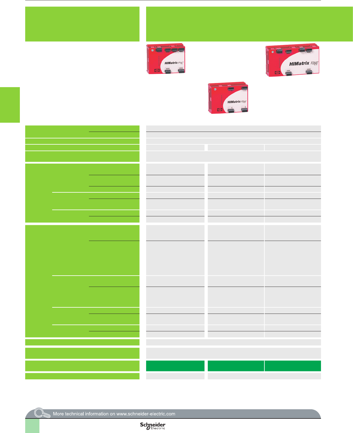
3/128
Selection guide Monitor and Processing
Preventa safety PLCs
Compact and modular, XPSMF
Safety remote input, output and input/output modules
XPSMF1/2/3
Presentation Remote input, output and input/output modules:
bLocation: within the vicinity of machines to be monitored.
bExtension of the I/O capacity of compact and modular safety PLCs.
bDesigned for use in safety related parts of control systems up to category 4, up to
performance level “e”, and up to SIL 3.
Products referenced XPSMF1DI1601 and XPSMF2pppppp are marked HIMatrix F1DI and HIMatrix F2DI . Products referenced XPSMF2ppppppp and XPSMF3ppppppp are marked HIMatrix F2DO and HIMatrix F3...
User memory Application – –
Data – –
Response time Depending on size of application Depending on size of application
Maximum consumption 0.8 A 0.5 A 9 A 0.6 A 0.6 A 8 A 14 A 8 A 0.8 A
Supply External c 24 V supply (with separate protection conforming to EN/IEC 60950, SELV (Safety
Extra Low Voltage) or PELV (Protection Extra Low Voltage) rated)
External c 24 V supply (with separate protection conforming to EN/IEC 60950, SELV (Safety Extra Low Voltage) or PELV (Protection Extra Low Voltage) rated)
Inputs Digital Number of channels 16, not electrically isolated – – – – 8, not electrically isolated 16, not electrically isolated 20, not electrically
isolated
–
Current at state 0 1.5 mA max., 1 mA at 5 V – – – – 1.5 mA max.
1.25 mA at c 5 V
1.5 mA max.
1 mA at c 5 V
1.5 mA max.
1.25 mA at c 5 V
–
Current at state 1 u 2 mA at c 15 V – – – – > 2 mA at c 15 V > 2 mA at c 15 V u 2 mA at c 15 V –
Analogue Number of channels – – – – – – – – 8 single-pole
Range: voltage/current – – – – – – – – c 0…10 V/0…20 mA
(1)
Counting Number of channels – – – – – – – – –
Current – – – – – – – – –
Outputs Digital Number of channels – 4, not electrically isolated 16, not electrically isolated – – 8 DO+ (reference pole L-)
2 DO- (reference pole S+)
8 2-pole or
16 single-pole, not
electrically isolated
8, not electrically
isolated (2)
–
Output current – 5 A max. 1 A max. at 60 °C,
2 A max. at 40 °C
– – DO+:
channels 1 to 3 and 5 to 7:
0.5 A at 60 °C
channels 4 and 8:
1 A at 60 °C, 2 A at 40 °C
DO-:
channels 1 and 2: 1 A at 60 °C
2 A max. at 40 °C,
1 A max. at 60 °C,
10 mA min.
Channels 1 to 3 and
5 to 7: 0.5 A at 60 °C
Channels 4 and 8:
1 A at 60 °C,
2 A at 50 °C
–
Analogue Number of channels – – – – – – – – 4 non safety related
outputs
Range: voltage/current – – – – – – – – Usable range:
0…20 mA
Nominal range:
4…20 mA
Relay Number – – – 816 – – – –
Switching voltage – – – u 5 V,
y c 250 V/ a 250 V
u 5 V,
y c 60 V/ a 30 V
– – – –
Line control Number 4, not electrically isolated – – – – 2, not electrically isolated – –
Current/Voltage 60 mA/20 V – – – – 60 mA/20 V 60 mA/20 V – –
Input/output connections Removable screw terminal blocks (1) Removable screw terminal blocks (3)
Safety communication on Ethernet network using
SafeEthernet protocol
Yes, access to network via integrated 2 RJ45 switched Ethernet communications ports Yes, access to network via integrated 2 RJ45 switched Ethernet communications ports
Safety remote I/O module type XPSMF1DI1601 XPSMF2DO401 XPSMF2DO1601 XPSMF2DO801 XPSMF2DO1602 XPSMF3DIO8801 XPSMF3DIO16801 XPSMF3DIO20802 XPSMF3AIO8401
See page 3/130 3/132 3/132 3/135
(1) Removable screw terminal blocks are provided with safety remote I/O modules XPSMF1/2/3.(1) With 500
W
shunt
(2) Congurable for Line control.
(3) Removable screw terminal blocks are provided with safety remote I/O modules XPSMF1/2/3.
2
1
3
4
5
6
7
8
9
10
2
1
3
4
5
6
7
8
9
10
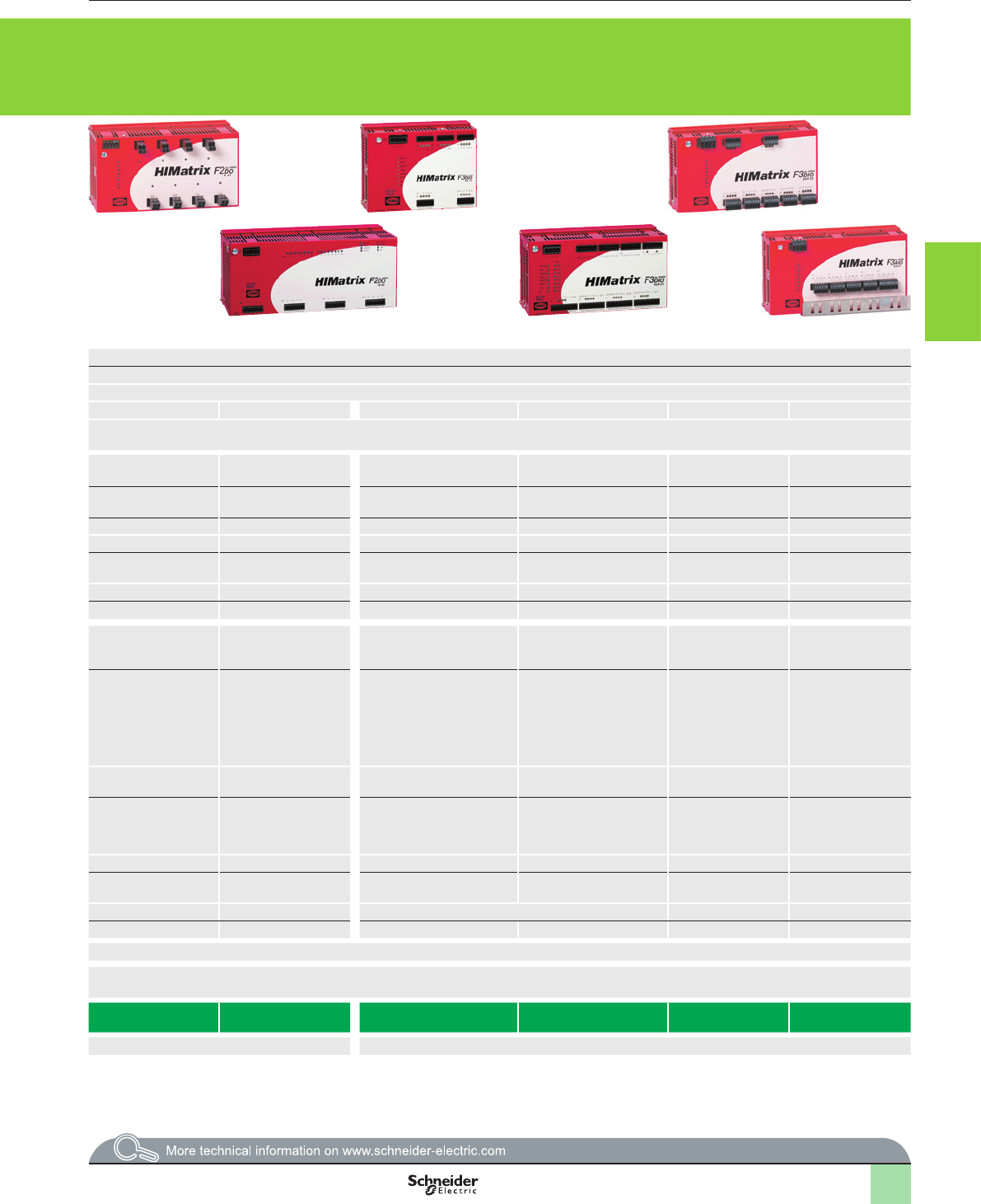
3/129
Presentation Remote input, output and input/output modules:
bLocation: within the vicinity of machines to be monitored.
bExtension of the I/O capacity of compact and modular safety PLCs.
bDesigned for use in safety related parts of control systems up to category 4, up to
performance level “e”, and up to SIL 3.
Products referenced XPSMF1DI1601 and XPSMF2pppppp are marked HIMatrix F1DI and HIMatrix F2DI . Products referenced XPSMF2ppppppp and XPSMF3ppppppp are marked HIMatrix F2DO and HIMatrix F3...
User memory Application – –
Data – –
Response time Depending on size of application Depending on size of application
Maximum consumption 0.8 A 0.5 A 9 A 0.6 A 0.6 A 8 A 14 A 8 A 0.8 A
Supply External c 24 V supply (with separate protection conforming to EN/IEC 60950, SELV (Safety
Extra Low Voltage) or PELV (Protection Extra Low Voltage) rated)
External c 24 V supply (with separate protection conforming to EN/IEC 60950, SELV (Safety Extra Low Voltage) or PELV (Protection Extra Low Voltage) rated)
Inputs Digital Number of channels 16, not electrically isolated – – – – 8, not electrically isolated 16, not electrically isolated 20, not electrically
isolated
–
Current at state 0 1.5 mA max., 1 mA at 5 V – – – – 1.5 mA max.
1.25 mA at c 5 V
1.5 mA max.
1 mA at c 5 V
1.5 mA max.
1.25 mA at c 5 V
–
Current at state 1 u 2 mA at c 15 V – – – – > 2 mA at c 15 V > 2 mA at c 15 V u 2 mA at c 15 V –
Analogue Number of channels – – – – – – – – 8 single-pole
Range: voltage/current – – – – – – – – c 0…10 V/0…20 mA
(1)
Counting Number of channels – – – – – – – – –
Current – – – – – – – – –
Outputs Digital Number of channels – 4, not electrically isolated 16, not electrically isolated – – 8 DO+ (reference pole L-)
2 DO- (reference pole S+)
8 2-pole or
16 single-pole, not
electrically isolated
8, not electrically
isolated (2)
–
Output current – 5 A max. 1 A max. at 60 °C,
2 A max. at 40 °C
– – DO+:
channels 1 to 3 and 5 to 7:
0.5 A at 60 °C
channels 4 and 8:
1 A at 60 °C, 2 A at 40 °C
DO-:
channels 1 and 2: 1 A at 60 °C
2 A max. at 40 °C,
1 A max. at 60 °C,
10 mA min.
Channels 1 to 3 and
5 to 7: 0.5 A at 60 °C
Channels 4 and 8:
1 A at 60 °C,
2 A at 50 °C
–
Analogue Number of channels – – – – – – – – 4 non safety related
outputs
Range: voltage/current – – – – – – – – Usable range:
0…20 mA
Nominal range:
4…20 mA
Relay Number – – – 816 – – – –
Switching voltage – – – u 5 V,
y c 250 V/ a 250 V
u 5 V,
y c 60 V/ a 30 V
– – – –
Line control Number 4, not electrically isolated – – – – 2, not electrically isolated – –
Current/Voltage 60 mA/20 V – – – – 60 mA/20 V 60 mA/20 V – –
Input/output connections Removable screw terminal blocks (1) Removable screw terminal blocks (3)
Safety communication on Ethernet network using
SafeEthernet protocol
Yes, access to network via integrated 2 RJ45 switched Ethernet communications ports Yes, access to network via integrated 2 RJ45 switched Ethernet communications ports
Safety remote I/O module type XPSMF1DI1601 XPSMF2DO401 XPSMF2DO1601 XPSMF2DO801 XPSMF2DO1602 XPSMF3DIO8801 XPSMF3DIO16801 XPSMF3DIO20802 XPSMF3AIO8401
See page 3/130 3/132 3/132 3/135
(1) Removable screw terminal blocks are provided with safety remote I/O modules XPSMF1/2/3.(1) With 500
W
shunt
(2) Congurable for Line control.
(3) Removable screw terminal blocks are provided with safety remote I/O modules XPSMF1/2/3.
2
1
3
4
5
6
7
8
9
10
2
1
3
4
5
6
7
8
9
10
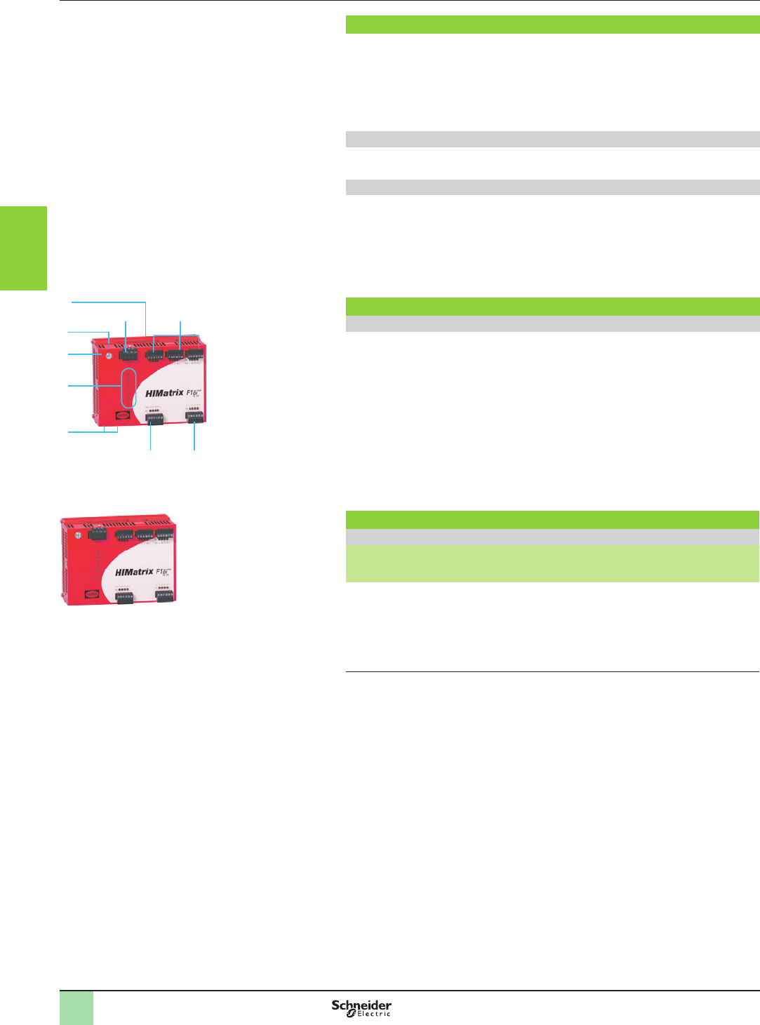
3/130
Presentation,
description,
references
Monitor and Processing
Preventa safety PLCs
Compact and modular
Safety remote input modules XPSMF1
Presentation
XPSMF1DI1601 is a compact safety remote input module which is designed to
extend the input capacity of safety PLCs XPSMF, either compact or modular, to
which it is associated.
The communication with either the compact or modular safety PLCs is managed
via one of its’ integrated 2 RJ45 switched Ethernet communications ports.
The safety remote input module XPSMF1DI1601 does not have a user program:
it receives its instructions from its’ parent safety PLC.
Safety remote input module XPSMF1DI1601
bRemote digital inputs: 16
bRemote line control outputs: 4 (Short-circuit and line break monitoring)
Safety communication on Ethernet network
The safety input module XPSMF1DI1601 incorporates two RJ45 (type 10BASE-
T/100BASE-TX) integrated switched ports, that enable communication on the
Ethernet network using SafeEthernet communication protocol and therefore, data
exchange with compact or modular safety PLCs XPSMF.
vBaud rate: 100 Mbps Half duplex, 10 Mbps Full duplex, + Autonegotiation,
vStructure: 10BASE-T/100BASE-TX,
vMedium : Dual twisted pair cable, category 5D or better (Ethernet).
Description
Safety remote input module XPSMF1DI1601
On the front face of the metal enclosure:
1 One terminal block (1) for c 24 V supply.
2 Four terminal blocks (1) for connection of digital inputs, with input status LED (four
LEDs per terminal block).
3 One terminal block (1) for connection of digital line control outputs, with four digital
output status LEDs.
4 Two RJ45 (type 10BASE-T/100BASE-TX) integrated switched ports, for
connection on Ethernet network and for conguring IP address.
5 Eight process status LEDs.
6 One earth connection screw.
7 On the top: one “Reset” button.
8 On the rear face: one spring operated xing device for mounting on 35 mm 5 rail.
References
Safety remote input module (c 24 V supply)
For use with Digital
inputs
Line
control
outputs
Ports Reference Weight
kg/
lb
Safety PLCs,
modular XPSMF60
or compact
XPSMF40 and
XPSMF31/30/35
16 4 Integrated 2 RJ45
switched Ethernet
communications ports
XPSMF1DI1601 0.700/
1.543
This product, referenced
XPSMF1DI1601, is
marked HIMatrix F1DI.
1 2
2 3
4
5
6
7
8
XPSMF1DI1601
2
1
3
4
5
6
7
8
9
10
2
1
3
4
5
6
7
8
9
10
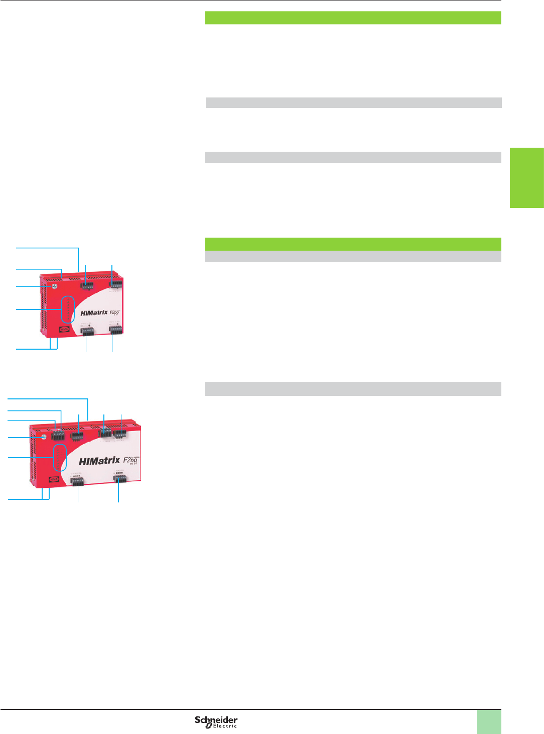
3/131
Presentation,
description
Monitor and Processing
Preventa safety PLCs
Compact and modular
Safety remote output modules XPSMF2
Presentation
XPSMF2DOpppp are compact safety remote output modules which are designed
to extend the output capacity of safety PLCs XPSMF, either compact or modular,
to which they are associated.
The communication with either the compact or modular safety PLCs is managed
via one of its’ integrated 2 RJ45 switched Ethernet communications ports.
Safety modules XPSMF2DOpppp do not have a user program: they receive their
instructions from its’ parent safety PLC.
Safety remote output modules XPSMF2DOpppp
bXPSMF2DO401 : 4 digital power outputs
bXPSMF2DO1601 : 16 digital outputs
bXPSMF2DO801 : 8 relay outputs
bXPSMF2DO1602 : 16 relay outputs
Safety communication on Ethernet network
The safety remote output modules XPSMF2DOpppp incorporate two RJ45 (type
10BASE-T/100BASE-TX) integrated switched ports, that enable communication on
the Ethernet network using SafeEthernet communication protocol and therefore,
data exchange with compact or modular safety PLCs XPSMF.
vBaud rate: 100 Mbps Half duplex, 10 Mbps Full duplex, + Autonegotiation,
vStructure: 10BASE-T/100BASE-TX,
vMedium: Dual twisted pair cable, category 5D or better (Ethernet)
Description
Remote output module XPSMF2DO401
On the front face of the metal enclosure:
1 Two RJ45 (type 10BASE-T/100BASE-TX) integrated switched ports, for
connection on Ethernet network and for conguring IP address.
2 Eight process status LEDs.
3 One earth connection screw.
4 Four terminal blocks (1) for connection of digital outputs, with output status LED
(one LED per terminal block).
5 On the top: one “Reset” button.
6 On the rear face:
one spring operated xing device for mounting on 35 mm 5 rail.
Remote output module XPSMF2DO1601
On the front face of the metal enclosure:
1 Two RJ45 (type 10BASE-T/100BASE-TX) integrated switched ports, for
connection on Ethernet network and for conguring IP address.
2 Eight process status LEDs.
3 One earth connection screw.
4 One terminal block (1) for c 24 V supply.
5 Four terminal blocks (1) for connection of digital outputs, with output status LED
(four LEDs per terminal block).
6 One terminal block for connection of output channels.
7 On the top: one “Reset” button.
8 On the rear face:
one spring operated xing device for mounting on 35 mm 5 rail.
8
7
4
3
2
1
5 5
555
XPSMF2DO1601
1
2
4 4
4 4
3
5
6
XPSMF2DO401
Products referenced
XPSMF2pppppp are
marked HIMatrix F2 DO...
2
1
3
4
5
6
7
8
9
10
2
1
3
4
5
6
7
8
9
10
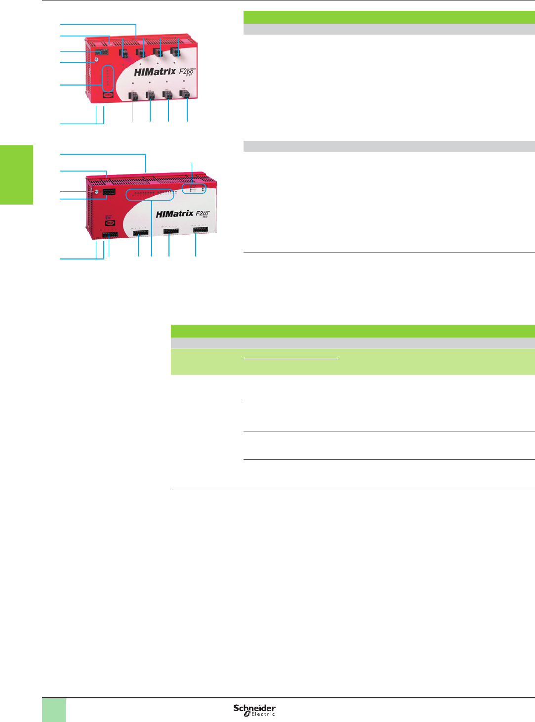
3/132
Description,
references
Monitor and Processing
Preventa safety PLCs
Compact and modular
Safety remote output modules XPSMF2
1
2
4
5
5 5
3
6
7
5
5 5
5
5
1
2
5 5
3
4
7
55
6
5
Description (continued)
Remote output module XPSMF2DO801
On the front face of the metal enclosure:
1 Two RJ45 (type 10BASE-T/100BASE-TX) integrated switched ports, for
connection on Ethernet network and for conguring IP address.
2 Eight process status LEDs.
3 One earth connection screw.
4 One terminal block (1) for c 24 V supply.
5 Eight terminal blocks (1) for connection of relay outputs, with output status LED
(one LED per terminal block).
6 On the top: one “Reset” button.
7 On the rear face:
one spring operated xing device for mounting on 35 mm 5 rail.
Remote output module XPSMF2DO1602
On the front face of the metal enclosure:
1 Two RJ45 (type 10BASE-T/100BASE-TX) integrated switched ports, for
connection on Ethernet network and for conguring IP address.
2 One terminal block (1) for c 24 V supply.
3 One earth connection screw.
4 Eight process status LEDs.
5 Four terminal blocks (1) for connection of relay outputs, with relay output status
LEDs.
6 On the top: one “Reset” button.
7 On the rear face:
one spring operated xing device for mounting on 35 mm 5 rail.
(1) Removable screw terminals are provided with the safety output modules XPSMF2.
XPSMF2DO1602
XPSMF2DO801
Products referenced
XPSMF2pppppp are
marked HIMatrix F2 DO...
References
Safety remote output modules (c 24 V supply)
For use with Outputs Ports Reference Weight
kg/
lb
Digital Relay
Safety PLCs, modular
XPSMF60 or compact
XPSMF40 and
XPSMF31/30/35
4 – Integrated 2 RJ45 switched
Ethernet communications ports
XPSMF2DO401 0.800/
1.764
16 – Integrated 2 RJ45 switched
Ethernet communications ports
XPSMF2DO1601 0.850/
1.874
–8Integrated 2 RJ45 switched
Ethernet communications ports
XPSMF2DO801 1.300/
2.866
– 16 Integrated 2 RJ45 switched
Ethernet communications ports
XPSMF2DO1602 2.000/
4.409
2
1
3
4
5
6
7
8
9
10
2
1
3
4
5
6
7
8
9
10
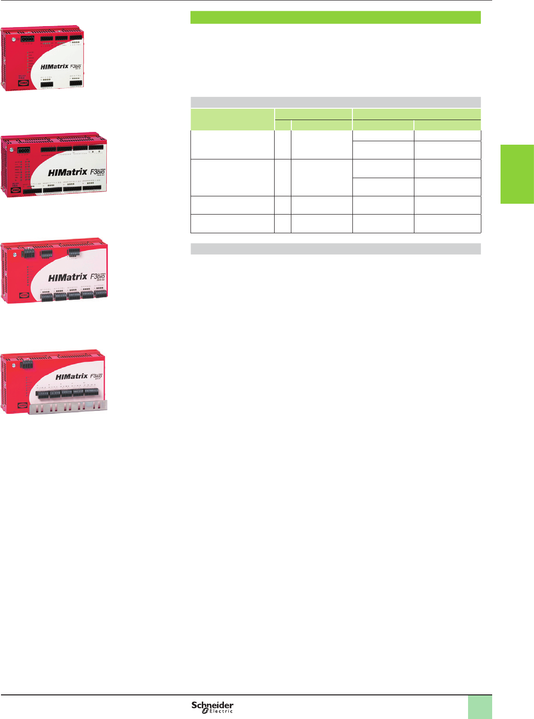
3/133
Presentation Monitor and Processing
Preventa safety PLCs
Compact and modular
Safety remote mixed I/O modules XPSMF3
XPSMF3DIO8801
XPSMF3DIO16801
XPSMF3DIO20802
XPSMF3AIO8401
Products referenced XPSMF2pppppp are
marked HIMatrix F2 DO...
Presentation
XPSMF3DIO/AIO are compact safety remote input/output modules which are
designed to extend the I/O capacity of safety PLCs XPSMF, either compact or
modular, to which they are associated.
The communication with either the compact or modular safety PLCs is managed
via one of its’ integrated 2 RJ45 switched Ethernet communications ports.
Safety modules XPSMF3DIO/AIO do not have a user program: they receive their
instructions from its’ parent safety PLC.
Safety remote mixed I/O modules XPSMF3DIO/AIO
Mixed I/O safety
modules
Remote inputs Remote outputs
N° Type N° Type
XPSMF3DIO8801 8 Digital 8 DO+ / 2 DO- Digital
2 Line control
XPSMF3DIO16801 16 Digital 8 2-pole
or 16 single-pole
Digital
2 Line control
XPSMF3DIO20802 20 Digital 8Digital
XPSMF3AIO8401 8 Analogue 4Analogue (non
safety outputs)
Safety communication on Ethernet network
The safety remote mixed I/O modules XPSMF3pIOpppp incorporate two RJ45 (type
10BASE-T/100BASE-TX) integrated switched ports, that enable communication on
the Ethernet network using SafeEthernet communication protocol and therefore,
data exchange with compact or modular safety PLCs XPSMF.
bBaud rate: 100 Mbps Half duplex, 10 Mbps Full duplex, + Autonegotiation,
bStructure: 10BASE-T/100BASE-TX,
bMedium: Dual twisted pair cable, category 5D or better (Ethernet).
2
1
3
4
5
6
7
8
9
10
2
1
3
4
5
6
7
8
9
10
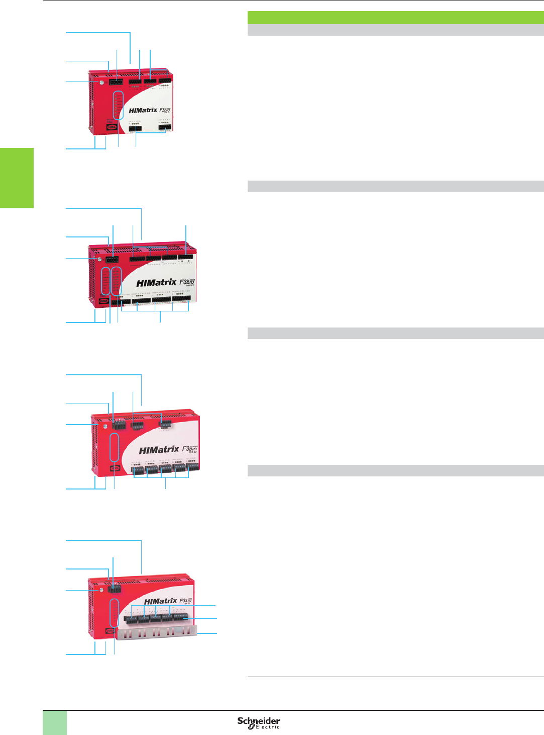
3/134
Description Monitor and Processing
Preventa safety PLCs
Compact and modular
Safety remote mixed I/O modules XPSMF3
Description
Remote mixed I/O module XPSMF3DIO8801
On the front face of the metal enclosure:
1 One terminal block (1) for c 24 V supply.
2 One terminal block (1) for connection of line control outputs, with four line control
output status LEDs.
3 Two terminal blocks (1) for connection of digital outputs, with output status LED
(four LEDs per terminal block).
4 Two terminal blocks (1) for connection of digital inputs, with input status LED (four
LEDs per terminal block).
5 Eight process status LEDs.
6 Two RJ45 (type 10BASE-T/100BASE-TX) integrated switched ports, for
connection on Ethernet network and for conguring IP address.
7 One earth connection screw.
8 One “Reset” button (on the top).
9 On the rear face:
One spring operated xing device for mounting on 35 mm 5 rail.
Remote mixed I/O module XPSMF3DIO16801
On the front face of the metal enclosure:
1 One terminal block (1) for c 24 V supply.
2 Three terminal blocks for connection of digital output channels.
3 One terminal block (1) for connection of line control outputs.
4 Four terminal blocks (1) for connection of digital inputs, with input status LED (four
LEDs per terminal block).
5 Sixteen digital output status LEDs.
6 Eight process status LEDs.
7 Two RJ45 (type 10BASE-T/100BASE-TX) integrated switched ports, for
connection on Ethernet network and for conguring IP address.
8 One earth connection screw.
9 One “Reset” button (on the top).
10 On the rear face:
One spring operated xing device for mounting on 35 mm 5 rail.
Remote mixed I/O module XPSMF3DIO20802
On the front face of the metal enclosure:
1 One terminal block (1) for c 24 V supply.
2 Two terminal blocks (1) for connection of digital outputs, with output status LED
(four LEDs per terminal block)
3 Five terminal blocks (1) for connection of digital inputs, with input status LED (four
LEDs per terminal block).
4 Eight process status LEDs.
5 Two RJ45 (type 10BASE-T/100BASE-TX) integrated switched ports, for
connection on Ethernet network and for conguring IP address.
6 One earth connection screw.
7 One “Reset” button (on the top).
8 On the rear face:
One spring operated xing device for mounting on 35 mm 5 rail.
Remote mixed I/O module XPSMF3AIO8401
On the front face of the metal enclosure:
1 One terminal block (1) for c 24 V supply.
2 Four terminal blocks (1) for connection of analogue inputs.
3 One terminal block (1) for connection of analogue outputs.
4 One metal plate for securing shielded analogue input/output connection cables
(EMC).
5 Eight process status LEDs.
6 TwTwo RJ45 (type 10BASE-T/100BASE-TX) integrated switched ports, for
connection on Ethernet network and for conguring IP address.
7 One earth connection screw.
8 One “Reset” button (on the top).
9 On the rear face:
one spring operated xing device for mounting on 35 mm 5 rail.
(1) Removable screw terminals are provided with the safety remote mixed I/O modules
XPSMF3DIO/AIO.
1 2
34
5
6
7
8
1
3
5
6
7
8
9
2
4
1 2
4
5
7
8
9
10
3
6
5
1 2
4
6
7
8
9
3
5
1 2
34
5
6
7
8
1
3
5
6
7
8
9
2
4
1 2
4
5
7
8
9
10
3
6
5
1 2
4
6
7
8
9
3
5
1 2
34
5
6
7
8
1
3
5
6
7
8
9
2
4
1 2
4
5
7
8
9
10
3
6
5
1 2
4
6
7
8
9
3
5
1 2
34
5
6
7
8
1
3
5
6
7
8
9
2
4
1 2
4
5
7
8
9
10
3
6
5
1 2
4
6
7
8
9
3
5
2
1
3
4
5
6
7
8
9
10
2
1
3
4
5
6
7
8
9
10
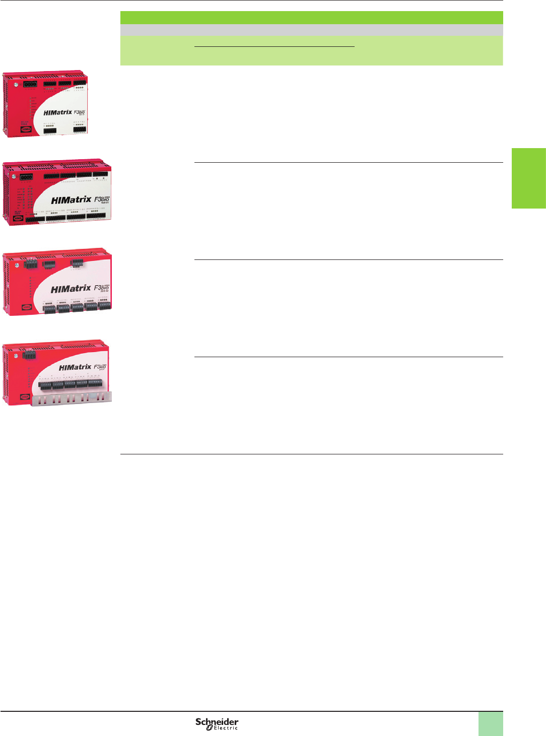
3/135
References Monitor and Processing
Preventa safety PLCs
Compact and modular
Safety remote mixed I/O modules XPSMF3
XPSMF3DIO8801
XPSMF3DIO16801
XPSMF3DIO20802
XPSMF3AIO8401
References
Safety remote mixed I/O modules (c 24 V supply)
For use with Inputs Outputs Ports Reference Weight
kg/
lb
Digital Analogue Digital Line
control
Analogue
Safety PLCs, modular
XPSMF60 or compact
XPSMF40 and
XPSMF31/30/35
8–8 DO+
2 DO-
2 – Integrated 2 RJ45
switched Ethernet
communications
ports
XPSMF3DIO8801 1.000/
2.205
16 – 8 x 2
or
16 x 1
2 – Integrated 2 RJ45
switched Ethernet
communications
ports
XPSMF3DIO16801 1.300/
2.866
20 –8 (1) – – Integrated 2 RJ45
switched Ethernet
communications
ports
XPSMF3DIO20802 1.000/
2.205
–8– – 4 Integrated 2 RJ45
switched Ethernet
communications
ports
XPSMF3AIO8401 0.950/
2.094
(1) Congurable for line control.
Products referenced
XPSMF3pppppp are
marked HIMatrix F3...
2
1
3
4
5
6
7
8
9
10
2
1
3
4
5
6
7
8
9
10
3/136
References Monitor and Processing
Preventa safety PLCs
Accessories
Conguration software
bReference SSV1XPSMFWIN is the full version of software XPSMFWIN version 4.1 and must be installed if no
previous version of this software has been installed.
Description Operating system Languages Reference Weight
kg/
lg
Conguration software
XPSMFWIN for
programming compact
safety PLCs
CD-ROM + user manual
Windows 2000,
Windows XP
English,
German,
French
SSV1XPSMFWIN 0,520/
1.146
Phaseo regulated switch mode power supplies
Mains input
voltage
Output
voltage
Nominal
power
Nominal
current
Auto-protect
reset
Conformity to
standard
IEC EN 61000-3-2
and IEC EN 60950
Reference Weight
Vc V W A kg/
lg
Single-phase (N-L1) or 2-phase (L1-L2) connection
a 100…120 V/200...500
- 15%, + 10%
50/60 Hz
24...28.8 72 3 Auto/Manual Yes ABL8RPS24030 0.300/
0.661
120 5 Auto/Manual Yes ABL8RPS24050 0.700/
1.543
240 10 Auto/Manual Yes ABL8RPS24100 1.000/
2.205
Single-phase connection
a 100…240 (1)
wide range, 47…63 Hz
12 60 5 Auto No ABL1REM12050 0.440/
0.970
24 60 2.5 Auto No ABL1REM24025 0.440/
0.970
a 100...120/200...240 (2) 24 240 10 Auto No ABL1REM24100 0.880/
1.940
Magelis multifunction graphic terminals
Magelis multifunction graphic terminals with touch sensitive screen and on-board Ethernet:
see our offer on www.schneider-electric.com
ABL8RPS24050
ABL1REM24025
2
1
3
4
5
6
7
8
9
10
2
1
3
4
5
6
7
8
9
10
3/137
References Monitor and Processing
Preventa safety PLCs
Accessories
Connecting cables for network and bus
Connection to Ethernet network
Cable conforming to standard EIA/TIA-568 category 5 and IEC 1180/EN 50 173 class D. For UL and CSA 22.1 approved cables,
add the letter U to the end of the reference.
Description Pre-tted connectors Length
(m)
Reference Weight
kg
Shielded twisted pair cables,
straight through
2 RJ45 connectors
For connection to DTE
(Data Terminal Equipment)
2490NTW00002 –
5490NTW00005 –
12 490NTW00012 –
40 490NTW00040 –
80 490NTW00080 –
Shielded twisted pair cables,
crossed wires
2 RJ45 connectors
For connection between hubs, switches and
transceivers
5490NTC00005 –
15 490NTC00015 –
40 490NTC00040 –
80 490NTC00080 –
Connection to Modbus serial link
Description Use Length
(m)
Reference Weight
kg/
lb
From To
Trunk cables, shielded dual
twisted pair, RS 485
Compact safety PLCs
XPSMF4020/MF4022
(RJ45)
Modbus splitter box
LU9GC3 (RJ45)
100 TSXCSA100 5.680/
12.552
200 TSXCSA200 10.920/
24.074
500 TSXCSA500 30.000/
66.139
Graphic terminals XBTGT
(SUB-D 9-pin)
Modbus splitter box
LU9GC3 (RJ45)
2.5 XBTZ938
(1)
0.210/
0.463
Adaptor for cable XBTZ938 SUB-D 9-pin (XBTGT) XBTZ938
(SUB-D 25-pin)
0.2 XBTZG909 –
Description Characteristics Sold in
lots of
Unit reference Weight
kg/
lb
End of line adaptors
For RJ45 connector R = 120 W,
C = 1 nF
2VW3A8306RC 0.200/
0.441
R = 150 W2VW3A8306R 0.010/
0.022
PROFIBUS DP bus connection components
Description Prole Services Reference Weight
kg/
lb
PROFIBUS DP module set for
Premium PLCs
Master, 12 Mbps Class 1 and Class 2 master V0
functions, see characteristics.
PROFIBUS FMS messaging not
supported
TSXPBY100 0.870/
1.918
Description Use Reference Weight
kg/
lb
Remote inputs/outputs on
PROFIBUS DP bus
Modicon STB network interface module STBNDP2112 0.140/
0.309
Momentum communication module 170DTN11000 –
Connectors for remote I/O
communication module
Line terminators 490NAD91103 –
Intermediate connection 490NAD91104 –
Intermediate connection and terminal port 490NAD91105 –
Description Length
(m)
Reference Weight
kg
PROFIBUS DP connecting
cables
100 TSXPBSCA100 –
400 TSXPBSCA400 –
Description Reference Weight
kg
Replacement parts Main bus junction box 490NAE91100 –
PCMCIA card 467NHP81100 –
(1) Requires adaptor XBTZG909.
490NTW000pp
+
490NAD91103
+
+
TSXPBY100
2
1
3
4
5
6
7
8
9
10
2
1
3
4
5
6
7
8
9
10
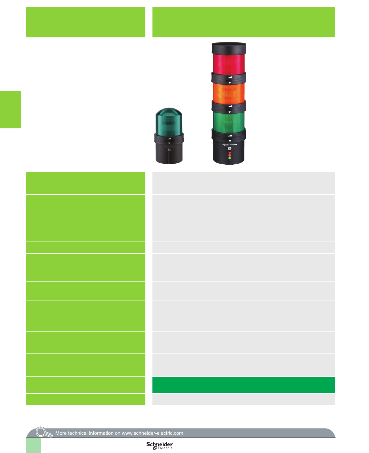
3/138
Selection guide Stop the machine
Signalling units for safety applications
Applications Illuminated beacons and tower lights Rotating beacons for long distance signalling applications Sirens and electronic alarms for long distance signalling applications
Features Direct xing or on support tube Super Bright LED Power
- 106 db, 2 tones
- 105 db, 43 tones
Conformity to standards EN/IEC 60947-5-1,
UL 508,
CSA C22-2 n°14,
CCC,
Gost
Ø 84 to 120 mm : EN/IEC 61000-6-2 and EN/IEC 61000-6-4,
Ø 130 mm: EN/IEC 60947-1 and EN/IEC 60947-5-1,
UL 508,
CSA C22-2-14
XVS10 and XVS14: EN/IEC 60947-1 andEN/IEC 60947-5-1,
XVS14BMW: EN/IEC 61000-6-2 and EN/IEC 61000-6-3
Protective treatment Standard version, “TC” Standard version, “TC” Standard version, “TC”
Ambient temperature
See page 3/140
Ø 84 to 120 mm: - 10..+ 50 °C,
Ø 130 mm: - 30..+ 50 °C ()
XVS10: - 30..+ 50 °C
XVS14: - 10..+ 50 °C
For operation
For storage - 40…+ 70 °C - 35…+ 70 °C - 35…+ 70 °C
Electric shock protection conforming to IEC 61140 Class I: mounted on support tube
Class II: mounted directly
Class II Class II
Degree of protection
conforming to IEC 60529, UL 508 and CSA C22-2 n° 14
IP 65 (mounted on xing base XVB Z0p)
IP 66 (mounted directly on base unit)
Ø 84: IP 23 (
IP 65 with accessory),
Ø 106: IP 23 (
IP 55 with accessory),
Ø 120: IP 23,
Ø 130: IP 66 and/or IP 67
IP 53
Rated insulation voltage Ui = 250 V conforming to EN/IEC 60947-1 – –
Rated impulse withstand voltage
conforming to
EN/IEC 60947-1
Uimp = 4 kV Ø 84 to 120 mm: Uimp = 0.8 kV,
Ø 130 mm: Uimp = 4 kV
z 12-24
and
c 12/24 V:
Uimp = 0.8 kV,
z 120/230 and a 120/240 V: Uimp = 4 kV
Type references XVBL, XVBC XVR XVS10, XVS14
Pages 3/140 3/149 3/151
2
1
3
4
5
6
7
8
9
10
2
1
3
4
5
6
7
8
9
10
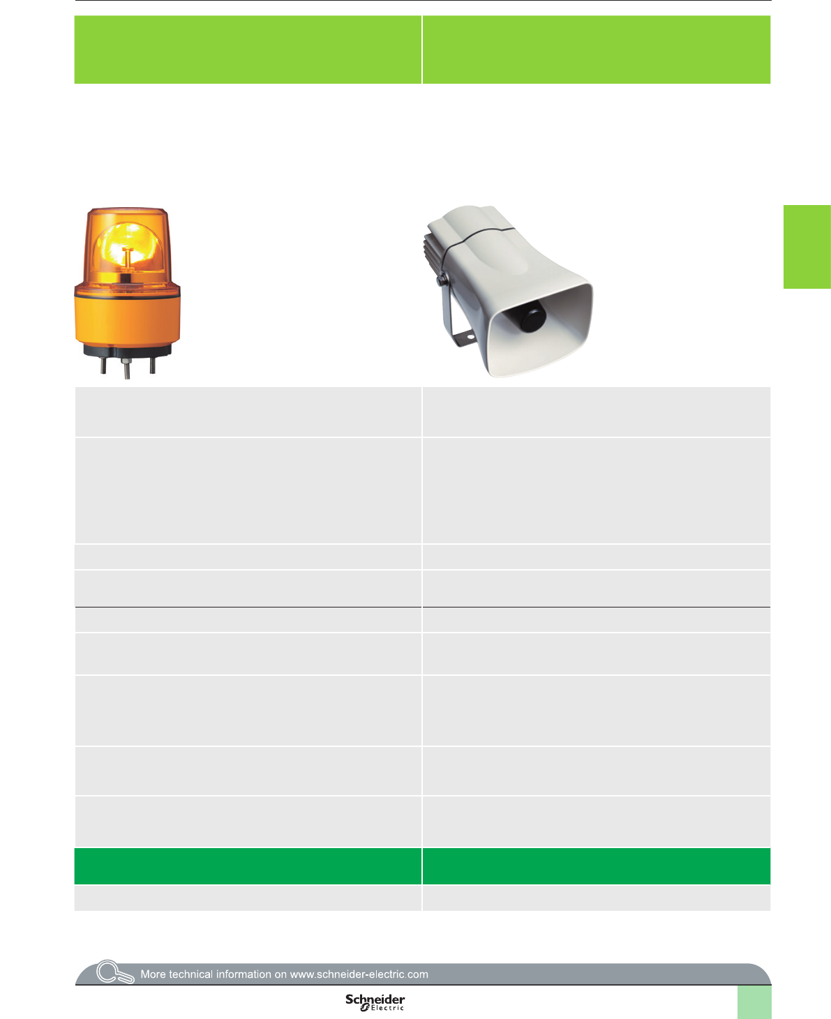
3/139
Applications Illuminated beacons and tower lights Rotating beacons for long distance signalling applications Sirens and electronic alarms for long distance signalling applications
Features Direct xing or on support tube Super Bright LED Power
- 106 db, 2 tones
- 105 db, 43 tones
Conformity to standards EN/IEC 60947-5-1,
UL 508,
CSA C22-2 n°14,
CCC,
Gost
Ø 84 to 120 mm : EN/IEC 61000-6-2 and EN/IEC 61000-6-4,
Ø 130 mm: EN/IEC 60947-1 and EN/IEC 60947-5-1,
UL 508,
CSA C22-2-14
XVS10 and XVS14: EN/IEC 60947-1 andEN/IEC 60947-5-1,
XVS14BMW: EN/IEC 61000-6-2 and EN/IEC 61000-6-3
Protective treatment Standard version, “TC” Standard version, “TC” Standard version, “TC”
Ambient temperature
See page 3/140
Ø 84 to 120 mm: - 10..+ 50 °C,
Ø 130 mm: - 30..+ 50 °C ()
XVS10: - 30..+ 50 °C
XVS14: - 10..+ 50 °C
For operation
For storage - 40…+ 70 °C - 35…+ 70 °C - 35…+ 70 °C
Electric shock protection conforming to IEC 61140 Class I: mounted on support tube
Class II: mounted directly
Class II Class II
Degree of protection
conforming to IEC 60529, UL 508 and CSA C22-2 n° 14
IP 65 (mounted on xing base XVB Z0p)
IP 66 (mounted directly on base unit)
Ø 84: IP 23 (
IP 65 with accessory),
Ø 106: IP 23 (
IP 55 with accessory),
Ø 120: IP 23,
Ø 130: IP 66 and/or IP 67
IP 53
Rated insulation voltage Ui = 250 V conforming to EN/IEC 60947-1 – –
Rated impulse withstand voltage
conforming to
EN/IEC 60947-1
Uimp = 4 kV Ø 84 to 120 mm: Uimp = 0.8 kV,
Ø 130 mm: Uimp = 4 kV
z 12-24
and
c 12/24 V:
Uimp = 0.8 kV,
z 120/230 and a 120/240 V: Uimp = 4 kV
Type references XVBL, XVBC XVR XVS10, XVS14
Pages 3/140 3/149 3/151
2
1
3
4
5
6
7
8
9
10
2
1
3
4
5
6
7
8
9
10
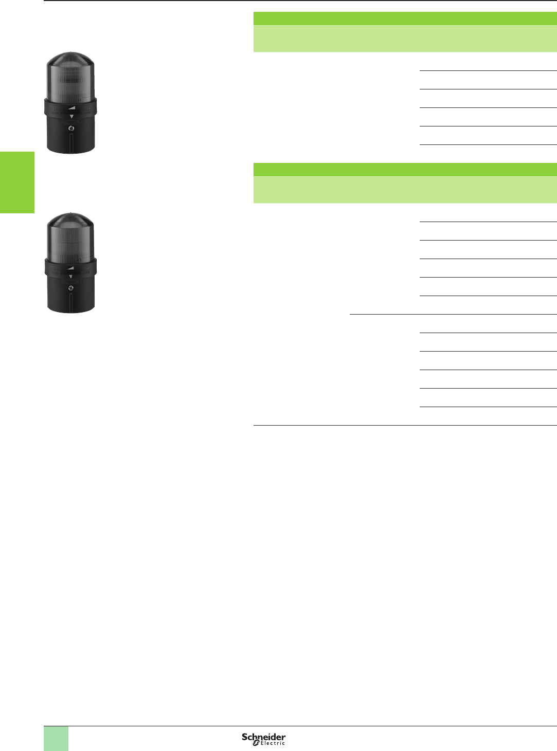
3/140
Stop the machine
Modular tower lights
Harmony® type XVBL Ø 70 mm
Illuminated beacons for incandescent bulbs or LEDs
(BA 15d base tting)
Illuminated beacons with steady light signalling
Description Light source,
to be ordered
separately (1)
Colour Reference Weight
kg
Complete unit
comprising:
- 1 illuminated unit
- 1 base unit for direct xing
(IP 66) or tube xing (IP 65)
Incandescent bulb
7 W max.
250 V max.
Green XVBL33 0.260
Red XVBL34 0.260
Orange XVBL35 0.260
Blue XVBL36 0.260
Clear XVBL37 0.260
Yellow XVBL38 0.260
Illuminated beacons with integral ashing light signalling
Description Light source,
to be ordered
separately (1)
Colour Reference Weight
kg
Complete unit
comprising:
- 1 illuminated unit
- 1 base unit for direct xing
(IP 66) or tube xing (IP 65)
Incandescent bulb
7 W max.
a 24 V
c 24…48 V
Green XVBL4B3 0.280
Red XVBL4B4 0.280
Orange XVBL4B5 0.280
Blue XVBL4B6 0.280
Clear XVBL4B7 0.280
Yellow XVBL4B8 0.280
Incandescent bulb
7 W max.
a 48…230 V
Green XVBL4M3 0.280
Red XVBL4M4 0.280
Orange XVBL4M5 0.280
Blue XVBL4M6 0.280
Clear XVBL4M7 0.280
Yellow XVBL4M8 0.280
(1) Incandescent bulbs and LEDs, see page 3/147.
References
PF110458
PF110456
XVBL3p
XVBL4Bp
1
2
3
4
5
6
7
8
9
10
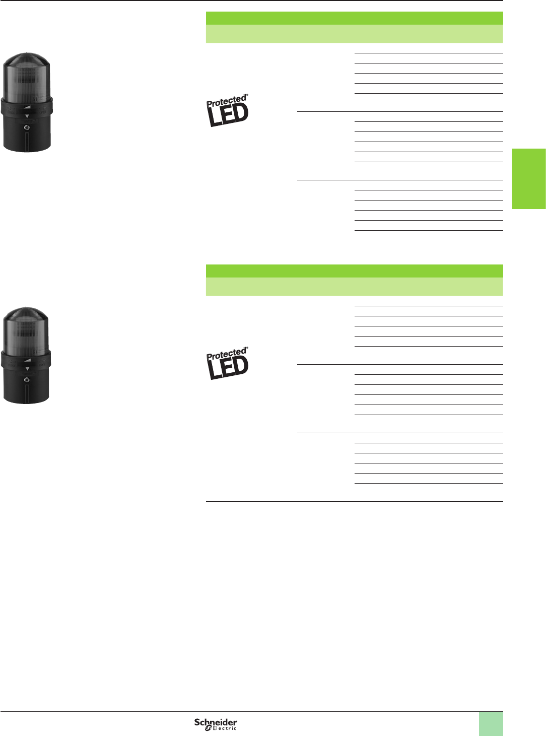
3/141
Stop the machine
Modular tower lights
Harmony® type XVBL Ø 70 mm
Illuminated beacons with LED light source
Illuminated beacons with steady light signalling
Description Light source Colour Reference Weight
kg
Complete unit
comprising:
- 1 illuminated unit
- 1 base unit for direct xing
(IP 66) or tube xing (IP 65)
LED, included
z 24 V
Green XVBL0B3 0.270
Red XVBL0B4 0.270
Orange XVBL0B5 0.270
Blue XVBL0B6 0.270
Clear XVBL0B7 0.270
Yellow XVBL0B8 0.270
LED, included
a 120 V
Green XVBL0G3 0.270
Red XVBL0G4 0.270
Orange XVBL0G5 0.270
Blue XVBL0G6 0.270
Clear XVBL0G7 0.270
Yellow XVBL0G8 0.270
LED, included
a 230 V
Green XVBL0M3 0.270
Red XVBL0M4 0.270
Orange XVBL0M5 0.270
Blue XVBL0M6 0.270
Clear XVBL0M7 0.270
Yellow
XVBL0M8 0.270
Illuminated beacons with integral ashing light signalling
Description Light source Colour Reference Weight
kg
Complete unit
comprising:
- 1 illuminated unit
- 1 base unit for direct xing
(IP 66) or tube xing (IP 65)
LED, included
z 24 V
Green XVBL1B3 0.280
Red XVBL1B4 0.280
Orange XVBL1B5 0.280
Blue XVBL1B6 0.280
Clear XVBL1B7 0.280
Yellow XVBL1B8 0.280
LED, included
a 120 V
Green XVBL1G3 0.280
Red XVBL1G4 0.280
Orange XVBL1G5 0.280
Blue XVBL1G6 0.280
Clear XVBL1G7 0.280
Yellow XVBL1G8 0.280
LED, included
a 230 V
Green XVBL1M3 0.280
Red XVBL1M4 0.280
Orange XVBL1M5 0.280
Blue XVBL1M6 0.280
Clear XVBL1M7 0.280
Yellow XVBL1M8 0.280
References
101407SE
PF110455
XVBL0Bp
XVBL1Bp
1
2
3
4
5
6
7
8
9
10
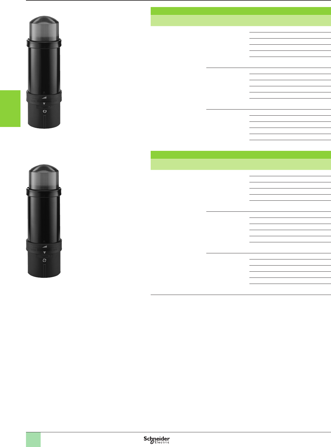
3/142
Stop the machine
Modular tower lights
Harmony® type XVBL Ø 70 mm
Illuminated beacons with ash discharge tube
Illuminated beacons with 5 Joule ash discharge tube
Description Light source Colour Reference Weight
kg
Complete unit
comprising:
- 1 illuminated unit
- 1 base unit for direct xing
(IP 66) or tube xing (IP 65)
Integral ash
discharge tube
z 24 V
Green XVBL6B3 0.440
Red XVBL6B4 0.440
Orange XVBL6B5 0.440
Blue XVBL6B6 0.440
Clear XVBL6B7 0.440
Yellow XVBL6B8 0.440
Integral ash
discharge tube
a 120 V
Green XVBL6G3 0.425
Red XVBL6G4 0.425
Orange XVBL6G5 0.425
Blue XVBL6G6 0.425
Clear XVBL6G7 0.425
Yellow XVBL6G8 0.425
Integral ash
discharge tube
a 230 V
Green XVBL6M3 0.435
Red XVBL6M4 0.435
Orange XVBL6M5 0.435
Blue XVBL6M6 0.435
Clear XVBL6M7 0.435
Yellow XVBL6M8 0.435
Illuminated beacons with 10 Joule ash discharge tube
Description Light source Colour Reference Weight
kg
Complete unit
comprising:
- 1 1 illuminated unit
- 1 base unit for direct xing
(IP 66) or tube xing (IP 65)
Integral ash
discharge tube
z 24 V
Green XVBL8B3 0.450
Red XVBL8B4 0.450
Orange XVBL8B5 0.450
Blue XVBL8B6 0.450
Clear XVBL8B7 0.450
Yellow XVBL8B8 0.450
Integral ash
discharge tube
a 120 V
Green XVBL8G3 0.460
Red XVBL8G4 0.460
Orange XVBL8G5 0.460
Blue XVBL8G6 0.460
Clear XVBL8G7 0.460
Yellow XVBL8G8 0.460
Integral ash
discharge tube
a 230 V
Green XVBL8M3 0.460
Red XVBL8M4 0.460
Orange XVBL8M5 0.460
Blue XVBL8M6 0.460
Clear XVBL8M7 0.460
Yellow XVBL8M8 0.460
References
PG110104SEPF110457
XVBL8Bp
XVBL6Bp
1
2
3
4
5
6
7
8
9
10
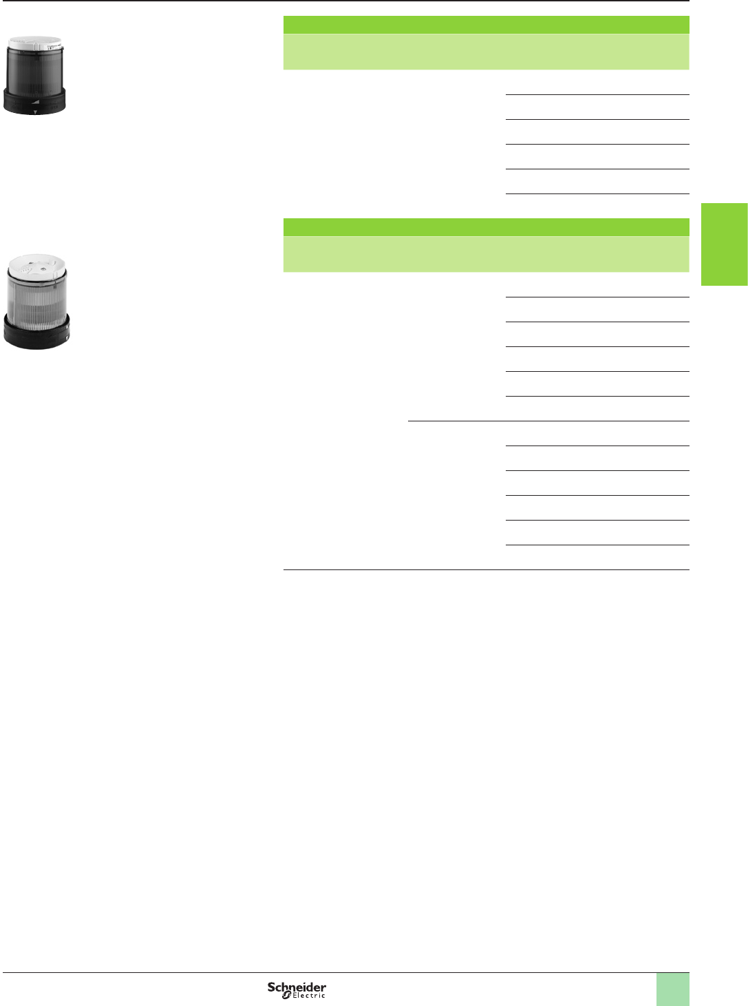
3/143
Stop the machine
Modular tower lights
Harmony® type XVBC Ø 70 mm
Tower lights for customer assembly (up to 5 units)
Illuminated units for incandescent bulbs or LEDs (BA 15d base tting)
Illuminated units with steady light signalling
Description Light source,
to be ordered
separately (1)
Colour Reference Weight
kg
Illuminated units Incandescent bulb
7 W max.
250 V max.
or LED
Green XVBC33 0.140
Red XVBC34 0.140
Orange XVBC35 0.140
Blue XVBC36 0.140
Clear XVBC37 0.140
Yellow XVBC38 0.140
Illuminated units with integral ashing light signalling
Description Light source,
to be ordered
separately (1)
Colour Reference Weight
kg
Illuminated units Incandescent bulb
7 W max.
a 24 V
c 24…48 V
or LED
Green XVBC4B3 0.160
Red XVBC4B4 0.160
Orange XVBC4B5 0.160
Blue XVBC4B6 0.160
Clear XVBC4B7 0.160
Yellow XVBC4B8 0.160
Incandescent bulb
7 W max.
a 48…230 V
or LED
Green XVBC4M3 0.160
Red XVBC4M4 0.160
Orange XVBC4M5 0.160
Blue XVBC4M6 0.160
Clear XVBC4M7 0.160
Yellow XVBC4M8 0.160
(1) Incandescent bulbs and LEDs, see page 3/147.
For use with base unit XVBCpp: see page 3/146
References
101405SE821002
XVBC3p
XVBC4pp
1
2
3
4
5
6
7
8
9
10
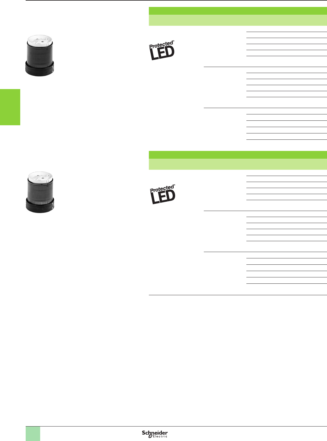
3/144
Stop the machine
Modular tower lights
Harmony® type XVBC Ø 70 mm
Tower lights for customer assembly (up to 5 units)
Illuminated units with integral LED
Illuminated units with steady light signalling
Description Voltage Colour Reference Weight
kg
Illuminated units
with integral LED
z 24 V Green XVBC2B3 (1) 0.150
Red XVBC2B4 (1) 0.150
Orange XVBC2B5 (1) 0.150
Blue XVBC2B6 (1) 0.150
Clear XVBC2B7 (1) 0.150
Yellow XVBC2B8 (1) 0.150
a 120 V Green XVBC2G3 0.150
Red XVBC2G4 0.150
Orange XVBC2G5 0.150
Blue XVBC2G6 0.150
Clear XVBC2G7 0.150
Yellow XVBC2G8 0.150
a 230 V Green XVBC2M3 0.150
Red XVBC2M4 0.150
Orange XVBC2M5 0.150
Blue XVBC2M6 0.150
Clear XVBC2M7 0.150
Yellow XVBC2M8 0.150
Illuminated units with integral ashing light signalling
Description Voltage Colour Reference Weight
kg
Illuminated units
with integral LED
z 24 V Green XVBC5B3 0.170
Red XVBC5B4 0.170
Orange XVBC5B5 0.170
Blue XVBC5B6 0.170
Clear XVBC5B7 0.170
Yellow XVBC5B8 0.170
a 120 V Green XVBC5G3 0.170
Red XVBC5G4 0.170
Orange XVBC5G5 0.170
Blue XVBC5G6 0.170
Clear XVBC5G7 0.170
Yellow XVBC5G8 0.170
a 230 V Green XVBC5M3 0.170
Red XVBC5M4 0.170
Orange XVBC5M5 0.170
Blue XVBC5M6 0.170
Clear XVBC5M7 0.170
Yellow XVBC5M8 0.170
(1) To order an illuminated unit with integral LED pre-tted with light diffuser XVBZ18, add the
letter “D” to the end of the reference. Example: XVBC2B3D.
For use with base unit XVBCpp: see page 3/146
References
821003821004
XVBC2pp
XVBC5pp
1
2
3
4
5
6
7
8
9
10
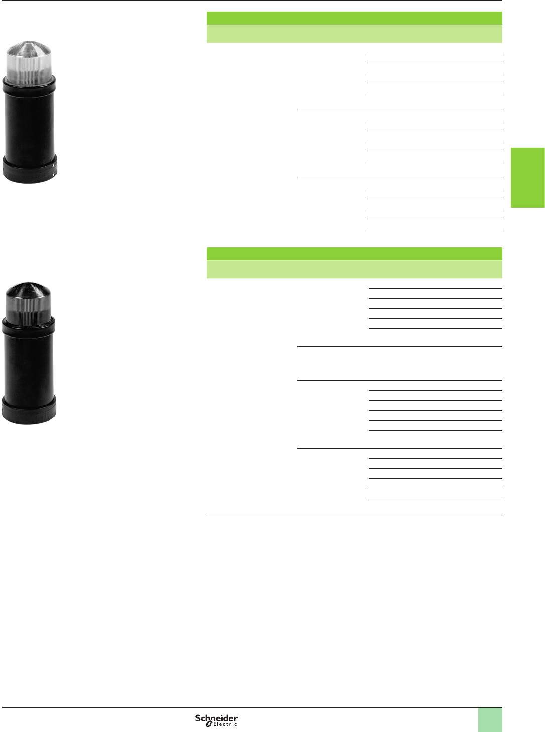
3/145
Stop the machine
Modular tower lights
Harmony® type XVBC Ø 70 mm
Tower lights for customer assembly (up to 5 units)
Illuminated units with integral ash discharge tube
Illuminated units with 5 Joule ash discharge tube (1)
Description Light source Colour Reference Weight
kg
Illuminated units Integral ash
discharge tube
z 24 V
Green XVBC6B3 0.295
Red XVBC6B4 0.295
Orange XVBC6B5 0.295
Blue XVBC6B6 0.295
Clear XVBC6B7 0.295
Yellow XVBC6B8 0.295
Integral ash
discharge tube
a 120 V
Green XVBC6G3 0.280
Red XVBC6G4 0.280
Orange XVBC6G5 0.280
Blue XVBC6G6 0.280
Clear XVBC6G7 0.280
Yellow XVBC6G8 0.280
Integral ash
discharge tube
a 230 V
Green XVBC6M3 0.290
Red XVBC6M4 0.290
Orange XVBC6M5 0.290
Blue XVBC6M6 0.290
Clear XVBC6M7 0.290
Yellow XVBC6M8 0.290
Illuminated units with 10 Joule ash discharge tube (1)
Description Light source Colour Reference Weight
kg
Illuminated units Integral ash
discharge tube
z 24 V
Green XVBC8B3 0.305
Red XVBC8B4 0.305
Orange XVBC8B5 0.305
Blue XVBC8B6 0.305
Clear XVBC8B7 0.305
Yellow XVBC8B8 0.305
Integral ash
discharge tube
z 48 V
Orange XVBC8E5 0.315
Integral ash
discharge tube
a 120 V
Green XVBC8G3 0.315
Red XVBC8G4 0.315
Orange XVBC8G5 0.315
Blue XVBC8G6 0.315
Clear XVBC8G7 0.315
Yellow XVBC8G8 0.315
Integral ash
discharge tube
a 230 V
Green XVBC8M3 0.315
Red XVBC8M4 0.315
Orange XVBC8M5 0.315
Blue XVBC8M6 0.315
Clear XVBC8M7 0.315
Yellow XVBC8M8 0.315
(1) Warning: illuminated units with a ash discharge tube are not suitable for steady light
signalling due to the heat generated.
For use with base unit XVBCpp: see page 3/146
References
821006 821005
XVBC8pp
XVBC6pp
1
2
3
4
5
6
7
8
9
10
3/146
Stop the machine
Modular tower lights
Harmony® type XVBC Ø 70 mm
Tower lights for customer assembly (up to 5 units)
Audible units, base units, cover, accessories
Audible units
Description Characteristics Reference Weight
kg
Buzzer, 90 dB at 1 m
Adjustable with
microswitch:
- from 70 to 90 dB
- continuous or intermittent
tone
z 12…48 V
XVBC9B 0.170
a 120…230 V XVBC9M 0.180
Base units - for direct (IP 66) or tube xing
Description For use with Type Reference Weight
kg
Base unit + cover
with bottom or side cable
entry
Modular tower lights without ash
discharge tube unit
Standard XVBC21 0.190
Base unit only
with bottom or side cable
entry
Modular tower lights with ash
discharge tube unit
Standard XVBC07 0.160
Base unit + cover
with side cable entry
All types of modular tower lights AS-Interface
(1)
XVBC21A –
Base unit + cover
with bottom entry,
pre-cabled (length 1 m) and
tted with M12 end
connector
All types of modular tower lights AS-Interface
(1)
XVBC21B –
Accessories specic to tower lights XVBC
Description Application Unit reference Weight
kg
Cover only For use with XVBC2, XVBC3, XVBC4, XVBC5 and XVBC9 XVBC081 0.030
Set of 6 coloured markers For identication of the position of units in the event of
dismantling the modular tower light
XVBC22 0.001
Set of 5 legend holders For identication of stacked units on base unit XVBC23 0.002
Sheet of 85 legends For use with base unit legend holder XVBC23
XVBCY1 0.005
Sheet of 52 legends For identication of stacked units, used on locking ring XVBCY2 0.005
Adaptor for side entry
through base unit
With 13P cable gland XVBC14 0.015
SIS labelling software
(in English, French, German,
Italian and Spanish)
For creating legends XBY2U 0.100
Light diffuser,
clear plastic
(Sold in boxes)
Only for use with LED illuminated units (all colours)
One box allows to equip 5 illuminated units.
XVBZ18 0.080
(1) For further information on AS-Interface connections, refer to our “Industrial communication in machines and installations”
catalogue.
References
XVBC081
821007101396SE107830SEDF524020
XVBC9p
XVBC07
XVBZ18
1
2
3
4
5
6
7
8
9
10
3/147
Stop the machine
Modular tower lights
Harmony® type XVB Ø 70 mm
Illuminated beacons, tower lights for customer assembly
(up to 5 units)
Accessories common to beacons XVB L and tower lights XVB C
Description Height under
base unit (mm)
Colour Reference Weight
kg
Fixing bases comprising
Ø 25 mm aluminium
support tube glued into a
black plastic xing plate
(IP 65)
80 Black aluminium XVBZ02 0.110
Aluminium XVBZ02A 0.110
380 Black aluminium XVBZ03 0.200
Aluminium XVBZ03A 0.200
780 Black aluminium XVBZ04 0.325
Aluminium XVBZ04A 0.325
Description For use with Material Reference Weight
kg
Support tube
concealment cover
Support tubes XVBZ02, XVBZ02A ABS XVBC020 0.080
Support tubes XVBZ03, XVBZ03A ABS XVBC030 0.305
Support tubes XVBZ04, XVBZ04A ABS XVBC040 0.610
Ø 25 mm aluminium
support tube
Height under base unit
780 mm
Fixing plate XVBZ01
(to be glued into the plastic xing plate)
Plastic
XVBZ14 0.690
Fixing plate for use
on horizontal support
Ø 25 mm aluminium support tube Plastic XVBZ01 0.050
Fixing plate for use
on vertical support
Base unit (direct mounting), xing plate
XVBZ01 or xing bases XVBZ0pZamak
XVBC12 0.380
Description Characteristics Sold in
lots of
Unit reference Weight
kg
Incandescent bulbs (1)
BA 15d base tting
12 V 7 W 10 DL1BEJ 0.090
24 V 6.5 W 10 DL1BEB 0.090
48 V 6 W 10 DL1BEE 0.090
120 V 7 W 10 DL1BEG 0.090
230 V 7 W 10 DL1BEM 0.090
LEDs (1)
BA 15d base tting
z 24 V White 1DL1BDB1 0.015
Green 1DL1BDB3 0.015
Red 1DL1BDB4 0.015
Orange 1DL1BDB5 0.015
Blue 1DL1BDB6 0.015
Yellow 1DL1BDB8 0.015
a 120 V White 1DL1BDG1 0.015
Green 1DL1BDG3 0.015
Red 1DL1BDG4 0.015
Orange 1DL1BDG5 0.015
Blue 1DL1BDG6 0.015
Yellow 1DL1BDG8 0.015
a 230 V White 1DL1BDM1 0.015
Green 1DL1BDM3 0.015
Red 1DL1BDM4 0.015
Orange 1DL1BDM5 0.015
Blue 1DL1BDM6 0.015
Yellow 1DL1BDM8 0.015
Flashing LEDs (1)
BA 15d base tting
z 24 V White 1DL1BKB1 0.015
Green 1DL1BKB3 0.015
Red 1DL1BKB4 0.015
Orange 1DL1BKB5 0.015
Blue 1DL1BKB6 0.015
Yellow 1DL1BKB8 0.015
a 120 V White 1DL1BKG1 0.015
Green 1DL1BKG3 0.015
Red 1DL1BKG4 0.015
Orange 1DL1BKG5 0.015
Blue 1DL1BKG6 0.015
Yellow 1DL1BKG8 0.015
a 230 V White 1DL1BKM1 0.015
Green 1DL1BKM3 0.015
Red 1DL1BKM4 0.015
Orange 1DL1BKM5 0.015
Blue 1DL1BKM6 0.015
Yellow 1DL1BKM8 0.015
(1) Warning: illuminated units with incandescent bulbs must not be combined with LED illuminated units, due to the risk of
overheating. Also, when different units (e.g. steady, ashing…) are combined, the maximum temperature is limited to that
of the weaker unit.
References
109753821012109754109755DF524033DF524034
109748
XVBZ02 XVBZ03/Z04
XVBC020
XVBZ01
XVBC12
DL1Bpp
DL1BDpp/DL1BKpp
1
2
3
4
5
6
7
8
9
10

2
1
3
4
5
6
7
8
9
10
2
1
3
4
5
6
7
8
9
10
3/148
Presentation Stop the machine
Rotating beacons Harmony® type XVR
(equipped with Super Bright LED)
Presentation
The rotating beacons in the Harmony® XVR range are optical signalling units
designed for long distance signalling applications.They are used mainly in the iron
and steel industry, on industrial handling vehicles or for safety applications.
The range involves complete products offering simplicity of use and speed of
installation: they are supplied pre-cabled, and equipped with their light source. The
use of “Super-bright” LED’s guarantees a good illuminating power and a long service
life (reduced time for maintenance) owing to their high resistance to mechanical
shock and vibration. These light sources are also energy saving with low power
consumption. A reecting prism can be used for increasing light diffusion.
4 sizes are available:
bØ 84 mm (XVR08). Colours : red, orange, green and blue,
bØ 106 mm (XVR10). Colours : red, orange, green and blue,
bØ 120 mm (XVR12). Colours : red, orange, green and blue,
bØ 130 mm (XVR13). Colours : red, orange.
For more efciency, Ø 120 mm rotating beacons may be delivered with a
complementary audible unit: a buzzer present at the base of the product, with a
continuous or intermittent tone and an adjustable sound level of 50 dB to 90 dB at
1 m.
Environment
XVR rotating beacons can offer a high degree of protection:
vowing to the adjunction of an accessory : a rubber base guarantees a degree of
protection type IP 55 or IP 65 for small models,
vaccording to the selected model:Ø 130 mm rotating beacons guarantee a degree
of protection type IP 66 (resistant to vibration) or IP 67 (see opposite page).
These products meet the requirements of the following standards:
vEN/IEC 61000-6-2 and EN/IEC 61000-6-4 forØ 84 mm (XVR08), 106 mm
(XVR10), 120 mm (XVR12) and 130 mm with direct current (XVR13Bpp and
XVR13Jpp),
vEN/IEC 60947-1 and EN/IEC 60947-5-1 for the otherØ 130 mm rotating beacons
(XVR13ppL) with voltage 24V A.C./D.C., 120 V A.C. or 230 V A.C.
These products are e, UL and CSA certied.
Connection
The connection is through ying leads, length 400 mm (500 mm for XVR08) and
section 0.83 mm2 (1,25 mm2 for XVR13).
XVR13pppLl
2
1
3
4
5
6
7
8
9
10
2
1
3
4
5
6
7
8
9
10
3/149
Complete, pre-cabled rotating beacons
Diameter
mm
Sound option IP degree
of protection
Voltage
V
Colour Reference Weight
kg
Ø 84 Without buzzer IP 23
(IP 65
With
accessories)
z 12 Red XVR08J04 0.300
Orange XVR08J05 0.300
Green XVR08J03 0.300
Blue XVR08J06 0.300
z 24 Red XVR08B04 0.300
Orange XVR08B05 0.300
Green XVR08B03 0.300
Blue XVR08B06 0.300
Ø 106 Without buzzer IP 23
(IP 55
With accessories)
z 12 Red XVR10J04 0.500
Orange XVR10J05 0.500
Green XVR10J03 0.500
Blue XVR10J06 0.500
z 24 Red XVR10B04 0.500
Orange XVR10B05 0.500
Green XVR10B03 0.500
Blue XVR10B06 0.500
Ø 120 Without buzzer IP 23 z 12 Red XVR12J04 0.500
Orange XVR12J05 0.500
Green XVR12J03 0.500
Blue XVR12J06 0.500
z 24 Red XVR12B04 0.500
Orange XVR12B05 0.500
Green XVR12B03 0.500
Blue XVR12B06 0.500
Ø 120 With buzzer
Continuous or
intermittent tone
Sound level at 1 m:
50 to 90 dB
IP 23 z 12 Red XVR12J04S 0.500
Orange XVR12J05S 0.500
Green XVR12J03S 0.500
Blue XVR12J06S 0.500
z 24 Red XVR12B04S 0.500
Orange XVR12B05S 0.500
Green XVR12B03S 0.500
Blue XVR12B06S 0.500
Ø 130 Without buzzer IP 66
Resistant to
vibration
c 12 Red XVR13J04 0.800
Orange XVR13J05 0.800
c 24 Red XVR13B04 0.800
Orange XVR13B05 0.800
IP 66 and IP 67 z 24 Red XVR13B04L 0.820
Orange XVR13B05L 0.820
a 120 Red XVR13G04L 0.990
Orange XVR13G05L 0.990
a 230 Red XVR13M04L 0.990
Orange XVR13M05L 0.990
Accessories for rotating beacons
Description To be used
for / with
Diameter
mm
Height
mm
Reference Weight
kg
Reecting prism Increasing light
diffusion
84 –XVRZR1 0.010
106 –XVRZR2 0.015
120/130 –XVRZR3 0.020
Rubber base Reaching IP 65 84 –XVRZ081 0.040
Reaching IP 55 106 –XVRZ082 0.050
Metal angle bracket Horizontal support 84, 106, 120 –XVCZ23 0.380
130 –XVR012L 1.300
Metal xing plate Horizontal support 106, 120 300 XVCZ13 0.700
References Stop the machine
Rotating beacons Harmony® type XVR
(equipped with Super Bright LED)
XVR13ppp
525877
XVR08ppp
525874
XVR10ppp
525875
XVR12pp
XVRZ081
XVRZR1
XVRZR2
XVRZR3XVRZ082
XVR13pppLl
PF540658

2
1
3
4
5
6
7
8
9
10
2
1
3
4
5
6
7
8
9
10
3/150
Presentation Stop the machine
Sound units Harmony® type XVS
Sirens and electronic alarms
Presentation
The sirens and electronic alarms in the Harmony® XVS range are audible signalling
units used for long distance indication of the operating status or sequences of a
machine or installation. They are mainly used on conveyor belts, on automated
industrial trucks and on the doors of electrical control panels.
The range involves several types of ready to use products:
vsirens with 2 tones, with very compact size, type XVS10,
vmultisound sirens (43 tones), pre-cabled, 8 channels, type XVS14.
The sound, with continuous or intermittent tone:
vguarantees a sound level of 106 dB at 1 m for XVS10,
vcan be adjusted from 0 to 105 dB at 1 m for XVS14.
Environment
The XVS sirens and electronic alarms offer the following degree of protection: IP 53
for sirens type XVS10 and XVS14.
These products meet the requirements of the following standards:
vEN/IEC 61000-6-2 and EN/IEC 61000-6-3 for voltages 120 V and 230 V A.C.
(XVS14BMW),
vEN/IEC 60947-1 and EN/IEC 60947-5-1 for voltages 12 V and 24 V A.C.
(XVS10, XVS14GMW and MMW).
They are e, UL and CSA certied.
Connection
Products are to be connected:
vthrough cable-glands for using 6.5 mm to 8.5 mm cables (XVS10)
vthrough power wire c.s.a.: 0.52 mm2 and signal wire c.s.a.: 0.33 mm2, with ying
leads, length 500 mm (XVS14),
For more technical information, please refer to our website
www.schneider-electric.com.
XVS10pM
2
1
3
4
5
6
7
8
9
10
2
1
3
4
5
6
7
8
9
10
3/151
References Stop the machine
Sound units Harmony® type XVS
Sirens and electronic alarms
References
Description Voltage Colour Reference Weight
V kg
Sirens
106 dB, 2 tones
z 12-24 White XVS10BMW 0.800
a 120 White XVS10GMW 1.000
a 230 White XVS10MMW 1.000
Multisound sirens
0 to 105 dB, 43 tones
8 channels
Pre-wired
c 12/24 White XVS14BMW 1.000
a 120 White XVS14GMW 1.200
a 240 White XVS14MMW 1.200
PF540616
XVS10pM
XVS14pMW
PF569825
3/152
Stop the machine
Mini-VARIO and VARIO switch disconnectors
Applications Mini-Vario and Vario rotary switch disconnectors from 12 to 175 A are suitable for
on-load making and breaking of resistive or mixed resistive and inductive circuits where
frequent operation is required. They can also be used for direct switching of motors in
utilisation categories AC-3 and DC-3.
Vario switch disconnectors are suitable for isolator applications with fully visible
breaking (since the handle cannot indicate the “open” position unless all the contacts
are actually open and separated by the appropriate isolation distance) and it is possible
to padlock the handles in the open position.
Application Standard applications
Presentation Bare switches Enclosed switches
Assembly Pre-assembled For customer
assembly
Pre-assembled For customer
assembly
Thermal current 12 and 20 A 10…32 A 10 and 16 A
Operational current AC-23 at 400 V 8.1 and 11 A 8.1…29 A 8.1…11 A
Number of poles 3 3…5 3 3…5
Number of auxiliary contacts – 1 or 2 – 1 or 2
Reversible terminal blocks Yes
Mounting On door At back of
enclosure
On door or at
back of enclosure
–
Operator Direct Offset with
door interlock
mechanism
Direct or offset
with door
interlock
mechanism
Direct
Switch type VCDN12
VCDN20
VCCDN12
VCCDN20
VN12
VN20
VCFN12GE
to
VCFN40GE
VN12,
VN20 +
VCFXGE1
Pages 3/154 3/155 3/162 3/163 to 3/165
Selection guide
1
2
3
4
5
6
7
8
9
10
3/153
0
Mini-Vario and Vario rotary switch disconnectors from 12 to 175 A are suitable for on-load making and breaking of resistive or mixed resistive and
inductive circuits where frequent operation is required.
They can also be used for direct switching of motors in utilisation categories AC-3 and DC-3.
Vario switch disconnectors are suitable for isolator applications with fully visible breaking (since the handle cannot indicate the “open” position unless
all the contacts are actually open and separated by the appropriate isolation distance) and it is possible to padlock the handles in the open position.
High performance applications
Bare switches Enclosed switches
Pre-assembled For customer
assembly
Pre-assembled For customer
assembly
12…175 A 10…140 A 10…63 A
8.1…83 A 8.1…41 A
33…6 (up to 80 A)
3 (for 125 and 175 A
ratings)
3 3… 6
– 1 or 2 – 2
Yes
On door At back of enclosure In enclosure or
modular distribution
boards
On door, at back of
enclosure, in
enclosure or modular
distribution boards
–
Direct Indirect with door interlock
mechanism
Direct Direct or indirect with
door interlock
mechanism
Direct
VCp02
to
VCp6
VCCp02
to
VCCp6
VVE0
to
VVE4
V02
to
V6
VCF02GE
to
VCF6GE
V02 to V4
+ VCFXGE1
to
VCFXGDXE
3/156 3/157 to 3/161 3/162 3/163
1
2
3
4
5
6
7
8
9
10
3/154
Stop the machine
Mini-VARIO switch disconnectors
for standard applications
Complete units
b 3-pole rotary switch disconnectors, 12 to 20 A
b Padlockable operating handle (padlocks not supplied).
b Degree of protection IP 65.
b Marking on operator .
Main and Emergency stop switch disconnectors
For door mounting
Operator lth Reference Weight
Handle Front plate Fixing
mm mm Akg
Red, padlockable
with up to 3 padlocks
(Ø 4 to Ø 8)
Yellow
60 x 60
Ø 22.5
12 VCDN12 0.177
20 VCDN20 0.177
Main and Emergency stop switch disconnectors
For mounting at back of an enclosure (1)
Operator lth Reference Weight
Handle Front plate Fixing
mm mm Akg
Red, padlockable
with up to 3 padlocks
(Ø 4 to Ø 8)
Yellow
60 x 60
Ø 22.5
12 VCCDN12 0.334
20 VCCDN20 0.334
(1) Switches supplied with a shaft extension VZN17 and a door interlock plate KZ32.
580551
580552
VCDN20
VCCDN20
References
1
2
3
4
5
6
7
8
9
10
3/155
Switch bodies
Description Rating
A
Reference Weight
kg
3-pole switch disconnectors 12 VN12 0.110
20 VN20 0.110
Add-on modules
Description Rating
A
Reference Weight
kg
Main pole modules 12 VZN12 0.020
20 VZN20 0.020
Neutral pole module
with early make and
late break contacts
12 and 20 VZN11 0.020
Earthing module 12 and 20 VZN14 0.016
Auxiliary contact block
modules
1 N/O late make contact VZN05 0.020
1 N/C early break contact VZN06 0.020
Input terminal
protection shrouds
For add-on pole modules or
auxiliary contact block modules
(single-pole shroud)
VZN26 0.004
For switch bodies
(3-pole shroud)
VZN08 0.007
Maximum number of add-on modules that can be tted on a switch body
VZN12 or VZN20 + + VZN12 or VZN20
VN12 or
or or VZN11 + VZN14
VN20 or
VZN05 or VZN06 VZN05 or VZN06
VZN11
VZN14
580800
580801
580802
580803
VN20
VZN05
Stop the machine
Mini-VARIO switch disconnectors
for standard applications
For customer assembly
References (continued)
1
2
3
4
5
6
7
8
9
10
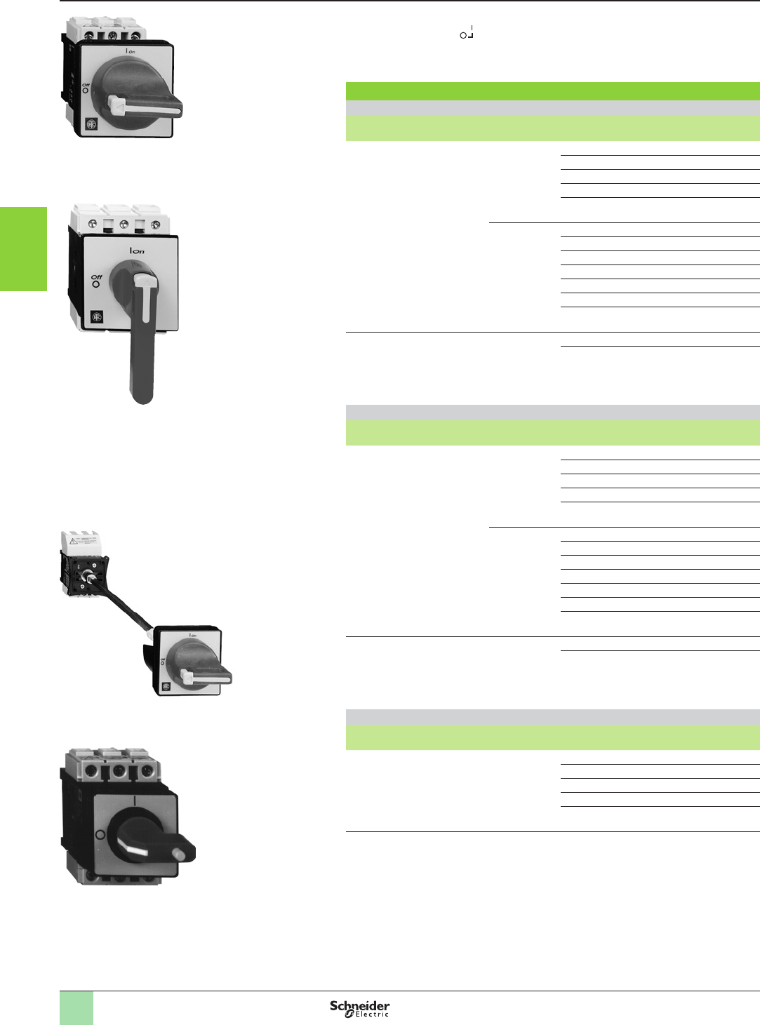
3/156
Stop the machine
VARIO switch disconnectors
for high performance applications
Complete units
b 3-pole rotary switch disconnectors, 12 to 175 A
b Marking on operator .
b Padlockable operating handle (padlocks not supplied).
Degree of protection IP 65.
Main and Emergency stop switch disconnectors
For door mounting
Handle Front plate
mm
Fixing Rating
A
Reference Weight
kg
Red,
padlockable
with up to
3 padlocks
(Ø 4 to Ø 8)
Yellow
60 x 60
Ø 22.5 12 VCD02 0.215
20 VCD01 0.215
25 VCD0 0.215
32 VCD1 0.215
40 VCD2 0.215
4 screws 12 VCF02 0.250
20 VCF01 0.250
25 VCF0 0.250
32 VCF1 0.250
40 VCF2 0.250
63 VCF3 0.560
80 VCF4 0.560
Red, long,
padlockable
with up to
3 padlocks
(Ø 4 to Ø 8)
Yellow
90 x 90
4 screws 125 VCF5 1.200
175 VCF6 1.200
For mounting at back of an enclosure (1)
Handle Front plate
mm
Fixing Rating
A
Reference Weight
kg
Red,
padlockable
with up to
3 padlocks
(Ø 4 to Ø 8)
Yellow
60 x 60
Ø 22.5 12 VCCD02 0.392
20 VCCD01 0.392
25 VCCD0 0.392
32 VCCD1 0.392
40 VCCD2 0.392
4 screws 12 VCCF02 0.527
20 VCCF01 0.527
25 VCCF0 0.527
32 VCCF1 0.527
40 VCCF2 0.527
63 VCCF3 0.440
80 VCCF4 0.680
Red, long,
padlockable
with up to
3 padlocks
(Ø 4 to Ø 8)
Yellow
90 x 90
4 screws 125 VCCF5 1.320
175 VCCF6 1.320
For mounting in an enclosure or for modular distribution boards
Handle Front plate
mm
Fixing Rating
A
Reference Weight
kg
Red,
padlockable
with 1 padlock
(Ø 4 to Ø 6)
Yellow
45 x 45
25 VVE0 0.250
32 VVE1 0.250
40 VVE2 0.250
63 VVE3 0.530
80 VVE4 0.530
(1) Switches supplied with a shaft extension VZN17 and a door interlock plate KZ32 or KZ74 (see
page 3/160).
580555 580554
VCF0
VCF5
VCCF0
580553
580804
VVE1
References
1
2
3
4
5
6
7
8
9
10
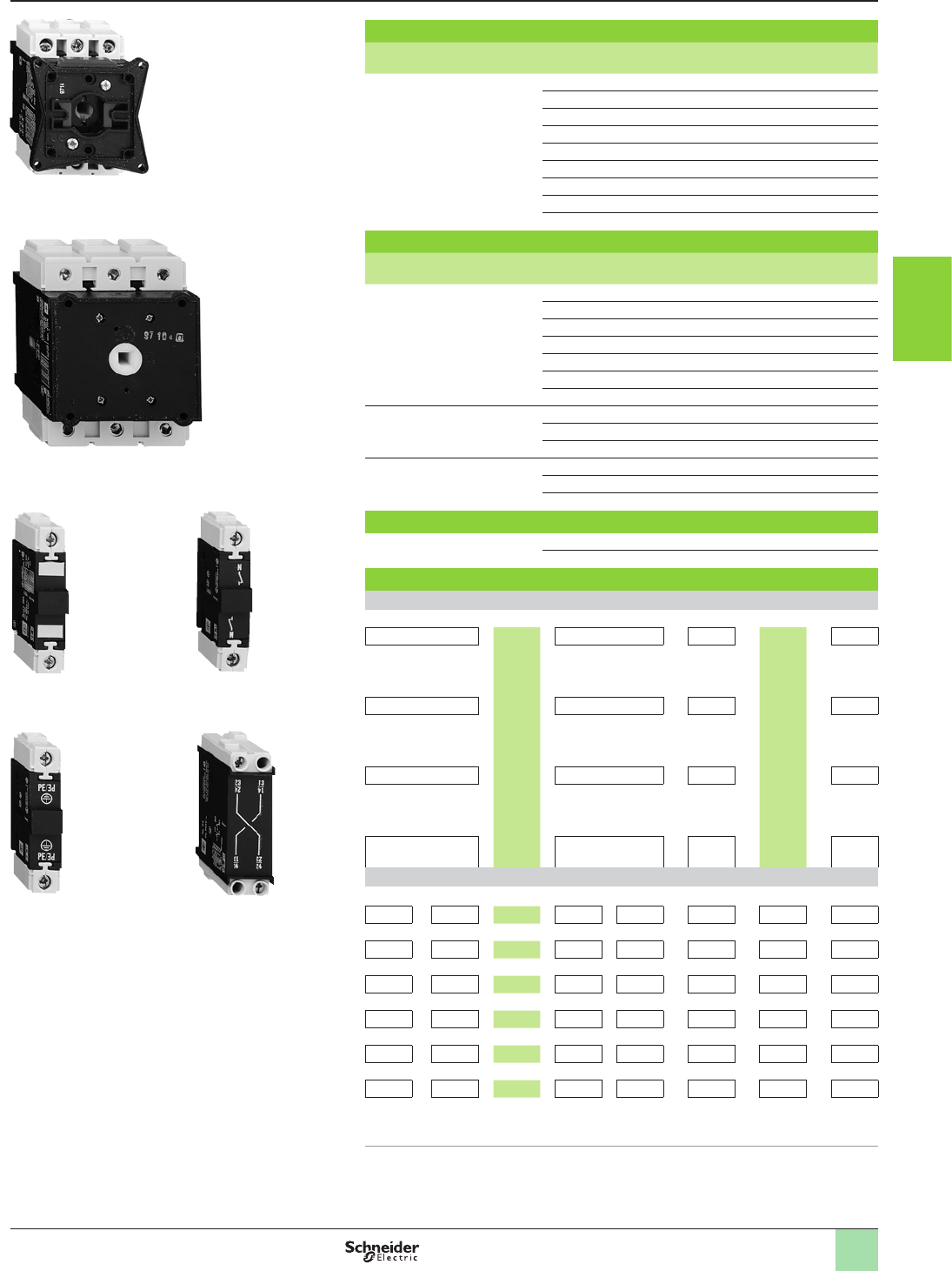
3/157
Switch bodies
Description Rating
A
Reference Weight
kg
3-pole switch disconnectors
(1)
12 V02 0.200
20 V01 0.200
25 V0 0.200
32 V1 0.200
40 V2 0.200
63 V3 0.500
80 V4 0.500
125 V5 0.900
175 V6 0.900
Add-on modules
Description Rating
A
Reference Weight
kg
Main pole modules 12 VZ02 0.050
20 VZ01 0.050
25 VZ0 0.050
32 VZ1 0.050
40 VZ2 0.050
63 VZ3 0.100
80 VZ4 0.100
Neutral pole modules
with early make and
late break contacts (1)
12 to 40 VZ11 0.050
63 to 80 VZ12 0.100
125 and 175 VZ13 0.250
Earthing modules 12 to 40 VZ14 0.050
63 and 80 VZ15 0.100
125 and 175 VZ16 0.250
Auxiliary contact block modules
Auxiliary contact block
modules with 2 auxil. contacts
N/O + N/C (2) VZ7 0.050
N/O + N/O VZ20 0.050
Maximum no. of add-on modules that can be tted on a switch body
1 add-on module on each side of the switch body
VZ7 or VZ20 +V0p
V0
to
V4
+VZ7 or VZ20 VZ7 +
V5
or
V6
+ VZ7
or or or or
VZ11 or VZ12 + + VZ11 or VZ12 VZ20 + + VZ20
or or or or
VZ14 or VZ15 + + VZ14 or VZ15 VZ13 + + VZ13
or or or or
VZ0p/VZ0 to VZ4 + + VZ0p/VZ0 to VZ4 VZ16 + + VZ16
2 add-on modules on each side of the switch body
VZ0p+VZ0p+V0p+VZ0p+ VZ7 or VZ20 or VZ11 or VZ14
VZ0 +VZ0 +V0 +VZ0 + VZ7 or VZ20 or VZ11 or VZ14
VZ1 + VZ1 + V1 + VZ1 + VZ7 or VZ20 or VZ11 or VZ14
VZ2 + VZ2 + V2 + VZ2 + VZ7 or VZ20 or VZ11 or VZ14
VZ3 + VZ3 + V3 + VZ3 + VZ7 or VZ20 or VZ12 or VZ15
VZ4 + VZ4 + V4 + VZ4 + VZ7 or VZ20 or VZ12 or VZ15
Note : The add-on modules mounted next to the switch body are main poles. Maximum of 3 main
pole modules per switch body.
(1) Protection shrouds are available if required: see page 3/160.
(2) Late make N/O, early break N/C contacts
580561
580560 580558
580559
V0
V5
VZ11
580556580557
VZ0
VZ15 VZ20
Stop the machine
VARIO switch disconnectors
for high performance applications
Complete units
References (continued)
1
2
3
4
5
6
7
8
9
10
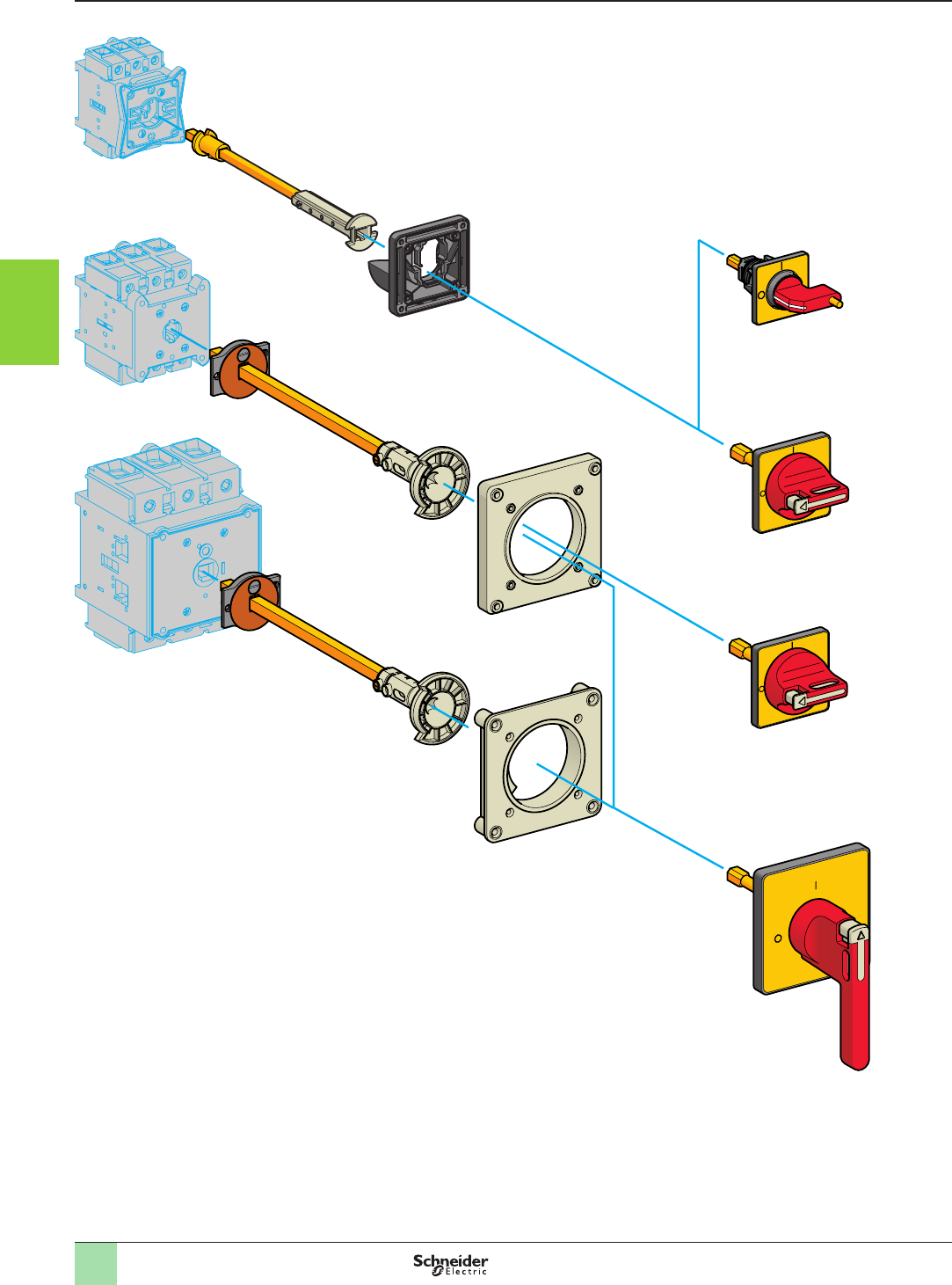
3/158
Stop the machine
Mini-VARIO and VARIO switch disconnectors
503800
VN12, VN20
V02…V2
VZN17, VZN30
V3, V4
KZ32, KZ83 KCp1YZ
KCp1PZ
VZ18, VZ31
V5, V6
KZ81
VZ18, VZ31
KCF3PZ
KZ74
KCF2PZ
Presentation
1
2
3
4
5
6
7
8
9
10

3/159
Stop the machine
Mini-VARIO and VARIO switch disconnectors
Operators, handles and front plates
(for customer assembly)
b Padlockable operating handle (padlocks not supplied).
b Degree of protection IP 65.
b Marking on operator .
Handles and front plates for main and Emergency stop
switch disconnectors
For
switch
body
Operator Reference Weight
Handle Front plate
Dimensions Fixing
mm kg
VN12, VN20
V02…V2
Red,
padlockable
with up to
1 padlock
(Ø 4 to Ø 6)
Yellow
45 x 45
Ø 22.5
KCC1YZ 0.050
4 screws
KCE1YZ 0.040
Red,
padlockable
with up to
3 padlocks
(Ø 4 to Ø 8)
Yellow
60 x 60
Ø 22.5
KCD1PZ 0.082
4 screws
KCF1PZ 0.075
V3 and V4 Red,
padlockable
with up to
3 padlocks
(Ø 4 to Ø 8)
Yellow
60 x 60
4 screws
KCF2PZ 0.070
V5 and V6 Red, long,
padlockable
with up to
3 padlocks
(Ø 4 to Ø 8)
Yellow
90 x 90
4 screws
KCF3PZ (1) 0.160
(1) For door mounting of 63 and 80 A switch disconnectors, adapter plate KZ106 must be ordered
separately (see page 3/160).
References
1
2
3
4
5
6
7
8
9
10
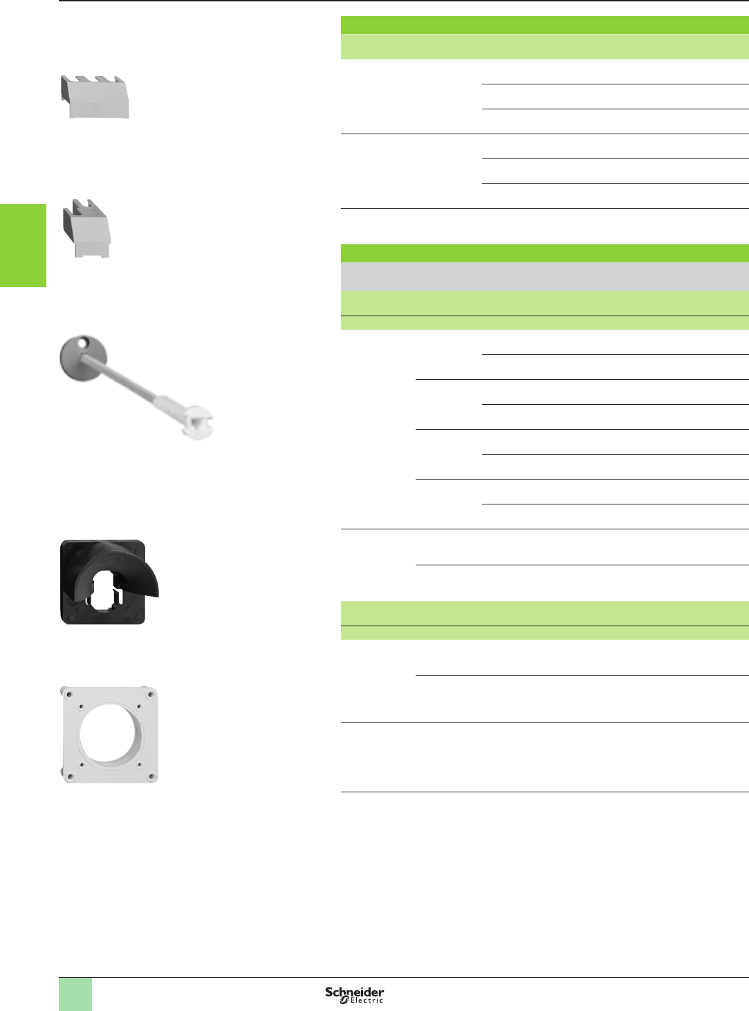
3/160
Stop the machine
Mini-VARIO and VARIO switch disconnectors
Accessories
Input terminal protection shrouds
Description For
use on
Reference Weight
kg
For switch bodies
(3-pole shroud)
V02…V2 VZ8 0.015
V3 and V4 VZ9 0.020
V5 and V6 VZ10 0.060
For add-on pole modules
(single-pole shroud)
VZ02…VZ2, VZ11, VZ14 VZ26 0.005
VZ3, VZ4, VZ12, VZ15 VZ27 0.007
VZ13, VZ16 VZ28 0.020
For contact blocks
with 2 auxiliary contacts
–VZ29 0.005
Components for door interlocking
For rear xing switch disconnectors mounted at the back of an enclosure, in
addition to a direct operator
Description For
use on
Distance
enc.back/door
Sold in
lots of
Unit
reference
Weight
mm kg
Shaft
extensions
VN12, VN20
V02…V2
300…330 1VZN17 (1) 0.100
400…430 1VZN30 (1) 0.130
V02…V2 300…330 1VZ17 0.075
400…430 1VZ30 0.125
V3 and V4 300…320 1VZ18 0.170
400…420 1VZ31 0.215
V5 and V6 330…350 1VZ18 0.170
430…450 1VZ31 0.215
Door
interlock
plates
VN12, VN20
V02…V2
–5KZ32 0.177
V3…V6 – 5KZ74 0.020
Description For
use on
Front plate
dimensions
Sold in
lots of
Unit
reference
Weight
mm kg
Plates for
door mounting
of handles with
4 screw xing
VN12, VN20
V02…V2
45 x 45 or
60 x 60
5KZ83 0.205
V3…V6 60 x 60 or
90 x 90
5KZ81 0.010
Adapter plate
for switch
disconnectors
V3 and V4 90 x 90 5KZ106 0.075
(1) Can be used with V02 to V2 switches.
580563580564580565
580566
580567
VZ8
VZ26
VZ18
KZ32
KZ81
References (continued)
1
2
3
4
5
6
7
8
9
10
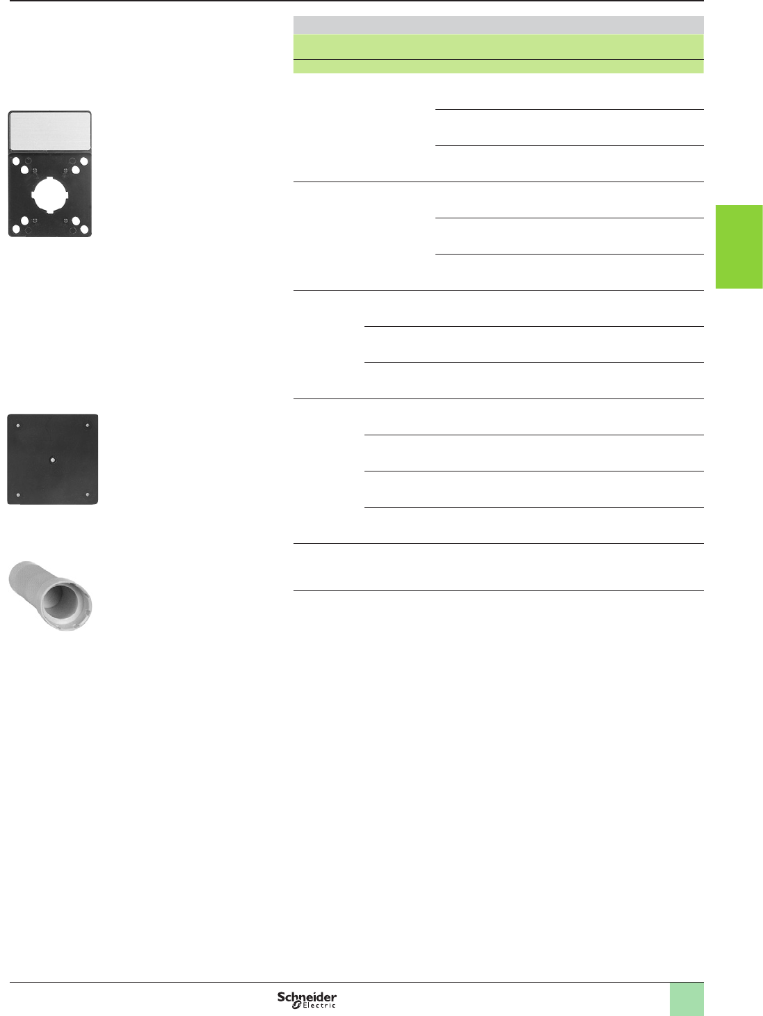
3/161
Stop the machine
Mini-VARIO and VARIO switch disconnectors
Accessories
Accessories for operators
Description For
use on
Front plate
dimensions
Sold in
lots of
Unit reference Weight
mm kg
Legend
holder with
silver coloured
blank legend
plate
Front plate 45 x 45 5KZ13 0,060
60 x 60 5KZ15 0,065
90 x 90 5KZ103 0,070
Legend
holders
without
legend plate
Front plate 45 x 45 20 KZ14 0,060
60 x 60 10 KZ16 0,065
90 x 90 5KZ101 0,070
Silver
coloured
blank legend
plates for
engraving by
customer
KZ14 – 20 KZ76 0,020
KZ16 – 10 KZ77 0,010
KZ101 –5KZ100 0,005
Seals VN12, VN20 45 x 45 5KZ65 0,037
V02…V2 60 x 60 5KZ66 0,033
V3 and V4 60 x 60 5KZ62 0,033
V3…V6 90 x 90 5KZ67 0,064
Tightening
tool
For operators
with Ø 22.5
xing
–5Z01 0,050
580568
580569
580570
KZ15
KZ67
Z01
References (continued)
1
2
3
4
5
6
7
8
9
10
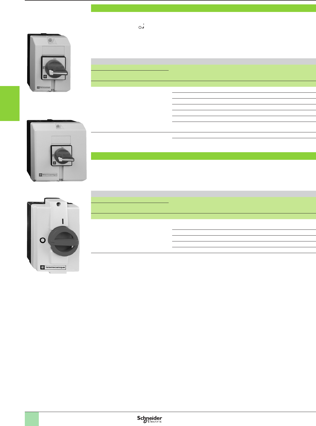
3/162
Stop the machine
VARIO enclosed switch disconnectors
(pre-assembled)
Enclosed switch disconnectors for high performance applications
b Marking on operator .
b 3-pole rotary switch disconnectors from 10 to 140 A
b Padlockable operating handle (padlock not included).
b IP 65 degree of protection enclosures, sealable and lockable.
b Cover lockable in position “I” (ON) up to 63 A rating.
3-pole main and Emergency stop switch disconnectors
Operator lthe Power
AC-23
at 400 V
Incorporated
switch
body
Possible
attachments
(1)
Reference Weight
Handle Front plate
Dimensions
mm AkW kg
Red, padlockable
with up to 3 padlocks
(Ø 4 to Ø 8 shank)
Yellow
60 x 60
10 4V02 2VCF02GE 0.500
16 5.5 V01 2VCF01GE 0.500
20 7.5 V0 2VCF0GE 0.500
25 11 V1 2 VCF1GE 0.500
32 15 V2 2 VCF2GE 0.500
50 22 V3 3 VCF3GE 0.930
63 30 V4 3 VCF4GE 0.930
Red, long padlockable
with up to 3 padlocks
(Ø 4 to Ø 8 shanks)
Yellow
90 x 90
100 37 V5 1 VCF5GE 2.190
140 45 V6 1 VCF6GE 2.190
Enclosed switch disconnectors for standard applications
b 3-pole rotary switch disconnectors from 10 to 32 A
b Degree of protection IP 55.
3-pole main and Emergency stop switch disconnectors
Operator lthe Power
AC-23
at 400 V
Incorporated
switch
body
Possible
attachments
(1)
Reference Weight
Handle Front plate
Dimensions
mm AkW kg
Red, padlockable
with 1 padlock
(Ø 8 shank)
or up to 3 padlocks
(Ø 6 shank)
Yellow
60 x 60
10 4 VN12 2 VCFN12GE
(1)
0.422
16 5.5 VN20 2VCFN20GE (1) 0.422
20 7.5 V0 0 VCFN25GE 0.512
25 11 V1 0VCFN32GE 0.512
32 15 V2 0VCFN40GE 0.512
(1) For enclosures VCF and VCFN, see page 3/164
580571
VCF0GE
580572
VCF3GE
580573
VCFN12GE
References
1
2
3
4
5
6
7
8
9
10
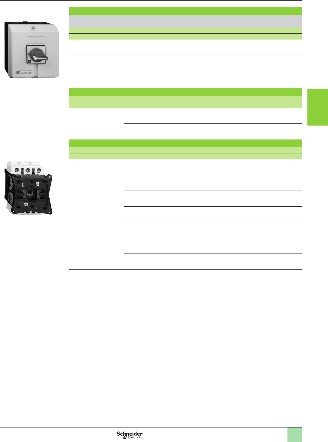
3/163
Stop the machine
VARIO enclosed switch disconnectors
(assembled by the user)
Empty enclosures
IP 65 enclosure with red padlockable handle operator and yellow front plate
(for mounting a main or Emergency stop switch disconnector)
For switch body type lthe Possible attachments (1) Reference Weight
Akg
VN12, VN20
V02…V2
10…32 2VCFXGE1 0.340
V02…V2 10…32 4VCFXGE4 0.660
V3 and V4 50…63 3VCFXGE2 0.660
4VCFXGDXE 0.660
Switch bodies for standard applications
Description Rating Reference Weight
Akg
3-pole
switch disconnectors
10 VN12 0.110
16 VN20 0.110
Switch bodies for high performance applications (2)
Description Rating Reference Weight
Akg
3-pole
switch disconnectors
10 V02 0.200
16 V01 0.200
20 V0 0.200
25 V1 0.200
32 V2 0.200
50 V3 0.200
63 V4 0.200
(1) See page 3/164.
VCFXGE2
580574
V0
580575
References (continued)
1
2
3
4
5
6
7
8
9
10
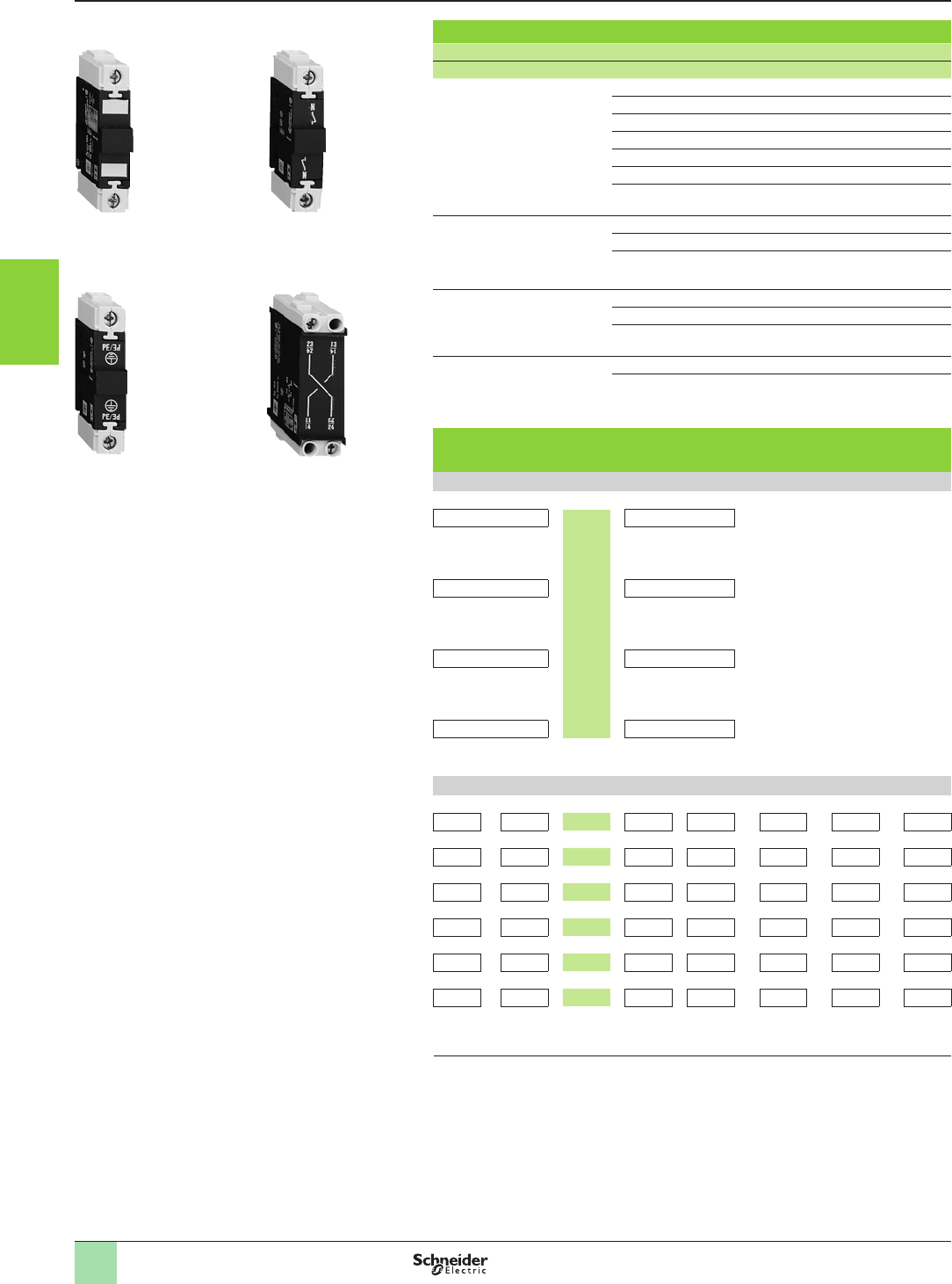
3/164
Stop the machine 0
VARIO enclosed switch disconnectors
Add-on modules
Add-on modules for enclosure VCF
Description Rating Reference Weight
Akg
Main pole modules
(mounted in enclosure)
10 VZ02 0.050
16 VZ01 0.050
20 VZ0 0.050
25 VZ1 0.050
32 VZ2 0.050
50 VZ3 0.100
63 VZ4 0.100
Neutral pole modules
with early make and
late break contacts
10 to 32 VZ11 0.050
50 and 63 VZ12 0.100
100 and 140 VZ13 0.250
Earthing modules 10 to 32 VZ14 0.050
50 and 63 VZ15 0.100
100 and 140 VZ16 0.250
Auxiliary contact block
modules with
2 auxiliary contacts
N/O + N/C (1) VZ7 0.050
N/O + N/O VZ20 0.050
Maximum number of add-on modules that can be tted on a
switch body
1 add-on module on each side of the switch body
VZ7 or VZ20 +V0p
V0
to
V4
+VZ7 or VZ20
or or
VZ11 or VZ12 + + VZ11 or VZ12
or or
VZ14 or VZ15 + + VZ14 or VZ15
or or
VZ0p/VZ0 to VZ4 + + VZ0p/VZ0 to VZ4
2 add-on modules on each side of the switch body
VZ0p+VZ0p+V0p+VZ0p+ VZ7 or VZ20 or VZ11 or VZ14
VZ0 +VZ0 +V0 +VZ0 + VZ7 or VZ20 or VZ11 or VZ14
VZ1 + VZ1 + V1 + VZ1 + VZ7 or VZ20 or VZ11 or VZ14
VZ2 + VZ2 + V2 + VZ2 + VZ7 or VZ20 or VZ11 or VZ14
VZ3 + VZ3 + V3 + VZ3 + VZ7 or VZ20 or VZ12 or VZ15
VZ4 + VZ4 + V4 + VZ4 + VZ7 or VZ20 or VZ12 or VZ15
Note : The add-on modules mounted next to the switch body are main pole modules. Maximum
of 3 main pole modules per switch body.
(1) Late make N/O, early break N/C contacts
580579
580578 580576
580577
VZ0 VZ11
VZ15 VZ20
References
1
2
3
4
5
6
7
8
9
10
3/165
Stop the machine 0
Mini-VARIO enclosed switch disconnectors
Add-on modules
Add-on modules for enclosures VCFN12GE and 20GE
Description Rating Reference Weight
Akg
Main pole modules 10 VZN12 0.020
16 VZN20 0.020
Neutral pole module
with early make and
late break contacts
10 and 16 VZN11 0.020
Earthing module 10 and 16 VZN14 0.016
Auxiliary contact block
modules
1 late make N/O contact VZN05 0.020
1 early break N/C contact VZN06 0.020
Maximum number of add-on modules that can be tted on a
switch body
VZN12 or VZN20 + + VZN12 or VZN20
VN12 or
VZN11
or
or or
VN20 VZN05 or VZN06
or
VZN05 or VZN06 VZN14
VZN11
VZN14
580580580581
VZN05
580582
References (continued)
1
2
3
4
5
6
7
8
9
10
3/166
Applications Automation systems
Rated operational current le max AC-3 (Ue y 440 V) 9 A 12 A 18 A 25 A 32 A 38 A 40 A 50 A 65 A
le AC-1 (q y 60 °C) 20/25 A 20/25 A 25/32 A 25/40 A 50 A 50 A 60 A –80 A
Rated operational voltage 690 V 690 V 690 V
Number of poles 3 or 4 3 or 4 3 or 4 3 or 4 3 3 3 3 3
Rated operational
power in AC-3
220/240 V 2.2 kW 3 kW 4 kW 5.5 kW 7.5 kW 9 kW 11 kW 15 kW 18.5 kW
380/400 V 4 kW 5.5 kW 7.5 kW 11 kW 15 kW 18.5 kW 18.5 kW 22 kW 30 kW
415/440 V 4 kW 5.5 kW 9 kW 11 kW 15 kW 18.5 kW 22 kW 25/30 kW 37 kW
500 V 5.5 kW 7.5 kW 10 kW 15 kW 18.5 kW 18.5 kW 22 kW 30 kW 37 kW
660/690 V 5.5 kW 7.5 kW 10 kW 15 kW 18.5 kW 18.5 kW 30 kW 33 kW 37 kW
Coil consumption 2.4 W (100 mA - 24 V) 2.4 W (100 mA - 24 V) 0.6 W (25 mA - 24 V) for relay LA4DFB + the power consumed by the
contactor coil
Operating ranges 0.7…1.25 Uc 0.7…1.25 Uc – – –
Operating time
at 20 °C and at Uc
Closing 70 ms 70 ms – – –
Opening 25 ms 25 ms – – –
Auxiliary contact block modules 1 N/C and 1 N/O instantaneous contacts incorporated in the contactors, with add-on blocks
common to the whole range, comprising up to 2 N/C or 2 N/O instantaneous standard contacts
1 N/C and 1 N/O instantaneous contacts incorporated in the contactors, with add-on blocks common to the whole range, comprising up to 2 N/C or 2 N/O
instantaneous standard contacts
Interference suppression Built-in suppression as standard, by bi-directional peak limiting diode Built-in suppression as standard, by bi-directional peak limiting diode
Contactor type 3-pole LC1D09 LC1D12 LC1D18 LC1D25 LC1D32 LC1D38 LC1D40A (1) LC1D50A (1) LC1D65A (1)
4-pole LC1DT20/D098 LC1DT25/D128 LC1DT32/D188 LC1DT40/D258 – – –
Reversing contactor type 3-pole LC2D09 LC2D12 LC2D18 LC2D25 LC2D32 LC2D38 LC2D40A (2) LC2D50A (2) LC2D65A (2)
4-pole LC2DT20 LC2DT25 LC2DT32 LC2DT40
Pages Contactors Please consult our website www.schneider-electric.com Please consult our website www.schneider-electric.com
Reversing contactors Please consult our website www.schneider-electric.com Please consult our website www.schneider-electric.com
(1) With low consumption kit LA4DBL (“Please refer to our website www.schneider-electric.com”).
(2) With 2 low consumption kits LA4DBL (“Please refer to our website www.schneider-electric.com”).
Selection guide Stop the machine
TeSys contactors
TeSys D low consumption contactors
2
1
3
4
5
6
7
8
9
10
2
1
3
4
5
6
7
8
9
10
3/167
Applications Automation systems
Rated operational current le max AC-3 (Ue y 440 V) 9 A 12 A 18 A 25 A 32 A 38 A 40 A 50 A 65 A
le AC-1 (q y 60 °C) 20/25 A 20/25 A 25/32 A 25/40 A 50 A 50 A 60 A –80 A
Rated operational voltage 690 V 690 V 690 V
Number of poles 3 or 4 3 or 4 3 or 4 3 or 4 3 3 3 3 3
Rated operational
power in AC-3
220/240 V 2.2 kW 3 kW 4 kW 5.5 kW 7.5 kW 9 kW 11 kW 15 kW 18.5 kW
380/400 V 4 kW 5.5 kW 7.5 kW 11 kW 15 kW 18.5 kW 18.5 kW 22 kW 30 kW
415/440 V 4 kW 5.5 kW 9 kW 11 kW 15 kW 18.5 kW 22 kW 25/30 kW 37 kW
500 V 5.5 kW 7.5 kW 10 kW 15 kW 18.5 kW 18.5 kW 22 kW 30 kW 37 kW
660/690 V 5.5 kW 7.5 kW 10 kW 15 kW 18.5 kW 18.5 kW 30 kW 33 kW 37 kW
Coil consumption 2.4 W (100 mA - 24 V) 2.4 W (100 mA - 24 V) 0.6 W (25 mA - 24 V) for relay LA4DFB + the power consumed by the
contactor coil
Operating ranges 0.7…1.25 Uc 0.7…1.25 Uc – – –
Operating time
at 20 °C and at Uc
Closing 70 ms 70 ms – – –
Opening 25 ms 25 ms – – –
Auxiliary contact block modules 1 N/C and 1 N/O instantaneous contacts incorporated in the contactors, with add-on blocks
common to the whole range, comprising up to 2 N/C or 2 N/O instantaneous standard contacts
1 N/C and 1 N/O instantaneous contacts incorporated in the contactors, with add-on blocks common to the whole range, comprising up to 2 N/C or 2 N/O
instantaneous standard contacts
Interference suppression Built-in suppression as standard, by bi-directional peak limiting diode Built-in suppression as standard, by bi-directional peak limiting diode
Contactor type 3-pole LC1D09 LC1D12 LC1D18 LC1D25 LC1D32 LC1D38 LC1D40A (1) LC1D50A (1) LC1D65A (1)
4-pole LC1DT20/D098 LC1DT25/D128 LC1DT32/D188 LC1DT40/D258 – – –
Reversing contactor type 3-pole LC2D09 LC2D12 LC2D18 LC2D25 LC2D32 LC2D38 LC2D40A (2) LC2D50A (2) LC2D65A (2)
4-pole LC2DT20 LC2DT25 LC2DT32 LC2DT40
Pages Contactors Please consult our website www.schneider-electric.com Please consult our website www.schneider-electric.com
Reversing contactors Please consult our website www.schneider-electric.com Please consult our website www.schneider-electric.com
(1) With low consumption kit LA4DBL (“Please refer to our website www.schneider-electric.com”).
(2) With 2 low consumption kits LA4DBL (“Please refer to our website www.schneider-electric.com”).
2
1
3
4
5
6
7
8
9
10
2
1
3
4
5
6
7
8
9
10
3/168
Stop the machine
TeSys contactors 5
From 6 to 16 A
Applications Simple automation systems
Rated operational current Ie max AC-3 (Ue y 440 V) 6 A 6 A
Ie AC-1 (q y 40 °C) 12 A –
Rated operational voltage 690 V
Number of poles 2 or 3 3
Rated operational power
in category AC-3
220/240 V 1.1 kW 1.5 kW
380/400 V 2.2 kW 2.2 kW
415/440 V 2.2 kW 2.2/3 kW
500 V – 3 kW
660/690 V – 3 kW
1000 V – –
Add-on auxiliary
contact blocks
Front Up to 2 N/C or N/O Up to 4 N/C or N/O
Side – –
Front time delay – 1 N/C
Front dust and damp protected – –
Associated manual-auto
thermal overload relays
Class 10 A –0.11…16 A
Class 20 A – –
Suppressor modules Varistor or diode Varistor, diode + Zener diode or RC circuit
Contactor type references aLC1SK LC1 or LC7K06
cLP1SK LP1K06
Reversing contactor with
mechanical interlock
type references
a–LC2 or LC8K06
c–LP2K06
Pages Contactors Please consult our website www.schneider-electric.com
Reversing contactors Please consult our website www.schneider-electric.com
Selection guide
5
1
2
3
4
5
6
7
8
9
10
3/169
5
5
9 A 12 A 16 A
20 A – –
3 or 4
2.2 kW 3 kW 3 kW
4 kW 5.5 kW 7.5 kW
4 kW 5.5 kW 7.5 kW
4 kW 4 kW 5.5 kW
4 kW 4 kW 4 kW
–––
LC1 or LC7K09 LC1 or LC7K12 LC1K16
LP1K09 LP1K12 –
LC2 or LC8K09 LC2 or LC8K12 LC2K16
LP2K09 LP2K12 –
Please consult our website www.schneider-electric.com
Please consult our website www.schneider-electric.com
1
2
3
4
5
6
7
8
9
10
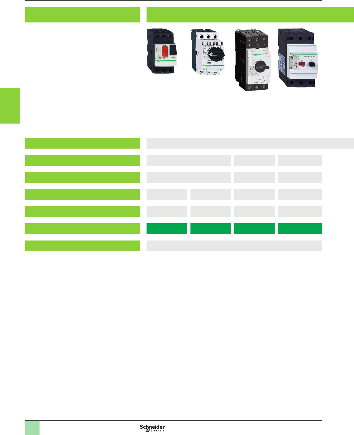
3/170
Selection guide
Applications Protection of motors against short-circuits and overloads
Tripping threshold on short-circuit 13 In
Standard motor power ratings in AC-3, 415 V Up to 15 kW Up to 30 kW 37 kW
Operational current at 415 V 0.1…32 A 9…65 A 56…80 A
Breaking capacity at 415 V (Icu) to IEC 60947-2 10…100 kA 35…100 kA 50…100 kA 15 kA
Door interlock mechanism Without With With Without
Circuit-breaker type GV2ME GV2P GV3P GV3ME80
Pages Please consult our website www.schneider-electric.com
Stop the machine
TeSys protection components
Thermal-magnetic motor circuit-breakers
1
2
3
4
5
6
7
8
9
10
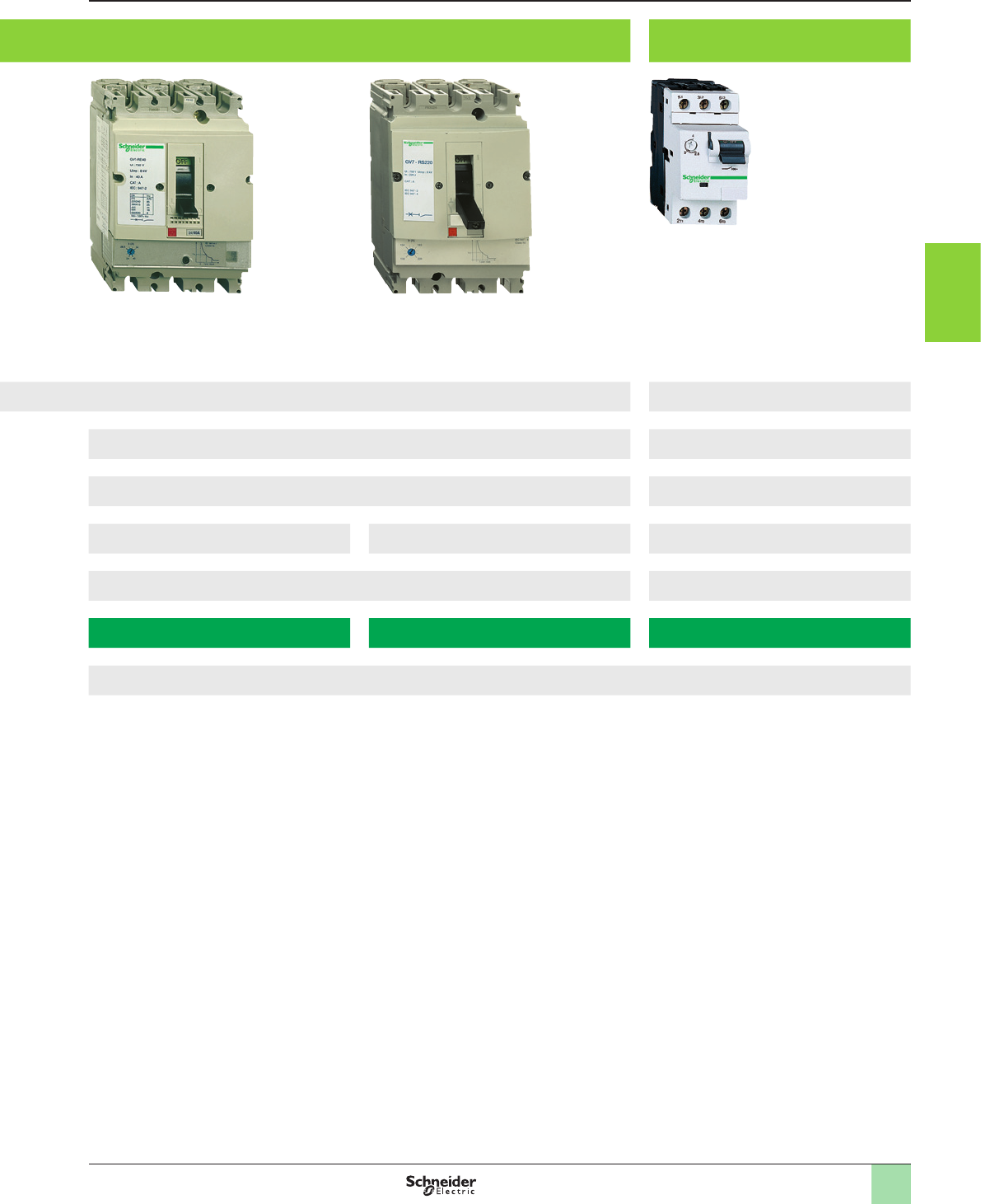
3/171
Protection of motors with high current peak
on starting
20 In
7.5…110 kW Up to 11 kW
12…220 A 0.25…23 A
35 and 36 kA 70 kA 15…100 kA
With With
GV7RE GV7RS GV2RT
Please consult our website www.schneider-electric.com
1
2
3
4
5
6
7
8
9
10
2
1
3
4
5
6
7
8
9
10
2
1
3
4
5
6
7
8
9
10
3/1723/172
Selection guide Stop the machine
Variable speed drives for asynchronous and
synchronous motors
Application Variable speed drives without sensor (velocity control) Variable speed drive
For material handling (conveyors), transfer machines, packaging machines, hoisting, special
machines (textile, transfer), wood-working or metal processing machines, etc.
For pumps and fans (building : Heating, Ventilation and Air Conditioning)For hoisting, material handling, packaging, textile machines, wood-working
machines, process machines
Power range for 50…60 Hz (kW/HP) line supply 0.18…15/0.25...20 0.37…800/0.5...900 0.37…630/0.5...700
Single-phase 100…120 V (kW) – – –
Single-phase 200…240 V (kW) 0.18…2.2/0.25...3 0.37…5.5/0.5...7.5 0.37…5.5/0.5...7.5
Three-phase 200…230 V (kW) – – –
Three-phase 200…240 V (kW) –0.75…90/1...125 0.37…75/0.5...100
Three-phase 380…480 V (kW) –0.75…630/1...900 0.75…500/1...700
Three-phase 380…500 V (kW) 0.37…15/0.5...20 – –
Three-phase 500…600 V (kW) – 2.2…7.5/3...10 1.5…7.5/2...10
Three-phase 525…600 V (kW) – – –
Three-phase 500…690 V (kW) –2.2…800/3...800 1.5…630/2...700
Degree of protection IP 20 IP 20 IP 20
Type of cooling Heatsink Heatsink or water-cooled system Heatsink, base plate or water-cooled circuit
Drive system Output frequency 0.1…599 Hz 0.1…500 Hz for the entire range
0.1…599 Hz up to 37 kW/50 HP at 200…240 V a and 380…480 V a 0.1…500 Hz across the entire range
0.1…599 Hz up to 37 kW at 200…240 V a and 380…480 V a
Type of control Asynchronous
motor
Voltage/frequency ratios: U/f and 5-point U/f
Sensorless ux vector control ratio
Kn2 quadratic ratio (pump/fan)
Energy saving ratio
Sensorless ux vector control
Voltage/frequency ratio (2 or 5 points)
Energy saving ratio
Flux vector control with or without sensor
Voltage/frequency ratio (2 or 5 points). ENA System
Synchronous motor Ratio for synchronous motor without sensor Vector control without speed feedback Vector control with or without speed feedback
Transient overtorque 170…200% of the nominal motor torque 120% of the nominal motor torque for 60 seconds 220% of nominal motor torque for 2 seconds, 170% for 60 seconds
Functions (number) 150 > 100 > 150
Safety functions Integrated 1: STO (Safe Torque Off) “Power removal” (PWR) safety function “Power removal” (PWR) safety function
Available as an option 3 : SLS (Safe Limited Speed), SDI (Safe Direction Information),
SS1 (Safe Stop 1)
– –
Number of preset speeds – 816
Number
of I/O
Analog inputs 3 2…4 2…4
Logic inputs 6 6…20 6…20
Analog outputs 1 : congurable as voltage (0-10 V) or current (0-20 mA) 1…3 1…3
Logic outputs 1 0…8 0…8
Relay outputs 2 2…4 2…4
Communication Integrated Modbus, CANopen Modbus, CANopen Modbus, CANopen
Available as an option DeviceNet, PROFIBUS DP V1, EtherNet/IP, Modbus TCP, EtherCat Modbus TCP Daisy Chain, Modbus/Uni-Telway, EtherNet/IP, DeviceNet,
PROFIBUS DP V0 and V1, INTERBUS, CC-LINK, LONWORKS, METASYS N2,
APOGEE FLN, BACnet
Modbus TCP Daisy Chain, Modbus/Uni-Telway, EtherNet/IP, DeviceNet,
PROFIBUS DP V0 and V1, InterBus, CC-Link
Bluetooth link®Integrated – –
Options Filters, braking resistors, line chokes TVIMC integrated controller card, I/O extension cards, “Controller Inside”
programmable card,
multi-pump cards, encoder interface cards
ATVIMC integrated controller card, interface cards for incremental, resolver,
SinCos, SinCos Hiperface®, EnDat® or SSI encoders, I/O extension cards,
“Controller Inside” programmable card
Dialogue tools IP 54 or IP 55 drive navigator
IP 54 or IP 55 remote graphic display terminal
IP 54 or IP 65 remote graphic display terminal IP 54 or IP 65 remote graphic display terminal
Conguration Setup software SoMove SoMove SoMove
Conguration tools Simple Loader, Multi-Loader Simple Loader, Multi-Loader Simple Loader, Multi-Loader
Standards and certications IEC 61800-5-1, EN/IEC 61800-5-2, IEC 61800-3 (environments 1 and 2, category C2),
UL508C, EN/ISO 13849-1/- 2 category 3 (PL e), IEC 61508 SIL 3,
IEC 60 721-3-3 classes 3C3 and 3S2
IEC 61800-5-1,
IEC 61800-3 (environments 1 and 2, categories C1 to C3),
IEC 61000-4-2/4-3/4-4/4-5/4-6/4-11
IEC 61800-5-1,
IEC 61800-3 (environments 1 and 2, categories C1 to C3),
IEC 61000-4-2/4-3/4-4/4-5/4-6/4-11
e, UL, CSA, C-Tick, NOM, GOST e, UL, CSA, DNV, C-Tick, NOM, GOST e, UL, CSA, DNV, C-Tick, NOM, GOST
References ATV32 ATV61 ATV71
Catalogues “Altivar 32 variable speed drives” “Altivar 61 variable speed drives” “Altivar 71 variable speed drives”
2
1
3
4
5
6
7
8
9
10
2
1
3
4
5
6
7
8
9
10
3/1733/173
Application Variable speed drives without sensor (velocity control) Variable speed drive
For material handling (conveyors), transfer machines, packaging machines, hoisting, special
machines (textile, transfer), wood-working or metal processing machines, etc.
For pumps and fans (building : Heating, Ventilation and Air Conditioning)For hoisting, material handling, packaging, textile machines, wood-working
machines, process machines
Power range for 50…60 Hz (kW/HP) line supply 0.18…15/0.25...20 0.37…800/0.5...900 0.37…630/0.5...700
Single-phase 100…120 V (kW) – – –
Single-phase 200…240 V (kW) 0.18…2.2/0.25...3 0.37…5.5/0.5...7.5 0.37…5.5/0.5...7.5
Three-phase 200…230 V (kW) – – –
Three-phase 200…240 V (kW) –0.75…90/1...125 0.37…75/0.5...100
Three-phase 380…480 V (kW) –0.75…630/1...900 0.75…500/1...700
Three-phase 380…500 V (kW) 0.37…15/0.5...20 – –
Three-phase 500…600 V (kW) – 2.2…7.5/3...10 1.5…7.5/2...10
Three-phase 525…600 V (kW) – – –
Three-phase 500…690 V (kW) –2.2…800/3...800 1.5…630/2...700
Degree of protection IP 20 IP 20 IP 20
Type of cooling Heatsink Heatsink or water-cooled system Heatsink, base plate or water-cooled circuit
Drive system Output frequency 0.1…599 Hz 0.1…500 Hz for the entire range
0.1…599 Hz up to 37 kW/50 HP at 200…240 V a and 380…480 V a 0.1…500 Hz across the entire range
0.1…599 Hz up to 37 kW at 200…240 V a and 380…480 V a
Type of control Asynchronous
motor
Voltage/frequency ratios: U/f and 5-point U/f
Sensorless ux vector control ratio
Kn2 quadratic ratio (pump/fan)
Energy saving ratio
Sensorless ux vector control
Voltage/frequency ratio (2 or 5 points)
Energy saving ratio
Flux vector control with or without sensor
Voltage/frequency ratio (2 or 5 points). ENA System
Synchronous motor Ratio for synchronous motor without sensor Vector control without speed feedback Vector control with or without speed feedback
Transient overtorque 170…200% of the nominal motor torque 120% of the nominal motor torque for 60 seconds 220% of nominal motor torque for 2 seconds, 170% for 60 seconds
Functions (number) 150 > 100 > 150
Safety functions Integrated 1: STO (Safe Torque Off) “Power removal” (PWR) safety function “Power removal” (PWR) safety function
Available as an option 3 : SLS (Safe Limited Speed), SDI (Safe Direction Information),
SS1 (Safe Stop 1)
– –
Number of preset speeds – 816
Number
of I/O
Analog inputs 3 2…4 2…4
Logic inputs 6 6…20 6…20
Analog outputs 1 : congurable as voltage (0-10 V) or current (0-20 mA) 1…3 1…3
Logic outputs 1 0…8 0…8
Relay outputs 2 2…4 2…4
Communication Integrated Modbus, CANopen Modbus, CANopen Modbus, CANopen
Available as an option DeviceNet, PROFIBUS DP V1, EtherNet/IP, Modbus TCP, EtherCat Modbus TCP Daisy Chain, Modbus/Uni-Telway, EtherNet/IP, DeviceNet,
PROFIBUS DP V0 and V1, INTERBUS, CC-LINK, LONWORKS, METASYS N2,
APOGEE FLN, BACnet
Modbus TCP Daisy Chain, Modbus/Uni-Telway, EtherNet/IP, DeviceNet,
PROFIBUS DP V0 and V1, InterBus, CC-Link
Bluetooth link®Integrated – –
Options Filters, braking resistors, line chokes TVIMC integrated controller card, I/O extension cards, “Controller Inside”
programmable card,
multi-pump cards, encoder interface cards
ATVIMC integrated controller card, interface cards for incremental, resolver,
SinCos, SinCos Hiperface®, EnDat® or SSI encoders, I/O extension cards,
“Controller Inside” programmable card
Dialogue tools IP 54 or IP 55 drive navigator
IP 54 or IP 55 remote graphic display terminal
IP 54 or IP 65 remote graphic display terminal IP 54 or IP 65 remote graphic display terminal
Conguration Setup software SoMove SoMove SoMove
Conguration tools Simple Loader, Multi-Loader Simple Loader, Multi-Loader Simple Loader, Multi-Loader
Standards and certications IEC 61800-5-1, EN/IEC 61800-5-2, IEC 61800-3 (environments 1 and 2, category C2),
UL508C, EN/ISO 13849-1/- 2 category 3 (PL e), IEC 61508 SIL 3,
IEC 60 721-3-3 classes 3C3 and 3S2
IEC 61800-5-1,
IEC 61800-3 (environments 1 and 2, categories C1 to C3),
IEC 61000-4-2/4-3/4-4/4-5/4-6/4-11
IEC 61800-5-1,
IEC 61800-3 (environments 1 and 2, categories C1 to C3),
IEC 61000-4-2/4-3/4-4/4-5/4-6/4-11
e, UL, CSA, C-Tick, NOM, GOST e, UL, CSA, DNV, C-Tick, NOM, GOST e, UL, CSA, DNV, C-Tick, NOM, GOST
References ATV32 ATV61 ATV71
Catalogues “Altivar 32 variable speed drives” “Altivar 61 variable speed drives” “Altivar 71 variable speed drives”
2
1
3
4
5
6
7
8
9
10
2
1
3
4
5
6
7
8
9
10
3/1743/174
Selection guide Stop the machine
Motion control
Lexium 32
Application areas Common Printing, material handling, conveying, etc.), transfer machines, packaging, textiles, etc. Printing, material handling, conveying, etc.), transfer machines, packaging, textiles, etc.
Specic Clamping, cutting, cutting to length, ying shear, rotary knife, Pick & Place, winding,
marking, etc.
Clamping, cutting, cutting to length, ying shear, rotary knife, Pick & Place, winding, marking, etc.
Technology type Lexium 32 servo drives with sensor feedback (position control) Lexium 32 servo drives with sensor feedback (position control)
BMH servo motor
BSH servo motor
BMH servo motor
BSH servo motor
Power range for 50…60 Hz (kW) line supply 0.15…7 0.15…7
Single-phase 100…120 V (kW) 0.15…0.8 0.15…0.8
Single-phase 200…240 V (kW) 0.3…1.6 0.3…1.6
Three-phase 380…480 V (kW) 0.4…7 0.4…7
Three-phase 380…500 V (kW) – –
Drive system Motor speed Nominal speed:
bBMH servo motors: continuous stall torque range between 1.2…84 Nm for nominal speeds
between 1200 and 5000 rpm
bBSH servo motors: continuous stall torque range between 0.5…33.4 Nm for nominal speeds
between 2500 and 6000 rpm
Nominal speed:
bBMH servo motors: continuous stall torque range between 1.2…84 Nm for nominal speeds between 1200 and 5000 rpm
bBSH servo motors: continuous stall torque range between 0.5…33.4 Nm for nominal speeds between 2500 and 6000 rpm
Type of control Asynchronous motor – –
Synchronous motor Synchronous motor with sensor feedback for BMH and BSH servo motors Synchronous motor with sensor feedback for BMH and BSH servo motors
Motor sensor Integrated SinCos Hiperface® sensor SinCos Hiperface® sensor
Available as an
option
–Resolver encoder
Analog encoder (motor and machine)
Digital encoder (machine only)
Transient overtorque –
Peak current Peak current, up to 4 times the drive direct current for 1 second Peak current, up to 4 times the drive direct current for 1 second
Number of functions – –
Safety functions Integrated 1: STO (Safe Torque Off) 1: STO (Safe Torque Off)
Available as an
option
4 : SLS (Safe Limited Speed), SS1 (Safe Stop 1), SS2 (Safe Stop 2), SOS (Safe Operating Stop) 4 : SLS (Safe Limited Speed), SS1 (Safe Stop 1), SS2 (Safe Stop 2), SOS (Safe Operating Stop)
Number
of I/O
Inputs Analog 2 – –
Logic 6 1 capture input 6 (2 of which can be used as a capture input)
Outputs Analog – – –
Logic 5 – 3
Relay outputs – – –
Communication Integrated Modbus Modbus, CANopen, CANmotion Modbus
Available as an option – – CANopen, CANmotion, DeviceNet, EtherNet/IP, PROFIBUS DP V1, EtherCat
Bluetooth link®Available as an option Available as an option Available as an option
Options SoMove setup software
Multi-Loader conguration tool
IP 54 remote graphic display terminal
Filters, braking resistors, line chokes
SoMove setup software
Multi-Loader conguration tool
IP 54 remote graphic display terminal
Filters, braking resistors, line chokes
Standards and certications IEC 61800-5-1, EN/IEC 61800-5-2, IEC 61800-3 (environments 1 and 2, categories C2 and C3)
IEC 61000-4-2/4-3/4-4/4-5, EN/ISO 13849-1 (PL e), IEC 61508 SIL 3
IEC 61800-5-1, IEC 61800-3 (environments 1 and 2, categories C2 and C3)
IEC 61000-4-2/4-3/4-4/4-5, EN/ISO 13849-1-1 (PL e), IEC 61508 SIL 3
e, UL, CSA e, UL, CSA
References LXM32C LXM32A LXM32M
Catalogue Please consult our website www.schneider-electric.com
2
1
3
4
5
6
7
8
9
10
2
1
3
4
5
6
7
8
9
10
3/1753/175
Application areas Common Printing, material handling, conveying, etc.), transfer machines, packaging, textiles, etc. Printing, material handling, conveying, etc.), transfer machines, packaging, textiles, etc.
Specic Clamping, cutting, cutting to length, ying shear, rotary knife, Pick & Place, winding,
marking, etc.
Clamping, cutting, cutting to length, ying shear, rotary knife, Pick & Place, winding, marking, etc.
Technology type Lexium 32 servo drives with sensor feedback (position control) Lexium 32 servo drives with sensor feedback (position control)
BMH servo motor
BSH servo motor
Power range for 50…60 Hz (kW) line supply 0.15…7 0.15…7
Single-phase 100…120 V (kW) 0.15…0.8 0.15…0.8
Single-phase 200…240 V (kW) 0.3…1.6 0.3…1.6
Three-phase 380…480 V (kW) 0.4…7 0.4…7
Three-phase 380…500 V (kW) – –
Drive system Motor speed Nominal speed:
bBMH servo motors: continuous stall torque range between 1.2…84 Nm for nominal speeds
between 1200 and 5000 rpm
bBSH servo motors: continuous stall torque range between 0.5…33.4 Nm for nominal speeds
between 2500 and 6000 rpm
Nominal speed:
bBMH servo motors: continuous stall torque range between 1.2…84 Nm for nominal speeds between 1200 and 5000 rpm
bBSH servo motors: continuous stall torque range between 0.5…33.4 Nm for nominal speeds between 2500 and 6000 rpm
Type of control Asynchronous motor – –
Synchronous motor Synchronous motor with sensor feedback for BMH and BSH servo motors Synchronous motor with sensor feedback for BMH and BSH servo motors
Motor sensor Integrated SinCos Hiperface® sensor SinCos Hiperface® sensor
Available as an
option
– Resolver encoder
Analog encoder (motor and machine)
Digital encoder (machine only)
Transient overtorque –
Peak current Peak current, up to 4 times the drive direct current for 1 second Peak current, up to 4 times the drive direct current for 1 second
Number of functions – –
Safety functions Integrated 1: STO (Safe Torque Off) 1: STO (Safe Torque Off)
Available as an
option
4 : SLS (Safe Limited Speed), SS1 (Safe Stop 1), SS2 (Safe Stop 2), SOS (Safe Operating Stop) 4 : SLS (Safe Limited Speed), SS1 (Safe Stop 1), SS2 (Safe Stop 2), SOS (Safe Operating Stop)
Number
of I/O
Inputs Analog 2 – –
Logic 6 1 capture input 6 (2 of which can be used as a capture input)
Outputs Analog – – –
Logic 5 – 3
Relay outputs – – –
Communication Integrated Modbus Modbus, CANopen, CANmotion Modbus
Available as an option – – CANopen, CANmotion, DeviceNet, EtherNet/IP, PROFIBUS DP V1, EtherCat
Bluetooth link®Available as an option Available as an option Available as an option
Options SoMove setup software
Multi-Loader conguration tool
IP 54 remote graphic display terminal
Filters, braking resistors, line chokes
SoMove setup software
Multi-Loader conguration tool
IP 54 remote graphic display terminal
Filters, braking resistors, line chokes
Standards and certications IEC 61800-5-1, EN/IEC 61800-5-2, IEC 61800-3 (environments 1 and 2, categories C2 and C3)
IEC 61000-4-2/4-3/4-4/4-5, EN/ISO 13849-1 (PL e), IEC 61508 SIL 3
IEC 61800-5-1, IEC 61800-3 (environments 1 and 2, categories C2 and C3)
IEC 61000-4-2/4-3/4-4/4-5, EN/ISO 13849-1-1 (PL e), IEC 61508 SIL 3
e, UL, CSA e, UL, CSA
References LXM32C LXM32A LXM32M
Catalogue Please consult our website www.schneider-electric.com
3/176
Product reference index
Index
0 to 9
170DTN11000 3/137
467NHP81100 3/137
490NAD91103 3/137
490NAD91104 3/137
490NAD91105 3/137
490NAE91100 3/137
490NTC00005 3/137
490NTC00015 3/137
490NTC00040 3/137
490NTC00080 3/137
490NTW00002 3/137
490NTW00005 3/137
490NTW00012 3/137
490NTW00040 3/137
490NTW00080 3/137
A
ABL1REM12050 3/136
ABL1REM24025 3/136
ABL1REM24100 3/136
ABL8RPS24030 3/136
ABL8RPS24050 3/136
ABL8RPS24100 3/105
3/136
D
DE9EC21 3/60
DE9RA2125 3/60
DL1BDBp3/147
DL1BDGp3/147
DL1BDMp3/147
DL1BEB 3/147
DL1BEE 3/147
DL1BEG 3/147
DL1BEJ 3/147
DL1BEM 3/147
DL1BKBp3/147
DL1BKGp3/147
DL1BKMp3/147
K
KCC1YZ 3/159
KCD1PZ 3/159
KCE1YZ 3/159
KCF1PZ 3/159
KCF2PZ 3/159
KCF3PZ 3/159
KZ13 3/161
KZ14 3/161
KZ15 3/161
KZ16 3/161
KZ32 3/160
KZ62 3/161
KZ65 3/161
KZ66 3/161
KZ67 3/161
KZ74 3/160
KZ76 3/161
KZ77 3/161
KZ81 3/160
KZ83 3/160
KZ100 3/161
KZ101 3/161
KZ103 3/161
KZ106 3/160
S
SSV1XPSMFWIN 3/124
3/136
STBNDP2112 3/137
T
TCSMCNAM3M002P 3/105
TM3SAC5R 3/93
TM3SAC5RG 3/93
TM3SAF5R 3/93
TM3SAF5RG 3/93
TM3SAFL5R 3/93
TM3SAFL5RG 3/93
TM3SAK6R 3/93
TM3SAK6RG 3/93
TM3XREC1 3/95
TM3XTRA1 3/95
TMAM2 3/93
3/95
TMAT2PSET 3/95
TMAT2PSETG 3/95
TSCCANTDM4 3/105
TSXCANCA50 3/105
TSXCANCA100 3/105
TSXCANCA300 3/105
TSXCANCADD1 3/105
TSXCANCADD03 3/105
TSXCANCADD3 3/105
TSXCANCADD5 3/105
TSXCSA100 3/137
TSXCSA200 3/137
TSXCSA500 3/137
TSXPBSCA100 3/105
3/137
TSXPBSCA400 3/105
3/137
TSXPBY100 3/137
TSXPCX1031 3/105
V
V0 3/157
3/163
V01 3/157
3/163
V1 3/157
3/163
V02 3/157
3/163
V2 3/157
3/163
V3 3/157
3/163
V4 3/157
3/163
V5 3/157
V6 3/157
VCCD0 3/156
VCCD01 3/156
VCCD1 3/156
VCCD02 3/156
VCCD2 3/156
VCCDN12 3/154
VCCDN20 3/154
VCCF0 3/156
VCCF01 3/156
VCCF1 3/156
VCCF02 3/156
VCCF2 3/156
VCCF3 3/156
VCCF4 3/156
VCCF5 3/156
VCCF6 3/156
VCD0 3/156
VCD01 3/156
VCD1 3/156
VCD02 3/156
VCD2 3/156
VCDN12 3/154
VCDN20 3/154
VCF0 3/156
VCF0GE 3/162
VCF01 3/156
VCF1 3/156
VCF01GE 3/162
VCF1GE 3/162
VCF02 3/156
VCF2 3/156
VCF02GE 3/162
VCF2GE 3/162
VCF3 3/156
VCF3GE 3/162
VCF4 3/156
VCF4GE 3/162
VCF5 3/156
VCF5GE 3/162
VCF6 3/156
VCF6GE 3/162
VCFN12GE 3/162
VCFN20GE 3/162
VCFN25GE 3/162
VCFN32GE 3/162
VCFN40GE 3/162
VCFXGDXE 3/163
VCFXGEp3/163
VDIP184546005 3/95
VDIP184546010 3/95
VDIP184546020 3/95
VDIP184546030 3/95
VDIP184546050 3/95
VN12 3/155
3/163
VN20 3/155
3/163
VVEp3/156
VW3A8306R 3/137
VW3A8306R30 3/105
VW3A8306RC 3/137
VZ0 3/157
3/164
VZ01 3/157
3/164
VZ1 3/157
3/164
VZ02 3/157
3/164
VZ2 3/157
3/164
VZ3 3/157
3/164
VZ4 3/157
3/164
VZ7 3/157
3/164
VZ8 3/160
VZ9 3/160
VZ10 3/160
VZ11 3/157
3/164
VZ12 3/157
3/164
VZ13 3/157
3/164
VZ14 3/157
3/164
VZ15 3/157
3/164
VZ16 3/157
3/164
VZ17 3/160
VZ18 3/160
VZ20 3/157
3/164
VZ26 3/160
VZ27 3/160
VZ28 3/160
VZ29 3/160
VZ30 3/160
VZ31 3/160
VZN05 3/155
3/165
VZN06 3/155
3/165
VZN08 3/155
VZN11 3/155
3/165
VZN12 3/155
3/165
VZN14 3/155
3/165
VZN17 3/160
VZN20 3/155
3/165
VZN26 3/155
VZN30 3/160
X
XALD01 3/36
XALD01H7 3/36
XALD02 3/36
XALD02H7 3/36
XALD03 3/36
XALD03H7 3/36
XALD04 3/36
XALD05 3/36
XALD101 3/32
XALD101H29 3/32
XALD102 3/32
XALD102E 3/32
XALD103 3/32
XALD104 3/32
XALD111 3/32
XALD111H29 3/32
XALD112 3/32
XALD112E 3/32
XALD114 3/32
XALD114E 3/32
XALD115 3/32
XALD116 3/32
XALD117 3/32
XALD118 3/32
XALD132 3/34
XALD134 3/34
XALD142 3/34
XALD144 3/34
XALD144E 3/34
XALD164 3/32
XALD211 3/34
XALD211H29 3/34
XALD213 3/34
XALD213E 3/34
XALD214 3/34
XALD215 3/34
XALD222 3/35
XALD222E 3/35
XALD223 3/35
XALD224 3/34
XALD225 3/34
XALD241 3/34
XALD311 3/35
XALD321 3/35
XALD324 3/35
XALD324E 3/35
XALD325 3/35
XALD326 3/35
XALD328 3/35
XALD334 3/35
XALD339 3/35
XALD361B 3/34
XALD361M 3/34
XALD363B 3/34
XALD363G 3/34
XALD363M 3/34
XALK01 3/36
XALK01H29 3/36
XALK01H44 3/36
XALK01HFR 3/36
XALK0p3/36
XALK174 3/33
XALK174E 3/33
XALK174F 3/33
XALK174G 3/33
XALK178 3/33
XALK178E 3/33
XALK178F 3/33
XALK178G 3/33
XALK184 3/33
XALK184E 3/33
XALK184F 3/33
XALK184G 3/33
XALK188 3/33
XALK188E 3/33
XALK188F 3/33
XALK188G 3/33
XALK194 3/33
XALK198 3/33
XALZ09 3/37
3/53
XB4BC21 3/12
XB4BS8442 3/14
XB4BS8444 3/14
XB4BS8445 3/14
XB4BS9445 3/14
XB4BS84441 3/14
XB4BT842 3/14
XB4BT845 3/14
XB5AC21 3/24
XB5AS142 3/27
XB5AS542 3/27
XB5AS8444 3/26
XB5AS8445 3/26
XB5AS9445 3/26
XB5AT42 3/27
XB5AT845 3/26
XBTZ938 3/137
XBTZG909 3/137
XBY2U 3/29
3/51
3/146
XCOM2514 3/59
XPSABV1133C 3/69
XPSABV1133P 3/69
XPSABV11330C 3/69
XPSABV11330P 3/69
XPSAC1321 3/68
XPSAC1321P 3/68
XPSAC3421 3/68
XPSAC3421P 3/68
XPSAC3721 3/68
XPSAC3721P 3/68
XPSAC5121 3/68
2
1
3
4
5
6
7
8
9
10
2
1
3
4
5
6
7
8
9
10

3/177
Product reference index
Index (continued)
XPSAC5121P 3/68
XPSAF5130 3/71
XPSAF5130P 3/71
XPSAFL5130 3/72
XPSAFL5130P 3/72
XPSAK311144 3/74
XPSAK311144P 3/74
XPSAK331144P 3/74
XPSAK351144 3/74
XPSAK351144P 3/74
XPSAK361144 3/74
XPSAK361144P 3/74
XPSAK371144 3/74
XPSAK371144P 3/74
XPSAR311144 3/73
XPSAR311144P 3/73
XPSAR351144 3/73
XPSAR351144P 3/73
XPSAR371144 3/73
XPSAR371144P 3/73
XPSATE3410 3/69
XPSATE3410P 3/69
XPSATE3710 3/69
XPSATE3710P 3/69
XPSATE5110 3/69
XPSATE5110P 3/69
XPSATR1153C 3/70
XPSATR1153P 3/70
XPSATR3953C 3/70
XPSATR3953P 3/70
XPSATR11530C 3/70
XPSATR11530P 3/70
XPSATR39530C 3/70
XPSATR39530P 3/70
XPSAV11113 3/69
XPSAV11113P 3/69
XPSAV11113T050 3/69
XPSAV11113Z002 3/69
XPSAXE5120C 3/68
XPSAXE5120P 3/68
XPSBAE3920C 3/76
XPSBAE3920P 3/76
XPSBAE5120C 3/76
XPSBAE5120P 3/76
XPSBCE3110C 3/76
XPSBCE3110P 3/76
XPSBCE3410C 3/76
XPSBCE3410P 3/76
XPSBCE3710C 3/76
XPSBCE3710P 3/76
XPSBF1132 3/76
XPSBF1132P 3/76
XPSCM1144 3/77
XPSCM1144P 3/77
XPSDMB1132 3/81
XPSDMB1132P 3/81
XPSDME1132 3/81
XPSDME1132P 3/81
XPSDME1132TS220 3/81
XPSECME5131C 3/79
XPSECME5131P 3/79
XPSECPE3910C 3/79
XPSECPE3910P 3/79
XPSECPE5131C 3/79
XPSECPE5131P 3/79
XPSEDA5142 3/83
XPSLCM1150 3/78
XPSMC16Z 3/104
XPSMC16ZC 3/104
XPSMC16ZCPACK 3/104
XPSMC16ZP 3/104
XPSMC16ZPACK 3/104
XPSMC16ZPPACK 3/104
XPSMC32Z 3/104
XPSMC32ZC 3/104
XPSMC32ZCPACK 3/104
XPSMC32ZP 3/104
XPSMC32ZPACK 3/104
XPSMC32ZPPACK 3/104
XPSMCCPC 3/105
XPSMCSCY 3/105
XPSMCTC16 3/104
XPSMCTC32 3/104
XPSMCTS16 3/104
XPSMCTS32 3/104
XPSMCWIN 3/104
XPSMF1DI1601 3/130
XPSMF2DO401 3/132
XPSMF2DO801 3/132
XPSMF2DO1601 3/132
XPSMF2DO1602 3/132
XPSMF3AIO8401 3/133
3/135
XPSMF3DIO8801 3/133
3/135
XPSMF3DIO16801 3/133
3/135
XPSMF3DIO20802 3/133
3/135
XPSMF3022 3/113
3/122
XPSMF3502 3/113
3/122
XPSMF3522 3/113
3/122
XPSMF3542 3/113
3/122
XPSMF4000 3/111
3/122
XPSMF4002 3/111
3/122
XPSMF4020 3/111
3/122
XPSMF4022 3/111
3/122
XPSMF4040 3/111
3/122
XPSMF4042 3/111
3/122
XPSMF31222 3/113
3/122
XPSMFAI801 3/114
3/117
3/118
XPSMFAO801 3/114
3/117
3/119
XPSMFBLK 3/117
XPSMFCIO2401 3/114
3/117
3/119
XPSMFCPU22 3/117
XPSMFDI2401 3/114
3/117
3/120
XPSMFDI3201 3/114
3/117
3/120
XPSMFDIO241601 3/114
3/117
3/121
XPSMFDO801 3/114
3/117
3/121
XPSMFGEH01 3/117
XPSMFPS01 3/117
XPSMP11123 3/99
XPSMP11123P 3/99
XPSOT3444 3/87
XPSOT3744 3/87
XPSPVK1184 3/85
XPSPVK3484 3/85
XPSPVK3784 3/85
XPSPVT1180 3/84
XPSTSA3442P 3/80
XPSTSA3742P 3/80
XPSTSA5142P 3/80
XPSTSW3442P 3/80
XPSTSW3742P 3/80
XPSTSW5142P 3/80
XPSVC1132 3/75
XPSVC1132P 3/75
XPSVNE1142HSP 3/82
XPSVNE1142P 3/82
XPSVNE3442HSP 3/82
XPSVNE3442P 3/82
XPSVNE3742HSP 3/82
XPSVNE3742P 3/82
XVBC2Bp3/144
XVBC2Gp3/144
XVBC2Mp3/144
XVBC4Bp3/143
XVBC4Mp3/143
XVBC5Bp3/144
XVBC5Gp3/144
XVBC5Mp3/144
XVBC6Bp3/145
XVBC6Gp3/145
XVBC6Mp3/145
XVBC07 3/146
XVBC8Bp3/145
XVBC8E5 3/145
XVBC8Gp3/145
XVBC8Mp3/145
XVBC9B 3/146
XVBC9M 3/146
XVBC12 3/147
XVBC14 3/146
XVBC020 3/147
XVBC21 3/146
XVBC21A 3/146
XVBC21B 3/146
XVBC22 3/146
XVBC23 3/146
XVBC030 3/147
XVBC33 3/143
XVBC34 3/143
XVBC35 3/143
XVBC36 3/143
XVBC37 3/143
XVBC38 3/143
XVBC040 3/147
XVBC081 3/146
XVBCYp3/146
XVBL0Bp3/141
XVBL0Gp3/141
XVBL0Mp3/141
XVBL1Bp3/141
XVBL1Gp3/141
XVBL1Mp3/141
XVBL4Bp3/140
XVBL4Mp3/140
XVBL6Bp3/142
XVBL6Gp3/142
XVBL6Mp3/142
XVBL8Bp3/142
XVBL8Gp3/142
XVBL8Mp3/142
XVBL33 3/140
XVBL34 3/140
XVBL35 3/140
XVBL36 3/140
XVBL37 3/140
XVBL38 3/140
XVBZ01 3/147
XVBZ02 3/147
XVBZ02A 3/147
XVBZ03 3/147
XVBZ03A 3/147
XVBZ04 3/147
XVBZ04A 3/147
XVBZ14 3/147
XVBZ18 3/146
XVCZ13 3/149
XVCZ23 3/149
XVR08B0p3/149
XVR08J0p3/149
XVR10B0p3/149
XVR10J0p3/149
XVR12B03 3/149
XVR12B03S 3/149
XVR12B04 3/149
XVR12B04S 3/149
XVR12B05 3/149
XVR12B05S 3/149
XVR12B06 3/149
XVR12B06S 3/149
XVR12J03 3/149
XVR12J03S 3/149
XVR12J04 3/149
XVR12J04S 3/149
XVR12J05 3/149
XVR12J05S 3/149
XVR12J06 3/149
XVR12J06S 3/149
XVR012L 3/149
XVR13B04 3/149
XVR13B04L 3/149
XVR13B05 3/149
XVR13B05L 3/149
XVR13G04L 3/149
XVR13G05L 3/149
XVR13J04 3/149
XVR13J05 3/149
XVR13M04L 3/149
XVR13M05L 3/149
XVRZ081 3/149
XVRZ082 3/149
XVRZRp3/149
XVS10BMW 3/151
XVS10GMW 3/151
XVS10MMW 3/151
XVS14BMW 3/151
XVS14GMW 3/151
XVS14MMW 3/151
XY2AUp3/55
XY2AZp3/55
XY2SB71 3/59
XY2SB72 3/59
XY2SB75 3/59
XY2SB76 3/59
XY2SB90 3/60
XY2SB93 3/60
XY2SB96 3/60
XY2SB98 3/60
XY2SB99 3/60
XY2SB511 3/60
XY2SB531 3/60
XY2SB714 3/59
XY2SB724 3/59
Z
Z01 3/161
ZALVBp3/37
ZALVGp3/37
ZALVMp3/37
ZALYp3/49
ZB2BE101 3/28
ZB2BE102 3/28
ZB2BP012 3/53
ZB2BP013 3/53
ZB2BP014 3/53
ZB2BP015 3/53
ZB2BP016 3/53
ZB4BCp3/12
ZB4BCp43/12
ZB4BRp3/12
ZB4BR216 3/12
3/60
ZB4BR316 3/12
ZB4BR416 3/12
ZB4BR516 3/12
ZB4BR616 3/12
ZB4BS12 3/13
ZB4BS22 3/13
ZB4BS42 3/13
ZB4BS52 3/13
ZB4BS55 3/13
ZB4BS62 3/13
ZB4BS72 3/13
ZB4BS834 3/14
ZB4BS844 3/14
3/60
ZB4BS845S 3/60
ZB4BS864 3/14
ZB4BS934 3/14
ZB4BS944 3/14
ZB4BS964 3/14
ZB4BT2 3/13
ZB4BT84 3/14
ZB4BT844 3/14
ZB4BW413 3/12
ZB4BW433 3/12
ZB4BW443 3/12
ZB4BW453 3/12
ZB4BW463 3/12
ZB4BW613 3/13
ZB4BW633 3/13
ZB4BW643 3/14
ZB4BW653 3/13
ZB4BW663 3/13
ZB4BX2 3/13
ZB4BX84 3/14
ZB4BZ009 3/28
ZB4BZ101 3/28
ZB4BZ102 3/28
ZB4BZ103 3/28
ZB4BZ104 3/28
3/60
ZB4BZ105 3/28
3/60
ZB4BZ106 3/28
ZB4BZ107 3/28
2
1
3
4
5
6
7
8
9
10
2
1
3
4
5
6
7
8
9
10

3/178
ZB4BZ141 3/28
ZB5AAp3/38
ZB5AA14 3/38
ZB5AA16 3/38
ZB5AA18 3/38
3/45
ZB5AA24 3/38
ZB5AA26 3/38
ZB5AA34 3/38
ZB5AA36 3/38
ZB5AA38 3/38
3/45
ZB5AA44 3/38
ZB5AA46 3/38
ZB5AA48 3/38
3/45
ZB5AA54 3/38
ZB5AA56 3/38
ZB5AA58 3/38
3/45
ZB5AA64 3/38
ZB5AA66 3/38
ZB5AA68 3/38
3/45
ZB5AA131 3/39
ZB5AA133 3/39
ZB5AA136 3/39
ZB5AA141 3/39
ZB5AA142 3/39
ZB5AA145 3/39
ZB5AA232 3/39
ZB5AA233 3/39
ZB5AA234 3/39
ZB5AA235 3/39
ZB5AA245 3/39
ZB5AA331 3/39
ZB5AA333 3/39
ZB5AA334 3/39
ZB5AA335 3/39
ZB5AA336 3/39
ZB5AA341 3/39
ZB5AA342 3/39
ZB5AA343 3/39
ZB5AA344 3/39
ZB5AA432 3/39
ZB5AA433 3/39
ZB5AA434 3/39
ZB5AA435 3/39
ZB5ACp3/24
3/39
ZB5ACp43/24
3/39
ZB5ADp3/41
ZB5AD28 3/44
ZB5AD29 3/43
ZB5AD39 3/43
ZB5AD48 3/44
ZB5AD49 3/43
ZB5AD59 3/43
ZB5AD79 3/43
ZB5AD89 3/43
ZB5AD201 3/41
ZB5AD203 3/41
ZB5AD204 3/42
ZB5AD205 3/42
ZB5AD206 3/42
ZB5AD301 3/41
ZB5AD303 3/41
ZB5AD304 3/42
ZB5AD305 3/42
ZB5AD306 3/42
ZB5AD401 3/41
ZB5AD403 3/41
ZB5AD404 3/42
ZB5AD405 3/42
ZB5AD406 3/42
ZB5AD501 3/41
ZB5AD503 3/41
ZB5AD504 3/42
ZB5AD505 3/42
ZB5AD506 3/42
ZB5AD701 3/41
ZB5AD703 3/41
ZB5AD704 3/42
ZB5AD705 3/42
ZB5AD706 3/42
ZB5AD801 3/41
ZB5AD803 3/41
ZB5AD804 3/42
ZB5AD805 3/42
ZB5AD806 3/42
ZB5AD2801 3/44
ZB5AD2804 3/44
ZB5AD2806 3/44
ZB5AG0 3/43
ZB5AG0D 3/44
ZB5AG1 3/43
ZB5AG1D 3/44
ZB5AG2 3/43
ZB5AG02 3/43
ZB5AG2D 3/44
ZB5AG02D 3/44
ZB5AG3 3/43
ZB5AG3D 3/44
ZB5AG03D 3/44
ZB5AG4 3/43
ZB5AG4D 3/44
ZB5AG04D 3/44
ZB5AG5 3/43
ZB5AG05 3/43
ZB5AG5D 3/44
ZB5AG05D 3/44
ZB5AG6 3/43
ZB5AG6D 3/44
ZB5AG06D 3/44
ZB5AG7 3/43
ZB5AG07D 3/44
ZB5AG7D 3/44
ZB5AG8 3/43
ZB5AG08 3/43
ZB5AG8D 3/44
ZB5AG08D 3/44
ZB5AG9 3/43
ZB5AG09 3/43
ZB5AG9D 3/44
ZB5AG09D 3/44
ZB5AJp3/42
ZB5AK1213 3/46
ZB5AK1233 3/46
ZB5AK1243 3/46
ZB5AK1253 3/46
ZB5AK1263 3/46
ZB5AK1313 3/46
ZB5AK1333 3/46
ZB5AK1343 3/46
ZB5AK1353 3/46
ZB5AK1363 3/46
ZB5AK1413 3/46
ZB5AK1433 3/46
ZB5AK1443 3/46
ZB5AK1453 3/46
ZB5AK1463 3/46
ZB5AK1513 3/46
ZB5AK1533 3/46
ZB5AK1543 3/46
ZB5AK1553 3/46
ZB5AK1563 3/46
ZB5AK1713 3/46
ZB5AK1733 3/46
ZB5AK1743 3/46
ZB5AK1753 3/46
ZB5AK1763 3/46
ZB5AK1813 3/46
ZB5AK1833 3/46
ZB5AK1843 3/46
ZB5AK1853 3/46
ZB5AK1863 3/46
ZB5ALp3/38
ZB5AL232 3/39
ZB5AL233 3/39
ZB5AL234 3/39
ZB5AL235 3/39
ZB5AL432 3/39
ZB5AL433 3/39
ZB5AL434 3/39
ZB5AL435 3/39
ZB5AP1S 3/38
ZB5AP2S 3/38
ZB5AP3S 3/38
ZB5AP4S 3/38
ZB5AP5S 3/38
ZB5AP6S 3/38
ZB5ARp3/24
ZB5AR216 3/24
ZB5AR316 3/24
ZB5AR416 3/24
ZB5AR516 3/24
ZB5AR616 3/24
ZB5AS12 3/25
3/40
ZB5AS14 3/27
3/40
ZB5AS14D 3/27
3/40
ZB5AS22 3/25
ZB5AS24 3/27
ZB5AS42 3/25
3/40
ZB5AS44 3/27
3/40
ZB5AS52 3/25
3/40
ZB5AS54 3/27
3/40
ZB5AS55 3/25
3/40
ZB5AS62 3/25
ZB5AS64 3/27
ZB5AS72 3/25
3/40
ZB5AS74 3/27
3/40
ZB5AS834 3/26
3/40
ZB5AS844 3/26
3/40
ZB5AS934 3/26
3/40
ZB5AS944 3/26
3/40
ZB5AS944D 3/26
3/40
ZB5AS964 3/26
3/40
ZB5AT2 3/25
3/40
ZB5AT4 3/27
3/40
ZB5AT24 3/25
3/40
ZB5AT44 3/27
3/40
ZB5AT84 3/26
3/40
ZB5AT844 3/26
3/40
ZB5AT8643M 3/26
ZB5AV013 3/45
ZB5AV013E 3/45
ZB5AV013S 3/45
ZB5AV033 3/45
ZB5AV033E 3/45
ZB5AV033S 3/45
ZB5AV043 3/45
ZB5AV043E 3/45
ZB5AV043S 3/45
ZB5AV053 3/45
ZB5AV053E 3/45
ZB5AV053S 3/45
ZB5AV063 3/45
ZB5AV063E 3/45
ZB5AV063S 3/45
ZB5AW113 3/45
ZB5AW133 3/45
ZB5AW143 3/45
ZB5AW153 3/45
ZB5AW163 3/45
ZB5AW313 3/45
ZB5AW313S 3/45
ZB5AW333 3/45
ZB5AW333S 3/45
ZB5AW343 3/45
ZB5AW343S 3/45
ZB5AW353 3/45
ZB5AW353S 3/45
ZB5AW363 3/45
ZB5AW363S 3/45
ZB5AW713 3/25
3/46
ZB5AW733 3/25
3/46
ZB5AW743 3/27
3/46
ZB5AW753 3/25
3/46
ZB5AW763 3/25
3/46
ZB5AX2 3/25
ZB5AX4 3/27
ZB5AX84 3/26
ZB5AZ009 3/28
3/37
ZB5AZ901 3/37
ZB5AZ905 3/37
3/53
ZB5CAp3/38
ZB5CA331 3/39
ZB5CA432 3/39
ZB5CA2912 3/39
ZB5CA2934 3/39
ZB5CA6939 3/39
ZB5CLp3/38
ZB5CV003 3/45
ZB5CV013 3/45
ZB5CV033 3/45
ZB5CV043 3/45
ZB5CV053 3/45
ZB5CV063 3/45
ZB5CW313 3/45
ZB5CW333 3/45
ZB5CW343 3/45
ZB5CW353 3/45
ZB5CW363 3/45
ZB5SZ3 3/37
3/53
ZB5SZ5 3/53
ZBAp3/52
ZBA131 3/52
ZBA133 3/52
ZBA136 3/52
ZBA137 3/52
ZBA138 3/52
ZBA141 3/52
ZBA142 3/52
ZBA145 3/52
ZBA232 3/52
ZBA233 3/52
ZBA234 3/52
ZBA235 3/52
ZBA245 3/52
ZBA331 3/52
ZBA333 3/52
ZBA334 3/52
ZBA335 3/52
ZBA336 3/52
ZBA337 3/52
ZBA338 3/52
ZBA341 3/52
ZBA342 3/52
ZBA343 3/52
ZBA344 3/52
ZBA346 3/52
ZBA432 3/52
ZBA433 3/52
ZBA434 3/52
ZBA435 3/52
ZBA639 3/52
ZBA2934 3/52
ZBA2935 3/52
ZBCV0113 3/53
ZBCV0133 3/53
ZBCV0143 3/53
ZBCV0153 3/53
ZBCV0163 3/53
ZBCW9113 3/53
ZBCW9133 3/53
ZBCW9143 3/53
ZBCW9153 3/53
ZBCW9163 3/53
ZBCW9313 3/53
ZBCW9333 3/53
ZBCW9343 3/53
ZBCW9353 3/53
ZBCW9363 3/53
ZBCY2H101 3/47
ZBCY4H101 3/47
ZBCY1101 3/51
ZBCZ34 3/47
ZBE101 3/28
3/37
ZBE102 3/28
3/37
Product reference index
Index (continued)
2
1
3
4
5
6
7
8
9
10
2
1
3
4
5
6
7
8
9
10

3/179
ZBE201 3/28
ZBE202 3/28
ZBE203 3/28
ZBE204 3/28
ZBE205 3/28
ZBE501 3/28
ZBE502 3/28
ZBE503 3/28
ZBE504 3/28
ZBE505 3/28
ZBE1016 3/28
ZBE1016P 3/28
ZBE1026 3/28
ZBE1026P 3/28
ZBG421E 3/53
ZBG455 3/53
ZBG458A 3/53
ZBG520E 3/53
ZBG3131A 3/53
ZBLp3/52
ZBV0103S 3/53
ZBV0113 3/53
ZBV0133 3/53
ZBV0143 3/53
ZBV0153 3/53
ZBV0163 3/53
ZBVBp3/37
ZBVGp3/37
ZBVMp3/37
ZBW9113 3/53
ZBW9133 3/53
ZBW9143 3/53
ZBW9153 3/53
ZBW9163 3/53
ZBW9313 3/53
ZBW9333 3/53
ZBW9343 3/53
ZBW9353 3/53
ZBW9363 3/53
ZBY001 3/29
ZBY2H101 3/47
ZBY4H101 3/47
ZBY0101 3/49
ZBY0102 3/49
ZBY0104 3/47
ZBY00104 3/49
ZBY0123 3/47
ZBY00123 3/49
ZBY0140 3/49
ZBY1101 3/51
ZBY1103 3/51
ZBY1104 3/51
ZBY1105 3/51
ZBY1106 3/51
ZBY1107 3/51
ZBY1108 3/51
ZBY1115 3/51
ZBY1116 3/51
ZBY1146 3/51
ZBY1147 3/51
ZBY1148 3/51
ZBY1149 3/51
ZBY1203 3/51
ZBY1204 3/51
ZBY1207 3/51
ZBY1208 3/51
ZBY1214 3/51
ZBY1303 3/51
ZBY1304 3/51
ZBY1311 3/51
ZBY1312 3/51
ZBY1316 3/51
ZBY1912 3/51
ZBY2101 3/47
ZBY2103 3/47
ZBY02103 3/49
ZBY2104 3/47
ZBY02104 3/49
ZBY2105 3/47
ZBY02105 3/49
ZBY2106 3/47
ZBY02106 3/49
ZBY2107 3/47
ZBY02107 3/49
ZBY2108 3/47
ZBY02108 3/49
ZBY2109 3/47
ZBY02109 3/49
ZBY2110 3/47
ZBY02110 3/49
ZBY2111 3/47
ZBY02111 3/49
ZBY2112 3/47
ZBY02112 3/49
ZBY2113 3/47
ZBY02113 3/49
ZBY2114 3/47
ZBY02114 3/49
ZBY2115 3/47
ZBY02115 3/49
ZBY2116 3/47
ZBY02116 3/49
ZBY2123 3/47
ZBY02123 3/49
ZBY2126 3/47
ZBY02126 3/49
ZBY2127 3/47
ZBY02127 3/49
ZBY2128 3/47
ZBY02128 3/49
ZBY2129 3/47
ZBY02129 3/49
ZBY02130 3/49
ZBY2130 3/47
ZBY2131 3/47
ZBY02131 3/49
ZBY2132 3/47
ZBY02132 3/49
ZBY2133 3/47
ZBY02133 3/49
ZBY2134 3/47
ZBY02134 3/49
ZBY2135 3/47
ZBY02135 3/49
ZBY2146 3/47
ZBY02146 3/49
ZBY2147 3/47
ZBY02147 3/49
ZBY2148 3/47
ZBY02148 3/49
ZBY2164 3/47
ZBY02164 3/49
ZBY2165 3/47
ZBY02165 3/49
ZBY2166 3/47
ZBY02166 3/49
ZBY2167 3/47
ZBY02167 3/49
ZBY2178 3/47
ZBY02178 3/49
ZBY2179 3/47
ZBY02179 3/49
ZBY2184 3/47
ZBY02184 3/49
ZBY2185 3/47
ZBY02185 3/49
ZBY2186 3/47
ZBY02186 3/49
ZBY2195 3/47
ZBY02195 3/49
ZBY2196 3/47
ZBY02196 3/49
ZBY2197 3/47
ZBY02197 3/49
ZBY2198 3/47
ZBY02198 3/49
ZBY2199 3/47
ZBY02199 3/49
ZBY2203 3/48
ZBY02203 3/50
ZBY2204 3/48
ZBY02204 3/50
ZBY2205 3/48
ZBY02205 3/50
ZBY2206 3/48
ZBY02206 3/50
ZBY2207 3/48
ZBY02207 3/50
ZBY2208 3/48
ZBY02208 3/50
ZBY2209 3/48
ZBY02209 3/50
ZBY2210 3/48
ZBY02210 3/50
ZBY2211 3/48
ZBY02211 3/50
ZBY2212 3/48
ZBY02212 3/50
ZBY2213 3/48
ZBY02213 3/50
ZBY2214 3/48
ZBY02214 3/50
ZBY2223 3/48
ZBY02223 3/50
ZBY2226 3/48
ZBY02226 3/50
ZBY2227 3/48
ZBY02227 3/50
ZBY2228 3/48
ZBY02228 3/50
ZBY2229 3/48
ZBY02229 3/50
ZBY2230 3/48
ZBY02230 3/50
ZBY2231 3/48
ZBY02231 3/50
ZBY2232 3/48
ZBY02232 3/50
ZBY2233 3/48
ZBY02233 3/50
ZBY2234 3/48
ZBY02234 3/50
ZBY2235 3/48
ZBY02235 3/50
ZBY2265 3/48
ZBY02265 3/50
ZBY2266 3/48
ZBY02266 3/50
ZBY2267 3/48
ZBY02267 3/50
ZBY2284 3/48
ZBY02284 3/50
ZBY2295 3/48
ZBY02295 3/50
ZBY2297 3/48
ZBY02297 3/50
ZBY2298 3/48
ZBY02298 3/50
ZBY2299 3/48
ZBY02299 3/50
ZBY2303 3/48
ZBY02303 3/50
ZBY2304 3/47
ZBY02304 3/49
ZBY2305 3/48
ZBY02305 3/50
ZBY2306 3/48
ZBY02306 3/50
ZBY2307 3/48
ZBY02307 3/50
ZBY2308 3/48
ZBY02308 3/50
ZBY2309 3/48
ZBY02309 3/50
ZBY2310 3/48
ZBY02310 3/50
ZBY2311 3/48
ZBY02311 3/50
ZBY2312 3/48
ZBY02312 3/50
ZBY2313 3/48
ZBY02313 3/50
ZBY2314 3/48
ZBY02314 3/50
ZBY2316 3/48
ZBY02316 3/50
ZBY2321 3/48
ZBY02321 3/50
ZBY2322 3/48
ZBY02322 3/50
ZBY2323 3/48
ZBY02323 3/50
ZBY2326 3/48
ZBY02326 3/50
ZBY2327 3/48
ZBY02327 3/50
ZBY2328 3/48
ZBY02328 3/50
ZBY2330 3/48
ZBY02330 3/50
ZBY2334 3/48
ZBY02334 3/50
ZBY2364 3/48
ZBY02364 3/50
ZBY2366 3/48
ZBY02366 3/50
ZBY2367 3/48
ZBY02367 3/50
ZBY2385 3/48
ZBY02385 3/50
ZBY2387 3/48
ZBY02387 3/50
ZBY2931 3/47
ZBY02931 3/49
ZBY4100 3/49
ZBY4101 3/47
ZBY4140 3/47
ZBY8101 3/51
ZBY8130 3/51
ZBY8140 3/51
ZBY8160 3/51
ZBY8230 3/51
ZBY8260 3/51
ZBY8330 3/51
ZBY8360 3/51
ZBY8430 3/51
ZBY8460 3/51
ZBY8630 3/51
ZBY8660 3/51
ZBY9101 3/51
ZBY9120 3/15
ZBY9121 3/15
ZBY9130 3/51
ZBY9140 3/51
ZBY9160 3/51
ZBY9220 3/15
ZBY9230 3/51
ZBY9260 3/51
ZBY9320 3/15
ZBY9330 3/51
ZBY9360 3/51
ZBY9420 3/15
ZBY9430 3/51
ZBY9460 3/51
ZBY9620 3/15
ZBY9630 3/51
ZBY9660 3/51
ZBY22420001 3/48
ZBY022420001 3/50
ZBZ001 3/29
ZBZ28 3/15
3/26
3/53
ZBZ32 3/47
ZBZ34 3/47
ZBZ48 3/26
3/53
ZBZ58 3/15
3/26
3/53
ZBZ160p3/52
ZBZVG 3/37
ZBZVM 3/37
ZENL1111 3/37
ZENL1121 3/37
Product reference index
Index (continued)
2
1
3
4
5
6
7
8
9
10
2
1
3
4
5
6
7
8
9
10

The information provided in this documentation contains general descriptions and/or technical
characteristics of the performance of the products contained herein. This documentation is not
intended as a substitute for and is not to be used for determining suitability or reliability of these
products for specic user applications. It is the duty of any such user or integrator to perform the
appropriate and complete risk analysis, evaluation and testing of the products with respect to the
relevant specic application or use thereof. Neither Schneider Electric nor any of its afliates or
subsidiaries shall be responsible or liable for misuse of the information contained herein.
Design: Schneider Electric
Photos: Schneider Electric
Head Ofce
35, rue Joseph Monier
F-92500 Rueil-Malmaison
France
Schneider Electric Industries SAS
MKTED2140201EN
www.schneider-electric.com
