Rittal Ri4Power Form 2 4 1000442487 Catalog
2016-09-04
: Pdf 1000442487-Catalog 1000442487-Catalog B4 unilog
Open the PDF directly: View PDF ![]() .
.
Page Count: 148 [warning: Documents this large are best viewed by clicking the View PDF Link!]
- Contents
- Form 2-4: Universal in best form
- Form 2-4: Switchgear with a high level of safety
- Form 2-4 system example 1
- Form 2-4 system example 2
- Form 2-4 system example 3
- Form 2-4 system example 4
- Form 2-4 system example 5
- Form 2-4 enclosures
- Benefits of the TS 8 system platform
- SV-TS 8 modular enclosures (height 1800 mm)
- SV-TS 8 modular enclosures (height 2000 mm)
- SV-TS 8 modular enclosures (height 2200 mm)
- SV-TS 8 cable chamber enclosures (height 1800 mm)
- SV-TS 8 cable chamber enclosures (height 2000 mm)
- SV-TS 8 cable chamber enclosures (height 2200 mm)
- SV-TS 8 switch-disconnector-fuse enclosure (height 2000 mm)
- SV-TS 8 switch-disconnector-fuse enclosure (height 2200 mm)
- SV-TS 8 busbar enclosures (width 200 mm)
- Form 2-4 enclosure system accessories
- Form 2-4 compartment
- Time-saving system assembly
- Compartment configuration
- Functional space side panel modules
- Gland plates
- Functional space side panel modules
- Cover plates
- Terminal box Form 4b
- Mounting bracket
- Mounting bracket
- Mounting bracket
- Air circuit-breaker support bar
- Attachment set
- Functional space divider
- Functional space divider
- Functional space divider
- Gland plate
- Partial mounting plates
- Support frame
- Mini-TS profiles 17 x 15.5 mm
- Frame connector piece
- T-connector piece
- Corner connector
- Coupling set mounting kit
- Punched sections with mounting flanges
- Divider panel
- Dividing plate
- Contact hazard protection, cable chamber
- Assembly parts
- Mounting rails 23 x 23 mm
- U nuts
- Form 2-4 busbar systems
- RiLine60 up to 1600 A
- RiLine60
- Busbar supports (3-pole)
- System components (3-pole)
- PLS busbar supports (3-pole)
- PLS system components (3-pole)
- Busbar connection adaptors (3-pole)
- Component adaptors 100 A/circuit-breaker component adaptors 125 A, 160 A (3-pole)
- Circuit-breaker component adaptors 250 A/630 A (3-pole)
- Busbar supports (4-pole)
- System components (4-pole)
- Busbar supports PLUS (4-pole)
- System components (4-pole)
- Busbar connection adaptors (4-pole)
- Circuit-breaker component adaptors 160 A/250 A (4-pole)
- Maxi-PLS and Flat-PLS up to 5500 A
- System components, Maxi-PLS 1600/2000
- Connection components, Maxi- PLS 1600/2000
- System components, Maxi-PLS 3200
- Connection components, Maxi-PLS 3200
- Connection components, Maxi-PLS/Flat-PLS
- Flat-PLS
- Busbar support Flat-PLS
- System attachments
- Busbar support Flat-PLS
- Busbar stabiliser bars
- End covers
- Filler pieces
- Spacers
- Busbar claws
- Covers
- Cover sections
- Direct connection terminals
- Connection plates with studs M12/16
- Connection plates with studs M10
- Connection plates for laminated copper bars
- Contact makers
- Connection bracket
- Connector kits
- Flat-PLS
- Accessories
- Accessories
- T-connector kits
- T-connector kits
- T-connector kits
- Distribution busbars
- Corner bracket
- Connector kits
- Spacer rolls
- System attachments
- Terminal studs
- Screw connections
- Screw connections
- Claw with nut M10
- Stacking insulator
- Support rails
- Stabiliser
- Busbar support
- End support
- Distribution busbar
- Distribution busbar cover
- Punched rail cover, distribution busbar
- Distribution busbar cover
- Connection bracket
- Terminal block distribution busbar
- Busbars
- PE/PEN combination angle
- Base isolators
- Busbars
- Busbar cover section
- Busbar support
- Busbar connectors
- PLS busbar connectors
- PLS expansion connectors
- Laminated copper bars and accessories
- RiLine60 accessories
- Form 2-4 technical information
- Busbar systems
- Short-circuit resistance diagrams RiLine60
- Short-circuit resistance diagrams Flat-PLS
- Short-circuit resistance diagram Flexibar “S”
- Rated currents of busbars E-Cu (DIN 43 671)
- Rated currents of Flat-PLS busbar systems
- Planning and configuration of Ri4Power systems
- Maxi-PLS system components
- Maxi-PLS connection components
- Flat-PLS system components
- Flat-PLS connection components
- Dimensions SV-TS 8 enclosures
- System data
- Busbar screw connections to DIN 43 673
- List of model numbers
- Index

Including
innovations 2009
Low-voltage switchgear
for maximum flexibility
Rittal – Ri4Power Form 2-4
2
Form 1
Low-voltage switch-
gear without form
separation
Form 2-4
Low-voltage switchgear with form separation
Top enclosure system TS 8 in conjunction with busbar
systems up to 5500 A as a modular solution.
ISV
Distribution enclosures
Software
Planning, configuration,
selection
Ri4Power – structured system solutions for the reliable, fast assembly of low-voltage switchgear systems
for machines, plant, and buildings. Rittal Ri4Power is the new name in low-voltage switchgear and distribution
enclosures under a single roof – in accordance with the worldwide standard (IEC 60 439-1 and IEC 61 439-1/-2).
Applications:
●Process industry
●Water supply/disposal
●Building distribution
●Chemical industry
●Mechanical engineering
●Small power plants
●Wind power

3Rittal Ri4Power Form 2-4
Form 2-4, system examples from page 9
Complete examples of the principal panel types:
●Circuit-breaker section ...............................................................................................................................................................9
●Coupling section.......................................................................................................................................................................13
●Outgoing section ......................................................................................................................................................................17
●Cable chamber .........................................................................................................................................................................21
●Switch-disconnector-fuse section.............................................................................................................................................25
Form 2-4 enclosures from page 28
TS 8 Top enclosure system – System platform of infinite possibilities for Ri4Power Form 2-4
●Benefits of the TS 8 system platform ........................................................................................................................................29
●SV-TS 8 modular enclosures ....................................................................................................................................................30
●SV-TS 8 cable chamber enclosures .........................................................................................................................................33
●SV-TS 8 switch-disconnector-fuse enclosures..........................................................................................................................36
●SV-TS 8 busbar enclosures ......................................................................................................................................................38
Form 2-4 enclosure system accessories from page 39
The modular system for fast, perfect, individual configuration. Please also refer to Catalogue 32.
●Enclosure configuration (overview) ..........................................................................................................................................39
●Side panels, base/plinths .........................................................................................................................................................39
●Baying, front trim panels, cross members ................................................................................................................................41
●Partial doors, locks ...................................................................................................................................................................43
●Roof plates, cable entry............................................................................................................................................................44
●Front trim panels and assembly kit for switch-disconnector-fuse section................................................................................46
Form 2-4 compartment from page 48
TS 8-compatible components for simple assembly of compartments
●System benefits, compartment configuration (overview) .........................................................................................................50
●Side panel modules, covers .....................................................................................................................................................51
●Compartment divider, mounting bracket ..................................................................................................................................53
●Partial mounting plates .............................................................................................................................................................56
●Support frame, punched rails, accessories .............................................................................................................................56
Form 2-4 busbar systems from page 62
Tested safety, infinite solution diversity, rapid assembly with RiLine60, Maxi-PLS and Flat-PLS
●System benefits of RiLine60 .....................................................................................................................................................63
●RiLine60 bar systems, system components, adaptors.............................................................................................................65
●System benefits of Maxi-PLS and Flat-PLS...............................................................................................................................83
●Maxi-PLS bar systems, system components, connection components ...................................................................................84
●Flat-PLS bar systems, system components, connection components.....................................................................................90
●Accessories for RiLine60, Maxi-PLS and Flat-PLS .................................................................................................................100
Form 2-4 technical information from page 115
Detailed dimensions, diagrams and other important information for reliable project-planning
●Regulations and information regarding busbar systems........................................................................................................115
●Short-circuit resistance diagrams...........................................................................................................................................116
●Rated currents ........................................................................................................................................................................120
●Planning and configuration of Ri4Power systems ..................................................................................................................122
●Maxi-PLS, Flat-PLS system components, connection components, dimensions SV-TS 8 enclosures...................................125
●System data ............................................................................................................................................................................134
●Busbar screw connections to DIN 43 673 ..............................................................................................................................141
4Rittal Ri4Power Form 2-4
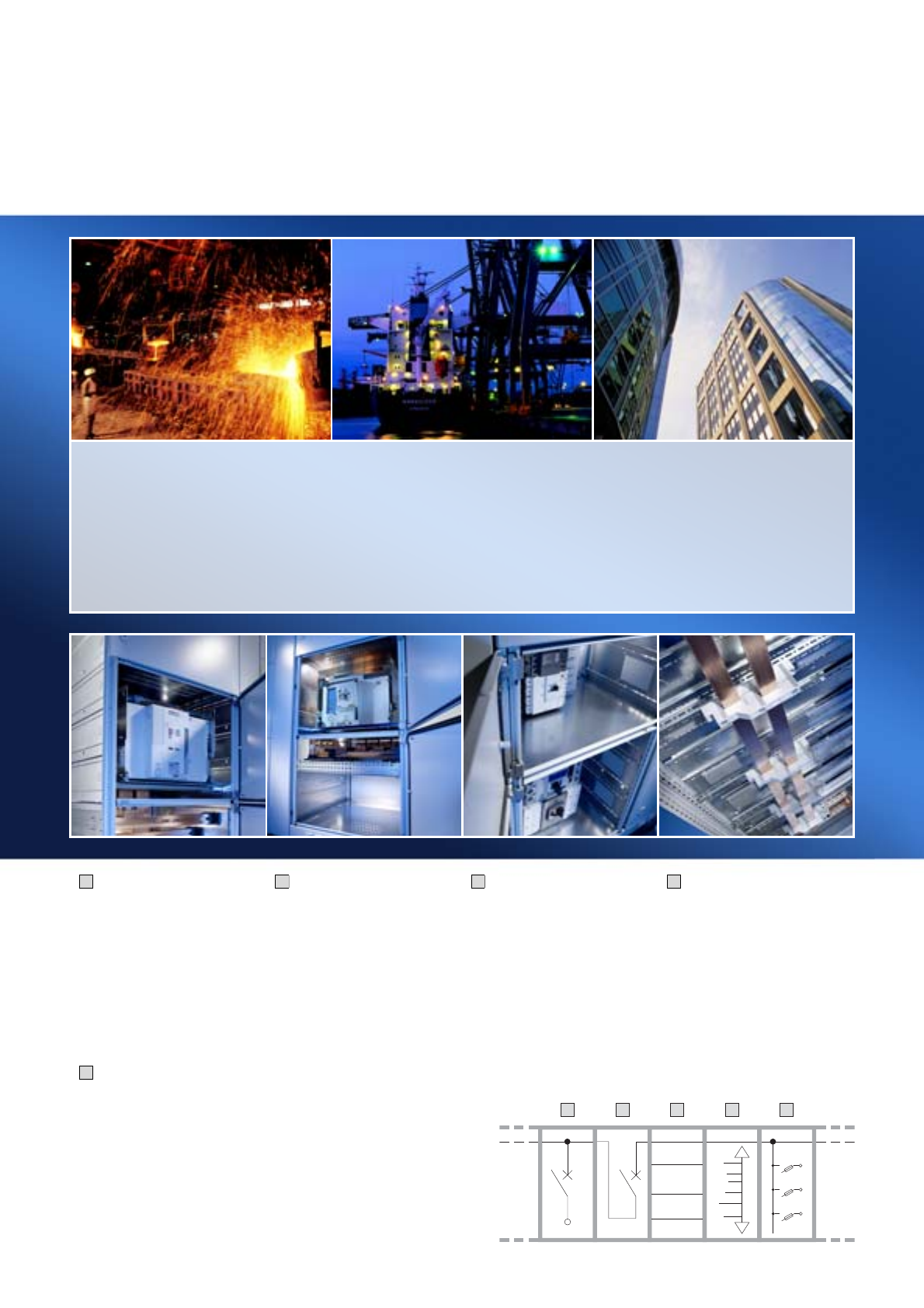
Form 2-4:
Universal in best form
Process industry
●Sewage treatment plant
●Heavy industry (mining, iron, steel)
●Cement works
●Waste disposal industry
●Paper industry
●Chemicals, petrochemicals
●Pharmaceutical industry
Industrial plants
●Automotive industry
●Mechanical engineering
●Shipbuilding, marine engineering
Energy generation
●Small power plants
●Wind and solar power
●Biomass power plants
Buildings, infrastructure
●Schools
●Banks
●Insurance companies
●Data centres
●Football stadiums
●Hospitals
●
Festival halls and exhibition buildings
●Airports
Circuit-breaker section
●For switchgear from all
well-known manufacturers
such as Siemens, ABB,
Mitsubishi, Moeller, Merlin
Gerin, Terasaki
●Use of air and moulded
case circuit-breakers
See page 9.
NEW
Switch-disconnector-fuse
section
●For switchgear from
Jean Müller, Moeller, ABB,
Siemens
●Alternatively also suitable
for installation of
equipment modules from
Jean Müller.
See page 25.
1
5
Coupling section
●Combination of a circuit-
breaker section with a
space-saving busbar riser
●Separation into individual
busbar sections to boost
equipment availability
See page 13.
2
Outgoing section
●Flexible design of the
interior installation
●Fully insulated distribution
busbars with extensive
connection system
See page 17.
3
Cable chamber
●Available from a field width
of 300 mm
●Optional cable entry from
above or below
●Flexible installation with
Rittal system accessories
See page 21.
4
1 2 3 54
Rittal Ri4Power Form 2-4
1
2
3
4
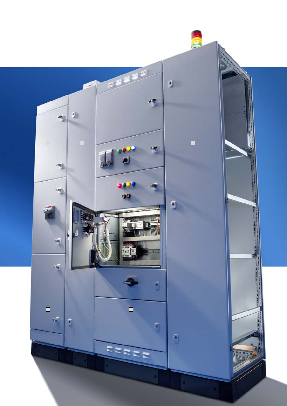
Ri4Power Form 2-4 – An individual system for the configuration of type-tested low-voltage switchgear with
inner form separation. The flexible combination of Ri4Power field types supports optimum
configuration for your applications.
6Rittal Ri4Power Form 2-4
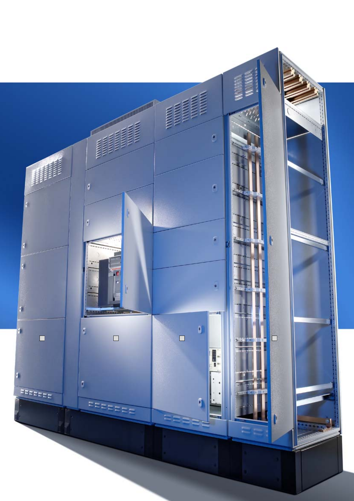
Form 2-4:
Switchgear with a high level of safety
Cable connection
●Tested connection system
●Clear arrangement of the cable
connection points
●Contacting system with no drilling
required
●Space-optimised configuration,
even for smaller rated currents
1
Busbar infeed
●An extensive range of accessories
to cover the busbar
●Fully insulated busbar connection
●Connection accessories for every
type of conductor
2
Side busbar riser
●Connection accessories for every
type of conductor
●Unobstructed access to the busbar
compartment from the front
●For the side infeed of compartments
3
Modular outgoing section
●Safe compartmentalisation
●Logically structured layout of func-
tional units
●Access control, thanks to lockable
partial doors
●Combination of control units and
power outlet within one enclosure is
supported
4
Cable chamber enclosure
●Various options for structured cable
routing
●Safe shielding from the compart-
ments
●Solid shielding from the main
busbar system
5
Tested safety
●Type-tested to the internationally
valid standard IEC 60 439-1
●Design verification to IEC 61 439-1/-2
●Tests with ASTA certification
●Tested accidental arcing protection
to IEC 61 641
●Protection category up to IP 54
●Prevention of accidental arcing
Rittal Ri4Power Form 2-4
1
2
3
4
5
Ri4Power Form 2-4 offers the best possible operator protection. Thanks to extensive busbar insulation and
sub-division of the compartments, the occurrence and spread
of accidental arcs is largely prevented.
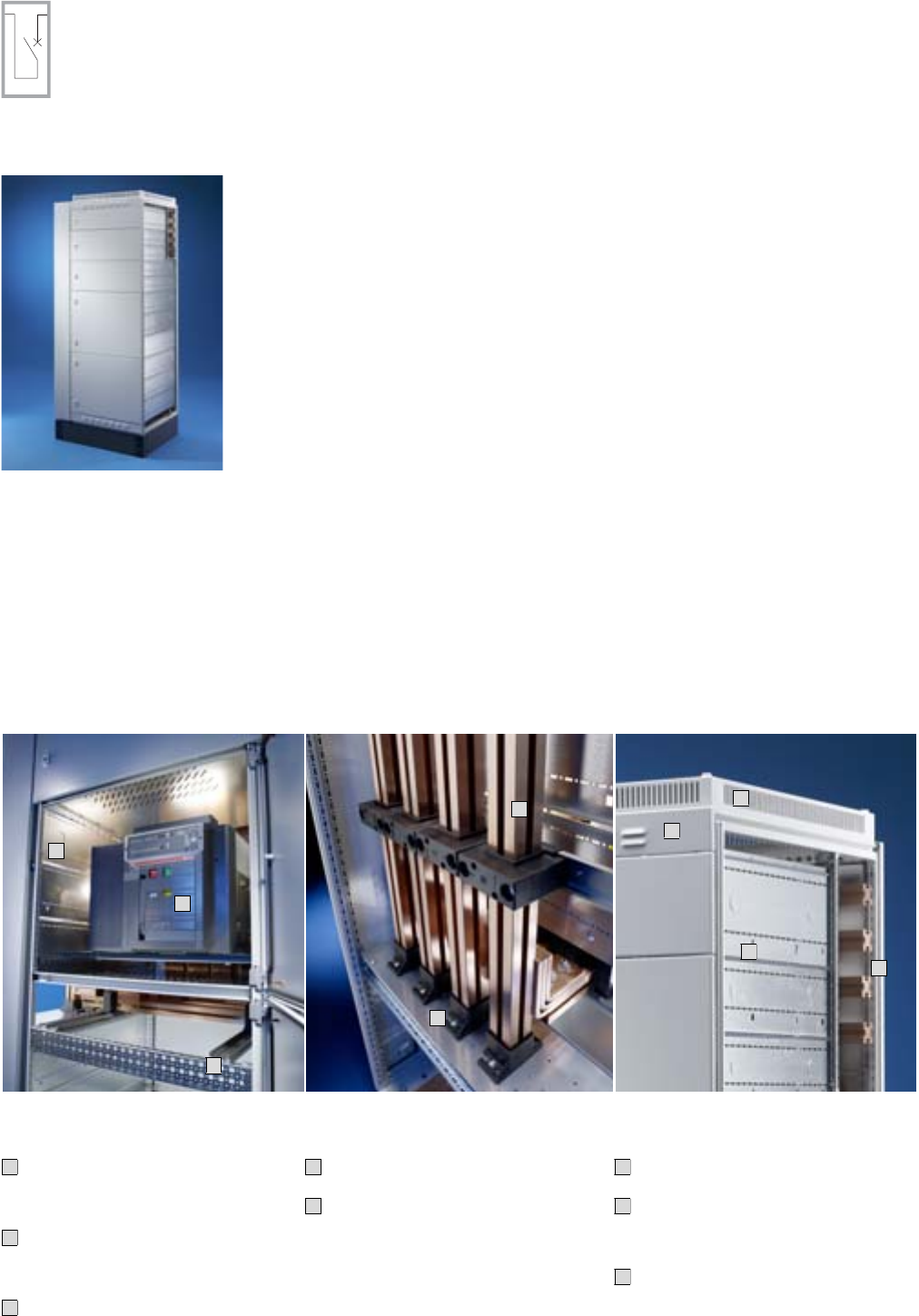
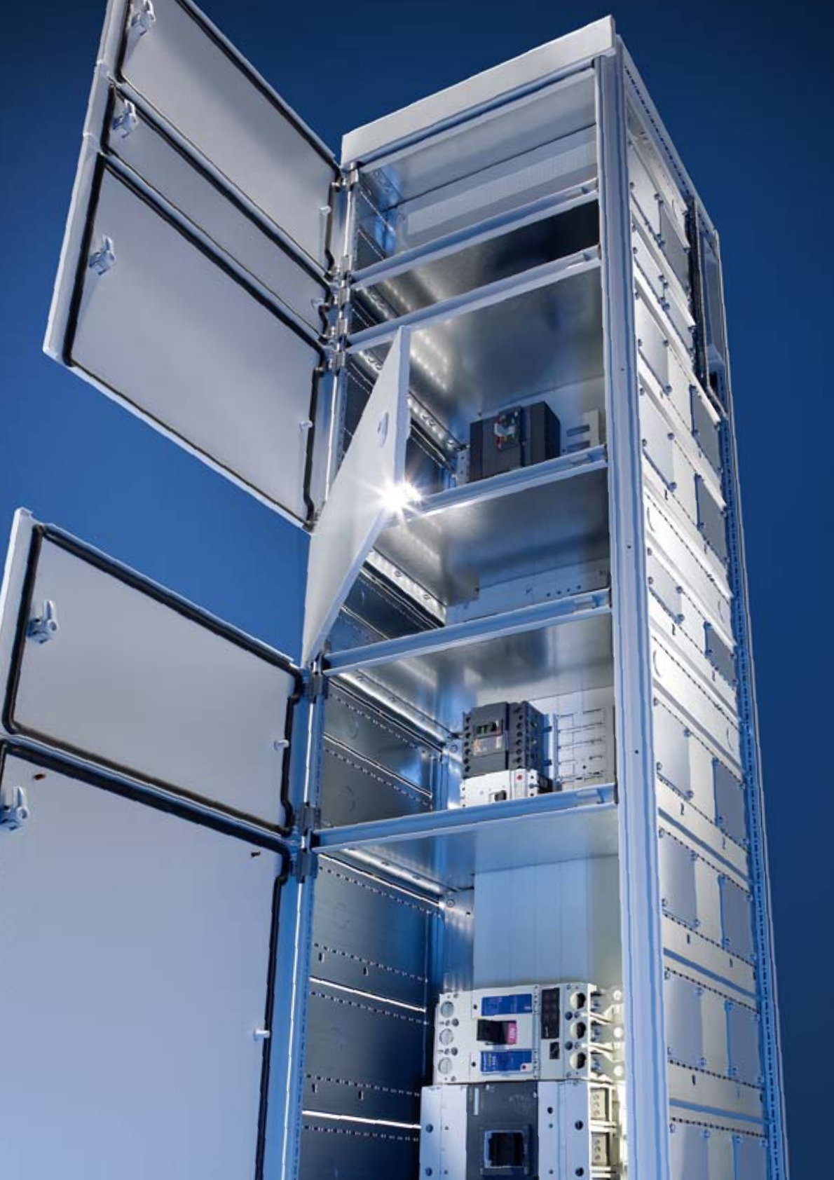
9Rittal Ri4Power Form 2-4
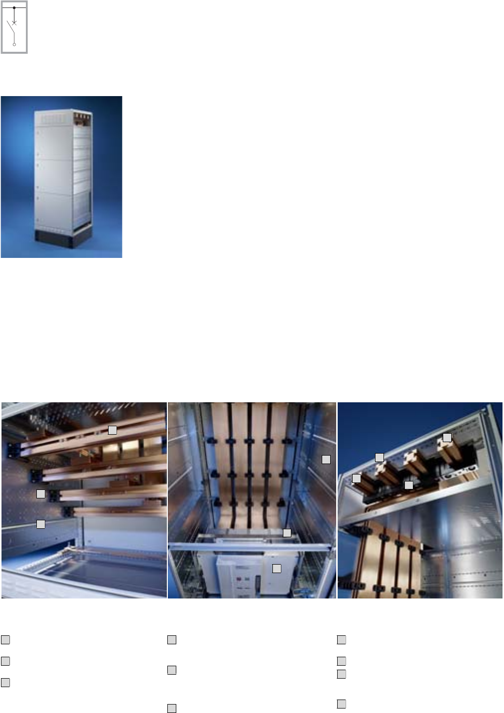
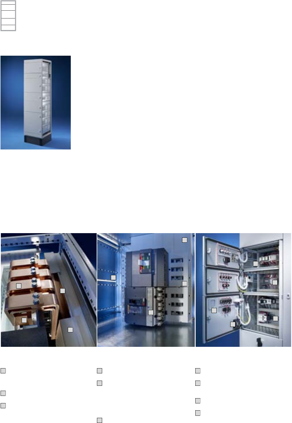
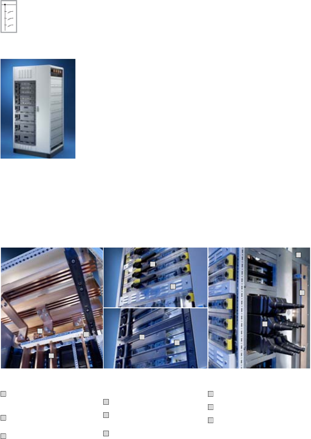
Form 2-4 system example 1
Circuit-breaker section
Terminal space
Stepped, assembly-friendly arrange-
ment of the connection bars.
Cable connection system for optimum
connection of all conductor types.
Flexible positioning of the bars in the
connection space thanks to the modu-
lar side panel system.
1
2
3
Circuit-breakers
Circuit-breakers available as fixed
or rack-mounted, allowing a choice of
positioning.
Connection systems for ACB air circuit-
breakers from all well-known manu-
facturers (Siemens, ABB, Mitsubishi,
Moeller, Merlin Gerin, Terasaki).
Modular configuration of the compart-
ments, for circuit-breakers and function
groups, in accordance with your
requirements.
4
5
6
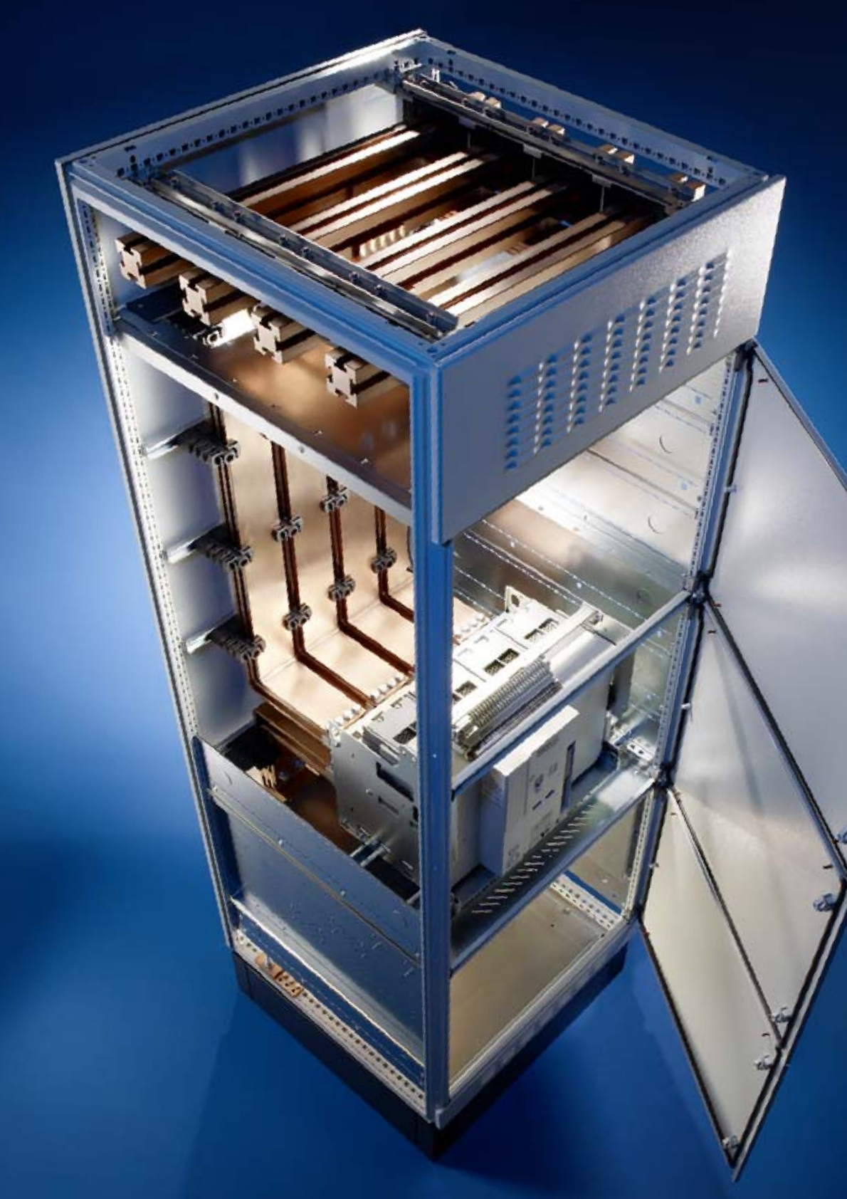
Busbar system
Maxi-PLS up to 4000 A, alternatively
Flat-PLS up to 5500 A.
Main busbar system 3- or 4-pole.
Busbar mounting options include:
Roof, base or rear panel area, both top
and bottom.
“Section to section connection system”
for all busbar systems, with no drilling
required.
7
8
9
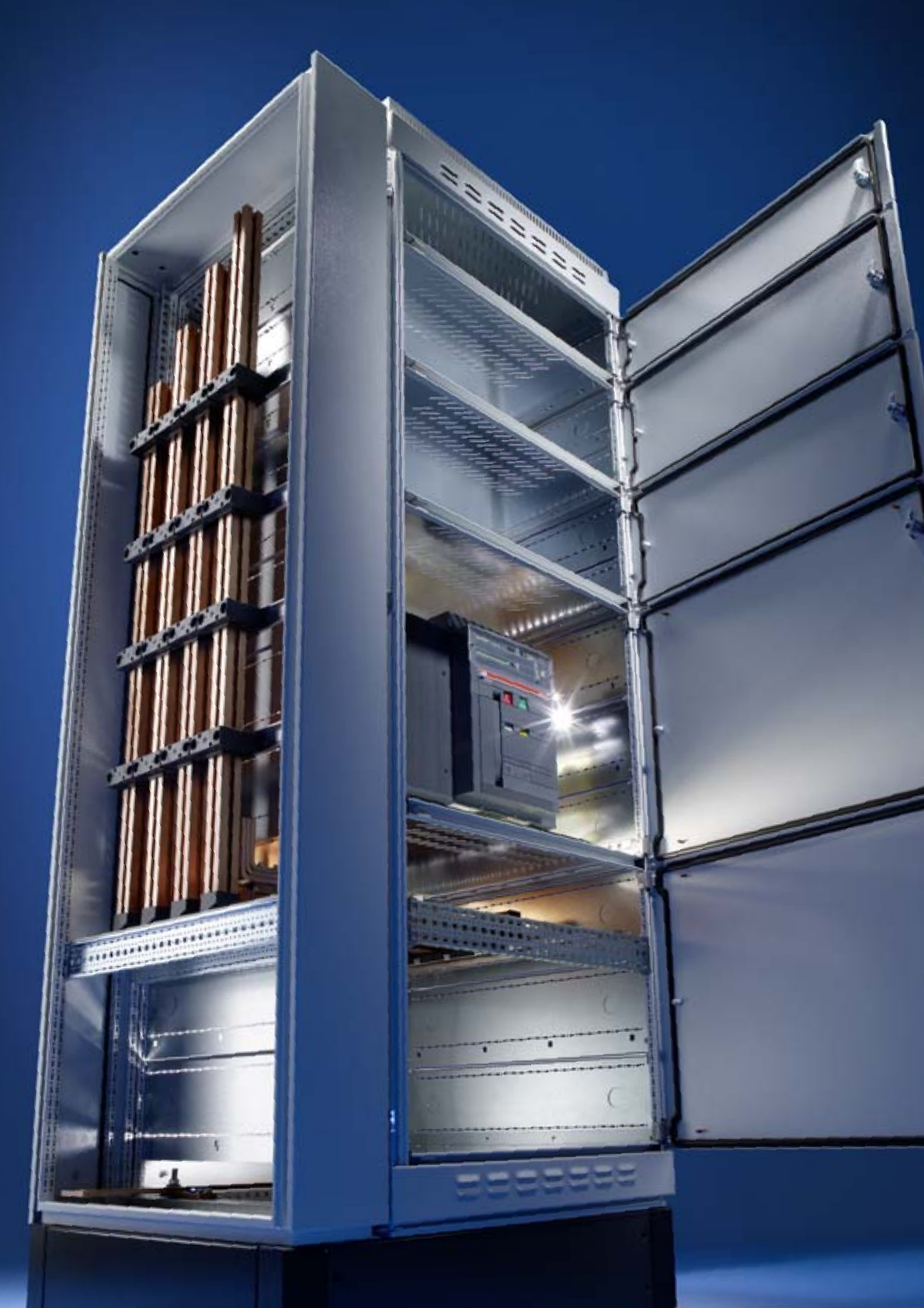
10
Example of a comprehensive circuit-breaker section design with Ri4Power Form 2-4.
2
1
3
4
5
6
10
7
9
8
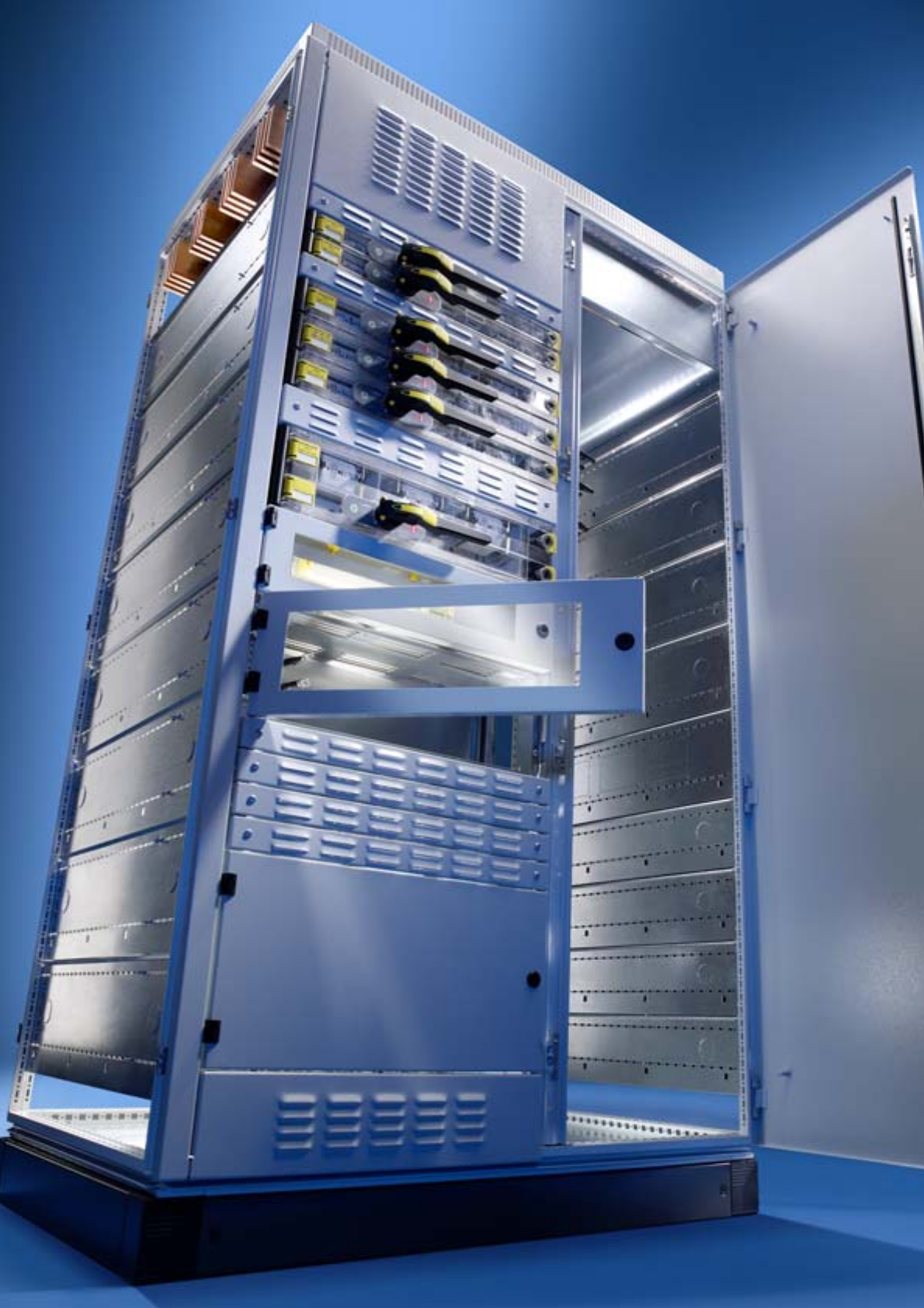
The circuit-breaker section is used as the feed to switchgear and the output of
large currents from switchgear. Busbar systems up to 5500 A with Maxi-PLS or
Flat-PLS are dimensioned and individually configured according to require-
ments. The integrated modular concept and high manufacturing quality ensure
fast, time-saving configuration. The Ri4Power Form 2-4 system is suitable for
circuit-breakers from all well-known manufacturers such as Siemens, ABB,
Mitsubishi, Moeller, Merlin Gerin and Terasaki. Finally, the compartment divider
is assembled, ensuring optimum access to all connection points throughout the
entire assembly process.
Note:
Use these examples of a circuit-
breaker section to give you ideas.
The following information and
tools will make project planning
easier:
●For diagrams and lists of
parts with model numbers
for this example,
please see page 10/11.
●Software Rittal Power
Engineering from Version 4.0,
see page 123.
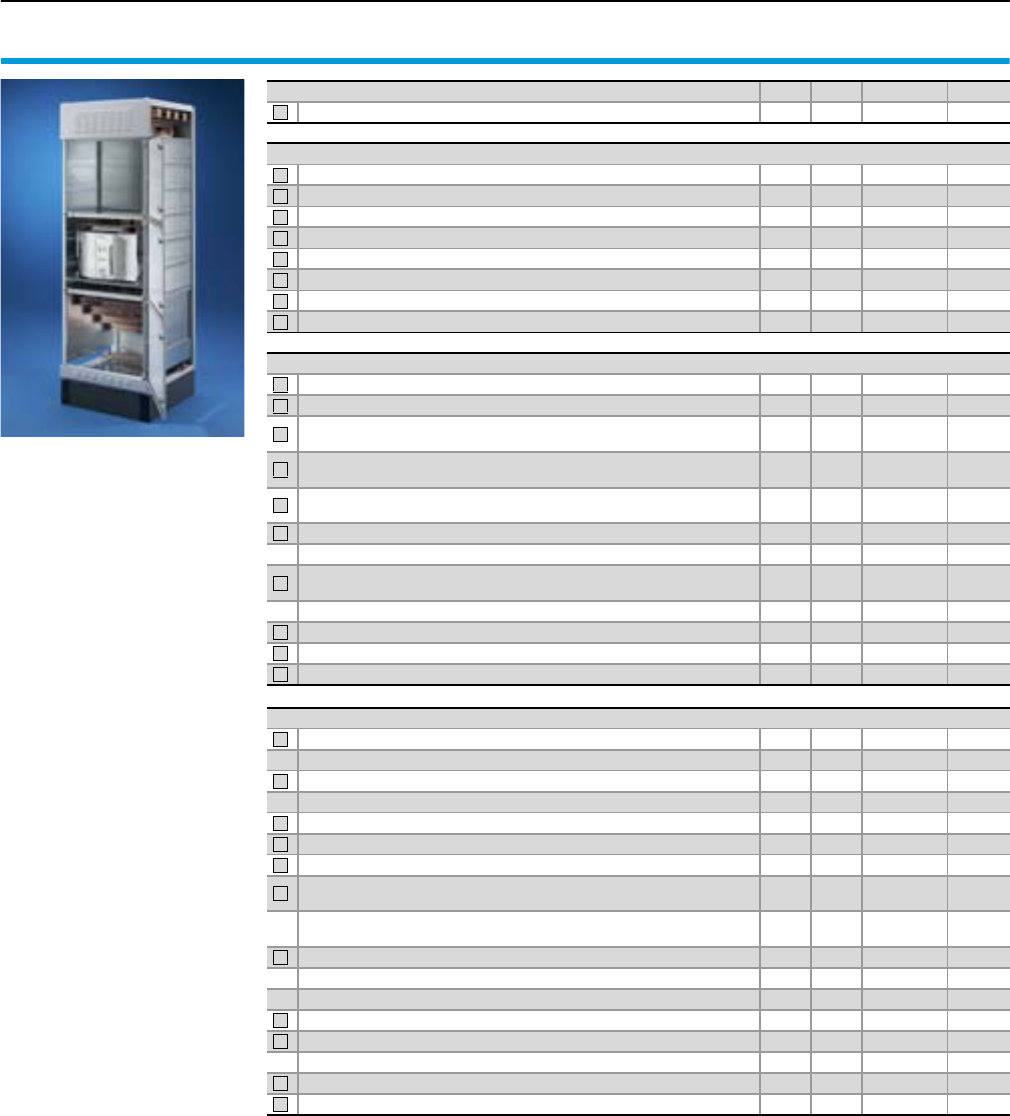
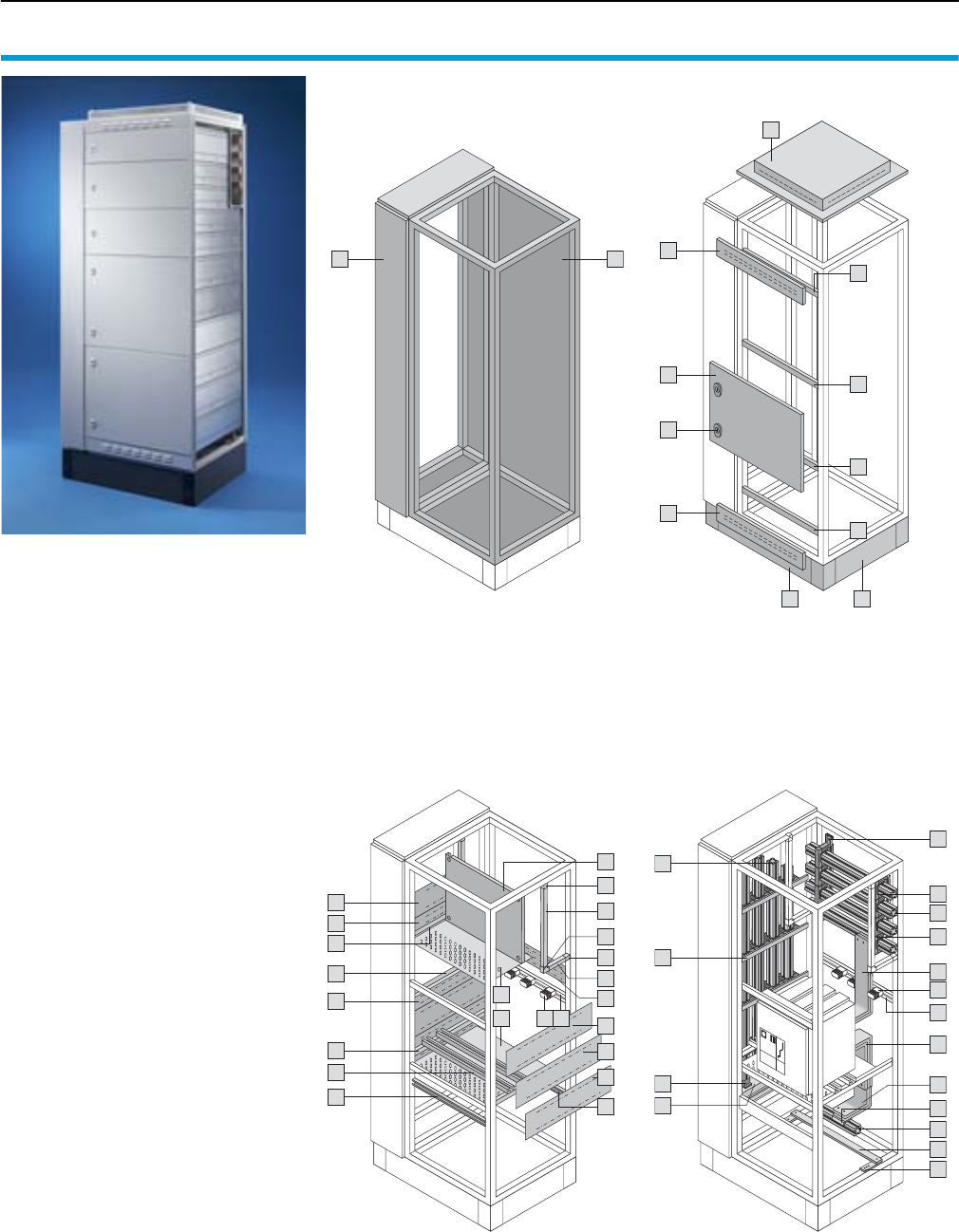
10 Rittal Ri4Power Form 2-4
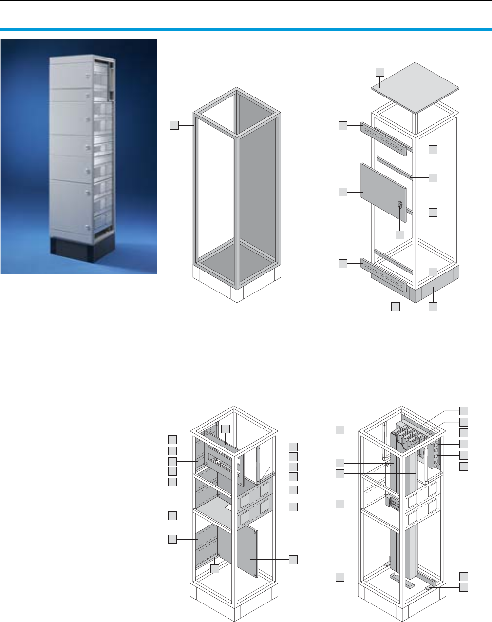
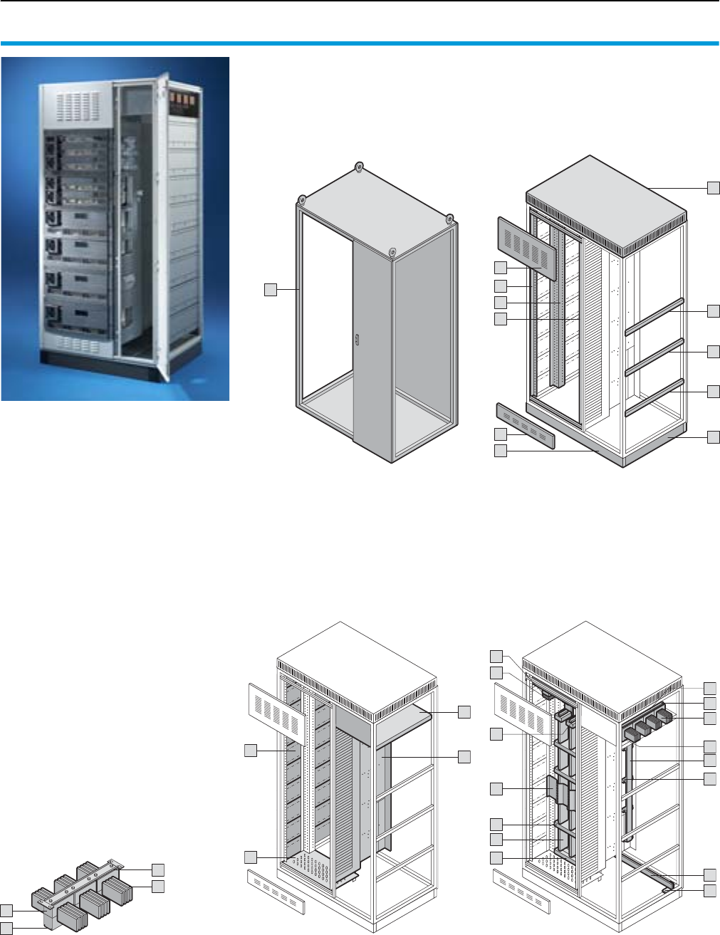
Form 2-4 system example 1
Circuit-breaker section, component overview
Enclosure Enclosure system accessories
The components required for a circuit-
breaker section are comprised of the enclo-
sure, the enclosure system accessories, the
compartment and the busbar systems.
Rittal Power Engineering
The software Rittal Power Engineering
from V4.0 is highly recommended for easy,
fast configuration of section types and sys-
tems. This continuously updated, graphics-
oriented software tool supports customer-
specific configuration and automatically
produces bills of materials, CAD drawings
and order lists of equipment and sections.
The export interfaces mean that data and
drawings are easily transmitted to other
programs such as Word or Excel, or to
EPLAN Electric P8.
See page 123.
1
7
2
5
4
6
6
3
8
9
Compartment Busbar systems
10
19
17
18
10
16
14
15
13
10
12
11
26
20
28
25
29
30
22
18
19
27
24
23
21
11Rittal Ri4Power Form 2-4
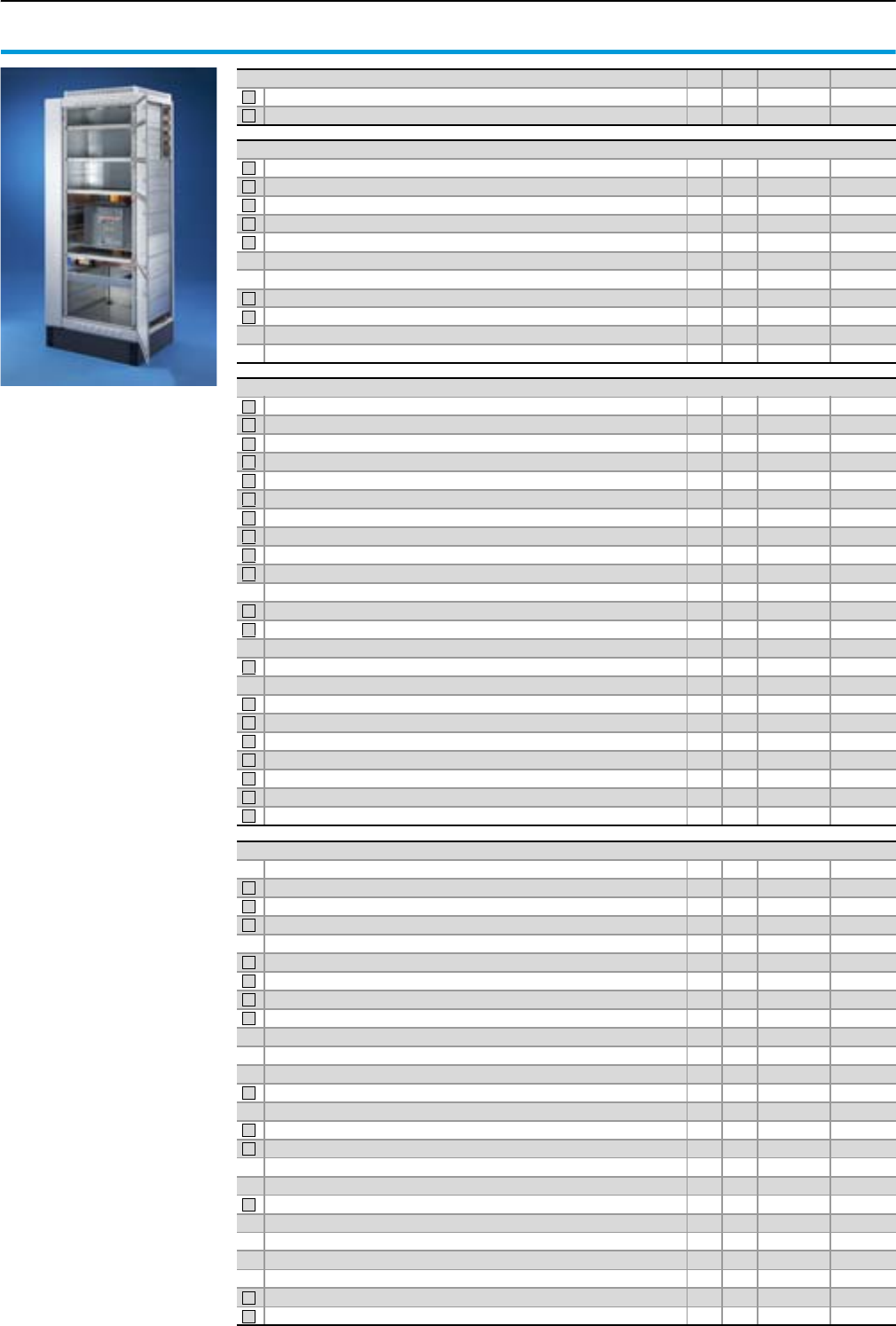
Circuit-breaker section, parts list
Form 2-4 system example 1
Enclosure Qty. P. of Model No. Page
SV-TS 8 mdoular enclosure, W/H/D: 800 x 2200 x 800 mm 1 1 9670.828 32
1
Configuration parameters:
Enclosure dimensions
W x H x D: 800 x 2200 x 800 mm,
with base/plinth 200 mm
Roof plate IP 54
Front trim panel IP 2X
Form 4b
Busbar system top
Maxi-PLS 3200, 4-pole,
in roof area,
without cover
PE busbar design 80 x 10 mm
For air circuit-breaker (ACB)
Mitsubishi AE, 3200 A,
4-pole, rack-mounted,
positioned behind the door,
with cable connection system
Maxi-PLS 3200 A, 4-pole
Functional space divider, vented.
Enclosure system accessories
Base/plinth components, front and rear, 200 mm high 1 1 8602.800 40
Base/plinth trim, side, 200 mm high 1 1 8602.080 40
Front trim panel kit, IP 2X, W/H: 800 x 300/100 mm 1 1 9672.038 42
Horizontal roof frame bar, W: 800 mm 1 2 9672.008 44
Cross member for functional space divider, W: 800 mm 3 5 9671.008 42
Solid roof plate, W/D: 800 x 800 mm 1 1 9671.688 44
Partial door, W/H: 800 x 600 mm 3 1 9671.186 43
Lock with double-bit insert 6 1 9671.130 43
2
3
4
5
6
7
8
9
Compartment
Functional space side panel module, H/D: 200 x 800 mm 12 6 9673.082 51
Functional space side panel module, H/D: 150 x 800 mm 2 6 9673.085 51
Functional space side panel module connection space,
H/D: 450 x 800 mm 229673.089 51
Mounting bracket for functional space divider
for enclosure depth 800 mm 4 8 9673.408 53
Mounting bracket for ACB + functional space divider
for enclosure depth 800 mm 229673.428 53
Air circuit-breaker support rail Form 2-4 for enclosure width 800 mm 2 2 9673.008 54
Mounting kit for air circuit-breaker 1 1 9660.970 54
Functional space divider for busbar system gland, vented,
W/D: 800 x 800 mm 3 4 9673.478 55
Gland plate for functional space divider, W: 800 mm 3 4 9673.508 55
Partial mounting plate, W/H: 800 x 600 mm 1 1 9673.686 56
Stacking insulator 25 6 9660.200 105
Support rail for stacking insulator for enclosure width 800 mm 5 2 9676.198 105
10
11
12
13
14
15
16
17
18
19
Busbar systems
Busbar support Maxi-PLS 3200 6 3 9650.000 86
Busbar support Maxi-PLS 3200 2 1 9659.000 86
End support Maxi-PLS 3200 6 6 9650.010 86
End support Maxi-PLS 3200 2 2 9659.010 86
System attachment, Maxi-PLS 3200, 4-pole, in roof area 2 2 9650.080 86
Busbars Maxi-PLS 3200 691 mm 4 1 9650.231 86
Busbars Maxi-PLS 3200 799 mm 4 1 9650.251 86
Connection bracket for Maxi-PLS 3200, 3-pole, 3 x 100 x 10 mm,
for D: 800 mm 2 1 9659.483 87
Connection bracket for Maxi-PLS 3200, for N, 3 x 100 x 10 mm,
for D: 800 mm 219659.484 87
U contact makers Maxi-PLS 3200, W: 100 mm 3 3 9650.180 87
U contact maker Maxi-PLS 3200, W: 100 mm 1 1 9659.180 87
Sliding blocks Maxi-PLS 3200, M12 815 9650.990 87
Connection kit, top, for ACB, design code 828F8J1H8H6F16 1 1 9676.910 88
Connection kit, bottom, for ACB, design code 828F8J1H8H6F16 1 1 9676.912 88
Screw connection for connection bracket 2 8 9676.963 104
Busbars 80 x 10 mm, 792 mm 1 2 9661.180 109
PE/PEN combination angles, flat, 40 x 10 mm 2 4 9661.240 109
20
21
22
23
24
25
26
27
28
29
30
13Rittal Ri4Power Form 2-4
8
7
8
6
Form 2-4 system example 2
Coupling section
Coupling switch
Connection systems for ACB air circuit-
breakers from all well-known manu-
facturers (Siemens, ABB, Mitsubishi,
Moeller, Merlin Gerin, Terasaki).
The same system architecture as the
circuit-breaker section reduces the
number of different items and the re-
quired assembly work.
Other system accessories facilitate
virtually any variant, tailored to the
required application.
1
2
3
Busbar riser
Version with Maxi-PLS or alternatively
Flat-PLS.
Space-saving, modular and flexible
arrangement of the busbar riser
(on the left, alternatively on the right,
or on both sides).
4
5
Busbar configuration
Main busbar routing in the rear. Alterna-
tively, other positions are also supported.
Option of using the other compartments
separately. Flexible design with standard
items e.g. for controlling and monitoring
the coupling switch.
Individual selection of the roof plate and
front trim panel allows process-optimised
population of the switchgear.
6
7
8
Example of a comprehensive coupling section design with Ri4Power Form 2-4.
3
1
2
4
5
Disconnecting and connecting main busbar systems in a low-voltage switchgear
is the task of a coupling section. For plant with several incomers, this prevents
total failure and helps to reduce costs in the event of a malfunction. Similarly,
the requirements governing overall short-circuit resistance may be reduced.
Overall, the investment, operating and maintenance costs are reduced, while
reliability is increased. In the event of servicing, individual busbar sections can
be de-energised without having to switch off the entire system.
The coupling section is a combination of a circuit-breaker section with a busbar
riser optionally arranged on the left or right. The large number of identical parts
and work stages therefore also translates into convincing cost and time benefits
during assembly.
Note:
Use these examples of a cou-
pling
section to give you ideas.
The following information and
tools will make your individual
project planning easier:
●For diagrams and lists of
parts with model numbers
for this example,
please see page 14/15.
●Software Rittal Power
Engineering from Version 4.0,
see page 123.
14 Rittal Ri4Power Form 2-4
Form 2-4 system example 2
Coupling section, component overview
Enclosure Enclosure system accessories
The components required for a coupling
section are comprised of the enclosure,
the enclosure system accessories, the
compartment and the busbar systems.
Rittal Power Engineering
The software Rittal Power Engineering from
V4.0 is highly recommended for easy, fast
configuration of section types and systems.
This continuously updated, graphics-ori-
ented software tool supports customer-
specific configuration and automatically
produces bills of materials, CAD drawings
and order lists of equipment and sections.
The export interfaces mean that data and
drawings are easily transmitted to other
programs such as Word or Excel, or to
EPLAN Electric P8.
See page 123.
2 1
7
3
6
6
6
6
4
5
5
8
9
Compartment Busbar systems
11
10
12
12
12
21
20
19
10
14
16
13
18
15
17
27
26
22
27
28
25
23 24
39
37
40
35
38
30
36
33
29
32
34
40
41
42
23
24
31
15Rittal Ri4Power Form 2-4
Coupling section, parts list
Form 2-4 system example 2
Enclosure Qty. P. o f Model No. Page
SV-TS 8 mdoular enclosure, W/H/D: 800 x 2200 x 800 mm
119670.828 32
SV-TS 8 busbar enclosure, W/H/D: 200 x 2200 x 800 mm
1 1 9670.228 38
1
2
Enclosure system accessories
Base/plinth components, front and rear, 200 mm high
118602.000 40
Base/plinth trim, side, 200 mm high
1 1 8602.080 40
Front trim panel kit, IP 2X, W/H: 800 x 100 mm
119671.038 41
Cross member for functional space divider, W: 800 mm
6 5 9671.008 42
Roof plate, vented, IP 2X, W/D: 800 x 800 mm
119659.535 44
Partial door, W/H: 800 x 200 mm
1 1 9671.182 43
Partial door, W/H: 800 x 300 mm
219671.183 43
Partial door, W/H: 800 x 600 mm
2 1 9671.186 43
Lock with double-bit insert
719671.130 43
Baying connectors, external
6 6 8800.490 41
Angular baying bracket TS/TS
448800.430 41
3
4
5
6
7
8
9
Compartment
P
unched section w. mounting flange for coupling set section, for encl. width 800 mm
229674.058 59
TS punched section with mounting flange, 23 x 73 mm, for enclosure width 800 mm
1 4 8612.580
Cat. 32, 995
Functional space side panel module, H/D: 200 x 800 mm
13 69673.082 51
Functional space side panel module, H/D: 100 x 800 mm
2 6 9673.081 51
Functional space side panel module, H/D: 200 x 600 mm
4 6 9673.062 51
Functional space side panel module, H/D: 100 x 600 mm
2 6 9673.061 51
Mounting bracket for functional space divider for enclosure depth 800 mm
2 8 9673.408 53
Mounting bracket for functional space divider for enclosure depth 600 mm
6 8 9673.406 53
Mounting bracket for ACB + functional space divider for enclosure depth 800 mm
2 2 9673.428 53
Air circuit-breaker support rail Form 2-4 for enclosure width 800 mm
2 2 9673.008 54
Mounting kit for air circuit-breaker
1 1 9660.970 54
Functional space divider, vented, W/D: 800 x 600 mm
3 4 9673.485 54
Functional space divider for
busbar
system
gland
, vented, W/D: 800 x 800
mm
2 4 9673.478 55
Gland plate for functional space divider, W: 800 mm
2 4 9673.508 55
Partial mounting plate, W/H: 800 x 200 mm
1 1 9673.682 56
Partial mounting plate, W/H: 800 x 300 mm
2 1 9673.683 56
Stacking insulator
5 6 9660.200 105
Support rail for stacking insulator for enclosure width 800 mm
1 2 9676.198 105
Mini-TS profile, 17 x 15.5 mm, L: 137.5 mm
212 9673.920 57
Mini-TS profile, 17 x 15.5 mm, L: 487.5 mm
212 9673.953 57
Frame connector piece for Mini-TS profile
424 9673.901 58
Corner connector for Mini-TS profile
210 9673.902 58
Coupling set mounting kit for enclosure depth 800 mm
119674.198 59
10
11
12
13
14
15
16
17
18
19
20
21
22
23
24
25
26
27
28
29
Busbar systems
Busbar support Maxi-PLS 2000
24 3 9640.000 84
Busbar support Maxi-PLS 2000, suitable for top-mounting
8 3 9640.160 84
End support Maxi-PLS 2000
469640.010 84
System attachment Maxi-PLS 2000/4, rear section, frame chassis
2 2 9640.098 84
System attachment Maxi-PLS 2000/4, in the roof area
229640.088 84
System attachment Maxi-PLS 2000/4, coupling section
6 2 9649.078 84
Busbars Maxi-PLS 2000 725 mm
419640.241 84
Busbars Maxi-PLS 2000 799 mm
4 1 9640.251 84
Busbars Maxi-PLS 2000, special length 1299 mm
119640.368 on request
Busbars Maxi-PLS 2000, special length 1399 mm
1 1 9640.368 on request
Busbars Maxi-PLS 2000, special length 1499 mm
119640.368 on request
Busbars Maxi-PLS 2000, special length 1599 mm
1 1 9640.368 on request
Connection bracket for Maxi-PLS 1600/2000, 3-pole, 2 x 100 x 10 mm
119640.473 85
Connection bracket for Maxi-PLS 1600/2000, for N, 2 x 100 x 10 mm
1 1 9640.474 85
Connection kit, top, for ACB, design code 828D9A2G4H6D26
119676.910 88
Connection kit, bottom, for ACB, design code 828D9A2G4H6D26
1 1 9676.912 88
Terminal studs for connector kit
889676.976 103
Screw connection for connection bracket
8 8 9676.962 104
U contact makers Maxi-PLS 2000, W: 100 mm
839640.180 85
Corner bracket Maxi-PLS 2000
4 1 9640.700 102
Sliding blocks Maxi-PLS 2000, M10
16 15 9640.980 85
Connection kit Maxi-PLS 2000/3, coupling set in the rear section
1 1 9660.313 102
Connection kit Maxi-PLS 2000/N, coupling set in the rear section
119660.314 102
Busbars 80 x 10 mm, 992 mm
1 2 9661.100 109
PE/PEN combination angles, flat, 40 x 10 mm
249661.240 109
30
31
32
33
34
35
36
37
38
39
40
41
42
Configuration parameters:
Enclosure dimensions
W x H x D: 800 x 2200 x 800 mm,
200 x 2200 x 800 mm,
with base/plinth 200 mm
Roof plate IP2X vented
Front trim panel IP 2X vented
Form 4b
Busbar system top
Maxi-PLS 2000, 4-pole,
in rear area,
without cover
PE busbar design 80 x 10 mm
For air circuit-breakers (ACB)
ABB, E2, 2500 A,
static installation, 4-pole,
positioned behind the door
Busbar system, bottom
Maxi-PLS 2000, 4-pole,
directly underneath the
circuit-breaker
Functional space divider, vented
17Rittal Ri4Power Form 2-4
Form 2-4 system example 3
Outgoing section
Distributor busbars
RiLine60 is ideal for small rated cur-
rents. Alternatively, for higher currents,
Maxi-PLS or Flat-PLS may be used for
the main busbar.
Simple insulation and cover with
standard parts.
T-connection kits for connecting main
and distribution busbar systems.
1
2
3
Compartments with power outlet
Interior installation individual, flexible
and tailored to your requirements.
Distribution busbar arrangement of the
indoor busbar system, alternatively:
– Behind the compartments/partial
mounting plates
– At the side adjacent to the modular
outgoing section to the side infeed
into the compartments.
RiLine60 circuit-breaker adaptor for
time-saving, maintenance-friendly
installation of circuit-breakers up to
630 A.
4
5
6
Compartments with control units
Use of control units to your individual
requirements.
For all well-known brands of switchgear
from Siemens, ABB, Mitsubishi, Moeller,
Merlin Gerin, Terasaki.
Space-optimised configuration thanks
to graduation of the compartment heights.
Rittal system accessories provide com-
prehensive installation and numerous
design variants depending on the intended
application.
7
8
9
10
Example of a comprehensive outgoing section design with Ri4Power Form 2-4.
3
1
2
1
5
8
6
4
9
8
10
10
7
Installation of switchgear, power supply outlets or controllers – the application
areas of the outgoing section are very versatile. With multifunctional compo-
nents, the individual compartments may be quickly assembled and configured
to suit your requirements. The busbar distributor system may be positioned
adjacent to, behind or directly in the compartments and is easily and safely
connected to the main busbar systems using system components.
The benefits are convincing, both in terms of assembly and during sub-
sequent operation: Simple project planning, fast assembly, flexible adaptation
and a high level of safety.
Note:
Use these examples of an out-
going section to give you ideas.
The following information and
tools will make project planning
easier:
●For diagrams and lists of parts
with model numbers for this
example, please see page
18/19.
●Software Rittal Power
Engineering from Version 4.0,
see page 123.
18 Rittal Ri4Power Form 2-4
Form 2-4 system example 3
Outgoing section, component overview
Enclosure Enclosure system accessories
The components required for an outgoing
section are comprised of the enclosure,
the enclosure system accessories, the
compartment and the busbar systems.
Rittal Power Engineering
The software Rittal Power Engineering from
V4.0 is highly recommended for easy, fast
configuration of section types and systems.
This continuously updated, graphics-ori-
ented software tool supports customer-
specific configuration and automatically
produces bills of materials, CAD drawings
and order lists of equipment and sections.
The export interfaces mean that data and
drawings are easily transmitted to other
programs such as Word or Excel, or to
EPLAN Electric P8.
See page 123.
1
6
2
4
4
5
5
5
5
3
7
8
Compartment Busbar systems
19
13
13
18
16
10
11
14
17
12
15
9
22
21
20
23
28
30
31
26
24
27
34
29
25
33
28
27
32
19Rittal Ri4Power Form 2-4
Outgoing section, parts list
Form 2-4 system example 3
Enclosure Qty. P. of Model No. Page
SV-TS 8 modular enclosure, W/H/D: 600 x 2200 x 600 mm 1 1 9670.626 32
1
Configuration parameters:
Enclosure dimensions
W x H x D: 600 x 2200 x 600 mm,
with base/plinth 200 mm
Roof plate IP 54, solid
Front trim panel IP 54, solid
Form 4a
Main busbar system
RiLine60, PLS 1600, 4-pole,
in rear section, top,
with busbar cover
PE busbar design 30 x 10 mm
Distributor busbar system
RiLine60, PLS 1600, 4-pole,
in compartment (indoor),
with cover
Functional space divider for
RiLine60, solid
Device-specific design of the
compartments and adaptors
Enclosure system accessories
Base/plinth components, front and rear, 200 mm high 1 1 8602.600 40
Base/plinth trim, side, 200 mm high 1 1 8602.060 40
Front trim panel kit IP 54, W/H: 600 x 100 mm 1 1 9671.016 41
Cross member for functional space divider, W: 600 mm 7 5 9671.006 42
Solid roof plate, W/D: 600 x 600 mm 1 1 9671.666 44
Partial door, W/H: 600 x 150 mm 1 1 9671.161 43
Partial door, W/H: 600 x 300 mm 2 1 9671.163 43
Partial door, W/H: 600 x 400 mm 1 1 9671.164 43
Partial door, W/H: 600 x 600 mm 1 1 9671.166 43
Partial door, W/H: 600 x 250 mm 1 1 9671.167 43
Lock with double-bit insert 7 1 9671.130 43
2
3
4
5
6
7
8
Compartment configuration
Functional space side panel module, H/D: 100 x 425 mm 2 6 9673.051 51
Functional space side panel module, H/D: 200 x 425 mm 1 6 9673.052 51
Functional space side panel module, H/D: 150 x 425 mm 1 6 9673.055 51
Functional space side panel module, H/D: 100 x 600 mm 4 6 9673.061 51
Functional space side panel module, H/D: 200 x 600 mm 6 6 9673.062 51
Functional space side panel module, H/D: 150 x 600 mm 1 6 9673.065 51
Functional space side panel module with gland plate,
H/D: 200 x 425 mm 169673.152 51
Functional space side panel module with gland plate,
H/D: 150 x 425 mm 1 6 9673.155 51
Functional space side panel module with gland plate,
H/D: 200 x 600 mm 669673.162 51
Functional space side panel module with gland plate,
H/D: 150 x 600 mm 1 6 9673.165 51
Mounting bracket for functional space divider for enclosure depth
425 mm 689673.405 53
Mounting bracket for functional space divider for enclosure depth
600 mm 8 8 9673.406 53
Functional space divider for RiLine60, solid, W/D: 600 x 401 mm 7 4 9673.450 55
Partial mounting plate, W/H: 600 x 150 mm 1 1 9673.661 56
Partial mounting plate, W/H: 600 x 300 mm 2 1 9673.663 56
Partial mounting plate, W/H: 600 x 400 mm 1 1 9673.664 56
Partial mounting plate, W/H: 600 x 600 mm 1 1 9673.666 56
Partial mounting plate, W/H: 600 x 250 mm 1 1 9673.667 56
Support frame for DIN rail-mounted devices, W: 600 mm, 2-row 1 1 9674.762 56
Mini-TS profile, 17 x 15.5 mm, L: 62.5 mm 212 9673.915 57
Mini-TS profile, 17 x 15.5 mm, L: 437.5 mm 2 12 9673.952 57
Frame connector piece for Mini-TS profile 424 9673.901 58
Corner connector for Mini-TS profile 2 10 9673.902 58
9
10
11
12
13
14
15
16
17
18
19
20
21
22
23
Busbar systems
RiLine60 busbar support PLS 1600 PLUS 7 4 9342.004 76
RiLine60 end cover for PLS 1600 PLUS 1 2 9342.074 76
Busbar PLS 1600 A, 495 mm long 4 3 3527.000 68
RiLine60 base tray for PLS 1600 PLUS 2 2 9342.134 77
RiLine60 cover section, L: 1100 mm 2 2 9340.214 77
RiLine60 support panel 14 59340.224 77
Circuit-breaker component adaptor 160 A, 690 V, outlet at bottom,
3-pole 119342.510 72
Circuit-breaker component adaptor 160 A, 690 V, outlet at bottom,
4-pole 2 1 9342.514 80
Circuit-breaker component adaptor 250 A, 690 V, outlet at bottom,
4-pole 219342.614 80
Circuit-breaker component adaptor 630 A, 690 V, outlet at bottom,
3-pole 3 1 9342.710 73
Insert strip, W: 25 mm, for SV 9342.700/.710 4 4 9342.720 113
Busbar, 30 x 10 mm, for enclosure width 600 mm 1 2 9661.360 109
PE/PEN combination angles, 30 x 10 mm 2 4 9661.230 109
System attachment for RiLine60 for enclosure width 600 mm 1 1 9674.006 103
T-connector RiLine60, 1600 A, 4-pole, indoor, PLS 1600 1 1 9675.166 100
Distribution busbar PLS 1600, indoor, for enclosure height 2200 mm 4 1 9675.242 102
24
25
26
27
28
29
30
31
32
33
34
21Rittal Ri4Power Form 2-4
Form 2-4 system example 4
Cable chamber
The distribution of cables into and out of the individual compartments
is the task of the cable chamber. Depending on the main busbar system
chosen, cable entry may be either from below, above, or below and
above. There are various cable entry glands to choose from for the roof
plate. The main busbar system is covered in a contact hazard-proof
way, depending on the type and configuration. Ri4Power Form 2-4 offers
every conceivable option for designing PE and N distribution busbars.
In each case, the panel builder’s requirements are effectively met to
perfection.
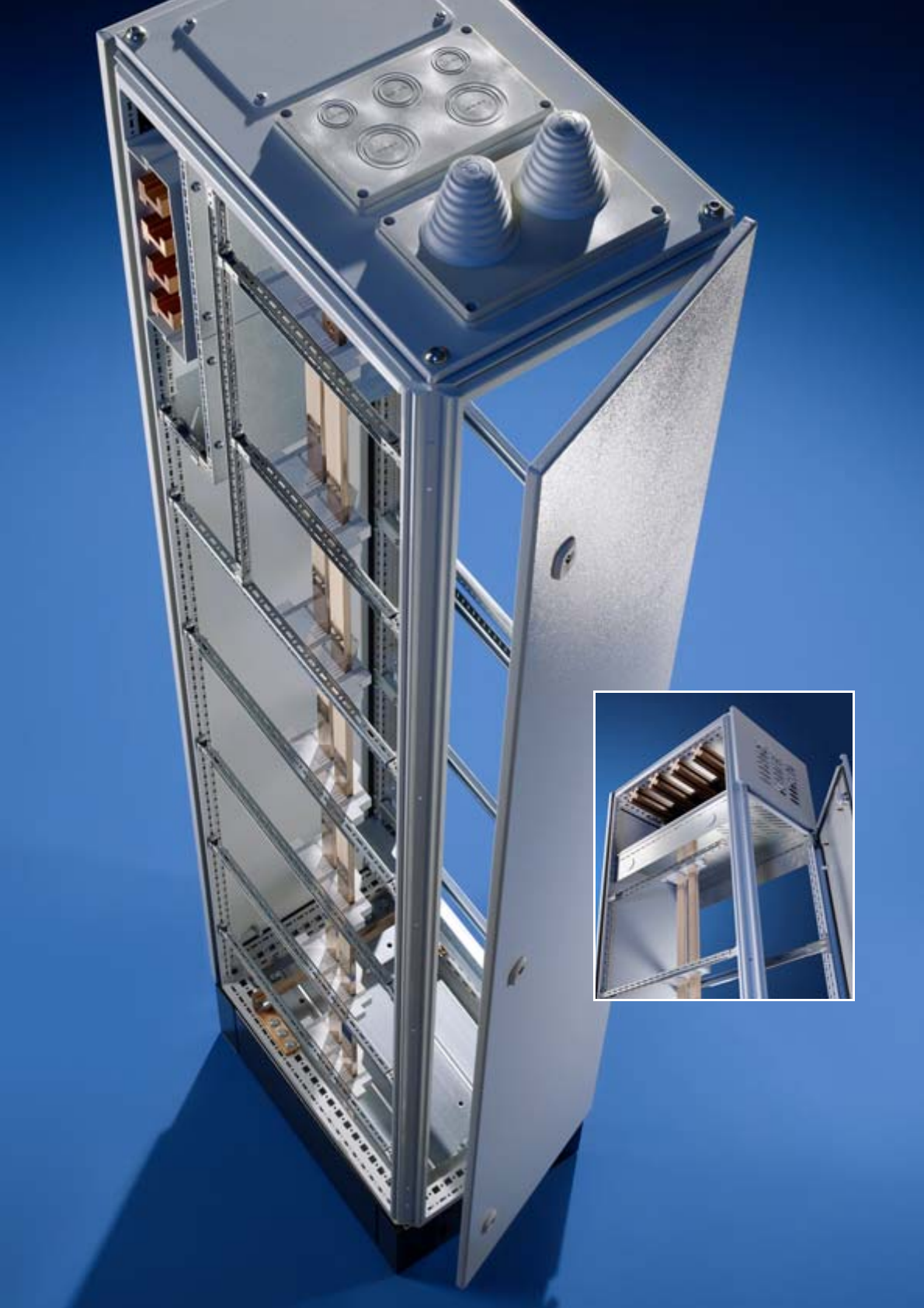
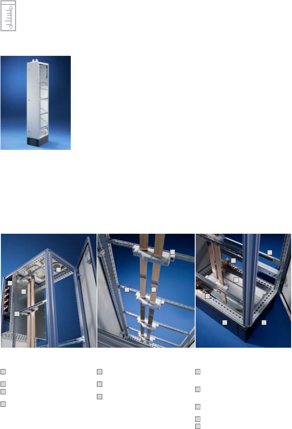
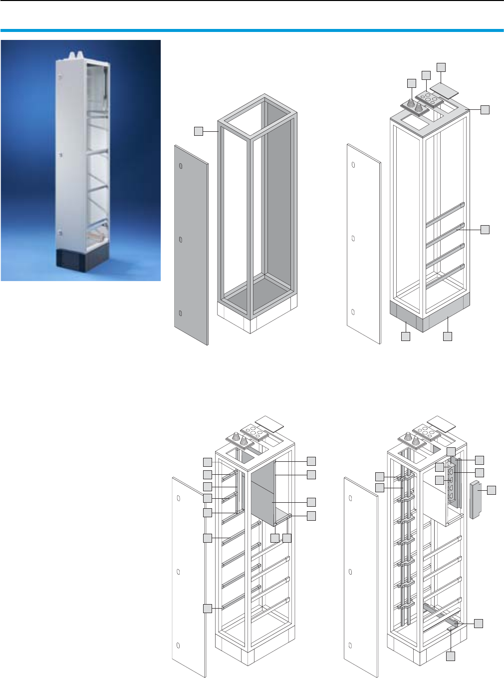
SV-TS 8 cable chamber enclosure
Roof plate for cable gland plates,
cable entry glands.
Cover of the main busbar system.
Mini-TS profiles as an auxiliary con-
struction.
Main busbar system with RiLine60,
alternatively with Maxi-PLS or Flat-PLS.
1
2
3
4
PE and N distributor busbars
Busbar supports for PE and N distri-
bution busbars.
Distribution busbar to match the enclo-
sure heights.
Supporting structure of Mini-TS sec-
tions for individual attachment.
5
6
7
PE/PEN, cable entry, base/plinth
PE/PEN busbar tailored to the enclosure
width. Configurable in various cross-sec-
tions.
PE/PEN combination angles for attaching
the PE busbar and incorporating the TS 8
enclosure into the protective measure.
C rails for cable attachment, alternatively
cable clamp rail from right-angle profile.
Gland plates divided in the depth.
Base/plinth components, front and rear
base/plinth trim, side.
8
9
10
11
12
Example of a comprehensive cable chamber design with Ri4Power Form 2-4.
4
3
1
2
5
6
7
11
10
9
8
12
12
Note:
Use these examples of a cable
chamber to give you ideas. The
following information and tools will
make project planning easier:
●For diagrams and lists of parts
with model numbers for this
example, please see page
22/23.
●Software Rittal Power
Engineering from Version 4.0,
see page 123.
22 Rittal Ri4Power Form 2-4
Form 2-4 system example 4
Cable chamber, component overview
Enclosure Enclosure system accessories
The components required for a cable
chamber are comprised of the enclosure,
the enclosure system accessories, the
compartment and the busbar systems.
Rittal Power Engineering
The software Rittal Power Engineering
from V4.0 is highly recommended for easy,
fast configuration of section types and sys-
tems. This continuously updated, graphics-
oriented software tool supports customer-
specific configuration and automatically
produces bills of materials, CAD drawings
and order lists of equipment and sections.
The export interfaces mean that data and
drawings are easily transmitted to other
programs such as Word or Excel, or to
EPLAN Electric P8.
See page 123.
1
6
5
7
2 3
4
8
Compartment Busbar systems
15
12
9
15
16 1013
11
11
17
17
14
15
23
25
18
19
27
26
24
21
20
22
23Rittal Ri4Power Form 2-4
Cable chamber, parts list
Form 2-4 system example 4
Enclosure Qty. P. of Model No. Page
SV-TS 8 cable chamber enclosure, W/H/D: 400 x 2200 x 600 mm 1 1 9670.436 35
1
Configuration parameters:
Enclosure dimensions
W x H x D: 400 x 2200 x 600 mm,
with base/plinth 200 mm
Roof plate for cable gland plates
Form 4a
Main busbar system RiLine60,
PLS 1600, 4-pole,
in rear section, top,
with cover
PE busbar design 30 x 10 mm
PE/N distribution busbar version
PE + N
PE 30 x 10 mm
N 30 x 10 mm
Cable clamp rail
C rail
Enclosure system accessories
Base/plinth components, front and rear, 200 mm high 1 1 8602.400 40
Base/plinth trim, side, 200 mm high 1 1 8602.060 40
Roof plate for cable gland plates, W/D: 400 x 600 mm 1 1 9671.546 44
ISV cable entry gland, M25/32/40/50/63 1 1 9665.760 45
ISV cable entry gland, with entry fittings 1 1 9665.780 45
ISV cable entry gland, solid 1 4 9665.785 45
Support rail for TS 8, W: 600 mm 4 2 9676.196 105
2
3
4
5
6
7
8
Compartment
Cover plate for main busbar system, W: 400 mm 1 2 9673.540 52
Mini-TS profile, 17 x 15.5 mm, L: 62.5 mm 212 9673.915 57
Mini-TS profile, 17 x 15.5 mm, L: 262.5 mm 2 12 9673.940 57
Mini-TS profile, 17 x 15.5 mm, L: 487.5 mm 212 9673.953 57
Mini-TS profile, 17 x 15.5 mm, L: 462.5 mm 5 12 9673.960 57
Mini-TS profile, 17 x 15.5 mm, L: 662.5 mm 112 9673.980 57
Frame connector piece for Mini-TS profile 17 24 9673.901 58
Corner connector for Mini-TS profile 210 9673.902 58
T-connector piece for Mini-TS profile 3 24 9673.903 58
9
10
11
12
13
14
15
16
17
Busbar systems
RiLine60 busbar support PLS 1600 PLUS 2 4 9342.004 76
RiLine60 end cover for PLS 1600 PLUS 1 2 9342.074 76
Busbar PLS 1600 A, 495 mm long 4 3 3527.000 68
RiLine60 base tray for PLS 1600 PLUS 1 2 9342.134 77
RiLine60 cover section, L: 1100 mm 1 2 9340.214 77
RiLine60 support panel 2 5 9340.224 77
Busbar, 30 x 10 mm, for enclosure width 400 mm 1 2 9661.340 109
PE/PEN combination angles, 30 x 10 mm 2 4 9661.230 109
System attachment for RiLine60 for enclosure width 400 mm 1 1 9674.004 103
Distribution busbar 30 x 10 mm, indoor, for enclosure height 2200 mm 2 1 9675.222 102
Busbar support N/PE, 2-pole 7 4 9340.040 110
18
19
20
21
22
23
24
25
26
27
25Rittal Ri4Power Form 2-4
Form 2-4 system example 5
Switch-disconnector-fuse section
The distribution of electrical power with fused switchgear can be achieved com-
pactly and variably with a switch-disconnector-fuse section.
Thanks to the modular Ri4Power configuration system the installation of switch-
disconnector-fuse sections sizes 00 to 3 from Jean Müller or ABB/Siemens can
be fully prepared.
With the device modules from Jean Müller, live-interchangeable control units may
also be integrated into the switch-disconnector-fuse section.
The distribution busbars are selectively and economically dimensioned according
to requirements. The main and the distribution busbar system can be confi-
gured for short-circuit resistance of up to 100 kA.
Internal sub-division in the switch-disconnector-fuse section is from Form 1 to
Form 4b, depending on customer requirements, thanks to the optional selection
of components.
Busbar system
Accommodates standard commer-
cially available flat copper bars from
50 x 10 to 100 x 10 mm for rated
currents up to 2100 A.
Connection of the distribution busbars
with terminal block, no drilling
required.
Flexible busbar support arrangement
on a 25 mm pitch pattern for optimum
switch-disconnector-fuse configura-
tion.
1
2
3
Switchgear area
Individual interior configuration for:
a) Jean Müller Sasil switch-disconnec-
tor-fuses, Jean Müller device modules
b) ABB SlimLine switch-disconnector-
fuses/Siemens 3NJ62 switch-discon-
nector-fuses
Variable positioning of ventilation trim
panels between switch-disconnector-
fuses according to manufacturer’s
instructions.
4
5
6
Cable connection space
Upgradable to Form 4b with device-
specific terminal space covers.
Application-specific design of PE and N
for the distribution busbar system.
Optional contact hazard protection even
without form separation.
7
8
9
Example of a comprehensive switch-disconnector-fuse section design with Ri4Power Form 2-4.
3
1
2
6
4
9
8
7
Note:
Use these examples of a switch-
disconnector-fuse section to give
you ideas. The following informa-
tion and tools will make project
planning easier:
●For diagrams and lists of parts
with Model Numbers for this
example, please see page
26/27.
●Rittal Power Engineering
software from Version 4.1,
see page 123.
5
6
26 Rittal Ri4Power Form 2-4
Form 2-4 system example 5
Switch-disconnector-fuse section, component overview
Enclosure Enclosure system accessories
The components required for a switch-dis-
connector-fuse section are comprised of
the enclosure,
the enclosure system accessories, the
compartment and the busbar systems.
Rittal Power Engineering
The software Rittal Power Engineering from
V4.1 is highly recommended for easy, fast
configuration of panel types and systems.
This continuously updated, graphics-ori-
ented software tool supports customer-
specific configuration and automatically
produces bills of materials, CAD drawings
and order lists of equipment and panels.
The export interfaces mean that data and
drawings are easily transmitted to other
programs such as Word or Excel, or to
EPLAN Electric P8.
See page 123.
1
6
7
7
7
3
2
4
5
5
5
4
Compartment Busbar systems
11
9
10
8
18
20
19
22
17
16
21
23
25
26
24
14
15
12
13
13
15
12
14
27Rittal Ri4Power Form 2-4
Switch-disconnector-fuse section, component list
Form 2-4 system example 5
Enclosure Qty. P. of Model No. Page
SV-TS 8 switch-disconnector-fuse enclosure,
W/H/D: 1200 x 2200 x 800 mm 119670.128 37
1
Configuration parameters:
Enclosure dimensions
W x H x D: 1200 x 2200 x 800 mm
,
with base/plinth 200 mm
Roof plate IP 2X vented
Front trim panel IP 2X vented
Form 4b
Busbar system top
Flat-PLS 100, 4-pole,
4 x 100 x 10 mm,
reinforced,
in roof section with cover
PE busbar design 80 x 10 mm
For Jean Müller (JM) NH switch-
disconnector-fuses, type Sasil
Enclosure system accessories
Base/plinth components, front and rear, 200 mm high 1 1 8602.200 40
Base/plinth trim, side, 200 mm high 1 1 8602.080 40
Front trim panels, switch-disconnector-fuse section,
top 350 mm/bottom 150 mm 119674.340 46
Assembly kit for switch-disconnector-fuse section JM, H: 2200 mm 1 1 9674.352 46
Maxi-PLS roof plate, vented, W/D: 1200 x 800 mm, 50 mm high,
RAL 7035 119659.555 44
Baying connector, external 6 6 8800.490 41
Angular baying bracket TS/TS 4 4 8800.430 41
Support rails for TS 8, W/D: 800 mm 4 2 9676.198 105
2
3
4
5
6
7
Compartment
Divider panel, switch-disconnector-fuse section JM/ABB,
H/D: 2200 x 800 mm 119674.328 60
Dividing plate for switch-disconnector-fuse section for JM 2 1 9674.346 60
Contact hazard protection, switch-disconnector-fuse section,
W/D: 1200 x 800 mm 119674.368 60
Functional space side panel module, H/D: 200 x 800 mm 9 6 9673.082 51
8
9
10
11
Busbar systems
Busbar support Flat-PLS 100 suitable for stabiliser bar 12 1 9676.021 91
System attachment for busbar support Flat-PLS 100,
in roof/bases, 3-/4-pole, D: 800 mm 3 2 9674.184 90
Busbar stabiliser bar, 4-pole 3 2 9676.025 91
Busbars E-Cu, 100 x 10 x 2400 mm 8 3 3590.010 110
Busbar claws up to 4 x 100 x 10 mm, 1-pole 12 1 9676.016 93
Contact piece for Flat-PLS, 4 bars, W: 60 mm 4 1 9676.546 96
Connection bracket, switch-disconnector-fuse section, Flat-PLS 100,
L1 – 3, D: 800 mm 119674.457 108
Connection bracket, switch-disconnector-fuse section, Flat-PLS 100,
N, D: 800 mm 1 1 9674.458 108
End support for switch-disconnector-fuse section, 3-/4-pole,
bar width: 100 mm 119674.430 106
Busbar support for switch-disconnector-fuse section, 3-/4-pole,
bar width: 100 mm 6 1 9674.410 106
Distributor bar for switch-disconnector-fuse section, W/H: 100/2200 mm 4 1 9674.420 106
Terminal block, distribution busbar for switch-disconnector-fuse
section, 80/100 mm 4 1 9674.488 108
Cover for distribution busbar, switch-disconnector-fuse section JM,
enclosure height: 2000/2200 mm 119674.380 107
Punched rail for distribution busbar cover, switch-disconnector-fuse
section JM, enclosure height: 2000/2200 mm 1 1 9674.381 107
Busbar support up to 1600 A, 3-pole,
185 mm bar centre distance for busbars E-Cu 50 x 10 to 80 x 10 mm 223052.000 Cat. 32,
391
Distribution busbar for switch-disconnector-fuse section,
W/H: 80/2000 mm 1 1 9674.408 106
Busbars, 1192 x 80 x 10 mm, for enclosure width 1200 mm 1 2 9661.120 109
PE/PEN combination angles, flat, E-Cu 40 x 10 mm 2 4 9661.240 109
12
13
14
15
16
17
18
19
20
21
22
23
24
25
26
28 Rittal Ri4Power Form 2-4
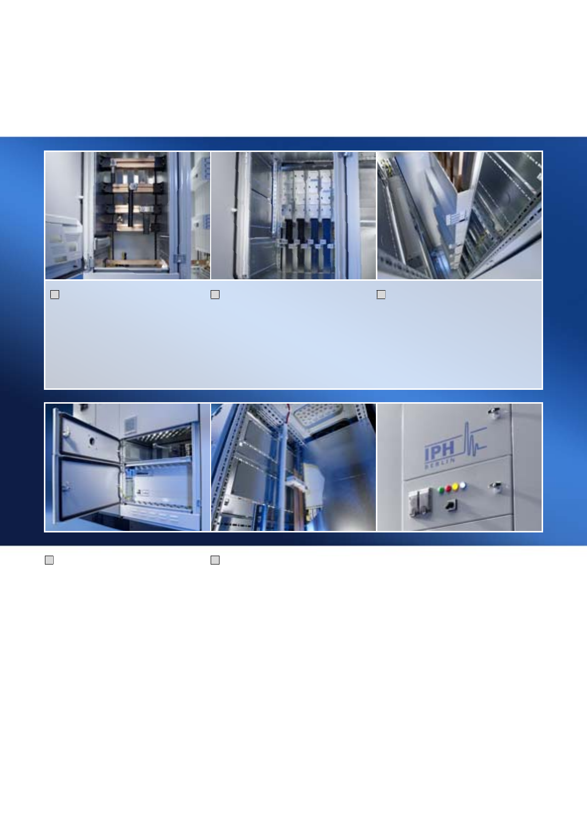
Top enclosure, top flexibility, top efficient:
TS 8
With the TS 8 enclosure system, every enclosure is a specialist – however exceptional the task. By combining
Ri4Power and busbar components with general system accessories, it is possible to create infinite possibilities
in the separation of Form 2-4 – the TS 8 system punching is the key.
29Rittal Ri4Power Form 2-4
Benefits of the TS 8 system platform
Form 2-4 enclosures
Base/plinth components (front
and rear) combined with trim
panels (side) or used to link two
base/plinths.
Quick assembly:
Door-operated switch and lights
– simply fit and secure – and it’s
done.
Roof plate options for every
type of cable entry and ventila-
tion.
Ri4Power configuration
The proven TS 8 pitch pattern is
used for many Ri4Power Form
2-4 components, thus enabling
the use of TS 8 system acces-
sories.
Undoubtedly convincing –
RiLine60: effective space utili-
sation, extensive safety back-
ups, all-round contact hazard
protection, safe and fast con-
tacting.
Low voltage switchgear with
Maxi-PLS and Flat-PLS. Future-
oriented, type-tested modular
systems offer exceptional fast
assembly and safety.
System platform TS 8 Top enclosure system
Universal interior installation:
Frame sections, slotted on a
25 mm pitch pattern. Two sym-
metrical levels for maximum
space utilisation in the width and
depth.
Uninhibited access from all
sides: Doors are possible at the
front, rear and sides. 4-point
hinge and lock system.
Bayable on all sides: Around
corners, to the front, rear, left,
right and if necessary, even
upwards.
Ri4Power system solutions
are based on the TS 8 Top
enclosure system. Winning
features: Compatibility with all
power distribution compo-
nents.
The enclosure system with the
efficiency of infinite possibili-
ties. Unbeatable in terms of
space utilisation, bayability,
interior installation and fast
assembly.
Standard accessories
Rittal system accessories for
individuality, perfection and
speed when solving your
tasks.
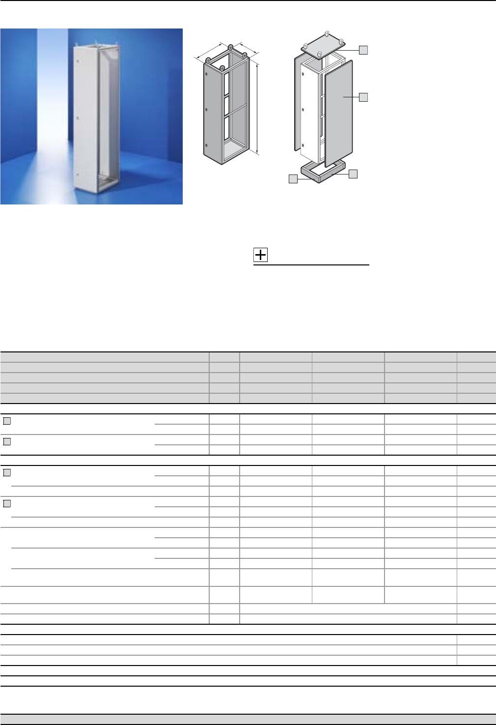
Form 2-4 enclosures
SV-TS 8 modular enclosures (height 1800 mm)
30 Rittal Ri4Power Form 2-4
T
H
B
1
5
4
3
2
5
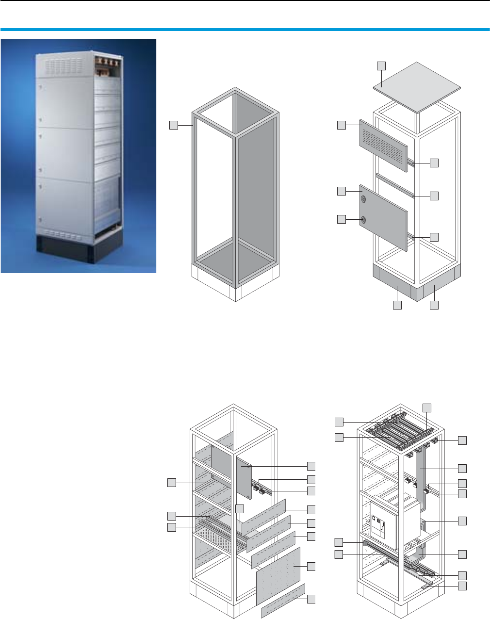
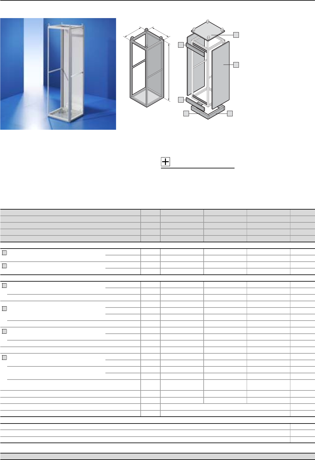
Modular enclosure frame for
installation with partial doors
and internal separation.
Material:
Sheet steel
Enclosure frame, rear panel
and gland plates: 1.5 mm
Surface finish:
Enclosure frame:
Dipcoat-primed
Rear panel:
Dipcoat-primed,
powder-coated in textured
RAL 7035 on the outside
Gland plates: Zinc-plated
Protection category:
Up to IP 54,
depending on the roof plate,
front trim panels and side panel.
Supply includes:
Enclosure frame with rear panel
and gland plates.
Accessories:
System accessories,
see Cat. 32, page 890.
Standard:
Type-tested in accordance with
IEC 60 439-1.
Design verification in accord-
ance with IEC 61 439-1/-2.
Detailed drawings,
see page 130.
Technical information,
see page 134 – 140.
Width (B) mm Packs of 400 600 800 Page
Height (H) mm 1800 1800 1800
Depth (T) mm 600 600 600
Model No. SV 19670.486 9670.686 9670.886
Weight (kg) 42.0 53.0 58.0
Base/plinth
Components
front and rear
Height 100 mm 1 set 8601.400 8601.600 8601.800 40
Height 200 mm 1 set 8602.400 8602.600 8602.800 40
Trim panels
sides
Height 100 mm 1 set 8601.060 8601.060 8601.060 40
Height 200 mm 1 set 8602.060 8602.060 8602.060 40
Also required
Side panels
for protection category
IP 55 2 8186.235 8186.235 8186.235 39
IP 2X 2 9671.986 9671.986 9671.986 39
Upgrade kit for side panels IP 2X IP 43 2 sets1) 9671.996 9671.996 9671.996 39
Roof plates
for protection category
IP 55 1 9671.646 9671.666 9671.686 44
IP 43 1 9671.746 9671.766 9671.786 44
IP 2X 1 9671.446 9660.235 9660.245 44
Roof plates for cable entry gland 1 9671.546 9665.903 9671.586 44
Front trim panels
for protection category
IP 54 1 set 9671.014 9671.016 9671.018 41
IP 2X 1 set 9671.034 9671.036 9671.038 41
Upgrade kit for front panels IP 2X IP 43 1 set 9671.044 9671.046 9671.048 41
Partial doors for clearance height with front trim panel 100/100 mm 1 9671.156 9671.176 9671.196 43
Front trim panels, top 300 mm/
bottom 100 mm for protection category
IP 54 1 set 9672.014 9672.016 9672.018 42
IP 2X 1 set 9672.034 9672.036 9672.038 42
Front trim panels, top 100 mm/
bottom 300 mm for protection category
IP 54 1 set 9672.024 9672.026 9672.028 42
IP 2X 1 set 9672.044 9672.046 9672.048 42
Upgrade kit
for front trim panels 300/100 mm IP 2X IP 43 1 set 9672.054 9672.056 9672.058 42
Partial doors for clearance height with front trim panel 300/100 mm 1 – – –
Partial doors for modular configuration 1 䡲 䡲 䡲 43
Angular baying brackets 4 8800.430 41
Baying connectors, external 6 8800.490 41
Accessories
Enclosure configuration 39 – 46
Compartment configuration 50 – 61
Components 65 – 114
1) Pack sufficient for 1 pack of side panels.
1
2
3
4
5
5
System examples Page 9 – 27

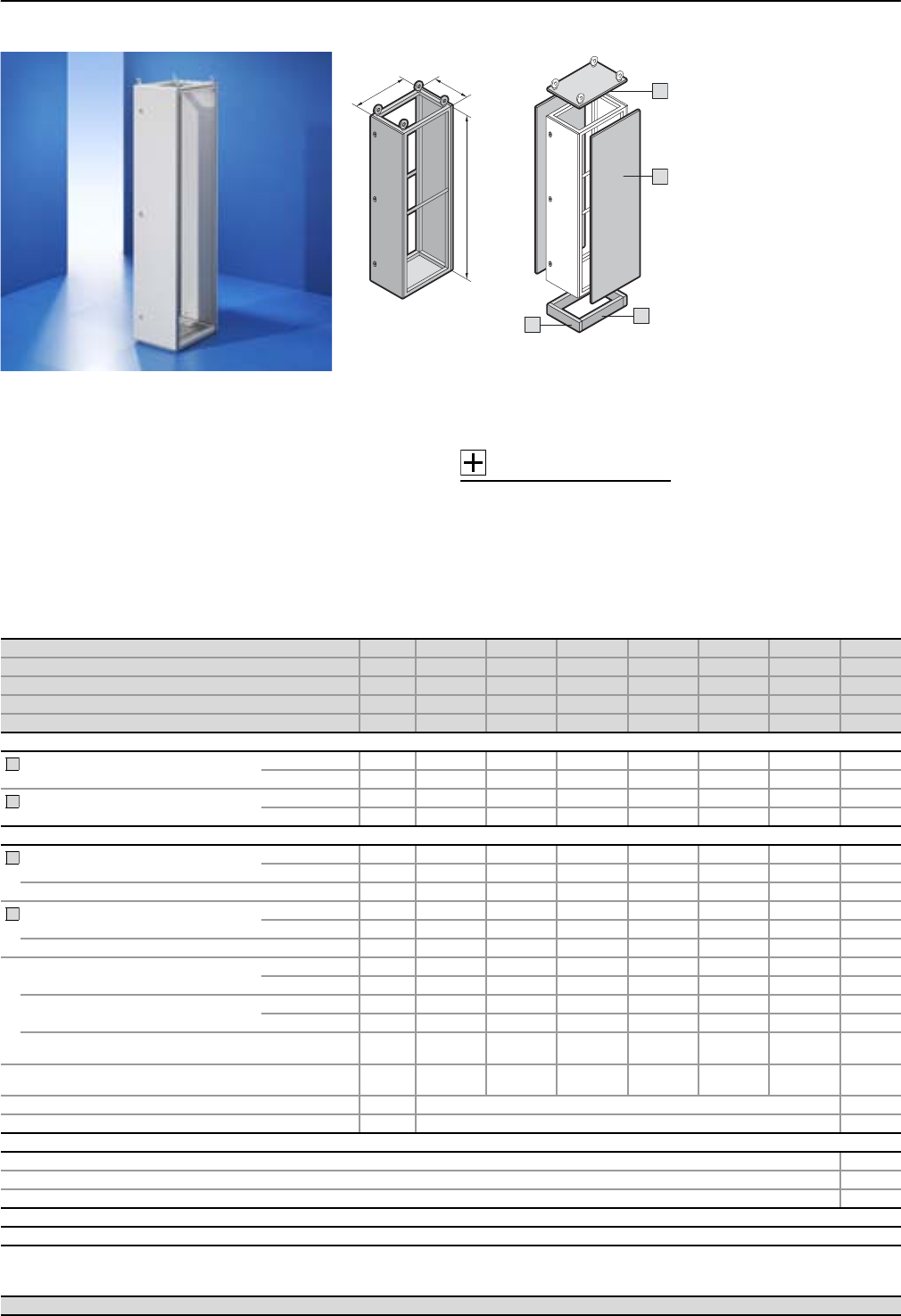
SV-TS 8 modular enclosures (height 2000 mm)
Form 2-4 enclosures
31Rittal Ri4Power Form 2-4
Width (B) mm Packs of 400 600 800 400 600 800 Page
Height (H) mm 2000 2000 2000 2000 2000 2000
Depth (T) mm 600 600 600 800 800 800
Model No. SV 19670.406 9670.606 9670.806 9670.408 9670.608 9670.808
Weight (kg) 43.8 54.0 59.2 43.8 53.7 64.2
Base/plinth
Components
front and rear
Height 100 mm 1 set 8601.400 8601.600 8601.800 8601.400 8601.600 8601.800 40
Height 200 mm 1 set 8602.400 8602.600 8602.800 8602.400 8602.600 8602.800 40
Trim panels
sides
Height 100 mm 1 set 8601.060 8601.060 8601.060 8601.080 8601.080 8601.080 40
Height 200 mm 1 set 8602.060 8602.060 8602.060 8602.080 8602.080 8602.080 40
Also required
Side panels
for protection category
IP 55 2 8106.235 8106.235 8106.235 8108.235 8108.235 8108.235 39
IP 2X 2 9671.906 9671.906 9671.906 9671.908 9671.908 9671.908 39
Upgrade kit for side panels IP 2X IP 43 2 sets1) 9671.996 9671.996 9671.996 9671.998 9671.998 9671.998 39
Roof plates
for protection category
IP 55 1 9671.646 9671.666 9671.686 9671.648 9671.668 9671.688 44
IP 43 1 9671.746 9671.766 9671.786 9671.748 9671.768 9671.788 44
IP 2X 1 9671.446 9660.235 9660.245 9671.448 9659.525 9659.535 44
Roof plates for cable entry gland 1 9671.546 9665.903 9671.586 9671.548 9671.568 9671.588 44
Front trim panels
for protection category
IP 54 1 set 9671.014 9671.016 9671.018 9671.014 9671.016 9671.018 41
IP 2X 1 set 9671.034 9671.036 9671.038 9671.034 9671.036 9671.038 41
Upgrade kit for front panels IP 2X IP 43 1 set 9671.044 9671.046 9671.048 9671.044 9671.046 9671.048 41
Partial doors for clearance height with front trim panel 100/100 mm
1 9671.158 9671.178 9671.198 9671.158 9671.178 9671.198 43
Front trim panels, top 300 mm/
bottom 100 mm for protection category
IP 54 1 set 9672.014 9672.016 9672.018 9672.014 9672.016 9672.018 42
IP 2X 1 set 9672.034 9672.036 9672.038 9672.034 9672.036 9672.038 42
Front trim panels, top 100 mm/
bottom 300 mm for protection category
IP 54 1 set 9672.024 9672.026 9672.028 9672.024 9672.026 9672.028 42
IP 2X 1 set 9672.044 9672.046 9672.048 9672.044 9672.046 9672.048 42
Upgrade kit
for front trim panels 300/100 mm IP 2X IP 43 1 set 9672.054 9672.056 9672.058 9672.054 9672.056 9672.058 42
Partial doors for clearance height with front trim panel 300/100 mm
1 9671.156 9671.176 9671.196 9671.156 9671.176 9671.196 43
Partial doors for modular configuration 1 䡲 䡲 䡲 䡲 䡲 䡲 43
Angular baying brackets 4 8800.430 41
Baying connectors, external 6 8800.490 41
Accessories
Enclosure configuration 39 – 46
Compartment configuration 50 – 61
Components 65 – 114
1) Pack sufficient for 1 pack of side panels.
1
2
3
4
5
5
System examples Page 9 – 27
T
H
B
1
5
4
3
2
5
Modular enclosure frame for
installation with partial doors
and internal separation.
Material:
Sheet steel
Enclosure frame, rear panel
and gland plates: 1.5 mm
Surface finish:
Enclosure frame:
Dipcoat-primed
Rear panel:
Dipcoat-primed,
powder-coated in textured
RAL 7035 on the outside
Gland plates: Zinc-plated
Protection category:
Up to IP 54,
depending on the roof plate,
front trim panels and side panel.
Supply includes:
Enclosure frame with rear panel
and gland plates.
Accessories:
System accessories,
see Cat. 32, page 890.
Standard:
Type-tested in accordance with
IEC 60 439-1.
Design verification in accord-
ance with IEC 61 439-1/-2.
Detailed drawings,
see page 130.
Technical information,
see page 134 – 140.

Form 2-4 enclosures
SV-TS 8 modular enclosures (height 2200 mm)
32 Rittal Ri4Power Form 2-4
T
H
B
1
5
4
3
2
5
Modular enclosure frame for
installation with partial doors
and internal separation.
Material:
Sheet steel
Enclosure frame, rear panel
and gland plates: 1.5 mm
Surface finish:
Enclosure frame:
Dipcoat-primed
Rear panel:
Dipcoat-primed,
powder-coated in textured
RAL 7035 on the outside
Gland plates: Zinc-plated
Protection category:
Up to IP 54,
depending on the roof plate,
front trim panels and side panel.
Supply includes:
Enclosure frame with rear panel
and gland plates.
Accessories:
System accessories,
see Cat. 32, page 890.
Standard:
Type-tested in accordance with
IEC 60 439-1.
Design verification in accord-
ance with IEC 61 439-1/-2.
Detailed drawings,
see page 130.
Technical information,
see page 134 – 140.
System examples Page 9 – 27
Width (B) mm Packs of 400 600 800 400 600 800 Page
Height (H) mm 2200 2200 2200 2200 2200 2200
Depth (T) mm 600 600 600 800 800 800
Model No. SV 19670.426 9670.626 9670.826 9670.428 9670.628 9670.828
Weight (kg) 43.2 54.0 59.4 46.1 55.8 66.0
Base/plinth
Components
front and rear
Height 100 mm 1 set 8601.400 8601.600 8601.800 8601.400 8601.600 8601.800 40
Height 200 mm 1 set 8602.400 8602.600 8602.800 8602.400 8602.600 8602.800 40
Trim panels
sides
Height 100 mm 1 set 8601.060 8601.060 8601.060 8601.080 8601.080 8601.080 40
Height 200 mm 1 set 8602.060 8602.060 8602.060 8602.080 8602.080 8602.080 40
Also required
Side panels
for protection category
IP 55 2 8126.235 8126.235 8126.235 8128.235 8128.235 8128.235 39
IP 2X 2 9671.926 9671.926 9671.926 9671.928 9671.928 9671.928 39
Upgrade kit for side panels IP 2X IP 43 2 sets1) 9671.996 9671.996 9671.996 9671.998 9671.998 9671.998 39
Roof plates
for protection category
IP 55 1 9671.646 9671.666 9671.686 9671.648 9671.668 9671.688 44
IP 43 1 9671.746 9671.766 9671.786 9671.748 9671.768 9671.788 44
IP 2X 1 9671.446 9660.235 9660.245 9671.448 9659.525 9659.535 44
Roof plates for cable entry gland 1 9671.546 9665.903 9671.586 9671.548 9671.568 9671.588 44
Front trim panels
for protection category
IP 54 1 set 9671.014 9671.016 9671.018 9671.014 9671.016 9671.018 41
IP 2X 1 set 9671.034 9671.036 9671.038 9671.034 9671.036 9671.038 41
Upgrade kit for front panels IP 2X IP 43 1 set 9671.044 9671.046 9671.048 9671.044 9671.046 9671.048 41
Partial doors for clearance height with front trim panel 100/100 mm
1 9671.150 9671.170 9671.190 9671.150 9671.170 9671.190 43
Front trim panels, top 300 mm/
bottom 100 mm for protection category
IP 54 1 set 9672.014 9672.016 9672.018 9672.014 9672.016 9672.018 42
IP 2X 1 set 9672.034 9672.036 9672.038 9672.034 9672.036 9672.038 42
Front trim panels, top 100 mm/
bottom 300 mm for protection category
IP 54 1 set 9672.024 9672.026 9672.028 9672.024 9672.026 9672.028 42
IP 2X 1 set 9672.044 9672.046 9672.048 9672.044 9672.046 9672.048 42
Upgrade kit
for front trim panels 300/100 mm IP 2X
IP 43 1 set 9672.054 9672.056 9672.058 9672.054 9672.056 9672.058 42
Partial doors for clearance height with front trim panel 300/100 mm
1 9671.158 9671.178 9671.198 9671.158 9671.178 9671.198 43
Partial doors for modular configuration 1 䡲 䡲 䡲 䡲 䡲 䡲 43
Angular baying brackets 4 8800.430 41
Baying connectors, external 6 8800.490 41
Accessories
Enclosure configuration 39 – 46
Compartment configuration 50 – 61
Components 65 – 114
1) Pack sufficient for 1 pack of side panels.
1
2
3
4
5
5
SV-TS 8 cable chamber enclosures (height 1800 mm)
Form 2-4 enclosures
33Rittal Ri4Power Form 2-4
T
H
B
1
4
3
2
Enclosure frame for the manage-
ment of incoming and outgoing
cables. The use of a roof plate
with cable gland plates addition-
ally allows cables to be fed in
from above.
Material:
Sheet steel
Enclosure frame, rear panel
and gland plates: 1.5 mm
Door: 2.0 mm
Surface finish:
Enclosure frame:
Dipcoat-primed
Door and rear panel:
Dipcoat-primed,
powder-coated in textured
RAL 7035 on the outside
Gland plates: Zinc-plated
Protection category:
Up to IP 54,
depending on the roof plate
and the side panel.
Supply includes:
Enclosure frame with door,
rear panel and gland plates.
Accessories:
System accessories,
see Cat. 32, page 890.
Standard:
Type-tested in accordance with
IEC 60 439-1.
Design verification in accord-
ance with IEC 61 439-1/-2.
Detailed drawings,
see page 131.
Technical information,
see page 134 – 140.
System examples Page 9 – 27
Width (B) mm Packs of 300 400 600 Page
Height (H) mm 1800 1800 1800
Depth (T) mm 600 600 600
Model No. SV 19670.396 9670.496 9670.696
Weight (kg) 47.0 49.5 62.0
Base/plinth
Components
front and rear
Height 100 mm 1 set 8601.915 8601.400 8601.600 40
Height 200 mm 1 set 8602.915 8602.400 8602.600 40
Trim panels
sides
Height 100 mm 1 set 8601.060 8601.060 8601.060 40
Height 200 mm 1 set 8602.060 8602.060 8602.060 40
Also required
Side panels
for protection category
IP 55 2 8186.235 8186.235 8186.235 39
IP 2X 2 9671.986 9671.986 9671.986 39
Upgrade kit for side panels IP 2X IP 43 2 sets1) 9671.996 9671.996 9671.996 39
Roof plates
for protection category
IP 55 1 9671.636 9671.646 9671.666 44
IP 43 1 9671.736 9671.746 9671.766 44
Roof plates for cable entry gland 1 9671.536 9671.546 9665.903 44
Front trim panels, top 300 mm/
bottom 100 mm for protection category
IP 54 1 set – 9672.014 9672.016 42
IP 2X 1 set – 9672.034 9672.036 42
Front trim panels, top 100 mm/
bottom 300 mm for protection category
IP 54 1 set – 9672.024 9672.026 42
IP 2X 1 set – 9672.044 9672.046 42
Upgrade kit
for front trim panels 300/100 mm IP 2X IP 43 1 set – 9672.054 9672.056 42
Partial doors
for clearance height with front trim panel 300/100 mm 1–––
Angular baying brackets 4 8800.430 41
Baying connectors, external 6 8800.490 41
Accessories
Enclosure configuration 39 – 46
Compartment configuration 50 – 61
Components 65 – 114
Lock systems
Standard double-bit lock may be exchanged for a lock with security cylinder/T handles, see page 43.
1) Pack sufficient for 1 pack of side panels.
1
2
3
4

Form 2-4 enclosures
SV-TS 8 cable chamber enclosures (height 2000 mm)
34 Rittal Ri4Power Form 2-4
T
H
B
1
4
3
2
Enclosure frame for the manage-
ment of incoming and outgoing
cables. The use of a roof plate
with cable gland plates addition-
ally allows cables to be fed in
from above.
Material:
Sheet steel
Enclosure frame, rear panel
and gland plates: 1.5 mm
Door: 2.0 mm
Surface finish:
Enclosure frame:
Dipcoat-primed
Door and rear panel:
Dipcoat-primed,
powder-coated in textured
RAL 7035 on the outside
Gland plates: Zinc-plated
Protection category:
Up to IP 54,
depending on the roof plate
and the side panel.
Supply includes:
Enclosure frame with door,
rear panel and gland plates.
Accessories:
System accessories,
see Cat. 32, page 890.
Standard:
Type-tested in accordance with
IEC 60 439-1.
Design verification in accord-
ance with IEC 61 439-1/-2.
Detailed drawings,
see page 131.
Technical information,
see page 134 – 140.
System examples Page 9 – 27
Width (B) mm Packs of 300 400 600 300 400 600 Page
Height (H) mm 2000 2000 2000 2000 2000 2000
Depth (T) mm 600 600 600 800 800 800
Model No. SV 19670.316 9670.416 9670.616 9670.318 9670.418 9670.618
Weight (kg) 48.5 53.8 69.4 50.4 55.9 74.0
Base/plinth
Components
front and rear
Height 100 mm 1 set 8601.915 8601.400 8601.600 8601.915 8601.400 8601.600 40
Height 200 mm 1 set 8602.915 8602.400 8602.600 8602.915 8602.400 8602.600 40
Trim panels
sides
Height 100 mm 1 set 8601.060 8601.060 8601.060 8601.080 8601.080 8601.080 40
Height 200 mm 1 set 8602.060 8602.060 8602.060 8602.080 8602.080 8602.080 40
Also required
Side panels
for protection category
IP 55 2 8106.235 8106.235 8106.235 8108.235 8108.235 8108.235 39
IP 2X 2 9671.906 9671.906 9671.906 9671.908 9671.908 9671.908 39
Upgrade kit for side panels IP 2X IP 43 2 sets1) 9671.996 9671.996 9671.996 9671.998 9671.998 9671.998 39
Roof plates
for protection category
IP 55 1 9671.636 9671.646 9671.666 9671.638 9671.648 9671.668 44
IP 43 1 9671.736 9671.746 9671.766 9671.738 9671.748 9671.768 44
Roof plates for cable entry gland 1 9671.536 9671.546 9665.903 9671.538 9671.548 9671.568 44
Front trim panels, top 300 mm/
bottom 100 mm for protection category
IP 54 1 set 9672.013 9672.014 9672.016 9672.013 9672.014 9672.016 42
IP 2X 1 set 9672.033 9672.034 9672.036 9672.033 9672.034 9672.036 42
Front trim panels, top 100 mm/
bottom 300 mm for protection category
IP 54 1 set 9672.023 9672.024 9672.026 9672.023 9672.024 9672.026 42
IP 2X 1 set 9672.043 9672.044 9672.046 9672.043 9672.044 9672.046 42
Upgrade kit
for front trim panels 300/100 mm IP 2X IP 43 1 set 9672.053 9672.054 9672.056 9672.053 9672.054 9672.056 42
Partial doors
for clearance height with front trim panel 300/100 mm 1 9671.126 9671.156 9671.176 9671.126 9671.156 9671.176 43
Angular baying brackets 4 8800.430 41
Baying connectors, external 6 8800.490 41
Accessories
Enclosure configuration 39 – 46
Compartment configuration 50 – 61
Components 65 – 114
Lock systems
Standard double-bit lock may be exchanged for a lock with security cylinder/T handles, see page 43.
1) Pack sufficient for 1 pack of side panels.
1
2
3
4
SV-TS 8 cable chamber enclosures (height 2200 mm)
Form 2-4 enclosures
35Rittal Ri4Power Form 2-4
T
H
B
1
4
3
2
Enclosure frame for the manage-
ment of incoming and outgoing
cables. The use of a roof plate
with cable gland plates addition-
ally allows cables to be fed in
from above.
Material:
Sheet steel
Enclosure frame, rear panel
and gland plates: 1.5 mm
Door: 2.0 mm
Surface finish:
Enclosure frame:
Dipcoat-primed
Door and rear panel:
Dipcoat-primed,
powder-coated in textured
RAL 7035 on the outside
Gland plates: Zinc-plated
Protection category:
Up to IP 54,
depending on the roof plate
and the side panel.
Supply includes:
Enclosure frame with door,
rear panel and gland plates.
Accessories:
System accessories,
see Cat. 32, page 890.
Standard:
Type-tested in accordance with
IEC 60 439-1.
Design verification in accord-
ance with IEC 61 439-1/-2.
Detailed drawings,
see page 131.
Technical information,
see page 134 – 140.
System examples Page 9 – 27
Width (B) mm Packs of 300 400 600 300 400 600 Page
Height (H) mm 2200 2200 2200 2200 2200 2200
Depth (T) mm 600 600 600 800 800 800
Model No. SV 19670.336 9670.436 9670.636 9670.338 9670.438 9670.638
Weight (kg) 47.8 57.3 75.8 50.6 61.0 80.7
Base/plinth
Components
front and rear
Height 100 mm 1 set 8601.915 8601.400 8601.600 8601.915 8601.400 8601.600 40
Height 200 mm 1 set 8602.915 8602.400 8602.600 8602.915 8602.400 8602.600 40
Trim panels
sides
Height 100 mm 1 set 8601.060 8601.060 8601.060 8601.080 8601.080 8601.080 40
Height 200 mm 1 set 8602.060 8602.060 8602.060 8602.080 8602.080 8602.080 40
Also required
Side panels
for protection category
IP 55 2 8126.235 8126.235 8126.235 8128.235 8128.235 8128.235 39
IP 2X 2 9671.926 9671.926 9671.926 9671.928 9671.928 9671.928 39
Upgrade kit for side panels IP 2X IP 43 2 sets1) 9671.996 9671.996 9671.996 9671.998 9671.998 9671.998 39
Roof plates
for protection category
IP 55 1 9671.636 9671.646 9671.666 9671.638 9671.648 9671.668 44
IP 43 1 9671.736 9671.746 9671.766 9671.738 9671.748 9671.768 44
Roof plates for cable entry gland 1 9671.536 9671.546 9665.903 9671.538 9671.548 9671.568 44
Front trim panels, top 300 mm/
bottom 100 mm for protection category
IP 54 1 set 9672.013 9672.014 9672.016 9672.013 9672.014 9672.016 42
IP 2X 1 set 9672.033 9672.034 9672.036 9672.033 9672.034 9672.036 42
Front trim panels, top 100 mm/
bottom 300 mm for protection category
IP 54 1 set 9672.023 9672.024 9672.026 9672.023 9672.024 9672.026 42
IP 2X 1 set 9672.043 9672.044 9672.046 9672.043 9672.044 9672.046 42
Upgrade kit
for front trim panels 300/100 mm IP 2X IP 43 1 set 9672.053 9672.054 9672.056 9672.053 9672.054 9672.056 42
Partial doors
for clearance height with front trim panel 300/100 mm 1 9671.128 9671.158 9671.178 9671.128 9671.158 9671.178 43
Angular baying brackets 4 8800.430 41
Baying connectors, external 6 8800.490 41
Accessories
Enclosure configuration 39 – 46
Compartment configuration 50 – 61
Components 65 – 114
Lock systems
Standard double-bit lock may be exchanged for a lock with security cylinder/T handles, see page 43.
1) Pack sufficient for 1 pack of side panels.
1
2
3
4
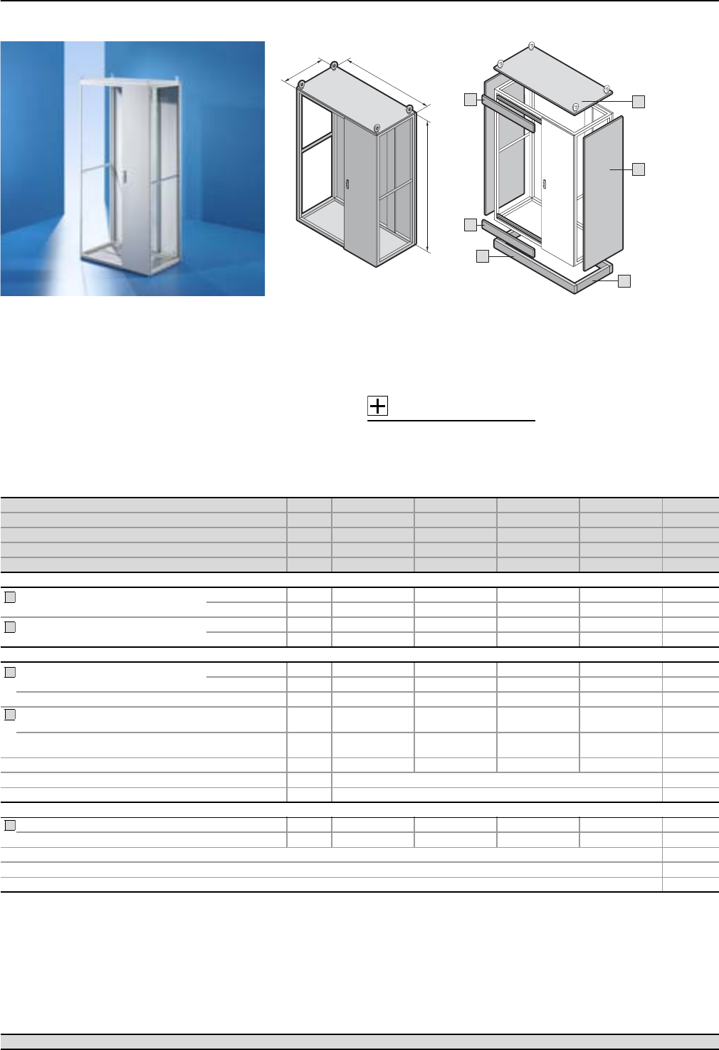
Form 2-4 enclosures
SV-TS 8 switch-disconnector-fuse enclosure (height 2000 mm)
36 Rittal Ri4Power Form 2-4
Width (B) mm Packs of 1000 1200 1000 1200 Page
Height (H) mm 2000 2000 2000 2000
Depth (T) mm 600 600 800 800
Model No. SV 19670.006 9670.106 9670.008 9670.108
Weight (kg) 97.0 116.0 104.0 123.0
Base/plinth
Components
front and rear
Height 100 mm 1 set 8601.000 8601.200 8601.000 8601.200 40
Height 200 mm 1 set 8602.000 8602.200 8602.000 8602.200 40
Trim panels
sides
Height 100 mm 1 set 8601.060 8601.060 8601.080 8601.080 40
Height 200 mm 1 set 8602.060 8602.060 8602.080 8602.080 40
Also required
Side panels
for protection category
IP 55 2 8106.235 8106.235 8108.235 8108.235 39
IP 2X 2 9671.906 9671.906 9671.908 9671.908 39
Upgrade kit for side panels IP 2X IP 43 2 sets1) 9671.996 9671.996 9671.998 9671.998 39
Front trim panels, top 350 mm/
bottom 150 mm for protection category IP 3X 1 set 9674.340 9674.340 9674.340 9674.340 46
Front trim panels, top 150 mm/
bottom 350 mm for protection category IP 3X 1 set 9674.342 9674.342 9674.342 9674.342 46
Contact hazard protection, cable chamber 1 set 9674.362 9674.366 9674.364 9674.368 60
Angular baying brackets 4 8800.430 41
Baying connectors, external 6 8800.490 41
Accessories
Roof plates for protection category IP 2X 1 9660.255 9660.265 9659.545 9659.555 44
Roof plates with pressure relief function2) 1 9660.955 9660.965 – – 44
Enclosure configuration 39 – 46
Compartment configuration 50 – 61
Components 65 – 114
1) Pack sufficient for 1 pack of side panels.
2) Other sizes available on request.
1
2
3
4
5
System examples Page 9 – 27
T
H
B
1
4
5
3
2
4
Enclosure frame for assembly
with mounting kit and distribu-
tion busbar system to install
switch-disconnector-fuses
from Jean Müller Sasil or ABB
SlimLine. Optionally with inner
separation in a modular design
up to Form 4b.
Material:
Sheet steel
Enclosure frame, roof, rear panel
and gland plates: 1.5 mm
Door: 2.0 mm
Surface finish:
Enclosure frame:
Dipcoat-primed
Door, roof and rear panel:
Dipcoat-primed,
powder-coated in textured
RAL 7035 on the outside
Gland plates: Zinc-plated
Protection category:
Up to IP 3X,
depending on the roof plate,
front trim panels and side panel.
Supply includes:
Enclosure frame prepared for
the installation of switch-discon-
nector-fuse section components
with door, roof, rear panel and
gland plates.
Accessories:
System accessories,
see Cat. 32, page 890.
Standard:
Type-tested in accordance with
IEC 60 439-1.
Design verification in accord-
ance with IEC 61 439-1/-2.
Detailed drawings,
see page 132.
Technical information,
see page 134 – 140.
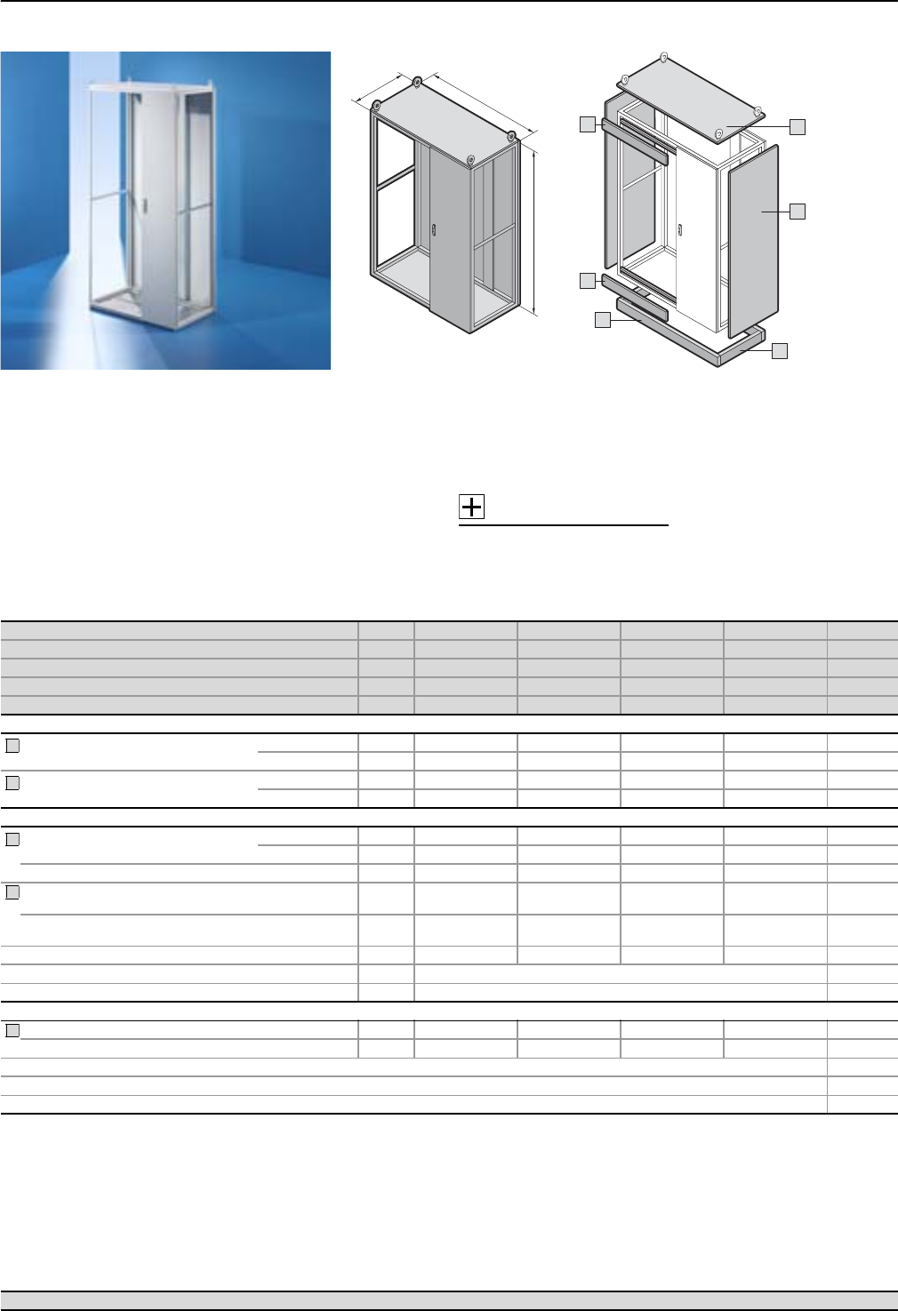
SV-TS 8 switch-disconnector-fuse enclosure (height 2200 mm)
Form 2-4 enclosures
37Rittal Ri4Power Form 2-4
T
H
B
1
4
5
3
2
4
Enclosure frame for assembly
with mounting kit and distribu-
tion busbar system to install
switch-disconnector-fuses
from Jean Müller Sasil or ABB
SlimLine. Optionally with inner
separation in a modular design
up to Form 4b.
Material:
Sheet steel
Enclosure frame, roof, rear panel
and gland plates: 1.5 mm
Door: 2.0 mm
Surface finish:
Enclosure frame:
Dipcoat-primed
Door, roof and rear panel:
Dipcoat-primed,
powder-coated in textured
RAL 7035 on the outside
Gland plates: Zinc-plated
Protection category:
Up to IP 3X,
depending on the roof plate,
front trim panels and side panel.
Supply includes:
Enclosure frame prepared for
the installation of switch-discon-
nector-fuses section compo-
nents with door, roof, rear panel
and gland plates.
Accessories:
System accessories,
see Cat. 32, page 890.
Standard:
Type-tested in accordance with
IEC 60 439-1.
Design verification in accord-
ance with IEC 61 439-1/-2.
Detailed drawings,
see page 132.
Technical information,
see page 134 – 140.
System examples Page 9 – 27
Width (B) mm Packs of 1000 1200 1000 1200 Page
Height (H) mm 2200 2200 2200 2200
Depth (T) mm 600 600 800 800
Model No. SV 19670.026 9670.126 9670.028 9670.128
Weight (kg) 102.0 122.0 109.0 129.0
Base/plinth
Components
front and rear
Height 100 mm 1 set 8601.000 8601.200 8601.000 8601.200 40
Height 200 mm 1 set 8602.000 8602.200 8602.000 8601.200 40
Trim panels
sides
Height 100 mm 1 set 8601.060 8601.060 8601.080 8601.080 40
Height 200 mm 1 set 8602.060 8602.060 8602.080 8602.080 40
Also required
Side panels
for protection category
IP 55 2 8126.235 8126.235 8128.235 8128.235 39
IP 2X 2 9671.926 9671.926 9671.928 9671.928 39
Upgrade kit for side panels IP 2X IP 43 2 sets1) 9671.996 9671.996 9671.998 9671.998 39
Front trim panels, top 350 mm/
bottom 150 mm for protection category IP 3X 1 set 9674.340 9674.340 9674.340 9674.340 46
Front trim panels, top 150 mm/
bottom 350 mm for protection category IP 3X 1 set 9674.342 9674.342 9674.342 9674.342 46
Contact hazard protection, cable chamber 1 set 9674.362 9674.366 9674.364 9674.368 60
Angular baying brackets 4 8800.430 41
Baying connectors, external 6 8800.490 41
Accessories
Roof plates for protection category IP 2X 1 9660.255 9660.265 9659.545 9659.555 44
Roof plates with pressure relief function2) 1 9660.955 9660.965 – – 44
Enclosure configuration 39 – 46
Compartment configuration 50 – 61
Components 65 – 114
1) Pack sufficient for 1 pack of side panels.
2) Other sizes available on request.
1
2
3
4
5
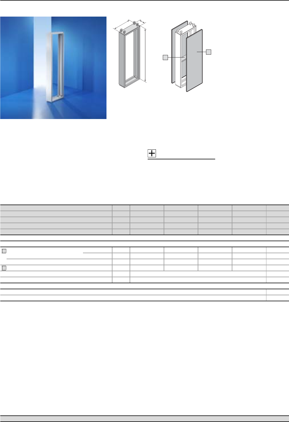
Form 2-4 enclosures
SV-TS 8 busbar enclosures (width 200 mm)
38 Rittal Ri4Power Form 2-4
T
H
B
1
2
Empty enclosure for baying to
TS 8 enclosures, to accommo-
date vertical busbar systems.
Material:
Sheet steel
enclosure frame with front trim
panel, rear panel and roof plate
and gland plate: 1.5 mm
Surface finish:
Enclosure frame, gland plate,
roof plate:
Dipcoat-primed and powder-
coated in textured RAL 7035
Rear panel, front trim panel:
Dipcoat-primed and powder-
coated in textured RAL 7035
Protection category:
Up to IP 55
Supply includes:
Enclosure frame with front trim
panel, rear panel, roof and
gland plates.
Accessories:
System accessories,
see Cat. 32, page 890.
Standard:
Type-tested in accordance with
IEC 60 439-1.
Design verification in accord-
ance with IEC 61 439-1/-2.
Detailed drawings,
see page 133.
Technical information,
see page 134 – 140.
Width (B) mm Packs of 200 200 200 200 Page
Height (H) mm 2000 2200 2000 2200
Depth (T) mm 600 600 800 800
Model No. SV 19670.206 9670.226 9670.208 9670.228
Weight (kg) 34.0 36.6 37.5 40.0
Base/plinth2)
Also required
Side panels
for protection category
IP 55 2 8106.235 8126.235 8108.235 8128.235 39
IP 2X 2 9671.906 9671.926 9671.908 9671.928 39
Upgrade kit for side panels IP 2X IP 43 2 sets1) 9671.996 9671.996 9671.998 9671.998 39
Coupling set mounting kit 1 set 9674.196 9674.196 9674.198 9674.198 59
Angular baying brackets 4 8800.430 41
Baying connectors, external 6 8800.490 41
Accessories
Compartment configuration 50 – 61
Components 65 – 114
1) Pack sufficient for 1 pack of side panels.
2) The busbar enclosure is on one base/plinth together with the main enclosure, i.e. please select a base/plinth for the main enclosure which is 200 mm wider.
1
2
System examples Page 9 – 27
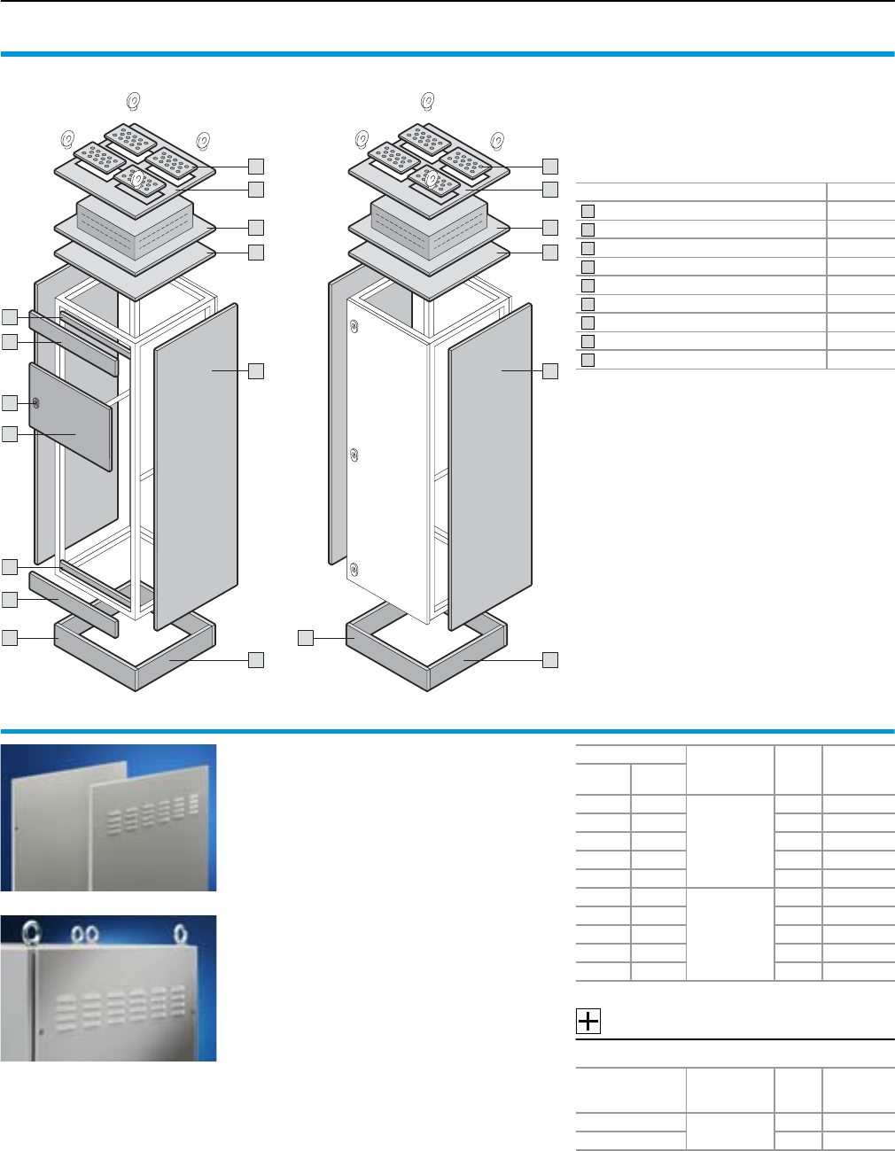
Enclosure configuration
Form 2-4 enclosure system accessories
39Rittal Ri4Power Form 2-4
Accessory components for external mounting
on a modular or cable chamber enclosure.
The required components should be selected
depending on the required function.
We highly recommend the Rittal Power Engineer-
ing software for easier selection – see page 123.
Accessory components Page
Side panels 39
Front trim panels 41/42/46
Roof frame bars/cross members 42/44
Roof plates 44
Cable entry glands 45
Partial doors 43
Locks 43
Base/plinth components, front and rear 40
Base/plinth trim, side 40
5
4
4
4
3
3
2
8 8
1
5
4
4
4
1
99
2
7
6
SV-TS 8 modular section SV-TS 8 cable chamber section
1
2
3
4
5
6
7
8
9
Side panels
for TS
Easy positioning on the frame with the location
aid.
Six enclosure panel holders with earthing insert
ensure automatic potential equalisation and
higher EMC protection. Earthing bolts with
contact surface are integrated.
Material:
Sheet steel, 1.5 mm
Surface finish:
Textured RAL 7035
Supply includes:
Assembly parts.
Accessories:
IP 43 upgrade kit for side panels
For enclosures
Version Packs
of
Model No.
SV
Height
mm
Depth
mm
1800 600
IP 55
sealed
28186.235
2000 600 2 8106.235
2200 600 2 8126.235
2000 800 2 8108.235
2200 800 2 8128.235
1800 600
IP 2X
with
ventilation
hole
29671.986
2000 600 2 9671.906
2200 600 2 9671.926
2000 800 2 9671.908
2200 800 2 9671.928
For
enclosure depth
mm
Version Packs
of
Model No.
SV
600 for side panels
IP 2X
2 sets 9671.996
800 2 sets 9671.998
Pack sufficient for 1 pack of side panels.
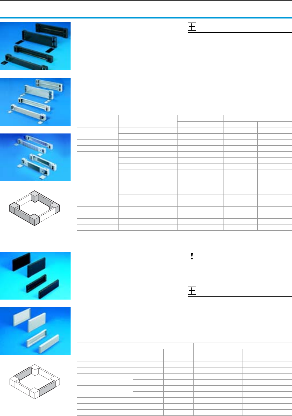
Form 2-4 enclosure system accessories
Enclosure configuration
40 Rittal Ri4Power Form 2-4
For enclosure depth
mm
Colour Model No. TS
RAL 7022 RAL 7035 100 mm high 200 mm high
300 䡲 – 8601.030 8602.030
400 䡲 – 8601.040 8602.040
500 䡲 – 8601.050 8602.050
600
䡲 – 8601.060 8602.060
– 䡲 8601.065 8602.065
800
䡲 – 8601.080 8602.080
– 䡲 8601.0851) 8602.085
900 – 䡲 8601.0952) 8602.095
1000 – 䡲 8601.0153) 8602.015
1200 – 䡲 8601.0254) 8602.025
1) Variant in RAL 9005: TS 8601.086
2) Variant in RAL 9005: TS 8601.092
3) Variant in RAL 9005: TS 8601.010
4) Variant in RAL 9005: TS 8601.026
Base/plinth components
front and rear
Sheet steel
for TS, CM, TP, PC-TS, IW, FR(i), TE
Base/plinth component consisting of one trim
panel and two pre-configured corner pieces. In
200 mm high base/plinth components, one trim
panel is divided into two for cable entry.
Material:
Sheet steel, spray-finished
Cover caps plastic RAL 9005/7035
Supply includes:
1 set =
2 base/plinth components, 4 cover caps,
4 screws and captive nuts M12
for mounting on the enclosure.
Accessories:
Base mounting plate SO 2817.000,
see Cat. 32, page 896.
Filter mat for vented variants,
see Cat. 32, page 898.
Detailed drawing,
see Cat. 32, page 894.
German patent no. 198 60 408
Base/plinth trim, side
Sheet steel
for TS, CM, TP, PC-TS, IW, FR(i), TE
For mounting between the base/plinth compo-
nents. At 200 mm height, two 100 mm base/plinth
trims may be used. Base/plinth trim (100 mm
high) may be installed rotated through 90° in
order to stabilise bayed base/plinth components.
Material:
Sheet steel, spray-finished
Supply includes:
1 set =
2 base/plinth trim panels, including parts for
attaching to the base/plinth components.
Also required:
Base/plinth baying brackets TS 8601.100,
see Cat. 32, page 896,
when mounting base/plinth trim panels rotated
through 90°.
Accessories:
Assembly bolts for base/plinth,
see Cat. 32, page 896.
Detailed drawing,
see Cat. 32, page 894.
For enclosure width
mm Version Colour Model No. TS
RAL 7022 RAL 7035 100 mm high 200 mm high
300 solid – 䡲 8601.905 8602.905
solid 䡲 – 8601.915 8602.915
400 solid 䡲 – 8601.400 8602.400
500 solid 䡲 – 8601.500 8602.500
600
solid 䡲 – 8601.600 8602.600
solid – 䡲 8601.6051) 8602.605
vented – 䡲 7825.6012) –
vented with designer cover – 䡲 7825.603 –
800
solid 䡲 – 8601.800 8602.800
solid – 䡲 8601.8053) 8602.805
vented – 䡲 7825.8014) –
vented with designer cover – 䡲 7825.803 –
850 solid 䡲 – 8601.850 8602.850
1000 solid 䡲 – 8601.000 8602.000
1100 solid 䡲 – 8601.300 8602.100
1200 solid 䡲 – 8601.200 8602.200
1600 solid 䡲 – 8601.920 8602.920
1) Variant in RAL 9005: TS 8601.602
2) Variant in RAL 9005: DK 7825.605
3) Variant in RAL 9005: TS 8601.802
4) Variant in RAL 9005: DK 7825.805
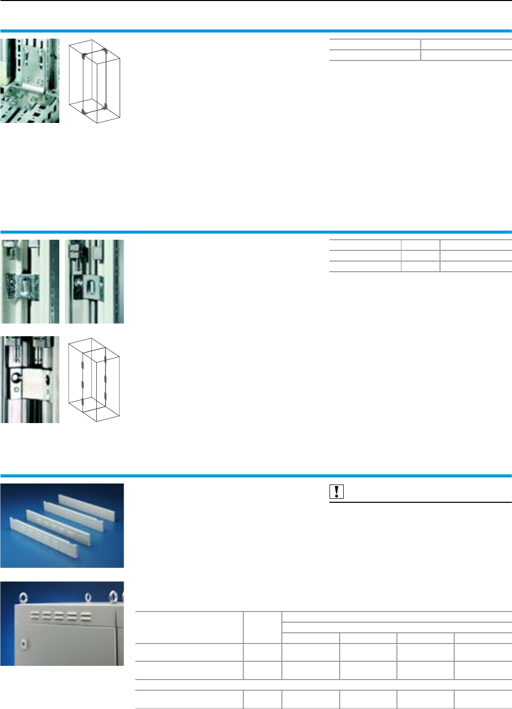
Enclosure configuration
Form 2-4 enclosure system accessories
41Rittal Ri4Power Form 2-4
Angular baying bracket
for TS/TS
The robust connection when transporting bayed
enclosure suites.
Screw-fastening either
●Horizontally and vertically with 8 screws
●Horizontally with 2 screws and M8 threaded
blocks, vertically with 4 screws
is supported.
Material:
Sheet steel, zinc-plated, passivated
Supply includes:
Assembly parts.
Packs of Model No. TS
48800.430
Baying connector, external
for TS/TS
For mounting on the vertical enclosure sections.
Simply position on the outside and screw-fasten
either from the inside or outside.
Material:
Sheet steel, zinc-plated, passivated
or stainless steel 1.4301 (AISI 304)
Supply includes:
Assembly parts.
German patent no. 197 37 668
Version Packs of Model No. TS
Sheet steel 6 8800.490
Stainless steel 6 8700.000
Front trim panels
for TS
Required as an upper and lower height filler
when partial doors are used.
Height: 100 mm.
Material:
Sheet steel, 2 mm
Surface finish:
Textured RAL 7035
Supply includes:
2 front trim panels, including assembly parts.
Also required:
Cross member,
see page 42.
Version Packs of
Model No. SV
For enclosure width
300 mm 400 mm 600 mm 800 mm
IP 54
sealed 1 set 9671.013 9671.014 9671.016 9671.018
IP 2X
with ventilation hole 1 set 9671.033 9671.034 9671.036 9671.038
Accessories
Upgrade kit IP 43
for front trim panel IP 2X 1 set 9671.043 9671.044 9671.046 9671.048
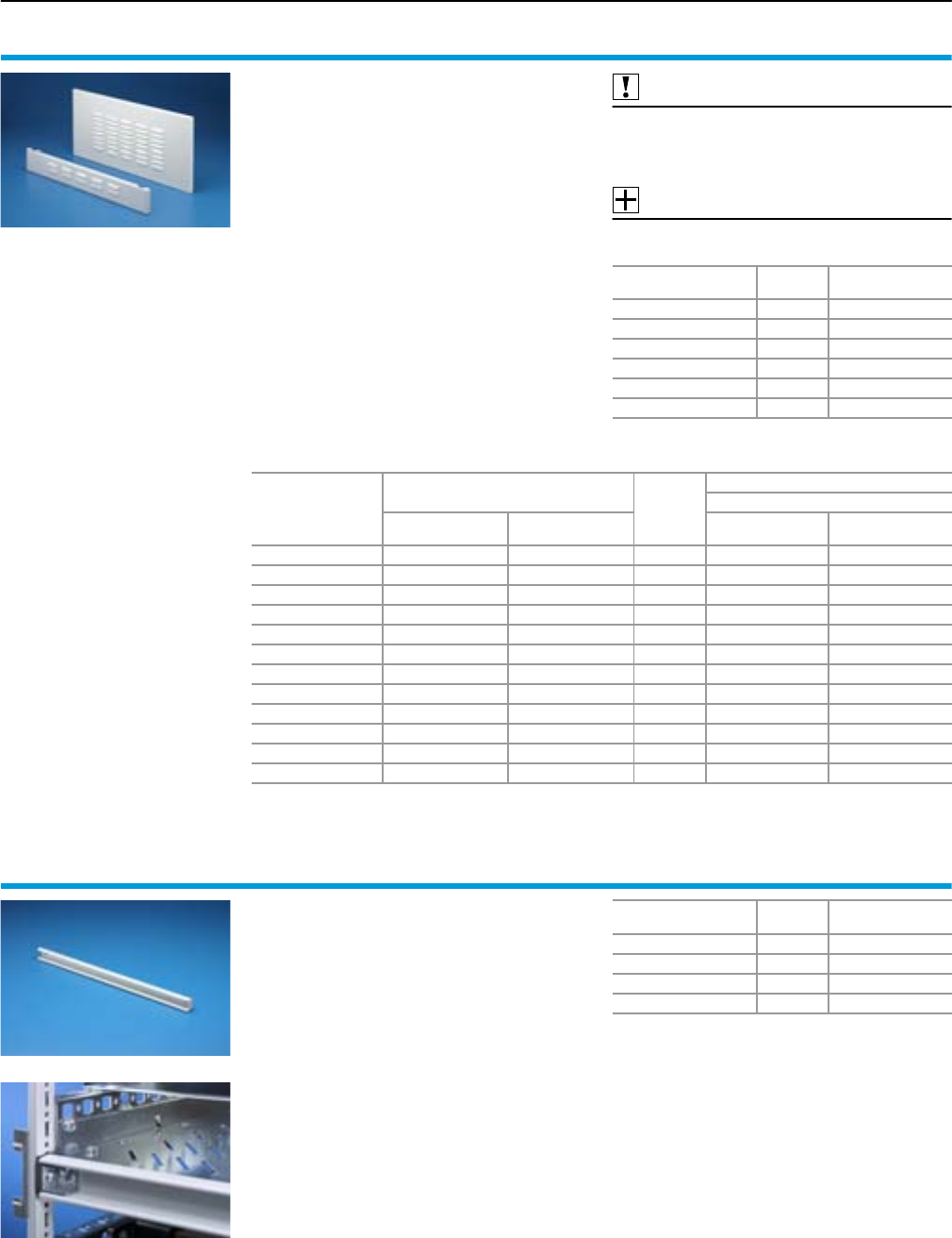
Form 2-4 enclosure system accessories
Enclosure configuration
42 Rittal Ri4Power Form 2-4
Front trim panels
for TS (busbar compartment)
Required to conceal a 300 mm high busbar com-
partment and for using partial doors as an upper
and lower height filler.
Height of busbar compartment cover: 300 mm.
Height of front trim panel opposite:
100 mm.
Material:
Sheet steel, 2 mm
Colour:
Textured RAL 7035
Supply includes:
2 front trim panels, including assembly parts.
Also required:
Roof frame bars,
see page 44.
Cross members,
see page 42.
Accessories:
Upgrade kit IP 43
for front trim panels IP 2X with ventilation hole
For enclosure width
mm Packs of Model No. SV
300 1 set 9672.053
400 1 set 9672.054
600 1 set 9672.056
800 1 set 9672.058
1000 1 set 9672.0501)
1200 1 set 9672.0521)
1) Delivery times available on request.
For enclosure width
mm
Height of front trim panels
Packs of
Model No. SV
Version
top
mm
bottom
mm
IP 54
sealed
IP 2X with
ventilation hole
300 300 100 1 set 9672.013 9672.033
300 100 300 1 set 9672.023 9672.043
400 300 100 1 set 9672.014 9672.034
400 100 300 1 set 9672.024 9672.044
600 300 100 1 set 9672.016 9672.036
600 100 300 1 set 9672.026 9672.046
800 300 100 1 set 9672.018 9672.038
800 100 300 1 set 9672.028 9672.048
1000 300 100 1 set 9672.0101) 9672.0301)
1000 100 300 1 set 9672.0201) 9672.0401)
1200 300 100 1 set 9672.0121) 9672.0321)
1200 100 300 1 set 9672.0221) 9672.0421)
1) Delivery times available on request.
Cross members
for TS
For use as sealing member between:
●Front trim panels
●Trim panels
●Partial doors
Material:
Sheet steel, 1 mm
Colour:
RAL 7035
Supply includes:
Assembly parts and sealing material.
For enclosure width
mm Packs of Model No. SV
300 5 9671.003
400 5 9671.004
600 5 9671.006
800 5 9671.008
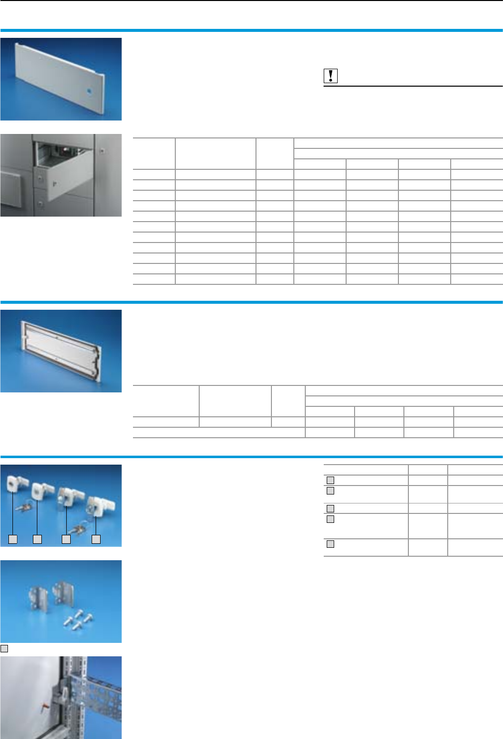
Enclosure configuration
Form 2-4 enclosure system accessories
43Rittal Ri4Power Form 2-4
Partial doors
for TS, without lock
Door hinges with non-drilled internal fastening.
Door may be optionally hinged on the right or left.
Material:
Sheet steel, 2 mm
Surface finish:
Textured RAL 7035
Supply includes:
Hinges and
assembly parts.
Also required:
Locks,
see page 43.
Cross members,
see page 42.
Height
mm
No. of
locks required Packs of
Model No. SV
For enclosure width
300 mm 400 mm 600 mm 800 mm
150 1 1 – 9671.141 9671.161 9671.181
200 1 1 – 9671.142 9671.162 9671.182
250 1 1 – 9671.147 9671.167 9671.187
300 1 1 – 9671.143 9671.163 9671.183
400 1 1 – 9671.144 9671.164 9671.184
600 2 1 – 9671.146 9671.166 9671.186
800 2 1 – 9671.148 9671.168 9671.188
1000 3 1 – 9671.140 9671.160 9671.180
1600 3 1 9671.126 9671.156 9671.176 9671.196
1800 3 1 9671.128 9671.158 9671.178 9671.198
2000 3 1 9671.120 9671.150 9671.170 9671.190
Perforated mounting strip
for partial doors
For retrospective external mounting on SV partial
doors. The perforated mounting strips have a
25 mm pitch pattern of holes and may be used for
individual mountings on the rear side of the door,
e.g. cable ducts, hose holders etc.
Material:
Sheet steel, 1 mm
Surface finish:
Sheet steel, zinc-plated, passivated
Supply includes:
Assembly parts.
For
partial door height
mm
Hole diameter
of the perforated strip
mm
Packs of
Model No. SV
For enclosure width mm
300 400 600 800
150 – 800 4.5 10 – 9671.204 9671.206 9671.208
Length mm – 298 498 698
Locks
For installation in partial doors or in exchange for
AE cam locks.
Material:
Housing made of fibreglass-reinforced plastic,
bolt made of PA
Colour:
RAL 7035
Supply includes:
Housing, lock insert, bolt
including assembly parts.
1
2
3
4
Version Packs of Model No. SV
With double-bit insert 1 9671.130
With cylinder insert,
lock no. 3524 E 19671.132
With T handle 1 9671.134
With T handle and
lock insert,
lock no. 3524 E
19671.135
Fastener lug
with end stop1) 29671.138
1) Must be used if the twist lock cannot be locked
on the TS 8 frame.
1
2
3
4
5
5
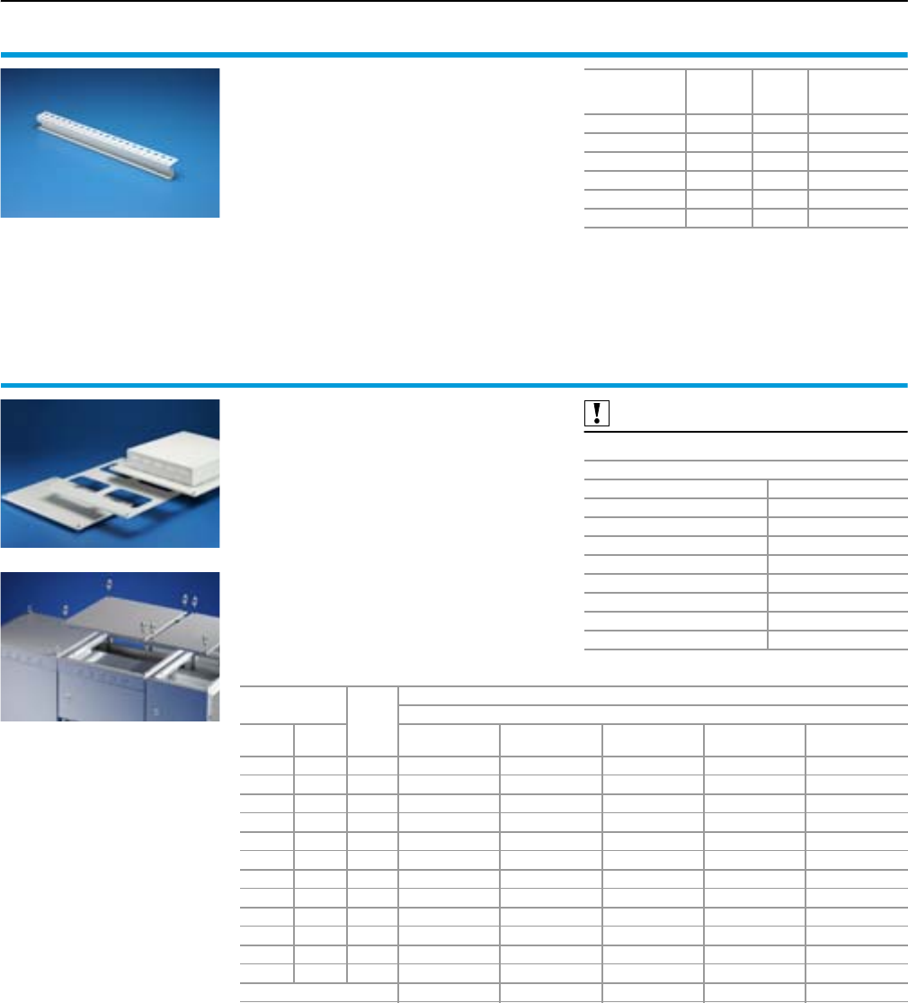
Form 2-4 enclosure system accessories
Enclosure configuration
44 Rittal Ri4Power Form 2-4
Roof frame strips, horizontal
for TS
Required as sealing bar between 300 mm high
front trim panels and partial doors.
Material:
Sheet steel, 1.5 mm
Colour:
RAL 7035
Supply includes:
Assembly parts and sealing material.
For
enclosure width
mm
Width
mm Packs of Model No. SV
300 208 2 9672.003
400 308 2 9672.004
600 508 2 9672.006
800 708 2 9672.008
1000 908 2 9672.0001)
1200 1108 2 9672.0021)
1) Delivery times available on request.
Roof plates
for TS
For SV-TS 8 modular and cable chamber enclo-
sures without roof plate and in exchange for the
standard roof plate for other TS enclosures.
Material:
Sheet steel, 1.5 mm
Surface finish:
Textured RAL 7035
Supply includes:
Assembly parts.
Also required:
Cable entry gland, see page 45.
No. of cable entry glands required
For roof plate Quantity required
SV 9671.536 2
SV 9671.546 3
SV 9665.903 4
SV 9671.586 8
SV 9671.538 2
SV 9671.548 4
SV 9671.568 8
SV 9671.588 8
For enclosures Packs
of
Model No. SV
Version
Width
mm
Depth
mm
IP 55
sealed
IP 43 with
ventilation hole
IP 2X with
ventilation hole
For cable entry
gland
With pressure
relief valve
300 600 1 9671.636 9671.736 – 9671.536 –
400 600 1 9671.646 9671.746 9671.846 9671.546 9671.4461)
600 600 1 9671.666 9671.766 9660.235 9665.903 9660.9351)
800 600 1 9671.686 9671.786 9660.245 9671.586 9660.9451)
1000 600 1 – – 9660.255 – 9660.955
1200 600 1 – – 9660.265 – 9660.965
300 800 1 9671.638 9671.738 – 9671.538 –
400 800 1 9671.648 9671.748 9671.848 9671.548 9671.4481)
600 800 1 9671.668 9671.768 9659.525 9671.568 9671.4681)
800 800 1 9671.688 9671.788 9659.535 9671.588 9671.4881)
1000 800 1 – – 9659.545 – 3)
1200 800 1 – – 9659.555 – 3)
Build height mm 0 93 72 02) 25
1) Delivery times available on request.
2) Build height depending on the cable entry gland.
3) Other sizes available on request.
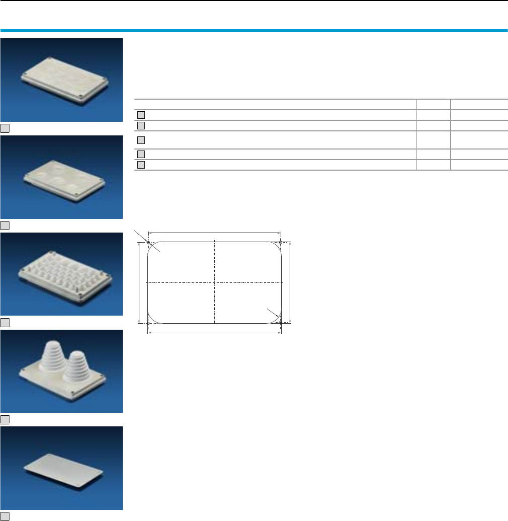
Enclosure configuration
Form 2-4 enclosure system accessories
45Rittal Ri4Power Form 2-4
Cable entry glands
●Including seal
●External dimensions 250 x 160 mm
●Protection category IP 55
Material:
SV 9665.750 to 9665.780
Insulating material RAL 7032
SV 9665.785
Sheet steel, spray-finished in RAL 7035
1
2
3
4
5
R25
135
223
138
226
Ø 4.5
Cut-out dimensions for
SV 9665.750 to SV 9665.785
Version Packs of Model No. SV
14 x M25/32 19665.750
2 x M25/32/40, 1 x M32/40/50, 2 x M40/50/63 1 9665.760
With sealing membranes
32 x dia. 7 – 16 mm, 4 x dia. 10 – 20 mm, 3 x dia. 14 – 26 mm 19665.770
With entry glands up to 66 mm diameter 1 9665.780
Solid 49665.785
1
2
3
4
5
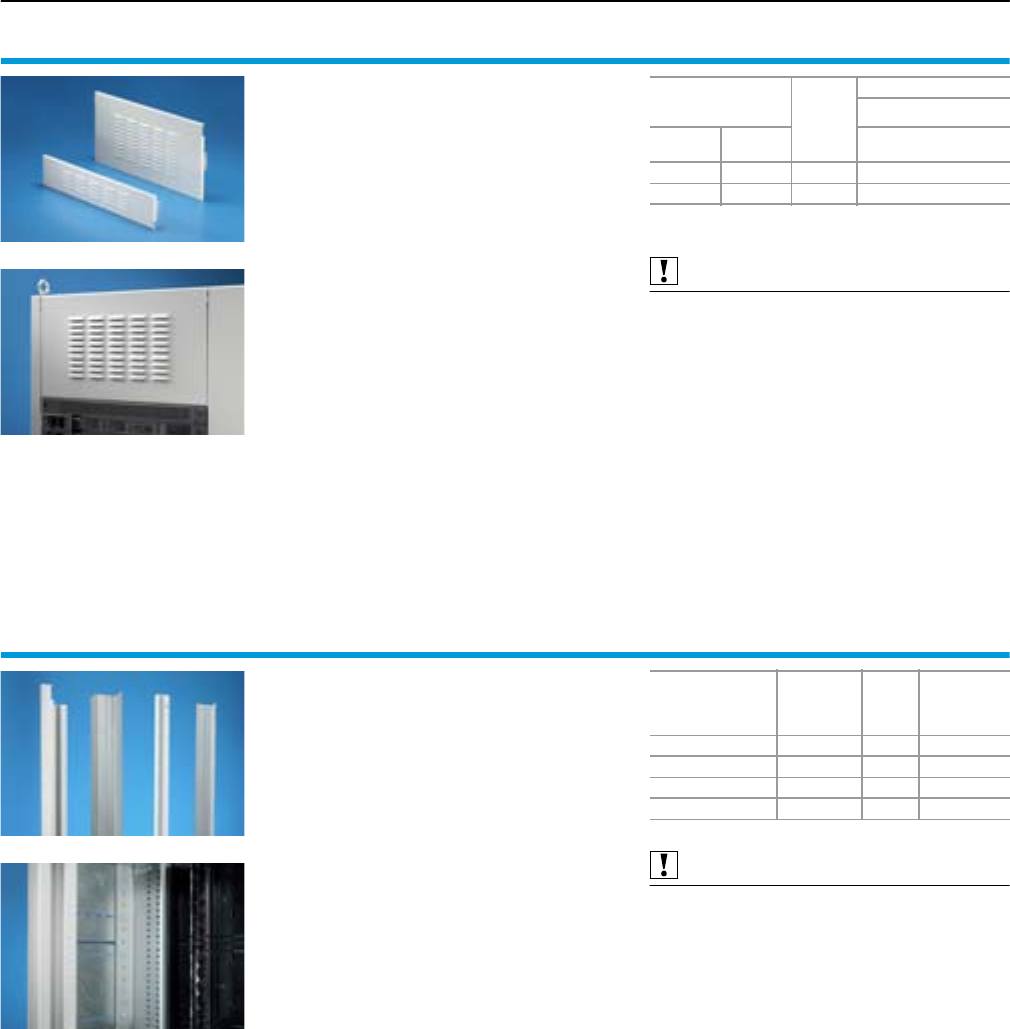
Form 2-4 enclosure system accessories
Enclosure configuration
46 Rittal Ri4Power Form 2-4
Front trim panels
for switch-disconnector-fuse section
The front trim panels cover above and below the
mounting area of the NH switch-disconnector-
fuses on the door front. With integral vent open-
ings, protection categories IP 3X/IP 2X of the
switch-disconnector-fuse section are achieved.
Material:
Sheet steel, 2 mm
Colour:
Textured RAL 7035
Supply includes:
2 front trim panels,
assembly parts.
Also required:
Assembly kit for switch-disconnector-fuse section,
see page 46.
Front trim panels
height
mm Packs of
Model No. SV
Version
top bottom IP 3X1)
with ventilation hole
338 136 1 set 9674.340
136 338 1 set 9674.342
1) For IP 2X the inner perforated plate must be removed.
Assembly kit
for switch-disconnector-fuse section
Assembly kit for the installation of switch-discon-
nector-fuses and attachment of the distribution
busbar system. Depending on the switch-discon-
nector-fuses to be used from ABB or Jean Müller,
the required assembly kits are selected accord-
ing to the enclosure height.
Material:
Section corner piece left/right,
sheet steel, zinc-plated, 2 mm
Trim panel left/right,
sheet steel, 2 mm, spray-finished
Colour:
Textured RAL 7035
Supply includes:
2 section corner pieces,
2 trim panels,
assembly parts.
Also required:
Divider panel for switch-disconnector-fuse section
,
see page 60.
For
make/switch-
disconnector-fuse
For
enclosure
height
mm
Packs
of
Model No.
SV
Jean Müller SASIL 2000 1 set 9674.350
Jean Müller SASIL 2200 1 set 9674.352
ABB SlimLine 2000 1 set 9674.356
ABB SlimLine 2200 1 set 9674.358
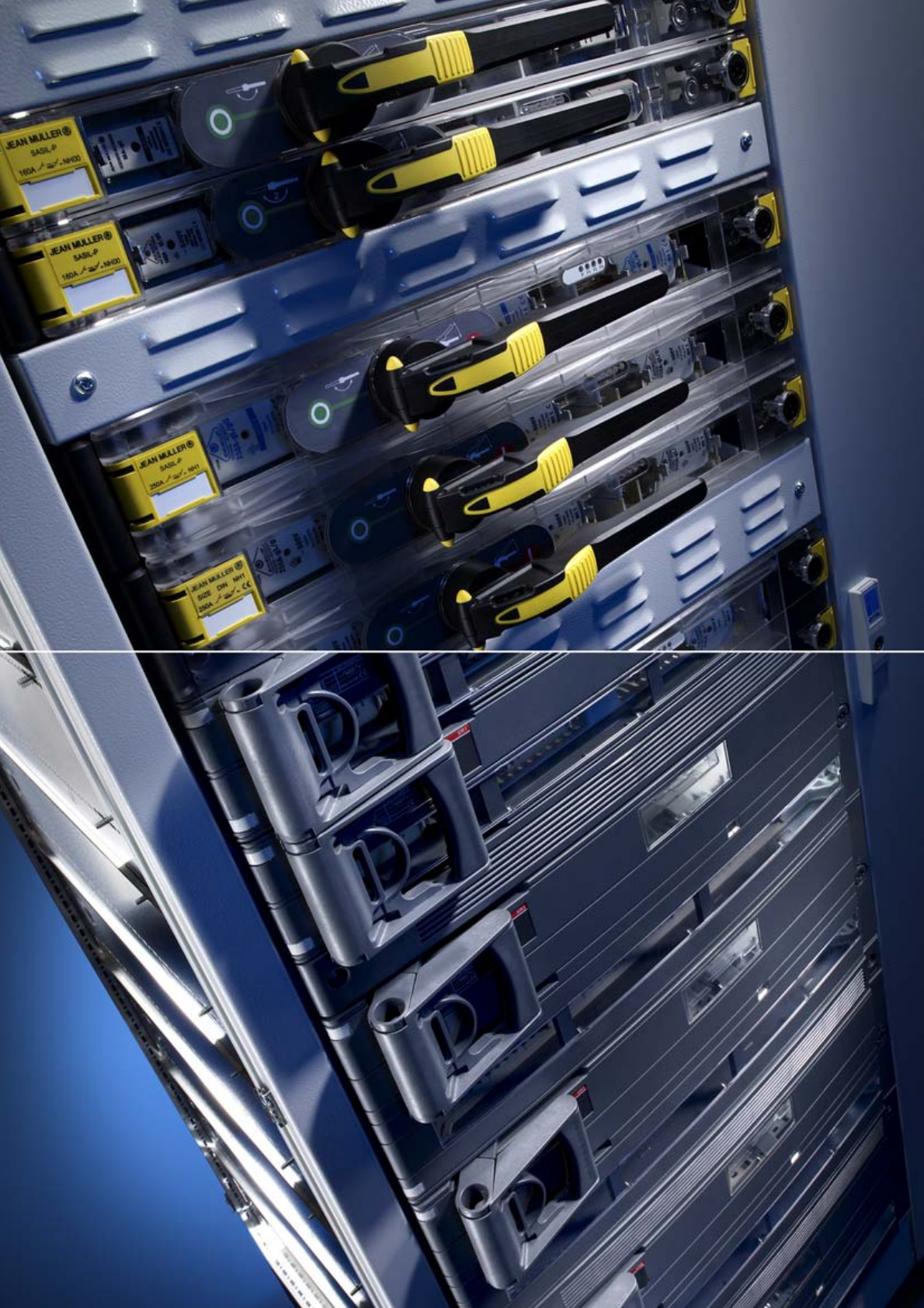
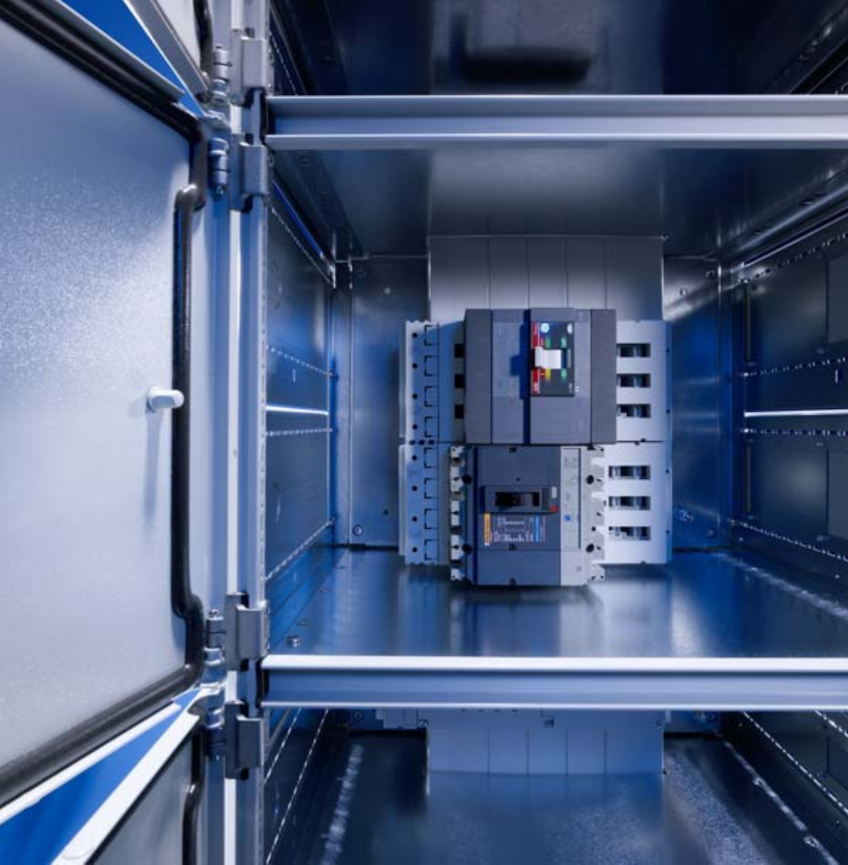
48 Rittal Ri4Power Form 2-4
Perfection down to the smallest detail
Time-saving system assembly, form-separated interior installation, innovative module components, and an
extensive range of accessories. Rittal Ri4Power Form 2-4 is a modular system for the time-optimised configura-
tion of form-separated low-voltage switchgear. Fresh approaches in installation technology and multifunctional
components now mean that the internal separation of a low-voltage switchgear can be installed with just a few
operations. The TS 8 Top enclosure system, as the system platform for Ri4Power Form 2-4, offers infinite possi-
bilities, and provides the ideal solution to suit your requirements, however specific.
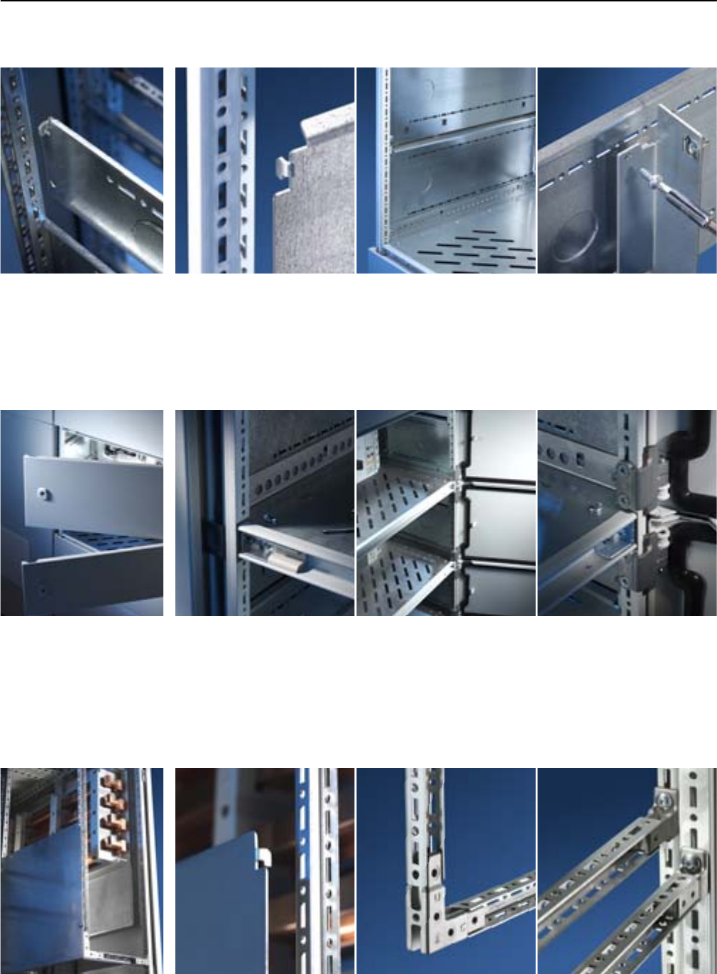
49Rittal Ri4Power Form 2-4
Time-saving system assembly
Form 2-4 compartment
Partial doors and cross members
Thanks to the new design, the
cross member may also be
retro-fitted.
Fitting accuracy and precision
are prerequisites for modular
technology.
The hinge of the partial doors
is mounted on the TS 8 frame
without any holes needing to
be drilled.
Side panel modules
One-person assembly: Locate
components into the TS 8 pitch
pattern, and release. Both hands
are now free for the next installa-
tion step.
The modular installation con-
cept enables optimum utilisa-
tion of the assembly area, thanks
to compartment heights in small
increments (150, 200, 250 mm,
etc.).
The proven TS 8 pitch is used
for many Ri4Power components
and so permits the use of TS 8
system accessories.
Simple assembly and high
quality standards charac-
terise the new partial door
system.
The side panel modules form
the basic element for internal
installation.
The three assembly sides of
the Mini-TS profile ensure the
versatility and fast assembly
technology of the TS 8 enclo-
sure profile at all times, what-
ever the location.
The connector pieces always
provide an attachment point at
every position in the 25 mm
pitch, irrespective of the mount-
ing angle used.
The small size means the Mini-
TS bars can be mounted with-
out conflict in the internal and
external mounting level of the
TS 8 enclosure.
Mini-TS profile
Mini-TS profile – the TS pitch
in the smallest dimension.
An extension of the assembly
spectrum for small and
medium loads.
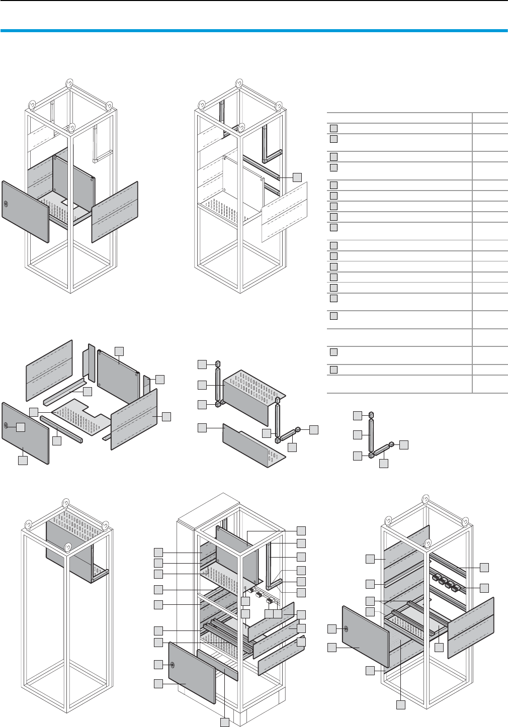
Form 2-4 compartment
Compartment configuration
50 Rittal Ri4Power Form 2-4
Circuit-breaker section
Accessory components for the configuration of
modular or cable chamber enclosures. The
required components are selected depending
on the required compartments and system con-
figuration.
We highly recommend the Rittal Power Engineer-
ing software for an explanation of the selection
process – see page 123.
10
3
4
5
4
17
2
1
6
7
18
1
1
1
3
3
12
1
2
1
16
1
2
9
8
4
9
10
8
13 14
7
6
Modular outgoing section with distribution busbar system
Inside the compartment
Cable chamber
Behind the compartment
Compartment layout Busbar space separation
(only required with main busbar
systems in the rear area)
Coupling section
9
9
11
8
10
11
8
9
9
8
10
8
Accessory components Page
Functional space side panel modules 51
Mounting bracket for functional space
divider 53
Functional space divider 54/55
Partial mounting plates
including angle brackets 56
Cross members 42
Partial doors 43
Locks 43
Mini-TS profiles 17 x 15.5 mm 57
Frame connector piece
(external mounting level) 58
Corner connector 58
Cover plates 52
Air circuit-breaker support bar 54
Stacking insulator 105
Support bar for packing insulator 105
Functional space side panel modules
for cable connection space 51
Mounting bracket for functional space
divider and air circuit-breaker support bar
53
Support frame for
DIN rail-mounted devices 56
Punched rails, RiLine distribution
busbar system 61
Accessories for coupling set 59
Accessories for switch-disconnector-
fuses 60
1
2
3
4
5
6
7
8
9
10
11
12
13
14
15
16
17
18
2
12
1
7
6
1
14
13
16
15
3
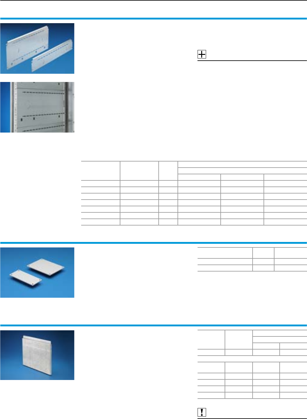
Compartment configuration
Form 2-4 compartment
51Rittal Ri4Power Form 2-4
Functional space side panel
modules
for TS
For internal separation as a side divider panel for
compartments, for mounting in the TS pitch pat-
tern. Prepared for the attachment of mounting
brackets for horizontal functional space dividers
or mounting plates with two M40 knockouts for
cable entry. Two TS system punchings allow the
use of additional TS accessories.
The side panel modules for reduced compart-
ment depth and an auxiliary construction using
the Mini-TS profiles can be used to provide a sep-
arate enclosure space in the side panel area,
e.g. for the provision of a busbar system. Version
with plastic plate has prepunched knockouts for
cable entry.
Material:
Sheet steel, zinc-plated, passivated, 1.5 mm
Supply includes:
Assembly parts.
Accessories:
Mini-TS extrusions and connector pieces,
see page 57, 58.
Gland plates,
see page 51.
Height
mm
Configuration
with
plastic gland plate
Packs
of
Model No. SV
For compartment depth
425 mm 600 mm 800 mm
100 – 6 9673.051 9673.061 9673.081
150 – 6 9673.055 9673.065 9673.085
150 䡲 69673.155 9673.165 9673.185
200 – 6 9673.052 9673.062 9673.082
200 䡲 69673.152 9673.162 9673.182
600 – 2 – 9673.066 9673.086
600 䡲 2 – 9673.166 9673.186
Gland plates
To seal additional cable entries.
Material:
PVC, 3 mm
fire protection corresponding to UL 94-V0
Colour:
RAL 7004
Supply includes:
Assembly parts.
For side panel modules
height mm Packs of Model No. SV
150 10 9673.195
200/600 10 9673.192
Functional space side panel
modules
for TS (cable connection space)
For mounting a Maxi-PLS cable connection bus-
bar system in a TS enclosure.
Material:
Sheet steel, zinc-plated, passivated, 2 mm
Supply includes:
Assembly parts.
Also required:
2 functional space side panel modules
with height 150 mm,
see page 51.
End support,
see page 84/86.
Height
mm Packs of
Model No. SV
For enclosure depth
600 mm 800 mm
450 2 9673.069 9673.089
Suitable for cable connection busbar system
Maxi-PLS Number
of poles
1600/2000 3-pole 䡲 䡲
1600/2000 4-pole 䡲 䡲
3200 3-pole 䡲 䡲
3200 4-pole – 䡲
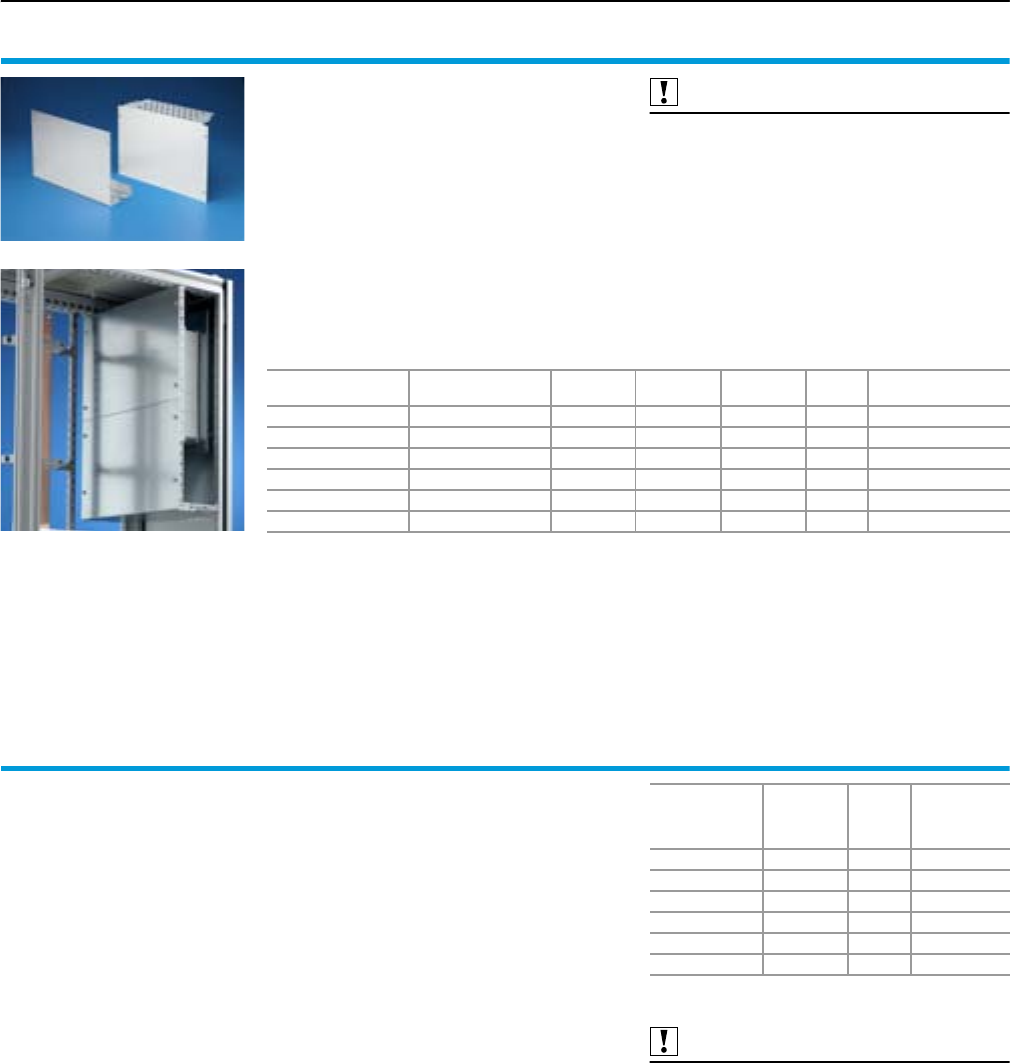
Form 2-4 compartment
Compartment configuration
52 Rittal Ri4Power Form 2-4
Cover plates
for rear busbar system
in the cable chamber
To separate an area of the cable chamber enclo-
sure for a rear-mounted busbar system. Attach-
ment requires an auxiliary construction made from
Mini-TS profiles, to which the cover plates are
attached and fastened.
Material:
Sheet steel, zinc-plated, passivated, 1.5 mm
Supply includes:
Assembly parts.
Also required:
Frame connector piece
(4 x SV 9673.901), see page 58.
Corner connector
(2 x SV 9673.902), see page 58.
Mini-TS profiles for SV 9673.5X0
(2 x SV 9673.915, 2 x SV 9673.953),
see page 57.
Mini-TS profiles for SV 9673.5X2
(2 x SV 9673.920, 2 x SV 9673.983),
see page 57.
For enclosure depth
mm
For enclosure width
mm
Width
mm
Height
mm
Depth
mm Packs of Model No. SV
600 300 297 540 170.5 2 sets 9673.5301)
600 400 397 540 170.5 2 sets 9673.5401)
600 600 597 540 170.5 2 sets 9673.5601)
600/800 300 297 837 245.5 1 set 9673.5322)
600/800 400 397 837 245.5 1 set 9673.5422)
600/800 600 597 837 245.5 1 set 9673.5622)
1) Suitable for RiLine60 and Maxi-PLS 1600/2000
2) Suitable for RiLine60, Maxi-PLS 1600/2000/3200 and Flat-PLS
Terminal box Form 4b
for modular outgoing section
To shield the connections (terminals) of the func-
tional space, busbar chamber and cable cham-
ber to Form 4b, IEC 60 439-1. The terminal boxes
are externally mounted on the functional space
side panel modules in the cable chamber, to
match the heights of the compartments. The ter-
minal box is prepared for mounting of a clamping
strip and the introduction of lines and cables.
Material:
Sheet steel, zinc-plated, passivated, 1.5 mm
Supply includes:
Assembly parts.
Note:
For installation of the terminal boxes, the width of
the cable chamber must be at least 400 mm!
Also required:
Functional space side panel modules,
see page 51.
For
compartment
height
mm
For
enclosure
width
mm1)
Packs of Model No.
SV
150 400/600 1 set 9674.701
200 400/600 1 set 9674.702
250 400/600 1 set 9674.707
300 400/600 1 set 9674.703
400 400/600 1 set 9674.704
600 400/600 1 set 9674.706
1) Enclosure width of the cable chamber
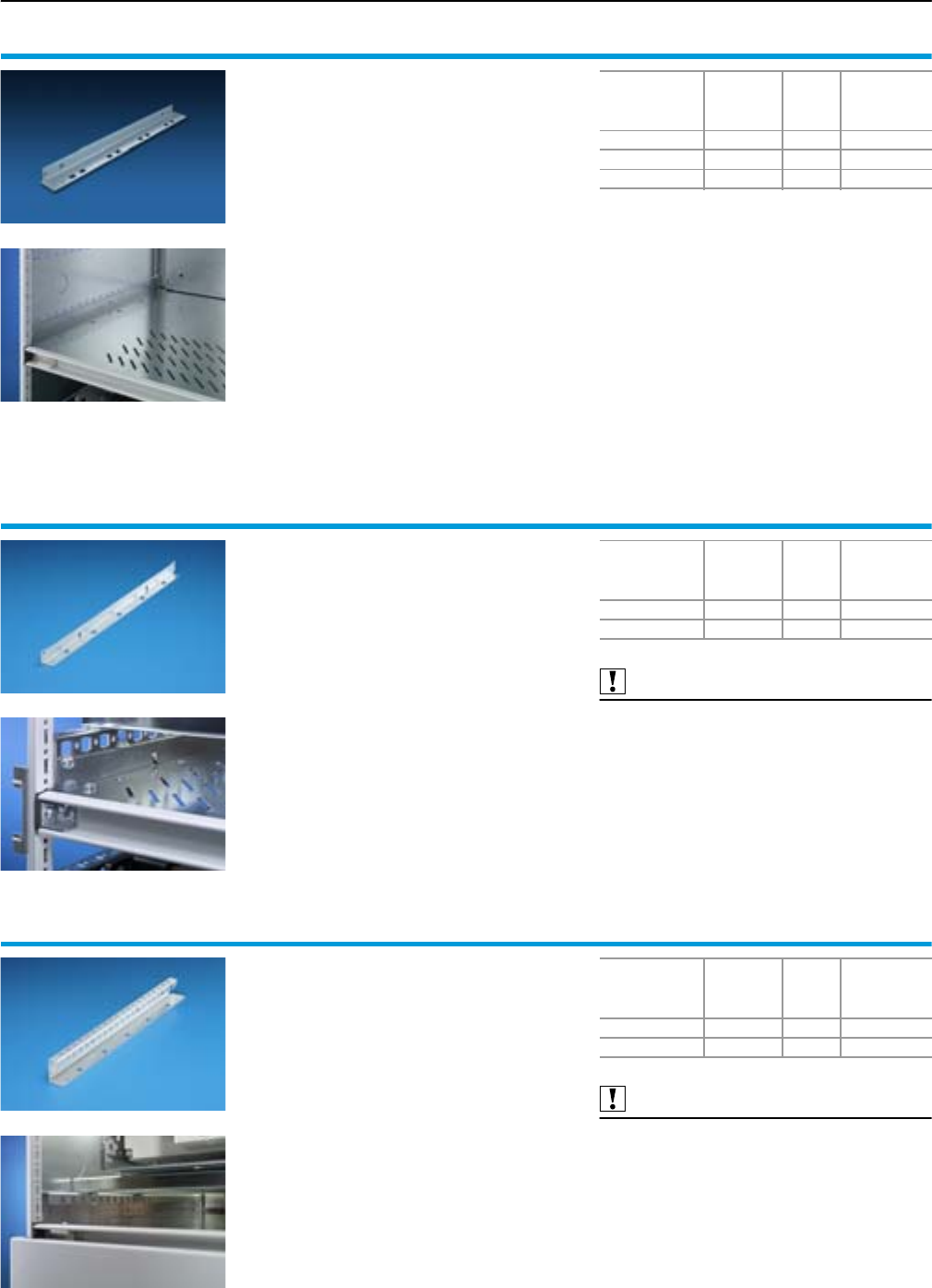
Compartment configuration
Form 2-4 compartment
53Rittal Ri4Power Form 2-4
Mounting bracket
for functional space divider
The mounting bracket is fastened to the TS frame
or between a frame section and an auxiliary con-
struction.
It is suitable both for fastening to a side panel
module and also directly to the TS frame. The
functional space dividers can be inserted into the
installation openings provided.
Material:
Sheet steel, zinc-plated, passivated, 1.5 mm
Supply includes:
Assembly parts.
For
compartment
depth
mm
Length
mm Packs of Model No.
SV
425 427 8 9673.4051)
600 552 8 9673.406
800 752 8 9673.408
1) In conjunction with vertical busbar space separation.
Mounting bracket
for functional space divider (inner mounting
level)
The mounting bracket is secured to a TS punched
section with mounting flange 23 x 73 mm.
The functional space dividers can be inserted into
the installation openings provided.
Material:
Sheet steel, zinc-plated, passivated, 1.5 mm
Supply includes:
Assembly parts.
Also required:
TS punched section with mounting flange,
23 x 73 mm,
see Cat. 32, page 995.
For
compartment
depth
mm
Length
mm Packs of Model No.
SV
600 544.5 8 9673.416
800 744.5 8 9673.418
Mounting bracket
for functional space divider
and air circuit-breaker support bar
The mounting bracket is attached to a side panel
module. The functional space dividers can be
inserted into the installation openings provided.
The air circuit-breaker support bar may be
attached to the upper level.
Material:
Sheet steel, zinc-plated, passivated, 2 mm
Supply includes:
Assembly parts.
Also required:
Functional space side panel modules,
see page 51.
Air circuit-breaker support bar,
see page 54.
For
compartment
depth
mm
Length
mm Packs of Model No.
SV
600 552 2 9673.426
800 752 2 9673.428
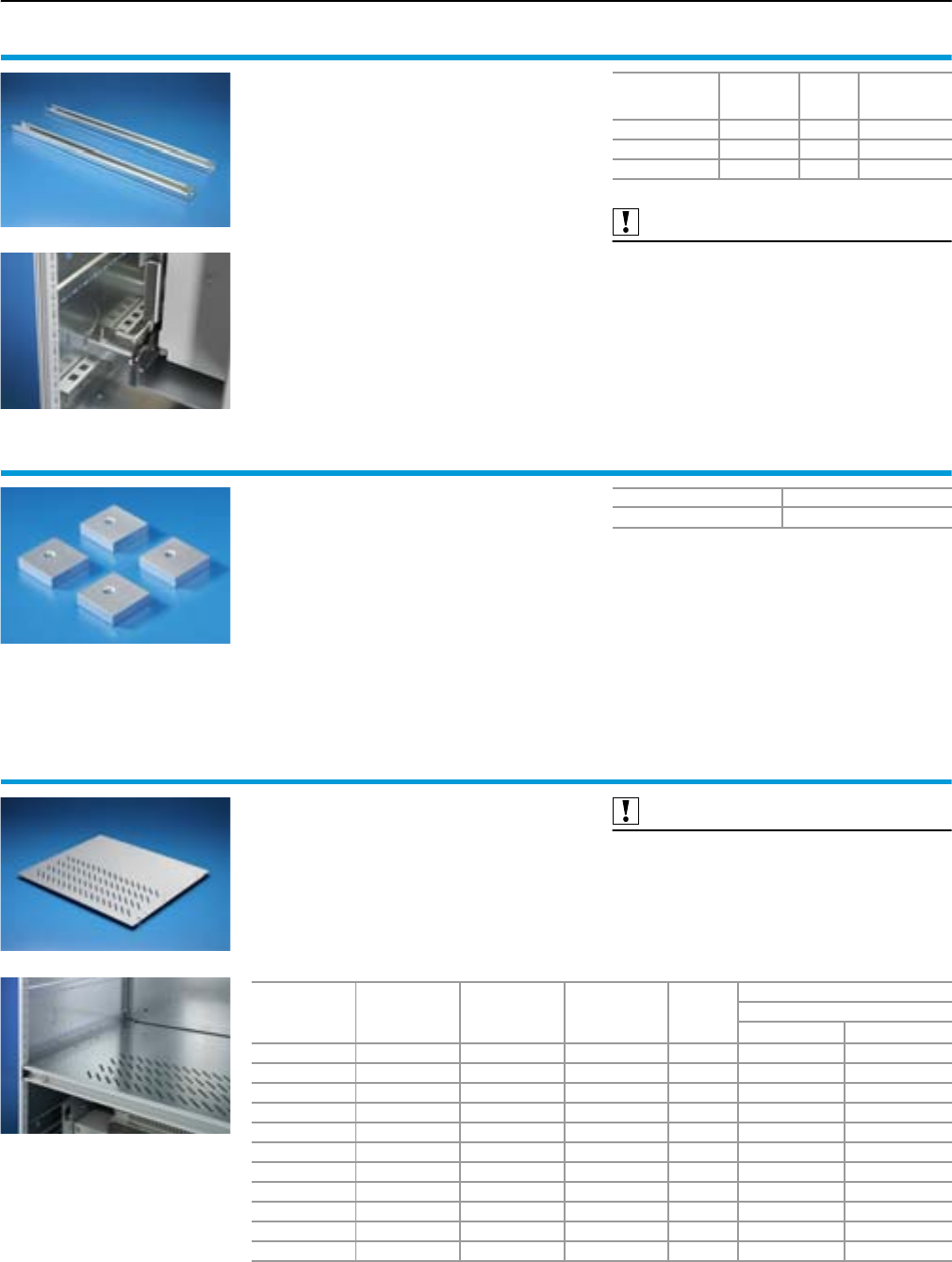
Form 2-4 compartment
Compartment configuration
54 Rittal Ri4Power Form 2-4
Air circuit-breaker support bar
For the configuration of air circuit-breakers (ACB)
in compartments. The air circuit-breaker support
bar is attached to a mounting bracket for functio-
nal space dividers and air circuit-breaker support
bar.
Material:
Sheet steel, zinc-plated, passivated, 2.5 mm
Supply includes:
Assembly parts.
Also required:
Mounting bracket for functional space divider
and air circuit-breaker support bar
see page 53.
Attachment set for air circuit-breaker installation,
see page 54.
For
enclosure width
mm
Length
mm Packs of Model No.
SV
400 351 2 9673.004
600 551 2 9673.006
800 751 2 9673.008
Attachment set
for air circuit-breaker installation
For attaching air circuit-breakers (ACB) to air
circuit-breaker support bars.
Material:
Sheet steel, zinc-plated
Supply includes:
4 threaded plates (M8).
Packs of Model No. SV
1 set 9660.970
Functional space divider
for TS
For the horizontal separation of compartments.
In combination with the side panel modules,
produces a separation in accordance with Form 3
or 4. Two mounting brackets are required to install
the functional space divider.
Material:
Sheet steel, zinc-plated, passivated, 1.25 mm
Also required:
Mounting bracket,
see page 53.
Cross members,
see page 42.
For
enclosure width
mm
For
compartment
depth
mm
Width
mm
Depth
mm Packs of
Model No. SV
Version
Vented1) Solid2)
300 600 206 588 4 – 9673.431
300 800 206 788 4 – 9673.432
400 425 306 445 4 9673.444 9673.440
400 600 306 588 4 9673.445 9673.441
400 800 306 788 4 9673.448 9673.449
600 425 506 445 4 9673.464 9673.460
600 600 506 588 4 9673.465 9673.461
600 800 506 788 4 9673.468 9673.469
800 425 706 445 4 9673.484 9673.480
800 600 706 588 4 9673.485 9673.481
800 800 706 788 4 9673.488 9673.489
1) With ventilation holes
2) Derating of 5% with enclosure protection category IP 2X or less, in relation to the rated currents
of the selected busbar system.
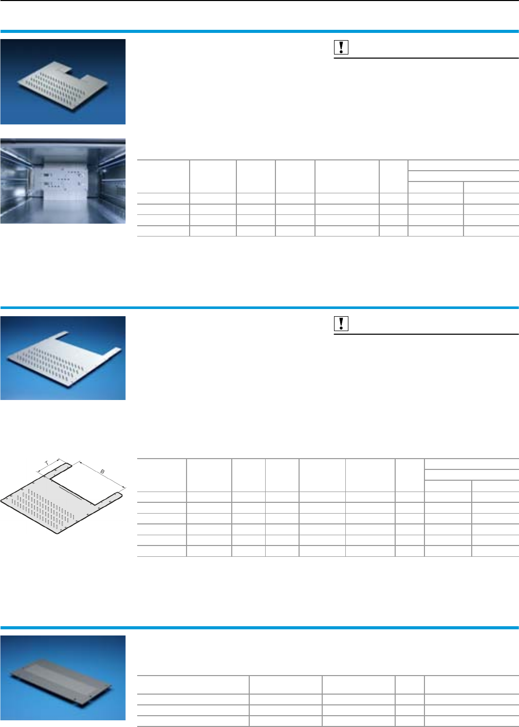
Compartment configuration
Form 2-4 compartment
55Rittal Ri4Power Form 2-4
Functional space divider
for TS, prepared for RiLine60 busbar systems
For the horizontal separation of compartments
with integrated RiLine60 multi-terminal busbar
system. In combination with the side panel mod-
ules, produces a separation in accordance with
Form 3 or 4. Two mounting brackets are required
to install the functional space divider.
Material:
Sheet steel, zinc-plated, passivated, 1.25 mm
Also required:
Mounting bracket,
see page 53.
Cross members,
see page 42.
For
enclosure
width
mm
For
compartment
depth
mm
Width
mm
Depth
mm
Position of the
busbar system
in the
compartment
Packs
of
Model No. SV
Version
Vented1) Solid3)
400 401 306 413 – 4 9673.4342) 9673.4302)
600 401 506 413 – 4 9673.454 9673.450
800 401 706 413 Right 4 9673.474 9673.470
800 401 706 413 Left 4 9673.475 9673.471
1) With ventilation holes
2) Only for use with a 3-pole bar system.
3) Derating of 5% with enclosure protection category IP 2X or less, in relation to the rated currents of the
selected busbar system.
Functional space divider
for TS,
prepared for the entry of vertical busbar
systems
For the horizontal separation of compartments
with vertical busbars. In combination with the side
panel modules, produces a separation in accord-
ance with Form 3 or 4. Two mounting brackets are
required to install the functional space divider.
Material:
Sheet steel, zinc-plated, passivated, 1.25 mm
Also required:
Mounting bracket,
see page 53.
Cross members,
see page 42.
Gland plate,
see page 55.
For
enclosure
width
mm
For
compartment
depth
mm
Width
mm
Depth
mm
Width
of
entry
(B) mm
Depth
of
entry
(T) mm
Packs
of
Model No. SV
Version
Vented1) Solid2)
400 600 306 588 212 201 4 9673.436 9673.437
400 800 306 788 212 201 4 9673.438 9673.439
600 600 506 588 412 201 4 9673.456 9673.457
600 800 506 788 412 201 4 9673.458 9673.459
800 600 706 588 612 201 4 9673.476 9673.477
800 800 706 788 612 201 4 9673.478 9673.479
1) With ventilation holes
2) Derating of 5% with enclosure protection category IP 2X or less, in relation to the rated currents
of the selected busbar system.
Gland plate
To shroud the opening for the vertical busbar
systems.
For enclosure width
mm
Width
mm
Height
mm
Packs
of Model No. SV
400 250 223.5 4 9673.504
600 450 223.5 4 9673.506
800 650 223.5 4 9673.508
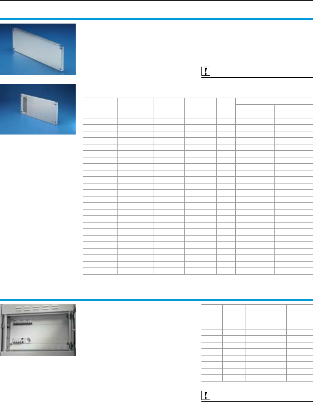
Form 2-4 compartment
Compartment configuration
56 Rittal Ri4Power Form 2-4
Partial mounting plates
With and without duct, for TS
For direct attachment to the functional space side
panel modules.
●Universal internal installation with switchgear
and control devices.
●Additional mounting levels.
In combination with functional space dividers and
side panel modules, internal separation in accord-
ance with Form 2, 3 or 4 is possible.
Material:
Sheet steel, zinc-plated, passivated, 2 mm
Supply includes:
Angle brackets and assembly parts.
For the version with cable entry:
Additional square cut-out with insulating plates
for sealing the cut-out.
Also required:
Functional space side panel modules,
see page 51.
For
enclosure width
mm
For
compartment
height
mm
Width
mm
Height
mm
Packs
of
Model No. SV
With duct Without duct
400 150 302 143 1 9673.651 9673.641
400 200 302 193 1 9673.652 9673.642
400 250 302 243 1 9673.657 9673.647
400 300 302 293 1 9673.653 9673.643
400 400 302 393 1 9673.654 9673.644
400 600 302 593 1 – 9673.646
400 800 302 793 1 – 9673.648
400 1000 302 993 1 – 9673.640
600 150 502 143 1 9673.671 9673.661
600 200 502 193 1 9673.672 9673.662
600 250 502 243 1 9673.677 9673.667
600 300 502 293 1 9673.673 9673.663
600 400 502 393 1 9673.674 9673.664
600 600 502 593 1 – 9673.666
600 800 502 793 1 – 9673.668
600 1000 502 993 1 – 9673.660
800 150 702 143 1 9673.691 9673.681
800 200 702 193 1 9673.692 9673.682
800 250 702 243 1 9673.697 9673.687
800 300 702 293 1 9673.693 9673.683
800 400 702 393 1 9673.694 9673.684
800 600 702 593 1 – 9673.686
800 800 702 793 1 – 9673.688
800 1000 702 993 1 – 9673.680
Support frame
for DIN rail-mounted devices
Support frame set for accepting DIN rail-mounted
devices (e.g. MCBs). The support rails are fasten-
ed with two mounting brackets to the side panel
modules. The cover is fastened to the support
frame with knurled screws.
In combination with functional space dividers,
partial mounting plates and side panel modules,
separation in accordance with Form 2, 3 or 4 is
possible.
Material:
Support frame: Sheet steel, zinc-plated,
passivated, 1.5 mm
Cover: Sheet steel, spray-finished, 1.5 mm
Supply includes:
2 support rails,
2 mounting brackets,
1 front trim panel with cut-out,
incl. assembly parts.
Also required:
Functional space side panel modules,
see page 51.
Partial mounting plates,
see page 56.
For
enclosure
width
mm
For
compart-
ment
height
mm
No. of
pitch units
17.5 mm
Packs
of
Model No.
SV
600 150 1 x 24 1 set 9674.761
600 300 2 x 24 1 set 9674.762
600 600 3 x 24 1 set 9674.763
600 600 4 x 24 1 set 9674.764
800 150 1 x 36 1 set 9674.781
800 300 2 x 36 1 set 9674.782
800 600 3 x 36 1 set 9674.783
800 600 4 x 36 1 set 9674.784
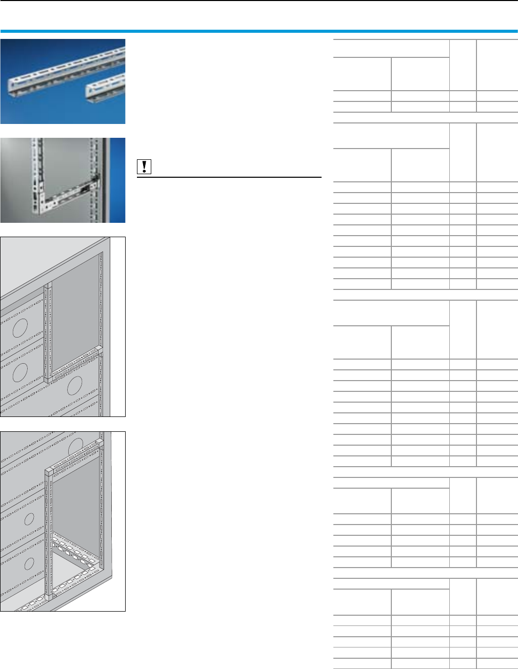
Compartment configuration
Form 2-4 compartment
57Rittal Ri4Power Form 2-4
Mini-TS profiles 17 x 15.5 mm
for TS
Mounting angle with TS pitch on three sides.
Suitable for
●building an auxiliary construction for dividing
the busbar space,
●individual use as mounting frame
for low and medium loads,
●fastening to the internal or external mounting
level of the TS 8 enclosure.
Material:
Sheet steel, zinc-plated, passivated, 1.5 mm
Also required:
Frame connector piece,
see page 58.
T-connector piece,
see page 58.
Corner connector,
see page 58.
For horizontal
busbar space separation
Packs
of
Model No.
SV
For
compartment
depth
mm
Length
mm
425 62.5 12 9673.915
600 137.5 12 9673.920
For vertical separation
with busbar system
in the top rear section Packs
of
Model No.
SV
For
compartment
height
mm
Length
mm
350 337.5 12 9673.942
400 387.5 12 9673.943
450 437.5 12 9673.952
500 487.5 12 9673.953
550 537.5 12 9673.962
600 587.5 12 9673.963
650 637.5 12 9673.972
700 687.5 12 9673.973
750 737.5 12 9673.982
800 787.5 12 9673.983
For vertical separation
with busbar system
in the bottom rear section Packs
of
Model No.
SV
For
compartment
height
mm
Length
mm
350 412.5 12 9673.951
400 462.5 12 9673.960
450 512.5 12 9673.961
500 562.5 12 9673.970
550 612.5 12 9673.971
600 662.5 12 9673.980
650 712.5 12 9673.981
700 762.5 12 9673.990
750 812.5 12 9673.991
800 862.5 12 9673.995
For external mounting level
Packs
of
Model No.
SV
For enclosure
width/depth
mm
Length
mm
300 162.5 12 9673.930
400 262.5 12 9673.940
500 362.5 12 9673.950
600 462.5 12 9673.960
800 662.5 12 9673.980
For internal mounting level
Packs
of
Model No.
SV
For enclosure
width/depth
mm
Length
mm
300 212.5 12 9673.931
400 312.5 12 9673.941
500 412.5 12 9673.951
600 512.5 12 9673.961
800 712.5 12 9673.981
Installation situation with
busbar system
in the top rear section
Installation situation with
busbar system
in the bottom rear section
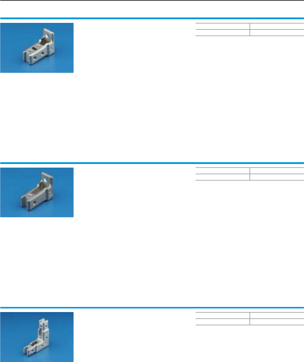
Form 2-4 compartment
Compartment configuration
58 Rittal Ri4Power Form 2-4
Frame connector piece
for Mini-TS profile
Mounting part with integral M4 threads for attach-
ing the Mini-TS profile to the horizontal and verti-
cal TS frame section (external level). The frame
adaptor piece can be used as a self-holding con-
struction aid in the TS pitch and fastened with a
screw to the frame. Can also be used for fasten-
ing other sections with TS pitch.
Material:
Die-cast zinc
Supply includes:
Assembly parts.
Packs of Model No. SV
24 9673.901
T-connector piece
for Mini-TS profile
Mounting part with integrated M4 threads for
fastening the Mini-TS profile to the
●horizontal and vertical TS chassis,
●Mini-TS profile,
●vertical TS frame section (internal level).
The T-connector piece can be used as a self-hold-
ing construction aid in the TS pitch and fastened
with a screw to the frame. Can also be used for
fastening other sections with TS pitch.
Material:
Die-cast zinc
Supply includes:
Assembly parts.
Packs of Model No. SV
24 9673.903
Corner connector
for Mini-TS profile
Mounting part with integrated M4 threads for
connecting two Mini-TS profiles at an angle of 90°
at the corner. Required for building the auxiliary
construction for the busbar space separation.
Material:
Die-cast zinc
Supply includes:
Assembly parts.
Packs of Model No. SV
10 9673.902
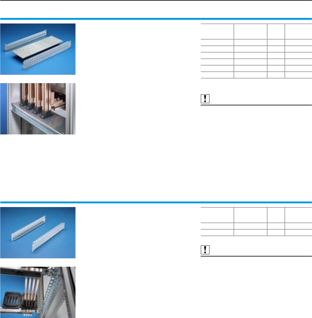
Compartment configuration
Form 2-4 compartment
59Rittal Ri4Power Form 2-4
Coupling set mounting kit
for busbar enclosure or riser
The mounting kit is used as a base support for a
vertical Maxi-PLS busbar system/Flat-PLS busbar
system.
Material:
Sheet steel, zinc-plated, passivated
Supply includes:
Support plate and punched section with mount-
ing flange, assembly parts.
With the version for 300 and 400 mm enclosure
widths, additionally with insulating plate for the
installation of Flat-PLS.
Also required:
End support,
see page 84/86.
For
enclosure width
mm
For
enclosure depth
mm
Packs
of
Model No.
SV
200 600 1 set 9674.1961)
200 800 1 set 9674.1981)
300 600 1 set 9674.036
300 800 1 set 9674.038
400 600 1 set 9674.046
400 800 1 set 9674.048
1) Only suitable for Maxi-PLS.
Punched sections with
mounting flanges
for coupling section
The punched section with mounting flange for
coupling set is needed for assembling a Maxi-PLS
or Flat-PLS busbar system directly beneath or
above the circuit-breaker. This punched section
with mounting flange may be used without con-
flict in conjunction with the functional space side
panel modules. It is attached to the outer level of
the TS 8 enclosure system, but thanks to the PS
punchings allows a mounting level as in the roof
or base frame, thereby facilitating the use of bus-
bar system attachment for the roof/base section.
Material:
Sheet steel, zinc-plated, passivated
Supply includes:
Assembly parts.
Also required:
System attachment for Maxi-PLS 1600/2000,
see page 84.
System attachment for Maxi-PLS 3200,
see page 86.
System attachment for Maxi-PLS 60 and 100,
see page 90.
For
enclosure width
mm
For
enclosure depth
mm
Packs
of
Model No.
SV
600 600 2 9674.056
800 800 2 9674.058
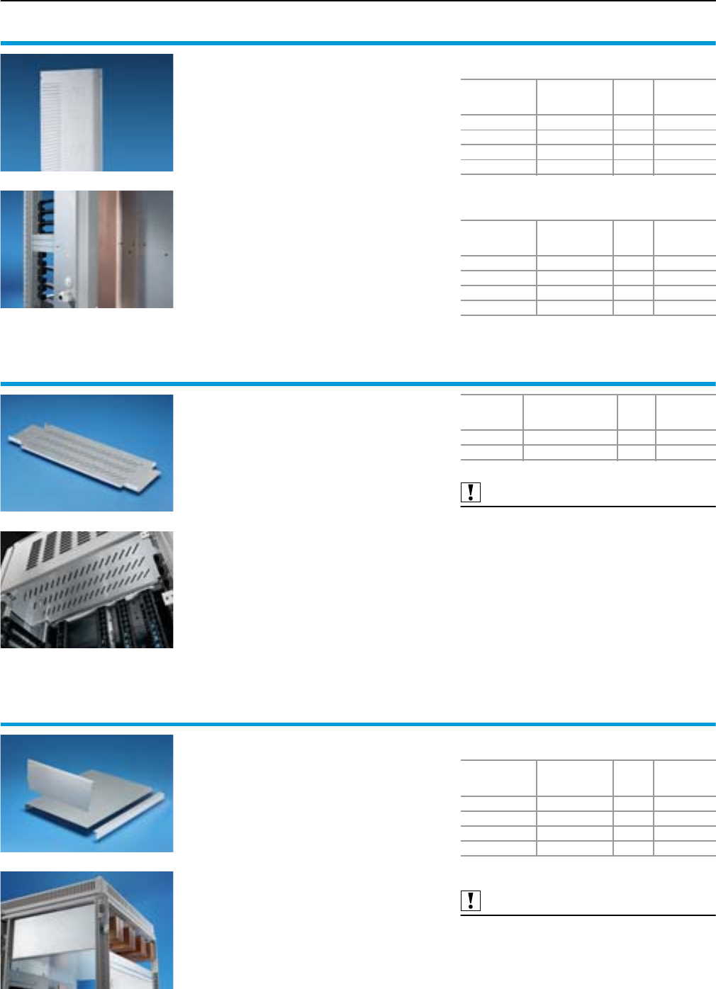
Form 2-4 compartment
Compartment configuration
60 Rittal Ri4Power Form 2-4
Divider panel
for switch-disconnector-fuse section
The divider panel is required for interior configu-
ration of the switch-disconnector-fuse section, and
divides the connection space from the functional
space. Depending on the chosen position of
the main busbar system, the divider panel is
fitted in the prepared switch-disconnector-fuse
enclosures. The prepared cut-outs are suitable
for the connection of switch-disconnector-fuse
Jean Müller Sasil and ABB SlimLine.
Material:
Sheet steel, zinc-plated, passivated, 1.5 mm
Supply includes:
Assembly parts.
For main busbar system
in the roof section
For main busbar system
in the rear section, top or bottom
For
enclosure height
mm
For
enclosure depth
mm
Packs
of
Model No.
SV
2000 600 1 9674.306
2000 800 1 9674.308
2200 600 1 9674.326
2200 800 1 9674.328
For
enclosure height
mm
For
enclosure depth
mm
Packs
of
Model No.
SV
2000 600 1 9674.305
2000 800 1 9674.307
2200 600 1 9674.325
2200 800 1 9674.327
Dividing plate
for switch-disconnector-fuse section
Dividing plate to divide the busbar chamber and
NH switch-disconnector-fuse chamber (compart-
ment). The design of the divider plate must be
matched to the chosen make of the NH switch-
disconnector-fuse and the installation position.
Material:
Sheet steel, zinc-plated, passivated, 1.5 mm
Supply includes:
Assembly parts.
Also required:
Assembly kit for switch-disconnector-fuse section,
see page 46.
Mounting
position
Make of
NH switch-
disconnector-fuse
Packs
of
Model No.
SV
Top/bottom Jean Müller SASIL 1 9674.346
Top/bottom ABB SlimLine 1 9674.348
Contact hazard protection,
cable chamber
for switch-disconnector-fuse section
The contact hazard protection cover plate shields
the main busbar in the cable chamber, enabling
the safe connection of cables and lines.
Suitable for Maxi-PLS and Flat-PLS busbar sys-
tems in the roof section. Contact hazard protec-
tion for main busbars in the rear section available
on request.
Material:
Sheet steel, zinc-plated, passivated, 1.5 mm
Supply includes:
Assembly parts.
For main busbar system
in the roof section
Also required:
Divider panel for switch-disconnector-fuse section
,
see page 60.
For
enclosure width
mm
For
enclosure depth
mm
Packs
of
Model No.
SV
1000 600 1 set 9674.362
1000 800 1 set 9674.364
1200 600 1 set 9674.366
1200 800 1 set 9674.368
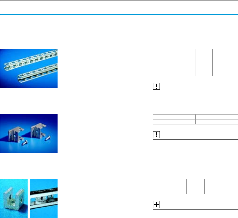
Compartment configuration
Form 2-4 compartment
61Rittal Ri4Power Form 2-4
Assembly parts
for RiLine60 distribution busbar systems
The following accessory components must be
used for mounting a type-tested vertical distribu-
tion busbar system behind the compartment:
Mounting bracket
For mounting the mounting rails on the TS frame.
Material:
Die-cast zinc
Supply includes:
24 screws 5.5 x 13 mm.
Also required:
U nuts (recommendation: M6),
see page 61.
Packs of Model No. TS
24 8800.370
Mounting rails 23 x 23 mm
For installing a vertical RiLine60 distribution bus-
bar system on the vertical enclosure section.
Material:
Sheet steel, zinc-plated, passivated
Also required:
Mounting bracket and U nuts,
see page 61.
Length
mm
For enclosures
WHD
mm
Packs of Model No. PS
295 400 12 4169.000
495 600 12 4171.000
695 800 12 4172.000
U nuts
For fastening the mounting rails to the bracket and
fastening the busbar holder to the mounting rails.
Accessories:
Multi-tooth screws M6 x 12 mm (for PS 4179.000),
see Catalogue 32, page 1011.
Thread Packs of Model No. PS
M5 20 4157.000
M6 20 4179.000
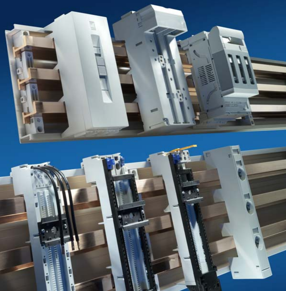
62 Rittal Ri4Power Form 2-4
Safe, flexible and fast –
Rittal busbar technology
Time-saving assembly, diverse application options, individual modularity and a high level of operational safety –
these are the benefits of the Rittal RiLine60 busbar systems. Simply insert the bars, secure – and it’s done!
This is how quickly a variety of copper cross-sections may be mounted in the support. Simple assembly and safe
contacting, coupled with a broad selection of connection and component support adaptors and fuse elements
are the prerequisites for efficient assembly and operation.
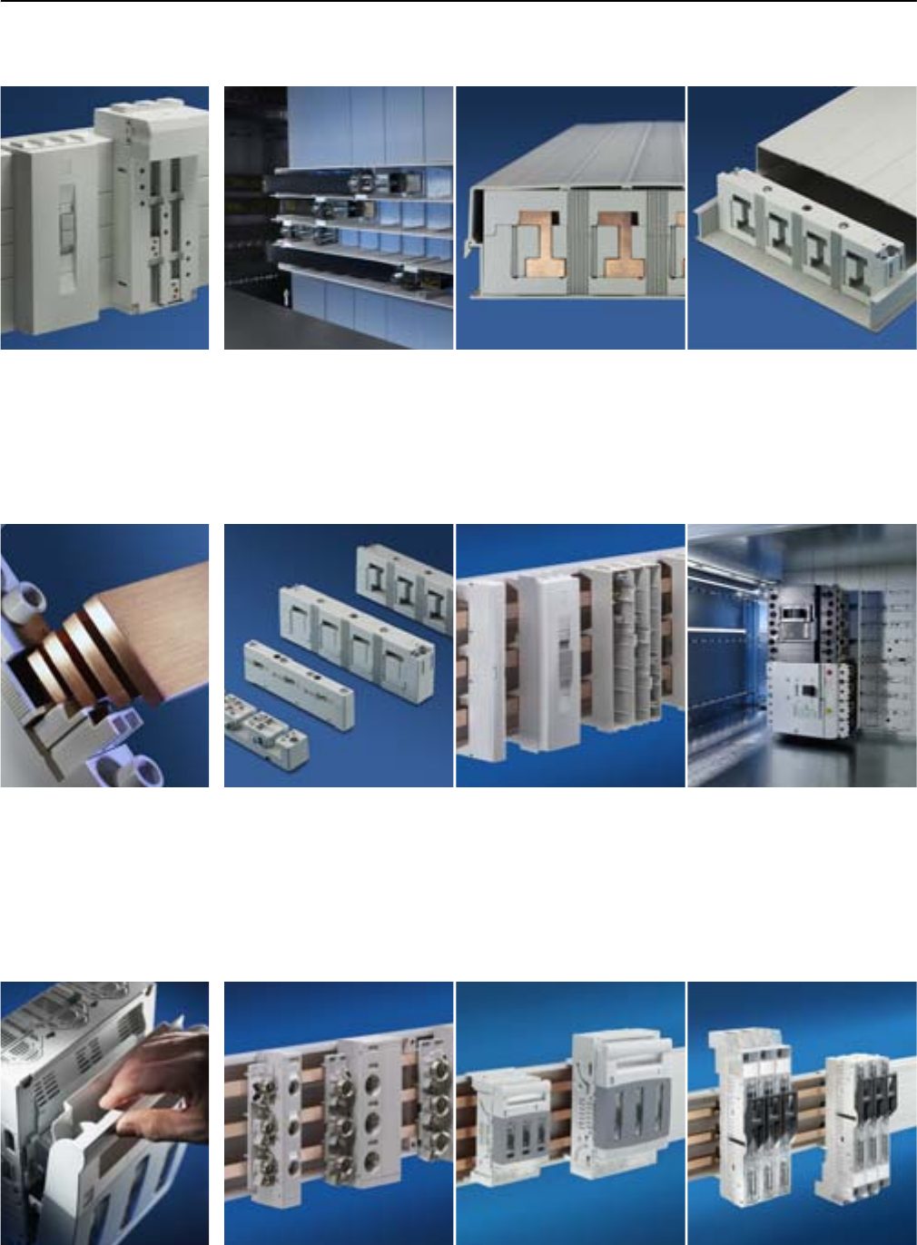
63Rittal Ri4Power Form 2-4
RiLine60 up to 1600 A
Form 2-4 busbar systems
Bus-mounting fuse bases for
snap-on mounting. The three-
pole components ensure reli-
able-contact, shake-proof con-
nection with the busbars.
RiLine NH fuse-switch-discon-
nector. The contact swivel feet
have one outstanding function:
The cable outlet can be switch-
ed from bottom to top in a mat-
ter of seconds.
Fuse elements
Simple planning, compact
designs, fast assembly,
reliable contacting.
Safety
Fully-insulated busbar system
with finger-safe contact hazard
protection, also at the connec-
tion points.
Increased arcing safety thanks
to busbar system installed
without any base points and
busbar holders with arcing fault
prevention.
All plastic materials used for the
busbar system are self-extin-
guishing (fire behaviour in
accordance with UL 94-V0).
Rittal busbar systems use
proven and tested system
components to provide a high
level of safety.
Each rated current, each con-
struction form and each required
short-circuit resistance has a
busbar system appropriate for
the enclosure.
Pre-assembled busbar connec-
tion adaptors ensure simple,
safe handling.
As well as enabling you to opti-
mise your assembly, the tested
component adaptors and the
alternative indoor busbar sys-
tem also saves valuable installa-
tion and servicing time.
Busbar system
Rittal busbar systems –
modular and compact.
With a build width of just 50 mm,
it sets new standards in compact,
space-saving configuration.
NH fuse-switch-disconnector.
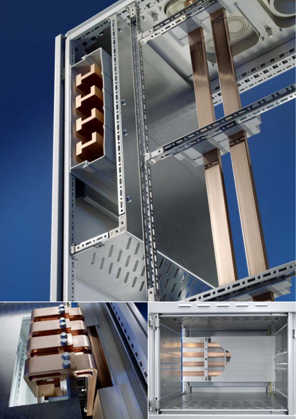
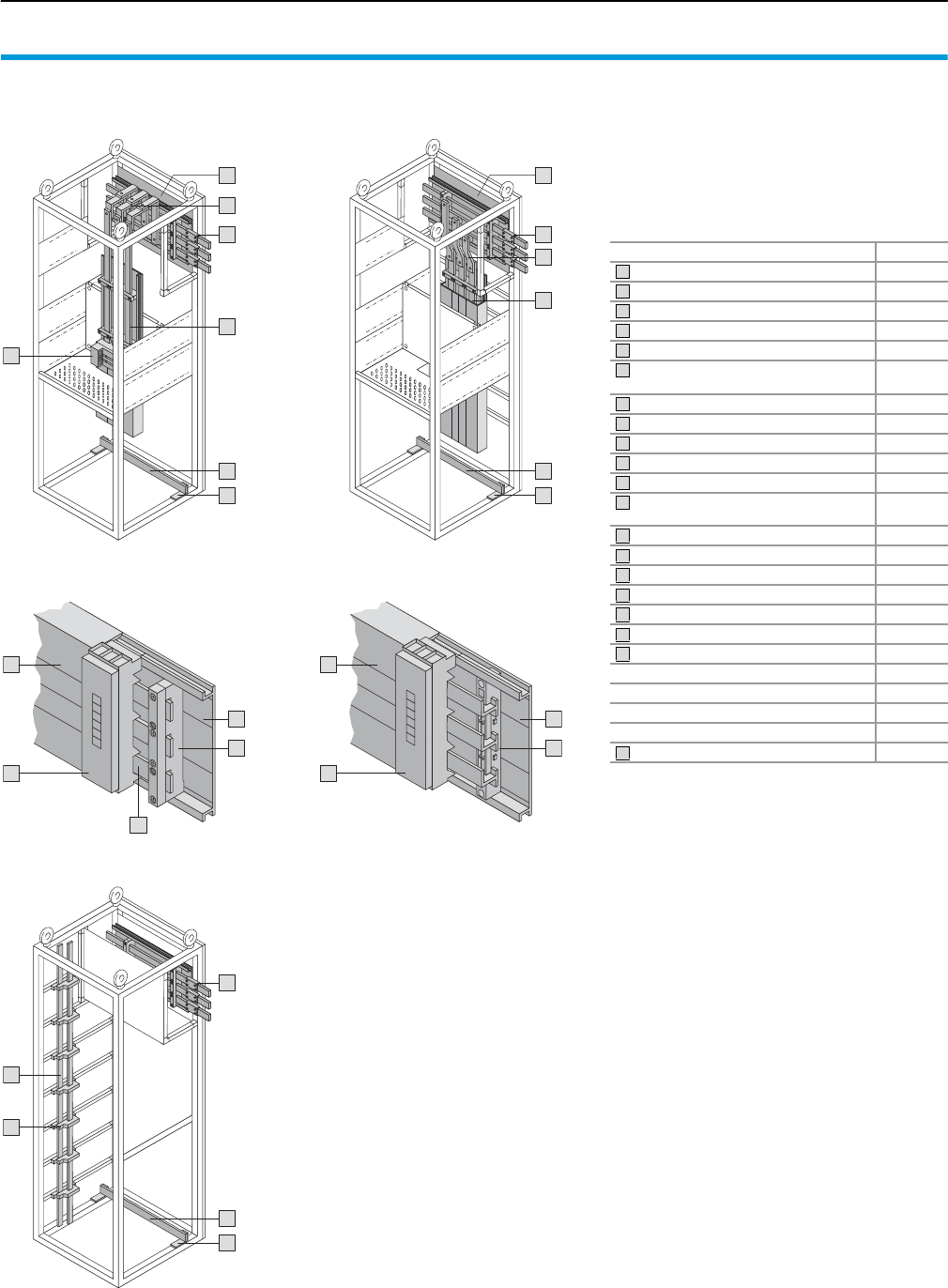
RiLine60
Form 2-4 busbar systems
65Rittal Ri4Power Form 2-4
Busbar components for the configuration of
modular sections or cable chambers with a
busbar system. Components must be selected
depending on the required rated current and the
associated system components. Connection and
cover components should be selected according
to requirements. We highly recommend the Rittal
Power Engineering software for an explanation of
the selection process – see page 123.
Components Page
Busbar supports (3-pole) 66
System components (3-pole) 67
PLS busbar supports (3-pole) 68
PLS system components (3-pole) 69
Busbar connection adaptors (3-pole) 70/71
Circuit-breaker component adaptor
(3-pole) 72/73
Busbar supports (4-pole) 74
System components (4-pole) 75
Busbar supports PLUS (4-pole) 76
PLS system components (4-pole) 77
Busbar connection adaptors (4-pole) 78/79
Circuit-breaker component adaptor
(4-pole) 80
Busbars 110
PE/PEN combination angle 109
Busbar supports (2-pole) 110
Busbar connectors 111
System attachments 103
Distribution busbars 102
T-connection kits 100/101
PLS busbar connectors 111
PLS expansion connectors 111
Busbar cover section 110
Base isolators 109
Busbar for PE/PEN 109
12
2
5
6
8
14
9
2
1
7
4
5
4
3
8
14
12
8
14
12
1111
13
10
13
10
10
Modular outgoing section with distribution busbar system
Flat copper busbar system PLS busbar system
Cable chamber
Inside the compartment Behind the compartment
1
2
3
4
5
6
1
2
3
4
5
6
7
8
9
10
11
12
13
14
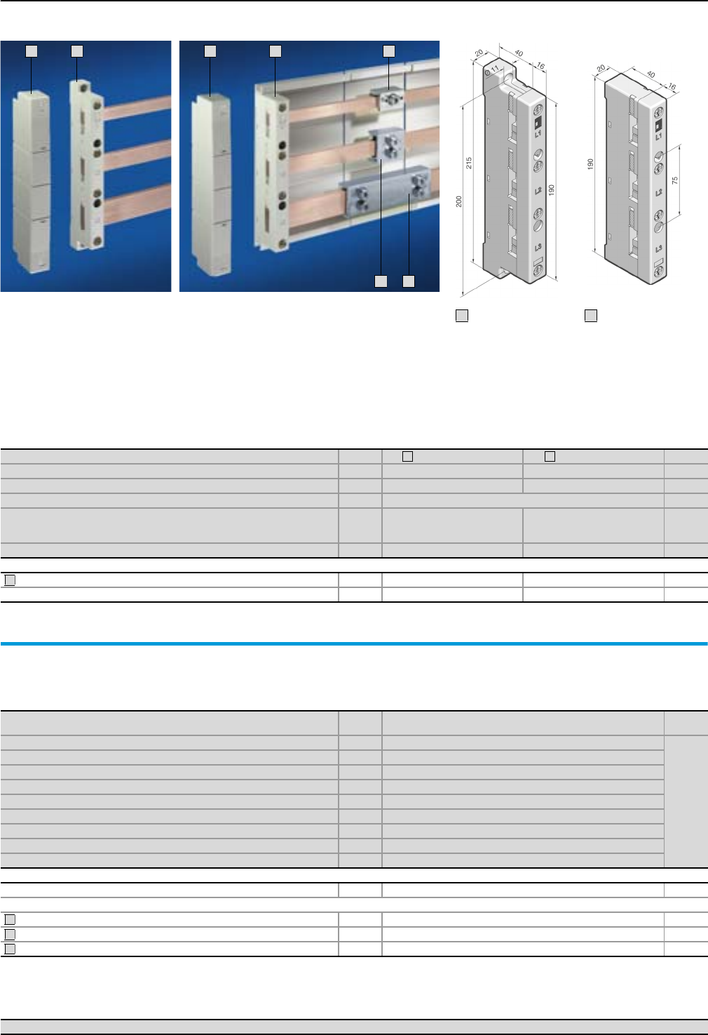
Form 2-4 busbar systems
Busbar supports (3-pole)
66 Rittal Ri4Power Form 2-4
1
3
2
3
5
6
4
Material:
Polyamide (PA 6.6),
25% fibreglass-reinforced.
Continuous operating
temperature max. 130°C.
Fire protection corresponding
to UL 94-V0.
Colour:
RAL 7035
Short-circuit protection
diagram,
see page 116.
Technical information
for the calculation
of rated currents,
see page 120.
Version Packs of External attachment Internal attachment Page
Number of poles 3-pole 3-pole
Bar centre distance 60 mm 60 mm
For busbars E-Cu 12 x 5/10 mm1), 15 x 5 – 30 x 10 mm
Tightening torque
● Assembly screw (M5 x 16)
● Cover attachment
3 – 5 Nm
1 – 3 Nm
3 – 5 Nm
1 – 3 Nm
Model No. SV 49340.010 9340.000
Accessories
End covers for contact hazard protection on the sides 2 9340.070 9340.070
Spacers for SV 9340.000/.010 12 9340.090 9340.090 113
1) If 12 x 5/10 mm busbars are used, the spacer SV 9340.090 is additionally required.
1
2
3
Busbars E-Cu
To DIN EN 13 601.
Length: 2400 mm/bar.
Dimensions
mm Packs of Model No. SV Page
12 x 5 63580.000
110
12 x 10 63580.100
15 x 5 63581.000
15 x 10 63581.100
20 x 5 63582.000
20 x 10 63585.000
25 x 5 63583.000
30 x 51) 63584.0002)
30 x 101) 63586.0002)
Accessories
Busbar cover section (length 1 m/each) 10 3092.000 110
Busbar connector for E-Cu
12 x 5 – 15 x 10 mm (single connection) 3 9350.075 111
20 x 5 – 30 x 10 mm (single connection) 3 9320.020 111
20 x 5 – 30 x 10 mm (bayed connection)3) 3 9320.030 111
1) Other busbar lengths, see page 109.
2) Tin-plated version available on request.
3) From enclosure to enclosure.
4
5
6
Busbar connection adaptors Page 70/71 Component adaptors Page 72/73 Accessories Page 109
With attachment
holes on the inside
2
With attachment
holes on the outside
1
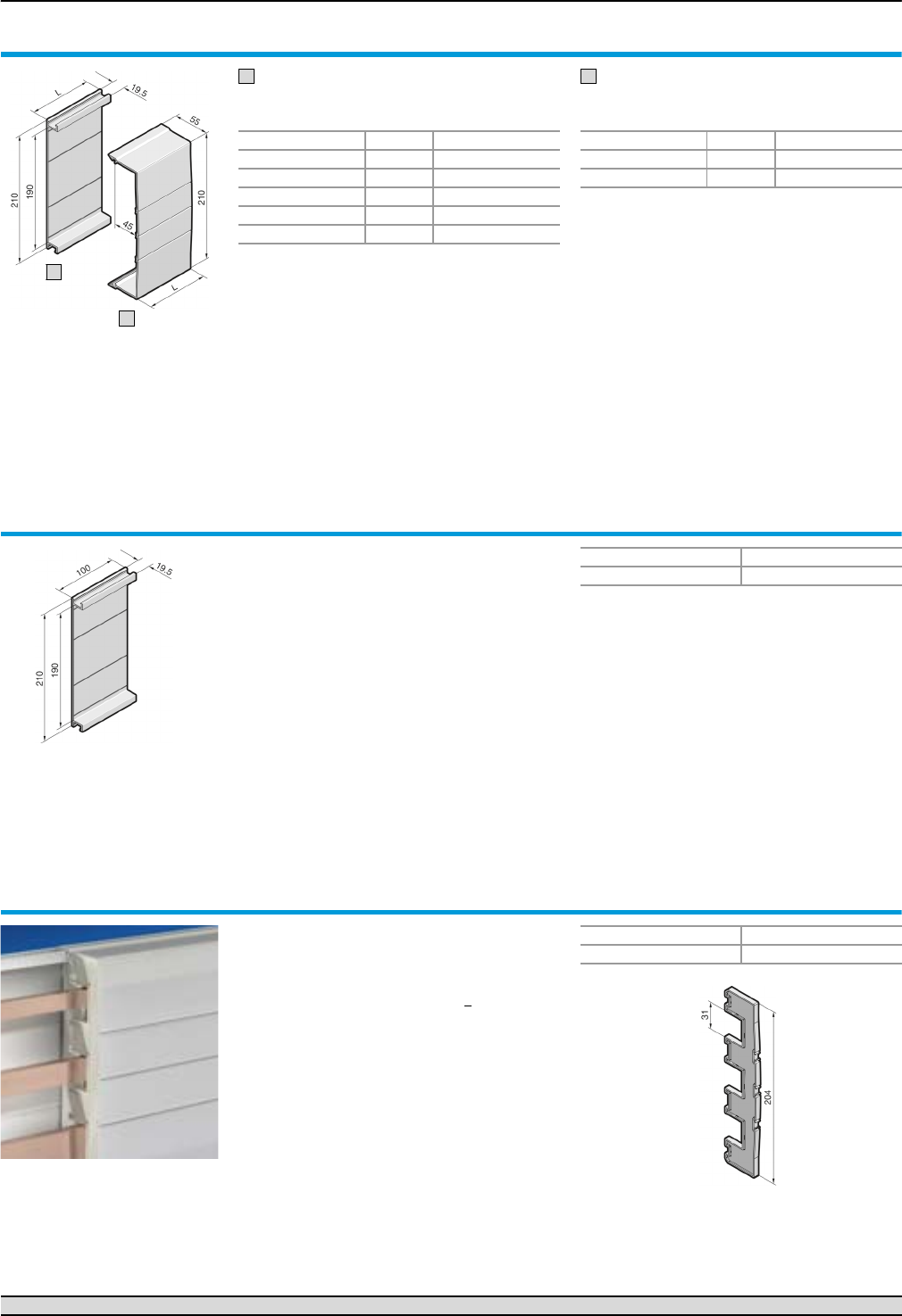
System components (3-pole)
Form 2-4 busbar systems
67Rittal Ri4Power Form 2-4
Base tray
For rear contact hazard protection of the flat bar
assembly.
Cover section
May be cut to length as required; for clip-on
mounting to the base tray.
Base tray and cover section
Material:
Thermally modified hard PVC.
Continuous operating temperature max. 91°C.
Fire protection corresponding to UL 94-V0.
Colour:
RAL 7035
Note:
If the cover section is mounted from the front,
the support panel (SV 9340.220) is needed for
stability.
Length (L) mm Packs of Model No. SV
500 2 9340.100
700 2 9340.110
900 2 9340.120
1100 2 9340.130
2400 1 9340.170
1
Length (L) mm Packs of Model No. SV
700 2 9340.200
1100 2 9340.210
2
1
2
Base tray infill
For rear contact hazard protection when connect-
ing the busbars from enclosure to enclosure.
Material:
Thermally modified hard PVC.
Continuous operating temperature max. 91°C.
Fire protection corresponding to UL 94-V0.
Colour:
RAL 7035
Supply includes:
Assembly parts.
Packs of Model No. SV
29340.140
Support panel
for cover section
To prevent side access to the cover section. The
support panel also provides additional stability.
Recommended mounting distance 500 mm.
Material:
Polyamide (PA 6.6).
Continuous operating temperature max. 105°C.
Fire protection corresponding to UL 94-V0.
Colour:
RAL 7035
<
Packs of Model No. SV
59340.220
Busbar connection adaptors Page 70/71 Component adaptors Page 72/73 Accessories Page 109
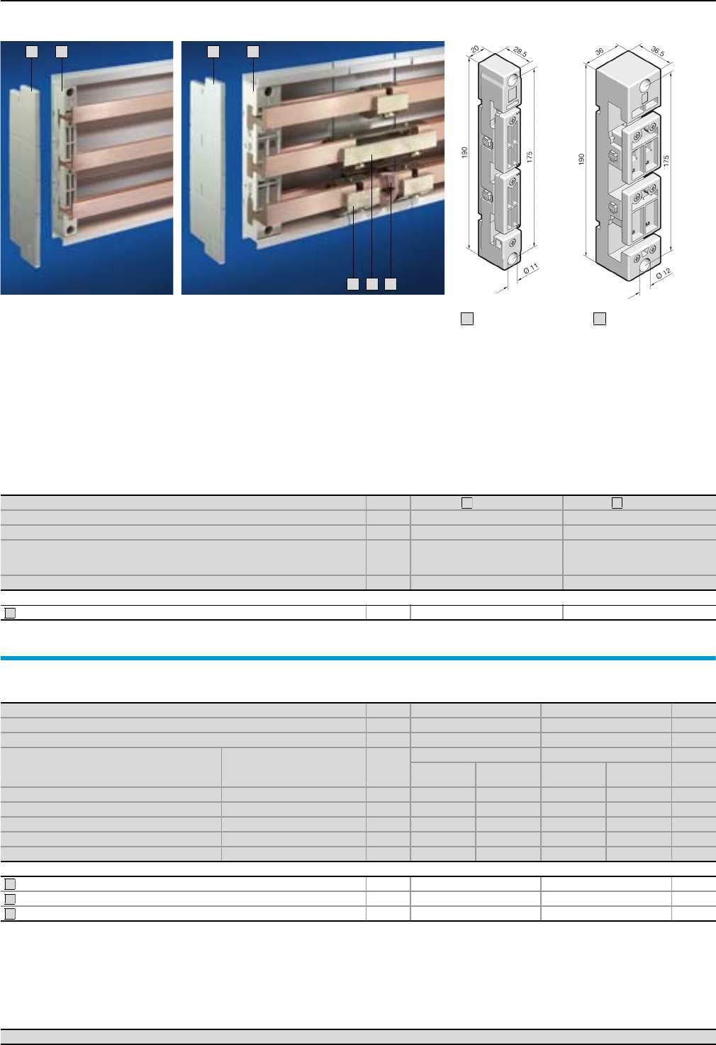
Form 2-4 busbar systems
PLS busbar supports (3-pole)
68 Rittal Ri4Power Form 2-4
3
1
2
3
6
5
4
Material:
Polyamide (PA 6.6),
25% fibreglass-reinforced.
Continuous operating
temperature max. 130°C.
Fire protection corresponding
to UL 94-V0.
Colour:
RAL 7035
Short-circuit protection
diagram,
see page 116.
Technical information
for the calculation
of rated currents,
see page 120.
For Rittal system Packs of PLS 800 PLS 1600
Number of poles 3-pole 3-pole
Bar centre distance 60 mm 60 mm
Tightening torque
● Assembly screw (M5 x 20)
● Busbar anti-slip guard
3 – 5 Nm
0.7 Nm
3 – 5 Nm
0.7 Nm
Model No. SV 49341.000 9342.000
Accessories
End covers for contact hazard protection on the sides 2 9341.070 9342.070
1
2
3
PLS special busbars
made from E-Cu
For Rittal system Packs of PLS 800 PLS 1600 Page
Cross-section 300 mm2 900 mm2
Bar thickness 5 mm 10 mm
Length
mm
For enclosure width
mm
Model No. SV Model No. SV
E-Cu E-Cu,
tin-plated E-Cu E-Cu,
tin-plated
495 6001) 3 3524.000 3524.2002) 3527.000 3527.2002)
695 8001) 3 3525.000 3525.2002) 3528.000 3528.2002)
895 10001) 33525.010 3525.2102) 3528.010 3528.2102)
1095 12001) 3 3526.000 3526.2002) 3529.000 3529.2002)
2400 variable 13509.000 3509.2002) 3516.000 3516.2002)
Accessories
PLS busbar connector (single connection) 3 3504.000 3514.000 111
PLS busbar connector (bayed connection)3) 3 3505.000 3515.000 111
PLS expansion connectors4) 3 9320.060 9320.070 111
1) For Rittal TS 8/ES enclosure systems.
2) Delivery times available on request.
3) From enclosure to enclosure.
4) Two PLS rail connectors (single connection) are required to fit one expansion connector.
4
5
6
Busbar connection adaptors Page 70/71 Component adaptors Page 72/73 Accessories Page 109
Rittal PLS 800
1
Rittal PLS 1600
2
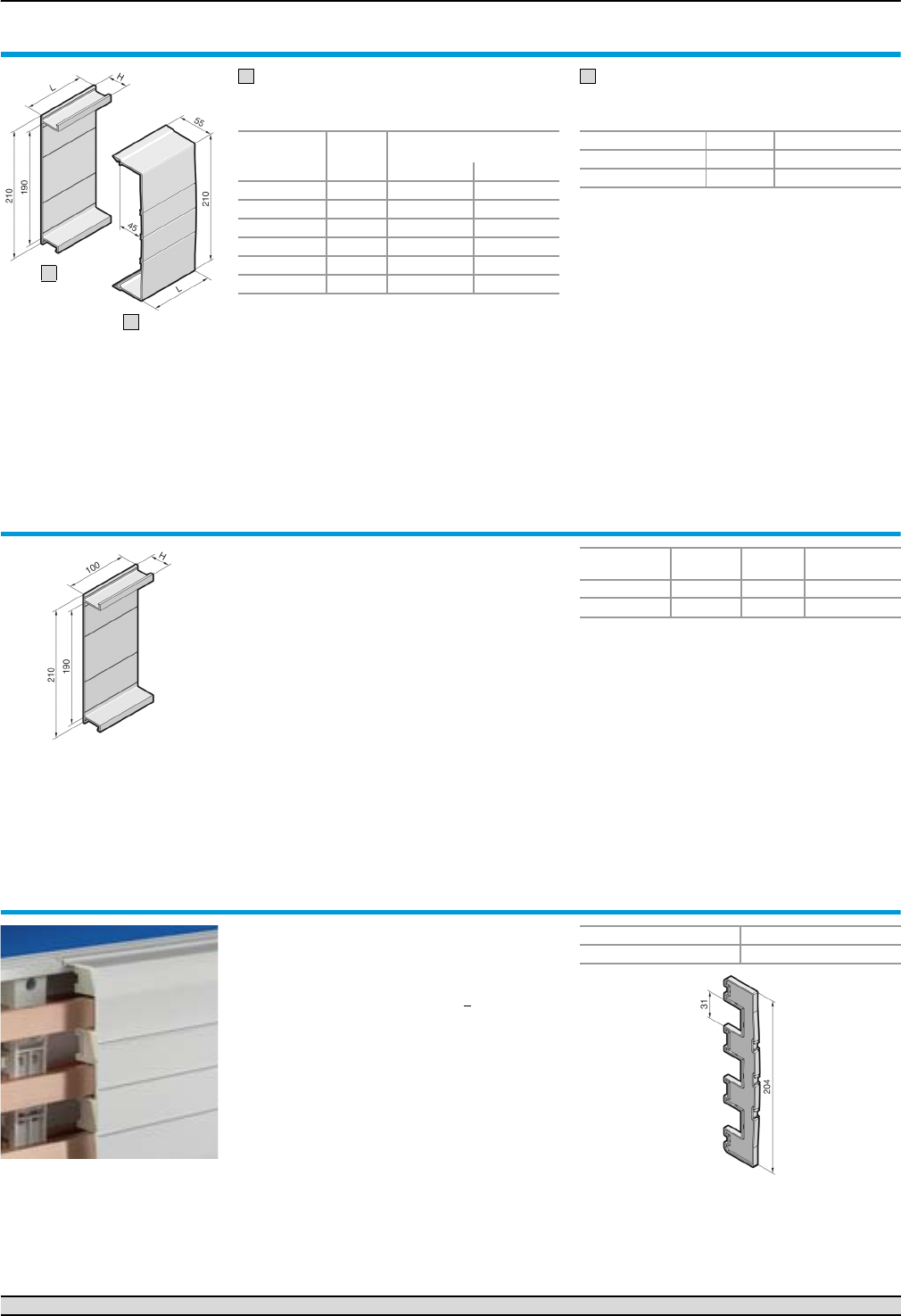
PLS system components (3-pole)
Form 2-4 busbar systems
69Rittal Ri4Power Form 2-4
Base tray
For rear contact hazard protection of the
PLS busbar assembly.
Cover section
May be cut to length as required; for clip-on
mounting to the base tray.
Base tray and cover section
Material:
Thermally modified hard PVC.
Continuous operating temperature max. 91°C.
Fire protection corresponding to UL 94-V0.
Colour:
RAL 7035
Note:
If the cover section is mounted from the front,
the support panel (SV 9340.220) is needed for
stability.
Length (L)
mm Packs of
Model No. SV
For system
PLS 800 PLS 1600
500 2 9341.100 9342.100
700 2 9341.110 9342.110
900 2 9341.120 9342.120
1100 2 9341.130 9342.130
2400 1 9341.170 9342.170
Height (H) mm 32 43
1
Length (L) mm Packs of Model No. SV
700 2 9340.200
1100 2 9340.210
2
Base tray infill
For rear contact hazard protection when connect-
ing the busbars from enclosure to enclosure.
Material:
Thermally modified hard PVC.
Continuous operating temperature max. 91°C.
Fire protection corresponding to UL 94-V0.
Colour:
RAL 7035
Supply includes:
Assembly parts.
For
system
Height (H)
mm Packs of Model No. SV
PLS 800 32 2 9341.140
PLS 1600 43 2 9342.140
Support panel
for cover section
To prevent side access to the cover section. The
support panel also provides additional stability.
Recommended mounting distance 500 mm.
Material:
Polyamide (PA 6.6).
Continuous operating temperature max. 105°C.
Fire protection corresponding to UL 94-V0.
Colour:
RAL 7035
<
Packs of Model No. SV
59340.220
Busbar connection adaptors Page 70/71 Component adaptors Page 72/73 Accessories Page 98
1
2
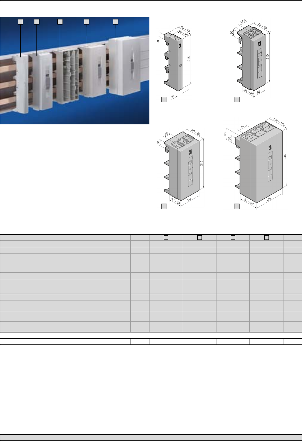
Form 2-4 busbar systems
Busbar connection adaptors (3-pole)
70 Rittal Ri4Power Form 2-4
1
2
3
3
4
Material:
Chassis
Polyamide (PA 6.6),
25% fibreglass-reinforced.
Continuous operating tempera-
ture max. 130°C.
Fire protection corresponding
to UL 94-V0.
Cover
ABS,
fire protection corresponding
to UL 94-V0.
Colour:
RAL 7035
Supply includes:
Cover.
Version (3-pole) Packs of Page
Rated current up to 63 A 125 A 250 A 800 A
Rated operating voltage 690 V~ 690 V~ 690 V~ 690 V~
Connection of round conductors
● Fine wire with wire end ferrule
● Multi-wire
● Solid
2.5 – 10 mm2
2.5 – 16 mm2
2.5 – 16 mm2
10 – 25 mm2
16 – 35 mm2
–
35 – 120 mm2
35 – 120 mm2
–
95 – 185 mm2
95 – 300 mm2
–
Clamping area for laminated copper bars – 10 x 7.8 mm 18.5 x 15.5 mm 33 x 20 mm
Tightening torque
● Assembly screw
● Terminal screw
2 Nm
2.5 Nm
2 Nm
2 – 3 Nm
4 – 6 Nm
12 Nm
6 Nm
12 – 14 Nm
For bar thickness 5/10 mm 5/10 mm 5/10 mm 5/10 mm
Outlet at top/bottom
Model No. SV 1 – 9342.220 9342.250 9342.280
Outlet at top
Model No. SV 1 9342.200 9342.230 9342.260 9342.290
Outlet at bottom
Model No. SV 1 9342.210 9342.240 9342.270 9342.300
Accessories
Laminated copper bars – 䡲 䡲 䡲 112
1
2
3
4
Busbar systems Page 66 – 69 Component adaptors Page 72/73 Accessories Page 112
1
2
3
4
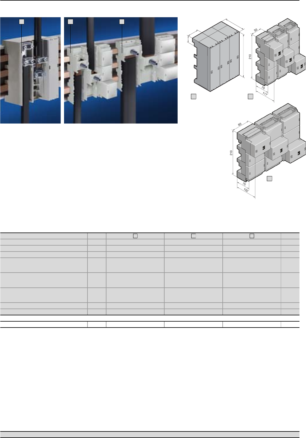
Busbar connection adaptors (3-pole)
Form 2-4 busbar systems
71Rittal Ri4Power Form 2-4
1
2
3
150
60
54
247
1
2
3
Busbar systems Page 66 – 69 Component adaptors Page 72/73 Accessories Page 112
Material:
Chassis
SV 3439.010
Fibreglass-reinforced,
thermoplastic polyester (PBT).
Continuous operating
temperature max.140°C.
Fire protection corresponding
to UL 94-V0.
SV 9342.310/.320
Polyamide (PA 6.6),
25% fibreglass-reinforced.
Continuous operating
temperature max. 130°C.
Fire protection corresponding
to UL 94-V0.
Cover
ABS,
fire protection corresponding
to UL 94-V0.
Colour:
RAL 7035
Supply includes:
Cover.
SV 3439.010
When connecting round conduc-
tors 300 mm2 with ring terminal,
the terminal clamps fitted as
standard in the busbar connec-
tion adaptors must be replaced
with screws and/or bolts M10.
Version (3 x 1-pole) Packs of Page
Rated current up to 600 A 800 A 1600 A
Rated operating voltage 690 V~ 690 V~ 690 V~
Outlet top/bottom top/bottom top/bottom
Connection of round conductors
● Fine wire with wire end ferrule
● Multi-wire
35 – 240 mm2
35 – 240 mm2
95 – 185 mm2
95 – 300 mm2
–
–
Clamping area for laminated copper bars
● For 5 mm bar thickness
● For 10 mm bar thickness
24 x 21 mm
24 x 21 mm
33 x 27 mm
33 x 22 mm
65 x 27 mm
65 x 22 mm
Tightening torque
● Assembly screw
● Terminal screw
15 – 20 Nm
15 Nm
–
12 – 14 Nm
–
15 – 20 Nm
For bar thickness 5/10 mm 5/10 mm 5/10 mm
Model No. SV 1 set 3439.010 9342.310 9342.320
Accessories
Laminated copper bars 䡲 䡲 䡲 112
1
2
3
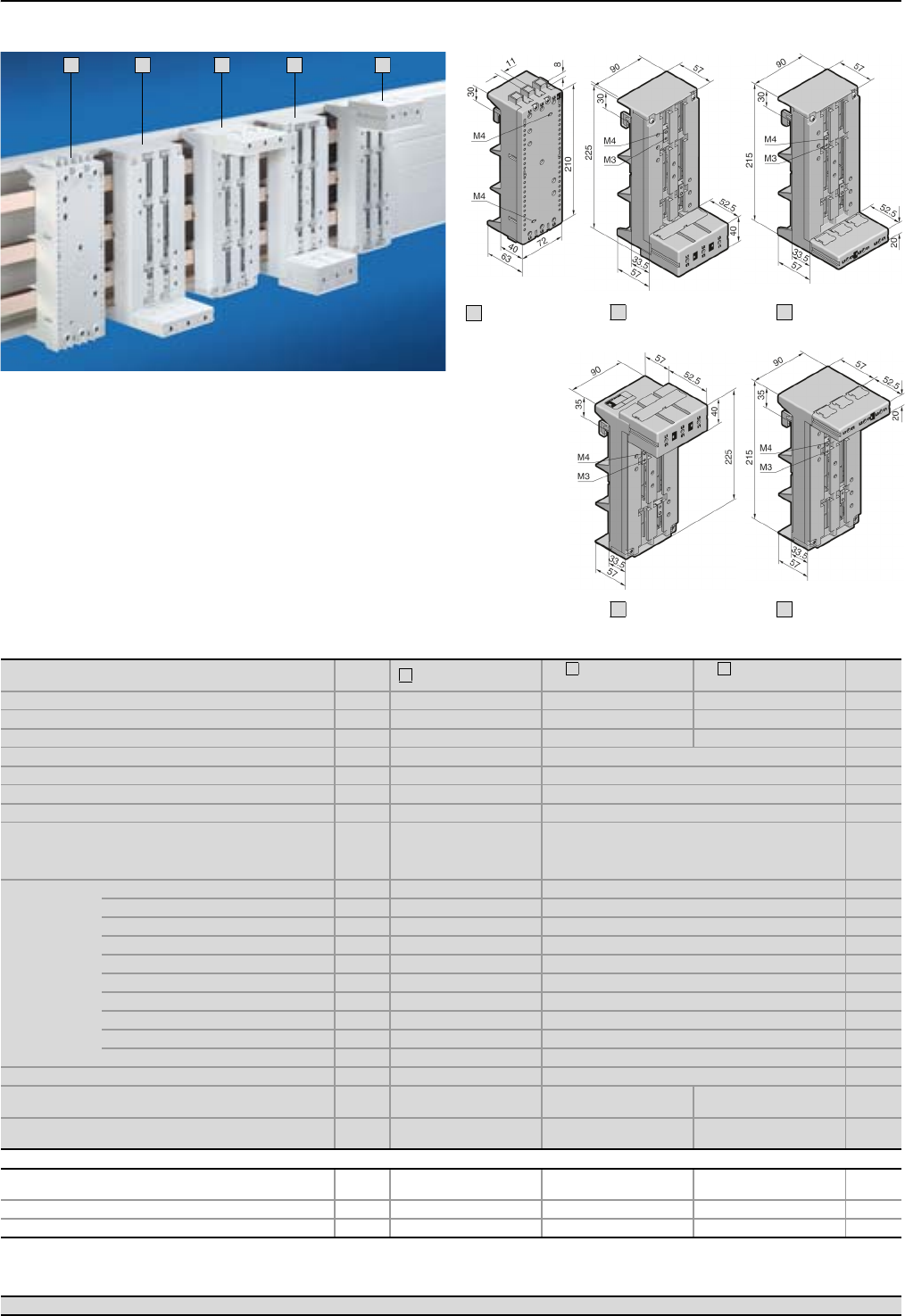
Form 2-4 busbar systems
Component adaptors 100 A/circuit-breaker component adaptors 125 A, 160 A (3-pole)
72 Rittal Ri4Power Form 2-4
1
2
3
2
3
Material:
Chassis
Polyamide (PA 6.6),
25% fibreglass-reinforced.
Continuous operating
temperature max. 130°C.
Fire protection corresponding
to UL 94-V0.
Colour:
RAL 7035
Scope of supply
Circuit-breaker component
adaptor:
Terminal cover and sliding
blocks for switchgear attach-
ment.
Version Packs of Component adaptor Circuit-breaker
component adaptor
Circuit-breaker
component adaptor Page
Construction width 72 mm 90 mm 90 mm
Length 210 mm 225 mm 215 mm
Rated current up to 100 A 125 A 160 A
Rated operating voltage 690 V~ 690 V~
Connection clamp Box terminal Box terminal
Connection of round conductors 10 – 35 mm2 35 – 120 mm2
Clamping area for laminated copper bars 10 x 7.8 mm 18.5 x 15.5 mm
Tightening torque
● Terminal screw
● Rail attachment
● Switchgear attachment
2 – 3 Nm
2 Nm
1.5 Nm
12 Nm
4 – 6 Nm
1.5 Nm
For
switchgear
make/model
ABB MS497 S2, T1, T2
Allen Bradley – 140 – CMN
GE – FD
Merlin Gerin –NS80, NSC100
Mitsubishi – –
Moeller Electric PKZ21) NZM1
Siemens S3 –
Telemecanique GV31) –
Terasaki –S125, E125
Universal application 䡲 1) –
For bar thickness 5/10 mm 5/10 mm
Cable outlet at the top2)
Model No. SV 1 9342.400 9342.540 9342.500
Cable outlet at the bottom2)
Model No. SV 1 9342.410 9342.550 9342.510
Accessories
Support rail
Width 72 mm, height 15 mm 5 9320.120 – – 113
Sliding blocks 6 – 9342.560 9342.560 113
Connection bracket – 䡲 䡲 114
1) Mounting only possible with support rail SV 9320.120.
2) Switch outlet or outgoing cable.
1
2
3
Busbar systems Page 66 – 69 Busbar connection adaptors Page 70/71 Accessories Page 109
SV 9342.400
SV 9342.410
1
SV 9342.540
2
SV 9342.550
2
SV 9342.500
3
SV 9342.510
3
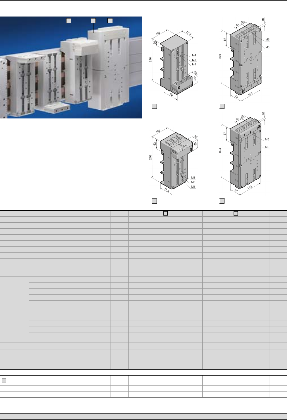
Circuit-breaker component adaptors 250 A/630 A (3-pole)
Form 2-4 busbar systems
73Rittal Ri4Power Form 2-4
1
2
3
Material:
Chassis
Polyamide (PA 6.6),
25% fibreglass-reinforced.
Continuous operating
temperature max.130°C.
Fire protection corresponding
to UL 94-V0.
Colour:
RAL 7035
Supply includes:
Terminal cover and sliding
blocks for switchgear attach-
ment.
Version Packs of Page
Construction width 105 mm 140 mm
Length 240 mm 324 mm
Rated current up to 250 A 630 A
Rated operating voltage 690 V~ 690 V~
Connection clamp Box terminal Screw terminal M10
Connection of round conductors 35 – 120 mm2 max. 150 mm2 2)
Clamping area for laminated copper bars 18.5 x 15.5 mm 32 x 10 mm
Tightening torque
● Terminal screw
● Rail attachment
● Switchgear attachment
12 Nm
4 – 6 Nm
1.5 Nm
30 – 32 Nm
12 – 14 Nm
2.5 Nm
For
switchgear
make/model
ABB S3, T3, T4 S5, T5
Allen Bradley 140 U – J 140 U – L
GE FE –
Merlin Gerin NS(X)100, NS(X)160, NS(X)250 NS(X)400, NS(X)630
Mitsubishi NF125-SGW, NF125-HGW,
NF160-SGW, NF160-HGW
NF400-SEW, NF400-HEW,
NF400-REW, NF600-SEW,
NF600-HEW, NF600-REW
Moeller Electric NZM2 NZM3
Siemens VL160X, VL160, VL250 VL400, VL6303)
Telemecanique GV7 –
Te r as a k i S160, S250, E250, H125,
L125, H160, L160, H250, L250
E400, S400, H400,
L400, E630, S630
For bar thickness 5/10 mm 5/10 mm
Cable outlet at the top1)
Model No. SV 1 9342.600 9342.700
Cable outlet at the bottom1)
Model No. SV 1 9342.610 9342.710
Accessories
Insert strip 25 mm
to extend the construction width from 140 mm to 190 mm
4
(1 set) – 9342.720 113
Sliding blocks 6 9342.640 – 113
Connection bracket 䡲 䡲 114
1) Switch outlet or outgoing cable.
2) With ring terminal.
3) Also required: Insert strip 25 mm (SV 9342.720).
1
2
3
SV 9342.600
1
SV 9342.700
2
SV 9342.710
2
SV 9342.610
1
Busbar systems Page 66 – 69 Busbar connection adaptors Page 70/71 Accessories Page 109
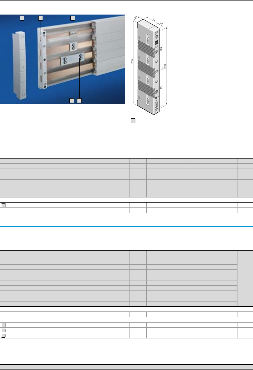
Form 2-4 busbar systems
Busbar supports (4-pole)
74 Rittal Ri4Power Form 2-4
1
2
4
5
3
Material:
Polyamide (PA 6.6),
25% fibreglass-reinforced.
Continuous operating
temperature max.130°C.
Fire protection corresponding
to UL 94-V0.
Colour:
RAL 7035
Short-circuit protection
diagram,
see page 117.
Technical information
for the calculation
of rated currents,
see page 120.
Version Packs of Page
Number of poles 4-pole
Bar centre distance 60 mm
For busbars E-Cu 12 x 5/10 mm1), 15 x 5 – 30 x 10 mm
Tightening torque
● Assembly screw (M5 x 25)
● Cover attachment
3 – 5 Nm
1 – 3 Nm
Model No. SV 49340.004
Accessories
End covers for contact hazard protection on the sides 2 9340.074
Spacers for SV 9340.004 12 9340.090 113
1) If 12 x 5/10 mm busbars are used, the spacer SV 9340.090 is additionally required.
1
2
Busbars E-Cu
To DIN EN 13 601.
Length: 2400 mm/bar.
Dimensions
mm Packs of Model No. SV Page
12 x 5 63580.000
110
12 x 10 63580.100
15 x 5 63581.000
15 x 10 63581.100
20 x 5 63582.000
20 x 10 63585.000
25 x 5 63583.000
30 x 51) 6 3584.0002)
30 x 101) 63586.0002)
Accessories
Busbar cover section (length 1 m/each) 10 3092.000 110
Busbar connector for E-Cu
12 x 5 – 15 x 10 mm (single connection) 3 9350.075 111
20 x 5 – 30 x 10 mm (single connection) 3 9320.020 111
20 x 5 – 30 x 10 mm (bayed connection)3) 3 9320.030 111
1) Other busbar lengths, see page 109.
2) Tin-plated version available on request.
3) From enclosure to enclosure.
3
4
5
With attachment holes
on the inside
1
Busbar connection adaptors Page 78/79 Component adaptors Page 80 Accessories Page 109
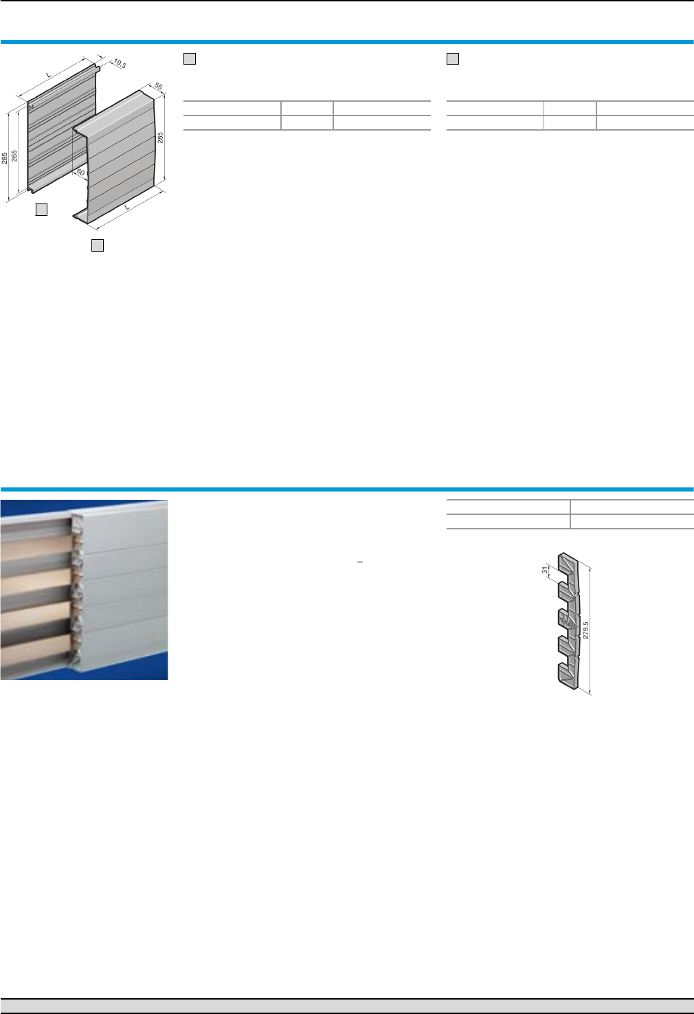
System components (4-pole)
Form 2-4 busbar systems
75Rittal Ri4Power Form 2-4
Base tray
For rear contact hazard protection of the flat bar
assembly.
Cover section
May be cut to length as required; for clip-on
mounting to the base tray.
Base tray and cover section
Material:
Thermally modified hard PVC.
Continuous operating temperature max. 91°C.
Fire protection corresponding to UL 94-V0.
Colour:
RAL 7035
Note:
If the cover section is mounted from the front,
the support panel (SV 9340.224) is needed for
stability.
Length (L) mm Packs of Model No. SV
1100 2 9340.134
1
2
1
Length (L) mm Packs of Model No. SV
1100 2 9340.214
2
Support panel
for cover section
To prevent side access to the cover section. The
support panel also provides additional stability.
Recommended mounting distance 500 mm.
Material:
Polyamide (PA 6.6).
Continuous operating temperature max. 105°C.
Fire protection corresponding to UL 94-V0.
Colour:
RAL 7035
<
Packs of Model No. SV
59340.224
Busbar connection adaptors Page 78/79 Component adaptors Page 80 Accessories Page 109
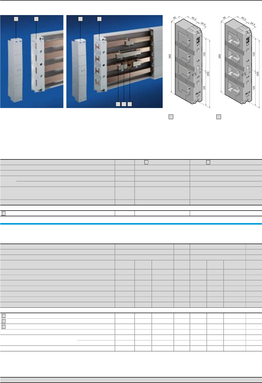
Form 2-4 busbar systems
Busbar supports PLUS (4-pole)
76 Rittal Ri4Power Form 2-4
3
1
2
3
6
5
4
Material:
Polyamide (PA 6.6),
25% fibreglass-reinforced.
Continuous operating
temperature max. 130°C.
Fire protection corresponding
to UL 94-V0.
Colour:
RAL 7035
Short-circuit protection
diagram,
see page 117.
Technical information
for the calculation
of rated currents,
see page 120.
For system Packs of Rittal 30 x 10 PLUS Rittal PLS 1600 PLUS
Number of poles 4-pole 4-pole
Bar centre distance 60 mm 60 mm
For busbars E-Cu 30 x 10 mm 䡲 –
PLS special busbars (PLS 1600) – 䡲
Tightening torque
● Assembly screw (M6 x 20)
● Cover attachment
3 – 5 Nm
5 – 7 Nm
3 – 5 Nm
5 – 7 Nm
Model No. SV 49342.014 9342.004
Accessories
End covers for contact hazard protection on the sides 2 9342.074 9342.074
1
2
3
Busbars
made from E-Cu
Detailed drawing:
SV 9661.300 to .380, see page 109.
For system Rittal 30 x 10 PLUS Page Rittal PLS 1600 PLUS Page
Size 30 x 10 mm –
Cross-section (bar thickness) – 900 mm2 (10 mm)1)
For enclosure width
mm
Length
mm Packs of Model No.
SV
Length
mm Packs of Model No.
SV
3002) 265 29661.330 109 – – –
4002) 365 29661.340 109 – – –
6002) 565 29661.360 109 495 33527.000 68
8002) 765 29661.380 109 695 33528.000 68
10002) 965 29661.300 109 895 33528.010 68
12002) 1165 29661.320 109 1095 33529.000 68
Variable 2400 63586.000 110 2400 13516.000 68
Accessories
PLS busbar connector (single connection) – – – – 3 3514.000 111
PLS busbar connector (bayed connection)3) – – – – 3 3515.000 111
PLS expansion connectors4) – – – – 3 9320.070 111
Baying bracket for SV 9661.300 to .380 (bayed connection) 95 4 9661.350 109 – – –
Busbar connector for SV 3586.000 Single connection – 3 9320.020 111 – – –
Baying connection3) – 3 9320.030 111 – – –
Busbar cover section 1000 10 3092.000 110 – – –
1) PLS special busbars (1600 A). To order tin-plated version, please add extension .2X0 to the Model No. Delivery times available on request.
2) For Rittal TS 8/ES enclosure systems.
3) From enclosure to enclosure.
4) Two PLS rail connectors (single connection) are required to fit one expansion connector.
4
5
6
Rittal 30 x 10 PLUS
1
Rittal PLS 1600 PLUS
2
Busbar connection adaptors Page 78/79 Component adaptors Page 80 Accessories Page 109
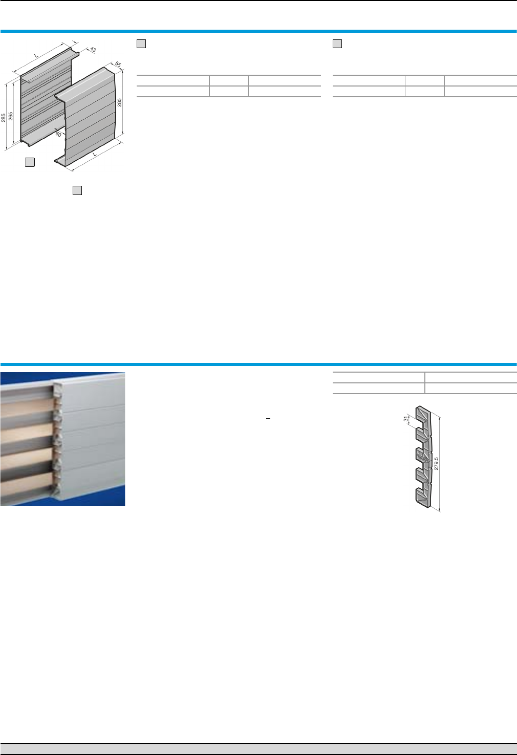
System components (4-pole)
Form 2-4 busbar systems
77Rittal Ri4Power Form 2-4
Base tray
For rear contact hazard protection of the busbar
assembly PLUS.
Cover section
May be cut to length as required; for clip-on
mounting to the base tray.
Base tray and cover section
Material:
Thermally modified hard PVC.
Continuous operating temperature max. 91°C.
Fire protection corresponding to UL 94-V0.
Colour:
RAL 7035
Note:
If the cover section is mounted from the front,
the support panel (SV 9340.224) is needed for
stability.
Length (L) mm Packs of Model No. SV
1100 2 9342.134
1
2
1
Length (L) mm Packs of Model No. SV
1100 2 9340.214
2
Support panel
for cover section
To prevent side access to the cover section. The
support panel also provides additional stability.
Recommended mounting distance 500 mm.
Material:
Polyamide (PA 6.6).
Continuous operating temperature max. 105°C.
Fire protection corresponding to UL 94-V0.
Colour:
RAL 7035
<
Packs of Model No. SV
59340.224
Busbar connection adaptors Page 78/79 Component adaptors Page 80 Accessories Page 109
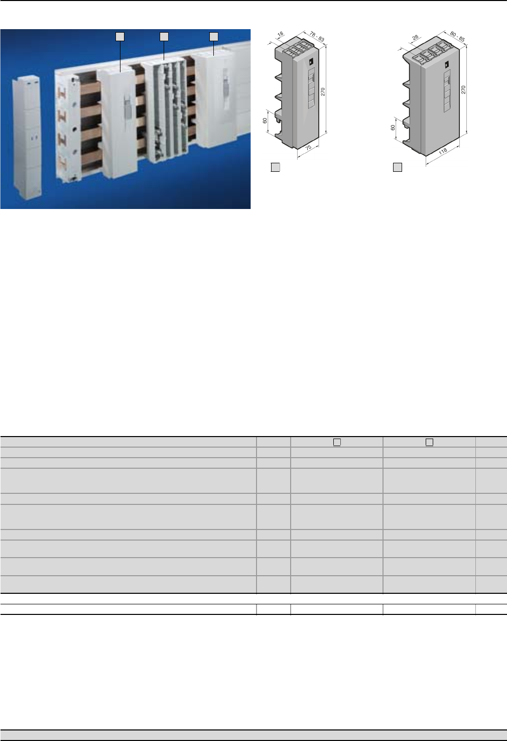
Form 2-4 busbar systems
Busbar connection adaptors (4-pole)
78 Rittal Ri4Power Form 2-4
1
2
2
Material:
Chassis
Polyamide (PA 6.6),
25% fibreglass-reinforced.
Continuous operating
temperature max.130°C.
Fire protection corresponding
to UL 94-V0.
Cover
ABS,
fire protection corresponding
to UL 94-V0.
Colour:
RAL 7035
Supply includes:
Cover.
Version (4-pole) Packs of Page
Rated current up to 125 A 250 A
Rated operating voltage 690 V~ 690 V~
Connection of round conductors
● Fine wire with wire end ferrule
● Multi-wire
10 – 25 mm2
16 – 35 mm2
35 – 120 mm2
35 – 120 mm2
Clamping area for laminated copper bars 10 x 7.8 mm 18.5 x 15.5 mm
Tightening torque
● Assembly screw
● Terminal screw
2 Nm
2 – 3 Nm
4 – 6 Nm
12 Nm
For bar thickness 5/10 mm 5/10 mm
Outlet at top/bottom
Model No. SV 1 9342.224 9342.254
Outlet at top
Model No. SV 1 9342.234 9342.264
Outlet at bottom
Model No. SV 1 9342.244 9342.274
Accessories
Laminated copper bars 䡲 䡲 112
1
2
1
2
Busbar systems Page 74 – 77 Component adaptors Page 80 Accessories Page 112
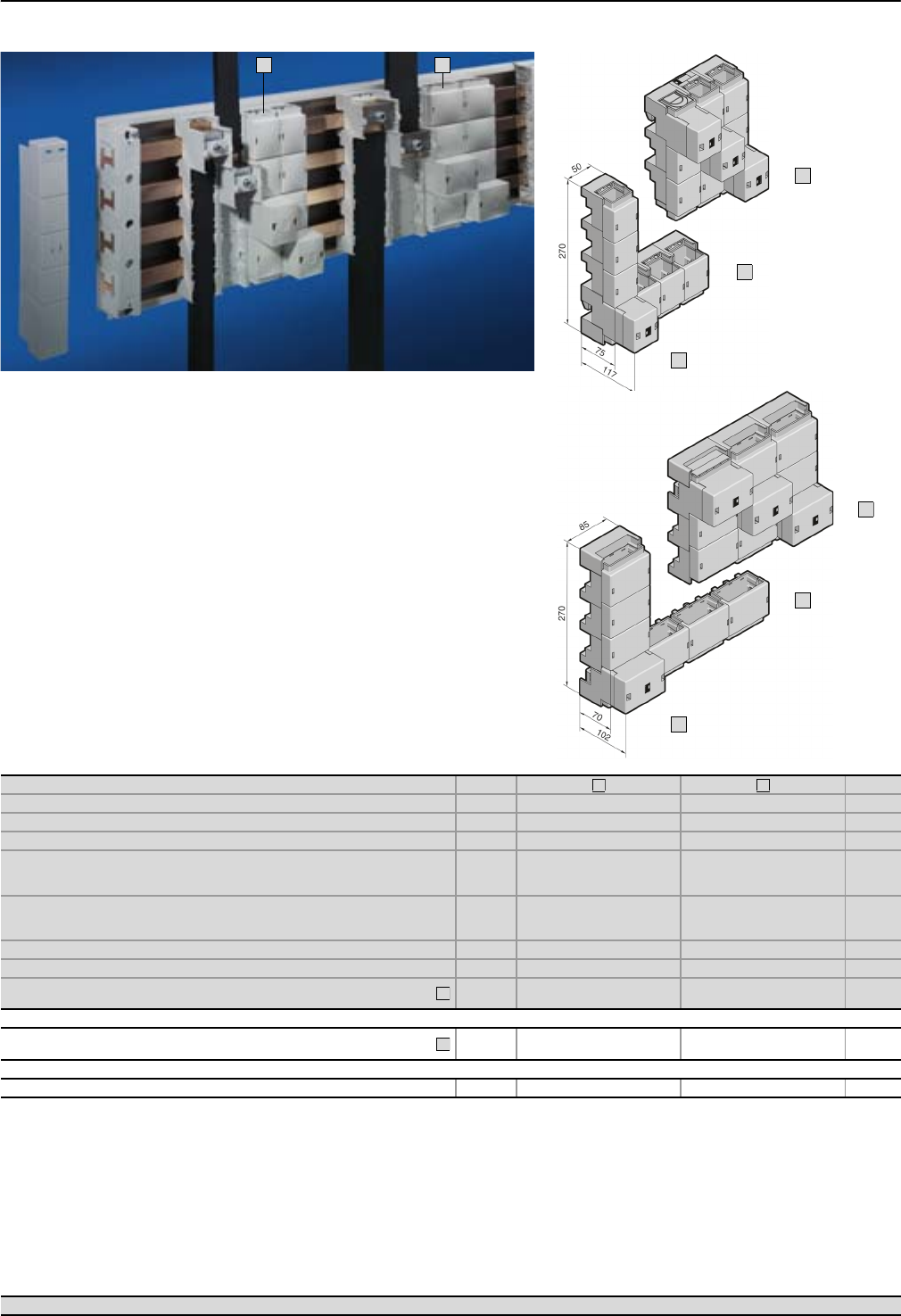
Busbar connection adaptors (4-pole)
Form 2-4 busbar systems
79Rittal Ri4Power Form 2-4
Material:
Chassis
Polyamide (PA 6.6),
25% fibreglass-reinforced.
Continuous operating
temperature max. 130°C.
Fire protection corresponding
to UL 94-V0.
Cover
ABS,
fire protection corresponding
to UL 94-V0.
Colour:
RAL 7035
Supply includes:
Cover.
1
2
SV 9342.310 with SV 9342.314
1
SV 9342.320 with SV 9342.324
2
A
B
A
B
Version Packs of Page
Rated current up to 800 A 1600 A
Rated operating voltage 690 V~ 690 V~
Outlet top/bottom top/bottom
Connection of round conductors
● Fine wire with wire end ferrule
● Multi-wire
95 – 185 mm2
95 – 300 mm2
–
–
Clamping area for laminated copper bars
● For 5 mm bar thickness
● For 10 mm bar thickness
33 x 27 mm
33 x 22 mm
65 x 27 mm
65 x 22 mm
Tightening torque 12 – 14 Nm 15 – 20 Nm
For bar thickness 5/10 mm 5/10 mm
Busbar connection adaptors (3 x 1-pole)
Model No. SV 1 set 9342.310 9342.320
Also required
Connection adaptor
(expansion set for 4-pole configuration) 19342.314 9342.324
Accessories
Laminated copper bars 䡲 䡲 112
1
2
A
B
Busbar systems Page 74 – 77 Component adaptors Page 80 Accessories Page 112
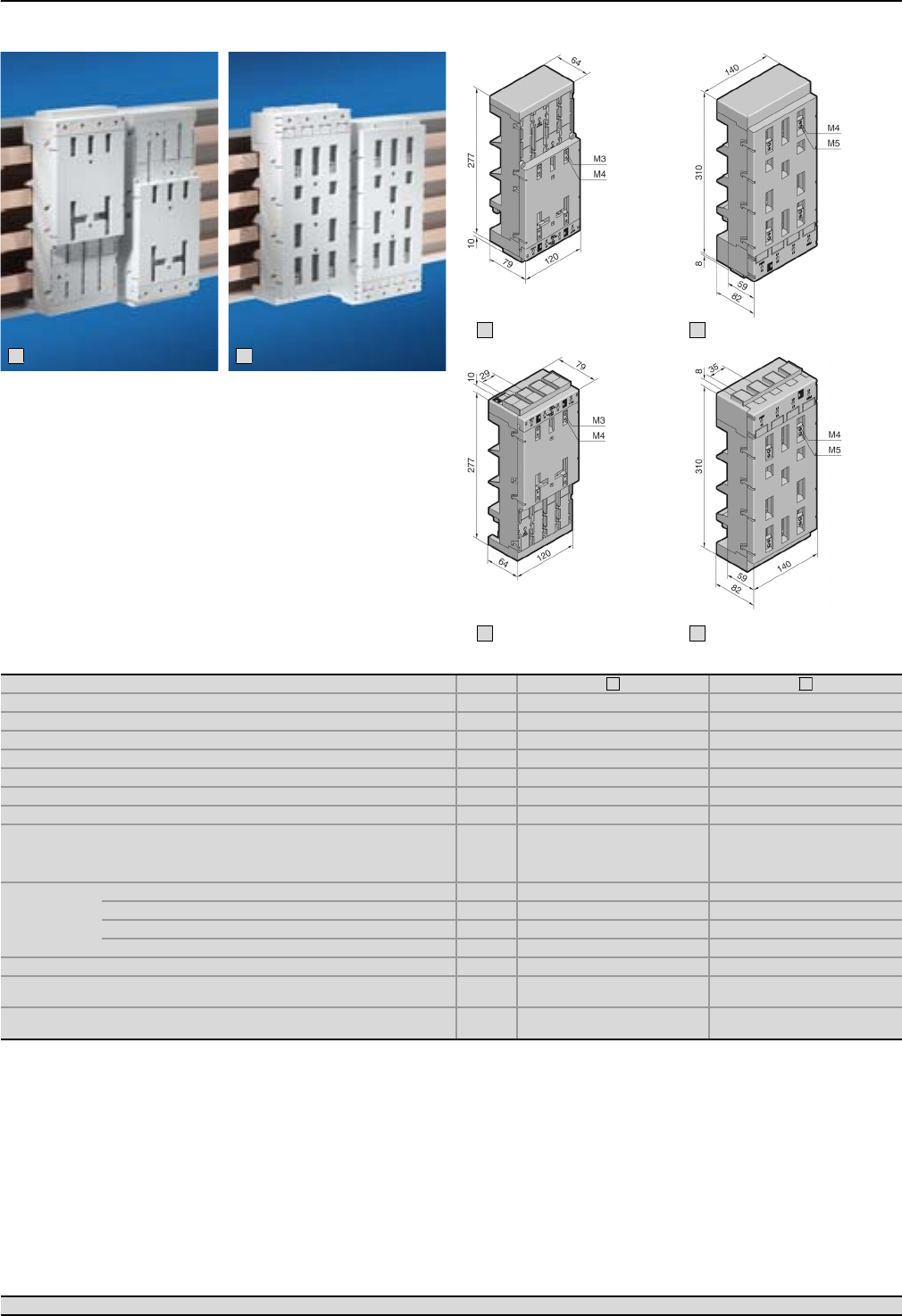
Form 2-4 busbar systems
Circuit-breaker component adaptors 160 A/250 A (4-pole)
80 Rittal Ri4Power Form 2-4
2
1
Material:
Chassis
Polyamide (PA 6.6),
25% fibreglass-reinforced.
Continuous operating
temperature max.130°C.
Fire protection corresponding
to UL 94-V0.
Colour:
RAL 7035
Supply includes:
Terminal cover and sliding
blocks for switchgear attach-
ment.
Version Packs of
Construction width 120 mm 140 mm
Length 277 mm 310 mm
Rated current up to 160 A 250 A
Rated operating voltage 690 V~ 690 V~
Connection clamp Box terminal Box terminal
Connection of round conductors 35 – 120 mm2 35 – 120 mm2
Clamping area for laminated copper bars 18.5 x 15.5 mm 18.5 x 15.5 mm
Tightening torque
● Terminal screw
● Rail attachment
● Switchgear attachment
12 Nm
4 – 6 Nm
1.5 Nm
12 Nm
4 – 6 Nm
1.5 Nm
For
switchgear
make/model
ABB T1 (160 A), T2 (160 A) T3S (250 A), T4V (315 A)
Merlin Gerin NSC100 NS(X)100, NS(X)160, NS(X)250
Moeller Electric NZM1-4 (125 A) NZM2-4 (250 A)
Siemens –VL160X, VL160, VL250
For bar thickness 5/10 mm 5/10 mm
Cable outlet at the top1)
Model No. SV 1 9342.504 9342.604
Cable outlet at the bottom1)
Model No. SV 1 9342.514 9342.614
1) Switch outlet or outgoing cable.
1
2
SV 9342.504
1
SV 9342.604
2
SV 9342.614
2
SV 9342.514
1
Busbar systems Page 74 – 77 Busbar connection adaptors Page 78/79 Accessories Page 112
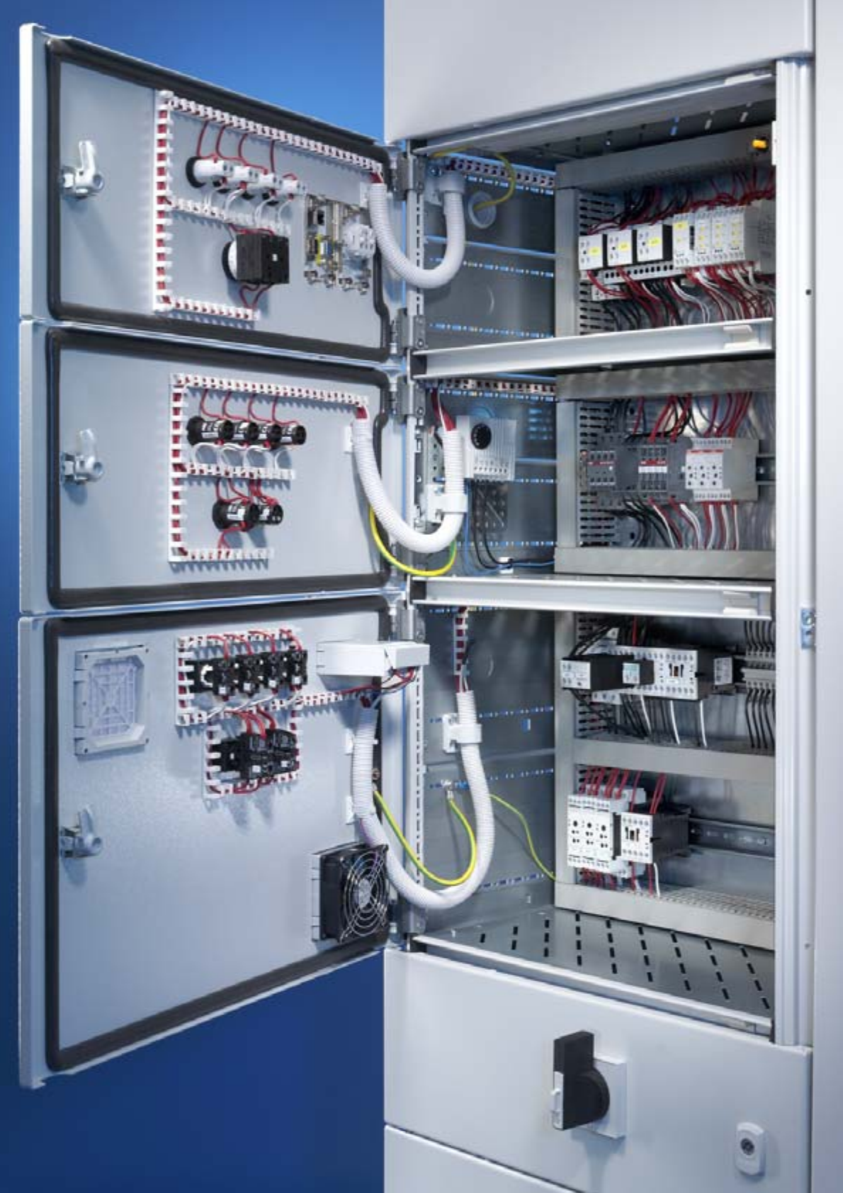
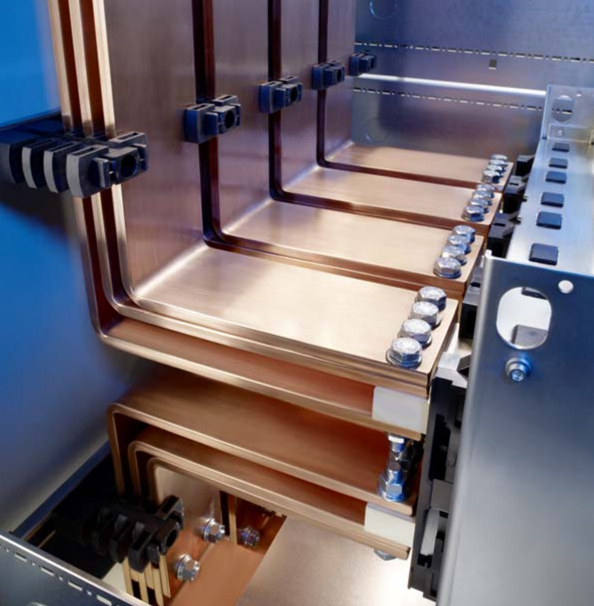
82 Rittal Ri4Power Form 2-4
Two systems for optimum performance
Ingeniously simple assembly of low-voltage distributors and switchgear in the heavy current range.
The Rittal Maxi-PLS system components are supplied ready to assemble. All modules are standardised and
batch-produced to ensure cost-effectiveness. One new addition to the range is the Flat-PLS, a busbar system
for standard, commercially available flat bars. Whether you opt for Maxi-PLS or Flat-PLS – Ri4Power systems
are the ideal links between power supply and power distribution, even down to the tiniest piece of equipment.
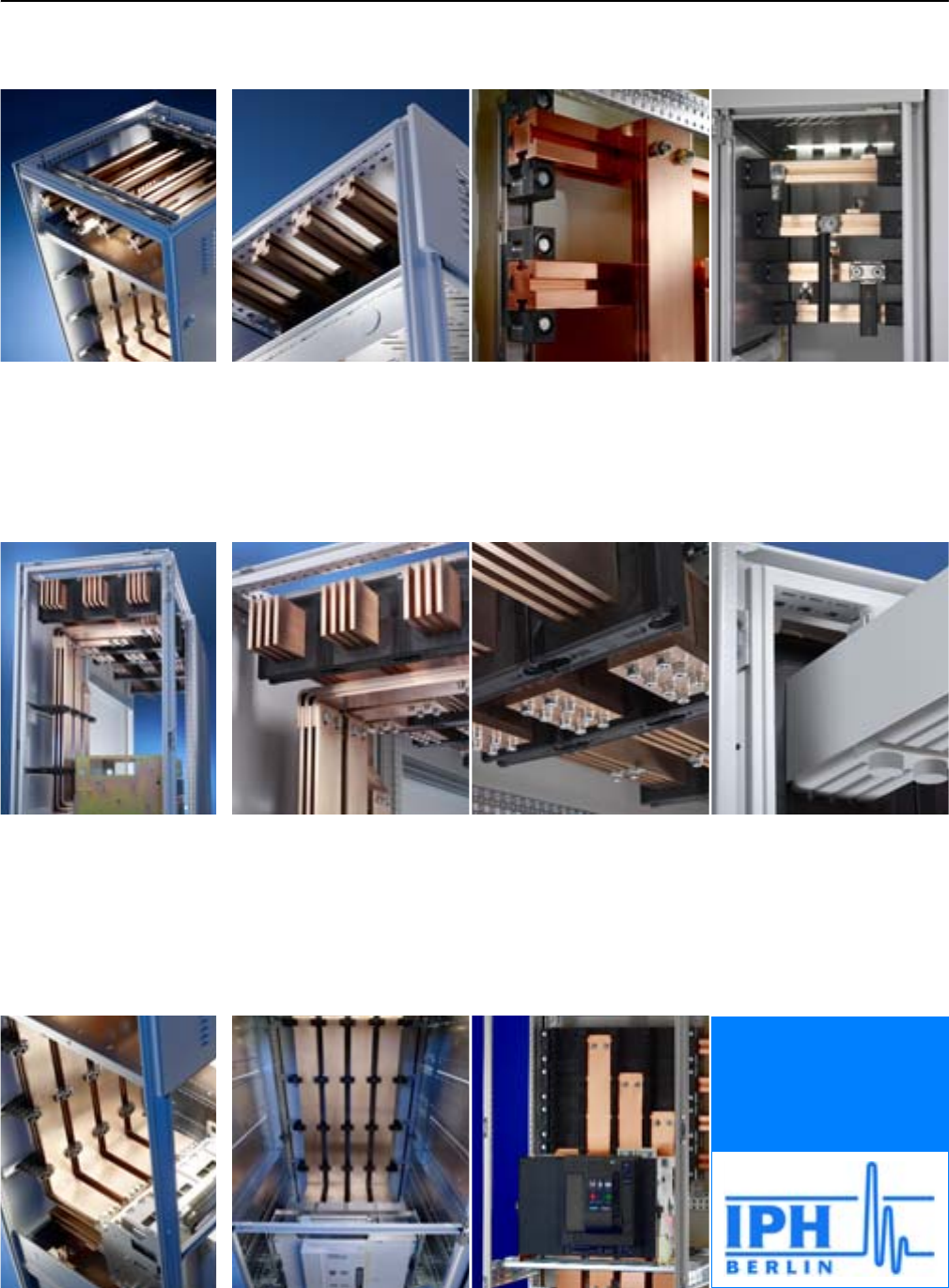
83Rittal Ri4Power Form 2-4
Maxi-PLS and Flat-PLS up to 5500 A
Form 2-4 busbar systems
IEC 60 439-1
IEC 61 439-1
IEC 61 439-2
IEC 61 641
Connected to Maxi-PLS und
Flat-PLS busbars using stand-
ardised components on the con-
nection tailored to the respec-
tive air circuit-breaker.
The combination of isolator
chassis, contact makers and
connection brackets forms the
heart of the connection.
Type-tested to IEC 60 439-1,
with ASTA certification. Design
verification to IEC 61 439-1/-2.
Special testing to EN 61 641/
IEC 61 641.
Flat-PLS
Flat-PLS busbar support. Multi-
variant dimensioning of the
busbars with just two supports.
Also suitable for aluminium and
copper-plated aluminium bars.
Longitudinal connectors for
Flat-PLS. For connecting Flat-
PLS busbar systems, no drilling
required. Adapted to your re-
quirements.
All-round contact hazard
protection for busbars and for
connection kits. Also for pre-
ventive protection against acci-
dental arcing.
Maxi-PLS
Thanks to the perfect system
technology and tailored dimen-
sional pitch pattern, Maxi-PLS
supports and bars ensure pre-
cise-fit, simple and fast installa-
tion.
With the aid of sliding blocks or
studs, the four attachment
levels of the Maxi-PLS busbars
enable infinitely variable attach-
ment and …
… contacting of round con-
ductors, laminated flat copper,
connection brackets and con-
nection kits.
System configuration analo-
gous to Maxi-PLS with stand-
ard, commercially available
flat copper bars.
Standardised Maxi-PLS
busbars in a super-compact
design with an ingeniously
simple attachment system.
Connection components
System packages for all com-
mercially available air circuit-
breakers.
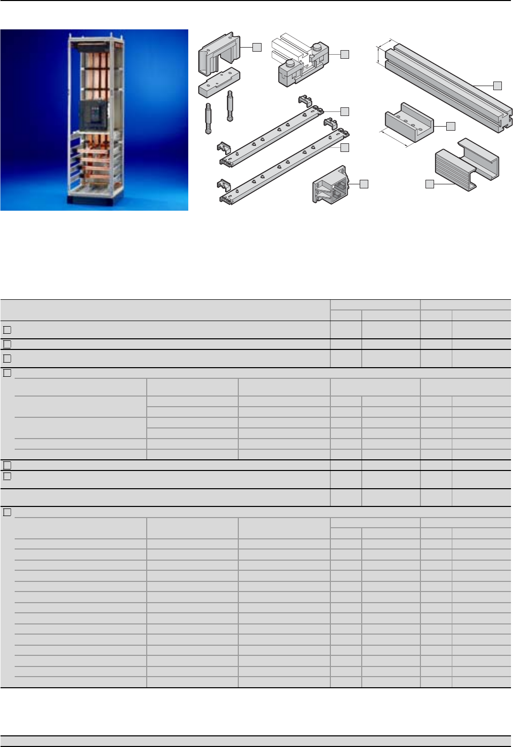
Form 2-4 busbar systems
System components, Maxi-PLS 1600/2000
84 Rittal Ri4Power Form 2-4
Material:
Busbar support, end support,
end cover: PA 6.6
System attachment:
Stainless steel
Cover section: Hard PVC
Note:
Busbars for
PE/PEN combinations,
see page 109.
Detailed drawing,
see page 125.
2
1
4
4
3
7
5
6
45
130
45
Connection components Page 85 SV-TS 8 enclosures Page 30 – 38 Accessories Page 99 – 112
Maxi-PLS system components 3-pole 4-pole
Packs of Model No. SV Packs of Model No. SV
Busbar support 39640.000 3
+ 1
9640.000
9649.000
Busbar support, suitable for top mounting 39640.160 39640.160
End support 69640.010 6
+ 2
9640.010
9649.010
System attachment for installing the busbar supports.
For application For enclosure depth
mm
Bar centre distance
mm
In the roof/base section 600 100 29640.080 29640.080
800 100 29640.088 29640.088
Vertical coupling set 600 100 29649.076 29649.076
800 100 29649.078 29649.078
Rear section top/bottom – 100 29640.098 29640.098
Rear section (185 mm) – 185 29640.150 – –
Cover section for clip-on mounting on the Maxi-PLS busbars, length 1000 mm. 59640.050 59640.050
Longitudinal connector E-Cu for simple baying connection of Maxi-PLS busbars.
Incl. sliding blocks, bolts, washers and nuts. 39640.190 3
+ 1
9640.190
9649.190
End cover for clip-on mounting on the end surface of Maxi-PLS busbars. 69640.060 6
+ 2
9640.060
9649.060
Maxi-PLS busbars E-Cu (special lengths available on request).
Length
mm
For enclosure width
mm
For
application1)
3/4-pole 3/4-pole
1600 A 2000 A
491 600 A 1 9640.206 19640.201
525 600 B 1 9640.216 19640.211
599 600 C 1 9640.226 19640.221
691 800 A 1 9640.236 19640.231
725 800 B 1 9640.246 19640.241
799 800 C 1 9640.256 19640.251
891 1000 A 1 9640.266 19640.261
925 1000 B 1 9640.276 19640.271
999 1000 C 1 9640.286 19640.281
1091 1200 A 1 9640.296 19640.291
1125 1200 B 1 9640.306 19640.301
1199 1200 C 1 9640.316 19640.311
2400 – – 3 9640.365 39640.360
2400 – – – – 49649.360
1) A = Cable connection system with end support
B = Left-hand or right-hand end enclosure in a switchgear installation
C = Bayed enclosure with sections bayed on the left and right
1
2
3
4
6
7
5
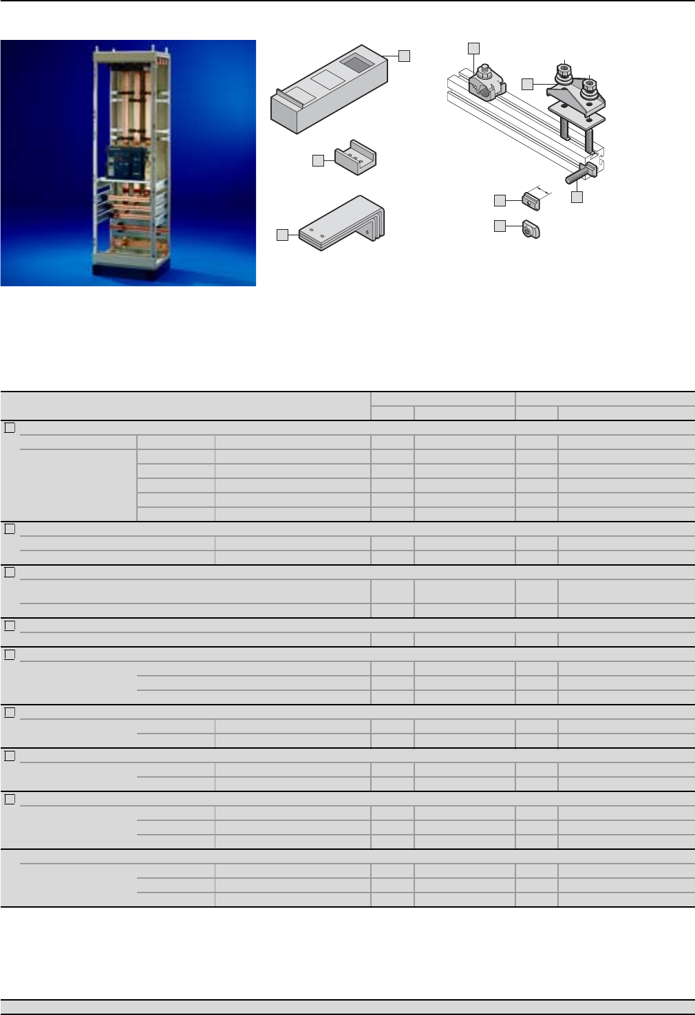
Connection components, Maxi-PLS 1600/2000
Form 2-4 busbar systems
85Rittal Ri4Power Form 2-4
Connection components Page 84 SV-TS 8 enclosures Page 30 – 38 Accessories Page 99 – 112
3
1
2
5
6
4
7
8
L
Maxi-PLS connection components 3-pole 4-pole
Packs of Model No. SV Packs of Model No. SV
Connection bracket E-Cu Transition from the main busbar system to the connection kits1).
For enclosure depth mm Width mm Number of brackets per phase
600/800
60 11 set 9640.433 1 set 9640.433 +9640.434
60 21 set 9640.443 1 set 9640.443 +9640.444
60 31 set 9640.453 1 set 9640.453 +9640.454
100 21 set 9640.473 1 set 9640.473 +9640.474
100 31 set 9640.483 1 set 9640.483 +9640.484
Isolator chassis for isolated routing of the connection brackets. Material: PA 6.6, black, including assembly parts.
Bar centre distance mm For connection bracket width mm
100 60 1 set 9640.020 1 set 9649.020
U contact maker E-Cu for contacting the connection brackets to the Maxi-PLS busbars. Including sliding blocks.
60 mm width 39640.170 3
+ 1
9640.170
9649.170
100 mm width 39640.180 39640.180
Connection clamp for the connection of round conductors (Cu/Al) 95 to 300 mm2 (single-wire and multi-wire). Including assembly parts.
50 mm width 19640.325 19640.325
Connection plates for the connection of laminated flat copper bars. Including assembly parts.
Maximum clamping area
2 x 10 x 32 x 1 mm 39640.330 39640.330
2 x 10 x 63 x 1 mm 39640.340 39640.340
2 x 10 x 100 x 1 mm 39640.350 39640.350
Terminal stud for connecting cables with ring terminals. Including sliding blocks.
Thread M12 Length 30 mm 39640.370 39640.370
M16 Length 30 mm 39640.380 39640.380
Sliding blocks for sliding into the Maxi-PLS busbar section at the sides.
Thread M8 Length (L) 20 mm 15 9640.970 15 9640.970
M10 Length (L) 25 mm 15 9640.980 15 9640.980
Sliding nuts for retrospective insertion into the Maxi-PLS busbar section.
Thread
M6 15 9640.900 15 9640.900
M8 15 9640.910 15 9640.910
M10 15 9640.920 15 9640.920
Threaded bolts for individual connection options2). Including plain washers, spring lock washers and nuts.
Thread
M6 Length 35 mm 69640.930 69640.930
M8 Length 35 mm 69640.940 69640.940
M10 Length 80 mm 69640.960 69640.960
1) For the assembly of connection brackets to Maxi-PLS busbars without using contact makers (e.g. for cable connection system), please choose
sliding blocks SV 9640.980 (3-pole = 6 pcs., 4-pole = 8 pcs.).
2) Sliding blocks or sliding nuts are additionally required for attachment.
1
2
3
4
5
6
7
8
Detailed drawing,
see page 126.
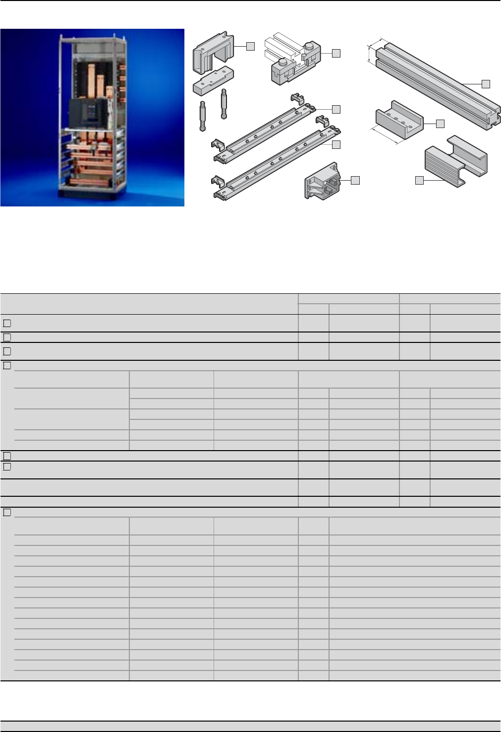
Form 2-4 busbar systems
System components, Maxi-PLS 3200
86 Rittal Ri4Power Form 2-4
2
1
4
4
3
7
5
6
60
130
60
Connection components Page 87 SV-TS 8 enclosures Page 30 – 38 Accessories Page 99 – 112
Maxi-PLS system components 3-pole 4-pole
Packs of Model No. SV Packs of Model No. SV
Busbar support 39650.000 3
+ 1
9650.000
9659.000
Busbar support, suitable for top mounting 39650.160 39650.160
End support 69650.010 6
+ 2
9650.010
9659.010
System attachment for installing the busbar supports.
For application For enclosure depth
mm
Bar centre distance
mm
In the roof/base section 600 150 29650.100 ––
800 150 29650.080 29650.080
Vertical coupling set 600 150 29650.076 ––
800 150 29659.078 29659.078
Rear section top/bottom –150 29650.098 29650.098
Rear section (185 mm) –185 29650.150 – –
Cover section for clip-on mounting on the Maxi-PLS busbars, length 1000 mm. 59650.050 59650.050
Longitudinal connector E-Cu for simple baying connection of the Maxi-PLS busbars.
Including sliding blocks, bolts, washers and nuts. 39650.190 3
+ 1
9650.190
9659.190
End cover for clip-on mounting on the end surface of Maxi-PLS busbars. 69650.060 6
+ 2
9650.060
9659.060
Stabiliser to increase short-circuit resistance (Icw up to 124 kA). 42) 9650.140 ––
Maxi-PLS busbars E-Cu (special lengths available on request).
Length
mm
For enclosure width
mm
For
application1) 3200 A
491 600 A 1 9650.201
525 600 B 1 9650.211
599 600 C 1 9650.221
691 800 A 1 9650.231
725 800 B 1 9650.241
799 800 C 1 9650.251
891 1000 A 1 9650.261
925 1000 B 1 9650.271
999 1000 C 1 9650.281
1091 1200 A 1 9650.291
1125 1200 B 1 9650.301
1199 1200 C 1 9650.311
2400 – – 3 9650.360
2400 – – 4 9659.360
1) A = Cable connection system with end support
B = Left-hand or right-hand end enclosure in a switchgear installation
C = Bayed enclosure with sections bayed on the left and right
2) Modules for two complete stabilisers
1
2
3
4
6
7
5
Material:
Busbar support, end support,
end cover: PA 6.6
System attachment:
Stainless steel
Cover section: Hard PVC
Note:
PE/PEN combination/busbars,
see page 109.
Detailed drawing,
see page 125.
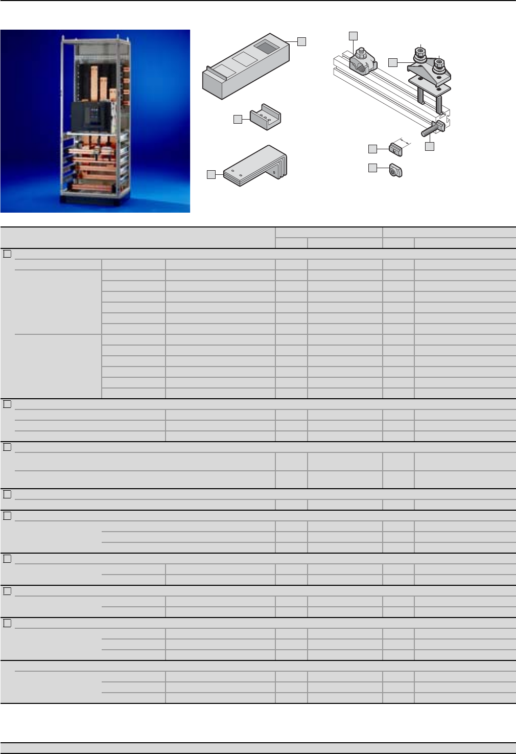
Connection components, Maxi-PLS 3200
Form 2-4 busbar systems
87Rittal Ri4Power Form 2-4
Connection components Page 86 SV-TS 8 enclosures Page 30 – 38 Accessories Page 99 – 112
3
1
2
5
6
4
7
8
L
Maxi-PLS connection components 3-pole 4-pole
Packs of Model No. SV Packs of Model No. SV
Connection bracket E-Cu Transition from the main busbar system to the connector kits1).
For enclosure depth mm Width mm Number of brackets per phase
600
60 11 set 9650.400 ––
60 21 set 9650.410 ––
60 31 set 9650.420 ––
100 21 set 9650.470 ––
100 31 set 9650.480 ––
120 31 set 9650.487 ––
800
60 11 set 9659.403 1 set 9659.403 +9659.404
60 21 set 9659.413 1 set 9659.413 +9659.414
60 31 set 9659.423 1 set 9659.423 +9659.424
100 21 set 9659.473 1 set 9659.473 +9659.474
100 31 set 9659.483 1 set 9659.483 +9659.484
120 31 set 9659.493 1 set 9659.493 +9659.494
Isolator chassis for isolated routing of the connection brackets. Material: PA 6.6, black, including assembly parts.
Bar centre distance mm For connection bracket width mm
150 60 1 set 9650.020 1 set 9659.020
150 100 1 set 9650.030 1 set 9659.030
U contact maker E-Cu for contacting the connection brackets to the Maxi-PLS busbars. Including sliding blocks.
60 mm width 39650.170 3
+ 1
9650.170
9659.170
100 mm width 39650.180 3
+ 1
9650.180
9659.180
Connection clamp for the connection of round conductors (Cu/Al) 95 to 300 mm2 (single-wire and multi-wire). Including assembly parts.
50 mm width 19650.325 19650.325
Connection plates for the connection of laminated flat copper bars. Including assembly parts.
Maximum clamping area
2 x 10 x 32 x 1 mm 39650.330 39650.330
2 x 10 x 63 x 1 mm 39650.340 39650.340
2 x 10 x 100 x 1 mm 39650.350 39650.350
Terminal stud for connecting cables with ring terminals. Including sliding blocks.
Thread M12 Length 32 mm 39650.370 39650.370
M16 Length 32 mm 39650.380 39650.380
Sliding blocks for sliding into the Maxi-PLS busbar section at the sides.
Thread M10 Length (L) 25 mm 15 9650.980 15 9650.980
M12 Length (L) 35 mm 15 9650.990 15 9650.990
Sliding nuts for retrospective insertion into the Maxi-PLS busbar section.
Thread
M6 15 9650.900 15 9650.900
M10 15 9650.910 15 9650.910
M12 15 9650.920 15 9650.920
Threaded bolts for individual connection options2). Including plain washers, spring lock washers and nuts.
Thread
M6 Length 35 mm 69650.930 69650.930
M10 Length 35 mm 69650.940 69650.940
M12 Length 80 mm 69650.960 69650.960
1) For the assembly of connection brackets to Maxi-PLS busbars without using contact makers (e.g. for cable connection system), please choose
sliding blocks SV 9650.990 (3-pole = 6 pcs., 4-pole = 8 pcs.).
2) Sliding blocks or sliding nuts are additionally required for attachment.
1
2
3
4
5
6
7
8
Detailed drawing,
see page 126.
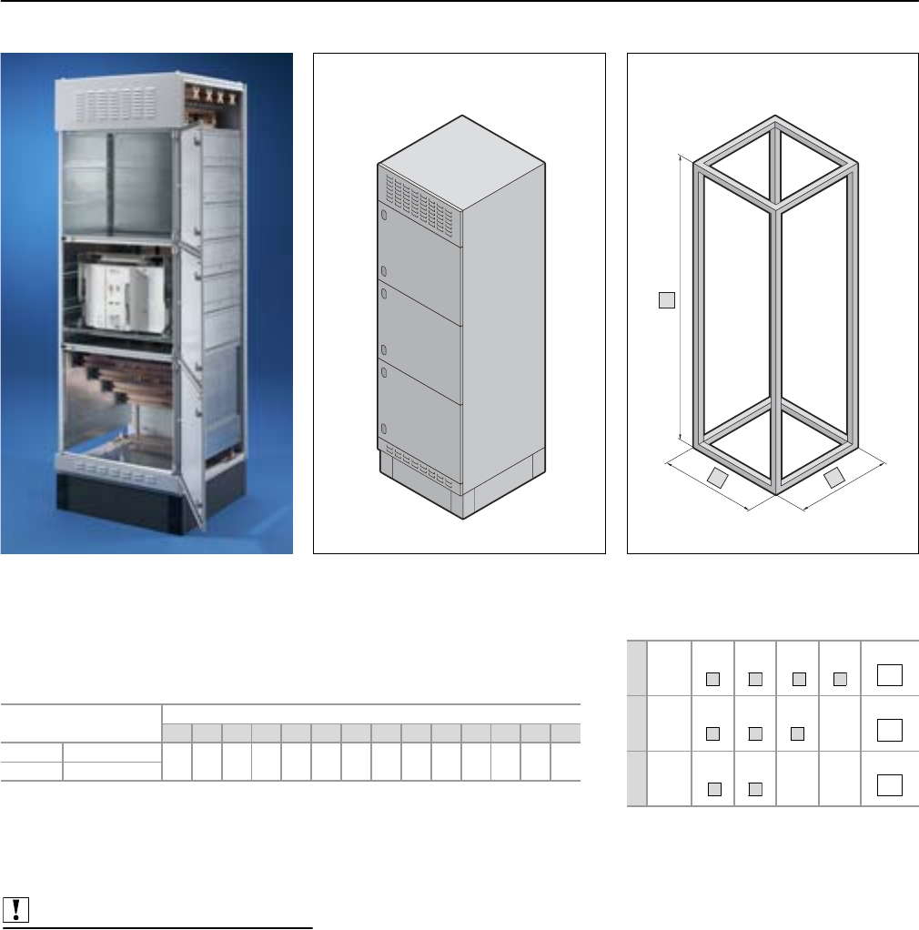
Form 2-4 busbar systems
Connection components, Maxi-PLS/Flat-PLS
88 Rittal Ri4Power Form 2-4
b
a
c
Connector kits
For connecting air circuit-breakers (ACB) to Maxi-PLS/Flat-PLS busbar systems in SV-TS 8
modular enclosures. Please include the design code of the specification below in the
order text for your connector kit.
We highly recommend the Rittal Power Engineering software for easier configuration of
the connector kits – see page 123.
Material:
E-Cu
Note:
Please quote the complete design code on all enquiries and orders.
Model No. SV Design code
a b c d e f g h i j k l m n
To p 9676.910
Bottom 9676.912
Enclosure
aWidth
mm
400
600
800
1000
Selection
bHeight
mm
1800
2000
2200
Selection
cDepth
mm
600
800
Selection
4
6
8
0
8
0
2
6
8
Also required:
M10/M12 screw connections,
see page 104.
Terminal studs Maxi-PLS,
see page 103.
Screw connections Flat-PLS,
see page 104.
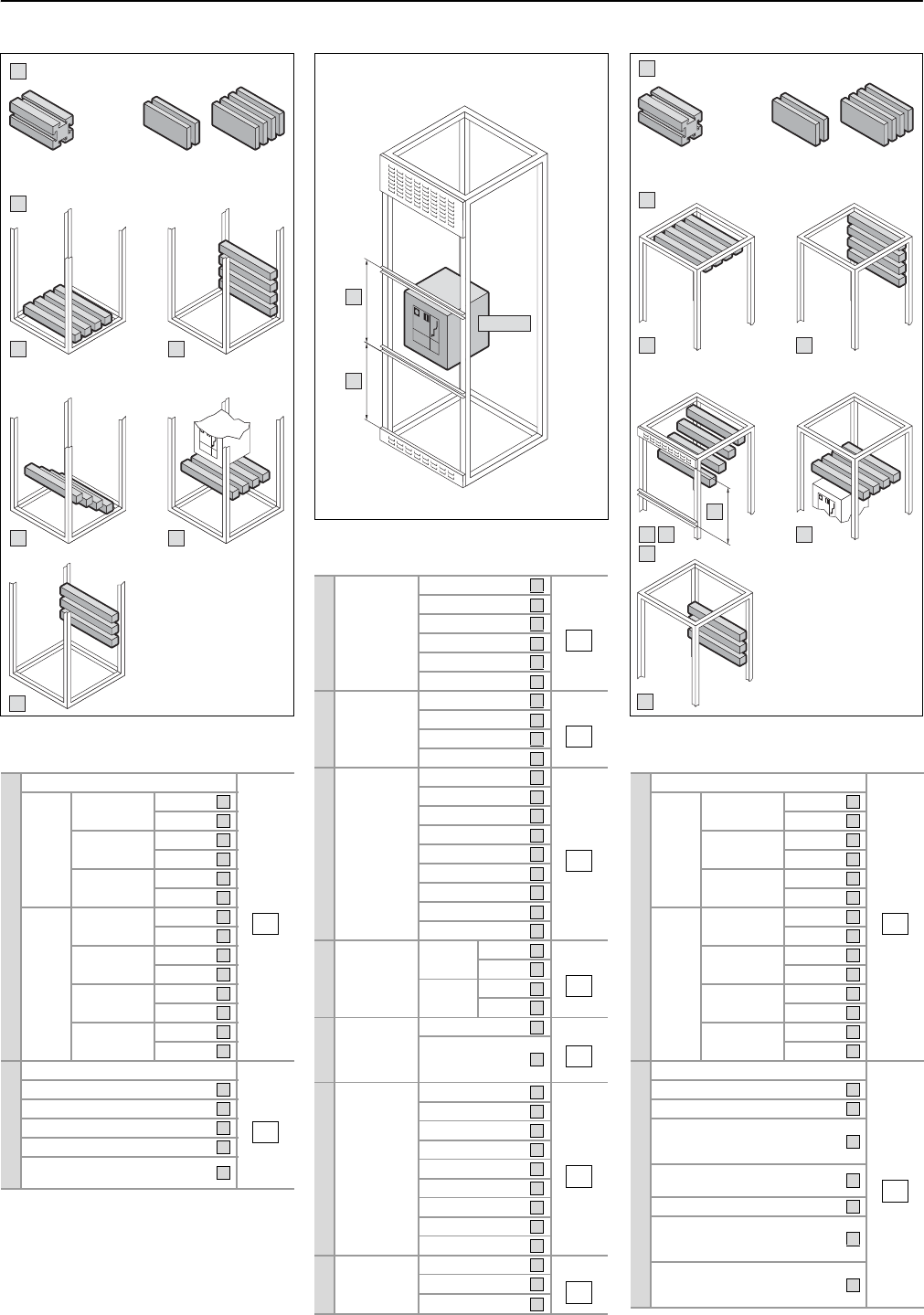
Connection components, Maxi-PLS/Flat-PLS
Form 2-4 busbar systems
89Rittal Ri4Power Form 2-4
8
6
d
e
9
7
Maxi-PLS Flat-PLS
2 bars/4 bars
5
k
n
2)
f/g/h/i/j
5
3 8
9
1
l
m
4
2
m
Maxi-PLS Flat-PLS
2 bars/4 bars
Air circuit-breakers
f
Brand ABB
Selection
Mitsubishi
Merlin Gerin
Siemens/Moeller
Terasaki
Various
g
Size 1/none Selection
2
3
4
h
Rated
current
630 A
Selection
800 A
1000 A
1250 A
1600 A
2000 A
2500 A
3200 A
4000 A
i
No. of
poles/
version
Static 3-pole Selection
4-pole
Rack-
mounted
3-pole
4-pole
j
Position Behind the door Selection
I
n front of the
door
(in door
cut-out)
k
Compart-
ment height
directly
underneath
the circuit-
breaker
0 mm
Selection
150 mm
200 mm
250 mm
300 mm
400 mm
600 mm1)
800 mm
1000 mm
n
2)
Compart-
ment height
of circuit-
breaker
600 mm Selection
800 mm
1000 mm
A
J
M
S
D
V
1
2
3
4
A
B
C
D
E
F
G
H
I
3
4
6
8
H
V
0
1
2
3
4
5
6
7
8
6
7
8
Above the air circuit-breaker
l
Busbar type
Selection
Maxi-
PLS 1600 3-pole
4-pole
2000 3-pole
4-pole
3200 3-pole
4-pole
Flat-
PLS 60
2 bars
3-pole
4-pole
60
4 bars
3-pole
4-pole
100
2 bars
3-pole
4-pole
100
4 bars
3-pole
4-pole
m
Busbar system configuration
Selection
in the roof section
in the top rear section
as cable connection system,
connection space height
600 mm
directly above the
circuit-breaker
in rear section, Form 11)
as cable connection system
connection space height
800 mm
as cable connection system
connection space height
1000 mm
A
B
C
D
E
F
G
H
I
J
K
L
M
N
1
2
3
4
5
8
9
Underneath the air circuit-breaker
d
Busbar type
Selection
Maxi-
PLS 1600 3-pole
4-pole
2000 3-pole
4-pole
3200 3-pole
4-pole
Flat-
PLS 60
2 bars
3-pole
4-pole
60
4 bars
3-pole
4-pole
100
2 bars
3-pole
4-pole
100
4 bars
3-pole
4-pole
e
Busbar system configuration
Selection
in rear section, Form 11)
in the base section
in the lower rear section
as cable connection system
directly underneath the
circuit-breaker
1) Standard height in Form 1
2) For Form 1 please select a 6
A
B
C
D
E
F
G
H
I
J
K
L
M
N
5
6
7
8
9
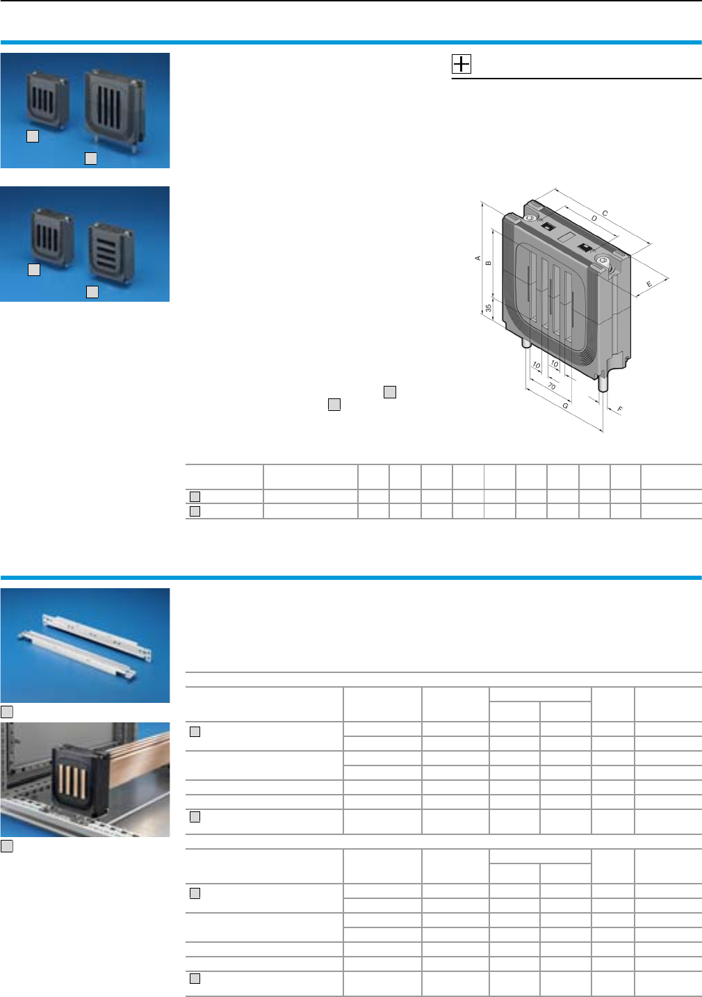
Form 2-4 busbar systems
Flat-PLS
90 Rittal Ri4Power Form 2-4
Busbar support
Flat-PLS
for flat copper busbars
For the configuration of busbar systems from flat
copper bars. For mounting on a system attach-
ment or directly on the mounting plate. Also suit-
able for aluminium and copper-plated aluminium
bars.
Max. permissible tolerance of bar width
(60/100 mm) ±0.3 mm, bar thickness (10 mm)
±0.15 mm.
Material:
Polyamide (PA 6.6), 25% fibreglass-reinforced.
Continuous operating temperature max. 130°C.
Fire protection corresponding to UL 94-V0.
Colour: RAL 9005
Short-circuit protection diagrams,
see page 118.
Current carrying capacity,
see page 121.
Supply includes:
Assembly parts.
Note:
The internal use of busbar supports may be
rotated through 90° so that the busbars
may be upright or horizontal for installation
purposes.
Busbars,
see page 110.
Accessories:
System attachments for Flat-PLS,
see page 90.
End cover,
see page 92.
Filler piece,
see page 92.
Spacer,
see page 92.
1
2
3
4
3
4
System For
busbars up to
A
mm
B
mm
C
mm
D
mm
E
mm FMd2)
Nm
G
mm
Packs
of
Model No.
SV
Flat-PLS 60 4 x 60 x 10 mm 127.5 60 120 70 50 M8 8 100 1 9676.0021)
Flat-PLS 100 4 x 100 x 10 mm 162.5 100 165 90 55 M10 9 125 1 9676.0041)
1) With a bar width of < 60/100 mm the spacer should be used.
When using only 1, 2 or 3 bars, the vacant bar slots should be closed using the filler pieces.
2) Rated torque
1
2
System attachments
for Flat-PLS
For the assembly of 3- or 4-pole busbar systems
of flat copper bars.
For mounting on the TS frame or punched section
with mounting flange.
Material:
Stainless steel
Supply includes:
Assembly parts.
For busbar support Flat-PLS 60
For application
For
enclosure depth
mm
Bar centre
distance
mm
For assembly
Packs of Model No.
SV
3-pole 4-pole
In the roof section/
base section
600 120 䡲 䡲 29674.162
800 120 䡲 䡲 29674.182
Vertical coupling set 600 120 䡲 䡲 29674.172
800 120 䡲 䡲 29674.192
Rear section1) 2) –120䡲 䡲 29674.122
Rear section3) –185䡲 –29674.152
Single-pole assembly, for
mounting on the TS 8 frame ––––29674.102
For busbar support Flat-PLS 100
For application
For
enclosure depth
mm
Bar centre
distance
mm
For assembly
Packs of Model No.
SV
3-pole 4-pole
In the roof section/
base section
600 165 䡲 – 2 9674.164
800 165 䡲 䡲 29674.184
Vertical coupling set 600 165 䡲 – 2 9674.174
800 165 䡲 䡲 29674.194
Rear section1) 2) –165䡲 䡲 29674.124
Rear section3) –185䡲 –29674.154
Single-pole assembly, for
mounting on the TS 8 frame ––––29674.104
1) For mounting between the TS 8 roof frame and TS punched section with mounting flange.
2) In conjunction with form separation, may only be used in 800 mm deep TS enclosures.
3) For mounting between two TS punched sections with mounting flanges.
1
2
1
2
2
1
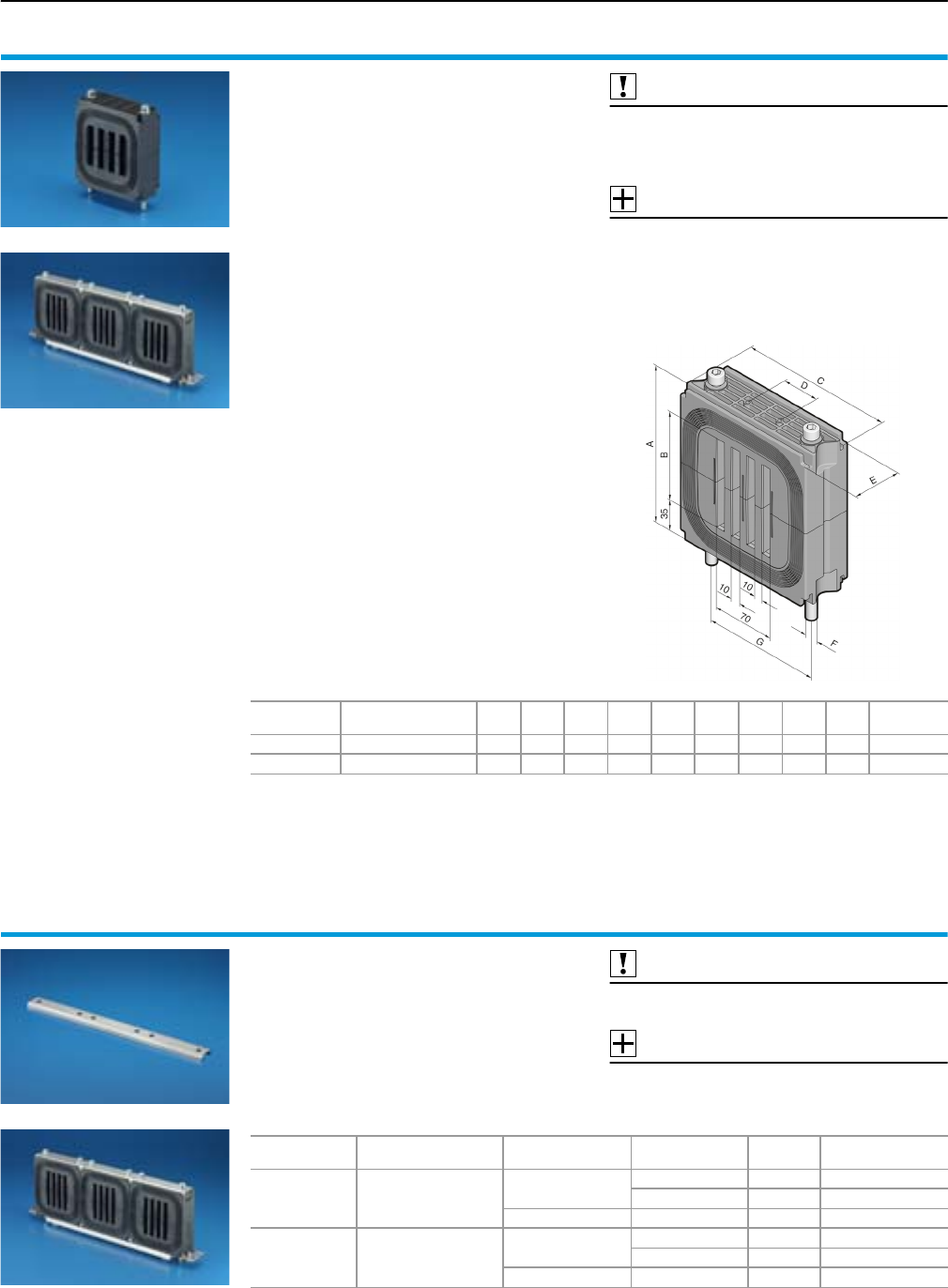
Flat-PLS
Form 2-4 busbar systems
91Rittal Ri4Power Form 2-4
Busbar support
Flat-PLS
for flat copper bar,
suitable for stabiliser bar
For the configuration of busbar systems from flat
copper bars with increased short-circuit resist-
ance. For mounting on a system attachment or
directly on the mounting plate.
Also suitable for aluminium and copper-plated
aluminium bars.
Max. permissible tolerance of bar width
(60/100 mm) ± 0.3 mm, bar thickness (10 mm)
± 0.15 mm.
Material:
Polyamide (PA 6.6), 25% fibreglass-reinforced.
Continuous operating temperature max. 130°C.
Fire protection corresponding to UL 94-V0.
Colour:
RAL 9005
Short-circuit protection diagrams,
see page 118.
Current carrying capacity,
see page 121.
Supply includes:
Assembly parts.
Note:
The internal busbar support insert may be rotated
through 90° to allow upright or flat installation of
the busbars.
Busbars,
see page 110.
Also required:
System attachments for Flat-PLS,
see page 90.
Busbar stabiliser bar,
see page 91.
Accessories:
End cover,
see page 92.
Filler piece,
see page 92.
Spacer,
see page 92.
System For
busbars up to
A
mm
B
mm
C
mm
D
mm
E
mm FMd2)
Nm
G
mm
Packs
of
Model No.
SV
Flat-PLS 60 4 x 60 x 10 mm 130 60 120 70 50 M8 10 100 1 9676.0201)
Flat-PLS 100 4 x 100 x 10 mm 170 100 165 90 55 M10 12 125 1 9676.0211)
1) With a bar width of < 60/100 mm the spacer should be used.
When using only 1, 2 or 3 bars, the vacant bar slots should be closed using the filler pieces.
2) Rated torque
Busbar stabiliser bars
for busbar support Flat-PLS
For the configuration of busbar systems from flat
copper bars with increased short-circuit resist-
ance. For mounting in conjunction with system
attachment and Flat-PLS busbar support for sta-
biliser bar.
Material:
Stainless steel
Also required:
System attachments for Flat-PLS,
see page 90.
Accessories:
Busbar claw,
see page 93.
For system For
busbar supports
Bar centre distance
mm
System
assembly Packs of Model No. SV
Flat-PLS 60 SV 9676.020 120 3-pole 2 9676.022
4-pole 2 9676.023
185 3-pole 2 9676.026
Flat-PLS 100 SV 9676.021 165 3-pole 2 9676.024
4-pole 2 9676.025
185 3-pole 2 9676.027
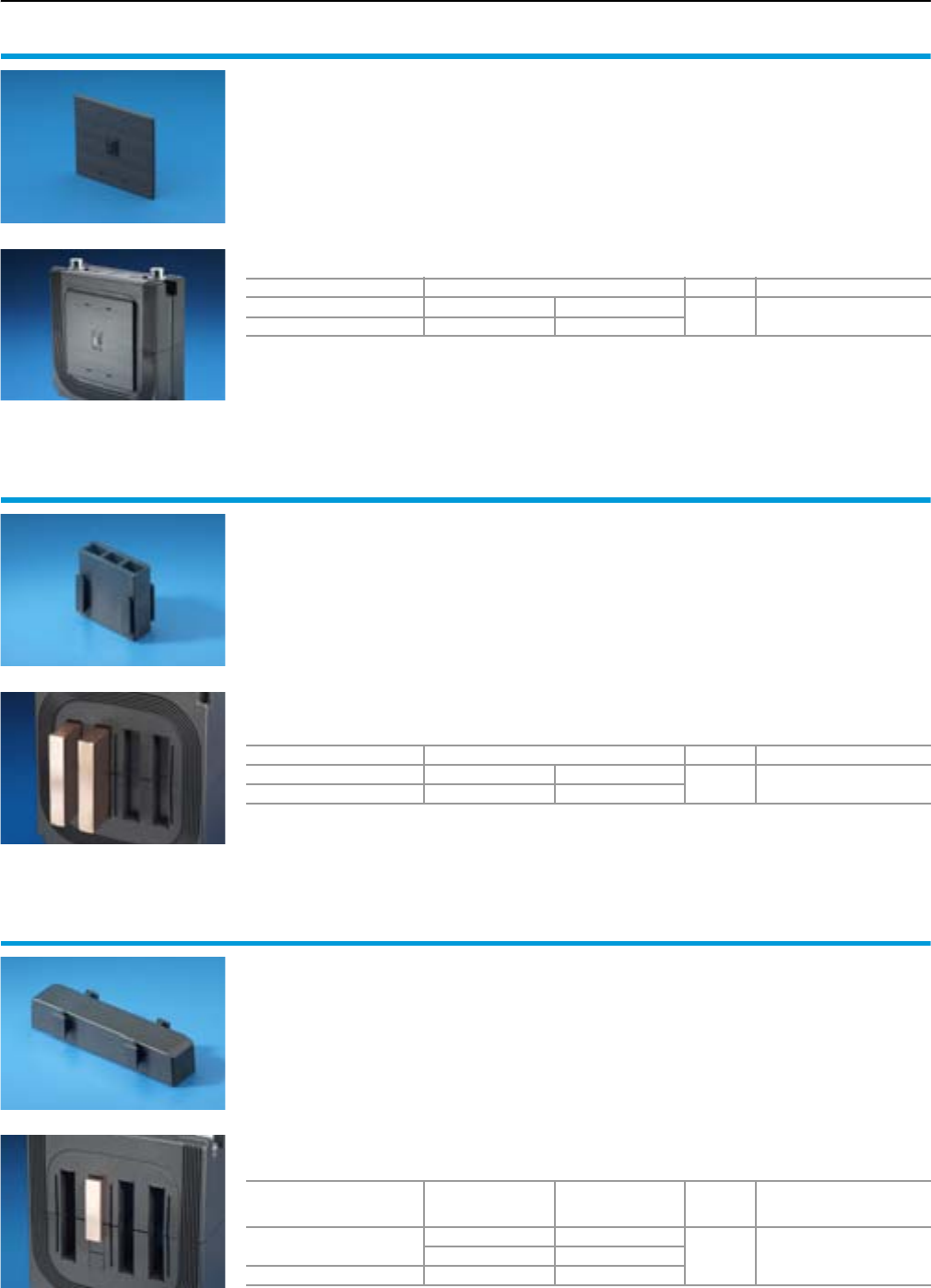
Form 2-4 busbar systems
Flat-PLS
92 Rittal Ri4Power Form 2-4
End covers
for busbar support Flat-PLS
Inserted into the Flat-PLS busbar supports for
electric shockproof covering of the busbar ends.
Material:
Polyamide (PA 6.6).
Continuous operating temperature max. 130°C.
Fire protection corresponding to UL 94-V0.
Colour:
RAL 9005
For system For busbar supports Packs of Model No. SV
Flat-PLS 60 SV 9676.002 SV 9676.020 29676.006
Flat-PLS 100 SV 9676.004 SV 9676.021
Filler pieces
for busbar support Flat-PLS
To cover open chambers in busbar supports
when using only 1, 2 or 3 bars per conductor or
when using a busbar support as an end support.
Material:
Polyamide (PA 6.6), 25% fibreglass-reinforced.
Continuous operating temperature max. 130°C.
Fire protection corresponding to UL 94-V0.
Colour:
RAL 9005
Note:
If only 2 busbars are used per support, the bars
should be inserted as shown in the left-hand
picture, in order to ensure the usability of connec-
tion brackets and connector kits.
For system For busbar supports3) Packs of Model No. SV
Flat-PLS 601) SV 9676.002 SV 9676.020 16 9676.008
Flat-PLS 1002) SV 9676.004 SV 9676.021
1) Two required per chamber.
2) Three required per chamber.
3) When using a busbar support as an end support, eight are required per support.
Spacers
for busbar support Flat-PLS
When using smaller busbar widths, the spacer
piece should be inserted into the chambers of the
support to compensate for width differences.
Material:
Polyamide (PA 6.6), 25% fibreglass-reinforced.
Continuous operating temperature max. 130°C.
Fire protection corresponding to UL 94-V0.
Colour:
RAL 9005
Note:
The spacers should always be inserted into the
support base, so that the busbars are as close as
possible to the support lid (see left-hand picture).
For system E-Cu
Dimensions
Required number
of spacers
per chamber
Packs of Model No. SV
Flat-PLS 60 40 x 10 mm 2
16 9676.00750 x 10 mm 1
Flat-PLS 100 80 x 10 mm 2
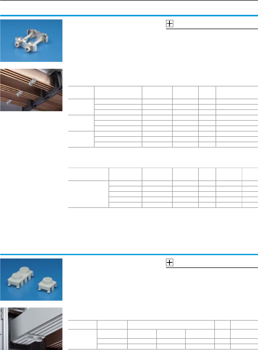
Flat-PLS
Form 2-4 busbar systems
93Rittal Ri4Power Form 2-4
Busbar claws
for Flat-PLS
For the assembly of busbar systems from flat cop-
per bars with increased short-circuit resistance or
for the mechanical stabilisation of busbar stacks.
For use on free busbar lengths > 300 mm in order
to achieve the specified short-circuit resistance
levels.
Material:
Stainless steel.
Accessories: Sheet steel, zinc-plated, passivated
Supply includes:
Assembly parts.
Accessories:
Covers for busbar claws,
see page 93.
Detailed drawing,
see page 127.
For system
For
busbar width
mm
Screw Rated torque
Nm Packs of Model No.
SV
Flat-PLS 60
2 x 60 x 10 mm M10 x 80 15 1 9676.011
3 x 60 x 10 mm M10 x 80 15 1 9676.012
4 x 60 x 10 mm M10 x 80 15 1 9676.013
Flat-PLS 100
2 x 100 x 10 mm M10 x 120 15 1 9676.014
3 x 100 x 10 mm M10 x 120 15 1 9676.015
4 x 100 x 10 mm M10 x 120 15 1 9676.016
Flat-PLS
2 x B x 10 mm1) Without screw2) 15 1 9676.017
3 x B x 10 mm1) Without screw3) 15 1 9676.018
4 x B x 10 mm1) Without screw3) 15 1 9676.019
1)
For the version without screw, the relevant screw must additionally be ordered according to the relevant busbar width B.
2) Required number of screws per busbar claw: 1
3) Required number of screws per busbar claw: 2
Accessories
For busbar width
B
mm
Screw Rated torque
Nm Packs of Model No.
SV Page
Screw connections
for Flat-PLS
busbar systems
40 M10 x 60 15 8 9676.806 104
50 M10 x 70 15 8 9676.807 104
60 M10 x 80 15 8 9676.808 104
80 M10 x 100 15 8 9676.810 104
100 M10 x 120 15 8 9676.812 104
Covers
for busbar claws
For contact hazard protection of the busbar
claws. The cover terminates flush with the cover
sections of the Flat-PLS system.
Material:
Polyamide (PA 6.6), 25% fibreglass-reinforced.
Continuous operating temperature max. 130°C.
Fire protection corresponding to UL 94-V0.
Colour:
RAL 7035
Accessories:
Cover section,
see page 94.
For system No. of bars
per conductor
For
busbar claw Packs of Model No.
SV
Flat-PLS 60/
Flat-PLS 100
2 SV 9676.011 SV 9676.014 SV 9676.017
SV 9676.832 89676.046
3 SV 9676.012 SV 9676.015 SV 9676.018 8 9676.047
4 SV 9676.013 SV 9676.016 SV 9676.019 8 9676.048
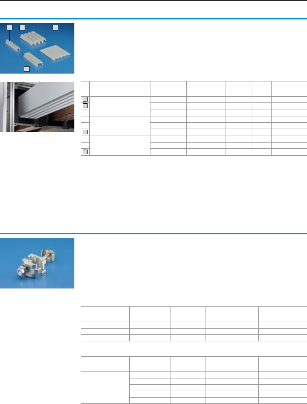
Form 2-4 busbar systems
Flat-PLS
94 Rittal Ri4Power Form 2-4
Cover sections
for Flat-PLS
For contact hazard protection of the Flat-PLS bus-
bar system and connector kits for open air circuit-
breakers. The cover sections may also be used
outside of Flat-PLS for covering standard, com-
mercially available flat copper bars. Edge cover
sections should always be combined with side
cover sections when assembling the cover.
Material:
Thermally modified hard PVC.
Continuous operating temperature max. 95°C.
Fire protection corresponding to UL 94-V0.
Colour:
RAL 7035
Detailed drawing,
see page 127.
2
1
3
4
For system
No. of
bars
per conductor
For
busbar width
mm
Length
mm Packs of Model No.
SV
Edge cover section
for bar systems
with no space
between the bars
1 – 1000 10 9676.041
2 – 1000 10 9676.042
3 – 1000 10 9676.043
Edge cover section
for bar systems
with 10 mm space
between the bars
2 – 1000 10 9676.052
3 – 1000 10 9676.053
4 – 1000 10 9676.054
Side cover section
for bar systems,
to match the edge cover
sections
– 60 1000 10 9676.056
– 80 1000 10 9676.058
– 100 1000 10 9676.059
1
2
3
4
Direct connection terminals
for Flat-PLS
For the direct connection of round conductors
95 – 300 mm2 (single-wire and multi-wire).
The mounting accessories supplied loose may
be used to mount the connection terminal on
the Flat-PLS busbar system without the need for
drilling.
Max. rated current with 300 m2
at 20°K = 630 A
at 70°K = 1300 A
Material:
Brass alloy,
nickel-plated surface finish
Supply includes:
Assembly parts.
Detailed drawing,
see page 128.
For system
For
busbar width
mm
Screw Rated torque
Nm Packs of Model No.
SV
Flat-PLS 60 60 M10 x 120 20 1 9676.731
Flat-PLS 100 100 M10 x 160 20 1 9676.733
Flat-PLS B1) Without screw 20 1 9676.730
1)
For the version without screw, the relevant screw must additionally be ordered according to the relevant busbar width B.
Accessories
For
busbar width B
mm
Screw Rated torque
Nm Packs of Model No.
SV Page
Screw connections
for Flat-PLS busbar
systems
40 M10 x 100 20 8 9676.810 104
50 M10 x 110 20 8 9676.811 104
60 M10 x 120 20 8 9676.812 104
80 M10 x 140 20 8 9676.814 104
100 M10 x 160 20 8 9676.816 104
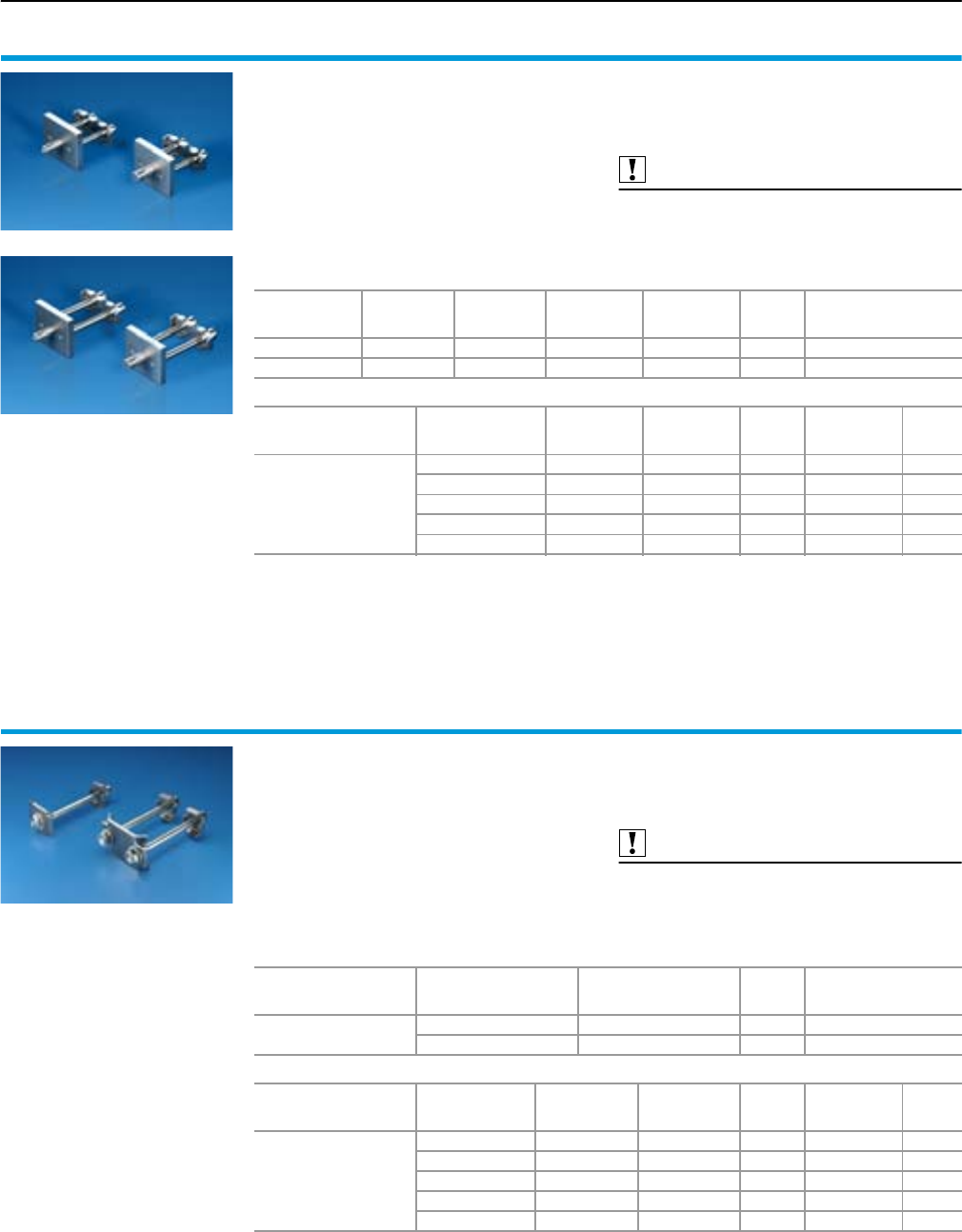
Flat-PLS
Form 2-4 busbar systems
95Rittal Ri4Power Form 2-4
Connection plates
with studs M12/16
for Flat-PLS
For connecting ring terminals to a Flat-PLS bus-
bar system with 2 – 4 bars per conductor. The
mounting accessories supplied loose may be
used to mount the connection terminal on a Flat-
PLS busbar system without the need for drilling.
Material:
E-Cu, nickel-plated
Supply includes:
Assembly parts.
Also required:
Screw connections Flat-PLS,
see page 104.
Detailed drawing,
see page 128.
For system Ter mi n al
studs
Stud
length
mm
Rated torque
Terminal stud
Nm
Rated torque
Screw M10
Nm
Packs of Model No.
SV
Flat-PLS M12 30 40 20 1 9676.700
Flat-PLS M16 30 40 20 1 9676.704
Accessories
For
busbar width B
mm
Screw Rated torque
Nm Packs of Model No.
SV Page
Screw connections
for Flat-PLS busbar
systems
40 M10 x 60 20 8 9676.806 104
50 M10 x 70 20 8 9676.807 104
60 M10 x 80 20 8 9676.808 104
80 M10 x 100 20 8 9676.810 104
100 M10 x 120 20 8 9676.812 104
Connection plates
with studs M10
for Flat-PLS
For connecting ring terminals to a Flat-PLS bus-
bar system with 2 – 4 bars per conductor. The
straight-through screws and the mounting acces-
sories supplied loose may be used to mount the
connection terminal on a Flat-PLS busbar system
without the need for drilling.
Material:
E-Cu, nickel-plated
Supply includes:
Assembly parts.
Also required:
Screw connections Flat-PLS,
see page 104.
Detailed drawing,
see page 128.
For system Te r mi n a l
stud
Rated torque
Screw M10
Nm
Packs of Model No.
SV
Flat-PLS M10 20 1 9676.710
2 x M10 20 1 9676.714
Accessories
For
busbar width B
mm
Screw Rated torque
Nm Packs of Model No.
SV Page
Screw connections
for Flat-PLS busbar
systems
40 M10 x 80 20 8 9676.808 104
50 M10 x 90 20 8 9676.809 104
60 M10 x 100 20 8 9676.810 104
80 M10 x 120 20 8 9676.812 104
100 M10 x 140 20 8 9676.814 104
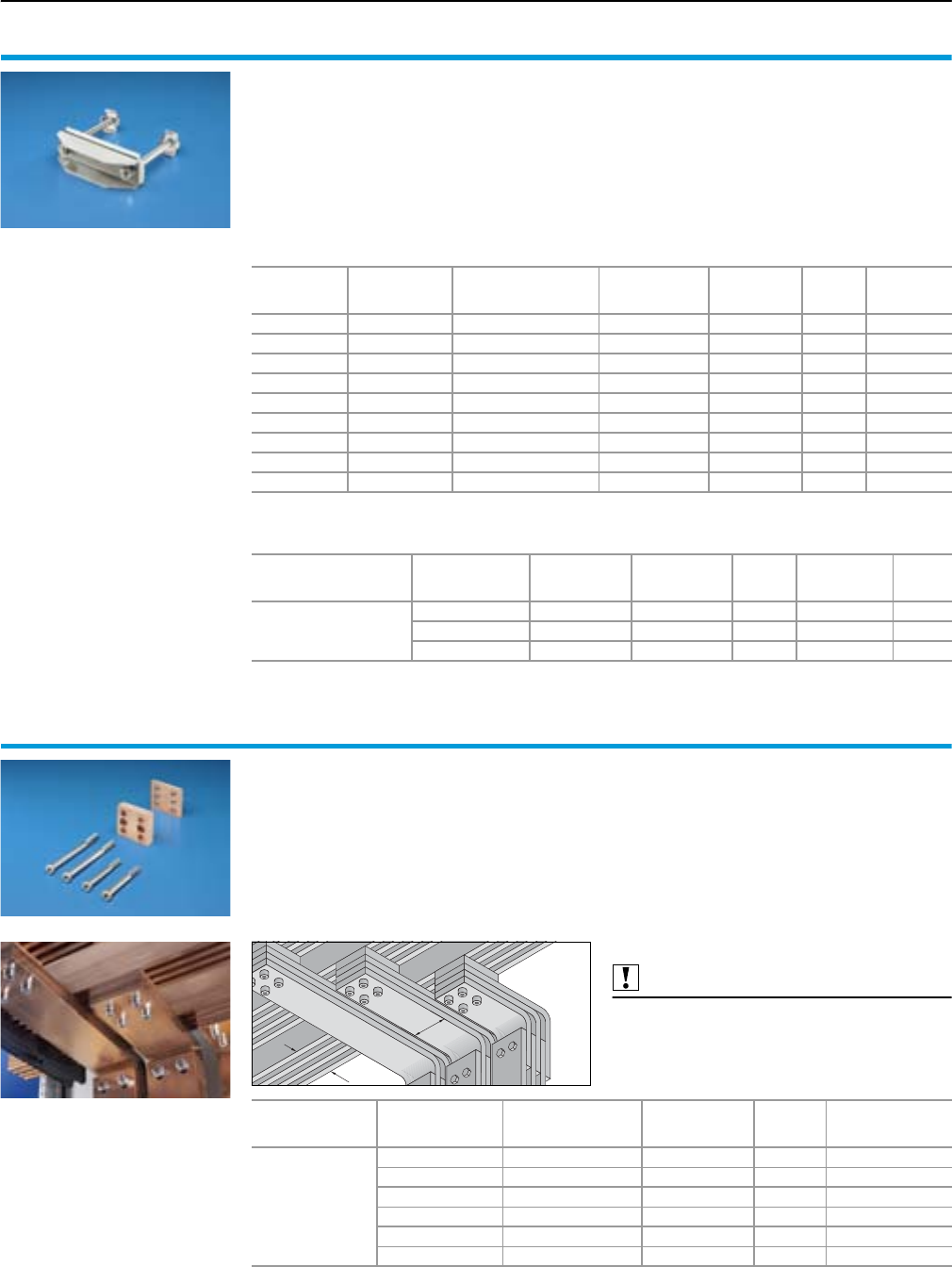
Form 2-4 busbar systems
Flat-PLS
96 Rittal Ri4Power Form 2-4
Connection plates
for laminated copper bars
for Flat-PLS
For connecting laminated copper bars up to 2 x
10 x 100 x 1.0 mm (Flexibar) to a Flat-PLS busbar
system with 2 – 4 bars per conductor. The mount-
ing accessories supplied loose may be used to
mount the copper bar on a Flat-PLS busbar sys-
tem without the need for drilling.
Material:
Infill plate: E-Cu, nickel-plated
Top: Stainless steel
Supply includes:
Assembly parts.
Laminated copper bars,
see page 112.
Detailed drawing,
see page 128.
For system
For
busbar width
mm
For
laminated copper bars
up to
Screw Rated torque
Nm Packs of Model No.
SV
Flat-PLS 60 60 2 x 10 x 32 x 1 mm 2 off M10 x 115 20 1 9676.741
Flat-PLS 60 60 2 x 10 x 63 x 1 mm 2 off M10 x 115 25 1 9676.742
Flat-PLS 60 60 2 x 10 x 100 x 1 mm 2 off M10 x 115 30 1 9676.743
Flat-PLS 100 100 2 x 10 x 32 x 1 mm 2 off M10 x 150 20 1 9676.744
Flat-PLS 100 100 2 x 10 x 63 x 1 mm 2 off M10 x 150 25 1 9676.745
Flat-PLS 100 100 2 x 10 x 100 x 1 mm 2 off M10 x 150 30 1 9676.746
Flat-PLS B1) 2 x 10 x 32 x 1 mm Without screws 20 1 9676.7472)
Flat-PLS B1) 2 x 10 x 63 x 1 mm Without screws 25g 1 9676.7482)
Flat-PLS B1) 2 x 10 x 100 x 1 mm Without screws 30 1 9676.7492)
1)
For the version without screw, the relevant screw must additionally be ordered according to the relevant busbar width B.
2) Version without assembly screws.
Accessories
For
busbar width B
mm
Screw Rated torque
Nm Packs of Model No.
SV Page
Screw connections
for Flat-PLS busbar
systems
40 M10 x 90 20/25/30 8 9676.809 104
50 M10 x 100 20/25/30 8 9676.810 104
80 M10 x 130 20/25/30 8 9676.813 104
Contact makers
for Flat-PLS
For connecting connection brackets and con-
nector kits of flat copper bars to Flat-PLS busbar
systems; no drilling required
For connecting the connection brackets or a con-
nector kit to the main busbar system, a suitable
screw connector kit should be ordered separately.
Material:
E-Cu
Supply includes:
Contact maker,
assembly aid for Flat-PLS with 60 or 100 mm
bar width1),
assembly parts.
Note:
Nickel-plated version of the contact maker
for connecting alumminium bars
available on request.
Also required:
Screw connections Flat-PLS2),
see page 104.
Detailed drawing,
see page 127.
B
n
For system
For
busbar width (B)
mm
No. (n) of
bars per
conductor
Rated torque
Nm Packs of Model No.
SV
Flat-PLS 60 +
Flat-PLS 100
60 2 20 1 9676.526
60 3 or 4 20 1 9676.546
80 2 20 1 9676.528
80 3 or 4 20 1 9676.548
100 2 20 1 9676.520
100 3 or 4 20 1 9676.540
1) If alternative main busbar widths are used, the screws supplied loose with the mounting aid cannot be used.
2) Required screw length for attaching the connection bracket:
Length of screw connection = (no. of bars of the connection bracket x 10 mm) + width of main busbar
system + 40 mm.
Required screw length for attaching the connector kits to main busbar systems in the rear section:
Length of screw connection = (no. of bars of connector kits x 10 mm) + width of main busbar system + 40 mm
+ sum total of distances between the bars of the connector kits.
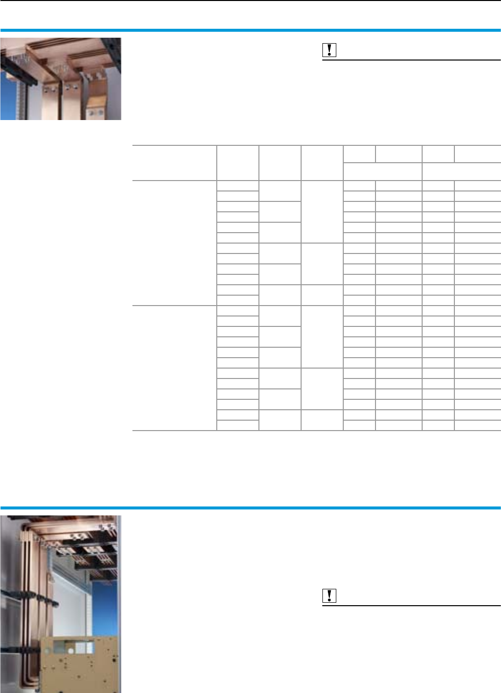
Flat-PLS
Form 2-4 busbar systems
97Rittal Ri4Power Form 2-4
Connection bracket
for Flat-PLS
For connecting connection brackets and con-
nector kits of flat copper bars to Flat-PLS busbar
systems; no drilling required.
Material:
E-Cu
Supply includes:
Connection bracket without assembly parts.
Also required:
Contact maker,
see page 96.
Connector kit for Flat-PLS,
see page 88.
Screw connections for Flat-PLS1),
see page 104.
M12 screw connections for connection brackets,
see page 104.
For
system
Flat-PLS
For
conductor
No. of
bars per
conductor
Bar width
of
connection
bracket
Packs of Model No.
SV Packs of Model No.
SV
For enclosure depth
600 mm
For enclosure depth
800 mm
for connecting
connector kits of
air circuit-breakers
to a Flat-PLS 60
main bar system
in the roof section,
base section,
directly above or below
the air circuit-breaker
L1, L2, L3 1
60
1 set 9676.201 1 set 9676.221
N 1 set 9676.202 1 set 9676.222
L1, L2, L3 21 set 9676.203 1 set 9676.223
N 1 set 9676.204 1 set 9676.224
L1, L2, L3 31 set 9676.205 1 set 9676.225
N 1 set 9676.206 1 set 9676.226
L1, L2, L3 2
100
1 set 9676.213 1 set 9676.233
N 1 set 9676.214 1 set 9676.234
L1, L2, L3 31 set 9676.215 1 set 9676.235
N 1 set 9676.216 1 set 9676.236
L1, L2, L3 3120
1 set 9676.217 1 set 9676.237
N 1 set 9676.218 1 set 9676.238
for connecting
connector kits of
air circuit-breakers
to a Flat-PLS 100
main bar system
in the roof section,
base section,
directly above or below
the air circuit-breaker
L1, L2, L3 1
60
1 set 9676.301 1 set 9676.321
N– – 1 set 9676.322
L1, L2, L3 21 set 9676.303 1 set 9676.323
N– – 1 set 9676.324
L1, L2, L3 31 set 9676.305 1 set 9676.325
N– – 1 set 9676.326
L1, L2, L3 2
100
1 set 9676.313 1 set 9676.333
N– – 1 set 9676.334
L1, L2, L3 31 set 9676.315 1 set 9676.335
N– – 1 set 9676.336
L1, L2, L3 3120
1 set 9676.317 1 set 9676.337
N– – 1 set 9676.338
1) Screw length = (no. of bars x 10 mm) + bar width of main busbar + 40 mm.
No. of screws per bracket: for 2 bars, per conductor of the main busbar system: 2,
for 3/4 bars, per conductor of the main busbar system: 4
Connector kits
for Flat-PLS
For connecting air circuit-breakers (ACB) to
Flat-PLS busbar systems in SV-TS 8 modular
enclosures. Please include the design code for
the relevant specification in the order text for your
connector kit.
We highly recommend the Rittal Power Engineer-
ing software for easier configuration of the con-
nector kits – see page 123.
Note:
Model No. design code,
see page 88.
Material:
E-Cu
Supply includes:
Connection bracket.
Also required:
M12 screw connections for connection brackets,
see page 104.
Screw connections Flat-PLS,
see page 104.
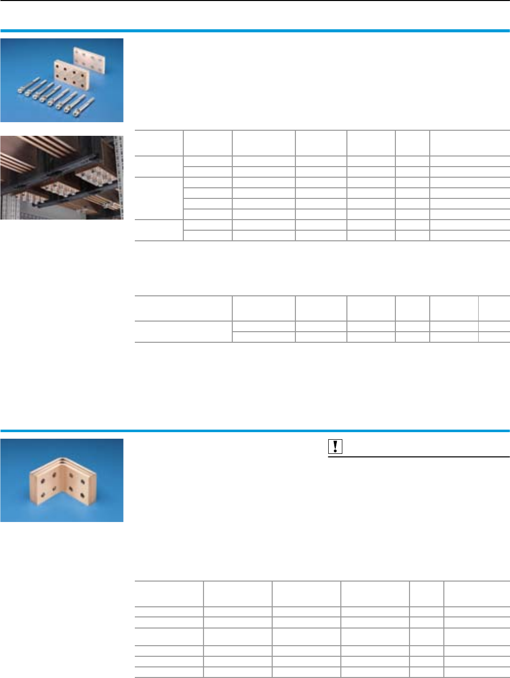
Rittal Ri4Power Form 2-4
Form 2-4 busbar systems
Flat-PLS
98
Longitudinal connector
for Flat-PLS
For connecting Flat-PLS busbar systems,
no drilling required.
Material:
E-Cu
Supply includes:
Assembly parts.
Note:
Nickel-plated version of the longitudinal connec-
tor for connecting alumminium bars available on
request.
Detailed drawing,
see page 127.
For system
No. of
bars per
conductor
For
busbar width
mm
Screw Rated torque
Nm Packs of Model No.
SV
Flat-PLS 60 260M10 x 1002019676.626
3 or 4 60 M10 x 100 20 1 9676.646
Flat-PLS 100
280M10 x 1202019676.628
3 or 4 80 M10 x 120 20 1 9676.648
2 100 M10 x 140 20 1 9676.620
3 or 4 100 M10 x 140 20 1 9676.640
Flat-PLS 2B
1) Without screw 20 1 9676.6212) 3)
3 or 4 B1) Without screw 20 1 9676.6412) 4)
1) For the version without screw, the relevant screw must additionally be ordered according to the relevant busbar
width B.
2) Design as for SV 9676.620/SV 9676.640, but without assembly screws.
3) Number of screws: 4
4) Number of screws: 8
Accessories
For
busbar width B
mm
Screw Rated torque
Nm Packs of Model No.
SV Page
Screw connections
for Flat-PLS busbar systems
40 M10 x 80 20 8 9676.808 104
50 M10 x 90 20 8 9676.809 104
Angular connector
for Flat-PLS busbar systems
For connecting horizontal and vertical Flat-PLS
busbar systems.
Material:
E-Cu
Supply includes:
Bracket.
Note:
No. of corner brackets required
for applications
●3-pole = 3
●4-pole = 4
Also required:
Screw connections for Flat-PLS busbar system1),
see page 104.
Claw with threaded insert,
see page 104.
For
systems
Bar population
up to
For
enclosure depth
mm
No. of
brackets Packs of Model No.
SV
Flat-PLS 60 2 x 40 x 10 mm 600/800 2 x 40 x 10 mm 1 9675.842
Flat-PLS 60 2 x 60 x 10 mm 600/800 3 x 40 x 10 mm 1 9675.843
Flat-PLS 60/100 4 x 40 x 10 mm or
2 x 100 x 10 mm 600/800 2 x 80 x 10 mm 1 9675.882
Flat-PLS 60 4 x 60 x 10 mm 600/800 3 x 80 x 10 mm 1 9675.883
Flat-PLS 100 4 x 80 x 10 mm 600/800 2 x 100 x 10 mm 1 9675.892
Flat-PLS 100 4 x 100 x 10 mm 600/800 3 x 100 x 10 mm 1 9675.893
1) Required length of screw connection = (no. of brackets x 10 mm) + bar width of main busbar system + 20 mm.
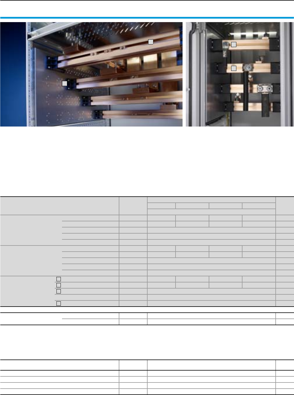
Rittal Ri4Power Form 2-4
Accessories
Form 2-4 busbar systems
99
1
2
3
4
Cable connection system
for Maxi-PLS/Flat-PLS
The type-tested cable connection system facilitates fast, cost-optimi-
sed assembly while guaranteeing the very highest level of security.
Thanks to the sliding block system, the connection components may
be moved around as required, for simple, manageable connection of
cables and lines.
In conjunction with the connection brackets and connection kits of
Ri4Power sytem technology, the complete assembly of air circuit-
breaker sections is simple and requires minimal installation time.
Cable connection systems are dimensioned according to
●Rated current for incoming/outgoing circuit
●Enclosure dimensions
●Number of poles in the connection
●Type and number of cables or lines
For rated current of cable connection system Packs of
For enclosure width mm
Page600 800 1000 1200
Model No. SV
up to 2000 A
Cable connection bar 1 9640.206 9640.236 9640.266 9640.296 84
End supports 6 9640.010 9640.010 9640.010 9640.010 84
Terminal studs M12 3 9640.370 85
Terminal studs M16 3 9640.380 85
Direct connection terminal 1 9640.325 85
up to 3200 A
Cable connection bar 1 9640.201 9640.231 9640.261 9640.291 84
End supports 6 9640.010 9640.010 9640.010 9640.010 84
Terminal studs M12 3 9640.370 85
Terminal studs M16 3 9640.380 85
Direct connection terminal 1 9640.325 85
up to 4000 A
Cable connection bar 1 9650.201 9650.231 9650.261 9650.291 86
End supports 6 9650.010 9650.010 9650.010 9650.010 86
Terminal studs M12 3 9650.370 87
Terminal studs M16 3 9650.380 87
Direct connection terminal 1 9650.325 87
Additionally required
Side panel module for
cable connection space
For enclosure depth 600 mm 2 9673.069 51
For enclosure depth 800 mm 2 9673.089 51
For more connection accessories, see page 85 or 87.
1
2
3
4
Order example
Cable connection for 2500 A, 4-pole, for enclosure W x H x D 800 x 2000 x 800 mm:
Designed for 6 cables, 240 mm2 per conductor, with ring terminals for studs M12
Required
quantity Model No. SV
Side panel module for cable connection space (D = 800 mm) 2 9673.089
Cable connection bar 4 9640.231
End supports 8 9640.010
Terminal studs M12 24 9640.370
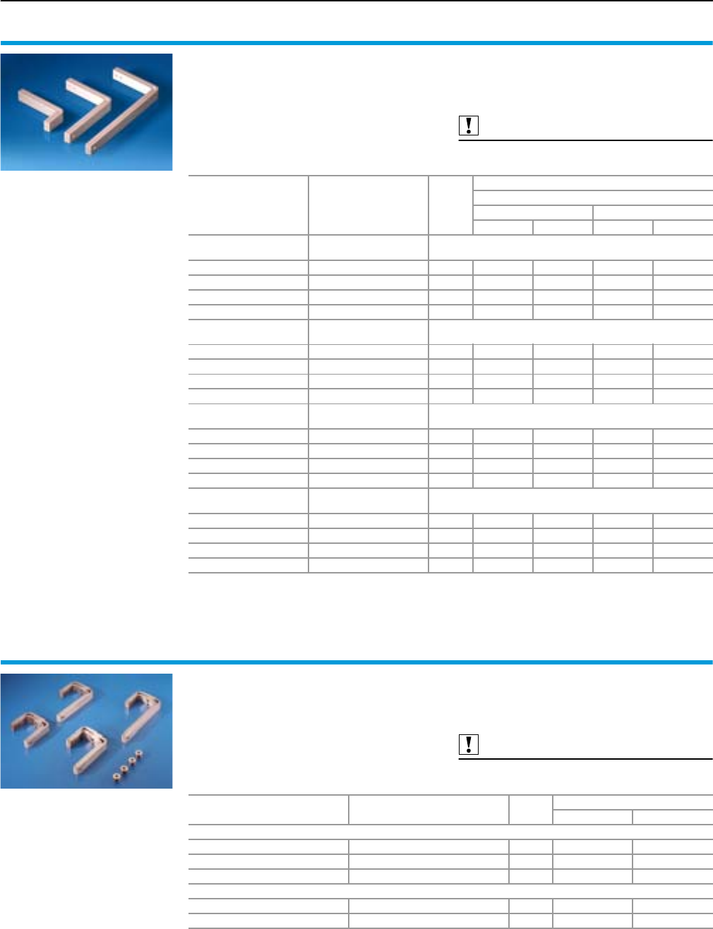
Rittal Ri4Power Form 2-4
Form 2-4 busbar systems
Accessories
100
T-connector kits
for Maxi-PLS/RiLine60 bar systems
For connecting horizontal Maxi-PLS main busbar
systems to vertical RiLine60 distribution busbar
systems in the modular outgoing section.
Material:
E-Cu
Supply includes:
Assembly parts.
Also required:
Distribution busbars,
see page 102.
Main busbar system Distribution busbar
system
Packs
of
Model No. SV
For enclosure depth mm
600 800
3-pole 4-pole 3-pole 4-pole
In the roof section/
base section
Behind the
compartment
Maxi-PLS 1600/2000 Cu 30 x 10/5 mm 1 set 9675.303 9675.304 9675.303 9675.304
Maxi-PLS 3200 Cu 30 x 10/5 mm 1 set 9675.311 – 9675.313 9675.314
Maxi-PLS 1600/2000 PLS 1600 1 set 9675.306 9675.307 9675.306 9675.307
Maxi-PLS 3200 PLS 1600 1 set 9675.315 – 9675.316 9675.317
In the roof section/
base section
In the compartment
(indoors)
Maxi-PLS 1600/2000 Cu 30 x 10/5 mm 1 set 9675.321 9675.322 9675.323 9675.324
Maxi-PLS 3200 Cu 30 x 10/5 mm 1 set 9675.331 – 9675.333 9675.334
Maxi-PLS 1600/2000 PLS 1600 1 set 9675.325 9675.328 9675.326 9675.327
Maxi-PLS 3200 PLS 1600 1 set 9675.335 – 9675.336 9675.337
In the rear section
top/bottom
Behind the
compartment
Maxi-PLS 1600/2000 Cu 30 x 10/5 mm 1 set 9675.343 9675.344 9675.343 9675.344
Maxi-PLS 3200 Cu 30 x 10/5 mm 1 set – – 9675.353 9675.354
Maxi-PLS 1600/2000 PLS 1600 1 set 9675.346 9675.347 9675.346 9675.347
Maxi-PLS 3200 PLS 1600 1 set – – 9675.356 9675.357
In the rear section
top/bottom
In the compartment
(indoors)
Maxi-PLS 1600/2000 Cu 30 x 10/5 mm 1 set 9675.361 9675.362 9675.363 9675.364
Maxi-PLS 3200 Cu 30 x 10/5 mm 1 set – – 9675.373 9675.374
Maxi-PLS 1600/2000 PLS 1600 1 set 9675.365 9675.368 9675.366 9675.367
Maxi-PLS 3200 PLS 1600 1 set – – 9675.376 9675.377
T-connector kits
for Rittal RiLine60 busbar systems
For connecting horizontal RiLine60 main busbar
systems to vertical RiLine60 distribution busbar
systems.
Material:
E-Cu
Supply includes:
Assembly parts.
Also required:
Distribution busbars,
see page 102.
Main busbar system Distribution busbar system Packs
of
Model No. SV
3-pole 4-pole
Behind the compartment
PLS 1600 Cu 30 x 10/5 mm 1 set 9675.130 9675.140
Cu 30 x 10/5 mm Cu 30 x 10/5 mm 1 set 9675.133 9675.143
PLS 1600 PLS 1600 1 set 9675.136 9675.146
Inside the compartment
PLS 1600/Cu 30 x 10/5 mm Cu 30 x 10/5 mm 1 set 9675.1531) 9675.1631)
PLS 1600 PLS 1600 1 set 9675.1561) 9675.1661)
1) Only suitable for enclosure depth 600 mm.
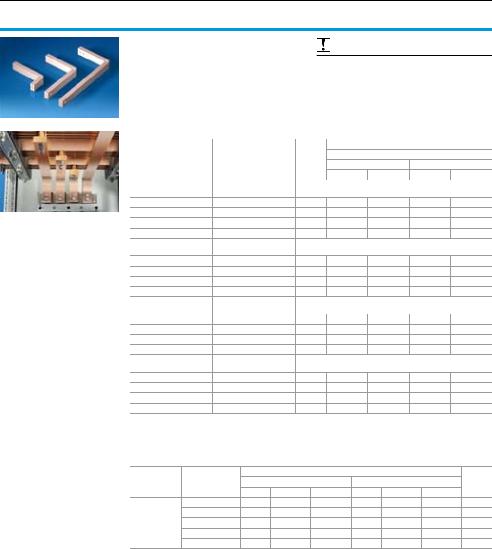
Rittal Ri4Power Form 2-4
Accessories
Form 2-4 busbar systems
101
T-connector kits
for Flat-PLS/RiLine60 bar systems
For connecting horizontal Flat-PLS main busbar
systems to vertical RiLine60 distribution busbar
systems in the modular outgoing section.
Material:
E-Cu
Supply includes:
Sets of screws for connection to distribution
busbar system.
Also required:
Distribution busbar,
see page 102.
Spacer rolls SV 9676.5031),
see page 103.
Screw connections for Flat-PLS1) 2),
see page 104.
Claw with threaded insert M101),
see page 104.
Main busbar system Distribution busbar
system
Packs
of
Model No. SV
For enclosure depth mm
600 800
3-pole 4-pole 3-pole 4-pole
In the roof section/
base section
Behind the
compartment
Flat-PLS 60 Cu 30 x 10/5 mm 1 set 9675.501 9675.502 9675.503 9675.504
Flat-PLS 100 Cu 30 x 10/5 mm 1 set 9675.511 – 9675.513 9675.514
Flat-PLS 60 PLS 1600 1 set 9675.505 9675.508 9675.506 9675.507
Flat-PLS 100 PLS 1600 1 set 9675.515 – 9675.516 9675.517
In the roof section/
base section
In the compartment
(indoors)
Flat-PLS 60 Cu 30 x 10/5 mm 1 set 9675.521 9675.522 9675.523 9675.524
Flat-PLS 100 Cu 30 x 10/5 mm 1 set 9675.531 – 9675.533 9675.534
Flat-PLS 60 PLS 1600 1 set 9675.525 9675.528 9675.526 9675.527
Flat-PLS 100 PLS 1600 1 set 9675.535 – 9675.536 9675.537
In the rear section
top/bottom
Behind the
compartment
Flat-PLS 60 Cu 30 x 10/5 mm 1 set – – 9675.543 9675.544
Flat-PLS 100 Cu 30 x 10/5 mm 1 set – – 9675.553 9675.554
Flat-PLS 60 PLS 1600 1 set – – 9675.546 9675.547
Flat-PLS 100 PLS 1600 1 set – – 9675.556 9675.557
In the rear section
top/bottom
In the compartment
(indoors)
Flat-PLS 60 Cu 30 x 10/5 mm 1 set – – 9675.563 9675.564
Flat-PLS 100 Cu 30 x 10/5 mm 1 set – – 9675.573 9675.574
Flat-PLS 60 PLS 1600 1 set – – 9675.566 9675.567
Flat-PLS 100 PLS 1600 1 set – – 9675.576 9675.577
1) For main busbar system with 2 or 3 bars, 1 spacer roll, 1 screw connection and 1 claw should be ordered per pole.
2) For main busbar systems with 4 bars, 2 spacer rolls, 2 screw connections and 2 claws should be ordered per pole.
Accessories
For
busbar width B
mm
Screws for connecting a T-connection kit for
PageCu 30 x 10/5 mm PLS 1600
Packs of Screw Model No. Packs of Screw Model No.
Screw
connections
for Flat-PLS
busbar
systems
40 8 M10 x 90 9676.809 8 M10 x 100 9676.810 104
50 8 M10 x 100 9676.810 8 M10 x 110 9676.811 104
60 8 M10 x 110 9676.811 8 M10 x 120 9676.812 104
80 8 M10 x 130 9676.813 8 M10 x 140 9676.814 104
100 8 M10 x 150 9676.815 8 M10 x 160 9676.816 104
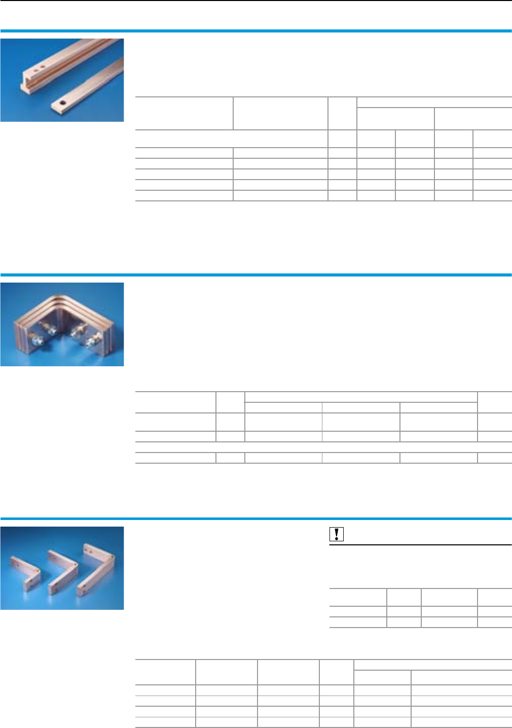
Rittal Ri4Power Form 2-4
Form 2-4 busbar systems
Accessories
102
Distribution busbars
Prepared for the connection of T-connector kits.
The lengths are adapted for applications in TS 8
enclosures.
Material:
E-Cu
For main busbar system
with RiLine60 and distribu-
tion busbar system behind
the compartment
For distribution busbar
system in the compartment
(indoors)
Packs
of
Version
Cu 30 x 10 mm PLS 1600
For enclosure height
mm
Length
mm
Model No.
SV
Length
mm
Model No.
SV
1800 – 1 1210 9675.218 1150 9675.238
2000 – 1 1410 9675.210 1350 9675.230
2200 18001) 116109675.212 1550 9675.232
–2000
1) 118109675.220 1750 9675.240
–2200
1) 120109675.222 1950 9675.242
1) Also suitable as a vertical busbar for PE/PEN/N.
Corner bracket
E-Cu
●For connecting horizontal Maxi-PLS busbar
systems in the roof/base section to vertical
busbar systems.
●For 90° connection of two Maxi-PLS busbars
in the rear area.
●May be used for individual installation.
Material:
E-Cu
Supply includes:
Bracket, threaded bolts, nuts,
washers.
Note:
No. of corner brackets required
for applications
●3-pole = 3
●4-pole = 4
For Maxi-PLS Packs
of
3/4-pole Page
1600 2000 3200
No. of brackets
per phase 2 x 60 x 10 mm 3 x 60 x 10 mm 3 x 80 x 10 mm
Model No. SV 19640.705 9640.700 9650.700
Also required
Sliding blocks 15 9640.9801) 9640.9801) 9650.9901) 85/87
1) Quantity required per corner bracket: 4
Connector kits
for busbar riser
For connecting horizontal Maxi-PLS busbar
systems in the rear section to vertical busbar
systems.
Material:
E-Cu
Supply includes:
Bracket.
Also required:
Terminal studs for connector kits and connection
brackets,
see page 103.
Sliding blocks
For
Maxi-PLS Packs of Model No. SV Page
1600/2000 15 9640.9801) 85
3200 15 9650.9901) 87
1) Quantity required per connector kit: 4
For
Maxi-PLS
For enclosure
depth
mm
No. of brackets
per phase Packs of
Model No. SV
for 3-pole for 4-pole
1600 600/800 2 1 set 9660.318 9660.318 + 9660.319
2000 600/800 3 1 set 9660.313 9660.313 + 9660.314
3200 600 3 1 set 9660.363 –
3200 800 3 1 set 9660.368 9660.368 + 9660.369
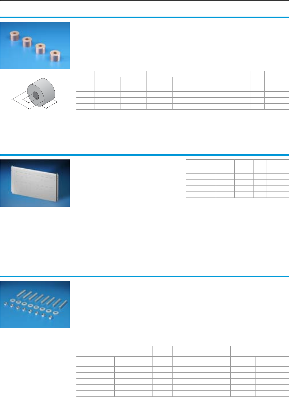
Rittal Ri4Power Form 2-4
Accessories
Form 2-4 busbar systems
103
Spacer rolls
for Maxi-PLS and flat copper bars
For use as a universal spacer.
Material:
E-Cu
20
D
13
Diameter
(D)
mm
Cu bar – Cu bar Maxi-PLS – Cu bar Flat-PLS – Cu bar
Packs
of
Model No.
SV
Cross-section
size
mm2
Max.
rated current
A
Contact
area
mm2
Max.
rated current
A
Contact
area
mm2
Max.
rated current
A
30 550 1100 360 800 380 850 4 9676.503
40 1100 2200 780 1600 670 1400 4 9676.504
50 1800 3400 1380 2800 990 2000 4 9676.505
System attachments
for RiLine60 main busbar system
System attachment with M5 and M6 threaded
holes in a 50 mm pitch for the rear assembly of
a RiLine60 main busbar system up to 1600 A.
For locating into the TS frame.
Material:
Sheet steel, zinc-plated, passivated
Supply includes:
Assembly parts.
Note:
RiLine60 busbar systems,
see page 66 – 76.
For
enclosure width
mm
Width
mm
Height
mm
Packs
of
Model No.
SV
300 238.5 362 1 9674.003
400 338.5 362 1 9674.004
600 538.5 362 1 9674.006
800 738.5 362 1 9674.008
Terminal studs
for connector kits and connection brackets
Special bolt for attaching a connector kit or con-
nection bracket with and without U contact maker
to a Maxi-PLS busbar section.
May be used for 3- and 4-pole connector kits.
Supply includes:
8 nuts and 8 washers.
Note:
For a connector kit bar width of 120 mm, 2 packs
are required per connector kit.
No. of bars per phase
when using
Packs
of
For
Maxi-PLS 1600/2000
For
Maxi-PLS 3200
with
U contact maker
without
U contact maker1)
Screw
design Model No. SV Screw
design Model No. SV
–18M10 x 359676.971 M12 x 40 9676.981
–28M10 x 459676.972 M12 x 50 9676.982
138M10 x 559676.973 M12 x 60 9676.983
2–8M10 x 709676.976 M12 x 70 9676.986
3–8M10 x 809676.977 M12 x 80 9676.987
1) Sliding blocks – see page 85/87 – additionally required.
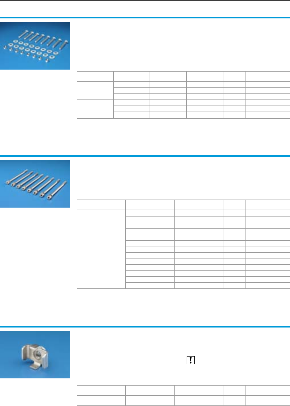
Rittal Ri4Power Form 2-4
Form 2-4 busbar systems
Accessories
104
Screw connections
for connection brackets
For connecting connection brackets and a con-
nector kit.
May be used for 3- and 4-pole connector kits.
Material:
Steel screws, zinc-plated, passivated
Supply includes:
8 nuts and 16 washers.
Note:
For a bar width of 120 mm, 2 packs are required
per connector kit.
For
systems Screw design Rated torque
Nm
No. of bars
per phase Packs of Model No. SV
Maxi-PLS
1600/2000/3200
M10 x 40 20 1 8 9676.966
M10 x 60 20 2 8 9676.967
M10 x 80 20 3 8 9676.968
Maxi-PLS
1600/2000/3200
and Flat-PLS
60 + 100
M12 x 40 40 1 8 9676.961
M12 x 60 40 2 8 9676.962
M12 x 80 40 3 8 9676.963
Screw connections
for Flat-PLS busbar systems
For attaching connection brackets and connector
kits, with and without contact makers, to Flat-PLS
busbar systems.
Material:
Stainless steel
Supply includes:
Allen screw,
spring lock washer and
plain washer.
For
systems
Screw
design
Rated torque
Nm Packs of Model No. SV
Flat-PLS
60 + 100
M10 x 60 20 8 9676.806
M10 x 70 20 8 9676.807
M10 x 80 20 8 9676.808
M10 x 90 20 8 9676.809
M10 x 100 20 8 9676.810
M10 x 110 20 8 9676.811
M10 x 120 20 8 9676.812
M10 x 130 20 8 9676.813
M10 x 140 20 8 9676.814
M10 x 150 20 8 9676.815
M10 x 160 20 8 9676.816
M10 x 170 20 8 9676.817
M10 x 190 20 8 9676.819
Claw with nut M10
for Flat-PLS
Double claw with nut M10. Used in combination
with screw connections for the mechanical con-
nection of connection components such as
angular connectors.
Material:
Stainless steel
Supply includes:
8 claws.
Also required:
Screw connectors for Flat-PLS,
see page 104.
For
systems Insert nut Rated torque
Nm Packs of Model No. SV
Flat-PLS
60 + 100 M10 20 8 9676.832
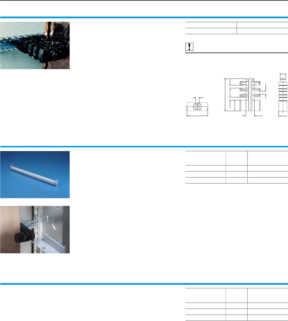
Rittal Ri4Power Form 2-4
Accessories
Form 2-4 busbar systems
105
Stacking insulator
To support the connection kits top/bottom for
circuit-breakers. Easily retro-fitted.
Supply includes:
Assembly parts.
Also required:
Support rail for stacking insulator,
see page 105.
Ø 70
11
Ø 28
10 . 2 10 . 2
10 . 2
36
10 8
28
19
Packs of Model No. SV
69660.200
Support rails
for stacking insulator
For attaching to the outer mounting level of the
TS 8 enclosure and for the configuration of
stacking insulators. C rail may also be used as
cable management bar.
Material:
Sheet steel, zinc-plated, passivated
Supply includes:
Assembly parts.
For
enclosure width
mm
Packs of Model No. SV
400 2 9676.194
600 2 9676.196
800 2 9676.198
Stabiliser
for connection kit
To increase short-circuit resistance of the connec-
tion kits to 100 kA, 1 sec.
2 stabilisers are required per connection kit.
May be used for 3- and 4-pole connector kits.
Fitted in addition to the stacking insulators.
Material:
Tapped rod: Fibreglass-reinforced plastic
Supply includes:
2 stabilisers
Assembly parts.
For
enclosure width
mm
Packs of Model No. SV
400 2 9676.184
600 2 9676.186
800 2 9676.188
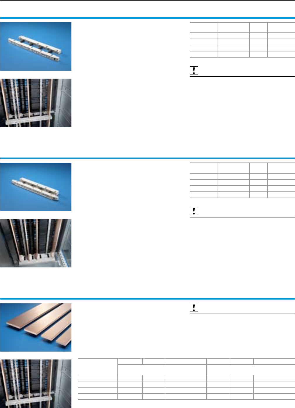
Rittal Ri4Power Form 2-4
Form 2-4 busbar systems
Accessories
106
Busbar support
for switch-disconnector-fuse section
Busbar support for the distribution busbar system
of the switch-disconnector-fuse section, to
assemble the distribution busbar.
The busbar supports are mounted on the section
corner pieces of the assembly kit.
Material:
Fibreglass-reinforced plastic
Supply includes:
Mounting bracket and screws.
Also required:
Assembly kit for switch-disconnector-fuse section,
see page 46.
End support for switch-disconnector-fuse section,
see page 106.
Distribution busbar for switch-disconnector-fuse
section,
see page 106.
Number of
poles
For bars
mm
Packs
of
Model No.
SV
3/4-pole 50 x 10 1 9674.415
3/4-pole 60 x 10 1 9674.416
3/4-pole 80 x 10 1 9674.418
3/4-pole 100 x 10 1 9674.410
End support
for switch-disconnector-fuse section
End support for the distribution busbar system of
the switch-disconnector-fuse section, for vertical
support of the distribution system with infeed from
above.
The end support is secured to the section corner
piece of the assembly kit.
Material:
Fibreglass-reinforced plastic
Supply includes:
Mounting bracket and screws.
Also required:
Assembly kit for switch-disconnector-fuse section,
see page 46.
Distribution busbar for switch-disconnector-fuse
section,
see page 106.
Number of
poles
For bars
mm
Packs
of
Model No.
SV
3/4-pole 50 x 10 1 9674.435
3/4-pole 60 x 10 1 9674.436
3/4-pole 80 x 10 1 9674.438
3/4-pole 100 x 10 1 9674.430
Distribution busbar
for switch-disconnector-fuse section
Distribution busbar to fit the Ri4Power main bus-
bar systems Maxi-PLS and Flat-PLS for installa-
tion in the switch-disconnector-fuse sections.
Material:
E-Cu
Also required:
Busbar support for switch-disconnector-fuse
section,
see page 106.
End support for switch-disconnector-fuse section,
see page 106.
Terminal block distribution busbar,
see page 108.
Dimensions
mm
Length mm Packs of Model No. SV Length mm Packs of Model No. SV
For enclosure height
2000 mm
For enclosure height
2200 mm
50 x 10 1632.5 1 9674.405 1832.5 1 9674.425
60 x 10 1632.5 1 9674.406 1832.5 1 9674.426
80 x 10 1632.5 1 9674.408 1832.5 1 9674.428
100 x 10 1632.5 1 9674.400 1832.5 1 9674.420
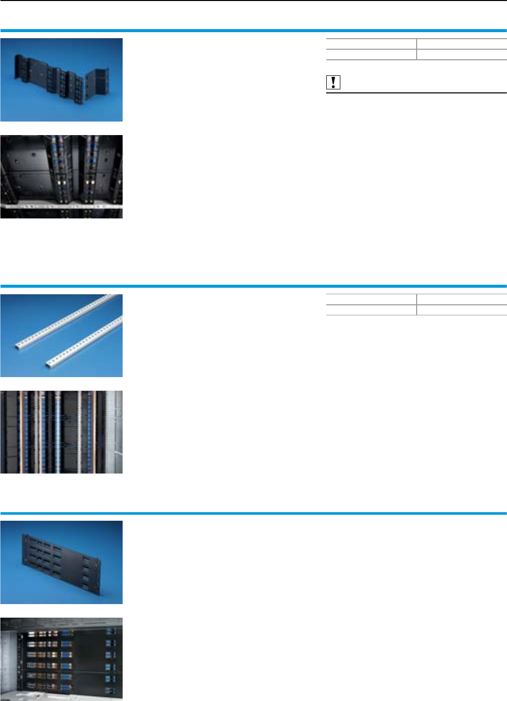
Rittal Ri4Power Form 2-4
Accessories
Form 2-4 busbar systems
107
Distribution busbar cover
for Jean Müller switch-disconnector-fuse
section
Busbar cover as kit for covering the distribution
busbar system of a switch-disconnector-fuse sec-
tion, designed to install devices from Jean Müller.
The 150 mm high busbar and cable connection
space covers shield the busbar compartment
from the functional space and the cable connec-
tion compartment so that it is safe from probe
contact, with a protection category of IP 20. The
internal separation significantly enhances perso-
nal safety of the switchgear, and is a pre-requisite
for all work when the system is live. For systems
from Form 2a and above, this cover is compul-
sory.
Material:
PVC, black
Supply includes:
Busbar cover and cable connection space cover
for enclosure height 2000 mm and 2200 mm.
Also required:
Punched rail cover, distribution busbar,
see page 107.
Packs of Model No. SV
1 set 9674.380
Punched rail cover,
distribution busbar
for Jean Müller switch-disconnector-fuse
section
Required for mounting the distribution busbar
cover. The cover modules are inserted into the
punched rail and create form-fit separation of the
busbar compartment from the functional space
and cable chamber. Suitable for use in enclo-
sures with height 2000 mm and 2200 mm. For
systems from Form 2a and above, this cover is
compulsory.
Material:
Sheet steel, zinc-plated, passivated
Supply includes:
2 punched rails.
Note:
For 1 switch-disconnector-fuse section,
1 pack of punched rails is required.
Packs of Model No. SV
1 set 9674.381
Distribution busbar cover
for ABB/Siemens switch-disconnector-fuse
section
Busbar cover to cover the distribution busbar
system of a switch-disconnector-fuse section,
designed to install equipment from ABB (model
SlimLine) or Siemens (model 3NJ62).
The 200 mm high busbar compartment covers
shield the busbar compartment from the functio-
nal space so that it is safe from probe contact,
with a protection category of IP 20. The internal
separation significantly enhances personal safety
of the switchgear, and is a pre-requisite for all
work when the system is live. For systems from
Form 2a and above, this cover is compulsory.
Material:
PVC, black
Note:
The distribution busbar cover for switch-discon-
nector-fuse sections from ABB/Siemens may be
ordered from ABB under order number NHP
407062R000X.
For enclosure height 2000 mm, a height of
1500 mm should be covered, and for enclosure
height 2200 mm, a height of 1700 mm should
be covered.
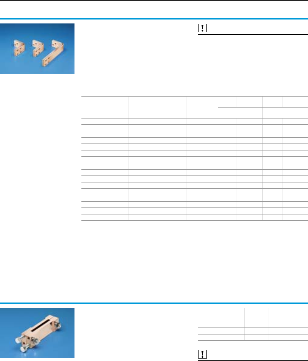
Rittal Ri4Power Form 2-4
Form 2-4 busbar systems
Accessories
108
Connection bracket
for switch-disconnector-fuse section
For connecting Maxi-PLS or Flat-PLS main bus-
bar systems to distribution busbar systems of the
switch-disconnector-fuse sections, no drilling
required.
Material:
E-Cu
Supply includes:
Assembly parts.
Also required:
Maxi-PLS contact makers, 60 mm,
see page 85/87.
Flat-PLS contact makers, 60 mm,
see page 96.
Terminal block distribution bar,
see page 108.
For
system
For
application
For
conductor
Packs
of
Model No.
SV
Packs
of
Model No.
SV
For enclosure depth
600 mm
For enclosure depth
800 mm
Flat-PLS 60 Roof section/base section L1, L2, L3 1 set 9674.451 1 set 9674.453
Flat-PLS 60 Roof section/base section N 1 set 9674.452 1 set 9674.454
Flat-PLS 60 Rear section top/bottom L1, L2, L3 1 set – 1 set 9674.473
Flat-PLS 60 Rear section top/bottom N 1 set – 1 set 9674.474
Flat-PLS 100 Roof section/base section L1, L2, L3 1 set 9674.455 1 set 9674.457
Flat-PLS 100 Roof section/base section N 1 set – 1 set 9674.458
Flat-PLS 100 Rear section top/bottom L1, L2, L3 1 set – 1 set 9674.477
Flat-PLS 100 Rear section top/bottom N 1 set – 1 set 9674.478
Maxi-PLS 1600/2000 Roof section/base section L1, L2, L3 1 set 9674.441 1 set 9674.443
Maxi-PLS 1600/2000 Roof section/base section N 1 set 9674.442 1 set 9674.444
Maxi-PLS 1600/2000 Rear section top/bottom L1, L2, L3 1 set 9674.461 1 set 9674.463
Maxi-PLS 1600/2000 Rear section top/bottom N 1 set 9674.462 1 set 9674.464
Maxi-PLS 3200 Roof section/base section L1, L2, L3 1 set 9674.445 1 set 9674.447
Maxi-PLS 3200 Roof section/base section N 1 set – 1 set 9674.448
Maxi-PLS 3200 Rear section top/bottom L1, L2, L3 1 set – 1 set 9674.467
Maxi-PLS 3200 Rear section top/bottom N 1 set – 1 set 9674.468
Terminal block distribution
busbar
for switch-disconnector-fuse section
Terminal block for connecting the connection
brackets to the distribution busbar system of the
switch-disconnector-fuse section, no drilling
required.
Material:
E-Cu
Supply includes:
Assembly parts.
Detailed drawing,
see page 128.
Also required:
Connection bracket for switch-disconnector-fuse
section,
see page 108.
Distribution busbar for switch-disconnector-fuse
section,
see page 106.
For
distribution busbar
width
mm
Packs of Model No. SV
50/60 1 9674.485
80/100 1 9674.488
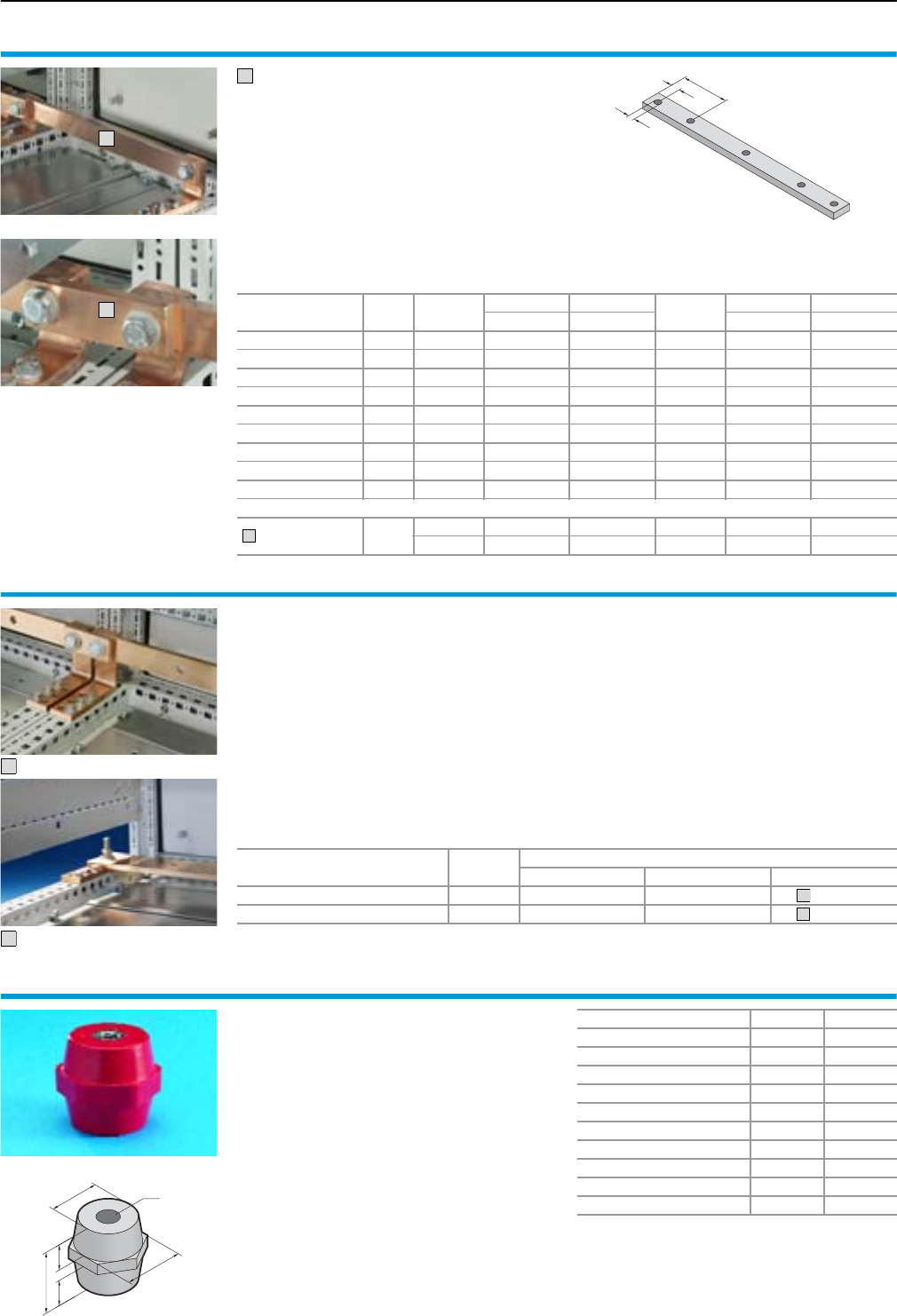
Rittal Ri4Power Form 2-4
Accessories
Form 2-4 busbar systems
109
Busbars
made from E-Cu
Suitable for
●Direct installation in TS 8 enclosures
●Busbar support
−SV 9340.000/.010, see page 66
−SV 9340.004, see page 74
−SV 9340.030/.040, see page 110
−SV 9342.014, see page 76
−SV 3052.000, see Cat. 32, page 391
−SV 3073.000, see Cat. 32, page 387
●PE/PEN combinations in conjunction with
combination angle and baying bracket.
1
2
A
B
C
1
For enclosure width
mm
Packs
of
Length
mm
30 x 5 mm 30 x 10 mm Length
mm
40 x 10 mm 80 x 10 mm
Model No. SV Model No. SV Model No. SV Model No. SV
300 2 265 9661.335 9661.330 292 9661.030 9661.130
400 2 365 9661.345 9661.340 392 9661.040 9661.140
600 2 565 9661.365 9661.360 592 9661.060 9661.160
800 2 765 9661.385 9661.380 792 9661.080 9661.180
1000 2 965 9661.305 9661.300 992 9661.000 9661.100
1200 2 1165 9661.325 9661.320 1192 9661.020 9661.120
A mm 15 15 20 20
B mm – – 158,5 158,5
C mm Ø 11 Ø 11 Ø 14 Ø 14
Accessories
Baying bracket
E-Cu 495 9661.355 9661.350 –– –
– – – 88 9661.050 9661.150
2
PE/PEN combination angle
for PE/PEN combinations
The PE/PEN combination, comprised of busbars,
combination angles and baying brackets, facili-
tates type-tested assembly to IEC 60 439-1.
The pre-manufactured combination angles and
baying brackets, and the busbars customised to
the individual enclosure width, facilitate inexpen-
sive, time-saving assembly.
Material:
E-Cu
Supply includes:
Assembly parts.
Technical specifications:
Tested short-circuit resistance
PE/PEN combination
●30 x 5 mm:
Icw 18 kA, 1 sec.
●PE/PEN combination
30 x 10 mm:
Icw 30 kA, 1 sec.
●PE/PEN combination
40/80 x 10 mm:
Icw 60 kA, 1 sec.
1
2
Combination angle
for Packs of For busbars mm
30 x 5 30 x 10 40 x 10/80 x 10
Form 2-4 insert 4 9661.235 9661.230 9661.2401)
Other applications 4 9661.235 9661.230 9661.2001)
1) Material of PE/PEN combination angles E-Cu 40 x 10 mm
2
1
Base isolators
For configuring busbar systems with any given
bar centre distances and for assembling PE or
PEN bars.
Material:
Duroplastic polyester (UP resin).
Continuous operating temperature max. 135°C.
Ø C
A
BB
D
M10
Rated operating voltage 1 kV 1 kV
Tensile strength 12 kN 13 kN
Torsional strength 75 Nm 90 Nm
Bending strength 6 kN 6 kN
Tightening torque 40 Nm 40 Nm
A mm 40 50
B mm 15 19
Ø C mm 32 42
D mm SW 36 SW 50
Packs of 6 6
Model No. SV 3031.000 3032.000
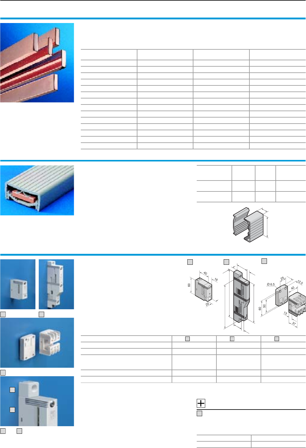
Rittal Ri4Power Form 2-4
Form 2-4 busbar systems
Accessories
110
Busbars
made from E-Cu
To DIN EN 13 601.
Length: 2400 mm/bar.
Dimensions
mm
Weight/bar
kg Packs of Model No. SV
12 x 5 1.28 6 3580.000
15 x 5 1.60 6 3581.000
20 x 5 2.14 6 3582.000
25 x 5 2.67 6 3583.000
30 x 5 3.20 6 3584.000
12 x 10 2.56 6 3580.100
15 x 10 3.20 6 3581.100
20 x 10 4.27 6 3585.000
30 x 10 6.41 6 3586.000
40 x 10 8.55 3 3587.000
50 x 10 10.68 3 3588.000
60 x 10 12.82 3 3589.000
80 x 10 17.09 3 3590.000
100 x 10 21.38 3 3590.010
Busbar cover section
Contact hazard protection via full encapsulation of
the busbars. May be cut to required length.
Material:
Thermally modified hard PVC.
Continuous operating temperature max. 91°C.
Fire protection corresponding to UL 94-V0.
For
busbars
mm
Width (B)
mm Packs of Model No. SV
12 x 5 – 30 x 10 40.6 10
@ 1 m 3092.000
40 – 60 x 10 70.6 10
@ 1 m 3085.000
40.6
20.6
Busbar support
1- and 2-pole
Material:
Polyamide (PA 6.6), 25% fibreglass-reinforced.
Continuous operating temperature max. 130°C.
Fire protection corresponding to UL 94-V0.
Colour:
RAL 7035
1
2
3
1
4
and
1
4
40 16
20
140
16
25
165
150
1
2
3
Version 1-pole 2-pole 1-pole
Bar centre distance –1) 60 mm –1)
For busbars E-Cu 12 x 5 – 30 x 10 mm 12 x 52) – 30 x 10 mm PLS 1600
Tightening torque
● Assembly screw M5 x 16
● Cover attachment/busbar anti-slip guard
(M5 x 16)
3 – 5 Nm
1 – 3 Nm
(M5 x 16)
3 – 5 Nm
1 – 3 Nm
(M6 x 20/353))
3 – 5 Nm
0.7 Nm
Packs of 4 4 4
Model No. SV 9340.0304) 9340.0405) 9342.0304)
1) Bayable for a bar centre distance of 60 mm.
2) If 12 x 5/10 mm busbars are used, the spacer SV 9340.090 is additionally required.
3) 35 mm when using the additional raised section.
4) PEN/N/PE support
5) N/PE support
1
2
3
Accessories:
Additional attachment for SV 9340.030
Optional anti-twist guard for SV 9340.030.
Facilitates support alignment with horizontal
or vertical mounting.
Packs of Model No. SV
49340.035
4
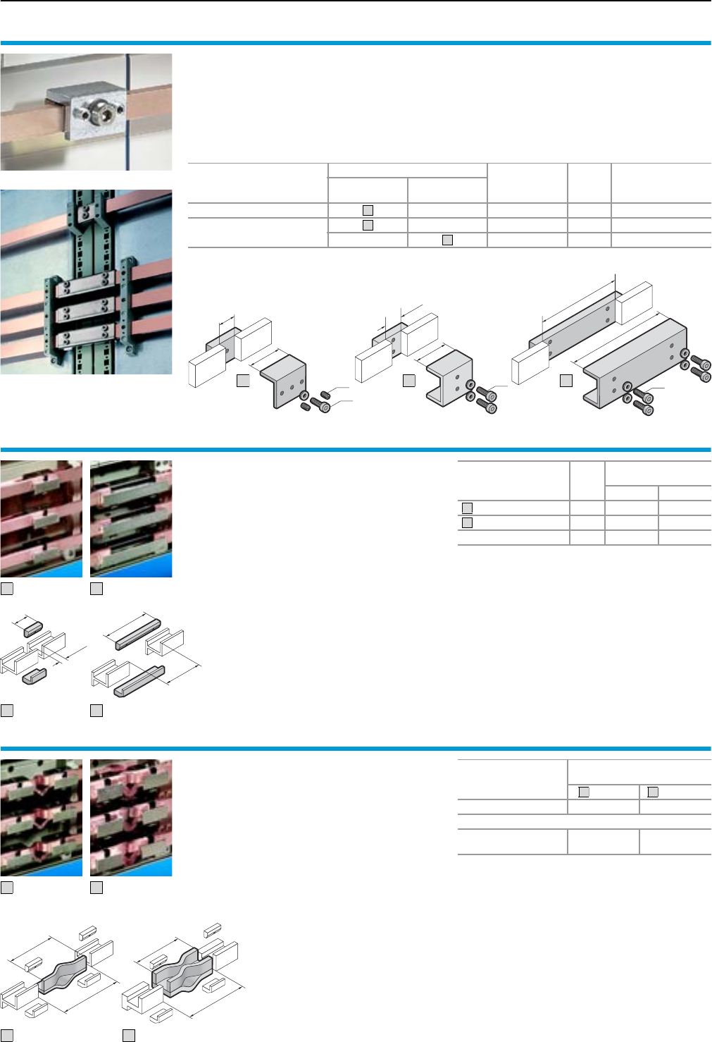
Rittal Ri4Power Form 2-4
Accessories
Form 2-4 busbar systems
111
Busbar connectors
For connecting busbars, no drilling required.
Material:
SV 9350.075
Top part: St 37, nickel-plated surface finish
Base: E-Cu
SV 9320.020/SV 9320.030
Top part: Sheet steel, zinc-plated, passivated
Contact plate: E-Cu, silver-plated
M8
45
8 – 15
M8
140
100 – 110
2
3
40
A
M8
M8
1
A = max. 10 mm
For
busbars
mm
Application Tightening
torque
Packs
of Model No. SV
Single
connection
Bayed
connection1)
12 x 5 – 15 x 10 – 5 Nm/15 Nm2) 3 9350.075
20 x 5 – 30 x 10 – 20 Nm 3 9320.020
– 20 Nm 3 9320.030
1) From enclosure to enclosure
2) Hex socket
– Screw M8 = 5 Nm
– Grub screw M8 = 15 Nm
1
2
3
PLS busbar connectors
For connecting the PLS special busbars;
no drilling required.
Material:
E-Cu, nickel-plated
A
B
50
8– 12
A
101 – 110
150
B
For Packs
of
Model No. SV
for system
PLS 800 PLS 1600
Single connection 3 3504.000 3514.000
Baying connection1) 3 3505.000 3515.000
Tightening torque 10 – 15 Nm 15 – 20 Nm
1) From enclosure to enclosure (TS 8)
A
B
PLS expansion connectors
For thermal and mechanical compensation during
connection of PLS special busbars from enclo-
sure to enclosure (TS 8).
Material:
E-Cu
Note:
With a temperature increase of 30 K, the busbars
will expand in length by around 0.5 mm/m. Conse-
quently, the use of an expansion connector is rec-
ommended for busbar systems with lengths in
excess of 3 m.
A
B
101 – 110
85
101 – 110
85
A
B
Packs of
Model No. SV
for system
PLS 800 PLS 1600
39320.060 9320.070
Also required
PLS
busbar connectors1) 3504.000 3514.000
1) Two busbar connectors are needed to fit
one expansion connector.
A
B
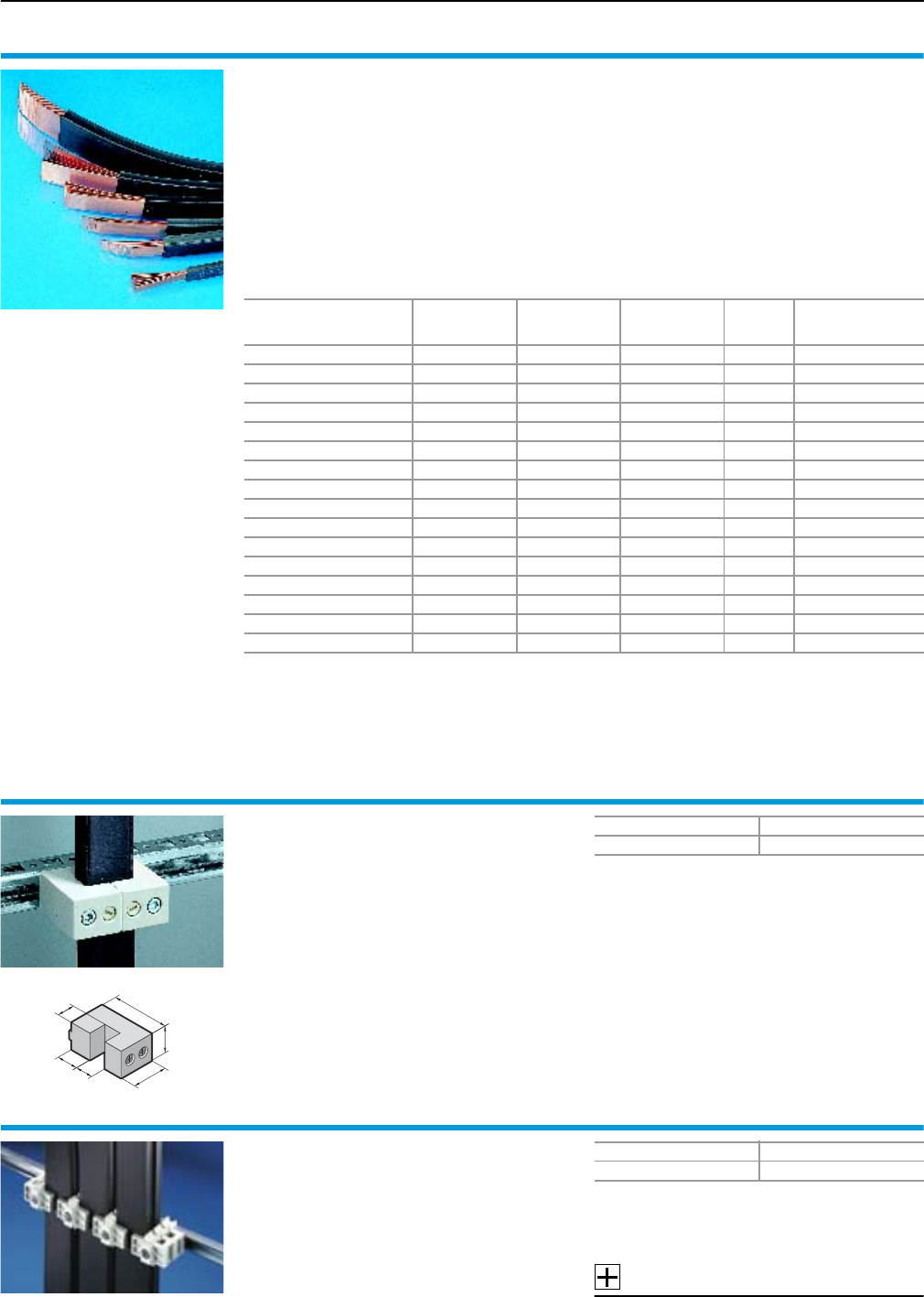
Rittal Ri4Power Form 2-4
Form 2-4 busbar systems
Laminated copper bars and accessories
112
Laminated copper bars
Rittal Flexibar “S”
Length: 2000 mm/bar.
Material:
Cu lamina
●High-purity electrolyte copper F20
Insulation
●High-strength vinyl compound
●Expansion 370%
●Temperature range: –30°C to +105°C
●Flame retardant version to UL 94-V0
●Dielectric strength: 20 kV/mm
Note:
Short-circuit protection diagram,
see page 119.
Configuration1)
mm
In
for
50 K2)
In
for
30 K2)
In
for
10 K2)
Packs of Model No. SV
8 x 6.0 x 0.5 165 A 125 A – 1 3565.010
6 x 9.0 x 0.8 250 A 220 A 120 A 1 3565.000
6 x 13.0 x 0.5 200 A 150 A 110 A 1 3566.000
4 x 15.5 x 0.8 300 A 210 A 140 A 1 3567.000
6 x 15.5 x 0.8 350 A 290 A 170 A 1 3568.000
10 x 15.5 x 0.8 450 A 350 A 190 A 1 3569.000
5 x 20.0 x 1.0 400 A 300 A 180 A 1 3570.000
5 x 24.0 x 1.0 450 A 370 A 230 A 1 3571.000
10 x 24.0 x 1.0 800 A 600 A 340 A 1 3572.000
5 x 32.0 x 1.0 550 A 470 A 280 A 1 3573.000
10 x 32.0 x 1.0 1000 A 800 A 460 A 1 3574.000
5 x 40.0 x 1.0 800 A 600 A 340 A 1 3575.000
10 x 40.0 x 1.0 1200 A 950 A 500 A 1 3576.000
5 x 50.0 x 1.0 900 A 700 A 400 A 1 3577.000
10 x 50.0 x 1.0 1400 A 1000 A 600 A 1 3578.000
10 x 63.0 x 1.0 1600 A 1240 A 715 A 1 3579.000
1) Number of lamina x lamina width x lamina thickness
2) The conductor temperature of the laminated copper bar is derived by adding the ambient temperature and
the temperature increase together.
Example:
SV 3565.000 carrying 220 A, i.e. the temperature increases by 30 K. At an ambient temperature of 35°C,
this produces a resultant conductor temperature of 35°C + 30 K = 65°C.
Universal support
For the attachment of laminated copper bars from
20 x 5 to 63 x 10 mm.
Material:
Fibreglass-reinforced, thermoplastic polyester
(PBT).
Fire protection corresponding to UL 94-V0.
Supply includes:
Screws and “U” nuts for mounting on PS/TS
mounting rails.
Note:
Short-circuit protection diagram,
see page 119.
18
49
15
23
30
15
Packs of Model No. SV
33079.000
Universal holder
For the attachment of multi-stacked laminated
copper bars from 40 x 5 to 100 x 10 mm.
Material:
Fibreglass-reinforced, thermoplastic polyester
(PBT).
Fire protection corresponding to UL 94-V0.
Supply includes:
Screws and sliding nuts for
attachment on C rails.
Note:
Short-circuit protection diagram,
see page 119.
Accessories:
Support rails for stacking insulator,
see page 105.
Packs of Model No. SV
3 set 3079.010
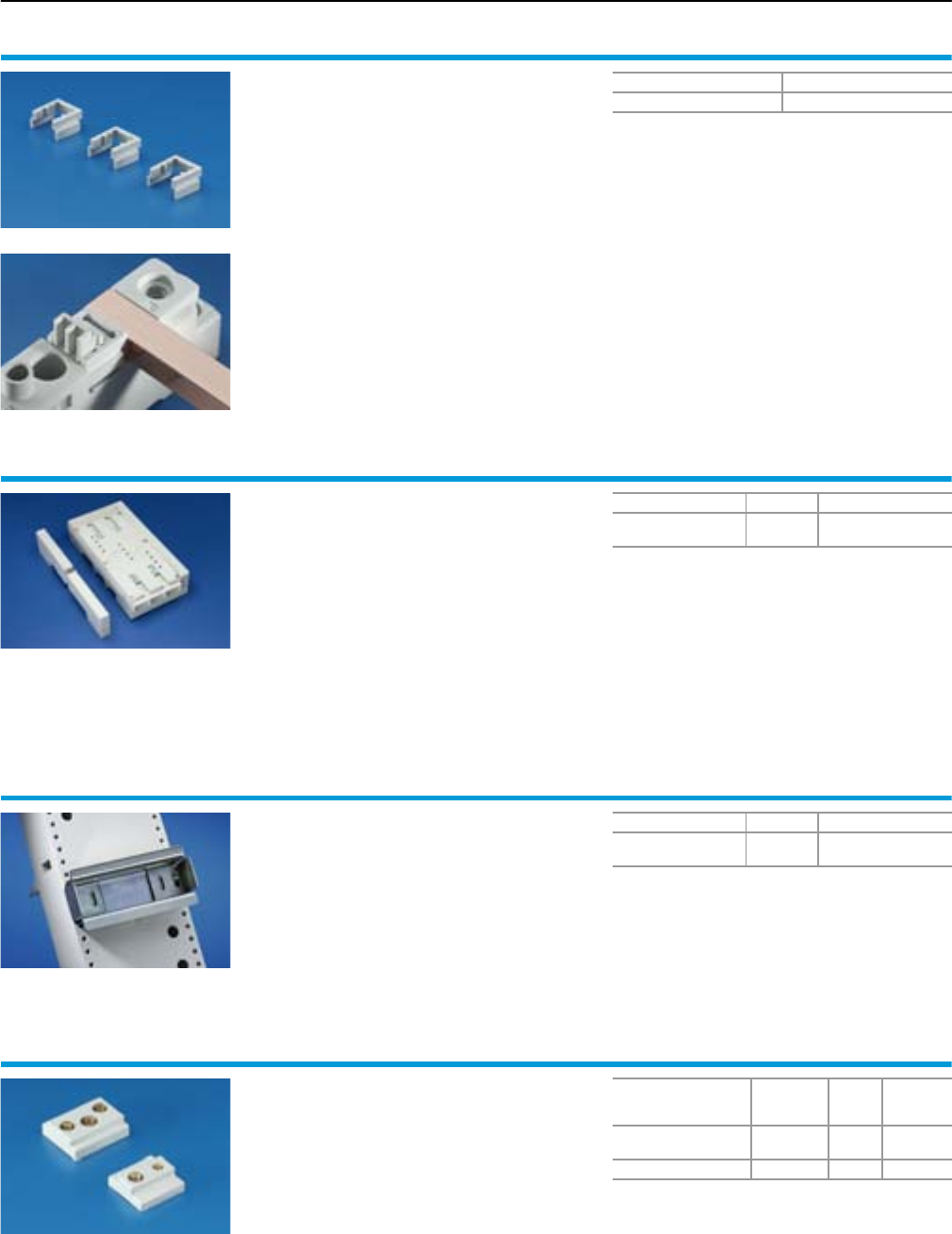
Rittal Ri4Power Form 2-4
RiLine60 accessories
Form 2-4 busbar systems
113
Spacers
for RiLine60 busbar supports
(flat busbar system)
For adapting 12 x 5 and 12 x 10 mm size busbars.
For busbar supports
●SV 9340.000/.010 (3-pole),
see page 66.
●SV 9340.004 (4-pole),
see page 74.
●SV 9340.030 (1-pole),
see page 110.
Material:
Polyamide (PA 6.6), 25% fibreglass-reinforced.
Continuous operating temperature max. 130°C.
Fire protection corresponding to UL 94-V0.
Colour:
RAL 7035
Packs of Model No. SV
12 9340.090
Insert strip
for circuit-breaker component adaptors
To extend the construction width from 140 mm
to 190 mm.
Width: 25 mm.
Material:
ABS
Colour:
RAL 7035
Note:
4 pieces (1 set) are needed to widen a compo-
nent adaptor.
For Packs of Model No. SV
SV 9342.700
SV 9342.710
4
(1 set) 9342.720
Support rail 35 x 15 mm
for component adaptors
Width 72 mm.
Material:
Sheet steel, zinc-plated, passivated
Supply includes:
Assembly screws and side end brackets.
For Packs of Model No. SV
SV 9342.400
SV 9342.410 59320.120
Sliding blocks
for circuit-breaker component adaptors
For additional circuit breakers with more than two
attachment points.
Colour:
RAL 7035
For
With
threaded
insert
Packs
of
Model No.
SV
SV 9342.500/.510
SV 9342.540/.550 M3/M4 6 9342.560
SV 9342.600/.610 M4/M5 6 9342.640
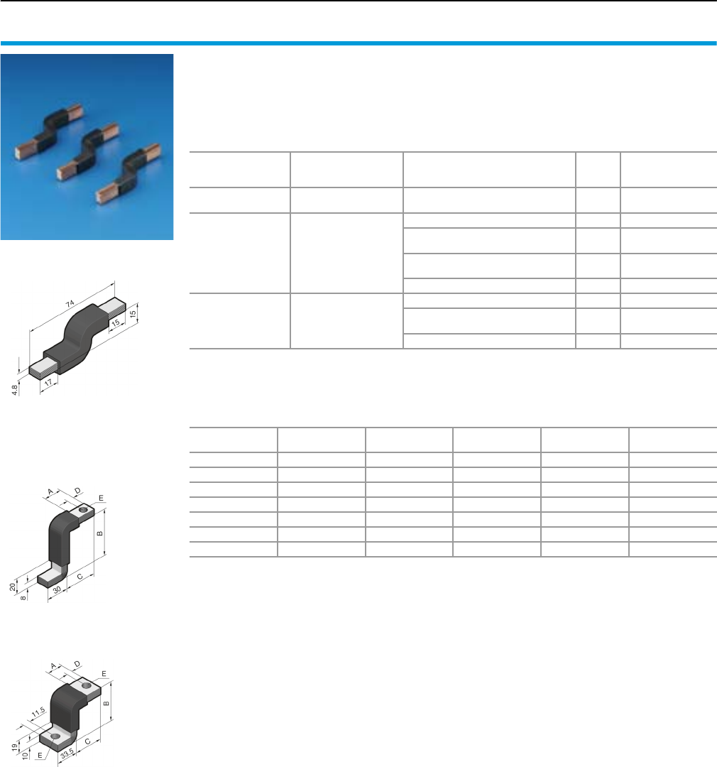
Rittal Ri4Power Form 2-4
Form 2-4 busbar systems
RiLine60 accessories
114
Connection bracket
for circuit-breaker component adaptors
Pre-assembled, laminated flat copper for connec-
ting standard, commercially available moulded
case circuit-breakers (MCCB).
Material:
Electrolyte copper F20
Insulation:
Vinyl compound.
Temperature resistance up to 105°C.
Fire protection corresponding to UL 94-V0.
SV 9342.570
SV 9342.660 – SV 9342.690
SV 9342.770 – SV 9342.790
Dimensions1)
mm
For
circuit-breaker
component adaptor
For connecting moulded case
circuit-breakers (MCCB),
make (model)
Packs
of2) Model No. SV
6 x 9 x 0.8 SV 9342.500/.510
SV 9342.540/.550 Moeller (NZM1) 3 9342.5703)
10 x 15.5 x 0.8 SV 9342.600/.610
ABB (T3), GE (FE) 3 9342.660
Merlin Gerin (NS/NSX100/160/250),
Telemecanique (GV7) 39342.670
ABB (S3), Moeller (NZM2),
Siemens (VL250) 39342.680
Siemens (VL160X, VL160) 3 9342.690
10 x 32.0 x 1.0 SV 9342.700/.710
ABB (T5) 3 9342.770
ABB (S5),
Merlin Gerin (NS400/630) 39342.780
Moeller (NZM3) 3 9342.790
1) Number of lamina x lamina width x lamina thickness
2) 3 = 1 set
3) Universal application for switchgear with a dimensional difference between the mounting level and the upper edge
of the contact level of 20 ± 5 mm.
Model No. SV A
mm
B
mm
C
mm
D
mm
E
mm
9342.660 26 65 43 9 Ø 10
9342.670 19 66 36 10 Ø 10
9342.680 23 71 40 9 Ø 10
9342.690 23 67 40 11 Ø 7
9342.770 26 51 62 9 Ø 12
9342.780 29 57 46 12 Ø 12
9342.790 28 62 38 14 Ø 12

Busbar systems
Form 2-4 technical information
115Rittal Ri4Power Form 2-4
Rittal busbar systems
When developing the Rittal busbar systems and their components,
Rittal drew on the latest state of the art and the currently valid stand-
ards and regulations. These applications are used by specialist
companies worldwide. As well as permanent in-house controls at
Rittal, the quality of the SV components is further reinforced by a vast
array of tests and approvals.
As product development is an on-going process, we reserve the
right to make amendments in line with technical progress.
Basic regulations for
busbar systems
●IEC/EN 60 439-1
Low-voltage switchgear and controlgear assemblies
Part 1: Type-tested and partially type-tested combinations
●IEC 61 439-1/-2
Low-voltage switchgear and controlgear assemblies
Part 1: General Rules
Part 2: Power switchgear and controlgear assemblies
●IEC/EN 60 947-1
Low-voltage switchgear and controlgear assemblies
Part 1: General specifications
●IEC/EN 60 947-3
Low-voltage switchgear and controlgear: switches, disconnec-
tors, switch disconnectors and fuse combination units
●IEC/EN 60 664-1
Coordination of insulation for electrical operating equipment in
low-voltage systems
Part 1: Basic principles, requirements and tests
●IEC/EN 60 999-1
Connector parts – Electrical copper conductors –
Safety requirements for screw terminals and screwless terminals
General and specific requirements for terminals for conductors
from 0.2 mm2 up to and including 35 mm2
●IEC/EN 60 999-2
Connector parts – Electrical copper conductors –
Safety requirements for screw terminals and screwless terminals
Part 2: Special requirements for terminals for conductors greater
than 35 mm2 up to and including 300 mm2
●DIN 43 671
Copper busbars, dimensioning for constant current
●DIN 43 673-1
Busbar drill holes and screw fastenings,
busbars with rectangular cross-section
●IEC/EN 60 715
Dimensions of low-voltage switchgear –
Standardised support rails for the mechanical attachment
of electrical components in switching systems
●DIN EN 13 601
Copper and copper alloys –
Copper rods and wires for general use in electrical engineering
Application
In order to avoid injury and damage to property, busbar systems
must only be assembled and used by suitably trained and qualified
personnel. The valid technical regulations, standards and provisions
must, of course, be observed.
Users are required to carefully observe the information and instruc-
tions supplied by Rittal, and where necessary to forward them to
downstream users and/or customers with a special advice note.
In particular, the specified tightening torques of electrical terminal
connections must be observed in order to achieve an optimum con-
tact pressure.
Technical data and catalogue information
Power distribution components are used in conjunction with a wide
range of different switchgear and other components for power distri-
bution, and in relation to a wide range of operating and ambient con-
ditions which are outside of Rittal’s control. The horizontal position of
busbars is considered the standard installation position for the bus-
bar system. IEC/EN 60 439-1 and the ambient conditions specified
therein should be considered the basis for the use of power distribu-
tion components.
At enclosure internal temperatures of > 35°C, application-specific
derating should be provided where necessary. Specifically in rela-
tion to the temperature limits admissible in IEC/EN 60 439-1, the
following factors should be critically reviewed:
●Arrangement of components inside the enclosure
●Heat loss of the circuit-breakers and fuses used
●Passive and/or active climate control measures
●Connected conductor cross-sections
●Operating mode of equipment (switching cycles etc.)
●Consideration of the operating and ambient conditions
●Consideration of the rated load factor.
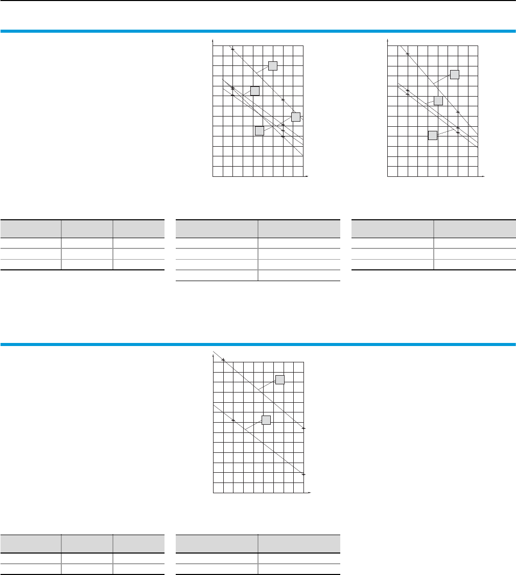
Form 2-4 technical information
Short-circuit resistance diagrams RiLine60
116 Rittal Ri4Power Form 2-4
25
250200
20
300 350 500450400 550 600
30
35
40
45
50
55
60
65
70
75
80
a
b
d
c
400250
20
200
25
30
300 350
50
40
35
45
55
60
65
70
75
80
450 500 600550
e
f
g
Busbar support
up to 800 A, 3-pole Page 66
Model No. SV 9340.000/SV 9340.010
60 mm bar centre distance,
for busbars 15 x 5 – 30 x 10 mm.
Rated operating voltage: up to 690 V AC
Rated insulation voltage: 1000 V AC
Rated surge voltage: 8 kV
Overvoltage category: IV
Level of contamination: 3
Rated frequency: 50/60 Hz
Test implemented:
●Rated surge current resistance Ipk
(see diagram)
●Rated short-time current resistance Icw
Busbar
mm
I
mm
Icw1)
kA
30 x 10 250 37.6
30 x 5 250 36.0
20 x 10 250 29.0
1) For 1 sec.
Busbar
mm Curve
30 x 10 a
20 x 10 b
25 x 5 c
15 x 5 d
Busbar
mm Curve
30 x 5 e
20 x 5 f
15 x 10 g
Ip peak short-circuit current [kA]
Busbar support spacing [mm]
Ip peak short-circuit current [kA]
Busbar support spacing [mm]
150
30
25
20
100 300200 250 350 400
50
45
35
40
65
60
55
500450
80
75
70
b
a
PLS busbar supports
up to 800 A/1600 A, 3-pole Page 68
Model No. SV 9341.000/SV 9342.000
60 mm bar centre distance,
for Mini-PLS special busbars.
Rated operating voltage: up to 690 V AC
Rated insulation voltage: 1000 V AC
Rated surge voltage: 8 kV
Overvoltage category: IV
Level of contamination: 3
Rated frequency: 50/60 Hz
Test implemented:
●Rated surge current resistance Ipk
(see diagram)
●Rated short-time current resistance Icw
Busbar
mm
I
mm
Icw1)
kA
PLS 800 150 25.9
PLS 1600 150 37.5
1) For 1 sec.
Ip peak short-circuit current [kA]
Busbar support spacing [mm]
Busbar
mm Curve
PLS 800 a
PLS 1600 b
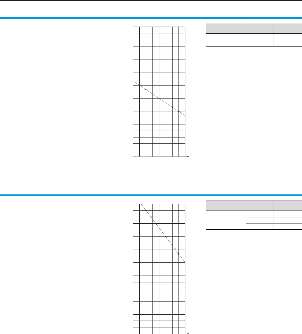
Short-circuit resistance diagrams RiLine60
Form 2-4 technical information
117Rittal Ri4Power Form 2-4
Busbar support
up to 800 A, 4-pole Page 74/76
Model No. SV 9340.004/SV 9342.014
60 mm bar centre distance,
for 30 x 10 mm busbars.
Rated operating voltage: up to 690 V AC
Rated insulation voltage: 1000 V AC
Rated surge voltage: 8 kV
Overvoltage category: IV
Level of contamination: 3
Rated frequency: 50/60 Hz
Test implemented:
●Rated surge current resistance Ipk
(see diagram)
●Rated short-time current resistance Icw
Busbar
mm
I
mm
Icw1)
kA
30 x 10 250 29
500 23
1) For 1 sec.
Ip peak short-circuit current [kA]
Busbar support spacing [mm]
60
55
50
45
40
35
30
25
20
200 250 400350300 450 500
65
70
75
80
85
90
95
100
105
110
115
PLS busbar support
up to 1600 A, 4-pole Page 76
Model No. SV 9342.004
60 mm bar centre distance,
for Mini-PLS special busbars.
Rated operating voltage: up to 690 V AC
Rated insulation voltage: 1000 V AC
Rated surge voltage: 8 kV
Overvoltage category: IV
Level of contamination: 3
Rated frequency: 50/60 Hz
Test implemented:
●Rated surge current resistance Ipk
(see diagram)
●Rated short-time current resistance Icw
Busbar
mm
I
mm
Icw
kA
PLS 1600
250 501)
250 532)
500 382)
1) For 3 sec.
2) For 1 sec.
Ip peak short-circuit current [kA]
Busbar support spacing [mm]
60
55
50
45
40
35
30
25
20
200 250 400350300 450 500
65
70
75
80
85
90
95
100
105
110
115
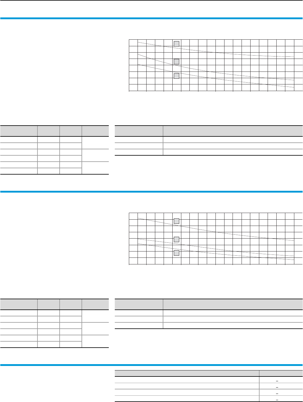
Form 2-4 technical information
Short-circuit resistance diagrams Flat-PLS
118 Rittal Ri4Power Form 2-4
160
150
140
130
120
110
90
100
80
a
c
b
450 500 550 600 650 700 750 800 850 900
Busbar support Flat-PLS 60
1- to 4-pole Page 90/91
Model No. SV 9676.002/SV 9676.020
120 mm bar centre distance,
for busbars 40 x 10 – 60 x 10 mm.
Population: 2, 3 or 4 bars per support
Rated operating voltage: up to 690 V AC
Rated insulation voltage: 1000 V AC
Rated surge voltage: 8 kV
Overvoltage category: IV
Level of contamination: 3
Rated frequency: 50/60 Hz
Test implemented:
●Rated surge current resistance Ipk
(see diagram)
●Rated short-time current resistance Icw
Busbar
mm
I
mm
Icw
kA/1 sec. Version
4 x 60 x 10 450 55.0 a
4 x 60 x 10 900 40.0
4 x 60 x 10 450 60.0 b
4 x 60 x 10 900 45.0
4 x 60 x 10 450 70.0 c
4 x 60 x 10 900 60.0
Ip peak short-circuit current [kA]
Busbar support spacing [mm]
Characteristic
curve/design Design of busbar attachment
a basic version1)
b with busbar claws2)
c with busbar stabilisers and busbar claws2)
1) Basic version consists of system attachment with fitted busbar support.
2) Version see page 118.
260
240
220
200
180
160
120
140
100
a
c
b
450 500 550 600 650 700 750 800 850 900
Busbar support Flat-PLS 100
1- to 4-pole Page 90/91
Model No. SV 9676.004/SV 9676.021
165 mm bar centre distance,
for busbars 80 x 10 – 100 x 10 mm.
Population: 2, 3 or 4 bars per support
Rated operating voltage: up to 690 V AC
Rated insulation voltage: 1000 V AC
Rated surge voltage: 8 kV
Overvoltage category: IV
Level of contamination: 3
Rated frequency: 50/60 Hz
Test implemented:
●Rated surge current resistance Ipk
(see diagram)
●Rated short-time current resistance Icw
Busbar
mm
I
mm
Icw
kA/1 sec. Version
4 x 100 x 10 450 75.0 a
4 x 100 x 10 900 52.0
4 x 100 x 10 450 81.6 b
4 x 100 x 10 900 55.9
4 x 100 x 10 450 110.0 c
4 x 100 x 10 900 78.0
Ip peak short-circuit current [kA]
Busbar support spacing [mm]
Characteristic
curve/design Design of busbar attachment
a basic version1)
b with busbar claws2)
c with busbar stabilisers and busbar claws2)
1) Basic version consists of system attachment with fitted busbar support.
2) Version see page 118.
Busbar claws
2-, 3- or 4-way Page 93
Model No. SV 9676.011 to SV 9676.019
Supplementary information on Flat-PLS short-
circuit protection diagrams
Mounting distance of busbar claws:
In order to achieve the cited short-circuit protec-
tion, the busbar claws must be fitted at a spacing
of 300 mm. If there is a busbar support, a contact
maker or a longitudinal connector located within
this 300 mm, there is no need to fit a claw at this
point.
Max. distance mm
Busbar claw – Busbar claw 300
Busbar claw – Busbar support 300
Busbar claw – Contact maker 300
Busbar claw – Longitudinal connector 300
<
<
<
<
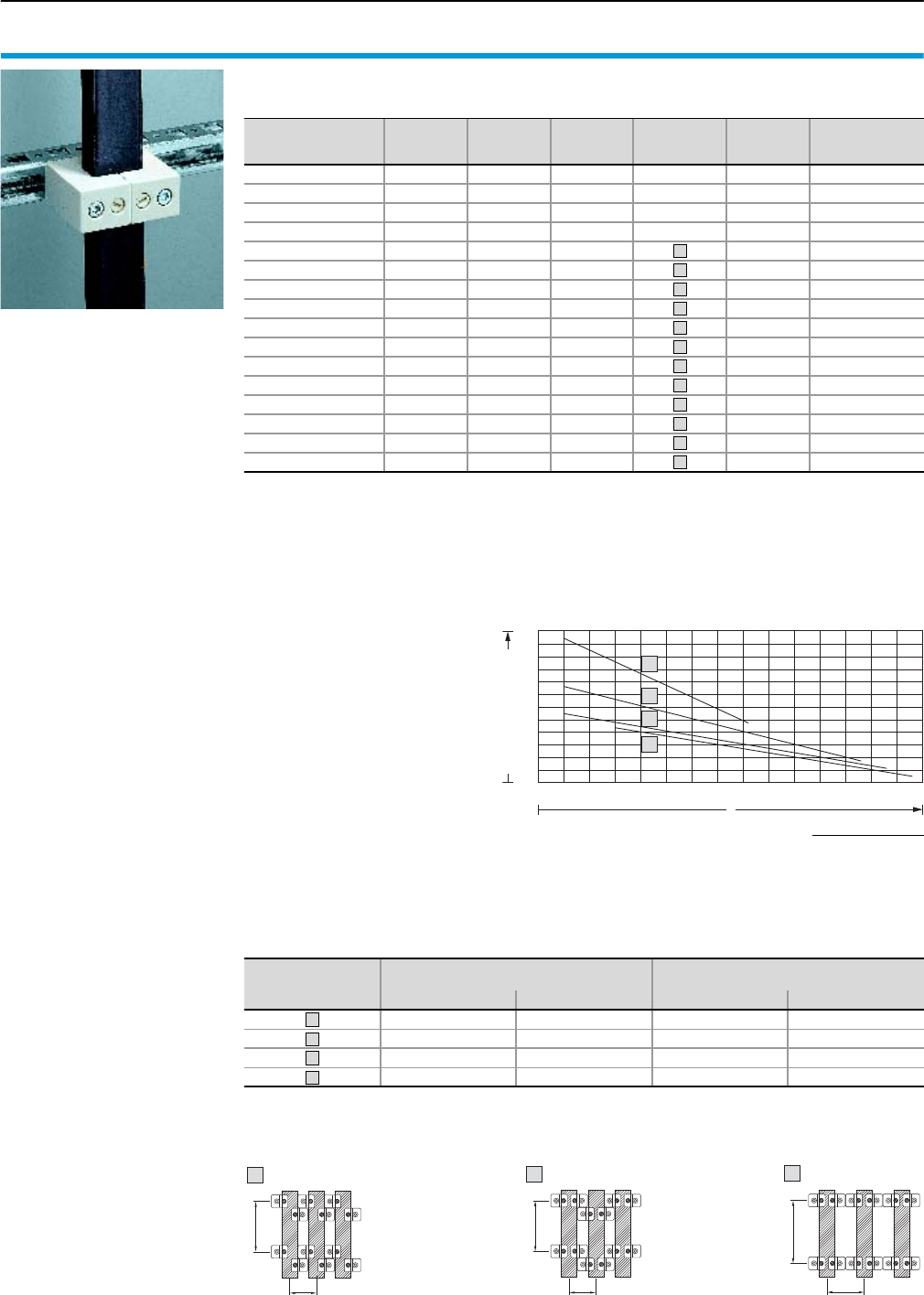
Short-circuit resistance diagram Flexibar “S”
Form 2-4 technical information
119Rittal Ri4Power Form 2-4
Laminated copper bars Rittal Flexibar “S”
Page 112
Configuration1)
mm
In
for
50 K2)
In
for
30 K2)
In
for
10 K2)
Curve
(short-circuit
resistance)
Installation
type Model No. SV
8 x 6.0 x 0.5 165 A 125 A – – – 3565.010
6 x 9.0 x 0.8 250 A 220 A 120 A – – 3565.000
6 x 13.0 x 0.5 200 A 150 A 110 A – – 3566.000
4 x 15.5 x 0.8 300 A 210 A 140 A – – 3567.000
6 x 15.5 x 0.8 350 A 290 A 170 A 1 3568.000
10 x 15.5 x 0.8 450 A 350 A 190 A 1 3569.000
5 x 20.0 x 1.0 400 A 300 A 180 A 1 3570.000
5 x 24.0 x 1.0 450 A 370 A 230 A 1 3571.000
10 x 24.0 x 1.0 800 A 600 A 340 A 1 3572.000
5 x 32.0 x 1.0 550 A 470 A 280 A 2/3 3573.000
10 x 32.0 x 1.0 1000 A 800 A 460 A 2/3 3574.000
5 x 40.0 x 1.0 800 A 600 A 340 A 2/3 3575.000
10 x 40.0 x 1.0 1200 A 950 A 500 A 2/3 3576.000
5 x 50.0 x 1.0 900 A 700 A 400 A 2/3 3577.000
10 x 50.0 x 1.0 1400 A 1000 A 600 A 2/3 3578.000
10 x 63.0 x 1.0 1600 A 1240 A 715 A 2/3 3579.000
1) Number of lamina x lamina width x lamina thickness
2) The conductor temperature of the laminated copper bar is derived by adding the ambient temperature and the
temperature increase together.
Example:
SV 3565.000 carrying 220 A, i.e. the temperature increases by 30 K. At an ambient temperature of 35°C,
this produces a resultant conductor temperature of 35°C + 30 K = 65°C.
a
a
a
a
b
b
c
b
c
b
c
d
Basis of test:
VDE 0660, part 500/IEC 60 439-1.
Test implemented:
Dynamic short-circuit resistance
to IEC 60 439-1.
The dimensions for the support
spacing (l) and for the centre-to-
centre spacing (a) must be within
the specified min./max. limits.
The quotients of l/a can be used
to determine the permissible
short-circuit current Ip by using
curves a to d. The prescribed
installation type must be taken
into account.
30
40
50
60
70
80
90
2.5 3.5 4.5 5.5 6.5 7.5 8.5
23456789
1.5
x
a
d
c
b
Ip short-circuit current [kA]
Support spacing (l)
Centre-to-centre spacing [a]
x =
Type of assembly with universal support SV 3079.000
l
a
1
l
a
2
a
l
3
Curve
Support spacing (l)
mm
Centre-to-centre spacing (a)
mm
min. Max. min. Max.
150 300 34 60
150 350 42 85
200 400 51 85
200 450 81 100
a
b
c
d
Short-circuit resistance diagrams
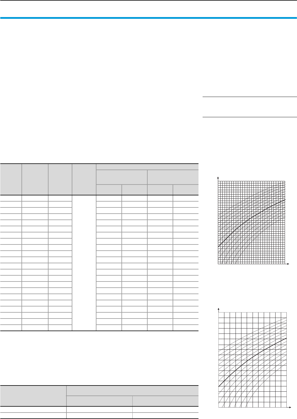
Form 2-4 technical information
Rated currents of busbars E-Cu (DIN 43 671)
120 Rittal Ri4Power Form 2-4
DIN 43 671 specifies the continuous cur-
rents for busbars at an ambient temperature
of 35°C and an average busbar tempera-
ture of 65°C. With the aid of a correction fac-
tor (k2), the continuous currents specified in
the following table may be adjusted to alter-
native operating temperatures.
For safe operation with thermal reserve, it is
advisable to limit the busbar temperature to
a maximum of 85°C. However, the decisive
factor is the lowest permissible continuous
temperature of the components which
directly contact the busbar sytem (fuse
bases, outgoing cables etc.). The ambient
air temperature of the busbars or busbar
system should not exceed 40°C; an aver-
age of 35°C maximum is recommended.
For the continuous temperatures specified in
the table, an emission level of 0.4 applies,
equivalent to an oxidating copper bar. In
modern busbar systems – built into enclo-
sures with a protection category of IP 54 and
above – a more favourable emission level
can be assumed. The lower emission level
facilitates an additional increase in continu-
ous currents compared with the figures in
DIN 43 671, irrespective of the specified air
and busbar temperature. Experience has
shown an increase in the continuous current
of 6 – 10% compared with the table figures
for uncoated copper bars, and 60% for sur-
face-oxidised copper bars.
Example:
For a Cu bar 30 x 10 mm (E-Cu F30),
DIN 43 671 specifies a constant current of
IN65 = 573 A.
The correction factor diagram for square
cross-sections indicates a correction factor
k2 = 1.29 at an air temperature of 35°C and
a busbar temperature of 85°C. Thanks to the
favourable emission level, the continuous
current is increased by a further 6 – 10%.
In this example, a mean value of 8% is used.
Compared with the table figure from
DIN 43 671, the Rittal rated current specifi-
cation for a Cu bar 30 x 10 mm is:
IN85 = IN65 · k2 + 8%
= 573 A · 1.29 · 1.08
IN85 = 800 A
Continuous currents for busbars
Made from E-Cu with square cross-section in indoor locations at 35°C air temperature and
65°C bar temperature, vertical position or horizontal position of the bar width.
Rittal PLS current load
According to DIN 43 671, the correction factor k2 (correction diagram) is used to correct the
basic current with reference to the existing temperatures of the ambient air and the busbar.
In accordance with DIN 43 671, the load figures of the Rittal PLS special bars have been
determined on the basis of measurement trials, as follows:
Width
x
thickness
mm
Cross-section
mm2Weight1) Material2)
Continuous current in A
AC current
up to 60 Hz
DC current +
AC current
16 Hz
Bare
bar
Coated
bar
Bare
bar
Coated
bar
12 x 2 23.5 0.209
E-Cu
F30
108 123 108 123
15 x 2 29.5 0.262 128 148 128 148
15 x 3 44.5 0.396 162 187 162 187
20 x 2 39.5 0.351 162 189 162 189
20 x 3 59.5 0.529 204 237 204 237
20 x 5 99.1 0.882 274 319 274 320
20 x 10 199.0 1.770 427 497 428 499
25 x 3 74.5 0.663 245 287 245 287
25 x 5 124.0 1.110 327 384 327 384
30 x 3 89.5 0.796 285 337 286 337
30 x 5 149.0 1.330 379 447 380 448
30 x 10 299.0 2.660 573 676 579 683
40 x 3 119.0 1.060 366 435 367 436
40 x 5 199.0 1.770 482 573 484 576
40 x 10 399.0 3.550 715 850 728 865
50 x 5 249.0 2.220 583 697 588 703
50 x 10 499.0 4.440 852 1020 875 1050
60 x 5 299.0 2.660 688 826 696 836
60 x 10 599.0 5.330 985 1180 1020 1230
80 x 5 399.0 3.550 885 1070 902 1090
80 x 10 799.0 7.110 1240 1500 1310 1590
100 x 10 999.0 8.890 1490 1810 1600 1940
1) Calculated with a density of 8.9 kg/dm3
2) Reference basis for the continuous current levels (figures taken from DIN 43 671)
PLS special
busbars
Rated current
AC 50/60 Hz
for
35/75°C
for
35/65°C (basic value)
E-Cu PLS 800 800 A 684 A
E-Cu PLS 1600 1600 A 1368 A
50 60 70 80 90 100 110 120
0.4
0.6
0.8
1.0
1.2
1.4
1.6
1.8
2.0
2.2 0
10
20
30
40
50
60
Factor k2
Ambient temperature [°C]
Busbar temperature [°C]
Correction factor diagram
to DIN 43 671
0.6
0.8
1.0
1.2
0.4
1.4
1.6
2.0
1.8
50 60 70 80 90 100 110
0
10
20
30
40
50
60
70
Factor k2
Ambient temperature [°C]
Busbar temperature [°C]
Correction factor diagram
for PLS
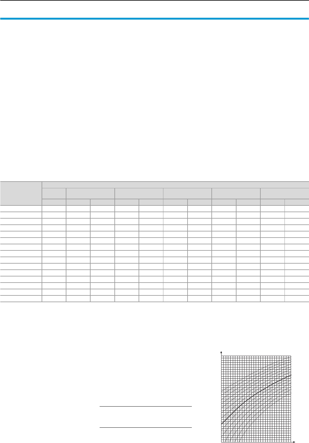
Rated currents of Flat-PLS busbar systems
Form 2-4 technical information
121Rittal Ri4Power Form 2-4
DIN 43 671 specifies the continuous cur-
rents for busbars surrounded by air, giving
defined temperatures for the ambient and
busbar temperature (35°C/65°C). The air
temperature around the busbars is consid-
ered the ambient temperature, not the air
temperature around the enclosure housing.
However, in certain circumstances, a bus-
bar system installed in an enclosure may be
subject to completely different conditions.
Similarly, the figures in DIN 43 671 do not
make allowance for the effect of airflows
inside the enclosure caused by fan sys-
tems, which may influence the maximum
rated currents.
In addition to the rated currents for copper
busbars to DIN 43 671, the following table
lists additional values for rated currents of
Flat-PLS busbar systems with bare copper
bars for AC currents up to 60 Hz.
These values were determined on Flat-PLS
busbars fitted in enclosures with various pro-
tection categories, as well as with and with-
out forced ventilation. Depending on the
busbar system and protection category, two
figures are given, representing the rated
current at an overtemperature of 30°K and
70°K. In contrast to the rated currents to
DIN 43 671, the temperature outside the
enclosure is measured as the ambient tem-
perature here.
The benefit of this approach is that the
enclosure housing, which may exert a major
influence on the busbar system, is taken into
account in the ratings data for the busbar
system. Designing a busbar system to
DIN 43 671 without consideration of the
enclosure housing may lead to thermal prob-
lems in the enclosure interior, particularly
with higher currents.
Although IEC 60 439-1/IEC 61 439-1/-2
permits higher overtemperature limits than
70°K, the absolute busbar temperature at
an ambient temperature of 35°C and 70°K
overtemperature limit is 105°C. This figure
of 105°C is high, but significantly below the
thermal softening of copper material, and
therefore acceptable.
Example:
If a rated current is used at an overtempera-
ture of 30°K, this means that the tempera-
ture of the busbars is 30°K above the ambi-
ent temperature of the enclosure. Expressed
in absolute figures, therefore, at an ambient
temperature of 35°C around the enclosure
housing, this produces a maximum absolute
busbar temperature of 65°C.
Rated AC currents of Flat-PLS busbar system up to 60 Hz
for bare copper bars (E-Cu F30) in A
Design of
Flat-PLS busbar
system
Protection category of enclosure
Ri4Power
DIN 43 671
IP 2X
with forced ventilation1) IP 2X IP 43 IP 54
with forced ventilation2) IP 54
ΔT = 30°K ΔT = 30°K ΔT = 70°K ΔT = 30°K ΔT = 70°K ΔT = 30°K ΔT = 70°K ΔT = 30°K ΔT = 70°K ΔT = 30°K ΔT = 70°K
2 x 40 x 10 mm 1290 1800 2700 1200 1900 1000 1536 1700 2400 950 1500
3 x 40 x 10 mm 1770 2100 3250 1350 2150 1150 1650 2000 3000 1150 1800
4 x 40 x 10 mm 2280 2300 3400 1400 2300 1250 2040 2050 3100 1200 1900
2 x 50 x 10 mm 1510 2200 3260 1340 2140 1200 1920 1980 2920 1140 1800
3 x 50 x 10 mm 2040 2660 3900 1580 2540 1400 2240 2320 3440 1320 2100
4 x 50 x 10 mm 2600 2700 4040 1640 2660 1440 2340 2360 3500 1380 2220
2 x 60 x 10 mm 1720 2300 3600 1500 2450 1300 2200 2200 3200 1250 2000
3 x 60 x 10 mm 2300 2450 4050 1700 2700 1500 2500 2400 3520 1450 2300
4 x 60 x 10 mm 2900 2740 4220 1740 2840 1580 2540 2420 3580 1460 2360
2 x 80 x 10 mm 2110 2760 4160 1740 2840 1600 2560 2540 3720 1480 2360
3 x 80 x 10 mm 2790 3300 5060 2000 3260 1840 2960 3060 4520 1680 2700
4 x 80 x 10 mm 3450 3680 5560 2060 3440 1900 3280 3220 4880 1780 2820
2 x 100 x 10 mm 2480 3240 4840 1920 3200 1800 2880 2900 4340 1660 2660
3 x 100 x 10 mm 3260 3580 5400 2200 3720 1980 3240 3320 4880 1920 2980
4 x 100 x 10 mm 3980 4020 5760 2320 3820 2000 3400 3380 4900 1960 3120
1) For IN < = 2000 A using fan-and-filter unit SK 3326.107,
for IN > 2000 A using fan-and-filter unit SK 3327.107.
2) For IN < = 2000 A using fan-and-filter unit SK 3326.107 and outlet filter SK 3326.207,
for IN > 2000 A using fan-and-filter unit SK 3327.107 and outlet filter SK 3326.207.
Factor k2
Ambient temperature [°C]
Busbar temperature [°C]
Correction factor diagramFor calculating rated currents at tempera-
tures between the overtemperature limits
of Flat-PLS busbar systems, the correc-
tion factor diagram may be used. If data
is available regarding the maximum ambi-
ent temperature and the maximum bar
temperature, a correction factor k2 may
be calculated using the correction factor
diagram. With a correction factor k2 and a
specified rated current at 30°K overtem-
perature limit, the new rated current is cal-
culated.
Example:
Flat-PLS 100 busbar system
with 4 x 100 x 10 mm
IN30 at IP 2X = 2320 A
ambient temperature = 35°C
Bar temperature = 85°C
From the diagram, this produces a
factor k2 = 1.29
The new rated current under these condi-
tions is then calculated as follows:
IN = IN30 · k2
= 2320 A · 1.29
= 2992 A
50 60 70 80 90 100 110 120
0.4
0.6
0.8
1.0
1.2
1.4
1.6
1.8
2.0
2.2 0
10
20
30
40
50
60
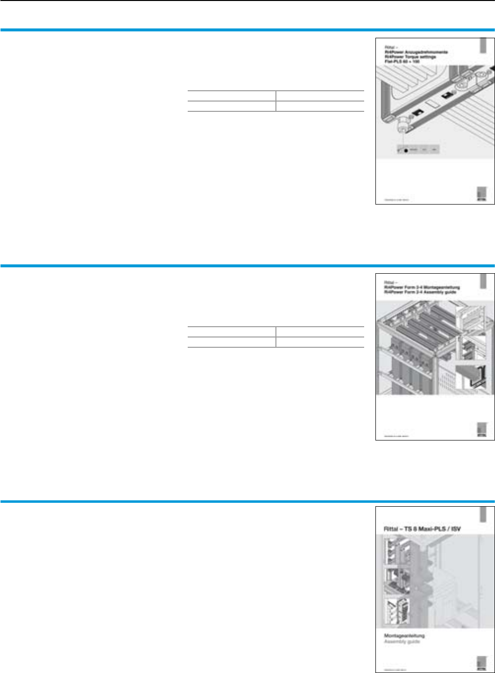
Form 2-4 technical information
Planning and configuration of Ri4Power systems
122 Rittal Ri4Power Form 2-4
Tightening torques for Flat-PLS busbar systems
There is separate documentation available con-
taining all the requisite torque information for the
configuration of Ri4Power systems with the new
Flat-PLS busbar system. Organised according to
item numbers, information is provided on screws,
screw drive and rated torque.
This documentation is available for downloading
at the Rittal website www.rittal.com. Alterna-
tively, a printed copy may be ordered quoting the
following item number.
Packs of Model No. SV
19676.001
Assembly instructions for Ri4Power low-voltage switchgear
for Form 2-4, with Flat-PLS, Maxi-PLS and
RiLine60
These assembly instructions explain the configu-
ration of type-tested Ri4Power field types and
possible busbar systems, divided into 3 sections.
The first section explains the assembly sequence
for the individual stages of the possible field types
in diagrammatic form.
The second section provides detailed assembly
instructions using diagrams and data tables. The
final section explains the installation of optional
accessories and general work operations.
This documentation is available for downloading
at the Rittal website www.rittal.com. Alterna-
tively, a printed copy may be ordered quoting the
following item number.
Packs of Model No. SV
19676.000
Assembly instructions for Ri4Power low-voltage switchgear
for Form 1 (open design), with Maxi-PLS
Assembly instructions for the configuration of
type-tested low-voltage switchgear, open design
(without internal compartmentalisation of the func-
tional areas) with the Maxi-PLS busbar system.
The document uses diagrams and data tables to
explain the assembly of the various field types.
This documentation is available for downloading
at the Rittal website www.rittal.com. Alterna-
tively, a printed copy may be requested from your
specialist Rittal advisor.
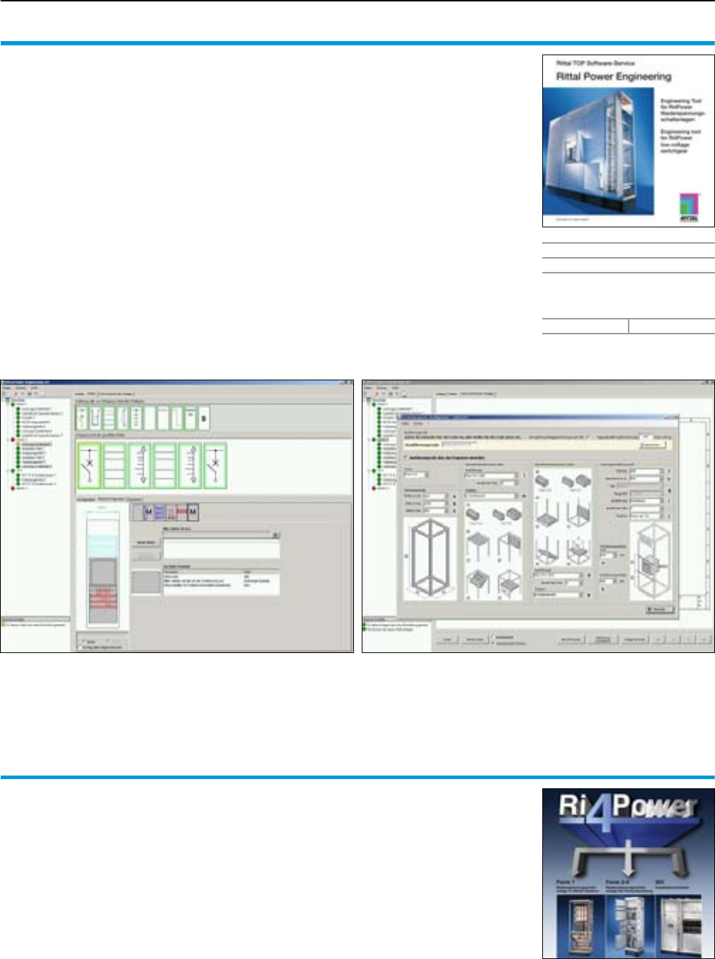
Planning and configuration of Ri4Power systems
Form 2-4 technical information
123Rittal Ri4Power Form 2-4
Rittal Power Engineering
Planning software for type-tested low-voltage
switchgear
with the System Ri4Power configuration tool for
simple, fast planning and calculation of type-
tested low-voltage switchgear with the Ri4Power
systems Form 1, Form 2-4 and ISV.
The multi-lingual software package includes the
following functions:
●Project handling, from the initial enquiry through
to ordering
●Complete, automatic function for the genera-
tion of bills of materials and a calculation pro-
gram for producing a quote
●Input and evaluation of assembly times to
calculate man hours
●Access to the entire range of Rittal products
●Output of orders, including combining several
projects into one order
●Generation of special fields configured by the
customer with graphical processing in the CAD
view
●Import/export interfaces for product and CAD
data
●Export function of order and parts lists in Excel
or CSV format
●Calculation based on current copper price
●Interface to EPLAN Electric P8, for the export of
CAD data and bills of materials
●The extra benefit for engineering and planning
offices: Output of detailed tender texts on the
basis of plant project-planned in Power Engi-
neering in MS Word format.
●Output of generated project-specific assembly
sketches
●Integral configurator for the generation of draw-
ings and bills of materials to create connector
kits for connecting air circuit-breakers (ACB).
As a stand-alone module, the integral configurator for connector kits
also supports the manual generation of production documents of air
circuit-breaker connector kits for air circuit-breakers from ABB, Merlin
Gerin, Mitsubishi, Moeller, Siemens and Terasaki.
With the graphical user interface, plant configurations may be
planned and designed very quickly and easily.
Supply includes
CD-ROM
Language: German/English/
French/Dutch/Danish/
Swedish/Czech/Italian/
Spanish/Polish/Russian
Model No. SV 3020.300
Engineering support for project handling
For individual project handling, Rittal offers an
extra service with specially trained expert advi-
sors and technical support staff for the genera-
tion of quotes, technical order handling, and after-
sales service.
Following technical coordination, individual low-
voltage switchgear may be configured. On
request, we can supply you with assembly draw-
ings and bills of materials to match your project.
As a planner, you have the option of requesting
a tender text for your project based on Power
Engineering project planning.
During the execution of your plant, our expert
advisors can also provide technical support with
the assembly and execution.
For initial contact with our engineering support
team, please contact your local expert advisor.
He or she will make a note of your request and
forward it to our technical team. Further informa-
tion is available at www.rittal.com.
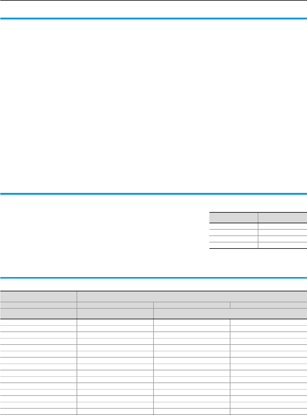
Form 2-4 technical information
Planning and configuration of Ri4Power systems
124 Rittal Ri4Power Form 2-4
Planning and project
management in line with
regulations
As a general principle, low-voltage switch-
gear and distributors should be planned to
meet the operating conditions of their final
installation site. To this end, the operator of
the plant, in collaboration with the manufac-
turer, should stipulate the operating and
ambient conditions. Moreover, as a general
rule, the operator or planning office should
also supply the manufacturer with full electri-
cal specifications of both the mains supply
end and the distributor outlet end. This
makes it possible to plan and manufacture a
cost-effective system with optimum adapta-
tion to the technical requirements.
Important basic data
for planning and project
management
●Applicable regulations and standards,
both regional and international
●Electricity supply company conditions
●Operator-specific regulations
●Mains-specific protective measures/mains
type
●Rated voltage and frequency
●Rated current with due regard for the
number of conductors (infeed and
busbars)
●Rated insulation voltage
●Short-circuit current at the point of installa-
tion
●Location of incoming cables, from above
or below
●Number of incoming cables, specifying
the type and cross-section
●Number of outlets, specifying the ope-
rating load and the envisaged outgoing
cables with type and cross-section
●For the outlet side, specification of the
simultaneity factor and rated load factor
of the relevant equipment items
Important operating and
ambient conditions
●Rated operating voltage Ue
●Mains frequency fN
●Rated insulation voltage Ui
●Busbar rated current Isas
●Rated current for the supply end Izu
●Rated surge current resistance Ipk
●Rated short-time current resistance Icw
●Ambient temperature condition ϑ
●Atmospheric climatic stress,
specifying the relative humidity and
temperature
●Protection category of the overall
system IP . . .
●Specification to DIN EN 60 529
●Protection category
The rated diversity factor of a switchgear
combination or part thereof (e.g. a field)
comprising several main circuits refers to
the ratio between the largest sum total of all
currents anticipated at any given time in
the affected main circuits and the sum total
of the rated currents of all main circuits of
the switchgear enclosure or observed part
thereof.
Application suggestion to IEC/EN 60 439-1
Number
of main circuits Load factor
2 and 3 0.9
4 and 5 0.8
6 and 7 0.7
10 or more 0.6
Rated diversity factor
Rated currents and short-circuit currents of standard transformers
Rated voltage
UN = 400 V 400 V
Short-circuit voltage Uk 4%1) 6%2)
Rated power SNT
[kVA]
Rated current IN
[A]
Short-circuit current Ik''3)
[kA]
50 72 1.89 1.20
100 144 3.61 2.41
160 230 5.77 3.85
200 288 7.22 4.81
250 360 9.02 6.01
315 455 11.36 7.58
400 589 14.43 9.62
500 722 18.04 12.03
630 910 22.73 15.15
800 1156 28.86 19.24
1000 1444 36.08 24.05
1250 1805 45.09 30.06
1600 2312 57.72 38.48
2000 2882 72.15 48.10
2500 3613 90.32 60.21
1) Uk = 4% standardised to DIN 42 503 for SNT = 50 . . . 630 kVA
2) Uk = 6% standardised to DIN 42 511 for SNT = 100 . . . 1600 kVA
3) Ik'' = Initial symmetrical short-circuit current of transformer when connecting to a mains supply with unlimited short-circuit lead
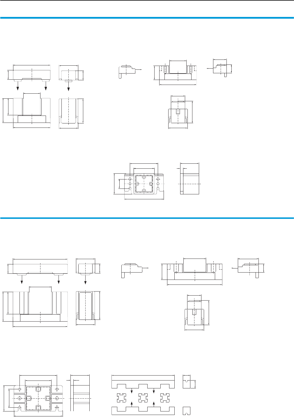
Maxi-PLS system components
Form 2-4 technical information
125Rittal Ri4Power Form 2-4
Maxi-PLS 1600/2000
Page 84
51
25
65
51
25
65
45.5
98.5
45
99.5
25
105
55
75
55
50
8
99.5
45.5
37
36
22
51
38
59
Busbar supports
Model No. SV 9640.000, SV 9649.000
Busbar support, suitable for top mounting
Model No. SV 9640.160
End supports
Model No. SV 9640.010, SV 9649.010
Maxi-PLS 3200
Page 86
51
80 25
51
60.5
60
80
148
25
146
70
50
70
130
100
50
8
Busbar supports
Model No. SV 9650.000, SV 9659.000
End supports
Model No. SV 9650.010, SV 9659.010
Busbar support, suitable for top mounting
Model No. SV 9650.160
Stabiliser
Model No. SV 9650.140
148
60.5
42.5
56
23
51
38
65.5
434 50
54.5
L3 L2 L1
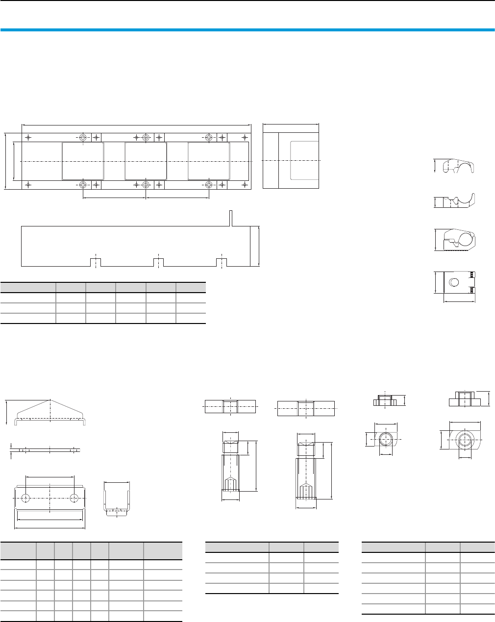
Form 2-4 technical information
Maxi-PLS connection components
126 Rittal Ri4Power Form 2-4
Maxi-PLS 1600/2000
Page 85
Maxi-PLS 3200
Page 87
Isolator chassis
64
D
D
B
A
C
E
Model No. SV A B C D E
9640.020 89 61 346 100 89
9650.020 89 61 479 150 94
9650.030 129 101 479 150 94
Model No.
SV Size A B C T-head
screws
Tightening
torque
9640.330 1 81 73 46 M10 20 Nm
9640.340 2 112 104 77 M10 25 Nm
9640.350 3 149 141 114 M10 30 Nm
9650.330 1 81 73 46 M12 25 Nm
9650.340 2 112 104 77 M12 30 Nm
9650.350 3 149 141 114 M12 35 Nm
11.3
24.8
14.8
B
8.3
17.8
10.8
A
Sliding nuts
(1600/2000)
Sliding nuts
(3200)
40
5
A
B
C
41
M10
40
9.5
A
M12
45
12.5
B
Connection plates Terminal studs
(1600/2000)
Terminal studs
(3200)
Model No. SV A B
9640.370 M12 –
9640.380 M16 –
9650.370 – M12
9650.380 – M16
Model No. SV A B
9640.900 M6 –
9640.910 M8 –
9640.920 M10 –
9650.900 – M6
9650.910 – M10
9650.920 – M12
Connection clamp
Model No.
SV 9640.325
SV 9650.325
17
36
35
50.5
23
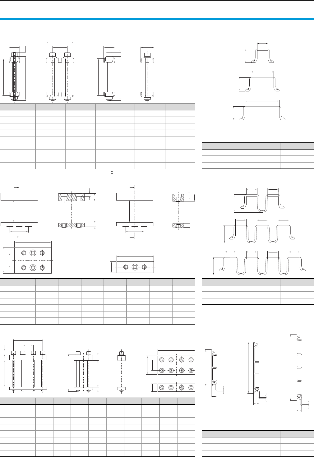
Flat-PLS system components
Form 2-4 technical information
127Rittal Ri4Power Form 2-4
Flat-PLS 60/100
B1
H1
H1
B1
B1 B1
H1
H1
B1
B1
H1
H1
B1
T1
H1
H2
10
B2
B1
T1
H2
H1 10
B1
A
A
H1
B2
8
H2
H3
B
B
H1
B2
8
H2
H3
B1
T1
T2
T1
B1
B3
B2
H2 10
H1
H3
H4
T1
B1
T2
T1
Busbar claw Page 93 Edge cover section without spacer Page 94
Contact makers Page 96 Edge cover section with spacer Page 94
Longitudinal connector Page 98 Side cover section Page 94
Model No. SV B1 B2 H1 H2 T1
9676.011 35.7 – 80 57 – 62 30
9676.012 55.7 20 80 57 – 62 30
9676.013 75.7 40 80 57 – 62 30
9676.014 35.7 – 120 97 – 102 30
9676.015 55.7 20 120 97 – 102 30
9676.016 75.7 40 120 97 – 102 30
9676.017 35.7 – Without screw +2/–31) 30
9676.018 55.7 20 Without screw +2/–31) 30
9676.019 75.7 40 Without screw +2/–31) 30
1) With reference to the required screw H2 = H1 – 20 (H1 length of screw).
Model No. SV B1 H1
9676.041 10.2 12.9
9676.042 21.3 12.9
9676.043 32.3 12.9
H1
B1
B1 B1 B1
H1
B1 B1 B1 B1
H1
Model No. SV B1 B2 H1 H2 H3 T1 T2
9676.526 60 36 40 – 100 20 10 30 –
9676.546 60 36 40 – 100 20 10 70 40
9676.528 80 50 40 – 100 20 10 30 –
9676.548 80 50 40 – 100 20 10 70 40
9676.520 100 50 40 – 100 20 10 30 –
9676.540 100 50 40 – 100 20 10 70 40
Model No. SV B1 H1
9676.052 10.3 16.65
9676.053 10.3 16.65
9676.054 10.3 16.65
A – A B – B
Model No. SV B1 B2 B3 H1 H2 H3 H4 T1 T2
9676.626 140 110 40 100 60 20 10 30 –
9676.646 140 110 40 100 60 20 10 70 40
9676.628 140 110 40 120 80 20 10 30 –
9676.648 140 110 40 120 80 20 10 70 40
9676.620 140 110 40 140 100 20 10 30 –
9676.640 140 110 40 140 100 20 10 70 40
9676.621 140 110 40 X1) H1 – 40 20 10 30 –
9676.641 140 110 40 X1) H1 – 40 20 10 70 40
1) Length of screw (to be ordered separately).
Model No. SV B1 H1
9676.056 49.2 7.65
9676.058 69.2 7.65
9676.059 89.2 7.65
B = Width
T = Depth
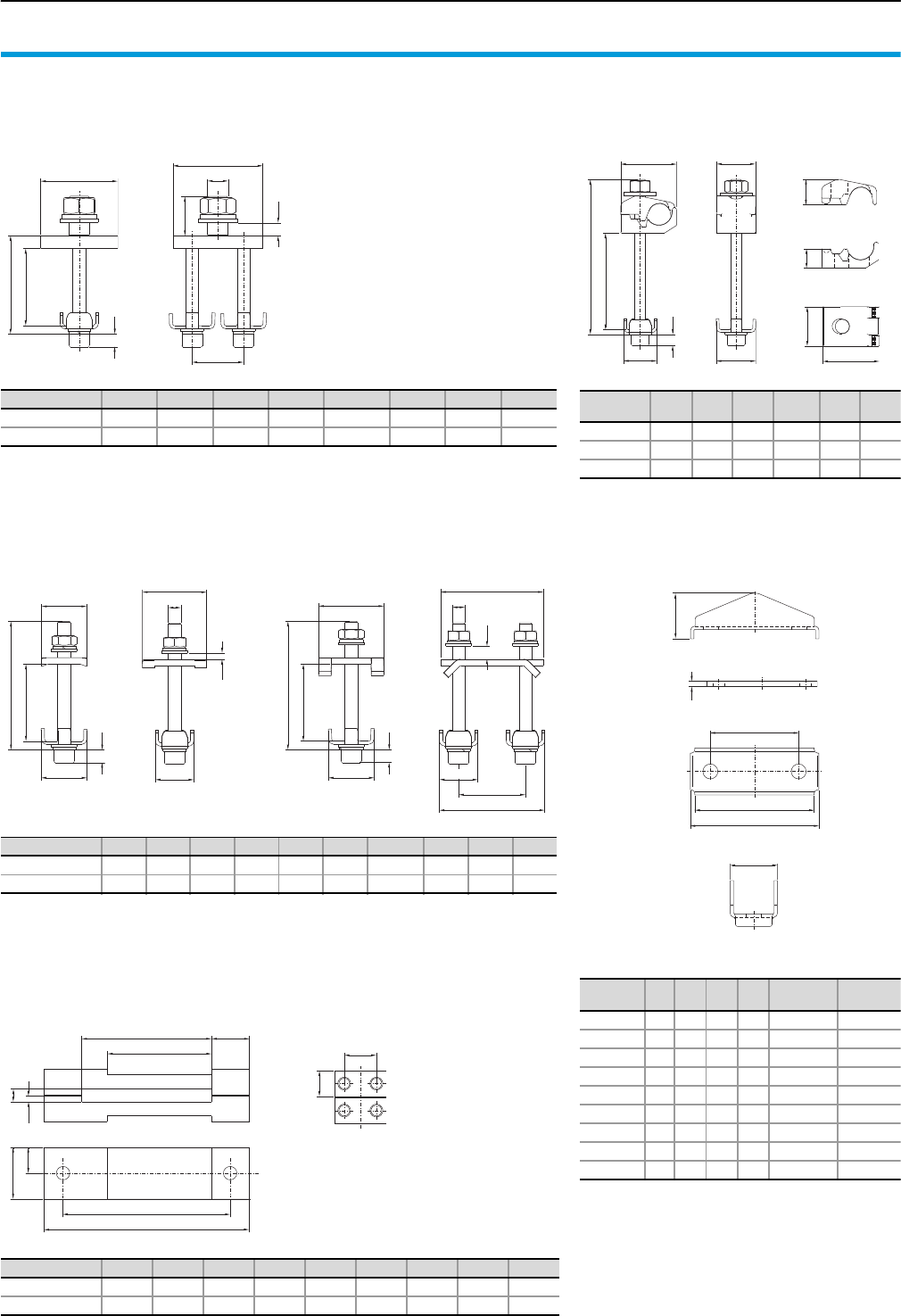
Form 2-4 technical information
Flat-PLS connection components
128 Rittal Ri4Power Form 2-4
Flat-PLS 60/100
B1
B2
H2
H1
Connection plates with bolts M12/M16 Page 95
Terminal block distributor bar Page 108
Connection plates with bolts M10 Page 95
Direct connection terminals Page 94
17
35
50.5
23
Model No.
SV Size A B C Screw Tightening
torque
9676.741 1 81 73 46 M10 x 115 20 Nm
9676.742 2 112 104 77 M10 x 115 25 Nm
9676.743 3 149 141 114 M10 x 115 30 Nm
9676.744 1 81 73 46 M10 x 150 20 Nm
9676.745 2 112 104 77 M10 x 150 25 Nm
9676.746 3 149 141 114 M10 x 150 30 Nm
9676.747 1 81 73 46 without 20 Nm
9676.748 2 112 104 77 without 25 Nm
9676.749 3 149 141 114 without 30 Nm
40
5
A
B
C
41
Connection plates for laminated copper bars
Page 96
Model No. SV B1 B2 B3 H1 H2 H3 H4 T1
9676.700 70 40 M12 1) H1 – 21.5 30.6 15.6 60
9676.704 70 40 M16 1) H1 – 21.5 30.6 11.1 60
1) Length of screw connection.
Model No. SV B1 B2 B3 B4 B5 H1 H2 H3 T1 T2
9676.710 50 – 30 M10 – 1) H1 – 40 5 35 35.7
9676.714 80 52 30 M10 82 1) H1 – 40 10 50 35.7
1) Length of screw connection.
Model No.
SV B1 B2 H1 H2 T1 T2
9676.730 35.7 35 1) H1 – 60 50.5 30
9676.731 35.7 35 120 60 50.5 30
9676.733 35.7 35 160 100 50.5 30
1) Length of screw connection.
Model No. SV B1 B2 B3 B4 B5 H1 H2 H3 T1
9674.485 160 130 61 51 29.5 40 20 25 20
9674.488 160 130 101 81 29.5 40 20 25 20
H2
H1
T2
T1
10
B1
B2
H1
H2
T1
10
B1
B2
H4
H3
B3
T2
T1
H1
H2
10
B4
B1
B3
H3
T1
H1
H2
T2
10
H3
B2
B3
B4
B1
B5
H3
T1
B3
B4
B5
4.5
10
B = Width
T = Depth
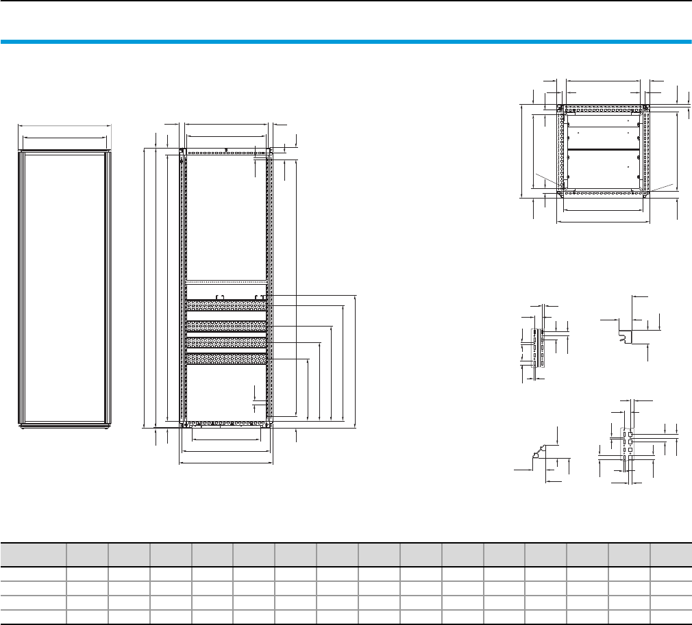
Dimensions SV-TS 8 enclosures
Form 2-4 technical information
129Rittal Ri4Power Form 2-4
B1
18
M12
61
61
B2
42.5 i.L. T3 46.5
B3
30
30
Ø 16
T1
65
61.5 T2
30 30
25
12.5
6.5
25
4.5
12.5
4
42.5
42.5
i.L.
i.L.
42.5
42.5
i.L.
i.L.
10.5
20
11.5
4
12.5
4.5
12.5
12.5
25
B1
B4
SV-TS 8 enclosures
for incoming/outgoing circuit (Form 1 only)
Catalogue 32, page 438
Cross-sections
vertical horizontal
Model No.
SV
B1
mm
B2
mm
B3
mm
B4
mm
H1
mm
H2
mm
H3
mm
H4
mm
T1
mm
T2
mm
T3
mm
T4
mm
T5
mm
T6
mm Door(s)
9660.665 597 512 475 535 2005 1997 1912 1850 601.5 475 512 568 440 535 1
9660.675 597 512 475 535 2005 1997 1912 1850 601.5 475 512 568 440 535 3
9660.865 797 712 675 735 2005 1997 1912 1850 601.5 475 512 568 440 535 1
9660.875 797 712 675 735 2005 1997 1912 1850 601.5 475 512 568 440 535 3
T1
12.5
25
T4
i.L. T5
77
42.5
4.5
44
3.5
46
H1
H2
H3
T6 31
35
i.L. T3
77 H4
800
368.5
468.5
568.5
693.5
B = Width
T = Depth
i.L. = Clearance width
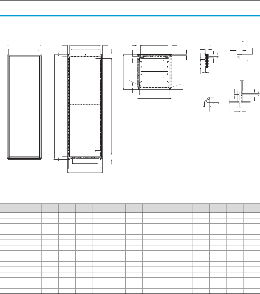
Form 2-4 technical information
Dimensions SV-TS 8 enclosures
130 Rittal Ri4Power Form 2-4
B1
18
M12
61
61
B2
42.5 i.L. T3 46.5
B3
30
30
Ø 16
T1
65
61.5 T2
30 30
25
12.5
6.5
25
4.5
12.5
4
42.5
42.5
i.L.
i.L.
42.5
42.5
i.L.
i.L.
10.5
20
11.5
4
12.5
4.5
12.5
12.5
25
B1
B4
SV-TS 8 modular enclosures
Page 30 – 32
Cross-sections
vertical horizontal
Model No.
SV
B1
mm
B2
mm
B3
mm
B4
mm
H1
mm
H2
mm
H3
mm
H4
mm
T1
mm
T2
mm
T3
mm
T4
mm
T5
mm
T6
mm
9670.406 397 312 275 335 2005 1997 1912 1850 601.5 475 512 568 440 535
9670.408 397 312 275 335 2005 1997 1912 1850 801.5 675 712 768 640 735
9670.426 397 312 275 335 2205 2197 2112 2050 601.5 475 512 568 440 535
9670.428 397 312 275 335 2205 2197 2112 2050 801.5 675 712 768 640 735
9670.486 397 312 275 335 1805 1797 1712 1650 601.5 475 512 568 440 535
9670.606 597 512 475 535 2005 1997 1912 1850 601.5 475 512 568 440 535
9670.608 597 512 475 535 2005 1997 1912 1850 801.5 675 712 768 640 735
9670.626 597 512 475 535 2205 2197 2112 2050 601.5 475 512 568 440 535
9670.628 597 512 475 535 2205 2197 2112 2050 801.5 675 712 768 640 735
9670.686 597 512 475 535 1805 1797 1712 1650 601.5 475 512 568 440 535
9670.806 797 712 675 735 2005 1997 1912 1850 601.5 475 512 568 440 535
9670.808 797 712 675 735 2005 1997 1912 1850 801.5 675 712 768 640 735
9670.826 797 712 675 735 2205 2197 2112 2050 601.5 475 512 568 440 535
9670.828 797 712 675 735 2205 2197 2112 2050 801.5 675 712 768 640 735
9670.886 797 712 675 735 1805 1797 1712 1650 601.5 475 512 568 440 535
T1
12.5
25
T4
i.L. T5
77
42.5
4.5
44
3.5
46
H1
H2
H3
T6 31
35
i.L. T3
77 H4
B = Width
T = Depth
i.L. = Clearance width
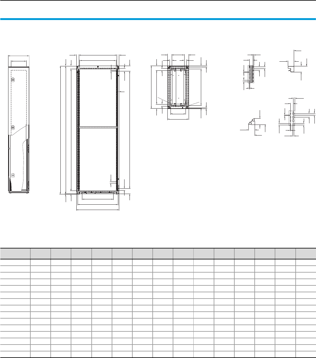
Dimensions SV-TS 8 enclosures
Form 2-4 technical information
131Rittal Ri4Power Form 2-4
25
12.5
6.5
25
4.5
12.5
4
42.5
42.5
i.L.
i.L.
42.5
42.5
i.L.
i.L.
10.5
20
11.5
4
12.5
4.5
12.5
12.5
25
B1
B4
T1
12.5
25
T4
i.L. T5
77
42.5
4.5
44
3.5
46
H1
H2
H3
T6 31
35
i.L. T3
77 H4
32.5
2
SV-TS 8 cable chamber enclosures
Page 33 – 35
Cross-sections
vertical horizontal
Model No.
SV
B1
mm
B2
mm
B3
mm
B4
mm
H1
mm
H2
mm
H3
mm
H4
mm
T1
mm
T2
mm
T3
mm
T4
mm
T5
mm
T6
mm
9670.316 297 212 175 235 2005 1997 1912 1850 605 475 512 568 440 535
9670.318 297 212 175 235 2005 1997 1912 1850 805 675 712 768 640 735
9670.336 297 212 175 235 2205 2197 2112 2050 605 475 512 568 440 535
9670.338 297 212 175 235 2205 2197 2112 2050 805 675 712 768 640 735
9670.396 297 212 175 235 1805 1797 1712 1650 605 475 512 568 440 535
9670.416 397 312 275 335 2005 1997 1912 1850 605 475 512 568 440 535
9670.418 397 312 275 335 2005 1997 1912 1850 805 675 712 768 640 735
9670.436 397 312 275 335 2205 2197 2112 2050 605 475 512 568 440 535
9670.438 397 312 275 335 2205 2197 2112 2050 805 675 712 768 640 735
9670.496 397 312 275 335 1805 1797 1712 1650 605 475 512 568 440 535
9670.616 597 512 475 535 2005 1997 1912 1850 605 475 512 568 440 535
9670.618 597 512 475 535 2005 1997 1912 1850 805 675 712 768 640 735
9670.636 597 512 475 535 2205 2197 2112 2050 605 475 512 568 440 535
9670.638 597 512 475 535 2205 2197 2112 2050 805 675 712 768 640 735
9670.696 597 512 475 535 1805 1797 1712 1650 605 475 512 568 440 535
B1
18
M12
61
61
B2
42.5i.L. T3 46.5
B3
30
30
Ø 16
T1
65 T2
30 30
65
15
B = Width
T = Depth
i.L. = Clearance width
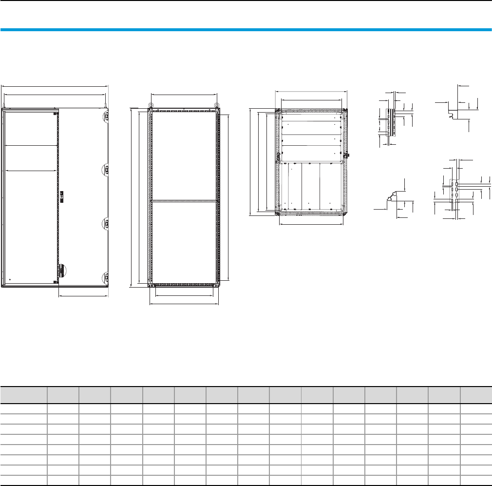
Form 2-4 technical information
Dimensions SV-TS 8 enclosures
132 Rittal Ri4Power Form 2-4
25
12.5
6.5
25
4.5
12.5
4
42.5
42.5
i.L.
i.L.
42.5
42.5
i.L.
i.L.
10.5
20
11.5
4
12.5
4.5
12.5
12.5
25
SV-TS 8 switch-disconnector-fuse enclosures
Page 36 – 37
Cross-sections
vertical horizontal
Model No.
SV
B1
mm
B2
mm
B3
mm
B4
mm
B5
mm
H1
mm
H2
mm
H3
mm
T1
mm
T2
mm
T3
mm
T4
mm
T5
mm
T6
mm
9670.006 997 912 875 935 350.5 1997 1912 1850 601.5 475 512 568 440 535
9670.008 997 912 875 935 350.5 1997 1912 1850 801.5 675 712 768 640 735
9670.026 997 912 875 935 350.5 2197 2112 2050 601.5 475 512 568 440 535
9670.028 997 912 875 935 350.5 2197 2112 2050 801.5 675 712 768 640 735
9670.106 1197 1112 1075 1135 550.5 1997 1912 1850 601.5 475 512 568 440 535
9670.108 1197 1112 1075 1135 550.5 1997 1912 1850 801.5 675 712 768 640 735
9670.126 1197 1112 1075 1135 550.5 2197 2112 2050 601.5 475 512 568 440 535
9670.128 1197 1112 1075 1135 550.5 2197 2112 2050 801.5 675 712 768 640 735
T2
T1
T3
B1
B2
B3
H3
H1
H2
T6
T4
T5
B1
B4
B5
579
609 ± 1
B = Width
T = Depth
i.L. = Clearance width
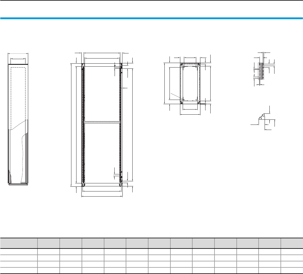
Dimensions SV-TS 8 enclosures
Form 2-4 technical information
133Rittal Ri4Power Form 2-4
25
12.5
6.5
25
4.5
12.5
4
42.5
42.5
i.L.
i.L.
B1
B4
T1
12.5
25
T4
77
42.5
44 46
H1
H2
T5 31
35
i.L. T3
77 H3
32.5
2
B1
18
61
61
B2
42.5 i.L. T3 46.5
B3
Ø 16
T1
65 T2 65
15
SV-TS 8 busbar enclosures
Page 38
Cross-sections
vertical
Model No.
SV
B1
mm
B2
mm
B3
mm
B4
mm
H1
mm
H2
mm
H3
mm
T1
mm
T2
mm
T3
mm
T4
mm
T5
mm
9670.206 197 112 75 75 1997 1912 1850 605 475 512 561 535
9670.208 197 112 75 75 1997 1912 1850 805 675 712 761 735
9670.226 197 112 75 75 2197 2112 2050 605 475 512 561 535
9670.228 197 112 75 75 2197 2112 2050 805 675 712 761 735
B = Width
T = Depth
i.L. = Clearance width

Form 2-4 technical information
System data
134 Rittal Ri4Power Form 2-4
Type-tested Ri4Power low-voltage switchgear combinations
The section types of Ri4Power low-voltage
switchgear combinations are type-tested to
IEC 60 439-1. If planned and executed in
accordance with the specifications and
assembly instructions for Ri4Power sys-
tems, the combination of section types
corresponds to a type-tested low-voltage
switchgear combination to IEC 60 439-1.
Alternatively, design verification to
IEC 61 439-1/-2 is possible. For further in-
formation please contact your local expert
advisor.
Type testing of Ri4Power systems was
carried out with the following switchgear
brands:
●ABB
●Jean Müller
●Merlin Gerin
●Mitsubishi
●Moeller Electric
●Siemens
●Teras a k i
and with RiLine components from Rittal. In
contrast to a non-type-tested switchgear
combination, the requirements for the se-
lection of components and switchgear are
linked to the tested types. When planning air
circuit-breakers, where necessary, reduction
factors should be taken into account for use
at increased temperatures in the enclosure
interior.
Before planning and assembling a type-
tested switchgear combination, the techni-
cal parameters of a type-tested switchgear
combination should be coordinated between
the user and switchgear manufacturer. For
type-tested execution of the Ri4Power sys-
tem, we recommend use of the Rittal Power
Engineering software. All parameters are
integrated into this software, which guides
users to the required solution.
Type-testing of a switchgear combination
confirms the combination of enclosure, bus-
bar system and switchgear as a functioning
unit, and verifies compliance with all techni-
cal limits. The technical data of a type-tested
switchgear combination may deviate from
the tested values of the individual compo-
nents, since these components are often
subject to different test requirements.
For busbar systems, too, the data within
a type-tested switchgear combination
may deviate from the data pursuant to
DIN 43 671, since in addition to the enclo-
sure and busbar system, type-testing also
makes allowance for heat loss in switch-
gear. For this reason, the technical system
data on the following pages is decisive for
the type-tested switchgear combinations.
If field types with different ratings data are
combined, please note that the lowest
values for the main busbar system and the
overall enclosure protection category pre-
scribe the rated for the overall switchgear
combination.
Ri4Power low-voltage switchgear assemblies without type-testing certificate
Ri4Power components may also be used
outside of type-tested switchgear and con-
trolgear assemblies. However, the technical
data for the products and the short-circuit
protection data and ratings data of the bus-
bar systems must be observed.
Operating and ambient conditions for Ri4Power switchgear assemblies
The siting conditions for Ri4Power systems
are identical for all field types. Any require-
ments which deviate from this should be
agreed with the product management team.
Additional field-specific technical data for
the type-tested field types is listed in detail
on the following pages. This data represents
the maximum, tested figures. For optimum
adaptation of customer requirements to the
possible system assemblies, we recom-
mend use of the latest version of the Rittal
Power Engineering software.
Operating and
ambient
conditions
Ambient
temperature
Short-term peak +40°C
IEC 60 439-1Maximum on a 24 h average +35°C
Low –5°C
Atmospheric
conditions
Normal climatic stress
IEC 60 439-1Relative humidity
50% at 40°C
90% at 20°C
(without condensation due to temperature fluctuations)
Operation up to 1000 m above sea level

System data
Form 2-4 technical information
135Rittal Ri4Power Form 2-4
SV-TS 8 enclosures
for air circuit-breakers and moulded case circuit-breakers (ACB + MCCB)
Enclosures
Mechanical
parameters
Dimensions
Enclosure width
Enclosure height
Enclosure depth
400/600/800 mm3)
1800/2000/2200 mm3)
600/800 mm3)
Pitch pattern 25 mm
Protection category Max. IP 54 EN 60 529
Design 1 – 4 EN 60 439-1
Surface protection/
Material
Enclosure frame Dipcoat-primed
Panels (roof plate, rear panel) Dipcoat-primed,
powder-coated in RAL 7035 on the outside
System attachment Stainless steel
System rails and punched sections
with mounting flanges
Sheet steel, zinc-plated,
passivated
General ratings data
Electrical
parameters Rated voltage
Rated insulation voltage Ui1000 V
EN 60 439-1
Rated operating voltage Ue 690 V
Rated surge voltage resistance Uimp 8 kV
Overvoltage category IV
Level of contamination 3
Rated frequency 50 Hz
Maxi-PLS busbar system Maxi-PLS 1600 Maxi-PLS 2000 Maxi-PLS 3200
Electrical
parameters
Rated current
(primary busbar)
Rated operating current Ie4)
1400 A 1800 A 2800 A IP 54
1600 A 2000 A 3000 A IP 2X1)
1800 A 2500 A 4000 A IP 2X2)
Rated surge current resistance Ipk 110 kA 220 kA EN 60 439-1
Rated short-time current resistance Icw 50 kA 100 kA
Testing under
accidental arc
conditions
Permissible prospective short-circuit current 50 kA 70 kA
EN 61 641Test voltage 420 V
Permissible arc duration 0.3 sec.
Mechanical
parameters Busbar
Material E-Cu, bare
External dimensions (cross-section) 45 x 45 mm
(1000 mm2)
45 x 45 mm
(1380 mm2)
60 x 60 mm
(2700 mm2)
RiLine60 busbar system E-Cu 30 x 10 mm PLS 1600
Electrical
parameters
Rated current
(primary busbar)
Rated operating current Ie4)
800 A 1150 A IP 54
860 A 1300 A IP 43
1000 A5) 1600 A2) IP 2X
Rated surge current resistance Ipk 68 kA 110 kA EN 60 439-1
Rated short-time current resistance Icw 32 kA, 1 sec. 50 kA, 1 sec./50 kA, 3 sec.
Testing under
accidental arc
conditions
Permissible prospective short-circuit current 30 kA 50 kA
EN 61 641Test voltage 690 V
Permissible arc duration 0.3 sec.
Mechanical
parameters Busbar
Material E-Cu, bare
Version (cross-section) 30 x 10 mm
(300 mm2)
PLS 1600
(900 mm2)
Flat-PLS busbar system Flat-PLS 60 Flat-PLS 100
Electrical
parameters
Rated current
(primary busbar)
Rated operating current Ie4)
3500 A 4000 A IP 54
3650 A 4200 A IP 43
4100 A2) 5500 A2) IP 2X
Rated surge current resistance Ipk 154 kA 220 kA EN 60 439-1
Rated short-time current resistance Icw 70 kA, 1 sec. 100 kA, 1 sec.
Mechanical
parameters Busbar
Material E-Cu, bare
Version (cross-section) Up to 4 x 60 x 10 mm
(max. 2400 mm2)
Up to 4 x 100 x 10 mm
(max. 4000 mm2)
1) Using outlet filter SK 3326.207 and roof plate IP 2X.
2) Using fan-and-filter unit SK 3327.107 (700 m3/h) and roof plate IP 2X.
3) Other sizes available on request.
4) Other rated currents for different protection categories on request.
5) Using fan-and-filter unit SK 3325.107 (230 m3/h) and roof plate IP 2X.

Form 2-4 technical information
System data
136 Rittal Ri4Power Form 2-4
SV-TS 8 enclosures
for coupling sections
Enclosures
Mechanical
parameters
Dimensions
Enclosure width
Enclosure height
Enclosure depth
600/800/1000 mm3)
2000/2200 mm3)
600/800 mm3)
Pitch pattern 25 mm
Protection category Max. IP 54 EN 60 529
Design 1 – 4 EN 60 439-1
Surface protection/
Material
Enclosure frame Dipcoat-primed
Panels
(roof plate, rear panel)
Dipcoat-primed,
powder-coated in RAL 7035 on the outside
System attachment Stainless steel
System rails and punched sections
with mounting flanges Sheet steel, zinc-plated, passivated
General ratings data
Electrical
parameters Rated voltage
Rated insulation voltage Ui1000 V
EN 60 439-1
Rated operating voltage Ue 690 V
Rated surge voltage resistance Uimp 8 kV
Overvoltage category IV
Level of contamination 3
Rated frequency 50 Hz
Maxi-PLS busbar system Maxi-PLS 1600 Maxi-PLS 2000 Maxi-PLS 3200
Electrical
parameters
Rated current
(primary busbar)
Rated operating current Ie4)
1400 A 1800 A 2000 A For IP 54
1600 A 2000 A 2400 A For IP 2X1)
1800 A 2500 A 3400 A For IP 2X2)
Rated surge current resistance Ipk 110 kA 165 kA EN 60 439-1
Rated short-time current resistance Icw 50 kA 75 kA
Testing under
accidental arc
conditions
Permissible prospective short-circuit current 50 kA 70 kA
EN 61 641Test voltage 420 V
Permissible arc duration 0.3 sec.
Mechanical
parameters Busbar
Material E-Cu, bare
External dimensions (cross-section) 45 x 45 mm
(1000 mm2)
45 x 45 mm
(1380 mm2)
60 x 60 mm
(2700 mm2)
RiLine60 busbar system E-Cu 30 x 10 mm PLS 1600
Electrical
parameters
Rated current
(primary busbar)
Rated operating current Ie4)
800 A 1150 A IP 54
860 A 1300 A IP 43
1000 A5) 1600 A2) IP 2X
Rated surge current resistance Ipk 68 kA 110 kA EN 60 439-1
Rated short-time current resistance Icw 32 kA, 1 sec. 50 kA, 1 sec./50 kA, 3 sec.
Testing under
accidental arc
conditions
Permissible prospective short-circuit current 30 kA 50 kA EN 61 641
Test voltage 690 V
Permissible arc duration 0.3 sec.
Mechanical
parameters Busbar
Material E-Cu, bare
Version (cross-section) 30 x 10 mm
(300 mm2)
PLS 1600
(900 mm2)
Flat-PLS busbar system Flat-PLS 60 Flat-PLS 100
Electrical
parameters
Rated current
(primary busbar)
Rated operating current Ie4)
2500 A 2500 A IP 54
2550 A 2550 A IP 43
3200 A2) 3600 A2) IP 2X
Rated surge current resistance Ipk 154 kA 220 kA EN 60 439-1
Rated short-time current resistance Icw 70 kA, 1 sec. 100 kA, 1 sec.
Mechanical
parameters Busbar
Material E-Cu, bare
Version (cross-section) Up to 4 x 60 x 10 mm
(max. 2400 mm2)
Up to 4 x 100 x 10 mm
(max. 4000 mm2)
1) Using outlet filter SK 3326.207 and roof plate IP 2X.
2) Using fan-and-filter unit SK 3327.107 (700 m3/h) and roof plate IP 2X.
3) Other sizes available on request.
4) Other rated currents for different protection categories on request.
5) Using fan-and-filter unit SK 3325.107 (230 m3/h) and roof plate IP 2X.
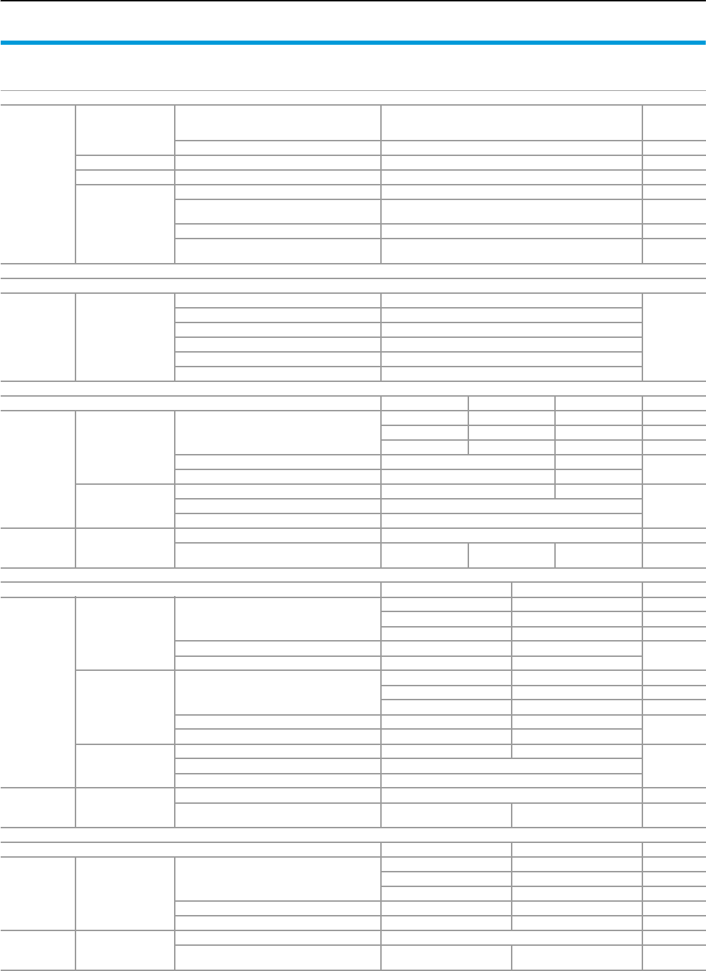
System data
Form 2-4 technical information
137Rittal Ri4Power Form 2-4
SV-TS 8 enclosures
for modular outgoing sections
Enclosures
Mechanical
parameters
Dimensions
Enclosure width
Enclosure height
Enclosure depth
400/600/800 mm3)
1800/2000/2200 mm3)
600/800 mm3)
Pitch pattern 25 mm
Protection category Max. IP 54 EN 60 529
Design 1 – 4 EN 60 439-1
Surface protection/
Material
Enclosure frame Dipcoat-primed
Panels (roof plate, rear panel) Dipcoat-primed,
powder-coated in RAL 7035 on the outside
System attachment Stainless steel
System rails and punched sections
with mounting flanges Sheet steel, zinc-plated, passivated
General ratings data
Electrical
parameters Rated voltage
Rated insulation voltage Ui1000 V
EN 60 439-1
Rated operating voltage Ue 690 V
Rated surge voltage resistance Uimp 8 kV
Overvoltage category IV
Level of contamination 3
Rated frequency 50 Hz
Maxi-PLS busbar system Maxi-PLS 1600 Maxi-PLS 2000 Maxi-PLS 3200
Electrical
parameters
Rated current
(primary busbar)
Rated operating current Ie4)
1400 A 1800 A 2800 A For IP 54
1600 A 2000 A 3000 A For IP 2X1)
1800 A 2500 A 4000 A For IP 2X2)
Rated surge current resistance Ipk 110 kA 220 kA EN 60 439-1
Rated short-time current resistance Icw 50 kA 100 kA
Testing under
accidental arc
conditions
Permissible prospective short-circuit current 50 kA 70 kA
EN 61 641Test voltage 690 V
Permissible arc duration 0.3 sec.
Mechanical
parameters Busbar
Material E-Cu, bare
External dimensions (cross-section) 45 x 45 mm
(1000 mm2)
45 x 45 mm
(1380 mm2)
60 x 60 mm
(2700 mm2)
RiLine60 busbar system E-Cu 30 x 10 mm PLS 1600
Electrical
parameters
Rated current
(primary busbar)
Rated operating current Ie4)
800 A 1150 A IP 54
860 A 1300 A IP 43
1000 A5) 1600 A2) IP 2X
Rated surge current resistance Ipk 68 kA 110 kA EN 60 439-1
Rated short-time current resistance Icw 32 kA, 1 sec. 50 kA, 1 sec./50 kA, 3 sec.
Rated current
(distribution busbar)
Rated operating current Ie4)
800 A 1600 A6) IP 54
860 A 1600 A6) IP 43
1000 A5) 1600 A2) IP 2X
Rated surge current resistance Ipk 68 kA 110 kA EN 60 439-1
Rated short-time current resistance Icw 32 kA, 1 sec. 50 kA, 1 sec./50 kA, 3 sec.
Testing under
accidental arc
conditions
Permissible prospective short-circuit current 30 kA 50 kA
EN 61 641Test voltage 690 V
Permissible arc duration 0.3 sec.
Mechanical
parameters Busbar
Material E-Cu, bare
Version (cross-section) 30 x 10 mm
(300 mm2)
PLS 1600
(900 mm2)
Flat-PLS busbar system Flat-PLS 60 Flat-PLS 100
Electrical
parameters
Rated current
(primary busbar)
Rated operating current Ie4)
3500 A 4000 A IP 54
3650 A 4200 A IP 43
4100 A2) 5500 A2) IP 2X
Rated surge current resistance Ipk 154 kA 220 kA
Rated short-time current resistance Icw 70 kA, 1 sec. 100 kA, 1 sec.
Mechanical
parameters Busbar
Material E-Cu, bare
Version (cross-section) Up to 4 x 60 x 10 mm
(max. 2400 mm2)
Up to 4 x 100 x 10 mm
(max. 4000 mm2)
1) Using outlet filter SK 3326.207 and roof plate IP 2X.
2) Using fan-and-filter unit SK 3327.107 (700 m3/h) and roof plate IP 2X.
3) Other sizes available on request.
4) Other rated currents for different protection categories on request.
5) Using fan-and-filter unit SK 3325.107 (230 m3/h) and roof plate IP 2X.
6) In conjunction with RiLine60 as the main busbar system: Rated currents on request.

Form 2-4 technical information
System data
138 Rittal Ri4Power Form 2-4
SV-TS 8 enclosures
for switch-disconnector-fuse sections
Enclosures
Mechanical
parameters
Dimensions
Enclosure width
Enclosure height
Enclosure depth
1000/1200 mm3)
2000/2200 mm3)
600/800 mm3)
Pitch pattern 25 mm
Protection category Max. IP 31 EN 60 529
Design 1 – 4 EN 60 439-1
Surface protection/
Material
Enclosure frame Dipcoat-primed
Panels (roof plate, rear panel) Dipcoat-primed,
powder-coated in RAL 7035 on the outside
System attachment Stainless steel
System rails and punched sections
with mounting flanges Sheet steel, zinc-plated, passivated
General ratings data
Electrical
parameters Rated voltage
Rated insulation voltage Ui1000 V
EN 60 439-1
Rated operating voltage Ue 690 V
Rated surge voltage resistance Uimp 8 kV
Overvoltage category IV
Level of contamination 3
Rated frequency 50 Hz
Maxi-PLS busbar system Maxi-PLS 1600 Maxi-PLS 2000 Maxi-PLS 3200
Electrical
parameters
Rated current
(primary busbar)
Rated operating current Ie4)
1400 A 1800 A 2800 A For IP 54
1600 A 2000 A 3000 A For IP 2X1)
1800 A 2500 A 4000 A For IP 2X2)
Rated surge current resistance Ipk 110 kA 220 kA EN 60 439-1
Rated short-time current resistance Icw 50 kA 100 kA
Testing under
accidental arc
conditions
Permissible prospective short-circuit current 50 kA 70 kA
EN 61 641Test voltage 690 V
Permissible arc duration 0.3 sec.
Mechanical
parameters Busbar
Material E-Cu, bare
External dimensions (cross-section) 45 x 45 mm
(1000 mm2)
45 x 45 mm
(1380 mm2)
60 x 60 mm
(2700 mm2)
Flat-PLS busbar system Flat-PLS 60 Flat-PLS 100
Electrical
parameters
Rated current
(primary busbar)
Rated operating current Ie4)
3500 A 4000 A IP 54
3650 A 4200 A IP 43
4100 A2) 5500 A2) IP 2X
Rated surge current resistance Ipk 154 kA 220 kA EN 60 439-1
Rated short-time current resistance Icw 70 kA, 1 sec. 100 kA, 1 sec.
Mechanical
parameters Busbar
Material E-Cu, bare
Version (cross-section) Up to 4 x 60 x 10 mm
(max. 2400 mm2)
Up to 4 x 100 x 10 mm
(max. 4000 mm2)
Flat-PLS distribution busbar system Flat-PLS
Electrical
parameters
Rated current
(distribution busbar)
Rated operating current Ie4) 1000 A 1250 A 1600 A 2100 A IP 31
Rated surge current resistance Ipk 154 kA 165 kA 187 kA 220 kA
EN 60 439-1
Rated short-time current resistance Icw 70 kA,
1 sec.
75 kA,
1 sec.
85 kA,
1 sec.
100 kA,
1 sec.
Mechanical
parameters Busbar
Material E-Cu, bare
Version (cross-section) 50 x 10 mm
(500 mm2)
60 x 10 mm
(600 mm2)
80 x 10 mm
(800 mm2)
100 x 10 mm
(1000 mm2)
1) Using outlet filter SK 3326.207 and roof plate IP 2X.
2) Using fan-and-filter unit SK 3327.107 (700 m3/h) and roof plate IP 2X.
3) Other sizes available on request.
4) Other rated currents for different protection categories on request.
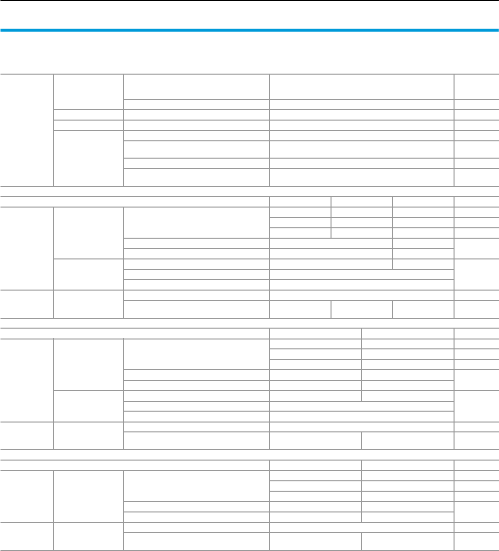
System data
Form 2-4 technical information
139Rittal Ri4Power Form 2-4
SV-TS 8 enclosures
for cable chambers
Enclosures
Mechanical
parameters
Dimensions
Enclosure width
Enclosure height
Enclosure depth
300/400/600 mm3)
1800/2000/2200 mm3)
600/800 mm3)
Pitch pattern 25 mm
Protection category Max. IP 54 EN 60 529
Design 1 – 4 EN 60 439-1
Surface protection/
Material
Enclosure frame Dipcoat-primed
Panels (roof plate, rear panel) Dipcoat-primed,
powder-coated in RAL 7035 on the outside
System attachment Stainless steel
System rails and punched sections
with mounting flanges Sheet steel, zinc-plated, passivated
Maxi-PLS busbar system Maxi-PLS 1600 Maxi-PLS 2000 Maxi-PLS 3200
Electrical
parameters
Rated current
(primary busbar)
Rated operating current Ie4)
1400 A 1800 A 2800 A For IP 54
1600 A 2000 A 3000 A For IP 2X1)
1800 A 2500 A 4000 A For IP 2X2)
Rated surge current resistance Ipk 110 kA 220 kA EN 60 439-1
Rated short-time current resistance Icw 50 kA 100 kA
Testing under
accidental arc
conditions
Permissible prospective short-circuit current 50 kA 70 kA
EN 61 641Test voltage 420 V
Permissible arc duration 0.3 sec.
Mechanical
parameters Busbar
Material E-Cu, bare
External dimensions (cross-section) 45 x 45 mm
(1000 mm2)
45 x 45 mm
(1380 mm2)
60 x 60 mm
(2700 mm2)
RiLine60 busbar system E-Cu 30 x 10 mm PLS 1600
Electrical
parameters
Rated current
(primary busbar)
Rated operating current Ie4)
800 A 1150 A IP 54
860 A 1300 A IP 43
1000 A5) 1600 A2) IP 2X
Rated surge current resistance Ipk 68 kA 110 kA EN 60 439-1
Rated short-time current resistance Icw 32 kA, 1 sec. 50 kA, 1 sec./50 kA, 3 sec.
Testing under
accidental arc
conditions
Permissible prospective short-circuit current 30 kA 50 kA
EN 61 641Test voltage 690 V
Permissible arc duration 0.3 sec.
Mechanical
parameters Busbar
Material E-Cu, bare
Version (cross-section) 30 x 10 mm
(300 mm2)
PLS 1600
(900 mm2)
Flat-PLS busbar system Flat-PLS 60 Flat-PLS 100
Electrical
parameters
Rated current
(primary busbar)
Rated operating current Ie4)
3500 A 4000 A IP 54
3650 A 4200 A IP 43
4100 A2) 5500 A2) IP 2X
Rated surge current resistance Ipk 154 kA 220 kA EN 60 439-1
Rated short-time current resistance Icw 70 kA, 1 sec. 100 kA, 1 sec.
Mechanical
parameters Busbar
Material E-Cu, bare
Version (cross-section) Up to 4 x 60 x 10 mm
(max. 2400 mm2)
Up to 4 x 100 x 10 mm
(max. 4000 mm2)
1) Using outlet filter SK 3326.207 and roof plate IP 2X.
2) Using fan-and-filter unit SK 3327.107 (700 m3/h) and roof plate IP 2X.
3) Other sizes available on request.
4) Other rated currents for different protection categories on request.
5) Using fan-and-filter unit SK 3325.107 (230 m3/h) and roof plate IP 2X.

Form 2-4 technical information
System data
140 Rittal Ri4Power Form 2-4
SV-TS 8 enclosures
for busbar sections
Enclosures
Mechanical
parameters
Dimensions
Enclosure width
Enclosure height
Enclosure depth
200/300/400 mm3)
1800/2000/2200 mm3)
600/800 mm3)
Pitch pattern 25 mm
Protection category Max. IP 54 EN 60 529
Design 1 – 4 EN 60 439-1
Surface protection/
Material
Enclosure frame Dipcoat-primed
Panels (roof plate, rear panel) Dipcoat-primed,
powder-coated in RAL 7035 on the outside
System attachment Stainless steel
System rails and punched sections with
mounting flanges Sheet steel, zinc-plated, passivated
General ratings data
Electrical
parameters Rated voltage
Rated insulation voltage Ui1000 V
EN 60 439-1
Rated operating voltage Ue 690 V
Rated surge voltage resistance Uimp 8 kV
Overvoltage category IV
Level of contamination 3
Rated frequency 50 Hz
Maxi-PLS busbar system6) Maxi-PLS 1600 Maxi-PLS 2000 Maxi-PLS 3200
Electrical
parameters
Rated current
(primary busbar)
Rated operating current Ie4)
1400 A 1800 A 2800 A For IP 54
1600 A 2000 A 3000 A For IP 2X1)
1800 A 2500 A 4000 A For IP 2X2)
Rated surge current resistance Ipk 110 kA 165 kA EN 60 439-1
Rated short-time current resistance Icw 50 kA 75 kA
Testing under
accidental arc
conditions
Permissible prospective short-circuit current 50 kA 70 kA
EN 61 641Test voltage 420 V
Permissible arc duration 0.3 sec.
Mechanical
parameters Busbar
Material E-Cu, bare
External dimensions (cross-section) 45 x 45 mm
(1000 mm2)
45 x 45 mm
(1380 mm2)
60 x 60 mm
(2700 mm2)
RiLine60 busbar system6) E-Cu 30 x 10 mm PLS 1600
Electrical
parameters
Rated current
(primary busbar)
Rated operating current Ie4)
800 A 1150 A IP 54
860 A 1300 A IP 43
1000 A5) 1600 A2) IP 2X
Rated surge current resistance Ipk 68 kA 110 kA EN 60 439-1
Rated short-time current resistance Icw 32 kA, 1 sec. 50 kA, 1 sec./50 kA, 3 sec.
Testing under
accidental arc
conditions
Permissible prospective short-circuit current 30 kA 50 kA
EN 61 641Test voltage 690 V
Permissible arc duration 0.3 sec.
Mechanical
parameters Busbar
Material E-Cu, bare
Version (cross-section) 30 x 10 mm
(300 mm2)
PLS 1600
(900 mm2)
Flat-PLS busbar system6) Flat-PLS 60 Flat-PLS 100
Electrical
parameters
Rated current
(primary busbar)
Rated operating current Ie4)
3500 A 4000 A IP 54
3650 A 4200 A IP 43
4100 A2) 5500 A2) IP 2X
Rated surge current resistance Ipk 154 kA 220 kA
Rated short-time current resistance Icw 70 kA, 1 sec. 100 kA, 1 sec.
Mechanical
parameters Busbar
Material E-Cu, bare
Version (cross-section) Up to 4 x 60 x 10 mm
(max. 2400 mm2)
Up to 4 x 100 x 10 mm
(max. 4000 mm2)
1) Using outlet filter SK 3326.207 and roof plate IP 2X.
2) Using fan-and-filter unit SK 3327.107 (700 m3/h) and roof plate IP 2X.
3) Other sizes available on request.
4) Other rated currents for different protection categories on request.
5) Using fan-and-filter unit SK 3325.107 (230 m3/h) and roof plate IP 2X.
6) Usability of the various busbar systems depends on the enclosure width.
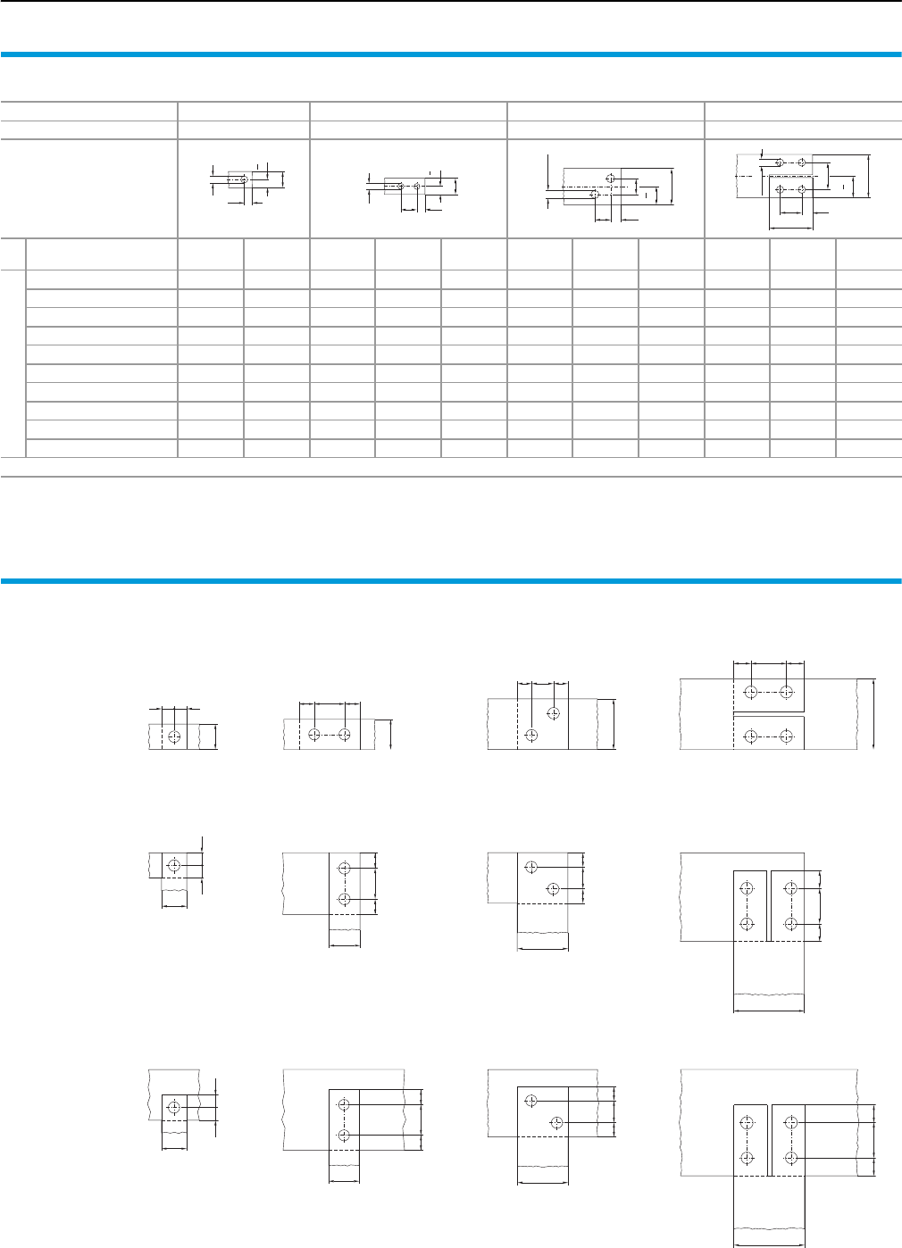
Busbar screw connections to DIN 43 673
Form 2-4 technical information
141Rittal Ri4Power Form 2-4
Drilling templates and drilled holes
Bar widths mm 12 to 50 25 to 60 60 80 to 100
Form1) 12 3 4
Drilled holes in
the bar ends (drilling pattern)
Nominal width
bde
1 de
1 e
2 e
1 e
2 e
3 e
1 e
2 e
3
Hole size
12 5.56–––––––––
15 6.67.5–––––––––
20 9.010–––––––––
25 1112.51112.530––––––
30 1115111530––––––
40 13.52013.52040––––––
50 13.52513.52040––––––
60 ––13.52040172626–––
80 ––––––––204040
100 ––––––––204050
Permissible deviations for hole-centre distances ± 0.3 mm
1) Form designations 1 – 4 match DIN 46 206, part 2 – Flat-type screw terminal
b
2
b
e1
d
b
2
b
e1
e2
d
b
2
b
e3
e1
e2
Ø 13.5
80
2
b
b
e1
e2
e3
Ø 13.5
Examples of busbar screw connections
Longitudinal connections
b
e1e2e1
e2e1e1
b
e1e2e1
b
b
e1 e1
Angular connections
b
e1
e1
b
e1
e2
e1
b
e1e2e1
b
e1
e2
e1
T-connections
b
e1
e1
b
e1e2e1
b
e1e1e2
b
e2
e1e1
Note:
Figures for dimensions b, d, e1 and e2 see table “Drilling templates and drilled holes”.
Longitudinal holes are permissible at the end of a bar or bar stack.

142 Rittal Ri4Power Form 2-4
List of model numbers
3020.300 to 9640.940
Model No. Page
3020.300 123
3031.000 109
3032.000 109
3079.000 112
3079.010 112
3085.000 110
3092.000 110
3439.010 71
3504.000 111
3505.000 111
3509.000 68
3509.200 68
3514.000 111
3515.000 111
3516.000 68
3516.200 68
3524.000 68
3524.200 68
3525.000 68
3525.010 68
3525.200 68
3525.210 68
3526.000 68
3526.200 68
3527.000 68
3527.200 68
3528.000 68
3528.010 68
3528.200 68
3528.210 68
3529.000 68
3529.200 68
3565.000 112
3565.010 112
3566.000 112
3567.000 112
3568.000 112
3569.000 112
3570.000 112
3571.000 112
3572.000 112
3573.000 112
3574.000 112
3575.000 112
3576.000 112
3577.000 112
3578.000 112
3579.000 112
3580.000 110
3580.100 110
3581.000 110
3581.100 110
3582.000 110
3583.000 110
3584.000 110
3585.000 110
3586.000 110
3587.000 110
3588.000 110
3589.000 110
3590.000 110
3590.010 110
4157.000 61
4169.000 61
4171.000 61
4172.000 61
4179.000 61
7825.601 40
7825.603 40
7825.605 40
7825.801 40
7825.803 40
7825.805 40
8106.235 39
8108.235 39
8126.235 39
8128.235 39
8186.235 39
8601.000 40
8601.010 40
8601.015 40
8601.025 40
8601.026 40
8601.030 40
8601.040 40
8601.050 40
8601.060 40
8601.065 40
8601.080 40
8601.085 40
8601.086 40
8601.092 40
8601.095 40
8601.200 40
8601.300 40
8601.400 40
8601.500 40
8601.600 40
8601.602 40
8601.605 40
8601.800 40
8601.802 40
8601.805 40
8601.850 40
8601.905 40
8601.915 40
8601.920 40
8602.000 40
8602.015 40
8602.025 40
8602.030 40
8602.040 40
8602.050 40
8602.060 40
8602.065 40
8602.080 40
Model No. Page
8602.085 40
8602.095 40
8602.100 40
8602.200 40
8602.400 40
8602.500 40
8602.600 40
8602.605 40
8602.800 40
8602.805 40
8602.850 40
8602.905 40
8602.915 40
8602.920 40
8700.000 41
8800.370 61
8800.430 41
8800.490 41
9320.020 111
9320.030 111
9320.060 111
9320.070 111
9320.120 113
9340.000 66
9340.004 74
9340.010 66
9340.030 110
9340.035 110
9340.040 110
9340.070 66
9340.074 74
9340.090 113
9340.100 67
9340.110 67
9340.120 67
9340.130 67
9340.134 75
9340.140 67
9340.170 67
9340.200 67, 69
9340.210 67, 69
9340.214 75, 77
9340.220 67, 69
9340.224 75, 77
9341.000 68
9341.070 68
9341.100 69
9341.110 69
9341.120 69
9341.130 69
9341.140 69
9341.170 69
9342.000 68
9342.004 76
9342.014 76
9342.030 110
9342.070 68
9342.074 76
Model No. Page
9342.100 69
9342.110 69
9342.120 69
9342.130 69
9342.134 77
9342.140 69
9342.170 69
9342.200 70
9342.210 70
9342.220 70
9342.224 78
9342.230 70
9342.234 78
9342.240 70
9342.244 78
9342.250 70
9342.254 78
9342.260 70
9342.264 78
9342.270 70
9342.274 78
9342.280 70
9342.290 70
9342.300 70
9342.310 71, 79
9342.314 79
9342.320 71, 79
9342.324 79
9342.400 72
9342.410 72
9342.500 72
9342.504 80
9342.510 72
9342.514 80
9342.540 72
9342.550 72
9342.560 113
9342.570 114
9342.600 73
9342.604 80
9342.610 73
9342.614 80
9342.640 113
9342.660 114
9342.670 114
9342.680 114
9342.690 114
9342.700 73
9342.710 73
9342.720 113
9342.770 114
9342.780 114
9342.790 114
9350.075 111
9640.000 84
9640.010 84
9640.020 85
9640.050 84
Model No. Page
9640.060 84
9640.080 84
9640.088 84
9640.098 84
9640.150 84
9640.160 84
9640.170 85
9640.180 85
9640.190 84
9640.201 84
9640.206 84
9640.211 84
9640.216 84
9640.221 84
9640.226 84
9640.231 84
9640.236 84
9640.241 84
9640.246 84
9640.251 84
9640.256 84
9640.261 84
9640.266 84
9640.271 84
9640.276 84
9640.281 84
9640.286 84
9640.291 84
9640.296 84
9640.301 84
9640.306 84
9640.311 84
9640.316 84
9640.325 85
9640.330 85
9640.340 85
9640.350 85
9640.360 84
9640.365 84
9640.370 85
9640.380 85
9640.433 85
9640.434 85
9640.443 85
9640.444 85
9640.453 85
9640.454 85
9640.473 85
9640.474 85
9640.483 85
9640.484 85
9640.700 102
9640.705 102
9640.900 85
9640.910 85
9640.920 85
9640.930 85
9640.940 85
Model No. Page

143Rittal Ri4Power Form 2-4
List of model numbers
9640.960 to 9672.013
9640.960 85
9640.970 85
9640.980 85
9649.000 84
9649.010 84
9649.020 85
9649.060 84
9649.076 84
9649.078 84
9649.170 85
9649.190 84
9649.360 84
9650.000 86
9650.010 86
9650.020 87
9650.030 87
9650.050 86
9650.060 86
9650.076 86
9650.080 86
9650.098 86
9650.100 86
9650.140 86
9650.150 86
9650.160 86
9650.170 87
9650.180 87
9650.190 86
9650.201 86
9650.211 86
9650.221 86
9650.231 86
9650.241 86
9650.251 86
9650.261 86
9650.271 86
9650.281 86
9650.291 86
9650.301 86
9650.311 86
9650.325 87
9650.330 87
9650.340 87
9650.350 87
9650.360 86
9650.370 87
9650.380 87
9650.400 87
9650.410 87
9650.420 87
9650.470 87
9650.480 87
9650.487 87
9650.700 102
9650.900 87
9650.910 87
9650.920 87
9650.930 87
Model No. Page
9650.940 87
9650.960 87
9650.980 87
9650.990 87
9659.000 86
9659.010 86
9659.020 87
9659.030 87
9659.060 86
9659.078 86
9659.170 87
9659.180 87
9659.190 86
9659.360 86
9659.403 87
9659.404 87
9659.413 87
9659.414 87
9659.423 87
9659.424 87
9659.473 87
9659.474 87
9659.483 87
9659.484 87
9659.493 87
9659.494 87
9659.525 44
9659.535 44
9659.545 44
9659.555 44
9660.200 105
9660.235 44
9660.245 44
9660.255 44
9660.265 44
9660.313 102
9660.314 102
9660.318 102
9660.319 102
9660.363 102
9660.368 102
9660.369 102
9660.935 44
9660.945 44
9660.955 44
9660.965 44
9660.970 54
9661.000 109
9661.020 109
9661.030 109
9661.040 109
9661.050 109
9661.060 109
9661.080 109
9661.100 109
9661.120 109
9661.130 109
9661.140 109
Model No. Page
9661.150 109
9661.160 109
9661.180 109
9661.200 109
9661.230 109
9661.235 109
9661.240 109
9661.300 109
9661.305 109
9661.320 109
9661.325 109
9661.330 109
9661.335 109
9661.340 109
9661.345 109
9661.350 109
9661.355 109
9661.360 109
9661.365 109
9661.380 109
9661.385 109
9665.750 45
9665.760 45
9665.770 45
9665.780 45
9665.785 45
9665.903 44
9670.006 36
9670.008 36
9670.026 37
9670.028 37
9670.106 36
9670.108 36
9670.126 37
9670.128 37
9670.206 38
9670.208 38
9670.226 38
9670.228 38
9670.316 34
9670.318 34
9670.336 35
9670.338 35
9670.396 33
9670.406 31
9670.408 31
9670.416 34
9670.418 34
9670.426 32
9670.428 32
9670.436 35
9670.438 35
9670.486 30
9670.496 33
9670.606 31
9670.608 31
9670.616 34
9670.618 34
Model No. Page
9670.626 32
9670.628 32
9670.636 35
9670.638 35
9670.686 30
9670.696 33
9670.806 31
9670.808 31
9670.826 32
9670.828 32
9670.886 30
9671.003 42
9671.004 42
9671.006 42
9671.008 42
9671.013 41
9671.014 41
9671.016 41
9671.018 41
9671.033 41
9671.034 41
9671.036 41
9671.038 41
9671.043 41
9671.044 41
9671.046 41
9671.048 41
9671.120 43
9671.126 43
9671.128 43
9671.130 43
9671.132 43
9671.134 43
9671.135 43
9671.138 43
9671.140 43
9671.141 43
9671.142 43
9671.143 43
9671.144 43
9671.146 43
9671.147 43
9671.148 43
9671.150 43
9671.156 43
9671.158 43
9671.160 43
9671.161 43
9671.162 43
9671.163 43
9671.164 43
9671.166 43
9671.167 43
9671.168 43
9671.170 43
9671.176 43
9671.178 43
9671.180 43
Model No. Page
9671.181 43
9671.182 43
9671.183 43
9671.184 43
9671.186 43
9671.187 43
9671.188 43
9671.190 43
9671.196 43
9671.198 43
9671.204 43
9671.206 43
9671.208 43
9671.446 44
9671.448 44
9671.468 44
9671.488 44
9671.536 44
9671.538 44
9671.546 44
9671.548 44
9671.568 44
9671.586 44
9671.588 44
9671.636 44
9671.638 44
9671.646 44
9671.648 44
9671.666 44
9671.668 44
9671.686 44
9671.688 44
9671.736 44
9671.738 44
9671.746 44
9671.748 44
9671.766 44
9671.768 44
9671.786 44
9671.788 44
9671.846 44
9671.848 44
9671.906 39
9671.908 39
9671.926 39
9671.928 39
9671.986 39
9671.996 39
9671.998 39
9672.000 44
9672.002 44
9672.003 44
9672.004 44
9672.006 44
9672.008 44
9672.010 42
9672.012 42
9672.013 42
Model No. Page

144 Rittal Ri4Power Form 2-4
List of model numbers
9672.014 to 9675.156
9672.014 42
9672.016 42
9672.018 42
9672.020 42
9672.022 42
9672.023 42
9672.024 42
9672.026 42
9672.028 42
9672.030 42
9672.032 42
9672.033 42
9672.034 42
9672.036 42
9672.038 42
9672.040 42
9672.042 42
9672.043 42
9672.044 42
9672.046 42
9672.048 42
9672.050 42
9672.052 42
9672.053 42
9672.054 42
9672.056 42
9672.058 42
9673.004 54
9673.006 54
9673.008 54
9673.051 51
9673.052 51
9673.055 51
9673.061 51
9673.062 51
9673.065 51
9673.066 51
9673.069 51
9673.081 51
9673.082 51
9673.085 51
9673.086 51
9673.089 51
9673.152 51
9673.155 51
9673.162 51
9673.165 51
9673.166 51
9673.182 51
9673.185 51
9673.186 51
9673.192 51
9673.195 51
9673.405 53
9673.406 53
9673.408 53
9673.416 53
9673.418 53
Model No. Page
9673.426 53
9673.428 53
9673.430 55
9673.431 54
9673.432 54
9673.434 55
9673.436 55
9673.437 55
9673.438 55
9673.439 55
9673.440 54
9673.441 54
9673.444 54
9673.445 54
9673.448 54
9673.449 54
9673.450 55
9673.454 55
9673.456 55
9673.457 55
9673.458 55
9673.459 55
9673.460 54
9673.461 54
9673.464 54
9673.465 54
9673.468 54
9673.469 54
9673.470 55
9673.471 55
9673.474 55
9673.475 55
9673.476 55
9673.477 55
9673.478 55
9673.479 55
9673.480 54
9673.481 54
9673.484 54
9673.485 54
9673.488 54
9673.489 54
9673.504 55
9673.506 55
9673.508 55
9673.530 52
9673.532 52
9673.540 52
9673.542 52
9673.560 52
9673.562 52
9673.640 56
9673.641 56
9673.642 56
9673.643 56
9673.644 56
9673.646 56
9673.647 56
Model No. Page
9673.648 56
9673.651 56
9673.652 56
9673.653 56
9673.654 56
9673.657 56
9673.660 56
9673.661 56
9673.662 56
9673.663 56
9673.664 56
9673.666 56
9673.667 56
9673.668 56
9673.671 56
9673.672 56
9673.673 56
9673.674 56
9673.677 56
9673.680 56
9673.681 56
9673.682 56
9673.683 56
9673.684 56
9673.686 56
9673.687 56
9673.688 56
9673.691 56
9673.692 56
9673.693 56
9673.694 56
9673.697 56
9673.901 58
9673.902 58
9673.903 58
9673.915 57
9673.920 57
9673.930 57
9673.931 57
9673.940 57
9673.941 57
9673.942 57
9673.943 57
9673.950 57
9673.951 57
9673.952 57
9673.953 57
9673.960 57
9673.961 57
9673.962 57
9673.963 57
9673.970 57
9673.971 57
9673.972 57
9673.973 57
9673.980 57
9673.981 57
9673.982 57
Model No. Page
9673.983 57
9673.990 57
9673.991 57
9673.995 57
9674.003 103
9674.004 103
9674.006 103
9674.008 103
9674.036 59
9674.038 59
9674.046 59
9674.048 59
9674.056 59
9674.058 59
9674.102 90
9674.104 90
9674.122 90
9674.124 90
9674.152 90
9674.154 90
9674.162 90
9674.164 90
9674.172 90
9674.174 90
9674.182 90
9674.184 90
9674.192 90
9674.194 90
9674.196 59
9674.198 59
9674.305 60
9674.306 60
9674.307 60
9674.308 60
9674.325 60
9674.326 60
9674.327 60
9674.328 60
9674.340 46
9674.342 46
9674.346 60
9674.348 60
9674.350 46
9674.352 46
9674.356 46
9674.358 46
9674.362 60
9674.364 60
9674.366 60
9674.368 60
9674.380 107
9674.381 107
9674.400 106
9674.405 106
9674.406 106
9674.408 106
9674.410 106
9674.415 106
Model No. Page
9674.416 106
9674.418 106
9674.420 106
9674.425 106
9674.426 106
9674.428 106
9674.430 106
9674.435 106
9674.436 106
9674.438 106
9674.441 108
9674.442 108
9674.443 108
9674.444 108
9674.445 108
9674.447 108
9674.448 108
9674.451 108
9674.452 108
9674.453 108
9674.454 108
9674.455 108
9674.457 108
9674.458 108
9674.461 108
9674.462 108
9674.463 108
9674.464 108
9674.467 108
9674.468 108
9674.473 108
9674.474 108
9674.477 108
9674.478 108
9674.485 108
9674.488 108
9674.701 52
9674.702 52
9674.703 52
9674.704 52
9674.706 52
9674.707 52
9674.761 56
9674.762 56
9674.763 56
9674.764 56
9674.781 56
9674.782 56
9674.783 56
9674.784 56
9675.130 100
9675.133 100
9675.136 100
9675.140 100
9675.143 100
9675.146 100
9675.153 100
9675.156 100
Model No. Page

145Rittal Ri4Power Form 2-4
List of model numbers
9675.163 to 9676.987
9675.163 100
9675.166 100
9675.210 102
9675.212 102
9675.218 102
9675.220 102
9675.222 102
9675.230 102
9675.232 102
9675.238 102
9675.240 102
9675.242 102
9675.303 100
9675.304 100
9675.306 100
9675.307 100
9675.311 100
9675.313 100
9675.314 100
9675.315 100
9675.316 100
9675.317 100
9675.321 100
9675.322 100
9675.323 100
9675.324 100
9675.325 100
9675.326 100
9675.327 100
9675.328 100
9675.331 100
9675.333 100
9675.334 100
9675.335 100
9675.336 100
9675.337 100
9675.343 100
9675.344 100
9675.346 100
9675.347 100
9675.353 100
9675.354 100
9675.356 100
9675.357 100
9675.361 100
9675.362 100
9675.363 100
9675.364 100
9675.365 100
9675.366 100
9675.367 100
9675.368 100
9675.373 100
9675.374 100
9675.376 100
9675.377 100
9675.501 101
9675.502 101
Model No. Page
9675.503 101
9675.504 101
9675.505 101
9675.506 101
9675.507 101
9675.508 101
9675.511 101
9675.513 101
9675.514 101
9675.515 101
9675.516 101
9675.517 101
9675.521 101
9675.522 101
9675.523 101
9675.524 101
9675.525 101
9675.526 101
9675.527 101
9675.528 101
9675.531 101
9675.533 101
9675.534 101
9675.535 101
9675.536 101
9675.537 101
9675.543 101
9675.544 101
9675.546 101
9675.547 101
9675.553 101
9675.554 101
9675.556 101
9675.557 101
9675.563 101
9675.564 101
9675.566 101
9675.567 101
9675.573 101
9675.574 101
9675.576 101
9675.577 101
9675.842 98
9675.843 98
9675.882 98
9675.883 98
9675.892 98
9675.893 98
9676.000 122
9676.001 122
9676.002 90
9676.004 90
9676.006 92
9676.007 92
9676.008 92
9676.011 93
9676.012 93
9676.013 93
Model No. Page
9676.014 93
9676.015 93
9676.016 93
9676.017 93
9676.018 93
9676.019 93
9676.020 91
9676.021 91
9676.022 91
9676.023 91
9676.024 91
9676.025 91
9676.026 91
9676.027 91
9676.041 94
9676.042 94
9676.043 94
9676.046 93
9676.047 93
9676.048 93
9676.052 94
9676.053 94
9676.054 94
9676.056 94
9676.058 94
9676.059 94
9676.184 105
9676.186 105
9676.188 105
9676.194 105
9676.196 105
9676.198 105
9676.201 97
9676.202 97
9676.203 97
9676.204 97
9676.205 97
9676.206 97
9676.213 97
9676.214 97
9676.215 97
9676.216 97
9676.217 97
9676.218 97
9676.221 97
9676.222 97
9676.223 97
9676.224 97
9676.225 97
9676.226 97
9676.233 97
9676.234 97
9676.235 97
9676.236 97
9676.237 97
9676.238 97
9676.301 97
9676.303 97
Model No. Page
9676.305 97
9676.313 97
9676.315 97
9676.317 97
9676.321 97
9676.322 97
9676.323 97
9676.324 97
9676.325 97
9676.326 97
9676.333 97
9676.334 97
9676.335 97
9676.336 97
9676.337 97
9676.338 97
9676.503 103
9676.504 103
9676.505 103
9676.520 96
9676.526 96
9676.528 96
9676.540 96
9676.546 96
9676.548 96
9676.620 98
9676.621 98
9676.626 98
9676.628 98
9676.640 98
9676.641 98
9676.646 98
9676.648 98
9676.700 95
9676.704 95
9676.710 95
9676.714 95
9676.730 94
9676.731 94
9676.733 94
9676.741 96
9676.742 96
9676.743 96
9676.744 96
9676.745 96
9676.746 96
9676.747 96
9676.748 96
9676.749 96
9676.806 104
9676.807 104
9676.808 104
9676.809 104
9676.810 104
9676.811 104
9676.812 104
9676.813 104
9676.814 104
Model No. Page
9676.815 104
9676.816 104
9676.817 104
9676.819 104
9676.832 104
9676.910 88
9676.912 88
9676.961 104
9676.962 104
9676.963 104
9676.966 104
9676.967 104
9676.968 104
9676.971 103
9676.972 103
9676.973 103
9676.976 103
9676.977 103
9676.981 103
9676.982 103
9676.983 103
9676.986 103
9676.987 103
Model No. Page

146 Rittal Ri4Power Form 2-4Rittal Ri4Power Form 2-4
Index
A
Accessories 100 – 114
Adaptor extension piece
– for circuit-breaker component
adaptors 113
Additional attachment
– for busbar support 1-pole 110
Air circuit-breaker support bar 54
Angular baying bracket
– for TS 41
Angular connector
– for Flat-PLS 98
Assembly kit
– for switch-disconnector-fuse section 46
Attachment set
– for air circuit-breaker installation 54
B
Base isolators 109
Base tray infill 67, 69
Base trays 67, 69, 75, 77
Base/plinth components
– front and rear 40
Base/plinth trim panels
–Side 40
Baying brackets
–PE/PEN 109
Baying connector
– for TS 41
Bolts Maxi-PLS 85, 87, 103
Bracket for mounting rail 61
Busbar claw
– for Flat-PLS 93
Busbar connection adaptor
– 3-pole 70, 71
– 4-pole 78, 79
Busbar connectors 111
Busbar stabiliser bars
– for busbar support Flat-PLS 91
Busbar support
–Flat-PLS 90
– for switch-disconnector-fuse
section 106
– for RiLine60 flat copper busbars 66, 74
– for stabiliser bar 91
– Maxi-PLS 84, 86
Busbar support RiLine60
– 3-pole 66
– 3-pole PLS 68
– 4-pole 74
– 4-pole PLUS 76
Busbar systems
– 1- and 2-pole 110
– 3-pole (RiLine60) 66 – 73
– 4-pole (RiLine60) 74 – 80
– Flat-PLS 90 – 97
– Maxi-PLS 84 – 89
– Technical information 115
Busbars
– Cover section 110
– Cover section for Flat-PLS 94
– E-Cu 102, 109, 110
– Maxi-PLS 84, 86
–PE/PEN 109
– PLS 68, 102
– Screw connections 141
C
Cable chamber 21 – 23
Cable chamber enclosures SV-TS 8 33 – 35
Cable connection system
– for Maxi-PLS/Flat-PLS 99
Cable entry gland
– for roof plates 45
– for side panel modules 51
Circuit-breaker component adaptor
– 3-pole 72, 73
– 4-pole 80
Circuit-breaker section 9 – 11
Clamps
– Maxi-PLS 85, 87
Claw with nut 104
Combination angle
– PE/PEN 109
Compartment configuration 50
Component adaptor
– 3-pole 72, 73
– 4-pole 80
Connection brackets
– for circuit-breaker component
adaptors 114
– for Flat-PLS 97
– for switch-disconnector-fuse
section 108
– Maxi-PLS 85, 87
Connection clamps
– Maxi-PLS 85, 87
Connection kits
– for busbar riser 102
Connection plates
– for laminated copper bars
for Flat-PLS 96
– Maxi-PLS 85, 87
– with studs M10/12/16 for Flat-PLS 95
Connection terminals
–Flat-PLS 94
Connector
– for busbars 111
– for Flat-PLS 98
– for Mini-TS profile 58
– Maxi-PLS 84, 86
Connector kits
– for Flat-PLS/RiLine60 101
– for Maxi-PLS/Flat-PLS 88, 89
– for Maxi-PLS/RiLine60 100
Connector pieces
– for Mini-TS profile 58
Contact hazard protection
for cable chamber
– for switch-disconnector-fuse
section 60
Contact makers
– for Flat-PLS 96
– Maxi-PLS 85, 87
Copper bars
– Busbars 109, 110
– Maxi-PLS 84, 86
– PLS special busbars 68
– Rittal Flexibar “S” 112
Copper busbars
– RiLine60 66
Corner bracket for Maxi-PLS 102
Corner connector
– for Mini-TS profile 58
Coupling set mounting kit 59
Coupling section 13, 15
Cover plates 52
Cover sections
– for base tray 67, 69, 75, 77
– for busbars 110
– for Flat-PLS 94
– Maxi-PLS 84, 86
Cover, distribution busbar
– for ABB/Siemens
switch-disconnector-fuse section 107
– for Jean Müller
switch-disconnector-fuse section 107
Covers
– for busbar claws 93
Cross members
– for TS 42
D
Direct connection components
– for Maxi-PLS 85, 87
Direct connection terminals
– for Flat-PLS 94
Distribution busbars 102
– for switch-disconnector-fuse section 106
Divider panel
– for switch-disconnector-fuse section 60
Dividing plate
– for switch-disconnector-fuse section 60
E
Enclosure configuration 39 – 46
Enclosures, SV-TS 8 30 – 38
– Busbar enclosures 38
– Cable chamber enclosures 33 – 35
– Modular enclosures 30 – 32
– Switch-disconnector-fuse
enclosures 36 – 37
– System data 134 – 140
End covers for busbar supports
– 3-pole 66, 68
– 4-pole 74, 76
–Flat-PLS 92
– Maxi-PLS 84, 86
– PLS 68
– PLUS 76
End support
– for switch-disconnector-fuse
section 106
– Maxi-PLS 84, 86
Expansion connector PLS 111
F
Filler pieces
– for busbar support Flat-PLS 92
Flat-PLS busbar systems 90 – 97
Frame adaptor piece
– for Mini-TS profile 58
Front trim panels
– for switch-disconnector-fuse
section 46
– for TS 41, 42
Functional space divider
– for TS 54, 55
– Mounting bracket 53
Functional space side panel modules
– for cable connection space 51
– for TS 51
G
Gland plates
– for cable entry 45
– for side panel modules 51
– to shroud the opening for
vertical busbar systems 55

147Rittal Ri4Power Form 2-4
Index
I
Isolator chassis
– Maxi-PLS 85, 87
L
Laminated copper bars 112
Locks (twist locks) 43
Longitudinal connector
– for Flat-PLS 98
– Maxi-PLS 84, 86
M
Maxi-PLS
– Bar systems 84 – 89
Mini-TS profiles 57
Modular enclosures SV-TS 8 30 – 32
Mounting accessories
– for RiLine60 distribution busbar
system 61
Mounting bracket 61
– for functional space divider 53
– for functional space divider and
air circuit-breaker support bar 53
Mounting claw with nut 104
Mounting kit, coupling set 59
Mounting plates
– for Ri4Power Form 2-4 56
Mounting rails 61
N
Nuts for mounting rails 61
O
Outgoing section 17
P
Partial doors
– for TS 43
Partial mounting plates
– for TS 56
PE/PEN
–Busbars 109
– Combination angle 109
Perforated mounting strip
– for partial doors 43
Planning and configuration
of Ri4Power systems 122
PLS
– Busbar connectors 111
– Busbars 68, 102
– Expansion connectors 111
Power Engineering software 123
Punched rail
– 17 x 15.5 mm for TS 57
Punched rails
– for Jean Müller
switch-disconnector-fuse section 107
Punched section with mounting flange
– for coupling set 59
R
Rated currents
– Busbars E-Cu 120
– Flat-PLS busbar systems 121
Ri4Power assembly instructions 122
RiLine60 busbar support
– 1- and 2-pole 110
RiLine60 busbar systems 66 – 80
Roof frame strips
– for TS 44
Roof plates
– for TS 44
S
Screw connections
– for connection brackets 104
– for Flat-PLS busbar systems 104
Short-circuit protection diagrams
– for RiLine60 116
Short-circuit resistance diagrams
– Flat-PLS 118
– Laminated copper bars 119
Side panel modules
– for cable connection space 51
– for TS 51
Side panels
– for TS 39
Sliding blocks
– for circuit-breaker
component adaptor 113
– Maxi-PLS 85, 87
Sliding nuts
– Maxi-PLS 85, 87
Spacer rolls 103
Spacers
– for Flat-PLS busbar support 92
– for RiLine60 busbar supports 113
Special busbars
– Maxi-PLS 84, 86
– PLS 68, 102
Stabiliser
– for connection kit 105
– Maxi-PLS 86
Stabiliser bars
–Flat-PLS 91
Stacking insulator 105
Support
– for Flat-PLS 90, 91
– for laminated copper bars 112
– for Maxi-PLS 84, 86
Support bars
– for air circuit-breakers 54
Support frame
– for DIN rail-mounted devices 56
Support panel
– for cover sections 67, 69, 75, 77
Support rails
– for component adaptors 113
– for stacking insulators 105
SV-TS 8 enclosures 30 – 38
Switch-disconnector-fuse section 25 – 27
Switch-disconnector-fuse
enclosures 36 – 37
System accessories
– for SV-TS 39 – 46
System attachment
– for Flat-PLS 90
– for Maxi-PLS 84, 86
– for RiLine60 103
System benefits
– Maxi-PLS 83
– RiLine60 63
System data 134 – 140
T
T-connector kits
– for Flat-PLS/RiLine60 bar systems 101
– for Maxi-PLS/RiLine60 bar systems 100
– for RiLine60 100
T-connector piece
– for Mini-TS profile 58
Technical information 115 – 141
Terminal box Form 4b 52
Terminal block, distribution busbar
– for switch-disconnector-fuse section 108
Terminal studs
– for connector kits
and connection brackets 103
– Maxi-PLS 85, 87
Terminals
–Flat-PLS 94
Threaded bolts
– for connector kits
and connection brackets 103
– Maxi-PLS 85, 87
Trim panels
– for TS 41, 42
TS 8 system platform 29
Twist locks 43
U
U contact makers
– Maxi-PLS 85, 87
U nut 61
Universal support
– for laminated copper bars 112
Upgrade kit
– for front panels 41, 42
– for side panels 39
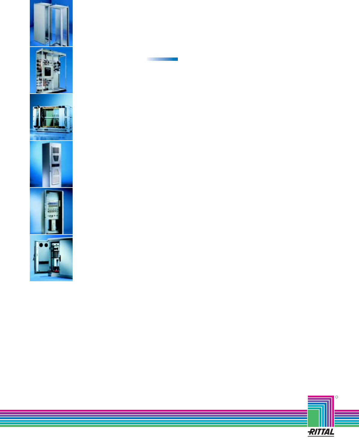
Low-voltage switchgear
for maximum flexibility
Rittal – Ri4Power Form 2-4
Including
innovations 20
09
Rittal – Ri4Power Form 2-4
R
Switch to perfection
All in all – solutions from Rittal
Rittal has one of the largest ranges of enclosures available
for immediate delivery. However, Rittal also supplies inte-
grated solutions – up to Level 4. This comprises mechanical
installation, power supply, electronic components, climate
control and central monitoring. For all of your requirements.
Fully assembled and functional. Wherever in the world you
develop and implement solutions for yourself and your
customers, we are close at hand. The global alliance
between production, distribution and service guarantees
closeness to the customer. Worldwide!
09/09 䡠 E470
Busbar systems RiLine60
Busbar systems 40/100/150/185 mm
Ri4Power low-voltage switchgear
Electronic Packaging
IT Solutions
Communication Systems
System Climate Control
Power Distribution
Industrial Enclosures
Rittal GmbH & Co. KG 䡠 Postfach 1662 䡠 D-35726 Herborn
Telephone: +49(0)2772 505-0 䡠 Telefax: +49(0)2772 505-2319 䡠 eMail: info@rittal.de 䡠 www.rittal.com
