1000443679 Catalog
168083-Catalog 168083-Catalog 168083-Catalog B4 unilog cesco-content
1000388737-Catalog 1000388737-Catalog 1000388737-Catalog B5 unilog cesco-content
102921-Catalog 102921-Catalog 102921-Catalog 782274 Batch6 unilog cesco-content
2016-07-29
: Pdf 1000443679-Catalog 1000443679-Catalog B2 unilog
Open the PDF directly: View PDF ![]() .
.
Page Count: 160 [warning: Documents this large are best viewed by clicking the View PDF Link!]
- 1
- 2-3
- 4-5
- 6-7
- 8-9
- 10-11
- 12-13
- 14-15
- 16-17
- 18-19
- 20-21
- 22-23
- 24-25
- 26-27
- 28-29
- 30-31
- 32-33
- 34-35
- 36-37
- 38-39
- 40-41
- 42-43
- 44-45
- 46-47
- 48-49
- 50-51
- 52-53
- 54-55
- 56-57
- 58-59
- 60-61
- 62-63
- 64-65
- 66-67
- 68-69
- 70-71
- 72-73
- 74-75
- 76-77
- 78-79
- 80-81
- 82-83
- 84-85
- 86-87
- 88-89
- 90-91
- 92-93
- 94-95
- 96-97
- 98-99
- 100-101
- 102-103
- 104-105
- 106-107
- 108-109
- 110-111
- 112-113
- 114-115
- 116-117
- 118-119
- 120-121
- 122-123
- 124-125
- 126-127
- 128-129
- 130-131
- 132-133
- 134-135
- 136-137
- 138-139
- 140-141
- 142-143
- 144-145
- 146-147
- 148-149
- 150-151
- 152-153
- 154-155
- 156-157
- 158-159
- 160
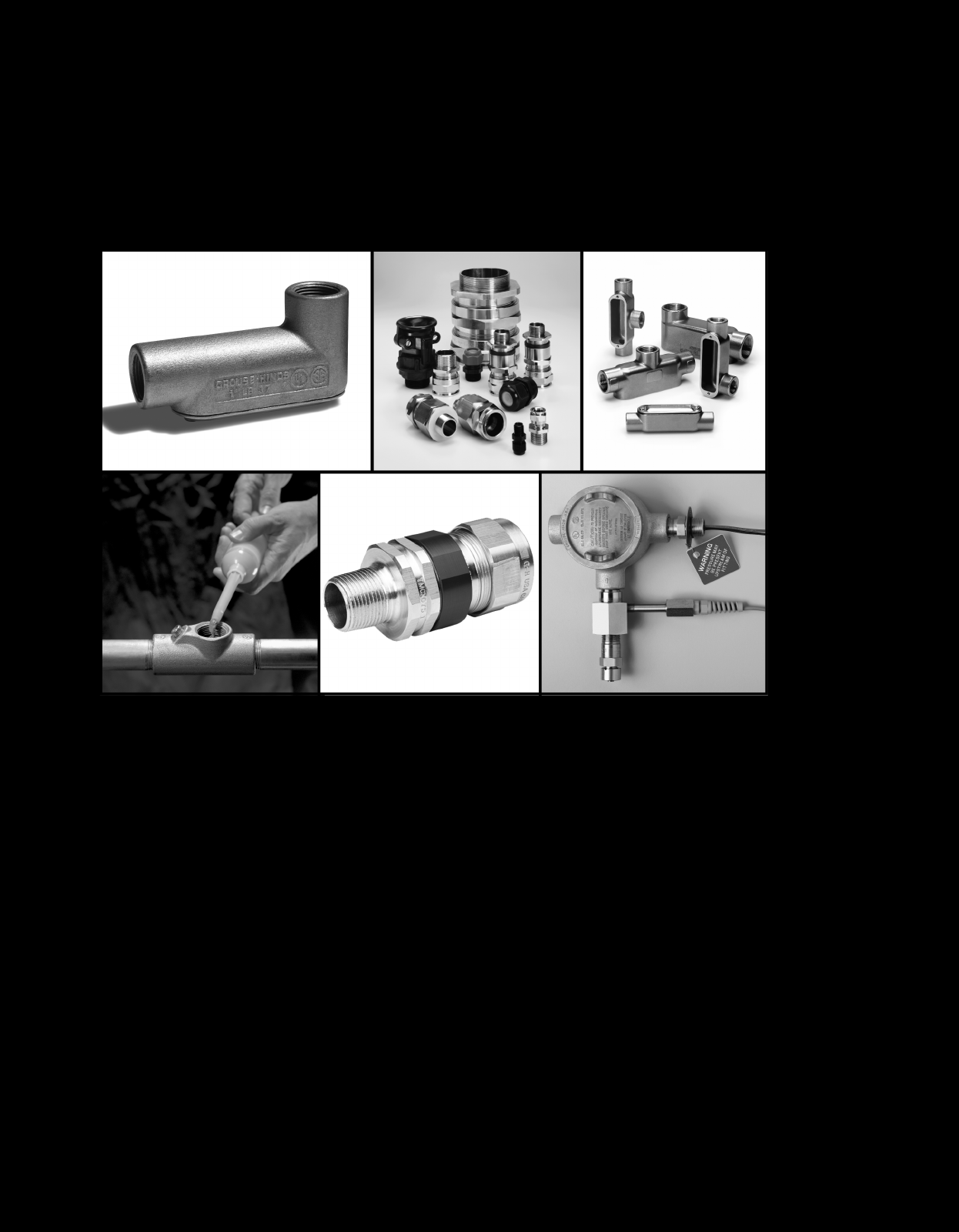
IInndduussttrriiaall FFiittttiinnggss
Section F
Time-tested and innovative conduit fittings, cord connectors and cable
glands move power where you need it simply and safely in any
electrical installation.
New Products in the Industrial Fittings Product Line Section
• Terminator™ II TMCX Cable Glands 4F
1.qxp 12/16/2013 11:59 AM Page 1

2
www.crouse-hinds.com US: 1-866-764-5454 CAN: 1-800-265-0502 Copyright©2013 Eaton’s Crouse-Hinds Business
FElectrical Fittings
Table of Contents
Section F of the Eaton's Crouse-Hinds Product Catalog lists a wide
variety of conduit outlet bodies and boxes, cable fittings, unions,
connectors, seals, breathers, and drains for both hazardous and
non-hazardous area use. Information on applications, features,
standard materials, standard finishes, options, size ranges,
compliances, and accessories is presented for ease of product
selection. Information relating to product families in Section F is
grouped as follows:
Section 1F
Condulet®Conduit Bodies and Outlet Boxes
(for non-hazardous areas)
Conduit bodies for installation in conduit systems to act as pull
outlets, make 90° bends, provide for splices, taps, mounting
outlets, etc.
Form 7 Mogul SLB
Form 8 LBD LBY
Mark 9 LBNEC ET
Form 5
Series 5
Form 7 SnapPack™
Round cast outlet boxes and accessories for use in conjunction
with threaded rigid conduit to serve as junction boxes, pull outlets,
accommodate wiring devices and support lighting fixtures.
GRF VXF
Section 2F
Condulet Device Boxes
(for non-hazardous areas)
For installation in conduit systems to:
• Accommodate wiring devices
• Act as pull boxes
• Provide openings for taps and splices
Provided in two box depths with a wide variety of hub
configurations and sizes. Boxes can accommodate single or
multiple devices.
FS FD Covers
Section 3F
Condulet Conduit Bodies and Outlet Boxes
(for hazardous areas)
For use with rigid conduit systems:
• Act as pull and splice boxes
• Act as mounting outlets or supports for lighting fixtures
• Act as sealing fittings
CPS ET LBH STL
EAB GUA LBY EAJ
EKC HTL OE GUR
Section 5F
Elbows, Couplings, Hubs, Grounding Devices,
Plugs, Reducers, Service Entrance and Unions
(for hazardous and non-hazardous areas)
Includes:
• Service entrance heads
• Grounding receptacles and straps
• Unions and elbows for threaded conduit systems
• Couplings for use where allowance must be made in conduit
system for difficult bends or vibration
• Reducers for connecting conduit of different dimensions
• Plugs for unused conduit openings and hubs
ECGJH GC LNR UNA UNY
ECLK GCR PLG UNF UNYL
EL GCT RE UNFL XD
FHUBS REC UNL XJG
Section 6F
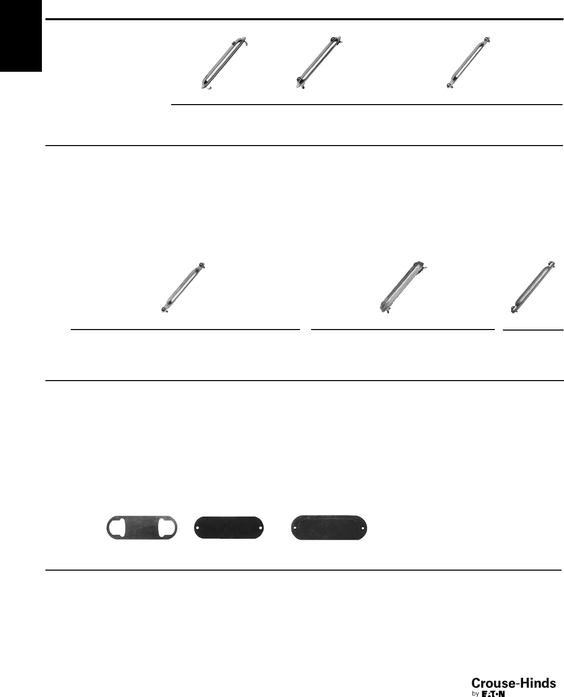
Seals, Breathers and Drains
(for hazardous areas)
Includes:
• Seals used to prevent passage of gases or flames in conduit runs
and from device enclosures
• Sealing/drain fittings for retrofit applications
• Breathers used to provide ventilation for enclosures
• Drains used to prevent accumulation of moisture in conduit
systems and enclosures
•Chico®sealing compound and fiber
Seal Seal and drain Breather
EYS EYD and drain
EZS EZD ECD
EYSR EYDX CD
EYSX
Secondary Process Sealing Fitting
EYS Tool Kit
F
Section 4F
Cable Glands and Cable Accessories
(for hazardous and non-hazardous areas)
Includes listings of cable and cord connectors and cable
terminators for armoured and unarmoured cable and cord, and
aluminum sheathed cable. Used to:
• Provide means for passing cord, cable or flexible conduit through
bulkhead and into boxes and cabinets
• Form watertight seal
• Form non-slip connection or termination for flexible cord, cable or
flexible conduit
• Provide grounding continuity
ADE 1F ADE 6FC LCC TMC
ADE 4F CGB LCCF Terminator™II TMCX
ADE 6F CGFP TGC TMCX
ADE 1FC EBY THRU-WALL
2-3.qxp 12/16/2013 11:59 AM Page 2

3
www.crouse-hinds.com US: 1-866-764-5454 CAN: 1-800-265-0502 Copyright©2013 Eaton’s Crouse-Hinds Business
1F
Condulet®Conduit Bodies and Outlet Boxes
Non-Hazardous
1F
1F
Description Page No.
Application/Selection see page 4
Shape Selector Chart see page 5
Conduit Bodies - Cast Iron or Aluminum
Forms 7 & 8, Mark 9, Series 5 and Form 5 see pages 6–81
Form 7 SnapPack™ see page 9
Mogul Series see pages 13–14
LBD Series see page 15
LBNEC Mogul Pulling Elbows see page 16
Covers for Cast Iron or Aluminum Conduit Bodies
Blank
Forms 7 & 8, Mark 9, Series 5 and Form 5 see page 8
Mogul Series see pages 13–14
Gaskets for Cast Iron or Aluminum Conduit Bodies
Forms 7 & 8, Mark 9, Series 5 and Form 5 see page 8
LBD Series see page 15
Mogul Series see pages 13–14
Conduit Bodies, Covers and Gaskets - Stainless Steel see pages 17–27
Condulet®Outlet Boxes
GRF Series see page 19
VXF Series see page 19
Service Entrance Elbows & Tees
ET Tees see page 20
LBY & SLB Elbows see page 20
2-3.qxp 12/16/2013 11:59 AM Page 3
4
www.crouse-hinds.com US: 1-866-764-5454 CAN: 1-800-265-0502 Copyright©2013 Eaton’s Crouse-Hinds Business
Application and Selection
Condulet®Conduit Bodies and Outlet Boxes
Considerations for Selection:
• Shape required – determine from configuration of conduit system
and intended function of conduit bodies or outlet boxes
• Size required – determine from conduit and conductor size
• Material required – determine from environmental conditions
(corrosive fumes, buried in concrete, etc.)
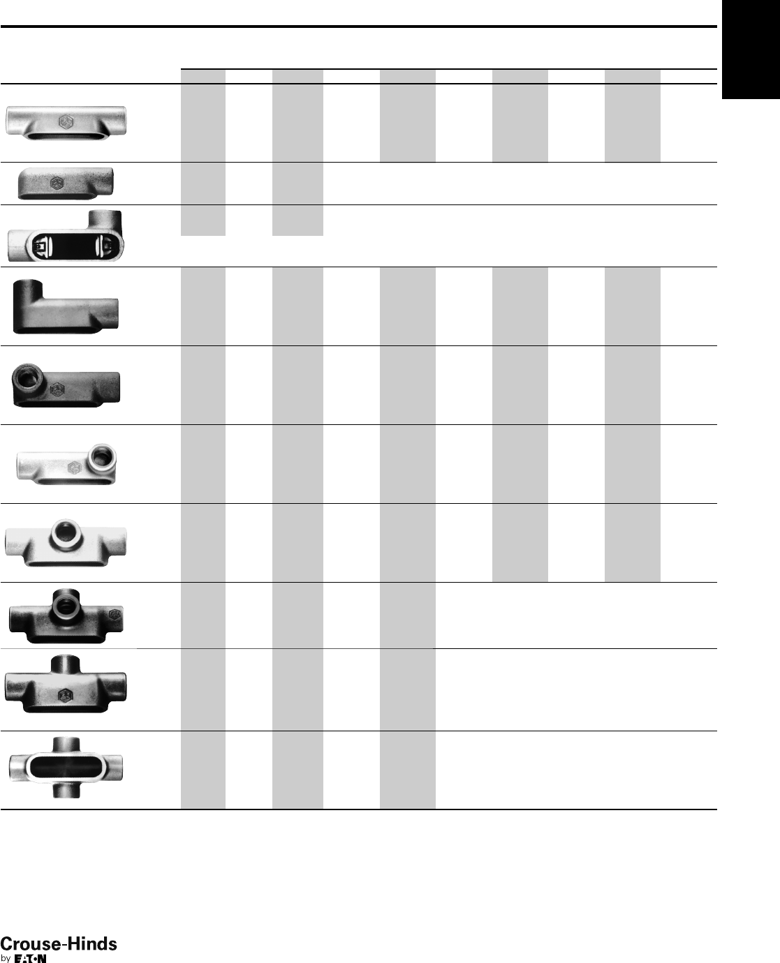
Quick Selector Chart - Conduit Bodies
Quick Selector Chart - Conduit Outlet Boxes
1F
Series
Conduit
Sizes Configuration Styles
Standard
Material
Form 7 1/2" - 4" C, E, L, LB, LL, LR, T,
TA, TB and X
Feraloy®iron or aluminum
Form 8 1/2" - 4" C, LB, LL, LR, T, TB and X Feraloy iron
Mark 9 1/2" - 4" C, LB, LL, LR, T, TB and X Copper-free aluminum
Form 5 1/2" - 4" C, LB, LL, LR, T, TB and X Durable malleable iron construction
Series 5 1/2" - 4" C, LB, LL, LR and T Corrosion-resistant copper-free aluminum construction
Inside
Dimensions
Series
Conduit
Sizes Depth Dia.
No. of
Conduit
Openings
Surface
or Flush
Mtg.
Standard
Material Finish Covers
VXF 1/2and 3/413/441/44 or 5 S Copper-free
aluminum
Epoxy enamel When box is used as
junction or pull box,
install GRF covers, gaskets.
GRF 1/2to 1 13/8to 31/8311/16 0 to 4 S – F Feraloy iron
alloy or
aluminum
Electrogalvanized
and aluminum paint
Blank, hub, standard
4" octagonal box
covers, wiring devices,
lighting fixture
hangers, gaskets.
Applications:
Conduit bodies and outlet boxes are installed at appropriate
locations in threaded rigid conduit systems to:
• Act as pull outlets for conductors to be installed in a conduit
system
• Provide openings for splices and taps in conductors
• Act as mounting outlets for luminaires and wiring devices, or as
support for luminaires (with hub and fixture hanging covers)
• Act as junction or fuse boxes when fitted with connection blocks
or fuse blocks
• Connect conduit sections and change direction of conduit runs
• Make 90º bends in conduit runs
• Provide access to conductors for maintenance and future
system changes
1F
4-5.qxp 12/23/2013 2:00 PM Page 4
5
www.crouse-hinds.com US: 1-866-764-5454 CAN: 1-800-265-0502 Copyright©2013 Eaton’s Crouse-Hinds Business
Condulet®Conduit Bodies and Outlet Boxes
Shape Selector Chart
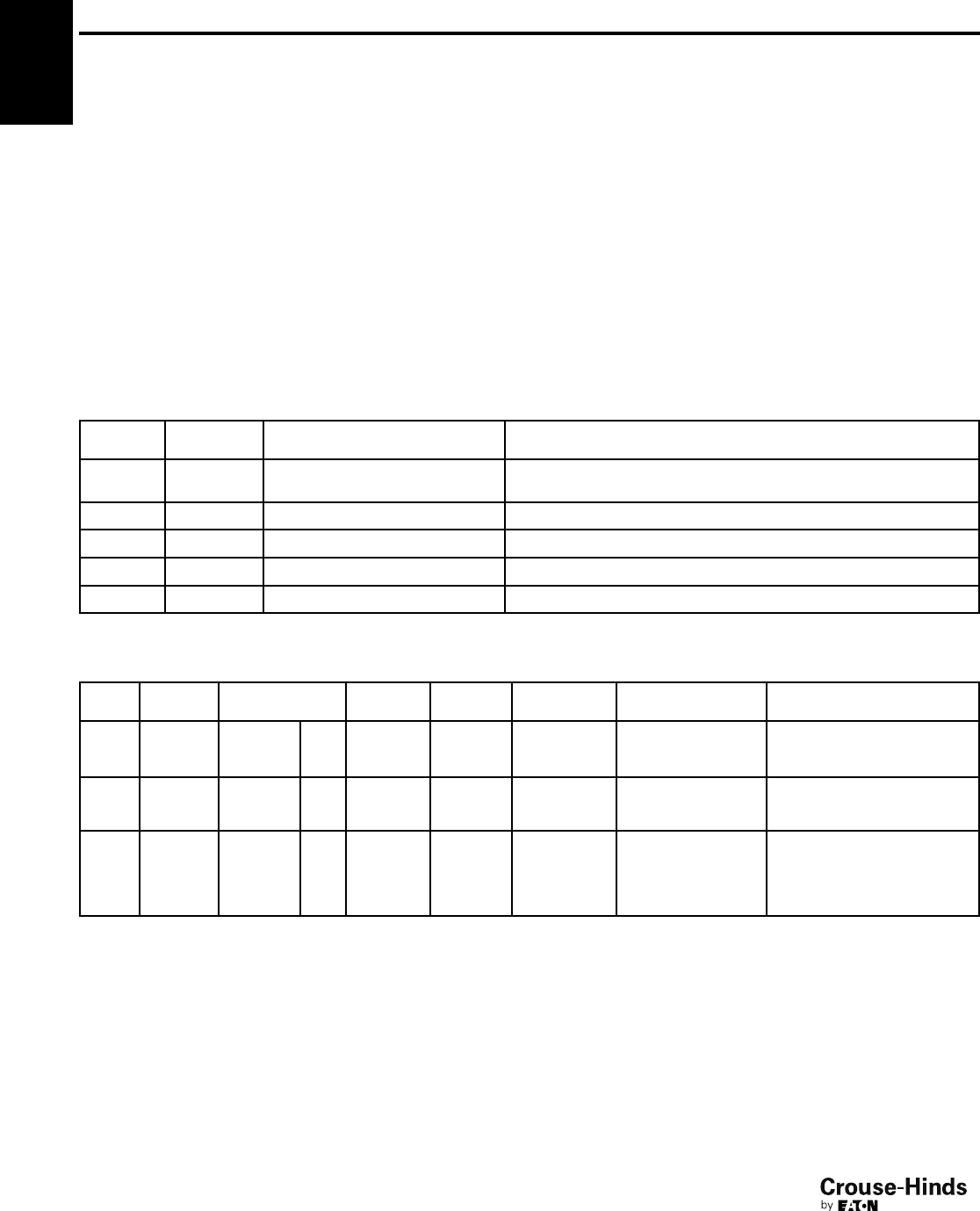
Series Page
C
Form 7 see pages 6–12
Form 8 see pages 6–12
Mark 9 see pages 6–12
Form 5 see pages 6–12
Series 5 see pages 6–12
E
Form 7 see pages 6–12
LB
Form 7 see pages 6–12
Form 8 see pages 6–12
Mark 9 see pages 6–12
Form 5 see pages 6–12
Series 5 see pages 6–12
LL
Form 7 see pages 6–12
Form 8 see pages 6–12
Mark 9 see pages 6–12
Form 5 see pages 6–12
Series 5 see pages 6–12
LR
Form 7 see pages 6–12
Form 8 see pages 6–12
Mark 9 see pages 6–12
Form 5 see pages 6–12
Series 5 see pages 6–12
L
Form 7 see pages 6–12
TA
Form 7 see pages 6–12
Series Page
T
Form 7 see pages 6–12
Form 8 see pages 6–12
Mark 9 see pages 6–12
Form 5 see pages 6–12
Series 5 see pages 6–12
TB
Form 7 see pages 6–12
Form 8 see pages 6–12
Mark 9 see pages 6–12
Form 5 see pages 6–12
X
Form 7 see pages 6–12
Form 8 see pages 6–12
Mark 9 see pages 6–12
Form 5 see pages 6–12
LBNEC
LBNEC see page 16
BC
Mogul see pages 13–14
BLB
Mogul see pages 13–14
BUB
Mogul see pages 13–14
VXF
Outlet Box see page 19
GRF
Series Page
Outlet Box see page 19
BT
Mogul see pages 13–14
LBD
1/2–1" see page 15
LBD
11/4–6" see page 15
SLB
Service Entrance Elbows see page 20
LBY
Service Entrance Elbows see page 20
ET
Service Entrance Elbows see page 20
1F
1F
4-5.qxp 12/23/2013 2:00 PM Page 5
1F
6
www.crouse-hinds.com US: 1-866-764-5454 CAN: 1-800-265-0502 Copyright©2013 Eaton’s Crouse-Hinds Business
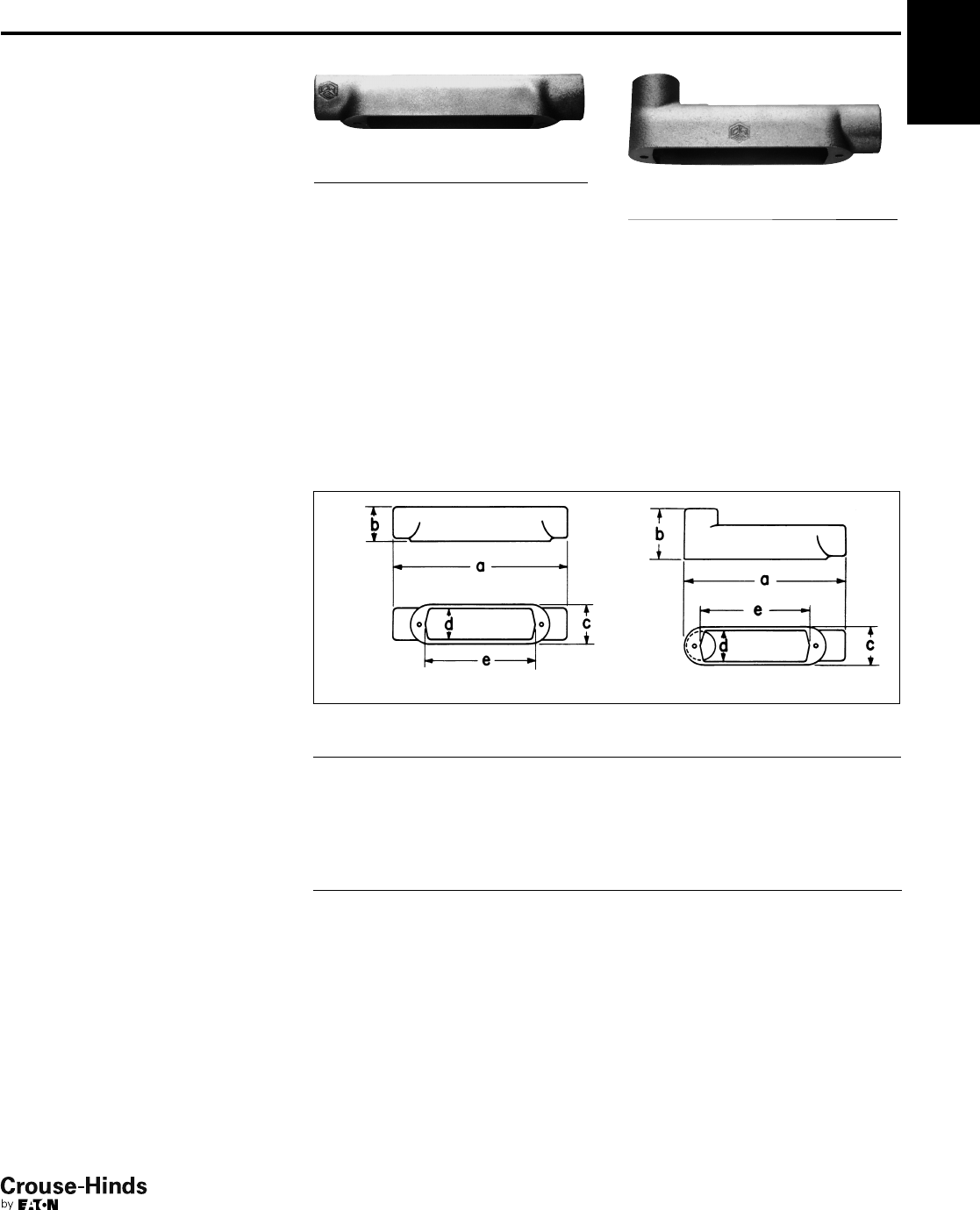
1F Condulet®Conduit Bodies -
Cast Iron or Aluminum
Gasket and Covers see page 8
Applications:
Conduit outlet bodies are installed in conduit systems to:
• Act as pull outlets for conductors being installed
• Provide openings for making splices and taps in conductors
• Connect conduit sections
• Provide taps for branch conduit runs
• Make 90° bends in conduit runs
• Provide for access to conductors for maintenance and future
system changes
Features:
Conduit Outlet Bodies
• Form 7 Condulet outlet bodies approach conduit in size for neat,
compact installations
• Form 8 and Mark 9 bodies provide more room for heavier
conductors
• Many shapes and sizes are available for rigid threaded conduit –
for complete listings see pages 6–12
• Conduit hubs have tapered threads and feature integral bushings
for protection of wire insulation
• Form 7 has exclusive snaptight and wedgenut cover attachment to
provide clear, unobstructed cover opening
• Built-in rollers on all Form 5 11/4" to 4" C and LB bodies to
facilitate wire pulling
• Series 5 bodies available in optional configuration with set screws
on hubs for EMT conduit (add suffix -MT to catalog number)
Gaskets
Solid gaskets:
• Are used with blank covers
• For Mark 9 and Form 5, can be converted to open type gaskets by
tearing out center section along scored lines – 1/2" to 2" sizes
• For Form 7 are used with all covers
Open gaskets:
• For Form 8 – 1/2" to 4" sizes
• For Mark 9 – 21/2" to 4" sizes
Blank Covers
Stainless steel cover screws are standard on Form 7, Form 8,
Mark 9, Series 5 and Form 5 covers.
•Form 7
Wedge nut design facilitates installation and removal. Nuts are held
captive in cover. Covers can be used with or without gaskets.
SNAPTIGHT™Form 7 Covers with integral sealing gaskets are
installed without the use of screws, reducing installation time and
costs. Covers are reusable.
•Form 8
Two cover screws provided on all sizes to provide tight cover and
gasket assembly. Feraloy iron alloy covers have dome shapes for
added strength and extra wiring room.
•Mark 9
Self-retaining cover screws.
Standard Materials:
• Form 7, Form 8 outlet bodies – Feraloy iron alloy
• Mark 9 outlet bodies – copper-free aluminum
• Form 5 – malleable iron
• Series 5 – die cast aluminum
Standard Finishes:
• Form 7, Form 8 outlet bodies – electrogalvanized with aluminum
acrylic paint
• Mark 9 outlet bodies – natural
• Form 5 – electrogalvanized with aluminum acrylic paint
• Series 5 – aluminum acrylic paint
Options:
Description Suffix
Form 7 body and cover only:
Copper-free aluminum . . . . . . . . . . . . . . . . . . . . . . . . . . . . . . . . SA
Corro-free™epoxy powder coat - external body only . . . . . . . . . S752
Corro-free™epoxy powder coat - internal and external . . . . . . . S753
Series 5 in an EMT version with set screws on all hubs . . . . . . . MT
Series 5 pre-packaged with neoprene gasket and cover . . . . . . CGN
Certifications and Compliances:
Outlet Bodies –
• UL Standard: 514B
• Fed. Spec.: W-C-586D
• CSA Standard 22.2 No. 18
• NEMA 3R Raintight (when installed with cover and gasket)
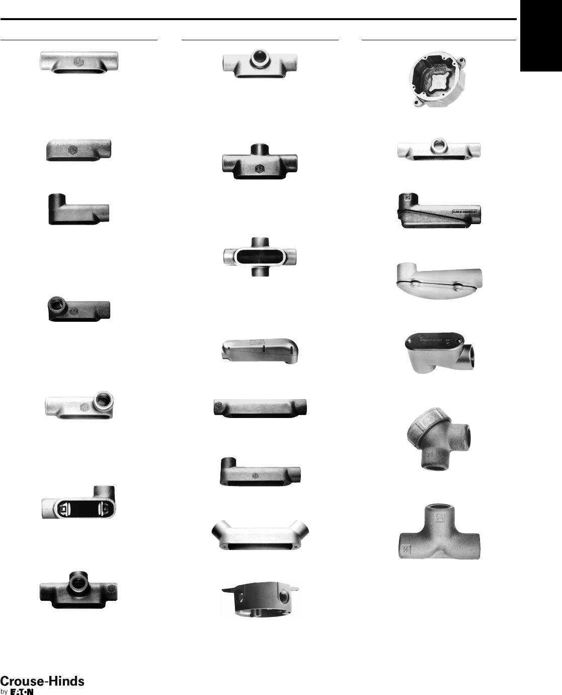
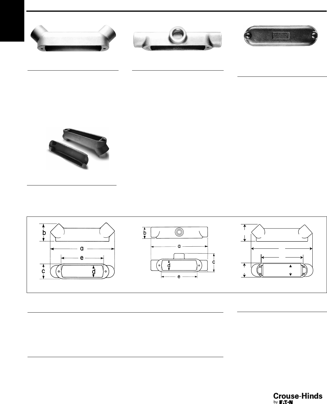
Form 7
Mark 9
Form 8
Mogul
6-7.qxp 12/23/2013 2:31 PM Page 6
1F
7
www.crouse-hinds.com US: 1-866-764-5454 CAN: 1-800-265-0502 Copyright©2013 Eaton’s Crouse-Hinds Business
Condulet®Conduit Bodies -
Cast Iron or Aluminum
Dimensions Pgs. See pages 10–12 (Dimensions for Form 5 – see Section CP)
Threaded Rigid Bodies
Hub Size
Shape Style 1/23/411
1/411/222
1/233
1/24
C
Form 7 C17 C27 C37 C47 C57 C67 C77 C87
Form 8 C18 C28 C38 C448 C58 C68 C78 C88
Mark 9 C19 C29 C39 C49 C59 C69 C789 C889 C989 C1089
Form 5 C50M C75M C100M C125M* C150M* C200M* C250M* C300M* C350M* C400M*
Series 5 C15 C25 C35 C45 C55 C65 C75 C85 C95* C105*
E
Form 7 E17 E27 E37
L
Form 7 L17 L27 L37 L47 L57 L67
Double faced – may be used as LL or LR – has 2 openings, one of which is furnished with a blank sheet steel cover
LB
Form 7 LB17 LB27 LB37 LB47 LB57 LB67 LB777 LB87 LB97 LB107
Form 8 LB18 LB28 LB38 LB448 LB58 LB68 LB78 LB888 LB98 LB108
Mark 9 LB19 LB29 LB39 LB49 LB59 LB69 LB789 LB889 LB989 LB1089
Form 5 LB50M LB75M LB100M LB125M* LB150M* LB200M* LB250M* LB300M* LB350M* LB400M*
Series 5 LB15 LB25 LB35 LB45 LB55 LB65 LB75 LB85 LB95 LB105
LL
Form 7 LL17 LL27 LL37 LL47 LL57 LL67 LL777 LL87 LL97 LL107
Form 8 LL18 LL28 LL38 LL448 LL58 LL68 LL78 LL888
Mark 9 LL19 LL29 LL39 LL49 LL59 LL69 LL789 LL889 LL989 LL1089
Form 5 LL50M LL75M LL100M LL125M LL150M LL200M LL250M LL300M LL350M LL400M
Series 5 LL15 LL25 LL35 LL45 LL55 LL65 LL75 LL85 LL95 LL105
LR
Form 7 LR17 LR27 LR37 LR47 LR57 LR67 LR777 LR87 LR97 LR107
Form 8 LR18 LR28 LR38 LR448 LR58 LR68 LR78 LR888
Mark 9 LR19 LR29 LR39 LR49 LR59 LR69 LR789 LR889 LR989 LR1089
Form 5 LR50M LR75M LR100M LR125M LR150M LR200M LR250M LR300M LR350M LR400M
Series 5 LR15 LR25 LR35 LR45 LR55 LR65 LR75 LR85 LR95 LR105
T
Form 7 T17 T27 T37 T47 T57 T67 T77 T87 T97 T107
Form 8 T18 T28 T38 T448 T58 T68 T78 T88
Mark 9 T19 T29 T39 T49 T59 T69 T789 T889 T989 T1089
Form 5 T50M T75M T100M T125M T150M T200M T250M T300M T350M T400M
Series 5 T15 T25 T35 T45 T55 T65 T75 T85 T95* T105*
TA
Form 7 TA17 TA27 TA37 TA47 TA57 TA67
TB
Form 7 TB17 TB27 TB37 TB47 TB57 TB67
Form 8 TB18 TB28 TB38 TB448 TB58 TB68
Mark 9 TB19 TB29 TB39 TB49 TB59 TB69
Form 5 TB50M TB75M TB100M TB125M TB150M TB200M
1F
* 11/4" - 4" Form 5 LB and C bodies are supplied with built-in rollers to facilitate wire pulling.
Series 5 TB15 TB25 TB35 TB45 TB55 TB65
X
Form 7 X17 X27 X37 X47 X57 X67
Form 8 X18 X28 X38 X448 X58 X68
Mark 9 X19 X29 X39
Form 5 X50M X75M X100M X125M X150M X200M
Series 5 X15 X25 X35 X45 X55 X65
6-7.qxp 12/23/2013 2:31 PM Page 7
1F
8
www.crouse-hinds.com US: 1-866-764-5454 CAN: 1-800-265-0502 Copyright©2013 Eaton’s Crouse-Hinds Business
1F Condulet®Conduit Bodies - Cast Iron or Aluminum
Covers and Gaskets
Dimensions Pgs. See pages 10–12 (Dimensions for Form 5 – see Section CP)
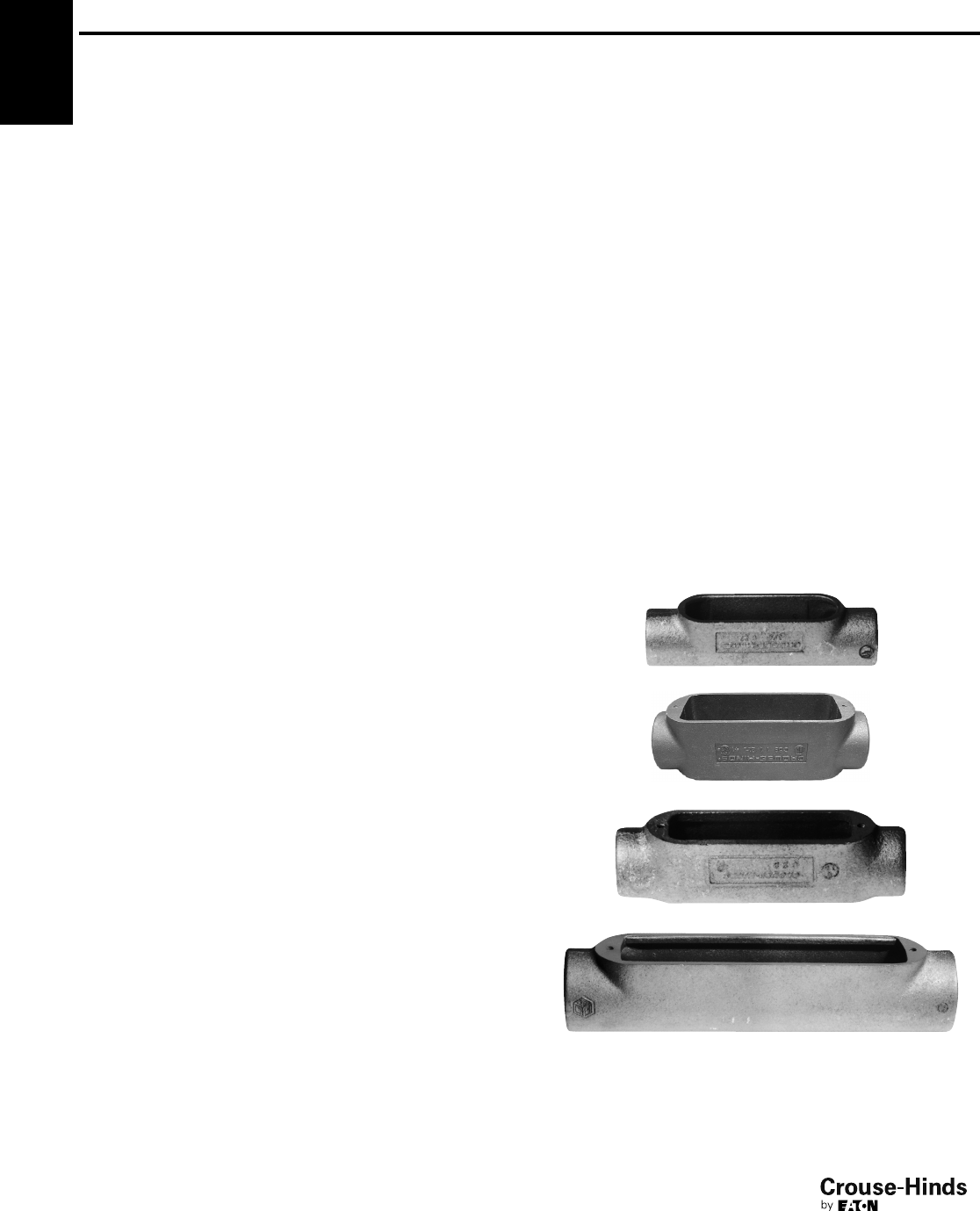
Blank Covers
Sheet Steel
Size
Form 7
Wedgenut
Cat. #
Form 7
Snaptight™
Covers‡
Cat. #
Form 7
Wedgenut
w/Integral Gasket
Cat. #
Form 8§
Cat. #
Form 8
w/Integral
Gasket
Cat. #
Form 5
w/Integral
Gasket**
Cat. #
1/2170 170SG 170G 180 180G K50SG
3/4270 270SG 270G 280 280G K75SG
1370 370SG 370G 380 380G K100SG
11/4470 470SG 470G 480 480G K125SG
11/2570 570SG 570G 580 580G K125SG
2670 670SG 670G 680 680G K200SG
21/2870 870G 880 K250SG
3870 880 K250SG
31/2970 970G 980 K350SG
4970 980 K350SG
‡Form 7 Snaptight covers with integral sealing gasket are installed without the use of screws.
§Two cover screws on 1
/2" to 2" Form 8 covers and four cover screws on 21
/2" and larger Form 8 covers.
**For cover without integral gasket, remove G from catalog number.
Sheet Aluminum Feraloy®Iron Alloy Cast Aluminum
Solid Gaskets - Neoprene
Size
Form 7
Cat. #
Form 8*
Cat. #
Mark 9†
Cat. #
Form 5
Cat. #
Series 5
Cat. #
1/2GASK571 GASK851N GASK1941 GK50N GASK015N
3/4GASK572 GASK852N GASK1942 GK75N GASK025N
1GASK573 GASK853N GASK1943 GK100N GASK035N
11/4GASK574 GASK854N GASK1944 GK125N GASK045N
11/2GASK575 GASK805N GASK1945 GK125N GASK045N
2GASK576 GASK806N GASK1946 GK200N GASK065N
21/2GASK578 GASK808N GASK808N GK250N GASK085N
3GASK578 GASK808N GASK808N GK250N GASK085N
31/2GASK579 GASK809N GASK809N GK350N GASK095N
4GASK579 GASK809N GASK809N GK350N GASK095N
*1/2– 11/4are solid gaskets; 11/2– 4 are open gaskets.
†1/2– 2 are solid gaskets; 21/2– 4 are open gaskets.
Size
Mark 9
Cat. #
Mark 9
w/Integral
Gasket
Cat. #
Form 7
Cat. #
Form 7
w/Integral
Gasket
Cat. #
Series 5
w/Integral
Gasket**
Cat. #
Form 7
Wedgenut
Cat. #
Form 7
Wedgenut
w/Integral
Gasket
Cat. #
Form 8§
Cat. #
Form 5‡
Cat. #
Form 7
Wedgenut
Cat. #
1/2190 190G 170 SA 170G SA 150 G 170F 170FG 180F K50CM 170F SA
3/4290 290G 270 SA 270G SA 250 G 270F 270FG 280F K75CM 270F SA
1390 390G 370 SA 370G SA 350 G 370F 370FG 380F K100CM 370F SA
11/4490 490G 470 SA 470G SA 450 G 470F 470FG 480F K125CM 470F SA
11/2590 590G 570 SA 570G SA 450 G 570F 570FG 580F K125CM 570F SA
2690 690G 670 SA 670G SA 650 G 670F 670FG 680F K200CM 670F SA
21/2889 870 SA 850 G 870F 880F K250CM 870F SA
3889 870 SA 850 G 870F 880F K250CM 870F SA
31/2989 970 SA 950 G 970F 980F K350CM 970F SA
4989 970 SA 950 G 970F 980F K350CM 970F SA
‡Malleable iron covers.
§Two cover screws on 1
/2" to 2" Form 8 covers and four cover screws on 21
/2" and larger Form 8 covers.
**For cover without integral gasket, remove G from catalog number.
8-9.qxp 12/23/2013 2:32 PM Page 8
1F
9
www.crouse-hinds.com US: 1-866-764-5454 CAN: 1-800-265-0502 Copyright©2013 Eaton’s Crouse-Hinds Business
1F
Condulet®Conduit Bodies - Cast Iron or Aluminum
Form 7 SnapPack™
Pre-Assembled Body, Gasket and Cover
Applications:
Form 7 Condulets are installed in conduit
systems to:
• Act as pull outlets for conductors being
installed
• Provide an opening for making splices
and taps in conductors
• Connect conduit sections
• Provide taps for branch conduit runs
• Make 90-degree bends in conduit runs
• Provide access to conductors in a
conduit system for maintenance and
future system changes
Features:
• All SnapPack product is individually bar
coded to facilitate more efficient
inventory control
• Distributors and end-users need to
stock a single SKU instead of three
separate component numbers – order
the body, cover and gasket with one
catalog number – saving transaction
costs, and making product selection
and merchandising fast and easy
• Form 7 conduit bodies are compact with
a round back design for neat, efficient
installations
• Conduit hubs have tapered threads and
integral bushings for protection of wire
insulation
• Many shapes and trade sizes available
• Sheet-steel wedge nut cover is provided
with integral gasket. The wedge nut
design facilitates installation and
removal. Nuts and screws are held
captive in cover
• Cover screws are stainless steel with a
combination slotted and Phillips head,
for easy installation and superior
corrosion protection
Standard Materials:
• Body – Feraloy®iron alloy
• Gasket – urethane
• Cover – sheet steel
• Cover screws – stainless steel
Standard Finishes:
•Feraloy – electrogalvanized with
aluminum acrylic paint
• Sheet steel – electrogalvanized
Certifications and
Compliances:
• UL Standard: 514B
• CSA Standard: C22.2 No. 18
Trade
Size Shape Cat. #
1/2"CC17 CG
3/4"CC27 CG
1" CC37 CG
11/4"CC47 CG
11/2"CC57 CG
2" CC67 CG
1/2"LBLB17 CG
3/4"LB LB27 CG
1" LB LB37 CG
11/4"LB LB47 CG
11/2"LB LB57 CG
2" LB LB67 CG
1/2"LLLL17 CG
3/4"LL LL27 CG
1" LL LL37 CG
11/4"LL LL47 CG
11/2"LL LL57 CG
2" LL LL67 CG
1/2"LRLR17 CG
3/4"LR LR27 CG
1" LR LR37 CG
11/4"LR LR47 CG
11/2"LR LR57 CG
2" LR LR67 CG
1/2"TT17 CG
3/4"TT27 CG
1" TT37 CG
11/4"TT47 CG
11/2"TT57 CG
2" TT67 CG
1/2"TBTB17 CG
3/4"TB TB27 CG
1" TB TB37 CG
11/4"TB TB47 CG
11/2"TB TB57 CG
2" TB TB67 CG
1/2"XX17 CG
3/4"XX27 CG
1" XX37 CG
11/4"XX47 CG
11/2"XX57 CG
2" XX67 CG
Form 7 Condulets and covers are available in additional configurations, sizes and
materials. For a complete listing of Form 7, Form 8 and Mark 9 conduit bodies and
covers see pages 6–12.
Ordering Information
8-9.qxp 12/23/2013 2:32 PM Page 9
1F
10
www.crouse-hinds.com US: 1-866-764-5454 CAN: 1-800-265-0502 Copyright©2013 Eaton’s Crouse-Hinds Business
1F Condulet®Conduit Bodies -
Cast Iron or Aluminum
Dimensions (In Inches)
C
Form 7 C
Size 1/23/411
1/411/222
1/23
a53/8677
7/16 83/16 93/16 12 113/4
b13/815/817/825/16 29/16 31/835/843/8
c13/819/16 13/423/16 27/16 34
1/441/4
d15/16 11/813/813/4115/16 27/16 39/16 39/16
e33/16 313/16 41/255
7/16 63/883/883/8
Form 8 C
Size 1/23/411
1/411/222
1/23
a511/16 69/32 75/16 81/2103/8121/4155/8155/8
b17/16 111/16 115/16 23/8225/32 39/16 47/16 413/16
c13/813/16 13/423/16 23/433/455
d11
3/16 13/813/421/834
1/441/4
e35/16 315/16 49/16 55/16 61/289/16 107/8107/8
Mark 9 C
Size 1/23/411
1/411/222
1/233
1/24
a55
11/16 619/32 71/281/4101/2155/8155/8183/4183/4
b13/815/817/821/223/437/16 47/16 413/16 511/16 515/16
c13/819/16 13/423/16 21/233/16 556
1/461/4
d13/16 13/811/2115/16 21/427/841/441/457/16 57/16
e35/16 315/16 49/16 55/16 68
1/16 107/8107/8137/16 137/16
E
Form 7 E
Size 1/23/41
a49/16 53/16 6
b13/815/817/8
c13/819/16 13/4
d15/16 11/813/8
e33/16 313/16 41/2
L
Form 7 L
Size 1/23/411
1/411/22
a49/16 53/16 66
1/271/831/8
b13/815/817/825/16 29/16 31/8
c21/427/16 23/433/16 39/16 41/8
d15/16 11/813/813/4115/16 27/16
e33/16 313/16 41/255
7/16 63/8
10-11.qxp 12/16/2013 12:00 PM Page 10

1F
11
www.crouse-hinds.com US: 1-866-764-5454 CAN: 1-800-265-0502 Copyright©2013 Eaton’s Crouse-Hinds Business
Dimensions (In Inches)
1F
Form 7 LB
Size 1/23/411
1/411/222
1/233
1/24
a49/16 53/16 66
1/271/881/8101/2101/21211/16 1211/16
21/421/227/835/16 311/16 41/451/857/869/16 71/16
c13/819/16 13/423/16 27/16 34
1/441/451/451/4
d15/16 11/813/813/4115/16 27/16 39/16 39/16 41/241/2
e33/16 313/16 41/255
7/16 63/883/883/8101/4101/4
Form 8 LB
Size 1/23/411
1/411/222
1/233
1/24
a415/16 59/16 615/32 717/32 91/811 1315/16 1315/16 167/8167/8
b27/32 27/16 213/16 311/32 41/32 413/16 61/861/279/16 713/16
c13/819/16 13/423/16 23/433/4556
1/461/4
d11
3/16 13/813/421/834
1/441/457/16 57/16
e35/16 315/16 49/16 55/16 61/289/16 107/8107/8137/16 137/16
Mark 9 LB
Size 1/23/411
1/411/222
1/233
1/24
a419/32 51/463/32 71/32 73/4101/32 1315/16 1315/16 167/8167/8
b21/8213/32 227/32 315/32 33/4415/32 61/861/279/16 713/16
c13/819/16 13/423/16 21/233/16 556
1/461/4
d13/16 13/811/2115/16 21/427/841/441/457/16 57/16
e35/16 315/16 49/16 55/16 68
1/16 107/8107/8137/16 137/16
Form 7 LL & LR
Size 1/23/411
1/411/222
1/233
1/24
a49/16 53/16 66
1/271/881/8101/2101/21211/16 1211/16
b13/815/817/825/16 29/16 31/835/843/847/853/8
c21/427/16 23/433/16 39/16 41/853/453/4615/16 615/16
d15/16 11/813/813/4115/16 27/16 39/16 39/16 41/241/2
e33/16 313/16 41/255
7/16 63/883/883/8101/4101/4
Form 8 LL & LR
Size 1/23/411
1/411/222
1/23
a415/16 59/16 615/32 717/32 91/811 1315/16 1315/16
b17/16 111/16 115/16 23/8225/32 39/16 47/16 413/16
c25/32 25/16 25/835/32 456
11/16 611/16
d11
3/16 13/813/421/834
1/441/4
e35/16 315/16 49/16 55/16 61/289/16 107/8107/8
Mark 9 LL & LR
Size 1/23/411
1/411/222
1/233
1/24
a419/32 51/463/32 71/32 73/4101/32 1315/16 1315/16 167/8167/8
b13/815/817/821/223/437/16 47/16 413/16 511/16 515/16
c21/823/825/833/32 37/16 41/8611/16 611/16 81/881/8
d13/16 13/811/2115/16 21/427/841/441/457/16 57/16
e35/16 315/16 49/16 55/16 68
1/16 107/8107/8137/16 137/16
Condulet®Conduit Bodies -
Cast Iron or Aluminum
b
LB
LL LR
10-11.qxp 12/16/2013 12:00 PM Page 11
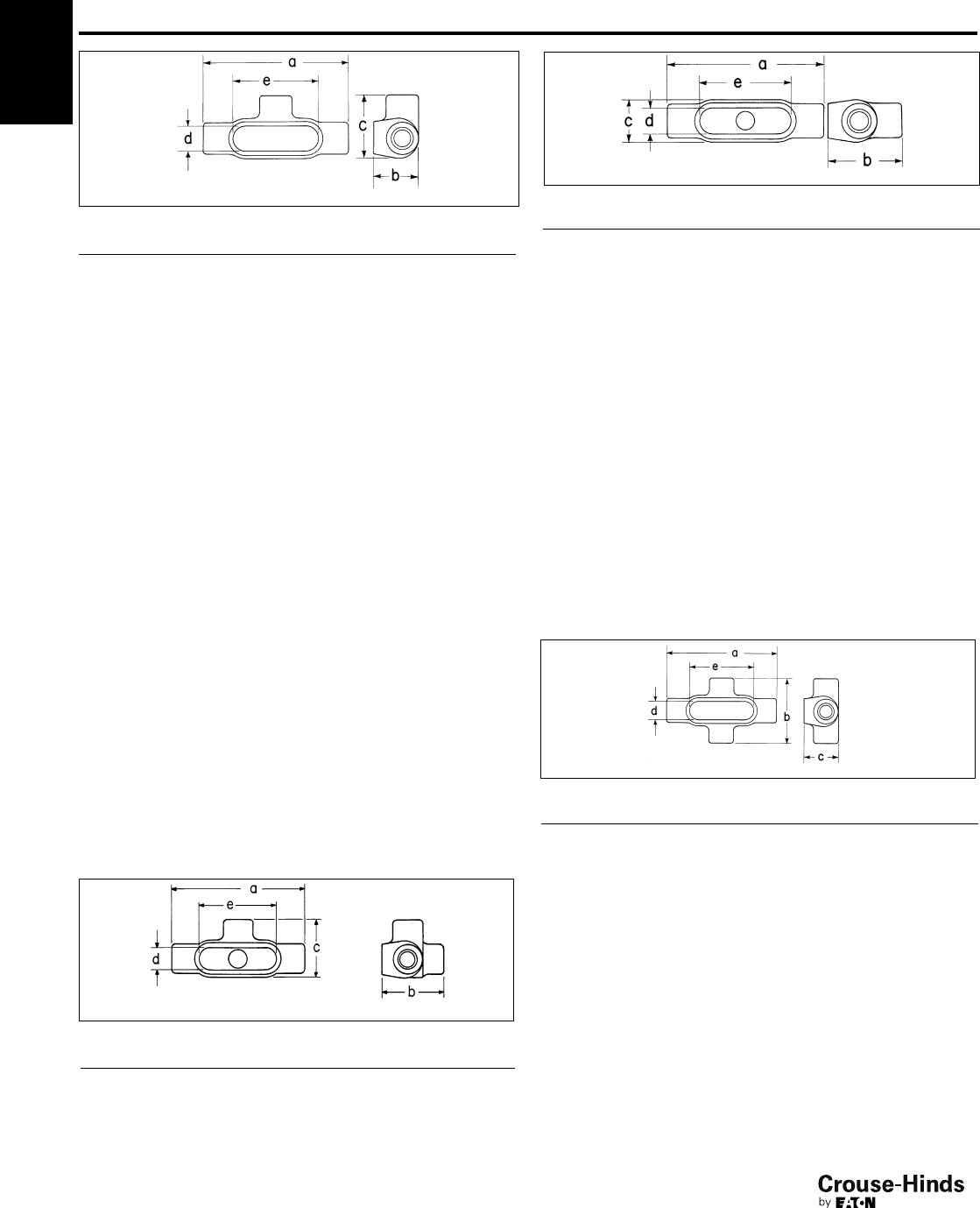
TA
1F
12
www.crouse-hinds.com US: 1-866-764-5454 CAN: 1-800-265-0502 Copyright©2013 Eaton’s Crouse-Hinds Business
1F
T
Form 7T
Size a b c d e
1/255/813/427/16 15/16 33/16
3/461/422
5/811/8313/16
171/421/431
3/841/2
11/477/16 25/16 33/16 13/45
11/283/16 29/16 39/16 115/16 57/16
293/16 31/841/827/16 63/8
21/212 35/853/439/16 83/8
3121/16 43/853/439/16 83/8
31/2145/16 47/8615/16 41/2101/4
4145/16 53/8615/16 41/2101/4
Form 8T
1/2511/16 13/425/32 13
5/16
3/469/32 22
5/16 13/16 315/16
175/16 21/425/813/849/16
11/481/225/835/32 13/455/16
11/2103/8225/32 42
1/861/2
2121/439/16 538
9/16
21/2155/847/16 611/16 41/4107/8
3155/8413/16 611/16 41/4107/8
Mark 9T
1/251
3/821/813/16 35/16
3/4511/16 15/823/813/8315/16
1619/32 17/825/811/249/16
11/471/221/233/32 115/16 55/16
11/281/423/437/16 21/46
2101/237/16 41/827/881/16
21/2155/847/16 611/16 41/4107/8
3155/8413/16 611/16 41/4107/8
31/2183/4511/16 81/857/16 137/16
4183/4515/16 81/857/16 137/16
Form 7TA
Size a b c d e
1/255/825/827/16 15/16 33/16
3/461/427/825/811/8313/16
171/431/431
3/841/2
11/477/16 35/16 33/16 13/45
11/283/16 311/16 39/16 115/16 57/16
293/16 41/441/827/16 63/8
Condulet®Conduit Bodies -
Cast Iron or Aluminum
Form 7TB
Size a b c d e
1/255/825/819/16 15/16 33/16
3/461/427/813/411/8313/16
171/431/421
3/841/2
11/477/16 35/16 23/16 13/45
11/283/16 52
7/16 115/16 57/16
293/16 61/832
7/16 63/8
Form 8TB
1/2511/16 217/32 13/813
5/16
3/469/32 23/419/16 13/16 315/16
175/16 31/813/413/849/16
11/481/2311/32 23/16 13/455/16
11/2103/841/32 23/421/861/2
2121/4413/16 33/438
9/16
Mark 9TB
1/252
1/813/813/16 35/16
3/4511/16 213/32 19/16 13/8315/16
1619/32 227/32 13/411/249/16
11/471/2315/32 23/16 115/16 55/16
11/2811/32 37/821/225/32 57/8
2105/8419/32 37/32 213/16 83/32
Form 7X
Size a b c d e
1/255/835/16 13/415/16 33/16
3/461/431/221
1/8313/16
171/442
1/413/841/2
11/477/16 41/825/16 13/45
11/283/16 45/829/16 115/16 57/16
293/16 53/16 31/827/16 63/8
Form 8X
1/2511/16 229/32 13/413
5/16
3/469/32 31/16 21
3/16 315/16
175/16 31/221/413/849/16
11/481/241/825/813/455/16
11/2103/851/4215/32 21/861/2
2121/461/439/16 38
9/16
Mark 9X
1/2511/16 229/32 13/413
5/16
3/469/32 31/16 21
3/16 315/16
175/16 31/221/413/849/16
TB
X
Dimensions (In Inches)
12-13.qxp 12/16/2013 12:00 PM Page 12
1F
13
www.crouse-hinds.com US: 1-866-764-5454 CAN: 1-800-265-0502 Copyright©2013 Eaton’s Crouse-Hinds Business
1F
Mogul Bodies, Covers and Gaskets
Applications:
Mogul bodies are installed in conduit
systems to:
• Act as pull outlets for conductors that
are stiff, due to large
size or type of insulation
• Provide the longer openings needed
when pulling large conductors
• Prevent sharp bends and kinks in large
conductors (protects insulation during
installation)
• Provide ample openings for splices and
taps
• Provide access to wiring for
maintenance and future
system changes
Standard Materials:
•Feraloy®iron alloy
Standard Finishes:
•Feraloy – electrogalvanized and
aluminum acrylic paint
Options:
Description Suffix
Material – copper-free aluminum SA
Hot dipped galvanized HDG
Certifications and
Compliances:
• UL Standard: 514B
• Fed. Spec.: W-C-586d
• CSA Standard: C22.2 No. 18
BC
Mogul Series
Size Cat. #
1BC3
11/4BC4
11/2BC5
2BC6
21/2BC7
3BC8
31/2BC9
4BC10
BLB†
Mogul Series
Size Cat. #
1BLB3
11/4BLB4
11/2BLB5
2BLB6
21/2BLB7
3BLB8
31/2BLB9
4BLB10
† For 5" size use LBD012.
For 6" size use LBD014.
Condulet®Conduit Bodies -
Cast Iron or Aluminum
Dimensions
In Inches:
BC BLB
Mogul Series BC
Size 1 11/411/222
1/233
1/24
a99/16 99/16 133/4133/4183/8183/8233/4233/4
b17/825/16 29/16 31/835/843/847/853/8
c23/16 23/16 334
1/441/451/451/4
d17/817/825/825/8313/16 313/16 43/443/4
e6 6 10 10 15 15 20 20
Mogul Series BLB
Size 1 11/411/222
1/233
1/24
a819/32 819/32 1211/16 1211/16 1629/32 1629/32 221/8221/8
b227/32 39/32 35/843/16 53/32 527/32 61/27
c23/16 23/16 334
1/441/451/451/4
d17/817/825/825/8313/16 313/16 43/443/4
e6 6 10 10 15 15 20 20
Features:
Mogul bodies have:
• Long openings
• Provision for easy bends
• Taper tapped hubs with integral
bushings
• Stainless steel cover screws
• Covers are designed with integral gasket
12-13.qxp 12/16/2013 12:00 PM Page 13
1F
14
www.crouse-hinds.com US: 1-866-764-5454 CAN: 1-800-265-0502 Copyright©2013 Eaton’s Crouse-Hinds Business
1F
BUB
Mogul Series
Size Cat. #
1BUB3
11/4BUB4
11/2BUB5
2BUB6
21/2BUB7
3BUB8
31/2BUB9
4BUB10
BT
Mogul Series
Size Cat. #
1BT3
11/4BT4
11/2BT5
2BT6
21/2BT7
3BT8
31/2BT9
4BT10
Blank Covers
Feraloy®iron alloy (for all
Mogul Series except BUBXL)
Size
With Round Neoprene
Gasket Cat. #
1 or 11/4BG48
11/2or 2 BG68
21/2or 3 BG88
31/2or 4 BG98
BUBXL with Cover & Gasket
Extra Large Mogul Series
Size Cat. #
2BUBXL6
3BUBXL8
Condulet®Conduit Bodies -
Cast Iron or Aluminum
Mogul Bodies, Covers and Gaskets
BUBXL Moguls
XL Mogul Conduit Bodies and Covers are designed to ease installation, saving time and
money while maintaining the quality you have come to expect from Eaton's Crouse-Hinds.
• Larger internal volume provides additional space for bending and pulling large conductors
(complies with the 6x wire bending rule)
• Rollers improve the ability to pull larger conductors and protect the insulation when the
wire is being pulled, greatly reducing cut cable incidents
• Cover design takes less time to install and can be used as a solid or with the center
removed for more internal volume
Dimensions
In Inches:
BUB BT
Mogul Series BUB
Size 1 11/411/222
1/233
1/24
a93/16 95/16 131/2131/2173/4177/8233/8231/4
b211/16 33/16 31/241/8413/16 55/863/8613/16
c23/16 23/16 334
1/441/451/451/4
d17/817/825/825/8313/16 313/16 43/443/4
e6 6 10 10 15 15 20 20
Mogul Series BT
Size 1 11/411/222
1/233
1/24
a99/16 99/16 133/4133/4183/8183/8233/4233/4
b17/825/16 29/16 31/835/843/847/853/8
c35/32 35/32 41/16 41/16 519/32 523/32 67/867/8
d17/817/825/825/8313/16 313/16 43/443/4
e6 6 10 10 15 15 20 20
A
E
B
CD
BUBXL
Mogul Series BUBXL
Size 2 3
a15.28 22.85
b4.07 5.58
c3.00 4.25
d2.25 3.38
e12.25 15.25
14-15.qxp 12/16/2013 12:00 PM Page 14
1F
15
www.crouse-hinds.com US: 1-866-764-5454 CAN: 1-800-265-0502 Copyright©2013 Eaton’s Crouse-Hinds Business
1F
Condulet®Conduit Bodies -
Cast Iron or Aluminum
LBD Mogul
Applications:
LBD bodies are installed at 90° bends in
rigid conduit to:
• Act as pull outlets for conductors that
are stiff due to large size or type of
insulation
• Make 90° bends in conduit system,
allowing straight pull in either direction
• Provide for conduit service entrance to
buildings
• Provide for conductor entrance to
motors
• Provide access to wiring for
maintenance and future expansion
Features:
LBD bodies have:
• Cover openings on an angle permitting
conductors to be pulled straight through
hubs from either direction
• Domed covers to permit easy conductor
bends (relieves strain on insulation)
• Cover and gasket furnished
• Taper tapped hubs with integral
bushings
Standard Materials:
• Body and cover – Feraloy®iron alloy
• Gasket – Neoprene
Standard Finishes:
•Feraloy iron alloy:
1/2" to 4" sizes, electrogalvanized and
aluminum acrylic paint; 5" and 6" sizes,
zinc chromate primer and aluminum
lacquer
• Neoprene – natural
Options:
Description Suffix
Material – All sizes, copper-free
aluminum SA
Certifications and
Compliances:
• UL Standard: 514B
• Fed. Spec.: W-C-586d
• CSA 22.2 No. 18
Ordering Information
1/2– 1" 11/4– 2", 5" – 6" 21/2– 4"
Size Cat. # Size Cat. # Size Cat. #
1/2LBD1100 11/4LBD4400 31/2LBD9900
3/4LBD2200 11/2LBD5500 4LBD10900
1LBD3300 2LBD6600 5LBD012
21/2LBD7700 6LBD014
3LBD8800
Replacement Gaskets for Above Sizes
Rubber
Size Cat. # Size Cat. # Size Cat. #
1/2GASK680R 11/4GASK683R 31/2GASK989R
3/4GASK681R 11/2GASK684R 4GASK989R
1GASK682R 2GASK684R 5GASK687R
21/2GASK990R 6GASK688R
3GASK990R
Replacement Cover Assembly with Hardware
Size Cat. # Size Cat. # Size Cat. #
1/2LBD100 11/4LBD400 3LBD800
3/4LBD200 11/2LBD600 31/2LBD900
1LBD300 2LBD600 4LBD900
21/2LBD800 5LBD120
6LBD140
Dimensions
In Inches:
Cat. # Size a b c d e
LBD1100 1/252
5/16 15/16 13
11/32
LBD2200 3/461/425/819/16 11/4417/32
LBD3300 161/4215/16 113/16 11/2411/32
LBD4400 11/485/841/431/2113/16 73/16
LBD5500 11/2127/16 57/16 45/825/8107/8
LBD6600 2127/16 57/16 45/825/8107/8
LBD7700 21/21911/16 99/16 55/8315
3/4
LBD8800 31911/16 99/16 55/8315
3/4
LBD9900 (iron) 31/2207/8107/873/443/4197/8
LBD10900 (iron) 4207/8107/873/443/4197/8
LBD9900 (-SA) 31/22713/16 117/871/8424
LBD10900 (-SA) 42713/16 117/871/8424
LBD012 5327/16 121/285/857/830
LBD014 6411/215 93/4739
14-15.qxp 12/16/2013 12:00 PM Page 15
1F
16
www.crouse-hinds.com US: 1-866-764-5454 CAN: 1-800-265-0502 Copyright©2013 Eaton’s Crouse-Hinds Business
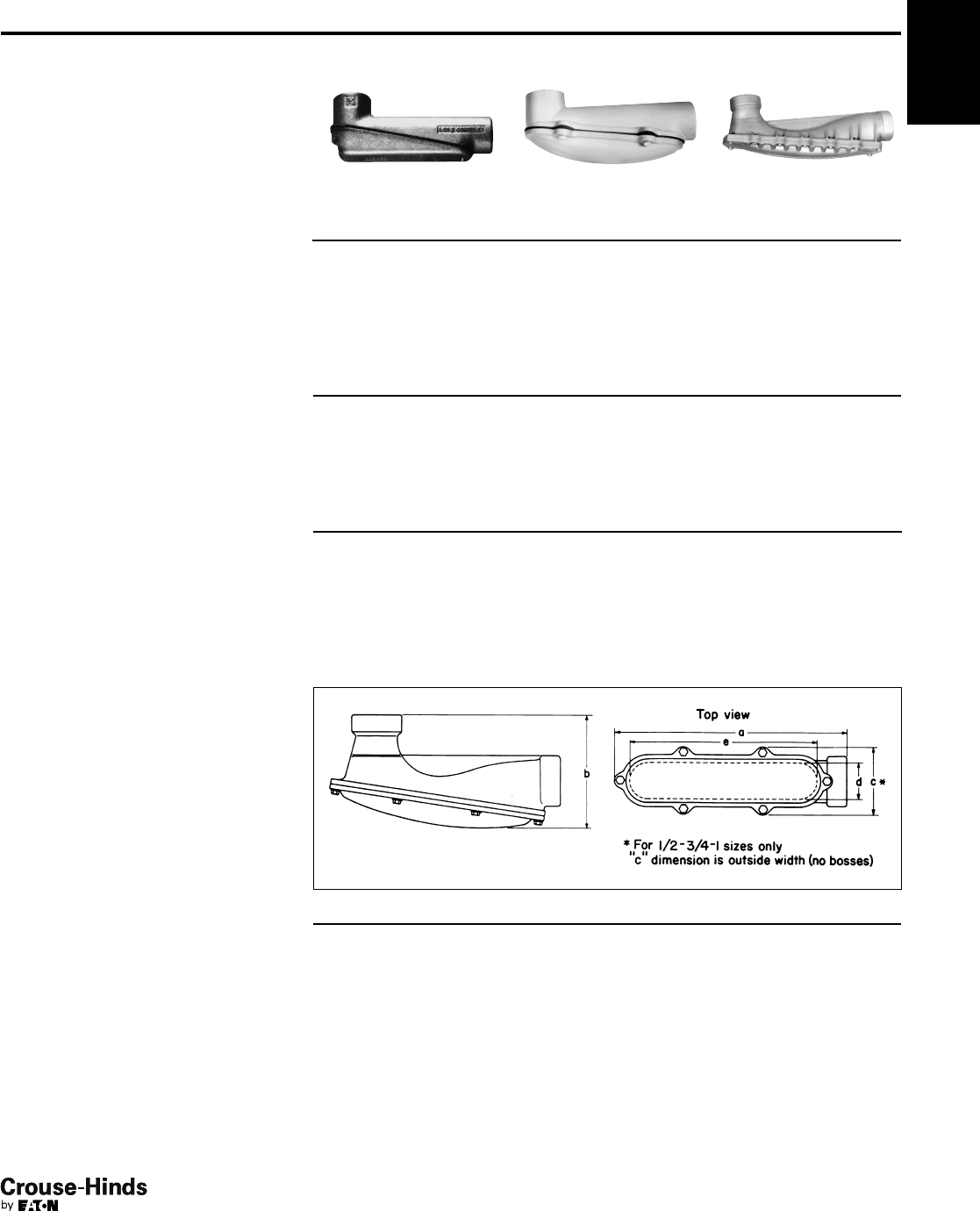
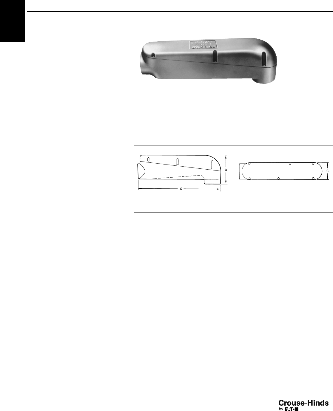
1F Condulet®Conduit Bodies -
Cast Iron or Aluminum
Mogul Pulling Elbows
Weather Resistant
Applications:
Die cast mogul pulling elbows are installed
in conduit systems to provide:
• An accessible weather resistant
chamber for containing heavy duty
conductors
• A chamber for containing 90° turn in
large stiff conductors. Used either to
change conductor direction or to enter
buildings
• A pull box for pulling large conductors
• A chamber for making splices and taps
• An accessible opening to accommodate
future changes of the system
Features:
• Large dome cover permits easy, straight
through pull
• Dimension from centerline of back hub
to bushing of end hub exceeds six times
the trade diameter of the conduit
• Tapered threads provide easy assembly,
tight construction
• Heavy duty machine screws for cover
• Cover is gasketed
• Smooth design and finish make handling
easy and complement any construction
job
Standard Materials:
• Die cast copper-free aluminum
Standard Finishes:
• Aluminum lacquer
Certifications and
Compliances:
• UL Standard: 514A
• NEC: Article 314
• CSA C22.2 No. 18
• CEC: 22.1
LBNEC Furnished With Cover, Gasket
and Screws
Size Cat. # Bending Radius
21/2LBNEC7 51/4
3LBNEC8 53/4
31/2LBNEC9 7
4LBNEC10 73/8
Dimensions
In Inches:
Cat. # Size a b c
LBNEC7 21/22111/16 89/32 41/2
LBNEC8 321
11/16 89/32 41/2
LBNEC9 31/22811/16 97/32 51/2
LBNEC10 428
11/16 97/32 51/2
16-17.qxp 12/16/2013 12:01 PM Page 16
1F
17
www.crouse-hinds.com US: 1-866-764-5454 CAN: 1-800-265-0502 Copyright©2013 Eaton’s Crouse-Hinds Business
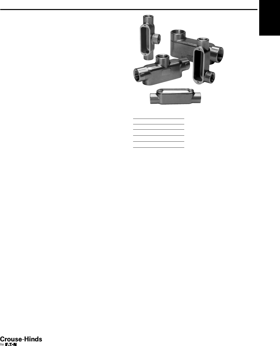
1F
Condulet®Conduit Outlet Bodies,
Covers and Gaskets - Stainless Steel
Eaton's Crouse-Hinds Condulet®Stainless Steel Fittings deliver
power where you need it, saving you time and money throughout
the life of your facility.
Superior resistance to corrosion and heat, combined with unmatched
strength, make stainless steel Condulet bodies and boxes a long-
term solution for even the most extreme environments.
Applications:
Conduit outlet bodies are installed in conduit systems to:
• Act as pull outlets for conductors being installed
• Provide openings for making splices and taps in conductors
• Act as mounting outlets for lighting fixtures and wiring devices
• Connect conduit sections
• Provide taps for branch conduit runs
• Make 90° bends in conduit runs
• Provide for access to conductors for maintenance and future
system changes
Standard Materials:
• Bodies - 316 stainless steel
• Covers - 316 stainless steel
• Cover Screws - 316 stainless steel
• Gasket - neoprene
Certifications and Compliances:
• UL Standard 514A
• CSA Standard C22.2 No. 18.1-04
• Raintight - when installed with cover and gasket
Features:
• Self-healing properties of stainless steel fittings help reduce the
penetration of rust/corrosion and eliminate damage to the fitting
• Stainless steel fittings retain their strength in extreme heat and
extreme cold conditions
• Fitting surface is easy to maintain and keep clean
• Easy cleaning capabilities make these fittings perfect for food
processing and other hygienic areas where wash downs are
common
• Superior strength and durability greatly reduce replacement of
fittings - this will lower your total cost of ownership and increase
your return on investment
• Stainless steel fittings do not require harsh environment-damaging
cleaners to keep them looking like new
• Conduit hubs have tapered threads and feature integral bushing
for protection of wire insulation
• Outlet bodies designed to match conduit size for neat, compact
installations
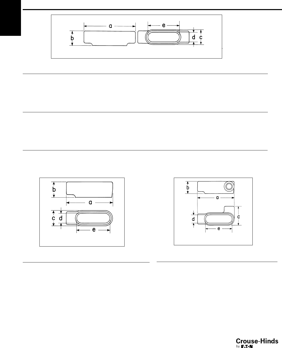
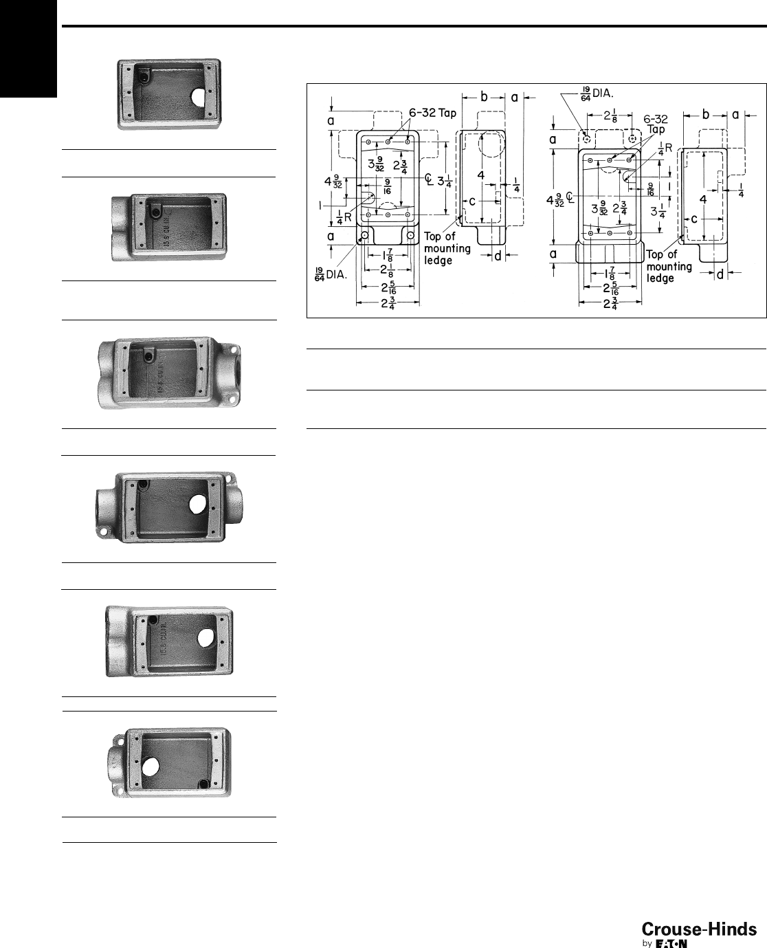
Dimension
A Overall length
B Overall height
C Overall width
D Width of opening
E Length of opening
16-17.qxp 12/16/2013 12:01 PM Page 17
1F
18
www.crouse-hinds.com US: 1-866-764-5454 CAN: 1-800-265-0502 Copyright©2013 Eaton’s Crouse-Hinds Business
1F
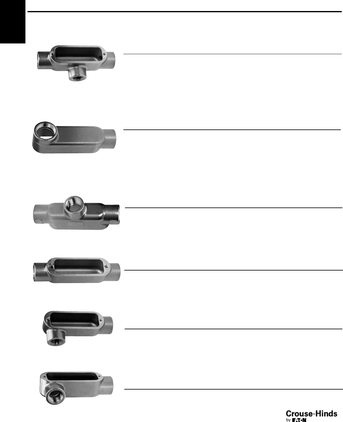
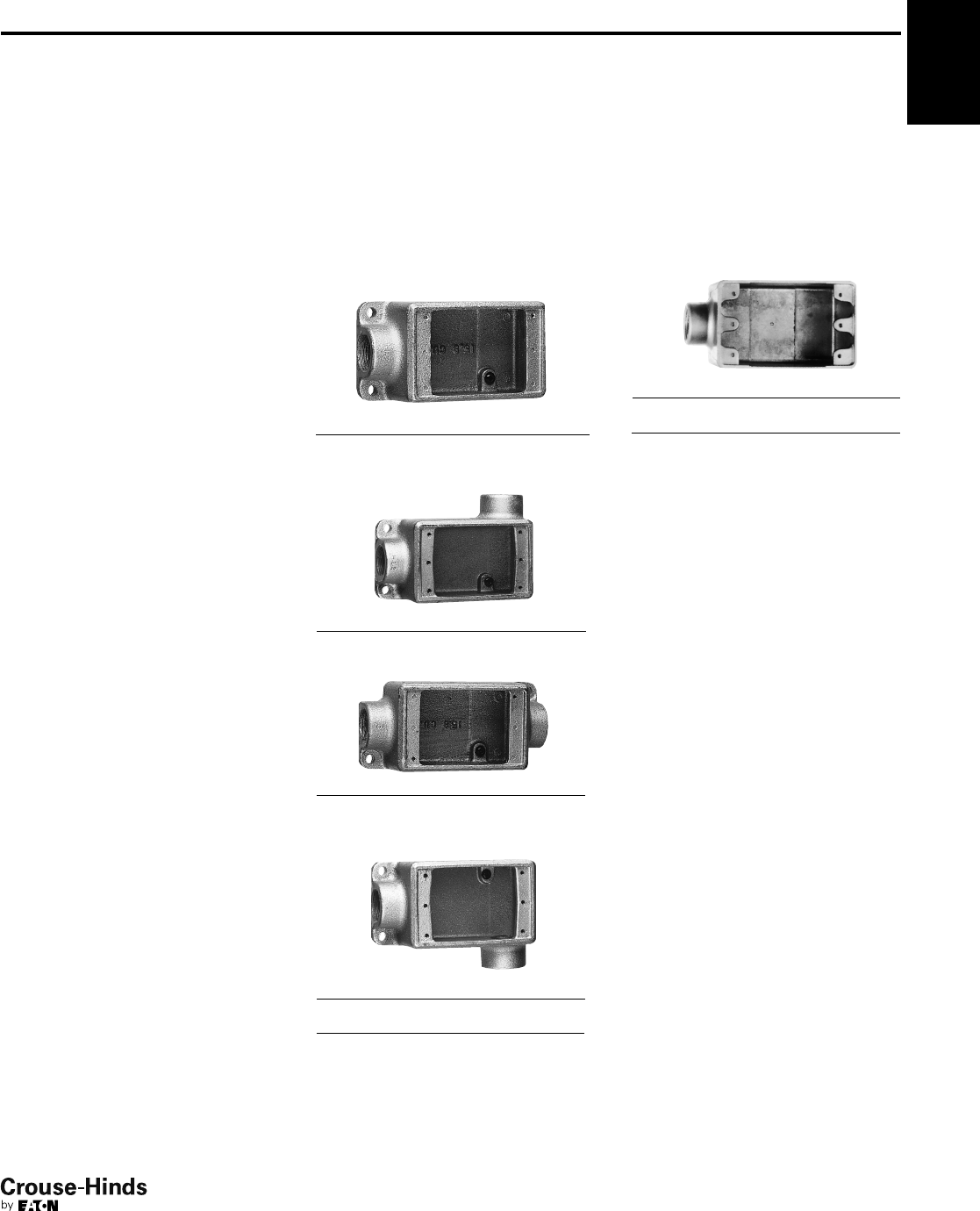
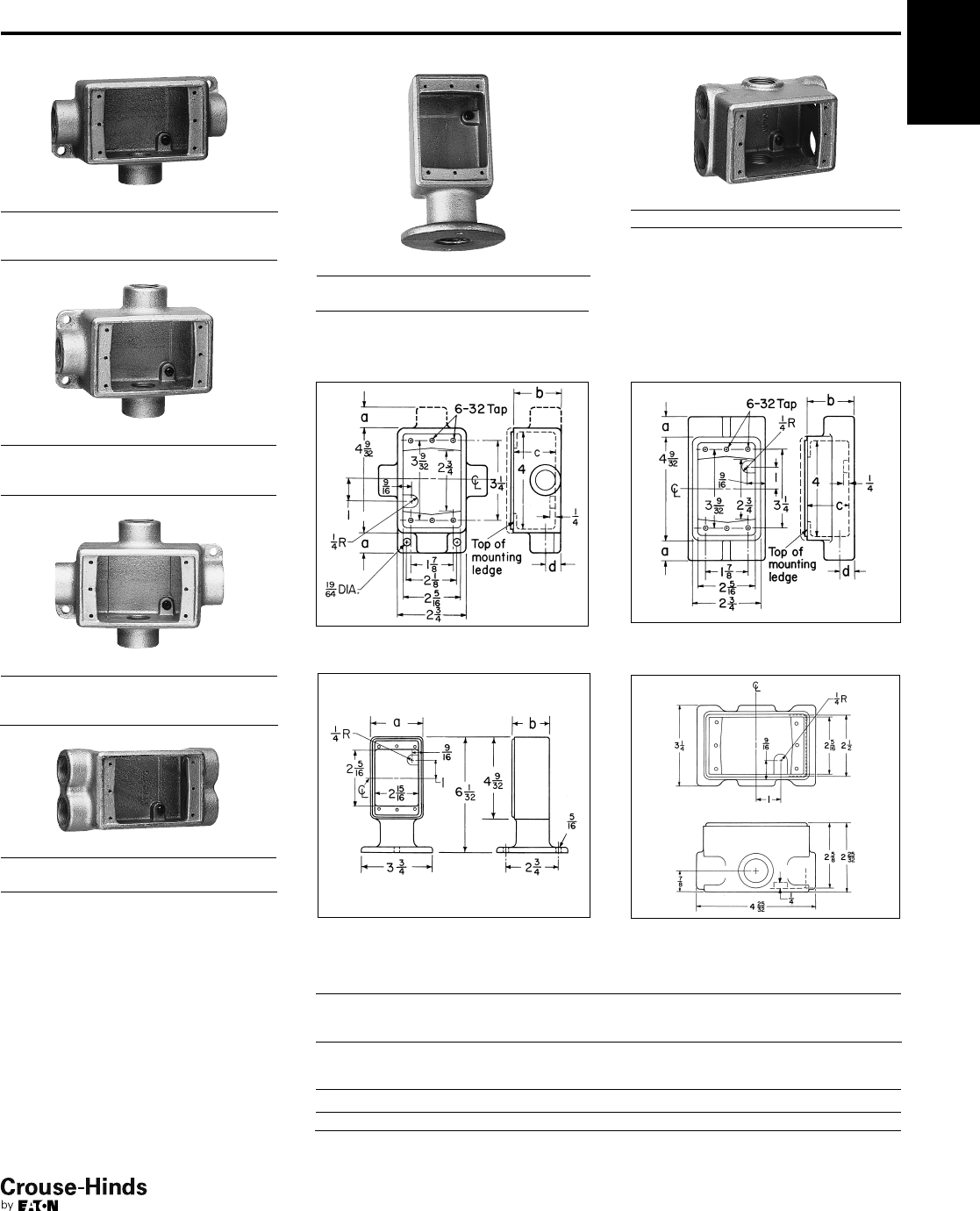
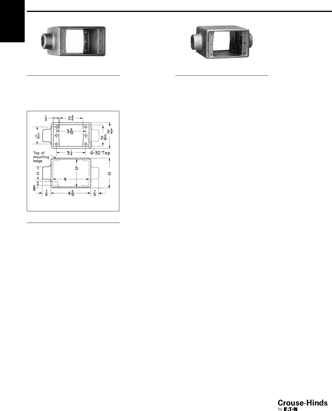
Ordering Information - conduit body supplied with cover and gasket
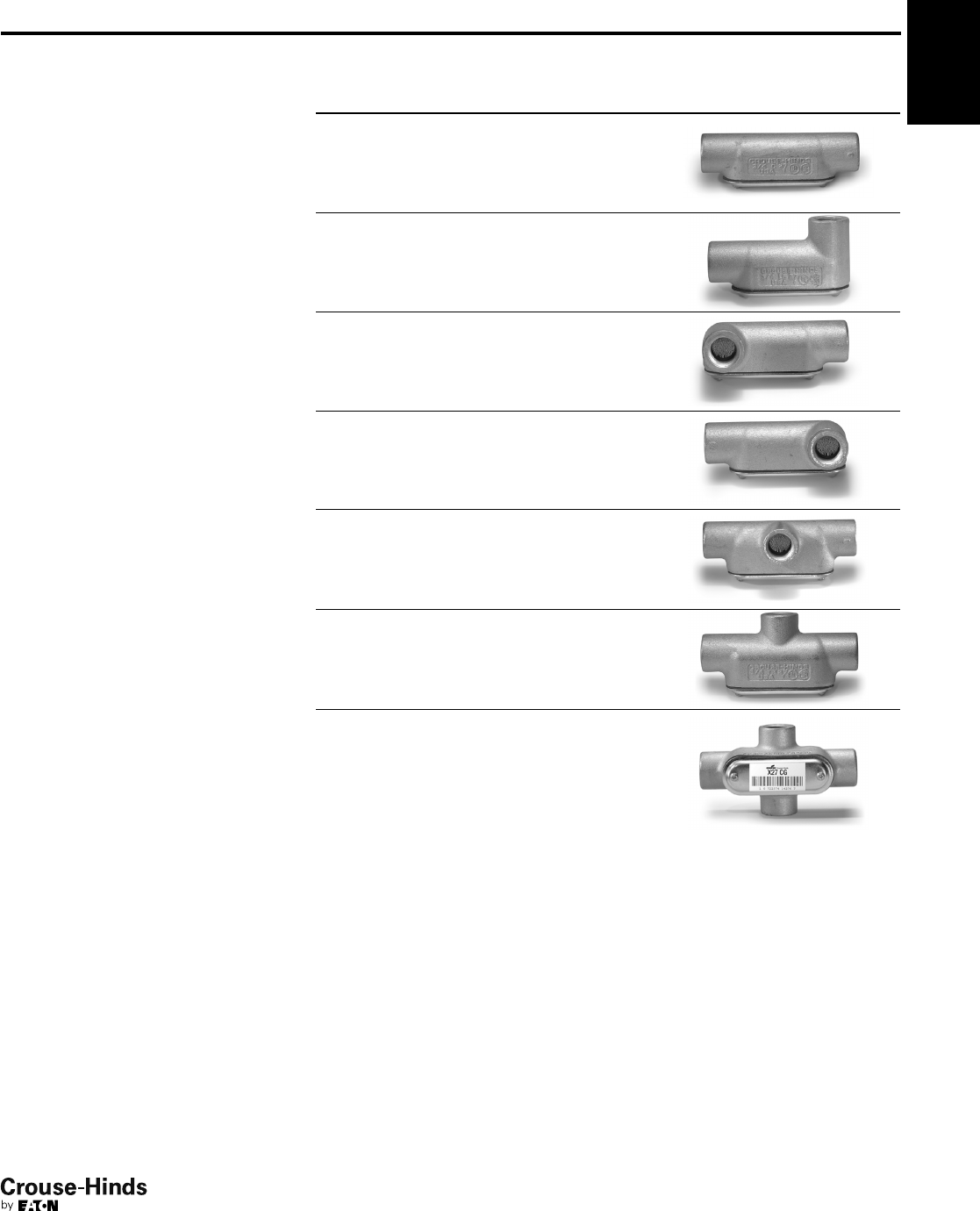
T Conduit Body, Cover and Gasket
LB Conduit Body, Cover and Gasket
TB Conduit Body, Cover and Gasket
C Conduit Body, Cover and Gasket
LR Conduit Body, Cover and Gasket
Condulet®Conduit Outlet Bodies,
Covers and Gaskets - Stainless Steel
LL Conduit Body, Cover and Gasket
Catalog
Number
Trade
Size A B C D E
T18SS 1/2" 5.56 1.75 1.31 1.02 3.15
T28SS 3/4" 6.61 2.00 1.63 1.27 3.92
T38SS 1" 7.53 2.31 1.78 1.42 4.61
T48SS 11/4" 8.75 2.50 2.25 1.83 5.50
T58SS 11/2" 9.37 2.75 2.47 2.03 6.12
T68SS 2" 11.50 3.38 3.13 2.50 8.00
T88SS 3" 15.00 4.63 4.34 3.71 10.25
T108SS 4" 18.25 5.44 5.50 4.87 13.00
Catalog
Number
Trade
Size A B C D E
LB18SS 1/2" 4.86 1.35 1.31 1.02 3.15
LB28SS 3/4" 5.75 1.63 1.63 1.27 3.94
LB38SS 1" 6.48 2.00 1.78 1.42 4.55
LB48SS 11/4" 7.75 3.50 2.25 1.83 5.50
LB58SS 11/2" 8.38 2.75 2.47 2.03 6.13
LB68SS 2" 10.50 3.38 3.13 2.50 8.00
LB88SS 3" 13.50 6.13 4.34 3.71 10.25
LB108SS 4" 16.63 7.25 5.50 4.87 13.00
Catalog
Number Trade Size A B C D E
TB28SS 3/4" 6.61 2.88 1.63 1.27 3.95
TB38SS 1" 7.53 3.23 1.78 1.42 4.61
TB48SS 11/4" 8.75 3.50 2.25 1.83 5.50
TB58SS 11/2" 9.37 3.75 2.47 2.03 6.12
TB68SS 2" 11.50 4.38 3.13 2.50 8.00
Catalog
Number
Trade
Size A B C D E
C18SS 1/2" 5.56 1.38 1.31 1.02 3.15
C28SS 3/4" 6.56 1.63 1.63 1.27 3.94
C38SS 1" 7.50 2.00 1.78 1.42 4.61
Catalog
Number
Trade
Size A B C D E
LL28SS 3/4" 5.72 1.63 1.63 1.27 3.95
LL38SS 1" 6.59 2.00 1.78 1.42 4.61
Catalog
Number Trade Size A B C D E
LR28SS 3/4" 5.72 1.63 1.63 1.27 3.95
LR38SS 1" 6.59 2.00 1.78 1.42 4.61
18-19.qxp 12/16/2013 12:01 PM Page 18
1F
19
www.crouse-hinds.com US: 1-866-764-5454 CAN: 1-800-265-0502 Copyright©2013 Eaton’s Crouse-Hinds Business
1F
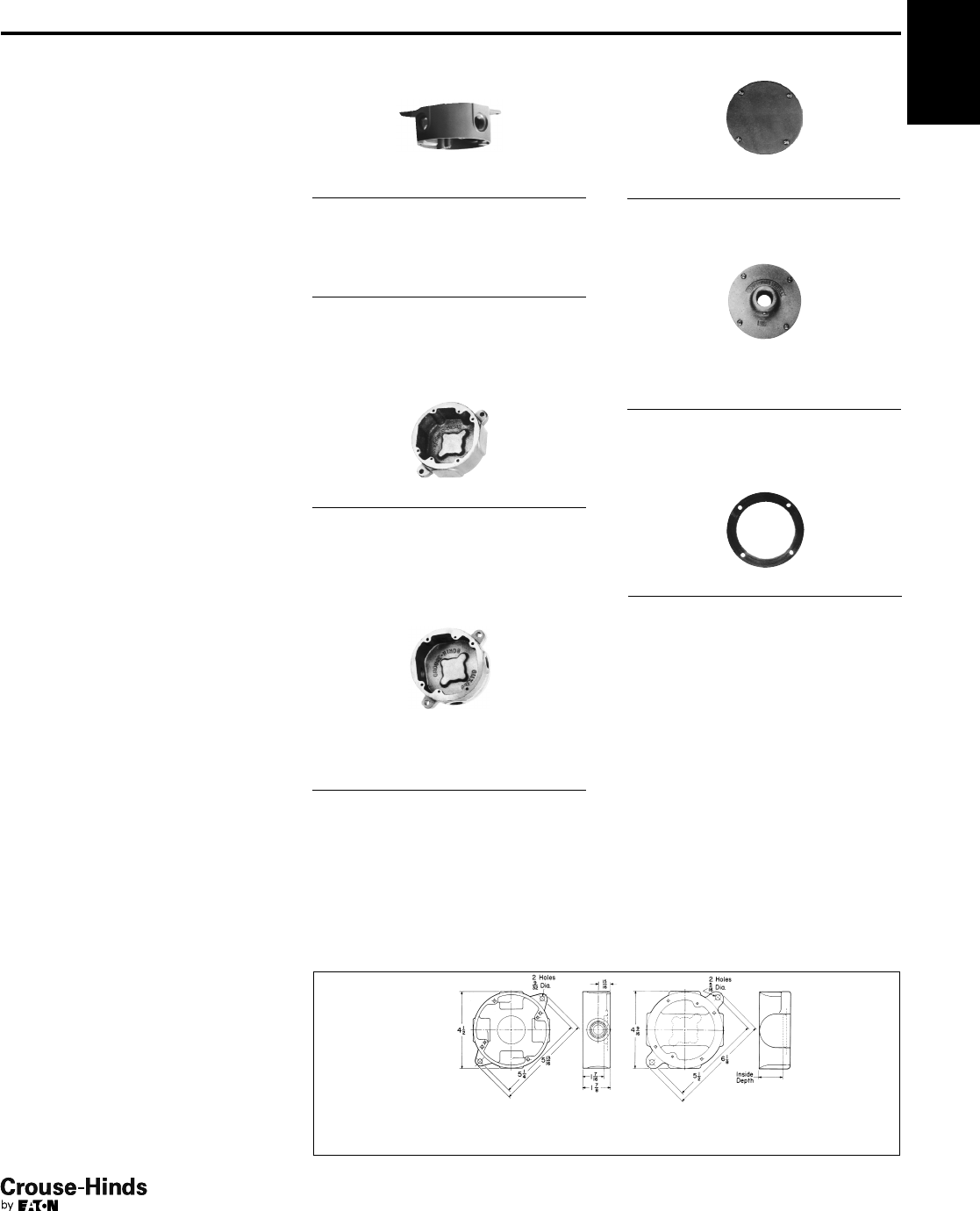
Condulet®Outlet Boxes -
Cast Iron or Aluminum
Covers and Gaskets
Applications:
VXF and GRF cast outlet boxes are
installed in threaded rigid conduit
systems to:
• Act as junction boxes
• Act as pull outlets
• Accept round base wiring devices and
covers intended for use on 4" outlet
boxes (GRF boxes only)
• Act as ceiling or wall mounting for
Vaporgard™ lighting fixtures (VXF boxes)
• Mount enclosed and gasketed lighting
fixtures: Series ARB and VGR; Series
ARB fixture hangers (GRF boxes)
Features VXF:
• Compact, shallow design
• Takes GRF covers
• Multiple tapped conduit openings and
pipe plugs for versatility
• 4 hubs and 3 plugs on VXF10 and
VXF20
• 5 hubs and 4 plugs on VXFT10 and
VXFT20
Features GRF:
• Surface mounting. Flush mounting can
be obtained by nailing box to concrete
form through mounting lug
• Drilled mounting lugs
• Four conduit bosses spaced 90° apart
on sides and one boss on back
• Blank or drilled and tapped bodies (with
4 side bosses tapped and plugged, plus
blank back boss)
Standard Materials:
• VXF – copper-free aluminum
• GRF – Feraloy®iron alloy or copper-free
aluminum
Standard Finishes:
• VXF – epoxy enamel
• GRF – electrogalvanized and aluminum
acrylic paint
Certifications and
Compliances:
• UL Standard: boxes and covers – 514A
• CSA Standard: C22.2
VXF Tapped Surface
With Lugs
4 Hubs, 3 Plugs
Hub Size Cat. #
1/2VXF10
3/4VXF20
Surface With Lugs
5 Hubs, 4 Plugs
Hub Size Cat. #
1/2VXFT10
3/4VXFT20
GRF Blank Surface
With Lugs
Inside Depth Cat. #
13/8GRF19
115/16 GRF29
31/8GRF39
GRFX Tapped Surface
With Lugs
4 Hubs, 3 Plugs
Blank Back Boss
Inside
Depth
Size
Tap
Iron
Cat. #
Aluminum
Cat. #
13/81/2GRFX119 GRF119
13/83/4GRFX219 GRF219
21/16 1/2GRFX129 GRF129
21/16 3/4GRFX229 GRF229
21/16 1GRFX329 GRF329
31/81/2GRFX139 GRF139
31/83/4GRFX239 GRF239
31/81GRFX339 GRF339
GRF Blank Cover
GRF Hub Covers
Fixture weight to 125 lbs.
Description Size
Iron
Cat. #
Aluminum
Cat. #
Surface 1/2GRF11 GRF11 SA
Surface 3/4GRF12 GRF12 SA
GRF Gasket
Description Cat. #
Neoprene GASK643
Dimensions
In Inches:
VXF-VXFT† GRF-GRFX
†VXFT has hubs on 4 sides and back; VXF has hubs on 4 sides only.
See lighting section 7L for complete listing of lighting fixtures and hangers.
Description
Iron
Cat. #
Aluminum
Cat. #
Surface GRF10 GRF110
Options:
Description Suffix
GRF bodies and covers - hot
dipped galvanized HDG
18-19.qxp 12/16/2013 12:01 PM Page 19
1F
20
www.crouse-hinds.com US: 1-866-764-5454 CAN: 1-800-265-0502 Copyright©2013 Eaton’s Crouse-Hinds Business
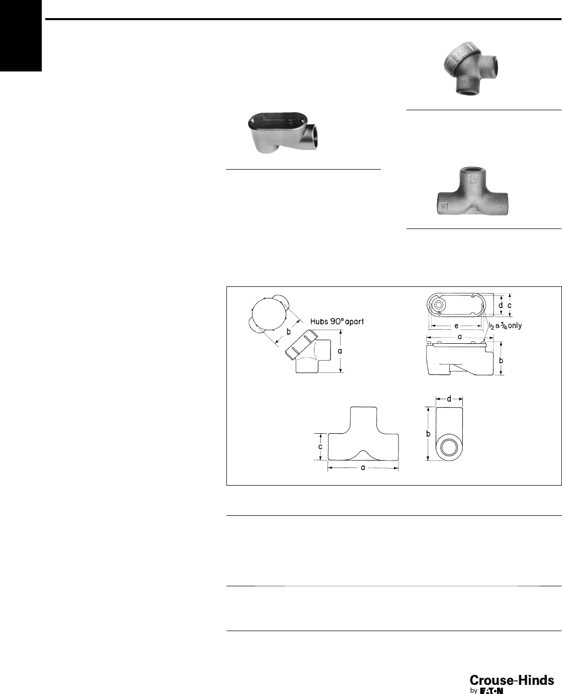
1F Condulet®Service Entrance Elbows and Tees
Applications:
SLB and LBY elbows are installed in
conduit systems to:
• Act as service entrance elbows between
service entrance and vertical
weatherhead conduit runs
• Make 90° bends in conduit systems
where space is limited
• Act as pull outlets
• Provide access to conductors for
maintenance and future system changes
ET short radius tees are installed in conduit
systems:
• In concealed conduit runs allowing single
conduit stub up to outlet boxes located
above or below main conduit run.
Eliminates separate feed and return
conduits to flush floor box or junction
box
Features:
SLB elbows have:
• Compact overall size and short hubs
• Taper tapped hubs and integral bushing
for standard threaded conduit
• Covers and gaskets furnished
LBY elbows have:
• Maximum volume for bends within a
compact overall size
• Screw-on cover for ease of installation
and removal
• Cover openings on an angle, permitting
conductors to be pulled straight through
either hub
• Taper tapped hubs and integral bushing
for standard threaded conduit
ET short radius tees have:
• Compact size, small radius of bend for
use in concealed or open conduit
systems. Particularly suited for use in
shallow floors or partitions
• Taper tapped hubs and integral bushing
for standard threaded conduit
Standard Materials:
• SLB elbows – copper–free aluminum
• LBY elbows – Feraloy®iron alloy
• ET tees – Feraloy iron alloy
Standard Finishes:
• Copper-free aluminum – natural
•Feraloy iron alloy – electrogalvanized
and aluminum acrylic paint
Options:
Description Suffix
Finishes – LBY elbows:
Corro-free™epoxy power coat S752
Material (LBY only) – copper-free
aluminum construction SA
Certifications and
Compliances:
• UL Standard: 514B
• Fed. Spec.: W-C-586a
SLB (includes cover)
Size Cat. #
1/2SLB1
3/4SLB2
1SLB3
11/4SLB4
11/2SLB5
2SLB6
LBY (includes cover)
Size Cat. #
1/2LBY15
3/4LBY25
1LBY35
11/4LBY45
11/2LBY55
ET
Size Cat. #
3/4– 1/2– 1/2ET218
3/4– 3/4– 3/4ET228
1 – 3/4– 3/4ET328
Largest hub shown at top of photo
Dimensions
In Inches:
LBY SLB
ET
SLB
Size 1/23/411
3/411/22
a31/831/241/853/8623/32 73/4
b125/32 219/32 225/32 31/32 329/32
c13/16 13/8111/16 23/32 23/83
d11
3/16 115/32 17/825/32 25/8
e211/16 215/16 311/32 43/461/32 631/32
LBY
Size 1/23/411
3/411/2
a213/16 33/16 31/4325/32 41/2
b22
1/421/2215/16 33/8
ET
Size 3/4– 1/2– 1/23/4– 3/4– 3/41 – 3/4– 3/4
a444
b25/833
c11/411/211/2
d11/211/213/4
20-21.qxp 12/23/2013 2:32 PM Page 20

2F
21
www.crouse-hinds.com US: 1-866-764-5454 CAN: 1-800-265-0502 Copyright©2013 Eaton’s Crouse-Hinds Business
Condulet®Device Boxes
Non-hazardous
2F
Description Page No.
Application/Selection see page 22
Shape Selector Charts see page 23
Device Boxes - Cast Iron or Aluminum
FS/FD Series
Single gang
Blank see pages 31–34
Cast hubs see pages 25–28
Multi-gang
Blank see pages 31–34
Cast hubs see pages 29–30
Covers for Cast Iron or Aluminum Device Boxes
WLR and WLG Wet Locations Covers For NEMA
Configuration and GFCI Receptacles
Blank see page 39
Pilot light see page 43
Push button see page 41
Receptacle see page 37
Switch see page 39
Device Boxes and Covers - Stainless Steel
FS/FD Series see pages 35–36
Plugs and Receptacles
DS Series see page 42
DS/WP Series see page 42
FSE Series see page 46
20-21.qxp 12/23/2013 2:32 PM Page 21
2F
22
www.crouse-hinds.com US: 1-866-764-5454 CAN: 1-800-265-0502 Copyright©2013 Eaton’s Crouse-Hinds Business
2F Condulet®Cast Device Boxes and Covers
Application and Selection
Applications:
Cast device boxes are installed in conduit and cable systems to:
• Accommodate wiring devices
• Act as pull boxes for conductors in a conduit system
• Provide openings to make splices and taps in conductors
• Provide access to conductors for maintenance and future system
changes
Considerations for Selection of Device Box
Type of conduit system:
• Should be compatible with conduit or cable system.
• Boxes are standard with mounting lugs and internal green ground
screw.
• Boxes are available for rigid steel, IMC; rigid aluminum; flexible
conduit and cable systems.
Number of devices to be used in the box:
• Standard flush devices require one gang each
Depth:
• Two box types are available – standard (FS) and deep (FD), single
through five gang.
• Standard flush wiring devices will normally fit in the FS boxes.
• Some special purpose devices of higher ratings will require the
deeper box (FD).
• In addition, the need for additional wiring space will require the
deep box.
Hub configuration and size:
• The layout of the conduit system dictates the conduit opening
locations of the box.
The table below indicates the types of conduit and the boxes
available. Drilled and tapped openings can be supplied in blank
boxes to meet your requirements.
• Hub size is the same as conduit size. A variety of hub sizes are
available. Where the specific hub size is not available, reducing
bushings can be used.
Materials and finishes:
• The environment and the use of the box will determine the material
and finish needed. Areas of the country with harsh weather and
corrosive environments may require different materials and finishes
for added protection.
• Standard material and finish is Feraloy®iron alloy with
electrogalvanized and aluminum acrylic paint. Many items are also
available in copper-free aluminum.
• Optional finishes can be obtained if environment warrants. See
Options listings.
Considerations for Selection of Covers,
Devices, and Accessories
Both general purpose and weatherproof, waterproof devices and
covers are available. Selection will depend on individual conditions.
To provide for a wide variety of applications, the following covers
and devices are available:
Covers Pg.
General use snap switch see pages 39–41 and 44–45
Pushbutton switch see page 41
Plug and receptacle see pages 37, 39, 42, and 44–46
Blank see pages 39 and 44–45
Pilot light see page 43
Receptacle see pages 37–39, 42, and 44–46
Devices Pg.
Receptacle see page 42
Pilot lights see page 43
Wiring device see page 42
Accessories Pg.
Gaskets see page 43
Box extensions see page 43
Flush mtg. adapter see page 43
Options:
Description Suffix
Corro-free™epoxy powder coat S752
Quick Selector Chart
Box Depth Gang
Conduit
Type
Standard
Material
Standard
Finish
FS 111/16 1-3 Threaded rigid Feraloy iron alloy
(some are copper-free
aluminum)
Feraloy iron alloy – electrogalvanized
and aluminum acrylic paint.
Copper-free aluminum – natural
FD 21/21-3 Threaded rigid Feraloy iron alloy Feraloy iron alloy – electrogalvanized
and aluminum acrylic paint
FD-SS 3.03 1 Threaded rigid Stainless steel Natural
FS blank bodies
Drilled and tapped
115/16 1-4
1-3
Threaded rigid Feraloy iron alloy Feraloy iron alloy – electrogalvanized
and aluminum acrylic paint
FD blank bodies
Drilled & tapped
21/21-5
1-3
Threaded rigid Feraloy iron alloy Feraloy iron alloy – electrogalvanized
and aluminum acrylic paint
22-23.qxp 12/24/2013 2:51 PM Page 22
2F
23
www.crouse-hinds.com US: 1-866-764-5454 CAN: 1-800-265-0502 Copyright©2013 Eaton’s Crouse-Hinds Business
2F
Condulet®Cast Device Boxes with Hubs
Single Gang Shape Selector Chart
FS/FD see pages 25–26
FSA/FDA see pages 25–26
FS (Double face) see pages 25–28
FS-SA see pages 25–26
FSR/FDR see pages 25–26
FSSA see pages 25–26
FSL/FDL see pages 25–26
FSCA see pages 25–26
FSC see pages 25–26
FSS see pages 25–26
FDC see pages 25–26
FDD see pages 25–26
FSC (Double face) see pages 25–28
FSC-SA see pages 25–26
FSLA/FDLA see pages 25–26
Series Page
Series Page
Series Page
FSCC/FDCC see pages 25–26
FSX/FDX see pages 27–28
FSCT/FDCT see pages 27–28
FDXC see pages 27–28
FST/FDT see pages 27–28
FSCD see pages 27–28
FSY (With flange) see pages 27–28
FD Stainless Steel see pages 35–36
If the hub configurations required are not available, drilled and tapped openings can be provided in blank boxes per your
specifications. See pages 31–34 for details.
22-23.qxp 12/24/2013 2:51 PM Page 23
2F
24
www.crouse-hinds.com US: 1-866-764-5454 CAN: 1-800-265-0502 Copyright©2013 Eaton’s Crouse-Hinds Business
2F
Series Page Series Page Series Page
FSC
(Two gang tandem)
see pages 29–30 FSD (Two gang) see pages 29–30 FS/FD (Three gang) see pages 29–30
FS/FD (Two gang) see pages 29–30 FSS/FDS (Two gang) see pages 29–30 FSS (Three gang) see pages 29–30
FSC/FDC (Two gang) see pages 29–30 FSE (Two gang) see pages 29–30
If the hub configurations required are not available, drilled and tapped openings can be provided in blank boxes per your
specifications. See pages 31–34 for details.
Condulet®Cast Device Boxes with Hubs
Multi-Gang Shape Selector Chart
24-25.qxp 12/23/2013 2:35 PM Page 24
2F
25
www.crouse-hinds.com US: 1-866-764-5454 CAN: 1-800-265-0502 Copyright©2013 Eaton’s Crouse-Hinds Business
2F
Accessories
see pages 37–45
Applications:
Cast device boxes are installed to:
• Accommodate wiring devices
• Act as pull boxes for conductors in a
conduit system
• Provide openings to make splices and
taps in conductors
• Provide access to conductors for
maintenance and future system changes
• Connect conduit sections
• FSY boxes for mounting surface devices
on floor or bench (used with single gang
covers)
Features:
• Internal green ground screw standard on
boxes
• Suitable for use in wet locations when
used with gasketed covers
• Mounting lugs standard on most boxes
• Tapered threaded hubs (NPT) with
integral bushing
• Available for surface mounting (with
mounting lugs) or flush mounting
(without mounting lugs) as listed
• Available as shallow (FS) or deep (FD)
configuration. Use FD if device to be
enclosed exceeds 15/8" in depth
• Ample wiring room provided in either FS
or FD configuration
• Wide selection of surface or flush covers
available in three materials (sheet steel,
Feraloy®, aluminum)
• Covers for flush mounting extend to
conceal the rough plaster line
• Available in single gang and multi-gang
configurations with hubs, and as blank
bodies for drilled and tapped openings
Standard Materials:
•Feraloy iron alloy or copper-free
aluminum.
Standard Finishes:
•Feraloy – electrogalvanized and
aluminum acrylic paint
• Aluminum – natural
Size Ranges:
• Hubs – 1/2" to 1"
Certifications and
Compliances:
• UL Standard: 514
• ANSI Standard: C33.84
• Fed. Spec.: W-C-5860
• CSA Standard: C22.2 No. 18
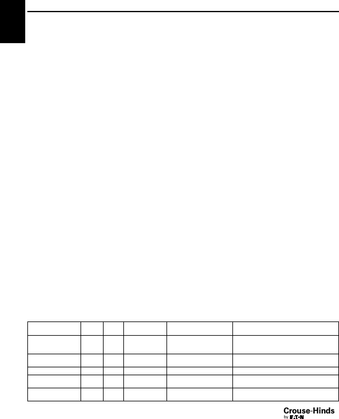
FS & FD
Size Cat. # Cat. #
1/2FSR1 FDR1
3/4FSR2 FDR2*†
Size Cat. # Cat. #
1/2FSC1* FDC1†
3/4FSC2* FDC2†
1FSC3† FDC3†
Size Cat. # Cat. #
1/2FSL1 FDL1
3/4FSL2 FDL2*†
*Available in sand cast copper-free aluminum – add
suffix SCA to Cat. No.
†Available in sand cast copper-free aluminum – add
suffix SA to Cat. No.
Die Cast Aluminum‡
Size Cat. # Cat. #
1/2FS1 SA FSC1 SA
3/4FS2 SA FSC2 SA
‡Mounting lugs and ground screw are not offered with
standard die cast aluminum box. For sand cast
aluminum box with mounting lugs and ground screw,
change "SA" in catalog number to "SCA"
(Example: FS1 SCA).
Size Cat. # Cat. #
1/2FS1* FD1†
3/4FS2* FD2†
1FS3† FD3†
With and Without Mounting Lugs for
Threaded Rigid and IMC Conduit
Options:
Description Suffix
Finishes:
Corro-free™ epoxy powder coat
- external body S752
Corro-free™ epoxy powder coat
- internal and external S753
Hot dipped galvanized HDG
Condulet®Single Gang Device Boxes -
Cast Iron or Aluminum
24-25.qxp 12/23/2013 2:35 PM Page 25
2F
26
www.crouse-hinds.com US: 1-866-764-5454 CAN: 1-800-265-0502 Copyright©2013 Eaton’s Crouse-Hinds Business
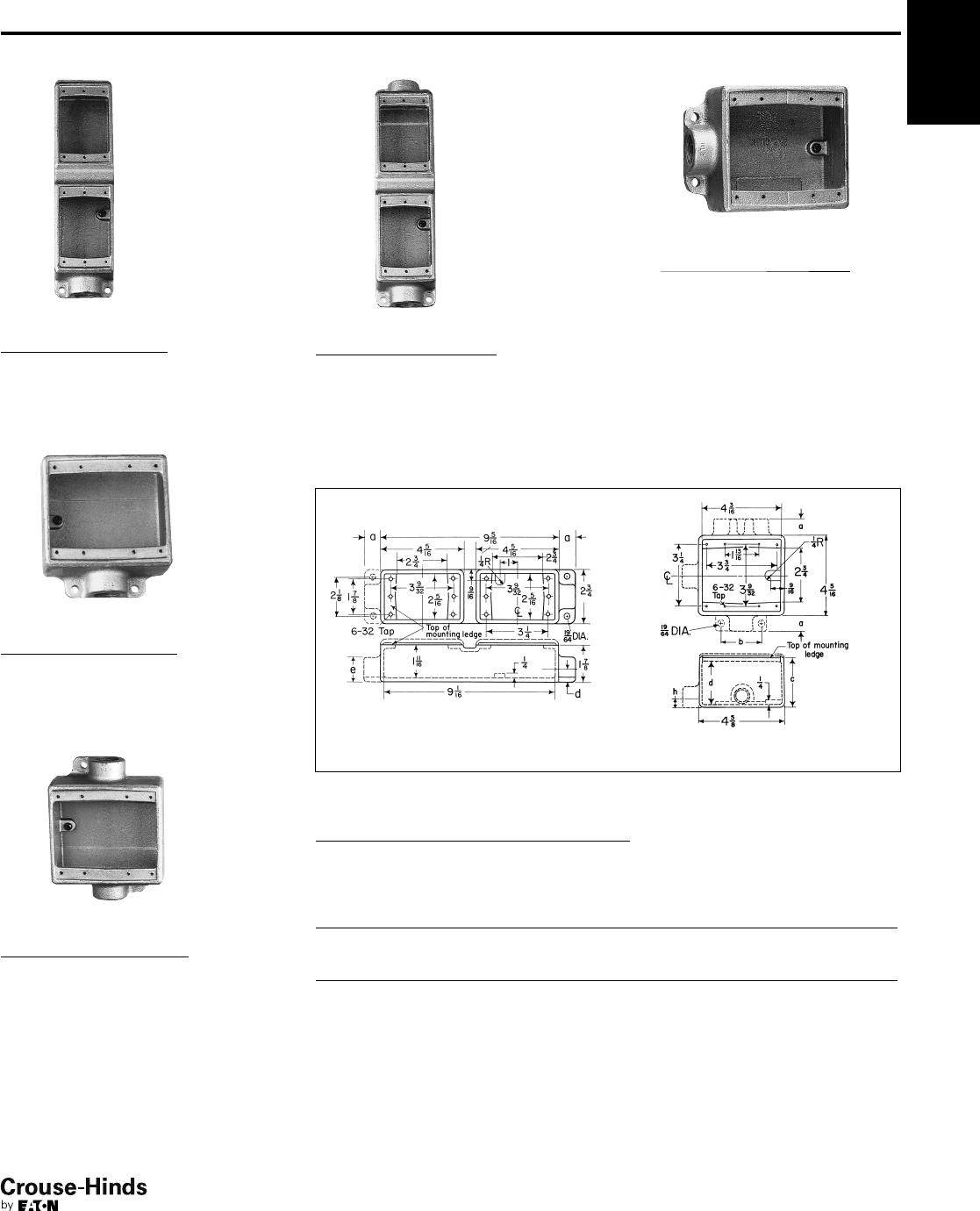
2F
FS & FD
Size Cat. #† Cat. #†
1/2FSA1 FDA1
3/4FSA2 FDA2
Size Cat. #† Cat. #†
1/2FSS1* FDD1
3/4FSS2* FDD2*
1FSS3 FDD3
Size Cat. # Cat. #
1/2FSCC1 FDCC1
3/4FSCC2 FDCC2
Size Cat. #
1/2FSCA1
3/4FSCA2
Size Cat. #†
3/4FSSA2
Size Cat. # Cat. #
1/2FSLA1 FDLA1
3/4FSLA2 FDLA2
*Available in copper-free aluminum; add suffix "SA".
†Mounting lugs not available.
Dimensions
In Inches:
Series Hub Size a b c d
FS 1/27/817/8111/16 5/8
3/47/817/8111/16 3/4
111
7/8111/16 7/8
FD
1/27/8211/16 21/25/8
3/47/8211/16 21/23/4
112
11/16 21/27/8
Condulet®Single Gang Device Boxes -
Cast Iron or Aluminum
Accessories
see pages 37–45
With and Without Mounting Lugs for
Threaded Rigid and IMC Conduit
26-27.qxp 12/23/2013 2:35 PM Page 26
2F
27
www.crouse-hinds.com US: 1-866-764-5454 CAN: 1-800-265-0502 Copyright©2013 Eaton’s Crouse-Hinds Business
2F
FS & FD
Size Cat. # Cat. #
1/2FSCT1 FDCT1
3/4FSCT2* FDCT2*
1FSCT3 FDCT3
Size Cat. # Cat. #
1/2FST1* FDT1
3/4FST2* FDT2
1FDT3
Size Cat. # Cat. #
1/2FSX1 FDX1
3/4FSX2 FDX2
1FDX3
Size Cat. #‡
1/2FSCD1
3/4FSCD2
FSY
Description Hub Size Cat. # ‡
Single face 1 FSY311
Double face 1 FSY312
FDXC†
Hub Size Cat. #‡
3/4FDXC219
*Available in copper-free aluminum; add suffix "SA".
†6 Hubs – all 3/4" pipe tap.
‡ Not avaliable with mounting lugs.
Dimensions
In Inches:
FSCT, FSX, FST, FSCD
FDXCFSY
FSCT, FSX, FST, FSCD
Series Hub Size a b c d
FS 1/27/817/8111/16 5/8
3/47/817/8111/16 3/4
111
7/8111/16 7/8
FSY
Description Hub Size a b
Single gang, single face 12
3/4115/16
Single gang, double face 12
3/433/8
Condulet®Single Gang Device Boxes -
Cast Iron or Aluminum
Accessories
see pages 37–45
With and Without Mounting Lugs for
Threaded Rigid and IMC Conduit
26-27.qxp 12/23/2013 2:35 PM Page 27
2F
28
www.crouse-hinds.com US: 1-866-764-5454 CAN: 1-800-265-0502 Copyright©2013 Eaton’s Crouse-Hinds Business
2F Condulet®Single Gang Device Boxes -
Cast Iron or Aluminum
With and Without Mounting Lugs
FS
Double Face
Size Cat. #†
1/2FS152
3/4FS252
Double Face
Size Cat. #†
1/2FSC152
3/4FSC252
†Mounting lugs not available.
Dimensions
In Inches:
Double face
Series Hub Size a b c
FS 1/235/16 31/811/4
3/4311/16 31/211/2
Accessories
see pages 37–45
28-29.qxp 12/23/2013 2:36 PM Page 28
2F
29
www.crouse-hinds.com US: 1-866-764-5454 CAN: 1-800-265-0502 Copyright©2013 Eaton’s Crouse-Hinds Business
2F
Condulet®Multi-Gang Device Boxes -
Cast Iron or Aluminum
With and Without Mounting Lugs for
Threaded Rigid and IMC Conduit
Accessories
see pages 37–45
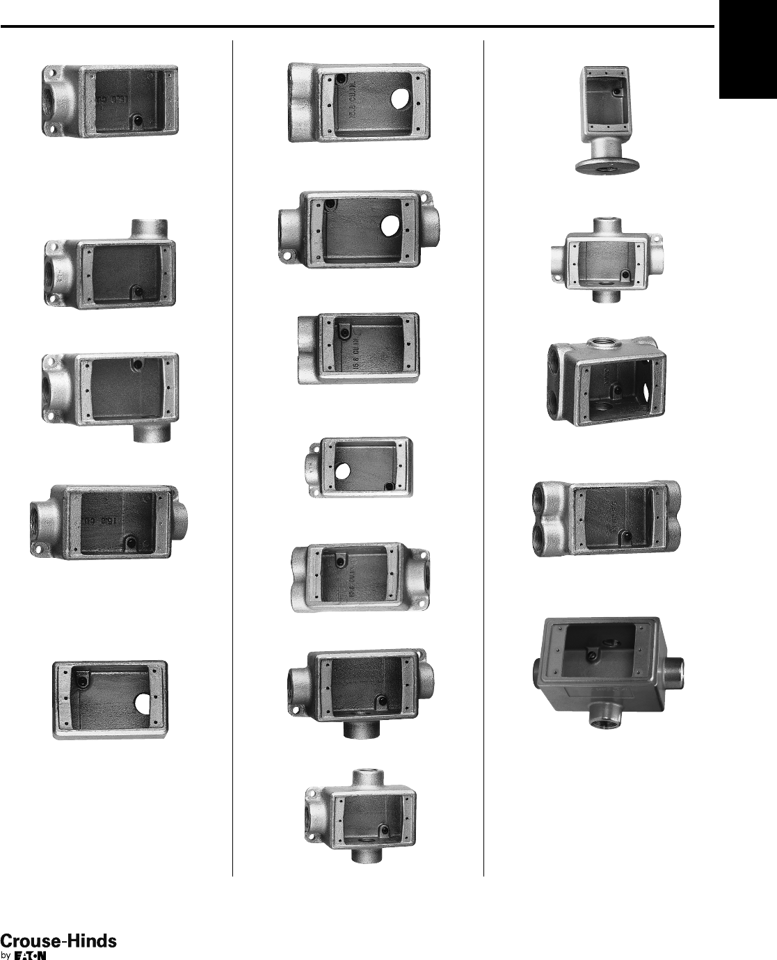
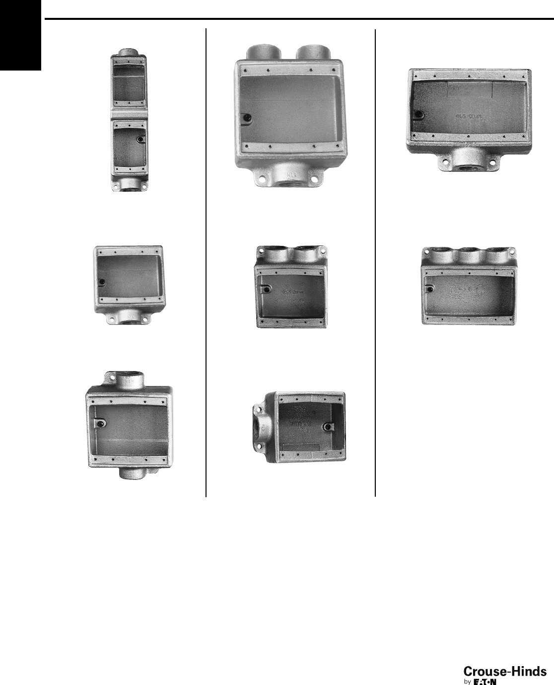
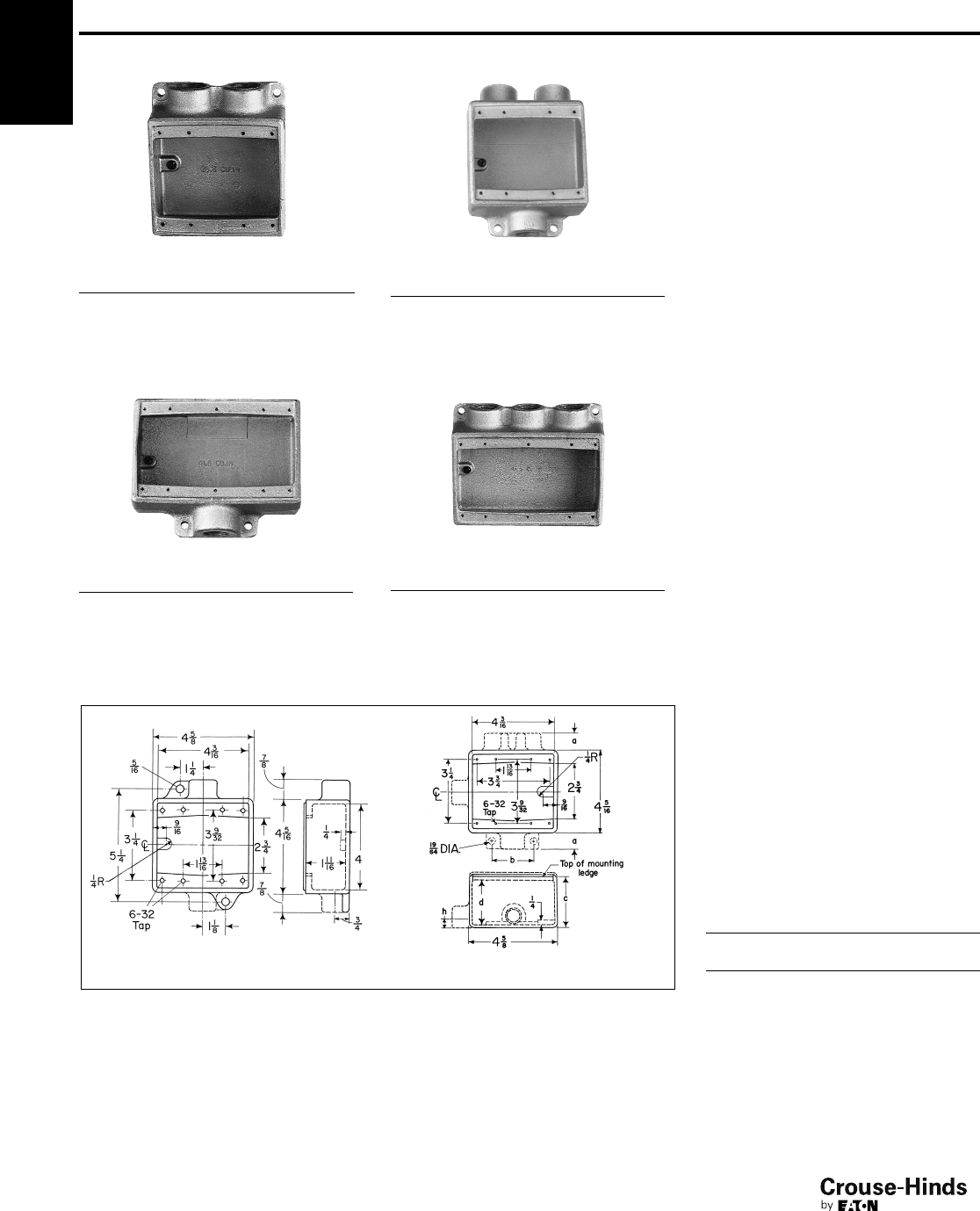
FS†
Two Gang Tandem
Size Cat. #
1/2FS17
3/4FS27
FSC†
Two Gang Tandem
Size Cat. #
1/2FSC17
3/4FSC27
†Use single gang covers only.
FS & FD
Two Gang
Size Cat. # Cat. #
1/2FS12* FD12
3/4FS22* FD22*
1FS32 FD32
FSC & FDC
Two Gang
Size Cat. # Cat. #
1/2FSC12 FDC12
3/4FSC222 FDC222*
1FSC32 FDC32
FSE
Two Gang
Size Cat. #
3/4FSE22
*Available in copper-free aluminum;
add suffix "SA".
Dimensions
In Inches:
Two gang tandem Two gang
Two gang tandem
Series
Hub
Size a b e
FS 1/27/85/811/4
3/47/83/411/2
Two gang
Series Hub Size a b c d h
FS 1/27/821/417/8111/16 5/8
3/47/821/417/8111/16 3/4
112
1/217/8111/16 7/8
FD
1/27/821/4211/16 21/25/8
3/47/821/4211/16 21/23/4
112
1/2211/16 21/27/8
28-29.qxp 12/23/2013 2:36 PM Page 29
2F
30
www.crouse-hinds.com US: 1-866-764-5454 CAN: 1-800-265-0502 Copyright©2013 Eaton’s Crouse-Hinds Business
2F
FSS & FDS
Two Gang
Size Cat. # Cat. #
3/4FSS222 FDS222
FS & FD
Three Gang
Size Cat. # Cat. #
3/4FS23 FD23
1FS33
FSD
Two Gang
Size Cat. #
3/4FSD212*
*Hubs on 2 hub side are 1/2"
FSS
Three Gang
Size Cat. #
3/4FSS23
Dimensions
In Inches:
Two gang with mounting lugs Three gang
Three gang
Series
Hub
Size a c d
FS 3/47/817/8111/16
111
7/8111/16
FD 3/47/8211/16 21/2
Condulet®Multi-Gang Device Boxes -
Cast Iron or Aluminum
With and Without Mounting Lugs for
Threaded Rigid and IMC Conduit
Accessories
see pages 37–45
30-31.qxp 12/23/2013 2:36 PM Page 30
2F
31
www.crouse-hinds.com US: 1-866-764-5454 CAN: 1-800-265-0502 Copyright©2013 Eaton’s Crouse-Hinds Business
2F
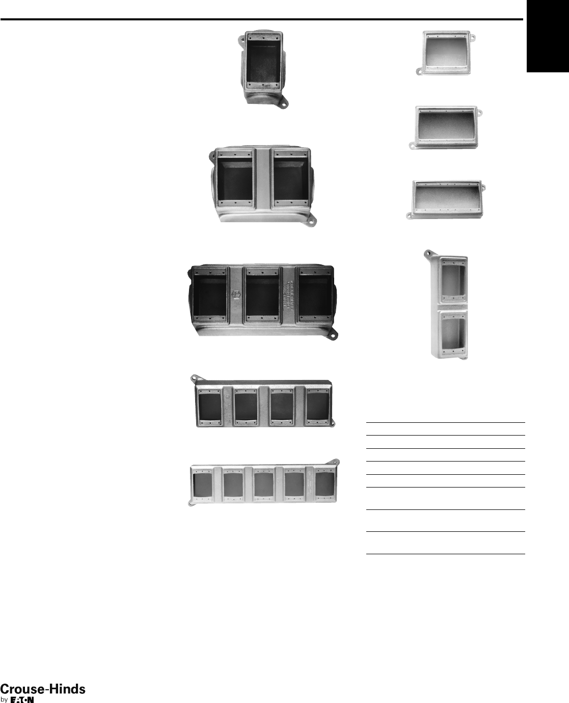
Condulet®Blank Device Boxes - Cast Iron
Blank Bodies With Mounting Lugs for
Drilling and Tapping Single Gang,
Multi-Gang, Tandem
Accessories
see pages 37–45
Applications:
Blank cast device boxes are used:
• Where several wiring devices are to be
grouped together
• To assemble special combinations of
wiring devices
• Where special arrangements of conduit
hubs or entrances are required
Features:
• Available in shallow (FS) or deep (FD)
configurations.
• FS/FD bodies have thick walls for drilling
and tapping conduit entrances.
• Internal green ground screw standard on
boxes.
• Available in single, two, three, four and
five gang and two gang tandem bodies.
• Cast mounting lugs at diagonally
opposite corners.
• For a wide selection of standard surface
or flush covers see pages 37–45.
Standard Materials:
•Feraloy iron alloy
Standard Finishes:
•Feraloy – electrogalvanized and
aluminum acrylic paint
Certifications and
Compliances:
• UL Standard: 514A
• CSA Standard: C22.2 No. 18
FS019, FD019 single gang
FS029, FD029 two gang
FS039, FD039 three gang
FD04 four gang
FD05 five gang
FS062, FD062 two gang
FS063, FD063 three gang
FS094, FD094 four gang
FS097, FD097 two gang tandem
Ordering Information:
Description
Shallow
Cat. #
Deep
Cat. #
Single gang FS019 FD019*
Two gang FS029 FD029*
Three gang FS039 FD039*
Four gang FD04
Five gang FD05
Two gang (takes one
two gang cover) FS062 FD062
Three gang (takes one
three gang cover) FS063 FD063
Four gang (takes one
four gang cover) FS094 FD094
Two gang tandem FS097 FD097
*Available in copper-free aluminum. To order add suffix
SA to Cat. No.
30-31.qxp 12/23/2013 2:36 PM Page 31
2F
32
www.crouse-hinds.com US: 1-866-764-5454 CAN: 1-800-265-0502 Copyright©2013 Eaton’s Crouse-Hinds Business
2F Condulet®Blank Device Boxes - Cast Iron
Blank Bodies for Drilling and Tapping
Ordering Information
Ordering Information:
To order one of the blank bodies with
drilled and tapped holes listed on see
pages 31–33, proceed as follows:
Step 1
Select the required box.
Step 2
Select the arrangement that meets the
requirements from Table 1.
Step 3
Determine the maximum size and spacing
of conduit openings from Table 2.
Step 4
Substitute the appropriate symbol from
Table 4 for each conduit entrance, using
‘‘0’’ (zero) for those locations on
arrangement where an entrance is not
required.
Example:
Step 1 – box required FS062
Step 2 – arrangement 1
Step 3 – conduit entrances – 1/2" at "a",
none at "b"; 1" at "c" and "d"; none at "e"
and "f".
Step 4 – symbols are substituted and
written in alphabetical order starting with
location "a". For this example A0CC00.
Complete Cat. No. is made up of
three parts:
Part 1 – box number;
Part 2 – arrangement number;
Part 3 – symbols for conduit entrances.
For this example:
FS062-1-A0CC00.
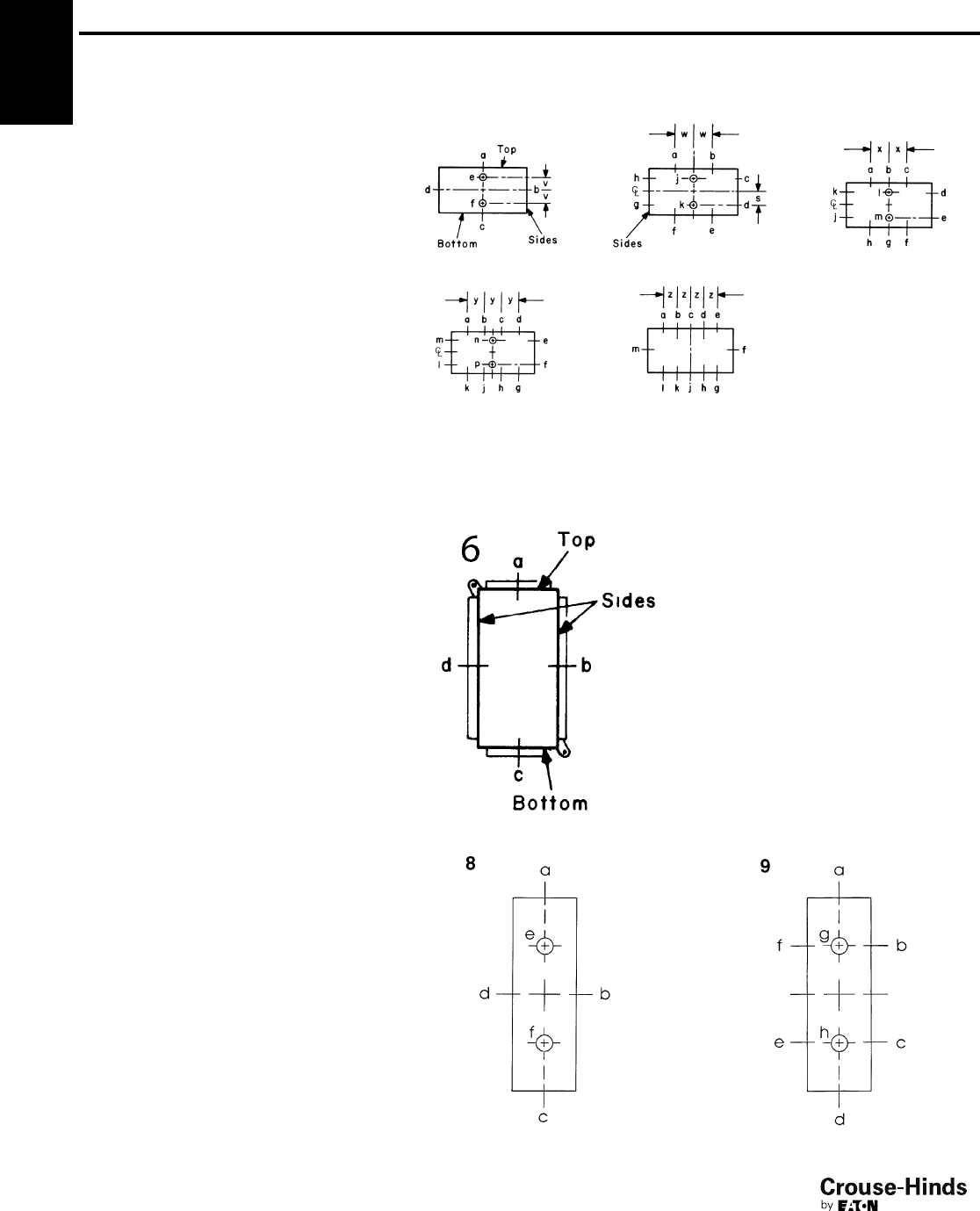
Table 1/Drilling and Tapping Arrangements*
Two, Three, Four and Five Gang
*Drilling and tapping arrangements other than those in Table 1 are available. Consult Eaton's Crouse-Hinds.
†If only one conduit entry is specified or permitted (see Table 2) on a side wall that conduit entry will be centered on the wall.
Single Gang Only (FS or FD019)
Two Gang Tandem (FS or FD097)
12†3†
4† 5
32-33.qxp 12/16/2013 12:03 PM Page 32
2F
33
www.crouse-hinds.com US: 1-866-764-5454 CAN: 1-800-265-0502 Copyright©2013 Eaton’s Crouse-Hinds Business
2F
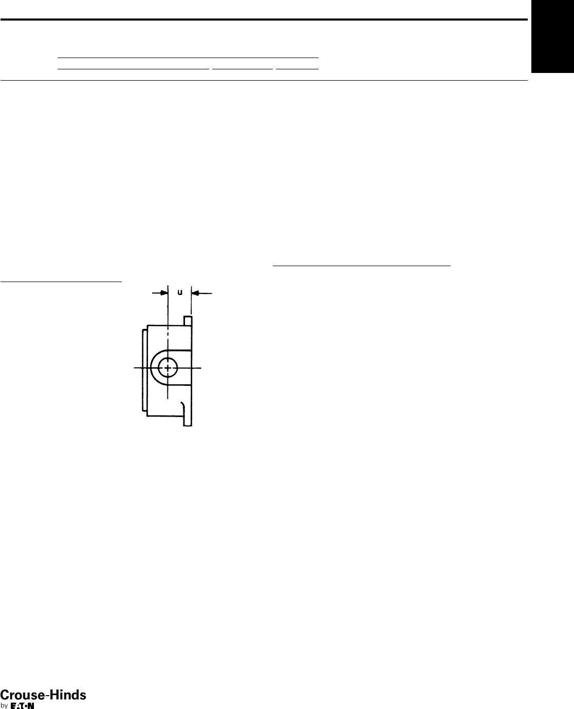
Table 3/Distance From Mounting Surface
to Centerline of Conduit Opening ("u")
Cat. # u
FS019 29/32
FD019* 13/8
FS029 29/32
FD029* 13/8
FS039 31/32
FD039* 13/8
FD04 19/16
FD05 19/16
FS062 15/32
FD062 15/8
FS063 15/32
FD063 15/8
FS094 15/32
FD094 19/16
FS097 15/32
FD097 19/16
Table 2/Maximum Number, Size and Spacing of Conduit Openings
Maximum Conduit Opening Size
Top and Bottom Sides Back Spacings
Cat. # 12345122 sv w x y z
FS019 11
FD019* 11/211/2
FS029 11 1 3/411
7/817/815/16
FD029* 11/211/213/411/217/817/815/16
FS039 111111 3
3/433/421/217/8
FD039* 11/211/211/211/211
1/233/433/421/217/8
FD04 11/211/211/211
/211/211 1
3/16 17/833/433/4
FD05 11/211/211/211/211/211/211 1
3/16 33/433/433/433/4
FS062 11 3/4111 1
1/429/32 15/8
FD062 11/211/43/411/211
1/411 1 1
3/8
FS063 11 1 3/4111 1
1/4113/16 113/16 15/8
FD063 11/211/413/411/211
1/411 1
13/16 21
7/16
FS094 11113/4111 1
1/4113/16 113/16 113/16 15/8
FD094 11/211/211/213/411/211 1
1/811/225/8113/16 15/8
FS097 11
1/2111
1/215/16 3/4
FD097 11/211/211/211/211/215/16 3/4
Table 4/Symbols for Openings
Conduit Size Symbol
1/2A
3/4B
1C
11/4E
11/2F
None 0
Condulet®Cast Device Boxes
Blank Bodies for Drilling and Tapping
Single-Gang, Multi-Gang, Tandem
*Available in copper-free aluminum. To order add suffix SA to Cat. No.
32-33.qxp 12/16/2013 12:03 PM Page 33
2F
34
www.crouse-hinds.com US: 1-866-764-5454 CAN: 1-800-265-0502 Copyright©2013 Eaton’s Crouse-Hinds Business
2F
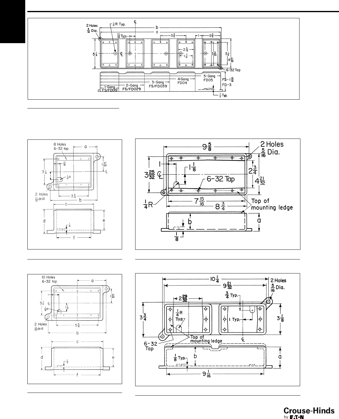
FS/FD062
Cat. # a b c d e f
FS062 27/853/452
3/16 11/243/8
FD062 215/16 57/851/16 31/16 21/245/16
FS/FD063
Cat. # a b c d e f
FS063 313/16 75/867/823/16 11/261/4
FD063 37/871/471/16 31/32 21/263/16
FS/FD094
Cat. # a b
FS094 23/16 145/64
FD094 32
1/2
Cat. # a b
FS097 21/32 11/2
FD097 227/32 25/16
FS/FD097
Cat. # a b
FS/FD019 31/431/4
FS/FD029 77
FS/FD039 103/4103/4
FD04 143/815
FD05 181/8183/4
Condulet®Cast Device Boxes
Blank Bodies for Drilling and Tapping
Single-Gang, Multi-Gang, Tandem
Dimensions (In Inches)
34-35.qxp 12/16/2013 12:03 PM Page 34
2F
35
www.crouse-hinds.com US: 1-866-764-5454 CAN: 1-800-265-0502 Copyright©2013 Eaton’s Crouse-Hinds Business
2F
Condulet®Stainless Steel Conduit
Device Boxes, Covers and Gaskets
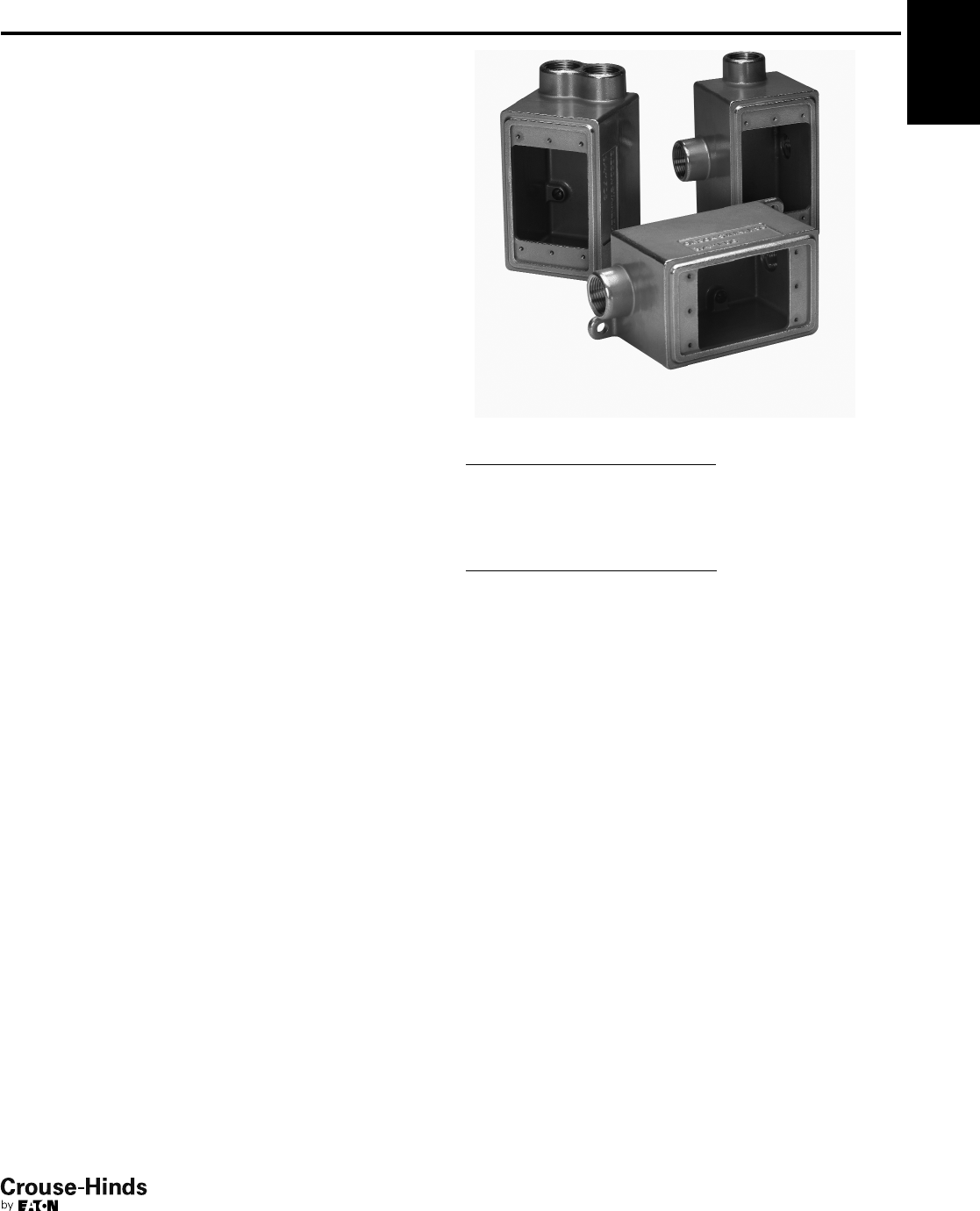
Eaton's Crouse-Hinds Condulet®Stainless Steel Device Boxes
deliver power where you need it, saving you time and money
throughout the life of your facility.
Superior resistance to corrosion and heat, combined with unmatched
strength, make stainless steel Condulet bodies and boxes a long-
term solution for even the most extreme environments.
Features:
• Self-healing properties of stainless steel fittings help reduce the
penetration of rust/corrosion and eliminate damage to the fitting
• Stainless steel fittings retain their strength in extreme heat and
extreme cold conditions
• Fitting surface is easy to maintain and keep clean
• Easy cleaning capabilities make these fittings perfect for food
processing and other hygienic areas where wash downs are
common
• Superior strength and durability greatly reduce replacement of
fittings - this will lower your total cost of ownership and increase
your return on investment
• Stainless steel fittings do not require harsh environment-damaging
cleaners to keep them looking like new
• Internal green grounding screw - standard
• Tapered threads for protection of wire insulation
• Wide selection of covers available
• Single or double conduit entry
• Ample wiring room provided for easy installations
Applications:
Cast device boxes are installed in conduit systems to:
• Accommodate wiring devices
• Act as pull boxes for conductors in a conduit system
• Provide openings to make splices and taps in conductors
• Provide access to conductors for maintenance and future
system changes
• Connect conduit systems
Standard Materials:
• Bodies - 316 stainless steel
• Covers - 316 stainless steel
• Cover Screws - 316 stainless steel
• Gasket - neoprene
Certifications and Compliances:
• UL Standard 514A
• CSA Standard C22.2 No. 18.1-04
• Raintight - when installed with cover and gasket
Dimension
A Length of box
B Overall length (including hubs)
C Width of box
D Overall width (including hubs)
E Height of box
F Overall height (including hubs)
34-35.qxp 12/16/2013 12:03 PM Page 35
2F
36
www.crouse-hinds.com US: 1-866-764-5454 CAN: 1-800-265-0502 Copyright©2013 Eaton’s Crouse-Hinds Business
2F
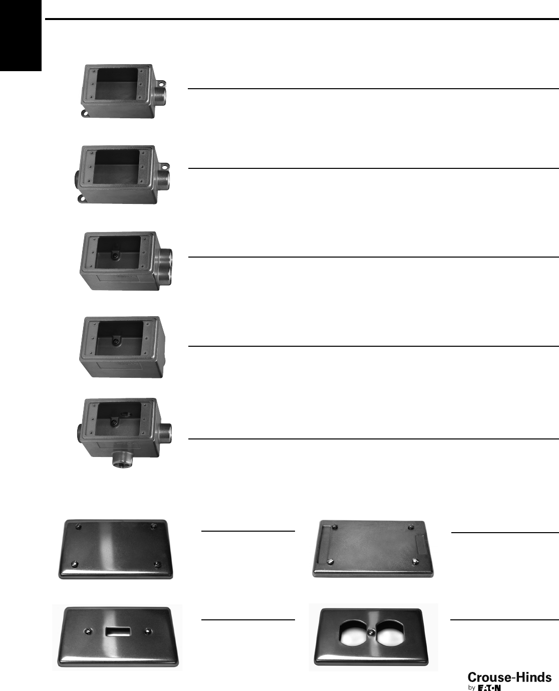
Ordering Information
FDC Device Body
FDS Device Body
FDA Device Body
FDX Device Body
Ordering Information - Device Box Cover and Gasket
Blank Cover
Switch Formed Cover
Blank Formed Cover
Receptacle Formed Cover
Condulet®Stainless Steel Conduit Device Boxes,
Covers and Gaskets
The Ultimate in Corrosion Resistance and Durability
Catalog Number
DS7000BC
Catalog Number
DS7000SF
Catalog Number
DS7000BF
Catalog Number
DS7000RF
Catalog Number Trade Size A B C D E F
FDC2SS 3/4" 4.63 6.19 2.94 2.94 3.03 3.03
Catalog Number Trade Size A B C D E F
FDS2SS 3/4" 4.63 5.41 2.94 2.94 3.03 3.03
Catalog Number Trade Size A B C D E F
FDA2SS 3/4" 4.63 4.63 2.94 2.94 3.03 3.80
Catalog Number Trade Size A B C D E F
FDX2SS 3/4" 4.63 6.19 2.94 4.50 3.03 3.03
FD Device Body
Catalog Number Trade Size A B C D E F
FD2SS 3/4" 4.63 5.41 2.94 2.94 3.03 3.03
36-37.qxp 12/16/2013 12:03 PM Page 36
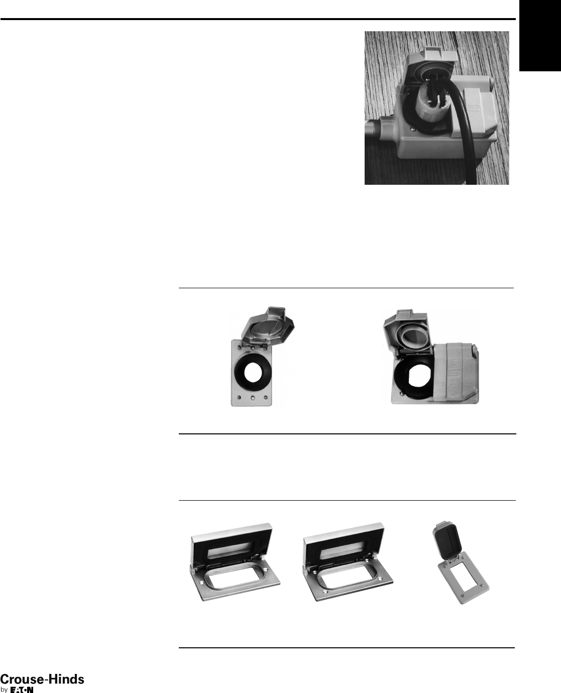
2F
37
www.crouse-hinds.com US: 1-866-764-5454 CAN: 1-800-265-0502 Copyright©2013 Eaton’s Crouse-Hinds Business
2F
Covers for Cast Iron or Aluminum Device Boxes
WLRS and WLG Wet Location Covers
For NEMA Configuration Receptacle Interiors and GFCI Receptacles
Applications:
WLRS, WLRD and WLGF series wiring
device covers are designed to meet the
total NEC Code requirements for wet
locations. WLRS, WLRD and WLGF series
covers are suitable for use in wet and
damp locations:
• Wherever portable equipment is required
• As general purpose utility receptacle
covers
• For industrial, commercial or residential
use
• In areas where electrical requirements
do not exceed medium duty ratings
• To mount FS and FD single-gang or
multi-gang boxes having individual cover
openings (see Sect. 2F for listings)
• To mount on most flush device boxes
(see Accessories)
Typical installation
Certifications and
Compliances:
• ANSI/UL Standard 514A
• NEC Code 410-57
• OSHA Standards, Subpart "S"
• NEMA Standards WD-1, 1974 (Straight
Blade) and WD-5, 1972 (Locking Type)
Standard Materials:
• WLRS, WLRD and WLGF face plate and
cover – die cast copper-free aluminum
• Cover hinge spring – stainless steel
• Cover screws – corrosion resistant metal
• Gasket – ethylene propylene rubber
(EPDM)
Standard Finishes:
• Copper-free aluminum – aluminum
lacquer
Electrical Rating Ranges:
• 15 amperes; 125, 250, or 277 volts
• 20 and 30 amperes; 125, 250, 277, 480,
600, 125 / 250, 208 / 120, 480 / 277 or
600 / 347 volts
Accessories:
• Flush mounting adapter – WLRA-1
required for mounting on device boxes.
(Order separately)
Spring Door Covers – with Gasket*
For NEMA Configuration Round Receptacles
Single cover
Cat. # Diameter
Duplex cover
Cat. # Diameter
WLRS1 13/8"WLRD1 13/8"
WLRS2 11/2"
*Patent Number 4,058,358
†Horizontal mount only.
Features:
WLRS, WLRD and WLGF covers:
• Self-closing spring door assures
protection of wiring device at all times,
in wet and damp locations
• One piece EPDM gasket provides
environmental protection of wiring
device at all times
• EPDM gasketing material offers
excellent resistance to ozone, weather
and temperature extremes of –50°F to
260°F
• Die cast, copper-free aluminum
construction with aluminum lacquer
finish provides maximum corrosion
resistance
• Positive ground path ensured for all
exposed metal parts
NEMA configuration receptacle
interiors:
• Comply with NEMA Standards WD-1
and WD-5
• Grounded through an extra contact in all
types except 3-phase applications; self
grounded in duplex variety
• Back and side wired
• Offered in single and duplex
configurations for use with standard
plugs
• Specification grade
Spring Door Covers – with Gasket*
For GFCI Receptacles in Wet Locations
Horizontal Mount
for flush
device boxes
Cat. #
Horizontal Mount
for FS and FD
device boxes
Cat. #
Vertical Mount
for FS and FD
device boxes
Cat. #
WLGF WLGF FS WLGF FSV
36-37.qxp 12/16/2013 12:03 PM Page 37
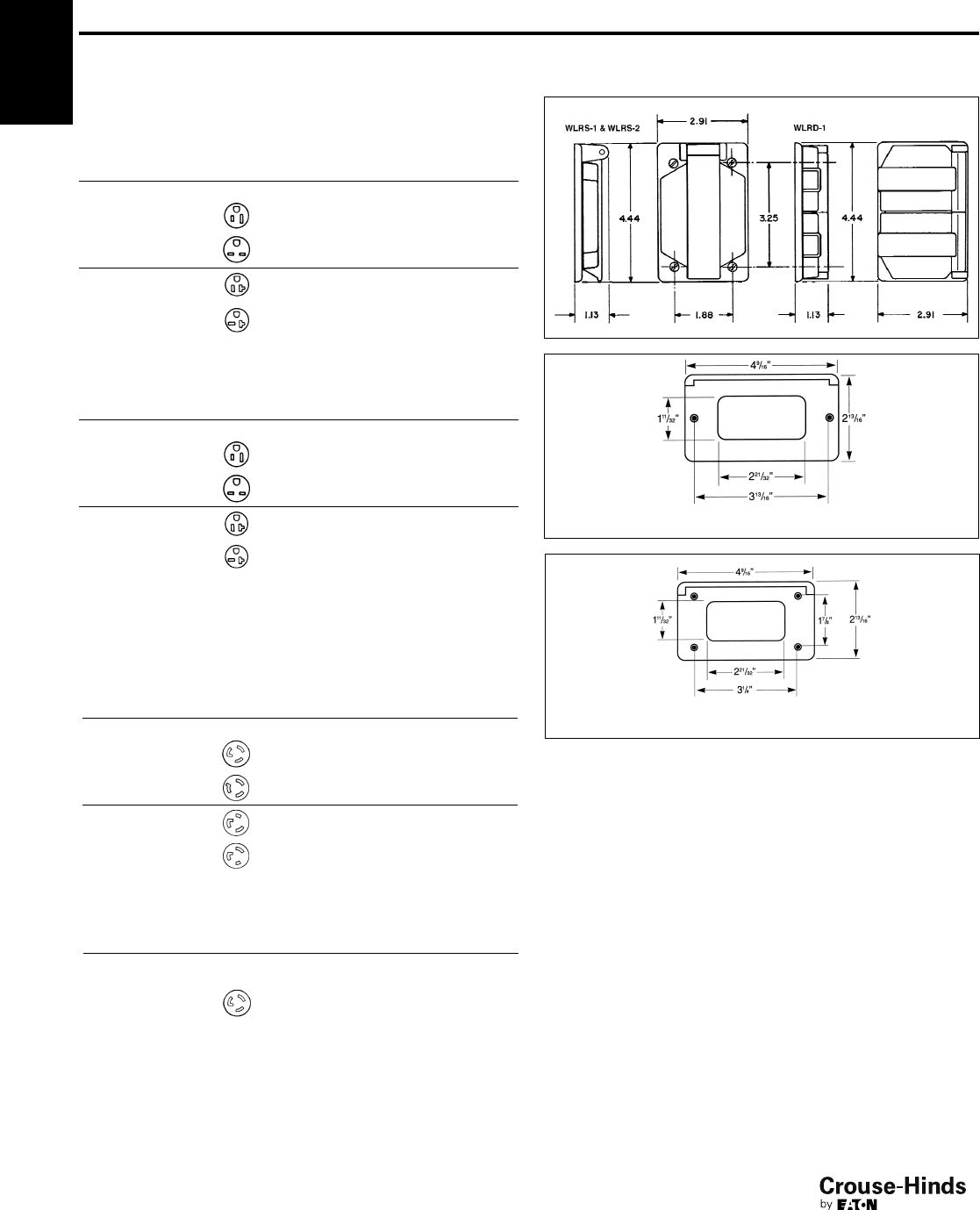
2F
38
www.crouse-hinds.com US: 1-866-764-5454 CAN: 1-800-265-0502 Copyright©2013 Eaton’s Crouse-Hinds Business
2F Covers for Cast Iron or Aluminum Device Boxes
WLRS and WLG Wet Location Covers
For NEMA Configuration Receptacle Interiors and GFCI Receptacles
Ordering Information - Covers with and
without NEMA Configuration Receptacles
For Non-Locking Blade Plugs
Type Volts
NEMA
Configuration
Complete
Cover with
Receptacle
Assy. Cat. #
Spring Door
Cover &
Gasket Only
Cat. #*
Single Device
2-Pole
3-Wire
Grounding
15 Amp
125V 5-15R WLRS 5 15 WLRS1
250V 6-15R WLRS 6 15 WLRS1
2-Pole
3-Wire
Grounding
20 Amp
125V 5-20R WLRS 5 20 WLRS1
250V 6-20R WLRS 6 20 WLRS1
Type Volts
NEMA
Configuration
Complete
Cover with
Receptacle
Assy. Cat. #
Spring Door
Cover &
Gasket Only
Cat. #*
Duplex Device
2-Pole
3-Wire
Grounding
15 Amp
125V 5-15R WLRD 5 15 WLRD1
250V 6-15R WLRD 6 15 WLRD1
2-Pole
3-Wire
Grounding
20 Amp
125V 5-20R WLRD 5 20 WLRD1
250V 6-20R WLRD 6 20 WLRD1
Ordering Information - Covers with and
without NEMA Configuration Receptacles
For Locking Blade Plugs
Type Volts
NEMA
Configuration
Complete
Cover with
Receptacle
Assy. Cat. #
Spring Door
Cover &
Gasket Only
Cat. #*
Single Device
2-Pole
3-Wire
Grounding
15 Amp
125V L5-15R WLRS L5 15 WLRS1
250V L6-15R WLRS L6 15 WLRS1
2-Pole
3-Wire
Grounding
20 Amp
125V L5-20R WLRS L5 20 WLRS2
250V L6-20R WLRS L6 20 WLRS2
Type Volts
NEMA
Configuration
Complete
Cover with
Receptacle
Assy. Cat. #
Spring Door
Cover &
Gasket Only
Cat. #*
Duplex Device
2-Pole
3-Wire
Grounding
15 Amp
125V L5-15R WLRD L5 15 WLRD1
*Must be used with a wet locations rated wiring device.
Dimensions
In Inches:
WLGF
WLGF-FS & WLGF-FSV
38-39.qxp 12/23/2013 2:37 PM Page 38
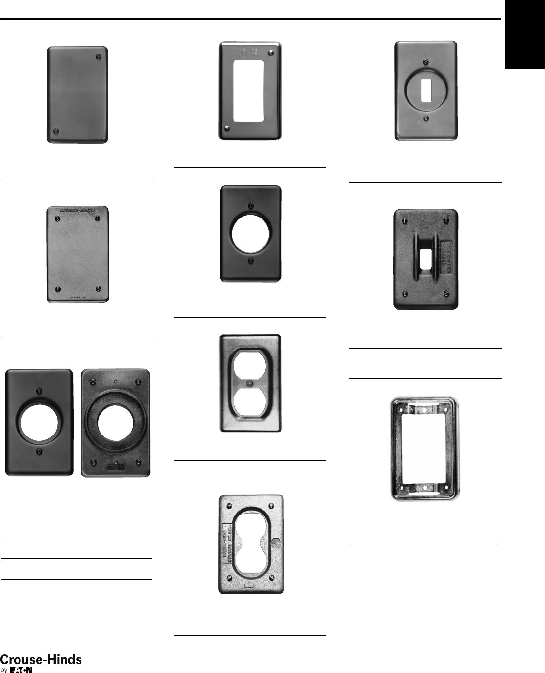
2F
39
www.crouse-hinds.com US: 1-866-764-5454 CAN: 1-800-265-0502 Copyright©2013 Eaton’s Crouse-Hinds Business
2F
Covers for Cast Iron or Aluminum Device Boxes
Single Gang
Blank cover for enclosing splices and
taps where device not used.
Description Material Cat. #
Surface Sheet aluminum DS100
Flush Sheet steel DSS100
Blank cover with gasket for enclosing
splices and taps where device not used.
Description Material Cat. #
Surface or
Flush Cast aluminum DS100G
DS21 DS21G
For standard and 3-pole, 2-wire
grounding type round flush
receptacles. Opening diameter 17/16".
Description Material Cat. #
Surface Sheet steel DS21
Surface Sheet
aluminum DS21 SA
Surface
or flush
Feraloy®
iron alloy
with gasket
DS21G
For GFI receptacles.
Description Material Cat. #
Surface Sheet steel DS23 GFI
For flush plug receptacle requiring 15/8"
opening diameter.
Description Material Cat. #
Surface Sheet steel DS35
For duplex convenience receptacles.
Description Material Cat. #
Surface Sheet steel DS23
Surface Sheet aluminum DS23 SA
Flush Sheet steel DSS23
For standard and 3-pole, 2-wire
grounding type duplex convenience
receptacles. Gasket included.
Description Material Cat. #
Surface
or flush
Feraloy®
iron alloy DS23G
For square handle general use snap or
toggle switches – unguarded.
Description Material Cat. #
Surface Sheet steel DS32
Surface Sheet aluminum DS32 SA
For square handle general use snap or
toggle switches – guarded.
Description Material Cat. #
Surface
or flush
Feraloy®
iron alloy
with gasket
DS32G
Surface Sheet steel DS52
Adapter plate for mounting WLRS/
WLRD covers to flush device boxes.
Description Cat. #
Flush Device Adapter WLRA1
Also can be used to mount all covers with
four corner screws listed see pages
37, 39, 40, 41, 42 and 43 to flush device
boxes.
See page 42 for receptacle specifications and listings of
complete receptacle/cover combinations.
†Must be used with a wet locations rated wiring device.
Ordering Information
38-39.qxp 12/23/2013 2:37 PM Page 39
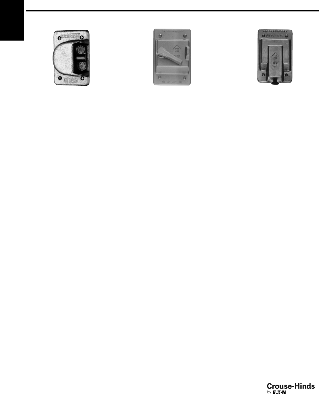
2F
40
www.crouse-hinds.com US: 1-866-764-5454 CAN: 1-800-265-0502 Copyright©2013 Eaton’s Crouse-Hinds Business
2F Covers for Cast Iron or Aluminum Device Boxes
Single Gang - Raintight Covers (Gasket Included)
For general use snap switches.
Includes gasket.
Description Material Cat. #
For standard
ON-OFF
operation
Copper-free
aluminum DS181
For general use snap switches.
Includes gasket.
Description Material Cat. #
For standard
ON-OFF
operation.
With hole for
lock
Die cast
aluminum DS185
For general use snap switches.
Includes gasket.
Description Material Cat. #
For standard
operation.
Marked
ON-OFF
handle
Cast
aluminum DS128
Ordering Information
40-41.qxp 12/16/2013 12:04 PM Page 40
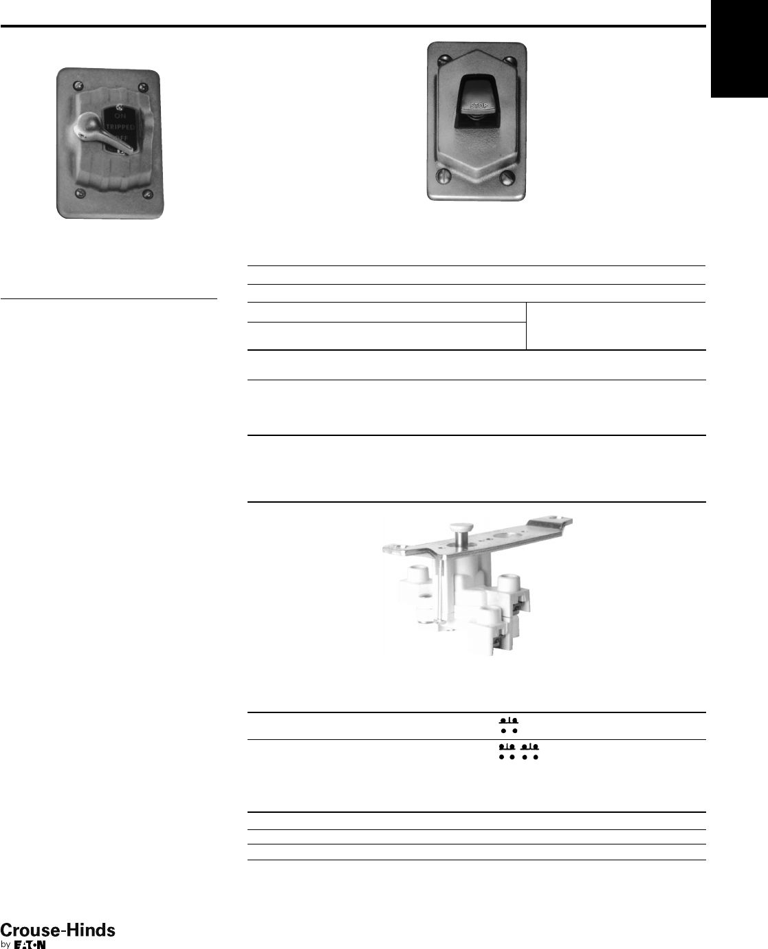
2F
41
www.crouse-hinds.com US: 1-866-764-5454 CAN: 1-800-265-0502 Copyright©2013 Eaton’s Crouse-Hinds Business
Covers for Cast Iron or Aluminum Device Boxes
Single Gang - Switches and Motor Control Push Button
Raintight
For manual motor starting switches.
Fits FS and FD boxes. Takes
Westinghouse switches MST01 (1-pole)
and MST02 (2-pole). Includes gasket.
Description Material Cat. #
For standard
ON-OFF operation
Feraloy
iron alloy DS199
Furnished with buttons for operating motor control push button switches.
Includes gasket.
Push Buttons
Description No. Color Material Cat. #
Button (normally open) marked START 1 Green Feraloy iron alloy DS171F ➀
Button (normally closed) marked STOP 1 Red Feraloy iron alloy DS171G ➀
Button (normally open) marked 1 Green
Feraloy iron alloy DS171 ➀
START and button (normally closed)
marked STOP
1 Red
Description No. Color Material Cat. #
Two push button 2 Black Feraloy iron alloy DS171J ➀
➀ If desired, markings on indicating plates may be added to catalog number. Select from the list of
standard markings below:
HAND CLOSE OFF AUTO. UP RUN
EMER. DOWN JOG FORWARD START RESET
REVERSE STOP TRIP OPEN ON TEST
LGT. ON
Heavy duty motor control push button switch
No. of
Buttons Normal Positions Cat. #
1 1 circuit universal ED11
2 2 circuits universal ED12†
†Two universal contact blocks, must be wired as two circuits, with one normally open and one normally closed.
DS Covers use the switches shown in the list below.
Cover Takes Switch Cover Takes Switch
DS171 ED12 DS171F ED11
DS171G ED11 DS266 ED12
DS265 ED11
2F
Ordering Information
40-41.qxp 12/16/2013 12:04 PM Page 41
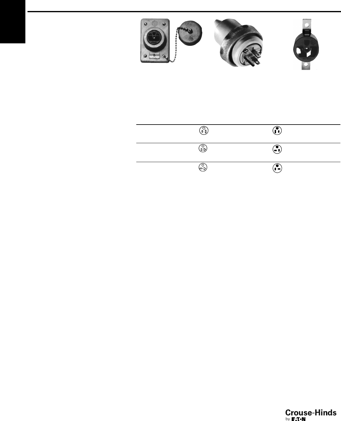
2F
42
www.crouse-hinds.com US: 1-866-764-5454 CAN: 1-800-265-0502 Copyright©2013 Eaton’s Crouse-Hinds Business
2F Covers for Cast Iron or Aluminum Device Boxes
Single Gang - DS Receptacles and WP Plugs
Weatherproof
Applications:
WP plugs and DS receptacles are used:
• Wherever dust, dirt, moisture and
corrosion are a problem
• Outdoors or in locations where frequent
washdowns occur, as in dairies and
food processing plants
Features:
DS receptacle housings are used:
• With FS and FD cast device boxes,
either surface mounted or installed flush
in a wall
• With single gang, two gang tandem and
multiple gang boxes having individual
cover openings
• A threaded cap which effectively seals
housing when not in use
WP plugs include:
• A molded Neoprene hood with integral
sleeve to seal the cord entrance
• An aluminum ring which clamps the
hood to receptacle housing face, to
complete watertight seal when plug is in
use
Standard Materials:
• Receptacle housings: body – Feraloy®
iron alloy; cap – copper-free aluminum
• Plug exteriors: hood – Neoprene;
fastening ring – copper-free aluminum
Standard Finishes:
•Feraloy iron alloy – electrogalvanized
and aluminum acrylic paint
• Copper-free aluminum – natural
• Neoprene – natural (black or yellow)
Electrical Rating Ranges:
• 15 amperes, 125 volts
• 20 amperes, 125, 250 volts
Certifications and
Compliances:
• UL Standards: 498; 514A
• NEMA/EEMAC: WD-1; WD-5
• CSA Standard: C22.2 No. 42*
*Compliance.
DS Receptacle
housings
WP Plugs CC Replacement
receptacle
Grounding Type Receptacles
For Plugs with U shaped or Round Grounding Contacts
Rating
Cover With
Recept.
Cat. # Diagram Style
Plug
Cat. # Diagram Cord Dia.
Repl.
Recept.
Cat. #
15 amps
125 volts DS96* 2-wire,
3-pole† WP820 .500 to
.625 CC55
NEMA: 5-15R NEMA: 5-15P
20 amps
125 volts DS222 2-wire,
3-pole† WP832 .500 to
.625 CC71
NEMA: 5-20R NEMA: 5-20P
20 amps
250 volts DS290 2-wire,
3-pole† WP930 .500 to
.625 CC90
NEMA: 6-20R NEMA: 6-20P
†Third pole grounded.
*Compliance
For listing of typical FS cast devices boxes, see pages 23 and 24.
42-43.qxp 12/16/2013 12:04 PM Page 42
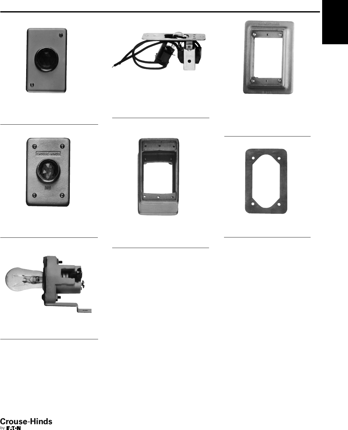
2F
43
www.crouse-hinds.com US: 1-866-764-5454 CAN: 1-800-265-0502 Copyright©2013 Eaton’s Crouse-Hinds Business
Covers for Cast Iron or Aluminum Device Boxes
Single Gang - Pilot Light Covers, Extensions and Adapters
For pilot light units
(furnished with jewels)
Description Material
Jewel
Color Cat. #
Surface Sheet steel Red DS24
For pilot light units
(furnished with jewel and gasket).
Description Material
Jewel
Color Cat. #
Surface or
flush
Feraloy
iron alloy Red DS24G
Pilot light unit (without transformer)
Circuit
Voltage
Lamp
Base Watts Cat. #
110 Candelabra 6 C3310
Pilot light (with transformer)†, FD only
Circuit
Voltage
Lamp
Base Watts Cat. #
440 Candelabra 6 C333
†Transformer 50–60 cycle, 440 / 110 volts.
EXF Extensions (takes covers and flush
rectangular wiring devices, or plug
receptacles with housings)
Ext. Depth Cat. #
1" EXF11
21/2"EXF21
FS flush mounting adapter (can be
used with multi-gang bodies
having individual cover openings.
Furnished with gasket and screws)
Mtg. Style Cat. #
Wall FS031
Gaskets for use between device
boxes and covers.
Material Cat. #
Neoprene GASK91‡
‡Not recommended as watertight.
2F
Ordering Information
42-43.qxp 12/16/2013 12:05 PM Page 43
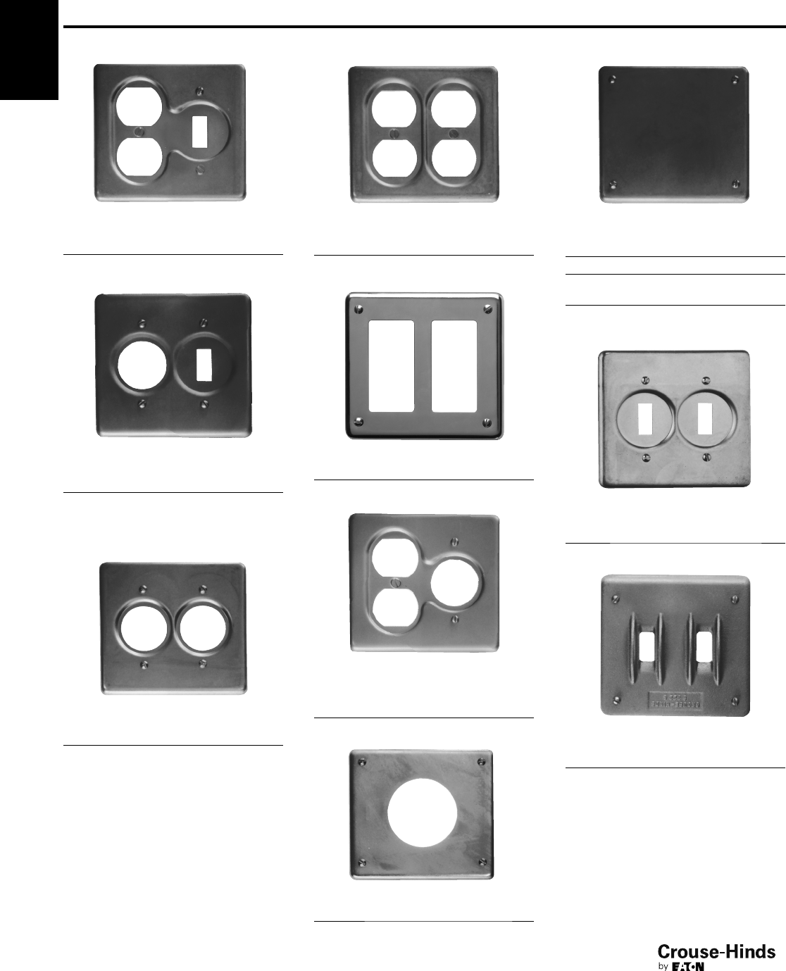
2F
44
www.crouse-hinds.com US: 1-866-764-5454 CAN: 1-800-265-0502 Copyright©2013 Eaton’s Crouse-Hinds Business
2F Covers for Cast Iron or Aluminum Device Boxes
Two Gang
For flush general use snap
switches with square handles
Material Cat. #
Sheet steel S32232
For flush general use snap switches
with square handles
Description Material Cat. #
For round plug
flush receptacles.
Surface
Sheet steel S32212
For standard and 2-wire,
3-pole grounding
Description Material Cat. #
For round plug
flush receptacles.
Surface
Sheet steel S212
For duplex convenience receptacles,
standard and 2-wire, 3-pole grounding
Description Material Cat. #
Surface Sheet steel S232
For GFI receptacles
Description Material Cat. #
Surface Sheet steel S232 GFI
For round flush receptacles, duplex
convenience receptacles, standard
and 2-wire, 3-pole grounding
Description Material Cat. #
Surface Sheet steel S21232
For 20 amp., 250 volt receptacles
Description Material Cat. #
2-pole, Surface Sheet steel S612
Blank. Feraloy®iron alloy with gasket
Description Material Cat. #
Surface Sheet steel S1002
Surface or
flush
Feraloy
iron alloy
S1002G
Surface or
flush
Copper-free
aluminum
S1002G SA
For flush general use snap switches
with square handles
Description Material Cat. #
Surface Sheet steel S322
For flush general use snap
switches with square handles
Description Material Cat. #
Surface or
flush
Feraloy
iron alloy
S322G
Ordering Information
44-45.qxp 12/16/2013 12:05 PM Page 44
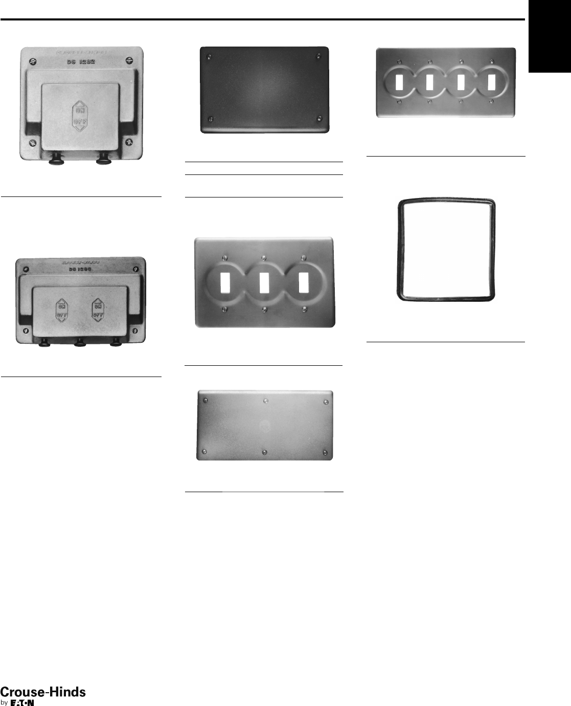
2F
45
www.crouse-hinds.com US: 1-866-764-5454 CAN: 1-800-265-0502 Copyright©2013 Eaton’s Crouse-Hinds Business
Covers for Cast Iron or Aluminum Device Boxes
Two Gang
2F
With operating mechanism and gasket
Description Material Cat. #
Two gang. For
operation of
general use snap
switches. Surface
or flush
Feraloy®
iron alloy DS1282
With operating mechanism and gasket
Description Material Cat. #
Three gang with
gasket. For
external operation
of general use
snap switches.
Surface or flush.
Feraloy
iron alloy DS1283
Blank with gasket
Description Material Cat. #
Surface Sheet steel S1003
Surface or
flush
Feraloy
iron alloy
S1003G
Surface or
flush
Copper-free
aluminum
S1003G SA
*Includes gasket
For flush general use snap switches
with square handles
Description Material Cat. #
Surface, three gang Sheet steel S323
Blank with gasket
Description Material Cat. #
Surface or flush Feraloy
iron alloy S1004G
For flush general use snap switches
with square handles
Description Material Cat. #
Surface, four gang† Sheet steel S324
†For FS094 and FD094 boxes.
Gasket for use between
device box and cover
Description Material Cat. #
Two gang Rubber GASK434
Three gang Rubber GASK460
Four gang Rubber GASK461
Ordering Information
44-45.qxp 12/16/2013 12:05 PM Page 45
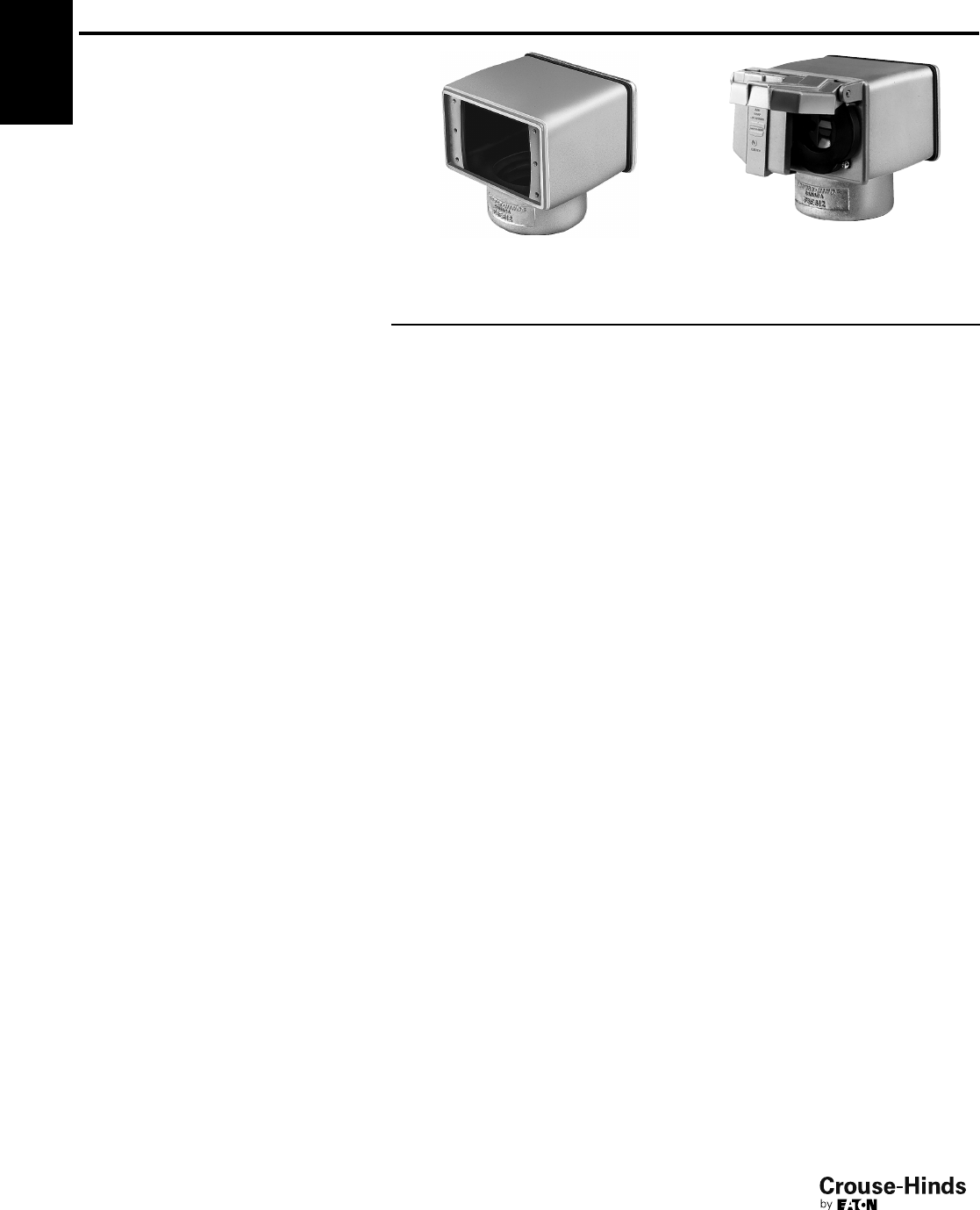
2F
46
www.crouse-hinds.com US: 1-866-764-5454 CAN: 1-800-265-0502 Copyright©2013 Eaton’s Crouse-Hinds Business
2F FSE Receptacle and Breaker Assemblies
Applications:
• FSE series assemblies are used in
outdoor areas for supplying power in
remote locations, particularly parking
lots, automobile engine block heaters,
marinas, drive-in theaters, trailer
camps, etc.
Features:
• Compact design.
• Suitable for a variety of combinations.
• U ground duplex receptacle.
• Circuit breaker protection.
• Breakers cannot be manually tripped.
Size:
• 2" integral hub for pole mounting.
Standard Materials:
• Body and cover – copper-free aluminum
Standard Finishes:
• Copper-free aluminum – natural
Electrical Ratings:
• 15A 120V
Certifications and
Compliances:
• CSA Standard C22.2 No. 18
FSE 6121 FSE 612
Cat. # Description
FSE612 Double face receptacle body only
FSE6121 Fitting complete with 1-15 amp. duplex receptacle and blank cover.
FSE6122 Fitting complete with 2-15 amp. duplex receptacles.
FSE61212 Fitting complete with 1-15 amp. duplex receptacle and two 1- pole Minibreakers
FSE61211 Fitting complete with 1-15 amp. duplex receptacle and one 1- pole Minibreaker.
Other combinations available on request
Ordering Information
46-47.qxp 12/23/2013 2:37 PM Page 46

3F
47
www.crouse-hinds.com US: 1-866-764-5454 CAN: 1-800-265-0502 Copyright©2013 Eaton’s Crouse-Hinds Business
3F
Condulet®Conduit Bodies and Outlet Boxes
Hazardous
Description Page No.
Application/Selection see page 48
Lubricants
HTL see page 63
STL see page 63
Conduit Bodies & Outlet Boxes
Cylindrical
EKC see page 60
90° Elbow
FE see page 62
LBH see page 61
LBY see page 61
Rectangular
OE see page 59
Round
C30 and C31 for IEC Applications see page 57
CPS see page 58
GUA see pages 50–51
EAB see page 54
EAB ATEX see page 55
EAJ see page 56
GUR Universal see page 53
Tees
Short Radius
ET see page 61
FT see page 62
46-47.qxp 12/23/2013 2:37 PM Page 47
3F
48
www.crouse-hinds.com US: 1-866-764-5454 CAN: 1-800-265-0502 Copyright©2013 Eaton’s Crouse-Hinds Business
3F Condulet®Conduit Bodies and
Outlet Boxes
Application and Selection
Applications:
Hazardous area conduit bodies and outlet boxes are installed in rigid
conduit systems in Class I and II hazardous locations to:
• Protect conductors
• Act as pull and splice boxes
• Connect lengths of conduit
• Change conduit direction
• Provide access to conductors for maintenance and future system
changes
• Act as mounting outlets for fixtures (with appropriate covers)
• Act as sealing fittings (with appropriate covers)
Considerations for Selection:
• Determine the area classification per National Electrical Code
Hazardous Area Groups. Based on this classification, select the
product families that are acceptable for use in the particular
location.:
• Establish functional physical requirements these will help to
determine box size, cover, shape and mounting for the particular
installation.
• Each product family has features suitable for specific functions:
• i.e., boxes used as mountings for lighting fixtures are generally of
a small size, and provided with mounting lugs when required to
support lighting fixtures.
• Boxes used for wire pulling should generally be larger to provide
room for easy pulling.
• Boxes used to splice and/or tap conductors should be large
enough to permit ease of work and sufficient room for the required
size and number of conductors.
• Hub size and configuration – dependent on the conduit system
configuration and the conduit size used.
• Material and finish – determine from environmental conditions
(corrosive fumes, weather, buried in concrete, etc.)
Options and Accessories:
• Flat blank covers (surface and flanged flush), fixture support and
sealing covers and extensions are available. See specific product
listing for details.
• Lubricant (STL and HTL) are available to make joints raintight,
provide for easy cover removal and to lubricate shafts over a wide
temperature range.
•Corro-free™ epoxy powder coat – information available on
request.
Quick Selector Chart
Series
NEC
Class I & II
Groups
IEC
Certifications
Normal
Function
Cover
Opening
Diameter
Hub
Size†
Cover
Type
GUA C, D E, F, G Mtg. ltg. fixt., taps, pulling,
splicing
2–5 1/2-2 Threaded
EAJ A, B, C, D E, F, G Pulling, splicing, taps 33/16 & 5 1/2-2 Threaded
C30 / C31 Ex II 2 G EEx d IIC T6
Ex II 2 D IP66 T 85ºC
Pulling, splicing, taps 98mm (C30)
130mm (C31)
1/2-1 Threaded
EAB A, B, C, D E, F, G Pulling, splicing, taps 3 1/2-1 Threaded
EAB ATEX A, B, C, D E, F, G II 2 G EEx d IIC T5
PTB 05 ATEX 1052
Pulling, splicing, taps 33/41/2-1 Threaded
CPS C, D E, F, G Fixt. support, pulling,
splicing
31/21/2& 3/4Ground joint
OE C, D E, F, G Pulling 1/2-1 Ground joint
ET C, D E, F, G Stub up 1/2-1
FT Flameproof, Exd, IIB,
IP67, Zone 1
Combustible Dust Zone
21 & 22
Stub up 20mm -
25mm
Threaded
LBY C, D E, F, G Pulling 1/2– 11/4Threaded
LBH B, C, D E, F, G Pulling 1/2-4 Ground joint
FE Flameproof, Exd, IIB,
IP67, Zone 1
Combustible Dust Zone
21 & 22
Pulling 20mm -
25mm
Threaded
EKC C, D E, F, G Pulling 1/2-3 Ground joint
GUR C, D E, F, G Pulling, splicing 1/2-1 Threaded
†See following table for standard hub configuration.
48-49.qxp 12/23/2013 2:38 PM Page 48
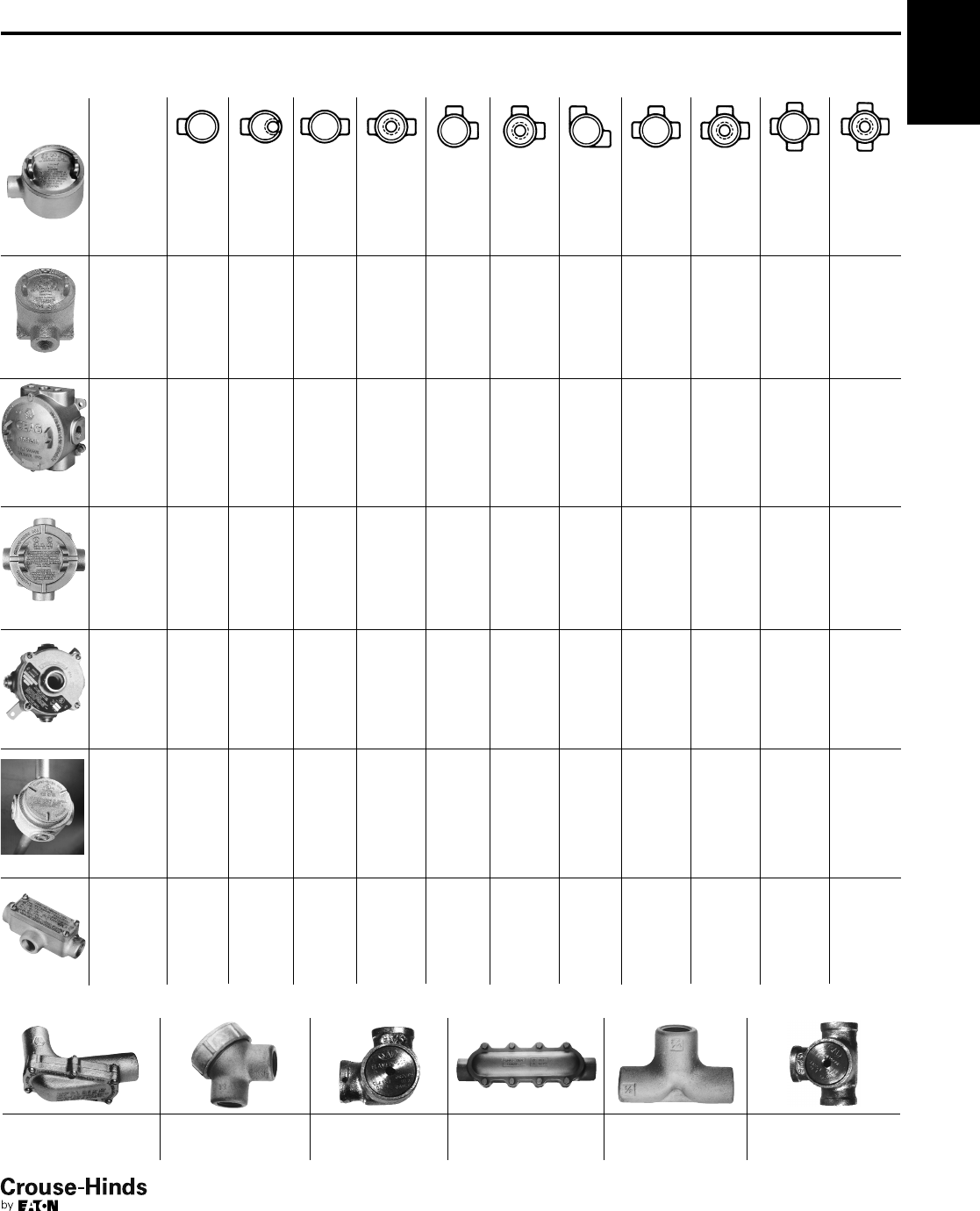
3F
49
www.crouse-hinds.com US: 1-866-764-5454 CAN: 1-800-265-0502 Copyright©2013 Eaton’s Crouse-Hinds Business
Condulet®Conduit Bodies and
Outlet Boxes
Standard Shape and Hub Selector
Shape Hub Style
Series Page
GUA GUAB GUAC GUAD GUAL GUAM GUAN GUAT GUAW GUAX
GUA
see pages
50–52
EABC EABL EABT EABX EABY
EAB
see
page 54
C30 /
C31
C30 /
C31
C30 / C31
see
page 57
EAJB EAJC EAJD EAJL EAJT EAJX
EAJ
see
page 56
CPS
see
page 58 CPS
GUR
GUR
see
page 53
OELB OEC OELL OELR OET
OE
see
page 59
The fittings below are available only in the configurations shown.
LBH see page 61 LBY see page 61 see page 62FE EKC see page 60 ET see page 61 see page 62
FT
3F
48-49.qxp 12/23/2013 2:38 PM Page 49
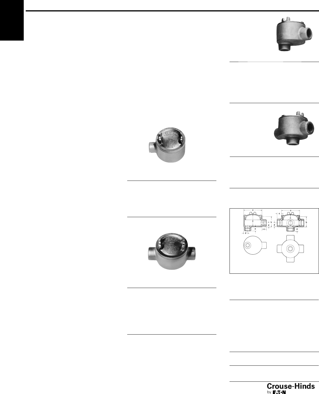
3F
50
www.crouse-hinds.com US: 1-866-764-5454 CAN: 1-800-265-0502 Copyright©2013 Eaton’s Crouse-Hinds Business
Condulet®Conduit Outlet
Boxes With Covers
GUA Series
Cl. I, Div. 1 & 2, Groups C, D
Cl. II, Div. 1, Groups E, F, G
Cl. II, Div. 2, Groups F, G
Cl. III
NEMA 3, 4, 7CD, 9EFG
Explosionproof
Dust-Ignitionproof
Raintight
Wet Locations
Applications:
GUA series conduit outlet boxes are
installed within hazardous area conduit
systems to:
• Protect conductors in threaded
rigid conduit
• Act as pull and splice boxes
• Connect lengths of conduit
• Change conduit direction
• Provide access to conductors for
maintenance and future system changes
• Act as mounting outlets for fixtures
(with appropriate covers)
• Act as sealing fittings (with appropriate
covers)
Features:
GUA conduit boxes have:
• Neoprene "O" ring standard to meet
NEMA 4 requirements
• Cast ears on cover to permit easy
removal and tightening
• Four standard mounting pads except for
boxes with bottom hubs
• Threaded cover openings
• Ten different hub arrangements
• Taper threaded hubs to provide
grounding continuity
• Smooth integral hub bushing protects
conductor insulation when pulling
• Surface covers furnished with boxes
• Sealing covers, dome covers, and fixture
hanger covers are available
• Cover threads are 12 pitch
Standard Materials:
• Bodies – Feraloy iron alloy
• Covers – Copper-free aluminum
Standard Finishes:
•Feraloy iron alloy – electrogalvanized and
aluminum acrylic paint
• Aluminum – natural
Size Ranges:
• Hub – 1/2" to 2"
• Cover opening – 2" to 5" dia.
Options:
Description Suffix
Bodies – copper-free aluminum SA†*
Covers – Feraloy iron alloy –
electrogalvanized and aluminum
acrylic paint WOD
GUA Form 6 (with 3" cover opening)
are available with optional cover
with viewing window. VW
Corro-free epoxy powder coat S752
To order box less cover add "0" to end of
catalog number ie.GUAT260.
Certifications and
Compliances:
• NEC/CEC:
Class I, Division 1 & 2, Groups C, D
Class II, Division 1, Groups E, F, G
Class II, Division 2, Groups F, G
Class III
• UL Standard: 1203
• ANSI Standard: C33.27
• CSA Standard: C22.2 No. 30
• NEMA/EEMAC 3, 4
When assembled with sealing type cover, GUA series
outlet boxes provide adequate sealing for 40% fill in
hazardous areas – Class I, Groups C, D; Class II, Groups
E, F, G; and Class III. Seals can be made in either
horizontal or vertical positions. Use Chico®"A" sealing
compound or Chico®SpeedSeal only. Conductor splices
or connections must not be made in enclosures where
sealing compound is to be used per NEC.
GUA
Hub
Size
Cover
Opening
Dia. Cat. #
1/22GUA14
3/42GUA24
1/23GUA16
3/43GUA26*
13 GUA36
11/435/8GUA47
11/25GUA59
GUAC
Hub
Size
Cover
Opening
Dia. Cat. #
1/22GUAC14†
3/42GUAC24†
1/23GUAC16*
3/43GUAC26*
13 GUAC36*
11/435/8GUAC47†
11/45GUAC49
11/25GUAC59†
25 GUAC69†
GUAB
Hub
Size
Cover
Opening
Dia. Cat. #
1/22GUAB14†
3/42GUAB24
1/23GUAB16*
3/43GUAB26*
13 GUAB36*
11/435/8GUAB47†
11/25GUAB59†
25 GUAB69†
Dimensions
In Inches:
Length of Hub
Hub Size
Dimension "e"
Length
1/2- 3/47/8
1 – 11/41
11/2– 2 11/16
GUA, GUAD, GUAM,
GUAW, GUAX
Cat. # a b c d
14 21/2113/16 13/45/8
24 21/222
3/4
16 31/221
7/85/8
26 31/221
7/83/4
36 31/225/16 23/16 7/8
37 41/425/16 23/87/8
47 41/4211/16 23/413/32
49 53/4313/16 33/413/32
59 53/4313/16 33/419/32
69 53/441/16 41
9/16
GUAD
Hub
Size
Cover
Opening
Dia. Cat. #
1/22GUAD14†
3/42GUAD24
1/23GUAD16
3/43GUAD26†
13 GUAD36†
11/45GUAD49
†Available in copper-free aluminum, add suffix -SA.
*Available in copper-free aluminum, add suffix -SA. GUA
outlet boxes marked with * when ordered with suffix -SA
are listed for Class I, Division 1 & 2, Groups B, C and D,
Class II, Division 1, Groups E, F, G and Class III.
Covers have 16 pitch threads. Replacement cover
is a GUA06-GB.
3F
GUAB Only All others
50-51.qxp 12/16/2013 12:06 PM Page 50
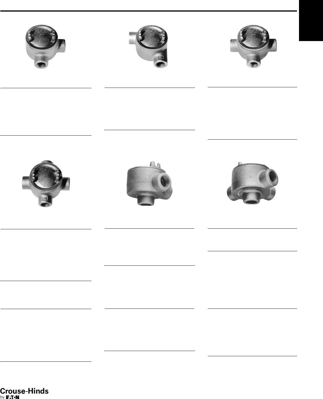
3F
51
www.crouse-hinds.com US: 1-866-764-5454 CAN: 1-800-265-0502 Copyright©2013 Eaton’s Crouse-Hinds Business
GUAL
Hub
Size
Cover
Opening
Dia. Cat. #
1/22GUAL14†
3/42GUAL24†
1/23GUAL16*
3/43GUAL26*†
13 GUAL36*
11/435/8GUAL47†
11/45GUAL49†
11/25GUAL59†
25 GUAL69†
GUAN
Hub
Size
Cover
Opening
Dia. Cat. #
1/22GUAN14
3/42GUAN24
1/23GUAN16
3/43GUAN26
13 GUAN36†
11/435/8GUAN47
11/25GUAN59†
25 GUAN69
GUAT
Hub
Size
Cover
Opening
Dia. Cat. #
1/22GUAT14†
3/42GUAT24†
1/23GUAT16*
3/43GUAT26*
13 GUAT36*
13
5/8GUAT37
11/435/8GUAT47†
11/45GUAT49†
11/25GUAT59†
25 GUAT69†
GUAX
Hub
Size
Cover
Opening
Dia. Cat. #
1/22GUAX14†
3/42GUAX24†
1/23GUAX16*
3/43GUAX26*
13 GUAX36*
13
5/8GUAX37†
11/435/8GUAX47†
11/45GUAX49
11/25GUAX59†
25 GUAX69†
GUAM
Hub
Size
Cover
Opening
Dia. Cat. #
1/22GUAM14†
3/42GUAM24
1/23GUAM16
3/43GUAM26
13 GUAM36
11/435/8GUAM47
25 GUAM69
GUAW
Hub
Size
Cover
Opening
Dia. Cat. #
1/22GUAW14†
3/42GUAW24†
1/23GUAW16
3/43GUAW26*†
Dimensions
GUAC, GUAT
Cat. # a b c d
14 21/221/423/16 5/8
24 21/222
3/4
16 31/221
7/85/8
26 31/221
7/83/4
36 31/225/16 23/16 7/8
37 41/425/16 23/87/8
47 41/4211/16 23/413/32
49 53/4313/16 33/415/32
59 53/4313/16 33/419/32
69 53/441/16 41
9/16
GUAN
Cat. # a b c d
14 21/221/821/16 5/8
24 21/225/16 21/43/4
16 31/221
7/83/4
26 31/221
7/83/4
36 31/225/16 23/87/8
47 41/4211/16 23/413/32
59 53/441/16 41
9/32
69 53/441/16 41
9/16
GUAB, GUAL
Cat. # a b c d
14 21/221/423/16 5/8
24 21/221/227/16 3/4
16 31/221
7/85/8
26 31/221
7/83/4
36 31/225/16 23/16 7/8
47 41/4211/16 23/413/32
49 53/4313/16 33/415/32
59 53/4313/16 33/419/32
69 53/441/16 41
9/16
†Available in copper-free aluminum, add suffix -SA.
*Available in copper-free aluminum, add suffix -SA. GUA outlet boxes marked with * when ordered with suffix -SA are listed for Class I, Division 1 & 2, Groups B, C and D, Class II,
Division 1, Groups E, F, G and Class III. Covers have 16 pitch threads. Replacement cover is a GUA06-GB.
Condulet®Conduit Outlet
Boxes With Covers
GUA Series
Cl. I, Div. 1 & 2, Groups C, D
Cl. II, Div. 1, Groups E, F, G
Cl. II, Div. 2, Groups F, G
Cl. III
NEMA 3, 4, 7CD, 9EFG
Explosionproof
Dust-Ignitionproof
Raintight
Wet Locations
3F
50-51.qxp 12/16/2013 12:06 PM Page 51
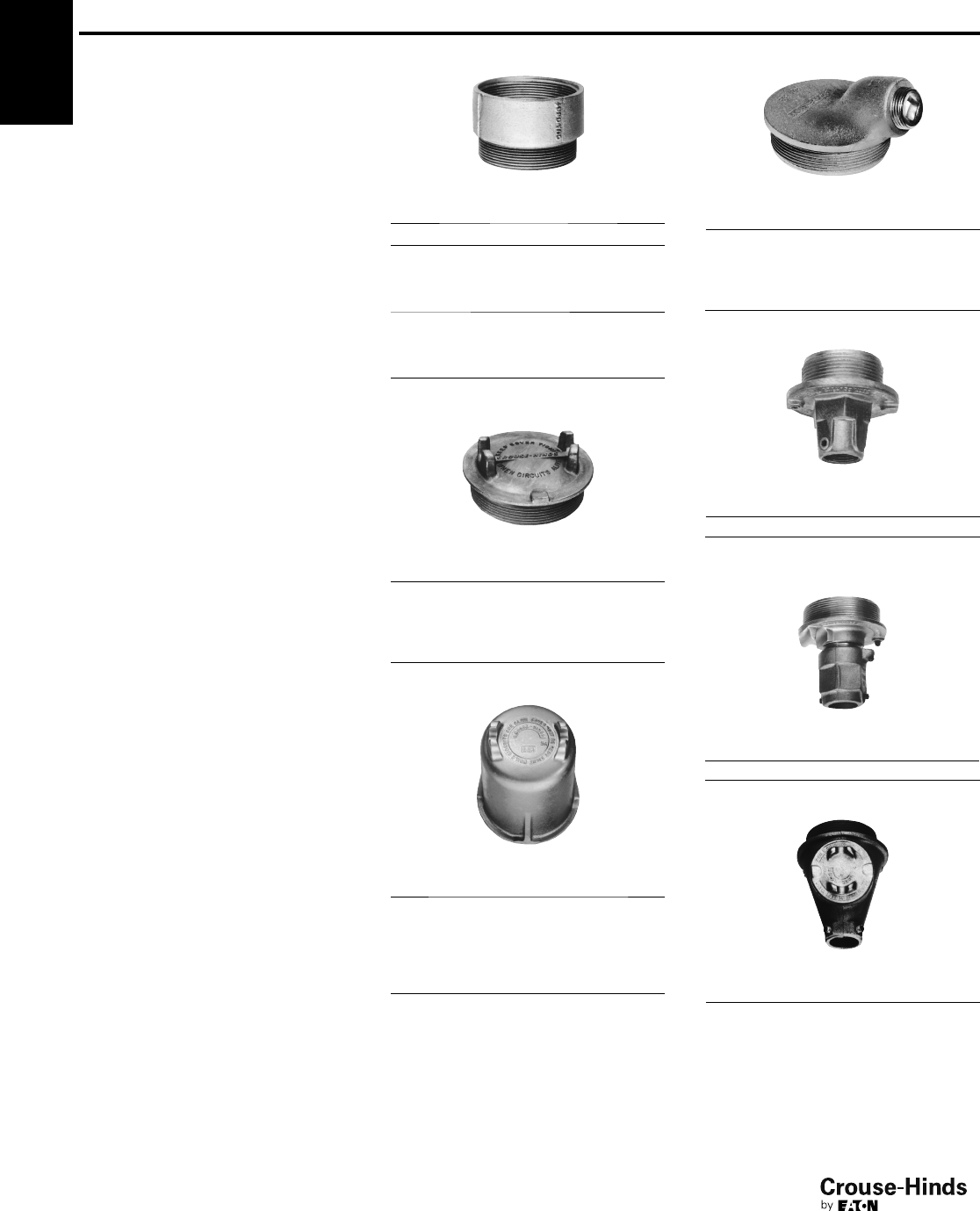
52
www.crouse-hinds.com US: 1-866-764-5454 CAN: 1-800-265-0502 Copyright©2013 Eaton’s Crouse-Hinds Business
3F
Covers and Accessories
For GUA Condulet®Conduit Outlet Boxes
Applications:
Threaded covers, canopies and extensions
are used:
• To provide a seal in hazardous areas
(sealing cover). See note below.
• To mount pendant lighting fixtures such
as EVA listed in lighting section (fixture
canopy)
• To mount EVA pendant lighting fixtures
on cover which is then screwed into
outlet box without twisting conductors
(union hub cover)
• To mount pendant lighting fixtures on
cover which is then screwed into outlet
box as above, for wiring after fixture
stem is installed (nipple cover)
• To provide means of increasing outlet
box depth (threaded extension)
Features:
• Surface covers are supplied with GUA
boxes
• Sealing cover has removable plug for
filling enclosure with sealing compound
after installation. Sealing cover meets
40% fill requirement of the NEC®. See
note below.
• Fixture canopy has a threaded cover in
its side to provide access for making
splices or taps. Fixture with its conduit
stem and canopy can be assembled and
wired before installation and conductors
can be spliced in canopy after it has
been screwed into the body
• Cover threads are 12 pitch.
Standard Materials:
• Surface and dome covers, union hub
covers, nipple covers – copper-free
aluminum
• Sealing covers, fixture canopies,
threaded extensions – Feraloy®
iron alloy
Standard Finishes:
• Aluminum – natural
•Feraloy iron alloy – electrogalvanized
and aluminum acrylic paint
Options:
Description Suffix
Corro-free™epoxy powder coat S752
To order an iron surface cover WOD
Size Ranges:
• Fixture stems – 3/4"
• Body openings – 2" to 5"
Note: Depth of sealing compound in body must satisfy
requirements of NEC section 501-5 (C-3). Splices and
taps in sealing fittings are prohibited by NEC.
GUA Threaded Extension
Cover
Opening
Dia.
Ext.
Depth Cat. #
31
1/4GUA0631
GUA
Cover
Opening
Replacement O-Ring
Gasket Cat. #
2" GASK1713
3" GASK1151
35/8"GASK1589
5" GASK925
Surface Cover
Cover
Opening
Dia.
Thread
Pitch Cat. #
212GUA04
312GUA06
316GUA06 GB*
35/812 GUA07
512GUA09
Dome Cover
Cover
Opening
Dia.
Ext.
Depth
Thread
Pitch Cat. #
2212GUA047
3212GUA067
35/8212 GUA077
35/8412 GUA0716
5412GUA514
51012GUA5110
Sealing Cover
Cover
Opening
Dia.
Thread
Pitch Cat. #
212GUA041
312GUA062
316GUA062 GB*
35/812 GUA072†
512GUA092
3F
Nipple Cover
Cover
Opening
Dia.
Fixt.
Stem
Size
Thread
Pitch Cat. #
33/412 GUA0672
Fixture Canopy
Cover
Opening
Dia.
Fixt.
Stem
Size
Thread
Pitch Cat. #
33/412 GUA068
†Also used with GUP bodies see page 753 or
GU and GUE bodies see page 722.
*GUA covers with 16 pitch threads are used with GUA
bodies ordered with -SA suffix identified with * symbol
see pages 50–51.
Fixture Cover
Union Hub Type
Cover
Opening
Dia.
Fixt.
Stem
Size
Thread
Pitch Cat. #
33/412 GUA0687
52-53.qxp 12/23/2013 2:38 PM Page 52
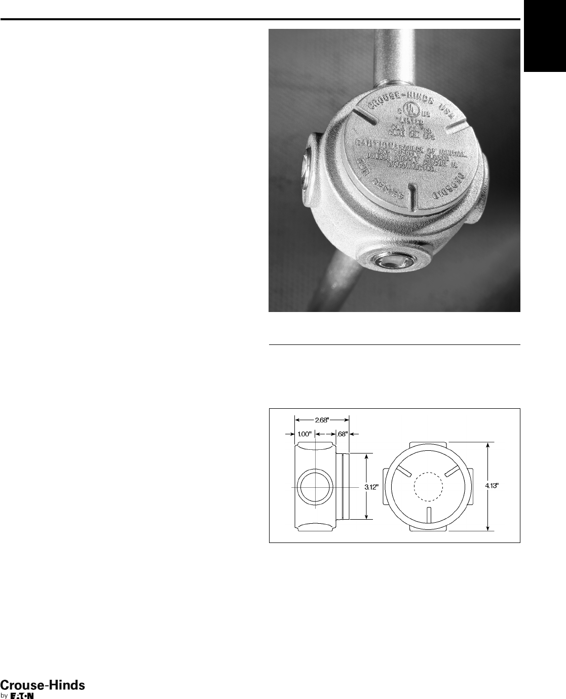
3F
53
www.crouse-hinds.com US: 1-866-764-5454 CAN: 1-800-265-0502 Copyright©2013 Eaton’s Crouse-Hinds Business
Condulet®Conduit Outlet
Boxes With Covers
GUR Series
Cl. I, Div. 1 & 2, Groups C, D
Cl. II, Div. 1, Groups E, F, G
Cl. II, Div. 2, Groups F, G
Cl. III
NEMA 4
Explosionproof
Dust-Ignitionproof
Raintight
Wet Locations
Applications:
GUR conduit outlet boxes are installed within hazardous areas:
• To protect conductors in threaded rigid conduit
• To act as pull and splice boxes
• To connect lengths of conduit
• To provide access to conductors for maintenance and future
system changes
• To change conduit direction
• Where space is limited, such as underneath gasoline pumps
Features:
GUR outlet boxes feature:
• Neoprene O-ring standard in cover to meet NEMA 4/UL Type 4
requirements
• Internal green ground screw
• Five standard hubs with three pipe plugs included
• Threaded cover opening
• Recesses in cover to assist in cover tightening and removal
• Smooth, integral hub bushing to protect conductor insulation
when pulling
• Compact design for confined spaces
• UL and cUL listing
• Optional all-aluminum construction
Standard Materials:
• Bodies – Feraloy®iron alloy
• Covers – copper-free aluminum
Standard Finishes:
•Feraloy iron alloy – electrogalvanized with aluminum acrylic paint
• Aluminum – natural
Certifications and Compliances:
• NEC/CEC
Class I, Division 1 and 2, Groups C and D
Class II, Division 1, Groups E, F and G
Class III
Zone 1 and 2
• UL Standard 1203
• cUL to CSA Standard C22.2 No. 30
• NEMA 4
Options:
Description Suffix
Bodies – copper-free aluminum SA
Dimensions
In Inches:
3F
Ordering Information:
Hub Size Cat. #
1/2"GUR1
3/4"GUR2
1" GUR3
52-53.qxp 12/23/2013 2:38 PM Page 53
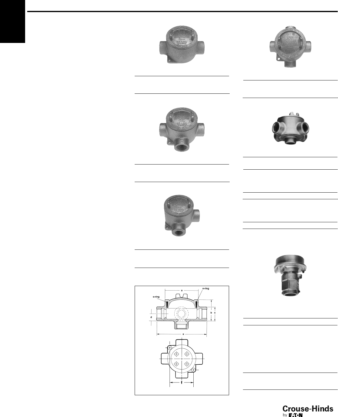
3F
54
www.crouse-hinds.com US: 1-866-764-5454 CAN: 1-800-265-0502 Copyright©2013 Eaton’s Crouse-Hinds Business
Condulet®Conduit Outlet
Boxes With Covers
EAB Series
Cl. I, Div. 1 & 2, Groups A, B, C, D
Cl. II, Div. 1, Groups E, F, G
Cl. II, Div. 2, Groups F, G
Cl. III
NEMA 3,4,7ABCD,9EFG
Explosionproof
Dust-Ignitionproof
Raintight
Wet Locations
Applications:
EAB series conduit outlet boxes are
installed in conduit systems within
hazardous areas to:
• Provide protection against exterior
explosion where acetylene, hydrogen
and other hazardous gases are present
• Protect conductors in threaded
rigid conduit
• Act as pull and splice boxes
• Interconnect lengths of conduit
• Change conduit direction
• Provide access to conductors for
maintenance and future system changes
Features:
EAB series conduit outlet boxes have:
• Five different hub configurations
• Taper threaded hubs to provide ground
continuity
• Smooth integral hub bushing to protect
conductor insulation when pulling
• Threaded cover openings
• Surface covers furnished with boxes
• Neoprene "o"-ring gasket and green
ground screw are both standard.
• Four standard mounting pads,
except for EABY.
• Cover threads are 16 pitch.
Standard Materials:
• Bodies – Feraloy®iron alloy
• Covers – Copper-free aluminum
Standard Finishes:
•Feraloy – electrogalvanized and
aluminum acrylic paint
• Aluminum – natural
Options:
Description Suffix
Bodies – copper-free aluminum SA†*
Covers – Feraloy iron alloy –
electrogalvanized and aluminum
acrylic paint WOD
Corro-free epoxy powder coat S752
Size Ranges:
• Hub – 1/2" to 1"
• Cover opening – 3" dia.
Certifications and
Compliances:
• NEC/CEC:
Class I, Division 1 & 2, Groups A, B, C, D
Class II, Division 1, Groups E, F, G
Class II, Division 2, Groups F, G
Class III
• UL Standard: 1203
• CSA Standard: C22.2 No. 30
EABC
Hub
Size Cat. #
1/2EABC16†
3/4EABC26
1EABC36†
EABT
Hub
Size Cat. #
1/2EABT16†
3/4EABT26†
1EABT36†
EABL
Hub
Size Cat. #
1/2EABL16†
3/4EABL26†
1EABL36†
3F
EABX
Hub
Size Cat. #
1/2EABX16†
3/4EABX26†
1EABX36†
EABY
Hub
Size Cat. #
1/2EABY16†
3/4EABY26†
Replacement Cover:
Size Cat. #
3" EAB06
Replacement O-Ring:
Description Cat. #
Replacement O-Ring GASK1151
Dimensions
In Inches:
EAB Series
EAB Series
Cat. # a b c d e f
16 33/4217/32 11/23
/455/16 33/32
26 33/4225/32 13/47/859/16 33/32
36 33/4225/32 13/47/859/16 33/32
†Available in copper-free aluminum, add suffix -SA.
*EAB0687 is listed for Group C & D only.
Fixture Cover
Union Hub Type
Cover
Opening
Dia.
Fixt.
Stem
Size Cat. #
3" 3/4EAB0687*
54-55.qxp 12/16/2013 12:06 PM Page 54
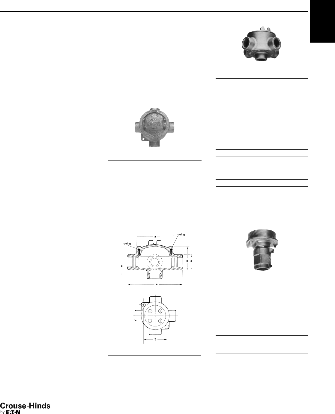
3F
55
www.crouse-hinds.com US: 1-866-764-5454 CAN: 1-800-265-0502 Copyright©2013 Eaton’s Crouse-Hinds Business
3F
Condulet®Conduit Outlet
Boxes With Covers
EAB Series with UL, cUL and
ATEX Certifications
Cl. I, Div. 1 & 2, Groups A, B, C, D
Cl. II, Div. 1 & 2, Groups E, F, G
II 2 G EEx d IIC T5
PTB 05 ATEX 1052
UL and cUL Listed
Explosionproof
Dust-Ignitionproof
Raintight
Wet Locations
Type 4 Enclosure / IP66
Applications:
EAB ATEX series conduit outlet boxes are
installed in conduit systems within
hazardous areas to:
• Provide protection against exterior
explosion where acetylene, hydrogen
and other hazardous gases are present
• Protect conductors in threaded
rigid conduit
• Act as pull and splice boxes
• Interconnect lengths of conduit
• Change conduit direction
• Provide access to conductors for
maintenance and future system changes
Features:
EAB ATEX series conduit outlet boxes
have:
• Two different hub configurations
• Taper threaded hubs to provide ground
continuity
• Smooth integral hub bushing to protect
conductor insulation when pulling
• Threaded cover openings
• Surface covers furnished with boxes
• Neoprene "o"-ring gasket and green
ground screw are both standard.
• Cover threads are 16 pitch.
Standard Materials:
• Bodies – Feraloy®iron alloy or copper-
free aluminum
• Covers – Copper-free aluminum
Standard Finishes:
•Feraloy – electrogalvanized and
aluminum acrylic paint
• Aluminum – natural
Options:
Description Suffix to be
added to Cat. #
Covers – Feraloy iron
alloy – electrogalvanized
and aluminum acrylic
paint WOD
Corro-free epoxy
powder coat S752
Size Ranges:
• Hub – 1/2" to 1"
• Cover opening – 3" dia.
EABX
Hub
Size Body Material Cat. # †
1/2Feraloy®Iron EABX16 ATEX
1/2Copper-free
Aluminum EABX16 SA ATEX
3/4Feraloy®Iron EABX26 ATEX
3/4Copper-free
Aluminum EABX26 SA ATEX
1 Feraloy®Iron EABX36 ATEX
1Copper-free
Aluminum EABX36 SA ATEX
EABY
Hub
Size Body Material Cat. # †
1/2Feraloy®Iron EABY16 ATEX
1/2Copper-free
Aluminum EABY16 SA ATEX
3/4Feraloy®Iron EABY26 ATEX
3/4Copper-free
Aluminum EABY26 SA ATEX
Replacement Cover:
Size Cat. #
3" EAB06
Replacement O-Ring:
Description Cat. #
Replacement O-Ring GASK1151
Dimensions
In Inches:
EAB Series
EAB Series
Cat. # a b c d e f
16 33/4217/32 11/23/455/16 33/32
26 33/4225/32 13/47/859/16 33/32
36 33/4225/32 13/47/859/16 33/32
†Available with 6-point Phoenix MBK type terminal block
mounted on DIN rail. Add suffix DIN16 before ATEX.
Ordering example: EABX26 DIN16 ATEX
*EAB0687 is listed for Group C & D only.
Certifications and
Compliances:
• NEC/CEC:
Class I, Division 1 & 2,
Groups A, B, C, D
Class II, Division 1 & 2, Groups E, F, G
Class III
II 2 G EEx d IIC T5
PTB 05 ATEX 1052
• UL Standard: 1203
• cUL Listed to CSA Standard:
C22.2 No. 30
• Type 4 Enclosure
• IP66
Fixture Cover
Union Hub Type
Cover
Opening
Dia.
Fixt.
Stem
Size Cat. #
3" 3/4EAB0687*
54-55.qxp 12/16/2013 12:06 PM Page 55
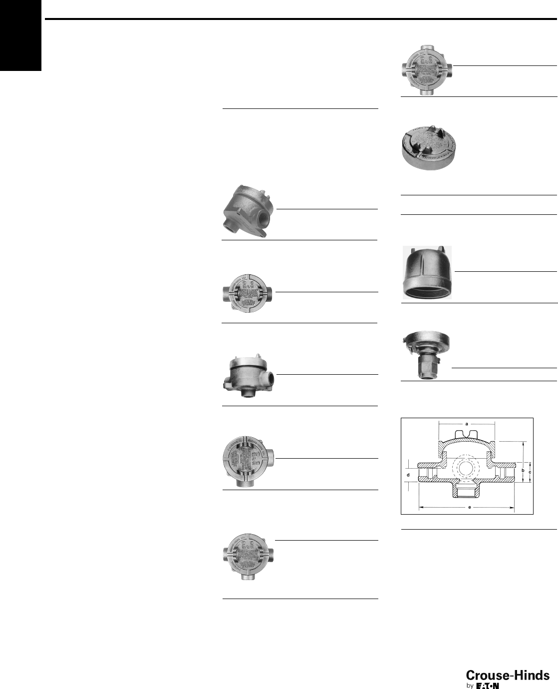
3F
56
www.crouse-hinds.com US: 1-866-764-5454 CAN: 1-800-265-0502 Copyright©2013 Eaton’s Crouse-Hinds Business
3F
Cl. I, Div. 1 & 2, Groups A‡, B, C, D
Cl. II, Div. 1, Groups E, F, G
Cl. II, Div. 2, Groups F, G
Cl. III
NEMA 3, 4, 7ABCD, 9EFG
Explosionproof
Dust-Ignitionproof
Raintight
Wet Locations
Condulet®Conduit Outlet
Boxes With Covers
EAJ Series
Applications:
EAJ series conduit outlet boxes are
installed in conduit systems within
hazardous areas to:
•
Protect conductors in threaded rigid
conduit
• Act as pull and splice boxes
• Interconnect lengths of conduit
• Change conduit direction
• Provide access to conductors for
maintenance and future system changes
• Act as mounting outlets for fixtures (with
appropriate covers)
• Act as sealing fittings (with appropriate
covers)
Features:
EAJ conduit outlet boxes have:
•
Water shedding cover – suitable for wet
locations when mounted in upright
position
•
External cover threads on body protecting
conductors from damage
during pulling
• No pinching of conductors during cover
installation
• Six different hub arrangements
• Taper threaded hubs to provide ground
continuity
• Smooth integral hub bushing to protect
conductor insulation when pulling
• Internally threaded cover openings for
additional wiring room
• Flat overlapping threaded covers
furnished with boxes
• Weather-resistant finish
•
Green ground screw standard in all
boxes
• Four standard mounting pads, except for
EAJB and EAJD
Standard Materials:
• Body – Feraloy®iron alloy
• Cover – copper-free aluminum
Standard Finishes:
•Feraloy iron alloy – electrogalvanized and
aluminum acrylic paint
• Aluminum – natural
Size Ranges:
• Hub – 1/2" to 2"
• Cover opening – 33/16" to 5" dia.
Certifications and
Compliances:
• NEC/CEC:
Class I, Division 1 & 2, Groups
A‡,B,C,D
Class II, Division 1, Groups E,F,G
Class II, Division 2, Groups F,G
Class III
• UL Standard: 1203
• CSA Standard: C22.2 No. 30
Options:
Description Suffix
Bodies – copper-free aluminum SA†
Covers – Feraloy iron alloy –
electrogalvanized and aluminum
acrylic paint WOD
Corro-free epoxy powder coat S752
EAJB
Cover
Opening
Dia.
Hub
Size Cat. #
33/16 1/2EAJB16†
33/16 3/4EAJB26†
33/16 1EAJB36†
EAJC Cover
Opening
Dia.
Hub
Size Cat. #
33/16 1/2EAJC16†
33/16 3/4EAJC26†
33/16 1EAJC36†
EAJD Cover
Opening
Dia.
Hub
Size Cat. #
33/16 1/2EAJD16†
33/16 3/4EAJD26†
33/16 1EAJD36†
EAJL Cover
Opening
Dia.
Hub
Size Cat. #
33/16 1/2EAJL16†
33/16 3/4EAJL26†
33/16 1EAJL36†
EAJT Cover
Opening
Dia.
Hub
Size Cat. #
33/16 1/2EAJT16†
33/16 3/4EAJT26†
33/16 1EAJT36†
51
1/4EAJT49†‡
51
1/2EAJT59†‡
52EAJT69†‡
EAJ Threaded Covers
Flat Covers
Cover Opening Dia. Cat. #
33/16 EAJ06
5EAJ09
EAJX Cover
Opening
Dia.
Hub.
Size Cat. #
33/16 1/2EAJX16†
33/16 3/4EAJX26†
33/16 1EAJX36†
Dome Covers
Cover
Opening
Dia.
Depth
Cat. #
33/16 2
EAJ0612
Fixture Covers
Union Hub Type
Cover
Opening
Dia.
Fixt.
Stem
Size Cat. #
33/16 3/4EAJ0687*
Dimensions
In Inches:
Cat. # a b c d e f
16 33/4217/32 11/23/455/16 33/32
26 33/4225/32 13/47/859/16 33/32
36 33/4225/32 13/47/859/16 33/32
49 53/441/16 23/16 13/32 75/16 43/4
59 53/441/16 31
1/2713/16 43/4
69 53/441/16 31
1/2713/16 43/4
*EAJ0687 is listed for Group C & D only.
†Available in copper-free aluminum, add suffix -SA.
‡Form 9 products with 5" cover opening are not
suitable for Group A.
56-57.qxp 12/16/2013 12:07 PM Page 56
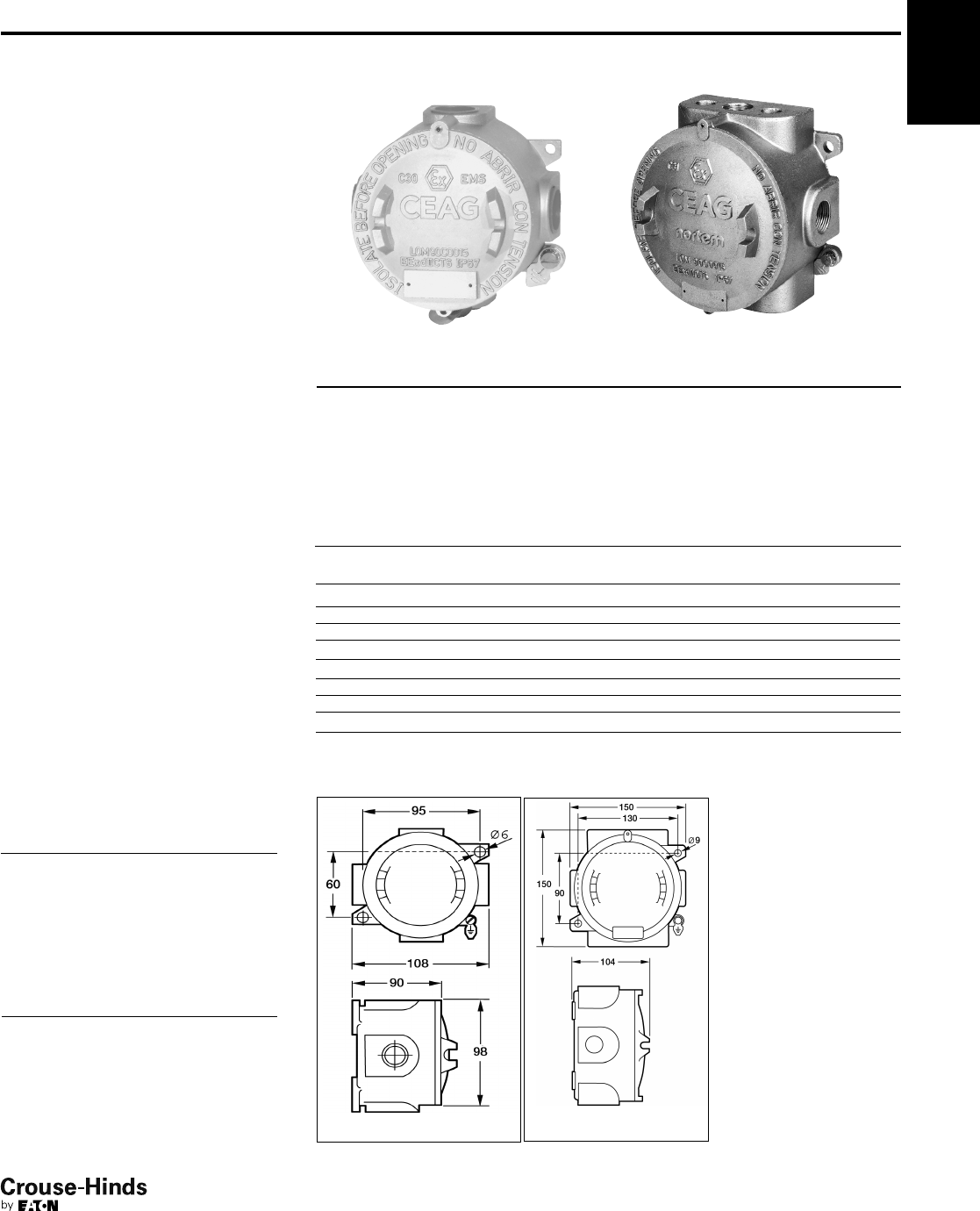
3F
57
www.crouse-hinds.com US: 1-866-764-5454 CAN: 1-800-265-0502 Copyright©2013 Eaton’s Crouse-Hinds Business
3F
Condulet®Conduit Outlet
Boxes With Covers
for IEC Applications
Ex II 2 G EEx d IIC T6
Ex II 2 D IP66 T 85ºC
Zone 1, 2, 21 and 22
C30 Series C31 Series
Applications:
C30 and C31 series conduit outlet boxes
are installed in electrical systems within
hazardous areas to:
• Provide protection against exterior
explosion where acetylene, hydrogen
and other hazardous gases are present
• Protect conductors in threaded rigid
conduit
• Act as pull and splice boxes
• Interconnect lengths of conduit
• Change conduit direction
• Provide access to conductors for
maintenance and future system changes
Certifications and
Compliances:
• IEC:
Ex d IIC T6
Ex tD A21 IP67 T85ºC
EC-Type examination certificate LOM
02 ATEX 2037 X
Compliant to EN60079-0
•IP67
Standard Materials:
• Bodies – Light alloy, natural finish
• Covers – Light alloy, natural finish
Technical Specifications
Operating temperature
range
-50ºC to +55ºC
Degree of protection IP67
Rated voltage up to 690V
Rated current Acc. terminals
Terminals C30 Series:
up to 6mm2
C31 Series:
up to 10 mm2
Ordering Information
Series Shape Hub Size Cat. # †
C30 T 3 x 1/2"NOR 000 001 151 181
C30 T 3 x 3/4"NOR 000 001 151 199
C30 X 4 x 1/2"NOR 000 001 151 206
C30 X 4 x 3/4"NOR 000 001 151 214
C31 T 3 x 1/2"NOR 000 111 150 001
C31 T 3 x 3/4"NOR 000 111 150 002
C31 T 3 x 1" NOR 000 111 150 003
C31 X 4 x 1/2"NOR 000 111 150 004
C31 X 4 x 3/4"NOR 000 111 150 005
C31 X 4 x 1" NOR 000 111 150 006
Description Cat. #
C30 Mounting plate with pillar terminals 4 x 4mm2NOR 000 001 151 222
C30 support rail DIN 46877 NOR 000 000 115 314
C30 mounting plate without terminals NOR 000 000 115 302
C30 pending support NOR 000 000 115 311
C31 mounting plate with pillar terminals 4 x 4mm2NOR 000 111 150 009
C31 mounting plate without terminals NOR 000 000 115 306
C31 support rail DIN 46877 NOR 000 000 115 315
Dimensions
In Inches:
C30 Series
C31 Series
†Other entries available upon request.
Accessories
Features:
C30 and C31 series conduit outlet
boxes have:
• Taper threaded hubs to provide ground
continuity
• Smooth integral hub bushing to protect
conductor insulation when pulling
• Threaded cover openings
• Surface covers furnished with boxes
• Neoprene "o"-ring gasket and green
ground screw are both standard
• Cover threads are 16 pitch
56-57.qxp 12/16/2013 12:07 PM Page 57
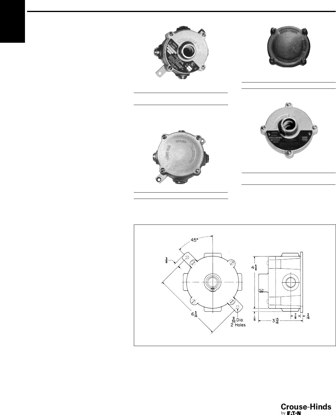
3F
58
www.crouse-hinds.com US: 1-866-764-5454 CAN: 1-800-265-0502 Copyright©2013 Eaton’s Crouse-Hinds Business
Condulet®Conduit Outlet
Boxes With Covers
CPS Series
Cl. I, Div. 1 & 2, Groups C, D
Cl. II, Div. 1, Groups E, F, G
Cl. II, Div. 2, Groups F, G
Cl. III
NEMA 7CD,9EFG
Explosionproof
Dust-Ignitionproof
Applications:
CPS series conduit outlet boxes are
installed in conduit systems in hazardous
areas to:
• Protect conductors in threaded rigid
conduit
• Act as pull and splice boxes
• Change conduit direction
• Interconnect lengths of conduit
• Act as fixture hangers with hub covers
• Provide access to conductors for
maintenance and future system changes
Features:
CPS conduit outlet boxes have:
• Two types of cover:
blank for splice or pull box use
threaded hub for mounting light fixtures
• Wide, accurately machined body and
cover mating surfaces, to insure
flametight joint
• Blind tapped holes for cover screws to
further insure flametightness
• Removable mounting feet for flush or
surface mounting to wall or ceiling
Standard Materials:
•Feraloy®iron alloy
Standard Finishes:
• Electrogalvanized and aluminum
acrylic paint
Options:
Description Suffix
Corro-free™epoxy powder coat S752
Certifications and
Compliances:
• NEC/CEC
Class I, Division 1 & 2, Groups C, D
Class II, Division 1, Groups E, F, G
Class II, Division 2, Groups F, G
Class III
• UL Standard: 1203
• CSA Standard C22.2 No. 30
Box with Hub Cover
Hub Size
Body‡ Cover Cat. #
3/41/2CPS12021
3/43/4CPS12022
‡Furnished with four 3/4" standard taper tapped,
integrally bushed hubs. Three hubs are plugged.
Box with Blank Cover
Hub Size Cat. #
3/4CPS12026
CPS Covers
Blank Covers
Description Cat. #
Form 20 CPS026
Hub Covers*
Description
Hub
Size Cat. #
Form 20 1/2CPS021
Form 20 3/4CPS022
*Fixture weight up to 125 lbs.
Complete line of fixture hangers are located in section 7L of this catalog.
Dimensions
In Inches:
3F
58-59.qxp 12/16/2013 12:07 PM Page 58
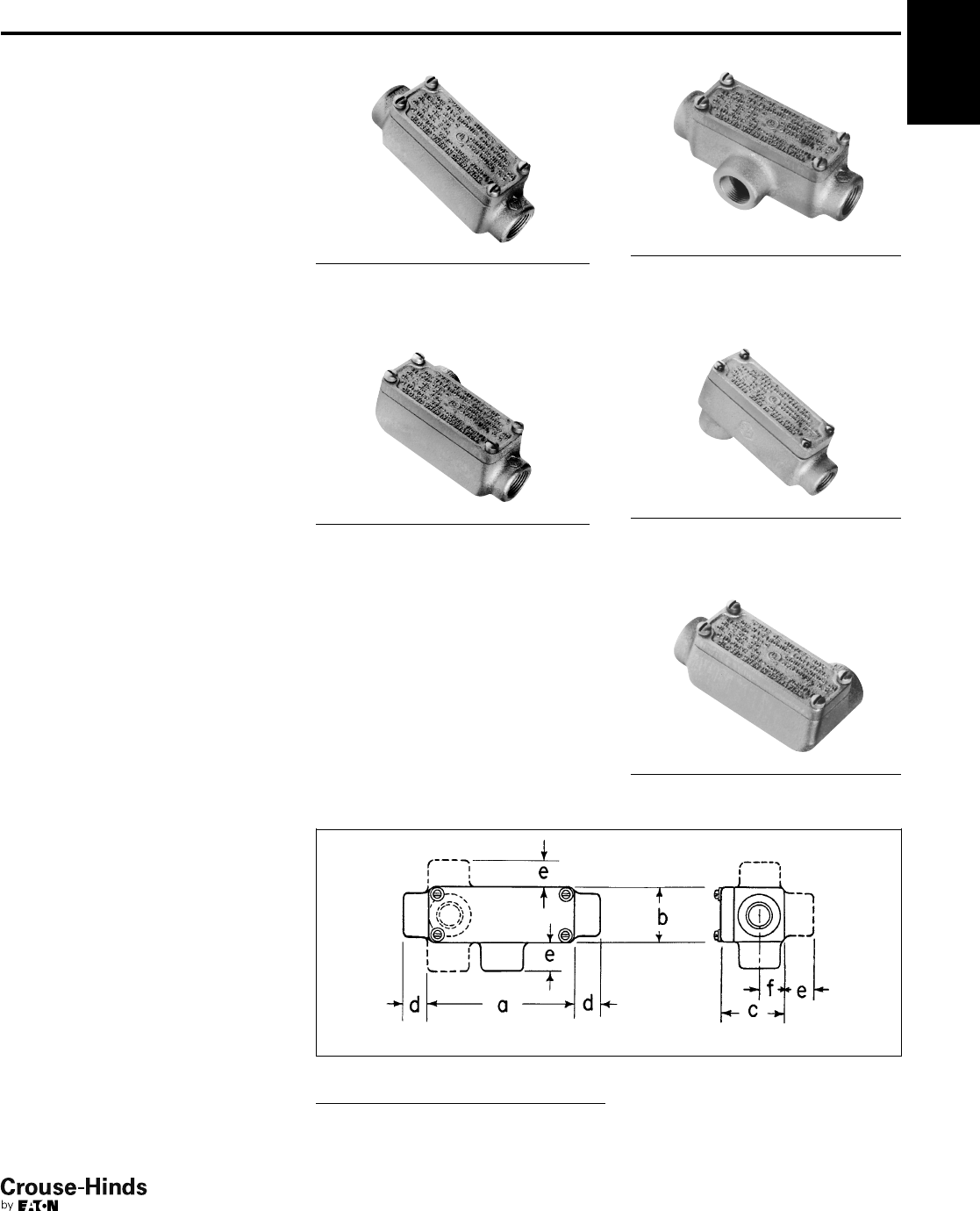
3F
59
www.crouse-hinds.com US: 1-866-764-5454 CAN: 1-800-265-0502 Copyright©2013 Eaton’s Crouse-Hinds Business
3F
Condulet®Conduit Bodies
With Covers
OE Series
Cl. I, Div. 1 & 2, Groups C, D
Cl. II, Div. 1, Groups E, F, G
Cl. II, Div. 2, Groups F, G
Cl. III
NEMA 7CD, 9EFG
Explosionproof
Dust-Ignitionproof
Applications:
OE series are installed in conduit systems
within hazardous areas to:
• Protect conductors in threaded
rigid conduit
• Act as pulling and splice fittings
• Interconnect lengths of conduit
• Change direction of conduit
• Provide access for maintenance and
future system changes
Features:
OE conduit outlet bodies have:
• Taper threaded hubs for ground
continuity
• Smooth integral hub bushings to protect
conductor insulation when pulling
• Five different hub arrangements
• Accurately machined body with blind
tapped screw holes
• Most compact design of all hazardous
area outlet bodies
Standard Materials:
•Feraloy®iron alloy (1/2" and 3/4" fittings)
• Copper-free aluminum (1" fittings)
Standard Finishes:
• Electrogalvanized and aluminum
acrylic paint
Options:
Description Suffix
Corro-free™epoxy powder coat S752
Certifications and
Compliances:
• NEC/CEC:
Class I, Division 1 & 2, Groups C, D
Class II, Division 1, Groups E, F, G
Class II, Division 2, Groups F, G
Class III
• UL Standard: 1203
• CSA Standard: C22.2 No. 30
OEC OET
OELB
OELL
Hub Size Cat. #
1/2OEC1
3/4OEC2
1OEC3 SA
Hub Size Cat. #
1/2OELL1
3/4OELL2
1 OELL3 SA
Hub Size Cat. #
1/2OET1
3/4OET2
1 OET3 SA
Hub Size Cat. #
1/2OELB1
3/4OELB2
1 OELB3 SA
OELR
Hub Size Cat. #
1/2OELR1
3/4OELR2
1 OELR3 SA
Dimensions
In Inches:
OE Series
Hub
Size in. a b c d e f
1/241/16 19/16 113/16 11/16 7/85/8
3/445/16 17/821/16 11/16 7/83/4
Size Ranges:
• Hub - 1/2" to 1"
58-59.qxp 12/16/2013 12:07 PM Page 59
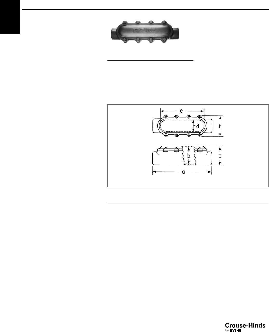
3F
60
www.crouse-hinds.com US: 1-866-764-5454 CAN: 1-800-265-0502 Copyright©2013 Eaton’s Crouse-Hinds Business
Condulet®Conduit Bodies
With Covers
EKC Series
Cl. I, Div. 1 & 2, Groups C, D
Cl. II, Div. 1, Groups E, F, G
Cl. II, Div. 2, Groups F, G
Cl. III
NEMA 7CD,9EFG
Explosionproof
Dust-Ignitionproof
Applications:
EKC series conduit outlet bodies are installed
in conduit systems within hazardous areas to:
• Provide convenient opening in conduit
system for pulling or splicing conductors
Features:
EKC bodies have:
• Accurately machined body and cover
mating surfaces to ensure flametight
joint when properly assembled
• Extra long cover opening to facilitate
pulling and splicing of conductors
• Taper threaded hubs and integral
bushing for rigid threaded conduit
Standard Materials:
• EKC bodies – Feraloy iron alloy
Standard Finishes:
•Feraloy – electrogalvanized and
aluminum acrylic paint
Options:
Description Suffix
EKC series:
Corro-free™epoxy powder coat S752
Size Ranges:
• EKC bodies – hub size – 1" to 3"
Certifications and
Compliances:
• NEC:
EKC 30 – 60
Class I, Division 1 & 2, Groups C, D
Class II, Division 1, Groups E, F, G
Class II, Division 2, Groups F, G
Class III
EKC 70, 80
Class I, Division 1 & 2, Group D
Class II, Division 1, Groups E, F, G
Class II, Division 2, Groups F, G
Class III
• UL Standard: 1203
• CSA Standard: C22.2 No. 30
Ordering Information
EKC
Hub Size Cat. #
1
EKC30
11
/
4
EKC40
11
/
2
EKC50
2
EKC60
21
/
2
EKC70
3
EKC80
Dimensions
In Inches:
EKC
EKC
Size a b c d e f
1 – 11
/
4
125/831/16 37/16 13/494
11
/
2– 2
1515/16 37/845/16 21/212 5
21
/
2– 3
213/451/263
3/416 65/8
3F
60-61.qxp 12/16/2013 12:07 PM Page 60
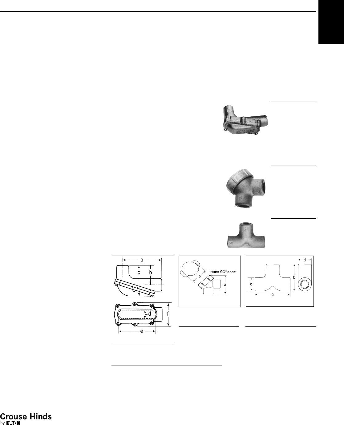
3F
61
www.crouse-hinds.com US: 1-866-764-5454 CAN: 1-800-265-0502 Copyright©2013 Eaton’s Crouse-Hinds Business
Condulet®Conduit Bodies
With Covers; Elbows and Tees
LBH, LBY, ET Series
Cl. I, Div. 1 & 2, Groups A, B, C, D*
Cl. II, Div. 1, Groups E, F, G
Cl. II, Div. 2, Groups F, G
Cl. III
NEMA 7ABCD,9EFG
Explosionproof
Dust-Ignitionproof
Applications:
LBH conduit outlet bodies are installed in
hazardous areas to:
• Act as pull outlets especially for
conductors that are stiff due to large size
or type of insulation
• Make 90° bends in conduit system,
allowing straight pull in either direction
• Provide for conduit service entrance to
buildings
• Provide for conductor entrance to motors
• Provide access to wiring for maintenance
and future system changes
LBY elbows are installed in conduit systems
within hazardous areas to:
• Make 90° bends in conduit systems where
space is limited
• Act as pull outlets
• Provide access to conductors for
maintenance and future system changes
ET series short radius tees are installed in
conduit systems within hazardous areas to:
• Allow single conduit stub up to outlet and
device boxes located above or below main
conduit runs. Eliminates separate feed and
return conduits
Features:
LBH bodies have:
• Cover openings on an angle, permitting
conductors to be pulled straight through
hubs from either direction
• Domed covers to permit easy conductor
bends (relieves strain on insulation)
• Taper threaded hubs with integral
bushings
LBY elbows have:
• Maximum volume for bends within a
compact overall size
• Screw on cover for ease of installation and
removal
• Over opening on an angle, permitting
conductors to be pulled straight through
either hub
• Taper threaded hubs and integral bushing
for rigid threaded conduit
ET short radius tees have:
• Compact size and small radius of bend for
use in concealed, or open conduit
systems.
• Particularly suited for use in shallow floors
or partitions
• Taper threaded hubs and integral bushing
for rigid threaded conduit
Standard Materials:
• LBH, LBY and ET – Feraloy®iron alloy
Standard Finishes:
• LBH, LBY and ET – electrogalvanized and
aluminum acrylic paint
Options:
Description Suffix
LBH and LBY series – copper-free
aluminum SA
LBH and LBY series – Corro-free™
epoxy powder coat S752
Size Ranges:
• LBH bodies – hub size 1/2" to 4"
• LBY elbows – hub size 1/2" to 11/2"
Certifications and
Compliances:
• NEC:
LBH 10-20 –
Class I, Division 1 & 2, Groups B, C, D
Class II, Division 1, Groups E, F, G
Class II, Division 2, Groups F, G
Class III
LBH Hub Size Cat. #
1
/
2
LBH10
3
/
4
LBH20
1
LBH30
11
/
4
LBH40
11
/
2
LBH50
2
LBH60
21
/
2
LBH70
3
LBH80
31
/
2
LBH90
4
LBH100
LBY Hub Size Cat. #
1
/
2
LBY15
3
/
4
LBY25
1
LBY35
11
/
4
LBY45
11
/
2
LBY55
ET Hub Size Cat. #
3
/
4–1
/
2–1
/
2‡
ET218
3
/
4–3
/
4–3
/
4‡
ET228
1–3
/
4–3
/
4‡
ET328
‡Largest hub is shown at
top of photo.
LBH
Size a b c d e f
1
/
2–
3/451/16 219/32 41
3/16 42
3/4
1–
1/477/8313/32 51/413/474
11
/
2
1015/16 41/273/32 21/210 5
2
1021/32 425/32 73/32 21/210 5
2-1
/
2–3
155/851/291/2315
3/455/8
3-1
/
2–4
239/16 611/16 113/44247
1/8
LBY
Size a b
1
/
2
29/16 2
3
/
4
213/16 21/4
1
33/32 21/2
11
/
4
33/4215/16
11
/
2
41/433/8
ET
Size a b c d
3/4
–1
/
2–1
/
2
42
5/811/411/2
3/4
–
3/4
–
3/443 1
1/211/2
1–
3/4
–
3/443 1
1/213/4
*See Compliances for classification of each product.
LBH 30-100
Class I, Division 1 & 2, Group D
Class II, Division 1, Groups E, F, G
Class II, Division 2, Groups F, G
Class III
LBY –
Class I, Division 1 & 2, Groups C, D
Class II, Division 1, Groups E, F, G
Class II, Division 2, Groups F, G
Class III
ET –
Class I, Division 1 & 2, Groups A, B, C, D
Class II, Division 1, Groups E, F, G
Class II, Division 2, Groups F, G
Class III
• UL Standard: 1203
• CSA Standard: C22.2 No. 30
Dimensions
In Inches:
LBH
LBY ET
3F
Ordering Information
60-61.qxp 12/16/2013 12:07 PM Page 61
3F
62
www.crouse-hinds.com US: 1-866-764-5454 CAN: 1-800-265-0502 Copyright©2013 Eaton’s Crouse-Hinds Business
Condulet®Elbows and Tees
IEC Certifications
FE and FT Series
Zone 1 Zone 21
Zone 2 Zone 22
Applications:
FE and FT conduit fittings are installed in
hazardous areas to:
• Act as draw-in outlets especially for
cables that are stiff due to large size or
type of insulation
• Make 90º bends in conduit systems,
allowing for a straight pull in either
direction
• Provide access to wiring for
maintenance and future system changes
Features:
• Maximum volume for bends within a
compact overall size
• Large openings to facilitate cable pulling
Certifications and
Compliances:
Type of Protection
• Ex d, DIP A21, IP67
Degree of Protection
•IP67
Gas Group
• IIB
Approvals
• Ex1108U
Standard Materials:
• Body – Copper-free aluminum
• Cover – Brass
Standard Finishes:
• Natural
Ordering Information:
Inspection Elbows and Tees Selection
Cat. # Type Entry Size (metric)
FE1 Elbow M20 (F)-M20 (F)
FE2 Elbow M25 (F)-M25 (F)
FT1 Tee M20 (F)-M20 (F)
FT2 Tee M25 (F)-M25 (F)
Options:
Description Suffix
NPT & BSP thread sizes Consult Factory
Dimensions (mm)
3F
62-63.qxp 12/16/2013 12:07 PM Page 62
3F
63
www.crouse-hinds.com US: 1-866-764-5454 CAN: 1-800-265-0502 Copyright©2013 Eaton’s Crouse-Hinds Business
3F
Lubricants
Applications:
• STL thread lubricant is used between any screw thread and its
tapped opening, on any rotating shaft – threaded or plain, and to
inhibit corrosion on any metal-to-metal joint of apparatus and
control enclosures.
• HTL high temperature lubricant is used on lighting fixture threaded
joints and on threaded joints of the enclosures of any heat-
producing apparatus or control.
Features:
STL thread lubricant is lithium based, antigalling and:
• Is especially effective between parts made of dissimilar metals
• Is effective and stable from –20°F to +300°F
• Maintains grounding continuity; should not be used on exposed
current-carrying parts
• Has excellent adhesion qualities; a liberal application on threaded
joints maintains raintightness and inhibits corrosion
HTL is a high temperature, anti-seize, conductive thread lubricant:
• Effective and stable from –70°F to +1800°F
• Prevents seizure, galling, rust, galvanic action
• Maintains grounding continuity; should not be used on exposed
current-carrying parts
• Effective between parts made of dissimilar metals
Certifications and Compliances:
• Complies with NEC 2008, Article 300.6
STL Thread Lubricant
Net Wt. Cat. #
13/4oz. (tube) STL2
8 oz. (can) STL8
HTL High Temperature Thread Lubricant
Net Wt. Cat. #
4 oz. (tube) HTL4
MSDS Sheets are available at www.crouse-hinds.com
3F
62-63.qxp 12/16/2013 12:07 PM Page 63

3F 3F
64
www.crouse-hinds.com US: 1-866-764-5454 CAN: 1-800-265-0502 Copyright©2013 Eaton’s Crouse-Hinds Business
3F
64-65.qxp 12/16/2013 12:07 PM Page 64

4F
65
www.crouse-hinds.com US: 1-866-764-5454 CAN: 1-800-265-0502 Copyright©2013 Eaton’s Crouse-Hinds Business
4F
Cable Glands and Cable Accessories
Hazardous and Non-hazardous
Description Page No.
Application see page 66
Cable Glands - International Standards
Quick Selection Guide see pages 67–70
Flameproof and Increased Safety
ADE 1F see page 71
ADE 4F see page 72
ADE 6F see page 73
ADE 6FC see page 74
ADE 1FC see page 75
Ex - e see page 76
Ex - i see page 77
Trumpet see page 78
Enlargement and Multiple see page 79
Industrial
ADE 4I see page 80
Cable Glands - North American
Standards
Quick Selection Guide see pages 67–70
Explosionproof
Terminator™ II TMCX see pages 81–82
TMCX see page 83
ADE 6FC see page 84
ADE 1FC see page 85
CGBS see page 86
EBY see page 86
General Purpose
TMC see page 87
TECK see page 88
CGB see pages 89–90
CGD see page 91
CGE see page 92
CGB1013 see page 93
CGFP see page 94
NCG see page 95
NCGB see page 95
Cable Glands - Accessories
A Series see page 96
B Series see page 100
D Series see page 101
E Series see page 102
Breathers and Drains see page 103
Cable Tray Clamps
Conduit
LCC, LCCF Series see page 104
Grounding Conductor
TGC Series see page 105
Cable/Conduit Sealing Devices
Thru-Wall Barrier®
TW Series see pages 106–107
Link Seal – For Conduit
Environmental Seal see pages 112–113
Fire Seal see pages 114–115
Description Page No.
64-65.qxp 12/16/2013 12:07 PM Page 65

4F
66
www.crouse-hinds.com US: 1-866-764-5454 CAN: 1-800-265-0502 Copyright©2013 Eaton’s Crouse-Hinds Business
Cable Glands and Cable Accessories
Application and Selection
Applications:
Cable glands and cord fittings:
• Provide means for passing a cord, cable (armored or unarmored)
or flexible conduit into an enclosure, through a bulkhead or into a
rigid conduit
• Form a mechanical grip and water and/or oil-resistant seal for cord
and unarmored or jacketed armored, round cables
• Form a non-slip connection or termination for flexible cord, cable
(armored or unarmored), or flexible conduit
• Provide grounding continuity for cable armor and flexible conduit
Cable glands with sealing fitting or epoxy are installed to:
• Provide means for passing armored, metal clad, jacketed or
unjacketed and unarmored cables through a bulkhead or
enclosure in hazardous areas. These fittings are suitable for use in
Class I, Groups C, D locations only when Chico®A sealing
compound or TSC epoxy (TMCX) is used to make the seal in the
fitting*
• Form a mechanical grip and water and/or oil-resistant termination
• Provide ground continuity of cable armor and flexible conduit
TMC (non-hazardous) and TMCX (hazardous) fittings are designed
for use with Type MC jacketed steel or aluminum metal clad cables
with interlocked or corrugated armor and Type TC tray cable (TMCX).
LCC cable tray conduit clamps are used for installation on cable tray
side rails with inside flanges (requiring inside tray mounting) and
outside flanges; LCCF clamps are for use exclusively on inside
flanges. LCC/LCCF series cable tray conduit clamps are installed to:
• Provide a means of clamping metal conduit (rigid steel or
aluminum, IMC and EMT) to cable tray for the exit of power and/or
control cables from tray
• Provide a means to firmly bond exiting conduit to cable tray for
best grounding continuity
TW Series THRU-WALL BARRIER®cable/conduit sealing devices are
installed to:
• Seal cables or conduits penetrating fire rated walls, ceilings, or
floors
• Restrict entrance of water and dust and contain treated air
• Provide a seal for cable/conduit penetrations through steel,
masonry or concrete; to restrict the entrance of contaminants
through cable/conduit penetrations into clean areas
TGC cable tray grounding conductor clamp provides a means for
securely attaching a grounding conductor to cable tray to provide
grounding continuity for the entire tray system. TGC cable tray
grounding conductor clamps provide a reliable method for carrying
ground fault current for equipment protection. TGC clamp may be
installed on most types of cable trays – with inside or outside
flanges.
Considerations for Selection:
• Selection of the proper cable gland involves consideration of the
type of cable to be installed and the environment that will surround
the cable after installation.
• A proper matching of the cable and its gland is necessary to
prevent physical damage to the cable when installed. Some types
of cable glands depend on gripping methods (set screws, etc.)
which may lead to damage of the cable outer covering. Eaton's
Crouse-Hinds cable glands and cord fittings utilize compression of
split lead or tapered neoprene bushings to provide high gripping
strength for adequate cable support and strain relief without
damage to the cable sheath.
• Compression of bushing provides a strong electrical bond that
assures grounding continuity.
• Compression of a tapered neoprene bushing assures the
watertight integrity of Eaton's Crouse-Hinds cable glands.
Additional watertightness, to prevent water seepage into the fitting
body, can be obtained by use of a potting head filled with a hot
pouring compound.
• To meet National Electrical Code requirements for electrical
installations in hazardous atmospheres, a sealing fitting may be
required in conjunction with the cable or cord fitting.
*With specific cords and cables when installed in accordance with NEC/CEC requirements.
4F
66-67.qxp 12/16/2013 6:28 PM Page 66
4F
67
www.crouse-hinds.com US: 1-866-764-5454 CAN: 1-800-265-0502 Copyright©2013 Eaton’s Crouse-Hinds Business
Global Cable Glands
ADE 1F
(see
page 71)
Non-armoured,
armoured and tray
cable (does not
terminate the armour)
Non-armoured Nickel-plated brass Flameproof &
Increased Safety
ADE 1FC
(see
page 75)
Non-armoured,
armoured and tray
cable (does not
terminate the armour)
Non-armoured
barrier Nickel-plated brass Flameproof &
Increased Safety
ADE 4F
(see
page 72)
SWA, SWB, STA,
braided marine
shipboard and lead
sheathed (with
addition of earthing
washer)
Armoured Nickel-plated brass Flameproof &
Increased Safety
ADE 6F
(see
page 73)
SWA, SWB, STA and
braided marine
shipboard
Armoured Nickel-plated brass Flameproof &
Increased Safety
CABLE
GLAND ILLUSTRATION
CABLE
TYPE
GLAND
TYPE
STANDARD
MATERIAL CERTIFICATION
PROTECTION
TYPE
ADE 6FC
(see
page 74)
SWA, SWB, STA,
braided marine
shipboard and lead
sheathed (with
addition of earthing
washer)
Armoured
barrier Nickel-plated brass Flameproof &
Increased Safety
4F
Quick Selection Guide - International Standards
66-67.qxp 12/16/2013 6:28 PM Page 67
4F
68
www.crouse-hinds.com US: 1-866-764-5454 CAN: 1-800-265-0502 Copyright©2013 Eaton’s Crouse-Hinds Business
Ex - e
(see
page 76)
Non-
armoured Non-armoured Polyamide Increased Safety
Ex - i
(see
page 77)
Non-
armoured Non-armoured Polyamide Increased Safety
Trumpet
(see
page 78)
Non-
armoured Non-armoured Polyamide Increased Safety
Enlargement
and Multiple
(see
page 79)
Non-
armoured Non-armoured Polyamide Increased Safety
ADE 4I
(see
page 80)
SWA, SWB,
STA, braided
marine
shipboard
and lead
sheathed
(with addition
of earthing
washer)
Armoured Nickel-plated brass Industrial
CABLE
GLAND ILLUSTRATION
CABLE
TYPE
GLAND
TYPE
STANDARD
MATERIAL CERTIFICATION
PROTECTION
TYPE
Global Cable Glands
4F
Quick Selection Guide - International Standards
68-69.qxp 12/23/2013 2:38 PM Page 68
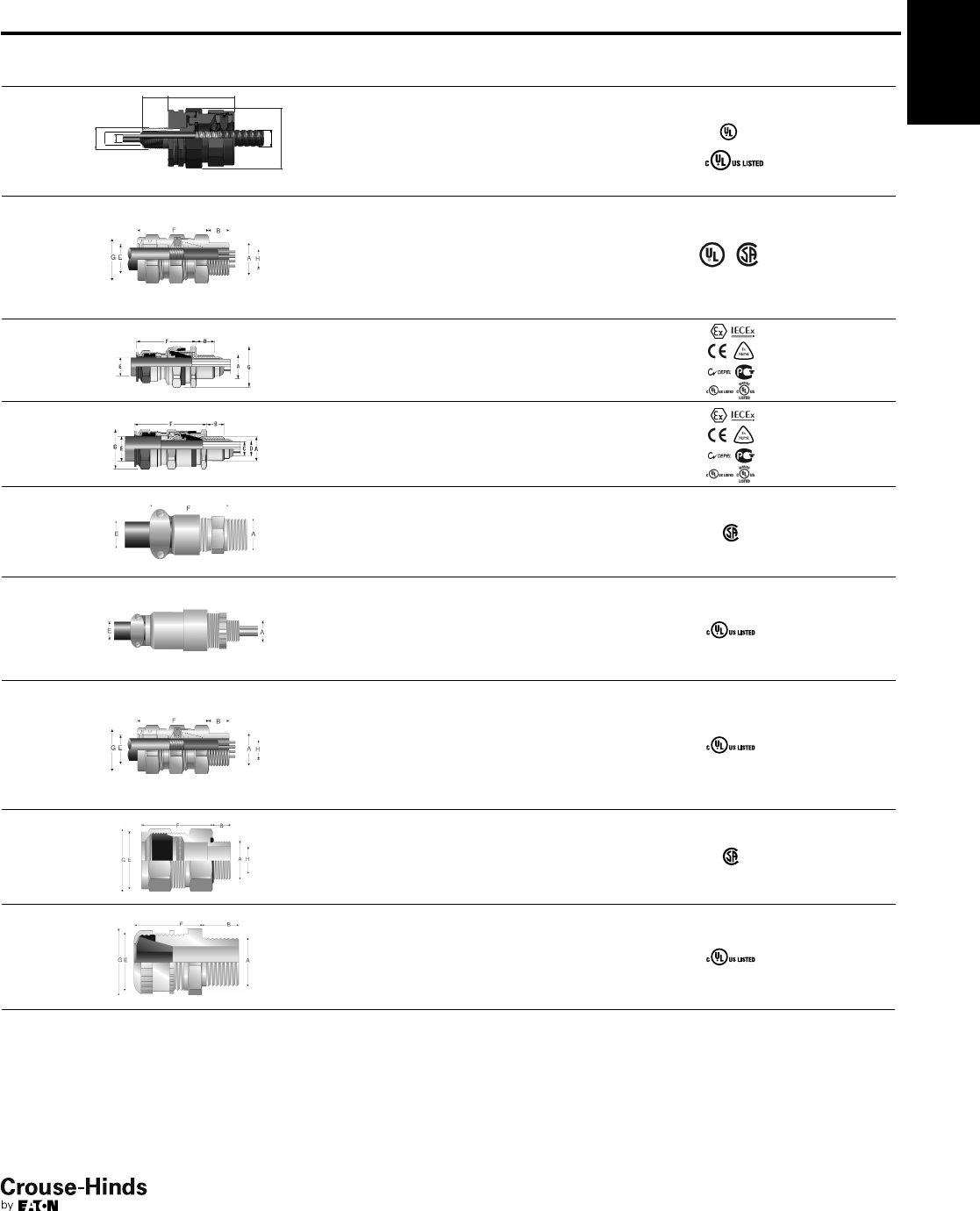
4F
69
www.crouse-hinds.com US: 1-866-764-5454 CAN: 1-800-265-0502 Copyright©2013 Eaton’s Crouse-Hinds Business
Quick Selection Guide - North American Standards
TMCX
(see
page 83)
Metal-clad with
interlocked or
continuously welded
corrugated, TECK
armoured, non-armoured
and tray cable
Armoured
barrier and
non-armoured
barrier
Aluminum Explosionproof
ADE 1FC
(see
page 85)
Non-armoured,
armoured and tray
cable (does not
terminate the armour)
Non-armoured
barrier
Nickel-plated
brass
Flameproof &
Increased
Safety
ADE 6FC
(see
page 84)
SWA, SWB, STA,
braided marine
shipboard and lead
sheathed (with addition
of earthing washer)
Armoured
barrier
Nickel-plated
brass
Flameproof &
Increased
Safety
CGBS
(see
page 86)
Non-armoured
and tray cable
Portable cord
connector
Body: steel
Gland nut:
aluminum
Explosionproof
EBY
(see
page 86)
Non-armoured Portable cord
connector Aluminum Explosionproof
TMC
(see
page 87)
Metal-clad with
interlocked or
continuously welded
corrugated, TECK
armoured, non-armoured
and tray cable
Armoured or
non-armoured Aluminum General
Purpose
TECK
(see
page 88)
TECK armoured Armoured Aluminum General
Purpose
CABLE
GLAND ILLUSTRATION
CABLE
TYPE
GLAND
TYPE
STANDARD
MATERIAL CERTIFICATION
PROTECTION
TYPE
CGB
(see
pages 89–90)
Non-armoured
and tray cable Non-armoured
Body steel
Form A-D steel
Form E-F iron
General
Purpose
Global Cable Glands 4F
Terminator™
II TMCX
X (see
pages 81–82)
G
C
E
D
F
B
A
Metal-clad, TECK
(interlocked and
continuously welded
corrugated armoured),
unarmoured, and tray
cable
Armoured
barrier, non-
armoured
barrier, and
TECK
armoured
Aluminum Explosionproof
68-69.qxp 12/23/2013 2:39 PM Page 69
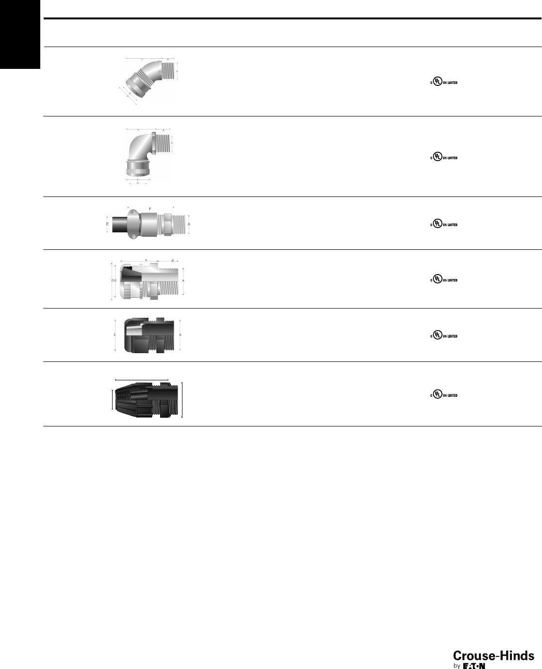
4F
70
www.crouse-hinds.com US: 1-866-764-5454 CAN: 1-800-265-0502 Copyright©2013 Eaton’s Crouse-Hinds Business
CGE
(see
page 92)
Non-armoured
and tray cable Non-armoured Body: iron
Gland nut: steel General Purpose
CGB1013
(see
page 93)
Non-armoured
and tray cable
Portable cord
connector
Body: steel
Gland nut:
aluminum
General Purpose
CGFP
(see
page 94)
Non-armoured
and tray cable Non-armoured Form B-C: steel
Form D-G: iron General Purpose
CGD
(see
page 91)
Non-armoured
and tray cable Non-armoured Body: iron
Gland nut: steel General Purpose
CABLE
GLAND ILLUSTRATION
CABLE
TYPE
GLAND
TYPE
STANDARD
MATERIAL CERTIFICATION
PROTECTION
TYPE
NCG
(see
page 95)
Non-armoured
and tray cable Non-armoured Polyamide General Purpose
NCGB
(see
page 95)
NCGB
Non-armoured
and tray cable Non-armoured Thermoplastic
polyester General Purpose
4F Global Cable Glands
Quick Selection Guide - North American Standards
70-71.qxp 12/23/2013 2:39 PM Page 70
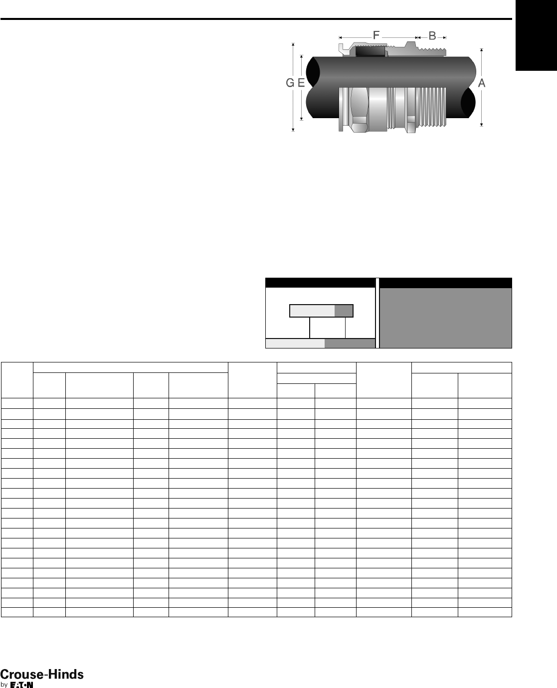
–
4F
71
www.crouse-hinds.com US: 1-866-764-5454 CAN: 1-800-265-0502 Copyright©2013 Eaton’s Crouse-Hinds Business
Features:
• Standard material is nickel-plated brass for superior corrosion
resistance
• Provides a flameproof and weatherproof seal on the outer sheath
of the cable
• Standard neoprene seal suitable for use in operating temperatures
ATEX (-60°C to 100°C), IECEx and cULus (-40°C to 100°C)
• Available with optional silicone seal for extreme temperatures
• Available with metric or NPT threads
• See pages 96–103 for related accessories
ORDERING EXAMPLE:
CAP81640 4KX
OptionsGland Type
9 Stainless steel (316L)
8 Bronze
7 Aluminum
5 Silicone sealing ring with temperature range of
-70°C to 220°C
K1 Includes locknut and fiber washer
K2 Includes locknut, fiber washer, earth tag, and
shroud
OPTIONS (replace last digit with option number):
ADE 1F
International Standards -
Flameproof and Increased Safety
Gland
Size
Entry Thread Size ‘A’ Thread
Length ‘B’
Metric
(NPT)
Cable Acceptance Gland
Length ‘F’
(less entry)
Hexagon Dimensions
Metric
Size
Metric
Catalog #
NPT
Size
NPT
Catalog #
Outer Sheath‘E’ Across
Flats
Across
Corners ‘G’
Min Max
4 M12 CAP816404 1/4"CAP818404 15 (12.0) 4.0 8.0 20 – 16.5
4 M16 CAP816594 3/8"CAP818594 15 (12.0) 4.0 8.5 20 – 20.9
5 M16 CAP816504 1/2"CAP818694 15 (12.0) 6.0 12.0 22 – 20.9
4 M20 CAP816674 1/2"CAP818674 15 (20.2) 4.0 8.5 20 – 26.4
5 M20 CAP816694 1/2"CAP818694 15 (20.2) 6.0 12.0 22 – 26.4
6 M20 CAP816604 1/2"CAP818604 15 (20.2) 8.5 16.0 25 – 26.4
5 M25 CAP816774 3/4"CAP818774 15 (20.2) 6.0 12.0 22 – 33
6 M25 CAP816794 3/4"CAP818794 15 (20.2) 8.5 16.0 25 – 33
7 M25 CAP816704 3/4"CAP818704 15 (20.2) 12.0 21.0 27 – 33
7 M32 CAP816894 1" CAP818894 15 (25.3) 12.0 21.0 27 – 39.6
8 M32 CAP816804 1" CAP818804 15 (25.3) 16.0 27.5 34 – 45.1
8 M40 CAP816994 11/4"CAP818994 15 (26.0) 16.0 27.5 34 – 48.4
9 M40 CAP816904 11/4"CAP818904 15 (26.0) 21.0 34.0 36 – 52.8
9 M50 CAP817094 11/2"CAP819094 15 (26.5) 21.0 34.0 36 – 60.5
10 M50 CAP817004 11/2"CAP819004 15 (26.5) 27.0 41.0 39 – 60.5
11 M63 CAP817294 2" CAP819294 17 (27.2) 33.0 48.0 41 – 73.7
12 M63 CAP817204 2" CAP819204 17 (27.2) 40.0 56.0 43 – 79.2
12 M75 CAP817394 21/2"CAP819494 18 (40.5) 40.0 56.0 43 – 88
13 M75 CAP817304 21/2"CAP819404 18 (40.5) 47.0 65.0 49 – 93.5
14 M90 CAP817594 3" CAP819594 22 (42.0) 54.0 74.0 56 – 104.5
15 M90 CAP817504 3" CAP819504 22 (42.0) 63.0 78.0 61 – 121
16 M110 CAP817794 31/2"CAP819604 22 (43.2) 72.0 92.0 62 132
SELECTION TABLE
4F
ATEX
IECEx
cULus Listed for Class I, Zone 2
cULus Marine Listed for Class I, Zone 2
CEPEL
GOST-R
NEPSI
NEMA 4X and IP68
Gland Type:
Non-armoured
Cable Type:
Non-armoured, armoured and tray cable (does not terminate the
armour)
Certifications and Compliances:
• ATEX LCIE 97 ATEX 6008X – Exd IIC/Exe II/Ex tD /Ex II 2 GD
• IECEx LCI 05.0004X
• cULus Listed for Class I Zone 2 AEx e II/Ex e II E310130
• cULus Marine Listed for Class I Zone 2 AEx e II/Ex e II E314047
• NEMA 4X and IP68
• CEPEL cepel-EX-558/05X
• GOST-R POCC FR.B02011
• NEPSI N° GYJ071336U & GYJ071337U
70-71.qxp 12/23/2013 2:39 PM Page 71
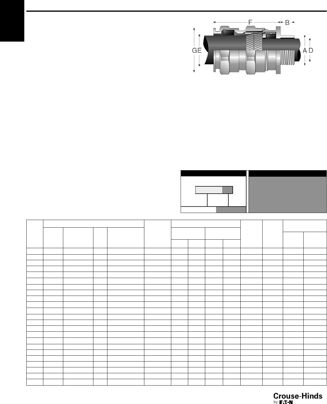
4F
72
www.crouse-hinds.com US: 1-866-764-5454 CAN: 1-800-265-0502 Copyright©2013 Eaton’s Crouse-Hinds Business
ADE 4F
International Standards -
Flameproof and Increased Safety
Gland Type:
Armoured
Cable Type:
Steel wire armoured, steel wire braided, steel tape armoured, braided
marine shipboard and lead sheathed (with addition of earthing
washer)
Certifications and Compliances:
• ATEX LCIE 97 ATEX 6008X – Exd IIC/Exe II/Ex tD/Ex II 2 GD
• IECEx LCI 05.0004X
• cULus listed for Class I, Zone 2 AEx e II/Ex e II E310130
• cULus Marine listed for Class I, Zone 1 AEx e II/Ex e II E314047
• NEMA 4X and IP68
• CEPEL cepel-EX-559/05X
• GOST-R POCC FR.B02011
• NEPSI N° GYJ071336U & GYJ071337U
Features:
• Standard material is nickel-plated brass for superior corrosion
resistance
• Armour clamping and bonding with no reversible components for
easy installation, minimizing error
• Provides flameproof seal on inner jacket and weatherproof seal on
outer sheath of cable
• Optional earthing washer for use with lead sheathed cable
(see page 97)
• Standard neoprene seal suitable for use in operating temperatures
ATEX (-60°C to 100°C), IECEx and cULus (-40°C to 100°C)
• Available with optional silicone seal for extreme temperatures
• Available with metric or NPT threads
• See pages 96–103 for related accessories
4F
ORDERING EXAMPLE:
CAP84640 4KX
OptionsGland Type
9 Stainless steel (316L)
8 Bronze
7 Aluminum
5 Silicone sealing ring with temperature range of
-70°C to 220°C
K1 Includes locknut and fiber washer
K2 Includes locknut, fiber washer, earth tag, and
shroud
OPTIONS (replace last digit with option number):
SELECTION TABLE
Gland
Size
Entry Thread Size ‘A’
Thread
Length ‘B’
Metric
(NPT)
Cable Acceptance
Armour
(max)
Gland
Length
‘F’ (less
entry)
Hexagon
Dimensions
Metric
Size
Metric
Catalog #
NPT
Size NPT Catalog #
Inner Sheath
‘D’
Outer Sheath
‘E’ Across
Flats
Across
Corners
‘G’
Min Max Min Max
5 M12 CAP846404 1/4"CAP848404 15 (12.0) 4.0 8.0 6.0 12.0 0.9 36 – 20.9
5 M16 CAP846594 3/8"CAP848594 15 (12.0) 4.0 8.5 6.0 12.0 0.9 36 – 20.9
6 M16 CAP846504 3/8"CAP848504 15 (12.0) 6.0 12.0 8.5 16.0 1.25 42 – 26.4
5 M20 CAP846674 1/2"CAP848674 15 (20.2) 4.0 8.5 6.0 12.0 0.9 36 – 26.4
6 M20 CAP846694 1/2"CAP848694 15 (20.2) 6.0 12.0 8.5 16.0 1.25 42 – 26.4
7 M20 CAP846604 1/2"CAP848604 15 (20.2) 8.5 16.0 12.0 21.0 1.25 46 – 33.0
6 M25 CAP846774 3/4"CAP848774 15 (20.2) 6.0 12.0 8.5 16.0 1.25 42 – 33.0
7 M25 CAP846794 3/4"CAP848794 15 (20.2) 8.5 16.0 12.0 21.0 1.25 46 – 33.0
8 M25 CAP846704 3/4"CAP848704 15 (20.2) 12.0 20.5 16.0 27.5 1.6 56 – 45.1
8 M32 CAP846894 1" CAP848894 15 (25.3) 12.0 21.0 16.0 27.5 1.6 56 – 45.1
9 M32 CAP846804 1" CAP848804 15 (25.3) 16.0 27.5 21.0 34.0 1.6 63 – 52.8
9 M40 CAP846994 11/4"CAP848994 15 (26.0) 16.0 27.5 21.0 34.0 1.6 63 – 52.8
10 M40 CAP846904 11/4"CAP848904 15 (26.0) 21.0 34.0 27.0 41.0 2.0 68 – 60.5
10 M50 CAP847094 11/2"CAP849094 15 (26.5) 21.0 34.0 27.0 41.0 2.0 68 – 60.5
11 M50 CAP847004 11/2"CAP849004 15 (26.5) 27.0 41.0 33.0 48.0 2.5 74 – 70.4
12 M63 CAP847294 2" CAP849294 17 (27.2) 27.0 41.0 33.0 48.0 2.5 77 – 79.2
13 M63 CAP847204 2" CAP849204 17 (27.2) 33.0 48.0 47.0 56.0 2.5 85 – 93.5
13 M75 CAP847394 21/2" CAP849494 18 (40.5) 40.0 56.0 47.0 65.0 2.5 85 – 93.5
14 M75 CAP847304 21/2"CAP849404 18 (40.5) 47.0 65.0 54.0 74.0 2.5 92 – 104.5
15 M90 CAP847794 3" CAP849594 22 (42.0) 54.0 74.0 63.0 83.0 3.15 104 – 121.0
16 M90 CAP847504 3" CAP849504 22 (42.0) 63.0 82.0 72.0 93.0 3.15 108 – 132.0
16 M90 CAP847574 31/2"CAP849604 N/A (43.2) 63.0 82.0 72.0* 93.0* 3.15 108 – 132.0
17 M110 CAP847794 4" CAP849704 22 (44.5) 72.0 92.0 85.0 107.0 3.15 115 – 148.5
All dimensions in millimeters unless otherwise noted * CAP849604 “outer sheath” min: 85 max: 107.
ATEX
IECEx
cULus Listed for Class I, Zone 2
cULus Marine Listed for Class I,
Zone 1
CEPEL
GOST-R
NEPSI
NEMA 4X and IP68
72-73.qxp 12/23/2013 2:39 PM Page 72
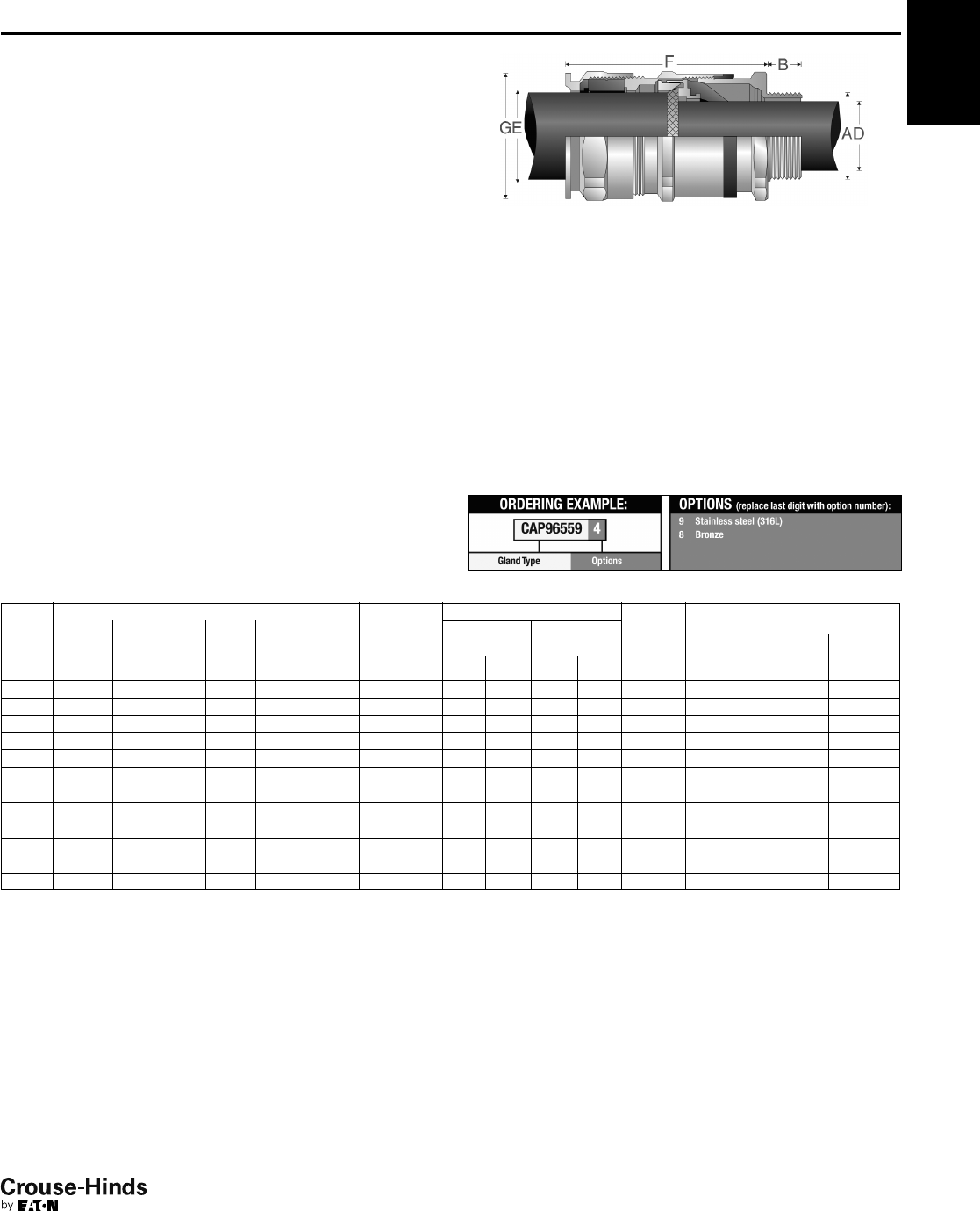
5 M16 CAP965594 3/8"CAP967594 15 (12.0) 3.0
7.5
6.0 12.0 0.9 46.0 – 20.9
5 M20 CAP965674 1/2"CAP967674 15 (20.2) 3.0 7.5 6.0 12.0 0.9 46.0 – 26.4
6 M20 CAP965694 1/2"CAP967694 15 (20.2) 6.5 11.0 8.5 16.0 1.25 53.0 – 26.4
7 M20 CAP965604 1/2"CAP967604 15 (20.2) 9.0 14.5 12.0 21.0 1.25 59.0 – 33.0
7 M25 CAP965794 3/4"CAP967794 15 (20.2) 9.0 14.5 12.0 21.0 1.25 59.0 – 33.0
8 M25 CAP965704 3/4"CAP967704 15 (20.2) 12.0 19.5 16.0 27.5 1.6 74.5 – 45.1
8 M32 CAP965894 1" CAP967894 15 (25.3) 12.0 19.5 16.0 27.5 1.6 74.5 – 45.1
9 M32 CAP965804 1" CAP967804 15 (25.3) 17.5 26.0 21.0 34.0 1.6 83.5 – 52.8
9 M40 CAP965994 11/4"CAP967994 15 (26.0) 17.5 26.0 21.0 34.0 1.6 83.5 – 52.8
10 M40 CAP965904 11/4"CAP967904 15 (26.0) 23.0 33.0 27.0 41.0 2.0 92.0 – 60.5
10 M50 CAP966094 CAP968094 16 (26.5) 23.0 33.0 27.0 41.0 2.0 92.0 – 60.5
11 M50 CAP966004 2" CAP968294 16 (27.2) 28.5 41.0 33.0 48.0 2.5 104.0 – 70.4
4F
73
www.crouse-hinds.com US: 1-866-764-5454 CAN: 1-800-265-0502 Copyright©2013 Eaton’s Crouse-Hinds Business
SELECTION TABLE
Gland
Size
Entry Thread Size ‘A’ Thread
Length ‘B’
Metric
(NPT)
Cable Acceptance
Armour
(max)
Gland
Length
‘F’ (less
entry)
Hexagon
Dimensions
Metric
Size
Metric
Catalog #
NPT
Size
NPT
Catalog #
Inner
Sheath ‘D’
Outer
Sheath ‘E’ Across
Flats
Across
Corners
‘G’Min Max Min Max
Larger sizes available in ADE 4F design, see page 72.
All dimensions in millimeters unless otherwise noted.
4FADE 6F
International Standards -
Flameproof and Increased Safety
Features:
• Standard material is nickel-plated brass for superior corrosion
resistance
• Armour clamping and bonding with no reversible components for
easy installation, minimizing error
• Provides fully inspectable inner seal after installation
• Flameproof diaphragm seal on inner jacket does not damage
cables exhibiting “cold-flow”; weatherproof seal on outer
sheath of cable
• Deluge boot provides enhanced protection from water ingress
• Standard neoprene seal suitable for use in operating temperatures
ATEX (-60°C to 100°C), IECEx and cULus (-40°C to 100°C)
• Available with metric or NPT threads
• See pages 96–103 for related accessories
Gland Type:
Armoured
Cable Type:
Steel wire armoured, steel wire braided, steel tape armoured and
braided marine shipboard
11/2"
Certifications and Compliances:
• ATEX LCIE 97 6008X - Exd IIC / Exe II / Ex tD / Ex II 2GD
• IECEx LCI 05.0004X
• cULus Listed for Class I, Zone 2 AEx e II / Ex e II E310130
• cULus Marine Listed for Class I, Zone 2 AEx e II / Ex e II E314047
• NEMA 4X and IP68
• CEPEL
• GOST-R
• NEPSI
ATEX
IECEx
cULus Listed for Class I, Zone 2
cULus Marine Listed for Class I,
Zone 2
CEPEL
GOST-R
NEPSI
NEMA 4X and IP68
72-73.qxp 12/23/2013 2:39 PM Page 73
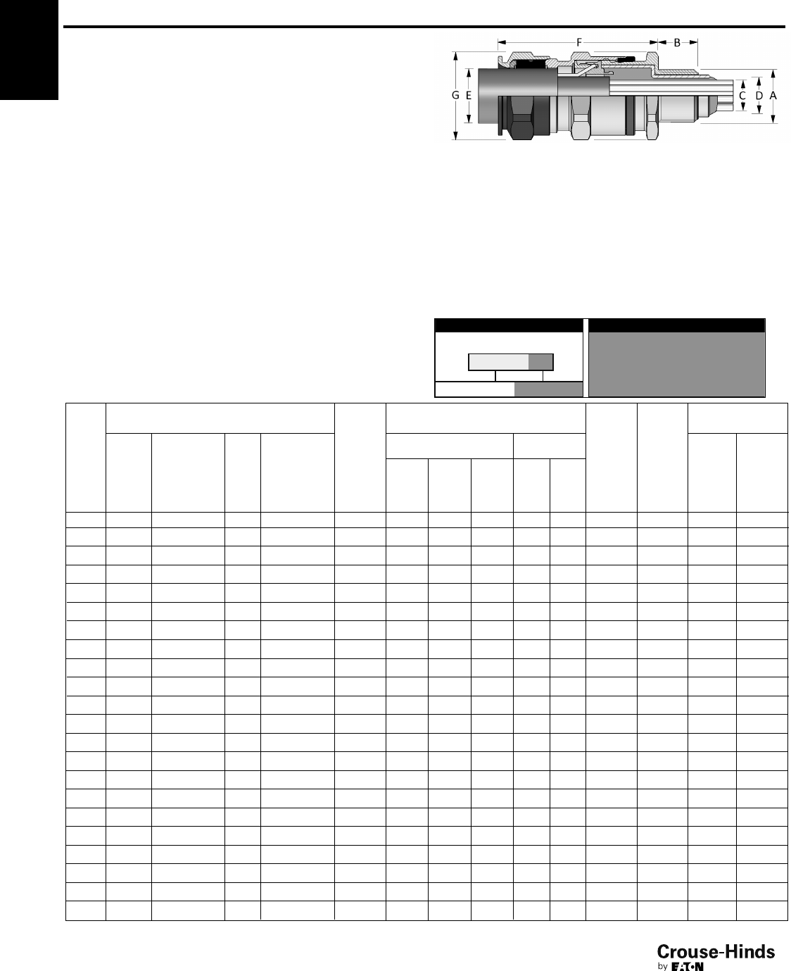
4F
74
www.crouse-hinds.com US: 1-866-764-5454 CAN: 1-800-265-0502 Copyright©2013 Eaton’s Crouse-Hinds Business
4F ADE 6FC
International Standards -
Flameproof and Increased Safety
ATEX
IECEx
cULus Listed for Class I, Zone 2
cULus Marine Listed for Class I, Div. 1
CEPEL
GOST-R
NEMA 4X and IP68
Gland Type:
Armoured barrier
Cable Type:
Steel wire armoured, steel wire braided, steel tape armoured,
braided marine shipboard and lead sheathed (with addition of
earthing washer)
ORDERING EXAMPLE:
CAP96959 4KX
OptionsGland Type
9 Stainless steel (316L)
8 Bronze
7 Aluminum
K1 Includes locknut and fiber washer
K2 Includes locknut, fiber washer, earth tag, and
shroud
OPTIONS (replace last digit with option number):
Certifications and Compliances:
• ATEX LCIE 97 ATEX 6008X - Exd IIC/Exe II/Ex tD/Ex II 2 GD
• IECEx LCI 05.0004X
• cULus Listed for Class I, Zone 2 AEx de II/Ex de II
• cULus Marine Listed for Class I, Division 1, Groups A, B, C, D
• NEMA 4X and IP68
• CEPEL-EX-558/05X
• GOST-R POCC FR Bo2011
• NEPSI N° GYJ071336U & GYJ071337U
• ABS approbation:
n° 10-HS 577243-PDA / P1836754-X
• DNV N° E-10892
• Lloyds
Features
• Standard material is nickel-plated brass for superior corrosion
resistance
• Armour clamping with no reversible components for easy
installation, minimizing error
• Provides explosionproof compound seal (denoted by red back nut)
on conductors and weatherproof seal on outer sheath of cable
• Deluge boot provides enhanced protection from water ingress
• Standard neoprene seal suitable for use in operating temperatures
-60°C (-25°C UL) to 80°C
• Available with metric or NPT threads
• See pages 96–103 for related accessories
5 M16 CAP969594 3/8"CAP974594 15 (12.0) 6.5 7.5 6.0 6.0 12.0 0.9 46.0 – 20.9
5 M20 CAP969674 1/2"CAP971674 15 (20.2) 6.5 7.5 6.0 6.0 12.0 0.9 46.0 – 26.4
6 M20 CAP969694 1/2"CAP971694 15 (20.2) 9.5 11.0 6.0 8.5 16.0 1.25 53.0 – 26.4
7 M20 CAP969604 1/2"CAP971604 15 (20.2) 12.0 14.5 10.0 12.0 21.0 1.25 59.0 – 33.0
7 M25 CAP969794 3/4"CAP971794 15 (20.5) 12.0 14.5 10.0 12.0 21.0 1.25 59.0 – 33.0
8 M25 CAP969704 3/4"CAP971704 15 (20.5) 17.0 19.5 21.0 16.0 27.5 1.6 74.5 – 45.1
8 M32 CAP969894 1" CAP971894 15 (25.3) 17.0 19.5 21.0 16.0 27.5 1.6 74.5 – 45.1
9 M32 CAP969804 1" CAP971804 15 (25.3) 23.0 28.0 42.0 21.0 34.0 1.6 83.5 – 52.8
9 M40 CAP969994 11/4"CAP971994 15 (26.0) 23.0 28.0 42.0 21.0 34.0 1.6 83.5 – 52.8
10 M40 CAP969904 11/4"CAP971904 15 (26.0) 29.0 33.0 60.0 27.0 41.0 2.0 92.0 – 60.5
10 M50 CAP970094 11/2"CAP972094 16 (26.5) 29.0 33.0 60.0 27.0 41.0 2.0 92.0 – 60.5
11 M50 CAP970004 11/2"CAP972004 16 (27.2) 36.5 41.0 80.0 33.0 48.0 2.5 104.0 – 70.4
12 M63 CAP970294 2" CAP972274 17 (29.2) 43.0 48.0 100.0 40.0 56.0 2.5 108.0 – 79.2
13 M63 CAP970204 2" CAP972204 17 (29.2) 50.0 56.0 100.0 46.0 65.0 2.5 118.0 – 93.5
13 M75 CAP970394 21/2"CAP972494 18 (42.5) 50.0 56.0 100.0 46.0 65.0 2.5 118.0 – 93.5
14 M75 CAP970304 21/2"CAP972404 18 (42.5) 59.0 65.0 120.0 54.0 74.0 2.5 124.0 – 104.5
14 – –3" CAP972574 (44) 59.0 65.0 120.0 54.0 74.0 2.5 124.0 – 104.5
15 M90 CAP970594 3" CAP972594 22 (44.0) 66.0 73.0 140.0 63.0 83.0 3.15 133.0 – 121.0
15 – –31/2"CAP972694 (45.2) 66.0 73.0 140.0 63.0 83.0 3.15 133.0 – 121.0
16 M90 CAP970504 3" CAP972504 22 (44.0) 75.0 82.0 140.0 72.0 93.0 3.15 137.0 – 132.0
16 – –31/2"CAP972604 (45.2) 75.0 82.0** 140.0 72.0 93.0 3.15 137.0 – 132.0
17 M110 CAP970794 4" CAP972704 22 (46.5) 85.0 92.0** 200.0 85.0 107.0 3.15 142.0 – 148.5
All dimensions in millimeters unless otherwise noted.
*Aluminum not currently available with UL marine certification.
**Contact Customer Service or your field sales representative for amended UL marine range.
SELECTION TABLE
Gland
Size
Entry Thread Size ‘A’
Thread
Length
‘B’
Metric
(NPT)
Cable Acceptance
Armour
(max)
Gland
Length
‘F’ (less
entry)
Hexagon
Dimensions
Metric
Size
Metric
Catalog #
NPT
Size
NPT
Catalog #
Inner Sheath
and Cores
Outer
Sheath ‘E’
Across
Flats
Across
Corners
‘G’
Max
Over
Cores
'C'
Max
Inner
Sheath
'D'
Max
No. of
Cores Min Max
74-75.qxp 12/24/2013 2:59 PM Page 74
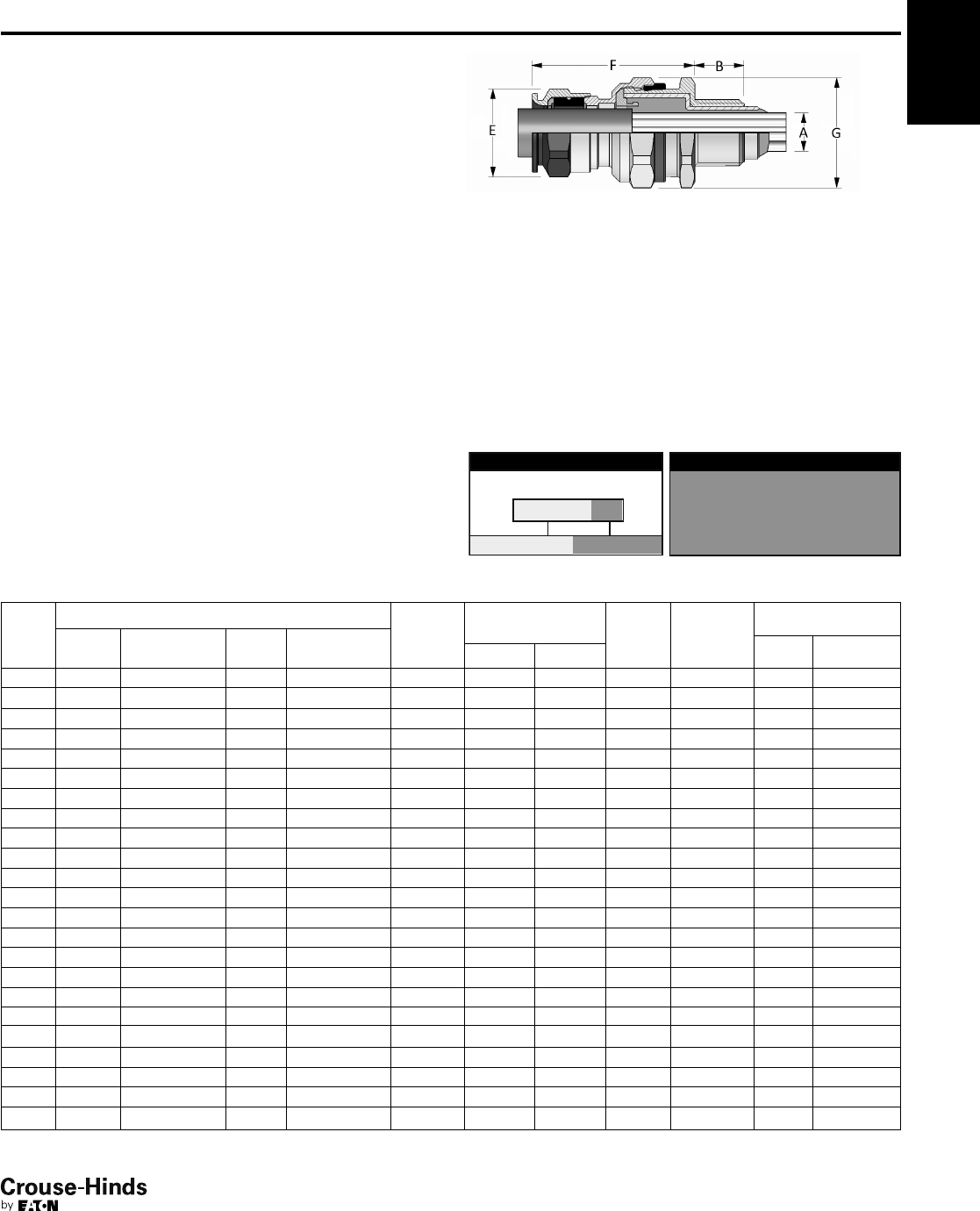
4F
75
www.crouse-hinds.com US: 1-866-764-5454 CAN: 1-800-265-0502 Copyright©2013 Eaton’s Crouse-Hinds Business
4F
ADE 1FC
International Standards -
Flameproof and Increased Safety
Gland Type:
Non-armoured barrier
Cable Type:
Non-armoured, armoured and tray cable (does not terminate the
armour)
Features:
• Standard material is nickel-plated brass for superior corrosion
resistance
• Provides a flameproof and weatherproof seal on outer sheath of
cable
• Provides explosionproof compound seal (denoted by red back nut)
on conductors
• Deluge boot provides enhanced protection from water ingress
• Standard neoprene seal suitable for use in operating temperatures
-60°C (-25°C UL) to 80°C
• Available with metric or NPT threads
• See pages 96–103 for related accessories
SELECTION TABLE
Gland
Size
Thread
Length ‘B’
Metric
(NPT)
Cable Acceptance
Max No.
Cores
Gland
Length ‘F’
(less entry)
Hexagon
Dimensions
Metric
Size
Metric
Catalog #
NPT
Size
NPT
Catalog #
Outer Sheath ‘E’ Across
Flats
Across
Corners ‘G’
Min Max
4 M16 CAP019594 3/8"CAP011594 15 (12.0) 4.0 7.5 6.0 46.0 –
–
–
–
–
–
–
–
–
–
–
–
–
–
–
–
–
–
–
–
–
–
–
20.9
4 M20 CAP019674 1/2"CAP011674 15 (22.2) 4.0 7.5 6.0 46.0 26.4
5 M20 CAP019694 1/2"CAP011694 15 (22.2) 6.5 11.0 6.0 53.0 26.4
6 M20 CAP019604 1/2"CAP011604 15 (22.2) 9.0 14.5 10.0 59.0 33.0
6 M25 CAP019794 3/4"CAP011794 15 (22.5) 9.0 14.5 10.0 59.0 33.0
7 M25 CAP019704 3/4"CAP011704 15 (22.5) 12.0 19.5 21.0 74.5 45.1
7 M32 CAP019894 1" CAP011894 15 (27.3) 12.0 19.5 21.0 74.5 45.1
8 M32 CAP019804 1" CAP011804 15 (27.3) 17.5 26.0 42.0 83.5 52.8
8 M40 CAP019994 11/4"CAP011994 15 (28.0) 17.5 26.0 42.0 83.5 52.8
9 M40 CAP019904 11/4"CAP011904 15 (28.0) 23.0 33.0 60.0 92.0 60.5
9 M50 CAP019094 11/2"CAP011094 16 (28.5) 23.0 33.0 60.0 92.0 60.5
10 M50 CAP019004 2" CAP011004 16 (29.2) 28.5 41.0 80.0 104.0 70.4
10 M63 CAP019204 ––16 28.5 41.0 80.0 – 73.7
11 M63 CAP019294 2" CAP011294 17 (29.2) 43.0 48.0 100.0 98.0 70.4
12 M63 CAP019274 2" CAP011204 17 (29.2) 50.0 56.0 100.0 103.0 79.2
12 – –21/2"CAP011494 42.5 50.0 56.0 100.0 103.0 79.2
13 M75 CAP019304 21/2"CAP011404 18 (42.5) 59.0 65.0 120.0 111.0 93.5
13 – –3" CAP012504 44 59.0 65.0 120.0 111.0 93.5
14 M90 CAP010594 3" CAP012574 22 (44.0) 66.0 73.0 140.0 120.0 104.5
14 – –31/2"CAP012604 45.2 66.0 73.0 140.0 120.0 104.5
15 M90 CAP010504 3" CAP012594 22 (44.0) 75.0 82.0 140.0 125.0 121.0
15 – –31/2"CAP012694 45.2 75.0 82.0** 140.0 125.0 121.0
16 M110 CAP010794 4" CAP012704 22 (46.5) 85.0 92.0** 200.0 128.0 132.0
All dimensions in millimeters unless otherwise noted.
*Aluminum not currently available with UL marine certification.
**Contact Customer Service or your field sales representative for amended UL marine range.
Entry Thread Size ‘A’
ATEX
IECEx
cULus Listed for Class I, Zone 2
UL Marine Listed for Class I, Div. 2
CEPEL
GOST-R
NEMA 4X and IP68
Certifications and Compliances:
• LCIE 97 ATEX 6008X II GD - Exd IIC/Exe II/Ex tD
• IECEx LCI 05.0004X Ex c e IIC/Ex c e II/Ex tD
• cULus Listed for Class I, Zone 2 AEx de II/Ex de II
• UL Marine Listed for Class I, Division 2, Groups A, B, C, D
• NEMA 4X and IP68
• CEPEL EX-558/05X
• GOST-R POCC FR.B03126
• NEPSI N° GYJ071336U & GYJ071337U
• DNV N° E-10892
• ABS approbation:
n° 10-HS 577243-PDA / P1836754-X
• Lloyds
ORDERING EXAMPLE:
CAP01959 4KX
OptionsGland Type
9 Stainless steel (316L)
8 Bronze
7 Aluminum
K1 Includes locknut and fiber washer
K2 Includes locknut, fiber washer, earth tag, and
shroud
OPTIONS (replace last digit with option number):
74-75.qxp 12/24/2013 2:59 PM Page 75
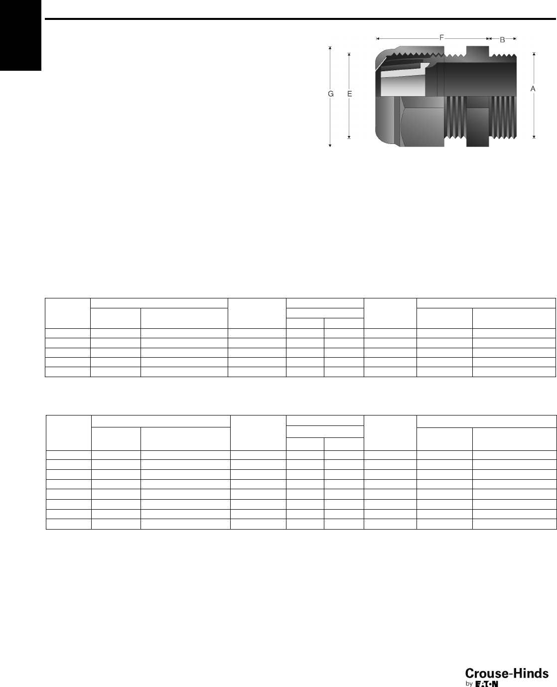
4F
76
www.crouse-hinds.com US: 1-866-764-5454 CAN: 1-800-265-0502 Copyright©2013 Eaton’s Crouse-Hinds Business
Ex-e
International Standards -
Flameproof and Increased Safety
Sizes M12-M16: PTB 99 ATEX
3101 X
Sizes M20-M63: PTB 99 ATEX
3128 X
IECEx
IP66
Gland Type:
Non-armoured
Cable Type:
Non-armoured
Certifications and Compliances:
• Sizes M12-M16: PTB 99 ATEX 3101 X
Sizes M20-M63: PTB 99 ATEX 3128 X
Ex II 2 G Ex e II/Ex II 2 D Ex tD A21
• IECEx PTB 05.0004X
•IP66 Features:
• Standard material is high-impact resistant polyamide
• Forms weatherproof seal on outer sheath of cable
• Standard silicone seal suitable for use in operating temperatures
-55° to 70°C (M12 and M16 for use in operating temperatures
-20° to 70°C)
• Available with optional silicone seal for extreme temperatures
• Available with metric threads
• See page 101 for related accessories
SELECTION TABLE - LONG THREAD
Gland Size
Entry Thread Size ‘A’ Thread
Length ‘B’
Metric
Cable Acceptance Gland
Length ‘F’
(less entry)
Hexagon Dimensions
Metric Size Metric Catalog #
Outer Sheath ‘E’
Across Flats
Across Corners ‘G’
Min Max
12 M12 GHG 960 1955 R 0021 8.0 4.0 7.0 19.3 15.0 16.5
16 M16 GHG 960 1955 R 0022 8.0 5.5 10.0 23.0 20.0 22.0
20
25
M20 GHG 960 1955 R 0023 8.0 5.5 13.0 25.0 24.0 26.4
M25 GHG 960 1955 R 0024 8.0 8.0 27.0 29.5 29.0 31.9
32 M32 GHG 960 1955 R 0025 10.0 12.0 21.0 35.5 36.0 39.6
40 M40 GHG 960 1955 R 0026 15.0 17.0 28.0 39.5 46.0 50.6
50 M50 GHG 960 1955 R 0027 16.0 22.0 35.0 44.0 55.0 60.5
63 M63 GHG 960 1955 R 0028 16.0 27.0 48.0 47.0 68.0 74.8
All dimensions in millimeters unless otherwise noted.
4F
SELECTION TABLE - SHORT THREAD
Gland Size
Entry Thread Size ‘A’ Thread
Length ‘B’
Metric
Cable Acceptance Gland
Length ‘F’
(less entry)
Hexagon Dimensions
Metric Size Metric Catalog #
Outer Sheath ‘E’
Across Flats Across Corners ‘G’Min Max
12 M12 GHG 960 1955 R 0001 8.0 4.0 7.0 19.3 15.0 16.5
16 M16 GHG 960 1955 R 0002 8.0 5.5 10.0 23.0 20.0 22.0
20 M20 GHG 960 1955 R 0003 8.0 5.5 13.0 25.0 24.0 26.4
25 M25 GHG 960 1955 R 0004 8.0 8.0 17.0 29.5 29.0 31.9
32 M32 GHG 960 1955 R 0005 10.0 12.0 21.0 35.5 36.0 39.6
76-77.qxp 12/16/2013 12:12 PM Page 76
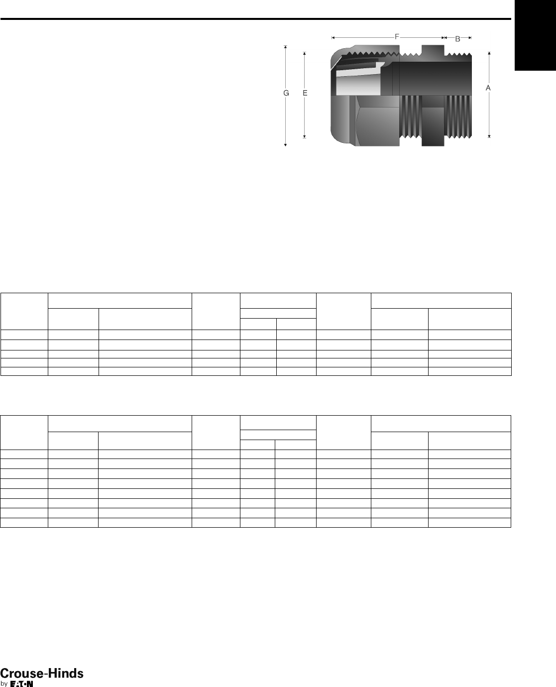
4F
77
www.crouse-hinds.com US: 1-866-764-5454 CAN: 1-800-265-0502 Copyright©2013 Eaton’s Crouse-Hinds Business
Ex-i
International Standards -
Flameproof and Increased Safety
Sizes M12-M16: PTB 99 ATEX
3101 X
Sizes M20-M63: PTB 99 ATEX
3128 X
IECEx
IP66
Gland Type:
Non-armoured
Cable Type:
Non-armoured
Certifications and Compliances:
• Sizes M12-M16: PTB 99 ATEX 3101 X
Sizes M20-M63: PTB 99 ATEX 3128 X
Ex II 2 G Ex e II/Ex II 2 D Ex tD A21
• IECEx PTB 05.0004X
•IP66 Features:
• Standard material is high-impact resistant polyamide (gland nut is
blue for intrinsically safe circuits)
• Forms weatherproof seal on outer sheath of cable
• Standard silicone seal suitable for use in operating temperatures
-55° to 70°C (M12 and M16 for use in operating temperatures
-20° to 70°C)
• Available with metric threads
• See page 101 for related accessories
SELECTION TABLE – LONG THREAD
Gland Size
Entry Thread Size ‘A’ Thread
Length ‘B’
Metric
Cable Acceptance Gland
Length ‘F’
(less entry)
Hexagon Dimensions
Metric Size Metric Catalog #
Outer Sheath ‘E’ Across Flats Across Corners ‘G’
Min Max
12 M12 GHG 960 1955 R 0121 12.0 4.0 7.0 19.3 15.0 16.5
16 M16 GHG 960 1955 R 0122 12.0 5.5 10.0 23.0 20.0 22.0
20 M20 GHG 960 1955 R 0123 13.0 5.5 13.0 25.0 24.0 26.4
25 M25 GHG 960 1955 R 0124 13.0 8.0 17.0 29.5 29.0 31.9
32 M32 GHG 960 1955 R 0125 15.0 12.0 21.0 35.5 36.0 39.6
40 M40 GHG 960 1955 R 0126 15.0 17.0 28.0 39.5 46.0 50.6
50 M50 GHG 960 1955 R 0127 16.0 22.0 35.0 44.0 55.0 60.5
63 M63 GHG 960 1955 R 0128 16.0 27.0 48.0 47.0 68.0 74.8
All dimensions in millimeters unless otherwise noted.
4F
SELECTION TABLE – SHORT THREAD
Gland Size
Entry Thread Size ‘A’ Thread
Length ‘B’
Metric
Cable Acceptance Gland
Length ‘F’
(less entry)
Hexagon Dimensions
Metric Size Metric Catalog #
Outer Sheath ‘E’ Across Flats Across Corners ‘G’
Min Max
12 M12 GHG 960 1955 R 0101 8.0 4.0 7.0 19.3 15.0 16.5
16 M16 GHG 960 1955 R 0102 8.0 5.5 10.0 23.0 20.0 22.0
20 M20 GHG 960 1955 R 0103 8.0 5.5 13.0 25.0 24.0 26.4
25 M25 GHG 960 1955 R 0104 8.0 8.0 17.0 29.5 29.0 31.9
32 M32 GHG 960 1955 R 0105 10.0 12.0 21.0 35.5 36.0 39.6
76-77.qxp 12/16/2013 12:12 PM Page 77
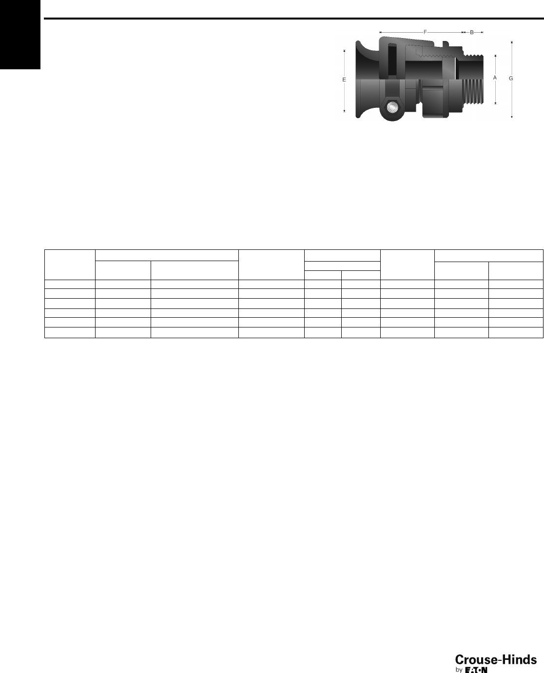
4F
78
www.crouse-hinds.com US: 1-866-764-5454 CAN: 1-800-265-0502 Copyright©2013 Eaton’s Crouse-Hinds Business
Trumpet
International Standards -
Flameproof and Increased Safety
ATEX IP66
Gland Type:
Non-armoured
Cable Type:
Non-armoured
Certifications and Compliances:
• ATEX PTB 00ATEX3121X Ex II 2 G Ex e II/Ex II 2 D Ex tD A21
•IP66 Features:
• Standard material is high-impact resistant polyamide
• Forms weatherproof seal on outer sheath of cable
• Flared rear seal provides protection for cable
• Standard neoprene seal suitable for use in operating temperatures
-40° to 85°C
• Available with metric threads
• See page 101 for related accessories
SELECTION TABLE
Entry Thread Size ‘A’
Thread Length
‘B’ Metric
Cable Acceptance Gland
Length ‘F’
(less entry)
Hexagon Dimensions
Metric
Size
Metric
Catalog #
Outer Sheath ‘E’ Across
Flats
Across
Corners ‘G’Min Max
20 M20 GHG 960 1949 R0111 15.0 8.0 13.0 49.0 26.0 28.6
25 M25 GHG 960 1949 R0112 15.0 11.0 16.0 50.0 32.0 35.2
32 M32 GHG 960 1949 R0113 15.0 15.0 20.0 65.0 41.0 45.1
40 M40 GHG 960 1949 R0114 15.0 19.0 27.0 71.0 50.0 55.0
50 M50 GHG 960 1949 R0115 16.0 26.0 34.0 79.0 60.0 66.0
60 M60 GHG 960 1949 R0116 16.0 35.0 46.0 89.0 75.0 82.5
All dimensions in millimeters unless otherwise noted.
4F
Gland
Size
78-79.qxp 12/16/2013 12:43 PM Page 78
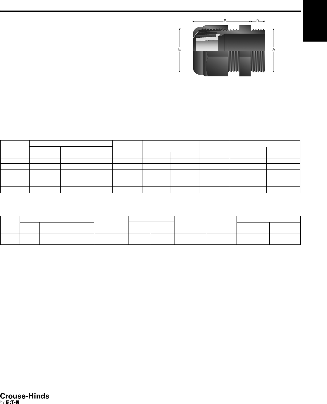
SELECTION TABLE – MULTIPLE
4F
79
www.crouse-hinds.com US: 1-866-764-5454 CAN: 1-800-265-0502 Copyright©2013 Eaton’s Crouse-Hinds Business
Enlargement and Multiple
International Standards -
Flameproof and Increased Safety
Sizes M16: PTB 99 ATEX 3101 X
Sizes M20-M63: PTB 99 ATEX
3128 X
IECEx
IP66
Gland Type:
Non-armoured
Cable Type:
Non-armoured
Certifications and Compliances:
• Sizes M16: PTB 99 ATEX 3101 X
Sizes M20-M63: PTB 99 ATEX 3128 X
Ex II 2 G Ex e II/Ex II 2 D Ex tD A21
• IECEx PTB 05.0004X
•IP66
Features:
• Standard material is high-impact resistant polyamide
• Forms weatherproof seal on outer sheath of cable
• Provides reduced entry threads for larger gland size
• Standard silicone seal suitable for use in operating temperatures
-55° to 70°C (M16 for use in operating temperatures -20° to 70°C)
• Available with metric threads
• See page 101 for related accessories
SELECTION TABLE – ENLARGEMENT
Gland
Size
Entry Thread Size ‘A’ Thread
Length ‘B’
Metric
Cable Acceptance Gland
Length ‘F’
(less entry)
Hexagon Dimensions
Metric
Size
Metric
Catalog #
Outer Sheath ‘E’ Across
Flats
Across
Corners ‘G’
Min Max
16/20 M16 GHG 960 1956 R0002 12.0 5.5 13.0 25.0 24.0 26.4
20/25 M20 GHG 960 1956 R0003 13.0 8.0 17.0 29.5 29.0 31.9
25/32 M25 GHG 960 1956 R0004 13.0 12.0 21.0 35.5 36.0 39.6
32/40 M32 GHG 960 1956 R0005 15.0 16.0 28.0 39.5 46.0 50.6
40/50 M40 GHG 960 1956 R0006 15.0 21.0 35.0 44.0 55.0 60.5
50/63 M50 GHG 960 1956 R0007 16.0 27.0 48.0 47.0 68.0 74.8
4F
Gland
Size
Entry Thread Size ‘A’ Thread
Length ‘B’
Metric
Cable Acceptance Maximum
Number of
Conductors
Gland
Length ‘F’
(less entry)
Hexagon Dimensions
Metric
Size Metric Catalog #
Outer Sheath ‘E’ Across
Flats
Across
Corners ‘G’Min Max
25 M25 GHG 960 1955 R0054 8.0 4.5 7.0 2 29.5 36.0 39.6
32 M32 GHG 960 1955 R0055 10.0 4.5 7.0 4 39.5 46.0 50.6
All dimensions in millimeters unless otherwise noted.
78-79.qxp 12/16/2013 12:43 PM Page 79
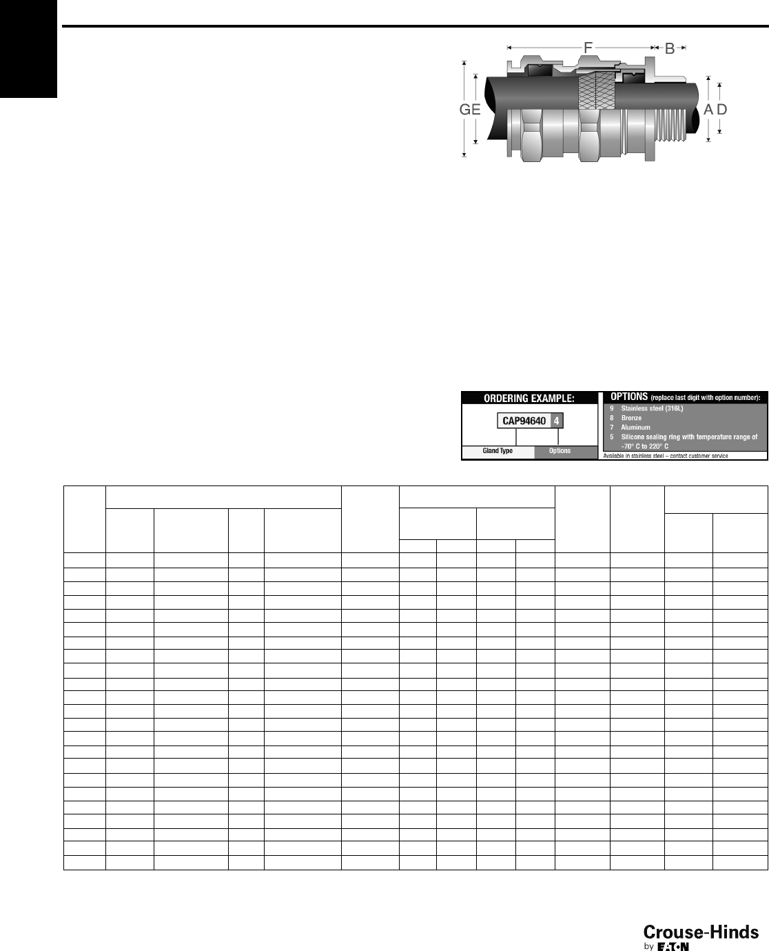
4F
80
www.crouse-hinds.com US: 1-866-764-5454 CAN: 1-800-265-0502 Copyright©2013 Eaton’s Crouse-Hinds Business
4F ADE 4I
International Standards -
Industrial
NEMA 4X and IP68
Gland Type:
Armoured
Cable Type:
Steel wire armoured, steel wire braided, steel tape armoured,
braided marine shipboard lead sheathed (with addition of earthing
washer) and tray cable
Certifications and Compliances:
• NEMA 4X and IP68 Features:
• Standard material is nickel-plated brass for superior corrosion
resistance
• Armour clamping and bonding with no reversible components for
easy installation, minimizing error
• Provides seal on inner jacket and weatherproof seal on outer
sheath of the cable
• An optional earthing washer for use with lead sheathed cable
( see page 97)
• Standard neoprene seal suitable for use in operating temperatures
of -60°C to 100°C
• Available with optional silicone seal for extreme temperatures
• Available with metric or NPT threads
• See pages 96–103 for related accessories
SELECTION TABLE
Gland
Size
Entry Thread Size ‘A’
Thread
Length
‘B’ Metric
(NPT)
Cable Acceptance
Armour
(max)
Gland
Length
‘F’ (less
entry)
Hexagon
Dimensions
Metric
Size
Metric
Catalog #
NPT
Size
NPT
Catalog #
Inner Sheath
‘D’
Outer Sheath
‘E’ Across
Flats
Across
Corners
‘G’Min Max Min Max
5 M12 CAP946404 1/4"CAP948404 15 (12.0) 4.0 8.0 6.0 12.0 0.9 36.0 – 20.9
5 M16 CAP946594 3/8"CAP948594 15 (12.0) 4.0 8.5 6.0 12.0 0.9 36.0 – 20.9
6 M16 CAP946504 3/8"CAP948504 15 (12.0) 6.0 12.0 8.5 16.0 1.25 42.0 – 26.4
5 M20 CAP946674 1/2"CAP948674 15 (20.2) 4.0 8.5 6.0 12.0 0.9 36.0 – 26.4
6 M20 CAP946694 1/2"CAP948694 15 (20.2) 6.0 12.0 8.5 16.0 1.25 42.0 – 26.4
7 M20 CAP946604 1/2"CAP948604 15 (20.2) 8.5 16.0 12.0 21.0 1.25 46.0 – 33.0
6 M25 CAP946774 3/4"CAP948774 15 (20.2) 6.0 12.0 8.5 16.0 1.25 42.0 – 33.0
7 M25 CAP946794 3/4"CAP948795 15 (20.2) 8.5 16.0 12.0 21.0 1.25 46.0 – 33.0
8 M25 CAP946704 3/4"CAP948704 15 (20.2) 12.0 20.5 16.0 27.5 1.6 56.0 – 45.1
8 M32 CAP946894 1" CAP948894 15 (25.3) 12.0 21.0 16.0 27.5 1.6 56.0 – 45.1
9 M32 CAP946804 1" CAP948804 15 (25.3) 16.0 27.5 21.0 34.0 1.6 63.0 – 52.8
9 M40 CAP946994 11/4"CAP948994 15 (26.0) 16.0 27.5 21.0 34.0 1.6 63.0 – 52.8
10 M40 CAP946904 11/4"CAP948904 15 (26.0) 21.0 34.0 27.0 41.0 2.0 68.0 – 60.5
10 M50 CAP947094 11/2"CAP949904 16 (26.5) 21.0 34.0 27.0 41.0 2.0 68.0 – 60.5
11 M50 CAP947004 11/2"CAP949004 16 (26.5) 27.0 41.0 33.0 48.0 2.5 74.0 – 70.4
12 M63 CAP947294 2" CAP949294 17 (27.2) 27.0 41.0 33.0 48.0 2.5 77.0 – 79.2
13 M63 CAP947204 2" CAP949204 17 (27.2) 33.0 48.0 40.0 56.0 2.5 85.0 – 93.5
13 M75 CAP947394 21/2"CAP949949 18 (40.5) 40.0 56.0 47.0 65.0 2.5 85.0 – 93.5
14 M75 CAP947304 21/2"CAP949404 18 (40.5) 47.0 65.0 54.0 74.0 2.5 92.0 – 104.5
15 M90 CAP947594 3" CAP949564 22 (42.0) 54.0 74.0 63.0 83.0 3.15 104.0 – 121.0
16 M90 CAP947504 3" CAP949504 22 (42.0) 63.0 82.0 72.0 93.0 3.15 108.0 – 132.0
16 – –31/2"CAP949604 – (43.2) 63.0 82.0 72.0 93.0 3.15 108.0 – 132.0
17 M110 CAP947794 4" CAP949704 22 (44.5) 72.0 92.0 85.0 107.0 3.15 115.0 – 148.5
All dimensions in millimeters unless otherwise noted.
80-81.qxp 12/24/2013 3:12 PM Page 80
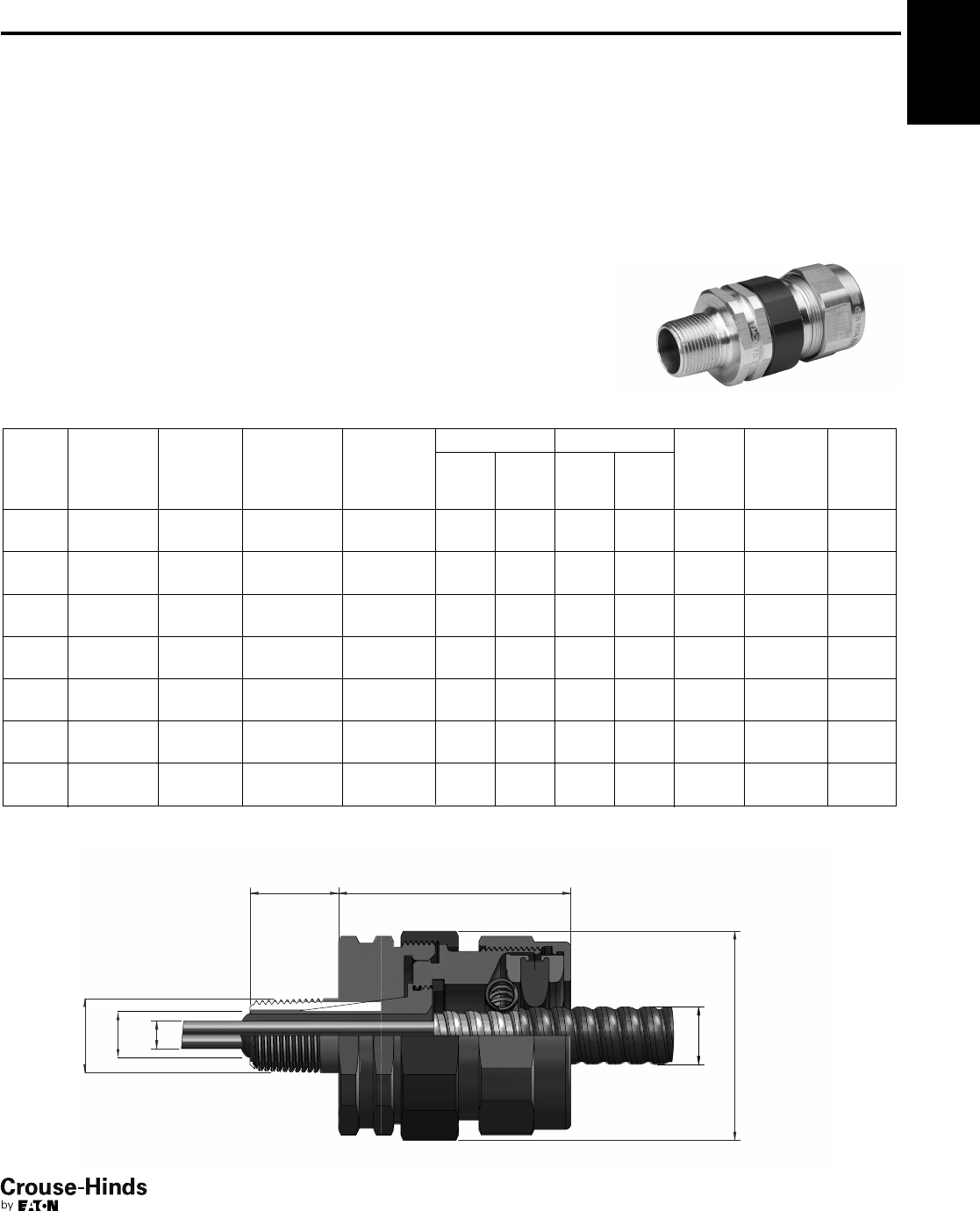
4F
81
www.crouse-hinds.com US: 1-866-764-5454 CAN: 1-800-265-0502 Copyright©2013 Eaton’s Crouse-Hinds Business
Gland Type:
Armoured barrier, TECK armoured, and
non-armoured barrier
Cable Type:
Metal-clad and TECK (interlocked and
continuously welded corrugated
armoured), unarmoured, and tray cable
Certifications and
Compliances:
• Class I, Division 1, Groups A, B, C, D
• Class II, Groups E, F, G
• Class III
• NEMA 6P
• UL/cULus Listed - File No. E122485
• IECEx/ATEX (Pending)
Features:
• Designed to minimize the opportunity for
incorrect assembly
• Simple selection process and field
preparation aids to ensure the right gland is
selected every time
• Full coverage of all popular cables and hub
sizes, ensuring a perfect seal in all instances
• Use of nickel-plated brass and stainless steel
to increase corrosion resistance and maintain
integrity in the harshest environments
• Chico®LiquidSeal, an innovative liquid
compound with fast gel and cure times,
reduces waiting times
• Complete with integral dam to facilitate
liquid pour
• Integral union design reduces the number of
times the gland has to be assembled and
disassembled during installation
• Mating components have generous lead-ins
to ensure that assembly is as trouble-free as
possible, even with the heaviest cables
• Use of neoprene seal allows use in
temperatures from -40°C to +60°C; for
specific temperature information, please
contact your local sales representative
• Metric size threads allow interfacing to
European machinery
• Wide range of global certifications and
approvals
• See page 102 for related accessories
SELECTION TABLE
Entry
Thread
‘C’
NPT
Catalog #
Entry
Thread ‘C’
(Metric
Option)
Metric
Catalog #
Over
Conductors
O.D. Max.
Inches ‘G’
‘A’ Armour O.D. ‘B’ Cable O.D.†
Across
Corners
‘D’
Thread
Length
NPT ‘E’
(Metric
mm.)
Length
‘F’Min. Max. Min. Max.
1/2"TMCX050 1 M20 TMCXM20 1 0.480 0.40
(10.16)
0.86
(21.84)
0.49
(12.45)
0.90
(22.86)
1.75
(44.45)
1.00
(25.40)
3.05
(77.47)
1/2"TMCX050 2 M20 TMCXM20 2 0.480 0.56
(14.22)
1.14
(28.96)
0.65
(16.51)
1.18
(29.97)
2.25
(57.15)
1.00
(25.40)
3.18
(80.77)
3/4"TMCX075 1 M25 TMCXM25 1 0.713 0.40
(10.16)
0.86
(21.84)
0.49
(12.45)
0.90
(22.86)
1.75
(44.45)
1.00
(25.40)
3.05
(77.47)
3/4"TMCX075 2 M25 TMCXM25 2 0.713 0.56
(14.22)
1.14
(28.96)
0.65
(16.51)
1.18
(29.97)
2.25
(57.15)
1.00
(25.40)
3.18
(80.77)
1" TMCX100 1 M32 TMCXM32 1 0.939 0.56
(14.22)
1.14
(28.96)
0.65
(16.51)
1.18
(29.97)
2.25
(57.15)
1.08
(27.40)
3.18
(80.77)
1" TMCX100 2 M32 TMCXM32 2 0.939 0.78
(19.81)
1.35
(34.29)
0.87
(22.10)
1.39
(35.31)
2.56
(65.02)
1.08
(27.40)
3.30
(83.82)
11/4"TMCX125 1 M40 TMCXM40 1 1.172 0.78
(19.81)
1.35
(34.29)
0.87
(22.10)
1.39
(35.31)
2.56
(65.02)
1.08
(27.40)
3.30
(83.82)
All dimensions in inches; metric millimeters shown in parenthesis. Sizes 11/2" and above will be available soon.
†When making your cable gland selection based on Cable O.D., be sure to also observe the Over Conductors O.D. dimension.
G
C
E
D
F
B
A
Terminator™II TMCX
North American Standards -
Explosionproof
UL/cULus Listed
Cl. I, Div. 1, Groups A, B, C, D
Cl. II, Groups E, F, G
Cl. III
NEMA 6P
IECEx/ATEX (Pending)
4F
80-81.qxp 12/24/2013 3:12 PM Page 81
4F
82
www.crouse-hinds.com US: 1-866-764-5454 CAN: 1-800-265-0502 Copyright©2013 Eaton’s Crouse-Hinds Business
Catalog Numbering System:
4F Terminator™II TMCX
North American Standards -
Explosionproof
UL/cULus Listed
Cl. I, Div. 1, Groups A, B, C, D
Cl. II, Groups E, F, G
Cl. III
NEMA 6P
IECEx/ATEX (Pending)
TMCX 050 1 NP L
Hub Size
NPT Hub (in.) Metric Hub (mm.)
050 ½ ” M20 20
075 ¾ ” M25 25
100 1” M32 32
125 1-¼ ” M40 40
Cable Sealing Range
Hub Size
Code Thread
Sealing
Range
Code Standard Cable
Sealing Range
050 ½ ” NPT
10.49” - 0.90”
20.65” - 1.18”
075 ¾ ” NPT
10.49” - 0.90”
20.65” - 1.18”
100 1” NPT
10.65” - 1.18”
20.87” - 1.39”
125 1-¼ ” NPT 10.87” - 1.39”
M20 M20 ISO
112.4 mm - 22.8 mm
216.5 mm - 29.9 mm
M25 M25 ISO
112.4 mm - 22.8 mm
216.5 mm - 29.9 mm
M32 M32 ISO
116.5 mm - 29.9 mm
222.0 mm - 35.3 mm
M40 M40 ISO 122.0 mm - 35.3 mm
Material
BLANK Aluminum
SS 316 Stainless Steel
NP Nickel-plated Brass
Compound Type
BLANK TSC
LLiquid
82-83.qxp 12/16/2013 12:13 PM Page 82
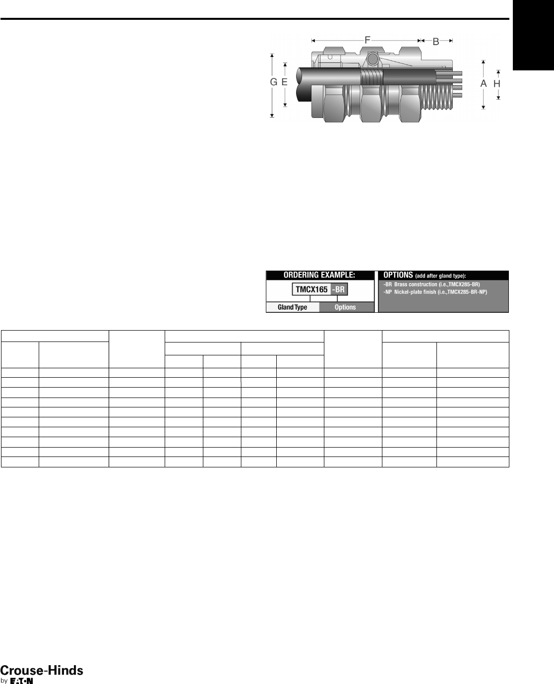
4F
83
www.crouse-hinds.com US: 1-866-764-5454 CAN: 1-800-265-0502 Copyright©2013 Eaton’s Crouse-Hinds Business
SELECTION TABLE
Entry Thread Size ‘A’
Thread
Length
‘B’ NPT
Cable Acceptance
Gland Length
‘F’ (less entry)
Hexagon Dimensions
NPT
Size
NPT
Catalog #
Armour Range ‘H’ Outer Sheath ‘E’ Across
Flats
Across
Corners ‘G’Min Max Min Max
1/2"TMCX165 0.750 0.440 0.650 0.490 0.781 2.625 1.250 1.375
3/4"TMCX285 0.781 0.600 0.850 0.650 1.000 2.875 1.500 1.625
1" TMCX3112 0.938 0.800 1.120 0.850 1.313 3.125 1.875 2.000
11/4"TMCX4140 0.969 1.100 1.400 1.150 1.625 3.125 2.250 2.438
11/2"TMCX5161 0.969 1.330 1.610 1.380 1.781 3.375 2.500 2.750
2" TMCX6206 1.000 1.570 2.060 1.630 2.313 5.313 3.250 3.500
21/2"TMCX7247 1.438 1.930 2.470 1.990 2.719 6.063 3.750 4.000
3" TMCX8302 1.438 2.450 3.020 2.525 3.281 6.063 4.500 4.875
31/2"TMCX9352 1.625 2.950 3.520 3.025 3.781 7.750 5.000 5.375
4" TMCX10402 1.625 3.500 4.020 3.585 4.281 8.313 5.500 5.875
All dimensions in inches unless otherwise noted.
4F
TMCX
North American Standards -
Explosionproof
Gland Type:
Armoured barrier, TECK armoured and non-armoured barrier
Cable Type:
Metal-clad (interlocked or continuously welded corrugated
armoured), non-armoured and tray cable
Certifications and Compliances:
• UL Listed, CSA Certified Class I, Div. 1, Groups, A, B, C, D;
Class II; Class III – UL File E122485, CSA File LR13046
• NEMA 4 and IP56 rated
• Wet locations
Features:
• Standard material is aluminum
• Stainless steel copper-plated spring provides grounding continuity
of cable armour (MC cable only)
• Provides explosionproof compound seal on conductors and
watertight seal on outer sheath of cable
• Standard neoprene seal suitable for use in operating temperatures
-25° to 60°C
• Cold Shrink™ Kit is available for extra protection in aggressive
environments (see page 102)
• Available with NPT threads
• See page 102 for related accessories
UL Listed
CSA Certified Class I, Div. 1,
Groups A, B, C, D
Class II; Class III
NEMA 4 and IP56
Wet locations
82-83.qxp 12/16/2013 12:13 PM Page 83
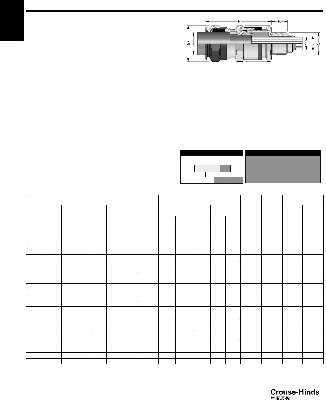
4F
84
www.crouse-hinds.com US: 1-866-764-5454 CAN: 1-800-265-0502 Copyright©2013 Eaton’s Crouse-Hinds Business
ADE 6FC
ATEX
IECEx
cULus Listed for Class I, Zone 2
cULus Marine Listed for Class I, Div. 1
CEPEL
GOST-R
NEMA 4X and IP68
Features:
• Standard material is nickel-plated brass for superior corrosion
resistance
• Armour clamping with no reversible components for easy
installation, minimizing error
• Provides explosionproof compound seal (denoted by red back nut)
on conductors and weatherproof seal on outer sheath of cable
• Deluge boot provides enhanced protection from water ingress
• Standard neoprene seal suitable for use in operating temperatures
-60°C (-25°C UL) to 80°C
• Available with metric or NPT threads
• See pages 96–99 for related accessories
4F
North American Standards -
Explosionproof
Gland Type:
Armoured barrier
Cable Type:
Steel wire armoured, steel wire braided, steel tape armoured,
braided marine shipboard and lead sheathed (with addition of
earthing washer)
All dimensions in millimeters unless otherwise noted.
*Aluminum not currently available with UL marine certification.
**Contact Customer Service or your field sales representative for amended UL marine range.
ORDERING EXAMPLE:
CAP96959 4KX
OptionsGland Type
9 Stainless steel (316L)
8 Bronze
7 Aluminum
K1 Includes locknut and fiber washer
K2 Includes locknut, fiber washer, earth tag, and
shroud
OPTIONS (replace last digit with option number):
Max
Over
Cores
'C'
Max
Inner
Sheath
'D'
Max
No. of
Cores Min Max
SELECTION TABLE
Gland
Size
Entry Thread Size ‘A’
Thread
Length
‘B’
Metric
(NPT)
Cable Acceptance
Armour
(max)
Gland
Length
‘F’ (less
entry)
Hexagon
Dimensions
Metric
Size
Metric
Catalog #
NPT
Size
NPT
Catalog #
Inner Sheath
and Cores
Outer
Sheath ‘E’
Across
Flats
Across
Corners
‘G’
5 M16 CAP969594 3/8"CAP974594 15 (12.0) 6.5 7.5 6.0 6.0 12.0 0.9 46.0 – 20.9
5 M20 CAP969674 1/2"CAP971674 15 (20.2) 6.5 7.5 6.0 6.0 12.0 0.9 46.0 – 26.4
6 M20 CAP969694 1/2"CAP971674 15 (20.2) 9.5 11.0 6.0 8.5 16.0 1.25 53.0 – 26.4
7 M20 CAP969604 1/2"CAP971604 15 (20.2) 12.0 14.5 10.0 12.0 21.0 1.25 59.0 – 33.0
7 M25 CAP969794 3/4"CAP971794 15 (20.5) 12.0 14.5 10.0 12.0 21.0 1.25 59.0 – 33.0
8 M25 CAP969704 3/4"CAP971704 15 (20.5) 17.0 19.5 21.0 16.0 27.5 1.6 74.5 – 45.1
8 M32 CAP969894 1" CAP971894 15 (25.3) 17.0 19.5 21.0 16.0 27.5 1.6 74.5 – 45.1
9 M32 CAP969804 1" CAP971804 15 (25.3) 23.0 28.0 42.0 21.0 34.0 1.6 83.5 – 52.8
9 M40 CAP969994 11/4"CAP971994 15 (26.0) 23.0 28.0 42.0 21.0 34.0 1.6 83.5 – 52.8
10 M40 CAP969904 11/4"CAP971904 15 (26.0) 29.0 33.0 60.0 27.0 41.0 2.0 92.0 – 60.5
10 M50 CAP970094 11/2"CAP972094 16 (26.5) 29.0 33.0 60.0 27.0 41.0 2.0 92.0 – 60.5
11 M50 CAP970004 11/2"CAP972004 16 (27.2) 36.5 41.0 80.0 33.0 48.0 2.5 104.0 – 70.4
12 M63 CAP970294 2" CAP972274 17 (29.2) 43.0 48.0 100.0 40.0 56.0 2.5 108.0 – 79.2
13 M63 CAP970204 2" CAP972204 17 (29.2) 50.0 56.0 100.0 46.0 65.0 2.5 118.0 – 93.5
13 M75 CAP970394 21/2"CAP972494 18 (42.5) 50.0 56.0 100.0 46.0 65.0 2.5 118.0 – 93.5
14 M75 CAP970304 21/2"CAP972404 18 (42.5) 59.0 65.0 120.0 54.0 74.0 2.5 124.0 – 104.5
14 – –3" CAP972574 (44) 59.0 65.0 120.0 54.0 74.0 2.5 124.0 – 104.5
15 M90 CAP970594 3" CAP972594 22 (44.0) 66.0 73.0 140.0 63.0 83.0 3.15 133.0 – 121.0
15 – –31/2"CAP972694 (45.2) 66.0 73.0 140.0 63.0 83.0 3.15 133.0 – 121.0
16 M90 CAP970504 3" CAP972504 22 (44.0) 75.0 82.0 140.0 72.0 93.0 3.15 137.0 – 132.0
16 – –31/2"CAP972604 (45.2) 75.0 82.0** 140.0 72.0 93.0 3.15 137.0 – 132.0
17 M110 CAP970794 4" CAP972704 22 (46.5) 85.0 92.0** 200.0 85.0 107.0 3.15 142.0 – 148.5
Certifications and Compliances:
• ATEX LCIE 97 ATEX 6008X - Exd IIC/Exe II/Ex tD/Ex II 2 GD
• IECEx LCI 05.0004X
• cULus Listed for Class I, Zone 2 AEx de II/Ex de II
• cULus Marine Listed for Class I, Division 1, Groups A, B, C, D
• NEMA 4X and IP68
• CEPEL-EX-558/05X
• GOST-R POCC FR Bo2011
• NEPSI N° GYJ071336U & GYJ071337U
• ABS approbation:
n° 10-HS 577243-PDA / P1836754-X
• DNV N° E-10892
• Lloyds
84-85.qxp 12/23/2013 2:41 PM Page 84
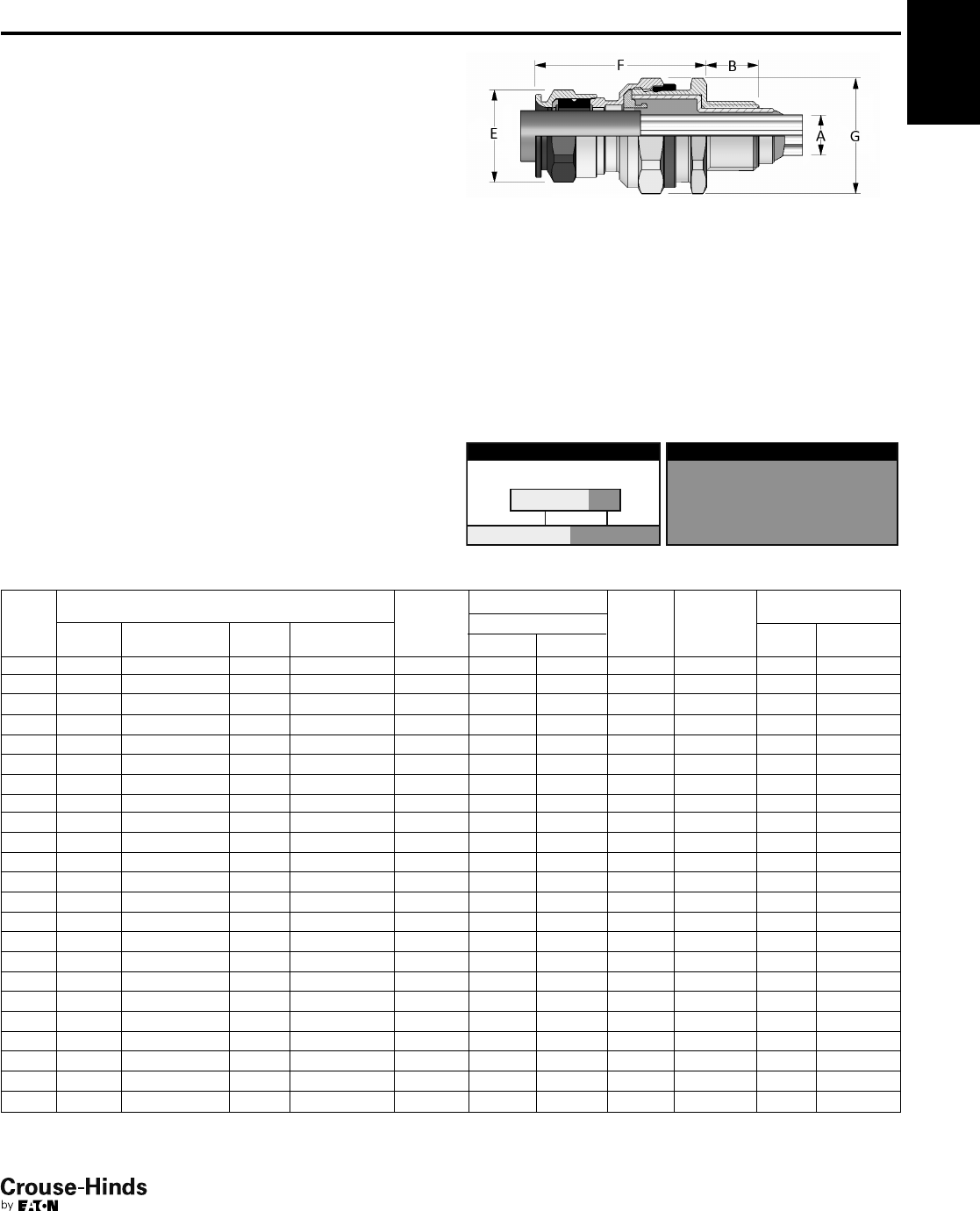
4F
85
www.crouse-hinds.com US: 1-866-764-5454 CAN: 1-800-265-0502 Copyright©2013 Eaton’s Crouse-Hinds Business
4F
ADE 1FC
North American Standards -
Explosionproof
Features:
• Standard material is nickel-plated brass for superior corrosion
resistance
• Provides a flameproof and weatherproof seal on outer sheath of
cable
• Provides explosionproof compound seal (denoted by red back nut)
on conductors
• Deluge boot provides enhanced protection from water ingress
• Standard neoprene seal suitable for use in operating temperatures
-60°C (-25°C UL) to 80°C
• Available with metric or NPT threads
• See pages 96–99 for related accessories
Gland Type:
Non-armoured barrier
Cable Type:
Non-armoured, armoured and tray cable (does not terminate the
armour)
ATEX
IECEx
cULus Listed for Class I, Zone 2
UL Marine Listed for Class I, Div. 2
CEPEL
GOST-R
NEMA 4X and IP68
SELECTION TABLE
Gland
Size
Entry Thread Size ‘A’ Thread
Length
‘B’ Metric
(NPT)
Cable Acceptance
Max No.
Cores
Gland
Length ‘F’
(less entry)
Hexagon
Dimensions
Metric
Size
Metric
Catalog #
NPT
Size
NPT
Catalog #
Outer Sheath ‘E’ Across
Flats
Across
Corners ‘G’
Min Max
4 M16 CAP019594 3/8"CAP011594 15 (12.0) 4.0 7.5 6.0 46.0 – 20.9
4 M20 CAP019674 1/2"CAP011674 15 (22.2) 4.0 7.5 6.0 46.0 – 26.4
5 M20 CAP019694 1/2"CAP011694 15 (22.2) 6.5 11.0 6.0 53.0 – 26.4
6 M20 CAP019604 1/2"CAP011604 15 (22.2) 9.0 14.5 10.0 59.0 – 33.0
6 M25 CAP019794 3/4"CAP011794 15 (22.5) 9.0 14.5 10.0 59.0 – 33.0
7 M25 CAP019704 3/4"CAP011704 15 (22.5) 12.0 19.5 21.0 74.5 – 45.1
7 M32 CAP019894 1" CAP011894 15 (27.3) 12.0 19.5 21.0 74.5 – 45.1
8 M32 CAP019804 1" CAP011804 15 (27.3) 17.5 26.0 42.0 83.5 – 52.8
8 M40 CAP019994 11/4"CAP011994 15 (28.0) 17.5 26.0 42.0 83.5 – 52.8
9 M40 CAP019904 11/4"CAP011904 15 (28.0) 23.0 33.0 60.0 92.0 – 60.5
9 M50 CAP019094 11/2"CAP011094 16 (28.5) 23.0 33.0 60.0 92.0 – 60.5
10 M50 CAP019004 2" CAP011004 16 (29.2) 28.5 41.0 80.0 104.0 – 70.4
10 M63 CAP019204 ––16 28.5 41.0 80.0 – – 73.7
11 M63 CAP019294 2" CAP011294 17 (29.2) 43.0 48.0 100.0 98.0 – 70.4
12 M63 CAP019274 2" CAP011204 17 (29.2) 50.0 56.0 100.0 103.0 – 79.2
12 – –21/2"CAP011494 42.5 50.0 56.0 100.0 103.0 – 79.2
13 M75 CAP019304 21/2"CAP011404 18 (42.5) 59.0 65.0 120.0 111.0 – 93.5
13 – –3" CAP012504 44 59.0 65.0 120.0 111.0 – 93.5
14 M90 CAP010594 3" CAP012574 22 (44.0) 66.0 73.0 140.0 120.0 – 104.5
14 – –31/2"CAP012604 45.2 66.0 73.0 140.0 120.0 – 104.5
15 M90 CAP010504 3" CAP012594 22 (44.0) 75.0 82.0 140.0 125.0 – 121.0
15 – –31/2"CAP012694 45.2 75.0 82.0** 140.0 125.0 – 121.0
16 M110 CAP010794 4" CAP012704 22 (46.5) 85.0 92.0** 200.0 128.0 – 132.0
All dimensions in millimeters unless otherwise noted.
*Aluminum not currently available with UL marine certification.
**Contact Customer Service or your field sales representative for amended UL marine range.
ORDERING EXAMPLE:
CAP01959 4KX
OptionsGland Type
9 Stainless steel (316L)
8 Bronze
7 Aluminum
K1 Includes locknut and fiber washer
K2 Includes locknut, fiber washer, earth tag, and
shroud
OPTIONS (replace last digit with option number):
Certifications and Compliances:
• LCIE 97 ATEX 6008X II GD - Exd IIC/Exe II/Ex tD
• IECEx LCI 05.0004X Ex c e IIC/Ex c e II/Ex tD
• cULus Listed for Class I, Zone 2 AEx de II/Ex de II
• UL Marine Listed for Class I, Division 2, Groups A, B, C, D
• NEMA 4X and IP68
• CEPEL EX-558/05X
• GOST-R POCC FR.B03126
• NEPSI N° GYJ071336U & GYJ071337U
• DNV N° E-10892
• ABS approbation:
n° 10-HS 577243-PDA / P1836754-X
• Lloyds
84-85.qxp 12/23/2013 2:41 PM Page 85
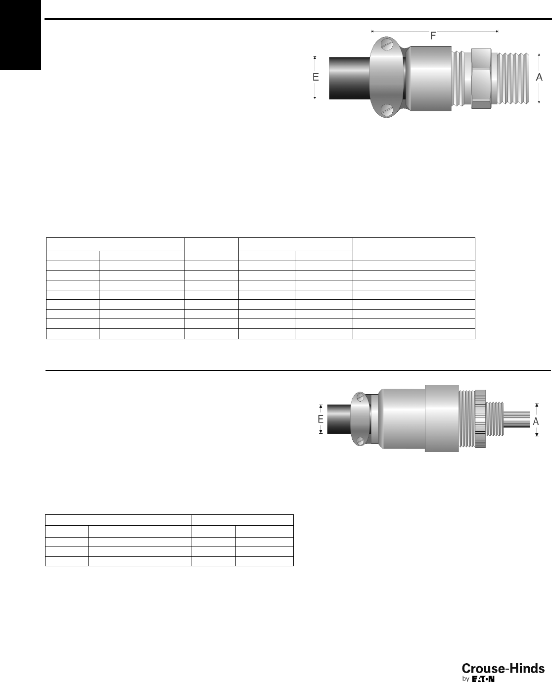
4F
86
www.crouse-hinds.com US: 1-866-764-5454 CAN: 1-800-265-0502 Copyright©2013 Eaton’s Crouse-Hinds Business
4F CGBS and EBY
North American Standards -
Explosionproof
Gland Type:
Portable cord connector
Cable Type:
Non-armoured and tray cable
Certifications and Compliances:
• CSA Certified Class I, Div. 1, Groups C, D
• Class II, Div. 1 & 2, Groups E, F, G
• Class III – CSA File LR13046 CGBS Features:
• Body – steel with zinc electroplate and chromate finish coat
• Gland nut – aluminum
• Body well for Chico A sealing compound (for ordering
information please contact customer service)
• Standard neoprene seal suitable for use in operating
temperatures -25° to 40°C
• Available with NPT threads
SELECTION TABLE
Entry Thread Size ‘A’ Form Outer Sheath ‘E’ Gland Length ‘F’ (less entry)
NPT Size NPT Catalog # Min Max
1/2"CGBS1013 A 0.312 0.437 51/4"
3/4"CGBS2013 A 0.312 0.437 51/4"
3/4"CGBS2014 A 0.375 0.500 51/4"
1" CGBS3015 B 0.500 0.625 27/8"
1" CGBS3016 B 0.625 0.750 215/16"
11/4"CGBS4017 B 0.750 0.875 213/16"
11/4"CGBS4018 B 0.875 1.000 31/2"
11/4"CGBS4019 B 1.000 1.188 39/16"
All dimensions in inches unless otherwise noted.
Gland Type:
Portable cord connector
Cable Type:
Non-armoured
EBY Features:
• Standard material is aluminum
• Factory sealed conductors and seal on outer sheath of cable
• Three, 12-inch long, #12 type SF-2 (150°C rating) stranded
pigtails; two circuit wires and one identified
grounding wire
• Three pressure connectors for 3-conductor cord,
range #18 to #12 AWG
• Standard neoprene seal suitable for use in operating
temperatures -25° to 40°C
• Available with NPT threads
SELECTION TABLE
Entry Thread Size ‘A’ Outer Sheath ‘E’
NPT Size NPT Catalog # Min Max
3/4"EBY2672 0.250 0.437
3/4"EBY2682 0.375 0.500
3/4"EBY26102 0.500 0.625
All dimensions in inches unless otherwise noted.
Certifications and Compliances:
• UL, cUL Listed Class I, Div. 1, Groups B, C, D
• Class II, Div. 1, Groups, F, G – UL File E10279
CGBS:
CSA Certified Class I,
Div. 1, Groups C, D
Class II, Div. 1 & 2, Groups E, F, G
Class III
EBY:
UL, cUL Listed Class I,
Div. 1, Groups B, C, D
Class II, Div. 1, Groups F, G
86-87.qxp 12/23/2013 2:42 PM Page 86
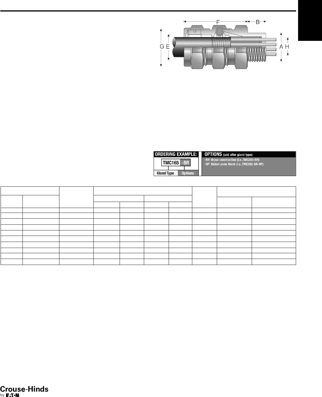
4F
87
www.crouse-hinds.com US: 1-866-764-5454 CAN: 1-800-265-0502 Copyright©2013 Eaton’s Crouse-Hinds Business
4F
TMC
North American Standards -
General Purpose
UL, CSA Listed NEMA 4 and IP56
Wet locations
Gland Type:
Armoured and TECK armoured
Cable Type:
Metal-clad (interlocked or continuously welded corrugated armoured)
and TECK
Features:
• Standard material is aluminum
• Stainless steel copper-plated spring provides grounding continuity
of cable armour
• Watertight seal on outer sheath of cable
• Standard neoprene seal suitable for use in operating temperatures
-25° to 60°C
• Cold Shrink™ Kit is available for extra protection in aggressive
environments (see page 102)
• Available with NPT threads
• See page 102 for related accessories
SELECTION TABLE
Entry Thread Size ‘A’ Thread
Length
‘B’ NPT
Cable Acceptance Gland
Length
‘F’ (less
entry)
Hexagon Dimensions
NPT
Size
NPT
Catalog #
Armour Range ‘H’ Across
Flats
Across
Corners ‘G’
Min Max Min Max
1/2"TMC165 0.750 0.440 0.650 0.490 0.781 2.375 1.250 1.375
3/4"TMC285 0.781 0.600 0.850 0.650 1.000 2.625 1.500 1.625
1" TMC3112 0.938 0.800 1.120 0.850 1.313 2.625 1.875 2.000
11/4"TMC4140 0.969 1.100 1.400 1.150 1.625 2.750 2.250 2.438
11/2"TMC5161 0.969 1.330 1.610 1.380 1.781 2.750 2.500 2.75
2" TMC6206 1.000 1.570 2.060 1.630 2.313 4.500 3.250 3.500
21/2"TMC7247 1.438 1.930 2.470 1.990 2.719 4.750 3.750 4.000
3" TMC8302 1.438 2.450 3.020 2.525 3.281 4.875 4.500 4.875
31/2"TMC9352 1.625 2.950 3.520 3.025 3.781 5.375 5.000 5.375
4" TMC10402 1.625 3.500 4.020 3.585 4.281 5.500 5.500 5.875
All dimensions in inches unless otherwise noted.
Outer Sheath ‘E’
Certifications and Compliances:
• UL Listed – UL File E36379
• CSA Listed – CSA File LR291
• NEMA 4 and IP56
• Wet locations
86-87.qxp 12/23/2013 2:42 PM Page 87
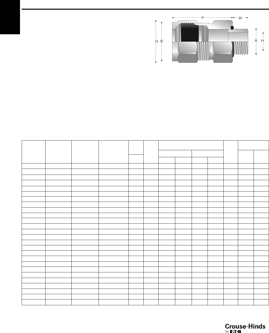
4F
88
www.crouse-hinds.com US: 1-866-764-5454 CAN: 1-800-265-0502 Copyright©2013 Eaton’s Crouse-Hinds Business
4F TECK
North American Standards -
General Purpose
CSA Certified Class II, Div. 1 & 2, Groups E, F, G
Class III - CSA
Type 4 and IP56
Wet locations
Gland Type:
Armoured
Cable Type:
TECK armoured
Certifications and Compliances:
• CSA Certified Class II, Div. 1 & 2, Groups E, F, G; Class III –
CSA File LR13046
• Type 4 and IP56
• Wet locations Features:
• Standard material is aluminum
• Stainless steel copper-plated spring provides grounding continuity
of cable armour (TECK cable only)
• Watertight seal on outer sheath of cable
• Standard neoprene seal suitable for use in operating temperatures
-25° to 60°C
• Cold Shrink™Kit is available for extra protection in aggressive
environments (see page 102)
• An integral o-ring seal on entry threads
• Available with NPT threads
• See page 102 for related accessories
SELECTION TABLE
Aluminum
Catalog #
Steel
Catalog #
Stainless
Steel
Catalog # PVC Catalog #
Entry
Thread
Size ‘A’ Thread
Length
‘B’ NPT
Cable Acceptance Gland
Length
‘F’
(less
entry)
Hexagon
Dimensions
NPT
Size
Armour Range ‘H’ Outer Sheath ‘E’ Across
Flats
Across
Corners
‘G’
Min Max Min Max
TECK050 1 TECK050 1S TECK050 1SS TECK050 1PVC
1
/
2
" 0.630 0.415 0.570 0.525 0.650 2.300 1.250 1.350
TECK050 2 TECK050 2S TECK050 2SS TECK050 2 PVC
1
/
2
" 0.630 0.490 0.680 0.600 0.760 2.300 1.375 1.500
TECK050 3 TECK050 3S TECK050 3SS TECK0503PVC
1
/
2
" 0.630 0.615 0.805 0.725 0.885 2.300 1.500 1.600
TECK050 4 TECK050 4S TECK050 4SS TECK050 4PVC
1
/
2
" 0.630 0.715 0.905 0.825 0.985 2.300 1.500 1.600
TECK075 5 TECK075 5S TECK075 5SS TECK075 5PVC
3
/
4
" 0.630 0.770 0.985 0.880 1.065 2.500 2.000 2.125
TECK075 6 TECK075 6S TECK075 6SS TECK075 6PVC
3
/
4
" 0.630 0.915 1.125 1.025 1.205 2.500 2.000 2.125
TECK100 7 TECK100 7S TECK100 7SS TECK1007PVC 1" 0.750 1.077 1.295 1.187 1.375 2.625 2.250 2.400
TECK125 8 TECK125 8S – TECK125 8PVC 1
1
/
4
" 0.800 1.240 1.545 1.350 1.625 3.500 3.000 3.125
TECK125 9 TECK125 9S – TECK125 9PVC 1
1
/
4
" 0.800 1.390 1.545 1.500 1.625 3.400 3.000 3.125
TECK125 10 TECK125 10S – TECK125 10PVC 1
1
/
4
" 0.800 1.490 1.795 1.600 1.875 3.500 3.000 3.125
TECK150 11 TECK150 11S – TECK150 11PVC 1
1
/
2
" 0.800 1.590 1.885 1.700 1.965 3.800 3.750 3.600
TECK150 12 TECK150 12S – TECK150 12PVC 1
1
/
2
" 0.800 1.790 2.107 1.900 2.187 3.900 3.500 3.750
TECK200 13 TECK200 13S – TECK200 13PVC 2" 0.825 1.790 2.107 1.900 2.187 4.000 3.750 4.000
TECK200 14 TECK200 14S – TECK200 14PVC 2" 0.825 1.990 2.280 2.100 2.375 4.000 3.750 4.000
TECK200 15 TECK200 15S – TECK200 15PVC 2" 0.875 2.190 2.485 2.300 2.565 4.000 4.125 4.400
TECK200 16 TECK200 16S – TECK200 16PVC 2" 0.875 2.390 2.656 2.500 2.750 4.000 4.125 4.400
TECK250 17 TECK250 17S – TECK250 17PVC 2
1
/
2
" 1.300 2.240 2.560 2.380 2.640 5.000 4.500 4.750
TECK250 18 TECK250 18S – TECK250 18PVC 2
1
/
2
" 1.300 2.440 2.750 2.580 2.840 5.000 4.500 4.750
TECK300 19 TECK300 19S – TECK300 19PVC 3" 1.400 2.640 2.970 2.790 3.060 5.000 4.600 4.900
TECK300 20 TECK300 20S – TECK300 20PVC 3" 1.400 2.870 3.190 3.000 3.270 5.000 4.900 5.250
TECK300 21 TECK300 21S – TECK300 21PVC 3" 1.400 3.042 3.390 3.210 3.480 5.000 5.000 5.250
TECK350 22 TECK350 22S – TECK350 22PVC 3
1
/
2
" 1.400 3.270 3.590 3.420 3.690 5.000 5.600 5.900
TECK350 23 TECK350 23S – TECK350 23PVC 3
1
/
2
" 1.400 3.440 3.770 3.610 3.870 5.000 5.500 5.900
TECK400 24 TECK400 24S – – 4" 1.400 3.600 3.930 3.810 4.030 5.000 6.125 6.500
TECK400 25 TECK400 25S – – 4" 1.400 3.755 4.065 3.965 4.185 5.000 6.125 6.500
TECK400 26 TECK400 26S – – 4" 1.400 3.910 4.220 4.120 4.340 5.000 6.125 6.500
All dimensions in inches unless otherwise noted.
88-89.qxp 12/23/2013 2:42 PM Page 88
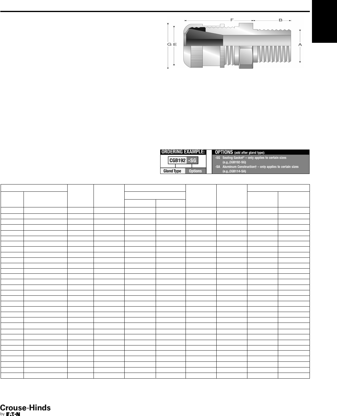
4F
89
www.crouse-hinds.com US: 1-866-764-5454 CAN: 1-800-265-0502 Copyright©2013 Eaton’s Crouse-Hinds Business
CGB
North American Standards -
General Purpose
cULus Listed
Gland Type:
Non-armoured
Cable Type:
Non-armoured and tray cable
Features:
• Form A - D bodies and gland nuts – steel with zinc electroplate
and chromate finish coat
• Form E - F bodies and gland nuts – Feraloy®iron alloy with
electrogalvanized and aluminum acrylic paint
• Weatherproof seal on outer sheath of cable
• Standard neoprene seal suitable for use in operating temperatures
-25° to 40°C
• Available with NPT threads
• Available in all aluminum construction
• See page 102 for related accessories
SELECTION TABLE
3/8"CGB3814 A 0.438 0.125 0.250 1.063 – 0.750 0.875
3/8"CGB3816 A 0.438 0.250 0.375 1.063 – 0.750 0.875
3/8"CGB3817 A 0.438 0.375 0.437 1.063 – 0.750 0.875
3/8"CGB3892 B 0.438 0.125 0.250 1.313 – 1.000 1.188
3/8"CGB3893 B 0.438 0.250 0.375 1.313 – 1.000 1.188
3/8"CGB3894 B 0.438 0.375 0.500 1.313 – 1.000 1.188
1/2"CGB114† A 0.625† 0.125 0.250 1.000 – 0.875 1.188
1/2"CGB116† A 0.625† 0.250 0.375 1.000 – 0.875 1.188
1/2"CGB117† A 0.625† 0.375 0.437 1.000 – 0.875 1.188
1/2"CGB192*† B 0.750*† 0.125 0.250 1.313 – 1.000 1.188
1/2"CGB193*† B 0.750*† 0.250 0.375 1.313 – 1.000 1.188
1/2"CGB194*† B 0.750*† 0.375 0.500 1.313 – 1.000 1.188
1/2"CGB195*† B 0.750*† 0.500 0.625 1.313 – 1.000 1.188
1/2"CGB196* C 0.625* 0.625 0.750 1.750 – 1.500 1.656
1/2"CGB197*† C 0.625*† 0.750 0.875 1.750 – 1.500 1.656
3/4"CGB292† B 0.625† 0.125 0.250 1.375 – 1.060 1.250
3/4"CGB293† B 0.625† 0.250 0.375 1.375 – 1.060 1.250
3/4"CGB294† B 0.625† 0.375 0.500 1.375 – 1.060 1.250
3/4"CGB295† B 0.625† 0.500 0.625 1.375 – 1.060 1.250
3/4"CGB296*† C 0.625*† 0.625 0.750 1.750 – 1.630 1.656
3/4"CGB297*† C 0.625*† 0.750 0.875 1.750 – 1.630 1.656
3/4"CGB298*† D 0.625*† 0.875 1.000 2.500 2.250 – –
1" CGB393† B 0.688† 0.250 0.375 1.375 – 1.375 1.625
1" CGB394† B 0.688† 0.375 0.500 1.375 – 1.375 1.625
1" CGB395*† C 0.688*† 0.500 0.625 1.688 – 1.500 1.875
1" CGB396*† C 0.688*† 0.625 0.750 1.688 – 1.500 1.875
1" CGB397*† C 0.688*† 0.750 0.875 1.688 – 1.500 1.875
1" CGB3239† C 0.688† 0.875 1.000 1.688 – – 1.875
1" CGB398*† D 0.625*† 0.875 1.000 2.375 2.375 – –
1" CGB399*† D 0.625*† 1.000 1.188 2.375 2.375 – –
1" CGB3911*† D 0.625*† 1.188 1.375 2.375 2.375 – –
All dimensions in inches unless otherwise noted.
*With optional Sealing Gasket.
†With optional Aluminum Construction.
4F
Min Max
NPT
Size
NPT
Catalog #
Outer Sheath ‘E’ Across
Flats
Across
Corners ‘G’
Entry Thread Size ‘A’
Form
Thread
Length ‘B’
NPT
Cable Acceptance
Gland
Length ‘F’
(less entry)
External
Diameter
‘G’
Hexagon Dimensions
Certifications and Compliances:
• cULus Listed - UL File E23223
• Suitable for use in Class I, Div. 2 hazardous locations when
installed in accordance with NEC501.10(B)(2)
88-89.qxp 12/23/2013 2:42 PM Page 89
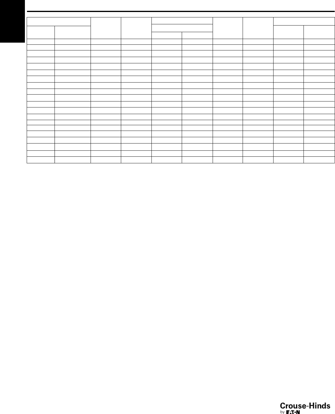
4F
90
www.crouse-hinds.com US: 1-866-764-5454 CAN: 1-800-265-0502 Copyright©2013 Eaton’s Crouse-Hinds Business
11/4"CGB498 D 0.688 0.875 1.000 2.313 2.250 – –
11/4"CGB499 D 0.688 1.000 1.188 2.313 2.250 – –
11/4"CGB4911 D 0.688 1.188 1.375 2.313 2.250 – –
11/4"CGB4913 E 0.688 1.375 1.625 2.625 3.000 – –
11/4"CGB4915 E 0.688 1.625 1.875 2.625 3.000 – –
11/2"CGB598 D 0.813 0.875 1.000 2.313 2.250 – –
11/2"CGB599 D 0.813 1.000 1.188 2.313 2.250 – –
11/2"CGB5911 D 0.813 1.188 1.375 2.313 2.250 – –
11/2"CGB5913 E 0.813 1.375 1.625 2.625 3.000 – –
11/2"CGB5915 E 0.813 1.625 1.875 2.625 3.000 – –
2" CGB6913 E 0.813 1.375 1.625 2.625 3.000 – –
2" CGB6915 E 0.813 1.625 1.875 2.625 3.000 – –
2" CGB6917 F 0.813 1.875 2.188 2.563 3.750 – –
2" CGB6920 F 0.813 2.188 2.500 2.563 3.750 – –
21/2"CGB7913 E 1.000 1.375 1.625 2.625 3.125 – –
21/2"CGB7915 E 1.000 1.625 1.875 2.625 3.125 – –
21/2"CGB7917 F 1.000 1.875 2.188 2.625 3.750 – –
21/2"CGB7920 F 1.000 2.188 2.500 2.625 3.750 – –
3" CGB8917 F 1.000 1.875 2.188 2.625 3.750 – –
3" CGB8920 F 1.000 2.188 2.500 2.625 3.750 – –
Min Max
NPT
Size
NPT
Catalog #
Outer Sheath ‘E’ Across
Flats
Across
Corners ‘G’
Entry Thread Size ‘A’
Form
Thread
Length ‘B’
NPT
Cable Acceptance Gland
Length ‘F’
(less entry)
External
Diameter
‘G’
Hexagon Dimensions
CGB
North American Standards -
General Purpose
cULus Listed
4F
90-91.qxp 12/16/2013 12:15 PM Page 90
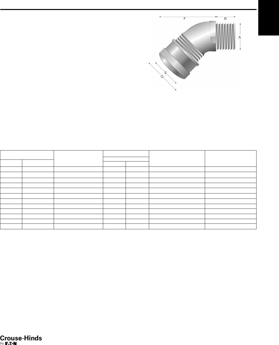
4F
91
www.crouse-hinds.com US: 1-866-764-5454 CAN: 1-800-265-0502 Copyright©2013 Eaton’s Crouse-Hinds Business
CGD
North American Standards -
General Purpose
cULus Listed
SELECTION TABLE
Entry Thread Size ‘A’
Thread Length
‘B’ NPT
Cable Acceptance
Gland Length
‘F’ (less entry)
External
Diameter ‘G’NPT Size NPT Catalog #
Outer Sheath ‘E’
Min Max
1/2"CGD192 0.630 0.125 0.250 1.688 1.188
1/2"CGD193 0.630 0.250 0.375 1.688 1.188
1/2"CGD194 0.630 0.375 0.500 1.688 1.188
1/2"CGD195 0.630 0.500 0.625 1.688 1.188
1/2"CGD196 0.630 0.625 0.750 2.063 1.625
1/2"CGD197 0.630 0.750 0.875 2.063 1.625
3/4"CGD292 0.630 0.125 0.250 1.938 1.141
3/4"CGD293 0.630 0.250 0.375 1.938 1.141
3/4"CGD294 0.630 0.375 0.500 1.938 1.125
3/4"CGD295 0.630 0.500 0.625 1.938 1.125
3/4"CGD296 0.630 0.625 0.750 2.000 1.625
3/4"CGD297 0.630 0.750 0.875 2.000 1.625
All dimensions in inches unless otherwise noted.
4F
Features:
• 45° angle with male thread
• Standard body material is Feraloy®iron alloy
• Standard gland nut material is steel
• Weatherproof seal on outer sheath of cable
• Standard neoprene seal suitable for use in operating temperatures
-25° to 40°C
• Available with NPT threads
• See page 102 for related accessories
Gland Type:
Non-armoured
Cable Type:
Non-armoured and tray cable
Certifications and Compliances:
• cULus Listed - UL File E23223
• Suitable for use in Class I, Div. 2 hazardous locations when
installed in accordance with NEC501.10(B)(2)
90-91.qxp 12/16/2013 12:15 PM Page 91
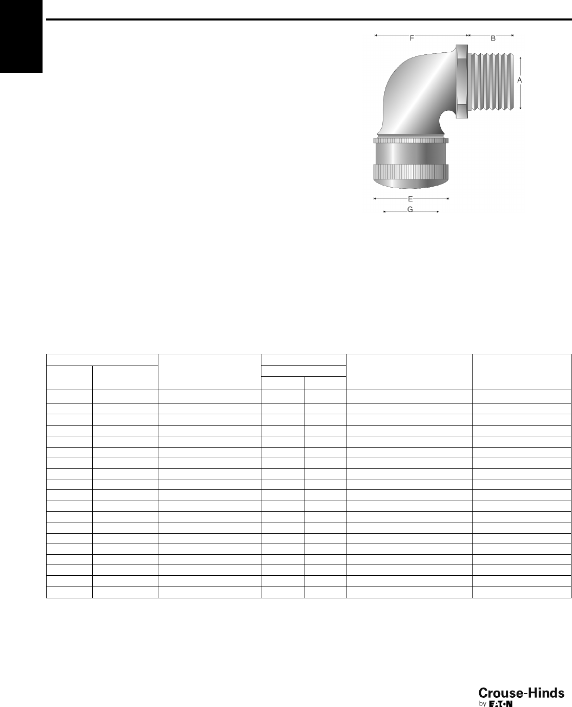
4F
92
www.crouse-hinds.com US: 1-866-764-5454 CAN: 1-800-265-0502 Copyright©2013 Eaton’s Crouse-Hinds Business
CGE
North American Standards -
General Purpose
cULus Listed
SELECTION TABLE
Entry Thread Size ‘A’ Thread
Length
‘B’ NPT
Cable Acceptance
Gland Length
‘F’ (less entry)
External
Diameter ‘G’
NPT
Size
NPT
Catalog #
Outer Sheath ‘E’
Min Max
1/2"CGE192 0.710 0.1250 0.2500 1.438 1.188
1/2"CGE193 0.710 0.2500 0.3750 1.438 1.188
1/2"CGE194 0.710 0.3750 0.5000 1.438 1.188
1/2"CGE195 0.710 0.5000 0.6250 1.438 1.188
1/2"CGE196 0.710 0.6250 0.7500 2.000 1.625
1/2"CGE197 0.710 0.7500 0.8750 2.000 1.625
3/4"CGE292 0.710 0.1250 0.2500 1.406 1.188
3/4"CGE293 0.710 0.2500 0.3750 1.406 1.188
3/4"CGE294 0.710 0.3750 0.5000 1.406 1.188
3/4"CGE295 0.710 0.5000 0.6250 1.406 1.188
3/4"CGE296 0.710 0.6250 0.7500 1.875 1.625
3/4"CGE297 0.710 0.7500 0.8750 1.875 1.625
1" CGE395 0.710 0.5000 0.6250 2.063 1.625
1" CGE396 0.710 0.6250 0.7500 2.094 1.625
1" CGE397 0.710 0.7500 0.8750 2.094 1.625
1" CGE3239 0.710 0.8750 1.0000 2.094 2.250
1" CGE398 0.710 0.8750 1.0000 2.656 2.250
1" CGE399 0.710 1.0000 1.1880 2.656 1.625
1" CGE3911 0.710 1.1880 1.3750 2.656 2.250
All dimensions in inches unless otherwise noted.
4F
Features:
• 90° angle with male thread
• Standard body material is Feraloy®iron alloy
• Standard gland nut material is steel
• Weatherproof seal on outer sheath of cable
• Standard neoprene seal suitable for use in operating temperatures
-25° to 40°C
• Available with NPT threads
• See page 102 for related accessories
Gland Type:
Non-armoured
Cable Type:
Non-armoured and tray cable
Certifications and Compliances:
• cULus Listed - UL File E23223
• Suitable for use in Class I, Div. 2 hazardous locations when
installed in accordance with NEC501.10(B)(2)
92-93.qxp 12/16/2013 12:14 PM Page 92
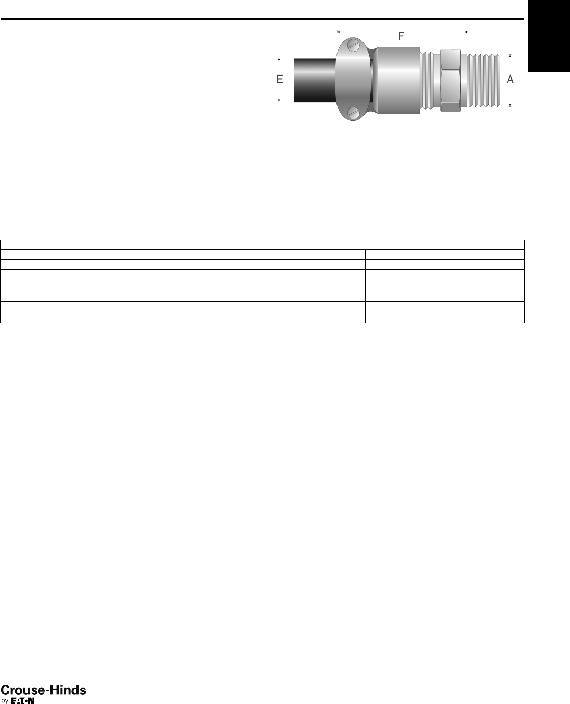
4F
93
www.crouse-hinds.com US: 1-866-764-5454 CAN: 1-800-265-0502 Copyright©2013 Eaton’s Crouse-Hinds Business
4F
CGB1013
North American Standards -
General Purpose
cULus Listed
Features:
• Body – steel with zinc electroplate and chromate finish coat
• Gland nut – material is aluminum
• Standard neoprene seal suitable for use in operating temperatures
-25° to 40°C
• Available with NPT threads
• See page 102 for related accessories
SELECTION TABLE
Entry Thread Size ‘A’ Outer Sheath ‘E’
NPT Size NPT Catalog # Min Max
1/2"CGB1013 0.312 0.437
1/2"CGB1014 0.375 0.500
1/2"CGB1015 0.500 0.625
3/4"CGB2013 0.312 0.437
3/4"CGB2014 0.375 0.500
3/4"CGB2015 0.500 0.625
All dimensions in inches unless otherwise noted.
Gland Type:
Portable cord connector
Cable Type:
Non-armoured and tray cable
Certifications and Compliances:
• cULus Listed - UL File E23223
• Suitable for use in Class I, Div. 2 hazardous locations when
installed in accordance with NEC501.10(B)(2)
92-93.qxp 12/16/2013 12:14 PM Page 93
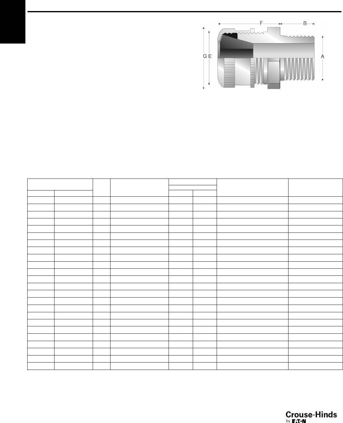
4F
94
www.crouse-hinds.com US: 1-866-764-5454 CAN: 1-800-265-0502 Copyright©2013 Eaton’s Crouse-Hinds Business
CGFP
North American Standards -
General Purpose
Features:
• Form B - C standard body and gland nut are turned steel
• Form D - G standard body and gland nut are Feraloy®iron alloy
• Weatherproof seal on outer sheath of cable
• Standard neoprene seal suitable for use in operating temperatures
-25° to 40°C
• Available with NPT threads
• See page 102 for related accessories
SELECTION TABLE
Entry Thread Size ‘A’
Form
Thread Length
‘B’ NPT
Cable Acceptance
Gland Length
‘F’ (less entry)
External
Diameter ‘G’NPT Size NPT Catalog #
Outer Sheath ‘E’
Min Max
1/2"CGFP192 B 0.750 0.1250 0.2500 1.375 1.281
1/2"CGFP193 B 0.750 0.2500 0.3750 1.375 1.281
1/2"CGFP194 B 0.750 0.3750 0.5000 1.375 1.281
1/2"CGFP195 B 0.750 0.5000 0.6250 1.375 1.281
3/4"CGFP296 C 0.750 0.6250 0.7500 1.750 1.781
3/4"CGFP297 C 0.750 0.7500 0.8750 1.750 1.781
3/4"CGFP2239 C 0.750 0.8750 1.0000 1.750 1.781
1" CGFP396 C 0.938 0.6250 0.7500 1.750 1.781
1" CGFP397 C 0.938 0.7500 0.8750 1.750 1.781
1" CGFP3239 C 0.938 0.8750 1.0000 1.750 1.781
11/4"CGFP499 D 0.938 1.0000 1.1880 2.375 2.250
11/4"CGFP4911 D 0.938 1.1880 1.3750 2.375 2.250
11/2"CGFP599 D 0.938 1.0000 1.1880 2.375 2.250
11/2"CGFP5911 D 0.938 1.1880 1.3750 2.375 2.250
2" CGFP6913 E 1.000 1.3750 1.6250 3.250 3.250
2" CGFP6915 E 1.000 1.6250 1.8750 3.250 3.250
21/2"CGFP7917 F 1.438 1.8750 2.1880 3.250 3.875
21/2"CGFP7920 F 1.438 2.1880 2.5000 3.250 3.875
3" CGFP8917 F 1.500 1.8750 2.1880 3.250 3.875
3" CGFP8920 F 1.500 2.1880 2.5000 3.250 3.875
31/2"CGFP923 G 1.563 2.5000 3.0000 4.250 5.500
31/2"CGFP927 G 1.563 3.0000 3.5000 4.250 5.500
4" CGFP1023 G 1.625 2.5000 3.0000 4.250 5.500
4" CGFP1027 G 1.625 3.0000 3.5000 4.250 5.500
All dimensions in inches unless otherwise noted.
4F
Gland Type:
Non-armoured
Cable Type:
Non-armoured and tray cable
Certifications and Compliances:
• Suitable for use in Class I, Div. 2 hazardous locations when
installed in accordance with NEC501.10(B)(2)
94-95.qxp 12/16/2013 12:15 PM Page 94
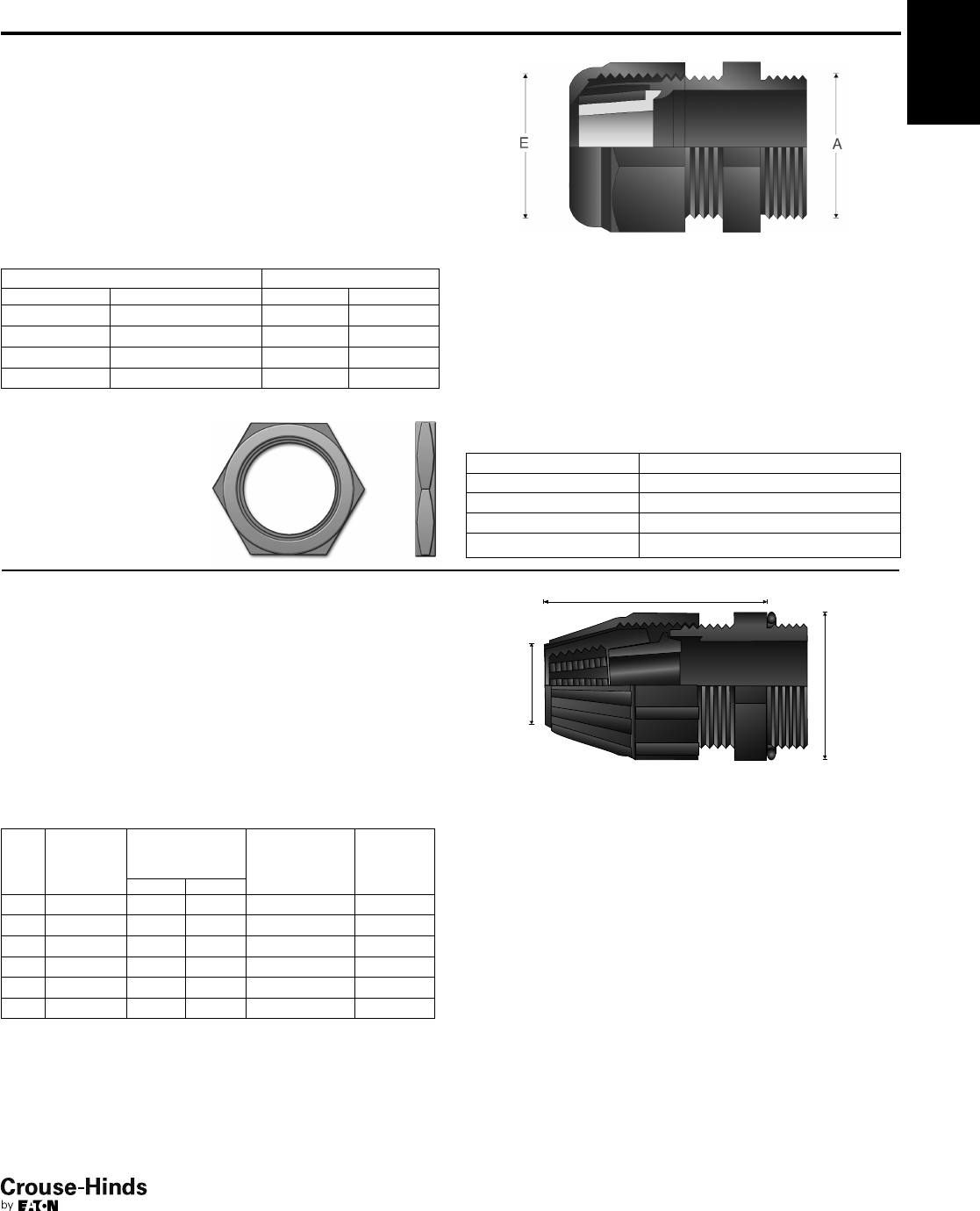
4F
95
www.crouse-hinds.com US: 1-866-764-5454 CAN: 1-800-265-0502 Copyright©2013 Eaton’s Crouse-Hinds Business
NCG and NCGB
North American Standards -
General Purpose
cULus Listed
NEMA 3, 4X (NCGB only)
Gland Type:
Non-armoured
Cable Type:
Non-armoured and tray cable
Certifications and Compliances:
• cULus Listed - UL File E23223
NCG Features:
• Standard material is polyamide 6
• Weatherproof seal on outer sheath of cable
• Standard neoprene seal suitable for use in operating temperatures
-25° to 40°C
• Available with NPT threads
SELECTION TABLE
Entry Thread Size ‘A’ Outer Sheath ‘E’
NPT Size NPT Catalog # Min Max
3/8"NCG38 35 0.10 0.35
1/2"NCG50 50 0.20 0.50
3/4"NCG75 75 0.35 0.75
1" NCG100 100 0.55 1.00
All dimensions in inches unless otherwise noted.
Gland Type:
Non-armoured
Cable Type:
Non-armoured and tray cable
Certifications and Compliances:
• cULus Listed - UL File E23223
• NEMA 3, 4X
SELECTION TABLE
NPT
Size
NPT
Catalog #
Cable
Acceptance
Range 'E'
Gland Length
(Less Entry)
'F'
External
Diameter
'G'Min Max
1/2"NCGB1231 0.25 0.42 2.25 1.33
1/2"NCGB1232 0.40 0.57 2.25 1.33
3/4"NCGB2233 0.54 0.68 2.52 1.58
3/4"NCGB2234 0.64 0.78 2.52 1.58
1" NCGB3235 0.76 0.91 3.19 2.02
1" NCGB3236 0.89 1.03 3.19 2.02
All dimensions in inches unless otherwise noted.
4F
POLYAMIDE LOCK NUT
SELECTION TABLE
Size Catalog #
3/8"10N
1/2"11N
3/4"12N
1" 13N
NCGB Features:
• Standard material is thermoplastic polyester
• Tightens by hand to create a watertight seal
• Gasket on entry threads included
• Compact design allows close grouping of connectors
• Available with NPT threads
94-95.qxp 12/16/2013 12:15 PM Page 95
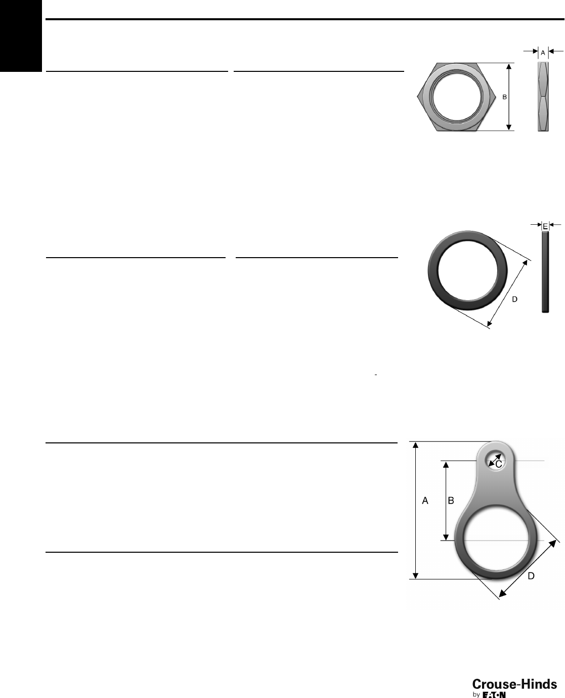
4F
96
www.crouse-hinds.com US: 1-866-764-5454 CAN: 1-800-265-0502 Copyright©2013 Eaton’s Crouse-Hinds Business
4F Accessories – A Series
A Series – Lock Nut – Standard material is nickel-plated brass
A Series – Sealing Washer
METRIC SELECTION TABLE
Metric
Size
Metric
Catalog #
Metric
Diam.
‘D’
Metric
Thickness
‘E’
10 CAP221049 15.0 1.2
12 CAP221249 18.0 1.2
16 CAP221649 22.0 1.2
20 CAP222049 24.0 1.2
25 CAP222549 30.0 1.5
32 CAP223249 42.0 1.5
40 CAP224049 52.0 1.5
50 CAP225049 63.0 1.5
63 CAP226349 77.0 2.0
––––
––––
NPT SELECTION TABLE
NPT
Size
NPT
Catalog #
NPT
Diam.
‘D’
NPT
Thickness
‘E’
1/4"CAP229014 20.0 1.5
3/8"CAP229038 22.0 1.5
1/2"CAP229012 27.0 1.5
3/4"CAP229034 33.0 1.5
1" CAP229010 41.0 1.5
11/4"CAP229114 52.0 1.5
11/2"CAP229112 57.0 1.5
2" CAP229020 71.0 2.0
21/2"CAP229212 85.0 2.0
3" CAP229300 104.0 2.0
31/2"CAP229312 120.0 2.0
4F
A Series – Earth Tag – Standard material is nickel-plated brass
METRIC SELECTION TABLE
Entry Thread A B C D Catalog #
M16 48.75 30 6.75 24.5 CAP567034
M20 53.8 33 7 28.6 CAP567054
M25 61.5 36 10.5 34 CAP567074
M32 73 41 12.2 42 CAP567094
M40 86.5 44.5 13.5 54 CAP567124
M50 111.5 58 13.5 67 CAP567154
M63 125.5 67 13.5 77 CAP567184
M75 137.5 73 13.5 89 CAP567194
NPT SELECTION TABLE
Entry Thread A B C D Catalog #
1/2" 61.5 36 10.5 34 CAP567064
3/4" 73 41 12.2 42 CAP567084
1" 73 41 12.2 42 CAP567104
11/4" 86.5 44.5 13.5 54 CAP567134
11/2" 111.5 58 13.5 67 CAP567154
2" 125.5 67 13.5 77 CAP567174
21/2" 137.5 73 13.5 89 CAP567194
All dimensions in millimeters unless otherwise noted.
– Standard material is neoprene
METRIC SELECTION TABLE
Entry Thread A B Catalog #
M16 3 19 CAP221694
M20 4 24 CAP222094
M25 4 30 CAP222594
M32 4.5 36 CAP223294
M40 4.5 46 CAP224094
M50 4.7 65 CAP225094
M63 6.4 80 CAP226394
M75 6.4 95 CAP227594
M90 8 110 CAP229094
M110 12 130 CAP221104
* For stainless steel replace last digit with "9".
NPT SELECTION TABLE
Entry Thread A B Catalog #
1/2" 3.75 25.4 CAP280124
3/4"433CAP280134
1" 4.75 40 CAP280144
11/4" 5.25 50 CAP280154
11/2" 5.75 55.9 CAP280164
2" 6.25 70 CAP280174
21/2"990CAP280184
3" 10 105 CAP280194
96-97.qxp 12/16/2013 12:15 PM Page 96
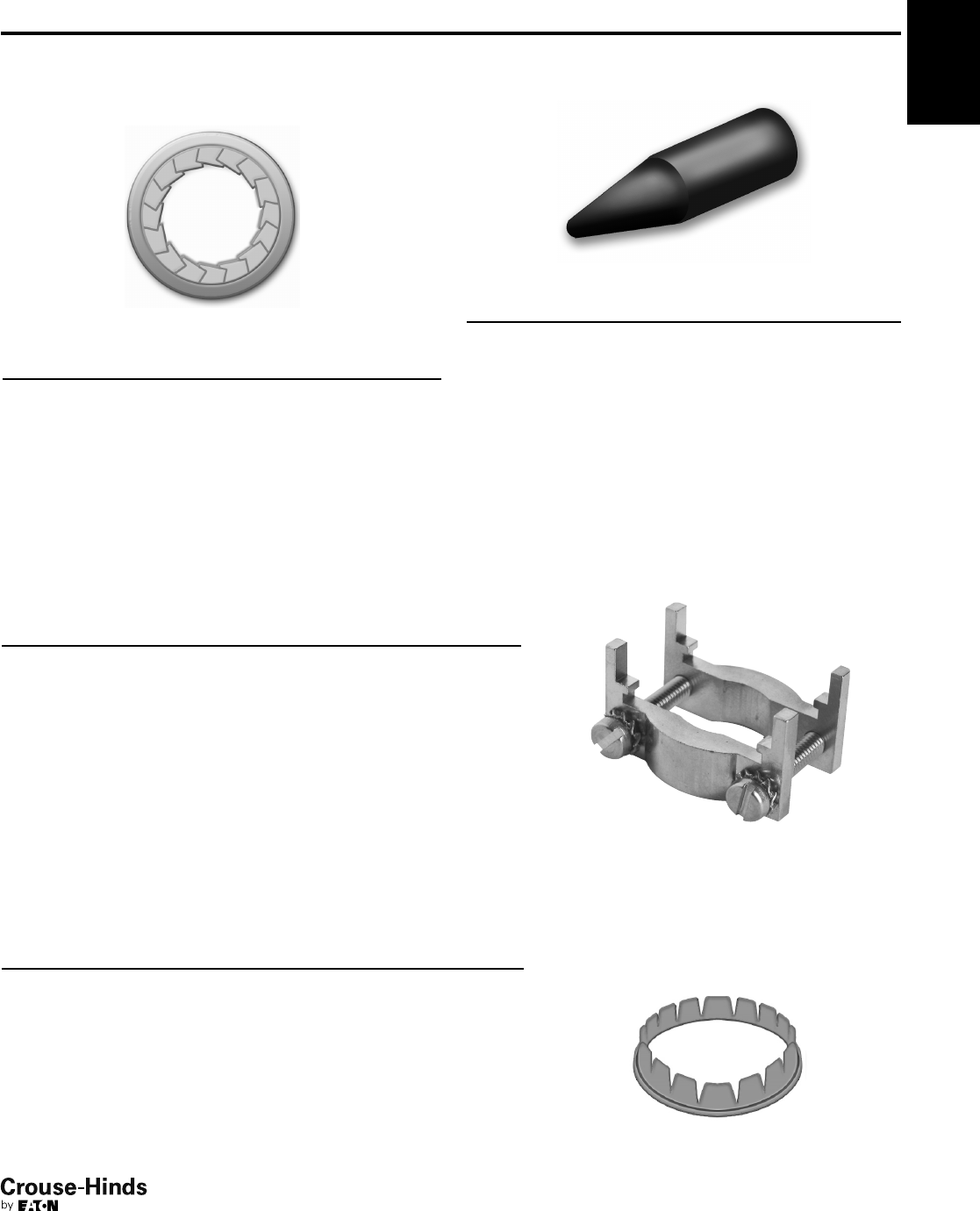
4F
97
www.crouse-hinds.com US: 1-866-764-5454 CAN: 1-800-265-0502 Copyright©2013 Eaton’s Crouse-Hinds Business
4F
Accessories – A Series
A Series – Serrated Lock Washer
– Standard material is stainless steel
SELECTION TABLE
Metric Size External Diameter Catalog #
16 25.5 CAP280069
20 32.5 CAP280029
25 39.5 CAP280259
32 49.5 CAP280329
40 64.5 CAP280409
50 80.5 CAP280509
63 100 CAP280639
75 112 CAP280759
90 123 CAP280099
A-Series – Shroud
– Standard material is PVC
SELECTION TABLE
Gland Size Catalog #
4CAP506040
5CAP506050
6CAP506060
7CAP506070
8CAP506080
9CAP506090
10 CAP506100
11 CAP506110
12 CAP506120
13 CAP506130
14 CAP506140
15 CAP506150
16 CAP506160
A Series – Clamping Module
– Standard materials are nickel-plated brass body with stainless steel screws and washers
SELECTION TABLE
Cable Range Gland Size Across Flats Width Thickness Catalog #
4-8.5 4 15 18 5 CAP810434
6-11 5 19 22 5 CAP810534
8.5-16 6 24 27.5 6 CAP810634
12-21 7 30 33.5 8 CAP810734
16-27.5 8 41 45 8 CAP810834
21-34 9 48 52 9.5 CAP810934
27-41 10 55 59 9.5 CAP811034
33-48 11 64 69 12 CAP811134
40-56 12 72 78 12 CAP811234
47-65 13 85 92 16 CAP811334
54-74 14 95 103 16 CAP811434
63-83 15 110 118 18 CAP811534
72-93 16 120 128 18 CAP811634
A Series – Earthing Washer – Standard material is brass
METRIC SELECTION TABLE
Gland Size
Lead Sheath Sealing Range Cable
Diameter Catalog #Min Max
5 4 7.5 10 CAP560530
6 6 11 13.9 CAP560630
7 9 15 18.3 CAP560730
8 12 20 23.8 CAP560830
9 16 26.5 31 CAP560930
10 21 32.5 38.3 CAP561030
11 28 39.5 45.3 CAP561130
12 33 46.5 52.8 CAP561230
13 40 54.5 60.8 CAP561330
14 46.5 61 71 CAP561430
15 54 72.5 80.5 CAP561530
16 63 81.5 89.5 CAP561630
All dimensions in millimeters unless otherwise noted.
96-97.qxp 12/16/2013 12:15 PM Page 97
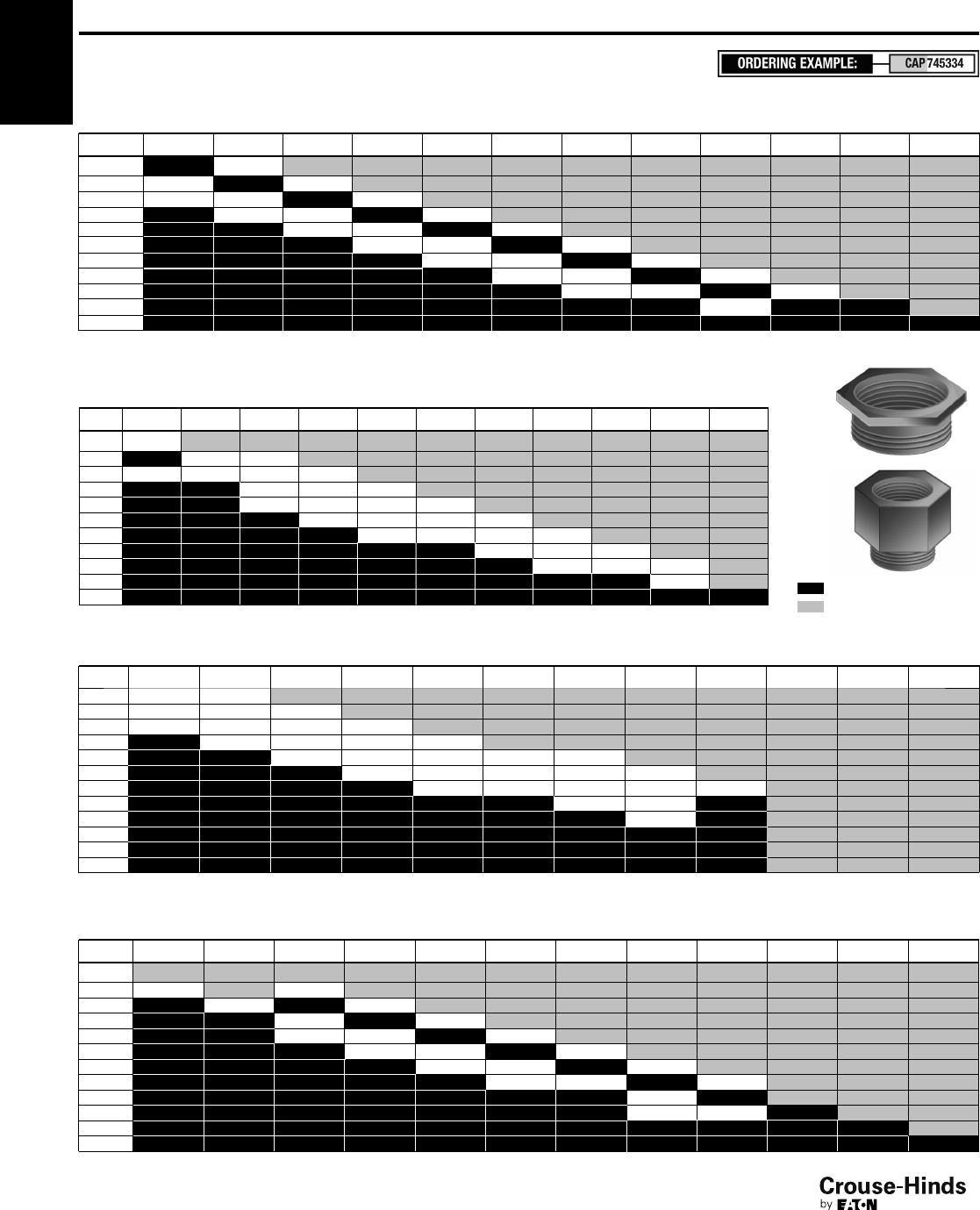
4F
98
www.crouse-hinds.com US: 1-866-764-5454 CAN: 1-800-265-0502 Copyright©2013 Eaton’s Crouse-Hinds Business
METRIC x NPT SELECTION TABLE
Female →→
Male 1/4"3/8"1/2"3/4"1"1
1/4"1
1/2"2"2
1/2"3"3
1/2"
M12 744104
M16 744194 744694
M20 744204 744214 744704 744964
M25 744714 744974 745234
M32 744724 744984 745244 745504
M40 744994 745254 745514 745774
M50 745264 745524 745784 746044
M63 745794 746054 746314
M75 746064 746324 746584
M90 744304
M110
Accessories – A Series
A Series – Adaptors and Reducers
METRIC x METRIC SELECTION TABLE
Female →→
Male M12 M16 M20 M25 M32 M40 M50 M63 M75 M80 M90 M110
M12 745334
M16 745834 740274
M20 745844 740024 740544
M25 740034 740294 740814
M32 740304 740564 741084
M40 740574 740834 741354
M50 740844 741104 741624
M63 741114 741374 741894
M75 741384 741644 745394
M90 745864
M110
Size available – no part number
Size not available
NPT x METRIC SELECTION TABLE
Female →→
Male M12 M16 M20 M25 M32 M40 M50 M63 M75 M90 M100 M110
1/4"740614 740624
3/8"740884 740894 740904
1/2"740914 740194 740454 740714
3/4"740204 740464 740724 740984
1" 740474 740734 740994 741264 741524
11/4"740744 741004 741274 741534 741794
11/2"741104 741284 741544 741804 742064
2" 741554 741814
21/2"741824
3"
31/2"
4"
NPT x NPT SELECTION TABLE
Female →→
Male 1/4"3/8"1/2"3/4"1"1
1/4"1
1/2"2"2
1/2"3"3
1/2"4"
1/4"
3/8"745574 744624
1/2"745594 745134
3/4"744884 745404
1" 744894 745154 745674
11/4"745164 745424 745944
11/2"745434 745694 746214
2" 745704 745964 746484
21/2"746234
3" 746244 746504
31/2"
4"
* For stainless steel replace last digit with "9".
4F
– Standard material is nickel-plated brass
ATEX Exe Exd with LCIE 98 ATEX 00010
98-99.qxp 12/23/2013 2:43 PM Page 98
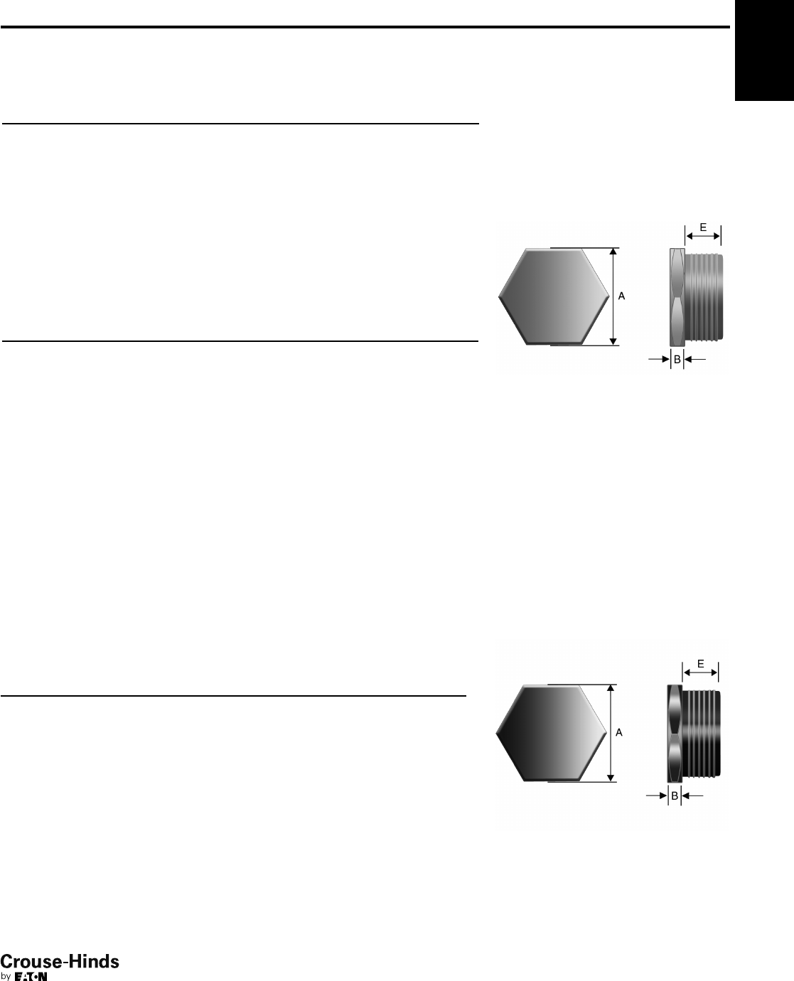
4F
99
www.crouse-hinds.com US: 1-866-764-5454 CAN: 1-800-265-0502 Copyright©2013 Eaton’s Crouse-Hinds Business
Accessories – A Series
A Series – Stopping Plug
METRIC SELECTION TABLE
Metric
Size
Metric Catalog #*
Across Flats
‘A’
Hex Thickness
‘B’
Thread Length
‘E’
12 CAP190124 14 2.8 15
16 CAP190164 18 3.0 15
20 CAP190204 23 3.0 15
25 CAP190254 28 3.5 15
32 CAP190324 36 4.0 15
40 CAP190404 44 4.0 15
50 CAP190504 54 5.0 16
63 CAP190634 67 5.5 17
75 CAP190754 80 6.0 18
80 CAP190804 85 7.0 20
90 CAP199904 95 8.0 22
100 CAP191004 110 10.0 22
* For stainless steel replace last digit with "9".
NPT SELECTION TABLE
NPT Size NPT Catalog #* Across Flats ‘A’ Hex Thickness ‘B’ Thread Length ‘E’
1/4"CAP190194 14 2.8 12
3/8"CAP109294 18 2.8 12
1/2"CAP190394 22 3.0 16
3/4"CAP190494 28 3.0 16
1" CAP190594 36 3.5 20
11/4"CAP190694 44 4.0 20
11/2"CAP190794 50 5.0 20
2" CAP190894 64 5.5 20
21/2"CAP190994 75 6.0 28
3" CAP191094 90 6.0 30
31/2"CAP191194 110 10.0 32
All dimensions in millimeters unless otherwise noted.
*For stainless steel replace last digit with "9".
*For stainless steel replace last digit with "9".
A Series – Nonmetallic Stopping Plug – Standard material is polyamide 6; ATEX
certified Ex e II with LCIE 97ATEX6007X
Washer and locknut are required for non-threaded holes (not included) see page 96
4F
POLYAMIDE SELECTION TABLE
Metric
Size
Metric
Catalog #*
Across
Flats ‘A’
Hex
Thickness ‘B’
Thread
Length ‘E’
12 CAP191127 15 4 15
16 CAP191167 19 4 15
20 CAP191207 23 4 15
25 CAP191257 28 5 15
32 CAP191327 36 5.5 15
40 CAP191407 44 5.5 15
50 CAP191507 54 6 16
63 CAP191637 67 6.5 17
– Standard material is nickel-plated brass;
ATEX Exe Exd with LCIE 98 ATEX 00010
98-99.qxp 12/23/2013 2:43 PM Page 99
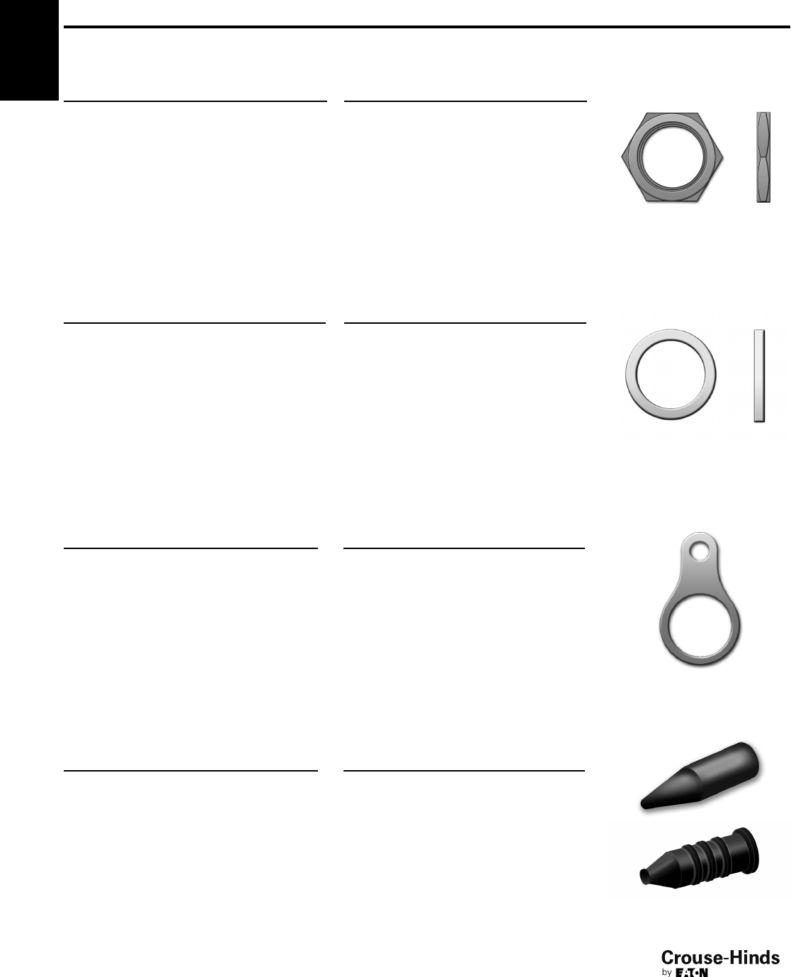
4F
100
www.crouse-hinds.com US: 1-866-764-5454 CAN: 1-800-265-0502 Copyright©2013 Eaton’s Crouse-Hinds Business
Accessories – B Series
B Series – Lock Nut – Standard material is brass
NPT SELECTION TABLE
NPT Entry Thread Catalog #
1/2"BLN/050NPT
3/4"BLN/075NPT
1" BLN/100NPT
11/4"BLN/125NPT
11/2"BLN/150NPT
2" BLN/200NPT
21/2"BLN/250NPT
3" BLN/300NPT
31/2"BLN/350NPT
4" BLN/400NPT
B Series – Sealing Washer – Standard material is nylon
NPT SELECTION TABLE
NPT Entry Thread Catalog #
1/2"RNSW/050NPT
3/4"RNSW/075NPT
1" RNSW/100NPT
11/4"RNSW/125NPT
11/2"RNSW/150NPT
2" RNSW/200NPT
21/2"RNSW/250NPT
3" RNSW/300NPT
31/2"RNSW/350NPT
4" RNSW/400NPT
B Series – Earth Tag – Standard material is brass
METRIC SELECTION TABLE
Metric Entry Thread Catalog #
M16 BET/M16
M20 BET/M20
M25 BET/M25
M32 BET/M32
M40 BET/M40
M50 BET/M50
M63 BET/M63
M75 BET/M75
M80 BET/M80
M85 BET/M85
M90 BET/M90
M100 BET/M100
NPT SELECTION TABLE
NPT Entry Thread Catalog #
1/2"BET/050NPT
3/4"BET/075NPT
1" BET/100NPT
11/4"BET/125NPT
11/2"BET/150NPT
2" BET/200NPT
21/2"BET/250NPT
3" BET/300NPT
31/2"BET/350NPT
4" BET/400NPT
B Series – Shroud
PVC SELECTION TABLE
Size (Gland Size) Catalog #
L24 (16, 20s) PVC-L24
L30 (20) PVC-L30
L38 (25) PVC-L38
L46 (32) PVC-L46
L55 (40) PVC-L55
L65 (50, 50s) PVC-L65
L80 (63, 63s) PVC-L80
L90 (75, 75s) PVC-L90
L104 (80,85) PVC-L104
L114 (90, 100) PVC-L114
PCP SELECTION TABLE
Size Catalog #
L24 (16, 20s) PCP-L24
L30 (20) PCP-L30
L38 (25) PCP-L38
L46 (32) PCP-L46
L55 (40) PCP-L55
L65 (50, 50s) PCP-L65
L80 (63, 63s) PCP-L80
L90 (75, 75s) PCP-L90
L104 (80, 85) PCP-L104
All dimensions in millimeters unless otherwise noted.
METRIC SELECTION TABLE
Metric Entry Thread Catalog #
M16 BLN/M16
M20 BLN/M20
M25 BLN/M25
M32 BLN/M32
M40 BLN/M40
M50 BLN/M50
M63 BLN/M63
M75 BLN/M75
M80 BLN/M80
M85 BLN/M85
M90 BLN/M90
M100 BLN/M100
METRIC SELECTION TABLE
Metric Entry Thread Catalog #
M16 RNSW/M16
M20 RNSW/M20
M25 RNSW/M25
M32 RNSW/M32
M40 RNSW/M40
M50 RNSW/M50
M63 RNSW/M63
M75 RNSW/M75
M80 RNSW/M80
M85 RNSW/M85
M90 RNSW/M90
M100 RNSW/M100
4F
PCP
PVC
100-101.qxp 12/16/2013 12:16 PM Page 100
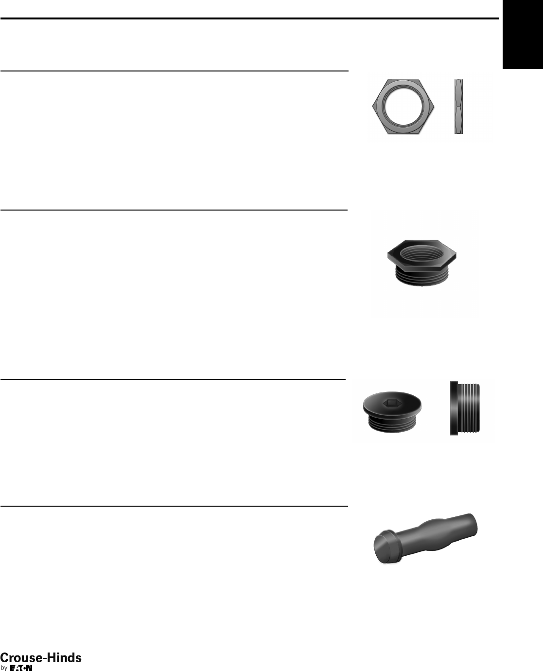
4F
101
www.crouse-hinds.com US: 1-866-764-5454 CAN: 1-800-265-0502 Copyright©2013 Eaton’s Crouse-Hinds Business
D Series – Lock Nut – Standard material is polyamide
SELECTION TABLE
Metric Entry Diameter Width Thickness Catalog #
M12 x 1.5 17.00 5.00 GHG 960 1941 R0031
M16 x 1.5 22.00 5.00 GHG 960 1941 R0032
M20 x 1.5 26.00 6.00 GHG 960 1941 R0033
M25 x 1.5 32.00 6.00 GHG 960 1941 R0034
M32 x 1.5 41.00 7.00 GHG 960 1941 R0035
M40 x 1.5 50.00 7.00 GHG 960 1941 R0036
M50 x 1.5 60.00 8.00 GHG 960 1941 R0037
M63 x 1.5 75.00 8.00 GHG 960 1941 R0038
D Series – Reducing Ring – Standard material is polyamide
SELECTION TABLE
Thread 1 Thread 2 Length 1 Length 2 Length 3
Across
Flats Catalog #
20 x 1.5 M16 x 1.5 12.00 8.00 8.00 24.00 GHG 960 1946 R0071
25 x 1.5 M20 x 1.5 14.00 8.00 8.00 29.00 GHG 960 1946 R0072
32 x 1.5 M20 x 1.5 16.00 10.00 6.00 36.00 GHG 960 1946 R0056
32 x 1.5 M25 x 1.5 16.00 10.00 10.00 36.00 GHG 960 1946 R0074
40 x 1.5 M25 x 1.5 16.00 10.00 8.00 46.00 GHG 960 1946 R0059
40 x 1.5 M32 x 1.5 16.00 10.00 10.00 46.00 GHG 960 1946 R0077
50 x 1.5 M32 x 1.5 18.00 12.00 10.00 55.00 GHG 960 1946 R0062
50 x 1.5 M40 x 1.5 18.00 12.00 10.00 68.00 GHG 960 1946 R0080
63 x 1.5 M40 x 1.5 18.00 12.00 10.00 68.00 GHG 960 1946 R0065
63 x 1.5 M50 x 1.5 18.00 12.00 12.00 68.00 GHG 960 1946 R0083
D Series – Screw Plug – Standard material is polyamide
SELECTION TABLE
Thread 1 Diameter Length 1 Length 2 Catalog #
16 x 1.5 21.50 4.00 12.00 GHG 960 1952 R0111
20 x 1.5 25.50 4.00 13.00 GHG 960 1952 R0112
25 x 1.5 30.50 4.00 13.00 GHG 960 1952 R0113
32 x 1.5 37.50 5.50 15.00 GHG 960 1952 R0114
40 x 1.5 45.50 5.50 15.00 GHG 960 1952 R0115
50 x 1.5 55.50 5.50 16.00 GHG 960 1952 R0116
63 x 1.5 85.00 6.50 16.00 GHG 960 1952 R0117
D Series – Blanking Plug – For sealing unused cable glands;
Standard material is polyamide
SELECTION TABLE
Thread 1 Diameter Length 1 Catalog #
12 6.00 30.30 GHG 960 1944 R0101
16 7.00 33.00 GHG 960 1944 R0102
20 8.50 34.50 GHG 960 1944 R0103
25 11.00 36.00 GHG 960 1944 R0104
32 14.00 39.50 GHG 960 1944 R0105
40 20.00 42.00 GHG 960 1944 R0106
50 26.00 44.00 GHG 960 1944 R0107
63 34.00 45.00 GHG 960 1944 R0108
All dimensions in millimeters unless otherwise noted.
Accessories – D Series 4F
100-101.qxp 12/16/2013 12:16 PM Page 101
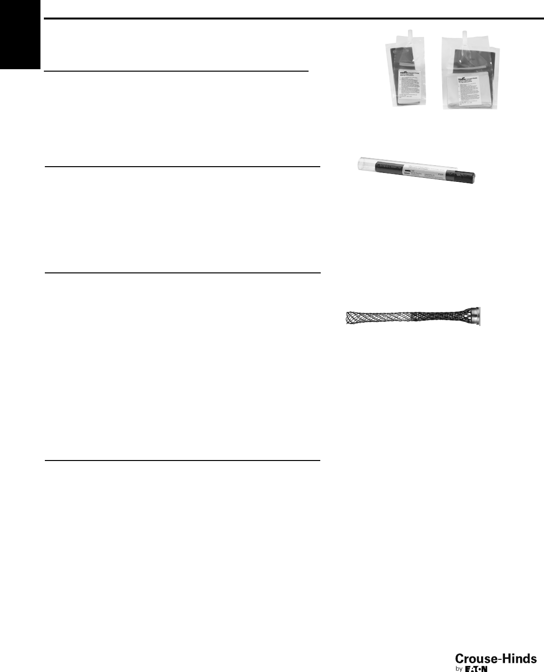
4F
102
www.crouse-hinds.com US: 1-866-764-5454 CAN: 1-800-265-0502 Copyright©2013 Eaton’s Crouse-Hinds Business
Accessories – E Series
E Series – TSC Epoxy Sealing Compound
SELECTION TABLE
Std. Carton Qty. Tube Size Catalog #
10 0.5 oz. TSC05
10 1.0 oz. TSC1
5 4.0 oz. TSC4
E Series – Wire Mesh Grip
SELECTION TABLE
Cord Range Diameter Gland Nut Wire Mesh Grip Catalog #
.375 to .500 NUT94 RPE417-115
.500 to .625 NUT94 RPE417-116
.500 to .625 NUT95 RPE417-129
.625 to .750 NUT95 RPE417-117
.750 to .875 NUT95 RPE421-119
.875 to 1.000 NUT98 16676N
.875 to 1.000 NUT98 16676N
.875 to 1.000 NUT95 RPE421-120
.875 to 1.000 NUT98 16676N
1.000 to 1.188 NUT98 RPE421-121
1.188 to 1.375 NUT98 RPE433-122
1.375 to 1.625 NUT913 RPE433-123
1.625 to 1.875 NUT913 17317N
E Series – Cold Shrink™Kit
SELECTION TABLE
Entry Thread Catalog #
1/2"TMC-K1
3/4"TMC-K2
1" TMC-K3
11/4"TMC-K4
11/2"TMC-K5
2" TMC-K6
21/2"TMC-K7
3" TMC-K8
31/2"TMC-K9
4" TMC-K10
All dimensions in inches unless otherwise noted.
Cold Shrink™Corrosion Protection Kits are specially designed for Eaton's Crouse-Hinds TMC, TMCX, and TECK fittings to provide protection
against corrosive elements like salt spray and moisture. The TMC-K kit is made of a Cold Shrink material that is quick and easy to install on
the gland. The Cold Shrink material is made of EPDM rubber that contains no chlorides or sulfurs. The protection kit installs easily over the
gland without the use of a heat source to shrink the material tightly over the seal. The Cold Shrink material can be removed easily from the
gland by simply cutting it off. See ordering information for complete offering of TMC-K Cold Shrink kits for corrosion protection. Cold Shrink
is a registered trademark of the 3M Company.
4F
E Series – Chico®LiquidSeal
SELECTION TABLE
Std. Carton Qty. Size (ml.) Catalog #
10 10 ml. LSC 10
10 20 ml. LSC 20
5 50 ml. LSC 50
102-103.qxp 12/16/2013 12:16 PM Page 102

4F
103
www.crouse-hinds.com US: 1-866-764-5454 CAN: 1-800-265-0502 Copyright©2013 Eaton’s Crouse-Hinds Business
4F
Breather Drain – SIRA 99 ATEX 3050 U
I M2 II, 2GD, EExe I & II (Stainless steel & brass only)
II 2GD, EExe II (Nylon only)
Enclosure type 4X IP66
Breathing and Drainage Plug – Standard material is glass-filled polyamide;
SIRA 99 ATEX 3050 U Ex 1126 Exe II
SELECTION TABLE
Thread 1 Catalog #
M25 x 1.5 GHG 960 1954 R0002
All dimensions in millimeters unless otherwise noted.
Please refer to section 6F for additional breather and drain options.
Drainage Plug – Standard material is polyamide; PTB01 ATEX 1128X Ex 1126 Exe II
SELECTION TABLE
Thread 1 Diameter Length 1 Length 2 Catalog #
M25 x 1.5 30.00 19.00 4.50 GHG 960 1927 R0105
SELECTION TABLE
Entry Thread Material Catalog #
M20 Brass DPE1004S3
M20 Stainless Steel DPE3004S3
M20 Nylon DPE4004S3
M25 Brass DPE1005S3
M25 Stainless Steel DPE3005S3
M25 Nylon DPE4005S3
1/2” Brass DPE1029S3
1/2” Stainless Steel DPE3029S3
3/4” Brass DPE1030S3
3/4” Stainless Steel DPE3030S3
Accessories – Breathers & Drains
102-103.qxp 12/16/2013 12:16 PM Page 103
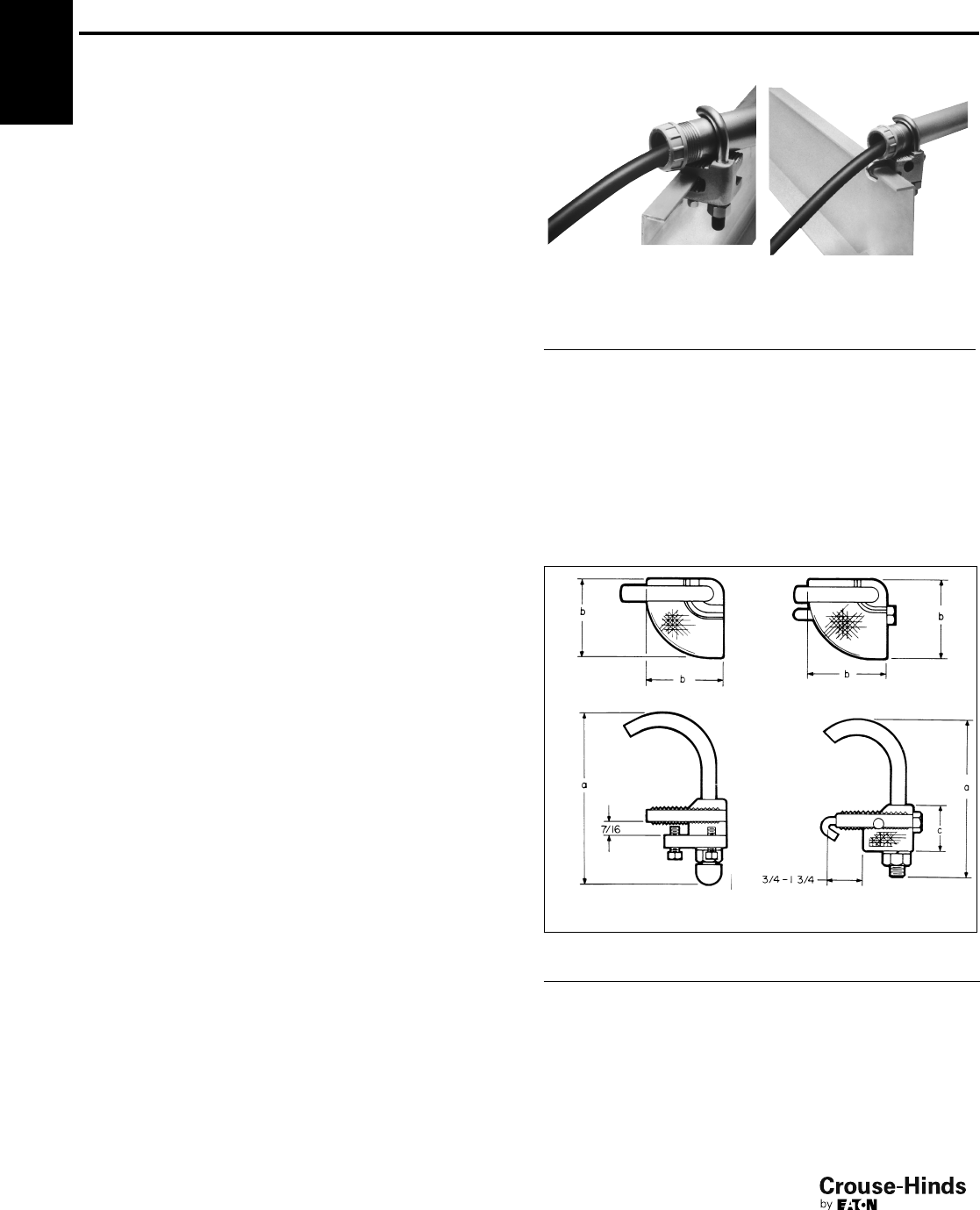
4F
104
www.crouse-hinds.com US: 1-866-764-5454 CAN: 1-800-265-0502 Copyright©2013 Eaton’s Crouse-Hinds Business
LCC Series Cable Tray
Conduit Clamps
Applications:
LCC cable tray conduit clamps are used for installation on cable tray
side rails with inside flanges (requiring inside tray mounting) and
outside flanges; LCCF clamps are for use exclusively on inside
flanges.
LCC/LCCF cable tray conduit clamps:
• Provide a means of clamping metal conduit (rigid steel or
aluminum, IMC and EMT) to cable tray to provide for the exit of
power and/or control cables from tray
• Provide a means to firmly bond exit conduit to cable tray for best
grounding continuity
• Provide strong mechanical support for exit conduits and cables
• Can be used indoors or outdoors, wherever cable tray systems are
installed
• Facilitate the safe exit of cables from tray – insure protection of
cables from damage
Features:
• Quick and easy installation – low installed cost. Merely tighten
clamp nut and/or set screw(s)
• Swivel hook clears conduit. No disassembly required for
installation
• No drilling or welding necessary for installation
• Provides superior ground continuity between conduit and cable
tray
• Clamps conduit at any angle with relation to tray – facilitates wire
pulling, minimizes conduit bending
• Malleable iron body provides great strength
• Knurled body has no-slip surface for conduit and tray – positive
grip assured
• Compact design has low profile – minimum tray space required for
assembly
• Design accommodates all popular types of cable tray
• Accommodates wide range of conduit sizes – 1/2" through 4"
LCCF features:
• Outside mounting facilitates inside rail installation
• Adjustable hook assures positive grip on inside rail
• Accommodates 3/4" through 13/4" wide flange
Standard Materials:
• Body – cast iron
• Hook – steel
• Set screws and clamping nut – steel
• Hook cap – vinyl
Standard Finishes:
• Cast iron – electrogalvanized and aluminum acrylic paint
• Steel – zinc electroplate
• Vinyl – natural
Conduit Size Ranges:
•1/2" to 4"
Certifications and Compliances:
• UL Standard: 467 (Grounding and Bonding Equipment)
LCC LCCF
For use with outside rail tray For use with inside rail tray
Dimensions
In Inches:
LCC LCCF
LCC LCCF
Conduit Size a b a b c
1/233/16 111/16 31/815/8111/32
3/437/16 111/16 311/32 15/8111/32
139/16 111/16 319/32 15/8111/32
11/441
11/16 315/16 15/8111/32
11/2413/16 211/16 43/423/4111/16
255/16 211/16 51/423/4111/16
21/2513/16 211/16 53/423/4111/16
3613/16 33/463/4311/16 23/16
31/275/16 33/471/4311/16 23/16
4713/16 33/473/4311/16 23/16
Ordering Information
Conduit Size Cat. # Cat. #
1/2LCC1 LCCF1
3/4LCC2 LCCF2
1LCC3 LCCF3
11/4LCC4 LCCF4
11/2LCC5 LCCF5
2LCC6 LCCF6
21/2LCC7 LCCF7
3LCC8 LCCF8
31/2LCC9 LCCF9
4LCC010 LCCF010
4F
104-105.qxp 12/16/2013 12:17 PM Page 104
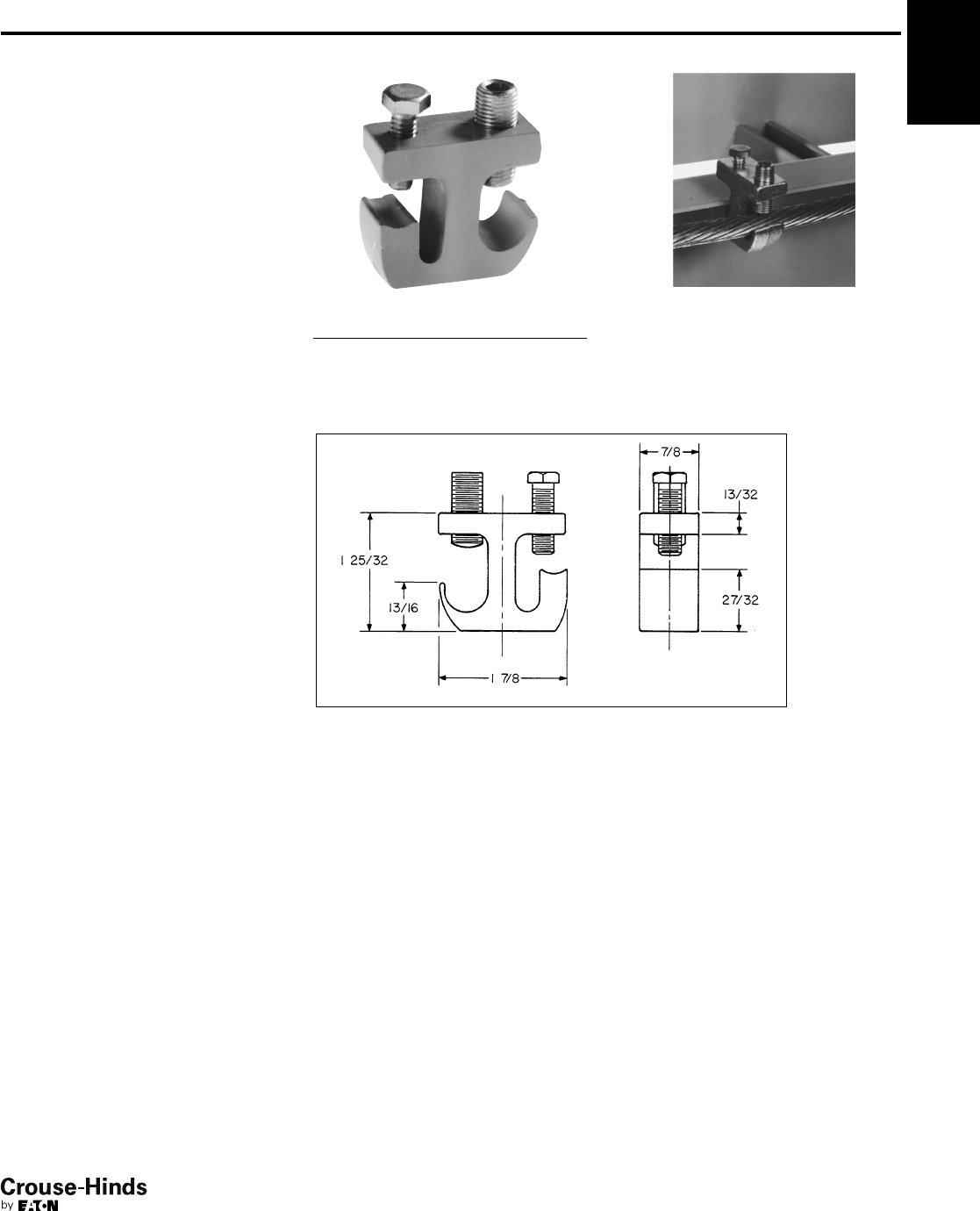
4F
105
www.crouse-hinds.com US: 1-866-764-5454 CAN: 1-800-265-0502 Copyright©2013 Eaton’s Crouse-Hinds Business
4F
Applications:
Cable tray grounding conductor clamps
are designed for use in heavy industrial
applications:
• To provide a means for securely
attaching a grounding conductor to
cable tray to maintain grounding
continuity for the entire cable tray
system
• To provide protection of equipment
through a reliable method for carrying
ground fault currents
• To meet UL and NEC Code
requirements
• For installation indoors or outdoors, with
most types of cable trays with inside or
outside flanges
Features:
• Meets requirements of NEC Code Article
318-7 for grounding and bonding
• Quick and easy installation – low
installed cost. No drilling or special tools
required.
• Accommodates solid (where suitable) or
stranded aluminum or copper grounding
conductors in sizes from #6 to 2/0
• Set screw bonds the clamp to the tray
and another set screw securely attaches
the grounding conductor to the clamp –
outstanding pull-out and vibration
resistance
• Design accommodates most popular
types of cable tray
• Mechanical device – can be easily
inspected
• Malleable iron body provides high
strength
Standard Materials:
• Body – malleable iron
• Set screws – steel
Standard Finishes:
• Malleable iron and steel –
electrogalvanized
Certifications and
Compliances:
• UL Standard: 467 (Grounding and
Bonding Equipment)
Ordering Information
Ground Wire Size Cat. #
#6 to 2/0TGC40
TGC Clamp installs on cable trays with
inside or outside flanges
Dimensions
In Inches:
TGC Cable Tray Ground Conductor Clamp
104-105.qxp 12/16/2013 12:17 PM Page 105
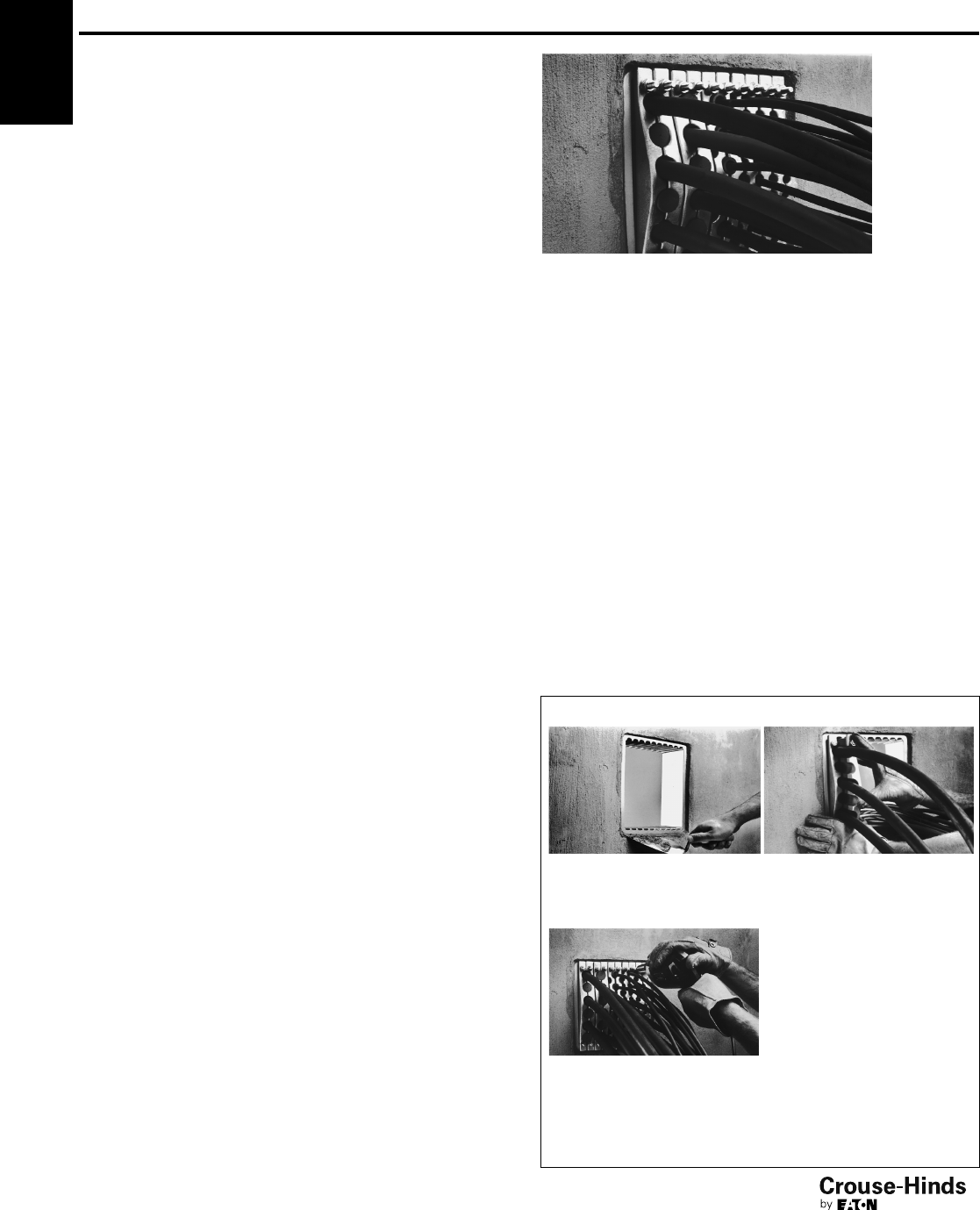
4F
106
www.crouse-hinds.com US: 1-866-764-5454 CAN: 1-800-265-0502 Copyright©2013 Eaton’s Crouse-Hinds Business
TW Series THRU-WALL BARRIER®
Cable/Conduit Sealing Device
Applications:
THRU-WALL BARRIER cable/conduit sealing device is used
wherever there is a need to seal cables or conduits penetrating fire-
or non-fire-rated walls, ceilings, floors, bulkheads or decks. For non-
fire-rated walls, ceilings, floors, bulkheads or decks, THRU-WALL
BARRIER also restricts water and dust and will help contain treated
air. THRU-WALL BARRIER is designed:
• To provide a seal for cable/conduit penetrations through masonry,
concrete or steel; to restrict the entrance of contaminants through
cable/conduit penetrations into clean areas
• For use with most types of power, instrument and control cables
as well as conduits
• To be used indoors or outdoors, in new construction or existing
structures
Features:
System
• Few parts required to seal a wide range of diameters of cables or
conduits
• Easy and fast installation, using factory assembled components
• High degree of flexibility with interchangeable sealing block
assemblies and a selection of different sizes of frames
Mounting frame
• One-piece cast malleable iron or steel mounting frame can be cast
into concrete during wall construction, grouted in masonry
surfaces or welded into steel bulkheads at any time
• Retrofit frame allows for easy installation of frame where
cables/conduit are already installed
• Available in sizes to accommodate a wide range of cable tray sizes
and loadings, including single and multiple layers of cables for
power or instrument applications
• Cast keyways in mounting frame align and position sealing block
assemblies
• Frames can be installed in wall such that sealing block assemblies
can be inserted in either horizontal or vertical position
Sealing block assembly
• Specially formulated elastomeric material between cast malleable
iron pressure plates protects cable from mechanical damage;
provides high pull-out resistance and positive cable separation;
expands during fire to seal any voids left by burned cable
insulation
• Interchangeable sealing block assemblies fit all THRU-WALL
BARRIER mounting frames
• Cast stops on front pressure plate prevent sealing block assembly
from slipping through mounting frame during installation
• Assemblies are offered for all cable/conduit outside diameters
from .250" to 4.500" (6.4 mm to 114.3 mm); cables with diameters
less than .250" can be accommodated – consult Eaton's Crouse-
Hinds
• Sealing block openings will accommodate undersize and
out-of-round cable
• Each sealing block assembly seals multiple cables/conduits;
compact design permits close nesting of cables, saving space
• Reducers permit sealing block assemblies to accept cables with
smaller O.D. than the specified range
• Plugs are used to fill unused openings in sealing block assemblies;
blank sealing block assemblies fill unused spaces in mounting
frames, providing for future expansion
Standard Materials:
• Mounting frame:
TWF, TWFR – cast malleable iron
TWFS – cast carbon steel,
ASTM A27 Grade 60-30
• Pressure plate – cast malleable iron
• Sealing material – special elastomeric material
• Clamping hardware – steel
Standard Finishes:
• Malleable iron and hardware – electrogalvanized
• Steel – aluminized weldable paint
• Special elastomeric material – natural
Certifications and Compliances:
• ASTM Standard E-119
• NFPA 251
• UL Classification per UL Standard 1479
• USCG Acceptance – consult Eaton's Crouse-Hinds
• NAVSEA Approval – Electric Plant Installation Standard Methods
No. S9300- AW-EDG-010/EPISM – TWFS/TWBS assemblies
Easy three step installation
1. Cast, grout or weld the one-
piece mounting frame into
masonry or steel surface.
2. Feed cables/conduit
through the frame.
3. Position cables/conduit,
insert factory assembled
sealing blocks into keyways in
mounting frame, and tighten
nuts on clamping hardware to
effect the seal.
4F
106-107.qxp 12/16/2013 12:19 PM Page 106
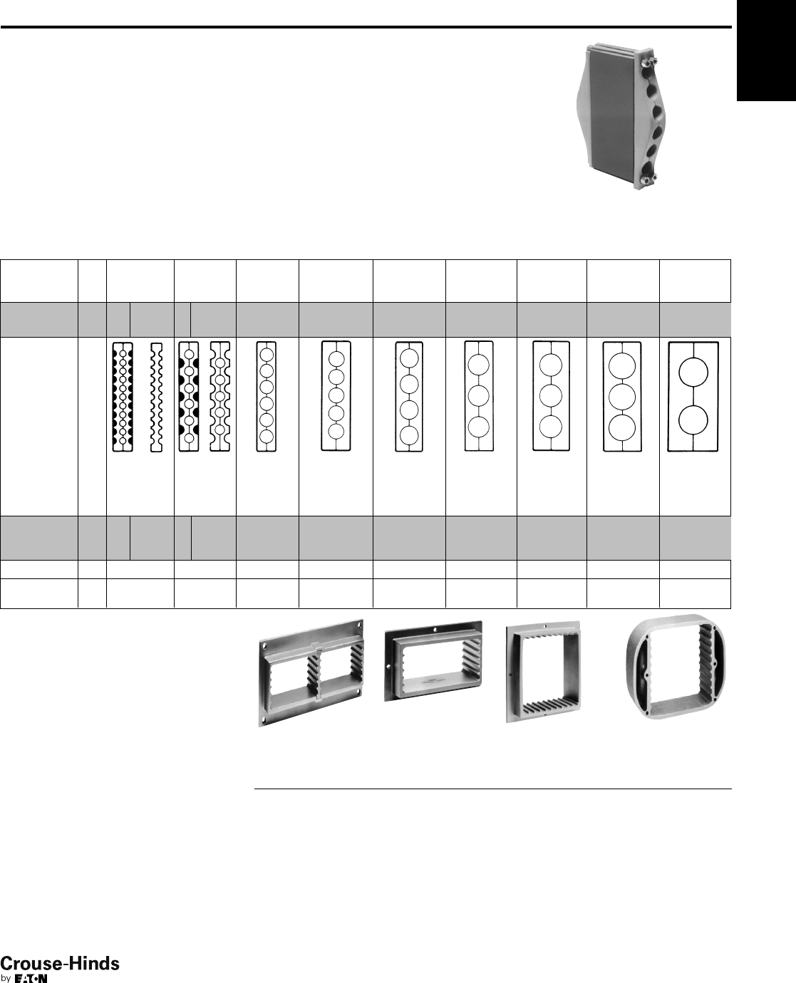
4F
107
www.crouse-hinds.com US: 1-866-764-5454 CAN: 1-800-265-0502 Copyright©2013 Eaton’s Crouse-Hinds Business
4F
.500–.750.250–.500
Opening
Size
Range
.750–1.000
TWB Sealing Block Assemblies
TWB sealing block assemblies are offered
for cable/conduit outside diameters (O.D.)
from .250" to 4.500" (6.4 mm to 114.3
mm). Cables with diameters less than
.250" can be accommodated – consult
Eaton's Crouse-Hinds. Each assembly
opening will accommodate a .250"
(6.4 mm) O.D. range. When clamping
hardware is tightened, the elastomeric
material is uniformly compressed around
all cable/conduits for a completely tight fit.
TWB2063
Depending on opening size range, a
standard sealing block assembly will
seal from one to eleven cables
In.
mm
1.000–1.250 1.250–1.500 1.500–1.750 1.750–2.000 2.000–2.250 2.250–2.500
6.4–12.7 12.7–19.1 19.1–25.4 25.4–31.8 31.8–38.1 38.1–44.5 44.5–50.8 50.8–57.2 57.2–63.5
No. Openings
In Block 11 11
Added* 611
Added* 6 5 4 3 3 3 2
Sealing
Block
Assembly
Cat. #
TWB2111 TWB2062
TWB2063 TWB3054 TWB3045 TWB30355 TWB4036 TWB40366 TWB5027
TWB1111 TWB2112
Frame
Spaces
Required
2 1 2 2 2 3 3 3 4 4 5
Plug Cat. # TWP1 TWP3 TWP5 TWP6 TWP7
Reducer
Cat. # § —TWR2 TWR3 TWR4 TWR5 TWR55 TWR6 TWR66 TWR7
TWF Mounting Frames
TWF(S) mounting frames may be installed
either horizontally or vertically. TWFR retrofit
frames are used wherever cables/conduits
are already installed through a fire- or non-
fire-rated wall, floor or ceiling. They are
designed with a removable section to permit
installation around cables/conduits. TWFR
retrofit frames can be grouted into walls,
floors, or ceilings, or welded into steel
bulkheads or decks. TWFR retrofit frames
will perform in the same manner as the one-
piece TWF(S) frames.
TWFS steel mounting frames are welded
directly into steel bulkheads, decks and
prepared sleeves. For marine applications,
keeper bars are provided to securely hold
TWBS sealing block assemblies in position
when installed.
TWF12
TWF6
TWF10 TWFS10
†For 3.5" - 4" cable/conduit – use TWB7011010 assembly and reduce down using TWR reducers.
*Catalog # TWB1111 and TWB2112 are used between TWB2111 and TWB2062 in cases where the number of cables to be sealed in .250-.750 range exceeds the number of openings in
standard assemblies. Use as many of these higher density assemblies as needed, sandwiched between halves of a standard assembly.
§TWR reducers match TWB sealing block assemblies shown in column above Cat. No. and reduce openings to accept cable size ranges shown in adjacent column to the left (in direction of
arrow).
Sealing block assemblies are offered for
use in marine applications. Each assembly
has the required lubrication and sealing
gaskets to meet U.S. Navy Hydrostatic
Pressure Test Requirements. Assemblies
for marine applications are available for
cable/conduit outside diameters (O.D.)
from .250" (6.4 mm) through 3.500"
(88.9 mm). To order, add suffix S to TWB
sealing block assembly Cat. No. Example:
TWBS4036.
No. of Spaces
Available Frame Cat. #
Retrofit
Frame Cat. #
Cast Steel
Frame Cat. #
6TWF6 TWFR6
10 TWF10 TWFR10 TWFS10
12 TWF12† TWFR12†
20 TWF20 TWFR20 TWFS20
24 TWF24 TWFR24
30 TWF30 TWFR30 TWFS30
†Includes removable partition.
TW Series THRU-WALL BARRIER®
Cable/Conduit Sealing Device
Sealing Block Assemblies & Mounting Frames
Ordering Information
106-107.qxp 12/16/2013 12:19 PM Page 107
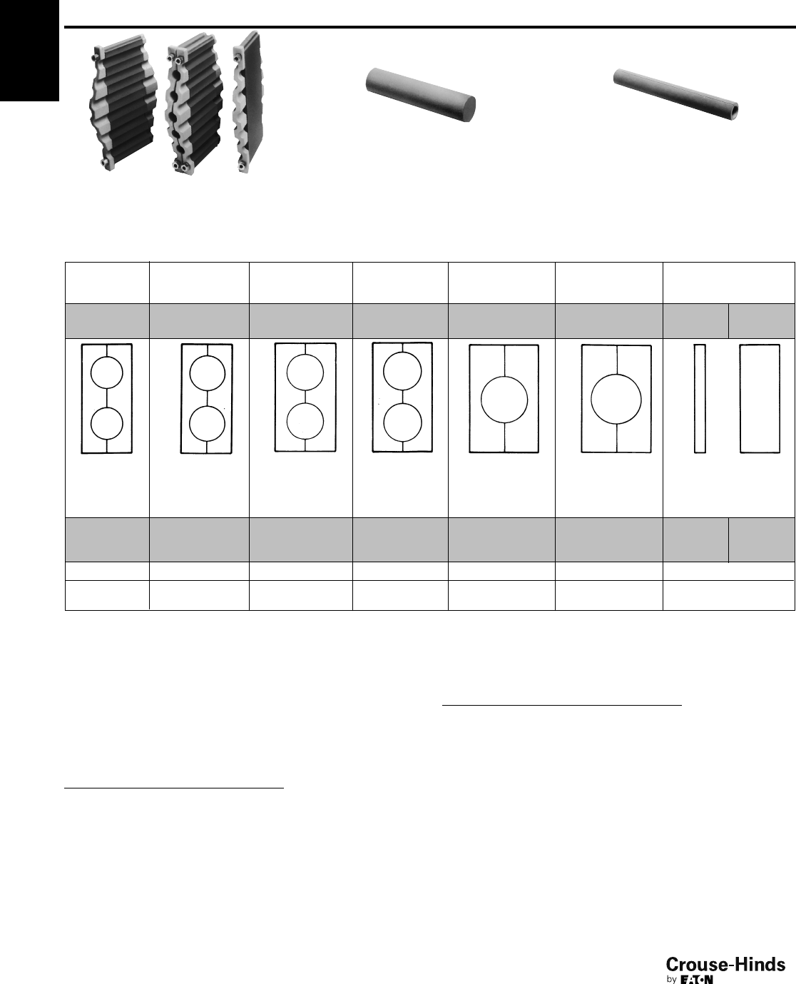
4F
108
www.crouse-hinds.com US: 1-866-764-5454 CAN: 1-800-265-0502 Copyright©2013 Eaton’s Crouse-Hinds Business
5
4F TW Series THRU-WALL BARRIER®
Cable/Conduit Sealing Device
Plugs, Reducers, Closure Cover Kits, Anchors & Lubricant
Ordering Information
TWB2112 TWB2062
TWP Plugs
TWP plugs will close any unused openings
in sealing block assemblies. See table for
plug catalog numbers which match
specific sealing block assemblies.
TWR Reducers
TWR reducers will reduce openings by
.250" (6.4 mm) in sealing block
assemblies. See table for reducer catalog
numbers which match specific sealing
block assemblies. More than one reducer
can be used in a single opening.
It is possible to increase cable fill density with double-sided sealing block assemblies (TWB1111 and TWB2112) sandwiched between halves
of a standard assembly.
2.500–2.750 2.750–3.000 3.000–3.250 3.250–3.500 3.500–4.250† 4.250–4.500 Blank – No
Openings
63.5–69.9 69.9–76.2 76.2–82.6 82.6–88.9 101.6–108.0 108.0–114.3
2 2 2 2 1 1 None None
TWB50277 TWB5028 TWB60288 TWB6029 TWB7011010 TWB70111 TWB1 TWB3
5 6 6 7 7 1 3
TWP7 TWP8 TWP9 TWP10 TWP11 —
TWR77 TWR8 TWR88 TWR9 TWR1010 TWR11 —
TWR99 TWR10
TWB Closure Cover Kits
TWB closure cover kits offer an optional method to close TWF
frames installed for future expansion or those that are abandoned.
Closure cover kits include two covers clamped to opposite sides of
the frame with hardware provided. The insulating material provided is
sandwiched between the two covers to maintain the fire rating of the
assembly. See table below for closure kit catalog numbers.
No. of
Spaces
Available
Closure
Cover Kit
Cat. #*
6TWB600‡
10 TWB1000
12 TWB600‡
20 TWB2000
24 TWB2400
30 TWB3000
*TWB closure cover kits are not designed to provide a
watertight seal in marine/shipboard applications or
washdown areas. One kit seals one unused frame
opening of same size. Example: use one TWB2000 kit to
seal one TWF20, or TWFR20 frame.
‡Use two TWB600 kits to seal one TWF12 or TWFR12
frame opening.
TWK Anchors
TWK anchor assemblies are used to attach mounting frames to wall,
ceiling or floor when grouting in frames.
Mounting Type Cat. #
Flush TWK1
Recessed TWK2
108-109.qxp 12/16/2013 12:19 PM Page 108
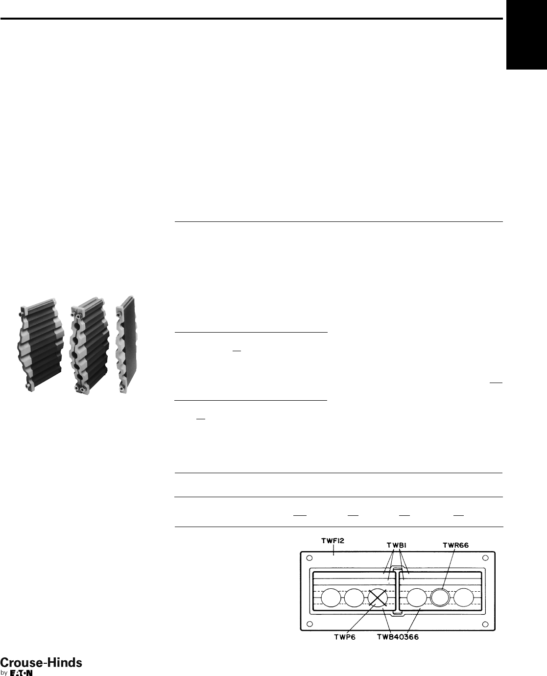
4F
109
www.crouse-hinds.com US: 1-866-764-5454 CAN: 1-800-265-0502 Copyright©2013 Eaton’s Crouse-Hinds Business
4F
Product Information
Selecting and specifying THRU-WALL
BARRIER components is a simple
procedure. Primary components for the
THRU-WALL BARRIER consist of TWF
mounting frames in various sizes and TWB
sealing block assemblies for cable/conduit
outside diameters (O.D.) in 1/4-inch
increments from .250" to 4.500" (6.4 mm
to 114.3 mm). Cables with diameters less
than .250" can be accommodated –
consult Eaton's Crouse-Hinds.
Cable/conduit sizes can be mixed within a
sealing block assembly by inserting TWR
reducers to accommodate smaller
diameters. The use of reducers can
decrease the number of sealing block
assemblies required. More than one
reducer can be used in a single opening.
Another way to increase density is to use
TWB1111 and TWB2112 sealing block
assemblies wherever there is a large
number of cables/conduits in sizes ranging
from .250" to .750".
TWB2112
TWB2062 TWB2062
Shown here is a double-sided sealing
block assembly (TWB2112) sandwiched
between halves of a standard sealing
block assembly (TWB2062). Additional
double-sided sealing block assemblies
may be used to accommodate larger
quantities of cables or conduits.
Unused sealing block openings must be
closed with TWP plugs. Blank sealing
block assemblies TWB1 and TWB3 are
used to fill each unused space in the
mounting frame and permit future
expansion of the system. Typical practice
is to include space allowance of 20 to
50% for future expansion. TWB closure
kits are used to seal entire frames and
permit future system expansion.
Specifying & Ordering
The selection of components is based on
the quantity and sizes of cables or
conduits going through the penetrations.
Once these are known, the sealing block
assemblies and frames can be selected.
Step 1. Group cables/conduits by outside
diameter (O.D.) and rank from the largest
to the smallest.
Step 2. Keeping in mind that sealing block
assemblies are available in one-quarter
inch increments, group cables/conduits
that fall within the same sealing block
assembly O.D. size range.
Step 3. Starting with the largest cable/
conduit O.D., select the sealing block
assemblies required. All openings in each
sealing block assembly must be filled.
Ordering Example A:
Cable tray size: 24"
Cables specified: 5 power cables – sizes
ranging from 1.960" to 2.200" O.D.
Spare capacity required: 50%
Step 1. Group cables by O.D. and rank
from largest to smallest.
Cable Qty.
Cable
O.D.
4 2.200
1 1.960
Total 5
Step 2. Group cables that fall within the
same sealing block assembly size.
Cable Qty.
Sealing Block
O.D. Range
4 2.000–2.250
1 1.750–2.000
Total 5
Step 3. Starting with the largest cable
O.D., select the quantity of sealing
block assemblies required. Specify
TWR reducers to accommodate smaller
Note: In the example, one TWR66 reducer is required to
accommodate the cable with 1.960 O.D. and one TWP6
plug is required for the unused opening.
Step 4. Total the frame spaces required for
sealing block assemblies and select
appropriate size mounting frame. Factor in
spare capacity required for future
expansion.
Total frame spaces required 8
Specification requires 50%
spare capacity 4
Total spaces 12
Selection: One TWF12 mounting frame
with capacity of 12 spaces. Four TWB1
blank sealing block assemblies to fill
unused frame space. (Choice of frame
could vary based on future expansion
needs and/or specific cable arrangement.)
Sealing Block
Assy Cat. # O.D. Range
Number of
Openings
Cables to
be Sealed
Number of
Openings
Cables to
be Sealed
TWB40366 2.000–2.250 3 3 — 4
TWB40366 2.000–2.250 3 2 1 4
Totals 66 5 1 8
Step 5. Bill of materials for
specification/order should read:
(1) TWF12
(2) TWB40366
(4) TWB1
(1) TWR66
(1) TWP6
Example A diagram
Specify TWR reducers to accommodate
smaller diameter cables where possible
and TWP plugs to fill openings not used.
Step 4. Total the frame spaces required for
the specified sealing block assemblies and
select an appropriate mounting frame(s).
Frames are available in 6-, 10-, 12-, 20-,
24- and 30-space sizes. Keep future
expansion requirements in mind when
specifying frame. Specify blank sealing
block assemblies to fill unused mounting
frame space and TWB closure cover kits
to fill unused frames.
Step 5. Check specification/order to be
sure it includes 1) frames, 2) sealing block
assemblies, 3) plugs and 4) reducers.
diameter cables where possible and
TWP plugs to fill openings not used.
(See Example A diagram.)
TW Series THRU-WALL BARRIER®
Cable/Conduit Sealing Device
Ordering Example A
108-109.qxp 12/16/2013 12:19 PM Page 109
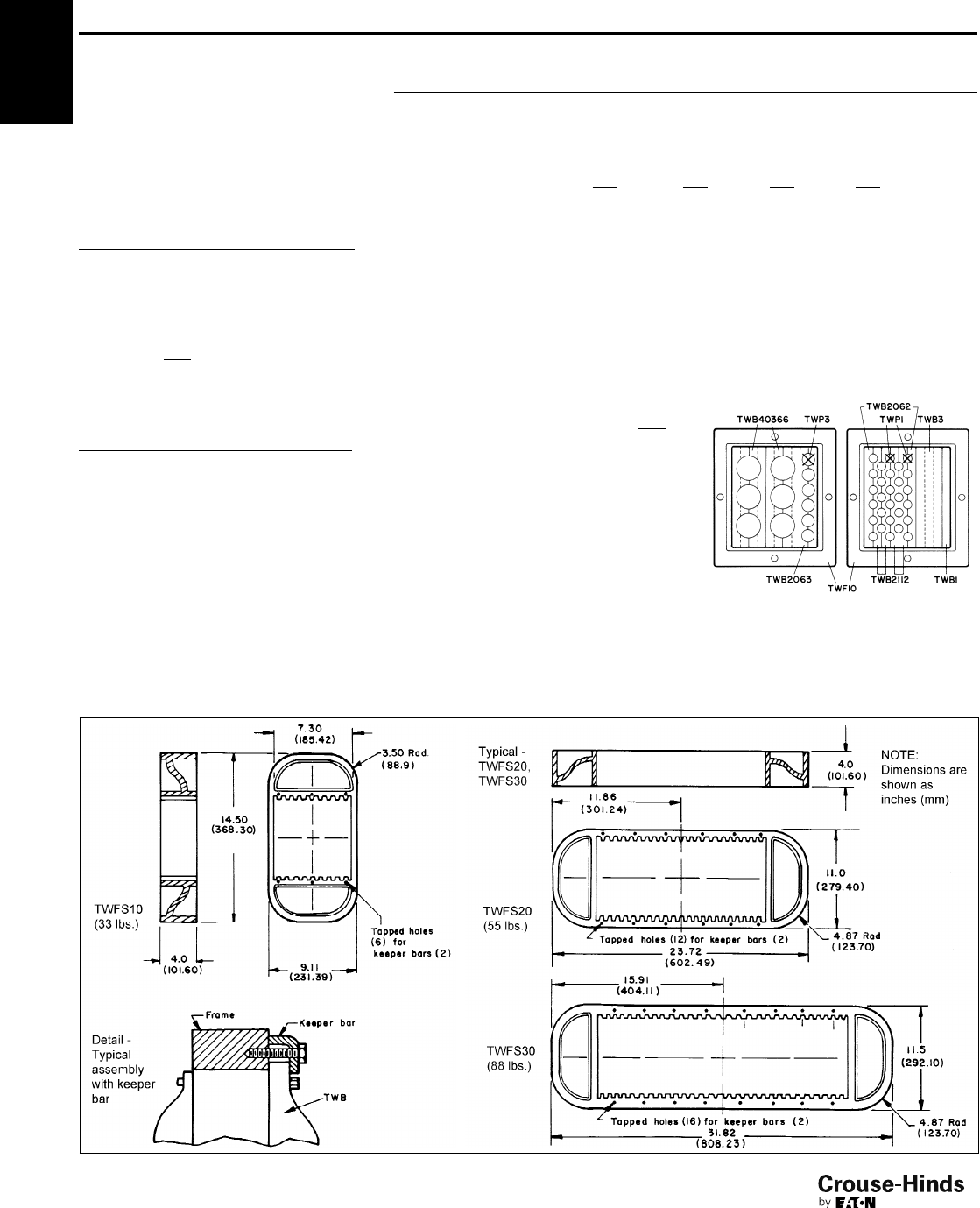
4F
110
www.crouse-hinds.com US: 1-866-764-5454 CAN: 1-800-265-0502 Copyright©2013 Eaton’s Crouse-Hinds Business
4F TW Series THRU-WALL BARRIER®
Cable/Conduit Sealing Device
Ordering Example B
Dimensions
Ordering Example B:
Cable tray size: 24"
Cables specified: 6 power cables – sizes
ranging from 2.140" to 2.180" O.D. 31
control cables – sizes ranging from .550" to
.945" O.D.
Spare capacity required: 25%
Step 1. Group cables by O.D. and rank
from largest to smallest.
Cable Qty. Cable O.D.
4 2.180
2 2.140
1 .945
4 .890
7 .700
9 .637
10 .550
Total 37
Step 2. Group cables that fall within the
same sealing block assembly size.
Cable Qty.
Sealing Block
O.D. Range
6 2.000–2.250
5 .750–1.000
26 .500–.750
Total 37
Step 3. Starting with the largest cable O.D.,
select the quantity of sealing block
assemblies required. Specify TWR reducers
to accommodate smaller diameter cables
where possible and TWP plugs to fill
openings not used. (See Example B
diagram.)
Sealing Block
Assy Cat. # O.D. Range
Number of
Openings
Cables to
be Sealed
Openings
Not Used
Frame Spaces
Required
TWB40366 2.000–2.250 33—4
TWB40366 2.000–2.250 33—4
TWB2063 .750–1.000 6512
TWB2062 .500–.750 66—2
TWB2112 .500–.750 11 11 — 2
TWB2112 .500–.750 11 9 2 2
Totals 40 37 3 16
Note: In this example, two TWB2112 sealing block
assemblies are sandwiched between two halves of a
TWB2062. This dramatically increases cable density in
minimum frame space. One TWP3 plug is required for
unused opening in TWB2063 and two TWP1 plugs are
required for unused openings in the TWB2112.
Step 4. Total the frame spaces required for
sealing block assemblies and select
appropriate size mounting frame(s). Factor
in spare capacity required for future
expansion.
Total frame spaces required 16
Specification requires 25%
spare capacity 4
Total 20
Selection: Two TWF10 (or one TWF20)
mounting frames with total capacity of 20
spaces. One TWB3 and one TWB1 blank
sealing block assembly to fill unused frame
space. (Choice of frame could vary based
on future expansion needs and/or specific
cable/conduit arrangement.)
Step 5. Bill of materials for
specification/order should read:
(2) TWF10 or (1) TWF20
(2) TWB40366
(1) TWB2063
(1) TWB2062
(2) TWB2112
(1) TWP3
(2) TWP1
(1) TWB3
(1) TWB1
*For TWFS mounting frame hole dimensions, contact
Eaton's Crouse-Hinds ECM field representative or
headquarters.
Dimensions
In Inches:
Example B diagram
110-111.qxp 12/16/2013 12:21 PM Page 110
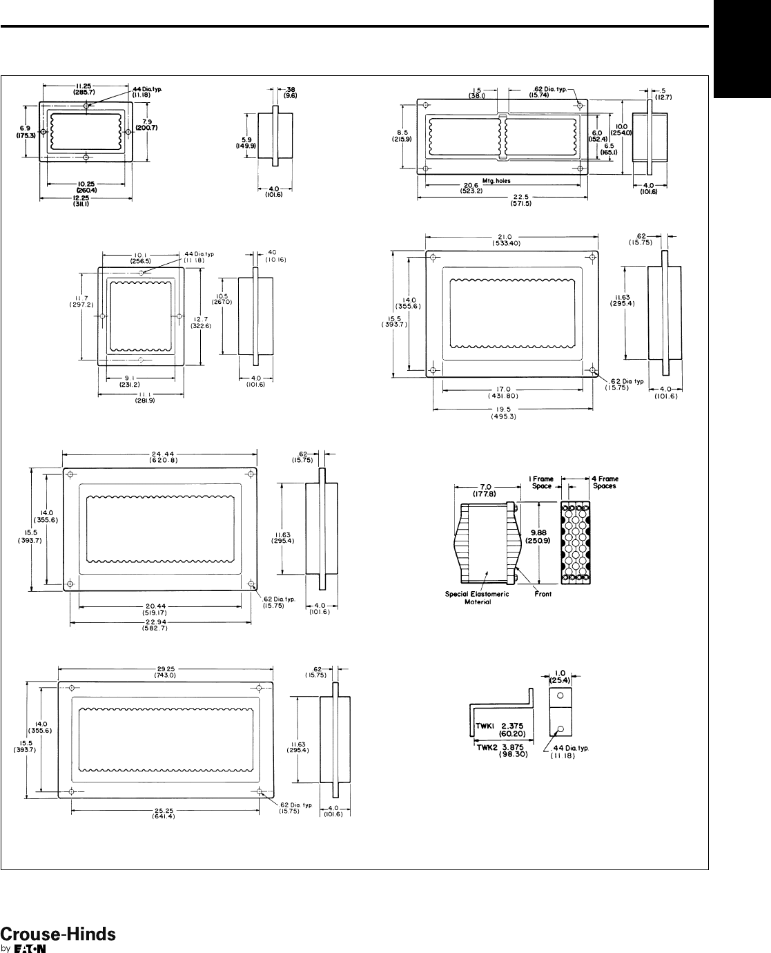
4F
111
www.crouse-hinds.com US: 1-866-764-5454 CAN: 1-800-265-0502 Copyright©2013 Eaton’s Crouse-Hinds Business
4F
Dimensions
In Inches:
TWF6 (20 lbs.) TWF12 (38 lbs.)
TWF10 (25 lbs.) TWF20 (82 lbs.)
TWF24 (88 lbs.)
TWB
TWF30 (97 lbs.)
TWK
*For TWF mounting frame hole dimensions, contact Eaton's Crouse-Hinds ECM field representative or headquarters.
1. Dimensions are shown as inches (mm).
2. Dimensions shown for TWF frames also apply for TWFR retrofit frames.
TW Series THRU-WALL BARRIER®
Cable/Conduit Sealing Device
Dimensions*
110-111.qxp 12/16/2013 12:21 PM Page 111

4F
112
www.crouse-hinds.com US: 1-866-764-5454 CAN: 1-800-265-0502 Copyright©2013 Eaton’s Crouse-Hinds Business
Link-Seal®Devices
Environmental Seal for
Conduit Passing Through
Concrete Walls, Floors, or Ceilings
Link-Seal Devices
Wet Locations
Corrosive Environments
Applications:
• Eaton's Crouse-Hinds Link-Seal®is the
quick, economical way to seal around
conduit in concrete walls, floors and
casings. Link-Seal is a modular
mechanical seal used for any type of
penetration.
Features and Benefits:
• Saves time and money – Link-Seal
installs in up to 75% less time than
competition products
• Positive Hydrostatic Sealing – properly
installed, Link-Seal is rated at 20 psig
(40 feet of head), which exceeds the
performance requirements of most
applications
• Environment Seals – Link-Seal
environmental seal is designed for long
life and use as a permanent seal. Seal
elements are specially compounded to
resist aging, ozone, sunlight, water and a
wide range of chemicals
• Fire Seals – for fire protection in floor
and wall penetrations Link-Seal is
Factory Mutual approved
• Resistance to high and low temperatures
– Link-Seal environmental seal is
manufactured from special compounds
that resist temperatures from
–40°F to +250°F. Link-Seal Fire
Seal is manufactured from a silicone
material that resists temperatures from
–67°F to +400°F
• Corrosion protection – where installation
against galvanic corrosion (or
electrolysis) is required, Link-Seal
provides complete separation pipe and
casing. Metal-to-metal contact is
eliminated
• Compensates for misalignment –
Link-Seal allows for some angular and
off-center conduit conditions and still
seals effectively
• Absorbs shock, sound and vibration –
this inherent benefit of Link-Seal helps
reduce conduit failure due to fatigue and
threaded connections
Standard Materials:
• Rubber Seal Elements:
EPDM (Black) – Environmental Seals
Silicone (Grey) – Fire Seals
• Pressure Plates:
Glass Reinforced Nylon – Environmental
Seals
Steel w/Zinc Dichromate Plate – Fire Seals
• Fasteners:
Carbon Steel, Zinc Dichromate Plate –
Environmental Seals
316 Stainless Steel – Environmental with
Option S316
Carbon Steel w/Zinc Dichromate – Fire
Seals
Environmental Conduit
Seal
Ordering Information:
It’s easy. Locate the conduit size and type
you are installing in the columns on the
left. Then locate the seal and sleeve part
numbers under the installation method
you’ve selected. No sleeve is needed for
cored or cast hole installation.
Cored or Cast Hole
Method:
Note the appropriate hole diameter and
select the seal part number. Example:
For 3/4" EMT conduit through a cored
hole – Core a 2" diameter hole and install
the conduit using Link-Seal part number
LSA200-C-04.
Sleeve Methods:
Select either the plastic or metal sleeve.
Both types of sleeves are designed to be
cast into concrete walls or floors. Sleeves
are ordered separately. Remember to add
the wall or floor thickness to the steel
sleeve part number to insure the sleeve is
provided in the proper length. Plastic
sleeves are a standard 16 long and can be
modified in the field.
Materials:
The standard product for environmental
conduit seals is made from EPDM supplied
with steel bolts and nuts with a zinc
dichromate finish. These seals are suitable
for use in water, direct ground burial and
atmospheric conditions. They provide
electrical insulation where cathodic
protection is required. EPDM rubber is
resistant to most inorganic acids and
alkalis, and some organic chemicals
(acetone, alcohol, ketones).
Options:
To order the standard product with 316
stainless steel bolts and nuts, for corrosive
environments, replace the "C" in the seal
catalog number with "S316". For example,
a 1/2" seal for rigid steel conduit for a cored
hole is an LSA200-C-04; ordered with
stainless steel bolts and nuts the catalog
number becomes LSA200-S316-04.
4F
112-113.qxp 12/16/2013 12:21 PM Page 112

4F
113
www.crouse-hinds.com US: 1-866-764-5454 CAN: 1-800-265-0502 Copyright©2013 Eaton’s Crouse-Hinds Business
4F
The last two digits of the seal part number indicate the number of links (and the number of bolts) per seal.
Ordering Information - Environmental Conduit Seal
Conduit
Nominal
Size
Conduit
Type*
Conduit
Actual O.D.
(inches)
Cast/Cored
Hole Dia.
(inches)
Seal for
Cast/Cored Hole
Cat. #
Plastic
Sleeve
Cat. #
Seal for
Plastic Sleeve
Cat. #
Steel
Sleeve
Cat. #
Seal for
Steel Sleeve
Cat. #
1/2" EMT .706 2.000 LSA275 C 04 LS CS 2 16 LSA200 C 04 WS2 15 ➀LSA275 C 04
1/2" IMC .815 2.000 LSA200 C 04 LS CS 2 16 LSA200 C 04 WS2 21 ➀LSA200 C 04
1/2" RSC .840 2.000 LSA200 C 04 LS CS 2 16 LSA200 C 04 WS2 21 ➀LSA200 C 04
3/4" EMT .922 2.000 LSA200 C 04 LS CS 3 16 LSA315 C 04 WS2 15 ➀LSA200 C 04
3/4" IMC 1.029 2.500 LSA275 C 06 LS CS 3 16 LSA315 C 04 WS2 15 ➀LSA200 C 04
3/4" RSC 1.050 2.500 LSA275 C 06 LS CS 3 16 LSA315 C 04 WS2.5 20 ➀LSA275 C 06
1" EMT 1.163 2.500 LSA315 C 04 LS CS 3 16 LSA300 C 04 WS2.5 20 ➀LSA275 C 06
1" IMC 1.290 3.000 LSA300 C 04 LS CS 3 16 LSA300 C 04 WS2.5 10 ➀LSA275 C 06
1" RSC 1.315 3.000 LSA300 C 04 LS CS 3 16 LSA300 C 04 WS2.5 20 ➀LSA200 C 05
11/4" EMT 1.510 3.000 LSA300 C 04 LS CS 3.5 16 LSA315 C 05 WS3.5 22 ➀LSA315 C 05
11/4" IMC 1.638 3.000 LSA275 C 07 LS CS 3.5 16 LSA300 C 05 WS3.5 22 ➀LSA315 C 05
11/4" RSC 1.660 3.000 LSA275 C 07 LS CS 3 16 LSA200 C 06 WS3.5 22 ➀LSA315 C 05
11/2" EMT 1.740 3.500 LSA315 C 05 LS CS 3.5 16 LSA300 C 05 WS3.5 32 ➀LSA315 C 05
11/2" IMC 1.883 3.500 LSA300 C 05 LS CS 3.5 16 LSA275 C 08 WS3.5 22 ➀LSA300 C 05
11/2" RSC 1.900 3.500 LSA300 C 05 LS CS 3.5 16 LSA275 C 08 WS3.5 22 ➀LSA300 C 05
2" EMT 2.197 4.000 LSA315 C 06 LS CS 4 16 LSA315 C 06 WS4 23 ➀LSA315 C 06
2" IMC 2.360 4.000 LSA300 C 06 LS CS 4 16 LSA300 C 06 WS4 23 ➀LSA300 C 06
2" RSC 2.375 4.000 LSA300 C 06 LS CS 4 16 LSA300 C 06 WS4 23 ➀LSA300 C 06
21/2" EMT/RSC 2.875 4.000 LSA200 C 09 LS CS 4 16 LSA200 C 09 WS4 23 ➀LSA200 C 09
21/2" IMC 2.857 4.000 LSA200 C 09 LS CS 4 16 LSA200 C 09 WS4 23 ➀LSA200 C 09
3" EMT/RSC 3.500 5.000 LSA300 C 08 LS CS 5 16 LSA300 C 08 WS5 25 ➀LSA300 C 08
3" IMC 3.476 5.000 LSA300 C 08 LS CS 5 16 LSA300 C 08 WS5 25 ➀LSA300 C 08
31/2" EMT/RSC 4.000 6.000 LSA325 C 05 LS CS 6 16 LSA325 C 05 WS6 28 ➀LSA325 C 05
31/2" IMC 3.971 6.000 LSA325 C 05 LS CS 6 16 LSA325 C 05 WS6 28 ➀LSA325 C 05
4" EMT/RSC 4.500 6.000 LSA300 C 10 LS CS 6 16 LSA300 C 10 WS6 28 ➀LSA300 C 10
4" IMC 4.466 6.000 LSA300 C 10 LS CS 6 16 LSA300 C 10 WS6 28 ➀LSA300 C 10
5" RSC 5.563 8.000 LSA425 C 06 LS CS 8 16 LSA425 C 06 WS8 32 ➀LSA425 C 06
6" RSC 6.625 10.000 LSA475 C 10 LS CS 10 16 LSA475 C 10 WS8 18 ➀LSA300 C 15
*EMT – Electrical Metallic Tubing; IMC – Intermediate Metal Conduit; RSC – Rigid Steel Conduit
➀Specify length of steel sleeve in inches. Example: S6-28-08 is 8" long. All plastic sleeves come in standard 16" lengths and can be field cut to desired length.
Link-Seal®Devices
Environmental Seal for
Conduit passing through
Concrete Walls, Floors or Ceilings
Wet Locations
Corrosive Environments
112-113.qxp 12/16/2013 12:21 PM Page 113

1/2"
1/2"
1/2"
3/4"
3/4"
3/4"
1"
1"
1"
11/4"
11/4"
11/4"
11/2"
11/2"
11/2"
2"
2"
2"
21/2"
21/2"
3"
3"
31/2"
31/2"
4"
4"
5"
6"
4F
114
www.crouse-hinds.com US: 1-866-764-5454 CAN: 1-800-265-0502 Copyright©2013 Eaton’s Crouse-Hinds Business
4F Link-Seal®Devices
Fire Seal for
Conduit passing through
Concrete Walls, Floors or Ceilings
Fire Rated
Fire Conduit Seal
Ordering Information:
Locate the conduit size and type you are
installing in the columns on the left. Then
locate the seal and sleeve part number
under the installation method you've
selected. No sleeve is needed for cored or
cast hole installation.
Cored or Cast Hole
Method:
Note the appropriate hole diameter and
select the seal part number. Example: For
3/4" EMT conduit through a cored hole
–Core a 2" diameter hole and install the
conduit using Link-Seal Part number
LSA200-T-04.
Sleeve Methods:
Select the appropriate metal sleeve for the
size and type of conduit being installed.
The sleeve should be ordered separately.
Remember to add the wall or floor
thickness to the steel sleeve part number
to insure the sleeve is provided in the
proper length.
Materials:
The standard product for fire conduit seals
is made from grey silicone supplied with
steel bolts and nuts with a zinc dichromate
finish. These seals are Factory Mutual
approved for use as a 1-hour fire stop and
can handle temperature extremes of –67°F
to +400°F.
Options:
To order the fire seal for a 3-hour rating,
replace the "T" in the seal catalog number
with a "FS". For example, a 1/2" seal for
rigid steel conduit for a cored hole is an
LSA200-T-04; ordered with option FS the
catalog number becomes LSA200-FS-04.
A 3-hour fire seal can also be made by
using two Model T’s back-to-back.
The Model FS is basically two Model T's
back-to-back. In Model FS, a tie rod
tightens both seals simultaneously – for
use when only one side of an opening is
accessible.
Fire Conduit Seal - Ordering Information
Conduit
Nominal
Size
Conduit
Type*
Conduit
Actual O.D.
(inches)
Cast/Cored
Hole Dia.
(inches)
Seal for
Cast/Cored Hole
Cat. #
Steel
Sleeve
Cat. #
Seal for
Steel Sleeve
Cat. #
EMT 0.706 2.000 LSA275 T 04 WS2 15 ➀LSA275 T 04
IMC 0.815 2.000 LSA200 T 04 WS2 21 ➀LSA200 T 04
RSC 0.840 2.000 LSA200 T 04 WS2 21 ➀LSA200 T 04
EMT 0.922 2.000 LSA200 T 04 WS2 15 ➀LSA200 T 04
IMC 1.029 2.500 LSA275 T 06 WS2 15 ➀LSA200 T 04
RSC 1.050 2.500 LSA275 T 06 WS2.5 20 ➀LSA275 T 06
EMT 1.163 3.000 LSA315 T 04 WS2.5 20 ➀LSA275 T 06
IMC 1.290 3.000 LSA300 T 04 WS2.5 10 ➀LSA275 T 06
RSC 1.315 3.000 LSA300 T 04 WS2.5 20 ➀LSA200 T 05
EMT 1.510 3.000 LSA300 T 04 WS3.5 22 ➀LSA315 T 05
IMC 1.638 3.000 LSA275 T 07 WS3.5 22 ➀LSA315 T 05
RSC 1.660 3.000 LSA275 T 07 WS3.5 22 ➀LSA300 T 05
EMT 1.740 3.500 LSA315 T 05 WS3.5 32 ➀LSA300 T 05
IMC 1.883 3.500 LSA300 T 05 WS3.5 22 ➀LSA300 T 05
RSC 1.900 3.500 LSA300 T 05 WS3.5 22 ➀LSA275 T 08
EMT 2.197 4.000 LSA315 T 06 WS4 23 ➀LSA315 T 06
IMC 2.360 4.000 LSA300 T 06 WS4 23 ➀LSA300 T 06
RSC 2.375 4.000 LSA300 T 06 WS4 23 ➀LSA300 T 06
EMT/RSC 2.875 4.000 LSA200 T 09 WS4 23 ➀LSA200 T 09
IMC 2.857 4.000 LSA200 T 09 WS4 23 ➀LSA200 T 09
EMT/RSC 3.500 5.000 LSA300 T 08 WS5 25 ➀LSA300 T 08
IMC 3.476 5.000 LSA300 T 08 WS5 25 ➀LSA300 T 08
EMT/RSC 4.000 6.000 LSA325 T 05 WS6 28 ➀LSA325 T 05
IMC 3.971 6.000 LSA325 T 05 WS6 28 ➀LSA325 T 05
EMT/RSC 4.500 6.000 LSA300 T 10 WS6 28 ➀LSA300 T 10
IMC 4.466 6.000 LSA300 T 10 WS6 28 ➀LSA300 T 10
RSC 5.563 8.000 LSA425 T 06 WS8 32 ➀LSA425 T 06
RSC 6.625 10.000 LSA475 T 10 WS8 18 ➀LSA300 T 15
➀Specify length of steel sleeve in inches. Example: WS6-28-08 is 8" long.
*EMT – Electrical Metallic Tubing; IMC – Intermediate Metal Conduit; RSC – Rigid Steel Conduit
The last two digits of the seal part number indicate the number of links (and the number of bolts) per seal.
114-115.qxp 12/16/2013 12:23 PM Page 114
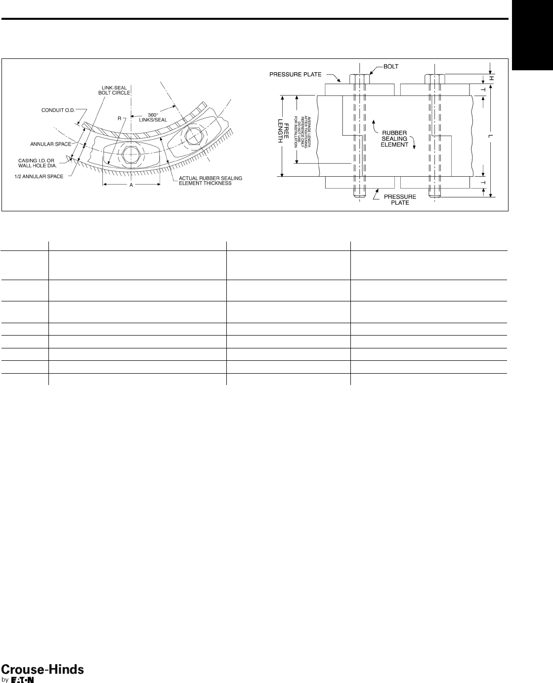
4F
115
www.crouse-hinds.com US: 1-866-764-5454 CAN: 1-800-265-0502 Copyright©2013 Eaton’s Crouse-Hinds Business
4F
Dimensions
In Inches:
Technical Information
Rubber Sealing Element Pressure Plate Bolt
Link-Seal
Cat. #
Actual
Thickness
(inches)
Free
Length
(inches)
Avg. Length After
Tightening
(inches)
A
(inches)
R
(inches)
T
(inches)
Hex
Across
Flats
H
(inches)
Thread
Size
(inches) L
LSA200 C .478 13/413/811/621/45/16 M5
slotted hex .180 M5 21/2
LSA275 C .607 13/413/87/817/85/16 M5
slotted hex .180 M5 21/2
LSA300 C .687 21/221
1/221/27/16 1/27/32 5/16–5/18 31/2
LSA315 C .807 21/221
7/16 21/27/16 1/27/32 5/16–5/18 31/2
LSA325 C .875 3 23/831/821/21/27/32 5/16–5/18 4
LSA425 C 1.062 31/223/431/233/49/16 1/43/8–3/16 5
LSA475 C 1.562 31/223/431/231/21/29/16 1/43/8–3/16 41/2
Link-Seal®Devices
Dimensions
114-115.qxp 12/16/2013 12:23 PM Page 115

4F
116
www.crouse-hinds.com US: 1-866-764-5454 CAN: 1-800-265-0502 Copyright©2013 Eaton’s Crouse-Hinds Business
4F
116-117.qxp 12/16/2013 6:31 PM Page 116

117
www.crouse-hinds.com US: 1-866-764-5454 CAN: 1-800-265-0502 Copyright©2013 Eaton’s Crouse-Hinds Business
5F
Elbows, Couplings, Hubs, Grounding
Devices, Plugs, Reducers, Service
Entrance and Unions
Hazardous and Non-hazardous
Description Page No. Description Page No.
Application/Selection see page 118
Elbows
EL Series see page 121
FE / FT Series see page 122
Flexible & Expansion Joint Couplings
EC Series see pages 127–128
XD Series see page 129
XJG Series see page 130
XJG-EMT Series see page 131
XJGD Series see page 132
Grounding Devices, Straps, Clamps
GC Series see page 134
Hubs
HUB Series see page 133
Pipe Plugs
PLG Series see page 124
NOR Series see page 126
Reducers and Adapters
AMN / ANM Series see page 125
RE Series see page 124
REA Series see page 124
REC Series see page 124
NOR Series see page 126
Service Entrance Fittings
Heads
F Series see page 135
Unions
Non-Expansion
UNA Series see page 121
UNF Series see page 120
UNL Series see page 120
UNY Series see page 120
Expansion
UNF Series see page 123
UNY Series see page 123
UNFL Series see page 123
UNYL Series see page 123
Nipples
NOR Series see page 126
Conduit Liners
LNR Series see page 136
5F
116-117.qxp 12/16/2013 6:31 PM Page 117
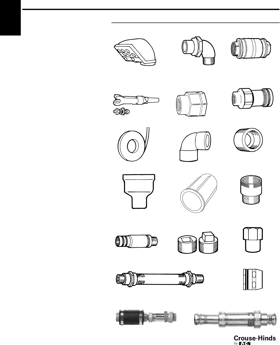
5F
118
www.crouse-hinds.com US: 1-866-764-5454 CAN: 1-800-265-0502 Copyright©2013 Eaton’s Crouse-Hinds Business
Elbows, Couplings, Hubs, Grounding
Devices, Plugs, Reducers, Service
Entrance and Unions
Application and Selection
Applications:
Service entrance heads, elbows, unions,
couplings, grounding receptacle and stud
and grounding straps with clamps are the
miscellaneous fittings needed to complete
an electrical conduit system from the
overhead service entrance to machinery,
lighting fixtures and/or final electrical
outlets. These fittings are installed in
conduit systems within non-hazardous
areas to:
• Plug
• Connect
• Reduce
• Terminate
• Change direction
• Ground
Use in Hazardous Areas:
• Most of the items shown above are also
suitable for hazardous areas (see
specific listings for compliance
information).
Considerations for
Selection:
Service Heads:
• Size required – determine from size and
number of conductors in service and
conduit or mast size.
• Type required – (threaded, slip fit,
clamp) – determine from conduit used
with service head.
Elbows, Unions, Reducers, Couplings and
Grounding Receptacles/Connectors:
• Size required – determine from conduit
size.
• Type required – determine from
intended function in system (i.e. male
and female thread for connecting
conduit to outlet box etc.)
• Material and finish required – determine
from environmental conditions (corrosive
fumes, buried in concrete, etc.)
Options:
Description Suffix
Corro-free™epoxy powder coat S752
Series Page Series Page Series Page
F see page 135 UNL see page 120 XD see page 129
GCT see page 134 UNF see page 120 XJG see page 130
RE see page 124
REA / AMN see page 124
GCR see page 134 LNR see page 136
REC see page 124
UNYL see page 123 PLG
EC
see pages
127–128 HUB see page 133
XJGD see page 132 XJG-EMT see page 131
GC see page 134 EL / FE
see pages
121–122
5F
see
page 124
118-119.qxp 12/16/2013 12:24 PM Page 118

5F
119
www.crouse-hinds.com US: 1-866-764-5454 CAN: 1-800-265-0502 Copyright©2013 Eaton’s Crouse-Hinds Business
Elbows, Couplings, Hubs, Grounding
Devices, Plugs, Reducers, Service
Entrance and Unions
Quick Selector Chart
XD Expansion/deflection
coupling
1" to 6" Threaded rigid Feraloy®iron alloy hubs,
neoprene outer jacket, tinned
copper grounding strap
FThreaded service entrance
head
1/2" to 4" conduit Threaded rigid Copper-free aluminum
FClamp type service entrance
head
3/4" to 2" conduit Threadless rigid or EMT Copper-free aluminum
GCT Ground connector and stud .312" to .406" Used to provide "quick
connect" static electricity
grounding connections with
portable cable
Bronze connector body;
aluminum cable clamp; brass
stud
GC100 Grounding strap 50' coil Used for bonding and
grounding
Flexible copper, tinned
GCR Grounding receptacle 3/4" threaded grounding
rod
Used to provide static
electricity grounding
connection
Bronze body, cap and chain;
brass grounding stud
GC102 Grounding clamp Adjustable
Used as clamp for GC100
Brass
HUB Conduit hub 1/2" to 4" Threaded rigid Steel or Feraloy iron alloy
UNL Union, 90° angle; for
connecting conduit to cast
boxes
1/2" - 1/2" to 3/4" - 3/4" Threaded rigid Feraloy iron alloy
UNY Union, male; for connecting
conduit to cast boxes
1/2" to 6" / 20mm to 50mm Threaded rigid Steel or Feraloy iron alloy
UNF Union, female; for connecting
conduit to conduit
1/2" to 6" / 20mm to 50mm Threaded rigid Steel or Feraloy iron alloy
UNA Male Union, 90° to 180°
adjustable; for connecting
conduit to boxes for conduit
support
1/2" to 1" Threaded rigid Feraloy iron alloy
EL-45° 45° elbow, female 12" to 4" Threaded rigid Feraloy iron alloy
EL-90° 90° elbow, male; 90° elbow,
female; 90° elbow, male and
female
1/2" to 11/4" male; 1/2" to 21/2"
female; 1/2" to 11/4" male
and female
Threaded rigid Feraloy iron alloy
FE 90º elbow, metric 20mm to 25mm Threaded rigid Cooper-free aluminium
RE Reducer, threaded 1/2" - 1/8" to 6" - 5" / 20mm
to 50mm
Threaded rigid Steel or Feraloy iron alloy
REA / AMN Adapter fitting
1/2" male to 3/4" female; 3/4"
male to 1" female; 1" male to
11/4" female; 16mm to 63mm
Threaded rigid Steel or Brass
REC Reducer coupling 3/4" - 1/2" to 5" - 4" Threaded rigid Feraloy iron alloy
PLG Pipe plug, recessed head or
square head
1/2" to 4" / 20mm to 63mm Threaded rigid Steel or Feraloy iron alloy or
Brass
EC Flexible coupling 1/2" to 4" See catalog page 7F for
details
LNR Conduit liner 1/2" to 4" Threaded rigid & IMC Polypropylene
XJG Expansion fitting 1/2" to 6" Threaded rigid or IMC Feraloy iron alloy
XJG-EMT Expansion fitting 1/2" to 4" EMT Feraloy iron alloy
Series Description Size Range Conduit Type
Standard
Materials
XJGD Expansion-deflection 1" to 4" Threaded rigid Feraloy iron alloy
5F
118-119.qxp 12/16/2013 12:24 PM Page 119
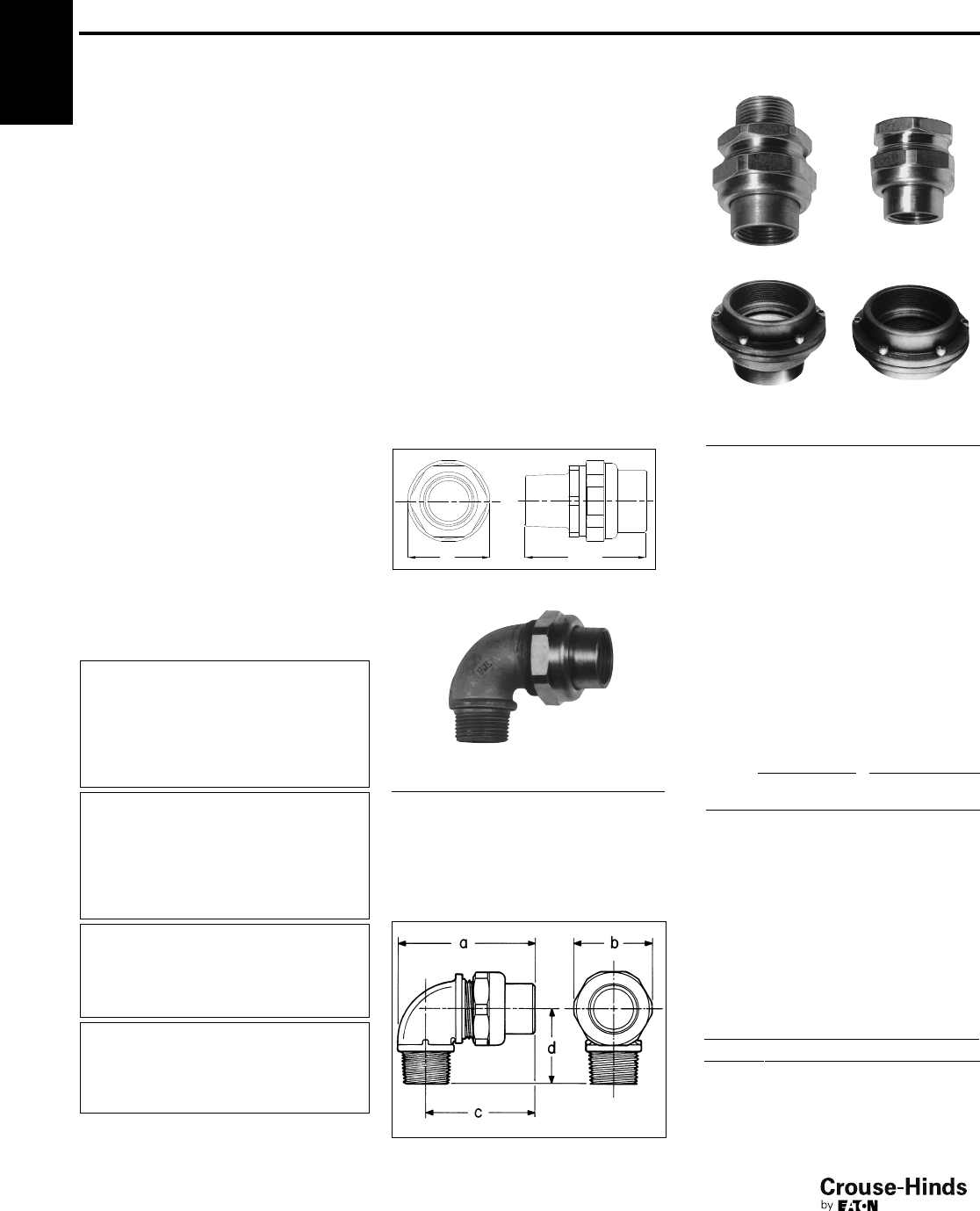
5F
120
www.crouse-hinds.com US: 1-866-764-5454 CAN: 1-800-265-0502 Copyright©2013 Eaton’s Crouse-Hinds Business
Unions and Elbows
Cl. I, Div. 1 & 2, Groups A, B, C, D†
Cl. II, Div. 1, Groups E, F, G
Cl. II, Div. 2, Groups F, G
Cl. III
Explosionproof
Dust-Ignitionproof
Applications:
UNY and UNF unions are installed in
threaded thickwall conduit systems:
• UNY – to connect conduit to a conduit
fitting, junction box or device enclosure
• UNF – to connect conduit to conduit, or
to provide a means for future
modification of the conduit system
UNA unions are used in conduit and fitting
installations when entrance angle is
between 90° and 180°.
EL elbows are installed in conduit run or in
box or fitting hub:
• To change direction in threaded rigid
conduit run by 90°, or when terminating
at a box or fitting
Features:
UNY, UNF and UNL unions have:
• Compact design which permits
assembly with a minimum of clearance
to other adjacent conduit and/or
equipment
• Strong and durable construction
UNA unions:
• Have a single clamping nut on angle,
making it both a union and a connector
• Permit conduit joints at angles between
90° and 180°
EL elbows have a smooth interior and are
both strong and compact.
Standard Materials:
• UNY, UNF unions – 1/2" to 1" – steel
• UNY, UNF unions – 11/4" to 6" – Feraloy®
iron alloy
• UNL, UNA unions – Feraloy iron alloy
• EL elbows – Feraloy iron alloy or ductile
iron
Standard Finishes:
• Steel – electrogalvanized with chromate
treatment
•Feraloy iron alloy, malleable iron –
electrogalvanized and aluminum acrylic
paint
Options:
Description Suffix
Copper-free aluminum SA
Not available on UNA or 5" and
6" UNY/UNF
†See compliances for classification of each product.
Certifications and
Compliances:
• NEC/CEC:
Class I, Division 1 & 2, Groups A, B, C, D
Class II, Division 1, Groups E, F, G
Class II, Division 2, Groups F, G
Class III
EL 1/2", 3/4", 1"
UNF/UNY 105, -215, -205, -305
UNL 105, -125, -215, -205
Class I, Division 1 & 2, Groups B, C, D
Class II, Division 1, Groups E, F, G
Class II, Division 2, Groups F, G
Class III
UNF/UNY406, -506,
-606, -706, -806,
-905, -1005
Class I, Division 1 & 2, Groups C, D
Class II, Division 1, Groups E, F, G
Class II, Division 2, Groups F, G
Class III
EL, UNF, UNL, UNY - all sizes
Class I, Division 1 & 2, Group D
Class II, Division 1, Groups E, F, G
Class II, Division 2, Groups F, G
Class III
UNA
• UL Standard: 1203
• CSA Standard: C22.2 No. 30
UNL
90° Angle
Size Cat. #
1/2to 1/2UNL105
3/4female to 1/2male UNL125
1/2female to 3/4male UNL215
3/4to 3/4UNL205
Dimensions
In Inches:
UNY UNF
1/2" – 4" 1/2" – 4"
5" – 6" 5" – 6"
Male Female
Size Cat. # Size Cat. #
1/2UNY105 1/2UNF105
1/2female
to 3/4male UNY215 3/4to 1/2UNF215
3/4UNY205 3/4UNF205
1UNY305 1UNF305
11/4UNY405 11/4UNF405
11/4UNY406 11/4UNF406
11/2UNY505 11/2UNF505
11/2UNY506 11/2UNF506
2UNY605 2UNF605
2UNY606 2UNF606
21/2UNY705 21/2UNF705
21/2UNY706 21/2UNF706
3UNY805 3UNF805
3UNY806 3UNF806
31/2UNY905 31/2UNF905
4UNY1005 4UNF1005
5UNY012 5UNF012
6UNY014 6UNF014
UNY UNF
Size Length
Max.
Dia. Length
Max.
Dia.
1/225/811/2113/16 11/2
3/4– 1/2211/16 113/16 13/4113/16
3/4211/16 113/16 13/4113/16
13 1
7/821
7/8
11/4311/16 23/421/423/4
11/241/431/16 25/831/16
24
1/4313/16 29/16 313/16
21/257/16 45/16 33/16 45/16
35
3/451/16 37/16 51/16
31/261/2511/16 41/8511/16
46
5/863/16 41/863/16
56
1/883/16 313/16 83/16
66
1/895/16 313/16 95/16
UNL
Dim. 105 125 215 205
a211/16 211/16 27/827/8
b117/32 113/16 113/16 113/16
c21/16 21/16 21/421/4
d17/16 17/16 15/815/8
5F
UNY
DIA LENGTH
www.crouse-hinds.com US: 1-866-764-5454 CAN: 1-800-265-0502 Copyright©2013 Eaton’s Crouse-Hinds Business
120-121.qxp 12/16/2013 12:24 PM Page 120
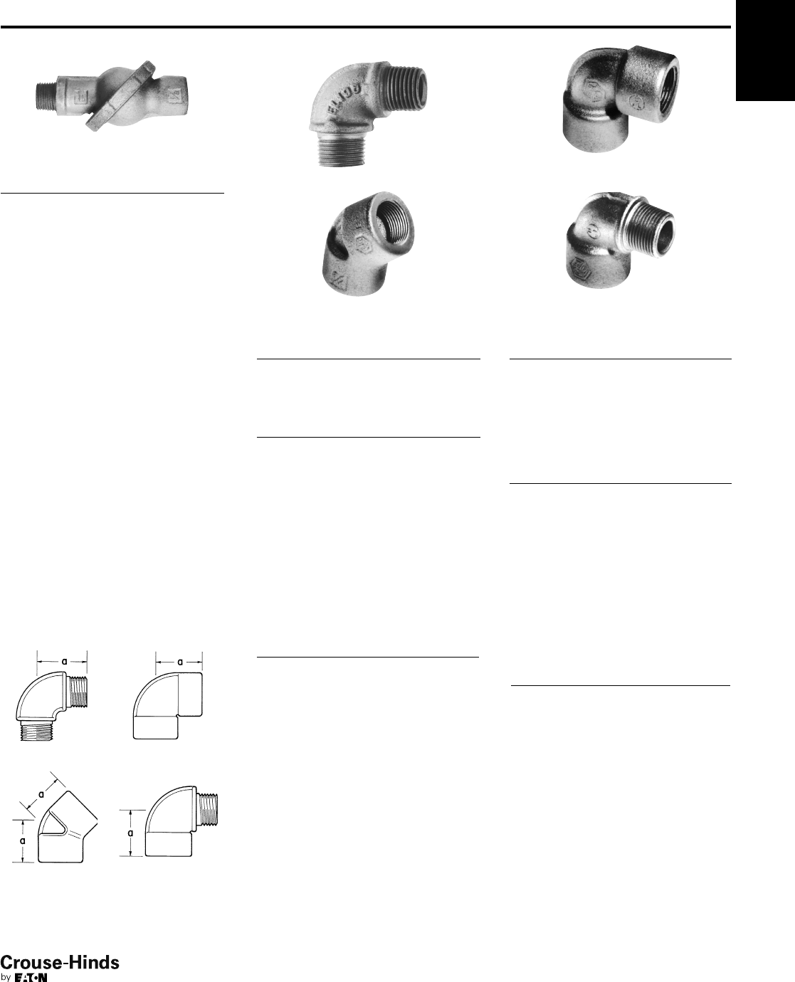
5F
121
www.crouse-hinds.com US: 1-866-764-5454 CAN: 1-800-265-0502 Copyright©2013 Eaton’s Crouse-Hinds Business
5F
Unions and Elbows
Cl. I, Div. 1 & 2, Groups C, D†
Cl. II, Div. 1, Groups E, F, G
Cl. II, Div. 2, Groups F, G
Cl. III
Explosionproof
Dust-Ignitionproof
UNA
Male (with removable nipple)
Male
Size Cat. #
1/2UNA16
3/4UNA26
1UNA36
EL
90° Male
45° Female
90° Male
Size Cat. #
1/2EL195
3/4EL295
1EL395
45° Female
Size Cat. #
1/2EL1
3/4EL2
1EL3
11/4EL4
11/2EL5
2EL6
21/2EL7
3EL8
31/2EL9
4EL10
90° Female
90° Male and female
90° Female
Size Cat. #
1/2EL19*
3/4EL29*
1EL39*
11/4EL49*
11/2EL59*
2EL69*
21/2EL79
90° Male and Female
Size Cat. #
1/2EL196*
3/4EL296*
1EL396*
11/4EL496
*Available in copper free aluminum – add suffix SA to
catalog number.
UNA
Male
Size Length Width
1/245/16 25/8
3/4413/16 27/8
1511/16 31/2
Dimensions
In Inches:
90° Male 90° Female
45° Female 90° Male and
female
EL
EL
45°
Female
90°
Male
90°
Female
90°
Male &
Female
Size a a a a
1/213/16 17/16 117/32 117/32
3/413/815/813/415/8
11
21/32 17/821
7/8
11/413/421/421/8
11/2115/16 4
22
1/45
21/223/467/16
33
1/6
31/237/16
43
5/8
†See compliances for classification of each product.
www.crouse-hinds.com US: 1-866-764-5454 CAN: 1-800-265-0502 Copyright©2013 Eaton’s Crouse-Hinds Business
120-121.qxp 12/16/2013 12:24 PM Page 121
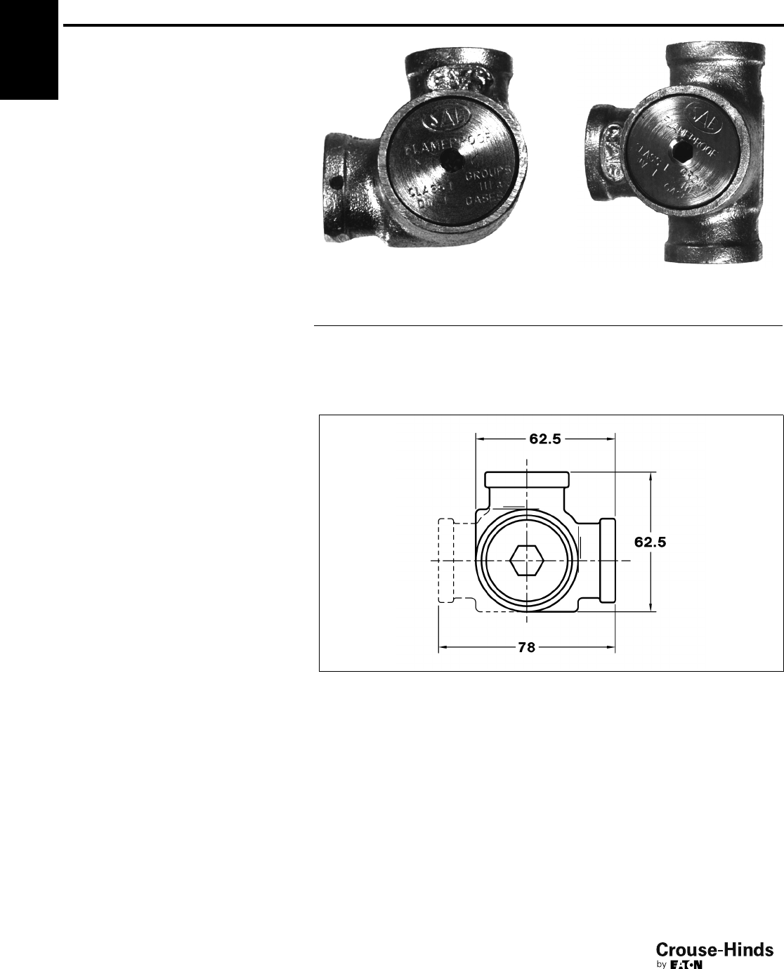
122
www.crouse-hinds.com US: 1-866-764-5454 CAN: 1-800-265-0502 Copyright©2013 Eaton’s Crouse-Hinds Business
5F
Condulet®Elbows and Tees
For IEC Applications
FE and FT Series
Zone 1 Zone 21
Zone 2 Zone 22
Applications:
FE and FT conduit fittings are installed in
hazardous areas to:
• Act as draw-in outlets especially for
cables that are stiff due to large size or
type of insulation
• Make 90º bends in conduit systems,
allowing for a straight pull in either
direction
• Provide access to wiring for
maintenance and future system changes
Features:
• Maximum volume for bends within a
compact overall size
• Large openings to facilitate cable pulling
Certifications and
Compliances:
Type of Protection
• Ex d, DIP A21, IP67
Degree of Protection
•IP67
Gas Group
• IIB
Approvals
• Ex1108U
Standard Materials:
• Body – Copper-free aluminum
• Cover – Brass
Standard Finishes:
• Natural
Ordering Information:
Inspection Elbows and Tees Selection
Cat. # Type Entry Size (metric)
FE1 Elbow M20 (F)-M20 (F)
FE2 Elbow M25 (F)-M25 (F)
FT1 Tee M20 (F)-M20 (F)
FT2 Tee M25 (F)-M25 (F)
Options:
Description Suffix
NPT & BSP thread sizes Consult Factory
Dimensions (mm)
5F
122-123.qxp 12/16/2013 12:25 PM Page 122
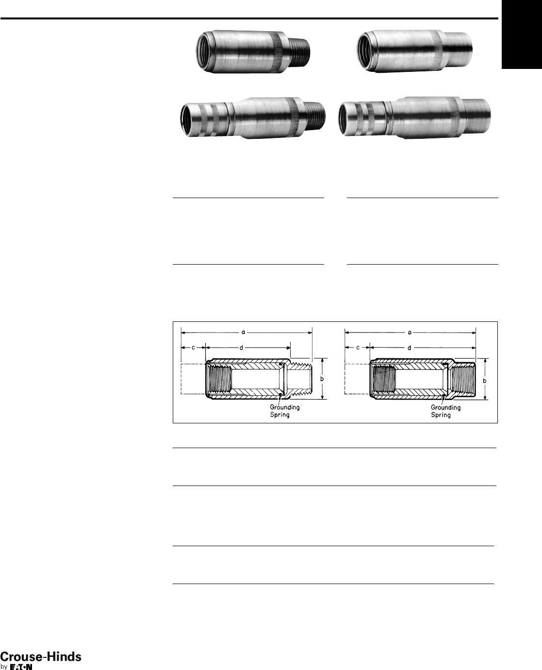
5F
123
www.crouse-hinds.com US: 1-866-764-5454 CAN: 1-800-265-0502 Copyright©2013 Eaton’s Crouse-Hinds Business
5F
Applications:
UNF/UNY expansion unions are designed
to be used in all threaded rigid metal†
conduit systems indoors and outdoors, in
hazardous locations to:
• Connect conduit to conduit
• Connect conduit to a junction box or
device enclosure
• Compensate for conduit cut too short
• Allow for expansion and contraction of
conduit
• Connect stub-ups to threaded conduit
• Replace sections of conduit runs
Features:
• Compact design
• Internal beryllium copper grounding
spring to insure positive grounding
continuity.
• Knurled surface on body and sleeve
allows secure gripping with wrench.
• Steel construction for maximum
strength.
• Available in two styles – short length
where space is limited, long length when
extra expansion is required.
Standard Materials:
• Body and sleeve – steel
• Grounding spring – beryllium copper
Standard Finishes:
• Steel – electrogalvanized with chromate
finish
• Beryllium copper – natural
Certifications and
Compliances:
• NEC/CEC:
Class I, Division 1 & 2, Groups C, D
Class II, Division 1, Groups E, F, G
Class II, Division 2, Groups F, G
Class III
• UL Standard: 1203
• CSA Standard: C22.2 No. 30
UNYL UNFL
UNYL with sleeve extended UNFL with sleeve extended
UNY
Male – Short
Conduit Size Cat. #
1/2UNY17
3/4UNY27
1UNY37
UNF
Female – Short
Conduit Size Cat. #
1/2UNF17
3/4UNF27
1UNF37
UNYL
Male – Long
Conduit Size Cat. #
1/2UNYL17
3/4UNYL27
1UNYL37
UNFL
Female – Long
Conduit Size Cat. #
1/2UNFL17
3/4UNFL27
1UNFL37
Dimensions
In Inches:
Dimension
Size a* b c‡ d
UNY
1/235/16 13/16 1/221/16
3/433/817/16 1/221/8
1313/16 111/16 5/821/4
UNYL
1/245/16 13/16 12
9/16
3/441/217/16 11/16 211/16
153/16 111/16 15/16 215/16
Dimension
Size a* b c‡ d
UNF
1/233/813/16 1/227/8
3/437/16 17/16 1/2215/16
1313/16 111/16 5/833/16
UNFL
1/243/813/16 13
3/8
3/449/16 17/16 11/16 31/2
151/8111/16 15/16 313/16
*Overall length at maximum expansion
‡Maximum expansion
†Suitable with intermediate Metal Conduit in non-hazardous locations
UNF/UNY Expansion Unions
Cl. I, Div. 1 & 2, Groups C, D
Cl. II, Div. 1, Groups E, F, G
Cl. II, Div. 2, Groups F, G
Cl. III
Explosionproof
Dust-Ignitionproof
122-123.qxp 12/16/2013 12:25 PM Page 123
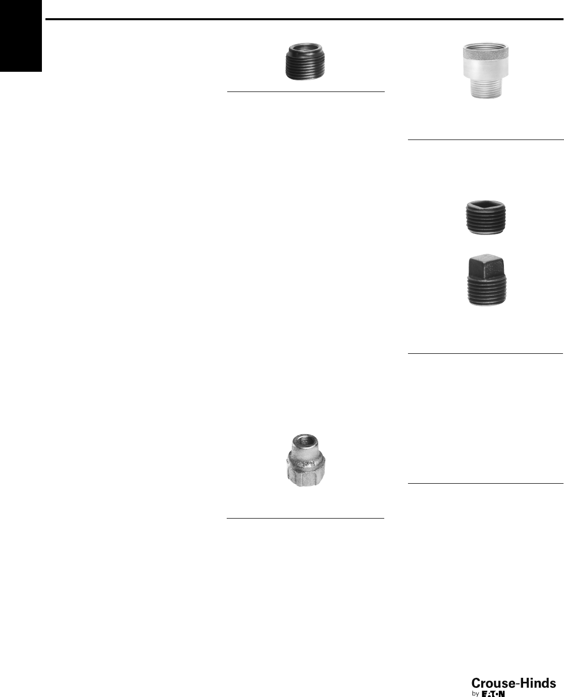
5F
124
www.crouse-hinds.com US: 1-866-764-5454 CAN: 1-800-265-0502 Copyright©2013 Eaton’s Crouse-Hinds Business
Reducers, Couplings
and Plugs
Cl. I, Div. 1 & 2, Groups A†,B,C,D
Cl. II, Div. 1, Groups E, F, G
Cl. II, Div. 2, Groups F, G
Cl. III
Explosionproof
Dust-Ignitionproof
Applications:
• RE and REC reducers are used in
threaded heavy wall conduit systems.
• RE reduces conduit hubs to a smaller size.
• REA adapters enlarge drilled and tapped
openings by 1 NPT size.
• REC connects two different sizes of
conduit together or is used to replace a
coupling and reducer in an installation.
• PLG plugs are used for closing threaded
conduit hubs.
Features:
RE reducers have:
• Integral bushing which prevents damage
to wires
• Full, clean cut tapered threads
REC reducers have:
• Integral bushings in both ends which
prevents damage to wires
• Funnel shaped interior to guide the wires
from large to small conduit, making it
easy to pull wire
REA adapters have:
• Smooth integral bushing to protect wire
insulation
• Knurled body for easy wrenching
PLG plugs:
• Have clean tapered threads
• Are available in two styles, flush
(recessed), or square head type
Standard Materials:
• RE reducers – RE1108 through RE54 in
steel; all others in Feraloy®iron alloy
• REA adapters – steel
• REC reducers – REC21 and REC32 in
steel; all others in Feraloy iron alloy
• PLG plugs – Recessed: PLG28-PLG3:
steel, PLG4-PLG10: grey iron alloy;
Square Head: PLG15-PLG55: steel,
PLG65-PLG105: grey iron alloy
Standard Finishes:
•Feraloy iron alloy – electrogalvanized and
aluminum acrylic paint
• Steel – electrogalvanized with chromate
treatment
Certifications and
Compliances:
• NEC/CEC:
Class I, Division 1 & 2, Groups A, B, C, D
Class II, Division 1, Groups E, F, G
Class II, Division 2, Groups F, G
Class III
(see listings for specific Cat. Nos. suitable
for Groups A or B)
• UL Standard: 1203
• CSA Standard: C22.2 No. 30
Options:
Description Suffix
Copper-free aluminum SA
RE
REC
Large
Hub
Size
Small
Hub
Size Cat. #
3/41/2REC21†
11/2REC31†
13/4REC32
11/43/4REC42
11/41REC43
11/23/4REC52
11/21REC53
11/211/4REC54
23/4REC602
21REC603
21
1/4REC604
21
1/2REC605
21/211/2REC75
32REC86
31/221/2REC97*
43REC108*
54REC01210*
REA
Male
Hub
Size
Female
Hub
Size Cat. #
1/23/4REA12†
3/41REA23†
11
1/4REA34†
PLG
Recessed
Square Head
Recessed
Size Cat. #
1/4PLG28†
1/2PLG1†
3/4PLG2†
1PLG3†
11/4PLG4
11/2PLG5
2PLG6
21/2PLG7
3PLG8
31/2PLG9
4PLG10
Square Head
Size Cat. #
1/2PLG15†
3/4PLG25†
1PLG35†
11/4PLG45
11/2PLG55
2PLG65
21/2PLG75
3PLG85
31/2PLG95
4PLG105
*Not available in aluminum.
†Suitable for use in Class I, Groups A and B areas.
5F
Size Cat. #
1/2– 1/8RE1108*
1/2– 1/4RE1208*
1/2– 3/8RE1308
3/4– 1/2RE21†
1 – 1/2RE31†
1 – 3/4RE32†
11/4– 1/2RE41†
11/4– 3/4RE42†
11/4– 1 RE43†
11/2– 1/2RE51†
11/2– 3/4RE52†
11/2– 1 RE53†
11/2– 11/4RE54†
2 – 1/2RE61†
2 – 3/4RE62†
2 – 1 RE63†
2 – 11/4RE64†
2 – 11/2RE65†
21/2– 1 RE73†
21/2– 11/4RE74†
21/2– 11/2RE75†
21/2– 2 RE76†
3 – 1 RE83†
3 – 11/4RE84†
3 – 11/2RE85†
3 – 2 RE86†
3 – 21/2RE87†
31/2– 2 RE96†
31/2– 21/2RE97†
31/2– 3 RE98†
4 – 2 RE106†
4 – 21/2RE107†
4 – 3 RE108†
4 – 31/2RE109†
5 – 4 RE01210
6 – 5 RE01412
124-125.qxp 12/16/2013 12:25 PM Page 124
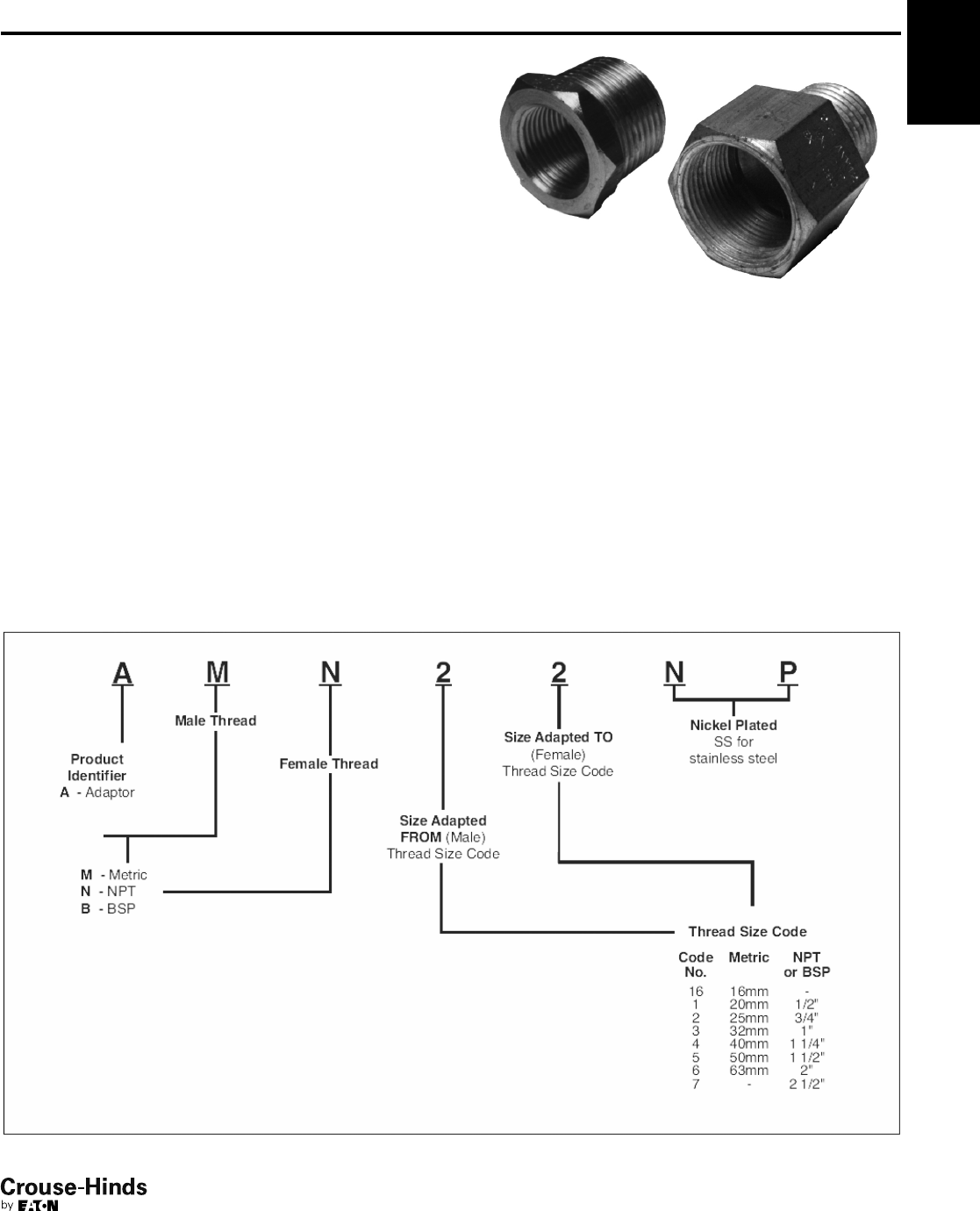
5F
125
www.crouse-hinds.com US: 1-866-764-5454 CAN: 1-800-265-0502 Copyright©2013 Eaton’s Crouse-Hinds Business
5F
Application:
Adapters are used to change the thread form and/or size in a wide
range of BSP, NPT, and metric cable and conduit entries.
Certifications and Compliances:
Type of Protection
• Ex d, DIP A21, IP67
Degree of Protection
• IP66/67
Gas Group
• IIC
Approvals
• Ex1108U
Standard Materials:
• Brass, nickel plated
Standard Finish:
• Natural
Options:
Stainless Steel - Replace NP with SS
Size Ranges:
• Standard sizes listed in table below; other sizes may be available;
please consult factory
Notes:
1. Adapters have different size thread at each end
2. Adapters may step up the same type of thread
3. Downwards adapters are Type A; upward or same size adapters
are Type B
4. For downward adapters of same thread type, see Reducers
Catalog Page
5. For same size and type of thread, see Unions Catalog Page
Ordering Information:
AMN / ANM Adapters
For IEC Applications
Zone 1 Zone 21
Zone 2 Zone 22
124-125.qxp 12/16/2013 12:25 PM Page 125
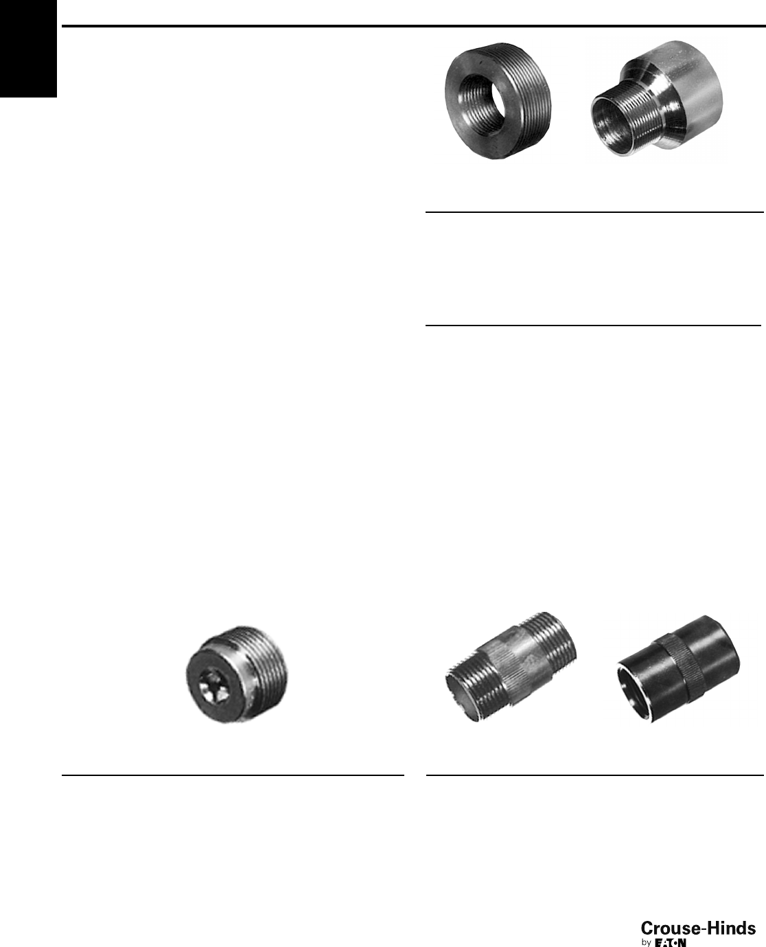
5F
126
www.crouse-hinds.com US: 1-866-764-5454 CAN: 1-800-265-0502 Copyright©2013 Eaton’s Crouse-Hinds Business
Reducers, Adapters, Plugs and
Nipples for IEC Applications
Ex II 2 G EEx e II
Ex II 2 G EEx d IIC
Ex II 2 D
IP67
Applications:
• Reducers are used in threaded heavy wall conduit systems to
reduce conduit hubs to a smaller size or to connect two different
sizes of conduit together
• Adapters enlarge drilled and tapped openings by 1 NPT size
• Plugs are used for closing unused threaded conduit hubs
Features:
Reducers:
• Integral bushing which prevents damage to wires
• Full, clean cut tapered threads
• Funnel shaped interior to guide the wires from large to small
conduit, making it easy to pull wire
Adapters:
• Smooth integral bushing to protect wire insulation
• Knurled body for easy wrenching
Plugs:
• Full, clean cut tapered threads
Certifications and Compliances:
• Plugs:
Ex II 2 G EEx e II
Ex II 2 G EEx d IIC
EC-Type examination certificate LOM 02 ATEX 3035U
IP67
• Reducers and Adapters:
Ex II 2 G EEx e II
Ex II 2 G EEx d IIC
Ex II 2 D
EC-Type examination certificate LOM 03 ATEX 3019U
IP67
• Nipples:
Ex II 2 G EEx d IIC
EC-Type examination certificate LOM 03 ATEX 3019U
IP67
Standard Materials:
• Reducers, Adapters, Plugs and Nipples - Zinc Plated Steel
Ordering Information - Plugs
Thread Size Cat. #
1/2" ISO 7/1NOR 000 002 140 117
3/4" ISO 7/1NOR 000 002 140 125
1" ISO 7/1NOR 000 002 140 133
1" NPT NOR 000 002 140 365
M20 x 1.5 NOR 000 002 140 655
M25 x 1.5 NOR 000 002 140 656
M32 x 1.5 NOR 000 002 140 657
M50 x 1.5 NOR 000 002 140 658
M60 x 1.5 NOR 000 002 140 659
Type PLG
Ordering Information - Reducers
Male Thread Female Thread Cat. #
3/4" ISO 7/11/2" ISO 7/1NOR 000 002 190 112
1" ISO 7/13/4" ISO 7/1NOR 000 002 190 188
1/2" ISO 7/13/4" ISO 7/1NOR 000 002 190 675
3/4" ISO 7/11" ISO 7/1NOR 000 002 190 740
Ordering Information - Adapters
Male Thread Female Thread Cat. #
M20 x 1.5 1/2" ISO 7/1NOR 000 112 190 010
PG13 1/2" ISO 7/1NOR 000 112 190 015
PG16 1/2" ISO 7/1NOR 000 112 190 014
M20 x 1.5 3/4" ISO 7/1NOR 000 112 190 009
M25 x 1.5 3/4" ISO 7/1NOR 000 112 190 008
PG13 3/4" ISO 7/1NOR 000 112 190 013
PG16 3/4" ISO 7/1NOR 000 112 190 012
PG21 3/4" ISO 7/1NOR 000 112 190 011
1/2" ISO 7/1M20 x 1.5 NOR 000 112 190 002
3/4" ISO 7/1M20 x 1.5 NOR 000 112 190 001
PG13 M20 x 1.5 NOR 000 112 190 017
PG16 M20 x 1.5A NOR 000 112 190 016
3/4" ISO 7/1M25 x 1.5 NOR 000 112 190 000
PG16 M25 x 1.5 NOR 000 112 190 020
1/2" ISO 7/1PG13 NOR 000 112 190 007
3/4" ISO 7/1PG13 NOR 000 112 190 005
1/2" ISO 7/1PG16 NOR 000 112 190 006
3/4" ISO 7/1PG16 NOR 000 112 190 004
M20 x 1.5 PG16 NOR 000 112 190 018
M25 x 1.5 PG16 NOR 000 112 190 019
3/4" ISO 7/1PG21 NOR 000 112 190 003
Ordering Information - Nipples
Thread Size Type Cat. #
1/2" ISO 7/1EMM 1 NOR 000 002 130 118
3/4" ISO 7/1EMM 2 NOR 000 002 130 126
1" ISO 7/1EMM 3 NOR 000 002 130 134
1/2" ISO 7/1EMF 1 NOR 000 002 130 217
3/4" ISO 7/1EMF 2 NOR 000 002 130 225
1" ISO 7/1EMF 3 NOR 000 002 130 233
5F
126-127.qxp 12/16/2013 12:25 PM Page 126
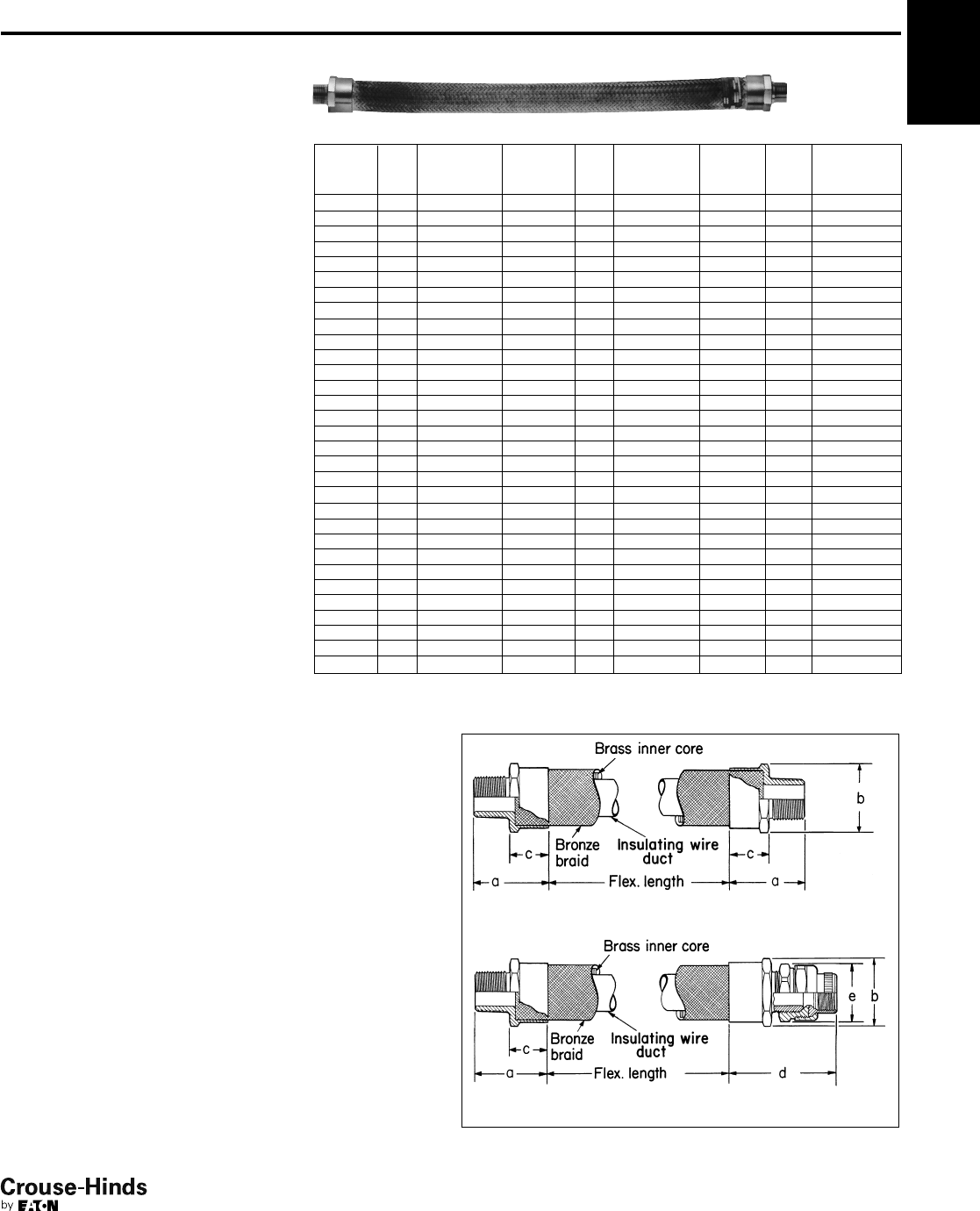
5F
127
www.crouse-hinds.com US: 1-866-764-5454 CAN: 1-800-265-0502 Copyright©2013 Eaton’s Crouse-Hinds Business
5F
Applications:
EC couplings are used:
• In hazardous areas where a flexible
member is required in a conduit system
to accomplish difficult bends, or to allow
for movement or vibration of connected
equipment or units
Features:
• Rugged design to withstand explosive
pressure (Class I)
• Mechanical abuse
• Liquid-tight for wet locations
• For use where lack of space makes use
of rigid conduit difficult
• Wire duct liner in sizes 1/2" to 2"
insulates against grounds and burn-
through from short circuit
• No bonding jumpers required, metallic
braid provides continuous electrical path
• ECGJH combination has two threaded
male end fittings
• ECLK combination has one female union
and one male threaded end fitting
ECGJH (Male connections both ends)
Flexible
Length
(In.) Size Cat. #
Flexible
Length
(In.) Size Cat. #
Flexible
Length
(In.) Size Cat. #
41/2ECGJH14 18 1 ECGJH318 27 21/2ECGJH727
43/4ECGJH24 18 11/4ECGJH418 27 3 ECGJH827
61/2ECGJH16 18 11/2ECGJH518 27 4 ECGJH1027
63/4ECGJH26 18 2 ECGJH618 30 1/2ECGJH130
61ECGJH36 18 21/2ECGJH718 30 3/4ECGJH230
81/2ECGJH18 18 3 ECGJH818 30 1 ECGJH330
83/4ECGJH28 18 4 ECGJH1018 30 11/4ECGJH430
81ECGJH38 21 1/2ECGJH121 30 11/2ECGJH530
10 1/2ECGJH110 21 3/4ECGJH221 30 2 ECGJH630
10 3/4ECGJH210 21 1 ECGJH321 30 21/2ECGJH730
10 1ECGJH310 21 11/4ECGJH421 30 3 ECGJH830
12 1/2ECGJH112 21 11/2ECGJH521 30 4 ECGJH1030
12 3/4ECGJH212 21 2 ECGJH621 33 1/2ECGJH133
12 1ECGJH312 21 21/2ECGJH721 33 3/4ECGJH233
12 11/4ECGJH412 21 3 ECGJH821 33 1 ECGJH333
12 11/2ECGJH512 21 4 ECGJH1021 33 11/4ECGJH433
12 2ECGJH612 24 1/2ECGJH124 33 11/2ECGJH533
12 21/2ECGJH712 24 3/4ECGJH224 33 2 ECGJH633
12 3ECGJH812 24 1 ECGJH324 33 21/2ECGJH733
12 4ECGJH1012 24 11/4ECGJH424 33 3 ECGJH833
15 1/2ECGJH115 24 11/2ECGJH524 33 4 ECGJH1033
15 3/4ECGJH215 24 2 ECGJH624 36 1/2ECGJH136
15 1ECGJH315 24 21/2ECGJH724 36 3/4ECGJH236
15 11/4ECGJH415 24 3 ECGJH824 36 1 ECGJH336
15 11/2ECGJH515 24 4 ECGJH1024 36 11/4ECGJH436
15 2ECGJH615 27 1/2ECGJH127 36 11/2ECGJH536
15 21/2ECGJH715 27 3/4ECGJH227 36 2 ECGJH636
15 3ECGJH815 27 1 ECGJH327 36 21/2ECGJH736
15 4ECGJH1015 27 11/4ECGJH427 36 3 ECGJH836
18 1/2ECGJH118 27 11/2ECGJH527 36 4 ECGJH1036
18 3/4ECGJH218 27 2 ECGJH627
Dimensions
In Inches:
ECGJH
ECLK
Certifications and
Compliances:
• NEC:
1/2" and 3/4" (Brass and S516) – Class I,
Division 1, Groups A, B, C, D
1" to 2" (Brass and S516) – Class I,
Division 1, Groups C, D
All sizes also for use in Class II, Division 1,
Groups E, F, G and Class III
• UL Standard: 1203
• ATEX and IECEx - ECGJH S516 Only:
1/2" and 3/4" (4" to 36" flexible length
only) – Ex d IIC, IP66
1", 11/4", 11/2", 2" (4" to 36" flexible
length only) – Ex d IIB, IP66
Standard Materials and Finishes:
• End fittings:
1/2" to 2" – forged brass; natural
21/2" to 4" – stainless steel; natural
• Female unions:
1/2" to 1" – steel; electrogalvanized with chromate treatment
11/4" to 4" – Feraloy®iron alloy; electrogalvanized with aluminum
acrylic paint
•1/2" to 2" have bronze braid covering and flexible brass inner core;
packing is woven cotton braid impregnated with asphalt
•2
1/2" to 4" have a Type 304 stainless steel braid
Options:
Description Suffix
All stainless steel (available for ECGJH only) S516
For severely corrosive locations, a flexible PVC protective
coating will be supplied S758
Special coupling lengths available up to 144 inches. To order,
change last two digits in any standard catalog number to the
two or three digit length desired in whole inches i.e. To order
a 3/4" trade size 110 inches long, use catalog number
ECGJH2110.
Couplings
1
/
2"–2" Brass Construction
2-1/2–4" Stainless Steel construction only
Cl. I, Groups A, B, C, D
Cl. II, Groups E, F, G
Cl. III
Explosionproof
Dust-Ignitionproof
Wet Locations
126-127.qxp 12/16/2013 12:25 PM Page 127
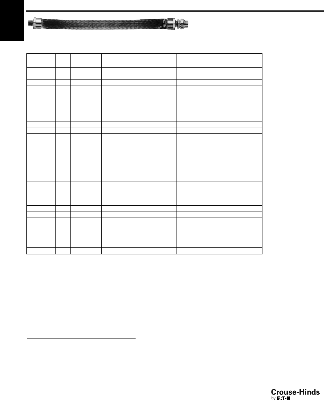
5F
128
www.crouse-hinds.com US: 1-866-764-5454 CAN: 1-800-265-0502 Copyright©2013 Eaton’s Crouse-Hinds Business
ECLK (ECGJH provide with UNF Female union – male
connection 1 end, female connection 1 end)
Flexible
Length (In.) Size Cat. #
Flexible
Length (In.) Size Cat. #
Flexible
Length (In.) Size Cat. #
41/2ECLK14 18 1 ECLK318 27 21/2ECLK727
43/4ECLK24 18 11/4ECLK418 27 3 ECLK827
61/2ECLK16 18 11/2ECLK518 27 4 ECLK1027
63/4ECLK26 18 2 ECLK618 30 1/2ECLK130
61ECLK36 18 21/2ECLK718 30 3/4ECLK230
81/2ECLK18 18 3 ECLK818 30 1 ECLK330
83/4ECLK28 18 4 ECLK1018 30 11/4ECLK430
81ECLK38 21 1/2ECLK121 30 11/2ECLK530
10 1/2ECLK110 21 3/4ECLK221 30 2 ECLK630
10 3/4ECLK210 21 1 ECLK321 30 21/2ECLK730
10 1ECLK310 21 11/4ECLK421 30 3 ECLK830
12 1/2ECLK112 21 11/2ECLK521 30 4 ECLK1030
12 3/4ECLK212 21 2 ECLK621 33 1/2ECLK133
12 1ECLK312 21 21/2ECLK721 33 3/4ECLK233
12 11/4ECLK412 21 3 ECLK821 33 1 ECLK333
12 11/2ECLK512 21 4 ECLK1021 33 11/4ECLK433
12 2ECLK612 24 1/2ECLK124 33 11/2ECLK533
12 21/2ECLK712 24 3/4ECLK224 33 2 ECLK633
12 3ECLK812 24 1 ECLK324 33 21/2ECLK733
12 4ECLK1012 24 11/4ECLK424 33 3 ECLK833
15 1/2ECLK115 24 11/2ECLK524 33 4 ECLK1033
15 3/4ECLK215 24 2 ECLK624 36 1/2ECLK136
15 1ECLK315 24 21/2ECLK724 36 3/4ECLK236
15 11/4ECLK415 24 3 ECLK824 36 1 ECLK336
15 11/2ECLK515 24 4 ECLK1024 36 11/4ECLK436
15 2ECLK615 27 1/2ECLK127 36 11/2ECLK536
15 21/2ECLK715 27 3/4ECLK227 36 2 ECLK636
15 3ECLK815 27 1 ECLK327 36 21/2ECLK736
15 4ECLK1015 27 11/4ECLK427 36 3 ECLK836
18 1/2ECLK118 27 11/2ECLK527 36 4 ECLK1036
18 3/4ECLK218 27 2 ECLK627
ECGJH and ECLK
Size a b c d e
1/217/811/211/831
9/16
3/421/16 17/813/16 31/4113/16
121/221/811/235/817/8
11/427/8215/16 17/843/16 23/4
11/235/16 31/217/853/16 31/16
231/441/425
1/16 313/16
21/234
7/16 15/851/16 45/16
331/849/16 13/453/851/16
445/8415/16 31/471/263/16
Minimum Recommended Radius of Bend
Size Radius Size Radius
1/210 2 16
3/412 21/216
114 3 18
11/414 4 30
11/216
5F Couplings
1
/
2"–2" Brass Construction
2-1/2–4" Stainless Steel construction only
Cl. I, Groups A, B, C, D
Cl. II, Groups E, F, G
Cl. III
Explosionproof
Dust-Ignitionproof
Wet Locations
128-129.qxp 12/16/2013 12:25 PM Page 128
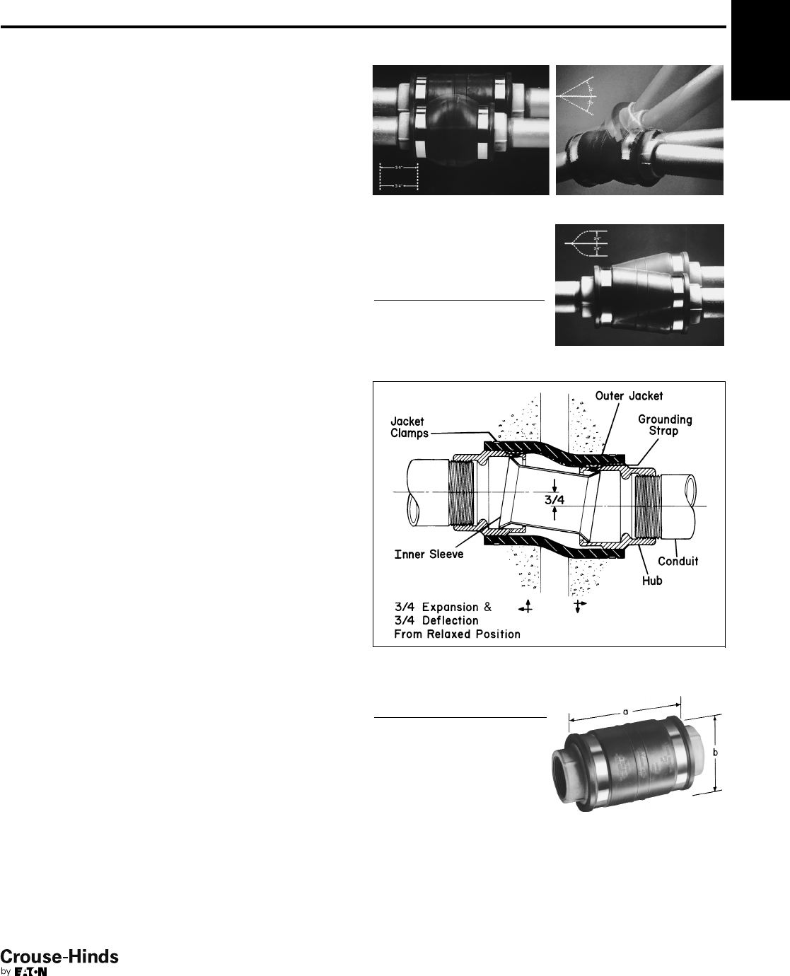
5F
129
www.crouse-hinds.com US: 1-866-764-5454 CAN: 1-800-265-0502 Copyright©2013 Eaton’s Crouse-Hinds Business
5F
Applications:
XD couplings can be installed indoors, outdoors, buried
underground, or embedded in concrete in non-hazardous areas.
XD's are used with standard rigid conduit or PVC rigid conduit. (PVC
requires rigid metal conduit nipples and rigid metal-to-PVC conduit
adapters.) XD's provide a flexible and watertight connection for
protection of conduit wiring systems from damage due to movement.
Typical applications include:
• Underground conduit feeder runs
• Runs between sections of concrete subject to relative movement
• Runs between fixed structures
• Conduit entrances in high-rise buildings
• Bridges
• Marinas, docks, piers
Features:
• XD couplings accommodate the following movements without
collapsing or fracturing the conduit, and damaging the wires it
contains:
1. Axial expansion or contraction up to 3/4"
2. Angular misalignment of the axes of the coupled conduit runs
in any direction to 30°
3. Parallel misalignment of the axes of coupled conduit runs in
any direction to 3/4"
• Inner sleeve maintains constant I.D. in any position and provides a
smooth insulated wireway for protection of wire insulation
• Watertight flexible neoprene outer jacket is corrosion resistant and
protects the grounding strap and the attachment points of the
hubs
• Tinned copper flexible braid grounding straps assure grounding
continuity
• Stainless steel jacket clamps for strength and corrosion resistance
• Standard tapered electrical threads fit standard rigid conduit
• Integral hub bushing protects insulation of conductors
Certifications and Compliances:
• UL Standard: 514B
Standard Materials:
• Hubs – Feraloy®iron alloy
• Outer jacket – molded neoprene
• Jacket clamps – stainless steel
• Inner sleeve – molded plastic
• Grounding straps – tinned copper flexible braid
Standard Finishes:
•Feraloy – electrogalvanized
• Neoprene – natural (black)
• Molded plastic – natural (brown)
Options:
Description Suffix
Hot dipped galvanized HDG
Size Ranges:
• 1" to 6" (Smaller sizes can be obtained by using reducing
bushings)
XD
1. Axial expansion/contraction. 2. Angular misalignment.
3. Parallel misalignment.
Ordering
Information
Hub Size Cat. #
Hub
Size Cat. #
1XD3 3XD8
11/4XD4 31/2XD9
11/2XD5 4XD010
2XD6 5XD012
21/2XD7 6XD014
Dimensions
In Inches:
Hub
Size ab
173
15/16
1- 1/473/841/4
11/271/441/2
271/4415/16
21/271/255/16
375/8515/16
31/273/461/2
477/8615/16
573/48
683/89
XD Expansion/Deflection Coupling
Watertight
Corrosion-Resistant
128-129.qxp 12/16/2013 12:25 PM Page 129
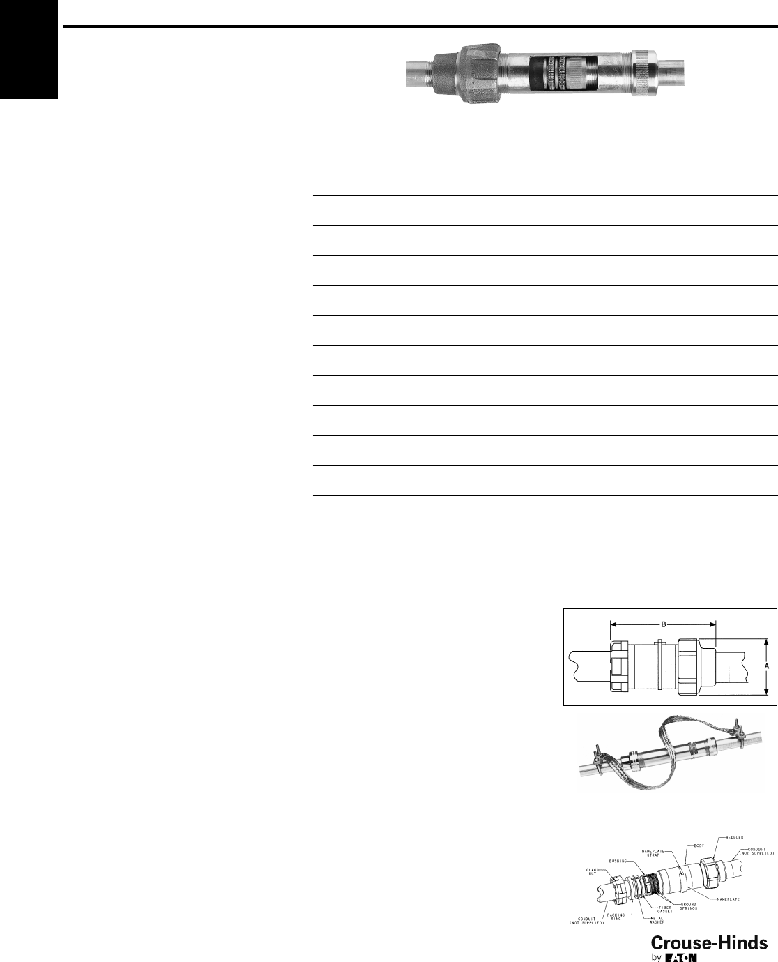
5F
130
www.crouse-hinds.com US: 1-866-764-5454 CAN: 1-800-265-0502 Copyright©2013 Eaton’s Crouse-Hinds Business
XJG Conduit Expansion Joints
With Internal Grounding
For Rigid Metal Conduit and IMC
Wet Locations
Applications:
XJG expansion couplings are used with
rigid metal conduit and IMC:
• Without the need for an external bonding
jumper and clamps (up to 4")
• To couple together two (2) sections of
conduit subject to longitudinal
movement
• In long conduit runs to permit linear
movement caused by thermal expansion
and contraction
• On long conduit runs to prevent conduit
from buckling and ensuing circuit failures
• Indoors or outdoors where conduit
expansion occurs and there are wide
temperature ranges
• In conduit runs that cross structural
joints
• In conduit runs to prevent damage to
conduit supports such as in a building or
on a bridge
• With optional redundant visible
grounding strap
Standard Materials and
Finishes:
Body
• Steel - electrogalvanized
• Copper-free aluminum - natural
•Feraloy®iron alloy - electrogalvanized (5"
+ 6" only)
Reducer
•1/2" through 1" - Steel - electrogalvanized
•1
1/4" through 6" - Feraloy®iron alloy -
electrogalvanized and aluminum paint
• Copper-free aluminum - natural
Gland Nut
•1/2" through 1" - Steel - electrogalvanized
•1
1/4" through 6" - Feraloy®iron alloy -
electrogalvanized and aluminum paint
• Copper-free aluminum - natural
Packing
• Teflon®(trademark of E.I. DuPont Co.)
Washer
• Steel - electrogalvanized
• Copper-free aluminum - natural
Gasket
• Vellum
Bushing
•1/2" through 1" - Steel - electrogalvanized
•1
1/4" through 6" - Feraloy®iron alloy -
electrogalvanized and aluminum paint
• Copper-free aluminum - natural
Ground Springs
• Phosphor bronze - electrogalvanized
Ground Strap
• Braided tinned copper
U-Bolts
• Malleable iron – electrogalvanized
Patented Design
Ordering Information
Conduit
Size
Maximum
Conduit
Movement Cat. #
Optional
Bonding
Jumper†
A
Diameter
B
Length
Bonding
Jumper
Length
1/2
4XJG14 BJ14 1.75 6.75 20"
8XJG18 BJ18 1.75 10.75 30"
3/4
4XJG24 BJ24 2.12 6.75 20"
8XJG28 BJ28 2.12 10.75 30"
14XJG34 BJ34 2.43 7.25 20"
8XJG38 BJ38 2.43 11.25 30"
11/4
4XJG44 BJ44 3.19 7.56 24"
8XJG48 BJ48 3.19 11.56 30"
11/2
4XJG54 BJ54 3.68 7.87 24"
8XJG58 BJ58 3.68 11.87 30"
24XJG64 BJ64 4.75 8.25 24"
8XJG68 BJ68 4.75 12.25 30"
21/2
4XJG74 BJ74 4.87 9.31 24"
8XJG78 BJ78 4.87 13.31 36"
34XJG84 BJ84 5.37 10.00 30"
8XJG88 BJ88 5.37 14.00 36"
31/2
4XJG94 BJ94 6.62 9.81 30"
8XJG98 BJ98 6.62 13.81 36"
44XJG104 BJ104 6.62 9.81 30"
8XJG108 BJ108 6.62 13.81 36"
58 XJ128‡ — 7.64 15.50 —
68 XJ148‡ — 9.56 16.00 —
†XJG expansion couplings use a metallic bushing and ground springs to create a high integrity internal ground connection.
External ground straps offer a redundant ground path and easy visible indication of ground.
‡XJ128 and XJ148 are not internally grounded. A pair of 36" bonding jumpers are provided with fitting.
Size Ranges:
•1/2" through 6" conduit size
• 4" and 8" maximum conduit movement
Certifications and
Compliances:
• UL Standard: 514B
• CSA Standard: C22.2 No. 18
• NEC Articles 250-77 and 300-7 (b)
• NEMA FB1
• Wet Locations
Dimensions
In Inches:
XJG shown with optional bonding
jumper
5F
Options:
Description Suffix
Available in copper-free aluminum SA
Not available on 5" and 6" sizes
Hot dipped galvanized HDG
Available with redundant† ground strap
for visible indication of grounding –
order separately (BJ Series)
130-131.qxp 12/16/2013 12:26 PM Page 130
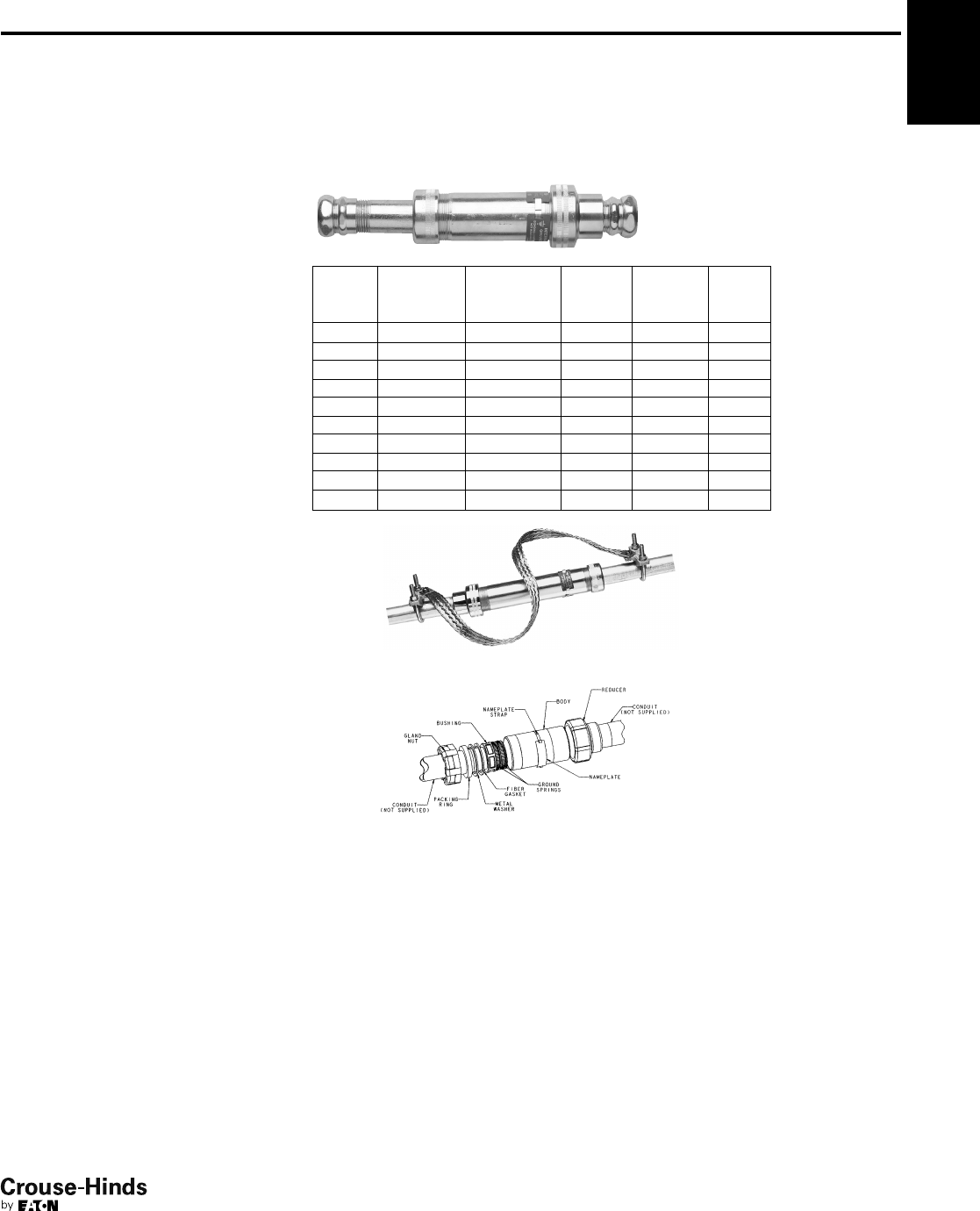
5F
131
www.crouse-hinds.com US: 1-866-764-5454 CAN: 1-800-265-0502 Copyright©2013 Eaton’s Crouse-Hinds Business
5F
Applications:
XJG expansion couplings are used with
EMT Conduit:
• Without the need for an external bonding
jumper and clamps
• To couple together two (2) sections of
conduit subject to longitudinal movement
• In long conduit runs to permit linear
movement caused by thermal expansion
and contraction
• On long conduit runs to prevent conduit
from buckling and ensuing circuit failures
• Indoors or outdoors where conduit
expansion occurs and there are wide
temperature ranges
• In conduit runs that cross structural joints
• In conduit runs to prevent damage to
conduit supports such as in a building or
on a bridge
• With optional redundant visible
grounding strap
Standard Materials and
Finishes:
Body
• Steel - electrogalvanized
• Copper-free aluminum - natural
Reducer
•1/2" through 1" - Steel - electrogalvanized
•1
1/4" through 4" - Feraloy®iron alloy -
electrogalvanized and aluminum paint
Gland Nut
•1/2" through 1" - Steel - electrogalvanized
•1
1/4" through 4" - Feraloy®iron alloy -
electrogalvanized and aluminum paint
Packing
• Teflon®(trademark of E.I. DuPont Co.)
Washer
• Steel - electrogalvanized
Gasket
• Vellum
Bushing
•1/2" through 1" - Steel - electrogalvanized
•1
1/4" through 4" - Feraloy®iron alloy -
electrogalvanized and aluminum paint
Ground Springs
• Phosphor bronze - electrogalvanized
Ground Strap
• Braided tinned copper
U-Bolts
• Malleable iron – electrogalvanized
Options:
Available with redundant† ground strap
for visible indication of grounding – order
separately (BJ Series)
Size Ranges:
•1/2" through 4" conduit size
• 4" maximum conduit movement
Certifications and
Compliances:
• UL Standard: 514B
• CSA Standard: C22.2 No. 18
• NEC Articles 250-77 and 300-7 (b)
• NEMA FB1
Ordering Information
Conduit
Size
Maximum
Conduit
Movement Cat. #
Optional
Bonding
Jumper
A
Diameter
B
Length
1/2"4" XJG14 EMT BJ14 13/4"10
3/4"
3/4"4" XJG24 EMT BJ24 21/8" 11"
1" 4" XJG34 EMT BJ34 27/16"11
1/2"
11/4"4" XJG44 EMT BJ44 31/8"15
1/4"
11/2"4" XJG54 EMT BJ54 35/8"15
1/2"
2" 4" XJG64 EMT BJ64 43/4"15
1/2"
21/2"4" XJG74 EMT BJ74 47/8"18
3/4"
3" 4" XJG84 EMT BJ84 53/8"19
7/8"
31/2"4" XJG94 EMT BJ94 65/8"21
1/4"
4" 4" XJG104 EMT BJ104 65/8"21
1/4"
XJG shown with optional bonding jumper
†XJG expansion couplings use a metallic bushing and ground springs to create a high
integrity internal ground connection. External ground straps offer a redundant ground path
and easy visible indication of ground.
XJG-EMT Conduit Expansion
Joints With Internal Grounding
For EMT Conduit
130-131.qxp 12/16/2013 12:26 PM Page 131
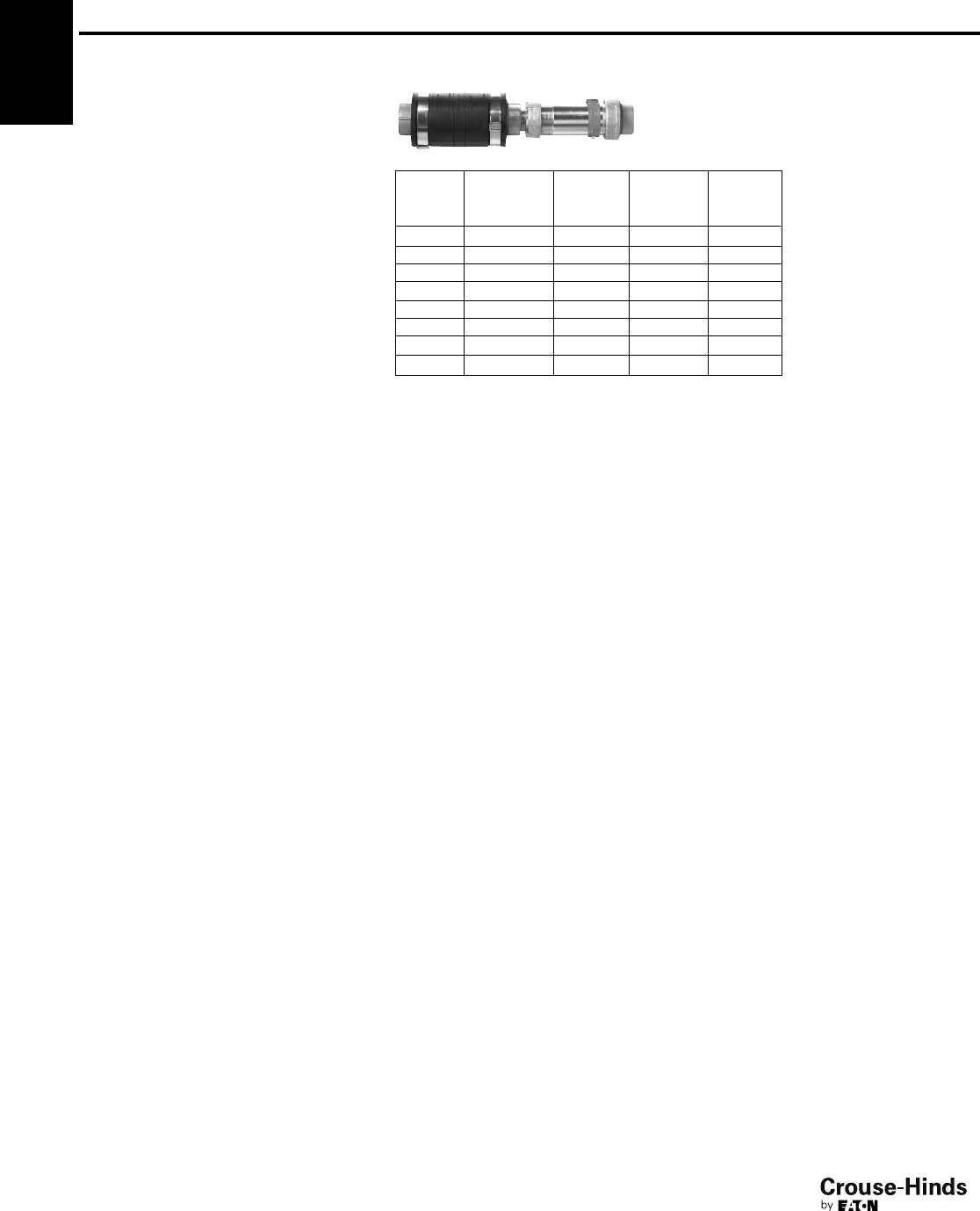
5F
132
www.crouse-hinds.com US: 1-866-764-5454 CAN: 1-800-265-0502 Copyright©2013 Eaton’s Crouse-Hinds Business
5F XJGD Combination
Expansion/Deflection Coupling
and Expansion Joint
Internally Grounded
Wet Locations
Applications:
XJGD combination fittings are used with
rigid metal conduit and IMC:
• To accommodate axial expansion,
angular misalignment and parallel
misalignment
• To couple together two (2) sections of
conduit subject to longitudinal
movement
• To maintain a ground connection without
the need for an external bonding jumper
and clamps
• In long conduit runs to prevent conduit
from buckling and causing circuit failures
• Indoors or outdoors where conduit
expansion occurs and there are wide
temperature swings
• In conduit runs that cross structural
joints
• In conduit runs to prevent damage to
conduit supports such as in a building or
on a bridge
Standard Materials:
• Body, Hubs, Gland Nut, Washer,
Bushing – Feraloy®
• Packing – Teflon®
• Gasket – vellum
• Ground Spring – phosphor bronze
• Outer Jacket – molded neoprene
• Jacket Clamps – stainless steel
• Inner Sleeve – molded plastic
• Ground Straps – tinned copper braid
Standard Finishes:
•Feraloy®– electrogalvanized
Certifications and
Compliances:
• UL Standard: 514B
Ordering Information
Hub Size
Maximum
Conduit
Movement Cat. #
A
Diameter
B
Length
1" 4" XJGD34 315/16"17
3/4"
11/4"4" XJGD44 41/4"18
1/8"
11/2"4" XJGD54 41/2"18
5/8"
2" 4" XJGD64 415/16"19
1/4"
21/2"4" XJGD74 55/16"20
3/4"
3" 4" XJGD84 515/16"21
5/8"
31/2"4" XJGD94 61/2"21
5/8"
4" 4" XJGD104 8" 273/4"
132-133.qxp 12/23/2013 2:44 PM Page 132
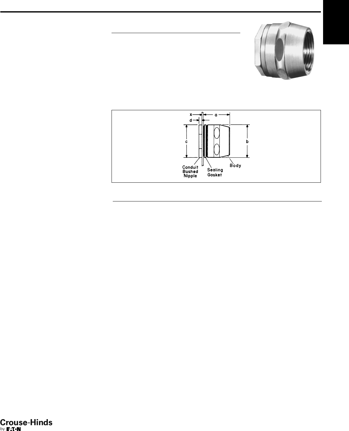
5F
133
www.crouse-hinds.com US: 1-866-764-5454 CAN: 1-800-265-0502 Copyright©2013 Eaton’s Crouse-Hinds Business
5F
Conduit Hubs
(Also see Myers Hubs see page 211)
Cl. I, Div. 2, Groups A, B, C, D Watertight
Applications:
HUB Conduit Hubs:
• Provide a convenient means for
installing a threaded conduit hub on a
junction box or device enclosure
• Are used to connect conduit to a sheet
metal or cast enclosure
• Are used with threaded rigid conduit or
IMC, steel or aluminum; indoors or
outdoors
Features:
• Smooth insulated throat provides easier
wire pulling and protection for
conductors during installation.
• Neoprene sealing gasket provides a
watertight seal.
• Compact design permits close spacing
of conduit.
• Wide range of sizes from 1/2" to 4".
Standard Materials:
•1/2" to 4" malleable iron
Standard Finishes:
•Feraloy iron alloy – electrogalvanized
and aluminum acrylic paint
Size Ranges:
•1/2" to 4"
Certifications and
Compliances:
• UL Standard: 514B
• CSA Standard: C22.2 No. 18
• NEC/CEC:
Class I, Division 2, Groups A, B, C, D
Per NEC 501-4(b), 502-4(a) and
503-3(a)
Cat. #
Conduit
Size a b c d x
HUB1 1/211
1/411/89/64
HUB2 3/411/819/16 13/85/32 1/4
HUB3 113/817/815/83/16 9/32
HUB4 11/411/225/16 21/47/16
HUB5 11/215/821/223/81/47/16
HUB6 2111/16 32
13/16 1/47/16
HUB7 21/223/16 35/837/16 1/47/16
HUB8 327/16 41/441/16 1/47/16
HUB9 31/227/16 43/4411/16 5/16 3/4
HUB10 429/16 51/451/16 5/16 11/8
Dimension "x" is maximum wall thickness of box that will meet the requirement for three full
threads engagement of nipple and fitting body when liquidtight box connector or rigid
conduit hub is installed in a knockout or slip hole.
Ordering Information
Conduit Size Cat. #
1/2HUB1
3/4HUB2
1HUB3
11/4HUB4
11/2HUB5
2HUB6
21/2HUB7
3HUB8
31/2HUB9
4HUB10
Dimensions
In Inches:
132-133.qxp 12/23/2013 2:44 PM Page 133
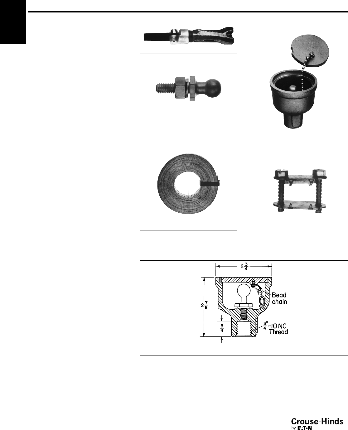
5F
134
www.crouse-hinds.com US: 1-866-764-5454 CAN: 1-800-265-0502 Copyright©2013 Eaton’s Crouse-Hinds Business
Grounding Devices
Straps and Clamps
Applications:
• GCR grounding receptacles are used to
provide static electricity grounding
connections; particularly suited for, but
not limited to, use in aircraft hangar
floors and airport aprons.
• GCT ground connector and studs are
used to provide "quick-connect" static
electricity grounding connections with
portable cable.
• GC grounding strap and clamp are
suitable for bonding and grounding
equipment in wiring systems, such as
meter circuits, service entrance
equipment, and appliances per NEC
requirements.
Features:
GCR grounding receptacles have:
• Grounding stud integral with housing
• Grounding stud designed to accept
standard battery clip
• Thread at bottom for attaching to 3/4"
threaded grounding rod
• Cover attached to receptacle by chain to
prevent loss of cover
• Corrosion resistant material
GCT grounding connector and studs have:
• Substantial clip tension for grounding
• Integral cable clamp to prevent cable
from breaking free of connector or
fraying at connector
• Lock washer on stud to maintain good
electrical contact
GC strap:
• Is pliable, strong and corrosion resistant
• Assures a lasting bond. Prongs on strap
clamp engage strap perforations,
preventing slippage.
Standard Materials:
• GCR – Bronze body, cap and chain;
brass grounding stud
• GCT – Bronze connector body;
aluminum cable clamp; brass stud
• Strap – flexible copper
• Clamp – brass
Standard Finishes:
• Bronze, brass, aluminum parts – natural
• Flexible copper strap – tinned
Certifications and
Compliances:
• UL Standard: GC strap and clamps – 467
• CSA Standard: C22.2 No. 41
GCT Grounding Connector
Cable Dia. Cat. #
.312" to .406" GCT8
GCT Stud*
Description
Thread
Size Cat. #
Brass 3/8- 16 GCT2
*Not a replacement for grounding stud in GCR
receptacle.
GC Grounding Strap
Used with GC102 Strap Clamp
Description Cat. #
50' coil, 1" wide GC100
GCR Receptacles
For Static Electricity Grounding
Strap Clamp
Description Cat. #
Brass GC102
Dimensions
In Inches:
GCR
Description Thread Size Cat. #
With cap and
chain
5/16 - 18 GCR210
5F
134-135.qxp 12/16/2013 12:26 PM Page 134
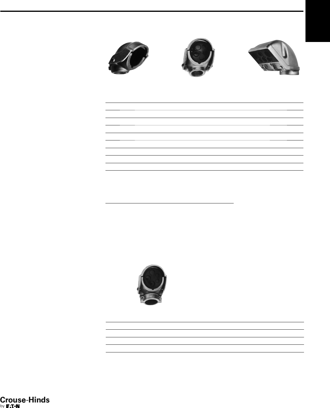
5F
135
www.crouse-hinds.com US: 1-866-764-5454 CAN: 1-800-265-0502 Copyright©2013 Eaton’s Crouse-Hinds Business
5F
Service Entrance Heads and
Replacement Covers
Applications:
F type service entrance heads are used:
• For overhead service entrance to
buildings
• With threaded rigid, threadless rigid or
threadless thinwall (EMT) conduit and
rigid conduit masts
Features:
Two types available:
• Threaded rigid – threads to conduit.
• Threadless rigid or EMT – clamps to
conduit.
• Available knockouts in covers allow use
with variety of sizes and numbers of
wires.
• Simple construction and easy assembly.
• Consists of only two pieces plus the
insulating knockout cover.
• Easy to install.
Standard Materials:
• Copper-free aluminum
Standard Finishes:
• Natural
Certifications and
Compliances:
• UL Standard: 514B
• CSA Standard: C22.2 No. 18
F Service Heads
1/2" size 3/4" – 2" size 1/2" size
Threaded Rigid
Conduit
Size Number and Dia. of Cover Knockouts Cat. #
Replacement
Cover Cat. #
1/26 – 9/32 F186 CF690
3/42 – 3/8and 3 – 13/32 F285 5 H
12 – 7/16 and 3 – 1/2F385 5 NS
11/42 – 27/64 and 3 – 5/8F485 5 NL
11/22 – 27/64 and 3 – 5/8F585 5 NL
22 – 7/8, 1 – 13/16, 1 – 11/16,1 – 9/16 and 1 – 21/32 F686 CF60
21/22 – 17/16, 1 – 17/32, 1 – 11/64, 1 – 61/64 and 1 – 55/64 F766 CF707
32 – 1
7/16, 1 – 17/32, 1 – 11/64, 1 – 61/64 and 1 – 55/64 F866 CF707
31/23 – 13/4, 1 – 17/16, 1 – 15/16 and 1 – 13/16 F966 CF708
43 – 1
3/4, 1 – 17/16, 1 – 15/16 and 1 – 13/16 F1066 CF708
Overall Dimensions of Replacement Covers
for F Series Service Heads
Cat. # Dim.
CF690 11/2dia.
5 H 131/32 dia.
5 NS 215/64 dia.
5 NL 219/32 dia.
CF60 33/16 dia.
CF707 713/16 ×311/16
CF708 101/4×43/4
Clamp Type
Threadless Rigid or EMT
Conduit
Size Number and Dia. of Cover Knockouts Cat. #
Replacement
Cover Cat. #
3/42 – 3/8and 3 – 13/32 F235 5 H
12 – 7/16 and 3 – 1/2F335 5 NS
11/42 – 27/64 and 3 – 5/8F435 5 NL
11/22 – 27/64 and 3 – 5/8F535 5 NL
22 – 7/8, 1 – 13/16, 1 – 11/16, 1 – 9/16 and 1 – 21/32 F636 CF60
134-135.qxp 12/16/2013 12:26 PM Page 135
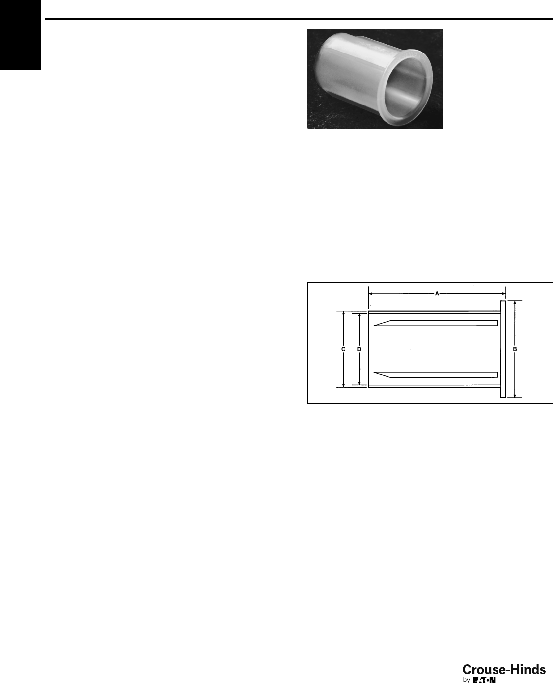
5F
136
www.crouse-hinds.com US: 1-866-764-5454 CAN: 1-800-265-0502 Copyright©2013 Eaton’s Crouse-Hinds Business
5F LNR Conduit Liner
Applications:
LNR conduit liners are installed in rigid metal conduit or IMC:
• To provide a smooth wire entry from conduit into enclosures to
protect wires from abrasion as they are pulled.
• With thin wall or thick wall enclosures.
• Entering drilled and tapped openings or slip holes.
• Entering an enclosure vertically or horizontally.
• Regardless of where the conduit ends in relation to the
enclosure wall.
Features:
• UL listed and CSA certified.
• No need for threaded bushings, reducers, or special machining.
• Corrosion and heat resistant polypropylene material.
• Smooth flange providing easy wire pulling and protects conductors
being installed.
• Space saving.
• Molded ribs ensure a tight fit, preventing the liner from sliding out
while conductors are being pulled.
• Quick and easy to install.
Standard Materials:
• Polypropylene
Standard Finishes:
• Natural (clear)
Sizes:
•1/2" through 4"
Certifications and Compliances:
• NEC Article 346-8
• UL Standard 514B
• CSA Standard C22.2 No. 18
• U.S. Patent No. 5,383,688
Dimensions
In Inches:
Ordering Information
Cat. # Size A B C D
LNR1 1/2"1
3/16"7/8"5/8"9/16"
LNR2 3/4"1
9/16"1
1/8"13/16"3/4"
LNR3 1" 21/16"1
3/8"1
1/16"7/8"
LNR4 11/4"2
1/16"1
3/4"1
3/8"1
1/4"
LNR5 11/2"2
9/16"2" 1
5/8"1
7/16"
LNR6 2" 29/16"2
7/16"2
1/16"1
7/8"
LNR7 21/2"2
7/8"2
7/16"2
1/4"
LNR8 3" 27/8"3
9/16"3
1/16"2
7/8"
LNR9 31/2"3
1/16"4
1/16"3
9/16"3
3/8"
LNR10 4" 31/16"4
9/16"4" 3
7/8"
136-137.qxp 12/23/2013 2:47 PM Page 136

6F
137
www.crouse-hinds.com US: 1-866-764-5454 CAN: 1-800-265-0502 Copyright©2013 Eaton’s Crouse-Hinds Business
6F
Conduit Seals, Breathers and Drains
Hazardous
Description Page No.
Application/Selection see page 138
Breathers & Drains
Standard
ECD Series see page 158
CD Series (Non-hazardous) see page 159
Universal
ECD Series see page 158
Sealing Compound
Chico®Asee pages 155–156
Chico®SpeedSeal™ see pages 155–156
Sealing Fiber
Chico®Xsee pages 155–156
Sealing Fittings Tool Kit
EYS Tool Kit see page 157
Seals
Drains
EYD Series see page 144
EZD Series see page 145
EYDX Series see page 147
Elbows
EYS see page 140
Horizontal/Vertical
ES Series see page 149
EYS Series see page 140
EYS Series with ATEX see page 142
EYSA Series see page 143
EYSX Series see page 146
Inspection
EZD Series see page 145
Retrofit
EYSR Series see page 148
Universal
EZS Series see page 141
EZS Series with ATEX see page 142
Secondary Process Seals
Ultra High Pressure Seal see page 150
Secondary Process Seal Assembly with Rupture Sensor see pages 151–154
136-137.qxp 12/23/2013 2:47 PM Page 137
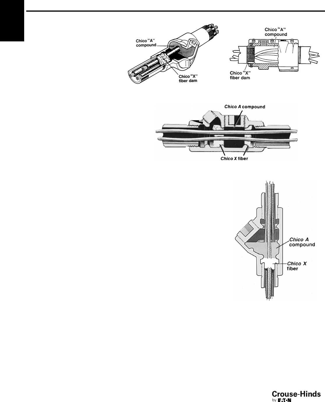
6F
138
www.crouse-hinds.com US: 1-866-764-5454 CAN: 1-800-265-0502 Copyright©2013 Eaton’s Crouse-Hinds Business
Conduit Seals, Breathers and Drains
Application and Selection
Applications:
Seals:
• Seals are installed in conduit runs to
prevent the passage of gases, vapors or
flames from one portion of the electrical
installation to another through the
conduit, limiting any explosion to the
enclosure and preventing
precompression or "pressure piling."
• While not a National Electrical Code
requirement, many engineers consider it
good practice to sectionalize long
conduit runs by inserting seals not more
than 50' to 100' apart, depending on the
conduit size, to minimize the effects of
"pressure piling."
Breathers:
• Breathers (vents), are installed in the top
of enclosures to provide ventilation to
minimize condensation in enclosures.
Drains:
• Drains are used in humid atmospheres
or in wet locations where it is likely that
water can gain entrance to the interiors
of enclosures or raceways. The
raceways should be inclined so that
water will not collect in enclosures or on
seals, but will be led to low points where
it may pass out through ECD drains.
• Frequently the arrangement of raceway
runs makes this method impractical if
not impossible. In such instances, EZD
or EYD drain seal fittings should be
used. These fittings prevent harmful
accumulations of water above the seal.
Considerations for
Selection:
Seals:
• Select the proper sealing fitting for the
hazardous vapor involved; i.e., Class I,
Division 1 & 2, Groups A, B, C or D.
• Select the appropriate seal for new or
retrofit installations.
• Select a sealing fitting for the proper use
in respect to mounting position. This is
particularly critical when the conduit
runs between hazardous and non-
hazardous areas. Improper positioning
of a seal may permit hazardous gases or
vapors to enter the system beyond the
seal and permit them to escape into
another portion of the hazardous area or
to enter a non-hazardous area. Some
seals are designed to be mounted in any
position; others are restricted to vertical
mounting.
The amount of Chico®fiber and compound required for
any seal is determined by volume, hub size and mounting
position of the seal.
Drains:
• In locations which are usually
considered dry, surprising amounts of
water frequently collect in conduit
systems. No conduit system is airtight,
therefore, it may "breathe". Alternate
increases and decreases in temperature
and/or in barometric pressure, due to
weather changes or due to the nature of
the process carried on in the location
where the conduit is installed, will cause
"breathing," resulting in condensation
and water accumulation.
• In view of this likelihood, it is therefore
good practice to insure against such
water accumulations and probable
subsequent insulation failures by
installing breathers, drain seals, or
inspection seals, even though conditions
prevailing at the time of planning or
installing do not indicate their need.
Options:
Description Suffix
Corro-free™ epoxy powder coat S752
EZS Horizontal seal EYSR Retrofit seal
EYS 1 Vertical sealing
EYS Horizontal seal
6F
138-139.qxp 12/16/2013 12:28 PM Page 138
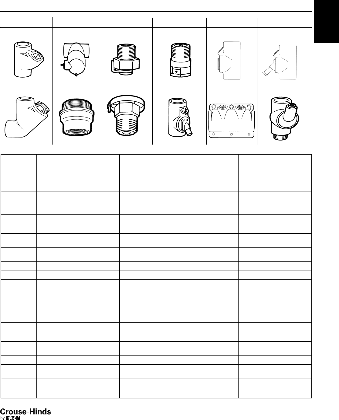
6F
139
www.crouse-hinds.com US: 1-866-764-5454 CAN: 1-800-265-0502 Copyright©2013 Eaton’s Crouse-Hinds Business
Conduit Seals, Breathers and Drains
Shape Selector Chart
Quick Selector Chart
Series Page Series Page Series Page Series Page Series Page Series Page
EYS /
EYSA
see
page 140 EZD
see
page 145
ECD
Standard
see
page 158
ECD
Universal
see
page 158 EYSX
see
page 146
EYS
Elbow Seal
see
page 140 ES
see
page 149
EYDX
see
page 147
EZS
see
page 141
EYD
see
page 144 EYSR
see
page 144
Quick Selector Chart
6F
Series Description
NEC
Hazardous Group
For Conduit
Angle
EYS Seal Class I, Groups A, B, C, D
Class II, Groups E, F, G
Vertical and Horizontal
EYS ATEX Seal Ex II 2 G EEx d IIC Vertical and Horizontal
EYSA Seal Flameproof, Exd, IIC Vertical and Horizontal
EYS 29 Elbow Seal Class I, Groups C, D
Class II, Groups E, F, G
90° turn
EYSR Retrofit Seal/Drain Seal* Class I, Div. 2, Groups C, D
Class II, Div. 2, Groups E, F, G
Class III
Vertical and Horizontal
EYSX Expanded Fill Sealing
Fittings
Class I, Groups B, C, D
Class II, Groups E, F, G
Vertical and Horizontal
EZS Seal Class I, Groups C, D
Class II, Groups E, F, G
All
EZS ATEX Seal Ex II 2 G EEx d IIC All
ES Sealing Hub Class I, Groups C, D Vertical
EYD Seal and Drain Class I, Groups B, C, D
Class II, Groups F, G
Vertical
EYDX Expanded Fill Sealing
Fittings and Drain
Class I, Groups B, C, D
Class II, Groups F, G
Vertical
EZD Inspection Seal and Drain –
Inspection Seal only
Class I, Groups C, D
Class II, Groups E, F, G
Vertical
ECD Standard Breather only
Drain only
Class I, Groups B, C, D
Class II, Groups E, F, G
Class III
ECD Universal Drain – Breather Class I, Groups C, D
Class II, Groups F, G
CD Non-hazardous Drain
UHPS Ultra High Pressure Seal Class I, Div. 1, Groups B, C, D
Certified to CSA Standards through QPS
SPSR Secondary Process Seal with
Rupture Sensor
Class I, Div. 1 & 2, Groups B, C, D
Class I, Zone 1 & 2 IIB + H2
Class II, Div. 1 & 2, Groups E, F, G
*Drain purchased separately.
138-139.qxp 12/16/2013 12:28 PM Page 139
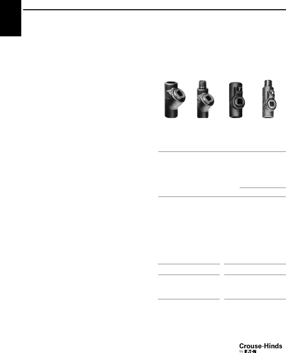
6F
140
www.crouse-hinds.com US: 1-866-764-5454 CAN: 1-800-265-0502 Copyright©2013 Eaton’s Crouse-Hinds Business
For Sealing in Vertical or Horizontal Positions
Approximate Internal
Volume in Cubic
Inches
Hub
Size
Female Hub
Cat. #
Male & Female
Hub Cat. # Vertical Horizontal
1/2EYS11* EYS116* 11
3/4EYS21* EYS216* 22
1EYS31* EYS316* 33
3/4
11/4EYS41 EYS416 68
11/2EYS51 EYS516 103/4121/4
2EYS61 EYS616 19 223/4
21/2EYS71 EYS716 251/230
3EYS81 EYS816 56 641/2
31/2EYS91 EYS916 72 82
4EYS101 EYS1016 95 110
*Available in copper-free aluminum – to order, add suffix SA to Cat. No.
6F Conduit Sealing Fittings
Chico Sealing Compound
and Fiber see pages 155–156
Cl. I, Div. 1 & 2, Groups A, B, C, D
Cl. II, Div. 1, Groups E, F, G
Cl. II, Div. 2, Groups F, G
Cl. III
Explosionproof
Dust-Ignitionproof
Applications:
EYS and EZS sealing fittings:
• Restrict the passage of gases, vapors or flames from one portion
of the electrical installation to another at atmospheric pressure and
normal ambient temperatures
• Limit explosions to the sealed off enclosure
• Limit precompression or pressure "piling" in conduit systems
Sealing fittings are required:
• At each entrance to an enclosure housing an arcing or sparking
device when used in Class I, Division 1 and 2 hazardous locations.
To be located as close as practicable and, in no case, more than
18" from such enclosures
• At each conduit entrance of 2" size or larger to an enclosure or
fitting housing terminals, splices or taps when used in Class I,
Division 1 hazardous locations. To be located as close as
practicable and, in no case, more than 18" from such enclosures
• In conduit systems when leaving Class I, Division 1 or Division 2
hazardous locations
• In cable systems when the cables either do not have a
gas/vaportight continuous sheath or are capable of transmitting
gases or vapors through the cable core when those cables leave
the Class I, Division 1 or Division 2 hazardous locations
Features:
EYS and EZS sealing fittings include:
• Minimum turning radius
• Large openings with threaded closures to provide easy access to
conduit hubs for making dams
• Integral bushings in conduit hubs to protect conductor insulation
from damage
• Taper-tapped hubs to ensure ground continuity
EYS sealing fittings are available for installation in either vertical only
or in both horizontal or vertical positions.
EZS sealing fittings for installation at any angle; the covers with
opening for sealing compound can be properly positioned to accept
the compound.
Standard Materials:
• Bodies – Feraloy®iron alloy and/or ductile iron
• Plugs – Feraloy iron alloy and/or steel
• Removable nipples – steel
Standard Finishes:
•Feraloy iron alloy and ductile iron – electrogalvanized and
aluminum acrylic paint
• Steel – electrogalvanized
Options:
Description Suffix
Copper-free aluminum bodies, nipples and enclosures SA
Size Ranges:
•1/2" – 6"
Certifications and Compliances:
• NEC/CEC:
EYS1-3, 11-31, 16-36, 116-316
Class I, Division 1 & 2, Groups A, B, C, D
Class II, Division 1, Groups E, F, G
Class II, Division 2, Groups F, G
Class III
EYS41-101, 416-1016
Class I, Division 1 & 2, Groups B, C, D
Class II, Division 1, Groups E, F, G
Class II, Division 2, Groups F, G
Class III
EYS29, 4-014, 46-0146
EZS1-8, 16-86
Class I, Division 1 & 2, Groups C, D
Class II, Division 1, Groups F, G
Class II, Division 2, Groups F, G
Class III
• UL Standard: 1203
• CSA Standard: C22.2
Ordering Information - EYS
Vertical
female
Vertical
male &
female
Vertical or
horizontal
female
Vertical or
horizontal
male & female
For Sealing in Vertical Positions Only
Hub
Size
Female
Hub Cat. #
Male & Female
Hub Cat. #
Approximate Internal
Volume in Cubic Inches
1/2EYS1* EYS16* 1
3/4EYS2* EYS26* 2
1EYS3* EYS36* 33/4
EYS 46 Series EYS 116 Series
11/451/16 23/16 123/32 51/16 23/16 123/32
11/251/227/16 21/16 51/227/16 21/16
261/432
5/16 61/432
5/16
21/271/231/2211/16 71/231/2211/16
381/241/435/16 81/241/435/16
31/293/16 43/437/16‡9
3/16 43/437/16‡
493/451/4311/16‡9
3/451/4311/16‡
5111/16 61/2419/32‡
6121/875/8511/32‡
‡With cover removed.
Dimensions (In Inches)
EYS 16 Series EYS 116 Series
Size a b
Turning
Radius a b
Turning
Radius
1/239/32 11/415/8311/16 11/415/32
3/4312/16 11/2129/32 311/16 11/211/4
145/16 13/423/845/16 13/413/8
Sealing fittings are approved for use in hazardous locations only when Chico®Xfiber and
Chico A sealing compound or Chico SpeedSeal are used to make the seal.
140-141.qxp 12/16/2013 12:28 PM Page 140
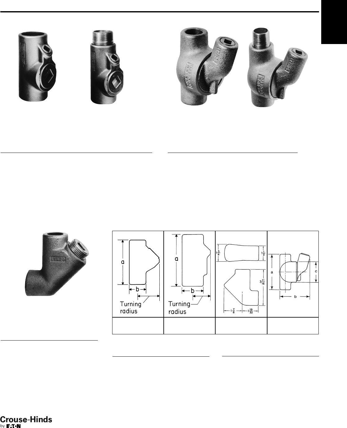
6F
141
www.crouse-hinds.com US: 1-866-764-5454 CAN: 1-800-265-0502 Copyright©2013 Eaton’s Crouse-Hinds Business
6FConduit Sealing Fittings
Chico Sealing Compound
and Fiber see pages 155–156
Cl. I, Div. 1 & 2, Groups C, D
Cl. II, Div. 1, Groups E, F, G
Cl. II, Div. 2, Groups F, G
Cl. III
Explosionproof
Dust-Ignitionproof
Ordering Information - EYS
Vertical or horizontal male & female
For Sealing in Vertical or Horizontal Positions
Female
Male &
Female
Approximate Internal
Volume in Cubic Inches
Hub
Size
Hub
Cat. #
Hub
Cat. # Vert. Horiz.
11/4EYS4* EYS46* 68
11/2EYS5* EYS56* 103/4121/4
2EYS6* EYS66* 19 223/4
21/2EYS7* EYS76* 251/230
3EYS8* EYS86* 56 641/2
31/2EYS9* EYS96* 72 82
4EYS10* EYS106* 95 110
5EYS012 EYS0126 200 222
6EYS014 EYS0146 290 315
*Available in copper-free aluminum – to order, add suffix SA to Cat. No.
EYS
Elbow seal
For Sealing in Vertical Positions
Hub
Size Cat. #
Approximate
Internal Volume
in Cubic Inches
3/4EYS29 13/4
Ordering Information - EZS
Male & female hub
For Sealing at Any Angle
Female
Male &
Female
Approximate Internal
Volume in Cubic Inches
Hub
Size
Hub
Cat. #
Hub
Cat. # Vert. Horiz.
1/2EZS1 EZS16 61/461/4
3/4EZS2 EZS26 61/261/2
1EZS3 EZS36 101/4101/4
11/4EZS4 EZS46 121/2121/2
11/2EZS5 EZS56 141/2141/2
2EZS6 EZS66 46 46
21/2EZS7 EZS76 55 55
3EZS8 EZS86 90 90
Dimensions
In Inches
EYS 16 Series EYS 46 and
EYS 116 Series
EYS Elbow Seal EZS Series
EYS Elbow Seal
Size a b
Turning Radius
(Vertical)
3/4311/16 13/417/8
EZS Series
Size a b c
Turning
Radius†
1/243/16 35/821/217/8
3/443/16 35/821/217/8
1415/16 331/32 32
1/8
11/451/16 413/32 32
5/16
11/253/16 49/16 31/4211/32
271/16 513/32 53/16 39/32
21/2715/16 527/32 53/16 33/8
385/861/257/837/8
†With cover removed.
140-141.qxp 12/16/2013 12:28 PM Page 141
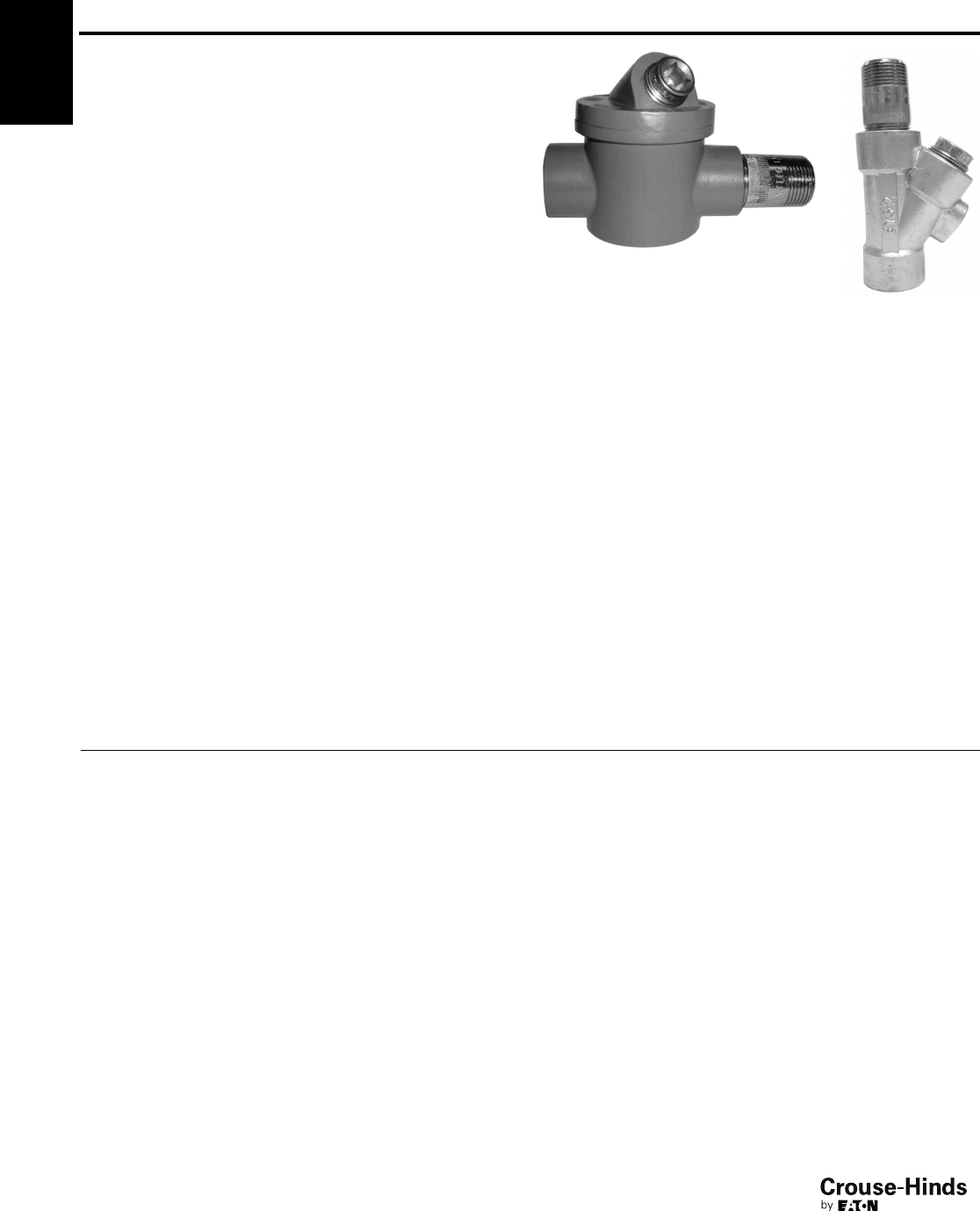
6F
142
www.crouse-hinds.com US: 1-866-764-5454 CAN: 1-800-265-0502 Copyright©2013 Eaton’s Crouse-Hinds Business
6F Conduit Sealing Fittings
for IEC Applications
Ex II 2 G EEx d IIC Zone 1 and 2
Applications:
EYS and EZS sealing fittings:
• Restrict the passage of gases, vapors or flames from one portion
of the electrical installation to another at atmospheric pressure and
normal ambient temperatures
• Limit explosions to the sealed off enclosure
• Limit precompression or pressure "piling" in conduit systems
Sealing fittings are required:
• At each entrance to an enclosure housing an arcing or sparking
device when used in Class I, Division 1 and 2 hazardous locations.
To be located as close as practicable and, in no case, more than
18" from such enclosures
• At each conduit entrance of 2" size or larger to an enclosure or
fitting housing terminals, splices or taps when used in Class I,
Division 1 hazardous locations. To be located as close as
practicable and, in no case, more than 18" from such enclosures
• In conduit systems when leaving Class I, Division 1 or Division 2
hazardous locations
• In cable systems when the cables either do not have a
gas/vaportight continuous sheath or are capable of transmitting
gases or vapors through the cable core when those cables leave
the Class I, Division 1 or Division 2 hazardous locations
Features:
EYS and EZS sealing fittings include:
• Minimum turning radius
• Large openings with threaded closures to provide easy access to
conduit hubs for making dams
• Integral bushings in conduit hubs to protect conductor insulation
from damage
• Taper-tapped hubs to ensure ground continuity
EYS sealing fittings are available for installation in either vertical only
or in both horizontal or vertical positions.
EZS sealing fittings for installation at any angle; the covers with
opening for sealing compound can be properly positioned to accept
the compound.
Certifications and Compliances:
• IEC:
Ex II 2 G EEx d IIC
EC-Type examination certificate LOM 03 ATEX 2108
• IP67 according to EN 60529
Standard Materials:
• Bodies – Light alloy, natural finish
• Plugs – Light alloy, natural finish
• Removable nipples – Light alloy, natural finish
Size Ranges:
• EYS - 1/2" – 4"
• EZS - 1/2" – 1"
Ordering Information:
Series Mounting Direction Hub Size Cat. #
EYS Vertical 1/2" NPT NOR 000 002 220 117
EYS Vertical 3/4" NPT NOR 000 002 220 125
EYS Vertical 1" ISO NOR 000 002 220 133
EYS Vertical 1" NPT NOR 000 002 220 620
EYS Horizontal 11/2" NPT NOR 000 002 220 160
EYS Horizontal 2" NPT NOR 000 002 220 168
EZS Horizontal 1/2" NPT NOR 000 002 220 216
EZS Horizontal 3/4"NPT NOR 000 002 220 224
EZS Horizontal 1" ISO NOR 000 002 220 232
EZS Horizontal 1" NPT NOR 000 002 220 729
EZS
EYS
142-143.qxp 12/16/2013 12:28 PM Page 142
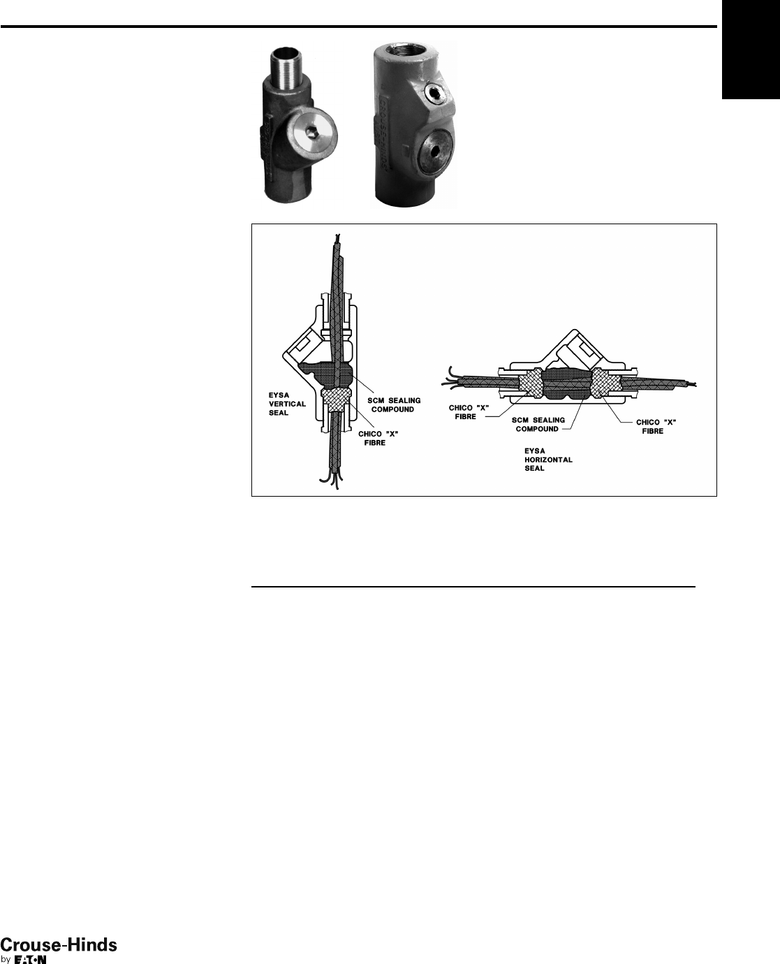
6F
143
www.crouse-hinds.com US: 1-866-764-5454 CAN: 1-800-265-0502 Copyright©2013 Eaton’s Crouse-Hinds Business
6F
Conduit Sealing Fittings
EYSA Flameproof Sealing Fitting
Zone 1
Zone 2
Zone 21
Zone 22
Applications:
EYSA sealing fittings:
• Restrict the passage of gases, vapors,
or flames from one portion of the
electrical installation to another at
atmospheric pressure and normal
ambient temperatures
• Limit explosions to the sealed off
enclosure
• Prevent pre-compression or "pressure
piling" in conduit systems
Sealing fittings are required:
• At each entrance to an enclosure
housing an arcing or sparking device
when used in Zone 1, hazardous
locations to be located as close as
practicable and in no case more than
450mm from such enclosures
• In conduit systems when leaving the
Zone 1 area and entering an area of
lesser hazard
Features:
• Minimum turning radius
• Large openings with threaded closures
to provide easy access to conduit hubs
for making dams
• Integral bushings to protect conductor
insulation from damage
• Removable male nipple supplied when
male and female hub style is ordered
Certifications and
Compliances:
• Type of Protection: Ex d, DIP A21,
T60ºC, IP66
• Degree of Protection: IP66
• Gas Group: IIC
• Approvals: IEC Ex TSA07.0015-1
Standard Materials:
• Bodies - copper-free aluminum
• Removable nipples and plugs - brass
Standard Finishes:
• Body - polyurethane gray
• Nipples and plugs - natural
Ordering Information:
Entry Size Female
Male &
Female
Weight of
Sealing
Compound
per Seal (g)
Weight of
Chico X
Fiber
per Seal (g)
20mm/20mm EYSA1M EYSA16M 50 1
25mm/25mm EYSA2M EYSA26M 100 2
32mm/32mm EYSA3M EYSA36M 188 3.5
40mm/40mm EYSA4M EYSA46M 406 7
50mm/50mm EYSA5M EYSA56M 550 14
3/4" BSP/3/4" BSP EYSA2B EYSA26B 100 2
20mm/1/2" BSP EYSA11MB -50 1
20mm/3/4" BSP EYSA12MB -50 1
25mm/1/2" BSP EYSA21MB - 100 2
25mm/3/4" BSP EYSA22MB - 100 2
142-143.qxp 12/16/2013 12:28 PM Page 143
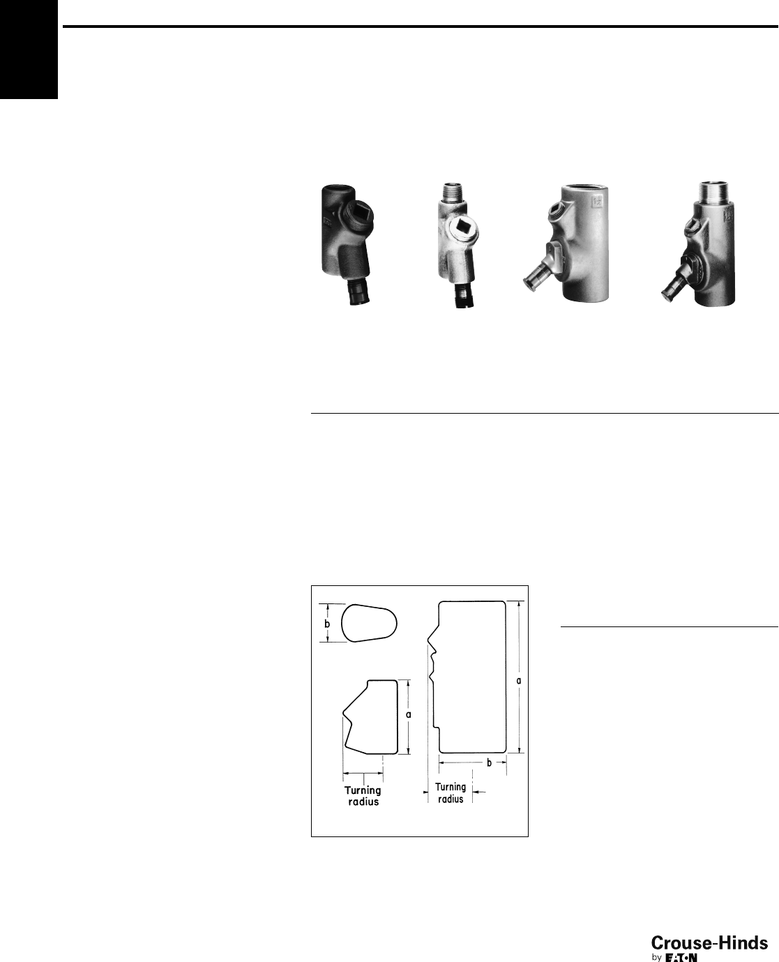
6F
144
www.crouse-hinds.com US: 1-866-764-5454 CAN: 1-800-265-0502 Copyright©2013 Eaton’s Crouse-Hinds Business
Conduit Sealing Fittings
With Drains
Cl. I, Div. 1 & 2, Groups B, C, D§
Cl. II, Div. 1, Groups E, F, G
Cl. II, Div. 2, Groups F, G
Cl. III
Explosionproof
Dust-Ignitionproof
Applications:
EYD drain and EZD drain and inspection
sealing fittings:
• Restrict the passage of gases, vapors or
flames from one portion of the electrical
installation to another at atmospheric
pressure and normal ambient
temperatures
• Limit explosions to the sealed-off
enclosure
• Prevent precompression or "pressure
piling" in conduit systems
Drain sealing fittings are installed in vertical
conduit runs and at low points in conduit
systems to prevent accumulation of
condensate above seal.
For sealing fittings requirements
see page 139.
Features:
EYD and EZD drain sealing fittings include:
• Drain to provide continuous, automatic
drainage of condensate
• Large openings with threaded closures
to provide easy access to conduit hubs
for making dams
• Integral bushings to protect conductor
insulation from damage
• Taper-tapped hubs to ensure ground
continuity
EZD drain and inspection sealing fittings
also include:
• Removable covers for periodic
inspection of seals
• Barrier for sealing compound easily
installed after dams are made and
before compound is poured.
Standard Materials:
• Bodies, and inspection or drain covers –
Feraloy®iron alloy and/or ductile iron
• Closure for drain – copper-free
aluminum or ductile iron
• Small closure plug – Feraloy iron alloy
and/or steel
• Drain – stainless steel
• Removable nipples – steel
Certifications and
Compliances:
• NEC/CEC:
EYD11-101, 116-1016
Class I, Division 1 & 2, Groups B, C, D
Class II, Division 1, Groups E, F, G
Class II, Division 2, Groups F, G
Class III
EYD1-10, 16-106,
EZD10-60, 111-611
Class I, Division 1 & 2, Groups C, D
Class II, Division 1, Groups F, G
Class II, Division 2, Groups F, G
Class III
• UL Standard: 1203
• CSA Standard: C22.2
Ordering Information - EYD
1/2" – 1"
Female hub
1/2" – 1"
Male &
female hub
11/4" – 4"
Female hub
11/4" – 4"
Male &
female hub
Hub
Size
Female
Hub
Cat. #
Male &
Female
Hub
Cat. #
Female
Hub
Cat. #
Male &
Female
Hub
Cat. #
Approximate
Internal Volume
in Cubic Inches
1/2EYD1* EYD16* EYD11 EYD116 1
3/4EYD2* EYD26* EYD21 EYD216 2
1EYD3* EYD36* EYD31 EYD316 33/4
11/4EYD4* EYD46* EYD41 EYD416 8
11/2EYD5* EYD56* EYD51 EYD516 103/4
2EYD6* EYD66* EYD61 EYD616 20
21/2EYD7* EYD76* EYD71 EYD716 35
3EYD8* EYD86* EYD81 EYD816 57
31/2EYD9* EYD96* EYD91 EYD916 75
4EYD10* EYD106* EYD101 EYD1016 105
Dimensions
In Inches
EYD 1/2" – 1" EYD 11/4" – 4"
†With cover removed.
*Available in copper-free aluminum – to order, add suffix SA to Cat. No.
Sealing Fittings are approved for use in hazardous locations only when Chico®Xfiber and Chico A sealing compound or
Chico SpeedSeal are used to make the seal.
§See Certifications and Compliances for classification of each product.
6F
Standard Finishes:
•Feraloy iron alloy and ductile iron –
electrogalvanized and aluminum acrylic
paint
• Copper-free aluminum – natural
• Stainless steel – natural
• Steel – electrogalvanized
Options:
Description Suffix
Copper-free aluminum bodies,
nipples and enclosures SA
Size Ranges:
• EYD – 1/2" – 4"
• EZD – 1/2" – 2"
EYD Drain Seal
Size a b
Turning
Radius
1/239/32 11/415/8
3/4311/16 11/2129/32
145/16 23/16 23/8
11/451/16 23/16 1-27/32†
11/251/227/16 2-1/16†
261/432-
5/16†
21/271/231/22-11/16†
381/241/43-5/16†
31/293/16 43/43-7/16†
493/451/43-1/2†
144-145.qxp 12/16/2013 12:28 PM Page 144
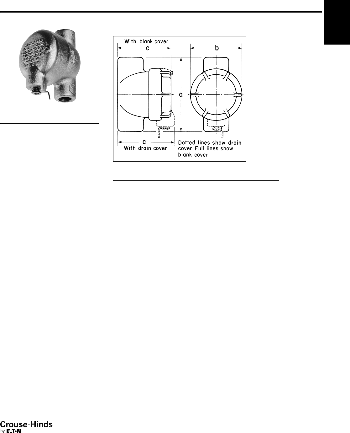
6F
145
www.crouse-hinds.com US: 1-866-764-5454 CAN: 1-800-265-0502 Copyright©2013 Eaton’s Crouse-Hinds Business
Conduit Sealing Fittings with
Drain and Inspection Cover
Chico Sealing Compound and Fiber
see pages 155–156
Cl. I, Div. 1 & 2, Groups C, D
Cl. II, Div. 1, Groups E, F, G
Cl. II, Div. 2, Groups F, G
Cl. III
Explosionproof
Dust-Ignitionproof
EZD With Drain Cover
Hub
Size Cat. #
Approximate
Internal Volume
in Cubic Inches
1/2EZD111 5
3/4EZD211 6
1EZD311 10
11/4EZD411 11
11/2EZD511 13
2EZD611 40
Dimensions
In Inches:
EZD Drain and Inspection Seals
Size a b Drain Cover c Turning Radius†
1/243/16 33
3/821/16
3/443/16 33
5/823/16
1415/16 31/237/827/16
11/4415/16 31/245/16 25/8
11/253/16 31/249/16 211/16
271/859/16 51/4311/16
†With cover removed.
6F
144-145.qxp 12/16/2013 12:28 PM Page 145
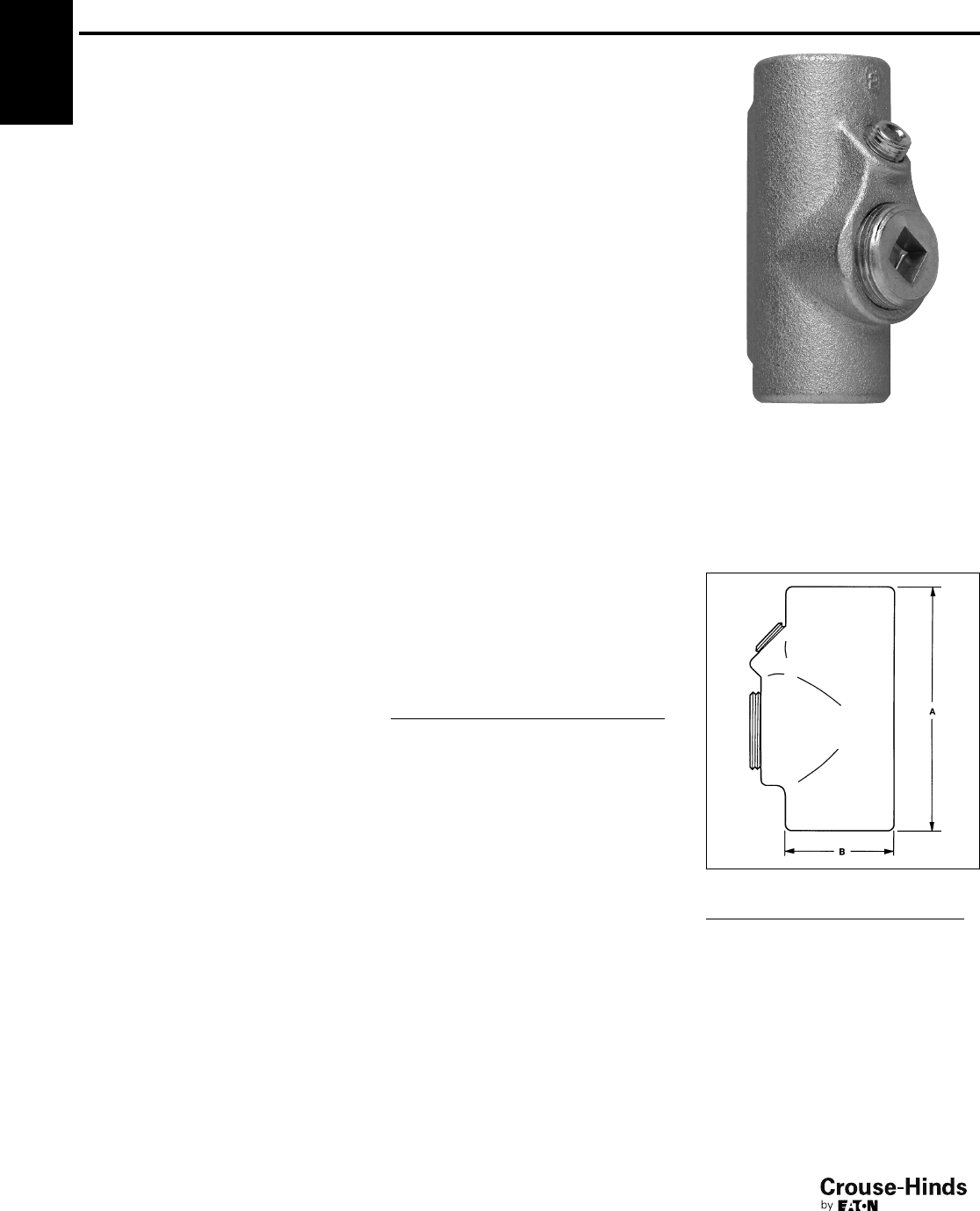
6F
146
www.crouse-hinds.com US: 1-866-764-5454 CAN: 1-800-265-0502 Copyright©2013 Eaton’s Crouse-Hinds Business
EYSX Expanded Fill
Sealing Fittings
Chico Sealing Compound and
Fiber see pages 155–156
Cl. I, Div. 1 & 2, Groups B, C, D§
Cl. II, Div. 1, Groups E, F, G
Cl. II, Div. 2, Groups F, G
Cl. III
Explosionproof
Dust-Ignitionproof
Applications:
EYSX Expanded Fill Sealing Fittings:
• Restrict the passage of gases, vapors or
flames from one portion of the electrical
installation to another at atmospheric
pressure and normal ambient
temperatures
• Limit explosions to the sealed-off
enclosure
• Limit precompression or "pressure
piling" in conduit systems
• Provide 40% wire fill capacity to allow
uninterrupted runs in a conduit system
Sealing fittings are required:
• At each entrance to an enclosure
housing an arcing or sparking device
when used in Class I, Division 1 and 2
hazardous locations. To be located as
close as practicable and, in no case,
more than 18" from such enclosures
• At each entrance of 2" size or larger to
an enclosure or fitting housing terminals,
splices or taps when used in Class I,
Division 1 hazardous locations. To be
located as close as practicable and, in
no case, more than 18" from such
enclosures
• In conduit systems when leaving Class I,
Division 1 or 2 hazardous locations
• In cable systems when the cables either
do not have a gas/vaportight continuous
sheath or are capable of transmitting
gases or vapors through the cable core
when those cables leave the Class I,
Division 1 or 2 hazardous locations
Features:
EYSX Expanded Fill Sealing Fittings
provide:
• A 40% wire fill capacity for expanded fill
sealing
• Large openings with threaded closures
to provide easy access to conduit hubs
for making dams
• Integral bushings in conduit hubs to
protect conductor insulation from
damage
• Taper-tapped hubs to ensure ground
continuity
• Minimum turning radius
EYSX Expanded Fill Sealing Fittings are
available for installation in both horizontal
or vertical positions.
Standard Materials:
• Bodies – Feraloy®iron alloy and/or
ductile iron or copper-free aluminum
(SA Suffix)
• Closures – Feraloy iron alloy and/or steel
or copper-free aluminum (SA Suffix)
Standard Finishes:
•Feraloy iron alloy and ductile iron –
electrogalvanized and aluminum acrylic
paint
• Steel – electrogalvanized
• Copper-free aluminum – natural
Options:
Description Suffix
Copper-free aluminum bodies and
enclosures SA
Size Ranges:
•1/2" – 4"
Certifications and
Compliances:
• NEC/CEC:
EYSX11 – EYSX81
Class I, Division 1 and 2, Groups B, C, D
Class II, Division 1, Groups E, F, G
Class II, Division 2, Groups F, G
Class III
EYSX9, EYSX10, EYSX1 SA – EYSX10 SA
Class I, Division 1 and 2, Groups C, D
Class II, Division 1, Groups E, F, G
Class II, Division 2, Groups F, G
Class III
• UL Standard: 1203
• CSA Standard: C22.2 No. 30
Ordering Information
For Sealing in Vertical or
Horizontal Positions
Hub Female Hub
Internal Volume
in Cubic Inches
Size Cat. # Vertical Horizontal
1/2EYSX11* 22
1/2EYSX1 SA 22
3/4EYSX21* 33
3/4
3/4EYSX2 SA 33
3/4
1EYSX31 68
1EYSX3 SA 68
11/4EYSX41 19 223/4
11/4EYSX4 SA 19 223/4
11/2EYSX51 19 223/4
11/2EYSX5 SA 19 223/4
2EYSX61 56 641/2
2EYSX6 SA 56 641/2
21/2EYSX71 72 82
21/2EYSX7 SA 72 82
3EYSX81 95 110
3EYSX8 SA 95 110
31/2EYSX9* 200 222
31/2EYSX9 SA 200 222
4EYSX10* 200 222
4EYSX10 SA 200 222
Vertical or horizontal female
Sealing fittings are approved for use in hazardous
locations only when Chico®Xfiber and Chico A sealing
compound or Chico SpeedSeal are used to make the
seal.
NPT
Size A B
Turning
Radius
1/2311/16 11/211/4
3/445/16 13/413/8
151/16 23/16 123/32
11/461/432
5/16
11/261/432
5/16
281/241/435/16
21/293/16 43/43-7/16‡
393/451/43-11/16‡
31/2111/16 61/24-19/32‡
4111/16 61/24-19/32‡
§ See Certifications and Compliances for classsification
of each product.
‡With plug cover removed.
*Feraloy®
Dimensions
In Inches:
6F
146-147.qxp 12/16/2013 12:30 PM Page 146
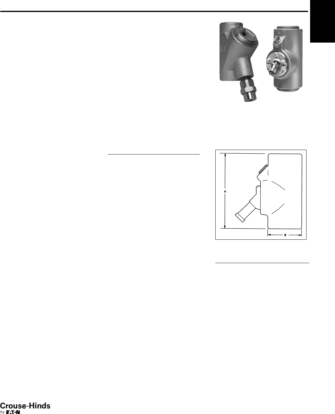
6F
147
www.crouse-hinds.com US: 1-866-764-5454 CAN: 1-800-265-0502 Copyright©2013 Eaton’s Crouse-Hinds Business
EYDX Expanded Fill Sealing
Fittings With Drains
Chico Sealing Compound and Fiber
see pages 155–156
Cl. I, Div. 1 & 2, Groups B, C, D§
Cl. II, Div. 1, Groups E, F, G
Cl. II, Div. 2, Groups F, G
Cl. III
Explosionproof
Dust-Ignitionproof
Applications:
EYDX Expanded Fill Sealing Fittings with
drains:
• Restrict the passage of gases, vapors or
flames from one portion of the electrical
installation to another at atmospheric
pressure and normal ambient
temperatures
• Limit explosions to the sealed-off
enclosure
• Prevent precompression or "pressure
piling" in conduit systems
• Provide 40% wire fill capacity to allow
uninterrupted runs in a conduit system
Drain sealing fittings are installed in vertical
conduit runs and at low points in conduit
systems to prevent accumulation of
condensate above seal.
For sealing fittings requirements
see page 139.
Features:
EYDX Expanded Fill drain sealing fittings
provide:
• A 40% wire fill capacity for expanded fill
sealing
• Drain to provide continuous, automatic
drainage of condensate
• Large openings with threaded closures
to provide easy access to conduit hubs
for making dams
• Integral bushings to protect conductor
insulation from damage
• Taper-tapped hubs to ensure ground
continuity
Standard Materials:
• Bodies and drain covers – Feraloy®iron
alloy, and ductile iron or copper-free
aluminum (SA Suffix)
• Closure for drain – copper-free aluminum
or malleable iron
• Small closure plug – Feraloy iron alloy
and/or steel or copper-free aluminum
(SA Suffix)
• Drain – stainless steel
Standard Finishes:
•Feraloy iron alloy and ductile iron –
electrogalvanized and aluminum acrylic
paint
• Copper-free aluminum – natural
• Stainless steel – natural
• Steel – electrogalvanized
Options:
Description Suffix
Copper-free aluminum bodies and
enclosures SA
Size Ranges:
• EYDX – 1/2" – 3"
Certifications and
Compliances:
• NEC/CEC:
EYDX11 – EYDX81
Class I, Division 1 and 2,
Groups B, C, D
Class II, Division 1, Groups E, F, G
Class II, Division 2, Groups F, G
Class III
EYDX1 SA – EYDX8 SA
Class I, Division 1 and 2, Groups C, D
Class II, Division 1, Groups F, G
Class II, Division 2, Groups F, G
Class III
• UL Standard: 1203
• CSA Standard: C22.2 No. 30
Sealing Fittings are approved for use in hazardous
locations only when Chico®Xfiber and Chico A sealing
compound or Chico SpeedSeal are used to make the
seal.
1/2" – 3/4" 1" – 3"
Dimensions
In Inches:
EYDX NPT
Size A B
Turning
Radius
1/2311/16 13/4129/32
3/445/16 23/16 23/8
1 51/16 23/16 1-27/32†
11/461/432-
5/16†
11/261/432-
5/16†
281/241/43-5/16†
21/293/16 43/43-7/16†
393/451/43-1/2†
†With drain cover removed.
§ See Certifications and Compliances for classification of
each product.
* Feraloy®
6F
Ordering Information
Hub
Size
Female Hub
Cat #
Internal Volume
in Cubic Inches
1/2EYDX11* 2
1/2EYDX1 SA 2
3/4EYDX21* 33/4
3/4EYDX2 SA 33/4
1EYDX31 8
1EYDX3 SA 8
11/4EYDX41 20
11/4EYDX4 SA 20
11/2EYDX51 20
11/2EYDX5 SA 20
2EYDX61 57
2EYDX6 SA 57
21/2EYDX71 75
21/2EYDX7 SA 75
3EYDX81 105
3EYDX8 SA 105
146-147.qxp 12/16/2013 12:30 PM Page 147
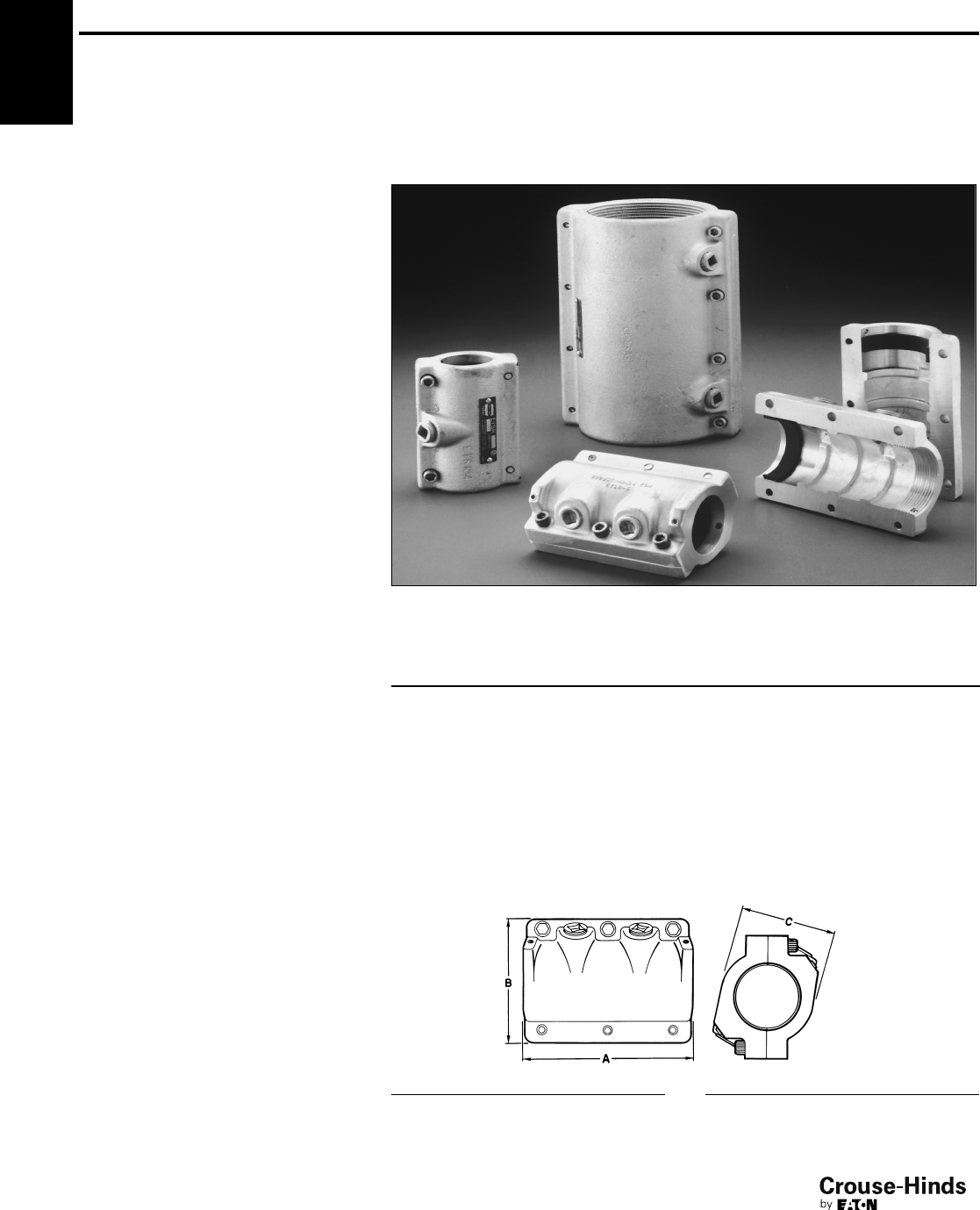
6F
148
www.crouse-hinds.com US: 1-866-764-5454 CAN: 1-800-265-0502 Copyright©2013 Eaton’s Crouse-Hinds Business
6F EYSR Retrofit Sealing Fitting
Chico Sealing Compound
and Fiber see pages 155–156
Cl. I, Div. 2, Groups C, D
Cl. II, Div. 2, Groups E, F, G
Explosionproof
Dust-Ignitionproof
Applications:
EYSR retrofit sealing fittings are installed:
• In rigid metal conduit systems in Class I,
Division 2 hazardous locations
• To replace installed Eaton's Crouse-
Hinds type EYS or EYD sealing fittings
• Without disassembly of the conduit
system
• In vertical or horizontal positions,
indoors or outdoors
• To restrict the passage of gases, vapors,
or flames from one portion of the
electrical system to another at
atmospheric pressures and normal
ambient temperatures
• To limit explosions to the sealed-off
enclosure
• To limit precompression or "pressure
piling" in the conduit system
• To prevent accumulation of water in the
conduit system when installed with an
ECD15 drain
Features:
• Seal may be installed in the existing
conduit run without disassembly of the
conduit system saving time and labor
• Overall length and spacing requirements
do not exceed those of standard EYS
seals; permits close nesting of seals
• Pipe plugs permit the installation of a
standard ECD15 drain fitting (order
separately) for use in vertical conduit
runs to drain any water that might
accumulate in the conduit system
• Steel set screws provide grounding
continuity
• Suitable for vertical and horizontal
installations for indoor and outdoor
applications
• Available in 3/4" to 4" NPT sizes
Standard Materials:
• Body – Feraloy®iron alloy
• Pipe plugs, bolts and set screws – steel
• Gasket – neoprene
Standard Finishes:
•Feraloy iron alloy – electrogalvanized
and aluminum acrylic paint
• Steel – electrogalvanized
• Gasket – natural
Options:
Description Suffix
Copper-free aluminum SA
Size Ranges:
•3/4" – 4"
Certifications and
Compliances:
• NEC:
Class I, Division 2, Groups C, D
Class II, Division 2, Groups E, F, G
• UL Standard: 1203
• CEC:
Class I, Division 1, Groups C, D
Class II, Division 1, Groups E, F, G
• CSA Standard: C22.2 No. 30
EYSR sealing fittings are approved for use in hazardous
locations only when Chico®Asealing compound and
Chico X fiber are used to make the seal.
Ordering Information
Approximate Internal
Volume in
Cubic Inches*
Approximate Amount
(oz.) of Fiber
per Hub
Hub Size Cat. # Vert. Horiz. Vert. Horiz.
3/4EYSR2 31/253/41/16 1/8
1EYSR3 43/491/21/81/4
11/4EYSR4 7 131/21/41/2
11/2EYSR5 121/4241/41/21
2EYSR6 253/4401/212
21/2EYSR7 48 751/211/23
3EYSR8 861/2126 2 4
31/2EYSR9 147 210 41/29
4EYSR10 186 252 41/29
*Use the approximate internal volume in cubic inches to determine how much Chico A sealing compound is required.
Dimensions
In Inches:
Cat. # A B C
EYSR2 311/16 21/211/2
EYSR3 43/831/831/8
EYSR4 53
3/83
EYSR5 51/435/83
EYSR6 61/443
Cat. # A B C
EYSR7 71/253
7/8
EYSR8 81/251/241/4
EYSR9 913/64 61/16 43/4
EYSR10 93/465/851/4
148-149.qxp 12/24/2013 3:01 PM Page 148
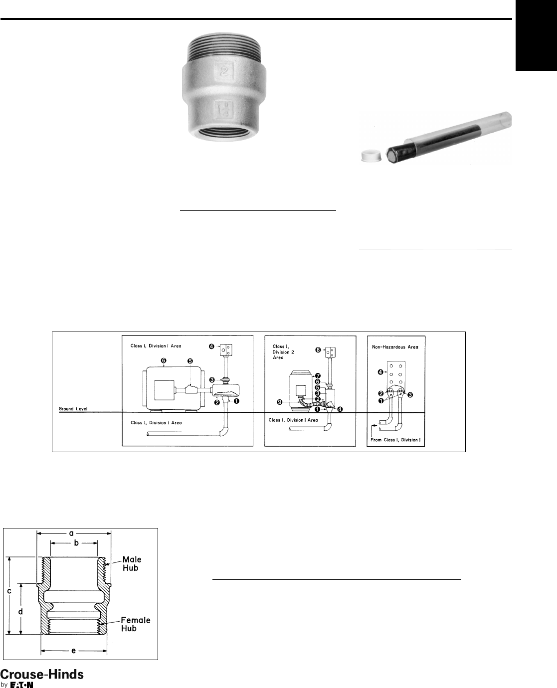
6F
149
www.crouse-hinds.com US: 1-866-764-5454 CAN: 1-800-265-0502 Copyright©2013 Eaton’s Crouse-Hinds Business
ES Sealing Hubs
Chico Sealing Compound and Fiber
see pages 155–156
Cl. I, Div. 1 & 2, Groups C, D
Explosionproof
Watertight
Applications:
ES sealing hubs are used to:
• Seal vertical conduit risers at switchgear
and motor control centers, sheet metal
structures or cast boxes and enclosures
• Seal horizontal conduit runs at
enclosures when used with TSC sealing
compound
Standard Materials:
•Feraloy®iron alloy
Standard Finishes:
• Electrogalvanized and aluminum acrylic
paint
Options:
ES sealing hubs, when used with SG
armored gaskets and locknuts, provide a
water and oiltight connection
Description Suffix
Sealing gaskets and locknuts SG
Certifications and
Compliances:
• Class I, Division 1 & 2, Groups C & D
• UL Standard: 1203
• CSA Standard: C22.2 No. 30
Note: Sealing hubs are approved for use in hazardous
locations when Chico®Xfiber and Chico A sealing
compound are used to make the seal. Sealing hubs are
approved for horizontal conduit runs for use in
hazardous locations when used with TSC sealing
compound, order 1 oz. tube as TSC1.
6F
TSC Epoxy Sealing
Compound
A two part epoxy sealing compound may
be used to seal ES sealing hubs. It is
quick and easy to measure, mix and
install. The compound is kneaded until a
uniform color is obtained. It is then
packed around the conductors to
effectively seal the cable.
Std. Ctn. Qty. Tube Size Cat. #†
10 0.5 oz TSC05
10 1.0 oz TSC1
5 4.0 oz TSC4
†Order quantity of one (1) TSC05 or TSC1 equals 10
tubes; one (1) TSC4 equals 5 4.0 oz tubes.
Typical Installations
1. ES Sealing Hub
2. EJB Junction Box
3. UNY Union
4. EDS Factory Sealed
Control Station
5. EYS Horizontal Seal
6. Explosion-Proof Motor
1. ES Sealing Hub
2. LT Connector
3. Locknut
4. Sealing Gasket
5. Junction Box
6. UNY Union
7. Synchronous Motor
8. EDS Factory Sealed
Control Station
9. LT Conduit
1. ES Sealing Hub
2. Locknut
3. Sealing Gasket
4. Sheet Metal
Structure, Motor
Control Center,
Panelboard, Unit
Substation, Etc.
Dimensions
In Inches:
Cat. # a b c d e
ES31 19/16 7/822
5/32 11/4
ES32 113/16 7/8225/32 11/2
ES53 21/413/823/4115/16 13/4
ES64 23/413/423/4115/16 23/16
ES65 23/415/831/16 22
7/16
ES76 31/221/16 39/16 23
ES108 51/435/843/4231/32 41/4
ES01210 65/845/863/4427/32 51/4
ES014012 71/4525/32 71/4511/32 61/2
Ordering Information
Female
Hub
Size
Male
Hub
Size Cat. #
Approximate
Internal
Volume
in Cubic
Inches
1/21ES31 .65
3/41ES32 .65
11
1/2ES53 3.2
11/42ES64 4.9
11/22ES65 4.7
2 21/2ES76 9.1
34ES108 36.0
45ES01210 95.0
56ES014012 155.0
148-149.qxp 12/24/2013 3:01 PM Page 149
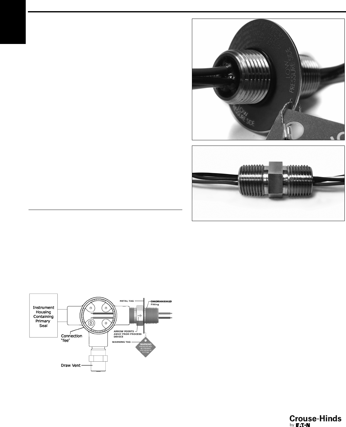
6F
150
www.crouse-hinds.com US: 1-866-764-5454 CAN: 1-800-265-0502 Copyright©2013 Eaton’s Crouse-Hinds Business
6F Ultra High Pressure Seal
Rated to 1500 PSI
Applications:
• If the primary seal in an instrument should fail, the Eaton's Crouse-
Hinds Ultra High Pressure Seal (UHPS) will prevent gases from
migrating through the electrical system into a non-classified
location.
• Are designed to prevent the passage of gases under pressure
through conduits, cables and conductors.
• Are ideal where volatile liquids or gases are stored, processed or
transported under pressure.
Certifications & Compliances:
• Class I, Division 1, Groups B, C, D
• Certified to CSA Standards through QPS
• 24 Volt DC - 120 Volt AC
• Wire grade is rated to a 600 Volt safety factor
•1/2” MNPT x 1/2” NPT
• Conforms to Section 18-108 and 18-158 of the CEC®for The
Requirements of a Secondary Seal.
Standard Materials & Finishes:
• Stainless steel body - natural finish
Ordering Information:
Catalog Number Description
CH6DR500X002D14G UHPS, 2 wire, 14 gauge
CH6DR500X002D16G UHPS, 2 wire, 16 gauge
CH6DR500X002D18G UHPS, 2 wire, 18 gauge
CH6DR500X002D22G UHPS, 2 wire, 22 gauge
CH6DR500X004D14G UHPS, 4 wire, 14 gauge
CH6DR500X004D16G UHPS, 4 wire, 16 gauge
CH6DR500X004D18G UHPS, 4 wire, 18 gauge
CH6DR500X004D22G UHPS, 4 wire, 22 gauge
CH6DR500X234D14G UHPS, 4 wire, 14G, 2' input, 3' output
CH6DR500X264D16G UHPS, 4 wire, 16G, 2' input, 6' output
CH6DR500X294D16G UHPS, 4 wire, 16G, 2' input, 9' output
CH6DR500X2D2D16G UHPS, 2 wire, 16G, 2' input, CF output
INSTALLATION EXAMPLE:
Quality Assurance:
Each fitting is tested at 1.5 times working pressure (max. working
pressure 1500 PSI) as a gas and liquidtight explosionproof fitting.
Each seal is also di-electric and resistance tested.
Cl. I, Div. 1, Groups B, C, D
Certified to CSA Standards through QPS
150-151.qxp 12/16/2013 12:30 PM Page 150
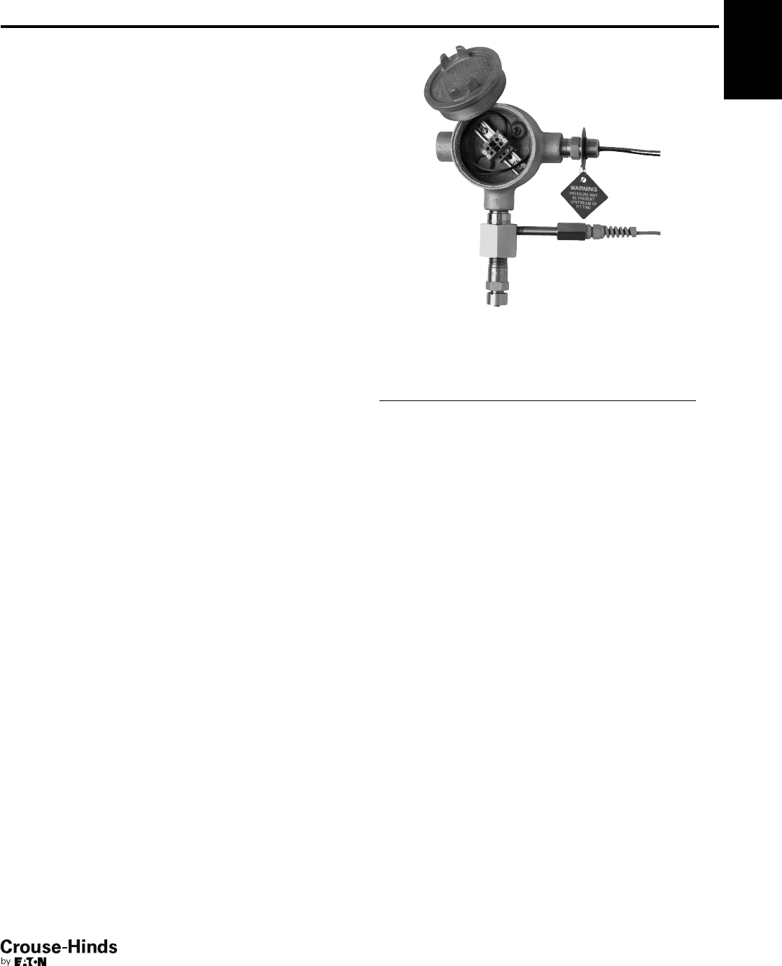
6F
151
www.crouse-hinds.com US: 1-866-764-5454 CAN: 1-800-265-0502 Copyright©2013 Eaton’s Crouse-Hinds Business
Secondary Process
Seal Assemblies
Cl. I, Div. 1 & 2, Groups B, C, D
Cl. I, Zone 1 & 2 IIB + H2
Cl. II, Div. 1 & 2, Groups E, F, G
NEMA 3, 4, 7BCD, 9
Applications:
Eaton's Crouse-Hinds Secondary Process Seal Assembly with
Rupture Indication Sensor is designed to prevent the passage of
gases under pressure through conduit, cables and conductors while
providing immediate notification of a dangerous, potentially explosive
seal rupture. These assemblies are ideal where volatile liquids or
gases are stored, processed or transported under pressure. If the
primary seal in an instrument should fail, the Eaton's Crouse-Hinds
Secondary Process Seal will prevent gases, vapors and liquids from
migrating into the non-classified location through the electrical
system.
Rupture Indication Sensor:
The Secondary Process Seal features a rupture indication sensor that
opens safely at 60 psi minimum and activates a circuit to a control
system or alarm, which immediately alerts maintenance personnel
that the primary seal has ruptured. The location of the problem can
be pinpointed so the problem can be quickly addressed.
Innovative, intelligent technology combined with easy installation and
low maintenance cost provides a safe and reliable solution for
detection of a process seal rupture within your facility.
Features and Benefits:
Secondary Process Seal
• CSA and CSAus certified
• Meets or exceeds ANSI / ISA / CSA / CEC / NEC / API
requirements for a secondary process seal and explosionproof
conduit seal
• Sealed to 1500 psi, operates in any position
• Simplified design allows for easier installation in new and existing
applications
• Integrated packaging contains all necessary components for
installation
• The explosionproof drain allows for the safe release of gas, vapor
or liquid from the electrical system to meet required codes
• Explosionproof terminal box features a simple design to provide
access for quick connection of circuits
• Assembly with drain provides local "make obvious" indication of
primary seal failure
Rupture Indication Sensor
• Rupture detection and indication at 60 psi
• Provides remote, immediate notification of a seal rupture, allowing
for maintenance to quickly address the problem and isolate safety
concerns
• Stainless steel construction provides superior corrosion resistance
and durability
Ordering Information:
Assembly with
Vent/Drain
Assembly with
Rupture Indication
Sensor and Vent/Drain
2 wire, 14 gauge SPS214 SPS214R
2 wire, 16 gauge SPS216 SPS216R
2 wire, 18 gauge SPS218 SPS218R
2 wire, 22 gauge SPS222 SPS222R
4 wire, 14 gauge SPS414 SPS414R
4 wire, 16 gauge SPS416 SPS416R
4 wire, 18 gauge SPS418 SPS418R
4 wire, 22 gauge SPS422 SPS422R
For Process Seal Rupture Indication Sensor replacement, order catalog #PSRIS.
6F
Options:
Description Suffix
No terminal blocks (leave option blank)
2 terminal blocks DIN12
4 terminal blocks DIN14
150-151.qxp 12/16/2013 12:30 PM Page 151
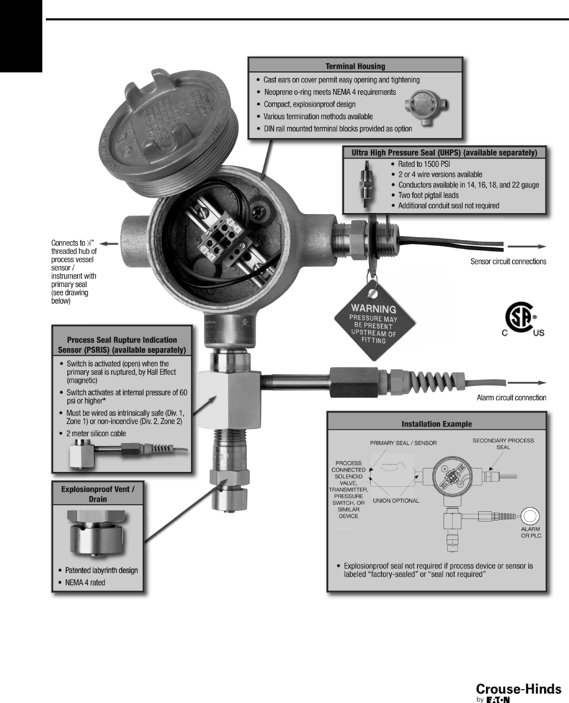
6F
152
www.crouse-hinds.com US: 1-866-764-5454 CAN: 1-800-265-0502 Copyright©2013 Eaton’s Crouse-Hinds Business
Assembly Information
Assembly with process seal rupture indication sensor
*60 psi internal pressure rating at 25°C ambient. Activation pressure may vary +/ - 10% depending on ambient variation.
Secondary Process
Seal Assemblies
Cl. I, Div. 1 & 2, Groups B, C, D
Cl. I, Zone 1 & 2 IIB + H2
Cl. II, Div. 1 & 2, Groups E, F, G
NEMA 3, 4, 7BCD, 9
6F
152-153.qxp 12/16/2013 12:32 PM Page 152

6F
153
www.crouse-hinds.com US: 1-866-764-5454 CAN: 1-800-265-0502 Copyright©2013 Eaton’s Crouse-Hinds Business
Installation Examples
Secondary Process Seal with local "make obvious"
indication using an ECD explosionproof drain
Secondary Process Seal with Rupture Indication
Sensor for remote indication, and ECD
explosionproof drain for local "make obvious"
indication
Technical Data - Assembly
Product Certification
The Secondary Process Seal and Assemblies are CSA certified
(Canada, U.S.)
Operating Pressure Rating
Rupture protection to 1500 psi
Rupture indication at 60 psi minimum
Operating Temperature Range
-25ºC to +50ºC
Note: For more extreme temperature and/or pressure requirements, please consult
factory.
Technical Data - Components
Components Construction Certifications and Compliances Rating Area Suitability
Process Seal Rupture
Indication Sensor
Hub - 316
stainless steel
ANSI / ISA 12.27.01 - 2003
CEC 18 - 108, 158
NEC 501.15(F)(3)
–
Cl. I, Div. 1 & 2, Groups
B, C, D
Cl. II, Div. 1 & 2, Groups
E, F, G
Zone 1 IIB+H2and
Zone 2 IIB+H2
NEMA 3, 4, 7BCD, 9
Switch Assembly -
hermetically sealed,
nickeled brass, with
silicon cable
(Div. 1, Zone 1) intrinsically safe
(Div. 2, Zone 2) non-incendive
Simple apparatus (NEC 504.4)
174 mA
24VDC
T6 (Tamb ≤40°C)
T5 (40°C < Tamb ≤55°C)
T4 (55°C < Tamb ≤80°C)
Ultra High Pressure Seal Stainless steel
CSA 22.2 No. 30 - 03
CSA 22.2 No. 14 - 2005
ANSI / ISA 12.27.01 - 2003
CEC 18 - 108, 158
NEC 501.15(F)(3)
24VDC
120VAC
Terminal Housing Copper-free
aluminum
UL1203
CSA C22.2 No. 30 –
Drain / Vent Stainless steel UL1203
CSA C22.2 No. 30 –
6F
Secondary Process
Seal Assemblies
Cl. I, Div. 1 & 2, Groups B, C, D
Cl. I, Zone 1 & 2 IIB + H2
Cl. II, Div. 1 & 2, Groups E, F, G
NEMA 3, 4, 7BCD, 9
152-153.qxp 12/16/2013 12:32 PM Page 153
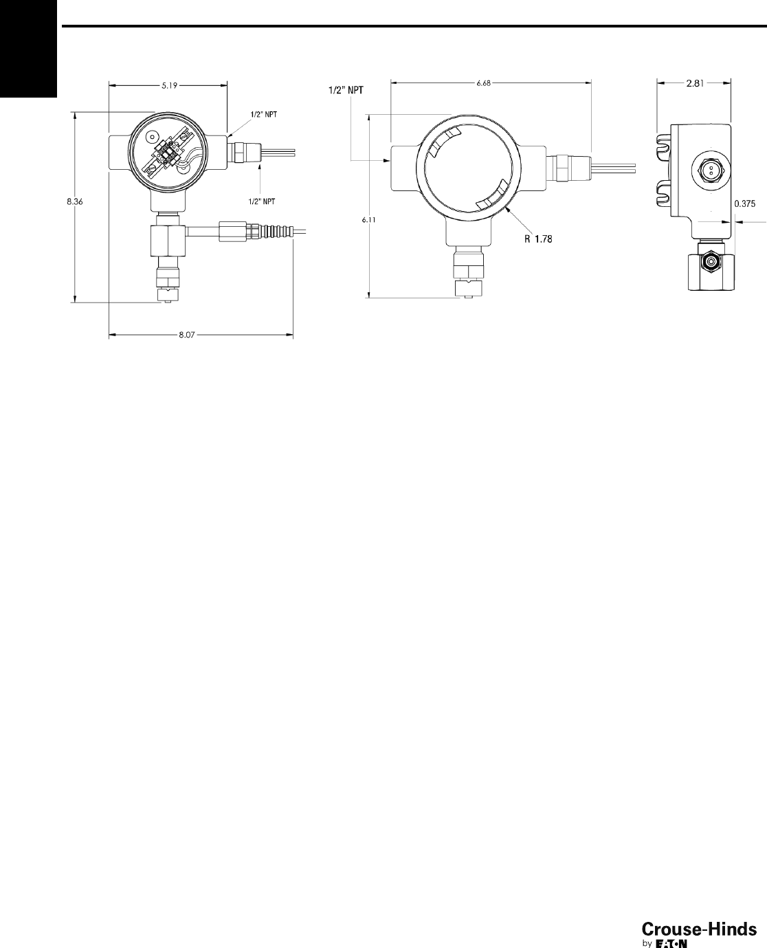
6F
154
www.crouse-hinds.com US: 1-866-764-5454 CAN: 1-800-265-0502 Copyright©2013 Eaton’s Crouse-Hinds Business
6F Secondary Process
Seal Assemblies
Cl. I, Div. 1 & 2, Groups B, C, D
Cl. I, Zone 1 & 2 IIB + H2
Cl. II, Div. 1 & 2, Groups E, F, G
NEMA 3, 4, 7BCD, 9
Dimensions (Inches):
Assembly with rupture sensor and vent/drain Assembly with vent/drain
Note: Assemblies shown with DIN12 terminal blocks (optional)
154-155.qxp 12/23/2013 2:49 PM Page 154
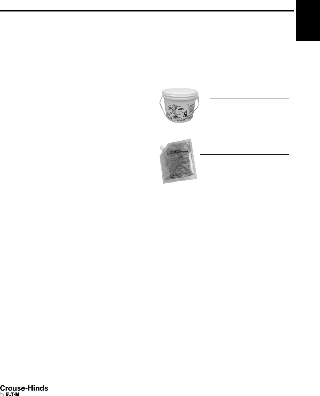
6F
155
www.crouse-hinds.com US: 1-866-764-5454 CAN: 1-800-265-0502 Copyright©2013 Eaton’s Crouse-Hinds Business
Chico®A and Chico®A-P Sealing Compound
Chico®X Fiber
Chico®SpeedSeal™
For Sealing Fittings and Hubs
Applications:
Chico X fiber:
• Forms a dam between the integral bushing of the sealing fitting and
the end of the conduit and around the electrical conductors entering
the hub
Chico A sealing compound:
• Forms a seal around each electrical conductor and between them
and inside of the sealing fitting to restrict the passage of gases,
vapors or flames through the sealing fitting at atmospheric pressure
and at normal ambient temperatures
Chico®SpeedSeal™Compound:
• Designed to separate and form an explosionproof seal around each
electrical conductor in Eaton's Crouse-Hinds EYS and EYD sealing
fittings
• Restricts the passage of gases, vapors or flames through the
sealing fitting
• Creates a seal for Class I, Division 1, Groups C, D and Class II,
Division 1, Groups E, F, G hazardous areas
6F
Size Ranges:
•Chico A compound – 1 lb. to 5 lbs. (provides 23–115 cubic
inches of compound)
•Chico X fiber – 2 oz. to 1 lb.
•Chico A-P (5 pouches per carton) – provides 25 and 55 cubic
inches of compound
•Chico SpeedSeal - 2 oz. or 6 oz. cartridge
Eaton's Crouse-Hinds sealing fittings are approved for use in hazardous locations
only when Chico X fiber and Chico A Sealing Compound or Chico SpeedSeal are
used to make the seal.
Ordering Information - Chico A
Ordering Information - Chico A-P Intrapak®
*A sixth pouch, containing an appropriate quantity of Chico X fiber, is included in
these cartons.
Cu. In.
Fill per
Pouch†
No. of
Pouches
per Carton Cat. #
55 Chico A19 PX*
11 5 Chico A39 PX*
Net
Weight
Vol.
Cu. In.† Cat. #
1 lb. 23 Chico A3
1 lb.‡ 23 Chico A4
5 lb. 115 Chico A05
†Number of cubic inches this amount will fill when set. See internal volume
requirements for EYS, EZS, EYD, EZD and EYSR sealing fittings and ES sealing
hubs (see pages 140–149).
‡Includes 1 oz. Chico X fiber.
Features:
Chico A sealing compound:
• A water soluble powder that can be easily mixed and poured. The
compound, unusually dense, expands slightly when hardening and
bonds to inner walls of sealing fittings. Compound hardens in 60–70
minutes
• Chico A cure time is 8 hours for Class I, Group C and D applications
and 72 hours for Class I, Group A and B applications.
• Chico A has a 1 year shelf life from date of manufacture.
• Chico A ambient temperature range (after curing) is –40°F to +165°F.
Chico A-P Intrapak®:
• Packaged in two-compartment plastic pouch with precise amount of
water for mixing. No mixing or measuring implements required.
• A hard squeeze of the water compartment forces the water into the
compartment containing the Chico compound. Mixing is completed by
kneading the pouch for one minute.
• The mixed sealing compound is poured directly into the sealing fitting
– no funnel required. The package label indicates the size and quantity
of sealing fittings each pouch will properly fill. Compound hardens in
60–70 minutes.
Chico X fiber:
• A mineral wool that packs easily, forming around each conductor
Chico®SpeedSeal™ Compound:
• Installs a reliable seal in five minutes - every time
• Hardens to a dense, strong mass that is suitable for Class I, Division 1,
Groups C, D and Class II, Division 1, Groups E, F, G hazardous
applications.
• UL and cUL Listed for use with 1/2" to 2" Eaton's Crouse-Hinds sealing
fittings only.
• Packaged in a 2 oz. or 6 oz. pre-measured cartridge, eliminating the
need for measuring before mixing.
• Packaged with a screw-on nozzle for accurate dispensing.
• Expands four times its original size in the sealing fitting, eliminating the
need to separate the individual conductors with Chico X fiber.
• Chico X fiber dams are not required in horizontal applications,
reducing installation times.
• Completely hardens in 20 minutes, simplifying use for OEMs.
• Suitable for cold temperature environments without the costly need to
build a temporary shelter around sealing fittings. All ice crystals must
be removed from inside the conduit seal before dispensing Chico
SpeedSeal compound. The Chico SpeedSeal compound should be
kept above 10°C (50°F) and below 85°F (29°C) prior to mixing.
The sealing fitting must be kept at or above 4°C (40°F) during the
4 to 10 minute expansion/gel time of the compound.
• 18 months shelf-life.
• Patent pending.
154-155.qxp 12/23/2013 2:49 PM Page 155
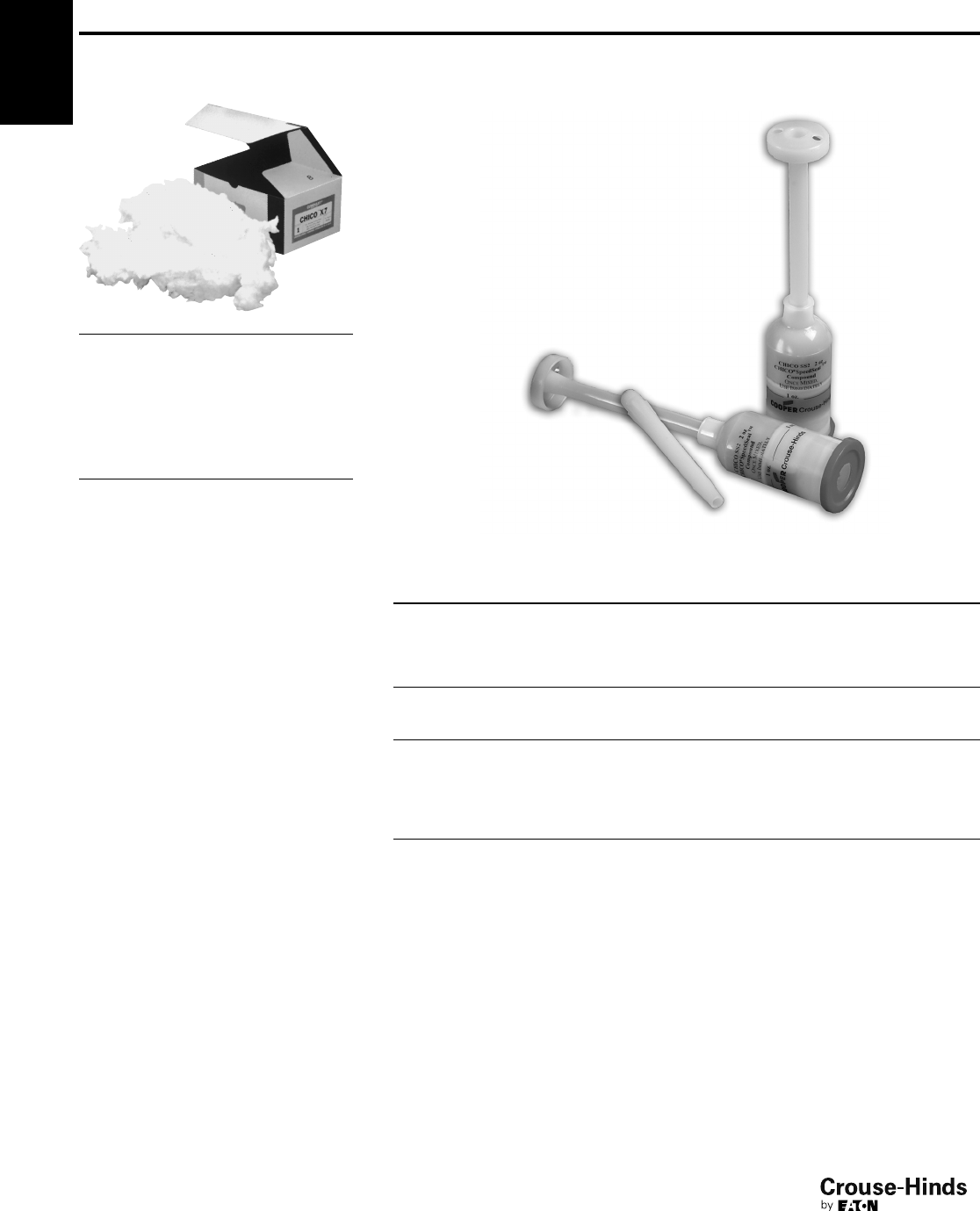
6F
156
www.crouse-hinds.com US: 1-866-764-5454 CAN: 1-800-265-0502 Copyright©2013 Eaton’s Crouse-Hinds Business
Ordering Information -
Chico X Fiber
Net Weight Cat. #
2 oz. Chico X4
8 oz. Chico X6
1 lb. Chico X7
Chart for Approximate Amount
of Fiber Per Hub
Hub Size Ozs. Required
1/21/32
3/41/16
1 1/8
11/41/4
11/21/2
2 1
21/211/2
32
31/23
4 41/2
57
610
MSDS sheets are available at www.crouse-hinds.com
Chico®A and Chico®A-P Sealing Compound
Chico®X Fiber
Chico®SpeedSeal™
For Sealing Fittings and Hubs
6F
Sealing Fitting
Cat. #
Amount of
SpeedSeal Material
needed per fitting
(in ounces) SpeedSeal Cat. #
EYS1, EYS16; EYS11, EYS116
1CHICO SS2
(2 oz. Cartridge)
EYD1, EYD16, EYD11, EYD116
EYS2, EYS26, EYS21, EYS216
EYD2, EYD26, EYD21, EYD216
EYSX11, EYDX11
EYS3, EYS36, EYS31, EYS316
2CHICO SS2
(2 oz. Cartridge)
EYD3, EYD36, EYD31, EYD316
EYSX21, EYDX21
EYS41, EYS416, EYS4, EYS46
3CHICO SS6
(6 oz. Cartridge)
EYD4, EYD46, EYD41, EYD416
EYS51, EYS516, EYS5, EYS56
EYD5, EYD56, EYD51, EYD516
EYSX31, EYDX31
EYSX41, EYDX41
EYS61, EYS616, EYS6, EYS66
6CHICO SS6
(6 oz. Cartridge)
EYD6, EYD66, EYD61, EYD616
EYSX51, EYDX51
Ordering Information - Chico SpeedSeal
Class I, Div. 1, Groups C & D and Class II, Div. 1, Groups E, F and G
156-157.qxp 12/16/2013 12:38 PM Page 156
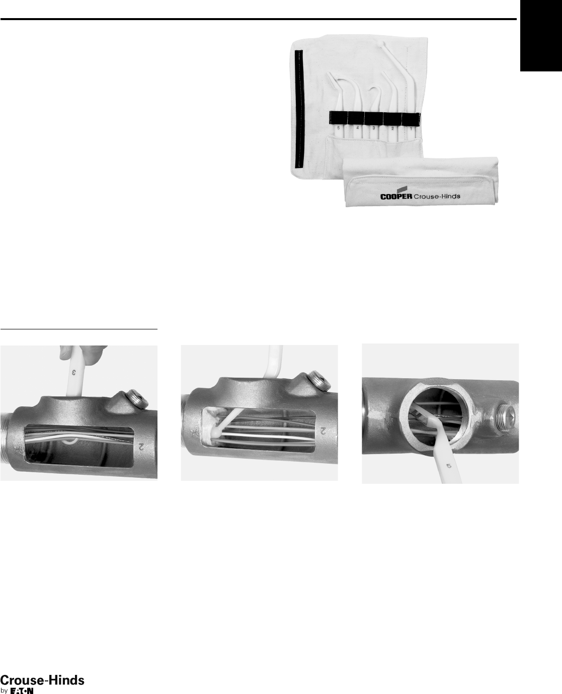
6F
157
www.crouse-hinds.com US: 1-866-764-5454 CAN: 1-800-265-0502 Copyright©2013 Eaton’s Crouse-Hinds Business
EYS Tool Kit
For Use with Sealing Fittings and Hubs
Features and Benefits:
• The EYS Tool Kit consists of five tools and a canvas tool bag. Four
tools have two unique ends for a total of 9 different tools.
• Each tool is numbered for easy identification.
• Tools are constructed of durable plastic with smooth and rounded
surfaces that will not abrade the electrical insulation.
• The Hook tool (#3) with a large hook on one end and a small hook
on the other end is designed to lift and separate individual wires.
• The Packing tools (#1, #2 & #4) have rounded ends designed for
packing fiber in between and around electrical conductors.
• The Wedge tools (#2 & #5) are designed for hands-free separation
of conductors while packing fiber.
• The Mirrored tool (#5) allows for easy inspection of the sealing
fittings.
• All tools are sized and precisely angled to accomodate various
sizes of fittings.
• The canvas tool bag is designed to neatly store and protect tools
while not in use.
Ordering Information
Description Cat. #
EYS Tool Kit EYS TOOL KIT
Eaton's Crouse-Hinds EYS Tool Kit lets you safely and reliably pack
the fiber dam in explosionproof sealing fittings. Consisting of five
patented, two-sided tools in a handy canvas bag, the EYS Tool Kit
makes the critical steps of separating electrical conductors and
packing fiber dams quick and easy.
The large hook on Tool #3 quickly lifts
all the conductors.
With one of the packing tools, packing
fiber in between and around electrical
conductors is effortless.
The mirrored tool allows for proper
inspection of the fiber dam in difficult
to see areas.
6F
156-157.qxp 12/16/2013 12:38 PM Page 157
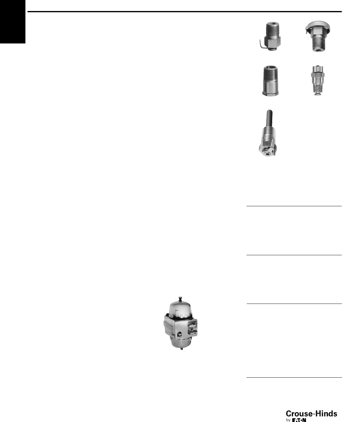
6F
158
www.crouse-hinds.com US: 1-866-764-5454 CAN: 1-800-265-0502 Copyright©2013 Eaton’s Crouse-Hinds Business
Drains and Breathers
Cl. I, Div. 1 & 2, Groups B, C, D
Cl. II, Div. 1, Groups E, F, G
Cl. II, Div. 2, Groups F, G
Cl. III
II 2 G Ex d IIB (ECD15)
II 2 G Ex d IIB + Hydrogen
(ECD Type 4X Series)
Explosionproof
Dust-Ignitionproof
Applications:
• ECD drains and breathers are installed in
enclosures or conduit systems to:
Provide ventilation to minimize condensation
Drain accumulated condensate
• At least one breather should be used with
each drain
• A breather is installed in top of enclosure or
upper section of conduit system
• A "standard" drain is installed in bottom of
enclosure or in lower section of conduit
system
• "Universal" breather or drain functions as a
breather when mounted at the top of an
enclosure, or as a drain when mounted in the
bottom of an enclosure
• "Combination" breather and drain is used in
those applications where the use of a top
mounted breather is not practical due to
limited space; or in offshore and marine
installations where moisture may enter the
enclosure through the breather located on top
of enclosure
• Drains and breathers are installed in hubs or
drilled and tapped openings
Features:
ECD284, ECD384, ECD385 and ECD15
"Universal" drains and breathers have:
• Patented labyrinth design, suitable for use in
Class I, Division 1 & 2, Groups C,D and Class
II, Division 1 & 2, Groups F,G areas
• Capability to pass 50 cc of water per minute
and 0.2 cubic feet or air per minute at
atmospheric pressure
• ECD15 and ECD385 each have a well inside
the inner, threaded end to provide for
accumulation of sediment without clogging
when used as a drain
"Standard" ECD drains and breathers have:
• Thread-in-thread design, suitable for use in
Class I, Division 1 & 2, Groups C,D; Class II,
Division 1, Groups E,F,G; Class II, Division 2,
Groups F,G and Class III areas
• ECD 11, 13 have capability to pass 25 cc of
water per minute and .05 cubic feet of air per
minute at atmospheric pressure
• ECD387 and ECD16 are a unique thread-in-
shaft design for use in Class I, Division 1 & 2,
Groups B,C,D; Class II, Division 1, Groups
E,F,G; Class II, Division 2, Groups F,G; Class
III areas. The ECD387 and ECD16 can pass
15cc of water per minute. The ECD16 can
pass .01 cubic feet of air per minute.
"Combination" ECD breather and drain:
• Provides ventilation to minimize condensation
and drains accumulated condensate – two
functions performed by a single device
installed in the bottom of an enclosure or
conduit system
• Have the capability to pass 25 cc of water
per minute and .10 cubic feet of air per
minute at atmospheric pressure
• Thread-in-thread and labyrinth design,
suitable for use in Class I, Division 1 & 2,
Groups C and D; Class II, Division 1 & 2,
Groups F and G; and Class III areas
Size Ranges:
•
1
/
4
" to
1
/
2
"
Ordering Information
ECD "Type 4X"
Drain and Breather
Size
Drain
Cat. #
Breather
Cat. #
3/8ECD38 N4D ECD38 N4B
1/2ECD1 N4D ECD1 N4B
ECD "Standard"
Drain and Breather
Size
Drain
Cat. #
Breather
Cat. #
1/4ECD281
3/8ECD387
1/2ECD11 ECD13
ECD "Universal"
Drain or Breather
Size Cat. #
1/4ECD284†
3/8ECD384†
3/8ECD385
1/2ECD15
1/2ECD16
†Shorter overall length than ECD15 and ECD385. For
use in confined spaces such as panelboard assemblies.
ECD "Combination"
Drain or Breather
Size Cat. #
1/2ECD18
ECD11 ECD13
ECD15 ECD16
ECD18
Standard Materials:
• ECD11, ECD15, ECD281, ECD284, ECD384,
ECD385 – stainless steel
• ECD13 – stainless steel with aluminum cap
• ECD16, ECD-N4D, ECD-N4B – stainless steel
• ECD387 – stainless steel
• ECD18 – stainless steel with neoprene tube
Certifications and
Compliances:
• NEC/CEC:
ECD 16, ECD387, ECD-N4D, ECD-N4B –
Class I, Division 1 & 2, Groups B, C, D
Class II, Division 1, Groups E, F, G
Class II, Division 2, Groups F, G
Class III
IP46 (ECD-N4D and ECD-N4B only)
IIB + Hydrogen (ECD-N4D and
ECD-N4B only)
ECD11, ECD13, ECD281 –
Class I, Division 1 & 2, Groups C, D
Class II, Division 1, Groups E, F, G
Class II, Division 2, Groups F, G
Class III
ECD18, ECD384, ECD15, ECD385 –
Class I, Division 1 & 2, Groups C, D
Class II, Division 1, Groups F, G
Class II, Division 2, Groups F, G
Class III
IP42 IIB (ECD 15 only)
ECD284 –
Class I, Division 1 & 2, Group C, D
Class II, Division 1, Groups F, G
Class II, Division 2, Groups F, G
• UL Standard: 1203
• CSA Standard: C22.2 No. 30
• Type 4X: ECD-N4D and ECD-N4B
• ATEX Certificate # ITS07ATEX15639U
Breather
Drain
Typical installation of drain and breather in
a combination motor starter
1. At least 5 full threads of drain or breather must be
engaged in matching female thread, taper-tapped in
accordance with NEMA/EEMAC Standard FB-1, Type
NTC or National Bureau of Standards Handbook H28,
Part II, Table 7.6.
2. These breathers and drains can be factory installed on
various explosion-proof equipment. See options on
applicable equipment pages for suffixes to be used.
6F
158-159.qxp 12/16/2013 12:38 PM Page 158
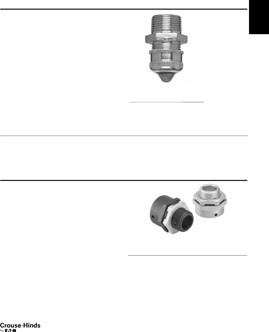
6F
159
www.crouse-hinds.com US: 1-866-764-5454 CAN: 1-800-265-0502 Copyright©2013 Eaton’s Crouse-Hinds Business
CD Series Ordinary Location Drain
Straight Body • Male Thread
Applications:
CD Series drains are for use in conduit systems to:
• Drain accumulated condensate.
• Provide ventilation to minimize condensation.
Drains are installed in hubs or drilled and tapped openings.
Standard Materials:
• CD bodies and nuts – steel or aluminum
• CD screen – stainless steel
Standard Finishes:
• Steel – electrogalvanized with chromate treatment.
Certifications and Compliances:
• UL Standard 514B
Options:
Description Suffix
Copper-free aluminum construction
SA
Ordering Information
Size Cat. #
1/2CD1
3/4CD2
NEMA 4X Breather/Drain
ATEX and CENELEC Range
I M2 II 2GD, E Exe I & II
(Stainless Steel & Brass only)
II 2GD, E Exe II (Nylon version)
CSA Class I, Division 2, Groups
A, B, C & D, Exe II
Enclosure Type 4X
IP66
Certifications and Compliances:
• SIRA 99 ATEX 3050U
• I M2 II 2GD, E Exe I & II (Stainless Steel & Brass only)
• II 2GD, E Exe II (Nylon only)
• CSA Class I, Division 2, Groups A, B, C & D, Exe II
• Enclosure Type 4X
•IP66
Operating Temperature:
• –50°C to +85°C
Applications:
For use in enclosures to provide a method to effectively drain
moisture while allowing the enclosure to breathe.
Features:
All NEMA 4X breather/drains offer:
• Castellated locknuts that allow moisture to pass between the
enclosure and the locknut to the drain holes in the fitting
.
• Available in brass, stainless steel (Type 316) or 30% glass filled nylon.
• Captive "O" ring on recess of the face of the breather/drain to
optimize ingress protection.
• ATEX and CSA Certified for worldwide market acceptance.
• Available with metric or NPT threads.
Ordering Information
Entry
Method Material Cat. #
M20 Brass ACDPEB/M20/15
M20 Stainless Steel ACDPES/M20/15
M20 Nylon ACDPEN/M20/15
M25 Brass ACDPEB/M25/15
M25 Stainless Steel ACDPES/M25/15
M25 Nylon ACDPEN/M25/15
1/2" Brass ACDPEB/050NPT/15
1/2" Stainless Steel ACDPES/050NPT/15
3/4" Brass ACDPEB/075NPT/15
3/4" Stainless Steel ACDPES/075NPT/15
6F
158-159.qxp 12/16/2013 12:38 PM Page 159

6F
160
www.crouse-hinds.com US: 1-866-764-5454 CAN: 1-800-265-0502 Copyright©2013 Eaton’s Crouse-Hinds Business
6F
160.qxp 12/16/2013 12:40 PM Page 160
