Volume 1 Tab 1000450789 Catalog
1000443241-Catalog 1000443241-Catalog 1000443241-Catalog B4 unilog cesco-content
2016-09-04
: Pdf 1000450789-Catalog 1 1000450789-Catalog_1 B4 unilog
Open the PDF directly: View PDF ![]() .
.
Page Count: 44

Volume 1—Residential and Light Commercial CA08100002E—April 2015 www.eaton.com V1-T1-45
1
1
1
1
1
1
1
1
1
1
1
1
1
1
1
1
1
1
1
1
1
1
1
1
1
1
1
1
1
1
1.2
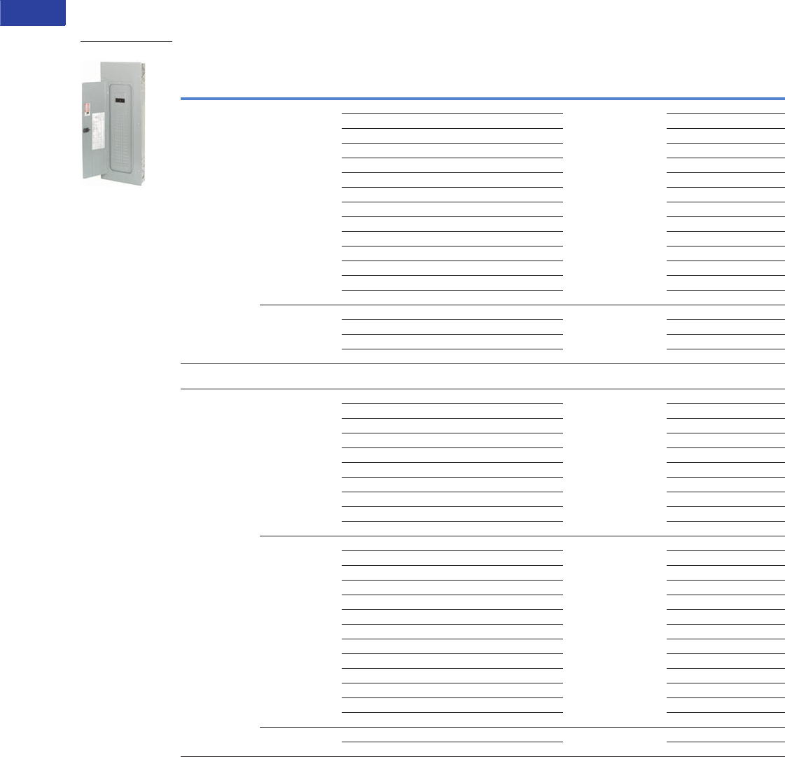
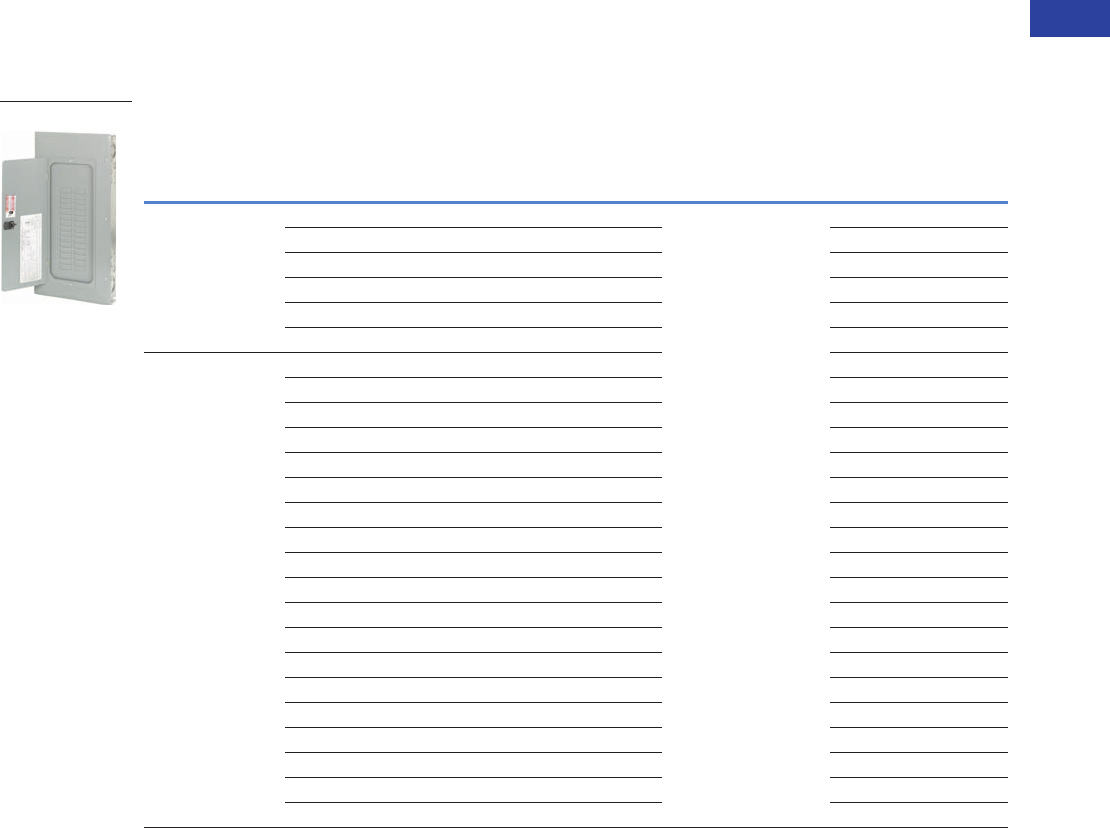
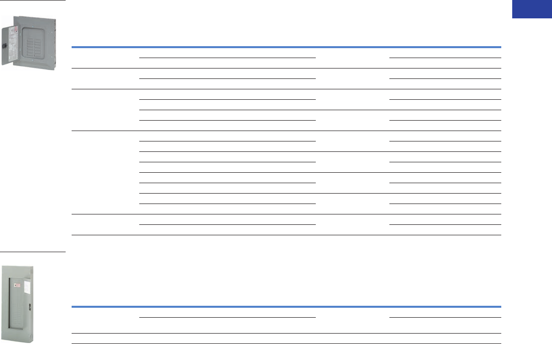
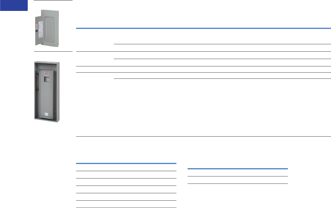
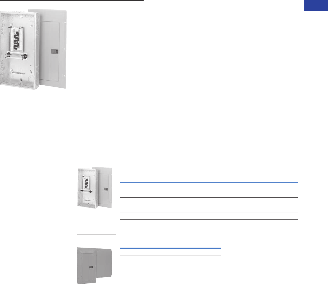
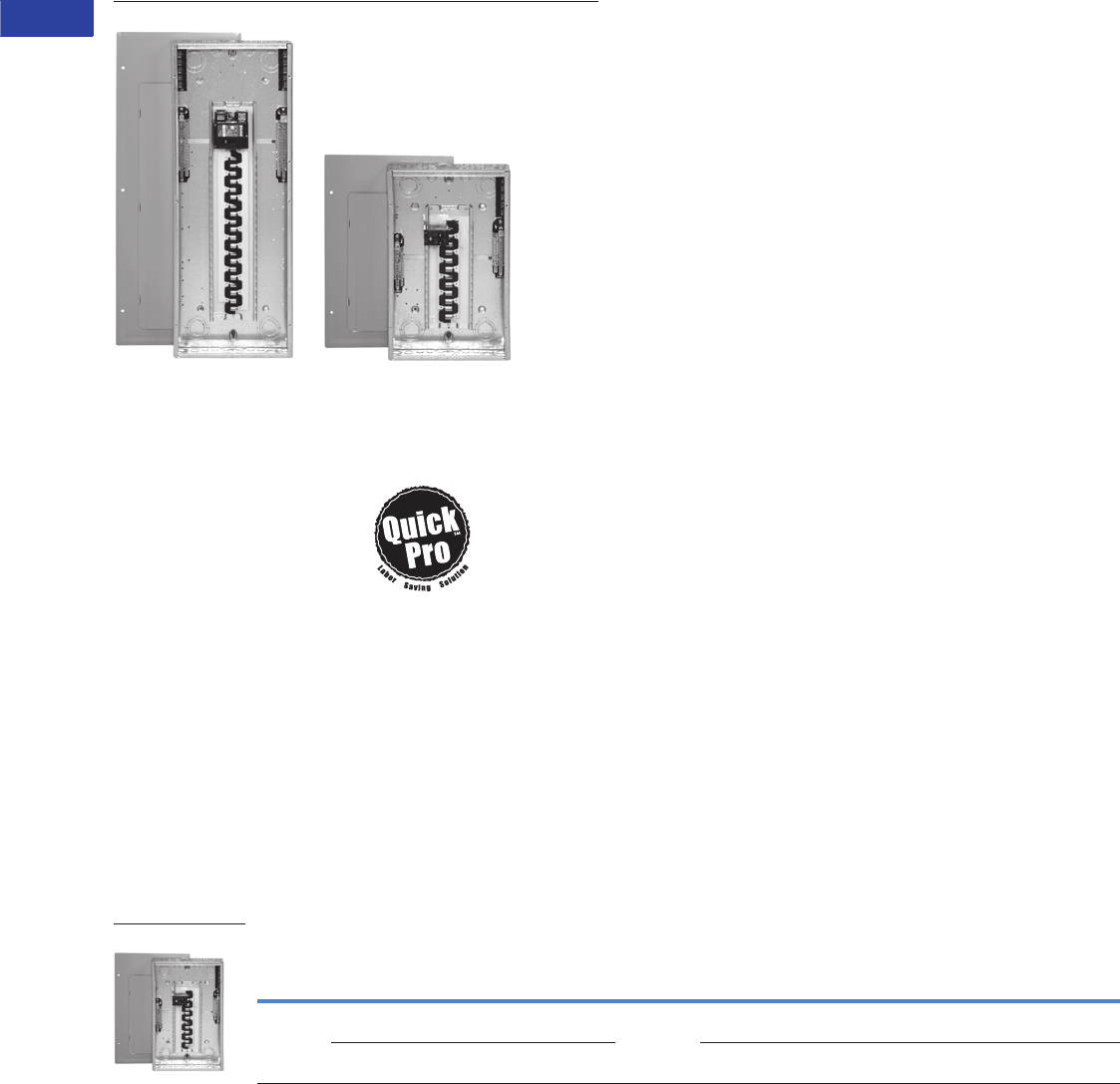
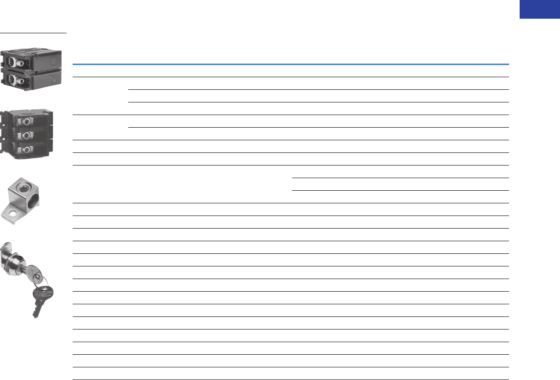
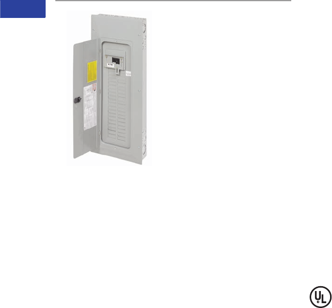
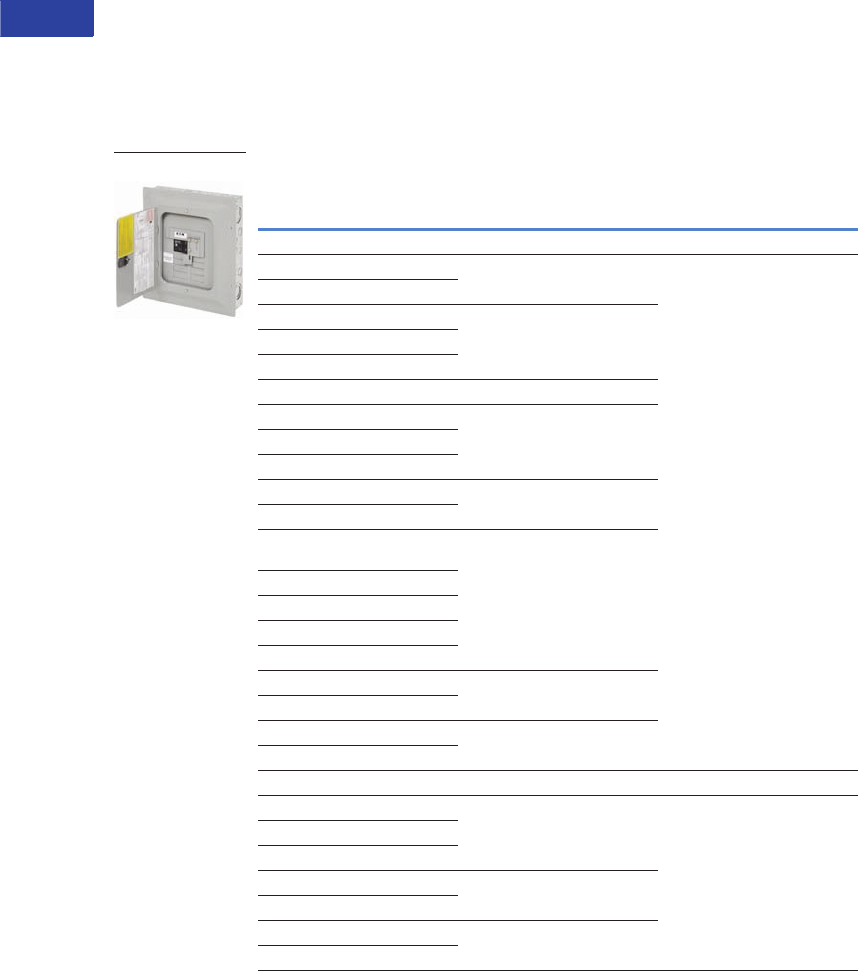
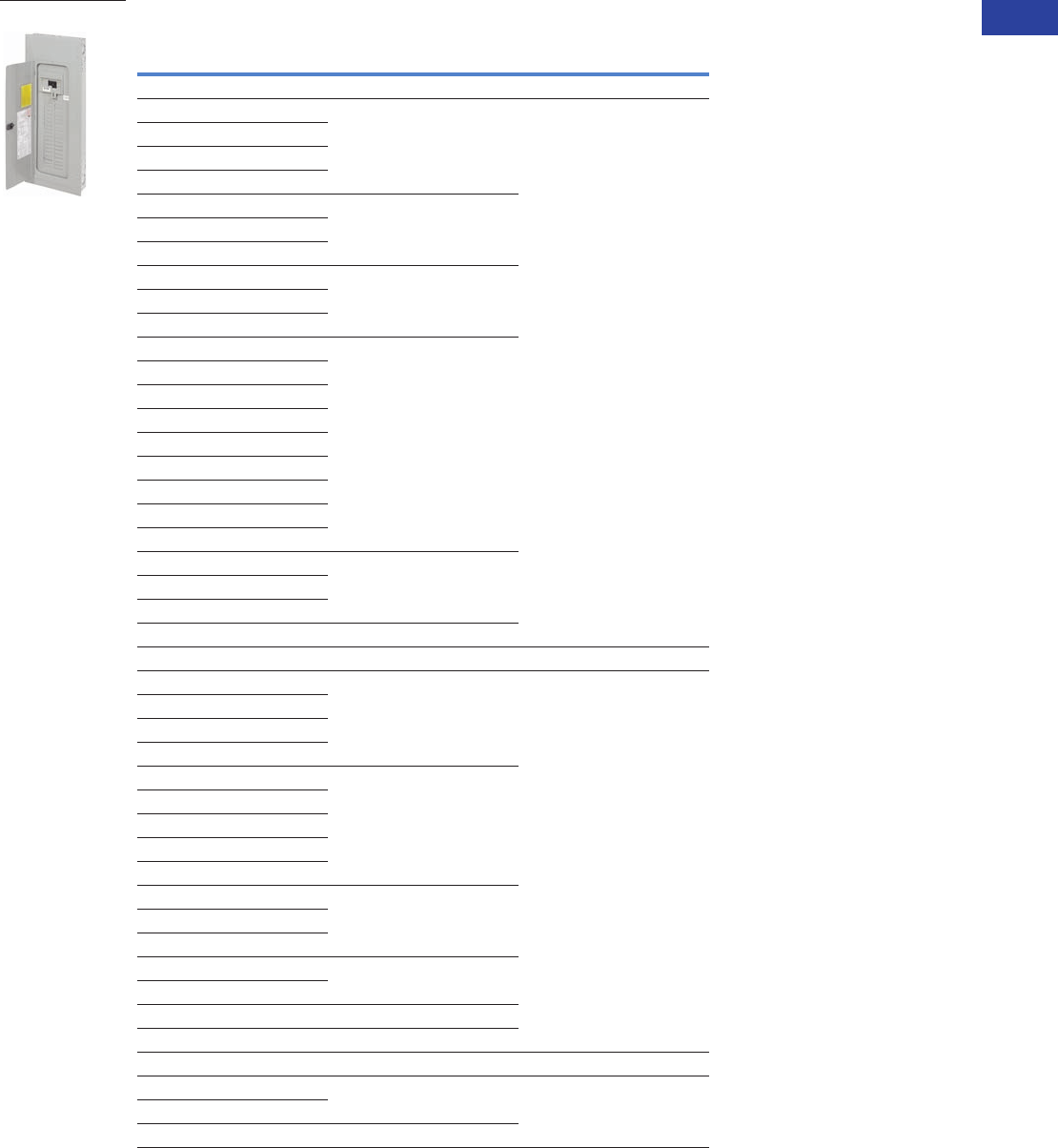
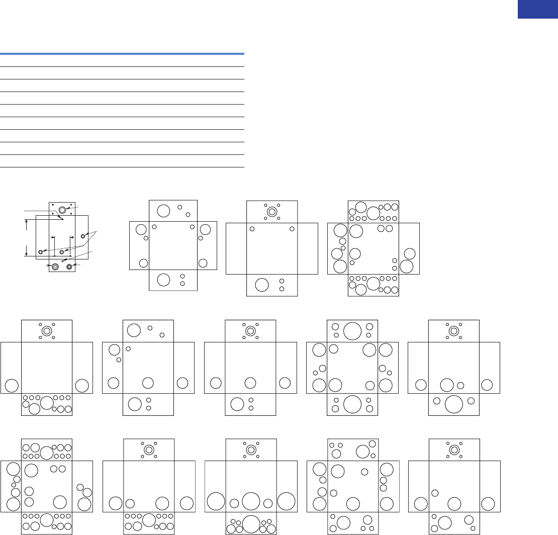
Loadcenters and Circuit Breakers
Type BR Loadcenters and Circuit Breakers
Standards and Certifications
UL Listings
All Eaton Type BR loadcenters
are listed under UL File
E52977 except the
2–8 circuit loadcenters,
up through and including
125 A, which are listed under
UL File E8741.
Catalog Number Selection
Single- and Three-Phase Through 600 A
Note
1No character space used.
3BR 30 42 B C 200
Phase
Blank = Single-phase 1
3= Three-phase
Construction
Blank = No feed thru lugs 1
F= Feed-through lugs
G= Ground bar
P= Current design
NY = NY City gutter space
Number of 1-Inch
(25.4 mm) Spaces
Factory Options
SUR = Factory integrated surge
Eaton’s Type BR
Loadcenter
Maximum Number
of Circuits
Bus
Blank = Aluminum bus 1
C= Copper bus
Main Device
B= Main breaker
L= Main lug
N= Convertible main
H= Main breaker high AIC
Enclosure
R= NEMA Type 3R rainproof
S= NEMA Type 1 indoor with
surface trim
F= NEMA Type 1 indoor with
flush trim
Blank = NEMA Type 1 indoor with
combination trim 1
RIS = Riser panel
Amperes
50 = 50 A
70 = 70 A
100 = 100 A
125 = 125 A
150 = 150 A
200 = 200 A
225 = 225 A
300 = 300 A
400 = 400 A
600 = 600 A
V1-T1-46 Volume 1—Residential and Light Commercial CA08100002E—April 2015 www.eaton.com
1
1
1
1
1
1
1
1
1
1
1
1
1
1
1
1
1
1
1
1
1
1
1
1
1
1
1
1
1
1
1.2
Loadcenters and Circuit Breakers
Type BR Loadcenters and Circuit Breakers
Product Selection
Single-Phase—Main Circuit Breaker Loadcenters—10/25 kAIC
Single-Phase Three-Wire—120/240 Vac—Insulated/Bondable Split Neutral
Notes
1 Combination style covers may be used in surface or flush applications.
2 Wire range size for BR1020B100SP is #6–#1 Cu/Al.
3 Includes through-feed lugs for both phase and neutral conductors.
4 Rainproof panels are furnished with hub closure plates. For rainproof hubs, refer to Page V1-T1-66.
5 22 kAIC series combination rating is obtained when Types BD, BR, BQ, BQC and GFCB 10 kAIC branch breakers are used in series with Type BRH main breaker.
6 25 kAIC series combination rating is obtained when Types BD, BR, BQ, BQC and GFCB 10 kAIC branch circuit breakers are used in series with Type CSR main breaker.
7 Supplied with adapter plate to use DS Group1 hubs on Page V1-T1-66. If 2.50-inch (63.5 mm) hub is needed, remove adapter and use ARP00007CH25 hub.
8 Neutral is bonded—suitable for service entrance only—cannot be converted for sub-feed application.
9 Add G to the end of the catalog number for factory-installed GBK2120 ground bar.
All main circuit breaker loadcenters are listed for use as service entrance equipment and are shipped with neutral bonding strap preattached. The maximum rating of the
panel is the main circuit breaker rating when used as service entrance equipment. Ground bar kits priced separately. See Page V1-T1-66.
Main
Breaker Type
Main
Ampere Rating
Maximum Number
1-Inch (25.4 mm) Enclosure
Type
Box
Size
Wire Size Range
Cu/Al 60 °C or 75 °C
for Main Breaker
Loadcenter Catalog Number
with Combination 1 or
NEMA Type 3R CoverSpaces Circuits
BR
10 kAIC
100 8 16 Indoor B1 #4–1/0 2BR816B100
10 20 Indoor A1 BR1020B100S11
10 20 Indoor A1 BR1020B100F11
10 20 Outdoor B2R BR1020B100RF 34
12 12 Indoor B2 BR1212B100
12 20 Indoor B2 BR1220B100
12 24 Outdoor B2R BR1224B100R 4
16 16 Indoor C1 BR1616B100
16 20 Indoor C1 BR1620B100
16 24 Outdoor C1R BR1624B100R 4
20 24 Outdoor C3R BR2024B100R 4
20 20 Indoor C2 BR2020B100
16 24 Indoor C1 BR1624B100
30 30 Indoor D1 BR3030B100
125 16 24 Indoor C1 #4–2/0 BR1624B125
20 24 Indoor C1 BR2024B125
20 24 Outdoor C3R BR2024B125R 4
30 30 Indoor D1 BR3030B125
BRH 5
22 kAIC
100 20 24 Indoor C2 #4–1/0 BR2024H100 5
CSR 6
25 kAIC
150 8 16 Outdoor C3R #2–300 kcmil BR816B150RF 34
16 30 Indoor C4 BR1630B150
20 30 Indoor C4 BR2030B150
20 30 Outdoor D1R BR2030B150R 4
20 40 Indoor D1 BR2040B150
20 40 Outdoor D1R BR2040B150R 4
24 30 Indoor G1 BR2430B150
30 30 Outdoor G1R BR3030B150R 4
30 30 Indoor G1 BR3030B150
30 40 Indoor G1 BR3040B150
200 4 8 Outdoor 8R #2–300 kcmil BR48B200RF 378
8 16 Outdoor C3R BR816B200RF 34
16 32 Indoor C4 BR1632B200
20 40 Outdoor D1R BR2040B200R 4
20 40 Indoor D1 BR2040B200
24 40 Indoor G1 BR2440B200
30 40 Outdoor G1R BR3040B200R 4
30 40 Indoor G1 BR3040B200 9
40 40 Outdoor L1R BR4040B200R 4
40 40 Indoor L1 BR4040B200
40 50 Indoor L1 BR4050B200
60 120 Indoor L3 BR60120B200
60 120 Outdoor L3R BR60120B200R
225 42 42 Indoor L2 #1–250 kcmil BR4242B225
42 42 Outdoor L2R BR4242B225R 4
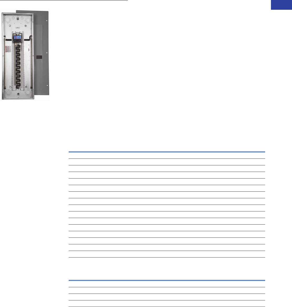
BR4040B200
Volume 1—Residential and Light Commercial CA08100002E—April 2015 www.eaton.com V1-T1-47
1
1
1
1
1
1
1
1
1
1
1
1
1
1
1
1
1
1
1
1
1
1
1
1
1
1
1
1
1
1
1.2
Loadcenters and Circuit Breakers
Type BR Loadcenters and Circuit Breakers
Main Circuit Breaker Loadcenters—10/22 kAIC
Single-Phase Three-Wire—120/240 Vac—Insulated/Bondable Split Neutral
Notes
1 Ground bar kits priced separately. See Page V1-T1-66.
2 The maximum rating of the panel is the main circuit breaker rating when used as service entrance equipment.
3 Door lock and key included with loadcenter.
4 Type DK main circuit breaker is rated 65 kAIC at 240 Vac and allows a 22 kAIC series rating on the panel when Types BR, BD and BJ branch circuit breakers are used.
5 Rainproof panels are furnished with hub closure plates. For rainproof hubs, refer to Page V1-T1-66.
6 Type HLD main circuit breaker is rated 65 kAIC at 240 Vac. Type HLD circuit breaker is not series rated with Types BR, BD and BJ branch circuit breakers.
Box sizes Pages V1-T1-67 through V1-T1-70.
Please contact the Lincoln Flex Center for any configurations not listed.
Main
Breaker
Type
Main
Ampere
Rating
Maximum Number
1-Inch (25.4 mm)
Enclosure
Type
Box
Size
Wire Size Range
Cu/Al 60 °C or 75 °C
for Main Breaker
Commercial Loadcenter
Catalog Number 123
Spaces Circuits
With Flush or
NEMA Type 3R Cover
With
Surface Cover
DK 4300 42 42 Indoor 24 (2) #3/0–250 kcmil BR4242B300F BR4242B300S
400 42 42 Indoor 24 (2) #3/0–250 kcmil BR4242B400F BR4242B400S
42 42 Outdoor 47 (2) #3/0–250 kcmil BR4242B400R 5—
HLD 6600 42 42 Indoor 24 (2) #3/0–500 kcmil — BR4242B600S
B4242DFN
V1-T1-48 Volume 1—Residential and Light Commercial CA08100002E—April 2015 www.eaton.com
1
1
1
1
1
1
1
1
1
1
1
1
1
1
1
1
1
1
1
1
1
1
1
1
1
1
1
1
1
1
1.2
Loadcenters and Circuit Breakers
Type BR Loadcenters and Circuit Breakers
Single-Phase—Main Lug Loadcenters
Single-Phase Three-Wire—120/240 Vac—Insulated/Bondable Split Neutral
Notes
1 Ground bar kits priced separately. See Page V1-T1-66.
– For 2/4 circuit loadcenters, use GBK5 or GBK520 ground bar.
– For 4/8, 6/12 and 8/16 circuit loadcenters, use GBK10 ground bar.
– Ground bars mount to the left side wall of the enclosure for the 4/8, 6/12 and 8/16 circuit loadcenters.
2 Suitable for use as service equipment when not more than two service disconnecting mains are provided or when not used as a lighting and appliance panelboard
(see Article 408.34 of the NEC).
3 Ground bar GBK5 is installed.
4 Rainproof panels are furnished with hub closure plates. For rainproof hubs, refer to Page V1-T1-66.
5 CSA and UL approved.
6 Neutral/ground holes (6) #14–6 and (3) #14–2/0 AWG Cu/Al.
7 For use as service entrance applications only.
8 Neutral/ground holes (6) #14–6 and (3) #14–1/0 AWG Cu/Al.
9
Suitable for use as service equipment when not more than two service disconnecting mains are provided or when not more than six service disconnecting mains are provided and
when not used as a lighting and appliance panelboard (see Article 408.34 of the NEC).
jSuitable for use as service equipment when a main breaker is used or when not more than six service disconnecting mains are provided and when not used
as a lighting and appliance panelboard (see Article 408.34 of the NEC).
kGround bar GBK10 is installed.
lGround bar GBK14 is installed.
Box sizes Pages V1-T1-67 through V1-T1-70.
Main
Ampere Rating
Maximum Number
1-Inch (25.4 mm) Enclosure
Type Trim Type
Box
Size
Wire Size Range
Cu/Al 60 °C or 75 °C
for Main Lugs
Loadcenter
Catalog NumberSpaces Circuits
70 2 4 Indoor Surface (no door) 5 #8–#2 BR24L70SP 12
2 4 Indoor Surface (no door) 5 BR24L70SGP 23
2 4 Outdoor — 5R BR24L70RP 124
2 4 Indoor Flush (no door) 5 BR24L70FP 12
2 4 Indoor Flush (no door) 5 BR24L70FGP 25
125 2 4 Indoor Surface (no door) 6 #14–1/0 BR24L125SP 12
2 4 Outdoor — 6R BR24L125RP 124
2 4 Outdoor — 6R BR24L125RSEP 278
2 4 Outdoor — 6R BR24L125RSE2P 267
2 4 Indoor Flush (no door) 6 BR24L125FP 12
4 8 Indoor Surface (no door) 7 #14–1/0 BR48L125SP 19
4 8 Indoor Surface (no door) 7 BR48L125SGP 39
4 8 Outdoor — 7R BR48L125RP 149
4 8 Indoor Flush (no door) 7 BR48L125FP 19
4 8 Indoor Flush (with door) 7 BR48L125FDP 19
4 8 Indoor Flush (no door) 7 BR48L125FGP 39
6 12 Indoor Surface (no door) 7 #14–#1 BR612L125SP 1j
6 12 Indoor Surface (no door) 7 BR612L125SGP jk
6 12 Indoor Surface (with door) 7 BR612L125SDP 1j
6 12 Indoor Surface (with door) 7 BR612L125SDGP jk
6 12 Outdoor — 7R BR612L125RP 14j
6 12 Indoor Flush (no door) 7 BR612L125FP 1j
6 12 Indoor Flush (no door) 7 BR612L125FGP 5jk
6 12 Indoor Flush (with door) 7 BR612L125FDP j
6 12 Indoor Flush (with door) 7 BR612L125FDGP 5jk
8 16 Indoor Surface (no door) 7 #14–#1 BR816L125SP 1j
8 16 Indoor Surface (no door) 7 BR816L125SGP jl
8 16 Indoor Surface (with door) 7 BR816L125SDP 1j
8 16 Indoor Surface (with door) 7 BR816L125SDGP jl
8 16 Outdoor — 7R BR816L125RP 14j
8 16 Indoor Flush (no door) 7 BR816L125FP 1j
8 16 Indoor Flush (no door) 7 BR816L125FGP 5jl
8 16 Indoor Flush (with door) 7 BR816L125FDP 1j
8 16 Indoor Flush (with door) 7 BR816L125FDGP 5jl
Surface Outdoor
Flush Outdoor
Surface (No Door)
Flush (No Door)
Outdoor
Volume 1—Residential and Light Commercial CA08100002E—April 2015 www.eaton.com V1-T1-49
1
1
1
1
1
1
1
1
1
1
1
1
1
1
1
1
1
1
1
1
1
1
1
1
1
1
1
1
1
1
1.2
Loadcenters and Circuit Breakers
Type BR Loadcenters and Circuit Breakers
Single-Phase—Main Lug Loadcenters
Single-Phase Three-Wire—120/240 Vac—Insulated/Bondable Split Neutral, continued
Notes
1 Ground bar kits priced separately unless otherwise noted. See Page V1-T1-66.
2 Has notch for BREQS125 hold-down kit.
3 Single, movable neutral is provided.
4 Combination cover style.
5 Suitable for use as service equipment when not more than six main disconnecting means are provided and when not used as a lighting and appliance panelboard
(see Article 408.34 of the NEC).
6 Ground bars GBK5 and GBK520 installed.
7 Rainproof panels are furnished with hub closure plates. For rainproof hubs, refer to Page V1-T1-66.
8 Ground bar GBK1220 installed.
9 Has notch for BRHDK125 hold-down kit.
jIncludes through-feed lugs for both phase and neutral conductors.
kIncludes main lugs. Loadcenters can convert to main breaker using kit.
Main
Ampere Rating
Maximum Number
1-Inch (25.4 mm) Enclosure
Type
Box
Size
Wire Size Range
Cu/Al 60 °C or 75 °C
for Main Lugs
Loadcenter Catalog Number
with Combination or
NEMA Type 3R Cover 1
Spaces Circuits
125 12 12 Indoor B1 #6–2/0 BR1212L125 2345
12 24 Indoor B1 BR1224L125 245
12 24 Indoor B1 BR1224L125G 245
12 24 Indoor B1 BR1224L125DG 2456
12 24 Outdoor B1R BR1224L125R 257
16 16 Indoor B2 BR1616L125 245
16 24 Indoor B2 BR1624L125 24
16 24 Indoor B2 BR1624L125G 24
16 24 Outdoor B2R BR1624L125R 27
20 20 Indoor C1 BR2020L125 245
20 24 Indoor C1 BR2024L125 24
20 24 Indoor C1 BR2024L125G 248
20 24 Outdoor C1R BR2024L125R 27
24 24 Indoor C2 BR2424L125 24
24 24 Indoor C2 BR2424L125G 248
30 42 Indoor D1 BR3042L125 24
150 16 30 Indoor C2 #1–300 kcmil BR1630L150 49
20 30 Indoor C2 BR2030L150 49
200 8 16 Outdoor B2R #1–300 kcmil BR816L200RF 57j
12 24 Indoor B2 BR1224L200 459
12 24 Outdoor B2R BR1224L200R 579
20 40 Indoor C2 BR2040L200 49
20 40 Indoor C2 BR2040L200G 489
20 40 Outdoor C3R BR2040L200R 79
24 40 Indoor C4 BR2440L200 49
30 40 Indoor D1 BR3040L200 49
30 40 Indoor D1 BR3040L200G 489
30 40 Outdoor D1R BR3040L200R 79
40 40 Indoor G1 BR4040L200 49
40 40 Indoor G1 BR4040L200G 49
40 40 Outdoor G1R BR4040L200R 79
60 120 Indoor L3 BR60120L200 k
225 42 42 Indoor L1 #1–300 kcmil BR4242L225 4
42 42 Outdoor L1R BR4242L225R 7
BR1224L125
BR1224L200

V1-T1-50 Volume 1—Residential and Light Commercial CA08100002E—April 2015 www.eaton.com
1
1
1
1
1
1
1
1
1
1
1
1
1
1
1
1
1
1
1
1
1
1
1
1
1
1
1
1
1
1
1.2
Loadcenters and Circuit Breakers
Type BR Loadcenters and Circuit Breakers
Single-Phase—Main Lug Loadcenters—400 and 600 A
Single-Phase Three-Wire—120/240 Vac—Insulated/Bondable Split Neutral
Notes
1 Ground bar kits priced separately unless otherwise noted. See Page V1-T1-66.
2 Has notch for BRHDK125 hold-down kit.
3 Ground bar GBK8 installed.
4 Rainproof panels are furnished with hub closure plates. For rainproof hubs, refer to Page V1-T1-66.
5 Suitable for use as service equipment when not more than six main disconnecting means are provided and when not used as a lighting and appliance panelboard
(see Article 408.34 of the NEC).
Main
Ampere Rating
Maximum Number
1-Inch (25.4 mm)
Enclosure
Type
Box
Size
Wire Size Range
Cu/Al 60 °C or 75 °C
for Main Lugs
Commercial Loadcenter
Catalog Number 123
Spaces Circuits
With Flush or NEMA
Type 3R Cover
With Surface
Cover
400 12 24 Outdoor 42 (2) #3/0–400 kcmil BR1224L400R 45 —
42 42 Indoor 22 BR4242L400F BR4242L400S
42 42 Outdoor 46 BR4242L400R 4—
600 42 42 Indoor 22 (2) #2–500 kcmil — BR4242L600S
4242DFN
Volume 1—Residential and Light Commercial CA08100002E—April 2015 www.eaton.com V1-T1-51
1
1
1
1
1
1
1
1
1
1
1
1
1
1
1
1
1
1
1
1
1
1
1
1
1
1
1
1
1
1
1.2
Loadcenters and Circuit Breakers
Type BR Loadcenters and Circuit Breakers
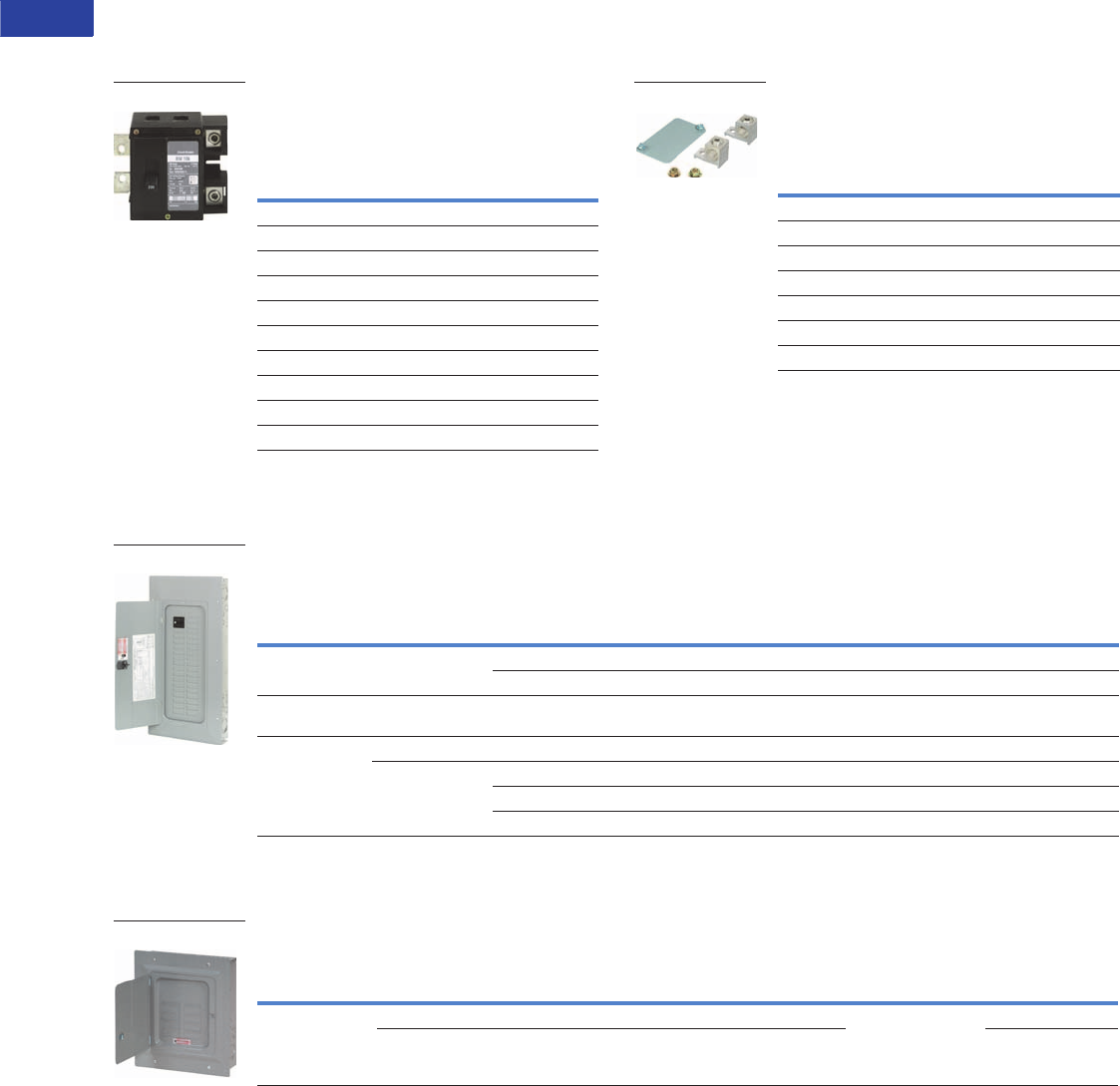
Convertible Loadcenters MCB or MLO—Base Units and Main Devices 10/22/25 kAIC,
Complete Assembly Consists of: Loadcenter and Either Main Breaker Kit or Main Lug Kit
Note: Interrupting rating depends on main circuit breaker selected.
Base Units—Single-Phase Three-Wire—120/240 Vac—Insulated/Bondable Split Neutral
(Unless Otherwise Noted)
Notes
1 The maximum rating of the loadcenter is the main circuit breaker rating when used as service entrance equipment.
2 100, 125 and 200 A convertible base unit catalog numbers include interior, box and cover only. Main devices and accessories must be ordered separately for field
installation. All convertible base units are listed as suitable for use as service entrance equipment when used per Article 384 of the NEC.
3 Ground bar kits priced separately except as noted, refer to Page V1-T1-66.
4 For main breaker, use Type BR. For main lug use Type BRSF.
5 BREQS125 hold-down screw comes with loadcenter for back-fed Types BR and BRH main circuit breakers.
6 Convertible to maximum of 100 A main circuit breaker and 125 A main lug.
7 Rainproof loadcenters are furnished with hub closure plates. For rainproof hubs, refer to Page V1-T1-66.
8 For main breaker, use Type BW or CSR. For main lug, use Type BRL.
9 Includes through-feed lugs for both phase and neutral conductors.
jNo hold-down provisions for back-fed Types BR and BRH main circuit breakers.
kInsulated/bondable single neutral.
lIncludes GBK2120 ground bar.
Main
Ampere Rating 1
Maximum Number
1-Inch (25.4 mm) Enclosure
Type
Box
Size
Wire Size Range
Cu/Al 60 °C or 75 °C
for Main
Loadcenter Catalog Number
With Combination or NEMA
Type 3R Cover 23
Spaces Circuits
125 412 24 Indoor B2 See main breaker and
main lug kit tables
Page V1-T1-54.
BR1224N125 56
12 24 Outdoor B2R BR1224N125R 567
16 24 Indoor C1 BR1624N125 5
16 24 Outdoor C1R BR1624N125R 57
20 24 Indoor C2 BR2024N125 5
20 24 Outdoor C3R BR2024N125R 57
200 8 8 16 Outdoor C3R BR816N200RF 79jk
12 24 Indoor C4 BR1224N200 j
12 24 Outdoor C3R BR1224N200R 7j
16 32 Indoor C4 BR1632N200 j
20 40 Indoor D1 BR2040N200 j
20 40 Indoor D1 BR2040N200G l
20 40 Outdoor D1R BR2040N200R 7j
20 40 Outdoor D1R BR2040N200RG l
24 40 Indoor G1 BR2440N200 7j
30 40 Indoor G1 BR3040N200 j
30 40 Indoor G1 BR3040N200G l
30 40 Outdoor G1R BR3040N200R 7j
30 40 Outdoor G1R BR3040N200RG l
40 40 Indoor L1 BR4040N200 j
40 40 Indoor L1 BR4040N200G l
40 40 Outdoor L1R BR4040N200R 7j
40 40 Outdoor L1R BR4040N200RG l
40 50 Indoor L1 BR4050N200
40 50 Outdoor L1R BR4050N200R
BR3040N200
V1-T1-52 Volume 1—Residential and Light Commercial CA08100002E—April 2015 www.eaton.com
1
1
1
1
1
1
1
1
1
1
1
1
1
1
1
1
1
1
1
1
1
1
1
1
1
1
1
1
1
1
1.2
Loadcenters and Circuit Breakers
Type BR Loadcenters and Circuit Breakers
Convertible Loadcenters MCB or MLO—Base Units and Main Devices 10/22/25 kAIC,
Complete Assembly Consists of: Loadcenter and Either Main Breaker Kit or Main Lug Kit
Note: Interrupting rating depends on main circuit breaker selected.
Main Devices—Two- and Three-Pole
Main Circuit Breakers—120/240 Vac or
208Y/120 Vac or 240 Vac
Main Devices—Two- and Three-Pole
Main Lug Kits—120/240 Vac or
208Y/120 Vac or 240 Vac
Main Circuit Breaker with Accessory
Example: BW22005R01 (Put description with catalog number on
order. See Page V1-T1-87.)
Main Circuit Breaker Loadcenters—Copper Bus 10/22/25 kAIC
Main Circuit Breaker Loadcenters—With Copper Bus—Single-Phase Three-Wire—120/240 Vac—
Insulated/Bondable Split Neutral
Main Lug Only Loadcenters—Copper Bus
Single-Phase Three-Wire—120/240 Vac—Insulated/Bondable Single Neutral with Copper Bus
Notes
1 Series combination rating with Types BD, BR, BQ, BQC and GFCB is 22 kAIC with BRH main and 25 kAIC with CSR main.
2 All main circuit breaker loadcenters are listed for use as service entrance equipment and are shipped with neutral bonding strap preattached. The maximum rating of the
panel is the main circuit breaker rating when used as service entrance equipment.
3 Ground bar kits priced separately. See Page V1-T1-66.
4 22 kAIC series combination rating is obtained when Types BD, BR, BQ, BQC and GFCB 10 kAIC branch breakers are used in series with Type BRH main breaker.
Box sizes Pages V1-T1-67 through V1-T1-70.
Ampere
Rating
Wire Size Range
Cu/Al 60 °C or 75 °C
for Main Breaker
10 kAIC 22/25 kAIC
Catalog
Number
Catalog
Number 1
Tw o - Po l e
100 #4–1/0 BR2100 BRH2100
110 #4–1/0 BR2110 BRH2110
125 #4–2/0 BR2125 BRH2125
125 #2–300 kcmil BW2125 CSR2125N
150 #2–300 kcmil BW2150 CSR2150N
175 #2–300 kcmil BW2175 CSR2175N
200 #2–300 kcmil BW2200 CSR2200N
Three-Pole
100 #1 BR3100 BRH3100
BW2200
Ampere
Rating
Wire Size Range
Cu/Al 60 °C or 75 °C
for Main Lugs
Catalog
Number
Tw o - P o l e
125 #6–2/0 BRSF125
150 #1–300 kcmil BRL200
175 #1–300 kcmil BRL200
200 #1–300 kcmil BRL200
Three-Pole
150 #6–3/0 3BRSF150
BRL200
Main
Breaker Type
Main
Ampere Rating
Maximum Number
1-Inch (25.4 mm) Enclosure
Type
Box
Size
Wire Size Range
Cu/Al 60 °C or 75 °C
for Main Breaker
Loadcenter Catalog Number
with Combination Cover 23
Spaces Circuits
BR
10 kAIC
100 20 20 Indoor C2 #4–1/0 BR2020BC100
30 30 Indoor D1 #4–1/0 BR3030BC100
BRH
22 kAIC 4
100 30 30 Indoor D1 #4–1/0 BR3030HC100
CSR
25 kAIC
150 30 30 Indoor G1 #2–300 kcmil BR3030BC150
200 20 40 Indoor D1 #2–300 kcmil BR2040BC200
30 40 Indoor G1 #2–300 kcmil BR3040BC200
40 40 Indoor L1 #2–300 kcmil BR4040BC200
Main
Ampere Rating
Maximum Number
1-Inch (25.4 mm) Enclosure
Type Trim Type
Box
Size
Wire Size Range
Cu/Al 60 °C or 75 °C
for Main Lugs
Loadcenter
Catalog NumberSpaces Circuits
125 8 16 Indoor Surface (with door) 7 #14–1 BR816LC125SDP
8 16 Indoor Flush (with door) 7 BR816LC125FDP
BR3030BC100
BR816LC125FDP
Volume 1—Residential and Light Commercial CA08100002E—April 2015 www.eaton.com V1-T1-53
1
1
1
1
1
1
1
1
1
1
1
1
1
1
1
1
1
1
1
1
1
1
1
1
1
1
1
1
1
1
1.2
Loadcenters and Circuit Breakers
Type BR Loadcenters and Circuit Breakers
Convertible Loadcenters—Copper Bus 10/22/25 kAIC
Convertible—Single-Phase, Three-Wire—120/240 Vac—Insulated/Bondable Split Neutral
Notes
1 100, 125 and 200 A convertible base unit catalog numbers include interior, box and cover only. Main devices and accessories must be ordered separately for field
installation. All convertible base units are listed as suitable for use as service entrance equipment when used per Article 384 of the NEC.
2 Ground bar kits priced separately, refer to Page V1-T1-66.
3 All main circuit breaker loadcenters are listed for use as service entrance equipment and are shipped with a neutral bonding strap preattached. The maximum main
rating of the loadcenter is the main breaker rating when used as service entrance equipment.
4 Interrupting rating depends on main circuit breaker selected. See Page V1-T1-66 for mains.
5 For main breaker, use Type BW or CSR. For main lug, use Type BRL.
6 Rainproof loadcenters are furnished with hub closure plates. For rainproof hubs, refer to Page V1-T1-66.
7 Hold-down screw BREQS125 comes with loadcenter for back-fed Types BR and BRH main circuit breakers.
8 For main breaker, use Type BR. For main lug, use Type BRSF.
9 Suitable for use as service equipment when not more than six main disconnecting means are provided and when not used as a lighting and appliance panelboard.
(see Article 408.34 of the NEC).
Main
Ampere Rating
Maximum Number
1-Inch (25.4 mm) Enclosure
Type
Box
Size
Wire Size Range
Cu/Al 60 °C or 75 °C
for Main
Loadcenter Catalog Number
(With Combination or
NEMA Type 3R Cover) 123
Spaces Circuits
125
10/22 kAIC 45
12 24 Indoor B2 See main breaker
and main lug kit tables
on Page V1-T1-54.
BR1224NC125 67
12 24 Outdoor B2R BR1224NC125R 678
20 24 Indoor C2 BR2024NC125 7
20 24 Outdoor C3R BR2024NC125R 78
200
10/25 kAIC 49
20 40 Indoor D1 BR2040NC200
20 40 Outdoor D1R BR2040NC200R 8
30 40 Indoor G1 BR3040NC200
30 40 Outdoor G1R BR3040NC200R 8
40 40 Indoor L1 BR4040NC200
40 40 Outdoor L1R BR4040NC200R 8
BR3040NC200
V1-T1-54 Volume 1—Residential and Light Commercial CA08100002E—April 2015 www.eaton.com
1
1
1
1
1
1
1
1
1
1
1
1
1
1
1
1
1
1
1
1
1
1
1
1
1
1
1
1
1
1
1.2
Loadcenters and Circuit Breakers
Type BR Loadcenters and Circuit Breakers
Three-Phase—Type BR Main Circuit Breaker Loadcenters
Three-Phase, Four-Wire—Main Lug Loadcenters—Copper Bus—208Y/120 Vac or 240 Vac,
Insulated/Bondable Split Neutral
Three-Phase, Four-Wire—Main Circuit Breaker Loadcenters—Copper Bus—208Y/120 Vac or 240 Vac,
Insulated/Bondable Split Neutral
Three-Phase, Four-Wire—Main Circuit Breaker Loadcenters—Aluminum Bus—208Y/120 Vac or 240 Vac
Insulated/Bondable Split Neutral
Notes
1 All main circuit breaker loadcenters are listed for use as service entrance equipment and are shipped with a neutral bonding strap pre-attached (commercial loadcenters
do not have a pre-attached bonding strip). The maximum main rating of the panel is the main circuit breaker rating when used as service entrance equipment.
2 Ground bar kits priced separately. See Page V1-T1-66.
3 Rainproof loadcenters are furnished with hub closure plates. For rainproof hubs, refer to Page V1-T1-66.
4 Type DK main circuit breaker is rated 65 kAIC at 240 Vac and allows a 22 kAIC series rating on the loadcenter when Types BR, BD and BJ branch circuit breakers are used.
5 The LD main circuit breaker is rated 65 kAIC at 240 Vac. Type LD circuit breaker is not series rated with Types BR, BD and BJ branch circuit breakers.
6 Includes CHH 100 kAIC rated MCB. 100 kAIC series rating combination is obtained when types BD, BR, BQ, BQC and GFGB branch breakers are used with CHH main.
7 With surface cover.
Main
Ampere Rating
Maximum Number
1-Inch (25.4 mm) Enclosure
Type
Box
Size
Wire Size Range
Cu/Al 60 °C or 75 °C
for Main
Loadcenter Catalog Number
(With Combination or
NEMA Type 3R Cover)Spaces Circuits
125 12 24 Indoor C1 #6–3/0 3BR1224LC125
125 12 24 Outdoor C1R #6–3/0 3BR1224LC125R
150 24 42 Indoor D1 #4–300 kcmil 3BR2442LC150
150 24 42 Outdoor D1R #4–300 kcmil 3BR2442LC150R
200 12 24 Indoor C4 #4–300 kcmil 3BR1224LC200
200 12 24 Outdoor C3R #4–300 kcmil 3BR1224LC200R
200 30 42 Indoor G1 #4–300 kcmil 3BR3042LC200
200 30 42 Outdoor G1R #4–300 kcmil 3BR3042LC200R
200 42 42 Indoor L1 #4–300 kcmil 3BR4242LC200
200 42 42 Outdoor L1R #4–300 kcmil 3BR4242LC200R
225 30 42 Indoor L1 #4–300 kcmil 3BR3042LC225
225 30 42 Outdoor L1R #4–300 kcmil 3BR3042LC225R
400 42 42 Indoor 24 (2) 3/0–250 kcmil 3BR4242LC400S
42 42 Outdoor 47 3BR4242BC400R
600 42 42 Indoor 24 (2) 3/0–500 kcmil 3BR4242LC600S
Main
Breaker Type
Main
Ampere
Rating
Maximum Number
1-Inch (25.4 mm) Enclosure
Type
Box
Size
Wire Size Range
Cu/Al 60 °C or 75 °C
for Main Breaker
Loadcenter Catalog Number
(With Combination or
NEMA Type 3R Cover)Spaces Circuits
BR 10 kAIC 100 12 24 Indoor C1 #14–1/0 3BR1224BC100
100 12 24 Outdoor C1R #14–1/0 3BR1224BC100R
CC 10 kAIC 150 30 42 Indoor L1 #6–4/0 3BR3042BC150
150 30 42 Outdoor L1R #6–4/0 3BR3042BC150R
200 42 42 Indoor L2 2/0–300 kcmil 3BR4242BC200
200 42 42 Outdoor L2R 2/0–300 kcmil 3BR4242BC200R
225 42 42 Indoor L2 2/0–300 kcmil 3BR4242BC225
225 42 42 Outdoor L2R 2/0–300 kcmil 3BR4242BC225R
DK 22 kAIC 400 42 42 Indoor 24 (2) 3/0–250 kcmil 3BR4242BC400S
42 42 Outdoor 47 3BR4242BC400R
HLD 10 kAIC 600 42 42 Indoor 24 (2) 3/0–500 kcmil 3BR4242BC600S
Main
Breaker Type
Main
Ampere
Rating
Maximum Number
1-Inch (25.4 mm) Enclosure
Type
Box
Size
Wire Size Range
Cu/Al 60 °C or 75 °C
for Main Breaker
Loadcenter Catalog Number 12
(With Combination or
NEMA Type 3R Cover)Spaces Circuits
BR 10 kAIC 100 12 24 Indoor C1 #14–1/0 3BR1224B100
12 24 Outdoor C1R 3BR1224B100R 3
CC 10 kAIC 125 30 42 Indoor L1 #6–4/0 3BR3042B125
150 30 42 Indoor L1 #6–4/0 3BR3042B150
30 42 Outdoor L1R 3BR3042B150R 3
200 30 42 Indoor L1 #1–250 kcmil 3BR3042B200
30 42 Outdoor L1R 3BR3042B200R 3
42 42 Indoor L2 3BR4242B200
42 42 Outdoor L2R 3BR4242B200R 3
CHH 100 kAIC 200 42 42 Indoor L2 2/0–300 kcmil 3BR4242H200 6
CC 10 kAIC 225 42 42 Indoor L2 2/0–300 kcmil 3BR4242B225
42 42 Outdoor L2R 3BR4242B225R 3
DK 4 22 kAIC 400 42 42 Indoor 24 (2) #3/0–250 kcmil 3BR4242B400S 7
42 42 Indoor 24 3BR4242B400F
42 42 Outdoor 47 3BR4242B400R 3
LD 5600 42 42 Indoor 24 (2) #3/0–500 kcmil 3BR4242B600F
3BR4242B200
Volume 1—Residential and Light Commercial CA08100002E—April 2015 www.eaton.com V1-T1-55
1
1
1
1
1
1
1
1
1
1
1
1
1
1
1
1
1
1
1
1
1
1
1
1
1
1
1
1
1
1
1.2
Loadcenters and Circuit Breakers
Type BR Loadcenters and Circuit Breakers
Three-Phase, Four-Wire—Main Lug Loadcenters—Aluminum Bus—208Y/120 Vac or 240 Vac,
Insulated/Bondable (Unless Otherwise Noted)
Three-Phase, Four-Wire—Main Lug Loadcenters—Aluminum Bus—208Y/120 Vac or 240 Vac,
Insulated/Bondable Split Neutral
Notes
1 Ground bar kits priced separately. See Page V1-T1-66.
2 Surface cover only.
3 Insulated/bondable single neutral.
4 Rainproof loadcenters are furnished with hub closure plates. For rainproof hubs, refer to Page V1-T1-66.
5 Has notch for BREQS125 hold-down kit.
6 Suitable for use as service equipment when not more than six main disconnecting means are provided and when not used as a lighting and appliance panelboard
(see Article 408.34 of the NEC).
gDoor lock and key included with loadcenter.
Box sizes Pages V1-T1-67 through V1-T1-70.
Main
Ampere Rating
Maximum Number
1-Inch (25.4 mm) Enclosure
Type
Box
Size
Wire Size Range
Cu/Al 60 °C or 75 °C
for Main Lugs
Loadcenter Catalog Number 1
(With Combination or
NEMA Type 3R Cover)Spaces Circuits
100 3 3 Indoor 9 #6–1/0 3BR3L100S 23
3 3 Outdoor 9R 3BR3L100R 34
125 12 24 Indoor C1 #6–3/0 3BR1224L125 56
12 24 Outdoor C1R 3BR1224L125R 456
150 18 36 Indoor C2 #6–4/0 3BR1836L150
18 36 Outdoor C3R 3BR1836L150R
24 42 Indoor D1 #4–300 kcmil 3BR2442L150
24 42 Outdoor D1R 3BR2442L150R 4
200 12 24 Indoor C4 #4–300 kcmil 3BR1224L200 6
12 24 Outdoor C3R 3BR1224L200R 46
18 36 Indoor C4 #4–300 kcmil 3BR1836L200
18 36 Outdoor C3R 3BR1836L200R
30 42 Indoor G1 #4–300 kcmil 3BR3042L200
30 42 Outdoor G1R 3BR3042L200R 4
42 42 Indoor L1 #4–300 kcmil 3BR4242L200
42 42 Outdoor L1R 3BR4242L200R 4
225 42 42 Indoor L1 #4–300 kcmil 3BR4242L225
42 42 Outdoor L1R 3BR4242L225R 4
Main
Ampere Rating
Maximum Number
1-Inch (25.4 mm)
Enclosure
Type
Box
Size
Wire Size Range
Cu/Al 60 °C or 75 °C
for Main Lugs
Commercial Loadcenter
Catalog Number g
Spaces Circuits
With Flush or
NEMA Type 3R Cover
With
Surface Cover
400 42 42 Indoor 22 (1) 250–750 kcmil
or
(2) #3/0–250 kcmil
3BR4242L400F 3BR4242L400S
42 42 Outdoor 46 3BR4242L400R 4—
600 42 42 Indoor 22 (2) #2–500 kcmil — 3BR4242L600S
3BR1224L125
3BR4242L400F
V1-T1-56 Volume 1—Residential and Light Commercial CA08100002E—April 2015 www.eaton.com
1
1
1
1
1
1
1
1
1
1
1
1
1
1
1
1
1
1
1
1
1
1
1
1
1
1
1
1
1
1
1.2
Loadcenters and Circuit Breakers
Type BR Loadcenters and Circuit Breakers
Three-Phase, Four-Wire—Convertible Loadcenters—Aluminum Bus—208Y/120 Vac or 240 Vac,
Insulated/Bondable Split Neutral
Three-Phase Main Breaker Kits—10 kAIC
Notes
1 The maximum rating of the loadcenter is the main circuit breaker
rating when used as service entrance equipment.
2 100, 125 and 200 A convertible base unit catalog numbers include
interior, box and cover only. Main devices and accessories must be
ordered separately for field installation.
All convertible base units are listed as suitable for use as service
entrance equipment when used per Article 384 of the NEC.
3 Ground bar kits priced separately. See Page V1-T1-66.
4 For main breaker, use Type BR. For main lug, use Type BRSF.
5 BREQS125 hold-down screw comes with loadcenter for back-fed
Types BR and BRH main circuit breakers.
6 Rainproof loadcenters are furnished with hub closure plates. For
rainproof hubs, refer to Page V1-T1-66.
7 Convertible to maximum of 100 A main circuit breaker and 125 A
main lug.
8 Suitable for use as service equipment when not more than six
main disconnecting means are provided and when not used as a
lighting and appliance panelboard
(see Article 408.34 of the NEC).
9 Order 3BR42FTNY or 3BR42STNY cover separately.
jFor subfeed.
Box sizes Pages V1-T1-67 through V1-T1-70.
Three-Phase Main Lugs Kit for
Convertible Loadcenters
Main
Ampere Rating 1
Maximum Number
1-Inch (25.4 mm) Enclosure
Type
Box
Size
Wire Size Range
Cu/Al 60 °C or 75 °C
for Main
Loadcenter Catalog Number 23
(With Combination or
NEMA Type 3R Cover)Spaces Circuits
100 430 30 Indoor D1 See main breaker
and main lug kit tables
below.
3BR3030N100 5
30 30 Outdoor D1R 3BR3030N100R 56
125 412 24 Indoor C1 3BR1224N125 567
12 24 Outdoor C1R 3BR1224N125R 5678
200 30 42 Indoor L1 3BR3042N200
225 42 42 Indoor L2 3BR4242N225
42 42 Indoor B 3BR4242B225NY 9
3BR3030N100
3BR4242N225NY
Ampere
Rating
Wire Size Range
Cu/Al 60 °C or 75 °C
Catalog
Number
100 #6–4/0 CC3100N
125 #6–4/0 CC3125N
150 #6–4/0 CC3150N
175 #2/0–300 kcmil CC3175N
200 #2/0–300 kcmil CC3200N
225 #2/0–300 kcmil CC3225N
Ampere
Rating
Wire Size Range
Cu/Al 60 °C or 75 °C
Catalog
Number
225 #1–300 kcmil 3BRL225
225 #1–300 kcmil 3BRS225 j
Volume 1—Residential and Light Commercial CA08100002E—April 2015 www.eaton.com V1-T1-57
1
1
1
1
1
1
1
1
1
1
1
1
1
1
1
1
1
1
1
1
1
1
1
1
1
1
1
1
1
1
1.2
Loadcenters and Circuit Breakers
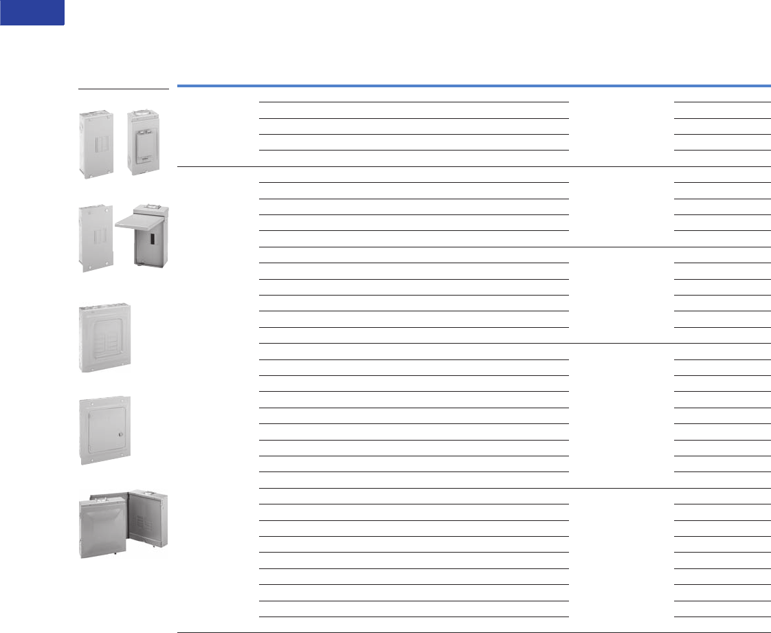
Type BR Loadcenters and Circuit Breakers
BR Quick Connect Neutral Loadcenters
Contents—BR Specialty Products
Description Page
Overview . . . . . . . . . . . . . . . . . . . . . . . . . . . . . . . V1-T1-42
BR Specialty Products
BR Quick Connect Neutral Loadcenters
Spa Panels . . . . . . . . . . . . . . . . . . . . . . . . . . . . V1-T1-58
Riser Panel. . . . . . . . . . . . . . . . . . . . . . . . . . . . V1-T1-59
Type BR Renovation Loadcenter . . . . . . . . . . . V1-T1-60
Type BR Mechanical Interlock Kits . . . . . . . . . . V1-T1-62
Type BR Retrofit Interior Kits . . . . . . . . . . . . . . V1-T1-73
BR Circuit Breakers. . . . . . . . . . . . . . . . . . . . . . . . V1-T1-76
BR Specialty Products
BR Quick Connect
Neutral Loadcenters
Product Description
The Type BR Quick Connect
Neutral loadcenters coupled
with Type BR Quick Connect
Neutral electronic breakers
provide a clean, quick
connection for an installer
looking to save time while
providing a professional look.
Features and Benefits
●Full-length neutral bars
provide over 300% neutral
capacity while enhancing
installation flexibility for the
installer
●Backed-out neutral screws
allow an installer to make a
quick connection when
terminating neutral and
ground wires
●Extended circuits (30/60,
40/80) provide maximum
flexibility to a contractor on
every space possible
●Standard LED diagnostics
on AFCI and AF/GF
breakers provides installers
best-in-class
troubleshooting technology
●Cut-to-length neutral wires
provides a clean,
professional look versus
traditional pigtail circuit
breakers
●Solid-tip, stranded neutral
wires provide a quick
connection to the full
length neutral bar
Product Selection
BR Quick Connect Neutral Loadcenters 1
BR Quick Connect Neutral Electronic Breakers
Notes
1BR Quick Connect Neutral loadcenters accept both standard and Quick Connect Neutral breakers.
2Loadcenters accept Type BR twin breakers.
3Combination cover included with every indoor loadcenter.
4Ground bar kit not included. Purchase separately.
Main
Device
Ampere
Rating Spaces Circuits 2
Incoming
Lug Size
Enclosure
Type 3
Box
Size
Ground
Bar
Number of
Neutral
Terminations
Catalog
Number
BR 10 kAIC 100 30 60 #4–1/0 Indoor D1 496 BR3060BQN100
CSR 25 kAIC 150 30 60 #2–300 kcmil Indoor G1 4102 BR3060BQN150
CSR 25 kAIC 200 30 60 #2–300 kcmil Indoor G1 4102 BR3060BQN200
CSR 25 kAIC 200 40 80 #2–300 kcmil Indoor L1 4128 BR4080BQN200
CSR 25 kAIC 200 30 60 #2–300 kcmil Outdoor L1R 494 BR3060BQN200R
CSR 25 kAIC 200 40 80 #2–300 kcmil Outdoor G1R 4128 BR4080BQN200R
Main lug only 125 24 48 #6–2/0 Indoor C2 GBK14 80 BR2448LQN125G
Main lug only 125 30 60 #6–2/0 Indoor D1 GBK10 96 BR3060LQN125G
Main lug only 200 30 60 #1–300 kcmil Indoor D1
GBK1020 + GBK10
96 BR3060LQN200G
Main lug only 200 40 80 #1–300 kcmil Indoor G1
GBK1020 + GBK10
122 BR4080LQN200G
Main lug only 125 20 40 #6–2/0 Outdoor C1R GBK14 68 BR2040LQN125RG
Main lug only 200 30 60 #1–300 kcmil Outdoor D1R GBK1420 94 BR3060LQN200RG
Convertible 200 30 60 — Indoor G1 4102 BR3060NQN200
Convertible 200 40 80 — Indoor L1 4128 BR4080NQN200
Convertible 200 30 60 — Outdoor G1R 494 BR3060NQN200R
Convertible 200 40 80 — Outdoor L1R 4128 BR4080NQN200R
Ampere
Rating Poles Wire Size Breaker Type
LED Diagnostics
Included
Catalog
Number
15 Single-pole 10 kAIC #14–4 Combination AFCI Yes BRCAF115QN
20 Single-pole 10 kAIC #14–4 Combination AFCI Yes BRCAF120QN
15 Single-pole 10 kAIC #14–4 Arc fault/ground fault Yes BRLAFGF115QN
20 Single-pole 10 kAIC #14–4 Arc fault/ground fault Yes BRLFAFGF120QN
V1-T1-58 Volume 1—Residential and Light Commercial CA08100002E—April 2015 www.eaton.com
1
1
1
1
1
1
1
1
1
1
1
1
1
1
1
1
1
1
1
1
1
1
1
1
1
1
1
1
1
1
1.2
Loadcenters and Circuit Breakers
Type BR Loadcenters and Circuit Breakers
Spa Panels
Contents—BR Specialty Products
Description Page
Overview . . . . . . . . . . . . . . . . . . . . . . . . . . . . . . . . V1-T1-42
BR Specialty Products
BR Quick Connect Neutral Loadcenters . . . . . . V1-T1-57
Spa Panels
Riser Panel . . . . . . . . . . . . . . . . . . . . . . . . . . . . V1-T1-59
Type BR Renovation Loadcenter . . . . . . . . . . . . V1-T1-60
Type BR Mechanical Interlock Kits . . . . . . . . . . V1-T1-62
Type BR Retrofit Interior Kits. . . . . . . . . . . . . . . V1-T1-73
BR Circuit Breakers . . . . . . . . . . . . . . . . . . . . . . . . V1-T1-76
Spa Panels
Product Description
Eaton’s BR Spa Panels
distribute power to outdoor
loads and provide protection
for people from electric
shock. Save time and money
with streamlined installation
procedures and easy-access
features. Spa panels meet
NEC requirements by
providing a ground fault
circuit interruption device and
a disconnect switch in a
single simple device. Ships
assembled prewired, factory
tested and ready to install.
Features
●10-year warranty
●UL Listed
●Factory-installed
two-pole ground fault
circuit interrupter (GFCI)
Product Selection
Spa Panel—Meets NEC Article 680.40 Through 680.43—
Requirements for GFCI Protection
Notes
1 Includes a GFCB240 breaker, factory installed.
2 Includes a GFCB250 breaker, factory installed.
Main
Ampere
Rating
Maximum Number
1-Inch (25.4 mm) Enclosure
Type
Box
Size
Wire Size Range Cu/Al 60 °C
or 75 °C for Main Lugs
Catalog
NumberSpace Poles
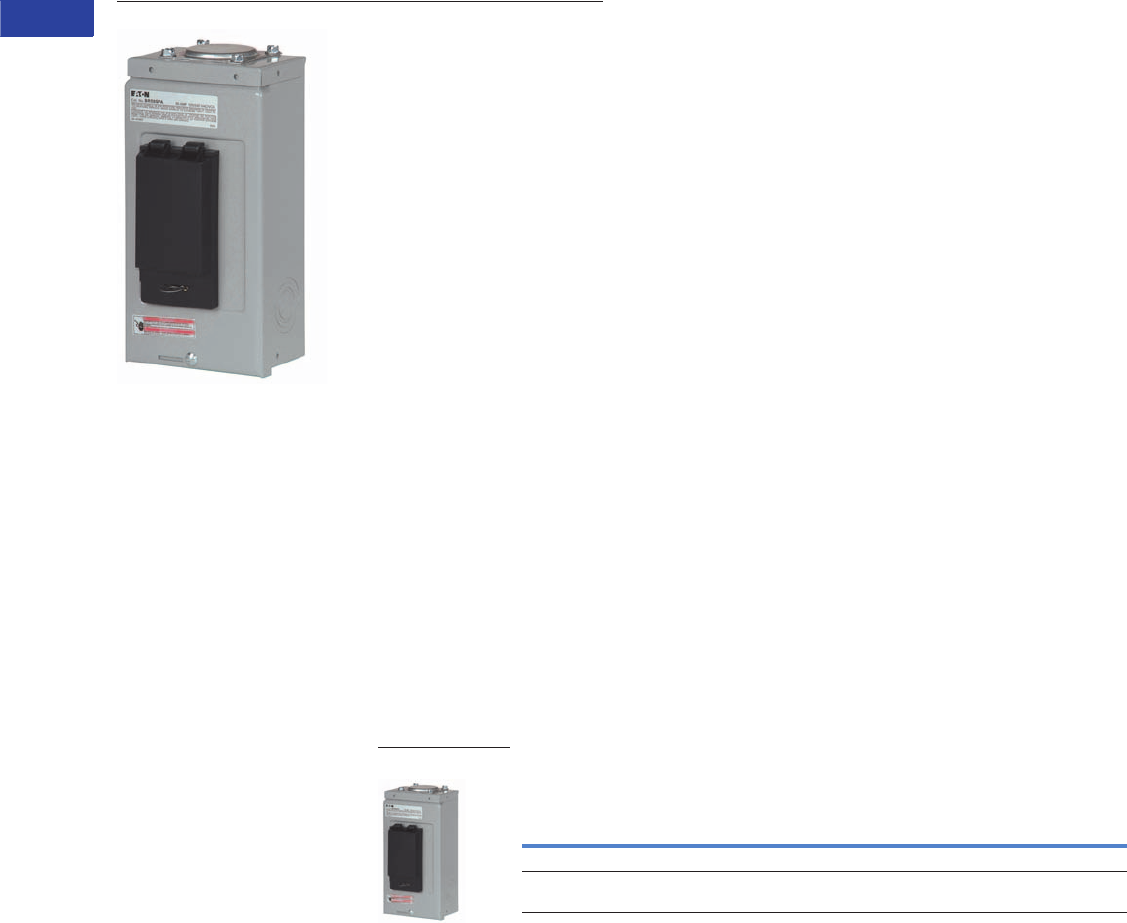
40 — — Outdoor 5R #8–#2 BR40SPA 1
50 — — Outdoor 5R #8–#2 BR50SPA 2
BR Spa Panel
Volume 1—Residential and Light Commercial CA08100002E—April 2015 www.eaton.com V1-T1-59
1
1
1
1
1
1
1
1
1
1
1
1
1
1
1
1
1
1
1
1
1
1
1
1
1
1
1
1
1
1
1.2
Loadcenters and Circuit Breakers
Type BR Loadcenters and Circuit Breakers
Riser Panel
Contents—BR Specialty Products
Description Page
Overview . . . . . . . . . . . . . . . . . . . . . . . . . . . . . . . V1-T1-42
BR Specialty Products
BR Quick Connect Neutral Loadcenters . . . . . V1-T1-57
Spa Panels . . . . . . . . . . . . . . . . . . . . . . . . . . . . V1-T1-58
Riser Panel
Type BR Renovation Loadcenter . . . . . . . . . . . V1-T1-60
Type BR Retrofit Interior Kits . . . . . . . . . . . . . . V1-T1-73
BR Circuit Breakers. . . . . . . . . . . . . . . . . . . . . . . . V1-T1-76
Riser Panel
Product Description
Eaton’s Riser Panel is a
loadcenter with an offset
interior to allow riser cables
to pass through the enlarged
gutter. By using lay-in tap
lugs, the contractor is able to
simply strip off a length of the
riser cable’s insulation, and
tap off to the riser panel’s
main lugs. These panels are
used in the construction of
assisted living homes,
dormitories, public housing
complexes and apartments.
Product Selection
Riser Panel
Riser Panel Accessories
Notes
1 Bulk-packaged loadcenter without carton. Must be ordered in
multiples of 16.
2 Refer to Page V1-T1-68 for dimensions. BRGUTTER is box
size C2.
Accessories
For riser panels not shown, contact the Flex Center at
1-800-330-6479 for both CH and BR riser panels.
Main Ampere
Rating
Maximum Number
1-Inch (25.4 mm) Enclosure
Type
Box
Size
Wire Size Range
Cu/Al 60 °C or 75 °C
for Main Lugs
Catalog
NumberSpace Circuits
125 12 24 Indoor C4 #6–2/0 BR1224L125RIS
125 12 24 Indoor C4 #6–2/0 BR1224L125RISBP 1
125 20 24 Indoor C4 #6–2/0 BR2024L125RIS
125 20 24 Indoor C4 #6–2/0 BR2024L125RISBP 1
125 20 30 Indoor C2 #6–2/0 BR2030L125RIS
200 30 40 Indoor D1 #1–300 BR3040L200RIS
Catalog Number
BRGUTTER 2
GTAP250
BR1224L125RIS
BRGUTTER (Shown
with Loadcenter)
V1-T1-60 Volume 1—Residential and Light Commercial CA08100002E—April 2015 www.eaton.com
1
1
1
1
1
1
1
1
1
1
1
1
1
1
1
1
1
1
1
1
1
1
1
1
1
1
1
1
1
1
1.2
Loadcenters and Circuit Breakers
Type BR Loadcenters and Circuit Breakers
BR Renovation Loadcenters
Contents—BR Specialty Products
Description Page
Overview . . . . . . . . . . . . . . . . . . . . . . . . . . . . . . . V1-T1-42
BR Specialty Products
BR Quick Connect Neutral Loadcenters . . . . . V1-T1-57
Spa Panels . . . . . . . . . . . . . . . . . . . . . . . . . . . . V1-T1-58
Riser Panel. . . . . . . . . . . . . . . . . . . . . . . . . . . . V1-T1-59
Type BR Renovation Loadcenter
Options and Accessories . . . . . . . . . . . . . . V1-T1-61
Type BR Retrofit Interior Kits . . . . . . . . . . . . . . V1-T1-73
BR Circuit Breakers. . . . . . . . . . . . . . . . . . . . . . . . V1-T1-76
Type BR Renovation Loadcenter
Product Description
●Available in 10, 20, 30
and 40 circuit main
breaker styles
●Designed to replace
existing loadcenters
and fuse boxes
●Type BR loadcenter
packaged with circuit
breakers
●Factory-installed 5-circuit
terminal block(s)
●Twin-stacked neutral
design
Quick-ProSM
All you need to
know to save
time and make
more money.
Specified on certain Eaton
products, the Quick-Pro
symbol allows for immediate
recognition of products
that are designed for
straightforward installation.
When you see Quick-Pro,
you know you can install
quickly—sometimes up to
50% less than the usual
installation time—and move
on to your next job.
Product Selection
BR Value Packs 1
Note
1 Indoor enclosure type.
Main
Breaker
Type Description
Wire Size
Range
Number of
5-Circuit
Terminal Blocks
Single-Pole
Breakers
Two-Pole
Breakers
Catalog
Number
BR
10 kAIC
Single-phase 100 A 10k main breaker 10/20
circuit surface-mount box is 11.75" wide x 13" tall
#6–1/0 0 (2) BR115 (1) BR230 BR1020B100SRNV
Single-phase 100 A 10k main breaker 10/20
circuit flush-mount box is 11.75" wide x 13" tall
0 (2) BR115 (1) BR230 BR1020B100FRNV
BR2020B100RN
Features, Benefits and Functions
●Factory-installed terminal
block(s) allows installer to
terminate existing short
wires without using wire
nuts or junction boxes
●Twin-stacked neutrals are
mounted up high in the
loadcenter, which allows
for all neutral and ground
wires to be terminated in
the top half of the
loadcenter
●Specifically designed for
the service contractor—
this is the ONLY renovation
line in the industry
●Single-pole and two-pole
breakers included
●10-year warranty on
loadcenter and breakers
Volume 1—Residential and Light Commercial CA08100002E—April 2015 www.eaton.com V1-T1-61
1
1
1
1
1
1
1
1
1
1
1
1
1
1
1
1
1
1
1
1
1
1
1
1
1
1
1
1
1
1
1.2
Loadcenters and Circuit Breakers
Type BR Loadcenters and Circuit Breakers
Options and Accessories
Field Installation Kits and Parts
Notes
1 Must be purchased in multiples of ordering quantities indicated.
2 #8–2/0 wire size range is 75 °C rated only.
Number
of Poles
Ampere
Rating
Number of 1-Inch (25.4 mm)
Spaces Needed
Wire Size Range
Cu/Al 60 °C or 75 °C
Ordering
Quantity 1
Catalog
Number
Main and Sub-Feed Lug Blocks
2 125 2 #8–2/0 1 BRSF125
150 2 #8–2/0 1 BRSF150 2
225 4 #2–300 kcmil 1 BRS225
3 150 3 #8–2/0 1 3BRSF150 2
225 6 #2–300 kcmil 1 3BRS225
Main Lugs
Two-pole, 200 A stud mounted (includes deadfront filler plate) #1–300 kcmil 1 BRL200
Neutral/ground lug
Add-on neutral or ground lug
#2/0 maximum 1 NL20
#3/0 maximum 1 NL30
300 kcmil maximum 1 NL300
Filler Plates
1-inch (25.4 mm) circuit breaker space 25 BRFP
BW main circuit breaker space (with hardware) 1 BWFP
Door lock —12–42 circuits, and 100–225 A 1 TDL
Door lock—4–8 circuits, 125 A 1CH9FL
ANSI-61 light gray touchup paint for current loadcenters 1 SPC61
Isolated neutral assembly (computer circuits) 1 BINA
Circuit directory—adhesive backed 10 TCD
Cover screws 25 LCCS
Cover replacement latch (gray) 14-5/16 (363.5 mm) wide loadcenters only 1 BRRL
Circuit marking strip (next to breaker) 10 BRMS
Circuit identification label (preprinted breaker labels) 25 CHBL
Series rated caution label 25 SRL
Bonding strip with screw 1BSSUSE
BRSF125
3BRS225
BRL200
TDL
V1-T1-62 Volume 1—Residential and Light Commercial CA08100002E—April 2015 www.eaton.com
1
1
1
1
1
1
1
1
1
1
1
1
1
1
1
1
1
1
1
1
1
1
1
1
1
1
1
1
1
1
1.2
Loadcenters and Circuit Breakers
Type BR Loadcenters and Circuit Breakers
Type BR Loadcenter with
Mechanical Interlock Kit
Type BR Mechanical Interlock Kits
Contents
Description Page
Overview . . . . . . . . . . . . . . . . . . . . . . . . . . . . . . . V1-T1-42
BR Specialty Products
BR Quick Connect Neutral Loadcenters . . . . . V1-T1-57
Spa Panels . . . . . . . . . . . . . . . . . . . . . . . . . . . . V1-T1-58
Riser Panel. . . . . . . . . . . . . . . . . . . . . . . . . . . . V1-T1-59
Type BR Renovation Loadcenter . . . . . . . . . . . V1-T1-60
Type BR Retrofit Interior Kits . . . . . . . . . . . . . . V1-T1-73
Type BR Mechanical Interlock Kits
BR Circuit Breakers
Product Selection. . . . . . . . . . . . . . . . . . . . . . . V1-T1-77
Circuit Breaker Accessories. . . . . . . . . . . . . . . V1-T1-85
Wiring Diagrams . . . . . . . . . . . . . . . . . . . . . . . V1-T1-87
Type BR Mechanical Interlock Kits
Product Description
With the aging electrical
infrastructure and frequent
severe storms, power
outages are becoming more
and more frequent, affecting
thousands of people
nationwide. Eaton mechanical
interlock kit provides an easy
and cost-effective solution
when using backup
emergency power.
This solution expands the
robust line of emergency
power products and
accessories.
Features and Benefits
●Prevents utility and
generator supplies from
being on at the same time
●Protects utility linemen
from dangerous generator
backfeed
●Robust interlock design
●Offered in two unique
styles for almost any BR
loadcenter, which can
reduce inventory levels
●Quick and easy
installation—drill points or
fixtures for pilot holes are
provided on all applicable
BR loadcenters; no
additional assembly is
required
Standards and Certifications
●UL 67 Listed—For use with
BR loadcenters
●Meets NEC® Article 702

Volume 1—Residential and Light Commercial CA08100002E—April 2015 www.eaton.com V1-T1-63
1
1
1
1
1
1
1
1
1
1
1
1
1
1
1
1
1
1
1
1
1
1
1
1
1
1
1
1
1
1
1.2
Loadcenters and Circuit Breakers
Type BR Loadcenters and Circuit Breakers
Product Selection
Each mechanical interlock kit
includes:
●Interlock assembly
●Hold down kit 1
●New labels
●Necessary screws
Warranty information:
●10-year warranty on all
Type BR circuit breakers
and loadcenters
●Refer to Eaton for
complete warranty details
Mechanical Interlock Kits 2
Notes
1For breakers under 70 A used in backfed applications, add “B” to the end of the catalog string
to get the appropriate “hold-down” version.
2Clamshell packaged.
3Bulk pack contains 10 units, individually packaged.
Description Catalog Number
Single BRMIKBR
Bulk pack 3BRMIKBRBP
Single BRMIKCSR
Bulk pack 3BRMIKCSRBP
BRMIKCSR
BRMIKBR
V1-T1-64 Volume 1—Residential and Light Commercial CA08100002E—April 2015 www.eaton.com
1
1
1
1
1
1
1
1
1
1
1
1
1
1
1
1
1
1
1
1
1
1
1
1
1
1
1
1
1
1
1.2
Loadcenters and Circuit Breakers
Type BR Loadcenters and Circuit Breakers
Mechanical Interlock Cover
Covers mechanically interlock
two breakers—Type BW
or CSR main breaker with a
Type BR branch breaker.
Mechanical Interlock Cover
Fits Loadcenter
Catalog Numbers
Mechanical Interlock
Trim/Deadfront
Catalog Numbers
Mechanical Interlock Kit
Catalog Numbers
Indoor
BR816B100 BRCOVC10M BRMIKBR
BR816N100
BR1212B100 BRCOVC12M
BR1220B100
BR1220H100
BR1224N125 BRCOVC13M
BR1616B100 BRCOVC16M
BR1620B100
BR1624B100
BR1624B125 BRCOVC17M
BR1624N125
BR2020B100, BR2020BC100
BR2020H100, BR2020HC100
BRCOVC22M
BR2024H100
BR2020HC100
BR2030B100
BR2040B100
BR2024B125 BRCOVC23M
BR2024N125, BR2024NC125
BR3030B100, BR3030BC100 BRCOVC59M
BR3030H100, BR3030HC100
Raintight
BR1020B100R BR3RDF1M Field-installed interlock kits not
available for these catalog numbers.
BR1224B100R
BR1224N125R, BR1224NC125R
BR1624B100R BR3RDF2M
BR1624N125R
BR2024B100R, BR2024B125R BR3RDF4M
BR2024N125R, BR2024NC125R
BR816B100
Volume 1—Residential and Light Commercial CA08100002E—April 2015 www.eaton.com V1-T1-65
1
1
1
1
1
1
1
1
1
1
1
1
1
1
1
1
1
1
1
1
1
1
1
1
1
1
1
1
1
1
1.2
Loadcenters and Circuit Breakers
Type BR Loadcenters and Circuit Breakers
Mechanical Interlock Cover, continued
Notes
1 Deadfront only.
2 Can only be provided as replacement covers for factory-installed mechanically interlock loadcenters.
Fits Loadcenter
Catalog Numbers
Mechanical Interlock
Trim/Deadfront
Catalog Numbers
Mechanical Interlock Kit
Catalog Numbers
Indoor
BR1630B150 BRCOV16C4FM BRMIKCSR
BR1224N200
BR1632B200
BR1632N200
BR2030B150 BRCOV20C4FM
BR2030H150
BR2040B150
BR2040B200, BR2040BC200 BRCOV20D1FM
BR2040H200
BR2040N200, BR2040NC200
BR2430B150, BR2430BC150 BRCOV30G1FM
BR3030B150
BR3030H150
BR3040B150
BR2440B200
BR2440N200
BR3040B200, BR3040BC200
BR3040N200, BR3040NC200
BR3040H200
BR4040B200, BR4040BC200 BRCOV40L1FM
BR4040H200
BR4040N200, BR4040NC200
BR4242B225 BRCOV42L2FM
Raintight
BR816B150RF BR3RDF5M 1
BR816B200RF
BR816N200RF
BR1224N200R
BR2030B150R BR3RDF11M 1
BR2040B150R
BR2040B200R
BR2040B225R
BR2040N200R
BR3030B150R BR3RDF12M 1
BR3040B200R
BR3040N200R
BR4040B200R BR3RDF13M 1
BR4040N200R
BR48B200RF BR3RDF14M
BR4242B225R BR3RDF15M 1
Mechanical Interlock Loadcenter Replacement Covers 2
BR2020B100M, BR2020BC100M BRCOV20C2FM Field-installed interlock kits not
available for these catalog numbers.
BR2024H100M
BR3030BC100M BRCOV30D1FM
BR4040B200
V1-T1-66 Volume 1—Residential and Light Commercial CA08100002E—April 2015 www.eaton.com
1
1
1
1
1
1
1
1
1
1
1
1
1
1
1
1
1
1
1
1
1
1
1
1
1
1
1
1
1
1
1.2
Loadcenters and Circuit Breakers
Type BR Loadcenters and Circuit Breakers
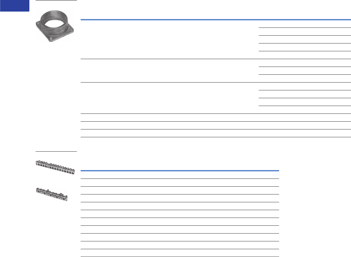
Field Installation Rainproof Conduit Hubs
Ground Bar Kits
Ground Bar Legend
Notes
1 Must be purchased in multiples of ordering quantities indicated.
2 Distance between mounting holes is 1.75 inches (44.5 mm).
3 For single- and three-phase 400 and 600 A applications.
4 Distance between mounting holes is 2.34 inches (59.5 mm).
5 For non-metallic enclosures. Snaps into molded base.
Description
Conduit Size
Inches (mm)
Ordering
Quantity 1
Catalog
Number
Group 1—for use with 70, 100 and 125 A MLO and MCB loadcenters and circuit breaker enclosures and the
following 150 and 200 A panels: BR48B200RF
0.75 (19.1) 1 DS075H1
1.00 (25.4) 1 DS100H1
1.25 (31.8) 1 DS125H1
1.50 (38.1) 1 DS150H1
2.00 (50.8) 1 DS200H1
Group 2—for use with 150, 200 and 225 A MLO and MCB loadcenters and circuit breaker enclosures except for
the following 200 A loadcenters: BR48B200RF. Also for use with 400 and 600 A loadcenters and New York City
loadcenters manufactured after November 1, 2005
2.00 (50.8) 1 DS200H2
2.50 (63.5) 1 DS250H2
3.00 (76.2) 1 DS300H2
Type H conduit hubs for loadcenters PL0724R and S3100RN 0.75 (19.1) 1 RH75P
1.00 (25.4) 1 RH100P
1.25 (31.8) 1 RH125P
1.50 (38.1) 1 RH150P
Adapter kit—Allows Installing a Group 1 hub on devices arranged for Group 2 hubs — 1 DS900AP
Group 1 small blank hub plate with bump — 1 DS900CP1
Group 2 Large blank hub plate with bump — 1 DS900CP2
Description
(See Legend)
Length
Inches (mm)
Ordering
Quantity 1
Catalog
Number
dssssds 2.54 (64.5) 1 GBK5 2
dssssdsj 3.59 (91.2) 1 GBK520 2
dssssdssssss 4.29 (109.0) 1 GBK10 2
dssssdssssssj 5.34 (135.6) 1 GBK1020 2
4.61 (117.1) 1 GBK13 2
dssssdssssssssss 5.69 (144.5) 1 GBK14 2
dssssdssssssssssj 6.74 (171.2) 1 GBK1420 2
dssssdsssssssssssssssss 8.14 (206.8) 1 GBK21 2
dssssdsssssssssssssssssj 9.19 (233.4) 1 GBK2120 2
5.78 (146.8) 1 BRGBK39512 34
sssss 1.84 (46.7) 1 GB4NM 5
s
j
d
(3) #14–10 Cu/Al or (1) #14–4 Cu/Al
(1) #6–2/0 Cu/Al
(1) #14–1/0 Cu/Al or (3) #14–10 Cu/Al
(1) #14–6 Cu/Al or (2) #14–12 Cu/Al
Mounting Hole
DS300H2
GBK14
BRGBK39512
f
d
f
f
f
k
f
d
f
k
f
f
f
f
k
f
d
f
k
f
f
f
k
f
d
f
k
f
f
f
k
f
k
f

Volume 1—Residential and Light Commercial CA08100002E—April 2015 www.eaton.com V1-T1-67
1
1
1
1
1
1
1
1
1
1
1
1
1
1
1
1
1
1
1
1
1
1
1
1
1
1
1
1
1
1
1.2
Loadcenters and Circuit Breakers
Type BR Loadcenters and Circuit Breakers
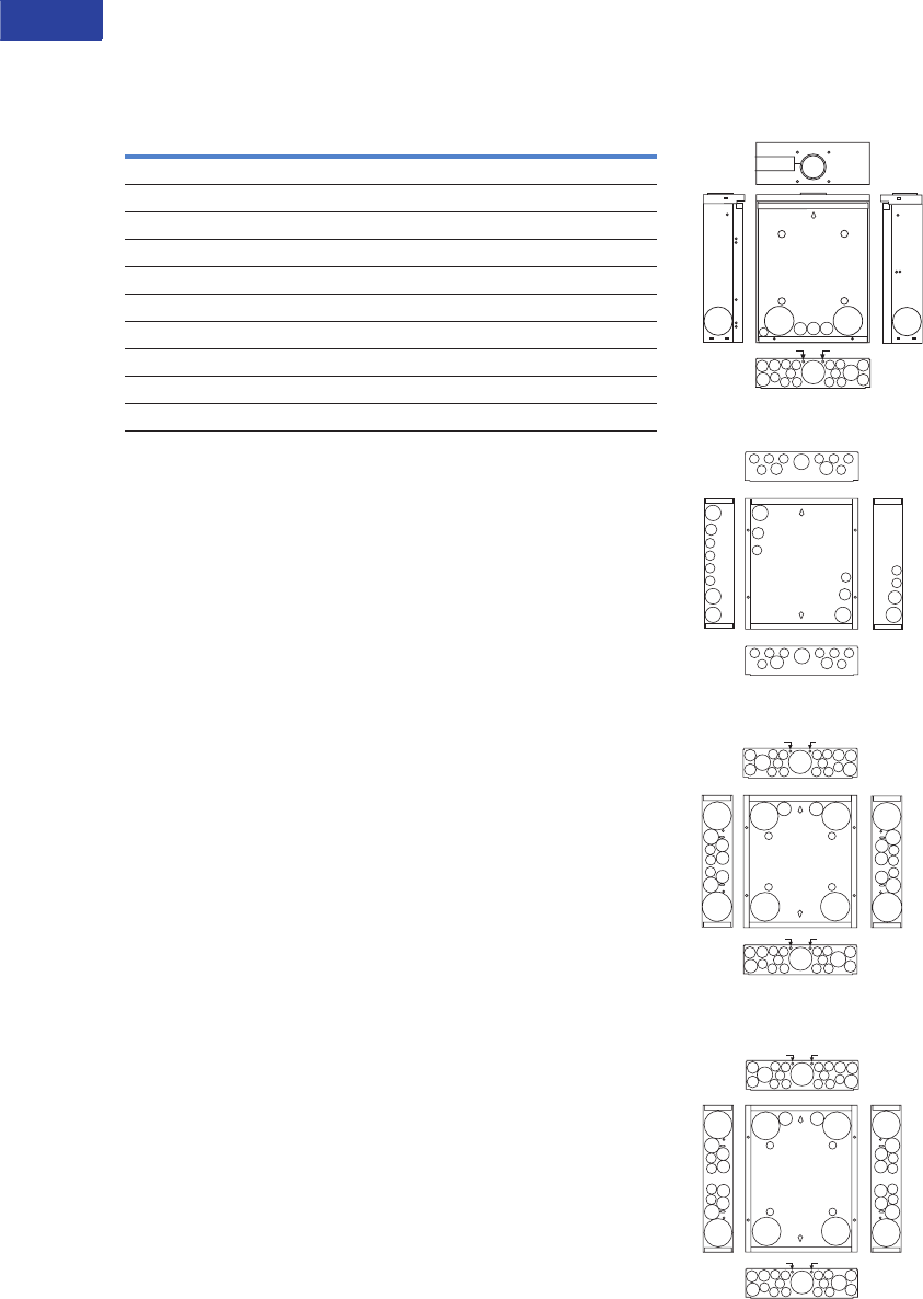
Dimensions
Approximate Dimensions in Inches (mm)
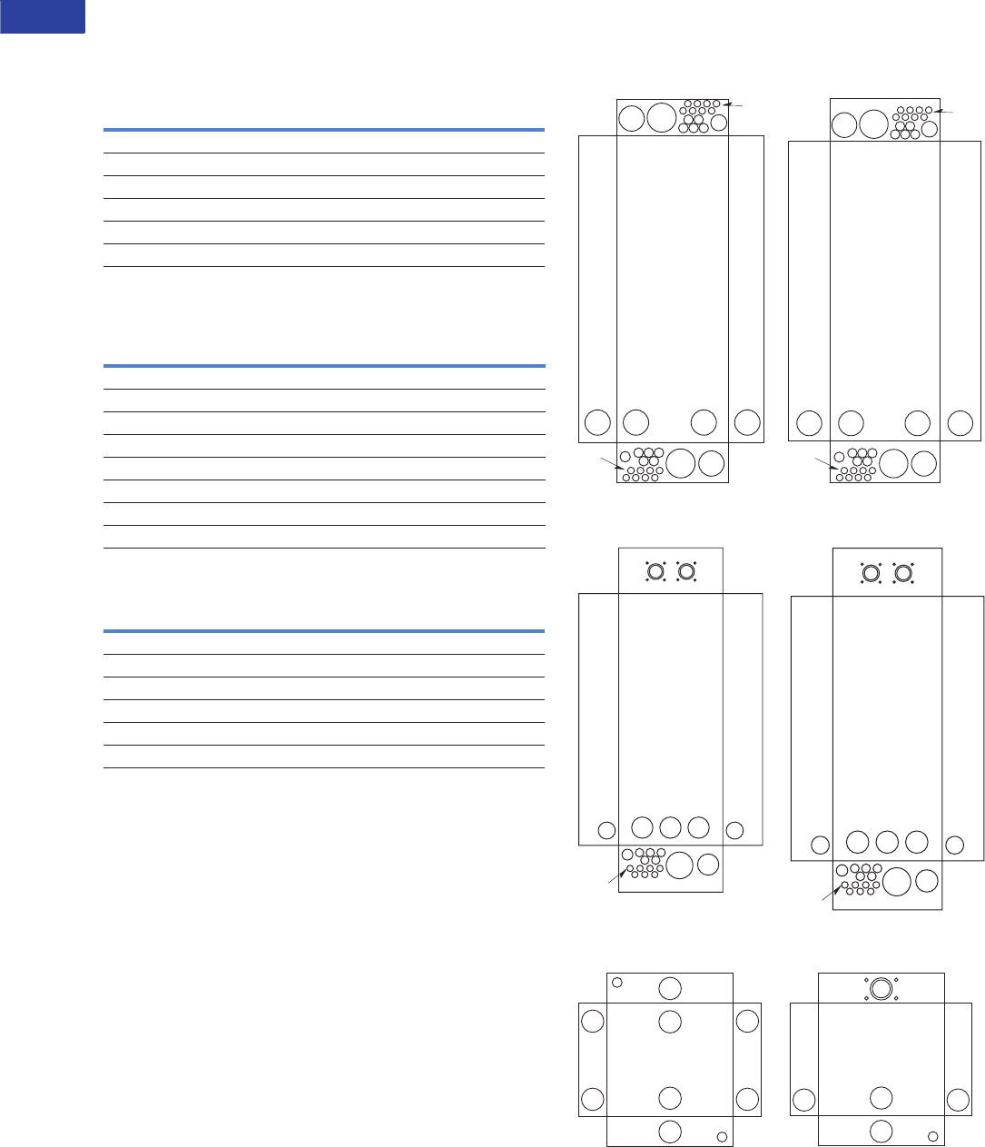
Residential/Commercial/New York City Loadcenters, Unit Enclosures—Box Sizes
Note: Box sizes do not include covers/fronts.
Residential Loadcenters—NEMA Type 1 Indoor
Residential Loadcenters—NEMA Type 3R Outdoor
Commercial Loadcenters—NEMA Type 1 Indoor
Commercial Loadcenters—NEMA Type 3R Outdoor
New York City Loadcenters—NEMA Type 1 Indoor
ECC Unit Enclosures—NEMA Type 1 Indoor
ECC Unit Enclosures—NEMA Type 3R Outdoor
Box Size Height Width Depth
A1 15.00 (381.0) 11.25 (285.8) 3.75 (95.3)
B1 16.75 (425.5) 14.31 (363.5) 3.88 (98.4)
B2 18.75 (476.3) 14.31 (363.5) 3.88 (98.4)
C1 21.00 (533.4) 14.31 (363.5) 3.88 (98.4)
C2 23.00 (584.2) 14.31 (363.5) 3.88 (98.4)
C4 27.00 (685.8) 14.31 (363.5) 3.88 (98.4)
D1 29.13 (739.8) 14.31 (363.5) 3.88 (98.4)
G1 34.13 (866.8) 14.31 (363.5) 3.88 (98.4)
L1 39.00 (990.6) 14.31 (363.5) 3.88 (98.4)
L2 45.00 (1143.0) 14.31 (363.5) 3.88 (98.4)
L3 48.38 (1228.3) 14.31 (363.5) 3.88 (98.4)
2 8.63 (219.1) 5.00 (127.0) 3.50 (88.9)
3 9.44 (239.7) 4.50 (114.3) 3.00 (76.2)
4 13.00 (330.2) 11.00 (279.4) 3.56 (90.5)
5 9.44 (239.7) 4.50 (114.3) 3.00 (76.2)
6 12.00 (304.8) 6.88 (174.6) 4.50 (114.3)
7 13.00 (330.2) 11.00 (279.4) 3.56 (90.5)
9 14.50 (368.3) 6.50 (165.1) 3.50 (88.9)
Box Size Height Width Depth
B1R 16.75 (425.5) 14.31 (363.5) 5.19 (131.8)
B2R 18.75 (476.3) 14.31 (363.5) 5.19 (131.8)
C3R 25.00 (635.0) 14.31 (363.5) 5.19 (131.8)
D1R 29.13 (739.8) 14.31 (363.5) 5.19 (131.8)
G1R 34.13 (866.8) 14.31 (363.5) 5.19 (131.8)
L1R 39.00 (990.6) 14.31 (363.5) 5.19 (131.8)
L2R 45.00 (1143.0) 14.31 (363.5) 5.19 (131.8)
L3R 48.75 (1238.2) 14.31 (363.5) 5.19 (131.8)
2R 8.63 (219.1) 5.00 (127.0) 3.50 (88.9)
3R 9.44 (239.7) 4.50 (114.3) 3.00 (76.2)
4R 13.00 (330.2) 11.00 (279.4) 3.56 (90.5)
5R 9.44 (239.7) 4.50 (114.3) 3.00 (76.2)
6R 11.75 (298.5) 6.50 (165.1) 4.50 (114.3)
7R 13.00 (330.2) 11.00 (279.4) 3.56 (90.5)
8R 27.00 (685.8) 10.50 (266.7) 4.75 (120.7)
9R 14.25 (362.0) 6.50 (165.1) 4.00 (101.6)
C1R 21.00 (533.4) 14.31 (363.5) 5.19 (131.8)
Box Size Height Width Depth
19 44.00 (1117.6) 16.16 (410.4) 6.25 (158.8)
20 44.00 (1117.6) 16.16 (410.4) 6.25 (158.8)
22 54.00 (1371.6) 16.22 (412.0) 6.31 (160.3)
24 66.50 (1689.1) 16.22 (412.0) 6.31 (160.3)
Box Size Height Width Depth
42 38.00 (965.2) 16.31 (414.3) 6.38 (161.9)
43 44.00 (1117.6) 16.31 (414.3) 6.38 (161.9)
46 54.00 (1371.6) 16.31 (414.3) 6.38 (161.9)
47 66.56 (1690.7) 16.31 (414.3) 6.38 (161.9)
Box Size Height Width Depth
A 38.00 (965.2) 18.13 (460.4) 5.00 (127.0)
B 44.00 (1117.6) 18.13 (460.4) 5.00 (127.0)
C 66.50 (1689.1) 18.13 (460.4) 6.25 (158.8)
Height Width Depth
23.25 (590.6) 8.88 (225.4) 4.50 (114.3)
Height Width Depth
23.68 (601.7) 9.31 (236.5) 5.44 (138.1)
V1-T1-68 Volume 1—Residential and Light Commercial CA08100002E—April 2015 www.eaton.com
1
1
1
1
1
1
1
1
1
1
1
1
1
1
1
1
1
1
1
1
1
1
1
1
1
1
1
1
1
1
1.2
Loadcenters and Circuit Breakers
Type BR Loadcenters and Circuit Breakers
Approximate Dimensions in Inches (mm)
Residential Loadcenter Knockouts
Knockouts for Box Sizes A1, B1, B2, C1, C2, C4, D1, G1, L1,
L2, B1R, B2R, C1R, C3R, D1R, G1R, L1R, L2R
Residential NEMA Type 1 Indoor and
NEMA Type 3R Outdoor Enclosures
Code Diameter
A 0.50 (12.7) 0.75 (19.1) — — —
B0.50 (12.7)————
C 0.50 (12.7) 1.25 (31.8) 1.50 (38.1) 2.00 (50.8) 2.50 (63.5)
D 1.25 (31.8) 1.25 (31.8) 2.00 (50.8) 2.50 (63.5) —
E 0.50 (12.7) 0.75 (19.1) 1.00 (25.4) — —
F 0.50 (12.7) 0.75 (19.1) 1.00 (25.4) 1.50 (38.1) 2.00 (50.8)
G 1.25 (31.8) 1.50 (38.1) 2.00 (50.8) — —
H 0.50 (12.7) 0.75 (19.1) 1.00 (25.4) 1.25 (31.8) 1.50 (38.1)
I 1.00 (25.4) 1.25 (31.8) 1.50 (38.1) 2.00 (50.8) 2.50 (63.5)
J 1.00 (25.4) 1.25 (31.8) 1.50 (38.1) — —
J
E
B B B
A
B
B B B
B
E
J
B B B
A
B
B B B
B
E
J
J
A
B
A
B
J
J
J
A
B
B
B
B
J
B
B
Outdoor Boxes
B1R, B2R, C1R, C3R, D1R,
G1R, L1R, L2R
Indoor Boxes
B1, B2
Indoor Boxes
C1, C2, C4, D1, G1, L1, L2
.45 (11.4) Dia. KO.45 (11.4) Dia. KO
.45 (11.4) Dia. KO
.45 (11.4) Dia. KO
A
D
E
A
A
B
B
B
E
D
A
D
E
A
A
B
B
B
E
D
DD
D
D
EE
I
B
B
B
BB
A
A
H
B
B
B
BB
A
E
A
B
I
BB
B
B
B
A
AH
BB
B
B
B
A
E
A
B
.45 (11.4) Dia. KO
.45 (11.4) Dia. KO
.45 (11.4) Dia. KO.45 (11.4) Dia. KO
A
D
E
A
A
B
B
E
D
DD
D
D
EE
A
B
B
A
D
E
A
A
B
B
B
E
D
AB
I
B
B
B
BB
A
A
H
B
B
B
BB
A
E
A
B
I
BB
B
B
B
A
AH
BB
B
B
B
A
E
A
B
2.06 (52.3) Dia.
(125A Max.)
3.06 (77.7) Dia.
(225A Max.)
Hub
I
B
B
B
BB
A
A
H
B
B
B
BB
A
E
A
B
DDDD
.45 (11.4) Dia. KO
.45 (11.4) Dia. KO
EE E
B
Indoor Boxes
A1
Volume 1—Residential and Light Commercial CA08100002E—April 2015 www.eaton.com V1-T1-69
1
1
1
1
1
1
1
1
1
1
1
1
1
1
1
1
1
1
1
1
1
1
1
1
1
1
1
1
1
1
1.2
Loadcenters and Circuit Breakers
Type BR Loadcenters and Circuit Breakers
Approximate Dimensions in Inches (mm)
Knockouts for Box Sizes 3, 4, 5, 6, 7, 9, 2R, 3R, 4R, 5R, 6R,
7R, 8R, 9R
Residential NEMA Type 1 Indoor and NEMA Type 3R Outdoor Enclosures
Code Diameter
A 0.50 (12.7) — — —
B 0.50 (12.7) 0.75 (19.1) — —
C 0.50 (12.7) 0.75 (19.1) 1.00 (25.4) —
D 0.50 (12.7) 0.75 (19.1) 1.00 (25.4) 1.25 (31.8)
E 0.75 (19.1) 1.00 (25.4) 1.25 (31.8) —
F 0.75 (19.1) 1.00 (25.4) 1.25 (31.8) 1.50 (38.1)
G 1.00 (25.4) 1.25 (31.8) 1.50 (38.1) —
H 1.00 (25.4) 1.25 (31.8) 1.50 (38.1) 2.00 (50.8)
I 1.25 (31.8) 1.50 (38.1) 2.00 (50.8) —
Box 2, 2R
R1.00–1.25 KO
(25.4–31.8) KO
Mounting
Hole for
5/16 (7.9)
Screw .50–.75
(12.7–19.1)
2.38
(60.3)
.31 (7.9)
.50–.75–1.00
(12.7–19.1–25.4)
.50–1.00–1.25
(12.7–25.4–31.8)
6.38
(161.9)
A
A
A
A
C
E
A
A
C
E
F
A
A
F
Box 3
A
A
A
A
F
Hub
AAA A
A
A A
BB
B
D
G
G G
Hub
A
A
AA
A
A A A
A
A A
BBB
B
B
B
D
G
AAA A
A
A A
BB
B
D
D D
G
G
G
D
G
G
Box 3R Box 4
Box 4R Box 5 Box 5R Box 6
A
A
A
A
A
A
D D D
D
F
F
A
A
D D D
F
Hub
A
A
B
A
B
B
C
C
FF
F
F
A
B
F
F
H
A
B
A
B
H
Box 6R
F
B B
B
H
Hub
D D
Box 7 Box 7R
A
A
AA
A
AAA
AAA AAA
B B B
AB B
B
B
B
B
C C
C
C
C
BC
G
G
G
G
G G
F
AAA AAA
AB B
BC
C
G
G G
F
Hub
AA
B
C
C
Hub
I
AA
BC
C
I
I
A A
A
A
A A
B
B
B
B
BB
B
C
C
C
G
GG
G
G
GG
G
A
A
B
B
C
G
G
G
G
Hub
Box 8R Box 9 Box 9R
V1-T1-70 Volume 1—Residential and Light Commercial CA08100002E—April 2015 www.eaton.com
1
1
1
1
1
1
1
1
1
1
1
1
1
1
1
1
1
1
1
1
1
1
1
1
1
1
1
1
1
1
1.2
Loadcenters and Circuit Breakers
Type BR Loadcenters and Circuit Breakers
Approximate Dimensions in Inches (mm)
Commercial Loadcenter Knockouts
NEMA Type 1 Indoor Commercial Enclosures
Knockouts for Box Sizes 19, 20, 22, 24
NEMA Type 3R Outdoor Commercial Enclosures
Knockouts for Box Sizes 42, 43, 46, 47
Unit Enclosure Knockouts, Types ECB and ECC Knockouts
Indoor Commercial Enclosures
Outdoor Commercial Enclosures
Unit Enclosure Knockouts
Code Diameter
A 0.50 (12.7) — — —
B 0.50 (12.7) 0.75 (19.1) — —
C 0.75 (19.1) 1.00 (25.4) 1.50 (38.1) —
D 1.50 (38.1) 2.00 (50.8) 2.50 (63.5) 3.00 (76.2)
E 2.00 (50.8) 2.50 (63.5) 3.00 (76.2) —
F 2.50 (63.5) 3.00 (76.2) 3.50 (88.9) —
Code Diameter
A 0.50 (12.7) — — —
B 0.50 (12.7) 0.75 (19.1) — —
C 0.75 (19.1) 1.00 (25.4) 1.25 (31.8) —
D 1.50 (38.1) 2.00 (50.8) 2.50 (63.5) —
E 2.00 (50.8) 2.50 (63.5) 3.00 (76.2) —
F 2.50 (63.5) 3.00 (76.2) 3.50 (88.9) —
G 1.25 (31.8) 1.50 (38.1) 2.00 (50.8) 2.50 (63.5)
H 3.25 (82.6) Sq. — — —
Code Diameter
NEMA Type 1 Indoor (Flush and Surface Trims)
A 0.50 (12.7) — — — —
B 1.25 (31.8) 1.50 (38.1) 1.75 (44.5) 2.00 (50.8) 2.50 (63.5)
NEMA Type 3R Outdoor
A 0.50 (12.7) — — — —
B 1.25 (31.8) 1.50 (38.1) 1.75 (44.5) 2.00 (50.8) 2.50 (63.5)
A
H
E
F
A
B B B
B B
C
D D D D
E
C
B
B
B
B
B
A
H
B B B
B B
C
E E E E
E
E
F
A
C
B
B
B
B
B
Box 19, 20 Box 22, 24
GF
E E E
D D
C
B
B
B
B
B
A
HUB HUB
FE
E E E
D D
CB
B
B
B
B
A
HUB HUB
Box 42
Box 43, 46, 47
B
B
B
B
A
A
B
B
B
B
B
B
A
B B
HUB
NEMA Type 1—Indoor NEMA Type 3R—Outdoor

Volume 1—Residential and Light Commercial CA08100002E—April 2015 www.eaton.com V1-T1-71
1
1
1
1
1
1
1
1
1
1
1
1
1
1
1
1
1
1
1
1
1
1
1
1
1
1
1
1
1
1
1.2
Loadcenters and Circuit Breakers
Type BR Loadcenters and Circuit Breakers
Technical Data and Specifications
General
A. The Contractor shall
furnish and install
deadfront loadcenters
incorporating circuit
breakers of the number,
rating and type as
specified herein and
as shown on the
contract drawings.
B. The loadcenter and all
components shall be
designed, manufactured
and tested in accordance
with the latest applicable
standards of UL, NEMA
and NEC including:
1. UL 67—Standards
for Panelboards.
C. UL 50—Standards for
Cabinets and Boxes.
D. UL 489—Standards for
Molded Case Circuit
Breakers.
E. UL 869—Standards for
Service Equipment.
F. Federal Specification
W-C 375B—Circuit
Breakers.
G. Federal Specification
W-C P115b—Panel
Power Distribution
Type 1, Class 2.
Qualifications
A. The manufacturer of the
loadcenter shall be the
manufacturer of the
circuit breaker within
the loadcenter.
B. For the equipment
specified herein, the
manufacturer shall be
ISO 9000 certified.
C. The manufacturer of
this equipment shall have
produced similar
electrical equipment
for a minimum period
of seven (7) years.
Manufacturers
A. Eaton.
Ratings
A. Loadcenters shall be
rated for 120/240 Vac and
shall have short-circuit
ratings as shown on the
drawings or
as herein scheduled,
but not less than
10,000 amperes rms
symmetrical.
B. Circuit breakers shall be a
minimum of 125 A
frame. Circuit breakers
15 through 125 A trip size
shall take up the same
pole spacing.
C. Loadcenters shall be
labeled with a UL short-
circuit rating. When
series combination
ratings are applied
with integral or remote
upstream devices, a label
shall be provided. Series
combination ratings shall
cover all trip ratings of
installed frames. It shall
state the conditions of
the UL series ratings
including:
1. Size and type of
upstream device.
2. Branch devices that can
be used.
3. UL series short
circuit rating.
Construction
A. All interiors, with the
exception of the branch
circuit breakers, shall
be completely factory
assembled with main
breakers, main lugs,
or no main device.
B. Interiors shall be
designed so that circuit
breakers can be replaced
without disturbing
adjacent units and
without removing the
main bus connectors and
shall be designed so that
circuits may be changed
without machining,
drilling, or tapping.
C. Physical means shall be
provided to prevent the
installation of more
overcurrent devices than
that number for which
the enclosure was
designed, rated and
approved. Half-size
breakers shall have a
UL listed rejection tab
over the line terminals.
Loadcenter interiors
must have notched stabs
to accept these rejection
tab class CTL breakers, if
required and approved.
Bus
A. Busbars for the main and
cross connectors shall be
[tin-plated aluminum]
[copper] in accordance
with Underwriters
Laboratories standards.
Busing shall be braced
throughout to conform to
industry standard practice
governing short-circuit
stresses in loadcenters.
Note: Note to spec writer—
select one (copper available
in limited ratings).
B. Neutral busing shall
have a suitable lug for
each outgoing feeder
requiring a neutral
connection of same
ampacity as branch.
Wiring/Termination
A. All wire connectors and
terminals shall be of the
anti-turn solderless type
and shall be suitable for
copper or aluminum wire
of the sizes indicated. All
connectors must meet
the “Requirements for
Wire Connectors and
Soldering Lugs” as
stated in UL 486B.
B. All loadcenters where
marked shall be suitable
for use with 60 °C or
75 °C rated wire.
Circuit Breakers
A. Circuit breakers shall
be molded case type.
Circuit breakers shall
have four-rivet
construction (GFI Type—
5 rivets). Multipole circuit
breakers shall be of a
stack pole design to
provide electrical
phase isolation.
B. Each pole of the
circuit breaker will
provide inverse time
delay overload and
instantaneous short-
circuit protection by
means of both thermal
and magnetic sensors.
C. The circuit breaker
calibration shall
not be affected by
environmental changes
in relative humidity.
The thermal bimetal
element shall be welded
to the steel frame and
calibration shall be set
independent of the
molded case by computer
controlled equipment.
D. All circuit breakers
shall be operated by
a toggle-type handle
and multipole circuit
breakers shall have an
internal common trip
mechanism. The
circuit breakers shall
incorporate trip
mechanisms that are
mechanically trip-free
from the handle. The
handle position shall
provide visual trip
indication.
E. Contacts shall be of
non-welding silver alloy.
F. All circuit breakers shall
have the trip rating
inscribed on the handle
on each circuit breaker
pole. Also, unique color-
coded cases that indicate
the UL listed 10 kA or
22 kA interrupting
ratings. Breakers shall
be able to be used
as main or branch
disconnect devices.

V1-T1-72 Volume 1—Residential and Light Commercial CA08100002E—April 2015 www.eaton.com
1
1
1
1
1
1
1
1
1
1
1
1
1
1
1
1
1
1
1
1
1
1
1
1
1
1
1
1
1
1
1.2
Loadcenters and Circuit Breakers
Type BR Loadcenters and Circuit Breakers
G. Branch circuit breakers
may also be used in
the 1/2-inch (12.7 mm)
per pole ratings that
include two-pole 1-inch
(25.4 mm) wide modules
and four-pole 2-inch
(50.8 mm) wide
modules. Two-pole circuit
breakers must
incorporate a common
trip mechanism. The
exclusive CTL rejection
tab feature shall be
provided to limit the
number of branch
devices for a loadcenter
to 42, in compliance with
NEC Article 384.15.
H. Circuit breakers shall
be completely enclosed
in a molded case of
thermoset material.
No internal aluminum
parts shall be used. All
internal ferrous parts
shall be plated to
prevent corrosion.
I. All terminals shall be
listed for use with copper
or aluminum conductors.
Terminals shall be of the
box lug or clamp type
design. The terminals
shall meet UL 486B
requirements and shall
be suitable for use with
either 60 °C or
75 °C wire.
J. The calibrated bimetal
assembly shall be
mechanically isolated
from the load terminal
using a flexible braided
copper shunt wire, such
that movement of the
terminals due to twisting
and overtorquing does
not affect breaker
calibration.
K. Breakers shall be SWD
rated and/or HACR rated
as required.
L. Arc Fault Interrupting
circuit breakers, (AFI),
shall be provided on all
15 and 20 A single-phase
120/240 Vac circuits
except those indicated as
remote controlled
breakers. AFI breakers
shall be “Classified for
mitigating the effects of
arcing faults,” or
conforming to UL
Standard 1699 and as
defined by Article 210.12
Section A of the 1999
NEC Code.
Surge Protection Devices
See Volume 1, Tab 2 for
complete details on
surge protection.
Enclosures
A. Loadcenter shall have
NEMA Type 1 general
purpose or NEMA Type
3R rainproof enclosures
as indicated on the
drawings and shall be
surface or combination
flush/surface mounted
except where noted.
B. Boxes shall be made
from galvanized sheet
steel having multiple
knockouts. Rainproof
boxes shall use
galvanized steel or
an approved coating
system which meets or
exceeds standards for
outdoor NEMA Type 3R
enclosures. Boxes shall
be of sufficient size to
provide at least a
minimum code gutter
space on all sides.
C. The deadfront shall
have an easy adjustment
feature for flush
applications.
D. Boxes shall be factory
assembled into a single
rigid structure.
E. Unless otherwise noted
on drawings, hinged
doors covering all circuit
breaker handles shall
be included in all trims.
Trim doors shall not
uncover any live parts
in making the circuit
breaker handles
accessible. If key locks
are required, all locks
shall be keyed alike.
F. Combination trims for
flush and surface panels
shall be flat and shall
overlap the box by at
least 5/8-inch (15.9 mm)
all around. Trims shall
be mounted by a
screwdriver without the
need for special tools.
Finish
A. Trims shall be bonderized
and finished with a light
gray ANSI-61 enamel.
The paint finish shall be
of a type to which field
applied paint will adhere.
Factory Testing
A. The standard factory
tests shall be performed
on the equipment
provided under this
section. All tests shall
be in accordance with
the latest version of UL
and NEMA.
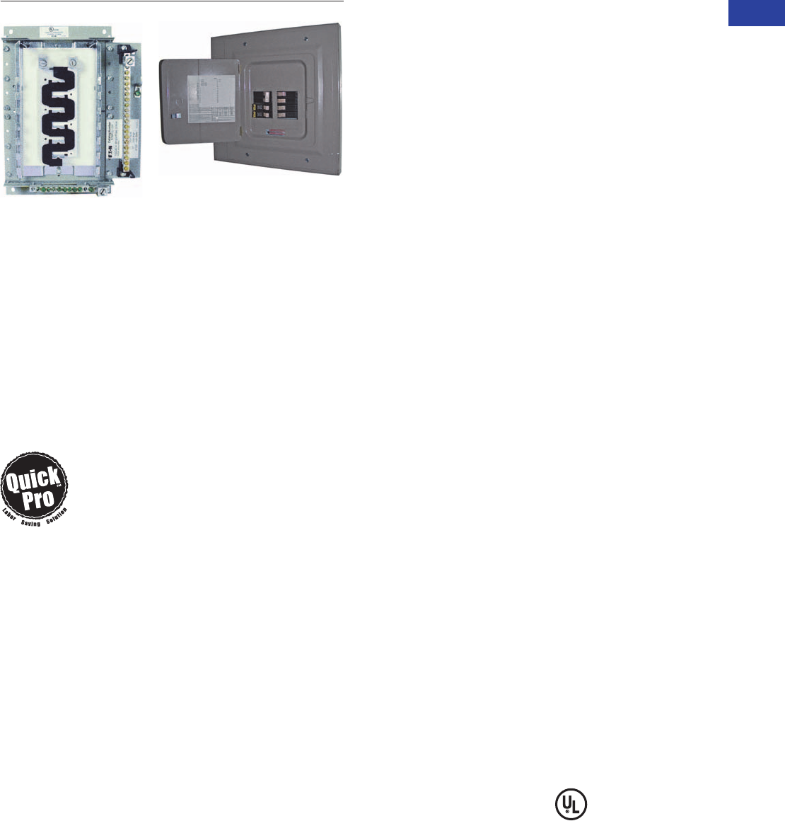
Volume 1—Residential and Light Commercial CA08100002E—April 2015 www.eaton.com V1-T1-73
1
1
1
1
1
1
1
1
1
1
1
1
1
1
1
1
1
1
1
1
1
1
1
1
1
1
1
1
1
1
1.2
Loadcenters and Circuit Breakers
Type BR Loadcenters and Circuit Breakers
Type BR Retrofit Type BR Retrofit Interior Collar
Adjustable Interior and Assembly with Trim
Type BR Retrofit Interior
Contents—BR Specialty Products
Description Page
Overview . . . . . . . . . . . . . . . . . . . . . . . . . . . . . . . V1-T1-42
BR Specialty Products
BR Quick Connect Neutral Loadcenters . . . . . V1-T1-57
Spa Panels . . . . . . . . . . . . . . . . . . . . . . . . . . . . V1-T1-58
Riser Panel. . . . . . . . . . . . . . . . . . . . . . . . . . . . V1-T1-59
Type BR Renovation Loadcenter . . . . . . . . . . . V1-T1-60
Type BR Mechanical Interlock Kits . . . . . . . . . . V1-T1-62
Type BR Retrofit Interior Kits
BR Circuit Breakers. . . . . . . . . . . . . . . . . . . . . . . . V1-T1-76
Type BR Retrofit Interior Kits
Product Description
Eaton’s unique Retrofit
Interior allows the customer
to cost-effectively and safely
upgrade an electrical service
without removing the existing
enclosure from the wall.
Quick-ProSM
All you need to
know to save
time and make
more money.
Specified on certain Eaton
products, the Quick-Pro
symbol allows for immediate
recognition of products
that are designed for
straightforward installation.
When you see Quick-Pro,
you know you can install
quickly—sometimes up to
50% less than the usual
installation time—and move
on to your next job.
Application Description
The Retrofit Interior is
designed and tested
specifically for renovating
an outdated electrical panel in
an apartment, a condominium
or a single family home.
These outdated panels are
being recognized by local
inspectors and other
authorities as a possible
hazard.
Opportunities to Retrofit
●Single- or three-phase
●Main lug only or main
breaker
●Up to 42 circuits
●Up to 225 A interiors,
400 A available upon
request
●Available with CH breakers
(3/4-inch) with copper bus
or BR breakers (1-inch) with
aluminum bus
●The minimum lifetime
warranty for residential
breakers shall be as
follows:
●10-year warranty on all
BR branch breakers and
loadcenters
●Refer to Eaton for
complete warranty
details
Features and Benefits
Upgrading Existing Electrical
Infrastructure Is Simple
●Replaces vintage brands
that have hard to find,
expensive replacement
breakers
●Safety upgrade to arc fault
and ground fault breakers
to meet current electrical
codes
●Maximizes number of
circuits available with
compact design
●Eco-friendly in asbestos-
filled environments
●Exclusive design
Save Time and Money
Throughout the Installation
●Uses existing panel
box and wires
●Eliminates expensive and
time-consuming drywall/
paint repair
●Saves 2–3 hours of
installation time compared
to a complete panel
changeout
●Eliminates precise
measurements with field-
adjustable kit
Detailed Product Guide
All standard retrofit kits are
suitable for a range of
existing box sizes:
●Box width ranging from
14.50 to 22.00 inches
(368.3 to 558.8 mm)
●Box depth ranging from
4.00 inches (101.6 mm)
for BR
●Box height ranging from
21.00 to 45.00 inches
(533.4 to 1143.0 mm)
For box dimensions outside
of these ranges, contact
the Lincoln Flex Center at
800-330-6479. Be sure to
provide the existing incoming
line wire size.
Standards and Certifications
●Meets 2008/2011/2014
NEC wire bending
requirements
●UL 67 Listed (for UL
listings for specific part
numbers, see the table on
the following page.

V1-T1-74 Volume 1—Residential and Light Commercial CA08100002E—April 2015 www.eaton.com
1
1
1
1
1
1
1
1
1
1
1
1
1
1
1
1
1
1
1
1
1
1
1
1
1
1
1
1
1
1
1.2
Loadcenters and Circuit Breakers
Type BR Loadcenters and Circuit Breakers
BR Specialty Product Selection
To select the retrofit kit:
1. From the existing box
size determine which
retrofit groups are
suitable (may be more
than one).
2. Use type of interior,
number of phases, and
type of main to find the
selection chart.
3. Select part number from
chart (if main breaker,
replace XXX with specific
amp rating).
4. Note that the overlap
of the existing wall is
the retro cover size
minus the existing
box size. If specific
measurements are
needed, communicate
that you need a custom
trim size.
5. Contact the Lincoln Flex
Center at 800-330-6479
for pricing, lead-times,
and order entry
instructions.
How to Order:
1. Measure the existing
panel enclosure to
determine appropriate
kits for your project.
2. Match the existing
dimensions with the
table below to obtain the
correct catalog number.
3. Order your retrofit kit
from a local Eaton
authorized distributor.
Need assistance or can’t find
retrofit to fit existing
enclosure?
Call Eaton’s Residential Flex
Center at 1-800-330-6479
or email for all your retrofit
needs. Go to
www.eaton.com/eccn to
locate an Eaton Certified
Contractor.
Retrofit Interior Kit Specifications
Five recommended groups: existing box height determines retro group size. Approximate Dimensions in Inches (mm).
Notes
1Catalog numbers shown with "_" at the end need one of the following suffixes to denote depth:
J = 3.75–4.25
K = 4.25–5.00
L = 5.00–6.00
Example: RTBR12L125J would signify an interior set with a depth range of 3.75 to 4.25 inches.
2****Denotes characters in the catalog number that relate to overall cover size.
Example: CRTBR12ML2620 would signify a cover 26.00 inches H x 20.00 inches W.
3Amperes for MB panels is maximum; catalog number will reflect actual amperage of breaker included.
For UL applications, maximum cover sizes may apply.
Existing Enclosure Parameters—Inches (mm)
Catalog
Number 1Cover 2
Minimum
Depth
Maximum
Depth
Minimum
Width
Minimum
Height Phase Main Bus Amperes
3
Spaces /
Circuits
UL 67
Listed
BR Retrofit Interiors and Covers
RTBR8L100P CRTBR8ML**** 3.13 (79.5) 3.63 (92.2) 10.50 (266.7) 13.00 (330.2) Single MLO BR 100 16 Yes
RUBR8L100_ CRUBR8ML**** 3.75 (95.3) 6.00 (152.4) 10.50 (266.7) 13.00 (330.2) Single MLO BR 100 16 Yes
RTBR12L100P CRTBR12ML**** 3.13 (79.5) 3.63 (92.2) 10.50 (266.7) 14.50 (368.3) Single MLO BR 100 24 Yes
RTBR10B100P CRTBR12ML**** 3.13 (79.5) 3.63 (92.2) 10.50 (266.7) 14.50 (368.3) Single MLO BR 100 20 Yes
RUBR12L100_ CRUBR12ML**** 3.75 (95.3) 6.00 (152.4) 10.50 (266.7) 14.50 (368.3) Single MLO BR 100 24 Yes
RUBR10B100_ CRUBR12ML**** 3.75 (95.3) 6.00 (152.4) 10.50 (266.7) 14.50 (368.3) Single MB BR 100 20 Yes
RTBR12L125P CRTBR12ML**** 3.13 (79.5) 3.63 (92.2) 11.00 (279.4) 17.00 (431.8) Single MLO BR 125 24 Yes
RTBR10B125P CRTBR12ML**** 3.13 (79.5) 3.63 (92.2) 11.00 (279.4) 17.00 (431.8) Single MB BR 125 20 Yes
RUBR12L125_ CRUBR12ML**** 3.75 (95.3) 6.00 (152.4) 11.00 (279.4) 17.00 (431.8) Single MLO BR 125 24 Yes
RUBR10B125_ CRUBR12ML**** 3.75 (95.3) 6.00 (152.4) 11.00 (279.4) 17.00 (431.8) Single MB BR 125 20 Yes
RABR20B125_ CRABR20ML**** 3.75 (95.3) 6.00 (152.4) 13.00 (330.2) 21.00 (533.4) Single MCB BR 125 24 No
RABR20L125_ CRABR20ML**** 3.75 (95.3) 6.00 (152.4) 13.00 (330.2) 21.00 (533.4) Single MLO BR 125 24 No
RBBR20B200_ CRBBR20BW**** 3.75 (95.3) 6.00 (152.4) 13.00 (330.2) 29.00 (736.6) Single MLO BR 200 40 No
RCBR40L200_ CRCBR40ML**** 3.75 (95.3) 6.00 (152.4) 13.00 (330.2) 34.00 (863.6) Single MLO BR 200 40 No
RDBR40B200_ CRDBR40BW**** 3.75 (95.3) 6.00 (152.4) 13.00 (330.2) 37.00 (939.8) Single MLO BR 200 40 No

Volume 1—Residential and Light Commercial CA08100002E—April 2015 www.eaton.com V1-T1-75
1
1
1
1
1
1
1
1
1
1
1
1
1
1
1
1
1
1
1
1
1
1
1
1
1
1
1
1
1
1
1.2
Loadcenters and Circuit Breakers
Type BR Loadcenters and Circuit Breakers
Complete Assembly
Note: For complete assembly,
interior and cover need to be
ordered separately.
Adjustable Interior
●Factory installed ground
and neutral bars positioned
to accept existing wires
●Field adjustable depth
matches existing panel box
●Adjustable height enables
optional placement of the
interior
●Field bondable for service
entrance options
Adjustable Interior
Standard Trim and Collar
●Standard trim matches
new interior
●New circuit directory for
updated labeling
●Oversized collar eliminates
expensive wall/paint repair
Collar and Assembly with Trim
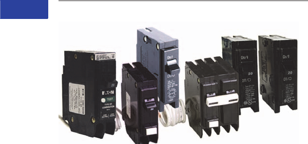
V1-T1-76 Volume 1—Residential and Light Commercial CA08100002E—April 2015 www.eaton.com
1
1
1
1
1
1
1
1
1
1
1
1
1
1
1
1
1
1
1
1
1
1
1
1
1
1
1
1
1
1
1.2
Loadcenters and Circuit Breakers
Type BR Loadcenters and Circuit Breakers
BR Circuit Breakers
Contents
Description Page
Overview . . . . . . . . . . . . . . . . . . . . . . . . . . . . . . . V1-T1-42
BR Specialty Products
BR Quick Connect Neutral Loadcenters . . . . . V1-T1-57
Spa Panels . . . . . . . . . . . . . . . . . . . . . . . . . . . . V1-T1-58
Riser Panel. . . . . . . . . . . . . . . . . . . . . . . . . . . . V1-T1-59
Type BR Renovation Loadcenter . . . . . . . . . . . V1-T1-60
Type BR Mechanical Interlock Kits . . . . . . . . . . V1-T1-62
Type BR Retrofit Interior Kits . . . . . . . . . . . . . . V1-T1-73
BR Circuit Breakers
Product Selection. . . . . . . . . . . . . . . . . . . . . . . V1-T1-77
Circuit Breaker Accessories. . . . . . . . . . . . . . . V1-T1-85
Wiring Diagrams . . . . . . . . . . . . . . . . . . . . . . . V1-T1-87
BR Circuit Breakers
Product Description
Plug-On Branch Feeder Type
Arc Fault Circuit Breakers,
Type BR—10 kAIC, 120 Vac
and 120/240 Vac
A branch feeder type arc fault
circuit interrupter is a device
intended to mitigate high
current arcing faults in the
complete circuit, including
connected cords. High
current arcing faults can
occur from line to neutral or
line to ground. These arcing
faults are in parallel with the
load and produce the most
energy of all arcing faults.
The branch feeder type AFCI
is required in the 1999 and
2002
National Electrical Code.
The
Combination Type AFCI is
required in the 2005, 2008, and
2011 National Electrical Code.
Plug-On Combination Type
Arc Fault Circuit Breakers,
Type BR—10 kAIC, 120 Vac
and 120/240 Vac
A combination type arc
fault circuit interrupter is a
device that includes all of
the protection offered by the
branch feeder AFCI (mitigation
of high current arcing faults in
the complete circuit, including
connected cords). In addition
it provides direct detection of
persistent low current arcing
faults down to 5 amps with
associated mitigation of
fire hazards in the cords
connected to the outlets. High
current arcing faults can occur
from line to neutral or line to
ground. These arcing faults
are in parallel with the load
and produce the most energy
of all arcing faults. The current
level of low current arcing
faults is limited by the load.
Plug-On Ground Fault Circuit
Breakers, Type GFCB and
GFEP—10/22 kAIC, 120 Vac
and 120/240 Vac
Ground Fault
Application Notes
Single-pole GFCBs are
designed for use in two-
wire, 120 Vac circuits. See
Page V1-T1-87 for a typical
wiring configuration.
Two-pole GFCBs are
designed for use in three-
wire, 120/240 Vac circuits,
120 Vac multiwire circuits
employing common, neutral
and two-wire, 240 Vac
circuits obtained from a
120/240 Vac source.
Page V1-T1-87 shows typical
wiring configurations for a
120/240 Vac multiwire
circuits, and a 240 Vac, two-
wire circuit. Note the “panel
neutral” conductor connects
to the neutral bar, even
though the neutral is not
included in the load circuit.
This connection is necessary
to supply a 120 Vac power
source to the ground fault
sensing circuit.
The figures are shown with
a 120/240 Vac, single-phase,
three-wire power source,
but are also applicable to a
120/208 Vac, three-phase,
four-wire power supply.
For all figures, the electrical
operation of the GFCB is
not affected by the
equipment ground.
Non-CTL Plug-On Replacement
—Circuit Breakers, Type BRD—
10 kAIC, 120/240 Vac
Non-CTL 10 kAIC
for Replacement
Purposes Only
For replacement in
enclosures manufactured
prior to 1968 with unnotched
stabs. Circuit breakers do
not have rejection tab.
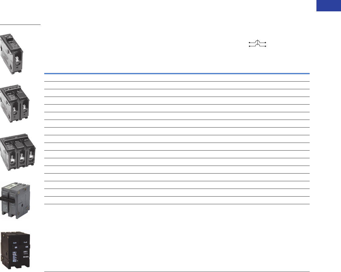
Volume 1—Residential and Light Commercial CA08100002E—April 2015 www.eaton.com V1-T1-77
1
1
1
1
1
1
1
1
1
1
1
1
1
1
1
1
1
1
1
1
1
1
1
1
1
1
1
1
1
1
1.2
Loadcenters and Circuit Breakers
Type BR Loadcenters and Circuit Breakers
Product Selection
Plug-On Circuit Breakers, Types BR—10/22/42 kAIC, 120 Vac, 120/240 Vac and 240 Vac
Type BR Breakers, 1-Inch (25.4 mm) per Pole 120/240, 10, 22 and 42 kAIC
Notes
1 One pole, 1-inch (25.4 mm) per pole circuit breakers are available with high magnetic setting for switching large tungsten lamp loads. Add suffix H to catalog number.
2 Switching duty rated.
3 On the black handle breaker, add suffix “B” to the catalog number to obtain a tapped molded opening for proper use with hold-down kits.
4 For use as a branch circuit breaker in 400 and 600 ampere panels only.
All Type BR single-, two- and three-pole circuit breakers carry listing for HACR application. For circuit breakers with a shunt trip, add ST suffix.
Ampere
Rating
Wire Size Range
Cu/Al 60 °C or 75 °C
Single-Pole 120/240 Vac
Requires One 1-Inch (25.4 mm) Space
Two-Pole 120/240 Vac
Common Trip Requires Two
1-Inch (25.4 mm) Spaces
10 per Shelf Carton 5 per Shelf Carton
10 kAIC 22 kAIC 10 kAIC 22 kAIC 42 kAIC 65 kAIC
Catalog
Number
Catalog
Number
Catalog
Number
Catalog
Number
Catalog
Number
Catalog
Number
10 #14–4 BR110 — BR210 — — —
15 #14–4 BR115 12 BRH115 BR215 3BRH215 — —
20 #14–4 BR120 12 BRH120 BR220 3BRH220 — —
25 #14–4 BR125 BRH125 BR225 3BRH225 — —
30 #14–4 BR130 BRH130 BR230 3BRH230 — —
35 #14–4 BR135 BRH135 BR235 3BRH235 — —
40 #14–4 BR140 BRH140 BR240 3BRH240 3——
45 #14–4 — BRH145 BR245 3BRH245 — —
50 #14–4 BR150 BRH150 BR250 3BRH250 3——
55 #14–3 BR150 BRH155 BR255 BRH255 — —
60 #8–1/0 BR160 BRH160 BR260 BRH260 BRHH260 BRX260
70 #8–1/0 BR170 BRH170 BR270 BRH270 BRHH270 BRX270
80 #8–1/0 — — BR280 BRH280 BRHH280 BRX280
90 #8–1/0 — — BR290 BRH290 BRHH290 BRX290
100 #8–1/0 — — BR2100 BRH2100 BRHH2100 BRX2100
110 #8–1/0 — — BR2110 BRH2110 BRHH2110 BRX2110
125 #4–2/0 — — BR2125 BRH2125 BRHH2125 BRX2125
150 #4–2/0 — — BR2150 4———
BR120
BR215
BR320
BRH2100
BRX2125
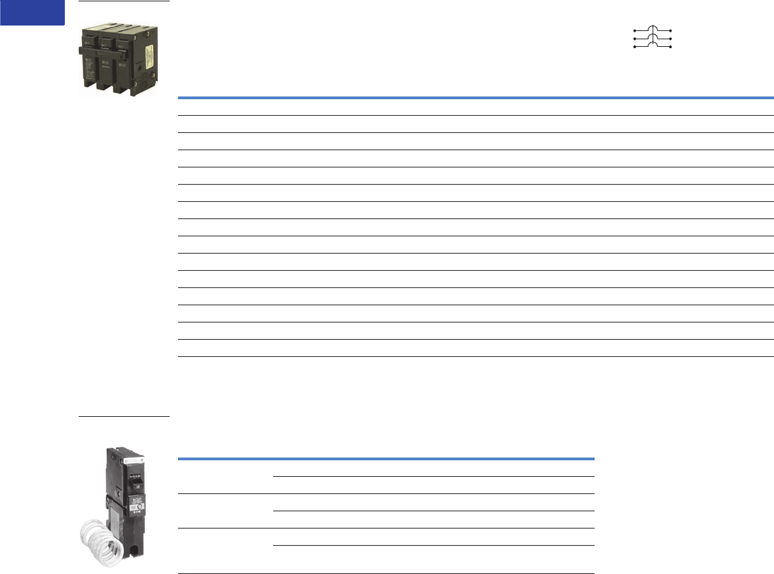
V1-T1-78 Volume 1—Residential and Light Commercial CA08100002E—April 2015 www.eaton.com
1
1
1
1
1
1
1
1
1
1
1
1
1
1
1
1
1
1
1
1
1
1
1
1
1
1
1
1
1
1
1.2
Loadcenters and Circuit Breakers
Type BR Loadcenters and Circuit Breakers
Type BR Breakers, 1-Inch (25.4 mm) per Pole 240 Vac, 10, 22 and 42 kAIC
Plug-On Branch Feeder Type Arc Fault Circuit Breakers, Type BR—10 kAIC, 120 Vac and 120/240 Vac
Type BR, 1-Inch (25.4 mm) Wide FIRE-GUARD AFCI Circuit Breakers
Notes
1 One pole, 1-inch (25.4 mm) per pole circuit breakers are available with high magnetic setting for switching large tungsten lamp loads. Add suffix H to catalog number.
2 Clamshell packaging available with CS modification code on the end of catalog number.
3 Common trip refers to two-pole 240 V load application sourced by 120/240 Vac (see Page V1-T1-87).
4 Independent trip refers to two-pole multi-wire, home run or shared neutral circuits (see Pages V1-T1-87 and V1-T1-88).
All Type BR single-, two- and three-pole circuit breakers carry listing for HACR application. For circuit breakers with a shunt trip, add ST suffix.
Ampere
Rating
Wire Size Range
Cu/Al 60 °C or 75 °C
Three-Pole 240 Vac
Common Trip Requires Three
1-Inch (25.4 mm) Spaces
5 per Shelf Carton
10 kAIC 22 kAIC
Catalog Number Catalog Number
10 #14–4 BR310 —
15 #14–4 BR315 1BRH315
20 #14–4 BR320 1BRH320
25 #14–4 BR325 BRH325
30 #14–4 BR330 BRH330
35 #14–4 BR335 BRH335
40 #14–4 BR340 BRH340
45 #14–4 BR345 BRH345
50 #14–4 BR350 BRH350
55 #14–3 BR355 BRH355
60 #4–1/0 BR360 BRH360
70 #4–1/0 BR370 BRH370
80 #4–1/0 BR380 BRH380
90 #4–1/0 BR390 BRH390
100 #4–1/0 BR3100 BRH3100
Poles
Ampere
Rating Configuration
Catalog
Number
Single-pole
10 kAIC
15 AFCI BR115AF 2
20 AFCI BR120AF 2
Single-pole
22 kAIC
15 AFCI BRH115AF
20 AFCI BRH120AF
Two-pole
10 kAIC 34
15 AFCI Common Trip BRL215AF
20 AFCI Common Trip BRL220AF
BR Breakers
Type BR AFCI
Circuit Breaker
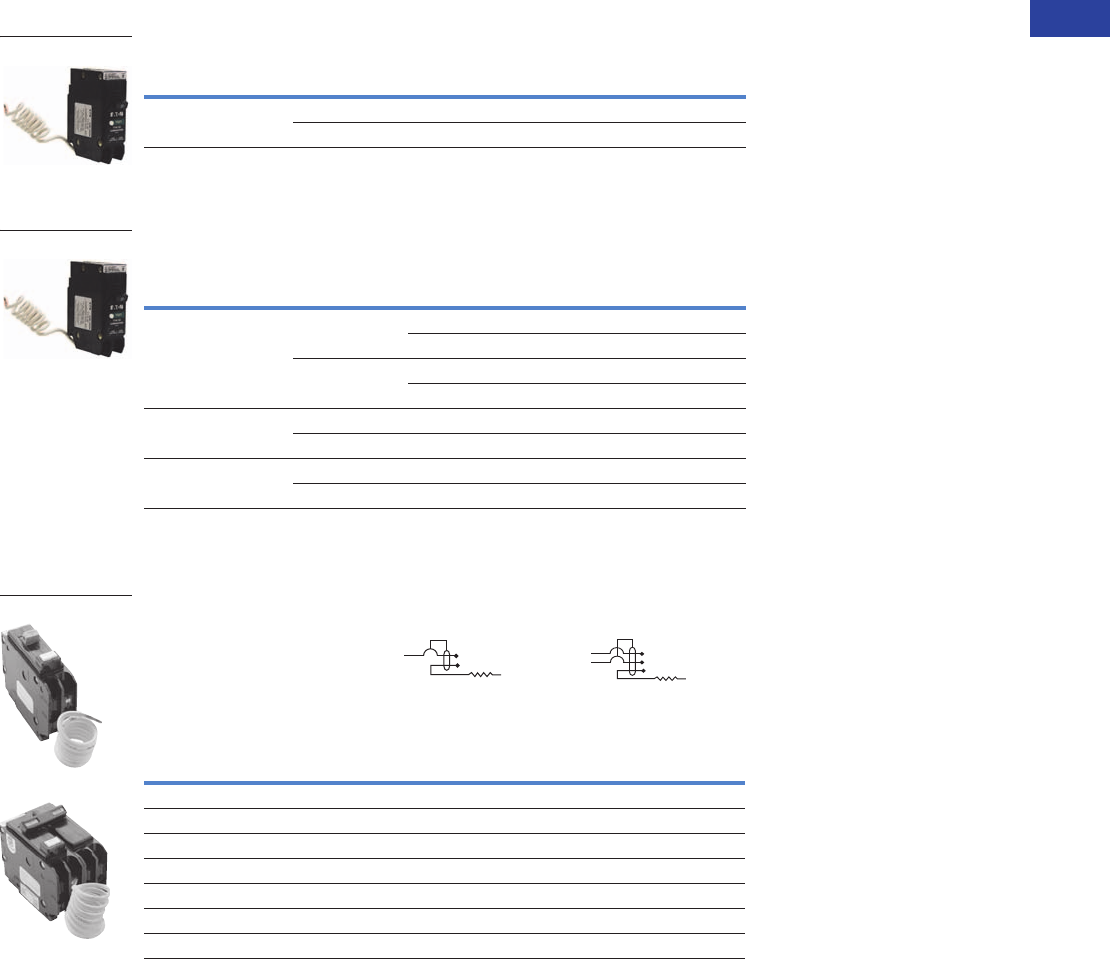
Volume 1—Residential and Light Commercial CA08100002E—April 2015 www.eaton.com V1-T1-79
1
1
1
1
1
1
1
1
1
1
1
1
1
1
1
1
1
1
1
1
1
1
1
1
1
1
1
1
1
1
1.2
Loadcenters and Circuit Breakers
Type BR Loadcenters and Circuit Breakers
Plug-On, Dual Purpose Arc Fault/ Ground Fault Circuit Breakers, Type BR—10 kAIC, 120 Vac
Type BR, 1-Inch (25.4 mm) wide Dual Purpose AF/GF Circuit Breakers 12
Plug-On Combination Type Arc Fault Circuit Breakers, Type BR—10 kAIC, 120 Vac and 120/240 Vac
Type BR, 1-Inch (25.4 mm) wide FIRE-GUARD Combination Type AFCI
Circuit Breakers
Plug-On Ground Fault Circuit Breakers, Type GFCB and GFEP—10/22 kAIC, 120 Vac and 120/240 Vac
Type GFCB Ground Fault Circuit Breakers—5 Milliampere—
1-Inch (25.4 mm) per Pole 120 Vac or 120/240 Vac, 10 kAIC
Notes
1 Breaker qualifies as combination arc fault, per UL 1699.
2 Breaker qualifies as personnel protection ground fault, (5 mA) per UL 943.
3 Clamshell packaging available with CS modification code on the end of catalog number.
4 Available with bell alarm or auxiliary switch. See circuit breaker accessories on Page V1-T1-85.
5 For use with copper wire only.
Poles
Ampere
Rating Configuration
Catalog
Number
Single-pole
10 kAIC
15 Combination AFCI GFCI BRLAFGF115
20 Combination AFCI GFCI BRLAFGF120
Poles
Ampere
Rating Configuration
Catalog
Number
Single-pole
10 kAIC
15 AFCI BRCAF115 3
Diagnostic AFCI BRACAF115
20 AFCI BRCAF120 3
Diagnostic AFCI BRACAF120
Single-pole
22 kAIC
15 AFCI BRHCAF115 3
20 AFCI BRHCAF120 3
Two-pole
10 kAIC
15 AFCI BRL215CAF
20 AFCI BRL220CAF
Ampere
Rating
Wire Size Range
Cu/Al 60 °C or 75 °C
Single-Pole 120 Vac
Requires One
1-Inch (25.4 mm) Space
Two-Pole 120/240 Vac
Common Trip Requires Two
1-Inch (25.4 mm) Spaces
1 per Shelf Carton 1 per Shelf Carton
Catalog Number 4Catalog Number
15 #14–4 GFCB115 GFCB215
20 #14–4 GFCB120 GFCB220
25 #14–4 GFCB125 GFCB225
30 #14–4 GFCB130 GFCB230
40 #14–4 GFCB140 GFCB240
50 #14–4 — GFCB250 5
60 #14–6 — GFCB260
BRLAFGF115
BRCAF115
Type GFCB Single-Pole
Type GFCB Two -Pole

V1-T1-80 Volume 1—Residential and Light Commercial CA08100002E—April 2015 www.eaton.com
1
1
1
1
1
1
1
1
1
1
1
1
1
1
1
1
1
1
1
1
1
1
1
1
1
1
1
1
1
1
1.2
Loadcenters and Circuit Breakers
Type BR Loadcenters and Circuit Breakers
Type GFCBH Ground Fault Breakers—5 Milliampere—
1-Inch (25.4 mm) per Pole 120 Vac or 120/240 Vac, 22 kAIC
Type GFEP Ground Fault Equipment Protectors—30 Milliampere—
1-Inch (25.4 mm) per Pole 120 Vac or 120/240 Vac, 10 kAIC
Note
1 For use with copper wire only.
Ampere
Rating
Wire Size Range
Cu/Al 60 °C or 75 °C
Single-Pole 120 Vac
Requires One
1-Inch (25.4 mm) Space
Two-Pole 120/240 Vac
Common Trip Requires Two
1-Inch (25.4 mm) Spaces
1 per Shelf Carton 1 per Shelf Carton
Catalog Number Catalog Number
15 #14–4 GFCBH115 GFCBH215
20 #14–4 GFCBH120 GFCBH220
25 #14–4 GFCBH125 GFCBH225
30 #14–4 GFCBH130 GFCBH230
Ampere
Rating
Wire Size Range
Cu/Al 60 °C or 75 °C
Single-Pole 120 Vac
Requires One
1-Inch (25.4 mm) Space
Two-Pole 120/240 Vac
Common Trip Requires Two
1-Inch (25.4 mm) Space
1 per Shelf Carton 1 per Shelf Carton
Catalog Number Catalog Number
15 #14–4 GFEP115 GFEP215
20 #14–4 GFEP120 GFEP220
25 #14–4 GFEP125 GFEP225
30 #14–4 GFEP130 GFEP230
40 #14–4 — GFEP240
50 #14–4 — GFEP250 1
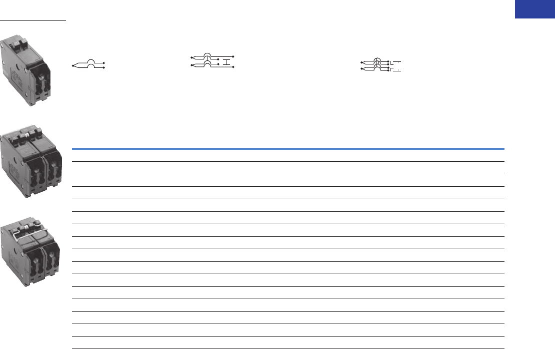
Volume 1—Residential and Light Commercial CA08100002E—April 2015 www.eaton.com V1-T1-81
1
1
1
1
1
1
1
1
1
1
1
1
1
1
1
1
1
1
1
1
1
1
1
1
1
1
1
1
1
1
1.2
Loadcenters and Circuit Breakers
Type BR Loadcenters and Circuit Breakers
CTL Plug-On Circuit Breakers, Type BD Duplex, BQ and BQC Quadplex—10 kAIC, 120/240 Vac
Class CTL, 1-Inch (25.4 mm) per Pole 10 kAIC—All Circuit Breakers Have Rejection Tab Feature
Notes
1 All 15 and 20 A single poles are switch-duty rated.
2 All Type BD duplex and BQ quadplex circuit breakers carry listing for HACR applications.
Type BD Duplex
(UL Type BRD)
Wire Size
Range
Cu/Al
65 °C or 75 °C
Type BQ Quadplex Independent Trip
(UL Type BRD)
Type BQ Quadplex Independent Trip
(UL Type BRD)
Single-Pole 1
Requires One 1-Inch
(25.4 mm) Space
10 per Shelf Carton
Two-Pole 2 and Single-Pole 1
Requires Two 1-Inch
(25.4 mm) Spaces
5 per Shelf Carton
Two-Pole
Requires Two 1-Inch
(25.4 mm) Spaces
5 per Shelf Carton
Ampere
Rating
120 Vac 120 Vac 120/240 Vac 120 Vac
Catalog
Number
120/240 Vac
Catalog
Number
Catalog
Number
Ampere Rating Ampere Rating
Outer Left
Single-Pole
Center Two-Pole
Independent Trip
Outer Right
Single-Pole
Outer Two-Pole
Independent Trip
Center Two-Pole
Independent Trip
10–10 BD1010 #14–4 15 20 15 BQ2202115 15 15 BQ215215
15–15 BD1515 #14–4 20 20 20 BQ2202120 15 20 BQ215220
15–20 BD1520 #14–4 15 30 15 BQ2302115 15 30 BQ215230
15–30 BD1530 #14–4 20 30 20 BQ2302120 15 40 BQ215240
20–15 BD2015 #14–4 15 40 15 BQ2402115 15 50 BQ215250
20–20 BD2020 #14–4 20 40 20 BQ2402120 20 20 BQ220220
20–30 BD2030 #14–4 15 50 15 BQ2502115 20 30 BQ220230
25–25 BD2525 #14–4 20 50 20 BQ2502120 20 40 BQ220240
30–15 BD3015 #14–4 — — — —20 50 BQ220250
30–20 BD3020 #14–4 — — — —25 25 BQ225225
30–30 BD3030 #14–4 — — — —30 30 BQ230230
30–40 BD3040 #14–4 — — — —30 40 BQ230240
30–50 BD3050 #14–4 — — — —30 50 BQ230250
50–30 BD5030 #14–4 — — — —40 40 BQ240240
50–50 BD5050 #14–4 — — — —40 50 BQ240250
————— ——50 50 BQ250250
BD2020
BQ2302115
BQ230230
120/240 Vac
120/240 Vac
120 Vac
120 Vac
120/240 Vac 120/240 Vac
120/240 Vac
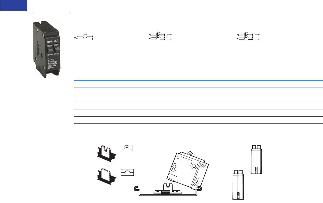
V1-T1-82 Volume 1—Residential and Light Commercial CA08100002E—April 2015 www.eaton.com
1
1
1
1
1
1
1
1
1
1
1
1
1
1
1
1
1
1
1
1
1
1
1
1
1
1
1
1
1
1
1.2
Loadcenters and Circuit Breakers
Type BR Loadcenters and Circuit Breakers
Non-CTL Plug-On Replacement—Circuit Breakers, Type BRD—10 kAIC, 120/240 Vac
Class Non-CTL, 1-Inch (25.4 mm) per Pole 10 kAIC—Breakers Do Not Have Rejection Tab Feature
CTL and Non-CTL Breakers
Note
Type BD Duplex, BQ and BQC Quadplex circuit breakers can be installed in Circuit Limiting (CTL) listed BR loadcenters. Type BR twin breakers can be installed in
Non-CTL BR loadcenters.
Type BR Duplex
Wire Size
Range
Cu/Al
65 °C or 75 °C
Type Brand BRD Quadplex Independent Trip
Type BRD Quadplex Common Trip
Center and Outer Poles
Single-Pole Requires One
1-Inch (25.4 mm) Space
10 per Shelf Carton
Two-Pole Requires Two
1-Inch (25.4 mm) Spaces
5 per Shelf Carton
Two-Pole Requires Two
1-Inch (25.4 mm) Spaces
5 per Shelf Carton
Ampere
Rating
120 Vac 120/240 Vac 120/240 Vac
Catalog
Number
120/240 Vac
Catalog
Number
Catalog
Number
Ampere Rating Ampere Rating
Outer Two-Pole
Independent Trip
Center Two-Pole
Independent Trip
Outer Two-Pole
Common Trip
Center Two-Pole
Common Trip
15–15 BR1515 #14–4 15 15 BR415 15 15 BRDC215215
15–20 BR1520 #14–4 20 20 BR420 30 30 BRDC230230
20–15 BR2015 #14–4 30 30 BR430 30 40 BRDC230240
20–20 BR2020 #14–4 20 30 BRD220230 30 50 BRDC230250
30–30 BR3030 #14–4 30 40 BRD230240 —— —
30–50 BR3050 #14–4 30 50 BRD230250 —— —
BR2020
120/240 Vac
120/240 Vac
120/240 Vac
120/240 Vac
120/240 Vac
120/240 Vac
Notched
Bus Stab
Unnotched
Bus Stab
Type BR or Type BD Duplex, (CTL),
Type BQ and
BQC Quadplex
Type BR Notched
Stab Non-CTL
Non-Circuit
Limiting
Type BR
Type BD
Duplex
Rejection
Tab
CTL Circuit
Limiting
Feature
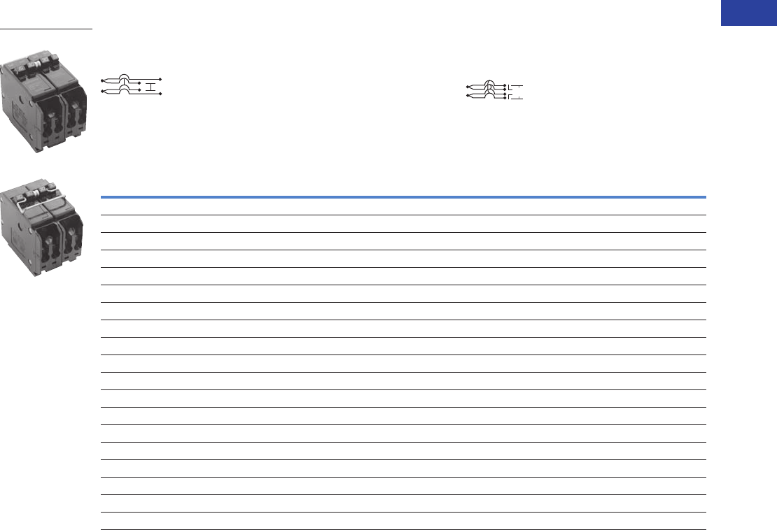
Volume 1—Residential and Light Commercial CA08100002E—April 2015 www.eaton.com V1-T1-83
1
1
1
1
1
1
1
1
1
1
1
1
1
1
1
1
1
1
1
1
1
1
1
1
1
1
1
1
1
1
1.2
Loadcenters and Circuit Breakers
Type BR Loadcenters and Circuit Breakers
Common Trip Quadplex Breakers
Class CTL, 1-Inch (25.4 mm) per Pole 10 kAIC—All Circuit Breakers Have Rejection Tab Feature
Notes
1 All Type BQC quadplex circuit breakers carry listing for HACR applications.
2 All 15 and 20 ampere single poles are switch-duty rated.
Type BQC Quadplex Common Trip Center Poles
(UL Type BRD)
Wire Size Range
Cu/Al 65 °C
or 75 °C
Type BQC Quadplex Common Trip Center and Outer Poles
(UL Type BRD)
Two-Pole 1 and Single-Pole 2
Requires Two 1-Inch (25.4 mm) Spaces
5 per Shelf Carton
Two-Pole 1
Requires Two 1-Inch (25.4 mm) Spaces
5 per Shelf Carton
120 Vac 120/240 Vac 120 Vac
Catalog
Number
120/240 Vac
Catalog
Number
Ampere Rating Ampere Rating
Outer Left
Single-Pole
Center Two-Pole
Common Trip
Outer Right
Single-Pole
Outer Two-Pole
Common Trip
Center Two-Pole
Common Trip
15 20 15 BQC2202115 #14–4 15 15 BQC215215
15 25 15 BQC2252115 #14–4 15 20 BQC215220
15 30 15 BQC2302115 #14–4 15 30 BQC215230
15 40 15 BQC2402115 #14–4 20 15 BQC220215
15 50 15 BQC2502115 #14–4 20 20 BQC220220
—— ——#14–4 20 30 BQC220230
—— ——#14–4 20 40 BQC220240
—— ——#14–4 20 50 BQC220250
20 15 20 BQC2152120 #14–4 25 25 BQC225225
20 20 20 BQC2202120 #14–4 25 30 BQC225230
20 25 20 BQC2252120 #14–4 30 15 BQC230215
20 30 20 BQC2302120 #14–4 30 30 BQC230230
20 40 20 BQC2402120 #14–4 30 40 BQC230240
20 50 20 BQC2502120 #14–4 30 50 BQC230250
30 50 20 BQC2502030 #14–4 40 30 BQC240230
—— ——#14–4 40 40 BQC240240
—— ——#14–4 40 50 BQC240250
—— ——#14–4 50 20 BQC250220
—— ——#14–4 50 50 BQC250250
BQC2302115
BQC2302115
120 Vac
120 Vac
120/240 Vac
120/240 Vac
120/240 Vac
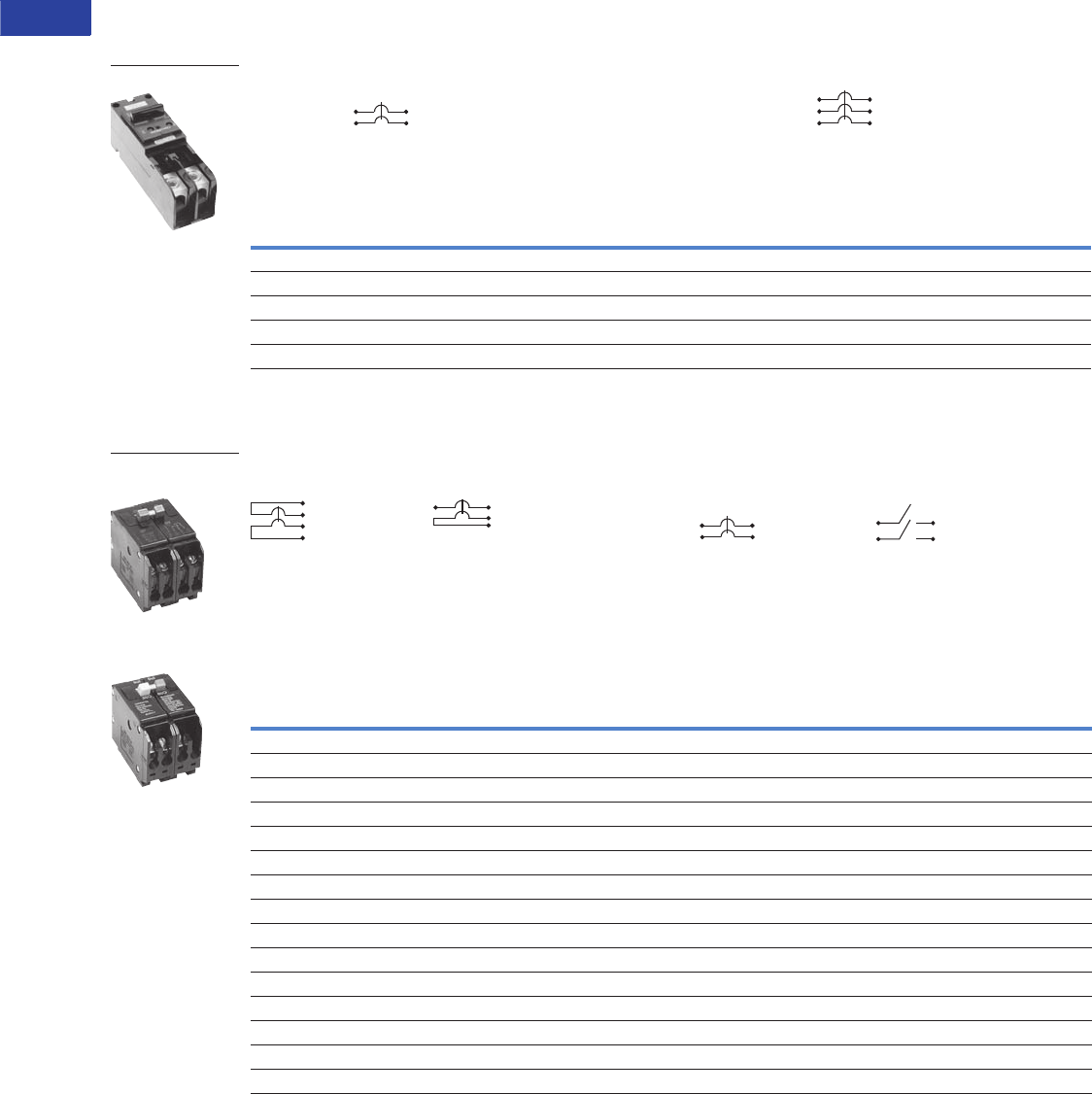
V1-T1-84 Volume 1—Residential and Light Commercial CA08100002E—April 2015 www.eaton.com
1
1
1
1
1
1
1
1
1
1
1
1
1
1
1
1
1
1
1
1
1
1
1
1
1
1
1
1
1
1
1.2
Loadcenters and Circuit Breakers
Type BR Loadcenters and Circuit Breakers
Plug-On Circuit Breakers, Types BJ and BJH—10/22 kAIC, 120/240 Vac and 240 Vac
For Use in Single-Phase and Three-Phase Loadcenters—150 Amperes and Above
Types BJ and BJH Breakers, 1-Inch (25.4 mm) per Pole, 120/240 or 240 Vac, 10, 22 kAIC
Plug-On Special Application Circuit Breakers—10 kAIC, 120 Vac, 120/240 Vac and 240 Vac
Special Application Circuit Breakers, 1-Inch (25.4 mm) per Pole
Notes
1 Breaker uses two 1-inch (25.4 mm) pole spaces on left side and two 1-inch (25.4 mm) pole spaces on right side of loadcenter.
2 Breaker uses three 1-inch (25.4 mm) pole spaces on left side and three 1-inch (25.4 mm) pole spaces on right side of loadcenter.
If BJ or BJH breakers are used as a main or a back feed device, a hold-down kit is required. See Page V1-T1-85.
Ampere
Rating
Wire Size Range
Cu/Al 60 °C or 75 °C
Two-Pole 120/240 Vac
Common Trip Requires Four
1-Inch (25.4 mm) Spaces 1
10 per Shelf Carton
Three-Pole 240 Vac
Common Trip Requires Six
1-Inch (25.4 mm) Spaces 2
5 per Shelf Carton
10 kAIC 22 kAIC 10 kAIC 22 kAIC
Catalog Number Catalog Number Catalog Number Catalog Number
125 BJ2125 BJH2125 #2–300 kcmil BJ3125 BJH3125
150 BJ2150 BJH2150 #2–300 kcmil BJ3150 BJH3150
175 BJ2175 BJH2175 #2–300 kcmil BJ3175 BJH3175
200 BJ2200 BJH2200 #2–300 kcmil BJ3200 BJH3200
225 BJ2225 BJH2225 #2–300 kcmil BJ3225 BJH3225
Water Heater Breakers Switching Neutral Breakers
Wire
Size
Range
Cu/Al
60 °C or
75 °C
240 V Breakers Non-Automatic Molded Case Switches
Two-Pole 120/240 Vac
Common Trip Requires Two
1-Inch (25.4 mm) Spaces
Two-Pole 120 Vac
Common Trip Requires Two
1-Inch (25.4 mm) Spaces
Two-Pole 240 Vac
Common Trip Requires Two
1-Inch (25.4 mm) Spaces
Two-Pole 240 Vac
Requires Two
1-Inch (25.4 mm) Spaces
With Isolated Line Terminals
for Separately Metered
Water Heaters
With Switching Neutral Pole
for Gasoline Pump Applications
Where Voltage to
Ground is 240 Vac
For Use as Disconnect Contains No
Magnetic or Thermal Trip Properties
5 per Shelf Carton 5 per Shelf Carton 5 per Shelf Carton 5 per Shelf Carton
10 kAIC 10 kAIC 10 kAIC 5 kAIC
Ampere
Rating
Catalog
Number
Ampere
Rating
Catalog
Number
Ampere
Rating
Catalog
Number
Ampere
Rating
Catalog
Number
15 BRWH215 15 BRSN215 #14–4 10 BR210H ——
20 BRWH220 20 BRSN220 #14–4 15 BR215H ——
30 BRWH230 25 BRSN225 #14–4 20 BR220H ——
——30 BRSN230 #14–4 25 BR225H ——
————#14–4 30 BR230H ——
————#14–4 35 BR235H ——
————#14–4 40 BR240H ——
————#14–4 45 BR245H ——
————#14–4 50 BR250H 50 BR250NA
————#14–4 55 BR255H ——
————#4–1/0 60 BR260H 60 BR260NA
————#4–1/0 70 BR270H ——
————#4–1/0 80 BR280H ——
————#4–1/0 90 BR290H ——
————#4–1/0 100 BR2100H 100 BR2100NA
Type BJ
BRWH215
Water Heater Breaker
BRSN220
Switching Neutral
Breaker
LINE
LOAD
OUT
IN
NEUTRAL
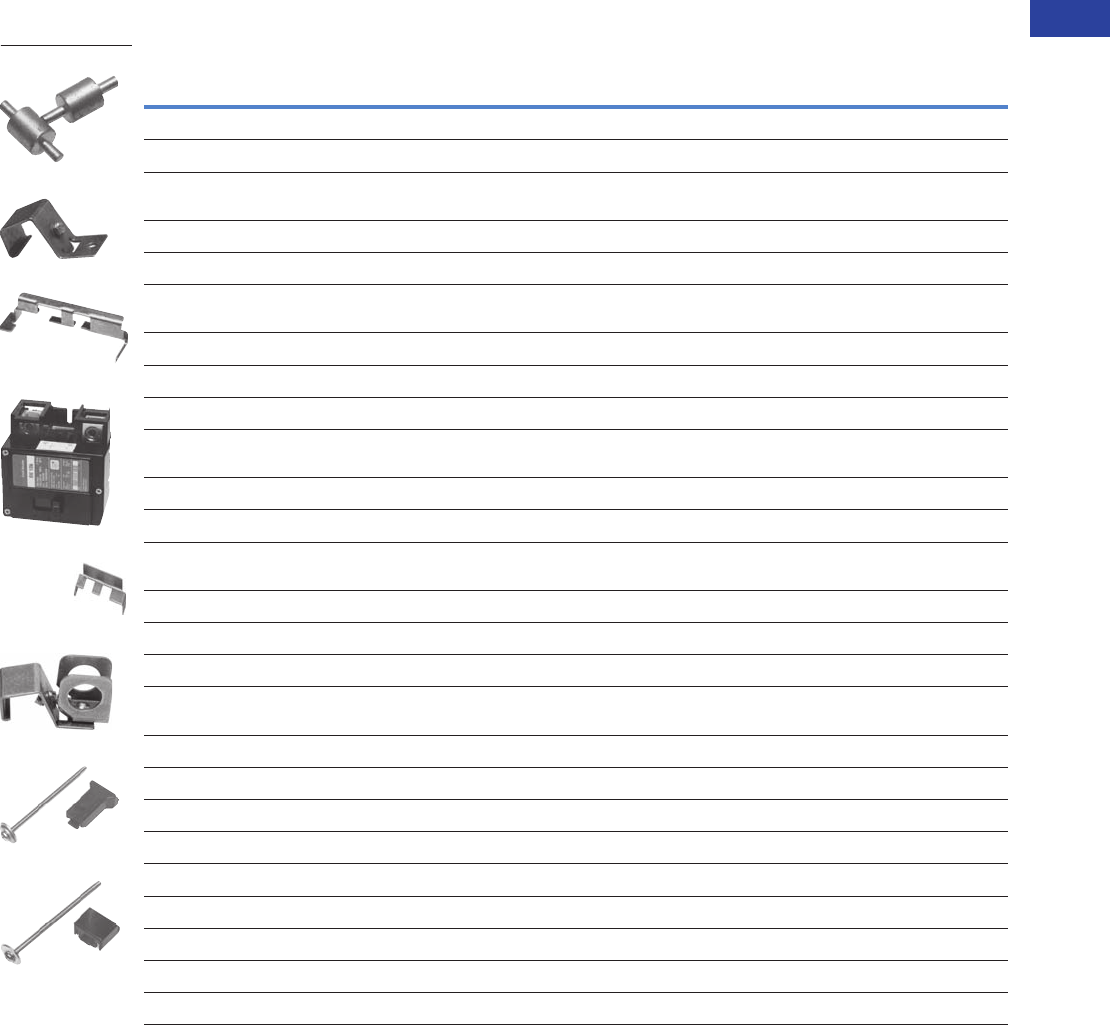
Volume 1—Residential and Light Commercial CA08100002E—April 2015 www.eaton.com V1-T1-85
1
1
1
1
1
1
1
1
1
1
1
1
1
1
1
1
1
1
1
1
1
1
1
1
1
1
1
1
1
1
1.2
Loadcenters and Circuit Breakers
Type BR Loadcenters and Circuit Breakers
Circuit Breaker Accessories
Field Installation Kits and Parts
Notes
1 Must be purchased in multiples of ordering quantities indicated.
2 Handle ties: typically used to join two similar independent single-pole breakers to form a two-pole noncommon trip breaker.
3 Handle lockoffs: devices that use a padlock to lock the circuit breaker’s handle in the ON or OFF position.
4 See table on Page V1-T1-86 for handle position changeability chart.
5 Escutcheon mounted: device mounted semipermanently to the face of the circuit breaker and secured by the loadcenter deadfront.
6 Handle mounted: device mounted directly to the handle by the use of a set screw.
7 Screw mounted: device permanently mounted to the face of the circuit breaker by the use of a non-removable screw.
8 Hold-down kits: devices used to secure the circuit breaker to the loadcenter for back-feed main application. See NEC Article 384.16(g).
Description
Ordering
Quantity
1
Catalog
Number
Handle Ties 2
Handle tie bar for physically joining the handles of two adjacent single-pole Type BR circuit breakers (metal cylinder pin type)10BHT
Handle tie bar for joining two independent outside poles of Types BQ and BQC Quadplex and outside poles of two Type BD
duplex circuit breakers
10 THOW
Handle tie bar for joining two adjacent outside poles of Types BQ and BQC Quadplex and outside poles of two Type BD duplex circuit breakers 10 THS1
Handle Lockoffs 34
Padlockable device for locking the handle of single-, two- or three-pole Type BR Circuit Breakers and single-pole of a Type BD Duplex
or one independent outside pole of a Type BQ or BQC Quadplex circuit breakers (escutcheon mounted) 5
10 BRLW
Padlockable device for locking the handle of a single-pole Type BR circuit breaker (handle mounted) 610 BRLW1
Padlockable device for locking the handle of a two- and three-pole Type BR circuit breaker (handle mounted) 610 BRLW2
Padlockable device for locking the handle of a single-pole Type BD Duplex, BQ or BQC Quadplex breaker (handle mounted) 610 BRDL1
Padlockable device for locking the handle of the two center poles and the two outer poles of a two-pole Types BQ and BQC quadplex
circuit breakers (escutcheon mounted) 5
10 BRQLW
Padlockable device for locking the handle of main circuit breaker Types CC and CHH into the ON or OFF position (screw mounted) 7 1 CCPL
Padlockable device for locking the handle of main breaker Types BW and CSR into the ON or OFF position (escutcheon mounted) 51MCBPL
Device used to secure handle in ON or OFF position for single-, two- or three-pole Type BR circuit breakers and single-pole of Type BD
duplex and one independent outside pole of Type BQ or BQC Quadplex circuit breakers (escutcheon mounted) 5
10 BHLW
Device used to secure handle in ON or OFF position for single-pole Type BR circuit breakers (handle mounted) 610 BHLW1
Device used to secure handle in ON or OFF position for two- and three-pole Type BR circuit breakers (handle mounted) 610 BHLW2
Device used to secure handle in ON or OFF position for single-pole Type GFCB ground fault circuit breakers (handle mounted) 610 BHGW
Device used to secure handle in ON or OFF position for one independent outside pole of Types BQ and BQC Quadplex or single-pole
Type BD duplex circuit breakers (handle mounted) 6
10 HLW1
Hold-Down Kits 8
Hold-down retainer kit for three-pole Type BR circuit breakers in S3100 and 3100R loadcenters only 1 BRHDB
Hold-down screw kit for two- and three-pole Type BR circuit breakers in single-phase MLO loadcenters through 100–125 A 1 BREQS125
Hold-down screw kit for two- and three-pole Type BR circuit breakers in MLO loadcenters 150–225 A 1 BRHDK125
Hold-down screw kit for two-pole Types BJ and BJH circuit breakers in MLO loadcenters 125–225 A 1 BJHDS
Hold-down screw kit for three-pole Types BJ and BJH circuit breakers in MLO loadcenters 125–225 A 1 BJHDS3P
Main Breaker Lug Kits
Types CC and CHH main breaker lug kit (2) 300 kcmil 1CCL300
Types BW/CSR main breaker lug kit (2) 300 kcmil 1MCBL300
THS1
BHLW2
BRQLW
MCBPL (Installed)
BHLW
BRLW2
BREQS125
BRHDK125

V1-T1-86 Volume 1—Residential and Light Commercial CA08100002E—April 2015 www.eaton.com
1
1
1
1
1
1
1
1
1
1
1
1
1
1
1
1
1
1
1
1
1
1
1
1
1
1
1
1
1
1
1.2
Loadcenters and Circuit Breakers
Type BR Loadcenters and Circuit Breakers
Field Installation Kits and Parts, continued
Shunt Trips, Auxiliary and Alarm Contacts
Handle Position Changeability Chart
Notes
1 Must be purchased in multiples of ordering quantities indicated.
2 Add suffix indicated to end of breaker catalog number.
Description
Ordering
Quantity
1
Catalog
Number
Mechanical Interlocks
Types BR for two-, three- and four-pole breakers 10 BRML
10 BRPLOFF
10 BRPLOFF2P
10 BRPLOFF3P
10 BJL2P
10 BJL3P
10 GHQRLOFF2P
10 GHQRLOFF
10 QCD123PLOFF
Description
Catalog Number 2
Suffix Adder
Shunt Trip for Types BW/CSR
12 Volts SR12
24 Volts SR24
120 Volts SR01
Shunt Trip for Types BR
120 Volts ST
Auxiliary Contact for Types BW/CSR
1NO and 1NC AL1
2NO and 2NC AL2
Alarm Contacts for Types BW/CSR
Types BW/CSR CR1
Alarm Contacts for Type GFCB (Single-Pole)
Alarm contact for GFCB (single-pole) W1
1NO and 1NC W2
Handle Lockoff and
Lockdog Types
To Change Handle Position from ON to OFF, or OFF to ON
You Must...
Remove
Padlock
Remove
Device
Remove
Loadcenter
Deadfront
Lockoff escutcheon mounted Remove — —
Lockoff handle mounted Remove Remove —
Lockoff screw mounted Remove — —
Lockdog escutcheon mounted N/A Remove Remove
Lockdog handle mounted N/A Remove —
BRML
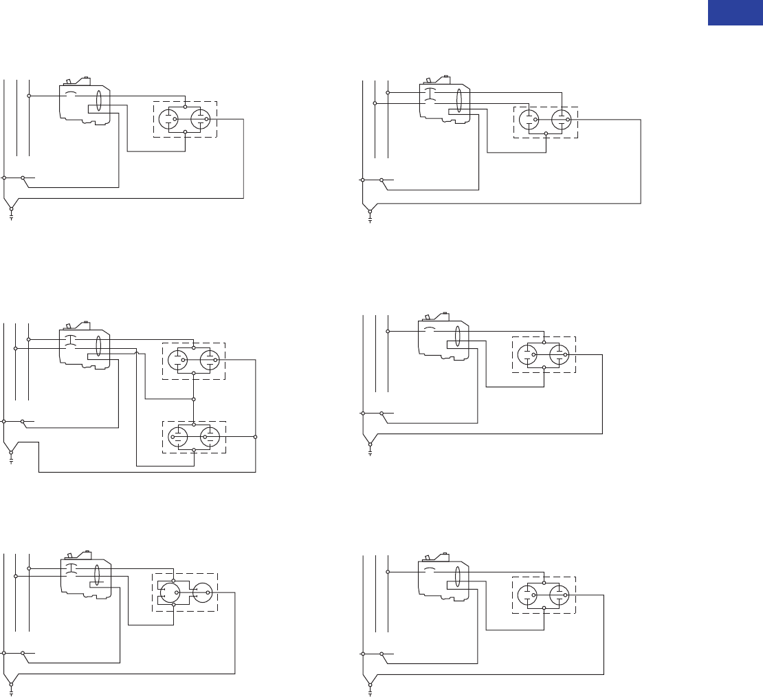
Volume 1—Residential and Light Commercial CA08100002E—April 2015 www.eaton.com V1-T1-87
1
1
1
1
1
1
1
1
1
1
1
1
1
1
1
1
1
1
1
1
1
1
1
1
1
1
1
1
1
1
1.2
Loadcenters and Circuit Breakers
Type BR Loadcenters and Circuit Breakers
Wiring Diagrams
Single-Pole 120 V Load Application Sourced by 120/240 Vac
Two-Pole Shared Neutral with
Multi-Duplex Receptacle Application
Two-Pole 240 V Load Application Sourced by 120/240 Vac
Two-Pole Shared Neutral with Duplex Receptacle Application
Single-Pole 120 V Load Application Sourced by 120/240 Vac
Single-Pole 120 V Duplex Receptacle Application
NAB
120/240 Vac
Source
120V
Duplex
Receptacle
Single-Pole
Line B
Neutral
Neutral
Equipment Ground
NA B
120/240 Vac
Source
Two 120V
Duplex
Receptacles
Two-Pole
Line B
Line A
Neutral
Neutral
Equipment Ground
Line B
NA B
120/240 Vac
Source
Line A 240V
Duplex
Receptacle
Two-Pole
Neutral
Equipment Ground
NAB
120/240 Vac
Source
Line A
120V Duplex
Receptacle
(With Line Side
Jumper Removed)
Two-Pole
Line B
Neutral
Neutral
Equipment Ground
NAB
120/240 Vac
Source
120V
Duplex
Receptacle
Single-Pole
Line B
Neutral
Neutral
Equipment Ground
NAB
120/240 Vac
Source
120V
Duplex
Receptacle
Single-Pole
Line B
Neutral
Neutral
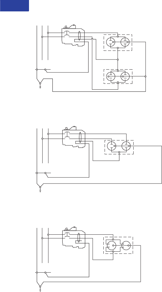
V1-T1-88 Volume 1—Residential and Light Commercial CA08100002E—April 2015 www.eaton.com
1
1
1
1
1
1
1
1
1
1
1
1
1
1
1
1
1
1
1
1
1
1
1
1
1
1
1
1
1
1
1.2
Loadcenters and Circuit Breakers
Type BR Loadcenters and Circuit Breakers
Two-Pole 120 V Multi-Duplex Receptacle Application
Two-Pole 120 V Duplex Receptacle Application
Two-Pole 240 V Duplex Receptacle Application
NA B
120/240 Vac
Source
Two 120V
Duplex
Receptacles
Two-Pole
Line B
Line A
Neutral
Neutral
NAB
120/240 Vac
Source
Line A
120V Duplex
Receptacle
(With Line Side
Jumper Removed)
Two-Pole
Line B
Neutral
Neutral
Line B
NA B
120/240 Vac
Source
Line A 240V
Duplex
Receptacle
Two-Pole
Neutral
