SS207 EN_Ver1.0 1000461851 Catalog
2016-07-29
: Pdf 1000461851-Catalog 1000461851-Catalog B2 unilog
Open the PDF directly: View PDF ![]() .
.
Page Count: 130 [warning: Documents this large are best viewed by clicking the View PDF Link!]
- Lexium Motion control
- Catalogue January 04 - DIA7ED2031006EN
- Contents
- 1 - Lexium motion control
- 2 - Modicon Premium motion control modules
- 3 - Modicon Quantum motion control modules
- 4 - Lexium servodrives
- 5 - SER brushless motors
- 6 - Lexium BPH brushless motors
- 7 - Additional products and services
01-04
Lexium
Motion control
Catalogue
January
04
Lexium motion control
www.schneider-electric.com
January 2004
Schneider Electric Industries SAS
DIA7ED2031006EN - © 2004 Schneider Electric - All right reserved
ART. 66692
Telemecanique
This document provided by Barr-Thorp Electric Co., Inc. 800-473-9123 www.barr-thorp.com

This document provided by Barr-Thorp Electric Co., Inc. 800-473-9123 www.barr-thorp.com

1
Contents Lexium motion control
1
1 - Lexium motion control
bPresentation . . . . . . . . . . . . . . . . . . . . . . . . . . . . . . . . . . . . . . . . . . . . . . . . page 2
bAssociation of brushless motors and servodrives . . . . . . . . . . . . . . . . . . . .page 3
2 - Modicon Premium motion control modules
Selection guides
Counter and electronic cam modules . . . . . . . . . . . . . . . . . . . . . . . . . . . . .page 4
Motion control modules . . . . . . . . . . . . . . . . . . . . . . . . . . . . . . . . . . . . . . . .page 6
bTSX CFY 11/21 motion control modules for stepper motors . . . . . . . . . . . . page 8
bTSX CAY motion control modules for servomotors . . . . . . . . . . . . . . . . . page 12
bTSX CFY/CAY module software setup . . . . . . . . . . . . . . . . . . . . . . . . . . . page 22
bSERCOS TSX CSY 84/164 motion control modules. . . . . . . . . . . . . . . . . page 24
3 - Modicon Quantum motion control modules
Selection guide, motion control modules. . . . . . . . . . . . . . . . . . . . . . . . .page 32
b140 MSB 101 00 single-axis motion module for servomotors . . . . . . . . . page 34
bSERCOS 141 MMS motion control modules . . . . . . . . . . . . . . . . . . . . . . page 38
4 - Lexium servodrives
bPresentation, description and functions. . . . . . . . . . . . . . . . . . . . . . . . . . . page 46
bUnilink software . . . . . . . . . . . . . . . . . . . . . . . . . . . . . . . . . . . . . . . . . . . . . page 51
bConnectivity of MHDA servodrives . . . . . . . . . . . . . . . . . . . . . . . . . . . . . . page 56
bCharacteristics and references . . . . . . . . . . . . . . . . . . . . . . . . . . . . . . . . . page 62
bDimensions and connections. . . . . . . . . . . . . . . . . . . . . . . . . . . . . . . . . . . page 68
5 - SER brushless motors
bPresentation, functions and description. . . . . . . . . . . . . . . . . . . . . . . . . . . page 76
bCharacteristics and dimensions . . . . . . . . . . . . . . . . . . . . . . . . . . . . . . . . page 79
bReferences . . . . . . . . . . . . . . . . . . . . . . . . . . . . . . . . . . . . . . . . . . . . . . . . page 86
bHolding brake . . . . . . . . . . . . . . . . . . . . . . . . . . . . . . . . . . . . . . . . . . . . . . page 88
bPLE gearboxes . . . . . . . . . . . . . . . . . . . . . . . . . . . . . . . . . . . . . . . . . . . . . page 89
6 - Lexium BPH brushless motors
bPresentation, functions and description. . . . . . . . . . . . . . . . . . . . . . . . . . . page 92
bCharacteristics and dimensions . . . . . . . . . . . . . . . . . . . . . . . . . . . . . . . . page 95
bReferences . . . . . . . . . . . . . . . . . . . . . . . . . . . . . . . . . . . . . . . . . . . . . . . page 106
7 - Additional products and services
bSizing the brushless motor and braking resistor . . . . . . . . . . . . . . . . . . . page 110
bPhaseo regulated power supplies . . . . . . . . . . . . . . . . . . . . . . . . . . . . . . page 112
bAutomation product certifications . . . . . . . . . . . . . . . . . . . . . . . . . . . . . . page 118
bSchneider Electric worldwide. . . . . . . . . . . . . . . . . . . . . . . . . . . . . . . . . . page 120
bIndex . . . . . . . . . . . . . . . . . . . . . . . . . . . . . . . . . . . . . . . . . . . . . . . . . . . . page 127
This document provided by Barr-Thorp Electric Co., Inc. 800-473-9123 www.barr-thorp.com
2
1
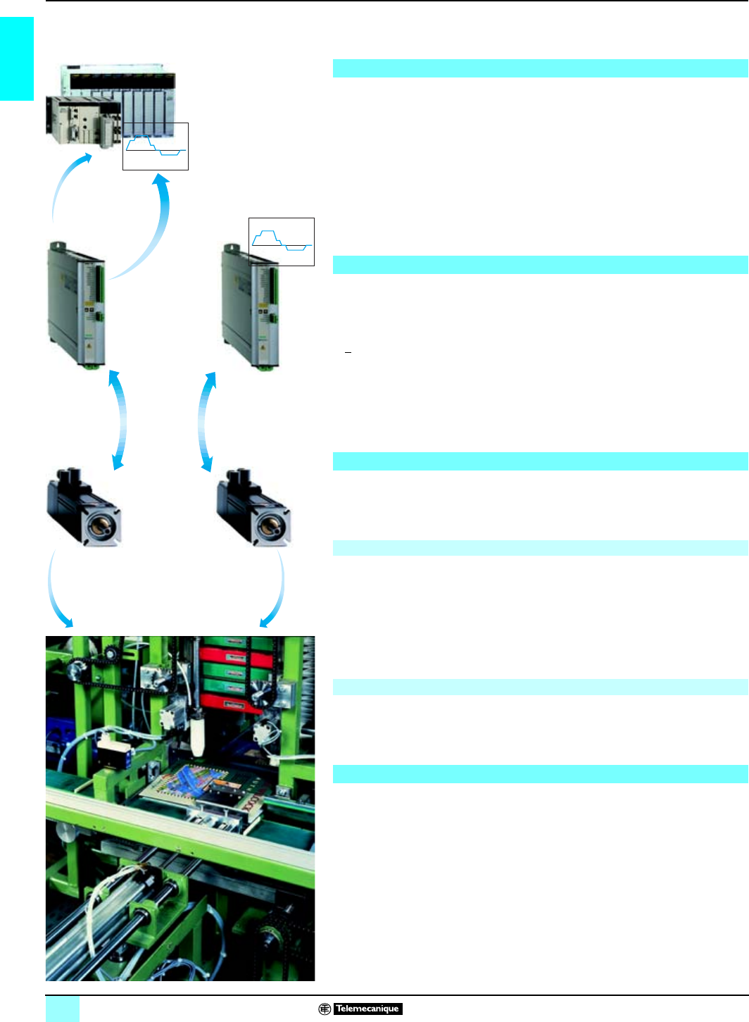
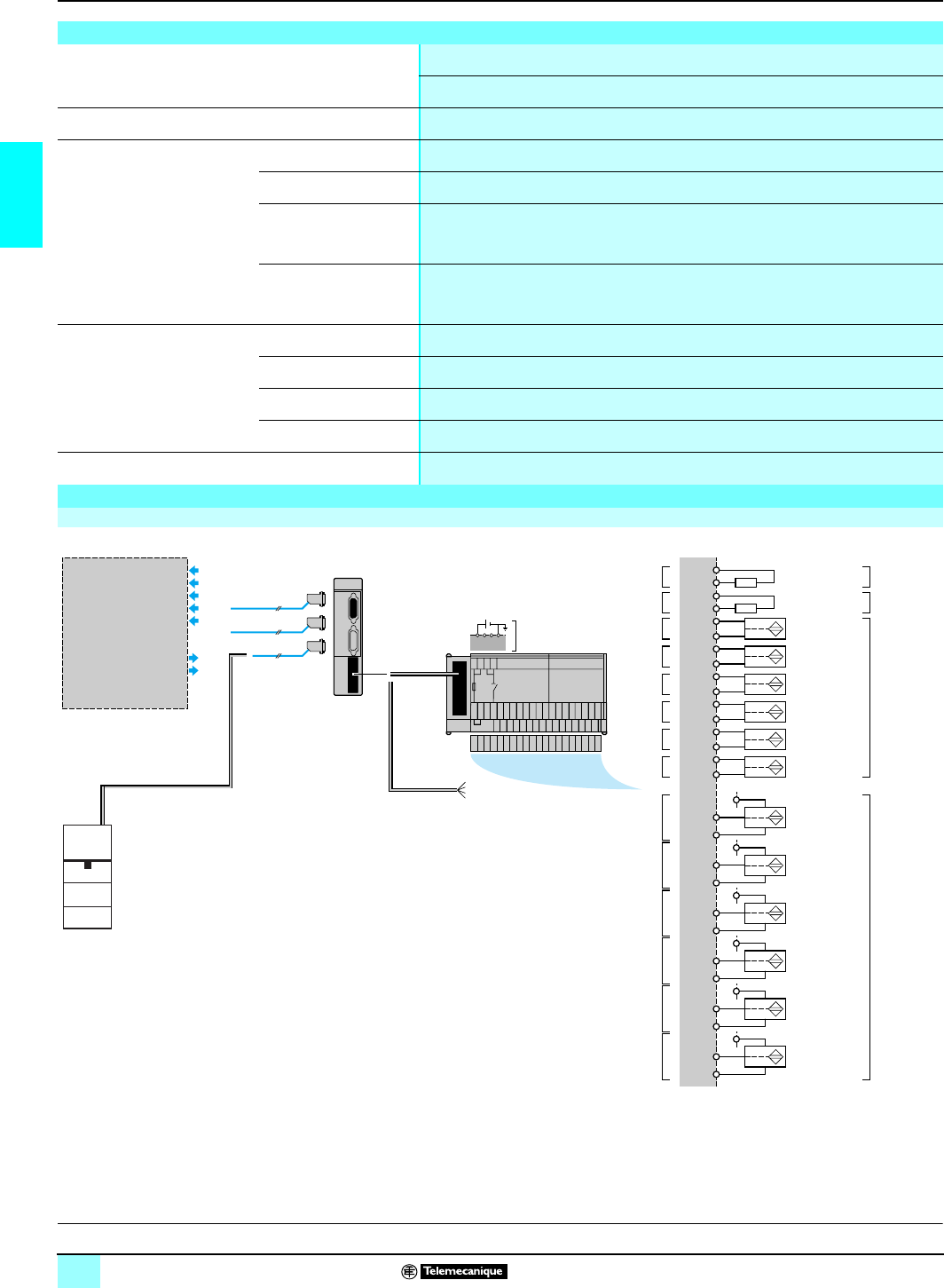
The axis control offer is intended for machines which simultaneously require high
performance servo motion control, associated with PLC sequential control.
Modicon Premium and Modicon Quantum automation platforms offer a range of
interfaces including axis control modules providing a position control function. These
modules are:
bAnalog output modules:
v TSX CAY, multi-axis control (2 to 4 axes) for Premium,
v 140 MSB, single-axis control for Quantum
bModules with SERCOS digital link:
v TSX CSY, controls up to 16 servodrives for Premium,
v 141 MMS, controls up to 22 servodrives for Quantum.
Lexium servodrives provide solid state switching, current (or torque), speed and
position control.
Three types of servodrive, each available in 7 current ratings (1.5, 3, 6, 10, 20, 40
and 70 A permanent rms), are available:
b
+
10 V analog setpoint, controlled by position control module of PLC.
bStand alone mode with integral position indexer, controlled by:
v discrete inputs/outputs (1),
v CANopen bus,
v Modbus Plus network, Fipio bus or Profibus DP bus (1).
bSERCOS high speed digital link (1) allows Lexium servodrives to be controlled by
PLC position control module.
Brushless motors are synchronous, 3-phase motors. They are equipped with a built-
in sensor which can be a resolver or a SinCos Hiperface absolute encoder. They are
provided with or without holding brake. Two ranges of motors are available:
Their design, with samarium cobalt permanent magnets, ensures perfect rotation
even at low speed. Depending on the model, they have:
bIP 65 or IP 67 protection (IP 54 for BPH 055 motor).
bKeyed or smooth shaft ends.
Motion control applications are designed and installed using:
bPL7 Junior/Pro (for Premium PLCs) software.
bConcept (for Quantum PLCs) software.
bUnity Pro (for Premium or Quantum PLCs) software.
Unilink user software, in association with Lexium servodrives, provides configuration
and adjustment of the parameters for these servodrives.
(1) Requires use of an optional card (one slot available per MHDA servodrive).
(2) Shaft end with key for the model without a gearbox, please contact our Regional Sales Office.
Position control system
Lexium MHDA servodrive
Lexium brushless motors
SER motors
They are equipped with Neodynium Iron Borium (NdFeB) magnets and provide a
high power density within a confined space, as well as large velocity dynamic that
meet all machine requirements. They have:
bIP 41 or IP 56 protection.
bWith or without gearbox. These gearboxes are offered with three speed reduction
ratios 3:1, 5:1 and 8:1.
bSmooth shaft end (2) (for the model without gearbox) or with key (for the model
with gearbox).
BPH motors
Configuration and installation
Lexium offer Lexium motion control 1
Presentation
Analog setpoint or digital
link mode Stand alone mode with
integral position indexer
This document provided by Barr-Thorp Electric Co., Inc. 800-473-9123 www.barr-thorp.com
3
1
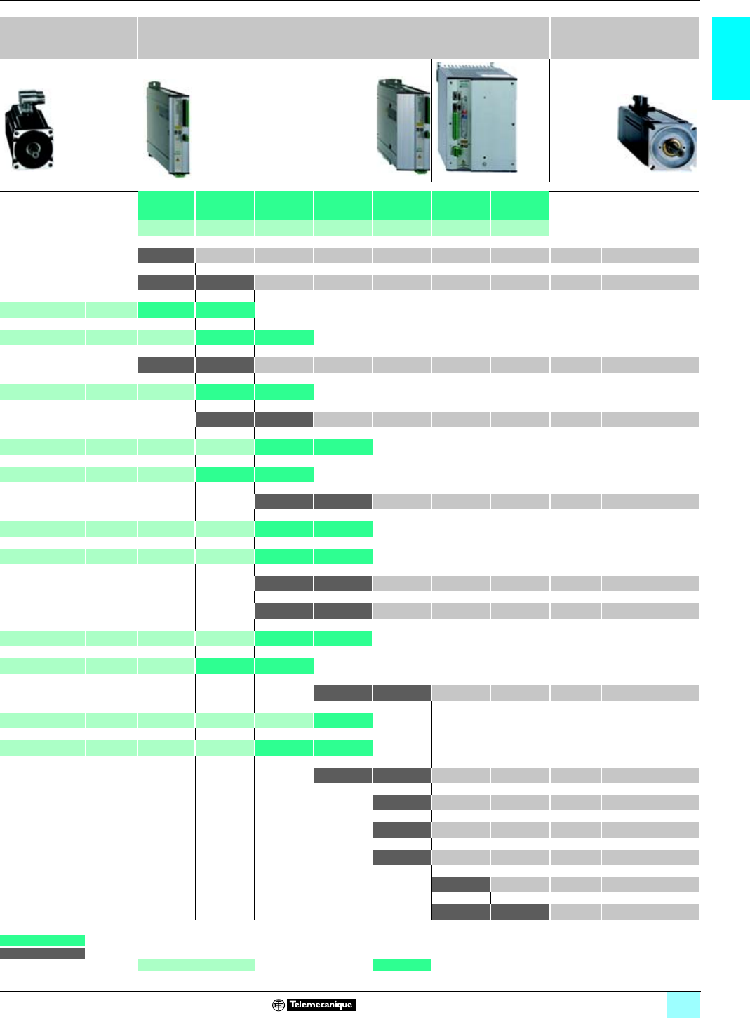
Lexium offer Lexium motion control 1
Association of brushless motors and
Lexium servodrives
SER brushless motors
(IP 41 or IP 56) Digital Lexium MHDA servodrives Lexium BPH brushless
motors
(IP65orIP67)
MHDA
1004p00 MHDA
1008p00 MHDA
1017p00 MHDA
1028p00 MHDA
1056p00 MHDA
1112A00 MHDA
1198A00
1.5 A rms 3 A rms 6 A rms 10 A rms 20 A rms 40 A rms 70 A rms
0.4/1.1 Nm 8,000 rpm BPH 0552 S
0.9/1.9 Nm 1.3/3.4 Nm 6,000 rpm BPH 0751 N
SER 39A 4L7S 6,000 rpm 1.1/2.5 Nm 1.1/4 Nm
SER 39B 4L3S 6,000 rpm 2.2/4.4 Nm 2.2/8.0 Nm
1.3/2.5 Nm 2.3/4.8 Nm 6,000 rpm BPH 0752 N
SER 39C 4L3S 6,000 rpm 2.9/4.7 Nm 2.9/9.4 Nm
3.7/7.2 Nm 4.3/13.4 Nm 6,000 rpm BPH 0952 N
SER 3BA 4L3S 6,000 rpm 4.6/9.2 Nm 4.6/15.3 Nm
SER 3BA 4L5S 6,000 rpm 4.6/8.2 Nm 4.6/15 Nm
6.0/13.4 Nm 6.0/20.3 Nm 6,000 rpm BPH 0953 N
SER 3BB 4L3S 6,000 rpm 6.6/12 Nm 6.6/20 Nm
SER 3BB 4L5S 6,000 rpm 6.6/15.8 Nm 6.6/25 Nm
7.4/13.6 Nm 7.4/19.3 Nm 6,000 rpm BPH 1152 N
6.8/13.5 Nm 10.5/19 Nm 6,000 rpm BPH 1153 N
SER 3BC 4L5S 6,000 rpm 10/17 Nm 10/28 Nm
SER 3BC 4L7S 3,000 rpm 10/16 Nm 10/32 Nm
11.4/18 Nm
12/30 Nm 4,000 rpm BPH 1422 N
SER 3BD 4L5D 6,000 rpm 13.4/29 Nm
SER 3BD 4L7S 3,000 rpm 13.4/24 Nm 13.4/38 Nm
14.5/24 Nm 17/42 Nm 4,000 rpm BPH 1423 N
25/37.5 Nm
4,000 rpm BPH 1902 N
36/57 Nm 4,000 rpm BPH 1903 K
46/76.2 Nm
4,000 rpm BPH 1904 K
75/157 Nm 4,000 rpm BPH 1907 K
90/163 Nm
100/230 Nm
4,000 rpm BPH 190A K
1.1/2.5 Nm For a SER motor, the 1st value corresponds to continuous stall torque max., the 2nd value corresponds to peak stall torque max.
1.3/3.4 Nm For a SER/Lexium BPH motor, the 1st value corresponds to continuous stall torque max., the 2nd value corresponds to peak stall torque max.
Example: The SER 3BB 4L3S motor associated with the MHDA1017 servodrive meets the requirements of applications requiring a
6.6 Nm continuous stall torque max, 12 Nm peak stall torque max. and 6,000 rpm mechanical speed.
This document provided by Barr-Thorp Electric Co., Inc. 800-473-9123 www.barr-thorp.com

4
2
Selection guide Lexium motion control 1
Counter and electronic cam modules
Applications Counter modules
Number of channels 2 channels 4 channels
Frequency per channel 40 kHz 40 kHz
Module cycle time 5 ms 10 ms
Counter/measurement
input Counting pulses
c24 V Up to 40 kHz:
- Proximity sensor type 2
- Mechanical contacts
Incremental encoder Up to 40 kHz :
- c 10…30 V
- c 5 V RS 422 with zero marker
Absolute encoder –
Reflex inputs/outputs Per channel:
- 3 inputs c 24 V: enable, preset and read
- 1 input c 24 V line check, incremental encoder power supply
- 2 reflex outputs c 24 V
Counting capacity 24 bits + sign (0 to + 16 777 215 points or ± 16 777 215 points)
Functions Downcounting with preset input, upcounting with reset to zero input
Up/down counting with preset input, configurable upcounter input:
- 1 upcounter input/1 downcounter input
- 1 up/down counter input and 1 direction input
- Incremental encoder with phase-shifted signals
Processing Inputs: counter enable, counter preset, read current value
Comparison:
- Downcounting, to value 0
- Upcounting, 2 thresholds and 1 setpoint
- Up/down counting, 2 thresholds and 2 setpoints
Reflex outputs:
- Downcounting function, 1 passage through zero output
- Upcounting function,1 passage through setpoint value output
- Up/down counting function, 2 user-definable outputs
- Up/down counting function, 2 user-definable outputs
Events User-definable activation of the event-triggered task (threshold crossing, setpoint crossing,
preset or reset, enable, capture)
Connection - 15-way SUB-D connectors (1 per counter channel, direct or TSX TAP S15 pp accessory)
- HE 10 connector for auxiliary I/O and power supply
- Telefast 2 system (ABE 7CPA01, ABE 7H08R10/16R20)
Type of module TSX CTY 2A TSX CTY 4A
Page Please consult our catalogue “Modicon Premium automation platform”
This document provided by Barr-Thorp Electric Co., Inc. 800-473-9123 www.barr-thorp.com

5
2
1
Fast counter and measurement module Electronic cam module
2 channels 1 channel
500 kHz
1 ms
Up to 1 MHz:
- Proximity sensor type 2
- Mechanical contacts
–
500 kHz in multiplication by 1, 250 kHz in multiplication by 4:
- c 10…30 V
- c 5 V RS 422 with zero marker
Power supply c 5 V ou c 10…30 V:
- SSI absolute encoder up to 25 bits
- Parallel absolute encoder up to 24 bits (with Telefast ABE 7CPA11 sub-base)
Per channel :
- 2 inputs c 24 V : preset and read
- 1 enable input or c 24 V output, configurable
- 2 reflex outputs c 24 V
- 1 programmable frequency output 24 V
- 1 encoder power supply input c 5 V/24 V
- 3 proximity sensor compatible inputs 24 V type I
- 24 track outputs 24 V/0.5 A protected
24 bits + sign (0 to + 16 777 215, upcounting) or 24 bits + sign (- 16 777 215 to
+ 16 777 215, downcounting, up/down counting). Up to 25 bits for SSI absolute
encoder
256 to 32 768 points per cycle and from 1 to 32 768 cycles,(absorbs play on
reverse)
Up/down counting with preset input, configurable counter input:
- 1 upcounter input/1 downcounter input
- 1 up/down counter input and 1 direction input
- Incremental encoder with phase-shifted signals
Measurement 2:
- SSI absolute encoder
- Parallel output absolute encoder with ABE 7CPA11 sub-base
Processing of 128 cams/32 tracks (of which 24 with direct output)
Output update cycle:
- 50 µs for 16 cams
- 100 µs for 64 cams
- 200 µs for 128 cams
Two capture registers
Control/recalibration of axis slip
Inputs: counter enable, counter preset, read current value Cam profiles: 3 basic types (position, monostable, brake)
Comparison:
2 thresholds Associated functions:
- Elimination of axis backlash, position recalibration
- Measurement capture
- Switching feedforward
- Parts counter
Reflex outputs:
2 user-definable outputs
Speed monitoring
Special functions
User-definable activation of the event-triggered task (crossing of thresholds or
modulo value, preset, enable, capture) User-definable activation of the event-triggered task (cams, track, adjustment,
read, etc.)
- 15 way SUB-D connectors (1 per counter channel, direct or TSX TAP S15pp accessory)
- HE 10 connector for reflex I/O and power supply
- Telefast 2 system (ABE 7CPA01, ABE 7H16R20, ABE 7CPA11)
TSX CTY 2C TSX CCY 1128
Please consult our catalogue “Modicon Premium automation platform”
This document provided by Barr-Thorp Electric Co., Inc. 800-473-9123 www.barr-thorp.com

6
2
Selection guide Lexium motion control 1
Premium motion control modules
Applications Motion control modules for stepper motor Motion control modules for servomotors
Compatible with:
- Lexium MHDA servodrives with analog setpoint
- Altivar ATV 38/58/68 variable speed drives
Number of axes 1 axis 2 axes 2 axes 4 axes
Frequency per axis 187 kHz Counter: 500 kHz with incremental encoder
Counter input Per axis:
Translator inputs c 5 V, negative logic
(translator loss of step checks)
Per axis:
Incremental encoder c 5 V, RS 422/RS 485
or Totem pole
SSI serial absolute encoder 16 to 25 bits
c10…30 V
Parallel output absolute encoder 16 to 24 bits
c5/10/30 V with Telefast 2 conversion sub-
base (ABE 7CPA11)
Control outputs Per axis:
RS 422 translator outputs, TTL 5 V
compatible (+/- pulses, boost, enable, reset
loss of step check)
Per axis:
1 analog output ± 10 V, 13 bits + sign,
Auxiliairy input/output Per axis:
6 discrete inputs c 24 V
1 output c 24 V (brake control)
Per axis:
4 discrete I/O c 24 V (homing cam, event, recalibration,
1 input/1 output for servodrive control
1 reflex output c 24 V
Counter capacity 24 bits + sign (± 16 777 215 points)
Functions Servo Control on individual linear axis
Processing Open loop control of the position of a moving
part on a limited linear axis according to
motion control functions supplied by the PLC
processor
Positioning of a moving part on an axis according
Axis parameter setting, adjustment and
debugging using PL7 Junior/Pro and
Unity Pro software
Axis parameter setting, adjustement and debugging using
Events User-definable activation of the event-triggered task
Connection - 15-way SUB-D connector for translator
- 20-way HE 10 connector for auxiliary I/O
- Telefast 2 system (ABE 7H16R20)
- 9 and 15-way SUB-D connectors for encoder input
- HE 10 connector for auxiliary inputs
- Telefast 2 system (ABE 7CPA01, ABE 7H16R20,
- Specific accessories (TSX TAP MAS)
Type of modules TSX CFY 11 TSX CFY 21 TSX CAY 21 TSX CAY 41
Page 11 15
This document provided by Barr-Thorp Electric Co., Inc. 800-473-9123 www.barr-thorp.com

7
2
1
Motion control modules for servomotors
Compatible with Lexium MHDA servodrives equipped with
optional card SERCOS
2 axes 4 axes 3 axes 8 axes 16 axes
Acquisition: 200 kHz with SSI serial absolute encoder or parallel output SERCOS
ring: 4 M bauds
Per axis:
- Incremental encoder c 5 V, RS 422/RS 485 or Totem pole,
- SSI serial absolute encoder 12 to 25 bits
Parallel output absolute encoder 12 to 24 bits c 5/10/30 V with Telefast 2 conversion sub-base
(ABE 7CPA11)
Per SERCOS
digital link
servodrive setpoint Per SERCOS
digital link
emergency stop) Per SERCOS
digital link
Servo control on individual infinite axis
Follower axes (dynamic ratio)
Realtime correction of servodrive offset
Servo control on individual
linear or infinite axis
Linear interpolation on 2 or
3 axes
Realtime correction of
servodrive offset
Individual linear or infinite axis
Linear interpolation on 2 to 8 axes
Follower axes (6 slaves) by gearing or camming
Manual mode (JOG and INC) (1)
Special functions, see page 26
Flying shear on position or
event (1) –
to motion control functions supplied by the Premium PLC processor
PL7 Junior/Pro and Unity Pro software (2) Axis parameter setting,
adjustment and debugging
using PL7 Junior/Pro
software
(direct or via TSX TAP S15pp ), speed reference
ABE 7CPA11),
2 SMA type connectors for plastic (or glass) fiber optic cable
TSX CAY 22 TSX CAY 42 TSX CAY 33 TSX CSY 84 TSX CSY 164
30
(1) Function not available with Premium platform under Unity Pro software.
(2) The Unity Pro software is not compatible with the TSX CSY 164 module.
This document provided by Barr-Thorp Electric Co., Inc. 800-473-9123 www.barr-thorp.com
8
2
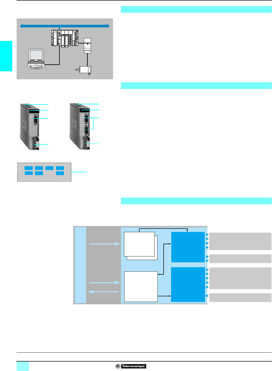
Presentation,
description Lexium motion control 1
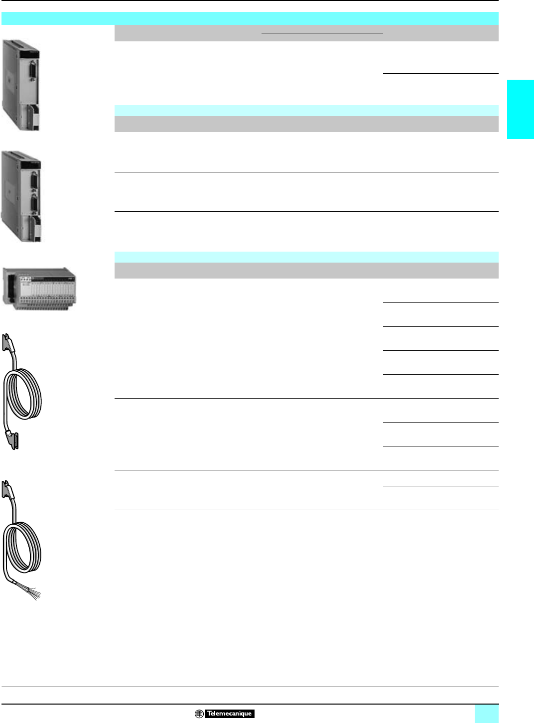
TSX CFY 11/21 modules for stepper motors
The TSX CFY 11/21 stepper motor axis control range is intended for machines which
simultaneously require motion control by stepper motor associated with sequential
control by programmable controller.
The TSX CFY 11 module controls, via an amplifier for stepper motor, 1 axis
(channel 0). The TSX CFY 21 module controls 2 axes (channels 0 and 1). They
accept amplifiers with:
bRS 422 or TTL 5 V inputs (negative logic).
bRS 422 or c 5 V NPN open collector outputs.
In a Premium PLC configuration, the number of TSX CFY motion control modules
should be added to the other application-specific modules (communication, counting,
axis control and weighing).
The front panel of TSX CFY 11/21 stepper control modules comprises:
1One 15-way SUB-D connector per channel for connecting:
v Amplifier inputs.
v Amplifier outputs.
v Amplifier input power supply.
2One 20-way HE 10 connector for connecting:
v Auxiliary inputs: per axis, homing cam, emergency stop, limit switches (+ and -),
event, external stop.
v Brake outputs (1 per axis).
v External power supplies for sensors and preactuators.
3Rigid casing which:
v Holds the electronic card.
v Locates and locks the module in its slot.
4Module diagnostics lamps:
v Module diagnostics:
- green RUN lamp: module operating,
- red ERR lamp: internal fault, module failure,
- red I/O lamp: external fault.
v Axis diagnostics:
- 2 green CHp lamps: axis diagnostics available.
Operating characteristics are described on page
10
. Stepper control modules are set
up using PL7 Junior/Pro and Unity Pro software.
Presentation
Motor
Premium
Fip
Amplifier
Description
2
4
3
1
3
4
1
2
CH2 ERRCH0 RUN
CH3 CH1 I/O
4
Operation block diagram
C
haracteristics:
p
ages 9 and 10 References:
page 11 Connection:
page 10
Amplifier enable output
A/B pulse outputs
Reactivation of loss of step output
Boost output
Amplifier fault input
Loss of step check input
Cam input (homing)
+ and – limit switch input
Emergency stop input
Event input
External stop input
Brake output
Pulse generator
Auxiliary I/O
processing
Configuration
parameters
Processing
Configuration
+ adjustment
%KW.%MW
SMOVE function
%O, %QW
%I, %IW
TSX CFY 11 TSX CFY 21
This document provided by Barr-Thorp Electric Co., Inc. 800-473-9123 www.barr-thorp.com

9
2
Characteristics Lexium motion control 1
TSX CFY 11/21 modules for stepper motors
Electrical characteristics
Type of module TSX CFY 11 TSX CFY 21
Modularity 1 axis 2 axes
Maximum pulse frequency kHz 187.316 187.316
Consumption c5V mA 510 650
c24 V mA 50 100
Power dissipated in the module Typical W3.8 5.6
Sensor power supply check Yes Yes
Input characteristics
Inputs Amplifier inputs Auxiliary inputs
Logic Negative Positive
Nominal values Voltage V524
Current mA 4.5 7
Limit values Voltage V–19...30 (up to 34 V possible, limited to 1 hr per
24 hr period)
At state 1 Voltage V< 2 ≥ 11
Current mA –> 6 (for U = 11 V)
At state 0 Voltage V> 3.6 < 5
Current mA –< 2 (for U = 5 V)
Input impedance for nominal U kΩ–3.4
Input immunity µsLoss of step input: 15 to 30: –
µs–Homing cam and event inputs: < 250
ms Amplifier fault input: 3 to 16 Limit switch, emergency stop and external stop
inputs: 3 to 10
Monitoring of
external power
supply for
sensors and
preactuators
Voltage for OK state V–> 18
Voltage for fault state V–< 14
Immunity OK V fault ms –> 1
Immunity fault V OK ms –< 30
Type of input Resistive Current sink
IEC 1131 conformity –Type 2
Sensor compatibility –2-wire/3-wire
Output characteristics
Outputs Amplifier outputs Brake outputs (1 per axis)
Type of output RS 422, TTL 5 V open collector NPN
compatible Open collector, PNP
Output differential voltage V± 2 (load resistance ≤ 100 Ω) –
Short-circuit current mA < 150 –
Permissible common mode voltage V≤ 7 –
Permissible differential voltage V≤ 12 –
Voltages Nominal V–c 24
Limit V–19...30 (up to 34 V possible, limited to 1 hr per
24 hr period)
Currents Nominal mA –500
Leakage mA –< 0.3
Maxi mA –625 (for U = 30 or 34 V)
Maximum voltage drop when ON V–c < 1
Switching time µs–< 250
Compatibility with DC inputs –All positive logic inputs with input resistance
< 15 kΩ
IEC 1131-2 compliance –Yes
Protection against overloads and
short-circuits –Via current limiter and thermal tripping
(reactivated via program or automatically)
Short-circuit check on each channel –One signalling bit per channel
Protection against channel overvoltage –Zener diode between outputs and c + 24 V
Protection against polarity inversions –By diode reverse-mounted on supply
R
eferences:
p
age 11 Connection:
page 10
This document provided by Barr-Thorp Electric Co., Inc. 800-473-9123 www.barr-thorp.com
10
2
Characteristics (continued),
connections Lexium motion control 1
TSX CFY 11/21 modules for stepper motors
Operating characteristics
Control Pulse, frequency from 0 to 187 kHz
+ and - outputs or +/- outputs and direction
Paths Trapezoidal speed profile with minimum movement frequency
Operating modes OFF Module inactive
DIR DRIVE Module operating as pulse generator
MAN Motion controlled by operator:
vvisual control of movement
vincremental movement
AUTO Movement sequence controlled by PLC program. Movements are described using a syntax
similar to that of ISO language. Movements may be expressed in absolute or relative terms (in
relation to either the current position or a home point). Operation is possible in "step-by-step"
mode.
Checks Environment Amplifier, limits switches, Emergency stop
Motion Check correct execution by software position limits, loss of step
Control Check consistency of commands
Parameters Check validity of parameters
Optional commands Boost, brake
Connections
TSX CFY 11/21 stepper control module connections
(1) Type of amplifier
b
With RS 422 interface:
v
RS 422 compatible inputs,
v
RS 422 outputs.
b
With open collector, NPN interface:
v
TTL/5 V source compatible inputs,
v
Open collector, NPN outputs (5 V power supply from TSX CFY 11/21 module).
––
++
Ð
++
Ð
1
2
3
4
100
101
102
103
104
105
106
107
108
109
110
111
112
113
114
115
C
C
C
C
300
301
302
303
304
305
306
307
308
309
310
311
312
313
314
315
200
201
202
203
204
205
206
207
208
209
210
211
212
213
214
215
Telefast 2
ABE 7H16R20
34
2
1
1
1
300
+
Ð
301
+
Ð
302
+
Ð
303
+
Ð
103
203
102
202
304
+
Ð
305
+
Ð
105
Q0
Q0
I5
I2
I4
I1
I3
I0
I5
I2
I4
I1
I3
I0
RIRI
205
104
204
101
201
100
200
+ +
111
211
110
210
+ + + +
109
209
108
208
107
207
106
206
112
212
114
214
TSX CFY 11/21
Auxiliary I/O c
24 V
Power supply
Limit switch –
Brake output
Brake output
External stop
Emergency stop
Event
Homing
Limit switch –
Limit switch +
External stop
Emergency stop
Event
Homing
Output axis 1
+
pulses
–
pulses
(or direction)
Boost
Amplifier enable
Reactivation of step loss
check
Amplifier check
Loss of step check
Amplifier
(1)
Axis 0
Axis 1
Axis 0 or 1
T
win line TLD 01 servodrive
w
ith PULSE-C option
Inputs axis 0
Output axis 0
Inputs axis 1
1TSX CAP S15 connector
2TSX CDPpp3 cable with connector
3TSX CDPp01 preformed cable with connector
4TSX CDPp63 cable with connector
Axes 0 and 1
Limit switch +
C
haracteristics:
p
ages 9 and 10 References:
page 11
This document provided by Barr-Thorp Electric Co., Inc. 800-473-9123 www.barr-thorp.com
11
2
References Lexium motion control 1
TSX CFY 11/21 modules for stepper motors
Motion control modules for stepper motors
Description
To control Connections to connectors No. of
axes Reference
(1) Weight
kg
SUB-D, 15-way HE 10, 20-way
Motion control modules
for stepper motors Amplifier with
RS 422 I/O,
c 5 V TTL and
O c 5 V with
open collector
Amplifier I/O Auxiliary I/O,
c24 V power
supply
1TSX CFY 11 0.440
2TSX CFY 21 0.480
Connection accessories
Description TSX CFY p1
connector Type of connector on
TSX CFY p1 module N°
(2) Unit
reference Weight
kg
SUB-D connectors Amplifier SUB-D, 15-way
(1 per axis)
Sold in lots of 2
1 TSX CAP S15 0.050
Telefast 2 connection sub-
base Auxiliary I/O for axes 0/
1, c 24 V power
supply
HE 10, 20-way
(1 for 2 axes) ABE 7H16R20 0.300
Additional terminal block 20 shunted terminals
for ABE 7H16R20 sub-
bases
Order in multiples of 5 ABE 7BV20 0.030
Connecting cables
Description From module
TSX CFY p1To N°
(2)
Length
Reference Weight
kg
Cables (cross-
section 0.324 mm2)20-way HE 10
connector ABE 7H16R20 sub-
base (20-way HE 10
molded connector)
20.5 m TSX CDP 053 0.085
1 m TSX CDP 103 0.150
2 m TSX CDP 203 0.280
3 m TSX CDP 303 0.410
5 m TSX CDP 503 0.670
Preformed cables (cross-
section 0.324 mm
2
)20-way HE 10
connector Auxiliary I/O for axes 0/
1,
24 V cpower supply
(flying leads at I/O end)
33 m TSX CDP 301 0.400
5 m TSX CDP 501 0.660
10 m TSX CDP 1001 1.310
Cables for Twin Line
TLD 01p amplifier 15-way SUB-D
connector Twin Line TLD 01p
amplifier with PULSE-
C option
(15-way female SUB-
D connector)
42 m TSX CXP 263 –
6 m TSX CXP 663 –
(1) Includes a bilingual Quick Reference Guide: French and English.
(2) For key, see page 10.
C
haracteristics:
p
ages 9 and 10 Connection:
page 10
TSX CFY 21
TSX CFY 11
ABE 7H16R20
TSX CDP
p
01
TSX CDP
p
03
This document provided by Barr-Thorp Electric Co., Inc. 800-473-9123 www.barr-thorp.com
12
2
Description Lexium motion control 1
TSX CAY modules for servomotors
The TSX CAY pp servo loop positioning axis control range is intended for machines
which require simultaneous high performance motion control together with
sequential control by programmable controller.
Depending on model:
bThe TSX CAY 21/22 modules control 2 individual axes.
bThe TSX CAY 41/42 modules control up to 4 individual axes.
bThe TSX CAY 33 module control 3 interpolated linear axes.
They can be used with ± 10 V analog input servodrives such as Lexium 17D/17D HP,
and Twin Line TLD 13 servodrives.
TSX CAY pp modules can be installed, like all application-specific modules, in any
location on a Premium PLC rack.
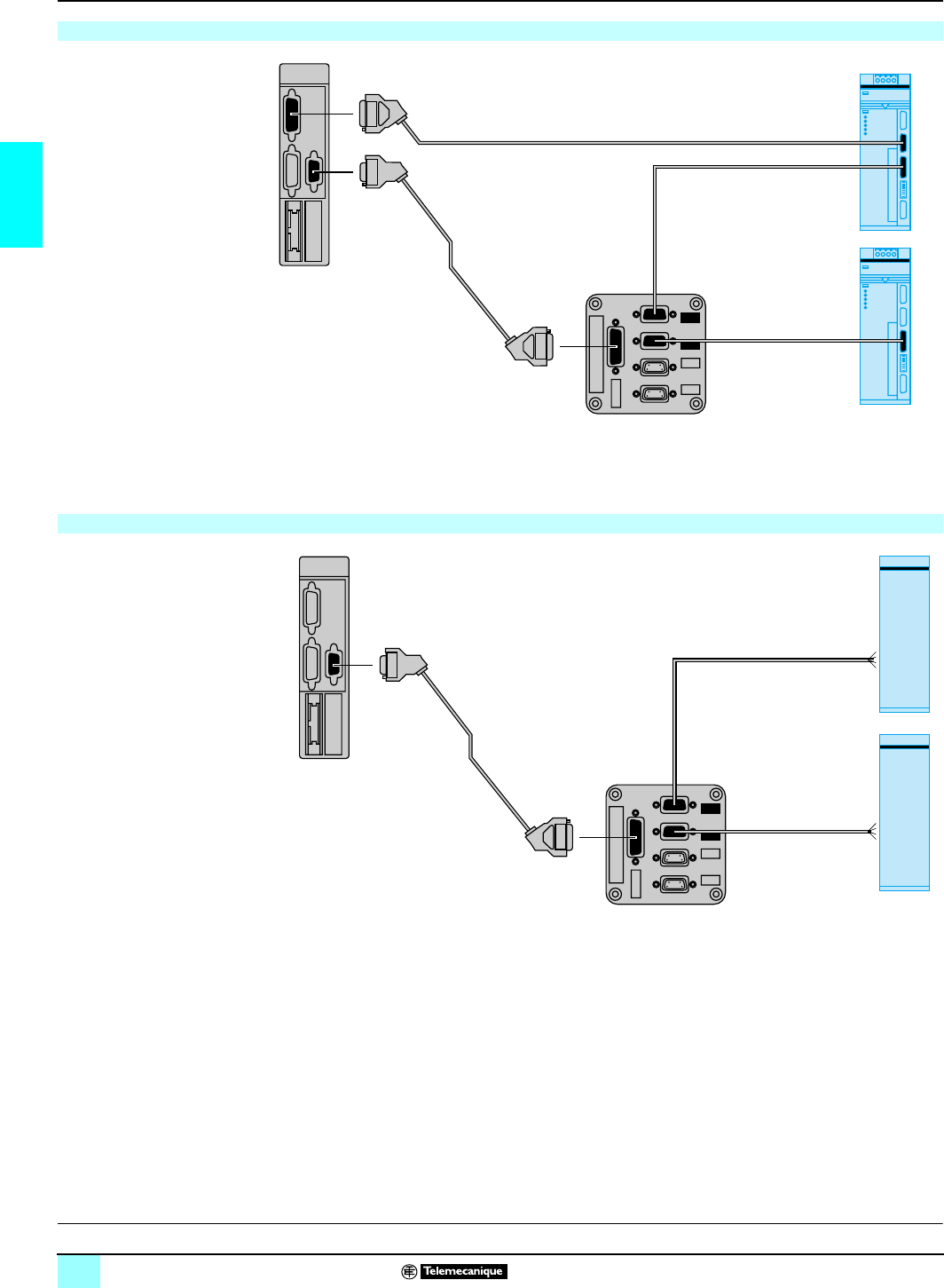
The front panel of TSX CAY pp axis control modules comprises:
1One 15-way SUB-D connector per axis for connecting an incremental or absolute
encoder.
2One 9-way SUB-D connector for all axes for connecting:
v 1 "speed reference" analog output for each axis.
3One 20-way HE 10 connector for all axes for connecting:
v Auxiliary inputs for servodrive control,
v External power supply for servodrive I/O.
4One 20-way HE 10 connector for 2 axes (0/1 or 2/3) for connecting:
v Auxiliary inputs: homing cam, Emergency stop, event, recalibration.
v High speed outputs.
v External power supplies for sensors and preactuators.
5Rigid casing which:
v Holds the electronic card.
v Locates and locks the module in its slot.
6Module diagnostic lamps:
v Module diagnostics:
- green RUN lamp: module operating,
- red ERR lamp: internal fault, module failure,
- red I/O lamp: external fault.
v Axis diagnostics:
- green CHp lamps: axis diagnostics available.
Axis control modules are set up using PL7 Junior/Pro or Unity Pro software (see
page
22
).
TSX CAY 22/42/33 modules require the use of TSX P57 pp2M/3M/4M processors
and Atrium TPCX57 pp2M/3M coprocessors or TSX PCI 57pp4M.
Flying shear function of the TSX CAY 22 module requires the version ≥ 4.1 of
PL7 Junior/Pro software (function not available with Unity Pro software, version 1.0).
Lexium
servodrive
Motor
Premium
5
6
1
2
3
4
TSX CAY 41/42
5
6
1
2
3
4
T
SX CAY 21/22
Description
Operation
Block diagram of an axis
Configuration
+ adjustment
%KW.%MW
SMOVE function
%O, %QW
%I, %IW
Configuration
parameters
Processing
Servo loops
Auxiliary
I/O
processing
Encoder input
Servodrive speed reference output
Cam input (homing)
Event input
Recalibration input
Emergency stop input
Drive fault input
Drive enable output
High speed output
C
haracteristics:
p
ages 13 and 14 References:
pages 15 and 16 Dimensions:
page 21
This document provided by Barr-Thorp Electric Co., Inc. 800-473-9123 www.barr-thorp.com
13
2
Characteristics Lexium motion control 1
TSX CAY modules for servomotors
Operating characteristics
Type of module TSX CAY 21/22 TSX CAY 41/42 TSX CAY 33
Servo loop Proportional with feedforward and gain switching
Period ms 2 4
Paths Speed profile Trapezoidal or parabolic
Resolution Minimum 0.5 position unit per point
Maximum 1000 position units per point
Length of axis Minimum TSX CAY 21: 32,000 points TSX CAY 41: 32,000 points TSX CAY 33: 256 points
TSX CAY 22: 256 points TSX CAY 42: 256 points
Maximum 32,000,000 points
Speed Minimum 54,000 points/min
Maximum 270,000 points/min
Acceleration
(from 0 to VMAX) Minimum s10
Maximum ms 8 16
Operating modes OFF Measurement mode, inhibition of servo loop
The module operates in current speed and position acquisition mode
DIR DRIVE Direct drive mode, inhibition of servo loop
The module operates in analog output mode only
MAN Motion controlled by operator:
bvisual control of movement
bincremental movement
AUTO Movement sequence controlled by PLC program. Movements are described using a syntax
similar to that of ISO language. Movements can be expressed in absolute or relative terms
(either in relation to current position, to a captured position or in relation to a home point).
Operation is possible in "step by step" mode, by motion stop/start, by speed correction
FOLLOWER The n axis of the module is governed by:
beither the 0 axis of the same module
bor a command profile transmitted by the application
program
–
Checks Environment Encoder link, drive present, Emergency stop
Motion Check correct execution of movements (following error, in-position band, software position
limits)
Commands Check consistency of commands
Parameters Check validity of parameters
Functions
Type of module TSX CAY 21 TSX CAY 22 TSX CAY 41 TSX CAY 42 TSX CAY 33
Linear interpolation, 2/3 axes – – – – Yes
Limited axes Yes Yes Yes Yes Yes
Infinite axes –Yes –Yes Yes
Follower axes Static ratio Yes –Yes – –
Dynamic ratio –Yes –Yes –
Correction of servodrive offset –Yes –Yes Yes
Flying shear On position or on event
with infinite master axis
and linear slave axis
–Yes
(see page 12) – – –
C
haracteristics:
p
ages 13 and 14 References:
pages 15 and 16 Connections:
pages
17
to
20
This document provided by Barr-Thorp Electric Co., Inc. 800-473-9123 www.barr-thorp.com

14
2
Characteristics (continued) Lexium motion control 1
TSX CAY modules for servomotors
Electrical characteristics
Type of module TSX CAY 21 TSX CAY 22 TSX CAY 41 TSX CAY 42 TSX CAY 33
Number of axes 2 axes 2 axes 4 axes 4 axes 3 axes
Maximum frequency at counter inputs 16 to 25 bits 12 to 25 bits 16 to 25 bits 12 to 25 bits 12 to 25 bits
SSI absolute encoder
CLK transmission frequency kHz 200
Incremental encoder x 1 kHz 500
x 4 kHz 250 kHz as input or 1 MHz as counter
Consumption c 5 V mA 1100 1500
c 24 V mA 15 30
Current drawn by the module
on the 10/30 V encoder at 24 V
(24 V absolute encoder)
Typical mA 11 (20 max) 22 (40 max)
Power dissipated in the
module Typical W7.2 (11.5 max) 10 (17 max)
Sensor power supply check Yes Yes
Input characteristics
Type of input Counter inputs c 5 V
(IA/IB/IZ) Servodrive check inputs
(1 per axis) Auxiliary inputs
(homing, event, recalibration,
Emergency stop)
Logic Positive Positive Positive
Nominal values Voltage V524 24
Current mA 18 8 8
Limit values Voltage V≤ 5.5 19...30 (up to 34 V possible,
limited to 1 hr per 24 hr period) 19...30 (up to 34 V possible,
limited to 1 hr per 24 hr period)
At state 1 Voltage V≥ 2.4 ≥ 11 (OK state) ≥ 11
Current mA > 3.7 (for U = 2.4 V) > 3.5 (for U = 11 V) > 6 (for U = 11 V)
At state 0 Voltage V≤ 1.2 ≤ 5 (fault state) ≤ 5
Current mA < 1 (for U = 1.2 V) < 1.5 (for U = 5 V) < 2 (for U = 5 V)
Voltage/encoder feedback check Presence check – –
Input impedance for nominal U Ω270 3000 3000
Type of input Resistive Resistive Current sink
IEC 1131 compliance –Type 1 Type 2
2-wire sensor compatibility ––Yes (all prox. sens. 24 V)
3-wire sensor compatibility ––Yes (all prox. sens. 24 V)
Output characteristics
Type of output Analog outputs
(1 per axis) Drive enable
(1 relay output per axis) High speed outputs
(1 per axis)
Range V± 10.24 – –
Resolution 13 bits + sign – –
Value of LSB mV 1.25 – –
Nominal voltage V–c 24 c 24
Voltage limit V–5…30 19...30 (up to 34 V possible,
limited to 1 hr per 24 hr period)
Current mA ––500 nominal
Maximum current mA 1.5 200 (resistive load at 30 V) 625 (for U = 30 or 34 V)
Minimum permitted load –1 V/1 mA –
Maximum voltage drop when ON V––< 1
Leakage current mA ––< 0.3
Switching time –< 5 ms < 500 µs
Compatibility with DC inputs ––All positive logic inputs with
input resistance < 15 kΩ
IEC 1131 compliance ––Yes
Protections against overload
and short-circuits ––Current limiter and thermal
tripping
Protection against channel overvoltage ––Zener diode between outputs
and + 24 V supply
Protection against polarity inversions ––Reverse-mounted diode on
supply
R
eferences:
p
ages 15 and 16 Connections:
pages
1
7 to
2
0Dimensions:
page 21
This document provided by Barr-Thorp Electric Co., Inc. 800-473-9123 www.barr-thorp.com
15
2
References Lexium motion control 1
TSX CAY modules for servomotors
(1) TSX CAY 41/42/43 modules, double format.
(2) Product supplied with a bilingual Quick Reference Guide: English and French
(3) Totem Pole encoder with complementary Push/Pull outputs.
(4) Parallel output absolute encoders with ABE 7CPA11 adaptor interface.
(5) Flying shear function available with TSX CAY 22 module. Requires version ≥ 4.1. of
PL7 Junior/Pro software. Function not available with Unity Pro software.
(6) For key, see pages
17
to
20
.
Motion control modules for servomotors
Type of input Characteristics Functions No. of
axes (1) Reference
(2) Weight
kg
Incremental encoders
c5 V RS 422, c 10…30 V
Totem Pole (3)
Absolute encoders
RS 485 serial or parallel
(4)
500 kHz counter
with incremental
encoder,
Acquisition 200 kHz
with serial absolute
encoder
Servo control on independent
linear axis 2TSX CAY 21 0.480
4TSX CAY 41 0.610
Servo control on independent
linear or infinite axis
Follower axes
Realtime correction of servodrive
offset
Flying shear (5)
2TSX CAY 22 0.480
4TSX CAY 42 0.610
Servo control on linear or infinite
axis
Linear interpolation on 2 or 3 axes
Realtime correction of servodrive
offset
3TSX CAY 33 0.610
Connection accessories
Description Connection Type of connector on
TSX CAY pp module No.
(6) Reference Weight
kg
SUB-D connectors
(lot of 2) Incremental/SSI
absolute encoder SUB-D, 15-way
(1 per axis) 4TSX CAP S15 0.050
Speed references SUB-D, 9-way
(1 per TSX CAY module) 7TSX CAP S9 0.050
Connection interface for
incremental encoder Incremental encoder
c 5V
RS 422/RS 485
SUB-D, 15-way
(1 per axis) 6TSX TAP S15 05 0.260
Splitter block Speed references
to servodrives SUB-D, 9-way
(1 per TSX CAY module) –TSX TAP MAS 0.590
Telefast 2 connection sub-
bases Speed references SUB-D, 9-way
(1 per TSX CAY module) –ABE 7CPA01 0.300
Auxiliary inputs,
High speed outputs,
I/O power supply
c 24 V, encoder
power supplies
c 5/24 V
HE 10, 20-way
(1 for 2 axes) –ABE 7H16R20 0.300
Servodrive control
signals,
I/O c24 V power
supply
HE 10, 20-way
(1 per TSX CAY module) –ABE 7H16R20 0.300
Adaptor sub-base Parallel output
absolute encoders
(16 to 24 bits)
c 5V, c10…30 V
SUB-D, 15-way – ABE 7CPA11 0.300
TSX CAY 4
p
A
BE 7CPA01
A
BE 7H16R20
C
haracteristics:
p
ages 13 and 14 Connections:
pages
1/
7 to
2
0Dimensions:
page 21
TSX CAY 2
p
TSX TAP MAS
TSX TAP S15
TSX CAY 33
This document provided by Barr-Thorp Electric Co., Inc. 800-473-9123 www.barr-thorp.com

16
2
References (continued) Lexium motion control 1
TSX CAY modules for servomotors
Cables with SUB-D connectors
From To No.
(1) Length Reference Weight
kg
TSX CAYpp
module, 15-
way SUB-D
connector
TSX TAP S15 05 interface,
or ABE 7CPA11 adaptor sub-
base (15-way SUB-D
connector)
50.5 m TSX CCP S15 050 0.110
1 m TSX CCP S15 100 0.160
2.5 m TSX CCP S15 0.220
TSX CAYpp
module, 9-
way SUB-D
connector
(speed reference)
ABE 7CPA01 sub-base
or TSX TAP MAS block (15-
way SUB-D connector)
82.5 m TSX CXP 213 0.270
6 m TSX CXP 613 0.580
TSX CDP
p
01
TSX CDP
pp
3
Preformed cables with SUB-D connector fitted at 1 end and 1 free end
(servodrive side)
TSX CAY pp
module, or
TSX TAP MAS
block
Speed reference for
servodrive: Lexium MHDA,
Twin Line TLD 13 or other
(cross-section 0.205 mm2)
96 m TSX CDP 611 0.790
Connecting cables with HE 10 connector
TSX CAY pp
module, (20-way
HE 10 connector)
ABE 7H16R20 sub-base (20-
way HE 10 moulded
connector)
(500 mA max.)
10 0.5 m TSX CDP 053 0.085
1 m TSX CDP 103 0.150
2 m TSX CDP 203 0.280
3 m TSX CDP 303 0.410
5 m TSX CDP 503 0.670
Preformed cables with HE 10 connector fitted at 1 end and 1 free end
(servodrive side
)
TSX CAY pp
module, (20-way
HE 10 connector)
Auxiliary inputs, high speed
outputs, control signals, power
supplies (free end)
20-wire (500 mA max.)
11 3 m TSX CDP 301 0.400
5 m TSX CDP 501 0.660
Connecting cables for Lexium MHDA servodrive
TSX CAY pp
module, 15 way
SUB-D connector
(encoder input)
Simulated incremental
encoder feedback (9-
way SUB-D connector)
12 2 m TSX CXP 235 0.210
6 m TSX CXP 635 0.470
Simulated absolute encoder
feedback (9-way SUB-
D connector)
13 2 m TSX CXP 245 0.210
6 m TSX CXP 645 0.470
Connecting cables for Twin Line TLD 13 servodrive
TSX CAY pp
module, 15 way
SUB-D connector
(encoder input)
TLD 13 servodrive with ESIM1-
C/2-C module
Simulated incremental
encoder feedback (15-
way SUB-D connector)
14 2 m TSX CXP 243
(1) –
6 m TSX CXP 643
(1) –
TLD 13 servodrive with SSI-C
module
Simulated absolute encoder
feedback (15-way SUB-
D connector)
15 2 m TSX CXP 273 –
6 m TSX CXP 673 –
Connecting cables for NUM MDLA servodrive (2)
TSX CAY pp
module, 15-
way SUB-D
connector
(encoder input)
NUM MDLA modular speed
drive
(15-way, high density, SUB-
D connector)
16 2.5 m TSX CXP 233 0.220
6 m TSX CXP 633 0.470
TSX TAP MAS
block, 9-way
SUB-D connector
Speed reference on
NUM MDLA modular speed
drive
(25-way SUB-D connector)
17 2.5 m TSX CXP 223 0.340
Cables fitted with splitter block for Altivar AC drive
TSX CAY pp
module Speed reference for ATV 38/
58/58F AC drives for
asynchronous motors
18 1 m VY1 X411CA15 0.400
(1) For key, see pages
17
to
20
.
(2)See page 122.
C
haracteristics:
p
ages 13 and 14 Connections:
pages
1
7 to
2
0Dimensions:
page 21
This document provided by Barr-Thorp Electric Co., Inc. 800-473-9123 www.barr-thorp.com
17
2
Connections Lexium motion control 1
TSX CAY modules for servomotors
Connections for TSX CAY modules
General connections
Examples of encoder connections Examples of speed reference signal connections
GND
6
8
10
11
12
14
15
16
18
19
20
23
21
+
–
+
–
+
–
+
–
––
++
––++
GND
2
4
6
8
10
12
14
16
18
20
22
24
26
28
30
32
1
3
5
7
9
11
13
15
17
19
21
23
25
27
29
31
Telefast 2
ABE 7CPA01
––++
GND
2
4
6
8
10
12
14
16
18
20
22
24
26
28
30
32
1
3
5
7
9
11
13
15
17
19
21
23
25
27
29
31
Telefast 2
ABE 7CPA11
–
++
–
1
2
3
4
100
101
102
103
104
105
106
107
108
109
110
111
112
113
114
115
C
C
C
C
300
301
302
303
304
305
306
307
308
309
310
311
312
313
314
315
200
201
202
203
204
205
206
207
208
209
210
211
212
213
214
215
Telefast 2
ABE 7H16R20
––
++
–
++
–
1
2
3
4
100
101
102
103
104
105
106
107
108
109
110
111
112
113
114
115
C
C
C
C
300
301
302
303
304
305
306
307
308
309
310
311
312
313
314
315
200
201
202
203
204
205
206
207
208
209
210
211
212
213
214
215
Telefast 2
ABE 7H16R20
147
8
9
10
11
10
14
26
5
5
TSX CAY 41
204
104
303
113
203
103
201
101
301
112
200
100
P4
308 309 310 311
+
+
+
+
+
+
+
+
–
–
–
–
314
114
111
211
110
210
109
209
108
208
312
112
107
207
106
206
105
205
104
204
102
+
10/30 V
+
5 V
0 V
100
101
I3
I2
I1
I0
Q0
I3
I2
I1
I0
Q0
3
encoder
power
supply
Axes 0 and 2
Axes 1 and 3
High speed
output
Event
Recalibration
Homing
Emergency
stop
Event
Recalibration
High speed
output
Homing
Emergency
stop
Axis 3 Axis 1
Power supply c 24 V
Power supply c 24 V
auxiliary I/O sensors
0 V
Drive check input
Drive enable
24 V
0 V
Drive check input
Drive enable
24 V
Axis 2 Axis 0
Axis 0
Axis 1
Vref 3
Axis 3
Vref 2
Axis 2
Vref 1
Axis 1
Vref 0
Axis 0
Speed drive
with 2-wire input
Ref
Common
GND
Common (0 V)
Ref –
Ref +
GND
Speed drive
with differential
inputs
GND-ANA link
(terminals 5, 11, 15 and 19)
1Incremental or absolute encoder
25 V RS 422 incremental encoder
3Parallel output absolute encoder
4TSX CAP S15 connector
5TSX CCP S15ppp cable with connectors
6TSX TAP S15 05 connector
1IB- 7NC
2Sup. Ret. 8IB + 5 V
3IZ + 5 V 9NC
4IZ - 100 V
5IA + 5 V 11NC
6IA - 12+5 V
7TSX CAP S9 connector
8TSX CXP 213/613 cable with connector
9TSX CDP 611 preformed cable with connector
10TSX CDPpp3 cable with connector
11TSX CDPp01 preformed cable with connector
Example of speed drive connection
(auxiliary I/O)
Example of auxiliary I/O connection
C
haracteristics:
p
ages 13 and 14 References:
pages 15 and 16 Dimensions:
page 21
This document provided by Barr-Thorp Electric Co., Inc. 800-473-9123 www.barr-thorp.com
18
2
Connections (continued) Lexium motion control 1
TSX CAY modules for servomotors
Connection example for Lexium MHDA servodrives
Connection example for Twin Line TLD 13 servodrives with ESIM 1-C/2-C option
8
13
12
––
++
–
++
–
1
2
3
4
100
101
102
103
104
105
106
107
108
109
110
111
112
113
114
115
C
C
C
C
300
301
302
303
304
305
306
307
308
309
310
311
312
313
314
315
200
201
202
203
204
205
206
207
208
209
210
211
212
213
214
215
Telefast 2
ABE 7H16R20
TSX CAY 42
––
++
–
++
–
1
2
3
4
100
101
102
103
104
105
106
107
108
109
110
111
112
113
114
115
C
C
C
C
300
301
302
303
304
305
306
307
308
309
310
311
312
313
314
315
200
201
202
203
204
205
206
207
208
209
210
211
212
213
214
215
Telefast 2
ABE 7H16R20
10
9
9
11
10
165
212
112
101
3
2
15
1
2
1
5
4
112
212 11
18
4
3
TSX TAP MAS
X3
X5
r
Lexium MHDA
servodrive
Incremental encoder
SSI absolute encoder
black
blue
brown
To other
Lexium
servodrives
Power supply c 24 V
Power supply c 24 V
auxiliary I/O sensors
Common
Input 1
Enable
servodrive OK
+ 24 V
- In +
- In -
Com
C
haracteristics:
p
ages 13 and 14 References:
pages 15 and 16 Dimensions:
page 21
1Incremental or absolute encoder
5TSX CCP S15
ppp
cable with connector
(encoder feedback)
6TSX TAP S15 05 connector
8TSX CXP 213/613 cable with connector
9TSX CDP 611 preformed cable with
connector
10 TSX CDPpp3 cable with connector
11 TSX CDPp01 preformed cable with
connector
12 TSX CXP 235/635 cable with connector (simulated incremental encoder feedback)
13 TSX CXP 245/645 cable with connector (simulated SSI absolute encoder feedback)
14 TSX CXP 243/643 cable with connector (simulated incremental encoder feedback)
15 TSX CXP 273/673 cable with connector (simulated SSI absolute encoder feedback)
15
14
––
++
–
++
–
1
2
3
4
100
101
102
103
104
105
106
107
108
109
110
111
112
113
114
115
C
C
C
C
300
301
302
303
304
305
306
307
308
309
310
311
312
313
314
315
200
201
202
203
204
205
206
207
208
209
210
211
212
213
214
215
Telefast 2
10
11
165
8
9
9
TSX TAP MAS
r
17
18
16
31
32
33
34
Power supply c 24 V
Incremental encoder with module ESIM1-C/2-C Simulated
encoder
feedback
Speed
reference,
auxiliary
servodrive I/Os
Absolute encoder with SSI-C option M4
TSX CAY 42
ABE 7H16R20
black
blue
brown
To other
Twin Line
servodrives Twin Line TLD 13
servodrive
This document provided by Barr-Thorp Electric Co., Inc. 800-473-9123 www.barr-thorp.com
19
2
Connections (continued) Lexium motion control 1
TSX CAY modules for servomotors
1Incremental encoder
8TSX CXP 213/613 cable with connector
9TSX CDP 611 preformed cable with connector
10TSX CDPpp3 cable with connector
18VY1 X411CA15 cable with connector and adapter sub-base
(1) For auxiliary I/O connections (for example: Emergency stop, homing, etc), see the
connections on page
17
.
(2) The speed drive must be programmed as "Macro configuration General use". For other
ATV 58F speed drive connections, please see our specialist catalog "Progressive starters and
speed servodrives".
Connection example for Altivar ATV-58F speed drive (for asynchronous motors)
1
––
++
–
++
–
1
2
3
4
100
101
102
103
104
105
106
107
108
109
110
111
112
113
114
115
C
C
C
C
300
301
302
303
304
305
306
307
308
309
310
311
312
313
314
315
200
201
202
203
204
205
206
207
208
209
210
211
212
213
214
215
Telefast 2
ABE 7H16R20
TSX CAY 42
10
8
18
9
TSX TAP MAS
AA+
A/ A–
BB+
B/ B–
Z+
Z–
0V 0V
LI1
LI4
R1B
R1A
AI1A
AI1B
COM
+5V
101
112
212
1
2
A1
Enable
ATV 58F speed drive (2)
(1)
Power supply c 24 V
Axis 0
To other drives
Drive fault
Ref.
power
supply
black
blue
brown
C
haracteristics:
p
ages 13 and 14 References:
pages 15 and 16 Dimensions:
page 21
This document provided by Barr-Thorp Electric Co., Inc. 800-473-9123 www.barr-thorp.com
20
2
Connections (continued) Lexium motion control 1
TSX CAY modules for servomotors
8TSX CXP 213/613 cable with connector
16TSX CXP 233/633 cable with connector
17TSX CXP 223 cable with connector
8TSX CXP 213/613 cable with connector
9TSX CDP 611 preformed cable with connector
Connection example for NUM MDLA modular speed drives
NUM MDLA
J2
J3
J4
J3
TSX TAP MAS
TSX CAY 21
NUM MDLA
8
17
17
16
Connection example for distribution of speed references for speed drives
TSX TAP MAS
TSX CAY 21
8
9
9
Drive
Drive
C
haracteristics:
p
ages 13 and 14 References:
pages 15 and 16 Dimensions:
page 21
This document provided by Barr-Thorp Electric Co., Inc. 800-473-9123 www.barr-thorp.com
21
2
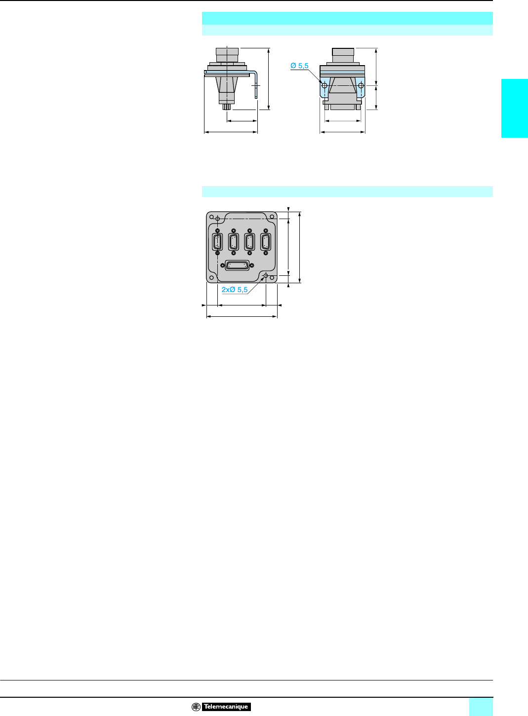
Dimensions Lexium motion control 1
TSX CAY modules for servomotors
Mounting in enclosure feedthrough (dust and damp proof)
bØ 37 cut-out,
bPanel thickness 5 mm maximum
Mounting on DIN rail with LA9-DC9976 accessory.
Dimensions
TSX TAP S15 05 connection interface for incremental encoder
70,4
31
55
27,4
38
47
43
TSX TAP MAS speed reference splitter block for speed drives
50==
80
65 ==
80
C
haracteristics:
p
ages 13 and 14 References:
pages 15 and 16
This document provided by Barr-Thorp Electric Co., Inc. 800-473-9123 www.barr-thorp.com
22
2
Software set up Lexium motion control 1
Motion control modules
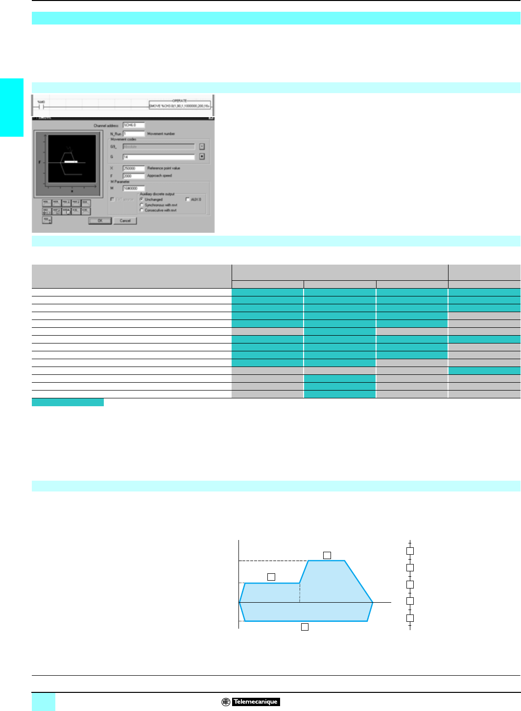
PL7 Junior/Pro or Unity Pro setup software provides:
bSMOVE and XMOVE motion control functions for programming movements.
These functions can be used in Ladder language, Instruction list language or
Structured Text language.
bSpecialized screens for configuring, adjusting and debugging axes.
A movement on an independent axis is initiated by executing an SMOVE control
function in the application program.
Example: go to the absolute position 10 000 000 µm, at a speed of 200 mm/min,
without stopping.
A screen enables the assisted entry of parameters in the SMOVE function in an
operation block.
The XMOVE command enables movement to be initialized on interpolated axes
(TSX CAY 33 only).
A complete path can be programmed by means of a series of SMOVE or XMOVE
elementary motion control functions.
Grafcet language is ideal for this type of programming. An elementary movement is
associated with each step.
(10)Only with TSX CAY 22 module. Requires the version > 4.1 of PL7 Junior/Pro software
TLX CD/RCD PL7J/P P 41M. Not available with Unity Pro software.
TSX CAY/CFY module software setup
Programming movements
Instruction codes
The characteristics of movements are described using a syntax similar to that for a numerical controller program block written in ISO language.
TSX CAY and TSX CFY motion control modules use the following instructions:
Individual axes
(SMOVE) Interpol. axes
(XMOVE)
Code and type of instruction TSX CAY 21/41 TSX CAY 22/42/33 TSX CFY 11/21 TSX CAY 33
09 Move to the position and stop
01 Move to the position without stopping
10 Move until an event is detected and stop
11 Move until an event is detected without stopping
14 Homing
04 Stop command
05 Await an event
07 Memorize the current position when an event occurs
62 Forced homing
30/32 Simple machining
92 Initialization of memorized positions
21 Move without stopping, with homing on the fly
22 Flying shear on two axes (1)
90/98 Cutting mode (on position or on event) (1)
Possible instruction
These instruction codes can be represented as symbols by the user in G code (for example: 09 can be represented by G09).
The instruction codes are preceded by another code indicating the type of target position:
b90 : if the target position is absolute.
b91 : if the target position is relative to the current position.
b98 : if the target position is relative to a memorized position (index).
b60 : if the target position is absolute and movement direction is fixed (TSX CAY 22/42/33 only).
b68 : if the target position is relative to a memorized position and movement direction is fixed (TSX CAY 22/42/33 only).
Programming a path
5
4
3
2
1SMOVE %CH102.0 (1, 90, 01, X1, F1)
SMOVE %CH102.0 (2, 90, 09, X2, F2)
SMOVE %CH102.0 (3, 90, 09, 0, F1)
2
1
3
F2
F1
F1
X1
X
p
: coordinate of target position
F
p
: movement speed of moving
part
Speed
X2 Position
This document provided by Barr-Thorp Electric Co., Inc. 800-473-9123 www.barr-thorp.com
23
2
Software setup (continued) Lexium motion control 1
Motion control modules
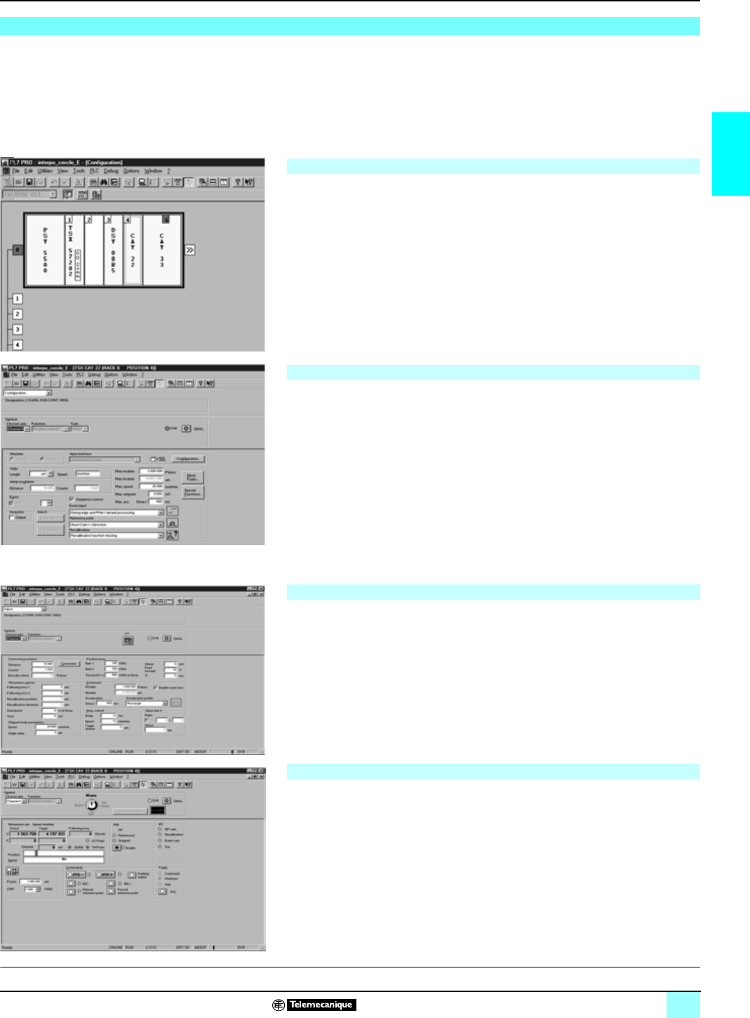
When setting up application-specific functions, screens specific to axis control and
stepper control functions can be accessed via PL7 Junior/Pro software for
configuration, adjustment, debugging and documentation of applications.
These services are performed by editors which can be directly accessed from the basic
screen using icons in the tool bars. Windows relating to the editors can be simultaneously
displayed on one screen (example : it is possible to simultaneously program using the
program editor and define the symbols in the variables editor).
Parameter entry screens for application-specific functions can be accessed via the
configuration screen by clicking on the slot.
Example : modules TSX CAY 21 and TSX CFY 21 in which the module has been
defined.
The configuration editor provides assistance with entering and modifying the values
of the various axis configuration parameters. These parameters enable the operation
of the axis control module (module TSX CAY 21 for example) to be adapted to the
machine which is to be controlled.
Axis configuration parameters are :
bUnits of measurement.
bResolution.
bType of encoder.
bMaximum and minimum limits.
bMaximum speed.
b…
This data relates to the machine and cannot be modified by the program.
These parameters are associated with operation of the axes. They generally require
the operations on and movements of the moving part to be known. These parameters
are adjusted in online mode (they are initialized during configuration, in offline mode).
They concern:
bEncoder offset.
bResolution.
bServo control parameters.
b…
In online mode, the configuration editor also provides the user with a control panel
screen, giving him a quick visual display which he can use to control and observe the
behaviour of the axis.
The control panel provides different information and commands according to the
selected operating mode :
bAutomatic mode (Auto).
bManual mode (Manu).
bDirect mode (Dir_Cde).
bOff mode (Off).
TSX CAY/CFY module software setup (continued)
Declaring the axis control modules and stepper control modules
Configuring the modules
Adjusting the modules
Debugging the modules
This document provided by Barr-Thorp Electric Co., Inc. 800-473-9123 www.barr-thorp.com
24
2
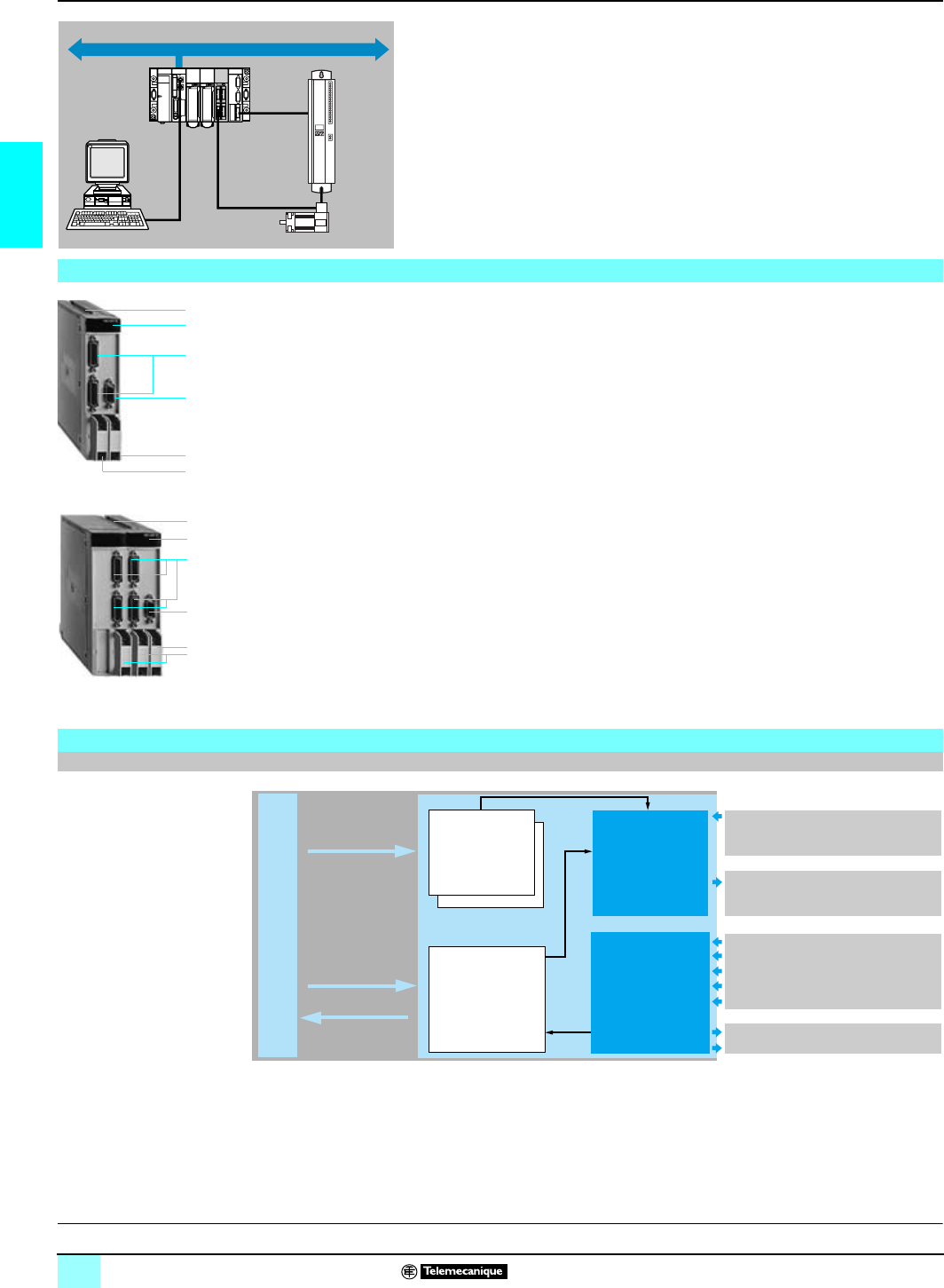
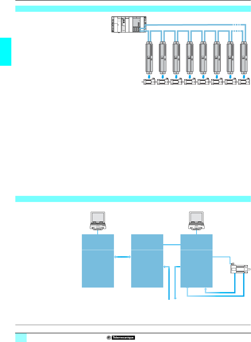
SERCOS architecture,
system overview Lexium motion control 1
SERCOS TSX CSY 84/164
motion control module
SERCOS
(SERiaI COmmunication System) is a communication standard which
defines the digital link (exchange protocol and medium) between a motion control
module and intelligent servodrives. It is defined in European standard EN 61491.
Using the SERCOS distributed architecture allows application I/O (position encoder,
emergency stop, etc.) to be connected directly to the intelligent servodrives, reducing
the cost of connection. The fiber optic digital link permits high speed exchanges (2 or
4 M bauds) while ensuring a high level of immunity in disturbed industrial environments.
The SERCOS range in the Premium control system platform comprises:
bTwo TSX CSY 84/164 axis control modules which can each control up to 16
servodrives via a SERCOS ring. The module calculates the path and interpolation for
several axes (position mode). Access to the other modes (speed and torque) is
possible with the assistance of Schneider Electric application services.
b1.5 A to 70 A Lexium MHDA servodrives with digital link (equipped with SERCOS
option card). The servodrives manage the position loop, speed loop and torque loop,
and ensure power conversion to control the motor. The encoder feedback
information is sent to the servodrive (current position, current speed).
bSER/Lexium BPH brushless motors. These have permanent magnets delivering a
high power-to-weight ratio, resulting in excellent dynamic speed response in a
compact unit.
The Lexium range offers all the accessories required (filter choke, braking resistor,
etc.) and a full set of connectors.
The system overview presents the various functions performed by the different parts
of the multi-axis control system.
Architecture
Fiber optic cables
SERCOS ring network
Lexium MHDA
servodrives
(with SERCOS
option card).
SER/Lexium BPH
motors
System overview
C
haracteristics:
p
ages 26 and 26 Functions:
pages 28 and 29 References:
page 30 Connections:
page 31
PLC
Premium/Atrium
Application
program Bus X
SERCOS
TSX CSY 84/164
module
Linear or infinite
independent axes
2 to 8-axis linear
interpolation
Follower axes
(6 slaves) by gearing
or profiled cams
Lexium MDHA
servodrive (with
SERCOS option card).
Interpretation of
commands
Position loop
Speed loop
Current loop
Power
conversion
Speed Position
SER/Lexium
BPH motor
PL7 Junior/Pro,
Unity Pro
Unilink
SERCOS ring
(to servodrive network)
This document provided by Barr-Thorp Electric Co., Inc. 800-473-9123 www.barr-thorp.com
25
2
System overview (continued),
description Lexium motion control 1
SERCOS TSX CSY 84/164
motion control modules
PL7 Junior/Pro or Unity software via the Premium platform terminal port can:
bDeclare TSX CSY 84/164 SERCOS modules (1) in the PLC configuration.
bConfigure the functions and define the parameters for the axes used.
bProgram the movements in the PLC application.
bAdjust the parameters via the operating codes (parameters, TSX CSY module and
Lexium MHDA servodrives) (2).
bTest and debug the application.
Unilink software, via the RS 232 terminal port for the Lexium MHDA servodrive (2) can:
bDefine types of Lexium MHDA servodrives (2) and SER/Lexium BPH motors.
bAdjust the parameters for Lexium MHDA servodrives (2), back them up to
EEprom memory in the drive and save them on a compatible PC.
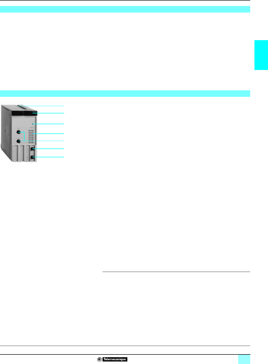
The TSX CSY 84/164 SERCOS axis control modules comprise:
1A SMA-type connector, marked Tx, for connecting the servodrives using the
SERCOS ring fiber optic transmission cable.
2A SMA-type connector, marked Rx, for connecting the servodrives using the
SERCOS ring fiber optic reception cable.
3Rigid cases, double format, in order to:
bSupport electronic cards
bAttach and lock the module in its slot.
4Module diagnostic lamps:
bRUN LED (green): LED ON indicates module operating correctly.
bSER LED (yellow): flashing LED indicates data transmission and reception on the
SERCOS network
bERR LED (red):
v LED ON indicates internal module fault,
v flashing LED on module start up indicates communication fault, incompatible
configuration or application missing.
bI/O LED (red): LED ON indicates external fault or application fault.
bINI LED (yellow): flashing LED indicates module is reinitializing.
5Channel diagnostic LEDs (green): LED ON indicates axis operating normally;
OFF: configuration fault; flashing: serious error on axis:
b1 to 8: display of 8 real axes (3).
b9 to 12: display of 4 imaginary axes (3).
b13 to 16: display of 4 remote axes (3).
b17 to 20: display of 4 coordinated sets.
b21 to 24: display of 4 follower sets.
6A pencil point button to initialize the module.
7Two mini DIN type 8-way connectors for Schneider Electric use.
(1) TSX CSY 164 module can not be implemented with Unity Pro V1.0 software.
(2) Lexium MHDA servodrive equipped with AM0 SER 001V000 SERCOS option card.
(3) 1 to 16: display the 16 axes (real, imaginary or remote) with module TSX CSY 164.
System overview (continued)
Description
3
4
6
5
7
2
1
C
haracteristics:
p
ages 26 and 26 Functions:
pages 28 and 29 References:
page 30 Connections:
page 31
This document provided by Barr-Thorp Electric Co., Inc. 800-473-9123 www.barr-thorp.com
26
2
Characteristics Lexium motion control 1
SERCOS TSX CSY 84/164
motion control module
(1)4 ms default value. Values may be programmed according to number of axes.
(2) Without the use of a TSX REY 200 bus X remote module.
(3) For further certification details, see pages 118 and 119.
(4) Determine external position using an encoder connected to the servodrive position input.
Characteristics
Electrical characteristics TSX CSY 84 TSX CSY 164
SERCOS ring network Type Industrial medium complying with standard EN 61491
Topology Ring
Medium Fiber optic cable
Baud rate M bauds 4 by default
Cycle time (1)
(independent axes) ms 2 axes 4 axes 8 axes 2 axes 4 axes 8 axes 12 axes 16 axes
22422234
Maximum number of
segments 9 17
Length of segment m38 max. with plastic fiber optic cable, 150 max. with glass fiber optic cable
Bus X Distance m100 max. (2) between TSX CSY 84 axis control module and the Premium processor
SERCOS certification (3) TSX CSY 84/164 modules comply with SERCOS CEI/EN 61491 certification and with the tests
determined by IGS (Interest Group SERCOS).
Certification N° Z00030
Power consumption for c 5V voltage mA 1800
Power dissipated in the module W9 (typical)
Operating characteristics TSX CSY 84 TSX CSY 164
Number of channels 32 configurable (0 to 31), channel 0 used for SERCOS ring configuration
Type of axes Real axes
(connected to a servodrive)
8 (channels 1 to 8) 16 (channels 1 to 16) may be dynamically configured as
real axes, imaginary axes or remote axis.
Imaginary axes
4 (channels 9 to 12)
Remote axes (4) 4 (channels 13 to 16)
Set of axes 4 coordinated (channels 17 to 20). Each set allows linear interpolation of 2 to 8 axes
4 followers (channels 21 to 24). Each set can comprise a maximum of 7 axes: 1 master/6 slaves
in gearing or camming
Cam profile 7 (channels 25 to 31). Used to create the electronic cams with linear or cubic interpolation
between profile points
A
rchitectures
p
ages 24 and 25 Functions:
pages 28 and 29 References:
page 30 Connections:
page 31
This document provided by Barr-Thorp Electric Co., Inc. 800-473-9123 www.barr-thorp.com

27
2
Characteristics (continued) Lexium motion control 1
SERCOS TSX CSY 84/164
Premium motion control module
(1) Implementation of the TSX CSY 84, release
u
1.3 requires the use of the PL7 Junior/Pro
software, version
u
4.4. Access available only with TSX CSY 164 module.
Characteristics (continued)
Main functions
Programming Movements bHoming, absolute, relative, or continuous
bImmediate movement, or queued, to a given position
bSpeed override possible
bAcceleration and deceleration parameters may be set for each axis motion control (1)
bSynchronisation on start and desynchronisation on stop for a slave axis on a master axis,
in a given position (1)
bRollover counter (1)
Special functions bCapture position and distance measurement between two edges on one or two discrete
inputs on the drive. This can be applied to a real or remote axis (position measurement via
external encoder)
bCount probe: counts the edges on a discrete input on the drive over a period of time
bFast index: starts a movement on an event
bRegistration move: position capture on an edge of the discrete input on the drive
bRotary Knife: cuts using a rotary knife. Synchronizes a circular axis on a linear axis and
controls a discrete output on the drive
Other special functions The development of all other special function is possible with the assistance of our application
services. Please consult our Regional Sales Offices .
Stop/start functions bFast stop, stop on configured deceleration profile
bTemporary stop
bRestart of stopped movement
bChoice of stop method (1):
vOn faulty slave: master is not stopped. master stops normally according to pre-determined
deceleration ramp or Servo-driven master emergency stop
vOn faulty master: slave stops normally according to pre-determined deceleration ramp or
Servo-driven slave emergency stop
bOn Emergency Stop: calculation of slave axis deceleration ramp alignment with master axis
so that obtains the synchronization stop of all set axes. (1)
bEmergency Stop: axes may be allowed to "freewheel" or may be stopped according to pre-
determined ramp (1)
Configuration
/adjustment SERCOS ring Bus cycle time, traffic on the bus, optical power on the fiber, SERCOS loop diagnostics
Acceleration/deceleration Ramp values, ramp type (rectangular, triangular and trapezoid), choice of units, maximum
acceleration adjustment
Speed Speed units, default speed, maximum speed, speed override
Other settings Target window, rollover, software limits
Set of follower axes Following of master axis by gearing or camming (cam profile), threshold position of master
triggers the following, bias value when synchronizing an axis, monitoring of master/slave
positions, master offset for follower axis
Set of coordinated axes Type of interpolation: linear
Cam profile Value of an existing point of a cam profile, number of points (5000 max.), type of interpolation,
table addresses
State of a movement or axis Moving, accelerating, decelerating, homing, in position, faulty, etc.
Diagnostics bDrive fault, axis currently reading data, following error, overvoltage, undervoltage,
overcurrent, power supply fault
bAvailability of master axis fault information for a given axis set (1)
bMultiaxis motion path control according to common tolerance for all axes in the motion, with
alarm feature. Access available only with TSX CSY 164 module
A
rchitectures
p
ages 24 and 25 Functions:
pages 28 and 29 References:
page 30 Connections:
page 31
This document provided by Barr-Thorp Electric Co., Inc. 800-473-9123 www.barr-thorp.com
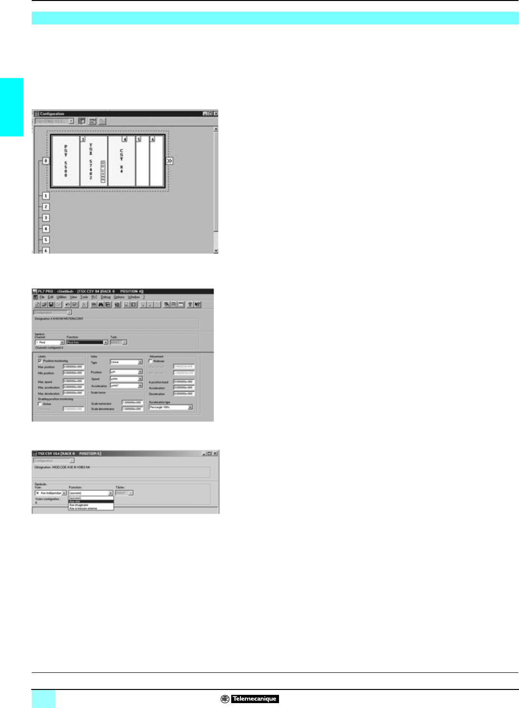
28
2
Functions Lexium motion control 1
SERCOS TSX CSY 84/164
motion control modules
When setting up application-specific functions, screens specific to SERCOS axis
control functions can be accessed via PL7 Junior/Pro or Unity software for
configuration, adjustment, debugging and documentation of applications. These
services are performed by editors which can be directly accessed from the basic
screen using icons in the tool bars. Windows relating to the editors can be
simultaneously displayed on one screen (example: it is possible to program using
the program editor and simultaneously define the symbols in the variables editor).
Declaring the SERCOS motion control modules
Parameter entry screens for application-specific functions are accessed via the
configuration screen by clicking on the slot.
Example: configuration in which a TSX CSY 84/164 module has been defined.
Configuring the module
The configuration editor provides assistance with entering and modifying the values
of the various axis configuration parameters. These parameters enable the operation
of the axis control module to be adapted to the machine which is to be controlled.
Axis configuration parameters are:
bUnits of measurement.
bResolution.
bMaximum and minimum limit positions.
bMaximum speed.
bAccelerating/decelerating.
This data relates to the machine and cannot be modified by the program.
The following configuration screen can be used to declare the 16 axes as real,
imaginary or remote measurement axes in module TSX CSY 164.
(1) The setting up screens require the version
u
4.1 of PL7 Junior/Pro software TLX CD/RCD
PL7J/P P41M/42M/43M/44M or Unity Pro UNY SPU
p
FU CD 10.
Software setup (1)
A
rchitectures
p
ages 24 and 25 Characteristics:
pages 26 and 27 References:
page 30 Connections:
page 31
This document provided by Barr-Thorp Electric Co., Inc. 800-473-9123 www.barr-thorp.com
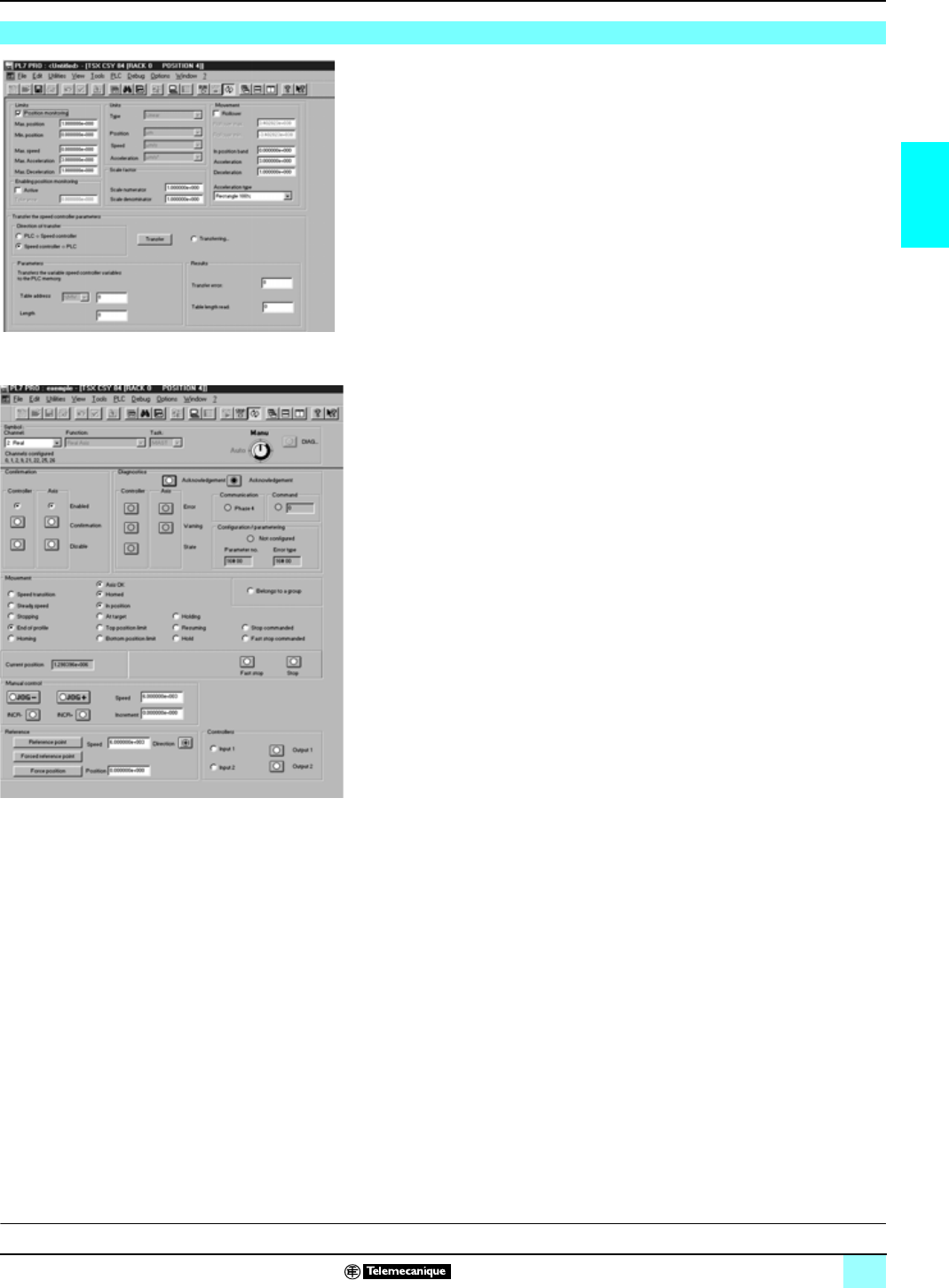
29
2
Functions (continued) Lexium motion control 1
SERCOS TSX CSY 84/164
motion control modules
Adjusting the modules
These parameters are associated with operation of the axes. They
generally require
the
operations on and movements of the moving
part to be known. These parameters
are
adjusted in online mode (they are initialized during
configuration, in offline mode).
They concern:
bMaximum speed.
bResolution.
bServocontrol parameters.
bAccelerating/decelerating.
Debugging the modules
In online mode, the configuration editor also provides the user with a control panel
screen, giving a quick visual display which can be used to control and observe the
behavior of the axis.
The TSX CSY 84/164 module associated with PL7 Junior/Pro software (1) provides
manual mode for running continual (JOG) or incremental (INC) motion commands
without prior programming.
(1) Mode not available with Unity Pro.
Software setup (continued)
A
rchitectures
p
ages 24 and 25 Characteristics:
pages 26 and 27 References:
page 30 Connections:
page 31
This document provided by Barr-Thorp Electric Co., Inc. 800-473-9123 www.barr-thorp.com
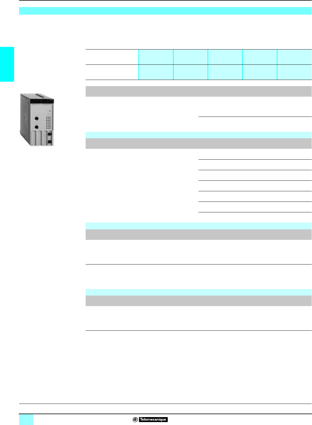
30
2
References Lexium motion control 1
SERCOS TSX CSY 84/164
motion control module
The TSX CSY 84/164 multiaxis control module has 32 application-specific channels
which are only counted when they are configured in the Premium application (using
PL7 Junior/Pro or Unity Pro software). The maximum number of application-specific
channels allowed depends on the type of processor:
(1) The TSX CSY 164 module is compatible with version 4.3 of the PL7 Junior/Pro software
application with the Motion software add-on update included on the TSX CSY 164 module
CD-Rom. Version 4.4 of PL7 Junior/Pro includes this software add-on. The TSX CSY 164
module is not compatible with Unity Pro version 1.0 software.
(2) The add-on can be downloaded when the default configuration file is not adapted to the
configuration required.
References
Type of processors TSX/57 1pTSX/57 2p
PCX 57-20
PCI 57-20
TSX/57 3p
PCX 57-35 TSX/57 4p
PCI 57-45 TSX/57 5p
Maximum number of
application-specific
channels
824 32 64 64
Description Functions Number of axes Reference Weight
kg
Multiaxis control modules
SERCOS digital servodrives
control 8 real axes
4 imaginary axes
4 remote axes
TSX CSY 84 0.520
16 axes (real axes, imaginary
axes or remote axes) TSX CSY 164
(1) –
Connection accessories
Description Connection Length Reference Weight
kg
Plastic fiber optic cables
fitted with SMA-type
connectors
(curvature radius:
25 mm min.)
Lexium MHDA
servodrive 1pppN00/A00
(with SERCOS option card)
0.3 m 990 MCO 000 01 0.050
0.9 m 990 MCO 000 03 0.180
1.5 m 990 MCO 000 05 0.260
4.5 m 990 MCO 000 15 0.770
16.5 m 990 MCO 000 55 2.830
22.5 m 990 MCO 000 75 4.070
37.5 m 990 MCO 001 25 5.940
Sets of plastic fiber optic connections
Description Composition Reference Weight
kg
Set of fiber optic cables
and SMA-type connectors 12 SMA-type connectors
12 insulating sleeves
Plastic fiber optic cable, length 30 m
990 MCO KIT 01 –
Fiber optic cable
installation tool Tools for making up cables to required length from a
990 MCO KIT 01 kit
Includes stripping tool, crimping pliers, 25 W/110 V cutting tool,
and instructions for use
990 MCO KIT 00 –
Separate item
Description Use Reference Weight
kg
PC to TSX CSY 84/164
connectors connection
cable
(length 2 m)
Used to download the servodrive operation configuration file for
the servodrives present on the SERCOS ring (2)
Used to download specific functions developed by our Industrial
Applications Department.
TSX CCT 200 0.100
T
SX CSY 84 164:
A
rchitectures:
p
ages 24 and 25 Characteristics:
pages 26 and 27 Functions:
pages 28 and 29 Connections:
page 31
This document provided by Barr-Thorp Electric Co., Inc. 800-473-9123 www.barr-thorp.com
31
2
Connections Lexium motion control 1
SERCOS TSX CSY 84/164
motion control module
1TSX CSY 84/164: multiaxis control module for Premium.
2MHDA 1pppN00/A00 Lexium servodrives fitted with the SERCOS
AM0 SER 001 V000 option card.
3990 MCO 000 pp: plastic fiber optic cables fitted with SMA type connectors.
TXTransmission.
RXReception.
Connections
SERCOS ring with 5 servodrives (example)
3
3
2
TX RX
RX TX RX TX RX TX TXRXTXRX
X13 X15 X13 X15
3 3 3 3
2 2 2 2
1
Servodrive 1 Servodrive 3 Servodrive 5 Servodrive 2 Servodrive 4
SERCOS network ring
A
rchitectures:
p
ages 24 and 25 Characteristics:
pages 26 and 27 Functions:
pages 28 and 29 References:
page 30
This document provided by Barr-Thorp Electric Co., Inc. 800-473-9123 www.barr-thorp.com

32
3
Selection guide Lexium motion control 1
Quantum motion control modules
Applications Single-axis Motion module for servomotors. Compatible with Lexium servodrive through an
analog interface
Drive interface Counter inputs: incremental encoder, c 5 V, (RS 422) 2 channels
Encoder feedback : ± 10 V, 12 bits
Programming Methodology Using MMDS motion configuration software, with Concept or ProWORX 32 software
Features Multiplication of counter frequency (x4)
Automatic brake control
Configurable discrete I/O inputs (including one high-speed input)
Configurable discrete/analog I/O outputs
Axis Count 1 real axis
1 remote axis (for master signal)
Special Functions Master/slave position capture
Synchronization of master/slave axes
Point lock
Model
140 MSB 101 00
Page 36
This document provided by Barr-Thorp Electric Co., Inc. 800-473-9123 www.barr-thorp.com
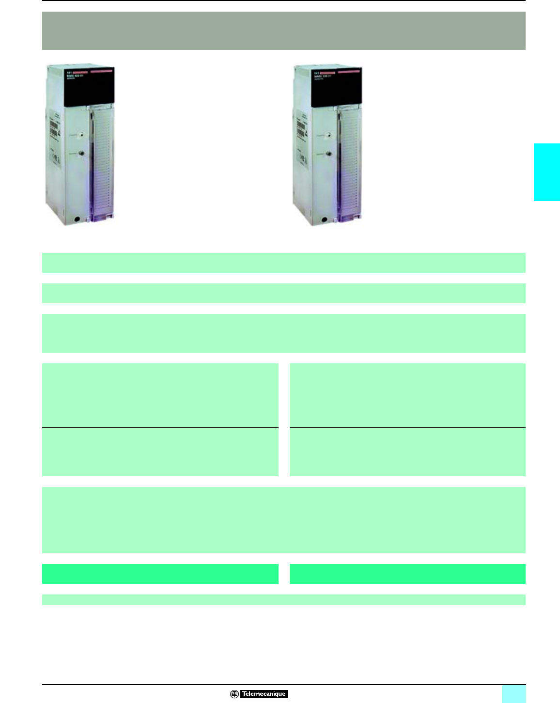
33
3
1
Multi-axis Motion control modules for servomotors. Compatible with Lexium servodrive via SERCOS link
Via SERCOS link
Library of Motion Function Block under Concept software
The development of all other special function is possible with the assistance of our application services
Electronic gearing
Multi-axis interpolation
Cam profiles execution from Register Table
With MMF Start programmer's kit
- 8 real axes
- 4 imaginary axes
- 4 remote axes
- 4 coordinate sets (with linear interpolation of 8 axes maximum)
- 4 follower sets
- Cam profiles
With MMF Start programmer's kit
- 8 real axes
- 4 imaginary axes
- 4 remote axes
- 4 coordinate sets (with linear interpolation of 8 axes maximum)
- 4 follower sets
- Cam profiles
The evolution, up to
- 16 real axes
- 22 axes/axis sets
is possible with the Motion Open C kit requiring the assistance of our
Application Department
The evolution, up to
- 22 real axes
- 32 axes/axis sets
is possible with the Motion Open C kit requiring the assistance of our
Application Department
Point lock position and point lock time
Measure part
Count probe
Fast index
Registration move
Rotary knife
141 MMS 425 01 141 MMS 535 02
44
This document provided by Barr-Thorp Electric Co., Inc. 800-473-9123 www.barr-thorp.com
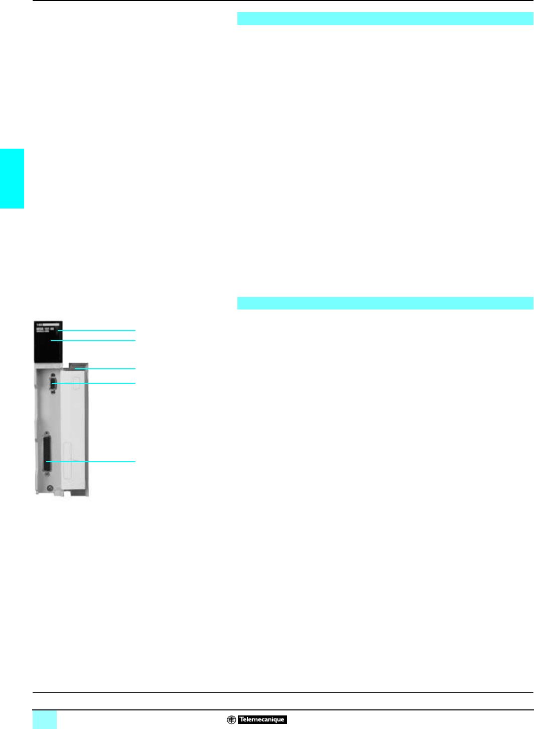
34
3
Presentation,
description Lexium motion control 1
140 MSB 101 00 Quantum single-axis motion
module for servomotors
The 140 MSB 101 00 single-axis motion module is designed for applications with
one axis requiring a strong integration with the sequential program of the machine.
The analog output of this module can drive the speed reference of the
Lexium MHDA servodrive, or any other servodrive with an analog interface. See
characteristics on page 35.
The module, using encoder feedback input, receives a signal from an incremental
encoder which represents the position of the machine axis. After calculation, this
information, depending on the movement driven by the application program, delivers
a speed reference of ± 10 V to the servodrive.
The 140 MSB 101 00 module is designed as follows:
b8 digital inputs of 24 VDC, configurable in stops or in motion-specific functions.
The inputs not used in the axis control application can be used as standard inputs for
the application program.
b3 outputs of 24 VDC and one ± 10 V analog output, which can be programmed as
a real-time image of the internal parameters of the axis under control.
These inputs and outputs require an external 24 V power supply. The module
includes a ± 10 V analog input.
The incremental encoder's multiplication of impulses is integrated in the
140 MSB 101 00 module, which accepts a second auxiliary encoder feedback signal
as an image of the master axis.
The 690 MCB 000 00 breakout box allows connection between the 141 MSB 101 00
motion module and the Lexium MHDA servodrive, to simplify the system cabling.
The 140 MSB 101 00 is comprised of:
1A rugged outer rugged shell ensures the following:
v PCB card support.
v closing and locking of module into position.
2Module diagnostic LEDs, including a digital Modbus status indicator.
3A SUB-D 9 connector for RS 232 Modbus link.
4A SUB-D 50 port for connection to the servodrive.
5A clear access door to hold the user label.
Presentation
4
3
5
2
1
Description
C
haracteristics:
p
age 35 References:
page 36 Connections:
page 37
This document provided by Barr-Thorp Electric Co., Inc. 800-473-9123 www.barr-thorp.com

35
3
Characteristics Lexium motion control 1
140 MSB 101 00 Quantum single-axis motion
module for servomotors
Operating characteristics
Axe Type Automatic control of linear, rotary, or continuous axes
Synchronization of master/slave speed and position
Number 1 real axis, 1 remote axis
Positioning
range Maximum 4 294 967 296 points (32 bits)
Units inches, mm or orther units
Speed Range 1...4 294 967 296 points (32 bits)
Units counts/s, inches/s, mm/s, rpm…
Update Position loop ms 1
Speed loop ms 0.5
Motion Homing, absolute, relative, or continuous movement
28 traversing programs
650 flash memory commands
Controls Environnement Encoder interface, position captures (stops)
Motion Logical stops, loop position control, point window
Register words 3 input words and 4 output words
Electrical characteristics
Encoder
feedback
(2 channels)
Incremental
encoder Type Differential
Voltage c V5 ± 20 %
Impedance W> 500 at 5 V nominal
Frequency x 1 kHz 200 nominal, 500 maximum
Frequency x 4 kHz 2000 maximum (internal counting)
Maximum system
accuracy 0.5 arc/minute, encoder-dependent
Servo interface Analogue
outputs Type Bipolar
Range V+ 10,24
Resolution 11 bits + sign
Drive-enable
output Voltage V24 nominal, 30 maximum
Current mA 500 (resistive maximum under 30 V)
Drive-fault input True high, 5 V TTL-compatible
I/O Discrete inputs Number 7
Voltage c V 24 + 20 %
Discrete
outputs Number 3
Voltage c V24 + 20 %
Current mA 150 maximum
Analog inputs Voltage V± 10.24
Resolution 9 bits + sign
Impedance kΩ30
Analog outputs Voltage V± 10.24
Maximum current mA 3
Resolution 11 bits + sign
High-speed
input Position capture time ms 250
Pulse width ms 25
Time between two
captures ms 20 minimum
OT inputs Dry contact
Communication
ports Serial ports Type RS 232 D
Protocol Modbus slave
Baud rate Bits/s 300...9600, software selectable
Power
requirements From the backplane c 5 V - 1000 mA
External (power process) c 24 V + 20 % at - 500 mA max (for auxiliary I/O)
D
escription:
p
age 34 References:
page 36 Connections:
page 37
This document provided by Barr-Thorp Electric Co., Inc. 800-473-9123 www.barr-thorp.com

36
3
References Lexium motion control 1
140 MSB 101 00 Quantum single-axis motion
module for servomotors
All types of Quantum CPUs support the 140 MSB 101 00 single-axis motion module.
The module performs the same regardless of rack selected (primary, RI/O, or DI/O).
References
Designation For Encoder
inputs Functions Reference Weight
kg
Motion module for
one controlled axis Servodrive via
analog
reference
2 encoder
inputs
c5 V, 500 kHz Closed-loop control of linear,
rotary and continuous axes.
Synchronization of master-slave
axes.
140 MSB 101 00 0.450
Connection accessories
Designation Use No.
(1) Reference Weight
kg
Breakout box
(2) Connection between the 141 MSB 101 00
module and the servodrive: speed reference,
auxiliary I/O, and simulated encoder feedback
3690 MCB 000 00 –
Connector cables
Designation Use No.
(1) Length Reference Weight
kg
Supplied cables Connection between the
140 MSB 101 00 module and
the 690 MCB 000 00 breakout
box. Cable comes with SUB-D
50 connectors on each end.
40,3 m
(1 ft) 690 MCI 000 01 –
0,9 m
(3 ft) 690 MCI 000 03 –
1,8 m
(6 ft) 690 MCI 000 06 –
Connection between the
breakout box 690 MCB 000 00
and Lexium MHDA servodrive
(simulated encoder feedback).
Cable comes with SUB-D
9 connector on one end
56 m
(20 ft) 690 MCI 002 06 –
Configuration software
Designation Description Reference Weight
kg
MMDS configuration
and programming
software
Configuration and programming software for the 140 MSB 101 00
motion module
Use with ProWORX 32 or Concept
SW MMDS 1DB 0.525
(1)See page 37 for key.
(2) For e conformity, you must order the breakout box field wiring kit (690 MCB 101 00).
D
escription:
p
age 34 Characteristics:
page 35 Connections:
page 37
140 MSB 101 00
This document provided by Barr-Thorp Electric Co., Inc. 800-473-9123 www.barr-thorp.com
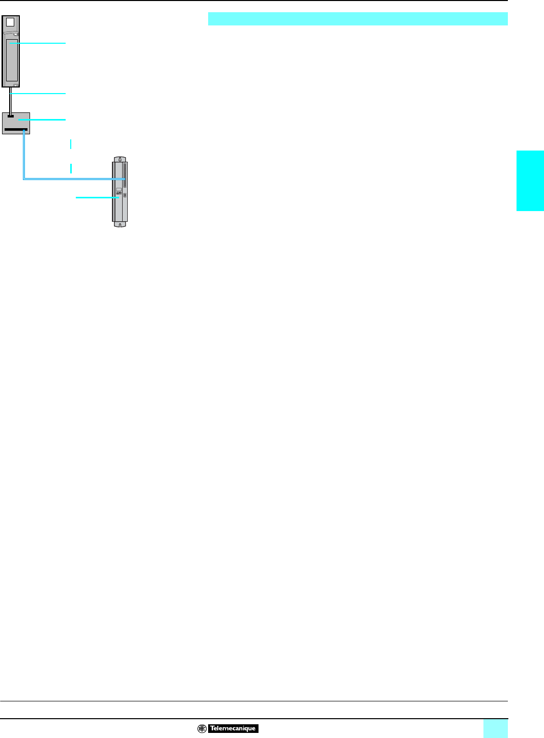
37
3
Connections Lexium motion control 1
140 MSB 101 00 Quantum single-axis motion
module for servomotors
1140 MSB 101 00: single-axis motion module 140 MSB 101 00.
2MHDA 1pppN00/A00: Lexium servodrive for Lexium SER or BPH motor.
3690 MCB 000 00: breakout box (speed reference, auxiliary I/O, and simulated
encoder feedback).
4690 MCI 000 0p: breakout box cable (0p indicates cable length).
5690 MCI 002 06: cable with connector for simulated encoder feedback.
6Cable (not included; flying lead cable with connections to terminal strips on each
end).
Connections
1
4
3
5
2
6
D
escription:
p
age 34 Characteristics:
page 35 References:
page 36
This document provided by Barr-Thorp Electric Co., Inc. 800-473-9123 www.barr-thorp.com

38
3
Presentation Lexium motion control 1
SERCOS 141 MMS Quantum motion control
modules
SERCOS MMS motion control modules are used to build a distributed automation
solution, tightly integrating axis command applications with control applications,
based on Quantum PLCs. The motion control modules and Quantum CPUs
communicate either through the Quantum backplane or via the Modbus Plus
network. The data transfer is transparent, and does not need any additional
application program.
The physical interface between the motion control module and speed servodrives is
provided by the SERCOS network, using fiber optic cable. This optic link is entirely
digital, and provides communication parameters for the tuning, diagnostics and
operation of both motion control modules and servodrives.
The SERCOS offer, based on the Quantum platform contains:
bTwo multi-axis modules, 141 MMS 425 01/535 02, that can drive up to 8 real
axes (1), each one connected to a Lexium servodrive using the SERCOS ring
network.
All these modules perform the trajectory calculation, synchronization or interpolation
of several axes.
bLexium MHDA (with optional SERCOS card) servodrives with a SERCOS digital
link from 1.5 A to 70 A. These drives manage the position, speed and torque loops,
and convert the power that drives the motor. Feedback from the motor sensors or
external encoders (such as usual position and actual speed) are sent to the
servodrive.
bSER/Lexium BPH brushless motors. These devices are equipped with magnets
which deliver a high power-to-weight ratio, resulting in a wide range of speed within
low overall dimensions.
The Lexium range includes all necessary accessories (filter chokes, braking
resistors, etc.) and connection elements.
The 141 MMS SERCOS motion modules are double-width Quantum modules. They
provide high-performance motion control functions, while being integrated with the
Quantum PLC and via a real-time multi-task system.
In addition to communicating with the Quantum CPU via the internal bus, each
141 MMS module has a Modbus Plus communications port. The availability of
program libraries simplifies configuration of the motion controls for high-performance
applications requiring highly dynamic and high-precision position tracking
algorithms.
This integration is used to fulfill motion control applications requiring a large number
and great diversity of inputs and outputs. The solution makes it possible to share a
single database between the Quantum CPU and the SERCOS motion control
module. The SERCOS ring network corresponds to
a widely developed standard used in closed-loop position and speed applications.
It complies with the European standard EN 61491.
The SERCOS solution, compared to analog interface solutions, offers the following
benefits:
bEfficient diagnostics, supplied in the motion control modules and the Quantum
CPU, can send feedback to the upper levels of the control hierarchy for action.
This minimizes machine downtime.
bThe distributed architecture significantly reduces cabling costs and simplifies the
installation.
bThe SERCOS digital network eliminates the low-resolution analog interface (12 or
14-bits) between the servodrive and the motion control module.
bFiber optic connections increase immunity from electromagnetic interference
found in harsh industrial environments.
bIt is easy to expand the number of axes in one machine using the ring network.
(1) The use of the Motion Open C kit (requiring the assistance of our applications team) enables
you to extend the capacities of these modules: 141 MMS 425 01, up to 16 real axes and
141 MMS 535 02, up to 22 real axes.
Presentation
SERCOS offer
Quantum motion modules
SERCOS motion control built into Quantum PLCs
D
escritpion:
p
age 40 Characteristics:
pages 42 and 43 References:
pages 44 and 45 Connections:
page 45
This document provided by Barr-Thorp Electric Co., Inc. 800-473-9123 www.barr-thorp.com
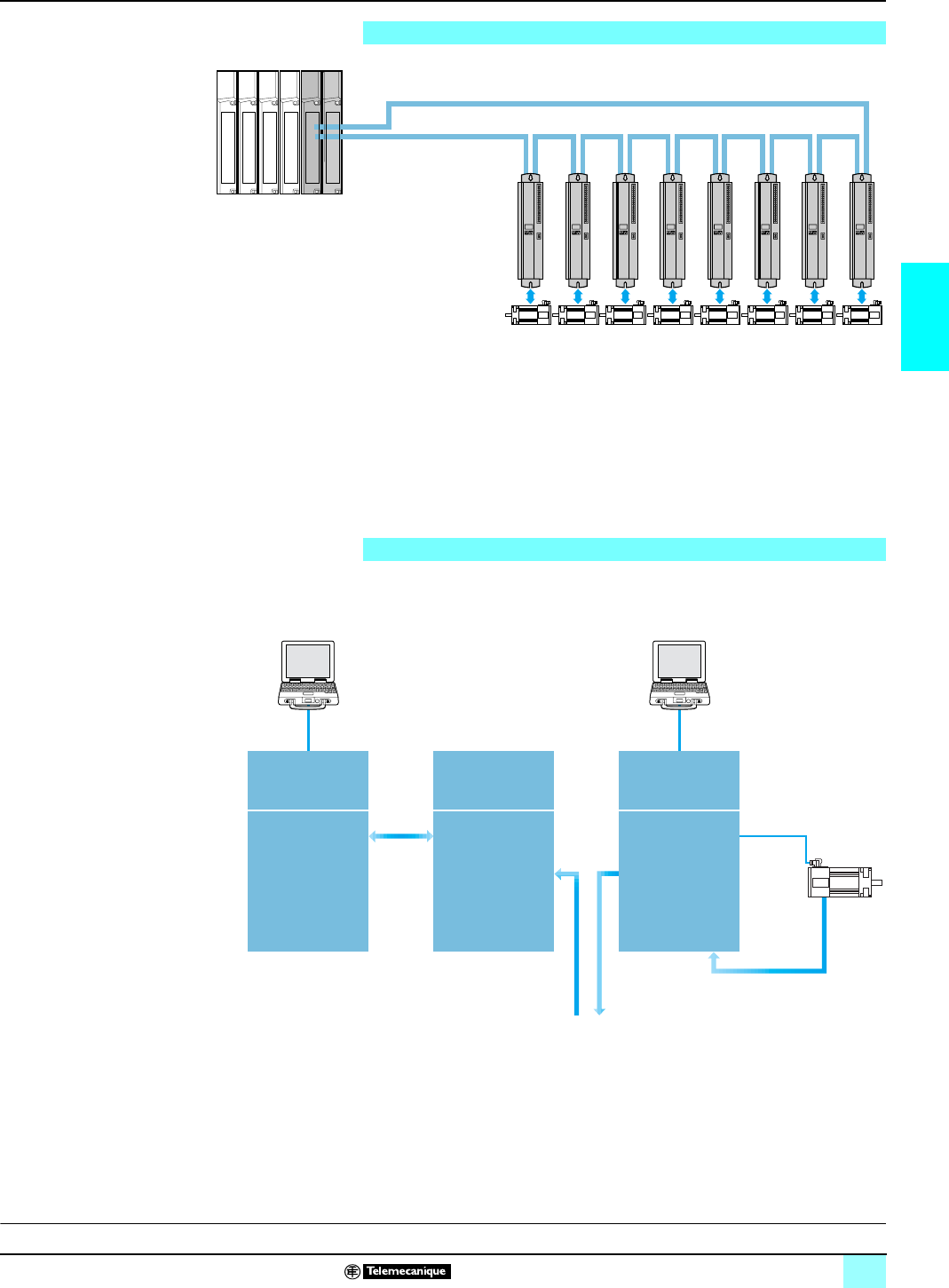
39
3
SERCOS architecture,
system overview Lexium motion control 1
SERCOS 141 MMS Quantum motion control
modules
SERCOS (SERiaI COmmunication System) is a communication standard defining
the digital link (medium and exchange protocol) between the motion control module
and intelligent servodrives. It is defined by European standard EN 61491.
The use of SERCOS distributed architecture enables the connection of input/output
devices (position encoder, Emergency stop, etc.) directly with the intelligent
servodrives, thereby reducing connection costs.
The fiber optic digital medium enables high-speed exchange (2 or 4 M bauds), yet
provides a high level of noise immunity in high-interference industrial environments.
The system overview presents the various functions performed by the different parts
of the multi-axis control system.
SERCOS architecture
Fiber optic cables
Quantum
Lexium MHDA
servodrives
(with optional
SERCOS card)
SER Lexium BPH motors
SERCOS ring network
System overview
Lexium MDHA
Servodrives
(with SERCOS)
Interpretation of
commands Position
loop, speed loop,
current loop,
Power conversion
SERCOS modules
141 MMS 425 01/
141 MMS 535 02
Independent or
continuous axes
Interpolation
linear
Follower sets by gearing
or camming
PLC
or
Modbus
Plus
Quantum PLC
CPU
Application program
SERCOS ring
(to drives network)
Position and speed
SER/Lexium
BPH motor
UniLink
software
Concept
Unity Pro
software
D
escritpion:
p
age 40 Characteristics:
pages 42 and 43 References:
pages 44 and 45 Connections:
page 45
This document provided by Barr-Thorp Electric Co., Inc. 800-473-9123 www.barr-thorp.com
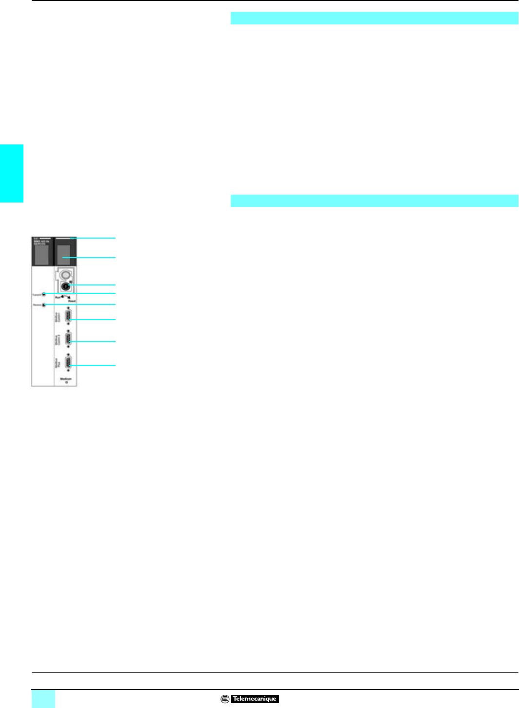
40
3
System overview (continued),
description Lexium motion control 1
SERCOS 141 MMS Quantum motion control
modules
Concept or Unity Pro software (via the Modbus Plus communications port) enable
you to:
bRegister the SERCOS 141 MMS module(s) in the Quantum module configuration
table.
bConfigure functions and parameterize used axes.
bProgram activities in the PLC application.
bAdjust parameters through operating codes (parameters for 141 MMS module,
and Lexium MHDA servodrives) (1).
bTest and update the application.
The UniLink software via the PC port of the Lexium MHDA servodrive allows you to:
bDefine the Lexium MHDA drive and SER/Lexium BPH motor types.
bAdjust the Lexium MHDA drive parameters, save them into the drive's EEprom
memory and store them on a PC.
The 141 MMS pp5 0p double-width SERCOS axis modules are equipped with:
1A SMA-type connector, marked Tx, for connecting the servodrives using the
SERCOS ring fiber optic transmission cable.
2A SMA-type connector, marked Rx, for connecting the servodrives using the
SERCOS ring fiber optic reception cable.
3Hard outer casing, performing the following functions:
bElectronic card support.
bAttachment and locking of the module in its slot.
4Module diagnostics indicator lamps:
bREADY: when lit, indicates the module as successfully passed power-up tests.
bRUN lamp:
v Steady, indicates the motion controller is in run mode, the SERCOS ring is
complete, and the motion controller is accepting commands from the PLC to control
the servodrives.
v Blinking, indicates that the motion controller is attempting to go into run mode, but
the SERCOS ring has not been established due to a physical disconnection or an
incorrect address setting.
v Off, indicates the motion controller is stopped.
bMODBUS PLUS: normal Modbus Plus indicator codes.
5A RUN/ RESET keyswitch.
6COM 1 port with SUB-D 9 connectors - for Schneider Electric use only.
7COM 2 port with SUB-D 9 connectors - for Schneider Electric use only.
8Modbus Plus port with SUB-D 9 connectors.
(1) Lexium MHDA servodrive equipped with AM0 SER 001V000 SERCOS option card.
System overview (continued)
Description
3
4
5
1
2
6
7
8
C
haracteristics:
p
ages 42 and 43 References:
pages 44 and 45 Connections:
page 45
This document provided by Barr-Thorp Electric Co., Inc. 800-473-9123 www.barr-thorp.com
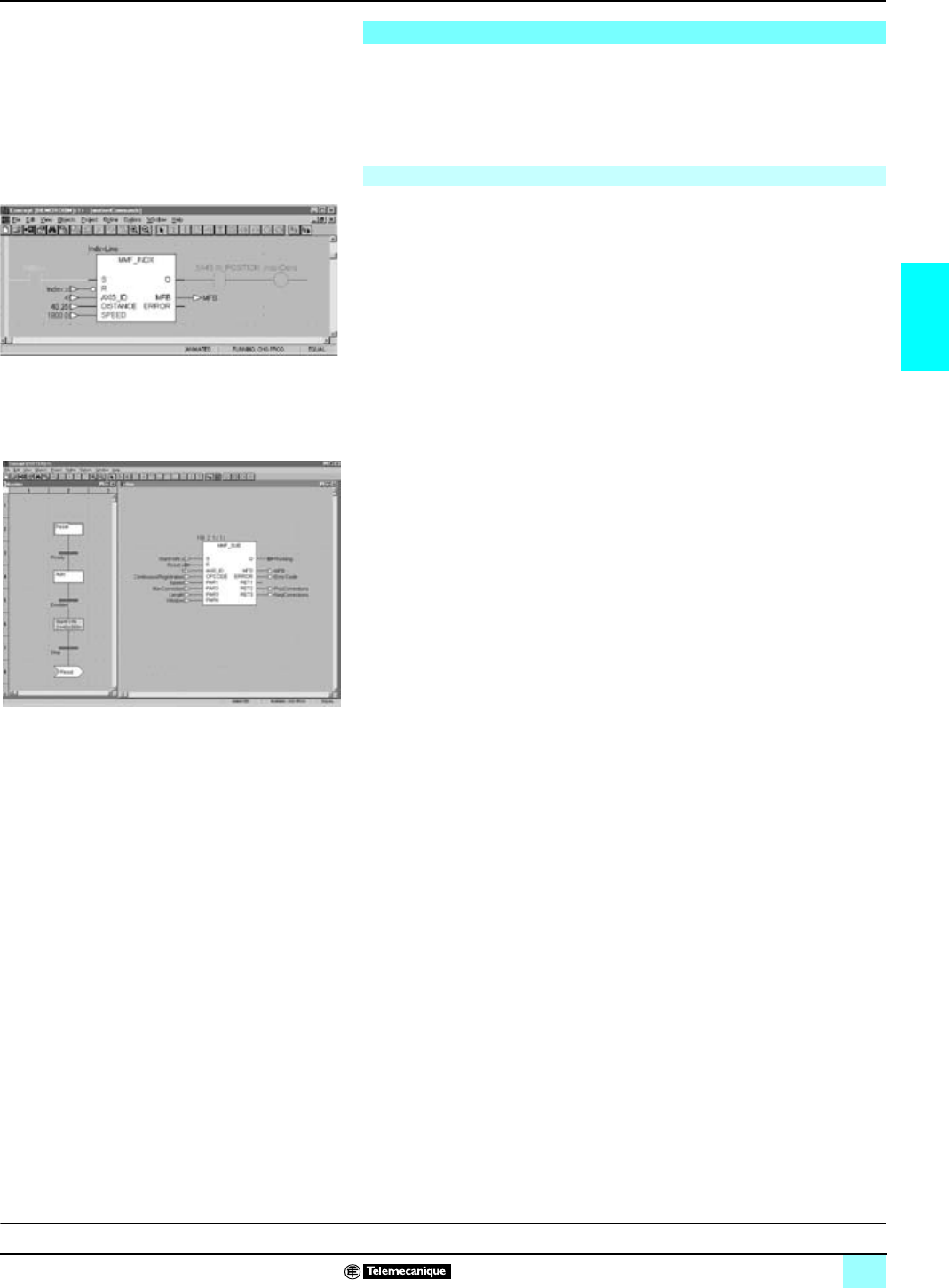
41
3
Software setup Lexium motion control 1
SERCOS 141 MMS Quantum motion control
modules
The configuration of the multi-axis motion modules are carried out by Concept or
Unity Pro software and the MMFStart Programmer’s kit, 396 MMC 500 04. They are
used to configure the multi-axis applications by the creation of a common database
(between Quantum PLC and the 141 MMS motion control modules). It simplifies the
access to a library of motion-specific function blocks.
Movements are initiated using function blocks in the Concept or Unity Pro application
program (Quantum CPU).
The function blocks can be written in IEC Ladder or Function Block Diagrams.
Function blocks are available for each specific move type: incremental, absolute, or
continuous. In addition, function blocks are available to set parameters and configure
objects (axes, sets, cam profiles, and special application functions).
The sequence of events or movements can be controlled by using the Sequential
Function Chart (Grafcet) defined by IEC standard 61131-3.
Application-specific functions, such as Continuous Registration, are set up using the
MMF_SUB function block (see screen opposite).
Software setup
Programming motion and special functions
D
escritpion:
p
age 40 Characteristics:
pages 42 and 43 References:
pages 44 and 45 Connections:
page 45
This document provided by Barr-Thorp Electric Co., Inc. 800-473-9123 www.barr-thorp.com

42
3
Characteristics Lexium motion control 1
SERCOS 141 MMS Quantum motion control
modules
(1) Please consult our Regional Sales Offices.
(2) Special functions require version 1.2 of the MMFStart 396 MMC 500 04 multi-axis
programming kit.
Functional characteristics of modules 141 MMS 425 01/535 02
Type of module 141 MMS 425 01 141 MMS 535 02
Software kit 396 MMC 500 04 With the assistance
of our application
services (1)
396 MMC 500 04 With the assistance
of our application
services (1)
Number of axes –22 max –32 max
Type of axes Actual axes
(connected to Lexium drives) 816 822
Imaginary axes 4Up to 22 axes/sets of
axes 4Up to 32 axes/sets of
axes
Remote axes 4, for interpretation of
remote position by
encoder
Up to 22 axes/sets of
axes 4, for interpretation of
remote position by
encoder
Up to 32 axes/sets of
axes
Set of axes Coordinates 4 allowed in each
group for the linear
interpolation of up to 8
axes (max.)
Up to 22 axes/sets of
axes 4 allowed in each
group for the linear
interpolation of up to 8
axes (max.)
Up to 32 axes/sets of
axes
Followers 4 groups up to 8 axes
maximum Up to 22 axes/sets of
axes 4 groups up to 8 axes
maximum Up to 32 axes/sets of
axes
Cam profile 8 profiles which can be
changed from PLC
registers
Any number up to the
memory limitation of
64 K points on all cam
profiles
8 profiles which can be
changed from PLC
registers
Any number up to the
memory limitation of
64 K points on all cam
profiles
Main functions
Programming Movements Homing, absolute, relative, or continuous
Immediate movement, or queued, toward a given position
Speed override possible
Special functions bPoint lock position and point lock time: synchronizes a Slave axis with a Slave position target
and a Master position target using parameters
bMeasure part: measures the distance between two edges on a discrete input on the drive
This can be applied to a real or auxiliary axis (position measurement via external encoder)
bCount probe (2): counts the edges on a discrete input on the drive within a period of time
bFast index (2): starts a movement on an event.
bRegistration move (2): position reading on the edge of a discrete input on the drive
bRotary knife: cuts using a rotary knife. Synchronizes a circular axis on a linear axis and
controls a discrete output on the drive
Other special functions The development of all other special functions is possible with the use of a Motion Open C kit
requiring the assistance of our application services (1).
Stop/start functions Rapid stop, stop following configured deceleration profile
Temporary stop
Restart of stopped movement
Configuration/adjustment SERCOS ring Bus cycle time, traffic on the bus, optical power on the fiber, SERCOS loop diagnostics
Acceleration/deceleration Ramp values, ramp type (rectangular, triangular, and trapezoidal), unit choices, maximum
acceleration adjustment
Speed Speed units, default speed, maximum speed, speed modulation coefficient
Other setting Target window, rollover, software limits
Groups of Slave axes Tracking of master axis by ratio or by cam (cam profile), threshold position of tracking master,
value of the Bias during synchronization of an axis, monitoring of Master/Slave positions,
master offset for a slave axis
Groups of coordinate axes Linear interpolation
Cam profile Values of a point existing from a cam profile, number of points (5,000 maximum), type of
interpolation, table addresses
State of an activity or axis Movement in acceleration, in deceleration, in homing, servodrive fault…
Diagnostics Drive fault, tracking error, overvoltage, undervoltage, current overload, power supply fault
D
escritpion:
p
age 40 References:
pages 44 and 45 Connections:
page 45
This document provided by Barr-Thorp Electric Co., Inc. 800-473-9123 www.barr-thorp.com
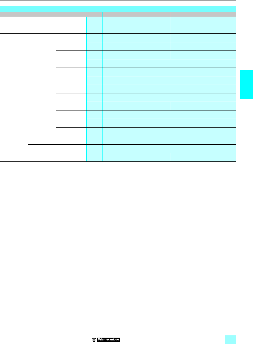
43
3
Characteristics (continued) Lexium motion control 1
SERCOS 141 MMS Quantum motion control
modules
Electrical characteristics of modules 141 MMS 425 01/535 02
Type of module 141 MMS 425 01 141 MMS 535 02
Processor MHz 66 133
PLC registers 10 000 60 000
Memory Application Mb 2 4
Static RAM Mb 2 4
Dynamic RAM Mb 8 8
SERCOS network Nature Industrial support complying with standard EN 61491
Topology Ring
Medium Fiber optic cable
Baud rate M bauds 4
Cycle time ms 2 to 4, configurable
Number of segments 9 max 23 max
Length of segment m38 max with plastic fiber optic cable
150 max with glass fiber optic cable (230 µm)
Communication
ports Serial links Number 2 RS 232 D
Protocol Modbus slave
Data rate Bit/s 300…9600
Network interface 1 Modbus Plus
Consumption mA 2000 at c 5 V 2500 at c 5V
D
escritpion:
p
age 40 References:
pages 44 and 45 Connections:
page 45
This document provided by Barr-Thorp Electric Co., Inc. 800-473-9123 www.barr-thorp.com
44
3
References Lexium motion control 1
SERCOS 141 MMS Quantum motion control
modules
Any of the Quantum PLC processors can be used with the SERCOS 141 MMS
motion modules. To obtain optimum performances, the cycle time of the Quantum
processor should not exceed 10 ms. The maximum number of 141 MMS modules in
a configuration depends on the processor type:
(1) The Motion Open C kit requires the assistance of our applications services. Consult our
Regional Sales Offices.
(2) Connectors to be used exclusively for connecting SERCOS motion control modules in the
same electrical cabinet.
References
Type of processors 140 CPU 113 02 140 CPU 113 03 140 CPU 434 12A 140 CPU 534 14A
Maximum number of
MMS, NOE or NOM
modules
2266
Description Functions Number of axes with: Reference Weight
kg
396 MMC 500 04
Programmer’s kit Motion Open C kit
(1)
Multi-axis control modules SERCOS digital
servodrive control 8 real axes
4 imaginary axes
8 sets of axes
16 real axes
22 axes/sets of axes 141 MMS 425 01 0.520
8 real axes
8 imaginary axes
8 sets of axes
22 real axes
32 axes/sets of axes 141 MMS 535 02 0.520
Connection accessories
Description Connection Length Reference Weight
kg
Plastic fiber optic cables fitted with SMA-type
connectors
(curvature radius: 25 mm minimum)
Lexium
MHDA 1pppN00,
MHDA 1pppA00
servodrive
0.3 m (1 ft) 990 MCO 000 01 0.050
0.9 m (3 ft) 990 MCO 000 03 0.180
1.5 m (5 ft) 990 MCO 000 05 0.260
4.5 m (15 ft) 990 MCO 000 15 0.770
16.5 m (55 ft) 990 MCO 000 55 2.830
22.5 m (75 ft) 990 MCO 000 75 4.070
37.5 m (125 ft) 990 MCO 001 25 5.940
Set of plastic fiber optic connections
Description Composition Reference Weight
kg
Set of fiber optic cables and SMA-type
connectors (2) 12 SMA-type connectors
12 insulating sleeves
Plastic fiber optic cable, length 30 m
990 MCO KIT 01 –
Equipment for installation of fiber optic cables Tools for making up cables to required
length from a 990 MCO KIT 01 kit
Includes stripping tool, crimping pliers,
25 W/110 V cutting tool, and instructions for
use
990 MCO KIT 00 –
D
escritpion:
p
age 40 Characteristics:
pages 42 and 43 Connections:
page 45
141 MMS 425 01
141 MMS 535 02
This document provided by Barr-Thorp Electric Co., Inc. 800-473-9123 www.barr-thorp.com
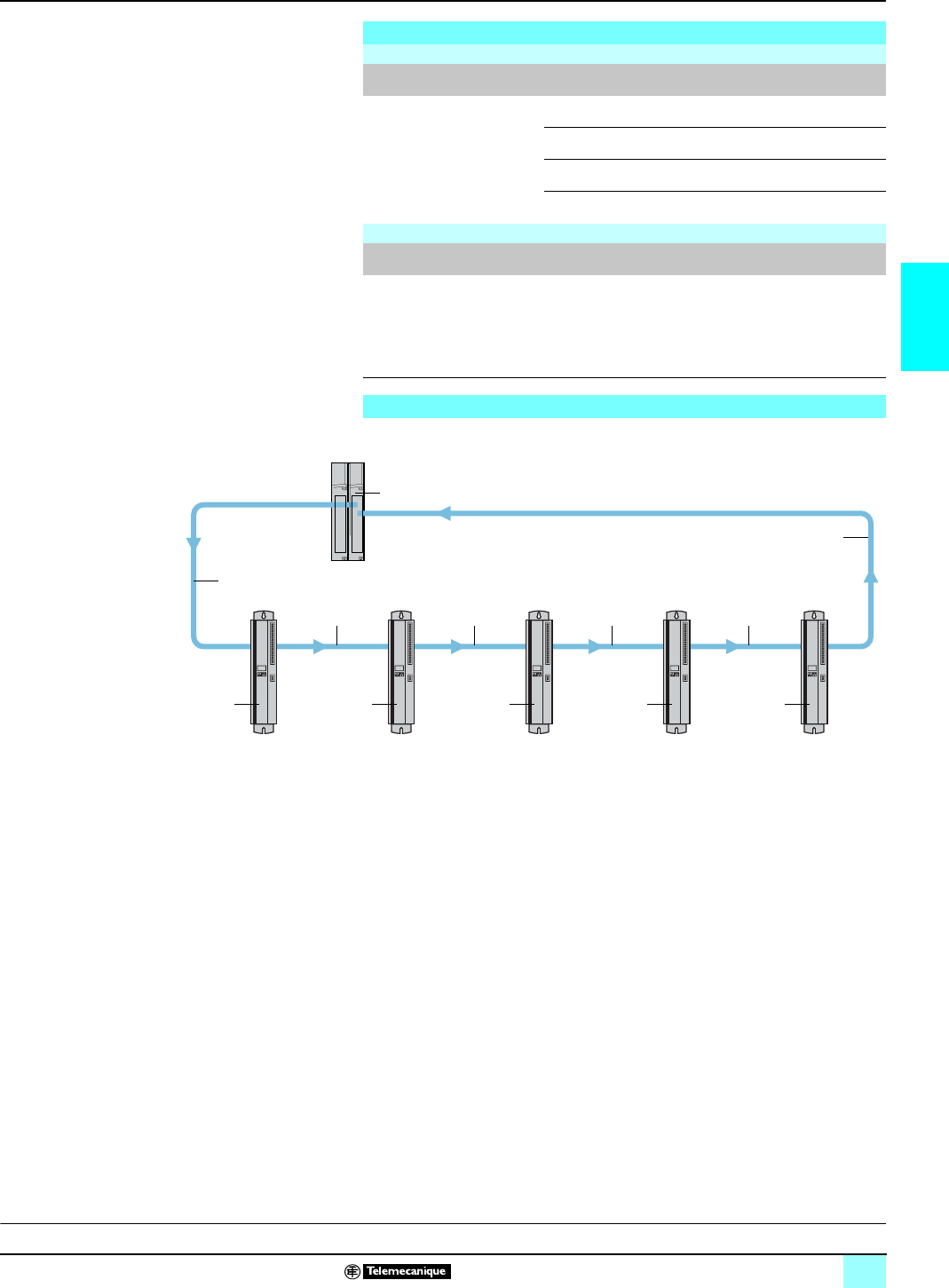
45
3
References (continued),
connections Lexium motion control 1
SERCOS 141 MMS Quantum motion control
modules
1141 MMS 425 01/535 02: Quantum multi-axis control module.
2MHDA 1pppN00/A00: Lexium drives (equipped with the optional SERCOS card
AM0 SER 001V000) for SER/Lexium BPH motor.
3990 MCO 000ppp: plastic fiber optic cables fitted with SMA-type connectors.
Tx
Transmission.
Rx Reception.
References (continued)
Concept programming and configuration software
Description Type of user
license Reference Weight
kg
Concept packages
Concept XL version 2.6 Single-user license 372 SPU 474 01 V26 –
3-user license 372 SPU 474 11 V26 –
10-user license 372 SPU 474 21 V26 –
Network license 372 SPU 474 31 V26 –
SERCOS multi-axis motion control software
Designation Description Reference Weight
kg
Multi-Axis MMF start
programmer’s kit Concept library and MMF Start
Shared data base creation
Backup and restoration
functions for maintenance
personnel.
Configuration software.
396 MMC 500 04 –
Connections
1
3
3
2
Tx
Rx
Rx Tx Rx Tx Rx Tx Rx Tx Rx Tx
3333
2 2 2 2
Servodrive 4Servodrive 2Servodrive 5Servodrive 3 Servodrive 1
SERCOS ring network
D
escritpion:
p
age 40 Characteristics:
pages 42 and 43
This document provided by Barr-Thorp Electric Co., Inc. 800-473-9123 www.barr-thorp.com
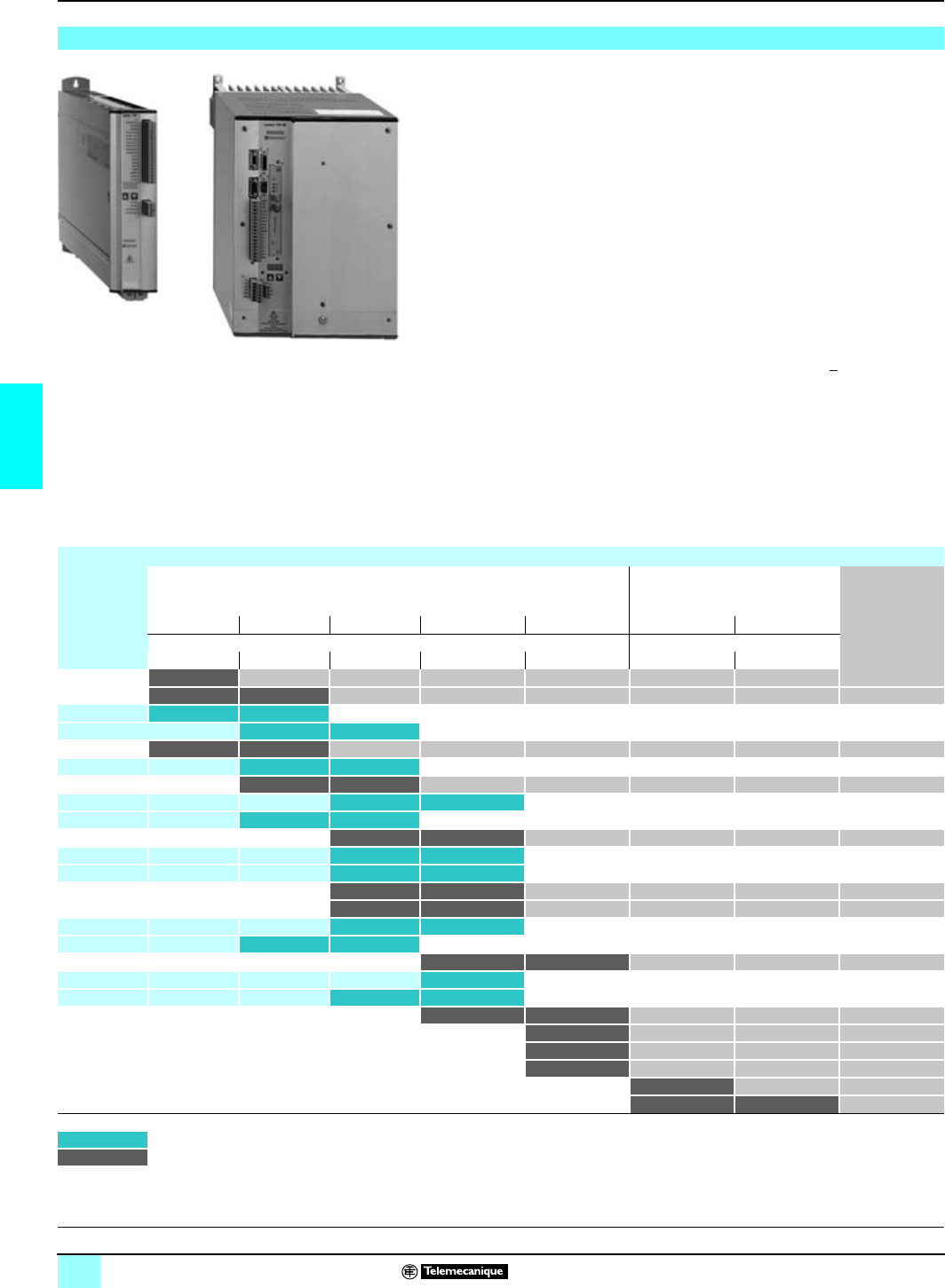
46
4
The Lexium MHDA servodrives are designed for the control of the torque, speed and/or
position of the SER/Lexium BPH brushless motors. These servodrive units are designed
for high performance applications, which require strong dynamics and high precision
positionning.
Lexium MHDA servodrives, with 3-phase power supply, are supplied with 7 different
current ratings: permanent current 1.5 A to 70 A rms. They must also be connected to an
auxiliary power supply of c24 V (from 0.75A to 3.5 A).
Some MHDA servodrives are equipped with an anti-start device designed to protect
anyone working on the machines. High current rating servodrives (40 to 70 A) are all
equipped with the anti-start device.
The Lexium servodrive/motor units are designed mainly to be controlled by the
positioning modules on the Modicon Premium or Modicon Quantum automation
platforms.
These Lexium MHDA servodrives are all equipped with standard
+
10 V analog
setpoint.
If equipped with a SERCOS option card, they can be integrated in a SERCOS ring.
Furthermore, the Lexium MHDA servodrives have an integral position indexer, which
can be used in cases where the simple applications do not require positioning
modules. In this case, the numerous possibilities for connectivity
(RS 232 serial link,
CANopen bus, Fipio bus, Profibus DP bus, Modbus Plus network,)
respond to the
different automation structures.
Presentation
Compatibility between Lexium servodrives and SER/Lexium BPH axis motors
SER
brushless
motors
Lexium 17D
servodrives Lexium 17D HP
servodrives Lexium BPH
brushless
motors
MHDA MHDA
1004p00 1008p00 1017p00 1028p00 1056p00 1112A00 1198A00
Permanent rms current Permanent rms current
1.5 A 3 A 6 A 10 A 20 A 40 A 70 A
0.4/1.1 Nm: BPH 0552S
0.9/1.9 Nm: 1.3/3.4 Nm: BPH 0751N
SER 39A 4L7S 1.1/2.5 Nm 1.1/4 Nm
SER 39B 4L3S 2.2/4.4 Nm 2.2/8.0 Nm:
1.3/2.5 Nm: 2.3/4.8 Nm: BPH 0752N
SER 39C 4L3S 2.9/4.7 Nm: 2.9/9.4 Nm:
3.7/7.2 Nm: 4.3/13.4 Nm: BPH 0952N
SER 3BA 4L3S 4.6/9.2 Nm: 4.6/15.3 Nm:
SER 3BA 4L5S 4.6/8.2 Nm 4.8/15.0 Nm
6.0/13.4 Nm: 6.0/20.3 Nm: BPH 0953N
SER 3BB 4L3S 6.6/12.0 Nm 6.6/20.0 Nm
SER 3BB 4L5S 6.6/15.8 Nm 6.6/25.0 Nm
7.4/13.6 Nm: 7.4/19.3 Nm BPH 1152N
6.8/13.5 Nm: 10.5/19.0 Nm BPH 1153N
SER 3BC 4L5S 10.0/17.0 Nm: 10.0/28.0 Nm:
SER 3BA 4L7S 10.0/16.0 Nm: 10.0/32.0 Nm
11.4/18.0 Nm: 12.0/30.0 Nm: BPH 1422N
SER 3BD 4L5D 13.4/29.0 Nm:
SER 3BB 4L7S 13.4/24.0 Nm: 13.4/38.0 Nm
14.5/24.0 Nm: 17.0/42.0 Nm: BPH 1423N
25.0/37.5 Nm: BPH 1902N
36.0/57.0 Nm: BPH 1903K
46.0/76.3 Nm: BPH 1904K
75.0/157 Nm: BPH 1907K
90.0/163 Nm: 100/230 Nm: BPH 190AK
1.1/2,5 Nm: For a SER motor, the 1st value corresponds to continuous stall torque max., and the 2nd value corresponds to peak stall torque max.
1.3/3.4 Nm: For a SER/Lexium BPH motor, the 1st value corresponds to continuous stall torque max., and the 2nd value corresponds to peak stall torque max.
D
escription:
p
ages 47 and 48 Characteristics:
pages 62 and 65 References:
pages 66 and 67 Dimensions:
page 68 and 69 Connections:
pages 70 and 75
Presentation
0
Lexium motion control 1
Lexium servodrives
This document provided by Barr-Thorp Electric Co., Inc. 800-473-9123 www.barr-thorp.com
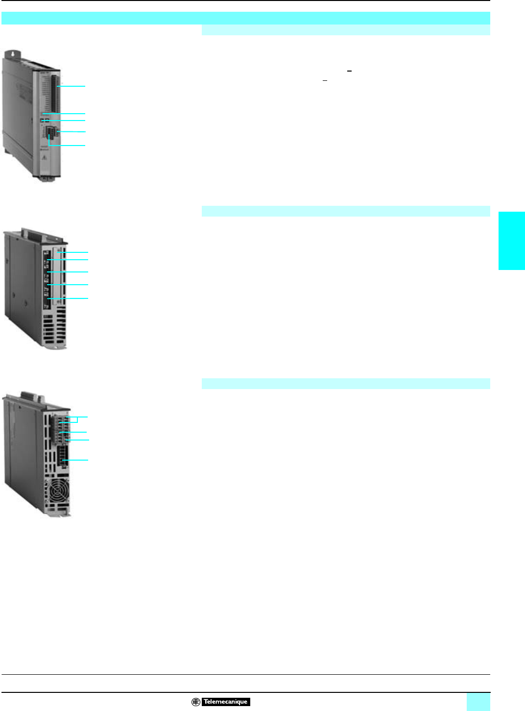
47
4
17D servodrives are in RAL gray metal casings (degree of protection IP 20).
1A 18-way male connector (1) (addr. X3) to connect:
v two configurable analog setpoint inputs
+
10 V,
v two configurable analog outputs
+
10 V,
v four configurable discrete inputs/two configurable discrete outputs c 24 V,
v one servodrive validation input c 24 V,
v one alarm relay contact.
2A 4-way male connector (1) (addr. X4) terminal block for connection to the
external c 24 V power supply. This connector distributes the power supply
c 24 V to other Lexium servodrives.
3A 3-digit display, which indicates the operating status of the servodrive, as well as
error code messages.
4Two control keys, which provide access to the various operating modes for the
display.
5A 4-way male connector (2) (addr. X10) for use with the anti-start function (AS
function) Only available on MHDA 1pppA00.servodrives
1A 9-way SUB-D male connector (addr. X6) for connection to the CANopen field
bus. (RS 232 integral serial link) This connector is also used to connect the PC
compatible terminal, which supports the Unilink configuration software.
2Slot for one of the following option cards:
v SERCOS digital link control card
v Fipio bus, Modbus Plus network, or Profibus DP bus connection card,
v Discrete I/O card for Lexium servodrive control with integral position indexer
function.
3A 9-way SUB-D male connector (addr. X5) to connect the simulated encoder
feedback (incremental or SSI). This connector can also be used to interconnect
with other Lexium servodrives (maximum 16) in Master/Slave operation (2).
4A 9-way SUB-D female connector (addr. X2) to connect the SER/Lexium BPH
motor resolver (includes connection of the PTC probe).
5A 15-way SUB-D female connector (addr. X1) to connect the SinCos encoder on
the SER/ Lexium BHP motor (includes connection of the PTC probe).
1Two 4-way unscrewable terminals (addr. X0A and X0B) to connect to the 3-phase
power supply network a208...480 V (or single phase a230 V). The second
connector distributes the network supply to other Lexium servodrives.
2Two 4-way unscrewable terminal (addr. X7) to interconnect the Lexium servodrive
power buses, when operating with the braking power distribution over a set of
Lexium servodrives.
3Two 4-way unscrewable terminal (addr. X8) to connect the external braking
resistance. By default, braking is on the internal resistance (shunt fitted to the
connector).
4A 6-way male connector (addr. X9) to connect the SER/Lexium BPH motor power
(includes connection to the holding brake - model dependant).
(1)
Female screw connectors supplied with each servodriv
e.
(2) Please use TSX CXP
p
83 servodrive interconnecting cables (see page 67)
Lexium 17D servodrives: overview
Front panel
3
4
2
1
5
Top panel of MHDA servodrives (with analog setpoint ± 10V)
1
3
4
5
2
Lower panel
1
2
3
4
F
unctions:
p
ages 56 and 61 Characteristics:
pages 62 and 65 References:
pages 66 and 67 Dimensions:
page 68 and 69 Connections:
pages 70 and 75
Description
0
Lexium motion control 1
Lexium servodrives
This document provided by Barr-Thorp Electric Co., Inc. 800-473-9123 www.barr-thorp.com
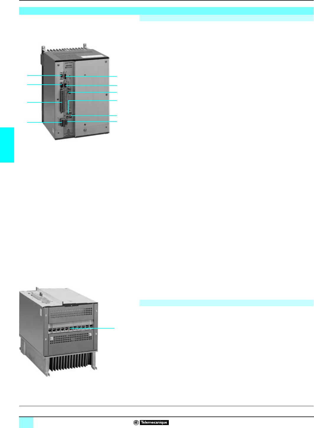
48
4
Description (continued)
0
Lexium motion control 1
Lexium servodrives
Lexium 17 HP servodrives are in RAL gray metal casings (degree of protection
IP 20).
1A 18-way female connector (1) (addr. X3) to connect:
v two configurable analog setpoint inputs ±10 V,
v two configurable analog outputs ±10 V,
v four configurable discrete inputs/outputs c 24 V,
v one servodrive validation input c 24 V,
v one alarm relay contact.
2A 6-way male connector (2) (addr. X4) to connect the auxiliary power supply
c 24 V and the holding brake connection (depending on the model of SER/
Lexium BPH motor).
A EMC filter for this supply is built-in to the Lexium 17D HP servodrives.
3A 3-digit display, which indicates the operating status of the servodrive, as well as
error code messages.
4Two control keys, which provide access to the various operating modes for the
display.
5A 4-way male connector (2) (addr. X10) for use with the anti-start function
(AS function).
6A 9-way SUB-D male connector (addr. X6) to connect the servodrive to the
CANopen field bus. (RS 232 integral serial link) This connector is also used to
connect the PC compatible terminal, which supports the Unilink configuration
software.
7Slot for one of the following option cards:
v SERCOS digital link control card
v Fipio bus, Modbus Plus network, or Profibus DP bus connection card,
v CANopen bus adapter to ensure conformity of link 6 above to the CANopen
standard.
v Discrete I/O card for Lexium servodrive control with integral position indexer
function.
8A 9-way SUB-D male connector (addr. X5). Connects the simulated encoder
feedback (incremental or SSI), for the ± 10 V analog setpoint servodrives.
This connector can also be used to interconnect with other Lexium servodrives
(maximum 16) in Master/Slave operation (3).
9A 9-way SUB-D female connector (addr. X2) to connect the SER/Lexium BPH
motor resolver (includes connection of the PTC probe).
10A 15-way SUB-D female connector (addr. X1) to connect the SinCos encoder on
the SER/ Lexium BHP motor (includes connection of the PTC probe).
111-way screw terminal (addr. X0) to connect :
v Connect to the 3-phase power supply network a208...480 V. An external choke
must be inserted between the network supply and the 17D HP servodrive (4). The
EMC filter for the power input is not built-in, which means that it should be externally
provided, when Class A is essential (non-propagation of electromagnetic
disturbances).
v The power connection of the SER/Lexium BPH motor.
v The connection of the external braking resistance. The 17D HP servodrives do not
have internal braking resistance.
(1) Male screw connectors supplied with each servodrive.
(2) Female screw connectors supplied with each servodrive.
(3) Please use TSX CXP
p
83 servodrive interconnecting cables (see page 67)
(4) External input choke is not necessary when using isolation transformers 840
pp
shown on
page 73
Lexium 17D HP servodrives: overview
Front panel
9
68
1
5
10
7
3
4
2
Lower panel
1
F
unctions:
p
ages 56 and 61 Characteristics:
pages 62 and 65 References:
pages 66 and 67 Dimensions:
pages 68 and 69 Connections:
pages 70 and 75
This document provided by Barr-Thorp Electric Co., Inc. 800-473-9123 www.barr-thorp.com

49
4
Functions
0
Lexium motion control 1
Lexium servodrives
The Lexium servodrives can be directly connected to 3-phase mains supply, whose
nominal value can be any voltage within the range a 208…480 V, 50…60 Hz. If the
motor’s maximum speed and current rating are derated (see page
62
), low current
rating Lexium servodrives can be powered by a a 230 V single phase supply.
bWithstance of electromagnetic disturbances and non-propagation of
electromagnetic disturbances is provided by the EMC filter integral to the Lexium
17D servodrives (1), in compliance with EEC directives 89/336, 92/31 and 93/68.
bLexium servodrives are compatible with the TT or TN loads. When the load is IT
(isolated neutral), it is necessary to provide an isolating transformer so that a TT load
(neutral to ground) can be re-built on the secondary (servodrive side).
bAn auxiliary c 24 V SELV power supply is required for the internal electronic circuits
and the input/output interfaces (isolation required for the motor power supply).
The servodrive is fitted with a braking (or ballast) resistance (80 or 200 W depending
on the model). Depending on the required braking characteristics, internal braking
can be disabled and an external 250, 500 or 1500 W braking resistance used
instead, depending on the Lexium 17D servodrive used.
Placing the servodrive power buses in parallel shares the internal capacitors and
braking resistances, thus making it possible to benefit from the cumulative absorption
and dissipation capacities offered by the servodrives.
17D HP servodrives do not have internal braking resistance. See page 111 for
external braking resistance selection.
bThree programmable built-in digital regulators:
v a current regulator (torque image) with a control loop period of 62.5 µs,
v a speed regulator with proportional and integral gain with a control loop period of
250 µs,
v a position regulator with a control loop period of 250 µs.
bProcessing of motor position feedback signals from the motor sensor (SinCos
EnDAT
®
or SinCos Hiperface
®
) type high resolution absolute encoder or resolver).
Using this information, the servodrive can generate a simulated encoder feedback,
which can be either incremental or absolute SSI. The simulated encoder feedback
and external encoder functions can not be used concurrently.
bTwo discrete data bits control the automation system:
v one servodrive validation input c 24 V,
v one volt-free relay output, for servodrive faults.
bTwo analog inputs/outputs
+
10 V and four discrete inputs/two discrete outputs
c24 V, allowing Lexium servodrives to be integrated into sequential command
systems controlled by programmable PLCs (e.g. Micro). The I/O functions can be
configured.
bIntegral position indexer: In addition, Lexium MHDA servodrives have integral
position indexing (243 program steps, of which 180 are stored). This positioning
function performs simple automation operations, which permanently do not require
motion control modules.
bConnectivity: Lexium MHDA servodrives all have an RS 232 serial link or
CANopen bus link. If an option card is added, they can also be connected to the
Modbus Plus network, a Fipio bus or a Profibus DP bus (or a SERCOS network).
(1) With Lexium 17D HP servodrives, an AMO EMC
p
1
p
external EMC input filter may be
required on the power supply side.
Functions
Power supplies
Internal braking resistance (for Lexium 17D servodrives only)
Signal processing/motor control
D
escription:
p
ages 47 and 48 Characteristics:
pages 62 and 65 References:
pages 66 and 67 Dimensions:
pages 68 and 69 Connections:
pages 70 and 75
This document provided by Barr-Thorp Electric Co., Inc. 800-473-9123 www.barr-thorp.com
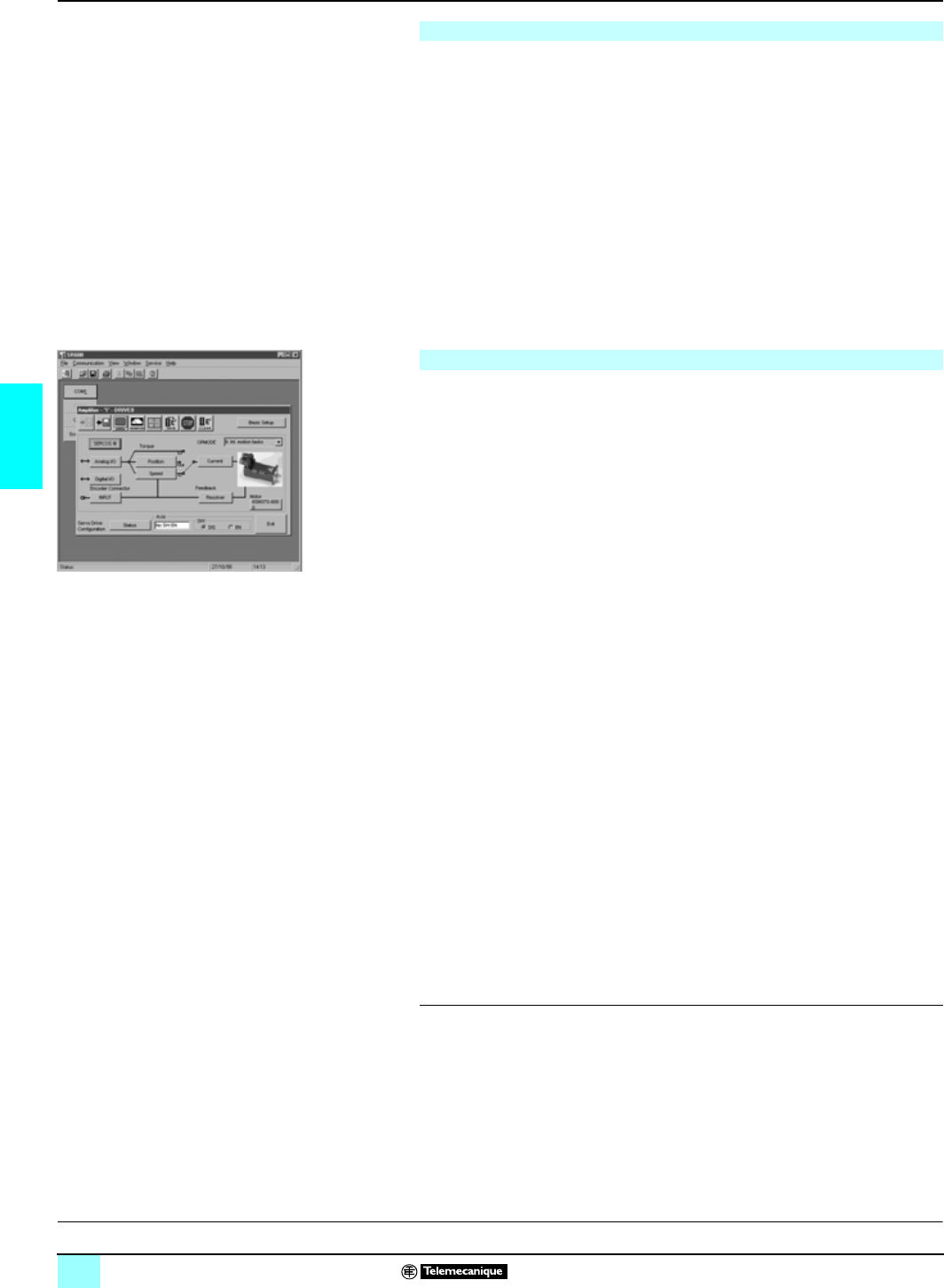
50
4
Functions (continued)
0
Lexium motion control 1
Lexium servodrives
The AS (anti-start) function found on all Lexium MHDA ppppA00 servodrive models
should be used primarily when the motor has to be de-activated, as for instance
when operators need to have access to the machines for brief periods of time.
The system consists of an additional auxiliary relay switch, accessible on the 4-way
screw terminal (rep. X10). When the relay switch coil is automatically activated, this
locks the servodrive power bridge, cutting out the motor power supply (1).
The anti-start relay contact is used to check that the locking mechanism is activated.
The state of the relay contact must be checked constantly by the control system: to
ensure that the system is working and that emergency stop and locking procedures
are strictly applied.
The AS (anti-start) function is standard in all Lexium MDHA ppppA00 servodrives
and provides the following features:
bServodrive power supply stays ON even when system is locked.
bReduced cabling requirements.
MHDA servodrives must be configured using the Unilink software installed on a PC.
This terminal is connected to the servodrives via a RS 232 C serial link.
Accessible parameters relate to:
bThe type of motor, braking.
bThe position loop.
bThe speed loop.
bThe current loop (torque).
bThe power converter.
bThe discrete and analog I/O.
bThe integral position indexer.
bModbus Plus, CANopen or SERCOS communication.
These parameters are backed up to the servodrive EEProm memory using Unilink
software.
The multi-lingual Unilink software, compatible with Windows 95/98, 2000, NT 4.0
and XP, is supplied with the "Lexium motion tools" CD-Rom AM0 CSW 001 V300,
also including the following multi-lingual (French, English, German, Spanish and
Italian) documentation:
bTechnical guide to SER/BPH motors.
bSER/BPH motor file library for CAD software (2D and 3D).
bLexium 17D and 17D HP servodrives user guide
bList of ASCII commands for the Lexium 17D servodrives (English and German).
bUnilink software user guide.
bGraphic Motion Task for Unilink software.
bSERCOS ring communication.
bFipio bus communication.
bCANopen bus communication.
bModbus Plus network communication.
bProfibus DP communication.
bExample file for the installation of a CANopen bus application on a Premium
platform.
b.esd files for configuring the CANopen bus with the SyCon configuration tool.
b.gsd files for configuring the Profibus DP bus with the SyCon configuration tool.
b.dib files, images of the Lexium servodrives.
(1) Vertical axis immobilization can only be obtained by installing a mechanical locking system
(servo brake) on the axes.
AS anti-start function
Configuring the Lexium MHDA servodrives
D
escription:
p
ages 47 and 48 Characteristics:
pages 62 and 65 References:
pages 66 and 67 Dimensions:
pages 68 and 69 Connections:
pages 70 and 75
This document provided by Barr-Thorp Electric Co., Inc. 800-473-9123 www.barr-thorp.com
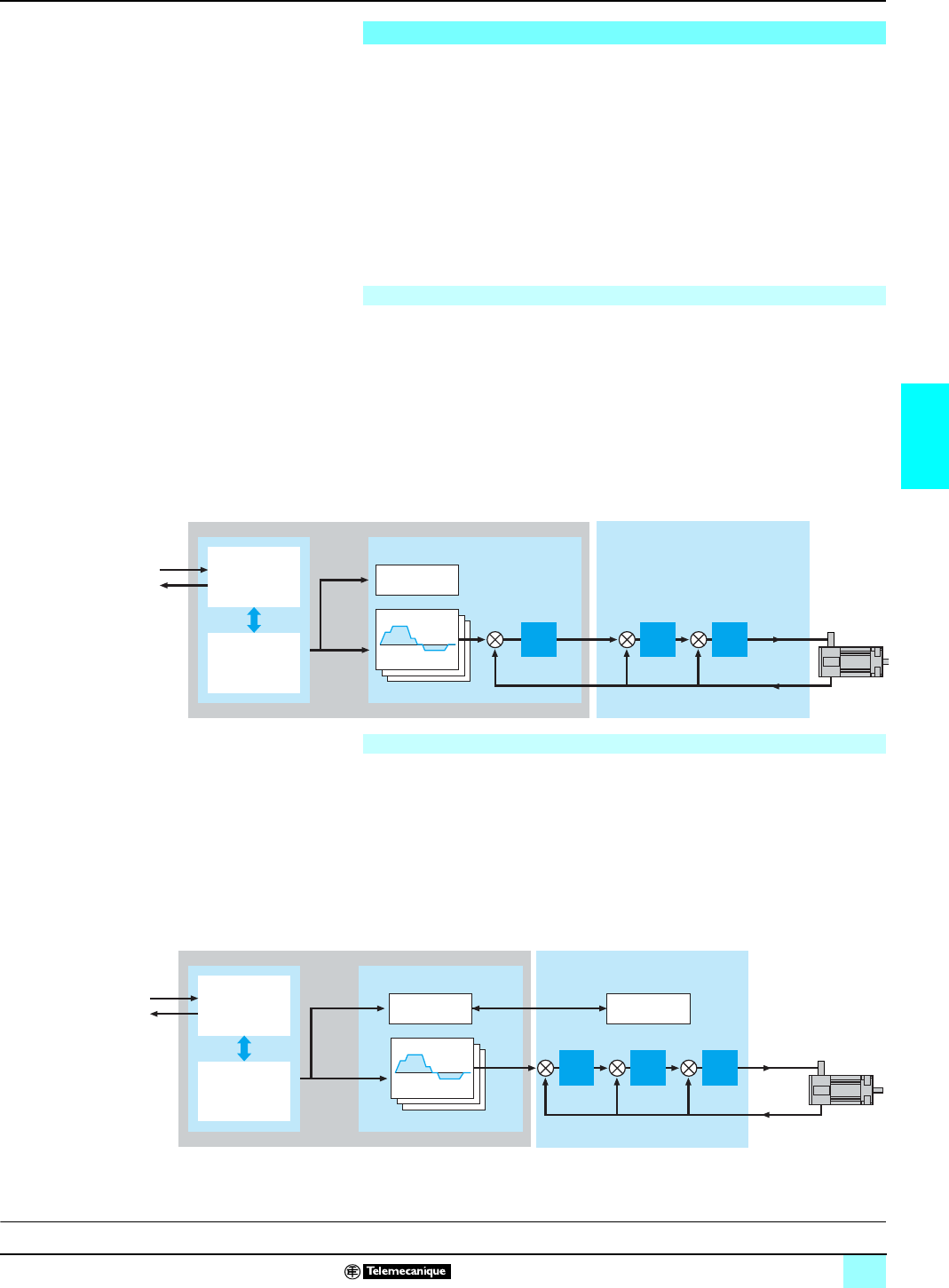
51
4
Unilink software is used to configure and adjust Lexium MHDA servodrives according
to the associated BPH axis motor and the application requirements. During these
phases, the PC supporting Unilink software under Windows 95/98, 2000, NT 4.0 or
XP, is connected to MHDA servodrives via a serial link ( 9 -way SUB-D connector,
on X6).
Three types of configuration are possible:
bMHDA servodrive with analog setpoint, with Premium or Quantum motion control
module.
bMHDA servodrive with SERCOS digital link option card; with Premium or Quantum
motion control module.
bMHDA servodrive in independent position indexer mode with discrete input/output
control or field bus control.
The MHDA servodrive with analog setpoint is associated with the TSX CAY 2p/33/
4p (with Premium platform) or the 140 MSB 101 00 (with Quantum platform) motion
control module. The KP position loop is executed in the automation platform control
module. It is configured and adjusted using PL7 Junior/Pro (with TSX CAY module) or
Concept (with 140 MSB module) programming software.
The closed KV speed loop and KT torque loop in the MHDA servodrive are configured
and adjusted using Unilink software.
The motion program, which defines the paths, is in the Premium or Quantum platform
application program. The position and speed setpoints are calculated by the motion
control module.
The MHDA servodrive with the SERCOS digital link option card is associated with
the TSX CSY 84/164 (with Premium platform) or 141 MMS 425 01/535 02 (with
Quantum platform) motion control modules. The closed KP position loops, KV speed
loops and KT torque loops in the servodrive are configured and adjusted using
Unilink software. The motion program, which defines the paths, is in the Premium or
Quantum platform application program. The position setpoints are calculated by the
motion control module (position mode). The motion control module can also work out
the speed reference (speed mode) or the current reference (torque mode). The last
two modes can be accessed with the assistance of Schneider application services.
Presentation of Unilink software
MHDA servodrive with analog setpoint
Premium/Quantum platform
Process PLC
Input/output
PLC program
Motion control module
Set-up/
diagnostics
Path
Lexium MHDA servodrive
Servodrive with analog setpoint
Motor
SER/Lexium
BPH
KP KV KT
TSX CAY or 140 MSB
MHDA servodrive with SERCOS digital link
TSX SAY or 141 MMS
Set-up/
diagnostics
Set-up/
diagnostics
SERCOS axis control module
Path
Premium/Quantum platform Lexium MHDA servodrive with AM0 SER 001V000 SERCOS card
KP KV KT
Process PLC
Input/output
PLC program
SERCOS digital link servodrive
Motor
SER/Lexium
BPH
D
escription:
p
ages 47 and 48 Characteristics:
pages 62 and 65 References:
pages 66 and 67 Dimensions:
pages 68 and 69 Connections:
pages 70 and 75
Presentation of Unilink
software
0
Lexium motion control 1
Lexium servodrives
This document provided by Barr-Thorp Electric Co., Inc. 800-473-9123 www.barr-thorp.com
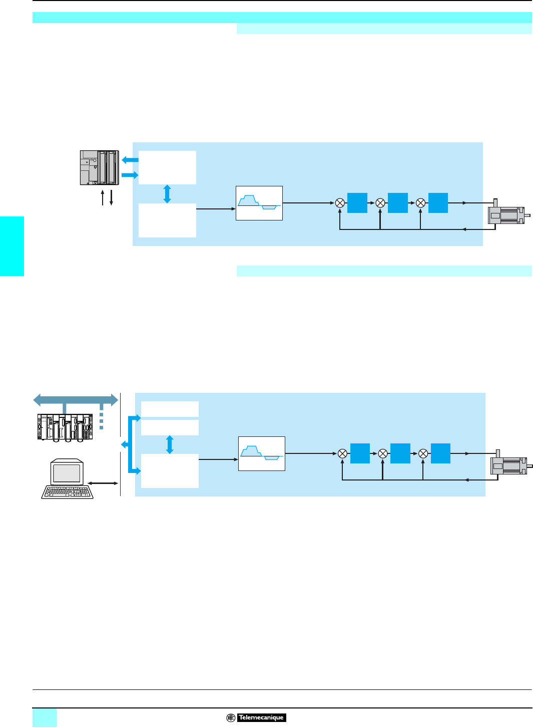
52
4
Presentation of Unilink
software (continued)
0
Lexium motion control 1
Lexium servodrives
MHDA servodrives have an integral position indexer function. The servodrive is then
controlled by its discrete input/outputs, which can be extended to 14 discrete inputs/
8 discrete outputs, using extension card AMO INE 001V000. The closed KP position
loops, KV speed loops and KT torque loops in the MHDA servodrive are configured
and adjusted using Unilink software. The motion program (243 program steps, of
which 180 are permanently stored in Flashmemory) and the calculation of the
position setpoints are provided by the integral position indexer of the MHDA
servodrive.
The MHDA servodrive can be remotely controlled by:
bThe CANopen bus or the integral RS 232 C serial link, available as standard on
the X6 connector.
bWith the addition of an option card, they can be connected to the Fipio bus, the
Modbus Plus network,or the Profibus DP bus.
These links download the motion program steps (servodrive in run mode for the 63
steps stored in the dynamic RAM memory). They also allow the set-up and
diagnostics functions of the drive.
Presentation of the Unilink software (continued)
MHDA servodrive with integral position indexer function
Process
243 program steps
Path
Lexium MHDA servodrive
Motor
SER/Lexium
BPH
KP KV KT
PLC I/O
PLC
Connectivity of the MHDA servodrive with integral position indexer function
RS 232
Parameters
Path
Lexium MHDA servodrive
Motor
SER/Lexium
BPH
KP KV KT
Program
243 steps
Premium Diagnostics
OR
Modbus Plus/CANopen
Profibus DP/Fipio
D
escription:
p
ages 47 and 48 Characteristics:
pages 62 and 65 References:
pages 68 and 69 Dimensions:
pages 68 and 69 Connections:
pages 70 and 75
This document provided by Barr-Thorp Electric Co., Inc. 800-473-9123 www.barr-thorp.com
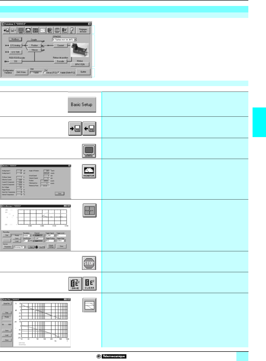
53
4
Unilink software functions
0
Lexium motion control 1
Lexium servodrives
The basic screen providing access to the Unilink software services and functions is
divided into three zones:
1Top bar, for accessing the main functions.
2Block diagram for accessing the configuration/adjust/set-up and the realtime
display of the different drive values.
3Lower zone indicating the drive status.
Unilink software functions
Basic screen
1
2
3
Main Unilink functions
Servodrive configuration Used at servodrive level to select the power supply voltage and the braking resistance (internal/
external for the Lexium 17D servodrive, external for 17D HP servodrives. Used to define the
name of the servodrive.
Offline/online operation used to import or export drive parameters and data files as well as the motion task for the integral
position indexer function.
These functions allow the servodrive application to be developed offline.
Hyperterminal mode The set of drive parameters is accessible in read/write mode from a single terminal operating in
ASCII mode
Monitor mode Realtime display of 17 drive data items, for example, values for the following: analog setpoint
inputs, instantaneous current, actual speed, drive power bus voltage (DC bus), braking power,
angular position of the axis, following error, etc.
Oscilloscope mode Storage and display, in the form of internal drive data curves, of values for the following:
setpoint, actual speed and current, drive power bus voltage, image of ›following error. Activation
of the speed increment generation service (up and down) for optimizing loop tuning
Stop command Motion stop control (for safety reasons, this software control should not be substituted for the
external Emergency stop command).
EEP memory access for the Lexium
servodrive E
2
Save saves the defined set of servodrive parameters in the EEProm memory
E
2
Clear clears the content of the EEProm memory
Bode diagram Acquires data (gain G and phase shift ϕ) in the frequential domain.
Graphically displays the responses in frequency.
This document provided by Barr-Thorp Electric Co., Inc. 800-473-9123 www.barr-thorp.com
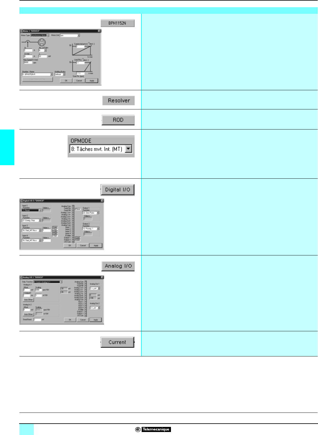
54
4
Unilink software functions
(continued)
0
Lexium motion control 1
Lexium servodrives
(1) To use the encoder output in absolute SSI simulation mode, contact our Regional Sales
Offices.
Lexium servodrive parameters
Motor parameters Used to define the parameters for MHDA servodrives, according to the associated motor.
Used to define motor with or without brake, maximum speed, and to adapt the min. and max.
motor currents. When used with SER/BPH motors, which are referenced in the Unilink software,
the selection of a motor causes its parameters to be set up by default. It is the responsibility of
the user, should it be necessary, to adjust these values for another application.
Motor encoder selection Defines the type and characteristics of motor encoder feedback (resolver, SinCos EnDAT/
Hiperface high resolution absolute encoder)
Electronic gearing command or encoder
emulation Defines the type and characteristics of the simulated, incremental or absolute SSI (1) encoder
feedback or the type in electronic gearing mode (ROD)
Servodrive operating mode Specifies the servodrive operating mode:
vMHDA servodrive with analog setpoint, with TSX CAY pp or 140 MSB 101 00 motion control
module.
vMHDA servodrive with SERCOS digital link, with TSX CSY 84/164 or
141 MMS 425 01/435 02 motion control module
vMHDA servodrive with integral position indexer
vMHDA servodrive in independent mode in Master/Slave operation (electronic gearing)
vMHDA servodrive connected to a PLC via the CANopen/Fipio/Profibus DP bus or the
Modbus Plus network
Functions associated to discrete inputs/
outputs Assigns:
va specific function to 4 inputs (1 of 25, depending on the type of servodrive). For example,
position limit sensor, speed reference analog input, deactivation of integral position check,
homing, starting a motion sequence, brake control, etc.
va specific function to 2 outputs (1 of 26, depending on the type of servodrive). For example,
following error, actual position greater than a predefined value, target position reached,
servodrive inhibited, etc.
Furthermore, this screen displays the state of the I/O in realtime.
Functions associated with the analog
input/outputs (with MHDA servodrive) Assigns:
va specific function to 2 analog inputs (1 of 6, depending on the type of servodrive).
For example, control voltage on the first input, control current on the second input, setpoint
corresponding to the sum of the 2 analog inputs, etc. The automatic offset compensation
and scaling can be configured on these 2 inputs.
va specific function to 2 analog outputs (1 of 5). For example, actual speed or current values,
setpoint values for speed or current, following error image, etc.
Furthermore, this screen displays the values (mV) of the I/O in realtime. These I/O allow many
possibilities for applications which require electrical shafts (for example, sending an analog
output from the "Master" servodrive, current image and setpoint, to an analog input on the
"Slave" servodrive in order to create a coupled electrical shafts).
Set-up of the current loop Adjusts the parameters of the KT current loop using the defined default values
through the set-up operation of the "SET Motor" SER/BPH motor
D
escription:
p
ages 47 and 48 Characteristics:
pages 62 and 65 References:
pages 66 and 67 Dimensions:
pages 68 and 69 Connections:
pages 70 and 75
This document provided by Barr-Thorp Electric Co., Inc. 800-473-9123 www.barr-thorp.com
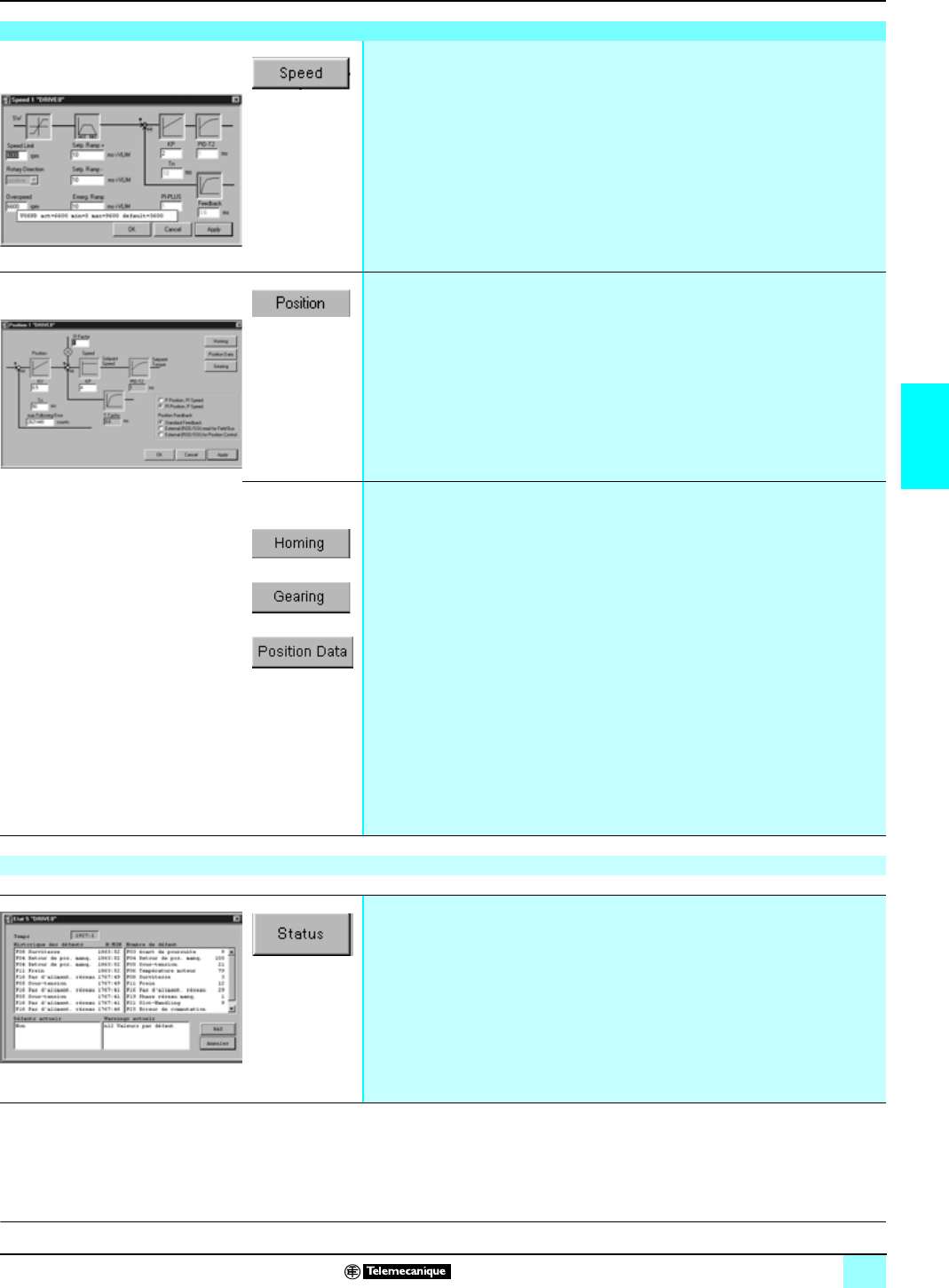
55
4
Unilink software functions
(continued)
0
Lexium motion control 1
Lexium servodrives
Lexium servodrives parameters (continued)
Speed loop settings
Adjusts the KV speed loop gain parameters using the default values defined by the SER/BPH
motor set-up operation "SET Motor". For example, maximum speed, overspeed threshold,
acceleration and deceleration ramps, Emergency stop deceleration time, etc.
Position loop parameter settings The position loop parameter settings are only effective with MHDA servodrives with a SERCOS
link or with the MHDA servodrives in integral position indexer mode. Adjusts the KV speed loop
and KP position loop gain parameters and defines the maximum following error.
The following additional functions can be accessed:
vSpecifies the homing type and parameters (acceleration/deceleration ramps and speed).
Also used to define motion speed in running continual manual (JOG) mode.
vUsed in follower mode to specify the type of motor position feedback and define the
movement multiplier ratio
vProvides access to the following definitions:
- axis type (linear or rotary),
- axis resolution,
- minimum acceleration/deceleration time, maximum speed, data relating to the target
windows, position registers, upper/lower software limits, thresholds to compare the current
position (determine discrete output status).
v Used to program the movement steps in integral position indexer operation, including for
each step (243 steps max.):
- movement type (absolute or relative),
- target position and setpoint speed,
- speed profile (trapezoid or sinusoid),
- conditions for accessing the next step,
- definition of start conditions.
Lexium servodrive status display
Drive status The lower zone of the basic screen:
vindicates the servodrive status,
vprovides access to a window, which displays the current alarm or fault in realtime, as well as
its history and frequency.
D
escription:
p
ages 47 and 48 Characteristics:
pages 62 and 65 References:
pages 66 and 67 Dimensions:
pages 68 and 69 Links
pages 70 and 75
This document provided by Barr-Thorp Electric Co., Inc. 800-473-9123 www.barr-thorp.com
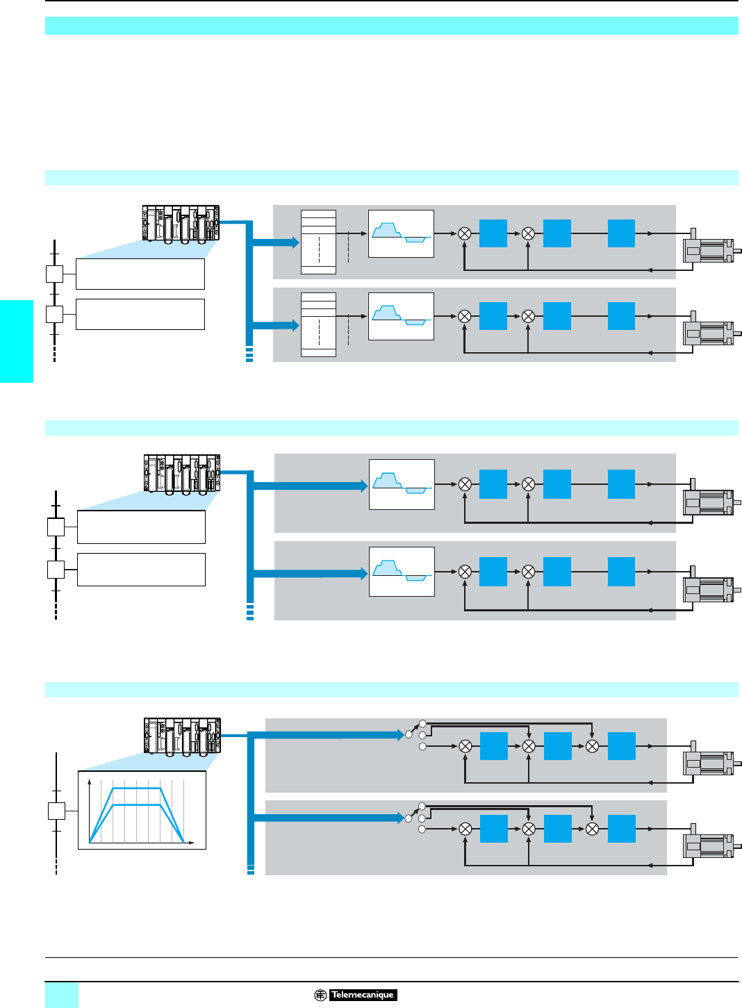
56
4
Connectivity of MHDA
servodrives
0
Lexium motion control 1
Lexium Servodrives
MHDA servodrives support connections using the CANopen bus, Modbus Plus
network, Fipio bus or Profibus DP bus. The CANopen bus connection
bis standard on MHDA servodrives.
bThe Modbus Plus network can be established by adding an option card.
bThe Fipio bus can be established by adding an option card.
bThe Profibus DP bus can be established by adding an option card.
This type of structure is used to respond to performances in three types of
applications: applications with independent servodrives, PLC controlled independent
axes and PLC controlled electronic gearing.
The "Motion tasks" (MT) for each Lexium servodrive are managed using the basic
activation/deactivation commands from the Premium or Quantum PLCs (i.e. start,
stop, etc.).
Typical number of controlled servodrives: 16
The PLC application calculates and directly updates the parameters for a
"Motion Task" (position/speed/acceleration) for each movement for each of the
servodrives, which work out various paths from these parameters.
Typical number of controlled servodrives: 4 to 8
The path (position or speed or torque) of the virtual Master axis is worked out by the
PLC. This path is used to determine the new positions of each of the Slave axes in
each PLC cycle according to the formula SPn = [SP1 (t) x ratio].
Typical number of controlled servodrives: 2 to 4
Motion control applications
Applications with independent servodrives
SP1
MT1
MT2
MTn
SP2
MT1
MT2
MTn
Start Motion Task 0 axe 1
Start Motion Task 0 axe 2
Start Motion Task 1 axe 1
Start Motion Task 3 axe 2
Axe 1
Axe 2
KP
KP
KV
KV
KT
KT
Bus/network
Independent axes controlled by PLC
SP1
SP2
Axe 1
Axe 2
KP
KP
KV
KV
KT
KT
Bus/network
MT1 motion parameters
(position, speed, acceleration)
MT1 motion parameters
(new positions, speed,
acceleration)
Electronic gearing controlled by PLC
SP2
SP1
Set point SP1
Set point SP2
Axe 1
Axe 2
KP
KP
KT
KT
KV
KV
Bus/network
Path generator
Speed
t
Setpoint SP2 = f [SP1(t) x ratio]
D
escription:
p
ages 47 and 48 Characteristics:
pages 62 to 65 References:
pages 66 and 67 Dimensions:
pages 68 and 69 Connections:
pages 69 to 75
This document provided by Barr-Thorp Electric Co., Inc. 800-473-9123 www.barr-thorp.com
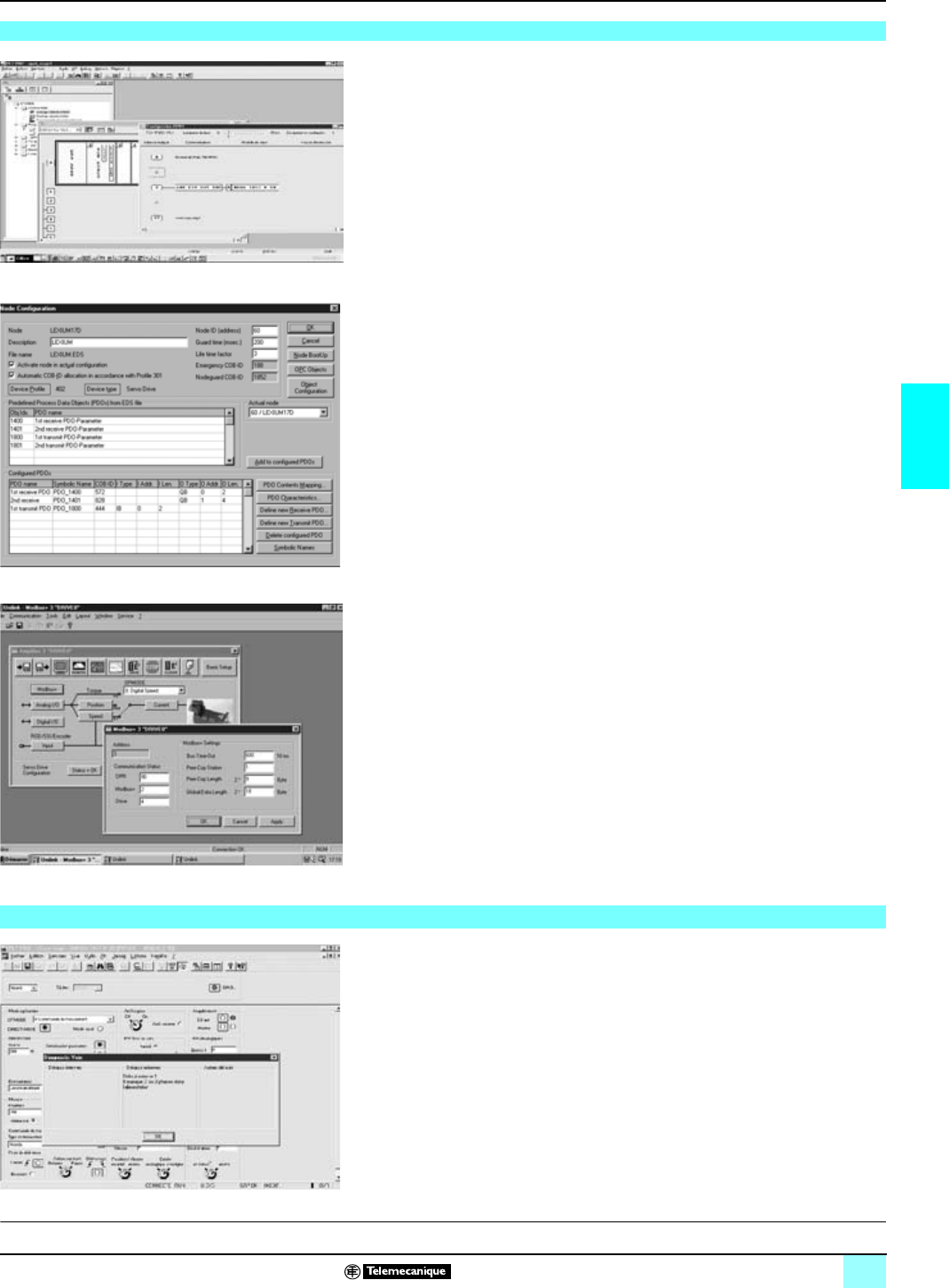
57
4
Connectivity of MHDA
servodrives (continued)
0
Lexium motion control 1
Lexium Servodrives
Communication and Parameterizing are integrated in the following software tools:
b
Configuration mode for PL7Junior/Pro or Concept, depending on the medium used:
v CANopen and Profibus DP bus: the configuration mode of the PL7 Junior/Pro or
Concept installation software is used to define the communication buffers (addresses
and lengths of the %MW input and output word tables).
v Modbus Plus network: the configuration mode of the PL7 Junior/Pro or Concept
installation software is used to define the data exchanged.
v Fipio bus: the configuration mode of the PL7 Junior/Pro installation software is
used to define the numbers of the connection points from the Lexium MHDA
servodrives to the Fipio bus.
v Profibus DP bus: the configuration mode of the PL7 Junior/Pro installation software
is used to define the numbers of the connection points from the Lexium MHDA to the
Profibus DP bus.
bThe CANopen bus and Profibus DP bus are configured using a specific software
(SyCon) to be ordered separately (reference SYS SPU LFp CD28M). This software
is used to generate a configuration file to define the data exchanged on the bus.
The file must be imported in the PL7 application via the PL7Junior/Pro installation
software.
bUnilink software: is used to define the address of the Lexium servodrive on which
the user would like to communicate with. The transmission speed of the CANopen
bus or the Modbus Plus network is also defined at this level.
Furthermore, with the Modbus Plus network, a function of the Unilink software can
be used to define the configuration parameters and display the Modbus Plus
communication status.
The Unlilink software is also used to define the parameters relating to the Fipio bus
(time-out, etc.).
The Unilink software and PL7 Junior/Pro installation software provide different
debugging services:
bUnilink software: access to commands and statuses for managing DRIVECOM,
including specific debugging screens with the Profibus bus.
bPL7 Junior/Pro software: specific debugging and diagnostics screens with the
Fipio bus (see left for example).
Software configuration
Configuration example for Fipio with PL7 Junior/Pro
Configuration example for CANopen with the SyCon tool
Configuration example for Modbus Plus with Unilink
D
escription:
p
ages 47 and 48 Characteristics:
pages 62 to 65 References:
pages 66 and 67 Dimensions:
pages 68 and 69 Connections:
pages 70 to 75
Debugging
This document provided by Barr-Thorp Electric Co., Inc. 800-473-9123 www.barr-thorp.com
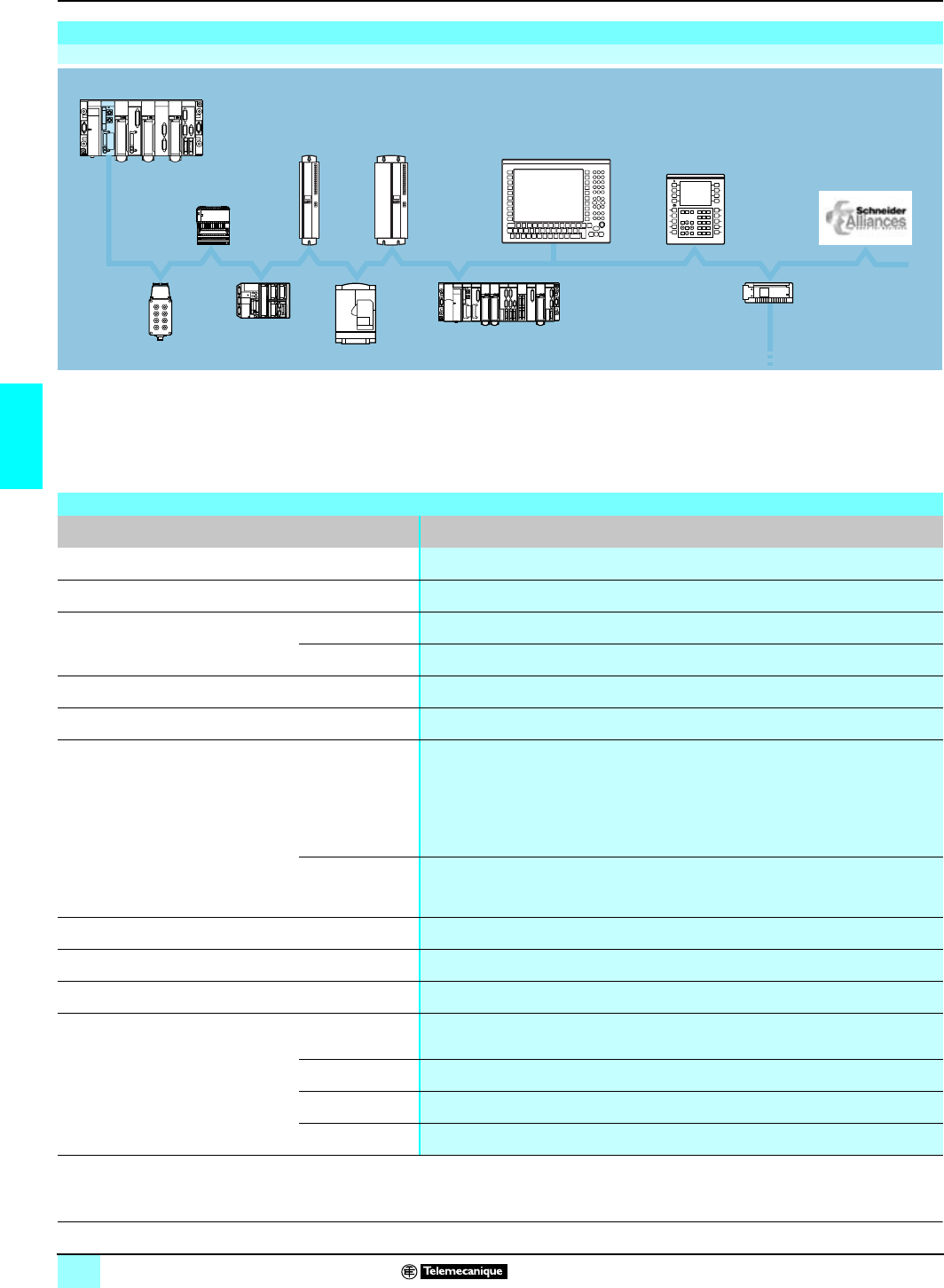
58
4
Connectivity of MHDA
servodrives (continued)
0
Lexium motion control 1
Lexium servodrives
The Fipio field bus is an industrial standard for communication between different PLC
components. This field bus complies with the WorldFip standard for production/
consumption mechanisms. It is used for extending remote I/O to up to 15 km.
Schneider Electric is a major promoter of Fipio bus technology, which supports the
connectivity of PLCs, Lexium servodrives, Altivar starter motors, Magelis terminals
and the partner products of the Schneider Alliances program.
Fipio bus
Architecture
AS-i
ATV
Momentum
Magelis XBT,
CCX17
Fipio
Magelis IPC
Lexium MHDA
servodrives
Sealed TBX
Micro (Agent) Premium (Agent)
AS-i gateway
Premium (bus manager)
D
escription:
p
ages 47 and 48 Characteristics:
pages 62 to 65 References:
pages 66 and 67 Dimensions:
pages 68 to 69 Connections:
pages 70 to 75
Characteristics
Type of bus Fipio bus
Compatibility Modicon automation platform Premium (TSX P 57 153/253/2823/353/453/4823) or Atrium coprocessor (T PCX 57 353)
Profile Open industrial medium complying with the World Fip standard
Transmission Rate 1 Mbit/s
Medium 150 W double twisted shielded pair
Length Max. 1,000 m for an electrical segment
Max. 3,000 m for an optical segment
Device addressing 1…62
Fipio utilities with Lexium MHDA
servodrive X-Way Uni-Te utilities Access to all the parameters of the Lexium servodrives in read/write:
v"DRIVECOM" data for operating modes and fault management modes
voperating modes
vMotion Task movement data (realtime modification of acceleration, position and speed)
vexternal position, speed and torque setpoints
vservodrive status, path and fault data
vloading and downloading of the servodrive parameters (max. 128 bytes of data)
Installation utility
using PL7 Junior/Pro
software
v integrated installation screens (presymbolization of objects, management of double word
length, debugging and diagnostics screens)
v "FDR" utility, operating context restoration for servodrive replacement
Configuration tool Unilink software (version u 2.5)
Installation tool PL7 Junior/Pro software (version 4.2, recommended 4.3)
Fipio communication card Optional AM0 FIP 001V000 card
Cabling system Wiring on MHDA
servodrive 9-way SUB-D male connector
T-Junction box TSX FP ACC3/ACC4 block
Derivation cable TSX FP CCp00 cable
Main cable TSX FP CA/CRp00 cable
This document provided by Barr-Thorp Electric Co., Inc. 800-473-9123 www.barr-thorp.com
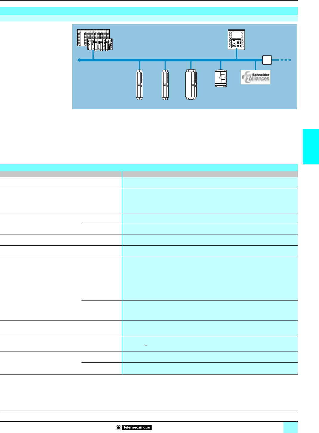
59
4
Connectivity of the MHDA
servodrives (continued)
0
Lexium motion control 1
Lexium Servodrives
The Modbus Plus communication network is a high baud rate industrial network (up
to 1 Mbit/s). It consists of a main segment and secondary segments concerning the
use of accessories such as electric repeaters, optical repeaters or bridges.
The Modbus Plus network supports connectivity for Schneider products (PLCs,
distributed I/O, ATV variable speeddrives, Magelis terminals with graphic screens
etc. As part of the Schneider Alliances partnership, several third party products are
compatible with the Modbus Plus network.
(1) Utilities available only on the main segment of the Modbus Plus, and with Premium or
Quantum platforms only.
(2) For other Modbus Plus network connection cables and accessories, consult our Premium
platform and Quantum platform catalogs.
Modbus Plus network
Architecture
Premium or Quantum
Lexium MHDA servodrive
Magelis XBT-F/T XBT Repeater
ATV58-F Third party products
D
escription:
p
ages 47 and 48 Characteristics:
pages 62 to 65 References:
pages 66 and 67 Dimensions:
pages 68 and 69 Connections:
pages 70 to 75
Characteristics
Type of network Modbus Plus network
Compatibility Modicon automation platform Premium, Quantum and Micro
Profile Exchanges:
vPeer Cop 9 registers
vGlobal Data 18 registers
vModbus Messaging
Transmission Rate 500...1000 Kbit/s
Medium Twisted pair, optic fiber
Length v max. 450 m per segment
v max. 1,800 m with 3 repeaters
Device addressing 1...63
Modbus Plus utilities with
Lexium MDHA servodrives Peer Cop (1)
Global data (1) Read/write access to Lexium servodrive Status/Command data:
v"DRIVECOM" registers
vSetpoints (position, speed and torque)
vRun/Stop for Motion tasks
v"OPMODE" operating modes
v"STATCOD and ERRCOD" diagnostics, etc.
The Global Data utility is only effective when transmitting data from Lexium servodrives
Modbus Messaging Access to all the above data as well as to the following parameters:
vAdjustment of torque, speed and position loops
vMonitoring (threshold, gap, etc.)
Configuration tool v PL7 Junior/Pro software with Premium platform
v Concept software with Quantum platform
Modbus Plus communication card Optional AM0 MBP 001V000 card, requiring a Lexium 17D or 17D HP servodrive,
version RL > 08 (9-way SUB-D male connector)
Cabling system (2) Junction boxes v IP 20 T-Junction box 990_NAD 230 00 Requires cabling tool ref. 043 509 383
v IP 65 T-Junction box 990_NAD 230 10 (connection on screw terminals)
Derivation cables 990 NAD 211 10/30 derivation cable (length 2, 4 or 6 m). Servodrive end of cable equipped with
a 9-way SUB-D female connector and derivation end with free wires
This document provided by Barr-Thorp Electric Co., Inc. 800-473-9123 www.barr-thorp.com
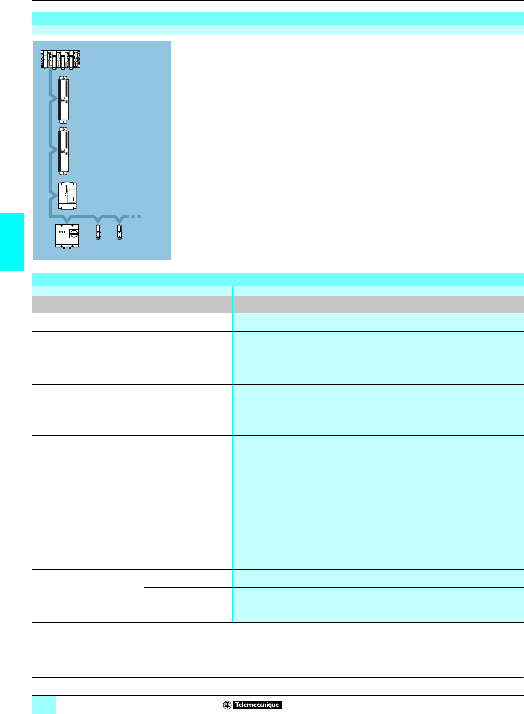
60
4
Connectivity of MHDA
servodrives (continued)
0
Lexium motion control 1
Lexium Servodrives
The CANopen bus is a field bus based on CAN low layers and components. It
complies with standard ISO 11898 compliant. Thanks to its standard communication
profiles, the CANopen bus can be used to ensure the opening and interoperability
of various devices (servodrives, motor starters, smart sensors, etc.)
The CANopen bus is a multi-master bus, which guarantees a sure and deterministic
access to realtime automation device data. The CSMA/CA type protocol is based on
exchanges, transmitted cyclically or on event, which guarantee optimum use of the
bandwidth. A messaging channel is also used to parameterize the slave devices.
Lexium MHDA servodrives are all equipped with a CANopen bus compatible
interface (connector on X6, see pages 25 and 48).
(1) Function available with version SV
u
4.51 MHDA servodrives.
CANopen bus
Architecture
Premium
Lexium MHDA
Lexium MHDA
ATV-58F
Motor starter Smart sensors
Characteristics
Type of bus CANopen bus
CANopen communication Integrated with the Lexium MHDA servodrive
Compatibility Modicon automation platform Premium (with the PCMCIA card and SYS SPU LFp CD28M, SyCon CANopen configuration
software)
Profile CANopen DS with DSP 402 profile
Transmission Rate 250...1000 Kbit/s
Medium Shielded twisted double pair
Length Max. 20 m at 1 Mbit/s
Max. 70 m at 500 Kbit/s
Max. 115 m at 250 Kbit/s
Device addressing 0 to 63
CANopen utility with
Lexium MHDA servodrive PDO (Process Date Object)
periodic exchange Implicit read/write access to Lexium servodrive Status/Command data (using %MW words):
vSetpoints (position and torque)
vStop/start "Motion Tasks"
vCommand register/DRIVECOM status
SDO messaging
(Service Data Object) Explicit access (by READ_VAR/WRITE_VAR function) to the following parameters:
vAdjustment of torque, speed and position loops
vMonitoring (threshold, gap, etc.)
v"OPMODE" operating modes
v"STATCOD and ERRCOD" diagnostics
SYNC object For applications requiring axis synchronization (1)
Configuration tool SYS SPU LFp CD28M, SyCon configuration software
CANopen cabling system Wiring on MHDA servodrive A 9-way SUB-D male connector (addr. X6)
T-Junction box TSX CPP ACC1 (1 x 15-way SUB-D male connector on the device end and 2 9-way SUB-D
male connectors on the bus end)
Derivation cable Client provision
D
escription:
p
ages 47 and 48 Characteristics:
pages 62 to 65 References:
pages 66 and 67 Dimensions:
pages 68 and 69 Connections:
pages 69 to 75
This document provided by Barr-Thorp Electric Co., Inc. 800-473-9123 www.barr-thorp.com
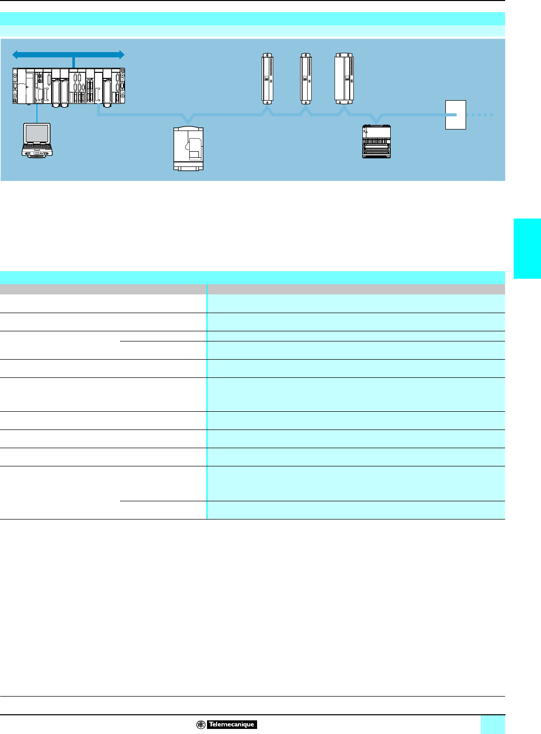
61
4
Connectivity of MHDA
servodrives (continued)
0
Lexium motion control 1
Lexium Servodrives
The Profibus DP bus is a field bus that meets industrial communication requirements.
Profibus DP has linear bus topology with a Master/Slave-type centralized access
procedure.
The physical link is made by a single shielded twisted pair, although optical interfaces
are available for establishing tree, star or ring structures.
Profibus DP bus
Architecture
With PL7 and
DP software ATV
Momentum
Premium Lexium
MHDA
servodrive
Repeaters
(max. 3)
Characteristics
Bus type Profibus DP bus
Compatibility Modicon automation platform Premium and Quantum
Profile Industrial bus, line architecture with end of line resistance
Transmission/length Baud rate/segment length 9.6 Kbit/s: 1,200m (4,800 m with 3 repeaters) at 12 Mbit/s 100 m (400 m with 3 repeaters)
Medium Twisted pair, optic fiber, infrared
Lexium servodrive addressing 1…62 (max. 32 Lexium servodrives, without repeater)
Profibus DP utilities with
Lexium MDHA servodrives PPO-type 2 profile v Access to all movement parameters and diagnostics parameters (4 words PKW)
v DRIVECOM command and status words
v Access to the different Motion Task command words (speed, torque, electronic gearing)
Configuration tool SYS SPU LFp CD28M, SyCon configuration software
Installation tool Unilink software (version u 2.5)
Profibus DP communication card Optional AM0 PBS 001V000 card
Cabling system Wiring on Profibus DP
communication card:
AM0 PBS 001V000
9-way SUB-D female connectors 490 NAD 911 0p
Daisy chaining cable Profibus DP connection cable: TSX PBS CA 100/400 (length 100 m/400 m)
D
escription:
p
ages 47 and 48 Characteristics:
pages 62 to 65 References:
pages 66 and 67 Dimensions:
pages 68 and 69 Connections:
pages 70 to 75
This document provided by Barr-Thorp Electric Co., Inc. 800-473-9123 www.barr-thorp.com

62
4
Characteristics
0
Lexium motion control 1
Lexium servodrives
(1)The second value is provided for a power supply of
a
230 V single-phase
(2) Position precision depends on the associated SER/Lexium BPH motor, see pages 93 and 77.
(3) For use of the simulated encoder output in absolute SSI type, please consult our Regional
Sales Offices.
Characteristics of Lexium 17 D Servodrives
Lexium servodrives have been developed to comply with the main international standards which relate to electronic devices for international
automation:
bSpecific requirements : operating characteristics, immunity, ruggedness, safety, etc. EN 50178, EN 60139-1, EN 60204, UL 508C, IEC 1491
(for SERCOS cards).
bConformity to the European directives on low voltage 73/23/EEC, electromagnetic compatibility 89/336/EEC and machinery 89/392/EEC.
bConformity to the machine safety standard NF EN 292-1.
bElectrical quality of insulating materials (electrical equipment, printed circuit boards) UL 840.
Characteristics of Lexium 17 Servodrives
Type of module MHDA
1004p00 MHDA
1008p00 MHDA
1017p00 MHDA
1028p00 MHDA
1056p00
Power supply Voltage V rms a 208...480 V 3-phase ± 10%, 50/60 Hz (a 230 V authorized single-phase with derating)
Current A rms 1.8 3.6 7.2 12 24
Inrush current Internal limitation
Neutral load Compatible TN and TT loads. If the load is IT, it is necessary to use an isolation transformer on
the power supply, see page 73.
External
protection against
overloads and
short circuits
Via circuit-breaker
Q1 GV2-L10 (6.3 A) GV2-L14 (10 A) GV2-L16 (14 A) GV2-L22 (25 A)
By fuse A6 type aM 10 type aM 16 type aM 25 type aM
Motor output Permanent current A rms 1.5/1.5 (1) 3/3 (1) 6/4 (1) 10/4 (1) 20/4 (1)
Maximum current A rms 3/3 (1) 6/4 (1) 12/4 (1) 20/4 (1) 40/4 (1)
Motor choke mH 16 min 8 min 4 min 3.5 min 1.5 min
Cable length mmax. 75 Use motor choke AM0 FIL 001V056 for lengths > 25 m
Holding brake
command Nominal voltage Vc 24, supplied by the external power supply, see page 63
Current A1.7 max
Resolver input Frequency kHz 8 ± 0.1 %
Voltage V rms 4.75
Current mA
rms 35 max.
Transformation ratio 0.5
Resolution 14 bits (2)
Cable length m75 max
SinCos absolute
encoder input Voltage V9 ± 5 %
Current mA 200
Single-turn encoder Resolution: 20 bits (2)
Multi-turn encoder Resolution: 20 bits per revolution, number of revolutions: 12 bits (2)
Cable length m75 max. with Hiperface encoder, 50 m max. with EnDAT encoder
Simulated
encoder output Type (3) RS 485 differential, incremental format
Resolver resolution 512/1024 points
SinCos resolution 512/1024/2048/4096/8192/16384 points
Master/Slave Interface Use of the Master Lexium servodrive simulated encoder output to control up to 16 Slave Lexium
servodrives (electric gearing function)
Control loop performances Adjustable with Unilink software
Torque µs62.5
Speed µs250
Position µs250
Speed scale rpm 0…6000 (0...8000 with the BPH 055 motor)
Discrete I/O Number 5 isolated (1 drive enable input, 4 inputs configurable with Unilink software)
Voltage Vc 20…30
Current mA 5 to 24 V
Limit values VAt state 1: > 12, at state 0: < 7 status
Acquisition period ms 1 in normal cycle, 0.050 in rapid cycle
Discrete outputs Number 2 isolated with current absorption (programmable with Unilink software)
Voltage Vc 20…30
Current mA 10
Acquisition period ms 1
D
escription:
p
ages 47 and 48 Functions:
pages 49 to 61 References:
pages 66 and 67 Dimensions:
pages 68 and 69 Connections:
pages 70 to 75
This document provided by Barr-Thorp Electric Co., Inc. 800-473-9123 www.barr-thorp.com
63
4
Characteristics (continued)
0
Lexium motion control 1
Lexium servodrives
Lexium 17D servodrive characteristics (continued)
Module type MDHA
1004p00 MDHA
1008p00 MDHA
1017p00 MDHA
1028p00 MDHA
1056p00
Alarm output Number 1 volt-free contact
Max voltage Vc 30, a 42
Current mA 500 (resistive load)
Analog inputs Number 2 non-isolated differentials (programmable with Unilink software)
Input range V± 10
Input impedance kΩ20
Resolution 14 bits channel 1, 12 bits channel 2
Common mode V± 10 between channels and ground
Acquisition period µs250
Analog
outputs
(with MHDA
servodrive)
Number 2 non-isolated (programmable with Unilink software)
Output range V± 10
Output impedance kΩ2.2
Resolution 10 bits
Conversion time ms 5
Asynchronous
serial link
Type RS 232 isolated
Rate bit/s 9600
Transmission 8 data bits, 1 stop bit, no parity
Dissipated internal power (at nominal current) W30 40 60 90 200
Braking
power 3-phase servodrive power supply V230 400 480 230 400 480 230 400 480 230 400 480 230 400 480
On internal resistor Ω66 66 33 33 33
Max. continual PPr W80 80 200 200 200
Peak (1s) PCr kW 2.5 810.5 2.5 810.5 516 21 516 21 516 21
Protection Internal, electronic circuit-breaker
On external resistor Ω33
Continuous PPr kW 0.25 0.40 0.50 0.25 0.40 0.50 0.75 1.2 1.5 0.75 1.2 1.5 0.75 1.2 1.5
Peak (1s) PCr kW 516 21 516 21 516 21 516 21 516 21
Resistance to be
associated AM0 RFE 001 V025
AM0 RFE 001 V050 AM0 RFE 001 V150
Protection by
fuse F1 GK1-DD + DF2-CN04
(2 x 4 A gC serial fuses) GK1-DD + DF2-CN06
(2 x 6 A gC serial fuses)
Auxiliary
power supply
c24 V (See
page 115)
Limit values For SER motors, see page 88
For BPH motors, see page 104
Environment
Temperature Operation C: 0....45, 45...55 with derating of 2.5 %/°C (> 45 °C) of motor output current
Storage C: - 25…+ 70
Relative
humidity Operation 85 % without condensation
Storage 95 % without condensation
Pollution Level 2 (EN 50178)
Altitude Operation m0...1000, up to 2500 with derating of 1.5 %/100 m (above 1000 m) of motor output current
Storage m0…4500
Withstand to
vibrations 10…57 Hz mm Sinusoidal, amplitude of 0.075 during operation
57…150 Hz 1 g during operation
D
escription:
p
ages 47 and 48 Functions:
pages 49 to 61 References:
pages 66 and 67 Dimensions:
pages 68 and 69 Connections:
pages 70 to 75
This document provided by Barr-Thorp Electric Co., Inc. 800-473-9123 www.barr-thorp.com
64
4
Characteristics (continued)
0
Lexium motion control 1
Lexium servodrives
(1) Position precision depends on the associated SER/Lexium BPH motor, see page 93.
Characteristics of Lexium 17D HP Servodrives
Lexium servodrives have been developed to comply with the main international standards which relate to electronic devices for international
automation:
bSpecific requirements: operating characteristics, immunity, ruggedness, safety, etc. EN 50178, EN 60439-1, EN 60204, UL 508C, IEC 1491
(for SERCOS cards).
bConformity to the European directives on low voltage 73/23/EEC, electromagnetic compatibility 89/336/EEC and machinery 89/392/EEC.
bCompatibility with the machine safety standard NF EN 292-1.
bElectrical quality of insulating materials (electrical equipment, printed circuit boards) UL 840.
Lexium 17D HP servodrive characteristics
Module type MDHA
1112A00 MDHA
1198A00
Power supply Voltage V rms a 208...480 V 3-phase ± 10%, 50/60 Hz
Current A rms 48 84
Inrush current Internal limitation
Neutral load Compatible TN and TT loads. If the load is IT, it is necessary to use an isolation transformer on
the power supply, see page 73.
External
protection against
overloads and
short circuits
Via circuit-breaker
Q1 NS100LMA50 (50A) NS100LMA100 (100A)
By fuse A50 type aM 80 type aM
Motor output Permanent current A rms 40 70
Maximum current A rms 80 140
Motor choke mH 0.75 min 0.38 min
Cable length m75 max
Holding brake
command Nominal voltage Vc 24, supplied by the external power supply, see page 63
Current A1.7 max
Resolver input Frequency kHz 8 ± 0.1 %
Voltage V rms 4.75
Current mA
rms 35
Transformation ratio 0.5
Resolution 14 bits (1)
Cable length m75 max
SinCos absolute
encoder input Voltage V9 ± 5 %
Current mA 200
Single-turn encoder Resolution: 20 bits (1)
Multi-turn encoder Resolution: 20 bits per revolution, number of revolutions: 12 bits (1)
Cable length m75 max. with Hiperface encoder, 50 m max. with EnDAT encoder
Simulated
encoder output Type RS 485 differential, incremental format
Resolver resolution 512/1024 points
SinCos resolution 512/1024/2048/4096/8192/16384 points
Master/Slave Interface Use of the Master Lexium servodrive simulated encoder output to control up to 16 Slave Lexium
servodrives (electric gearing function)
Control loop perfomances Adjustable with Unilink software
Torque µs62.5
Speed µs250
Position µs250
Discrete I/O Number 5 isolated (1 drive enable input, 4 inputs configurable with Unilink software)
Voltage Vc 20…30
Current mA 5 to 24 V
Limit values VAt state 1: > 12, at state 0: < 7 status
Acquisition period ms 1 in normal cycle, 0.050 in rapid cycle
Discrete outputs Number 2 isolated with current absorption (programmable with Unilink software)
Voltage Vc 20…30
Current mA 10
Acquisition period ms 1
D
escription:
p
ages 47 and 48 Functions:
pages 49 to 61 References:
pages 66 and 67 Dimensions:
pages 68 and 69 Connections:
pages 70 to 75
This document provided by Barr-Thorp Electric Co., Inc. 800-473-9123 www.barr-thorp.com
65
4
Characteristics (continued)
0
Lexium motion control 1
Lexium servodrives
Lexium 17D HP servodrive characteristics (continued)
Module type MHDA
1112A00 MHDA
1198A00
Alarm output Number 1 volt-free contact
Max voltage Vc 30, a 42
Current mA 500 (resistive load)
Analog inputs Number 2 non-isolated differential (programmable with Unilink software)
Input range V± 10
Input impedance kΩ20
Resolution 14 bits channel 1, 12 bits channel 2
Common mode V± 10 between channels and ground
Acquisition period µs250
Analog
outputs
(with MHDA
servodrive)
Number 2 non-isolated (programmable with Unilink software)
Output range V± 10
Output impedance kΩ2.2
Resolution 10 bits
Conversion time ms 5
Asynchronous
serial link
Type RS 232 isolated
Rate bit/s 9600
Transmission 8 data bits, 1 stop bit, no parity
Dissipated internal power (at nominal current) W400 700
Braking
power 3-phase servodrive power supply V230 400 480 230 400 480
On external resistor Ω15 10
Max. continuity PPr kW 6 6
Max. peak (1s) PCr kW 10 35 45 16 50 70
Resistor to be
associated AM0 RFE 002 V086 AM0 RFE 002 V160
Protection by
fuse F1 GK1-DD + DF2-CN16
(2 x 16 A gG serial fuses) GK1-DD + DF2-CN20
(2 x 20 A gG serial fuses)
Auxiliary
power supply
c24 V (See
page 115)
Limit values For BPH motors, see page 104
Environment
Temperature Operation C: 0....45, 45...55 with derating of 2.5 %/°C (> 45 °C) of motor output current
Storage C: - 25…+ 70
Relative
humidity Operation 85 % without condensation
Storage 95 % without condensation
Pollution Level 2 (EN 50178)
Altitude Operation m0...1000, up to 2500 with derating of 1.5 %/100 m (above 1000 m) of motor output current
Storage m0…4500
Withstand to
vibrations 10…57 Hz mm Sinusoidal, amplitude of 0.075 during operation
57…150 Hz 1 g during operation
D
escription:
p
ages 47 and 48 Functions:
pages 49 to 61 References:
pages 66 and 67 Dimensions:
pages 68 and 69 Connections:
pages 70 to 75
This document provided by Barr-Thorp Electric Co., Inc. 800-473-9123 www.barr-thorp.com
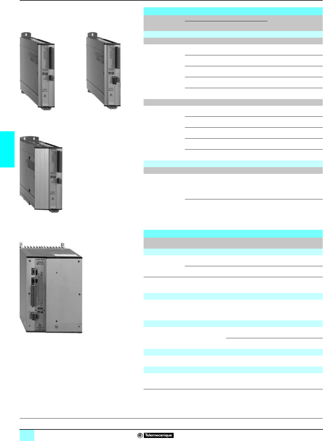
66
4
References
0
Lexium motion control 1
Lexium Servodrives
Digital servodrives for brushless motor
Specific functions Output current Reference Weight
kg
Permanent Discontinuous (5s)
Lexium 17D Servodrives
No anti-start safety function
Integral braking
resistors, integral
EMC filter
1.5 A rms 3 A rms MHDA 1004N00 4.000
3 A rms 6 A rms MHDA 1008N00 4.000
6 A rms 10 A rms MHDA 1017N00 4.000
10 A rms 20 A rms MHDA 1028N00 4.000
20 A rms 40 A rms MHDA 1056N00 7.500
Integral anti-start safety function
Integral braking
resistors, integral
EMC filter
1.5 A rms 3 A rms MHDA 1004A00 4.000
3 A rms 6 A rms MHDA 1008A00 4.000
6 A rms 10 A rms MHDA 1017A00 4.000
10 A rms 20 A rms MHDA 1028A00 4.000
20 A rms 40 A rms MHDA 1056A00 7.500
Lexium 17D HP servodrives
Integral anti-start safety function
No integral braking
resistors, no integral
EMC filter, obligatory
input choke
(1)
(to be ordered
separately).
40 A rms 80 A rms MHDA 1112A00 19.500
70 A rms 140 A rms MHDA 1198A00 21.000
Accessories for Lexium 17D Servodrives
Use Functions Reference Weight
kg
External braking resistors
MDHA 1004/1008
servodrives 33 Ω, power 250 W AM0 RFE 001V025 1.200
33Ω, power 500 W AM0 RFE 001V050 2.300
MDHA Servodrives
1017/1028/1056 33Ω, power 1,500 W AM0 RFE 001V150 5.200
Motor choke
Filter choke to be
placed very close
to the servodrive
For cable lengths between servodrive/motor
of ≥ 25 m AM0 FIL 001V056 –
Connecting cables
Connection to BPH motors See page 107 –
SER motors See page 87 –
Documentation (not included with the MHDA servodrives)
Lexium 17D User Guide 890 USE 1200p
(2) –
Servodrive replacement wiring
Set of connectors for
the Lexium 17D Female screw connectors
(X3, X4, X7, X8, X0A and X0B) AM0 SPA 001V000 –
(1) Input choke is obligatory when the servodrive is not powered by an isolation transformer.
(2) For the documentation, add to the end of the reference 0: English, 1: French, 2: German,
3: Spanish, 4: Italian.
MHDA 10
pp
N00A00 MHDA 10
pp
A00
M
HDA 1056N00/A00
MHDA 1112/1198A00
D
escription:
p
ages 47 and 48 Functions:
pages 49 to 61 Characteristics:
pages 62 to 65 Dimensions:
pages 68 and 69 Connections:
pages 70 to 75
This document provided by Barr-Thorp Electric Co., Inc. 800-473-9123 www.barr-thorp.com

67
4
References (continued)
0
Lexium motion control 1
Lexium servodrives
Accessories for Lexium 17D HP servodrives
Use Functions Reference Weight
kg
External braking resistors
MDHA 1112 Servodrives 15Ω, power 860 W AM0 RFE 002V086 3.500
MDHA 1198 Servodrives 10Ω, power 1600 W AM0 RFE 002V160 8.000
EMC input filters (1)
MDHA 1112 Servodrives 42 A rms permanent AM0 EMC 118 –
MDHA 1198 Servodrives 75 A rms permanent AM0 EMC 212 –
Input chokes
MDHA 1112 Servodrives 60 A rms permanent AM0 CHK 170 (2) 9.000
MDHA 1198 Servodrives 75 A rms permanent AM0 CHK 212 (2) 10.000
Connection cables
Connection to BPH motors See page 107 –
Documentation
Lexium 17D HP user guide 890 USE 1220p (3) –
Servodrive replacement wiring
Set of connectors for the
Lexium 17D HP 3 screw connectors
(X3, X4 and X10) AM0 SPA 002V001 –
Shared accessories for Lexium servodrives
Use Functions Reference Weight
kg
"Lexium motion tools" CD-ROM containing the Unilink software and a set of
documentation (4)
Configuration and setting of the
Lexium 17D servodrives from a
PC terminal
Defines the type of servodrive
and motor
Sets the parameters for the
servodrive and saves to the
servodrive's EEProm memory
AM0 CSW 001V300 –
Connection cables
Servodrive end connector ( X5) Master/Slave 2 m TSX CXP 283 –
6 m TSX CXP 683 –
Connection to a compatible PC,
equipped with Unilink software SUB-D connector with
9 contacts at the PC end (3 m) AM0 CAV 001V003 –
Connection to the CAY and CSY
positioning modules – See pages 16 and
29 –
Optional items for MHDA servodrives (1 slot)
SERCOS digital link card SERCOS network AM0 SER 001V000 0.150
Communication cards Fipio bus (5) and (6) AM0 FIP 001V000 0.140
Modbus Plus network (5) AM0 MBP 001V000 0.140
Profibus DP bus (5) and (6) AM0 PBS 001V000 0.140
Input/Output cards
Discrete 14 discrete inputs/8 discrete
outputs for controlling the
MHDA servodrive integral
position indexer
AM0 INE 001V000 0.180
(1) Radio interference filter element to be ordered when class A EMC (EN55011) resistance is
necessary.
(2) Must be ordered with the servodrive. Do not order if an isolation transformer in IT load is used.
(3) For the documentation, add to the end of the reference 0: English, 1: French,
2: German, 3: Spanish, 4: Italian
(4) For details, see page 50.
(5) Connection accessories, see wiring system pages 74 and 75.
(6) Requires Unilink software version
u
V2.5, included in reference AM0 CSW 001V200.
AM0 MBP 001V000
AM0 SER 001V000
AM0 FIP 001V000
AM0 PBS 001V000
F
unctions:
p
ages 49 to 61 Description:
pages 47 and 48 Characteristics:
pages 62 to 65 Dimensions:
pages 68 and 69 Connections:
pages 70 to 75
This document provided by Barr-Thorp Electric Co., Inc. 800-473-9123 www.barr-thorp.com
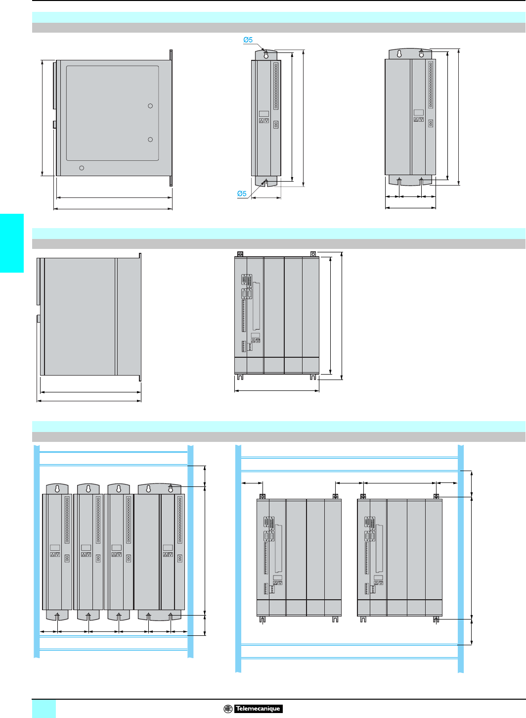
68
4
Dimensions
0
Lexium motion control 1
Lexium servodrives
Lexium 17D servodrives
Common side view MHDA 1004/1008/1017/1028 p00 MHDA 1056p00:
(1) With connectors
Lexium 17D HP Servodrives
Common side view MHDA1112/1198 A00
(1) With connectors (2) 495 with grounding part
Mounting
Lexium 17D servodrives Lexium 17D HP servodrives
(3) Cable clip or ducting
265
273 (1)
275
325
70
305
=50=
325
305
120
300
308
(1)
250
345
375 (2)
40 40
45 305
70 5070 70
45
(3)
70 7085 215
361
92 92
(3)
(3)
This document provided by Barr-Thorp Electric Co., Inc. 800-473-9123 www.barr-thorp.com
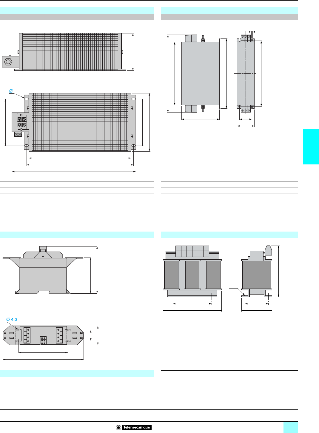
69
4
Dimensions (continued)
0
Lexium motion control 1
Lexium servodrives
Braking resistors EMC input filters (for Lexium 17D HP servodrives)
AM0 RFE 00pVppp AM0 EMC ppp
G
a
H
b2
b1
b
Ø
c
c
H
J
b
a1
G
a
AM0 RFE aa1bcGHJ ∅a b b1 b2 c GH∅
001 V025 412 330 66 77 390 44 35 4.5 x 9 AM0 EMC 118 60 355 305 335 150 35 320 7
001 V050 486 400 92 120 426 64 64 6.5 x 12 AM0 EMC 212 80 380 300 330 185 55 314 7
001 V150 586 500 185 120 526 150 150 6.5 x 12
002 V086 386 300 92 120 326 64 64 6.5 x 12
002 V160 570 500 182 130 526 150 150 5.5 x 8
Motor choke (for Lexium 17D servodrives) Input chokes (for Lexium 17D HP servodrives)
AM0 FIL 001V056 AM0 CHK ppp
Phaseo power supplies c 24 V abc GH ∅
ABL/7RE 24pp AM0 CHK 170 190 110 255 170 58 8
See page 117 AM0 CHK 212 190 120 255 170 68 8
113
150
c
H
b
Ø
a
G
35
153,3
250
62
Description:
p
ages 47 and 48
Functions:
pages 49 to 61
Characteristics:
pages 62 to 65
References:
pages 66 and 67
Connections:
pages 70 to 75
This document provided by Barr-Thorp Electric Co., Inc. 800-473-9123 www.barr-thorp.com
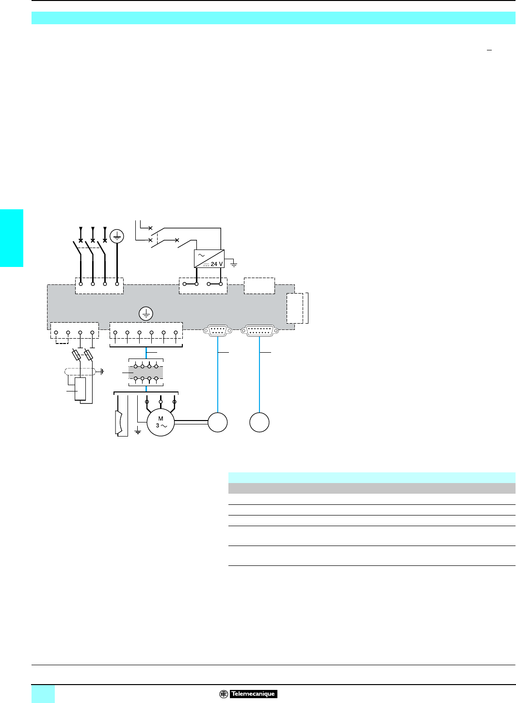
70
4
Connections
0
Lexium motion control 1
Lexium servodrives
1Braking resistor AM0 RFE 001Vppp.
2
Motor choke AM0 FIL 001V056 (required for servodrive/motor cable lengths > 25 m).
This inductance should be placed very closely to the servodrive (≤ 1 m).
Connection cables for SER or BPH motors:
3Power cable.
4Resolver cable.
5SinCos Hiperface encoder cable.
The power, resolver or SinCos Hiperface cables offer two possibilities:
bAGO FRU: Ready to use cables.
bAGO KIT: extension cables (mounting of the connector on the servodrive end
performed by the user).
For SER motors, see page 87
For BPH motors, see page 107
(1) Max. length 1m.
Connections for the Lexium 17D Servodrives
2
1
3
4
Q1
Q2
Q2
XOA
A1
2
1
3
4
X8
L1
2
4
6
1
21
4365
3
5
L2 L3
2
1
3
4
X4
X3
X10
2
1
3
4
5
6
X9 X2 X1
543
2
1
F1
2
4
1
3
Integral brake
(depending
on model)
Resolver
(depending
on model)
SinCos Hiperface Encoder
(depending on model)
SUB-D with
9 contacts SUB-D with
15 contacts
- Motor enable
- Alarm
- 4 discrete inputs/2 discrete outputs
- 2 analog inputs
- 2 analog outputs
or
- Anti-start lock (on MHDA10ppA00)
a 100…240 V
Additional components required
Address Description
Q1 GV2-L magnetic circuit breaker, see page
62
Q2 GB2 or C60N thermal magnetic circuit breaker, see page 117
A1
Phaseo process power supply
c
24 V ABL 7RE, see page 117
F1 GK1-DD bipolar fuse carrier (obligatory) with 10 x 38 DF2-CN04 (4 A) or
DF2-CN06 (6 A) type gG cartridges, see page
63
To connect the connectors X3 and X5 to the Premium motion control
modules, see page
18
, for X13 and X15, see page 31
Description:
p
ages 47 and 48
Functions:
pages 49 to 60
Characteristics:
pages 62 to 65
References:
pages 66 and 67
Dimensions:
pages 68 to 69
This document provided by Barr-Thorp Electric Co., Inc. 800-473-9123 www.barr-thorp.com
71
4
Connections (continued)
0
Lexium motion control 1
Lexium servodrives
1AM0 CHK 170/212 input choke (not to be used if power supply is via Schneider
recommended insulation transformer, see page 73).
2AM0 EMC 118/212 EMC input filter (if Class A is requested).
3AM0 RFE 002V086/160 braking resistor.
Connection cables for SER/BPH motors:
4Power cable.
5Resolver cable.
6SinCos Hiperface encoder cable.
The power, resolver or SinCos Hiperface cables offer two possibilities:
bAGO FRU: Ready to use cables.
bAGO KIT: extension cables (mounting of the connector on the servodrive end
performed by the user for the resolver or SinCos encoder cable, connection on the
screw terminal on the servodrive end for the power cable).
See page 107.
Connections for the Lexium 17D HP servodrives
2
1
3
4
Q1
X0
A1
5
7
L1
2
4
6
Q2
1
3
5
L2 L3
4
3
5
6
X4
2
1
3
4
X10
18
1
X3
2
1
8
9
10
11
X4
X2 X1
654
1
2
3
F1
2
4
1
3
X0
+-
Integral brake
(depending
on model)
Resolver
(depending
on model)
- Motor enable
- Alarm
- 4 discrete inputs/2 discrete outputs
- 2 analog inputs
- 2 analog outputs
Lock
circuit
SinCos Hiperface Encoder
(depending on model)
or
- Anti-start lock
a 100…240 V
SUB-D with
9 contacts SUB-D with
15 contacts
Additional components required
Address Description
Q1 Magnetic circuit-breaker 50/100A NS100LMA 50/100, see page 64
Q2 GB2 or C60N thermal magnetic circuit breaker, see page 117
A1 Phaseo process power supply c 24 V ABL 7RE, see page 117
F1 GK1-DD bipolar fuse carrier (obligatory) with 10 x 38 DF2-CN16 (16 A) or
DF2-CN20 (20 A) type gG cartridges, see page
63
To connect the connectors X3 and X5 to the Premium motion control
modules, see page 18, for X13 and X15, see page 31.
D
escription:
p
ages 47 and 48 Functions:
pages 49 to 61 Characteristics:
pages 62 to 65 References:
pages 66 and 67 Dimensions:
pages 70 to 75
This document provided by Barr-Thorp Electric Co., Inc. 800-473-9123 www.barr-thorp.com
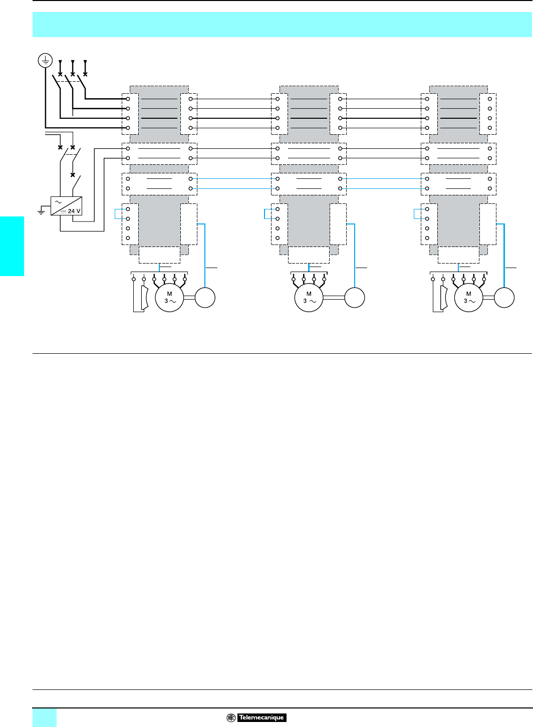
72
4
Connections (continued)
0
Lexium motion control 1
Lexium servodrives
For keys 3, 5 and 6: See page 70
Example of connecting a set of Lexium 17D servodrives with a distribution of braking energy
(links on X7 connectors) (1)
XOA
2
1
(2)
(3) (3)
3
4
XOB
2
1
3
4
X8
X9
X1
X2
2
1
3
4
X4
3
1
X7
- DC
+ DC
L3 L2 L1
3
2
4
+ DC
- DC
XOA
2
1
3
4
XOB
2
1
3
4
X8
X9
X1
X2
2
1
3
4
X4
2
1
X7
- DC
+ DC
3
3
4
+ DC
- DC
XOA
2
1
3
4
XOB
2
1
3
4
X8
X9
X1
X2
2
1
3
4
X4
2
1
X7
- DC
+ DC
3
3
4
+ DC
- DC
Q1
2
4
6
1
3
5
Q2
Q2
A1
21
4365
(4)
5 or 65 or 6 5 or 6
Example of
Lexium 17D
servodrive
connection
a 100…240 V
(1) The same connection principle for connecting the Lexium 17D HP servodrive power buses in parallel is possible. Please consult our Regional Sales Offices.
(2) Circuit-breaker Q1 and the power supply cables must be of sufficient size to provide protection against overloads and short-circuits on each servodrive.
The connectors (XOA, XOB) limit the line current to 20 A rms, therefore for line currents > 20 A rms use the separate power supplies and protection devices.
(3) Cables for connecting the power buses in parallel: using non-shielded cables for lengths
y
20 cm. For lengths > 20 cm, use shielded cables (maximum length
10 meters). The connectors (X7) are limited to 20 A.
(4) On the X4 connectors for the main servodrive, check that the sum of
c
24 V power supply currents for the servodrives and the holding brakes is
y
10 A.
D
escription:
p
ages 47 and 48 Functions:
pages 49 to 61 Characteristics:
pages 62 to 65 References:
pages 66 and 67 Dimensions:
pages 70 to 75
This document provided by Barr-Thorp Electric Co., Inc. 800-473-9123 www.barr-thorp.com
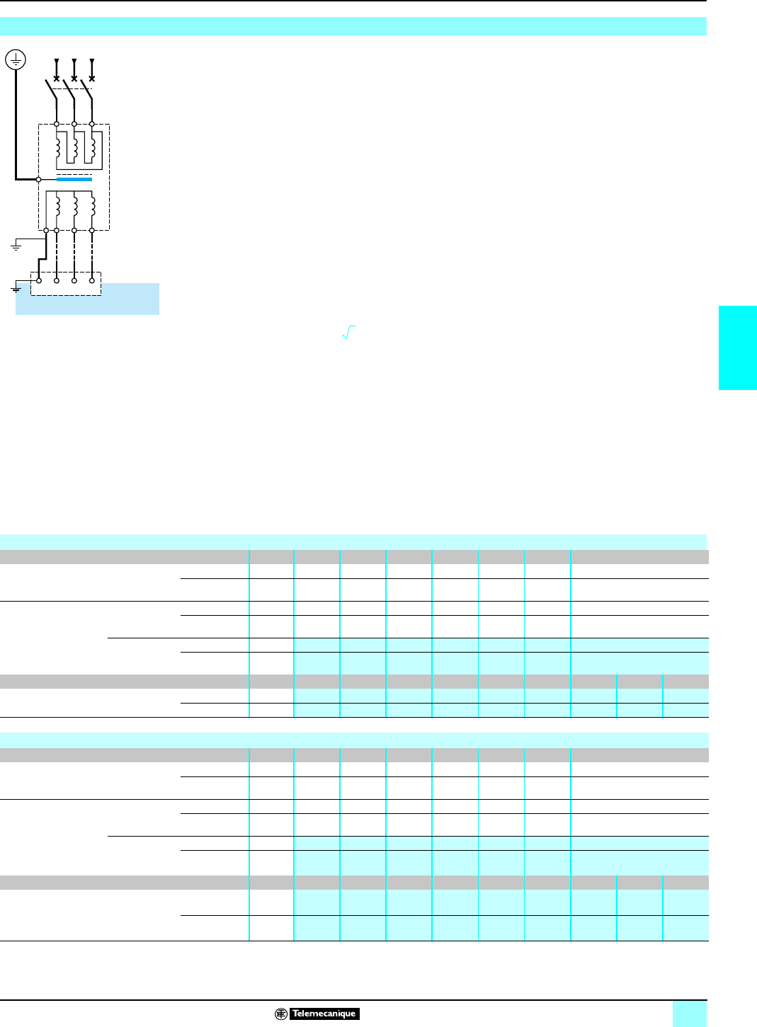
73
4
Connections (continued)
0
Lexium motion control 1
Lexium servodrives
In this type of installation, a 3-phase BT/BT transformer is inserted in the supply
circuit for the servodrives, which also allows a TT load network to be re-built on the
secondary side. This plan, with a secondary star transformer, also meets the
following requirements:
bProtection of personnel.
bAdaptation of the supply voltage. In the case of associating a MHDA 1004
servodrive with a BPH 055 motor, use a 400/230 V transformer to obtain the optimum
performances for the servodrive, see page 95.
Adding an insulation transformer dispenses of the use of a AM0 CHKppp input
choke.
Merlin Gerin or Square D brand T1 3-phase transformer to be associated
The dimensions of the transformers are defined by the following formulae
bLexium servodrives with independent power supply (one transformer per servodrive):
where Pu: unitary power (KVA), Un: Nominal input voltage (V), In: permanent
current (A), K = 0.9: reduction factor of the servodrive and 1.5 factor that takes into
account the call and peak currents of the servodrive.
bLexium servodrives with common power supply (one transformer for n servodrives):
If Pm < Pu of the largest servodrive, take Pm = Pu of the largest servodrive.
where Pm: power used (KVA) and Pu: servodrive unitary power (KVA). Formula not
applicable for permanent operation (S1 mode).
Connection of Lexium servodrives with installation in IT neutral load (insulated or impedance neutral)
Q1
1w 1v 1v
T1
L3
6
4
2
5
3
1
L2 L1
PE L3 L2 L1
Primary
Secondary
Pu 3UnInK×××()15,×=
Pm ΣPu()2⁄=
Selection of Merlin Gerin transformer with 3 x 400 V rms primary voltage
Lexium servodrives with independent power supply MHDA 1004 1008 1017 1028 1056 1112 1198
Required
power
Pu
230 V rms (1) kVA 0,81 –
400 V rms (1) kVA 1.4 2.8 5.6 9.4 19 38 66
Merlin Gerin 3-phase
T1 BT/BT transformer
to be associated
Nominal
transformer
power
230 V rms (1) kVA 2.5 –
400 V rms (1) kVA 2.5 4 6.3 10 20 40 80
Reference 400/230 V rms 84010 –
400/400 V rms 84030 84032 84033 84035 84038 84041 84044
Lexium servodrives with common power supply kVA 2,5 46,3 10 20 40 80 160 250
Power required Pm Reference 400/230 V rms 84010 84012 84013 –
400/400 V rms 84030 84032 84033 84035 84038 84041 84044 84047 84049
Selection of Square D transformer with 3 x 460 V rms primary voltage
Lexium servodrives with independent power supply MHDAp1004 1008 1017 1028 1056 1112 1198
Required
power
Pu
230 V rms (1) kVA 0.81 –
460 V rms (1) kVA 1.4 2.8 5.6 9.4 19 38 66
Square D 3-phase T1
BT/BT transformer to
be associated
Nominal
transformer
power
230 V rms (1) kVA ––
460 V rms (1) kVA ––7.511204075
Reference 460/230 V rms – –
460/460 V rms – – 7T145
HDIT 11T145
HDIT 20T145
HDIT 40T145
HDIT 75T145
HDIT
Lexium servodrives with common power supply kVA 2.5 47.5 11 20 40 75 145 220
Power required Pm Reference 460/230 V rms (2) (2) 7T144
HDIT 11T144
HDIT –
460/460 V rms (2) (2) 7T145
HDIT 11T145
HDIT 20T145
HDIT 40T145
HDIT 75T145
HDIT 145T145
HDIT 220T145
HDIT
(1) For 3-phase secondary voltage,
(2) contact our Regional Sales Offices.
Unit equivalence: 1 kW = 0.746 HP.
This document provided by Barr-Thorp Electric Co., Inc. 800-473-9123 www.barr-thorp.com
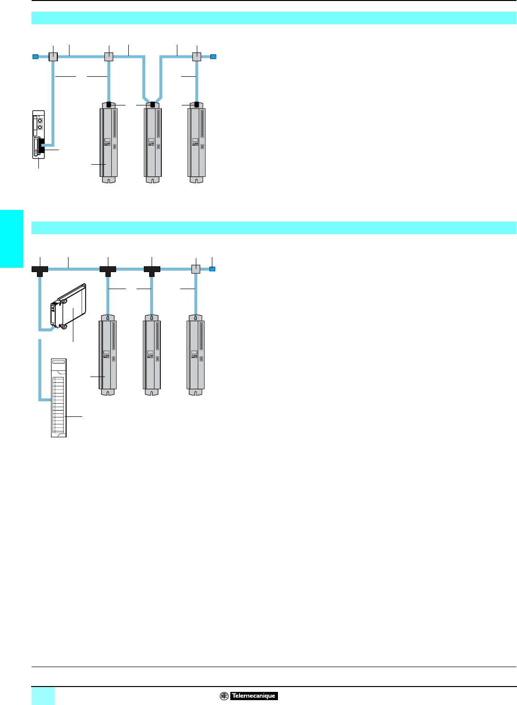
74
4
Connections (continued)
0
Lexium motion control 1
Lexium servodrives
1TSX P57p53M: Premium processor with integrated Fipio bus link manager.
2MHDA 1pppN00/A00: Lexium 17D or 17D HP servodrives, equipped with an
optional AM0 FIP 001V00 communication card.
3TSX FP ACC2/ACC12: 9-way SUB-D female connector. Used to provide a tap link
or daisy-chain connection (case of 2nd servodrive).
4TSX FP CA/CRpp00: trunk cable, shielded twisted pair. In lengths of 100, 200 or
500 m.
5
TSX FP ACC4/ACC3
:
IP 65 (TSX FP ACC4) or IP 20 (TSX FP ACC3) T-junction
box.
6TSX FP CCp00: derivation cable, 2 shielded twisted pairs. In lengths of 100, 200
or 500 m.
Other connection elements: consult our “Premium automation platform” catalogue
1TSX MBP 100: Modbus Plus PCMCIA card to be placed in processor's type III slot
on the Premium platform with the TSX MBP CE 030/060 derivation cable (3 m or
6 m in length).
140 CPU ppp pp p: Quantum platform processor.
2MHDA 1ppp N00/A00: Lexium 17D or 17D HP servodrives, equipped with the
optional AM0 MBP 001V000 Modbus Plus communication card.
3490 NAA 2710p: main cable, shielded twisted pair with shielding drain (free wire
end). In lengths of 0.25, 0.72, 3 or 10 m.
4990 NAD 230 10: IP 20 T-junction box (in plastic) to connect one device. Adapts
the impedance when installed at the end of the line (connecting the connectors
requires the 043 509 383 cabling tool).
5990 NAD 230 10: IP 65 T-junction box (in zamac) to connect one device
(connection on screw terminals). Has an RJ 45 type connector to connect a
programming and maintenance terminal.
6990 NAD 230 11: lot of 2 impedance line terminators (990 NAD 230 11 adapter)
for the 990 NAD 230 10 box, to be placed at the end of each segment.
7990 NAD 211 10/30: derivation cable with a 9-way SUB-D male connector at the
device end and a junction box with free wires. In lengths of 2.4 m or 6 m.
Connecting Lexium MHDA servodrives to the Fipio bus
4
1
3
3
3
66
2
55 5 44
DC D
P
remium bus
m
anager D: tap link connection
C: daisy-chain connection
Connecting Lexium MHDA servodrives to the Modbus Plus network
4 3 4
1
4
7 7
2
6
5
1
Premium
Lexium MHDA servodrives
Quantum
Functions:
p
ages 49 to 61
Description:
pages 47 and 61
Characteristics:
pages 62 to 65
References:
pages 66 and 67
Dimensions:
pages 70 to 75
This document provided by Barr-Thorp Electric Co., Inc. 800-473-9123 www.barr-thorp.com
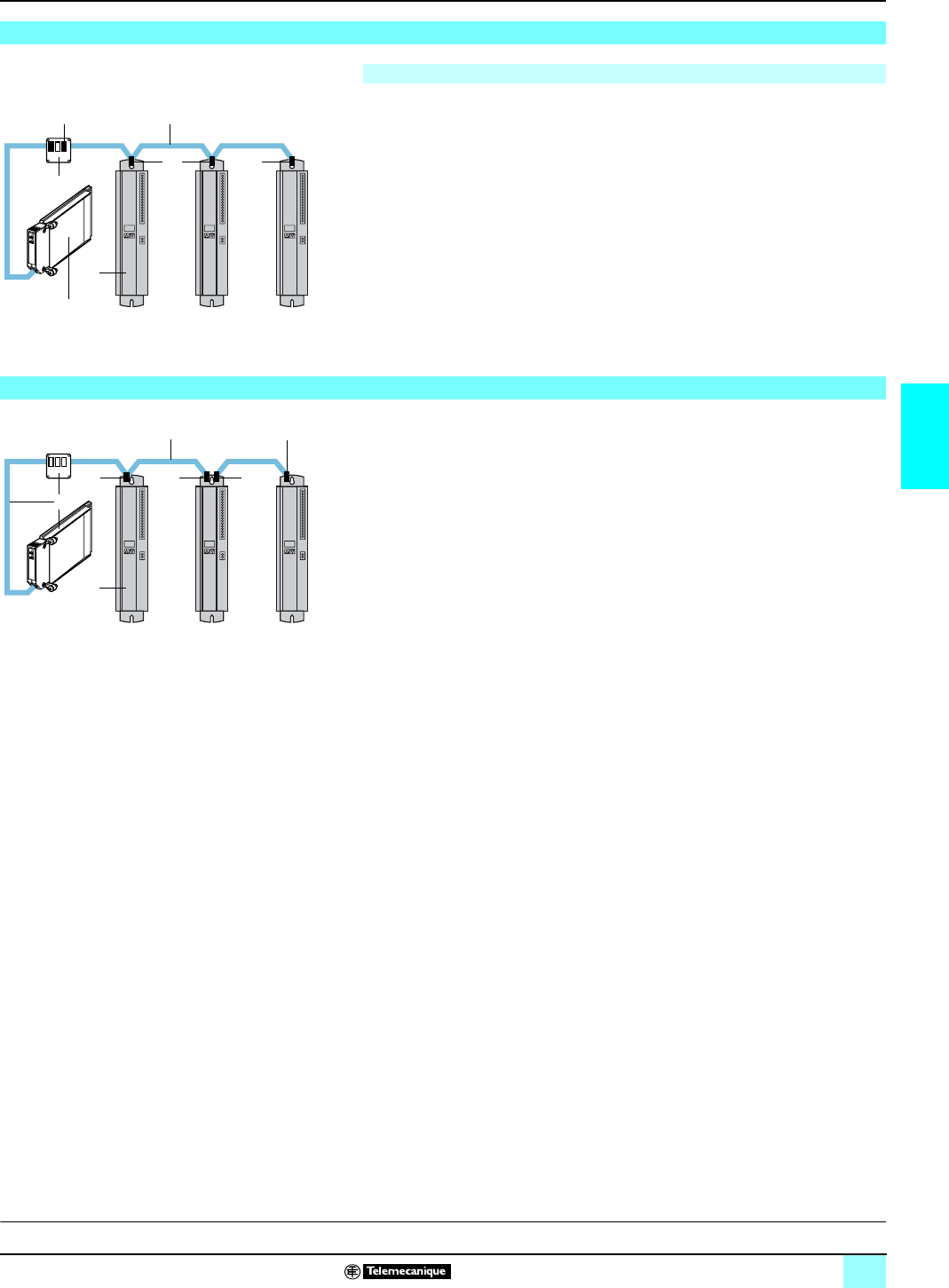
75
4
Connections (continued)
0
Lexium motion control 1
Lexium servodrives
1TSX CPP 100: CANopen card to be placed in the processor's type III slot on the
Premium platform. Card supplied with 0.6 m length cable.
2MHDA 1ppp N00/A00: Lexium 17D or 17D HP servodrives (connecting to the
connector, add. X6).
3TSX CPP ACC1: junction box equipped with SUB-D male connectors (one with
15 contacts and two with 9 contacts).
4Cable: a shielded twisted pair (impedance 100/120 Ω, capacity 60 nF/km max.,
resistance 159.8 Ω/km).
59-way SUB-D female connector. 120 Ω 1/4 W resistor to be provided at the line
end.
1TSX PBY 100: Profibus DP module set (host module, PCMCIA card and junction
box) to be placed in the Premium platform rack.
140 CRP 811 00: Profibus DP module set (host module, PCMCIA card and
junction box) to be placed in the Quantum platform rack.
2MHDA 1ppp N00/A00: Lexium 17D or 17D HP servodrives, equipped with an
optional AM0 PBS 001V000 Profibus DP communication card.
3TSX PBS CA 100/200: Profibus DP connection cable: In lengths of 100 or 400 m.
4490 NAD 911 04: 9-way SUB-D male connector for intermediate connection
(gray).
5490 NAD 911 03: 9-way SUB-D male connector for end of line (yellow).
490 NAD 911 05: 9-way SUB-D male connector for intermediate connection. Has a
9-way SUB-D female connector (for example for connecting a programming
terminal).
Connecting Lexium MHDA servodrives to the CANopen bus
The CANopen bus is integrated as standard in Lexium servodrive.
1
3
2
45
55
P
remium Lexium MHDA servodrives
Connecting Lexium MHDA servodrives to the Profibus DP bus.
1
2
35
444
P
remium Lexium MHDA servodrives
F
unctions:
p
ages 49 to 60 Description:
pages 47 and 48 Characteristics:
pages 62 to 65 References:
pages 66 and 67 Dimensions:
pages 64 to 75
This document provided by Barr-Thorp Electric Co., Inc. 800-473-9123 www.barr-thorp.com
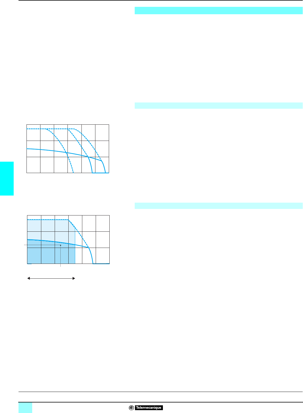
76
5
Presentation Lexium motion control 1
SER brushless motors
SER AC brushless motors are equipped with Neodymium Iron Borium (NdFeB)
magnets and provide a high level of density power within a confined space, as well
as a dynamic velocity range that meets all machine requirements. Thermal protection
is provided by an integral probe in the motor. These support high overloads without
risk of demagnetization. SER motors are certified "Recognized" (UR) by the
Underwriters Laboratories. They are compliant with standard UL1004 and with
European directives (marking e).
Depending on the model, SER motors are available with a holding brake and
gearbox.
MHDA servodrives, which are associated with SER motors, deliver a sinusoidal wave
allowing perfect rotation, even at low speed.
SER motors show torque/speed profiles similar to the example opposite with:
1Continuous torque at 480 V, 3-phase.
2Continuous torque at 400 V, 3-phase.
3Continuous torque at 230 V, 3-phase.
4Peak torque at 480 V, 3-phase.
5Peak torque at 400 V, 3-phase.
6Peak torque at 230 V, 3-phase.
where:
6000 (in rpm) corresponds to the motor's maximum mechanical speed.
Tn (in Nm) represents the continuous stall torque value.
Tm (in Nm) represents the peak stall torque value.
Torque/speed curves enable the optimum size of a motor to be determined. For
example, for a supply voltage of 400 V, 3-phase, the useful graphs are graphs
2
and
5
.
The time diagram of speeds and torques according to the motor cycle must also be
defined (see page
110
):
1Locate the work zone of the application in speed.
2Verify, using the motor cycle time diagram, (see page
110
), that the torques
required by the application during the different cycle phases are located within the
area bounded by graph
5
in the work zone.
3Calculate the average speed
S
avg and the equivalent thermal torque
T
eq (see
page
110
).
4The point defined by
S
avg and
T
eq must be within the area bounded by graph
2
in
the work zone.
Presentation
Speed/torque characteristics
1
0
1
5
5
01000 2000 3000 4000 5000 600
0
0
4, 5, 6
1, 2, 3 3
4
12
5
6
Speed in rpm
Torque in Nm
Tm
Tn
Principle for determining the size of the motor according to the application
1
0
1
5
5
01000 2000 3000 4000 5000 600
0
0
5
52
2
Work zone
T
m
T
n
T
eq
Savg
Torque in Nm
Speed in rpm
F
unctions:
p
age 77 Description:
page 78 Characteristics:
pages 79 to 84 References:
pages 86 and 87 Dimensions:
page 85
This document provided by Barr-Thorp Electric Co., Inc. 800-473-9123 www.barr-thorp.com

77
5
Functions Lexium motion control 1
SER brushless motors
SER brushless motors have been developed to meet to the following requirements:
bFunctional characteristics, robustness, safety, etc. in compliance with IEC 34-1.
bAmbient operating temperature: - 25...40 °C according to DIN 50019R14.
bRelative humidity: y 75 % yearly average/95 % for 30 days without condensation.
bStorage and transport temperature: - 25...70 °C.
bWinding insulation class: F (threshold temperature for windings 150 °C) according
to VDE 0530.
bSupply and sensor connections using angled connectors rotatable over 310 °.
bThermal protection by built-in PTC thermistor probe, controlled by the Lexium
servodrive.
bOut-of-round, concentricity and perpendicularity between flange and shaft as per
DIN 42955, class N.
bFlange compliant with standard DIN 42948.
bPermitted mounting positions: no mounting restriction for IMB5 - IMV1 and IMV3
as per DIN 42950.
bPolyester resin based paint: opaque black RAL 9005.
bDegree of protection of the motor casing: IP 56 as per IEC 529.
bDegree of protection of the shaft end: IP 41 as per IEC 529, IP 56 as option.
bDegree of protection of the gearbox (depending on model): IP 54 as per IEC 529.
bIntegrated sensor, 2 pole resolver or SinCos Hiperface high-resolution multi-
revolution absolute encoder.
bStandard sized shaft end (as per DIN 42948):
v for motors without gearbox: smooth shaft end (1),
v for motors with gearbox: shaft end with key.
The integral brake fitted on the SER motor (depending on the model) is a failsafe
electro-magnetic holding brake.
d Use of the holding brake as a dynamic brake for deceleration purposes will
rapidly cause damage to it.
The motor has a position sensor which, depending on the model, can be:
bA 2-pole resolver providing a precision of the angular position of the shaft to less
than ± 6 arc minutes.
bA SinCos Hiperface high-resolution absolute encoder, multi-revolution (4096
revolutions) making the angular position of the shaft precise to less than ± 45 arc
seconds.
These sensors make it possible to:
bGive the angular position of the rotor in such a way that flows can be synchronized.
bMeasure the motor speed via the associated Lexium servodrive. This information
is used by the speed regulator of the Lexium servodrive.
bMay measure position information for the position controller of the Lexium
servodrive.
bMeasure and transmit, if required, position information in incremental or absolute
format, for the position return of a motion control module ("simulated encoder" output
of the Lexium servodrive).
(1) For shaft end with key, consult our Regional Sales Offices.
Functions
General functions
Functions
Holding brake (depending on model)
Built-in encoder
D
escription:
p
age 78 Characteristics:
pages 79 to 84 References:
pages 86 and 87 Dimensions:
page 85
This document provided by Barr-Thorp Electric Co., Inc. 800-473-9123 www.barr-thorp.com

78
5
Description Lexium motion control 1
SER brushless motors
SER brushless motors with a 3-phase stator and an 8 pole rotator with Neodymium
Iron Borium magnets (NdFeB) comprising:
1Housing with a square cross-section, protected by black opaque polyester resin
paint RAL 9005.
2Axial flange with 4 fixing points complying with DIN 42948.
3A smooth shaft end of standard DIN 42948 (1).
4A dust and damp-proof male screw connector for connecting the power cable. The
output of this connector is continuously rotatable over an arc of 310°.
5A dust and damp-proof male screw connector for connecting the resolver or
encoder cable. The output of this connector is continuously rotatable over an arc
of 310°.
6A manufacturer's data plate located on the side opposite the shaft end.
7A ground terminal.
Connector to be ordered separately, for connecting to Lexium MHDA servodrives.
See page 87.
Schneider Electric has taken great care to find the most appropriate match between
SER motors and MHDA servodrives. This compatibility is only guaranteed when
cables sold by Schneider Electric are used (see page 87).
(1) For shaft end with key, consult our Regional Sales Offices.
Description
2
3
4
5
6
1
7
P
resentation:
p
age 76 Functions:
page 77 Characteristics:
pages 79 to 84 References:
pages 86 and 87 Dimensions:
page 85
This document provided by Barr-Thorp Electric Co., Inc. 800-473-9123 www.barr-thorp.com
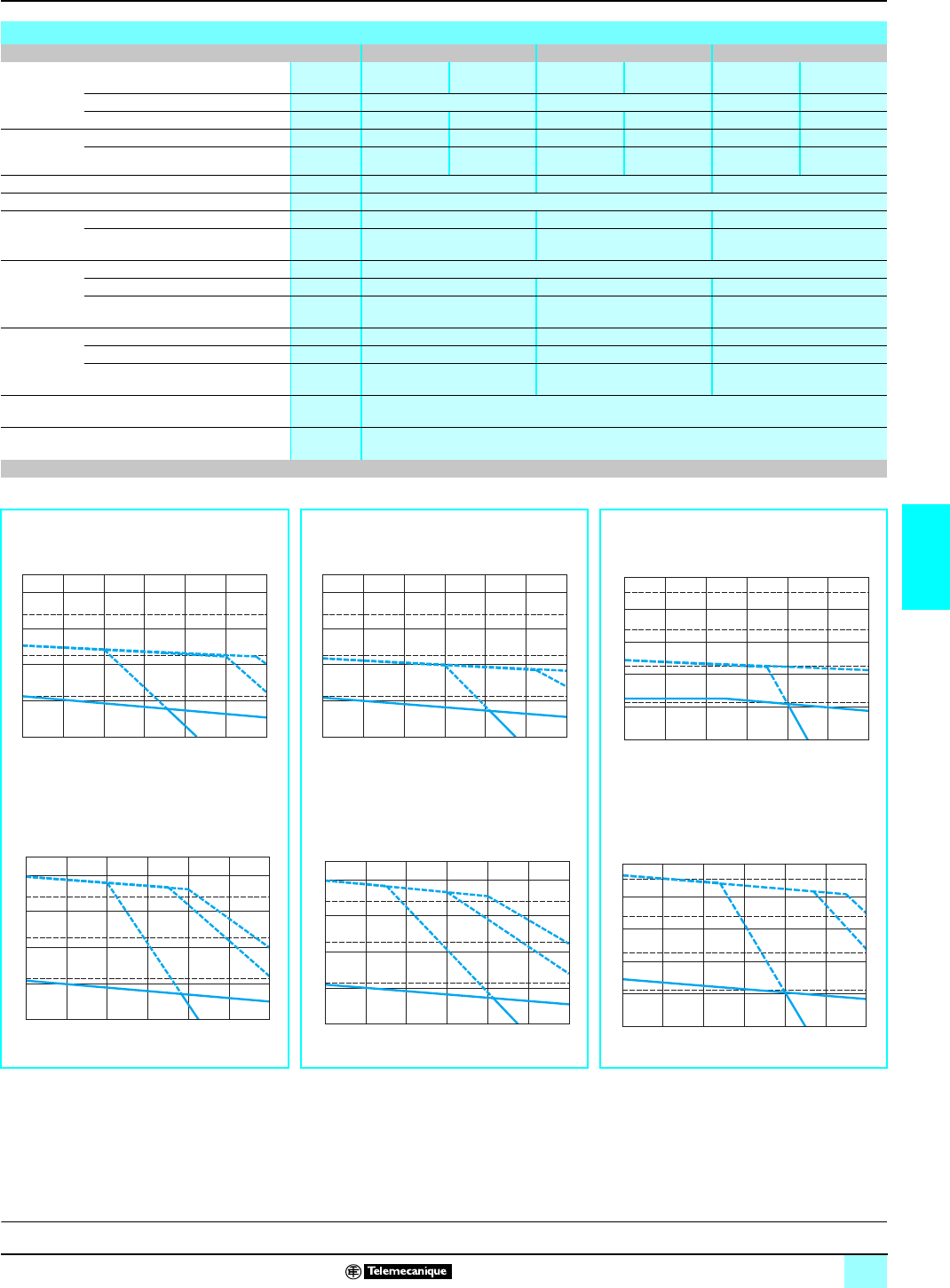
79
5
Couple en Nm
Vitesse en tr/min
Characteristics Lexium motion control 1
SER brushless motors
Characteristics of motors SER 39A/39B/39C
Type of motor SER 39A 4L7S SER 39B 4L3S SER 39C 4L3S
Torque
(model
without
gearbox)
Associated with Lexium
servodrive MHDA
1004p00 MHDA
1008p00 MHDA
1008p00 MHDA
1017p00 MHDA
1008p00 MHDA
1017p00
Continuous stall Tn Nm 1.1 2.2 2.4 2.9
Peak stall Tm Nm 2.5 4.0 4.4 8.0 4.7 9.4
Current Permanent A rms 1.3 1.3 3333.7
Maximum A rms 36612 612
Demagnetization current A612 18
Maximum speed rpm 6000
Constants
(at 25 °C) Torque Nm/A rms 0.85 0.73 0.78
Back emf V rms s/
rad 0.48 0.46 0.48
Rotor Number of poles 8
Inertia without brake Jm gm20.085 0.16 0.24
Inertia with brake Jm gm20.105 0.18 0.26
Stator
(at 25 °C) Resistance (phase/phase) Ω13 5.4 3.3
Inductance (phase/phase) mH 47.9 20.3 14.1
Electrical time constant ms 3.68 3.76 4.27
Holding brake (depending on model) See page 88
gearbox (depending on model) See page 89
Speed/torque graphs (1)
SER 39A 4L7S motors SER 39B 4L3S motors SER 39C 4L3S motors
bwith MHDA 1004p00 servodrives bwith MHDA 1008p00 servodrives bwith MHDA 1008p00 servodrives
bwith MHDA 1008p00 servodrives bwith MHDA 1017p00 servodrives bwith MHDA 1017p00 servodrives
1Continuous torque at 480 V, 3-phase
2Continuous torque at 400 V, 3-phase
3Continuous torque at 230 V, 3-phase
4Peak torque at 480 V, 3-phase
5Peak torque at 400 V, 3-phase
6Peak torque at 230 V, 3-phase
(1) The graphs above are given for an increase in motor temperature of 85 °C.
1000 2000 3000 4000 5000 60000
1
2
3
4
3
0
2
0
1
0
0
C
m4, 5, 6
1, 2, 3
3
65
4
1, 2
C
n
Torque in Nm
Speed in rp
m
Torque in IN-lb
s
1000 2000 3000 4000 5000 60000
2
4
6
8
0
6
0
3
0
2
0
C
m4, 5, 6
1, 2, 3
3
65
4
1, 2
C
n
Torque in Nm
Speed in rp
m
Torque in IN-lbs
1000 2000 3000 4000 5000 60000
2
4
6
8
10
0
8
0
6
0
4
0
2
0
C
m4, 5, 6
1, 2, 3
3
6
4, 5
1, 2
Cn
Torque in Nm
Speed in rpm
Torque in IN-lbs
1000 2000 3000 4000 5000 60000
1
2
3
4
0
3
0
2
0
1
0
C
m4, 5, 6
1, 2, 3
3
654
1, 2
Cn
Torque in Nm
Speed in rpm
Torque in IN-lbs
1000 2000 3000 4000 5000 60000
2
4
6
8
0
6
0
3
0
2
0
C
m4, 5, 6
1, 2, 3
3
654
1, 2
Cn
Torque in Nm
Speed in rpm
Torque in IN-lbs
1000 2000 3000 4000 5000 60000
2
4
6
8
10
0
8
0
6
0
4
0
2
0
C
m4, 5, 6
1, 2, 3
3
654
1, 2
Cn
Torque in Nm
Speed in rpm
Torque in IN-lbs
P
resentation:
p
age 76 Functions:
page 77 Description:
page 78 References:
pages 86 and 87 Dimensions:
page 85
This document provided by Barr-Thorp Electric Co., Inc. 800-473-9123 www.barr-thorp.com
80
5
Characteristics (continued) Lexium motion control 1
SER brushless motors
Characteristics of SER 3BA motors
Type of motor SER 3BA 4L3S SER 3BA 4L5S
Torque
(model
without
gearbox)
Associated with Lexium
servodrive MHDA 1017p00 MHDA 1028p00 MHDA 1008p00 MHDA 1017p00
Continuous stall Tn Nm 4.6 4.2 4.5
Peak stall Tm Nm 9.2 15.3 7.6 15.0
Current Permanent A rms 6 3 3.2
Maximum A rms 12 20 612
Demagnetization current A30 16.5
Maximum speed rpm 6000 5500
Constants
(at 25°C) Torque Nm/A rms 0.76 1.41
Back emf V rms s/
rad 0.42 0.74
Rotor Number of poles 8
Inertia without brake Jm gm20.4
Inertia with brake Jm gm20.43
Stator
(at 25 °C) Resistance (phase/phase) Ω1.5 4
Inductance (phase/phase) mH 12.6 34.1
Electrical time constant ms 8.40 8.53
Holding brake (depending on model) See page 88
Gearbox (depending on model) See page 89
Speed/torque graphs (1)
SER 3BA 4L3S motors SER 3BA 4L5S motors
bwith MHDA 1017p00 servodrives bwith MHDA 1008p00 servodrives
bwith MHDA 1028p00 servodrives bwith MHDA 1017p00 servodrives
1Continuous torque at 480 V, 3-phase
2Continuous torque at 400 V, 3-phase
3Continuous torque at 230 V, 3-phase
4Peak torque at 480 V 3-phase
5Peak torque at 400 V 3-phase
6Peak torque at 230 V 3-phase
(1) The graphs above are given for an increase in motor temperature of 85 °C.
1000 2000 3000 4000 5000 60000
5
10
15
20
0
50
100
150
Cm 4, 5, 6
1, 2, 3
3
65
4
1, 2
Cn
Torque in Nm
Speed in rpm
Torque in IN-lbs
1000 2000 3000 4000 5000 60000
5
10
15
0
25
50
75
100
125
Cm 4, 5, 6
1, 2, 3
321
654
Cn
Torque in Nm
Speed in rpm
Torque in IN-lbs
1000 2000 3000 4000 5000 60000
5
10
15
20
0
50
10
0
15
0
C
m4, 5, 6
1, 2, 3
3
65
4
1, 2
Cn
Torque in Nm
Speed in rpm
Torque in IN-lbs
1000 2000 3000 4000 5000 60000
5
10
15
0
25
75
100
125
50
Cm 4, 5, 6
1, 2, 3
321
654
Cn
Torque in Nm
Speed in rpm
Torque in IN-lbs
P
resentation:
p
age 76 Functions:
page 77 Description:
page 78 References:
pages 86 and 87 Dimensions:
page 85
This document provided by Barr-Thorp Electric Co., Inc. 800-473-9123 www.barr-thorp.com
81
5
Characteristics (continued) Lexium motion control 1
SER brushless motors
Characteristics of SER 3BB motors
Type of motor SER 3BB 4L3S SER 3BB 4L5S
Torque
(model without
gearbox)
Associated with Lexium
servodrive MHDA 1017p00 MHDA 1028p00 MHDA 1017p00 MHDA 1028p00
Continuous stall Tn Nm 6.0 6.6 6.6
Peak stall Tm Nm 12.0 20.0 15.8 25.0
Current Permanent A rms 66.6 5 5
Maximum A rms 12 20 12 20
Demagnetization current A32 24
Maximum speed rpm 6000 5800
Constants
(at 25 °C) Torque Nm/A rms 1.00 1.32
Back emf V rms s/
rad 0.56 0.78
Rotor Number of poles 8
Inertia without brake Jm gm20.8
Inertia with brake Jm gm20.83
Stator
(at 25 °C) Resistance (phase/phase) Ω1.2 2.3
Inductance (phase/phase) mH 11.3 21.2
Electrical time constant ms 9.42 9.22
Holding brake (depending on model) See page 88
Gearbox (depending on model) See page 89
Speed/torque graphs (1)
SER 3BB 4L3S motors SER 3BB 4L5S motors
bwith MHDA 1017p00 servodrives bwith MHDA 1017p00 servodrives
bwith MHDA 1028p00 servodrives bwith MHDA 1028p00 servodrives
1Continuous torque at 480 V, 3-phase
2Continuous torque at 400 V, 3-phase
3Continuous torque at 230 V, 3-phase
4Peak torque at 480 V 3-phase
5Peak torque at 400 V 3-phase
6Peak torque at 230 V 3-phase
(1) The graphs above are given for an increase in motor temperature of 85 °C.
1000 2000 3000 4000 5000 60000
10
5
15
20
0
50
100
150
Cm 4, 5, 6
1, 2, 3
3
1, 2
65
4
Cn
Torque in Nm
Speed in rpm
Torque in IN-lbs
1000 2000 3000 4000 5000 60000
25
0
5
10
15
20
50
100
150
200
Cm
4, 5, 6
1, 2, 3
321
654
Cn
Torque in Nm
Speed in rpm
Torque in IN-lbs
1000 2000 3000 4000 5000 60000
10
5
15
20
0
50
100
150
Cm 4, 5, 6
1, 2, 3
3
1, 2
654
Cn
T
orque in Nm
Speed in rpm
Torque in IN-lbs
1000 2000 3000 4000 5000 60000
25
0
5
10
15
20
50
100
150
200
Cm 4, 5, 6
1, 2, 3
321
654
Cn
Torque in Nm
Speed in rpm
Torque in IN-lbs
P
resentation:
p
age 76 Functions:
page 77 Description:
page 78 References:
pages 86 and 87 Dimensions:
page 85
This document provided by Barr-Thorp Electric Co., Inc. 800-473-9123 www.barr-thorp.com
82
5
Characteristics (continued) Lexium motion control 1
SER brushless motors
Characteristics of SER 3BC motors
Type of motor SER 3BC 4L5S SER 3BC 4L7S
Torque
(model without
gearbox)
Associated with Lexium
servodrive MHDA 1017p00 MHDA 1028p00 MHDA 1008p00 MHDA 1017p00
Continuous stall Tn Nm 8.6 10.0 8.3 10.0
Peak stall Tm Nm 17.0 28.0 16.0 32.0
Current Permanent A rms 6733.6
Maximum A rms 12 20 612
Demagnetization current A32 16.5
Maximum speed rpm 4800 2500
Constants
(at 25 °C) Torque Nm/A rms 1.43 2.78
Back emf V rms s/
rad 0.87 1.69
Rotor Number of poles 8
Inertia without brake Jm gm21.14
Inertia with brake Jm gm21.17
Stator
(at 25 °C) Resistance (phase/phase) Ω1.7 5.7
Inductance (phase/phase) mH 17.2 62.5
Electrical time constant ms 10.12 10.96
Holding brake (depending on model) See page 88
Gearbox (depending on model) See page 89
Speed/torque graphs (1)
SER 3BC 4L5S motors SER 3BC 4L7S motors
bwith MHDA 1017p00 servodrives bwith MHDA 1008p00 servodrives
bwith MHDA 1028p00 servodrives bwith MHDA 1017p00 servodrives
1Continuous torque at 480 V, 3-phase
2Continuous torque at 400 V, 3-phase
3Continuous torque at 230 V, 3-phase
4Peak torque at 480 V 3-phase
5Peak torque at 400 V 3-phase
6Peak torque at 230 V 3-phase
(1) The graphs above are given for an increase in motor temperature of 85 °C.
1000 2000 3000 4000 5000 60000
0
10
20
30
50
100
150
200
250
Cm 4, 5, 6
1, 2, 3
321
654
Cn
Torque in Nm
Speed in rpm
Torque in IN-lbs
500 1000 1500 2000 2500 30000
40
0
10
20
30
100
200
300
Cm 4, 5, 6
1, 2, 3
321
654
Cn
Torque in Nm
Speed in rpm
Torque in IN-lbs
1000 2000 3000 4000 5000 60000
0
10
20
30
50
100
150
200
250
Cm 4, 5, 6
1, 2, 3
321
654
Cn
Torque in Nm
Speed in rpm
Torque in IN-lbs
500 1000 1500 2000 2500 30000
40
0
10
20
30
100
200
300
Cm 4, 5, 6
1, 2, 3
321
654
Cn
Torque in Nm
Speed in rpm
Torque in IN-lbs
P
resentation:
p
age 76 Functions:
page 77 Description:
page 78 References:
pages 86 and 87 Dimensions:
page 85
This document provided by Barr-Thorp Electric Co., Inc. 800-473-9123 www.barr-thorp.com
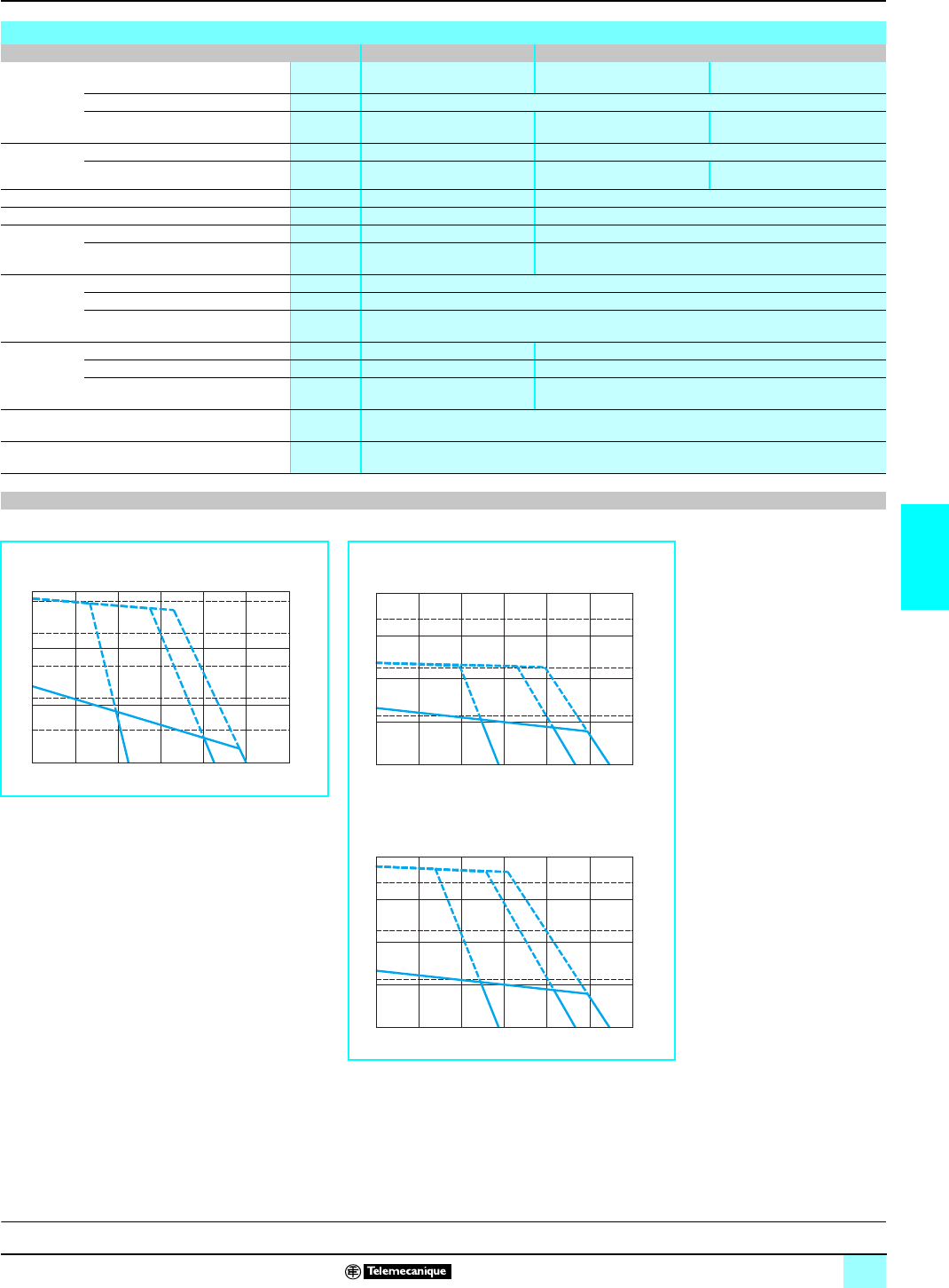
83
5
Characteristics (continued) Lexium motion control 1
SER brushless motors
Characteristics of SER 3BD motors
Type of motor SER 3BD 4L5D SER 3BD 4L7S
Torque
(model without
gearbox)
Associated with Lexium
servodrive MHDA 1028p00 MHDA 1017p00 MHDA 1028p00
Continuous stall Tn Nm 13.4
Peak stall Tm Nm 29.0 24.0 38
Current Permanent A rms 9.2 5.1
Maximum A rms 20 12 20
Demagnetization current A45 25
Maximum speed rpm 5000 2750
Constants
(at 25 °C) Torque Nm/A rms 1.46 2.63
Back emf V rms s/
rad 0.84 1.53
Rotor Number of poles 8
Inertia without brake Jm gm21.55
Inertia with brake Jm gm21.58
Stator
(at 25 °C) Resistance (phase/phase) Ω1.3 3.75
Inductance (phase/phase) mH 14.5 41.5
Electrical time constant ms 11.15 11.07
Holding brake (depending on model) See page 88
Gearbox (depending on model) See page 89
Speed/torque graphs (1)
SER 3BD 4L5D motors SER 3BD 4L7S motors
bwith MHDA 1028p00 servodrives bwith MHDA 1017p00 servodrives
bwith MHDA 1028p00 servodrives
1Continuous torque at 480 V, 3-phase
2Continuous torque at 400 V, 3-phase
3Continuous torque at 230 V, 3-phase
4Peak torque at 480 V 3-phase
5Peak torque at 400 V 3-phase
6Peak torque at 230 V 3-phase
(1) The graphs above are given for an increase in motor temperature of 85 °C.
1000 2000 3000 4000 5000 60000
0
10
20
30
50
100
150
200
250
Cm 4, 5, 6
1, 2, 3
321
654
Cn
Torque in Nm
Speed in rpm
Torque in IN-lbs
500 1000 1500 2000 2500 30000
0
10
20
30
40
100
200
300
Cm 4, 5, 6
1, 2, 3
321
654
Cn
Torque in Nm
Speed in rpm
Torque in IN-lbs
500 1000 1500 2000 2500 30000
0
10
20
30
40
100
200
300
Cm 4, 5, 6
1, 2, 3
321
654
Cn
Torque in Nm
Speed in rpm
Torque in IN-lbs
P
resentation:
p
age 76 Functions:
page 77 Description:
page 78 References:
pages 86 and 87 Dimensions:
page 85
This document provided by Barr-Thorp Electric Co., Inc. 800-473-9123 www.barr-thorp.com
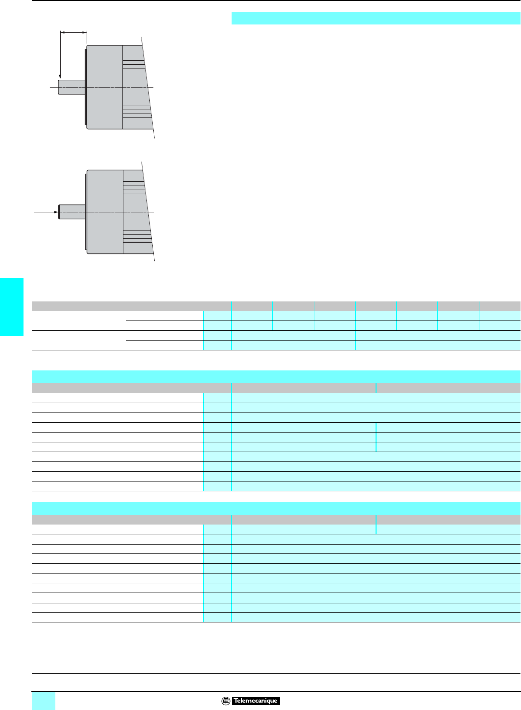
84
5
Characteristics (continued) Lexium motion control 1
SER brushless motors
Radial and axial forces permissible on the motor shaft
Even when motors are used under optimum conditions, their lifetime is limited by that
of the bearings.
Conditions:
bNominal lifetime of bearings (1)
bSpeed
bAmbient temperature (temperature of
bearings ~ 100 °C)
bPeak torque
bContinuous torque
bForce application point
L10h = 20,000 hours
N = 4,000 rpm
40 °C
cyclic ratio of 10%
permanent
X = 15 mm with motors SER 39A
X = 20 mm with motors SER 3Bp
(1) Hours of use with a failure probability of 10 %
d The following conditions must be respected:
bRadial and axial forces must not be applied simultaneously.
bThe maximum pressure permissible on the shaft end is 1,800 N.
bShaft end with IP 41 degree of protection, optional IP 56.
bBearings cannot be changed by the user as the built-in position sensor must be
realigned after disassembly of the apparatus.
x
Fr
Fa
Motors SER 39A SER 39B SER 39C SER 3BA SER 3BB SER 3BC SER 3BD
Maximum radial force Fr Cyclic ratio 10 % N600 520 500 1480 1550 1530 760
Permanent N340 400 430 690 800 860 760
Maximum axial force Fa Cyclic ratio 10 % N1240 1770
Permanent N450 1770
P
resentation:
p
age 76 Functions:
page 77 Description:
page 78 References:
pages 86 and 87 Dimensions:
page 85
Characteristics of motor-servodrive power connection cables
LXA CP AAA ppp 1 LXA CP AAB ppp 1
External cover PUR orange colored RAL 2003
Insulation TPM or PP/PE
Capacity pF/m < 70 (conductors/shielding)
Number of conductors (shielded) [(4 x 1.5 mm2) + (2 x 1.0 mm2)] [(4 x 2.5 mm2) + (2 x 1.0 mm2)]
External diameter mm 11 13
Curvature radius mm 110 (suitable for flexible cable carrier/tray) 130 (suitable for flexible cable carrier/tray)
Working voltage V600
Maximum service length m75 (with Lexium MHD servodrives)
Service temperature °C - 15…+ 85 (storage: - 40...+ 85)
Certification UL, CSA
Characteristics of motor-servodrive encoder connection cables
LXA CF ACA ppp 1 LXA CF ABA ppp 1
Encoder type Resolver SinCos Hiperface encoder
External cover PUR green colored RAL 6018
Insulation Polyester
Number of conductors (shielded) 5 x (2 x 0.25 mm2)+(2 x 0.5 mm2)
External diameter mm 8.5 max
Curvature radius mm 85 (suitable for flexible cable carrier/tray)
Working voltage V300
Maximum length m75 (with Lexium MHD servodrives)
Service temperature °C - 15…+ 85 (storage: - 40...+ 85)
Certification UL, CSA
This document provided by Barr-Thorp Electric Co., Inc. 800-473-9123 www.barr-thorp.com
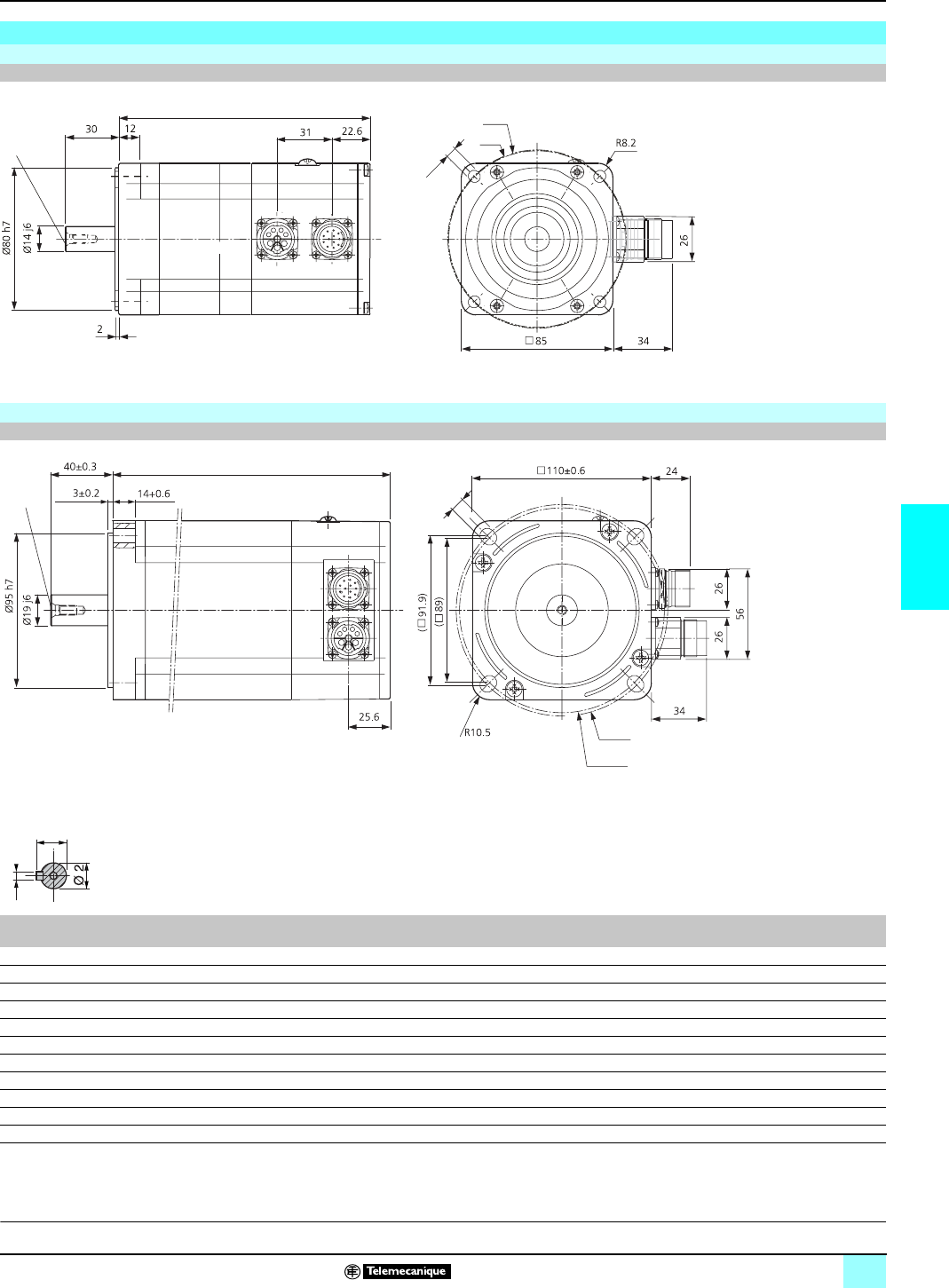
85
5
Dimensions Lexium motion control 1
SER brushless motors
SER motors (models without gearbox), for gearbox dimensions, see page 91
SER motors 39A/39B/39C
CA synchronous servo-motor, standard, size 90
SER motors 3BA/3BB/3BC
CA synchronous servo-motor, standard, size 110
Shaft end with key
SER a
(without brake) a
(with brake) g2 (2) g1 hØ2
39A 4L7S 141 186.5 M5 x 12.5 16 5 14
39B 4L3S 171 216.5 M5 x 12.5 16 5 14
39C 4L3S 201 246.5 M5 x 12.5 16 5 14
3BA 4L3S 132 198 M6 x 16 21.5 6 19
3BA 4L5S 132 198 M6 x 16 21.5 6 19
3BB 4L3S 180 246 M6 x 16 21.5 6 19
3BB 4L5S 180 246 M6 x 16 21.5 6 19
3BC 4L5S 228 294 M6 x 16 21.5 6 19
3BC 4L7S 228 294 M6 x 16 21.5 6 19
3BD 4L5D 276 342 M6 x 16 21.5 6 19
3BD 4L7S 276 342 M6 x 16 21.5 6 19
(1) 39 with mounted connector
(2) according to DIN 332-DS
(1)
aØ 100
6.5 Ø 99
g2
Ø130
Ø125,9
a
(1)
g2
9
g1
h
P
resentation:
p
age 76 Functions:
page 77 Description:
page 78 Characteristics:
pages 79 to 84 References:
pages 86 and 87
This document provided by Barr-Thorp Electric Co., Inc. 800-473-9123 www.barr-thorp.com
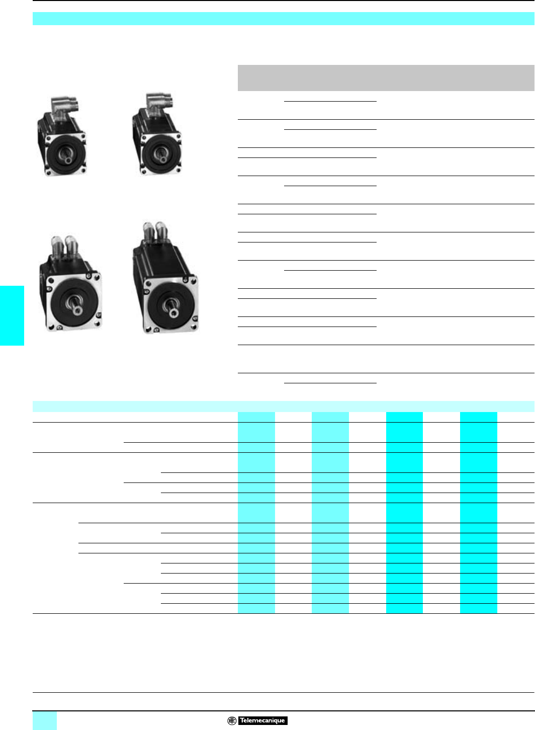
86
5
References Lexium motion control 1
SER brushless motors
SER brushless motors
The SER motors shown below are not equipped with gearboxes. They are supplied
with smooth shaft ends (1).
The SER motors equipped with PLE gearboxes are given on page 89.
Continuous
stall torque Associated
servodrive
MHDA
Peak stall
torque Mechanical
speed Reference
Weight
(1)
kg
1.1 Nm 1004p00 2.5 Nm 6000 rpm
SER 39A 4L7S
pp
pOO 2.200
1008p00 4.0 Nm
2.2 Nm 1008p00 4.4 Nm 6000 rpm
SER 39B 4L3S
pp
p
OO 3.300
1017p00 8.0 Nm
2.4 Nm 1008p00 4.7 Nm 6000 rpm
SER 39C 4L3S
pp
pOO 4.400
2.9 Nm 1017p00 9.4 Nm
4.6 Nm 1017p00 9.2 Nm 6000 rpm
SER 3BA 4L3S
pp
pOO 5.000
1028p00 15.3 Nm
4.2 Nm 1008p00 8.2 Nm 5500 rpm
SER 3BA 4L5S
pp
pOO 5.000
4.5 Nm 1017p00 15.0 Nm
6.0 Nm 1017p00 12.0 Nm 6000 rpm
SER 3BB 4L3S
pp
pOO 8.000
6.6 Nm 1028p00 20.0 Nm
6.6 Nm 1017p00 15.8 Nm 5800 rpm SER 39BB 4L5S
pp
pOO 8.000
1028p00 25 Nm
8.6 Nm 1017p00 17.0 Nm 4800 rpm
SER 39BC 4L5S
pp
pOO 11.000
10.0 Nm 1028p00 28.0 Nm
8.3 Nm 1008p00 16.0 Nm 2500 rpm SER 3BC 4L7S
pp
pOO 11.000
10.0 Nm 1017p00 32.0Nm
13.4 Nm 1028p00 29.0 Nm 5000 rpm
SER 3BD 4L5D
pp
pOO 13.000
13.4 Nm 1017p00 24.0 Nm 2,750 rpm SER 3BD 4L7S
pp
pOO 13.000
1028p00 38.0 Nm
To order an SER motor, fill out each reference
SER 39/3B A/B/C/D 4L 3/5/7 S/D pp p O/2/3/4 O/3/5/8
Sensor integrated in motor RA
Resolver with 1 pair of poles
SinCos multiturn absolute encoder MO
Shaft tightness A
IP 41 Without holding brake
With holding brake 1
IP 56 Without holding brake B
With holding brake 2
Gearbox (see page 89) O
Without gearbox
Shaft end Smooth O
With key (2) –
With gearbox (shaft end with key)
Type (3) PLE80 2
PLE120 3
PLE160 4
Reduction
ratio Ratio 3:1 3
Ratio 5:1 5
Ratio 8:1 8
(1) Without brake, for weight of motor with brake see page 88.
(2) For motor without gearbox equipped with shaft end with key, consult our regional branch.
(3) For motor equipped with PLE gearbox, see page 89.
P
resentation:
p
age 76 Functions:
page 77 Description:
page 78 Characteristics:
pages 79 to 84 Dimensions:
page 85
SER 39B 4L3SRA
p
OO
SER 3BA 4L3S
RA
p
OO
SER 39A 4L7S
RA
p
OO
SER 3BD 4L5D
RA
p
OO
This document provided by Barr-Thorp Electric Co., Inc. 800-473-9123 www.barr-thorp.com
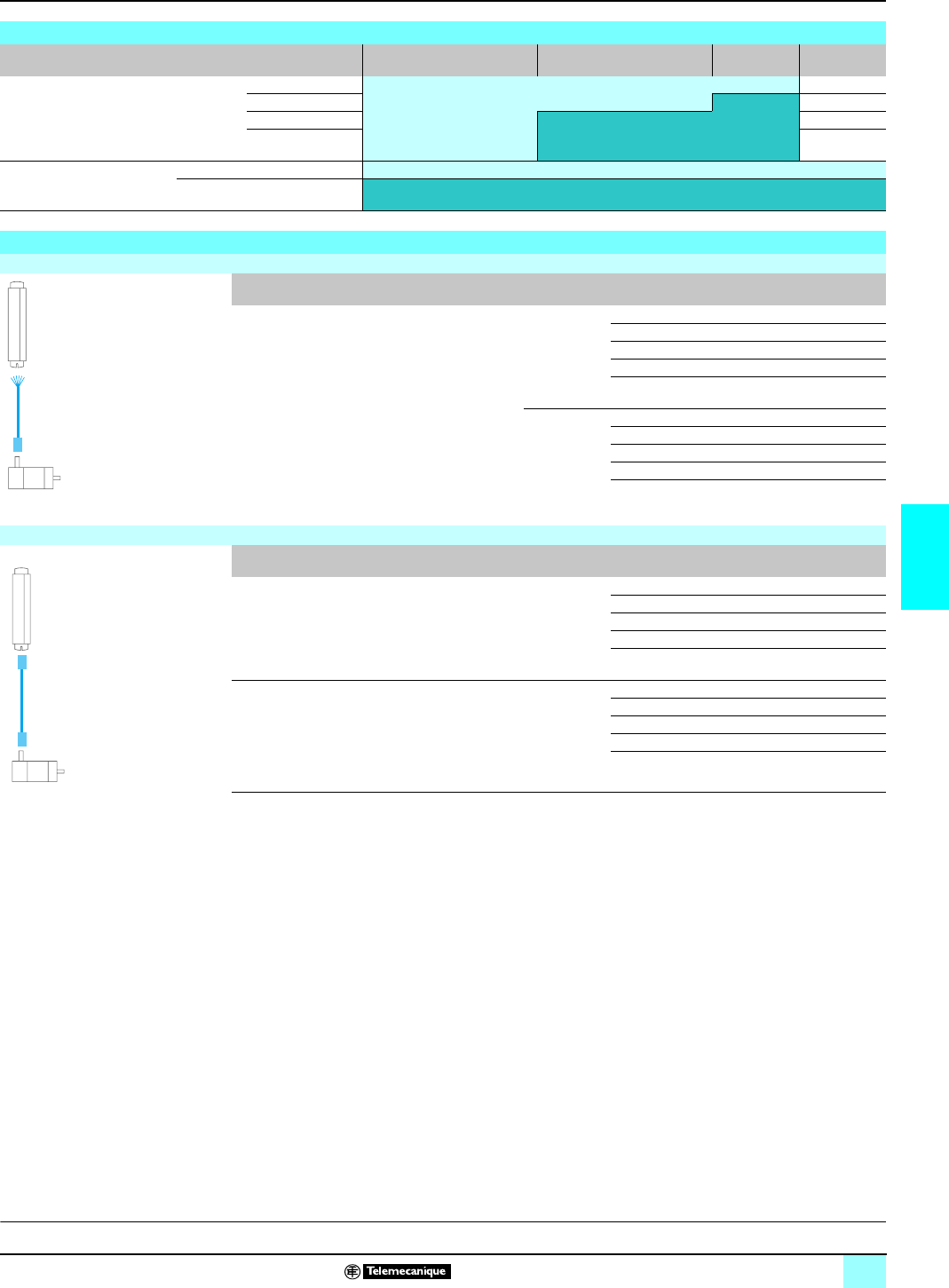
87
5
References (continued) Lexium motion control 1
SER brushless motors
.
Choice of power cables, resolver and SinCos Hiperface encoder
MHDA servodrive Length = 3 m 3 m < length = 10 m 10 m y length
y30 m (1) 30 m < length
y75 m (1)
Cables supplied with a fitted
connector (motor end) and a
second connector for fitting
(servodrive end)
Power 1004 p00 (2)
1008 p00 LXA CP AAA ppp 1 (2)
1017 p00 (2)
1028 p00 LXA CP AAB ppp 1 (2)
Cables fitted with connectors
at both ends Resolver LXA CF ACA ppp 1
SinCos Hiperface encoder (2) LXA CF ABA ppp 1
P
resentation:
p
age 76 Functions:
page 77 Description:
page 78 Characteristics:
pages 79 to 84 Dimensions:
page 85
Connecting cables
Cables fitted with a connector at the motor end (the servodrive end connector supplied with the cable has to be fitted)
Description From To Composition Length Reference Weight
kg
Power cables
(2)
For association with
servodrives, see
table above
Motors SER Lexium
MHDA 1ppp
N00/A00
servodrives
[(4 x 1.5 mm2)
+ (2 x 1 mm2)] 3 m LXA CP AAA 003 1 –
5 m LXA CP AAA 005 1 –
10 m LXA CP AAA 010 1 –
20 m LXA CP AAA 020 1 –
30 m (1) LXA CP AAA 030 1 –
[(4 x 2.5 mm2)
+ (2 x 1 mm2)] 3 m LXA CP AAB 003 1 –
5 m LXA CP AAB 005 1 –
10 m LXA CP AAB 010 1 –
20 m LXA CP AAB 020 1 –
30 m (1) LXA CP AAB 030 1 –
Cables fitted with connectors at both ends
Description From To Length Reference Weight
kg
Resolver cables
(2) Lexium
SER motors Lexium MHDA 1ppp N00/A00
servodrives 3 m LXA CF ACA 003 1 –
5 m LXA CF ACA 005 1 –
10 m LXA CF ACA 010 1 –
20 m LXA CF ACA 020 1 –
30 m LXA CF ACA 030 1 –
Sincos Hiperface
encoder cables
(2)
Lexium
SER motors Lexium MHDA 1ppp N00/A00
servodrives 3 m LXA CF ABA 003 1 –
5 m LXA CF ABA 005 1 –
10 m LXA CF ABA 010 1 –
20 m LXA CF ABA 020 1 –
30 m LXA CF ABA 030 1 –
(1) For a cable length between the servodrive and motor
u
25 m, it is essential to use a motor choke placed as close as
possible to the servodrive. For information, see page 66.
(2)For a cable length of >
30 m, consult our Regional Sales Offices.
LXA CP AAA/AAB 0
pp
1
LXA CF ACA/ABA 0
pp
1
This document provided by Barr-Thorp Electric Co., Inc. 800-473-9123 www.barr-thorp.com

88
5
Presentation,
characteristics Lexium motion control 1
SER brushless motor options
Holding brake
The integral brake fitted on the SER motor (depending on the model) is a failsafe
electro-magnetic holding brake.
d Use of the holding brake as a dynamic brake for deceleration purposes will
rapidly cause damage to it.
Presentation
Holding brake
Characteristics
Holding brake
SER 39p motor brake SER 3Bp motor brake
Holding torque MBr
(1) Nm 6 16
Inertia of rotor (brake only) JBr gm20.02 0.035
Electrical clamping power PBr W24 28
Supply voltage with Lexium servodrive Vc 22.8...26.2
Current A11.2
Opening time ms 40 60
Closing time ms 20 30
Weight (brake only) kg 1.8 3.0
(1) Holding torque for a motor temperature
y
80 °C.
For a temperature of > 80 °C, apply a derating coefficient of 50 %.
This document provided by Barr-Thorp Electric Co., Inc. 800-473-9123 www.barr-thorp.com
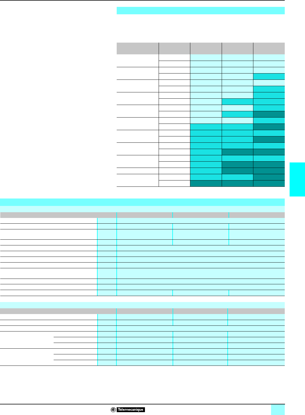
89
5
Presentation,
characteristics Lexium motion control 1
SER brushless motor options
PLE gearboxes
SER motors are also available with mounted PLE-type gearboxes. Schneider
Electric has selected and standardized the following gearbox models, available in a
choice of 3 speed reduction ratios 3:1, 5:1 and 8:1.
Presentation
Type of motor Associated
servodrive Gearbox
3:1 Gearbox
5:1 Gearbox
8:1
SER 39A 4L7S MHDA 1004pPLE 80 PLE 80 PLE 80
MHDA 1008pPLE 80 PLE 80 PLE 80
SER 39B 4L3S MHDA 1008pPLE 80 PLE 80 PLE 80
MHDA 1017pPLE 80 PLE 80 PLE 120
SER 39C 4L3S MHDA 1008pPLE 80 PLE 80 PLE 80
MHDA 1017pPLE 80 PLE 80 PLE 120
SER 3BA 4L3S MHDA 1017pPLE 80 PLE 80 PLE 120
MHDA 1028pPLE 80 PLE 120 PLE 120
SER 3BA 4L5S MHDA 1008pPLE 80 PLE 80 PLE 120
MHDA 1017pPLE 80 PLE 120 PLE 160
SER 3BB 4L3S MHDA 1017pPLE 80 PLE 80 PLE 120
MHDA 1028pPLE 120 PLE 120 PLE 160
SER 3BB 4L5S MHDA 1017pPLE 120 PLE 120 PLE 120
MHDA 1028pPLE 120 PLE 120 PLE 160
SER 3BC 4L5S MHDA 1017pPLE 120 PLE 120 PLE 120
MHDA 1028pPLE 120 PLE 160 PLE 160
SER 3BC 4L7S MHDA 1008pPLE 120 PLE 120 PLE 120
MHDA 1017pPLE 120 PLE 160 PLE 160
SER 3BD 4L5D MHDA 1028pPLE 120 PLE 160 PLE 160
SER 3BD 4L7S MHDA 1017pPLE 120 PLE 120 PLE 160
MHDA 1028pPLE 160 PLE 160 PLE 160
Characteristics
General characteristics
Type PLE 80 PLE 120 PLE 160
Gearbox type Planetary gearbox with single reduction level straight teeth
Inversion play min arc < 12 < 8 < 6
Torsional rigidity Nm/
min arc 4.5 11 32.5
Noise level dB (A) 60 65 70
Junction box Black anodized aluminum
Shaft material C 45
Tightness of shaft output IP 43
Lubrication No lubrication required
Average lifetime (1) Hour 10 000 : S1 mode (permanent service) and 100% continuous torque
20 000 : S1 mode (permanent service) and 85% continuous torque
Mounting position All positions
Operating temperature °C - 25...+ 90 (+ 120 when operating impulsively)
Weight (gearbox only) kg 2.100 6.000 18.000
Combining an SER motor with a PLE gearbox
Gearbox type PLE 80 PLE 120 PLE 160
Maximum permitted radial force (2) (3) N950 2000 6000
Maximum permitted axial force (2) N1200 2800 8000
Efficiency 0.96
Inertia of gearbox 3:1 gm20.077 0.263 1.214
5:1 gm20.045 0.153 0.607
8:1 gm20.039 0.132 0.463
Continuous output torque
T2N (3) 3:1 Nm 40 80 400
5:1 Nm 50 110 450
8:1 Nm 50 120 450
(1) Data in operating hours for a 10% fault probability rating.
(2) Values given for a minimum lifetime of 10,000 hours at an output speed of 100 rpm for a cyclic ratio = 1 (S1 mode) on electrical machines.
(3) Force applied at mid-distance from the output shaft.
This document provided by Barr-Thorp Electric Co., Inc. 800-473-9123 www.barr-thorp.com

90
5
Associations and
references Lexium motion control 1
SER brushless motor options
PLE gearboxes
The following table of references provides the different torque and speed values of
shaft ends for the various possible motor configurations.
d The continuous output torque of the gearbox T2N must not be exceeded
permanently. It is possible, for example in an emergency stop, to have a double
torque over a short period. The motor's torque should be limited thereafter to avoid
destroying the gearbox through excessive torque.
References of SER brushless motors and associated PLE gearboxes
Associated
Lexium
servodrive
Gearbox type Continuous
stall torque Peak stall
torque Maximum output
speed of gearbox Reference Weight
(1)
kg
SER 39A 4L7S motors
MHDA 1004pWithout 1.1 Nm 2.5 Nm 6000 rpm SER 39A 4L7Spp pOO 2.200
PLE80, ratio 3:1 3.2 Nm 7.2 Nm 2000 rpm SER 39A 4L7Spp p23 4.300
PLE80, ratio 5:1 5.3 Nm 12.0 Nm 1200 rpm SER 39A 4L7Spp p25 4.300
PLE80, ratio 8:1 8.4 Nm 19.2 Nm 750 rpm SER 39A 4L7Spp p28 4.300
MHDA 1008pWithout 1.1 Nm 4.0 Nm 6000 rpm SER 39A 4L7Spp pOO 2.200
PLE80, ratio 3:1 3.2 Nm 11.5 Nm 2000 rpm SER 39A 4L7Spp p23 4.300
PLE80, ratio 5:1 5.3 Nm 19.2 Nm 1200 rpm SER 39A 4L7Spp p25 4.300
PLE80, ratio 8:1 8.4 Nm 30.7 Nm 750 rpm SER 39A 4L7Spp p28 4.300
SER 39B 4L3S motors
MHDA 1008pWithout 2.2 Nm 4.4 Nm 6000 rpm SER 39B 4L3Spp pOO 3.300
PLE80, ratio 3:1 6.3 Nm 12.6 Nm 2000 rpm SER 39B 4L3Spp p23 5.400
PLE80, ratio 5:1 10.6 Nm 21.1 Nm 1200 rpm SER 39B 4L3Spp p25 5.400
PLE80, ratio 8:1 16.9 Nm 33.7 Nm 750 rpm SER 39B 4L3Spp p28 5.400
MHDA 1017pWithout 2.2 Nm 8.0 Nm 6000 rpm SER 39B 4L3Spp pOO 3.300
PLE80, ratio 3:1 6.3 Nm 23.0 Nm 2000 rpm SER 39B 4L3Spp p23 5.400
PLE80, ratio 5:1 10.6 Nm 38.4 Nm 1200 rpm SER 39B 4L3Spp p25 5.400
PLE120, ratio 8:1 16.9 Nm 61.4 Nm 750 rpm SER 39B 4L3Spp p28 9.300
SER 39C 4L3S motors
MHDA 1008pWithout 2.4 Nm 4.7 Nm 6000 rpm SER 39C 4L3Spp pOO 4.400
PLE80, ratio 3:1 6.9 Nm 13.5 Nm 2000 rpm SER 39C 4L3Spp p23 6.500
PLE80, ratio 5:1 11.5 Nm 22.5 Nm 1200 rpm SER 39C 4L3Spp p25 6.500
PLE80, ratio 8:1 18.4 Nm 36.0 Nm 750 rpm SER 39C 4L3Spp p28 6.500
MHDA 1017pWithout 2.9 Nm 9.4 Nm 6000 rpm SER 39C 4L3Spp pOO 4.400
PLE80, ratio 3:1 8.4 Nm 27.0 Nm 2000 rpm SER 39C 4L3Spp p23 6.500
PLE80, ratio 5:1 13.9 Nm 45.1 Nm 1200 rpm SER 39C 4L3Spp p25 6.500
PLE120, ratio 8:1 22.3 Nm 72.1 Nm 750 rpm SER 39C 4L3Spp p38 10.400
SER 3BA 4L3S motors
MHDA 1017pWithout 4.6 Nm 9.2 Nm 6000 rpm SER 3BA 4L3Spp pOO 5.000
PLE80, ratio 3:1 13.2 Nm 26.4 Nm 2000 rpm SER 3BA 4L3Spp p23 7.100
PLE80, ratio 5:1 22.1 Nm 44.1 Nm 1200 rpm SER 3BA 4L3Spp p25 7.100
PLE120, ratio 8:1 35.3 Nm 70.6 Nm 750 rpm SER 3BA 4L3Spp p38 11.000
MHDA 1028N Without 4.6 Nm 15.3 Nm 6000 rpm SER 3BA 4L3Spp pOO 5.000
PLE80, ratio 3:1 13.2 Nm 44.0 Nm 2000 rpm SER 3BA 4L3Spp p23 7.100
PLE120, ratio 5:1 22.1 Nm 73.2 Nm 1200 rpm SER 3BA 4L3Spp p35 11.000
PLE120, ratio 8:1 35.3 Nm 117.5 Nm 750 rpm SER 3BA 4L3Spp p38 11.000
SER 3BA 4L5S motors
MHDA 1008pWithout 4.2 Nm 8.2 Nm 5500 rpm SER 3BA 4L5Spp pOO 5.000
PLE80, ratio 3:1 12.0 Nm 23.6 Nm 1830 rpm SER 3BA 4L5Spp p23 7.100
PLE80, ratio 5:1 20.0 Nm 39.3 Nm 1100 rpm SER 3BA 4L5Spp p25 7.100
PLE120, ratio 8:1 31.9 Nm 62.9 Nm 680 rpm SER 3BA 4L5Spp p38 11.000
MHDA 1017pWithout 4.5 Nm 15.0 Nm 5500 rpm SER 3BA 4L5Spp pOO 5.000
PLE80, ratio 3:1 12.9 Nm 43.2 Nm 1830 rpm SER 3BA 4L5Spp p23 7.100
PLE120, ratio 5:1 21.5 Nm 72.0 Nm 1100 rpm SER 3BA 4L5Spp p35 7.100
PLE160, ratio 8:1 34.2 Nm 115.2 Nm 680 rpm SER 3BA 4L5Spp p48 11.000
SER 3BB 4L3S motors
MHDA 1017pWithout 6.0 Nm 12.0 Nm 6000 rpm SER 3BB 4L3Spp pOO 8.000
PLE80, ratio 3:1 17.3 Nm 34.5 Nm 2000 rpm SER 3BB 4L3Spp p23 10.100
PLE80, ratio 5:1 28.7 Nm 57.6 Nm 1200 rpm SER 3BB 4L3Spp p25 10.100
PLE120, ratio 8:1 46.0 Nm 92.1 Nm 750 rpm SER 3BB 4L3Spp p38 14.000
MHDA 1028pWithout 6.6 Nm 20.0 Nm 6000 rpm SER 3BB 4L3Spp pOO 8.000
PLE120, ratio 3:1 19.0 Nm 57.6 Nm 2000 rpm SER 3BB 4L3Spp p33 14.000
PLE120, ratio 5:1 31.6 Nm 96.0 Nm 1200 rpm SER 3BB 4L3Spp p35 14.000
PLE160, ratio 8:1 50.6 Nm 153.6 Nm 750 rpm SER 3BB 4L3Spp p48 26.000
(1) For weight of motor with or without brake, see page 88.
This document provided by Barr-Thorp Electric Co., Inc. 800-473-9123 www.barr-thorp.com
91
5
Associations and
references (continued)
Lexium motion control 1
SER brushless motor options
PLE gearboxes
(1) Complete the reference by replacing:
pp
with RA: Resolver with 1 pair of poles, with MO: SinCos absolute encoder.
p with A, B, 1 2: For tightness of shaft end and holding brake, see page 86.
(1) Tolerance H7
References of SER brushless motors and associated PLE gearboxes (continued)
Associated
Lexium
servodrive
Gearbox type Continuous
stall torque Peak stall
torque Maximum output
speed of gearbox Reference
(1) Weight
kg
SER 3BB 4L5S motors
MHDA 1017pWithout 6.6 Nm 15.8 Nm 5800 rpm SER 3BB 4L5Spp pOO 8.000
PLE120, ratio 3:1 19.0 Nm 45.5 Nm 1930 rpm SER 3BB 4L5Spp p33 14.000
PLE120, ratio 5:1 31.6 Nm 75.8 Nm 1160 rpm SER 3BB 4L5Spp p35 14.000
PLE120, ratio 8:1 50.6 Nm 121.3 Nm 725 rpm SER 3BB 4L5Spp p38 14.000
MHDA 1028pWithout 6.6 Nm 26.4 Nm 5800 rpm SER 3BB 4L5Spp pOO 8.000
PLE120, ratio 3:1 19.0 Nm 76.0 Nm 1930 rpm SER 3BB 4L5Spp p33 14.000
PLE120, ratio 5:1 31.6 Nm 126.7 Nm 1160 rpm SER 3BB 4L5Spp p35 14.000
PLE160, ratio 8:1 50.6 Nm 202.7 Nm 725 rpm SER 3BB 4L5Spp p38 26.000
SER 3BC 4L5S motors
MHDA 1017pWithout 8.6 Nm 17.0 Nm 4800 rpm SER 3BC 4L5Spp pOO 11.000
PLE120, ratio 3:1 24.7 Nm 48.9 Nm 1600 rpm SER 3BC 4L5Spp p33 17.000
PLE120, ratio 5:1 41.3 Nm 81.6 Nm 960 rpm SER 3BC 4L5Spp p35 17.000
PLE120, ratio 8:1 66.0 Nm 130.5 Nm 600 rpm SER 3BC 4L5Spp p38 17.000
MHDA 1028pWithout 10.0 Nm 28.0 Nm 4800 rpm SER 3BC 4L5Spp pOO 11.000
PLE120, ratio 3:1 28.8 Nm 80.6 Nm 21600 rpm SER 3BC 4L5Spp p33 17.000
PLE160, ratio 5:1 48.0 Nm 134.4 Nm 960 rpm SER 3BC 4L5Spp p45 29.000
PLE160, ratio 8:1 76.8 Nm 215.0 Nm 600 rpm SER 3BC 4L5Spp p48 29.000
SER 3BC 4L7S motors
MHDA 1008pWithout 8.3 Nm 16.0 Nm 2500 rpm SER 3BC 4L7Spp pOO 11.000
PLE120, ratio 3:1 23.9 Nm 46.0 Nm 830 rpm SER 3BC 4L7Spp p33 17.000
PLE120, ratio 5:1 39.8 Nm 76.8 Nm 500 rpm SER 3BC 4L7Spp p35 17.000
PLE120, ratio 8:1 63.7 Nm 122.8 Nm 310 rpm SER 3BC 4L7Spp p38 17.000
MHDA 1017pWithout 10.0 Nm 32.0 Nm 2500 rpm SER 3BC 4L7Spp pOO 11.000
PLE120, ratio 3:1 28.8 Nm 92.1 Nm 830 rpm SER 3BC 4L7Spp p33 17.000
PLE160, ratio 5:1 48.0 Nm 153.6 Nm 500 rpm SER 3BC 4L7Spp p45 29.000
PLE160, ratio 8:1 76.8 Nm 245.7 Nm 310 rpm SER 3BC 4L7Spp p48 29.000
SER 3BD 4L5D motors
MHDA 1028pWithout 13.4 Nm 29.0 Nm 5000 rpm SER 3BD 4L5Dpp pOO 13.000
PLE120, ratio 3:1 38.5 Nm 83.5 Nm 1660 rpm SER 3BD 4L5Dpp p33 19.000
PLE160, ratio 5:1 64.3 Nm 139.2 Nm 1000 rpm SER 3BD 4L5Dpp p45 31.000
PLE160, ratio 8:1 102.9 Nm 222.7 Nm 625 rpm SER 3BD 4L5Dpp p48 31.000
SER 3BD 4L7S motors
MHDA 1017pWithout 13.4 Nm 24.0 Nm 2,750 rpm SER 3BD 4L7Spp pOO 13.000
PLE120, ratio 3:1 38.5 Nm 69.1 Nm 920 rpm SER 3BD 4L7Spp p33 19.000
PLE120, ratio 5:1 64.3 Nm 115.2 Nm 550 rpm SER 3BD 4L7Spp p35 19.000
PLE160, ratio 8:1 102.9 Nm 184.3 Nm 340 rpm SER 3BD 4L7Spp p48 31.000
MHDA 1028pWithout 13.4 Nm 38.0 Nm 2,750 rpm SER 3BD 4L7Spp pOO 13.000
PLE160, ratio 3:1 38.5 Nm 109.4 Nm 920 rpm SER 3BD 4L7Spp p43 31.000
PLE160, ratio 5:1 64.3 Nm 182.4 Nm 550 rpm SER 3BD 4L7Spp p45 31.000
PLE160, ratio 8:1 102.9 Nm 291.8 Nm 340 rpm SER 3BD 4L7Spp p48 31.000
Dimensions
PLE planetary gearboxes
PLE80 PLE120 PLE160
a 134 176.5 255.5
b 33.5 47.5 64.5
c 60.5 74 104
d 365080
f 405587
f1 4 5 8
g1 22.5 28 43
h 6812
Ø1 80 115 160
Ø2 (1) 60 80 130
Ø3 (1) 20 25 40
G 70 100 145
Ø4 M6 x 10 M10 x 16 M12 x 20
h
G
Ø4
g1
bc f
d
Ø3
Ø2
Ø1
f1
a
This document provided by Barr-Thorp Electric Co., Inc. 800-473-9123 www.barr-thorp.com
92
6
Presentation Lexium motion control 1
Lexium BPH brushless motors
Lexium BPH AC brushless motors with samarium cobalt magnets provide greatly
increased power and an excellent dynamic speed response in a compact unit.
Thermal protection is provided by an integral probe in the motor. These motors
support high temperature overloads without risk of demagnetization. Lexium BPH
motors (except for motor BPH 055) are certified as Recognized (RL) and Listed (UL)
by the Underwriters Laboratories. They comply with standards UL1004 and CSA 100
(except for motor BPH 055) as well as to European directives (marking e).
Lexium MHDA servodrives, which are associated with Lexium BPH motors, deliver
a sinusoidal wave allowing perfect rotation, even at low speed.
Lexium BPH motors show torque/speed profiles similar to the example displayed:
1Continuous torque at 480 V, 3 phase.
2Continuous torque at 400 V, 3 phase.
3Continuous torque at 230 V, 3 phase.
4Peak torque at 480 V, 3 phase.
5Peak torque at 400 V, 3 phase.
6Peak torque at 230 V, 3 phase.
where:
6000 (in rpm) corresponds to the motor's maximum mechanical speed.
Tn (in Nm) represents the continuous stall torque value.
Tm (in Nm) represents the peak stall torque value.
Torque/speed curves enable the optimum size of a motor to be determined. For
example, for a supply voltage of 400 V, 3-phase, the useful graphs are graphs
2
and
5
.
The time diagram of speeds and torques according to the motor cycle must also be
defined (see page 110):
1Locate the work zone of the application in speed.
2Verify, using the motor cycle time diagram, (see page 110), that the torques
required by the application during the different cycle phases are located within the
area bounded by graph
5
in the work zone.
3Calculate the average speed
S
avg and the equivalent thermal torque
T
eq (see
page 110).
4The point defined by
S
avg and
T
eq must be within the area bounded by graph
2
in
the work zone.
Presentation
Speed/torque characteristics
1
0
1
5
5
01000 2000 3000 4000 5000 600
0
0
4, 5, 6
1, 2, 3 3
4
12
5
6
Speed in rpm
Torque in Nm
Tm
Tn
Principle for determining the size of the motor according to the application
1
0
1
5
5
01000 2000 3000 4000 5000 600
0
0
5
52
2
Work zone
T
m
T
n
T
eq
Savg
Torque in Nm
Speed in rpm
F
unctions:
p
age 93 Description:
page 94 Characteristics:
pages 95 to 104 References:
pages 106 to 109 Dimensions:
page 105
This document provided by Barr-Thorp Electric Co., Inc. 800-473-9123 www.barr-thorp.com

93
6
Functions Lexium motion control 1
Lexium BPH brushless motors
Lexium BPH AC brushless motors have been developed to respond to the following
specifications:
bFunctional characteristics, robustness, safety, etc. complying with IEC 34-1.
bAmbient operating temperature: 0 to 40 °C.
bWinding insulation class: H (limit temperature of windings: 180 °C) as per
VDE 0530, class F, for motor BPH 055.
bPower and sensor connection via connector rotatable in increments of 90 °C.
bThermal protection by built-in PTC thermistor probe, controlled by the Lexium
servodrive.
bOut-of-round, concentricity, perpendicularity between flange and shaft as per
DIN 42955 R, class N, for motor BPH 055.
bClass S balancing, complying with ISO 2373.
bEuropean flange with smooth holes (complying with IEC 72-2).
bPermitted mounting positions: no mounting restriction for IMB5 - IMV1 and IMV3
as per DIN 42950.
Polyester resin based paint: opaque black RAL 9005.
bDegree of protection: IP 65 or IP 67 (IP 65 for the motor BPH 055) in accordance
with IEC 529.
bDegree of protection at shaft end: IP 65 or IP 67 (IP 54 or IP 65 with end joint for
motor BPH 055) in accordance with IEC 529.
bIntegral sensor, 2-pole resolver or SinCos Hiperface interface 20-bit high-
resolution absolute encoder.
bStandard size shaft end, smooth or with key (complying with IEC 72-1).
The integral brake fitted on the Lexium BPH motor (depending on the model) is a
failsafe electro-magnetic brake.
It is a holding brake (and not a dynamic brake which enables slow-down). However,
it is capable of applying 1800 to 2000 brake operations in the event of emergencies
or loss of power with an inertia equivalent to twice that of the rotor.
d Do not use the holding brake as a dynamic brake.
The motor has a position sensor which, depending on the model, can be:
bA 2-pole resolver ensuring precision of the angular position of the shaft to less than
+
15 arc minutes.
bA high-resolution absolute encoder (20 bits per revolution), single turn or multiturn
(4096 revolutions) making the angular position of the shaft precise to less than
± 40 arc seconds.
These sensors are compatible with the following functions:
bGive the angular position of the rotor in such a way that flows can be synchronized.
bMeasure the motor speed via the associated Lexium servodrive. This information
is used by the speed regulator of the Lexium servodrive.
bMay measure position information for the position controller of the Lexium
servodrive.
bMeasure and transmit, if required, position information in incremental or absolute
format, for the position return of a motion control module (“simulated encoder” output
of the Lexium servodrive).
Functions
General functions
Functions (depending on model)
Holding brake (according to model)
Integral sensor
D
escription:
p
age 94 Characteristics:
pages 95 to 104 References:
pages 106 to 109 Dimensions:
page 105
This document provided by Barr-Thorp Electric Co., Inc. 800-473-9123 www.barr-thorp.com

94
6
Description Lexium motion control 1
Lexium BPH brushless motors
Lexium BPH brushless motors with a 3-phase stator and a 6-pole rotator (4-poles for
the BPH 055 motor) with samarium cobalt magnets comprising:
1Housing with a square cross-section, protected by black opaque polyester resin
paint RAL 9005.
2An axial flange with 4 mounting points complying with IEC 72-2.
3IEC 72-2 standard shaft end, smooth or with key depending on the model.
4A dust and damp-proof male screw connector for connecting the power cable. The
output of this connector can be rotated in increments of 90° (1).
5
A dust and damp-proof male screw connector for connecting the resolver or
encoder cable. The output of this connector can be rotated in increments of 90° (1).
6A manufacturer's rating plate.
7Two lifting rings which can be screwed to any 4 points on both sides of the motor
(for model BPH 190).
Connector to be ordered separately, for connecting to Lexium MHDA servodrives.
See pages 107 to 109.
Schneider Electric has taken great care to find the most appropriate match between
Lexium motors and servodrives. This compatibility is only guaranteed when cables
sold by Schneider Electric are used (see pages
107 and 108
).
(1) By default, this connector is turned towards the motor shaft end.
Description
4576
32
1
I
ntroduction:
p
age 92 Functions:
page 93 Characteristics:
pages 95 to 104 References:
pages 106 to 109 Dimensions:
page 105
This document provided by Barr-Thorp Electric Co., Inc. 800-473-9123 www.barr-thorp.com
95
6
Characteristics Lexium motion control 1
Lexium BPH brushless motors
Characteristics of BPH 055 motors d
Type of motor BPH 0552S
Torque Associated with Lexium
servodrive MHDA 1004p00
Continuous stall Tn Nm 0.4
Peak stall Tm Nm 1.1
Current Permanent A rms 1.07
Maximum A rms 3
Demagnetization current A4.28
Maximum mechanical speed rpm 8000
Constants
(at 25 °C) Torque Nm/A rms 0.374
Back emf V rms s/
rad 0.216
Rotor Number of poles 4
Inertia without brake Jm gm20.024
Inertia with brake Jm gm20.025
Static friction Nm < 0.02
Mechanical time constant ms 4.9
Stator Resistance Ω19
(at 25 °C) Inductance mH 17
Electrical time constant ms 0.9
Thermal time constant min 20
Holding
brake
(depending on
model)
Holding torque Nm 1
Voltage Vc 24 nominal, for limit values see page 104
Current A0.33
Opening time ms 25
Closing time ms 20
d For this BPH 055 motor, the MHDA 1004 servodrive must not be supplied by a voltage greater than 3 x 230 V rms + 10 %. This motor is not UL/cUL listed.
Speed/torque curves (1)
Motors BPH 0552S
bwith MHDA 1004p00 servodrives
1Continuous torque at 230 V, 3-
phase
2Continuous torque at 230 V,
single phase
3Peak torque at 230 V 3-phase
4Peak torque at 230 V single
phase
(1) This curve is given for a motor temperature increase of 100 °C.
1
2
1
0
8
6
4
2
020000 4000 6000 800
0
3, 4
1, 2
4
3
1
2
1
.5
1
0
.5
Torque in Nm
Speed in rpm
Tm
Tn
Torque in In-lbs
I
ntroduction:
p
age 92 Functions:
page 93 Description:
page 94 References:
pages 106 to 109 Dimensions:
page 105
This document provided by Barr-Thorp Electric Co., Inc. 800-473-9123 www.barr-thorp.com
96
6
Characteristics (continued) Lexium motion control 1
Lexium BPH brushless motors
Characteristics of BPH 075 motors
Type of motor BPH 0751 N BPH 0752 N
Torque Associated with Lexium
servodrive MHDA 1004p00 MHDA 1008p00 MHDA 1004p00 MHDA 1008p00
Continuous stall Tn Nm 0.9 1.3 1.3 2.3
Peak stall Tm Nm 1.9 3.4 2.5 4.8
Current Permanent A rms 1.5 2.2 1.5 2.7
Maximum A rms 3636
Demagnetization current A8.8 10.8
Maximum mechanical speed rpm 6000
Constants
(at 25 °C) Torque Nm/A rms 0.58 0.84
Back emf V rms s/
rad 0.33 0.48
Rotor Number of poles 6
Inertia without brake Jm gm20.08 0.12
Inertia with brake Jm gm20.12 0.16
Static friction Nm < 0.11 < 0.14
Mechanical time constant ms 4.6 2.5
Stator Resistance Ω11.7 8.9
(at 25 °C) Inductance mH 19.5 20.3
Electrical time constant ms 1.5 2
Thermal time constant min 20 23
Holding
brake
(according to
model)
Holding torque Nm 2.5
Voltage Vc 24 nominal, for threshold values see page 104
Current A0.5
Opening time ms 7
Closing time ms 5
Speed/torque curves (1)
BPH 0751N motors BPH 0752N motors
bwith MHDA 1004p00 servodrives bwith MHDA 1004p00 servodrives
1Continuous torque at
480 V, 3-phase
2Continuous torque at
400 V, 3-phase
3Continuous torque at
230 V, 3-phase
4Peak torque at 480 V 3-
phase
5Peak torque at 400 V 3-
phase
6Peak torque at 230 V 3-
phase
bwith MHDA 1008p00 servodrives bwith MHDA 1008p00 servodrives
(1) The curves are given for a motor temperature increase of 100 °C.
2
1
,5
1
0
,5
0
1
5
5
1
0
1000 2000 3000 4000 5000 60000
1, 2, 3 1,
2
4, 54, 5, 6
3
6
Torque in Nm
T
m
T
n
Speed in rpm
Torque in In-lbs
3
0
1000 2000 3000 4000 5000 600
0
0
1, 2, 3 1, 2
4, 5
3
6
2
1
25
15
5
4, 5, 6
Torque in Nm
T
m
T
n
Speed in rpm
Torque in In-lbs
4
3
2
1
2
0
1
0
3
0
0
1000 2000 3000 4000 5000 60000
1, 2, 3
1,
2
4, 54, 5, 6
3
6
Torque in Nm
Speed in rpm
T
m
T
n
Torque in In-lbs
6
0
1000 2000 3000 4000 5000 60000
1, 2, 3
1, 2
44, 5, 6
5
3
6
4
5
0
3
0
1
0
2
Torque in Nm
Speed in rpm
T
m
T
n
Torque in In-lbs
I
ntroduction:
p
age 92 Functions:
page 93 Description:
page 94 References:
pages 106 to 109 Dimensions:
page 105
This document provided by Barr-Thorp Electric Co., Inc. 800-473-9123 www.barr-thorp.com
97
6
Characteristics (continued) Lexium motion control 1
Lexium BPH brushless motors
Characteristics of BPH 095 motors
Type of motor BPH 0952 N BPH 0953 N
Torque Associated with Lexium
servodrive MHDA 1008p00 MHDA 1017p00 MHDA 1017p00 MHDA 1028p00
Continuous stall Tn Nm 3.7 4.3 6
Peak stall Tm Nm 7.2 13.4 13.4 20.3
Current Permanent A rms 33.5 5.2 5.2
Maximum A rms 612 12 20
Demagnetization current A14 20.8
Maximum mechanical speed rpm 6000
Constants Torque Nm/A rms 1.21 1.12
(at 25 °C) Back emf V rms s/
rad 0.7 0.65
Rotor Number of poles 6
Inertia without brake Jm gm20.3 0.41
Inertia with brake Jm gm20.41 0.52
Static friction Nm < 0.19 < 0.24
Mechanical time constant ms 2.3 1.7
Stator Resistance Ω73.1
(at 25 °C) Inductance mH 31 17.6
Electrical time constant ms 4.1 4.9
Thermal time constant min 26 29
Holding
brake
(according to
model)
Holding torque Nm 5
Voltage Vc 24 nominal, for threshold values see page 104
Current A0.7
Opening time ms 15
Closing time ms 7
Speed/torque curves (1)
BPH 0952N motors BPH 0953 N motors
bwith MHDA 1008p00 servodrives bwith MHDA 1017p00 servodrives
1Continuous torque at
480 V, 3-phase
2Continuous torque at
400 V, 3-phase
3Continuous torque at
230 V, 3-phase
4Peak torque at 480 V 3-
phase
5Peak torque at 400 V 3-
phase
6Peak torque at 230 V 3-
phase
bwith MHDA 1017p00 servodrives bwith MHDA 1028p00 servodrives
(1) The curves are given for a motor temperature increase of 100 °C.
8
6
4
2
01000 2000 3000 4000 5000 60000
4, 5, 6
1, 2, 3
6
3
54
1
2
70
50
30
10
Torque in Nm
Speed in rpm
T
m
T
n
Torque in In-lbs
10
15
5
01000 2000 3000 4000 5000 6000
0
4, 5, 6
6
1, 2, 3
3
54
1
2
125
75
25
Torque in Nm
Speed in rpm
T
m
T
n
Torque in In-lbs
10
15
5
01000 2000 3000 4000 5000 60000
4, 5, 6
6
1, 2, 3
3
54
1
2
125
75
25
Torque in Nm
Speed in rpm
T
m
T
n
Torque in In-lbs
25
20
15
10
5
01000 2000 3000 4000 5000 60000
4, 5, 6
6
1, 2, 3
3
54
1
2
200
150
100
50
Torque in Nm
Speed in rpm
T
m
T
n
Torque in In-lbs
I
ntroduction:
p
age 92 Functions:
page 93 Description:
page 94 References:
pages 106 to 109 Dimensions:
page 105
This document provided by Barr-Thorp Electric Co., Inc. 800-473-9123 www.barr-thorp.com

98
6
Characteristics (continued) Lexium motion control 1
Lexium BPH brushless motors
Characteristics of BPH 115 motors
Type of motor BPH 1152 N BPH 1153 N
Torque Associated with Lexium
servodrive MHDA 1017p00 MHDA 1028p00 MHDA 1017p00 MHDA 1028p00
Continuous stall Tn Nm 7.4 7.4 6.8 10.5
Peak stall Tm Nm 13.6 19.3 13.5 19.4
Current Permanent A rms 5.5 5.5 59.2
Maximum A rms 12 20 12 20
Demagnetization current A22 36.8
Maximum mechanical speed rpm 6000
Constants
(at 25 °C) Torque Nm/A rms 1.32 1.1
Back emf V rms s/
rad 0.76 0.64
Rotor Number of poles 6
Inertia without brake Jm gm20.7 0.97
Inertia with brake Jm gm21.07 1.34
Static friction Nm < 0.27 < 0.33
Mechanical time constant ms 2.4 1.9
Stator
(at 25 °C) Resistance Ω3.75 1.37
Inductance mH 27.7 12.8
Electrical time constant ms 6.9 8
Thermal time constant min 29 33
Holding
brake
(depending on
model)
Holding torque Nm 12
Voltage Vc 24 nominal, for threshold values see page 104
Current A0.8
Opening time ms 30
Closing time ms 13
Speed/torque curves (1)
BPH 1152N motors BPH1153 N motors
bwith MHDA 1017p00 servodrives bwith MHDA 1017p00 servodrives
1Continuous stall torque
at 480 V, 3-phase
2Continuous stall torque
at 400 V, 3-phase
3Continuous stall torque
at 230 V, 3-phase
4Peak stall torque at
480 V 3-phase
5Peak stall torque at
400 V 3-phase
6Peak stall torque at
230 V 3-phase
(1) The curves are given for a
motor temperature increase
of 100°C.
bwith MHDA 1028p00 servodrives bwith MHDA 1028p00 servodrives
10
15
5
01000 2000 3000 4000 5000 60000
4, 5, 6
6
1, 2, 3
3
54
12
125
75
25
Torque in Nm
Speed in rpm
T
m
T
n
Torque in In-lbs
15
01000 2000 3000 4000 5000 60000
10
5
4, 5, 6 6
1, 2, 3
3
5
4
1
2
125
75
25
Torque in Nm
Speed in rpm
T
m
T
n
Torque in In-lbs
20
15
10
5
01000 2000 3000 4000 5000 60000
4, 5, 6
6
1, 2, 3
3
54
12
50
15
0
10
0
Torque in Nm
Speed in rpm
T
m
T
n
Torque in In-lbs
20
15
10
5
01000 2000 3000 4000 5000 60000
4, 5, 6
6
1, 2, 3
3
54
1
2
50
150
100
Torque in Nm
Speed in rpm
T
m
T
n
Torque in In-lbs
I
ntroduction:
p
age 92 Functions:
page 93 Description:
page 94 References:
pages 106 to 109 Dimensions:
page 105
This document provided by Barr-Thorp Electric Co., Inc. 800-473-9123 www.barr-thorp.com
99
6
Characteristics (continued) Lexium motion control 1
Lexium BPH brushless motors
Characteristics of BPH 142 motors
Type of motor BPH 1422 N BPH 1423 N
Torque Associated with Lexium
servodrive MHDA 1028p00 MHDA 1056p00 MHDA 1028p00 MHDA 1056p00
Continuous stall Tn Nm 11.4 12 14.5 17
Peak stall Tm Nm 18 30 24.2 42
Current Permanent A rms 10 10.4 10 11.7
Maximum A rms 20 40 20 40
Demagnetization current A41.6 46.8
Maximum mechanical speed rpm 4000
Constants
(at 25 °C) Torque Nm/A rms 1.15 1.45
Back emf V rms s/
rad 0.66 0.84
Rotor Number of poles 6
Inertia without brake Jm gm21.59 2.19
Inertia with brake Jm gm22.54 3.14
Static friction Nm < 0.41 < 0.51
Mechanical time constant ms 2.6 2
Stator
(at 25 °C) Resistance Ω1.25 1.1
Inductance mH 14.3 15
Electrical time constant ms 9.8 11.7
Thermal time constant min 30 34
Holding
brake
(depending on
model)
Holding torque Nm 20
Voltage Vc 24 nominal, for threshold values see page 104
Current A1
Opening time ms 55
Closing time ms 18
Speed/torque curves (1)
BPH 1422N motors BPH1423 N motors
bwith MHDA 1028p00 servodrives bwith MHDA 1028p00 servodrives
1Continuous torque at
480 V, 3-phase
2Continuous torque at
400 V, 3-phase
3Continuous torque at
230 V, 3-phase
4Peak torque at 480 V 3-
phase
5Peak torque at 400 V 3-
phase
6Peak torque at 230 V 3-
phase
(1) The curves are given for a
motor temperature increase
of 100 °C.
bwith MHDA 1056p00 servodrives bwith MHDA 1056p00 servodrives
20
01000 2000 3000 40000
15
10
5
4, 5, 6
6
1, 2, 3
3
5
4
1, 2
50
150
100
Torque in Nm
Speed in rpm
T
m
T
n
Torque in In-lbs
30
01000 2000 3000 40000
20
10
4, 5, 6
6
1, 2, 3
3
5
4
1, 2
250
150
50
Torque in Nm
Speed in rpm
T
m
T
n
Torque in In-lbs
40
01000 2000 3000 40000
30
20
10
4, 5, 6
6
1, 2, 3
3
5
4
1, 2
300
150
100
Torque in Nm
Speed in rpm
T
m
T
n
Torque in In-lbs
50
01000 2000 3000 40000
40
30
20
10
4, 5, 6
6
1, 2, 3
3
5
4
1, 2
400
300
200
100
Torque in Nm
Speed in rpm
Tm
T
n
Torque in In-lbs
I
ntroduction:
p
age 92 Functions:
page 93 Description:
page 94 References:
pages 106 to 109 Dimensions:
page 105
This document provided by Barr-Thorp Electric Co., Inc. 800-473-9123 www.barr-thorp.com
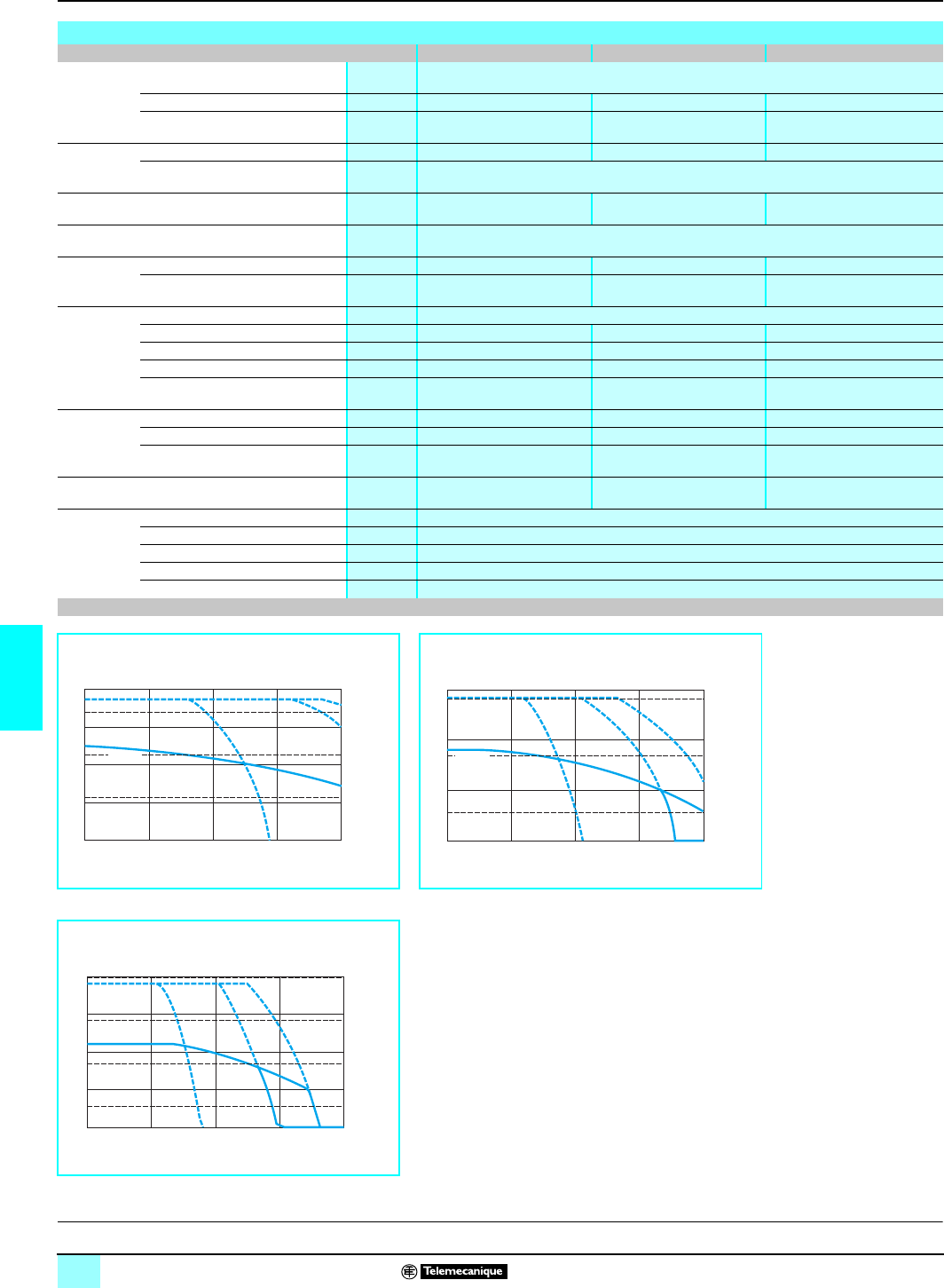
100
6
Characteristics (continued) Lexium motion control 1
Lexium BPH brushless motors
Characteristics of BPH 190 motors
Type of motor BPH 1902 N BPH 1903 K BPH 1904 K
Torque Associated with Lexium
servodrive MHDA 1056p00
Continuous stall Tn Nm 25 36 46
Peak stall Tm Nm 37.5 57 76.2
Current Permanent A rms 19.9 19.7 20.6
Maximum A rms 40
Demagnetization current A79.6 78.8 82.4
Maximum mechanical speed rpm 4000
Constants
(at 25 °C) Torque Nm/A rms 1.24 1.79 2.18
Back emf V rms s/
rad 0.72 1.03 1.26
Rotor Number of poles 6
Inertia without brake Jm gm25.14 7.1 9.04
Inertia with brake Jm gm28.25 10.2 12.1
Static friction Nm < 0.72 < 0.94 < 1.18
Mechanical time constant ms 2.6 1.9 1.7
Stator
(at 25 °C) Resistance Ω0.53 0.58 0.59
Inductance mH 8.5 11.4 11.6
Electrical time constant ms 16 19.6 19.6
Thermal time constant min 38 43 48
Holding
brake
(depending on
model)
Holding torque Nm 40
Voltage Vc 24 nominal, for threshold values see page 104
Current A1.5
Opening time ms 100
Closing time ms 30
Speed/torque curves (1)
BPH 1902 N motors BPH1903 K motors
bwith MHDA 1056p00 servodrives bwith MHDA 1056p00 servodrives
1Continuous torque at
480 V, 3-phase
2Continuous torque at
400 V, 3-phase
3Continuous torque at
230 V, 3-phase
4Peak torque at 480 V 3-
phase
5Peak torque at 400 V 3-
phase
6Peak torque at 230 V 3-
phase
(1)
BPH 1904 K motors
bwith MHDA 1056p00 servodrives
(1) The curves are given for a motor temperature increase of 100 °C.
40
01000 2000 3000 40000
30
20
10
4, 5, 6
6
1, 2, 3
3
5
4
1, 2
300
150
100
Torque in Nm
Speed in rpm
T
m
T
n
Torque in In-lbs
60
01000 2000 3000 40000
40
20
4, 5, 6
6
1, 2, 3
3
54
12
500
300
100
Torque in Nm
Speed in rpm
T
m
T
n
Torque in In-lbs
80
01000 2000 3000 40000
60
40
20
4, 5, 6
6
1, 2, 3
3
54
12
700
500
300
100
Torque in Nm
Speed in rpm
T
m
T
n
Torque in In-lbs
I
ntroduction:
p
age 92 Functions:
page 93 Description:
page 94 References:
pages 106 to 109 Dimensions:
page 105
This document provided by Barr-Thorp Electric Co., Inc. 800-473-9123 www.barr-thorp.com
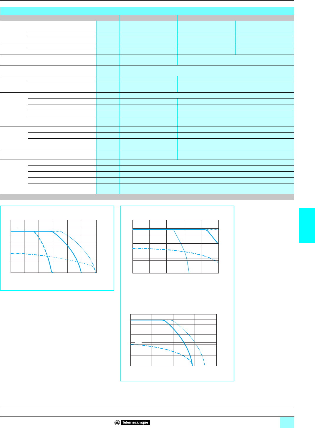
101
6
Characteristics (continued) Lexium motion control 1
Lexium BPH brushless motors
Characteristics of BPH 190 motors
Type of motor BPH 1907 K BPH 190A K
Torque Associated with Lexium
servodrive MHDA 1112A00 MHDA 1112A00 MHDA 1198A00
Continuous stall Tn Nm 75 90 100 (1)
Peak stall Tm Nm 157 163 230 (1)
Current Permanent A rms 27.9 40 44
Maximum A rms 80 80 140
Demagnetization current A111.6 176
Maximum mechanical speed rpm 4000
Constants
(at 25 °C) Torque Nm/A rms 2.61 2.24
Back emf V rms s/
rad 1.51 1.3
Rotor Number of poles 6
Inertia without brake Jm gm214.9 20.75
Inertia with brake Jm gm218 23.8
Static friction Nm <1.7 < 2.2
Mechanical time constant ms 1.2 1.05
Stator
(at 25 °C) Resistance Ω0.37 0.17
Inductance mH 9.6 5.4
Electrical time constant ms 25.9 31.7
Thermal time constant min 61 65
Holding
brake
(depending on
model)
Holding torque Nm 80
Voltage Vc 24 nominal, for threshold values see page 104
Current A1.5
Opening time ms 97
Closing time ms 53
Speed/torque graphs (2)
BPH 1907 K motors BPH190A K motors
bwith MHDA 1112A00 servodrives bwith MHDA 1112A00 servodrives
1Continuous torque at
480 V, 3-phase
2Continuous torque at
400 V, 3-phase
3Continuous torque at
230 V, 3-phase
4Peak torque at 480 V 3-
phase
5Peak torque at 400 V 3-
phase
6Peak torque at 230 V 3-
phase
bwith MHDA 1198A00 servodrives
(1) For BPH motor with higher torque, please consult our Regional Sales Office.
(2) The curves are given for a motor temperature increase of 100 °C.
150
0
100
0
50
0
05000 1000 1500 2000 2500 3000
1, 2, 3
4, 5, 6
6
3
54
21
2
00
1
50
1
00
50
Torque in Nm
Speed in rpm
T
m
T
n
Torque in In-lbs
05000 1000 1500 2000 2500
1, 2, 3
4, 5, 6
6
3
5
4
1, 2
150
0
100
0
50
0
2
00
1
50
1
00
50
Torque in Nm
Speed in rpm
T
m
T
n
Torque in In-lbs
200
0
150
0
100
0
50
0
010000 2000 3000 4000
1, 2
4, 5
54
2
50
2
00
1
50
1
00
50
Torque in Nm
Speed in rpm
Tm
T
n
Torque in In-lbs
I
ntroduction:
p
age 92 Functions:
page 93 Description:
page 94 References:
pages 106 to 109 Dimensions:
page 105
This document provided by Barr-Thorp Electric Co., Inc. 800-473-9123 www.barr-thorp.com
102
6
Characteristics (continued) Lexium motion control 1
Lexium BPH brushless motors
Radial force
The permissible permanent radial force is limited by:
bThe shaft end resistance.
bThe desired life of the bearings.
The graphs on pages 102 and 104 characterize the permissible radial force on the
axis according to:
bThe rotation speed of the motor.
bThe radial force application distance x in relation to the surface to which it is
applied.
for a bearing life of 20,000 hours.
Axial force
The axial force allowed is illustrated by the graphs on pages 102 and 104 according
to:
bThe rotation speed of the motor.
bThe motor mounting position (horizontal or vertical).
for a bearing life of 20,000 hours.
Radial and axial forces permissible on the motor shaft
x
Fr
Fa
Graphs showing the forces applied to the motor shaft (1)
BPH 0552 S motors
BPH 0751 N/0752 N motors
Average motor speeds
1500 rpm
21,000 rpm
32,000 rpm
43,000 rpm
54,000 rpm
65,000 rpm
76,000 rpm
88,000 rpm
Motor mounting
9Horizontal position
10Vertical position
(1) The graphs above are given for an increase in motor temperature of 100 °C.
4
50
050 10 15 2
0
4
00
3
50
3
00
2
50
2
00
1
50
1
00
50
1
2
3
4
6
7
8
R
adial force Fr (N)
Application distance of radial force X in mm
120
020000 4000 6000 8000
100
80
60
40
20
9
10
A
xial force Fa (N)
Rotation speed of motor in rpm
800
0510 15 20 25 300
1
2
3
5
4
67
700
600
500
400
300
200
100
Radial force Fr (N)
Application distance of radial force X in mm
240
01000 2000 3000 4000 5000 60000
200
160
120
80
40
9
10
Axial force Fa (N)
Rotation speed of motor in rpm
I
ntroduction:
p
age 92 Functions:
page 93 Description:
page 94 References:
pages 106 to 109 Dimensions:
page 105
This document provided by Barr-Thorp Electric Co., Inc. 800-473-9123 www.barr-thorp.com
103
6
Characteristics (continued) Lexium motion control 1
Lexium BPH brushless motors
Radial and axial forces permissible on the motor shaft (continued)
Graphs showing the forces applied to motor shaft (1)
BHP 0952 N/0953 N motors
BPH 1152 N/1153 N motors
BPH 1422 N/1423 N motors
Average motor speeds
1500 rpm
21,000 rpm
32,000 rpm
43,000 rpm
54,000 rpm
65,000 rpm
76,000 rpm
Motor mounting
8Horizontal position
9Vertical position
(1) The graphs above are given for an increase in motor temperature of 100 °C.
1400
0510 15 20 25 30 35 400
1200
1000
800
600
400
200
1
2
3
5
4
67
Radial force Fr (N)
Application distance of radial force X in mm
350
50 1000 2000 3000 4000 5000 60000
300
250
200
150
100
8
9
Axial force Fa (N)
Rotation speed of motor in rpm
1400
0510 15 20 25 30 35 40 45 500
1200
1000
800
600
400
200
1
2
3
5
4
67
Radial force Fr (N)
Application distance of radial force X in mm
350
01000 2000 3000 4000 5000 60000
300
250
200
150
100
50
8
9
Axial force Fa (N)
Rotation speed of motor in rpm
1800
200 10 20 30 40 50 600
1
2
3
4
5
1600
1400
1200
1000
800
600
400
Radial force Fr (N)
Application distance of radial force X in mm
450
50 500 1000 1500 2000 2500 3000 3500 40000
400
350
300
250
200
150
100
8
9
Axial force Fa (N)
Rotation speed of motor in rpm
I
ntroduction:
p
age 92 Functions:
page 93 Description:
page 94 References:
pages 106 to 109 Dimensions:
page 105
This document provided by Barr-Thorp Electric Co., Inc. 800-473-9123 www.barr-thorp.com
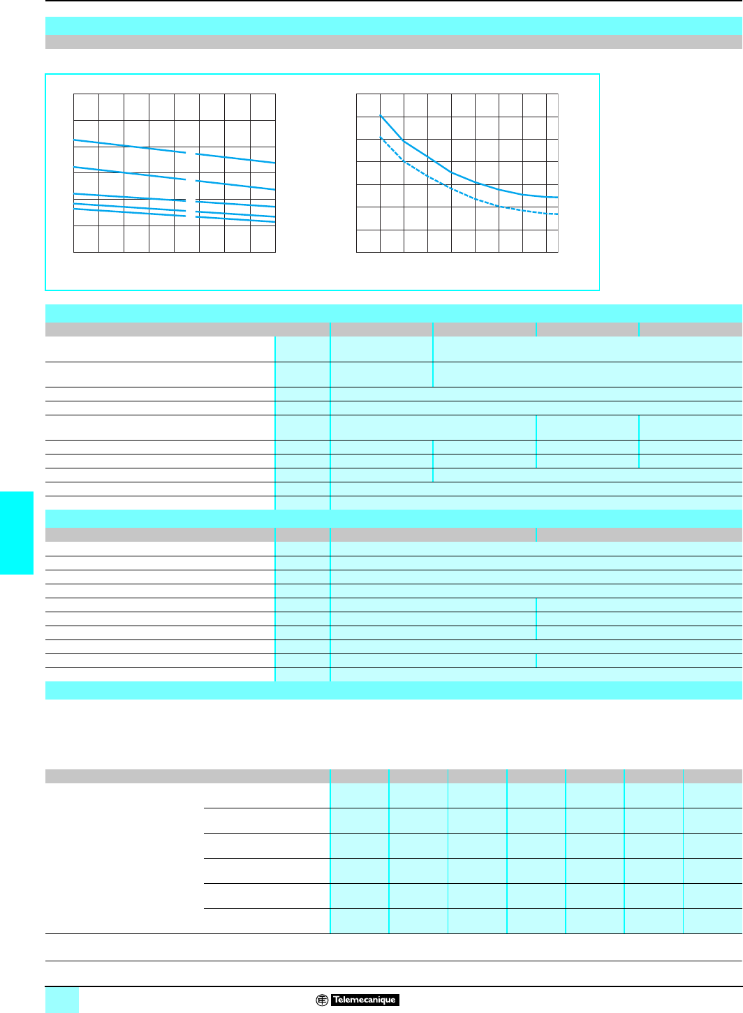
104
6
Characteristics (continued) Lexium motion control 1
Lexium BPH brushless motors
To take into account voltage drops caused by the Lexium MHDA servodrive and
AGO FRU/AGO KIT supply cable connecting the servodrive to the motor, it is
essential that the servodrive power connection supply the holding brake with a
compatible voltage.
Radial and axial forces permissible on the motor shaft (continued)
Graphs showing the forces applied to motor shaft (1)
BPH 1902 N/1903 K/1904 K/1907 K/190A K motors
(1) The graphs above are given for an increase in motor temperature of 100 °C.
Characteristics of motor-servodrive power connection cables
BPH 055 BPH 075/095/115 BPH 142/1902/3/4 BPH 1907/A
External cover Polyurethane, color
RAL5010 Polyester polyurethane PUR 11Y, VDE compliant, color RAL 5010
Insulation Polypropylene,
polyester for brake Polyolefin, TPE-E for signals
Traction resistance N/mm220 dynamic, 50 static
Capacity pF/m < 150 (conductors/shielding)
Number of conductors (shielded) (4 x 1.5 mm2 + 2 x 1 mm2)(4 x 4 mm2 +
2x1mm
2)(4 x 10 mm2+
2x1mm
2)
External diameter mm 11 12.5 15.5 22.1
Curvature radius (bend) mm 132 150 186 266
Working voltage V450 600
Maximum length of operation m75
Operating temperature °C 0…80
Characteristics of motor-servodrive encoder connection cables
Resolver SinCos Hiperface Encoder
External cover Polyester polyurethane PUR 11Y, VDE compliant
Insulation Polyolefin TPE-E for signals
Traction resistance N/mm220 dynamic, 50 static
Capacity pF/m < 120 (conductors/shielding)
Number of conductors (shielded) (4 x 2 x 0.25 mm2)(4 x 2 x 0.38 mm2 + 2 x 0.5 mm2)
External diameter mm 7.5 9.4
Curvature radius (bend) mm 90 112
Working voltage V300
Maximum length m75 75
Service temperature °C 0…80
Limit supply values of the servodrive MHDA associated with a BPH motor with brake
3500
500 10 20 30 40 50 60 70 800
1
2
3
4
5
3000
2500
2000
1500
1000
Radial force Fr (N)
Application distance of radial force X in mm
800
100 500 1000 1500 2000 2500 3000 3500 40000
700
600
500
400
300
200
8
9
Axial force Fa (N)
Rotation speed of motor in rpm
Average motor speeds
1500 rpm
21,000 rpm
32,000 rpm
43,000 rpm
54,000 rpm
65,000 rpm
76,000 rpm
Motor mounting
8Horizontal position
9Vertical position
I
ntroduction:
p
age 92 Functions:
page 93 Description:
page 94 References:
pages 106 to 109 Dimensions:
page 105
Power supply cable length 5 m 10 m 15 m 25 m 40 m 50 m 75 m
Voltage range c V
servodrive power supply (1) BPH0552 with brake 22.8…25.8 22.8…25.9 22.8…26.2 22.8…26.1 23…26.2 23.2…26.3 23.5…26.6
BPH075p with brake 22.8…26.1 22.8…26.2 22.9…26.3 23.2…26.4 23.5…26.2 23.7…26.8 24.3…27.1
BPH095p with brake 22.9…26.2 23.1…26.3 23.2…26.4 23.5…26.6 24…26.9 24.3…27.1 25…27.6
BPH115p with brake 23…26.4 23.2…26.4 23.4…26.6 23.7…26.8 24.2…27.1 24.6…27.3 25.4…27.6
BPH142p with brake 23.1…26.4 23.3…26.5 23.6…26.7 24…27 24.7…27.4 25.2…27.6 26.3…27.6
BPH190p with brake 23.6…26.8 24…27 24.3…27.2 25…27.6 26…27.6 26.6…27.6 impossible
(1)Voltage measured on the
c
24 V connector of the MHDA servodrive.
This document provided by Barr-Thorp Electric Co., Inc. 800-473-9123 www.barr-thorp.com
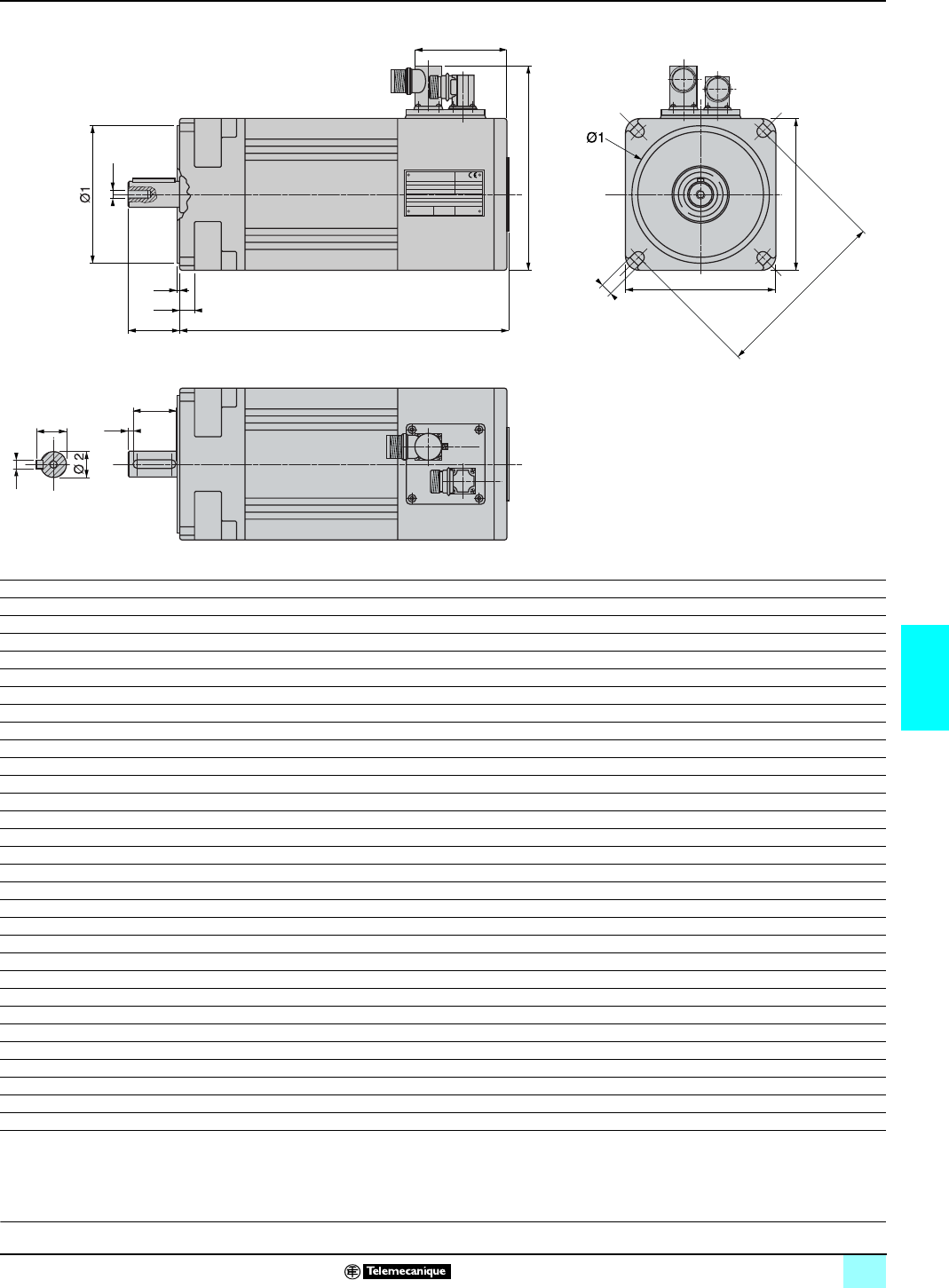
105
6
Dimensions Lexium motion control 1
Lexium BPH brushless motors
Lexium BPH motors (all models)
BPH abb1cc1deØ1 (2) GH
0552 S5 140/176 (1) 55 86 20 2.5 9 63 40 63 5.5
0751 N5 221 75 127 23 2.5 8 83 60 75 6
0752 N5 250 75 127 30 2.5 8 83 60 75 6
0952 N5 275 95 147 40 3 9 80 80 100 7
0953 N5 304 95 147 40 3 9 80 80 100 7
1152 N5 290 115 166 40 3 10 82 95 115 9
1153 N5 319 115 166 40 3 10 82 95 115 9
1422 N5 316 142 193 50 3 14 89 130 165 11
1423 N5 345 142 193 50 3 14 89 130 165 11
1902 N5 354 190 242 58 3 17 93 180 215 14
1903 K5 383 190 242 58 3 17 93 180 215 14
1904 K5 412 190 242 58 3 17 93 180 215 14
1907 K5 500 190 242 80 3 17 93 180 215 14
190A K5 605 190 242 80 3 17 93 180 215 14
Shaft end with key
BPH c f f1 g1 g2 h (3) Ø2 (4)
0552 S5 20 15 0 10.2 M3 x 10 3 9
0751 N5 23 15 5 12.5 M4 x 10 4 11
0752 N5 30 20 5 16 M5 x 12.5 5 14
0952 N5 40 30 5 21.5 M6 x 16 6 19
0953 N5 40 30 5 21.5 M6 x 16 6 19
1152 N5 40 30 5 21.5 M6 x 16 6 19
1153 N5 40 30 5 21.5 M6 x 16 6 19
1422 N5 50 40 5 27 M8 x 19 8 24
1423 N5 50 40 5 27 M8 x 19 8 24
1902 N5 58 45 6.5 35 M12 x 28 10 32
1903 K5 58 45 6.5 35 M12 x 28 10 32
1904 K5 58 45 6.5 35 M12 x 28 10 32
1907 K5 80 70 6.5 41 M12 x 28 10 38
190A K5 80 70 6.5 41 M12 x 28 10 38
(1) 140 for motor without holding brake / 176 for motor with holding brake
(2) Tolerance j6
(3) Tolerance h9
(4) Tolerance j6
c1
b1
g2
d
ca
e
G
b
b
H
f
f1
g1
h
I
ntroduction:
p
age 92 Functions:
page 93 Description:
page 94 Characteristics:
pages 95 to 104 References:
pages 106 to 109
This document provided by Barr-Thorp Electric Co., Inc. 800-473-9123 www.barr-thorp.com
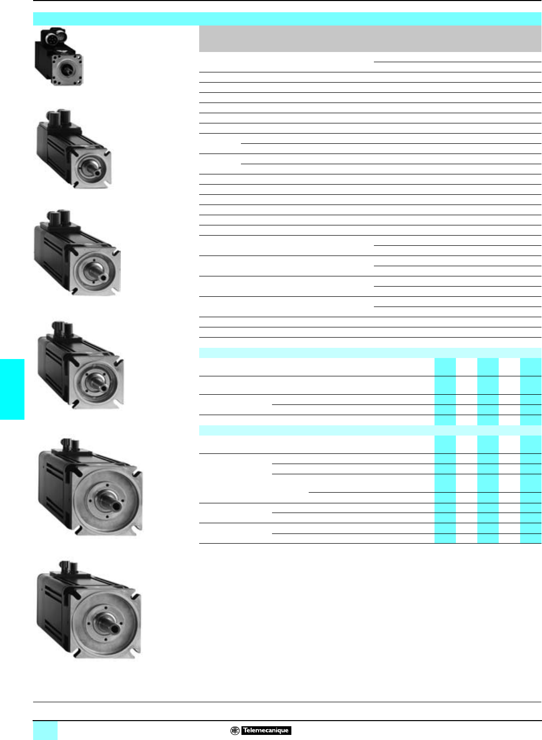
106
6
References Lexium motion control 1
Lexium BPH brushless motors
Lexium BPH brushless motors
Continuous
stall
torque (1)
Associated
servodrive
MHDA
Peak stall
torque Maximum
mechanical
speed
Holding brake Reference
dWeight
kg
0.4 Nm 1004N/A 1.1 Nm 8,000 rpm Without brake (2)
BPH 0552 S5
p
A2
p
0
p1.400
With brake (2)
BPH 0552 S5
p
F2
p
0
p1.650
0.9 Nm or 1004N/A 1.7 Nm 6,000 rpm Without brake (3)
BPH 0751 N5
p
A2
p
A
p3.500
1.3 Nm 1008N/A 3.4 Nm 6,000 rpm With brake (3)
BPH 0751 N5
p
F2
p
A
p3.850
1.3 Nm or 1004N/A 2.5 Nm 6,000 rpm Without brake (3)
BPH 0752 N5
p
A2
p
A
p4.300
2.3 Nm 1008N/A 4.8 Nm 6,000 rpm With brake (3)
BPH 0752 N5
p
F2
p
A
p4.650
3.7 Nm or 1008N/A 7.2 Nm 6,000 rpm Without brake (3)
BPH 0952 N5
p
A2
p
A
p6.700
4.3 Nm 1017N/A 13.4 Nm 6,000 rpm With brake (3)
BPH 0952 N5
p
F2
p
A
p7.500
6.0 Nm 1017N/A 13.4 Nm 6,000 rpm Without brake (3)
BPH 0953 N5
p
A2
p
A
p8.000
1028N/A 20.3 Nm 6,000 rpm With brake (3)
BPH 0953 N5
p
F2
p
A
p8.800
7.4 Nm 1017N/A 13.6 Nm 6,000 rpm Without brake (3)
BPH 1152 N5
p
A2
p
A
p9.600
1028N/A 19.3 Nm 6,000 rpm With brake (3)
BPH 1152 N5
p
F2
p
A
p10.900
6.8 Nm or 1017N/A 13.5 Nm 6,000 rpm Without brake (3)
BPH 1153 N5
p
A2
p
A
p11.700
10.5 Nm 1028N/A 19.4 Nm 6,000 rpm With brake (3)
BPH 1153 N5
p
F2
p
A
p13.000
11.4 Nm or 1028N/A 18.0 Nm 4000 rpm Without brake (3)
BPH 1422 N5
p
A2
p
A
p17.200
12.0 Nm 1056N/A 30.0 Nm 4,000 rpm With brake (3)
BPH 1422 N5
p
F2
p
A
p19.400
14.5 Nm or 1028N/A 24.2 Nm 4,000 rpm Without brake (3)
BPH 1423 N5
p
A2
p
A
p20.100
17.0 Nm 1056N/A 42.0 Nm 4,000 rpm With brake (3)
BPH 1423 N5
p
F2
p
A
p22.300
25.0 Nm 1056N/A 37.5 Nm 4,000 rpm Without brake (3)
BPH 1902 N5
p
A2
p
A
p32.100
With brake (3)
BPH 1902 N5
p
F2
p
A
p36.200
36.0 Nm 1056N/A 57.0 Nm 4,000 rpm Without brake (3)
BPH 1903 K5
p
A2
p
A
p37.300
With brake (3)
BPH 1903 K5
p
F2
p
A
p41.400
46.0 Nm 1056N/A 76.2 Nm 4,000 rpm Without brake (3)
BPH 1904 K5
p
A2
p
A
p42.400
With brake (3)
BPH 1904 K5
p
F2
p
A
p46.500
75.0 Nm 1112A 157.0 Nm 4,000 rpm Without brake (3)
BPH 1907 K5
p
A2
p
A
p58.000
With brake (3)
BPH 1907 K5
p
F2
p
A
p62.100
90.0 Nm or 1112A 163.0 Nm 4,000 rpm Without brake (3)
BPH 190A K5
p
A2
p
A
p73.900
100 Nm 1198A 230.0 Nm 4,000 rpm With brake (3)
BPH 190A K5
p
F2
p
A
p78.000
(1) Depending on the associated Lexium servodrive
(2) To order a BPH 0552 motor, fill out the reference
BPH 0552 S5 A2/
F2 0 (4)
Sensor integrated in
motor Resolver with 1 pair of poles U
Shaft end Key C
Smooth L
Degree of protection IP 65 (housing), IP 54 (shaft end) 0 (5)
(3) To order a BPH 075...190 motor, fill out each reference
BPH 1422 N5 A2/
F2 A (6)
Sensor integrated in
motor Resolver with 1 pair of poles M
High resolution absolute encoder,
multiturn, SinCos Hiperface (no. of
turns: 4096) A
single turn, SinCos Hiperface B
Shaft end Key C
Smooth L
Degree of protection IP 65 (housing and shaft end) 1
IP 67 (housing and shaft end) 2
(4) This motor is compatible with the MHDA 1004 servo drive even though its reference ends in 0
p
. However,
the servodrive's supply voltage must be limited to 3 x 230 V rms + 10 %.
(5) IP 64 with BMH Q101 end of shaft joint.
(6) The reference ending in A
p
refers to Lexium motors that are compatible with Lexium MHDA servodrives.
Other BPH motors with 0
p
at the end of their reference are not compatible with MHDA servodrives.
d To obtain the list of short delay BPH motors, contact our Regional Sales Offices.
B
PH 075
p
BPH 095
p
BPH 0552
p
BPH 115
p
B
PH 142
p
B
PH 190
p
I
ntroduction:
p
age 92 Functions:
page 93 Description:
page 94 Characteristics:
pages 95 to 104 Dimensions:
page 105
This document provided by Barr-Thorp Electric Co., Inc. 800-473-9123 www.barr-thorp.com
107
6
References (continued) Lexium motion control 1
Lexium BPH brushless motors
References (continued)
Choice of power cables, resolver and SinCos Hiperface encoder
Length BPH 0552 BPH 0751N
BPH 0752N BPH 0952N
BPH 0953N BPH 1152N
BPH 1153N BPH 1422N
BPH 1423N BPH 1902N
BPH 1903K
BPH 1904K
BPH 1907K
BPH 190AK
Cables with
connectors fitted
at both ends
Power 10 m –AGO FRU 015M 010 AGO FRU 016M 010 –
Resolver 10 m –AGO FRU 014M 010
SinCos
Hiperface
Encoder
10 m –AGO FRU 013M 010
Cables fitted with
one connector
(motor side) and
one connector to
be mounted
(servodrive side)
Power 5 m AGO KIT
001M 005 AGO KIT 018M 005 AGO KIT 019M 005 AGO FRU
020M 005
10 m – – – AGO FRU
020M 010
15 m AGO KIT
001M 015 AGO KIT 018M 015 AGO KIT 019M 015 AGO FRU
020M 015
25 m AGO KIT
001M 025 AGO KIT 018M 025 AGO KIT 019M 025 AGO FRU
020M 025
50 m –AGO KIT 018M 050 AGO KIT 019M 050 AGO FRU
020M 050
75 m –AGO KIT 018M 075 AGO KIT 019M 075 AGO FRU
020M 075
Resolver 5 m AGO KIT
025M 005 AGO KIT 024M 005
15 m AGO KIT
025M 015 AGO KIT 024M 015
25 m AGO KIT
025M 025 AGO KIT 024M 025
50 m –AGO KIT 024M 050
75 m –AGO KIT 024M 075
SinCos
Hiperface
Encoder
5 m –AGO KIT 023M 005
15 m –AGO KIT 023M 015
25 m –AGO KIT 023M 025
50 m –AGO KIT 023M 050
75 m –AGO KIT 023M 075
Cables sold
by the meter Power Sold by
the meter RPC 305S
(2) –
Resolver Sold by
the meter AGO CAV
003
(2)
–
(1) AGO FRU 020M
ppp
cables are fitted with a connector (at the motor end) and a free wire termination (for connection to the screw terminal block at the servodrive
end).
(2) The two lengths of cable, RPC 305S and AGO CAV 003, are fitted with all 4 AGO KIT 002CON shear connectors.
I
ntroduction:
p
age 92 Functions:
page 93 Description:
page 94 Characteristics:
pages 95 to 104 Dimensions:
page 105
This document provided by Barr-Thorp Electric Co., Inc. 800-473-9123 www.barr-thorp.com

108
6
References (continued) Lexium motion control 1
Lexium BPH brushless motors
Connecting cables (1)
Cables fitted with connectors at both ends
Description From To Length Reference Weight
kg
Cables power
(2) Lexium motors
BPH 0751…1153 Lexium MHDA 1004/1008/
1017/1028 servodrives 10 m AGO FRU 015M 010 –
Lexium motors
BPH 1422…1904K Lexium
MHDA 1028/1056
servodrives
10 m AGO FRU 016M 010 –
Cable resolver Lexium motors
BPH 0751…190AK Lexium
MHDA 1ppp servodrives 10 m AGO FRU 014M 010 –
Encoder cable SinCos
Hiperface Lexium motors
BPH 0751…190AK Lexium
MHDA 1ppp servodrives 10 m AGO FRU 013M 010 –
Cables fitted with a connector at the motor end (the servodrive end connector supplied with the cable has
to be fitted)
Description From To Length
(3) Reference Weight
kg
Power cables
(2) Lexium motors
BPH 0552 Lexium
MHDA 1004 servodrives 5 m AGO KIT 001M 005 –
15 m AGO KIT 001M 015 –
25 m (4) AGO KIT 001M 025 –
Lexium motors
BPH 0751…1153 Lexium
MHDA 1004/1008/1017/
1028 servodrives
5 m AGO KIT 018M 005 –
15 m AGO KIT 018M 015 –
25 m (4) AGO KIT 018M 025 –
50 m (4) AGO KIT 018M 050 –
75 m (4) AGO KIT 018M 075 –
Lexium motors
BPH 1422…1904 Lexium
MHDA 1028/1056
servodrives
5 m AGO KIT 019M 005 –
15 m AGO KIT 019M 015 –
25 m (4) AGO KIT 019M 025 –
50 m (4) AGO KIT 019M 050 –
75 m (4) AGO KIT 019M 075 –
Lexium motors
BPH 1907…190A Lexium
MHDA 1112/1198
servodrives
5 m (5) AGO FRU 020M 005 –
10 m (5) AGO FRU 020M 010
15 m (5) AGO FRU 020M 015 –
25 m (5) AGO FRU 020M 025 –
50 m (5) AGO FRU 020M 050 –
75m (5) AGO FRU 020M 075 –
Resolver cables Lexium motors
BPH 0552 Lexium
MHDA 1004 servodrives 5 m AGO KIT 025M 005 –
15 m AGO KIT 025M 015 –
25 m AGO KIT 025M 025 –
Lexium motors
BPH 0751…190A Lexium
MHDA 1ppp servodrives 5 m AGO KIT 024M 005 –
15 m AGO KIT 024M 015 –
25 m AGO KIT 024M 025 –
50 m AGO KIT 024M 050 –
75 m AGO KIT 024M 075 –
SinCos encoder cables Lexium motors
BPH 0751…190A Lexium
MHDA 1ppp servodrives 5 m AGO KIT 023M 005 –
15 m AGO KIT 023M 015 –
25 m AGO KIT 023M 025 –
50 m AGO KIT 023M 050 –
75 m AGO KIT 023M 075 –
(1) The properties of Lexium MHDA servodrives associated with Lexium BPH motors require the use of the AGO FRU/AGO
KIT connection cables described above. (See paragraph on the characteristics of motor-servodrive power connection
cables).
(2) The reference AGO KIT 00
p
M 0
pp
includes a cable silk-screened AGO FRU 0
pp
M 0
pp
. In the case you order a
AGO KIT 024M 015, the cable will be silk-screened AGO FRU 024M 015.
(3) Conductors for supplying the holding brake integrated in the motor are included.
(4) If the connection distance between the BPH motor and the MHDA servodrive (1004....1056) is greater than or equal to 25
m, an AM0 FIL 001V056 choke must be inserted at the connection. This element must be placed as close as possible to
the servodrive (a distance of less than one meter). See page 66.
(5) There is no connector at the servodrive end: connection to the servodrive is via a screw terminal.
AGO FRU
013/014/015/016 M010
A
GO FRU 020M 0
pp
AGO KIT
001/018/019/023/024/025M 0
pp
I
ntroduction:
p
age 92 Functions:
page 93 Description:
page 94 Characteristics:
pages 95 to 104 Dimensions:
page 105
This document provided by Barr-Thorp Electric Co., Inc. 800-473-9123 www.barr-thorp.com

109
6
References (continued) Lexium motion control 1
Lexium BPH brushless motors
Connecting cables (continued)
Cables (sold by the meter) to be assembled from separate elements
Description From To Length Reference Weight
kg
Power cables Lexium motors
BPH 0552 Lexium MHDA 1004
servodrives Sold by the meter (1) RPC 305S –
Resolver cables Lexium motors
BPH 0552 Lexium MHDA 1004
servodrives Sold by the meter (1) AGO CAV 003 –
Description Type Used for Reference Weight
kg
Package with
4 connectors Power and resolver
(shear connectors) Lexium BPH 0552 motors and Lexium
MHDA 1004 servodrives with RPC 305S/
AGO CAV 003 cables
AGO KIT 002 CON –
(1) The quantity ordered specifies the cable length in meters (maximum length 75m).
For example, ordering 6 RPC 305S corresponds to ordering one 6-meter long RPC 305S cable.
Documentation
Documentation A5 (English, French, German, Spanish and Italian)
Description Reference Weight
kg
Lexium BPH technical guide AMO MAN 001U 0.250
Separate parts
Description Use Reference Weight
kg
End joint for IP 64
shaft end BPH 055 motors BMH Q101 –
Hoisting eye BPH 1902...190A motors AMO GOL 001 M8 –
Replacement parts
Description Use Reference Weight
kg
Keys for motor
shaft Lexium BPH 0552 motors AMO CHI 00615X3 –
Lexium BPH 0751 motors AMO CHI 0014X4 –
Lexium BPH 0752 motors AMO CHI 0025X5 –
Lexium BPH 0952...1153 motors AMO CHI 0036X6 –
Lexium BPH 1422/1423 motors AMO CHI 0048X7 –
Lexium BPH 1902...1904 motors AMO CHI 0050X8 –
Lexium BPH 1907/190A motors AMO CHI 00770X10 –
RPC 3055
AGO
CAV 003
AGO KIT 002 CON
I
ntroduction:
p
age 92 Functions:
page 93 Description:
page 94 Characteristics:
pages 95 to 104 Dimensions:
page 105
This document provided by Barr-Thorp Electric Co., Inc. 800-473-9123 www.barr-thorp.com
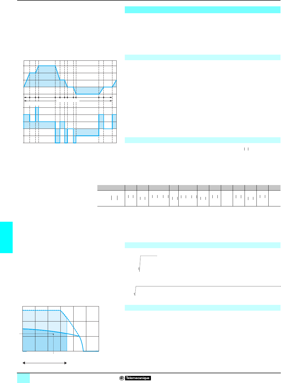
110
7
Sizing the brushless motor Lexium motion control 1
To assist you in sizing the motor the Lexium Sizer utility is available on the
site:www.schneiderautomation.com.
This page is to help you understand the method of calculation used.
In order to size a motor, you need to know the equivalent thermal torque and average
speed required by the mechanics to be associated with the motor. Both these values
are calculated using a motor cycle trend diagram and should be compared with the
speed/torque curves given for each motor (see pages 95 to 101).
The motor cycle is made up of several sub-cycles, the duration of which is known.
Each sub-cycle is split into phases which correspond to the periods of time during
which the motor torque is constant (maximum 1 to 3 phases per sub-cycle).
This division can be used to calculate, for each phase :
bthe duration (ti)
bthe speed (Si)
bthe required torque (Ti)
The trend diagrams opposite show the 4 phase types :
bconstant acceleration during t1, t3 and t9
bat work during times t2, t4, t6, and t10
bconstant deceleration during t5, t7 and t11
bmotor stopped during t8 and t12
The total duration of the cycle is calculated as follows :
Cycle time = t1 + t2 + t3 + t4 + t5 + t6 + t7 + t8 + t9 + t10 + t11 + t12
The average speed is calculated using the formula :
bSi corresponds to the various working speeds
b corresponds to the average speeds during the constant acceleration and
deceleration phases. In the example above :
The average speed is calculated as follows :
The equivalent thermal torque is calculated using the formula :
In the example above, this formula gives the following calculation :
The point defined by the 2 calculations above, where the :
bvertical axis represents the average speedSavg
bhorizontal axis represents the thermal torque Teq
must be within the area bounded by curve 2 and the work zone. The example time
diagram opposite illustrates a BPH 1152N motor used with an MHDA 1017N/1017A
servodrive, with a 3-phase 400 V supply.
The motor cycle time diagram should also be used to ensure that all torques Ti
required for the different speeds Si during the various cycle phases are within the
area bounded by curve 4 and the work zone.
2Nominal stopping torque at 400 V, 3-phase.
4Maximum torque at 400 V, 3-phase.
Sizing the brushless motor
Motor cycle trend diagram
V
3
V
2
V
1
0
V
4
t1 t2 t3 t4 t5 t6 t7 t8 t9 t10 t11 t12
C
3
C
2
C
1
0
t
t
C
4
C
5
Motor speed
Cycle time
Torque required
Calculating the average speed
Savg
Si ti⋅
∑
ti
∑
---------------------------=
Duration ti t1 t2 t3 t4 t5 t6 t7 t8 t9 t10 t11 t12
Speed 00
Si
S2
2
---------- S2 S3 S2+
2
-------------------------------S3 S3 S1+
2
-------------------------------S1 S1
2
---------- S4
2
---------- S4 S4
2
----------
Savg
S2
2
------- t1 S2+t2⋅⋅
S3 S2+
2
----------------------+t3S3t4
S3 S1+
2
----------------------t5 S1 t6 S1
2
------- t7 S4
2
------- t9 S4 t10 S4
2
-------+t11⋅⋅+⋅+⋅+⋅+⋅+⋅+⋅
Cycletime
---------------------------------------------------------------------------------------------------------------------------------------------------------------------------------------------------------------------------------------------------------------------------------=
Calculating the equivalent thermal torque
Teq
Ti2ti⋅
∑
Cycletime
-------------------------------=
Teq T22t1 T12t2 T32t3 T12t4 T52t5 T12t6 T52t7 T52t9 T42t10 T22t1
1
⋅+⋅+⋅+⋅+⋅+⋅+⋅+⋅+⋅+⋅Cycletime
------------------------------------------------------------------------------------------------------------------------------------------------------------------------------------------------------------------------------------------------------------------------------
-----
=
Determining the motor size
1
0
1
5
5
01000 2000 3000 4000 5000 600
0
0
2
4
4
2
Torque in Nm
Speed in rpm
Work zone
Si
2
-----
This document provided by Barr-Thorp Electric Co., Inc. 800-473-9123 www.barr-thorp.com
111
7
Lexium motion control 1
When braking or deceleration is required, the kinetic energy of the load must be
absorbed by the servodrive. The energy generated by deceleration loads the
capacitors integrated in the servodrive. When the voltage at the capacitor terminals
exceeds the permitted threshold, the braking resistor (internal or external) is
automatically activated in order to dissipate this energy. Calculation of the power to
be dissipated by the braking resistor requires an understanding of the trend diagram
giving the motor torques and speeds according to time in order to identify the curve
segments in which the servodrive decelerates the load.
These two curves are used on page 110 to size the motor. The segments of the curve
to be taken into account, when the servodrive is decelerating, are marked in blue by
Di.
In order to do this you need to know the total inertia, defined as follows :
Jt
: total inertia
where :
Jt
=
Jm
(motor inertia, with or without brake) +
Jc
(load inertia). For
Jm
, see pages
79 to 83 (for SER motors) or 95 to 101 (for BPH motors).
The energy
Ei
of each deceleration segment is defined as follows :
Ei
= 1/2
Jt.
ωi2 = 1/2
Jt
.(2πSi/60)2
giving, for the different segments :
E1
= 1/2
Jt.
(2π/60)2. (S32-S12) for segment
D1
E2
= 1/2
Jt.
(2π S1/60)2 for segment
D2
E3
= 1/2
Jt.
(2π S4/60)2 for segment
D3
where Ei is in joules, Jt in kgm2, ω in radians and Si in rpm
The energy absorption capacity of the servodrive
Edrive
(without using an internal or
external braking -resistor) is shown opposite.
In the calculation, only take into account segments
Di
whose energy
Ei
is greater
than the absorption capacity given in the table opposite. The additional -energy
values
EDi
are dissipated in the resistor (internal or external) :
EDi
=
Ei
-
Edrive
(in joules)
Pulsed power : for each segment, the power
PIi
is defined as follows :
PIi
=
EDi
/
ti
where Pli is in W, EDi in joules and t in s and
ti
corresponds to the deceleration time
of the segment concerned.
The continuous power
Pc
is calculated for each machine cycle as follows :
Pc
= ∑
EDi
/ Cycle time
where Pc is in W, EDi in joules and Cycle time in s.
There are two options :
The pulsed powers
PIi
of the various segments are to be compared with the
maximum peak braking power
PCr
given in the table below. Select
PCr
>
PIi
.
This selection is confirmed by comparing the continuous power calculated
Pc
with the
continuous braking power
PPr
given in the table below. Select
PPr
>
Pc
.
Sizing the braking resistor
Motor cycle trend diagram
Calculating the constant deceleration power
Energy absorbed by the internal capacitors
Calculating pulsed and continuous power
Selecting the braking resistor (internal or external)
Braking power of servodrive
Lexium 17D HP et 17S HP Lexium 17D MHDA Lexium 17D HP
1004/1008N/A 1017/1028/1056N/A MHDA 1112/A00 MHDA 1198/A00
3-phase servodrive supply V230 400 480 230 400 480 230 400 480 30 400 480
Internal resistor Ω66 33 – –
Continuous PPr W80 200 ––
Peak (1s) PCr W2500 8000 10500 5000 16000 21000 – –
External resistor Ω33 33 15 10
Continuous PPr W250 400 500 750 1200 1500 6000 6000
Peak (1s) PCr W5000 16000 21000 5000 16000 21000 10000 35000 45000 16000 50000 70000
Resistor to
associate AM0 RFE 001 AM0 RFE 001 V150 AM0 RFE 002 V086 AM0 RFE 002 V150
V025 V050
Sizing the braking resistor
Edrive
Power supply V230
single
ph.
230
3-ph. 400
3-ph. 480
3-ph.
MHDA 1004pJoules 5 5 19 23
MHDA 1008pJoules 5 5 19 23
MHDA 1017pJoules – 5 19 23
MHDA 1028pJoules – 5 19 23
MHDA 1056pJoules –10 38 47
MHDA 1112pJoules –60 150 180
MHDA 1198pJoules –120 300 360
This document provided by Barr-Thorp Electric Co., Inc. 800-473-9123 www.barr-thorp.com
112
7
Presentation Lexium motion control 1
Phaseo regulated power supplies
The ABL 7 range of power supplies is designed to provide the d.c. voltage necessary
for the control circuits of automation system equipment. Split into three families, this
range meets all the needs encountered in industrial, commercial and residential
applications. Single-phase or 3-phase (1), of the electronic switch mode type, they
provide a quality of output which is suitable for the loads supplied and compatible
with the mains supply available in the equipment. Clear guidelines are given on
selecting protection devices which are often used with them, and thus a
comprehensive solution is provided which can be used in total safety.
These switch mode power supplies are totally electronic and regulated. The use of
electronics makes it possible to significantly improve the performance of these power
supplies which offer:
bcompact size,
bintegrated overload, short-circuit, overvoltage and undervoltage protection,
ba very wide range of permissible input voltages, without any adjustment,
ba high degree of output voltage stability,
bhight performance,
bLED indicators on the front panel.
Phaseo power supplies are available in single-phase and 3-phase versions (1). They
deliver a voltage which is precise to 3%, whatever the load and whatever the type of
mains supply, within a range of 85 to 264 V for single-phase, or 360 to 550 V for 3-
phase. Conforming to IEC standards, UL and CSA certified, they are suitable for
universal use. The inclusion of overload and short-circuit protection makes
downstream protection unnecessary if discrimination is not required.
ABL 7 RE supplies are also equipped with an output undervoltage control which
causes the product to trip if the output voltage drops below 19 V, in order to ensure
that the voltage delivered is always usable by the actuators being supplied. All the
products are fitted with an output voltage adjustment potentiometer in order to be
able to compensate for any line voltage drops in installations with long cable runs.
Most of our power supplies are designed for direct mounting on 35 and 75 mm 7
rails.
The 24 AC single-phase power supplies ABL 7RE selected (2) in this catalogue are
quite adapted to tie-up with the Lexium MHDA servodrives):
bpower between 48 W (2 A) and 240 W (10 A),
bcompact size,
bfor all machine equipment,
bsuitable for use in automation system environments based on the Modicon
platforms of Telemecanique brand requiring c 24 V power supply.
(1) 3-phase power supplies, consult our catalogue “Phaseo Power Supplies and Transformers”.
(2) ABL 7RP single-phase power supplies, consult our catalogue “Phaseo Power Supplies and
Transformers”.
ABL 7 power supplies
2/3 A power supply
Phaseo switch mode power supplies
5 A power supply
10 A power supply
S
election
p
age 114 Characteristics:
pages 115 and 116 References:
page 117 Dimensions:
page 117
This document provided by Barr-Thorp Electric Co., Inc. 800-473-9123 www.barr-thorp.com

113
7
Presentation (continued) Lexium motion control 1
Phaseo regulated power supplies
bUsing c 24 V enables so-called protection installations (PELV) to be built. Using
PELV is a measure designed to protect people from direct and indirect contact.
Measures relating to these installations are defined in publication NF C 12-201 and
in standard IEC 364-4-41.
bThe application of these measures to the electrical equipment in machines is
defined in standard NF EN 60204-1 and requires:
v that the voltage used is below 60 V d.c. in dry environments and below 30 V in
damp environments,
v the connection of one side of the PELV circuit, or one point of the source, to the
equipotential protection circuit associated with higher voltages.
v the use of switchgear and control gear on which measures have been taken to
ensure "safety separation" between power circuits and control circuits.
bA safety separation is necessary between power circuits and control circuits in
PELV circuits. Its aim is to warn of the appearance of dangerous voltages in c 24 V
safety circuits.
bThe reference standards involved are:
v IEC 61558-2-6 and EN 61558-2-6 (safety transformers),
v IEC 664 (coordination of isolation).
Telemecanique power supplies meet these requirements.
bMoreover, to ensure that these products will operate correctly in relation to the
demands of their reinforced isolation, it is recommended that they be mounted and
wired as indicated below:
v they should be placed on an earthed mounting plate or rail,
v they should be connected using flexible cables, with a maximum of two wires per
connection, and tightened to the nominal torque,
v conductors of the correct insulation class must be used.
bIf the d.c. circuit is not connected to an equipotential protection conductor, an earth
leakage detector will indicate any accidental insulation faults (please consult your
Regional Sales Office).
bThe permissible tolerances for the operating voltage are listed in publications
IEC 1131-2 and DIN 19240.
bFor nominal voltage Un = c 24 V, the extreme operating values are from - 15 %
to + 20 % of Un, whatever the supply variations in the range - 10 % to + 6 % (defined
by standard IEC 38) and load variations in the range 0-100 % of In.
All Telemecanique c 24 V power supplies are designed to provide a voltage within
this range.
bIt may be necessary to use a voltage measurement relay to detect when the
normal voltage limits are being surpassed and to deal with the consequences of this
(please consult your Regional Sales Office).
Using c 24 V
Operating voltage
S
election
p
age 114 Characteristics:
pages 115 and 116 References:
page 117 Dimensions:
page 117
This document provided by Barr-Thorp Electric Co., Inc. 800-473-9123 www.barr-thorp.com

114
7
Selection Lexium motion control 1
Phaseo regulated power supplies
The Phaseo range is the solution because it guarantees precision to 3% of the output
voltage, whatever the load current and the input voltage. In addition, the wide input
voltage range of Phaseo power supplies allows them to be connected to all mains
supplies within the nominal range, without any adjustment.
The current drawn by a power supply is not sinusoidal. This leads to the existence of
harmonic currents which pollute the mains supply. European standard EN 61000-3-
2 limits the harmonic currents produced by power supplies. This standard covers all
devices between 75 W and 1000 W, drawing up to 16 A per phase, and connected
directly to the public mains power supply. Devices connected downstream of a
private, low voltage, general transformer are therefore excluded.
Regulated switch mode supplies always produce harmonic currents; a filter circuit
(Power Factor Correction or PFC) must therefore be added to comply with standard
EN 61000-3-2.
Levels of conducted and radiated emissions are defined in standards EN 55011 and
EN 55022.
All products in the Phaseo range have class B certification and can be used without
any restrictions due to their low emissions.
Phaseo power supplies are equipped with an electronic protection device. This
protection device resets itself automatically on elimination of the fault (around
1 second for ABL 7RE, which avoids having to take any action or change a fuse).
The quality of the mains power supply
Harmonic pollution (power factor)
Electromagnetic compatibility
Behaviour in the event of short-circuits
P
resentation:
p
ages 112 and 113 Characteristics:
pages 115 and 116 References:
page 117 Dimensions:
page 117
This document provided by Barr-Thorp Electric Co., Inc. 800-473-9123 www.barr-thorp.com

115
7
Characteristics Lexium motion control 1
Phaseo regulated power supplies
Technical characteristics
Type of power supply ABL 7RE
Approvals UL, CSA, TÜV, CTick
Conforming to
standards Safty UL 508, CSA 22.2 n° 950
EMC EN 50081-1, IEC 61000-6-2 (EN 50082-2)
Low frequency harmonic currents –
Input circuit
LED indication Orange LED
Input voltages Rated values Va 100…240 single-phase
Permissible values Va 85…264 single-phase
Permissible frequencies Hz 47…63
Efficiency at nominal load > 85 %
Current consumption Ue = 240 V A0.6 (48 W)/0.83 (72 W)
1.2 (120 W)/2.5 (240 W)
Ue = 100 V A1.2 (48 W)/1.46 (72 W)
1.9 (120 W)/3.6 (240 W)
Current at switch-on A< 30
Power factory 0.65 approx.
Output circuit
LED indication Green LED
Nominal output voltage (U out) Vc 24
Nominal output current A2/3/5/10
Precision Output voltage Ajustable from 100 to 120 %
Line and load regulation ± 3 %
Residual ripple - interference mV < 200 (peak-peak)
Micro-breaks Holding time at I max and Ve min ms > 10
Temporary
overloads Permissible inrush current
(U out >19V) See page 116
Protections Short-circuits Permanent/automatic restart
Overload 1.1 In
Overvoltage Tripping if U > 1.5 Un
Undervoltage Tripping if U < 0.8 Un
Operational and environmental characteristics
Connections Input mm22 x 2.5 + earth
Output mm22 x 2.5 + earth, multiple output, depending on model
Ambient
conditions Storage temperature °C - 25… + 70
Operating temperature °C 0… + 60 (derating as from 50 °C, mounted vertically)
Max. relative humidity 95 % without condensation
Degree of protection IP 20 conforming IEC 529
Vibrations Conforming EN 61131-2
Operating position Vertical
MTBF at 40 °C > 100 000 h
Connections Series Possible
Parallel Possible (max. temperature 50 °C)
Dielectric
strength Input/output 3000 V/50 and 60 Hz 1 minute
Input/earth 3000 V/50 and 60 Hz 1 minute
Ouput/earth (and output/output) 500 V/50 and 60 Hz 1 minute
Input fuse incoporated Yes, not interchangeable
Disturbance EN 50081-1
Conducted EN 55011/EN 55022 cl.B
Radiated EN 55011/EN 55022 cl.B
Immunity IEC 61000-6-2 (generic)
Electrostatic discharge EN 61000-4-2 (4 kV contact/8 kV air)
Electromagnetic EN 61000-4-3 niv.3 (10 V/m)
Conduced interference EN 61000-4-4 niv.3 (2 kV) , EN 61000-4-5, EN 61000-4-6 niv.3, EN 61000-4-8 niv. 4.
Mains interference EN 1000-4-11 (voltage drops and cuts)
P
resentation:
p
ages 112 and 113 Selection:
page 114 References:
page 117 Dimensions:
page 117
This document provided by Barr-Thorp Electric Co., Inc. 800-473-9123 www.barr-thorp.com
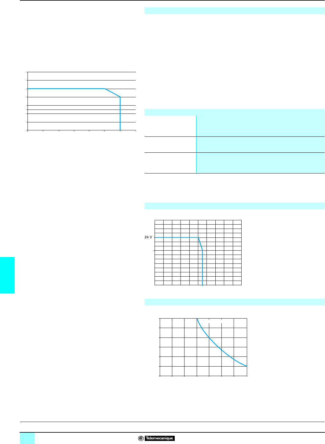
116
7
Characteristics (continued) Lexium motion control 1
Phaseo regulated power supplies
The ambient temperature is a determining factor which limits the power that an
electronic power supply can deliver continuously. If the temperature around the
electronic components is too high, their life will be significantly reduced. Conversely,
a power supply can deliver more than its nominal power if the ambient temperature
remains largely below the rated operating temperature.
The rated ambient temperature for Phaseo power supplies is 50 °C. Above this,
derating is necessary up to a maximum temperature of 60 °C.
The graph below shows the power P (in relation to the nominal power Pn) which the
power supply can deliver continuously, according to the ambient temperature.
Derating should be considered in extreme operating conditions:
bIntensive operation (output current permanently close to the nominal current,
combined with a high ambient temperature).
bOutput voltage set above 24V (to compensate for line voltage drops, for example).
bParallel connection to increase the total power.
In all cases, there must be adequate convection round the products to ensure easier
cooling. There must be a clear space of 50 mm above and below Phaseo power
supplies and of 15 mm at the sides.
Derating
0010 20 30 40 50 60 70
20
40
50
60
80
100
120
140
P/Pn (%)
Maximum operational temperature (°C
)
General rules to be complied with
Intensive operation See derating on above graph.
Example for ABL 7RE:
vwithout derating, from 0 °C to 50 °C,
vderating of nominal current by 2%, per additional °C, up to 60 °C.
Rise in output The nominal power is fixed.
Increasing the output voltage means that the current delivered must
be reduced.
Parallel connection to
increase the power The total power is equal to the sum of the power of the power supplies
used, but the maximum ambient temperature for operation is 50 °C.
To improve heat dissipation, the power supplies must not be in
contact with each other.
Load limit
Temporary overloads
1,1 x In I out
U out
19 V
1,2 1,3 1,4 1,5 1,6 1,7 1,8
x In
0
10
12
14
16
18
20
T (ms)
I out:(0...100%)
I out
P
resentation:
p
ages 112 and 113 Selection:
page 114 References:
page 117 Dimensions:
page 117
This document provided by Barr-Thorp Electric Co., Inc. 800-473-9123 www.barr-thorp.com
117
7
Selection,
references,
dimensions
Lexium motion control 1
Phaseo regulated power supplies
To define the size of the ABL 7RE power supply, it is necessary to add the other
elements of the control system connected to this power supply to the consumption of
the servodrive, giving a total Σ la.
The power supply is selected by applying a factor of 1.25 to take into account the
dispersions and different inrush currents, thus:
Nominal output current TSX SUP > 1,25 Σ la.
A reminder of the c 24 V consumption for Lexium MHDA servodrives with SER/BPH
motors is given below.
(1) According to the length of power cable (between the servodrive and motor), check the output
voltage range is compatible with the voltage ranges indicated on page 104 : limit supply values
of the servodrive MHDA associated with a BPH motor with brake.
ABL 7RE and ABL 7RP power supply: protection of the power supply line
Type of mains supply a 115 V single-phase a 230 V single-phase
Type of protection
Thermal-magnetic circuit-
breaker gG fuse Thermal-magnetic circuit-
breaker gG fuse
GB2 C60N GB2 C60N
ABL 7RE2402 GB2 pB07 MG24517 (1) 2 A GB2-DB06 MG24516 (1) 2 A
ABL 7RE2403 GB2 pB07 MG24517 (1) 2 A GB2-DB06 MG24516 (1) 2 A
ABL 7RE2405 GB2 pB08 MG24518 (1) 4 A GB2-DB07 MG17453 (1) 2 A
ABL 7RE2410 GB2 pB12 MG17454 (1) 6 A GB2-DB08 MG24518 (1) 4 A
(1) Circuit-breaker certified UL.
Association of the single-phase power supplies Phaseo with Lexium MHDA servodrives
Lexium servodrive MHDA 1004/1008p00 MHDA 1017p00 MHDA 1028p00 MHDA 1056p00 MHDA 1112/1198A00
Associated BPH motor 0552 075p095p095p115p095p115p142p142p1902/3/4 1907/190A
Current without brake (A) 0.75 0.75 0.75 0.75 0.75 0.75 0.75 0.75 1.2 1.2 2
Current out brake (A) (1) 1.08 1.25 1.45 1.45 1.55 1.45 1.55 1.75 2.2 2.7 3.5
Associated SER motor 39p3Bp39p3Bp3Bp– –
Current without brake (A) 0.75 0.75 0.75 0.75 0.75 – –
Current out brake (A) (1) 1.75 1.95 1.75 1.95 1.95 – –
References (1)
ABL 7RE single-phase regulated switch mode power supplies
Mains input voltage
47...63 Hz
V
Output
voltage
c V
Nominal
power
W
Nominal
current
A
Auto-protect
reset
Conforming to
standard
EN 61000-3-2
Reference Weight
kg
a 100…240
single-phase wide range 24 48 2 auto no ABL 7RE2402 0.520
72 3 auto no ABL 7RE2403 0.520
120 5 auto no ABL 7RE2405 1.000
240 10 auto no ABL 7RE2410 2.200
(1) Other Phaseo power supplies, consult our catalogue “ Phaseo Power supply and
Transformer”.
Dimensions
ABL 7RE24pp/ABL 7RP24pp ABL 7RE2402/2403 ABL 7RE2405 ABL 7RE2410
Common side view
Mounting on 35 and 75 mm rails
ABL 7RE2405
120 27
120
54 135
120
120
This document provided by Barr-Thorp Electric Co., Inc. 800-473-9123 www.barr-thorp.com
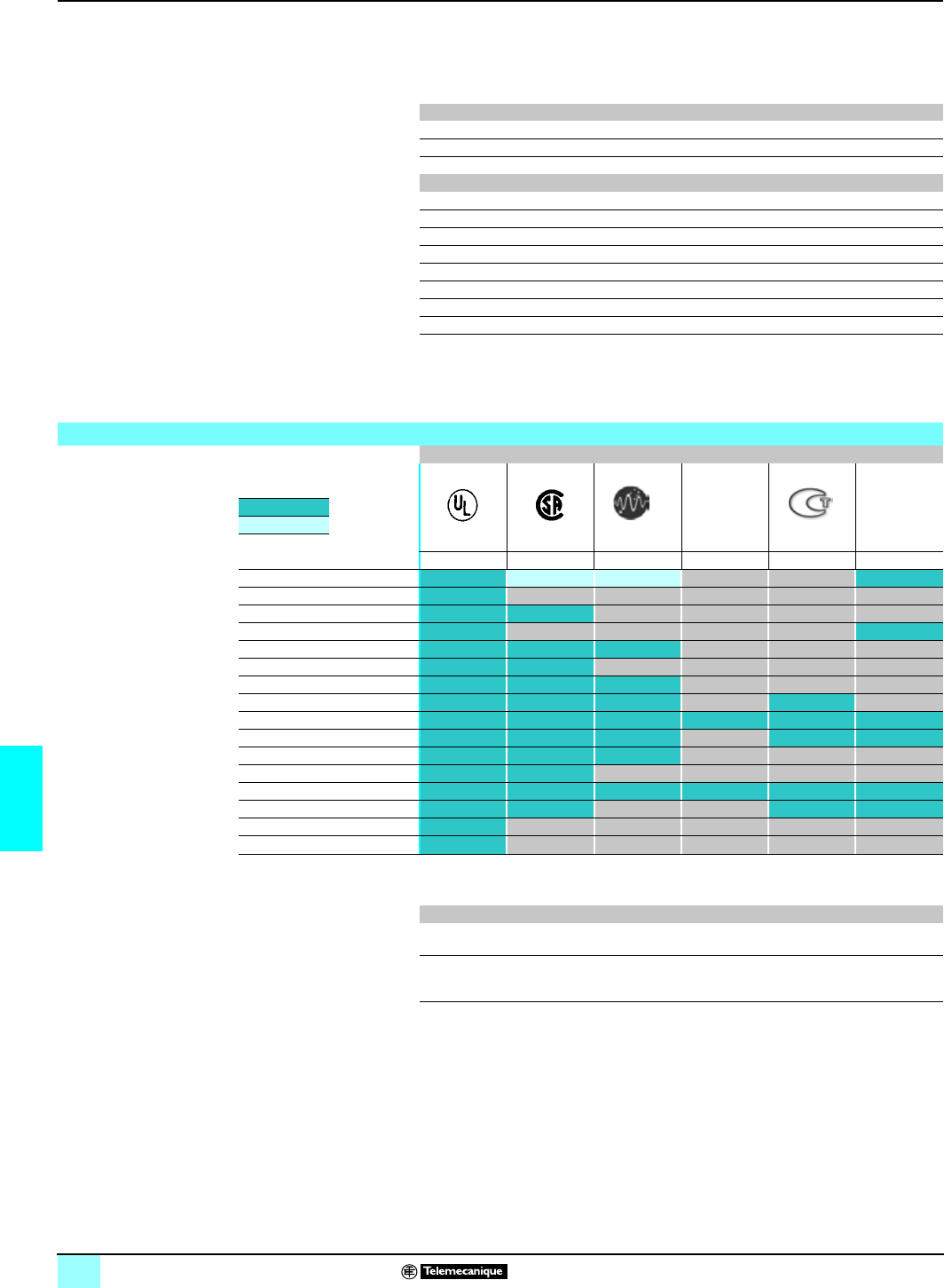
118
7
Lexium motion control 1
Automation products certifications
In some countries, certification of certain electrical components is enforced by law.
A standard conformity certificate is then issued by the official organization. Each
certified product must carry approval symbols when enforced.
Use on board merchant navy vessels generally requires prior approval
(= certification) of an electrical device by certain marine classification authorities.
The table below shows the situation as of the 01.01.2004 for certifications obtained
or pending from organizations for base PLCs. An overview of certificates for
Telemecanique products is available on our Internet web site :
www.telemecanique.com
Key Certification body Country
CSA Canadian Standards Association Canada
C-Tick Australian Communication Authority Australia
UL Underwriters Laboratories USA
Key Classification authority Country
ABS American Bureau of Shipping USA
BV Bureau Veritas France
DNV Det Norske Veritas Norway
GL Germanischer Lloyd Germany
GOST Institut de recherche Scientifique Gost Standardt C.I.S., Russia
LR Lloyd's Register United-Kingdom
RINA Registro Italiano Navale Italiy
RMRS Register of Shipping C.I.S.
Product certifications
Certifications
C-Tick
Certified Hazardous
locations
Class 1 Div 2
Pending
certification UL CSA ACA SIMTARS GOST
USA Canada Australia Australia CEI, Russia US
Advantys STB
CCX 17
Lexium MHD/BPH
Magelis iPC
Magelis XBT-F/FC
Magelis XBT-G/H/P/E/HM/PM
Momentum
Nano
Premium
Quantum
TBX
Telefast 2
TSX Micro
TSX/PMX 47 à 107
Twido (1)
Twin Line
(1) cULus north-american certification (Canada and US).
Local certifications
BG Germany TSX DPZ 10D2A safety module (TSX Micro)
TSX PAY 262/282 safety modules (Premium)
AS-Interface Europe TSX SAZ 10 master module (TSX Micro)
TSX SAY 100/1000 master modules (Premium)
TBX SAP 10 Fipio bus/AS-Interface bus gateway
This document provided by Barr-Thorp Electric Co., Inc. 800-473-9123 www.barr-thorp.com
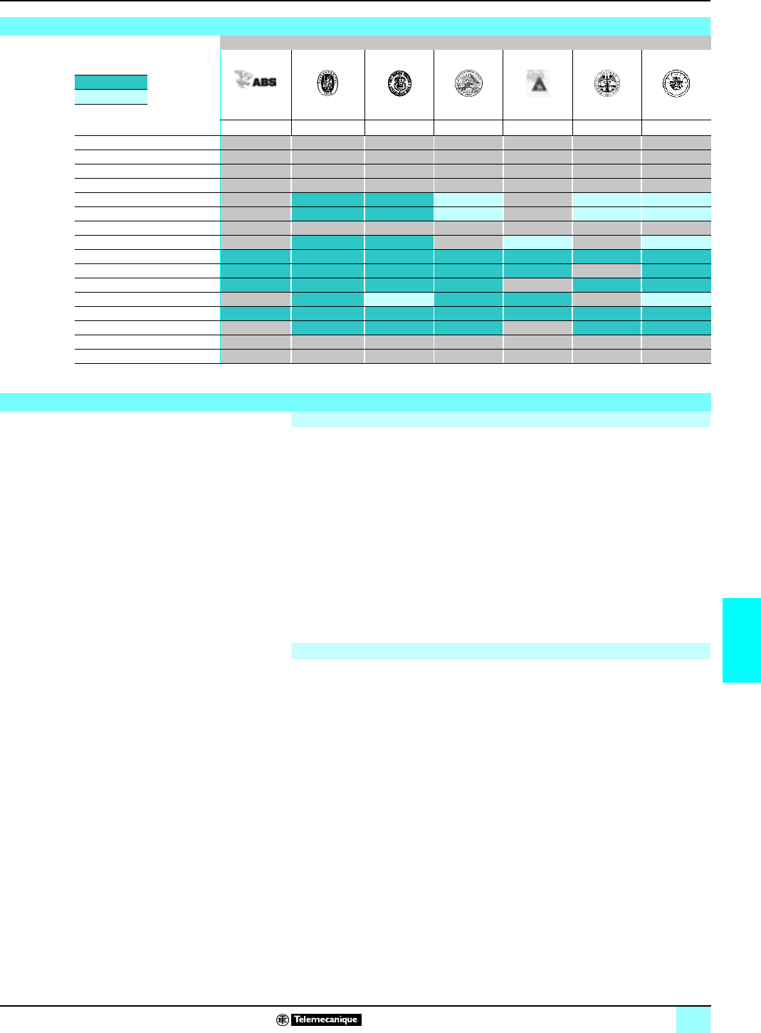
119
7
Lexium motion control 1
Automation products certifications
Community regulations
The opening of European markets implies a harmonization of regulations in the
various European Union member states.
European Directives are documents used to remove obstacles to the free movement
of goods and their application is compulsory in all states of the European Union.
Member states are obliged to transcribe each Directive into their national legislation
and, at the same time, to withdraw any conflicting regulations.
The Directives, particularly those of a technical nature with which we are concerned,
only set objectives, called “general requirements”.
The manufacturer must take all necessary measures to ensure that his products
conform to the requirements of each Directive relating to his equipment.
As a general rule, the manufacturer affirms that his product conforms to the
necessary requirements of the Directive(s) by applying the e label to his product.
e marking is applied to Telemecanique products where relevant.
be marking on a product means that the manufacturer certifies that his product
conforms to the relevant European Directives ; it is necessary in order that a product
which is subject to a Directive(s) can be marketed and freely moved within the
European Union.
be marking is intended solely for the national authorities responsible for market
regulation.
For electrical equipment, only conformity of the product to standards indicates that it
is suitable for use, and only a guarantee by a recognised manufacturer can ensure
a high level of quality.
One or more Directives, as appropriate, may apply to our products, in particular :
bThe Low Voltage Directive 72/23/EEC amended by Directive 93/68/EEC : e
marking under the terms of this Directive is compulsory as of 1 January 1997.
bThe Electromagnetic Compatibility Directive 89/336/EEC, amended by Directives
92/31/EEC and 93/68/EEC : e marking on the products covered by this Directive
has been compulsory since 1 January 1996.
Marine classification
Marine classification des authorities
Certified
Pending
certification ABS BV DNV GL LR RINA RMRS
USA France Norway Germany Unit.-Kingdom Italiy C.I.S.
Advantys STB
CCX 17
Lexium MHD/BPH
Magelis iPC
Magelis XBT-F/FC
Magelis XBT-H/P/E/HM/PM
Momentum
Nano
Premium (1)
Quantum
TBX
Telefast 2
TSX Micro
TSX/PMX 47 à 107
Twido
Twin Line
(1) Unity processors, pending certification.
Community regulations
European directives
The significance of e marking
This document provided by Barr-Thorp Electric Co., Inc. 800-473-9123 www.barr-thorp.com

120
7
Schneider Electric worldwide
1
Afghanistan Contacts are assured by Schneider Electric India
Albania Contacts are assured by Schneider Electric Austria
Algeria bSchneider Electric voie A Lot C22
Zone industrielle Rouiba - Alger Tel. : +213 21 92 97 02 à 09
Fax : +213 21 92 97 00 à 01
Andorra Contacts are assured by Schneider Electric France
Angola Contacts are assured by Schneider Electric South Africa
Anguilla Contacts are assured by Schneider Electric Dominican Rep.
Antartica Contacts are assured by Schneider Electric Brazil
Antigua & Barbuda Contacts are assured by Schneider Electric Dominican Rep.
Argentina bSchneider Argentina Viamonte 2850 - 1678 Caseros
(provincia Buenos Aires) Tel.: +54 1 716 88 88
Fax: +54 1 716 88 33 www.schneider-electric.com.ar
Armenia Contacts are assured by Schneider Electric Russian Fed.
Aruba Contacts are assured by Schneider Electric Dominican Rep.
Australia bSchneider Electric (Australia) Pty.
Limited 2 Solent Circuit
Norwest Business Park
Baulkham Hill _ NSW 2153
Tel.: +61 298 51 28 00
Fax: +61 296 29 83 40 www.schneider.com.au
Austria bSchneider Austria Ges.m.b.H. Birostrasse 11
1239 Wien Tel.: +431 610 540
Fax: +431 610 54 54 www.schneider-electric.at
Azerbaijan Contacts are assured by Schneider Electric Russian Fed.
Bahamas bSchneider Electric Union Village
PO Box 3901 - Nassau Tel. : +1 242 327 42 91
Fax : +1 242 327 42 91 www.squared.com
Bahrain bSchneider Electric Floor 1 - Juma Building
Abu Horaira Avenue
PO Box 355 - 304 Manama
Tel.: +97 322 7897
Fax: +97 321 8313
Bangladesh Contacts are assured by Schneider Electric India
Barbados Contacts are assured by Schneider Electric Dominican Rep.
Belarus bSchneider Electric Industries SA Prospect Macherova 5, of. 202
220004 Minsk Tel. : +375 172 23 75 50
Fax : +375 172 23 97 61
Belgium bSchneider Electric nv/sa Dieweg 3
B - 1180 Brussels Tel.: +3223737711
Fax: +3223753858 www.schneider-electric.be
Belize Contacts are assured by Schneider Electric USA
Benin Contacts are assured by Schneider Electric Ivory Coast
Bermuda Contacts are assured by Schneider Electric Dominican Rep.
Bhutan Contacts are assured by Schneider Electric India
Bolivia Contacts are assured by Schneider Electric Chile
Bosnia and Herzegovina Contacts are assured by Schneider Electric Croatia
Botswana Contacts are assured by Schneider Electric South Africa
Bouvet island Contacts are assured by Schneider Electric Dominican Rep.
Brazil bSchneider Electric Brazil Ltda. Avenida Das Nações Unidas 23223
Jurubatuba - CEP 04795-907
São Paulo-SP
Tel.: +55 55 24 52 33
Fax: +55 55 22 51 34 www.schneider-electric.com.br
Brunei (Darussalam) Contacts are assured by Schneider Electric Singapore
Bulgaria bSchneider Electric Expo 2000, Boulevard Vaptzarov
1407 Sofiav Tel.: +3592 919 42
Fax: +3592 962 44 39 www.schneiderelectric.bg
Burkina Faso Contacts are assured by Schneider Electric Ivory Coast
Burundi Contacts are assured by Schneider Electric Kenya
Cambodia Contacts are assured by Schneider Electric Viet Nam
Cameroon bSchneider Electric Cameroon 166, rue de l'Hôtel de Ville
BP12087 - Douala Tel.: +237 343 38 84
Fax: +237 343 11 94
Canada bSchneider Canada 19, Waterman Avenue
M4 B1Y2 Toronto - Ontario Tel.: +1 416 752 8020
Fax: +1 416 752 4203 www.schneider-electric.ca
Cape Verde Contacts are assured by Schneider Electric Senegal
Caribee Contacts are assured by Schneider Electric Dominican Rep.
Cayman islands Contacts are assured by Schneider Electric Dominican Rep.
Central African Republic Contacts are assured by Schneider Electric Cameroon
Chad Contacts are assured by Schneider Electric Cameroon
Chile bSchneider Electric Chile S.A.
Avda. Pdte Ed. Frei Montalva, 6001-31
Conchali - Santiago Tel.: +56 2 444 3000
Fax: +56 2 423 9335 www.schneider-electric.co.cl
China bSchneider Beijing Landmark bldg-Room 1801
8 North Dong Sanhuan Rd
Chaoyang District
100004 Beijing
Tel.: +86 10 65 90 69 07
Fax: +86 10 65 90 00 13 www.schneider-electric.com.cn
Up-dated: 28-07-2003
This document provided by Barr-Thorp Electric Co., Inc. 800-473-9123 www.barr-thorp.com

Schneider Electric worldwide
0
Up-dated: 28-07-2003
121
7
Christmas island Contacts are assured by Schneider Electric Australia
Cocos (Keeling) islands Contacts are assured by Schneider Electric Australia
Colombia bSchneider Electric de Colombia
S.A. Calle 45A #102-48
Bogota DC Tel.: +57 1 426 97 00
Fax: +57 1 426 97 40
Comoros Contacts are assured by Schneider Electric la Reunion
Congo Contacts are assured by Schneider Electric Cameroon
Cook islands Contacts are assured by Schneider Electric Australia
Costa Rica bSchneider Centroamérica Ltda. 1.5 kmts oeste de la Embajada
Americana,
Pavas, San José, Costa Rica C.A.
Apartado: 4123-1000 San Jose
Tel.: +506 232-60-55
Fax: +506 232-04-26 www.schneider-ca.com
Croatia bSchneider Electric SA Fallerovo Setaliste 22
HR - 10000 Zagreb Tel.: +385 1 367 100
Fax: +385 1 367 111
Cuba bSchneider Electric Bureau de Liaison de La Havane
Calle 36- N°306-Apto1
Entre 3ra y 5ta Avenida Miramar
Playa Habana
Tel.: +53 724 15 59
Fax: +53 724 12 17
Cyprus bSchneider Electric Cyprus 28 General Timayia Avenue
Kyriakos Building, Block #A301
Larnaca 6046
Tel.: +00357 248 12646
Fax: +00357 246 37382
Czech Republic bSchneider Electric CZ, s.r.o. Thámova 13
Praha 8 - 186 00 Tel.: +420 2 810 88 111
Fax: +420 2 24 81 08 49 www.schneider-electric.cz
Democratic Rep. of Congo Contacts are assured by Schneider Electric Cameroon
Denmark bSchneider Electric A/S Baltorpbakken 14
DK-2750 Ballerup Tel.: +45 44 73 78 88
Fax: +45 44 68 5255 www.schneider-electric.dk
Djibouti Contacts are assured by Schneider Electric Egypt
Dominican Republic bSchneider Electric Calle Jacinto Manon
Esq. Federico Geraldino
Edificio D' Roca Plaza Suite 402,
Ens. Paraiso - Santo Domingo
Tel.: +1 809 334 66 63
Fax: +1 809 334 66 68
Ecuador bSchneider Electric Ecuador SA
Av.Republica del Salvador 1082 y Nac
Edificio Mansion Blanca-Quito Tel. : +593 2 224 42 42
Fax : +593 2 224 42 94
Egypt bSchneider Electric Egypt sae 68, El Tayaran Street
Nasr City, 11371 - Cairo Tel.: +20 24 01 01 19
Fax: +20 24 01 66 87 www.schneider.com.eg
El Salvador Contacts are assured by Schneider Electric USA
Equatorial Guinea Contacts are assured by Schneider Electric Cameroon
Eritrea Contacts are assured by Schneider Electric Egypt
Estonia bLexel Electric Ehitajate tee 110
EE 12618 Talinn Tel. : +372 650 97 00
Fax : +372 650 97 22
Ethiopia Contacts are assured by Schneider Electric Egypt
Falkland islands Contacts are assured by Schneider Electric Brazil
Faroe islands Contacts are assured by Schneider Electric Australia
Fiji Contacts are assured by Schneider Electric Australia
Finland bSchneider Electric Oy Sinimäentie 14
02630 Espoo Tel. : +358 9 527 000
Fax : +358 9 5270 0376 www.schneider-electric.fi
France bSchneider Electric SA 5, rue Nadar
92500 Rueil Malmaison Tel.: +33 (0)1 41 29 82 00
Fax: +33 (0)1 47 51 80 20 www.schneider-electric.fr
French Polynesia Contacts are assured by Schneider Electric Australia
French West Indies Contacts are assured by Schneider Electric Dominican Rep.
Gabon Contacts are assured by Schneider Electric Cameroon
Gambia Contacts are assured by Schneider Electric Senegal
Georgia Contacts are assured by Schneider Electric Russian Fed.
Germany bSchneider Electric GmbH Gothaer Straße 29
D-40880 Ratingen Tel.: +49210 240 40
Fax: +492 10 240 49 256 www.schneiderelectric.de
Ghana bSchneider Electric Ghana PMB Kia
3rd Floor Opeibea House
Airport Commercial Center
Liberation road - Accra
Tel. : +233 21 70 11 687
Fax : +233 21 77 96 22
Gilbraltar Contacts are assured by Schneider Electric Spain
Greece bSchneider Electric AE 14th km - RN Athens-Lamia
GR - 14564 Kifissia Tel.: +302 106 29 52 00
Fax: +302 106 29 52 10 www.schneider-electric.com.gr
Greenland Contacts are assured by Schneider Electric United States
Grenada Contacts are assured by Schneider Electric Dominican Rep.
Guadeloupe Contacts are assured by Schneider Electric Martinique
Guam Contacts are assured by Schneider Electric Australia
This document provided by Barr-Thorp Electric Co., Inc. 800-473-9123 www.barr-thorp.com

Schneider Electric worldwide
0
Up-dated: 28-07-2003
122
7
Guatemala Contacts are assured by Schneider Electric United States
Guinea-Bissau Contacts are assured by Schneider Electric Sénégal
Guinea Contacts are assured by Schneider Electric Ivory Coast
Guyana Contacts are assured by Schneider Electric United States
Haiti Contacts are assured by Schneider Electric Dominican Rep.
Heard & Mac Donald isl. Contacts are assured by Schneider Electric Australia
Honduras Contacts are assured by Schneider Electric United States
Hong Kong bSchneider Electric (Hong Kong)
Ltd Room 3108-28, 31th Floor,
Sun Hung Kai Centre,
30 Harbour Road, Wanchai
Tel.: +852 25 65 06 21
Fax: +852 28 11 10 29
Hungary bSchneider Electric Hungária
Villamossági Rt. Fehérvári út 108 – 112
H-1116 Budapest Tel.: +36 1 382 26-06
Fax: +36 1 206 1429 www.schneider-electric.hu
Iceland Contacts are assured by Schneider Electric Denmark
India bSchneider Electric India Max House, 1 Dr Jha Marg, Okhla
110 020 New Dehli Tel. : +91 11 631 85 84
Tel. : +91 11 631 71 61 www.schneiderelectric-in.com
Indonesia bP.T. Schneider Indonesia Ventura Building 7th Floor
Jalan R.A. Kartini Kav.26
Cilandak - 12430 Jakarta
Tel.: +62 +21 750 44 06
Fax: +62 +21 750 44 15/ 16 www.schneider-electric.co.id
Iran (Islamic Republic of) bTelemecanique Iran 1047 Avenue VALI ASSR
P.O. Box 15875-3547
15116 Teheran
Tel.: +98 218 71 01 42
Fax: +98 218 71 81 87
Irak bSchneider Electric Industries SA 38050 Grenoble Cedex 9 Tel.: +33 04 76 60 54 27
Fax: +33 04 76 60 56 60
Ireland bSchneider Electric Ireland Maynooth Road
Cellbridge - Co. Kildare Tel.: +353+0 1 6012200
Fax: +353+0 1 6012201 www.schneiderelectric.ie
Italy bSchneider Electric S.p.A. Centro Direzionale Colleoni
Palazzo Sirio - Viale Colleoni, 7
20041 Agrate Brianza (Mi)
Tel.: +39 39 655 8111
Fax: +39 39 605 6237 www.schneiderelectric.it
Ivory Coast bSchneider Electric Afrique de
l'Ouest Rue Pierre et Marie Curie
18 BP 2027 Abidjan 18 Tel.: +225 21 75 00 10
Fax: +225 21 75 00 30
Jamaica bSchneider Electric Shop#5, Plaza Dunrobin
30 Dunrobin Avenue - Kingstown Tel. : +1876 755 41 27
Tel. : +931 87 74
Japan bSchneider Electric Japan Ltd Torigoe F. Bldg
1-8-2, Torigoe
Taito-Ku - 111-0054 Tokyo
Tel.: +81 358 35 35 81
Fax: +81 358 35 35 85 www.schneider-electric.co.jp
Jordan bSchneider Electric Industr. Jordan Jordan University Street
Abu Al Haj Commercial Complex
2nd Floor - Office # 202 - Amman
Tel.: 962 65 16 78 87
Fax: 962 65 16 79 1
Kazakstan bSchneider Electric Kazakhstan
Liaison Office Prospekt Abaia 157 off 9
480009 Almaty Tel. : +7 327 250 93 88
Tel. : +7 327 250 63 70
Kenya bSchneider East Africa Power Technics Complex
Monbasa Road - PO Box 46345
Nairobi
Tel. : +254 2.824.156
Fax : +254 2.824.157
Kiribati Contacts are assured by Schneider Electric Australia
Korea bSchneider Electric Korea Ltd 3Floor, Cheil Bldg., 94-46, 7-Ka
Youngdeungpodong,
Youngdeungpo-ku
150-037 Seoul
Tel. : +82 2 2630 9700
Fax : +82 2 2630 9800 www.csinfo.co.kr/schneider/
Kurdistan Contacts are assured by Schneider Electric Russian Fed.
Kuwait bSchneider Electric Kuwait Al Gaas Tower - Sharq 2nd Floor
PO Box 20092 - 13 061 Safat Tel.: +965 240 75 46
Fax: +965 240 75 06
Kyrgyz Republic Contacts are assured by Schneider Electric Russian Fed.
Laos Contacts are assured by Schneider Electric Thailand
Latvia bLexel Electric 60A A.Deglava str.
LV1035 Riga Tel. : +371 780 23 74/75
Fax : +371 754 62 80
Lebanon bSchneider Electric Liban Tabaris, Avenue Charles Malek
Immeuble Ashada, 8
P.O. Box 166223 - Beyrouth
Tel. : +961 1 20 46 20
Tel. : +961 1 20 31 19
Lesotho Contacts are assured by Schneider Electric South Africa
Liberia Contacts are assured by Schneider Electric Ghana
Libya Contacts are assured by Schneider Electric Tunisia
Liechtenstein Contacts are assured by Schneider Electric Switzerland
Lithuania bLexel Electric 44, Verkiu str.
LT-2012 Vilnius Tel. : +370 278 59 59/61
Fax : +370 278 59 60
Loro Sae Contacts are assured by Schneider Electric Australia
Luxembourg bSchneider Electric Industrie SAS Agence de Metz
1, Rue Graham Bell - BP n° 35190
57075 Metz cedex 3 - France
Tel.: 33 03 87 39 06 03
Fax: 33 03 87 74 25 96 www.schneider-electric.fr
This document provided by Barr-Thorp Electric Co., Inc. 800-473-9123 www.barr-thorp.com

Schneider Electric worldwide
0
Up-dated: 28-07-2003
123
7
Macau Contacts are assured by Schneider Electric China
Macedonia Contacts are assured by Schneider Electric Bulgaria
Madagascar Contacts are assured by Schneider Electric la Reunion
Malawi Contacts are assured by Schneider Electric South Africa
Malaysia bSchneider Electric (Malaysia) Sdn
Bhd No.11 Jalan U1/19, Seksyen U1
Hicom-Glenmarie Industrial Park
40150 Shah Alam
Selangor Darul Ehsan
Tel. : (603) 7883 6333
Fax : (603) 7883 6188 www.schneider-
electric.com.my
Maldives Contacts are assured by Schneider Electric Reunion
Mali Contacts are assured by Schneider Electric Senegal
Malta Contacts are assured by Schneider Electric Tunisia
Marshall islands Contacts are assured by Schneider Electric Australia
Martinique bSchneider Electric Schneider Electric
Immeuble Cottrell - ZI de la Lézarde
97232 Le Lamentin
Tel.: +05 96 51 06 00
Fax: +05 96 51 11 26
Mauritania Contacts are assured by Schneider Electric Senegal
Mauritius bSchneider Electric Route côtière
Calodyne - Mauritius Tel.: 230 282 18 83
Fax: 230 282 18 84
Mayotte Contacts are assured by Schneider Electric Reunion
Mexico bGroupe Schneider Mexico Calz. Rojo Gomez N° 1121-A
Col. Guadalupe del Moral
México, D.F. - C.P. 09300
Tel.: +525 686 30 00
Fax: +525 686 24 09 www.schneider-
electric.com.mx
Micronesia Contacts are assured by Schneider Electric Australia
Moldova Contacts are assured by Schneider Electric Romania
Monaco Contacts are assured by Schneider Electric France
Mongolia Contacts are assured by Schneider Electric Russian Fed.
Montserrat Contacts are assured by Schneider Electric Dominican Rep.
Morocco bSchneider Electric Morocco 26, rue Ibnou Khalikane
Quartier Palmiers
20100 Casablanca
Tel.: +212 299 08 48 to 57
Fax: +212 299 08 67 and 69 www.schneider.co.ma
Mozambique Contacts are assured by Schneider Electric South Africa
Myanmar Contacts are assured by Schneider Electric Singapore
Namibia Contacts are assured by Schneider Electric South Africa
Nauru Contacts are assured by Schneider Electric Australia
Nepal Contacts are assured by Schneider Electric India
Netherlands bSchneider Electric BV Waarderweg 40 - Postbus 836
2003 RV Haarlem Tel.: +31 23 512 4124
Fax: +31 23 512 4100 www.schneider-electric.nl
Netherlands Antilles Contacts are assured by Schneider Electric Dominican Rep.
New Caledonia Contacts are assured by Schneider Electric Australia
New Zealand bSchneider Electric (NZ) Ltd 14 Charann Place Avondale
P.O. Box 15355 - New Lynn
Auckland
Tel. : +64 9 829 04 90
Fax : +64 9 829 04 91 www.schneider-electric.co.nz
Nicaragua Contacts are assured by Schneider Electric United States
Niger Contacts are assured by Schneider Electric Ivory Coast
Nigeria bSchneider Electric Nigeria Limited Biro plaza - 8th Floor - Plot 634
Abeyemo Alakija Street
Victoria Islan - Lagos
Tel. : +234 1 2702973
Fax : +234 1 2702976
Niue Contacts are assured by Schneider Electric Australia
Norfolk island Contacts are assured by Schneider Electric Australia
North Korea Contacts are assured by Schneider Electric China
Northern Mariana islands Contacts are assured by Schneider Electric Australia
Norway bSchneider Electric Norge A/S Solgaard Skog 2
Postboks 128 - 1501 Moss Tel.: +47 6924 9700
Fax: +47 6925 7871 www.schneider-electric.no
Oman bSchneider Electric CA c/o Arab Development Co
PO Box 439 - 113 Muscat Tel.: +968 77 163 64
Fax: +968 77 104 49
Pakistan bSchneider Electric Pakistan 43-L, 2nd floor, M.M. Alam Road,
Gulberg II - Lahore Tel.: +92 42 5754471 à 73
Fax: +92 42 5754474
Palau Contacts are assured by Schneider Electric Australia
Panama Contacts are assured by Schneider Electric United States
Papua New Guinea Contacts are assured by Schneider Electric Australia
Paraguay Contacts are assured by Schneider Electric Uruguay
This document provided by Barr-Thorp Electric Co., Inc. 800-473-9123 www.barr-thorp.com

Schneider Electric worldwide
0
Up-dated: 28-07-2003
124
7
Peru bSchneider Electric Peru S.A. Los Telares n°231 Urb. Vulcano, Ate
Lima 03 Tel.: +511 348 44 11
Fax: +511 348 05 23 www.schneider-electric.com.pe
Philippines bSchneider Electric Philippines, Inc 5th Floor, ALCO Building
391 Sen, Gil Puyat Avenue
Makati 1209
Tel. : +632 896 6063
Fax : +632 896 7229
Pitcairn Contacts are assured by Schneider Electric Australia
Poland bSchneider Electric Polska Sp.zo.o. ul. Lubinowa 4a
03-878 - Warszawa Tel.: +48 22 511 8 200
Fax: +48 22 511 8 210 www.schneider-electric.pl
Portugal bSchneider Electric Portugal Av.do Forte, 3
Edificio Suécia II, Piso 3-A
CP 2028 Carnaxide
2795 Linda-A-Velha
Tel.: +351 21 416 5800
Fax: +351 21 416 5857 www.schneiderelectric.pt
Puerto Rico Contacts are assured by Schneider Electric United States
Qatar bSchneider Electric Qatar Branch c/o Khalifa BinFahred Al Thani
Trad.and Co - P.O. Box 4484
Doha
Tel.: +97 4424358
Fax: +97 4424358
Reunion bSchneider Electric Immeuble Futura,
190, rue des 2 canons
BP 646 - 97497 Sainte Clothilde
Tel.: +262 28 14 28
Fax: +262 28 39 37
Romania bSchneider Electric Bd Ficusului n°42
Apimondia, Corp.A, et.1, Sector 1
Bucuresti
Tel.: +401 203 06 50
Fax: +401 232 15 98 www.schneider-electric.ro
Russian Federation bSchneider Electric ZAO Enisseyskaya 37
129 281 Moscow Tel.: +7095 797 40 00
Fax: +7095 797 40 03 www.schneider-electric.ru
Rwanda Contacts are assured by Schneider Electric Kenya
Samoa Contacts are assured by Schneider Electric Australia
San Marino Contacts are assured by Schneider Electric Italy
Sandwich & Georgia island Contacts are assured by Schneider Electric Australia
Sao Tome & Principe Contacts are assured by Schneider Electric Senegal
Saudi Arabia bSchneider Electric Second Industrial City
P.O. Box 89249 - 11682 Riyadh Tel.: +966 1 265 1515
Fax: +966 1 265 1860
Senegal bSchneider Electric Sénégal BP 15952 - Dakar-Fann
Rond point N'Gor - Dakar Tel.: +221 820 68 05
Fax: +221 820 58 50
Seychelles Contacts are assured by Schneider Electric Reunion
Sierra Leone Contacts are assured by Schneider Electric Ghana
Singapore bSchneider Electric Singapore Pte
Ltd 10 Ang Mo Kio Street 65
#02-17/20 TechPoint
Singapore 569059
Tel.: +65 484 78 77
Fax: +65 484 78 00 www.schneider-electric.com.sg
Slovak Republic bSchneider Electric Slovakia spol
s.r.o. Borekova 10
SK-821 06 Bratislava Tel. : +02 45 52 40 10 and 40 30
Fax : +02 45 52 40 00 www.schneider-electric.sk
Slovenia bSchneider Electric, d.o.o. Dunasjka 47
1000 Ljubljana Tel. : +386 1 23 63 555
Fax : +386 1 23 63 559 www.schneider-electric.si
Solomon islands Contacts are assured by Schneider Electric Australia
Somalia Contacts are assured by Schneider Electric Egypt
South Africa bSchneider Electric South Africa
(PTY) Ltd Private Bag X139
Halfway House
1685 - Midrand.
Tel.: +27 11 254 6400
Fax: +27 11 315 8830 www.schneider-electric.co.za
Spain bSchneider Electric España, S.A. Pl. Dr. Letamendi, 5-7
08007 Barcelona Tel.: +34 93 484 3100
Fax: +34 93 484 3308 www.schneiderelectric.es
Sri Lanka bSchneider Electric Industries SA Liaison office SRI Lanka
Level 3B Valiant towers
46/7 Nawam Mawatha-Colombo 2
Tel. : +94 77 48 54 89 www.schneiderelectric-in.com
St Helena Contacts are assured by Schneider Electric Italy
St Kitts & Nevis Contacts are assured by Schneider Electric Dominican Rep.
St Lucia Contacts are assured by Schneider Electric Dominican Rep.
St Pierre et Miquelon Contacts are assured by Schneider Electric Dominican Rep.
St Vincent & Grenadines Contacts are assured by Schneider Electric Dominican Rep.
Sudan Contacts are assured by Schneider Electric Egypt
Suriname Contacts are assured by Schneider Electric United States
Svalbard & Jan Mayen isl. Contacts are assured by Schneider Electric Denmark
Swaziland Contacts are assured by Schneider Electric South Africa
Sweden bSchneider Electric AB Djupdalsvägen 17/19
19129 Sollentuna Tel.: +46 8 623 84 00
Fax: +46 8 623 84 85 www.schneider-electric.se
Switzerland bSchneider Electric (Switzerland)
S.A. Schermenwaldstrasse 11
CH - 3063 Ittigen Tel.: +41 31 917 3333
Fax: +41 31 917 3355 www.schneider-electric.ch
This document provided by Barr-Thorp Electric Co., Inc. 800-473-9123 www.barr-thorp.com

Schneider Electric worldwide
0
Up-dated: 28-07-2003
125
7
Syrian Arab Republic bSchneider Electric Syria Elba Street - Malki
Gheibeh and Qassas bldg, 1st floor
PO Box 33876-Damascus
Tel. : +963 11 37 49 88 00
Fax : +963 11 37 17 55 9
Taiwan, Republic of China bSchneider Electric Taiwan Co Ltd 2FI., N°37, Ji-Hu Road, Nei-Hu Dist.,
Taipei 114 Tel. : +886 2 8751 6388
Fax : +886 2 8751 6389 www.schneider-electric.com.tw
Tajikistan Contacts are assured by Schneider Electric Russian Fed.
Tanzania, United Rep. of Contacts are assured by Schneider Electric Kenya
Thailand bSchneider (Thailand) Ltd 20th Floor Richmond Building
75 Sukhumvit 26 Road, Klongtoey
Bangkok 10110
Tel.: +662 204 9888
Fax: +662 204 9816 www.schneider-electric.co.th
Togo Contacts are assured by Schneider Electric Ivory Coast
Tokelau Contacts are assured by Schneider Electric Australia
Tonga Contacts are assured by Schneider Electric Australia
Trinidad & Tobago bSchneider Electric 6, 1st Street West Ext.
Beaulieu Avenue
Trincity Trinidad West Indies
Tel.: 1868 640 42 04
Fax: 1868 640 42 04
Tunisia bSchneider Electric Tunisia Rue du Lac Oubeira
1053 Les Berges du Lac - Tunis Tel.: +216 71 960 477
Fax: +216 71 960 342
Turkey bSchneider Elektrik Sanayi Ve
Ticaret A.S. Tütüncü Mehmet Efendi Cad. N°:110
Kat 1-2 - 81080 Göztepe – Istanbul Tel.: +90 21 63 86 95 70
Fax: +90 21 63 86 38 75 www.schneiderelectric.com.tr
Turkmenistan bSchneider Electric Turkmenistan
Liaison Office rue Neitralny Turkmenistan 28,
off.326/327
74 000 Achgabad
Tel. : +993 12 46 29 52
Fax : +993 12 46 29 52
Turks & Caicos islands Contacts are assured by Schneider Electric Dominican Rep.
Tuvalu Contacts are assured by Schneider Electric Australia
Uganda Contacts are assured by Schneider Electric Kenya
Ukraine bSchneider Electric Rue Krechtchalik 2
252601 Kiev Tel.: +380 44 462 04 25
Fax: +380 44 462 04 24 www.schneider-electric.com.ua
United Arab Emirates bSchneider Electric Abu Dhabi PO Box 29580
Office Floor 2/Lulu Street
Al Marina Plaza Tower
Abu Dhabi
Tel.: +9712 6 339444
Fax: +9712 6 316606
United Kingdom bSchneider Electric Ltd Braywick House East
Windsor Road - Maidenhead
Berkshire SL6 1 DN
Tel.: +44 (0)1 628 508 500
Fax: +44 (0)1 628 508 508 www.schneider.co.uk
United States bSchneider Electric North American Division
1415 Roselle Road
Palatine - IL 60067
Tel.: +1 847 397 2600
Fax: +1 847 925 7500 www.squared.com
Uruguay bSchneider Electric Uruguay S.A. Ramon Masini 3190
Montevideo Tel. : +59 82 707 2392
Fax : +59 82 707 2184
Uzbekistan Contacts are assured by Schneider Electric Russian Fed.
Vanuatu Contacts are assured by Schneider Electric Australia
Vatican city St./Holy See Contacts are assured by Schneider Electric Italy
Venezuela bSchneider Mg SD TE, S.A Calle 162/ Piso 2
Edificio Centro Cynamid
La Urbina, 1070 - 75319 Caracas
Tel.: +58 2 241 13 44
Fax: +58 2 243 60 09 www.schneider-electric.com.ve
Viet Nam bR.R.O. of Schneider Electric
Industries S.A.S. in Viet Nam Unit 2.9, 2nd Floor, e-Town Building
364 Cong Hoa Street
Tan Binh District - Ho Chi Minh City
Tel.: +84 8 8103 103
Fax: +84 8 8120 477
Virgin islands Contacts are assured by Schneider Electric Dominican Rep.
Wallis & Futuna islands Contacts are assured by Schneider Electric Australia
Western Sahara Contacts are assured by Schneider Electric Morocco
Yemen Contacts are assured by Schneider Electric U.A.E.
Yugoslavia bSchneider Electric Jugoslavija
d.o.o. Ratarski put 27d
11186 Belgrade Tel.: +381 11 192 414
Fax: +381 11 107 125
Zambia bSchneider Zambia Zambia Office
c/o Matipi Craft Center Building
Plot 1036 - Accra Road
PO Box 22792 - Kitwe
Tel.: +260 222 22 52
Fax: +260 222 83 89
Zimbabwe bSchneider Electric Zimbabwe Liaison Office
75A Second Street
(corner Livingstone Avenue)
Harare
Tel.: +263 4 707 179/180
Fax: +263 4 707 176
Subsidiaries
France bNUM SA Immeuble Les Courlis
46, avenue Kléber
F-92700 Colombes
Tel.: +33 (0)1 56 47 58 00
Fax: +33 (0)1 56 47 58 89 www.schneider-num.com
Germany bBerger Lahr Breslaver Strasse 7
77933 Lahr Tel.: +49 (0)78 21 946 02
Fax: +49 (0)78 21 946 220 www.berger-lahr.de
This document provided by Barr-Thorp Electric Co., Inc. 800-473-9123 www.barr-thorp.com

126
7
© Copyright Schneider Electric Industries SAS 2004.
All rights reserved. No part of this work may be translated and/
or reproduced or copied in any form or by any means, graphic,
electronic or mechanical including photocopying, recording,
taping or storage in an information retrieval system.
Owing to changes in standards and products, hardware and software, the characteristics given
in the text and images in this document are not binding until they have been confirmed with us.
All software quoted in this document is the property of
Schneider Electric Industries SAS, or a third party which has
granted rights to Schneider Electric Industries SAS. The supply
of such software confers a non-exclusive licence on the
recipient to use such software solely for the purpose for which
it was supplied.
Any copying of such software, etc. (except solely for the
purpose of producing back-up and security copies) is totally
forbidden.
Modbus Plus, Fipio, Lexium, Concept, ProWORX, PL7 and Unity are registered trademarks of
Schneider Automation SAS.
Telemecanique, Phaseo, Altivar, NUM are registered trademarks of Schneider Electric SAS.
All other products and brands (CANopen, SERCOS) quoted in this document are registered
trademarks of their respective holders.
This document provided by Barr-Thorp Electric Co., Inc. 800-473-9123 www.barr-thorp.com

127
7
Product references index 0
14p
140 MSB 101 00 36
141 MMS 425 01 44
141 MMS 535 02 44
3pp
372 SPU 474 01 V26 45
372 SPU 474 11 V26 45
372 SPU 474 21 V26 45
372 SPU 474 31 V26 45
396 MMC 500 04 45
690
690 MCB 000 00 36
690 MCI 000 01 36
690 MCI 000 03 36
690 MCI 000 06 36
690 MCI 002 06 36
890
890 USE 1200p66
890 USE 1220p67
990
990 MCO 000 01 30, 44
990 MCO 000 03 30, 44
990 MCO 000 05 30, 44
990 MCO 000 15 30, 44
990 MCO 000 55 30, 44
990 MCO 000 75 30, 44
990 MCO 001 25 30, 44
990 MCO KIT 00 30, 44
990 MCO KIT 01 30, 44
A
ABE 7BV20 11
ABE 7CPA01 15
ABE 7CPA11 15
ABE 7H16R20 11, 15
ABL 7RE2402 117
ABL 7RE2403 117
ABL 7RE2405 117
ABL 7RE2410 117
AGO CAV 003 109
AGO FRU 013M 010 108
AGO FRU 014M 010 108
AGO FRU 015M 010 108
AGO FRU 016M 010 108
AGO FRU 020M 005 108
AGO FRU 020M 010 108
AGO FRU 020M 015 108
AGO FRU 020M 025 108
AGO FRU 020M 050 108
AGO FRU 020M 075 108
AGO KIT 001M 005 108
AGO KIT 001M 015 108
AGO KIT 001M 025 108
AGO KIT 002 CON 109
AGO KIT 018M 005 108
AGO KIT 018M 015 108
AGO KIT 018M 025 108
AGO KIT 018M 050 108
AGO KIT 018M 075 108
AGO KIT 019M 005 108
AGO KIT 019M 015 108
AGO KIT 019M 025 108
AGO KIT 019M 050 108
AGO KIT 019M 075 108
AGO KIT 023M 005 108
AGO KIT 023M 015 108
AGO KIT 023M 025 108
AGO KIT 023M 050 108
AGO KIT 023M 075 108
AGO KIT 024M 005 108
AGO KIT 024M 015 108
AGO KIT 024M 025 108
AGO KIT 024M 050 108
AGO KIT 024M 075 108
AGO KIT 025M 005 108
AGO KIT 025M 015 108
AGO KIT 025M 025 108
AM0 CAV 001V003 67
AM0 CHK 170 67
AM0 CHK 212 67
AM0 CSW 001V300 67
AM0 EMC 118 67
AM0 EMC 212 67
AM0 FIL 001V056 66
AM0 FIP 001V000 67
AM0 INE 001V000 67
AM0 MBP 001V000 67
AM0 PBS 001V000 67
AM0 RFE 001V025 66
AM0 RFE 001V050 66
AM0 RFE 002V086 67
AM0 RFE 002V160 67
AM0 SER 001V000 67
AM0 SPA 001V000 66
AM0 SPA 002V001 67
AMO CHI 0014X4 109
AMO CHI 0025X5 109
AMO CHI 0036X6 109
AMO CHI 0048X7 109
AMO CHI 0050X8 109
AMO CHI 00615X3 109
AMO CHI 00770X10 109
AMO GOL 001 M8 109
AMO MAN 001U 109
B
BMH Q101 109
BPH 0552 S5p A2p0p106
BPH 0552 S5p F2p0p106
BPH 0751 N5p A2pAp106
BPH 0751 N5p F2pAp106
BPH 0752 N5p A2pAp106
BPH 0752 N5p F2pAp106
BPH 0952 N5p A2pAp106
BPH 0952 N5p F2pAp106
BPH 0953 N5p A2pAp106
BPH 0953 N5p F2pAp106
BPH 1152 N5p A2pAp106
BPH 1152 N5p F2pAp106
BPH 1153 N5p A2pAp106
BPH 1153 N5p F2pAp106
BPH 1422 N5p A2pAp106
BPH 1422 N5p F2pAp106
BPH 1423 N5p A2pAp106
BPH 1423 N5p F2pAp106
BPH 1902 N5p A2pAp106
BPH 1902 N5p F2pAp106
BPH 1903 K5p A2pAp106
BPH 1903 K5p F2pAp106
BPH 1904 K5p A2pAp106
BPH 1904 K5p F2pAp106
BPH 1907 K5p A2pAp106
BPH 1907 K5p F2pAp106
BPH 190A K5p A2pAp106
BPH 190A K5p F2pAp106
L
LXA CF ABA 0031 87
LXA CF ABA 0051 87
LXA CF ABA 0101 87
LXA CF ABA 0201 87
LXA CF ABA 0301 87
LXA CF ACA 0031 87
LXA CF ACA 0051 87
LXA CF ACA 0101 87
LXA CF ACA 020 1 87
LXA CF ACA 030 1 87
LXA CP AAA 003 1 87
LXA CP AAA 005 1 87
LXA CP AAA 010 1 87
LXA CP AAA 020 1 87
LXA CP AAA 030 1 87
LXA CP AAB 003 1 87
LXA CP AAB 005 1 87
LXA CP AAB 010 1 87
LXA CP AAB 020 1 87
LXA CP AAB 030 1 87
M
MHDA 1004A00 66
MHDA 1004N00 66
MHDA 1008A00 66
MHDA 1008N00 66
MHDA 1017A00 66
MHDA 1017N00 66
MHDA 1028A00 66
MHDA 1028N00 66
MHDA 1056A00 66
MHDA 1056N00 66
MHDA 1112A00 66
MHDA 1198A00 66
R
RPC 305S 109
S
SER 39A 4L7Spp p23 90
SER 39A 4L7Spp p25 90
SER 39A 4L7Spp p28 90
SER 39A 4L7Spp pOO 86, 90
SER 39B 4L3Spp p23 90
SER 39B 4L3Spp p25 90
SER 39B 4L3Spp p28 90
SER 39B 4L3Spp pOO 86, 90
SER 39C 4L3Spp p23 90
SER 39C 4L3Spp p25 90
SER 39C 4L3Spp p28 90
SER 39C 4L3Spp p38 90
SER 39C 4L3Spp pOO 86, 90
SER 3BA 4L3Spp p23 90
SER 3BA 4L3Spp p25 90
SER 3BA 4L3Spp p35 90
SER 3BA 4L3Spp p38 90
SER 3BA 4L3Spp pOO 86, 90
SER 3BA 4L5Spp p23 90
SER 3BA 4L5Spp p25 90
SER 3BA 4L5Spp p35 90
SER 3BA 4L5Spp p38 90
SER 3BA 4L5Spp p48 90
SER 3BA 4L5Spp pOO 86, 90
SER 3BB 4L3Spp p23 90
SER 3BB 4L3Spp p25 90
SER 3BB 4L3Spp p33 90
SER 3BB 4L3Spp p35 90
SER 3BB 4L3Spp p38 90
SER 3BB 4L3Spp p48 90
SER 3BB 4L3Spp pOO 86
SER 3BB 4L3Spp pOO 90
SER 3BB 4L5Spp p33 91
SER 3BB 4L5Spp p35 91
SER 3BB 4L5Spp p38 91
SER 3BB 4L5Spp pOO 86, 91
SER 3BC 4L5Spp p33 91
SER 3BC 4L5Spp p35 91
SER 3BC 4L5Spp p38 91
SER 3BC 4L5Spp p45 91
SER 3BC 4L5Spp p48 91
SER 3BC 4L5Spp pOO 86, 91
SER 3BC 4L7Spp p33 91
SER 3BC 4L7Spp p35 91
SER 3BC 4L7Spp p38 91
SER 3BC 4L7Spp p45 91
SER 3BC 4L7Spp p48 91
SER 3BC 4L7Spp pOO 86, 91
SER 3BD 4L5Dpp p33 91
SER 3BD 4L5Dpp p45 91
SER 3BD 4L5Dpp p48 91
SER 3BD 4L5Dpp pOO 86, 91
SER 3BD 4L7Spp p33 91
SER 3BD 4L7Spp p35 91
SER 3BD 4L7Spp p43 91
SER 3BD 4L7Spp p45 91
SER 3BD 4L7Spp p48 91
SER 3BD 4L7Spp pOO 86, 91
SW MMDS 1DB 36
T
TSX CAP S15 11, 15
TSX CAP S9 15
TSX CAY 21 15
TSX CAY 22 15
TSX CAY 33 15
TSX CAY 41 15
TSX CAY 42 15
TSX CCP S15 050 16
TSX CCP S15 100 16
TSX CCP S15 16
TSX CCT 200 30
TSX CDP 053 11, 16
TSX CDP 101 11
TSX CDP 103 11, 16
TSX CDP 203 11, 16
TSX CDP 301 11, 16
TSX CDP 303 11, 16
TSX CDP 501 11, 16
TSX CDP 503 11, 16
TSX CDP 611 16
TSX CFY 11 11
TSX CFY 21 11
TSX CSY 164 30
TSX CSY 84 30
TSX CXP 213 16
TSX CXP 223 16
TSX CXP 233 16
TSX CXP 235 16
TSX CXP 243 16
TSX CXP 245 16
TSX CXP 263 11
TSX CXP 273 16
TSX CXP 283 67
TSX CXP 613 16
TSX CXP 633 16
TSX CXP 635 16
TSX CXP 643 16
TSX CXP 645 16
TSX CXP 663 11
TSX CXP 673 16
TSX CXP 683 67
TSX TAP MAS 15
TSX TAP S15 05 15
VY1 X411CA15 16
This document provided by Barr-Thorp Electric Co., Inc. 800-473-9123 www.barr-thorp.com
01-04
Lexium
Motion control
Catalogue
January
04
Lexium motion control
www.schneider-electric.com
January 2004
Schneider Electric Industries SAS
DIA7ED2031006EN - © 2004 Schneider Electric - All right reserved
ART. 66692
Telemecanique
This document provided by Barr-Thorp Electric Co., Inc. 800-473-9123 www.barr-thorp.com
