1000465382 Catalog
1000322765-Catalog 1000322765-Catalog 1000322765-Catalog B2 unilog cesco-content
1000348383-Catalog 1000348383-Catalog 1000348383-Catalog B5 unilog cesco-content
2016-07-04
: Pdf 1000465382-Catalog 1000465382-Catalog B1 unilog
Open the PDF directly: View PDF ![]() .
.
Page Count: 153 [warning: Documents this large are best viewed by clicking the View PDF Link!]
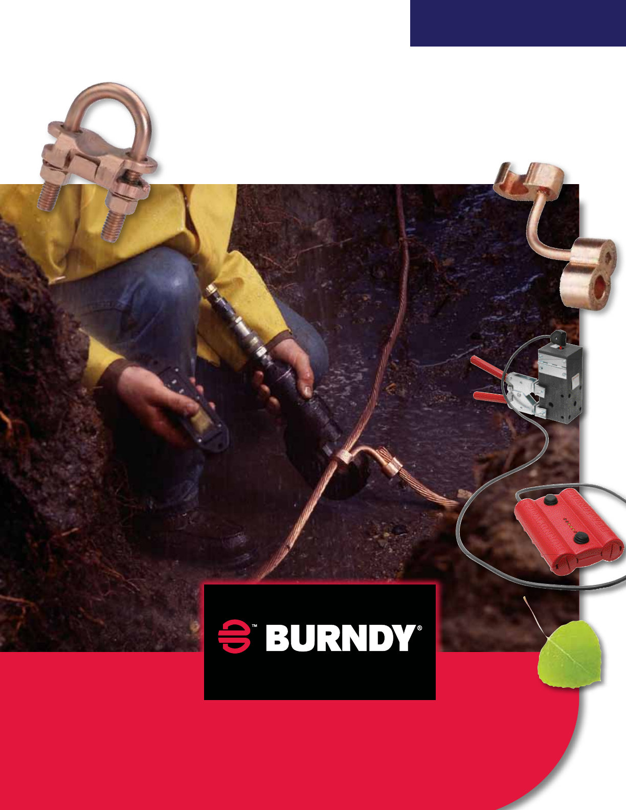
e BURNDY® Advantage
Experience. Technology. Answers.
TM
Grounding Solutions
GroundingSuperstoreTM
The
A Look at the Versatile SUPER-CLAMPTM Raised Floor Pedestal Ground Connector
Installing raised floors is easier with the SUPER-CLAMPTM Raised Floor Pedestal Ground Connector. This
specialized connector features a high-copper alloy body and stainless-steel hardware that can be installed
on round or square pedestals. Able to accommodate multiple wire configurations, the
open-face design can be installed without disassembling u-bolts or hardware.
Contact your local Sales Representative to discover how one SUPER-CLAMPTM
can take the place of many other currently available options.
Covering the Field
With ree Grounding Solutions
More than 80 years of technological innovation have made BURNDY® grounding
connectors the most widely used and highly respected lines in the industry. Today,
BURNDY® is a leading connector manufacturer and provider of commercial and
industrial, utility and OEM solutions.
Through The Grounding SuperstoreTM
, we offer three types of grounding products:
•Mechanical grounding connectors. Our nut-and bolt design is simple
to install without sacrificing performance. Because our mechanical
connectors are made of high copper content alloy, top performance
under the most extreme conditions is routine. Most connectors are
listed for direct burial applications in earth or concrete.
•BURNDYWeld® exothermic products. This is a simple, portable and
efficient method for welding copper to copper and other various materials.
The high-temperature molecular weld reaction of powdered copper oxide
and aluminum, results in a permanent, fusion or molecular weld connection.
•HYGROUND® Irreversible Compression Grounding System. This is the
industry’s safest, most complete, cost-effective and time-efficient grounding
system. Our unique system of cross grid, tap, splice, cable to ground rod, ground
plates and termination connectors are made of pure wrought copper—the same
material as the conductor.
No matter the option you choose, you’ll know you’re getting quality products that
meet and exceed standard performance guidelines—in all conditions.
BURNDY® has a made in the USA solution for virtually every
grounding application.
BURNDY®Grounding
US: 1-800-346-4175 www.burndy.com Canada: 1-800-387-6487
1
TABLE OF CONTENTS
HYGROUND®IRREVERSIBLE COMPRESSION GROUNDING
AND INSTALLATION TOOLING
Type YGIB . . . . . . . . . . . . . . 24 - 25
Type GSTUD-HY . . . . . . . . . . . . . 26
Types YGT & YTTAG . . . . . . . . . . 27
Type YG-B . . . . . . . . . . . . . . . . . . 28
MECHANICAL GROUNDING
Types KC, K2C . . . . . . . . . . . . . . 29
Types KC22J12T13,
EQC632C, KS . . . . . . . . . . . . . . 30
Types GKA, KPB, CL50-1 . . . . . . 31
Type GAR . . . . . . . . . . . . . . . 32 - 33
Types GAR-BU & GAR
3900 Series & GAR-RB . . . . . . . 34
Type GAR-TC . . . . . . . . . . . . . . . . 35
HYGROUND®Features
and Benefits . . . . . . . . . . . . . 6 - 7
Installation Instructions . . . . . 8 - 9
Type YGL-C . . . . . . . . . . . . . . . . . 10
Type YGLR-C . . . . . . . . . . . . . . . . 11
Type YGHP-C . . . . . . . . . . . . . . . 12
Type YGHP-C . . . . . . . . . . . . . . . 13
Type YGHC-C . . . . . . . . . . . . . . . 14
Type YGC . . . . . . . . . . . . . . . . . . . 15
Type YSHG . . . . . . . . . . . . . . . . . . 16
Type YGHR-C . . . . . . . . . . . . . . . 17
Type YGHR-C . . . . . . . . . . . . . . . 18
Type YGHA . . . . . . . . . . . . . . . . . 19
Type YGHS . . . . . . . . . . . . . . . . . . 19
Type YGA . . . . . . . . . . . . . . . . . . . 20
Type YGS . . . . . . . . . . . . . . . . . . . 21
Type YGF . . . . . . . . . . . . . . . . . . . 22
I-Beam Connector
Installation Instructions . . . . . 23
LIGHTNING PROTECTION INFO.
Basic rules for selection are:
1. Must be like material to the conductor.
2. Two bolts to ground rod –– minimum, for mechanical.
3. Cable to cable connections can be installed with – one bolt,
two bolt, or compression.
4. Cable to steel structure must have 8 in.2contact with steel.
5. Heavy duty stacks –– mechanical only.
6. On all connectors with heavy duty stack rating, we must
offer 1/16thick lead plating as an option. Reason is closest
25 ft. to stack opening must use lead coated product.
7. UL 96 Listing.
Grounding BURNDY®
Canada: 1-800-387-6487 www.burndy.com US: 1-800-346-4175
2
TABLE OF CONTENTS
MECHANICAL GROUNDING (Continued)
Type GC-CT . . . . . . . . . . . . . . . . . 54
Type BDT-1 BONDIT®. . . . . . . . . 55
Type BDTIBB BONDIT®. . . . . . . 56
BWB680 Series . . . . . . . . . . . . . . 57
BSD Series . . . . . . . . . . . . . . . . . 58
Type GIE-G . . . . . . . . . . . . . . . . . 59
Rail Connector . . . . . . . . . . . . . . . 60
Type QGFL . . . . . . . . . . . . . . . . . . 61
Type GA-H . . . . . . . . . . . . . . . . . . 61
Type GRF . . . . . . . . . . . . . . . . . . . 62
Raised Floor Grounding
Types GP-G1, GP-RT . . . . . . . . . 63
Raised Floor Grounding
Type GXP . . . . . . . . . . . . . . . . . . . 64
Raised Floor Grounding
Type BBB . . . . . . . . . . . . . . . 65 - 66
Copper BusBar
Type GD . . . . . . . . . . . . . . . . . . . . 36
Type GP . . . . . . . . . . . . . . . . . . . . 37
Type GK . . . . . . . . . . . . . . . . . . . . 37
Water Pipe Grounding . . . . . 38 - 43
Type GC-A . . . . . . . . . . . . . . . . . . 44
Type GG . . . . . . . . . . . . . . . . . . . . 45
Type GQ . . . . . . . . . . . . . . . . . . . . 46
Type GX . . . . . . . . . . . . . . . . . . . . 46
Types GRC, GRL, GCRT1/0 . . . . 47
Type B. . . . . . . . . . . . . . . . . . 48 - 51
Types GB, GBM . . . . . . . . . . . . . . 52
Types GC, GCM . . . . . . . . . . . . . . 52
Type GL . . . . . . . . . . . . . . . . . . . . 53
Type GZ . . . . . . . . . . . . . . . . . . . . 53
BURNDY®Grounding
US: 1-800-346-4175 www.burndy.com Canada: 1-800-387-6487
3
TABLE OF CONTENTS
BURNDYWeld®
BURNDYWeld®
Introduction . . . . . . . . . . . . . . . . . 68
Making a BURNDYWeld®
Connection . . . . . . . . . . . . . . . 69
QIKLITE™ . . . . . . . . . . . . . . . . . . 70
WELD METAL . . . . . . . . . . . . . . . 71
Type BCC-1 . . . . . . . . . . . . . . . . . 72
Type BCC-2 . . . . . . . . . . . . . . . . . 73
Type BCC-4 . . . . . . . . . . . . . . . . . 74
Type BCC-11 . . . . . . . . . . . . . . . . 75
Type BCC-6 . . . . . . . . . . . . . . . . . 76
Type BCC-14 . . . . . . . . . . . . . . . . 76
Type BCC-7 . . . . . . . . . . . . . . . . . 77
Type BCR-1 . . . . . . . . . . . . . . . . . 78
Type BCR-2 . . . . . . . . . . . . . . . . . 79
Type BCR-3 . . . . . . . . . . . . . . . . 80
Type BCR-17 . . . . . . . . . . . . . . . . 81
Type BCR-24 . . . . . . . . . . . . . . . . 82
Type BCS-1 . . . . . . . . . . . . . . . . . 84
Type BCS-8 . . . . . . . . . . . . . . . . . 84
Type BCS-2 . . . . . . . . . . . . . . . . . 85
Type BCS-9 . . . . . . . . . . . . . . . . . 85
Type BCS-3 . . . . . . . . . . . . . . . . . 86
Type BCS-23 . . . . . . . . . . . . . . . . 87
Type BCS-4 . . . . . . . . . . . . . . . . . 88
Type BCS-6 . . . . . . . . . . . . . . . . . 88
Type BCS-7 . . . . . . . . . . . . . . . . . 89
Type BCS-18 . . . . . . . . . . . . . . . . 89
Type BCS-5 . . . . . . . . . . . . . . . . . 90
Type BCRE-1 . . . . . . . . . . . . . . . . 91
Type BCRE-2 . . . . . . . . . . . . . . . . 92
Grounding BURNDY®
Canada: 1-800-387-6487 www.burndy.com US: 1-800-346-4175
4
TABLE OF CONTENTS
BURNDYWeld®(Continued)
Type BCRE-3 . . . . . . . . . . . . . . . . 93
Type BCRE-4 . . . . . . . . . . . . . . . . 94
Type BCRE-6 . . . . . . . . . . . . . . . . 95
BURNDY®
GROUNDMAX™ . . . . . . . . 96 - 97
BURNDY®GRIDMAX™ . . . . . . . 98
Types B-106 & B-107
Handle Clamps . . . . . . . . . . . . . 99
B40-0106-75
Handle Attachment . . . . . . . . . . 99
Mold Support Clamp . . . . . . . . . . 99
Vertical Magnetic
Clamps . . . . . . . . . . . . . . . . . . 100
Horizontal & Vertical
Chain Clamps . . . . . . . . . . . . . 100
SINGLE SHOT MOLDS
Type BCR-1 . . . . . . . . . . . . . . . . . 83
Type BCR-2 . . . . . . . . . . . . . . . . . 83
Type BCR-24 . . . . . . . . . . . . . . . . 83
Type BCR-25 . . . . . . . . . . . . . . . . 83
ACCESSORIES
B38-0330-00 Cable Clamp . . . . 101
Cable Cleaning Brush . . . . . . . . 101
Card Cloth Brush . . . . . . . . . . . . 101
Mold Cleaning Brush . . . . . . . . . 101
Mold Cleaners . . . . . . . . . . . . . . 101
Packing Material . . . . . . . . . . . . 101
BURNDYWeld®Tool Kit . . . . . . 102
BURNDYWeld®Tools . . . . . . . . 102
B38-0101-00 Rasp . . . . . . . . . . 102
B38-0309-00 Flint Ignitor . . . . . . 102
Ground Rod
Driving Sleeves . . . . . . . . . . . . 103
Shim Stock and
Adapter Sleeves . . . . . . . . . . . 103
Tips . . . . . . . . . . . . . . . . . 104 - 105
BURNDY®Grounding
US: 1-800-346-4175 www.burndy.com Canada: 1-800-387-6487
5
TABLE OF CONTENTS
GROUNDING ACCESSORIES
ACCESSORIES
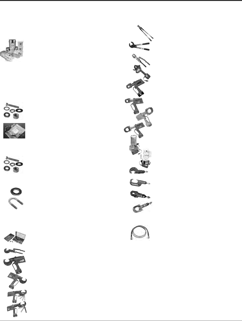
PENETROX™ A,
PENACARTRIDGE,
PENETROX™ A-13,
PENETROX™ E . . . . . . . . . . 106
PENETROX™
Technical and
Ordering Information . . . . . . . 107
HARDWARE
DURIUM™ Bolts,
Nuts, Washers . . . . . . . 108 - 109
DURIUM™ Hardware Kits. . . . . . 110
Stainless Steel Hardware Kits. . . 110
Galvanized Nuts,
Bolts, Washers . . . . . . . . . . . . 111
Aluminum Nuts,
Bolts, Washers . . . . . . . . . . . . 112
Stainless Steel Nuts,
Bolts, Washers . . . . . . . . . . . . 113
Belleville Washers . . . . . . . . . . . . 113
DURIUM™ U-Bolts . . . . . . . . . . . 114
TOOLS
Warranty Information . . . . . . . . 115
U Dies, W Dies . . . . . . . . . . . . . 116
Y750HSXT, Y750CHSXT . . . . . . 117
PATRIOT®PAT750XT-18V . . . . . 118
PATRIOT®PAT750LI . . . . . . . . . 119
PATRIOT®PAT46-18V . . . . . . . . 120
PATRIOT®PAT46-LI. . . . . . . . . . 121
MCC500, MCC1000 . . . . . . . . . 122
RCC556, RCC600, RCC750HD,
RCC954ACSR1K, RCC1000 123
YCUT129ACSR . . . . . . . . . . . . . 124
BCC1000CUAL . . . . . . . . . . . . . 125
PATRIOT®
PATCUT129ACSR-18V . . . . . 126
PATRIOT®PATCUT129-LI . . . . . 127
PATRIOT®
PATCUT245CUAL-18V . . . . . 128
PATRIOT®PATCUT245-LI . . . . . 129
Y10AC9. . . . . . . . . . . . . . . . . . . . 130
EPP10, EPP6 . . . . . . . . . . . . . . . 131
Y750BHXT, Y750CBHXT . . . . . 132
Y46, Y46C . . . . . . . . . . . . . . . . . 133
RHCC129ACSR . . . . . . . . . . . . 134
RHCC245CUAL . . . . . . . . . . . . . 135
ACCESSORIES
Hydraulic Hoses, ALFLUID™,
HYFLUID™, Die Cases. . . . . . 136
REFERENCE
Specifications for BURNDY®
HYGROUND®System . . . . . 138
Hardware Data . . . . . . . . . . . . . 139
Cable Data . . . . . . . . . . . . 140 - 143
Alpha-Numeric Index . . . 144 - 149

Grounding BURNDY®
HYGROUND®Compression
Canada: 1-800-387-6487 www.burndy.com US: 1-800-346-4175
6
THE HYGROUND®
IRREVERSIBLE
COMPRESSION
SYSTEM
BURNDY®has developed an irreversible
compression ground system which meets the
most stringent safety and performance
requirements, including those of OSHA and
nuclear power plant design. Performance
excellence and long life expectancy are the
system’s basic design guidelines. It is a com-
plete system which consists of connectors for
grid cross connections, taps, splices, cable to
ground rod, ground plates and terminations.
Our irreversible compression ground connec-
tors employ well-proven design principles and
technology that have been in existence for
over 60 years.
Connectors are just one component of our
Irreversible Compression Ground System.
Installation tooling is also an integral part of
this system. BURNDY®pioneered the com-
pression connector principle and continues
today to be the leader in compression tech-
nology. Our tooling package is the most
extensive in the industry and affords the user
many options.

BURNDY®Grounding
HYGROUND®Compression
US: 1-800-346-4175 www.burndy.com Canada: 1-800-387-6487
7
THE HYGROUND®
IRREVERSIBLE
COMPRESSION
SYSTEM
(Continued)
Features and Benefits
• Irreversible compression.
〫Meets NEC code section 250.
• Material-pure wrought copper extrusions,
rod and seamless tubing––identical
material to the conductor.
〫Completely eliminates the possibility of
corrosion due to dissimilar metals.
• Heavy duty connector design.
〫All connectors will carry the equivalent
or greater current carrying capacity
of the conductor while maintaining
high mechanical strength and
electrical integrity.
• Range taking design––minimum number of
connector combinations required to install
a conductor range of #6 solid to 500 kcmil
plus 1/2, 5/8, 3/4, and 1ground rods
and rebar.
〫Inventories are kept to a minimum and
product selection is simplified.
• System engineered tooling.
〫Each tooling recommendation has
been designed to ensure reliability
of the connection.
• Irreversible compression connectors
can be installed in all kinds of weather.
〫Eliminates costly construction delays
and enables the installer to better
schedule his job.
• May be installed without special training
or special tools. Y750 crimps entire range.
〫Low installed cost.
〫Simplified installation.
• Each connection can be made in less than
3 minutes.
〫Low installed cost.
〫Simplified installation.
• Each connector is clearly marked with
catalog number, conductor size and
installation die information.
〫Easy and accurate identification.
• Inspection ports are provided to assure
proper insertion of the conductor.
〫Built-in quality assurance.
• The die index number is embossed on the
connector after completion of the crimp.
〫Facilitates speedy inspection of installed
connectors to insure consistently
reliable and sound connections.
• Most HYGROUND®irreversible
compression elements are prefilled with
PENETROX™ and individually sealed
in clear polyethylene sheet.
〫Ensures that all contact surfaces are in
the proper condition for installation.
〫Ensures the electrical integrity of the
finished connection by inhibiting
moisture and contaminates from
entering the contact area.
• All HYGROUND®irreversible compression
connectors are Listed in conformance with
Underwriters Laboratories Standard UL467
and conform to applicable sections of the
National Electrical Code.
〫May be used in direct burial or concrete
embedded grounding applications.
• All HYGROUND®irreversible connectors
(with the exception of type YGA and YGS)
have been tested successfully according
to requirements of Standard IEEE 837.
〫Meets tough industry performance
requirements.
〫UPRECRIMP dies give added
mechanical strength. UPRECRIMP 34
for 3/4rod, UPRECRIMP 12 for 1/2
rod, and UPRECRIMP 58 for 5/8rod
(now includes undersized U.S. market
place rods).
• Allows connection to most sizes of
structural steel with no drilling, tapping,
or welding.
〫Safely installed at low cost. Hot work
permits are not required to install in
hazardous areas
Ground Rod and Rebar Diameter Chart
Ground Rod Reinforcing Bar (Rebar)
Size Material* Diameter Size Diameter
Steel 0.500 #3 (3/8) 0.375
1/2Copperclad 0.475 #4 (1/2) 0.500
Steel 0.625 #5 (5/8) 0.625
5/8Copperclad 0.563 #6 (3/4) 0.750
Steel 0.750 #7 (7/8) 0.875
3/4Copperclad 0.682 #8 (1) 1.000
Steel 1.000 #9 (1-1/8) 1.128
1Copperclad 0.914 — —
Sizes are nominal — Consult Ground Rod or Reinforcing Bar Manufacturers for exact dimensions.
*Steel Ground Rods include: Galvanized, Stainless Steel.
Grounding BURNDY®
HYGROUND®Compression
Canada: 1-800-387-6487 www.burndy.com US: 1-800-346-4175
8
Installation Instructions
BURNDY®HYGROUND®is the safest, most cost-effective, time-efficient, and easily
inspected grounding system available today. A BURNDY®HYGROUND®compression
connection can be made in three minutes. That translates to tremendous labor savings.
Plus, you can keep your entire jobsite work on schedule as BURNDY®HYGROUND®
connections can be made in even the most inclement weather conditions.
BURNDY®Grounding
HYGROUND®Compression
US: 1-800-346-4175 www.burndy.com Canada: 1-800-387-6487
9
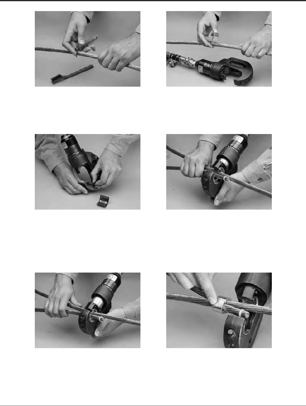
STEP 1
Select conductor or measure conductor
with BURNDY®HYGROUND®WIREMIKE™.
Clean conductor with wire brush as needed.
STEP 2
Select the appropriate connector and crimping
tool. Select the connector size by conductor
size or rod size or both.
STEP 3
Select and install proper die in tool. Note:
When connecting to a ground rod, precrimp
ground rod to increase mechanical strength
by using the appropriate precrimp die.
(Ground rods should be completely driven
before connector installation.)
STEP 4
Center the connector in the die to ensure full
embossment.
STEP 5
Place tool and connector on cable. Place this
on cross cable or the rod to be connected.
STEP 6
Cycle crimping tool until audible pressure
release is heard. Release tool.
The completed connection is ready for
inspection for proper connector,
conductor, die, and tool.
Grounding BURNDY®
HYGROUND®Compression
Canada: 1-800-387-6487 www.burndy.com US: 1-800-346-4175
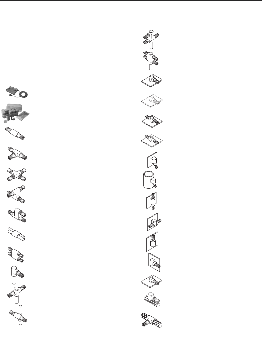
10
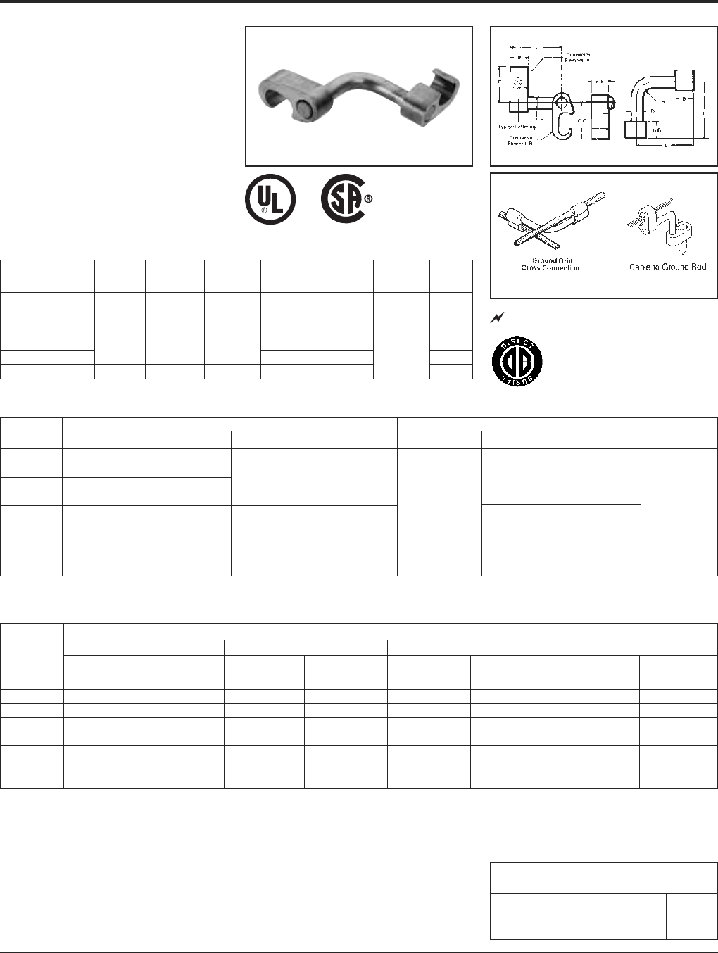
TYPE YGL-C
HYGRID™ CROSS
CONNECTOR
An irreversable compression ground grid
cross connector which allows adjustment of
the compression elements prior to installation.
Only six connectors and four dies are required
to install all combinations from #6 solid
through 500 kcmil. UL467 Listed. Acceptable
for direct burial in earth and concrete. Prefilled
with PENETROX™ compound and strip
sealed.
NOTES:
• Before crimping, both connector elements can
be turned on rod diameter “D” to any desired
position.
• Clean rust and/or protective coatings from rebar
prior to installation.
• When attaching connector to ground rod,
ground rod must be embossed with appropriate
PRECRIMP™ die. For connections that must
meet IEEE 837 requirements UPRECRIMP - type
PRE crimp dies must be used for maximum
clamping retention.
ORDERING INFORMATION
1. Where a “U” or “PU” die is recommended with Y45
HYPRESS™, a PT6515 adapter must be used.
2. Where a “U” or “PU” die is recommended with the Y46
HYPRESS™, a PUADP-1 adapter must be used.
➂Polarized die for the PAT750-18V.
UL96 Listed for Lightning Protection.
467 96
Catalog Cable to Cable Cable to Ground Rod To Rebar
Number Element “A” Element “B” Element “A” Element “B” Element “A”
YGL2C2 #6 Sol. (.162) – #2 Str. (.292)
{59500} – {59500} #6 Sol. (.162) – #2 Str. (.292)
YGL29C2 #1 Str. (.332) – 250 kcmil (.575) {59500} – {59500} #6 Sol. (.162) – #2 Str. (.292) 3/8– 1/2
{98500} – {131500} 1/2– 5/8Rod
YGL29C29 #2 Str. (.292) – 250 kcmil (.575) #2 Str. (.292) – 250 kcmil (.575) #2 Str. (.292) – 250 kcmil (.575) #3 – 4 Rebar
{65500} – {131500} {65500} – {131500}
YGL34C2 #6 Sol. (.162) – #2 Str. (.292) #6 Sol. (.162) – #2 Str. (.292) 5/8– 3/4
YGL34C29 250 kcmil (.575) – 500 kcmil (.813) #2 Str. (.292) – 250 kcmil (.575) 5/8– 3/4Rod #2 Str. (.292) – 250 kcmil (.575)
YGL34C34 250 kcmil (.575) – 500 kcmil (.813) 250 kcmil (.575) – 500 kcmil (.813) #5 – 6 Rebar
Dimensions in brackets { } represent lightning
protection conductors.
* These connectors can only be installed using the Y750,
Y45, or Y46 HYPRESS™ with the recommended dies.
These connectors CANNOT be installed with the Y35 and
Y39 HYPRESS™.
Installation Tools, Die Set Catalog Number (Number of Crimps)
Catalog Y750/Y35/Y39 HYPRESS™ PAT750-18V Y45 HYPRESS™ Y46 HYPRESS™
Number Element “A” Element “B” Element “A” Element “B” Element “A” Element “B” Element “A” Element “B”
YGL2C2 U-0 (1) U-0 (1) U-0 (1) U-0 (1) U-0 (1) U-0 (1) U-0 (1) U-0 (1)
YGL29C2 U997 (1) U-0 (1) ➂ U997P (1) U-0 (1) U997 (1) U-0 (1) U997 (1) U-0 (1)
YGL29C29 U997 (1) U997 (1) ➂ U997P (1) ➂ U997P (1) U997 (1) U997 (1) U997 (1) U997 (1)
S998 or P998 or
YGL34C2* PU998 (1) U-0 (1) PU998 (1) U-0 (1) PU998 (1) U-0 (1) PU998 (1) U-0 (1)
S998 or PU998 or
YGL34C29* PU998 (1) U997 (1) PU998 (1) ➂ U997P (1) PU998 (1) U997 (1) PU998 (1) U997 (1)
YGL34C34* U1011 (3) U1011 (3) U1011 (3) U1011 (3) S1011 (3) S1011 (3) P1011 (3) P1011 (3)
Catalog
Number B B-B C C-C D L R
YGL2C2 1.09
YGL29C2 1.09 .313 .31
YGL29C29 .75 .75 1.66 1.66 .500 .50
YGL34C2 1.09 .313 2.50 .31
YGL34C29 2.09 1.66 .500 .50
YGL34C34 1.10 1.10 2.28 2.28 .750 .75
Ground Rod
Dia. PRECRIMP Dies
1/2UPRECRIMP 12
5/8UPRECRIMP 58 U2CABT
3/4UPRECRIMP 34
IEEE-837
BURNDY®Grounding
HYGROUND®Compression
US: 1-800-346-4175 www.burndy.com Canada: 1-800-387-6487
11
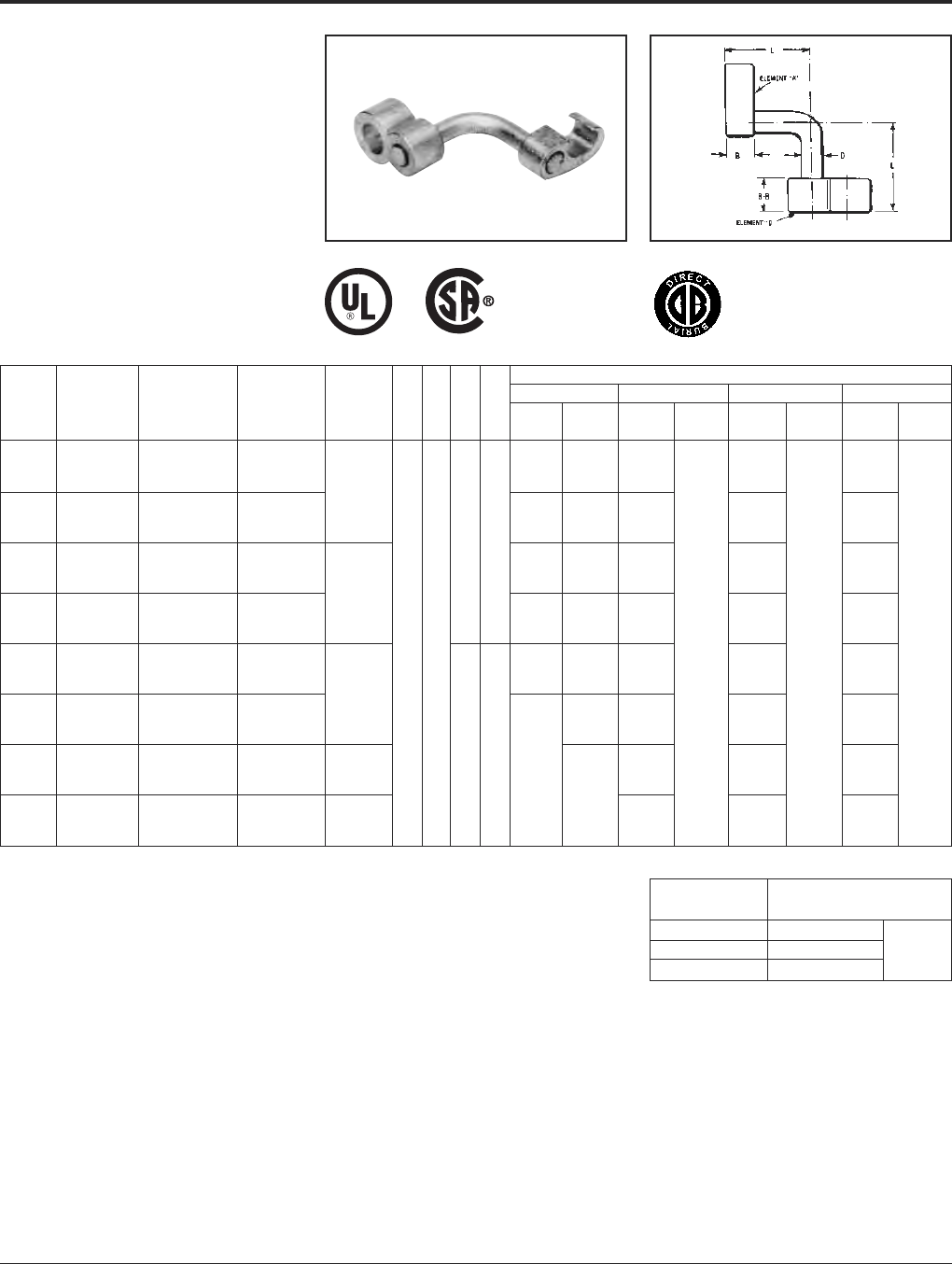
TYPE YGLR-C
GRIDLOK™
High Strength Irreversible
Compression Ground Rod to
Grid Connector
Ground grid connector for a wide range of
copper cable to ground rod. Provides high
torque strength on ground rod. UL467 Listed.
Acceptable for direct burial in earth and
concrete. Prefilled with PENETROX™
compound and strip sealed.
When attaching connector to ground rod, ground
rod must be embossed with appropriate PRE-
CRIMP™ die. For connections that must meet IEEE
837 requirements UPRECRIMP - type PRE crimp
dies must be used for maximum clamping retention.
NOTES:
1. Before crimping, both connector elements can be turned
on rod diameter 'D' to any desired position.
2. Grooves are filled with PENETROX™.
3. Suitable for direct burial in earth or concrete.
4. The catalog numbers shown are for unplated copper
connectors for use on copper clad or stainless steel ground
rod. To order electro-tin plated connectors for use on
galvanized steel ground rod add suffix “TN” to the catalog
number, only if the Figure 8 connector (Element “B”) is tin
plated, the Figure 6 connector (Element “A”) is unplated.
Note: The ground rod hole diameter is larger for galvanized
steel ground rod in the tin plated connector.
Element B
Element A
5. Ground rod must be pre-crimped with die U2CABT (Index
No. 348) when crimping the ground rod element (Element
“B”) with the PU998 dies in the Y750, Y35, Y39, Y45, or
Y46 tools. Pre-crimping is not required when the S1012,
P1011 or U1011 dies are used. See precrimp die chart.
6. Where a 'U' or 'PU' die is recommended with the Y45
HYPRESS™, a PT6515 adapter must be used.
7. Where a 'U' or 'PU' die is recommended with the Y46
HYPRESS™, a PUADP-1 adapter must be used.
8. Dimensions in bracket [ ] are in millimeters.
9. Die “1011” appears on Element “B” of the connector only.
Ground Rod
Dia. PRECRIMP Dies
1/2UPRECRIMP 12
5/8UPRECRIMP 58 U2CABT
3/4UPRECRIMP 34
Commercial Installation Tools, Die Set Cat. No. (Number of Crimps)
Copper Metric Copper Copper Weld Ground Rod Y35/Y39 HYPRESS™ Y750/PAT750 Y45 HYPRESS™ Y46 HYPRESS™
Catalog Cable Range Cable Range Cable Range Dia. Element Element Element Element Element Element Element Element
Number Element “A” Element “A” Element “A” Element “B” B B-B D L “A” “B” “A” “B” “A” “B” “A” “B”
#2 Str. (.292 Dia.) 35mm2(7.62mm Dia.) 91.65 kcmil (.343 Dia.)
YGLR29C12 thru thru thru U997 (1) PU998 (1) U997 (1) U997 (1) U997 (1)
250 kcmil (.575 Dia.) 120 mm2(14.40mm Dia.) 248.8 kcmil (.572 Dia.) 1/2
250 kcmil (.575 Dia.) 120 mm2(14.40mm Dia.) 248.8 kcmil (.572 Dia.) [12.7] U1011 S998 P998
YGLR34C12 thru thru thru — or or or
500 kcmil (.813 Dia.) 240 mm2(20.35mm Dia.) 498.8 kcmil (.810 Dia.) .313 2.53 PU998 (1) PU998 (1) PU998 (1)
#2 Str. (.292 Dia.) 35 mm2(7.62mm Dia.) 91.65 kcmil (.343 Dia.) [7.9] [64.3]
YGLR29C58 thru thru thru U997 (1) PU998 (1) U997 (1) U997 (1) U997 (1)
250 kcmil (.575 Dia.) 120 mm2(14.40mm Dia.) 248.8 kcmil (.572 Dia.) 5/8
250 kcmil (.575 Dia.) 120 mm2(14.40mm Dia.) 248.8 kcmil (.572 Dia.) [15.9] U1011 S998 P998
YGLR34C58 thru thru thru — or U1011 (2) or S1012 (2) or P1011(2)
500 kcmil (.813 Dia.) 240 mm2(20.35mm Dia.) 498.8 kcmil (.810 Dia.) .75 .88 PU998 (1) or PU998 (1) or PU998 (1) or
#2 Str. (.292 Dia.) 35 mm2(7.62mm Dia.) 91.65 kcmil (.343 Dia.) [19.1] [22.4] PU998 (1) PU998 (1) PU998 (1)
YGLR29C34 thru thru thru U997 (1) PU998 (1) U997 (1) U997 (1) U997 (1)
250 kcmil (.575 Dia.) 120 mm2(14.40mm Dia.) 248.8 kcmil (.572 Dia.) 3/4
250 kcmil (.575 Dia.) 120 mm2(14.40mm Dia.) 248.8 kcmil (.572 Dia.) [19.1] U1011 (2) U1011 (2) U1011 (2)
YGLR34C34 thru thru thru or or or
500 kcmil (.813 Dia.) 240 mm2(20.35mm Dia.) 496.8 kcmil (.810 Dia.) .500 2.63 PU998 PU998 PU998
#2 Str. (.292 Dia.) 35 mm2(7.62mm Dia.) 91.65 kcmil (.343 Dia.) [12.7] [66.8]
YGLR29C100 thru thru thru 1— U997 (1) U997 (1) U997 (1)
250 kcmil (.575 Dia.) 120 mm2(14.40mm Dia.) 248.8 kcmil (.572 Dia.) [25.4]
250 kcmil (.575 Dia.) 120 mm2(14.40mm Dia.) 248.8 kcmil (.572 Dia.) —U1011 (2) U1011 (2) U1011 (2)
YGLR34C100 thru thru thru 1or or or
500 kcmil (.813 Dia.) 240 mm2(20.35mm Dia.) 498.8 kcmil (.810 Dia.) [25.4] PU998 (1) PU998 PU998
IEEE-837

Grounding BURNDY®
HYGROUND®Compression
Canada: 1-800-387-6487 www.burndy.com US: 1-800-346-4175
12
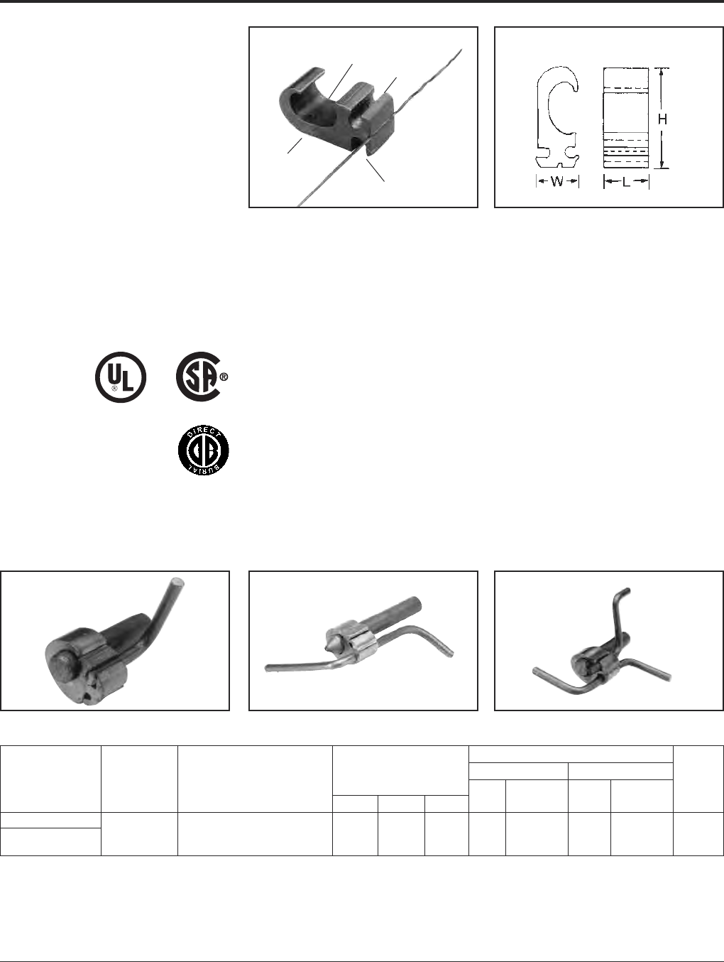
TYPE YGHP-C
HYTAP™ CONNECTOR
Irreversible compression ground tap figure 6
can be used as a tap connector or as a tap
splice connector. Four die sets and eight con-
nectors can accommodate a conductor range
from #8 solid through 500 kcmil plus 1/2, 5/8,
and 3/4copper bonded ground rods. UL467
Listed. Acceptable for direct burial in earth and
concrete. Prefilled with PENE TROX™
compound and strip sealed.
NOTES:
➀When using #6 Sol. in tap, fold conductor double to improve
fill in YGHP2C2.
➁For YGHP29C29 when using 3/0 in tap, minimum run
conductor is 2/0 Str.
➂Where a 'U' or 'PU' die is recommended with the Y45
HYPRESS™, a PT6515 adapter must be used.
➃Where a 'U' or 'PU' die is recommended with the Y45
HYPRESS™, a P-UADP-1 adapter must be used.
➄Clean rust and protective coatings from rebar before
connector installation to provide a proper ground
connection. Precrimping is not required.
For increased rotational resistance on ground rods,
pre-crimp ground rod with U2CABT die Index 348 or
uprecrimp dies may be used for even greater rota-
tion and vibration resistance on ground rods.
CABLE TO GROUND ROD
CABLE TO REBAR
CABLE TO CABLE
FOR CONCRETE ENCASED
ELECTRODE GROUNDING
APPLICATIONS
Fig. 1 Fig. 2
UL96 Listed for Lightning Protection.
Installation Data
➄
Die Y750/Y35
➂➃
Catalog Fig. Accommodates Cable To Rebar Index Y39 Y45 Y46 No. of
Number No. Run Tap Run Tap B No. HYPRESS™ PAT750-18V HYPRESS™ HYPRESS™ Crimps
YGHP2C2 1#6 Sol. (0.162) {59500} –
➀
#6 Sol. (0.162) {#2 Str.} – ——
#2 Str. (0.292) {59500} #2 Str. (0.292) {#2 Str.} 0U0U0U0 U01
YGHP2C6W6W
➇
2#6 Sol. (0.162) – #8 Sol. (0.128) – ——
#2 Str. (0.292) 6 Str. (0.184) Qty. 2
YGHP29C6W6W
➇
2#8 Sol. (0.128) – #8 Sol. – 6 Str.
6 Str. (0.184) Qtr. 2 #3 Rebar
YGHP29C2 1 1/0 Str. (0.372) {98500} – #4 Sol. (0.204) {#4 Sol.} – 3/8 #2 Str.
250 kcmil (0.575) {131500} #2 Str. (0.292) {#2 Str.} 997 U997
➆
U997P U997 U997 1
YGHP29C26 1 1/2– 5/8Rod 1/0 Str. (0.372) {98500} – thr0ugh
1/0 Str. – 2/0 Str. .75
2/0 Str. (0.419) {98500} 1/2 [19]
YGHP29C29
➁
13/0 Str. (0.470) {131500} – #4 Rebar 3/0 Str. – 250 kcmil
250 kcmil (0.575) {211500}
YGHP34C2
➅
1#4 Sol. (0.204) – #5 Rebar —
#2 Str. (0.292) 5/8
YGHP34C26
➅
1
250 kcmil (0.575) {250 kcmil} –
1/0 Str. (0.372) {98500} – 1/0 Str. – 2/0 Str. 998 PU998 PU998 PU998 or PU998 or 1500 kcmil (0.813) {500 kcmil} 2/0 Str. (0.419) {98500} S998 P998
YGHP34C29
➅
1
5/8– 3/4Rod 3/0 Str. (0.470) {131500} – through
3/0 Str. – 250 kcmil
250 kcmil (0.575) {211500}
250 kcmil (0.575) – 350 kcmil (0.681) –
3/4
1.10
YGHP34C34
➅
1 500 kcmil (0.813) #6 Rebar
350 kcmil – 500 kcmil
1011
➅
U1011 U1011 S1011 P1011 3
5/8– 3/4Rod 500 kcmil (0.843) [28]
Dimensions in brackets { } represent lightning protection
conductors.
467 96
➅These connectors can only be installed using the Y750,
Y45 or Y46 HYPRESS™ with the recommended dies.
These connectors can not be installed with the Y35 and
Y39 HYPRESS™.
➆Polarized die for the PAT750-18V.
➇Not UL96/CSA.
Ground Rod
Dia. PRECRIMP Dies
1/2UPRECRIMP 12
5/8UPRECRIMP 58 U2CABT
3/4UPRECRIMP 34
IEEE-837
BURNDY®Grounding
HYGROUND®Compression
US: 1-800-346-4175 www.burndy.com Canada: 1-800-387-6487
13
TYPE YGHP-C
HYTAP™ CONNECTOR
High Strength
Copper Irreversible
Compression
Ground Rod Tap Connector
Type YGHP-C irreversible compression ground
tap figure 6 can be used as a ground rod tap
connector for both continuous run and tapping
applications. An open groove allows ground
rod to be connected to a continuous run or tap.
The second groove is for a tap only. Prefilled
with PENETROX™ E and strip sealed. UL467
Listed for direct burial in earthor concrete.
Features and Benefits
• Tap (A) accepts a continuous run on
tap conductor
Tap (B) accepts a tap conductor only.
〫One connector style can be used for
many applications, reducing number
of connectors in inventory.
• Material is high conductivity wrought
copper extrusion, identical material to
the conductor.
〫High-conductivity copper minimizes
resistance and voltage drop. Eliminates
the possibility of corrosion due to
dissimiliar metals.
• System engineered tooling.
〫The tooling recommendation has been
designed to ensure a reliable,
dependable connection every time.
• The die index number is embossed on
conductor after completion of crimp.
〫Faciliates speedy inspection of installed
connectors to ensure consistently
reliable and dependable connections.
NOTE: A 12bend radius is recommended for the conductor.
• Use PUADP-1 with ‘U’-dies in Y46.
▲See tooling section in Master Catalog for complete tool
and die listing.
+ Either tap position may be left void when fewer than (2)
conductors are used.
SINGLE TAP CONTINUOUS RUN CONTINUOUS RUN AND TAP
PATENTED
TAP (A)
TAP (B)
PREFILLED WITH
PENETROX™ E
DIE INDEX
AND CONDUCTOR
INFORMATION
“THIRD HAND”
• Prefilled with PENETROX™ E and
individually sealed in clear polyethylene
sheet.
〫Ensures the electrical integrity of the
finished connection by inhibiting
moisture and contaminates from
entering the contact area. Maintains
long-term high-conductivity.
• UL467 Listed.
〫May be used in direct burial or concrete
embedded grounding applications.
Provides quality assurance to recognized
industry NEC standards from an
independent party.
• “Third Hand” constrains conductors while
installer completes crimp. Included with
each connector.
〫Simplifies installation, reducing
installed cost.
■Ground rod must be precrimped with die U2CABT (Index
No. 348).
For even greater rotational resistance use UPRECRIMP die.
For Galvanized Steel Rods order YGHP58C2W-2TN.
▲Installation Tooling
Y35/Y750/PAT750 Y46 •
Catalog Ground Dimensions Die No. of Die No. of Die
Number Rod Dia. ■Tap Conductor + H B W No. Crimps No. Crimps Index
YGHP58C2W-2 #2 Sol. - #6 Sol. Copper
1/2- 5/8(1) Continuous run and (1) Tap or 1.90.75.94U997 (1) U997 (1) 997
YGHP58C2W-2TN up to (2) taps may be connected.
IEEE-837

Grounding BURNDY®
HYGROUND®Compression
Canada: 1-800-387-6487 www.burndy.com US: 1-800-346-4175
14
Commercial Copper Cable Range/ Installation Data
Ground Rod
➇
Stranded Copper Die Y750/Y35/
➀➁
No.
Catalog
to Copper Cable Cable Range Index PAT750/Y39 Y45 Y46 of
Number
Run Tap Run Tap A B No. HYPRESS™ HYPRESS™ HYPRESS™ Crimps
#6 Sol. (0.162)
YGHC2C2
#2 Str. (0.292) #6 Sol. (0.162) 10 mm2(4.12 mm) 10 mm2(4.12 mm) 1.16 0.75 C U-C U-C U-C 1
1/4Rod ➆#2 Str. (0.292) 35 mm2(7.62 mm) 35 mm2(7.62 mm) [30] [19]
1 Str. (0.328)
{98500} #6 Sol. (0.162)
YGHC26C2
2/0 Str. (0.419) {#6 Sol.} 35 mm2(7.62 mm) 10 mm2(4.12 mm) 1.41 0.75 0 U-O U-O U-O 1
{98500} #2 Str. (0.292) 70 mm2(10.9 mm) 35 mm2(7.62 mm) [36] [19]
3/8Rod ➆{#2 Str.}
1 Str. (0.328)
{98500} 1 Str. (0.328)
YGHC26C26
2/0 Str. (0.419) {98500} 35 mm2(7.62 mm) 35 mm2(7.62 mm) 1.54 0.75 0 U-O U-O U-O 1
{98500} 2/0 Str. (0.419) 70 mm2(10.9 mm) 70 mm2(10.9 mm) [39] [19]
3/8Rod ➆{98500}
3/0 Str. (0.470)
{3/0 Str.} 6 Sol. (0.162)
YGHC29C26
250 kcmil (0.575) {59500} 95 mm2(12.5 mm) 10 mm2(4.12 mm) 1.97 0.75 997 U997 U997 U997 1
{250 kcmil} 2/0 Str. (0.419) 120 mm2(14.4 mm) 70 mm2(10.9 mm) [50] [19]
1/2or 5/8Rod
➆{98500}
3/0 Str. (0.470)
YGHC29C29
250 kcmil (0.575) 3/0 Str. (0.470) 95 mm2(12.5 mm) 95 mm2(12.5 mm) 2.06 0.88 997 U997 U997 U997 1
1/2or 5/8Rod
➆250 kcmil (0.575) 120 mm2(14.4 mm)
120 mm
2
(14.4 mm)
[52] [22]
300 kcmil (0.630)
{300 kcmil} #6 Sol. (0.162)
YGHC34C26
➅
500 kcmil (0.813)
{59500} 150 mm2(16 mm) 10 mm2(4.12 mm) 2.42 0.88 1011 U1011 S1011 P1011 2
{500 kcmil} 2/0 Str. (0.419)
240 mm
2
(20.35 mm)
70 mm2(10.9 mm) [62] [22]
3/4Rod ➆{98500}
300 kcmil (0.630) 3/0 Str. (0.470) 150 mm2(16 mm) 95 mm2(12.5 mm) 2.67 0.88
YGHC34C29
➅
500 kcmil (0.813) 250 kcmil (0.575) 240 mm
2
(20.35 mm) 120 mm
2
(14.4 mm)
[66] [22] 1011 U1011 S1011 P1011 2
300 kcmil (0.630) 300 kcmil (0.630) 150 mm2(16 mm) 150 mm2(16 mm) 2.91 1.1
YGHC34C34
➅
500 kcmil (0.813) 500 kcmil (0.813) 240 mm
2
(20.35 mm) 240 mm
2
(20.35 mm)
[74] [28] 1011 U1011 S1011 P1011 3
TYPE YGHC-C
HYTAP™ CONNECTOR
Irreversible compression ground tap figure
“C” connectors. Accommodates all cable
combinations from #6 solid through 500
kcmil. “C”- shaped opening permits placing
two continuous parallel cables into conductor
groove. UL 467 Listed. Acceptable for direct
burial in earth or concrete. Prefilled with PEN-
E TROX™ compound and strip sealed. Certain
sizes are also UL467 Listed and CSA Certified
for wire to ground rod.
NOTES:
➀Where a “U” or “PU” die is recommended with the Y45
HYPRESS™, PT6515 adapter must be used.
➁Where a “U” or “PU” die is recommended with the Y46
HYPRESS™, a PUADP-1 adapter must be used.
3. Listed under UL486A for copper wire connectors
4. Dimensions in brackets [ ] are in millimeters.
5. In referencing connectors without PENETROX™ oxide
inhibitor add suffix “NP” to the end of the Catalog
Number.
UL96 Listed for Lightning Protection. 467 96
Dimensions in brackets { } represent lightning protection conductors.
➅These connectors can only be installed using the Y750,
Y45 or Y46 HYPRESS™ with the recom mended dies.
These connectors cannot be installed with the Y35 and
Y39 HYPRESS™.
➆Ground rod to copper cable is UL 467 Listed for direct
burial in earth and concrete.
➇For ground rod to wire applications, ground rod must be
precrimped, see above table for appropriate precrimp
dies.
IEEE-837
Ground Rod
Dia. PRECRIMP Dies
1/2UPRECRIMP 12
5/8UPRECRIMP 58 U2CABT
3/4UPRECRIMP 34
BURNDY®Grounding
HYGROUND®Compression
US: 1-800-346-4175 www.burndy.com Canada: 1-800-387-6487
15
TYPE YGC
COPPER CRIMPIT™
UL 467 Listed for direct burial in earth or
concrete. Prefilled with PENETROX™ E2
oxide inhibitor.
Copper
Catalog Conductor
Number Run Tap H L Index OUR840 MD6/MD7 Crimps
#8 Sol. #8 Sol.
YGC8C8 #8 Str. #8 Str. .46 .52 162 W162 W162 2
#6 Sol. #8 Sol.
YGC6C8 #6 Str. #8 Str. .73 .62 BG XBG WBG 2
#6 Sol. #6 Sol.
YGC6C6 #6 Str. #6 Str. .76 .62 BG XBG WBG 2

Grounding BURNDY®
HYGROUND®Compression
Canada: 1-800-387-6487 www.burndy.com US: 1-800-346-4175
16
TYPE YSHG
HIGH STRENGTH
COPPER IRREVERSIBLE
COMPRESSION
Double H-Tap Connector
Type YSHG Double H-Tap grounding series is
comprised of five connectors designed to
accommodate wire range sizes #14 through
500 kcmil, including ground rod sizes: 3/4, 1,
and rebar sizes: #6, #8 and #9. Prefilled with
PENETROX™ E2 and strip sealed. Features and Benefits
• UL467 Listed.
〫Suitable for direct burial in earth
or concrete.
• Material is high conductivity
copper extrusion.
〫Minimizes resistance, eliminates
corrosion due to dissimilar metals.
* NOTE: Not for use on 1steel ground rod.
† Use PUADP-1 adapter.
Fig. 1 Fig. 2 Fig. 3
• Grooves are prefilled with PENETROX™ E2
oxide inhibitor and individually sealed.
〫Inhibits moisture and contaminants
ensuring electrical integrity.
Tooling Index
Catalog Fig. Conductor Sizes (number of crimps) Emboss- W T L
Number No. Main Tap 1 Tap 2 Tap 3 PAT750/Y750 Y46 ment .06 .04 .06
#9 & #8 Rebar, 1[25] Ground 3.22 1.70 2.44
YSHG4429 3Rod 250 - 2 PYFR (2) K-R [82] [43] [62]
#6 Rebar, 1[25] Cu Clad
* YSHG3931 2 Ground Rod, 3/4Ground Rod 4/0 - 1/0 1 - 6 2 - 14 PYFR (2) K-R 2.97 1.50 2.34
500 - 350 kcmil Copper [75] [38] [59]
#6 Rebar, 3/4[19] Ground Rod P1104 (2) 2.43 1.15 2.44
YSHG3434 1400 - 250 kcmil Copper 400 - 4/0 U1104 (4) †U1104 (4) 1104 [62] [29] [62]
#6 Rebar, 3/4[19] Ground Rod P1104 (2) 2.23 1.31 2.44
YSHG3429 2400 - 4/0 kcmil Copper 3/0 - 1/0 1 - 4 8 - 14 U1104 (4) †U1104 (4) 1104 [57] [33] [62]
BURNDY®Grounding
HYGROUND®Compression
US: 1-800-346-4175 www.burndy.com Canada: 1-800-387-6487
17
TYPE YGHR-C
HYTAIL™
High Strength Irreversible
Compression Ground Rod
Tap Connectors
High torque strength ground rod connectors.
Accommodates a wide range of copper
conductors to ground rod. UL467 Listed.
Acceptable for direct burial in earth or con-
crete. Prefilled with PENETROX™ compound
and strip sealed.
NOTES:
•The catalog numbers shown are for unplated copper
connectors for use on copper clad or stainless steel
ground rod. To order electro-tin plated connectors for use
on galvanized steel ground rod add suffix “TN” to the
catalog number. Note: The ground rod hole diameter is
larger for galvanized steel ground rod in the tin plated
connector.
①Ground rod must be pre-crimped with die U2CABT (Index
No. 348) when the PU998 dies are used in the Y750, Y35,
Y39, Y45, or Y46 tools. Pre-crimping is not required when
the P1011, S1011, S1012 or U1011 dies are used.
UPRECRIMP dies may be used for additional mechanical
resistance on ground rods.
➁Where a PU998 die is recommended with the Y45
HYPRESS™, a PT6515 adapter must be used.
➂Where a PU998 die is recommended with the Y46
HYPRESS™, a PUADP-1 adapter must be used.
➃These die numbers do not appear on the connector.
*These connectors can only be installed using the Y750,
Y45 or the Y46 HYPRESS™ with the recommended dies.
These connectors CAN NOT be installed with the Y35 and
Y39 HYPRESS™. When attaching connector to ground
rod, ground rod must be embossed with appropriate
PRECRIMP™ die. For connections that must meet IEEE
837 requirements UPRECRIMP - type PRE crimp dies
must be used for maximum clamping retention.
Catalog
Number H B
YGHR26C12 1.94[49.3]
YGHR26C58 1.97[50.0]
YGHR26C34 2.19[55.6]
YGHR26C100 2.55[56.2]
YGHR29C12 1.94[49.3] .88
YGHR29C58 2.14[54.4]
YGHR29C34 2.19[55.6] [22.4]
YGHR29C100 2.45[62.2]
YGHR34C58 2.14[54.4]
YGHR34C34 2.44[62.0]
YGHR34C100 2.70[68.6]
Catalog Commercial Copper Nominal Ground Installation Tools, Die Set Catalog Number (Number of Crimps)
Number Cable Range Rod Dia. PAT750/Y750/Y35/Y39 ①Y45 HYPRESS™ ①Y46 HYPRESS™ ①
YGHR26C12 1/2[12.7] S1012 (2)
YGHR26C58 #2 Str. (.292 Dia.) 5/8[15.9] ➃
YGHR26C34 through 3/4[19.0] PU998 (1) ②
2/0 Str. (.419 Dia.) S1011 (2) S1012 (2)
YGHR26C100* 1[25.4] PU998 (1)
YGHR29C12 1/2[12.7] U1011 (2) S1012 (2) P1011 (2)
YGHR29C58 #4/0 Str. (.528 Dia.) 5/8[15.9] ➃➃ ➃
YGHR29C34 through 3/4[19.0] PU998 (1) PU998 (1) ②PU998 (1)
250 kcmil (.575 Dia.) S1011 (2) S1012 (2) ③
YGHR29C100* 1[25.4] ➃PU998 (1)
YGHR34C58 300 kcmil (.630 Dia.) 5/8[15.9] S1012 (2)
YGHR34C34* through 3/4[19.0] ➃PU998 (1) ②
YGHR34C100* 500 kcmil (.813 Dia.) 1[25.4] S1011 (2) P1011 (2)
IEEE-837
Grounding BURNDY®
HYGROUND®Compression
Canada: 1-800-387-6487 www.burndy.com US: 1-800-346-4175
18
TYPE YGHR-C
HYTAIL™
High Strength Irreversible
Compression Ground Rod
Tap Connectors
Type YGHR-C irreversible compression
grounding connector is engineered specifically
for the Telecommunications Industry for
(1, 2 or 3) #2 solid, tinned or bare conductor
taps. UL467 Listed. Acceptable for direct
burial in earth or concrete. BURNDY®has
designed this connector to meet the stringent
requirements of OSHA, the National Electric
Code (NEC), UL, and the Telecommunications
Industry. Performance and long life are this
connector’s basic design guidelines.
Features and Benefits
• Tap side 1, 2 or 3 conductors.
〫One connector style can be used for
many applications.
• Material is high conductivity wrought
copper extrusion, identical material to
the conductor.
〫High-conductivity copper minimizes
resistance and voltage drop. Eliminates
the possibility of corrosion due to
dissimilar metals.
• System engineered tooling.
〫Each tooling recommendation has
been designed to provide a reliable,
dependable connection.
• Contact BURNDY®for other ground rod diameters.
* PU998 and U1011 die sets require PUADP-1 adapter for
use in the Y46 HYPRESS™.
Tap positions may be left void when fewer than (3)
conductors are used.
+ To order electro-tin plated connector for use on galvanized
steel ground rod add suffix -”TN” to the catalog number.
NOTE: The ground rod hole diameter is larger for galvanized
steel ground rod in the tin plated connector.
TAP TAP
RUN RUN
AND
• The die index number is embossed on
connector after completion of crimp.
〫Facilitates speedy inspection of installed
connectors to ensure consistently reliable
and dependable connections.
• Prefilled with PENETROX™ and individually
sealed in clear polyethylene sheet.
〫Ensures the electrical integrity of the
finished connection by inhibiting
moisture and contaminates from
entering the contact area. Maintains
long-term high-conductivity.
• UL 467 Listed. Acceptable for direct burial.
〫May be used in direct burial or concrete
embedded grounding applications.
Provides quality assurance to
recognized industry NEC standards
from an independent party.
† Ground rod must be precrimped with die U2CABT (Index
No. 348) when PU998 die set is used in the Y35, Y750 or
Y46.
▲HYPRESS™ tools. For even greater mechanical resistance
use UPRECRIMP 58 dies.
** The Y750 utilizes PU dies and the U1011 die. The Y35 only
uses PU998 die set.
NOTE: A 12bend radius is recommended for the conductor.
Installation Tooling
PAT750/Y35/Y750** Y46*
Catalog Ground Rod Die No. of Die No. of Die
Number + Diameter • Tap Conductor ▲No. Crimps No. Crimps Index
PU998† (1)
#2 Sol. Copper 1, 2, or 3 PU998† (1) U1011 (2) 998 or
YGHR58C2W-3 5/8may be connected P998 (1) 1011
U1011 (2) P1011 (2)
BURNDY®Grounding
HYGROUND®Compression
US: 1-800-346-4175 www.burndy.com Canada: 1-800-387-6487
19
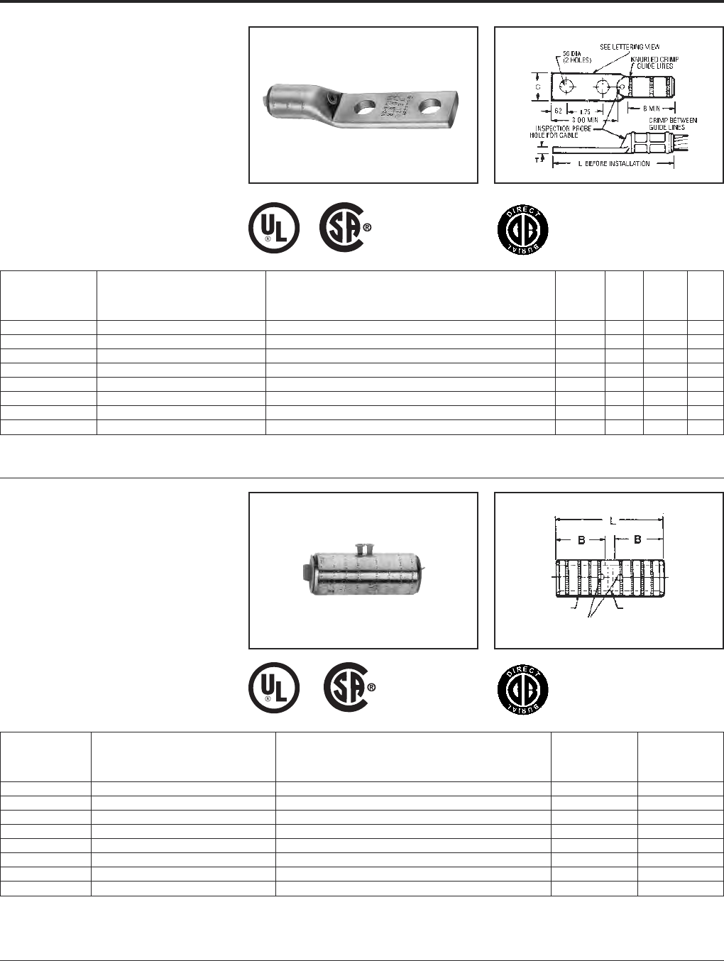
TYPE YGHA
HYLUG™
Heavy Duty Irreversible
Compression Terminals
Heavy duty HYLUG™ irreversible compres-
sion terminals designed not only to carry short
circuit load, but to also withstand high
mechanical stress. Each conductor element
has an inspection probe hole to ensure proper
cable insertion. UL467 Listed. Acceptable for
direct burial in earth or concrete. UL486A
Listed. Prefilled with PENE TROX™ compound
and strip sealed.
TYPE YGHS
HYLINK™
Heavy Duty Irreversible
Compression Terminals
Heavy duty HYLINK™ ground splice de-
signed not only to carry short circuit load, but
to also withstand high mechanical stress.
Each conductor element has an inspection
probe hole and a center stop to ensure proper
cable insertion. UL467 Listed. Acceptable for
direct burial in earth or concrete. UL486A
Listed. Prefilled with PENETROX™ com-
pound and strip sealed.
①Where a “U” or “PU” die is recommended with the Y45
HYPRESS™, a PT6515 adapter must be used.
①Where a “U” or “PU” die is recommended with the Y45
HYPRESS™, a PT6515 adapter must be used.
INSPECTION PROBE HOLES
FOR CABLE STOP
KNURLED
RINGS
IEEE-837
IEEE-837
Installation Tools, Die Set Catalog Number,
Catalog and (Number of Crimps)
Number Copper Conductor Size HYPRESS™ Y35/Y39/Y45 ①/Y46 ②/Y750 /PAT750 B C L T
YGHA2C-2N 2 str. U1CRT (1) .75 .97 4.21 .26
YGHA25-2N 1/0 str. U27RT (1) .83 .91 4.60 .19
YGHA26-2N 2/0 str. U28RT (1) .83 .97 4.38 .26
YGHA27-2N 3/0 str. U29RT (1) 1.18 1.08 4.94 .29
YGHA28-2N 4/0 str. U30RT (2) 1.18 1.22 4.94 .30
YGHA29-2N 250 kcmil U31RT (2) 1.18 1.28 4.94 .34
YGHA31-2N 350 kcmil U34RT (2) 1.18 1.62 5.00 .43
YGHA34-2N 500 kcmil U36RT (3) 1.48 1.72 5.42 .40
Installation Tools, Die Set Catalog Number,
Catalog and (Number of Crimps)
Number Copper Conductor Size HYPRESS™ Y35/Y39/Y45 ①/Y46 ②/Y750 /PAT750 B L
YGHS2C 2 str. U1CRT (1) .75 1.73
YGHS25 1/0 str. U27RT (1) .83 1.89
YGHS26 2/0 str. U28RT (1) .83 1.89
YGHS27 3/0 str. U29RT (1) 1.18 2.59
YGHS28 4/0 str. U30RT (2) 1.18 2.59
YGHS29 250 kcmil U31RT (2) 1.18 2.59
YGHS31 350 kcmil U34RT (2) 1.18 2.59
YGHS34 500 kcmil U36RT (3) 1.48 3.19
➁Where a “U” or “PU” die is recommended with the Y46
HYPRESS™, a PUADP-1 adapter must be used.
➁Where a “U” or “PU” die is recommended with the Y46
HYPRESS™, a PUADP-1 adapter must be used.

Grounding BURNDY®
HYGROUND®Compression
Canada: 1-800-387-6487 www.burndy.com US: 1-800-346-4175
20
TYPE YGA
HYLUG™
Grounding Irreversible
Compression Terminals
Irreversible compression HYLUG™ Ground
terminal specifically designed for grounding
applications. Each connector has an inspec-
tion probe hole to ensure proper cable inser-
tion. UL467 Listed. Acceptable for direct
burial in earth or concrete. UL486A Listed.
Prefilled with PENETROX™ compound and
strip sealed.
①Where a “U” or “PU” die is recommended with the Y45
HYPRESS™, a PT6515 adapter must be used.
Fig. 1 Fig. 2
Installation Tools, Die Set Catalog Number
(Number of Crimps)
Mechanical Hydraulic
Y35/Y39/Y45/PAT750 ①
Copper Y2MR MD7-34R OUR840 /Y46 ②/Y750
Catalog Fig. Conductor Die # (# of Die # (# of Die # (# of Die # (# of Stud
Number No. Size crimps) crimps) crimps) crimps) Size B C L T E
W8CVT (2)
YGA8C-TC10 2 8 sol./8 str. Red (4) X8CRT (2) U8CRT (2) #10 .81 .41 1.57 .08 —
W8CVT (2)
YGA8C-TC14 2 8 sol./8 str. Red (4) X8CRT (2) U8CRT (2) 1/4 .81 .44 1.69 .08 —
W8CVT (2)
YGA8C-TC516 2 8 sol./8 str. Red (4) X8CRT (2) U8CRT (2) 5/16 .81 .51 1.75 .06 —
W8CVT (2)
YGA8C-2N 1 8 sol./8 str. Red (4) X8CRT (2) U8CRT (2) 1/2 .81 .71 4.09 .05 1.75
W5CVT (2)
YGA6C-TC10 2 6 sol./6 str. Blue (4) X5CRT (2) U5CRT (2) #10 1.12 .42 1.89 .09 —
W5CVT (2)
YGA6C-TC14 2 6 sol./6 str. Blue (4) X5CRT (2) U5CRT (2) 1/4 1.12 .45 2.02 .08 —
W5CVT (2)
YGA6C-TC516 2 6 sol./6 str. Blue (4) X5CRT (2) U5CRT (2) 5/16 1.12 .51 2.08 .07 —
W5CVT (2)
YGA6C-2TC38E2G1 1 6 sol./6 str. Blue (4) X5CRT (2) U5CRT (2) 3/8 1.12 .58 3.42 .06 .75
W5CVT (2)
YGA6C-2N 1 6 sol./6 str. Blue (4) X5CRT (2) U5CRT (2) 1/2 1.12 .83 4.40 .12 1.75
W2CVT (2)
YGA2C-2TC38 1 2 sol./2 str. Brown (4) X2CRT (2) U2CRT (2) 3/8 1.25 .60 3.48 .12 1.00
W2CVT (2)
YGA2C-2N 1 2 str. Brown (4) X2CRT (2) U2CRT (2) 1/2 1.22 .81 4.71 .12 1.75
W25VT (4)
YGA25-2N 1 1/0 str. — X25RT (4) U25RT (2) 1/2 1.35 .81 4.91 .12 1.75
W26VT (4)
YGA26-2N 1 2/0 str. — X26RT (4) U26RT (2) 1/2 1.45 .81 4.89 .12 1.75
W28VT (4)
YGA28-2N 1 4/0 str. — X28RT (4) U28RT (2) 1/2 1.57 1.00 5.06 .14 1.75
YGA29-2N 1 250 kcmil — W29VT (4) U29RT (2) 1/2 1.57 1.09 5.16 .16 1.75
YGA34-2N 1 500 kcmil — W34VT (4) U34RT (4) 1/2 2.20 1.52 5.94 .23 1.75
➁Where a “U” or “PU” die is recommended with the Y46
HYPRESS™, a PUADP-1 adapter must be used.

BURNDY®Grounding
HYGROUND®Compression
US: 1-800-346-4175 www.burndy.com Canada: 1-800-387-6487
21
TYPE YGS
HYLINK™
Grounding Irreversible
Compression Splices
Irreversible compression HYLINK™ ground
splices specifically designed for grounding
applications. Each conductor element has an
inspection probe hole and a center stop to
ensure proper cable insertion. UL467 Listed.
Acceptable for direct burial in earth or
concrete. UL486A Listed. Prefilled with
PENETROX™ compound and strip sealed.
①Where a “U” or “PU” die is recommended with the Y45
HYPRESS™, a PT6515 adapter must be used.
➁Where a “U” or “PU” die is recommended with the Y46
HYPRESS™, a PUADP-1 adapter must be used.
③Use “X” with OUR840, “W” with MD6/MD7.
Installation Tools, Die Set Catalog Number
(Number of Crimps)
Mechanical Hydraulic
Copper Y2MR MD7-34R OUR840 Y35/Y39/Y45①
Catalog Conductor Die # (# of Die # (# of Die # (# of /Y46②/Y750/PAT750
Number Size Crimps) Crimps) Crimps) Die # (# of Crimps) B L
YGS8C #8 sol./str. — X8CRT, W8CRT, W8CVT ➂U8CRT (2) .78 1.75
YGS6C #6 sol./str. — X5CRT, W5CRT, W5CVT ➂U5CRT (2) 1.09 2.38
W2CVT (2)
YGS2C 2 str. Brown (4) X2CRT (2) U2CRT (2) 1.22 2.67
W25VT (4)
YGS25 1/0 str. — X25RT (4) U25RT (2) 1.35 2.97
W26VT (4)
YGS26 2/0 str. — X26RT (4) U26RT (2) 1.45 3.13
W28VT (4)
YGS28 4/0 str. — X28RT (4) U28RT (2) 1.57 3.37
YGS29 250 kcmil — W29VT (4) U29RT (2) 1.57 3.37
YGS34 500 kcmil — W34VT (4) — U34RT (4) 2.20 4.63
Grounding BURNDY®
HYGROUND®Compression
Canada: 1-800-387-6487 www.burndy.com US: 1-800-346-4175
22
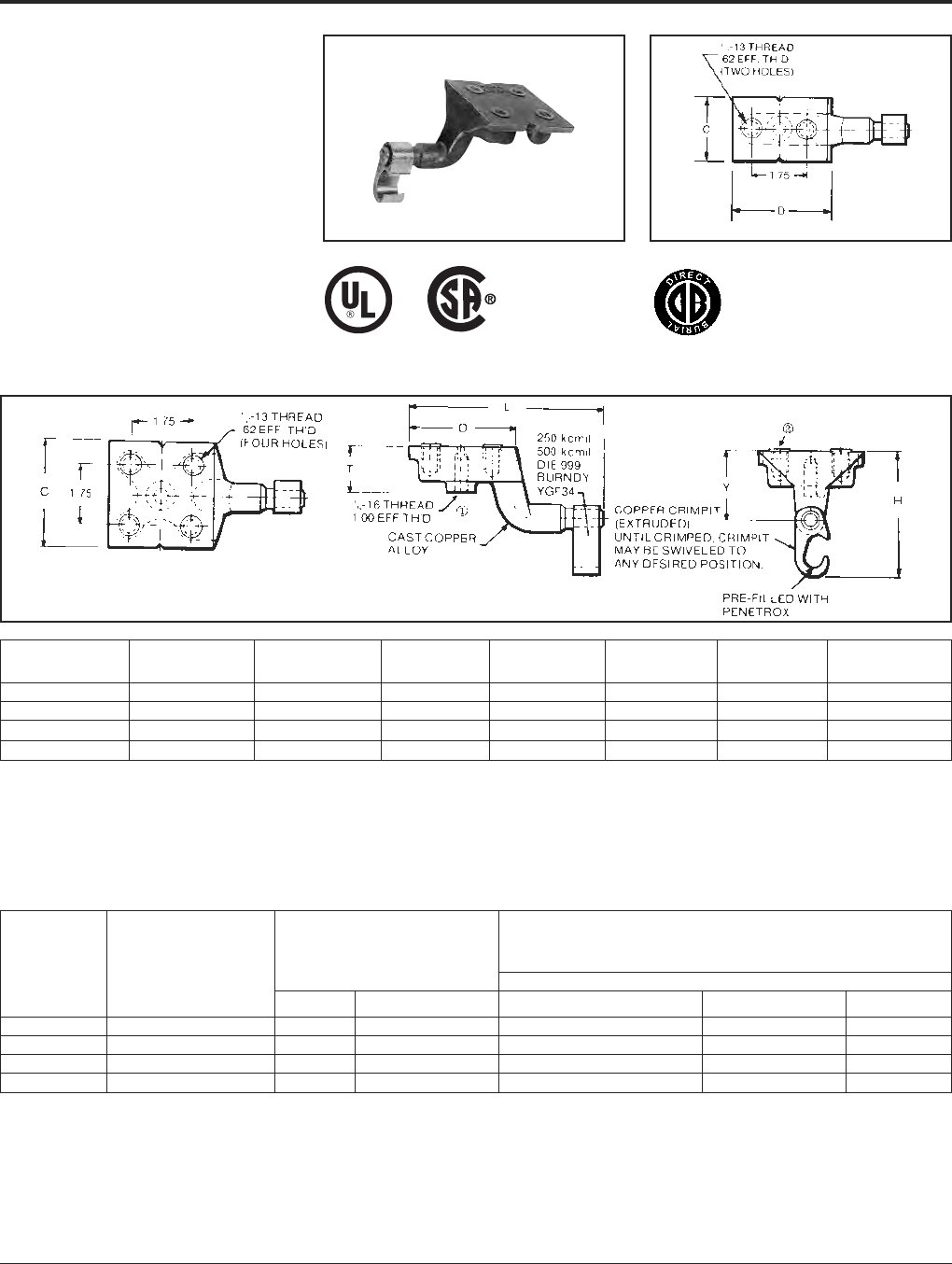
TYPE YGF
GROUNDING PLATE
The irreversible compression ground plate is
designed to withstand the rigors of concrete
construction. The ground plates are made of
high strength, high-conductivity cast copper
alloy body with a pure wrought copper
compression element. In addition to the
tapped NEMA size holes and spacing on the
face, the plate comes with a tapped hole on
the underside for ease of positioning prior to
pouring the concrete. UL467 Listed. Accept-
able for direct burial in earth or
concrete. Prefilled with PENETROX™
compound and strip sealed.
NOTES:
①This tapped hole may be used to position the grounding
plate on a threaded rod prior to placement of the concrete.
ORDERING INFORMATION
①Where a “U” or “PU” die is recommended
with the Y45 HYPRESS™, a PT6515
adapter must be used.
Fig. 1
Fig. 2
IEEE-837
①3/8-16 thread with 1.00 EFF. Thread is standard. If other
thread is required, add appropriate Code No. to Catalog No.
for desired thread.
-50 (1/2 -13, .94 EFF. Thread), -62 (5/8 -11, .94 EFF. Thread)
and -75 (3/4 -10, .81 EFF. Thread)
Example: YGF34-4N-50 is YGF34-4N with 1/2 -13 Thread
②Plastic plugs are provided to keep dirt out of the threaded
holes until the attachment of grounding terminals.
Catalog
Number Fig. No. C D H L T Y
YGF29-2N 1 2.00 3.25 3.62 5.78 1.31 2.00
YGF29-4N 2 3.25 3.25 3.62 5.78 1.31 2.00
YGF34-2N 1 2.00 3.25 4.62 5.40 1.31 2.19
YGF34-4N 2 3.75 3.75 4.62 5.90 1.31 2.19
Installation Tools,
Die Set Cat. No., and
(number of crimps)
Catalog Copper Tapped Holes HYPRESS™
Number Conductor Range Size Hole Centers PAT750/Y750/Y35/Y39 Y45 ①Y46 ②
YGF29-2N 2 - 250 kcmil 1/2 - 13 1-3/4 U997 (1) U997 (1) U997 (1)
YGF29-4N 2 - 250 kcmil 1/2 - 13 1-3/4 U997 (1) U997 (1) U997 (1)
YGF34-2N* 250 - 500 kcmil 1/2 - 13 1-3/4 U1011 (3) S1011 (2) P1011 (2)
YGF34-4N* 250 - 500 kcmil 1/2 - 13 1-3/4 U1011 (3) S1011 (2) P1011 (2)
➁Where a “U” or “PU” die is recommended
with the Y46 HYPRESS™, a PUADP-1
adapter must be used.
* These connectors can only be installed
using the Y750, Y45 or Y46 HYPRESS™
with recommended dies. These connec-
tors CAN NOT be installed with the Y35 or
Y39 HYPRESS™.
BURNDY®Grounding
HYGROUND®Compression
US: 1-800-346-4175 www.burndy.com Canada: 1-800-387-6487
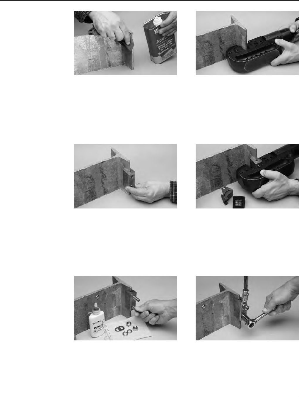
23
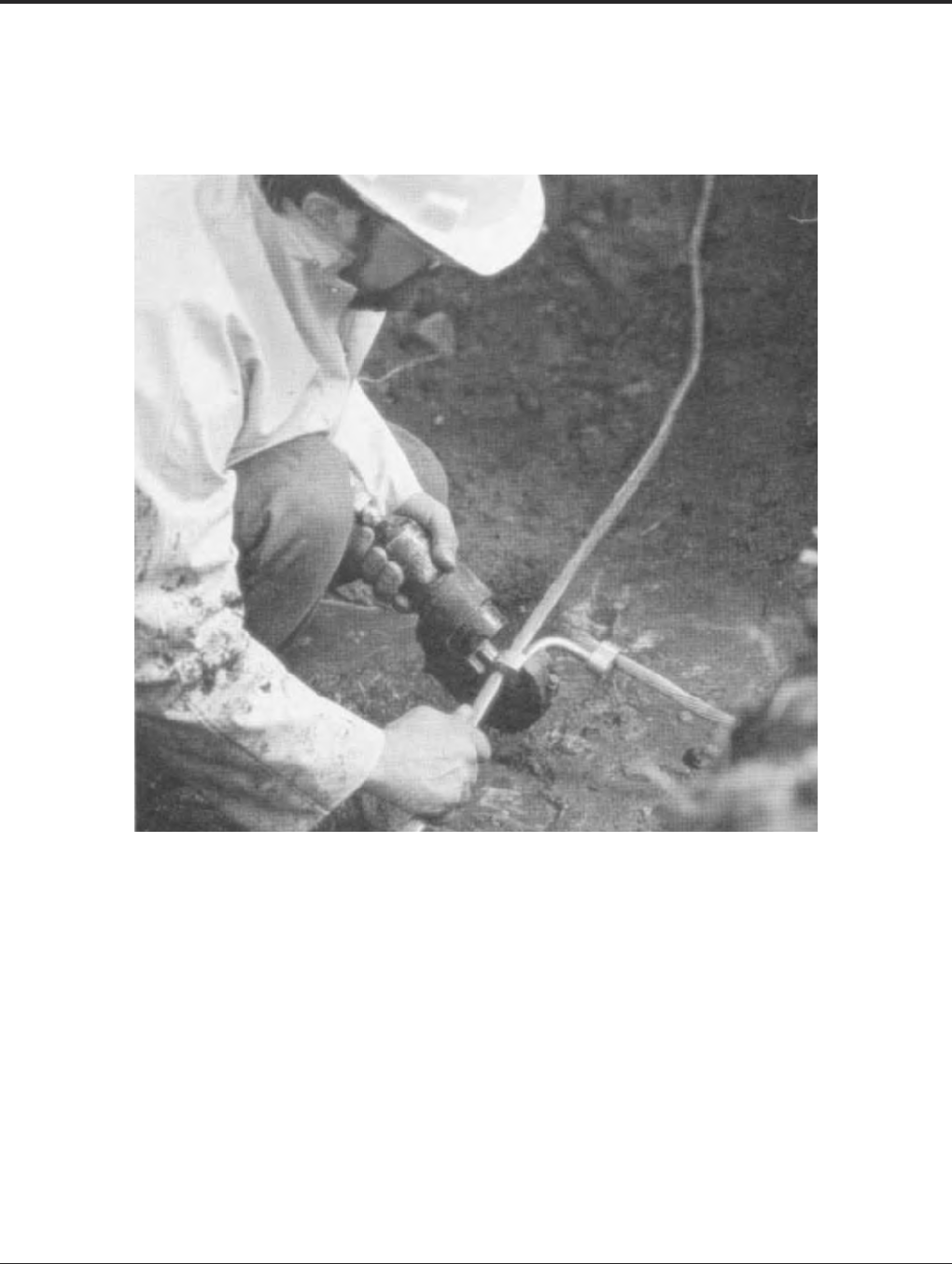
STEP 1
Sand or grind I-beam to bare metal on
both sides. Galvanized beams should be
cleaned with a solvent without disturbing
the plating/galvanizing.
STEP 2
Select the appropriate PRECRIMP die kit for
the beam.* Install the die set into the crimping
tool. Precrimp the I-beam bare metal area.
Crimp the length of the connector, slightly
overlapping each crimp.
* For wide, parallel flanges and beams, the PIBEW P1 kit
should be used. For standard angled flanges, the PIBES
P1 should be used.
STEP 3
Select the connector and install directly over
the precrimped area of the beam. Position the
connector on the beam so the flange is fully
inserted into the connector. Minimize sideways
motion of the connector to prevent the loss
of PENETROX™ between the connector and
the beam.
STEP 4
Remove the PRECRIMP dies from the tool,
leaving the embossing dies in place. Begin
crimping at the center of the connector.
Overlap the crimps by moving to either
side of the center and crimp the full length
of the connector. Inspect the assembled
connector for die embossment (#1105)
for quality assurance.
STEP 5
Remove the dummy stud from the connector.
Replace with the screw set supplied in the
TMHG grounding hardware kit. Screw the stud
into the connector until the stud is finger tight.
STEP 6
Apply PENETROX™ to the surface of the YGIB.
Install a YGA or YGHA terminal onto the ground
conductor and slide the terminal over the studs.
Place flat washers, lock washers, and nuts on
the studs. Using a torque wrench, tighten the
nuts to the recommended torque.
I-Beam
Connector
Installation
Instructions
Grounding BURNDY®
HYGROUND®Compression
Canada: 1-800-387-6487 www.burndy.com US: 1-800-346-4175
24
NOTES:
1. Terminal conector to be ordered separately. When I-
beam connector is used with type “YGHA” terminal, the
connection meets IEEE 837-1989 requirements. YGA-2N,
YA-2N and other BURNDY®2-hole NEMA copper
terminals are suitable.
2. Order “TMHG” Terminal Mounting Hardware Kit
separately. Kit consists of 2 studs, 2 flat washers, 2
lockwashers and 2 hex nuts.
3. Using the 1/4 hex key wrench, screw the stud into the
connector until stud bottoms out in connector. Install a
“YGHA” terminal, flat washer, lockwasher and hex nut
onto stud. Tighten and torque to 480 pound-inches.
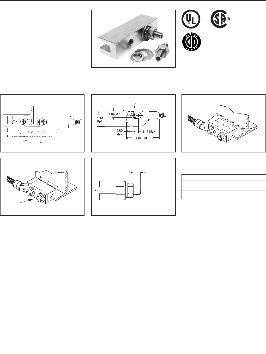
TYPE YGIB
GROUNDLINK™ CONNECTOR
An irreversible compression ground connec-
tion which allows attachment to a structural
steel standard (angled) or wide flange
(para llel) beam. Installed with a required
5-piece die set, Catalog PIBEAMKIT or
UIBEAMKIT. Die index 1105. GROUNDLINK™
connectors are made of high-conductivity
wrought copper and come pre-filled with
PENETROX™ E compound and strip sealed.
Order terminal mounting hardware separately.
NOTE: Use TMHG-92 to double stack lugs.
Fig. 1
Fig. 2
Connector shipped with thread protection studs only. Order
TMHG kits separately.
1.84 In. Minimum flange depth.
3.06 In. Minimum flange width.
Standard Beams
(Flange Angled) use YGIBS
Wide Flange Beams
(Flange Parallel) use YGIBW
TERMINAL MOUNTING HARDWARE
“T” Ref. Maximum
Terminal Pad
Thickness
Y46 Series
use PIBEAMKIT Y750 Series
use UIBEAMKIT
2 Hole NEMA
Spacing
➃➃
IEEE-837
➃Dimensions shown reflect the minimum dimensions
required on a beam to properly install the I-beam
connector.
5. To correctly determine the appropriate YGIB connector to
use based on flange thickness, order either YGIBGAUGE1
or YGIBKIT1 (KIT1 contains wiremike).
Catalog Number “T”
TMHG-42 .42
TMHG-92 .92
BURNDY®Grounding
HYGROUND®Compression
US: 1-800-346-4175 www.burndy.com Canada: 1-800-387-6487
25
TYPE YGIB
(Continued)
GROUNDLINK™ CONNECTOR
Copper i-Beam
Conductor Fig. Flange Suggested Terminals
Range Catalog Number No. “L” “J” Thickness Copper Conductor Terminal “T” Ref.
#2 Str. AWG YGHA2C-2N .26
YGIBS28-338-2N 1 3.00 1/0 Str. AWG YGHA25-2N .19
2 - 4/0 AWG .2502/0 Str. AWG YGHA26-2N .26
YGIBW28-338-2N 2 3.00 to 4/0 Str. AWG YGHA28-2N .30
YGIBS34-338-2N 1.338250 kcmil YGHA29-2N .34
250 - 500 kcmil YGIBW34-338-2N 26.00 500 kcmil YGHA34-2N .40
#2 Str. AWG YGHA2C-2N .26
YGIBS28-400-2N 1 3.00 1/0 Str. AWG YGHA25-2N .19
2 - 4/0 AWG .3382/0 Str. AWG YGHA26-2N .26
YGIBW28-400-2N 2 3.00 to 4/0 Str. AWG YGHA28-2N .30
YGIBS34-400-2N 1.400250 kcmil YGHA29-2N .34
250 - 500 kcmil YGIBW34-400-2N 26.00 500 kcmil YGHA34-2N .40
#2 Str. AWG YGHA2C-2N .26
YGIBS28-462-2N 1 3.00 1/0 Str. AWG YGHA25-2N .19
2 - 4/0 AWG .4002/0 Str. AWG YGHA26-2N .26
YGIBW28-462-2N 2 3.00 to 4/0 Str. AWG YGHA28-2N .30
YGIBS34-462-2N 1 1/2 - 13 .462250 kcmil YGHA29-2N .34
250 - 500 kcmil YGIBW34-462-2N 26.00 500 kcmil YGHA34-2N .40
#2 Str. AWG YGHA2C-2N .26
YGIBS28-550-2N 1 3.00 1/0 Str. AWG YGHA25-2N .19
2 - 4/0 AWG 4.622/0 Str. AWG YGHA26-2N .26
YGIBW28-550-2N 2 3.00 to 4/0 Str. AWG YGHA28-2N .30
YGIBS34-550-2N 1.550250 kcmil YGHA29-2N .34
250 - 500 kcmil YGIBW34-550-2N 26.00 500 kcmil YGHA34-2N .40
#2 Str. AWG YGHA2C-2N .26
YGIBS28-613-2N 1 3.00 1/0 Str. AWG YGHA25-2N .19
2 - 4/0 AWG .5502/0 Str. AWG YGHA26-2N .26
YGIBW28-613-2N 2 3.00 to 4/0 Str. AWG YGHA28-2N .30
250 - 500 kcmil YGIBW34-613-2N 2 6.00 500 kcmil YGHA34-2N .40
#2 Str. AWG YGHA2C-2N .26
YGIBS28-675-2N 1 3.00 1/0 Str. AWG YGHA25-2N .19
2 - 4/0 AWG .6132/0 Str. AWG YGHA26-2N .26
YGIBW28-675-2N 2 3.00 to 4/0 Str. AWG YGHA28-2N .30
YGIBS34-675-2N 1.675250 kcmil YGHA29-2N .34
250 - 500 kcmil YGIBW34-675-2N 26.00 500 kcmil YGHA34-2N .40
Grounding BURNDY®
HYGROUND®Compression
Canada: 1-800-387-6487 www.burndy.com US: 1-800-346-4175
26
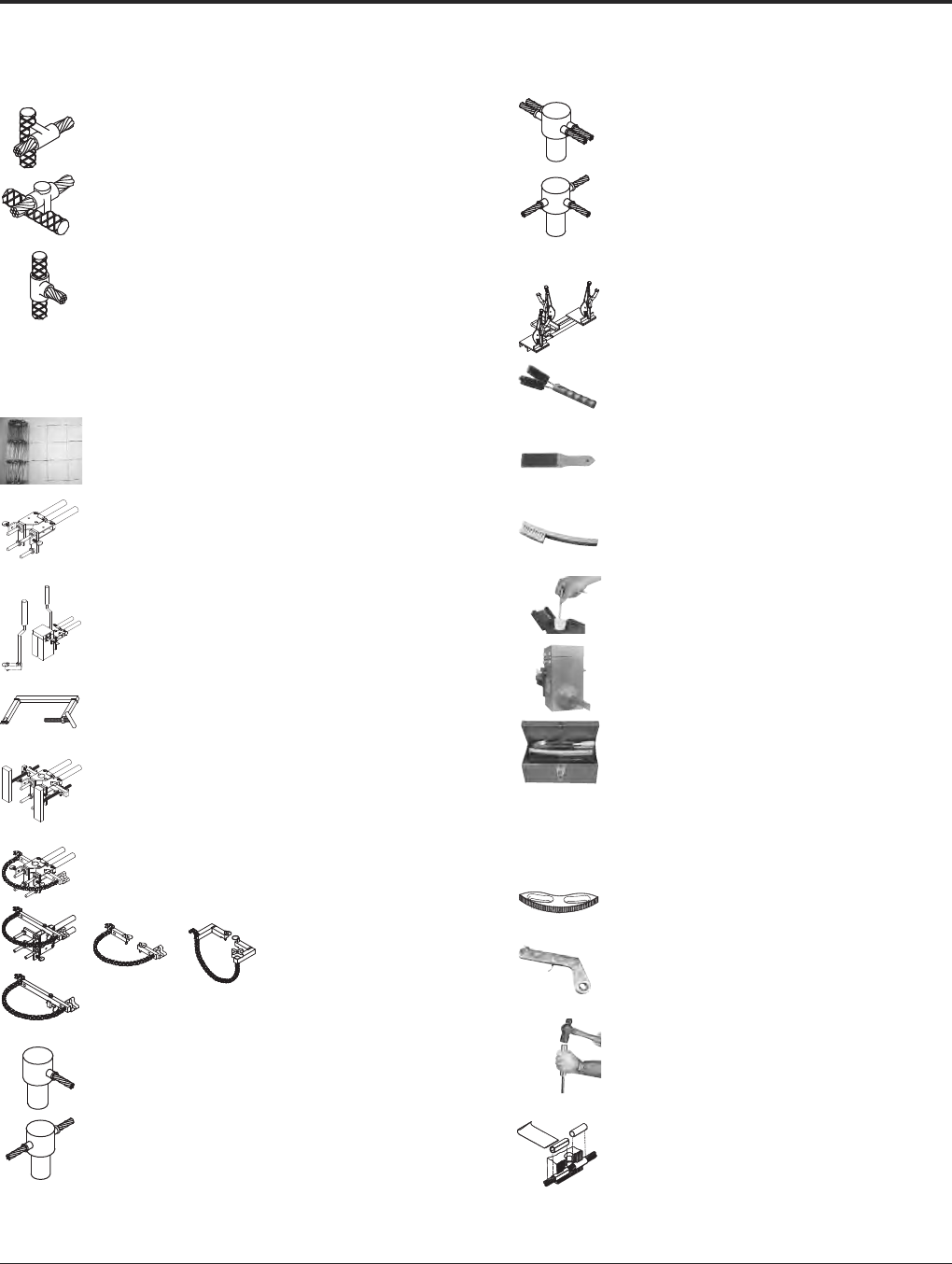
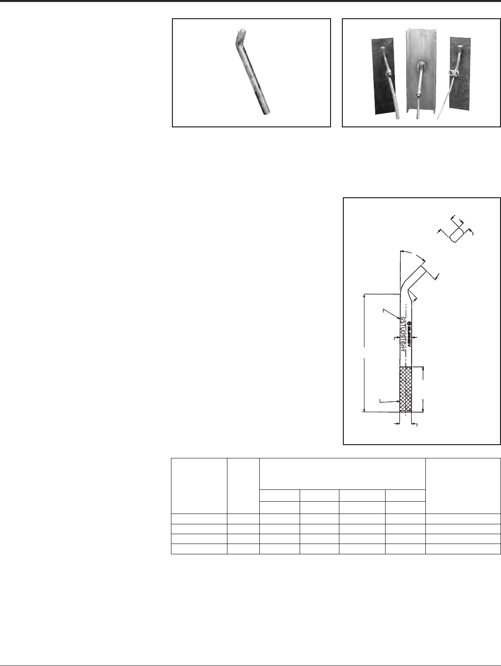
TYPE GSTUD-HY
VERSITAIL™
Structural Steel Grounding
Connector
INSTALLATION
1. Weld the VERSITAIL™ to the steel member.
2. Select the proper connector for your
specific application.
a. FOR COMPRESSION CONNECTORS
Select the proper BURNDY®“YGHP,”
connector. Clean the conductor, join the
VERSITAIL™ and the grounding con-
ductor together with the recommended
tool and die set, then crimp the connec-
tor over the knurled area of the VERSI-
TAIL™.
b. FOR MECHANICAL CONNECTORS
Select the properly sized BURNDY®
connector. Clean the conductor, then
apply PENETROX™ E oxide inhibiting
compound on the contact area for in-
creased effectiveness and service life.
Put the connector over the knurled area
of the VERSITAIL™ and apply the rec-
om mended torque value for correct in-
stal lation.
SPECIFICATIONS
• Low Carbon, hot rolled steel.
• Pure copper plated finish.
FEATURES
• The VERSITAIL™ may be welded to steel
surfaces quickly and easily with normal
construction equipment.
• The VERSITAIL™ eliminates costly disk
grinding and the need to expose virgin
metal. The welding process burns through
the oxidation and “scale” to establish
excellent electrical grounding continuity.
• The VERSITAIL™ may be installed by the
welder in the field or at the steel fabricator
based on customer preference.
• The VERSITAIL™ pure copper coating over
low carbon, hot rolled steel is compatible
with standard welding processes.
No toxic gasses are generated.
• The VERSITAIL™ knurled surface is
copper plated and specifically designed to
ensure excellent mechanical gripping and
electrical integrity for BURNDY®compres-
sion and mechanical connectors in all
grounding applications.
• The VERSITAIL™ may be installed during
adverse weather conditions thus eliminating
costly construction delays.
BENEFITS
Low installation cost.
• No drilling . . . No cleaning . . .
• No special preparation
* This is the equivalent rating for continuous service. Larger
conductors may be connected using both compression and
bolted connectors in potential ground fault applications.
A (STOCK
Dia.)
KNURLED
END
B (Dia. OVER KNURL)
T
(FLATTENING
RESULTANT)
1.25
[32]
TYPICAL
LETTERING
2.19
[56]
L
45°
Electrical
Equivalent
Nom. Dimensions Copper
Catalog Rod A B L T Conductor Size
Number Size In. [mm] In. [mm] In. [mm] In. [mm] (AWG)*
GSTUD14HY 1/4.25 [6.3] .26 [6.6] 4.81 [122.2] .19 [4.8] #6
GSTUD38HY 3/8.38 [9.7] .39 [9.9] 5.81 [147.6] .25 [6.4] #3
GSTUD916HY 5/8.56 [14.2] .57 [14.5] 5.68 [144.3] .38 [9.7] 1/0
GSTUD34HY 3/4.75 [19.0] .76 [19.3] 5.81 [147.6] .51 [13.0] 4/0

BURNDY®Grounding
HYGROUND®Compression
US: 1-800-346-4175 www.burndy.com Canada: 1-800-387-6487
27
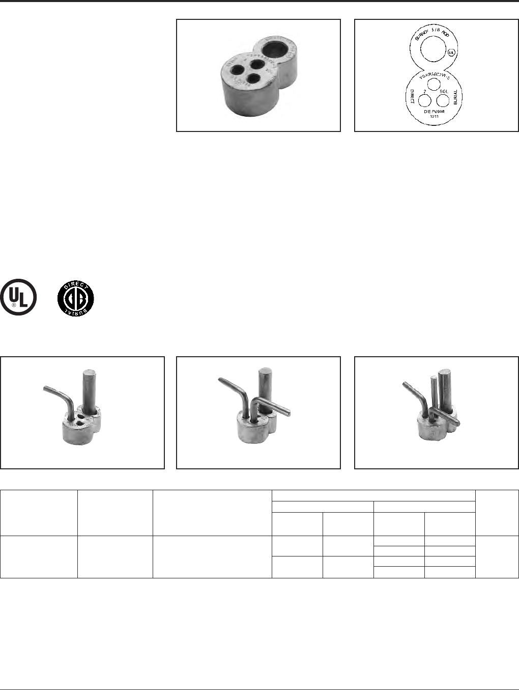
TYPES YGT & YTTAG
STATIC GROUNDING
RECEPTACLE
Type YGT static grounding receptacles are
designed for static grounding of equipment.
The receptacle is connected to the ground
grid with HYGROUND®compression
connectors and finished flush with surface to
provide a permanent corrosion proof ground-
ing point.
* When using U or PU dies with Y46 HYPRESS™, a PUADP-1
adapter is required.
NOTES:
1. Ground rod must be pre-crimped with U2CABT die set
when PU998 die is used or for even higher mechanical
resistance use special UPRECRIMP dies on ground rods.
2. Pre-crimping of ground is not necessary when P1011 die
is used. Install YGHR or YGLR on hub Y. Hub Z is inserted
into 1/2” rigid conduit. The conduit is driven into earth to
provide support and provide correct level of receptacle
prior to cement pour.
Type YTTAG Combination
Static Grounding Receptacle
and Aircraft Tie Down Bar
Type YGT Static
Grounding Receptacle
with Cover
Fig. 1 Fig. 2
Catalog Figure Dimensions
Number Number * HYGROUND®Connector H D Y Dia. Z Dia. TD
YGT275 1Select suitable YGHR or 5.5 2.75 .75 .56 —
YGLR for 3/4ground rod and
YTTAG388 2sized to ground conductor. 6.5 4.75 .75 .56 4.3
Grounding BURNDY®
HYGROUND®Compression
Canada: 1-800-387-6487 www.burndy.com US: 1-800-346-4175
28
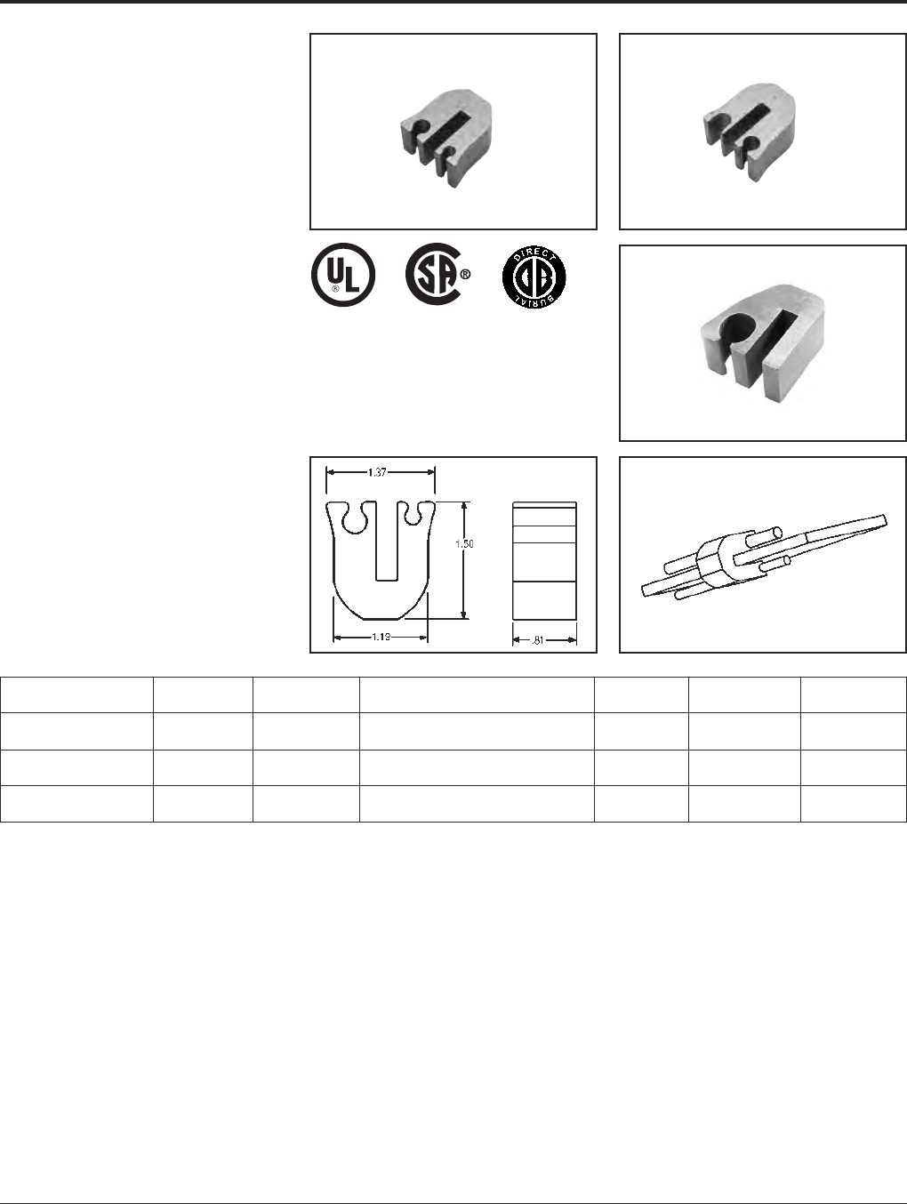
TYPE YG-B
BUS BAR CONNECTOR
BURNDY’s YG14B2TC2C6C Compression
Bus Bar Connector is ideally suited for cellu-
lar tower applicatons and is easier to use than
exothermic connections. This high conduc -
tivity wrought copper connector allows at-
tachment of the ground conductor to the
ground bus with just one crimp using the
BURNDY®Y750 HYPRESS™ Hydraulic
Compression tool and the U1105 die set. This
exclusive patent pending design allows the
user to attach #2 AWG sol./str. and/or #6
sol./str. copper conductor to 1/4thick cop-
per bus bar. This connection is suitable using
(1) or (2) conductors for power, grounding and
bonding applictions. UL Listed to both UL486
and UL467 (suitable for direct burial) ensures
that this connector will meet the rigors of ei-
ther application. Prefilled with PENE TROX™
E compound and strip sealed.
Ground Bar Bus Bar Installation
Catalog Number Fig No. Thickness Tap Conductors Tooling Die No. No. of Crimps
YG14B2TC2C6C 1 1/4” #2 Sol./and/or Str. Copper
#6 Sol./and/or Str. Copper PAT750, Y750 U1105 1
YG14B2TC2C2C* 2 1/4” #2
#2 PAT750, Y750 U1105 1
4/0 AWG Str. to 1/0
YG14BTC28 3 1/4” AWG Str. Copper PAT750, Y750 U1105 1
NOTE: Suitable for use with either (1) or (2) conductors
(excluding YG14BTC26 and YG14BTC28).
* For continuous uncut conductor applications.
Fig. 1 Fig. 2
Fig. 3
BURNDY®Grounding
Mechanical
US: 1-800-346-4175 www.burndy.com Canada: 1-800-387-6487
29
MECHANICAL
GROUNDING
CONNECTORS
More than 60 years of technological innovation
has made BURNDY®mechanical grounding
connectors one of the most widely used, highly
respected lines in the industry. There is virtu-
ally no grounding application problem that this
diversified line cannot help solve.
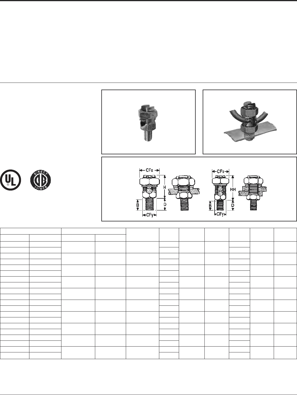
TYPES KC, K2C
SERVIT POST™
For Copper Cable to Flat
SERVIT POST™ used to ground one or two
cables to steel structures, fence posts, trans-
formers. Also used to tap one or two cables
from bus bar. One-wrench installation.
KC K2C
All BURNDY®mechanical grounding connec-
tors have been designed for easy installation
and for outstanding durability. Only the finest
high copper alloys are used in their manufac-
ture, ensuring top performance under the
most extreme environmental conditions.
† For 1 conductor.
‡ For 1 or 2 conductors.
Add “NSP” suffix to have connector supplied w/split
lockwasher and nut.
UL467 Listed for direct burial applications in
earth or concrete.
Catalog Number Conductor Stud
Type KC † Type K2C ‡ Stranded Solid Diameter B CFx CFy D H HH
KC15 K2C15 3/8 1/2
KC15B1 K2C15B1 12 - 9 12 - 8 1/4 - 20 7/8 1/2 3/8 15/8 7/8
KC17 K2C17 3/8 1/2
KC17B1 K2C17B1 10 - 7 10 - 6 1/4 - 20 7/8 5/8 7/16 17/8 1
KC20 K2C20 13/32 5/8
KC20B1 K2C20B1 10 - 5 10 - 4 5/16 - 18 27/32 11/16 1/2 17/8 1-1/8
KC22 K2C22 15/32 5/8
KC22B1 K2C22B1 10 - 3 10 - 2 3/8 - 16 31/32 3/4 5/8 1-1/8 1 1-1/4
KC23 K2C23 15/32 5/8
KC23B1 K2C23B1 8 - 2 10 - 1 3/8 - 16 31/32 13/16 5/8 1-1/8 1 1-3/8
KC25 K2C25 9/16 3/4
KC25B1 K2C25B1 2 - 1/0 2 - 2/0 1/2 - 13 1-1/16 15/16 3/4 1-1/4 1-1/8 1-5/8
KC26 K2C26 17/32 3/4
KC26B1 K2C26B1 2 - 2/0 2 - 3/0 1/2 - 13 1-1/16 1 7/8 1-1/4 1-3/8 1-7/8
KC28 K2C28 3/4 1
KC28B1 K2C28B1 1 - 4/0 1 - 4/0 5/8 - 11 1-1/4 1-1/2 1-3/16 1-1/2 1-3/4 2-1/4
KC31 K2C31 3/4 1
KC31B1 K2C31B1 1 - 350 — 5/8 - 11 1-1/4 1-11/16 1-3/8 1-1/2 2-1/4 2-7/8
KC34 K2C34 1 1-1/4
KC34B1 K2C34B1 3/0 - 500 — 3/4 - 10 1-1/2 2 1-5/8 1-3/4 2-3/8 3-1/4
Grounding BURNDY®
Mechanical
Canada: 1-800-387-6487 www.burndy.com US: 1-800-346-4175
30
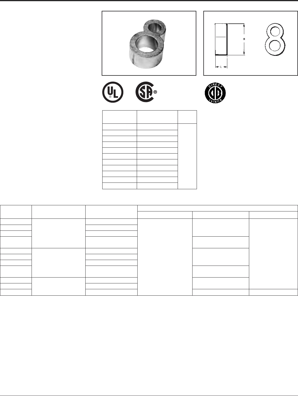
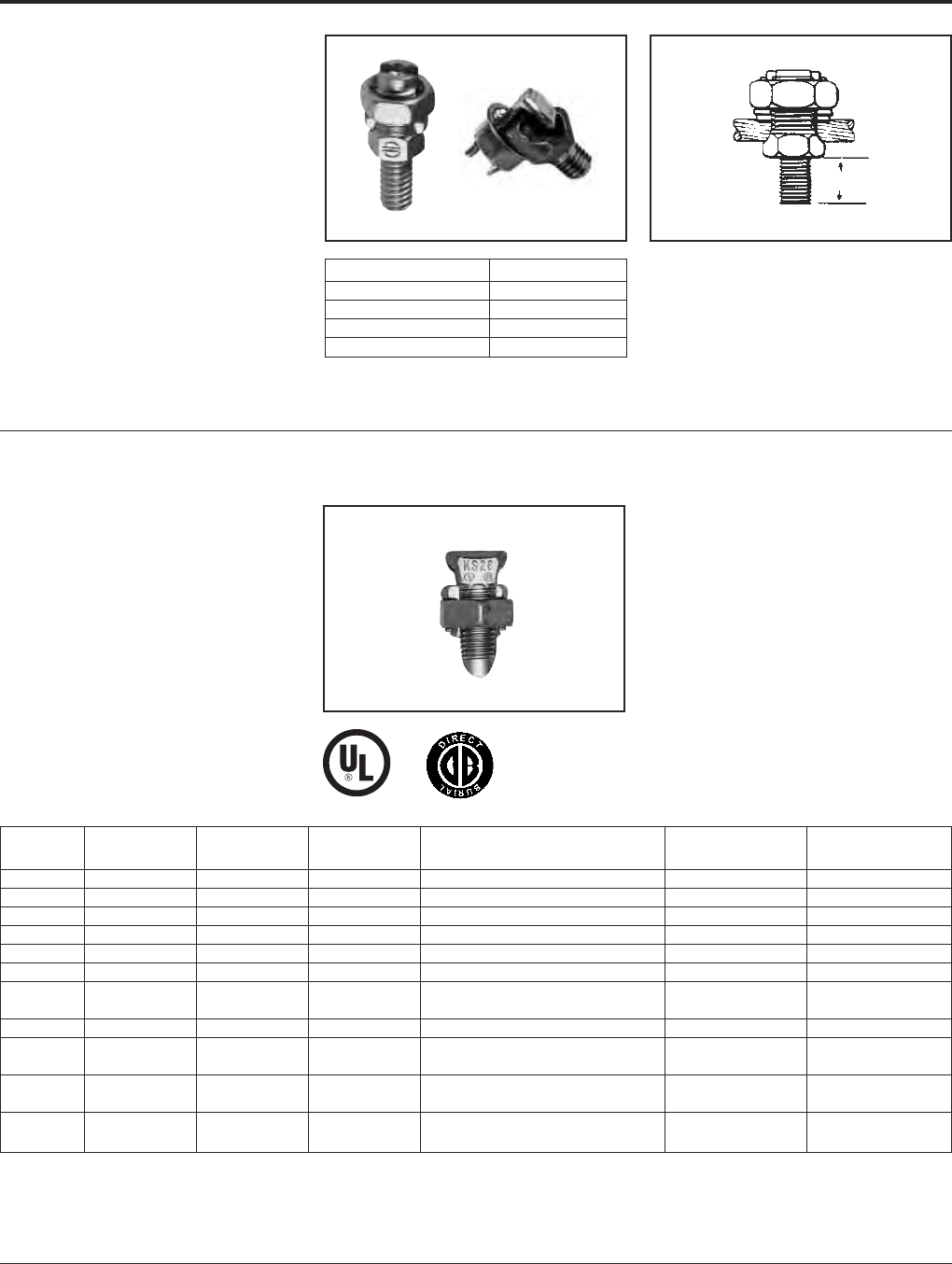
TYPE KS
SERVIT®
For Copper
UL467 Listed for direct burial applications in
earth or concrete. Compact, high-strength,
high copper alloy SERVIT®split-bolt has free-
running threads and easy to grip wrench flats.
Highly resistant to cracking and corrosion.
TYPES KC22J12T13,
EQC632C
TRANSFORMER GROUND
CONNECTORS
For Copper
Fits all standard EEI NEMA distribution
transformers as a tank grounding terminal.
Both, one-wrench installation.
Type EQC632C Type KC22J12T13
Stud Size = 1⁄2- 13
.6
Catalog Number Ranges
KC22J12T13 8 Sol. - 2 Sol.
KC26 2 Sol. - 2/0 Str.
KC34J12T13 3/0 - 500 Str.
EQC632C 8 Sol. - 2 Str.
Catalog Copper Conductor Range Rebar w/ (1) Recommended
Number Cross Flats L W (Sol. - Str.) No. 8 Sol. Cu Torque (In. Lb.)
KS15 .50 .85 .38 12 AWG - 8 AWG N/A 80
KS17 .63 1.14 .45 8 AWG - 6 AWG N/A 165
KS20 .69 1.20 .51 8 AWG - 4 AWG N/A 165
KS22 .75 1.50 .60 6 AWG - 3 AWG N/A 275
KS23 .82 1.54 .62 6 AWG - 2 AWG N/A 275
KS25 .94 1.77 .73 4 AWG - 1/0 N/A 385
2 AWG - 2/0 #3
KS26 1.05 1.94 .82 6 AWG - 8 AWG Str./Sol. (3/8)385
KS27 1.36 1.86 1.17 1 AWG - 3/0 N/A 500
1 AWG - 250 kcmil #4
KS29 1.36 2.07 1.17 6 AWG - 8 AWG Str./Sol. (1/2)650
1/0 AWG - 350 kcmil #5
KS31 1.70 2.51 1.41 6 AWG - 8 AWG Str./Sol. (5/8)650
2/0 AWG - 500 kcmil #6
KS34 1.82 2.79 1.48 6 AWG - 8 AWG Str./Sol. (3/4)825
BURNDY®Grounding
Mechanical
US: 1-800-346-4175 www.burndy.com Canada: 1-800-387-6487
31
TYPE GKA
For Copper
UL467 Listed for direct burial applications in
earth or concrete. One-piece forged body
construction insures mechanical integrity in
an underground environment. Supplied with a
stainless steel headless screw.
TYPE KPB
For Copper
UL467 Listed for direct burial in earth or con-
crete. UL486 listed. This exclusive BURNDY®
design accommodates #10 - #4 copper
where continuous conductor runs are
preferable.
1. To be assembled with TMH322 stainless steel hardware kit.
Ordered separately.
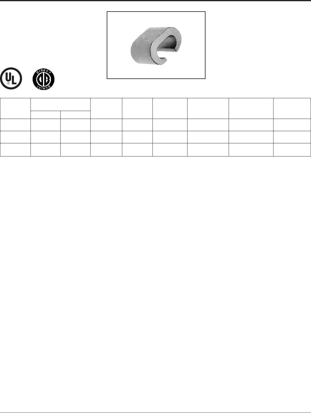
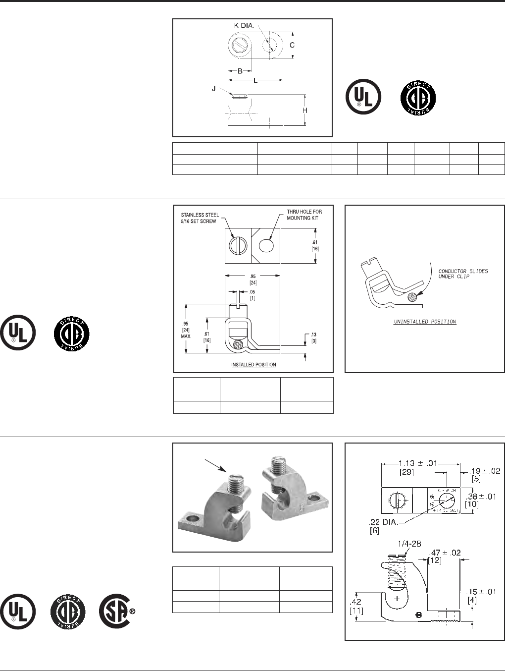
TYPE CL50-1
COPPER LAY-IN QIKLUG™
For Copper
The Lay-In QIKLUG™ is manufactured from
high strength pure electrolytic copper to en-
sure maximum strength and conductivity.
UL467 Listed for direct burial in earth or con-
crete. The open-faced design allows for fast
lay-in of the conductor without the need for
cutting or breaking.
Catalog
Number Range Stud Hole
KPB4CG1 #10 - #4 CU #10 1
1. To be assembled with TMH322SS stainless steel hardware
kit. Ordered separately.
Catalog Number Cable Range B C H J K L
GKA8C 1#10 Sol. - #8 Str. .31 .38 .58 #10 - 32 .21 .81
GKA4C 2#14 Sol. - #4 Str. .46 .54 .71 5/16 - 24 .28 1.13
2. To be assembled with TMH 323 stainless steel hardware kit.
Ordered separately.
Stainless Steel Screw
Catalog Wire Range
Number Copper Stud Hole
CL50-1 #14 - #4 CU #10
CL50-1TN* #14 - #4 CU #10
*-TN Version is tin plated. Commonly used for solar panel
grounding.

Grounding BURNDY®
Mechanical
Canada: 1-800-387-6487 www.burndy.com US: 1-800-346-4175
32
TYPE GAR
• Wire to Rebar
• Fence Post Grounding
Connector
• Wire to Pipe
For Parallel or 90°
Copper Cable Connection
to Rod or Pipe with
the Same Connector
High copper alloy ground connector for join-
ing a range of cable, parallel or at right angles
to rod or tube. Especially good for fence
posts. High copper alloy cast body with
DURIUM™ U-bolts, nuts and lockwashers,
permit entire connection to be buried in
ground or concrete without danger of
corrosion.
• One-wrench installation.
• UL467 Listed.
• Acceptable for direct burial.
Catalog Conductor
Number Tube I.P.S. Rod Size or O.D. Range Rebar Size Cable H J W
GAR114C 8 Sol. - 4 Str.
GAR1126 1/4 1/2 — 4 Sol. - 2/0 Str. 2-1/2 1-7/8
GAR1129 2/0 Sol. - 250
GAR644C 8 Sol. - 4 Str. 3/8
GAR6426 #5 (5/8) - 4 Sol. - 2/0 Str. 2-7/8 2-1/8
GAR6429 3/8 5/8 - 3/4 #6 (3/4) 2/0 Sol. - 250
GAR6434 300 - 500 3-1/2 1/2 2-1/2
GAR144C 8 Sol. - 4 Str. 2-3/4
GAR1426 #7 (7/8) - 4 Sol. - 2/0 Str. 3/8 2-3/8
GAR1429 1/2 - 3/4 7/8 - 1 #8 (1) 2/0 Sol. - 250 3
GAR1434 300 - 500 3-3/4 1/2 2-3/4
GAR154C 8 Sol. - 4 Str.
GAR1526 #9 (1-1/8) - 4 Sol. - 2/0 Str. 2-7/8 3/8 2-5/8
GAR1529 1 1-1/8 - 1-1/4 #10 (1-1/4) 2/0 Sol. - 250 3-3/8
GAR1534 300 - 500 4-1/2 1/2
GAR164C 8 Sol. - 4 Str.
GAR1626 4 Sol. - 2/0 Str. 3-1/2 3/8 3
GAR1629 1-1/4 1-3/8 - 1-1/2 #11 (1-3/8)2/0 Sol. - 250
GAR1634 300 - 500 4-1/4 1/2 3-3/8
GAR174C 8 Sol. - 4 Str.
GAR1726 4 Sol. - 2/0 Str. 4 3/8 3-1/4
GAR1729 1-1/2 1-5/8 - 1-7/8 — 2/0 Sol. - 250
GAR1734 300 - 500 4-5/8 1/2 2-5/8
GAR184C 8 Sol. - 4 Str.
GAR1826 4 Sol. - 2/0 Str. 4-1/4 3/8 3-3/4
GAR1829 2 2 - 2-3/8 — 2/0 Sol. - 250 4-1/2
GAR1834 300 - 500 5-1/4 1/2 4-1/8
GAR194C 8 Sol. - 4 Str.
GAR1926 4 Sol. - 2/0 Str. 5 3/8 4-1/4
GAR1929 2-1/2 2-1/2 - 2-7/8 — 2/0 Sol. - 250
GAR1934 300 - 500 5-5/8 1/2 4-5/8
Wire to Rebar
Wire Parallel to PipeWire at Right Angle to Pipe

BURNDY®Grounding
Mechanical
US: 1-800-346-4175 www.burndy.com Canada: 1-800-387-6487
33
TYPE GAR
(Continued)
FENCE POST GROUNDING
CONNECTOR
Contact BURNDY®for additional pipe and wire size
combinations not shown.
Catalog Conductor
Number Tube I.P.S. Rod Size or O.D. Range Cable H J W
GAR204C 8 Sol. - 4 Str.
GAR2026 4 Sol. - 2/0 Str. 5-5/8 3/8 4-3/4
GAR2029 3 3 - 3-1/2 2/0 Sol. - 250
GAR2034 300 - 500 6-3/8 1/2 5-1/4
GAR214C 8 Sol. - 4 Str.
GAR2126 4 Sol. - 2/0 Str. 6-1/4 3/8 5-3/8
GAR2129 3-1/2 3-1/2 - 4 2/0 Sol. - 250
GAR2134 300 - 500 6-3/4 1/2 5-3/4
GAR224C 8 Sol. - 4 Str.
GAR2226 4 Sol. - 2/0 Str. 6-3/8 3/8 5-7/8
GAR2229 4 4 - 4-1/2 2/0 Sol. - 250
GAR2234 300 - 500 6-7/8 1/2 6-1/4
GAR244C 8 Sol. - 4 Str.
GAR2426 4 Sol. - 2/0 Str. 7-3/4 3/8 6-7/8
GAR2429 5—
2/0 Sol. - 250
GAR2434 300 - 500 8-5/8 1/2 7-1/4
GAR8629 6 — 2/0 Sol. - 250 8-13/16 1/2 8-3/8
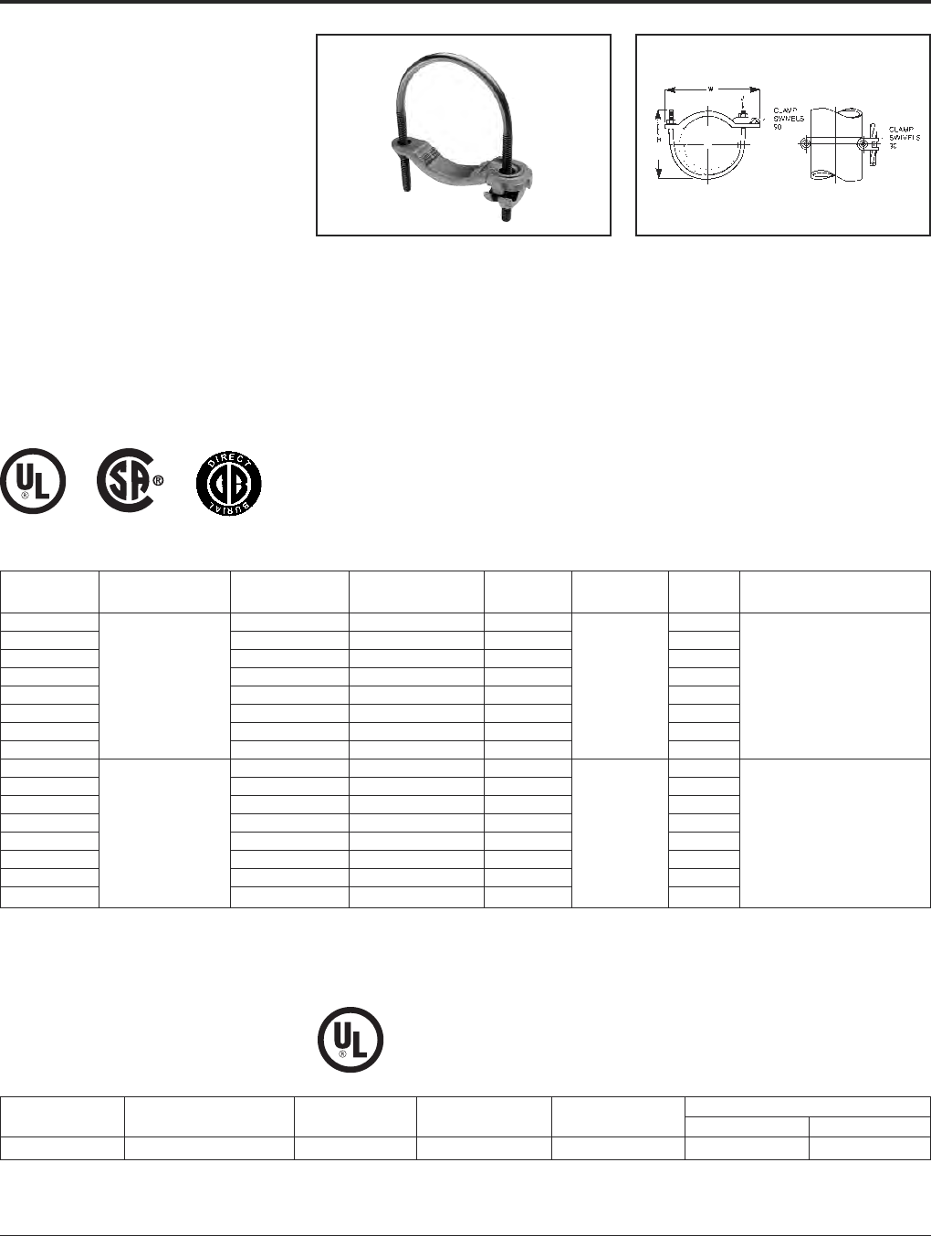
Grounding BURNDY®
Mechanical
Canada: 1-800-387-6487 www.burndy.com US: 1-800-346-4175
34
TYPES GAR-BU AND
GAR3902 SERIES
GROUND CONNECTORS
Type GAR-BU is a high-conductivity copper
ground connector for connecting a small to
medium range copper ground conductor to
water pipe as well as structural and reinforc-
ing rod shapes. Universal acceptance of
several sizes of cylindrical shapes makes this
suitable for industrial construction and main-
tenance work as well as cathodic protection.
Cable clamp swivels to permit parallel
grounding of one pipe or 90° degree cable run
for grounding several parallel pipes. Single
wrench installation. UL467 Listed and
CSA certified.
TYPE GAR-RB
For Reinforcement Bar
* Type GAR-BU is supplied with DURIUM™ silicon bronze
hardware and is listed for direct burial.
UL467 listed for direct burial in earth or concrete.
Features and Benefits
• Cable clamp swivels at 90°.
〫Permits parallel grounding of one pipe
or a 90° cable run for grounding several
parallel pipes.
• One-wrench installation.
〫Simplified installation.
• DURIUM™ silicon bronze hardware
(-BU Series)*.
〫Long lasting corrosion resistance and
acceptable for direct burial in earth
or concrete.
• UL467 Listed.
〫Provides quality assurance to recognized
industry NEC standards from an
independent party.
*
Catalog Recommended
Number * Cable Range IPS Size O.D. Range H J W Tightening Torque
GAR3902-BU 1/2- 1.840 - 1.32 3.50 3.25
GAR3903-BU 1-1/4- 21.66 - 2.38 4.00 4.25
GAR3904-BU 2-1/2- 3-1/22.88 - 4.00 6.50 6.00
GAR3905-BU 4- 54.50 - 5.56 7.50 7.50
GAR3906-BU #4 - 4/0 AWG 66.62 8.50 3/8- 16 8.62 240 in. - lbs.
GAR3907-BU 88.62 10.00 10.62
GAR3908-BU 1010.75 12.00 12.75
GAR3909-BU 1212.75 14.00 14.75
GAR3902 1/2- 1.840 - 1.32 3.50 3.25
GAR3903 1-1/4- 21.66 - 2.38 4.00 4.25
GAR3904 2-1/2- 3-1/22.88 - 4.00 6.50 6.00
GAR3905 4- 54.50 - 5.56 7.50 7.50
GAR3906 #4 - 4/0 AWG 66.62 8.50 3/8- 16 8.62 240 in. - lbs.
GAR3907 88.62 10.00 10.62
GAR3908 1010.75 12.00 12.75
GAR3909 1212.75 14.00 14.75
Catalog Copper Conductor
Number Rebar IPS Size O.D. Range Rod Min. Max.
GAR644C-RB #3 - 6 (.375 - .750) 3/8 .625 - .75 5/8 - 3/4 8 Sol. 4 Str.
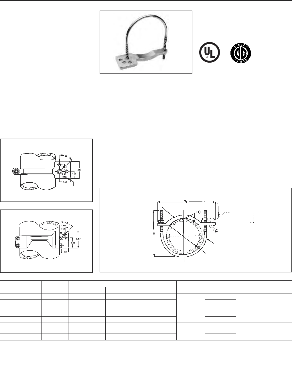
BURNDY®Grounding
Mechanical
US: 1-800-346-4175 www.burndy.com Canada: 1-800-387-6487
35
TYPE GAR-TC
WATER PIPE
GROUND CONNECTOR
Type GAR-TC is a high-conductivity copper
ground connector that features a pre-drilled
pad, allowing a 2-hole compression terminal
to be directly connected to water pipe as well
as structural and reinforcing rod shapes.
Universal acceptance of several sizes of
cylindrical shapes makes this suitable for
industrial construction and maintenance work
as well as telecommunications grounding.
Terminal may be mounted parallel, 45° or 90°
degrees to the pipe. Acceptable for direct
burial.
Features and Benefits
• Large, smooth connector contact area
between pipe and ground clamp
〫Provides large surface contact area
to maximize contact area between
connector and pipe.
• The GAR-TC mounting pad permits
parallel, 45° or 90° angle connections
to the pipe.
〫Provides maximum flexibility for
field installation.
• Pre-drilled pad for (2) 3/8bolts on
1centers.
〫Allows direct mounting of (2) hole
compression terminals up to 750 kcmil
to pipe.
①Add suffix “-TNET” for electro-tin plated connector and
electro-tin plated DURIUM™ silicon bronze hardware. Tin
plated catalog number includes mounting hardware for
second bolt hole.
②TMH-289 includes (1) 38 x 125 HEB, (1) 38 CHEN, (1) 38
SW and (2) 38 FW. Order separately.
Fig. 1
Fig. 2
PATENTED
MOUNTING PAD
FOR (2) 3/8
BOLTS - 1L
J
MOUNTING PAD
DURIUM 3/8
SILICON BRONZE
HARDWARE
• DURIUM™ silicon bronze hardware.
〫Provide long lasting corrosion resistance
acceptable for direct burial in earth or
concrete.
• One-wrench installation.
〫Simplified installation.
• UL467 Listed.
〫Provides quality assurance to recognized
industry NEC standards from an
independent party. Type GAR-TC is
acceptable for direct burial
PIPE Dia.
CAST HIGH COPPER ALLOY SADDLE
COMPRESSION LUG WITH PAD
FOR (2) 3/8Dia. BOLTS
ON 1CENTERS. 750 KCMIL MAX.
Catalog Fig. Accommodates Recomended
Number No. I.P.S. O.D. Size H J W Tightening Torque
GAR3902TC 1 1/2- 1.840 - 1.32 3.50 3.75
GAR3903TC 1 1-1/4- 21.66 - 2.38 4.00 4.75
GAR3904TC 1 2-1/2- 3-1/22.88 - 4.00 6.50 3/8- 16 6.50 240 in.-lbs.
GAR3905TC 14- 54.50 - 5.56 7.50 8.00
GAR3906TC 166.62 8.50 9.12
GAR3907TC 288.62 10.00 11.25
GAR3908TC 21010.75 12.00 3/8- 16 13.25 240 in.-lbs.
GAR3909TC 21212.75 14.00 15.25
NOTE: Clean pipe surface beneath saddle until virgin metal
is exposed, install GAR-TC ground connector and for
maximum conductivity, apply PENETROX®E oxide
inhibiting compound around perimeter of the saddle.
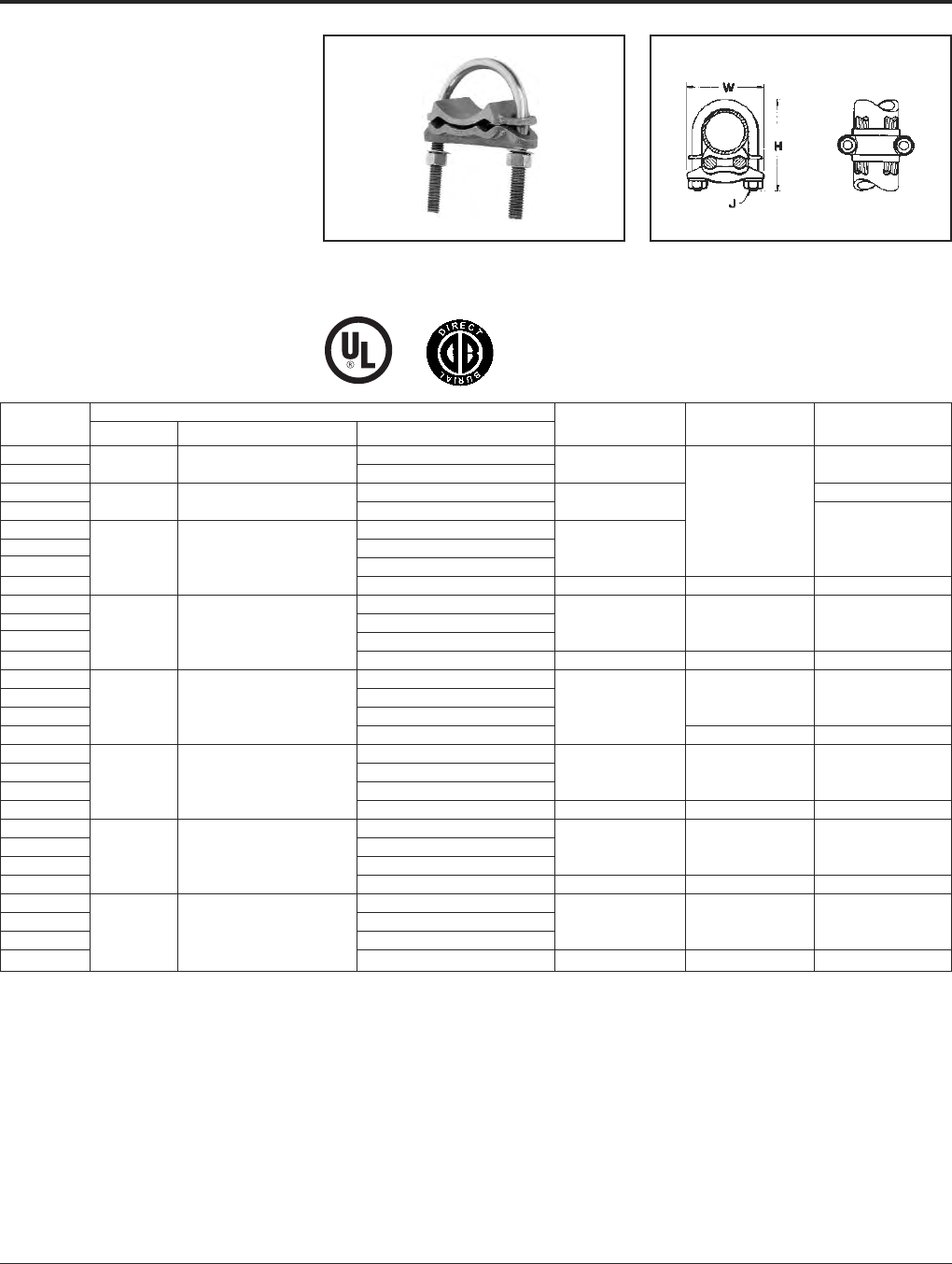
Grounding BURNDY®
Mechanical
Canada: 1-800-387-6487 www.burndy.com US: 1-800-346-4175
36
TYPE GD
CABLE TO ROD/TUBE
GROUND CONNECTOR
For Two Copper Cables
to Rod or Tube
High copper alloy ground connector for join-
ing a range of two parallel cables to rod or
pipe. Especially good for grounding fence
posts. High copper alloy cast body with
DURIUM™ U-bolts, nuts, and lockwashers
make the GD suitable for burial in ground or
concrete. One-wrench installation. UL467
Listed. Acceptable for direct burial in earth
or concrete.
Complies with NFPA 78-86 HEAVY DUTY stacks.
(Order: LD for lead plating for HEAVY DUTY stack
applications.)
Catalog Conductor
Number Tube I.P.S. Rod Size or O.D. Range Cable H J W
GD1526 4 Sol. - 2/0 Str.
GD1529 1 1-1/8 - 1-1/4 2/0 Sol. - 250 3-3/8 2-5/8
GD1626 4 Sol. - 2/0 Str. 3
GD1629 1-1/4 1-3/8 - 1-1/2 2/0 Sol. - 250 3-1/2 3/8
GD174C 8 Sol. - 4 Str.
GD1726 4 Sol. - 2/0 Str. 4 3-1/4
GD1729 1-1/2 1-5/8 - 1-7/8 2/0 Sol. - 250
GD1734 300 - 500 4-5/8 1/2 3-5/8
GD184C 8 Sol. - 4 Str.
GD1826 4 Sol. - 2/0 Str. 4-3/8 3/8 3-3/4
GD1829 2 2 - 2-3/8 2/0 Sol. - 250
GD1834 300 - 500 5-3/8 1/2 4-1/8
GD194C 8 Sol. - 4 Str.
GD1926 4 Sol. - 2/0 Str. 3/8 4-1/4
GD1929 2-1/2 2-1/2 - 2-7/8 2/0 Sol. - 250 5
GD1934 300 - 500 1/2 4-5/8
GD204C 8 Sol. - 4 Str.
GD2026 4 Sol. - 2/0 Str. 5-5/8 3/8 4-7/8
GD2029 3 3 - 3-1/2 2/0 Sol. - 250
GD2034 300 - 500 6-3/8 1/2 5-1/4
GD214C 8 Sol. - 4 Str.
GD2126 4 Sol. - 2/0 Str. 6-1/4 3/8 5-3/8
GD2129 3-1/2 3-1/2 - 4 2/0 Sol. - 250
GD2134 300 - 500 6-7/8 1/2 5-3/4
GD224C 8 Sol. - 4 Str.
GD2226 4 Sol. - 2/0 Str. 6-3/8 3/8 5-7/8
GD2229 4 4 - 4-1/2 2/0 Sol. - 250
GD2234 300 - 500 6-7/8 1/2 6-1/4

BURNDY®Grounding
Mechanical
US: 1-800-346-4175 www.burndy.com Canada: 1-800-387-6487
37
TYPE GP
GROUND CONNECTOR
For Two Copper Cables
to Rod or Pipe
High copper alloy ground connector for joining
a range of parallel cables perpendicular to rod,
pipe or column. Also used with one groove for
run, the other for tap to equipment. High
copper alloy cast body and DURIUM™
U-bolts, nuts, and lockwashers make the GP
suitable for direct burial in the ground or
concrete. One-wrench installation. UL467
Listed. Acceptable for direct burial in earth
or concrete.
TYPE GK
GROUND CONNECTOR
For Three Copper Cables
to Rod or Pipe
High copper alloy ground connector for join-
ing three equal cables to rod or tube. Cable
grooves take a wide range of cable. High
copper alloy cast body and DURIUM™
U-bolts, nuts, and lockwashers make the GK
suitable for direct burial in soil or concrete.
One-wrench installation. UL467 Listed.
Acceptable for direct burial in earth or
concrete.
Catalog Conductor
Number Tube I.P.S. Rod Size or O.D. Range Cable H J W
GP114C 8 Sol. - 4 Str.
GP1126 1/4 1/2 4 Sol. - 2/0 Str. 1-7/8
GP1129 2/0 Sol. - 250 2-1/2
GP644C 8 Sol. - 4 Str. 3/8
GP6426 4 Sol. - 2/0 Str. 2-1/8
GP6429 3/8 5/8 - 3/4 2/0 Sol. - 250 2-7/8
GP6434 300 - 500 3-1/2 1/2 2-1/2
GP144C 8 Sol. - 4 Str. 2-3/4
GP1426 4 Sol. - 2/0 Str. 38 2-3/8
GP1429 1/2 - 3/4 7/8 - 1 3/0 Sol. - 250 3
GP1434 300 - 500 3-3/4 1/2 2-3/4
GP164C 8 Sol. - 4 Str.
GP1629 1-1/4 1-5/8 2/0 Sol. - 250 3-1/2 3
GP1726 1-1/2 1-7/8 4 Sol. - 2/0 Str. 4 3-1/4
GP184C 8 Sol. - 4 Str. 4-1/8 3/8
GP1826 2 2-3/8 4 Sol. - 2/0 Str. 4-3/8 3-11/16
GP2026 3 3-1/2 4 Sol. - 2/0 Str. 5-1/2 4-13/16
GP2226 4 4-1/2 4 Sol. - 2/0 Str. 6-3/8 5-13/16
Catalog Conductor
Number Tube I.P.S. Rod Size or O.D. Range Cable H J W
GK114C 8 Sol. - 4 Str. 2-1/2
GK1126 1/4 1/2 4 Sol. - 2/0 Str. 2-1/2 3/8 2-3/4
GK1129 2/0 Sol. - 250 1/2 3-3/8
GK644C 8 Sol. - 4 Str. 2-5/8
GK6426 4 Sol. - 2/0 Str. 2-7/8 3/8 3
GK6429 3/8 5/8 - 3/4 2/0 Sol. - 250 3-1/2
GK6434 300 - 500 3-1/2 1/2 4
GK1426 4 Sol. - 2/0 Str. 2-3/4 38 3-1/4
GK1429 1/2 - 3/4 7/8 - 1 2 Sol. - 250 3-7/8
GK1434 300 - 500 3-3/4 1/2 4-3/8
GK1526 4 Sol. - 2/0 Str. 3-3/8 3/8 3-1/2
GK1529 1 1-1/8 - 1-1/4 2/0 Sol. - 250 3-3/4 1/2 4-1/8
GK1626 4 Sol. - 2/0 Str. 3-1/2 3/8 3-7/8
GK1629 1-1/4 1-3/8 - 1-1/2 2/0 Sol. - 250 4-1/4 1/2 4-1/2
GK1726 4 Sol. - 2/0 Str. 4 3/8 4-1/8
GK1729 1-1/2 1-5/8 - 1-7/8 2/0 Sol. - 250 4-5/8 1/2 4-3/4
GK1826 4 Sol. - 2/0 Str. 4-1/4 3/8 4-5/8
GK1829 2 2 - 2-3/8 2/0 Sol. - 250 4-3/8 1/2 5-1/8
GK1926 4 Sol. - 2/0 Str. 5 3/8 5-1/8
GK1929 2-1/2 2-1/2 - 2-7/8 2/0 Sol. - 250 5 1/2 5-5/8
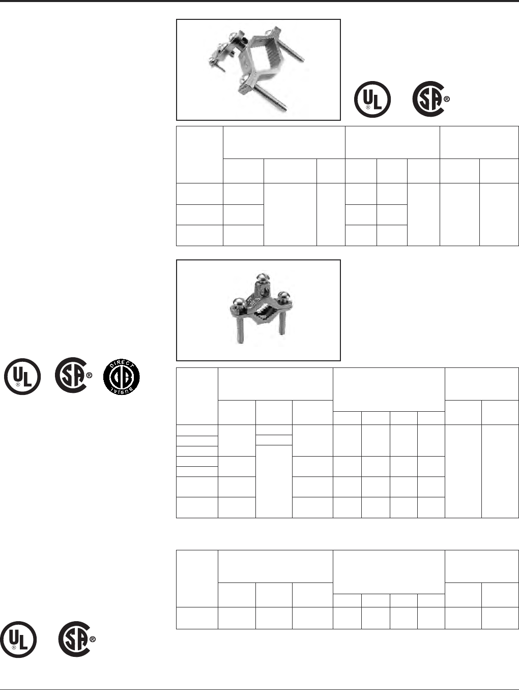
Grounding BURNDY®
Mechanical
Canada: 1-800-387-6487 www.burndy.com US: 1-800-346-4175
38
CAST BRONZE
CLAMPS
FOR CONDUIT
Pressure bar type conduit hub adjusts for
1/2, 3/4EMT or 1/2rigid conduit. Hub
swings 360° for easy alignment. Zinc plated
hardware.
CAST BRONZE
GROUND CLAMPS
For connecting grounding conductor to water
pipe or copper tube. “D” indicates UL467
Listed for direct burial in earth and concrete
and are supplied with silicon bronze hard-
ware. “B” indicates brass hardware.
BUDGET PRICE
CAST BRONZE
GROUND CLAMP
Similar to above but lighter duty.
Recommended
Accommodates Reference Screw Torque
Conductor Range Dimensions (Inch Pounds)
Catalog Water Hub Pipe Wire
Number Pipe Ground Size H L W Clamp Clamp
1/2 - 1 2.07 3.19
C-11JPT [13 - 25] [53] [81]
1-1/4 - 2 10 - 6 1/2 2.70 3.83 2.70
C-22JPT [32 - 51] Sol. [13] [69] [97] [69] 50 in.-lb. 50 in.-lb.
2-1/2 - 4 4.39 5.15
C-4JPT [64 - 102] [112] [131]
Recommended
Accommodates Screw Torque
Conductor Range (Inch Pounds)
Catalog Water Reference Dimensions Pipe Wire
Number Pipe Rebar Ground H L W C Clamp Clamp
C-11N —
C-11D 1/2 - 1 #4 - #8 10 - 2 1.81 2.25 .63 .63
C-11B [13 - 25] Str. [46] [56] [16] [16]
C-22 * 1-1/4 - 2 10 - 2 2.38 3.63 .75 1.00
C-22D [32 - 51] Str. [60] [92] [19] [25] 50 in.-lb. 50 in.-lb.
2-1/2 - 4 —10 - 2 4.13 6.25 .96 1.88
C-4 * [64 - 114] Str. [105] [159] [24] [48]
4-1/2 - 6 10 - 2 4.29 8.34 1.25 1.88
C-8 * [114 - 165] Str. [109] [212] [32] [48]
Recommended
Accommodates Screw Torque
Conductor Range (Inch Pounds)
Catalog Water Reference Dimensions Pipe Wire
Number Pipe Rebar Ground H L W C Clamp Clamp
C-5 1/2 - 1 10 - 2 1.56 2.25 .56 .50
(JUNIOR) [13 - 25] —Str. [40] [56] [14] [13] 50 in.-lb. 50 in.-lb.
* Catalog numbers C-22, C-4, and C-8 are supplied with zinc
plated steel hardware.
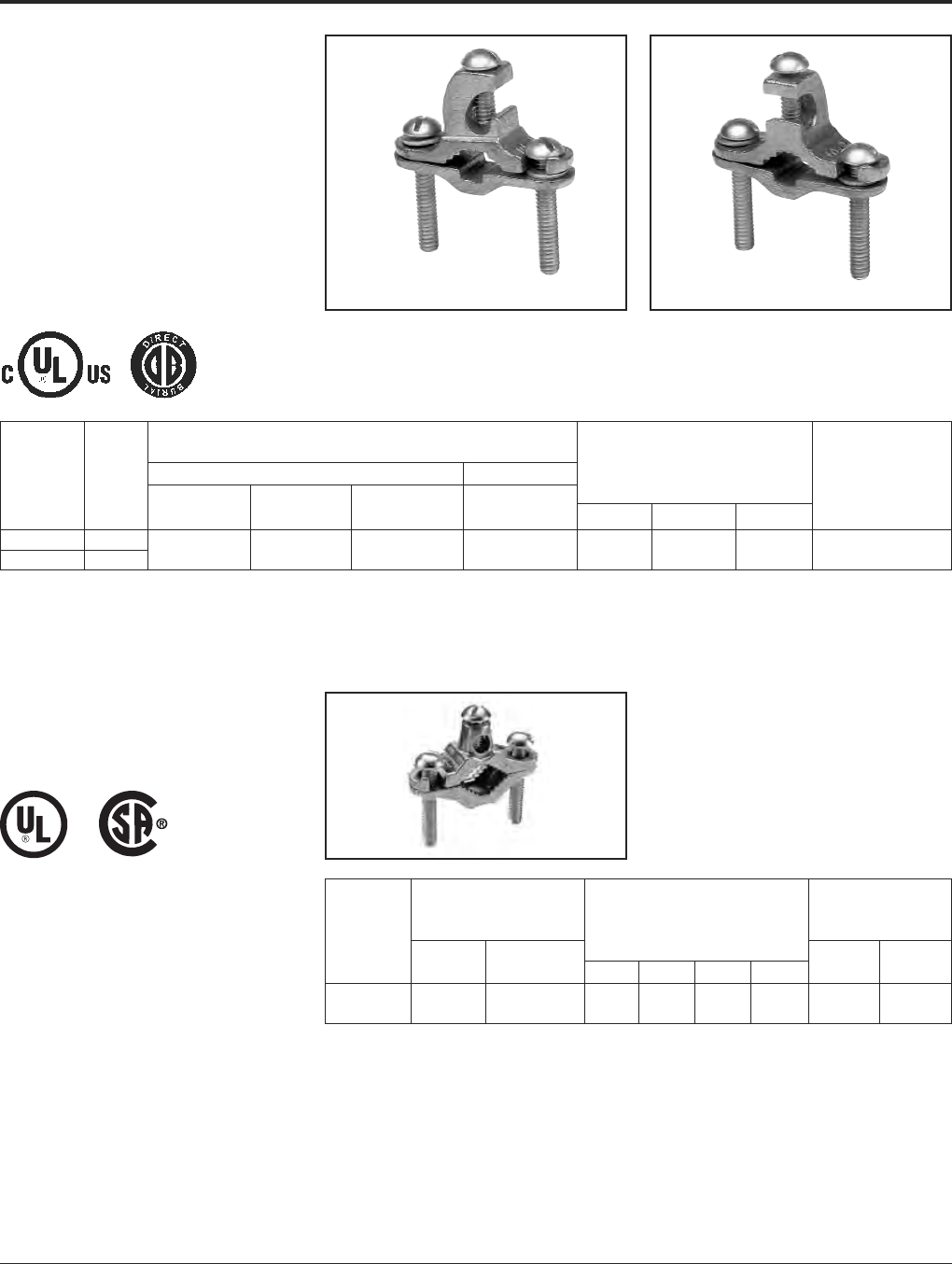
BURNDY®Grounding
Mechanical
US: 1-800-346-4175 www.burndy.com Canada: 1-800-387-6487
39
CAST BRONZE
GROUND CLAMPS
With Lay-in Feature
For connecting grounding conductor to water
pipe, copper tube, ground rod or rebar. The
open face design allows for fast lay-in of the
tap conductor without the need for cutting.
Simply reverse bottom clamp for smaller size
rebar or rod. Connectors are provided with
Silicon Bronze hardware.
Accommodates
Conductor Range
Main Tap Reference Recommended
Catalog Water Ground Dimensions Screw Torque
Number Fig. # Pipe Rebar Rod Ground H L W (Inch Pounds)
C11K16D Fig. 1 1/2- 1#10 - #2
C11K17D Fig. 2 [13 - 25] #4 - #6 3/8- 1Str. 1.642.280.6650 in.-lbs.
Fig. 2
DIE CAST CLAMPS
Die cast zinc with zinc plated screws.
Recommended
Accommodates Screw Torque
Conductor Range (Inch Pounds)
Catalog Water Reference Dimensions Pipe Wire
Number Pipe Ground H L W C Clamp Clamp
1/2- 110 - 2 1.562.25.56.50
CZ-11 [13 - 25] Str. [40] [56] [14] [13] 50 in.-lb. 50 in.-lb.
Fig. 1
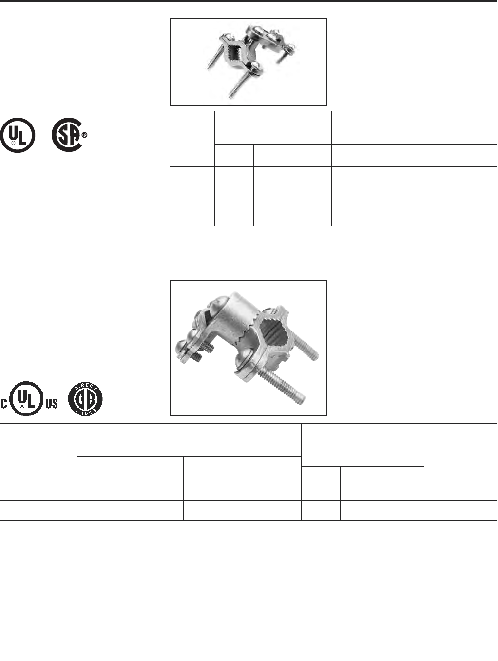
Grounding BURNDY®
Mechanical
Canada: 1-800-387-6487 www.burndy.com US: 1-800-346-4175
40
CAST BRONZE
GROUND CLAMPS
For connecting grounding conductor, EMT or
rigid conduit to water pipe, copper tube,
ground rod or rebar. Hub swings 360° for easy
alignment. Simply reverse bottom clamp for
smaller size rebar or rod. Connectors are
provided with Silicon Bronze hardware.
Accommodates
Conductor Range
Main Tap Reference Recommended
Catalog Water Ground Dimensions Screw Torque
Number Pipe Rebar Rod Ground H L W (Inch Pounds)
1/2- 1#8 - 4/0
C11HD4/0DB [13 - 25] #4 - #6 3/8- 1AWG 2.25 2.65 1.56 50 in.-lbs.
1-1/4- 2#8 - 4/0
C22HD4/0DB [32 - 51] ——AWG 2.70 3.60 1.56 50 in.-lbs.
CAST BRONZE
CLAMPS
To connect armored cable to water pipe. Zinc
plated screws. Pressure bar grips armor or
outer cable insulation. 360° swing hub for
easy alignment.
Recommended
Accommodates Reference Screw Torque
Conductor Range Dimensions (Inch Pounds)
Catalog Water Armored Pipe Wire
Number Pipe Conductor H L W Clamp Clamp
1/2 - 1 1.38 3.05
C-11JA [13 - 25] [35] [77]
1-1/4 - 2 10 - 6 2.60 3.69 1.41
C-22JA [32 - 51] Sol. [66] [94] [36] 50 in.-lb. 50 in.-lb.
2-1/2 - 4 4.29 5.01
C-4JA [64 - 102] [109] [128]
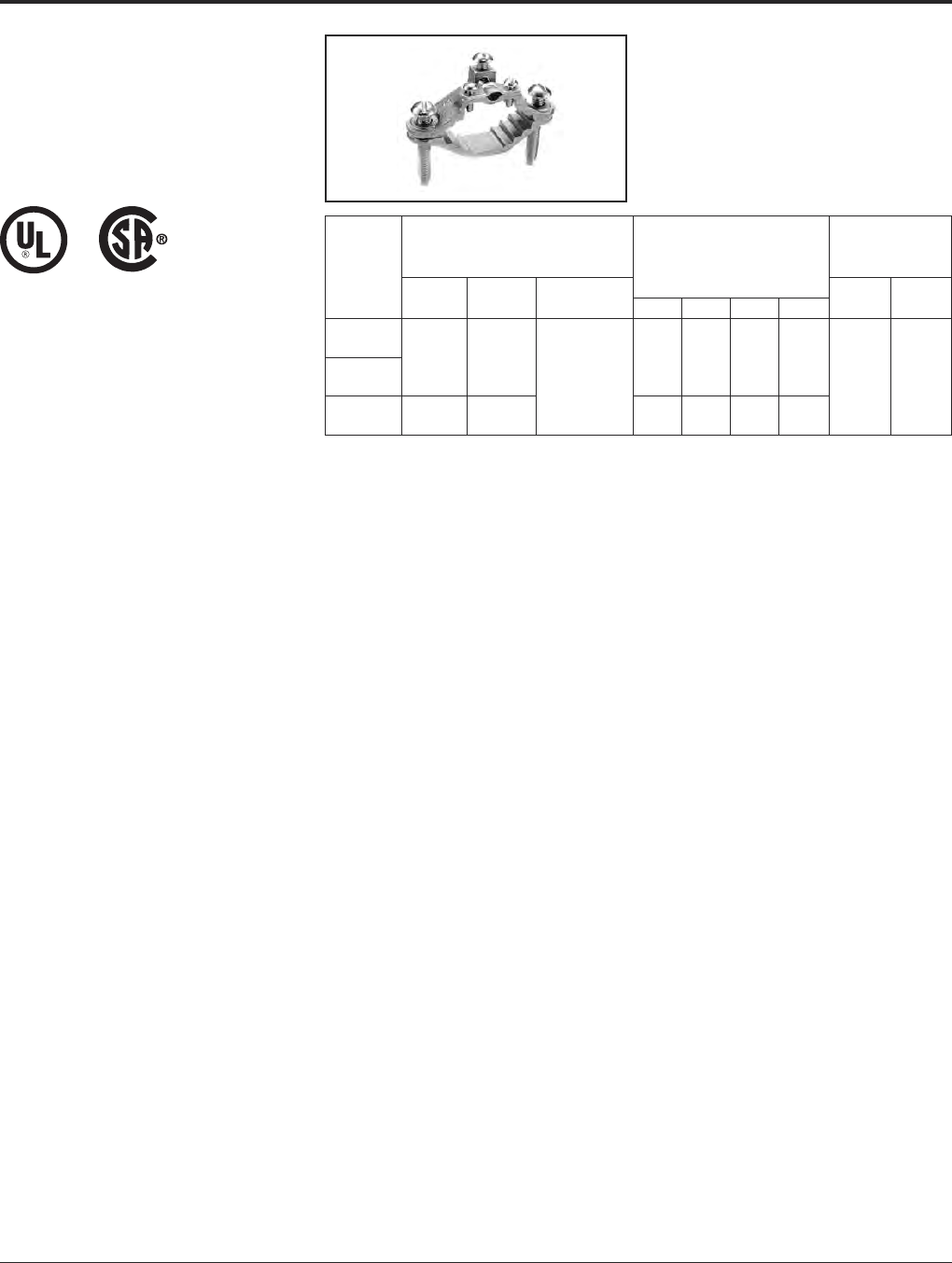
BURNDY®Grounding
Mechanical
US: 1-800-346-4175 www.burndy.com Canada: 1-800-387-6487
41
CAST BRONZE
CLAMPS
For connecting armored cable to water pipe.
Zinc plated screws. “D” indicates UL467 for
direct burial in earth and concrete, supplied
with silicon bronze hardware.
Recommended
Accommodates Screw Torque
Conductor Range (Inch Pounds)
C
atalog Water Ground Reference Dimensions Pipe Wire
N
umber Pipe Ground Clamp
HLWC
Clamp Clamp
C-6 1/2 - 1 10 - 2 Bare Armored 1.60 2.34 1.06 .63
[13 - 25] Str. Unarmored [41] [59] [27] [16]
C-6D Wire Cables 50 in.-lb. 50 in.-lb.
1-1/4 - 2 10 - 2 or Cords 2.38 3.62 .94 1.00
C-7 [32 - 51] Str. [60] [92] [24] [25]

Grounding BURNDY®
Mechanical
Canada: 1-800-387-6487 www.burndy.com US: 1-800-346-4175
42
CAST BRONZE
CLAMP FOR
RIGID CONDUIT
For grounding rigid conduit systems.
Zinc plated screws.
CAST BRONZE
CLAMPS FOR
CONDUIT
For grounding rigid conduit systems. Conti-
nuity from rigid conduit systems to ground
provided by cast bronze threaded conduit
hub. Zinc plated screws.
Recommended
Accommodates Screw Torque
Conductor Range (Inch Pounds)
Catalog Water Hub Reference Dimensions Pipe Wire
Number Pipe Ground Size H L W C Clamp Clamp
1/2 - 1 2.07 2.34 1.34 1.06
C-61 [13 - 25] #6 Sol. 1/2 [53] [59] [34] [27]
1-1/4 - 2 Max. [13] 2.69 3.62 1.34 1.40 50 in.-lb. 50 in.-lb.
C-66 [32 - 51] [68] [92] [34] [36]
Recommended
Accommodates Screw Torque
Conductor Range (Inch Pounds)
Catalog Water Hub Reference Dimensions Pipe Wire
Number Pipe Ground Size H L W C Clamp Clamp
1/2 - 1 2.25 3.23 .97
C-11LH-1 [13 - 25] [57] [83] [25]
1-1/4 - 2 10 Str. - 1/2 2.88 3.50 .69 1.34
C-22LH-1 [32 - 51] 6 Sol. [13] [73] [89] [18] [34]
2-1/2 - 4 4.56 4.82 2.44
C-4LH-1 [54 - 102] [116] [122] [62]
1/2 - 1 2.56 2.86 1.13
C-11LH-2 [13 - 25] [65] [73] [29]
1-1/4 - 2 2/0 - 10 3/4 3.19 3.50 1.00 1.50
C-22LH-2 [32 - 51] Str. [19] [65] [89] [25] [38] 50 in.-lb. 50 in.-lb.
2-1/2 - 4 4.88 4.82 2.38
C-4LH-2 [64 - 102] [124] [122] [60]
1/2 - 1 2.69 2.86 1.19
C-11LH-3 [13 - 25] [68] [73] [30]
1-1/4 - 2 3/0 - 10 1 3.32 3.50 1.13 1.56
C-22LH-3 [32 - 51] Str. [25] [59] [89] [29] [40]
2-1/2 - 4 5.01 4.82 2.44
C-4LH-3 [63 - 102] [127] [122] [62]
-2, -3 Versions*
*C-LH parts ending in “-1” have one screw and a washer,
not shown. C-LH parts ending in “-2” or “-3” have two
screws as shown.

BURNDY®Grounding
Mechanical
US: 1-800-346-4175 www.burndy.com Canada: 1-800-387-6487
43
CAST BRONZE
CLAMP WITH
COPPER STRAP
For grounding rigid conduit systems. Strap
helps protect conduit system from water
system vibrations. Zinc plated screws. Strap
ETP copper.
Recommended
Accommodates Screw Torque
Conductor Range (Inch Pounds)
Catalog Water Hub Reference Dimensions Pipe Wire
Number Fig. # Pipe Ground Size H L W C D Clamp Clamp
6 Sol. 1/2 1.06 1.06
C-11CSH-1 Fig. 1 Max. [13] [27] [27]
3/4 1.25 1.50
C-11CSH-2 Fig. 1 1/2 - 1 4/0 Str. [19] 1.75 8.50 [32] [38] 6.12 50 in.-lb.
[13 - 25] Max. 1 [44] [216] 1.50 1.75 [155] 50 in.-lb.
C-11CSH-3 Fig. 1 [25] [38] [44]
#10 - 2/0 1/2 1.18 1.06
C11CSLH12 Fig. 2 AWG [13] [27] 45 in.-lb.
Fig. 1 Fig. 2
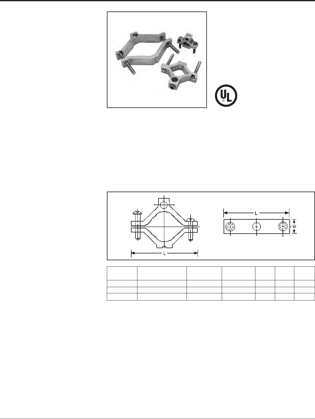
Grounding BURNDY®
Mechanical
Canada: 1-800-387-6487 www.burndy.com US: 1-800-346-4175
44
TYPE GC-A
DUAL RATED
GROUND CLAMP
For Copper and
Aluminum Cable
GC-A ground clamps are UL Listed for use
with either copper or aluminum conductors to
copper water pipe, galvanized pipe or steel
conduit. All clamps are constructed from tin
plated high-strength extruded aluminum alloy.
PENETROX™ oxide inhibiting joint com-
pounds are recommended for all aluminum
applications. Features and Benefits
• Clamps are dual rated for both copper
and aluminum conductors.
〫Maximum flexibility of application.
• All connectors are tin plated.
〫Provide low contact resistance and
prevents galvanic corrosion.
• All clamps are range taking.
〫Only 3 catalog numbers covers
complete range of applications from
1/2 - 4 inches.
Catalog Conduit, Pipe, or Wire Screw Hex
Number Water Tube Size Range Type W L Size
GC15A 1/2 - 3/4 - 1 1/0 - 14 Slotted 11/16 2-1/4 S
GC18A 1-1/4 - 1-1/2 - 2 250 kcmil - 6 Hex Socket 13/16 3-3/4 5/16
GC22A 2-1/2 - 3 - 3-1/2 - 4 250 kcmil - 6 Hex Socket 1 6-5/16 5/16
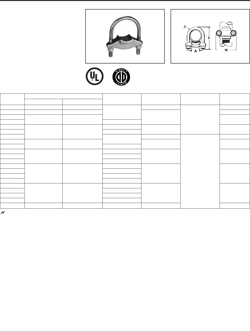
BURNDY®Grounding
Mechanical
US: 1-800-346-4175 www.burndy.com Canada: 1-800-387-6487
45
TYPE GG
GROUND CONNECTOR
For Copper Bar, Strap, Braid or
Cable to Rod or Tube
High copper alloy ground connector for join-
ing bar, strap, braid or cable to rod or tube.
High copper alloy cast body, DURIUM™
U-bolts, nuts and lockwashers make the GG
particularly effective for use with braid for
ground rods, switch handles, fence posts and
gates. One-wrench installation.
Catalog Conductor
Number Tube I.P.S. Rod A H J W
GG15-1 1 1-1/8 - 1-1/4 3-3/8 2-5/8
GG16-1 1-1/4 1-3/8 - 1-1/2 1 3
GG17-1 3-1/2
GG17-15 1-1/2 1-5/8 - 1-7/8 1-1/2 3/8 3-1/4
GG18-1 1
GG18-15 2 2 - 2-3/8 1-1/2 4-1/4 3-3/4
GG18-2 4-3/8 4-1/8
GG19-2 2
GG19-25 2-1/2 2-1/2 - 2-7/8 2-1/2 5 4-5/8
GG20-2 2
GG20-25 3 3 - 3-1/2 2-1/2 6-3/8 5-1/4
GG20-3 3
GG21-2 2
GG21-25 2-1/2 1/2
GG21-3 3-1/2 3-1/2 - 4 35-7/8 5-3/4
GG21-35 3-1/2
GG22-2 2
GG22-25 2-1/2
GG22-3 4 4 - 4-1/2 36-1/2 6-1/4
GG22-4 4
GG24-2 5 — 2 7-5/8 7-1/4
See note page 1
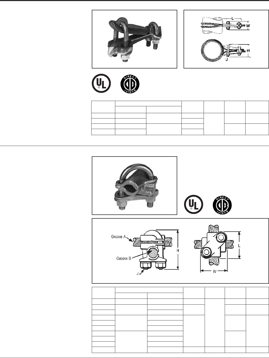
Grounding BURNDY®
Mechanical
Canada: 1-800-387-6487 www.burndy.com US: 1-800-346-4175
46
TYPE GQ
GROUND CONNECTOR
For Copper Cable to Tube
High copper alloy ground connector for cross
connecting a wide range of cable. High
copper alloy, cast body, DURIUM™ U-bolts,
nuts, and lockwashers make the GQ suitable
for burial in soil or concrete. One-wrench
installation. UL467 Listed. Acceptable for
direct burial in earth or concrete.
Catalog Conductor
Number Tube I.P.S. Cable H J L W
GQ2626 6Max. 4-1/2
GQ26-1 Above 64 Str. - 2/0 Str. 7-1/8 5 2-1/2
GQ2929 6Max. 4-1/8 1/2
GQ29-1 Above 62/0 Str. - 250 7-1/2 6 2-3/4
TYPE GX
GROUND CONNECTOR
For Copper Cables
High copper alloy ground connector for cross
connecting a wide range of cable. The high
copper alloy cast body, DURIUM™ U-bolts,
nuts, and lockwashers make the GX suitable
for burial in soil or concrete. One-wrench
installation. UL467 Listed. Acceptable for
direct burial in earth or concrete.
Catalog Conductor
Number Groove A Groove B H J L W
GX4C4C 8 Sol. - 4 Str. 8 Sol. - 4 Str. 1-7/8 1-5/8 1-5/8
GX264C 8 Sol. - 4 Str.
GX2626 4 Sol. - 2/0 Str. 4 Sol. - 2/0 Str. 2-1/2 1-3/4 1-3/4
GX294C 8 Sol. - 4 Str.
GX2926 2/0 Sol. - 250 4 Sol. - 2/0 Str. 3/8 1-7/8
GX2929 2/0 Sol. - 250
GX344C 8 Sol. - 4 Str. 2-3/4 1-7/8
GX3426 4 Sol. - 2/0 Str. 2-1/8
GX3429 300 - 500 2/0 Sol. - 250
GX3434 300 - 500 4-1/4 1/2 2-5/8 2-5/8
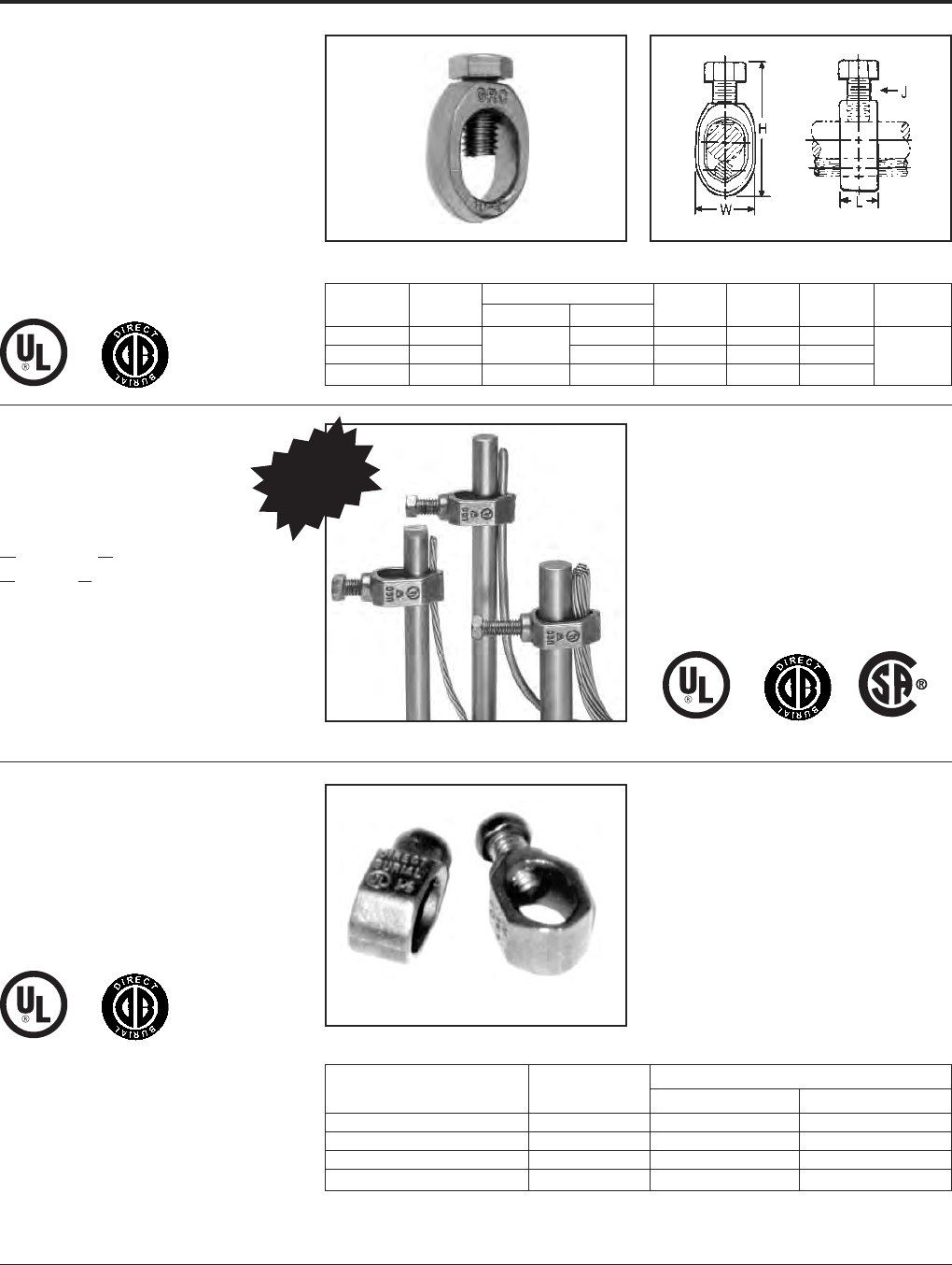
BURNDY®Grounding
Mechanical
US: 1-800-346-4175 www.burndy.com Canada: 1-800-387-6487
47
TYPE GRC
HIGH STRENGTH
GROUND ROD CLAMP
For Copper Cable to Rod
High copper alloy ground connector for
joining a range of cable to copper clad,
gal vanized steel, and stainless steel ground
rods. Slips over end of rod, one-wrench
installation. UL467 Listed for direct burial in
earth and concrete.
REA LISTED
Catalog Drive Conductor Range
Number Rod Min. Max. H W L J
GRC12 1/2 2 Str. 2.00 .89 .63
GRC58 5/8 10 Sol. 1 Str. 2.19 .95 .63 3/8
GRC34 3/4 8 Sol. 1/0 Str. 2.47 1.09 .65
TYPE GRL
LIGHT DUTY
ECONOMICAL GROUND ROD
CLAMP
UL467 Listed. Acceptable for direct burial.
Conductor Range
Catalog Number Rod Size Minimum Maximum
GRL3* 3/8 10 AWG 4 AWG
GRL4 1/2 10 AWG 2 AWG
GRL5 5/8 10 AWG 2 AWG
GRL6 3/4 10 AWG 2 AWG
* GRL3 not UL Listed.
TYPE GCRT1/0
GROUND
CONNECTORS
GROUND CLAMP
RANGE TAKING, UP TO 1/0
The GCRT1/0 is a range taking ground rod
clamp offering another choice from the
BURNDY®family of connectors. The GCRT1/0
works on 1/2, 5/8and 3/4ground rods with
a wire range of #8 through 1/0! The clamp is
UL467 Listed for direct burial in earth and con-
crete. Catalog number GCRT1/0.
Features and Benefits
• Range taking design helps reduce
inventory.
• UL Listed and CSA Certified.
• UL467 Listed for direct burial in earth and
concrete.
NEW!
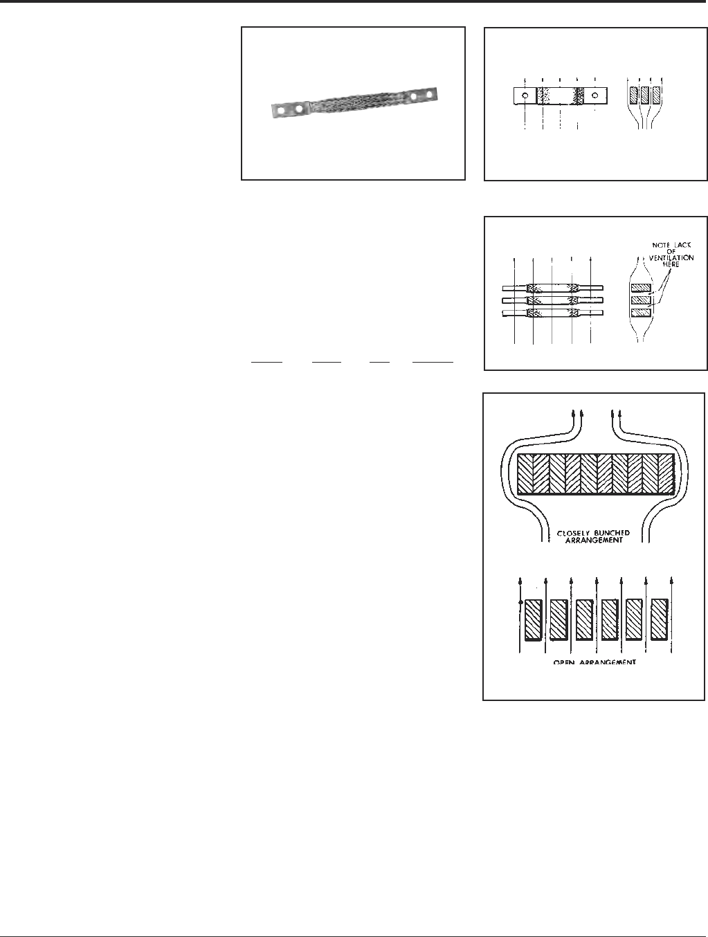
Grounding BURNDY®
Mechanical
Canada: 1-800-387-6487 www.burndy.com US: 1-800-346-4175
48
FLEXIBLE COPPER
BRAID JUMPER
Copper braid is made of tinned, pure copper
wire woven and flattened into a rectangular
shape for greater flexibility. Seamless, pure
copper ferrules are formed and assembled
on each end to provide appropriate
contact surfaces.
Braid is used extensively to compensate for
expansion and contraction of moving parts
and for thermal movement of rigid devices; to
prevent breakage of insulators or bushings or
equipment because of misalignment during
settling of substation foundations; to absorb
shock and vibration of operating equipment;
and to provide flexible current carrying leads
between moving parts of heavy machinery
or equipment.
CURRENT CARRYING
CAPACITY
Flexible copper braid has generally better
heat dissipation properties than flat bar, cable
or other conductors, and therefore can be ex-
pected to have a greater current carrying ca-
pacity for a given cross-sectional area. This is
due to its greater surface area resulting from
the woven construction of fine strands. How-
ever, ventilation, due to the vertical convec-
tion current of air, is appreciably better when
the long axis of the braid is vertical rather than
horizontal, so that the long sides of the braid,
rather than the edges, are exposed to the
moving air. This is particularly true when
spaced braids are used in
multiple as can be seen by comparing Figures
1 and 2.
To take full advantage of ventilation, the
cooling convection current of air should be
permitted to flow freely between the braids.
Therefore, if possible, the braids should be
spaced apart, rather than bunched together,
as illustrated in Figure 3. The effectiveness of
spacing is, or course, greater when the braids
are in a vertical position.
BULK BRAID
Bulk braid can be ordered with a minimum
order quantity of 10 feet. Specify feet in num-
ber of inches.
Example: 10 feet of 190 ampere braid is Cat-
alog No. BB077L120.
INDOOR EQUIV APPROX
RATING CIRCULAR CAT WEIGHT
AMPS AREA NO. PER* FT
190 77,184 BB077L .24
340 153,700 BB154L .49
360 231,552 BB226L .76
415 300,000 BB300L 1.06
Fig. 1
Fig. 2
Fig. 3
Cooling Due to Convection Currents Much
More Effective with Spaced Braid

BURNDY®Grounding
Mechanical
US: 1-800-346-4175 www.burndy.com Canada: 1-800-387-6487
49
FLEXIBLE
COPPER BRAID
CUSTOM DESIGNS
Flexible copper braid offers an economical
and efficient means of protecting electrical
equipment from the potentially harmful effects
of shock and vibration, terminal expansion,
movement of components and misalignment
that may occur during the
service life of the equipment.
Many varieties of braid are required to meet
those needs which we can build to your
specifications.
We also offer engineering assistance in the
selection of the most appropriate standard
or custom braid configuration for your
application.
CUSTOM VARIATIONS
Drilling
* Undrilled
* Elongated (slotted) holes
* Special hole patterns and location
* Metric
*NEMA
Plating
* Tin
* Silver
* Nickel
* Unplated
Length
* Jumper (overall)
* Ferrule(s) contact
Insulated (covered)
* Tubular
* Heat shrink
Split Braid Assemblies
* Stacked
* Side-by-side
Multiple Ferrules
Preformed Configurations
* Offset contact surfaces
* Angular (e.g., 90°, 180°) bends
* Ferrule contact surfaces rotated 90°
on braid axis
Combined Braid Assemblies
Combined Connector - Braid Assemblies
Ferrule Variations
* Belled/unbelled
* Width/thickness
* Contact length
* Special shaping
* Bent at angle °
High Ampacity Requirements
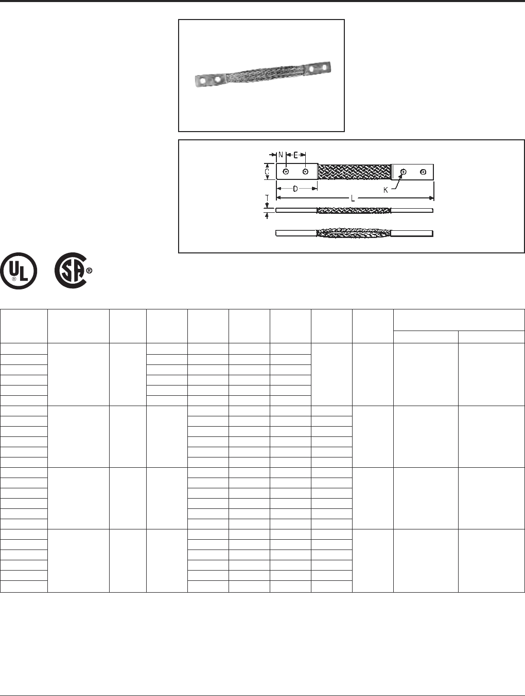
Grounding BURNDY®
Mechanical
Canada: 1-800-387-6487 www.burndy.com US: 1-800-346-4175
50
TYPE B
FLEXIBLE COPPER BRAID
Flexible copper braid jumpers designed to
take up linear expansion and contraction,
compensate for misalignment and absorb vi-
bratory movement of electrical equipment
and devices.
Made of flat extra flexible, tinned, pure copper
braid, with unplated, seamless, pure copper
ferrules formed into a rectangular shape on
each end.
Last two numbers in catalog number indicate
total length of braid in inches (e.g., BD12N or
BD12 is 12long braid jumper).
Other lengths, plating and drilling are avail-
able. Refer to factory.
* This rating may vary with ambient conditions, orientation of
the braid and other service conditions.
** Tongue drilled per (2) hole NEMA standard.
Number of Approximate
Catalog Braids in Ampere Rating
Number Ferrules C D E K L N T Indoor Outdoor
BD12 † 2.50 1.25 .44 12
BD12N** † 3.00 1.75 .56 12
BD18 † 2.50 1.25 .44 18
BD18N** † 1.94
3.00 1.75 .56 18 .62 .13 190 225
BD24 † 2.50 1.25 .44 24
BD24N** † 3.00 1.75 .56 24
BE12 † 1.50 .44 12 .75
BE12N** † 1.75 .56 12 .62
BE18 † 1.50 .44 18 .75
BE18N** † 1 1.50 3.00 1.75 .56 18 .62 .17 340 405
BE24 † 1.50 .44 24 .75
BE24N** † 1.75 .56 24 .62
BF12 † 1.50 .44 12 .75
BF12N** † 1.75 .56 12 .62
BF18 † 1.50 .44 18 .75
BF18N** † 1 1.19 3.00 1.75 .56 18 .62 .25 360 430
BF24 † 1.50 .44 24 .75
BF24N** † 1.75 .56 24 .62
BG12 1.50 .44 12 .75
BG12N** 1.75 .56 12 .62
BG18 1.50 .44 18 .75
BG18N** 1 1.50 3.00 1.75 .56 18 .62 .25 415 495
BG24 1.50 .44 24 .75
BG24N** 1.75 .56 24 .62
Note: All sizes are listed to UL467 and specific sizes (†) are
certified to CSA C22.2, No. 41 Grounding and Bonding
Equipment Standards. Equivalent sizes may be designated
by suffix letters representing variations in length, mounting
configurations, pad size and finish. Contact factory for
details.

BURNDY®Grounding
Mechanical
US: 1-800-346-4175 www.burndy.com Canada: 1-800-387-6487
51
Number of Approximate
Catalog Braids in Ampere Rating
Number Ferrules C D E K L N T Indoor Outdoor
B2D12 † 2.50 1.25 .44 12 .62
B2D12N** † .94 3.00 1.75 .56 12 .62 .25 380 455
B2E12 3.00 1.50 .44 12 .75
B2E12N** 21.62 3.00 1.75 .56 12 .62 .25 530 635
B2F12 3.00 1.50 .44 12 .75
B2F12N** 1.38 3.00 1.75 .56 12 .62 .38 600 720
B2G12N** 1.50 3.00 1.75 .56 12 .62 .50 700 840
B3D12 † 2.50 1.25 .44 12 .62
B3D12N** † 1.19 3.00 1.75 .56 12 .62 .25 470 560
B3E12 3.00 1.50 .44 12 .75
B3E12N** 1.64 3.00 1.75 .56 12 .62 .31 700 840
B3F12 33.00 1.50 .44 12 .75
B3F12N** 1.44 3.00 1.75 .56 12 .62 .56 820 980
B3G12 3.00 1.50 .44 12 .75
B3G12N** 1.69 3.00 1.75 .56 12 .62 .69 960 1150
B4D12 2.50 1.25 .44 12 .62
B4D12N** 1.19 3.00 1.75 .56 12 .62 .32 600 720
B4E12 3.00 1.50 .44 12 .75
B4E12N** 41.64 3.00 1.75 .56 12 .62 .36 850 1020
B4F12 3.00 1.50 .44 12 .75
B4F12N** 1.50 3.00 1.75 .56 12 .62 .78 1000 1200
B4G12N** 1.69 3.00 1.75 .56 12 .62 .94 1200 1440
TYPE B
FLEXIBLE COPPER BRAID
(Continued)
* This rating may vary with ambient conditions, orientation of
the braid and other service conditions.
** Tongue drilled per (2) hole NEMA standard.
Note: All sizes are listed to UL467 and specific sizes (†) are
certified to CSA C22.2, No. 41 Grounding and Bonding
Equipment Standards. Equivalent sizes may be designated
by suffix letters representing variations in length, mounting
configurations, pad size and finish. Contact factory for
details.
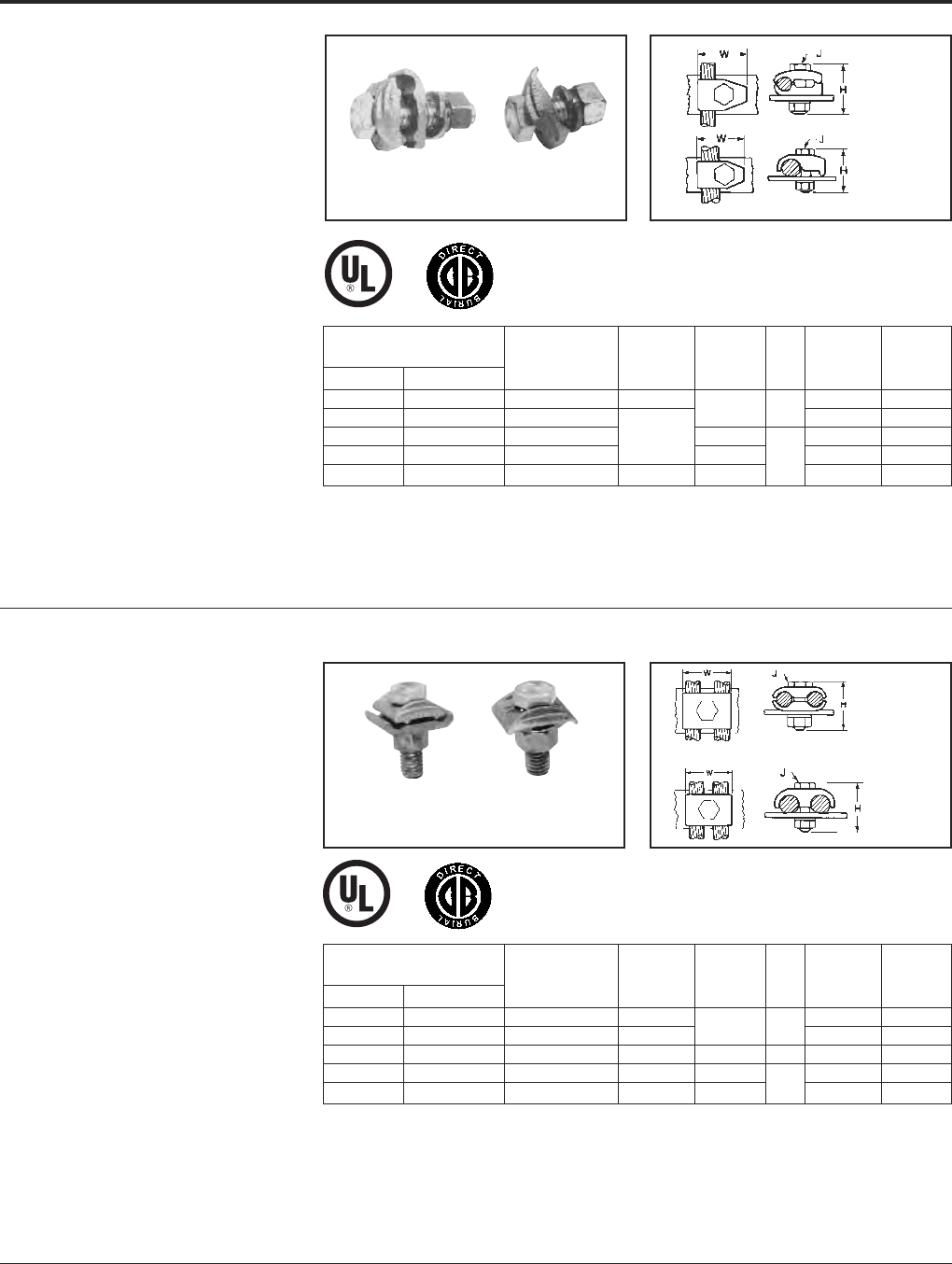
Grounding BURNDY®
Mechanical
Canada: 1-800-387-6487 www.burndy.com US: 1-800-346-4175
52
TYPES GB, GBM
GROUND CONNECTOR
For Copper Cable to Bar
High copper alloy ground connector for
joining a range of cable to 1/4thick bar.* Type
GB separates cable from bar, GBM clamps
cable directly on bar surface.
One-wrench installation. UL467 Listed. The
high copper alloy cast body and DURIUM™
bolts, nuts, and lockwashers make the GB
and GBM suitable for direct burial in concrete
or ground.
TYPES GC, GCM
GROUND CONNECTOR
For Two Copper
Cables to Bar
High copper alloy ground connector for joining
a wide range of two parallel cables to 1/4
thick bar.* Type GC separates cable from bar,
GCM clamps cable to bar surface.
One-wrench installation. UL467 Listed. The
high copper alloy cast body and DURIUM™
bolts, nuts, and lockwashers make the GC
and GCM suitable for direct burial in concrete
or ground.
+ GBL30 is not UL listed.
Add “GS” suffix for galvanized steel hardware.
* For other bar thicknesses see note at bottom of page E-48.
Smooth oval-shank bolts are available upon request for cable-
tray applications (example: GC30G3). Also refer to type GC-CT.
Add “GS” suffix for galavanized steel hardware.
* For other bar thicknesses see note at bottom of page E-48.
Type
GC
Type
GCM
Type
GB
Type
GBM
Type
GBM
Type
GB
Type
GC Type
GCM
HH WW
Catalog Number Type Type Type Type
Type GB Type GBM Conductor GB/GBL GBM J GB/GBL GBM
GB4C GBM4C 8 Sol. - 4 Str. 1-1/2 1-1/4 1-1/4
GB26 GBM26 4 Sol. - 2/0 Str. 1-1/2 3/8 1-1/2 1-1/2
+GBL30 4 Sol. - 300 2 7/8 0
GB29 GBM29 2/0 Sol. - 250 2 1/2 2 2
GB34 GBM34 300 - 500 3 2-1/4 2-3/8 2-3/8
HH WW
Catalog Number Type Type Type Type
Type GC Type GCM Conductor GC/GCL GCM J GC/GCL GCM
GC4C4C GCM4C 8 Sol. - 4 Str. 1-1/2 1-3/8 1
GC2626 GCM26 4 Sol. - 2/0 Str. 2 1-1/2 3/8 1-3/4 1-3/8
GCL30 GCM30 4 Str. - 300 2 — — 1 —
GC2929 GCM29 2/0 Sol. - 250 2-1/4 2 — 2-1/4 2
GC3434 GCM34 300 - 500 2-7/8 2-1/4 1/2 2-7/8 2-5/8
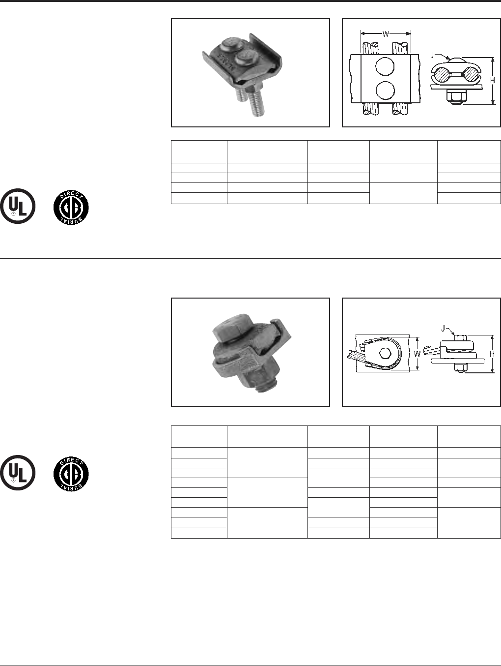
BURNDY®Grounding
Mechanical
US: 1-800-346-4175 www.burndy.com Canada: 1-800-387-6487
53
TYPE GL
GROUND CONNECTOR
For Two Copper
Cables to Bar
High copper alloy ground connector for join-
ing a wide range of two parallel cables to 1/4
thick bar.* Two-bolt design, separates cable
from bar. One-wrench installation. UL467
Listed. The high copper alloy cast body and
DURIUM™ bolts, nuts, and lockwashers
make them suitable for direct burial in
concrete or ground.
TYPE GZ
GROUND CONNECTOR
For Copper Cable to Bar
High copper alloy ground connector for
joining a wide range of cable to 1/4thick
bar*. Cable is gripped by curving it around the
clamping bolt in connector groove. UL467
Listed. The high copper alloy cast body and
DURIUM™ bolts, nuts, and lockwashers
make them suitable for direct burial in
concrete or ground.
* For other bar thicknesses see note at bottom of page.
NOTE:
* The GB, GBM, GC, GCM, GL and GZ are all
used for joining a range of cable to bar. The
catalog numbers in each table accommodate the
indicated cable range and up to 1/4thick bar.
Optional bolt lengths are available to accommo-
date up to 1thick bar. For bar thicknesses from
1/4to 1/2, add the suffix “T4” to the catalog
number in the table. For bar thicknesses from
1/2to 1, add the suffix “T8” to the catalog
number in the table.
Catalog
Number* Conductor H J W
GL4C4C 8 Sol. - 4 Str. 1-1/2 1-3/8
GL2626 4 Sol. - 2/0 Str. 2 3/8 1-3/4
GL2929 2/0 Sol. - 250 2-1/4 2-1/4
GL3434 300 - 500 2-7/8 1/2 2-7/8
Catalog
Number* Conductor H J W
GZ4C-38 1-1/2 3/8 1-1/8
GZ4C-12 8 Str. - 4 Str. 1-7/8 1/2
GZ4C-58 5/8 1-3/4
GZ26-38 23/8 1-5/8
GZ26-12 3 Str. - 2/0 Str. 2-1/8 1/2
GZ26-58 5/8 1-3/4
GZ29-38 2-1/4 3/8
GZ29-12 3/0 Str. - 250 2-3/8 1/2 2-1/4
GZ29-58 2-1/2 5/8
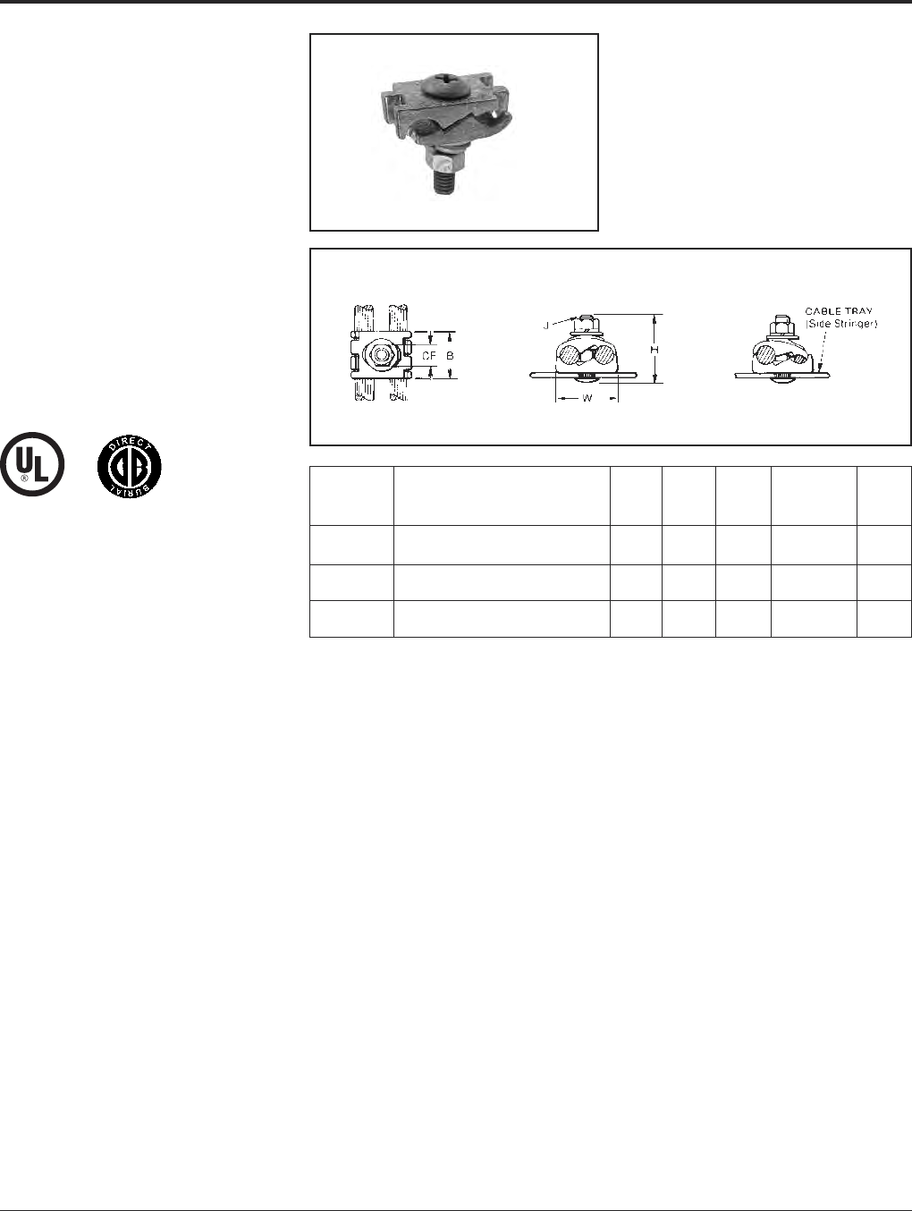
Grounding BURNDY®
Mechanical
Canada: 1-800-387-6487 www.burndy.com US: 1-800-346-4175
54
TYPE GC-CT
CABLETRAY
GROUND CLAMP
This unique connector incorporates features
which are unmatched. Made of tin-plated cast
copper alloy, it accommodates either one or
two conductors, copper or aluminum cable.
In addition to a low profile head with a deep
Phillips recess, the galvanized steel bolt has a
ribbed neck which prevents rotation during in-
stallation when installed in a .44 diameter
hole. When used on aluminum conductor, the
cable must be scratch brushed and
PENETROX™ A joint compound must be
used on cable and connector.
UL467 Listed for copper conductor only. Suit-
able for direct burial in concrete or earth.
NOTE:
The bolt head is mounted on the inside wall of cabletray to avoid
damage to the cable insulation.
May be used with aluminum or galvanized steel cable tray.
Accommodates Copper or
Catalog Alunimum Conductor
Number in Either Groove B CF H J W
#6 Sol. (.162 Dia.) -
GC2525CT 1/0 Str. (.372 Dia.) 1.12 .56 1.95 3/8” - 16 1.45
#2 Sol. (.258 Dia.) -
GC2626CT 2/0 Str. (.419 Dia.) 1.12 .56 1.95 3/8” - 16 1.70
2/0 Str. (.414 Dia.) -
GC2929CT 250 kcmil (.575 Dia.) 1.12 .56 2.20 3/8” - 16 1.98
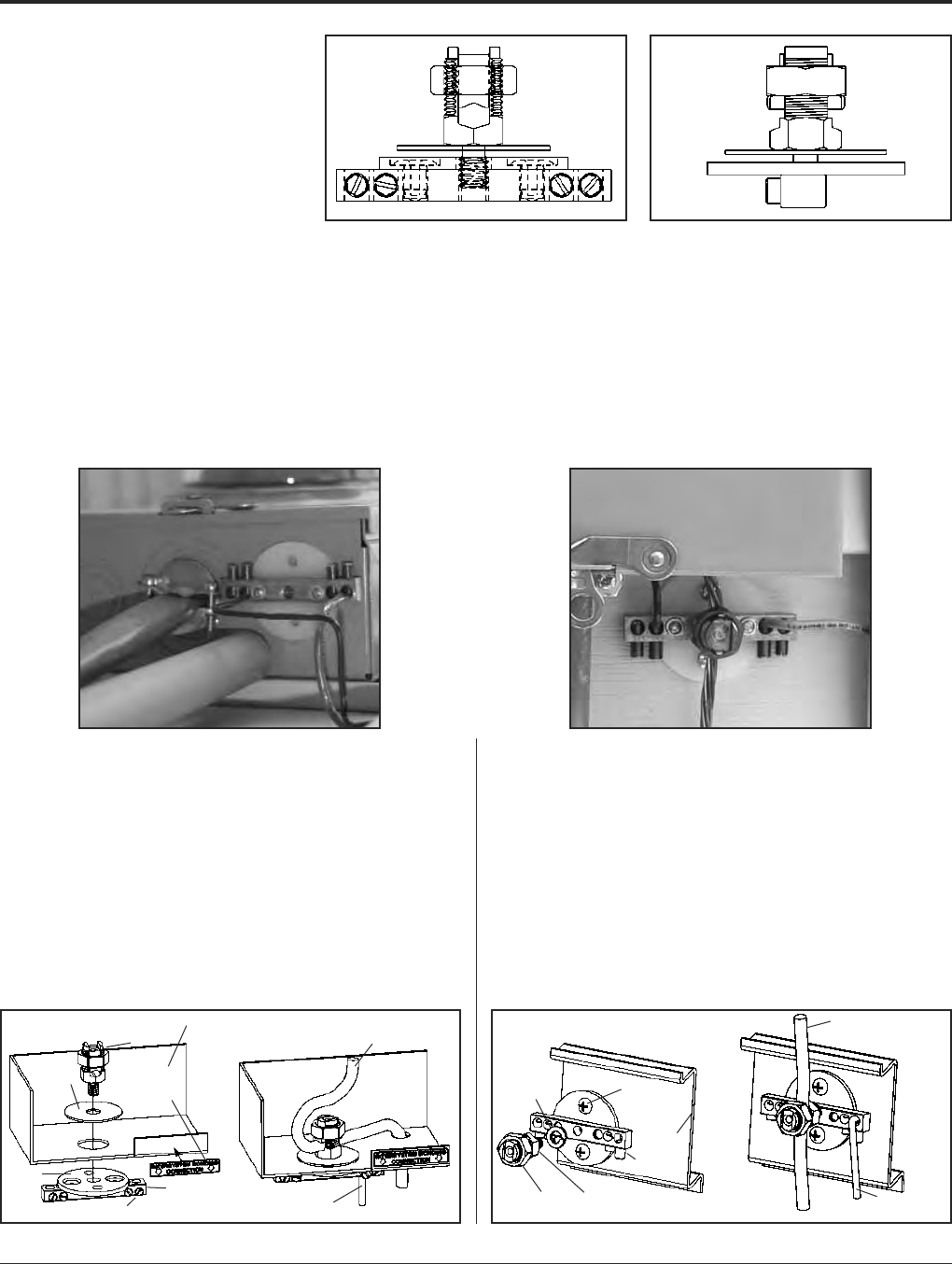
BURNDY®Grounding
Mechanical
US: 1-800-346-4175 www.burndy.com Canada: 1-800-387-6487
55
TYPE BDT
BONDIT™ INTERSYSTEM
BONDING CONNECTOR
House Mounted or
Meter Socket Mounted
Designed to meet the requirements of 2008
NEC Article 250.94 “Bonding for Other Sys-
tems.” Corrosion-resistant stainless steel set
screws. Accepts main ground wire (#2-#8) and
up to 4 intersystem wires (#6-#14). Same de-
sign can be mounted directly to the meter
socket or mounted to the house. Innovative
design does not damage meter socket and will
not void warranty.
Catalog Number: BDT1
Features & Benefits
• Made in the USA!
• Meets Intersystem Bonding Requirements:
NEC2008 250.94
• One connector does it all
• House mount or meter socket mount
• Incorporates proven BURNDY®SERVIT
POST™ design
• Stainless steel set screws
• Accepts main ground wire (#2-#8), up to 4
intersystem wires (#6-#14)
• Easily mounts to meter box during new in-
stallation or can be wall mounted
• Easy to follow instructions included
• Does not damage meter socket; no worries
about damaging the paint or voiding war-
ranties
• Easily installed with a wrench and screw-
driver
• Open design prevents buildup of hornets,
bees, spiders
CONFIGURATION 1 — MOUNTED TO ENCLOSURE
1. Punch out a 1/2or 3/4knock out on the electrical enclosure.
2. Begin assembly by installing the ground electrode conductor in the
SERVIT POST™ inside the electrical enclosure. Torque on SERVIT®
nut: 275 in-lb max.
3. Install the rest of the connector as shown in figure 1 below, it is not
necessary for the bus bar to be aligned parallel with the enclosure.
(Note: the split washer is not used in this configuration.)
4. Tighten the intersystem ground wires with set screws in the bus bar
to a maximum torque of 35 in-lb.
5. Adhere the BONDIT™ location sticker to the front of the electrical
enclosure.
CONFIGURATION 2 — MOUNTED TO EXTERIOR WALL
1. Begin by assembling the connector as shown in figure 2 below. Be
sure SERVIT POST™ is as tight as it can be while its groove is
aligned with the ground electrode conductor. (Note: the flat washer
is not used in this configuration.)
2. Use two mounting screws (not included) to secure the connector to
the exterior wall so that the set screws in the bus bar face down-
ward.
3. Install the ground electrode conductor into the SERVIT POST™
while turning the nut/pressure bar assembly to a maximum torque
of 275 in-lb. (use 2 wrenches if necessary).
4. Tighten the intersystem ground wires with the set screws in the bus
bar to a maximum torque of 35 in-lb.
5. If hidden from view, use the BONDIT™ location sticker to indicate
the location.
Flat
washer
Plastic
disk
Set screw
Bus bar
SERVIT
POST™
Electrical
enclosure
(cut away)
BONDIT™
locaton
sticker
Ground
electrode
conductor
Intersystem
ground wire
Split lock-
washer
Nut & Pressure
Bar Assembly SERVIT
POST™
Set screw
Exterior
wall
Mounting
screws (not
included)
Intersystem
ground wire
Ground electrode
conductor

Grounding BURNDY®
Mechanical
Canada: 1-800-387-6487 www.burndy.com US: 1-800-346-4175
56
BONDIT™- Wall Mount
Intersystem Bonding Connector
NEC 250.94 refers to a requirement in the
2008 National Electrical Code. In the past,
ground wires from telephone systems or cable
systems were allowed to be grounded
separately from the GEC (Ground Electrode
Conductor from the main electrical service).
With the new code, all ground wires from
separate systems such as telephone systems,
CATV and radio systems must be tied together
at one location to the GEC. Hence, the term
intersystem refers to tying all of the “system”
grounds together in one location. The
BONDIT™ - Wall Mount is a great solution
when the GEC is exposed (not in conduit).
With the new BONDIT™ - Wall Mount con-
nector, BURNDY®provides an economical
solution that meets the needs of NEC 250.94.
Catalog Number: BDTIBB
Features and Benefits:
• Meets the Intersystem Bonding
requirements of NEC2008 250.94
• Provides an easy to access grounding
point for utilities such as telecom and
cable
• Easy to install
• UL Listed and CSA Certified
• Tin-plated connector body provides
long-lasting corrosion resistance
• Stainless steel set screws
Phone
Cable TV
Ground Conductor
Satellite Dish
Plastic Cover
Assembly ViewConnector Body
Lay-In Section
Conductor Ports (4)
Stainless Steel Screw
Stainless Steel Screw
(4 Places)
L
M
W
H
Intersystem
Ground Wire
(Ex.: Telephone)
Ground Conductor
(GEC)
Catalog Conductor Range Reference Dimensions
Number Lay-In Section Conductor Ports L W H M
3.99 .71 .91 2.46
BDTIBB #6 - #2 AWG #14 - #4 AWG [101] [18] [23] [62]
• Accepts main ground wire (#2 to #6), up
to (4) intersystem wires (#4 to #14)
• Supplied with durable cover, easily secured
over connector body
• Approved for use with solid or stranded
conductors
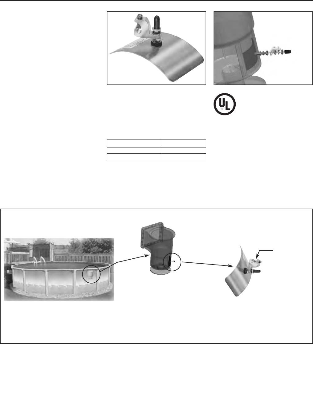
BURNDY®Grounding
Mechanical
US: 1-800-346-4175 www.burndy.com Canada: 1-800-387-6487
57
BWB680 SERIES
BURNDY®POOL WATER
BONDING KIT
NEC 2008 680.26(C) states: “An intentional
bond of a minimum conductive surface area
of 9shall be installed in contact with the pool
water. This bond shall be permitted to consist
of parts that are required to be bonded in
680.26(B).”
In order to comply with this requirement
BURNDY®is pleased to introduce the
BWB680 Series. Made of non-corrosive stain-
less steel, the BURNDY®water bonding kit
maintains constant contact with pool water to
ensure that the pool is effectively bonded at all
times.
BURNDY®BWB680 Series is one of the few
and the most user friendly, products on the
market that complies with this code. Other
products that are currently available are
placed in the plumbing, which is not always in
contact with the water and therefore does not
meet the code. Since the BWB680 is placed
in the skimmer, it is always in contact with the
water.
Some of the features of this product include:
• Easy installation
• Mounting hardware included
• UL Listed
• Placed out of the way on the side wall of
the skimmer, below the basket
Catalog Number Pool Type
BWB680IG In-Ground
BWB860AG Above Ground
Included in the BURNDY®BWB680 Series
Bonding Kit: One bonding plate, (1) rubber
sealing washer, (2) flat washers, (2) lock wash-
ers, (2) nuts and (1) BURNDY®CL501-TN
Skimmer
Bonding wire
goes here
A pool skimmer acts as a water filter at the top of a
pool. Because pool water is continuously flowing
through the skimmer drain, installing the BURNDY®
Pool Water Bonding Kit inside the skimmer is ideal
for complying with NEC 2008 680.26(C).

Grounding BURNDY®
Mechanical
Canada: 1-800-387-6487 www.burndy.com US: 1-800-346-4175
58
BSD Series
STATIC DISCHARGE REELS
Static Discharge Reels are an excellent addi-
tion to the BURNDY®static discharge line of
products. These reels are often used to dissi-
pate static charge buildup developed while
filling or dispensing fuel or other combustible
liquids from fuel trucks or rail cars. Often used
in the petroleum industry but applicable in any
area where static discharge creates a potential
hazard.
BURNDY®offers the three most common
static discharge reels found in the market.
These reels are heavy duty, with 50lengths
and are supplied with a 100 amp universal
jaw-type grounding clamp. All reels come
standard with spring rewind and centrifugal
brake. The tension can be adjusted on these
reels and installation instructions are included
to ensure the most efficient mounting method.
Every reel is Proudly Made in the USA and
meets the stringent quality expectations of the
BURNDY®portfolio of grounding products.
Features & Benefits
• Automatic E-Z PULL™ Rewinding
• Rugged Steel Construction
• Compact Enclosed Design
• Positive Ratchet Lock
• Includes Ratchet On/Off Switch
• Steel Cable Installed
• 100 Amp Universal Jaw-Type Grounding
Clamp
• Red Baked-on Finish
•50Cable Length
• Made in the USA
Number of Jaw-Type
Catalog Number Cable Length Grounding Clamps Weight (lbs.)
BSD2050 50 Feet 1 12
50 Feet
BSD2050N (Nylon Covered) 112
35 Feet
BSD2050Y plus 15 Feet for “Y” 213
BSD2050 BSD2050Y
“Y” Style with 2 clamps
BSD2050N
Clear Nylon Covered

BURNDY®Grounding
Mechanical
US: 1-800-346-4175 www.burndy.com Canada: 1-800-387-6487
59
TYPE GIE-G
GROUND CONNECTOR
For Vehicle Grounding
Heavy Duty Construction
High-strength copper alloy ground clamps for
grounding gasoline trucks, tank cars, aircraft
and other vehicles where danger of explosion
due to static electricity exists. Corrosion
resistant and supplied with nonsparking,
adjustable, replaceable contact grip screws.
Automatic safety release disconnects should
a vehicle unexpectedly move from the
grounded area. Accommodates 4 Str. flexible
copper cable.
1.2
MAX.
OPENING
TYPE GIE-G
GROUND CONNECTOR
Accommodates flexible rubber sheath cable
ranging from #6 to #2 conductor.
Catalog Number: GIE2CG3
8 1⁄8
Replaceable Contact Grip Screws
Catalog Number Catalog Number Material Point Configuration
GIE4CG3P5 Cone Point
GIE4CG3 GIE4CG3P7 Beryllium Copper Cup Point
GIE4CG4P5 Cone Point
GIE4CG4 GIE4CG4P7 Stainless Steel Cup Point
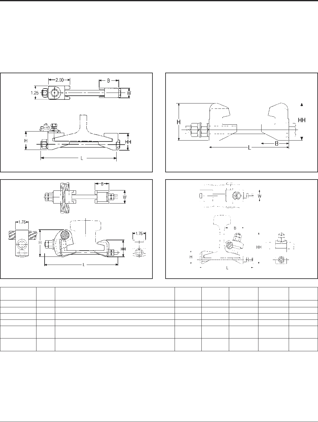
Grounding BURNDY®
Mechanical
Canada: 1-800-387-6487 www.burndy.com US: 1-800-346-4175
60
RAIL CONNECTOR
Mechanical clamp connectors designed for
use in power, contact or running rail appli -
cations. Connectors are cast of a high
conductivity copper alloy, tin-plated, and
assembled with high-strength DURIUM™
hardware. Connectors designed for extended
service life.
* Tin-plated.
Fig. 1 Fig. 2
Fig. 3 Fig. 4
Catalog Fig.
Number No. Accommodates B H HH L W
J278 1 100 Lbs. A.R.E.A. Running Rail 1.81 1.88 1.72 7.50 .88
J279 1 75 or 90 Lbs. Running Rail 1.81 1.71 1.55 7.50 .88
J280 1 150 Lbs. Contact Rail 2.12 2.08 1.92 7.00 1.25
J295 2 150 Lbs. Third Rail 2.62 3.50 3.50 7.75 3.00
150 Lbs. NMC Contact Rail and
RGC44G1* 3(1) 800-1000 kcmil CU Cable 1.75 2.82 2.25 10.00 1.75
115 Lbs. Contact or Running Rail and
RGC39G1* 4(1) 500-750 kcmil CU Cable 2.75 2.00 4.78 8.32 1.25
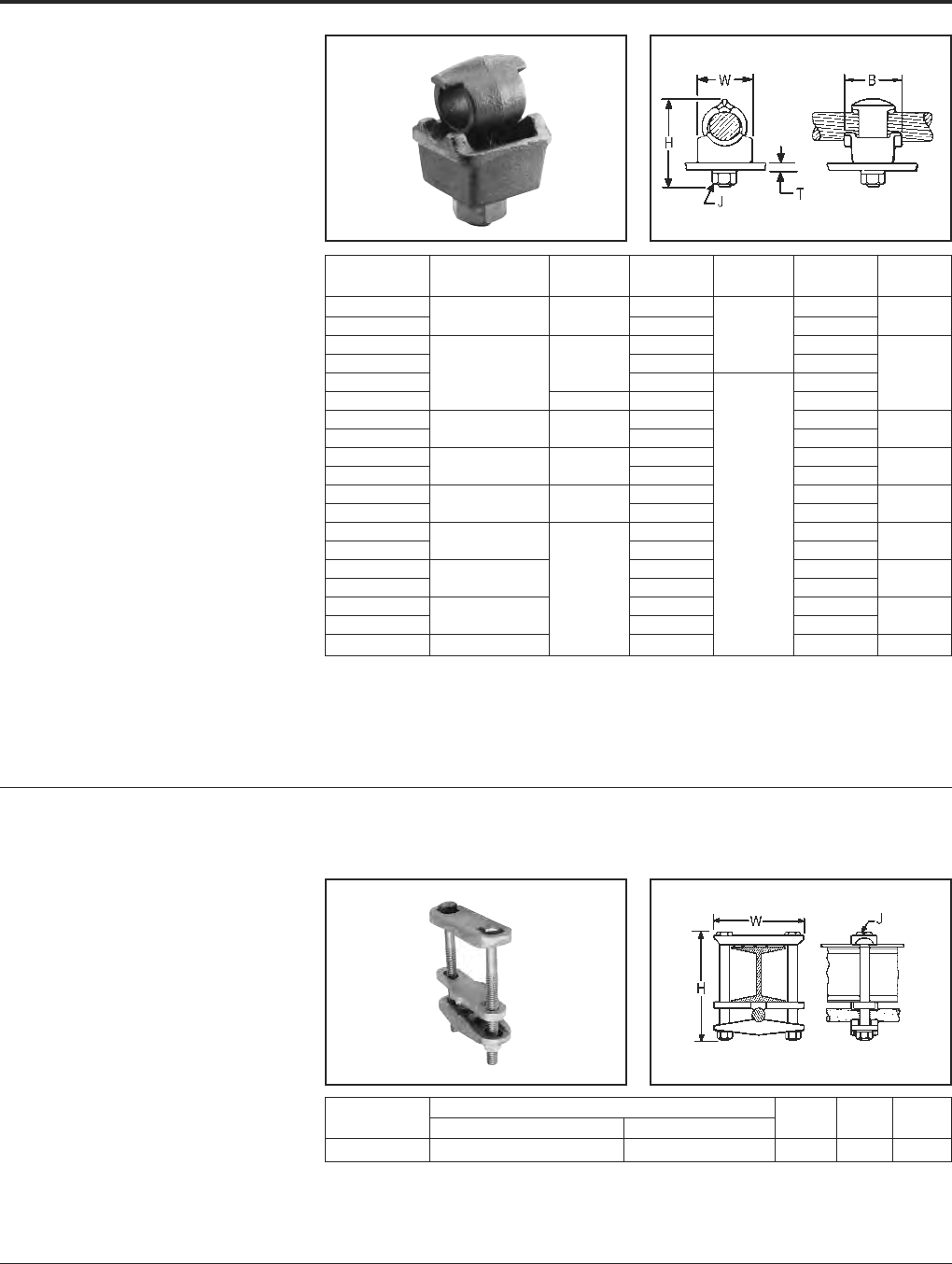
BURNDY®Grounding
Mechanical
US: 1-800-346-4175 www.burndy.com Canada: 1-800-387-6487
61
TYPE QGFL
BARTAP™
For Copper Cable to
Flat Bar or Pad
High copper alloy BARTAP™ for joining a
range of cable to bar or pad. One-wrench
instal lation. DURIUM™ nut and lockwasher.
TYPE GA-H
GROUND CONNECTOR
For Copper Cable
to “H” Beam
High copper alloy ground connector for join-
ing a wide range of cable parallel to “H”
beams or square tube. Hardware is
made from DURIUM™ for superior corrosion
protection.
* Can be installed side by side or in line on NEMA drilled bar.
Catalog T
Number Conductor B H J (Max.) W
QGFL1CB1 1-7/8 1/4
QGFL1CB1T6 10 Sol. - 1 Str. 1-1/8 2-3/8 3/4 1
QGFL26B1 2-1/8 3/8 1/4
QGFL26B1T6 1-1/4 2-5/8 3/4
QGFL26B2* 8 Sol. - 2/0 Str. 1-1/2 1/4 1-1/8
QGFL26B2T6* 1-1/2 2-7/8 3/4
QGFL29B1* 2-5/8 1/4
QGFL29B1T6* 6 Str. - 250 1-5/8 3-1/8 3/4 1-3/8
QGFL31B1* 2-7/8 1/4
QGFL31B1T6* 2 Sol. - 350 1-3/4 3-1/4 3/4 1-5/8
QGFL34B1 3-1/8 1/4
QGFL34B1T6 1/0 Sol. - 500 2 3-5/8 3/4 1-3/4
QGFL39B1 3-1/4 1/2 1/4
QGFL39B1T6 350 - 750 3-5/8 3/4 1-3/4
QGFL44B1 3-3/8 1/4
QGFL44B1T6 750 - 1000 4-1/8 3/4 2-1/8
QGFL46B1 2-1/4 4 1/4
QGFL46B1T6 1000 - 1500 4-1/2 3/4 2-1/2
QGFL48B1 1500 - 2000 4-3/4 1/4 3
Catalog Conductor
Number “H” Beam Cable H J W
GA25H26
1-7/81-7/8- 2-1/22-1/2
4 Sol. - 2/0 Str. 4-3/4 3/8 4
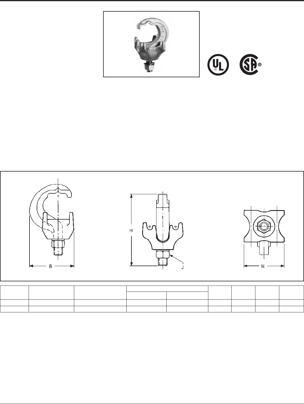
Grounding BURNDY®
Mechanical
Canada: 1-800-387-6487 www.burndy.com US: 1-800-346-4175
62
TYPE GRF
UNIGROUND™
Raised Floor Grounding
Connector
The BURNDY®UNIGROUND™ is a universal
grounding clamp, specifically designed for all
raised flooring systems. It can be installed on
round or square pedestals and can
accommodate one or two grounding wires to
make an efficient grid. The underfloor signal
reference grid provides the low impedance
ground path that attenuates high frequency
static and 60 Hz transient noise for cleaner
data output. UL467 Listed.
Features and Benefits
• One connector fits all applications.
〫Ease of specification and installation.
• Single bolt design.
〫Ease of installation:
— No need to disassemble.
— Single wrench installation.
• Accepts 1 or 2 ground conductors.
〫Requires less connectors to install
signal reference grid.
• Tin plated cast bronze construction.
〫Resists corrosion and provides ex-
tended life ground connection.
• Grounds all pedestals (round or square).
Will handle up to 7/8square and 1round.
〫Ease of installation. One connector
does it all
• Serves 3 needs:
1. Signal Reference Grid.
2. Static Ground.
3. Fault Current Ground.
〫UNIGROUND™ solves all possible
grounding problems found in computer
applications today.
Catalog Number of Conductor Pedestal Type
Number Conductors Size Sol. & Str. Round Square B H J W
GRF4C-3 1 or 2 #8 - #2 Up to 1Up to 7/81.96 3.14 3/81.76
GRF4C-4 1 or 2 #8 - #2 Up to 3/4Up to 5/81.79 3.13 3/81.40
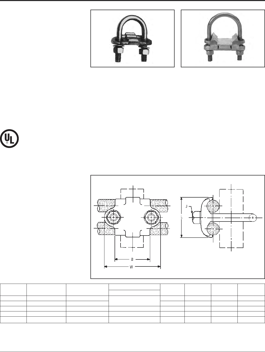
BURNDY®Grounding
Mechanical
US: 1-800-346-4175 www.burndy.com Canada: 1-800-387-6487
63
TYPES GP-G1, GP-RT
Raised Floor Grounding Clamps
High copper alloy ground connector for raised
floor computer grounding applications. These
connectors can be installed on round and
square pedestal applications and will accom-
modate one or two grounding wires to make
an efficient grid. The underfloor signal refer-
ence grid provides the low impedance ground
path that attenuates high frequency static and
60 Hz transient noise for cleaner data output.
UL467 Listed.
In addition we offer the GP1726RT, which is
especially designed for penetrating epoxy
paint on pedestals. This patented connector
offers a low impedance, time saving connec-
tion between conductors and the Pedestal.
Features and Benefits
• Accepts 1 or 2 Ground Conductors
〫Requires less connectors to install sig-
nal reference grid.
• Made of copper alloy.
• DURIUM™ U-Bolts, nuts and lockwashers.
〫Provides a low impedance ground path
for maximum performance.
• Grounds all pedestals (round or square).
• Will handle from 3⁄4to 1round or square.
〫Ease of installation.
• Serves 3 needs.
1. Signal Reference Grid.
2. Static Ground.
3. Fault Current Ground.
〫Connectors solves all possible
grounding problems found in computer
applications today.
GP1726RT
Catalog Number of Conductor Pedestal Type
Number Conductors Size Sol. & Str. Round or Square B J L W
GP654CG1 1 or 2 #8 Sol. - 4 Str. 3/4- 1Round 1.5 3/81.31 2.38
GP64526G1 1 or 2 #4 Sol. - 2/0 Str. 3/4- 7/8Square 1.5 3/81.69 2.38
GP1526G1 1 or 2 #4 Sol. - 2/0 Str. 1-1/4Round 1.75 3/81.69 2.62
GP1726RT 1 or 2 #6 Sol. - 2/0 Str. 2Round 2.12 3/81.50 3.22
GP1726G1 1 or 2 #6 Sol. - 2/0 Str. 2Round 2.12 3/81.50 3.22
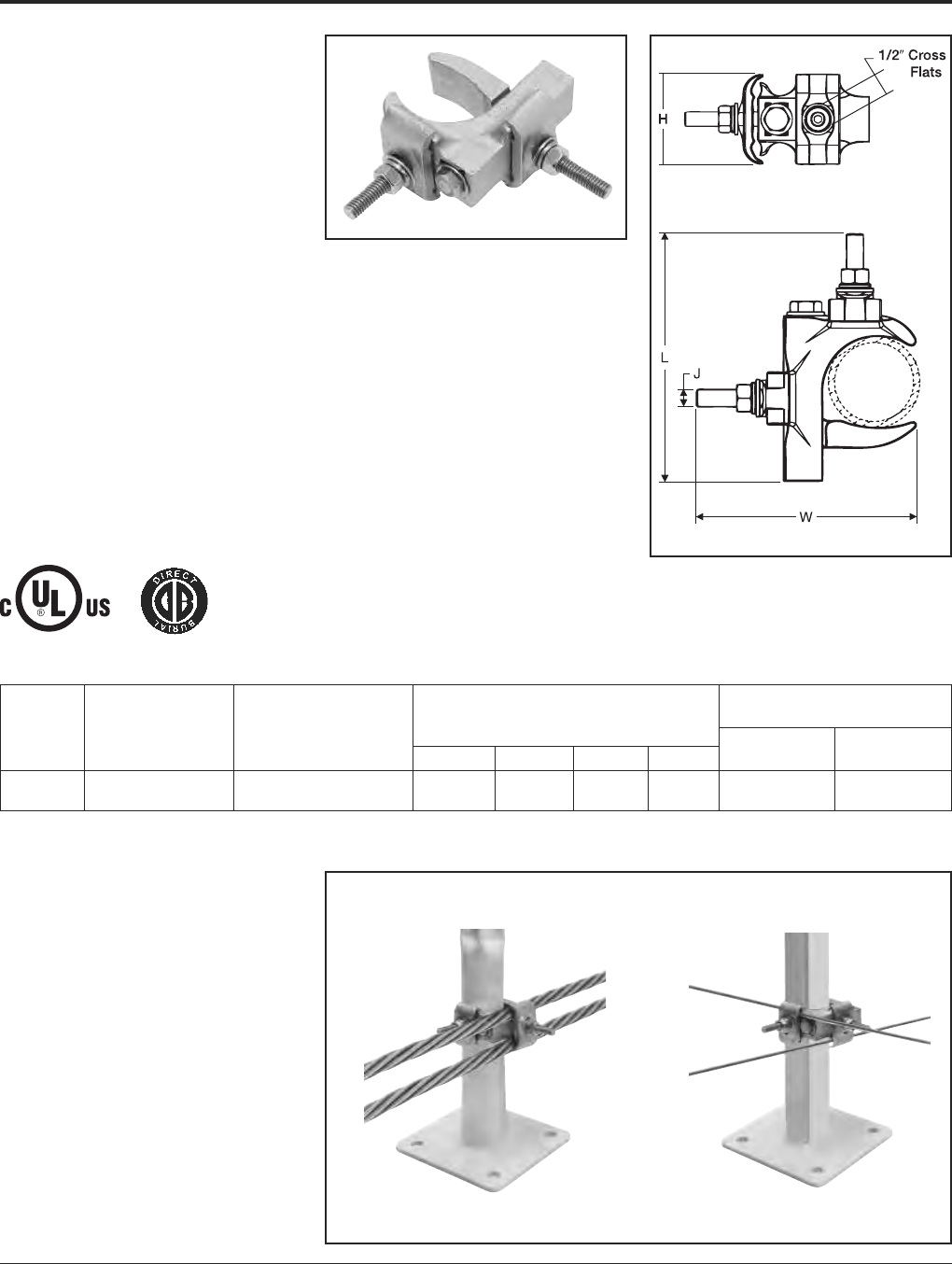
Grounding BURNDY®
Mechanical
Canada: 1-800-387-6487 www.burndy.com US: 1-800-346-4175
64
TYPE GXP1828RF
SUPER-CLAMP™
Raised Floor Pedestal
Ground Connector
The GXP1828RF is a versatile, easy to install,
range taking ground connector. This ground-
ing clamp accepts a wide range of pedestals
and conductors. Accepted pedestal range is
3/4through 2(7/8- 2round; 3/4- 1-1/2
square). The wire range is #6 solid to 4/0
stranded. The wires can be arranged in paral-
lel or in a cross grid configuration—accepts 1
or 2 wires.
UL Listed for the US and Canadian markets
(cULus). A high copper alloy body ensures
excellent conductivity and the hardware is
made of stainless steel. The connector is also
rated for Direct Burial. The versatility of the
connector makes it an excellent choice for
applications requiring multiple conductor sizes
and/or configurations.
Features & Benefits
• Fits a wide range of raised floor pedestals,
from 3/4to 2(7/8- 2round; 3/4- 1-1/2
square)
• Accepts a wide range of wire sizes, from #6
solid to 4/0 stranded
• Accommodates parallel wires or cross grid
arrangements; wires can be installed in
cross grid configuration
• Accepts one or two wires in any
configuration
• Easy to install—open design eliminates
need to disassemble before installing
• One socket size fits all hardware (1/2
socket size)
• Made of high copper alloy
• Stainless steel hardware
• UL Listed for the US and Canadian markets
(cULus)
• Rated for Direct Burial
Recommended Tightening
Copper Torque (in-lb)
Catalog Conductor Range Reference Dimensions Conductor Pedestal
Number (Solid or Stranded) Pedestal Range L W H J Saddle (Nut) Clamp (Bolt)
Round: 7/8- 2
GXP1828RF 6 AWG - 4/0 AWG Square: 3/4- 1-1/24.533.941.965/16120 180
Works on either Round or Square Pedestals
Parallel Configuration Cross Grid Configuration
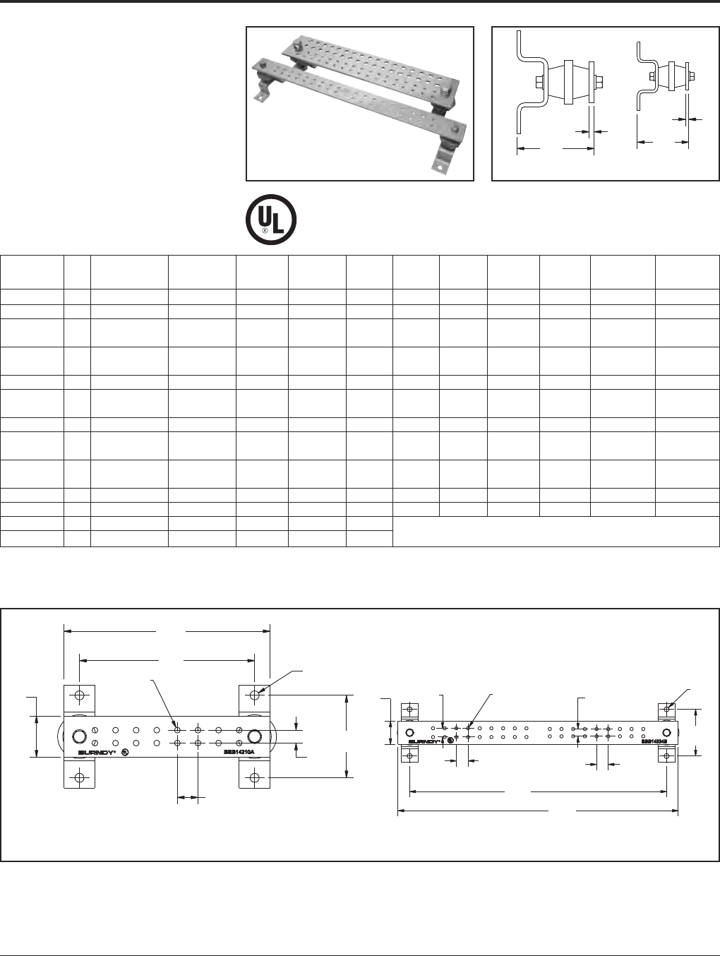
BURNDY®Grounding
Mechanical
US: 1-800-346-4175 www.burndy.com Canada: 1-800-387-6487
65
TYPE BBB
BURNDY®BusBar
Copper BusBar
Bare copper BusBar, UL Listed for grounding.
Available in many sizes and hole patterns.
Brackets and insulators included with most
styles. Also available in undrilled, horizontal
and vertical versions.
BusBar is used in a variety of applications.
Can be used as a common ground point and
“power” applications as well.
3.75
[95]
“T”
.25
[6]
“T”
.25
[6]
3.75
[95]
Catalog Fig. Insulator & T - Bar W - Bar L - Bar No. of
Number No. Bracket Thickness Width Length E1 E2 E3 F1 F2 Holes K
BBB14210A 1 A 1/4210.63 — — 1.00 — 16 .28
BBB14224B 2 A 1/4224.625 .75 — 1.00 1.00 36 .28
6 6-32
BBB14410C 3 A 1/4410.75 1.00 — 1.25 — 16 .28
6 6-32
BBB14410D 4 A 1/44101.25 1.00 — 1.13 1.13 16 .28
BBB14412E 5 A 1/4412.75 — — 2.00 1.25 18 .44
12 .44
BBB14412F 6 A 1/44121.00 .75 — 2.00 1.25 12 .28
BBB14416G 7 B 1/4416.75 1.00 — 1.69 — 24 .44
16 .44
BBB14416H 8 B 1/44161.00 1.00 .75 1.69 — 16 .25
34 .44
BBB14420J 9 B 1/44201.00 1.00 .75 1.00 — 34 .25
BBB412UD N/A A 1/4412N/A N/A N/A N/A N/A N/A N/A
BBB424UD N/A B 1/4424N/A N/A N/A N/A N/A N/A N/A
BBBHR19* N/A N/A 3/163/419.38
BBBVR36* N/A N/A 1/45/836.32 Contact Factory for Dimensions
* Not UL Listed.
Bracket/Insulator A Bracket/Insulator B
“W”
2.00
[51]
Ø.44
[11]
“E1”
.63
[16]
4.00
[102]
“F”
1.00
[25] (7 Plcs)
“K”
Ø.28
[7]
(16 Plcs)
8.50
[216]
“L”
10.00
[254]
“W”
2.00
[51]
“E2”
.75
[19]
“K”
Ø.28
[7]
(36 Plcs)
“E1”
.625
[15.9]
Ø.44
[11]
4.00
[102]
“L”
24.00
[610]
22.00
[559]
“F1”
1.00
[25]
(8 Plcs)
“F2”
1.00
[25]
(8 Plcs)
Figure 1 Figure 2
(Figures continued on next page)
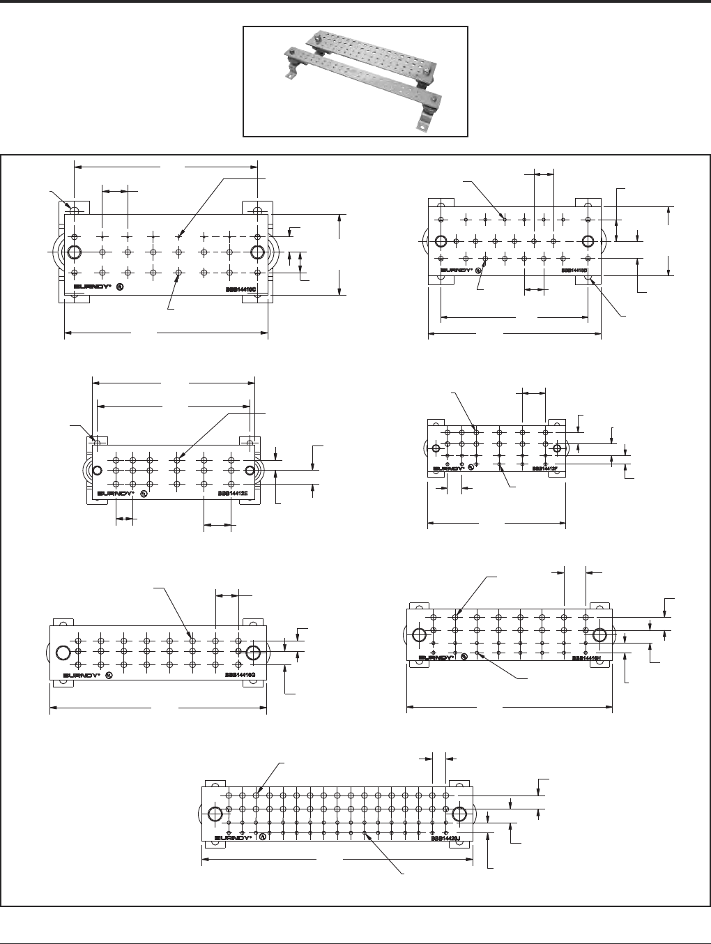
Grounding BURNDY®
Mechanical
Canada: 1-800-387-6487 www.burndy.com US: 1-800-346-4175
66
TYPE BBB
BURNDY®BusBar
Copper BusBar (Continued)
Ø.44
[11]
9.00
[229] 6 - 32 Tapped Holes
(6 Plcs)
“F”
1.25
[32] (5 Plcs)
“L”
10.00
[254]
“K2”
Ø.28
[7] (16 Plcs)
“W”
4.00
[102]
“E2”
1.00
[25]
“E1”
.75
[19]
Figure 3
“K1”
6 - 32 Tapped Holes
(6 Plcs)
“F1”
1.13
[29]
(5 Plcs)
“E1”
1.25
[32]
“W”
4.00
[102]
“E2”
1.00
[25]
Ø.44
[11]
“L”
10.00
[254]
“F2”
1.13
[29]
(5 Plcs)
“K2”
Ø.28
[7]
(16 Plcs)8.50
[216]
Figure 4
“L”
12.00
[305]
11.25
[286]
Ø.44
[11]
“K”
Ø.44
[11]
(18 Plcs)
“F2”
1.25
[32]
(2 Plcs)
“F1”
2.00
[51]
(3 Plcs)
“E1”
.75
[19]
“E2”
1.00
[25]
Figure 5
“K1”
Ø.44
[11]
(12 Plcs)
“F1”
2.00
[51]
(3 Plcs)“E1”
1.00
[25] 1.00
[25]
“E2”
.75
[19]
“L”
12.00
[305]
“F2”
1.25
[32]
(2 Plcs)
“K2”
Ø.25
[7]
(12 Plcs)
Figure 6
“K”
Ø.44
[11]
(24 Plcs)
“L”
16.00
[406]
“F”
1.69
[43]
(7 Plcs)
“E2”
1.00
[25]
“E1”
.75
[19]
Figure 7
“L”
16.00
[406]
“K2”
Ø.13
[3]
(16 Plcs)
“K1”
Ø.44
[11]
(16 Plcs)
“F”
1.69
[43]
(7 Plcs)“E1”
1.00
[25]
“E2”
1.00
[25]
“E3”
.75
[19]
Figure 8
“L”
20.00
[508]
“K”
Ø.44
[11]
(34 Plcs)
“K2”
Ø.25
[6]
(34 Plcs)
“E3”
.75
[19]
“E2”
1.00
[25]
“E1”
1.00
[25]
“F”
1.00
[25]
(16 Plcs)
Figure 9
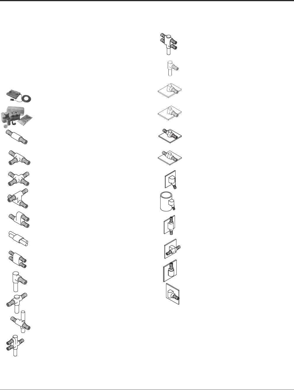
BURNDY®Grounding
BURNDYWeld®Exothermic
US: 1-800-346-4175 www.burndy.com Canada: 1-800-387-6487
67
TABLE OF CONTENTS
BURNDYWeld®
BURNDYWeld®
Introduction . . . . . . . . . . . . . . . . . 68
Making a BURNDYWeld®
Connection . . . . . . . . . . . . . . . 69
QIKLITE™ . . . . . . . . . . . . . . . . . . 70
WELD METAL . . . . . . . . . . . . . . . 71
Type BCC-1 . . . . . . . . . . . . . . . . . 72
Type BCC-2 . . . . . . . . . . . . . . . . . 73
Type BCC-4 . . . . . . . . . . . . . . . . . 74
Type BCC-11 . . . . . . . . . . . . . . . . 75
Type BCC-6 . . . . . . . . . . . . . . . . . 76
Type BCC-14 . . . . . . . . . . . . . . . . 76
Type BCC-7 . . . . . . . . . . . . . . . . . 77
Type BCR-1 . . . . . . . . . . . . . . . . . 78
RUS Accepted
Type BCR-2 . . . . . . . . . . . . . . . . . 78
Type BCR-3 . . . . . . . . . . . . . . . . 80
Type BCR-17 . . . . . . . . . . . . . . . . 81
Type BCR-24 . . . . . . . . . . . . . . . . 82
Single Shot Molds . . . . . . . . . . . 83
Type BCS-1 . . . . . . . . . . . . . . . . . 84
Type BCS-8 . . . . . . . . . . . . . . . . . 84
Type BCS-2 . . . . . . . . . . . . . . . . . 85
Type BCS-9 . . . . . . . . . . . . . . . . . 85
Type BCS-3 . . . . . . . . . . . . . . . . . 86
Type BCS-23 . . . . . . . . . . . . . . . . 87
Type BCS-4 . . . . . . . . . . . . . . . . . 88
Type BCS-6 . . . . . . . . . . . . . . . . . 88
Type BCS-7 . . . . . . . . . . . . . . . . . 89
Type BCS-18 . . . . . . . . . . . . . . . . 89
BURNDY®
GROUNDMAX™ . . . . . . . . 96 - 97
BURNDY®GRIDMAX™. . . . . . . . 98
For mold types or BURNDYWeld®items not shown, please contact factory.

Grounding BURNDY®
BURNDYWeld®Exothermic
Canada: 1-800-387-6487 www.burndy.com US: 1-800-346-4175
68
BURNDYWeld®
The BURNDYWeld®connection process is a
simple, efficient method of welding copper to
copper or copper to steel. One advantage is
that NO outside power is required when using
the BURNDYWeld®exothermic process. The
BURNDYWeld®process uses high tempera-
ture reaction of powdered copper oxide and
aluminum. The reaction takes place in a semi-
permanent graphite mold. These molds will
last for fifty or more welds if proper care is
given. The reaction takes place very rapidly,
therefore the total amount of heat applied to
the conductors or surfaces is considerably
less than that of brazing or soldering. It is im-
portant to remember this when welding to in-
sulated cable or thin wall pipe.
This system is very field friendly, since it is
light and portable and requires no outside
power source. It requires very little time or skill
to obtain an efficient, maintenance free con-
nection when using the BURNDYWeld®
process.
For more information visit our website at
www.burndy.com.
The BURNDYWeld®process has been used
to weld materials other than copper for elec-
trical purposes. Materials welded include:
Stainless Steel Columbium Brass
Copperweld® Plain Steel Bronze
Nichrome V Everdur® Niobium
Galvanized Steel Kama Chromax
Silcone Bronze Steel Rail Cast Iron
Copper Clad Steel Cor-Ten® Monel
When welding to galvanized steel it is recom-
mended to resurface exposed bare steel.
The BURNDYWeld®connection is a molecu-
lar weld. The weld metal has the same melting
point as copper. These factors along with the
increased cross section of the connection,
BURNDYWeld®connections:
1. Will not be affected by a high current
surge. Tests have shown that the electri-
cal conductor will melt before the
BURNDYWeld®connection when sub-
jected to high short circuit current. Consult
IEEE Standard 837-1989.
2. Will not loosen or corrode at the point of
weld. There are no contact surfaces or
mechanical pressures involved. A
BURNDYWeld®connection becomes an
integral part of the conductor.
3. Have a current-carrying capacity equal to
or greater than that of the conductors.
Lid
Graphite Mold
Weld Cavity
Ground Rod
Cable
Tap Hole
Weld Metal
Starting Powder
For mold types or BURNDYWeld®items not shown, please contact factory.
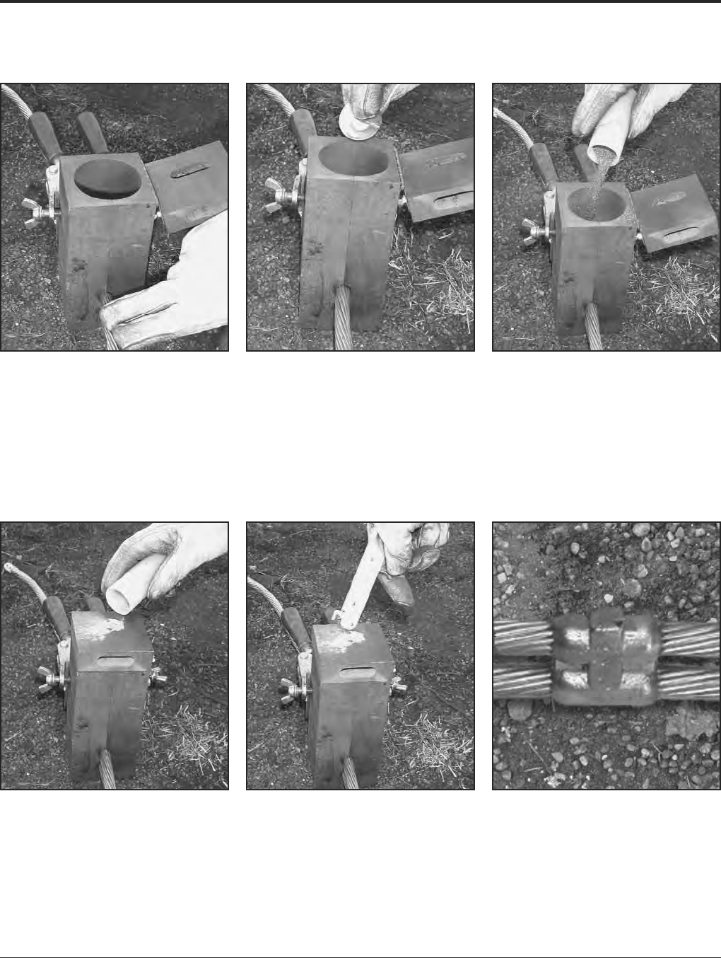
BURNDY®Grounding
BURNDYWeld®Exothermic
US: 1-800-346-4175 www.burndy.com Canada: 1-800-387-6487
69
Making a BURNDYWeld®Connection
Step 1
Position cleaned conductors in mold after
making sure mold is dry, by pre-heating or
making a test joint.
Step 2
Place metal disc in bottom of mold crucible.
Step 3
Dump powder into crucible, being careful not
to loosen all the starting powder.
Step 4
Close lid and place a small amount of start-
ing powder in the ignition pocket.
Step 6
Wait 15 seconds, then remove weld and clean
mold before making next connection.
Step 5
Ignite the starting powder with the Flint Ignitor.
For mold types or BURNDYWeld®items not shown, please contact factory.

Grounding BURNDY®
BURNDYWeld®Exothermic
Canada: 1-800-387-6487 www.burndy.com US: 1-800-346-4175
70
BURNDYWeld®
QIKLITE™
Battery Ignition System
The self-contained unit offers a built-in battery
life indicator, 6ignitor cord, and separate but-
tons for power and ignition. Also, no starting
powder is used with this system so emissions
are greatly reduced. QIKLITE™ works with
“off-the-shelf” molds and weld metal, so con-
tractors and installers can continue to use the
same quality BURNDYWeld®products.
Since the unit operates with standard weld
metal and molds, installers also have the op-
tion of using a traditional flint ignitor or the new
QIKLITE™ system. Another feature is the
speed of ignition, with virtually no delay
between depressing the “push to operate”
button and ignition of the weld metal. This
instant ignition feature offers quick reassur-
ance to the installer, without the delay.
• Power is supplied by 4 standard “D” Size
batteries
• Built-in battery life indicator
• There’s virtually no delay in ignition after
depressing the “push to operate” button
• Separate ON/OFF and Operate buttons
• Comes complete with durable 6heat
resistant cord
• Durable, long-lasting design
• QIKSTIK ignitor sticks are conveniently
packaged and available separately or
available packaged complete with
standard weld metal
Catalog Number Description
QIKLITE Battery Ignition System
QIKLITEKIT QIKLITE™ Battery Ignition System and 20 QIKSTIK Ignitor Sticks
Features and Benefits
• The QIKLITE™ system allows installers to
make exothermic connections remotely
• Uses standard exothermic molds and weld
metal
• Use the new BURNDYWeld®QIKLITE™
System or use a flint ignitor, this versatility
makes this system better than anything
available in the industry
• Installers have virtually 100% confidence
that the connection can be completed, and
no wasted material or weld metal shots
• No starting material required—which
greatly reduces the amount of emissions
generated
Catalog Number
Standard Cartridge Cartridges/Ignitors
Size with Ignitor Per Box
15Q 20
25Q 20
32Q 10
45Q 20
65Q 20
90Q 10
115Q 10
150Q 10
200Q 10
250Q 10
500Q 10
QIKSTIK*10
*Ignitor stick only.
QIKLITE™ with mold.
For mold types or BURNDYWeld®items not shown, please contact factory.
BURNDY®Grounding
BURNDYWeld®Exothermic
US: 1-800-346-4175 www.burndy.com Canada: 1-800-387-6487
71
For mold types or BURNDYWeld®items not shown, please contact factory.
WELD METAL
BURNDYWeld®Weld Metal is packed in
moisture-resistant plastic cartridges that have
tight fitting caps. These cartridges, along with
the necessary steel discs, are then packed in
boxes that are hermetically-sealed. This
ensures the powder arriving in good condi-
tion, always dry and ready for fast positive
ignition.
BURNDYWeld®Weld Metal comes in several
types; one for welding copper to copper, cop-
per to steel, copper to rail, copper to cast iron
and one for welding copper to steel for
cathodic protection. The size and weight (in
grams) of the cartridge are marked on each
individual cartridge.
Cathodic
Standard Cast Iron Protection Rail
Cartridge Cartridge Cartridge Cartridge Cartridges
Size Size Size Size Per Bo
15 15CI 15CP 15R 20
25 25CI 25CP 25R 20
32 32Cl 32CP 32R 10
45 45Cl 45CP 45R 20
65 65Cl 65CP 65R 20
90 90Cl —90R 10
115 115Cl —115R 10
150 ——150R 10
200 ——200R 10
250 ——250R 10
500 ——500R 10
BURNDYWeld®Weld Metal is sold in box quantities only.
Weld Catalog Number Package
Metal Size Steel Discs Only Quantity
15 to 65 B370320-01 20
90 to 115 B370320-02 10
150 to 500 B370320-03 10
Steel Discs Sold Separately
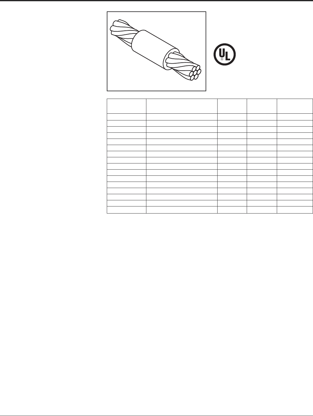
Grounding BURNDY®
BURNDYWeld®Exothermic
Canada: 1-800-387-6487 www.burndy.com US: 1-800-346-4175
72
BCC-1 TYPE MOLDS
Horizontal End to End
BCC-1 Type Molds are used for horizontal
end to end cable connections.
Size range is #6 through 1000 kcmil solid or
concentric stranded copper conductors.
Contact BURNDY®for information on molds
for conductors not listed below.
Price Weld Handle
Cable Mold Number Key Metal Clamps
#8 Use Type BCC-14 on Page 76 — — —
#6 Use Type BCC-14 on Page 76 — — —
#4 B-5623 18 † * 25 N/A
#3 B-5624 18 † * 32 N/A
#2 B-5625 18 † * 32 N/A
#1 B-5626 18 † * 32 N/A
1/0 B-205 4 45 B-106
2/0 B-206 4 65 B-106
3/0 B-207 4 90 B-106
4/0 B-208 4 90 B-106
250 kcmil B-209 4 115 B-106
300 kcmil B-210 4 115 B-106
350 kcmil B-211 4 150 B106
500 kcmil B-213 4 200 B-107
750 kcmil B-214 5 2-150 B-107
1000 kcmil B-215 5 2-200 B-107
• For sizes not listed, contact BURNDY®.
• Molds listed are for concentric stranded cable. Add suffix
“-S” to mold number for solid conductors.
• For heavy duty molds, molds with wear plates or molds for
Copperweld®cable, contact BURNDY®.
• For expedited service, contact BURNDY®.
Required Tools:
Handle Clamps (see chart for correct handles)
† Sold complete with handles
* B38-0309-00 Flint Ignitor (included)
Other recommended accessories:
B38-3922-00 Mold Cleaning Brush (pg 101)
B38-0135-00 Cable Cleaning Brush (pg 101)
B38-0330-00 Cable Clamp (pg 101)
For mold types or BURNDYWeld®items not shown, please contact factory.
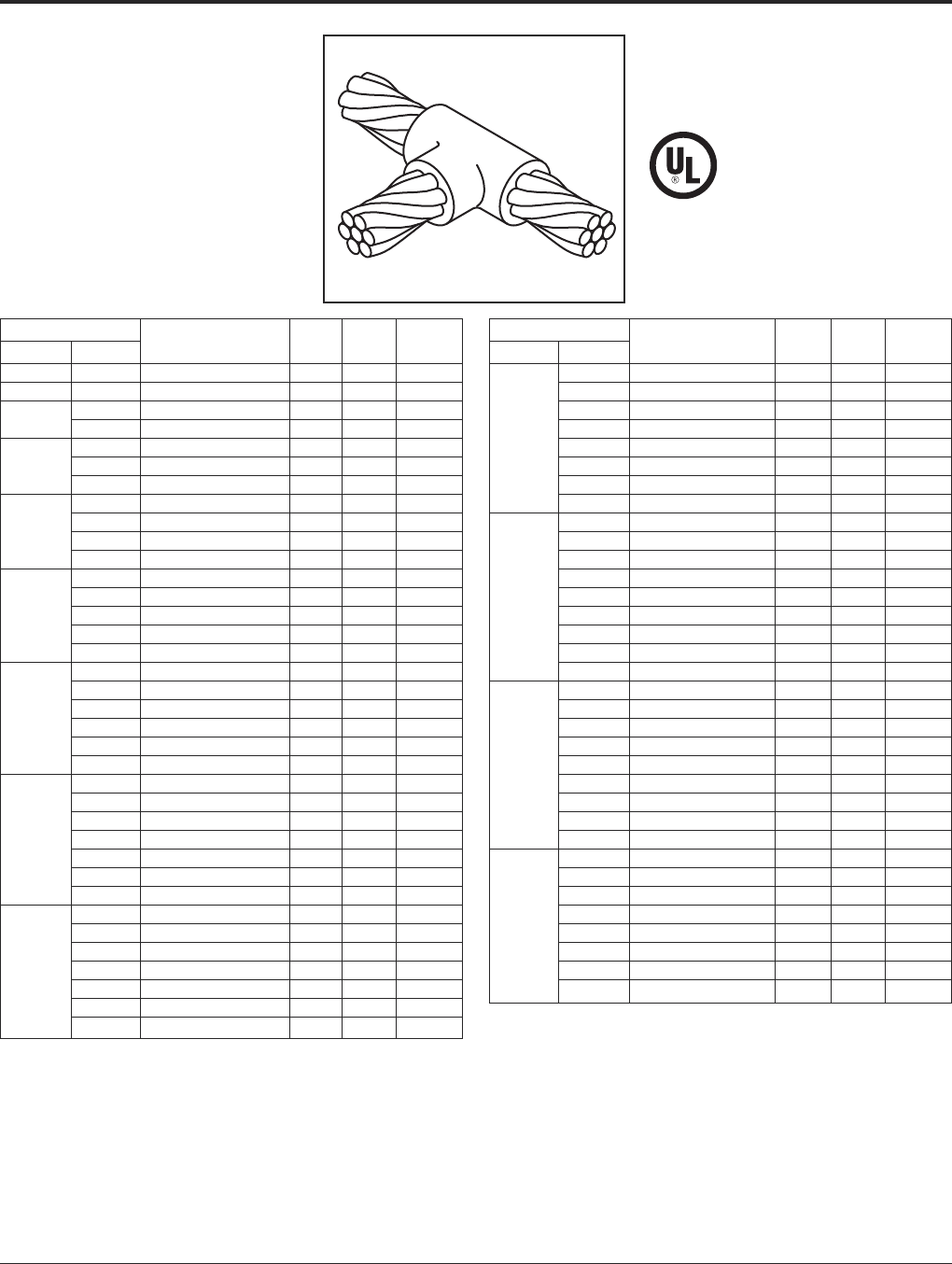
BURNDY®Grounding
BURNDYWeld®Exothermic
US: 1-800-346-4175 www.burndy.com Canada: 1-800-387-6487
73
For mold types or BURNDYWeld®items not shown, please contact factory.
TYPE BCC-2 MOLDS
Horizontal Cable Tap to
Horizontal Cable Run
Type BCC-2 Molds are used to join horizontal
cable tap to a horizontal run cable.
Size range is #6 through 750 kcmil solid or
concentric stranded copper conductors.
Contact BURNDY®for information on molds
for conductors not listed below.
Cable Price Weld Handle
Run Tap Mold Number Key Metal Clamps
#6 #6
Use Type BCC-14 on Page 76
—— —
#4 #4 B-221 4 32 B-106
#2 B-223 4 45 B-106
#2 #4 B-224 4 45 B-106
#1 B-225 4 45 B-106
#1 #2 B-226 4 45 B-106
#4 B-227 4 45 B-106
1/0 B-228 4 90 B-106
#1 B-229 4 45 B-106
1/0 #2 B-230 4 45 B-106
#4 B-231 4 45 B-106
2/0 B-232 4 90 B-106
1/0 B-233 4 90 B-106
2/0 #1 B-234 4 45 B-106
#2 B-235 4 45 B-106
#4 B-5475 4 45 B-106
3/0 B-236 4 115 B-106
2/0 B-237 4 90 B-106
1/0 B-238 4 90 B-106
3/0 #1 B-239 4 45 B-106
#2 B-240 4 45 B-106
#4 B-5574 4 45 B-106
4/0 B-241 4 150 B-106
3/0 B-242 4 115 B-106
2/0 B-243 4 90 B-106
4/0 1/0 B-244 4 90 B-106
#1 B-245 4 90 B-106
#2 B-246 4 90 B-106
#4 B-5021 4 90 B-106
250 kcmil B-247 4 150 B-106
4/0 B-248 4 150 B-106
3/0 B-249 4 150 B-106
250 kcmil 2/0 B-250 4 90 B-106
1/0 B-251 4 90 B-106
#1 B-252 4 90 B-106
#2 B-253 4 90 B-106
Cable Price Weld Handle
Run Tap Mold Number Key Metal Clamps
300 kcmil B-254 4 200 B-106
250 kcmil B-255 4 150 B-106
4/0 B-256 4 150 B-106
3/0 B-257 4 150 B-106
300 kcmil 2/0 B-258 4 90 B-106
1/0 B-259 4 90 B-106
#1 B-260 4 90 B-106
#2 B-261 4 90 B-106
350 kcmil B-262 4 200 B-106
300 kcmil B-263 4 200 B-106
250 kcmil B-264 4 200 B-106
4/0 B-265 4 150 B-106
350 kcmil 3/0 B-266 4 150 B-106
2/0 B-267 4 90 B-106
1/0 B-268 4 90 B106
#1 B-269 4 90 B-106
#2 B-270 4 90 B-106
500 kcmil B-280 4 2-150 B-106
350 kcmil B-282 4 200 B-106
300 kcmil B-283 4 200 B-106
250 kcmil B-284 4 200 B-106
500 kcmil 4/0 B-285 4 150 B-106
2/0 B-286 4 90 B-106
1/0 B-287 4 90 B-106
#1 B-288 4 90 B-106
#2 B-289 4 90 B-106
750 kcmil B-290 5 500 B-107
500 kcmil B-291 5 2-200 B-107
350 kcmil B-293 4 250 B-106
300 kcmil B-294 4 200 B-106
750 kcmil 250 kcmil B-295 4 200 B-106
4/0 B-296 4 150 B-106
2/0 B-297 4 150 B-106
1/0 B-298 4 150 B-106
• For sizes not listed, contact BURNDY®.
• Molds listed are for concentric stranded cable. Add suffix “-S” to mold number for solid
conductors.
• For heavy duty molds, molds with wear plates or molds for Copperweld®cable, contact
BURNDY®.
• For expedited service, contact BURNDY®.
Required Tools:
Handle Clamps (see chart for correct handles)
B38-0309-00 Flint Ignitor
Other recommended accessories:
B40-0319-01 Mold Cleaner for cartridge sizes #15-#65 (pg 101)
B40-0319-03 Mold Cleaner for cartridge sizes #90-#500 (pg 101)
B38-3922-00 Mold Cleaning Brush (pg 101)
B38-0135-00 Cable Cleaning Brush (pg 101)
B38-0330-00 Cable Clamp (pg 101)

Grounding BURNDY®
BURNDYWeld®Exothermic
Canada: 1-800-387-6487 www.burndy.com US: 1-800-346-4175
74
For mold types or BURNDYWeld®items not shown, please contact factory.
TYPE BCC-4 MOLDS
Horizontal to Horizontal
Cable Cross
Type BCC-4 Molds are used to join two hori-
zontal cables at right angles. One cable is cut
and the other is a through run.
Size range is #6 through 500 kcmil solid or
concentric stranded copper conductors.
Contact BURNDY®for information on molds
for conductors not listed below.
Cable Price Weld Handle
Run Tap Mold Number Key Metal Clamps
#6 #6
Use Type BCC-11 on Page 75
#4 #4 B-423 4 45 B-106
#3 #3 B-424 4 45 B-106
#2 B-425 4 65 B-106
#2 #4 B-426 4 65 B-106
#1 B-427 4 65 B-106
#1 #2 B-428 4 65 B-106
#4 B-429 4 65 B-106
1/0 B-430 4 90 B-106
#1 B-431 4 90 B-106
1/0 #2 B-432 4 90 B-106
#4 B-433 4 90 B-106
2/0 B-434 4 115 B-106
1/0 B-435 4 115 B-106
2/0 #1 B-436 4 115 B-106
#2 B-437 4 115 B-106
3/0 B-438 4 150 B-106
2/0 B-439 4 150 B-106
3/0 1/0 B-440 4 115 B-106
#1 B-441 4 115 B-106
#2 B-442 4 115 B-106
4/0 B-443 4 200 B-106
3/0 B-444 4 200 B-106
2/0 B-445 4 150 B-106
4/0 1/0 B-442 4 150 B-106
#1 B-447 4 115 B-106
#2 B-448 4 115 B-106
250 kcmil B-449 4 200 B-106
4/0 B-450 4 200 B-106
3/0 B-451 4 200 B-106
250 kcmil 2/0 B-452 4 150 B-106
1/0 B-453 4 150 B-106
#1 B-454 4 115 B-106
#2 B-455 4 115 B-106
Cable Price Weld Handle
Run Tap Mold Number Key Metal Clamps
300 kcmil B-456 4 250 B-106
250 kcmil B-457 4 250 B-106
4/0 B-458 4 200 B-106
3/0 B-459 4 200 B-106
300 kcmil 2/0 B-460 4 150 B-106
1/0 B-461 4 150 B-106
#1 B-462 4 115 B-106
#2 B-463 4 115 B-106
350 kcmil B-464 4 250 B-106
300 kcmil B-465 4 250 B-106
250 kcmil B-466 4 250 B-106
4/0 B-467 4 200 B-106
350 kcmil 3/0 B-468 4 200 B-106
2/0 B-469 4 200 B-106
1/0 B-470 4 200 B-106
#1 B-471 4 150 B-106
#2 B-472 4 150 B-106
500 kcmil B-483 5 500 B-107
350 kcmil B-485 5 2-200 B-107
300 kcmil B-486 5 2-200 B-107
250 kcmil B-487 5 2-150 B-107
4/0 B-488 5 2-150 B-107
500 kcmil 3/0 B-489 5 2-150 B-107
2/0 B-490 4 250 B-106
1/0 B-491 4 250 B-106
#1 B-492 4 200 B-106
#2 B-493 4 200 B-106
• For sizes not listed, contact BURNDY®.
• Molds listed are for concentric stranded cable. Add suffix “-S” to mold number for solid
conductors.
• For heavy duty molds, molds with wear plates or molds for Copperweld®cable, contact
BURNDY®.
• For expedited service, contact BURNDY®.
Required Tools:
Handle Clamps (see chart for correct handles)
B38-0309-00 Flint Ignitor
Other recommended accessories:
B40-0319-01 Mold Cleaner for cartridge sizes #15-#65 (pg 101)
B40-0319-03 Mold Cleaner for cartridge sizes #90-#500 (pg 101)
B38-3922-00 Mold Cleaning Brush (pg 101)
B38-0135-00 Cable Cleaning Brush (pg 101)
B38-0330-00 Cable Clamp (pg 101)

BURNDY®Grounding
BURNDYWeld®Exothermic
US: 1-800-346-4175 www.burndy.com Canada: 1-800-387-6487
75
For mold types or BURNDYWeld®items not shown, please contact factory.
TYPE BCC-11 MOLDS
Horizontal to Horizontal
Cable Cross
Type BCC-11 Molds are used to join uncut
horizontal cables at right angles to each other.
Size range is #6 through 500 kcmil solid or
concentric stranded copper conductors.
Contact BURNDY®for information on molds
for conductors not listed below.
Cable Price Weld Handle
Run Tap Mold Number Key Metal Clamps
#6 #6 B-5432 191* 45 N/A
#4 #4 B-2687 4 65 B-106
#2 B-2689 4 90 B-106
#2 #4 B-2690 4 65 B-106
#1 B-2691 4 115 B-106
#1 #2 B-2692 4 90 B-106
#4 B-2693 4 90 B-106
1/0 B-2694 22 150 B-106
#1 B-2695 22 150 B-106
1/0 #2 B-2696 22 115 B-106
#4 B-2697 22 115 B-106
2/0 B-2698 22 200 B-106
1/0 B-2699 22 200 B-106
2/0 #1 B-2700 22 150 B-106
#2 B-2701 22 150 B-106
3/0 B-2702 22 250 B-106
2/0 B-2703 22 200 B-106
3/0 1/0 B-2704 22 200 B-106
#1 B-2705 22 150 B-106
#2 B-2706 22 150 B-106
Cable Price Weld Handle
Run Tap Mold Number Key Metal Clamps
4/0 B-2707 22 250 B-106
3/0 B-2708 22 250 B-106
2/0 B-2709 22 200 B-106
4/0 1/0 B-2710 22 200 B-106
#1 B-2711 22 150 B-106
#2 B-2712 22 150 B-106
250 kcmil B-2713 22 2-150 B-106
4/0 B-2714 22 2-150 B-106
3/0 B-2715 22 2-150 B-106
250 kcmil 2/0 B-2716 22 250 B-106
1/0 B-2717 22 150 B-106
#1 B-2718 22 200 B-106
#2 B-2719 22 150 B-106
500 kcmil B-2747 23 3-250 B-107
250 kcmil B-2751 23 500 B-107
4/0 B-2752 23 500 B-107
3/0 B-2753 23 500 B-107
500 kcmil 2/0 B-2754 23 2-200 B-107
1/0 B-2755 22 2-150 B-106
#1 B-2756 22 250 B-106
#2 B-2757 22 250 B-106
• For sizes not listed, contact BURNDY®.
• Molds listed are for concentric stranded cable. Add suffix “-S” to mold number for solid
conductors.
• For heavy duty molds, molds with wear plates or molds for Copperweld® cable, contact
BURNDY®.
• For expedited service, contact BURNDY®.
Required Tools:
Handle Clamps (see chart for correct handles)
† Sold complete with handles
* B38-0309-00 Flint Ignitor
Other recommended accessories:
B40-0319-01 Mold Cleaner for cartridge sizes #15-#65 (pg 101)
B40-0319-03 Mold Cleaner for cartridge sizes #90-#500 (pg 101)
B38-3922-00 Mold Cleaning Brush (pg 101)
B38-0135-00 Cable Cleaning Brush (pg 101)
B38-0330-00 Cable Clamp (pg 101)
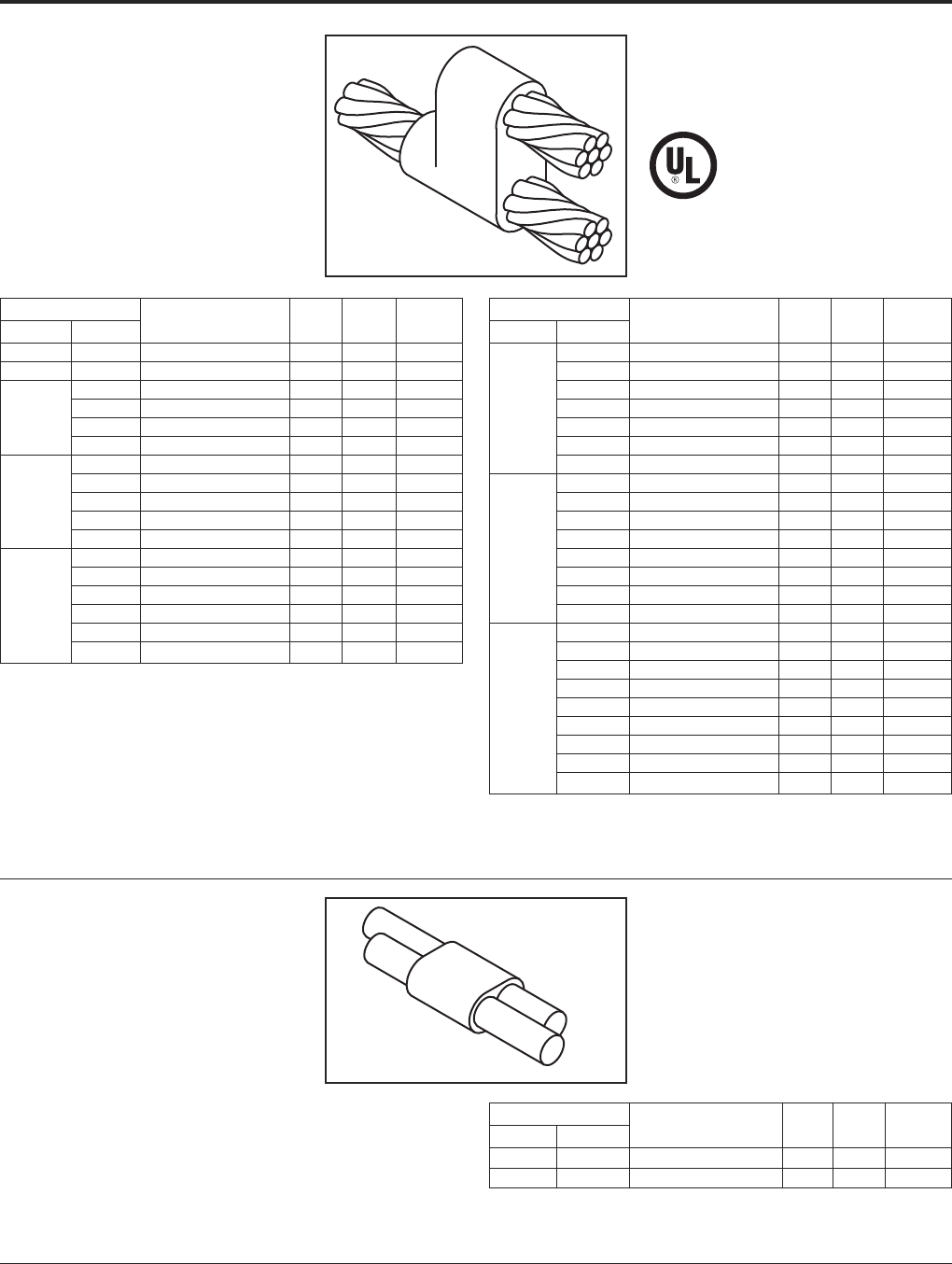
Grounding BURNDY®
BURNDYWeld®Exothermic
Canada: 1-800-387-6487 www.burndy.com US: 1-800-346-4175
76
For mold types or BURNDYWeld®items not shown, please contact factory.
TYPE BCC-6 MOLDS
Horizontal Parallel Tap
Type BCC-6 Molds are used to join horizontal
parallel tap to run connections. The tap cable
is over the run cable.
Size range is #6 through 4/0 solid or concen-
tric stranded copper conductors.
Contact BURNDY®for information on molds
for conductors not listed below.
Cable Price Weld Handle
Run Tap Mold Number Key Metal Clamps
#6 Sol #6 Sol B-1270 4 25 B-106
#6 #6 B-1271 4 25 B-106
#4 B-1272 4 32 B-106
#6 B-1273 4 32 B-106
#4 #6 Sol B-1274 4 32 B-106
#8 Sol B-1275 4 32 B-106
#2 B-1276 4 65 B-106
#4 B-1277 4 45 B-106
#2 #6 B-1278 4 32 B-106
#6 Sol B-1279 4 32 B-106
#8 Sol B-1280 4 32 B-106
#1 B-1281 4 65 B-106
#2 B-1282 4 65 B-106
#4 B-1283 4 45 B-106
#1 #6 B-1284 4 45 B-106
#6 Sol B-1285 4 45 B-106
#8 Sol B-1286 4 45 B-106
Cable Price Weld Handle
Run Tap Mold Number Key Metal Clamps
1/0 B-1287 4 90 B-106
#1 B-1288 4 90 B-106
#2 B-1289 4 65 B-106
1/0 #4 B-1290 4 65 B-106
#6 B-1291 4 45 B-106
#6 Sol B-1292 4 45 B-106
#8 Sol B-1293 4 45 B-106
2/0 B-1294 4 115 B-106
1/0 B-1295 4 115 B-106
#1 B-1296 4 90 B-106
#2 B-1297 4 90 B-106
2/0 #4 B-1298 4 65 B-106
#6 B-1299 4 65 B-106
#6 Sol B-1300 4 65 B-106
#8 Sol B-1301 4 65 B-106
4/0 B-1302 4 150 B-106
2/0 B-1303 4 115 B-106
1/0 B-1304 4 115 B-106
#1 B-1305 4 115 B-106
4/0 #2 B-1306 4 115 B-106
#4 B-1307 4 90 B-106
#6 B-1308 4 90 B-106
#6 Sol B-1309 4 90 B-106
#8 Sol B-1310 4 90 B-106
• For sizes not listed, contact BURNDY®.
• Molds listed are for concentric stranded cable. Add suffix “-S” to mold number for solid
conductors.
• For heavy duty molds, molds with wear plates or molds for Copperweld®cable, contact
BURNDY®.
• For expedited service, contact BURNDY®.
Required Tools:
Handle Clamps (see chart for correct handles)
Sold complete with handles
B38-0309-00 Flint Ignitor
Other recommended accessories:
B38-3922-00 Mold Cleaning Brush (pg 101)
B38-0135-00 Cable Cleaning Brush (pg 101)
B38-0330-00 Cable Clamp (pg 101)
TYPE BCC-14 MOLDS
Horizontal Parallel through
Cables
Type BCC-14 Molds are used to join horizon-
tal parallel through run cables. Cables run
side by side in the mold.
Size range is #8 through #6 solid or concen-
tric stranded copper conductors.
Contact BURNDY®for information on molds
for conductors not listed.
Cable Price Weld Handle
Run Tap Mold Number Key Metal Clamps
#8 #8 B-5709 18+ 15 N/A
#6 #6 B-5618 18+ 25 N/A
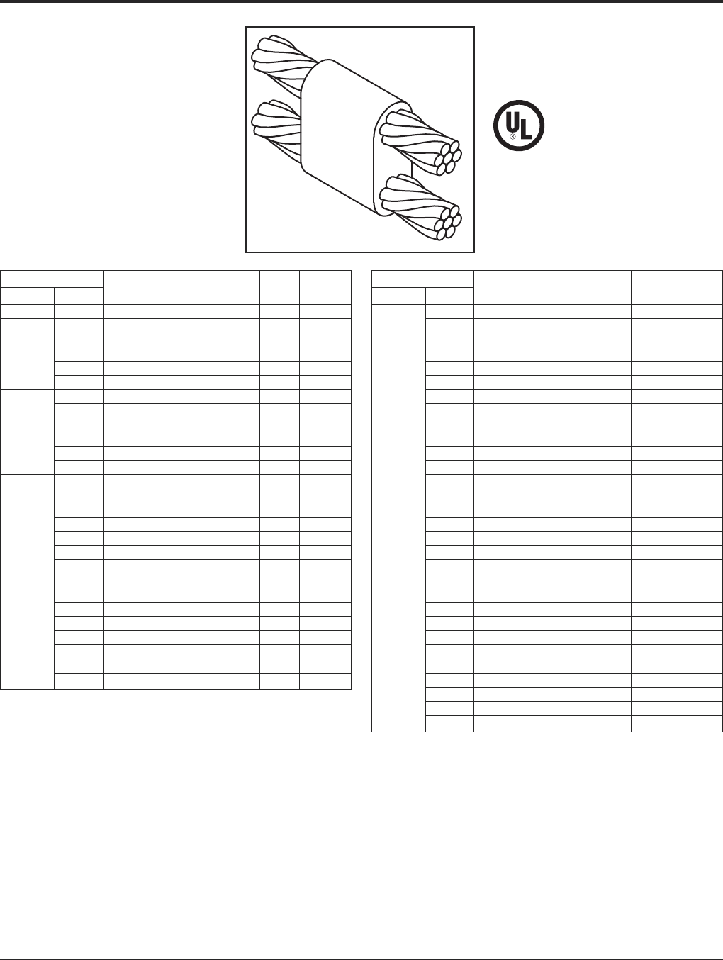
BURNDY®Grounding
BURNDYWeld®Exothermic
US: 1-800-346-4175 www.burndy.com Canada: 1-800-387-6487
77
For mold types or BURNDYWeld®items not shown, please contact factory.
TYPE BCC-7 MOLDS
Horizontal Parallel through
Cables
Type BCC-7 Molds are used to join horizontal
parallel through run cables. One cable runs
above the other cable in the mold.
Size range is #6 through 4/0 solid or concen-
tric stranded copper conductors.
Contact BURNDY®for information on molds
for conductors not listed below.
Cable Price Weld Handle
Run Tap Mold Number Key Metal Clamps
#6 #6
Use Type BCC-14 on Page 76
—— —
#4 B-1311 4 32 B-106
#6 B-5627 4 32 B-106
#4 #6 Sol B-8882 4 32 B-106
#8 B-5629 4 32 B-106
#8 Sol B-5630 4 32 B-106
#2 B-1313 4 65 B-106
#4 B-1314 4 65 B-106
#6 B-5631 4 45 B-106
#2 #6 Sol B-5632 4 45 B-106
#8 B-5634 4 45 B-106
#8 Sol B-5635 4 45 B-106
#1 B-1315 4 65 B-106
#2 B-1316 4 65 B-106
#4 B-1317 4 65 B-106
#1 #6 B-5636 4 65 B-106
#6 Sol B-5637 4 65 B-106
#8 B-5638 4 45 B-106
#8 Sol B-5639 4 45 B-106
1/0 B-1318 4 90 B-106
#1 B-1319 4 65 B-106
#2 B-1320 4 65 B-106
#4 B-1321 4 65 B-106
1/0 #6 B-5642 4 65 B-106
#6 Sol B-1208 4 65 B-106
#8 B-5644 4 65 B-106
#8 Sol B-5645 4 65 B-106
Cable Price Weld Handle
Run Tap Mold Number Key Metal Clamps
2/0 B-1322 4 115 B-106
1/0 B-1323 4 115 B-106
#1 B-1324 4 90 B-106
#2 B-1325 4 90 B-106
2/0 #4 B-5659 4 90 B-106
#6 B-5342 4 90 B-106
#6 Sol B-5652 4 90 B-106
#8 B-5668 4 65 B-106
#8 Sol B-5943 4 65 B-106
3/0 B-1326 4 150 B-106
2/0 B-1327 4 150 B-106
1/0 B-1328 4 115 B-106
#1 B-1329 4 115 B-106
3/0 #2 B-1330 4 115 B-106
#4 B-6046 4 115 B-106
#6 B-5676 4 90 B-106
#6 Sol B-5679 4 90 B-106
#8 B-5680 4 90 B-106
#8 Sol B-5682 4 90 B-106
4/0 B-1331 4 200 B-106
3/0 B-1332 4 200 B-106
2/0 B-1333 4 150 B-106
1/0 B-1334 4 150 B-106
#1 B-1335 4 150 B-106
4/0 #2 B-1336 4 150 B-106
#4 B-5340 4 150 B-106
#6 B-5684 4 90 B-106
#6 Sol B-6552 4 90 B-106
#8 B-5686 4 90 B-106
#8 Sol B-5688 4 90 B-106
• For sizes not listed, contact BURNDY®.
• Molds listed are for concentric stranded cable. Add suffix “-S” to mold number for solid
conductors.
• For heavy duty molds, molds with wear plates or molds for Copperweld® cable, contact
BURNDY®.
• For expedited service, contact BURNDY®.Required Tools:
Handle Clamps (see chart for correct handles)
B38-0309-00 Flint Ignitor
Other recommended accessories:
B38-3922-00 Mold Cleaning Brush (pg 101)
B38-0135-00 Cable Cleaning Brush (pg 101)
B38-0330-00 Cable Clamp (pg 101)
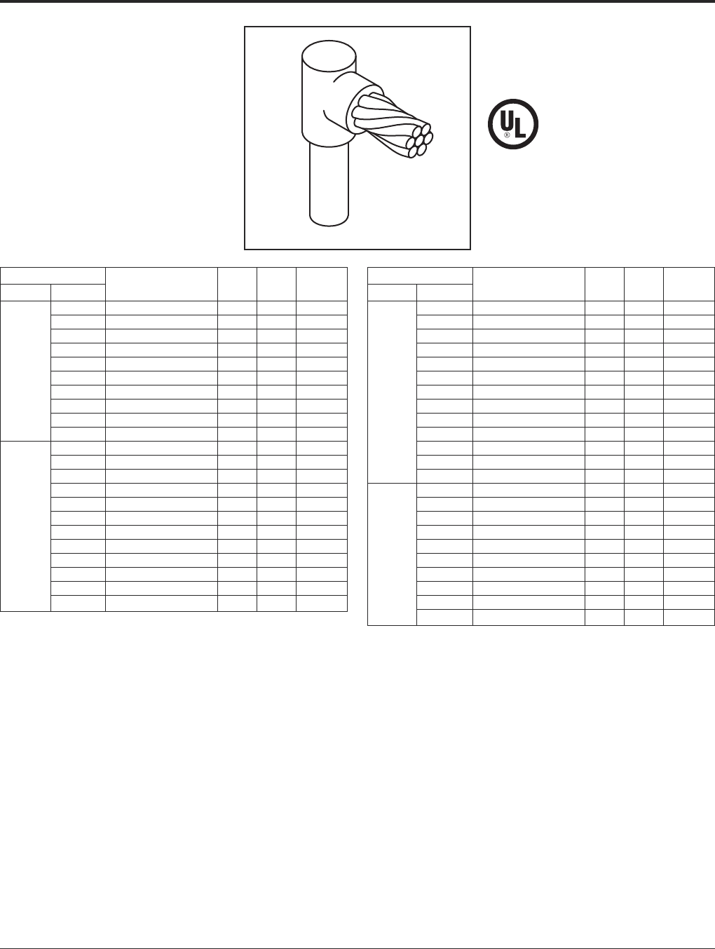
Grounding BURNDY®
BURNDYWeld®Exothermic
Canada: 1-800-387-6487 www.burndy.com US: 1-800-346-4175
78
For mold types or BURNDYWeld®items not shown, please contact factory.
TYPE BCR-1 MOLDS
Horizontal Cable Terminal to
Ground Rod
Type BCR-1 Molds are used to terminate hor-
izontal copper cable at the top of a vertical
ground rod.
Size range is #6 through 1000 kcmil solid or
concentric stranded copper conductors; 1/2
through 1for the ground rod.
Contact BURNDY®for information on molds
for conductors not listed below.
Cable Price Weld Handle
Grd Rod Tap Mold Number Key Metal Clamps
#6 B-8402 18†* 25 N/A
#4 B-8403 18†* 25 N/A
#2 B-495 4 65 B-106
#1 B-496 4 65 B-106
1/0 B-497 4 90 B-106
1/22/0 B-498 4 90 B-106
3/0 B-499 4 90 B-106
4/0 B-500 4 90 B-106
250 kcmil B-501 4 90 B-106
300 kcmil B-502 4 90 B-106
#6 B-8414 18† 32 N/A
#4 B-8415 18† 32 N/A
#2 B-503 4 65 B-106
#1 B-504 4 65 B-106
1/0 B-505 4 90 B-106
5/82/0 B-506 4 90 B-106
3/0 B-507 4 90 B-106
4/0 B-508 4 90 B-106
250 kcmil B-509 4 90 B-106
300 kcmil B-510 4 115 B-106
350 kcmil B-511 4 115 B-106
500 kcmil B-513 4 150 B-106
Cable Price Weld Handle
Grd Rod Tap Mold Number Key Metal Clamps
#6 B-8422 181* 32 N/A
#4 B-8426 191* 45 N/A
#2 B-5781 4 90 B-106
#1 B-514 4 90 B-106
1/0 B-515 4 90 B-106
2/0 B-516 4 90 B-106
3/43/0 B-517 4 90 B-106
4/0 B-518 4 90 B-106
250 kcmil B-519 4 90 B-106
300 kcmil B-520 4 115 B-106
350 kcmil B-521 4 115 B-106
500 kcmil B-523 4 150 B-106
750 kcmil B-524 4 250 B-106
1/0 B-525 4 150 B-106
2/0 B-526 4 150 B-106
3/0 B-527 4 150 B-106
4/0 B-528 4 150 B-106
250 kcmil B-529 4 150 B-106
1300 kcmil B-530 4 200 B-106
350 kcmil B-531 4 200 B-106
500 kcmil B-533 4 200 B-106
750 kcmil B-534 4 250 B-106
1000 kcmil B-535 5 2-150 B-106
• For sizes not listed, contact BURNDY®.
• Molds listed are for concentric stranded cable. Add suffix “-S” to mold number for solid
conductors.
• Molds listed are for copperclad ground rods. For welding to steel, stainless steel or galva-
nized steel ground rods add suffix “-N” to mold number.
• For heavy duty molds, molds with wear plates or molds for Copperweld®cable, contact
BURNDY®.
• For expedited service, contact BURNDY®.
Required Tools:
Handle Clamps (see chart for correct handles)
† Sold complete with handles
* B38-0309-00 Flint Ignitor (included)
Other recommended accessories:
B38-3922-00 Mold Cleaning Brush (pg 101)
B38-0135-00 Cable Cleaning Brush (pg 101)
B38-0304-00 File (pg 102)
B38-0330-00 Cable Clamp (pg 101)
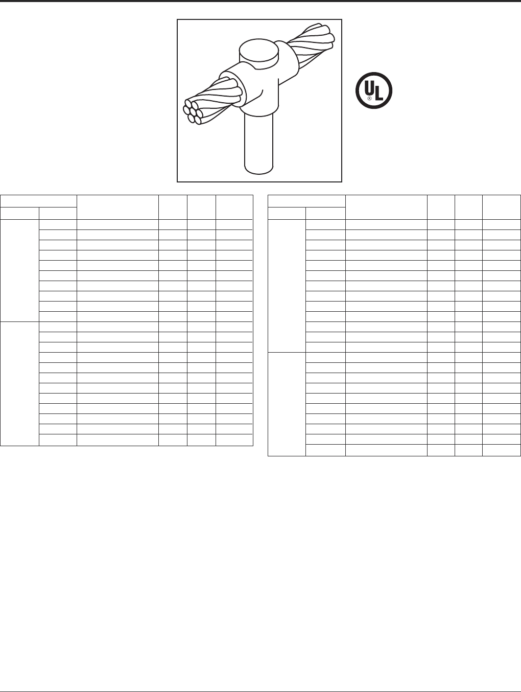
BURNDY®Grounding
BURNDYWeld®Exothermic
US: 1-800-346-4175 www.burndy.com Canada: 1-800-387-6487
79
For mold types or BURNDYWeld®items not shown, please contact factory.
TYPE BCR-2 MOLDS
Horizontal Cable to
Ground Rod
Type BCR-2 Molds are used to join horizontal
through copper cable to the top of a vertical
ground rod.
Size range is #6 through 1000 kcmil solid or
concentric stranded copper conductors; 1/2
through 1for the ground rod.
Contact BURNDY®for information on molds
for conductors not listed below.
Cable Price Weld Handle
Grd Rod Tap Mold Number Key Metal Clamps
#6 B-8434 181†* 32 N/A
#4 B-8435 18†* 32 N/A
#2 B-537 4 90 B-106
#1 B-538 4 90 B-106
1/0 B-539 4 90 B-106
1/22/0 B-540 4 90 B-106
3/0 B-541 4 115 B-106
4/0 B-542 4 115 B-106
250 kcmil B-543 4 150 B-106
300 kcmil B-544 4 200 B-106
#6 B-8441 18†* 32 N/A
#4 B-8442 18†* 32 N/A
#2 B-545 4 90 B-106
#1 B-546 4 90 B-106
1/0 B-547 4 90 B-106
2/0 B-548 4 115 B-106
5/83/0 B-549 4 115 B-106
4/0 B-550 4 115 B-106
250 kcmil B-551 4 150 B-106
300 kcmil B-532 4 200 B-106
350 kcmil B-553 4 200 B-106
500 kcmil B-555 4 250 B-106
Cable Price Weld Handle
Grd Rod Tap Mold Number Key Metal Clamps
#6 B-8452 19†* 45 N/A
#4 B-8454 19†* 65 N/A
#2 B-556 4 90 B-106
#1 B-557 4 90 B-106
1/0 B-558 4 115 B-106
2/0 B-559 4 115 B-106
3/43/0 B-560 4 115 B-106
4/0 B-561 4 115 B-106
250 kcmil B-562 4 150 B-106
300 kcmil B-563 4 200 B-106
350 kcmil B-564 4 200 B-106
500 kcmil B-566 4 250 B-106
750 kcmil B-567 5 2-200 B-107
1/0 B-569 4 150 B-106
2/0 B-570 4 150 B-106
3/0 B-571 4 150 B-106
4/0 B-572 4 150 B-106
250 kcmil B-573 4 200 B-106
1300 kcmil B-574 4 200 B-106
350 kcmil B-575 4 200 B-106
500 kcmil B-577 4 250 B-106
750 kcmil B-578 5 2-200 B-107
1000 kcmil B-579 5 500 B-107
• For sizes not listed, contact BURNDY®.
• Molds listed are for concentric stranded cable. Add suffix “-S” to mold number for solid
conductors.
• Molds listed are for copperclad ground rods. For welding to steel, stainless steel or
galvanized steel ground rods add suffix “-N” to mold number.
• For heavy duty molds, molds with wear plates or molds for Copperweld®cable, contact
BURNDY®.
• For expedited service, contact BURNDY®.
Required Tools:
Handle Clamps (see chart for correct handles)
† Sold complete with handles
*B38-0309-00 Flint Ignitor (included)
Other recommended accessories:
B38-3922-00 Mold Cleaning Brush (pg 101)
B38-0135-00 Cable Cleaning Brush (pg 101)
B38-0304-00 File (pg 102)
B38-0330-00 Cable Clamp (pg 101)
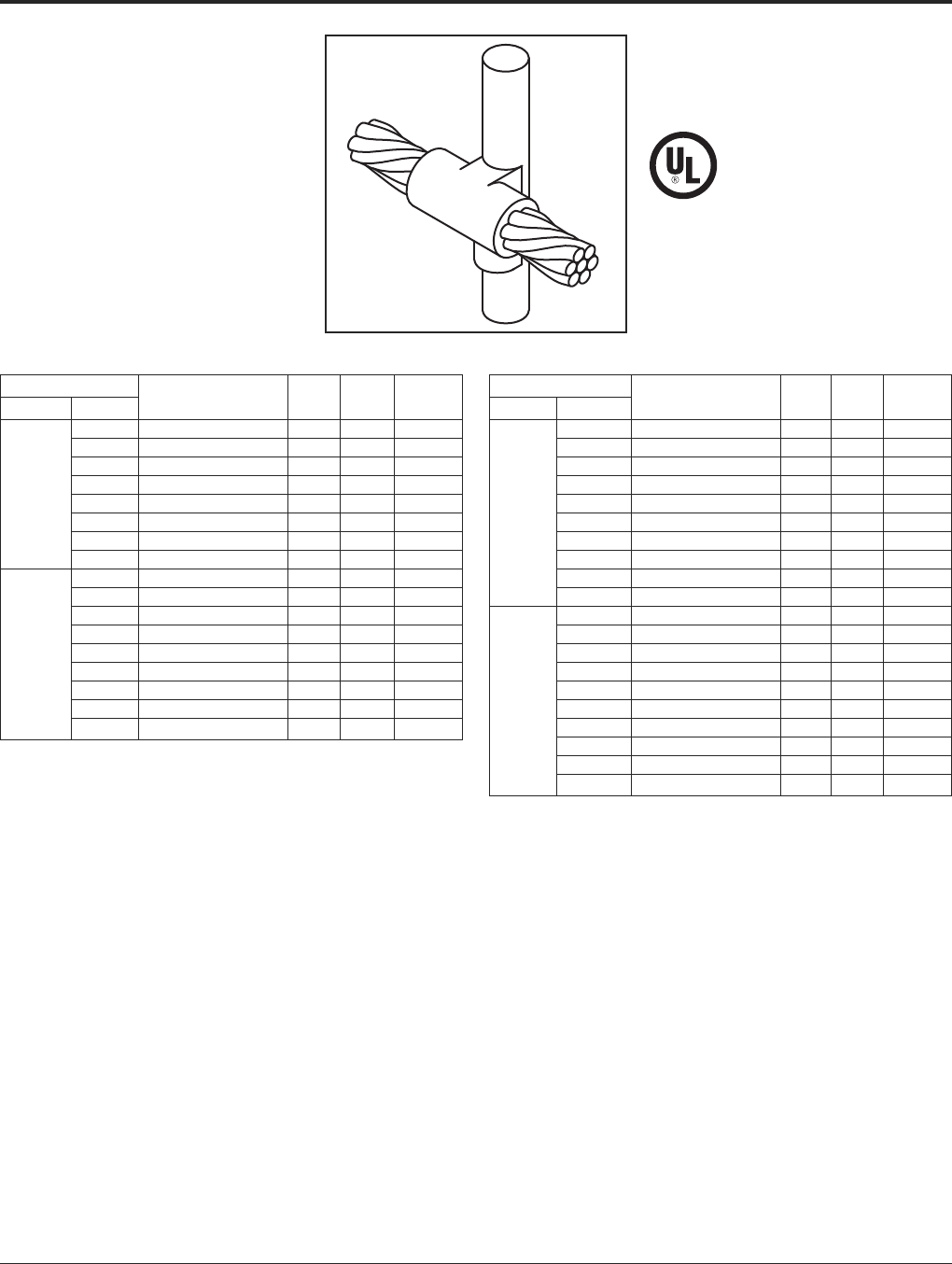
Grounding BURNDY®
BURNDYWeld®Exothermic
Canada: 1-800-387-6487 www.burndy.com US: 1-800-346-4175
80
For mold types or BURNDYWeld®items not shown, please contact factory.
TYPE BCR-3 MOLDS
Horizontal Through Cable to
Ground Rod
Type BCR-3 Molds are used to join horizontal
through run cable to the side of a vertical
ground rod.
Size range is #6 through 1000 kcmil solid or
concentric stranded copper conductors; 1/2
through 1for the ground rod.
Contact BURNDY®for information on molds
for conductors not listed below.
Cable Price Weld Handle
Grd Rod Tap Mold Number Key Metal Clamps
#6 B-5321 24 65 B-106
#4 B-2154 24 90 B-106
#2 B-2155 24 90 B-106
1/2#1 B-2156 24 115 B-106
1/0 B-1581 24 115 B-106
2/0 B-1582 24 115 B-106
4/0 B-1583 24 150 B-106
250 kcmil B-1584 24 150 B-106
#6 B-5660 24 65 B-106
#4 B-2157 24 90 B-106
#2 B-2158 24 90 B-106
#1 B-2159 24 115 B-106
5/81/0 B-1586 24 115 B-106
2/0 B-1587 24 115 B-106
4/0 B-1588 24 150 B-106
250 kcmil B-1589 24 150 B-106
500 kcmil B-1593 13 2-200 B-107
Cable Price Weld Handle
Grd Rod Tap Mold Number Key Metal Clamps
#6 B-6630 24 65 B-106
#4 B-2160 24 90 B-106
#2 B-2161 24 90 B-106
#1 B-2162 24 115 B-106
1/0 B-1594 24 115 B-106
3/42/0 B-1595 24 115 B-106
4/0 B-1596 24 150 B-106
250 kcmil B-1597 24 200 B-106
500 kcmil B-1601 13 500 B-107
750 kcmil B-1602 13 3-250 B-107
#6 B-6906 24 90 B-106
#4 B-2163 24 90 B-106
#2 B-2164 24 90 B-106
#1 B-2165 24 115 B-106
11/0 B-1603 24 15 B-106
2/0 B-1604 24 115 B-106
4/0 B-1605 24 150 B-106
250 kcmil B-1606 24 200 B-106
500 kcmil B-1610 13 500 B-107
750 kcmil B-1611 13 3-250 B-107
• For sizes not listed, contact BURNDY®.
• Molds listed are for concentric stranded cable. Add suffix “-S” to mold number for solid
conductors.
• Molds listed are for copperclad ground rods. For welding to steel, stainless steel or
galvanized steel ground rods add suffix “-N” to mold number.
• For heavy duty molds, molds with wear plates or molds for Copperweld®cable, contact
BURNDY®.
• For expedited service, contact BURNDY®.
Required Tools:
Handle Clamps (see chart for correct handles)
B38-0309-00 Flint Ignitor
Other recommended accessories:
B38-3922-00 Mold Cleaning Brush (pg 101)
B38-0135-00 Cable Cleaning Brush (pg 101)
B38-0330-00 Cable Clamp (pg 101)
B38-0304-00 File (pg 102)

BURNDY®Grounding
BURNDYWeld®Exothermic
US: 1-800-346-4175 www.burndy.com Canada: 1-800-387-6487
81
For mold types or BURNDYWeld®items not shown, please contact factory.
TYPE BCR-17 MOLDS
Horizontal Run and Tap
Cables to Ground Rod
Type BCR-17 Molds are used to join horizon-
tal run and tap cables to the top of a vertical
ground rod.
Size range is #4 through 750 kcmil solid or
concentric stranded copper conductors; 1/2
through 1for the ground rod.
Contact BURNDY®for information on molds
for conductors not listed below.
Cable Price Weld Handle
Grd Rod Tap Mold Number Key Metal Clamps
#4 B-5416 4 90 B-106
#2 B-6165 4 90 B-106
#1 B-5830 4 90 B-106
1/21/0 B-5940 4 115 B-106
2/0 B-5850 4 150 B-106
3/0 B-5833 4 200 B-106
4/0 B-5380 4 200 B-106
#4 B-5972 4 90 B-106
#2 B-5935 4 115 B-106
#1 B-5699 4 115 B-106
1/0 B-5746 4 150 B-106
5/82/0 B-5963 4 200 B-106
3/0 B-5734 4 250 B-106
4/0 B-5732 4 250 B-106
250 kcmil B-5722 5 2-150 B-107
Cable Price Weld Handle
Grd Rod Tap Mold Number Key Metal Clamps
#4 B-5698 4 90 B-106
#2 B-5294 4 115 B-106
#1 B-5390 4 115 B-106
1/0 B-6025 4 150 B-106
2/0 B-5738 4 200 B-106
3/43/0 B-6003 4 250 B-106
4/0 B-2566 4 250 B-106
250 kcmil B-5904 5 2-150 B-107
300 kcmil B-5857 5 2-200 B-107
350 kcmil B-5777 5 2-200 B-107
500 kcmil B-5961 5 3-200 B-106
#4 B-5556 4 115 B-106
#2 B-5555 4 150 B-106
#1 B-6048 4 150 B-106
1/0 B-5992 4 200 B-106
2/0 B-5877 4 250 B-106
3/0 B-5821 5 2-150 B-107
14/0 B-5820 5 2-150 B-107
250 kcmil B-5804 5 2-200 B-107
300 kcmil B-5803 5 500 B-107
350 kcmil B-5561 5 500 B-107
500 kcmil B-5515 6 3-250 B-107
750 kcmil B-5513 6 2-500 B-107
• For sizes not listed, contact BURNDY®.
• Molds listed are for concentric stranded cable. Add suffix “-S” to mold number for solid
conductors.
• Molds listed are for copperclad ground rods. For welding to steel, stainless steel or
galvanized steel ground rods add suffix “-N” to mold number.
• For heavy duty molds, molds with wear plates or molds for Copperweld®cable, contact
BURNDY®.
• For expedited service, contact BURNDY®.
Required Tools:
Handle Clamps (see chart for correct handles)
B38-0309-00 Flint Ignitor
Other recommended accessories:
B38-3922-00 Mold Cleaning Brush (pg 101)
B38-0135-00 Cable Cleaning Brush (pg 101)
B38-0330-00 Cable Clamp (pg 101)
B38-0304-00 File (pg 102)
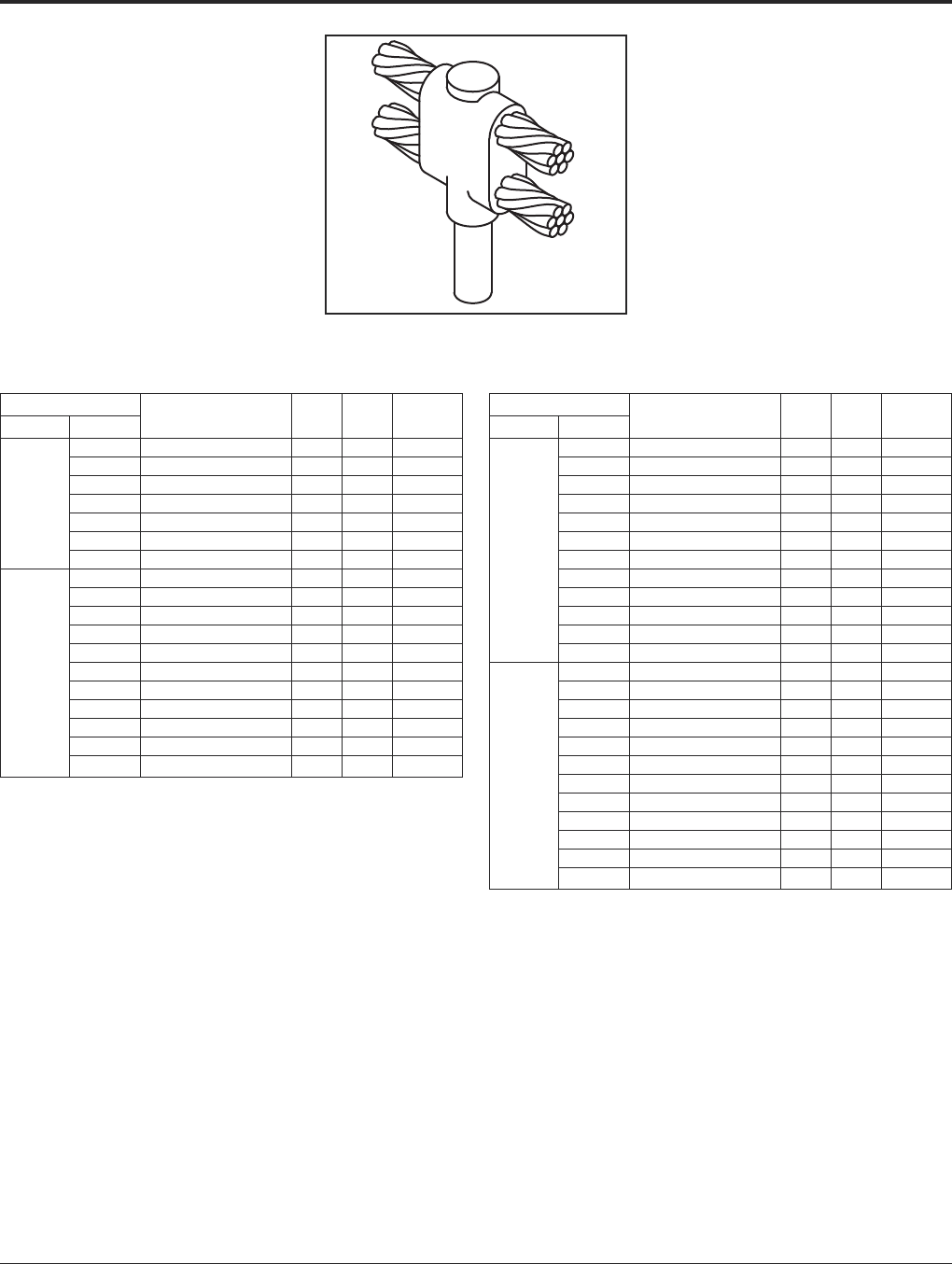
Grounding BURNDY®
BURNDYWeld®Exothermic
Canada: 1-800-387-6487 www.burndy.com US: 1-800-346-4175
82
For mold types or BURNDYWeld®items not shown, please contact factory.
TYPE BCR-24 MOLDS
Horizontal Parallel Run Cables
to Ground Rod
Type BCR-24 Molds are used to join horizon-
tal parallel cables to the top of a vertical
ground rod.
Size range is #4 through 750 kcmil solid or
concentric stranded copper conductors; 1/2
through 1for the ground rod.
Contact BURNDY®for information on molds
for conductors not listed below.
Cable Price Weld Handle
Grd Rod Tap Mold Number Key Metal Clamps
#4 B-5640 4 115 B-106
#2 B-5667 4 115 B-106
#1 B-6002 4 115 B-106
1/21/0 B-5767 4 150 B-106
2/0 B-5604 4 200 B-106
3/0 B-5560 4 250 B-106
4/0 B-6766 4 250 B-106
#4 B-6208 4 115 B-106
#2 B-5702 4 150 B-106
#1 B-5517 4 150 B-106
1/0 B-5573 4 200 B-106
2/0 B-8451 4 250 B-106
5/83/0 B-2510 5 2-150 B-107
4/0 B-5428 5 2-150 B-107
250 kcmil B-1212 5 2-200 B-107
300 kcmil B-2084 5 500 B-107
350 kcmil B-2558 5 500 B-107
500 kcmil B-2450 5 3-250 B-107
Cable Price Weld Handle
Grd Rod Tap Mold Number Key Metal Clamps
#4 B-8011 4 115 B-106
#2 B-2320 4 150 B-106
#1 B-2235 4 150 B-106
1/0 B-6051 4 200 B-106
2/0 B-8802 4 250 B-106
3/0 B-8726 5 2-150 B-107
3/44/0 B-5677 5 2-150 B-107
250 kcmil B-8461 5 2-200 B-107
300 kcmil B-8428 5 500 B-107
350 kcmil B-6294 5 500 B-107
500 kcmil B-8214 5 3-250 B-107
750 kcmil B-8027 6 2-500 B-107
#4 B-5330 4 150 B-106
#2 B-5332 4 200 B-106
#1 B-5333 4 200 B-106
1/0 B-5334 4 250 B-106
2/0 B-5335 5 2-150 B-107
3/0 B-5336 5 2-200 B-107
14/0 B-5337 5 2-200 B-107
250 kcmil B-5338 5 500 B-107
300 kcmil B-5341 5 3-200 B-107
350 kcmil B-5351 5 3-200 B-107
500 kcmil B-5352 6 2-500 B-107
750 kcmil B-5353 64 5-250 B-107
• For sizes not listed, contact BURNDY®.
• Molds listed are for concentric stranded cable. Add suffix “-S” to mold number for solid
conductors.
• Molds listed are for copperclad ground rods. For welding to steel, stainless steel or
galvanized steel ground rods add suffix “-N” to mold number.
• For heavy duty molds, molds with wear plates or molds for Copperweld®cable, contact
BURNDY®.
• For expedited service, contact BURNDY®.
Required Tools:
Handle Clamps (see chart for correct handles)
B38-0309-00 Flint Ignitor
‡ Crucible B-181 required
Other recommended accessories:
B38-3922-00 Mold Cleaning Brush (pg 101)
B38-0135-00 Cable Cleaning Brush (pg 101)
B38-0330-00 Cable Clamp (pg 101)
B38-0304-00 File (pg 102)
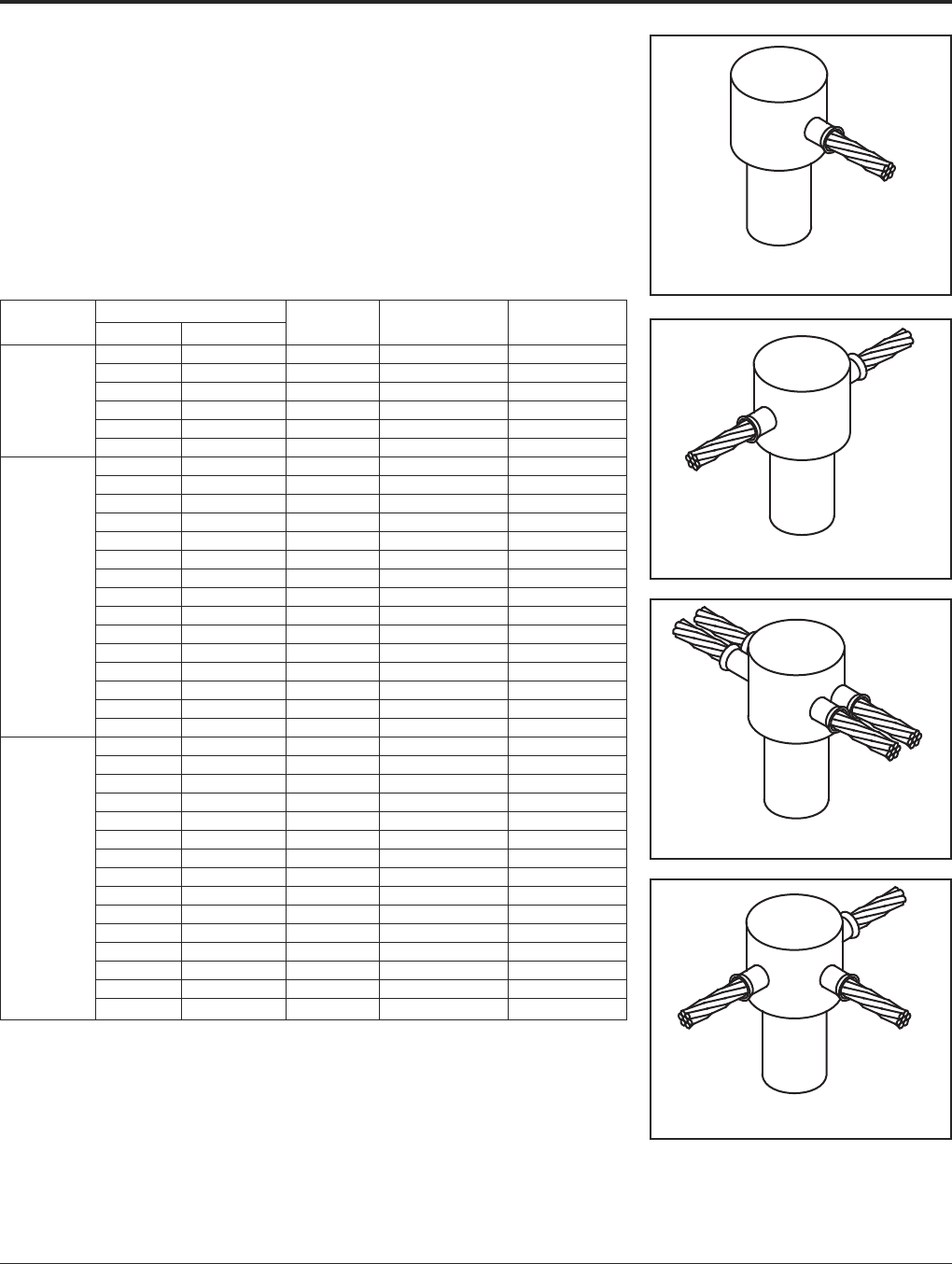
BURNDY®Grounding
BURNDYWeld®Exothermic
US: 1-800-346-4175 www.burndy.com Canada: 1-800-387-6487
83
For mold types or BURNDYWeld®items not shown, please contact factory.
SINGLE SHOT
MOLDS
RUS Accepted
BURNDYWeld®Single Shot Molds are an
economical way to make cable connections
onto the top of a ground rod. The Single Shot
is a disposable single use ceramic mold that
comes complete with everything required
except the Flint Ignitor.
Ground Cable Size Mold Cadweld®
Rod Size Solid Stranded Type Number Part #
#6, #8 #8 BCR-1 • BS-2009 GR1-141G
#3, #4 #4, #6 BCR-1 • BS-2010 GR1-141L
#1, #2 #2, #3 BCR-1 • BS-2011 GR1-141V
1/2#6, #8 #8 BCR-2 • BS-2024 GT1-141G
#3, #4 #4, #6 BCR-2 • BS-2025 GT1-141L
#1, #2 #2, #3 BCR-2 • BS-2026 GT1-141V
#6, #8 #8 BCR-1 • BS-2012 GT1-161G
#3, #4 #4, #6 BCR-1 • BS-2013 GT1-141L
#1, #2 #2, #3 BCR-1 • BS-2014 GR1-161V
2/0, 1/0 1/0, #1 BCR-1 • BS-2015 GR1-162C
2/0 BCR-1 • BS-2016 GR1-162G
#6, #8 #8 BCR-2 • BS-2027 FRT1-161G
#3, #4 #4, #6 BCR-2 • BS-2028 GT1-161L
5/8#1, #2 #2, #3 BCR-2 • BS-2029 GT1-161V
2/0, 1/0 1/0, #1 BCR-2 • BS-2030 GT1-162C
#6, #8 #8 BCR-24 BS-2105 NX1-161G
#3, #4 #4, #6 BCR-14 BS-2106 NX1-161L
#1, #2 #2, #3 BCR-24 BS-2107 NX1-161V
#6, #8 #8 BCR-25 BS-2006 NT1-161G
#3, #4 #4, #6 BCR-25 BS-2007 NT1-161L
#1, #2 #2, #3 BCR-25 BS-2008 NT1-161V
#6, #8 #8 BCR-1 BS-2017 GR1-181G
#3, #4 #4, #6 BCR-1 • BS-2018 GR1-181L
#1, #2 #2, #3 BCR-1 • BS-2019 GR1-181V
2/0, 1/0 1/0, #1 BCR-1 • BS-2020 GR1-182C
2/0 BCR-1 • BS-2021 GR1-182G
#6, #8 #8 BCR-2 • BS-2031 GT1-181G
#3, #4 #4, #6 BCR-2 • BS-2032 GT1-181L
3/4#1, #2 #2, #3 BCR-2 • BS-2033 GT1-181V
2/0, 1/0 1/0, #1 BCR-2 • BS-2034 T1-182C
#6, #8 #8 BCR-24 BS-2108 NX1-181G
#3, #4 #4, #6 BCR-24 BS-2109 NX1-181L
#1, #2 #2, #3 BCR-24 BS-2110 NX1-181V
#6, #8 #8 BCR-25 • BS-2068 NT1-181G
#3, #4 #4, #6 BCR-25 • BS-2069 NT1-181L
#1, #2 #2, #3 BCR-25 • BS-2070 NT1-181V
BCR-1
BCR-2
BCR-24
BCR-25
Cadweld®is a registered trademark of the Erico International Corporation.
• UL Listed.

Grounding BURNDY®
BURNDYWeld®Exothermic
Canada: 1-800-387-6487 www.burndy.com US: 1-800-346-4175
84
For mold types or BURNDYWeld®items not shown, please contact factory.
TYPE BCS-1 MOLDS
Horizontal Cable to Horizontal
Steel Surface
Type BCS-1 Molds are used to terminate a hor-
izontal copper cable to any horizontal steel sur-
face. Note that the cable is OFF the surface.
Size range is 1/0 through 1000 kcmil solid or
concentric stranded copper conductors.
Contact BURNDY®for information on molds
for conductors not listed below.
Price Weld Handle
Cable Size Mold Number Key Metal Clamps
1/0 B-644 4 90 B-106
2/0 B-645 4 90 B-106
3/0 B-646 4 115 B-106
4/0 B-647 4 115 B-106
250 kcmil B-648 4 115 B-106
300 kcmil B-649 4 150 B-106
350 kcmil B-650 4 200 B-106
500 kcmil B-652 4 200 B-106
750 kcmil B-653 5 2-150 B-106
1000 kcmil B-654 5 2-200 B-107
Price Weld Handle
Cable Size Mold Number Key Metal Clamps
#6 B-628 3†** 45 N/A
#4 B-629 3†* 45 N/A
#2 B-630 3†* 45 N/A
#1 B-631 3†* 65 N/A
1/0 B-7146 4 90 B-106
2/0 B-7075 4 90 B-106
3/0 B-2199 4 115 B-106
4/0 B-6114 4 115 B-106
250 kcmil B-2200 4 115 B-106
300 kcmil B-2506 4 150 B-106
350 kcmil B-2507 4 200 B-106
500 kcmil B-2509 4 200 B-106
750 kcmil B-2542 5 2-150 B-107
1000 kcmil B-2511 5 2-200 B-107
• For sizes not listed, contact BURNDY®.
• Molds listed are for concentric stranded cable. Add suffix “-S” to mold number for solid
conductors.
• For heavy duty molds, molds with wear plates or molds for Copperweld®cable, contact
BURNDY®.
• For expedited service, contact BURNDY®.
Required Tools:
Handle Clamps (see chart for correct handles)
B38-0309-00 Flint Ignitor
Other recommended accessories:
B38-3922-00 Mold Cleaning Brush (pg 101)
B38-0135-00 Cable Cleaning Brush (pg 101)
B38-0330-00 Cable Clamp (pg 101)
B38-0101-00 Rasp (pg 102)
• For sizes not listed, contact BURNDY®.
• Molds listed are for concentric stranded cable. Add suffix “-S” to mold number for solid
conductors.
• For heavy duty molds, molds with wear plates or molds for Copperweld®cable, contact
BURNDY®.
• For expedited service, contact BURNDY®.
Required Tools:
Handle Clamps (see chart for correct handles)
† Sold complete with frame
* B38-0309-00 Flint Ignitor (included)
Other recommended accessories:
B38-3922-00 Mold Cleaning Brush (pg 101)
B38-0135-00 Cable Cleaning Brush (pg 101)
B38-0330-00 Cable Clamp (pg 101)
B38-0101-00 Rasp (pg 102)
TYPE BCS-8 MOLDS
Horizontal Cable to Horizontal
Steel Surface
Type BCS-8 Molds are used to terminate a
horizontal copper cable to any horizontal steel
surface. Note that the cable is ON the surface.
Size range is #6 through 1000 kcmil solid or
concentric stranded copper conductors.
Contact BURNDY®for information on molds
for conductors not listed below.

BURNDY®Grounding
BURNDYWeld®Exothermic
US: 1-800-346-4175 www.burndy.com Canada: 1-800-387-6487
85
For mold types or BURNDYWeld®items not shown, please contact factory.
TYPE BCS-2 MOLDS
Horizontal Through Cable to
Horizontal Steel Surface
Type BCS-2 Molds are used to join horizontal
through copper cable to any horizontal steel
surface. Note the cable is OFF the surface.
Size range is 1/0 through 1000 kcmil solid or
concentric stranded copper conductors.
Contact BURNDY®for information on molds
for conductors not listed below.
Price Weld Handle
Cable Size Mold Number Key Metal Clamps
1/0 B-616 4 90 B-106
2/0 B-617 4 115 B-106
3/0 B-618 4 115 B-106
4/0 B-619 4 150 B-106
250 kcmil B-620 4 150 B-106
300 kcmil B-621 4 200 B-106
350 kcmil B-622 4 250 B-106
500 kcmil B-624 5 2-150 B-107
750 kcmil B-625-H 5 3-250 B-107
1000 kcmil B-626-H 5 2-500 B-107
Price Weld Handle
Cable Size Mold Number Key Metal Clamps
#6 B-602 3†* 45 N/A
#4 B-603 3†* 45 N/A
#2 B-604 3†* 45 N/A
#1 B-605 3†* 65 N/A
1/0 B-8379 4 90 B-106
2/0 B-5331 4 115 B-106
3/0 B-8381 4 115 B-106
4/0 B-7192 4 150 B-106
250 kcmil B-8413 4 150 B-106
300 kcmil B-8423 4 200 B-106
350 kcmil B-8410 4 250 B-106
500 kcmil B-5065 5 2-150 B-107
• For sizes not listed, contact BURNDY®.
• Molds listed are for concentric stranded cable. Add suffix “-S” to mold number for solid
conductors.
• For heavy duty molds, molds with wear plates or molds for Copperweld® cable, contact
BURNDY®.
• For expedited service, contact BURNDY®.
Required Tools:
Handle Clamps (see above for correct handles)
B38-0309-00 Flint Ignitor
Other recommended accessories:
B38-3922-00 Mold Cleaning Brush (pg 101)
B38-0135-00 Cable Cleaning Brush (pg 101)
B38-0101-00 Rasp (pg 102)
• For sizes not listed, contact BURNDY®.
• Molds listed are for concentric stranded cable. Add suffix “-S” to mold number for solid
conductors.
• For heavy duty molds, molds with wear plates or molds for Copperweld®cable, contact
BURNDY®.
• For expedited service, contact BURNDY®.
Required Tools:
Handle Clamps (see chart for correct handles)
† Sold complete with handle frame
* B38-0309-00 Flint Ignitor (included)
Other recommended accessories:
B40-0319-01 Mold Cleaner for cartridge sizes #15-#65 (pg 101)
B40-0319-03 Mold Cleaner for cartridge sizes #90-#500 (pg 101)
B38-3922-00 Mold Cleaning Brush (pg 101)
B38-0135-00 Cable Cleaning Brush (pg 101)
B38-0101-00 Rasp (pg 102)
TYPE BCS-9 MOLDS
Horizontal Through Cable to
Horizontal Steel Surface
Type BCS-9 Molds are used to join horizontal
through copper cable to any horizontal steel
surface. Note the cable is ON the surface.
Size range is #6 through 500 kcmil solid or
concentric stranded copper conductors.
Contact BURNDY®Products for information
on molds for conductors not listed below.

Grounding BURNDY®
BURNDYWeld®Exothermic
Canada: 1-800-387-6487 www.burndy.com US: 1-800-346-4175
86
TYPE BCS-3 MOLDS
Angular Cable Drop to Vertical
Steel Surface
Type BCS-3 Molds are used to join the end of
a copper cable at a 45˚ angle to a vertical steel
surface.
Size range is #6 through 1000 kcmil solid or
concentric stranded copper conductors.
Contact BURNDY®for information on molds
for conductors not listed below.
Price Weld Handle
Cable Size Mold Number Key Metal Clamps
#6 B-585 4 45 B-106
#4 B-586 4 45 B-106
#3 B-587 4 45 B-106
#2 B-588 4 45 B-106
#1 B-589 4 65 B-106
1/0 B-590 4 90 B-106
2/0 B-591 4 90 B-106
3/0 B-592 4 115 B-106
4/0 B-593 4 115 B-106
250 kcmil B-594 4 115 B-106
300 kcmil B-595 4 150 B-106
350 kcmil B-596 4 200 B-106
500 kcmil B-598 4 200 B-106
750 kcmil B-599 5 2-150 B-107
1000 kcmil B-600 5 2-200 B-107
Cable Pipe Mold Price Weld Handle
Size Size Number Key Metal Clamps
1-1/4to 4B-2476 4 45 B-106
4to 6B-2477 4 45 B-106
#4 6to 10B-2478 4 45 B-106
12& up B-586 ‡ 4 45 B-106
1-1/4to 4B-9233-S 4 45 B-106
4to 6B-2480-S 4 45 B-106
#2 Sol 6to 10B-2583-S 4 45 B-106
12& up B-588-S ‡ 4 45 B-106
1-1/4to 4B-9233 4 45 B-106
4to 6B-2480 4 45 B-106
#2 6to 10B-2583 4 45 B-106
12& up B-588 ‡ 4 45 B-106
1-1/4to 4B-2482 4 65 B-106
4to 6B-2483 4 65 B-106
#1 6to 10B-2484 4 65 B-106
12& up B-589 ‡ 4 65 B-106
1-1/4to 4B-2486 4 90 B-106
4to 6B-2487 4 90 B-106
1/0 6to 10B-2488 4 90 B-106
12& up B-590 ‡ 4 90 B-106
1-1/4to 4B-8833 4 90 B-106
4to 6B-2490 4 90 B-106
2/0 6to 10B-2491 4 90 B-106
12& upB-591 ‡ 4 90 B-106
1-1/4to 4B-2493 4 115 B-106
4to 6B-2494 4 115 B-106
3/0 6to 10B-2495 4 115 B-106
12& up B-592 ‡ 4 115 B-106
1-1/4to 4B-9021 4 115 B-106
4to 6B-2497 4 115 B-106
4/0 6to 10B-2498 4 115 B-106
12& up B-593 ‡ 4 115 B-106
• For sizes not listed, contact BURNDY®.
• Molds listed are for concentric stranded cable. Add suffix “-S” to mold number for solid
conductors.
• For heavy duty molds, molds with wear plates or molds for Copperweld®cable, contact
BURNDY®.
• For expedited service, contact BURNDY®.
Required Tools:
Handle Clamps (see chart for correct handles)
B38-0309-00 Flint Ignitor
Other recommended accessories:
Magnetic Clamps to hold molds against vertical steel (pg E-89)
B38-3922-00 Mold Cleaning Brush (pg 101)
B38-0135-00 Cable Cleaning Brush (pg 101)
B38-0101-00 Rasp (pg 102)
• For sizes not listed, contact BURNDY®.
• Molds listed are for concentric stranded cable. Add suffix “-S” to mold number for solid
conductors.
• For heavy duty molds, molds with wear plates or molds for Copperweld® cable, contact
BURNDY®.
• For expedited service, contact BURNDY®.
Required Tools:
Handle Clamps (see chart for correct handles)
B38-0309-00 Flint Ignitor
Other recommended accessories:
B106-32 Vertical Chain Clamp w/ B-106 Handles for 4Pipe & smaller
B40-0106-27 20Chain Extension for 4to 10Pipe
Use (2) 20Chain Extensions for pipe sizes between 10and 16
B38-3922-00 Mold Cleaning Brush (pg 101)
B38-0135-00 Cable Cleaning Brush (pg 101)
B38-0101-00 Rasp (pg 102)
‡ Flat Surface Mold
Cable to Flat Steel Cable to Pipe
Cable to Flat Steel Cable to Pipe
For mold types or BURNDYWeld®items not
shown, please contact factory.
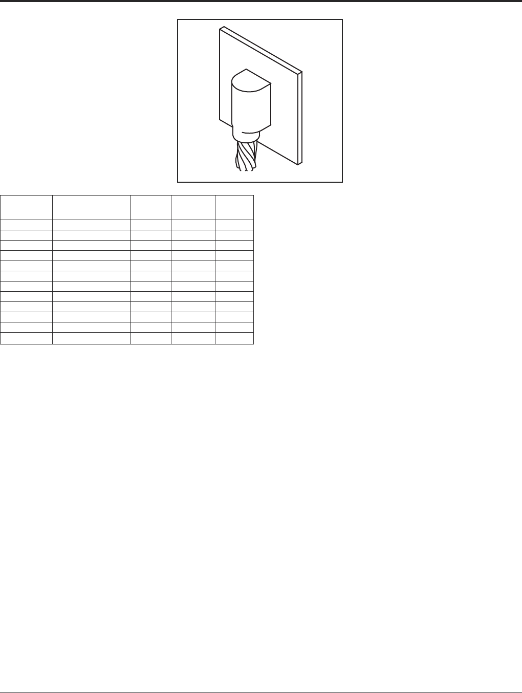
BURNDY®Grounding
BURNDYWeld®Exothermic
US: 1-800-346-4175 www.burndy.com Canada: 1-800-387-6487
87
For mold types or BURNDYWeld®items not shown, please contact factory.
TYPE BCS-23 MOLDS
Vertical Cable Drop to
Vertical Steel Surface
Type BCS-23 Molds are used to join vertical
cable down to a vertical steel surface. Note
that the cable is OFF the surface.
Size range is #6 through 500 kcmil solid or
concentric stranded copper conductors.
Contact BURNDY®for information on molds
for conductors not listed below.
Price Weld Handle
Cable Size Mold Number Key Metal Clamps
#6 B-5389 4 45 B-106
#4 B-5359 4 65 B-106
#2 B-2781 4 65 B-106
#1 B-5361 4 90 B-106
1/0 B-2189 4 115 B-106
2/0 B-2540 4 115 B-106
3/0 B-5362 4 150 B-106
4/0 B-8718 4 150 B-106
250 kcmil B-8165 4 200 B-106
300 kcmil B-5363 4 200 B-106
350 kcmil B-9029 4 250 B-106
500 kcmil B-8512 17 2-150 B-106
• For sizes not listed, contact BURNDY®.
• Molds listed are for concentric stranded cable. Add suffix “-S” to mold number for solid
conductors.
• For heavy duty molds, molds with wear plates or molds for Copperweld®cable, contact
BURNDY®.
• For expedited service, contact BURNDY®.
Required Tools:
Handle Clamps (see chart for correct handles)
B38-0309-00 Flint Ignitor
Other recommended accessories:
Magnetic Clamps to hold molds against vertical steel
B38-3922-00 Mold Cleaning Brush (pg 101)
B38-0135-00 Cable Cleaning Brush (pg 101)
B38-0101-00 Rasp (pg 102)
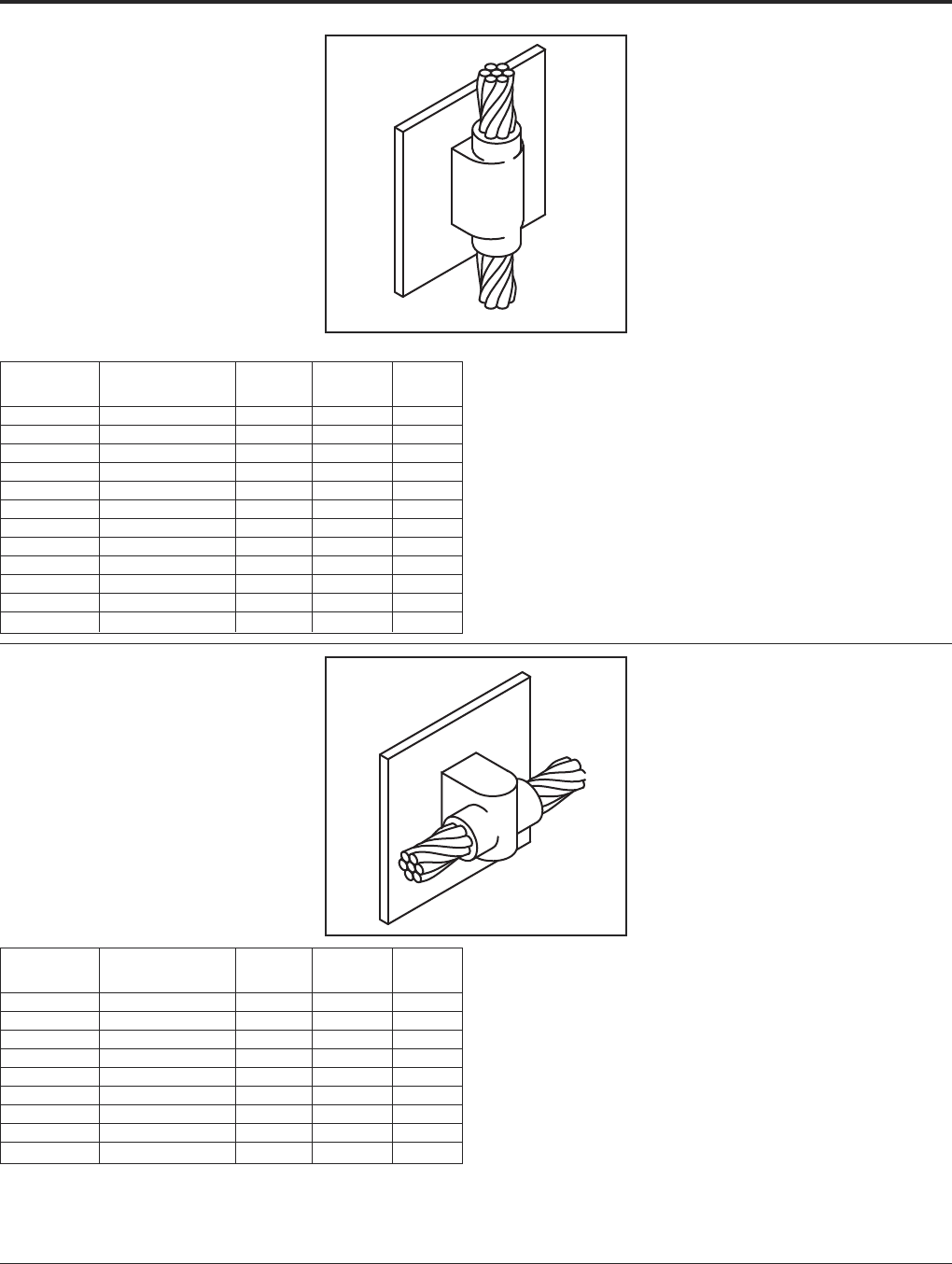
Grounding BURNDY®
BURNDYWeld®Exothermic
Canada: 1-800-387-6487 www.burndy.com US: 1-800-346-4175
88
For mold types or BURNDYWeld®items not shown, please contact factory.
TYPE BCS-4 MOLDS
Vertical Through Cable to
Vertical Steel Surface
Type BCS-4 Molds are used to join a vertical
through copper cable to a vertical steel sur-
face. Note that the cable is OFF the surface.
For molds with the cable on the surface, con-
tact BURNDY®Products.
Size range is #6 through 500 kcmil solid or
concentric stranded copper conductors.
Contact BURNDY®for information on molds
for conductors not listed below.
Price Weld Handle
Cable Size Mold Number Key Metal Clamps
#6 B-1215 4 90 B-106
#4 B-1216 4 90 B-106
#2 B-1218 4 115 B-106
#1 B-1219 4 115 B-106
1/0 B-1220 17 200 B-106
2/0 B-1221 17 200 B-106
3/0 B-1222 17 250 B-106
4/0 B-1223 17 250 B-106
250 kcmil B-1224 17 250 B-106
300 kcmil B-1225-H 6 500 B-107
350 kcmil B-1226-H 6 3-200 B-107
500 kcmil B-1228-H 6 3-250 B-107
Price Weld Handle
Cable Size Mold Number Key Metal Clamps
#6 B-1626 4 65 B-106
#4 B-1627 4 65 B-106
#2 B-1628 4 65 B-106
#1 B-1629 4 90 B-106
1/0 B-1630 4 115 B-106
2/0 B-1631 4 115 B-106
3/0 B-1632 4 150 B-106
4/0 B-1633 4 150 B-106
250 kcmil B-1634 4 150 B-106
• For sizes not listed, contact BURNDY®.
• Molds listed are for concentric stranded cable. Add suffix “-S” to mold number for solid
conductors.
• For heavy duty molds, molds with wear plates or molds for Copperweld®cable, contact
BURNDY®.
• For expedited service, contact BURNDY®.
Required Tools:
Handle Clamps (see chart for correct handles)
B38-0309-00 Flint Ignitor
Other recommended accessories:
Magnetic Clamps to hold molds against vertical steel
B38-3922-00 Mold Cleaning Brush (pg 101)
B38-0135-00 Cable Cleaning Brush (pg 101)
B38-0101-00 Rasp (pg 102)
• For sizes not listed, contact BURNDY®.
• Molds listed are for concentric stranded cable. Add suffix “-S” to mold number for solid
conductors.
• For heavy duty molds, molds with wear plates or molds for Copperweld®cable, contact
BURNDY®.
• For expedited service, contact BURNDY®.
Required Tools:
Handle Clamps (see chart for correct handles)
B38-0309-00 Flint Ignitor
Other recommended accessories:
B40-0319-01 Mold Cleaner for cartridge sizes #15-#65 (pg 101)
B40-0319-03 Mold Cleaner for cartridge sizes #90-#500 (pg 101)
B38-3922-00 Mold Cleaning Brush (pg 101)
B38-0135-00 Cable Cleaning Brush (pg 101)
B38-0101-00 Rasp (pg 102)
TYPE BCS-6 MOLDS
Horizontal Through Cable to
Vertical Steel Surface
Type BCS-6 Molds are used to join horizontal
through copper cable to a vertical steel sur-
face. Note that the cable is OFF the surface.
Size range is #6 through 250 kcmil solid or
concentric stranded copper conductors.
Contact BURNDY®for information on molds
for conductors not listed below.

BURNDY®Grounding
BURNDYWeld®Exothermic
US: 1-800-346-4175 www.burndy.com Canada: 1-800-387-6487
89
TYPE BCS-7 MOLDS
Overhead Vertical Tap Cable
to Vertical Steel Surface
Type BCS-7 Molds are used to join an over-
head vertical copper conductor drop tap to a
vertical steel surface.
Size range is #6 through 1000 kcmil solid or
concentric stranded copper conductors.
Contact BURNDY®for information on molds
for conductors not listed below.
Price Weld Handle
Cable Size Mold Number Key Metal Clamps
#6 B-1635 4 65 B-106
#4 B-1636 4 65 B-106
#3 B-1637 4 65 B-106
#2 B-1638 4 65 B-106
#1 B-1639 4 90 B-106
1/0 B-1640 4 150 B-106
2/0 B-1641 4 150 B-106
3/0 B-1642 17 200 B-106
4/0 B-1643 17 200 B-106
250 kcmil B-1644 17 200 B-106
300 kcmil B-1645 17 250 B-106
350 kcmil B-1646 6 2-150 B-107
500 kcmil B-1648 6 2-200 B-107
750 kcmil B-1649 6 500 B-107
1000 kcmil B-1650 6 3-200 B-107
Price Weld Handle
Cable Size Mold Number Key Metal Clamps
#6 B-5910 4 45 B-106
#4 B-2761 4 45 B-106
#2 B-2569 4 45 B-106
#1 B-6060 4 65 B-106
1/0 B-5419 4 90 B-106
2/0 B-2567 4 90 B-106
3/0 B-6072 4 115 B-106
4/0 B-9253 4 115 B-106
250 kcmil B-2568 4 115 B-106
300 kcmil B-6061 4 150 B-106
350 kcmil B-6067 4 200 B-106
500 kcmil B-8359 4 200 B-106
• For sizes not listed, contact BURNDY®.
• Molds listed are for concentric stranded cable. Add suffix “-S” to mold number for solid
conductors.
• For heavy duty molds, molds with wear plates or molds for Copperweld®cable, contact
BURNDY®.
• For expedited service, contact BURNDY®.
Required Tools:
Handle Clamps (see chart for correct handles)
B38-0309-00 Flint Ignitor
Other recommended accessories:
Magnetic Clamps to hold molds against vertical steel
B38-3922-00 Mold Cleaning Brush (pg 101)
B38-0135-00 Cable Cleaning Brush (pg 101)
B38-0101-00 Rasp (pg 102)
NOTE: Add (-R) to mold number for right hand mold or (-L) for left hand mold. Right hand (-R)
mold will be furnished if not specified.
• For sizes not listed, contact BURNDY®.
• Molds listed are for concentric stranded cable. Add suffix “-S” to mold number for solid
conductors.
• For heavy duty molds, molds with wear plates or molds for Copperweld®cable, contact
BURNDY®.
• For expedited service, contact BURNDY®.
Required Tools:
Handle Clamps (see chart for correct handles)
B38-0309-00 Flint Ignitor
Other recommended accessories:
Vertical Chain Clamps
B38-3922-00 Mold Cleaning Brush (pg 101)
B38-0135-00 Cable Cleaning Brush (pg 101)
B38-0101-00 Rasp (pg 102)
TYPE BCS-18 MOLDS
Horizontal Tap Cable to
Vertical Steel Surface
Type BCS-18 Molds are used to connect a
horizontal conductor to a vertical steel sur-
face. Note that the cable is ON the surface.
Size range is #6 through 500 kcmil solid or
concentric stranded copper conductors.
Contact BURNDY®for information on molds
for conductors not listed below.
For mold types or BURNDYWeld®items not shown, please contact factory.
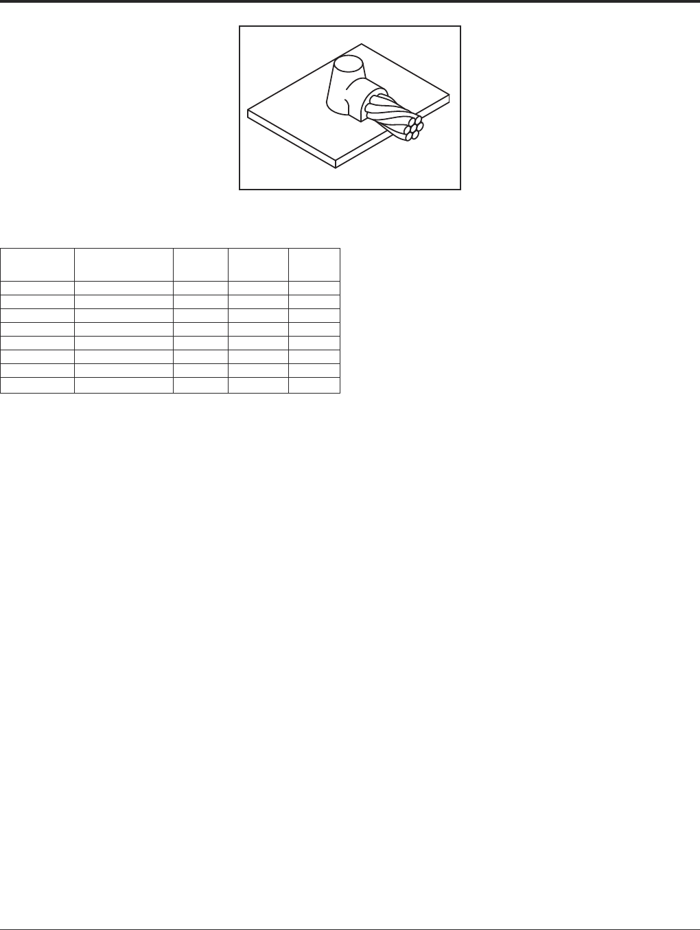
Grounding BURNDY®
BURNDYWeld®Exothermic
Canada: 1-800-387-6487 www.burndy.com US: 1-800-346-4175
90
TYPE BCS-5 MOLDS
Horizontal Cable Tap to
Horizontal Cast Iron Surface
Type BCS-5 Molds are used to join horizontal
cable taps to horizontal cast iron surfaces.
Note that the cable is ON the surface.
Size range is #6 through #1 solid or concen-
tric stranded copper conductors.
Contact BURNDY®for information on molds
for conductors not listed below.
Price Weld Handle
Cable Size Mold Number Key Metal Clamps
#6 Sol B-1613 3+ 2SCI N/A
#6 B-1614 3+ 25CI N/A
#4 Sol B-1615 3+ 45CI N/A
#4 B-1616 3+ 45CI N/A
#2 Sol B-1617 3+ 45CI N/A
#2 B-1618 3+ 45CI N/A
#1 Sol B-1619 3+ 65CI N/A
#1 B-1620 3+ 65CI N/A
• For sizes not listed, contact BURNDY®.
• Molds listed are for concentric stranded cable. Add suffix “-S” to mold number for solid
conductors.
• For heavy duty molds, molds with wear plates or molds for Copperweld®cable, contact
BURNDY®.
• For expedited service, contact BURNDY®.
Required Tools:
† Sold complete with frame
B38-0309-00 Flint Ignitor (included)
Other recommended accessories:
B38-3922-00 Mold Cleaning Brush (pg 101)
B38-0135-00 Cable Cleaning Brush (pg 101)
B38-0101-00 Rasp (pg 102)
DO NOT use Type BCS-5 molds on Soil Pipe (ASTM A74-82). A
test weld should be made on a section of the pipe being used to
determine the possibility of detrimental metallurgical effects.
For mold types or BURNDYWeld®items not shown, please contact factory.
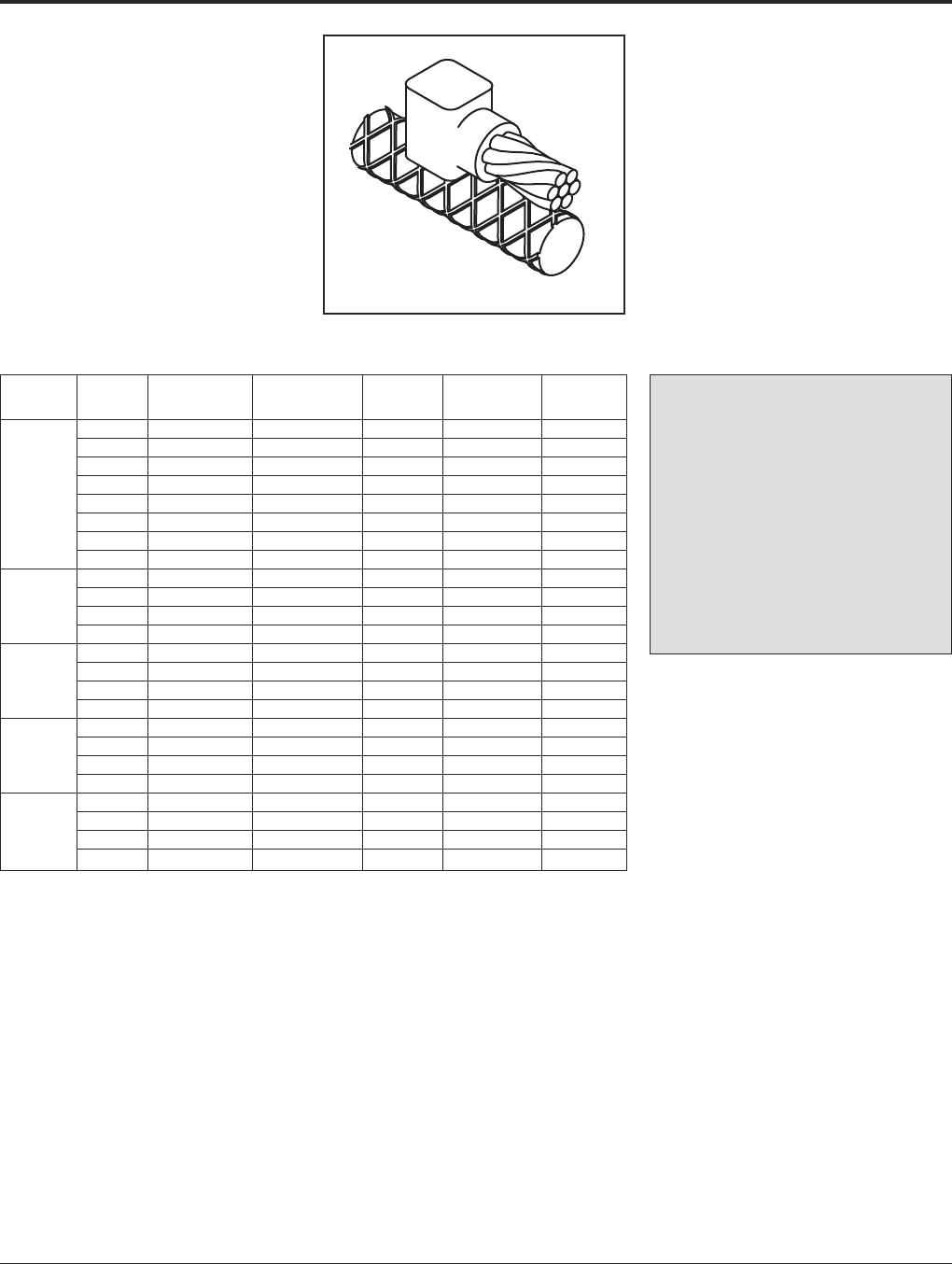
BURNDY®Grounding
BURNDYWeld®Exothermic
US: 1-800-346-4175 www.burndy.com Canada: 1-800-387-6487
91
For mold types or BURNDYWeld®items not shown, please contact factory.
TYPE BCRE-1 MOLDS
Horizontal Parallel Tap
to Rebar
Type BCRE-1 Molds are recommended for
parallel, horizontal connections for solid or
concentric stranded conductors #6 through
4/0 joined to reinforcing bars #3 through #6
and larger. The high copper content joint has
a higher current carrying capacity than the
conductors being joined and is impervious to
vibration and moisture.
Contact BURNDY®for information on molds
for conductors not listed below.
Rebar Cable Mold Packing Price Weld Handle
Size Size Number Material ‡ Key Metal Clamps
#6 B-7500 B38032900 4 25 B-106
#4 B-7501 B38032900 4 32 B-106
#2 B-7502 B38032900 4 45 B-106
#1 B-7503 B38032900 4 65 B-106
#3 1/0 B-7504 B38032900 4 90 B-106
2/0 B-7505 B38032900 4 90 B-106
3/0 B-7506 B38032900 4 115 B-106
4/0 B-7507 B38032900 4 115 B-106
#6 B-7508 B38406100 3+ 25 N/A
#4 #4 B-7509 B38406100 3+ 32 N/A
 B-7510 B38406100 3+ 45 N/A
Larger #1 B-7511 B38406100 3+ 65 N/A
1/0 B-7512 B38032900 4 90 B-106
2/0 B-7513 B38032900 4 90 B-106
#4 3/0 B-7514 B38032900 4 115 B-106
4/0 B-7515 B38032900 4 115 B-106
1/0 B-7520 B38032900 4 90 B-106
2/0 B-7521 B38032900 4 90 B-106
#5 3/0 B-7522 B38032900 4 115 B-106
4/0 B-7523 B38032900 4 115 B-106
1/0 B-7528 B38406200 14+ 90 N/A
#6 2/0 B-7529 B38406200 14+ 90 N/A
&3/0 B-7530 B38406200 14+ 115 N/A
Larger 4/0 B-7531 B38406200 14+ 115 N/A
• For sizes not listed, contact BURNDY®.
• Molds listed are for concentric stranded cable. Add suffix “-S” to mold number for solid
conductors.
• For heavy duty molds, molds with wear plates or molds for Copperweld®cable, contact
BURNDY®.
• For expedited service, contact BURNDY®.
Required Tools:
Handle Clamps (see chart for correct handles)
† Sold complete with frame
B38-0309-00 Flint Ignitor
Other recommended accessories:
B38-3922-00 Mold Cleaning Brush (pg 101)
B38-0135-00 Cable Cleaning Brush (pg 101)
B38-0304-00 File (pg 102)
‡ PACKING MATERIAL NOTE
A packing pad is necessary when mak-
ing BURNDYWeld®connections to rebar.
Packing material B38032900 is copper
shim stock. Packing material numbers
B38406100, B38406200 and B38406300
are a ceramic fiber material and can be
used for one connection only. Be sure to
specify packing material catalog number
when ordering mold and weld metal.
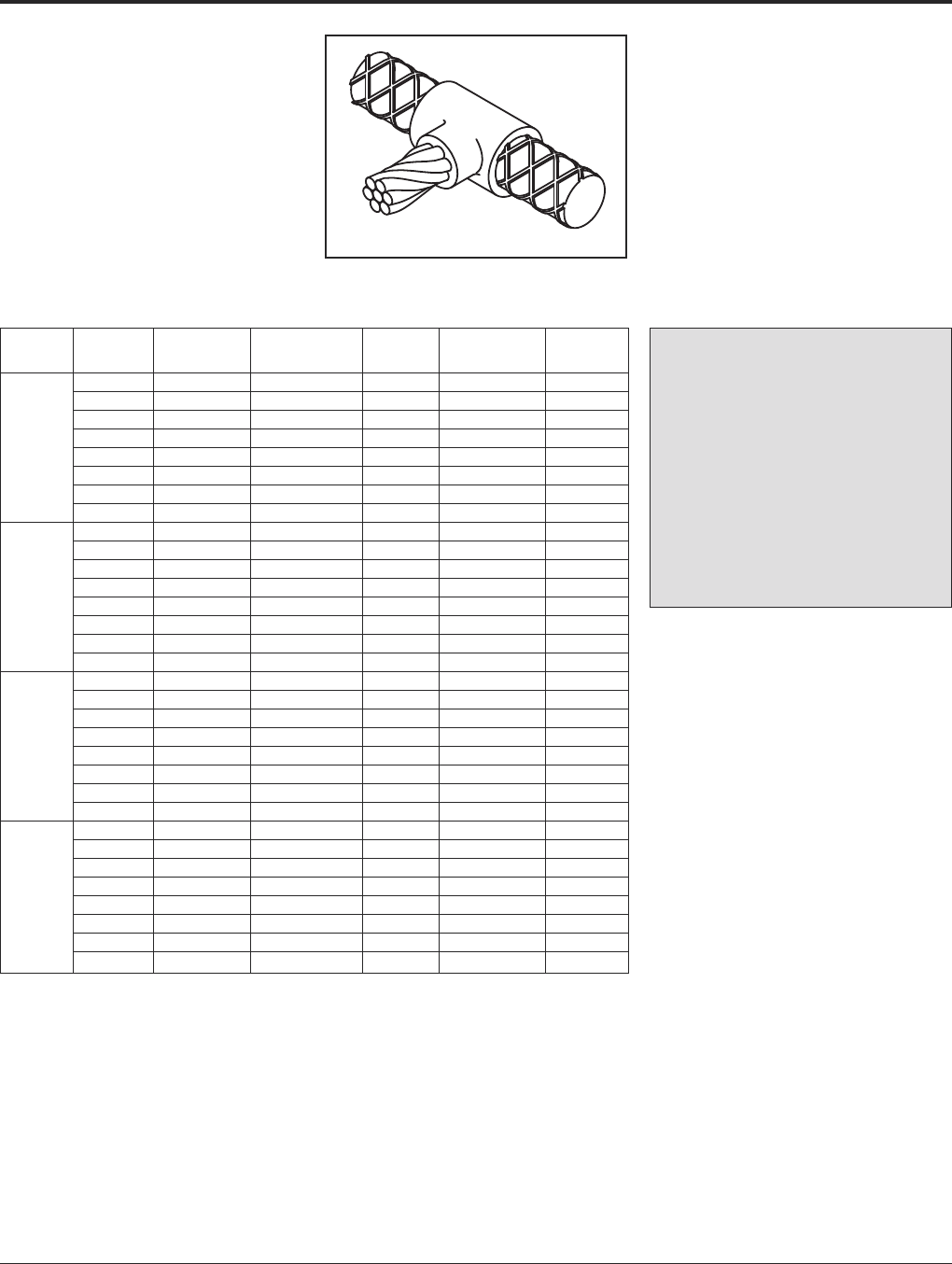
Grounding BURNDY®
BURNDYWeld®Exothermic
Canada: 1-800-387-6487 www.burndy.com US: 1-800-346-4175
92
TYPE BCRE-2 MOLDS
Horizontal Cable Tap to
Horizontal Rebar Run
Type BCRE-2 Molds are recommended for
right angle, horizontal connections for solid or
concentric stranded conductors #6 through
4/0 joined to reinforcing bars #3 through #6.
The high copper content joint has a higher
current carrying capacity than the conductors
being joined and is impervious to vibration
and moisture.
Rebar Cable Mold Packing Price Weld Handle
Size Size Number Material ‡ Key Metal Clamps
#6 B-7588 B38032900 4 45 B-106
#4 B-7589 B38032900 4 45 B-106
#2 B-7590 B38032900 4 65 B-106
#1 B-7591 B38032900 4 65 B-106
#3 1/0 B-7592 B38032900 4 90 B-106
2/0 B-7593 B38032900 4 90 B-106
3/0 B-7594 B38032900 4 115 B-106
4/0 B-7595 B38032900 4 115 B-106
#6 B-7596 B38032900 4 45 B-106
#4 B-7597 B38032900 4 45 B-106
#2 B-7598 B38032900 4 65 B-106
#1 B-7599 B38032900 4 65 B-106
#4 1/0 B-7600 B38032900 4 90 B-106
2/0 B-7601 B38032900 4 90 B-106
3/0 B-7602 B38032900 4 115 B-106
4/0 B-7603 B38032900 4 115 B-106
#6 B-7604 B38032900 4 90 B-106
#4 B-7605 B38032900 4 90 B-106
#2 B-7606 B38032900 4 90 B-106
#1 B-7607 B38032900 4 90 B-106
#5 1/0 B-7608 B38032900 4 115 B-106
2/0 B-7609 B38032900 4 115 B-106
3/0 B-7610 B38032900 4 150 B-106
4/0 B-7611 B38032900 4 150 B-106
#6 B-7612 B38032900 4 90 B-106
#4 B-7613 B38032900 4 90 B-106
#2 B-7614 B38032900 4 90 B-106
#1 B-7615 B38032900 4 90 B-106
#6 1/0 B-7616 B38032900 4 115 B-106
2/0 B-7617 B38032900 4 115 B-106
3/0 B-7618 B38032900 4 150 B-106
4/0 B-7619 B38032900 4 150 B-106
• For sizes not listed, contact BURNDY®.
• Molds listed are for concentric stranded cable. Add suffix
“-S” to mold number for solid conductors.
• For heavy duty molds, molds with wear plates or molds for
Copperweld®cable, contact BURNDY®.
• For expedited service, contact BURNDY®.
Required Tools:
Handle Clamps (see chart for correct handles)
B38-0309-00 Flint Ignitor
‡ PACKING MATERIAL NOTE
A packing pad is necessary when mak-
ing BURNDYWeld®connections to rebar.
Packing material B38032900 is copper
shim stock. Packing material numbers
B38406100, B38406200 and B38406300
are a ceramic fiber material and can be
used for one connection only. Be sure to
specify packing material catalog number
when ordering mold and weld metal.
For mold types or BURNDYWeld®items not shown, please contact factory.
Contact BURNDY®for information on molds
for conductors not listed below.
Other recommended accessories
B40-0319-01 Mold Cleaner for cartridge sizes #15-#65 (pg
101)
B40-0319-03 Mold Cleaner for cartridge sizes #90-#500
(pg 101)
B38-3922-00 Mold Cleaning Brush (pg 101)
B38-0135-00 Cable Cleaning Brush (pg 101)
B38-0304-00 File (pg 102)
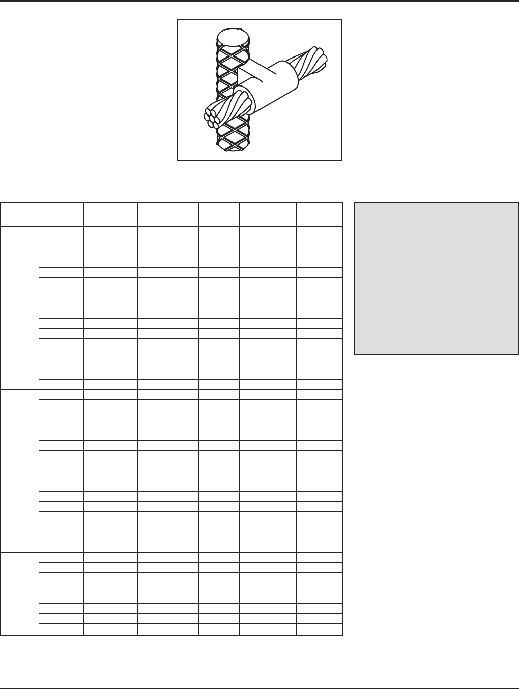
BURNDY®Grounding
BURNDYWeld®Exothermic
US: 1-800-346-4175 www.burndy.com Canada: 1-800-387-6487
93
TYPE BCRE-3 MOLDS
Horizontal through Cable to
Vertical Rebar
Type BCRE-3 Molds are recommended for
horizontal conductors to vertical rebar con-
nections for solid or concentric stranded con-
ductors #6 through 4/0 joined to reinforcing
bars #3 through #7 & larger. The high copper
content joint has a higher current carrying ca-
pacity than the conductors being joined and
is impervious to vibration and moisture.
Contact BURNDY®for information on molds
for conductors not listed below.
Rebar Cable Mold Packing Price Weld Handle
Size Size Number Material ‡ Key Metal Clamps
#6 B-7620 B38032900 24 90 B-106
#4 B-7621 B38032900 24 90 B-106
#2 B-7622 B38032900 24 90 B-106
#1 B-7623 B38032900 24 115 B-106
#3 1/0 B-7624 B38032900 24 115 B-106
2/0 B-7625 B38032900 24 115 B-106
3/0 B-7626 B38032900 24 150 B-106
4/0 B-7627 B38032900 24 150 B-106
#6 B-7628 B38032900 24 90 B-106
#4 B-7629 B38032900 24 90 B-106
#2 B-7630 B38032900 24 90 B-106
#1 B-7631 B38032900 24 115 B-106
#4 1/0 B-7632 B38032900 24 115 B-106
2/0 B-7633 B38032900 24 115 B-106
3/0 B-7634 B38032900 24 150 B-106
4/0 B-7635 B38032900 24 150 B-106
#6 B-7636 B38032900 24 90 B-106
#4 B-7637 B38032900 24 90 B-106
#2 B-7638 B38032900 24 90 B-106
#1 B-7639 B38032900 24 115 B-106
#5 1/0 B-7640 B38032900 24 115 B-106
2/0 B-7641 B38032900 24 115 B-106v
3/0 B-7642 B38032900 24 150 B-106
4/0 B-7643 B38032900 24 150 B-106
#6 B-7644 B38032900 24 90 B-106
#4 B-7645 B38032900 24 90 B-106
#2 B-7646 B38032900 24 90 B-106
#1 B-7647 B38032900 24 115 B-106
#6 1/0 B-7648 B38032900 24 115 B-106
2/0 B-7649 B38032900 24 115 B-106
3/0 B-7650 B38032900 24 150 B-106
4/0 B-7651 B38032900 24 150 B-106
#6 B-7652 B38406300 4+ 90 B-106-41
#4 B-7653 B38406300 4+ 90 B-106-41
#2 B-7654 B38406300 4+ 90 B-106-41
#7 #1 B-7655 B38406300 4+ 115 B-106-41
&1/0 B-7656 B38406300 4+ 115 B-106-41
Larger 2/0 B-7657 B38406300 4+ 115 B-106-41
3/0 B-7658 B38406300 4+ 150 B-106-41
4/0 B-7659 B38406300 4+ 150 B-106-41
• For sizes not listed, contact BURNDY®.
• Molds listed are for concentric stranded cable. Add suffix
“-S” to mold number for solid conductors.
• For heavy duty molds, molds with wear plates or molds for
Copperweld®cable, contact BURNDY®.
• For expedited service, contact BURNDY®.
Required Tools:
Handle Clamps (see chart for correct handles)
B38-0309-00 Flint Ignitor
Other recommended accessories:
Vertical Chain Clamps
† B40-0319-03 Mold Cleaner for cartridge sizes #90-
#500 (pg 101)
B38-3922-00 Mold Cleaning Brush (pg 101)
B38-0135-00 Cable Cleaning Brush (pg 101)
B38-0304-00 File (pg 102)
‡ PACKING MATERIAL NOTE
A packing pad is necessary when mak-
ing BURNDYWeld®connections to rebar.
Packing material B38032900 is copper
shim stock. Packing material numbers
B38406100, B38406200 and B38406300
are a ceramic fiber material and can be
used for one connection only. Be sure to
specify packing material catalog number
when ordering mold and weld metal.
For mold types or BURNDYWeld®items not shown, please contact factory.
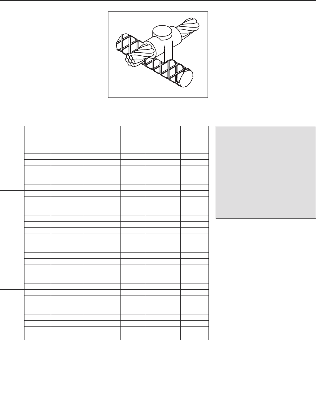
Grounding BURNDY®
BURNDYWeld®Exothermic
Canada: 1-800-387-6487 www.burndy.com US: 1-800-346-4175
94
TYPE BCRE-4 MOLDS
Horizontal through Cable to
Horizontal Rebar
Type BCRE-4 Molds are recommended for
horizontal through conductors to horizontal
rebar at right angle connections for solid or
concentric stranded conductors #6 through
4/0 joined to reinforcing bars #3 through #6 &
larger. The high copper content joint has a
higher current carrying capacity than the con-
ductors being joined and is impervious to vi-
bration and moisture.
Contact BURNDY®for information on molds
for conductors not listed below.
Rebar Cable Mold Packing Price Weld Handle
Size Size Number Material ‡ Key Metal Clamps
#6 B-7708 B38032900 4 90 B-106
#4 B-7709 B38032900 4 90 B-106
#2 B-7710 B38032900 4 90 B-106
#1 B-7711 B38032900 4 115 B-106
#3 1/0 B-7712 B38032900 22 115 B-106
2/0 B-7713 B38032900 22 115 B-106
3/0 B-7714 B38032900 22 150 B-106
4/0 B-7715 B38032900 22 150 B-106
#6 B-7716 B38032900 4 90 B-106
#4 B-7717 B38032900 4 90 B-106
#2 B-7718 B38032900 4 90 B-106
#1 B-7719 B38032900 22 115 B-106
#4 1/0 B-7720 B38032900 22 115 B-106
2/0 B-7721 B38032900 22 115 B-106
3/0 B-7722 B38032900 22 150 B-106
4/0 B-7723 B38032900 22 150 B-106
#6 B-7724 B38032900 4 90 B-106
#4 B-7725 B38032900 4 90 B-106
#2 B-7726 B38032900 4 90 B-106
#1 B-7727 B38032900 22 115 B-106
#5 1/0 B-7728 B38032900 22 115 B-106
2/0 B-7729 B38032900 22 115 B-106
3/0 B-7730 B38032900 22 150 B-106
4/0 B-7731 B38032900 22 150 B-106
#6 B-7732 B38406100 14+ 90 N/A
#4 B-7733 B38406100 14+ 90 N/A
#2 B-7734 B38406100 14+ 90 N/A
#6 #1 B-7735 B38406100 14+ 115 N/A
&1/0 B-7736 B38406200 14+ 115 N/A
Larger 2/0 B-7737 B38406200 14+ 115 N/A
3/0 B-7738 B38406200 14+ 150 N/A
4/0 B-7739 B38406200 14+ 150 N/A
• For sizes not listed, contact BURNDY®.
• Molds listed are for concentric stranded cable. Add suffix
“-S” to mold number for solid conductors.
• For heavy duty molds, molds with wear plates or molds for
Copperweld®cable, contact BURNDY®.
• For expedited service, contact BURNDY®.
Required Tools:
Handle Clamps (see chart for correct handles)
† Sold complete with frame
B38-0309-00 Flint Ignitor
‡ PACKING MATERIAL NOTE
A packing pad is necessary when mak-
ing BURNDYWeld®connections to rebar.
Packing material B38032900 is copper
shim stock. Packing material numbers
B38406100, B38406200 and B38406300
are a ceramic fiber material and can be
used for one connection only. Be sure to
specify packing material catalog number
when ordering mold and weld metal.
For mold types or BURNDYWeld®items not shown, please contact factory.
Other recommended accessories:
B40-0319-03 Mold Cleaner for cartridge sizes #90-#500
(pg 101)
B38-3922-00 Mold Cleaning Brush (pg 101)
B38-0135-00 Cable Cleaning Brush (pg 101)
B38-0304-00 File (pg 102)

BURNDY®Grounding
BURNDYWeld®Exothermic
US: 1-800-346-4175 www.burndy.com Canada: 1-800-387-6487
95
For mold types or BURNDYWeld®items not shown, please contact factory.
TYPE BCRE-6 MOLDS
Horizontal Cable Tap to
Vertical Rebar
Type BCRE-6 Molds are recommended for
horizontal conductors terminating at right
angles to vertical rebar connections for solid
or concentric stranded conductors #6 through
4/0 joined to reinforcing bars #3 through #7
and larger. The high copper content joint has
a higher current carrying capacity than the
conductors being joined and is impervious to
vibration and moisture.
Contact BURNDY®for information on molds
for conductors not listed below.
Rebar Cable Mold Packing Price Weld Handle
Size Size Number Material ‡ Key Metal Clamps
#6 B-7884 B38032900 4 90 B-106
#4 B-7885 B38032900 4 90 B-106
#2 B-7886 B38032900 4 90 B-106
#1 B-7887 B38032900 4 115 B-106
#3 1/0 B-7888 B38032900 4 115 B-106
2/0 B-7889 B38032900 4 115 B-106
3/0 B-7890 B38032900 4 150 B-106
4/0 B-7891 B38032900 4 150 B-106
#6 B-7892 B38032900 4 90 B-106
#4 B-7893 B38032900 4 90 B-106
#2 B-7894 B38032900 4 90 B-106
#1 B-7895 B38032900 4 115 B-106
#4 1/0 B-7896 B38032900 4 115 B-106
2/0 B-7897 B38032900 4 115 B-106
3/0 B-7898 B38032900 4 150 B-106
4/0 B-7899 B38032900 4 150 B-106
#6 B-7900 B38032900 4 90 B-106
#4 B-7901 B38032900 4 90 B-106
#2 B-7902 B38032900 4 90 B-106
#1 B-7903 B38032900 4 115 B-106
#5 1/0 B-7904 B38032900 4 115 B-106
2/0 B-7905 B38032900 4 115 B-106
3/0 B-7906 B38032900 4 150 B-106
4/0 B-7907 B38032900 4 150 B-106
#6 B-7908 B38032900 4 90 B-106
#4 B-7909 B38032900 4 90 B-106
#2 B-7910 B38032900 4 90 B-106
#1 B-7911 B38032900 4 115 B-106
#6 1/0 B-7912 B38032900 4 115 B-106
2/0 B-7913 B38032900 4 115 B-106
3/0 B-7914 B38032900 4 150 B-106
4/0 B-7915 B38032900 4 150 B-106
#6 B-7916 B38406300 4 90 B-106-32
#4 B-7917 B38406300 4 90 B-106-32
#2 B-7918 B38406300 4 90 B-106-32
#7 #1 B-7919 B38406300 4 115 B-106-32
&1/0 B-7920 B38406300 4 115 B-106-32
Larger 2/0 B-7921 B38406300 4 115 B-106-32
3/0 B-7922 B38406300 4 150 B-106-32
4/0 B-7923 B38406300 4 150 B-106-32
• For sizes not listed, contact BURNDY®.
• Molds listed are for concentric stranded cable. Add suffix
“-S” to mold number for solid conductors.
• For heavy duty molds, molds with wear plates or molds for
Copperweld®cable, contact BURNDY®.
• For expedited service, contact BURNDY®.
Required Tools:
Handle Clamps (see chart for correct handles)
B38-0309-00 Flint Ignitor
Other recommended accessories:
B38-3922-00 Mold Cleaning Brush (pg 101)
B38-0135-00 Cable Cleaning Brush (pg 101)
B38-0304-00 File (pg 102)
‡ PACKING MATERIAL NOTE
A packing pad is necessary when mak-
ing BURNDYWeld®connections to rebar.
Packing material B38032900 is copper
shim stock. Packing material numbers
B38406100, B38406200 and B38406300
are a ceramic fiber material and can be
used for one connection only. Be sure to
specify packing material catalog number
when ordering mold and weld metal.
*The B106-32 comes complete with a B-106 handle clamp
and B40-0106-76 vertical chain clamp. Although good for use
on all sizes of rebar, vertical chain clamps are strongly rec-
ommended on large size rebar as they hold the mold to the
rebar securely. If you already have a B-106 handle clamp, you
can purchase the vertical chain clamps separately. See page
E-91 for a variety of options.

Grounding BURNDY®
BURNDYWeld®Exothermic
Canada: 1-800-387-6487 www.burndy.com US: 1-800-346-4175
96
For mold types or BURNDYWeld®items not shown, please contact factory.
BURNDY®
GROUNDMAX™
BURNDY®GROUNDMAX™ is an economical
solution for areas with very difficult grounding
issues. BURNDY®GROUNDMAX™ is highly
conductive in a wet or dry application and
does not require moisture to lower the resist-
ance of your grounding system. BURNDY®
GROUNDMAX™ contains a corrosion in-
hibitor which forms a film on copper, creating
a barrier against corrosion.
BURNDY®GROUNDMAX™ can be poured in
dry or pumped in slurry form. No tamping
required. It is very contractor friendly. No
special tools required.
BURNDY®GROUNDMAX™
Advantages:
• Easy to install.
• Electrically conductive.
• Environmentally friendly.
• Will not leach into the ground.
• Positive low resistance, electrical
connection to earth.
• Does not contain any hazardous chemicals.
• Compatible with all copper grounding
systems.
• Contains a corrosion inhibitor to protect
copper.
• Will not expand or shrink.
• Not affected by freezing.
• Excellent shelf life.
• Typical resistivity <10 Ohm-cm
Material Required Per Linear Foot of Trench
Width of Trench (Inches)
4 6 8 10 12 14 16 18 20 22 24
24.1 6.2 8.1 10.1 12.1 14.1 16.2 18.2 20.2 22.2 24.2
36.2 9.3 12.1 15.2 18.2 21.2 24.2 27.3 30.3 33.3 36.4
48.2 12.3 16.2 20.2 24.2 28.3 32.3 36.4 40.4 44.5 48.5
510.3 15.4 20.2 25.3 30.3 35.4 40.4 45.5 50.5 55.6 60.6
612.3 18.5 24.2 30.3 36.4 42.4 48.5 54.6 60.6 66.7 72.7
714.4 21.6 28.3 35.4 42.4 49.5 56.6 63.7 70.7 77.8 84.9
816.4 24.7 32.3 40.4 48.5 56.0 64.7 72.7 80.8 88.9 97.0
918.5 27.8 36.4 45.5 54.6 63.7 72.7 81.8 90.9 100.0 109.1
10 20.6 30.8 40.4 50.5 60.6 70.7 80.8 90.9 101.0 111.1 121.2
Thickness of
BURNDY®GROUNDMAX™
(Inches)
To calculate the lbs. of material required to fill a trench:
• Determine desired thickness.
• Move to the right until you are under the known width of the trench. This number will be the
weight of the material in lbs./linear ft.
• Take this number and multiply by the length of the trench in feet. Your answer will be the amount
of BURNDY®GROUNDMAX™ material required to fill the trench to the desired level in lbs.
Example:
Thickness: = 6 inches
Width = 18 inches
54.6 lbs. per linear ft. (from the table above)
Answer = 54.6 lbs. per linear ft. x 25 ft. trench = 1,365 lbs. of BURNDY®
GROUNDMAX™
= 28 (50 lb.) bags of BURNDY®GROUNDMAX™
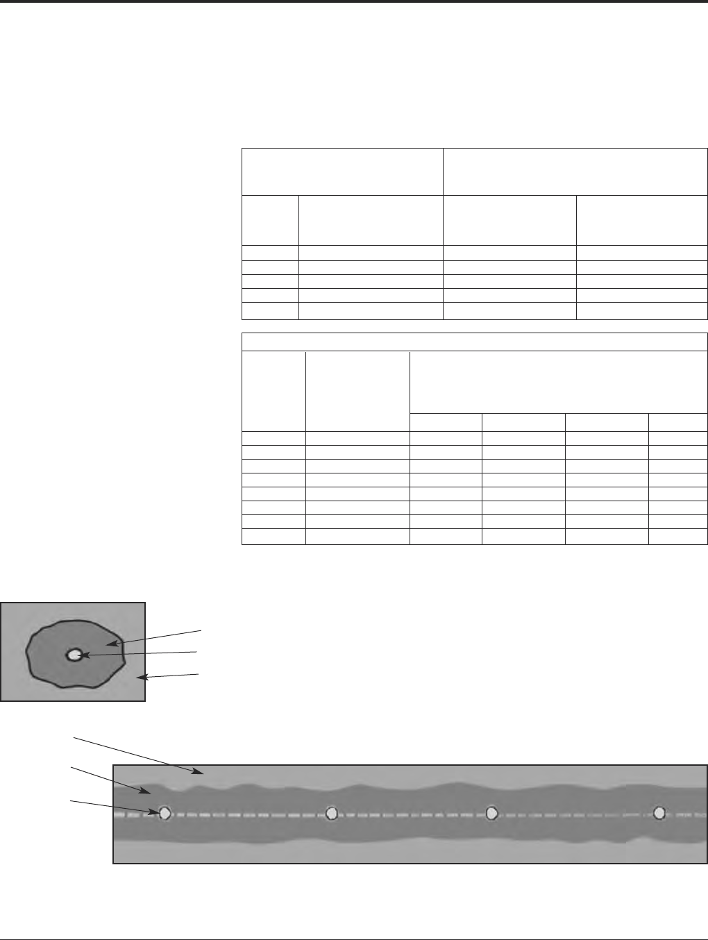
BURNDY®Grounding
BURNDYWeld®Exothermic
US: 1-800-346-4175 www.burndy.com Canada: 1-800-387-6487
97
BURNDY®
GROUNDMAX™
Application Information
Vertical Installation
Drill or bore a hole the desired diameter and
depth. Suspend ground electrode in center of
hole to be filled. Pour BURNDY®GROUND-
MAX™ until desired level is obtained. No
tamping is required.
Dry Volume of Ground Resistance
BURNDY®GROUNDMAX™ Comparison of
vs. Hole Size Bare Rod vs.
Lbs. of Hole Size with Percent Resistance
Hole BURNDY®GROUNDMAX™ 5/8x 10Rod in Compared to Rod
Size Per Ft. Center of 15Hole Only (100%)
46.5 452%
614.5 647%
825.8 844%
1040.4 1042%
1258.1 1240%
Steady State Leakage Resistance‡ Using 4/0 Copper Wire vs. BURNDY®GROUNDMAX™
Percentage of Resistance with .475
Wire Plus BURNDY®GROUNDMAX™ in
Various Diameters Compared
.475Diameter to Wire Only (100%)
Length Wire Only 2346
25100% 83% 78% 74% 69%
50100% 85% 81% 77% 73%
75100% 86% 82% 79% 75%
100100% 87% 83% 80% 77%
150100% 88% 84% 82% 78%
200100% 88% 85% 83% 79%
250100% 89% 85% 83% 80%
300100% 89% 86% 84% 80%
Horizontal or Grid
Construction†
Pour into horizontal trench until level of
ground wire is reached. Place ground wire.
Pour in additional BURNDY®GROUND-
MAX™ until wire is covered to desired height.
Cover with fill. No tamping required.
For grid construction, pour BURNDY®
GROUNDMAX™ and spread over ground grid
until desired thickness is achieved. Cover with
fill.
† Entire grounding system should be surrounded by
BURNDY®GROUNDMAX™. Conductors should
be insulated as they exit BURNDY®GROUND-
MAX™ column.
‡ The use of BURNDY®GROUNDMAX™ around
the grounding system will also reduce surge im-
pedance by increasing the effective contact area
of the electrode to soil.
Horizontal Construction
BURNDY®GROUNDMAX™
Copper Wire
Earth or Fill
Earth or Fill
BURNDY®
GROUNDMAX™
Copper Wire
Grid Construction
For mold types or BURNDYWeld®items not shown, please contact factory.
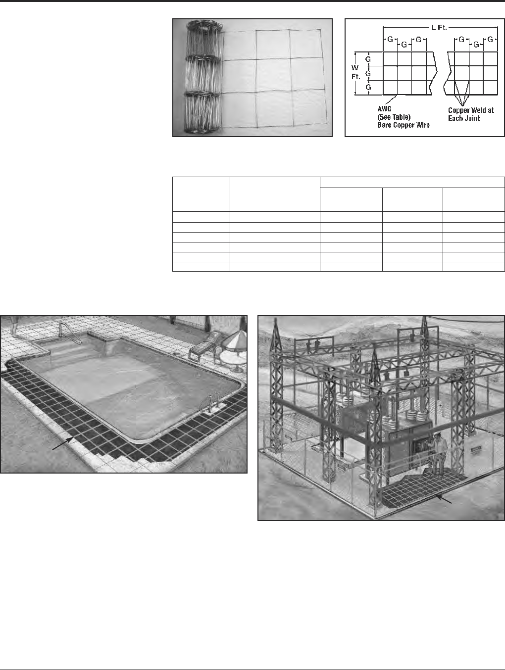
Grounding BURNDY®
BURNDYWeld®Exothermic
Canada: 1-800-387-6487 www.burndy.com US: 1-800-346-4175
98
BURNDY®GRIDMAX™
PREFABRICATED WIRE MESH
Grounding, Personnel Safety
Mats, Equipotential Bonding,
Pool and Spa Grounding
Features and Benefits
• Manufactured from bare solid copper.
• Spaced on 4, 6or 12centers.
• Copper to copper weld with 6% silver.
• Furnished in sections with lengths from 4
to 100.
• Easily and economically installed using
BURNDYWeld®HYGROUND®or our
Mechanical connectors.
• Sizes made specifically for the Pool and
Spa market 3100and 350. But
can be used where any large area grounds
are required.
Dimensions
Catalog G L W
Number Conductor (spacing) (length) (width)
BGM3100 8 AWG 121003
BGM3050 8 AWG 12503
BGM640044 6 AWG 444
BGM640068 6 AWG 864
BGM64006 6 AWG 1264
BGM640066 6 AWG 664
Example:
GRIDMAX™
3wide in pool area
GRIDMAX™
Personnel Safety Mat
For mold types or BURNDYWeld®items not shown, please contact factory.
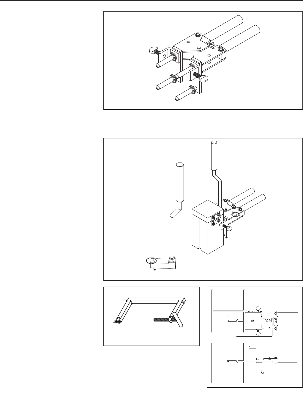
BURNDY®Grounding
BURNDYWeld®Exothermic
US: 1-800-346-4175 www.burndy.com Canada: 1-800-387-6487
99
B-106 & B-107
HANDLE CLAMPS
BURNDYWeld®Handle Clamps make possi-
ble the use of many different sizes and types
of molds with only two different clamps. The
two handle clamps are catalog numbers
B-106 and B-107. These will fit 95% of all
standard BURNDYWeld®molds.
1. Use B-106 clamps for all molds having a
price key 4, 7, 17, 22 or 24. These molds
are a nominal 3 1/83 1/8square.
2 Use B-107 clamps for all molds having a
price key 5, 6, 8 or 23. These molds are a
nominal 44square.
3. All molds having a price key 2, 3, 9, 10, 11,
12, 14, 15 or 16 have an attached frame;
separate handles are not required.
B40-0106-75 HANDLE
ATTACHMENT
This Handle Attachment is used to hold Price
Key-14 molds in position. It easily attaches to
the B-106 Handle Clamp. This Handle
Attachment can be used with weld types
BCRE-1 and BCRE-4.
Catalog Number B40-0106-75
MOLD SUPPORT
CLAMP
The Mold Support Clamp is used to hold a
mold in position on a vertical steel column or
angle. It is easily attached to the Handle
Clamps. The Mold Support Clamp can be
used with weld types BCS-3, BCS-18,
BCS-23 and BCS-27.
Catalog Number B40-3657-00
B40-0106-75
B40-0106-75 Shown Attached
to B-106 Handle Clamps
For mold types or BURNDYWeld®items not shown, please contact factory.
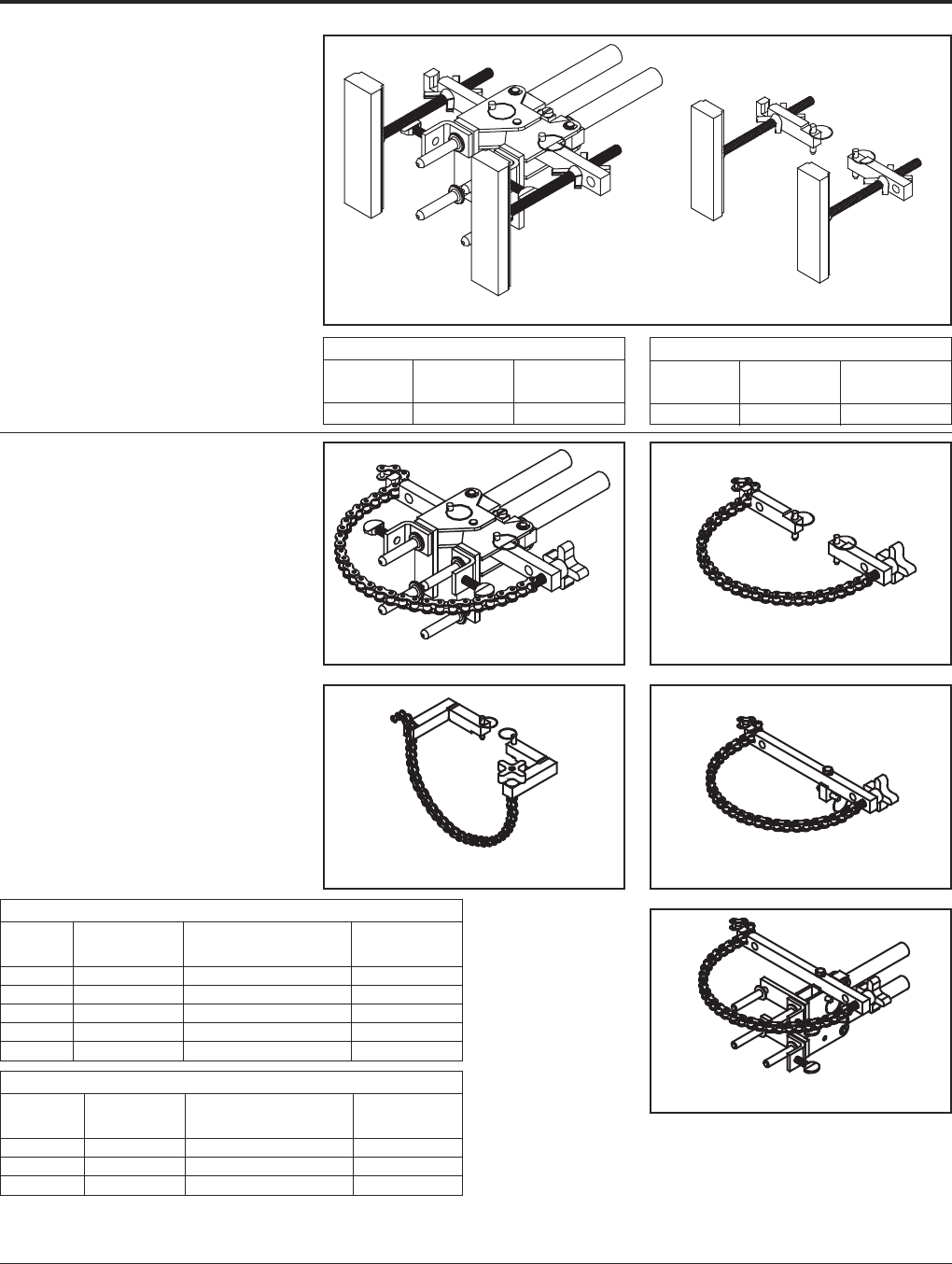
Grounding BURNDY®
BURNDYWeld®Exothermic
Canada: 1-800-387-6487 www.burndy.com US: 1-800-346-4175
100
Chain Clamp Only (Handle Clamps Not Included)
Catalog Fits Handle For Use With
Number Clamp Weld Types Pipe Position
B40-0106-76 B-106 & B-107 BCS-3, 4, 7, 23 & BCRE-6 Vertical
B40-0106-78 B-106 & B-107 BCS-1, 2, 5, 8 & 9 Horizontal
B40-0106-77 B-106 & B-107 BCS-6, 18 & BCRE-3 Vertical
VERTICAL MAGNETIC
CLAMPS
Magnetic Clamps are used to hold a mold in
position on a vertical steel surface. The mag-
netic clamp can be purchased complete with
B-106 Handle Clamps or if you already have a
set of handle clamps, you can order just the
magnetic mounting assembly. The mounting
assembly can easily be mounted on the
prongs of your existing B-106 handle clamps.
A minimum of 10is required.
Magnetic Clamps With B106 Handle
Catalog Fits Molds For Use With
Number W/Price Key Weld Types
B404431-00 4 & 17 BCS-3, 4, 7 & 23
Chain Clamps
Catalog Fits Molds For Use With
Number W/Price Key Weld Types Pipe Position
B106-32 4, 17, 22 & 24 BCS-3, 4, 7, 23 & BCRE-6 Vertical
B107-32 5, 6 & 23 BCS-3, 4, 7 & 23 Vertical
B106-37 4, 17, 22 & 24 BCS-1, 2, 5, 8 & 9 Horizontal
B107-37 5, 6 & 23 BCS-1, 2, 5, 8 & 9 Horizontal
B106-41 4, 17 BCS-6, 18 & BCRE-3 Vertical
HORIZONTAL &
VERTICAL
CHAIN CLAMPS
Chain Clamps are used to hold a mold in posi-
tion on horizontal or vertical pipe up to 4in
diameter. For larger pipe a 20chain extension
is available to allow the chain clamps to be
used on pipe up to 10in diameter. The chain
clamp can be purchased complete with B-106
or B-107 Handle Clamps or if you already have
a set of handle clamps, you can order just the
chain clamp and mounting assembly. The
mounting assembly can easily attached to your
existing handle clamps. 20Chain Extension
catalog number: B40-0106-27.
B40-4431-00 B40-4431-01
Magnetic Clamp Only
Catalog Fits Handle For Use With
Number Clamps Weld Types
B40-4431-01 B-106 & B-107 BCS-3, 4, 7 & 23
B106-32/B107-32 B40-0106-76
B40-0106-78 B40-0106-77
B106-41/B107-41
For mold types or BURNDYWeld®items not shown, please contact factory.
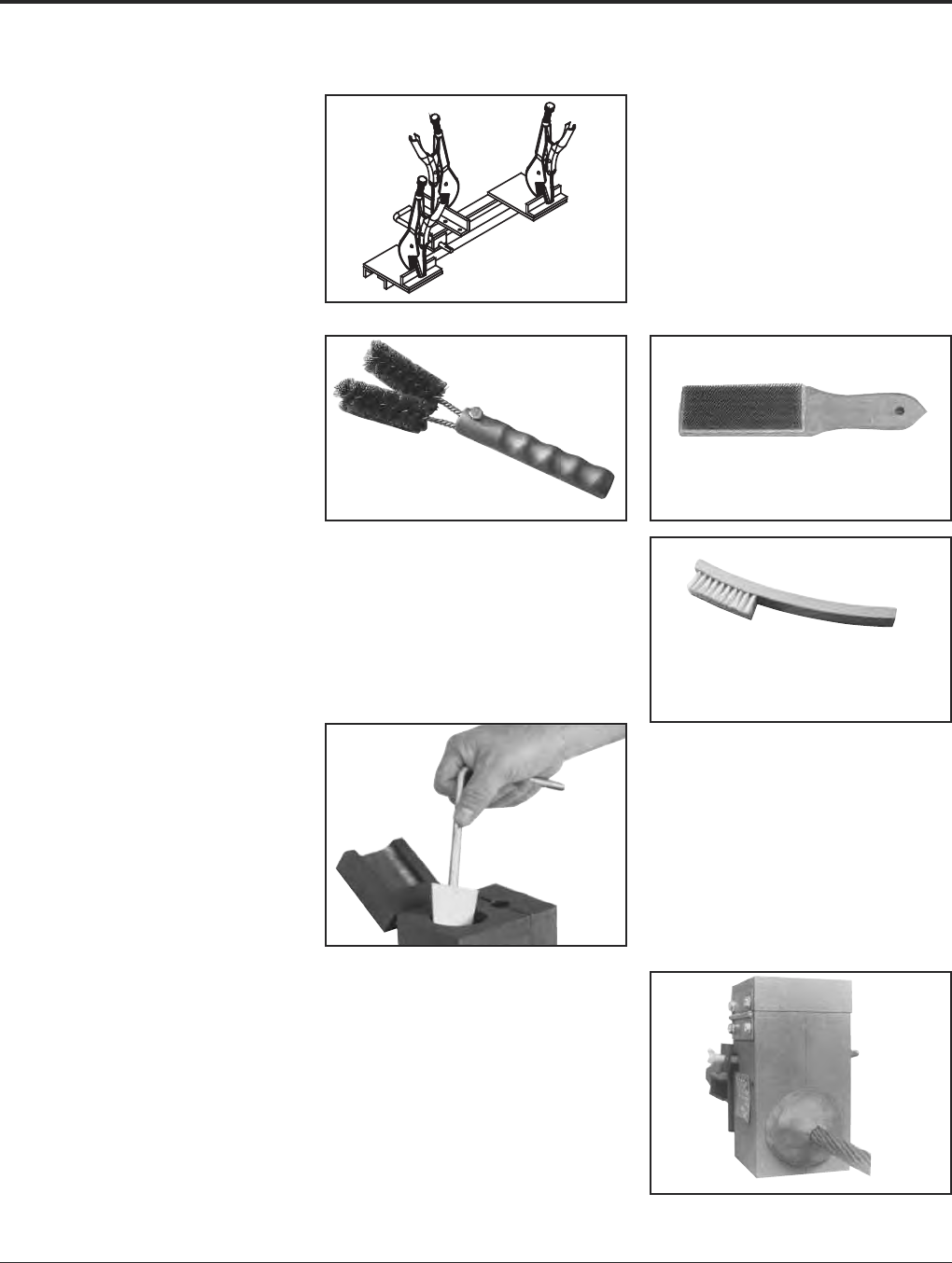
BURNDY®Grounding
BURNDYWeld®Exothermic
US: 1-800-346-4175 www.burndy.com Canada: 1-800-387-6487
101
BURNDYWeld®ACCESSORIES
CABLE CLEANING AND CARD
CLOTH BRUSH
The Cable Cleaning Brush is recommended
for cleaning heavily oxidized cables. The
V-shape brushes permit their use over a wide
range of cable sizes. Brush assembly consists
of a handle with two stiff wire bristle brushes
that are rotatable, for longer life and are re-
placeable.
The Card Cloth Brush is used for cleaning
large conductors and bus bar. It has short stiff
bristles. These brushes are for cleaning cable
only, not molds.
The Mold Cleaning Brush B38-3922-00 is
used to clean the graphite mold without
scratching the mold.
MOLD CLEANERS
Mold Cleaners are used to clean the slag from
molds that are not split through the crucible.
B40-0319-01 for cartridge sizes #15
through #65
B40-0319-03 for cartridge sizes #90
through #500
B38-0330-00 CABLE CLAMP
The BURNDYWeld®Cable Clamp is recom-
mended for holding a wide range of cables
properly in place in molds when welding
cables that are under tension. This prevents
the cables from pulling out of the mold when
the weld is made.
B38-0135-00 B38-0306-00
B38-3922-00
PACKING MATERIAL
Packing material is used to prevent the
molten weld metal from leaking out of the
mold. When the cable opening becomes worn
from heavy use, the packing material may be
used to prolong mold use. It is also used
around 7 strand cable to prevent leaking.
Packing material comes in a 1 lb. or 5 lb.
package.
Catalog Number Description
B38412900 1 lb. package
B38412905 5 lb. package
Cable Cleaning Brush B38-0135-00
Replacement Brush B38-0135-01
Card Cloth Brush B38-0306-00
Mold Cleaning Brush B38-3922-00
For mold types or BURNDYWeld®items not shown, please contact factory.
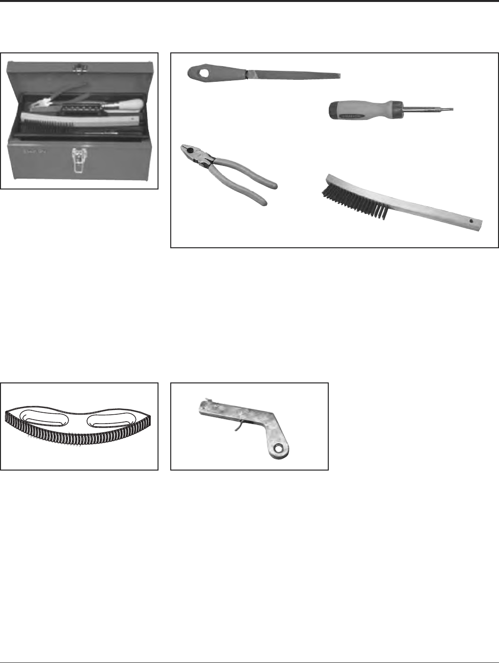
Grounding BURNDY®
BURNDYWeld®Exothermic
Canada: 1-800-387-6487 www.burndy.com US: 1-800-346-4175
102
BURNDYWeld®ACCESSORIES
BURNDYWeld®TOOL KIT
B38-0302-00 Tool Kit with Tools Shown
except Rasp
B38-0302-02 Tool Kit with Tools Shown
and Rasp
B38-0303-00 Tool Box only
B38-0309-00 FLINT IGNITOR
The B38-0309-00 Flint Ignitor is used to ignite
the starting powder. Each mold that is sold
with a frame has a Flint Ignitor included. For
added safety a Flint Ignitor extension is avail-
able, catalog number B38-0904-00, that at-
taches to the B38-0309-00 Flint Ignitor. This
allows installers to stay approximately 36
away from the mold.
To order replacement flints, specify part
number B38-0309-01.
BURNDYWeld®TOOLS
B38-0309-00 Flint Ignitor
B38-0304-00 8File
B38-0307-00 Crimping Tool
B38-3922-00 Mold Cleaning Brush
B38-0308-00 6Screwdriver
B38-0305-00 Wire Brush
B38-0101-00 Rasp
B38-0306-00 Card Cloth Brush
B38-0101-00 RASP
This tempered steel, curved rasp is recom-
mended for removing rust and mill scale from
steel and cast iron surfaces. The blade is re-
placeable. To order replacement rasp blade,
specify catalog number B38-0101-01.
Not recommended for use on galvanized
surfaces.
For mold types or BURNDYWeld®items not shown, please contact factory.
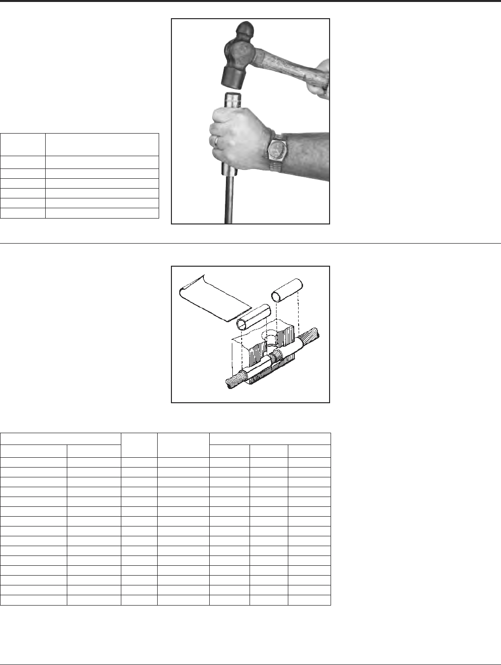
BURNDY®Grounding
BURNDYWeld®Exothermic
US: 1-800-346-4175 www.burndy.com Canada: 1-800-387-6487
103
GROUND ROD
DRIVING SLEEVES
Ground Rod Driving Sleeves are placed over
the top of a ground rod while driving it into the
ground. This prevents the top from mush-
rooming or flaring out. Ground rod driving
sleeves are available in sizes to fit all standard
unthreaded ground rods.
Catalog
Number For Use On
B38-3662-01 1/2Copper Clad or Steel Ground Rod
B38-3662-02 5/8Copper Clad Ground Rod
B38-3662-05 5/8Steel Ground Rod
B38-3662-03 3/4Copper Clad Ground Rod
B38-3662-06 3/4Steel Ground Rod
B38-3662-04 1Copper Clad Ground Rod
For Use on Cable Size Part Use in Sleeve Dimensions
Stranded Solid No. Mold Size O.D. I.D. Length
#12, #14 #10, #12, #14 BA-200 #6 Str & Sol .156 .111 1.00
#9. #10 #8. #9. #10 BA-208 #4 Sol .203 .140 1.00
#7, #8, #10 #6, #8 BA-201 #4 .227 .177 1.00
#6 #5 BA-202 #2 .292 .198 1.00
#4, #5 #3, #4 BA-207 #2 .302 .246 1.00
#4 #2 BA-204 #1 .340 .246 1.00
#2 #1 BA-203 1/0 .370 .307 1.00
#1 1/0 BA-209 2/0 .420 .359 1.00
1/0, #1 2/0 BA-205 3/0 & 4/0 Sol .469 .385 1.00
2/0, 1/0 3/0 BA-240 4/0 .524 .437 1.50
4/0 — BA-211 300 kcmil .625 .545 1.25
250 kcmil — BA-212 350 kcmil .677 .595 1.25
350,400 kcmil — BA-213 500 kcmil .811 .762 1.50
250, 300, 350 kcmil — BA-214 500 kcmil .811 .700 1.50
750,800 kcmil — BA-215 1000 kcmil 1.156 1.05 1.50
SHIM STOCK AND
ADAPTER SLEEVES
BURNDYWeld®molds designed for larger
cable sizes can be used on smaller diameter
cables if copper adapter sleeves or shim stock
are utilized. The copper shim stock, .0108
1-1/23, is normally wrapped around cable
until the diameter is about equal to the cable
opening. A tight fit is not necessary as the shim
stock will unwrap slightly and prevent leakage
of weld metal. To order shim stock use part
number B38-0329-00. Shim stock comes 100
pieces per box.
For mold types or BURNDYWeld®items not shown, please contact factory.

Grounding BURNDY®
BURNDYWeld®Exothermic
Canada: 1-800-387-6487 www.burndy.com US: 1-800-346-4175
104
PROBLEM PROBABLE CAUSE CORRECTION TO MAKE
Insufficient metal to Worn mold resulting in Replace mold. If only worn around conductor opening,
make weld. leaking weld metal. use duct seal around conductor. Do not get duct seal
into mold cavity.
Wrong size cartridge for mold. Check ID plate for mold and compare with number
on bottom of cartridge.
Too much spillage when Carefully open lid while holding over crucible and dump.
dumping powder.
Wrong mold for conductor Replace with correct mold. In some applications, shim
being used. stock or adapter sleeves can be used to enlarge cable
to fit mold.
Mold does not close tightly Handle clamps not properly adjusted. Remove cotter pin between the handles of the mold and
causing weld metal to leak out. adjust handle tension by backing out the eye bolt.
Dirt or slag stuck in parting Clean mold thoroughly between connections.
line of mold.
Bent or out-of-round cable. Straighten or cut out bad section of cable.
Handle clamps will not lock Handle clamps not properly adjusted. Remove cotter pin between the handles of the mold and
closed. adjust handle tension by backing out the eye bolt.
Excessively high weld, bubbly or Moisture in mold. Pre-heat mold to above 220° F with a propane torch,
gassy appearance, poor weld. or ignite a sacrificial shot in mold with pieces of
scrap conductor in it. If it is a horizontally split mold,
shoot 3/4 of the recommended cartridge to make sure
you do not lock up mold.
Oil, grease, moisture or foreign Pre-heat conductors with propane torch then use a clean
material on conductors. wire brush on conductor to remove any residue left on
conductors. If welding to cast iron or steel surface,
weld area must be cleaned down to bright metal.
Duct seal in weld cavity. Take special precautions to keep duct seal out of weld cavity.
Weld powder has gotten wet. Replace with fresh, dry weld powder.
Weld metal blows out top of mold. Mold worn or chipped around disc Replace mold.
seal allowing powder to leak into
mold cavity.
Forgot to use steel disc or did not Make sure disc is seated at bottom of crucible
seat it properly at bottom of crucible. before pouring the powder into crucible.
TROUBLE SHOOTING TIPS

BURNDY®Grounding
BURNDYWeld®Exothermic
US: 1-800-346-4175 www.burndy.com Canada: 1-800-387-6487
105
TROUBLE SHOOTING TIPS
(Continued)
PROBLEM PROBABLE CAUSE CORRECTION TO MAKE
Cannot ignite powder. Insufficient starting powder Place at least half of starting powder in ignition pocket of
in ignition pocket on mold lid. mold lid. Use all starting powder for each connection.
Flint ignitor not shooting Clean flint ignitor according to directions on box or replace
enough spark. flint ignitor.
Starting powder lumped together. Break up starting powder on lid with edge of powder tube.
Starting powder has gotten wet. Remove shot from mold and replace with a dry cartridge.
Mold wearing out too fast. Improper cleaning of mold. Use mold cleaner, soft natural bristle brush or clean rag
to clean mold between shots. Do not use wire brush or
screwdriver on molds.
Bent or out of round cable causes Use caution when closing mold. Do not force mold shut
chipping and premature wear of around bent, twisted or out of round conductors.
the mold.
Poor weld to ground rod. Weight of mold not supported Use locking pliers on ground rod under mold to support
during reaction causing mold to the weight of the mold during the reaction.
slip when cable melts.
Moisture or contaminant on Pre-heat conductors with propane torch then use a
cable or ground rod. clean wire brush on conductors to remove any residue
left on conductors.
Weld will not stick to steel surface. Improperly cleaned area on steel. An area larger than the weld area should be cleaned down
to bright clean metal.
Moisture or contaminant on cable Pre-heat conductors with propane torch then use a
or ground rod. clean wire brush on conductors to remove any residue
left on conductors.
Cable is improperly positioned in Position cable in mold in accordance with directions for
mold, blocking the flow of weld metal. mold. If directions are not available, position top of cable
in the center of where the liquid weld metal hits the steel.
Weld will not stick to cast iron All of the causes listed under
surface. welding to steel surface also
apply to this section.
Not using CI (Cast Iron) powder. Specify “CI” behind cartridge when ordering
powder (i.e., 25 CI).
Cable pulls out of mold when Cables are either twisted or Use B38-0330-00 cable clamp or other method to remove
it is fired. under tension. tension. Cut out severely twisted cable.
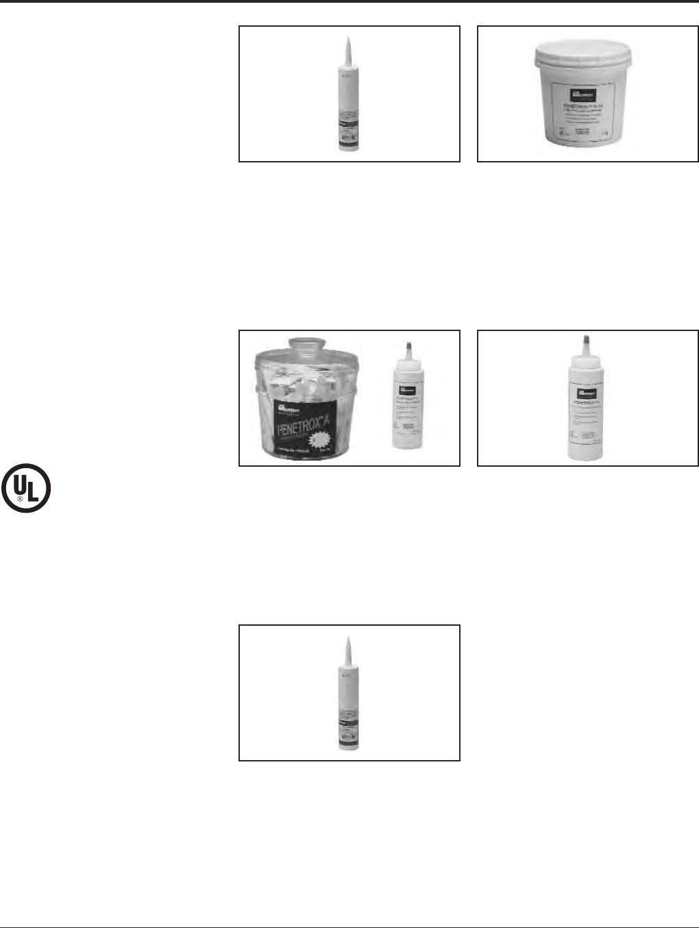
Grounding BURNDY®
Accessories
Canada: 1-800-387-6487 www.burndy.com US: 1-800-346-4175
106
TYPES PENETROX™
A, A-13, E AND HT
OXIDE-INHIBITING
JOINT COMPOUNDS
PENETROX™ oxide-inhibiting compounds
produce low initial contact resistance, seal out
air and moisture, prevent oxidation or corro-
sion, exhibit superior weathering characteris-
tics, are usable over wide temperature ranges,
and provide a high conductivity "gas-tight"
joint. All PENETROX™ compounds contain
homogeneously suspended metal particles.
The suspended metal particles assist in pen-
etrating thin oxide films, act as electrical
"bridges" between conductor strands, aid in
gripping the conductor, improve electrical
conductivity and enhance the integrity of the
connection.
The specially formulated PENETROX™
compounds are for use with compression and
bolted connectors providing an improved
service life for both copper and aluminum
connections. Additionally, the non-toxic
compounds are an excellent lubricant for
threaded applications reducing galling and
seizing.
PENACARTRIDGE
PENACARTRIDGE is a 1 lb. cartridge filled
with PENETROX-A. It's designed to fit stan-
dard caulking guns for easy insertion into
transmission and distribution connectors. Ad-
ditionally, this packaging design provides a
convenient method for applying PENE -
TROX™ to many different applications.
PENETROX™ A
PENETROX A is a natural (petroleum) base
compound with evenly suspended zinc parti-
cles. It is recommended for aluminum to alu-
minum, aluminum to copper connections and
aluminum conduit threads. It is not recom-
mended for use with rubber or polyethylene
insulated conductors. UL listed to 600V.
PENETROX™ A-13
PENETROX™ A-13 is a synthetic base com-
pound with evenly suspended zinc particles. It
is recommended for aluminum to aluminum,
aluminum to copper connection plus alu-
minum conduit threads. It is compatible with
rubber, polyethylene and other insulating ma-
terials. UL Listed for all voltages.
PENETROX™ E
PENETROX™ E is a synthetic base com-
pound with evenly suspended copper parti-
cles. It is recommended for copper to copper,
copper threads and all grounding applica-
tions. UL listed.
PENETROX™ HT
PENETROX™ HT is a synthetic silicone based
compound with evenly suspended zinc parti-
cles and nickel-aluminum alloy particles. It is
recommended for aluminum to aluminum con-
nection. It is compatible with rubber. Designed
for use with High Temperature ACSS and
ACCC connectors. Not UL Listed.
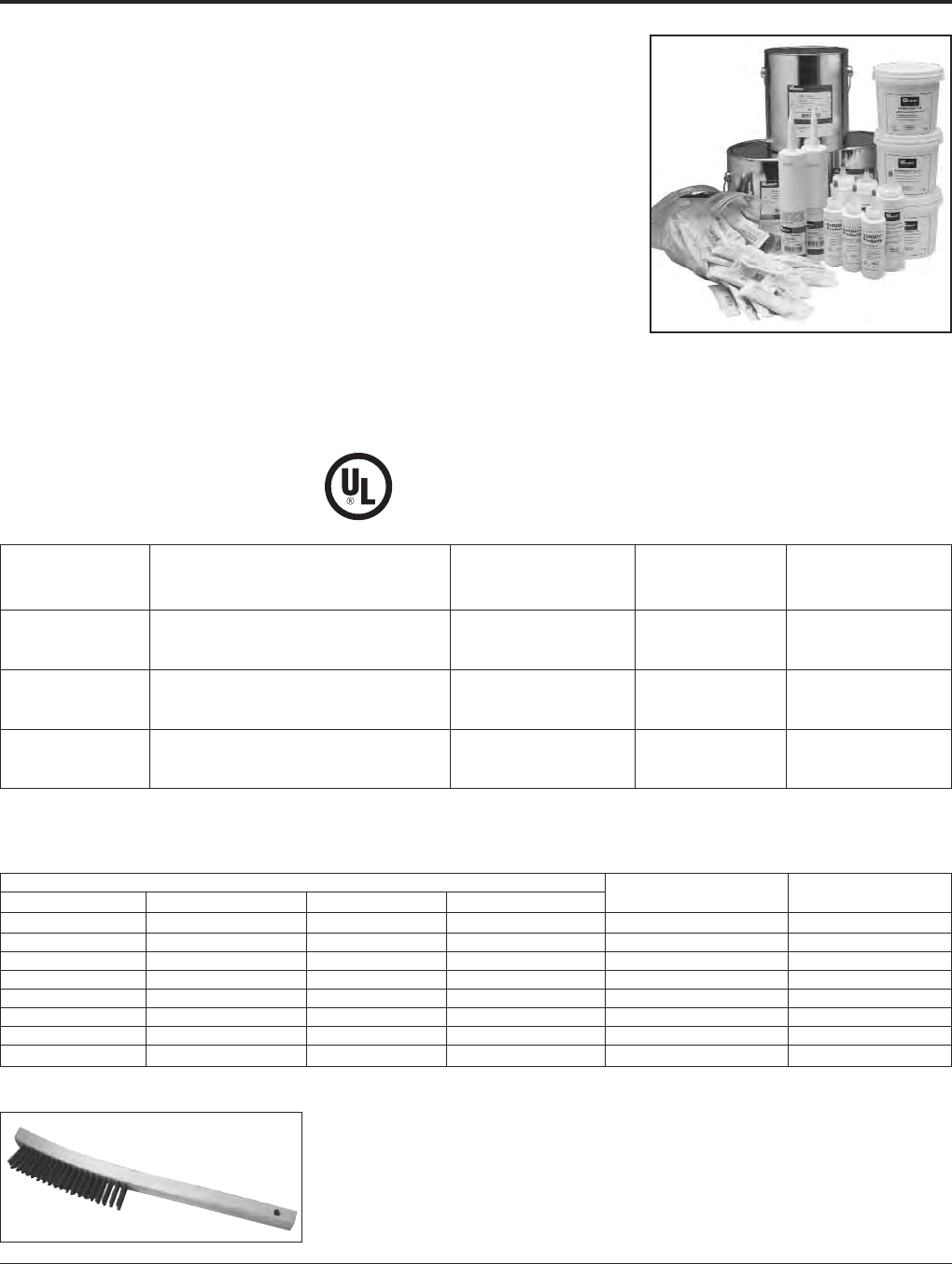
BURNDY®Grounding
Accessories
US: 1-800-346-4175 www.burndy.com Canada: 1-800-387-6487
107
PENETROX E
PENETROX E consists of a non-petroleum
base vehicle in which copper granules are
suspended. Recommended for copper to
copper applications, grounding and for use
on copper conduit threads. UL Listed.
PENETROX HT
PENETROX HT consists of a non-petroleum
base vehicle in which zinc and nickel-
aluminum particles are suspended. Recom-
mended for use with aluminum to aluminum
High Temperature rated ACSS and ACCC
conductors. Not UL Listed.
Easy to apply:
1. Scratch brush the conductor surfaces until
bright and clean.
2. Immediately apply PENETROX™ to the
conductive surfaces.
3. For EHV applications, remove all excess
PENETROX™ after installation is complete.
Catalog Number Container Container
PENETROX™ A PENETROX™ A-13 PENETROX™ E PENETROX™ HT Type Size
PENA 1/2 — — — Tube 1/2 oz.
PEN A-4 PEN A13-4 PEN E-4 PENHT-4 Squeeze Bottle 4 oz.
P8A PEN A13-8 PEN E-8 PENHT-8 Squeeze Bottle 8 oz.
PENACARTRIDGE PENA13CARTRIDGE —PENHT-1LB Cartridge 1 lb.*
PEN A-QT PEN A13-QT PEN E-QT — Plastic Tub 1 Quart
PEN A-GAL PEN A13-GAL PEN E-GAL PENHT-GAL Can 1 Gallon
PEN A-5GAL PEN A13-5GAL PEN E-5GAL — Pail 5 Gallons
PEN A-55GAL PEN A13-55GAL PEN E-55GAL — Drum 55 Gallons
PENETROX A,
A-13, E AND HT
TECHNICAL INFORMATION
PENETROX A
PENETROX A consists of a natural (petro leum)
base vehicle in which zinc particles are sus-
pended. For aluminum to aluminum, aluminum
to copper applications and aluminum conduit
threads. It is not recommended for use with
rubber and polyethylene insulated conductors.
UL Listed to 600 volts.
PENETROX A-13
PENETROX A-13 consists of a non- petroleum
base vehicle in which zinc particles are sus-
pended. Recommended for aluminum to alu-
minum, aluminum to copper applications and
aluminum conduit threads. Compatible with
insulating materials such as rubber, or poly-
ethylene. UL Listed and recommended for all
voltages.
ORDERING INFORMATION
PROPERTIES OF PENETROX™
* MSDS sheets available through customer service.
* 1 lb. cartridge will fit standard caulking guns.
B38-0305-00 Wire Brush
Value
PENETROX™ PENETROX™ PENETROX™ PENETROX™
Property Definition HT E & A13 A
The value in accordance to ASTM D217
Penetration indicates the consistency of a grease. The 240 250 230
(Unworked) higher the number, the softer the grease.
The temperature at which the grease passes
Dropping from the semi-solid to a liquid state under >580° F 500° F 230° F
Point (Minimum) test conditions.
The lowest termperature at which the
Pour Point compound will flow. Pour point is the –58° F –10° F –15° F
(Maximum) lubricant’s ability to perform in cold conditions.
SHELF LIFE
When stored in its original container in cool
(under 100°F) dry environment, PENE TROX™
oxide inhibiting compound will remain work-
able and functional for 5 years from the date
marked on the container provided it is mixed
per instructions prior to use.
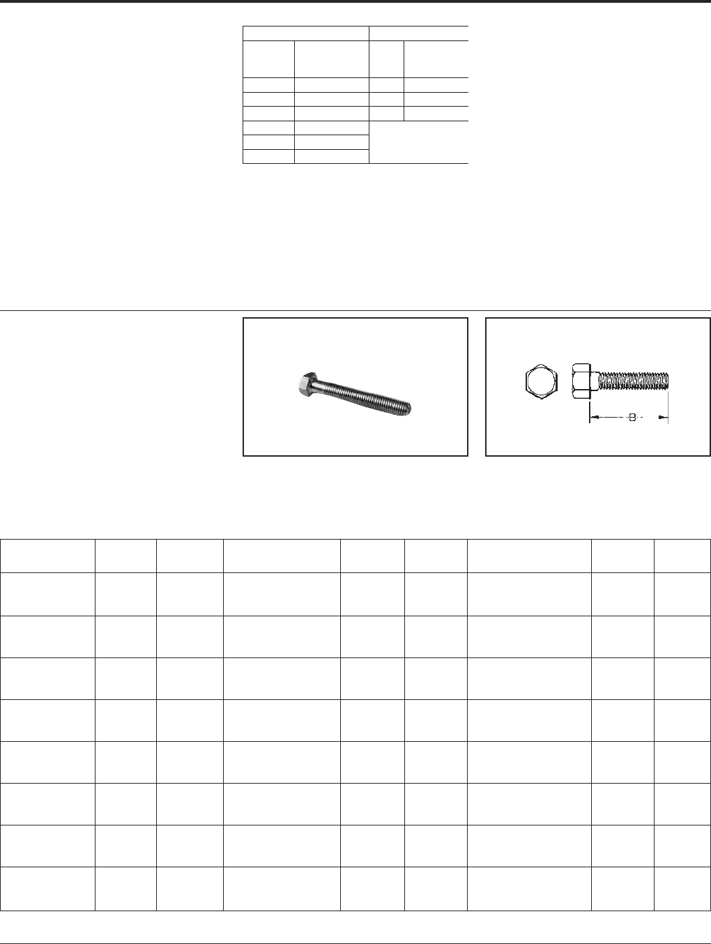
Grounding BURNDY®
Hardware
Canada: 1-800-387-6487 www.burndy.com US: 1-800-346-4175
108
DURIUM™ BOLT
SILICON BRONZE
BURNDY®introduced silicon-bronze bolts,
nuts, and other hardware items on outdoor
connector applications in 1927. Today the
DURIUM™ trademark is a standard for
this use.
DURIUM™ bolts combine high strength with
corrosion resistance. Bolts up to 2 inches
long are fully threaded; longer bolts are
threaded for two inches. Heads have Amer-
HARDWARE DATA
RECOMMENDED
TIGHTENING TORQUE
The hardware used in connectors must be
compatible with the connector material, have
high mechanical strength and be corrosion re-
sistant and correspond to NEMA
recommendations.
Copper alloy connectors have hardware
made of DURIUM™, which is BURNDY's
trade name for silicon bronze alloy ASTMB99
type B. This material was first introduced by
BURNDY®in 1927 for use in outdoor
construction, and today, is the standard
throughout the industry.
Aluminum connectors generally have
aluminum alloy hardware. The bolts are
2024T4 and anodized to resist corrosion. The
nuts are 6061T6, which is resistant to corro-
sion and does not require anodizing. Both
nuts and bolts are lubricated to eliminate
DURIUM™ and Steel Hardware Aluminum Hardware
Bolt
Size
Recommended
Torque
(Inch Pounds)
Bolt
Size
Recommended
Torque
(Inch Pounds)
1/4 - 20 80 1/2 - 13
5/8 - 11
3/4 - 10
300
5/16 - 18 180 480
3/8 - 16240 650
1/2 - 13 480
5/8 - 11 660
3/4 - 10 1,050
galling and to provide consistent clamping
forces.
To reduce or greatly exceed the recom-
mended torque can adversely affect the per-
formance of the connector.
Thread B Thread B Thread B
Catalog Number Size Length Catalog Number Size Length Catalog Number Size Length
25x50 HEB BOX 1/4-20 1/238x125 HEB BOX 3/8-16 1-1/450x300 HEB BOX 1/2-13 3
25x62 HEB BOX 1/4-20 5/838x150 HEB BOX 3/8-16 1-1/250x325 HEB BOX 1/2-13 3-1/4
25x75 HEB BOX 1/4-20 3/438x175 HEB BOX 3/8-16 1-3/450x350 HEB BOX 1/2-13 3-1/2
25x100 HEB BOX 1/4-20 138x200 HEB BOX 3/8-16 250x375 HEB BOX 1/2-13 3-3/4
25x125 HEB BOX 1/4-20 1-1/438x225 HEB BOX 3/8-16 2-1/450x400 HEB BOX 1/2-13 4
25x150 HEB BOX 1/4-20 1-1/238x250 HEB BOX 3/8-16 2-1/250x450 HEB BOX 1/2-13 4-1/2
25x200 HEB BOX 1/4-20 238x275 HEB BOX 3/8-16 2-3/450x500 HEB BOX 1/2-13 5
25x250 HEB BOX 1/4-20 2-1/238x300 HEB BOX 3/8-16 350x550 HEB BOX 1/2-13 5-1/2
25x300 HEB BOX 1/4-20 338x325 HEB BOX 3/8-16 3-1/450x600 HEB BOX 1/2-13 6
31x50 HEB BOX 5/16-18 1/238x350 HEB BOX 3/8-16 3-1/262x100 HEB BOX 5/8-11 1
31x62 HEB BOX 5/16-18 5/838x400 HEB BOX 3/8-16 462x125 HEB BOX 5/8-11 1-1/4
31x75 HEB BOX 5/16-18 3/438x450 HEB BOX 3/8-16 4-1/262x150 HEB BOX 5/8-11 1-1/2
31x100 HEB BOX 5/16-18 138x500 HEB BOX 3/8-16 562x175 HEB BOX 5/8-11 1-3/4
31x125 HEB BOX 5/16-18 1-1/4 44x150 HEB BOX 7/16-14 1-1/262x200 HEB BOX 5/8-11 2
31x150 HEB BOX 5/16-18 1-1/244x200 HEB BOX 7/16-14 262x225 HEB BOX 5/8-11 2-1/4
31x175 HEB BOX 5/16-18 1-3/450x75 HEB BOX 1/2-13 3/462x250 HEB BOX 5/8-11 2-1/2
31x200 HEB BOX 5/16-18 250x100 HEB BOX 1/2-13 162x275 HEB BOX 5/8-11 2-3/4
31x250 HEB BOX 5/16-18 2-1/250x125 HEB BOX 1/2-13 1-1/462x300 HEB BOX 5/8-11 3
31x300 HEB BOX 5/16-18 350x150 HEB BOX 1/2-13 1-1/262x325 HEB BOX 5/8-11 3-1/4
38x50 HEB BOX 3/8-16 1/250x175 HEB BOX 1/2-13 1-3/462x350 HEB BOX 5/8-11 3-1/2
38x62 HEB BOX 3/8-16 5/850x200 HEB BOX 1/2-13 262x400 HEB BOX 5/8-11 4
38x75 HEB BOX 3/8-16 3/450x225 HEB BOX 1/2-13 2-1/462x450 HEB BOX 5/8-11 4-1/2
38x88 HEB BOX 3/8-16 7/850x250 HEB BOX 1/2-13 2-1/262x500 HEB BOX 5/8-11 5
38x100 HEB BOX 3/8-16 150x275 HEB BOX 1/2-13 2-3/462x600 HEB BOX 5/8-11 6
ican Standard dimension, and the threads are
per American National Coarse Series, Class
#2 fit. The silicon bronze is per ASTM B99.
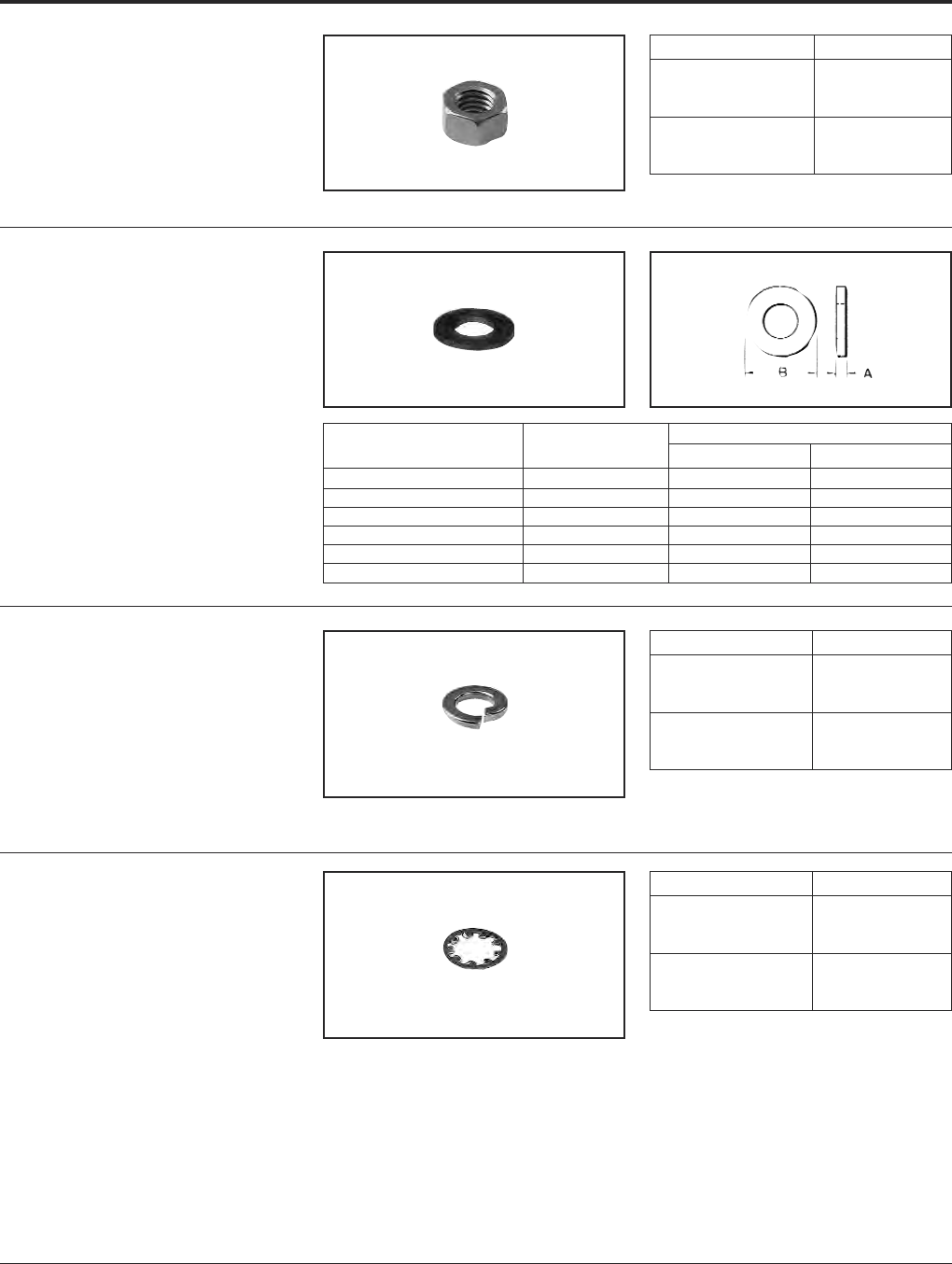
BURNDY®Grounding
Hardware
US: 1-800-346-4175 www.burndy.com Canada: 1-800-387-6487
109
DURIUM™ NUT
SILICON BRONZE
DURIUM™ hexagon regular nuts are non-
magnetic and are made to American Standard
dimensions. American National Coarse Series
threads, #2 fit.
DURIUM™
FLAT WASHER
SILICON BRONZE
High strength DURIUM™ Flat Washers are
non-magnetic and free from galvanic action
when in contact with copper. Conforms to
SAE standards.
DURIUM™ SPLIT
LOCKWASHER
SILICON BRONZE
DURIUM™ spring type lockwasher has high
resiliency and exerts constant pressure on the
face of the nut, preventing vibration from loos-
ening the nut.
DURIUM™
INTERNAL TOOTH
LOCKWASHER
SILICON BRONZE
DURIUM™ Internal Tooth Lockwashers are
available as illustrated. The teeth are twisted
slightly and present biting edges which grip
the nut and the part being clamped, prevent-
ing the nut from backing off.
Catalog Number Thread Size
25C HEN BOX 1/4-20
31C HEN BOX 5/16-18
38C HEN BOX 3/8-16
44C HEN BOX 7/16-14
50C HEN BOX 1/2-13
62C HEN BOX 5/8-11
For Bolt Nominal Dimensions in Inches
Catalog Number Size A B
25 FW BOX 1/4 1/16 5/8
31 FW BOX 5/16 1/16 11/16
38 FW BOX 3/8 1/16 13/16
44 FW BOX 7/16 1/16 15/16
50 FW BOX 1/2 3/32 1-1/16
62 FW BOX 5/8 3/32 1-5/16
Catalog Number For Bolt Size
25 SW BOX 1/4
31 SW BOX 5/16
38 SW BOX 3/8
44 SW BOX 7/16
50 SW BOX 1/2
62 SW BOX 5/8
Catalog Number For Bolt Size
25 NW BOX 1/4
31 NW BOX 5/16
38 NW BOX 3/8
44 NW BOX 7/16
50 NW BOX 1/2
62 NW BOX 5/8
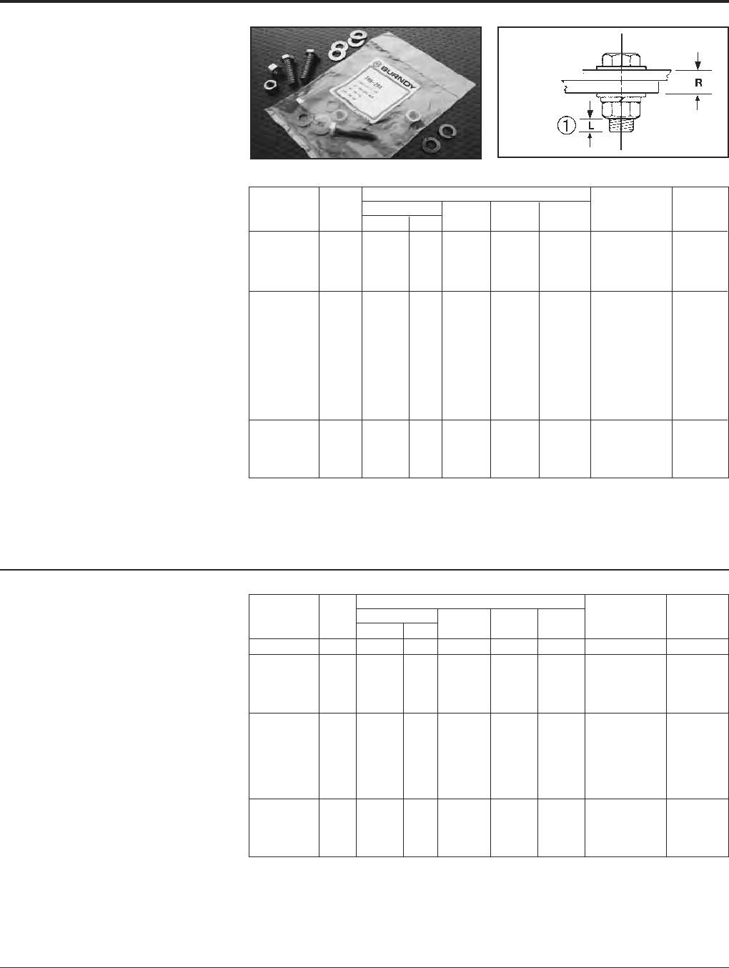
Grounding BURNDY®
Hardware
Canada: 1-800-387-6487 www.burndy.com US: 1-800-346-4175
110
TYPE TMH
DURIUM™ SILICON BRONZE
HARDWARE KITS
Type TMH are DURIUM™ silicon bronze hard-
ware kits. The kits can be ordered for speci fic
applications ensuring the proper type and
amount of hardware for each installation.
Packaged in separate sealed bags, they are
convenient to use, eliminating mismatched
quantities. DURIUM™ silicon bronze material
provides long lasting corrosion resistance.
† For use with CUSA750-2TC38 copper spacer adaptor, (2)
terminals and ˚" thick equipment bus bar.
For other combinations contact BURNDY®.
†† For use with all GAR-TC connectors. "R" dimension is al-
lowable pad thickness of terminal
Each TMH Kit Includes: Working Installation
Catalog Bolt Flat Split Hex Range Torque
Number Size Length Qty. Washer Washer Nut R (In-lbs)
TMH322SS 10 - 32 0.875 1 0 1 1 - 45
TMH262SS 0.75 2 4 2 2 0.09 - 0.34
TMH263SS 1.00 2 4 2 2 0.34 - 0.59
TMH264SS 1/4-20 1.25 2 4 2 2 0.59 - 0.84 80
TMH265SS 1.50 2 4 2 2 0.84 - 1.09
TMH267SS 1.00 2 4 2 2 0.19 - 0.44
TMH268SS 1.25 2 4 2 2 0.44 - 0.69
TMH269SS 1.50 2 4 2 2 0.69 - 0.94
TMH270SS 3/8-16 1.75 2 4 2 2 0.94 - 1.19 240
TMH271SS 2.00 2 4 2 2 1.19 - 1.44
TMH261SS †3.00 2 4 2 2 2.15 - 2.40
TMH295SS 1.25 2 4 2 2 0.27 - 0.49
TMH272SS 1.50 2 4 2 2 0.49 - 0.74
TMH294SS 1/2-13 1.75 2 4 2 2 0.74 - 0.99 480
TMH69SS 2.00 2 4 2 2 0.99 - 1.24
TYPE TMH-SS
STAINLESS STEEL
HARDWARE KITS
Type TMH-SS are stainless steel hardware
kits. Just like the standard TMH kits, these
kits can be ordered for specific applications
ensuring the proper type and amount of hard-
ware for each installation. They are packaged
in separate sealed bags and convenient for
use and ordering.
Each TMH Kit Includes: Working Installation
Catalog Bolt Flat Split Hex Range Torque
Number Size Length Qty. Washer Washer Nut R (In-lbs)
TMH262 0.75 2 4 2 2 0.09 - 0.34
TMH263 1.00 2 4 2 2 0.34 - 0.59
TMH264 1/4-20 1.25 2 4 2 2 0.59 - 0.84 80
TMH265 1.50 2 4 2 2 0.84 - 1.09
TMH266 0.75 2 4 2 2 0.00 - 0.19
TMH267 1.00 2 4 2 2 0.19 - 0.44
TMH268 1.25 2 4 2 2 0.44 - 0.69
TMH269 1.50 2 4 2 2 0.69 - 0.94
TMH270 3/8-16 1.75 2 4 2 2 0.94 - 1.19 240
TMH271 2.00 2 4 2 2 1.19 - 1.44
TMH332 22.75 2 4 2 2 —
TMH261 †3.00 2 4 2 2 2.15 - 2.40
TMH289 †† 1.25 1 2 1 1 0.02 - 0.27
TMH295 1.25 2 4 2 2 0.27 - 0.49
TMH272 1.50 2 4 2 2 0.49 - 0.74
TMH294 1/2-13 1.75 2 4 2 2 0.74 - 0.99 480
TMH69 2.00 2 4 2 2 0.99 - 1.24
* For other combinations contact BURNDY®.
➀"L" dimension never exceeds .25"
2 For use with CUSA442TC38 on 1/4" bus bar and
HYLUG™ 4/0 - 750 kcmil.
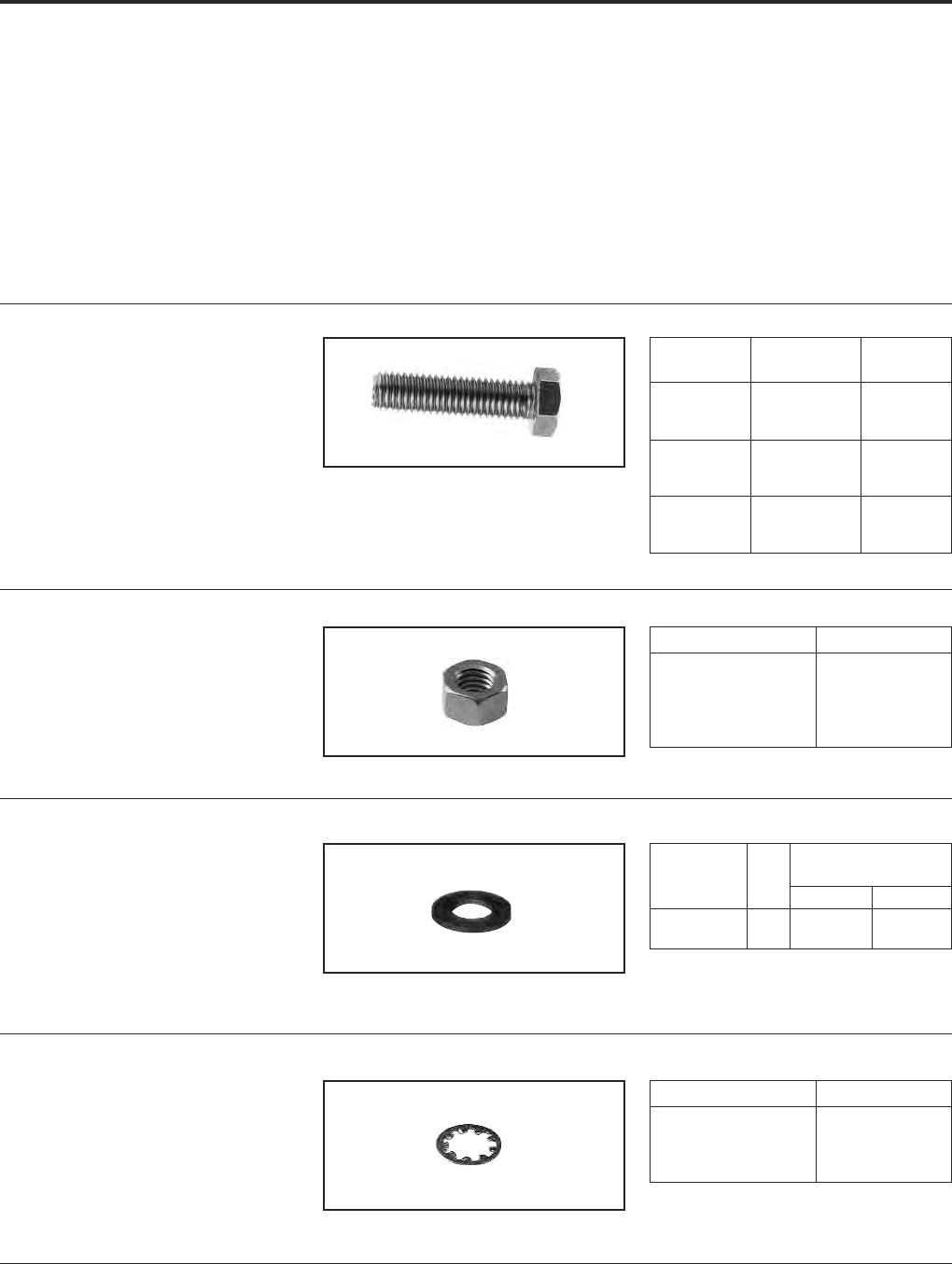
BURNDY®Grounding
Hardware
US: 1-800-346-4175 www.burndy.com Canada: 1-800-387-6487
111
GALVANIZED
STEEL HARDWARE
Galvanized bolts, nuts, flatwashers, and in-
ternal tooth lockwashers are manufactured
per ASTM307 Grade A. Bolts up to 2 inches
long are fully threaded; longer bolts are
threaded for 2 inches. Nut surfaces and bolt
heads have American Standard dimensions,
and the threads are per American National
Coarse Series, Class #2 fit. Galvanizing is per
ASTM A153.
BOLTS
NUTS
FLATWASHER
INTERNAL TOOTH
LOCKWASHERS
Catalog
Number Thread Size Length (B)
38x125 HGSB 3/8-16 1.25
38x275 HGSB 3/8-16 2.75
38x225 HGSB 3/8-16 2.25
50x100 HGSB 1/2-13 1.00
50x150 HGSB 1/2-13 1.50
50x200 HGSB 1/2-13 2.00
62x100 HGSB 5/8-11 1.00
62x175 HGSB 5/8-11 1.75
75x125 HGSB 3/4-10 1.25
Catalog Number Thread Size
31CHGSN 5/16-18
38 HGSN-009 3/8-16
38 HGSN 3/8-16
50 HGSN 1/2-13
62 HGSN 5/8-11
Nominal Dimensions
Catalog Bolt (Inches)
Number Size I.D. A O.D. B
38x81 FWGS 3/8 0.406 0.813
50x106 FWGS 1/2 0.531 1.06
Catalog Number Bolt Size
38 NWGS 3/8
50 NWGS 1/2
62 NWGS 5/8
75 NWGS 3/4
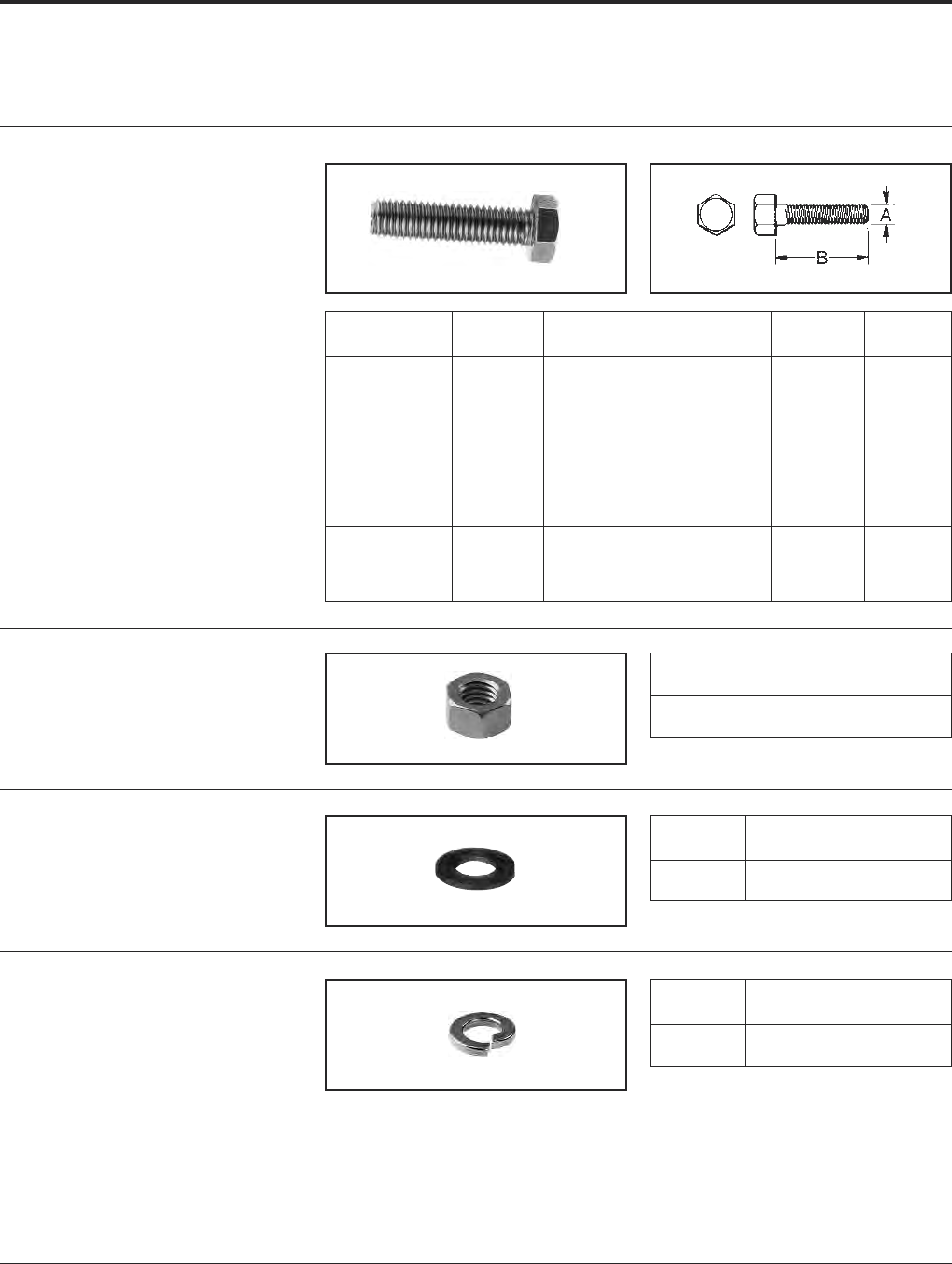
Grounding BURNDY®
Hardware
Canada: 1-800-387-6487 www.burndy.com US: 1-800-346-4175
112
ALUMINUM
HARDWARE
NUTS
BURNDY®aluminum nuts are manufactured
of alloy 6061-T6, are finished type, coarse
thread, class 2B fit.
BOLTS
BURNDY®aluminum hexagon head bolts are
manufactured of alloy 2024-T4 and are
finished with anodic coating and lubricated.
Threads are coarse series, class 2A fit.
FLATWASHER
BURNDY®aluminum flat washers are manu-
factured of alloy 2024-T4 and are medium de-
sign.
SPLIT LOCKWASHERS
BURNDY®aluminum split lockwashers are
manu factured of alloy 7075-T6 and are regu-
lar design.
Catalog Thread B Catalog Thread B
Number Size Length Number Size Length
50x150 HAB BOX 1/2-13 1-1/250x500 HAB BOX 1/2-13 5
50x175 HAB BOX 1/2-13 1-3/450x550 HAB BOX 1/2-13 5-1/2
50x200 HAB BOX 1/2-13 262x175 HAB BOX 5/8-11 1-3/4
50x225 HAB BOX 1/2-13 2-1/462x200 HAB BOX 5/8-11 2
50x250 HAB BOX 1/2-13 2-1/262x225 HAB BOX 5/8-11 2-1/4
50x275 HAB BOX 1/2-13 2-3/462x250 HAB BOX 5/8-11 2-1/2
50x300 HAB BOX 1/2-13 362x300 HAB BOX 5/8-11 3
50x325 HAB BOX 1/2-13 3-1/462x350 HAB BOX 5/8-11 3-1/2
50x350 HAB BOX 1/2-13 3-1/262x400 HAB BOX 5/8-11 4
50x375 HAB BOX 1/2-13 3-3/462x450 HAB BOX 5/8-11 4-1/2
50x400 HAB BOX 1/2-13 462x500 HAB BOX 5/8-11 5
50x425 HAB BOX 1/2-13 4-1/462x550 HAB BOX 5/8-11 5-1/2
50x450 HAB BOX 1/2-13 4-1/262x600 HAB BOX 5/8-11 6
Catalog
Number Thread Size
50 HAN BOX 1/2-13
62 HAN BOX 5/8-11
Catalog For
Number Description Bolt Size
50 FWA BOX Flat Washer 1/2
62 FWA BOX Flat Washer 5/8
Catalog For
Number Description Bolt Size
50 SWAL BOX Split Washer 1/2
62 SWAL BOX Split Washer 5/8
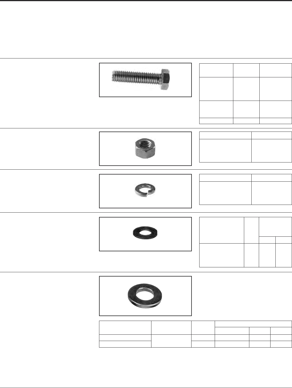
BURNDY®Grounding
Hardware
US: 1-800-346-4175 www.burndy.com Canada: 1-800-387-6487
113
STAINLESS STEEL
HARDWARE
Stainless steel bolts, nuts, flatwashers and
split lockwashers are manufactured from
18-8 non-magnetic material. Bolts up to
2 inches long are fully threaded; longer bolts
NUTS
BOLTS
FLATWASHER
SPLIT LOCKWASHERS
BELLEVILLE
WASHERS
Any bolted "pad to flat" electrical connection
should include a bolt, two flatwashers, and
the nut. In addition, if any of the flat compo-
nents is aluminum, a properly designed
Belleville washer should be interposed be-
tween one of the flatwashers and either the
bolt head or the nut, with the hollow of the
Belleville washer placed against the flat
washer. BURNDY®Belleville washers are de-
signed to maintain substantial force when
tightened to NEMA-recommended values and
finely finished to avoid galling.
The stainless washers are 301 stainless steel.
Catalog Thread Length B
Number Size (Inches)
38X125 HSSB 3/8-16 1.25
38x225 HSSB 3/8-16 2.25
38x250 HSSB 3/8-16 2.50
38x275 HSSB 3/8-16 2.75
50x200 HSSB 1/2-13 2.00
50x250 HSSB 1/2-13 2.50
50x300 HSSB 1/2-13 3.00
62x300 HSSB 5/8-11 3.00
Catalog Number Thread Size
25 HSSN 1/4-20
38 HSSN 3/8-16
50 HSSN 1/2-13
62 HSSN 5/8-11
Catalog Number For Bolt Size
25 SWSS LT 1/4
38 SWSSMD 3/8
50 SWSSMD 1/2
62 SWSSMD 5/8
Nominal
Dimensions
Catalog Bolt (Inches)
Number Size I.D. A O.D. B
25 FWSS 1/4 0.266 0.688
38 FWSS 3/8 0.406 1.000
50 FWSS 1/2 0.594 1.125
62 FWSS 5/8 0.656 1.312
Bolt Nominal Dimensions
Catalog Number Material Size Thickness I.D. O.D.
38x75 BWSS 3/8 .062 .388 .750
50x106 BWSS Stainless 1/2 .095 .530 1.06
are threaded for 2 inches. Nut surfaces and
bolt heads have American National Coarse
Series, Class #2 fit.
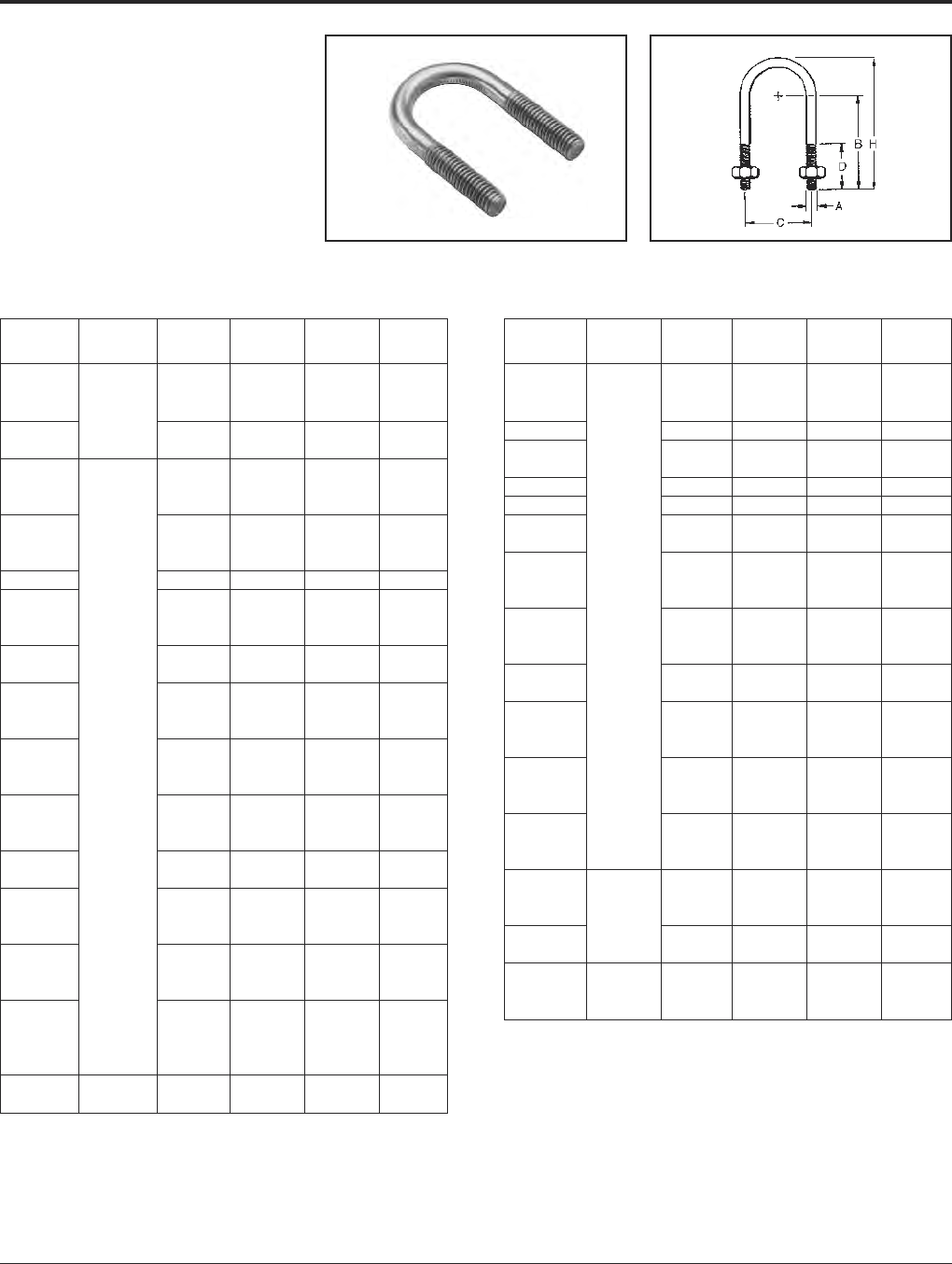
Grounding BURNDY®
Hardware
Canada: 1-800-387-6487 www.burndy.com US: 1-800-346-4175
114
TYPE UB
DURIUM™
SILICON BRONZE U-BOLTS
DURIUM™ U-BOLTS are specifically de-
signed for electrical connections to pipe and
rod. The U-BOLTS are threaded on the
straight portion of the legs only allowing for
more contact surface on the pipe or rod.
American National Coarse Threads Class #2
fit. The silicon bronze is per ASTM B99.
Catalog Thread
Number Size H C D B
UB101 1.38 0.75 0.75 0.88
UB104 1.81 1.12 0.88 1.12
UB105 1/4-20 2.03 1.31 1.00 1.25
UB106 2.31 1.62 1.12 1.38
UB107 2.66 1.94 1.31 1.56
UB336 1.50 0.88 0.62 0.88
UB337 1.94 1.12 0.75 1.19
UB178 2.00 0.88 0.75 1.38
UB354 2.44 1.25 1.00 1.62
UB187 2.47 1.16 1.06 1.69
UB271 2.50 1.00 1.19 1.81
UB222 2.69 1.50 1.12 1.75
UB242 2.72 1.16 1.31 1.94
UB383 2.75 0.94 1.47 2.09
UB269 2.78 1.19 1.38 2.00
UB357 2.78 1.69 1.12 1.75
UB384 2.91 1.44 1.38 2.00
UB249 3.00 1.50 1.44 2.06
UB1031 3.31 1.75 1.90 2.25
UB244 3.31 1.75 1.62 2.25
UB199 3.41 2.34 1.44 2.05
UB204 3/8-16 3.47 2.06 1.62 2.25
UB124 3.50 2.75 1.31 1.94
UB268 3.97 2.34 2.00 2.62
UB257 4.16 2.81 1.94 2.56
UB1032 4.41 2.81 2.56 2.81
UB310 4.41 2.81 2.19 2.81
UB266 4.97 3.31 2.50 3.12
UB267 5.53 3.94 2.75 3.38
UB258 5.56 4.00 2.75 3.38
UB264 6.16 4.44 3.12 3.75
UB1033 6.16 4.44 3.50 3.75
UB261 6.34 4.94 3.06 3.69
UB422 7.69 6.00 3.88 4.50
UB1027 8.12 7.12 2.88 4.38
UB1028 9.62 9.12 2.88 4.88
UB1029 11.20 11.25 2.88 5.38
UB1030 12.70 13.25 2.88 5.88
UB224 2.44 1.12 0.88 1.62
UB358 1/2-13 2.66 1.31 1.00 1.75
Catalog Thread
Number Size H C D B
UB226 2.75 1.25 1.12 1.88
UB291 2.81 1.19 1.22 1.97
UB293 2.81 1.75 1.19 1.69
UB464 3.12 1.81 1.31 1.96
UB540 3.19 1.38 1.75 2.25
UB254 3.41 1.31 1.75 2.50
UB328 3.41 2.94 0.94 1.69
UB400 4.03 1.31 2.38 3.12
UB256 4.16 2.22 2.06 2.81
UB230 4.34 2.94 1.88 2.62
UB311 4.44 1.88 2.50 3.25
UB302 4.62 2.47 2.38 3.12
UB232 1/2-13 4.97 3.44 2.25 3.00
UB260 5.34 2.94 2.88 3.62
UB390 5.38 2.50 3.12 3.88
UB263 5.78 4.56 2.50 3.25
UB282 6.31 4.12 3.25 4.00
UB236 6.41 5.06 2.88 3.62
UB399 6.66 1.31 5.00 5.75
UB436 6.66 4.56 3.62 4.12
UB262 6.78 5.06 3.25 4.00
UB392 7.06 1.62 5.25 6.00
UB416 7.53 5.06 4.00 4.75
UB300 7.62 6.12 3.56 4.31
UB306 7.88 6.12 3.81 4.56
UB275 5.09 1.19 3.60 4.25
UB437 8.56 6.12 4.50 5.25
UB294 3.50 1.38 1.75 2.50
UB314 3.66 2.09 1.56 2.31
UB425 5/8-11 3.72 2.31 1.50 2.25
UB317 4.97 1.81 3.00 3.75
UB315 5.56 2.09 3.44 4.19
UB318 4.22 2.44 1.87 2.62
UB344 3/4-10 4.72 1.94 2.63 3.38
UB319 6.34 2.44 4.00 4.75

BURNDY®Grounding
Tooling
US: 1-800-346-4175 www.burndy.com Canada: 1-800-387-6487
115
INTRODUCTION
INSTALLATION TOOLS
The BURNDY®total compression program
offers the most complete line of installation
tooling whether mechanical, full cycle ratchet,
self contained hydraulic, remote controlled
hydraulic, power actuated pumps, hoses and
accessories, available to the electrical indus-
try. These tools have been designed to inte-
grate with the complete line of BURNDY®
compression connectors. Whether you’re a
small contractor working with #22 wire or a
large utility working with 2500 kcmil conduc-
tor, there’s a BURNDY®compression tool
available to do the job. The benefits of com-
pression are many; however, probably the
most significant benefit is reliability. There’s
nothing more important to the electrical
industry today than reliability. It represents the
one area that leads to economical installa-
tions that will endure for the life of the instal-
lation.
TOOL CENTER
An important element of the BURNDY®engi-
neered system is the Tool Center, 150 Burndy
Road, Littleton, NH 03561 (800-426-8720).
This center provides advice and information
on the operation, maintenance and repair of
BURNDY®tools. The repair center is staffed
with specialized technicians who provide the
best possible tool repair service, for all
BURNDY®tools, pumps and accessories. We
designed and produced the first self con-
tained hydraulic compression electrical
connector installation tool in 1934. In our
continuing efforts to provide the highest qual-
ity and highest value connection systems, we
offer the current BURNDY®tool policy.
LIMITED WARRANTY
The majority of BURNDY®tools are warranted
to be free of defects in materials and work-
manship for a period of five (5) years from the
date of shipment. Please contact the Tool
Center (800-426-8720) for warranty informa-
tion on a specific item. If inspection by a
certified tool technician shows the issue is
due to by defective workmanship or material,
BURNDY®will repair (or at our option),
replace the tool.
This Warranty does not apply where:
• Repairs or alterations have been made
or attempted by others
• Repairs are required because of normal
wear and tear
• The tool has been abused, misused or
improperly maintained
• The use of any non-BURNDY®products
has resulted in damage to the tool
STANDARD LIMITED WARRANTY AND
LIMITATION OF LIABILITY
BURNDY®warrants that the goods and serv-
ices stated on the face hereof, when furnished
to Buyer by BURNDY®, conform with the cur-
rent written specifications and drawings of
BURNDY®(or with those of the Buyer specif-
ically accepted by BURNDY®in writing), and
will be free of defects in materials and work-
manship. The sole obligation of BURNDY®
(and Buyer’s sole and exclusive remedy) for
any breach of warranty under the foregoing
warranty shall be to repair (at location desig-
nated by BURNDY®) or, at the option of
BURNDY®: To replace FOB the original point
of delivery any goods which are non-
conforming or defective and are so specified
by Buyer in a written certified mail notice to
an officer of BURNDY®within the applicable
warranty period. BURNDY®expressly
disclaims any and all express or implied war-
ranties other than the warranty of its title to
goods and the warranty hereinabove set forth.
Such disclaimer includes, without limitation,
warranty of fitness for a particular purpose
and warranty of merchantable quality.
Limitation of Liability — BURNDY®will not,
under any circumstances, be liable for the
cost of removal or reinstallation of goods or
the cost of disassembly or reassembly of
equipment in connection therewith, or for loss
of the use of Buyer’s equipment or facilities, or
for loss of business or good will or profits, or
for cost of inspection or storage, or for any
incidental or consequential damages of any
nature or description whatever which may
arise from the sale of goods to Buyer from
BURNDY®.
REPAIR POLICY
All non-warranty repaired tools are completely
reconditioned and receive a limited 1-year
warranty. Non-warranty repair returns tools to
like new condition at a maximum cost of 40%
the current cost of a new tool. A nominal serv-
ice charge of $5.00 is applied to all repairs to
cover shop supplies, oil disposal and other
miscellaneous services not covered as part of
the standard repair. If the decision is made not
to repair, a handling charge of $25.00 will be
applied plus return freight costs.
RETURN PROCEDURE
All tools sent to the BURNDY®Tool Center or
an authorized repair center must be accom-
panied by a purchase order with detailed bill
to and ship to address authorizing repair.
Requests for repair charges before work is
done must be stated on the purchase order.
All tools sent to the BURNDY®Tool Center or
an authorized repair center as a warranty
claim must be accompanied by a proof of
purchase such as a BURNDY®invoice or
invoice from any BURNDY®distributor.
All tools must be shipped at the owner’s
expense, prepaid. BURNDY®pays for the
return freight, same surface freight as
received. Airfreight returns will be returned
same way collect for non-warranty repair and
prepaid for warranty repairs. This warranty
and repair policy supersedes all previous
policies and is in effect January 1, 2005.
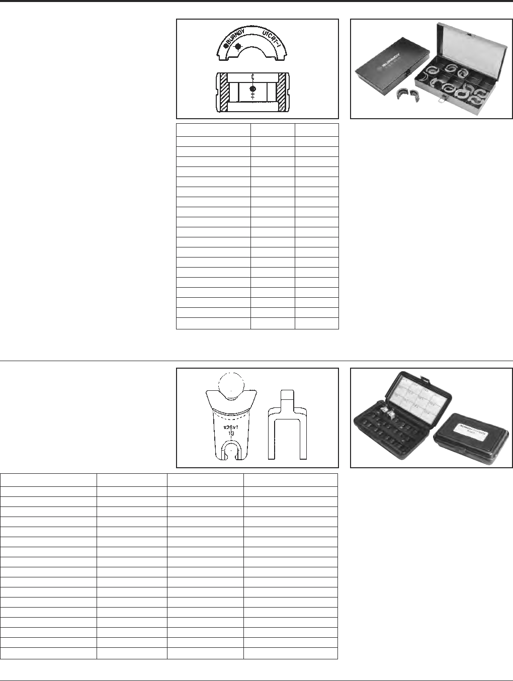
Grounding BURNDY®
Tooling
Canada: 1-800-387-6487 www.burndy.com US: 1-800-346-4175
116
12-TON U DIES*
BURNDY®Die Sets
Fits Y35, Y39, Y750 Series,
PAT750-18V Series,
PAT46-18V, Y46
(W/PUADP-1 Adapter)
U die case Part# PT29291, holds up to 15 dies
Wire Size Copper Aluminum
Small #8 U8CRT U8CABT
#6 U5CRT U6CABT
#4 U4CRT U4CABT
#3 U3CRT N/A
#2 U2CRT U2CABT
#1 U1CRT-1 U1CART
1/0 U25RT U25ART
2/0 U26RT U26ART
3/0 U27RT U27ART
4/0 U28RT U28ART
250 kcmil U29RT U29ART
300 kcmil U30RT U30ART
350 kcmil U31RT U31ART
400 kcmil U32RT U32ART
500 kcmil U34RT U34ART
535 Flex kcmil U38XRT N/A
600 kcmil U36RT U36ART
750 kcmil U39RT U39ART-2
Large 777 Flex U44XRT N/A
* Non-tension U-type 12-ton dies for YA, YS, YA-A, YS-A style
connectors.
NOTE: N/A = not applicable.
W DIES
BURNDY®Die Sets
Fits Tools MD6, MD7,
Y500CTHS, PAT600-18V,
PATMD6
* These sizes (250-500) for Y5000CTHS, MD7-34(R),
BAT500, BCT500HS only.
** For PAT600-18V only.
NOTE: N/A = not applicable.
Suitable for use on YA, YS, YA-A, YS-A type non-tension
connectors.
Wire Size Copper Copper Aluminum
Small #8 W8CVT W8CRT X8CART
#6 W5CVT W5CRT W161
#4 W4CVT W4CRT W162
#3 W3CRT W3CRT N/A
#2 W2CVT W2CRT W239
#1 W1CVT W1CRT W163
1/0 W25VT W25CRT W241
2/0 W26VT W26CRT W245
3/0 W27VT W27CRT W166
4/0 W28VT W28CRT W660
250 *W29VT W29CRT N/A
300 *W30VT W30CRT N/A
350 *W31VT W31CRT *W31ART
400 *W32VT W32CRT N/A
450 W33VT W33CRT
500 *W34VT W34CRT N/A
Large 600 **W36RT W36CRT N/A
Cat. No. CASEWDIES
Compact Die Case
Compact die case for (12) “W” or
“X” die sets. Dies purchased separately.
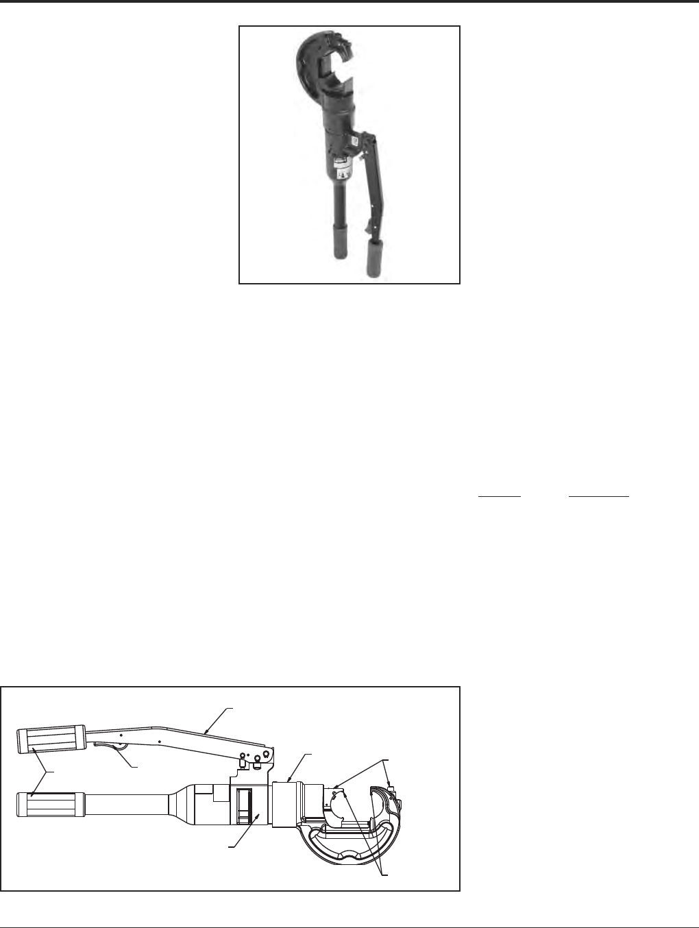
BURNDY®Grounding
Tooling
US: 1-800-346-4175 www.burndy.com Canada: 1-800-387-6487
117
Y750HSXT AND
Y750CHSXT RUBBER
COVERED HEAD
750 REVOLVER HYPRESS™
Hydraulic Hand Operated
Tool
12-Ton Crimp Force
Conductor Range:
#14 - 750 kcmil Cu/Al
#4 - 556.5 kcmil ACSR
The BURNDY®Y750HSXT Series HYPRESS™
is a wide mouth (1.65) hand operated
hydraulic 12 ton crimping tool for use on
virtually all compression applications. The
C-shaped head rotates 355° relative to the
handle and is mated to a patented rapid
advance pump. The Y750HSXT provides easy
tapping, splicing, and terminating of overhead
lines, the full line of HYGROUND
®
compres-
sion grounding connectors, NEC cable con-
nections, and N30 - N650 Navy cable
connections.
The Y750HSXT accepts all BURNDY®“U”
dies for use on conductor ranges of
#14 - 750 kcmil AL/CU and #4 - 556.5 kcmil
ACSR conductors.
The Y750CHSXT HYPRESS™ has a rubber-
covered head and handles for tool impact
protection.
Each Y750HSXT uses standard BURNDY®
dies and off-the-shelf connectors available
world-wide. Supplied with a durable high
impact formed carrying case to hold the tool,
and die compartment to hold “U” die sets.
(Dies sold separately.) All BURNDY®
Y750HSXT series tools are provided with a
5-year limited warranty.
SPECIFICATIONS
Force developed: 12 tons
Weight: 14.5 lbs. (6.6 kg)
Length: 23.96(608 mm)
Height: 2.86(78 mm)
Width: 8.71(222 mm)
Jaw opening: 1.65(42 mm)
FOR USE ON
• Tension Sleeves
Copper #8 sol. - 500 kcmil
Aluminum #8 sol. - 556.5 kcmil
ACSR #4 - 556.5 kcmil
• Taps
Copper #14 sol. - 500 kcmil
Aluminum #8 - 500 kcmil
• Aerial Cable
Copper #6 - 500 kcmil
• Terminals & Splices
Aluminum #8 - 750 kcmil
Copper #8 - 750 kcmil
ACSR #4 - 556 kcmil
• HYGROUND
®
(Compression Grounding)
Copper #8 - 500 kcmil
(cable/ground rod)
Ground Rods 1/2- 1Diameter
ACCESSORIES:
Cat. No. Description
Y750HSCASE Plastic Carrying Case for
Y750HSXT or
Y750CHSXT.
PT29279-2 Force test gauge for ac-
curate visual reading of
output force.
PT29291 Die Case
Steel case for storage and
protection of “U” dies.
WIREMIKE Provides quick and easy
identification of commonly
used conductors.
BENEFITS
• Covers a wide range of applications with
a lightweight, self-contained system and
provides easy tool removal from continu-
ous conductors with its C-shaped head.
• Easy tool positioning with its 355° head
rotation.
• Patented rapid advance pump for faster
crimps.
• Exposed positive die lock buttons for easy
die change out and die retention.
• Handle trigger drain for convenient ram
retraction.
• Quality assurance is provided with an
audible “Pop-Off” pressure relief valve.
• Comfort grip handles help ease operator
fatigue with continuous use.
• Long life expectancy from the company
that provided the industry with the first
self-contained hydraulic tool in 1934.
• Rubber covered head and handles on
Y750CHSXT for tool impact protection.
• Supplied with high impact plastic carrying
case.
• 5-year limited warranty.
Comfort Grip
Handles
Handle Trigger
Drain
Ergonomic Handle
Design
Audible “Pop-Off”
Pressure Relief Valve
355° Head
Rotation Both Die Release
Buttons Exposed
Large 1.65
Jaw Opening
FEATURES
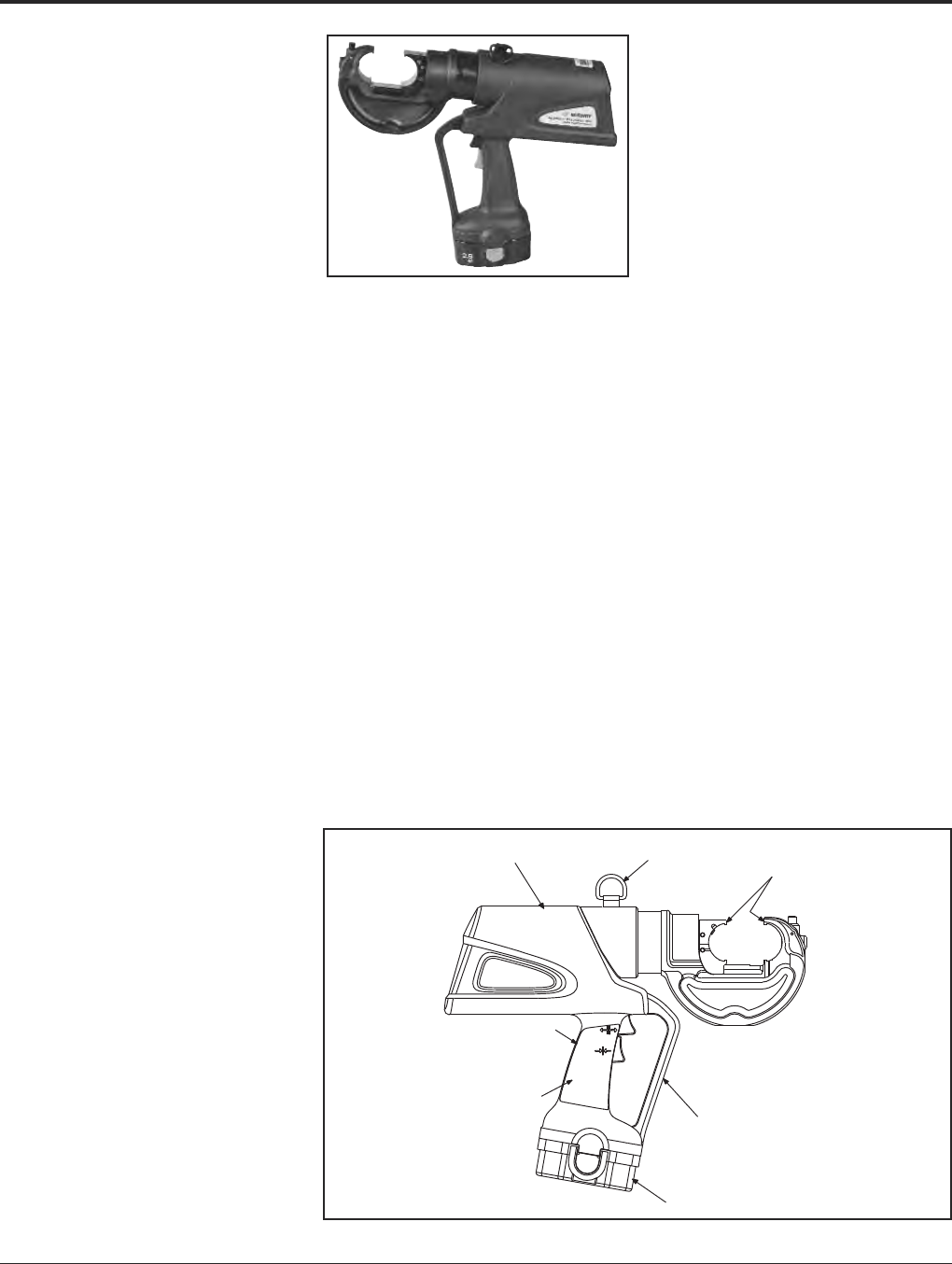
Grounding BURNDY®
Tooling
Canada: 1-800-387-6487 www.burndy.com US: 1-800-346-4175
118
PATRIOT®
HIGH PERFORMANCE
PAT750XT-18V
Battery Actuated Tool
Hydraulic Self-Contained
12-Ton Crimping Tool
The BURNDY®PATRIOT® High Performance
PAT750XT-18V tool is 25% faster than previ-
ous models. In addition to faster crimp cycles,
the High Performance PAT750XT-18V has
newly designed electronics that are field
proven for ultimate reliability and proven to
handle the harshest work environments.
The High Performance PAT750XT-18V incor-
porates the latest engineering technology with
a refined hydraulic system for ultra perform-
ance, speed and reliability. All PATRIOT®tools
feature the BURNDY INFINITY DRIVE®trans-
mission which has a lifetime warranty.
The High Performance PAT750XT-18V features
the BURNDY®Y750 tool head, capable of
using all “U” style dies, and incorporates a
bearing and alignment guide for use on
HYGROUND®and other asymmetrical con-
nectors. Features reliable head rotation
design for operation in virtually any position.
All PATRIOT®battery actuated hydraulic tools
provide a consistent, reliable connection every
time.
Each PATRIOT®tool uses standard
BURNDY®dies and off-the-shelf connectors
available world-wide. Supplied with a durable
high impact formed carrying case to hold the
tool, battery charger, two batteries, tool re-
tention lanyard, and die compartment to hold
“U” die sets. (Dies sold separately.) Provided
with a 5-year limited warranty.
Features and Benefits
• Refined hydraulic system for ultra
performance, speed and reliability.
• Field proven electronics for ultimate
reliability in the harshest environments.
• True, one-handed operation for advance,
retract, and hold.
• 12 tons of output force for use on virtually
all compression applications.
• State of the art crimping head design,
360° head rotation lets user get into tight
areas easier.
• Allows use of standard BURNDY®dies
already in use.
• Ergonomically balanced tool design eases
operation and helps lessen fatigue.
• Durable high impact formed carrying case
provides superior protection and stores all
accessories.
•PAT750CXT-18V — with rubber covered
head is available.
• 18 volt Ni-MH battery eliminates voltage
depression (memory issues).
• 5-year limited warranty on tool.
• Lifetime warranty on INFINITY DRIVE®.
• 1-year warranty on batteries and charger.
SPECIFICATIONS
Output force: 12 tons
(10.9 metric tons)
Tool Weight: 16.5 lbs (7.5 kg)
With Battery
Length: 15.75(40 cm)
Width: 3.5(8.89 cm)
Height: 13.5(34.29 cm)
Operating Voltage: 18 V-DC
Recharge Time: < 45 minutes
FOR USE ON
• Tension Sleeves
Copper #8 sol. - 500 kcmil
Aluminum #8 sol. - 587.2 kcmil
ACSR #4 - 556.5 kcmil
• Taps
Copper #14 sol. - 500 kcmil
Aluminum #8 - 500 kcmil
• Aerial Cable
Copper #6 - 500 kcmil
• Terminals & Splices
Aluminum #8 - 750 kcmil
Copper #8 - 750 kcmil
ACSR #4 - 556 kcmil
• HYGROUND®
Copper #8 - 500 kcmil
(cable/ground rod)
Ground Rods 1/2- 1Diameter
ACCESSORIES
Battery: Cat# BAT18V
Hi-capacity (2.6 AH)
Chargers:
120V-AC Cat# PATCHGR18V
12/24V-DC Cat# BCT/PATDCCHGR
240/250V-AC Cat# PATCHGR250V
Lanyard: Cat# PT208620
Refined Hydraulic System
for Ultra Performance,
Speed and Reliability
Safety Lanyard
Connection
Ergonomically Balanced
Tool Design
Field Proven Electronics
for Ultimate Reliability
in the Harshest Work
Environments
18 Volt Ni-MH Battery
Trigger Guard
12 Ton Output Force
Rotational Head
for Use with
“U” Style Dies
Large Jaw Opening
to Accommodate
Asymmetrical Connectors
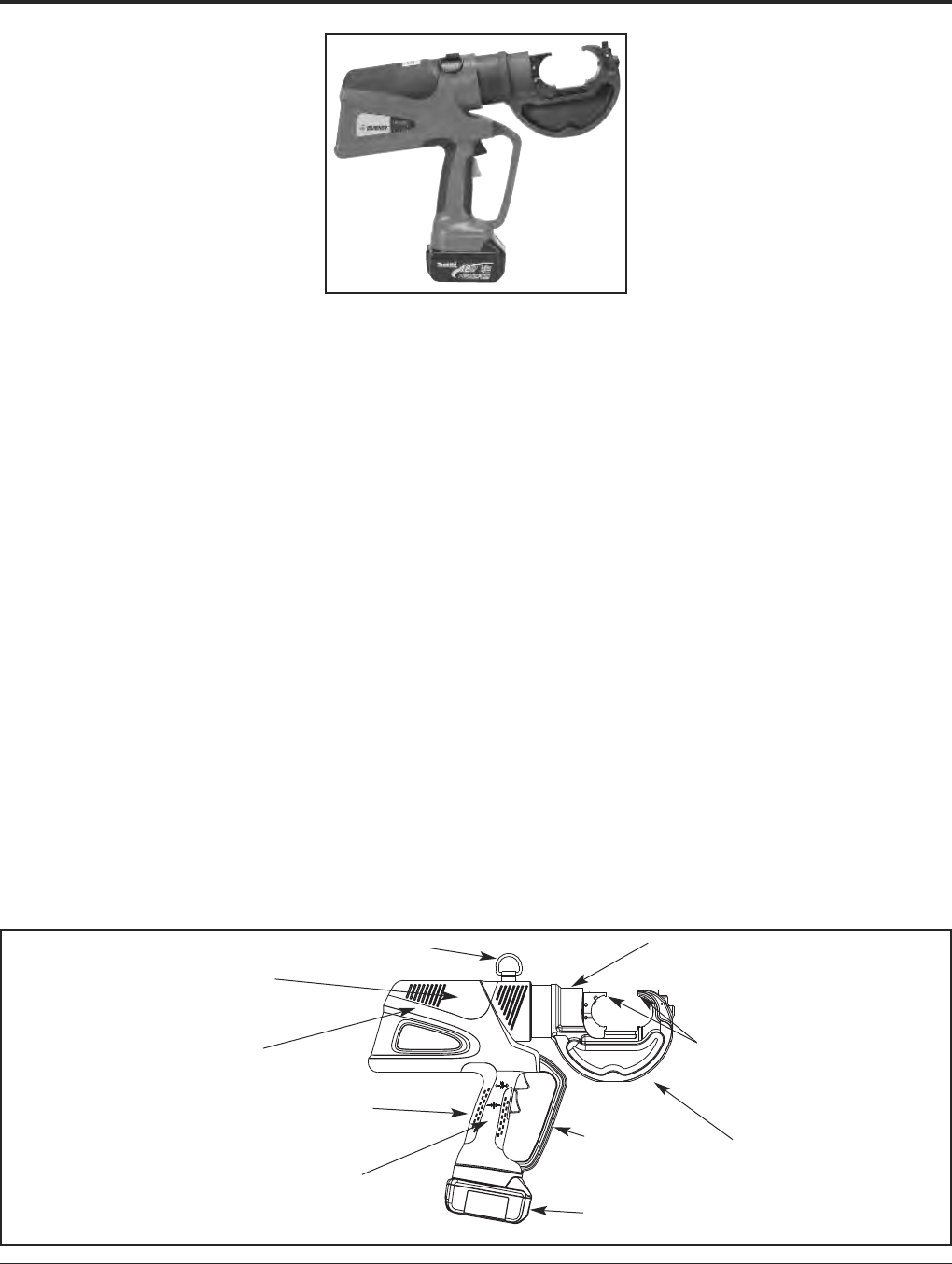
BURNDY®Grounding
Tooling
US: 1-800-346-4175 www.burndy.com Canada: 1-800-387-6487
119
PATRIOT®HIGH
PERFORMANCE
PAT750-LI
18 Volt Lithium-Ion
Battery Actuated Tool
Hydraulic Self-Contained
12-Ton Crimping Tool
The BURNDY®PATRIOT®PAT750-LI Lithium-
Ion tool is approximately 25% faster than the
previous models. In addition to faster crimp
cycles, the High Performance PAT750-LI has
newly designed electronics that are field
proven for ultimate reliability and proven to
handle the harshest work environments.
The PAT750-LI incorporates the latest engi-
neering technology with a refined hydraulic
system for ultra performance, speed and reli-
ability. The redesigned field proven electron-
ics provides the ultimate reliability in the
harshest work environments. All BURNDY®
battery actuated hydraulic tools provide a con-
sistent, reliable connection every time. The
PAT750-LI features the BURNDY®Y750 tool
head, capable of using all “U” style dies, and
incorporates a bearing and alignment guide
for use on HYGROUND®and other asymmet-
rical connectors. The crimp head rotates 355º
for operation in virtually any position.
Each PATRIOT®tool uses standard BURNDY®
dies and off-the-shelf connectors available
world-wide. Supplied with a durable high im-
pact formed carrying case to hold the tool,
battery charger, two 18 volt Lithium-Ion bat-
teries, tool retention lanyard, and die com-
partment to hold “U” die sets. (Dies sold
separately.) Provided with a 5-year limited
warranty. All PATRIOT®tools feature the
BURNDY®INFINITY DRIVE®transmission
which has a lifetime warranty.
Features and Benefits
• Refined hydraulic system for ultra
performance, speed and reliability
• Field proven electronics for ultimate
reliability in the harshest environments
• Overmolded handle for comfort and im-
proved grip; allows for one-handed opera-
tion for advance, retract, and hold
• 18 volt Lithium-Ion batteries provide 2.5
times more charge/discharge cycles than
traditional Ni-Cd batteries and provide
430% more lifetime work
• 30-minute charger controls current, voltage
& temperature to maximize battery life.
Forced air cooling fan cools the battery by
forcing cool air through the battery's built-
in air vents
• State of the art crimping head design, 355°
head rotation lets user get into tight areas
easier
• Allows use of standard BURNDY®dies al-
ready in use
• Ergonomically balanced tool design eases
operation
• Durable high impact formed carrying case
provides superior protection and stores all
accessories
•PAT750C-LI with rubber covered head is
available
• 5-year limited warranty on tool
• Lifetime warranty on INFINITY DRIVE®
• 1-year warranty on batteries and charger
SPECIFICATIONS
Output Force: 12 tons
(10.9 metric tons)
Tool Weight: 15.7 lbs. (7.12 kg)
With Battery
Length: 15.75(40 cm)
Width: 3.5(8.89 cm)
Height: 13.5(34.29 cm)
Operating Voltage: 18 V-DC
Recharge Time: 30 minutes
FOR USE ON
• Tension Sleeves
Copper #9 sol. - 500 kcmil
Aluminum #8 sol. – 587.2 kcmil
ACSR #4 – 556.5 kcmil
• Taps
Copper #14 sol. – 500 kcmil
Aluminum #8 – 500 kcmil
• Aerial Cable
Copper #6 – 500 kcmil
• Terminals & Splices
Aluminum #8 – 750 kcmil
Copper #8 – 750 kcmil
ACSR #4 – 556 kcmil
• HYGROUND®
Copper #8 – 500 kcmil
(cable/ground rod)
Ground Rods 1/2– 1Diameter
ACCESSORIES
Battery: Cat# BAT18VLI
(3.0 AH) Hi-capacity
Chargers:
120V-AC Cat# PATCHGR-LI
12/24V-DC Cat# PATCHGR-LIDC
240/250V-AC Cat# PATCHGR-LI250V
Lanyard: Cat# PT208620
Safety Lanyard Connection
Refined Hydraulic System
for Ultra Performance,
Speed and Reliability
Audible “Pop-Off” Valve
Ergonomically Balanced
Overmolded Handle
Field Proven Electronics for
Ultimate Reliability in the
Harshest Work Environments
355° Rotational Head for
Use with “U” Dies
Large 1.65Jaw Opening
to Accommodate
Asymmetrical Connectors
12 Ton Output Force
Trigger Guard
18 Volt Lithium-Ion Battery
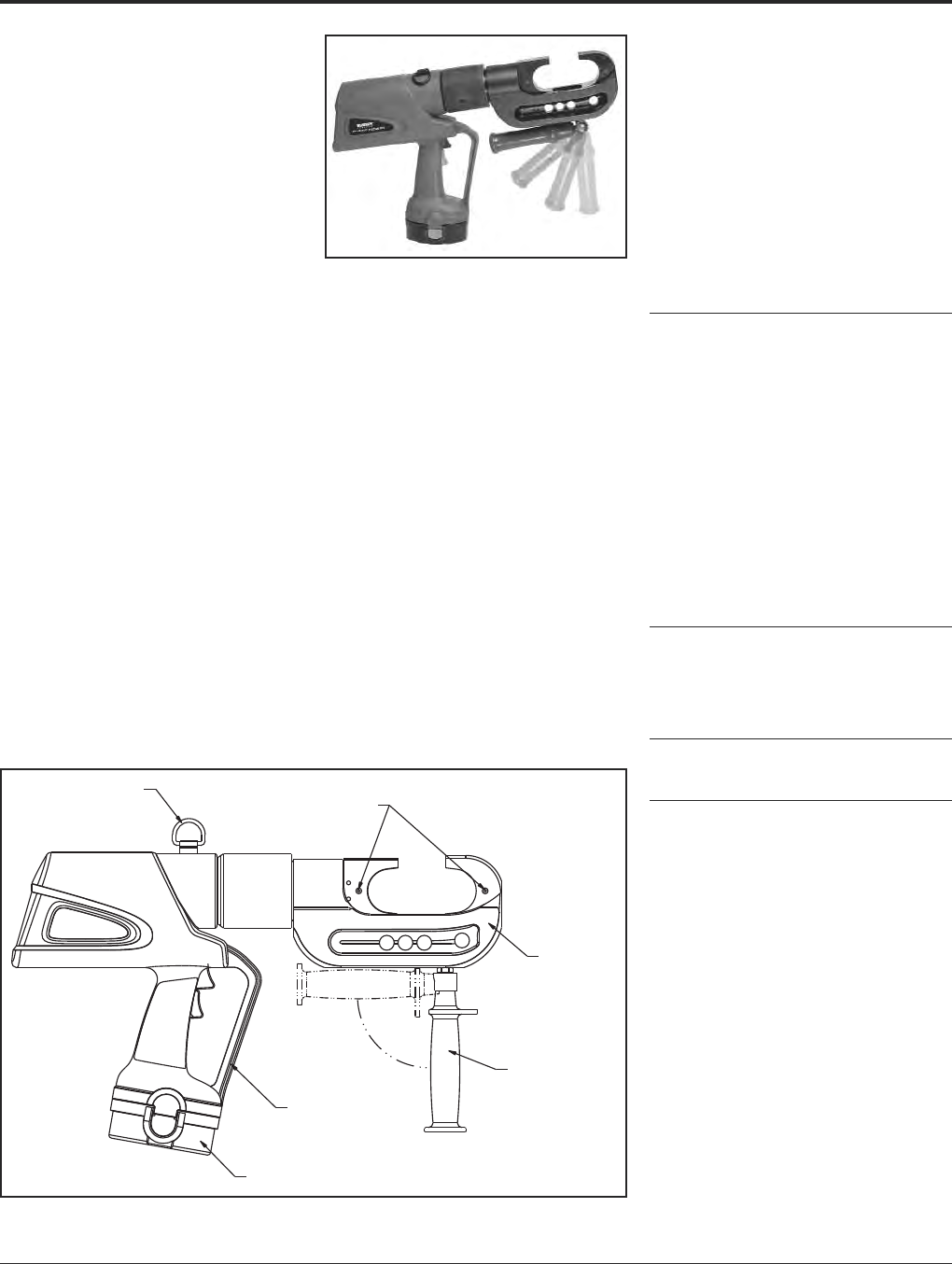
Grounding BURNDY®
Tooling
Canada: 1-800-387-6487 www.burndy.com US: 1-800-346-4175
120
PATRIOT®PAT46-18V
Battery Actuated Tool
Hydraulic Self-Contained
15-Ton Crimping Tool
The BURNDY®PATRIOT®PAT46-18V incorpo-
rates the latest engineering technology with a
patented high speed hydraulic pump. Our bat-
tery actuated hydraulic tool provides a con-
sistent, reliable connection every time. The
PAT46-18V features BURNDY’s Y46 tool head,
capable of using all “P” and “U” style dies.
Each PATRIOT®uses standard BURNDY®dies
and off-the-shelf connectors available world-
wide. Supplied with a durable high impact
formed carrying case to hold the tool, battery
charger, two batteries, tool retention lanyard,
and die compartments to hold both “P” and
“U” die sets (dies sold separately). All
BURNDY®PATRIOT®PAT46 tools are pro-
vided with a 5-year limited warranty.
PAT46C-18V — with rubber covered head is
available.
SPECIFICATIONS
Output Force: 15 tons (13.6 metric
tons)
Weight: 26.2 lbs. (11.88 kg)
Length: 20.77(52.76 cm)
Height: 14.43(36.65 cm)
Width: 3.70(9.40 cm)
Operating Voltage: 18V-DC
Battery Recharge
Time: <45 minutes
FOR USE ON
Connector Conductor
Type Range
Copper, Terminals, grounding: to 500 kcmil
#8 AWG str. - YGA, YGHA, YGF
1500 kcmil Terminals, uninsulated: #8 to
Code Cable, 1500 kcmil: YA, YA-2N, YA-L,
Navy Cable, YA-LB, YA-TC, YA-2LN, YAB-4N
Flexible and YAV-L Box, YAV-L, YAV-RS Box,
Extra Flexible YAV-RS, YA-TC-FX
1/2- 1Terminals, insulated: #8 to 2/0
Ground Rods YAEV-L Box, YAEV-L, YAEV-H,
YAEV-RS, YAEV-RH
Splices: #8 to 1500 kcmil
YS, YS-T, YS-L, YS-LB, YST,
YSP-T, YGS, YGHS
Taps:
YH, YCHC #14 to 1000 kcmil,
YC-C to 4/0 AWG
Taps, grounding: to 500 kcmil
YGHC-C, YGHP-C, YGHR-C
Aluminum Terminals:
#8 AWG - YA-A, AYP, AYPO
1250 kcmil Splices:
Code Cables YS-A, YS-AT, YRB
Taps:
YFD, YFN, YFO, YFR
ACSR See BURNDY®Overhead
Transmission and
Distribution Catalog Module
ACCESSORIES
Cutter Die: Cat# P15K
Die max. 1.2dia.
“U” Die Adapter: Cat# PUADP-1
Battery: Cat# BAT18V
High Capacity Ni-MH
(2.6 AH)
Chargers:
120V-AC Cat# PATCHGR18V
12/24V-DC Cat#
BCT/PATDCCHGR
240/250V-AC Cat# PATCHGR250V
Features and Benefits
• BURNDY’s largest battery actuated crimp
tool, providing 15-tons of output force with
a 2jaw opening.
〫Allows users to install the largest variety
of splices, taps and terminals with one
tool. Also provides easy placement and
removal from continuous conductor
lengths.
• State of the art C-Head crimp design with
355° head rotation.
〫Versatile tool head positioning lets user
get into tight areas easier.
• Retractable assist handle under head of
tool for better handling of tool.
〫Allows for better balance of tool and
retractable for getting head into tight
areas.
• Durable high impact formed carrying case.
〫Provides superior protection and stores
all accessories.
• 18-volt Ni-MH battery eliminates voltage
depression (memory issues).
〫Less “down-time” due to high capacity,
high voltage 18-volt battery
• 5-year limited warranty on tool. 1-year
warranty on battery and charger.
Safety Lanyard
Connection Positive Push
Button Die Lock
Forged Steel
Head
Retractable Assist
Handle
Trigger Guard
18-Volt Ni-MH Battery
15 Ton Output Force
Large 2
Jaw Opening
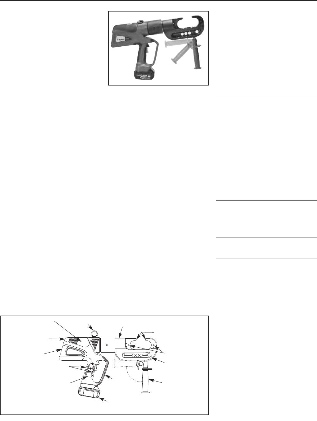
BURNDY®Grounding
Tooling
US: 1-800-346-4175 www.burndy.com Canada: 1-800-387-6487
121
PATRIOT®PAT46-LI
18 Volt Lithium-Ion
Battery Actuated Tool
Hydraulic Self-Contained
15-Ton Crimping Tool
The BURNDY®PATRIOT®PAT46-LI Lithium-
Ion tool incorporates the latest engineering
technology with a patented high speed hy-
draulic pump. The redesigned field proven
electronics provides the ultimate reliability in
the harshest work environments. BURNDY®
battery actuated hydraulic tools provide a con-
sistent, reliable connection every time. The
PAT46-LI features BURNDY’s Y46 tool head,
capable of using all “P” and “U” style dies.
Each PATRIOT®tool uses standard BURNDY®
dies and off-the-shelf connectors available
world-wide. Supplied with a durable high im-
pact formed carrying case to hold the tool, bat-
tery charger, two 18 volt Lithium-Ion batteries,
tool retention lanyard, and die compartments to
hold both “P” and “U” die sets (dies sold sep-
arately). All BURNDY®PATRIOT®tools are pro-
vided with a 5-year limited warranty. All
PATRIOT®tools feature the BURNDY®INFIN-
ITY DRIVE®transmission which has a lifetime
warranty.
PAT46C-LI — with rubber covered head is
available.
Features and Benefits
• BURNDY’s largest battery actuated crimp
tool providing 15-tons of output force with
a 2jaw opening
〫Allows users to install largest variety of
splices, taps and terminals with one tool
and provides easy placement and re-
moval from continuous conductor
lengths
• Redesigned field proved electronics
〫Provides the ultimate reliability in the
harshest work environments
SPECIFICATIONS
Output Force: 15 tons
(13.6 metric tons)
Total Weight: 25.5 lbs. (11.88 kg)
Length: 20.77(52.76 cm)
Height: 14.43(36.65 cm)
Width: 3.70(9.40 cm)
Operating Voltage: 18V-DC
Recharge Time: 30 minutes
FOR USE ON
Connector Conductor
Type Range
Copper, Terminals, grounding: to 500 kcmil
#8 AWG str. - YGA, YGHA, YGF
1500 kcmil Terminals, uninsulated: #8 to
Code Cable, 1500 kcmil: YA, YA-2N, YA-L,
Navy Cable, YA-LB, YA-TC, YA-2LN, YAB-4N
Flexible and YAV-L Box, YAV-L, YAV-RS Box,
Extra Flexible YAV-RS, YA-TC-FX
1/2- 1Terminals, insulated: #8 to 2/0
Ground Rods YAEV-L Box, YAEV-L, YAEV-H,
YAEV-RS, YAEV-RH
Splices: #8 to 1500 kcmil
YS, YS-T, YS-L, YS-LB, YST,
YSP-T, YGS, YGHS
Taps:
YH, YCHC #14 to 1000 kcmil,
YC-C to 4/0 AWG
Taps, grounding: to 500 kcmil
YGHC-C, YGHP-C, YGHR-C
Aluminum Terminals:
#8 AWG - YA-A, AYP, AYPO
1250 kcmil Splices:
Code Cables YS-A, YS-AT, YRB
Taps:
YFD, YFN, YFO, YFR
ACSR See BURNDY®Overhead
Transmission and
Distribution Catalog Module
ACCESSORIES
Cutter Die: Cat# P15K
Maximum Dia. 1.2
“U” Die Adapter: Cat# PUADP-1
Battery: Cat# BAT18VLI
High Capacity Li-Ion
(3.0 AH)
Chargers:
120V-AC Cat# PATCHGR-LI18V
12/24V-DC Cat# PATCHGR-LIDC
240/250V-AC Cat# PATCHGR-LI250V
Features and Benefits (continued)
• Overmolded ergonomic handle
〫For comfort and improved grip; allows
for one handed operation for advance,
retract, and hold
• 18-volt (3.0 AH) Li-Ion batteries
〫Batteries provide 2.5 times more charge/
discharge cycles than traditional Ni-Cd
batteries and 430% more lifetime work
〫Less “down-time” due to high capacity
(3.0 AH), 18 volt Li-Ion battery
〫No voltage depression (memory issues)
• 30-minute smart charger
〫Controls current, voltage and
temperature to maximize battery life
〫Forced air cooling fan cools the battery
by forcing cool air through the battery’s
built-in air vents
• State of the art C-Head crimp design with
355° head rotation
〫Versatile tool head positioning lets user
get into tight areas easier
• Retractable assist handle under head of
tool for better handling of tool
〫Allows for better balance of tool and re-
tractable for getting head into tight areas
• Durable high impact formed carrying case
〫Provides superior protection and stores
all accessories
• PAT46C-LI with rubber covered head is
available
• 5-year limited warranty on tool
• Lifetime warranty on INFINITY DRIVE®
• 1-year warranty on batteries and charger
Safety Lanyard
Connection 355° Rotational Head for
Use with “P” Dies
Large 2Jaw Opening
Positive Push Button
Die Lock
Forged Steel Head
Retractable Assist
Handle
18 Volt Lithium-Ion
Battery
Trigger
GuardField-Proven Electronics
for Ultimate Reliability in
the Harshest Work Envi-
ronments
Overmolded Handle
15 Ton Output Force
Audible “Pop-Off”
Valve
Refined Hydraulic System
for Ultra Performance,
Speed and Reliability
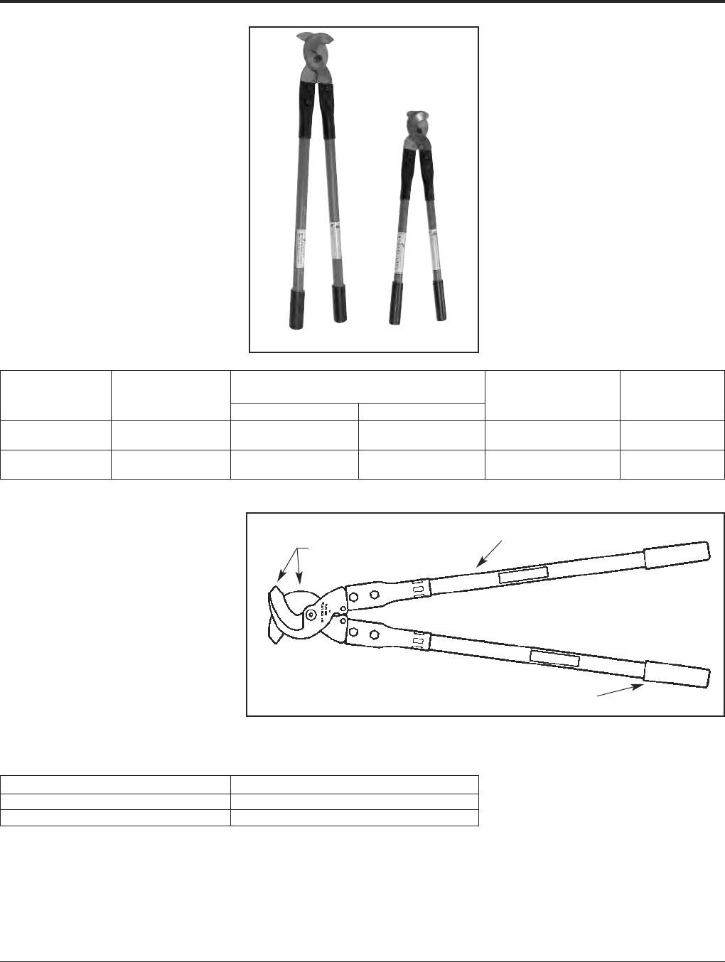
Grounding BURNDY®
Tooling
Canada: 1-800-387-6487 www.burndy.com US: 1-800-346-4175
122
MCC500, MCC1000
Manual Cable Cutters
The MCC series cable cutters are precision
cable cutters incorporating high leverage
shear-type design capable of cutting up to
1000 kcmil copper and aluminum cables.
Rugged steel blades and fiberglass construc-
tion provide cutting ease, long life and
minimum cable distortion.
The MCC series cable cutters are warranted
to be free from defects in material (excluding
blades) and workmanship for one year.
FEATURES
• High quality design and construction.
• Rugged high quality steel blades.
• Fiberglass handles with soft grips.
BENEFITS
• Easy cutting with minimal cable distortion.
• Excellent cutting edge performance.
• Provides comfortable tool operation and
long life.
MCC1000 MCC500
Max.
Catalog Overall Max. Capacity Insulation
Number Length Copper Aluminum Diameter Weight
211.253.5 lbs.
MCC500 [533 mm] 500 kcmil 500 kcmil [32 mm] (1.5 kg)
321.909.0 lbs.
MCC1000 [813 mm] 1000 kcmil 1000 kcmil [48 mm] (4.0 kg)
Replaceable
Blades
Handles
Handle Grips
Catalog Number Description
MCC500BLADESET Replacement blades for MCC500
MCC1000BLADESET Replacement blades for MCC1000
Replacement Blades
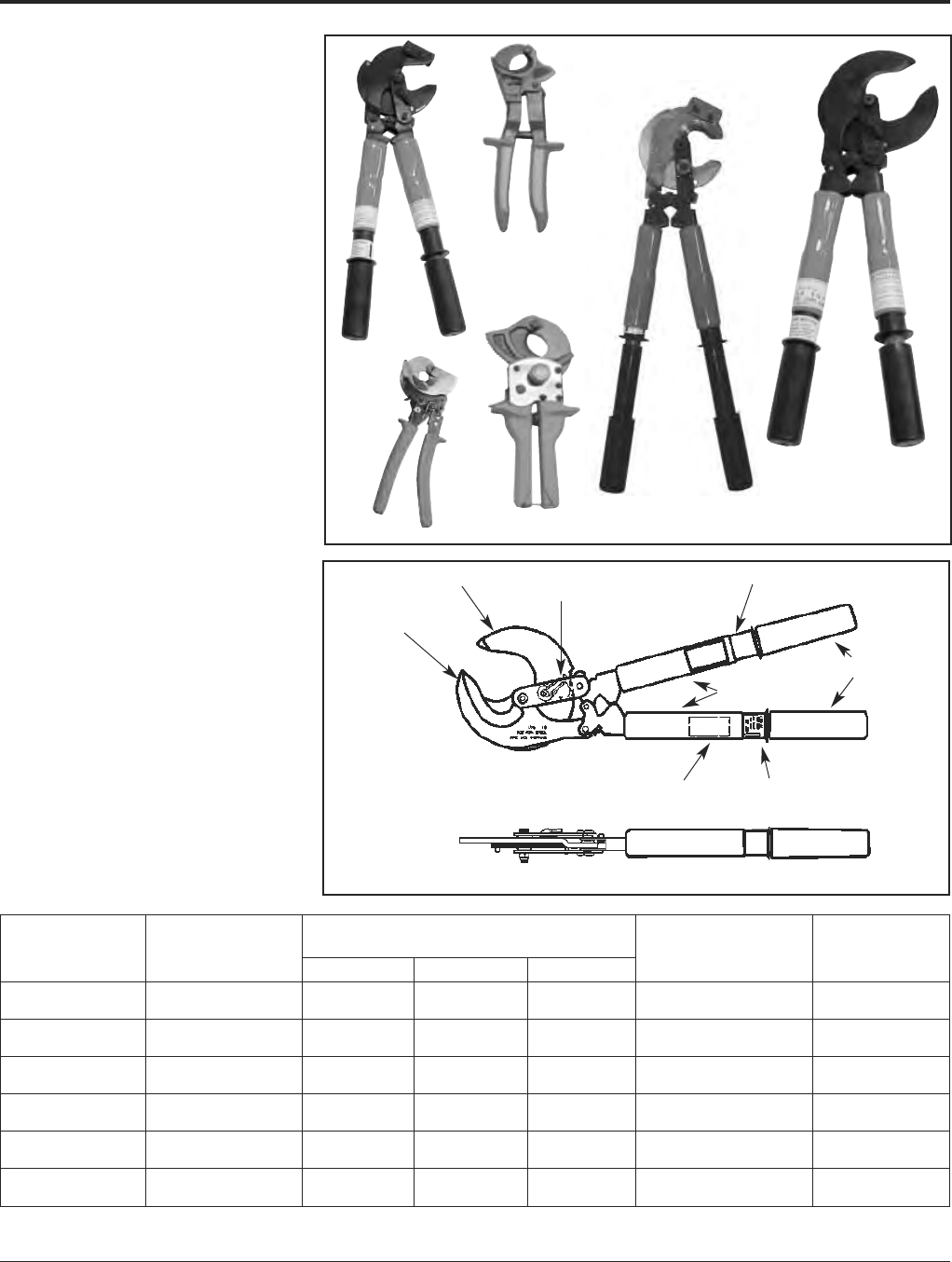
BURNDY®Grounding
Tooling
US: 1-800-346-4175 www.burndy.com Canada: 1-800-387-6487
123
RCC336, RCC556,
RCC600, RCC750HD,
RCC954ACSR1K,
RCC1000
Ratchet Cable Cutters
The RCC series cable cutters are precision
high quality tools designed to cut up to
954 ACSR and 1000 kcmil copper and
aluminum. The tools are equipped with
rugged steel blades, and a precision
bi- directional ratchet mechanism for positive
blade control, including where applicable, a
fast action thumb slide collar for rapid blade
advance and rugged fiberglass or non-slip
grip handles. RCC600 and RCC750HD have
cushion grip covered steel handles.
The RCC series cable cutters are warranted
to be free from defects in material (excluding
blades) and workmanship for one year.
For replacement blades, consult factory for
details.
FEATURES
• Patented high strength steel blades.
• Quick release, bi-directional ratchet
mechanism.
• Rapid blade advance.
BENEFITS
• Easy cutting with minimal cable distortion.
• Excellent cutting edge performance.
• Provides comfortable tool operation and
long life.
Moveable Jaw
Stationary Jaw
Warning Label
Cover
Handle Grips
Direction Lever
Open/Close Indicator
Rapid Advance Feature
Product Label
RCC600
RCC750HD
RCC1000
RCC556
RCC954ACSR1K
RCC336
Maximum
Catalog Overall Maximum Capacity Insulation
Number Length Copper Aluminum ACSR Diameter Weight
10.5350 kcmil 500 kcmil 336 kcmil 0.741.2 Lbs.
RCC336 [267 mm] [177 mm] [253 mm] [18.31 mm] [18.8 mm] (0.5 kg)
20500 kcmil 500 kcmil 556 kcmil 1.254.5 Lbs.
RCC556 [508 mm] [26.70 mm] [26.70 mm] [23.55 mm] [31.75 mm] (2.0 kg)
10600 kcmil 600 kcmil 1.251.27 Lbs.
RCC600 [254 mm] [26.70 mm] [26.70 mm] —[31.75 mm] (.57 kg)
10.5750 kcmil 750 kcmil 1.622.43 Lbs.
RCC750HD [267 mm] [29.36 mm] [29.36 mm] —[41.15 mm] (1.1 kg)
22.751000 kcmil 1000 kcmil 954 kcmil 1.386.5 Lbs.
RCC954ACSR1K [578 mm] [33.27 mm] [33.27 mm] [30.38 mm] [35.05 mm] (2.95 kg)
201000 kcmil 1000 kcmil 2.3754.5 Lbs.
RCC1000 [508 mm] [33.27 mm] [33.27 mm] —[60.32 mm] (2.0 kg)
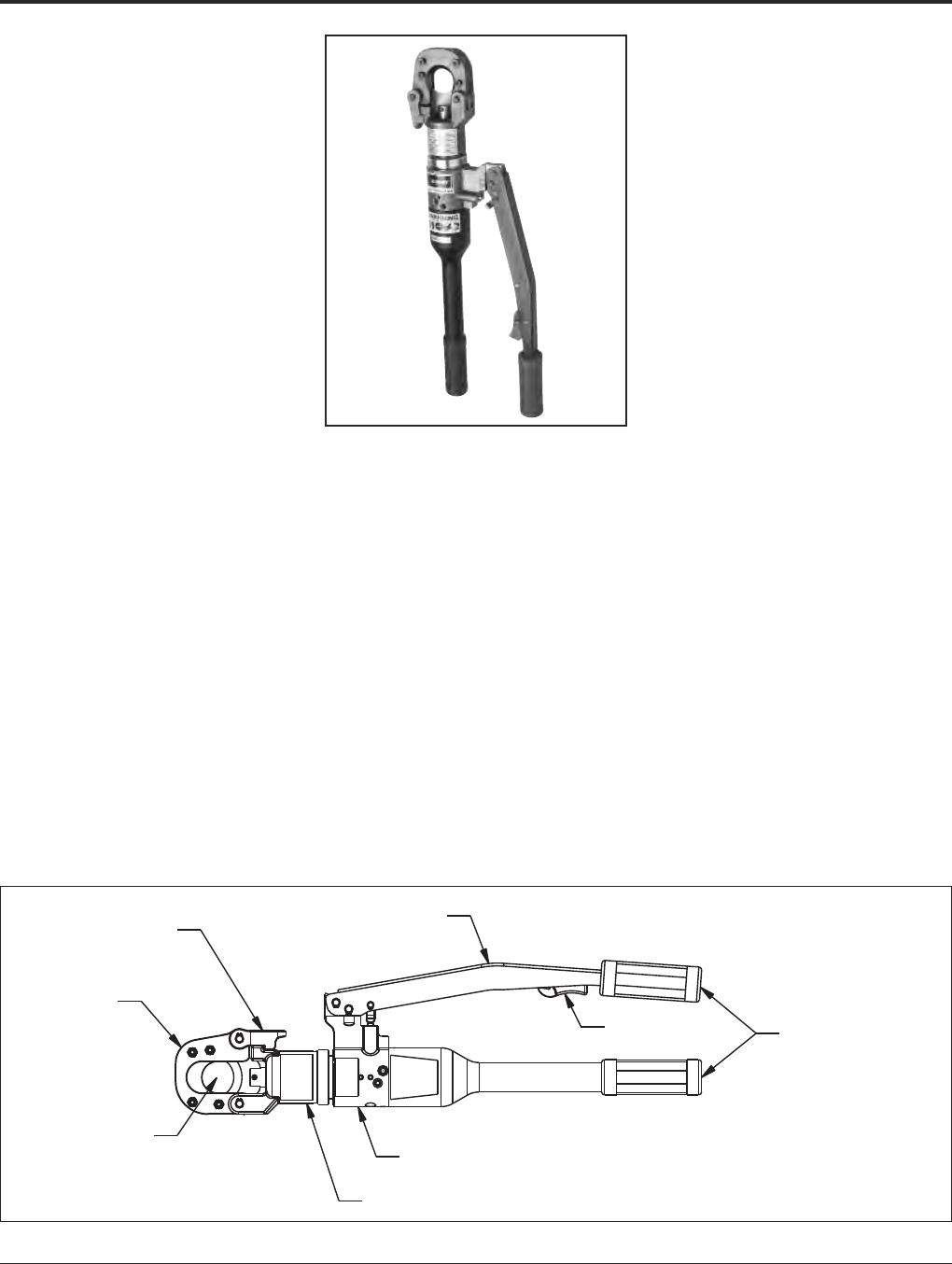
Grounding BURNDY®
Tooling
Canada: 1-800-387-6487 www.burndy.com US: 1-800-346-4175
124
YCUT129ACSR
Hydraulic Hand
Operated Cutter
The BURNDY®YCUT129ACSR incorporates
a specialized latch style cutting head that
allows interference-free closure for mid-span
cuts. The cutter head rotates 180 degrees to
allow users to get into tight areas easier. The
YCUT129ACSR weighs only 11.4 pounds, yet
delivers 7 tons of cutting force. The
YCUT129ACSR with its hardened steel
blades is capable of cutting up to 1.29diam-
eter bare or insulated copper and aluminum
cable, 1113 ACSR, 5/8ground rod, 1/2 rebar
and 5/8diameter soft steel bolts 1/2stan-
dard guy strand and up to 3/8EHS guy
strand.
The YCUT129ACSR comes equipped with a
high impact formed carrying case to hold the
tool and accessories. The BURNDY®
YCUT129ACSR is provided with a 5-year
limited warranty (excluding blades).
Features and Benefits
• Patented rapid advance pump.
〫Faster cuts with less hand strokes.
• Specialized latch head design.
〫Interference free closure on mid-span
cuts.
• Handle trigger drain
〫For convenient blade retraction.
• Hardened steel blades.
〫Ability to cut ACSR, ground rods, rebar
and guy wire.
• Comfort grip handles.
〫Help ease fatigue with continuous use.
• 180-degree head rotation.
〫Versatile head positioning to get into
tight areas easier.
• Durable high impact formed carrying case.
〫Provides tool protection and stores
accessories.
• 5-year limited warranty on tool (excluding
blades).
〫Customer satisfaction and support.
SPECIFICATIONS
Force Developed: 7 U.S. short tons
Tool Weight: 11.4 lbs. (5.1 kg)
Length: 22.4 (56.9 cm)
Width: 2.5 (6.4 cm)
Height: 6.6 (16.8 cm)
FOR USE ON
• Copper Cable: up to 1.29
• Aluminum Cable: up to 1.29
• ACSR: up to 1113 ACSR
• Ground Rod: up to 5/8
• Rebar: up to 1/2
• Soft Steel Bolts: up to 5/8
• Standard Guy Strand: up to 1/2
• EHS Guy Strand: up to 3/8
ACCESSORIES
•Carrying Case: Cat# PT10024162
•Replacement Blades:
Cat# PT10037388
(Moving Blade)
Cat# PT10037384
(Fixed Blade)
Specialized
Latch Head
Design
Precision
Cutting
Blades
1.29Cutting
Capacity
Ergonomic Handle Design
Patented Rapid
Advance Pump
180° Head Design
Comfort
Grip Handles
Handle Trigger
Drain
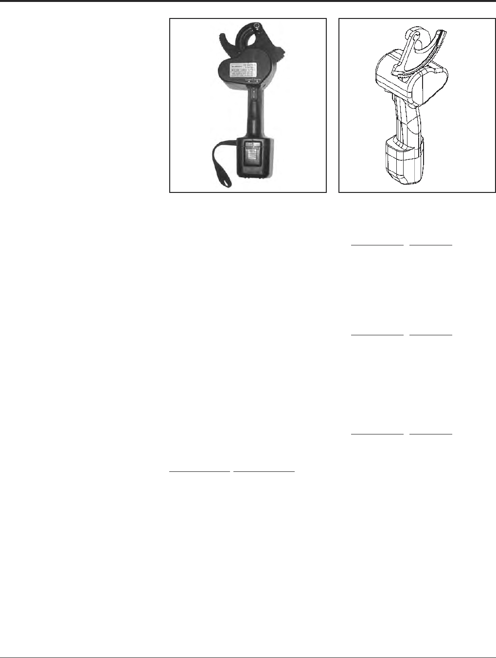
BURNDY®Grounding
Tooling
US: 1-800-346-4175 www.burndy.com Canada: 1-800-387-6487
125
BCC1000CUAL
Battery Actuated Cable Cutter
The BURNDY®BCC1000CUAL is a 12 V-DC
battery actuated cable cutter capable of
cutting up to 750 kcmil hard drawn copper
cable, and up to 1000 kcmil soft drawn
copper and up to 2O.D. aluminum cable.
DO NOT CUT STEEL or ACSR. The
BCC1000CUAL comes with battery powered
cutting tool, sealed nickel cadmium 12 V bat-
tery, 120V AC charger, carrying case, and
wrist loop which provides added security
when making cuts overhead.
The BURNDY®BCC1000CUAL is designed
to cut copper and aluminum cables in a
limited amount of space. The BCC1000CUAL
makes fast reliable cuts without stress to the
user. Just squeeze the trigger and it will cut
through your toughest copper and aluminum
cables. The BCC1000CUAL has a three-way
switch (forward, reverse, and neutral) which
allows the user to make partial cuts, back off
cables, or make adjustments during cutting.
The battery charge time is approximately
1 hour for a fast charge (80%), 4 to 6 hours
for a quick charge, and 14 to 16 hours for a
standard charge (100%). The 12 V battery can
be recharged approximately 1,000 times.
The BCC1000CUAL (excluding cutting
blades) is warranted to be free of defects in
material and workmanship for a period of 90
days, except in the case of abuse or
modification.
SPECIFICATIONS
Cutting Tool
Specifications Description
Drive Unit: 12 V-DC Motor
Dimensions: 4L 4.5W 14.5H
Weight: 6 lbs.
Cutting Capacity: 1000 kcmil soft drawn
copper, 750 kcmil hard
drawn copper and up to
2O.D. aluminum
Battery
Specifications Description
Battery Type: Sealed nickel cadmium
Voltage: 12 V-DC
Rated Capacity: 1.2 A/hr
Charge Time: Fast, approx. 1 hour
Quick, 4-6 hours
Standard, 14-16 hours
Dimensions:
2.75L 2.7W 4.75H
Weight: 1.4 lb.
Battery Charger
Specifications Description
Input Voltage: 120 V-AC
Input Frequency: 60 Hz
Input Current: 110/120V
Dimensions: 5.7L 3W 2.8H
Weight: 2.2 lbs.
FOR USE ON
Maximum conductors accommodated:
750 kcmil hard drawn copper
1000 kcmil soft drawn copper
1000 kcmil alumimum
FEATURES
• Hook head design.
• Three way switch.
• Hardened steel blades.
• Ergonomic design.
• Wrist loop.
BENEFITS
• Simplifies conductor cutting and allows
working in tight spaces.
• Allows backing off cable, partial cuts,
and adjusting during cutting.
• Helps ensure consistent cuts and longer
blade life.
• Prevents hand/wrist injury.
• Withstands rugged use. Resists oil
and solvents.
• Added security when cutting cables
overhead.
ACCESSORIES
Catalog Number Item Description
BCCBAT12V BCC1000CUAL Battery
BCCCHGR BCC1000CUAL Charger
BCCCASE BCC1000CUAL
Carrying Case
RP50RP03 BCC1000CUAL
Moving Blade
RP50RP02 BCC1000CUAL
Fixed Blade
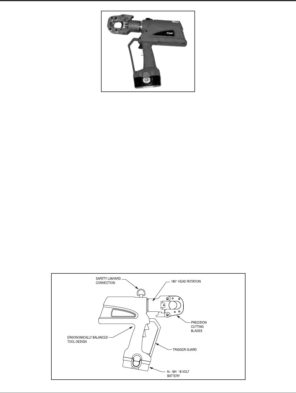
Grounding BURNDY®
Tooling
Canada: 1-800-387-6487 www.burndy.com US: 1-800-346-4175
126
PATRIOT®
PATCUT129ACSR-18V
Battery Actuated Tool
Hydraulic Self-Contained Cutter
The BURNDY®PATCUT129ACSR-18V battery
powered cutting tool is compact, fast, easy to
use and incorporates the latest in battery tool
technology. The ergonomic design allows one
hand operation so that the other is free to
manipulate the conductor in the proper cutting
position. The PATCUT129ACSR-18V incorpo-
rates a specialized latch style cutting head that
allows interference-free closure for mid-span
cuts. The cutter head rotates 180 degrees to
allow users to get into tight areas easier. The
PATCUT129ACSR-18V is capable of cutting
up to 1.29diameter copper and aluminum
cable, 1113 ACSR, 5/8ground rod, 1/2 rebar,
5/8diameter soft steel bolts, up to 1/2stan-
dard guy strand, and up to 3/8EHS guy
strand.
The PATCUT129ACSR-18V operates on
industry standard 18-volt Ni/MH batteries that
eliminate voltage depression or “memory”
issues. The PATCUT129ACSR-18V comes
equipped with a high impact formed carrying
case to hold the tool, a tool retention lanyard,
a battery charger and two batteries. The
PATCUT129ACSR-18V is provided with a
5-year limited warranty (excluding blades),
and 1-year on batteries and charger.
Features and Benefits
• Battery powered cutting technology.
〫Easy tool operation and portability.
• Advance design high-speed pump
completes tough cuts faster.
〫Longer life, efficiency, and reliability.
• Specialized latch head design.
〫Interference free closure for mid-span
cuts.
• Ergonomic design allows one hand
operation.
〫User has one hand free to manipulate
material to be cut.
• 180 degree head rotation.
〫Versatile head positioning allows user to
get into tight areas easier.
• Mechanical ram release.
〫Reliable ram release (no battery power
consumption).
• Operates on 18 volt Ni-MH batteries.
〫Eliminates voltage depression or
”memory” issues.
• Durable high impact formed carrying case.
〫Provides tool protection and stores all
accessories.
• 5-year limited warranty on tool (excluding
blades) and 1 year on batteries and
charger.
〫Customer satisfaction and support.
SPECIFICATIONS
Tool Weight: 11 lbs.
Length: 14.5
Width: 3.5
Height: 13.5
Operating Voltage: 18 V-DC
Recharge Time: < 45 mins.
FOR USE ON
• Copper Cable: up to 1.29
• Aluminum Cable: up to 1.29
• ACSR: up to 1113 ACSR
• Ground Rod: up to 5/8
• Rebar: up to 1/2
• Soft Steel Bolts: up to 5/8
• Standard Guy Strand: up to 1/2
• EHS Guy Strand: up to 3/8
ACCESSORIES
•Lanyard: Cat# PT208620
•Battery: Cat# BAT18V
Hi-capacity
(2.6 AH)
•Charger:
120V-AC Cat# PATCHGR18V
12/24V-DC Cat# BCT/PATDCCHGR
240/250V-AC Cat# PATCHGR250V
•Replacement Blades:
Cat# PT10037388
(Moving Blade)
Cat# PT10037384
(Fixed Blade)

BURNDY®Grounding
Tooling
US: 1-800-346-4175 www.burndy.com Canada: 1-800-387-6487
127
PATRIOT®
PATCUT129-LI
18 Volt Lithium-Ion
Battery Actuated Cutter
Hydraulic Self-Contained
Cutting Tool
The BURNDY®PATRIOT®PATCUT129-LI
Lithium-Ion tool incorporates the latest engi-
neering technology with a refined hydraulic
system for ultra performance, speed and
reliability. The redesigned field proven elec-
tronics provide the ultimate reliability in the
harshest work environments. All BURNDY®
battery actuated hydraulic tools provide a
consistent cut every time.
The PATCUT129-LI battery powered cutting
tool is compact, fast, easy to use and incor-
porates the latest in battery tool technology.
The ergonomic design allows one hand oper-
ation so that the other is free to manipulate the
conductor in the proper cutting position. The
PATCUT129-LI incorporates a specialized
latch-style cutting head that allows interfer-
ence-free closure for mid-span cuts. The
cutter head rotates 180 degrees to allow users
to get into tight areas easier. The PATCUT129-
LI is capable of cutting up to 1.29diameter
copper and aluminum cable, 1113 ACSR, 5/8
ground rods, 1/2rebar, 5/8diameter soft
steel bolts, up to 1/2standard guy strand,
and up to 3/8EHS guy strand.
The PATCUT129-LI is supplied with a durable
high impact formed carrying case to hold the
tool, battery charger, two 18 volt Lithium-Ion
batteries and tool retention lanyard. The
PATCUT129-LI is provided with a 5-year lim-
ited warranty (excluding blades), and 1-year
on batteries and charger. All PATRIOT®tools
feature the BURNDY®INFINITY DRIVE®trans-
mission which has a lifetime warranty.
Features and Benefits
• Refined hydraulic system for ultra
performance, speed and reliability
• Field proven electronics for ultimate
reliability in the harshest environments
• Overmolded handle for comfort and
improved grip; allows for one-handed
operation for advance, retract, and hold
• Specialized latch head design for
interference free closure for mid-span cuts
• 18-volt Lithium-Ion batteries provide 2.5
times more charge/discharge cycles than
traditional Ni-Cd batteries and provide
430% more lifetime work
• 30 minute charger controls current, voltage
and temperature to maximize battery life
• Forced air cooling fan cools the battery by
forcing cool air through the battery’s built-in
air vents
• 180° head rotation allows user to get into
tight areas easier
• Ergonomically balanced tool design eases
operation and lessens fatigue
• Durable high impact formed carrying case
provides superior protection and stores all
accessories
• 5-year limited warranty on tool (excluding
blades)
• Lifetime warranty on INFINITY DRIVE®
• 1-year warranty on batteries and charger
SPECIFICATIONS
Tool Weight: 10.2 lbs (4.6 kg)
with Battery
Length: 14.5(36.8 cm)
Width: 3.5(8.9 cm)
Height: 13.5(34.3 cm)
Operating Voltage: 18 V-DC
Recharge Time: 30 minutes
FOR USE ON
Copper & Aluminum Cable: Up to 1.29
ACSR: Up to 1113
Ground Rod: Up to 5/8
Rebar: Up to 1/2
Soft Steel Bolts: Up to 5/8
Standard Guy Strand: Up to 1/2
EHS Guy Strand: Up to 3/8
ACCESSORIES
Battery: Cat# BAT18VLI
(3.0 AH) Hi-capacity
Chargers:
120V-AC Cat# PATCHGR-LI
12/24V-DC Cat# PATCHGR-LIDC
240/250V-AC Cat# PATCHGR-LI250V
Replacement Blades:
Cat# PT10037388
(Moving Blade)
Cat# PT10037384
(Fixed Blade)
Lanyard: Cat# PT208620
Safety Lanyard Connection
Refined Hydraulic System
for Ultra Performance,
Speed and Reliability
6 Ton Output Force
Ergonomically Balanced
Overmolded Handle
Field Proven Electronics for
Ultimate Reliability in the
Harshest Work Environments
180° Head Rotation
Specialized Latch
Head Design
Trigger Guard
18 Volt Lithium-Ion Battery
Precision Cutting Blades
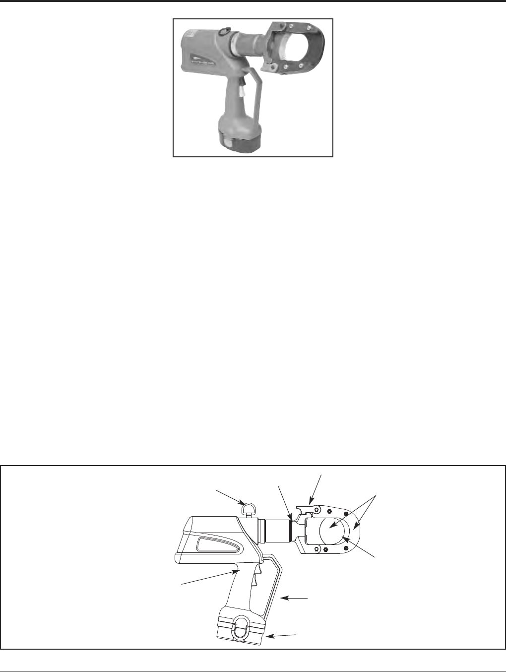
Grounding BURNDY®
Tooling
Canada: 1-800-387-6487 www.burndy.com US: 1-800-346-4175
128
PATRIOT®
PATCUT245CUAL-18V
Battery Actuated Tool
Hydraulic Self-Contained Cutter
The BURNDY®PATCUT245CUAL-18V battery
powered cutting tool is compact, fast, easy to
use and incorporates the latest in battery tool
technology. The ergonomic design allows one
hand operation so that the other is free to
manipulate the conductor in the proper cutting
position. The PATCUT245CUAL-18V incorpo-
rates a specialized latch style cutting head that
allows interference-free closure for mid-span
cuts. The cutter head rotates 180 degrees to
allow users to get into tight areas easier. The
PATCUT245CUAL-18V is capable of cutting
up to 2.45diameter copper and aluminum
cable.
The PATCUT245CUAL-18V operates on
industry standard 18-volt Ni/MH batteries that
eliminate voltage depression or “memory”
issues. The PATCUT245CUAL-18V comes
equipped with a high impact formed carrying
case to hold the tool, a tool retention lanyard,
a battery charger and two batteries. The
PATCUT245CUAL-18V is provided with a
5-year limited warranty (excluding blades),
and 1-year on batteries and charger.
Features and Benefits
• Battery powered cutting technology.
〫Easy tool operation and portability.
• Advance design high-speed pump
completes tough cuts faster.
〫Longer life, efficiency, and reliability.
• Specialized latch head design.
〫Interference free closure for mid-span
cuts.
• Ergonomic design allows one hand
operation.
〫User has one hand free to manipulate
material to be cut.
• 180-degree head rotation.
〫Versatile head positioning allows user to
get into tight areas easier.
• Mechanical ram release.
〫Reliable ram release (no battery power
consumption).
• Operates on 18-volt Ni/MH batteries.
〫Eliminates voltage depression or
“memory” issues.
• Durable high impact formed carrying case.
〫Provides tool protection and stores all
accessories.
• 5-year limited warranty on tool (excluding
blades) and 1-year on batteries and
charger.
〫Customer satisfaction and support.
SPECIFICATIONS
Tool Weight: 14.5 lbs. (5.4 kg)
With Battery
Length: 18(45.7 cm)
Width: 3.75(9.5 cm)
Height: 14.75(37.5 cm)
Operating Voltage: 18 V-DC
Recharge Time: < 45 mins.
FOR USE ON
Copper and Up to 2.45O.D
Aluminum Cable: (62.2 mm)
For Copper and Aluminum cable only. Do
not cut steel, ground rod, rebar, or guy
wire.
ACCESSORIES
•
Carrying Case: Cat# PT10044980
•Lanyard: Cat#
PT208620
•Battery: Cat# BAT18V
Hi-capacity
(2.6 AH)
•Charger:
120V-AC Cat# PATCHGR18V
12/24V-DC Cat# BCT/PATDCCHGR
240/250V-AC Cat# PATCHGR250V
•Replacement Blades:
Cat#
PT10038657
(Moving Blade)
Cat#
PT10040663
(Fixed Blade)
Safety Lanyard
Attachment
180° Head
Rotation
Specialized Latch
Head Design
Precision Cutting
Blades
2.45Cutting
Capacity
Trigger Guard
18 Volt Ni-MH
Battery
Ergonomically Balanced
Tool Design
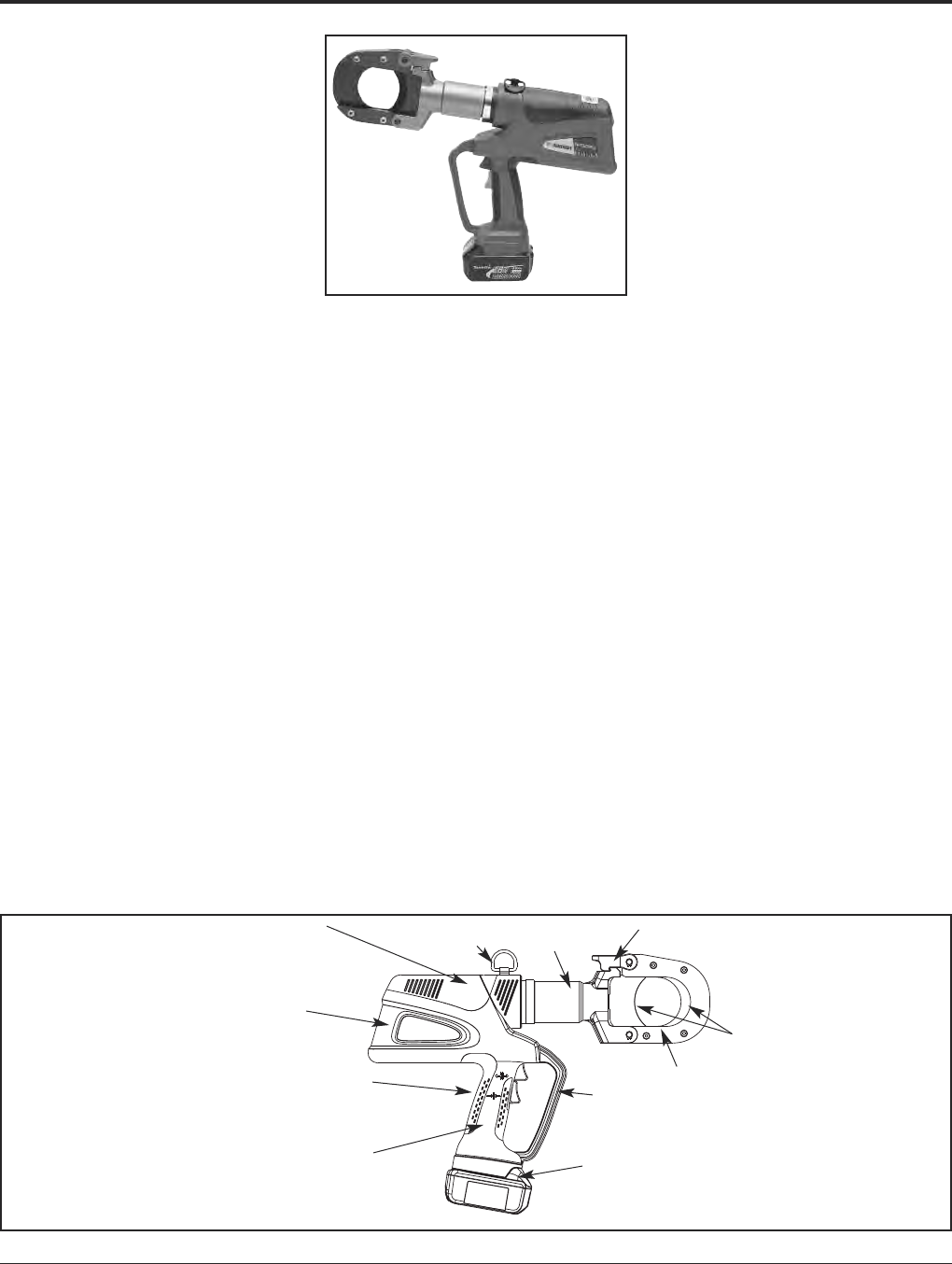
BURNDY®Grounding
Tooling
US: 1-800-346-4175 www.burndy.com Canada: 1-800-387-6487
129
PATRIOT®
PATCUT245-LI
18 Volt Lithium-Ion
Battery Actuated Cutter
Hydraulic Self-Contained
Cutting Tool
The BURNDY®PATRIOT®PATCUT245-LI
Lithium-Ion tool incorporates the latest engi-
neering technology with a refined hydraulic
system for ultra performance, speed and
reliability. The redesigned field proven elec-
tronics provide the ultimate reliability in the
harshest work environments. All BURNDY®
battery actuated hydraulic cutting tools pro-
vide a consistent cut every time.
The PATCUT245-LI battery powered cutting
tool is compact, fast, easy to use and incor-
porates the latest in battery tool technology.
The ergonomic design allows one hand oper-
ation so that the other is free to manipulate the
conductor in the proper cutting position. The
PATCUT245-LI incorporates a specialized
latch style cutting head that allows interfer-
ence-free closure for mid-span cuts. The cut-
ter head rotates 180 degrees to allow users to
get into tight areas easier. The PATCUT245-LI
is capable of cutting up to 2.45diameter
copper and aluminum cable.
The PATCUT245-LI is supplied with a durable
high impact formed carrying case to hold the
tool, battery charger, two 18 volt Lithium-Ion
batteries and tool retention lanyard. The
PATCUT245-LI is provided with a 5-year
limited warranty (excluding blades), and
1-year on batteries and charger. All PATRIOT®
tools feature the BURNDY®INFINITY DRIVE®
transmission which has a lifetime warranty.
SPECIFICATIONS
Tool Weight: 13.7 lbs (6.2 kg)
With Battery
Length: 18.1(45.9 cm)
Width: 3.5(8.9 cm)
Height: 13.5(34.3 cm)
Operating Voltage: 18 V-DC
Recharge Time: 30 minutes
FOR USE ON
Copper & Aluminum Cable: Up to 2.45O.D.
For Copper and Aluminum cable only. Do
not cut steel, ground rods, rebar, or guy
wire.
ACCESSORIES
Battery: Cat# BAT18VLI
(3.0 AH) Hi-capacity
Chargers:
120V-AC Cat# PATCHGR-LI
12/24V-DC Cat# PATCHGR-LIDC
1240/250V-AC Cat# PATCHGR-LI250V
Replacement Blades:
Cat# PT10038657
(Moving Blade)
Cat# PT10040663
(Fixed Blade)
Lanyard: Cat# PT208620
Features and Benefits
• Refined hydraulic system for ultra
performance, speed and reliability
• Field proven electronics for ultimate
reliability in the harshest environments
• Overmolded handle for comfort and im-
proved grip; allows for one-handed opera-
tion for advance, retract, and hold
• Specialized latch head design for interfer-
ence free closure for mid-span cuts
• 18-volt Lithium-Ion batteries provide 2.5
times more charge/discharge cycles than
traditional Ni-Cd batteries and provide
430% more lifetime work
• 30 minute charger controls current, voltage
and temperature to maximize battery life
• Forced air cooling fan cools the battery
by forcing cool air through the battery’s
built-in air vents
• 180° head rotation allows user to get into
tight areas easier
• Ergonomically balanced tool design eases
operation and lessens fatigue
• Durable high impact formed carrying case
provides superior protection and stores all
accessories
• 5-year limited warranty on tool (excluding
blades)
• Lifetime warranty on INFINITY DRIVE®
• 1-year warranty on batteries and charger
Refined Hydraulic System for
Ultra Performance, Speed
and Reliability
6 Ton Output Force
Ergonomically Balanced
Overmolded Handle
Field-Proven Electronics
for Ultimate Reliability in
the Harshest Work Envi-
ronments
18 Volt Lithium-Ion
Battery
Trigger
Guard
Safety Lanyard
Connection
2.45Cutting Capacity
Specialized Latch Head Design
Precision Cutting Blades
180° Head
Rotation
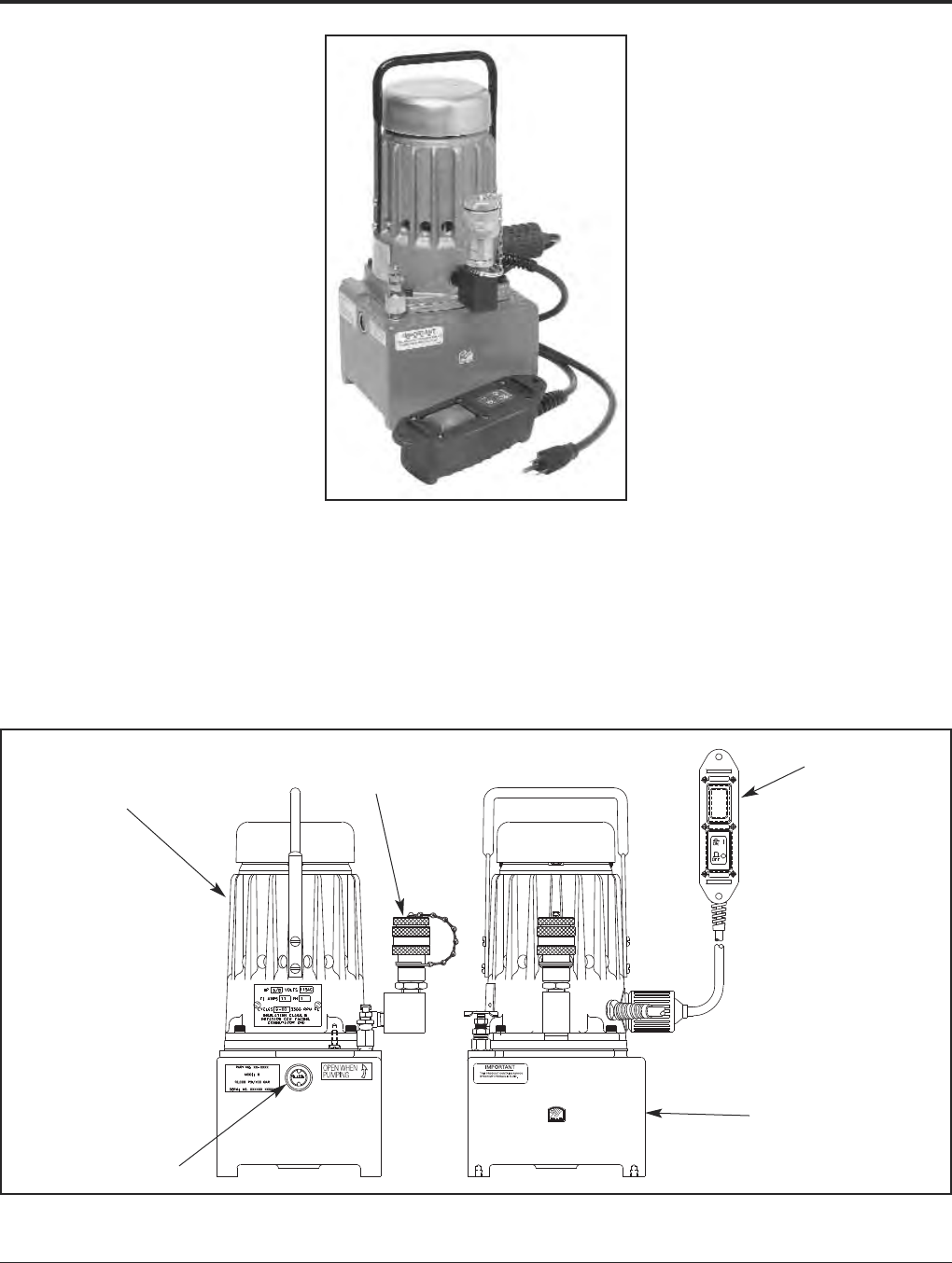
Grounding BURNDY®
Tooling
Canada: 1-800-387-6487 www.burndy.com US: 1-800-346-4175
130
Y10AC9
Electric Hydraulic Pump
Hydraulic Output Pressure of
10,000 PSI
The Y10AC9 electric hydraulic pump is for use
with all HYPRESS™ heads and cutters requir-
ing 10,000 PSI operating pressure.The
Y10AC9 is equipped with a built-in, factory set
pressure relief valve. An audible “pop” and
recycling of the pump as well as relaxing of the
hose signal completion of the crimping/cutting
cycle. Pump is supplied with a durable hand-
held electric pendant switch.
Features and Benefits
• Lightweight, small size.
〫Easy to lift, carry and transport tool
around job site with lightweight body
and handle.
• Factory set relief valve.
〫High quality crimps are achieved with
built-in, factory set pressure relief valve
and audible recycling of pump to signal
completion of crimp cycle.
• 100,000 (+) life cycles.
〫Long durable life expectancy with light-
weight cast aluminum reservoir body.
Specifications
Motor: 115V AC 50/60 Hz
5/8 HP, 10,000 rpm
11 amp current draw
Reservoir Volume: 1.61 quarts
Height: 14.38
Base: 6.58.25
Weight: 28 lbs. (with oil)
FOR USE ON
Y34BH, Y35BH, Y35BH4, Y39BH,
Y45, Y46, Y46C, Y750BHXT,
Y750CBHXT, Y644MBH,
Y4PC834MBH, Y81KFTMBH, Y60BHU,
RHCC129ACSR, RHCC245CUAL
ACCESSORIES
Catalog Number: YAC-CASE
Steel carrying case with
handle and locking latch.
The BURNDY®Y10AC9OEM is an additional
electric hydraulic pump offering that comes
equipped with a foot switch and “jog-and-
hold” feature. Keep both hands on the
connection with the Y10AC9OEM pump kit.
For further details please contact customer
service.
5/8 HP Motor
Oil Level Window
Quick Disconnect
Hydraulic Coupler
Pendant Switch
with 10Cord
1.6 Quart Reservoir
• Convenient 115V AC electric powered
motor.
• Saves time with quick disconnect hydraulic
fitting.
• Sealed electric pendant switch.
〫Easy operation with durable remote
pendant switch with 10-foot cord.
• 5-year limited warranty.
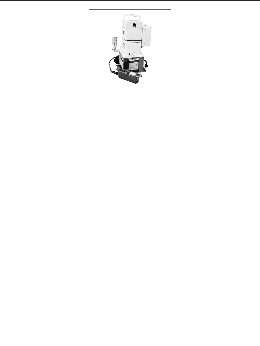
BURNDY®Grounding
Tooling
US: 1-800-346-4175 www.burndy.com Canada: 1-800-387-6487
131
EPP10 AND EPP6
EPP Series
Electric/Hydraulic Pump
Hydraulic Output Pressures
of 10,000 PSI and 6,000 PSI
The lightweight and durable EPP10 elec-
tric/hydraulic pump is for use with all
BURNDY®HYPRESS™ remote heads and
cutters requiring 10,000 PSI operating pres-
sure. Both the EPP10 and the EPP6 are
equipped with a built-in, factory set pressure
relief valve. An audible “pop” and recycling of
the pump and relaxing of the hose, signals
completion of the crimping/cutting cycle.
Both pumps are supplied with a durable
hand-held electric pendant switch, for remote
operation of the unit, and have a manual
selection switch mounted for operation of the
unit at the pump. The operator can select
which method is best suited for the
application.
An optional carry/shipping case can be
ordered. All EPP Series pumps have been life
cycle tested to over 100,000 cycles without
failure, and are warranted to be free of defects
in materials and workmanship for five (5) years
when properly maintained and operated.
SPECIFICATIONS
Motor: 115 V-AC/60 Hz
1/2 HP @ 3450 RPM
Maximum
current draw: 12.5 amperes
Reservoir volume: 2 qts.
Height: 16
Base: 68
Weight: 30 lbs.
FOR USE ON
EPP10 10,000 Y34BH, Y35BH, Y35BH-4,
Y39BH, Y45, Y46, Y46C,
Y60BHU, 750BH,
Y750BH-2, Y644MBH,
RHCC Series Cutters
EPP6 6,000 Y35L, Y28B
ACCESSORIES
Cat. No. EPPCASE-1
Steel carrying case with handle and locking
latch.
FEATURES
• Lightweight.
• Small size.
• Factory set relief valve.
• 100,000 (+) life cycles.
• Sealed electric pendant switch.
BENEFITS
• High quality crimps are achieved with
built in, factory set pressure release valve
and audible recycling of pump to signal
completion of crimp cycle.
• Easy to lift, carry and transport tool
around job site with lightweight body
and handle.
• Convenient 115 V-AC electric powered
motor.
• Durable remote pendent switch.
• Easy operation controlled with pendent
switch, or manual switch.
• Saves time with quick disconnect
hydraulic fitting.
• Long durable life expectancy with light-
weight cast aluminum reservoir body.
• 5-year limited warranty.
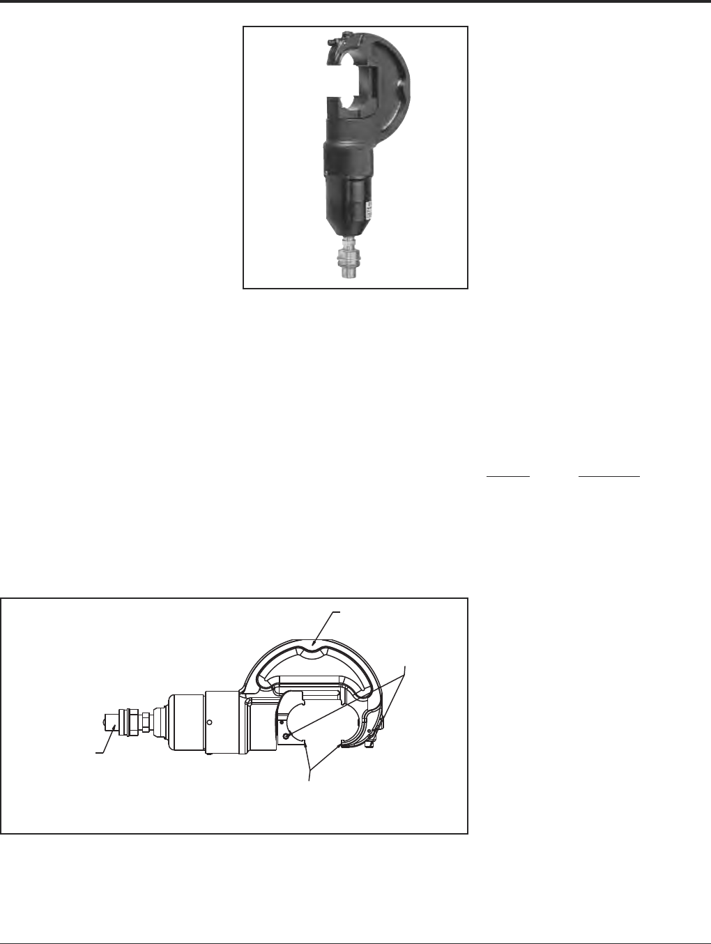
Grounding BURNDY®
Tooling
Canada: 1-800-387-6487 www.burndy.com US: 1-800-346-4175
132
Y750BHXT AND
Y750CBHXT RUBBER
COVERED HEAD
HYPRESS™
12-Ton Remote Power Operated
Hydraulic Tool
Conductor Range:
#14 - 750 kcmil Al/Cu
#4 - 556.5 kcmil ACSR
12 ton remote power operated hydraulic tool.
The Y750BHXT HYPRESS™ incorporates a
wide mouth (1.65) C-shaped head for all
compression applications. The hook style
head provides for easy tapping, splicing, and
terminating of overhead lines as well as the
full range of HYGROUND®compression
grounding system connectors, NEC cable
connections and N30 - N650 Navy cable
applications.
All standard BURNDY®“U” dies fit the
Y750BHXT and Y750CBHXT HYPRESS™.
Dies and accessories sold separately.
The Y750CBHXT has a permanently molded
rubber covered head and includes a separate
rubber molded boot that covers the lower
body and hydraulic fitting for tool impact
protection. 5-year limited warranty.
BENEFITS
• Covers a wide range of applications and
provides easy tool removal from
continuous conductors with its C-shaped
head (1.65opening).
• Easy die change out and retention with
exposed positive die lock buttons.
• Uses all standard BURNDY®U-dies.
• Y750CBHXT provides molded rubber
covering on head, body and hose fittings.
• Hot stick adapter sold separately.
• Infinitely rotatable head, so hydraulic
couplers won’t easily loosen.
• 5-year limited warranty.
Remote Head for Use
With “U” Style Dies
“C” - Shaped Head
Quick Disconnect
Hydraulic Fitting
Large 1.65Jaw Opening
to Accommodate
Asymmetrical Connectors
Both Die Release
Buttons Exposed
FEATURES
SPECIFICATIONS
Operating pressure:
10,000 psi
Force developed: 12 tons
Jaw opening: 1.65(42 mm)
Length: 12.8(325 mm)
Weight: 10.3 lbs. (4.7 kg)
Head width: 5.2(132 mm)
FOR USE ON
•Tension Sleeves
Copper #8 sol - 500 kcmil
Aluminum #6 sol. - 556.5 kcmil
ACSR #4 - 556.5 kcmil
•Taps
Copper #14 solid - 500 kcmil
Aluminum #6 - 500 kcmil
•Aerial Cable
Copper #6 - 500 kcmil
•Terminals and Splices
Aluminum #8 - 750 kcmil
Copper #8 - 750 kcmil
ACSR #4 - 556 kcmil
•HYGROUND®(Compression Grounding)
Copper #6 - 500 kcmil
(cable/ground rod)
Ground Rods 1/2- 1Diameter
ACCESSORIES:
Cat. No. Description
PT29402-1 Adjustable head grip for
joining head to universal
hot sticks.
PT29279-2 Force test gauge for
accurate visual reading of
output force.
PT29291 Die Case
Steel case for storage and
protection of “U” dies.
WIREMIKE Provides quick and easy
identification of commonly
used conductors.
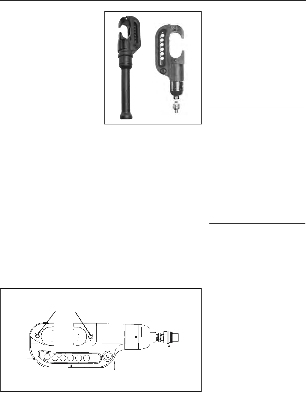
BURNDY®Grounding
Tooling
US: 1-800-346-4175 www.burndy.com Canada: 1-800-387-6487
133
Y46 AND Y46C
HYPRESS™
15 Ton Force Remote Operated
Hydraulic Tool—10,000 PSI
The Y46 standard tool and Y46C rubber cov-
ered tools are lightweight, compact and
versatile with installation dies for both cir-
cumferential and nest-indentor types. Acces-
sories include “U-” die adapter, a cable
cutting die for 1.2diameter non-steel
conductors, plus a lifting eye and universal
hot-stick adapter for overhead line construc-
tion. 5-year limited warranty.
BENEFITS
• Compact “C” shaped head allows easy
placement and removal from continuous
conductor lengths.
• Versatile and economical-HYPRESS™
tools work on all commonly used copper
and aluminum products.
• Dies and adapters lock into or remove
from tool head easily with the positive
push button die locks.
• Safety, strength and high quality is pro-
vided with strong forged steel and preci-
sion machined components.
• Excellent for HYGROUND®compression
grounding applications through 1ground
rods and up to 500 kcmil taps, terminals
and splices.
• Provides UL Listed and CSA Certified
connections when used in conjunction with
listed BURNDY®HYLUG™ terminals and
HYLINK™ splices.
• Y46C has a permanently molded head
of 3/16rubber and includes a separate
molded rubber boot to cover the lower
HYPRESS™ body and hydraulic coupler
for impact protection.
Male Quick
Disconnect
10,000 PSI
Hydraulic Fitting
Forged
Steel
Body
Precision Machined
Steel Components
Strong
Reinforced
Back
Large 2”
Jaw
Opening
Positive
Push
Button
Die Lock
FEATURES
SPECIFICATIONS
Y46 Y46C
Force developed: 15 Tons 15 Tons
Operating pressure:
10,000 psi 10,000 psi
Jaw opening: 22
Maximum width: 4-1/24-3/4
Overall length: 1521-3/4
(incl. boot)
Weight (less case): 16 lbs. 17-1/2 lbs.
Molded Covering: No Yes
FOR USE ON
Connector Conductor
Type Range
Copper Terminals-Grounding to 500 kcmil
#8 AWG str.- YGA, YGHA, YGF
1500 kcmil Terminals-Uninsulated #8 to
Code Cable 1500 kcmil YA, YA-2N, YA-L,
Navy Cables YA-LB, YA-TC, YA-2LN, YAB-4N,
Flexible and
Extra Flexible YAV-L Box, YAV-L, YAV-RS Box,
1/2”-1” Ground Rods YAV-RS, YA-TC-FX
Terminals-Insulated #8 to 2/0
YAEV-L Box, YAEV-L, YAEV-H,
YAEV-RS, YAEV-RH
Splices #8 to 1500 kcmil
YS, YS-T, YS-L, YS-LB, YST,
YSP-T, YGS, YGHS
Taps
YH, YCHC #14 to 1000 kcmil
YC-C to 4/0 AWG
Taps-Grounding to 500 kcmil
YGHC-C, YGHP-C, YGHR-C
Aluminum Terminals
#8 AWG- YA-A, AYP, AYPO
1250 kcmil Splices
Code Cables YS-A, YS-AT, YRB
Taps
YFD, YFN, YFO, YFR
ACSR See Burndy Overhead
Transmission and
Distribution Catalog Module
ACCESSORIES:
Cat. No.
P15K Cutter die max. 1.2dia.
PUADP-1 “U”-die adapter
PT10128 Universal hotstick adapter-Y46
Y46-2 Same as Y46 with Female
coupler
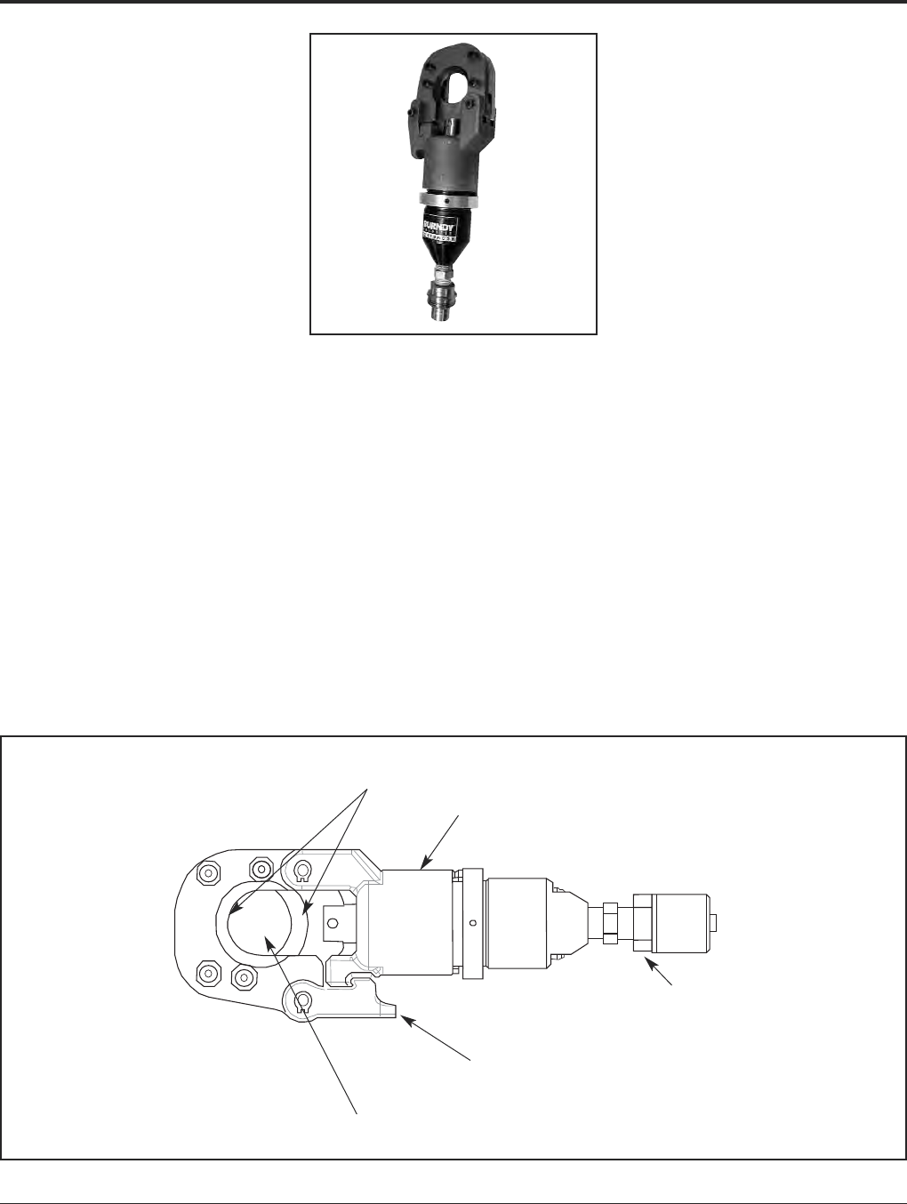
Grounding BURNDY®
Tooling
Canada: 1-800-387-6487 www.burndy.com US: 1-800-346-4175
134
RHCC129ACSR
10,000 PSI Remote
Cable Cutter
Remote Power Operated
Hydraulic Cable Cutter
The BURNDY®RHCC129ACSR remote
hydraulic cable cutter incorporates a special-
ized latch style cutting head that allows
interference-free closure for mid-span cuts.
The RHCC129ACSR with its precision cutting
blades is capable of cutting up to 1.29
diameter bare or insulated copper and
aluminum cable, 1113 ACSR, 5/8ground
rod, 1/2 rebar, 5/8diameter soft steel bolts,
1/2standard guy strand, and up to 3/8EHS
guy strand.
The RHCC129ACSR is provided with a
5-year limited warranty (excluding blades).
Features and Benefits
• Specialized latch head design.
〫Interference free closure for mid-span
cuts.
• Precision cutting blades.
〫For clean cuts on Cu/Al, ACSR, ground
rods, rebar, guy strand, and soft steel
bolts.
• High strength steel cylinder.
〫For durability and long life.
• Lightweight ergonomic design allows one
hand operation.
〫User has one hand free to manipulate
material to be cut.
• Durable canvas carrying bag.
〫Provides tool protection and stores all
accessories.
• 5-year limited warranty on tool (excluding
blades).
〫Customer satisfaction and support.
SPECIFICATIONS
Operating Pressure: 10,000 psi (700 bar)
Tool Weight: 5.85 lbs. (2.65 kg)
Length: 11.25(286 mm)
Width: 3.7(94 mm)
FOR USE ON
• Copper Cable: up to 1.29
• Aluminum Cable: up to 1.29
• ACSR: up to 1113 ACSR
• Ground Rod: up to 5/8
• Rebar: up to 1/2
• Soft Steel Bolts: up to 5/8
• Standard Guy Strand: up to 1/2
• EHS Guy Strand: up to 3/8
ACCESSORIES
Canvas Bag: Cat# PT10043890
Replacement Blades: Cat# PT10037388
(Moving Blade)
Cat# PT10037384
(Fixed Blade)
Hot Stick Adapter: Cat# RHCCHSA
Precision Cutting Blades
High Strength Steel
Cylinder
Quick Disconnect
Hydraulic Fitting
Specialized Latch
Head Design
1.29Cutting
Capacity
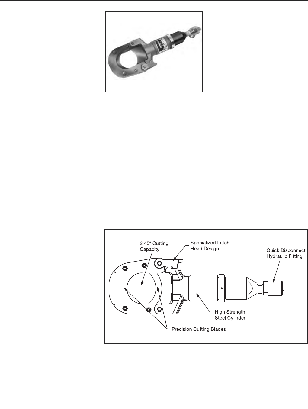
BURNDY®Grounding
Tooling
US: 1-800-346-4175 www.burndy.com Canada: 1-800-387-6487
135
RHCC245CUAL
10,000 PSI Remote
Cable Cutter
Remote Power Operated
Hydraulic Cable Cutter
The BURNDY®RHCC245CUAL remote
hydraulic cable cutter incorporates a special-
ized latch style cutting head that allows
interference-free closure for mid-span cuts.
The RHCC245CUAL with its precision cutting
blades is capable of cutting up to 2.45dia -
meter copper and aluminum cable.
The RHCC245CUAL is provided with a
5-year limited warranty (excluding blades).
Features and Benefits
• Specialized latch head design.
〫Interference free closure for mid-span
cuts.
• Precision cutting blades.
〫For clean cuts on copper and aluminum
cable.
• High strength steel body.
〫For durability and long life
• Lightweight ergonomic design allows one
hand operation.
〫User has one hand free to manipulate
material to be cut.
• Durable canvas carrying bag.
〫Provides tool protection and stores all
accessories.
• 5-year limited warranty on tool (excluding
blades).
〫Customer satisfaction and support.
SPECIFICATIONS
Operating Pressure:10,000 psi (700 bar)
Tool Weight: 8.3 lbs. (3.8 kg)
Length: 14.8(376 mm)
Width: 4.75(121 mm)
FOR USE ON
Copper & Aluminum 2.45O.D. (62 mm)
ACCESSORIES
Canvas Bag: Cat# PT10054094
Replacement Blades: Cat# PT10038657
(Moving Blade)
Cat# PT10040663
(Fixed Blade)
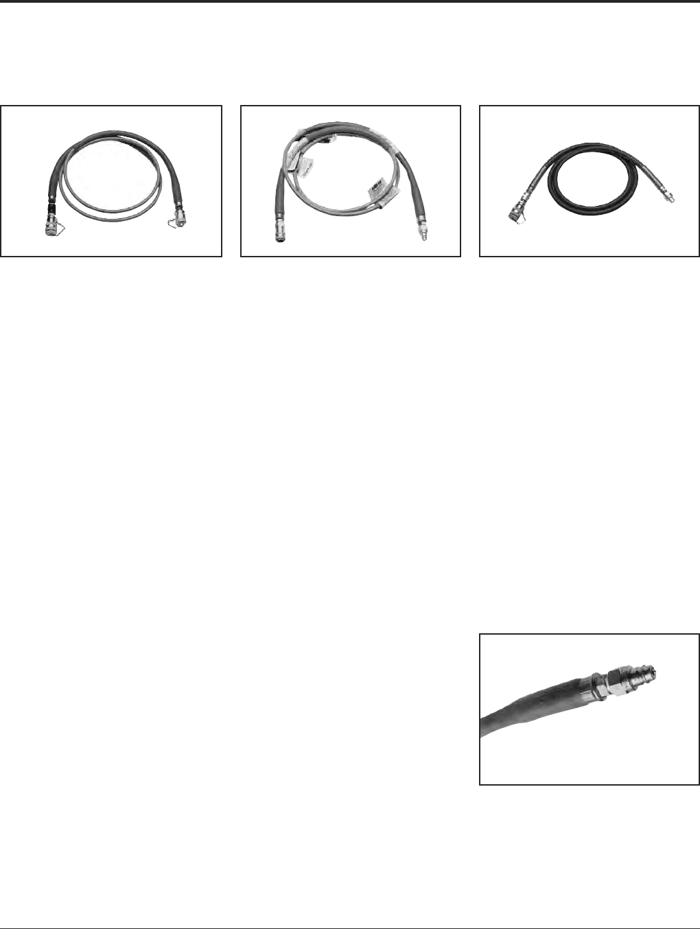
Grounding BURNDY®
Tooling
Canada: 1-800-387-6487 www.burndy.com US: 1-800-346-4175
136
HYDRAULIC HOSES
NON CONDUCTIVE HOSES*
6,000 PSI 10,000 PSI
Cat. No. Description
PT 29900-10 10- 3/16diameter - non
conductive hose with stack-
able couplers (male/female) -
orange
PT 29900-15 15- 3/16diameter - non
conductive hose with stack-
able couplers (male/female) -
orange
PT 29900-25 25- 3/16diameter - non
conductive hose with stack-
able couplers (male/female) -
orange
PT 29901-10 10- 1/4diameter - non
conductive hose with stack-
able couplers (male/female) -
orange
PT 29901-15 15- 1/4diameter - non
conductive hose with stack-
able couplers (male/female) -
orange
PT 29901-25 25- 1/4diameter - non
conductive hose with stack-
able couplers (male/female) -
orange
Note: 1/4diameter hose provides higher
flow rate for faster ram movement.
* For proper care and maintenance of hydraulic
hoses, consult the “Hydraulic Hose Care” manual,
Form No. 7828
Cat. No. Description
PT 29902-10 10- non conductive hose
with stackable couplers
(male/female) - orange
PT 29902-15 15- non conductive hose
with stackable couplers
(male/female) - orange
PT 29902-25 25- non conductive hose
with stackable couplers
(male/female) - orange
PT 29074-1 Non conductive hose carrying
bag
* For proper care and maintenance of hydraulic
hoses, consult the “Hydraulic Hose Care” manual,
Form No. 7828
Cat. No. Description
PT 91 8- steel braided hose
with steel spring reinforced
ends. Stackable couplers
(male/female) - Black. No
electrical rating. DO NOT
use on energized conductor.
8,800 PSI
Cat No. Description
PT 76 8- steel braided hose
with steel spring reinforced
ends. Stackable couplers
(male/female) - Black. No
electrical rating. DO NOT
use on energized conductor.
*
For proper care and maintenance of hydraulic
hoses, consult the “Hydraulic Hose Care”
manual,
Form No. 7828.
CONDUCTIVE HOSES*
Do not attempt to repair or recouple the hose yourself!
10,000 PSI
NON CONDUCTIVE HOSES*

BURNDY®Grounding
Reference
US: 1-800-346-4175 www.burndy.com Canada: 1-800-387-6487
137
REFERENCE
TABLE OF CONTENTS
Specifications for BURNDY®
HYGROUND®Connector System . . . . . 138
HARDWARE DATA . . . . . . . . . . . . . . . . . . . . 139
CABLE DATA (TABLES)
Copper Tube . . . . . . . . . . . . . . . . . . . . . . . . . 140
Solid Copper Wire . . . . . . . . . . . . . . . . . . . . . 140
Stranded Copper Cable . . . . . . . . . . . 140 - 141
Solid Copperweld Cable . . . . . . . . . . . . . . . . 141
Copperweld — Copper Cable . . . . . . . . . . . 141
Stranded Copperweld Cable . . . . . . . . . . . . 142
Galvanized Steel Cable . . . . . . . . . . . . . . . . . 142
AWG vs. Metric Wire Sizes . . . . . . . . . . . . . . 143
ALPHA-NUMERIC INDEX . . . . . . . . . . 144 -149

Grounding BURNDY®
Reference
Canada: 1-800-387-6487 www.burndy.com US: 1-800-346-4175
138
Specifications for
BURNDY®
HYGROUND®
Connector System
Ground Connectors
1.0 Scope
1.1 This specification establishes the
material, design, marking and
performance requirements of
compression grounding
connectors used to make
permanent ground connections for
direct burial, embedment in
concrete, or for above grade
applications.
1.2 The specification also provides the
requirements for mechanical
connectors intended for bonding
applications within the grounding
network.
2.0 Materials
2.1 All ground connections shall be
made using BURNDY®
HYGROUND®compression
ground connectors.
2.2 Cmopresson ground connectors
shall be manufactured from pure
wrought copper in compliance with
ASTM B187.
2.3 Mechanical cast connectors are
allowed for bonding applications
and shall be manufactured from a
copper alloy of minimum 80%
copper, according to ASTM B30.
3.0 Design
3.1 All ground connectors must be
designed for fault-duty loading,
and must have the fault capacity of
the maximum sized conductor for
which it is designed.
3.2 Pad terminals and in-line splices
may accommodate only one
conductor size. All other ground
connectors must be range taking.
3.3 Structural steel and bus bar
ground connectors may
accommodate only one rigid
member conductor.
3.4 All ground connectors must be
provided with a corrosion-inhibiting
compound preapplied to the
contact surfaces. The compound
must be compatible with the
conductors accommodate by the
connector.
3.5 All ground connectors must be
capable of being provided with tin
plating, if required by agency
jurisdiction or by the application.
3.6 All mechanical bonding connectors
must be designed to withstand
150% of the recommended
installation torque.
4.0 Marking
4.1 All connectors must be clearly and
permanently marked with the
following information:
4.1.1 Manufacturer’s inspection
symbol
4.1.2 Catalog number
4.1.3 Conductor accommodation(s)
4.1.4 Installation die index or die
catalog number
(compression)
4.1.5 Underwriters Laboratories
Listing Mark/CSA
certification mark
4.1.6 The words “Suitable for
Direct Burial,” or “Direct
Burial,” or “Burial” as
specified per ANSI/UL467.
4.2 The smallest unit package shall
contain the information listed
under 4.1, and shall also include
installation tooling.
5.0 Ground Connector Installation
5.1 Installation of connectors shall be
made in accordance with the
manufacturer’s recommendations.
The instructions typically include
conductor preparation (cleaning,
pre-crimp), installation tool and die
selection, and application of the
proper number of crimps.
5.2 Connectors must be installable
under all types of weather/field
conditions without special safety
precautions or procedures.
5.3 Connectors must be installable
without using or producing
hazardous materials or
byproducts.
6.0 Ground Connector Inspection
6..1 Compression dies must provide
embossment of the connector
upon successful installation. The
embossed index must match the
marking on the installed connector.
6.2 Connector marking information
specified in 4.1 must be legible
after installation for inspector
cross-reference.
6.3 Closed barrel connectors may
have inspection holes at the
appropriate location to verify
proper cable insertion.
7.0 Performance
7.1 All system connectors must be
Listed by Underwriters
Laboratories/Canadian Standards
Association for direct burial in
earth or embedment in concrete
per ANSI/UL467 Standard for
Grounding and Bonding
Equipment/CSA C22.2 No. 41.
7.2 All ground connectors must meet
the requirements of IEEE Std 837
Standard for Qualifying Permanent
Connections Used in Substation
Grounding.
7.3 Connectors must be suitable for
lightning protection applications.
Listing to UL96 Lightning
Protection Components is
preferred on applicable items.
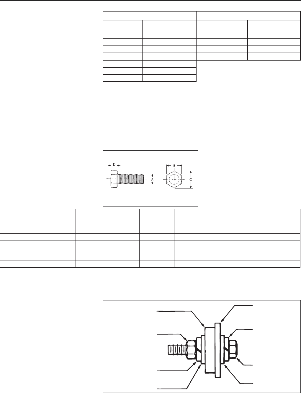
BURNDY®Grounding
Reference
US: 1-800-346-4175 www.burndy.com Canada: 1-800-387-6487
139
HARDWARE DATA
RECOMMENDED
TIGHTENING TORQUE
The hardware used in connectors must be
compatible with the connector material, have
high mechanical strength and be corrosion re-
sistant.
Copper alloy connectors have hardware
made of DURIUM™, which is BURNDY's
trade name for silicon bronze alloy ASTMB99.
This material was first introduced by
BURNDY®in 1927 for use in outdoor
construction, and today, is the standard
throughout the industry.
Aluminum connectors generally have alu-
minum alloy hardware. The bolts are 2024T4
and anodized to resist corrosion. The nuts are
6061T6, which is resistant to corrosion
and does not require anodizing. Bolts are
lubricated to eliminate galling and to provide
consistent clamping forces.
The size material for clamping hardware are
selected to provide the required force when
tightened to the recommended torque. To
reduce or greatly exceed the recommended
torque can adversely affect the performance
of the connector.
DURIUM™
(SILICON BRONZE)
HEXAGONAL BOLT DATA
erawdraHleetSerawdraHmunimulA
tloB
eziS
dednemmoceR
euqroT
)sdnuoPhcnI(
tloB
eziS
dednemmoceR
euqroT
)sdnuoPhcnI(
02-4/10831-2/1003
81-61/508111-8/5084
61-8/304201-4/3056
31-2/1084
11-8/5066
01-4/30501
Catalog No.
Series"A"
(Bolt Size)
"B" "C" "D"
Recommended
Torque (in-lb)
Min.
Breaking
Force (lb)
Min.
Shearing
Force (lb)
25X_ _ _HEB 1/4 - 20 UNC 7/16 .50 .16 80 1,780 990
31X_ _ _HEB 5/16 - 18 UNC 1/2 .56 .21 180 2,930 1,640
38X_ _ _HEB 3/8 - 16 UNC 9/16 .65 .24 240 4,350 2,430
50X_ _ _HEB 1/2 - 13 UNC 3/4 .87 .32 480 7,950 4,460
62X_ _ _HEB 5/8 - 11 UNC 15/16 1.08 .40 660 12,700 7,100
75X_ _ _HEB 3/4 - 10 UNC 1-1/8 1.30 .48 1,050 17,510 10,540
➁➂
Busbar or Equipment Pad
(Copper or Unknown Material)
Nut
Split Lock Washer
Flat Washer
Split Lock Washer
Belleville Washer
Steel Bolt
Copper or
Aluminum Terminal
1. Material: DURIUM™ (Silicon Bronze)
➁"_ _ _" is substituted for bolt length. Consult sales
representative for available lengths.
➂These torque values develop maximum bolt preload.
4. This drawing is based on BURNDY®engineering spec.
RECOMMENDED
TERMINATION
HARDWARE
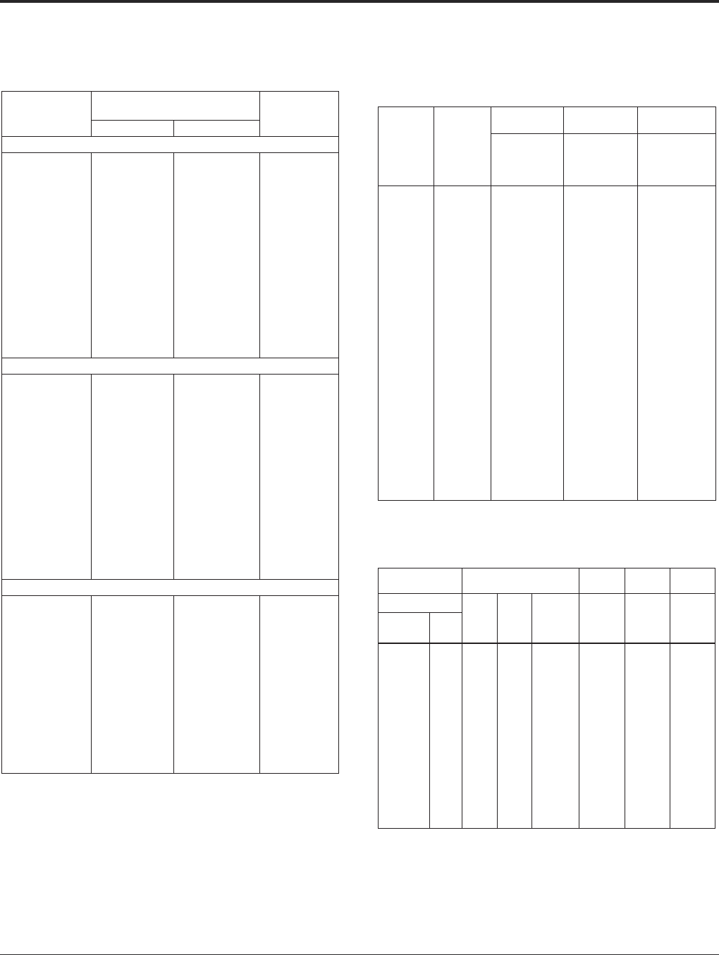
Grounding BURNDY®
Reference
Canada: 1-800-387-6487 www.burndy.com US: 1-800-346-4175
140
COPPER TUBE (BUS) SOLID COPPER WIRE
(ASTM B1, B2, & B3)
STRANDED COPPER WIRE
(ASTM B8 EXCLUDING BREAKING LOADS)
CABLE DATA
Size of Tube
IPS
Diameter of Tube
(Inches)Wall
Thickness
(Inches)
Outside Inside
Standard Pipe Sizes
1/4
3/8
1/2
3/4
1
1-1/4
1-1/2
2
2-1/2
3
3-1/2
4
4-1/2
5
6
0.540
0.675
0.840
1.050
1.315
1.660
1.900
2.375
2.875
3.500
4.000
4.500
5.000
5.563
6.625
0.375
0.494
0.625
0.822
1.062
1.368
1.600
2.062
2.500
3.062
3.500
4.000
4.500
5.063
6.125
0.082 5
0.090 5
0.107 5
0.114 0
0.126 5
0.146 0
0.150 0
0.156 5
0.187 5
0.219 0
0.250 0
0.250 0
0.250 0
0.250 0
0.250 0
Extra Heavy Pipe Sizes
1/4
3/8
1/2
3/4
1
1-1/4
1-1/2
2
2-1/2
3
3-1/2
4
4-1/2
5
6
0.540
0.675
0.840
1.050
1.315
1.660
1.900
2.375
2.875
3.500
4.000
4.500
5.000
5.563
6.625
0.294
0.421
0.542
0.736
0.951
1.272
1.494
1.933
2.315
2.892
3.358
3.818
4.250
4.813
5.751
0.123
0.127
0.149
0.157
0.182
0.194
0.203
0.221
0.280
0.304
0.321
0.341
0.375
0.375
0.437
Double Extra Heavy Pipe Sizes
1/2
3/4
1
1-1/4
1-1/2
2
2-1/2
3
3-1/2
4
4-1/2
5
6
0.840
1.050
1.315
1.660
1.900
2.375
2.875
3.500
4.000
4.500
5.000
5.563
6.625
0.252
0.434
0.599
0.896
1.100
1.503
1.771
2.300
2.728
3.152
3.580
4.063
4.897
0.294
0.308
0.358
0.382
0.400
0.436
0.552
0.600
0.636
0.674
0.710
0.750
0.864
Size
AWG
(Solid)
Wire
Dia.
Inch
Hard
Drawn Medium
Drawn Soft
Drawn
Normal
Breaking
Load
Pounds
Minimum
Elongation
in 10 In.
% Min.
Breaking
Load
Pounds
18
17
16
15
14
13
12
11
10
9
8
7
6
5
4
3
2
1
1/0
2/0
3/0
4/0
.040 30
.045 26
.050 82
.057 07
.064 08
.071 96
.080 81
.090 74
.101 9
.114 4
.128 5
.144 3
.162 0
.181 9
.204 3
.229 4
.257 6
.289 3
.324 9
.364 8
.409 6
.460 0
85.76
107.5
135.2
170.0
213.8
268.2
337.0
422.5
529.2
661.0
826.0
1,030
1,280
1,591
1,970
2,439
3,003
3,688
4,519
5,518
6,722
8,143
67.61
84.71
106.2
133.0
166.6
208.0
261.6
327.6
410.4
514.2
643.9
806.6
1,010
1,265
1,584
1,984
2,450
3,024
3,730
4,599
5,667
6,980
25
25
25
25
25
25
25
25
25
30
30
30
30
30
30
30
30
30
35
35
35
35
Size
ASTM
Strandings Hard
Drawn
Medium
Drawn
Soft
Drawn
Stranded
Class No. of
Wires
Cable
Diameter
Inches
Minimum
Breaking
Load
Pounds
Minimum
Breaking
Load
Pounds
Minimum
Breaking
Load
Pounds
Circular
Mills AWG
1,022
1,624
2,583
4,107
6,530
10,380
13,090
16,510
20,820
26,250
33,100
41,740
41,740
52,630
20
18
16
14
12
10
9
8
7
6
5
4
4
3
B
B
B
B
B
B
B
B
B
B
B
AA
B&A
AA
7
7
7
7
7
7
7
7
7
7
7
3
7
3
0.036 3
0.045 6
0.057 6
0.072 6
0.091 5
0.116
0.130
0.146
0.164
0.184
0.206
0.254
0.232
0.285
50.04
78.99
124.7
197.1
311.1
491.7
618.2
777.2
977.1
1,288
1,542
1,879
1,938
2,359
40.67
63.91
100.4
157.7
247.7
388.9
487.4
610.7
765.2
958.6
1,201
1,465
1,505
1,835
32.09
51.03
81.14
124.2
197.5
314.0
395.9
499.2
629.5
793.8
1001
1213
1262
1530
Tube dimensions (excepting wall thickness, of double extra
heavy) taken from A.S.T.M. Specification B42-33.
Tubular values based on a density of 0.322 pound per
cubic inch.
* Conductivity of 98% I.A.C.S. at 20° C or 68° F.
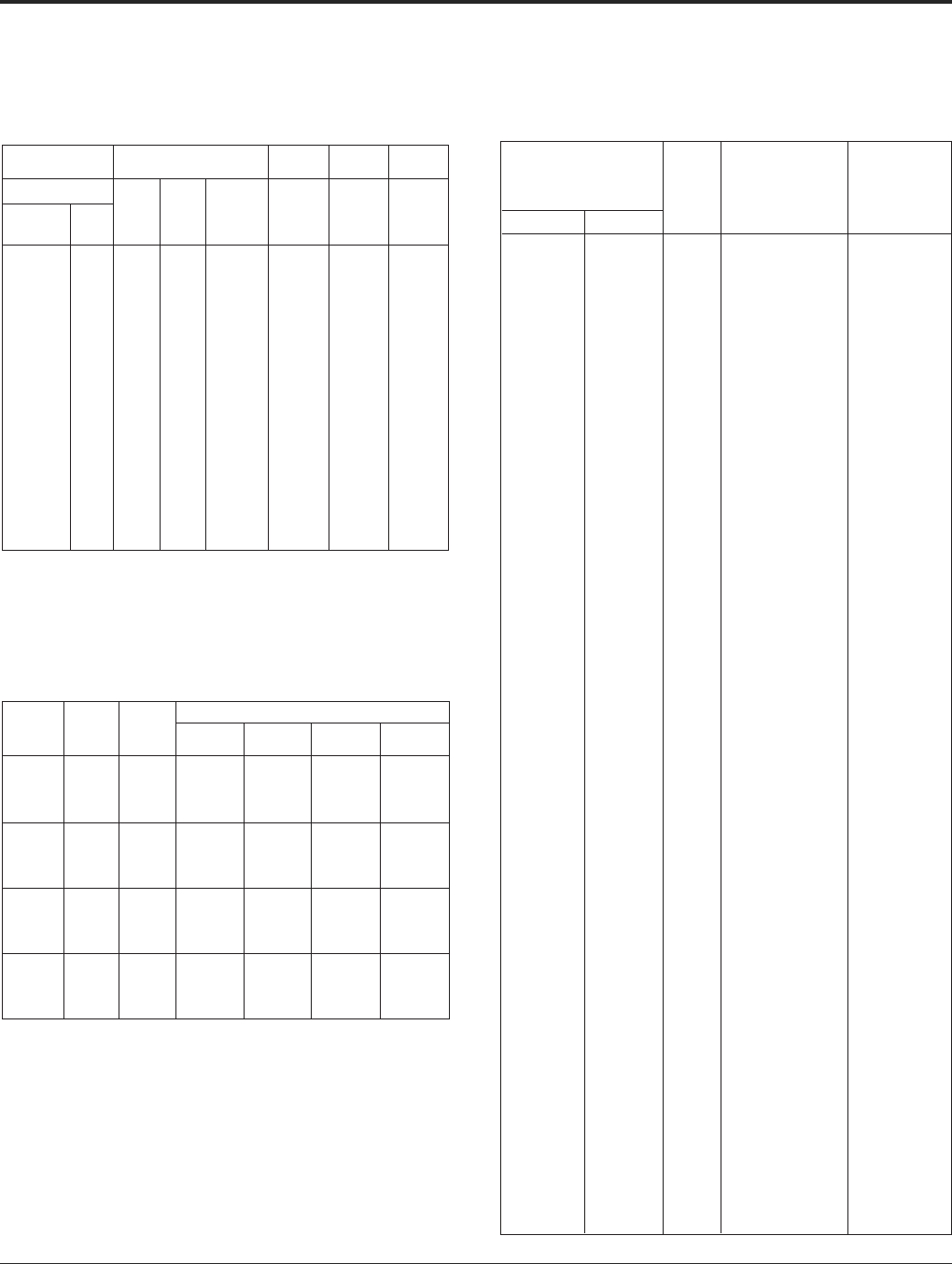
BURNDY®Grounding
Reference
US: 1-800-346-4175 www.burndy.com Canada: 1-800-387-6487
141
CABLE DATA (Continued)
STRANDED COPPER WIRE (Continued)
(ASTM B8 EXCLUDING BREAKING LOADS)
52,630
66,370
66,370
83,690
83,690
83,690
105,500
105,500
105,500
133,100
133,100
133,100
167,800
167,800
167,800
211,600
211,600
211,600
3
2
2
1
1
1
1/0
1/0
1/0
2/0
2/0
2/0
3/0
3/0
3/0
4/0
4/0
4/0
B&A
AA
B&A
AA
A
B
A&A
—
B
A&A
—
B
A&A
—
B
A&A
—
B
7
3
7
3
7
19
7
12
19
7
12
19
7
12
19
7
12
19
0.260
0.320
0.292
0.360
0.328
0.332
0.368
0.390
0.373
0.414
0.438
0.419
0.464
0.492
0.470
0.522
0.522
0.528
2,433
2,913
3,045
3,621
3,804
3,899
4,752
4,841
4,901
5,926
6,048
6,152
7,366
7,556
7,698
9,154
9,483
9,617
1,885
2,299
2,361
2,879
2,958
3,037
3,705
3,755
3,805
4,640
4,703
4,765
5,812
5,890
5,970
7,278
7,378
7,479
1592
1929
2007
2432
2432
2531
3067
3191
3191
3867
3867
4024
4876
4876
5074
6149
6149
6149
Size ASTM
Strandings Hard
Drawn
Medium
Drawn
Soft
Drawn
Stranded
Class
No. of
Wires
Cable
Diameter
Inches
Minimum
Breaking
Load
Pounds
Minimum
Breaking
Load
Pounds
Minimum
Breaking
Load
Pounds
Circular
Mills AWG
SOLID COPPERWELD CABLE
(ASTM B227)
Conductor
Size
(AWG)
Nominal
Diameter
(Inches)
Circular
Mils
Minimum Breaking Load (lbs.)
Grade 40
HS
Grade 40
EHS
Grade 30
HS
Grade 30
EHS
4
5
—
6
41,740
33,090
27,230
26,240
3,540
2,937
2,779
2,679
—
—
—
—
3,934
3,249
2,779
2,679
4,671
3,911
3,367
3,246
7
8
—
9
20,820
16,510
16,380
13,090
2,207
1,816
1,802
1,491
—
—
—
—
2,207
1,816
1,802
1,491
2,681
2,205
2,188
1,790
—
10
12
—
10,820
10,380
6,530
6,400
1,283
1,231
774
759
1,325
—
—
—
1,283
1,231
774
759
1,487
1,460
918
900
—
18
—
20
0.2043
0.1819
0.1650*
0.1620
0.1443
0.1285
0.1280*
0.1144
0.1040*
0.1019
0.0808
0.0800*
0.0640*
0.0403
0.0390*
0.0320
4,096
1,624
1,521
1,024
485
193
180
121
—
—
—
—
485
193
180
121
576
228
214
144
* These diameters are often employed by purchasers for communication lines BUT are not
in the American Wire Gauge (B & S Wire Gauge) series, as are the other diameters listed.
COPPERWELD-COPPER CABLE
(ASTM B229)
Conductor Size
Hard Drawn Copper
Equivalent
Type
Nominal
Diameter of
Conductor
(Inches)
Minimum
Breaking
Load
(Pounds)cmii AWG
350,000
350,000
350,000
300,000
300,000
300,000
250,000
250,000
250,000
211,600
211,600
211,600
211,600
167,800
167,800
167,800
167,800
167,800
167,800
133,100
133,100
133,100
133,100
133,100
105,600
105,600
105,600
105,600
83,690
83,690
83,690
83,690
83,690
66,360
66,360
66,360
66,360
66,360
66,360
66,360
55,620
52,620
52,620
52,620
52,620
41,740
41,740
41,740
41,740
33,090
33,090
33,090
26,240
26,240
26,240
20,820
20,820
16,510
16,510
16,510
11,750
—
—
—
—
—
211,600
—
—
—
4/0
4/0
4/0
4/0
4/0
3/0
3/0
3/0
3/0
3/0
3/0
2/0
2/0
2/0
2/0
2/0
1/0
1/0
1/0
1/0
1
1
1
1
1
2
2
2
2
2
2
2
3
3
3
3
3
4
4
4
4
5
5
5
6
6
6
7
7
8
8
8
9
E
EK
V
E
EK
V
E
EK
V
E
G
EK
V
F
E
J
G
EK
V
F
K
J
G
V
F
K
J
G
F
N
K
J
G
F
P
N
K
J
A
G
F
P
N
K
J
A
P
N
D
A
P
D
A
D
A
C
D
A
D
A
C
D
0.788
0.735
0.754
0.729
0.680
0.698
0.666
0.621
0.637
0.613
0.583
0.571
0.586
0.550
0.545
0.555
0.519
0.509
0.522
0.490
0.534
0.494
0.463
0.465
0.436
0.475
0.440
0.412
0.388
0.464
0.423
0.392
0.367
0.346
0.462
0.413
0.377
0.349
0.366
0.327
0.308
0.411
0.368
0.336
0.311
0.326
0.366
0.328
0.348
0.290
0.326
0.310
0.258
0.276
0.230
0.225
0.246
0.223
0.219
0.199
0.179
0.174
32,420
23,850
23,480
27,770
20,960
20,730
23,920
17,840
17,420
20,730
15,640
15,370
15,000
12,290
16,800
16,170
12,860
12,370
12,200
9,980
17,600
13,430
10,510
9,846
8,094
14,490
10,970
8,563
6,536
15,410
11,900
9,000
6,956
5,266
16,870
12,680
9,730
7,322
5,876
5,626
4,233
13,910
10,390
7,910
5,955
4,810
11,420
8,460
7,340
3,938
9,311
6,035
3,193
4,942
2,585
2,143
4,022
2,754
3,256
2,233
1,362
1,743
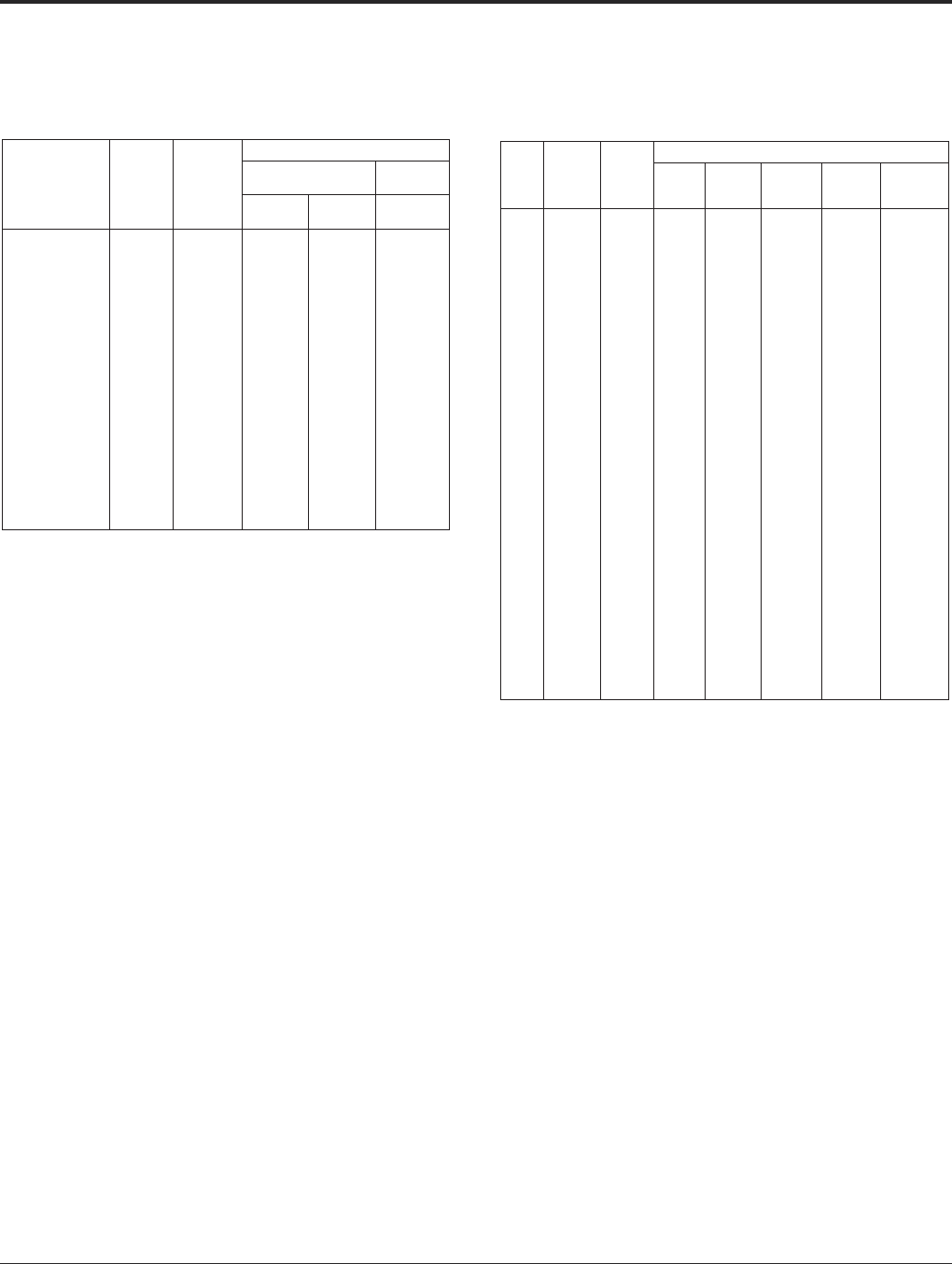
Grounding BURNDY®
Reference
Canada: 1-800-387-6487 www.burndy.com US: 1-800-346-4175
142
CABLE DATA (Continued)
STRANDED COPPERWELD CABLE
(ASTM B228)
Nominal
Diameter †
(Inch) Size
AWG‡
Circular
Mils
Diameter*
(Inch)
Breaking Load Lbs.**
High Strength Extra High
Strength
40%
Cond.
30%
Cond.
30%
Cond.
7/8 (19 No. 5)
13/16 (19 No. 6)
23/32 (19 No. 7)
27/32 (19 No. 8)
9/16 (19 No. 9)
5/8 (7 No. 4)
9/16 (7 No. 5)
1/2 (7 No. 6)
7/16 (7 No. 7)
3/8 (7 No. 8)
11/32 (7 No. 9)
5/16 (7 No. 10)
3 No. 5
3 No. 6
3 No. 7
3 No. 8
3 No. 9
3 No. 10
3 No. 12
628,900
498,800
395,500
313,700
248,800
292,200
231,700
183,800
145,700
115,600
91,650
72,680
99,310
78,750
62,450
49,530
39,280
31,150
19,590
.910
.810
.721
.642
.572
.613
.546
.486
.433
.385
.343
.306
.392
.349
.311
.277
.247
.220
.174
50,240
41,600
34,390
28,380
23,390
22,310
18,510
15,330
12,670
10,460
8,616
7,121
8,373
6,934
5,732
4,730
3,898
3,221
2,236
55,570
45,830
37,740
31,040
25,500
24,780
20,470
16,890
13,910
11,440
9,393
7,758
9,262
7,639
6,291
5,174
4,250
3,509
—
66,910
55,530
45,850
37,690
30,610
29,430
24,650
20,460
16,890
13,890
11,280
9,196
11,860
9,754
7,922
6,282
5,129
4,160
—
† The designation "Inch" is the approximate diameter in proper fraction of an inch.
‡ The designation of "AWG" is a combination of the number of wires each of the American
Wire Gage size indicated by "No."
* Diameter of circumscribing.
** Breaking loads of 7-wire and 19-wire conductors are taken as 90% of the sum of the
breaking loads of individual wires; breaking load of 3-wire conductors is taken as 95%
of the sum of the breaking loads of the individual wires.
GALVANIZED STEEL CABLE
(ASTM A475)
Minimum Breaking Load (lbs.)
Inches
Nominal
Diameter
of Strand
(mm)
Number
of Wires
in
Strand Utilities
Grade
Common
Grade
Siemens-
Martin
Grade
High-
Strength
Grade
Extra High-
Strength
Grade
1/8
5/32
3/16
3/16
7/32
7/32
1/4
1/4
1/4
9/32
9/32
5/16
5/16
5/16
3/8
3/8
7/16
1/2
1/2
9/16
9/16
5/8
5/8
3/4
7/8
1
1
1-1/8
1-1/4
(3.18)
(3.97)
(4.76)
(4.76)
(5.56)
(5.56)
(6.35)
(6.35)
(6.35)
(7.14)
(7.14)
(7.94)
(7.94)
(7.94)
(9.52)
(9.52)
(11.11)
(12.70)
(12.70)
(14.29)
(14.29)
(15.88)
(15.88)
(19.05)
(22.22)
(25.40)
(25.40)
(28.58)
(31.75)
7
7
7
7
3
7
3
3
7
3
7
3
7
7
3
7
7
7
19
7
19
7
19
19
19
9
37
37
37
—
—
—
2,400
—
—
3,150
4,500
—
—
4,600
6,500
—
6,000
8,500
11,500
18,000
25,000
—
—
—
—
—
—
—
—
—
—
—
540
870
1,150
—
1,400
1,540
1,860
—
1,900
2,080
2,570
2,490
3,200
—
3,330
4,250
5,700
7,400
7,620
9,600
9,640
11,600
11,000
16,000
21,900
28,700
28,300
36,000
44,600
910
1,470
1,900
—
2,340
2,560
3,040
—
3,150
3,380
4,250
4,090
5,350
—
5,560
6,950
9,350
12,100
12,700
15,700
16,100
19,100
18,100
26,200
35,900
47,000
46,200
58,900
73,000
1,330
2,140
2,850
—
3,500
3,850
4,730
—
4,750
5,260
6,400
6,350
8,000
—
8,360
10,800
14,500
18,800
19,100
24,500
24,100
29,600
28,100
40,800
55,800
73,200
71,900
91,600
113,600
1,830
2,940
3,990
—
4,900
5,400
6,740
—
6,650
7,500
8,950
9,100
11,200
—
11,800
15,400
20,800
26,900
26,700
35,000
33,700
42,400
40,200
58,300
79,700
104,500
102,700
130,800
162,200

BURNDY®Grounding
Reference
US: 1-800-346-4175 www.burndy.com Canada: 1-800-387-6487
143
AWG VS. METRIC WIRE SIZES
Circ.
Mils
Equiv-
alent
Circ.
Mils
Metric
Wire
Size
MM
AWG
Size
Stranding/Wire
Diameter per
Strand
Approximate
Overall
Diameter
In. MM In. MM MM MM
—
1020
—
1620
1620
—
—
937
—
1480
—
—
1974
1974
—
20
—
18
18
—
—
0.50
—
.75
—
—
1.0
1.0
1/.032
7/.0121
1/.039
1/.0103
7/.0152
1/.045
7/.017
1/.813
1/.307
1/.091
1/1.02
7/.386
1/1.14
7/.422
.032
.036
.039
.040
.046
.045
.061
.061
0.91
0.99
1.02
1.16
1.14
1.30
1
—
1/0
2/0
—
3/0
3/0
—
50
—
—
70
—
—
19/.0064
19/.073
19/.0745
19/.0837
19/.086
19/.094
36/.0673
19/1.50
19/1.85
19/1.59
19/2.13
19/2.18
19/2.59
37/1.71
.332
.365
.373
.419
.430
.470
.471
8.43
9.27
9.46
10.6
10.9
11.9
12.0
2580
2580
—
—
4110
4110
—
—
2960
2960
—
—
16
16
—
—
14
14
—
—
1.5
1.5
—
—
1/.0503
7/.0192
1/.055
7/.021
1/.0641
7/.0242
1/1.29
7/.468
1/1.40
7/5.33
1/1.63
7/.615
.051
.058
.055
.063
.064
.073
1.29
1.46
1.40
1.60
1.63
1.84
—
—
4/0
—
—
—
95
95
—
120
—
150
19/.101
37/.072
19/.1055
37/.081
37/.0822
37/.090
19/2.57
37/1.83
19/2.89
37/2.06
37/2.07
37/2.29
.505
.504
.528
.567
.575
.630
12.8
12.5
13.4
14.4
14.6
16.0
—
—
6530
6530
—
—
4934
4934
—
—
7894
7894
—
—
12
12
—
—
2.5
2.5
—
—
4
4
1/.071
7/.027
1/.0308
7/.0305
1/.089
7/.034
1/1.80
7/6.66
1/2.05
7/.775
1/2.26
7/.864
.071
.081
.081
.092
.089
.102
1.80
2.06
2.05
2.32
2.26
2.59
—
—
—
—
—
—
—
185
—
240
240
—
37/.0973
37/.100
37/104
37/.114
61/.089
37/.1162
37/2.47
37/2.54
37/2.64
37/2.90
61/2.26
37/2.95
.681
.700
.728
.798
.801
.813
17.3
17.8
18.5
20.3
20.3
20.7
10380
10380
—
—
13000
13090
—
—
11840
11840
—
—
10
10
—
—
9
9
—
—
6
6
—
—
1/.1019
7/.0355
1/.109
7/.042
1/.1144
7/.0432
1/2.59
7/.978
1/2.77
7/.107
1/2.91
7/1.10
.102
.116
.109
.126
.114
.130
2.59
2.93
2.77
3..21
2.91
3.30
—
—
—
—
—
—
—
300
—
—
—
—
61/.0905
61/.099
61/.0992
61/.1071
61/.1109
91/.0908
61/2.30
61/2.51
61/2.52
61/2.72
61/2.82
91/2.31
.814
.891
.893
.964
.998
.998
20.7
22.6
22.7
24.5
25.4
25.4
16510
16510
—
—
20520
20520
—
—
19740
19740
—
—
8
8
—
—
7
7
—
—
10
10
—
—
1/.1285
7/.0486
1/.141
7/.054
1/.1443
7/.0545
1/3.26
7/1.23
1/3.58
7/1.37
1/3.67
7/1.38
.128
.146
.141
.162
.144
.164
3.25
3.70
3.58
4.12
3.67
4.15
—
—
—
—
—
—
400
—
—
500
—
625
61/.114
61/.1145
91/.0938
61/.1280
91/.1048
91/.117
61/2.90
61/2.91
91/2.38
61/3.25
91/2.66
91/2.97
1.026
1.031
1.032
1.152
1.153
1.287
26.1
26.2
26.2
28.3
29.3
32.7
26240
26240
—
33090
41740
—
—
31580
—
—
6
6
—
5
4
—
—
16
—
—
1/.162
7/.0612
7/.008
7/.0688
7/.0772
1/4.11
7/1.55
7/1.73
7/1.75
7/1.96
.162
.184
.204
.206
.232
4.11
4.66
5.13
5.24
5.88
—
—
—
—
—
—
—
—
—
—
800
91/.1172
127/.0992
91/.1284
127/.1087
91/.132
91/2.93
127/2.52
91/3.26
127/2.76
91/3.35
1.289
1.200
1.412
1.413
1.452
32.7
32.8
36.9
36.9
36.9
—
—
52620
66300
—
—
49340
49340
—
—
69070
69070
—
—
3
2
—
—
25
25
—
—
35
35
7/.085
19/.052
7/.0867
7/.0974
7/.100
19/.001
7/2.16
10/1.32
7/2.20
7/2.47
7/2.54
19/1.55
.255
.260
.260
.292
.300
.305
6.48
6.60
6.61
7.42
7.62
7.75
—
—
—
—
98680
—
—
138100
—
—
187500
187500
—
237.8 kcmil
—
—
—
365.1 kcmil
—
473.6 kcmil
473.6 kcmil
—
—
592.1 kcmil
—
—
—
—
789.4 kcmil
—
—
986.8 kcmil
—
1233.7 kcmil
—
—
—
—
—
1578.8 kcmil
1973.5 kcmil
—
—
1000
—
—
83690
—
10500
133100
—
167800
167800
—
—
211600
—
250 kcmil
300 kcmil
350 kcmil
—
400 kcmil
—
—
500 kcmil
500 kcmil
—
600 kcmil
700 kcmil
750 kcmil
750 kcmil
—
800 kcmil
800 kcmil
1000 kcmil
1000 kcmil
—
1250 kcmil
1250 kcmil
1500 kcmil
1500 kcmil
—
—
2000 kcmil
2000 kcmil
91/.147
127/.1255
169/.1088
91/3.73
127/3.19
169/2.76
1.617
1.632
1.632
41.1
41.5
41.5
Metric
Wire
Size
MM
Circ.
Mils
Stranding/Wire
Diameter per
Strand
Equiv-
alent
Circ.
Mils AWG
Size In. In.
Approximate
Overall
Diameter

GROUNDMAX™ 97
PATCUT129-LI 127
PATCUT245-LI 129
PENETROX-A 106
115 71
115Cl 71
115Q 70
115R 71
15 71
150 71
150Q 70
150R 71
15CI 71
15CP 71
15Q 70
15R 71
200 71
200Q 70
200R 71
25 71
25 FW BOX 109
25 FWSS 113
25 HSSN 113
25 NW BOX 109
25 SW BOX 109
25 SWSS LT 113
250 71
250Q 70
250R 71
25C HEN BOX 109
25CI 71
25CP 71
25Q 70
25R 71
25x100 HEB BOX 108
25x125 HEB BOX 108
25x150 HEB BOX 108
25x200 HEB BOX 108
25x250 HEB BOX 108
25x300 HEB BOX 108
25x50 HEB BOX 108
25x62 HEB BOX 108
25x75 HEB BOX 108
31 FW BOX 109
31 NW BOX 109
31 SW BOX 109
31C HEN BOX 109
31CHGSN 111
31x100 HEB BOX 108
31x125 HEB BOX 108
31x150 HEB BOX 108
31x175 HEB BOX 108
31x200 HEB BOX 108
31x250 HEB BOX 108
31x300 HEB BOX 108
31x50 HEB BOX 108
31x62 HEB BOX 108
31x75 HEB BOX 108
32 71
32Cl 71
32CP 71
32Q 70
32R 71
38 FW BOX 109
38 FWSS 113
38 HGSN 111
38 HGSN-009 111
38 HSSN 113
38 NW BOX 109
38 NWGS 111
38 SW BOX 109
38 SWSSMD 113
38C HEN BOX 109
38x100 HEB BOX 108
38x125 HEB BOX 108
38x125 HGSB 111
38X125 HSSB 113
38x150 HEB BOX 108
38x175 HEB BOX 108
38x200 HEB BOX 108
38x225 HEB BOX 108
38x225 HGSB 111
38x225 HSSB 113
38x250 HEB BOX 108
38x250 HSSB 113
38x275 HEB BOX 108
38x275 HGSB 111
38x275 HSSB 113
38x300 HEB BOX 108
38x325 HEB BOX 108
38x350 HEB BOX 108
38x400 HEB BOX 108
38x450 HEB BOX 108
38x50 HEB BOX 108
38x500 HEB BOX 108
38x62 HEB BOX 108
38x75 BWSS 113
38x75 HEB BOX 108
38x81 FWGS 111
38x88 HEB BOX 108
44 FW BOX 109
44 NW BOX 109
44 SW BOX 109
44C HEN BOX 109
44x150 HEB BOX 108
44x200 HEB BOX 108
45 71
45Cl 71
45CP 71
45Q 70
45R 71
50 FW BOX 109
50 FWA BOX 112
50 FWSS 113
50 HAN BOX 112
50 HGSN 111
50 HSSN 113
50 NW BOX 109
50 NWGS 111
50 SW BOX 109
50 SWAL BOX 112
50 SWSSMD 113
500 71
500Q 70
50C HEN BOX 109
50x100 HEB BOX 108
50x100 HGSB 111
50x106 BWSS 113
50x106 FWGS 111
50x125 HEB BOX 108
50x150 HAB BOX 112
50x150 HEB BOX 108
50x150 HGSB 111
50x175 HAB BOX 112
50x175 HEB BOX 108
50x200 HAB BOX 112
50x200 HEB BOX 108
50x200 HGSB 111
50x200 HSSB 113
50x225 HAB BOX 112
50x225 HEB BOX 108
50x250 HAB BOX 112
50x250 HEB BOX 108
50x250 HSSB 113
50x275 HAB BOX 112
50x275 HEB BOX 108
50x300 HAB BOX 112
50x300 HEB BOX 108
50x300 HSSB 113
50x325 HAB BOX 112
50x325 HEB BOX 108
50x350 HAB BOX 112
50x350 HEB BOX 108
50x375 HAB BOX 112
50x375 HEB BOX 108
50x400 HAB BOX 112
50x400 HEB BOX 108
50x425 HAB BOX 112
50x450 HAB BOX 112
50x450 HEB BOX 108
50x500 HAB BOX 112
50x500 HEB BOX 108
50x550 HAB BOX 112
50x550 HEB BOX 108
50x600 HEB BOX 108
50x75 HEB BOX 108
62 FW BOX 109
62 FWA BOX 112
62 FWSS 113
62 HAN BOX 112
62 HGSN 111
62 HSSN 113
62 NW BOX 109
62 NWGS 111
62 SW BOX 109
62 SWAL BOX 112
62 SWSSMD 113
62C HEN BOX 109
62x100 HEB BOX 108
62x100 HGSB 111
62x125 HEB BOX 108
62x150 HEB BOX 108
62x175 HAB BOX 112
62x175 HEB BOX 108
62x175 HGSB 111
62x200 HAB BOX 112
62x200 HEB BOX 108
62x225 HAB BOX 112
62x225 HEB BOX 108
62x250 HAB BOX 112
62x250 HEB BOX 108
62x275 HEB BOX 108
62x300 HAB BOX 112
62x300 HEB BOX 108
62x300 HSSB 113
62x325 HEB BOX 108
62x350 HAB BOX 112
62x350 HEB BOX 108
62x400 HAB BOX 112
62x400 HEB BOX 108
62x450 HAB BOX 112
62x450 HEB BOX 108
62x500 HAB BOX 112
62x500 HEB BOX 108
62x550 HAB BOX 112
62x600 HAB BOX 112
62x600 HEB BOX 108
65 71
65Cl 71
65CP 71
65Q 70
65R 71
75 NWGS 111
75x125 HGSB 111
90 71
90Cl 71
90Q 70
90R 71
B-106 99
B-107 99
B-1208 77
B-1212 82
B-1215 88
B-1216 88
B-1218 88
B-1219 88
B-1220 88
B-1221 88
B-1222 88
B-1223 88
B-1224 88
B-1225-H 88
B-1226-H 88
B-1228-H 88
B-1270 76
B-1271 76
B-1272 76
B-1273 76
B-1274 76
B-1275 76
B-1276 76
B-1277 76
B-1278 76
B-1279 76
B-1280 76
B-1281 76
B-1282 76
B-1283 76
B-1284 76
B-1285 76
B-1286 76
B-1287 76
B-1288 76
B-1289 76
B-1290 76
B-1291 76
B-1292 76
B-1293 76
B-1294 76
B-1295 76
B-1296 76
B-1297 76
B-1298 76
B-1299 76
B-1300 76
B-1301 76
B-1302 76
B-1303 76
B-1304 76
B-1305 76
B-1306 76
B-1307 76
B-1308 76
B-1309 76
B-1310 76
B-1311 77
B-1313 77
B-1314 77
B-1315 77
B-1316 77
B-1317 77
B-1318 77
B-1319 77
B-1320 77
B-1321 77
B-1322 77
B-1323 77
B-1324 77
B-1325 77
B-1326 77
B-1327 77
B-1328 77
B-1329 77
B-1330 77
B-1331 77
B-1332 77
B-1333 77
B-1334 77
B-1335 77
B-1336 77
B-1581 80
B-1582 80
B-1583 80
B-1584 80
B-1586 80
B-1587 80
B-1588 80
B-1589 80
B-1593 80
B-1594 80
B-1595 80
B-1596 80
B-1597 80
B-1601 80
B-1602 80
B-1603 80
B-1604 80
B-1605 80
B-1606 80
B-1610 80
B-1611 80
B-1613 90
B-1614 90
B-1615 90
B-1616 90
B-1617 90
B-1618 90
B-1619 90
B-1620 90
B-1626 88
B-1627 88
B-1628 88
B-1629 88
B-1630 88
B-1631 88
B-1632 88
B-1633 88
B-1634 88
B-1635 89
B-1636 89
B-1637 89
B-1638 89
B-1639 89
B-1640 89
B-1641 89
B-1642 89
B-1643 89
B-1644 89
B-1645 89
B-1646 89
Grounding BURNDY®
Index
CATALOG NO. PAGE NO. CATALOG NO. PAGE NO. CATALOG NO. PAGE NO. CATALOG NO. PAGE NO. CATALOG NO. PAGE NO.
Canada: 1-800-387-6487 www.burndy.com US: 1-800-346-4175
144

B-1648 89
B-1649 89
B-1650 89
B-205 72
B-206 72
B-207 72
B-208 72
B-2084 82
B-209 72
B-210 72
B-211 72
B-213 72
B-214 72
B-215 72
B-2154 80
B-2155 80
B-2156 80
B-2157 80
B-2158 80
B-2159 80
B-2160 80
B-2161 80
B-2162 80
B-2163 80
B-2164 80
B-2165 80
B-2189 87
B-2199 84
B-2200 84
B-221 73
B-223 73
B-2235 82
B-224 73
B-225 73
B-226 73
B-227 73
B-228 73
B-229 73
B-230 73
B-231 73
B-232 73
B-2320 82
B-233 73
B-234 73
B-235 73
B-236 73
B-237 73
B-238 73
B-239 73
B-240 73
B-241 73
B-242 73
B-243 73
B-244 73
B-245 73
B-2450 82
B-246 73
B-247 73
B-2476 86
B-2477 86
B-2478 86
B-248 73
B-2480 86
B-2480-S 86
B-2482 86
B-2483 86
B-2484 86
B-2486 86
B-2487 86
B-2488 86
B-249 73
B-2490 86
B-2491 86
B-2493 86
B-2494 86
B-2495 86
B-2497 86
B-2498 86
B-250 73
B-2506 84
B-2507 84
B-2509 84
B-251 73
B-2510 82
B-2511 84
B-252 73
B-253 73
B-254 73
B-2540 87
B-2542 84
B-255 73
B-2558 82
B-256 73
B-2566 81
B-2567 89
B-2568 89
B-2569 89
B-257 73
B-258 73
B-2583 86
B-2583-S 86
B-259 73
B-260 73
B-261 73
B-262 73
B-263 73
B-264 73
B-265 73
B-266 73
B-267 73
B-268 73
B-2687 75
B-2689 75
B-269 73
B-2690 75
B-2691 75
B-2692 75
B-2693 75
B-2694 75
B-2695 75
B-2696 75
B-2697 75
B-2698 75
B-2699 75
B-270 73
B-2700 75
B-2701 75
B-2702 75
B-2703 75
B-2704 75
B-2705 75
B-2706 75
B-2707 75
B-2708 75
B-2709 75
B-2710 75
B-2711 75
B-2712 75
B-2713 75
B-2714 75
B-2715 75
B-2716 75
B-2717 75
B-2718 75
B-2719 75
B-2747 75
B-2751 75
B-2752 75
B-2753 75
B-2754 75
B-2755 75
B-2756 75
B-2757 75
B-2761 89
B-2781 87
B-280 73
B-282 73
B-283 73
B-284 73
B-285 73
B-286 73
B-287 73
B-288 73
B-289 73
B-290 73
B-291 73
B-293 73
B-294 73
B-295 73
B-296 73
B-297 73
B-298 73
B-423 74
B-424 74
B-425 74
B-426 74
B-427 74
B-428 74
B-429 74
B-430 74
B-431 74
B-432 74
B-433 74
B-434 74
B-435 74
B-436 74
B-437 74
B-438 74
B-439 74
B-440 74
B-441 74
B-442 74
B-443 74
B-444 74
B-445 74
B-447 74
B-448 74
B-449 74
B-450 74
B-451 74
B-452 74
B-453 74
B-454 74
B-455 74
B-456 74
B-457 74
B-458 74
B-459 74
B-460 74
B-461 74
B-462 74
B-463 74
B-464 74
B-465 74
B-466 74
B-467 74
B-468 74
B-469 74
B-470 74
B-471 74
B-472 74
B-483 74
B-485 74
B-486 74
B-487 74
B-488 74
B-489 74
B-490 74
B-491 74
B-492 74
B-493 74
B-495 78
B-496 78
B-497 78
B-498 78
B-499 78
B-500 78
B-501 78
B-502 78
B-5021 73
B-503 78
B-504 78
B-505 78
B-506 78
B-5065 85
B-507 78
B-508 78
B-509 78
B-510 78
B-511 78
B-513 78
B-514 78
B-515 78
B-516 78
B-517 78
B-518 78
B-519 78
B-520 78
B-521 78
B-523 78
B-524 78
B-525 78
B-526 78
B-527 78
B-528 78
B-529 78
B-5294 81
B-530 78
B-531 78
B-532 79
B-5321 80
B-533 78
B-5330 82
B-5331 85
B-5332 82
B-5333 82
B-5334 82
B-5335 82
B-5336 82
B-5337 82
B-5338 82
B-534 78
B-5340 77
B-5341 82
B-5342 77
B-535 78
B-5351 82
B-5352 82
B-5353 82
B-5359 87
B-5361 87
B-5362 87
B-5363 87
B-537 79
B-538 79
B-5380 81
B-5389 87
B-539 79
B-5390 81
B-540 79
B-541 79
B-5416 81
B-5419 89
B-542 79
B-5428 82
B-543 79
B-5432 75
B-544 79
B-545 79
B-546 79
B-547 79
B-5475 73
B-548 79
B-549 79
B-550 79
B-551 79
B-5513 81
B-5515 81
B-5517 82
B-553 79
B-555 79
B-5555 81
B-5556 81
B-556 79
B-5560 82
B-5561 81
B-557 79
B-5573 82
B-5574 73
B-558 79
B-559 79
B-560 79
B-5604 82
B-561 79
B-5618 76
B-562 79
B-5623 72
B-5624 72
B-5625 72
B-5626 72
B-5627 77
B-5629 77
B-563 79
B-5630 77
B-5631 77
B-5632 77
B-5634 77
B-5635 77
B-5636 77
B-5637 77
US: 1-800-346-4175 www.burndy.com Canada: 1-800-387-6487
145
BURNDY®Grounding
Index
CATALOG NO. PAGE NO. CATALOG NO. PAGE NO. CATALOG NO. PAGE NO. CATALOG NO. PAGE NO. CATALOG NO. PAGE NO.

B-5638 77
B-5639 77
B-564 79
B-5640 82
B-5642 77
B-5644 77
B-5645 77
B-5652 77
B-5659 77
B-566 79
B-5660 80
B-5667 82
B-5668 77
B-567 79
B-5676 77
B-5677 82
B-5679 77
B-5680 77
B-5682 77
B-5684 77
B-5686 77
B-5688 77
B-569 79
B-5698 81
B-5699 81
B-570 79
B-5702 82
B-5709 76
B-571 79
B-572 79
B-5722 81
B-573 79
B-5732 81
B-5734 81
B-5738 81
B-574 79
B-5746 81
B-575 79
B-5767 82
B-577 79
B-5777 81
B-578 79
B-5781 78
B-579 79
B-5803 81
B-5804 81
B-5820 81
B-5821 81
B-5830 81
B-5833 81
B-585 86
B-5850 81
B-5857 81
B-586 86
B-587 86
B-5877 81
B-588 86
B-588-S 86
B-589 86
B-590 86
B-5904 81
B-591 86
B-5910 89
B-592 86
B-593 86
B-5935 81
B-594 86
B-5940 81
B-5943 77
B-595 86
B-596 86
B-5961 81
B-5963 81
B-5972 81
B-598 86
B-599 86
B-5992 81
B-600 86
B-6002 82
B-6003 81
B-602 85
B-6025 81
B-603 85
B-604 85
B-6046 77
B-6048 81
B-605 85
B-6051 82
B-6060 89
B-6061 89
B-6067 89
B-6072 89
B-6114 84
B-616 85
B-6165 81
B-617 85
B-618 85
B-619 85
B-620 85
B-6208 82
B-621 85
B-622 85
B-624 85
B-625-H 85
B-626-H 85
B-628 84
B-629 84
B-6294 82
B-630 84
B-631 84
B-644 84
B-645 84
B-646 84
B-647 84
B-648 84
B-649 84
B-650 84
B-652 84
B-653 84
B-654 84
B-6552 77
B-6630 80
B-6766 82
B-6906 80
B-7075 84
B-7146 84
B-7192 85
B-7500 91
B-7501 91
B-7502 91
B-7503 91
B-7504 91
B-7505 91
B-7506 91
B-7507 91
B-7508 91
B-7509 91
B-7510 91
B-7511 91
B-7512 91
B-7513 91
B-7514 91
B-7515 91
B-7520 91
B-7521 91
B-7522 91
B-7523 91
B-7528 91
B-7529 91
B-7530 91
B-7531 91
B-7588 92
B-7589 92
B-7590 92
B-7591 92
B-7592 92
B-7593 92
B-7594 92
B-7595 92
B-7596 92
B-7597 92
B-7598 92
B-7599 92
B-7600 92
B-7601 92
B-7602 92
B-7603 92
B-7604 92
B-7605 92
B-7606 92
B-7607 92
B-7608 92
B-7609 92
B-7610 92
B-7611 92
B-7612 92
B-7613 92
B-7614 92
B-7615 92
B-7616 92
B-7617 92
B-7618 92
B-7619 92
B-7620 93
B-7621 93
B-7622 93
B-7623 93
B-7624 93
B-7625 93
B-7626 93
B-7627 93
B-7628 93
B-7629 93
B-7630 93
B-7631 93
B-7632 93
B-7633 93
B-7634 93
B-7635 93
B-7636 93
B-7637 93
B-7638 93
B-7639 93
B-7640 93
B-7641 93
B-7642 93
B-7643 93
B-7644 93
B-7645 93
B-7646 93
B-7647 93
B-7648 93
B-7649 93
B-7650 93
B-7651 93
B-7652 93
B-7653 93
B-7654 93
B-7655 93
B-7656 93
B-7657 93
B-7658 93
B-7659 93
B-7708 94
B-7709 94
B-7710 94
B-7711 94
B-7712 94
B-7713 94
B-7714 94
B-7715 94
B-7716 94
B-7717 94
B-7718 94
B-7719 94
B-7720 94
B-7721 94
B-7722 94
B-7723 94
B-7724 94
B-7725 94
B-7726 94
B-7727 94
B-7728 94
B-7729 94
B-7730 94
B-7731 94
B-7732 94
B-7733 94
B-7734 94
B-7735 94
B-7736 94
B-7737 94
B-7738 94
B-7739 94
B-7884 95
B-7885 95
B-7886 95
B-7887 95
B-7888 95
B-7889 95
B-7890 95
B-7891 95
B-7892 95
B-7893 95
B-7894 95
B-7895 95
B-7896 95
B-7897 95
B-7898 95
B-7899 95
B-7900 95
B-7901 95
B-7902 95
B-7903 95
B-7904 95
B-7905 95
B-7906 95
B-7907 95
B-7908 95
B-7909 95
B-7910 95
B-7911 95
B-7912 95
B-7913 95
B-7914 95
B-7915 95
B-7916 95
B-7917 95
B-7918 95
B-7919 95
B-7920 95
B-7921 95
B-7922 95
B-7923 95
B-8011 82
B-8027 82
B-8165 87
B-8214 82
B-8359 89
B-8379 85
B-8381 85
B-8402 78
B-8403 78
B-8410 85
B-8413 85
B-8414 78
B-8415 78
B-8422 78
B-8423 85
B-8426 78
B-8428 82
B-8434 79
B-8435 79
B-8441 79
B-8442 79
B-8451 82
B-8452 79
B-8454 79
B-8461 82
B-8512 87
B-8718 87
B-8726 82
B-8802 82
B-8833 86
B-8882 77
B-9021 86
B-9029 87
B-9233 86
B-9233-S 86
B-9253 89
B106-32 100
B106-37 100
B106-41 100
B107-32 100
B107-37 100
B107-41 100
B2D12 51
B2D12N 51
B2E12 51
B2E12N 51
B2F12 51
B2F12N 51
B2G12N 51
B370320-01 71
B370320-02 71
B370320-03 71
B38-0101-00 102
B38-0101-01 102
B38-0135-00 101
Grounding BURNDY®
Index
CATALOG NO. PAGE NO. CATALOG NO. PAGE NO. CATALOG NO. PAGE NO. CATALOG NO. PAGE NO. CATALOG NO. PAGE NO.
Canada: 1-800-387-6487 www.burndy.com US: 1-800-346-4175
146

B38-0135-01 101
B38-0302-00 102
B38-0302-02 102
B38-0303-00 102
B38-0304-00 102
B38-0305-00 102, 107
B38-0306-00 101, 102
B38-0307-00 102
B38-0308-00 102
B38-0309-00 102
B38-0309-01 102
B38-0329-00 103
B38-0330-00 101
B38-0904-00 102
B38-3662-01 103
B38-3662-02 103
B38-3662-03 103
B38-3662-04 103
B38-3662-05 103
B38-3662-06 103
B38-3922-00 101, 102
B38032900 91-95
B38406100 91-95
B38406200 91-95
B38406300 91-95
B38412900 101
B38412905 101
B3D12 51
B3D12N 51
B3E12 51
B3E12N 51
B3F12 51
B3F12N 51
B3G12 51
B3G12N 51
B40-0106-27. 100
B40-0106-75 99
B40-0106-76 100
B40-0106-77 100
B40-0106-78 100
B40-0319-01 101
B40-0319-03 101
B40-3657-00 99
B40-4431-01 100
B404431-00 100
B4D12 51
B4D12N 51
B4E12 51
B4E12N 51
B4F12 51
B4F12N 51
B4G12N 51
BA-200 103
BA-201 103
BA-202 103
BA-203 103
BA-204 103
BA-205 103
BA-207 103
BA-208 103
BA-209 103
BA-211 103
BA-212 103
BA-213 103
BA-214 103
BA-215 103
BA-240 103
BAT18V 118, 120, 126, 128
BAT18VLI 119, 121, 127, 129
BB077L 48
BB154L 48
BB226L 48
BB300L 48
BBB14210A 65
BBB14224B 65
BBB14410C 65
BBB14410D 65
BBB14412E 65
BBB14412F 65
BBB14416G 65
BBB14416H 65
BBB14420J 65
BBB412UD 65
BBB424UD 65
BBBHR19 65
BBBVR36 65
BCC1000CUAL 125
BCCBAT12V 125
BCCCASE 125
BCCCHGR 125
BCT/PATDCCHGR 118, 120,
126, 128
BD12 50
BD12N 50
BD18 50
BD18N 50
BD24 50
BD24N 50
BDT1 55
BDTIBB 56
BE12 50
BE12N 50
BE18 50
BE18N 50
BE24 50
BE24N 50
BF12 50
BF12N 50
BF18 50
BF18N 50
BF24 50
BF24N 50
BG12 50
BG12N 50
BG18 50
BG18N 50
BG24 50
BG24N 50
BGM3050 98
BGM3100 98
BGM640044 98
BGM64006 98
BGM640066 98
BGM640068 98
BS-2006 83
BS-2007 83
BS-2008 83
BS-2009 83
BS-2010 83
BS-2011 83
BS-2012 83
BS-2013 83
BS-2014 83
BS-2015 83
BS-2016 83
BS-2017 83
BS-2018 83
BS-2019 83
BS-2020 83
BS-2021 83
BS-2024 83
BS-2025 83
BS-2026 83
BS-2027 83
BS-2028 83
BS-2029 83
BS-2030 83
BS-2031 83
BS-2032 83
BS-2033 83
BS-2034 83
BS-2068 83
BS-2069 83
BS-2070 83
BS-2105 83
BS-2106 83
BS-2107 83
BS-2108 83
BS-2109 83
BS-2110 83
BSD2050 58
BSD2050N 58
BSD2050Y 58
BWB680IG 57
BWB860AG 57
C-11B 38
C-11CSH-1 43
C-11CSH-2 43
C-11CSH-3 43
C-11D 38
C-11JA 40
C-11JPT 38
C-11LH-1 42
C-11LH-2 42
C-11LH-3 42
C-11N 38
C-22 38
C-22D 38
C-22JA 40
C-22JPT 38
C-22LH-1 42
C-22LH-2 42
C-22LH-3 42
C-4 38
C-4JA 40
C-4JPT 38
C-4LH-1 42
C-4LH-2 42
C-4LH-3 42
C-5 JUNIOR 38
C-6 41
C-61 42
C-66 42
C-6D 41
C-7 41
C-8 38
C11CSLH12 43
C11HD4/0DB 40
C11K16D 39
C11K17D 39
C22HD4/0DB 40
CASEWDIES 116
CL50-1 31
CL50-1TN 31
CZ-11 39
EPP10 131
EPP6 131
EPPCASE-1 131
EQC632C 30
GA25H26 61
GAR1126 32
GAR1129 32
GAR114C 32
GAR1426 32
GAR1429 32
GAR1434 32
GAR144C 32
GAR1526 32
GAR1529 32
GAR1534 32
GAR154C 32
GAR1626 32
GAR1629 32
GAR1634 32
GAR164C 32
GAR1726 32
GAR1729 32
GAR1734 32
GAR174C 32
GAR1826 32
GAR1829 32
GAR1834 32
GAR184C 32
GAR1926 32
GAR1929 32
GAR1934 32
GAR194C 32
GAR2026 33
GAR2029 33
GAR2034 33
GAR204C 33
GAR2126 33
GAR2129 33
GAR2134 33
GAR214C 33
GAR2226 33
GAR2229 33
GAR2234 33
GAR224C 33
GAR2426 33
GAR2429 33
GAR2434 33
GAR244C 33
GAR3902 34
GAR3902-BU 34
GAR3902TC 35
GAR3903 34
GAR3903-BU 34
GAR3903TC 35
GAR3904 34
GAR3904-BU 34
GAR3904TC 35
GAR3905 34
GAR3905-BU 34
GAR3905TC 35
GAR3906 34
GAR3906-BU 34
GAR3906TC 35
GAR3907 34
GAR3907-BU 34
GAR3907TC 35
GAR3908 34
GAR3908-BU 34
GAR3908TC 35
GAR3909 34
GAR3909-BU 34
GAR3909TC 35
GAR6426 32
GAR6429 32
GAR6434 32
GAR644C 32
GAR644C-RB 34
GAR8629 33
GB26 52
GB29 52
GB34 52
GB4C 52
GBL30 52
GBM26 52
GBM29 52
GBM34 52
GBM4C 52
GC15A 44
GC18A 44
GC22A 44
GC2525CT 54
GC2626 52
GC2626CT 54
GC2929 52
GC2929CT 54
GC3434 52
GC4C4C 52
GCL30 52
GCM26 52
GCM29 52
GCM30 52
GCM34 52
GCM4C 52
GCRT1/0 47
GD1526 36
GD1529 36
GD1626 36
GD1629 36
GD1726 36
GD1729 36
GD1734 36
GD174C 36
GD1826 36
GD1829 36
GD1834 36
GD184C 36
GD1926 36
GD1929 36
GD1934 36
GD194C 36
GD2026 36
GD2029 36
GD2034 36
GD204C 36
GD2126 36
GD2129 36
GD2134 36
GD214C 36
GD2226 36
GD2229 36
GD2234 36
GD224C 36
GG15-1 45
GG16-1 45
GG17-1 45
GG17-15 45
GG18-1 45
GG18-15 45
GG18-2 45
GG19-2 45
GG19-25 45
GG20-2 45
GG20-25 45
GG20-3 45
GG21-2 45
US: 1-800-346-4175 www.burndy.com Canada: 1-800-387-6487
147
BURNDY®Grounding
Index
CATALOG NO. PAGE NO. CATALOG NO. PAGE NO. CATALOG NO. PAGE NO. CATALOG NO. PAGE NO. CATALOG NO. PAGE NO.

GG21-25 45
GG21-3 45
GG21-35 45
GG22-2 45
GG22-25 45
GG22-3 45
GG22-4 45
GG24-2 45
GIE2CG3 59
GIE4CG3 59
GIE4CG3P5 59
GIE4CG3P7 59
GIE4CG4 59
GIE4CG4P5 59
GIE4CG4P7 59
GK1126 37
GK1129 37
GK114C 37
GK1426 37
GK1429 37
GK1434 37
GK1526 37
GK1529 37
GK1626 37
GK1629 37
GK1726 37
GK1729 37
GK1826 37
GK1829 37
GK1926 37
GK1929 37
GK6426 37
GK6429 37
GK6434 37
GK644C 37
GKA4C 31
GKA8C 31
GL2626 53
GL2929 53
GL3434 53
GL4C4C 53
GP1126 37
GP1129 37
GP114C 37
GP1426 37
GP1429 37
GP1434 37
GP144C 37
GP1526G1 63
GP1629 37
GP164C 37
GP1726 37
GP1726G1 63
GP1726RT 63
GP1826 37
GP184C 37
GP2026 37
GP2226 37
GP6426 37
GP6429 37
GP6434 37
GP644C 37
GP64526G1 63
GP654CG1 63
GQ26-1 46
GQ2626 46
GQ29-1 46
GQ2929 46
GRC12 47
GRC34 47
GRC58 47
GRF4C-3 62
GRF4C-4 62
GRL3 47
GRL4 47
GRL5 47
GRL6 47
GROUNDMAX™ 96
GSTUD14HY 26
GSTUD34HY 26
GSTUD38HY 26
GSTUD916HY 26
GX2626 46
GX264C 46
GX2926 46
GX2929 46
GX294C 46
GX3426 46
GX3429 46
GX3434 46
GX344C 46
GX4C4C 46
GXP1828RF 64
GZ26-12 53
GZ26-38 53
GZ26-58 53
GZ29-12 53
GZ29-38 53
GZ29-58 53
GZ4C-12 53
GZ4C-38 53
GZ4C-58 53
J278 60
J279 60
J280 60
J295 60
K2C15 29
K2C15B1 29
K2C17 29
K2C17B1 29
K2C20 29
K2C20B1 29
K2C22 29
K2C22B1 29
K2C23 29
K2C23B1 29
K2C25 29
K2C25B1 29
K2C26 29
K2C26B1 29
K2C28 29
K2C28B1 29
K2C31 29
K2C31B1 29
K2C34 29
K2C34B1 29
KC15 29
KC15B1 29
KC17 29
KC17B1 29
KC20 29
KC20B1 29
KC22 29
KC22B1 29
KC22J12T13 30
KC23 29
KC23B1 29
KC25 29
KC25B1 29
KC26 29, 30
KC26B1 29
KC28 29
KC28B1 29
KC31 29
KC31B1 29
KC34 29
KC34B1 29
KC34J12T13 30
KPB4CG1 31
KS15 30
KS17 30
KS20 30
KS22 30
KS23 30
KS25 30
KS26 30
KS27 30
KS29 30
KS31 30
KS34 30
MCC1000 122
MCC1000BLADESET 122
MCC500 122
MCC500BLADESET 122
P15K 120, 121, 133
P8A 107
PAT46-18V 120
PAT46-LI 121
PAT46C-18V 120
PAT46C-LI 121
PAT750-LI 119
PAT750C-LI 119
PAT750CXT-18V 118
PAT750XT-18V 118
PATCHGR-LI 119, 127, 129
PATCHGR-LI18V 121
PATCHGR-LI250V 119, 121,
127, 129
PATCHGR-LIDC 119, 121,
127, 129
PATCHGR18V 118, 120,
126, 128
PATCHGR250V 118, 120,
126, 128
PATCUT129ACSR-18V 126
PATCUT245CUAL-18V 128
PEN A-4 107
PEN A-55GAL 107
PEN A-5GAL 107
PEN A-GAL 107
PEN A-QT 107
PEN A13-4 107
PEN A13-55GAL 107
PEN A13-5GAL 107
PEN A13-8 107
PEN A13-GAL 107
PEN A13-QT 107
PEN E-4 107
PEN E-55GAL 107
PEN E-5GAL 107
PEN E-8 107
PEN E-GAL 107
PEN E-QT 107
PENA 1/2 107
PENA13CARTRIDGE 107
PENACARTRIDGE 106, 107
PENETROX™ A 107
PENETROX™ A-13 106, 107
PENETROX™ E 106, 107
PENETROX™ HT 106, 107
PENHT-1LB 107
PENHT-4 107
PENHT-8 107
PENHT-GAL 107
PT 29074-1 136
PT 29900-10 136
PT 29900-15 136
PT 29900-25 136
PT 29901-10 136
PT 29901-15 136
PT 29901-25 136
PT 29902-10 136
PT 29902-15 136
PT 29902-25 136
PT 76 136
PT 91 136
PT10024162 124
PT10037384 124, 126,
127, 134
PT10037388 124, 126,
127, 134
PT10038657 128, 129, 135
PT10040663 128, 129, 135
PT10043890 134
PT10044980 128
PT10054094 135
PT10128 133
PT208620 118, 119, 126-129
PT29279-2 117, 132
PT29291 116, 117, 132
PT29402-1 132
PUADP-1 120, 121, 133
QGFL1CB1 61
QGFL1CB1T6 61
QGFL26B1 61
QGFL26B1T6 61
QGFL26B2 61
QGFL26B2T6 61
QGFL29B1 61
QGFL29B1T6 61
QGFL31B1 61
QGFL31B1T6 61
QGFL34B1 61
QGFL34B1T6 61
QGFL39B1 61
QGFL39B1T6 61
QGFL44B1 61
QGFL44B1T6 61
QGFL46B1 61
QGFL46B1T6 61
QGFL48B1 61
QIKLITE 70
QIKLITEKIT 70
QIKSTIK 70
RCC1000 123
RCC336 123
RCC556 123
RCC600 123
RCC750HD 123
RCC954ACSR1K 123
RGC39G1 60
RGC44G1 60
RHCC129ACSR 134
RHCC245CUAL 135
RHCCHSA 134
RP50RP02 125
RP50RP03 125
TMH261 110
TMH261SS 110
TMH262 110
TMH262SS 110
TMH263 110
TMH263SS 110
TMH264 110
TMH264SS 110
TMH265 110
TMH265SS 110
TMH266 110
TMH267 110
TMH267SS 110
TMH268 110
TMH268SS 110
TMH269 110
TMH269SS 110
TMH270 110
TMH270SS 110
TMH271 110
TMH271SS 110
TMH272 110
TMH272SS 110
TMH289 110
TMH294 110
TMH294SS 110
TMH295 110
TMH295SS 110
TMH322SS 110
TMH332 110
TMH69 110
TMH69SS 110
TMHG-42 24
TMHG-92 24
U1CART 116
U1CRT-1 116
U25ART 116
U25RT 116
U26ART 116
U26RT 116
U27ART 116
U27RT 116
U28ART 116
U28RT 116
U29ART 116
U29RT 116
U2CABT 116
U2CRT 116
U30ART 116
U30RT 116
U31ART 116
U31RT 116
U32ART 116
U32RT 116
U34ART 116
U34RT 116
U36ART 116
U36RT 116
U38XRT 116
U39ART-2 116
U39RT 116
U3CRT 116
U44XRT 116
U4CABT 116
U4CRT 116
U5CRT 116
U6CABT 116
U8CABT 116
U8CRT 116
UB101 114
UB1027 114
UB1028 114
UB1029 114
Grounding BURNDY®
Index
CATALOG NO. PAGE NO. CATALOG NO. PAGE NO. CATALOG NO. PAGE NO. CATALOG NO. PAGE NO. CATALOG NO. PAGE NO.
Canada: 1-800-387-6487 www.burndy.com US: 1-800-346-4175
148

UB1030 114
UB1031 114
UB1032 114
UB1033 114
UB104 114
UB105 114
UB106 114
UB107 114
UB124 114
UB178 114
UB187 114
UB199 114
UB204 114
UB222 114
UB224 114
UB226 114
UB230 114
UB232 114
UB236 114
UB242 114
UB244 114
UB249 114
UB254 114
UB256 114
UB257 114
UB258 114
UB260 114
UB261 114
UB262 114
UB263 114
UB264 114
UB266 114
UB267 114
UB268 114
UB269 114
UB271 114
UB275 114
UB282 114
UB291 114
UB293 114
UB294 114
UB300 114
UB302 114
UB306 114
UB310 114
UB311 114
UB314 114
UB315 114
UB317 114
UB318 114
UB319 114
UB328 114
UB336 114
UB337 114
UB344 114
UB354 114
UB357 114
UB358 114
UB383 114
UB384 114
UB390 114
UB392 114
UB399 114
UB400 114
UB416 114
UB422 114
UB425 114
UB436 114
UB437 114
UB464 114
UB540 114
W161 116
W162 116
W163 116
W166 116
W1CRT 116
W1CVT 116
W239 116
W241 116
W245 116
W25CRT 116
W25VT 116
W26CRT 116
W26VT 116
W27CRT 116
W27VT 116
W28CRT 116
W28VT 116
W29CRT 116
W29VT 116
W2CRT 116
W2CVT 116
W30CRT 116
W30VT 116
W31ART 116
W31CRT 116
W31VT 116
W32CRT 116
W32VT 116
W33CRT 116
W33VT 116
W34CRT 116
W34VT 116
W36CRT 116
W36RT 116
W3CRT 116
W4CRT 116
W4CVT 116
W5CRT 116
W5CVT 116
W660 116
W8CRT 116
W8CVT 116
WIREMIKE 117, 132
X8CART 116
Y10AC9 130
Y10AC9OEM 130
Y46 133
Y46-2 133
Y46C 133
Y750BHXT 132
Y750CBHXT 132
Y750CHSXT 117
Y750HSCASE 117
Y750HSXT 117
YAC-CASE 130
YCUT129ACSR 124
YG14B2TC2C2C 28
YG14B2TC2C6C 28
YG14BTC28 28
YGA25-2N 20
YGA26-2N 20
YGA28-2N 20
YGA29-2N 20
YGA2C-2N 20
YGA2C-2TC38 20
YGA34-2N 20
YGA6C-2N 20
YGA6C-2TC38E2G1 20
YGA6C-TC10 20
YGA6C-TC14 20
YGA6C-TC516 20
YGA8C-2N 20
YGA8C-TC10 20
YGA8C-TC14 20
YGA8C-TC516 20
YGC6C6 15
YGC6C8 15
YGC8C8 15
YGF29-2N 22
YGF29-4N 22
YGF34-2N 22
YGF34-4N 22
YGHA25-2N 19
YGHA26-2N 19
YGHA27-2N 19
YGHA28-2N 19
YGHA29-2N 19
YGHA2C-2N 19
YGHA31-2N 19
YGHA34-2N 19
YGHC26C2 14
YGHC26C26 14
YGHC29C26 14
YGHC29C29 14
YGHC2C2 14
YGHC34C26 14
YGHC34C29 14
YGHC34C34 14
YGHP29C2 12
YGHP29C26 12
YGHP29C29 12
YGHP29C6W6W 12
YGHP2C2 12
YGHP2C6W6W 12
YGHP34C2 12
YGHP34C26 12
YGHP34C29 12
YGHP34C34 12
YGHP58C2W-2 13
YGHP58C2W-2TN 13
YGHR26C100 17
YGHR26C12 17
yghr26c34 17
YGHR26C34 17
YGHR26C58 17
YGHR29C100 17
YGHR29C12 17
YGHR29C34 17
YGHR29C58 17
YGHR34C100 17
YGHR34C34 17
YGHR34C58 17
YGHR58C2W-3 18
YGHS25 19
YGHS26 19
YGHS27 19
YGHS28 19
YGHS29 19
YGHS2C 19
YGHS31 19
YGHS34 19
YGIBS28-338-2N 25
YGIBS28-400-2N 25
YGIBS28-462-2N 25
YGIBS28-550-2N 25
YGIBS28-613-2N 25
YGIBS28-675-2N 25
YGIBS34-338-2N 25
YGIBS34-400-2N 25
YGIBS34-462-2N 25
YGIBS34-550-2N 25
YGIBS34-675-2N 25
YGIBW28-338-2N 25
YGIBW28-400-2N 25
YGIBW28-462-2N 25
YGIBW28-550-2N 25
YGIBW28-613-2N 25
YGIBW28-675-2N 25
YGIBW34-338-2N 25
YGIBW34-400-2N 25
YGIBW34-462-2N 25
YGIBW34-550-2N 25
YGIBW34-613-2N 25
YGIBW34-675-2N 25
YGL29C2 10
YGL29C29 10
YGL2C2 10
YGL34C2 10
YGL34C29 10
YGL34C34 10
YGLR29C100 11
YGLR29C12 11
YGLR29C34 11
YGLR29C58 11
YGLR34C100 11
YGLR34C12 11
YGLR34C34 11
YGLR34C58 11
YGS25 21
YGS26 21
YGS28 21
YGS29 21
YGS2C 21
YGS34 21
YGS6C 21
YGS8C 21
YGT275 27
YSHG3429 16
YSHG3434 16
YSHG3931 16
YSHG4429 16
YTTAG388 27
US: 1-800-346-4175 www.burndy.com Canada: 1-800-387-6487
149
BURNDY®Grounding
Index
CATALOG NO. PAGE NO. CATALOG NO. PAGE NO. CATALOG NO. PAGE NO. CATALOG NO. PAGE NO. CATALOG NO. PAGE NO.

Experience. Technology. Answers.
TM
Dies and
connectors
Tools Safe, easy and
inspectable connection
+=
On the Mark. We’re Standing Behind It.
Since 1924, BURNDY® has been at the forefront of technological innovation.
From the first universal connector to the most up-to-date battery technology,
our engineering has built one of the most widely used and reliable product
lines available.
In fact, our products come with the assurance of the BURNDY® Engineered
System. Our coordinating dies, connectors and tools are designed to work
together and meet stringent, accepted quality standards.
Plus, when improving our products or debuting new ones, we’re committed
to ensuring they continue to work with the BURNDY® pieces you already have.
There is no substitute for the BURNDY® Engineered System.
Why take the risk with anyone else?
Interested in Learning More?
Call 1-800-346-4175 and a BURNDY® Customer Service Professional will answer the
phone and your questions—without having to press 1 or any other numbers!
We provide personal service to all of our customers. Instead of installing a canned
voice and menu of options, we’ve focused resources on giving you immediate access
to a BURNDY® representative.
Based in Londonderry, New Hampshire, our Customer Service Center is staffed from
8 a.m. to 8 p.m. Eastern Time, Monday through Friday. We also provide emergency
services 24 hours a day, seven days a week, 365 days a year.

Experience. Technology. Answers.
TM
www.burndy.com | 1-800-346-4175
Customer Service Department
7 Aviation Park Drive
Londonderry, NH 03053
1-800-346-4175
1-603-647-5299 (International)
Canada
1-800-361-6975 (Quebec)
1-800-387-6487 (All other provinces)
Mexico
011-52-722-265-4400
Brazil
011-55-11-5515-7200
Tool Center
Littleton Industrial Park
Littleton, NH 03561
1-800-426-8720
BURNDY® is
The Grounding SuperstoreTM is home to three versatile grounding systems: Mechanical Grounding,
BURNDYWeld® Exothermic Grounding and HYGROUND® Irreversible Compression Grounding.
GroundingSuperstoreTM
The
© 2011 BURNDY
