Installation Directions
87135-Installationsheet 87135-InstallationSheet 87135-InstallationSheet 078477 Batch2_1 unilog cesco-content
136351-Installatiounsheet 136351-InstallatiounSheet 136351-InstallatiounSheet Batch9 unilog cesco-content
2016-07-29
: Pdf 1000466157-Installationsheet 1000466157-InstallationSheet B2 unilog
Open the PDF directly: View PDF ![]() .
.
Page Count: 2
RENOIR II
INCANDESCENT/MAGNETIC LOW VOLTAGE DIMMING CONTROL
Cat. Nos. AWRMG-MXX, AWSMG-MXX & AWSMT-MXX
INSTALLATION
WARNINGS AND CAUTIONS:
• TO AVOID FIRE, SHOCK OR DEATH; TURN OFF POWER AT CIRCUIT BREAKER OR FUSE AND TEST THAT POWER IS OFF BEFORE WIRING!
• TO BE INSTALLED AND/OR USED IN ACCORDANCE WITH ELECTRICAL CODES AND REGULATIONS.
• IF YOU ARE NOT SURE ABOUT ANY PART OF THESE INSTRUCTIONS, CONSULT AN ELECTRICIAN.
• DO NOT GANG VERTICALLY.
• ONLY INSTALL FOR THE ALLOWED LOAD TYPES. INSTALLATION FOR ANY OTHER LOAD TYPE WILL VOID WARRANTY AND POSSIBLY CAUSE DAMAGE TO
THIS DEVICE AND/OR CONNECTED EQUIPMENT.
• USE THIS DEVICE WITH COPPER OR COPPER CLAD WIRE ONLY.
Installation Requirements:
• Thesedevicesaredesignedforinstallationintoametal2"x3"(5.08cmx7.62
cm)singlegangormulti-gangdevicebackbox.2-1/2"(6.35cm)ordeeper
backboxesarerequired.Thesedevicesarenotdesignedforamulti-gangeld
conguredbox.Insomeinstallationswhereconduitentryisfromtheside,or,in
multi-ganginstallationswherenipplesbetweentwoadjacentboxesareused,
deeperbackboxesmaybenecessary.Testtinstallationpriortorough-in.
• Installationofmultipledevicesintoasingleboxmayrequirede-ratingandother
specicinstallationprovisions.ReferenceMulti-Gang Installationsformore
details.
•
Asdevicesventtop/bottom,devicesshouldnotbeinstalledvertically
(oneovertheother).
• Toavoidickering,ashing,orlightsononedeviceadjustingwhenanother
device’slevelischanged,donotshareneutrals.Runseparateneutralsforeach
loadcircuitbacktothedevice.(See Figure 2).
Installation Instructions:
1. WARNING: TO AVOID FIRE, SHOCK OR DEATH; TURN OFF POWER AT
CIRCUIT BREAKER OR FUSE AND TEST THAT POWER IS OFF BEFORE
WIRING!
2.Removeexistingwallplateandswitch,ifapplicable.
3.Remove5/8"(1.6cm)ofinsulationfromeachcircuitconductor.Makesurethe
endsofwiresarestraight.
4.ConnectwiresperWIRINGDIAGRAMondeviceasfollows:Twiststrandsofeach
leadtightlytogetherand,withcircuitconductors,pushrmlyintoappropriatewire
connector.Screwconnectorsonclockwisemakingsurenobareconductorsshow
belowthewireconnectors.Secureeachconnectorwithelectricaltape.
5.Installationmaynowbecompletedbycarefullypositioningallwirestoprovide
roominoutletboxfordevice.Mountdeviceintoboxwithmountingscrews
supplied.Snapfaceplateintoplace.
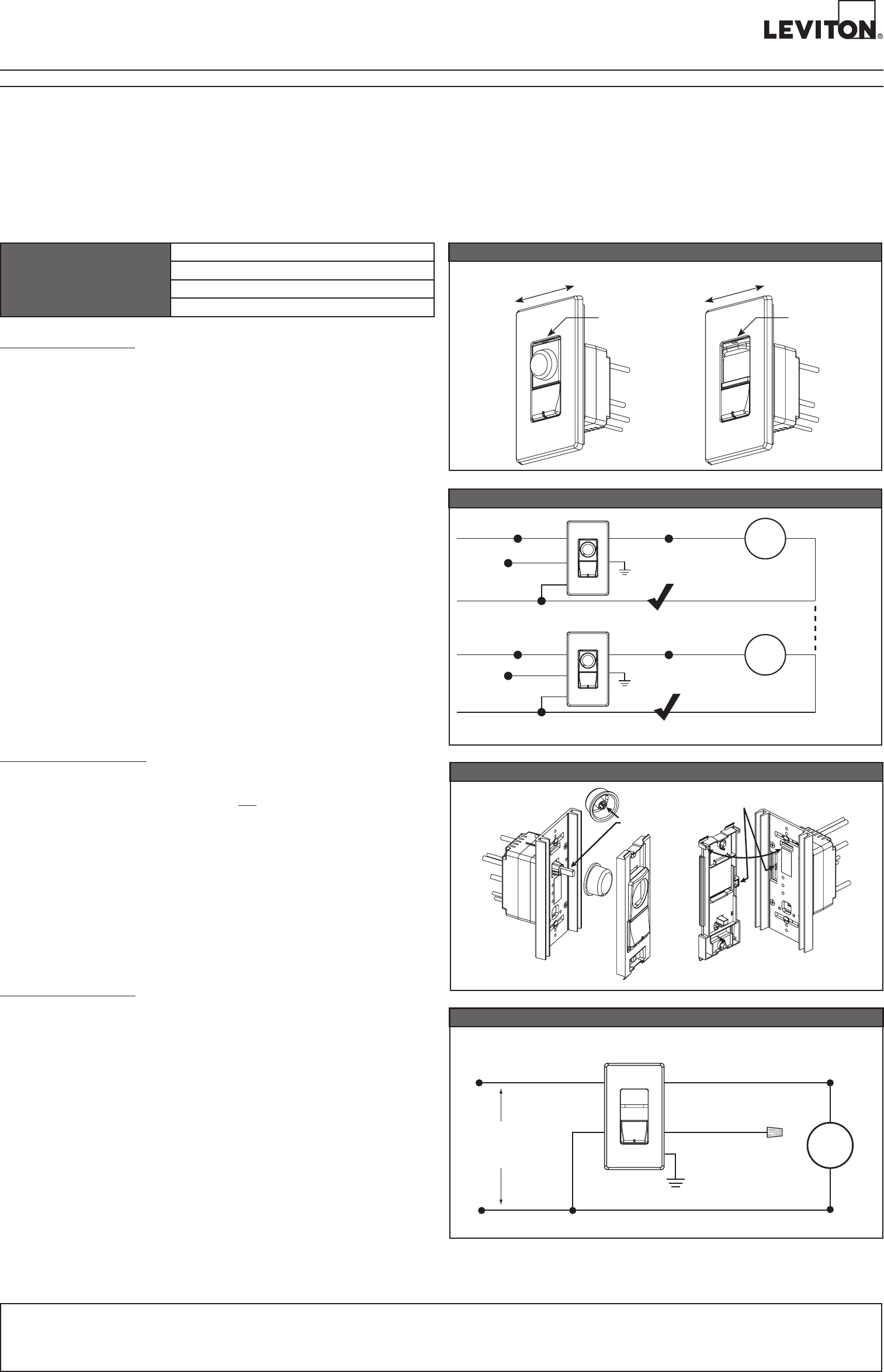
6.Installdevicecontrolpushbuttonandcontrolassembly(see Figure 3).
7.Restorepoweratcircuitbreakerorfuse.Installation is complete.
8.TestDeviceoperation.
INPUT - 120 - 277 VAC 60 HZ
OUTPUT-MA5A
OUTPUT-MB8.3A
OUTPUT-MC12.5A
OUTPUT-MD16A
Features and Operation:
• TurnDeviceONorOFF–PressingtheswitchwillturnthedeviceONifthe
deviceisOFF.IfthedeviceisON,pressingtheswitchwillturnthedeviceOFF.
• SetDeviceLevel–Adjusttheknoborslidertosetthedesiredoutputlevel.When
thedeviceturnsON,thedevicealwaysturnsONtothelevelsetbytheslideror
knob.
• SetCutoffLevel–Thecutofflevelisthelowestvoltagethedimmerwilloutput
beforeshuttingOFF.Tosetthecutofflevel,adjusttheknoborslidertothe
maximumoutput.Slowlylowertheoutputtothedesiredcutofflevel,thenpush
andholdthepowerbuttonfor5seconds.Thedimmerwilladjusttothenewlevel.
Toresetthecutofflevelto0,adjusttheknoborslidertotheminimumoutput,then
pushandholdthepowerbuttonfor5seconds.Ifyourloadisickering,notturning
ON,orsufferingfromanyothererraticbehaviorattheminimumsetting,raising
thecutofflevelmayeliminatetheproblem.
• PresetOperation–Whiledeviceisoff,setlevelofdevice.Thenpressbutton.The
devicewillturnonatthesetlevel.
• PowerRestore–Uponrestorationofpower,thedeviceturnsONtothestateit
wasinatthetimeofpowerloss.
• 5-WayOperation–Linktogether2,3,4,or5devicesformulti-waydimming.
• LEDLocator–AtthebottomoftheswitchisanLEDlocator.Thislocator
illuminateswhenthedeviceisOFFsoyoucanndthedeviceinthedark.
• RemoteControl–Ifyouareusingaremote,theoperationattheremoteis
identicaltotheoperationatthemaster.Aslightreactiondelaymaybenoticedif
operatinglevelchangesveryquickly.
• ServiceSwitch–Someunitshaveaserviceswitchwhichmustbeusedto
disconnecttheloadwhenreplacinglamps.Thebreakershouldbedisconnected
whenperforminganycircuitserviceotherthanlampreplacement.See Figure 1.
ForTechnicalAssistanceCall:1-800-824-3005(U.S.A.Only)www.leviton.com
LIMITED 5 YEAR WARRANTY AND EXCLUSIONS
LevitonwarrantstotheoriginalconsumerpurchaserandnotforthebenetofanyoneelsethatthisproductatthetimeofitssalebyLevitonisfreeofdefectsinmaterialsandworkmanshipundernormalandproperuseforveyearsfromthepurchasedate.Leviton’sonlyobligation
istocorrectsuchdefectsbyrepairorreplacement,atitsoption,ifwithinsuchveyearperiodtheproductisreturnedprepaid,withproofofpurchasedate,andadescriptionoftheproblemtoLevitonManufacturingCo.,Inc.,Att:QualityAssuranceDepartment,201North
ServiceRoad,Melville,NewYork11747.Thiswarrantyexcludesandthereisdisclaimedliabilityforlaborforremovalofthisproductorreinstallation.Thiswarrantyisvoidifthisproductisinstalledimproperlyorinanimproperenvironment,overloaded,misused,opened,
abused,oralteredinanymanner,orisnotusedundernormaloperatingconditionsornotinaccordancewithanylabelsorinstructions.Therearenootherorimpliedwarrantiesofanykind,includingmerchantabilityandtnessforaparticularpurpose,butifanyimplied
warrantyisrequiredbytheapplicablejurisdiction,thedurationofanysuchimpliedwarranty,includingmerchantabilityandtnessforaparticularpurpose,islimitedtoveyears.Levitonisnotliableforincidental,indirect,special,orconsequentialdamages,including
withoutlimitation,damageto,orlossofuseof,anyequipment,lostsalesorprotsordelayorfailuretoperformthiswarrantyobligation.Theremediesprovidedhereinaretheexclusiveremediesunderthiswarranty,whetherbasedoncontract,tortorotherwise.
PK-93974-10-00-2A
Align flats when
installing knob
Center tab in opening
Figure3-RemoteDimmerAssembly
RotaryDevice SlideDevice
Wiring Diagram
Dimming Control
LOAD
Black
Blue
Neutral (White)
Hot (Black)
White
White Yellow
For use in multi-way
control (remote)
applications.
Cap wire if not used.
Ground (Green)
Line
120-277VAC
60 Hz
Figure2-DONOTshareneutralwires
Blue
Hot (Black)
Neutral (White)
White
White
Load
Blue
Black
Black
White
Yellow
Yellow
Green
Ground
White
Hot (Black)
Neutral (White)
–
Load
X
–
Run a separate neutral wire
for each control circuit
–
Run a separate neutral wire
for each control circuit
DO NOT
share
neutral
wires
Green
Ground
Service Switch
Load
Connected
Load
Disconnected
Service Switch
Load
Connected
Load
Disconnected
Figure1-ServiceSwitchControl
RotaryDevice SlideDevice
1.Findthecellsthatcorrespondtoyourapplicationbyidentifyingtherowwiththe
numberofwideheatsinkdevicesyouhave,andthecolumnsthatcorrespondtothe
numberofnarrowheatsinkdevicesyouhave.Inthecellyou’llndthefollowing:
2.Thenumberindicatesthenumberof“Gangs”required.
3.Thelettersunderthenumberindicatetheorderdevicesshouldbeinstalled,N=narrow,
W=wide.
4.-W*=rightnbreak-offonwidedevice,N*=rightnbreak-offonnarrowdevice.
-*W=leftnbreak-offonwidedevice,*N=leftnbreak-offonnarrowdevice.
-*W*=nbreak-offonbothsidesofwidedevice,*N*=nbreak-offonbothsidesof
narrowdevice.
5.**indicatesthatuseofjumperbarsisrequired.Jumperbarscanbefoundinthekit
withthefaceplate.
6. Replace'x'inthefaceplatepartnumberwiththedesiredcolor:W=White,I=Ivory,
A=Almond,T=LightAlmond,E=Black,G=Gray,K=24KGold,L=SatinStainless,
R=AntiqueBronze,B=BrushedBrass.
NOTE:Metalnishesarenotavailableoncustomfaceplates.
BasicWIDE/NARROWcongurations,foradditionalcongurationssee:
www.leviton.com/RENOIRII
PK-93974-10-00-2A
©2012LevitonMfg.Co.,Inc.
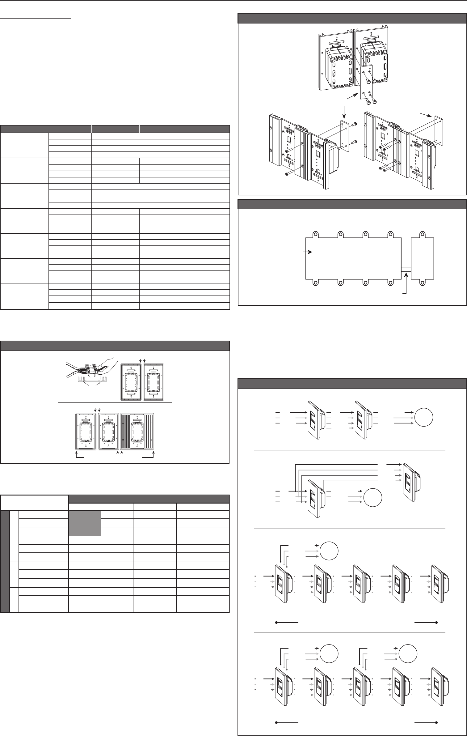
Multi-WayControl:
TheRenoirIIproductlinesupportsupto5-waycontrol.Anycombinationof
Dimmers,
FanControls,Switches,orRemotesaresupportedwithaMAXIMUM OF
5 DEVICES.TotalrunlengthfromendtoendisMAXIMUM 250 FEET.Remotes
requireUncontrolledHot,Neutral,&Groundforproperoperation.Onetravelerwireis
toruninbetweenallmastersandremotes.Remotesdraw15mApower(ea)fromthe
Controltowhichtheyareconnected.
NOTE:RemoteHot/NeutralshouldideallybefedfromthesamecircuitastheMaster.If
thisisnotpossible,ensurethatthemasterandremotearebothfedfromthesamephase.
Backbox - # Gangs
Wallplate Part #
Device Configuration
Backbox - # Gangs
Wallplate Part #
Device Configuration
Backbox - # Gangs
Wallplate Part #
Device Configuration
Backbox - # Gangs
Wallplate Part #
Device Configuration
Number & Type of NARROW
Number & Type of WIDE
0
1
2
3
0
4**
N+N+N
AWP00-30x
2
N*+*N
AWP00-20x
1
N
AWP0F-10x
1
6**
W+N+N+N
AWP00-31x
4
W+N*+*N
AWP00-21x
3
W+N
AWP0F-11x
1
W
AWP0F-01x
2
7
W+N*+N*+*N+W
AWP00-32x
6
W+N*+*N+W
AWP00-22x
5 or 6
W+N+W
AWP0F-12x
4
W+W
AWP0F-02x
3
9
W*+*W+N*+N*+*N+W
AWP00-33x
8
W*+*W+N*+*N+W
AWP00-23x
8
W+W+N+W
AWP0F-13x
6**
W+W+W
AWP0F-03x
Basic Configurations
Multi-Gang Installations:
Amulti-gangedinstallationexistswhenmultipledevicesareinstalledinthesame
backbox.Inmulti-ganginstallations,thefollowingmayberequired:
- Devicede-rating -Finremoval
- Useofjoinerbarsforadjacentdevices. - Backboxsize
NOTE: TEST FIT DEVICE INSTALLATION WITH THE WALL PLATE PRIOR TO BREAKING
FINS OR INSTALLING DEVICES TO ENSURE YOU UNDERSTAND ALL REQUIREMENTS.
BackBoxSize&JoinerBars:
Todeterminetherequiredback-boxsizeinmulti-ganginstallations,reference
tablebelow.Inapplicationswherethedevicesdonotlineupwithbackboxdevice
mountingholes,usejoinerbarstojointhecontrolstogether.ReferenceFigure 5.
De-ratings:
Whennsarebroken,somedevicesmustbede-rated.Referencetablebelowto
determinethedeviceratingswhen0,1,or2nsareremoved.
FinRemoval:
Whenitisdesiredtoinstalldevicesinassmallaspaceaspossible,allinsidensoflike
sized,adjacentdevicescanbebrokenoff.Figure 4showhowtobreakoffnsandthe
specicorderinwhichmultipledevicesmustbeinstalledinmulti-ganginstallations.
MULTI-GANGINSTALLATIONREQUIREMENTS
Multi-WayControlWiringDiagram
Maximum 5 Devices, Dimmers, Remotes or Fan Controls
Maximum 250 feet
Device/Switch
Maximum 5 Devices, Dimmers, Remotes or Fan Controls
Maximum 250 feet
Remote
Device/Switch Remote
Device/Switch Remote
Device/Switch
Multiple Device/Switches and Remote Device/Switches
Master
Device/Switch Remote
Device/Switch Remote
Device/Switch Remote
Device/Switch Remote
Device/Switch
Hot
Neutral
Ground
Traveler
Hot
Neutral
Ground
Hot
Neutral
Ground
Traveler
Hot
Neutral
Ground
Traveler
Hot
Neutral
Ground
Traveler
Dimmed Hot
Neutral
Ground
LOAD
Hot
Neutral
Ground
Traveler
Hot
Neutral
Ground
Hot
Neutral
Ground
Traveler
Hot
Neutral
Ground
Traveler
Hot
Neutral
Ground
Traveler
Dimmed Hot
Neutral
Ground
LOAD
Dimmed Hot
Neutral
Ground
LOAD
Multiple Remote Device/Switches
Load in between Master Device/Switch and Remote Device/Switch
Master Device/Switch Remote Device/Switch
Dimmed Hot
Neutral
Ground
Hot
Neutral
Ground
Traveler
Hot
Neutral
Ground
LOAD
Load after Remote Device/Switch and Master Device/Switch
Master Device/SwitchRemote Device/Switch
Hot
Neutral
Ground
Hot
Neutral
Ground
Dimmed Hot
Neutral
Ground
Traveler
LOAD
Master
Device/Switch
Figure4-FinRemoval
Back view of devices shown
Break off these fins
DO NOT Break off these fins
Break off these fins
Fin break off points
Figure5-JoinerBar
Narrow/Narrow
Wide/NarrowWide/Wide
Joiner Bar
Joiner Bar
Additional-SingleGangBox
3/4" space (use chase nipple)
3-1/2" deep
back box is
required
Four-gang wallbox Single-gang
wallbox
Incandescent Dimmer - 110-277VAC/VCA,60Hz
Useonlyforpermanentlyinstalledluminaireofloadtype:Incandescent,Tungsten,
InductiveTransformer(ex:magneticlowvoltage),LEDxtureswithdriverswith
incandescentcontrolinput.CAUTION:Toreduceriskofoverheatingandpossible
damagetootherequipment,donotinstalltocontrolareceptacle,amotor-operated
appliance,orauorescentlightingluminaire.
Incandescent 0 fins removed
2308
1917
1000
8.3
2308
1917
1000
8.3
3463
2875
1500
12.5
4432
3680
1920
16.0
4432
3680
1920
16.0
1 fin removed
1385
1801
1495
780
6.5
1150
600
5.0
1939
1610
840
7.0
2825
2346
1224
10.2
3601
2990
1560
13.0
3740
3105
1620
13.5
2 fins removed
1468
12.3
1219
636
3407
2829
1476
5.3
1524
1265
660
5.5
2410
2001
1044
8.7
3075
2553
1332
11.1
3407
2829
1476
12.3
3463
12.5
1500
2875
AWRMG-MA_
AWSMG-MA_
AWSMT-MA_
AWRMG-MB_
AWSMG-MB_
AWRMG-MC_
AWSMG-MC_
AWRMG-MD_
AWSMG-MD_
AWSMT-MB_
AWSMT-MC_
AWSMT-MD_
Amps
VA @ 120V
VA @ 230V
VA @ 277V
Amps
VA @ 120V
VA @ 230V
VA @ 277V
Amps
VA @ 120V
VA @ 230V
VA @ 277V
Amps
VA @ 120V
VA @ 230V
VA @ 277V
Amps
VA @ 120V
VA @ 230V
VA @ 277V
Amps
VA @ 120V
VA @ 230V
VA @ 277V
Amps
VA @ 120V
VA @ 230V
VA @ 277V
