Data Sheet PacDrive C400 / A8 Controller
2016-10-06
: Pdf 1000474754-Attachment 1000474754-Attachment B5 unilog
Open the PDF directly: View PDF ![]() .
.
Page Count: 18

Legal notice
© All rights reserved to ELAU GmbH, also in case of patent right applications.
No part of this documentation or the accompanying software and firmware may be
reproduced, transferred, paraphrased, saved to a storage medium or translated to
another language or computer language without the written consent of ELAU GmbH.
Any possible measure was taken to ensure that this product documentation is com‐
plete and correct. However, since hardware and software are continuously improved,
ELAU makes no representations or warranties with respect to the contents of this
documentation.
All information on our products in this manual are given purely for the purpose of prod‐
uct description and is not binding. Misprints, errors and modifications -without prior
notice in the course of product development- are reserved. If details contained in this
manual are explicitly a part of an agreement made with ELAU GmbH, then the details
of the agreements in this manual are exclusively to determine the agreed condition of
the object of agreement, on behalf of the § 434 BGB (condition guarantee on behalf
of legal regulations).
Trademark
PacDrive is a registered trademark of ELAU GmbH.
All other trademarks mentioned in this documentation are the exclusive property of
their manufacturers.
ELAU GmbH
Dillberg 12-16
97828 Marktheidenfeld, Germany
Tel.: +49 (0) 9391 / 606 - 0
Fax: +49 (0) 9391 / 606 - 300
E-mail: info@elau.de
Internet: www.elau.de
Imprint
Page 2 PacDrive Controller C400 ELAU GmbH
1 Overview
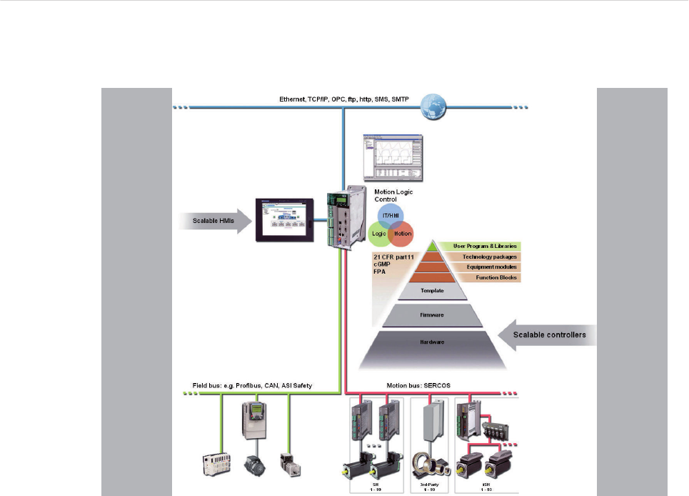
Figure 1-1: PacDrive System Overview
C400 / C400 A8 Controller
Controller based architecture
The PacDrive C400 Controller is based on an Intel module processor. It uses the real-
time operating system VxWorks. VxWorks provides logic and motion functions for a
production or packaging machine. A PacDrive Controller synchronizes, coordinates
and generates the positioning functions for up to 16 servo drives, which are connected
via the SERCOS bus interface.
Several standardized field bus interfaces are available: PROFIBUS DP, CAN, CAN‐
open or DeviceNet. A variety of standard HMI systems, ranging from low-cost text
displays to industrial PCs, can be used for the HMI functions.
•CPU: Intel Module, 600 MHz, 256 MB RAM
•Real-Time operating system: VxWorks
•IEC 61131-3 programming languages for PLC and Motion Control
•SERCOS interface
•Profibus DP, CAN, CANopen, DeviceNet, or Ethernet/IP
•Digital inputs, digital outputs, analog, interrupt and Touchprobe inputs
•Communication interfaces: RS 232, RS 485, Ethernet (TCP/IP)
•CompactFlash™ card (≥128 MB)
•Includes OPC server for Windows-based HMIs
•Teleservice via web server or modem
1
ELAU GmbH PacDrive Controller C400 Page 3
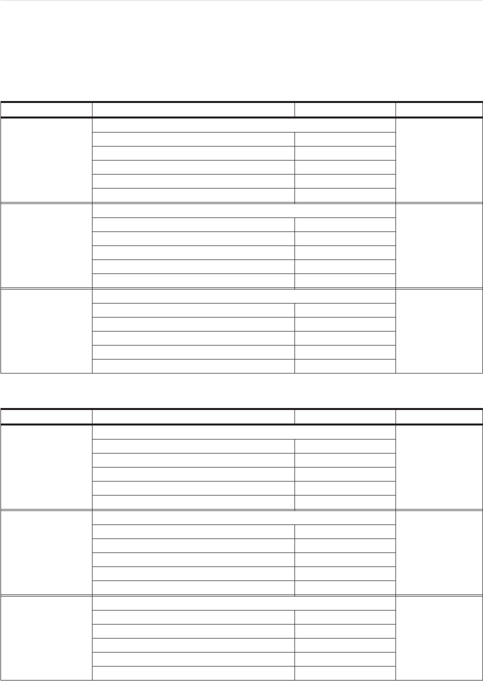
2 Technical data
2.1 Ambient conditions
Procedure Parameters Value Basis
Operation Class 3K3 IEC/EN 60721-3-3
Ambient temperature +5°C...+45°C
Condensation Prohibited
Icing Prohibited
Another water Prohibited
Relative humidity 5% ... 85%
Transport Class 2K3 IEC/EN 60721-3-2
Ambient temperature -25°C...+70°C
Condensation Prohibited
Icing Prohibited
Another water Prohibited
Relative humidity 5% ... 95%
Long time storage in
transport packaging
Class 1K4 IEC/EN 60721-3-1
Ambient temperature -25°C...+55°C
Condensation Prohibited
Icing Prohibited
Another water Prohibited
Relative humidity 5% ... 95%
Table 2-1: Ambient conditions PacDrive C400 Controller
Procedure Parameters Value Basis
Operation Class 3K3 IEC/EN 60721-3-3
Ambient temperature +5°C...+40°C
Condensation Prohibited
Icing Prohibited
Another water Prohibited
Relative humidity 5% ... 85%
Transport Class 2K3 IEC/EN 60721-3-2
Ambient temperature -25°C...+50°C
Condensation Prohibited
Icing Prohibited
Another water Prohibited
Relative humidity 5% ... 95%
Long time storage in
transport packaging
Class 1K3 IEC/EN 60721-3-1
Ambient temperature -5°C...+45°C
Condensation Prohibited
Icing Prohibited
Another water Prohibited
Relative humidity 5% ... 95%
Table 2-2: Ambient conditions PacDrive C400 Controller (with UPS)
2 Technical data
Page 4 PacDrive Controller C400 ELAU GmbH
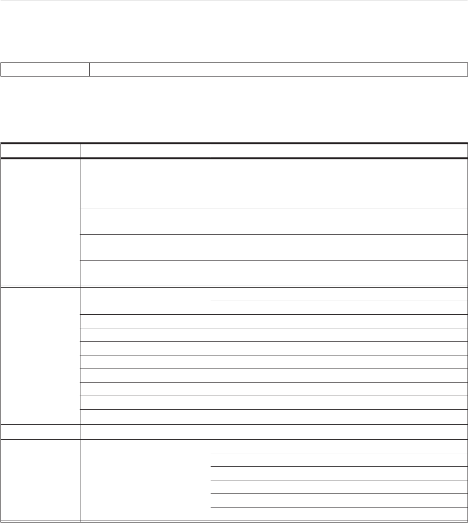
2.2 Standards and regulations
Certifications CE, UL , cUL
Table 2-3: Standards and regulations PacDrive C400 Controller
2.3 Mechanical and electrical data
Category Parameters Value
Product
configuration
Type key C400 up to 16 SER‐
COS slaves
(SERCOS slaves = MC-4, SCL,
iSH)
PacDrive C400 / 10 / 1 / 1 / 1 / 00
Type key C400 up to 8 SERCOS
slaves
PacDrive C400 / A8 / 1 / 1 / 1 / 00
Order number- C400 up to 16
SERCOS slaves
13 13 02 61
Order numbers C400 up to 8
SERCOS slaves
13 13 02 61-001
Processor
CPU C400 up to 16 SERCOS slaves: Intel Pentium M 600 MHz
C400 up to 8 SERCOS slaves: Celeron M 600 MHz
RAM 256 MB
L2 Cache C400 up to 16 SERCOS slaves: 1 MB
C400 up to 8 SERCOS slaves: 512 kB
NVRAM 128 kB
CompactFlashTM card ≥128 MB
Real time clock (RTC) Yes (battery maintenance interval: 5 years)
Watchdog Yes (max. 60 V < 2 A)
Diagnosis Alphanumeric diagnostic display, Status LEDs
Operating system Real-time operating system VxWorks
Programming
languages
Programming languages IEC
61131-3
Instruction list (IL)
Ladder diagram (LD)
Function block diagram (FBD)
Sequential function chart (SFC)
Structured text (ST)
Continuous function chart (CFC)
2.2 Standards and regulations
ELAU GmbH PacDrive Controller C400 Page 5

Category Parameters Value
Interfaces
Serial interfaces COM1: RS232 (X17)
COM2: RS485 (X18)
Network connection Ethernet (10/100 Base-T) (X10)
Field bus connections PROFIBUS DP Master/Slave (12 MBaud) (X20) or
CAN (2.0A) or CANopen (X19)
DeviceNet Slave (cable adapter required)
EtherNet/IP Slave (projected) (optional hardware module required)
Real-time bus interface SERCOS interface (16 MBaud) (X14, X15)
PacNet interface 2 PacNet interfaces (X12, X13)
Master encoder interfaces 1 SinCos master encoder or
1 incremental master encoder (X11)
HMI Interfaces RS485 (Modbus or PROFIBUS DP)
HMI software tools: OPC server (for Windows NT/2000/XP or Win‐
dows CE)
Diagnostic interface for remote
maintenance
Modem
Communications protocols Http
Ftp
SMTP (E-Mail)
Integrated trace recorder (soft‐
ware oscilloscope)
8 channels, resolution 1 ms
Integrated data logger for diag‐
nostic messages
27 kB
Output
C400 16 servo axes with all SERCOS cycle times
C400 / A8 8 servo axes with all SERCOS cycle times
Max. of 255 parallel motion profiles possible
SPS output
Time for 1000 Bit instructions 7 µs
Number of PLC processes Unlimited
Type of PLC processes Continuous,
periodic or
event-controlled
Cycle time fast task 250 µs
nominal I/O response time 500 µs (read in data, process, set output)
Cam Switch
Group
Number of cams Max. 256
Sequential circuit Dynamic
Outputs Memory or
Digital outputs
Inputs External master encoder
Virtual master encoder
Axis position
Processing time 250 µs
Digital inputs (X3)
Number 20 (IEC61131-2)
Range UIN 0 Voltage DC 0 ... 6 V
Range UIN 1 Voltage DC 20 ... 33 V
Input data IIN = 5 mA by UIN = 24 V
Polarized Yes
Input filter 1 or 5 ms can be parameterized
2 Technical data
Page 6 PacDrive Controller C400 ELAU GmbH

Category Parameters Value
Analog inputs (X5)
Number 2
Range UIN -10 ... 10 V
Resolution 12 Bit (5 mV)
Resistor 100 kOhm
Range IIN -20 ... 20 mA
Resolution 12 Bit, (5 μA)
Resistor 500 Ohm
Interrupt inputs
(X4)
Number: 4 (IEC61131-2)
Range UIN 0 Voltage DC 0 ... 6 V
Range UIN 1 Voltage DC 20 ... 33 V
Input data IIN = 5 mA by UIN = 24 V
Polarized Yes
Input filter 0.1 or 1 ms can be parameterized
Touchprobe inputs
(X4)
Number 16 (IEC61131-2)
Range UIN 0 Voltage DC 0 ... 6 V
Range UIN 1 Voltage DC 20 ... 33 V
Input data IIN = 5 mA by UIN = 24 V
Polarized Yes
Input filter TP0 to TP15 100 µs resolution
TP0 to TP15 10 µs at a cycle time of 1, 2, 4 ms
Digital outputs (X2)
Number 16 (IEC61131-2)
Output voltage (+UL-3 V) < UOUT < +UL
Rated current Ie = 250 mA per output
Inrush current Iemax < 2 A for 1 s
Leakage current with 0 signal < 0.4 mA
Transmission time 100 µs
short circuit proof Yes
Digital outputs (X5)
Number 2
Range UOUT -10 ... 10 V
Resolution 12 Bit (5 mV)
Load > 5 kOhm (max. Offset < +/- 75mV)
Additional digital
and analog I/Os
Via field bus Max. 3,584 bytes digital/analog inputs and
Max. 3,584 bytes digital/analog outputs
Max. number of stations: 126 (PROFIBUS)
Additional fast digi‐
tal I/Os
Via PacNet Max. 128 inputs and 128 outputs
Additional Touchp‐
robe inputs
Via PacNet Max. 128 Touchprobe inputs
Power supply
Power supply unit DC 24 V (-15% / +25%)
max. 3,0 A without UPS
max. 4,5 A without UPS
Power consumption Max. 85 W
Uninterruptible Power Supply
(UPS)
Internal, optional (maintenance interval 3 years)
Dimensions Dimensions packaging DxWxH (mm): 300x130x400
Weight Weight (with packaging) 3.5 kg (4.1 kg)
Protection class Housing IP 20
2.3 Mechanical and electrical data
ELAU GmbH PacDrive Controller C400 Page 7

Category Parameters Value
Isolation class Degree of pollution 2
Table 2-4: Technical data PacDrive C400 Controller
2 Technical data
Page 8 PacDrive Controller C400 ELAU GmbH
2.4 Electrical connections
battery
battery
battery
X21 cf-card
battery
X21 cf-card
15
14
X1
24V/wd
X4
tp/fast
X5
X2
digital out
analog in/out
X17
10
com1 rs232
X18
com2 rs485
X11 19
12 13
20
pacnet
phys enc
can
profibus dp
eth
X3
digital in
Made in Germany
battery
battery
X21 cf-card
X21 cf-card
enter
PacDrive
bus
err
wd
pow
err
C400
X17
X18
X10
X19
X11
X13
X12
X1
X2
X3
X4
X5 X14
X20
X15
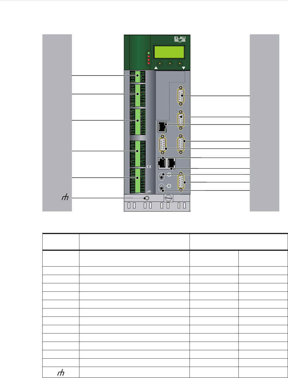
Figure 2-1: Connection overview PacDrive C400 Controller
Connection Meaning max. terminal cross-section [mm2]/
[AWG]
X1 Control voltage/
Watchdog
1.50 mm228 - 16
X2 Digital outputs 1.50 mm228 - 16
X3 Digital inputs 1.50 mm228 - 16
X4 Touchprobe and fast digital inputs 1.50 mm228 - 16
X5 Analog inputs/outputs 1.50 mm228 - 16
X10 Ethernet connection - -
X11 Master encoder (SinCos) 0.25 mm2-
X11 Master encoder (incremental) 0.25 mm2-
X12/X13 PacNet - -
X17 Com 1 (RS232) 0.25 mm2-
X18 Com 2 (RS485) 0.25 mm2-
X19 CAN 0.25 mm2-
X20 PROFIBUS db 0.25 mm2-
Shielded connector - -
Table 2-5: Connection overview PacDrive C400 Controller
2.4 Electrical connections
ELAU GmbH PacDrive Controller C400 Page 9
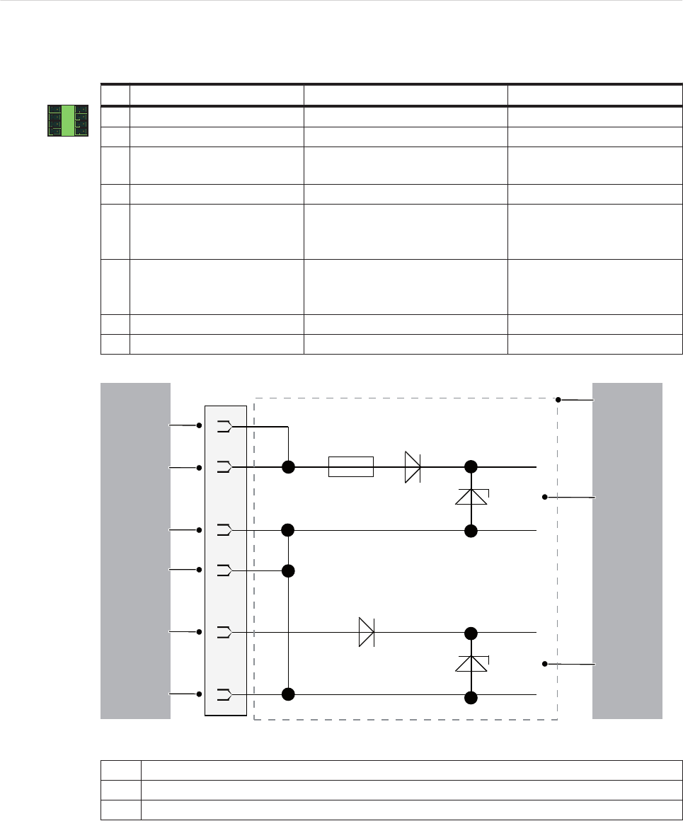
X1 - Control voltage and watchdog
1 5
4 8
Pin Designation Meaning Range
1 DC +24 V Supply voltage - 15 % / +25 %
2 DC 0 V Supply voltage
3+UL For digital outputs DC +24 V
-15 % / +25 %
4 L0 For digital inputs/outputs
5
DC +24 V Supply voltage
(with pin 1 bridged, max. ampacity
4A)
-15 % / +25 %
6
DC 0 V Supply voltage
(with pin 2 bridged, max. ampacity
4A)
7 WD Watchdog relay
8 WD Watchdog relay
Table 2-6: Connection X1
2
X1
3
1
Pin1
Pin5
Pin2
Pin6
Pin3
Pin4
Figure 2-2: Connection X1 - Input connection
1Internal wiring diagram - input connection of power supply (simplified)
2Internal supply voltage
3Supply voltage for digital outputs/inputs
2 Technical data
Page 10 PacDrive Controller C400 ELAU GmbH
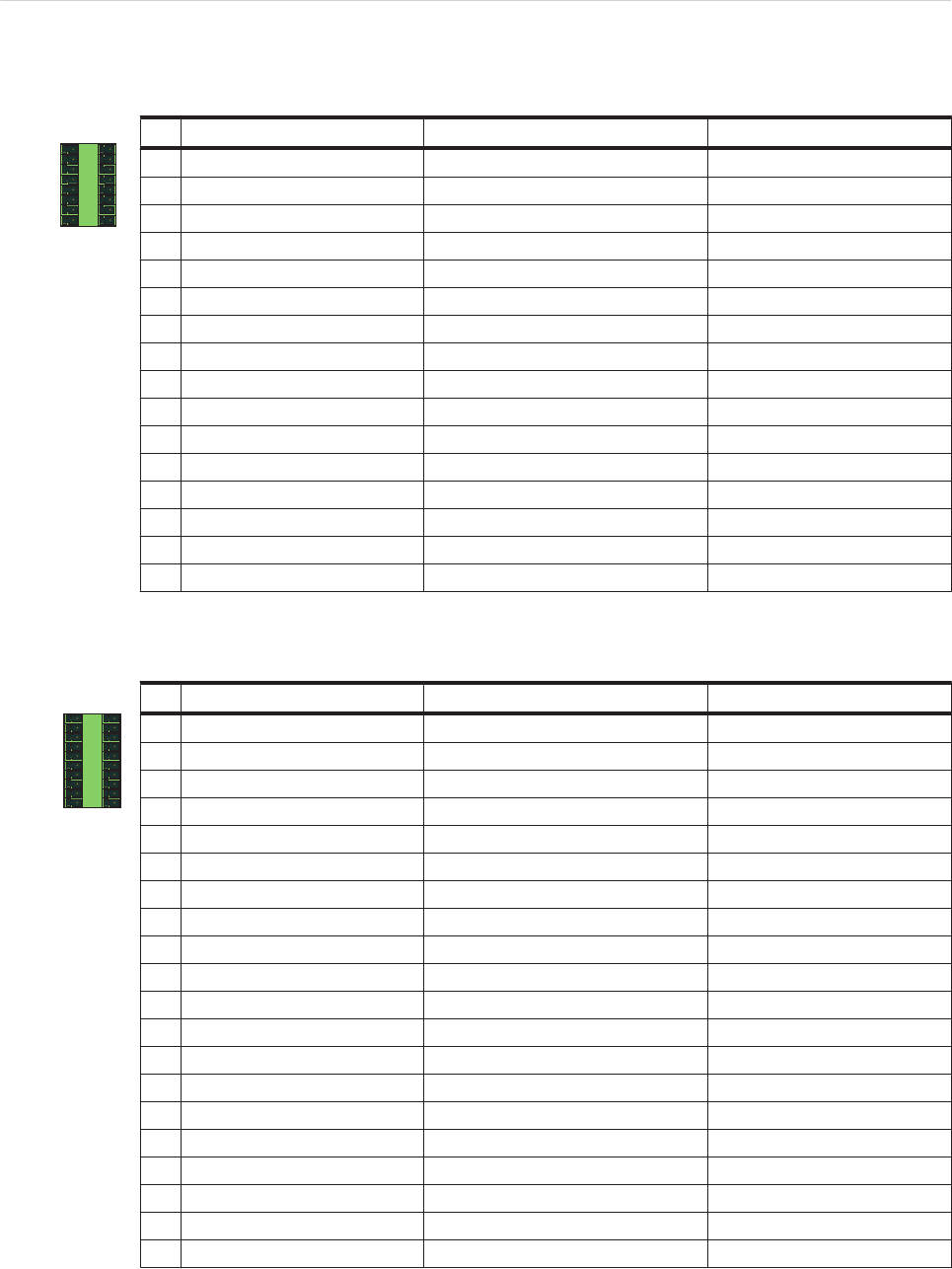
X2 - Digital outputs
1 9
8 16
Pin Designation Meaning Range
1 O.00 Digital output 1 DC 20 ... 30 V
2 O.01 Digital output 2 DC 20 ... 30 V
3 O.02 Digital output 3 DC 20 ... 30 V
4 O.03 Digital output 4 DC 20 ... 30 V
5 O.04 Digital output 5 DC 20 ... 30 V
6 O.05 Digital output 6 DC 20 ... 30 V
7 O.06 Digital output 7 DC 20 ... 30 V
8 O.07 Digital output 8 DC 20 ... 30 V
9 O.08 Digital output 9 DC 20 ... 30 V
10 O.09 Digital output 10 DC 20 ... 30 V
11 O.10 Digital output 11 DC 20 ... 30 V
12 O.11 Digital output 12 DC 20 ... 30 V
13 O.12 Digital output 13 DC 20 ... 30 V
14 O.13 Digital output 14 DC 20 ... 30 V
15 O.14 Digital output 15 DC 20 ... 30 V
16 O.15 Digital output 16 DC 20 ... 30 V
Table 2-7: Connection X2
X3 - Digital inputs
1 11
10 20
Pin Designation Meaning Range
1 l.00 Digital input 0 DC 20 ... 30 V
2 l.01 Digital input 1 DC 20 ... 30 V
3 l.02 Digital input 2 DC 20 ... 30 V
4 l.03 Digital input 3 DC 20 ... 30 V
5 l.04 Digital input 4 DC 20 ... 30 V
6 l.05 Digital input 5 DC 20 ... 30 V
7 l.06 Digital input 6 DC 20 ... 30 V
8 l.07 Digital input 7 DC 20 ... 30 V
9 l.08 Digital input 8 DC 20 ... 30 V
10 l.09 Digital input 9 DC 20 ... 30 V
11 l.10 Digital input 10 DC 20 ... 30 V
12 l.11 Digital input 11 DC 20 ... 30 V
13 l.12 Digital input 12 DC 20 ... 30 V
14 l.13 Digital input 13 DC 20 ... 30 V
15 l.14 Digital input 14 DC 20 ... 30 V
16 l.15 Digital input 15 DC 20 ... 30 V
17 l.16 Digital input 16 DC 20 ... 30 V
18 l.17 Digital input 17 DC 20 ... 30 V
19 l.18 Digital input 18 DC 20 ... 30 V
20 l.19 Digital input 19 DC 20 ... 30 V
Table 2-8: Connection X3
2.4 Electrical connections
ELAU GmbH PacDrive Controller C400 Page 11
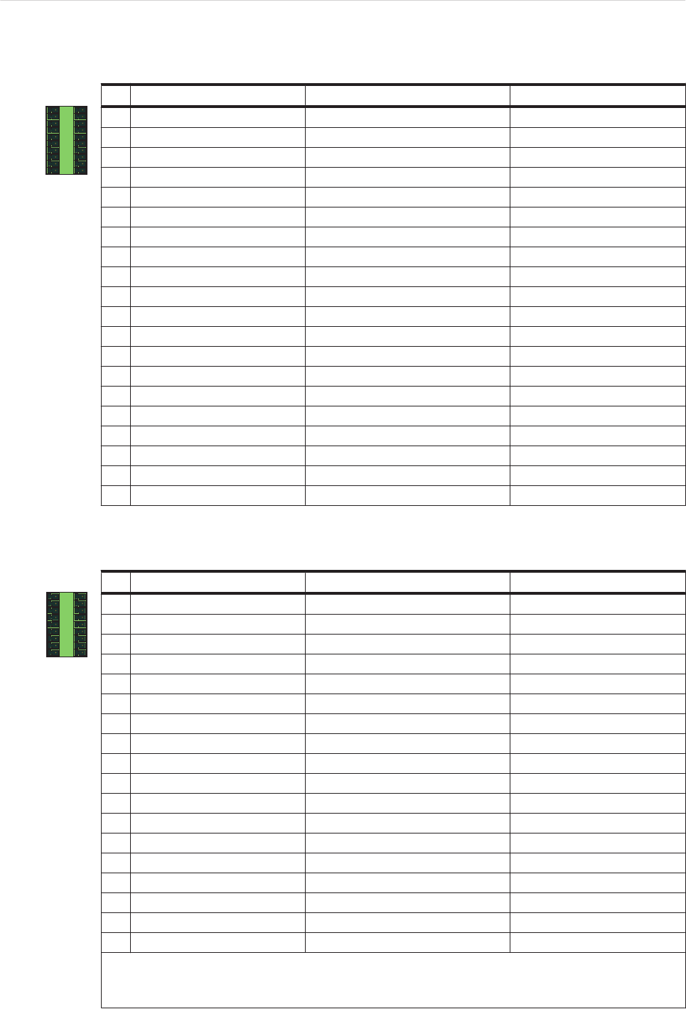
X4 - Touchprobe and fast digital inputs
1 11
10 20
Pin Designation Meaning Range
1 T.00 Touchprobe input 0 DC 20 ... 30 V
2 T.01 Touchprobe input 1 DC 20 ... 30 V
3 T.02 Touchprobe input 2 DC 20 ... 30 V
4 T.03 Touchprobe input 3 DC 20 ... 30 V
5 T.04 Touchprobe input 4 DC 20 ... 30 V
6 T.05 Touchprobe input 5 DC 20 ... 30 V
7 T.06 Touchprobe input 6 DC 20 ... 30 V
8 T.07 Touchprobe input 7 DC 20 ... 30 V
9 T.08 Touchprobe input 8 DC 20 ... 30 V
10 T.09 Touchprobe input 9 DC 20 ... 30 V
11 T.10 Touchprobe input 10 DC 20 ... 30 V
12 T.11 Touchprobe input 11 DC 20 ... 30 V
13 T.12 Touchprobe input 12 DC 20 ... 30 V
14 T.13 Touchprobe input 13 DC 20 ... 30 V
15 T.14 Touchprobe input 14 DC 20 ... 30 V
16 T.15 Touchprobe input 15 DC 20 ... 30 V
17 F.00 Fast input 1 DC 20 ... 30 V
18 F.01 Fast input 2 DC 20 ... 30 V
19 F.02 Fast input 3 DC 20 ... 30 V
20 F.03 Fast input 4 DC 20 ... 30 V
Table 2-9: Connection X4
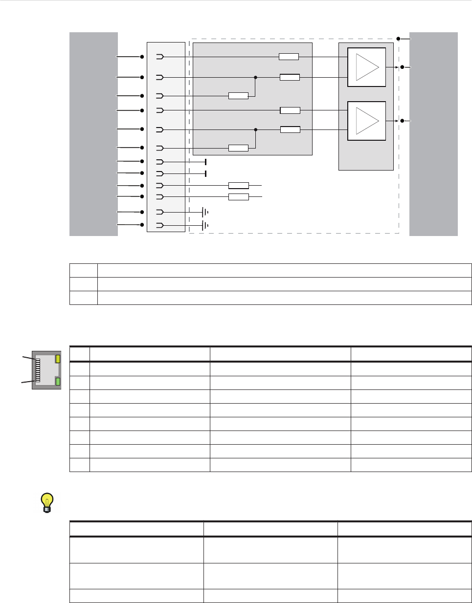
X5 - Analog inputs/outputs
1 10
9 18
Pin Designation Meaning Range
1 AI.0 + Analog input 0+ -10 ... +10 V (*) 0 ... 20 mA (**)
2 J.0 + Br. current input 0 +
3 AI.0 - Analog input 0-
4 A.GND 0 Analog ground 0
5 12 V Out 0 Output voltage 0 12 V
6 PE Shield
7 AO.0 Analog output 0 -10 ... +10 V
8 A.GND AO.0 Analog ground 0
9 PE Shield
10 AI.1 + Analog input 1+ -10 ... +10 V (*) 0 ... 20 mA (**)
11 J.1 + Br. current input 1 +
12 AI.1 - Analog input 1-
13 A.GND 1 Analog ground
14 12 V Out 1 Output voltage 1 12 V
15 PE Shield
16 AO.1 Analog output 1 -10 ... +10 V
17 A.GND AO.1 Analog ground
18 PE Shield
(*) Voltage metering and (**)current measurement on AI.0+ / AI.0- (Pin 1 / Pin 3) and AI.1+ / AI.1- (Pin 10 /
Pin 12)
(**)Current measurement by bridging to J.0+ (Pin 2) or. J.1+ (Pin 11).
Table 2-10: Connection X5
2 Technical data
Page 12 PacDrive Controller C400 ELAU GmbH
Pin1
Pin3
Pin10
Pin11
Pin4
Pin6
X5
PE
+12V
+
-
+
-
+12V
R1
R1, R2 = 500R
R3 - R8 = 1k
R4
R3
R5
R2
R7
AGND
R8
R6
Pin2
Pin12
Pin8
Pin5
Pin14
Pin9
2
3
1
Figure 2-3: Connection X5 - Input connection
1Internal wiring diagram - input connections for analog inputs (simplified)
2Analog Input 1
3Analog Input 2
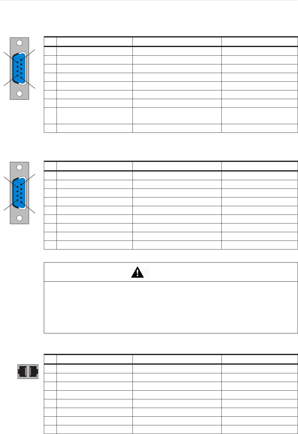
X10 - Ethernet
1
8
Pin Designation Meaning Range
1 Tx+ OutputTransmitData+
2 Tx- OutputTransmitData-
3 Rx+ InputReceiveData+
4 - (PE)
5 - (PE)
6 Rx- InputReceiveData-
7 - (PE)
8 - (PE)
Table 2-11: Connection X10
Depending on the application, you will need different cables to connect the controller
via the RJ-45 outlet.
Component A Component B required cable
PacDrive Controller "Firm network" with RJ-45 Commercially available patch ca‐
ble
PacDrive Controller Hub Commercially available patch ca‐
ble
PacDrive Controller PC Crossed RJ-45 network cable
▶In case of doubt, ask your network administrator.
2.4 Electrical connections
ELAU GmbH PacDrive Controller C400 Page 13
X11 - Master encoder (SinCos)
1
5
6
9
Pin Designation Meaning Range
1 REFSIN Reference Signal Sinus
2 SIN Sinus trace
3 REFCOS Reference Signal Cosinus
4 COS Cosinus trace
5 +9 V Supply voltage
6 RS485- Parameter channel -
7 RS485+ Parameter channel +
8SC_SEL Master encoder plugged in
(bridge to GND)
9 GND Supply voltage
Table 2-12: Connection X11 - Master encoder (SinCos)
X11 - Master encoder (incremental)
1
5
6
9
Pin Designation Meaning Range
1 _UA Track A
2 UA Track A
3 _UB Track B
4 UB Track B
5 +5 V Supply voltage
6 _UO Track O
7 UO Track O
8 - -
9 GND Ground
Table 2-13: Connection X11 - Master encoder (incremental)
CAUTION
PLUGGING IN/UNPLUGGING THE MASTER ENCODER PLUG WHEN SWITCHED
ON
•Only unplug or plug in master encoder when off-circuit.
•Disconnect controller from the 24 V supply voltage.
Failure to follow these instructions can result in equipment damage.
X12/13 - PacNet
1 8
8 1
Pin Designation Meaning Range
1 TxD+ OutputTransmitData+
2 TxD- OutputTransmitData-
3 RxD+ InputReceiveData+
4 TxC- OutputTransmitClock-
5 TXC+ OutputTransmitClock+
6 RxD- InputReceiveData-
7 RxC+ InputReceiveClock+
8 RxC- InputReceiveClock-
2 Technical data
Page 14 PacDrive Controller C400 ELAU GmbH
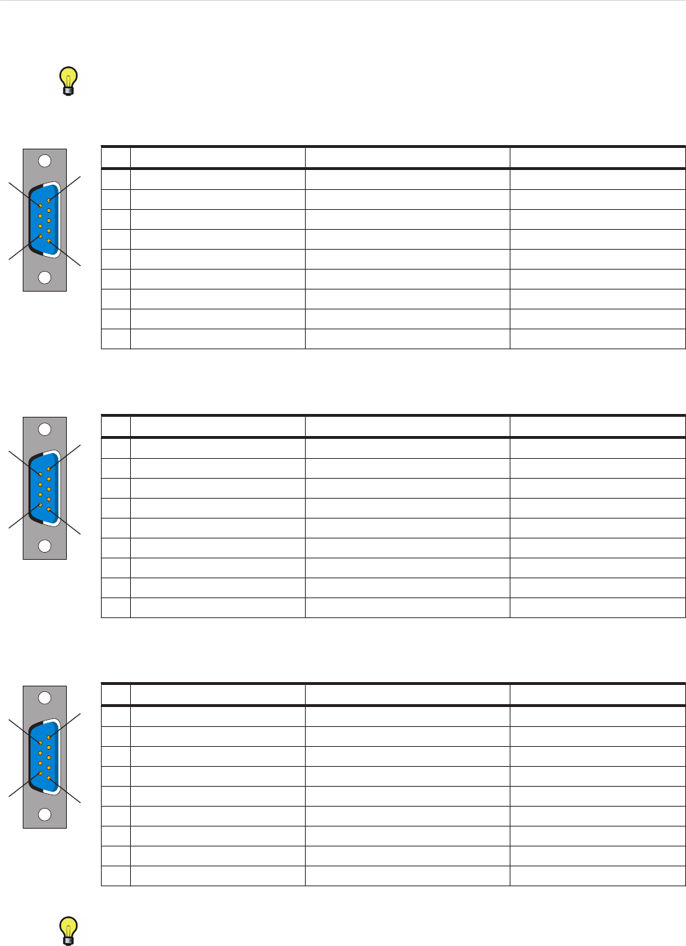
Table 2-14: Connection X12, X13
Use only approved PacNet cables at the PacNet connection to avoid malfunction.
X17 - Com 1 (RS 232)
1
5
6
9
Pin Designation Meaning Range
1 DCD Data Carrier Detect
2 RxD Receive Data
3 TxD Transmit Data
4 DTR Data Terminal Ready
5 GND Signal Ground
6 DSR Data Set Ready Clear To Send
7 RTS Request To Send
8 CTS Clear To Send
9 RI Ring Indicator
Table 2-15: Connection X17
X18 - Com 2 (RS485)
1
5
6
9
Pin Designation Meaning Range
1 +5 VM Supply voltage
2 TxD- RS485 Transmit -
3 TxD+ RS485 Transmit+
4 RxD+ RS485 Receive +
5 RxD- RS485 Receive -
6 GNDR GND receive RS485
7 - Reserved
8 GNDM Supply voltage
9 GNDR GND receive RS485
Table 2-16: Connection X18
X19 - CAN
1
5
6
9
Pin Designation Meaning Range
1 - Reserved
2 CAN_L Bus line (low)
3 GND Ground
4 - Reserved
5 - Reserved
6 - Reserved
7 CAN_H Bus line (high)
8 - Reserved
9 - Reserved
Table 2-17: Connection X19
An adapter is available for the connection to DeviceNet.
2.4 Electrical connections
ELAU GmbH PacDrive Controller C400 Page 15
X20 - profibus db
1
5
6
9
Pin Designation Meaning Range
1 PE Shield
2 - Reserved
3 RxD / TxD -P Data -P
4 CNTR-P Control signal P
5 DGND Signal ground
6 VP Supply voltage
7 - Reserved
8 RxD / TxD -N Data -N
9 Reserved
Table 2-18: Connection X20
Connector
A PROFIBUS connector must be used to connect to the 9 pole PROFIBUS outlet
because the bus terminal resistors are in this connector. The possible PROFIBUS
connectors with different cable outlets are illustrated below.
Figure 2-4: PROFIBUS connector
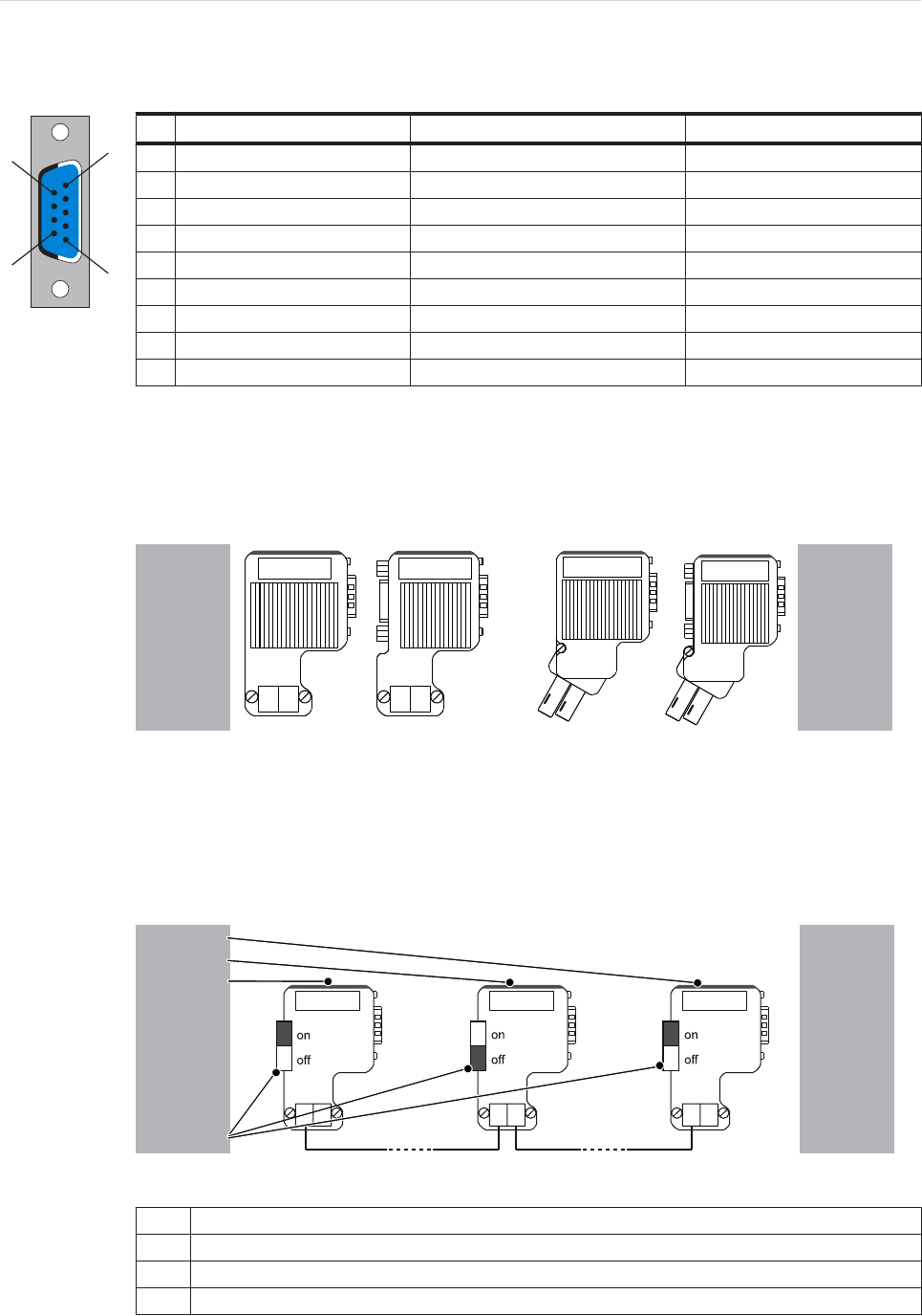
Bus terminal resistors
For the first and last bus nodes, the terminal resistors must be switched on. Otherwise
data transmission will not function properly.
The shielding must be applied generously and on both sides.
3
4
2
1
Figure 2-5: Position of the bus terminal resistors
1Last bus slave
2Nth bus slave
3First bus slave
4Bus terminator
2 Technical data
Page 16 PacDrive Controller C400 ELAU GmbH
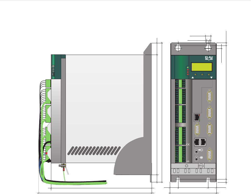
2.5 Dimensions
ca. 235 (9.25)
ca. 260 (10.23)
max. Bautiefe inkl. Steckverbinder
!
PDM_C400_Masszeichnung_de.FH8
X17
com1 rs232
X18
com2 rs485
X19
X20
can
profibus dp
310 (12.2)
268 (10.55) 24 (0.95)
18 (0.71)
16.6 (0.65) 70 (2.76)
103.2+2 (4.06)
296 (10.6)
7 (0.28)
6.5 (0.26)
12 (0.47)
16.6 (0.65)
7 (0.28)
7 (0.28)
battery
battery
battery
X21 cf-card
battery
X21 cf-card
X15
X14
X1
24V/wd
X4
tp/fast
X5
X2
digital out
analog in/out
X17
X10
com1 rs232
X18
com2 rs485
X11 X19
X12 X13
X20
pacnet
phys enc
can
profibus dp
eth
X3
digital in
Made in Germany
battery
battery
X21 cf-card
X21 cf-card
enter
PacDrive
bus
err
wd
pow
err
C400
Figure 2-6: Dimensions PacDrive C400 Controller
2.5 Dimensions
ELAU GmbH PacDrive Controller C400 Page 17
3 Type code
Product ID code C400 / 10 / 1 / 1 / 1 / 00
HW-Variant
Processor
1 = Intel Pentium M 600 MHz
RAM
1 = 256 MB
Flash memory
1 = 32 MB
Optional functions
3 Type code
Page 18 PacDrive Controller C400 ELAU GmbH
