0611DB0402
158611-Attachment 158611-Attachment 158611-Attachment B5 unilog cesco-content
200736-Brochure 200736-Brochure 200736-Brochure 785901 Batch5 unilog cesco-content
233303-Catalog 233303-Catalog 233303-Catalog 785901 Batch5 unilog cesco-content
216546-Attachment 216546-Attachment 216546-Attachment 785901 Batch8 unilog cesco-content
2016-10-06
: Pdf 1000476942-Attachment 1000476942-Attachment B5 unilog
Open the PDF directly: View PDF ![]() .
.
Page Count: 12
Data Bulletin
0611DB0402R01/10
01/2010
Cedar Rapids, IA USA
Replaces 0611DB0401R3/08
PowerPact® Circuit Breakers for Control Panel Disconnects
Class 0611
Retain for future use.
© 2004–2010 Schneider Electric USA, Inc. All Rights
Introduction The electrical power system in most facilities usually requires limited
maintenance or adjustment. In contrast, industrial control panels are
routinely accessed to adjust automation and/or control components and
therefore have unique safety and operating requirements for disconnecting
from the power circuit. As the primary link between a facilities's electrical
power system and the control/automation equipment, the control panel
disconnect must provide reliable operation and meet system performance
requirements. In addition, control panel builders are often faced with quick
turn around times, ever changing specifications, and last-minute alterations.
The PowerPact® Molded Case Circuit Breaker offer has been designed to
meet the required flexibility and high performance demanded of the panel
disconnect. With certifications covering US and International markets,
performance ratings unmatched in the industry, a variety of operating
mechanisms, termination possibilities, and field installable accessories the
PowerPact Molded Case Circuit Breaker is the optimum choice for control
panel disconnect applications.
Certifications PowerPact Molded Case Circuit Breakers are recognized globally for
performance, quality, reliability, and safety. Certified to US and International
standards the PowerPact family of molded case circuit breakers can be
used in applications around the world. Certifications include, but are not
limited to UL, IEC, CSA, NOM, and the CE mark.
For information on standards compliance that are not listed see the
respective product catalog or contact 1-888-SquareD. Circuit breakers
should be applied according to the National Electric Code and other
applicable local wiring codes.
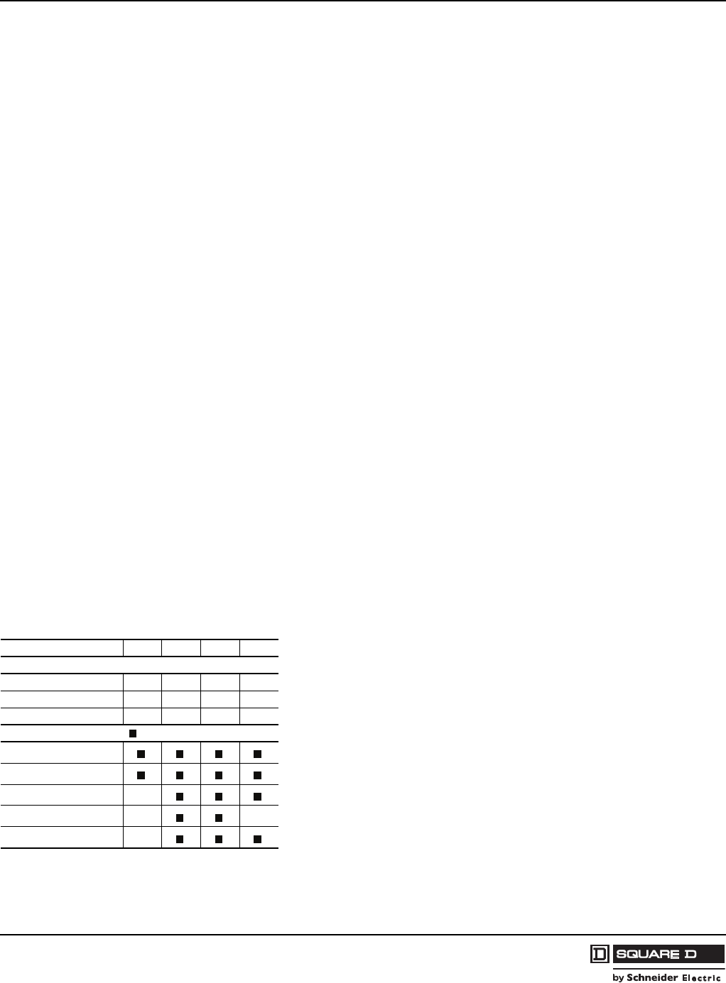
Performance Ratings
Table 1: UL 489 Interrupting Rating System PowerPact Molded Case Circuit Breakers are available in a variety of
voltage, ampacity, and interruption ratings to meet many applications. The
PowerPact range covers panel applications from 240 V through 600 V with
ampacities from 15 A to 1,200 A and interruption ratings as high as 125 kA
at 240 V and 100 kA at 480 V.
Circuit breakers are available as standard 80% rated devices and 100%
rated devices to meet your requirements. For more information on applying
80% and 100% rated devices see data bulletin 0600DB0702.
To simplify the selection process, all PowerPact circuit breaker interruption
ratings follow a simple code based on the 2nd letter (D, G, J, or L) of the
catalog number. Each letter designates a specific interruption rating, at a
specific voltage, for the entire range of PowerPact Molded Case Circuit
Breakers. Refer to Table 1 for these ratings.
DGJ L
Vac (Delta)
240 Vac 25 kA 65 kA 100 kA 125 kA
480 Vac 18 kA 35 kA 65 kA 100 kA
600 Vac 14 kA 18 kA 25 kA 50 kA1
Frame ( = available)
H-frame (15–150 A)
J-frame (150–250 A)
D-frame 1 (150–600 A) —
M-frame (300–800 A) — —
P-frame 1, 2 (100–1200 A) —
1D-frame and P-frame rating = 25 kA for 600 Vac
2P-frame is also available in a 50 kA, K-interrupting level at 600 Vac.
1
1
ENGLISH
PowerPact® Circuit Breakers for Control Panel Disconnects 0611DB0402R01/10
Data Bulletin 01/2010
© 2004–2010 Schneider Electric USA, Inc. All Rights2
Common Frame Sizes PowerPact® Molded Case Circuit Breakers are designed around three
common frame sizes. Each frame size has common mounting hole
configurations, handle operators, trim features, and actuator position.
The use of common frame sizes reduces the number of main disconnect
configurations needed to meet a variety of end-user applications. This
provides the ability to standardize panel designs around three broad ranges
of main disconnect ampacity requirements thereby reducing engineering
design time and inventory costs. Regardless of the interruption ratings
required, the size and mounting of the circuit breaker is determined by the
ampacity frame size. This eliminates the confusion and spacing challenges
typically presented when applications call for high interruption ratings that
were not anticipated.
The PowerPact H-frame (150 A) and PowerPact J-frame (250 A) circuit
breakers consolidate panel designs for 15 A to 250 A applications. The
PowerPact D-frame circuit breaker is designed for applications from 150 A
to 600 A. The PowerPact M-frame (800 A) and PowerPact P-frame (1200 A)
circuit breakers combine to meet 300 A to 1200 A requirements.
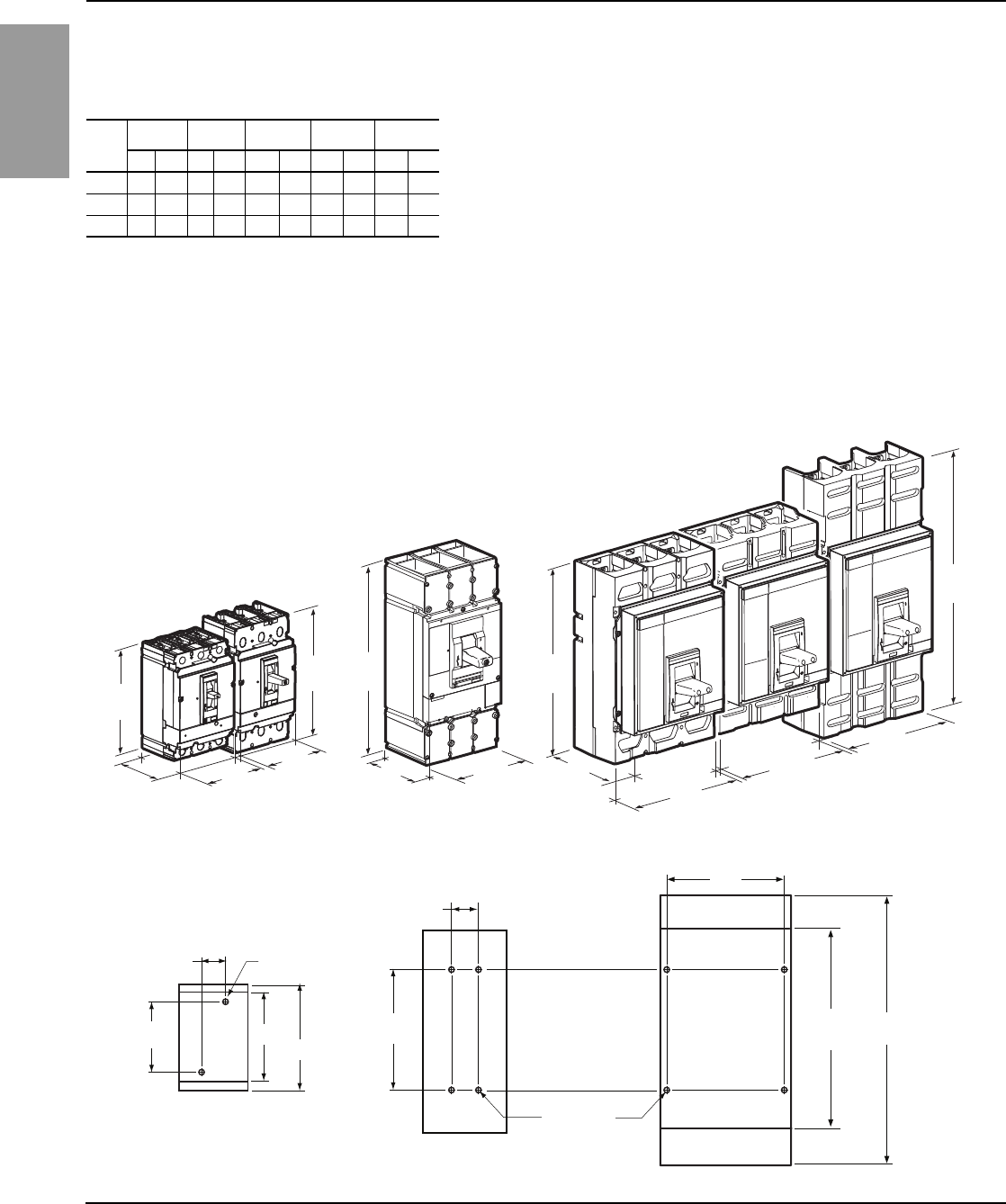
Table 2: Dimensions (3-pole Unit Mount)
Dim. H-frame J-frame D-frame M-frame P-frame
in. mm in. mm in. mm in. mm in. mm
H 6.4 163 7.5 191 13.3 340 12.8 325 16.2 413
W 4.1 105 4.1 105 5.5 140 8.3 210 8.3 210
D 3.4 86 3.4 86 4.4 113 5.8 146 5.8 146
Figure 1: Common Frame Sizes
4.1
[105]
4.1
[105] 5.5
[140] 8.3
[210]
8.3
[210]
8.3
[210]
5.8
[146]
3.4
[86]
4.4
[113]
6.4
[163]
H-frame
150 A
J-frame
250 A
D-frame
400/600 A
M-frame
800 A
P-frame
800 A
P-frame
1200 A
7.5
[191]
12.8
[325]
16.2
[413]
13.3
[340]
06113550
Figure 2: Common Mounting Holes
7.83
[199]
4.92
[125.0]
1.38
[35.1]
D-frame
M- and P-frame
H- and J-frame
M- and
P-frame
(800 A)
P-frame
(1200 A)
Mounting
Hole 4X
7.9
[200]
1.7
[45]
Mounting
Hole 2X
H-frame
J-frame
06113551
0611DB0402R01/10 PowerPact® Circuit Breakers for Control Panel Disconnects
01/2010 Data Bulletin
© 2004–2010 Schneider Electric USA, Inc. All Rights 3
ENGLISH
Operating Mechanisms PowerPact® Molded Case Circuit Breakers are complemented by a broad
offering of operating mechanisms and ratings specifically designed to be
used as the main panel disconnect for control panel applications. Three
basic designs minimize the selection process and easily cover the
PowerPact Molded Case Circuit Breaker offer from 15 A to 1200 A.
Available styles include an IEC rotary operating handle, a NEMA style rotary
handle, and a flange mounted operating handle.
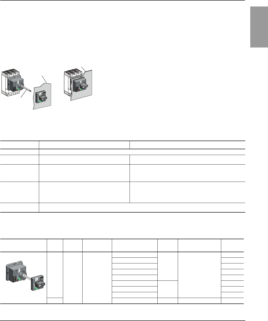
IEC Style Rotary Operating Handles IEC style rotary operating handles are designed for door mounted or direct
mounted applications. The handle operators maintain suitability for isolation
and can be locked in the off position by the use of a padlock meeting
Lockout/Tagout requirements. When interconnected to the circuit breaker
the handle provides visible indication of on, tripped and off status. Each
model is available with a black handle or a red handle on a yellow bezel to
distinguish between distribution power and machine control when required.
Door Mounted operators utilize a shaft that interlinks the handle operator to
the circuit breaker for applications requiring variable depth adjustments
between the circuit breaker and the panel door. The handle mechanisms
can be used on NEMA 1, 3R, and 12 enclosures.
Direct Mounted operators are designed to connect directly to the front of the
circuit breaker. The operator cover may be positioned to extend through a panel
cut out if required. Features of these handle operators are outlined in Table 3.
Direct
Mounted
Shaft
Panel Door
Panel Door
Door
Mounted
06113552
Table 3: IEC Style Handle Operator Features1
Feature Door Mounted Direct Mounted (to circuit breaker)
Handle Padlock The rotary handle may be locked in the OFF position with up to three padlocks.
Standard Configuration The panel door may only be opened with the circuit breaker
in the OFF position.
The panel door may be opened in either the
ON or OFF position.
Door Interlock
The standard configuration allows the panel door to be
opened only in the OFF position. The handle may be easily
reconfigured to allow the panel door to be opened in either
the ON or OFF position.
The standard configuration allows the panel door to be opened in either the
ON or OFF position. The door interlock feature may be engaged by
loosening a screw inside the handle. This will require the circuit breaker to be
in the OFF position before the panel door may be opened.
Open Door Interlock Not available
To ensure that the circuit breaker may not be energized with the panel door
open, the open door interlock may be utilized. This feature is built into the
direct mount handle and is engaged by loosening a different screw inside the
mechanism. This will ensure that the circuit breaker may only be turned ON
with the panel door closed.
Bypass Feature A discrete bypass button is also provided in both types of handles allowing the panel door to be opened with
the circuit breaker in the ON position.
1HAZARD OF ELECTRIC SHOCK, EXPLOSION, OR ARC FLASH. When bypass button is used, apply appropriate personal protective equipment (PPE). Electrical
equipment should only be serviced and maintained by qualified electrical personnel following applicable standards such as NFPA 70E. Failure to follow these
instructions will result in death or serious injury.
Table 4: Handle Operators (Complete Kits)
Operator Style NEMA
Ratings
Operator
Type Advantages Versions Available Circuit
Breakers Mounting Depth Part
Number
3R, 12 Door
Mounted
Rotary
Handle
Small operator
with similar look
and operation to
other control
components
Direct Mount (black)
H and J
7.5–24 in. (19.1–61 cm)
S29337 1
1IEC operating handle part numbers are for field-installable kits. Please reference catalogs for factory-installed kit numbers.
Extended Door Mount (black) S29338 1
Telescoping (black) S29343 1
Direct Mount (red) S29339 1
Extended Door Mount (red) S29340 1
Direct Mount (black)
D
32598 1
Direct Mount (red) 32600 1
Telescoping (black) 32603 1
12 Direct Mount (black) P 8.2–23.8 in. (20.8–60.5 cm) 33878 2
2P-frame IEC handle operators are factory installed only.
IEC Style
06113553
ENGLISH
PowerPact® Circuit Breakers for Control Panel Disconnects 0611DB0402R01/10
Data Bulletin 01/2010
© 2004–2010 Schneider Electric USA, Inc. All Rights4
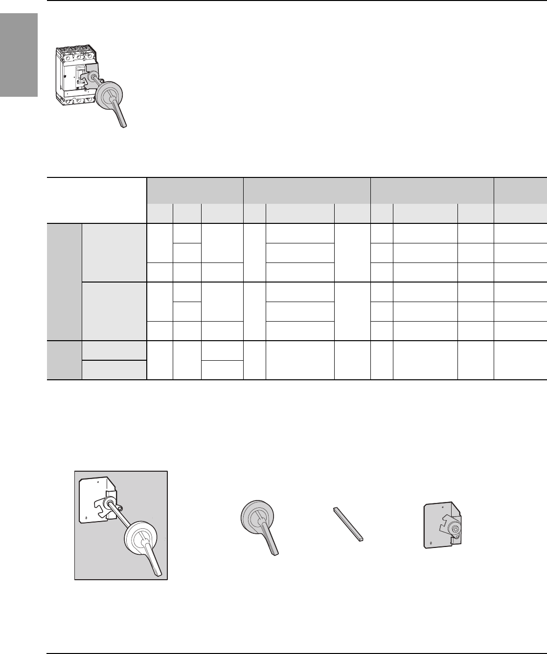
NEMA Style Operating Mechanisms Class 9421 NEMA Door Mounted Rotary Operating Handles are designed
for door mounted variable depth applications. Door mounted operators
utilize a shaft that interlinks the handle operator to the circuit breaker when
the panel door is in the closed position. The heavy duty, all-metal
construction features on, off, and trip indication via handle position. The
handle assembly can be used to lock the door in the closed position with up
to three padlocks to meet Lockout/Tagout requirements. The mechanism is
capable of locking in the off position independent of the handle operator.
This is useful when the breaker must be locked in the off position when the
panel door is open.
06114200
Table 5: Component Parts for Door Mounted Mechanisms
Handle Assemblies Standard Shaft
(Support Bracket Not Required)
Long Shaft
(Support Bracket Included)
Operating
Mechanism1
Type2Frame Part No. Type Mounting Depth3
Min.–Max Part No. Type Mounting Depth3
Min.–Max Part No. Part No.
Standard
NEMA Type 3,4
(Painted)
6 in.
H & J
9421LH6
LS8
5.5–10.25 in.
(14–26 cm)
9421LS8
LS10 5.5–21.38 in.
(14–54.3 cm) 9421LS10 9421LJ7
D7.25–12.06 in.
(18.4–30.6 cm) LS13 7.25–22.63 in.
(18.4–57.5 cm) 9421LS13 9421LD7
8 in. M & P 9421LHP8 7.19–11.63 in.
(18.3–29.5 cm) LS10 7.19–22.25 in.
(18.3–56.5 cm) 9421LS10 9421LW7
NEMA Type 3, 4, 4x
(Chrome Painted)
6 in.
H & J
9421LC46
LS8
5.5–10.25 in.
(14–26 cm)
9421LS8
LS10 5.5–21.38 in.
(14–54.3 cm) 9421LS10 9421LJ7
D7.25–12.06 in.
(18.4–30.6 cm) LS13 7.25–22.63 in.
(18.4–57.5 cm) 9421LS13 9421LD7
8 in. M & P 9421LCP48 7.19–11.63 in.
(18.3–29.5 cm) LS10 7.19–22.25 in.
(18.3–56.5 cm) 9421LS10 9421LW7
Special
3-inch
NEMA Type 3,4
(Painted) 3 in. H & J
9421LH3
LS8 5.5–10.25 in.
(14–26 cm) 9421LS8 LS10 5.5–21.38 in.
(14–54.3 cm) 9421LS10 9421LJ7
NEMA Type 3, 4, 4x
(Chrome Painted) 9421LC43
1Operating mechanism includes lockout.
28-inch handle assemblies are available but not recommended for H-, J-, and D-frame.
3Mounting depth is measured from circuit breaker mounting surface (control panel) to outside of enclosure.
Figure 3: Component Parts for Door Mounted Mechanisms
+=+
Handle Assembly Shaft Operating Mechanism
Door Mounted Mechanism
06113554
0611DB0402R01/10 PowerPact® Circuit Breakers for Control Panel Disconnects
01/2010 Data Bulletin
© 2004–2010 Schneider Electric USA, Inc. All Rights 5
ENGLISH
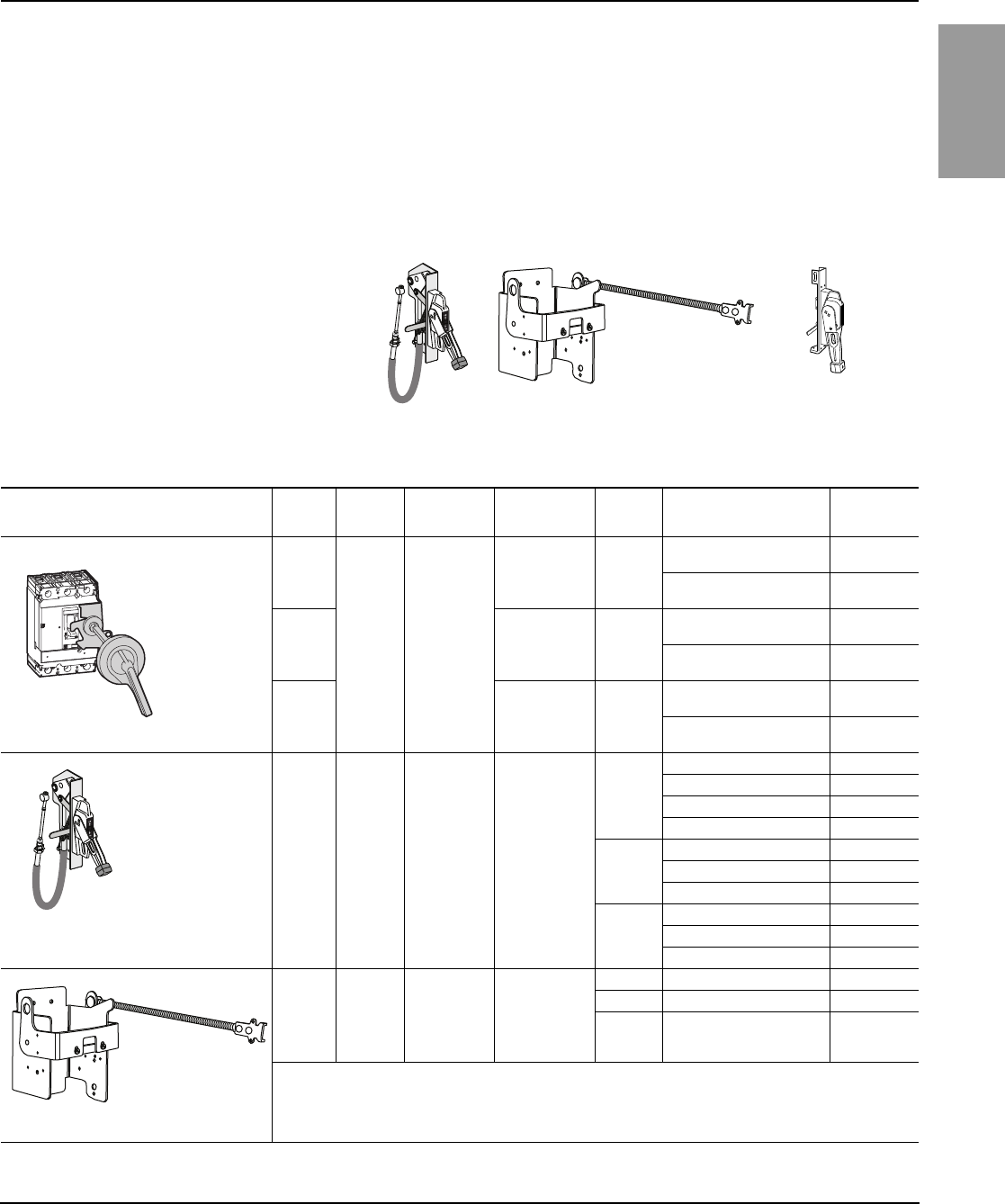
Class 9422 flange mounted operating mechanisms are available in two
distinct styles: variable depth or cable operated. The handle operating
mechanisms have the capability of accepting 1 to 3 padlock attachments to
meet Lockout/Tagout requirements to insure safety compliance. The
bracket mounted operators remain connected to the circuit breaker at all
times. The units are designed for installation flexibility for variable depth
applications and are field convertible to meet both right and left flanged
mounted requirements. Cable operated mechanisms provide maximum
installation flexibility for tall and/or deep enclosures. Cables come with
terminations already installed on both ends to save on installation time and
are available in 36, 60, 84, and 120 inch lengths.
06113483
Cable Operated
06114331
Variable Depth
Flange
Handle
Table 6: Handle Operators (Complete Kits)
Operator Style NEMA
Ratings
Operator
Type Advantages Versions
Available
Circuit
Breakers Mounting Depth Part
Number
1, 3R, 12
Door
Mounted
Rotary
Handle
Robust and
cost effective
solution for a
door mounted
disconnect
Complete kit with
6-in. (15.2 mm)
handle 1
H and J
(short shaft)
5.5–10.75 in. (14–27.3 cm) 9421LJ1
(long shaft)
5.5–21.4 in. (14–54.3 cm) 9421LJ4
1, 3R, 12
Complete kit with
6-in. (15.2 cm)
painted handle 3
D
(short shaft)
7.25–12.1 in. (18.4–30.7 cm) 9421LD1
(long shaft)
7.25–22.6 in. (18.4–57.4 cm) 9421LD4
1, 3R, 12
Complete kit with
8-in. (20.3 cm)
handle 1
M and P
(short shaft)
7.2–11.6 in. (18.3–29.5 cm) 9421LW1
(long shaft)
7.2–22.25 (18.3–56.5 cm) 9421LW4
1, 3, 3R,
4, 4X
Cable
Operated
Ideal for tall,
deep
enclosures
where
placement
flexibility
is required
Operating
mechanism only,
handle ordered
separately
H and J
cable: 36 in. (91.4 cm) 9422CSF30 2
cable: 60 in. (152.4 cm) 9422CSF50 2
cable: 84 in. (213.4 cm) 9422CSF70 2
cable: 120 in. (304.8 cm) 9422CSF10 2
D
cable: 36 in. (91.4 cm) 9422CSJ30 2
cable: 60 in. (152.4 cm) 9422CSJ50 2
cable: 120 in. (304.8 cm) 9422CSJ10 2
M and P
cable: 36 in. (91.4 cm) 9422CMP30 2
cable: 50 in. (127 cm) 9422CMP50 2
cable: 120 in. (304.8 cm) 9422CMP10 2
1, 3, 3R,
4, 4X
Variable
Depth
For custom-
built enclosures
where right or
left-hand
actuation is
important
Operating
mechanism only,
handle ordered
separately
H and J 5.88–17.75 in. (14.9–45.1 cm) 9422RQ1 2
D 9.00–17.75 in. (22.9–45.1 cm) 9422RS1 2
M and P 9.00–18.38 in. (22.9–46.7 cm) 9422RM1 2
Continued on next page
NEMA Class 9421
06113555
06114201
NEMA Class 9422
NEMA Class 9422
06114331
ENGLISH
PowerPact® Circuit Breakers for Control Panel Disconnects 0611DB0402R01/10
Data Bulletin 01/2010
© 2004–2010 Schneider Electric USA, Inc. All Rights6
Terminations A wide variety of terminal options are available for PowerPact molded case
circuit breakers. The terminations are designed to be extremely versatile
and easy to install.
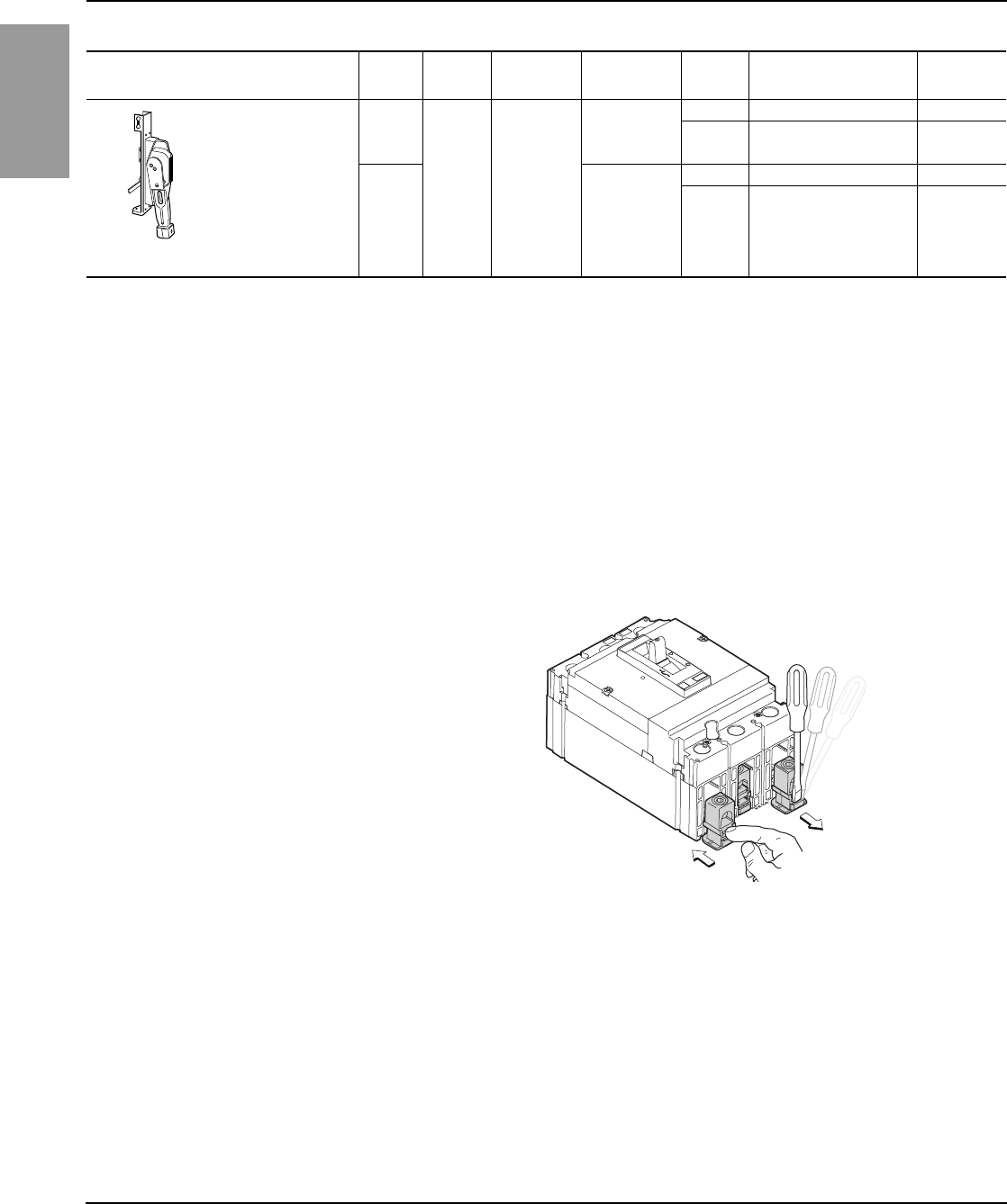
Snap-In Terminals The PowerPact® H- and J-frame circuit breakers are equipped with a unique
snap-in terminal design that makes converting between busbar and lug
options easy. The terminal nut or mechanical lug is set on a plastic retainer
that slides and snaps into place. This makes it possible to easily convert to a
distribution lug or add a control wire.
1, 2, 3,
3R, 4
Flange
Handle
Can be used
with cable
operated and
variable depth
mechanisms
6 in. (15.2 cm)
sheet steel
flange handle
only
H, J, and D N/A 9422A1
M and P N/A 9422AP1
4, 4X
6 in. (15.2 cm)
stainless steel
flange handle
only
H, J, and D N/A 9422A2
M and P N/A 9422AP2
1Refer to Digest for component parts.
2Handle must be ordered separately.
Table 6: Handle Operators (Complete Kits)
Operator Style NEMA
Ratings
Operator
Type Advantages Versions
Available
Circuit
Breakers Mounting Depth Part
Number
NEMA Class 9422
Figure 4: H- and J-Frame Snap-In Terminals
06113485
Insertion
Removal
— Continued
0611DB0402R01/10 PowerPact® Circuit Breakers for Control Panel Disconnects
01/2010 Data Bulletin
© 2004–2010 Schneider Electric USA, Inc. All Rights 7
ENGLISH
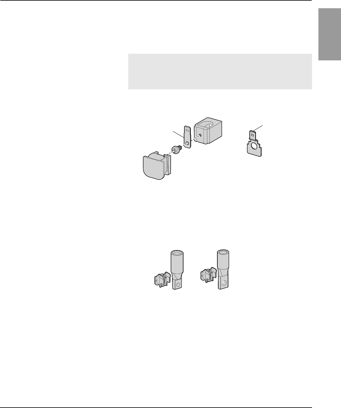
Mechanical Lugs Mechanical lugs are the standard offering, and are available in either
aluminum or copper. Both the aluminum and copper mechanical lugs can be
equipped with a control wire terminal kit that attaches to the bottom of the
lug, creating a 1/4 inch slip connect terminal. The control wire is ideally
suited for powering control transformers from the main circuit breaker.
These lugs are available factory installed or as field-installable kits.
Crimp Lugs Crimp lugs are available in both aluminum and copper and cover the entire
range of available wire sizes. The kits include all of the mounting hardware
and terminal inserts necessary to completely convert the circuit breaker.
NOTE:
— Similar connections are available for 600 A D-frame circuit breakers.
— PowerPact M- and P-frame circuit breakers can be ordered with
special lugs with control wire taps.
Figure 5: Control Wire Terminals for H- and J-Frame Circuit Breakers
06113486
Control Wire Terminal
for Mechanical Lugs
Control Wire Terminal
for Terminal Nuts
Figure 6: Crimp Lugs for H- and J-Frame
06113487
ENGLISH
PowerPact® Circuit Breakers for Control Panel Disconnects 0611DB0402R01/10
Data Bulletin 01/2010
© 2004–2010 Schneider Electric USA, Inc. All Rights8
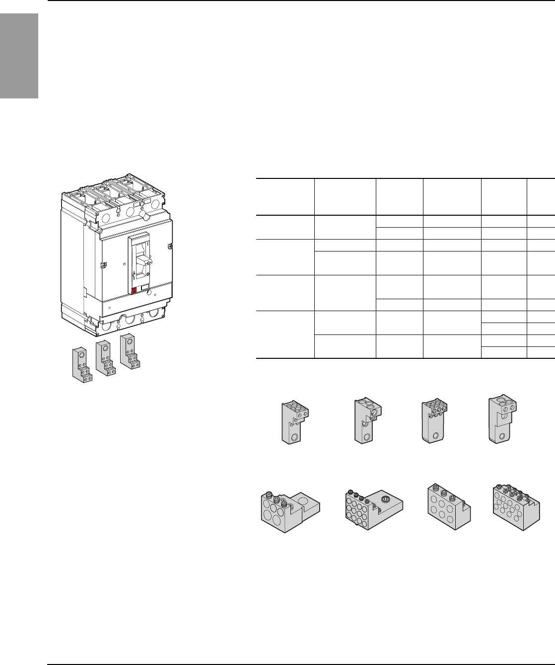
Power Distribution Lugs Power distribution lugs can be used for multiple load connections on one
circuit breaker and provide additional benefits for UL508A compliance.
When distribution lugs are attached to the circuit breaker, the lugs assume
the Short Circuit Current Rating (SCCR) of that circuit breaker, and don't
require stand-alone ratings. They can be used to replace standard
distribution blocks to save time and space. Field installable kits include tin-
plated aluminum lugs (for copper wires only) and all the required mounting
hardware. The distribution lugs are for use on the “Load” end only and on
UL 508 or UL 1995/CSA22.2 No. 236 control panel specifications. Long
terminal shields, or phase isolators, are available to maintain isolation
between phases. Use catalog number S37449 for H-frame long lug shields
and catalog number S37450 for J-frame long lug shields.
06113488
H-Frame Example
Table 7: Power Distribution Lugs
Use with
Circuit
Breaker
Circuit Breaker
Ampere Rating
Number of
Wires Per
Terminal
Wire Range Catalog
Number
Qty.
in Kit
HD, HG, HJ, HL 15–150 A 6 14–6 AWG Cu PDC6HD6 3
3 14–2 AWG Cu PDC3HD2 3
JD, JG, JJ, JL
150–250 A 6 14–4 AWG Cu PDC6JD4 3
150–250 A 2 14–1 AWG Cu PDC3JD20 3
+1 12–2/0 AWG Cu
D-frame 150–600 A
2 4–1 AWG Cu PDC5DG20 3
+3 14–6 AWG Cu
12 14–4 AWG Cu PDC12DG4 3
M- and P-frame
250–1200 A 6 12–2/0 AWG Cu PDC6P20 3
PDC6P204 4
250–1200 A 12 10–4 AWG Cu PDC12P4 3
PDC12P44 4
PDC6HD6 PDC3HD2 PDC6JD4 PDC3JD20
PDC5DG20 PDC12DG4 PDC6P20 PDC12P4
06113488
0611DB0402R01/10 PowerPact® Circuit Breakers for Control Panel Disconnects
01/2010 Data Bulletin
© 2004–2010 Schneider Electric USA, Inc. All Rights 9
ENGLISH
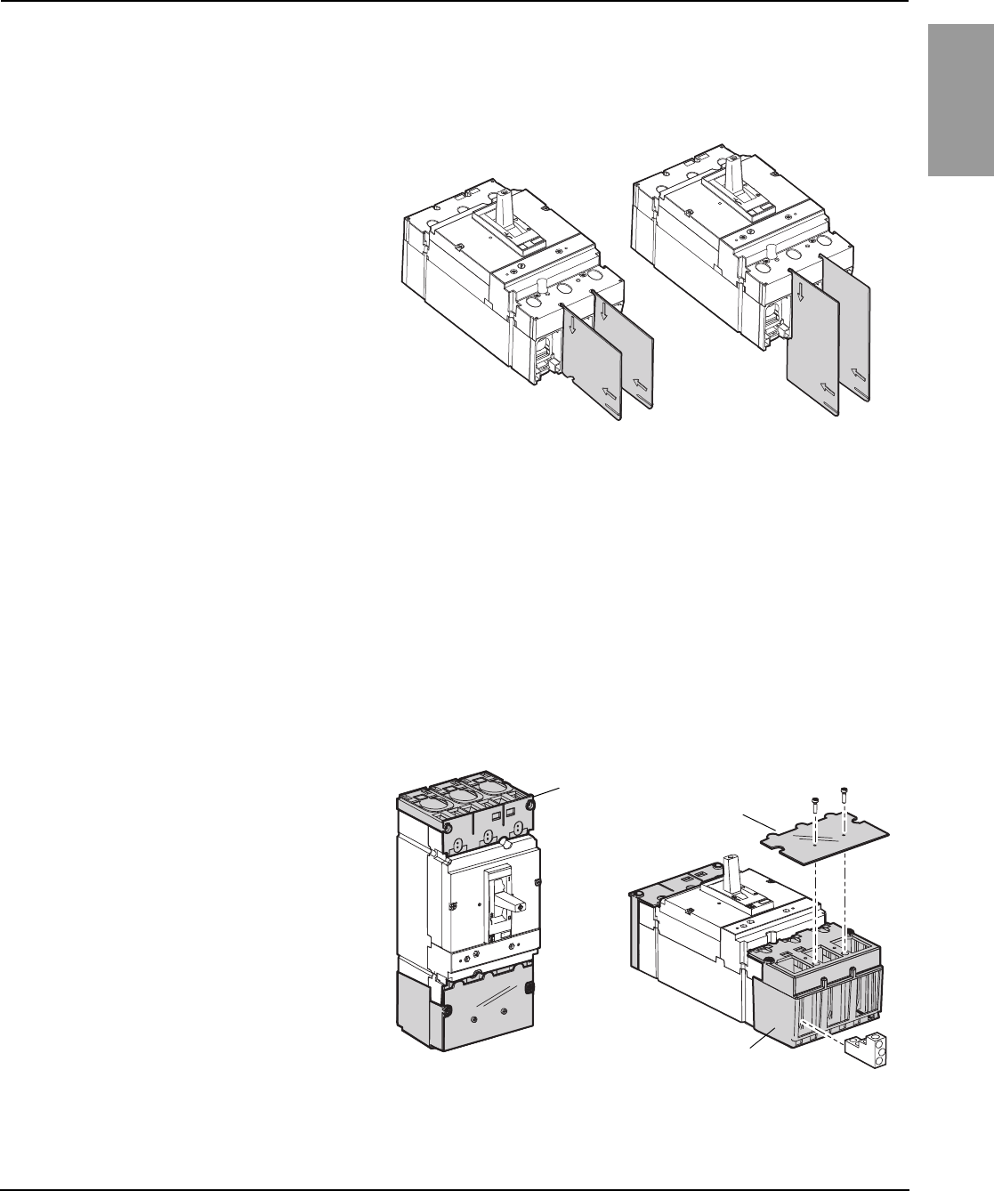
Phase Barriers and Lug Shields For additional shielding and protection, phase barriers are available to help
isolate phase conductors.
Safety is a key element of the panel disconnect. When the main disconnect
is used to turn the power off in the panel, the lugs and conductors on the
top, or line side, of the circuit breaker are still energized. Optional lug shields
may be mounted on the line-side where power enters the panel to provide
IP20 isolation, which indicates a degree of protection from tools or fingers
touching live parts.
When crimp lugs or power distribution lugs are added to the load end of the
circuit breaker they protrude outside of the circuit breaker. The PowerPact®
H- and J-frame circuit breakers can be equipped with optional lug shields
that provide some isolation of these parts. The covers are fitted with a
transparent cover allowing terminations to be inspected or re-tightened
without removing the covers.
Figure 7: Phase Barriers (J-Frame Examples)
Figure 8: Optional Lug Shields (J-Frame Examples)
push
to
trip
push
to
trip
06113489
Line-side
Lug Shield
Power
Distribution
Lug Shield
Transparent Cover
06113556
ENGLISH
PowerPact® Circuit Breakers for Control Panel Disconnects 0611DB0402R01/10
Data Bulletin 01/2010
© 2004–2010 Schneider Electric USA, Inc. All Rights10
Common Accessories A key feature of PowerPact® Molded Case Circuit Breakers are the common
accessories that are versatile and easy to install. These molded case circuit
breakers can be easily configured to add auxiliary switches, alarm contacts,
rotary handles, motor operators, padlocks, and a variety of terminal options.
The use of common accessories provides the ability to respond to late
specification changes without requiring expensive delays associated with
factory modifications. This also allows customers to reduce inventory
without sacrificing flexibility. Table 8 shows the common features and
accessories for the PowerPact family of circuit breakers.
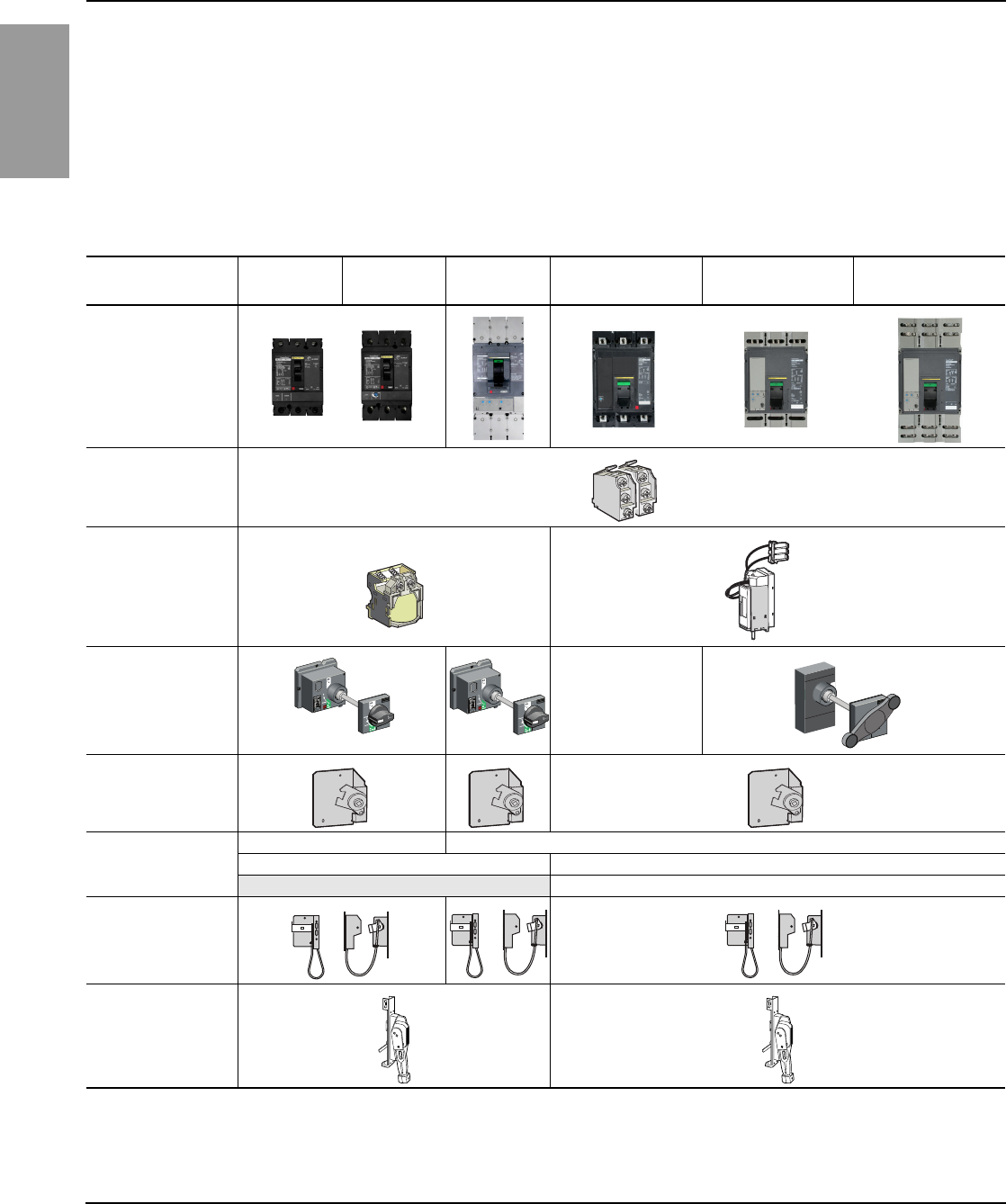
Table 8: Common Features and Accessories (PowerPact Circuit Breakers)
Common Design
Features
H-frame
150 A
J-frame
250 A
D-frame
600 A
M-frame
800 A
P-frame
800 A
P-frame
1200 A
• Mounting Holes
• Door Trim
• Handle Accessories
• Auxiliary Switches
• Alarm Switches
• Shunt Trip
• Undervoltage
Release
• IEC Operators N/A
• Operating
Mechanism
• NEMA Rotary Handle
3-inch N/A
6-inch N/A
8-inch1
18 inch handles are available but not recommended for H-, J-, and D-frame.
8-inch
• NEMA Cable or
Variable Depth
Mechanism
• NEMA Flange Handle
0611DB0402R01/10 PowerPact® Circuit Breakers for Control Panel Disconnects
01/2010 Data Bulletin
© 2004–2010 Schneider Electric USA, Inc. All Rights 11
ENGLISH
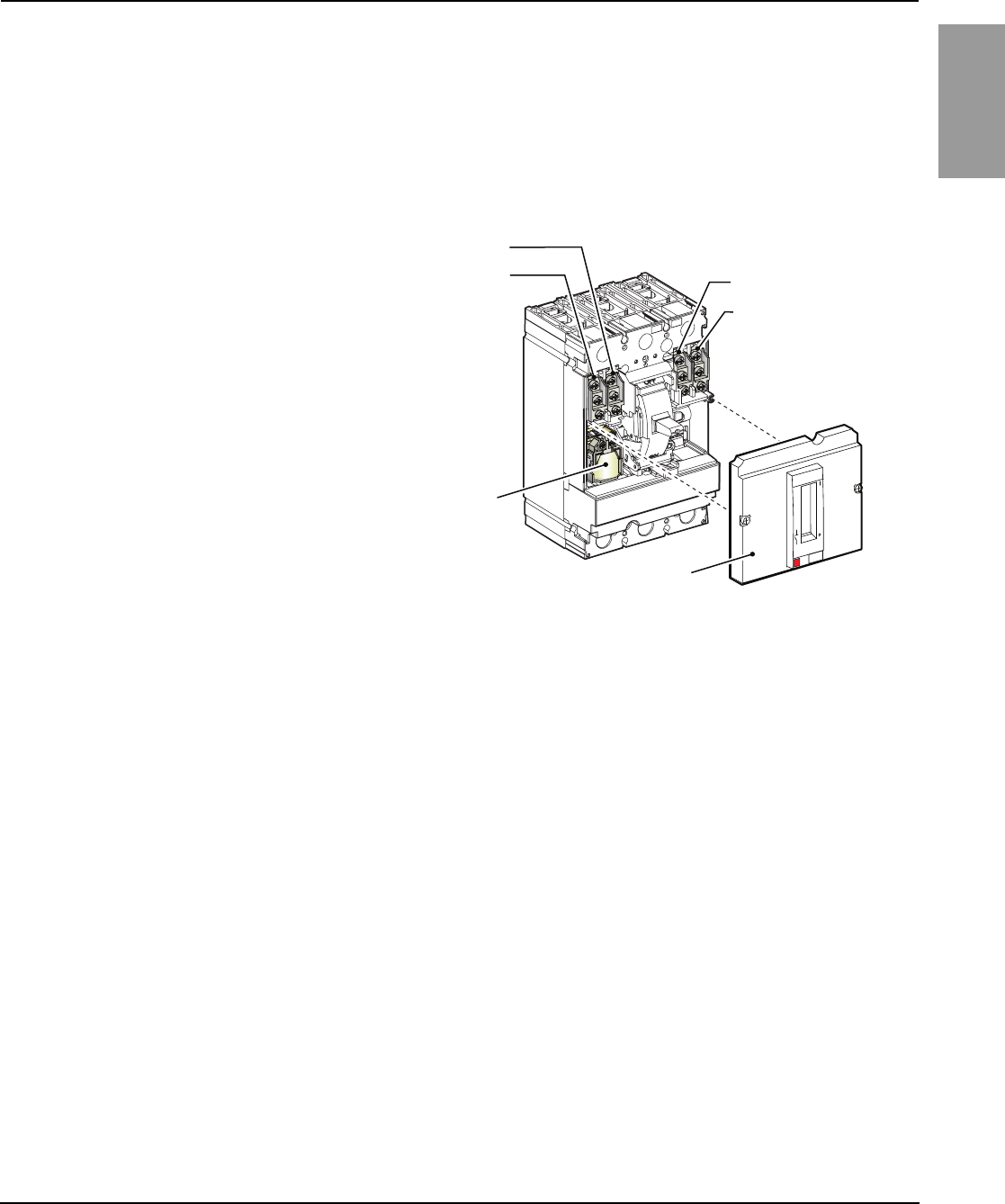
Careful attention was given to ease of installation and reliable operation. For
example, as shown in Figure 9, the H- or J-frame auxiliary cover can be
removed with two screws and the accessories can be snapped into place.
The switches, shunt trip, and UVR can also be easily installed or removed
with common tools. This creates a product that is easily configured.
The accessory cover has several locations for wire routing. The instruction
materials shipped with the devices provide clear steps and graphics to
ensure proper installation.
Overcurrent Trip Switch The overcurrent trip switch can be installed in addition to the alarm switch. This
switch provides a contact that indicates that the circuit breaker has tripped due
to an overcurrent condition. This contact will not be actuated when the circuit
breaker is tripped via the shunt trip, undervoltage release, or push-to-trip button.
The overcurrent trip indication is ideal for signaling the circuit breaker tripped
due to an overload or short circuit condition. This additional alarm switch can be
wired to a pennant light or included into a control scheme that requires the
system be inspected before being reenergized.
The PowerPact® P-frame circuit breakers are also available with ET and
Micrologic® monitoring capabilities. Features in the Micrologic trip unit
include universally interchangeable rating plugs and adjustable long-time
pickups. The Micrologic family consists of four models with progressively
increasing levels of functionality, from basic overcurrent protection to
advanced protection, communications, and power metering/monitoring. This
allows the circuit breaker to replace other parts of the panel and become
integrated into energy management software.
Figure 9: Easy Access to Accessories (H-frame Shown)
(OF1) Auxiliary Switch
(SD) Alarm Switch
(SDE) Overcurrent Trip Switch
(OF2) Auxiliary Switch
Accessory Cover
(MX) Shunt Trip or
(MN) Undervoltage Trip
06113490

ENGLISH
PowerPact® Circuit Breakers for Control Panel Disconnects 0611DB0402R01/10
Data Bulletin 01/2010
Electrical equipment should be installed, operated, serviced, and maintained only by
qualified personnel. No responsibility is assumed by Schneider Electric for any
consequences arising out of the use of this material.
Schneider Electric USA, Inc.
3700 Sixth St SW
Cedar Rapids, IA 52404
1-888-SquareD (1-888-778-2733)
www.schneider-electric.us
Square D® is a trademark or registered trademark of Schneider Electric. Other
trademarks used herein are the property of their respective owners.
© 2004–2010 Schneider Electric USA, Inc. All Rights12
Conclusion The combination of innovation, performance, reliability and safety provide
UL-type control panel builders with a comprehensive product solution. High
interrupting ratings, common design elements, versatile connection options,
and field-installable accessories allow for consolidated panel designs and
the flexibility to meet late specification changes or customer-specific
requirements. The PowerPact® family of circuit breakers, along with the
unmatched worldwide service and support of Schneider Electric, set the
standard for reliability and performance.
