Il16999.fh11 Installation Directions
2016-10-06
: Pdf 1000482524-Installationsheet 1000482524-InstallationSheet B5 unilog
Open the PDF directly: View PDF ![]() .
.
Page Count: 8
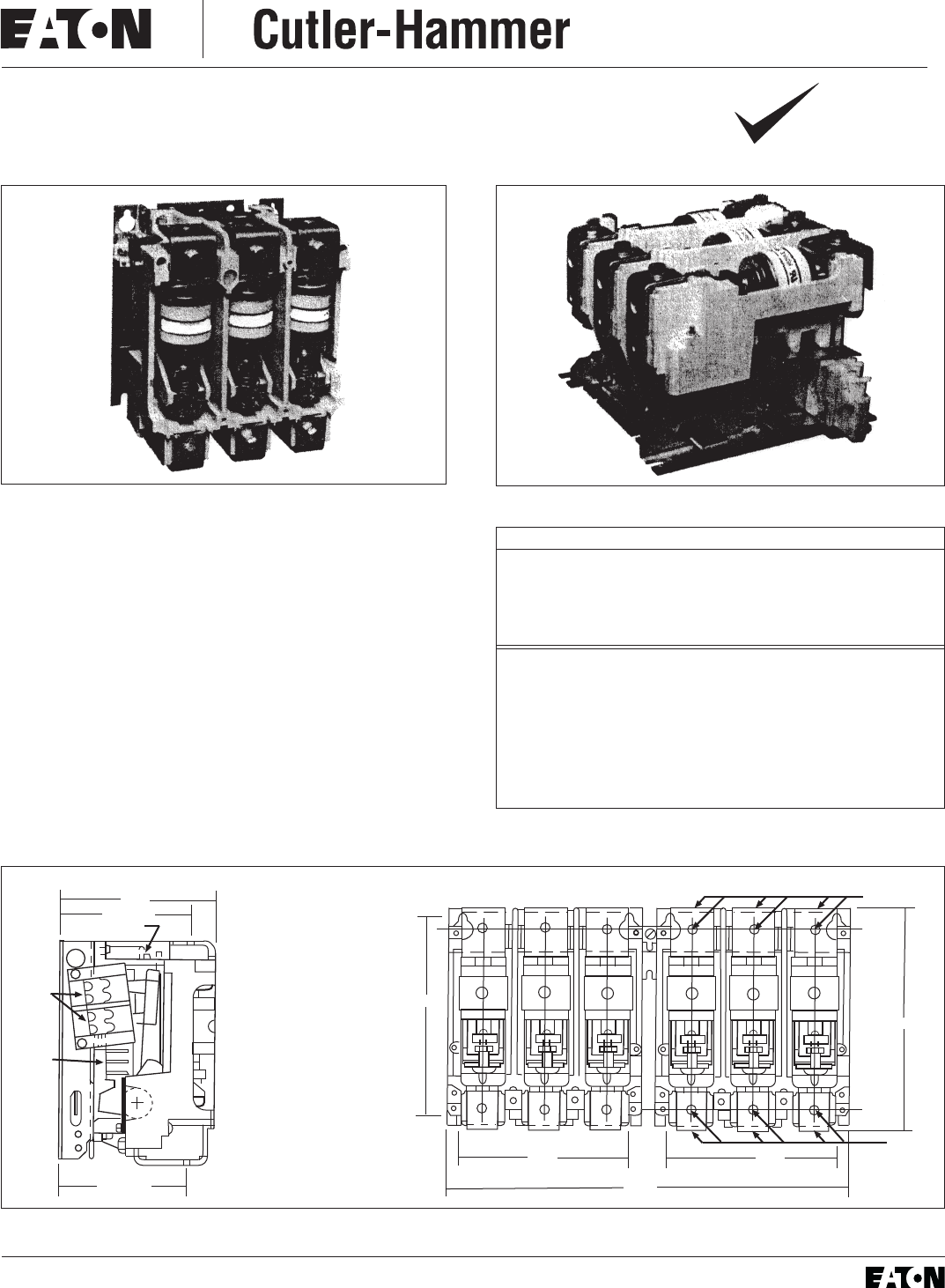
Instructions for V201, V211 V251
320 Ampere Vacuum Contactor
Nonreversing or Reversing
I.L. 16999
RoHS
THE CONTACTOR
V201 contactors are designed for the control of inductive
or non-inductive loads at voltages between 120 and 1500,
AC. The units are suitable for mounting on either steel or
insulated panels. All parts are front removable. Contactors
should be protected against short circuits by branch circuit
protective devices selected in accordance with the National
Electrical Code.
This industrial type control is designed to be installed,
operated, and maintained by adequately trained workmen.
These instructions do not cover all details, variations, or
combination, check out, safe operation, or maintenance. Care
must be exercised to comply with local, state, and national
regulations, as well as safety practices, for this class of
equipment.
Mount each contactor with four 5/16 x 18 or 1/4 x 20 bolts
or three 1/4 x 20 bolts if the V201 contactor. Flat washers
should be used on bolts entering slotted holes or keyholes.
Two-pole contactors have the same current ratings as 3 pole
devices but are not suitable for controlling 3 phase motors.
Fig. 1 V201 Nonreversing Contactor
CONTROLLER RATINGS - 3 POLE CONTACTORS
Rated Insulation Voltage (Ui)=1500Volts
3 Phase Horsepower At 50 or 60 Hz
200V 230V 380V 460V 575V 800V 1500V
100 125 200 250 300 400 500
MAXIMUM CURRENT RATINGS (RMS)
Continuous Continuous Motor, Transformer
Carrying Carrying or Capacitor
Open Enclosed Make or Break
350A 320A 3200A
Maximum Capacitor Switching - 3 Phase
200 kvar at 600 volts: 500 kvar at 1500 volts
Model A or B
Formerly Type SJM
Fig. 2 Left portion of V211 Reversing Contactor
Rev 01
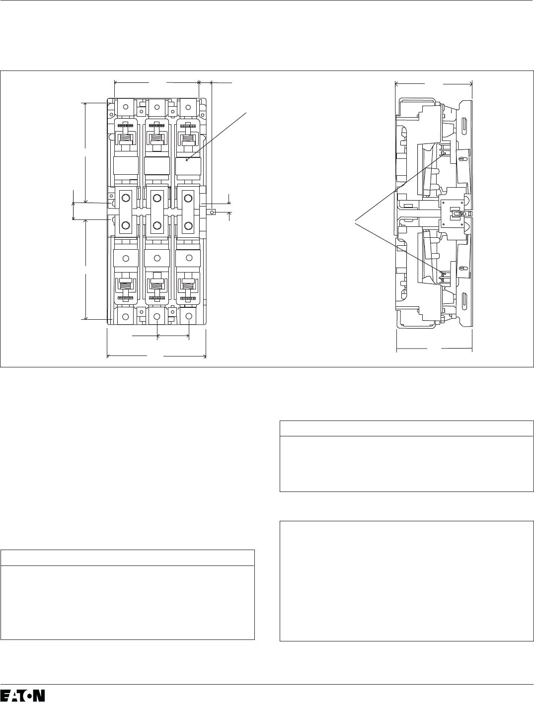
Fig. 3 Reversing and Nonreversing Contactor (V211, V201) Dimension Drawings (Dim. in inches)
A TWO DUAL CIRCUIT AUX-
ILIARYCONTACTSLOCAT-
ED ON BOTH SIDES OF
CINTACTOR WHEN USED
B COIL TERMINALS OCAT-
ED ON BOTH SIDES OF
CONTACTOR.
MOUNT WITH 5/16 x 18
or 1/4 x 20 bolts
8.94
6.75
16.30
6.75 1.65
8.00
SIX .375-16
TAP. LINE
TERMINALS.
SIX .375-16
TAP. LINE
TERMINALS.
6.20
5.20 LINE
COIL INTERLOCK
(A)
(B)
5.05 LOAD
2
AUXILIARY CONTACTS - TYPE J
Two mounting brackets for auxiliary contacts are provided on
each contactor. Auxiliary contacts themselves must be ordered
separately. An auxiliary contact with one or more normally
open poles may be used as the holding circuit auxiliary. A
maximum of four auxiliary units can be installed in the brackets
of each nonreversing contactor (three in each reversing
contactor). They mount by means of a spring clip and retainer
screw. To remove the auxiliary contacts, loosen the retainer
screw several times (counterclockwise) and then slide the
auxiliary contact unit out of the bracket.
Fig. 4 Reversing Controller (V251) Dimension Drawing (Dimensions in inches)
V201, V211, V251, 320 AMPERE VACUUM CONTACTOR I.L. 16999
TYPE J AUXILIARY CONTACTS
Contact Type Catalog No.
2 Normally Closed J02
2 Normally Open J20
1 Normally Open and 1 Normally Closed J11
1 Normally Open and 1 Normally Closed, DB* J1C
*DB = Delayed Break
TYPE J CONTACT RATINGS (A600, R300)
Voltage Continuous Make Break
120-600 VAC 10A 7200VA 720VA
72-120 VAC 10A 60A 720VA
28-72 VAC 10A 60A 10A
28-300 VDC 1.0A 28VA 28VA
TABLE I - ACCESSORIES
Fuse Block Kits - Meet requirements of
National Electric Code (NEC) concerning
common control fusing.
Order Qty. Description
F56 2 Contactor mounted Fuse Holder for
one 600 volt Bussmann ktk Fuse
FKR 1 Panel mounted Fuse Holder for two
Class CC (Bussmann KTKR) Fuses*
* Use when available fault current exceeds 10,000
amperes
L1 L2 L3
8.00
1.30
8.00
6.75 1.00
0.65
7.88
2.50
TYP
Mount with 5/16 - 18
or 1/4 - 20 bolts
(B)
A Coil terminal located on both
sides of contactor
B Upper contact mounted upside
down
(A)
6.00
6.20

3
COIL
The operating coil has a figure-eight shape and is really
two coils in series, with a connection to their common point.
Both coils are encapsulated in one environment-immune
coil shell, which also contains a full-wave bridge. When AC
is connected directly to terminals A and B on the coil shell,
the magnet excitation is unfiltered DC. The magnet will not
chatter as AC magnet sometimes do, but at less than rated
volts it may hum slightly. A normally-closed Type L63
auxiliary contact, set to open slightly before the armature
fully closes, is connected to terminals C and D on the coil
shell. When adjusted correctly, this contact allows a relatively
high current through the pick-up winding, and as the
contactor closes, the contact inserts the holding winding,
which reduces the coil current to a low value sufficient to
hold the magnet closed without overheating. No external
resistors are required.
Fig. 5 Control Circuit Diagrams
MAGNET OPERATING RANGE
When properly adjusted as described in previous sections,
the contactor should operate within the ranges shown in
Table II.
COIL DATA (TYPICAL VALUES)
Coil Inrush Sealed Part
Voltage Freq. VA VA/Watts Number
110-120 Any 600 20 7874A09G01
220-240 Any 600 20 7874A09G04
440-480 Any 600 20 7874A09G05
550-600 Any 600 20 7874A09G06
24 DC - 15 7874A09G07
48 DC - 15 7874A09G08
If the magnet chatters, look for mechanical interference
that prevents the magnet from sealing. If there is no
interference, then the magnet itself may be misaligned.
The magnet gap can be seen from the left and right sides
with the help of a flashlight. A screwdriver inserted into one
of the long slots (Y-Figure 9) can be used as a lever to put
a corrective set into the mounting plate around the magnet.
it should not be necessary to do this unless the contactor
has been damaged and it can be seen that the armature
does not fit against the magnet. A poor magnet to armature
fit usually produces a high dropout voltage and/or chatter.
Mechanical interference can be produced by various
incorrect adjustments. Two specific points to check are:
A. Armature travel incorrect, causing the contact
springs to be compressed into a solid, non-
resilient tube that stops the crossbar rigidly.
Refer to Eaton Service for assistance.
B. The auxiliary contact mounting brackets are mis-
adjusted, so that a contact plunger bottoms solidly
before the magnet seals. When the contactor is
fully sealed closed, there should still be a small
amount of travel remaining for the plungers. See
AUXILIARY CONTACT ADJUSTMENT.
V201, V211, V251, 320 AMPERE VACUUM CONTACTOR I.L. 16999
TABLE II - OPERATING RANGES
Pick-Up-To-Seal Drop-Out-To-Full
Rated Coil Open
Voltage Voltage Voltage
Above Below Above Below
110-120 VAC 60 77 10 50
220-240 VAC 120 152 20 100
440-480 VAC 240 304 40 200
550-600 VAC 300 385 50 250
24 VDC 12 15 2 10
48 VDC 24 30 4 20
NON-REVERSING
LOW VOLTAGE PROTECTION
WITH 3 WIRE PUSHBUTTON
START-STOP OPERATION
LOW VOLTAGE RELEASE
WITH 2 WIRE PUSHBUTTON
START-STOP OPERATION
STOP
START
STOP
START
1
2
31
3
REVERSING
DOUBLE-CIRCUIT PUSHBUTTON
LOW VOLTAGE PROTECTION
STOP
FWD
1
2
33
5
SINGLE-CIRCUIT PUSHBUTTON
LOW VOLTAGE PROTECTION
5
4
REV
STOP
FWD
REV
1
2
4
SHORT-CIRCUITS RATINGS
This motor controller is suitable for use on a circuit capable
of delivering not more than the current (rms symmetrical
amperes) shown below in circuits rated not more than the
voltage shown in Table III.
TERMINATION MEANS
Lugs for power circuit conductors are not supplied with
V201 contactors. Regardless of the termination means
used, maintain the minimum clearance shown in Table IV
for the application involved. Use adequate insulating material
as needed. One recommended terminal for conductor size
#0 though 500 MCM is Typical part Number 2119A76G01
(set of 6).
TABLE III - SHORT-CIRCUIT PROTECTION
Short-Circuit
Protective
Device
(SCPD)
Max.
size
SCPD
Current
Breaker
Inturrpting
Rating
Short-Circuit
Rating
Typical
Disconnect
Device
Cat No. Prefix
Current Voltage
Class J Fuse 600A - 65,000A 600V MCS (High
100,000A 480V Mag Trip)
Class K Fuse 600A - 65,000A 600V MCS (High
100,000A 480V Mag Trip)
Class L Fuse 600A - 22,000A 600V MCS (High
Mag Trip)
Class R Fuse 600A - 65,000A 600V MCS (High
100,000A 480V Mag Trip)
Class T Fuse 600A - 65,000A 600V MCS (High
100,000A 480V Mag Trip)
Magnetic Only¹ 400A* Marked 35,000A 600V HMCP
Type CB² HMCP
Thermal/Mag³ 600A 25,000A 25,000A 600A HLA, HLB, HLC
Type CB² 30,000A 30,000A 480V LA, LB, LC
35,000A 42,000A 480V HLA, HLB, HLC
ThermalMag.³ 600A 14,000A 14,000A 1,000V HNAM
Type CB² 22,000A 22,000A 1,000V HPBM
800A 14,000A 14,000A 1,000V HNAM
24,000A 22,000A 1,000V HPBM
¹ Instance Adjustable Trip
² Circuit Breaker
³ Inverse Time
* To comply with the NEC, thermal overload relays must be included in the
branch circuit.
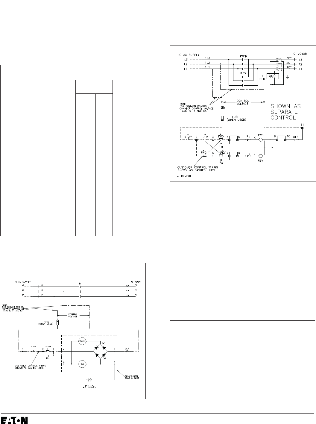
Fig. 7 Reversing Control Circuit
TABLE IV - MINIMUM CLEARANCES
System Voltage Minimum Clearence
Maintain minimum clearance between live parts
and grounded parts and between live parts of opposite
polarity.
Not greater than 600 volts .375 inches
Not greater than 1000 volts .550 inches
Not greater than 1500 volts .700 inches
Fig. 6 Connection Diagram, V201
V201, V211, V251, 320 AMPERE VACUUM CONTACTOR I.L. 16999
6713C39

5
MECHANICAL INTERLOCKS
Mechanical interlocks are used when a pair of con-
tactors must be mechanically protected against the clos-
ing of one when the other is already closed. For the
horizontal configuration, the Type M33-5 is used. For
the vertical configuration, the M36-2 is used. Both
mechanical interlocks occupy one recess in each con-
tactor.
GENERAL
The V201 contactor has its main contacts sealed inside
ceramic tubes from which all air has been evacuated, i.e.,
the contacts are in vacuum. No arcboxes are required,
because any arc formed between opening contacts in a
vacuum has no ionized air to sustain it. The arc simply
stops when the current goes through zero as it alternates
at line frequency. The arc usually does not survive beyond
the first half cycle after the contacts begin to separate. The
ceramic tube with the moving and stationary contacts
enclosed is called a vacuum interrupter or a bottle,
and there is one such bottle for each pole of the con-
tactor. A two-pole contactor has two vacuum bottle, and a
three-pole contactor has three vacuum bottles. A metal
bellows (like a small, circular accordion) allows
the moving contact to be closed and pulled open from
the outside without letting air into the vacuum cham-
ber of the bottle. Both the bellows and the metal-to-
ceramic seals of modern bottles have been improved
to the point that loss of vacuum is no longer cause for
undue concern.
The moving contacts are driven by a molded plastic
crossbar supported by two pre-lubricated ball bearings
that are clamped in alignment for long life and free
motion.
The contacts in an unmounted bottle (vacuum inter-
rupter) are normally-closed, because the outside air
pressure pushes against the flexible bellows. For con-
tactor duty, the contact must be normally-open when
the operating magnet is not energized. Therefore, the
contacts of the vacuum bottles must be held apart
mechanically against the air pressure when used in a
contactor. In the contactor, all of the bottles are held
open by a single kickout spring in the rear of the con-
tactor. The kickout spring pulls against the moving
armature and crossbar and thereby forces the bottles
into the open position. In the open position, the cross-
bar is pulling the moving contacts to hold them open.
The contactor is intended to be mounted with its
mounting plate vertical and the moving stem of the
vacuum bottles aimed down. However, mounting posi-
tion is not critical. If an unusual position is required, it
is wise to check the pick-up voltage on a bench before
installation, with the contactor oriented as it will ulti-
mately be installed. The kickout spring can be adjusted
as described under Kickout Spring Adjustment, if
required to obtain the correct pick-up voltage.
CONTACT FORCE AND ALTITUDE
A vacuum contactor is affected by atmospheric
pressure on the bellows of the vacuum bottle. Up to
an altitude of 3300 feet, the contactor is designed to
tolerate normal variations in barometric pressure. If the
contactor is to be operated over 3300 feet above sea
level, consult the factory.
CONTACT WEAR ALLOWANCE
Contact material vaporizes from the contact faces
during every interruption and condenses inside the
bottle. This is normal, and is provided for by overtravel,
or wear allowance. When the contactor is fully closed,
there is a gap between the pivot plate and the bottle
nuts. See Figure 9. As the contacts wear, this gap
decreases. When any gap goes below .020 in., the unit
should be replaced. Use the .020 in. thick fork-shaped
overtravel gauge supplied for this measurement. Part
No. 7874A59H01.
CAUTION: The easiest way to close the contactor
is to energize the coil. If the coil is energized for this
or other maintenance, use adequate care to guard
against electrical shock.
Do not re-adjust the bottle nuts to reset overtravel
as the bottles wear. Once placed in service, over-
travel should be checked but not adjusted. A star-wheel
lock is included for locking the bottle nuts of each bot-
tle to prevent tampering.
CHECK-OUT, VACUUM INTERRUPTERS
The dielectric strength of the interrupters should be
checked before the contactor is energized for the first
time and regularly thereafter to detect any deterioration
in the dielectric strength of the contact gap. A good
interrupter will withstand a 5.5KV, 50 or 60 hertz test
voltage for one minute across a 0.090 inch contact gap,
which is the normal new gap.
When a vacuum bottle is tested with voltage over
5000 volts across its open gap, there is some possibi-
lity of generating X-rays. Test time should be minimized
and personnel should not be closer than 10 feet. This
is a precaution until such time as the possible hazard
is better understood and standards are published.
Periodic dielectric tests across open contacts are
desirable since under certain operating conditions the
contactor may perform satisfactorily even though one
vacuum interrupter becomes defective. Dielectric tests
should be made with the contactor in the same posi-
tion it has when operating.
The interval between periodic tests depends on the
number of operations per day, environmental factors,
and experience. It is a matter of operator judgment,
and philosophy of preventative maintenance.
V201, V211, V251, 320 AMPERE VACUUM CONTACTOR I.L. 16999
6
CHECK-OUT, MECHANICAL
Make sure all power circuits are de-energized and iso-
lated. The controller can be checked in its cabinet or
outside. A mechanical interlock must be checked installed,
to make certain that it functions properly.
If the contactor is checked in its cabinet, make cer-
tain that the contactor coil is electrically isolated, to pre-
vent feedback into a control transformer that could be
hazardous.
Connect a separate power source of correct AC volt-
age to the coil of the contactor. Operate appropriate
pushbuttons to close and open the contactor. If the con-
tactor does not close fully or does not drop out fully
refer to Magnet Operating Range.
While the contactor is closed, observe the overtravel
gap between the pivot plates on the crossbar and the
bottle nut on each pole. This overtravel gap should be
not less than .045 inch when the contactor is new. If less
refer to Contact Wear Allowance. Disconnect separate
power source before proceeding.
While the contactor is open, attempt to pull the arma-
ture forward. The armature should not move because
it should already be firmly against the plastic main
frame. If it does move refer to Kickout Spring Adjustment.
CHECK-OUT, INSULATION LEVEL
After installation, and before energizing the contactor
for the first time, measure and record the insulation
resistance between poles and from each pole to ground.
It is not practical to specify an absolute value for this
reading since it is dependent on other connected
apparatus, and conditions of service. However, any
unusually low reading or sudden reduction in this read-
ing after the contactor has been in service indicates a
possible source of trouble, and the cause should be
determined and corrected before restoring power.
MAINTENANCE
Establish a maintenance program as soon as the con-
tactor is installed and put into operation. After the con-
tactor has been inspected a number of times at monthly
intervals, and the condition noted, the frequency of
inspections can be increased or decreased to suit the
conditions found, depending upon the severity of the
contactor duty. It is a matter of operator judgment.
This industrial type control is designed to be installed,
operated, and maintained by adequately trained work-
men. These instructions do not cover all details, varia-
tions, or combinations of the equipment, its storage,
delivery, installation, check-out, safe operation, or main-
tenance. Care must be exercised to comply with local,
state, and national regulations, as well as safety prac-
tices, for this class of equipment.
All work on this controller should be done with the
main circuit disconnect device open. Also, disconnect
power from any other external circuits. Discharge any
hazardous capacitors.
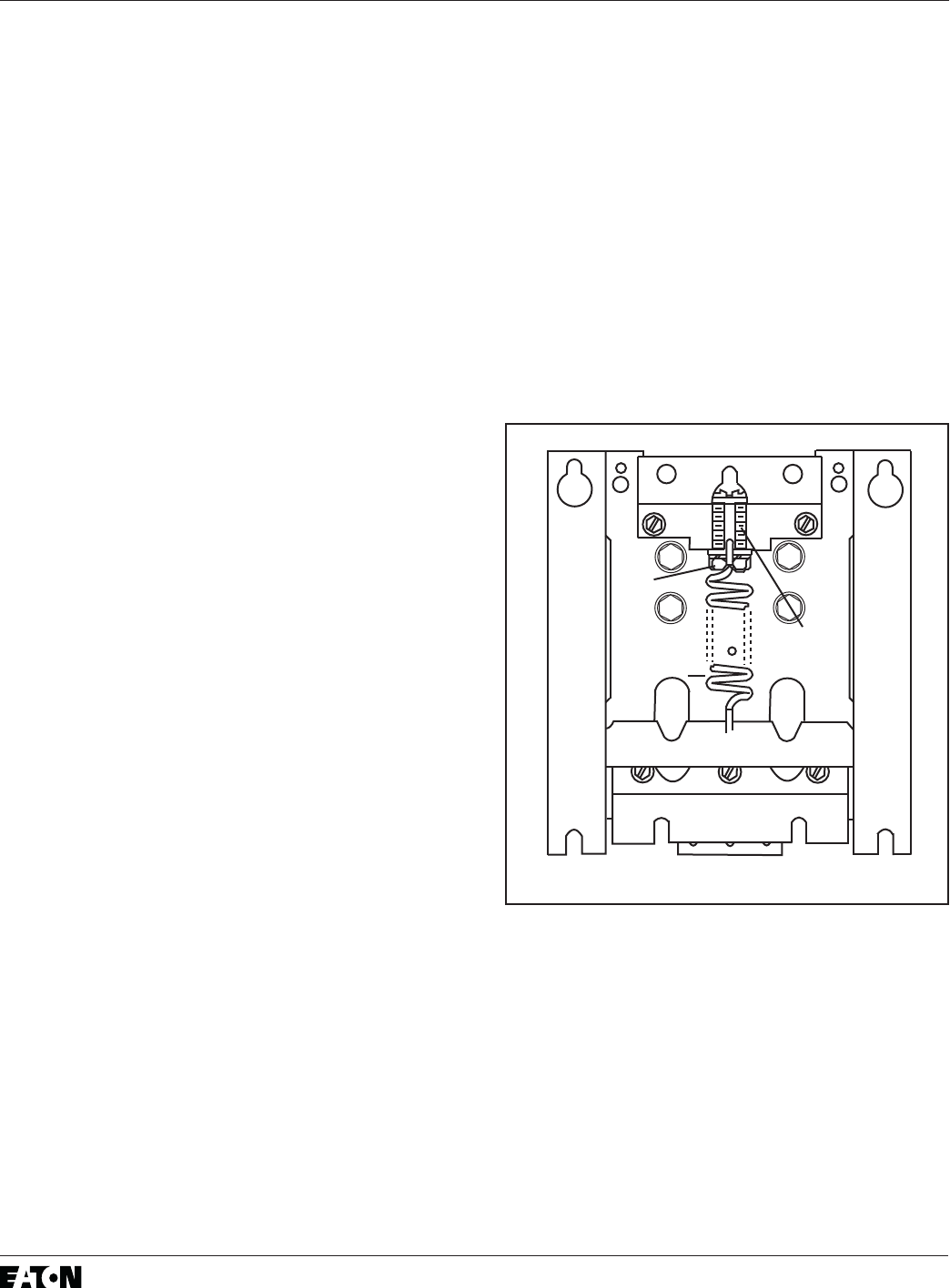
Kickout Spring Adjustment
The kickout spring is not disturbed by any maintenance
described in this leaflet, and it should not need to be adjusted.
However, when the contactor is in the de-energized, open
position, the crossbar should be solidly against the frame,
so that it cannot move any further open even when pulled.
It can moved, the kickout spring must be stretched to hold
the crossbar firmly against the frame. Refer to figure 8.
Loosen the lock nuts and tighten the adjusting screws
alternately (to keep the spring on centerline) until the force
from the spring holds the crossbar properly open. Lock the
two lock nuts again.
LOSS OF VACUUM
Gross loss of vacuum is highly unlikely, but it can be
checked easily. With the contactor open, pull downward
V201, V211, V251, 320 AMPERE VACUUM CONTACTOR I.L. 16999
Kickout
Spring
Lock
Nuts
Adjusting
Screws
Fig. 8 Kickout Spring

7
on the bottle nuts, one pole at a time, using an effort
of about 20 pounds. If the bottle nuts (see Figure 9)
move easily away from their pivot, the vacuum has
probably failed and the bottle must be replaced.
It is also unlikely, but possible, to have a very slight
leak that does not change the bottle force appreciably,
but which might seriously damage the ability of the bot-
tle to interrupt. In this regard, it must be remembered
that in a three-phase ungrounded circuit, it is possible
for any two good interrupters to successfully interrupt
the circuit even if the third interrupter is weak. But this
condition should not be allowed to continue. It can be
detected only by an electrical test. See Check-out
Vacuum Interrupters.
WARNING: All work on this contactor should be
done with the main disconnect device open. As with
any contactor, there is danger of electrocution
and/or severe burns. Make certain that the power is off.
Changing Operating Coil
The operating coil has a pickup winding which is
intermittently rated. It may burn out in only minutes if
continuously energized at rated voltage because the L63
auxiliary contact does not open correctly.
The coil contains its own rectifier to convert the applied
AC into unfiltered full-wave rectified DC. DC
coils do not contain a rectifier. When the coil is at rated
voltage, the magnet will be silent. At reduced AC volt-
age, some slight hum may be heard. However the mag-
net must not chatter.
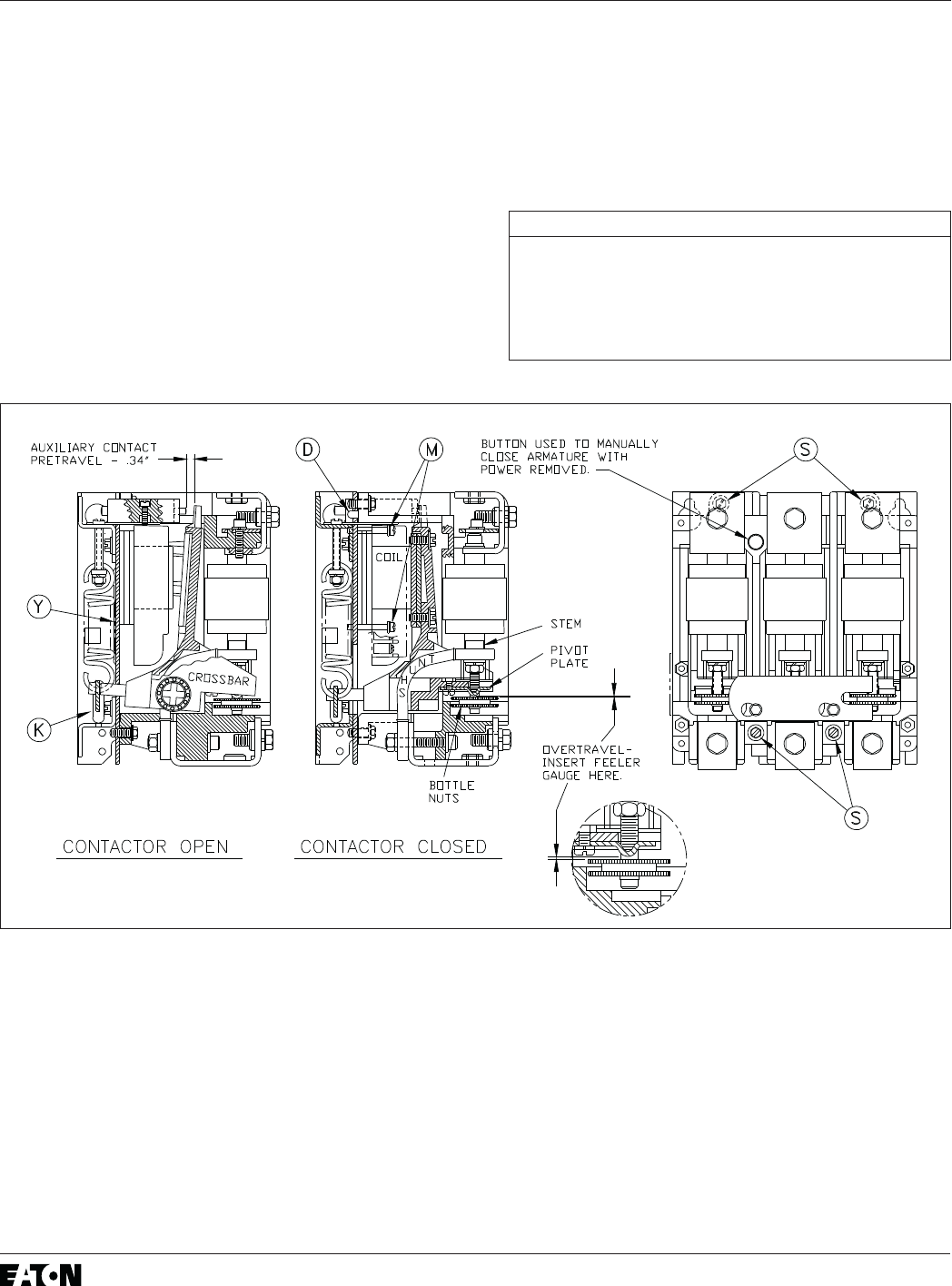
If for some reason a coil must be changed, proceed
as outlined below, referring to Figure 9.
1. De-energize all circuits as previously specified.
2. Disconnect the leads to the coil terminals, noting
their position for later reconnecting.
3. Disconnect the line and the load leads from the
contactor terminals.
4. Remove four ¼ x 20 screws (S) holding the frame
subassembly to the mounting base.
5. Lift the line side of the frame subassembly away
from the mounting base until two dowels (D) are
clear of their holes. The frame subassembly will
automatically move under pressure from the kick-
out system until the kickout bar reaches the end
of its slots in the mounting base. The frame sub-
assembly is then free to be moved outward away
from the coil and put elsewhere.
6. The coil is then accessible. Remove the two mount-
ing screws (M) to free the coil.
7. Install replacement coil and replace mounting
screws.
8. Place the frame subassembly onto the mounting
base so that the two posts extending from the
crossbar go through the oblong slots in the base
and into the notches in the kickout bar. Push the
frame subassembly a short distance along the sur-
face of the mounting plate toward the kickout bar
until the dowels (D) slip into the dowel holes.
Replace the mounting screws (S). Make sure
that the coil leads to the L63 auxiliary contact
are not pinched under the frame feet.
9. Reconnect coil and recheck contactor for correct
adjustment per this leaflet. By hand jiggle the ends
of the kickout bar(K) to make sure it is seated onto
the posts of the crossbar.
10. Reconnect line and load cables.
Auxiliary Contact Adjustment
The nominal .34 pretravel gap shown for the L63
auxiliary contact (normally-closed) in the left upper por-
tion of Figure 9 is important. If the gap is too big, the
hold winding of the operator coil will not be inserted
as the contactor closes, and the pick-up winding will
burn out, because the pickup winding is only intermit-
tently rated. If the gap is too small, the hold winding
will be inserted too soon, reducing the force to hold
before the contactor is closed, and producing an oscil-
lation like a doorbell. In a particular contactor, the .34
gap may need slight adjustment to avoid these problems.
The key is not the measurement, but the perform-
ance of the magnet. Replacement L63 auxiliary
contacts are available as Part No. 578D461G03.
The Type J auxiliary contacts are not as critical. In
the open position, their plungers may rest lightly against
the operating arm, or may have a small clearance.
However, neither of the auxiliary contact plungers
should bottom solidly in the closed contactor position, as
discussed under Magnet Operating Range. If required,
the auxiliaries can be adjusted by resetting their mounting
brackets in their slotted holes. Adjust the L63 by loosening
the two slotted hexagonal washer head screws the hold
the L63 mounting bracket, repositioning and tightening.
These bracket mounting screws are accessible from the
top side of the contactor and are recognized by the slotted
holes under their heads.
Inspection After Short Circuit
The V201 contactor is intended to be protected by power
fuses and/or a circuit breaker in accordance
with the National Electrical Code (NEC). However, the
magnitude of a short circuit may exceed the damage
threshold of the vacuum bottles. After a short circuit, the
unit should be examined for any apparent physical damage,
or deformation of conductor bars and cables. If there is any
evidence of severe stress, it is recommended that the unit
be replaced. If the overtravel has changed significantly
(from the last inspection) on one or more bottles, the unit
should be replaced.
A dielectric test would not by itself confirm that the unit
should be returned to service after a fault. How-
ever, if there is no physical evidence of stress, and if
the overtravel exceeds the .020 in. minimum, the bot-
V201, V211, V251, 320 AMPERE VACUUM CONTACTOR I.L. 16999
8
TABLE V - RECOMMENDED DRIVING TORQUE
Driving
Torque
(lb.-in.)
Fig. 9
Item
Refer.
Coil Terminals (4)
Base Mouting Screws (4)
Coil Mounting Screws (2)
Location (Qty.)
7-9
60-65
10-15
-
S
M
Insulation Level
Refer to the insulation resistance measurements
between poles and from each pole to ground that were
recorded at start-up and subsequent intervals. Measure
the same points in the same manner and record. Inves-
tigate any sudden reduction in resistance or any unusually
low reading.
Dust and moisture are detrimental to electrical equip-
ment. Industrial equipment is designed to tolerate a
less-than-perfect environment. However, excessive dust
can cause trouble, and should be wiped or blown off
tles can then be dielectrically tested as outlined previ-
ously. If physical stress, overtravel, and dielectric are
O.K., it is reasonable to return the unit to service after a
fault.
at appropriate intervals. If the contactor is wet for any
reason, it must be dried until insulation resistance be-
tween poles and from each pole to ground has returned
to normal.
Effective 5/07
Supersedes 16999D (4/90)
Eaton Corporation
Electrical Components Division
875 Greentree Road
Pittsburgh, PA 15220
Printed in USA
V201, V211, V251, 320 AMPERE VACUUM CONTACTOR I.L. 16999
