TB01600004E 1000482919 Catalog
1000466097-Catalog 1000466097-Catalog 1000466097-Catalog B5 unilog cesco-content
2016-10-06
: Pdf 1000482919-Catalog 1000482919-Catalog B5 unilog
Open the PDF directly: View PDF ![]() .
.
Page Count: 146 [warning: Documents this large are best viewed by clicking the View PDF Link!]
CA08104001E For more information, visit:
www.eaton.com/consultants
September 2011
Contents
Uninterruptible Power Supplies 33.0-1
Sheet
33
22
23
24
25
26
27
28
29
30
31
32
33
34
35
36
37
38
39
40
41
42
43
001
Uninterruptible
Power Supplies
Uninterruptible Power Supplies
General Introduction . . . . . . . . . . . . . . . . . . . . . . . . . . . . . . . . . . . . . . . . . 33.1-1
Product Overview . . . . . . . . . . . . . . . . . . . . . . . . . . . . . . . . . . . . . . . . .
33.1-1
All UPS Product Models . . . . . . . . . . . . . . . . . . . . . . . . . . . . . . . . . . . .
33.1-1
Three-Phase Units . . . . . . . . . . . . . . . . . . . . . . . . . . . . . . . . . . . . . . . . . . . 33.2-1
Eaton 9355 (10–30 kVA). . . . . . . . . . . . . . . . . . . . . . . . . . . . . . . . . . . . .
33.2-1
Eaton 9390 (40–80 kVA). . . . . . . . . . . . . . . . . . . . . . . . . . . . . . . . . . . . .
33.2-11
Large Three-Phase Unit—Eaton 9395
(225–1100 kVA)
. . . . . . . . . . . . . . 33.3-1
General Information/Features . . . . . . . . . . . . . . . . . . . . . . . . . . . . . . .
33.3-1
System Layouts. . . . . . . . . . . . . . . . . . . . . . . . . . . . . . . . . . . . . . . . . . .
33.3-3
Automatic Hot-Tie System . . . . . . . . . . . . . . . . . . . . . . . . . . . . . . . . . .
33.3-4
Layout Diagrams . . . . . . . . . . . . . . . . . . . . . . . . . . . . . . . . . . . . . . . . . .
33.3-9
Software and Connectivity Solutions . . . . . . . . . . . . . . . . . . . . . . . . . . . 33.4-1
Power Distribution Unit . . . . . . . . . . . . . . . . . . . . . . . . . . . . . . . . . . . . . . 33.5-1
General Information/Features . . . . . . . . . . . . . . . . . . . . . . . . . . . . . . .
33.5-1
Technical Data . . . . . . . . . . . . . . . . . . . . . . . . . . . . . . . . . . . . . . . . . . . .
33.5-2
Layouts and Dimensions . . . . . . . . . . . . . . . . . . . . . . . . . . . . . . . . . . .
33.5-5
Remote Power Panel . . . . . . . . . . . . . . . . . . . . . . . . . . . . . . . . . . . . . . . . . 33.5-40
General Information/Features . . . . . . . . . . . . . . . . . . . . . . . . . . . . . . .
33.5-40
Technical Data . . . . . . . . . . . . . . . . . . . . . . . . . . . . . . . . . . . . . . . . . . . .
33.5-40
Layouts and Dimensions . . . . . . . . . . . . . . . . . . . . . . . . . . . . . . . . . . .
33.5-43
Glossary . . . . . . . . . . . . . . . . . . . . . . . . . . . . . . . . . . . . . . . . . . . . . . . . . . . 33.6-1
Eaton’s Uninterruptible Power Supplies

33.0-2
For more information, visit:
www.eaton.com/consultants
CA08104001E
September 2011
Uninterruptible Power Supplies
Sheet
33
22
23
24
25
26
27
28
29
30
31
32
33
34
35
36
37
38
39
40
41
42
43
002
This page intentionally left blank.
CA08104001E For more information, visit:
www.eaton.com/consultants
33.1-1
September 2011
Uninterruptible Power Systems
Sheet
33
22
23
24
25
26
27
28
29
30
31
32
33
34
35
36
37
38
39
40
41
42
43
General Introduction
Product Overview
003
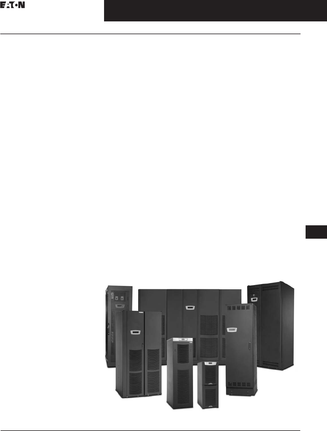
Product Overview
Eaton’s power quality portfolio encom-
passes a comprehensive offering of
power management solutions from a
single-source provider. This includes
UPSs, surge protective devices, power
distribution units (PDUs), remote
monitoring, meters, software,
connectivity, enclosures and services.
Our power quality portfolio was
designed to fulfill specific customer
requirements, to complement a new or
pre-existing solution, and to deliver a
comprehensive solution. With all our
products, Eaton strives for continued
success in leveraging technical
innovation to develop next-generation
solutions. The products and services
listed below are just a sampling of
our comprehensive solution set.
To view the complete offering or to
request a product catalog, please visit
www.eaton.com/powerquality.
PC/Workstation and
Home A/V UPS
Power Range: 500–1500 VA
These Eaton UPSs provide the perfect
level of protection for small office/
home office (SOHO) applications.
These essential, cost-effective prod-
ucts prevent damage such as data
loss, file corruption, flickering lights,
hardware damage and equipment
shutoff, and they are most commonly
used to protect single workstations,
telephone systems and point-of-sale
(POS) equipment.
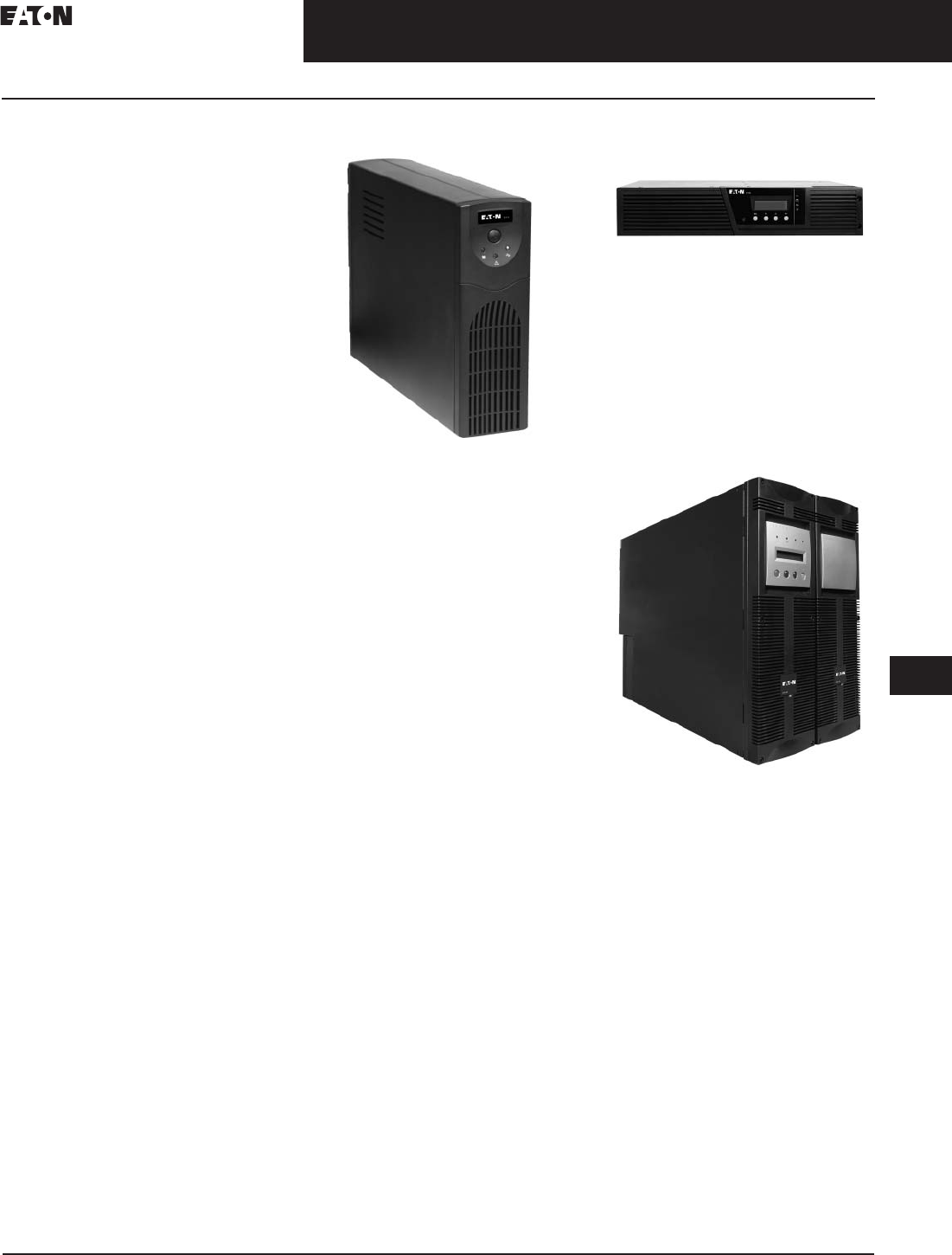
Eaton 5110, 500–1500 VA
Eaton 5110, 500–1500 VA
Eaton’s 5110 UPS provides cost-
effective, line-interactive backup
power and voltage regulation. With its
compact form factor, the 5110 can be
used as a standalone tower or under
a computer monitor. This UPS is also
equipped with eight outlets—four with
surge suppression and battery backup
and four with surge suppression only.
Network and Server UPS
Power Range: 500–18,000 VA
Eaton offers an extensive and
innovative line of network and server
UPS solutions to protect rack servers,
data storage, storage systems, VoIP
equipment, network equipment and
other critical devices. Get industry-
leading power protection with the
highest efficiency for increased energy
savings in optimized rack, tower and
rack/tower form factors.
Eaton 9130, 700–3000 VA,
Rack and Tower
Eaton 9130, 700–3000 VA, Rack and Tower
The 9130 delivers more real power
with a 0.9 power factor and offers a
high efficiency mode, performing at
a remarkable 95% efficiency or higher.
This UPS delivers superior power
protection for IT and networking
environments, medical and manufac-
turing systems.
Eaton EX RT, 5–11 kVA,
Rackmount/Tower
Eaton EX RT, 5–11 kVA, Rackmount/Tower
Ideal for high-density server
environments and harsh industrial
applications, the Eaton EX RT UPS
is specifically engineered to meet
the high-availability demands of
customers with switches, IT systems,
measuring instruments, PLCs,
industrial PCs and other sensitive
electronic equipment.
33.1-2
For more information, visit:
www.eaton.com/consultants
CA08104001E
September 2011
Uninterruptible Power Systems
Sheet
33
22
23
24
25
26
27
28
29
30
31
32
33
34
35
36
37
38
39
40
41
42
43
General Introduction
Product Overview
004
Data Center and Facility UPS
Power Range: 10–1100 kVA
Featuring an array of inventive
features, Eaton’s data center and
facility UPS solutions incorporate
the design elements essential to
protecting the most critical of
applications. These groundbreaking
solutions address current and future
power protection requirements,
featuring scalable architecture that
grows with you to manage changing
needs with the highest levels of
efficiency and reliability. And, with
Eaton’s Energy Saver System
technology, an Eaton UPS can run
at 99% efficiency, the energy savings
from which usually recover the total
cost of the UPS in 3–5 years.
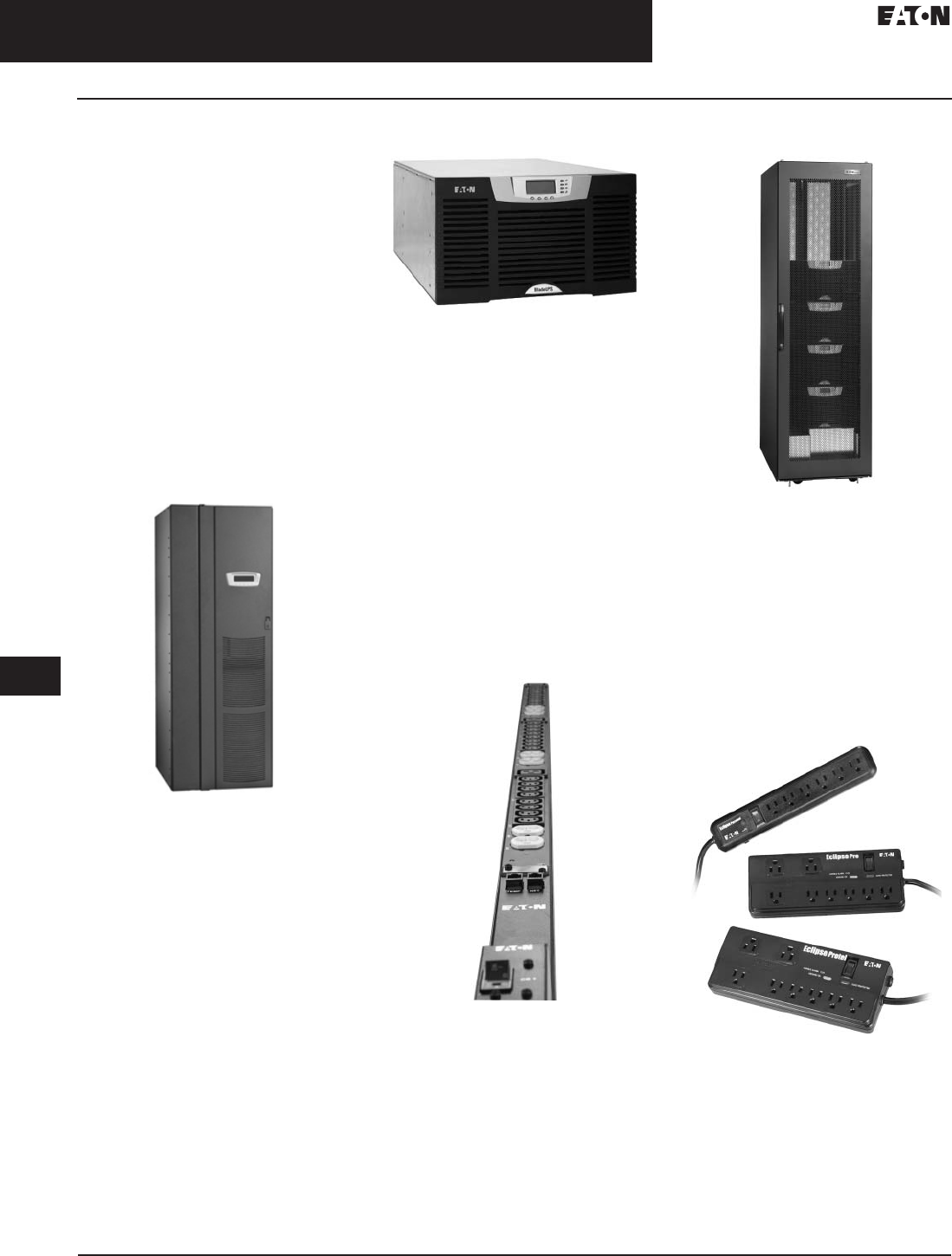
Eaton 9390, 20–160 kVA
Eaton 9390, 20–160 kVA
The 9390 UPS provides a high-end
power-quality solution for data
centers, banks and other critical
computing applications.
Eaton BladeUPS, 12–60 kW
Eaton BladeUPS, 12–60 kW
The scalable and modular BladeUPS
expands power protection up to 60 kW
in a single 19-inch rack while reducing
energy and cooling costs with its
energy-efficient UPS design. The
BladeUPS packs 12 kW of power
into only 6U of rack space.
Power Distribution
Eaton’s power distribution solutions
are designed to help you save money,
prevent downtime and use energy
more efficiently. Our comprehensive
portfolio includes enclosures, rack-
mount UPSs, ePDUs (rackmount
power distribution units) and a host
of other power-quality equipment.
ePDU
ePDU
Eaton’s line ePDU products distribute
1.4 to 15 kW of power and offer five
levels of functionality. From basic,
economical power distribution to
automatic transfer switch capabilities,
Eaton ePDU products satisfy demands
of every data center.
Eaton Enclosures
Eaton Enclosures
Designed specifically for IT
applications, this 42U modern
enclosure offers strength, stability
and a vendor-neutral environment
to house any IT equipment.
The enclosure is complemented with a
range of cable management, cooling
and power distribution accessories to
enable you to tailor your enclosures to
your specific application.
Surge Suppressors
Surge Suppressors
Eaton’s Eclipse surge suppressors
offer the best price/performance
ratio for home office and small
office users looking for a convenient
way to combine multiple receptacles
and excellent surge suppression
capabilities.General Introduction
CA08104001E For more information, visit:
www.eaton.com/consultants
33.1-3
September 2011
Uninterruptible Power Systems
Sheet
33
22
23
24
25
26
27
28
29
30
31
32
33
34
35
36
37
38
39
40
41
42
43
General Introduction
Product Overview
005
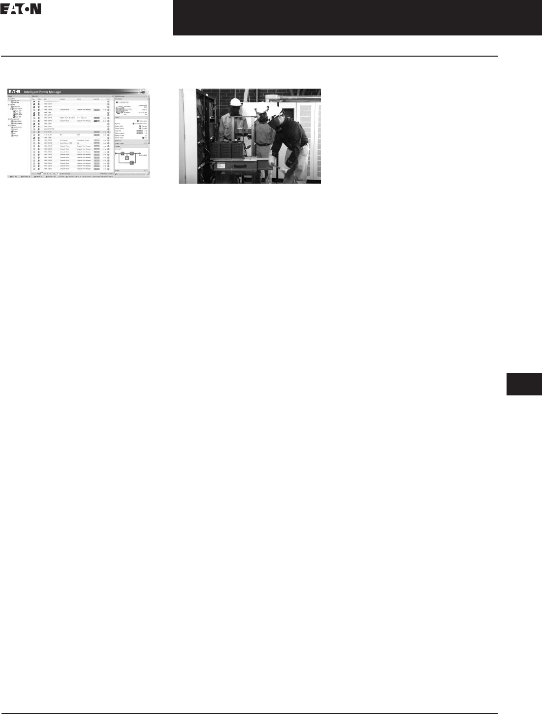
Software and Connectivity
Software and Connectivity
Eaton’s software products deliver
the ability to manage all your power
devices over your network or the Web,
from one or more PCs. With both
supervisory and protection capability,
our software allows you to monitor
your power devices and even grace-
fully shut them down in the event of
an extended power outage.
Eaton’s connectivity products are
accessory hardware options that link
Eaton UPS, PDU and RPP products
with external power and communica-
tion devices. Our connectivity prod-
ucts provide communication
compatibility with a variety of external
devices through the Web, serial, relays
or SNMP.
Eaton Services
Eaton Services
Eaton’s comprehensive, world-class
service solutions for our AC, DC,
software and connectivity products
are designed to improve costs, uptime,
reliability, power quality and safety.
We are consistently ranked No. 1
in quality and demonstrate our
commitment to strong customer
relationships through our technical
expertise and expansive support
services. With 240 customer field
technicians in North America and
1200 international authorized service
providers, we have more service
personnel than any other UPS
manufacturer. Eaton also provides
extended warranties.

33.1-4
For more information, visit:
www.eaton.com/consultants
CA08104001E
September 2011
Uninterruptible Power Systems
Sheet
33
22
23
24
25
26
27
28
29
30
31
32
33
34
35
36
37
38
39
40
41
42
43
006
This page intentionally left blank.
CA08104001E For more information, visit:
www.eaton.com/consultants
33.2-1
September 2011
Uninterruptible Power Supplies
Sheet
33
22
23
24
25
26
27
28
29
30
31
32
33
34
35
36
37
38
39
40
41
42
43
Three-Phase Units
Eaton 9355
007
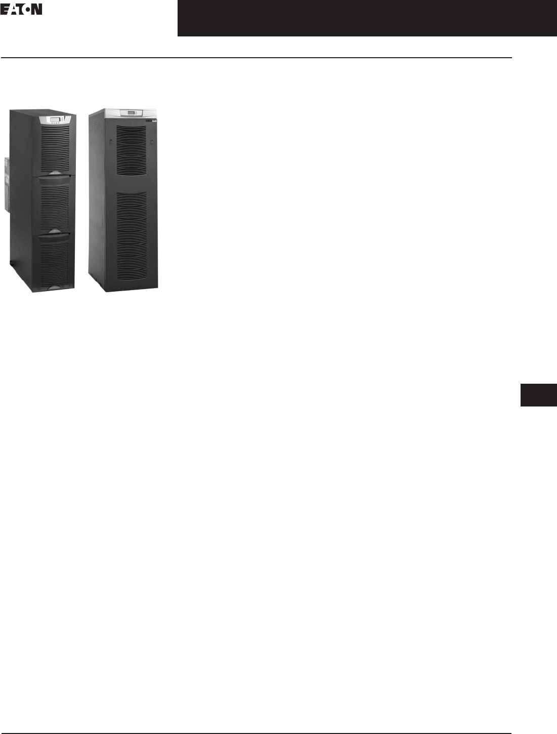
Eaton 9355 Uninterruptible
Power System
General Description
9355 10–15 kVA
Eaton’s 9355 10–15 kVA UPS provides
full-featured, efficient power protec-
tion in a compact tower about half the
size of most competitor units on the
market today—and is exceptionally
easy to install and manage.
9355 20–30 kVA
Eaton’s 9355 20–30 kVA UPS provides
full-featured, efficient power protec-
tion in a compact tower. The product
is exceptionally easy to install and
manage, and the paralleling capability
is unmatched in the industry.
Features and Benefits
■
Protects connected equipment
from all nine of the most common
power anomalies
■
Provides more real wattage in less
space with a 0.9 power factor—
protecting more equipment and
leaving more room for expansion
■
System efficiency up to 91%—
minimizes cost of ownership
■
Supports Eaton Hot Sync paralleling
of multiple modules for redundancy
or extra capacity
■
Increases battery life through
proven ABM
®
‚ a microprocessor-
controlled advanced battery
management technology
■
Provides 0.99 power factor and
generator friendly <5% total
harmonic distortion using an
active IGBT rectifier to control
the input power factor
■
Ensures data and system integrity
with complete power management
software for remote monitoring,
management and shutdown—
over the network and the Internet
With advances in miniaturization and
processing power, a single rack of
equipment demands more power than
ever—and more equipment will be
served by dual cord power supplies.
It’s a challenge to provide power
protection for expanding loads in
shrinking spaces.
Fortunately, technology advancements
have also raised the density per
square foot of power protection
systems. The Eaton 9155 and Eaton
9355 uninterruptible power systems
(UPSs) deliver premium levels of
efficiency, reliability and flexibility—
all in a sleek tower half the size of most
competitor units on the market today.
This double-conversion, online UPSs
resolve all nine common utility power
problems and supply clean, continu-
ous power to all connected equipment.
Even when presented with the most
severe power problems, power output
remains stable. And if the utility power
goes out altogether, there is no delay
transferring to backup power.
These capabilities make the
Eaton 9155 and Eaton 9355 ideal
for protecting essential data center,
communications and electrical
engineering infrastructures in
corporate, telecom, healthcare,
banking, public sector and industrial
applications—even marine environ-
ments, with special engineering.
Premium power protection is now
easier than ever.
With raised-floor real estate at a
premium, you will appreciate that
these UPSs are only 12 inches
(304.8 mm) wide and 33 inches
(838.2 mm) deep, including internal
batteries. With such a small footprint,
you have more location options, and
more space is available for future
expansion. Equipment installation is
easy, essentially plug-and-play. You
can order either UPS with your choice
of output receptacles with more than
17 types. To change or move data
center equipment, you simply unplug
from the old receptacle, plug into
a new one, and go. No need for an
electrician to run new conduit
and wiring.
kVA UPS, for example, can grow to
support loads of up to 45 kVA. There’s
no dependence on communications
wiring among those UPS modules.
Battery innovations optimize battery
performance and service life.
Standard internal batteries provide
power until auxiliary power takes over
or systems are gracefully shut down.
Battery run time can be extended to
hours by adding matching Extended
Battery Modules.
Eaton 9155 and Eaton 9355 UPSs also
use sophisticated technologies that
maximize the health and service life
of batteries:
■
ABM technology uses a unique
three-stage charging technique
that significantly extends battery
service life and optimizes recharge
time, compared to traditional
trickle charging
■
Temperature-compensated charging
monitors battery temperature and
adjusts the charge rate accordingly,
which properly charges the battery
and greatly extends battery life
■
An integrated battery management
system tests and monitors battery
health and remaining lifetime, and
provides advance notification to
guide preventive maintenance
Unlike heavy, old-style batteries,
Eaton’s are easily field-replaceable.
One person, working alone, can
replace a battery without disrupting
data center operations or power to
protected equipment.
Advanced design delivers unequaled
power performance.
The innovative design of these
UPSs deliver the industry’s best
performance combination of
efficiency, input current distortion,
input power factor and output
power factor.
Lower costs, lower temperatures.
High efficiency (greater than 90%
across all load ranges) reduces utility
costs, extends battery run times and
produces cooler operating conditions.
Generator-friendly design.
Total input harmonic distortion
(THD) remains below 5% without
compromising overall efficiency. The
result is maximum transfer of power
between source and protected load,
and exceptional compatibility with
auxiliary generators.
10–15 kVA 20–30 kVA
33.2-2
For more information, visit:
www.eaton.com/consultants
CA08104001E
September 2011
Uninterruptible Power Supplies
Sheet
33
22
23
24
25
26
27
28
29
30
31
32
33
34
35
36
37
38
39
40
41
42
43
Three-Phase Units
Eaton 9355
008
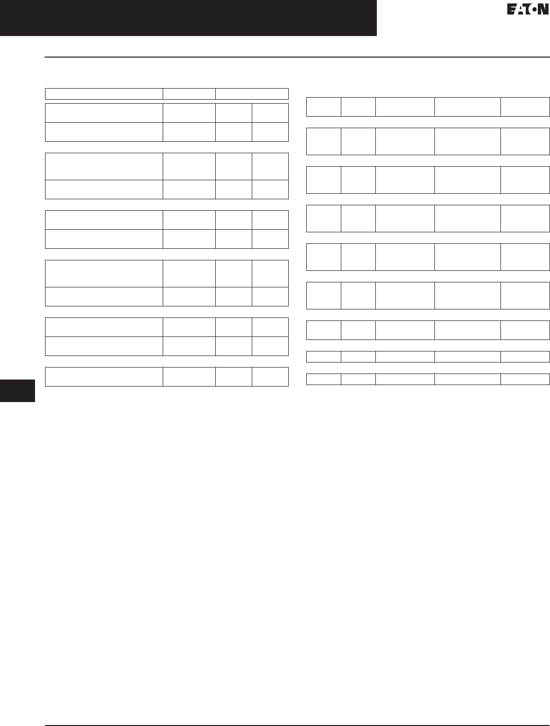
Table 33.2-1. Eaton 9355 Backup Times (In Minutes)
While protecting critical systems, the
UPS itself is protected in several ways:
Self-Diagnosis
■
The UPS constantly monitors its
own operation, such as voltage,
temperature or function of internal
elements—and sends alarms or
takes action if it detects a potential
problem. You’ll know your UPS is
always performing up to specifica-
tions to protect your equipment
Self-Correction
■
If the UPS senses an issue—planned
or unplanned—it instantly transfers
the power path to a bypass source,
with zero interruption in power.
When the alarm condition passes,
the UPS automatically reverts from
bypass to normal operation
Remote Monitoring
■
You can have Eaton specialists
securely monitor your Eaton 9155 and
Eaton 9355 UPSs around the clock with
eNotify service, or you can monitor
your own UPSs over your LAN or the
Internet. Either way, you’ll always be
informed about conditions in your
power protection infrastructure
Redundancy
■
Using Eaton Hot Sync technology,
you can configure up to N+3
redundancy. Any module can
serve as backup for any other,
with no interruption or downtime.
For instance, you could perform full
maintenance on any UPS without
having to remove any loads from
conditioned power
■
Most other paralleling systems
on the market use a top-down
configuration; if the master fails,
the subsidiary units fail. With
Eaton’s approach, each UPS module
is independent yet synchronized
with the others. There is no single
point of failure
The following options for the Eaton 9355
are available:
Remote Monitor Panel (RMP)
■
The optional RMP provides monitor-
ing of the operational status and
alarm condition of the UPS from
virtually any location within the
facility. You can install multiple RMPs
at remote locations to increase your
monitoring capabilities
Power Distribution Module (PDM—
Available on 10–15 kVA models only)
■
The optional PDM comes
equipped with several different
types of output receptacles
Parallel Tie Cabinet
■
A parallel system with up to four
UPSs can be installed to provide a
parallel capacity and/or redundant
system. This load sharing system
provides more capacity than a
single UPS and can provide backup,
depending on the load and configu-
ration. In addition, when one UPS is
taken out of service for maintenance
or is not operating properly, a
redundant UPS continues to supply
uninterrupted power to the critical
load. A parallel Eaton Hot Sync
Computer Area Network (CAN)
Bridge Card provides connectivity
for system metering and operational
mode control. The parallel system
consists of two to four UPSs, each
with a parallel CAN Bridge Card and
a parallel tie cabinet
Wall-Mounted Bypass Switch
■
The optional wall-mounted bypass
switch is used to bypass the UPS
during maintenance or servicing
providing wrap-around bypass for
UPS service without shutting down
the load
Input Isolation Transformer
■
The optional input isolation
transformer allows operation from
a 480V or 600V 60 Hz source
Seismic Kit (Available on 20–30 kVA UPS
and Auxiliary Cabinets Only)
■
The seismic kit secures the
UPS and optional EBMs for
seismic installations
VA Watt UPS (1) (2) (3) (4) UPS (1) (2) (3)
+Internal EBM EBM EBM EBM +Internal EBM EBM EBM
32 Battery 64 64 64 64 64 Battery 96 96 96
15,000
14,500
14,000
13,500
13,050
12,600
4.6
4.9
5.2
23.0
24.1
25.2
43.0
45.2
47.3
65.1
68.3
71.5
88.6
93.0
97.4
13.3
14.1
14.9
43.0
45.2
47.3
76.7
80.5
84.2
113.0
119.0
125.0
13,500
13,000
12,500
12,150
11,700
11,250
5.5
5.8
6.1
26.4
27.6
28.8
49.4
51.6
54.0
74.7
78.1
81.6
102.0
106.0
111.0
15.8
16.7
17.6
49.4
51.6
54.0
88.1
92.0
96.2
130.0
136.0
142.0
12,000
11,500
11,000
10,800
10,350
9900
6.5
6.9
7.3
30.2
31.6
33.3
56.5
59.3
62.4
85.5
89.7
94.4
116.0
122.0
129.0
18.6
19.2
20.2
56.5
59.3
62.4
101.0
106.0
111.0
149.0
156.0
164.0
10,500
10,000
9500
9450
9000
8550
7.8
8.4
9.1
35.1
37.2
39.6
65.9
69.8
74.2
99.6
106.0
112.0
136.0
144.0
153.0
21.4
22.6
24.1
65.9
69.8
74.2
117.0
124.0
132.0
174.0
184.0
196.0
9000
8500
8000
8100
7650
7200
9.9
10.8
11.9
42.3
45.5
49.1
79.4
85.2
91.9
120.0
129.0
139.0
163.0
175.0
189.0
25.7
27.6
29.8
79.4
79.4
91.9
141.0
152.0
164.0
209.0
225.0
242.0
7500
7000
6500
6750
6300
5850
13.1
14.6
16.3
53.2
58.0
63.5
99.7
109.0
119.0
151.0
164.0
180.0
205.0
224.0
245.0
32.3
35.2
38.6
99.7
109.0
119.0
178.0
194.0
212.0
263.0
286.0
314.0
6000
5500
5000
5400
4950
4500
18.4
20.1
22.4
70.0
77.6
86.6
131.0
145.0
162.0
198.0
220.0
245.0
270.0
300.0
334.0
42.5
47.2
52.6
131.0
145.0
162.0
234.0
259.0
289.0
346.0
383.0
428.0
4500
4000
3500
4050
3600
3150
25.2
28.6
32.8
97.4
110.0
127.0
182.0
207.0
238.0
276.0
313.0
359.0
376.0
426.0
—
59.2
67.1
77.0
182.0
207.0
238.0
325.0
369.0
423.0
—
—
—
3000
2500
2700
2250
38.3
45.6
148.0
176.0
277.0
329.0
418.0
—
—
—
89.7
107.0
277.0
329.0
—
—
—
—

CA08104001E For more information, visit:
www.eaton.com/consultants
33.2-3
September 2011
Uninterruptible Power Supplies
Sheet
33
22
23
24
25
26
27
28
29
30
31
32
33
34
35
36
37
38
39
40
41
42
43
Three-Phase Units
Eaton 9355
009
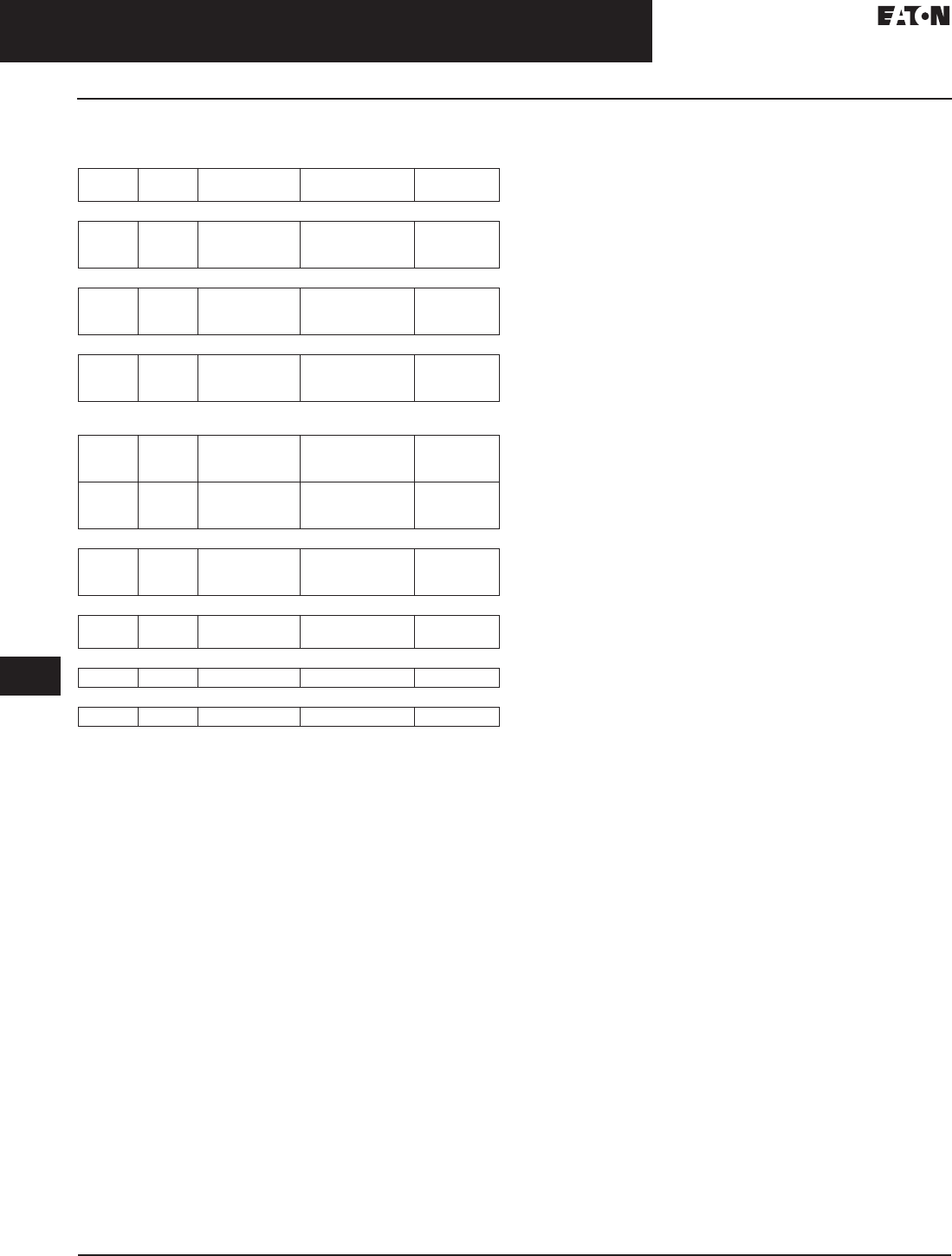
Table 33.2-2. Dimensions and Weights
Table 33.2-3. Accessories
Up to four EBM 64 cabinets or three EBM 96 cabinets can be added to each UPS for extended run time.
Table 33.2-4. Power Distribution Module (PDM) with Mechanical Bypass Switch
Maximum of eight panels per PDM.
The combined quantities of single-locking receptacle panels must not exceed five per PDM.
Description Dimensions in Inches (mm) Weight
Lbs (kg)
Height Width Depth
2-high UPS
3-high UPS-32
3-high UPS-64
32.20 (817.9)
47.80 (1214.1)
47.80 (1214.1)
12.00 (304.8)
12.00 (304.8)
12.00 (304.8)
33.50 (850.9)
33.50 (850.9)
33.50 (850.9)
381 (173)
587 (266)
619 (281)
2-high EBM
3-high EBM
32.20 (817.9)
47.80 (1214.1)
12.00 (304.8)
12.00 (304.8)
30.30 (769.6)
30.30 (769.6)
480 (218)
710 (322)
Description Dimensions in Inches (mm) Weight
Lbs (kg)
Order
Number
Height Width Depth
Extended Battery Modules
Eaton 9155 EBM 64 (2-high)
Eaton 9155 EBM 96 (3-high)
32.20 (817.9)
47.80 (1214.1)
12.00 (304.8)
12.00 (304.8)
30.20 (767.1)
30.20 (767.1)
484 (220)
720 (327)
103004192
103004193
Maintenance Bypass Module
Rear UPS-mount, maintenance
bypass module
16.50 (419.1) 12.00 (304.8) 7.00 (177.8) 15 (7)
103004184
Spare Parts
Eaton 9355 spare parts kit “A” ————106711169
Connectivity Options
ConnectUPS-X Web/SNMP/xHub card
ConnectUPS-MX SNMP/modem card
Modbus card
Power Xpert Gateway UPS card
————103002974-5501
05146288-5501
103002510-5501
PXGXUPS
Relay interface card (IBM eServer
iSeries compatible)
————1018460
Industrial relay card
Environmental monitoring probe
(requires connectUPS Web/SNMP device)
————103003055
103003637-5501
Optional
Receptacle Panels
Breaker
Ampere Rating
Voltage Phase
(2) 5-15R
(2) 5-20R UL
(2) 5-20R CSA
15
20
20
120
120
120
Single
Single
Single
(2) 6-15R
(2) 6-20R
(2) L5-15R
15
20
15
208
208
120
Dual
Dual
Single
(1) L5-20R
(1) L5-30R
(2) L6-15R
20
30
15
120
120
208
Single
Single
Dual
(1) L6-20R
(1) L6-30R
(1) L14-20R
20
30
20
208
208
120/208
Dual
Dual
Dual
(1) L14-30R
Blank plate
30
—
120/208
—
Dual
—

33.2-4
For more information, visit: www.eaton.com/consultants CA08104001E
September 2011
Uninterruptible Power Supplies
Sheet 33
22
23
24
25
26
27
28
29
30
31
32
33
34
35
36
37
38
39
40
41
42
43
Three-Phase Units
Eaton 9355
010
Table 33.2-5. 9355 Options
Table 33.2-6. X-Slot Communication Options
(Order Separate, Field Install)
Floor Loading
When planning the installation, consider
the UPS weight for floor loading. The
strength of the installation surface must
be adequate for point and distributed
loadings. The approximate weights are
shown in the following table.
Table 33.2-7. Standard Model Floor Loadings
(2-High/3-High Cabinets)
Clearances
Table 33.2-8. Clearances Recommended for
the Eaton 9355 UPS
Description Part
Number
Remote emergency
Power off (REPO)
103002939
Remote monitor 103002687-001
+ 103003055
Wallmount MBS 124100020-001
Parallel tie cabinet 124100020-001
External battery (2-high) 103004192-5501
External battery (3-high) 103004193-5501
kVA upgrade 10 to 15 103004657
Parallel upgrade kit 103004656
Seismic kit 103004194-5501
Description Part
Number
Parallel (CAN bridge) 103004336
Connect UPS-X Web/
SNMP
103002974-5501
Modbus® card 103002510-5501
Relay card 1018460
Industrial relay card 103003055
Modem card 109017
Eaton 9355 Maximum
Weight in
Lbs (kg)
Point Loading
lb/in2
(kg/mm2)
2-high UPS 381 (173) 95 (43)
3-high UPS-32 587 (266) 147 (67)
3-high UPS-64 619 (281) 155 (70)
2-high EBM 480 (218) 120 (54)
3-high EBM 710 (322) 178 (81)
Location Dimensions
in Inches (mm)
From front
of cabinet
36.00 (914.4) Working space
From back
of cabinet
6.00 (152.4) Without MBM/PDM
installed; with PDM installed,
clearance determined by
consumer-supplied mating plug
Table 33.2-9. Model Specifications
Table 33.2-10. Input/Output Specifications
Output
Voltage
(Line–
Line)
Output
Voltage
(Line–
Neutral)
Input
Voltage
Input
Current
Output
Current
Output
kVA
Output
kW
Efficiency
(Minimum)
Heat
Rejection
BTU/hr
(kg-mm/hr)
Model 15 kVA
208V 120V 208V 48A 41.6A 15 13.5 90% 5122 (1290)
208V 120V 480V
(with input
isolation
transformer)
20.9A 41.6A 15 13.5 85% 8134 (2048)
208V 120V 600V
(with input
isolation
transformer)
16.8A 41.6A 15 13.5 35% 8134 (2048)
220V 127V 220V 45.7A 33.5A 14 13.5 90% 5122 (1290)
Model 10 kVA
208V 120V 208V 32.2A 27.8A 10 9 89% 3798 (956)
208V 120V 480V
(with input
isolation
transformer)
14A 27.8A 10 9 83% 6294 (1585)
208V 120V 600V
(with input
isolation
transformer)
11.2A 27.8A 10 9 83% 6294 (1585)
220V 127V 220 30.5A 26.2A 10 9 89% 3798 (956)
Output
Voltage
(Line–Line)
Output
Voltage
(Line–Neutral)
Input
Voltage
Input
Current
Input Circuit
Breaker
(Customer
Supplied)
Output
Current
15 kVA
208V 120V 208V 48A 60A 41.6A
208V 120V 480V with input
isolation transformer
24A 40A 41.6A
208V 120V 600V with input
isolation transformer
20A 40A 41.6A
220V 127V 220V 45.7A 60A 39.4A
10 kVA
208V 120V 208V 32.2A 45A 27.8A
208V 120V 480V with input
isolation transformer
16A 40A 27.8A
208V 120V 600V with input
isolation transformer
13.3A 40A 27.8A
220V 127V 220V 30.5A 40A 26.2A
CA08104001E For more information, visit: www.eaton.com/consultants
33.2-5
September 2011
Uninterruptible Power Supplies
Sheet 33
22
23
24
25
26
27
28
29
30
31
32
33
34
35
36
37
38
39
40
41
42
43
Three-Phase Units
Eaton 9355
011
Wiring Specifications and Diagrams
Table 33.2-11. Terminal Block Wiring
Use only 90°C-rated copper wire. Minimum wire size is based on 120/208 full load ratings applied to National Electrical Code (NEC) Table 310.16.
Code may require a larger AWG size than shown in this table because of temperature, number of conductors in the conduit or long service runs.
Follow local requirements.
Per NEC Article 300.20(a), all three-phase conductors must be run in the same conduit. Neutral and ground must be run in the same conduit as
the phase conductors.
Conduit is sized to accommodate one neutral conductor the same size as the phase conductor and one #8 AWG ground conductor. If two neutral
conductors or an oversized neutral conductor are to be installed, check the size of the conduit needed to accommodate the extra wire or size, and
use that conduit size in place of the conduit size listed. Conduit sizes were chosen from NEC Table C1, type letters RHH, RHW, RHW-2, TW, THW,
THHW, THW-2.
Note: Input neutral must be wired for proper operation or the UPS will not start. If you have an Options Cabinet with an input isolation
transformer, the input neutral is supplied by the input isolation transformer. The Eaton 9355 UPS is shipped as a single-feed UPS and
can be converted to a dual-feed UPS in the field. DO NOT overtighten the screws; be sure to use the specified tightening torque values
shown in Table 33.2-1.
Input
Voltage
Wire
Function
Input Circuit
Breaker Size
L1, L2, L3,
N Wire Size
Ground Wire
Size
Tightening
Torque
Conduit Size
(Number of Conduits)
in Inches (mm)
10 kVA
208
220
480 (with transformer)
600 (with transformer)
Input 45A
45A
20A
20A
6 AWG
8 AWG
12 AWG
12 AWG
10 AWG
10 AWG
12 AWG
14 AWG
120 in-lb (13.5 Nm) 1.00 (25.4) conduit
208
220
480 (with transformer)
600 (with transformer)
Output 8 AWG
8 AWG
8 AWG
8 AWG
10 AWG
10 AWG
10 AWG
10 AWG
120 in-lb (13.5 Nm) 1.00 (25.4) conduit
15 kVA
208
220
480 (with transformer)
600 (with transformer)
Input 60A
60A
30A
25A
4 AWG
4 AWG
10 AWG
10 AWG
10 AWG
10 AWG
10 AWG
10 AWG
120 in-lb (13.5 Nm) 1.25 (31.8) conduit
1.25 (31.8) conduit
1.00 (25.4) conduit
1.00 (25.4) conduit
208
220
480 (with transformer)
600 (with transformer)
Output 6 AWG
6 AWG
6 AWG
6 AWG
10 AWG
10 AWG
10 AWG
10 AWG
120 in-lb (13.5 Nm) 1.00 (25.4) conduit
20 kVA
208
220
480 (with transformer)
600 (with transformer)
Input 100A
100A
45A
35A
1 AWG
1 AWG
8 AWG
8 AWG
6 AWG
6 AWG
10 AWG
10 AWG
120 in-lb (13.5 Nm) 2.00 (50.8) conduit
2.00 (50.8) conduit
1.00 (25.4) conduit
1.00 (25.4) conduit
208
220
480 (with transformer)
Output 1 AWG
1 AWG
1 AWG
6 AWG
6 AWG
6 AWG
120 in-lb (13.5 Nm) 2.00 (50.8) conduit
30 kVA
208
220
480 (with transformer)
600 (with transformer)
Input 125A
125A
60A
50A
1/0 AWG
1/0 AWG
6 AWG
8 AWG
6 AWG
6 AWG
10 AWG
10 AWG
120 in-lb (13.5 Nm) 2.00 (50.8) conduit
2.00 (50.8) conduit
1.00 (25.4) conduit
1.00 (25.4) conduit
208
220
480 (with transformer)
Output 1/0 AWG
1/0 AWG
1/0 AWG
6 AWG
6 AWG
6 AWG
120 in-lb (13.5 Nm) 2.00 (50.8) conduit
33.2-6
For more information, visit: www.eaton.com/consultants CA08104001E
September 2011
Uninterruptible Power Supplies
Sheet 33
22
23
24
25
26
27
28
29
30
31
32
33
34
35
36
37
38
39
40
41
42
43
Three-Phase Units
Eaton 9355
012
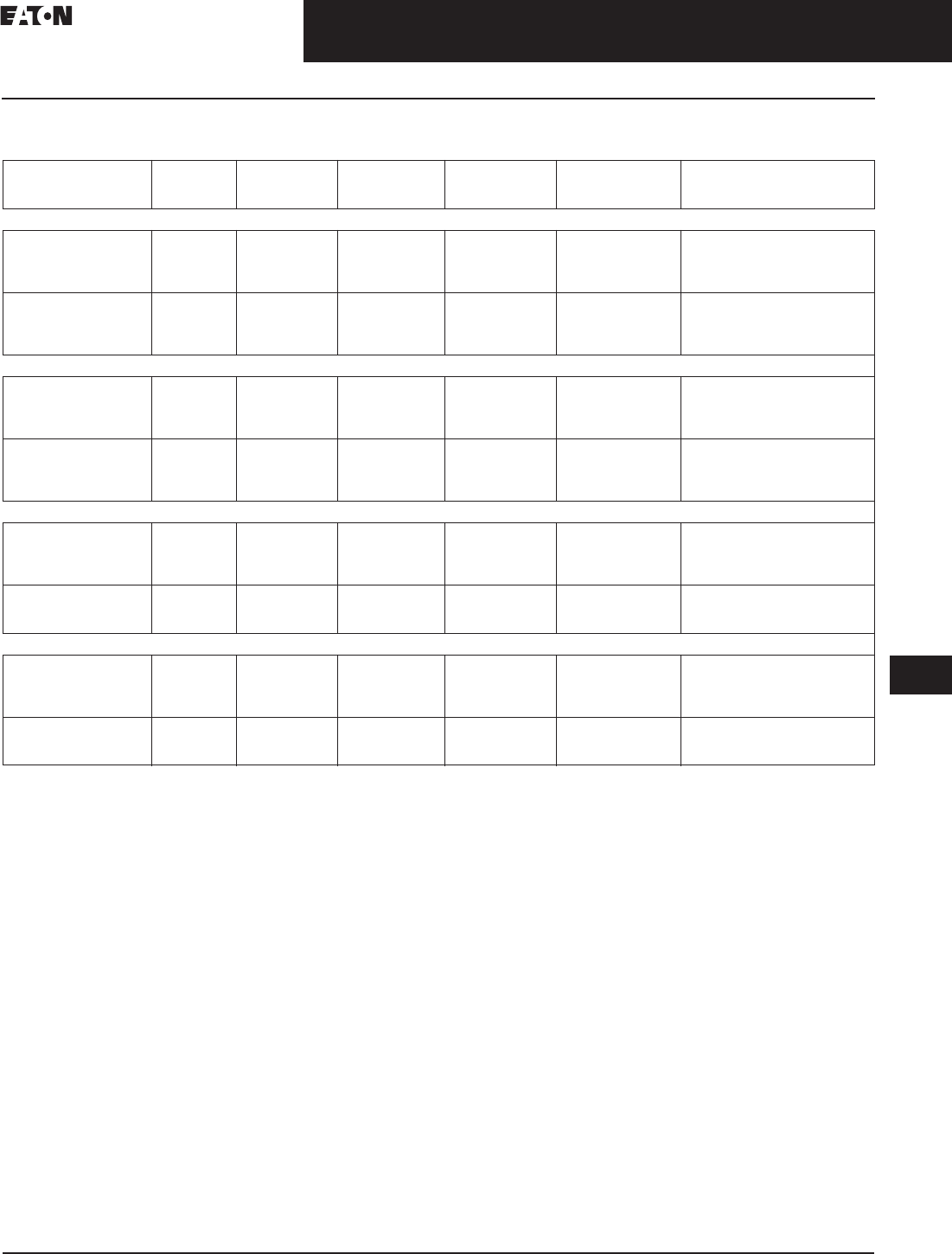
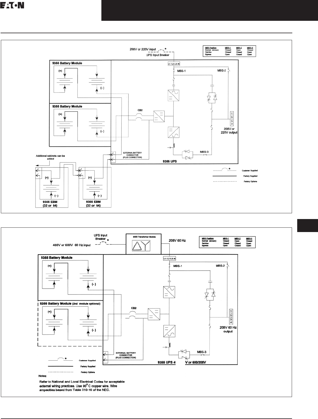
Figure 33.2-1. UPS with Extended Battery Modules Wiring Diagram
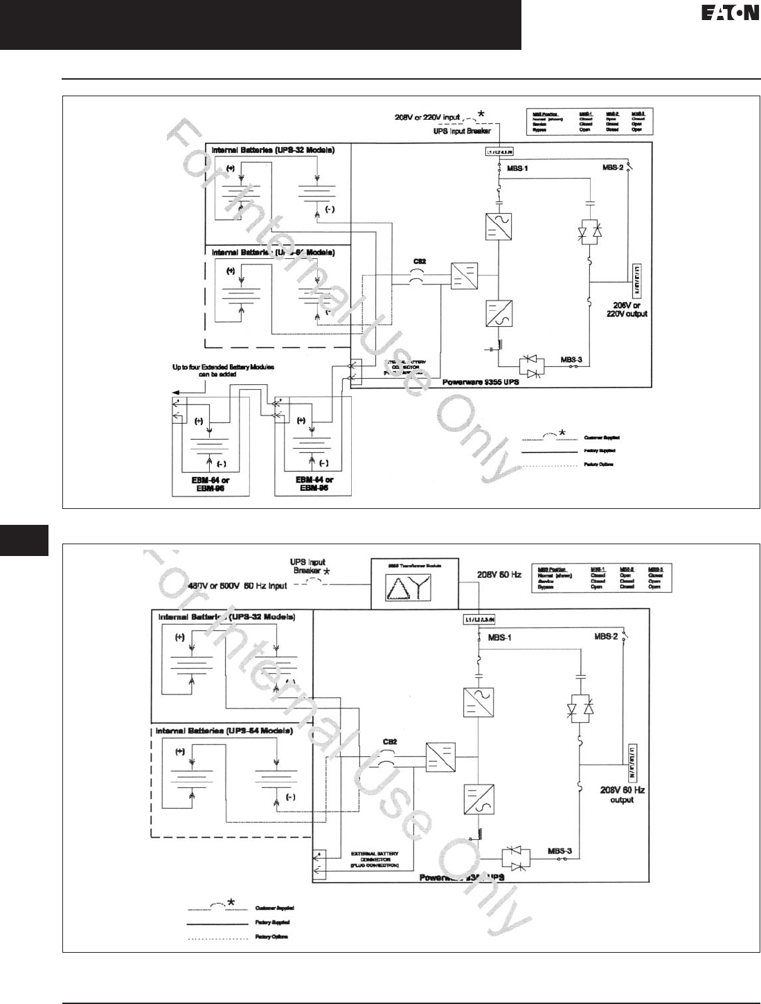
Figure 33.2-2. UPS with Input Isolation Transformer Wiring Diagram
CA08104001E For more information, visit: www.eaton.com/consultants
33.2-7
September 2011
Uninterruptible Power Supplies
Sheet 33
22
23
24
25
26
27
28
29
30
31
32
33
34
35
36
37
38
39
40
41
42
43
Three-Phase Units
Eaton 9355
013
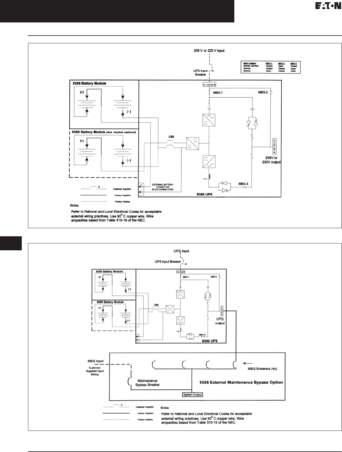
Figure 33.2-3. 208V or 220V Input 208V or 220V Output, Single-Feed UPS
Figure 33.2-4. 480V or 600V Input 208V Output, Single-Feed UPS
33.2-8
For more information, visit: www.eaton.com/consultants CA08104001E
September 2011
Uninterruptible Power Supplies
Sheet 33
22
23
24
25
26
27
28
29
30
31
32
33
34
35
36
37
38
39
40
41
42
43
Three-Phase Units
Eaton 9355
014
Figure 33.2-5. 208V or 220V Input or 220V Output, Single-Feed UPS
Figure 33.2-6. 208V or 220V Input or 220V Output, Single-Feed UPS
CA08104001E For more information, visit: www.eaton.com/consultants
33.2-9
September 2011
Uninterruptible Power Supplies
Sheet 33
22
23
24
25
26
27
28
29
30
31
32
33
34
35
36
37
38
39
40
41
42
43
Three-Phase Units
Eaton 9355
015
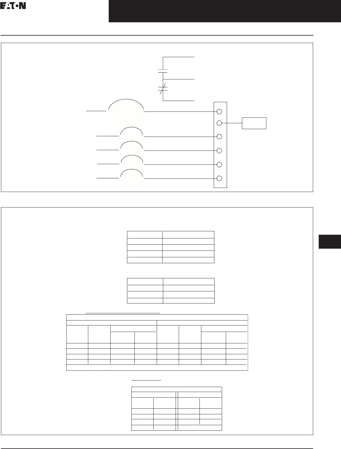
Figure 33.2-7. 9355 Parallel Tie Cabinet with Bypass Switch
Figure 33.2-8. Wire Specifications
Red Wire
Open When Breaker Open
Black Wire
Common
Blue Wire
Closed When Breaker Open
225 A Breaker
Auxiliary Contacts
LOAD
225 A
80 A (4X)
Bypass Input
(MBS or Parallel) UPS 1
(Parallel Only) UPS 2
(Parallel Only) UPS 3
(Parallel Only) UPS 4
AWG TORQUE LB-IN
14-10 20
825
4-8 27
1/0-4 54
1 – 225 A, 3 pole, circuit breaker with aux contacts (Bypass)
ACCEPTS 14AWG -300MCM WIRE
4 – 80 A, 3 pole, circuit breaker (UPS)
Main Components:
ACCEPTS 14-1/0 AWG WIRE
AWG TORQUE LB-IN
14-1/0 50
4-4/0 120
6-300MCM 275
NEUTRAL BUS/GROUND BUS
NEUTRAL GND NEUTRAL GND
14-12 35 1 2 14-10 35** 1 3
10 35 1 1 8 45 1 1
845 1 14-6 45 1 1
645 1 13-1/0 50 1 1
**When Using Three #10 Cu Conductors per opening apply 50 Lb-In Torque
SMALL OPENING LARGE OPENING
CONNECTING WIRE TORQUES
NEUTRAL NEUTRAL
TORQUE
LB-IN
WIRE
AWG
WIRE
AWG
TORQUE
LB-IN
WIRE LUGS
ACCEPTS TO 300MCM WIRE
WIRE
AWG
TORQUE
LB-IN
ACROSS
FLATS
TORQUE
LB-IN
18-10 35 5/16" 275
8403/8"375
6-4 45 1/2" 500
2-2/0 50
Screw Driver Socket Head
Connecting Wire Torques
33.2-10
For more information, visit: www.eaton.com/consultants CA08104001E
September 2011
Uninterruptible Power Supplies
Sheet 33
22
23
24
25
26
27
28
29
30
31
32
33
34
35
36
37
38
39
40
41
42
43
Three-Phase Units
Eaton 9355
016
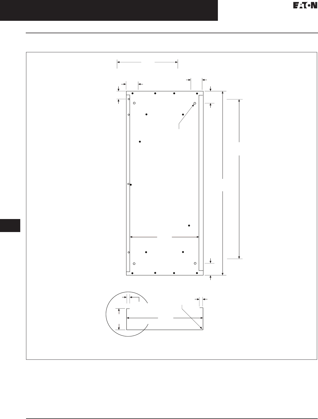
Dimensions in Inches (mm)
Figure 33.2-9. 9355 Parallel Tie Cabinet with Bypass
3.00
(76.2)
30.00
(762.0)
36.00 + 0.032
(914.4 + 0.8)
0.563 Dia. (Typ.)
19.00
(482.6)
2.00
(50.8)
2.00
(50.8)
2.00
(50.8)
16.00
(406.4)
0.786
(19.9)
R.060
(Typ.)
20.00
(508.0)
0.78
(19.8)
5.75
(146.0)
The Cabinet Must be UL/cUL Listed in Accordance with UL67 and UL50
3.00
(76.2)
CA08104001E For more information, visit: www.eaton.com/consultants
33.2-11
September 2011
Uninterruptible Power Supplies
Sheet 33
22
23
24
25
26
27
28
29
30
31
32
33
34
35
36
37
38
39
40
41
42
43
Three-Phase Units
Eaton 9390
017
Eaton 9390 Uninterruptible
Power System
Eaton 9390
General Description
The Eaton 9390 uninterruptible power
system (UPS) is a double-conversion
UPS that resolves all utility power
problems and supplies clean, continu-
ous, uninterruptible power to connected
equipment. Whether you’re selecting a
UPS for a branch office, manufacturing
floor, medical facility or a large data
center, there’s an Eaton 9390 model that
delivers just the right combination of
performance and price for your needs.
Features and Benefits
■Achieves 99% efficiency with
Eaton's Energy Saver System (ESS)
option. ESS continues to provide
complete protection to the load
while maximizing efficiency at
99%, even down to load levels
as low as 20%
■Scalable for capacity and
redundancy to meet present
and future power needs
■
Provides peace-of-mind that your
batteries will be ready when you
need them with innovative three-
stage charging, battery health-checks,
optional temperature-compensated
charging and remote monitoring
■Lowers installation time and
costs with small footprint and the
flexibility to install against walls,
using top- or bottom-entry cabling
■Provides a one-year, limited factory
warranty* on parts and labor, start-
up service, one year of remote
monitoring, on-site preventive main-
tenance and optional service plans
Advanced Design Delivers
Unequaled Power Performance
The innovative design of the Eaton 9390
delivers the industry’s best performance
combination of efficiency, input current
distortion and power factor.
The Eaton 9390 operates at up to 94%
in double-conversion mode and at
99% when using ESS, reducing utility
costs and extending battery run times.
Higher system efficiency produces
cooler operating conditions, which
reduces facility air conditioning cost,
extends the life of UPS components,
and increases overall reliability,
availability and performance.
A new input circuit design keeps input
current THD low and input power factor
near unity without compromising over-
all efficiency. As a result, the Eaton 9390
allows maximum transfer of power
between power source and protected
load and is exceptionally compatible
with multiple power sources, especially
auxiliary generators.
On the output side, the ultra high
speed switching pulse width
modulation (PWM) inverter enables
the Eaton 9390 to provide its full rated
power capability to the load whether
the load power factor is 0.9 lagging,
unity or 0.9 leading.
Double-Conversion Design
Offers the Highest Protection Possible
Unlike some other commercially
available UPS technologies, the
double-conversion design completely
isolates output power from all input
power anomalies and delivers 100%
conditioned, perfect sine-wave
output—regulating both voltage
and frequency.
Eaton 9390 View Panel
Even when presented with the most
severe power problems, power output
remains stable. Output voltage THD is
held within 2% of nominal specification
for linear loads, within 5% for nonlinear
loads—making the Eaton 9390 ideal for
supporting equipment that is sensitive
to a distorted voltage input as a result
of harmonic loads. In the event of a
utility power failure, there is no delay
transferring to backup power.
UPS Control Innovations Optimize
Battery Performance and Service Life
Eaton’s ABM (advanced battery
management) technology uses a
unique three-stage charging technique
that significantly extends battery
service life and optimizes recharge
time, compared to traditional trickle
charging. An integrated battery man-
agement system tests and monitors
battery health and remaining lifetime,
and provides advance notification to
guide preventive maintenance. The
temperature-compensated charger
monitors temperature changes and
adjusts the charge rate accordingly to
properly charge the battery and greatly
extend battery life.
A variable battery bus accommodates
384–480V configurations, so the
battery capacity can be matched to
your exact run time requirements—
either a specific run time, an extension
to existing battery run time, or legacy
battery installations.
With remote monitoring of the UPS
and battery system, Eaton is there
with you—able to respond to alarms
and real-time battery data to avert
potential battery problems.
Scalable Architecture Meets Your
Current and Future Load Requirements
The Eaton 9390 UPS supports loads
from 40–160 kVA to deliver power
protection for small branch offices
to large corporate data centers and
communication networks.
Up to four equivalent UPS modules
can be paralleled for additional
capacity or redundancy, without
having to use a central paralleling
cabinet. Up to eight UPS modules
can be paralleled by using a module
tie cabinet. In all paralleling configura-
tions, each UPS module operates
independently yet is completely
synchronized with the others. Parallel
UPS modules can provide N+1, N+2 or
greater redundancy.
Flexible Installation Options Expedite
Deployment and Save Valuable Space
Cabling can enter the UPS from either
the top or bottom of the cabinet to
provide easier and flexible installation.
The Eaton 9390 provides front panel
access for all services and operation,
increasing serviceability and reducing
mean time to repair (MTTR). And
because the compact Eaton 9390
cabinet can be installed against back
and side walls, you have more location
options, installation is fast and easy,
deployment cost is lower, and you
save valuable data center space for
future expansion.
33.2-12
For more information, visit: www.eaton.com/consultants CA08104001E
September 2011
Uninterruptible Power Supplies
Sheet 33
22
23
24
25
26
27
28
29
30
31
32
33
34
35
36
37
38
39
40
41
42
43
Three-Phase Units
Eaton 9390
018
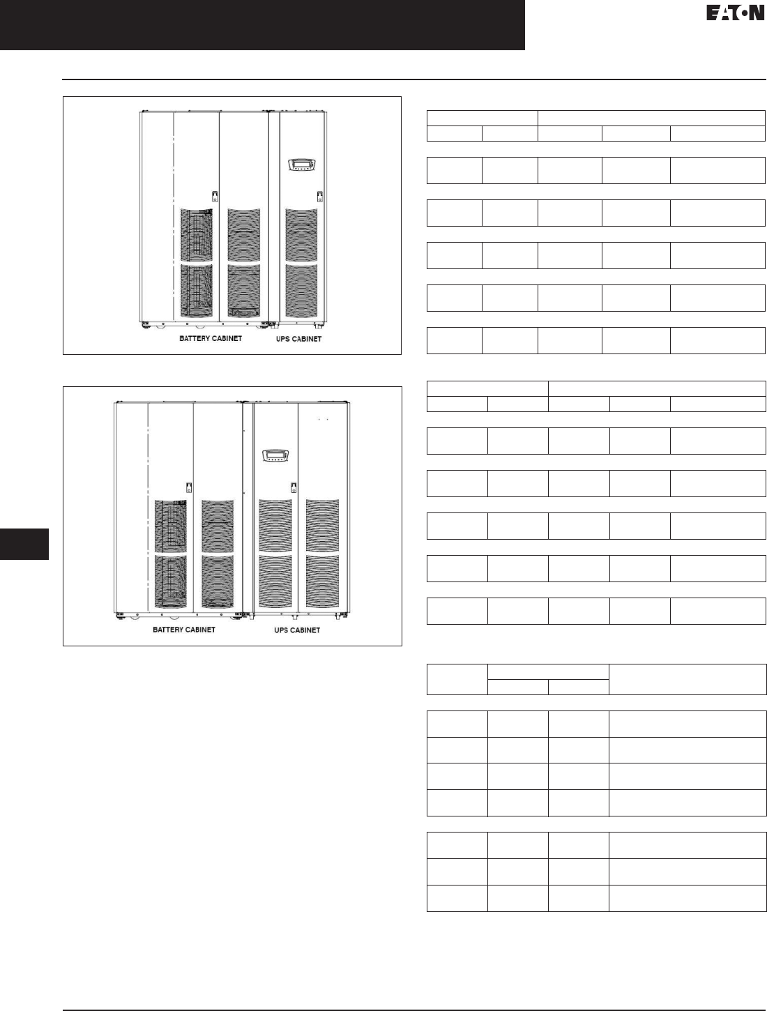
Figure 33.2-10. Eaton 9390 40/50/60/80 kVA UPS with Battery
Figure 33.2-11. Eaton 9390 40/50/60/80 kVA UPS with Battery Cabinet
Table 33.2-12. Eaton 9390 (40–80 kVA) UPS Weights
Table 33.2-13. Eaton 9390 (100–160 kVA) UPS Cabinet Weights
Table 33.2-14. Eaton 9390 Air Conditioning or Ventilation Requirements
During Full Load Operation
Ventilation required for cooling air exhaust: approximately
4.72 liter/sec (1000 cfm).
Ventilation required for cooling air exhaust: approximately
9.44 liter/sec (2000 cfm).
Voltage Weight—kg (Lbs)
Input Output Shipping Installed Point Loading
40/40
208/220
480
208/220
480
263 (580)
231 (508)
241 (530)
208 (458)
4 at 60.3 (133)
4 at 52.2 (115)
80/40
208/220
480
208/220
480
313 (690)
271 (618)
290 (640)
258 (568)
4 at 72.5 (160)
4 at 64.5 (142)
80/50
208/220
480
208/220
480
313 (690)
271 (618)
290 (640)
258 (568)
4 at 72.5 (160)
4 at 64.5 (142)
80/60
208/220
480
208/220
480
313 (690)
271 (618)
290 (640)
258 (568)
4 at 72.5 (160)
4 at 64.5 (142)
80/80
208/220
480
208/220
480
313 (690)
271 (618)
290 (640)
258 (568)
4 at 72.5 (160)
4 at 64.5 (142)
Voltage Weight—kg (Lbs)
Input Output Shipping Installed Point Loading
120/100
208/220
480
208/220
480
531 (1170)
467 (1030)
504 (1110)
440 (970)
6 at 84 (185)
6 at 73 (162)
120/120
208/220
480
208/220
480
531 (1170)
467 (1030)
504 (1110)
440 (970)
6 at 84 (185)
6 at 73 (162)
160/100
208/220
480
208/220
480
581 (1280)
517 (1140)
553 (1220)
490 (1080)
6 at 92 (204)
6 at 82 (180)
160/120
208/220
480
208/220
480
581 (1280)
517 (1140)
553 (1220)
490 (1080)
6 at 92 (204)
6 at 82 (180)
160/160
208/220
480
208/220
480
581 (1280)
517 (1140)
553 (1220)
490 (1080)
6 at 92 (204)
6 at 82 (180)
Ratings Voltage Heat Rejection
BTU/hr x 1000/hr (kg–cal/hr)
Input Output
40–80 kVA
40 kVA 208/220
480
208/220
480
11.8 (2.98)
10.9 (2.76)
50 kVA 208/220
480
208/220
480
14.8 (3.73)
13.7 (3.45)
60 kVA 208/220
480
208/220
480
17.7 (4.47)
16.4 (4.14)
80 kVA 208/220
480
208/220
480
23.6 (5.96)
21.9 (5.52)
100–160 kVA
100 kVA 208/220
480
208/220
480
29.6 (7.45)
27.4 (6.90)
120 kVA 208/220
480
208/220
480
35.5 (8.94)
32.8 (8.28)
160 kVA 208/220
480
208/220
480
47.3 (11.9)
43.8 (11.0)
CA08104001E For more information, visit: www.eaton.com/consultants
33.2-13
September 2011
Uninterruptible Power Supplies
Sheet 33
22
23
24
25
26
27
28
29
30
31
32
33
34
35
36
37
38
39
40
41
42
43
Three-Phase Units
Eaton 9390
019
Wiring Diagrams and Specifications
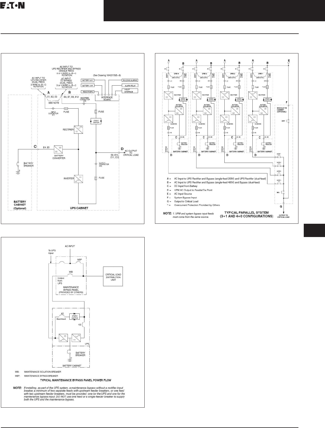
Figure 33.2-12. 9390 UPS with Battery—Single or Dual Feed
Figure 33.2-13. 9390 UPS with External Maintenance Bypass
Figure 33.2-14. 9390 UPS Four-Module Parallel System with
Remote Tie Cabinet
33.2-14
For more information, visit: www.eaton.com/consultants CA08104001E
September 2011
Uninterruptible Power Supplies
Sheet 33
22
23
24
25
26
27
28
29
30
31
32
33
34
35
36
37
38
39
40
41
42
43
Three-Phase Units
Eaton 9390
020
Read and understand the following notes while planning
and performing the installation:
1. Refer to national and local electrical codes for
acceptable external wiring practices.
2. Material and labor for external wiring requirements
are to be provided by designated personnel.
3. For external wiring, use 90°C copper wire. See the
appropriate information in the tables. Wire sizes are
based on using the specified breakers.
4. Wire ampacities are chosen from Table 310.16 of the
NEC. Wire is 90°C specification.
5. If installing, as part of the UPS system, a maintenance
bypass without a rectifier input breaker, a minimum
of two separate feeds with upstream feeder breakers,
or one feed with two upstream feeder breakers,
must be provided: one for the UPS and one for the
maintenance bypass input. DO NOT use one feed or
a single feeder breaker to supply both the UPS and
the maintenance bypass.
6. The bypass feed into this equipment uses three or four
wires. The rectifier feed into this equipment uses three
wires. The phases must be symmetrical about ground
(from a wye source) for proper equipment operation.
7. If the load requires a neutral, a bypass source neutral
must be provided. If the load does not require a neutral
and there is no neutral conductor connected at the
bypass input, a neutral to ground bonding jumper must
be installed. DO NOT install both a source neutral and a
bonding jumper. See tables for neutral bonding jumper
wire sizes. Bonding jumper must be copper wire.
8. The UPS cabinet is shipped with a debris shield
covering the ventilation grill on top of the unit. Do not
remove the debris shield until installation is complete.
However, remove the shield before operating the UPS.
Once the debris shield is removed, do not place objects
on the ventilation grill.
9. Refer to the UPS manual for installation instructions.
10. Terminals are UL and CSA rated at 90°C. Refer
to the tables for power cable terminations and
conduit requirements.
Note: Callout letters A, B, C and D map to (9390-7).
Table 33.2-15. Input/Output Ratings and External Wiring Requirements
for the Eaton 9390-40/40 and 9390-80/40
Table 33.2-16. Input/Output Ratings and External Wiring Requirements
for the Eaton 9390-80/50
Description Units Rating 50/60 Hz
Basic unit rating at
0.9 lagging pF load
kVA
kW
40
36
40
36
Input and bypass input
Output
Volts
Volts
208/220
208/220
480
480
A—AC Input to UPS Rectifier (0.98 min. pF)
Full load current plus battery
recharge current (3) phases,
(1) ground
Amps 125 55
Minimum conductor size
number per phase
AWG or kcmil
(each)
2/0
(1)
4
(1)
B—AC Input to UPS Bypass
Full load current—(3) phases,
(1) neutral-if required, (1) ground
Amps 111/105 48
Minimum conductor size
number per phase
AWG or kcmil
(each)
2/0
(1)
4
(1)
C—DC Input from Battery to UPS
(1) positive, (1) negative Vdc
Amps at
(2.0V/cell)
384–480
101
432–480
101
Minimum conductor size
number per pole
AWG or kcmil
(each)
1/0
(1)
1/0
(1)
D—AC Output to Critical Load
Full load current—(3) phases,
(1) neutral-if required, (1) ground
Amps 111/105 48
Minimum conductor size
number per phase
AWG or kcmil
(each)
2/0
(1)
4
(1)
Neutral Bonding Jumper
Minimum conductor size
number per phase
AWG or kcmil
(each)
4
(1)
6
(1)
Description Units Rating 50/60 Hz
Basic unit rating at
0.9 lagging pF load
kVA
kW
50
45
50
45
Input and bypass input
Output
Volts
Volts
208/220
208/220
480
480
A—AC Input to UPS Rectifier (0.98 min. pF)
Full load current plus
battery recharge current
(3) phases, (1) ground
Amps 155 67
Minimum conductor size
number per phase
AWG or kcmil
(each)
4/0
(1)
2
(1)
B—AC Input to UPS Bypass
Full load current—(3) phases,
(1) neutral-if required, (1) ground
Amps 139/131 60
Minimum conductor size
number per phase
AWG or kcmil
(each)
4/0
(1)
2
(1)
C—DC Input from Battery to UPS
(1) positive, (1) negative Vdc
Amps at
(2.0V/cell)
384–480
126
432–480
126
Minimum conductor size
number per pole
AWG or kcmil
(each)
1/0
(1)
1/0
(1)
D—AC Output to Critical Load
Full load current—(3) phases,
(1) neutral-if required, (1) ground
Amps 139/131 60
Minimum conductor size
number per phase
AWG or kcmil
(each)
4/0
(1)
2
(1)
Neutral Bonding Jumper
Minimum conductor size
number per phase
AWG or kcmil
(each)
2
(1)
6
(1)

CA08104001E For more information, visit: www.eaton.com/consultants
33.2-15
September 2011
Uninterruptible Power Supplies
Sheet 33
22
23
24
25
26
27
28
29
30
31
32
33
34
35
36
37
38
39
40
41
42
43
Three-Phase Units
Eaton 9390
021
Table 33.2-17. Input/Output Ratings and External Wiring Requirements
for the Eaton 9390-80/60
Table 33.2-18. Input/Output Ratings and External Wiring Requirements
for the Eaton 9390-80/80
Table 33.2-19. Input/Output Ratings and External Wiring Requirements
for the Eaton 9390-120/100 and 9390-160/100
Table 33.2-20. Input/Output Ratings and External Wiring Requirements
for the Eaton 9390-120/120 and 9390-160/120
Description Units Rating 50/60 Hz
Basic unit rating at
0.9 lagging pF load
kVA
kW
60
54
60
54
Input and bypass input
Output
Volts
Volts
208/220
208/220
480
480
A—AC Input to UPS Rectifier (0.98 min. pF)
Full load current plus
battery recharge current
(3) phases, (1) ground
Amps 185 80
Minimum conductor size
number per phase
AWG or kcmil
(each)
250
(1)
1
(1)
B—AC Input to UPS Bypass
Full load current—(3) phases,
(1) neutral-if required, (1) ground
Amps 167/158 72
Minimum conductor size
number per phase
AWG or kcmil
(each)
250
(1)
1
(1)
C—DC Input from Battery to UPS
(1) positive, (1) negative Vdc
Amps at
(2.0V/cell)
384–480
151
432–480
151
Minimum conductor size
number per pole
AWG or kcmil
(each)
2/0
(1)
2/0
(1)
D—AC Output to Critical Load
Full load current—(3) phases,
(1) neutral-if required, (1) ground
Amps 167/158 72
Minimum conductor size
number per phase
AWG or kcmil
(each)
250
(1)
1
(1)
Neutral Bonding Jumper
Minimum conductor size
number per phase
AWG or kcmil
(each)
2
(1)
6
(1)
Description Units Rating 50/60 Hz
Basic unit rating at
0.9 lagging pF load
kVA
kW
80
72
80
72
Input and bypass input
Output
Volts
Volts
208/220
208/220
480
480
A—AC Input to UPS Rectifier (0.98 min. pF)
Full load current plus
battery recharge current
(3) phases, (1) ground
Amps 240 105
Minimum conductor size
number per phase
AWG or kcmil
(each)
2/0
(1)
1/0
(1)
B—AC Input to UPS Bypass
Full load current—(3) phases,
(1) neutral-if required, (1) ground
Amps 222/210 96
Minimum conductor size
number per phase
AWG or kcmil
(each)
2/0
(2)
1/0
(1)
C—DC Input from Battery to UPS
(1) positive, (1) negative Vdc
Amps at
(2.0V/cell)
384–480
203
432–480
203
Minimum conductor size
number per pole
AWG or kcmil
(each)
3/0
(2)
3/0
(1)
D—AC Output to Critical Load
Full load current—(3) phases,
(1) neutral-if required, (1) ground
Amps 222/210 96
Minimum conductor size
number per phase
AWG or kcmil
(each)
2/0
(2)
1/0
(1)
Neutral Bonding Jumper
Minimum conductor size
number per phase
AWG or kcmil
(each)
1/0
(1)
6
(1)
Description Units Rating 50/60 Hz
Basic unit rating at
0.9 lagging pF load
kVA
kW
100
90
100
90
Input and bypass input
Output
Volts
Volts
208/220
208/220
480
480
A—AC Input to UPS Rectifier (0.98 min. pF)
Full load current plus
battery recharge current
(3) phases, (1) ground
Amps 300 130
Minimum conductor size
number per phase
AWG or kcmil
(each)
3/0
(2)
4/0
(1)
B—AC Input to UPS Bypass
Full load current—(3) phases,
(1) neutral-if required, (1) ground
Amps 278/262 120
Minimum conductor size
number per phase
AWG or kcmil
(each)
3/0
(2)
4/0
(1)
C—DC Input from Battery to UPS
(1) positive, (1) negative Vdc
Amps at
(2.0V/cell)
384–480
252
432–480
252
Minimum conductor size
number per pole
AWG or kcmil
(each)
2/0
(2)
2/0
(2)
D—AC Output to Critical Load
Full load current—(3) phases,
(1) neutral-if required, (1) ground
Amps 278/262 120
Minimum conductor size
number per phase
AWG or kcmil
(each)
3/0
(2)
4/0
(1)
Neutral Bonding Jumper
Minimum conductor size
number per phase
AWG or kcmil
(each)
1/0
(1)
2
(1)
Description Units Rating 50/60 Hz
Basic unit rating at
0.9 lagging pF load
kVA
kW
120
108
120
108
Input and bypass input
Output
Volts
Volts
208/220
208/220
480
480
A—AC Input to UPS Rectifier (0.98 min. pF)
Full load current plus
battery recharge current
(3) phases, (1) ground
Amps 360 160
Minimum conductor size
number per phase
AWG or kcmil
(each)
4/0
(2)
4/0
(1)
B—AC Input to UPS Bypass
Full load current—(3) phases,
(1) neutral-if required, (1) ground
Amps 333/315 120
Minimum conductor size
number per phase
AWG or kcmil
(each)
4/0
(2)
4/0
(1)
C—DC Input from Battery to UPS
(1) positive, (1) negative Vdc
Amps at
(2.0V/cell)
384–480
302
432–480
302
Minimum conductor size
number per pole
AWG or kcmil
(each)
3/0
(2)
3/0
(2)
D—AC Output to Critical Load
Full load current—(3) phases,
(1) neutral-if required, (1) ground
Amps 333/315 120
Minimum conductor size
number per phase
AWG or kcmil
(each)
4/0
(2)
4/0
(1)
Neutral Bonding Jumper
Minimum conductor size
number per phase
AWG or kcmil
(each)
1/0
(1)
2
(1)
33.2-16
For more information, visit: www.eaton.com/consultants CA08104001E
September 2011
Uninterruptible Power Supplies
Sheet 33
22
23
24
25
26
27
28
29
30
31
32
33
34
35
36
37
38
39
40
41
42
43
Three-Phase Units
Eaton 9390
022
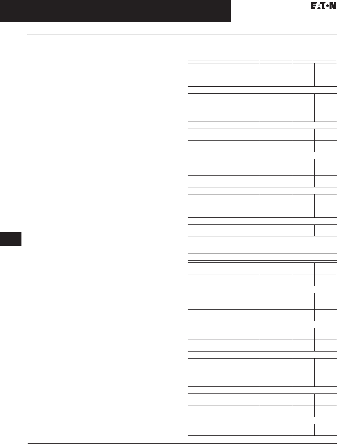
Table 33.2-21. Input/Output Ratings and External Wiring Requirements
for the Eaton 9390-160/160
Table 33.2-22. UPS Cabinet Power Cable Terminations for the
Eaton 9390-40/40, 9390-80/40, 9390-80/50, 9390-80/60 and
9390-80/80 (208V/220V Input and 208V/220V Output)
Description Units Rating 50/60 Hz
Basic unit rating at
0.9 lagging pF load
kVA
kW
160
144
160
144
Input and bypass input
Output
Volts
Volts
208/220
208/220
480
480
A—AC Input to UPS Rectifier (0.98 min. pF)
Full load current plus
battery recharge current
(3) phases, (1) ground
Amps 480 210
Minimum conductor size
number per phase
AWG or kcmil
(each)
400
(2)
1/0
(2)
B—AC Input to UPS Bypass
Full load current—(3) phases,
(1) neutral-if required, (1) ground
Amps 444/420 192
Minimum conductor size
number per phase
AWG or kcmil
(each)
400
(2)
1/0
(2)
C—DC Input from Battery to UPS
(1) positive, (1) negative Vdc
Amps at
(2.0V/cell)
384–480
403
432–480
403
Minimum conductor size
number per pole
AWG or kcmil
(each)
250
(2)
250
(2)
D—AC Output to Critical Load
Full load current—(3) phases,
(1) neutral-if required, (1) ground
Amps 444/420 192
Minimum conductor size
number per phase
AWG or kcmil
(each)
400
(2)
1/0
(2)
Neutral Bonding Jumper
Minimum conductor size
number per phase
AWG or kcmil
(each)
1/0
(2)
2
(2)
Terminal Function Size of Pressure
Termination
Tightening Torque
Nm (in-lb)
Screw
Type
AC Input to UPS Rectifier and Bypass (Single Input)
E6
E7
E8
Phase A
Phase B
Phase C
2–#6-250 kcmil
2–#6-250 kcmil
2–#6-250 kcmil
42.4 (375)
42.4 (375)
42.4 (375)
5/16-inch hex
5/16-inch hex
5/16-inch hex
AC Input to UPS Rectifier (Dual Input)
E1
E2
E3
Phase A
Phase B
Phase C
2–#6-250 kcmil
2–#6-250 kcmil
2–#6-250 kcmil
42.4 (375)
42.4 (375)
42.4 (375)
5/16-inch hex
5/16-inch hex
5/16-inch hex
AC Input to Bypass (Dual Input)
E6
E7
E8
Phase A
Phase B
Phase C
2–#6-250 kcmil
2–#6-250 kcmil
2–#6-250 kcmil
42.4 (375)
42.4 (375)
42.4 (375)
5/16-inch hex
5/16-inch hex
5/16-inch hex
Single-Feed Jumper from Rectifier Input Terminals to Bypass Input Terminals
—
—
—
Phase A
Phase B
Phase C
N/A
N/A
N/A
22.6 (200)
22.6 (200)
22.6 (200)
M10 hex bolt
M10 hex bolt
M10 hex bolt
AC Output to Critical Load
E9
E10
E11
Phase A
Phase B
Phase C
2–#6-250 kcmil
2–#6-250 kcmil
2–#6-250 kcmil
42.4 (375)
42.4 (375)
42.4 (375)
5/16-inch hex
5/16-inch hex
5/16-inch hex
DC Input from Battery to UPS
E4
E5
Positive
Negative
1–#6-350 kcmil
1–#6-350 kcmil
31.1 (275)
31.1 (275)
5/16-inch hex
5/16-inch hex
Input and Output Neutral
E12 Neutral 8–#6-250 kcmil 42.4 (375) 5/16-inch hex
Customer Ground
Ground Ground 8–#14-1/0 5.6 (50) Slotted

CA08104001E For more information, visit: www.eaton.com/consultants
33.2-17
September 2011
Uninterruptible Power Supplies
Sheet 33
22
23
24
25
26
27
28
29
30
31
32
33
34
35
36
37
38
39
40
41
42
43
Three-Phase Units
Eaton 9390
023
Table 33.2-23. UPS Cabinet Power Cable Terminations for the
Eaton 9390-120/100, 9390-120/120, 9390-160/100, 9390-160/120
and 9390-160/160 (208V/220V Input and 208V/220V Output)
Table 33.2-24. UPS Cabinet Power Cable Terminations for the
Eaton 9390-40/40, 9390-80/40, 9390-80/50, 9390-80/60 and 9390-80/80
(480V Input and 480V Output)
Terminal Function Size of Pressure
Termination
Tightening Torque
Nm (in-lb)
Screw
Type
AC Input to UPS Rectifier and Bypass (Single Input)
E1
E2
E3
Phase A
Phase B
Phase C
2–2/0-500 kcmil
2–2/0-500 kcmil
2–2/0-500 kcmil
31.1 (275)
31.1 (275)
31.1 (275)
4 mm hex
4 mm hex
4 mm hex
AC Input to UPS Rectifier (Dual Input)
E1
E2
E3
Phase A
Phase B
Phase C
2–2/0-500 kcmil
2–2/0-500 kcmil
2–2/0-500 kcmil
31.1 (275)
31.1 (275)
31.1 (275)
4 mm hex
4 mm hex
4 mm hex
AC Input to Bypass (Dual Input)
E6
E7
E8
Phase A
Phase B
Phase C
2–#2-600 kcmil
2–#2-600 kcmil
2–#2-600 kcmil
56.5 (500)
56.5 (500)
56.5 (500)
1/2-inch hex
1/2-inch hex
1/2-inch hex
Single-Feed to Dual-Feed Wire Transfer from
Rectifier Input Terminals to Bypass Input Terminals
Rectifier
Bypass
Rectifier
Phase A
Phase A
Phase B
N/A
N/A
N/A
12.5 (110)
12.5 (110)
12.5 (110)
M8 hex bolt
M8 hex bolt
M8 hex bolt
Bypass
Rectifier
Bypass
Phase B
Phase C
Phase C
N/A
N/A
N/A
12.5 (110)
12.5 (110)
12.5 (110)
M8 hex bolt
M8 hex bolt
M8 hex bolt
AC Output to Critical Load
E9
E10
E11
Phase A
Phase B
Phase C
2–2/0-500 kcmil
2–2/0-500 kcmil
2–2/0-500 kcmil
31.1 (275)
31.1 (275)
31.1 (275)
4 mm hex
4 mm hex
4 mm hex
DC Input from Battery to UPS
E4
E5
Positive
Negative
2–#2-600 kcmil
2–#2-600 kcmil
56.5 (500)
56.5 (500)
1/2-inch hex
1/2-inch hex
Input and Output Neutral
E12 Neutral 8–#2-600 kcmil 56.5 (500) 1/2-inch hex
Customer Ground
Ground Ground 8–#14-1/0 5.6 (50) Slotted
Terminal Function Size of Pressure
Termination
Tightening Torque
Nm (in-lb)
Screw
Type
AC Input to UPS Rectifier and Bypass (Single Input)
E6
E7
E8
Phase A
Phase B
Phase C
1–#14-2/0
1–#14-2/0
1–#14-2/0
13.5 (120)
13.5 (120)
13.5 (120)
3/16-inch hex
3/16-inch hex
3/16-inch hex
AC Input to UPS Rectifier (Dual Input)
E1
E2
E3
Phase A
Phase B
Phase C
1–#14-2/0
1–#14-2/0
1–#14-2/0
13.5 (120)
13.5 (120)
13.5 (120)
3/16-inch hex
3/16-inch hex
3/16-inch hex
AC Input to Bypass (Dual Input)
E6
E7
E8
Phase A
Phase B
Phase C
1–#14-2/0
1–#14-2/0
1–#14-2/0
13.5 (120)
13.5 (120)
13.5 (120)
3/16-inch hex
3/16-inch hex
3/16-inch hex
Single-Feed to Dual-Feed Wire Transfer from
Rectifier Input Terminals to Bypass Input Terminals
—
—
—
Phase A
Phase B
Phase C
N/A
N/A
N/A
5.6 (50)
5.6 (50)
5.6 (50)
1/4–20 hex nut
1/4–20 hex nut
1/4–20 hex nut
AC Output to Critical Load
E9
E10
E11
Phase A
Phase B
Phase C
1–#14-2/0
1–#14-2/0
1–#14-2/0
13.5 (120)
13.5 (120)
13.5 (120)
3/16-inch hex
3/16-inch hex
3/16-inch hex
DC Input from Battery to UPS
E4
E5
Positive
Negative
1–#6-350 kcmil
1–#6-350 kcmil
31.1 (275)
31.1 (275)
5/16-inch hex
5/16-inch hex
Input and Output Neutral
E12 Neutral 4–#14-1/0 5.6 (50) Slotted
Customer Ground
Ground Ground 8–#14-1/0 5.6 (50) Slotted
33.2-18
For more information, visit: www.eaton.com/consultants CA08104001E
September 2011
Uninterruptible Power Supplies
Sheet 33
22
23
24
25
26
27
28
29
30
31
32
33
34
35
36
37
38
39
40
41
42
43
Three-Phase Units
Eaton 9390
024
Table 33.2-25. UPS Cabinet Power Cable Terminations for the
Eaton 9390-120/100, 9390-120/120, 9390-160/100, 9390-160/120
and 9390-160/160 (480V Input and 480V Output)
Terminal Function Size of Pressure
Termination
Tightening Torque
Nm (in-lb)
Screw
Type
AC Input to UPS Rectifier and Bypass (Single Input)
E6
E7
E8
Phase A
Phase B
Phase C
2–#6-250
2–#6-250
2–#6-250
42.4 (375)
42.4 (375)
42.4 (375)
5/16-inch hex
5/16-inch hex
5/16-inch hex
AC Input to UPS Rectifier (Dual Input)
E1
E2
E3
Phase A
Phase B
Phase C
2–#6-250
2–#6-250
2–#6-250
42.4 (375)
42.4 (375)
42.4 (375)
5/16-inch hex
5/16-inch hex
5/16-inch hex
AC Input to Bypass (Dual Input)
E6
E7
E8
Phase A
Phase B
Phase C
2–#6-250
2–#6-250
2–#6-250
42.4 (375)
42.4 (375)
42.4 (375)
5/16-inch hex
5/16-inch hex
5/16-inch hex
Single-Feed to Jumper Bus from Rectifier Input Terminals
to Bypass Input Terminals
Rectifier
Bypass
Rectifier
Phase A
Phase A
Phase B
N/A
N/A
N/A
12.5 (110)
22.6 (200)
12.5 (110)
M8 hex bolt
M10 hex bolt
M8 hex bolt
Bypass
Rectifier
Bypass
Phase B
Phase C
Phase C
N/A
N/A
N/A
22.6 (200)
12.5 (110)
22.6 (200)
M10 hex bolt
M8 hex bolt
M10 hex bolt
AC Output to Critical Load
E9
E10
E11
Phase A
Phase B
Phase C
2–#6-250
2–#6-250
2–#6-250
42.4 (375)
42.4 (375)
42.4 (375)
5/16-inch hex
5/16-inch hex
5/16-inch hex
DC Input from Battery to UPS
E4
E5
Positive
Negative
2–#2-600 kcmil
2–#2-600 kcmil
56.5 (500)
56.5 (500)
1/2-inch hex
1/2-inch hex
Input and Output Neutral
E12 Neutral 8–#6-250 kcmil 42.4 (375) 1/2-inch hex
Customer Ground
Ground Ground 8–#14-1/0 5.6 (50) Slotted
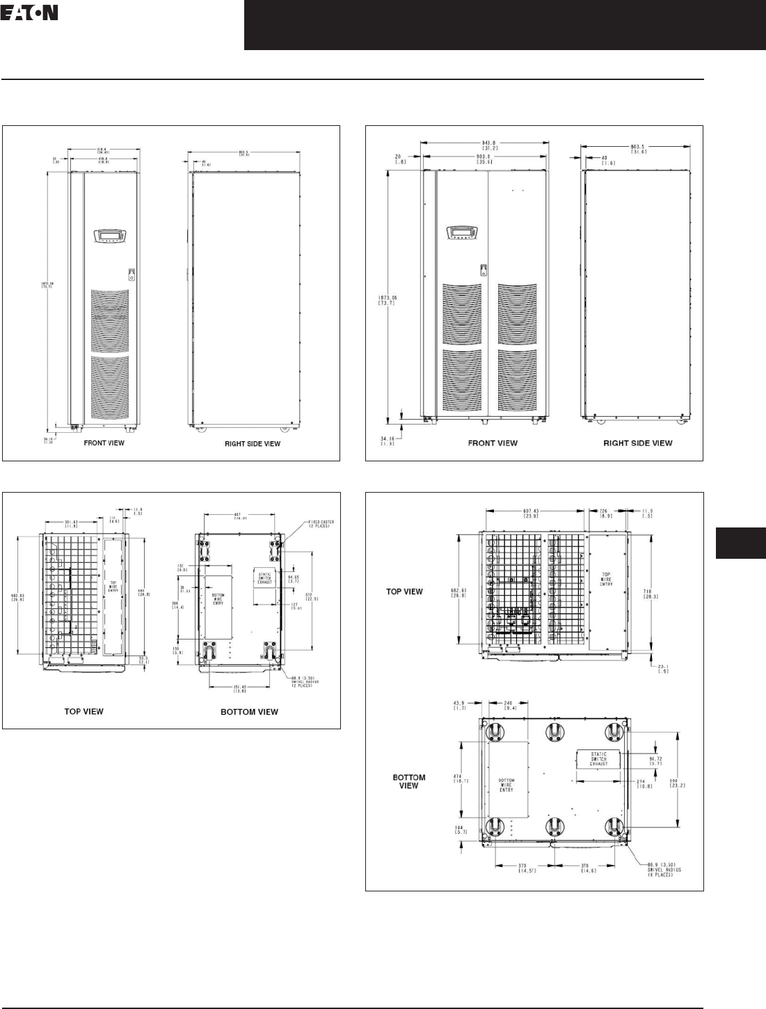
CA08104001E For more information, visit: www.eaton.com/consultants
33.2-19
September 2011
Uninterruptible Power Supplies
Sheet 33
22
23
24
25
26
27
28
29
30
31
32
33
34
35
36
37
38
39
40
41
42
43
Three-Phase Units
Eaton 9390
025
Dimensions in mm (Inches)
Figure 33.2-15. 9390 (40–80 kVA) UPS
Figure 33.2-16. 9390 (40–80 kVA) UPS
Figure 33.2-17. 9390 (100–160 kVA) UPS
Figure 33.2-18. 9390 (100–160 kVA) UPS
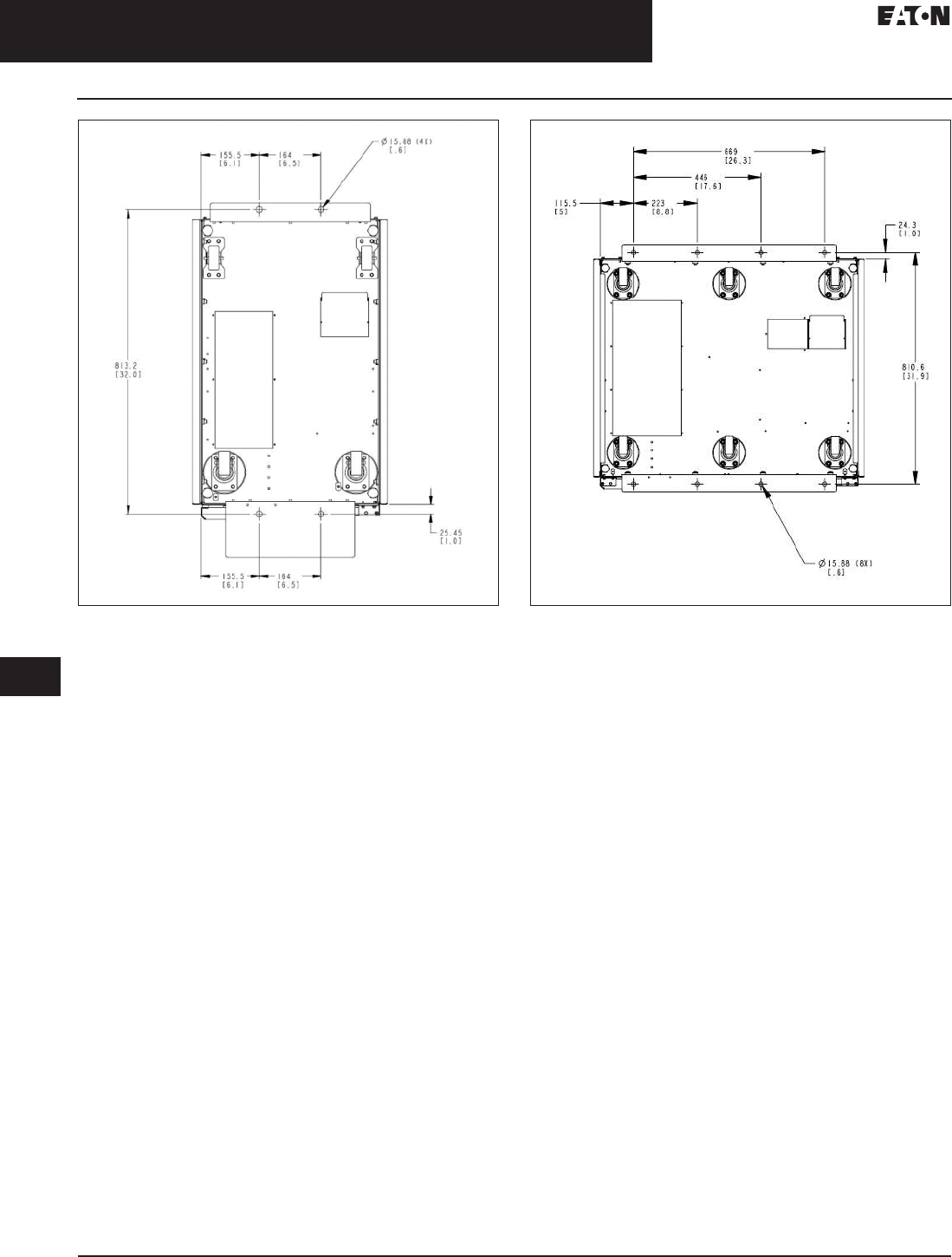
33.2-20
For more information, visit: www.eaton.com/consultants CA08104001E
September 2011
Uninterruptible Power Supplies
Sheet 33
22
23
24
25
26
27
28
29
30
31
32
33
34
35
36
37
38
39
40
41
42
43
Three-Phase Units
Eaton 9390
026
Figure 33.2-19. 9390 (40–80 kVA) UPS Floor-Mounted Figure 33.2-20. 9390 (100–160 kVA) UPS Floor-Mounted
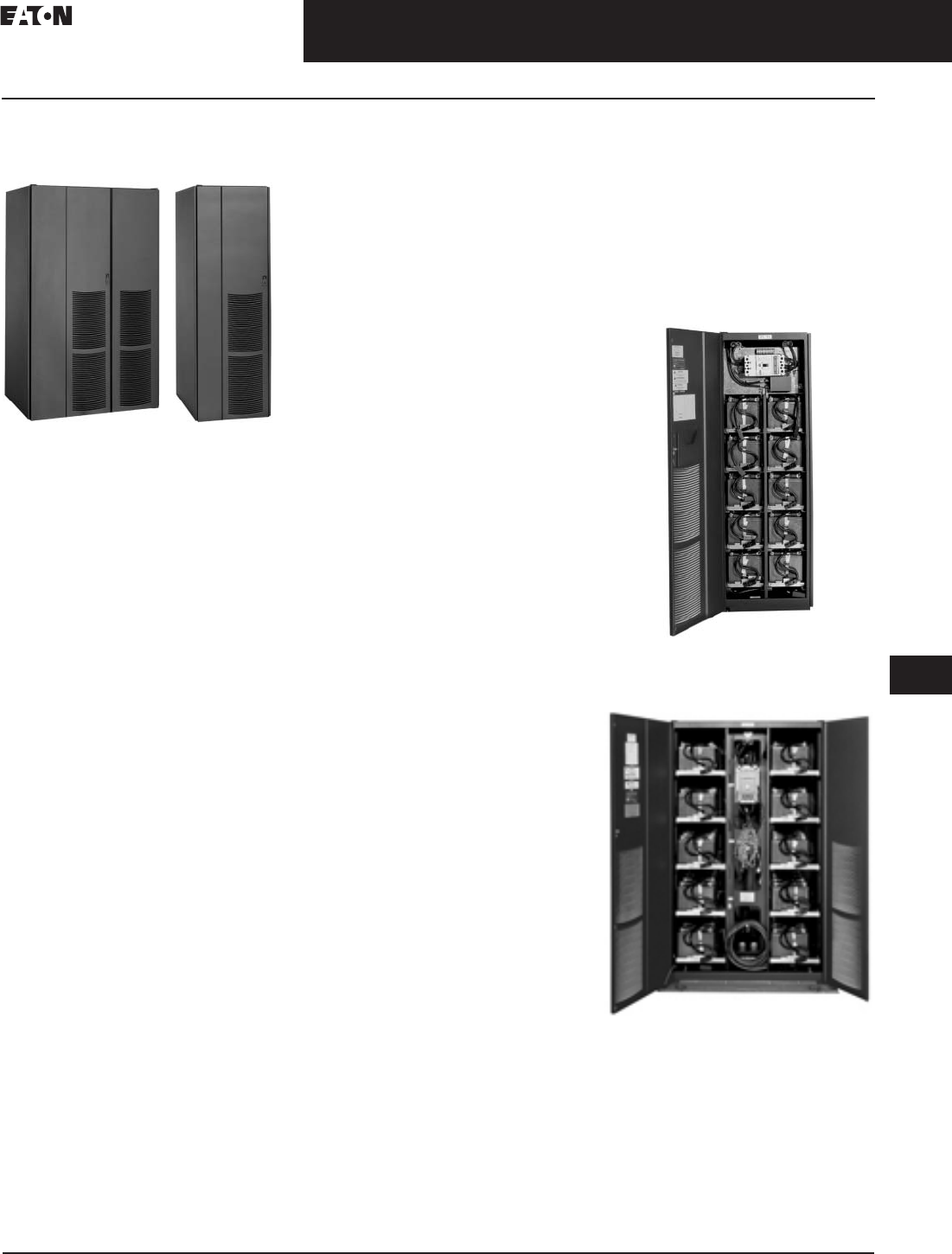
CA08104001E For more information, visit: www.eaton.com/consultants
33.2-21
September 2011
Uninterruptible Power Supplies
Sheet 33
22
23
24
25
26
27
28
29
30
31
32
33
34
35
36
37
38
39
40
41
42
43
Three-Phase Units
Eaton 9390
027
Eaton 9390 UPS Integrated
Battery Cabinets
IBC-L and IBC-S
General Description
Eaton offers two models of battery
cabinets, the IBC-S and IBC-L, for its
Eaton 9390 UPS series. These cabinets
line up and match with the 9390 UPS
and offer a wide range of run times.
Features and Benefits
■ABM (advanced battery manage-
ment) technology extends battery
life and optimizes recharge time
■Top and bottom cabling entry
provides installation flexibility
■CD-rated circuit breaker within each
cabinet provides protection and
servicing isolation
■Each circuit breaker includes:
❑Auxiliary switch for UPS sensing
of circuit breaker closure
❑48 Vdc UVR to interface with
UPS for remote EPO function
■Variable battery bus enables battery
capacity to be matched to exact run
time requirements
■Optional remote configurations
available
■Casters provided to enhance
portability
■Quick disconnects between battery
tray assemblies reduce battery
maintenance time
■Manufacturer-supplied wiring
provides plug and play capability for
line-up-and-match configurations
■Removable battery tray assemblies
reduce battery maintenance time
■DC-rated circuit breaker in each
battery cabinet allows multiple
battery strings to be serviced
independently of each other,
ensuring backup power is always
available to the UPS
■Circuit breaker features UVR trip
auxiliaries for system EPO and
UPS sensing of battery breaker
■Located adjacent to the internal
wireway, mechanical lugs
reduce installation time for
remote configurations
Flexibility
■A variable battery bus accommodates
384–480V configurations, so that the
battery capacity can be matched to
your exact run time requirements—
either a specific run time, an
extension to an existing battery run
time or legacy battery installations
■Daisy chain up to four cabinets
together for extended battery
run times
■Integral, line-up-and-match
configurations are standard
■Remote configurations available
Serviceability
■Front access only design enhances
servicing and installation
■Modular battery tray design
optimizes periodic servicing
Dimensions in Inches (mm)
■
IBC-S: 22.40 W x 31.60 D x 74.40 H
(569.0 W x 802.6 D x 1889.8 H)
■
IBC-L: 42.70 W x 31.60 D x 74.40 H
(1084.6 W x 802.6 D x 1889.8 H)
Reliability
■Battery cabinets are UL 1778 listed
■Flame-retardant batteries meet
UL94V2 for computer room
installations
IBC-S with Door Opened—IBC-S is
Compatible with Battery Types B12,
B17 and E20
IBC-L with Doors Opened—IBC-L is
Compatible with Battery Types E28,
E33, E39, E50, B27, B31, B37 and B47

33.2-22
For more information, visit: www.eaton.com/consultants CA08104001E
September 2011
Uninterruptible Power Supplies
Sheet 33
22
23
24
25
26
27
28
29
30
31
32
33
34
35
36
37
38
39
40
41
42
43
Three-Phase Units
Eaton 9390
028
Table 33.2-26. Eaton 9390 40–80 kVA Run Times: 480 Vac Systems, 60 Hz
All battery cabinets are 74.40 inches (1889.8 mm) height x 31.60 inches (802.6 mm) depth.
Maximum installed weight with largest breaker.
kVA 40 50 60 80 Weight
Lbs (kg)
40 50 60 80 Weight
Lbs (kg)
kW 36 45 54 72 36 45 54 72
Nominal DC Link Voltage 480 480 480 480 432 432 432 432
Battery
Type
Width
Inches (mm)
No. of
Strings
Minutes Minutes
B12
B17
B27
22.40 (569.0)
22.40 (569.0)
42.70 (1084.6)
1
1
1
9
16
33
5
10
25
—
7
19
—
—
13
1665 (756)
2445 (1110)
3150 (1430)
—
8
24
—
5
17
—
—
12
—
—
6
1560 (708)
2270 (1031)
2897 (1315)
E28
B31
E33
42.70 (1084.6)
42.70 (1084.6)
42.70 (1084.6)
1
1
1
35
39
42
27
30
33
22
24
27
15
16
19
3250 (1476)
3495 (1587)
3595 (1632)
24
28
30
18
21
23
13
16
18
5
8
11
2987 (1356)
3202 (1454)
3292 (1495)
B37
E39
B47
42.70 (1084.6)
42.70 (1084.6)
42.70 (1084.6)
1
1
1
48
48
66
36
38
51
29
31
40
20
23
26
3765 (1709)
3925 (1782)
4800 (2179)
34
36
53
26
27
38
21
22
29
13
16
18
3444 (1564)
3588 (1629)
4375 (1986)
E50
B12
B17
42.70 (1084.6)
44.80 (2169.2)
44.80 (2169.2)
1
2
2
65
26
43
51
19
31
41
16
25
30
10
17
4840 (2197)
3330 (1512)
4890 (2220)
54
19
32
41
14
24
34
11
17
25
5
9
4411 (2003)
3120 (1416)
4540 (2061)
B27
E28
B31
85.40 (1137.9)
85.40 (1137.9)
85.40 (2169.2)
2
2
2
78
79
90
60
61
68
50
49
57
34
35
40
6300 (2860)
6500 (2951)
6990 (3173)
61
57
71
47
43
54
36
34
43
25
24
29
5804 (2635)
5984 (2717)
6414 (2912)
E33
B37
E39
85.40 (2169.2)
85.40 (2169.2)
85.40 (2169.2)
2
2
2
92
100
105
72
80
82
58
65
67
42
50
49
7190 (3264)
7530 (3418)
7850 (3564)
69
82
80
52
62
61
42
51
50
30
35
36
6594 (2994)
6898 (3132)
7186 (3262)
B47
E50
B12
85.40 (2169.2)
85.40 (2169.2)
67.20 (1706.9)
2
2
3
149
144
45
114
111
32
92
91
26
67
66
18
9600 (4358)
9680 (4395)
4995 (2268)
125
121
36
94
93
26
76
76
20
54
54
13
8760 (3977)
8832 (4010)
4680 (2125)
B17
B27
E28
67.20 (1706.9)
128.10 (3253.7)
128.10 (3253.7)
3
3
3
72
125
125
55
95
96
43
78
78
29
57
56
7335 (3330)
9450 (4290)
9750 (4427)
58
102
96
44
77
72
33
61
58
22
44
40
6810 (3092)
8706 (3953)
8976 (4075)
B31
E33
B37
128.10 (3253.7)
128.10 (3253.7)
128.10 (3253.7)
3
3
3
141
147
157
110
113
122
91
92
100
65
66
75
10.485 (4760)
10.785 (4896)
11,295 (5128)
118
113
130
90
86
100
71
69
83
51
49
58
9621 (4368)
9891 (4491)
10,347 (4698)
E39
B47
E50
128.10 (3253.7)
128.10 (3253.7)
128.10 (3253.7)
3
3
3
164
251
230
128
188
177
105
150
144
76
107
104
11,775 (5346)
14,400 (6538)
14,520 (6592)
130
210
196
99
153
150
80
127
121
58
89
86
10,779 (4894)
13,140 (5966)
13,248 (6015)
B12
B17
B27
89.60 (2275.8)
89.60 (2275.8)
170.80 (4338.3)
4
4
4
63
104
175
50
79
135
39
63
110
27
44
80
6660 (3024)
9780 (4440)
12,600 (5720)
54
86
144
40
63
113
30
52
89
20
33
62
6240 (2833)
9080 (4122)
11,608 (5270)
E28
B31
E33
170.80 (4338.3)
170.80 (4338.3)
170.80 (4338.3)
4
4
4
176
200
206
135
153
158
110
125
128
78
92
92
13,000 (5902)
13,980 (6347)
14,380 (6529)
138
162
163
104
128
123
83
104
98
58
73
69
11,968 (5433)
12,828 (5824)
13,188 (5987)
B37
E39
B47
E50
170.80 (4338.3)
170.80 (4338.3)
170.80 (4338.3)
170.80 (4338.3)
4
4
4
4
222
228
360
322
170
178
280
248
140
145
212
201
101
105
152
144
15,060 (6837)
15,700 (7128)
19,200 (8717)
19,360 (8789)
187
184
309
278
140
141
230
209
115
113
185
172
84
81
128
123
13,796 (6263)
14,372 (6525)
17,520 (7954)
17,664 (8019)

CA08104001E For more information, visit: www.eaton.com/consultants
33.2-23
September 2011
Uninterruptible Power Supplies
Sheet 33
22
23
24
25
26
27
28
29
30
31
32
33
34
35
36
37
38
39
40
41
42
43
Three-Phase Units
Eaton 9390
029
Table 33.2-27. Eaton 9390 100–160 kVA Run Times: 480 Vac Systems, 60 Hz
All battery cabinets are 74.40 inches (1889.8 mm) height x 31.60 inches (802.6 mm) depth.
Maximum installed weight with largest breaker.
kVA 100 120 160 Weight
Lbs (kg)
100 120 160 Weight
Lbs (kg)
kW 90 108 144 90 108 144
Nominal DC Link Voltage 480 480 480 432 432 432
Battery
Type
Width
Inches (mm)
No. of
Strings
Minutes Minutes
B27
E28
B31
42.70 (1084.6)
42.70 (1084.6)
42.70 (1084.6)
1
1
1
9
10
11
7
6
8
—
—
—
3150 (1430)
3250 (1476)
3495 (1587)
—
—
—
—
—
—
—
—
—
2897 (1315)
2987 (1356)
3202 (1454)
E33
B37
E39
42.70 (1084.6)
42.70 (1084.6)
42.70 (1084.6)
1
1
1
14
15
11
10
11
13
—
7
7
3595 (1632)
3765 (1709)
3925 (1782)
—
—
—
—
—
—
—
—
—
3292 (1495)
3444 (1564)
3588 (1629)
B47
E50
B27
42.70 (1084.6)
42.70 (1084.6)
85.40 (2169.2)
1
1
2
18
22
25
13
17
19
8
10
13
4800 (2179)
4840 (2197)
6300 (2860)
—
—
17
—
—
12
—
—
6
4375 (1986)
4411 (2003)
5804 (2635)
E28
B31
E33
85.40 (2169.2)
85.40 (2169.2)
85.40 (2169.2)
2
2
2
27
30
33
22
24
27
15
16
19
6500 (2951)
6990 (3173)
7190 (3264)
18
21
23
13
16
18
5
8
11
5984 (2717)
6414 (2912)
6594 (2994)
B37
E39
B47
85.40 (2169.2)
85.40 (2169.2)
85.40 (2169.2)
2
2
2
36
38
51
29
31
40
20
23
27
7530 (3418)
7850 (3564)
9600 (4358)
27
28
38
21
22
29
13
16
18
6898 (3132)
7186 (3262)
8760 (3977)
E50
B27
E28
85.40 (2169.2)
128.10 (3253.7)
128.10 (3253.7)
2
3
3
51
43
43
41
34
35
30
23
26
9680 (4395)
9450 (4290)
9750 (4427)
42
32
30
34
25
24
25
16
16
8832 (4010)
8706 (3953)
8976 (4075)
B31
E33
B37
128.10 (3253.7)
128.10 (3253.7)
128.10 (3253.7)
3
3
3
52
51
59
40
42
49
28
31
34
10,485 (4760)
10,785 (4896)
11,295 (5128)
36
37
45
29
30
35
19
21
25
9621 (4368)
9891 (4491)
10,347 (4698)
E39
B47
E50
128.10 (3253.7)
128.10 (3253.7)
128.10 (3253.7)
3
3
3
59
83
80
48
67
65
35
48
47
11,775 (5346)
14,400 (6538)
14,520 (6592)
44
66
67
36
54
54
26
35
39
10,779 (4894)
13,140 (5966)
13,248 (6015)
B27
E28
B31
170.80 (4338.3)
170.80 (4338.3)
170.80 (4338.3)
4
4
4
60
60
69
50
49
58
34
35
40
12,600 (5720)
13,000 (5902)
13,980 (6347)
47
43
54
36
34
43
25
24
29
11,608 (5270)
11,968 (5433)
12,828 (5824)
E33
B37
E39
170.80 (4338.3)
170.80 (4338.3)
170.80 (4338.3)
4
4
4
71
80
81
57
65
66
42
50
49
14,380 (6529)
15,060 (6837)
15,700 (7128)
52
62
62
42
52
50
30
35
36
13,188 (5987)
13,796 (6263)
14,372 (6525)
B47
E50
170.80 (4338.3)
170.80 (4338.3)
4
4
115
110
92
90
66
65
19,200 (8717)
19,360 (8789)
94
94
77
76
54
54
17,520 (7954)
17,664 (8019)
33.2-24
For more information, visit: www.eaton.com/consultants CA08104001E
September 2011
Uninterruptible Power Supplies
Sheet 33
22
23
24
25
26
27
28
29
30
31
32
33
34
35
36
37
38
39
40
41
42
43
Three-Phase Units
Eaton 9390
030
Table 33.2-28. Eaton 9390 40–80 kVA Run Times: 208 Vac Systems, 60 Hz
All battery cabinets are 74.40 inches (1889.8 mm) height x 31.60 inches (802.6 mm) depth.
Maximum installed weight with largest breaker.
kVA 40 50 60 80 Weight
Lbs (kg)
40 50 60 80 Weight
Lbs (kg)
40 50 60 80 Weight
Lbs (kg)
kW 36 45 54 72 36 45 54 72 36 45 54 72
Nominal DC Link Voltage 480 480 480 480 432 432 432 432 384 384 384 384
Battery
Type
Width
Inches (mm)
No. of
Strings
Minutes Minutes Minutes
B12
B17
B27
22.40 (569.0)
22.40 (569.0)
42.70 (1084.6)
1
1
1
9
16
33
5
10
25
—
7
19
—
—
13
1665 (756)
2445 (1110)
3150 (1430)
7
13
30
—
8
22
—
5
17
—
—
11
1560 (708)
2270 (1031)
2897 (1315)
5.5
10
25
—
5
18
—
—
14
—
—
9
1455 (661)
2095 (951)
2649 (1203)
E28
B31
E33
42.70 (1084.6)
42.70 (1084.6)
42.70 (1084.6)
1
1
1
35
39
42
27
30
33
22
24
27
15
16
19
3250 (1476)
3495 (1587)
3595 (1632)
31
35
37
24
26
29
20
21
24
13
14
17
2987 (1356)
3202 (1454)
3292 (1495)
27
30
32
21
23
25
17
17
21
10
11
14
2729 (1239)
2914 (1323)
2994 (1359)
B37
E39
B47
42.70 (1084.6)
42.70 (1084.6)
42.70 (1084.6)
1
1
1
48
48
66
36
38
51
29
31
40
20
23
26
3765 (1709)
3925 (1782)
4800 (2179)
42
43
59
32
33
45
26
28
34
17
20
23
3444 (1564)
3588 (1629)
4375 (1986)
36
38
51
28
29
37
22
24
29
15
18
19
3128 (1420)
3256 (1478)
3955 (1796)
E50
B12
B17
42.70 (1084.6)
44.80 (1137.9)
44.80 (1137.9)
1
2
2
65
26
43
51
19
31
41
16
25
30
10
17
4840 (2197)
3330 (1512)
4890 (2220)
57
23
37
45
17
28
37
14
22
27
7
13
4411 (2003)
3120 (1416)
4540 (2061)
50
20
32
39
15
23
32
11
18
24
5
10
3987 (1810)
2910 (1321)
4190 (1902)
B27
E28
B31
85.40 (2169.2)
85.40 (2169.2)
85.40 (2169.2)
2
2
2
78
79
90
60
61
68
50
49
57
34
35
40
6300 (2860)
6500 (2951)
6990 (3173)
69
69
81
54
53
61
43
42
52
30
31
35
5794 (2630)
5974 (2712)
6404 (2907)
60
60
69
47
47
56
37
38
44
26
27
30
5308 (2410)
5468 (2482)
5838 (2650)
E33
B37
E39
85.40 (2169.2)
85.40 (2169.2)
85.40 (2169.2)
2
2
2
92
100
105
72
80
82
58
65
67
42
50
49
7190 (3264)
7530 (3418)
7850 (3564)
81
91
91
62
71
72
51
59
59
37
42
43
6584 (2989)
6888 (3127)
7176 (3258)
70
80
81
55
62
63
45
53
52
33
36
38
5998 (2723)
6266 (2845)
6522 (2961)
B47
E50
B12
85.40 (2169.2)
85.40 (2169.2)
67.20 (1706.9)
2
2
3
149
144
45
114
111
32
92
91
26
67
66
18
9600 (4358)
9680 (4395)
4995 (2268)
134
126
40
100
96
29
84
80
23
60
58
16
8750 (3973)
8822 (4005)
4680 (2125)
117
110
33
89
86
25
71
70
20
52
51
14
7920 (3596)
7984 (3625)
4365 (1982)
B17
B27
E28
67.20 (1706.9)
128.10 (3253.7)
128.10 (3253.7)
3
3
3
72
125
125
55
95
96
43
78
78
29
57
56
7335 (3330)
9450 (4290)
9750 (4427)
65
113
109
48
87
85
37
69
69
26
51
50
6810 (3092)
8691 (3946)
8961 (4068)
56
97
97
41
75
74
32
60
61
22
44
44
6285 (2853)
7962 (3615)
8202 (3724)
B31
E33
B37
128.10 (3253.7)
128.10 (3253.7)
128.10 (3253.7)
3
3
3
141
147
157
110
113
122
91
92
100
65
66
75
10,485 (4760)
10,785 (4896)
11,295 (5128)
130
128
143
98
99
111
80
81
90
59
59
66
9606 (4361)
9876 (4484)
10,332 (4691)
113
112
126
87
87
97
69
71
81
53
52
59
8757 (3976)
8997 (4085)
9399 (4267)
E39
B47
E50
128.10 (3253.7)
128.10 (3253.7)
128.10 (3253.7)
3
3
3
164
251
230
128
188
177
105
150
144
76
107
104
11,775 (5346)
14,400 (6538)
14,520 (6992)
145
220
200
113
164
155
91
132
126
68
95
91
10,764 (4887)
13,125 (5959)
13,233 (6008)
126
193
174
100
144
137
81
117
110
60
84
81
9783 (4441)
11,880 (5394)
11,976 (5437)
B12
B17
B27
89.60 (2275.8)
89.60 (2275.8)
170.80 (4338.3)
4
4
4
63
104
175
50
79
135
39
63
110
27
44
80
6660 (3024)
9780 (4440)
12,600 (5720)
58
92
156
43
69
121
33
56
95
23
37
69
6240 (2833)
9080 (4122)
11,588 (5261)
50
80
137
35
60
105
28
48
86
20
32
61
5820 (2642)
8380 (3805)
10,616 (4820)
E28
B31
E33
170.80 (4338.3)
170.80 (4338.3)
170.80 (4338.3)
4
4
4
176
200
206
135
153
158
110
125
128
78
92
92
13,000 (5902)
13,980 (6347)
14,380 (6527)
154
181
180
119
139
136
96
111
113
70
81
82
11,948 (5424)
12,808 (5815)
13,168 (5978)
135
155
157
103
122
121
85
98
98
61
70
71
10,936 (4965)
11,676 (5301)
11,996 (5446)
B37
E39
B47
E50
170.80 (4338.3)
170.80 (4338.3)
170.80 (4338.3)
170.80 (4338.3)
4
4
4
4
222
228
360
322
170
178
280
248
140
145
212
201
101
105
152
144
15,060 (6837)
15,700 (7128)
19,200 (8717)
19,360 (8789)
200
202
328
280
151
157
238
217
125
128
191
177
92
93
134
127
13,776 (6254)
14,352 (6516)
17,500 (7945)
17,644 (8019)
174
175
284
243
134
137
206
190
110
112
166
153
81
82
118
111
12,532 (5690)
13,044 (5922)
15,840 (7191)
15,968 (7249)

CA08104001E For more information, visit: www.eaton.com/consultants
33.2-25
September 2011
Uninterruptible Power Supplies
Sheet 33
22
23
24
25
26
27
28
29
30
31
32
33
34
35
36
37
38
39
40
41
42
43
Three-Phase Units
Eaton 9390
031
Table 33.2-29. Eaton 9390 100–160 kVA Run Times: 208 Vac Systems, 60 Hz
All battery cabinets are 74.40 inches (1889.8 mm) height x 31.60 inches (802.6 mm) depth.
Maximum installed weight with largest breaker.
kVA 100 120 160 Weight
Lbs (kg)
100 120 160 Weight
Lbs (kg)
100 120 160 Weight
Lbs (kg)
kW 90 108 144 90 108 144 90 108 144
Nominal DC Link Voltage 480 480 480 432 432 432 384 384 384
Battery
Type
Width
Inches (mm)
No. of
Strings
Minutes Minutes Minutes
B27
E28
B31
42.70 (1084.6)
42.70 (1084.6)
42.70 (1084.6)
1
1
1
9
10
11
7
6
8
—
—
—
3150 (1430)
3250 (1476)
3495 (1587)
—
—
—
—
—
—
—
—
—
2897 (1315)
2987 (1356)
3202 (1454)
—
—
—
—
—
—
—
—
—
2649 (1203)
2729 (1239)
2914 (1323)
E33
B37
E39
42.70 (1084.6)
42.70 (1084.6)
42.70 (1084.6)
1
1
1
14
15
11
10
11
13
—
7
7
3595 (1632)
3765 (1709)
3925 (1782)
—
—
—
—
—
—
—
—
—
3292 (1495)
3444 (1564)
3588 (1629)
—
—
—
—
—
—
—
—
—
2994 (1359)
3128 (1420)
3256 (1478)
B47
E50
B27
42.70 (1084.6)
42.70 (1084.6)
85.40 (2169.2)
1
1
2
18
22
25
13
17
19
8
10
13
4800 (2179)
4840 (2197)
6300 (2860)
—
—
22
—
—
17
—
—
11
4375 (1986)
4411 (2003)
5794 (2630)
—
—
18
—
—
14
—
—
9
3955 (1796)
3987 (1810)
5308 (2410)
E28
B31
E33
85.40 (2169.2)
85.40 (2169.2)
85.40 (2169.2)
2
2
2
27
30
33
22
24
27
15
16
19
6500 (2951)
6990 (3173)
7190 (3264)
24
27
29
20
21
24
13
13
17
5974 (2712)
6404 (2907)
6584 (2989)
21
23
25
17
17
21
10
11
14
5468 (2482)
5838 (2650)
5998 (2723)
B37
E39
B47
85.40 (2169.2)
85.40 (2169.2)
85.40 (2169.2)
2
2
2
36
38
51
29
31
40
20
23
27
7530 (3418)
7850 (3564)
9600 (4358)
32
34
46
26
28
34
17
20
22
6888 (3127)
7176 (3258)
8750 (3973)
28
29
37
22
24
29
15
18
18
6266 (2845)
6522 (2961)
7920 (3596)
E50
B27
E28
85.40 (2169.2)
128.10 (3253.7)
128.10 (3253.7)
2
3
3
51
43
43
41
34
35
30
23
26
9680 (4395)
9450 (4290)
9750 (4427)
45
37
38
37
30
31
27
20
23
8822 (4005)
8691 (3946)
8961 (4068)
39
32
33
32
25
27
24
17
20
7984 (3625)
7962 (3615)
8202 (3724)
B31
E33
B37
128.10 (3253.7)
128.10 (3253.7)
128.10 (3253.7)
3
3
3
52
51
59
40
42
49
28
31
34
10,485 (4760)
10,785 (4896)
11,295 (5128)
45
46
54
35
37
42
24
27
29
9606 (4361)
9876 (4484)
10,332 (4691)
38
40
47
30
33
36
21
24
25
8757 (3976)
8997 (4085)
9399 (4267)
E39
B47
E50
128.10 (3253.7)
128.10 (3253.7)
128.10 (3253.7)
3
3
3
59
83
80
48
67
65
35
48
47
11,775 (5346)
14,400 (6538)
14,520 (6592)
53
74
71
43
60
58
31
41
42
10,764 (4887)
13,125 (5959)
13,233 (6008)
46
64
62
38
51
51
28
34
37
9783 (4441)
11,880 (5394)
11,976 (5437)
B27
E28
B31
170.80 (4338.3)
170.80 (4338.3)
170.80 (4338.3)
4
4
4
60
60
69
50
49
58
34
35
40
12,600 (5720)
13,000 (5902)
13,980 (6347)
55
52
61
43
43
52
30
31
35
11,588 (5261)
11,948 (5424)
12,808 (5815)
47
47
55
37
38
44
25
27
30
10,616 (4820)
10,936 (4965)
11,676 (5301)
E33
B37
E39
170.80 (4338.3)
170.80 (4338.3)
170.80 (4338.3)
4
4
4
71
80
81
57
65
66
42
50
49
14,380 (6529)
15,060 (6837)
15,700 (7128)
63
71
72
51
59
59
37
41
43
13,168 (5978)
13,776 (6254)
14,352 (6516)
55
62
63
45
53
52
33
36
38
11,996 (5446)
12,532 (5690)
13,044 (5922)
B47
E50
170.80 (4338.3)
170.80 (4338.3)
4
4
115
110
92
90
66
65
19,200 (8717)
19,360 (8789)
100
98
84
80
59
58
17,500 (7945)
17,644 (8019)
90
86
72
70
51
51
15,840 (7191)
15,968 (7249)
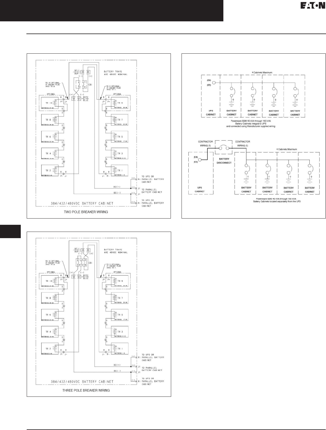
33.2-26
For more information, visit: www.eaton.com/consultants CA08104001E
September 2011
Uninterruptible Power Supplies
Sheet 33
22
23
24
25
26
27
28
29
30
31
32
33
34
35
36
37
38
39
40
41
42
43
Three-Phase Units
Eaton 9390
032
Wiring Diagrams and Specifications
Figure 33.2-21. 9390 Battery Cabinet Internal Wiring (Two-Pole)
Figure 33.2-22. 9390 Battery Cabinet Internal Wiring (Three-Pole)
Figure 33.2-23. 9390 Multiple Battery Cabinet Interconnect Wiring

CA08104001E For more information, visit: www.eaton.com/consultants
33.2-27
September 2011
Uninterruptible Power Supplies
Sheet 33
22
23
24
25
26
27
28
29
30
31
32
33
34
35
36
37
38
39
40
41
42
43
Three-Phase Units
Eaton 9390
033
Table 33.2-30. Battery Cabinet External Wiring and Termination Requirements (UPS-to-Battery, Battery-to-Battery, or Remote Disconnect to Battery)
Note: All specified wire sizes are 90°C rated copper minimum.
UPS Model
kVA
Battery
Type
No. of
Cabinets
Cabinet
Position
Wire Size Terminations Torque
Nm (in-lb)
Screw Size
and Type
UPS to Battery Battery to Battery
Eaton 9390 Model IBC-S
40 and 50 B12, B17, B20 1, 2, 3 or 4 Line-up-and-match Supplied
1 per pole
Supplied
1 per pole
1–#6-500 kcmil
2–1 bolt mounting
56.5 (500)
22.6 (200)
1/2-inch Allen
3/8-inch hex nut
B12, B17, B20 1, 2, 3 or 4 Stand-alone 1/0
1 per pole
1/0
1 per pole
1–#6-500 kcmil
2–1 bolt mounting
56.5 (500)
22.6 (200)
1/2-inch Allen
3/8-inch hex nut
60 B12, B17, B20 1, 2, 3 or 4 Line-up-and-match Supplied
1 per pole
Supplied
1 per pole
1–#6-500 kcmil
2–1 bolt mounting
56.5 (500)
22.6 (200)
1/2-inch Allen
3/8-inch hex nut
B12, B17, B20 1, 2, 3 or 4 Stand-alone 2/0
1 per pole
2/0
1 per pole
1–#6-500 kcmil
2–1 bolt mounting
56.5 (500)
22.6 (200)
1/2-inch Allen
3/8-inch hex nut
80 B12, B17, B20 1, 2, 3 or 4 Line-up-and-match Supplied
1 per pole
Supplied
1 per pole
1–#6-500 kcmil
2–1 bolt mounting
56.5 (500)
22.6 (200)
1/2-inch Allen
3/8-inch hex nut
B12, B17, B20 1, 2, 3 or 4 Stand-alone 3/0
1 per pole
3/0
1 per pole
1–#6-500 kcmil
2–1 bolt mounting
56.5 (500)
22.6 (200)
1/2-inch Allen
3/8-inch hex nut
Eaton 9390 Model IBC-L
40 and 50 B27, B31, B37, B47 1, 2, 3 or 4 Line-up-and-match Supplied
1 per pole
Supplied
1 per pole
2–#2-600 kcmil
2–1 bolt mounting
42.4 (375)
22.6 (200)
3/8-inch hex
M10 hex
B27, B31, B37, B47 1, 2, 3 or 4 Stand-alone 1/0
1 per pole
1/0
1 per pole
2–#2-600 kcmil
2–1 bolt mounting
42.4 (375)
22.6 (200)
3/8-inch hex
M10 hex
60 B27, B31, B37, B47 1, 2, 3 or 4 Line-up-and-match Supplied
1 per pole
Supplied
1 per pole
2–#2-600 kcmil
2–1 bolt mounting
42.4 (375)
22.6 (200)
3/8-inch hex
M10 hex
B27, B31, B37, B47 1, 2, 3 or 4 Stand-alone 2/0
1 per pole
2/0
1 per pole
2–#2-600 kcmil
2–1 bolt mounting
42.4 (375)
22.6 (200)
3/8-inch hex
M10 hex
80 B27, B31, B37, B47 1, 2, 3 or 4 Line-up-and-match Supplied
1 per pole
Supplied
1 per pole
2–#2-600 kcmil
2–1 bolt mounting
42.4 (375)
22.6 (200)
3/8-inch hex
M10 hex
B27, B31, B37, B47 1, 2, 3 or 4 Stand-alone 3/0
1 per pole
3/0
1 per pole
2–#2-600 kcmil
2–1 bolt mounting
42.4 (375)
22.6 (200)
3/8-inch hex
M10 hex
100 B27, B31, B37, B47 1, 2, 3 or 4 Line-up-and-match Supplied
2 per pole
Supplied
2 per pole
2–#2-600 kcmil
2–1 bolt mounting
42.4 (375)
22.6 (200)
3/8-inch hex
M10 hex
B27, B31, B37, B47 1, 2, 3 or 4 Stand-alone 2/0
2 per pole
2/0
2 per pole
2–#2-600 kcmil
2–1 bolt mounting
42.4 (375)
22.6 (200)
3/8-inch hex
M10 hex
120 B27, B31, B37, B47 1, 2, 3 or 4 Line-up-and-match Supplied
2 per pole
Supplied
2 per pole
2–#2-600 kcmil
2–1 bolt mounting
42.4 (375)
22.6 (200)
3/8-inch hex
M10 hex
B27, B31, B37, B47 1, 2, 3 or 4 Stand-alone 2/0
2 per pole
3/0
2 per pole
2–#2-600 kcmil
2–1 bolt mounting
42.4 (375)
22.6 (200)
3/8-inch hex
M10 hex
160 B27, B31, B37, B47 1, 2, 3 or 4 Line-up-and-match Supplied
2 per pole
Supplied
2 per pole
2–#2-600 kcmil
2–1 bolt mounting
42.4 (375)
22.6 (200)
3/8-inch hex
M10 hex
B27, B31, B37, B47 1, 2, 3 or 4 Stand-alone 250 kcmil
2 per pole
250 kcmil
2 per pole
2–#2-600 kcmil
2–1 bolt mounting
42.4 (375)
22.6 (200)
3/8-inch hex
M10 hex
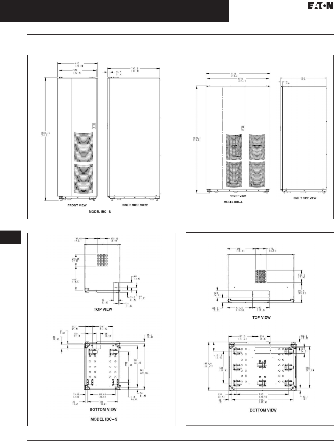
33.2-28
For more information, visit: www.eaton.com/consultants CA08104001E
September 2011
Uninterruptible Power Supplies
Sheet 33
22
23
24
25
26
27
28
29
30
31
32
33
34
35
36
37
38
39
40
41
42
43
Three-Phase Units
Eaton 9390
034
Dimensions in mm (Inches)
Figure 33.2-24. 9390 IBC-S Battery Cabinet Dimensions
Figure 33.2-25. 9390 IBC-S Battery Cabinet Top and Bottom View
Figure 33.2-26. 9390 Multiple Battery Cabinet Interconnect Wiring
Figure 33.2-27. 9390 IBC-S Battery Cabinet Top and Bottom View
CA08104001E For more information, visit: www.eaton.com/consultants
33.2-29
September 2011
Uninterruptible Power Supplies
Sheet 33
22
23
24
25
26
27
28
29
30
31
32
33
34
35
36
37
38
39
40
41
42
43
Three-Phase Units
Eaton 9390
035
Integrated Distribution
Cabinet™ for the
Eaton 9390 UPS
Power Protection and
Distribution for Data Centers
Eaton’s Integrated Distribution Cabinet
is specifically designed to complement
the Eaton 9390 family of three-phase
uninterruptible power systems (UPSs).
This cabinet integrates with the 9390
UPS models and is designed for the
specific power rating of the 9390 UPS
models from 40–160 kVA.
With this optional cabinet, Eaton
offers a complete, one-stop shop
for power protection and distribution
solutions that is easy to design, install,
customize and manage, while deliver-
ing “pay-as-you-grow” scalability
for future expansion.
Figure 33.2-28. Typical Application of
Eaton 9390 Integrated Distribution
Cabinet Distributing Power to IT Racks
Preconfigured for Ease-of-Use,
Mix-and-Match for Flexibility
The Integrated Distribution Cabinet is
preconfigured with the most popular
power distribution options for ease
of design and installation.
In addition, it offers the flexibility
to mix and match power distribution,
voltage transformation and mainte-
nance bypass options to select the
right combination of functions for
your data center requirements.
Power Distribution
■Options enable you to distribute
power to servers or racks via
distribution panelboards, or to
distribute power to larger loads
via distribution circuit breakers
Voltage Transformation
■Allows you to change output
voltage levels. For instance, you
could convert 480 Vac output from
the UPS into 208/120 Vac output to
serve single-phase loads. You can
also add an isolation transformer
if required
Maintenance Bypass
■
Enables power to completely bypass
the UPS power module. You can then
service or replace the UPS module in
complete safety, without interrupting
power to critical systems
Customized for Today’s Needs, Scalable
for Tomorrow’s Growth
In today’s economy, “pay as you grow”
is more than a catch phrase; it’s a way
of life. So is the need to balance the
often-conflicting requirements of
budgets, operational demands and
future growth.
Eaton addresses these realities with
a flexible architecture that lets you
configure just the right combination
of functions to complement your UPS.
You save money by only specifying
what your system currently needs—
while keeping your options open
for future expansion.
Simplified Installation and
Clean Appearance
The Integrated Distribution Cabinet has
the same look and finish as the Eaton
9390 UPS system it complements.
The cabinet is shipped with intercon-
necting cables for fast and easy
installation with the Eaton 9390 UPS.
The result is a clean look that enhances
the appearance of your data center.
Integrated Management and
Support for Enhanced Confidence
The 9390 UPS models can be
monitored and managed by
Eaton software such as LanSafe™,
PowerVision® and Foreseer®. This
close integration provides greater
visibility to your complete power
protection infrastructure.
Eaton also backs up the Integrated
Distribution Cabinet with the standard
one-year limited factory warranty we
offer on the 9390 UPS models. You can
have the confidence that both your
power protection and distribution
are supported by Eaton’s best-in-class
Global Services organization and
strong customer service commitments.
To find out more about the Integrated
Distribution Cabinet option or the
Eaton 9390 UPS, visit Eaton’s Web
site at www.eaton.com/9390, or
call 1-800-356-5794.
Table 33.2-31.
9390 40–80 kVA Integrated
Distribution Cabinet Technical Specifications
Three in combination with one panelboard.
Description Specification
General Characteristics
Installation Line up and match to UPS
Front access only
Color Same as UPS
Construction NEMA® 1 ventilated
Input voltage 208, 480
Output voltage
Isolation
Distribution
208, 208/120V
208/120V
Dimensions
inches (mm)
40–80 kVA
35.60 W x 31.60 D x 74.40 H
(904.2 W x 802.6 D x 1890.0 H)
Weight 1200 lbs (545 kg) (maximum)
Certification
Safety UL 1778
Markings UL, cUL
User Interface
Cable entry Top or bottom
EPO switch Optional
Transformer Option
Electrostatic
shield
Standard
Insulation 150°C rise, Class H
Impedance 5% (maximum)
K-factor K1; K13; K20
Compensation
taps
2-FCAN, 4-FCBN standard
Overload
protection
Input breaker standard
Power Distribution Option
Panelboard
distribution
Quantity
Voltage
Main breaker
Circuits
2 (maximum)
208/120V
225A, 65 kAIC
84 (maximum)
Distribution
breakers
(in lieu of
panelboards)
Quantity
Voltage
Size
6 (maximum)
208/120V
225A, 65 kAIC
Maintenance Bypass Option
Maintenance
bypass
Optional
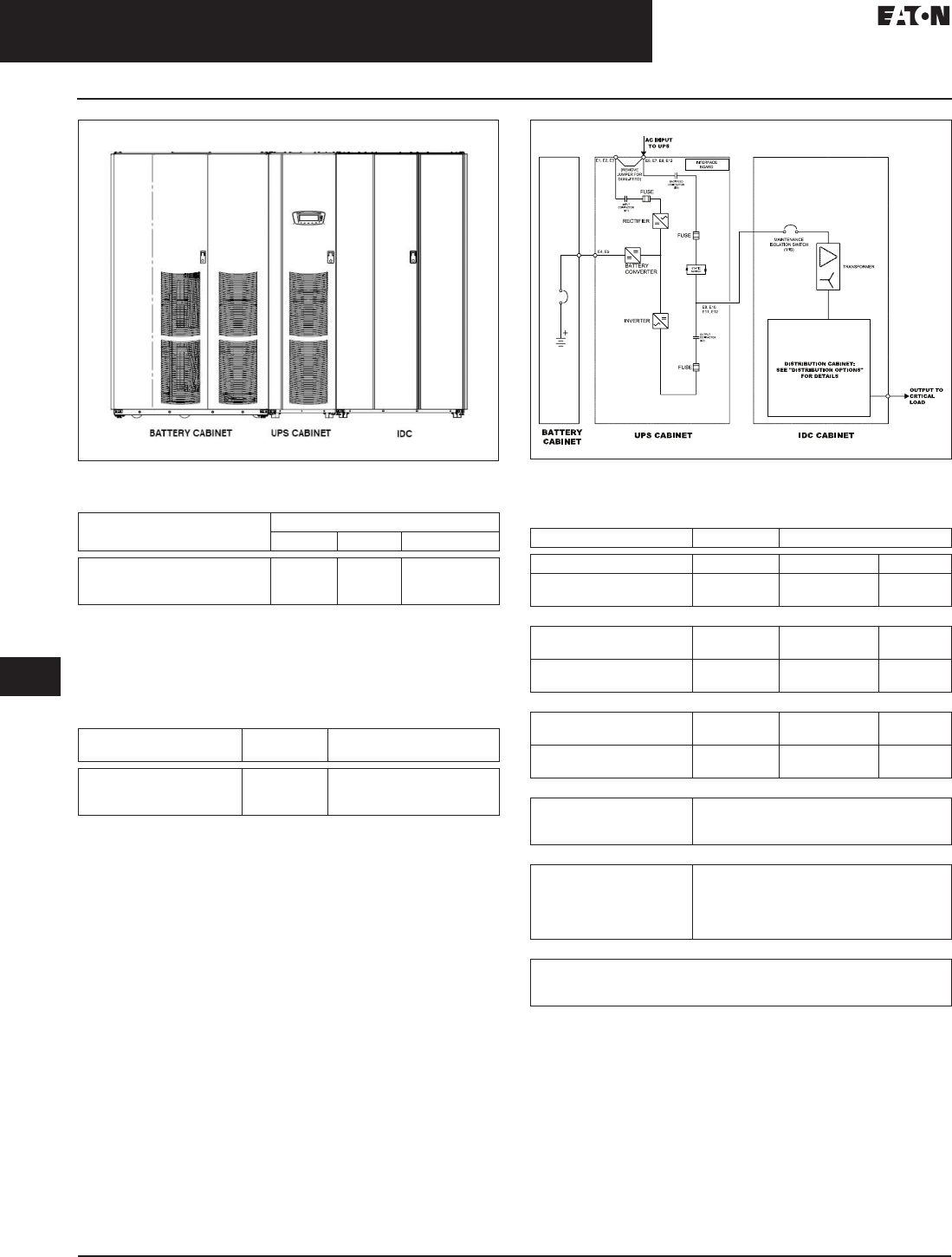
33.2-30
For more information, visit: www.eaton.com/consultants CA08104001E
September 2011
Uninterruptible Power Supplies
Sheet 33
22
23
24
25
26
27
28
29
30
31
32
33
34
35
36
37
38
39
40
41
42
43
Three-Phase Units
Eaton 9390
036
Figure 33.2-29. 9390 UPS, IBC-L and IDC Lineup
Table 33.2-32. Eaton 9390 40–80 kVA IDC Equipment Weight
Note: For IDC with transformer, add 331 kg (730 lbs).
For IDC with distribution panels, add 11.3 kg (25 lbs) for each panel.
For IDC with distribution breakers, add 6.8 kg (15 lbs) for each breaker.
For IDC with output lugs, add 2.3 kg (5 lbs).
Table 33.2-33. Eaton 9390 40–80 kVA IDC Air Conditioning or Ventilation
Requirements During Full Load Operation
Figure 33.2-30. 9390 (40–80 kVA) UPS, IBC-L and IDC One-line
Table 33.2-34. Input/Output Ratings and External Wiring Requirements
for Eaton 9390 80 kVA IDC
For contractor-supplied wiring, refer to the Eaton 9390
UPS (40–80 kVA) Installation and Operation Manual for wire size.
Wiring for Line-up-and-Match cabinet installation is factory supplied.
Component/Model Weight kg (Lbs)
Shipping Installed Point Loading
Eaton 9390 80 kVA IDC with
maintenance bypass switch
and input breaker
236 (520) 213 (470) 6 at 35.5 (78.3)
Component/Model Input/Output
Voltage
Heat Rejection
BTU/hr x 1000/hr (kg-cal/hr)
IDC-80 without transformer
IDC-80 with transformer
IDC-80 with transformer
N/A
208/208
480/208
N/A
7.4 (1.8)
7.4 (1.8)
Description Units Rating 60 Hz
Basic unit rating UPS kVA 40/50/6080 40/50/60/80
IDC input and bypass input
IDC output
Volts
Volts
208
208
480
208
A—AC Input from UPS—Stand-alone Installation
(3) phases, (1) neutral-
if required, (1) ground
Amps 111/155/185/222 48/67/80/96
Minimum conductor size
number per phase
AWG or kcmil
(each)
B—AC Input to Maintenance Bypass—Stand-alone Installation
(3) Phases, (1) neutral-
if required, (1) ground
Amps 111/155/185/222 48/67/80/96
Minimum conductor size
number per phase
AWG or kcmil
(each)
2/0
(2)
1/0
(1)
C—AC Output from 225A Distribution Breaker to Critical Load
(3) phases, (1) neutral,
(1) ground
Wire branch circuits according to the branch
circuit breaker manufacturer’s ratings, and
national and local electrical codes.
C—AC Output from Output Terminal Block to Critical Load
(3) phases, (1) neutral,
(1) ground
Wire output according to national and
local electrical codes. Refer to the Eaton 9390
UPS (40–80 kVA) Installation and Operation
Manual for output current rating and
wire size.
C—AC Output from Distribution Panel Breakers to Critical Load
Wire branch circuits according to the branch circuit breaker manufacturer’s
ratings and instructions, and national and local electrical codes
(output is prewired to the panelboard).
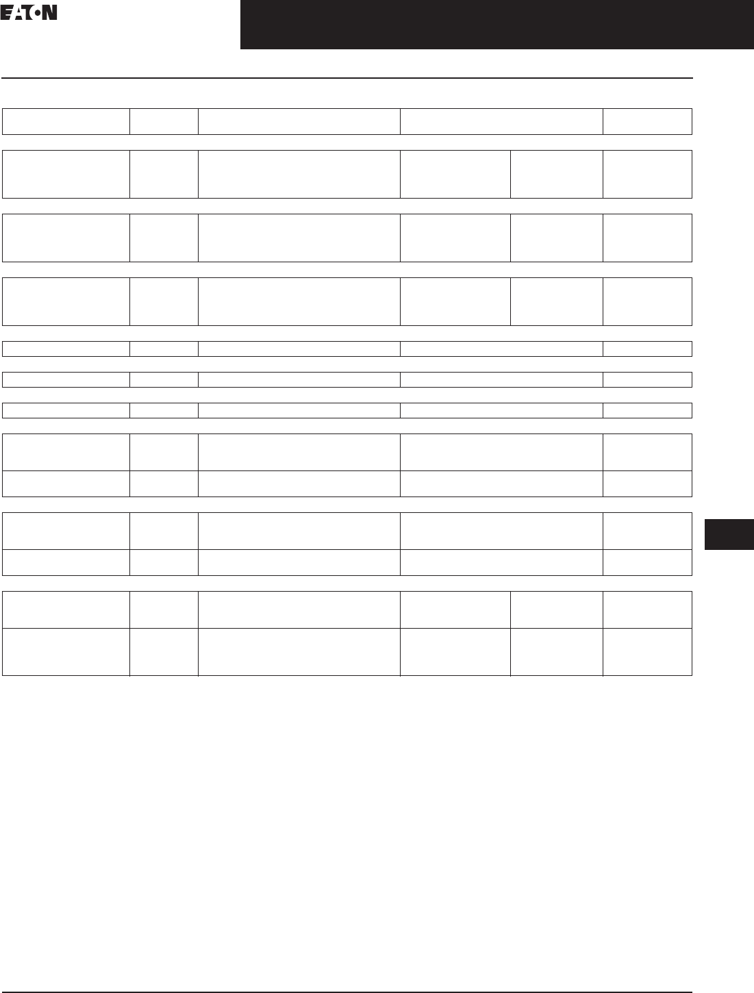
CA08104001E For more information, visit: www.eaton.com/consultants
33.2-31
September 2011
Uninterruptible Power Supplies
Sheet 33
22
23
24
25
26
27
28
29
30
31
32
33
34
35
36
37
38
39
40
41
42
43
Three-Phase Units
Eaton 9390
037
Table 33.2-35. IDC-80 Power Cable Terminations 208V/208V
Wire branch circuits according to the branch circuit breaker manufacturer’s ratings and instructions (output is prewired to the panelboard).
Terminal Function Size of Pressure
Termination
Tightening Torque
Nm (in-lb)
Screw
Type
AC Input from UPS (with Maintenance Bypass)
S1–3
S1–7
S1–11
Phase A
Phase B
Phase C
2–#14-2/0
2–#14-2/0
2–#14-2/0
2/0-#3:
#4-#6:
#8:
#10-#14:
5.6 (50)
5.0 (45)
4.5 (40)
4.0 (35)
Slotted
Slotted
Slotted
AC Input to Maintenance Bypass (with Maintenance Bypass)
S1–1
S1–5
S1–9
Phase A
Phase B
Phase C
2–#14-2/0
2–#14-2/0
2–#14-2/0
2/0-#3:
#4-#6:
#8:
#10-#14:
5.6 (50)
5.0 (45)
4.5 (40)
4.0 (35)
Slotted
Slotted
Slotted
AC Input from UPS (without Maintenance Bypass)
CB1–2
CB1–4
CB1–6
Phase A
Phase B
Phase C
2–#14-2/0
2–#14-2/0
2–#14-2/0
2/0-#3:
#4-#6:
#8:
#10-#14:
5.6 (50)
5.0 (45)
4.5 (40)
4.0 (35)
1/4-inch hex
1/4-inch hex
1/4-inch hex
Input Neutral from UPS (Models without a Transformer)—if Required
E4 Neutral 4–#4-300 kcmil 31 (275) 5/16-inch hex
Input Neutral from Bypass (Models without a Transformer)—if Required
E4 Neutral 4–#4-300 kcmil 31 (275) 5/16-inch hex
Input Ground
E9 Ground 2–#14-1/0 5.6 (50) Slotted
AC Output from 225A Distribution Breaker to Critical Load
CBxx–1
CBxx–3
CBxx–5
Phase A
Phase B
Phase C
1–#4-300 kcmil
1–#4-300 kcmil
1–#4-300 kcmil
22.6 (200)
22.6 (200)
22.6 (200)
1/4-inch hex
1/4-inch hex
1/4-inch hex
E10, E20
E18, E19, E28, E29
Neutral
Ground
4 ea.–#4-300 kcmil
2 ea.–#14-1/0
31 (275)
5.6 (50)
5/16-inch hex
Slotted
AC Output from Output Terminal Block to Critical Load
E11
E12
E13
Phase A
Phase B
Phase C
2–#6-250 kcmil
2–#6-250 kcmil
2–#6-250 kcmil
42.4 (375)
42.4 (375)
42.4 (375)
5/16-inch hex
5/16-inch hex
5/16-inch hex
E10
E19
Neutral
Ground
4–#4-300 kcmil
2–#14-1/0
31 (275)
5.6 (50)
5/16-inch hex
Slotted
AC Output from Distribution Panel Breakers to Critical Load
PB1–N
PB2–N
Neutral 45–#4-#14 #4-#6:
#8:
#10-#14:
4.0 (35)
2.8 (25)
2.3 (20)
Slotted
E18, E19, E28, E29 Ground 46–#4-#14 or
2 each #12–#14
#4-#6:
#8:
#10-#14:
#12-#14:
4.0 (35)
2.8 (25)
2.3 (20)
2.8 (25)
Slotted
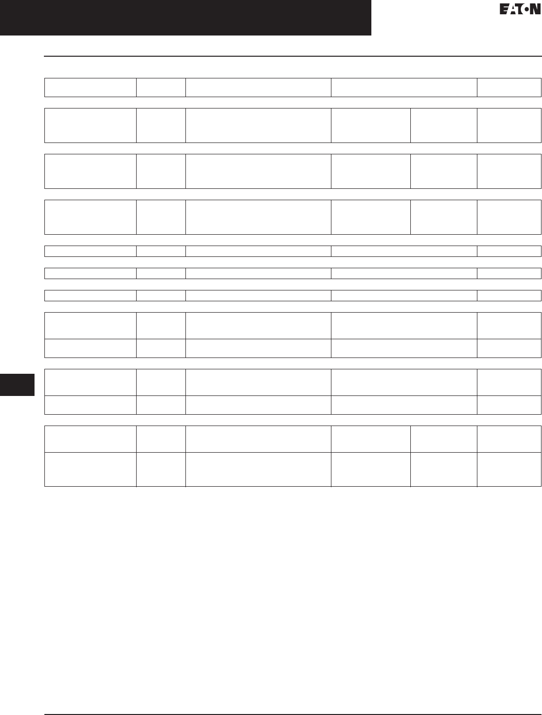
33.2-32
For more information, visit: www.eaton.com/consultants CA08104001E
September 2011
Uninterruptible Power Supplies
Sheet 33
22
23
24
25
26
27
28
29
30
31
32
33
34
35
36
37
38
39
40
41
42
43
Three-Phase Units
Eaton 9390
038
Table 33.2-36. IDC-80 Power Cable Terminations 480V/208V
Wire branch circuits according to the branch circuit breaker manufacturer’s ratings and instructions (output is prewired to the panelboard).
Terminal Function Size of Pressure
Termination
Tightening Torque
Nm (in-lb)
Screw
Type
AC Input from UPS (with Maintenance Bypass)
S1–3
S1–7
S1–11
Phase A
Phase B
Phase C
1–#14-2/0
1–#14-2/0
1–#14-2/0
2/0-#3:
#4-#6:
#8:
#10-#14:
5.6 (50)
5.0 (45)
4.5 (40)
4.0 (35)
Slotted
Slotted
Slotted
AC Input to Maintenance Bypass (with Maintenance Bypass)
S1–1
S1–5
S1–9
Phase A
Phase B
Phase C
1–#14-2/0
1–#14-2/0
1–#14-2/0
2/0-#3:
#4-#6:
#8:
#10-#14:
5.6 (50)
5.0 (45)
4.5 (40)
4.0 (35)
Slotted
Slotted
Slotted
AC Input from UPS (without Maintenance Bypass)
CB1–2
CB1–4
CB1–6
Phase A
Phase B
Phase C
1–#14-2/0
1–#14-2/0
1–#14-2/0
2/0-#3:
#4-#6:
#8:
#10-#14:
5.6 (50)
5.0 (45)
4.5 (40)
4.0 (35)
1/4-inch hex
1/4-inch hex
1/4-inch hex
Input Neutral from UPS (Models without a Transformer)—if Required
E4 Neutral 4–#4-300 kcmil 31 (275) 5/16-inch hex
Input Neutral from Bypass (Models without a Transformer)—if Required
E4 Neutral 4–#4-300 kcmil 31 (275) 5/16-inch hex
Input Ground
E9 Ground 2–#14-1/0 5.6 (50) Slotted
AC Output from 225A Distribution Breaker to Critical Load
CBxx–1
CBxx–3
CBxx–5
Phase A
Phase B
Phase C
1–#4-300 kcmil
1–#4-300 kcmil
1–#4-300 kcmil
22.6 (200)
22.6 (200)
22.6 (200)
1/4-inch hex
1/4-inch hex
1/4-inch hex
E10, E20
E18, E19, E28, E29
Neutral
Ground
4 ea.–#4-300 kcmil
2 ea.–#14-1/0
31 (275)
5.6 (50)
5/16-inch hex
Slotted
AC Output from Output Terminal Block to Critical Load
E11
E12
E13
Phase A
Phase B
Phase C
2–#6-250 kcmil
2–#6-250 kcmil
2–#6-250 kcmil
42.4 (375)
42.4 (375)
42.4 (375)
5/16-inch hex
5/16-inch hex
5/16-inch hex
E10
E19
Neutral
Ground
4–#4-300 kcmil
2–#14-1/0
31 (275)
5.6 (50)
5/16-inch hex
Slotted
AC Output from Distribution Panel Breakers to Critical Load
PB1–N
PB2–N
Neutral 45–#4-#14 #4-#6:
#8:
#10-#14:
4.0 (35)
2.8 (25)
2.3 (20)
Slotted
E18, E19, E28, E29 Ground 46–#4-#14 or
2 each #12–#14
#4-#6:
#8:
#10-#14:
#12-#14:
4.0 (35)
2.8 (25)
2.3 (20)
2.8 (25)
Slotted
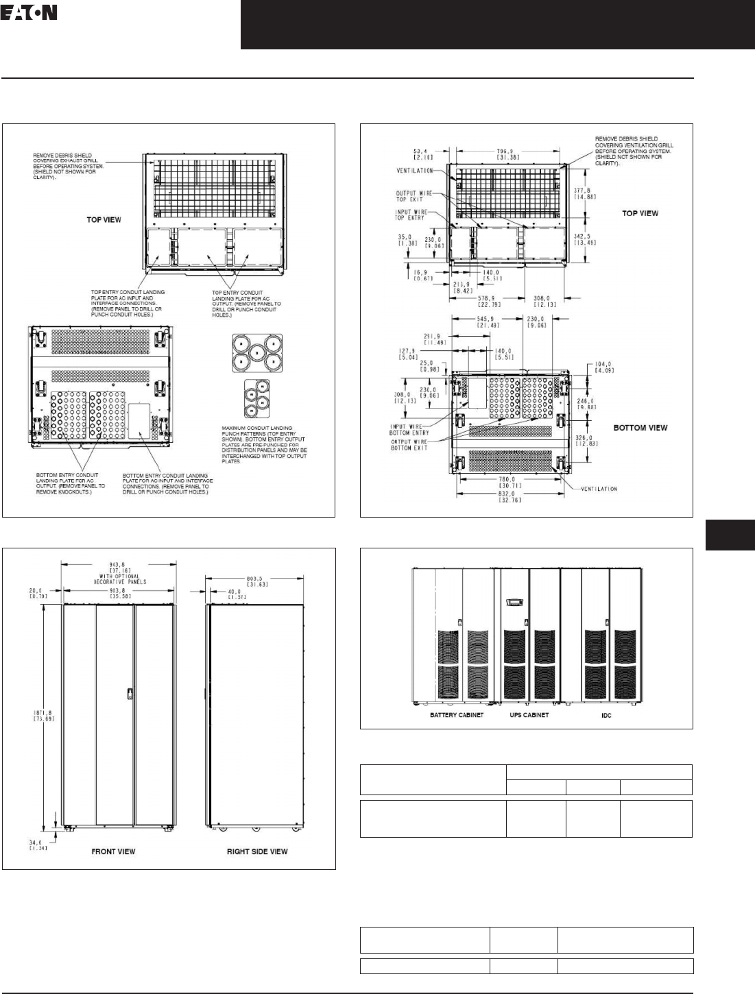
CA08104001E For more information, visit: www.eaton.com/consultants
33.2-33
September 2011
Uninterruptible Power Supplies
Sheet 33
22
23
24
25
26
27
28
29
30
31
32
33
34
35
36
37
38
39
40
41
42
43
Three-Phase Units
Eaton 9390
039
Dimensions in mm (Inches)
Figure 33.2-31. 9390 (40–80 kVA) IDC Top and Bottom View
Figure 33.2-32. 9390 (40–80 kVA) IDC Front and Side View
Figure 33.2-33. 9390 (40–80 kVA) IDC Top and Bottom View
Figure 33.2-34. 9390 (100 to 160 kVA) IDC-L and IDC Lineup
Table 33.2-37. Eaton 9390 40–80 kVA IDC Equipment Weight
Note:
For IDC with distribution panels, add 25 lbs (11.3 kg) for each
panel. For IDC with distribution breakers, add 15 lbs (6.8 kg) for each
breaker. For IDC with output lugs, add 5 lbs (2.3 kg). For IDC with a BIB,
add 15 lbs (6.8 kg). For IDC with a BIB and RIB, add 30 lbs (13.6 kg).
Table 33.2-38. Eaton 9390 40–80 kVA IDC Air Conditioning
or Ventilation Requirements During Full Load Operation
Component/Model Weight Lbs (kg)
Shipping Installed Point Loading
Eaton 9390 160 kVA IDC
Cabinet with transformer and
maintenance bypass breakers
2250 (1021) 2185 (991) 4 at
546.3 (247.8)
Component/Model Input/Output
Voltage
Heat Rejection
BTU/hr x 1000/hr (kg-cal/hr)
IDC-160 with transformer 480/208 14.8 (3.6)
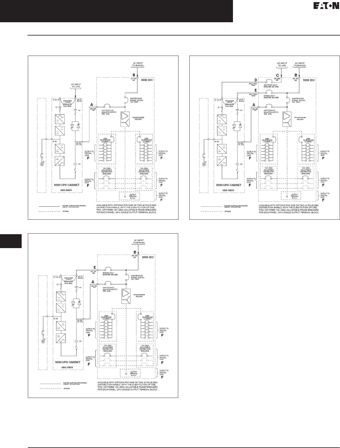
33.2-34
For more information, visit: www.eaton.com/consultants CA08104001E
September 2011
Uninterruptible Power Supplies
Sheet 33
22
23
24
25
26
27
28
29
30
31
32
33
34
35
36
37
38
39
40
41
42
43
Three-Phase Units
Eaton 9390
040
Wiring Diagrams and Specifications
Figure 33.2-35. 9390 (100–160 kVA) IDC with Two Breaker Bypass
Figure 33.2-36. 9390 (100–160 kVA) IDC with Three Breaker Bypass
Figure 33.2-37. 9390 (100–60 kVA) IDC with Four Breaker Bypass

CA08104001E For more information, visit: www.eaton.com/consultants
33.2-35
September 2011
Uninterruptible Power Supplies
Sheet 33
22
23
24
25
26
27
28
29
30
31
32
33
34
35
36
37
38
39
40
41
42
43
Three-Phase Units
Eaton 9390
041
Table 33.2-39. Input/Output Ratings and External Wiring Requirements
for Eaton 9390 80 kVA IDC
For contractor-supplied wiring, refer to Eaton 9390 UPS manual for
wire size. Wiring for Line-up-and-Match installation is factory-supplied.
Read and understand the following notes while planning
and performing the installation:
1. Refer to national and local electrical codes for
acceptable external wiring practices.
2. Material and labor for external wiring requirements
are to be provided by designated personnel.
3. For external input wiring, use 90°C copper wire.
Wire sizes are based on using the specified breakers.
4. Wire ampacities are chosen from Table 310.16 of the
NEC. Input wire is 90°C specification.
5. If a BIB is not installed, a minimum of two separate
feeds with upstream feeder breakers must be provided.
One for the for the UPS and one for the IDC bypass
input. Do not use one feed for both UPS and IDC.
6. The IDC cabinet is shipped with a debris shield covering
the ventilation grill on top of the unit. Do not remove
the debris shield until installation is complete. However,
remove the shield before operating the IDC. Once the
debris shield is removed, do not place objects on the
ventilation grill.
7. Optional 225A distribution panel uses Eaton type CH
breakers to be provided by the customer.
8. Refer to Section I of the manual for installation
instructions.
9. Refer to the Eaton 9390 UPS (100–160 kVA)
Installation and Operation Manual for UPS cabinet
conduit and terminal locations.
10. Terminals are UL and CSA rated at 90°C. Refer to
the table for power cable terminations.
11. Per NEC Article 300.20(a), all three-phase conductors
must be run in the same conduit. Neutral and
ground must be run in the same conduit as the
phase conductors.
Description Units Rating 60 Hz
Basic unit rating UPS kVA 100/120/160
IDC input and IDC bypass input
IDC output
Volts
Volts
480
208
A—AC Input from UPS—Stand-alone Installation
(3) phases, (1) ground Amps 120/144/192
Minimum conductor size
Number per phase
AWG or kcmil
(each)
B—AC Input to Maintenance Bypass
(Line-up-and-Match or Stand-alone Installation)
(3) phases, (1) ground Amps 120/144/192
Minimum conductor size
number per phase
AWG or kcmil
(each)
1/0
(2)
C—AC Input to Optional RIB
(Line-up-and-Match or Stand-alone Installation)
(3) phases, (1) ground Amps 130/160/210
Minimum conductor size
number per phase
AWG or kcmil
(each)
1/0
(2)
D—AC Output from Optional RIB to UPS (Stand-alone Installation)
(3) phases, (1) ground Amps 130/160/210
Minimum conductor size
number per phase
AWG or kcmil
(each)
E—AC Output from Optional BIB to UPS (Stand-alone Installation)
(3) phases, (1) ground Amps 120/144/192
Minimum conductor size
number per phase
AWG or kcmil
(each)
F—AC Output from Distribution Breaker to Critical Load
(3) phases, (1) neutral,
(1) ground
Wire branch circuits in accordance
with branch circuit breaker
manufacturers ratings, and national
and local electrical codes.
F—AC Output from Output Terminal Block to Critical Load
(3) phases, (1) neutral,
(1) ground
Wire output in accordance with national
and local electrical codes. Refer to
Eaton 9390 UPS manual for
output current rating and wire size.
F—AC Output from Distribution Panel Breakers to Critical Load
Wire branch circuits in accordance with branch circuit breaker
manufacturers ratings and instructions, and national and local electrical
codes (output is prewired to the panelboard).

33.2-36
For more information, visit: www.eaton.com/consultants CA08104001E
September 2011
Uninterruptible Power Supplies
Sheet 33
22
23
24
25
26
27
28
29
30
31
32
33
34
35
36
37
38
39
40
41
42
43
Three-Phase Units
Eaton 9390
042
Table 33.2-40. IDC-160 Power Cable Terminations 480V/208V
Wire branch circuits according to the branch circuit breaker manufacturer’s ratings and instructions (output is prewired to the panelboard).
Terminal Function Size of Pressure
Termination
Tightening
Torque Nm (in-lb)
Screw
Type
AC Input from UPS
E54
E55
E56
Phase A
Phase B
Phase C
2–#6-250 kcmil
2–#6-250 kcmil
2–#6-250 kcmil
42.4 (375)
42.4 (375)
42.4 (375)
5/16-inch hex
5/16-inch hex
5/16-inch hex
AC Input to Maintenance Bypass
E51
E52
E53
Phase A
Phase B
Phase C
2–#6-250 kcmil
2–#6-250 kcmil
2–#6-250 kcmil
42.4 (375)
42.4 (375)
42.4 (375)
5/16-inch hex
5/16-inch hex
5/16-inch hex
AC Input to Optional RIB
E57
E58
E59
Phase A
Phase B
Phase C
2–#6-250 kcmil
2–#6-250 kcmil
2–#6-250 kcmil
42.4 (375)
42.4 (375)
42.4 (375)
5/16-inch hex
5/16-inch hex
5/16-inch hex
AC Output from Optional RIB (CB4) to UPS
RIB–2
RIB–4
RIB–6
Phase A
Phase B
Phase C
1–#4-350 kcmil
1–#4-350 kcmil
1–#4-350 kcmil
20.3 (180)
20.3 (180)
20.3 (180)
3/16-inch hex
3/16-inch hex
3/16-inch hex
AC Output from Optional BIB to UPS (without RIB)
E57
E58
E59
Phase A
Phase B
Phase C
2–#6-250 kcmil
2–#6-250 kcmil
2–#6-250 kcmil
42.4 (375)
42.4 (375)
42.4 (375)
5/16-inch hex
5/16-inch hex
5/16-inch hex
AC Output from Optional BIB (CB3) to UPS (without RIB)
BIB–1
BIB–3
BIB–5
Phase A
Phase B
Phase C
1–#4-350 kcmil
1–#4-350 kcmil
1–#4-350 kcmil
20.3 (180)
20.3 (180)
20.3 (180)
3/16-inch hex
3/16-inch hex
3/16-inch hex
Ground
E8
E9
Ground
Ground
2–#14-1/0
2–#14-1/0
5.6 (50)
5.6 (50)
Slotted
Slotted
AC Output from Distribution Breaker to Critical Load
CBxx–2
CBxx–4
CBxx–6
Phase A
Phase B
Phase C
1–#4-350 kcmil
1–#4-350 kcmil
1–#4-350 kcmil
20.3 (180)
20.3 (180)
20.3 (180)
3/16-inch hex
3/16-inch hex
3/16-inch hex
E10, E20
E18, E19, E28, E29
Neutral
Ground
4 ea.–#4-300 kcmil
2 ea.–#14-1/0
31 (275)
5.6 (50)
5/16-inch hex
Slotted
AC Output from Output Terminal Block to Critical Load
E11
E12
E13
Phase A
Phase B
Phase C
2–#6-500 kcmil
2–#6-500 kcmil
2–#6-500 kcmil
56.5 (500)
56.5 (500)
56.5 (500)
1/2-inch hex
1/2-inch hex
1/2-inch hex
E10
E19
Neutral
Ground
4–#6-500 kcmil
2–#14-1/0
56.5 (500)
5.6 (50)
1/2-inch hex
Slotted
AC Output from Distribution Panel Breakers to Critical Load
PB1–N
PB2–N
Neutral 42–#4-#14 #4-#6:
#8:
#10-#14:
4.0 (35)
2.8 (25)
2.3 (20)
Slotted
E18, E19, E28, E29 Ground 42–#4-#14 #4-#6:
#8:
#10-#14:
4.0 (35)
2.8 (25)
2.3 (20)
Slotted
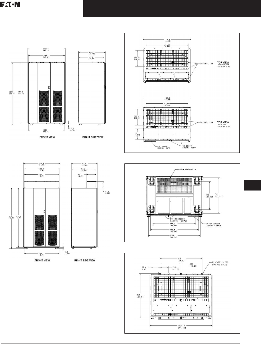
CA08104001E For more information, visit: www.eaton.com/consultants
33.2-37
September 2011
Uninterruptible Power Supplies
Sheet 33
22
23
24
25
26
27
28
29
30
31
32
33
34
35
36
37
38
39
40
41
42
43
Three-Phase Units
Eaton 9390
043
Dimensions in mm (Inches)
Figure 33.2-38. 9390 (100–160 kVA) IDC Front and Side View
Without Top Cable Entry Option
Figure 33.2-39. 9390 (100–160 kVA) IDC with Two Breaker Bypass
Figure 33.2-40. 9390 (100–160 kVA) IDC with Three Breaker Bypass
Figure 33.2-41. 9390 (100–160 kVA) IDC with Four Breaker Bypass
Figure 33.2-42. 9390 (100–160 kVA) IDC with Four Breaker Bypass

33.2-38
For more information, visit: www.eaton.com/consultants CA08104001E
September 2011
Uninterruptible Power Supplies
Sheet 33
22
23
24
25
26
27
28
29
30
31
32
33
34
35
36
37
38
39
40
41
42
43
Three-Phase Units
Eaton 9390
044
The Eaton 9390
Integrated
Accessory Cabinets
The IAC is designed for use with
the Eaton 9390 40 kVA to 160 kVA
three-phase uninterruptible power
systems. The IAC provides mainte-
nance bypass, parallel tie cabinet, or
parallel tie cabinet with maintenance
bypass functions with the following
custom-configurable features,
enabling adaptation and expansion
without costly electrical rework.
The IAC comes in two physical sizes,
a small cabinet mounted on the side
of the UPS and a larger freestanding
cabinet. The cabinet function UPS
sized voltage determines which size
cabinet is used. The IAC-SB and IAC-ST
are slim-line cabinets that are shipped
attached to the side of the UPS system.
These cabinets give the UPS system
the smallest footprint possible.
Maintenance Bypass Configuration
■Maintenance bypass (MBP) and
maintenance isolation (MIS) breakers
enable power to completely bypass
the UPS power module. The UPS
module can then be safely serviced
or replaced, without interrupting
power to critical systems. An
optional bypass input breaker (BIB)
and rectifier input breaker (RIB)
provide a single wiring point input
to the UPS and a convenient method
for removing power from the UPS,
when using the maintenance bypass
to supply the load
Parallel Redundant Configuration
■Module output breakers (MOB)
1 and 2 enable two UPS modules
to be paralleled together for
redundancy. An optional system
load breaker (SLB) provides output
control to the critical load for the
whole system
Parallel Redundant Configuration
with Maintenance Bypass
■Module output breakers (MOB)
1 and 2 enable two UPS modules
to be paralleled together for
redundancy. Optional maintenance
bypass (MBP) and maintenance
isolation (MIS) breakers enable
power to completely bypass the
UPS power module
The IAC-B and IAC-T are housed in
a single, freestanding cabinet, with
safety shields behind the doors for
hazardous voltage protection. The
cabinet matches the UPS cabinet in
style and color, and can be installed
in line-up-and-match or stand-alone
configurations.
IAC Standard Features
The IAC has many standard features
that provide a cost-effective and
reliable power system. The descrip-
tions provide a brief overview of
the IAC controls, and standard and
optional features.
Maintenance Bypass Configuration
■A maintenance bypass switch (MBP),
in combination with the maintenance
isolation switch (MIS), can be used
to completely isolate the UPS during
service. The UPS can be serviced or
replaced without interrupting power
to critical systems
Parallel Redundant Configuration
■Module output breakers (MOBs) 1
and 2 enable two UPS modules to be
paralleled together for redundancy.
An optional system level breaker
provides output control to the critical
load for the whole system
Parallel Redundant Configuration
with Maintenance Bypass
■MOBs 1 and 2 enable two UPS
modules to be paralleled together
for redundancy. The MBP, in combi-
nation with the MIS, can be used to
completely isolate the UPS during
service without interrupting power
to critical systems
Control Interface
■The IAC uses one UPS building
alarm input for maintenance bypass
switch monitoring. This alarm input
will detect when the maintenance
bypass switch is closed and the
system is on bypass
Installation Features
■The IAC-B and IAC-T can be installed
in line-up-and-match or stand-alone
configurations. The cabinet can be
permanently bolted to the floor or
left standing on leveling feet. Power
and control wiring can be routed
through the top or bottom of the
cabinet with connections made
to easily accessible terminals.
Line-up-and-match cabinets are
wired through knockouts in the
side panels of the units
Expansion
■The IAC supports custom configura-
tions and scalability to adapt to
changing and future power and
distribution needs
Options
Contact your sales representative
for information about any of these
available options:
Bypass Input Breaker
■Maintenance bypass configurations
have an optional bypass input
breaker for single-feed and dual-
feed systems. The BIB provides a
single point of input power control
to the UPS and easily removes
power from the UPS for servicing
Rectifier Input Breaker
■Maintenance bypass configurations
have an optional rectifier input
breaker for dual-feed systems.
The RIB provides a single point of
rectifier input power control to the
UPS and easily removes power
from the UPS for servicing
System Load Breaker
■A parallel redundant configuration
with an optional system load
breaker is available to control the
output to the critical load for the
whole system

CA08104001E For more information, visit: www.eaton.com/consultants
33.2-39
September 2011
Uninterruptible Power Supplies
Sheet 33
22
23
24
25
26
27
28
29
30
31
32
33
34
35
36
37
38
39
40
41
42
43
Three-Phase Units
Eaton 9390
045
The Eaton 9390 Integrated
Accessory Cabinet-
Distribution (IAC-D)
The IAC-D is designed for use with
the Eaton 9390 three-phase uninter-
ruptible power systems. The IAC-D
provides power distribution options
for servers, racks and other equipment
via distribution panelboards, or
distributes power to larger loads via
distribution circuit breakers. The
distribution options are custom
configurable, enabling adaptation
and expansion without costly
electrical rework.
The IAC-D is housed in a single,
free-standing cabinet, with safety
shields behind the doors for hazardous
voltage protection. The cabinet
matches the UPS cabinet in style
and color, and can be installed in
line-up-and-match or stand-alone
configurations. Figure 33.2-43 shows
the Eaton 9390 IAC-D.
Configurations
The following IAC-D configurations
are possible:
■One or two 225A distribution panels
(208V only)
■One to six 40–100A adjustable
distribution breakers (208V or 480V)
■One to six 100–250A adjustable
distribution breakers (208V
or 480V)
■One 225A distribution panel and
one to three 100–250A adjustable
distribution breakers (208V only)
■One 225A distribution panel and
one to three 40–100A adjustable
distribution breakers (208V only)
1. The IAC-D equipment operating environment must meet the weight require-
ments shown in Table A and size requirements shown in Figure 33.2-43.
2. The IAC-D cabinet is palleted separately for shipping.
3. Do not tilt cabinets more than ±10° during handling.
4. Dimensions are in millimeters (inches).
Table 33.2-41. Equipment Weight
For IAC–D with distribution panels, add 25 lbs (11.3 kg) for each panel.
For IAC–D with distribution breakers, add 15 lbs (6.8 kg) for each breaker.
For IAC–D with cosmetic covers, add 60 lbs (27.2 kg).
5. The clearances required around the IAC-D cabinet are shown in Table 33.2-43
Table 33.2-42. IAC-D Cabinet Clearances
6. The basic environmental requirements for operation of the IAC-D are:
c. Ambient temperature range: 0–40°C (32–104°F).
d. Recommended operating range: 20–25°C (68–77°F).
e. Maximum relative humidity: 95%, noncondensing.
7. The IAC-D ventilation requirements are shown in Table 33.2-43.
Table 33.2-43. Air Conditioning or Ventilation Requirements During Full Load Operation
Table 33.2-44. Input/Output Ratings and External Wiring Requirements for Eaton 9390 IAC-D
Component/Model Weight Lbs (kg)
Shipping Installed Point Loading
Eaton 9390 IAC–D (cabinet only) 465 (210.9) 415 (188.2) 103.8 (4 at 47.1)
Area Dimensions in
Inches (mm)
From top of cabinet Minimum clearance over the IAC–D cabinet is
18 inches (457.2 mm) for ventilation
From front of cabinet 36 inches (914.4 mm) working space
From back of cabinet None required
From right side of cabinet None required
From left side of cabinet None required
Component/Model Input/Output
Voltage
Heat Rejection
BTU/hr x 1000/hr (kg–cal/hr)
Eaton 9390 IAC-D N/A N/A
Description Units Rating 50/60 Hz
AC input from UPS
(standalone installation)
(3) phases, (1) ground
Amps Maximum input ratings are to be in accordance with
the rating label on the IAC-D and not to exceed 500A.
The total combined load is not to exceed the UPS
output ratings.
Minimum conductor
size number per phase
AWG or
kcmil
(each)
For contractor-supplied wiring, refer to the applicable
Eaton 9390 UPS Installation and Operation manual, listed
in paragraph 1.5. Wiring should be sized in accordance with
the rating label on the IAC-D. Factory supplied wiring for
line-up-and-match installation is available as an option.
AC output from distribution
breaker to critical load
(3) phases, (1) neutral,
(1) ground
Wire branch circuits in accordance with branch circuit breaker
manufacturer’s ratings, and national and local electrical codes.
Maximum output ratings are to be in accordance with the rating label
on the IAC-D and not to exceed 500A. The total combined load is not o
exceed the UPS output rating.
AC output from
distribution
panel breakers
Wire branch circuits in accordance with branch circuit breaker
manufacturer’s ratings and instructions, and national and local
electrical codes (output is prewired to the panelboard). Maximum
output ratings are to be in accordance with the rating label on the
IAC-D and not to exceed 500A. The total combined load is not to
exceed the UPS output rating.
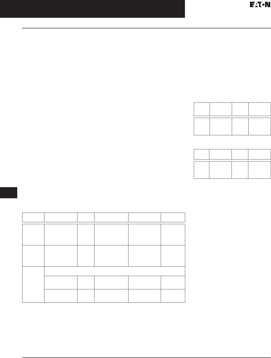
33.2-40
For more information, visit: www.eaton.com/consultants CA08104001E
September 2011
Uninterruptible Power Supplies
Sheet 33
22
23
24
25
26
27
28
29
30
31
32
33
34
35
36
37
38
39
40
41
42
43
Three-Phase Units
Eaton 9390
046
Read and understand the following
notes while planning and performing
the installation:
1. Refer to national and local
electrical codes for acceptable
external wiring practices.
2. Material and labor for external
wiring requirements are to be
provided by designated personnel.
3. For external input wiring, use 90°C
copper wire. See the appropriate
column in Table 33.2-44. Wire
sizes are based on using the
specified breakers.
4. Wire ampacities are chosen from
Table 310.16 of the NEC. Input wire
is 90°C specification.
5. Optional 225A distribution panels
use Eaton bolt-on type BAB or
QBHW breakers for bolt-on panels,
or plug-on type HQP or QPHW
breakers for plug-on panels.
Breakers to be provided by
the customer.
6. Refer to Section I of this manual
for installation instructions.
7. Refer to the applicable Eaton 9390
UPS installation and operation
manual, listed in paragraph 1.5,
for UPS cabinet wiring require-
ments, and conduit and terminal
locations.
8. When distribution panelboards or
a combination of panelboard and
distribution breakers are installed,
input and output to the IAC–D
must be 208V. If only distribution
breakers are installed, input and
output to the IAC–D can be either
208V or 480V.
9. Per NEC Article 300.20(a), all three-
phase conductors must be run in
the same conduit. Neutral and
ground must be run in the same
conduit as the phase conductors.
10. Conduit is to be sized to
accommodate one neutral
conductor the same size as the
phase conductor and one ground
conductor. If two neutral conduc-
tors or an oversized neutral
conductor are to be installed, size
the conduit to accommodate the
extra wire or size. All Eaton 9390
products can accommodate a
double-sized neutral.
11. Terminals are UL and CSA rated
at 90°C. Refer to Table 33.2-45 for
power cable terminations.
Table 33.2-45. IAC-D Power Cable Terminations
Terminal
Function
Terminal Function Size of Pressure
Termination
Tightening Torque
Nm (in-lb) (mm)
Screw
Type
AC input
from UPS
E54
E55
E56
E4
E9
Phase A
Phase B
Phase C
Neutral
Ground
2–#2–600 kcmil
2–#2–600 kcmil
2–#2–600 kcmil
4–#2–600 kcmil
2–#14–1/0
56.5 (500)
56.5 (500)
56.5 (500)
56.5 (500)
5.6 (50)
1/2-inch hex
1/2-inch hex
1/2-inch hex
1/2-inch hex
Slotted
AC output
from
distribution
breaker to
critical load
CBxx–2
CBxx–4
CBxx–6
E10, E20
E18, E19, E28, E29
Phase A
Phase B
Phase C
Neutral
Ground
1–#4–350 kcmil
1–#4–350 kcmil
1–#4–350 kcmil
6 ea–#4–300 kcmil
2 ea–#14–1/0
20.3 (180)
20.3 (180)
20.3 (180)
31 (275)
5.6 (50)
3/16-inch hex
3/16-inch hex
3/16-inch hex
5/16-inch hex
Slotted
AC output
from
distribution
panel
breakers to
critical load
Wire branch circuits in accordance with branch circuit breaker manufacturers
ratings and instructions (output is prewired to the panelboard)
PB1–N, PB2–N Neutral 42–#4–#14 or
3 x #10–#14
#4–#6: 4.0 (35)
#8: 2.8 (25)
#10–#14: 2.3 (20)
Slotted
E18, E19, E28, E29 Ground 42–#4–#14 or
2 x #12–#14
#4–#6: 4.0 (35)
#8: 2.8 (25)
#10–#14: 2.3 (20)
Slotted
12. The continuous current (Ir) values
for the corresponding lettered
adjustment setting marked on the
distribution panel Input breakers
(CB10 and CB20) are listed in
Table G. The continuous current
(Ir) values for the corresponding
lettered adjustment setting
marked on the distribution
breakers (CB11, CB12, CB13,
CB21, CB22 and CB23), are listed
in Table 33.2-46 and Table 33.2-47.
Table 33.2-46. Breaker Continuous Current (Ir)
Settings (Low Current Breaker)
Table 33.2-47. Breaker Continuous Current (Ir)
Settings (High Current Breaker)
13. If installed, verify that the
distribution panel input breakers
(CB10 and CB20) are set to 225A
(letter G on the breakers). Use
the dial on each breaker to adjust
as necessary.
14. If installed, use the dial on each
breaker to adjust distribution
breaker (CB11, CB12, CB13, CB21,
CB22 and CB23) current ratings as
required to protect the wiring to
the load. See Table 33.2-47 for the
correct breaker continuous current
adjustment letter.
Breaker
Setting
Continuous
Current (Ir)
Breaker
Setting
Continuous
Current (Ir)
40 E 70
A
B
C
D
40
45
50
63
E
F
G
H
70
80
90
100
Breaker
Setting
Continuous
Current (Ir)
Breaker
Setting
Continuous
Current (Ir)
A
B
C
D
100
125
150
160
E
F
G
H
175
200
225
250
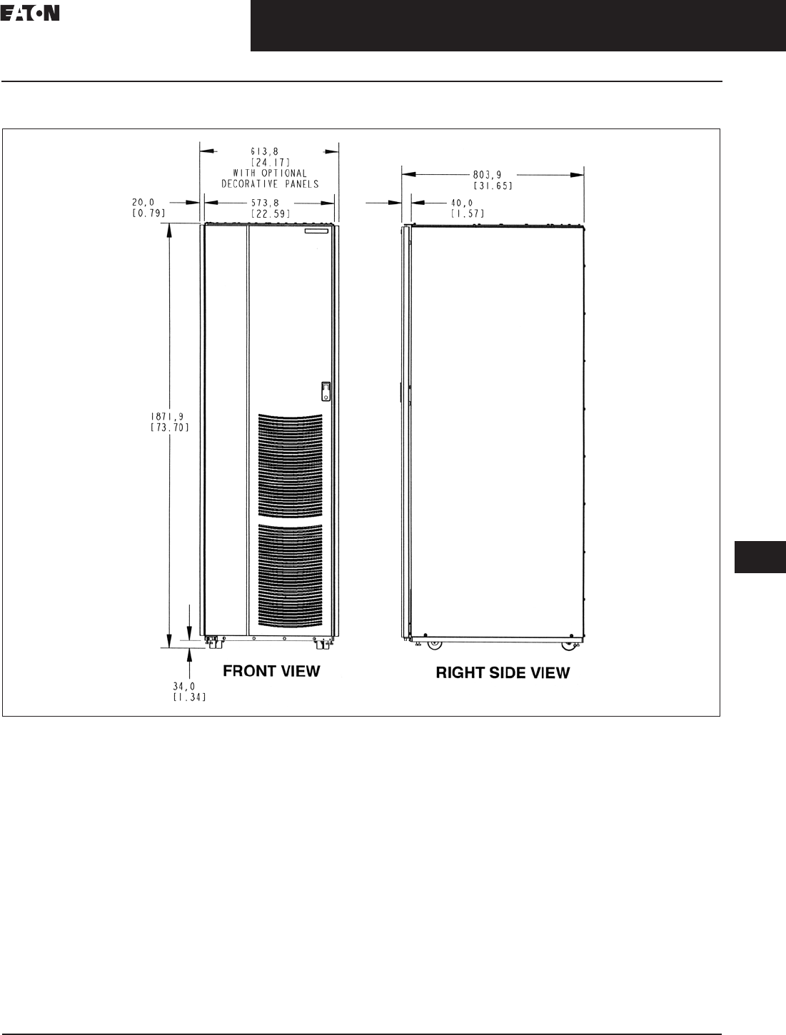
CA08104001E For more information, visit: www.eaton.com/consultants
33.2-41
September 2011
Uninterruptible Power Supplies
Sheet 33
22
23
24
25
26
27
28
29
30
31
32
33
34
35
36
37
38
39
40
41
42
43
Three-Phase Units
Eaton 9390
047
Dimensions in mm (Inches)
Figure 33.2-43. IAC-D Front and Right Side Views
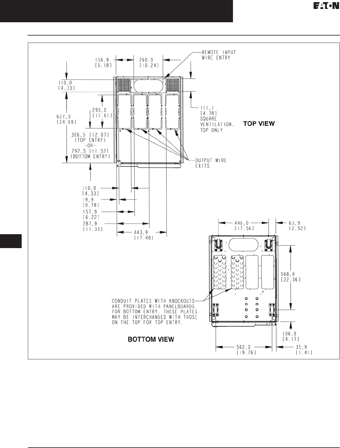
33.2-42
For more information, visit: www.eaton.com/consultants CA08104001E
September 2011
Uninterruptible Power Supplies
Sheet 33
22
23
24
25
26
27
28
29
30
31
32
33
34
35
36
37
38
39
40
41
42
43
Three-Phase Units
Eaton 9390
048
Figure 33.2-44. IAC-D Top and Bottom Views
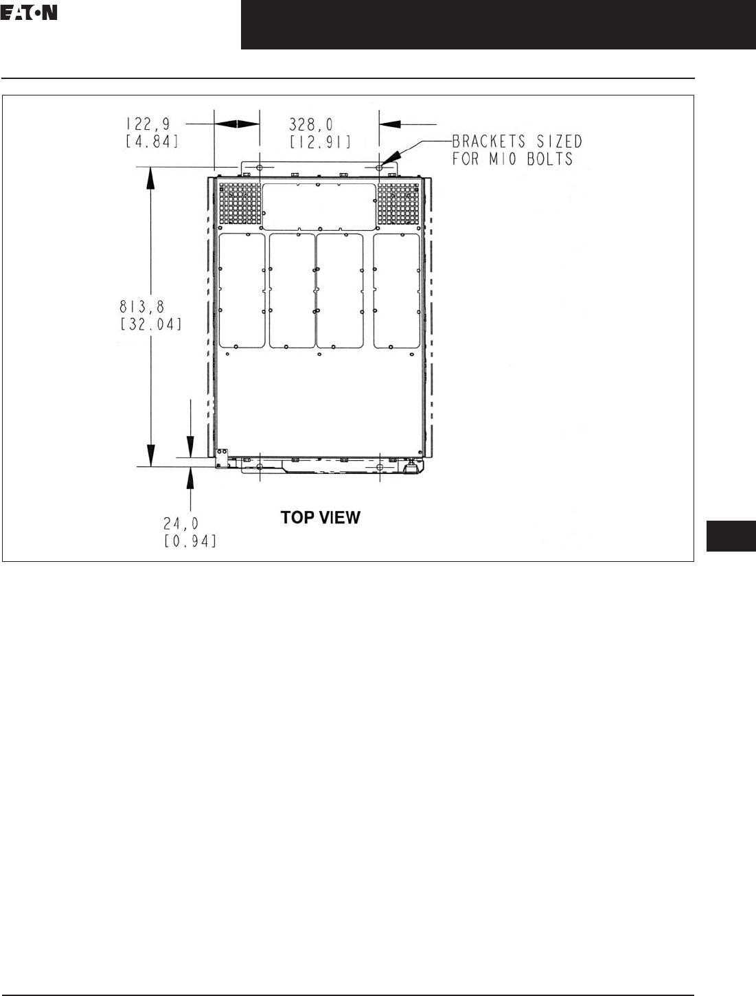
CA08104001E For more information, visit: www.eaton.com/consultants
33.2-43
September 2011
Uninterruptible Power Supplies
Sheet 33
22
23
24
25
26
27
28
29
30
31
32
33
34
35
36
37
38
39
40
41
42
43
Three-Phase Units
Eaton 9390
049
Figure 33.2-45. IAC-D Top View (Optional Floor Mounting)
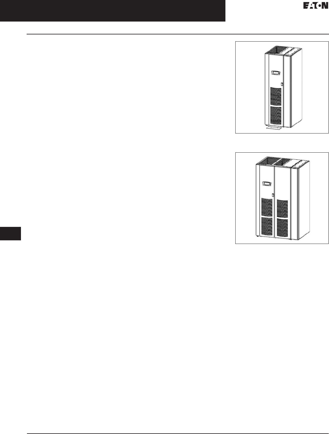
33.2-44
For more information, visit: www.eaton.com/consultants CA08104001E
September 2011
Uninterruptible Power Supplies
Sheet 33
22
23
24
25
26
27
28
29
30
31
32
33
34
35
36
37
38
39
40
41
42
43
Three-Phase Units
Eaton 9390
050
Eaton 9390 Integrated
Accessory Cabinet
(IAC-B and IAC-T)
The Eaton 9390 integrated accessory
cabinet is designed for use with the
Eaton 9390 40–160 kVA three-phase
uninterruptible power systems. The
IAC provides maintenance bypass,
parallel tie cabinet, or parallel tie
cabinet with maintenance bypass
functions with the following custom
configurable features, enabling
adaptation and expansion without
costly electrical rework.
Maintenance Bypass Configuration
■Maintenance bypass (MBP) and
maintenance isolation (MIS) breakers
enable power to completely bypass
the UPS power module. The UPS
module can then be safely serviced
or replaced, without interrupting
power to critical systems. An
optional bypass input breaker (BIB)
and rectifier input breaker (RIB)
provide a single wiring point input to
the UPS and a convenient method
for removing power from the UPS,
when using the maintenance bypass
to supply the load
Parallel Redundant Configuration—Module
Output Breakers (MOB) 1 and 2 Enable Two
■UPS modules to be paralleled
together for redundancy. An
optional system load breaker (SLB)
provides output control to the
critical load for the whole system
Parallel Redundant Configuration
with Maintenance Bypass—Module
Output Breakers
■(MOB) 1 and 2 enable two UPS
modules to be paralleled together for
redundancy. Optional maintenance
bypass (MBP) and maintenance
isolation (MIS) breakers enable
power to completely bypass the
UPS power module
The IAC is housed in a single, free-
standing cabinet, with safety shields
behind the doors for hazardous
voltage protection. The cabinet
matches the UPS cabinet in style
and color, and can be installed in
line-up-and-match or stand-alone
configurations.
Eaton 9390 IAC-SB or IAC-ST
The Eaton 9390 IAC-SB or IAC-ST is
designed for use with the Eaton 9390
80 kVA 208/208V and 480/480V and
160 kVA 480/480V three-phase uninter-
ruptible power systems. The IAC
provides maintenance bypass or tie
cabinet functions with the following
custom configurable features,
enabling adaptation and expansion
without costly electrical rework:
Maintenance Bypass Configuration
■Maintenance bypass (MBP) and
maintenance isolation (MIS) breakers
enable power to completely bypass
the UPS power module. The UPS
module can then be serviced
or replaced in complete safety,
without interrupting power to critical
systems. An optional bypass input
breaker (BIB) and rectifier input
breaker (RIB) provide a single
wiring point input to the UPS and
a convenient method for removing
power from the UPS, when using
the maintenance bypass to supply
the load
Parallel Redundant Configuration
■Module output breakers (MOB) 1 and
2 enable two UPS modules to be
paralleled together for redundancy.
An optional system level breaker
(SLB) provides output control to the
critical load for the whole system
The IAC is attached to and directly
integrated with the UPS cabinet, with
safety shields behind the removable
panel for hazardous voltage protec-
tion. The UPS Sidecar matches the
UPS cabinet in style and color. Figure
33.2-46 shows the Eaton 9390 UPS
(40–80 kVA) Cabinet with the UPS
Sidecar and Figure 33.2-47 shows the
Eaton 9390 UPS (100–160 kVA) Cabinet
with the UPS Sidecar.
Configurations
The following UPS IAC-SB or IAC-ST
configurations are possible:
■UPS sidecar with MBP and MIS
■UPS sidecar with MBP, MIS and BIB
■UPS sidecar with MBP, MIS, BIB
and RIB
■UPS sidecar with MOB1 and MOB2
■UPS sidecar with MOB1, MOB2
and SLB
Figure 33.2-46. Eaton 9390 UPS (40–80 kVA)
Cabinet with IAC-SB or IAC-ST
Figure 33.2-47. Eaton 9390 UPS (100–160 kVA)
Cabinet with IAC-SB or IAC-ST
Options IAC-SB or IAC-ST
Contact your Eaton sales representative
for information about any of these
available options:
Bypass Input Breaker
■Maintenance bypass configurations
have an optional bypass input
breaker for single-feed and dual-
feed systems. The BIB provides a
single point of input power control
to the UPS and easily removes
power from the UPS for servicing
Rectifier Input Breaker
■Maintenance bypass configurations
have an optional rectifier input
breaker for dual-feed systems.
The RIB provides a single point of
rectifier input power control to the
UPS and easily removes power
from the UPS for servicing
System Load Breaker
■A parallel redundant configuration
with an optional system load breaker
is available to control the output to the
critical load for the whole system

CA08104001E For more information, visit: www.eaton.com/consultants
33.2-45
September 2011
Uninterruptible Power Supplies
Sheet 33
22
23
24
25
26
27
28
29
30
31
32
33
34
35
36
37
38
39
40
41
42
43
Three-Phase Units
Eaton 9390
051
Table 33.2-48. Input/Output Ratings and External Wiring Requirements for Eaton 9390 IAC-SB or IAC-ST (Maintenance Bypass)
Table 33.2-49. Input/Output Ratings and External Wiring Requirements for Eaton 9390 IAC-SB or IAC-ST (1 + 1 Parallel Redundant)
Read and understand the following
notes while planning and performing
the installation:
1. Refer to national and local
electrical codes for acceptable
external wiring practices.
2. Material and labor for external
wiring requirements are to be
provided by designated personnel.
3. For external input wiring, use 90°C
copper wire. See the appropriate
column in Table 33.2-48. Wire
sizes are based on using the
specified breakers.
4. Wire ampacities are chosen from
Table 310.16 of the NEC. Input wire
is 90°C specification.
5. If a BIB is not installed, a minimum
of two separate feeds with
upstream feeder breakers, or one
feed with two upstream feeder
breakers, must be provided. One
for the UPS and one for the UPS
Sidecar bypass input. DO NOT
use one feed or a single feeder
breaker to supply both the UPS
and Sidecar.
6. Refer to Section 1 of this manual
for installation instruction.
7. Refer to the applicable Eaton 9390
UPS installation and operation
manual, listed in Paragraph 1.5,
for UPS cabinet wiring require-
ments, and conduit and terminal
locations.
8. Refer to the applicable Eaton 9390
UPS installation and operation
manual, listed in Paragraph 1.5,
for parallel system power and
control wiring requirements.
9. Terminals are UL and CSA rated
at 90°C. Refer to Table 33.2-50 for
power cable termination.
10. Per NEC Article 300.2.(a), all three-
phase conductors must be run in
the same conduit. Neutral and
ground must be run in the same
conduit as the phase conductors.
11. Conduit is to be sized to
accommodate one neutral
conductor the same size as the
phase conductor and one #8 AWG
ground conductor. If two neutral
conductors or an oversized neutral
conductor are to be installed, size
the conduit to accommodate the
extra wire or size. All Eaton 9390
products can accommodate a
double size neutral.
Description Units Rating 50/60 Hz
Basic unit rating UPS kVA 80 80 160
Input and bypass input output Volts
Volts
208
208
480
480
480
480
AC input to maintenance bypass (without BIB or RIB, or dual
feed with BIB and RIB) (3) phases, (1) neutral–if required,
(1) ground minimum conductor size number per phase
Amps 222 96 192
AWG or kcmil
(Each)
2/0
(2)
1/0
(1)
1/0
(2)
AC input to maintenance bypass (single feed with BIB, or
single feed with BIB and RIB) (3) phases, (1) neutral–if
required, (1) ground minimum conductor size number
per phase
Amps 240 105 210
AWG or kcmil
(Each)
2/0
(2)
1/0
(1)
1/0
(2)
AC input to optional RIB)3) phases, (1) ground minimum
conductor size number per phase
Amps 240 105 210
AWG or kcmil
(Each)
2/0
(2)
1/0
(1)
1/0
(2)
AC output to critical load full load current (3) phases,
(1) neutral–if required, (1) ground minimum
conductor size number per phase
Amps 222 96 192
AWG or kcmil
(Each)
2/0
(2)
1/0
(1)
1/0
(2)
Description Units Rating 50/60 Hz
Basic unit rating UPS kVA 80 80 160
Input and bypass input output Volts
Volts
208
208
480
480
480
480
AC input from UPM full load current for each module
(3) phases, (1) neutral–if required, (1) ground
Minimum conductor size for each module number per phase
for each module
Amps 222 96 192
For contractor-supplied wiring in a stand-alone installation, refer to the applicable Eaton 9390
UPS Installation and Operation manual, listed in paragraph 1.5, for wire size. Wiring for line-
up-and-match installation is factory supplied.
AC output to critical load full load current (3) phases,
(1) neutral–if required, (1) ground
minimum conductor size number per phase
Amps 222 96 192
AWG or kcmil
(Each)
2/0
(2)
1/0
(1)
1/0
(2)

33.2-46
For more information, visit: www.eaton.com/consultants CA08104001E
September 2011
Uninterruptible Power Supplies
Sheet 33
22
23
24
25
26
27
28
29
30
31
32
33
34
35
36
37
38
39
40
41
42
43
Three-Phase Units
Eaton 9390
052
Table 33.2-50. IAC-SB or IAC-ST Maintenance Bypass Power Cable Terminations 80 kVA 480V/480V
Table 33.2-51. IAC-SB or IAC-ST Maintenance Bypass Power Cable Terminations 80 kVA 208V/208V and kVA 480V/480V
Terminal
Function
Function Size of Pressure
Termination
Tightening Torque Nm
in-lb (mm)
Screw
Type
AC input to maintenance bypass Phase A
Phase B
Phase C
1–#14-2/0
1–#14-2/0
1–#14-2/0
120 (13.5)
120 (13.5)
120 (13.5)
3/16-inch hex
3/16-inch hex
3/16-inch hex
AC input to optional RIB Phase A
Phase B
Phase C
1–#4–350 kcmil
1–#4–350 kcmil
1–#4–350 kcmil
177 (20.0)
177 (20.0)
177 (20.0)
M4 hex
M4 hex
M4 hex
AC output to critical load Phase A
Phase B
Phase C
1–#14-2/0
1–#14-2/0
1–#14-2/0
120 (13.5)
120 (13.5)
120 (13.5)
3/16-inch hex
3/16-inch hex
3/16-inch hex
Terminal
Function
Function Size of Pressure
Termination
Tightening Torque Nm
in-lb (mm)
Screw
Type
AC input to maintenance bypass Phase A 1–2/0-250 kcmil
1–2/0-500 kcmil
275 (31.1)
275 (31.1)
5/16-inch hex
3/8-inch hex
Phase B 1–2/0-250 kcmil
1–2/0-500 kcmil
275 (31.1)
275 (31.1)
5/16-inch hex
3/8-inch hex
Phase C 1–2/0-250 kcmil
1–2/0-500 kcmil
275 (31.1)
275 (31.1)
5/16-inch hex
3/8-inch hex
AC input to optional RIB Phase A 1–2/0-250 kcmil
1–2/0-500 kcmil
275 (31.1)
275 (31.1)
5/16-inch hex
3/8-inch hex
Phase B 1–2/0-250 kcmil
1–2/0-500 kcmil
275 (31.1)
275 (31.1)
5/16-inch hex
3/8-inch hex
Phase C 1–2/0-250 kcmil
1–2/0-500 kcmil
275 (31.1)
275 (31.1)
5/16-inch hex
3/8-inch hex
AC output to critical load Phase A 1–2/0-250 kcmil
1–2/0-500 kcmil
275 (31.1)
275 (31.1)
5/16-inch hex
3/8-inch hex
Phase B 1–2/0-250 kcmil
1–2/0-500 kcmil
275 (31.1)
275 (31.1)
5/16-inch hex
3/8-inch hex
Phase C 1–2/0-250 kcmil
1–2/0-500 kcmil
275 (31.1)
275 (31.1)
5/16-inch hex
3/8-inch hex
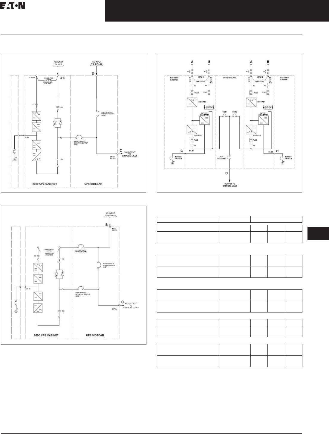
CA08104001E For more information, visit: www.eaton.com/consultants
33.2-47
September 2011
Uninterruptible Power Supplies
Sheet 33
22
23
24
25
26
27
28
29
30
31
32
33
34
35
36
37
38
39
40
41
42
43
Three-Phase Units
Eaton 9390
053
Wiring Diagrams and Specifications
Figure 33.2-48. UPS with IAC-SB Sidecar Bypass
Figure 33.2-49. UPS with IAC-SB Sidecar Bypass with BIB
Figure 33.2-50. 9390 (100–160 kVA) IDC with 3 Breaker Bypass
Table 33.2-52. Input/Output Ratings and External Wiring Requirements
for Eaton 9390 UPS Sidecar (Maintenance Bypass)
Description Units Rating 50/60 Hz
Basic unit rating UPS kVA 80 80 160
Input and bypass
input output
Volts
Volts
208
208
480
480
480
480
B—AC Input to Maintenance Bypass
(without BIB or RIB, or Dual Feed with BIB and RIB)
(3) phases, (1) neutral—
if required, (1) ground
Amps 222 96 192
Minimum conductor size
number per phase
AWG or kcmil
(each)
2/0
(2)
1/0
(1)
1/0
(2)
B—AC Input to Maintenance Bypass
(Single Feed with BIB, or Single Feed with BIB and RIB)
(3) phases, (1) neutral—
if required, (1) ground
Amps 240 105 210
Minimum conductor size
number per phase
AWG or kcmil
(each)
2/0
(2)
1/0
(1)
1/0
(2)
A—AC Input to Optional RIB
(3) phases, (1) ground Amps 240 105 210
Minimum conductor size
number per pole
AWG or kcmil
(each)
2/0
(2)
1/0
(1)
1/0
(2)
C—AC Output to Critical Load (Full Load Current)
(3) phases, (1) neutral—
if required, (1) ground
Amps 222 96 192
Minimum conductor size
number per phase
AWG or kcmil
(each)
2/0
(2)
1/0
(1)
1/0
(2)

33.2-48
For more information, visit: www.eaton.com/consultants CA08104001E
September 2011
Uninterruptible Power Supplies
Sheet 33
22
23
24
25
26
27
28
29
30
31
32
33
34
35
36
37
38
39
40
41
42
43
Three-Phase Units
Eaton 9390
054
Table 33.2-53. Input/Output Ratings and External Wiring Requirements
for Eaton 9390 UPS Sidecar (1+1 Parallel Redundant)
Table 33.2-54. UPS Sidecar Maintenance Bypass Power Cable
Terminations 80 kVA 480V/480V
Table 33.2-55. UPS Sidecar Maintenance Bypass Power Cable
Terminations 80 kVA 208V/208V and 160 kVA 480V/480V
Table 33.2-56. UPS Sidecar 1+1 Parallel Redundant Power Cable
Terminations 80 kVA 480V/480V
Table 33.2-57. UPS Sidecar 1+1 Parallel Redundant Power Cable
Terminations 80 kVA 208V/208V and 160 kVA 480V/480V
Description Units Rating 50/60 Hz
Basic unit rating UPS kVA 80 80 160
Input and bypass input
output
Volts
Volts
208
208
480
480
480
480
B—AC Input from UPM
Full load current for each
module (3) phases, (1) neutral-
if required, (1) ground
Amps 222 96 192
Minimum conductor size
number per phase
For contractor-supplied wiring in a
stand-alone installation, refer to the
applicable Eaton 9390 UPS manual for
wire size. Wiring for line-up-and-match
installation is factory-supplied.
D—AC Output to Critical Load
Full load current for each
module (3) phases, (1) neutral-
if required, (1) ground
Amps 222 96 192
Minimum conductor size
number per phase
AWG or kcmil
(each)
2/0
(2)
1/0
(1)
1/0
(2)
Function Size of Pressure
Termination
Tightening Torque
Nm (in-lb)
Screw
Type
AC Input to Maintenance Bypass
Phase A
Phase B
Phase C
1–#14-2/0
1–#14-2/0
1–#14-2/0
13.5 (120)
13.5 (120)
13.5 (120)
3/16-inch hex
3/16-inch hex
3/16-inch hex
AC Input to Optional RIB
Phase A
Phase B
Phase C
1–#4-350 kcmil
1–#4-350 kcmil
1–#4-350 kcmil
20.0 (177)
20.0 (177)
20.0 (177)
M4 hex
M4 hex
M4 hex
AC Output to Critical Load
Phase A
Phase B
Phase C
1–#14-2/0
1–#14-2/0
1–#14-2/0
13.5 (120)
13.5 (120)
13.5 (120)
3/16-inch hex
3/16-inch hex
3/16-inch hex
Function Size of Pressure
Termination
Tightening Torque
Nm (in-lb)
Screw
Type
AC Input to Maintenance Bypass
Phase A 1–2/0-250 kcmil
1–2/0-500 kcmil
31.1 (275)
31.1 (275)
5/16-inch hex
3/8-inch hex
Phase B 1–2/0-250 kcmil
1–2/0-500 kcmil
31.1 (275)
31.1 (275)
5/16-inch hex
3/8-inch hex
Phase C 1–2/0-250 kcmil
1–2/0-500 kcmil
31.1 (275)
31.1 (275)
5/16-inch hex
3/8-inch hex
AC Input to Optional RIB
Phase A 1–2/0-250 kcmil
1–2/0-500 kcmil
31.1 (275)
31.1 (275)
5/16-inch hex
3/8-inch hex
Phase B 1–2/0-250 kcmil
1–2/0-500 kcmil
31.1 (275)
31.1 (275)
5/16-inch hex
3/8-inch hex
Phase C 1–2/0-250 kcmil
1–2/0-500 kcmil
31.1 (275)
31.1 (275)
5/16-inch hex
3/8-inch hex
AC Output to Critical Load
Phase A 1–2/0-250 kcmil
1–2/0-500 kcmil
31.1 (275)
31.1 (275)
5/16-inch hex
3/8-inch hex
Phase B 1–2/0-250 kcmil
1–2/0-500 kcmil
31.1 (275)
31.1 (275)
5/16-inch hex
3/8-inch hex
Phase C 1–2/0-250 kcmil
1–2/0-500 kcmil
31.1 (275)
31.1 (275)
5/16-inch hex
3/8-inch hex
Function Size of Pressure
Termination
Tightening Torque
Nm (in-lb)
Screw
Type
AC Input from UPM to MOB 2 (Stand-alone Installation)
Phase A
Phase B
Phase C
1–#14-3/0
1–#14-3/0
1–#14-3/0
5.6 (50)
5.6 (50)
5.6 (50)
3/16-inch hex
3/16-inch hex
3/16-inch hex
AC Output to Critical Load (without SLB)
Phase A
Phase B
Phase C
1–#14-2/0
1–#14-2/0
1–#14-2/0
13.5 (120)
13.5 (120)
13.5 (120)
3/16-inch hex
3/16-inch hex
3/16-inch hex
AC Output to Critical Load (with SLB)
Phase A
Phase B
Phase C
1–#14-3/0
1–#14-3/0
1–#14-3/0
5.6 (50)
5.6 (50)
5.6 (50)
3/16-inch hex
3/16-inch hex
3/16-inch hex
Neutral
Neutral 4–#14-1/0 5.6 (50) Slotted
Ground
Ground 2–#14-1/0 5.6 (50) Slotted
Function Size of Pressure
Termination
Tightening Torque
Nm (in-lb)
Screw
Type
AC Input from UPM to MOB 2 (Stand-alone Installation)
Phase A 1–2/0-250 kcmil
1–2/0-500 kcmil
31.1 (275)
31.1 (275)
5/16-inch hex
3/8-inch hex
Phase B 1–2/0-250 kcmil
1–2/0-500 kcmil
31.1 (275)
31.1 (275)
5/16-inch hex
3/8-inch hex
Phase C 1–2/0-250 kcmil
1–2/0-500 kcmil
31.1 (275)
31.1 (275)
5/16-inch hex
3/8-inch hex
AC Output to Critical Load (with and without SLB)
Phase A 1–2/0-250 kcmil
1–2/0-500 kcmil
31.1 (275)
31.1 (275)
5/16-inch hex
3/8-inch hex
Phase B 1–2/0-250 kcmil
1–2/0-500 kcmil
31.1 (275)
31.1 (275)
5/16-inch hex
3/8-inch hex
Phase C 1–2/0-250 kcmil
1–2/0-500 kcmil
31.1 (275)
31.1 (275)
5/16-inch hex
3/8-inch hex
Neutral
Neutral 8–#6-250 kcmil 42.4 (375) 5/16-inch hex
Ground
Ground 4–#14-1/0 5.6 (50) Slotted
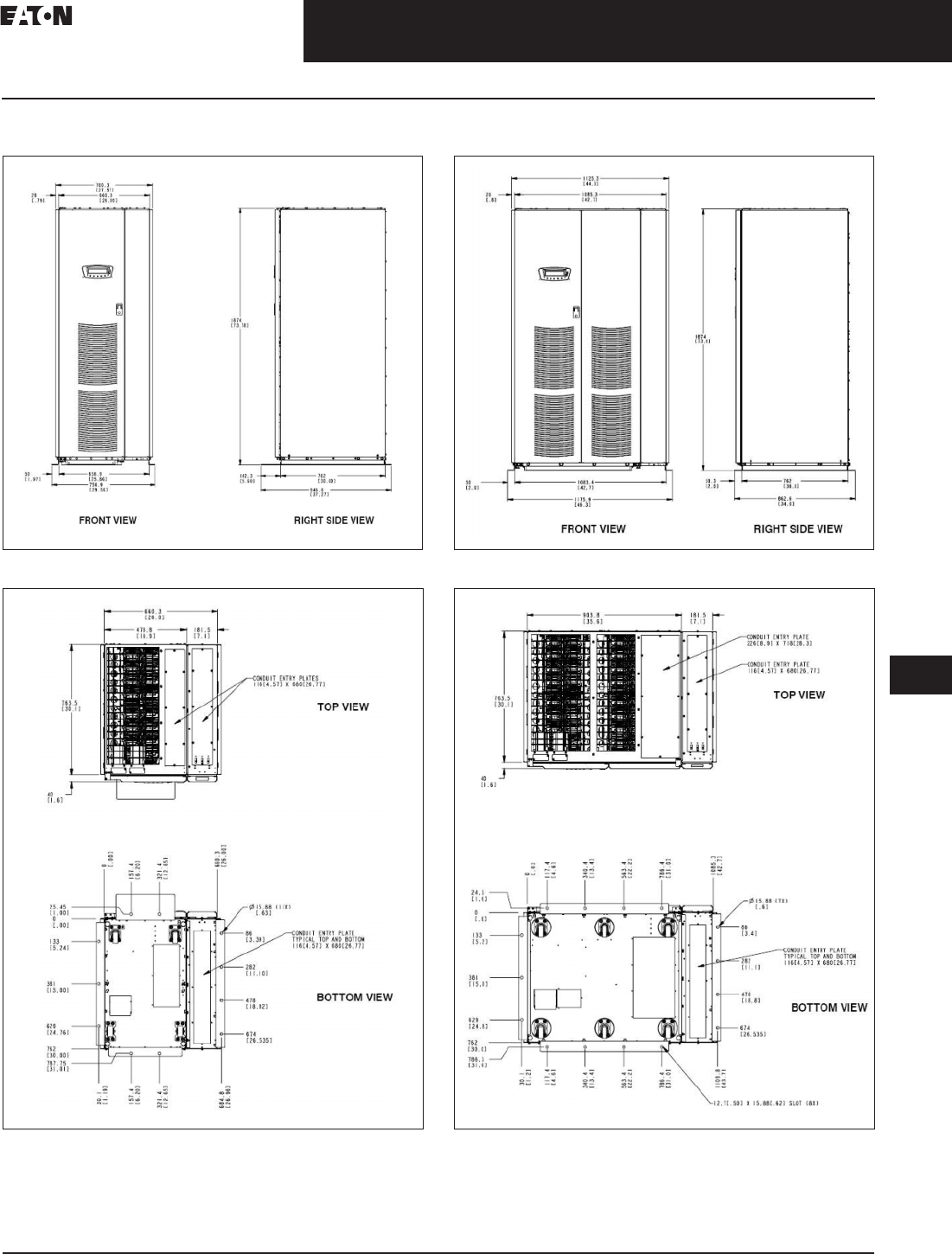
CA08104001E For more information, visit: www.eaton.com/consultants
33.2-49
September 2011
Uninterruptible Power Supplies
Sheet 33
22
23
24
25
26
27
28
29
30
31
32
33
34
35
36
37
38
39
40
41
42
43
Three-Phase Units
Eaton 9390
055
Dimensions in mm (Inches)
Figure 33.2-51. 9390 (40–80 kVA) UPS with IAC-SX Sidecar
Figure 33.2-52. 9390 (40–80 kVA) UPS with IAC-SX Sidecar
Top and Bottom View
Figure 33.2-53. 9390 (100–160 kVA) UPS with IAC-SX Sidecar
Figure 33.2-54. 9390 (100–160 kVA) UPS with IAC-SX Sidecar
Top and Bottom View

33.2-50
For more information, visit: www.eaton.com/consultants CA08104001E
September 2011
Uninterruptible Power Supplies
Sheet 33
22
23
24
25
26
27
28
29
30
31
32
33
34
35
36
37
38
39
40
41
42
43
056
This page intentionally left blank.
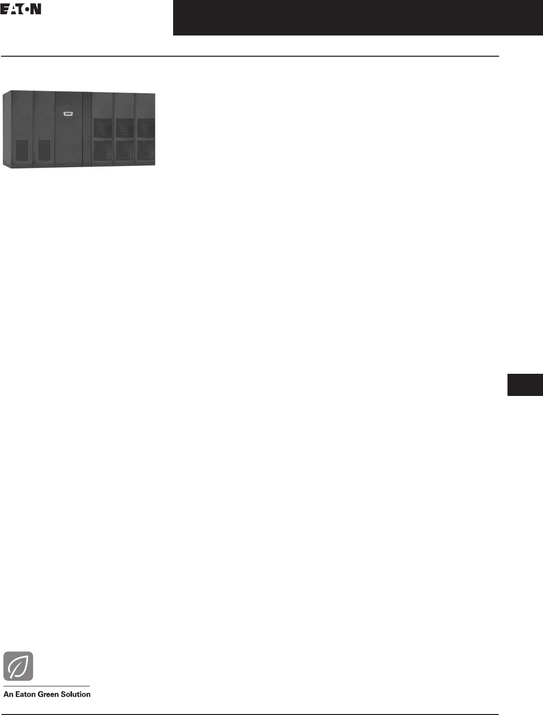
CA08104001E For more information, visit: www.eaton.com/consultants
33.3-1
September 2011
Uninterruptible Power Supplies
Sheet 33
22
23
24
25
26
27
28
29
30
31
32
33
34
35
36
37
38
39
40
41
42
43
Large Three-Phase Units—Eaton 9395
General Information/Features
057
Eaton 9395 (225–1100 kVA)
Eaton 9395
General Description
The Eaton 9395 is the industry’s most
reliable and flexible three-phase UPS.
The advanced software and technol-
ogy of Eaton’s Energy Saver System
(ESS) allow the 9395 to achieve 99%
efficiency while still maintaining
complete protection for the load. ESS
and another energy-saving technol-
ogy, Variable Module Management
System (VMMS), are part of Eaton’s
Energy Advantage Architecture (EAA),
which allows customers to maximize
efficiency and to tailor the technology
to their unique loads.
The Eaton 9395 UPS gives you
maximum flexibility, reliability and
system availability for your entire
enterprise, whether it’s a single
building or multiple locations spread
throughout the world. With the most
reliable hardware, sophisticated power
management software, and a multitude
of accessories and options, combined
with world-class service, the Eaton
9395 offers the power solution and
system availability that let’s you get
down to the business of your business.
Typical Applications
■Data centers
■Facilities
■Security operations
■Enterprise networks
■Server farms
■Telecommunications installations
■Internet service providers
■Diagnostic imaging equipment
■Positron Emission Tomagraphy (PET)
■Production lines water treatment
facilities
Features and Benefits
■SMaRT® Gold Certified, the 9395
can help architects and consultants
earn LEED® points toward
certification
■Provides flexible run-time options
for your application
■Delivers maximum uptime for
mission-critical systems by
including ProActive service
plan for the first year following
installation, including:
❑One year of 7 x 24 corrective
maintenance
❑One year of 7 x 24 remote
monitoring service (ProActive
service plan is required to obtain
“no charge” monitoring)
❑Annual performance check and
power protection audit
❑7 x 24 technical support
■Isolates connected equipment
from all incoming power problems
to provide the highest degree of
protection with online, double-
conversion technology
■Maintains and monitors battery
health continuously, dynamically
updating information on battery
time remaining
■Increases system reliability by
minimizing points-of-failure through
innovative design and reduced
component count
■Starts up with the push of a button
and displays UPS status information
on its monitor panel
■Incorporates connectivity products
to fit various environments and
applications
■Keeps you informed by sending
notification for power and UPS
events that you select
Monitor Panel
The monitor panel on the front of the
UPS contains an LCD screen to display
the current status of the UPS. You can
view a statistical history and log of
UPS events and display a real-time
graphic representation of power flow-
ing through the UPS components.
Backlit status indicators show the
operating mode of the UPS and alert
you to system events.
™
Communication Bays
■X-Slot™ communication bay—
allows internal, UPS powered
communication with four optional
X-Slot cards. The X-Slot cards
support several protocols such as
SNMP, HTTP and Modbus
■Computer interface—serial commu-
nication ports are standard on all
units, and are electrically isolated
from the UPS. You can use these
ports to link the UPS to the features
■Summary alarm contacts—alarm
contacts are provided for connec-
tion to equipment at your facility
such as a light, an audible alarm,
or a computer terminal. The equip-
ment you connect to these contacts
alerts you to a UPS alarm
■Building alarm monitoring—you
can connect your facility’s alarm
system contacts to six inputs in the
UPS. The UPS uses these inputs to
monitor your building alarms in
addition to the UPS status
Load Off
A LOAD OFF function is provided for
situations where you must immedi-
ately remove all power to your critical
load. The function is accessible on the
front of the UPS for quick access.
Automatic Battery Charge Current Limit
A preset limit restricts battery charging
current to protect batteries from
damage due to high current charging.
Charging at high currents can overheat
and damage batteries.
Installation Features
Power wiring can be routed through
the top or bottom of each UPS cabinet.
External sensing and monitoring
control wire must be installed in
accordance with Class 2 wiring
methods. Bottom entry is provided
for Class 2 wiring.

33.3-2
For more information, visit: www.eaton.com/consultants CA08104001E
September 2011
Uninterruptible Power Supplies
Sheet 33
22
23
24
25
26
27
28
29
30
31
32
33
34
35
36
37
38
39
40
41
42
43
Large Three-Phase Units—Eaton 9395
General Information/Features
058
Options and Accessories
Battery
You can enhance the protection
provided by your UPS with one
or more backup battery supplies
equipped with sealed lead-acid,
maintenance-free batteries in a
matching cabinet. Each battery
cabinet contains individual modular
battery trays and a battery circuit
breaker. Several battery capacities
are available.
The UPS battery cabinets can be
paralleled; you can increase your
battery backup time by adding
battery cabinets to your UPS system.
The Eaton 9395 can support multiple
battery cabinets.
External Battery Disconnect
An optional DC circuit breaker,
enclosed in a wall-mounted box
adjacent to the UPS, provides a
manual means of disconnecting
a battery that is located remotely
from the UPS.
Upgrade Capability
The UPS is available in various output
power ratings in both 50 and 60 Hz
models. If your power requirements
increase, you can upgrade the UPS
system to provide more output power
with minimum impact on your facility.
Remote Monitor Panel
An optional remote monitor panel
(RMP) contains backlit status
indicators and a local horn, allowing
you to monitor the operational status
and alarm condition of the UPS from
virtually any location within your
facility. You can install multiple RMPs
at remote locations to increase your
monitoring capabilities.
Relay Interface Module
An optional relay interface module
(RIM) uses relay contact closures to
indicate the operating status and
alarm condition of the UPS system.
The module uses a serial interface
line and may support up to eight
critical loads.
eNotify
Optional eNotify service provides a
monthly report detailing the ongoing
health of the Eaton 9395 UPS as well
as critical event alerts monitored
by Eaton’s Customer Reliability
Center (CRC) available 7 days a week,
24 hours a day.
The Customer Monitoring Report
delivers information on the unit’s
voltages, loads and external factors
such as temperature and humidity,
depending on the model. The report
also provides information about the
attached batteries and system
availability.
Additionally, eNotify informs users
when critical events are experienced.
This service alerts our Customer
Reliability Center (CRC) of any critical
events and provides for proactive
monitoring. Anomalies are checked
for incoming parametric or event data
logs, upon receipt of a status or event
e-mail, respectively. If an anomaly
is detected, a CRC analyst further
analyzes the data for possible
impending failures.
Hot-Tie
The Eaton 9395 hot-tie control system
is designed to operate with two Eaton
9395 hot-sync capacity/redundant
systems. Each system will include two
or more Eaton 9395 UPM (modules)
and a system bypass module (SBM).
The primary function of the Eaton 9395
hot-tie control is to provide increased
maintainability of the two Eaton hot-
sync capacity/redundant systems by
controlling a momentary, uninter-
rupted transfer of one system’s load
to the other system and isolating the
off-line system. After completion of
the transfer, preventive maintenance
can be performed on the complete
off-line system (SBM, modules,
cabling, and so on) without disturbing
the critical power paths to the load.
A scheduled shutdown of the off-line
system’s critical load is never required
or is a transfer to bypass power
needed. After preventive maintenance
is finished, the Eaton hot-tie control
can be used to return the loads to the
individual systems and reconfigure the
two systems to dual path operation.
The Eaton 9395 hot-tie control
performs the following actions:
■Monitoring UPS system status
■Monitoring switchboard breaker
status
■Synchronization of the two critical
load buses
■Control of SIS-A, SIS-B, and the
TIE breaker
■Control of MBP-A, MBP-B, MIS-A,
and MIS-B breakers (with optional
MBP only)
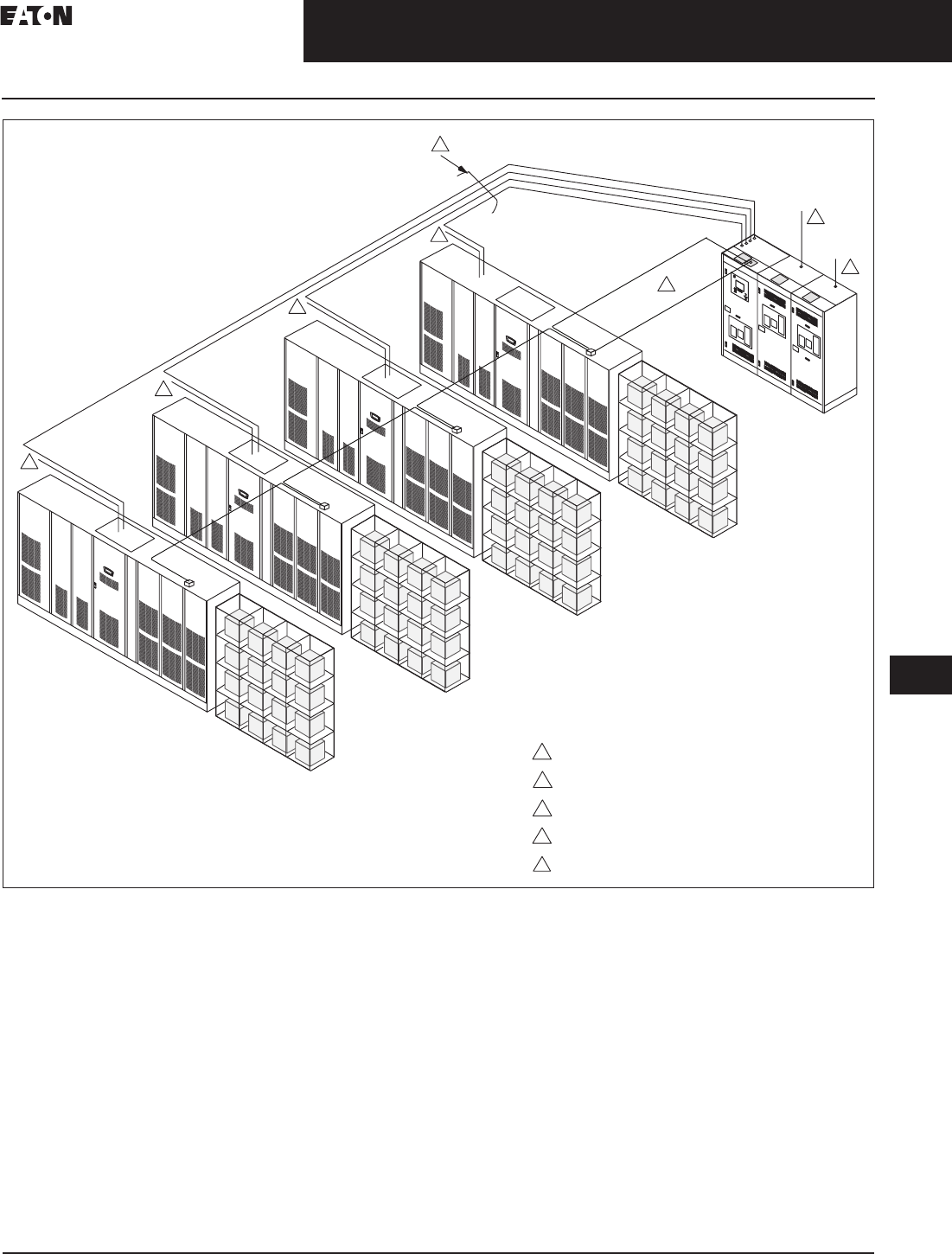
CA08104001E For more information, visit: www.eaton.com/consultants
33.3-3
September 2011
Uninterruptible Power Supplies
Sheet 33
22
23
24
25
26
27
28
29
30
31
32
33
34
35
36
37
38
39
40
41
42
43
Large Three-Phase Units—Eaton 9395
System Layout
059
Figure 33.3-1. Typical Parallel Capacity/Redundant System Layout
Note: Accommodates one to eight UPSs (restricted by SBM breaker rating). Four UPS system shown.
1
1
1
1
3
4
1
3
4
2
2
UPM
Utility Power Input to UPS
UPS Output To SBM Input
SBM Output to Critical Load
Utility Power Input to Bypass Bus
CAN Network
SBM
Battery
Rack
5
5
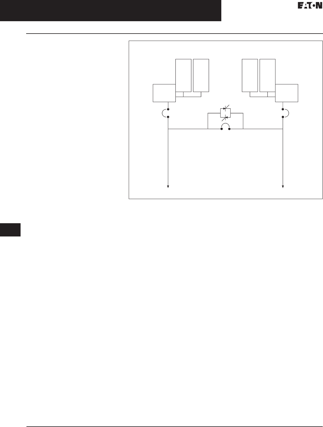
33.3-4
For more information, visit: www.eaton.com/consultants CA08104001E
September 2011
Uninterruptible Power Supplies
Sheet 33
22
23
24
25
26
27
28
29
30
31
32
33
34
35
36
37
38
39
40
41
42
43
Large Three-Phase Units—Eaton 9395
Automatic Hot-Tie System
060
Static Auto-Tie System
With this industry first static auto-tie
system, Eaton does not limit the
availability of dual power paths to
scheduled maintenance. Instead,
this incredible level of reliability is
continuously available. The static
auto-tie consists of a conventional
three-breaker hot-tie system with a
static switch paralleling the actual
tie-breaker. When system level
monitoring detects a reason why the
protected load in a dual power path
system should be transferred to one
UPS or the other, the static switch is
fired. The tie-breaker is signaled to
close in much the same way a UPS
transfers the load to its internal
bypass. The two systems are tied
together momentarily until the
appropriate isolation breaker opens,
leaving one UPS isolated with no load
and the other UPS supporting both
power paths. Because both power
paths to the load remain active, no
transfer devices are activated, and
dual power supply loads are not
challenged by shutting down one
power supply. In fact, in the Eaton
automatic hot-tie system, distribution
transfer devices can be eliminated.
A sample static auto-tie system is
shown in Figure 33.3-2.
Figure 33.3-2. Static Auto-Tie System
Note: This system eliminates downstream static switches and is designed for automatic
operation and concurrent maintenance.
U
P
S
A
:
E
ato
n
9395
U
P
S
B
:
E
ato
n
9395
S
B
M
S
B
M
Stat
i
c
S
wi
tch
Static Auto-Ti
e
Load Bas
e
Load Bu
s
SI
SI

CA08104001E For more information, visit: www.eaton.com/consultants
33.3-5
September 2011
Uninterruptible Power Supplies
Sheet 33
22
23
24
25
26
27
28
29
30
31
32
33
34
35
36
37
38
39
40
41
42
43
Large Three-Phase Units—Eaton 9395
Battery Information
061
Battery Cabinets—9395 225–550 kVA, 60 Hz Applications
Table 33.3-1. 1085 Cabinet Series, 480 Vdc Link
Note: All cabinets at 480 Vdc. All cabinets are remote configuration. Eaton-branded (”E” series) batteries feature three year warranty.
Table 33.3-1. 1085 Cabinet Series, 480 Vdc Link (Continued)
Note: All cabinets at 480 Vdc. All cabinets are remote configuration. Eaton-branded (”E” series) batteries feature three year warranty.
Cabinet
Quantity
Installed
Weight Lbs (kg)
Width
Inches (mm)
225 kVA 275 kVA
Runtime (min.) Runtime (min.)
Eaton Part Number 0.9 pf Eaton Part Number 0.9 pf
2
2
2
6300 (2858)
6500 (2942)
6990 (3171)
86 (2169)
86 (2169)
86 (2169)
TL2253B27221200
TL2253E28221200
TL2253B31221200
7
7
9
—
TL2753E28221200
TL2753B31221200
—
5
6
2
2
2
7190 (3255)
7530 (3416)
7850 (3554)
86 (2169)
86 (2169)
86 (2169)
TL2253E33221200
TL2253B37221200
TL2253E39221200
10
12
12
TL2753E33221200
TL2753B37221200
TL2753E39221200
7
9
9
2
2
3
9600 (4354)
9680 (4384)
9450 (4286)
86 (2169)
86 (2169)
129 (3254)
TL2253B47221200
TL2253E50221200
TL2253B27321200
16
18
14
TL2753B47221200
TL2753E50221200
TL2753B27321200
11
13
10
3
3
3
9750 (4409)
10,485 (4756)
10,785 (4878)
129 (3254)
129 (3254)
129 (3254)
TL2253E28321200
TL2253B31321200
TL2253E33321200
16
18
20
TL2753E28321200
TL2753B31321200
TL2753E33321200
10
13
14
3
3
3
11,295 (5123)
11,775 (5328)
14,400 (6532)
129 (3254)
129 (3254)
129 (3254)
TL2253B37321200
TL2253E39321200
TL2253B47321200
22
24
31
TL2753B37321200
TL2753E39321200
TL2753B47321200
17
17
23
3
4
4
14,520 (5673)
12,600 (5715)
13,000 (5876)
129 (3254)
171 (4338)
171 (4338)
TL2253E50321200
TL2253B27421200
TL2253E28421200
32
22
23
TL2753E50321200
TL2753B27421200
TL2753E28421200
25
16
16
4
4
4
13,980 (6341)
14,380 (6502)
15,060 (6831)
171 (4338)
171 (4338)
171 (4338)
TL2253B31421200
TL2253E33421200
TL2253B37421200
27
28
33
TL2753B31421200
TL2753E33421200
TL2753B37421200
20
22
25
4
4
4
15,700 (7101)
19,200 (8709)
19,360 (8761)
171 (4338)
171 (4338)
171 (4338)
TL2253E39421200
TL2253B47421200
TL2253E50421200
34
48
47
TL2753E39421200
TL2753B47421200
TL2753E50421200
26
34
36
Cabinet
Quantity
Installed
Weight
Lbs (kg)
Width
Inches
(mm)
450 kVA 500 kVA 550 kVA
Runtime (min.) Runtime (min.) Runtime (min)
Eaton
Part Number
0.9 pf Eaton
Part Number
0.9 pf Eaton
Part Number
0.9 pf
3
3
3
11,295 (5123)
11,775 (5328)
14,400 (6532)
129 (3254)
129 (3254)
129 (3254)
TL4503B37321200
TL4503E39321200
TL4503B47321200
6
6
8
TL5003B37321200
TL5003E39321200
TL5003B47321200
6
6
7
—
—
—
—
—
—
3
4
4
14,520 (5673)
12,600 (5715)
13,000 (5876)
129 (3254)
171 (4338)
171 (4338)
TL4503E50321200
TL4503B27421200
TL4503E28421200
9
6
6
TL5003E50321200
TL5003B27421200
TL5003E28421200
7
5
5
TL5503E503 21200
—
—
6
—
—
4
4
4
13,980 (6341)
14,380 (6502)
15,060 (6831)
171 (4338)
171 (4338)
171 (4338)
TL4503B31421200
TL4503E33421200
TL4503B37421200
8
9
12
TL5003B31421200
TL5003E33421200
TL5003B37421200
7
7
10
TL5503B31421200
TL5503E33421200
TL5503B37421200
6
6
9
4
4
4
15,700 (7101)
19,200 (8709)
19,360 (8761)
171 (4338)
171 (4338)
171 (4338)
TL4503E39421200
TL4503B47421200
TL4503E50421200
13
16
17
TL5003E39421200
TL5003B47421200
TL5003E50421200
11
13
14
TL5503E39421200
TL5503B47421200
TL5503E50421200
9
11
13

33.3-6
For more information, visit: www.eaton.com/consultants CA08104001E
September 2011
Uninterruptible Power Supplies
Sheet 33
22
23
24
25
26
27
28
29
30
31
32
33
34
35
36
37
38
39
40
41
42
43
Large Three-Phase Units—Eaton 9395
Battery Information
062
Table 33.3-2. ENERSYS
Note: All cabinets at 480 Vdc. All cabinets are remote configuration. All battery orders
from this list are drop ship. All battery orders from this list require a T-8 form attached for
order entry.
Number
(kVA)
Installed
Weight
in Lbs (kg)
Dimensions
W x D x H
kVA kW Runtime
in
Minutes
Cabinet
Quantity
Enersys
Part Number
650
650
650
650
5930 (2692)
21,240 (9643)
25,080 (11,386)
26,550 (12,054)
196 x 31.5 x 84
128 x 31.5 x 84
150 x 31.5 x 84
160 x 31.5 x 84
650
650
650
650
585
585
585
585
5
10
12
15
3
4
3
5
SA65550480B0800B
SA65550480B0600B
SA65800480B0800B
SA65550480B0400B
650
650
650
650
33,440 (15,182)
35,360 (16,053)
41,800 (18,977)
44,200 (20,069)
200 x 31.5 x 84
200 x 31.5 x 84
250 x 31.5 x 84
250 x 31.5 x 84
650
650
650
650
585
585
585
585
20
23
27
32
4
4
5
5
SA65800480B0600B
SA65925480B0600B
SA65800480B0400B
SA65925480B0400B
750
750
750
750
21,240 (9643)
25,080 (11,386)
26,550 (12,054)
26,520 (12,040)
128 x 31.5 x 84
150 x 31.5 x 84
160 x 31.5 x 84
150 x 31.5 x 84
750
750
750
750
675
675
675
675
8
8
11
12
4
3
5
3
SA65550480B0600B
SA65800480B0800B
SA65550480B0600B
SA65925480B0800B
750
750
750
750
33,440 (15,182)
35,360 (16,053)
41,800 (18,977)
44,200 (20,069)
200 x 31.5 x 84
200 x 31.5 x 84
250 x 31.5 x 84
250 x 31.5 x 84
750
750
750
750
675
675
675
675
15
19
23
26
4
4
5
5
SA65800480B0600B
SA65925480B0600B
SA65800480B0600B
SA65925480B0600B
825
825
825
825
21,240 (9643)
25,080 (11,386)
26,520 (12,040)
33,440 (15,182)
128 x 31.5 x 84
150 x 31.5 x 84
150 x 31.5 x 84
200 x 31.5 x 84
825
825
825
825
743
743
743
743
6
7
9
13
4
3
3
4
SA65550480B0600B
SA65800480B0800B
SA65925480B0800B
SA65800480B0800B
825
825
825
35,360 (16,053)
33,440 (15,182)
44,200 (20,069)
200 x 31.5 x 84
250 x 31.5 x 84
250 x 31.5 x 84
825
825
825
743
743
743
17
19
23
4
5
5
SA65925480B0800B
SA65800480B0600B
SA65925480B0600B
1000
1000
1000
1000
26,550 (12,054)
33,440 (15,182)
35,360 (16,053)
41,800 (18,977)
160 x 31.5 x 84
200 x 31.5 x 84
200 x 31.5 x 84
250 x 31.5 x 84
1000
1000
1000
1000
900
900
900
900
6
8
12
14
5
4
4
5
SA65550480B0600B
SA65800480B0800B
SA65925480B0800B
SA65800480B0600B
1000
1100
1100
1100
1100
44,200 (20,069)
33,440 (15,182)
35,360 (16,053)
41,800 (18,977)
44,200 (20,069)
250 x 31.5 x 84
200 x 31.5 x 84
200 x 31.5 x 84
250 x 31.5 x 84
250 x 31.5 x 84
1000
1100
1100
1100
1100
900
990
990
990
990
17
7
9
11
15
5
4
4
5
5
SA65925480B0600B
SA65800480B0800B
SB65925480B0800B
SA65800480B0800B
SA65925480B0800B
Key Factors that Affect
Battery Life
Ambient Temperature
The rated output capacity of a battery
is based on an ambient temperature of
25°C (77°F). It is important to realize
that any variation from this operating
temperature can alter the performance
of the battery and shorten its expected
life. A good rule of thumb when
determining battery life in relation to
temperature is that for every 8.3°C
(15°F) average annual temperature
about 25°C (77°F), the life of the
battery is reduced by 50 percent.
Cycling
During a utility power failure (severe
brownout or blackout conditions), the
UPS operates on battery power. Once
utility power is restored, the battery is
recharged for future use. This entire
“loop” is considered a discharge cycle.
When installed, the battery is at
100 percent of rated capacity. Each
discharge and subsequent recharge
reduces the relative capacity of the
battery by a small percentage. The
length of the discharge cycle will
determine the reduction in battery
capacity.
The Basic Environmental
Requirements for Operation
of the UPS System are:
■Ambient temperature range:
0°–40°C (32°–104°F)
■Recommended operating range:
20°–25°C (68°–77°F)
■Maximum relative humidity: 95%

CA08104001E For more information, visit: www.eaton.com/consultants
33.3-7
September 2011
Uninterruptible Power Supplies
Sheet 33
22
23
24
25
26
27
28
29
30
31
32
33
34
35
36
37
38
39
40
41
42
43
Large Three-Phase Units— Eaton 9395
063
Table 33.3-3. Maintenance Bypass Modules
Note: For other configurations, please contact ISE group at LSGInsideSalesPQSORaleigh@eaton.com.
kVA
Family
kVA Voltage Breaker
Configuration
kAIC Breaker
Interlock
CTO
Number
Line and Match
275
275
550
225
275
450
480/480
480/480
480/480
4
4
4
100
100
65
Electrical
Electrical
Electrical
MBM9A2216120000
MBM9A2716120000
MBM9B4515120000
550
550
550
500
550
450
480/480
480/480
480/480
4
4
4
65
65
100
Electrical
Electrical
Electrical
MBM9B5015120000
MBM9B5515120000
MBM9B4516120000
550
275
275
550
225
275
480/480
480/480
480/480
4
2
2
100
100
100
Electrical
Kirk Key
Kirk Key
MBM9B5516120000
MBM9A2212220000
MBM9A2712220000
550
550
550
450
500
550
480/480
480/480
480/480
2
2
2
65
65
65
Kirk Key
Kirk Key
Kirk Key
MBM9B4511220000
MBM9B5011220000
MBM9B5511220000
550
550
550
450
500
550
480/480
480/480
480/480
2
2
2
100
100
100
Kirk Key
Kirk Key
Kirk Key
MBM9B4512220000
MBM9B5012220000
MBM9B5512220000
275
275
275
225
275
275
480/480
480/480
480/480
3
3
3
65
65
100
Kirk Key
Kirk Key
Kirk Key
MBM9A2213220000
MBM9A2713220000
MBM9A2714220000
550
550
550
450
500
550
480/480
480/480
480/480
3
3
3
65
65
65
Kirk Key
Kirk Key
Kirk Key
MBM9B4513220000
MBM9B5013220000
MBM9B5513220000
550
275
275
550
225
225
480/480
480/480
480/480
3
4
4
100
65
100
Kirk Key
Kirk Key
Kirk Key
MBM9B5514220000
MBM9A2215220000
MBM9A2216220000
275
550
550
275
500
550
480/480
480/480
480/480
4
4
4
100
65
65
Kirk Key
Kirk Key
Kirk Key
MBM9A2716220000
MBM9B5015220000
MBM9B5515220000
550
550
450
550
480/480
480/480
4
4
100
100
Kirk Key
Kirk Key
MBM9B4516220000
MBM9B5516220000
Remote
275
275
550
225
275
450
480/480
480/480
480/480
2
2
2
100
100
65
Electrical
Electrical
Electrical
MBM9A2212110000
MBM9A2712110000
MBM9B4511110000
550
550
550
500
550
450
480/480
480/480
480/480
2
2
2
65
65
100
Electrical
Electrical
Electrical
MBM9B5011110000
MBM9B5511110000
MBM9B4512110000
550
275
275
550
225
275
480/480
480/480
480/480
2
3
3
100
65
65
Electrical
Electrical
Electrical
MBM9B5512110000
MBM9A2213110000
MBM9A2713110000
550
550
550
450
500
550
480/480
480/480
480/480
3
3
3
65
65
65
Electrical
Electrical
Electrical
MBM9B4513110000
MBM9B5013110000
MBM9B5513110000
275
275
550
225
275
450
480/480
480/480
480/480
4
4
4
100
100
65
Electrical
Electrical
Electrical
MBM9A2216110000
MBM9A2716110000
MBM9B4515110000
550
550
550
500
550
450
480/480
480/480
480/480
4
4
4
65
65
100
Electrical
Electrical
Electrical
MBM9B5015110000
MBM9B5515110000
MBM9B4516110000
550
275
275
550
225
275
480/480
480/480
480/480
4
2
2
100
100
100
Electrical
Kirk Key
Kirk Key
MBM9B5516110000
MBM9A2212210000
MBM9A2712210000
550
550
550
450
500
550
480/480
480/480
480/480
2
2
2
65
65
65
Kirk Key
Kirk Key
Kirk Key
MBM9B4511210000
MBM9B5011210000
MBM9B5511210000
550
550
550
450
500
550
480/480
480/480
480/480
2
2
2
100
100
100
Kirk Key
Kirk Key
Kirk Key
MBM9B4512210000
MBM9B5012210000
MBM9B5512210000
275
275
550
225
275
450
480/480
480/480
480/480
3
3
3
65
65
65
Kirk Key
Kirk Key
Kirk Key
MBM9A2213210000
MBM9A2713210000
MBM9B4513210000
550
550
275
500
550
225
480/480
480/480
480/480
3
3
4
65
65
100
Kirk Key
Kirk Key
Kirk Key
MBM9B5013210000
MBM9B5513210000
MBM9A2216210000
275
550
550
275
450
500
480/480
480/480
480/480
4
4
4
100
65
65
Kirk Key
Kirk Key
Kirk Key
MBM9A2716210000
MBM9B4515210000
MBM9B5015210000
550
550
550
550
450
550
480/480
480/480
480/480
4
4
4
65
100
100
Kirk Key
Kirk Key
Kirk Key
MBM9B5515210000
MBM9B4516210000
MBM9B5516210000

33.3-8
For more information, visit: www.eaton.com/consultants CA08104001E
September 2011
Uninterruptible Power Supplies
Sheet 33
22
23
24
25
26
27
28
29
30
31
32
33
34
35
36
37
38
39
40
41
42
43
Large Three-Phase Units—Eaton 9395
064
Table 33.3-4. Recommended Eaton Maintenance Bypass Panel
NEMA 1 PRL4B panelboard construction, exposed deadfront, UL 67.
NEMA 1 PRLC switchboard construction, front access, UL 891, top incoming.
Note: All MBPs include Kirk Key interlocks, solenoid key release unit, and “OK to bypass” indicator lamp. All breakers have 2A/2B auxiliary con-
tacts. All systems 480V, 60 Hz. Breakers 800A and below are thermal-magnetic. Breakers above 800A are electronic trip (LS). Your Eaton ISE can
configure many more custom MBP configurations.
9395
System
MBP/MIS
Rating
BIB
Rating
MBP/MIS/BIB
Terminal Size
RIB
Rating
RIB Terminal
Size
Dimensions in Inches
(W x H x D)
65 kAIC 100 kAIC
Eaton Part Number Eaton Part Number
Wall-Mounted
9395 225 kVA 400 None (2) 2/0–250 or
(1) 2/0 500
None N/A 24.00 x 57.00 x 11.30 M1FI0X0X111XXXX M1GI0X0X111XXXX
9395 225 kVA 400 400 (2) 2/0–250 or
(1) 2/0 500
None N/A 24.00 x 73.50 x 11.30 M1FIIX0X111XXXX M1GIIX0X111XXXX
9395 225 kVA 400 400 (2) 2/0–250 or
(1) 2/0 500
400 (2) 2/0–250 or
(1) 2/0 500
24.00 x 73.50 x 11.30 M1FIIXIX111XXXX M1GIIXIX111XXXX
9395 275 kVA 500 None (2) 3/0-350 None N/A 36.00 x 73.50 x 11.30 M1FK010X111XXXX M1GK010X111XXXX
9395 275 kVA 500 500 (2) 3/0–350 None N/A 36.00 x 73.50 x 11.30 M1FKK10X111XXXX M1GKK10X111XXXX
9395 275 kVA 500 500 (2) 3/0–350 500 (2) 3/0–350 36.00 x 73.50 x 11.30 M1FKK1K1111XXXX M1GKK1K1111XXXX
9395 450 kVA 800 None (3) 3/0–400 None N/A 36.00 x 73.50 x 11.30 M1FN0X0X111XXXX M1GN0X0X111XXXX
9395 450 kVA, 500 kVA 800 800 (3) 3/0–400 None N/A 36.00 x 90.00 x 11.30 M1FNNX0X111XXXX M1GNNX0X111XXXX
9395 450 kVA, 500 kVA 800 800 (3) 3/0–400 800 (3) 3/0–400 36.00 x 90.00 x 11.30 M1FNNXNX111XXXX M1GNNXNX111XXXX
9395 500 kVA 800 800 (3) 3/0–400 1000 (4) 4/0–500 36.00 x 90.00 x 11.30 M1FNNXPX111XXXX M1FNNXPX111XXXX
9395 550 kVA 1000 None (4) 4/0–500 None N/A 36.00 x 73.50 x 11.30 M1FP0X0X111XXXX M1GP0X0X111XXXX
9395 550 kVA 1000 1000 (4) 4/0–500 None N/A 36.00 x 90.00 x 11.30 M1FPPX0X111XXXX M1GPPX0X111XXXX
9395 550 kVA 1000 1000 (4) 4/0–500 1000 (4) 4/0–500 36.00 x 90.00 x 11.30 M1FPPXPX111XXXX M1GPPXPX111XXXX
9395 650 kVA 1000 None (4) 4/0–500 None N/A 36.00 x 73.50 x 11.30 M1FP0X0X111XXXX M1GP0X0X111XXXX
9395 650 kVA 1000 1000 (4) 4/0–500 None N/A 36.00 x 90.00 x 11.30 M1FPPX0X111XXXX M1GPPX0X111XXXX
9395 650 kVA 1000 1000 (4) 4/0–500 1200 (4) 4/0–500 36.00 x 90.00 x 11.30 M1FPPXQX111XXXX M1GPPXQX111XXXX
9395 750 kVA 1200 None (4) 4/0–500 None N/A 36.00 x 73.50 x 11.30 M1FQ0X0X111XXXX M1GQ0X0X111XXXX
9395 750 kVA 1200 1200 (4) 4/0–500 None N/A 36.00 x 90.00 x 11.30 M1FQQX0X111XXXX M1GQQX0X0111XXXX
Floor-Mounted
9395 225 kVA 400 None (2) 2/0–250 or
(1) 2/0 500
None N/A 36.00 x 90.00 x 24.00 M1FI0X0X211XXXX M1GI0X0X211XXXX
9395 225 kVA 400 400 (2) 2/0–250 or
(1) 2/0 500
None N/A 36.00 x 90.00 x 24.00 M1FIIX0X211XXXX M1GIIX0X211XXXX
9395 225 kVA 400 400 (2) 2/0–250 or
(1) 2/0 500
400 (2) 2/0–250 or
(1) 2/0 500
36.00 x 90.00 x 24.00 M1FIIXIX211XXXX M1GIIXIX211XXXX
9395 275 kVA 500 None (2) 3/0–350 None N/A 36.00 x 90.00 x 24.00 M1FK010X211XXXX M1GK010X211XXXX
9395 275 kVA 500 500 (2) 3/0–350 None N/A 36.00 x 90.00 x 24.00 M1FKK10X211XXXX M1GKK10X211XXXX
9395 275 kVA 500 500 (2) 3/0–350 500 (2) 3/0–350 36.00 x 90.00 x 24.00 M1FKK1K1211XXXX M1GKK1K1211XXXX
9395 450 kVA 800 None (3) 3/0–400 None N/A 36.00 x 90.00 x 24.00 M1FN0X0X211XXXX M1GN0X0X211XXXX
9395 450 kVA, 500 kVA 800 800 (3) 3/0–400 None N/A 36.00 x 90.00 x 24.00 M1FNNX0X211XXXX M1GNNX0X211XXXX
9395 450 kVA, 500 kVA 800 800 (3) 3/0–400 800 (3) 3/0–400 36.00 x 90.00 x 24.00 M1FNNXNX211XXXX M1GNNXNX211XXXX
9395 500 kVA 800 800 (3) 3/0–400 1000 (4) 4/0–500 36.00 x 90.00 x 24.00 M1FNNXPX211XXXX M1GNNXPX211XXXX
9395 550 kVA 1000 None (4) 4/0–500 None N/A 36.00 x 90.00 x 24.00 M1FP0X0X211XXXX M1GP0X0X211XXXX
9395 550 kVA 1000 1000 (4) 4/0–500 None N/A 36.00 x 90.00 x 24.00 M1FPPX0X211XXXX M1GPPX0X211XXXX
9395 550 kVA 1000 1000 (4) 4/0–500 1000 (4) 4/0–500 36.00 x 90.00 x 24.00 M1FPPXPX211XXXX M1GPPXPX211XXXX
9395 650 kVA 1000 None (4) 4/0–500 None N/A 36.00 x 90.00 x 24.00 M1FP0X0X211XXXX M1GP0X0X211XXXX
9395 650 kVA 1000 1000 (4) 4/0–500 None N/A 36.00 x 90.00 x 24.00 M1FPPX0X211XXXX M1GPPX0X211XXXX
9395 650 kVA 1000 1000 (4) 4/0–500 1200 (4) 4/0–500 36.00 x 90.00 x 24.00 M1FPPXQX211XXXX M1GPPXQX211XXXX
9395 750 kVA 1200 None (4) 4/0–500 None N/A 36.00 x 90.00 x 24.00 M1FQ0X0X211XXXX M1GQ0X0X211XXXX
9395 750 kVA 1200 1200 (4) 4/0–500 None N/A 36.00 x 90.00 x 24.00 M1FQQX0X211XXX M1GQQX0X211XXXX
9395 750 kVA 1200 1200 (4) 4/0–500 1600 (6) #4–500 (2) 36.00 x 90.00 x 30.00 M1FQQXRX211XXXX M1GQQXRX211XXXX
9395 825 kVA, 1000 kVA 1600 None (6) #4–500 None N/A 45.00 x 90.00 x 30.00 M1FR0X0X211XXXX M1GR0X0X211XXXX
9395 825 kVA, 1000 kVA 1600 1600 (6) #4–500 None N/A (3) 30.00 x 90.00 x 36.00 M1FRRX0X211XXXX M1GRRX0X211XXXX
9395 825 kVA 1600 1600 (6) #4–500 1600 (6) #4–500 (1) 45.00 x 90.00 x 36.00 &
(2) 30.00 x 90.00 x 36.00
M1FRRXRX211XXXX M1GRRXRX211XXXX
9395 1000 kVA 1600 1600 (6) #4–500 2000 (6) #4–500 (1) 45.00 x 90.00 x 36.00 &
(2) 30.00 x 90.00 x 36.00
M1FRRXSX211XXXX M1GRRXSX211XXXX
9395 1100 kVA 2000 None (6) #4–500 None N/A 45.00 x 90.00 x 30.00 M1FS0X0X211XXXX M1GS0X0X211XXXX
9395 1100 kVA 2000 2000 (6) #4–500 None N/A (3) 30.00 x 90.00 x 36.00 M1FSSX0X211XXXX M1GSSX0X211XXXX
9395 1100 kVA 2000 2000 (6) #4–500 2000 (6) #4–500 (1) 45.00 x 90.00 x 36.00 &
(2) 30.00 x 90.00 x 36.00
M1FSSXSX211XXXX M1GSSXSX211XXXX
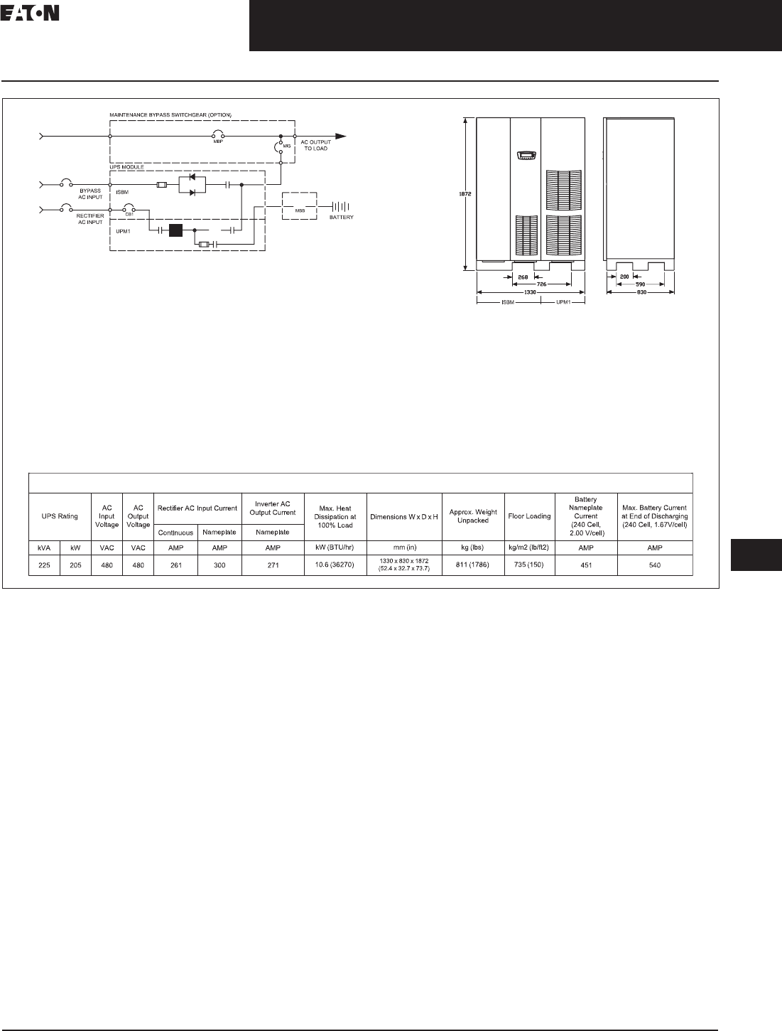
CA08104001E For more information, visit: www.eaton.com/consultants
33.3-9
September 2011
Uninterruptible Power Supplies
Sheet 33
22
23
24
25
26
27
28
29
30
31
32
33
34
35
36
37
38
39
40
41
42
43
Large Three-Phase Units—Eaton 9395
Layout Diagrams
065
Figure 33.3-3. Site Planning Data, 9395, 225 kVA, Single Module System
Product Specifications
Notes:
1. Rectifier AC input current calculations: Continuous—100% load without charging; nameplate—
100% load with maximum charging.
2. Inverter AC output current calculation: Nameplate—100% rated output load.
3. Bypass AC input current calculation is based on 100% rated output.
4. The system must be installed on a level floor suitable for computer or electronic equipment.
5. The system must be installed in a temperature and humidity controlled indoor area
free of conductive contaminants.
6. Ambient temperature range: 0º–40ºC (32º–104ºF); recommended operating range: 20º–25ºC
(68º–77ºF); maximum relative humidity: 95% noncondensing.
7. Minimum overhead clearance for ventilation above the UPS cabinet is 457 mm (18 inches).
8. Minimum 915 mm (36 inches) clearance in front of the UPS cabinet is required for cooling air intake
and servicing space.
9. The UPS cabinet can be installed in line-up-and-match or standalone configurations.
10. Top and bottom cable entries through removable access plates are standard for all configurations.
Access plates shall be custom-modified to suit conduit sizes.
11. All wiring is to be in accordance with National and Local electric codes.
12. AC input to UPS rectifier (0.98 min. pF): three phases, one ground.
AC output to load: three phases, one neutral if required, one ground.
DC input from battery to UPS: one positive, one negative, one ground.
13. The front panels must be removed to meet the 830 mm (32.7 inches) depth to fit through doors.
14. If the UPS is to be installed with the right side near a wall, a minimum of 6.00 inches (152.4 mm) is required
between the wall and the unit. If a battery cabinet is installed to the right of the UPS, the 6.00 inches
(152.4 mm) are not required.
15. Specifications are subject to change.
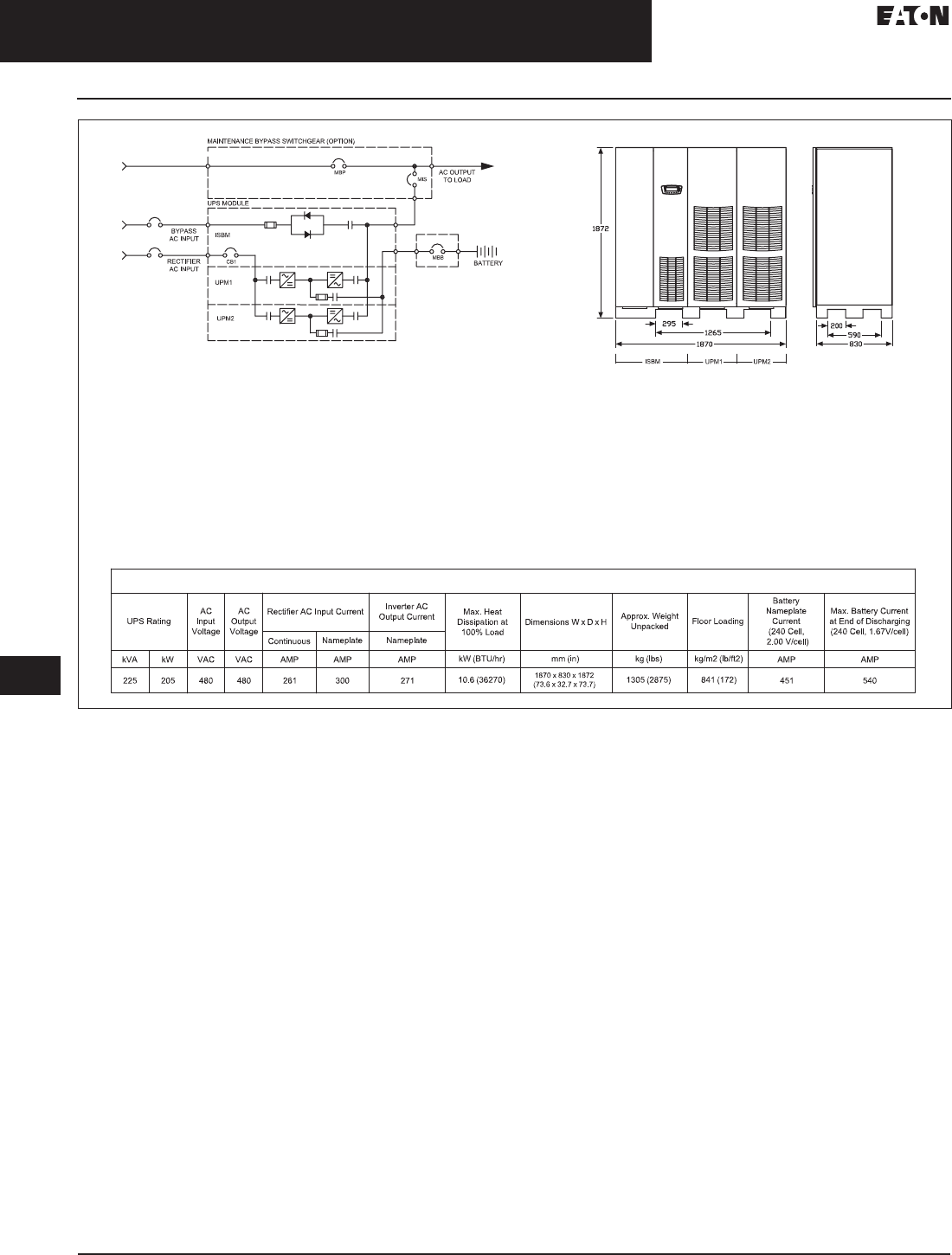
33.3-10
For more information, visit: www.eaton.com/consultants CA08104001E
September 2011
Uninterruptible Power Supplies
Sheet 33
22
23
24
25
26
27
28
29
30
31
32
33
34
35
36
37
38
39
40
41
42
43
Large Three-Phase Units—Eaton 9395
Layout Diagrams
066
Figure 33.3-4. Site Planning Data, 9395, 225 kVA Plus 1, Single Module System
Product Specifications
Notes:
1. Rectifier AC input current calculations: Continuous—100% load without charging; nameplate—
100% load with maximum charging.
2. Inverter AC output current calculation: Nameplate—100% rated output load.
3. Bypass AC input current calculation is based on 100% rated output.
4. The system must be installed on a level floor suitable for computer or electronic equipment.
5. The system must be installed in a temperature and humidity controlled indoor area
free of conductive contaminants.
6. Ambient temperature range: 0º–40ºC (32º–104ºF); recommended operating range: 20º–25ºC
(68º–77ºF); maximum relative humidity: 95% noncondensing.
7. Minimum overhead clearance for ventilation above the UPS cabinet is 457 mm (18 inches).
8. Minimum 915 mm (36 inches) clearance in front of the UPS cabinet is required for cooling air intake
and servicing space.
9. The UPS cabinet can be installed in line-up-and-match or standalone configurations.
10. Top and bottom cable entries through removable access plates are standard for all configurations.
Access plates shall be custom-modified to suit conduit sizes.
11. All wiring is to be in accordance with National and Local electric codes.
12. AC input to UPS rectifier (0.98 min. pF): three phases, one ground.
AC output to load: three phases, one neutral if required, one ground.
DC input from battery to UPS: one positive, one negative, one ground.
13. The front panels must be removed to meet the 830 mm (32.7 inches) depth to fit through doors.
14. If the UPS is to be installed with the right side near a wall, a minimum of 6.00 inches (152.4 mm) is required
between the wall and the unit. If a battery cabinet is installed to the right of the UPS, the 6.00 inches
(152.4 mm) are not required.
15. Specifications are subject to change.

CA08104001E For more information, visit: www.eaton.com/consultants
33.3-11
September 2011
Uninterruptible Power Supplies
Sheet 33
22
23
24
25
26
27
28
29
30
31
32
33
34
35
36
37
38
39
40
41
42
43
Large Three-Phase Units—Eaton 9395
Layout Diagrams
067
Figure 33.3-5. Site Planning Data, System 9395-275 ISBM, Models 225, 275 kVA, Single Module
UPS Rating
AC
Input
Voltage
AC
Output
Voltage
Inverter AC
Output Current Max. Heat
Dissipation at
100% Load
Dimensions W x D x H Approx. Weight
Unpacked Floor Loading
Battery
Nameplate
Current
(240 Cell,
2.00 V/cell)
Max. Battery Current
at End of Discharging
(240 Cell, 1.67V/cell)
Continuous Nameplate Nameplate
kVA kW VAC VAC AMP AMP AMP kW (BTU/hr) mm (in) kg (lbs) kg/m2 (lb/ft2) AMP AMP
225 205 480 480 264 300 271 12.8 (43863) 1330 x 830 x 1872
(52.4 x 32.7 x 73.7) 811 (1786) 735 (150) 451 540
ISBM UPM1
275 250 480 480 323 370 331 15.7 (53661) 1330 x 830 x 1872
(52.4 x 32.7 x 73.7) 811 (1786) 735 (150) 551 660
MBB
MBP
MIS AC OUTPUT
TO LOAD
BYPASS
AC INPUT
RECTIFIER
AC INPUT
UPS MODULE
MAINTENANCE BYPASS SWITCHGEAR (OPTION)
BATTERY
ISBM
UPM1
P/N 110100215-001 Sheet 1 of 10 Rev. 1
CB1 (OPTION)
Rectifier AC Input Current
Product Specifications
Notes:
1. Rectifier AC input current calculations: Continuous—100% load without charging; nameplate—
100% load with maximum charging.
2. Inverter AC output current calculation: Nameplate—100% rated output load.
3. Bypass AC input current calculation is based on 100% rated output.
4. The system must be installed on a level floor suitable for computer or electronic equipment.
5. The system must be installed in a temperature and humidity controlled indoor area
free of conductive contaminants.
6. Ambient temperature range: 0º–40ºC (32º–104ºF); recommended operating range: 20º–25ºC
(68º–77ºF); maximum relative humidity: 95% noncondensing.
7. Minimum overhead clearance for ventilation above the UPS cabinet is 457 mm (18 inches).
8. Minimum 915 mm (36 inches) clearance in front of the UPS cabinet is required for cooling air intake
and servicing space.
9. The UPS cabinet can be installed in line-up-and-match or standalone configurations.
10. Top and bottom cable entries through removable access plates are standard for all configurations.
Access plates shall be custom-modified to suit conduit sizes.
11. All wiring is to be in accordance with National and Local electric codes.
12. AC input to UPS rectifier (0.98 min. pF): three phases, one ground.
AC output to load: three phases, one neutral if required, one ground.
DC input from battery to UPS: one positive, one negative, one ground.
13. The front panels must be removed to meet the 830 mm (32.7 inches) depth to fit through doors.
14. If the UPS is to be installed with the right side near a wall, a minimum of 6.00 inches (152.4 mm) is required
between the wall and the unit. If a battery cabinet is installed to the right of the UPS, the 6.00 inches
(152.4 mm) are not required.
15. Specifications are subject to change.
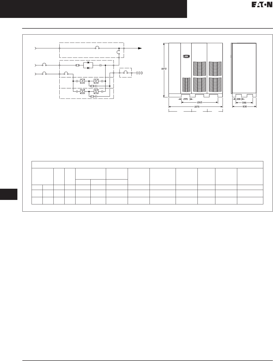
33.3-12
For more information, visit: www.eaton.com/consultants CA08104001E
September 2011
Uninterruptible Power Supplies
Sheet 33
22
23
24
25
26
27
28
29
30
31
32
33
34
35
36
37
38
39
40
41
42
43
Large Three-Phase Units—Eaton 9395
Layout Diagrams
068
Figure 33.3-6. Site Planning Data, System 9395-275 Plus 1 ISBM, Models 225, 275 kVA, Single Module
MBB
MBP
MIS
AC OUTPUT
TO LOAD
BYPASS
AC INPUT
RECTIFIER
AC INPUT
UPS MODULE
MAINTENANCE BYPASS SWITCHGEAR (OPTION)
BATTERY
ISBM
UPM1
ISBM UPM1 UPM2
UPM2
UPS Rating
AC
Input
Voltage
AC
Output
Voltage
Inverter AC
Output Current Max. Heat
Dissipation at Full
Load BTU/h
Dimensions W x D x H Approx. Weight
Unpacked Floor Loading
Battery
Nameplate
Current
(240 Cell,
2.00 V/cell)
Max. Battery Current
at End of Discharging
(240 Cell, 1.67V/cell)
Continuous Nameplate Nameplate
kVA kW VAC VAC AMP AMP AMP kW (BTU/hr) mm (in) kg (lbs) kg/m2 (lb/ft2) AMP AMP
225 205 480 480 264 300 271 12.8 (43863) 1870 x 830 x 1872
(73.6 x 32.7 x 73.7) 1305 (2875) 841 (172) 451 540
275 250 480 480 323 370 331 15.7 (53661) 1870 x 830 x 1872
(73.6 x 32.7 x 73.7) 1305 (2875) 841 (172) 551 660
P/N 110100215-001 Sheet 2 of 10 Rev. 1
CB1 (OPTION)
Rectifier AC Input Current
Product Specifications
Notes:
1. Rectifier AC input current calculations: Continuous—100% load without charging; nameplate—
100% load with maximum charging.
2. Inverter AC output current calculation: Nameplate—100% rated output load.
3. Bypass AC input current calculation is based on 100% rated output.
4. The system must be installed on a level floor suitable for computer or electronic equipment.
5. The system must be installed in a temperature and humidity controlled indoor area
free of conductive contaminants.
6. Ambient temperature range: 0º–40ºC (32º–104ºF); recommended operating range: 20º–25ºC
(68º–77ºF); maximum relative humidity: 95% noncondensing.
7. Minimum overhead clearance for ventilation above the UPS cabinet is 457 mm (18 inches).
8. Minimum 915 mm (36 inches) clearance in front of the UPS cabinet is required for cooling air intake
and servicing space.
9. The UPS cabinet can be installed in line-up-and-match or standalone configurations.
10. Top and bottom cable entries through removable access plates are standard for all configurations.
Access plates shall be custom-modified to suit conduit sizes.
11. All wiring is to be in accordance with National and Local electric codes.
12. AC input to UPS rectifier (0.98 min. pF): three phases, one ground.
AC output to load: three phases, one neutral if required, one ground.
DC input from battery to UPS: one positive, one negative, one ground.
13. The front panels must be removed to meet the 830 mm (32.7 inches) depth to fit through doors.
14. If the UPS is to be installed with the right side near a wall, a minimum of 6.00 inches (152.4 mm) is required
between the wall and the unit. If a battery cabinet is installed to the right of the UPS, the 6.00 inches
(152.4 mm) are not required.
15. Specifications are subject to change.
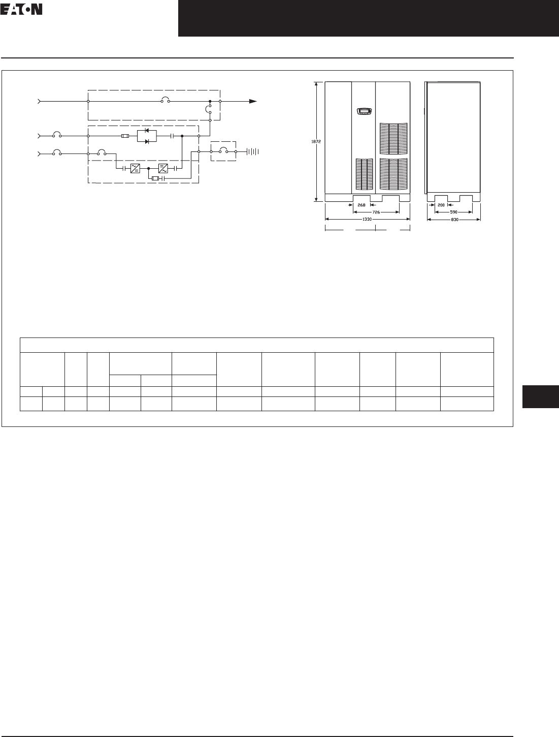
CA08104001E For more information, visit: www.eaton.com/consultants
33.3-13
September 2011
Uninterruptible Power Supplies
Sheet 33
22
23
24
25
26
27
28
29
30
31
32
33
34
35
36
37
38
39
40
41
42
43
Large Three-Phase Units—Eaton 9395
Layout Diagrams
069
Figure 33.3-7. Site Planning Data, System 9395, 300 kVA, ISBM, Single Module
UPS Rating
AC
Input
Voltage
AC
Output
Voltage
Inverter AC
Output Current Max. Heat
Dissipation at
100% Load
Dimensions W x D x H Approx. Weight
Unpacked Floor Loading
Battery
Nameplate
Current
(240 Cell,
2.00 V/cell)
Max. Battery Current
at End of Discharging
(240 Cell, 1.67V/cell)
Continuous Nameplate Nameplate
kVA kW VAC VAC AMP AMP AMP kW (BTU/hr) mm (in) kg (lbs) kg/m2 (lb/ft2) AMP AMP
300 240 480 480 310 360 361 15.1 (51466) 1330 x 830 x 1872
(52.4 x 32.7 x 73.7) 811 (1786) 735 (150) 529 633
ISBM UPM1
MBB
MBP
MIS AC OUTPUT
TO LOAD
BYPASS
AC INPUT
RECTIFIER
AC INPUT
UPS MODULE
MAINTENANCE BYPASS SWITCHGEAR (OPTION)
BATTERY
ISBM
UPM1
P/N 110100215-001 Sheet 3 of 10 Rev. 1
CB1 (OPTION)
Product Specifications
Rectifier AC Input Current
Notes:
1. Rectifier AC input current calculations: Continuous—100% load without charging; nameplate—
100% load with maximum charging.
2. Inverter AC output current calculation: Nameplate—100% rated output load.
3. Bypass AC input current calculation is based on 100% rated output.
4. The system must be installed on a level floor suitable for computer or electronic equipment.
5. The system must be installed in a temperature and humidity controlled indoor area
free of conductive contaminants.
6. Ambient temperature range: 0º–40ºC (32º–104ºF); recommended operating range: 20º–25ºC
(68º–77ºF); maximum relative humidity: 95% noncondensing.
7. Minimum overhead clearance for ventilation above the UPS cabinet is 457 mm (18 inches).
8. Minimum 915 mm (36 inches) clearance in front of the UPS cabinet is required for cooling air intake
and servicing space.
9. The UPS cabinet can be installed in line-up-and-match or standalone configurations.
10. Top and bottom cable entries through removable access plates are standard for all configurations.
Access plates shall be custom-modified to suit conduit sizes.
11. All wiring is to be in accordance with National and Local electric codes.
12. AC input to UPS rectifier (0.98 min. pF): three phases, one ground.
AC output to load: three phases, one neutral if required, one ground.
DC input from battery to UPS: one positive, one negative, one ground.
13. The front panels must be removed to meet the 830 mm (32.7 inches) depth to fit through doors.
14. If the UPS is to be installed with the right side near a wall, a minimum of 6.00 inches (152.4 mm) is required
between the wall and the unit. If a battery cabinet is installed to the right of the UPS, the 6.00 inches
(152.4 mm) are not required.
15. Specifications are subject to change.

33.3-14
For more information, visit: www.eaton.com/consultants CA08104001E
September 2011
Uninterruptible Power Supplies
Sheet 33
22
23
24
25
26
27
28
29
30
31
32
33
34
35
36
37
38
39
40
41
42
43
Large Three-Phase Units—Eaton 9395
Layout Diagrams
070
Figure 33.3-8. Planning Data, System 9395, 300 kVA, Plus 1 ISBM, Single Module
MBB
MBP
MIS
AC OUTPUT
TO LOAD
BYPASS
AC INPUT
RECTIFIER
AC INPUT
UPS MODULE
MAINTENANCE BYPASS SWITCHGEAR (OPTION)
BATTERY
ISBM
UPM1
ISBM UPM1 UPM2
UPM2
UPS Rating
AC
Input
Voltage
AC
Output
Voltage
Inverter AC
Output Current Max. Heat
Dissipation at Full
Load BTU/h
Dimensions W x D x H Approx. Weight
Unpacked Floor Loading
Battery
Nameplate
Current
(240 Cell,
2.00 V/cell)
Max. Battery Current
at End of Discharging
(240 Cell, 1.67V/cell)
Continuous Nameplate Nameplate
kVA kW VAC VAC AMP AMP AMP kW (BTU/hr) mm (in) kg (lbs) kg/m2 (lb/ft2) AMP AMP
300 240 480 480 310 360 361 15.1 (51466) 1870 x 830 x 1872
(73.6 x 32.7 x 73.7) 1305 (2875) 841 (172) 529 633
P/N 110100215-001 Sheet 4 of 10 Rev. 1
CB1 (OPTION)
Rectifier AC Input Current
Product Specifications
Notes:
1. Rectifier AC input current calculations: Continuous—100% load without charging; nameplate—
100% load with maximum charging.
2. Inverter AC output current calculation: Nameplate—100% rated output load.
3. Bypass AC input current calculation is based on 100% rated output.
4. The system must be installed on a level floor suitable for computer or electronic equipment.
5. The system must be installed in a temperature and humidity controlled indoor area
free of conductive contaminants.
6. Ambient temperature range: 0º–40ºC (32º–104ºF); recommended operating range: 20º–25ºC
(68º–77ºF); maximum relative humidity: 95% noncondensing.
7. Minimum overhead clearance for ventilation above the UPS cabinet is 457 mm (18 inches).
8. Minimum 915 mm (36 inches) clearance in front of the UPS cabinet is required for cooling air intake
and servicing space.
9. The UPS cabinet can be installed in line-up-and-match or standalone configurations.
10. Top and bottom cable entries through removable access plates are standard for all configurations.
Access plates shall be custom-modified to suit conduit sizes.
11. All wiring is to be in accordance with National and Local electric codes.
12. AC input to UPS rectifier (0.98 min. pF): three phases, one ground.
AC output to load: three phases, one neutral if required, one ground.
DC input from battery to UPS: one positive, one negative, one ground.
13. The front panels must be removed to meet the 830 mm (32.7 inches) depth to fit through doors.
14. If the UPS is to be installed with the right side near a wall, a minimum of 6.00 inches (152.4 mm) is required
between the wall and the unit. If a battery cabinet is installed to the right of the UPS, the 6.00 inches
(152.4 mm) are not required.
15. Specifications are subject to change.
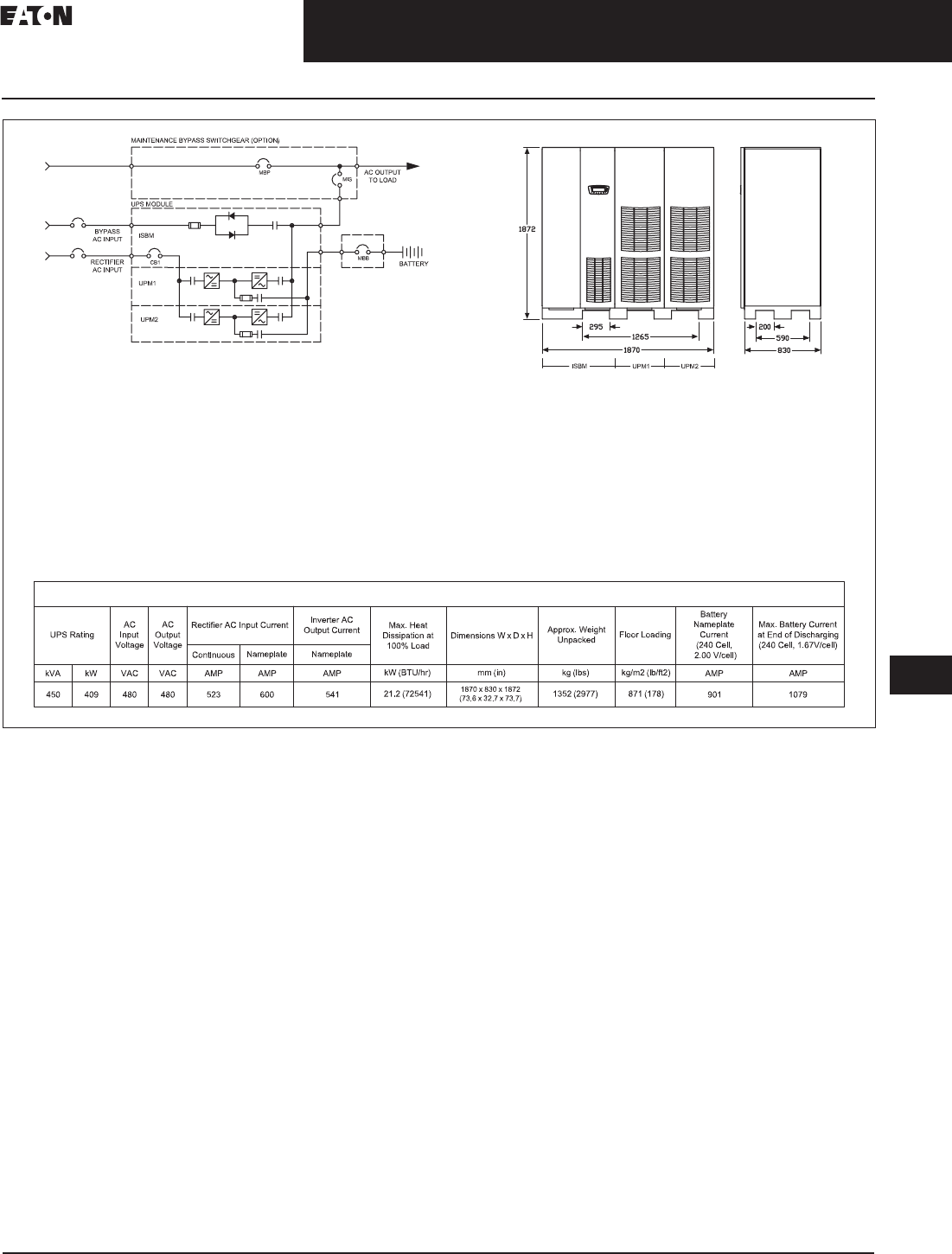
CA08104001E For more information, visit: www.eaton.com/consultants
33.3-15
September 2011
Uninterruptible Power Supplies
Sheet 33
22
23
24
25
26
27
28
29
30
31
32
33
34
35
36
37
38
39
40
41
42
43
Large Three-Phase Units—Eaton 9395
Layout Diagrams
071
Figure 33.3-9. Site Planning Data, 9395, 450 kVA, Single Module System
Product Specifications
Notes:
1. Rectifier AC input current calculations: Continuous—100% load without charging; nameplate—
100% load with maximum charging.
2. Inverter AC output current calculation: Nameplate—100% rated output load.
3. Bypass AC input current calculation is based on 100% rated output.
4. The system must be installed on a level floor suitable for computer or electronic equipment.
5. The system must be installed in a temperature and humidity controlled indoor area
free of conductive contaminants.
6. Ambient temperature range: 0º–40ºC (32º–104ºF); recommended operating range: 20º–25ºC
(68º–77ºF); maximum relative humidity: 95% noncondensing.
7. Minimum overhead clearance for ventilation above the UPS cabinet is 457 mm (18 inches).
8. Minimum 915 mm (36 inches) clearance in front of the UPS cabinet is required for cooling air intake
and servicing space.
9. The UPS cabinet can be installed in line-up-and-match or standalone configurations.
10. Top and bottom cable entries through removable access plates are standard for all configurations.
Access plates shall be custom-modified to suit conduit sizes.
11. All wiring is to be in accordance with National and Local electric codes.
12. AC input to UPS rectifier (0.98 min. pF): three phases, one ground.
AC output to load: three phases, one neutral if required, one ground.
DC input from battery to UPS: one positive, one negative, one ground.
13. The front panels must be removed to meet the 830 mm (32.7 inches) depth to fit through doors.
14. If the UPS is to be installed with the right side near a wall, a minimum of 6.00 inches (152.4 mm) is required
between the wall and the unit. If a battery cabinet is installed to the right of the UPS, the 6.00 inches
(152.4 mm) are not required.
15. Specifications are subject to change.
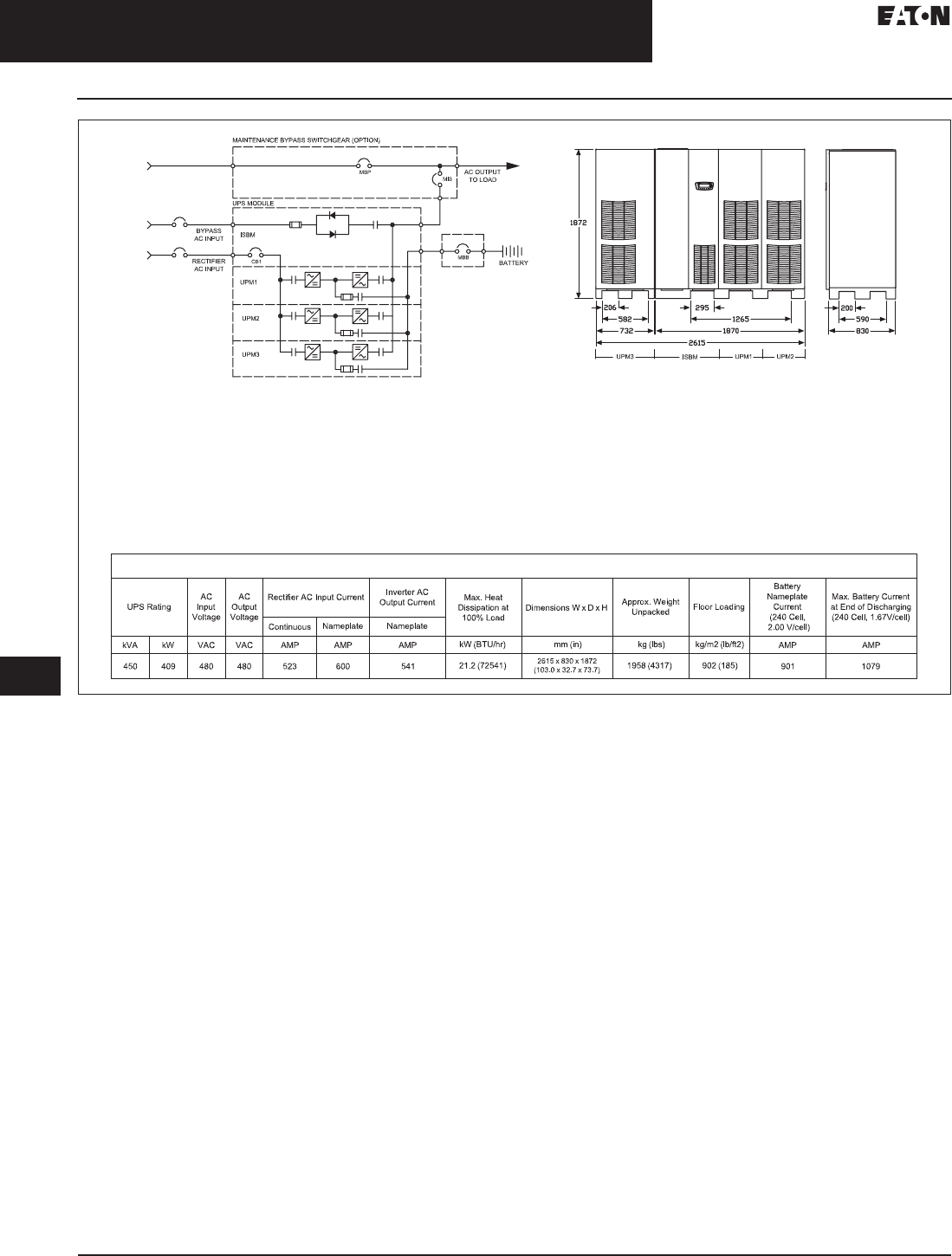
33.3-16
For more information, visit: www.eaton.com/consultants CA08104001E
September 2011
Uninterruptible Power Supplies
Sheet 33
22
23
24
25
26
27
28
29
30
31
32
33
34
35
36
37
38
39
40
41
42
43
Large Three-Phase Units—Eaton 9395
Layout Diagrams
072
Figure 33.3-10. Site Planning Data, 9395, 450 kVA, Plus 1, Single Module System
Product Specifications
Notes:
1. Rectifier AC input current calculations: Continuous—100% load without charging; nameplate—
100% load with maximum charging.
2. Inverter AC output current calculation: Nameplate—100% rated output load.
3. Bypass AC input current calculation is based on 100% rated output.
4. The system must be installed on a level floor suitable for computer or electronic equipment.
5. The system must be installed in a temperature and humidity controlled indoor area
free of conductive contaminants.
6. Ambient temperature range: 0º–40ºC (32º–104ºF); recommended operating range: 20º–25ºC
(68º–77ºF); maximum relative humidity: 95% noncondensing.
7. Minimum overhead clearance for ventilation above the UPS cabinet is 457 mm (18 inches).
8. Minimum 915 mm (36 inches) clearance in front of the UPS cabinet is required for cooling air intake
and servicing space.
9. The UPS cabinet can be installed in line-up-and-match or standalone configurations.
10. Top and bottom cable entries through removable access plates are standard for all configurations.
Access plates shall be custom-modified to suit conduit sizes.
11. All wiring is to be in accordance with National and Local electric codes.
12. AC input to UPS rectifier (0.98 min. pF): three phases, one ground.
AC output to load: three phases, one neutral if required, one ground.
DC input from battery to UPS: one positive, one negative, one ground.
13. The front panels must be removed to meet the 830 mm (32.7 inches) depth to fit through doors.
14. If the UPS is to be installed with the right side near a wall, a minimum of 6.00 inches (152.4 mm) is required
between the wall and the unit. If a battery cabinet is installed to the right of the UPS, the 6.00 inches
(152.4 mm) are not required.
15. Specifications are subject to change.
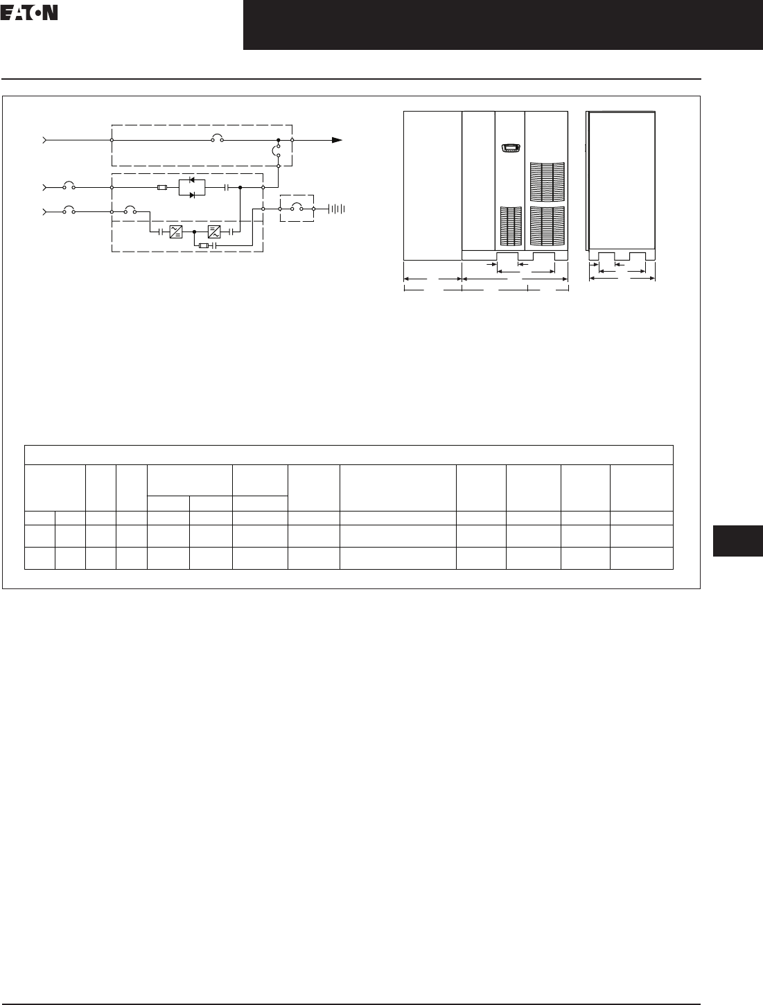
CA08104001E For more information, visit: www.eaton.com/consultants
33.3-17
September 2011
Uninterruptible Power Supplies
Sheet 33
22
23
24
25
26
27
28
29
30
31
32
33
34
35
36
37
38
39
40
41
42
43
Large Three-Phase Units—Eaton 9395
Layout Diagrams
073
Figure 33.3-11. Site Planning Data, System 9395-550 ISBM, Models 550/275 kVA, 550//275 kVA, Single Module
Future
Field
Installed
UPM
( Future Capacity in [ ] )
UPS Rating
AC
Input
Voltage
AC
Output
Voltage
Inverter AC
Output Current Max. Heat
Dissipation at
100% Load
Dimensions W x D x H
Approx.
Weight
Unpacked
Floor Loading
Battery
Nameplate
Current
(240 Cell,
2.00 V/cell)
Max. Battery
Current at End of
Discharging (240
Cell, 1.67V/cell)
Continuous Nameplate Nameplate
kVA kW VAC VAC AMP AMP AMP kW (BTU/hr) mm (in) kg (lbs) kg/m2 (lb/ft2) AMP AMP
225
[550]
205
[500] 480 480 264
[646]
300
[740]
271
[662]
12.8 (43863)
[31.4 (107221)]
1330 x 830 x 1872 (52.4 x 32.7 x 73.7)
[2062 x 830 x 1872 (81.2 x 32.7 x 73.7)]
811 (1786)
[1417 (3124)]
735 (150)
[828 (169)]
451
[1101]
540
[1319]
* Space should be reserved on the left side of the unit, for a future capacity upgrade, as shown above
While this is a 275kVA UPS, a 550kVA ISBM section is included. UPS should be wired for future capacity.
ISBM UPM1
FI-UPM
MBB
MBP
MIS AC OUTPUT
TO LOAD
BYPASS
AC INPUT
RECTIFIER
AC INPUT
UPS MODULE
MAINTENANCE BYPASS SWITCHGEAR (OPTION)
BATTERY
ISBM
UPM1
275
[550]
250
[500] 480 480 323
[646]
370
[740]
331
[662]
15.7 (53611)
[31.4 (107221)]
1330 x 830 x 1872 (52.4 x 32.7 x 73.7)
[2062 x 830 x 1872 (81.2 x 32.7 x 73.7)]
811 (1786)
[1417 (3124)]
735 (150)
[828 (169)]
551
[1101]
660
[1319]
P/N 110100215-001 Sheet 6 of 10 Rev. 1
CB1 (OPTION)
Product Specifications
Rectifier AC Input Current
830
200
590
268
726
1330732
Notes:
1. Rectifier AC input current calculations: Continuous—100% load without charging; nameplate—
100% load with maximum charging.
2. Inverter AC output current calculation: Nameplate—100% rated output load.
3. Bypass AC input current calculation is based on 100% rated output.
4. The system must be installed on a level floor suitable for computer or electronic equipment.
5. The system must be installed in a temperature and humidity controlled indoor area
free of conductive contaminants.
6. Ambient temperature range: 0º–40ºC (32º–104ºF); recommended operating range: 20º–25ºC
(68º–77ºF); maximum relative humidity: 95% noncondensing.
7. Minimum overhead clearance for ventilation above the UPS cabinet is 457 mm (18 inches).
8. Minimum 915 mm (36 inches) clearance in front of the UPS cabinet is required for cooling air intake
and servicing space.
9. The UPS cabinet can be installed in line-up-and-match or standalone configurations.
10. Top and bottom cable entries through removable access plates are standard for all configurations.
Access plates shall be custom-modified to suit conduit sizes.
11. All wiring is to be in accordance with National and Local electric codes.
12. AC input to UPS rectifier (0.98 min. pF): three phases, one ground.
AC output to load: three phases, one neutral if required, one ground.
DC input from battery to UPS: one positive, one negative, one ground.
13. The front panels must be removed to meet the 830 mm (32.7 inches) depth to fit through doors.
14. If the UPS is to be installed with the right side near a wall, a minimum of 6.00 inches (152.4 mm) is required
between the wall and the unit. If a battery cabinet is installed to the right of the UPS, the 6.00 inches
(152.4 mm) are not required.
15. Specifications are subject to change.
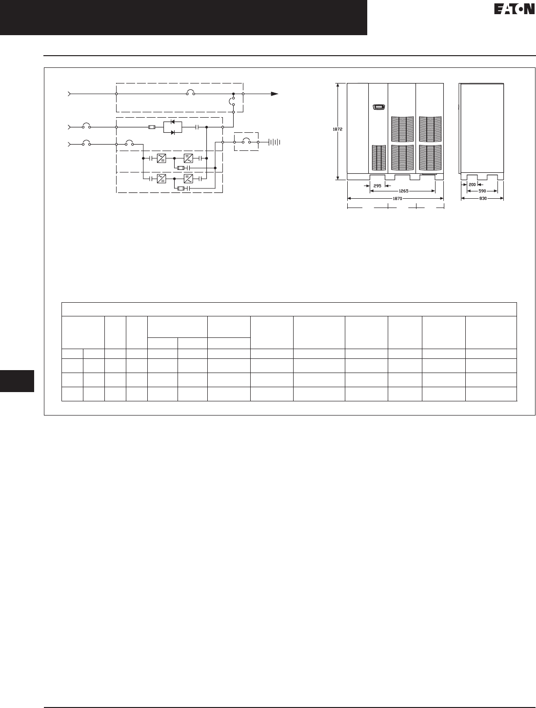
33.3-18
For more information, visit: www.eaton.com/consultants CA08104001E
September 2011
Uninterruptible Power Supplies
Sheet 33
22
23
24
25
26
27
28
29
30
31
32
33
34
35
36
37
38
39
40
41
42
43
Large Three-Phase Units—Eaton 9395
Layout Diagrams
074
Figure 33.3-12. Site Planning Data, System 9395-550 ISBM, Models 450, 500, 275 kVA, Single Module
MBB
CB1 (OPTION)
MBP
MIS
AC OUTPUT
TO LOAD
BYPASS
AC INPUT
RECTIFIER
AC INPUT
UPS MODULE
MAINTENANCE BYPASS SWITCHGEAR (OPTION)
BATTERY
ISBM
UPM1
ISBM UPM1 UPM2
UPM2
UPS Rating
AC
Input
Voltage
AC
Output
Voltage
Inverter AC
Output Current Max. Heat
Dissipation at
100% Load
Dimensions W x D x H Approx. Weight
Unpacked Floor Loading
Battery
Nameplate
Current
(240 Cell,
2.00 V/cell)
Max. Battery Current
at End of Discharging
(240 Cell, 1.67V/cell)
Continuous Nameplate Nameplate
kVA kW VAC VAC AMP AMP AMP kW (BTU/hr) mm (in) kg (lbs) kg/m2 (lb/ft2) AMP AMP
450 409 480 480 528 600 541 25.7 (87727) 1870 x 830 x 1872
(73.6 x 32.7 x 73.7) 1352 (2977) 871 (178) 901 1079
550 500 480 480 646 740 662 31.4 (107221) 1870 x 830 x 1872
(73.6 x 32.7 x 73.7) 1352 (2977) 871 (178) 1101 1319
500 455 480 480 587 660 601 28.6 (97474) 1870 x 830 x 1872
(73.6 x 32.7 x 73.7) 1352 (2977) 871 (178) 1001 1199
P/N 110100215-001 Sheet 5 of 10 Rev. 1
Product Specifications
Rectifier AC Input Current
Notes:
1. Rectifier AC input current calculations: Continuous—100% load without charging; nameplate—
100% load with maximum charging.
2. Inverter AC output current calculation: Nameplate—100% rated output load.
3. Bypass AC input current calculation is based on 100% rated output.
4. The system must be installed on a level floor suitable for computer or electronic equipment.
5. The system must be installed in a temperature and humidity controlled indoor area
free of conductive contaminants.
6. Ambient temperature range: 0º–40ºC (32º–104ºF); recommended operating range: 20º–25ºC
(68º–77ºF); maximum relative humidity: 95% noncondensing.
7. Minimum overhead clearance for ventilation above the UPS cabinet is 457 mm (18 inches).
8. Minimum 915 mm (36 inches) clearance in front of the UPS cabinet is required for cooling air intake
and servicing space.
9. The UPS cabinet can be installed in line-up-and-match or standalone configurations.
10. Top and bottom cable entries through removable access plates are standard for all configurations.
Access plates shall be custom-modified to suit conduit sizes.
11. All wiring is to be in accordance with National and Local electric codes.
12. AC input to UPS rectifier (0.98 min. pF): three phases, one ground.
AC output to load: three phases, one neutral if required, one ground.
DC input from battery to UPS: one positive, one negative, one ground.
13. The front panels must be removed to meet the 830 mm (32.7 inches) depth to fit through doors.
14. If the UPS is to be installed with the right side near a wall, a minimum of 6.00 inches (152.4 mm) is required
between the wall and the unit. If a battery cabinet is installed to the right of the UPS, the 6.00 inches
(152.4 mm) are not required.
15. Specifications are subject to change.
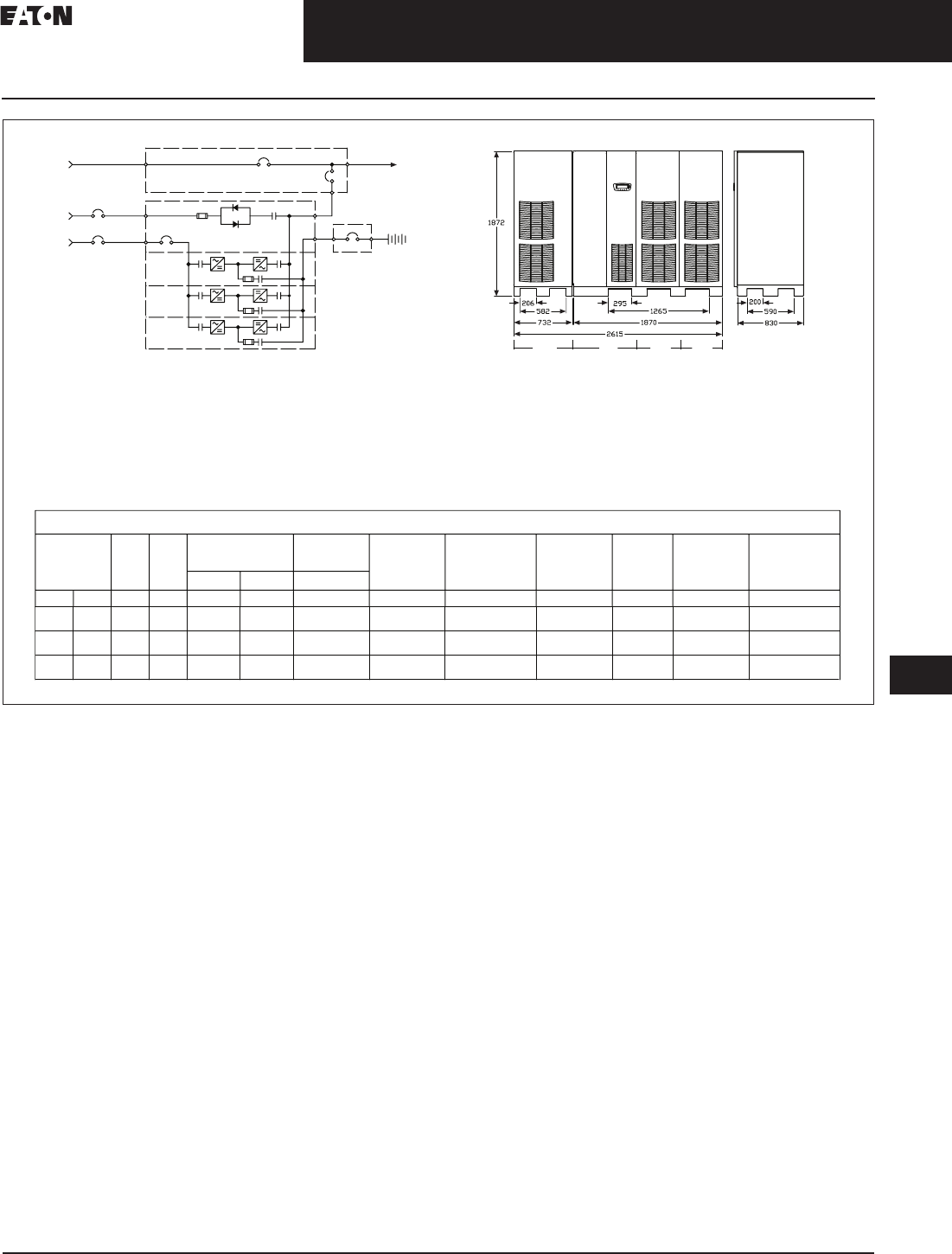
CA08104001E For more information, visit: www.eaton.com/consultants
33.3-19
September 2011
Uninterruptible Power Supplies
Sheet 33
22
23
24
25
26
27
28
29
30
31
32
33
34
35
36
37
38
39
40
41
42
43
Large Three-Phase Units—Eaton 9395
Layout Diagrams
075
Figure 33.3-13. Site Planning Data, System 9395-550 Plus 1 ISBM, Models 450, 500, 500 kVA, Single Module
MBB
MBP MIS
AC OUTPUT
TO LOAD
BYPASS
AC INPUT
RECTIFIER
AC INPUT
UPS MODULE
MAINTENANCE BYPASS SWITCHGEAR (OPTION)
BATTERY
ISBM
UPM1
ISBM UPM1 UPM2
UPM2
UPM3
UPS Rating
AC
Input
Voltage
AC
Output
Voltage
Inverter AC
Output Current Max. Heat
Dissipation at
100% Load
Dimensions W x D x H Approx. Weight
Unpacked Floor Loading
Battery
Nameplate
Current
(240 Cell,
2.00 V/cell)
Max. Battery Current
at End of Discharging
(240 Cell, 1.67V/cell)
Continuous Nameplate Nameplate
kVA kW VAC VAC AMP AMP AMP kW (BTU/hr) mm (in) kg (lbs) kg/m2 (lb/ft2) AMP AMP
450 409 480 480 528 600 541 25.7 (87727) 2615 x 830 x 1872
(103.0 x 32.7 x 73.7) 1958 (4317) 902 (185) 901 1079
UPM3
550 500 480 480 646 740 662 31.4 (107221) 2615 x 830 x 1872
(103.0 x 32.7 x 73.7) 1958 (4317) 902 (185) 1101 1319
500 455 480 480 587 660 601 28.5 (97474) 2615 x 830 x 1872
(103.0 x 32.7 x 73.7) 1958 (4317) 902 (185) 1001 1199
P/N 110100215-001 Sheet 7 of 10 Rev. 1
CB1 (OPTION)
Product Specifications
Rectifier AC Input Current
Notes:
1. Rectifier AC input current calculations: Continuous—100% load without charging; nameplate—
100% load with maximum charging.
2. Inverter AC output current calculation: Nameplate—100% rated output load.
3. Bypass AC input current calculation is based on 100% rated output.
4. The system must be installed on a level floor suitable for computer or electronic equipment.
5. The system must be installed in a temperature and humidity controlled indoor area
free of conductive contaminants.
6. Ambient temperature range: 0º–40ºC (32º–104ºF); recommended operating range: 20º–25ºC
(68º–77ºF); maximum relative humidity: 95% noncondensing.
7. Minimum overhead clearance for ventilation above the UPS cabinet is 457 mm (18 inches).
8. Minimum 915 mm (36 inches) clearance in front of the UPS cabinet is required for cooling air intake
and servicing space.
9. The UPS cabinet can be installed in line-up-and-match or standalone configurations.
10. Top and bottom cable entries through removable access plates are standard for all configurations.
Access plates shall be custom-modified to suit conduit sizes.
11. All wiring is to be in accordance with National and Local electric codes.
12. AC input to UPS rectifier (0.98 min. pF): three phases, one ground.
AC output to load: three phases, one neutral if required, one ground.
DC input from battery to UPS: one positive, one negative, one ground.
13. The front panels must be removed to meet the 830 mm (32.7 inches) depth to fit through doors.
14. If the UPS is to be installed with the right side near a wall, a minimum of 6.00 inches (152.4 mm) is required
between the wall and the unit. If a battery cabinet is installed to the right of the UPS, the 6.00 inches
(152.4 mm) are not required.
15. Specifications are subject to change.
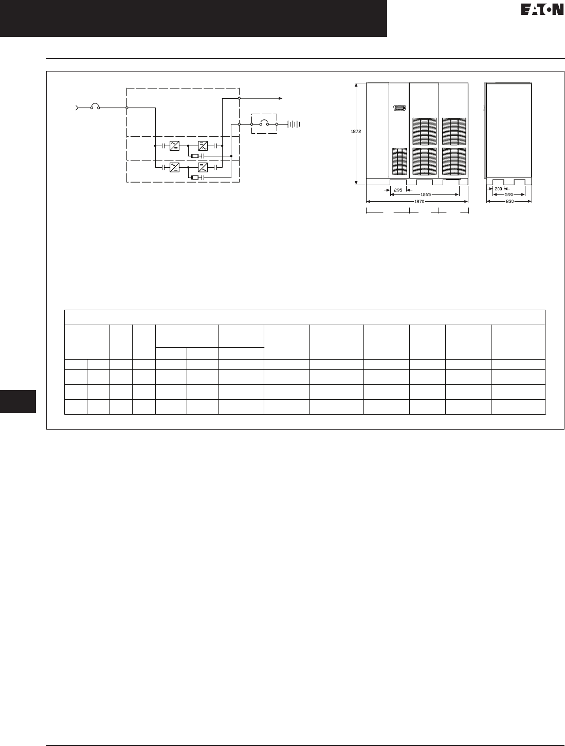
33.3-20
For more information, visit: www.eaton.com/consultants CA08104001E
September 2011
Uninterruptible Power Supplies
Sheet 33
22
23
24
25
26
27
28
29
30
31
32
33
34
35
36
37
38
39
40
41
42
43
Large Three-Phase Units—Eaton 9395
Layout Diagrams
076
Figure 33.3-14. Site Planning Data, System 9395-550 IOM, Models 450, 500, 550 kVA, Single Module
IOM UPM1 UPM2
UPS Rating
AC
Input
Voltage
AC
Output
Voltage
Per UPM
Inverter AC
Output Current Max. Heat
Dissipation at
100% Load
Dimensions W x D x H Approx. Weight
Unpacked Floor Loading
Battery
Nameplate
Current
(240 Cell,
2.00 V/cell)
Max. Battery Current
at End of Discharging
(240 Cell, 1.67V/cell)
Continuous Nameplate Nameplate
kVA kW VAC VAC AMP AMP AMP kW (BTU/hr) mm (in) kg (lbs) kg/m2 (lb/ft2) AMP AMP
450 409 480 480 264 370 541 25.7 (87727) 1870 x 830 x 1872
(73.6 x 32.7 x 73.7) 1298 (2857) 837 (171) 901 1079
550 500 480 480 323 370 662 31.4 (107221) 1870 x 830 x 1872
(73.6 x 32.7 x 73.7) 1298 (2857) 837 (171) 1101 1319
500 455 480 480 294 370 601 28.6 (97474) 1870 x 830 x 1872
(73.6 x 32.7 x 73.7) 1298 (2857) 837 (171) 1001 1199
P/N 110100215-003 Sheet 1 of 5 Rev. 1
UPM2
MBB
AC OUTPUT
TO LOAD
RECTIFIER
AC INPUT
UPS MODULE
BATTERY
IOM
UPM1
Product Specifications
Rectifier AC Input Current
Notes:
1. IOM—I/O module requires external system bypass module.
2. Rectifier AC input current calculations: Continuous—100% load without charging; nameplate—
100% load with maximum charging.
3. Inverter AC output current calculation: Nameplate—100% rated output load.
4. The system must be installed on a level floor suitable for computer or electronic equipment.
5. The system must be installed in a temperature and humidity controlled indoor area
free of conductive contaminants.
6. Ambient temperature range: 0º–40ºC (32º–104ºF); recommended operating range: 20º–25ºC
(68º–77ºF); maximum relative humidity: 95% noncondensing.
7. Minimum overhead clearance for ventilation above the UPS cabinet is 457 mm (18 inches).
8. Minimum 915 mm (36 inches) clearance in front of the UPS cabinet is required for cooling air intake
and servicing space.
9. The UPS cabinet can be installed in line-up-and-match or standalone configurations.
10. Top and bottom cable entries through removable access plates are standard for all configurations.
Access plates shall be custom-modified to suit conduit sizes.
11. All wiring is to be in accordance with National and Local electric codes.
12. AC input to UPS rectifier (0.98 min. pF): three phases, one ground.
AC output to load: three phases, one neutral if required, one ground.
DC input from battery to UPS: one positive, one negative, one ground.
13. The front panels must be removed to meet the 830 mm (32.7 inches) depth to fit through doors.
14. If the UPS is to be installed with the right side near a wall, a minimum of 6.00 inches (152.4 mm) is required
between the wall and the unit. If a battery cabinet is installed to the right of the UPS, the 6.00 inches
(152.4 mm) are not required.
15. Specifications are subject to change.
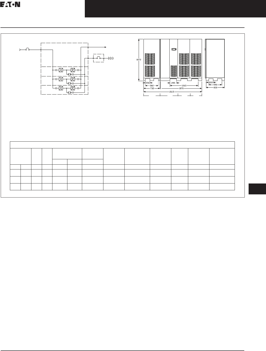
CA08104001E For more information, visit: www.eaton.com/consultants
33.3-21
September 2011
Uninterruptible Power Supplies
Sheet 33
22
23
24
25
26
27
28
29
30
31
32
33
34
35
36
37
38
39
40
41
42
43
Large Three-Phase Units—Eaton 9395
Layout Diagrams
077
Figure 33.3-15. Site Planning Data, System 9395-550 Plus 1 IOM, Models 450, 500, 550 kVA, Single Module
MBB
AC OUTPUT
TO LOAD
RECTIFIER
AC INPUT
UPS MODULE
BATTERY
IOM
UPM1
IOM UPM1 UPM2
UPM2
UPM3
UPS Rating
AC
Input
Voltage
AC
Output
Voltage
Per UPM
Inverter AC
Output Current Max. Heat
Dissipation at
100% Load
Dimensions W x D x H Approx. Weight
Unpacked Floor Loading
Battery
Nameplate
Current
(240 Cell,
2.00 V/cell)
Max. Battery Current
at End of Discharging
(240 Cell, 1.67V/cell)
Continuous Nameplate Nameplate
kVA kW VAC VAC AMP AMP AMP kW (BTU/hr) mm (in) kg (lbs) kg/m2 (lb/ft2) AMP AMP
450 409 480 480 264 370 541 25.7 (87727) 2615 x 830 x 1872
(103.0 x 32.7 x 73.7) 1908 (4197) 877 (180) 901 1079
UPM3
550 500 480 480 323 370 662 31.4 (107221) 2615 x 830 x 1872
(103.0 x 32.7 x 73.7) 1908 (4197) 877 (180) 1101 1319
500 455 480 480 294 370 601 28.5 (97474) 2615 x 830 x 1872
(103.0 x 32.7 x 73.7) 1908 (4197) 877 (180) 1001 1199
P/N 110100215-003 Sheet 2 of 5 Rev. 1
Product Specifications
Rectifier AC Input Current
Notes:
1. IOM—I/O module requires external system bypass module.
2. Rectifier AC input current calculations: Continuous—100% load without charging; nameplate—
100% load with maximum charging.
3. Inverter AC output current calculation: Nameplate—100% rated output load.
4. The system must be installed on a level floor suitable for computer or electronic equipment.
5. The system must be installed in a temperature and humidity controlled indoor area
free of conductive contaminants.
6. Ambient temperature range: 0º–40ºC (32º–104ºF); recommended operating range: 20º–25ºC
(68º–77ºF); maximum relative humidity: 95% noncondensing.
7. Minimum overhead clearance for ventilation above the UPS cabinet is 457 mm (18 inches).
8. Minimum 915 mm (36 inches) clearance in front of the UPS cabinet is required for cooling air intake
and servicing space.
9. The UPS cabinet can be installed in line-up-and-match or standalone configurations.
10. Top and bottom cable entries through removable access plates are standard for all configurations.
Access plates shall be custom-modified to suit conduit sizes.
11. All wiring is to be in accordance with National and Local electric codes.
12. AC input to UPS rectifier (0.98 min. pF): three phases, one ground.
AC output to load: three phases, one neutral if required, one ground.
DC input from battery to UPS: one positive, one negative, one ground.
13. The front panels must be removed to meet the 830 mm (32.7 inches) depth to fit through doors.
14. If the UPS is to be installed with the right side near a wall, a minimum of 6.00 inches (152.4 mm) is required
between the wall and the unit. If a battery cabinet is installed to the right of the UPS, the 6.00 inches
(152.4 mm) are not required.
15. Specifications are subject to change.
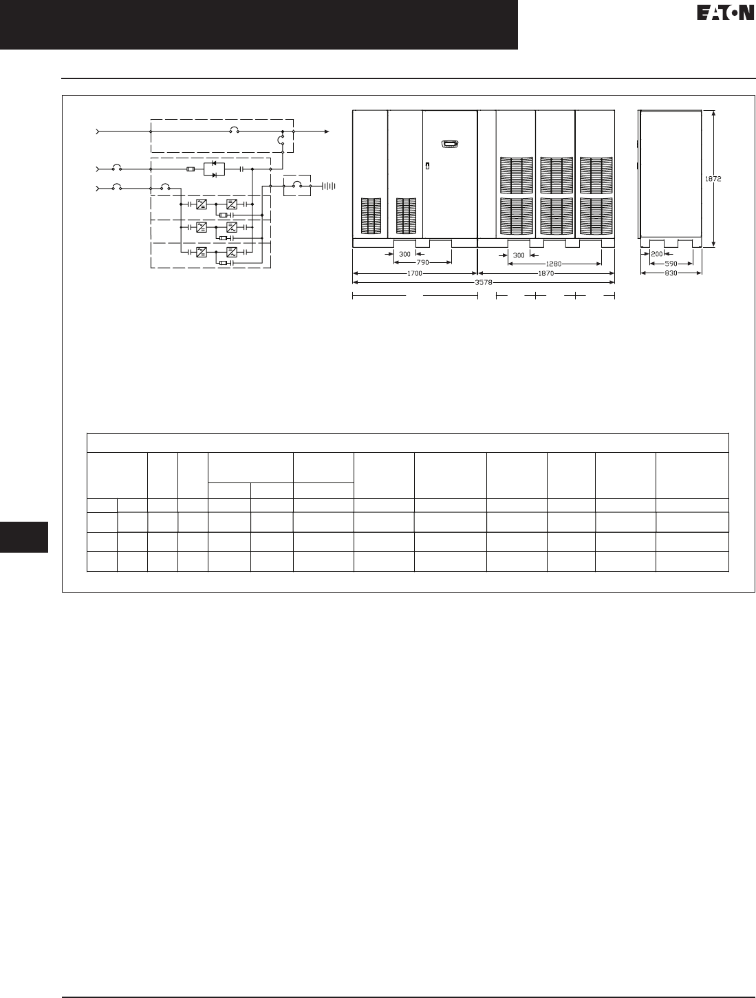
33.3-22
For more information, visit: www.eaton.com/consultants CA08104001E
September 2011
Uninterruptible Power Supplies
Sheet 33
22
23
24
25
26
27
28
29
30
31
32
33
34
35
36
37
38
39
40
41
42
43
Large Three-Phase Units—Eaton 9395
Layout Diagrams
078
Figure 33.3-16. Site Planning Data, System 9395-825 ISBM, Models 650, 750, 285 kVA, Single Module
MBB
MBP
MIS
AC OUTPUT
TO LOAD
BYPASS
AC INPUT
RECTIFIER
AC INPUT
UPS MODULE
MAINTENANCE BYPASS SWITCHGEAR (OPTION)
BATTERY
ISBM
UPM1
UPM2
UPS Rating
AC
Input
Voltage
AC
Output
Voltage
Inverter AC
Output Current Max. Heat
Dissipation at
100% Load
Dimensions WxDxH Approx. Weight
Unpacked Floor Loading
Battery
Nameplate
Current
(240 Cell,
2.00 V/cell)
Max. Battery Current
at End of Discharging
(240 Cell, 1.67V/cell)
Continuous Nameplate Nameplate
kVA kW VAC VAC AMP AMP AMP kW (BTU/hr) mm (in) kg (lbs) kg/m2 (lb/ft2) AMP AMP
650 591 480 480 763 891 782 37.1 (126716) 3578 x 830 x 1872
(140.9 x 32.7 x 73.7) 2297 (5065) 774 (158) 1280 1559
UPM1
ISBM UPM2 UPM3
UPM3
825 750 480 480 969 1130 992 47.1 (160832) 3578 x 30 x 1872
(140.9 x 32.7 x 73.7) 2297 (5065) 774 (158) 1600 1979
750 682 480 480 880 1028 902 42.8 (146211) 3578 x 830 x 1872
(140.9 x 32.7 x 73.7) 2297 (5065) 774 (158) 1502 1799
P/N 110100215-001 Sheet 8 of 10 Rev. 1
CB1 (OPTION)
Rectifier AC Input Current
Product Specifications
Notes:
1. Rectifier AC input current calculations: Continuous—100% load without charging; nameplate—
100% load with maximum charging.
2. Inverter AC output current calculation: Nameplate—100% rated output load.
3. Bypass AC input current calculation is based on 100% rated output.
4. The system must be installed on a level floor suitable for computer or electronic equipment.
5. The system must be installed in a temperature and humidity controlled indoor area
free of conductive contaminants.
6. Ambient temperature range: 0º–40ºC (32º–104ºF); recommended operating range: 20º–25ºC
(68º–77ºF); maximum relative humidity: 95% noncondensing.
7. Minimum overhead clearance for ventilation above the UPS cabinet is 457 mm (18 inches).
8. Minimum 915 mm (36 inches) clearance in front of the UPS cabinet is required for cooling air intake
and servicing space.
9. The UPS cabinet can be installed in line-up-and-match or standalone configurations.
10. Top and bottom cable entries through removable access plates are standard for all configurations.
Access plates shall be custom-modified to suit conduit sizes.
11. All wiring is to be in accordance with National and Local electric codes.
12. AC input to UPS rectifier (0.98 min. pF): three phases, one ground.
AC output to load: three phases, one neutral if required, one ground.
DC input from battery to UPS: one positive, one negative, one ground.
13. The front panels must be removed to meet the 830 mm (32.7 inches) depth to fit through doors.
14. If the UPS is to be installed with the right side near a wall, a minimum of 6.00 inches (152.4 mm) is required
between the wall and the unit. If a battery cabinet is installed to the right of the UPS, the 6.00 inches
(152.4 mm) are not required.
15. Specifications are subject to change.
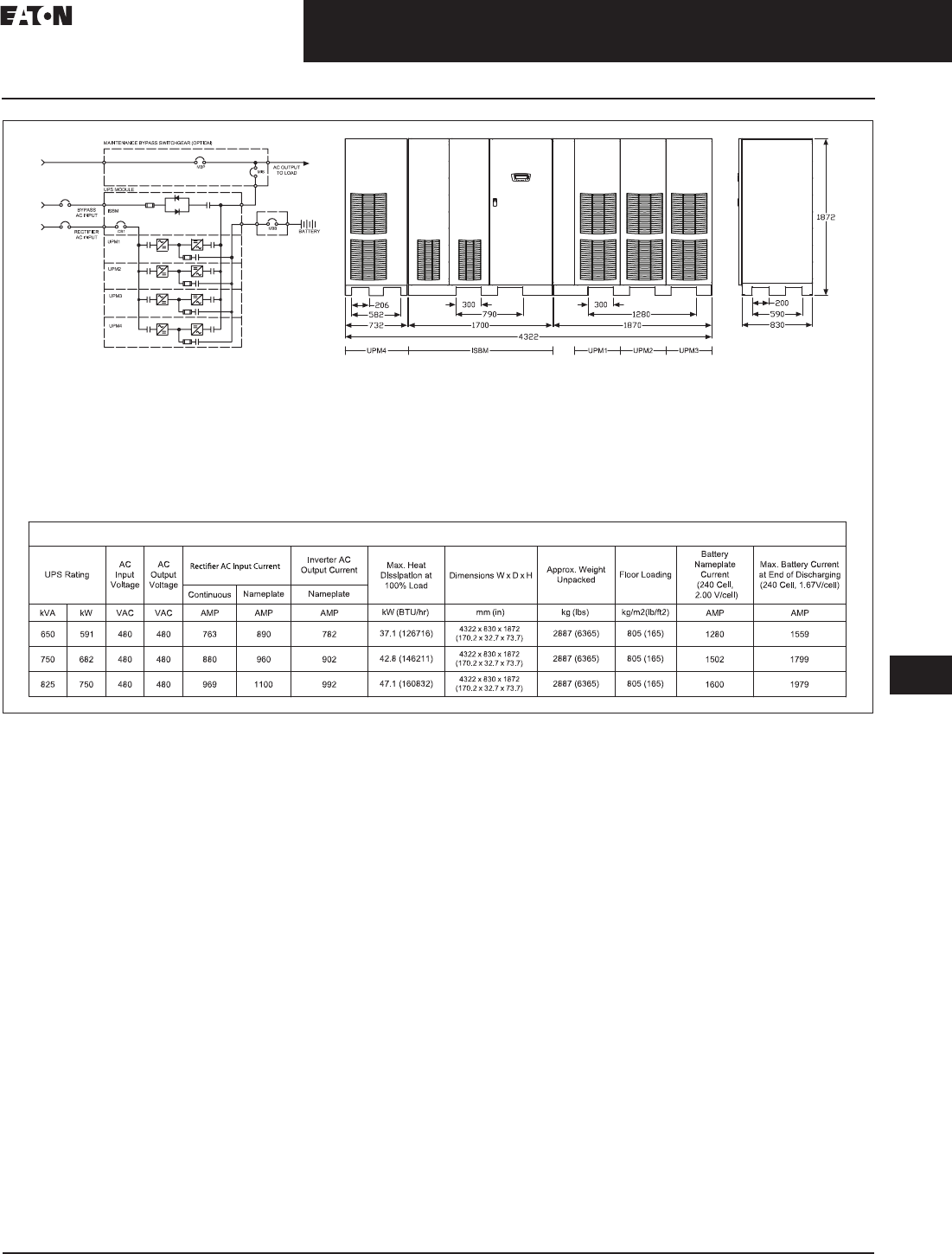
CA08104001E For more information, visit: www.eaton.com/consultants
33.3-23
September 2011
Uninterruptible Power Supplies
Sheet 33
22
23
24
25
26
27
28
29
30
31
32
33
34
35
36
37
38
39
40
41
42
43
Large Three-Phase Units—Eaton 9395
Layout Diagrams
079
Figure 33.3-17. Site Planning Data, System 9395-825 Plus 1, Models 650, 750, 825 kVA, Single Module
Product Specifications
Notes:
1. Rectifier AC input current calculations: Continuous—100% load without charging; nameplate—
100% load with maximum charging.
2. Inverter AC output current calculation: Nameplate—100% rated output load.
3. Bypass AC input current calculation is based on 100% rated output.
4. The system must be installed on a level floor suitable for computer or electronic equipment.
5. The system must be installed in a temperature and humidity controlled indoor area
free of conductive contaminants.
6. Ambient temperature range: 0º–40ºC (32º–104ºF); recommended operating range: 20º–25ºC
(68º–77ºF); maximum relative humidity: 95% noncondensing.
7. Minimum overhead clearance for ventilation above the UPS cabinet is 457 mm (18 inches).
8. Minimum 915 mm (36 inches) clearance in front of the UPS cabinet is required for cooling air intake
and servicing space.
9. The UPS cabinet can be installed in line-up-and-match or standalone configurations.
10. Top and bottom cable entries through removable access plates are standard for all configurations.
Access plates shall be custom-modified to suit conduit sizes.
11. All wiring is to be in accordance with National and Local electric codes.
12. AC input to UPS rectifier (0.98 min. pF): three phases, one ground.
AC output to load: three phases, one neutral if required, one ground.
DC input from battery to UPS: one positive, one negative, one ground.
13. The front panels must be removed to meet the 830 mm (32.7 inches) depth to fit through doors.
14. If the UPS is to be installed with the right side near a wall, a minimum of 6.00 inches (152.4 mm) is required
between the wall and the unit. If a battery cabinet is installed to the right of the UPS, the 6.00 inches
(152.4 mm) are not required.
15. Specifications are subject to change.
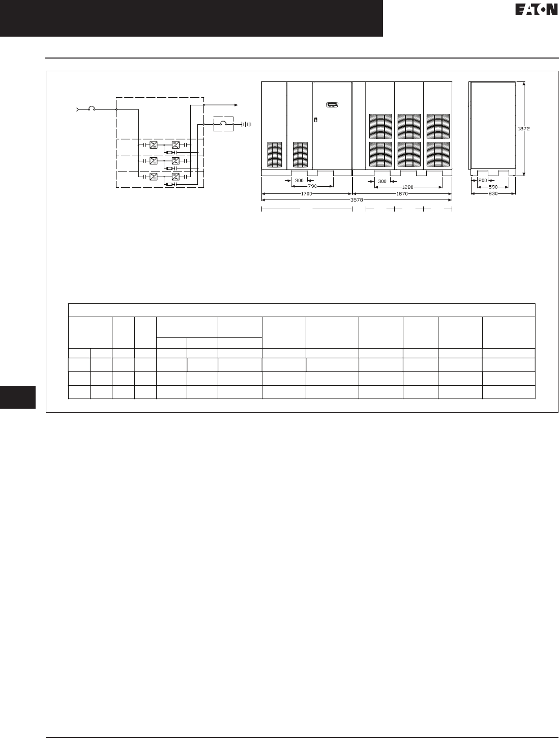
33.3-24
For more information, visit: www.eaton.com/consultants CA08104001E
September 2011
Uninterruptible Power Supplies
Sheet 33
22
23
24
25
26
27
28
29
30
31
32
33
34
35
36
37
38
39
40
41
42
43
Large Three-Phase Units—Eaton 9395
Layout Diagrams
080
Figure 33.3-18. Site Planning Data, System 9395-825, Models 650, 750, 825 kVA, Single Module
UPS Rating
AC
Input
Voltage
AC
Output
Voltage
Per UPM
Inverter AC
Output Current Max. Heat
Dissipation at
100% Load
Dimensions W x D x H Approx. Weight
Unpacked Floor Loading
Battery
Nameplate
Current
(240 Cell,
2.00 V/cell)
Max. Battery Current
at End of Discharging
(240 Cell, 1.67V/cell)
Continuous Nameplate Nameplate
kVA kW VAC VAC AMP AMP AMP kW (BTU/hr) mm(in) kg (lbs) kg/m2 (lb/ft2) AMP AMP
650 591 480 480 255 370 782 37.1 (126716) 3578 x 830 x 1872
(140.9 x 32.7 x 73.7) 2248 (4945) 756 (154) 1280 1559
UPM1
IOM UPM2 UPM3
825 750 480 480 323 370 992 47.1 (160832) 3578 x 830 x 1872
(140.9 x 32.7 x 73.7) 2248 (4945) 756 (154) 1600 1979
750 682 480 480 294 370 902 42.8 (146211) 3578 x 830 x 1872
(140.9 x 32.7 x 73.7) 2248 (4945) 756 (154) 1502 1799
P/N 110100215-003 Sheet 3 of 5 Rev. 1
MBB
AC OUTPUT
TO LOAD
RECTIFIER
AC INPUT
UPS MODULE
BATTERY
IOM
UPM1
UPM2
Product Specifications
Rectifier AC Input Current
Notes:
1. IOM—I/O module requires external system bypass module.
2. Rectifier AC input current calculations: Continuous—100% load without charging; nameplate—
100% load with maximum charging.
3. Inverter AC output current calculation: Nameplate—100% rated output load.
4. The system must be installed on a level floor suitable for computer or electronic equipment.
5. The system must be installed in a temperature and humidity controlled indoor area
free of conductive contaminants.
6. Ambient temperature range: 0º–40ºC (32º–104ºF); recommended operating range: 20º–25ºC
(68º–77ºF); maximum relative humidity: 95% noncondensing.
7. Minimum overhead clearance for ventilation above the UPS cabinet is 457 mm (18 inches).
8. Minimum 915 mm (36 inches) clearance in front of the UPS cabinet is required for cooling air intake
and servicing space.
9. The UPS cabinet can be installed in line-up-and-match or standalone configurations.
10. Top and bottom cable entries through removable access plates are standard for all configurations.
Access plates shall be custom-modified to suit conduit sizes.
11. All wiring is to be in accordance with National and Local electric codes.
12. AC input to UPS rectifier (0.98 min. pF): three phases, one ground.
AC output to load: three phases, one neutral if required, one ground.
DC input from battery to UPS: one positive, one negative, one ground.
13. The front panels must be removed to meet the 830 mm (32.7 inches) depth to fit through doors.
14. If the UPS is to be installed with the right side near a wall, a minimum of 6.00 inches (152.4 mm) is required
between the wall and the unit. If a battery cabinet is installed to the right of the UPS, the 6.00 inches
(152.4 mm) are not required.
15. Specifications are subject to change.

CA08104001E For more information, visit: www.eaton.com/consultants
33.3-25
September 2011
Uninterruptible Power Supplies
Sheet 33
22
23
24
25
26
27
28
29
30
31
32
33
34
35
36
37
38
39
40
41
42
43
Large Three-Phase Units—Eaton 9395
Layout Diagrams
081
Figure 33.3-19. Site Planning Data, System 9395-825 Plus 1, Models 650, 750, 825 kVA, Single Module
UPS Rating
AC
Input
Voltage
AC
Output
Voltage
Per UPM
Inverter AC
Output Current Max. Heat
Dissipation at
100% Load
Dimensions W x D x H Approx. Weight
Unpacked Floor Loading
Battery
Nameplate
Current
(240 Cell,
2.00 V/cell)
Max. Battery Current
at End of Discharging
(240 Cell, 1.67V/cell)
Continuous Nameplate Nameplate
kVA kW VAC VAC AMP AMP AMP kW (BTU/hr) mm (in) kg (lbs) kg/m2 (lb/ft2) AMP AMP
650 591 480 480 255 370 782 37.1 (126716) 4322 x 830 x 1872
(170.2 x 32.7 x 73.7) 2839 (6245) 790 (162) 1280 1559
UPM1
IOM UPM2 UPM3
UPM4
825 750 480 480 323 370 992 47.1 (160832) 4322 x 830 x 1872
(170.2 x 32.7 x 73.7) 2839 (6245) 790 (162) 1600 1979
750 682 480 480 294 370 902 42.8 (146211) 4322 x 830 x 1872
(170.2 x 32.7 x 73.7) 2839 (6245) 790 (162) 1502 1799
P/N 110100215-003 Sheet 4 of 5 Rev. 1
MBB
AC OUTPUT
TO LOAD
RECTIFIER
AC INPUT
UPS MODULE
BATTERY
IOM
UPM1
UPM2
UPM3
UPM4
Product Specifications
Rectifier AC Input Current
Notes:
1. IOM—I/O module requires external system bypass module.
2. Rectifier AC input current calculations: Continuous—100% load without charging; nameplate—
100% load with maximum charging.
3. Inverter AC output current calculation: Nameplate—100% rated output load.
4. The system must be installed on a level floor suitable for computer or electronic equipment.
5. The system must be installed in a temperature and humidity controlled indoor area
free of conductive contaminants.
6. Ambient temperature range: 0º–40ºC (32º–104ºF); recommended operating range: 20º–25ºC
(68º–77ºF); maximum relative humidity: 95% noncondensing.
7. Minimum overhead clearance for ventilation above the UPS cabinet is 457 mm (18 inches).
8. Minimum 915 mm (36 inches) clearance in front of the UPS cabinet is required for cooling air intake
and servicing space.
9. The UPS cabinet can be installed in line-up-and-match or standalone configurations.
10. Top and bottom cable entries through removable access plates are standard for all configurations.
Access plates shall be custom-modified to suit conduit sizes.
11. All wiring is to be in accordance with National and Local electric codes.
12. AC input to UPS rectifier (0.98 min. pF): three phases, one ground.
AC output to load: three phases, one neutral if required, one ground.
DC input from battery to UPS: one positive, one negative, one ground.
13. The front panels must be removed to meet the 830 mm (32.7 inches) depth to fit through doors.
14. If the UPS is to be installed with the right side near a wall, a minimum of 6.00 inches (152.4 mm) is required
between the wall and the unit. If a battery cabinet is installed to the right of the UPS, the 6.00 inches
(152.4 mm) are not required.
15. Specifications are subject to change.
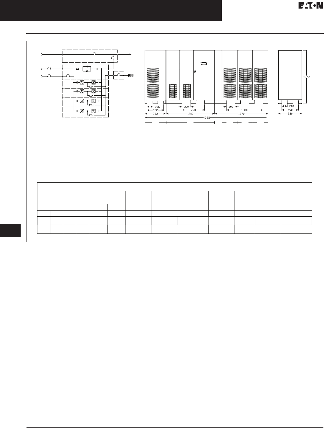
33.3-26
For more information, visit: www.eaton.com/consultants CA08104001E
September 2011
Uninterruptible Power Supplies
Sheet 33
22
23
24
25
26
27
28
29
30
31
32
33
34
35
36
37
38
39
40
41
42
43
Large Three-Phase Units—Eaton 9395
Layout Diagrams
082
Figure 33.3-20. Site Planning Data, System 9395-1100 ISBM, Models 1000, 1100 kVA, Single Module
MBB
MBP
MIS
AC OUTPUT
TO LOAD
BYPASS
AC INPUT
RECTIFIER
AC INPUT
UPS MODULE
MAINTENANCE BYPASS SWITCHGEAR (OPTION)
BATTERY
ISBM
UPM1
UPS Rating
AC
Input
Voltage
AC
Output
Voltage
Inverter AC
Output Current Max. Heat
Dissipation at
100% Load
Dimensions W x D x H Approx. Weight
Unpacked Floor Loading
Battery
Nameplate
Current
(240 Cell,
2.00 V/cell)
Max. Battery Current
at End of Discharging
(240 Cell, 1.67V/cell)
Continuous Nameplate Nameplate
kVA kW VAC VAC AMP AMP AMP kW (BTU/hr) mm (in) kg (lbs) kg/m2 (lb/ft2) AMP AMP
1000 909 480 480 1174 1370 1203 57.1 (194948) 4322 x 830 x 1872
(170.2 x 32.7 x 73.7) 2960 (6525) 825 (169) 2000 2398
UPM1
ISBM UPM2 UPM3
UPM4
UPM3
UPM2
UPM4
1100 1000 480 480 1291 1507 1323 62.8 (214443) 4322 x 830 x 1872
(170.2 x 32.7 x 73.7) 2960 (6525) 825 (169) 2203 2638
P/N 110100215-001 Sheet 10 of 10 Rev. 1
CB1 (OPTION)
Product Specifications
Rectifier AC Input Current
Notes:
1. Rectifier AC input current calculations: Continuous—100% load without charging; nameplate—
100% load with maximum charging.
2. Inverter AC output current calculation: Nameplate—100% rated output load.
3. Bypass AC input current calculation is based on 100% rated output.
4. The system must be installed on a level floor suitable for computer or electronic equipment.
5. The system must be installed in a temperature and humidity controlled indoor area
free of conductive contaminants.
6. Ambient temperature range: 0º–40ºC (32º–104ºF); recommended operating range: 20º–25ºC
(68º–77ºF); maximum relative humidity: 95% noncondensing.
7. Minimum overhead clearance for ventilation above the UPS cabinet is 457 mm (18 inches).
8. Minimum 915 mm (36 inches) clearance in front of the UPS cabinet is required for cooling air intake
and servicing space.
9. The UPS cabinet can be installed in line-up-and-match or standalone configurations.
10. Top and bottom cable entries through removable access plates are standard for all configurations.
Access plates shall be custom-modified to suit conduit sizes.
11. All wiring is to be in accordance with National and Local electric codes.
12. AC input to UPS rectifier (0.98 min. pF): three phases, one ground.
AC output to load: three phases, one neutral if required, one ground.
DC input from battery to UPS: one positive, one negative, one ground.
13. The front panels must be removed to meet the 830 mm (32.7 inches) depth to fit through doors.
14. If the UPS is to be installed with the right side near a wall, a minimum of 6.00 inches (152.4 mm) is required
between the wall and the unit. If a battery cabinet is installed to the right of the UPS, the 6.00 inches
(152.4 mm) are not required.
15. Specifications are subject to change.

CA08104001E For more information, visit: www.eaton.com/consultants
33.3-27
September 2011
Uninterruptible Power Supplies
Sheet 33
22
23
24
25
26
27
28
29
30
31
32
33
34
35
36
37
38
39
40
41
42
43
Large Three-Phase Units—Eaton 9395
Layout Diagrams
083
Figure 33.3-21. Site Planning Data, System 9395-1100 IOM, Models 1000, 1100 kVA, Single Module
UPS Rating
AC
Input
Voltage
AC
Output
Voltage
Per UPM
Inverter AC
Output Current Max. Heat
Dissipation at
100% Load
Dimensions WxDxH Approx. Weight
Unpacked Floor Loading
Battery
Nameplate
Current
(240 Cell,
2.00 V/cell)
Max. Battery Current
at End of Discharging
(240 Cell, 1.67V/cell)
Continuous Nameplate Nameplate
kVA kW VAC VAC AMP AMP AMP kW (BTU/hr) mm (in) kg (lbs) kg/m2 (lb/ft2) AMP AMP
1000 909 480 480 294 370 1203 57.1 (194948) 4322 x 830 x 1872
(170.2 x 32.7 x 73.7) 2911 (6405) 810 (166) 2000 2398
UPM1
IOM UPM2 UPM3
UPM4
1100 1000 480 480 323 370 1323 62.8 (214443) 4322 x 830 x 1872
(170.2 x 32.7 x 73.7) 2911 (6405) 810 (166) 2203 2638
P/N 110100215-003 Sheet 5 of 5 Rev. 1
MBB
AC OUTPUT
TO LOAD
RECTIFIER
AC INPUT
UPS MODULE
BATTERY
IOM
UPM1
UPM2
UPM3
UPM4
Product Specifications
Rectifier AC Input Current
Notes:
1. IOM—I/O module requires external system bypass module.
2. Rectifier AC input current calculations: Continuous—100% load without charging; nameplate—
100% load with maximum charging.
3. Inverter AC output current calculation: Nameplate—100% rated output load.
4. The system must be installed on a level floor suitable for computer or electronic equipment.
5. The system must be installed in a temperature and humidity controlled indoor area
free of conductive contaminants.
6. Ambient temperature range: 0º–40ºC (32º–104ºF); recommended operating range: 20º–25ºC
(68º–77ºF); maximum relative humidity: 95% noncondensing.
7. Minimum overhead clearance for ventilation above the UPS cabinet is 457 mm (18 inches).
8. Minimum 915 mm (36 inches) clearance in front of the UPS cabinet is required for cooling air intake
and servicing space.
9. The UPS cabinet can be installed in line-up-and-match or standalone configurations.
10. Top and bottom cable entries through removable access plates are standard for all configurations.
Access plates shall be custom-modified to suit conduit sizes.
11. All wiring is to be in accordance with National and Local electric codes.
12. AC input to UPS rectifier (0.98 min. pF): three phases, one ground.
AC output to load: three phases, one neutral if required, one ground.
DC input from battery to UPS: one positive, one negative, one ground.
13. The front panels must be removed to meet the 830 mm (32.7 inches) depth to fit through doors.
14. If the UPS is to be installed with the right side near a wall, a minimum of 6.00 inches (152.4 mm) is required
between the wall and the unit. If a battery cabinet is installed to the right of the UPS, the 6.00 inches
(152.4 mm) are not required.
15. Specifications are subject to change.

33.3-28
For more information, visit: www.eaton.com/consultants CA08104001E
September 2011
Uninterruptible Power Supplies
Sheet 33
22
23
24
25
26
27
28
29
30
31
32
33
34
35
36
37
38
39
40
41
42
43
084
This page intentionally left blank.

CA08104001E For more information, visit: www.eaton.com/consultants
33.4-1
September 2011
Uninterruptible Power Systems
Sheet 33
22
23
24
25
26
27
28
29
30
31
32
33
34
35
36
37
38
39
40
41
42
43
Eaton Software and Connectivity
Power Xpert Software
085
Power Xpert® Software
General Description
Power Xpert Software aggregates the
information arriving from different
types of device families via various
communication methods. Its unique
Web-based design, alarm bubble-up,
and advanced trend and waveform
analysis tools help you to quickly turn
your attention to the most important
events and to identify reliability issues
and cost-saving opportunities. The
standard custom graphic package, the
Layout Manager, with an icon library
and standard vertical templates,
allows you to import and mimic your
physical environment and gauges.
Open protocol support makes Power
Xpert Software compatible with most
newer generation third-party equip-
ment. Older legacy, proprietary
protocols are supported by Power
Xpert Gateways, and custom software
drop-in drivers made available by
Eaton. Power Xpert Software is the
first power system software of this
caliber to put all of these powerful
features at your fingertips.
Power Xpert Software provides an
easy upgrade path to allow existing
PowerNet users to enjoy the benefits
of power monitoring through a simple
Web browser interface.
Power Xpert is a complete software
solution to manage your power
system. Critical components such as
metering devices, protective relays,
circuit breaker trip units, motor
starters and uninterruptible power
supplies communicate vital informa-
tion about the health and status of
critical infrastructure devices.
Product Selection Guide
Power Xpert Software Professional Edition
■Geared toward end users, with built-
in support for Eaton power distribu-
tion products such as switchgear,
UPSs, breakers, PDUs, RPPs,
meters, relays, VFDs and MCCs,
among others
■Eaton products connect with the
software directly via an Ethernet
connection, while legacy devices
use a Power Xpert Gateway to Web-
enable their communications
■A subset of third-party meters and
devices are supported as standard
via the gateway connection
Power Xpert Software Enterprise Edition
■Geared toward advanced power
users, system integrators and enter-
prises with heterogeneous device
spectrum and system developers
who can take advantage of the
included SNMP and Modbus
integration development utilities
■Extensive support for third-party
devices via standard SNMP and
Modbus TCP protocols
■Large variety of ready made,
optional third-party drop-in
drivers available
Features
■Connects to your existing network
■Data trending and graphing for
detailed information for trouble-
shooting, problem prevention and
costs savings
■Web-based views that allow access
to critical information from any
location via a Web browser
■A modular, scalable architecture
that allows the addition of capabili-
ties and devices as the power
system expands
■Alarm conditions bubble up through
the system to allow personnel to
identify which device is in alarm and
where it is located
■All the functionality of Eaton’s
PowerNet software suite
■Connectivity to a wide range of
Eaton and third-party devices. For a
full list of compatible devices, refer
to the hardware compatibility list
found at www.eaton.com/pxs
For full details on Power Xpert
Software, refer to Tab 2, Section 2.4.
Foreseer® Services
Foreseer Software and Engineering
Services (Foreseer Services) provide
vendor independent, power and
energy infrastructure integration
solutions that help companies reduce
energy consumption and unplanned
downtime due to the failure of critical
power, environmental, safety or
security systems.
Turnkey software and connectivity
solutions are coupled with state-of-
the-art project management, systems
design, third-party device integration,
testing and custom application devel-
opment to develop a comprehensive
monitoring solution to meet your
custom needs.
Foreseer Services is delivered in
categories, offering a multitude of
unique value-add services that you
can discuss with your Eaton sales
professional.
■Design services
■Installation services
■Commissioning services
■Follow-up services
■Hardware services
■Software services
Foreseer Services is fully distributable
to allow different monitoring capabili-
ties to be deployed at different sites,
allowing you to purchase only what is
needed. Many competitive systems
offer a one-size-fits-all type approach
where you end up paying for more
capacity than is needed. With Foreseer
Services, you pay only for what you
need, when you need it.
For full details on Foreseer Services,
refer to Tab 2, Section 2.4.
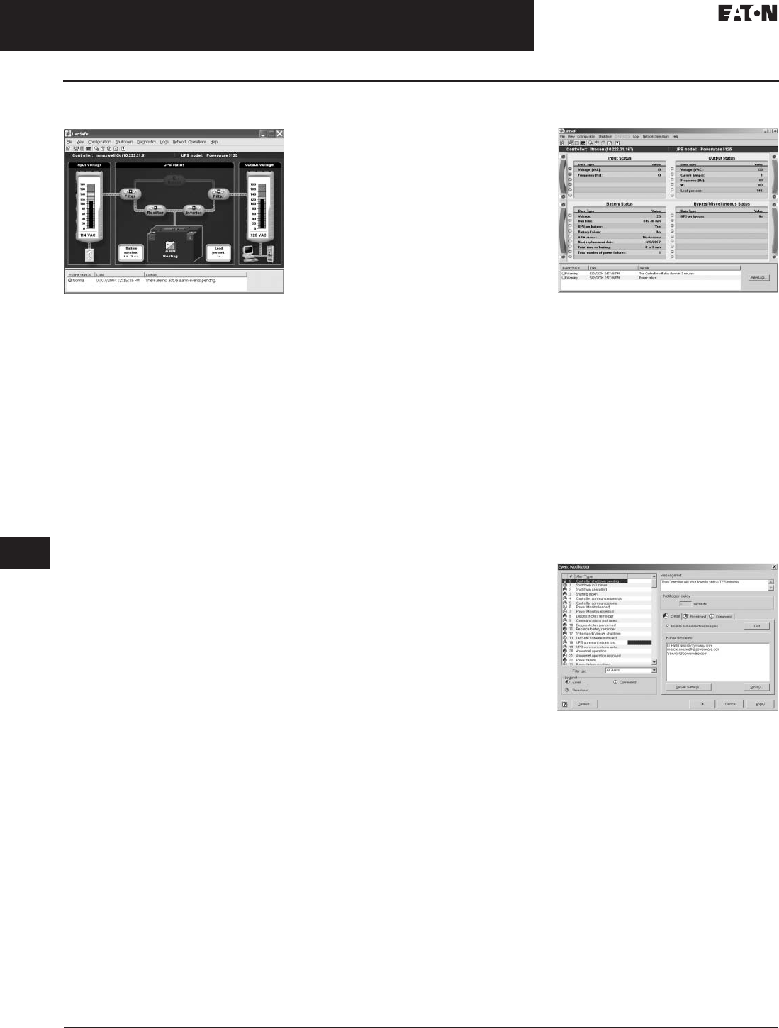
33.4-2
For more information, visit: www.eaton.com/consultants CA08104001E
September 2011
Uninterruptible Power Systems
Sheet 33
22
23
24
25
26
27
28
29
30
31
32
33
34
35
36
37
38
39
40
41
42
43
Eaton Software and Connectivity
Eaton LanSafe
086
Eaton LanSafe
Eaton LanSafe
General Description
LanSafe Power management software
provides automatic, unattended and
graceful shutdown of computer
systems throughout the network
during an extended power outage.
It continuously monitors the UPSs
status and automatically notifies
defined users locally and remotely
about UPS events.
LanSafe can be setup to shutdown
a large group of computers running
multiple operating systems (e.g. Linux,
UNIX, Windows, Novell). It’s exclusive
SafetyNet™ technology enables
network administrators to establish
a user-defined sequential shutdown
so that the most critical equipment
(such as database or file servers) is
shut down last, after work in progress
is saved from client workstations
through hubs, switches, routers
and communication servers.
With event notification, one can specify
unique text messages associated with
each alarm, and to which users the
alarms are broadcasted over the
network. For remote alarms, the
software can initiate an e-mail message
to immediately notify users about a
power problem.
In addition, LanSafe provides as
standard the ability to send SNMP
traps to any SNMP compliant network
management system (NMS) like
HP-OpenView or CiscoWorks 2000.
LanSafe also supports the ‘GET’ and
‘SET’ SNMP commands, which allows
the NMS administrator to periodically
enquire all metering information such
as input voltage, output voltage, bat-
tery health and runtime among others.
LanSafe software is bundled free-
of-charge with all Eaton UPSs
on the software suite CD-ROM.
Application Focus
■Advanced computer shutdown
capabilities
■Basic UPS monitoring and
management
■Local and networked single- or
three-phase Eaton UPSs
■Third-party UPS support via USB
HID and SNMP (RFC1628) standards
Key Product Features
■Automatically performs a graceful
shutdown of the computer system
and saves work-in-progress during
an extended power outage
■Displays vital UPS information
with an intuitive, graphic format for
non-technical personnel
■Broad OS support:
❑Compiles a full year of UPS events
with a graphical calendar view
■Communicates UPS status change
messages via e-mail, pager or
cell phone to keep you informed
at all times
■Notifies you in advance that it is time
to hot-swap your batteries so that
your UPS is ready for the next
power outage
■Saves electricity and adds security
with automatic power-on and
power-off scheduling capability
■Helps you determine how much
money the UPS and LanSafe is
saving you during every power
failure due to prevented downtime
with a cost savings calculator
■Runs invisibly with stealth mode
operation, which is particularly
useful when integrating LanSafe into
a POS, ATM or other environment
where discretion is necessary
■Remotely recycles power of hung-up
hubs, routers and computer systems
with UPS power on/off capability
Requirements
■Eaton UPS with contact closure,
serial, USB or connect UPS
network communications
■Third-party UPS support via USB
HID and SNMP (RFC1628) standards
■Supported computer operating
system, current list available
at http://www.powerware.com/
Software/Lansafe5.asp
■Configured SMTP server for e-mail
notifications
■Computer system supporting
minimum system requirements:
200 MHz CPU, 32MB RAM, 30MB
HD, SVGA monitor
Monitoring
Monitoring
LanSafe can monitor a single UPS at a
time via the ControlRoom (screenshot
above) or PowerScope views. Other
LanSafe installations on the network
can be selected for monitoring and
management via the file-open
controller option.
Communication—Input/Output
■RS-232
■USB
■ConnectUPS Web/SNMP Ethernet
network connection
■SNMP via RFC1628 standard
Notification
Notification
■Personalized UPS Alarm notifications
■Local event message notification
■Network broadcasts
■E-mail
■Command execution
■SNMP traps
■SNMP proxy agent (GET and
SET capability)
Computer Shutdown
Sequential SafetyNet shutdown
ensures that all network transactions
are completed prior to shutdown.
Workstations are shut down first,
internet working equipment is shut
down next and Servers are shut
down last.
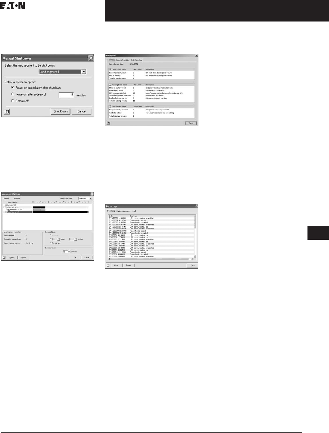
CA08104001E For more information, visit: www.eaton.com/consultants
33.4-3
September 2011
Uninterruptible Power Systems
Sheet 33
22
23
24
25
26
27
28
29
30
31
32
33
34
35
36
37
38
39
40
41
42
43
Eaton Software and Connectivity
Eaton LanSafe
087
Load Segment Control
Load Segment Control
Doubles the run time for mission
critical loads. Turns separate load
segments (receptacle groups) on and
off at predefined times, or automati-
cally during power outage events.
In addition load segments can be
turned off and back on again manually
over the network or locally.
Diagnostics
Diagnostics
LanSafe reminds the user ahead of
time when the UPS batteries need to
be replaced.
The Test Hardware option performs a
diagnostic test to verify your UPS is
functioning properly. The tests provide
information about the UPS battery and
internal circuitry and can be initiated
either locally or remotely.
Data Archiving/Analysis
Data Archiving/Analysis
The history data summary displays
a cumulative tally of system events
that have occurred since LanSafe
was installed.
View input, output voltage, output
load and battery voltage measurement
changes over a period of time in a
crisp clear graphic diagram format.
Integration
Integration
■NMS (network management
systems, e.g., HP-OpenView,
IBM Tivoli, CA-Unicenter,
Cisco 2000) via SNMP
■PowerVision network edition for
viewing all LanSafe installations
on the network
■Other systems via command
execution
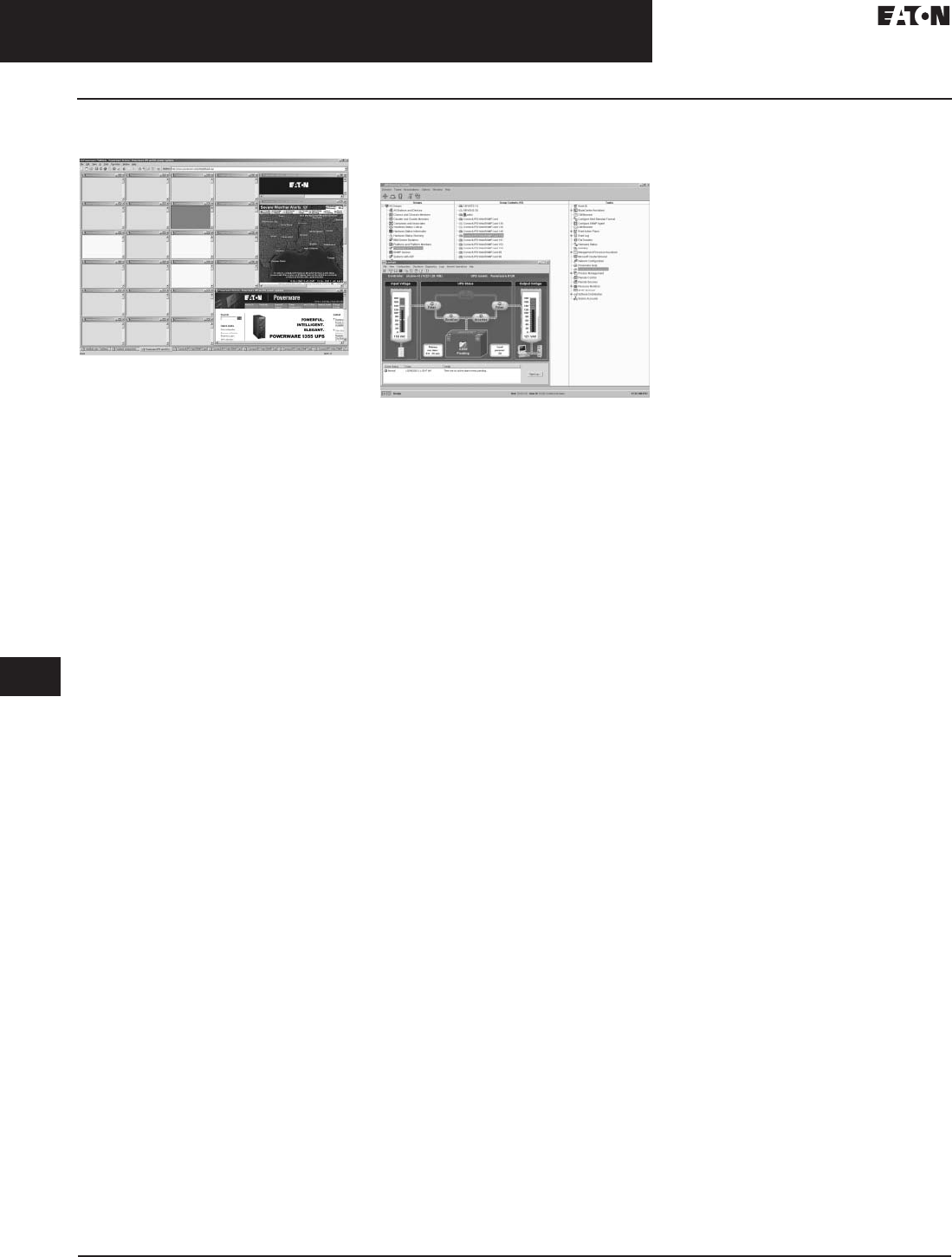
33.4-4
For more information, visit: www.eaton.com/consultants CA08104001E
September 2011
Uninterruptible Power Systems
Sheet 33
22
23
24
25
26
27
28
29
30
31
32
33
34
35
36
37
38
39
40
41
42
43
Eaton Software and Connectivity
MultiView and IBM Director
088
Eaton MultiView
Eaton MultiView
General Description
Windows-based Web browser for
monitoring multiple Eaton UPSs
via ConnectUPS Web cards and
LanSafe v. 5 instances.
Application Focus
■Basic network device monitoring
■Multiple single- or three-phase
Eaton UPSs
Key Product Features
■Simple monitoring for multiple
UPSs connected via ConnectUPS
Web/SNMP card and/or LanSafe v. 5
■Status@aGlance™ monitoring
capability
■Drill down access to web page
details (ConnectUPS Web/SNMP
card only)
■Allows user to view multiple web
sites simultaneously within a single
browser window
■Searches for and automatically
adds browser pages of connected
ConnectUPS Web/SNMP cards
as well as the Status@aGlance
monitoring feature from the
Eaton LanSafe v. 5 software
Requirements
■Eaton UPS
■Windows operating system
■Eaton connectivity device,
e.g., serial card or ConnectUPS
Web/SNMP
Eaton Extensions
for IBM Director
Eaton Extensions for IBM Director
General Description
Plug-in software for IBM director
network management system that
allows network system administrators
to monitor, diagnose, configure, set
alarms, schedule self-tests, check
battery, gather inventory information,
and control Eaton UPSs network-wide
from a single console within
IBM director.
Application Focus
■Network management system
integration
■Multiple single- or three-phase
Eaton UPSs
Key Product Features
■Network monitoring and control
software for all UPSs in the network
■UPS control and power manage-
ment for IBM director system
administrators
■Seamless integration of UPSs
into the IBM director management
console
■UPS Inventory management
■Central log for UPS events
Requirements
Primary computer running IBM
director version 5.1.
Integration
Installing the Eaton extensions for IBM
director enables the user to easily and
automatically integrate Eaton UPSs
into the IBM director environment.

CA08104001E For more information, visit: www.eaton.com/consultants
33.4-5
September 2011
Uninterruptible Power Systems
Sheet 33
22
23
24
25
26
27
28
29
30
31
32
33
34
35
36
37
38
39
40
41
42
43
Eaton Software and Connectivity
NetWatch/Modbus Profiler/Intelligent Power
089
Eaton NetWatch
General Description
NetWatch client UPS software
enables users to shutdown a server
or workstation and acts as a network-
monitoring tool through the Eaton
ConnectUPS-X, ConnectUPS-BD
or BestLink SNMP/WEB Adapter
connectivity devices. During an
extended power outage, the SNMP/
WEB adapter informs all registered
NetWatch clients to shut down their
respective operating systems, thus
preparing them for the removal of
AC power.
Application Focus
■Basic network device monitoring
■Multiple single- or three-phase
Eaton UPSs
Key Product Features
■Shutdown up to 255 computers
dependent upon power from a
Eaton UPS
■Popup messaging on Windows to
notify UPS on battery conditions
Requirements
■Eaton UPS
■Computer or server running
an operating system supported
by CoreLogic
■UPS-native or Eaton X-Slot
communications supporting
serial, USB or SNMP
Shutdown
Computer shutdown is achieved
through the use of NetWatch software.
The shutdown message is sent in the
form of a network broadcast from the
ConnectUPS or BestLink connectivity
card to all available NetWatch clients
on the network. In the event of a
power failure all clients are notified
to shutdown based upon their
local settings.
Eaton Modbus Profiler
General Description
Profiler is a power management
and UPS software tool that creates a
Modbus register map for a particular
Eaton UPS. It reads the available
parameters in a UPS and compares
them with a list of universally sup-
ported Modbus parameters. If the
parameter in the UPS and parameter
in the master list both exist, then
the Profiler program reports the
supported parameter.
Intelligent Power
Software Suite
Intelligent Power Software Suite
General Description
The Intelligent Power® Software Suite
CD ships with Eaton UPSs and delivers
the latest power monitoring and
management software. This software
works in conjunction with your UPSs
and other power devices to provide a
total power solution for your network.
Perfect for virtualized environments,
the software suite even integrates
seamlessly with VMware’s vCenter
Server™ and Microsoft’s SCVMM™.

33.4-6
For more information, visit: www.eaton.com/consultants CA08104001E
September 2011
Uninterruptible Power Systems
Sheet 33
22
23
24
25
26
27
28
29
30
31
32
33
34
35
36
37
38
39
40
41
42
43
Eaton Software and Connectivity
Power Xpert Gateway UPS Card
090
Power Xpert Gateway
UPS Card—Uninterruptible
Power Supplies
Power Xpert Gateway UPS Card
General Description
The Power Xpert Gateway UPS Card
(PXGX UPS) provides Web-enabled,
real-time monitoring of Powerware
Uninterruptible Power Supplies (UPS)
through standard on-board Web
pages, Power Xpert Software or
third-party software.
An integral part of the Power Xpert
Architecture, which provides end-to-
end PowerChain solutions, the PXGX
UPS provides a central point to
connect distribution products to an
Ethernet network.
Features
Information is presented in organized,
user-friendly Web pages and includes
the following:
■UPS system identification
■Voltage
■Current
■Frequency
■Energy
■Output Power
■Power—full load %
■Battery information
❑History and maintenance
❑Run time remaining
❑Voltage
❑% battery left
For full details on the Power Xpert
Gateway UPS card, see Tab 2,
Section 2.3.
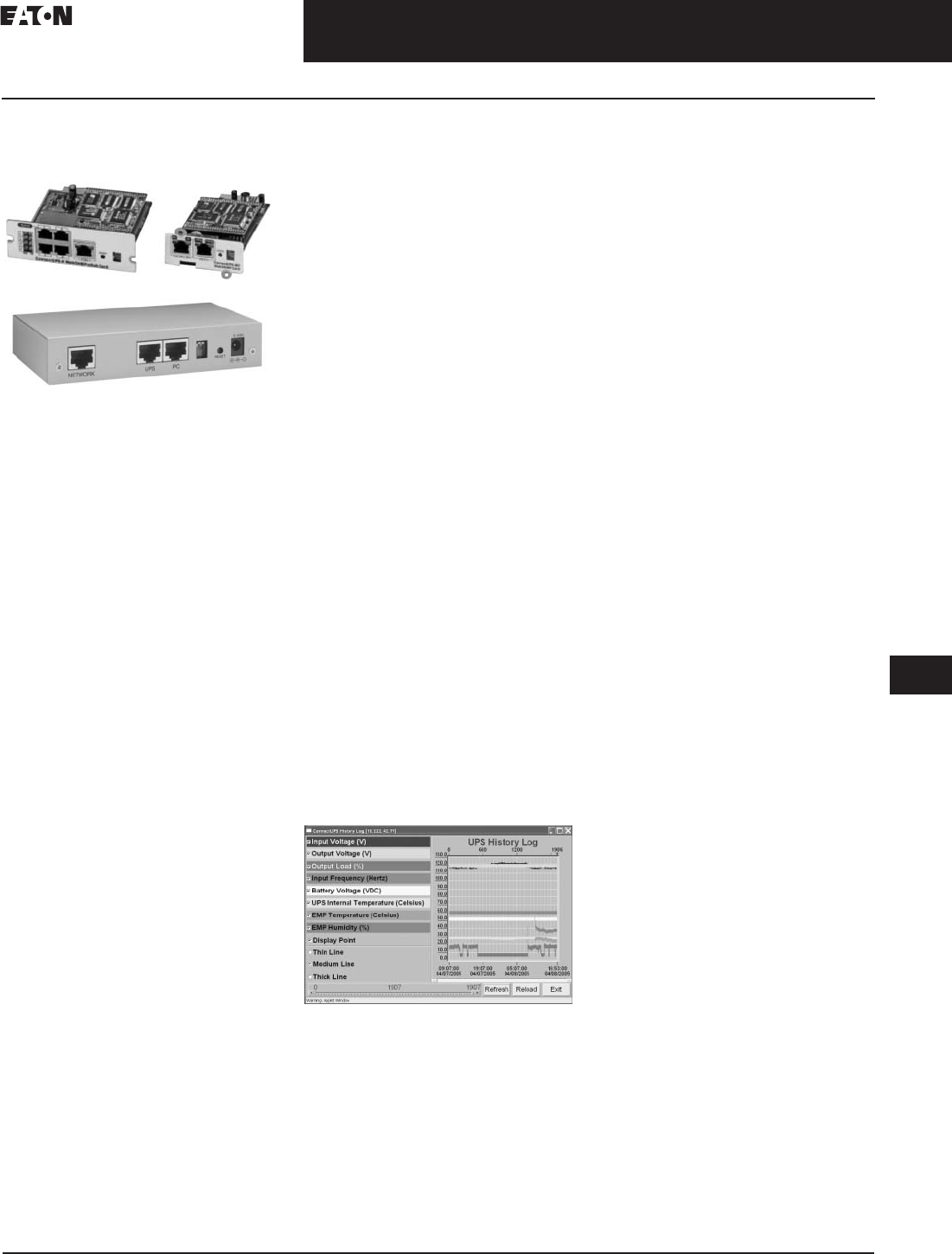
CA08104001E For more information, visit: www.eaton.com/consultants
33.4-7
September 2011
Uninterruptible Power Systems
Sheet 33
22
23
24
25
26
27
28
29
30
31
32
33
34
35
36
37
38
39
40
41
42
43
Eaton Software and Connectivity
ConnectUPS Web/SNMP Products
091
ConnectUPS Web/
SNMP Products
ConnectUPS Web/SNMP Products
General Description
The Eaton ConnectUPS Web/SNMP
product family provides seamless
Eaton UPS integration into the
Ethernet network and the Internet.
The built-in Web server allows the
users to monitor and manage the
UPSs through the ConnectUPS via
a standard Web browser.
HTTP, SNMP, SMTP, WAP, Telnet com-
patibility and a console port enable
dynamic and versatile support for a
large variety of system configurations.
When used in conjunction with
NetWatch client software, the
ConnectUPS products also provide
graceful shutdown of operating
systems of up to 255 computers
powered by a single UPS.
Application Focus
■Ethernet, Internet connectivity device
■Graceful shutdown functionality
when used in conjunction with
NetWatch power management
software
■Integration to standard SNMP, HTTP,
WAP, SMTP compliant applications
Key Product Features
■Supports real-time monitoring and
control of UPSs across the network
■Enables monitoring and control via
Web browsers, SNMP-compliant
network management systems or
power management software
■Delivers alarm notifications through
e-mail, to mobile phones, pagers,
or SNMP traps
■Enables rapid identification and
analysis of critical power conditions
■Logs and graphs detailed historical
data to analyze trends
■Uses standard communication
protocols on 10 Mb and 100 Mb
Ethernet networks
■Performs as a switching hub for
three 10/100Mbps connections
(ConnectUPS-X)
■Enables orderly shutdown and
restart of remote UPSs
■Supports optional Eaton
environmental monitoring probe
(EMP) for temperature, humidity
and other contact sensor monitor-
ing, management
■User Interface support for local lan-
guages (English, Chinese, Spanish,
French, German, Italian, other
■Interworks with optional Eaton
probe to monitor environmental
conditions: temperature and
humidity at remote sites
■Supports in-service installation
and upgrades without interrupting
critical loads (most UPS models)
Event Notification
ConnectUPS products send real-time
alert notifications to four designated
recipients via e-mail, PCS mobile
phone, or pager, and via SNMP traps to
an NMS or network messaging to
Eaton NetWatch software. Each recipi-
ent has the option of receiving real-time
event messages, daily status reports
based on criticality, containing data and
event log files, or a combination of rou-
tine reports and event notifications.
Monitoring
Monitoring
Gain up-to-the-minute assurance that
computing and communication.
systems are receiving the continuous,
clean power they demand. Through
easily navigable Web pages, network
administrators can check system
status and view critical meter
information, such as input and
output voltage, UPS load, battery
voltage and condition, at any time.
ConnectUPS-X, ConnectUPS-BD, and
ConnectUPS-E products have built-in
data and event logs that track and
record specific power-related occur-
rences over time, at user-defined incre-
ments as fine as one-minute intervals.
Communication—Input/Output
■10/100 Ethernet
■3-port switching hub
(ConnectUPS-X model only)
■HTTP
■SNMP
■SMTP
■WAP
■Telnet
Management
From a Web browser or NMS, which
may be hundreds or thousands of
miles away, a system administrator
can shut down or reboot a remote
UPS, perform remote UPS battery
tests, and set up scheduled shutdowns
of UPSs and associated servers.
The ability to shut down or restart
systems without a site visit dramati-
cally reduces field service expense
and response time. Scheduled
shutdowns can be devised to
conserve power or tighten security
during specific time periods, such
as evenings or weekends.
Integration
■Network management systems
(NMS) via SNMP
■Mobile phones via WAP
■Optional EMP (environmental
monitoring probe) for temperature
and humidity monitoring
Load Segment Control
Turns separate load segments
(receptacle groups) on and off at
predefined times, or automatically
during power outage events. In
addition load segments can be turned
off and back on again manually over
the network or locally.

33.4-8
For more information, visit: www.eaton.com/consultants CA08104001E
September 2011
Uninterruptible Power Systems
Sheet 33
22
23
24
25
26
27
28
29
30
31
32
33
34
35
36
37
38
39
40
41
42
43
Eaton Software and Connectivity
ConnectUPS Web/SNMP and Relay Products
092
Information Tables
Table 33.4-1. Technical Specifications
Table 33.4-2. ConnectUPS/Eaton UPS Compatibility
Model ConnectUPS-X ConnectUPS-BD ConnectUPS-E BestLink
Description Card providing remote monitoring and control of Eaton UPSs
Protocol support http, SNMP, TFTP, Telnet, BootP, DHCP, WAP, ARP, RARP
PS slot type X-Slot BestDock External External
Network support Ethernet 10/100Base-T
Switching hub Yes (three 10/100Base-T connections) No
Temperature
and humidity
monitoring
Yes
UPS
compatibility
See chart below
Supported MIB UPS standard MIB RFC-1628, Eaton MIB, MIB II, 2003 BestLink MIB
?/S supported
or shutdown
Microsoft Windows 9X, ME, 2000/NT and XP, Various UNIX (including Linux)
Versions, Novell NetWare, Macintosh
Operating
temperature
0–40°C
Operating
humidity
10–80%, noncondensing
Power input 9 Vdc unregulated 12V unregulated
Power
consumption
3.5 watts
Dimensions in
inches (mm)
4.70 x 4.50 x 1.50
(119.4 x 114.3 x 38.1)
5.30 x 3.20 x 1.30
(134.6 x 81.3 x 33.0)
5.30 x 3.40 x 1.10
(134.6 x 86.4 x 28.00)
5.30 x 3.40 x 1.10
(134.6 x 86.4 x 28.0)
Weight 6 oz. 4 oz. 6 oz. 6 oz.
Regulatory FCC Class B
Model Part
Number
Eaton
UPSs
Environmental
Monitoring Probe
X-Slot ConnectUPS-X Kit 116750221-001 5115 RM, 5125, 9125, 9320,
9330, 9335, 9340, and 9390
via expansion chassis: 9120,
9170+, 9315
Yes
Best dock ConnectUPS-BD kit 116750222-001 9120 and 9170+ Yes
ConnectUPS-E kit 116750223-001 9150 and 9305 Yes
Best Link Web/SNMP Kit 116750225-001 FERRUPS —
Relay Products
Relay Products
General Description
Eaton relay interface cards enable
automatic shutdown and network
monitoring of Eaton UPS system
status through a connected computer.
The relay interface cards are available
in two models, the X-Slot version and
BestDock version. Both are dedicated
adapters that provide the essential
dry-contact interface between an
Eaton UPS and any relay-connected
computer, including the IBM AS/400,
as well as a variety of industrial
applications.
Application Focus
■Basic network device monitoring
■Multiple single- or three-phase
Eaton UPSs
■Single UPS and parallel systems
(single/three phase UPS)
Key Product Features
■Simple integration with building and
security alarm systems
■Compatibility with simple shutdown
methods, i.e., IBM AS/400 and
Windows UPS service
■Option available for all UPS models
excluding 3110,3115, 5115 (tower)
models
■Isolated Form-C relay contacts
■Compatibility with simple shutdown
methods, i.e., IBM AS/400 and
Windows UPS service
Requirements
■Compatible Eaton UPS
■IBM AS/400 cable to connect
between DB-15 port on card
to computer
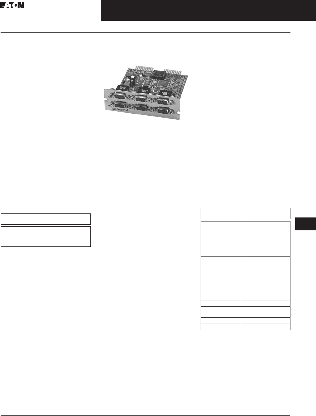
CA08104001E For more information, visit: www.eaton.com/consultants
33.4-9
September 2011
Uninterruptible Power Systems
Sheet 33
22
23
24
25
26
27
28
29
30
31
32
33
34
35
36
37
38
39
40
41
42
43
Eaton Software and Connectivity
Relay and Serial Protocol Products
093
Monitoring
Monitoring is accomplished though
the use Eaton relay products that
provide alarm information via Form-C
dry contacts that are connected the
customer alarm panel.
Management/Shutdown
IBM AS/400 computer shutdown is
achieved by using the computer port
on the Eaton relay cards for use with
all X-Slot compatible UPS models
along with the appropriate cable.
For information on AS/400 cables
available for all relay products please
refer to either the Eaton single- or
three-phase UPS price lists.
Integration
Simple integration with building
management systems or building
alarm systems can be achieved by
connecting the Form-C dry contact
outputs from the relay product to the
digital inputs on the I/O controller
provided by the BMS or security
alarm vendor.
Ordering Information
Table 33.4-3. Ordering Information
Serial Protocol Products
Multi-Server Card
Multi-Server Card
General Description
The multi-server card is a power
quality connectivity product designed
to enable multiple devices connected
to a single UPS system to be managed
and controlled independently.
This multi-server card is designed
to function with any Eaton UPS that
has an X-Slot communication device,
and is also compatible with Eaton
expansion chassis. The multi-server
card has six serial ports, three of which
correspond with the multiple load
segments of your Eaton UPS. By using
multiple serial cables and LanSafe
software, you can perform simulta-
neously yet independent monitoring
and control of up to six servers with
a mixture of operating systems.
Application Focus
Single UPS module and parallel
systems (single/three-phase UPS)
Key Product Features
■Multiple serial ports provide greater
power management control and
flexible monitoring
■LanSafe compatibility provides
simultaneous monitoring of
computer loads
■Allows user to configure each server
to provide a graceful shutdown at
the optimum time desired
■Works with multiple operating
systems
■Independent control of serial ports
gives load shedding capability for
maximum runtime of critical loads
■Simultaneously provides RS-232
monitoring and relay output
monitoring
■Plug and Play (PnP) protocol for
easy configuration
Monitoring
Monitoring is achieved through
RS-232 serial communications
between the connectivity device and
the host computer running LanSafe.
Table 33.4-4. Technical Specifications—
Dimensions in Inches (mm)
Product
Name
Part
Number
Relay card (X-Slot)
Relay card (BD)
Relay interface adapter
Industrial relay card
1018460
1014018
103001185-002
103003055
Part
Number
05146447-5502
Description X-Slot card with multiple
Serial connections for
serial communications
with Eaton UPS
UPS compatibility PW 5125, PW 9125,
PW 9330, PW 9340,
expansion chassis
Serial cable PN 124102022-002
O/S supported
for shutdown
All O/S supported by
Eaton Lan Safe
operating temperature
0–40°C
Operating humidity 10–80%
noncondensing
Power input 9 Vdc unregulated
Power consumption 1.5 Walls
L x W x H 4.7 x 4.5 x 1.5
(120 x 114 x .39)
Weight 7 oz.
Regulatory FCC Class A
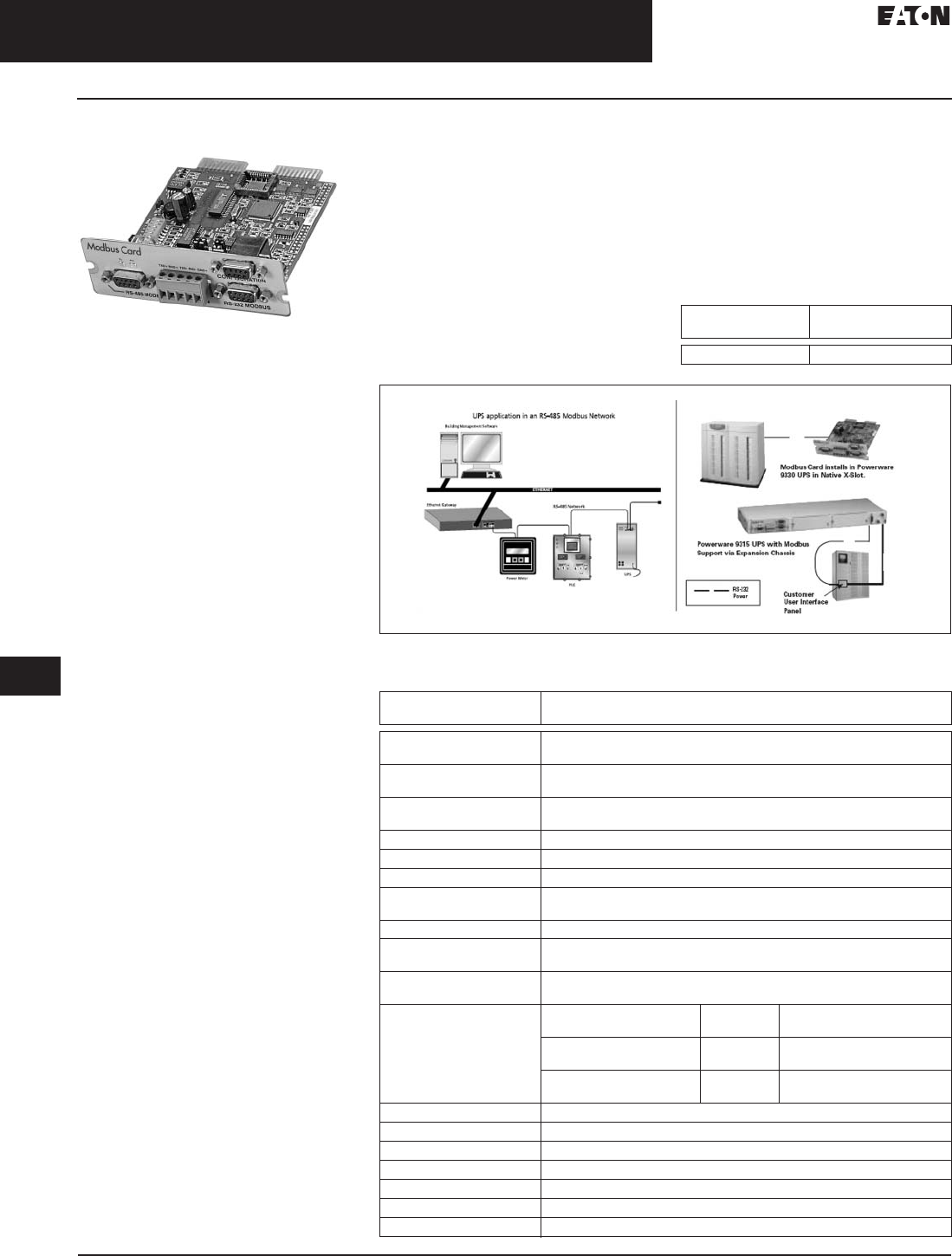
33.4-10
For more information, visit: www.eaton.com/consultants CA08104001E
September 2011
Uninterruptible Power Systems
Sheet 33
22
23
24
25
26
27
28
29
30
31
32
33
34
35
36
37
38
39
40
41
42
43
Eaton Software and Connectivity
Serial Protocol Products
094
Eaton Modbus Card
Eaton Modbus Card
General Description
The Eaton Modbus Card is an X-Slot
Eaton UPS connectivity device that
provides continuous, reliable and
accurate remote monitoring of a
Eaton UPS system through a building
management system (BMS) or
industrial automation system (IAS).
The card provides the means to
integrate data from the Eaton UPS
into the user-provided management
system using Modicon®‚ Modbus RTU
protocol. Key power quality and UPS
status information may be monitored
in real-time to aid in the management
of the UPS and notification of potential
power problems.
Application Focus
■Single UPS module and parallel
systems (single/three-phase UPS)
■BMS/IAS integration
Key Product Features
■Real-time monitoring of power
conditions through building
management systems (BMS)
■Supports Modbus RTU/Jbus protocol
■Seamless data integration via
included Profiler software package
■Flexible input/output communica-
tion methods: RS-232 and RS-485
multi-drop (network)
■Optically isolated communication
ports
■User-selectable communication
topologies
■Supports wide range of UPSs via
native Eaton X-Slot UPSs or
via Eaton expansion chassis
■Eaton Modbus profiler utility
provides exact UPS parameter
list (register map) for BMS
data integration
■Supports both commands 02 (read
input status) and 04 (read input
register) from a BMS query
■Compatible with common BMS
platforms such as: Siemens Apogee,
JCI Metasys, Honeywell EBI,
Liebert SiteScan, and Invensys
Climate Controls
Requirements
Eaton expansion chassis
required for UPS models without
communication slots.
Note: Modbus Card is included with the
expansion chassis as standard.
Integration
UPS data is easily integrated into the
building management system by
connecting the UPS into the RS-485
power and environmental device
network which in turn gets converted
to Ethernet for easy access by the
BMS host computer running the
management software.
Table 33.4-5. Ordering Information
Figure 33.4-1. Typical Configurations and Installation Methods
Table 33.4-6. Technical Data and Specifications
Product
Name
Part
Number
Modbus Card 103002510-5501
Part
Number
103002510-5501
Description X-Slot card providing integration with Modbus network and monitoring
of associated UPS through building management system (BMS)
Modbus command
support
Read input status (alarms and status points, function 02)
read input register (meters, function 04)
Profiler Automatically generates Modbus register map for each UPS
(Windows 32 application)
Configuration Via VT-100 terminal emulation through DB-9 port
Baud rate Selectable 1200 to 19.2 k
Slave address Selectable 1 to 247
Network connections RS-485 through isolated terminal block or DB-9 port
RS-232 through DB-9 port
Communications topology Selectable two-wire or four-wire
Additional
hardware features
Selectable termination resistance
Selectable polarity resistance
UPS compatibility
via native X-Slot
Eaton 5125, 9125, 9170+, 9330, 9340, 9390
UPS compatibility
via expansion chassis
Eaton
Prestige 9
Eaton
5115
Eaton 9315 Hot Sync
parallel redundant module
Eaton Plus
12, 18, 36
Eaton
9120
Eaton 9315 Hot Sync
parallel capacity UPM;
Eaton 9315
reverse transfer module
Eaton
9170+
Eaton 9315 Hot Sync
parallel capacity SBM
Operating temperature 10° to 40°C
Operating humidity 20–80% relative humidity (noncondensing)
Power input 9 Vdc unregulated
Power consumption 1.5 Watts
Dimensions in inches (mm) 4.70 L x 4.50 W x 1.50 H (119.4 L x 114.3 W x 38.1 H)
Weight 7 oz
Regulatory FCC Class B
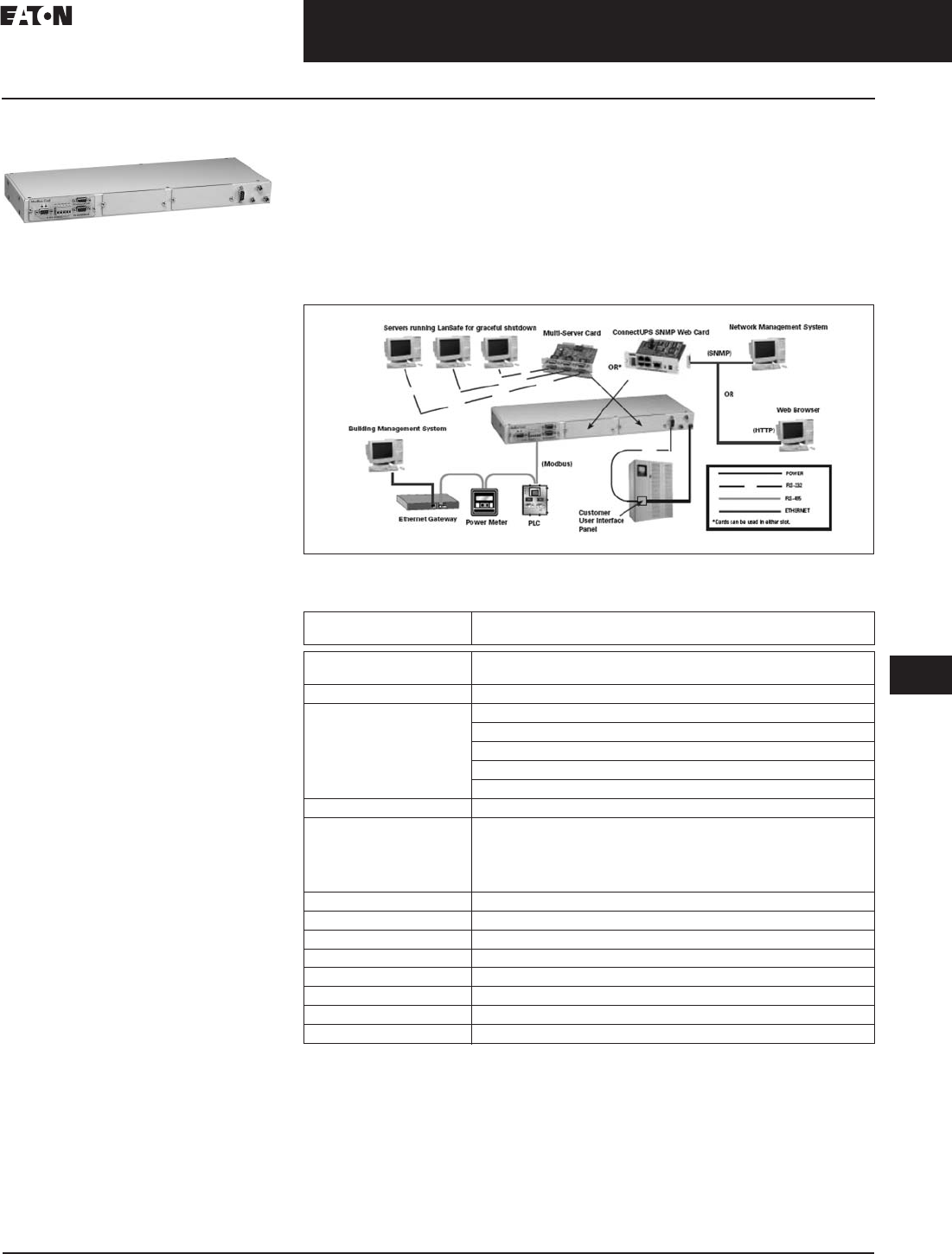
CA08104001E For more information, visit: www.eaton.com/consultants
33.4-11
September 2011
Uninterruptible Power Systems
Sheet 33
22
23
24
25
26
27
28
29
30
31
32
33
34
35
36
37
38
39
40
41
42
43
Eaton Software and Connectivity
Serial Protocol Products
095
Expansion Chassis
Expansion Chassis
General Description
The expansion chassis is a three-slot
power quality peripheral device that
expands communication methods for
a UPS through its support for X-Slot
cards. It comes pre-configured with
a card that conforms to the Modicon,
Modbus protocol.
Application Focus
■Single UPS module and parallel
systems (single/three-phase UPS)
Key Product Features
■Creates wide array of communica-
tion options for UPSs
■Primary focus on Eaton 9315 UPS
models to enable use of new
X-Slot communication cards
■Acts as the framework for protocol
conversion via compatible X-Slot
cards to: Modbus; SNMP; HTTP
■Built-in Modbus card provides
integration of UPS information into
building management systems
■Compatible with X-Slot cards:
Modbus card (one included);
ConnectUPS-X SNMP/Web adapter;
ConnectUPS-M SNMP module;
single port serial card; multi-
server card
■Flexible mounting options
■Redundant power inputs
Integration
The expansion chassis and associated
cards effectively act as a protocol
converter easily integrating the Eaton
UPS into open architecture manage-
ment systems. This device may be
placed on or close to the associated
UPS system using the included
mounting feet. The kit includes
brackets for rack and wall mounting.
Two additional slots are available for
use with any of the following cards:
■A ConnectUPS™-X SNMP/Web
adapter—monitor via SNMP or
the Web
■A ConnectUPS-M SNMP module—
monitor via simple network
management protocol (SNMP)
■A single port serial card—connect
an additional server for monitoring
and graceful shutdown
■A multi-server card—connect up
to three servers for monitoring and
graceful shutdown, supports load
segment control and RS-232 signals
for low battery and AC fail
■A Modbus card—connect to another
Modbus network, monitor via BMS
Figure 33.4-2. Typical Configuration
Table 33.4-7. Technical Data
Part
Number
05147063
Description Adds Modbus card plus two additional slots for X-Slot communication
cards to supported UPSs
Included card Modbus card
Optional cards ConnectUPS-Web/SNMP-X xHub card
ConnectUPS-M SNMP module
Single port serial card
Multi-server card
Additional Modbus card
Communication with UPS DB-9 via Included serial cable
UPS compatibility Eaton 5115; Eaton 5125; Eaton 9120; Eaton 9125; Eaton 9155; Eaton
9170+; Eaton Prestige 9; Eaton Plus 12, 18, 36; Eaton 9315 Reverse
Transfer Module; Eaton 9315 Hot Sync Parallel Redundant Module;
Eaton 9315 Hot Sync Parallel Capacity UPM; Eaton 9315 Hot Sync
Parallel Capacity SBM; Eaton 9320; Eaton 9335; Eaton 9390
Mounting Stand-alone (ft), rack (19 inches, 483 mm), or wall mount
Operating temperature 10° to 40°C
Operating humidity 20 to 80% relative humidity (noncondensing)
Power input Switchable 230/120 Vac, 50/60 Hz (via included transformer)
Power consumption 6 watts maximum
Dimensions in inches (mm) 18.00 x 1.75 x 6.00 (457.2 x 44.4 x 152.4)
Weight 6 lbs (including 1 lb for power supply)
Regulatory FCC Class B

33.4-12
For more information, visit: www.eaton.com/consultants CA08104001E
September 2011
Uninterruptible Power Systems
Sheet 33
22
23
24
25
26
27
28
29
30
31
32
33
34
35
36
37
38
39
40
41
42
43
096
This page intentionally left blank.
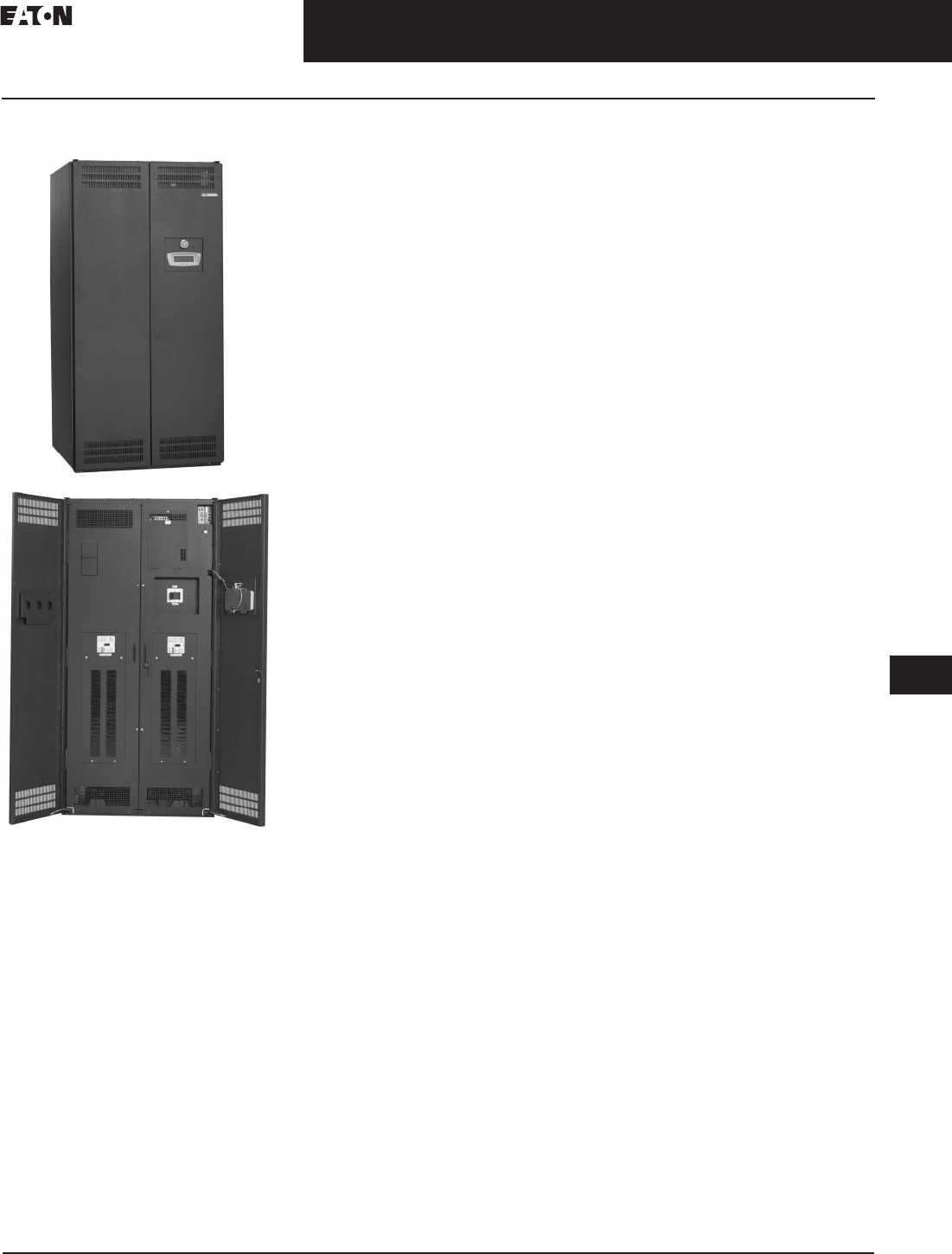
CA08104001E For more information, visit: www.eaton.com/consultants
33.5-1
September 2011
Uninterruptible Power Supplies
Sheet 33
22
23
24
25
26
27
28
29
30
31
32
33
34
35
36
37
38
39
40
41
42
43
Power Distribution Unit
General Information
097
Power Distribution Unit
Power Distribution Unit
General Description
Eaton’s line of three-phase power
distribution units (PDUs) provide
robust power distribution that can be
easily tailored to meet the design
specifications of any facility or data
center. The PDU offers ratings from
50 to 300 kVA and K13 and K20 trans-
formers, including TP-1 high efficiency
versions. Packed with Eaton’s advanced
Energy Management System (EMS),
understanding your facility’s power
distribution and characteristics has
never been easier.
Features
Standard Options
■Panelboards with 400A panel
main breaker
■225A frame or 400A frame
(on >150 kVA) additional
subfeed breakers
■Branch circuit monitoring up to
100A per branch CT
■See-through Plexiglas doors
■Input and ground compression
lug provisions
■Air skirts
■Dual input with manual Kirk
key interlock
■Lockout breaker tabs
■Load bank test lugs
Accessibility and Serviceability
■Ample cabling space between panel-
boards and for subfeed breakers
■Standard top and bottom cable
access for more flexible installation
options
■Front access for operation and
general service requirements
■Easily removable side and rear
covers with captive hardware
■Front access control panel for all
standard communication expansion
and maintenance
Aesthetics and Flexibility
■Line and Match design with other
Eaton power quality products gives
a clean professional appearance to
facilities and data centers
■Improved paint and surface texture
for easy cleaning and maintenance
■Side car options to expand
distribution capacity
Safety and Quality
■Protective trim panels cover panel-
board bus/breakers/wiring from
accidental contact
■Substantial partitions separate
Low/High/Control voltage sections
for safer servicing
■UL/CSA approved 60950
■Supported by Eaton’s extensive
network of over 240 field technicians
for fast reliable service
Monitoring and Connectivity
■Eaton’s Energy Management System
(EMS) provides state-of-the-art
monitoring and alarming provisions
■Access information via 8 x 40 char-
acter on-unit display or remotely via
your network through the Power
Xpert Gateway PDP card
■Stores consumption trends for up
to 24 months
■60A and 100A branch breaker
CTs available
■Time-stamped metering
■Custom alarm settings
Power Xpert Gateway PDP card
The Power Xpert Gateway PDP card
provides connectivity allowing the
Power Distribution Unit to seamlessly
communicate via an Ethernet network.
With its built-in Web server,
the Power Xpert Gateway PDP card
provides PDU information remotely,
without additional software.

33.5-2
For more information, visit: www.eaton.com/consultants CA08104001E
September 2011
Uninterruptible Power Supplies
Sheet 33
22
23
24
25
26
27
28
29
30
31
32
33
34
35
36
37
38
39
40
41
42
43
Power Distribution Unit
Technical Data
098
Technical Data
Table 33.5-1. Technical Specifications
Due to continuing improvements, specifications are subject to change without notice.
Please see sales configurator for additional information.
When using optional PRL3 chassis, a maximum of eight 225A frame breakers can be installed.
Branch breaker schedule required at time of order.
Options
■Branch circuit monitoring
■Subfeed breaker monitoring
■High kAIC input, panel and
subfeed breakers
■Surge protection device (100 or
200 kA) UL 1449
■Lightning arrestor
■Transient suppression plate
■Isolated ground (standard)
■Clear plexiglas doors
■Load bank test lugs (standard)
■Lockout breaker tabs
■Air skirts
■Floor stands (12, 18, 24, 30, 36
and 48 inches)
■High voltage input junction box
■Low voltage control junction box
■Input and ground compression lugs
■Dual input with Kirk key interlock
Connectivity
■Modbus RTU (RS-232/RS-485)
■Power Xpert Gateway Card—
PXGX1000 (Modbus TCP/IP, SNMP,
Ethernet)
General
■Natural convection cooling
■All swivel casters
■System level metering included
■8 x 40 character LCD display
■Top and bottom entry
■Protective trim panels
■Cable management for input and
panel wiring
■Two X-Slots for communication
Control
■Local EPO
■REPO provisions
■
Four building alarm inputs (NO or NC)
Optional Custom Shutdowns
on Alarms
■Phase rotation/loss
■Ground/neutral overcurrent
■Transformer overtemperature
■Output overload
■Input voltage out of tolerance
■Frequency out of tolerance
Category Up to 150 kVA 200–300 kVA
Electrical Characteristics
kVA 50/75/100/125/150 200/225/300
Input ratings 208/380/400/415/480/600V—three-phase, three-wire + ground (single and dual input)
Output ratings 208V– three-phase, four-wire + ground
Frequency 60 Hz
Transformer type Copper/double shielding/Class R (220°C) insulation
Transformer characteristics 150°C temp. rise/K13 (standard) and K20 (optional)/standard and TP-1 efficiency
Transformer compensation taps (4) 2–1/2% FCBN / (2) 2–1/2% FCAN
Neutral rating 200%
Power Distribution
Panelboards Up to six 42-pole panels—two panels in main cabinet and four panels in sidecars
Panelboard options Eaton (bolt-on or plug-on) or Square D panels (225A and 400A main breakers)
Subfeed breakers Up to eight 225A frame Up to 12 225A Frame
Up to five 400A Frame
Up to three 600A Frame
Branch breaker Factory installed branch circuit breaker
Additional subfeed breakers Up to two 225A frame Up to two 225A frame or one 400A frame
Sidecars Up to two front or side facing sidecars
Sidecar options Two 42-pole panels or four 225A frame subfeeds
Dimensions
Main cabinet 39.00 (990.6) W x 35.00 (889.0) D x 80.00 (2032.0) H 44.00 (1117.6) W x 35.00 (889.0) D x 80.00 (2032.0) H
Front facing sidecar 24.00 (609.6) W x 35.00 (889.0) D x 80.00 (2032.0) H
Side facing sidecar 9.50 (241.3) W x 35.00 (889.0) D x 80.00 (2032.0) H
Standards
Standards NEMA, UL 60950, CSA 60950

CA08104001E For more information, visit: www.eaton.com/consultants
33.5-3
September 2011
Uninterruptible Power Supplies
Sheet 33
22
23
24
25
26
27
28
29
30
31
32
33
34
35
36
37
38
39
40
41
42
43
Power Distribution Unit
Technical Data
099
Power Xpert Gateway
PDP Card
Power Xpert Gateway PDP Card
General Description
The Power Xpert Gateway PDP card
provides connectivity, allowing Eaton,
PDUs, RPPs, PDRs and RPMs to seam-
lessly communicate via an Ethernet
network. With its built-in Web server,
the Power Xpert Gateway PDP card
provides power distribution products’
information remotely, without
additional software.
Features, Benefits and Functions
The Power Xpert Gateway Power
Distribution Products Card (PXGXPDP)
provides Web-enabled, real-time
monitoring of Powerware Power
Distribution Units (PDUs), Rack Power
Modules (RPM) and Powerware RPPs
through standard on-board Web
pages, Power Xpert Software or
third-party software.
An integral part of the Power Xpert
Architecture, which provides end-to-
end PowerChain solutions, the PXGX
PDP provides a central point to con-
nect distribution products to an Ether-
net network. Information is presented
in organized, user-friendly Web pages
and include the following:
■PDU system identification
■Graphic panel layouts
■Voltage
■Current
■Frequency
■Energy
■Power
■THD (current and voltage)
For detailed information on the
PXGXPDP card, refer to Tab 2,
Section 2.3.
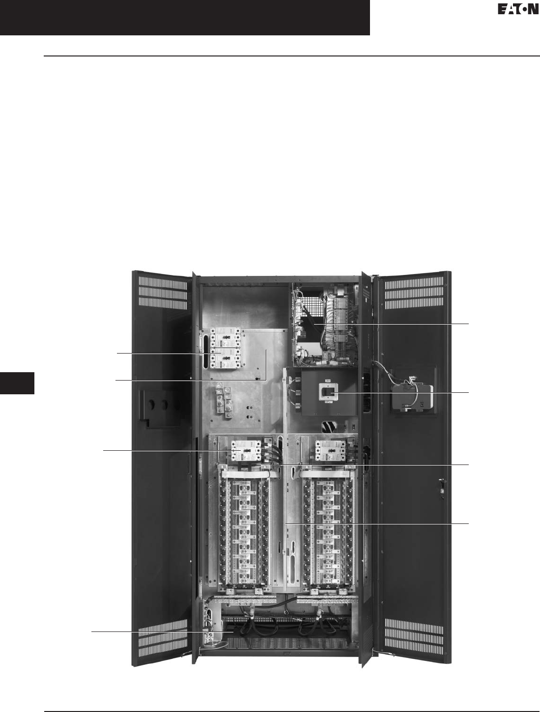
33.5-4
For more information, visit: www.eaton.com/consultants CA08104001E
September 2011
Uninterruptible Power Supplies
Sheet 33
22
23
24
25
26
27
28
29
30
31
32
33
34
35
36
37
38
39
40
41
42
43
Power Distribution Unit
Technical Data
100
Energy Management System
Monitored Parameters
■Input voltage (L-L and L-N)
■Input current (A, B and C phases)
■Output voltage (L-L and L-N)
■Output current (A, B and C phases)
■Output neutral current
■System ground current
■kVA, kW, Hz
■Monthly, yearly, total kW
■Input voltage THD (all phases)
■Output voltage THD (all phases)
■Power factor (lead/lag indicator)
■Output current % (A, B and
C phases)
Load Profiling
Captures highest and lowest reading on
monthly basis with trend information over
the last 24 months
■Input/output voltage
■Input/output current
■Input/output frequency
■Input/output power factor
■Input/output kVA
■Input/output voltage THD
■Ground and neutral current
Warnings/Alarms
■
Transformer over-temp and shutdown
■Input/output overvoltage and
undervoltage
■Input/output overfrequency and
underfrequency
■Input/output phase rotation
■Input/output voltage and current THD
■Output overload (three levels)
■Remote EPO
■Building alarms (two programmable)
■Summary alarm
■Communication fault
Power Distribution Unit Features
Top Cable Entry
Compression Lugs
(not pictured)
Additional Subfeed
Breakers
400A Breakers
(225A pictured)
Ample Wire
Space
Bottom Cable Entry
Controls
Main Breaker
HV Isolation
and Wire Route
Transformer Barrier
(HV Isolation)
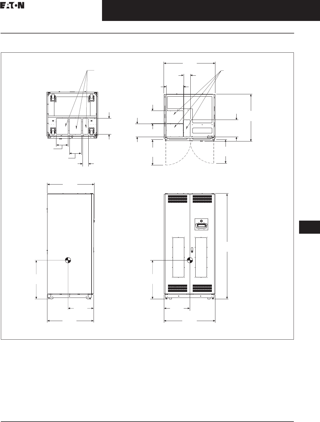
CA08104001E For more information, visit: www.eaton.com/consultants
33.5-5
September 2011
Uninterruptible Power Supplies
Sheet 33
22
23
24
25
26
27
28
29
30
31
32
33
34
35
36
37
38
39
40
41
42
43
Power Distribution Unit
Layouts and Dimensions
101
50–150 kVA PDU
Figure 33.5-1. 50–150 kVA PDU—Main Cabinet—Dimensions in Inches (mm)
Notes:
1. Weight: 2786 lbs (1264 kg) for PRL3 and 150 kVA transformer different configurations may have different weight.
2. The system must be installed on a level floor suitable for computer or electronic equipment.
3. The system must be installed in a temperature and humidity controlled indoor area free of conductive contaminants.
4. Ambient temperature range: 32°–104°F (0°–40°C), recommended operating range: 68°–77°F (20°–25°C) maximum relative humidity
95% noncondensing.
5. Minimum 18.00-inch (457.2 mm) clearance in front and minimum 4.00-inch (101.6 mm) in rear of the cabinet are required for cooling air
intake servicing space for rear access is 24.00 inches (609.6 mm).
6. Top and bottom cable entries through removable access plates are standard for all configurations. Access plates shall be custom-modified
to suit conduit sizes.
7. All wiring is to be in accordance with national and local electric codes.
8. Center of gravity location shown for PRL3 and 150 kVA transformer.
9. Specifications are subject to change.
29.50
(749.3)
19.37
(492.0)
35.12
(892.0)
35.79
(909.0)
29.45
(748.0)
19.60
(498.0)
38.89
(988.0)
80.12
(2035.0)
Front ViewLeft View
12.12
(308.0)
Conduit Entry Space
Conduit Plates
Interchangable
Top/Bottom
9.10
(230.0)
9.10
(230.0) 4.33
(110.0)
Bottom View
38.90
(988.0)
5.12
(130.0)
Conduit Entry Space
Conduit Plates
Interchangable
Top/Bottom
35.78
(909.0)
12.91
(328.0)
18.03
(458.0)
9.84
(250.0)
9.84
(250.0)
19.33
(491.0)
Top View
2x
12.91
(328.0)
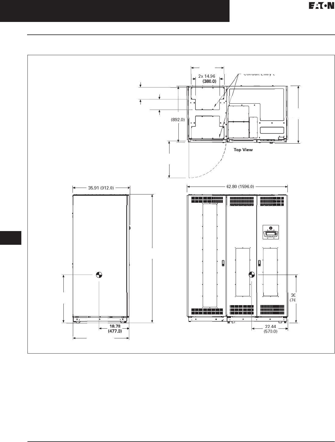
33.5-6
For more information, visit: www.eaton.com/consultants CA08104001E
September 2011
Uninterruptible Power Supplies
Sheet 33
22
23
24
25
26
27
28
29
30
31
32
33
34
35
36
37
38
39
40
41
42
43
Power Distribution Unit
Layouts and Dimensions
102
50–150 kVA PDU
Figure 33.5-2. 50–150 kVA PDU—Main Cabinet—Left Front Facing Sidecar—Dimensions in Inches (mm)
Notes:
1. Weight: 3062 lbs (1389 kg) for PRL3 and 150 kVA transformer different configurations may have different weight.
2. The system must be installed on a level floor suitable for computer or electronic equipment.
3. The system must be installed in a temperature and humidity controlled indoor area free of conductive contaminants.
4. Ambient temperature range: 32°–104°F (0°–40°C), recommended operating range: 68°–77°F (20°–25°C) maximum relative humidity
95% noncondensing.
5. Minimum 18.00-inch (457.2 mm) clearance in front and minimum 4.00-inch (101.6 mm) in rear of the cabinet are required for cooling air
intake servicing space for rear access is 24.00 inches (609.6 mm).
6. Top and bottom cable entries through removable access plates are standard for all configurations. Access plates shall be custom-modified
to suit conduit sizes.
7. All wiring is to be in accordance with national and local electric codes.
8. Center of gravity location shown for PRL3 and 150 kVA transformer.
9. Specifications are subject to change.
2x 2
0
.
63
(
524.0
)
Front Vie
w
2x 7.56
(
192.0
)
2x
6
.4
6
(
164.0
)
35
.1
2
Conduit Entry Space
2
3
.
03
(
585.0
)
35
.
91
(912.0)
.
08
4.0
)
Left Sid
e
80
.2
4
(
2038.0
)
30
.
08
(
764.0
)
35.12
(
892.0
)
CA08104001E For more information, visit: www.eaton.com/consultants
33.5-7
September 2011
Uninterruptible Power Supplies
Sheet 33
22
23
24
25
26
27
28
29
30
31
32
33
34
35
36
37
38
39
40
41
42
43
Power Distribution Unit
Layouts and Dimensions
103
50–150 kVA PDU
Figure 33.5-3. 50–150 kVA PDU—Main Cabinet—Left Side Facing Sidecar—Dimensions in Inches (mm)
Notes:
1. Weight: 3038 lbs (1378 kg) for PRL3 and 150 kVA transformer different configurations may have different weight.
2. The system must be installed on a level floor suitable for computer or electronic equipment.
3. The system must be installed in a temperature and humidity controlled indoor area free of conductive contaminants.
4. Ambient temperature range: 32°–104°F (0°–40°C), recommended operating range: 68°–77°F (20°–25°C) maximum relative humidity
95% noncondensing.
5. Minimum 18.00-inch (457.2 mm) clearance in front and minimum 4.00-inch (101.6 mm) in rear of the cabinet are required for cooling air
intake servicing space for rear access is 24.00 inches (609.6 mm).
6. Top and bottom cable entries through removable access plates are standard for all configurations. Access plates shall be custom-modified
to suit conduit sizes.
7. All wiring is to be in accordance with national and local electric codes.
8. Center of gravity location shown for PRL3 and 150 kVA transformer.
9. Specifications are subject to change.
35
.7
1
(
907.0
)
33
.4
0
(
848.4
)
1
9
.4
0
(
492.8
)
L
e
f
t
Vi
ew
Fr
o
n
t
Vi
ew
To
pV
2x 7.
3
2
(
186.0
)
2x
1
5
.
60
14.
06
(
357.1
)
30
.
00
(
762.0
)
30.00
(
762.
0
(892.0)
80
.2
4
(
2038.0
)
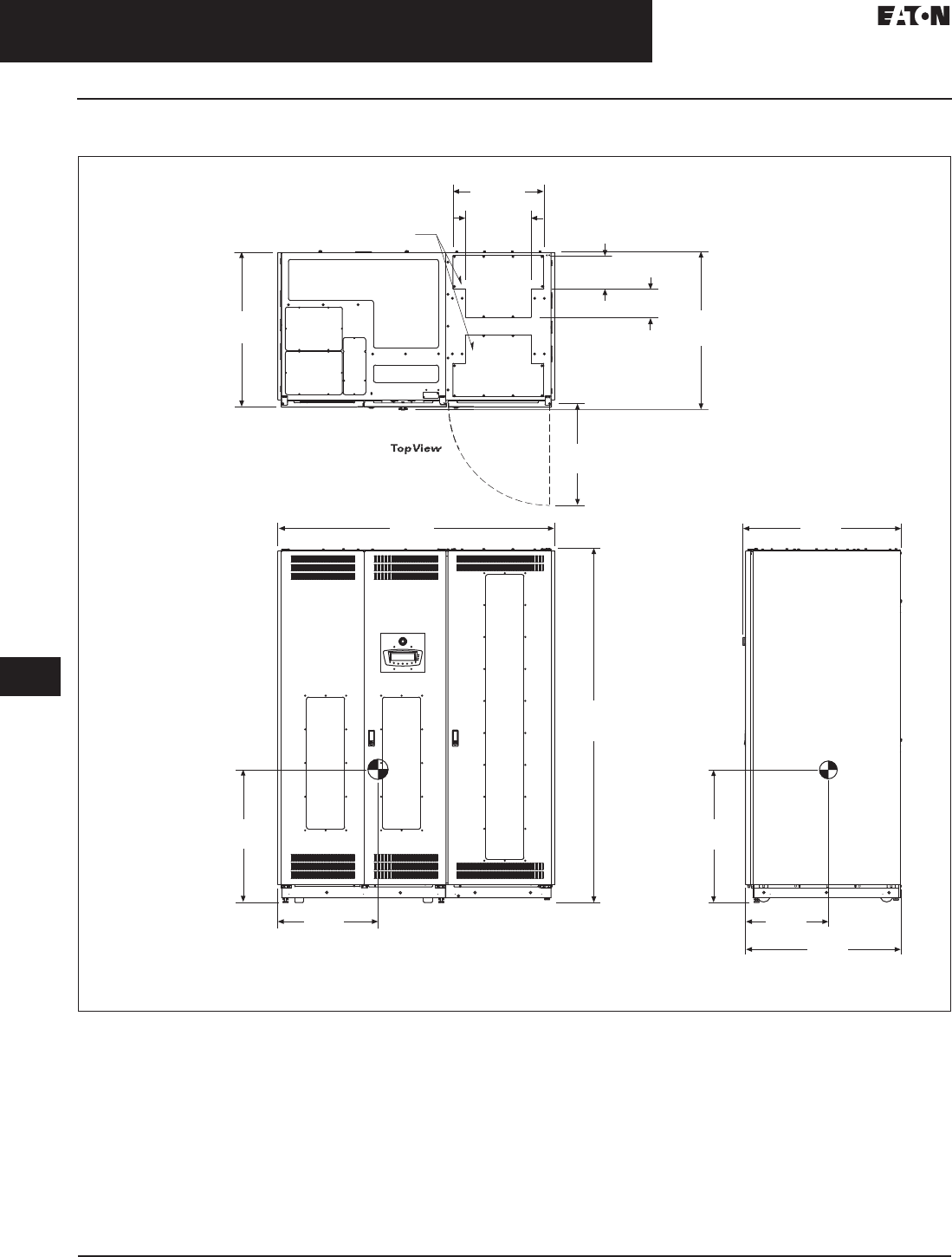
33.5-8
For more information, visit: www.eaton.com/consultants CA08104001E
September 2011
Uninterruptible Power Supplies
Sheet 33
22
23
24
25
26
27
28
29
30
31
32
33
34
35
36
37
38
39
40
41
42
43
Power Distribution Unit
Layouts and Dimensions
104
50–150 kVA PDU
Figure 33.5-4. 50–150 kVA PDU—Main Cabinet—Right Front Facing Sidecar—Dimensions in Inches (mm)
Notes:
1. Weight: 3062 lbs (1389 kg) for PRL3 and 150 kVA transformer different configurations may have different weight.
2. The system must be installed on a level floor suitable for computer or electronic equipment.
3. The system must be installed in a temperature and humidity controlled indoor area free of conductive contaminants.
4. Ambient temperature range: 32°–104°F (0°–40°C), recommended operating range: 68°–77°F (20°–25°C) maximum relative humidity
95% noncondensing.
5. Minimum 18.00-inch (457.2 mm) clearance in front and minimum 4.00-inch (101.6 mm) in rear of the cabinet are required for cooling air
intake servicing space for rear access is 24.00 inches (609.6 mm).
6. Top and bottom cable entries through removable access plates are standard for all configurations. Access plates shall be custom-modified
to suit conduit sizes.
7. All wiring is to be in accordance with national and local electric codes.
8. Center of gravity location shown for PRL3 and 150 kVA transformer.
9. Specifications are subject to change.
18.77
(477.0)
35.11
(892.0)
Right View
30.07
(764.0)
35.90
(912.0)
62.83
(1596.0)
Sidecar Shown With
Viewing Window 80.23
(2038.0)
30.07
(764.0)
22.71
(577.0)
35.11
(892.0)
Conduit Entry Space
2x 7.55
(192.0)
2x 6.45
(164.0)
35.90
(912.0)
23.03
(585.0)
Front View
2x 20.62
(524.0)
2x 14.96
(380.0)
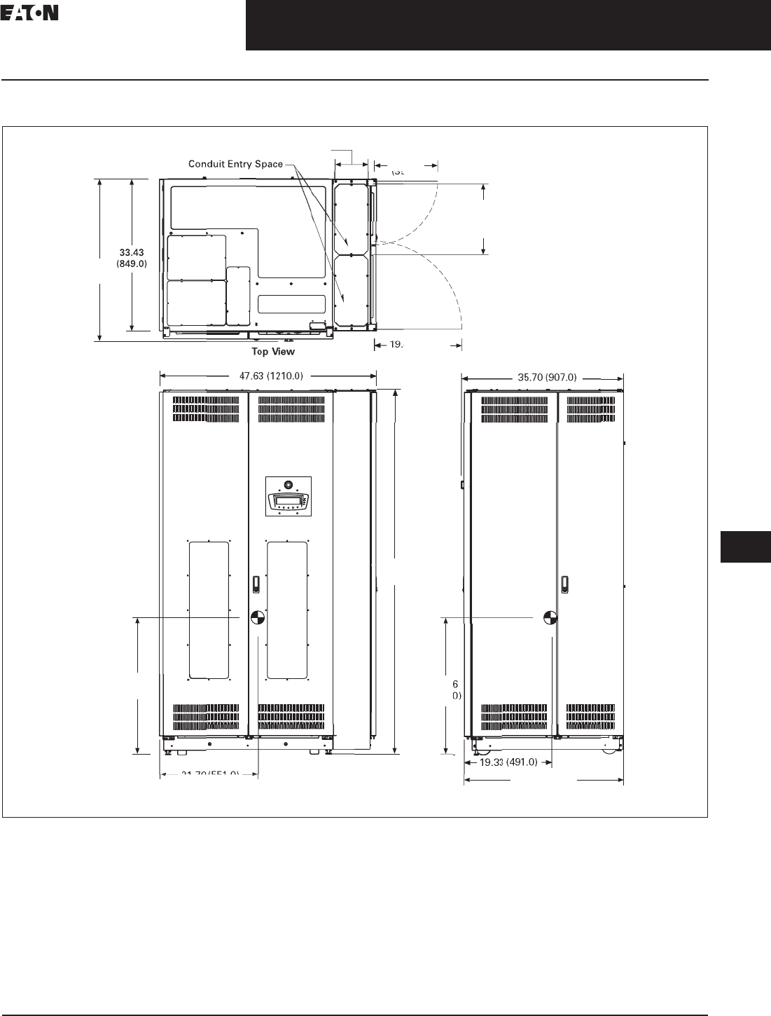
CA08104001E For more information, visit: www.eaton.com/consultants
33.5-9
September 2011
Uninterruptible Power Supplies
Sheet 33
22
23
24
25
26
27
28
29
30
31
32
33
34
35
36
37
38
39
40
41
42
43
Power Distribution Unit
Layouts and Dimensions
105
50–150 kVA PDU
Figure 33.5-5. 50–150 kVA PDU—Main Cabinet—Right Side Facing Sidecar—Dimensions in Inches (mm)
Notes:
1. Weight: 3038 lbs (1378 kg) for PRL3 and 150 kVA transformer different configurations may have different weight.
2. The system must be installed on a level floor suitable for computer or electronic equipment.
3. The system must be installed in a temperature and humidity controlled indoor area free of conductive contaminants.
4. Ambient temperature range: 32°–104°F (0°–40°C), recommended operating range: 68°–77°F (20°–25°C) maximum relative humidity
95% noncondensing.
5. Minimum 18.00-inch (457.2 mm) clearance in front and minimum 4.00-inch (101.6 mm) in rear of the cabinet are required for cooling air
intake servicing space for rear access is 24.00 inches (609.6 mm).
6. Top and bottom cable entries through removable access plates are standard for all configurations. Access plates shall be custom-modified
to suit conduit sizes.
7. All wiring is to be in accordance with national and local electric codes.
8. Center of gravity location shown for PRL3 and 150 kVA transformer.
9. Specifications are subject to change.
Fr
o
n
t
Vi
ew
RightVie
w
14.1
0
(357.0)
2x 7.32
(
186.0
)
35.12
(
892.0
)
2
9
.
9
(
761.
0
80
.2
4
(
2038.0
)
2
9
.
96
(
761.0
)
21.70 (551.0)
2x
1
5
.
60
(
396.0
)
35
.7
1
(
907.0
)
4
0
(
491.0
)
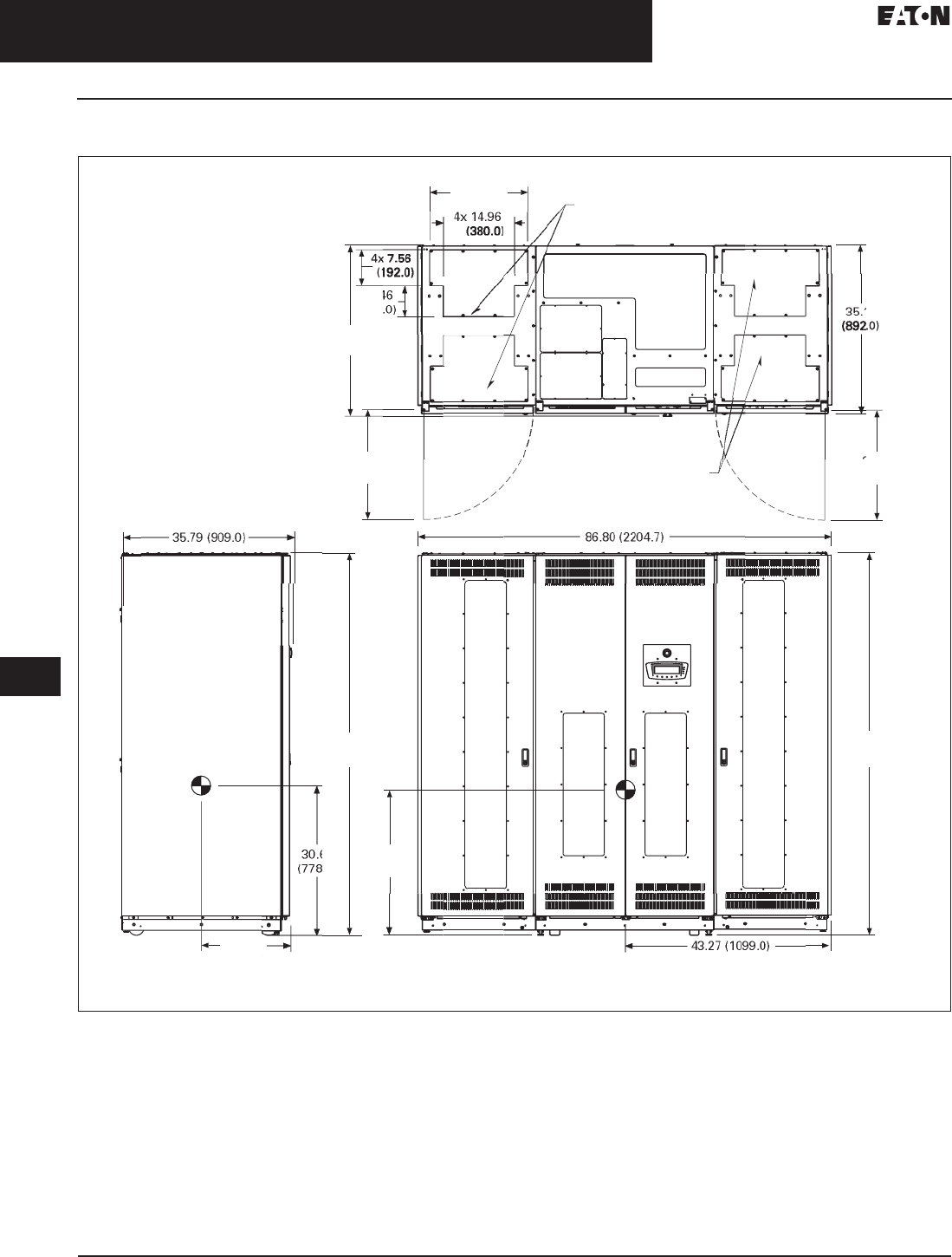
33.5-10
For more information, visit: www.eaton.com/consultants CA08104001E
September 2011
Uninterruptible Power Supplies
Sheet 33
22
23
24
25
26
27
28
29
30
31
32
33
34
35
36
37
38
39
40
41
42
43
Power Distribution Unit
Layouts and Dimensions
106
50–150 kVA PDU
Figure 33.5-6. 50–150 kVA PDU—Main Cabinet—Two Front Facing Sidecar—Dimensions in Inches (mm)
Notes:
1. Weight: 3338 lbs (1514 kg) for PRL3 and 150 kVA transformer different configurations may have different weight.
2. The system must be installed on a level floor suitable for computer or electronic equipment.
3. The system must be installed in a temperature and humidity controlled indoor area free of conductive contaminants.
4. Ambient temperature range: 32°–104°F (0°–40°C), recommended operating range: 68°–77°F (20°–25°C) maximum relative humidity
95% noncondensing.
5. Minimum 18.00-inch (457.2 mm) clearance in front and minimum 4.00-inch (101.6 mm) in rear of the cabinet are required for cooling air
intake servicing space for rear access is 24.00 inches (609.6 mm).
6. Top and bottom cable entries through removable access plates are standard for all configurations. Access plates shall be custom-modified
to suit conduit sizes.
7. All wiring is to be in accordance with national and local electric codes.
8. Center of gravity location shown for PRL3 and 150 kVA transformer.
9. Specifications are subject to change.
4x 2
0
.
6
2
(
524.0
)
4x
6
.
4
(
164
35
.
91
(
912.0
)
23
.
03
(
585.0
)
23.03
(
585.0
)
Conduit Entr
y
S
p
ac
e
12
80
.2
4
(
2038.0
)
63
.0
)
30
.
63
(
778.0
)
1
8
.2
7
(464.0)
80
.2
4
(
2038.0
)
Conduit Entr
y
S
p
ac
e
L
e
f
t
Vi
ew
Fr
o
n
t
Vi
ew
To
p
Vie
w
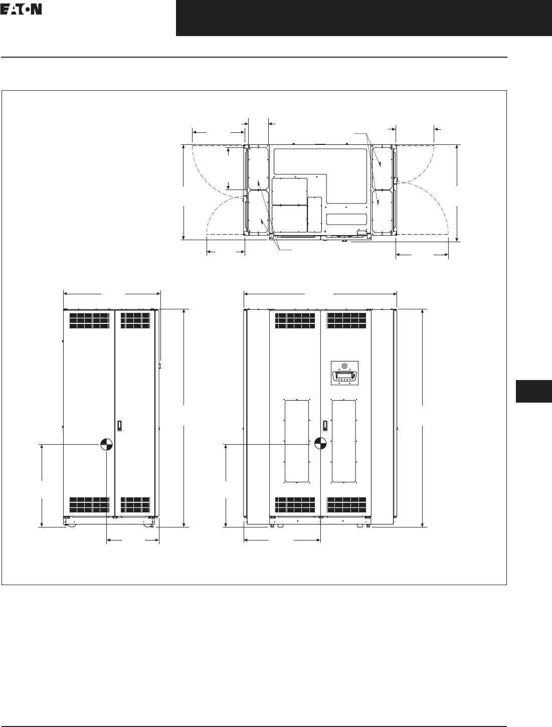
CA08104001E For more information, visit: www.eaton.com/consultants
33.5-11
September 2011
Uninterruptible Power Supplies
Sheet 33
22
23
24
25
26
27
28
29
30
31
32
33
34
35
36
37
38
39
40
41
42
43
Power Distribution Unit
Layouts and Dimensions
107
50–150 kVA PDU
Figure 33.5-7. 50–150 kVA PDU—Main Cabinet—Two Side Facing Sidecar—Dimensions in Inches (mm)
Notes:
1. Weight: 3289 lbs (1492 kg) for PRL3 and 150 kVA transformer different configurations may have different weight.
2. The system must be installed on a level floor suitable for computer or electronic equipment.
3. The system must be installed in a temperature and humidity controlled indoor area free of conductive contaminants.
4. Ambient temperature range: 32°–104°F (0°–40°C), recommended operating range: 68°–77°F (20°–25°C) maximum relative humidity
95% noncondensing.
5. Minimum 18.00-inch (457.2 mm) clearance in front and minimum 4.00-inch (101.6 mm) in rear of the cabinet are required for cooling air
intake servicing space for rear access is 24.00 inches (609.6 mm).
6. Top and bottom cable entries through removable access plates are standard for all configurations. Access plates shall be custom-modified
to suit conduit sizes.
7. All wiring is to be in accordance with national and local electric codes.
8. Center of gravity location shown for PRL3 and 150 kVA transformer.
9. Specifications are subject to change.
Conduit
Entry
Space
Conduit Entry Space
19.33
(491.0)
4x
15.59
(396.0)
4x
7.32
(186.0)
35.12
(892.0)
14.06
(357.0) 19.33
(491.0)
35.71
(907.0)
Front View
Top View
Left View
35.79
(909.0)
19.29
(490.0)
30.39
(772.0)
80.24
(2038.0)
30.39
(772.0)
28.31
(719.0)
80.24
(2038.0)
56.38
(1432.0)
14.06
(357.0)
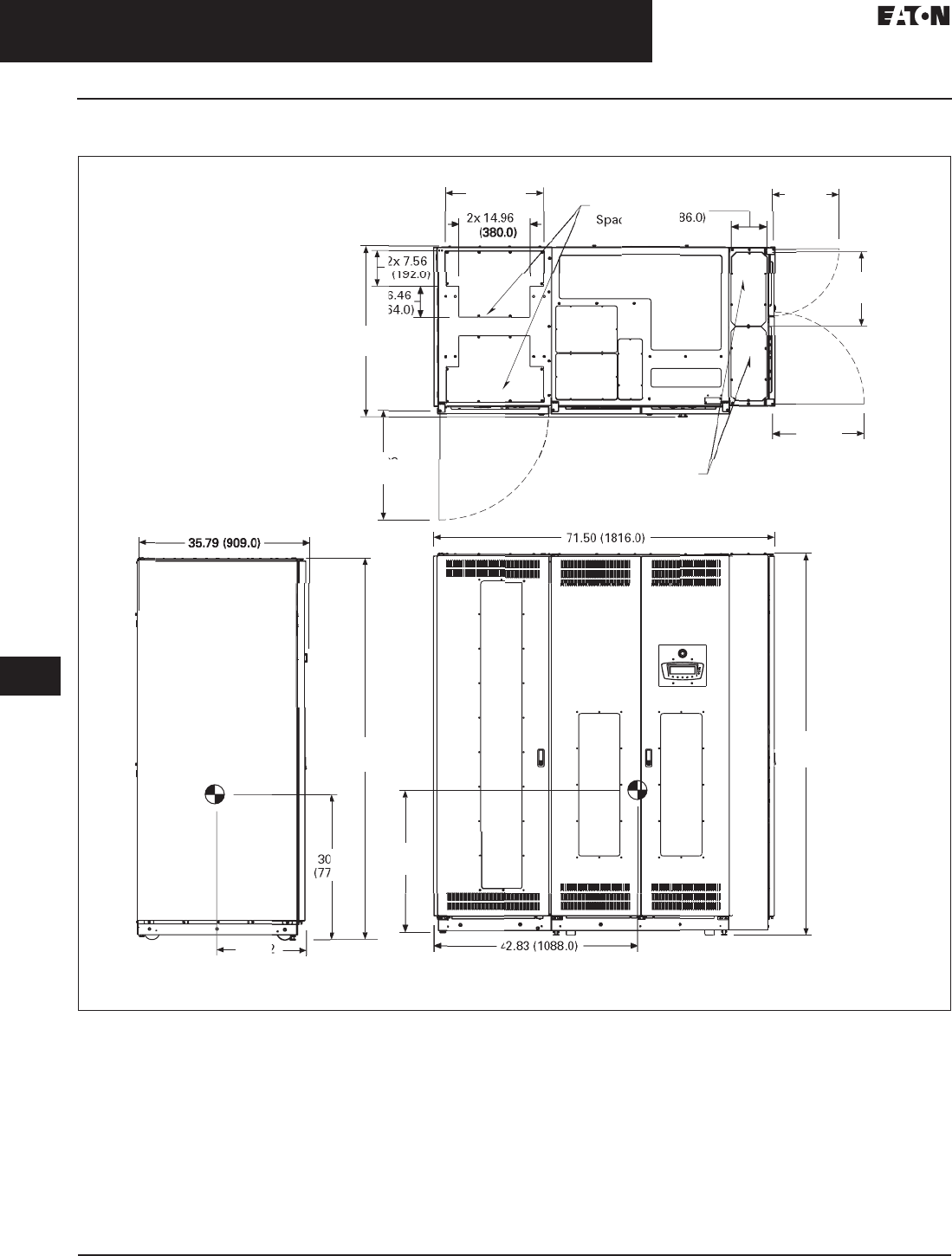
33.5-12
For more information, visit: www.eaton.com/consultants CA08104001E
September 2011
Uninterruptible Power Supplies
Sheet 33
22
23
24
25
26
27
28
29
30
31
32
33
34
35
36
37
38
39
40
41
42
43
Power Distribution Unit
Layouts and Dimensions
108
50–150 kVA PDU
Figure 33.5-8. 50–150 kVA PDU—Main Cabinet—Left Front Facing Sidecar and Right Side Facing Sidecar—Dimensions in Inches (mm)
Notes:
1. Weight: 3314 lbs (1503 kg) for PRL3 and 150 kVA transformer different configurations may have different weight.
2. The system must be installed on a level floor suitable for computer or electronic equipment.
3. The system must be installed in a temperature and humidity controlled indoor area free of conductive contaminants.
4. Ambient temperature range: 32°–104°F (0°–40°C), recommended operating range: 68°–77°F (20°–25°C) maximum relative humidity
95% noncondensing.
5. Minimum 18.00-inch (457.2 mm) clearance in front and minimum 4.00-inch (101.6 mm) in rear of the cabinet are required for cooling air
intake servicing space for rear access is 24.00 inches (609.6 mm).
6. Top and bottom cable entries through removable access plates are standard for all configurations. Access plates shall be custom-modified
to suit conduit sizes.
7. All wiring is to be in accordance with national and local electric codes.
8. Center of gravity location shown for PRL3 and 150 kVA transformer.
9. Specifications are subject to change.
2x 2
0
.
6
2
(
524.0
)
2
2x
6
(
1
6
35
.
91
(
912.0
)
23.03
(
585.0
)
Conduit Entr
y
S
p
ac
e
7.
32
(
1
8
14.
05
(
357.0
)
1
5
.
60
(
396.0
)
1
9
.
33
(
491.0
)
80
.2
4
(
2038.0
)
.4
7
4.0
)
1
8
.
82
(
478.0
)
80
.2
4
(
2038.0
)
Co
n
du
i
t
Entry
ce
2
9
.
84
(
758.0
)
L
e
f
t
Vi
ew
Fr
o
n
t
Vi
ew
To
p
Vie
w
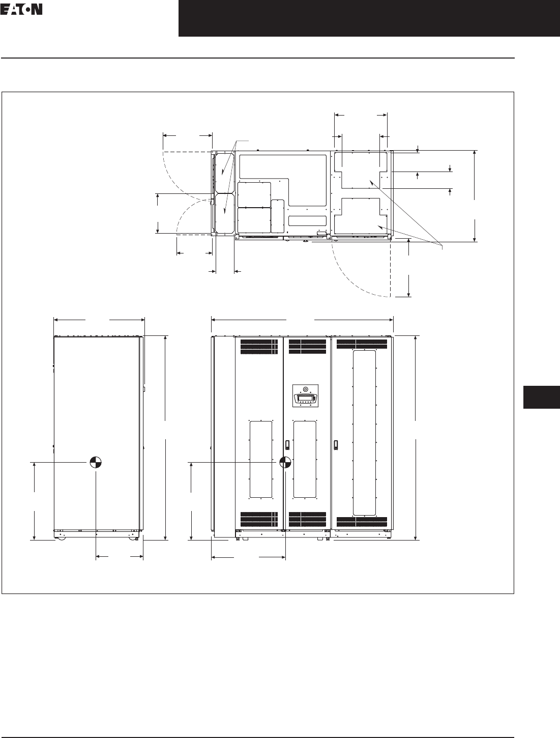
CA08104001E For more information, visit: www.eaton.com/consultants
33.5-13
September 2011
Uninterruptible Power Supplies
Sheet 33
22
23
24
25
26
27
28
29
30
31
32
33
34
35
36
37
38
39
40
41
42
43
Power Distribution Unit
Layouts and Dimensions
109
50–150 kVA PDU
Figure 33.5-9. 50–150 kVA PDU—Main Cabinet—Right Front Facing Sidecar and Left Side Facing Sidecar—Dimensions in Inches (mm)
Notes:
1. Weight: 3314 lbs (1503 kg) for PRL3 and 150 kVA transformer different configurations may have different weight.
2. The system must be installed on a level floor suitable for computer or electronic equipment.
3. The system must be installed in a temperature and humidity controlled indoor area free of conductive contaminants.
4. Ambient temperature range: 32°–104°F (0°–40°C), recommended operating range: 68°–77°F (20°–25°C) maximum relative humidity
95% noncondensing.
5. Minimum 18.00-inch (457.2 mm) clearance in front and minimum 4.00-inch (101.6 mm) in rear of the cabinet are required for cooling air
intake servicing space for rear access is 24.00 inches (609.6 mm).
6. Top and bottom cable entries through removable access plates are standard for all configurations. Access plates shall be custom-modified
to suit conduit sizes.
7. All wiring is to be in accordance with national and local electric codes.
8. Center of gravity location shown for PRL3 and 150 kVA transformer.
9. Specifications are subject to change.
19.33
(491.0) Conduit Entry Space
Front ViewLeft View
Top View
Conduit
Entry Space
2x 15.59
(396.0)
2x
7.32
(186.0)
14.05
(357.0)
2x 6.46
(164.0)
23.03
(585.0)
35.91
(912.0)
2x 7.56
(192.0)
2x 20.63
(524.0)
2x 14.96
(380.0)
35.79
(909.0)
30.51
(775.0)
18.74
(476.0)
80.24
(2038.0)
30.51
(775.0)
29.25
(743.0)
80.24
(2038.0)
71.50
(1816.0)
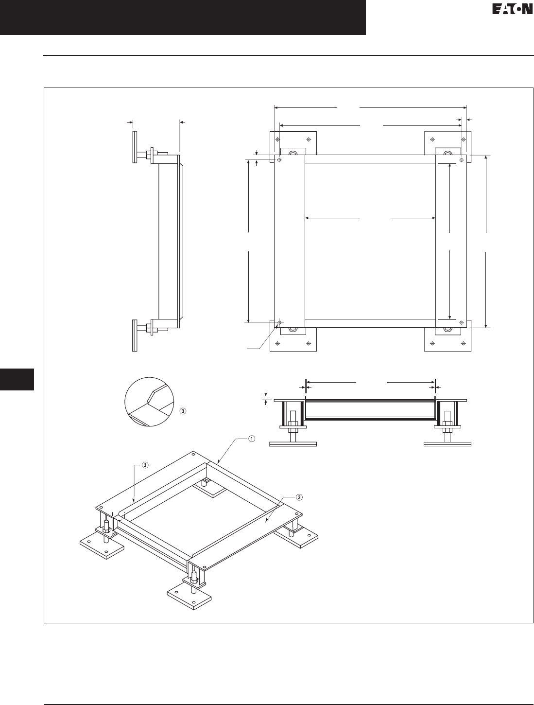
33.5-14
For more information, visit: www.eaton.com/consultants CA08104001E
September 2011
Uninterruptible Power Supplies
Sheet 33
22
23
24
25
26
27
28
29
30
31
32
33
34
35
36
37
38
39
40
41
42
43
Power Distribution Unit
Layouts and Dimensions
110
50–150 kVA PDU
Figure 33.5-10. 50–150 kVA PDU—Floor Stand, 9.00 Inch (228.6) Non-Seismic—Dimensions in Inches (mm)
Notes: Unless otherwise specified.
1. Top front and rear C4 x 5.4#.
2. Angle 6.00 x 4.00 x 0.38 inches thick (152.4 x 101.6 x 9.7).
3. Guide rails 1.50 x 0.13 inches thick (38.1 x 3.3), with 45° chamfers on top corners.
Front
9.00
(228.6)
2.00
(50.8)
±
ISO View
NTS
37.19
(944.6)
35.31
(896.9)
0.94
(23.9)
0.94
(23.9)
33.38
(847.9)
31.53
(800.9)
30.19
(766.8)
24.94
(633.5) ID
0.63
(16.0)Thru
4X Ø
Detail A
0.63
(16.0)
24.94
(633.5) ID
0.13
(3.3)
0.13
(3.3)
A
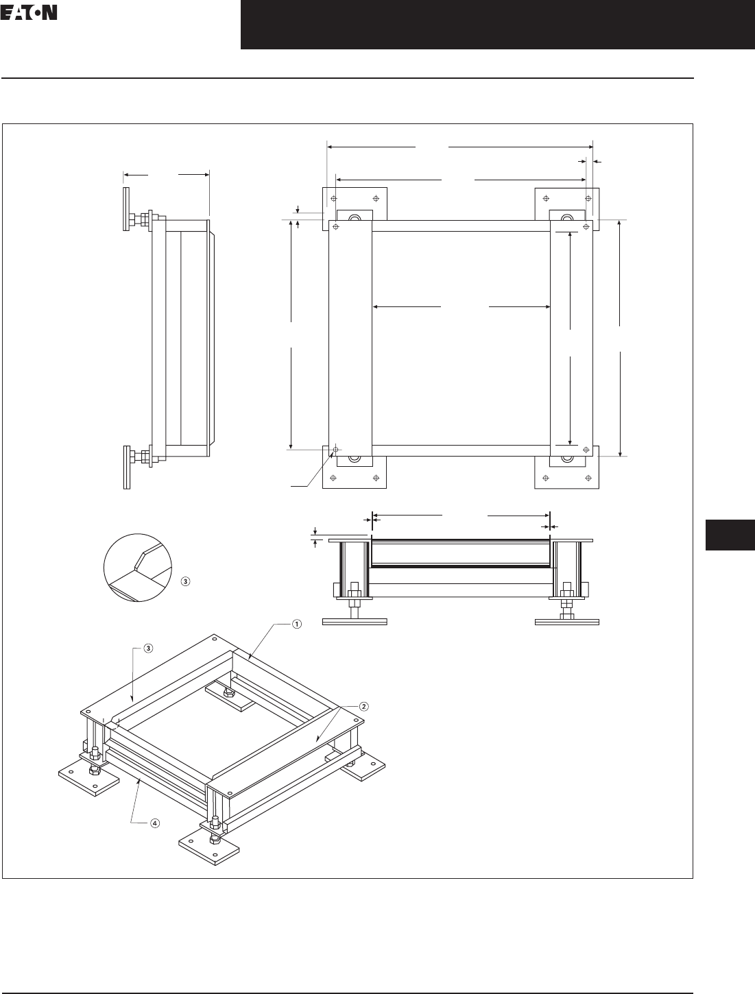
CA08104001E For more information, visit: www.eaton.com/consultants
33.5-15
September 2011
Uninterruptible Power Supplies
Sheet 33
22
23
24
25
26
27
28
29
30
31
32
33
34
35
36
37
38
39
40
41
42
43
Power Distribution Unit
Layouts and Dimensions
111
50–150 kVA PDU
Figure 33.5-11. 50–150 kVA PDU—Floor Stand, 12.00 Inch (304.8) Seismic—Dimensions in Inches (mm)
Notes: Unless otherwise specified.
1. Top front and rear C4 x 5.4#.
2. Angle 6.00 x 4.00 x 0.38 inches thick (152.4 x 101.6 x 9.7).
3. Guide rails 1.50 x 0.13 inches thick (38.1 x 3.3), with 45° chamfers on top corners.
4. Lower support TS 2x1.
Front
12.00
(304.8)
ISO View
NTS
37.19
(944.6)
35.31
(896.9)
0.94
(23.9)
0.94
(23.9)
33.38
(847.9)
31.53
(800.9) 30.19
(766.8)
24.94
(633.5) ID
0.63
(16.0) Thru4X Ø
Detail A
0.63
(16.0)
24.94
(633.5) ID
0.13
(3.3)
0.13
(3.3)
A
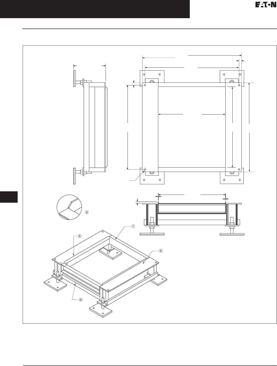
33.5-16
For more information, visit: www.eaton.com/consultants CA08104001E
September 2011
Uninterruptible Power Supplies
Sheet 33
22
23
24
25
26
27
28
29
30
31
32
33
34
35
36
37
38
39
40
41
42
43
Power Distribution Unit
Layouts and Dimensions
112
50–150 kVA PDU
Figure 33.5-12. 50–150 kVA PDU—Floor Stand, 12.00 Inch (304.8) Non-Seismic—Dimensions in Inches (mm)
Notes: Unless otherwise specified.
1. Top front and rear C4 x 5.4#.
2. Angle 6.00 x 4.00 x 0.38 inches thick (152.4 x 101.6 x 9.7).
3. Guide rails 1.50 x 0.13 inches thick (38.1 x 3.3), with 45° chamfers on top corners.
4. Lower support TS 2x1.
Front
4X Ø
Detail A
0.63
(16.0)
24.94
(633.5) ID
0.13
(3.3) 0.13
(3.3)
37.19
(944.6)
35.31
(896.9)
0.94
(23.9)
0.94
(23.9)
33.38
(847.9)
31.53
(800.9)
30.19
(766.8)
24.94
(633.5) ID
0.63
(16.0) Thru
ISO View
NTS
A
12.00
(304.8)
2.00
(50.8)
±
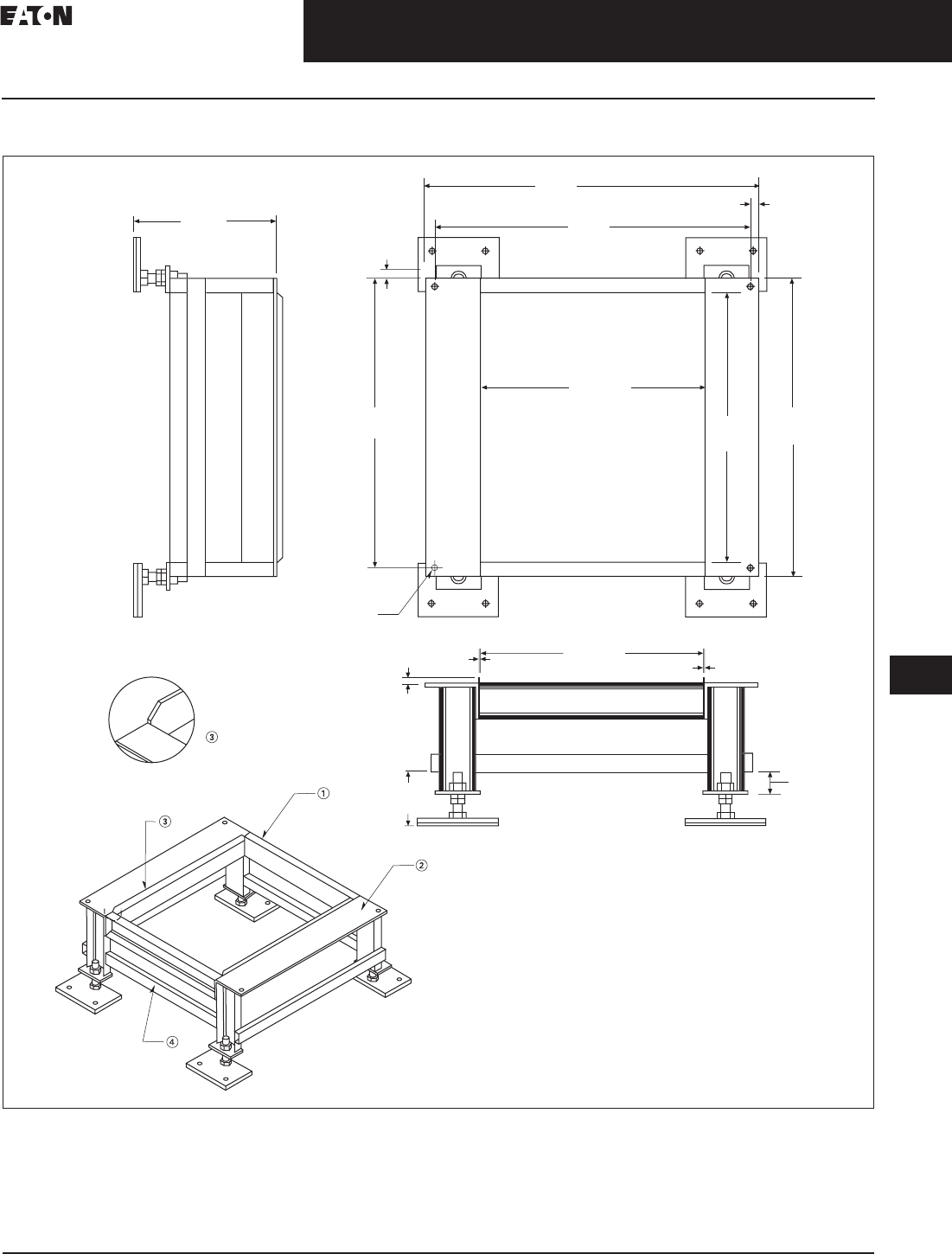
CA08104001E For more information, visit: www.eaton.com/consultants
33.5-17
September 2011
Uninterruptible Power Supplies
Sheet 33
22
23
24
25
26
27
28
29
30
31
32
33
34
35
36
37
38
39
40
41
42
43
Power Distribution Unit
Layouts and Dimensions
113
50–150 kVA PDU
Figure 33.5-13. 50–150 kVA PDU—Floor Stand, 16.00 Inch (406.4) Non-Seismic—Dimensions in Inches (mm)
Notes: Unless otherwise specified.
1. Top front and rear C4 x 5.4#.
2. Angle 6.00 x 4.00 x 0.38 inches thick (152.4 x 101.6 x 9.7).
3. Guide rails 1.50 x 0.13 inches thick (38.1 x 3.3), with 45° chamfers on top corners.
4. Lower support TS 2x1.
1
6
.
00
(
406.4
)
ISO View
NTS
A
Front
Detail A
0.63
(16.0)
24.94
(633.5) ID
0.13
(3.3)
0.13
(3.3)
37.19
(944.6)
35.31
(896.9)
0.94
(23.9)
31.53
(800.9) 30.19
(766.8)
24.94
(633.5) ID
0.63
(16.0) Thru4X Ø
33.38
(847.9)
0.94
(23.9)
2.
50
(
63.5
)
6
.
00
(152.4
)

33.5-18
For more information, visit: www.eaton.com/consultants CA08104001E
September 2011
Uninterruptible Power Supplies
Sheet 33
22
23
24
25
26
27
28
29
30
31
32
33
34
35
36
37
38
39
40
41
42
43
Power Distribution Unit
Layouts and Dimensions
114
50–150 kVA PDU
Figure 33.5-14. 50–150 kVA PDU—Floor Stand, 18.00 Inch (457.2) Seismic—Dimensions in Inches (mm)
Notes: Unless otherwise specified.
1. Top front and rear C4 x 5.4#.
2. Angle 6.00 x 4.00 x 0.38 inches thick (152.4 x 101.6 x 9.7).
3. Guide rails 1.50 x 0.13 inches thick (38.1 x 3.3), with 45° chamfers on top corners.
4. Lower support TS 2x1.
1
8
.
00
(
457.2
)
ISO View
NTS
A
Front
Detail A
0.63
(16.0)
24.94
(633.5) ID
0.13
(3.3)
0.13
(3.3)
37.19
(944.6)
35.31
(896.9)
0.94
(23.9)
31.53
(800.9) 30.19
(766.8)
24.94
(633.5) ID
0.63
(16.0) Thru4X Ø
33.38
(847.9)
0.94
(23.9)
2.
50
(
63.5
)
6
.
00
(
152.4
)
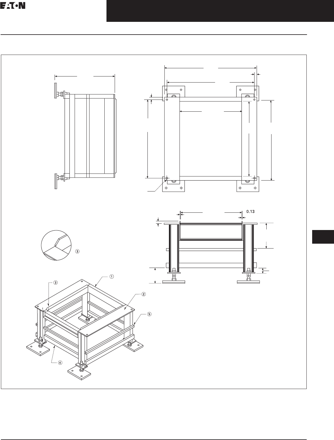
CA08104001E For more information, visit: www.eaton.com/consultants
33.5-19
September 2011
Uninterruptible Power Supplies
Sheet 33
22
23
24
25
26
27
28
29
30
31
32
33
34
35
36
37
38
39
40
41
42
43
Power Distribution Unit
Layouts and Dimensions
115
50–150 kVA PDU
Figure 33.5-15. 50–150 kVA PDU—Floor Stand, 24.00 Inch (609.6) Seismic—Dimensions in Inches (mm)
Notes: Unless otherwise specified.
1. Top front and rear C4 x 5.4#.
2. Angle 6.00 x 4.00 x 0.38 inches thick (152.4 x 101.6 x 9.7).
3. Guide rails 1.50 x 0.13 inches thick (38.1 x 3.3), with 45° chamfers on top corners.
4. Lower support TS 2x1.
5. Middle support 1.00 inch (25.4) square tubing.
24.
00
(
609.6
)
ISO View
NTS
A
Front
Detail A
0.63
(16.0)
24.94
(633.5) ID
0.13
(3.3)
(
3.3
)
37.19
(944.6)
35.31
(896.9)
0.94
(23.9)
31.53
(800.9) 30.19
(766.8)
24.94
(633.5) ID
0.63
(16.0) Thru4X Ø
33.38
(847.9)
0.94
(23.9)
2.
50
(
63.5
)
6
.
00
(
152.4
)
1
0
.2
5
(
260.4
)
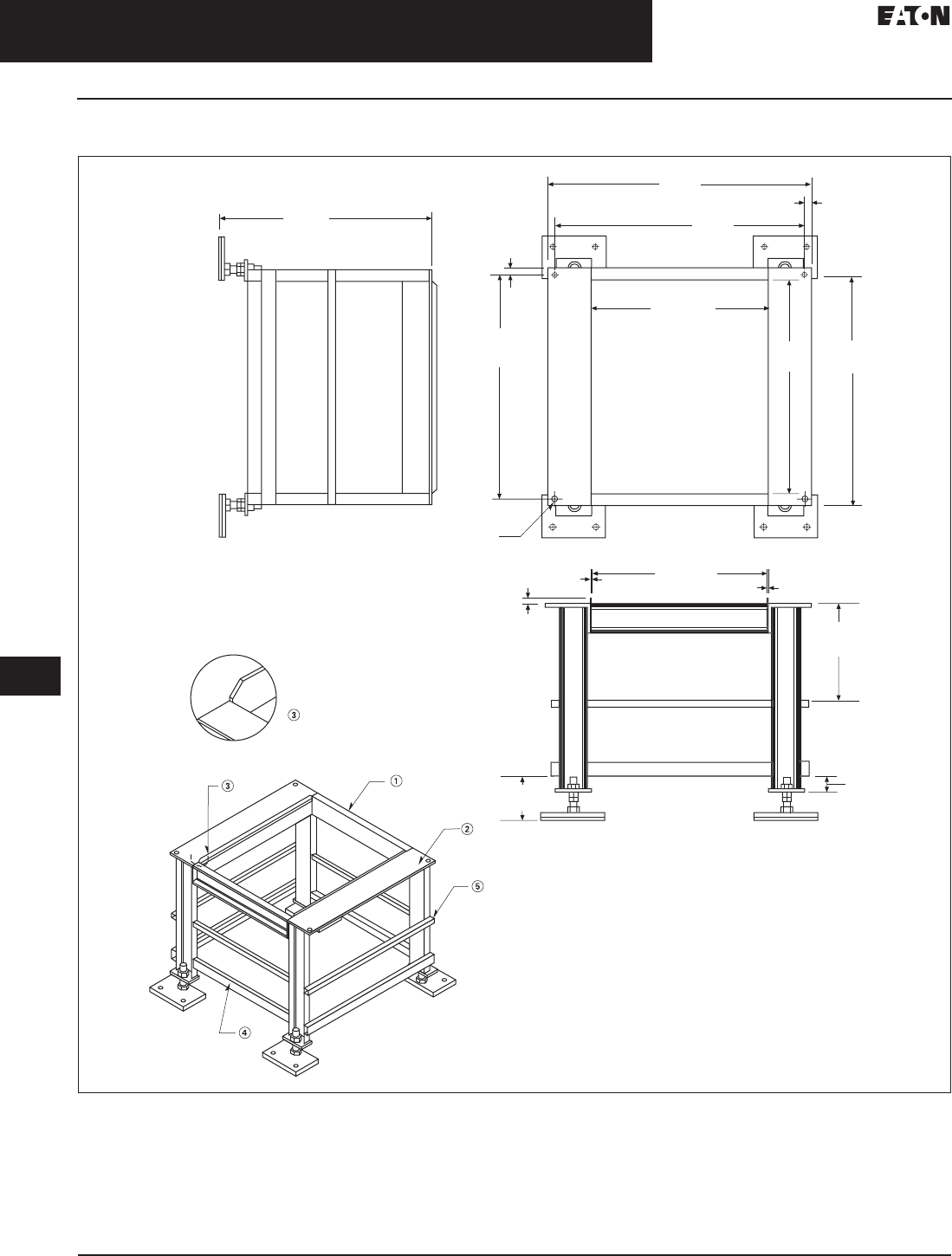
33.5-20
For more information, visit: www.eaton.com/consultants CA08104001E
September 2011
Uninterruptible Power Supplies
Sheet 33
22
23
24
25
26
27
28
29
30
31
32
33
34
35
36
37
38
39
40
41
42
43
Power Distribution Unit
Layouts and Dimensions
116
50–150 kVA PDU
Figure 33.5-16. 50–150 kVA PDU—Floor Stand, 30.00 Inch (762.0) Seismic—Dimensions in Inches (mm)
Notes: Unless otherwise specified.
1. Top front and rear C4 x 5.4#.
2. Angle 6.00 x 4.00 x 0.38 inches thick (152.4 x 101.6 x 9.7).
3. Guide rails 1.50 x 0.13 inches thick (38.1 x 3.3), with 45° chamfers on top corners.
4. Lower support TS 2x1.
5. Middle support 1.00 inch (25.4) square tubing.
30
.
00
(
762.0
)
ISO View
NTS
A
Front
Detail A
0.63
(16.0)
24.94
(633.5) ID
0.13
(3.3)
0
.1
3
(
3.3
)
37.19
(944.6)
35.31
(896.9)
0.94
(23.9)
31.53
(800.9) 30.19
(766.8)
24.94
(633.5) ID
0.63
(16.0) Thru
4X Ø
33.38
(847.9)
0.94
(23.9)
2.
50
(
63.5
)
6
.
00
(
152.4
)
1
3
.
50
(
342.9
)
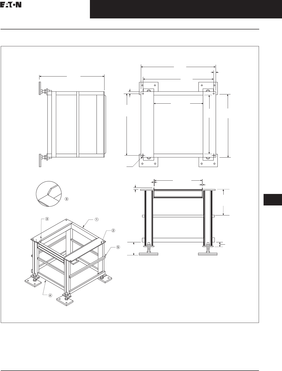
CA08104001E For more information, visit: www.eaton.com/consultants
33.5-21
September 2011
Uninterruptible Power Supplies
Sheet 33
22
23
24
25
26
27
28
29
30
31
32
33
34
35
36
37
38
39
40
41
42
43
Power Distribution Unit
Layouts and Dimensions
117
50–150 kVA PDU
Figure 33.5-17. 50–150 kVA PDU—Floor Stand, 33.00 Inch (838.2) Seismic—Dimensions in Inches (mm)
Notes: Unless otherwise specified.
1. Top front and rear C4 x 5.4#.
2. Angle 6.00 x 4.00 x 0.38 inches thick (152.4 x 101.6 x 9.7).
3. Guide rails 1.50 x 0.13 inches thick (38.1 x 3.3), with 45° chamfers on top corners.
4. Lower support TS 2x1.
5. Middle support 1.00 inch (25.4) square tubing.
33
.
00
(
838.2
)
ISO View
NTS
A
Front
Detail A
0.63
(16.0)
24.94
(633.5) ID
0.13
(3.3)
0.1
3
(
3.3
)
37.19
(944.6)
35.31
(896.9)
0.94
(23.9)
31.53
(800.9) 30.19
(766.8)
24.94
(633.5) ID
0.63
(16.0) Thru
4X Ø
33.38
(847.9)
0.94
(23.9)
2.
50
(
63.5
)
6.0
0
(
152.4
)
1
3
.
00
(
330.2
)
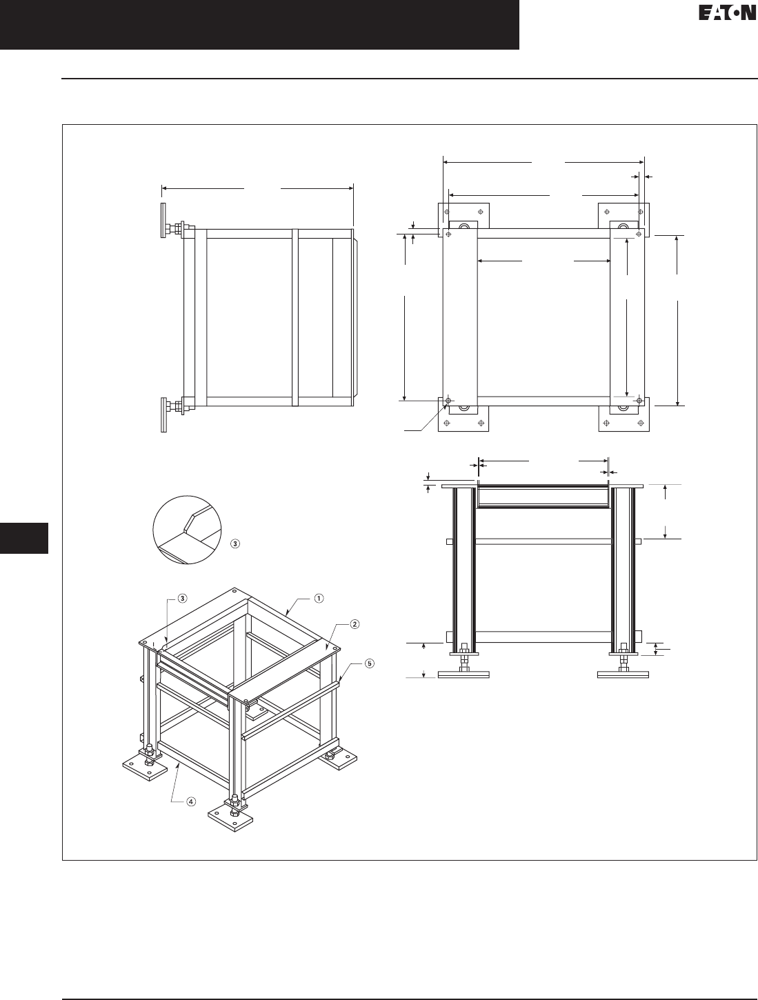
33.5-22
For more information, visit: www.eaton.com/consultants CA08104001E
September 2011
Uninterruptible Power Supplies
Sheet 33
22
23
24
25
26
27
28
29
30
31
32
33
34
35
36
37
38
39
40
41
42
43
Power Distribution Unit
Layouts and Dimensions
118
50–150 kVA PDU
Figure 33.5-18. 50–150 kVA PDU—Floor Stand, 36.00 Inch (914.4) Seismic—Dimensions in Inches (mm)
Notes: Unless otherwise specified.
1. Top front and rear C4 x 5.4#.
2. Angle 6.00 x 4.00 x 0.38 inches thick (152.4 x 101.6 x 9.7).
3. Guide rails 1.50 x 0.13 inches thick (38.1 x 3.3), with 45° chamfers on top corners.
4. Lower support TS 2x1.
5. Middle support 1.00 inch (25.4) square tubing.
36
.
00
(
914.4
)
ISO View
NTS
A
Front
Detail A
0.63
(16.0)
24.94
(633.5) ID
0.13
(3.3)
0
.1
3
(
3.3
)
37.19
(944.6)
35.31
(896.9)
0.94
(23.9)
31.53
(800.9) 30.19
(766.8)
24.94
(633.5) ID
0.63
(16.0) Thru
33.38
(847.9)
0.94
(23.9)
4X Ø
2.
50
(
63.5
)
6
.
00
(
152.4
)
1
0
.2
5
(
260.4
)
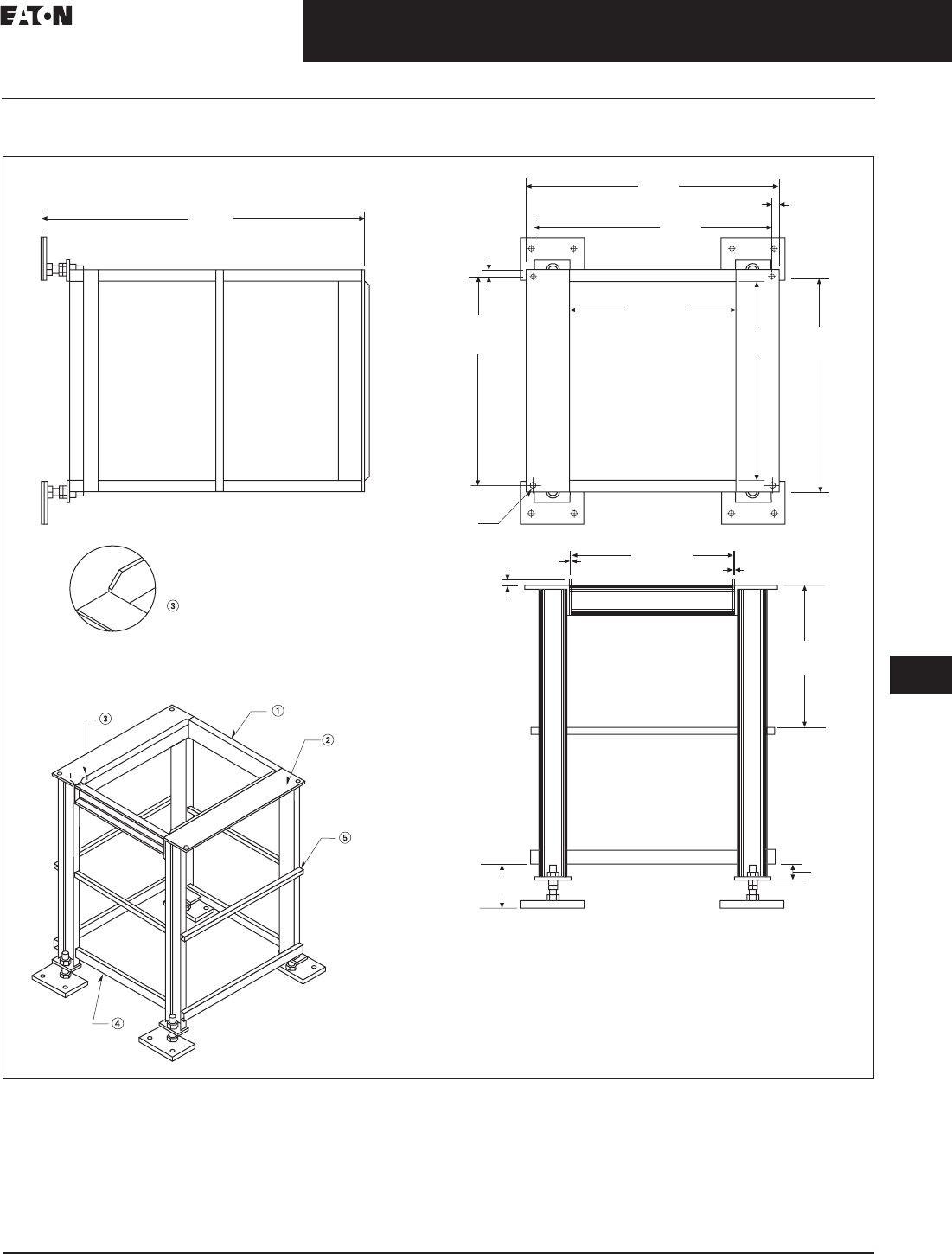
CA08104001E For more information, visit: www.eaton.com/consultants
33.5-23
September 2011
Uninterruptible Power Supplies
Sheet 33
22
23
24
25
26
27
28
29
30
31
32
33
34
35
36
37
38
39
40
41
42
43
Power Distribution Unit
Layouts and Dimensions
119
50–150 kVA PDU
Figure 33.5-19. 50–150 kVA PDU—Floor Stand, 48.00 Inch (1219.2) Seismic—Dimensions in Inches (mm)
Notes: Unless otherwise specified.
1. Top front and rear C4 x 5.4#.
2. Angle 6.00 x 4.00 x 0.38 inches thick (152.4 x 101.6 x 9.7).
3. Guide rails 1.50 x 0.13 inches thick (38.1 x 3.3), with 45° chamfers on top corners.
4. Lower support TS 2x1.
5. Middle support 1.00 inch (25.4) square tubing.
4
8
.
00
(
1219.2
)
ISO View
NTS
A
Front
Detail A
0.63
(16.0)
24.94
(633.5) ID
0.13
(3.3)
0.13
(3.3)
37.19
(944.6)
35.31
(896.9)
0.94
(23.9)
31.53
(800.9) 30.19
(766.8)
24.94
(633.5) ID
0.63
(16.0) Thru
33.38
(847.9)
0.94
(23.9)
4X Ø
2.
50
(
63.5
)
6
.
00
(
152.4
)
21.2
5
(
539.8
)
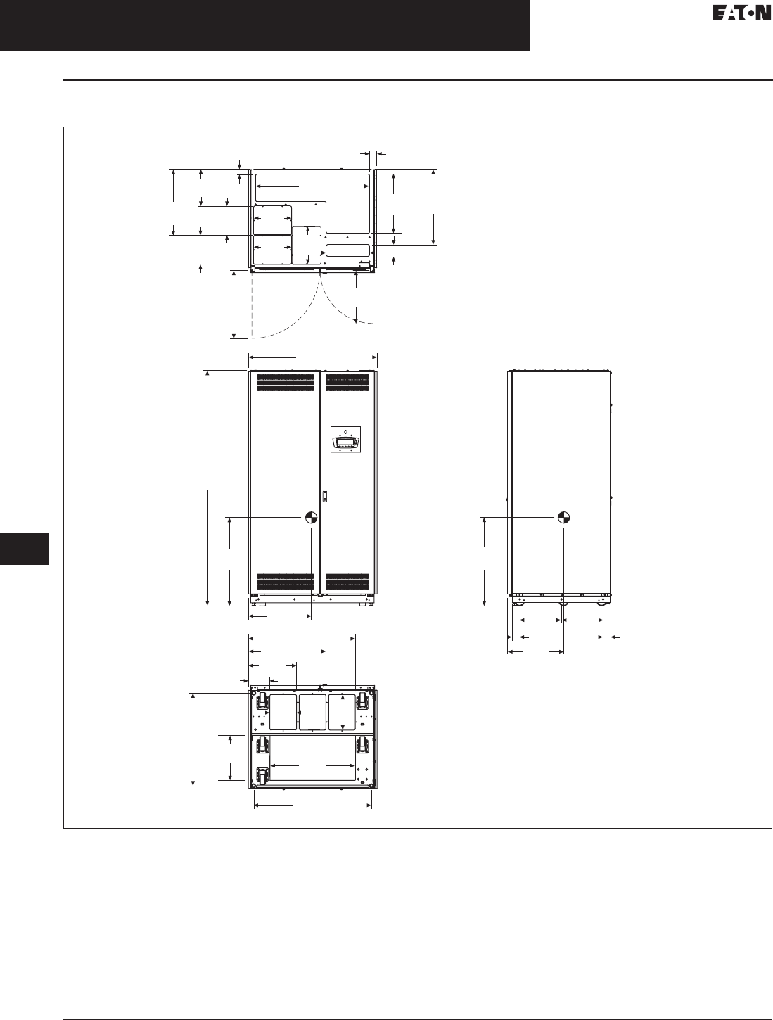
33.5-24
For more information, visit: www.eaton.com/consultants CA08104001E
September 2011
Uninterruptible Power Supplies
Sheet 33
22
23
24
25
26
27
28
29
30
31
32
33
34
35
36
37
38
39
40
41
42
43
Power Distribution Unit
Layouts and Dimensions
120
200–300 kVA PDU
Figure 33.5-20. 200–300 kVA PDU—Main Cabinet—Dimensions in Inches (mm)
Notes:
1. Weight: 3565 lbs (1617 kg) for 300 kVA transformer different configurations may have different weight.
2. The system must be installed on a level floor suitable for computer or electronic equipment.
3. The system must be installed in a temperature and humidity controlled indoor area free of conductive contaminants.
4. Ambient temperature range: 32°–104°F (0°–40°C), recommended operating range: 68°–77°F (20°–25°C) maximum relative humidity
95% noncondensing.
5. Minimum 18.00-inch (457.2 mm) clearance in front and minimum 4.00-inch (101.6 mm) in rear of the cabinet are required for cooling air
intake servicing space for rear access is 24.00 inches (609.6 mm).
6. Top and bottom cable entries through removable access plates are standard for all configurations. Access plates shall be custom-modified
to suit conduit sizes.
7. All wiring is to be in accordance with national and local electric codes.
8. Center of gravity location shown for 300 kVA transformer.
9. Specifications are subject to change.
9.06
(230.0)
12.91
(328.0) Top View
2.44
(62.0)
25.59
(650.0)
23.07
(586.0)
18.07
(459.0)
12.44
(316.0)
9.84
(250.0)
22.44
(570.0)
1.65
(42.0)
38.74
(984.0) 20.08
(510.0)
12.91
(328.0)
9.84
(250.0)
12.91
(328.0)
3.94
(100.0)
14.72 (374.0)
Front View
43.74
(1111.0)
80.08
(2034.0)
30.04
(763.0)
21.38
(543.0)
Bottom View
Side View
36.34 (923.0)
26.34 (669.0)
16.34
(415.0)
7.28
(185.0)
31.54
(801.0)
40.04
(1017.0)
12.13
(308.0)
15.28
(388.0) 28.98
(736.0)
2.52
(64.0)
2.52
(64.0)
30.04
(763.0)
19.13
(486.0)
14.21
(361.0)
14.21
(361.0)
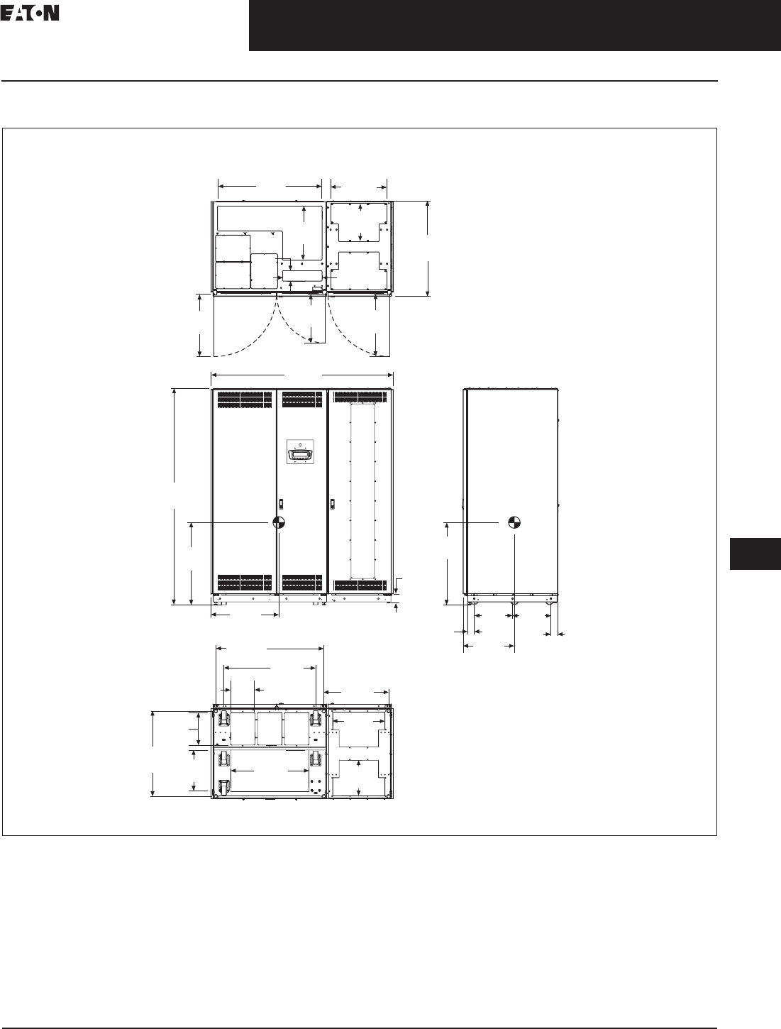
CA08104001E For more information, visit: www.eaton.com/consultants
33.5-25
September 2011
Uninterruptible Power Supplies
Sheet 33
22
23
24
25
26
27
28
29
30
31
32
33
34
35
36
37
38
39
40
41
42
43
Power Distribution Unit
Layouts and Dimensions
121
200–300 kVA PDU
Figure 33.5-21. 200–300 kVA PDU—Main Cabinet—Front Facing Sidecar—Dimensions in Inches (mm)
Notes:
1. Weight: 3842 lbs (1742 kg) for 300 kVA transformer different configurations may have different weight.
2. The system must be installed on a level floor suitable for computer or electronic equipment.
3. The system must be installed in a temperature and humidity controlled indoor area free of conductive contaminants.
4. Ambient temperature range: 32°–104°F (0°–40°C), recommended operating range: 68°–77°F (20°–25°C) maximum relative humidity
95% noncondensing.
5. Minimum 18.00-inch (457.2 mm) clearance in front and minimum 4.00-inch (101.6 mm) in rear of the cabinet are required for cooling air
intake servicing space for rear access is 24.00 inches (609.6 mm).
6. Top and bottom cable entries through removable access plates are standard for all configurations. Access plates shall be custom-modified
to suit conduit sizes.
7. All wiring is to be in accordance with national and local electric codes.
8. Center of gravity location shown for 300 kVA transformer.
9. Specifications are subject to change.
38.70
(983.0)
20.10
(510.5)
3.90
(99.1) 14.70
(373.4)
20.60
(523.2)
14.00
(355.6)
35.30
(896.6)
23.10
(586.7)
18.10
(459.7)
23.10
(586.7)
67.60
(1717.0)
Front
Top
View
View
80.10
(2034.5)
30.40
(772.2)
25.20
(640.1)
3.40
(86.4)
30.40
(772.2)
2.50
(63.5)
14.20
(360.7)
19.00
(482.6)
14.20
(360.7)
2.50
(63.5)
Side
View
Bottom
View
40.00
(1016.0) 34.00
(863.6)
24.00
(609.6)
19.30
(490.2)
9.10
(231.1)
12.10
(307.3)
31.50
(800.1) 29.00
(736.6)
15.30
(388.6) 13.10
(332.7)
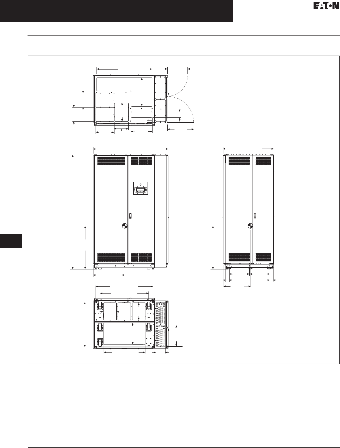
33.5-26
For more information, visit: www.eaton.com/consultants CA08104001E
September 2011
Uninterruptible Power Supplies
Sheet 33
22
23
24
25
26
27
28
29
30
31
32
33
34
35
36
37
38
39
40
41
42
43
Power Distribution Unit
Layouts and Dimensions
122
200–300 kVA PDU
Figure 33.5-22. 200–300 kVA PDU—Main Cabinet—Side Facing Sidecar—Dimensions in Inches (mm)
Notes:
1. Weight: 3816 lbs (1731 kg) for 300 kVA transformer different configurations may have different weight.
2. The system must be installed on a level floor suitable for computer or electronic equipment.
3. The system must be installed in a temperature and humidity controlled indoor area free of conductive contaminants.
4. Ambient temperature range: 32°–104°F (0°–40°C), recommended operating range: 68°–77°F (20°–25°C) maximum relative humidity
95% noncondensing.
5. Minimum 18.00-inch (457.2 mm) clearance in front and minimum 4.00-inch (101.6 mm) in rear of the cabinet are required for cooling air
intake servicing space for rear access is 24.00 inches (609.6 mm).
6. Top and bottom cable entries through removable access plates are standard for all configurations. Access plates shall be custom-modified
to suit conduit sizes.
7. All wiring is to be in accordance with national and local electric codes.
8. Center of gravity location shown for 300 kVA transformer.
9. Specifications are subject to change.
12.13
(308.0)
12.91
(328.0)
14.72
(374.0)
18.31
(465.0)
14.06
(357.0)
14.21
(361.0)
Top View
31.54
(801.0)
14.76
(375.0)
Front View
Bottom View
Side View
6.54 (166.0)
40.04 (1017.0)
33.98 (863.0)
15.28
(388.0)
9.06
(230.0)
22.17
(563.0)
30.31
(770.0)
30.31
(770.0)
80.08
(2034.0)
52.40 (1331.0) 35.28 (896.0)
14.21
(361.0)
2.52
(64.0)
2.52
(64.0)
19.13
(486.0)
9.84
(250.0)
20.08
(510.0)
38.74
(984.0)
9.84
(250.0)
9.84
(250.0) 3.94 (100.0)
12.91
(328.0)
28.98 (736.0)
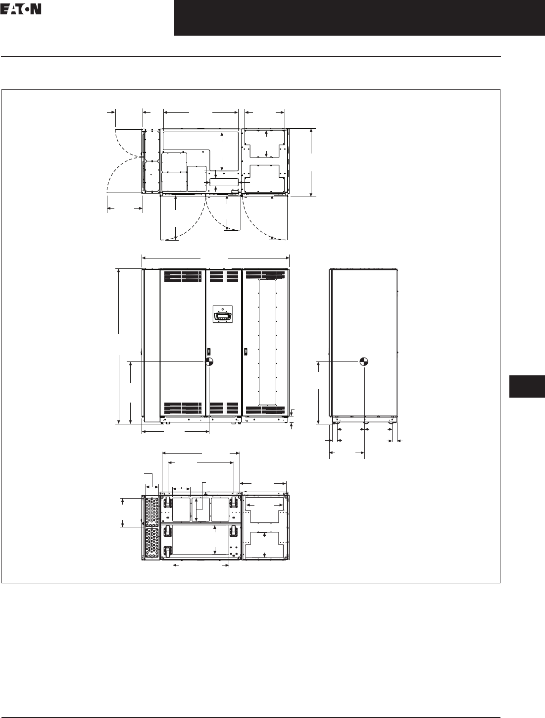
CA08104001E For more information, visit: www.eaton.com/consultants
33.5-27
September 2011
Uninterruptible Power Supplies
Sheet 33
22
23
24
25
26
27
28
29
30
31
32
33
34
35
36
37
38
39
40
41
42
43
Power Distribution Unit
Layouts and Dimensions
123
200–300 kVA PDU
Figure 33.5-23. 200–300 kVA PDU—Main Cabinet—Front and Side Facing Sidecars—Dimensions in Inches (mm)
Notes:
1. Weight: 4091 lbs (1856 kg) for 300 kVA transformer different configurations may have different weight.
2. The system must be installed on a level floor suitable for computer or electronic equipment.
3. The system must be installed in a temperature and humidity controlled indoor area free of conductive contaminants.
4. Ambient temperature range: 32°–104°F (0°–40°C), recommended operating range: 68°–77°F (20°–25°C) maximum relative humidity
95% noncondensing.
5. Minimum 18.00-inch (457.2 mm) clearance in front and minimum 4.00-inch (101.6 mm) in rear of the cabinet are required for cooling air
intake servicing space for rear access is 24.00 inches (609.6 mm).
6. Top and bottom cable entries through removable access plates are standard for all configurations. Access plates shall be custom-modified
to suit conduit sizes.
7. All wiring is to be in accordance with national and local electric codes.
8. Center of gravity location shown for 300 kVA transformer.
9. Specifications are subject to change.
14.00
(355.6)
18.30
(464.8) 23.10
(586.7)
18.10
(459.7) 23.10
(586.7)
35.30
(896.6)
38.70
(983.0)
20.10
(510.5)
3.90
(99.1) 14.70
(373.4)
20.60
(523.2)
14.00
(355.6)
76.20
(1935.5)
80.10
(2034.5)
Front
View
Side
View
32.10
(815.3)
34.80
(883.9)
3.40
(86.4)
2.50
(63.5) 18.10
(459.7)
14.20
(360.7)
14.20
(360.7) 2.50
(63.5)
32.10
(815.3)
14.80
(375.9)
6.50
(165.1)
40.00
(1016.0)
34.00
(863.6)
24.00
(609.6)
19.30
(490.2)
13.10
(332.7)
15.30
(388.6)
9.10
(231.1) 12.10
(307.3)
Top
View
Bottom
View
29.00 (736.6)
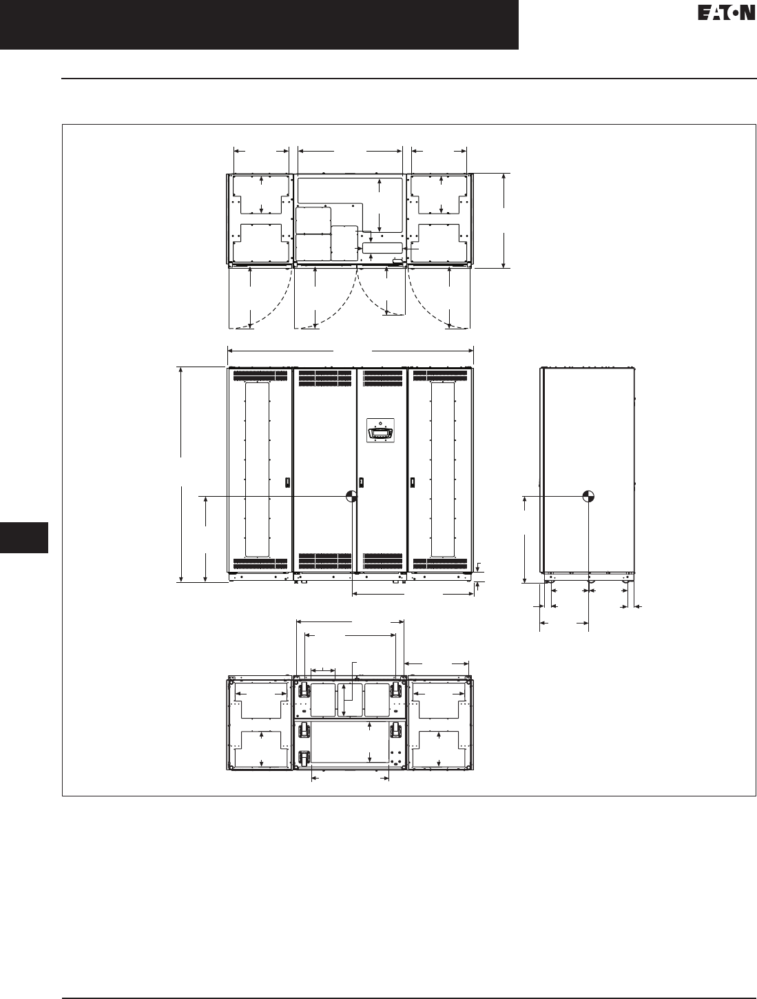
33.5-28
For more information, visit: www.eaton.com/consultants CA08104001E
September 2011
Uninterruptible Power Supplies
Sheet 33
22
23
24
25
26
27
28
29
30
31
32
33
34
35
36
37
38
39
40
41
42
43
Power Distribution Unit
Layouts and Dimensions
124
200–300 kVA PDU
Figure 33.5-24. 200–300 kVA PDU—Main Cabinet—Two Front Facing Sidecars—Dimensions in Inches (mm)
Notes:
1. Weight: 4116 lbs (1867 kg) for 300 kVA transformer different configurations may have different weight.
2. The system must be installed on a level floor suitable for computer or electronic equipment.
3. The system must be installed in a temperature and humidity controlled indoor area free of conductive contaminants.
4. Ambient temperature range: 32°–104°F (0°–40°C), recommended operating range: 68°–77°F (20°–25°C) maximum relative humidity
95% noncondensing.
5. Minimum 18.00-inch (457.2 mm) clearance in front and minimum 4.00-inch (101.6 mm) in rear of the cabinet are required for cooling air
intake servicing space for rear access is 24.00 inches (609.6 mm).
6. Top and bottom cable entries through removable access plates are standard for all configurations. Access plates shall be custom-modified
to suit conduit sizes.
7. All wiring is to be in accordance with national and local electric codes.
8. Center of gravity location shown for 300 kVA transformer.
9. Specifications are subject to change.
23.10
(586.7)
23.10
(586.7)
18.10
(459.7) 23.10
(586.7)
38.70
(983.0)
20.10
(510.5)
3.90
(99.1) 14.70
(373.4)
20.60
(523.2)
20.60
(523.2)
14.00
(355.6)
14.00
(355.6)
35.30
(896.6)
91.60
(2326.6)
79.60
(2021.8)
31.60
(802.6)
44.60
(1132.8)
3.40
(86.4)
2.50
(63.5) 18.70
(475.0)
14.20
(360.7)
14.20
(360.7) 2.50
(63.5)
24.00
(609.6)
19.30
(490.2)
19.30
(490.2)
13.10
(332.7)
15.30
(388.6)
31.60
(802.6)
Front
View
Side
View
Top
View
Bottom
View
29.00 (736.6)
13.10
(332.7)
40.00
(1016.0)
34.00
(863.6)
9.10
(231.1) 12.10
(307.3)
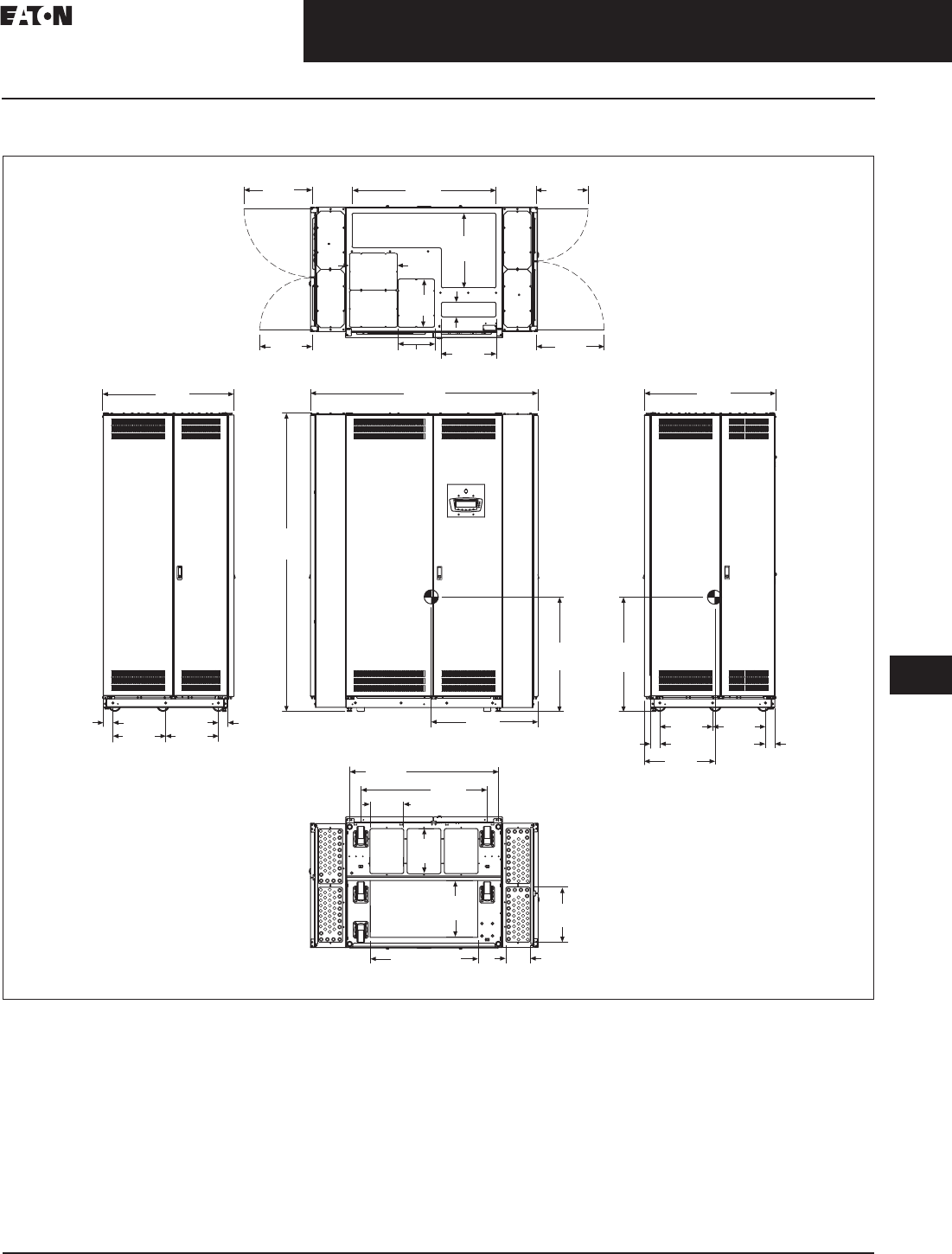
CA08104001E For more information, visit: www.eaton.com/consultants
33.5-29
September 2011
Uninterruptible Power Supplies
Sheet 33
22
23
24
25
26
27
28
29
30
31
32
33
34
35
36
37
38
39
40
41
42
43
Power Distribution Unit
Layouts and Dimensions
125
200–300 kVA PDU
Figure 33.5-25. 200–300 kVA PDU—Main Cabinet—Two Side Facing Sidecars—Dimensions in Inches (mm)
Notes:
1. Weight: 4067 lbs (1845 kg) for 300 kVA transformer different configurations may have different weight.
2. The system must be installed on a level floor suitable for computer or electronic equipment.
3. The system must be installed in a temperature and humidity controlled indoor area free of conductive contaminants.
4. Ambient temperature range: 32°–104°F (0°–40°C), recommended operating range: 68°–77°F (20°–25°C) maximum relative humidity
95% noncondensing.
5. Minimum 18.00-inch (457.2 mm) clearance in front and minimum 4.00-inch (101.6 mm) in rear of the cabinet are required for cooling air
intake servicing space for rear access is 24.00 inches (609.6 mm).
6. Top and bottom cable entries through removable access plates are standard for all configurations. Access plates shall be custom-modified
to suit conduit sizes.
7. All wiring is to be in accordance with national and local electric codes.
8. Center of gravity location shown for 300 kVA transformer.
9. Specifications are subject to change.
9.06
(230.0)
12.91
(328.0)
Top View
14.06
(357.0)
18.31
(465.0) 14.06
(357.0)
18.31
(465.0)
38.74
(984.0)
20.08
(510.0)
12.91
(328.0)
9.84
(250.0)
14.72
(374.0)
Bottom View
14.76
(375.0)
6.54
(166.0)
33.98
(863.0)
40.04
(1017.0)
12.13
(308.0)
15.28
(388.0)
Side View
Front View
2.52
(64.0)
2.52
(64.0)
14.21
(361.0)
14.21
(361.0)
35.28
(896.0)
28.66
(728.0)
30.71
(780.0)
30.71
(780.0)
80.16
(2036.0)
61.14
(1553.0) 35.28
(896.0)
Side View
2.52
(64.0)
2.52
(64.0)
14.21
(361.0)
14.21
(361.0)
18.98
(482.0)
28.98 (736.0)
3.94 (100.0)

33.5-30
For more information, visit: www.eaton.com/consultants CA08104001E
September 2011
Uninterruptible Power Supplies
Sheet 33
22
23
24
25
26
27
28
29
30
31
32
33
34
35
36
37
38
39
40
41
42
43
Power Distribution Unit
Layouts and Dimensions
126
200–300 kVA PDU
Figure 33.5-26. 200–300 kVA PDU—Floor Stand, 9.00 Inch (228.6) Non-Seismic—Dimensions in Inches (mm)
Notes: Unless otherwise specified.
1. Top front and rear C4 x 5.4#.
2. Angle 6.00 x 4.00 x 0.38 inches thick (152.4 x 101.6 x 9.7).
3. Guide rails 1.50 x 0.13 inches thick (38.1 x 3.3), with 45° chamfers on top corners.
Front
9.00
(228.6)
2.00
(50.8)
±40.03
(1016.9)
0.94
(23.9)
0.94
(23.9)
33.38
(847.9)
31.53
(800.9)
30.19
(766.8)
0.63
(16.0)Thru
4X Ø
0.63
(16.0)
0.13
(3.3)
0.13
(3.3)
41.88
(1063.8)
ID
29.63
(752.6)
ID
29.63
(752.6)
ISO View
NTS
Detail A
A
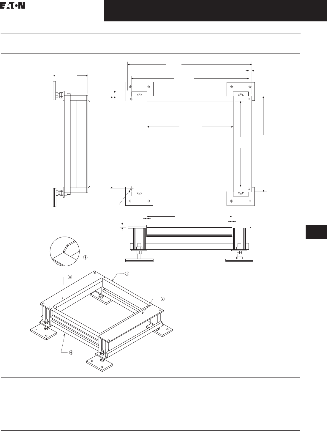
CA08104001E For more information, visit: www.eaton.com/consultants
33.5-31
September 2011
Uninterruptible Power Supplies
Sheet 33
22
23
24
25
26
27
28
29
30
31
32
33
34
35
36
37
38
39
40
41
42
43
Power Distribution Unit
Layouts and Dimensions
127
200–300 kVA PDU
Figure 33.5-27. 200–300 kVA PDU—Floor Stand, 12.00 Inch (304.8) Seismic—Dimensions in Inches (mm)
Notes: Unless otherwise specified.
1. Top front and rear C4 x 5.4#.
2. Angle 6.00 x 4.00 x 0.38 inches thick (152.4 x 101.6 x 9.7).
3. Guide rails 1.50 x 0.13 inches thick (38.1 x 3.3), with 45° chamfers on top corners.
4. Lower support TS 2x1.
Front
12.00
(304.8)
0.94
(23.9)
0.94
(23.9)
33.38
(847.9)
31.53
(800.9) 30.19
(766.8)
ID
Detail A
0.63
(16.0)
0.13
(3.3)
0.13
(3.3)
41.88
(1063.8)
29.63
(752.6)
ID
29.63
(752.6)
40.03
(1016.9)
ISO View
NTS
A
0.63
(16.0) Thru
4X Ø

33.5-32
For more information, visit: www.eaton.com/consultants CA08104001E
September 2011
Uninterruptible Power Supplies
Sheet 33
22
23
24
25
26
27
28
29
30
31
32
33
34
35
36
37
38
39
40
41
42
43
Power Distribution Unit
Layouts and Dimensions
128
200–300 kVA PDU
Figure 33.5-28. 200–300 kVA PDU—Floor Stand, 12.00 Inch (304.8) Non-Seismic—Dimensions in Inches (mm)
Notes: Unless otherwise specified.
1. Top front and rear C4 x 5.4#.
2. Angle 6.00 x 4.00 x 0.38 inches thick (152.4 x 101.6 x 9.7).
3. Guide rails 1.50 x 0.13 inches thick (38.1 x 3.3), with 45° chamfers on top corners.
4. Lower support TS 2x1.
Front
4X Ø
Detail A
0.63
(16.0)
0.13
(3.3) 0.13
(3.3)
41.88
(1063.8)
40.03
(1016.8)
0.94
(23.9)
0.94
(23.9)
33.38
(847.9)
31.53
(800.9)
30.19
(766.8)
29.63
(752.6) ID
0.63
(16.0) Thru
A
29.63
(752.6) ID
12.00
(304.8)
2.00
(50.8)
±
ISO View
NTS

CA08104001E For more information, visit: www.eaton.com/consultants
33.5-33
September 2011
Uninterruptible Power Supplies
Sheet 33
22
23
24
25
26
27
28
29
30
31
32
33
34
35
36
37
38
39
40
41
42
43
Power Distribution Unit
Layouts and Dimensions
129
200–300 kVA PDU
Figure 33.5-29. 200–300 kVA PDU—Floor Stand, 15.00 Inch (381.0) Seismic—Dimensions in Inches (mm)
Notes: Unless otherwise specified.
1. Top front and rear C4 x 5.4#.
2. Angle 6.00 x 4.00 x 0.38 inches thick (152.4 x 101.6 x 9.7).
3. Guide rails 1.50 x 0.13 inches thick (38.1 x 3.3), with 45° chamfers on top corners.
4. Lower support TS 2x1.
1
5
.
00
(
381.0
)
ISO View
NTS
A
Front
Detail A
0.63
(
16.0
)
29.63
(752.6) ID
0.13
(3.3)
0.13
(3.3)
41.88
(1063.8)
40.03
(1016.8)
0.94
(23.9)
31.53
(800.9) 30.19
(766.8)
29.63
(752.6) ID
0.63
(16.0) Thru4X Ø
33.38
(847.9)
0.94
(23.9)
2.
50
(
63.5
)
6
.
00
(
152.4
)
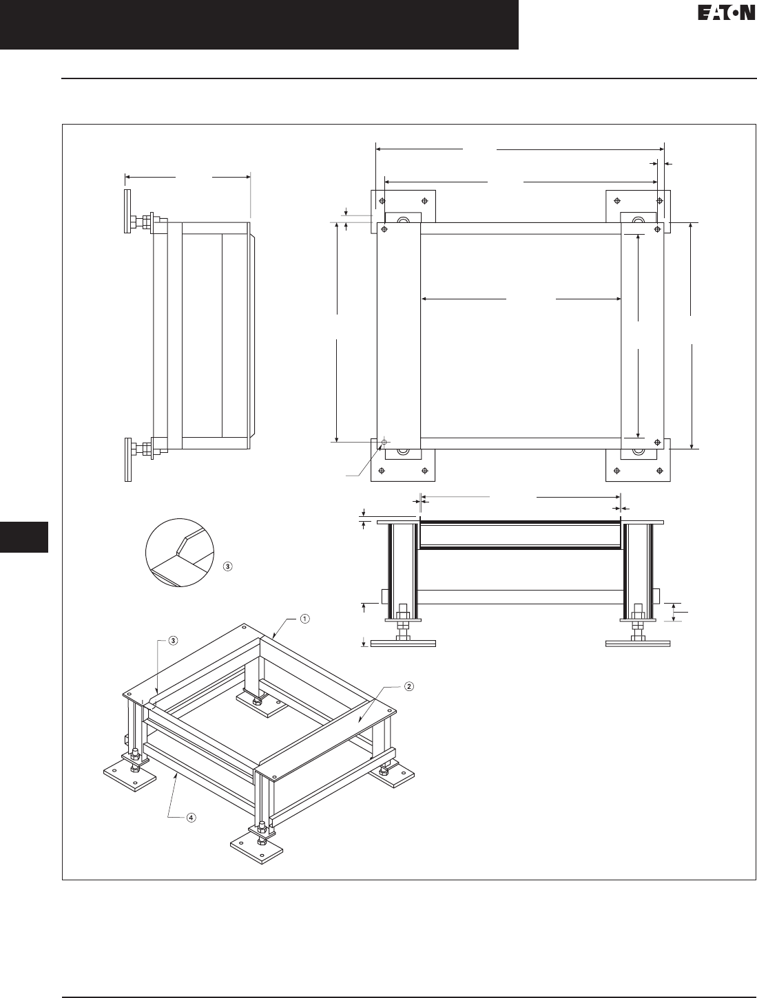
33.5-34
For more information, visit: www.eaton.com/consultants CA08104001E
September 2011
Uninterruptible Power Supplies
Sheet 33
22
23
24
25
26
27
28
29
30
31
32
33
34
35
36
37
38
39
40
41
42
43
Power Distribution Unit
Layouts and Dimensions
130
200–300 kVA PDU
Figure 33.5-30. 200–300 kVA PDU—Floor Stand, 18.00 Inch (457.2) Seismic—Dimensions in Inches (mm)
Notes: Unless otherwise specified.
1. Top front and rear C4 x 5.4#.
2. Angle 6.00 x 4.00 x 0.38 inches thick (152.4 x 101.6 x 9.7).
3. Guide rails 1.50 x 0.13 inches thick (38.1 x 3.3), with 45° chamfers on top corners.
4. Lower support TS 2x1.
1
8
.
00
(
457.2
)
ISO View
NTS
A
Front
Detail A
0.63
(16.0)
29.63
(752.6) ID
0.13
(3.3)
0.13
(3.3)
0.94
(23.9)
31.53
(800.9) 30.19
(766.8)
29.63
(752.6) ID
0.63
(16.0) Thru4X Ø
33.38
(847.9)
0.94
(23.9)
41.88
(1063.8)
40.03
(1016.8)
2.
50
(
63.5
)
6
.
00
(
152.4
)
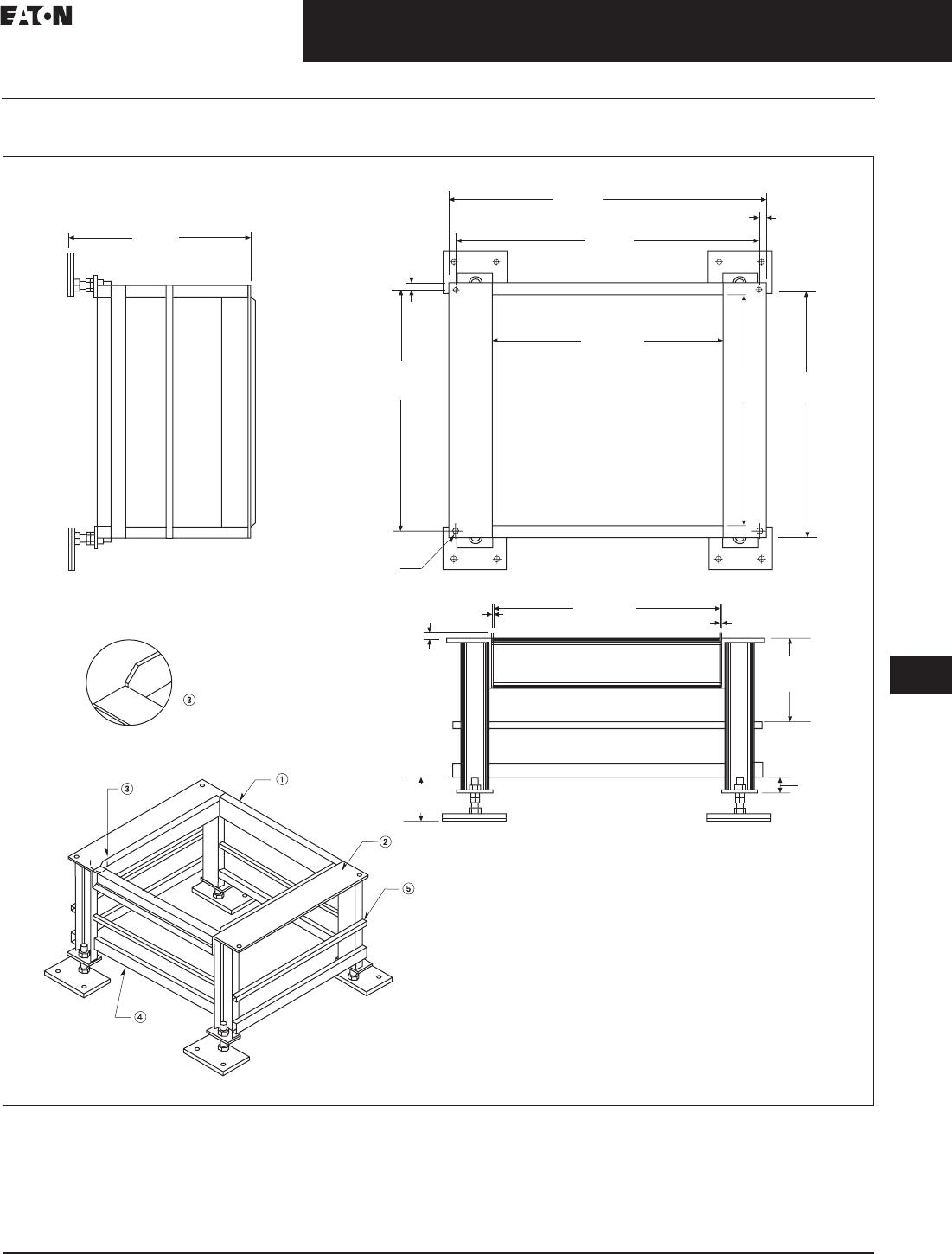
CA08104001E For more information, visit: www.eaton.com/consultants
33.5-35
September 2011
Uninterruptible Power Supplies
Sheet 33
22
23
24
25
26
27
28
29
30
31
32
33
34
35
36
37
38
39
40
41
42
43
Power Distribution Unit
Layouts and Dimensions
131
200–300 kVA PDU
Figure 33.5-31. 200–300 kVA PDU—Floor Stand, 24.00 Inch (609.6) Seismic—Dimensions in Inches (mm)
Notes: Unless otherwise specified.
1. Top front and rear C4 x 5.4#.
2. Angle 6.00 x 4.00 x 0.38 inches thick (152.4 x 101.6 x 9.7).
3. Guide rails 1.50 x 0.13 inches thick (38.1 x 3.3), with 45° chamfers on top corners.
4. Lower support TS 2x1.
5. Middle support 1.00 inch (25.4) square tubing.
24.
00
(
609.6
)
ISO View
NTS
A
Front
Detail A
0.63
(16.0)
29.63
(752.6) ID
0.13
(3.3)
0
.1
3
(
3.3
)
0.94
(23.9)
31.53
(800.9) 30.19
(766.8)
29.63
(752.6) ID
0.63
(16.0) Thru4X Ø
33.38
(847.9)
0.94
(23.9)
41.88
(1063.8)
40.03
(1016.8)
2.
50
(
63.5
)
6
.
00
(
152.4
)
1
0
.2
5
(
260.4
)
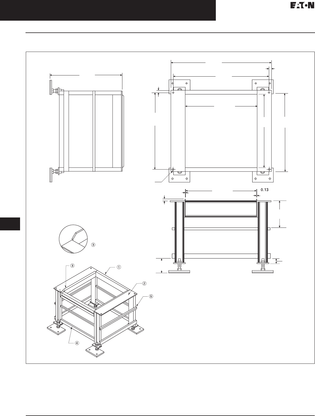
33.5-36
For more information, visit: www.eaton.com/consultants CA08104001E
September 2011
Uninterruptible Power Supplies
Sheet 33
22
23
24
25
26
27
28
29
30
31
32
33
34
35
36
37
38
39
40
41
42
43
Power Distribution Unit
Layouts and Dimensions
132
200–300 kVA PDU
Figure 33.5-32. 200–300 kVA PDU—Floor Stand, 30.00 Inch (762.0) Seismic—Dimensions in Inches (mm)
Notes: Unless otherwise specified.
1. Top front and rear C4 x 5.4#.
2. Angle 6.00 x 4.00 x 0.38 inches thick (152.4 x 101.6 x 9.7).
3. Guide rails 1.50 x 0.13 inches thick (38.1 x 3.3), with 45° chamfers on top corners.
4. Lower support TS 2x1.
5. Middle support 1.00 inch (25.4) square tubing.
30
.
00
(
762.0
)
ISO View
NTS
A
Front
Detail A
0.63
(16.0)
29.63
(752.6) ID
0.13
(3.3)
(
3.3
)
0.94
(23.9)
31.53
(800.9) 30.19
(766.8)
29.63
(752.6) ID
0.63
(16.0) Thru4X Ø
33.38
(847.9)
0.94
(23.9)
41.88
(1063.8)
40.03
(1016.8)
2.
50
(
63.5
)
6
.
00
(
152.4
)
11.2
5
(
285.8
)
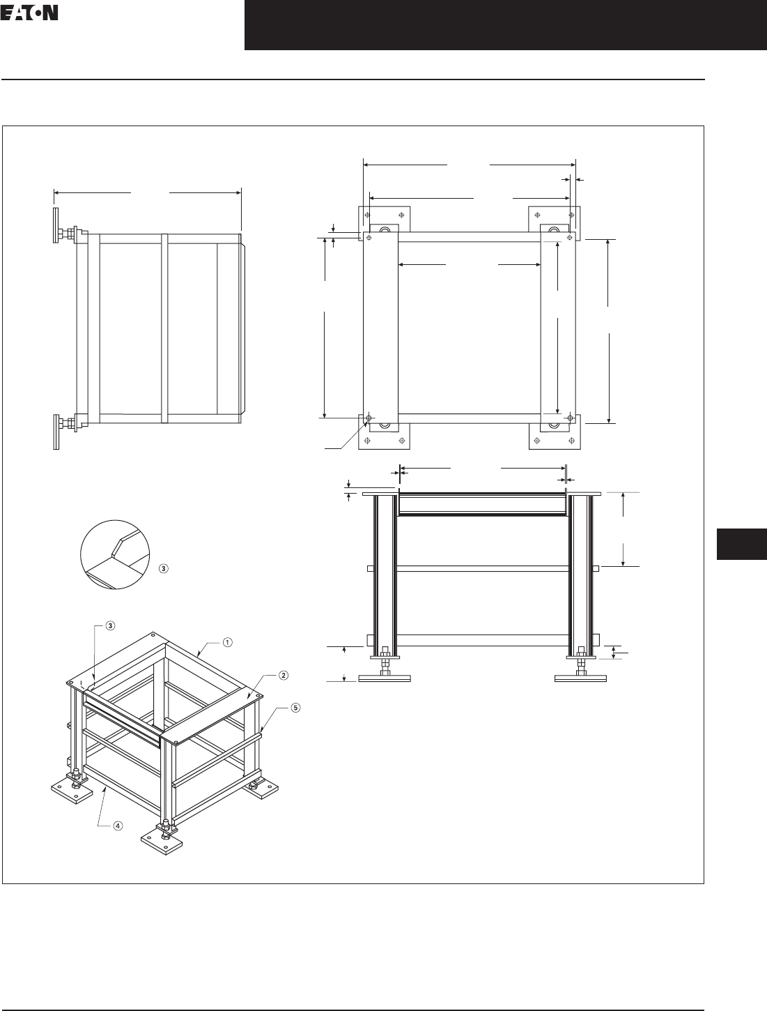
CA08104001E For more information, visit: www.eaton.com/consultants
33.5-37
September 2011
Uninterruptible Power Supplies
Sheet 33
22
23
24
25
26
27
28
29
30
31
32
33
34
35
36
37
38
39
40
41
42
43
Power Distribution Unit
Layouts and Dimensions
133
200–300 kVA PDU
Figure 33.5-33. 200–300 kVA PDU—Floor Stand, 33.00 Inch (838.2) Non-Seismic—Dimensions in Inches (mm)
Notes: Unless otherwise specified.
1. Top front and rear C4 x 5.4#.
2. Angle 6.00 x 4.00 x 0.38 inches thick (152.4 x 101.6 x 9.7).
3. Guide rails 1.50 x 0.13 inches thick (38.1 x 3.3), with 45° chamfers on top corners.
4. Lower support TS 2x1.
5. Middle support 1.00 inch (25.4) square tubing.
33
.
00
(
838.2
)
ISO View
NTS
AFront
Detail A
0.63
(16.0)
0.13
(3.3)
0
.1
3
(
3.3
)
0.94
(23.9)
31.53
(800.9) 30.19
(766.8)
0.63
(16.0) Thru
4X Ø
33.38
(847.9)
0.94
(23.9)
29.63
(752.6) ID
29.63
(752.6) ID
41.88
(1063.8)
40.03
(1016.8)
2.
50
(
63.5
)
6
.
00
(
152.4
)
1
3
.
00
(
330.2
)
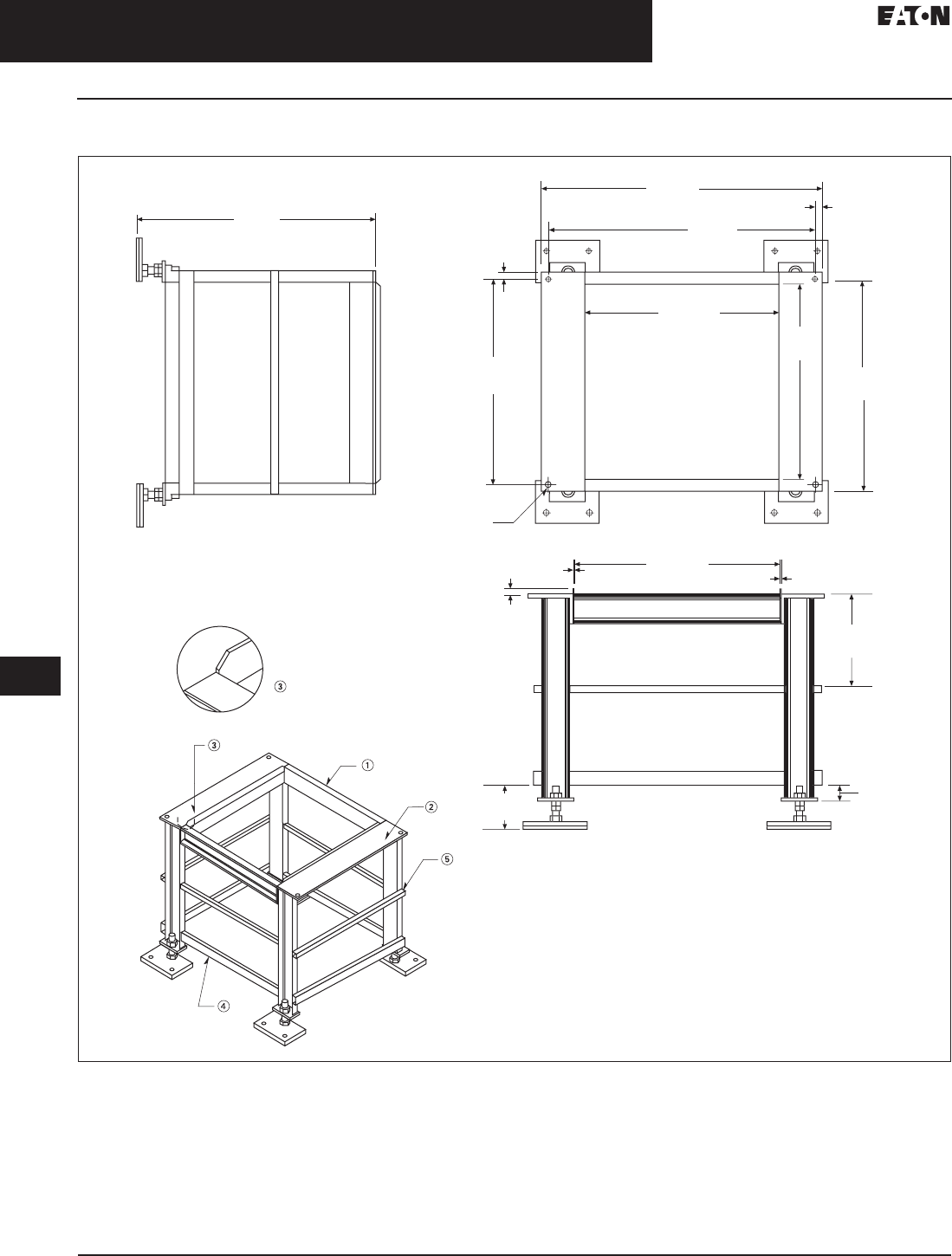
33.5-38
For more information, visit: www.eaton.com/consultants CA08104001E
September 2011
Uninterruptible Power Supplies
Sheet 33
22
23
24
25
26
27
28
29
30
31
32
33
34
35
36
37
38
39
40
41
42
43
Power Distribution Unit
Layouts and Dimensions
134
200–300 kVA PDU
Figure 33.5-34. 200–300 kVA PDU—Floor Stand, 36.00 Inch (914.4) Seismic—Dimensions in Inches (mm)
Notes: Unless otherwise specified.
1. Top front and rear C4 x 5.4#.
2. Angle 6.00 x 4.00 x 0.38 inches thick (152.4 x 101.6 x 9.7).
3. Guide rails 1.50 x 0.13 inches thick (38.1 x 3.3), with 45° chamfers on top corners.
4. Lower support TS 2x1.
5. Middle support 1.00 inch (25.4) square tubing.
36
.
00
(
914.4
)
ISO View
NTS
A
Front
Detail A
0.63
(16.0)
0.13
(3.3)
0
.1
3
(
3.3
)
0.94
(23.9)
31.53
(800.9)
30.19
(766.8)
0.63
(16.0) Thru
4X Ø
33.38
(847.9)
0.94
(23.9)
29.63
(752.6) ID
29.63
(752.6) ID
41.88
(1063.8)
40.03
(1016.8)
2.
50
(
63.5
)
6
.
00
(
152.4
)
1
5
.2
5
(
387.4
)

CA08104001E For more information, visit: www.eaton.com/consultants
33.5-39
September 2011
Uninterruptible Power Supplies
Sheet 33
22
23
24
25
26
27
28
29
30
31
32
33
34
35
36
37
38
39
40
41
42
43
Power Distribution Unit
Layouts and Dimensions
135
200–300 kVA PDU
Figure 33.5-35. 200–300 kVA PDU—Floor Stand, 48.00 Inch (1219.2) Seismic—Dimensions in Inches (mm)
Notes: Unless otherwise specified.
1. Top front and rear C4 x 5.4#.
2. Angle 6.00 x 4.00 x 0.38 inches thick (152.4 x 101.6 x 9.7).
3. Guide rails 1.50 x 0.13 inches thick (38.1 x 3.3), with 45° chamfers on top corners.
4. Lower support TS 2x1.
5. Middle support 1.00 inch (25.4) square tubing.
4
8
.
00
(
1219.2
)
ISO View
NTS
A
Front
Detail A
0.63
(16.0)
0.13
(3.3)
0.13
(3.3)
0.94
(23.9)
31.53
(800.9)
30.19
(766.8)
0.63
(16.0) Thru
4X Ø
33.38
(847.9)
0.94
(23.9)
29.63
(752.6) ID
29.63
(752.6) ID
41.88
(1063.8)
40.03
(1016.8)
2.
50
(
63.5
)
6
.
00
(
152.4
)
21.2
5
(
539.8
)
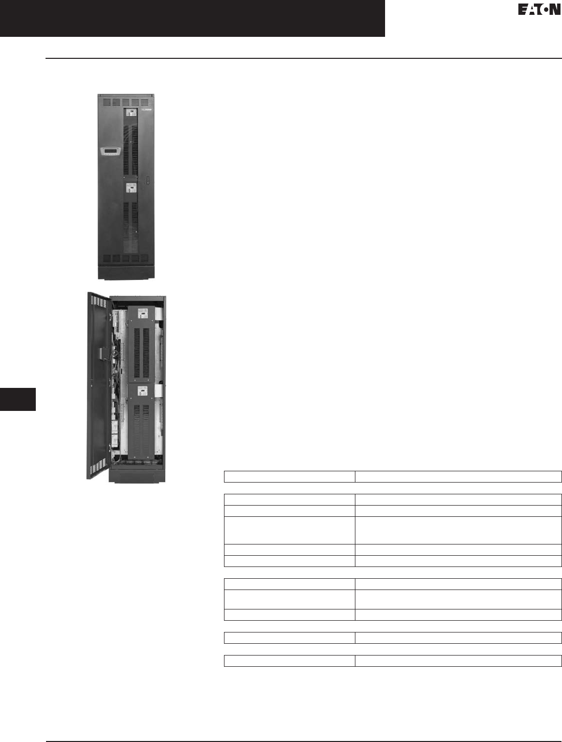
33.5-40
For more information, visit: www.eaton.com/consultants CA08104001E
September 2011
Uninterruptible Power Supplies
Sheet 33
22
23
24
25
26
27
28
29
30
31
32
33
34
35
36
37
38
39
40
41
42
43
Remote Power Panel
General Information—Technical Data
136
Remote Power Panel
Remote Power Panel
General Description
Eaton’s Remote Power Panel (RPP)
provides big power in a small footprint,
perfect for space-cramped facilities or
an end-of-row distribution solution.
The RPP can be configured with up to
four 400A panelboards, providing 168
poles of power distribution in a free-
standing structure with a footprint
of just four square feet. Loaded with
Eaton’s advanced Energy Management
System (EMS), understanding your
facility’s power distribution and
characteristics has never been easier.
Features
Standard Options
■Direct connection to panelboards
with BCMS option
■Panelboards with 400A panel
main breaker
■Branch circuit monitoring up to
100A per branch CT
■See-through Plexiglas doors
■Rack-style doors
■Reinforced conduit landing plates
■Rear access cut-out for two front
panel installations
■Air skirts
Accessibility and Serviceability
■Ample cabling space between
panelboards (up to 5.00 inches)
■Standard top and bottom cable
access for more flexible installation
options
■Up to two panelboards can be
mounted on both the front and
rear faces
■Easily removable side covers with
captive hardware
■Rear access cut-out for dual front
panel installations
Aesthetics and Flexibility
■Line and Match design with other
Eaton power quality products gives
a clean professional appearance to
facilities and data centers
■Improved paint and surface texture
for easy cleaning and maintenance
■Available Plexiglas and rack-style
door options
■Top or bottom panelboard
configuration
Safety and Quality
■Protective trim panels cover panel-
board wiring from accidental contact
■Substantial partitions separate
high/control voltage sections for
safer servicing
■UL/CSA approved 60950
■Supported by Eaton’s extensive
network of over 240 field technicians
for fast reliable service
Monitoring and Connectivity
■Eaton’s Energy Management System
(EMS) provides state-of-the-art
monitoring and alarming provisions
■Access information via 8 x 40
character on-unit display or via your
network through the PXGX1000
Power Xpert Gateway card
■Stores consumption trends for up
to 24 months
■60A and 100A branch breaker
CTs available
■Time-stamped metering
■Custom alarm settings
Technical Data
Table 33.5-2. Technical Specifications
Due to continuing improvements, specifications are subject to change without notice.
Please see sales configurator for additional information.
Category RPP
Electrical Characteristics
Input/output 208/120V—three-phase, four-wire + ground
Input ratings 100/225/450/900A
Input type Single feed into main lug
Dual feed into main lugs (up to four)
Direct connection to panelboard main breaker
Frequency 60 Hz
Neutral rating 200%
Power Distribution
Panelboards Up to four 42-pole panels—two panels in front and two in rear
Panelboard options Eaton (bolt-on or plug-in) or Square D panels
(225A and 400A main breakers)
Branch breakers Factory-installed branch circuit breakers
Dimensions
Main cabinet 24.00 (609.6) W x 24.00 (609.6) D x 80.00 (2032.0) H
Standards
Standards NEMA, UL 60950, CSA 60950
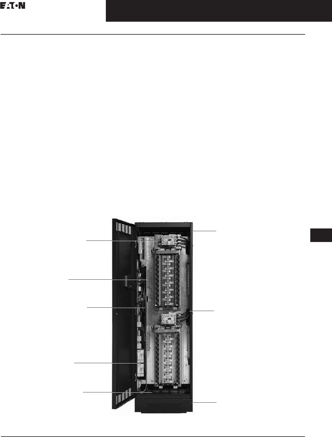
CA08104001E For more information, visit: www.eaton.com/consultants
33.5-41
September 2011
Uninterruptible Power Supplies
Sheet 33
22
23
24
25
26
27
28
29
30
31
32
33
34
35
36
37
38
39
40
41
42
43
Remote Power Panel
Technical Data
137
Options
■Energy Management System
■High kAIC panel main breakers
■Branch circuit monitoring
■Floor Stands (12, 18, 24, 30, 36 and
48 inches)
■Isolated ground (standard)
■Distribution cables (whips)
■Clear Plexiglas doors
■Isolation barrier for dual feed input
■Top or bottom panelboard installation
■Extra knock-out, incoming and
conduit plates
■Transient suppression plate
■Surge protection device (100 or
200 kA)
■Low voltage control junction box
■Mesh rack doors
■Four building alarm inputs
(NO or NC)
Connectivity
■Modbus RTU (RS-232/RS-485)
■Power Xpert Gateway Card—
PXGX1000 (Modbus TCP/IP, SNMP,
Ethernet)
Energy Management System
Monitored Parameters
■Input voltage (L-L and L-N)
■Input current (A, B and C phases)
■Output voltage (L-L and L-N)
■Output current (A, B and C phases)
■Output neutral current
■System ground current
■kVA, kW, Hz
■Monthly, yearly, total kW
■Input voltage THD (all phases)
■Output voltage THD (all phases)
■Power factor (lead/lag indicator)
■Output current % (A, B and
C phases)
Load Profiling
Captures highest and lowest reading on
monthly basis with trend information over
the last 24 months
■Input/output voltage
■Input/output current
■Input/output frequency
■Input/output power factor
■Input/output kVA
■Input/output voltage THD
■Ground current
■Neutral current
Warnings/Alarms
■Input/output overvoltage and
undervoltage
■Input/output overfrequency and
underfrequency
■Input/output phase rotation
■Input/output voltage THD
■Input/output current THD
■Output overload (three levels)
■Building alarms (two programmable)
■Summary alarm
■Communication fault connectivity
Remote Power Panel Features
400A Breakers
(225A pictured)
Barrier
Control
Section Isolated
SPD
(UL 1449)
Heavy Gauge
Conduit Plate
Top Cable Entry
Bottom Cable Entry
Rear Door
Access
Side Access
Air Skirts
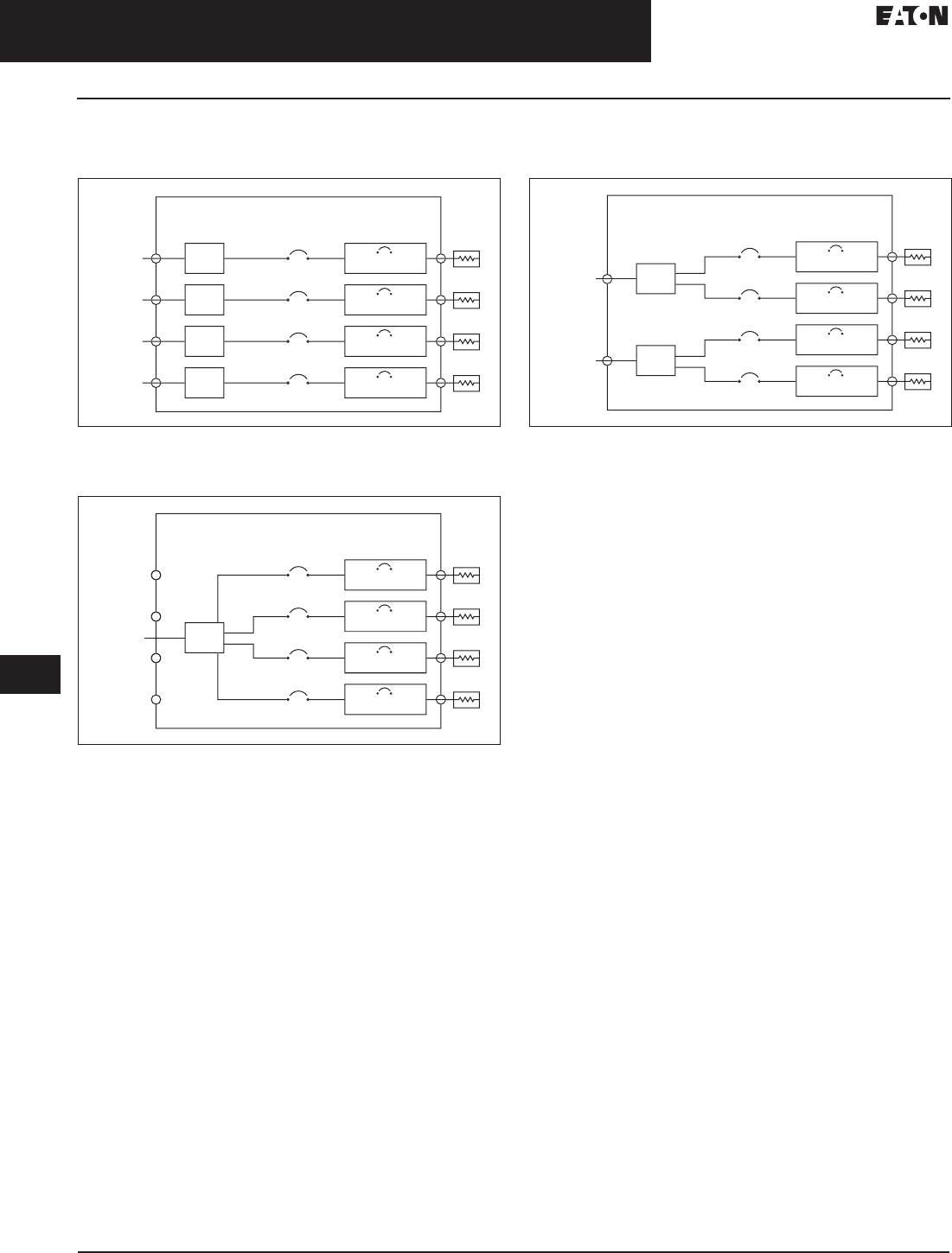
33.5-42
For more information, visit: www.eaton.com/consultants CA08104001E
September 2011
Uninterruptible Power Supplies
Sheet 33
22
23
24
25
26
27
28
29
30
31
32
33
34
35
36
37
38
39
40
41
42
43
Remote Power Panel
Technical Data
138
RPP Schematics—Direct Feed, Single MLO
and Dual MLO without Metering
Figure 33.5-36. RPP Direct Connect
One-line diagram shown with quad-panelboard configuration. The
maximum number of panelboards available may vary.
Figure 33.5-37. RPP Single MLO
One-line diagram shown with quad-panelboard configuration. The
maximum number of panelboards available may vary.
Figure 33.5-38. RPP Dual MLO
One-line diagram shown with quad-panelboard configuration. The
maximum number of panelboards available may vary.
L
oad
L
oad
L
oad
L
oad
Br
a
n
c
h
C
ir
cu
i
t
P
a
n
e
l
boa
r
d
P
a
n
e
l M
a
i
n
C
ir
cu
i
t
Br
ea
k
er
RPP
Cab
in
et
Utilit
y
1
M
ec
h
.
Lu
g
Br
a
n
c
h
C
ir
cu
i
t
Br
ea
k
er
(Up to 42x Sin
g
le-Pol
e
Utilit
y
2
M
ec
h
.
Lu
g
Br
a
n
c
h
C
ir
cu
i
t
Br
ea
k
er
(Up to 42x Sin
g
le-Pol
e
Utilit
y
3
M
ec
h
.
Lu
g
Br
a
n
c
h
C
ir
cu
i
t
Br
ea
k
er
(Up to 42x Sin
g
le-Pol
e
Utilit
y
4
M
ec
h
.
Lu
g
Br
a
n
c
h
C
ir
cu
i
t
Br
ea
k
er
(Up to 42x Sin
g
le-Pol
e
L
oad
L
oad
L
oad
L
oad
Br
a
n
c
h
C
ir
cu
i
t
P
a
n
e
l
boa
r
d
P
a
n
e
l M
a
i
n
C
ir
cu
i
t
Br
ea
k
er
RPP
Cab
in
et
Utilit
y
1
Br
a
n
c
h
C
ir
cu
i
t
Br
ea
k
er
(Up to 42x Sin
g
le-Pol
e
M
ec
h
.
Lu
g
Br
a
n
c
h
C
ir
cu
i
t
Br
ea
k
er
(Up to 42x Sin
g
le-Pol
e
Br
a
n
c
h
C
ir
cu
i
t
Br
ea
k
er
(Up to 42x Sin
g
le-Pol
e
Br
a
n
c
h
C
ir
cu
i
t
Br
ea
k
er
(Up to 42x Sin
g
le-Pol
e
L
oad
L
oad
L
oad
L
oad
Br
a
n
c
h
C
ir
cu
i
t
P
a
n
e
l
boa
r
d
P
a
n
e
l M
a
i
n
C
ir
cu
i
t
Br
ea
k
er
RPP
Cab
in
et
Utilit
y
2
Br
a
n
c
h
C
ir
cu
i
t
Br
ea
k
er
(Up to 42x Sin
g
le-Pol
e
M
ec
h
.
Lu
g
Utilit
y
1
M
ec
h
.
Lu
g
Br
a
n
c
h
C
ir
cu
i
t
Br
ea
k
er
(Up to 42x Sin
g
le-Pol
e
Br
a
n
c
h
C
ir
cu
i
t
Br
ea
k
er
(Up to 42x Sin
g
le-Pol
e
Br
a
n
c
h
C
ir
cu
i
t
Br
ea
k
er
(Up to 42x Sin
g
le-Pol
e
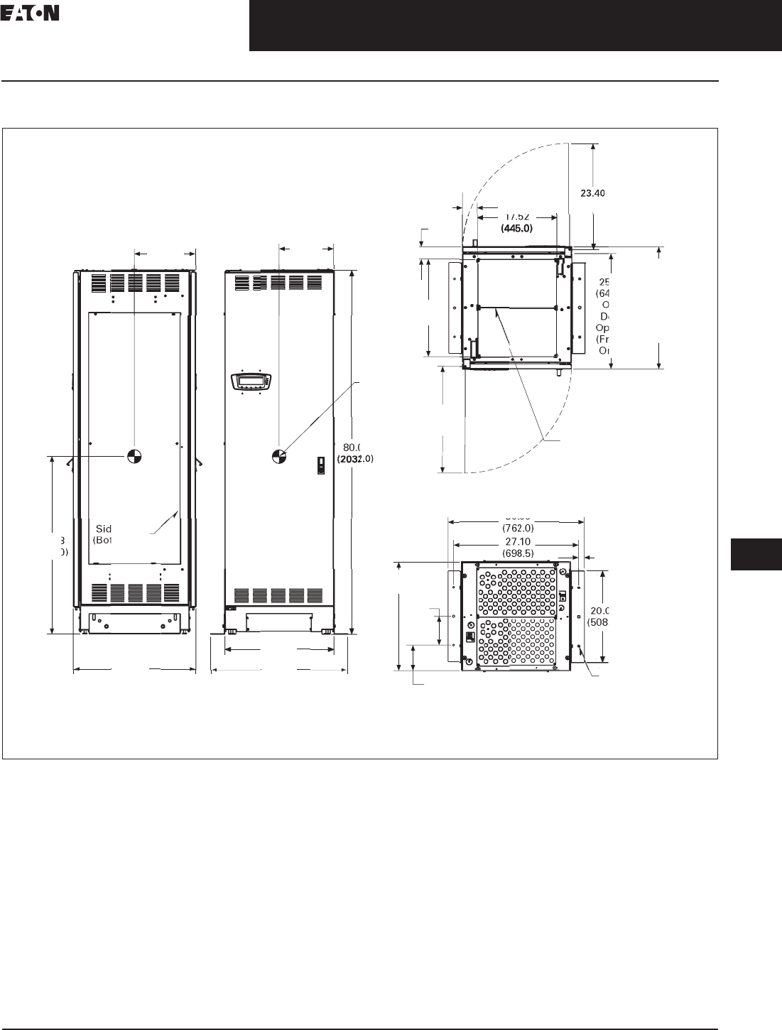
CA08104001E For more information, visit: www.eaton.com/consultants
33.5-43
September 2011
Uninterruptible Power Supplies
Sheet 33
22
23
24
25
26
27
28
29
30
31
32
33
34
35
36
37
38
39
40
41
42
43
Remote Power Panel
Layouts and Dimensions
139
RPP Site Planning
Figure 33.5-39. 50–150 kVA PDU—Main Cabinet—Right Front Facing Sidecar and Left Side Facing Sidecar—Dimensions in Inches (mm)
Notes:
1. For optional mounting brackets use shipping brackets.
2. Weight: 880 lbs (399 kg) for the worst case. Different configurations may have different weight.
3. The system must be installed on a level floor suitable for computer or electronic equipment.
4. The system must be installed in a temperature and humidity controlled indoor area free of conductive contaminants.
5. Ambient temperature range: 32°–104°F (0°–40°C), recommended operating range: 68°–77°F (20°–25°C) maximum relative humidity 95%
noncondensing.
6. Minimum 36.00-inch (914.4 mm) clearance in front and rear of the cabinet are required for cooling air intake and servicing space for front and
rear access unit. For front unit minimum clearance in front 36.00-inch (914.4 mm). None required in back. Side access is required for service.
7. Top and bottom cable entries through removable access plates are standard for all configurations. Access plates shall be custom-modified to
suit conduit sizes.
8. All wiring is to be in accordance with national and local electric codes.
9. Center of gravity location shown for dual feed, 400A panelboard (four). Center of gravity might vary for different configurations.
10. Specifications are subject to change.
(
594.6
)
17 52
3
.2
7
(
83.0
)
3
.
00
(
69.0
)
2
1.
50
(
546.0
)
27.
00
(
684.5
)
Tw
o
Doo
r
O
p
tio
n
(
Front an
d
Rear
)
5
.
53
4
8.5
)
n
e
oor
t
io
n
o
nt
n
l
y
)
2
3
.4
0
(
594.6
)
Conduit Entr
y
S
p
ac
e
Co
n
du
i
t
Pl
ates
Interchan
g
eabl
e
To
p
/Botto
m
1
3
.4
6
(
342.0
)
39.1
3
(
994.
0
27.
00
(
684.5
)
30
.
00
(
762.0
)
With O
p
tional
Mountin
g
Bracket
s
24.
00
(
610.0
)
e
Co
v
er
t
h Sides
)
R
e
f
er
N
ote
9
00
12.0
0
(
305.0
)
L
e
f
t
Vi
ew
Front
/
Back Vie
w
View to Show Mounting Locatio
n
Onl
y
Base Show
n
To
p
Vie
w
30 00
1.2
5
(
31.8
)
00
0)
24.
00
(
609.6
)
4X
6
.4
0
(
162.0
)
5
.
60
(
143.0
)
0
.4
0
(
10.0
)
Ø
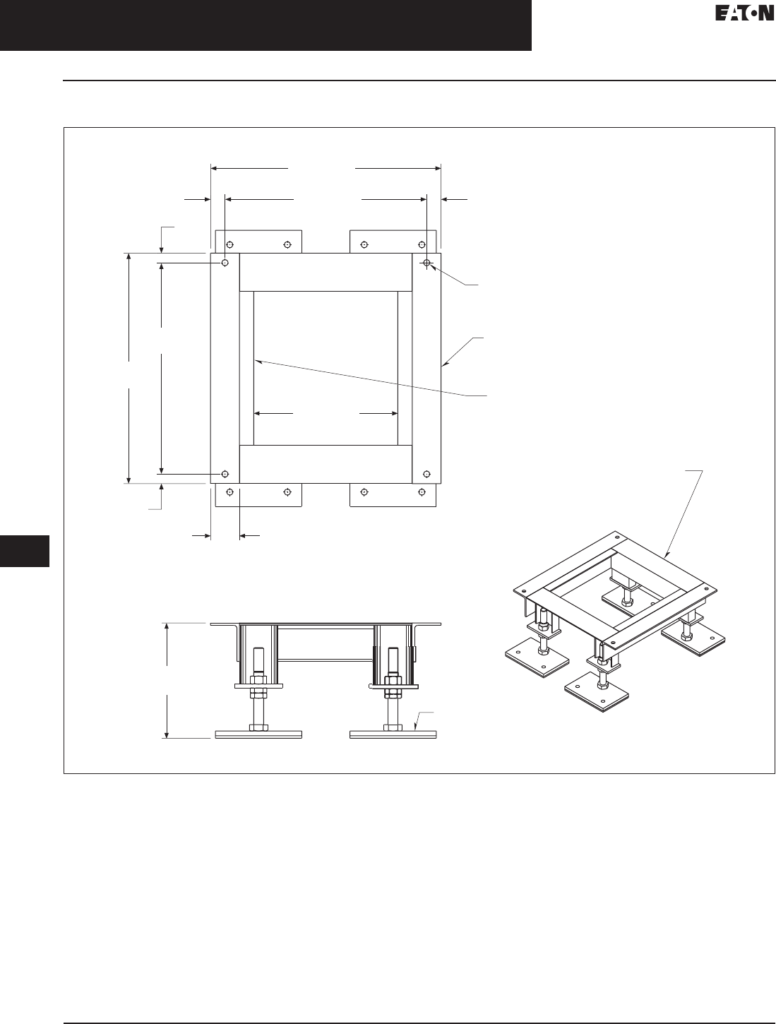
33.5-44
For more information, visit: www.eaton.com/consultants CA08104001E
September 2011
Uninterruptible Power Supplies
Sheet 33
22
23
24
25
26
27
28
29
30
31
32
33
34
35
36
37
38
39
40
41
42
43
Remote Power Panel
Layouts and Dimensions
140
RPP Floor Stand
Figure 33.5-40. RPP Floorstand, 12.00 Inch (304.8)—Dimensions in Inches (mm)
24.00
(
609.6
)
21.00
(
533.4
)
1.
50
(
38.1
)
1.
50
(
38.1
)
0
.
63
(
16.0
)
4X
Ø
T
hr
u
0
.25
(
6.4
)
x
3.00
(
76.2
)
4.00
(
101.6
)
x
Angl
e
0.19
(
4.8
)
x
1.50
(
38.1
)
x
1.50
(
38.1
)
x
16.00
(
406.4
)
An
g
l
e
1.
00
(
25.4
)
24.
00
(
609.6
)
22.
00
(
558.8
)
1.
00
(
25.4
)
4.50
(
114.3
)
15.00
(
381.0
)
12.00
(
304.8
)
±
2.25
(
57.2
)
0.25
(
6.4
)
x
4.00
(
101.6
)
x
4.00 (101.6
)
An
g
l
e
See Dw
g
. LA12-
8
For Le
g
Detail
s
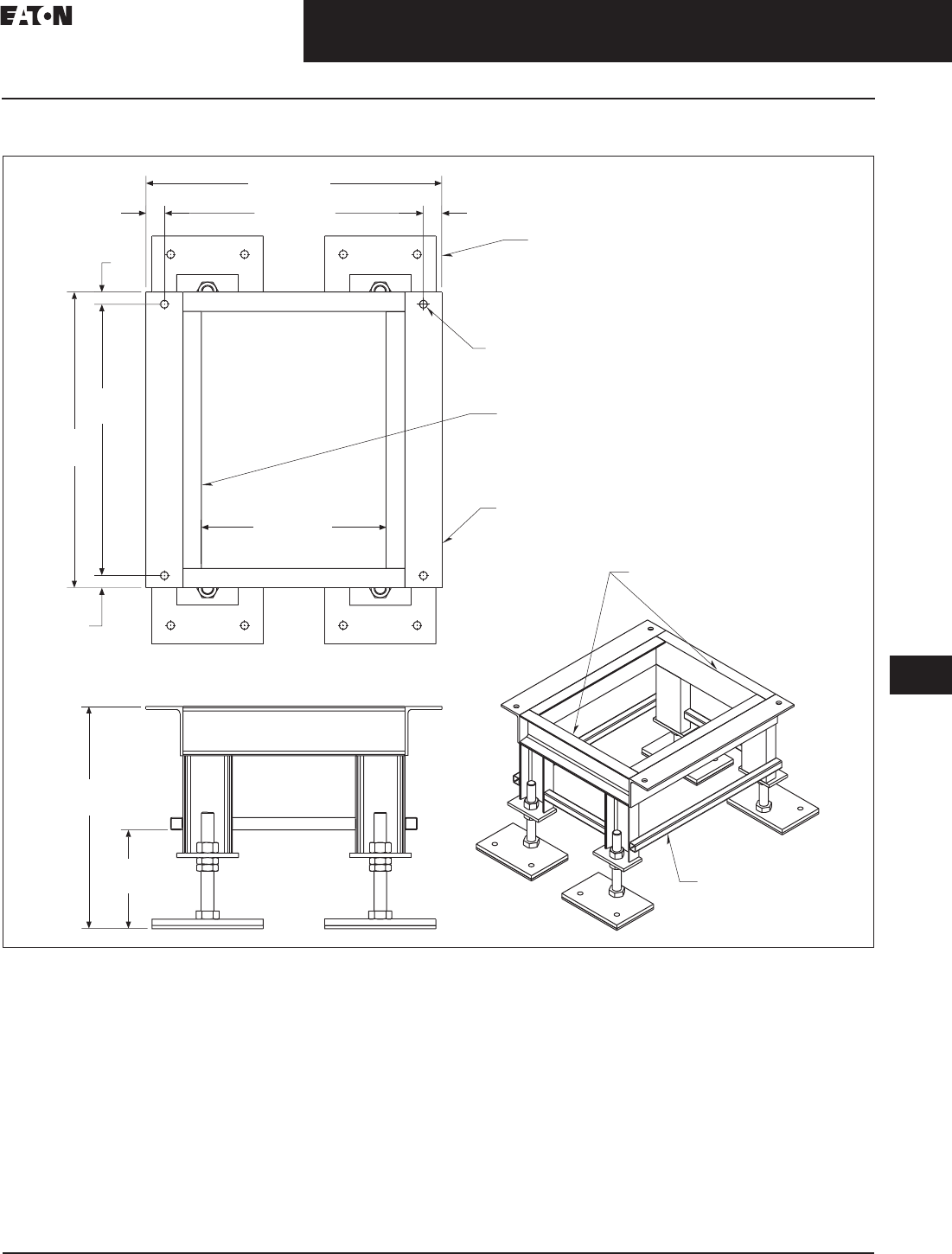
CA08104001E For more information, visit: www.eaton.com/consultants
33.5-45
September 2011
Uninterruptible Power Supplies
Sheet 33
22
23
24
25
26
27
28
29
30
31
32
33
34
35
36
37
38
39
40
41
42
43
Remote Power Panel
Layouts and Dimensions
141
RPP Floor Stand
Figure 33.5-41. RPP Floorstand, 18.00 Inch (457.2)—Dimensions in Inches (mm)
See Dw
g
. LC18-AD
J
For Le
g
Detail
s
24.00
(
609.6
)
21.00
(
533.4
)
1.
50
(
38.1
)
1.
50
(
38.1
)
0
.
63
(
16.0
)
4X
Ø
Thr
u
0.25
(
6.4
)
x
3.00
(
76.2
)
x
4.00
(
101.6
)
An
g
l
e
0.19
(
4.8
)
x
1.50
(
38.1
)
x
1.50
(
38.1
)
x
An
g
l
e
1.
00
(
25.4
)
24.
00
(
609.6
)
22.
00
(
558.8
)
1.
00
(
25.4
)
15.00
(
381.0
)
18.00
(
457.2
)
±
3.00
(
76.2
)
C4 x 5.4
#
8
.
00
(
203.2
)
1.00
(
25.4
)
Square Tubin
g
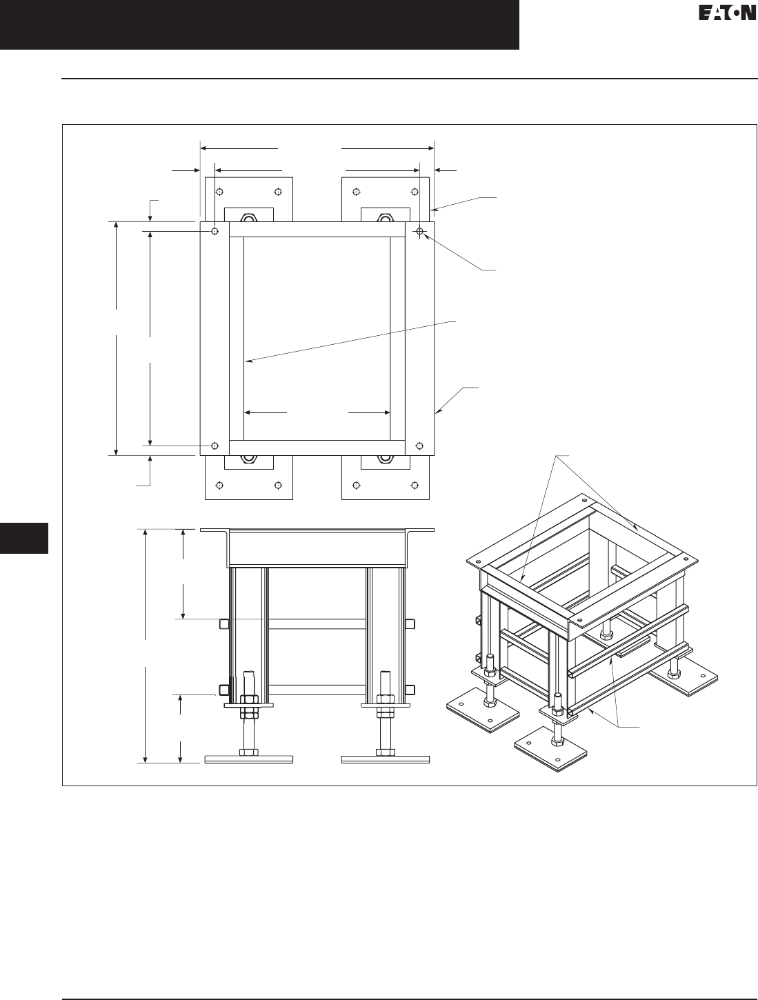
33.5-46
For more information, visit: www.eaton.com/consultants CA08104001E
September 2011
Uninterruptible Power Supplies
Sheet 33
22
23
24
25
26
27
28
29
30
31
32
33
34
35
36
37
38
39
40
41
42
43
Remote Power Panel
Layouts and Dimensions
142
RPP Floor Stand
Figure 33.5-42. RPP Floorstand, 24.00 Inch (609.6)—Dimensions in Inches (mm)
See Dw
g
. LC24-AD
J
For Le
g
Detail
s
24.00
(
609.6
)
21.00
(
533.4
)
1.
50
(
38.1
)
1.
50
(
38.1
)
0
.
63
(
16.0
)
4X
Ø
Thr
u
0.25
(
6.4
)
x
3.00 (76.2)
x
4.00
(
101.6
)
An
g
l
e
0.19
(
4.8
)
x
1.50
(
38.1
)
x
1.50
(
38.1
)
x
Angl
e
1.
00
(
25.4
)
24.
00
(
609.6
)
22.
00
(
558.8
)
1.
00
(
25.4
)
15.00
(
381.0
)
24.00
(
609.6
)
±
3.00
(
76.2
)
C4 x 5.4
#
7.
00
(177.8
)
9
.2
5
(
235.0
)
1.00
(
25.4
)
Square Tubin
g
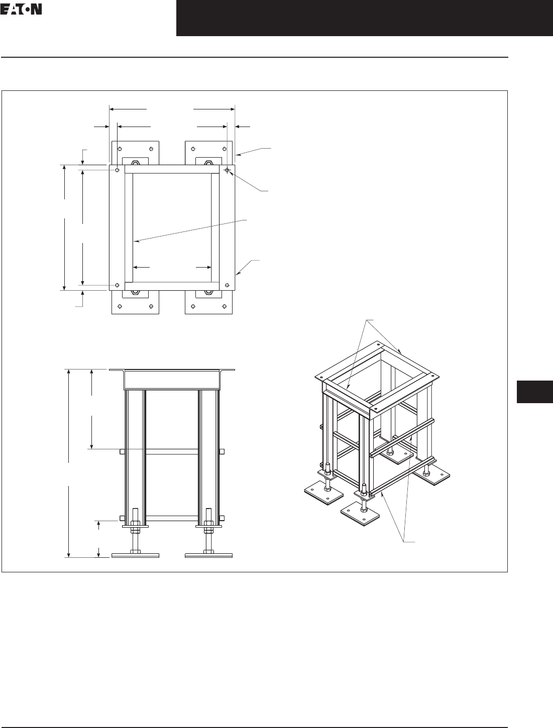
CA08104001E For more information, visit: www.eaton.com/consultants
33.5-47
September 2011
Uninterruptible Power Supplies
Sheet 33
22
23
24
25
26
27
28
29
30
31
32
33
34
35
36
37
38
39
40
41
42
43
Remote Power Panel
Layouts and Dimensions
143
RPP Floor Stand
Figure 33.5-43. RPP Floorstand, 36.00 Inch (914.4)—Dimensions in Inches (mm)
See Dw
g
. LC36-AD
J
For Le
g
Detail
s
24.00
(
609.6
)
21.00
(
533.4
)
1.
50
(
38.1
)
1.
50
(
38.1
)
0
.
63
(
16.0
)
4X
Ø
Thr
u
0.25
(
6.4
)
x
3.00
(
76.2
)
x
4.00
(
101.6
)
An
g
l
e
0.19
(
4.8
)
x
1.50
(
38.1
)
x
1.50
(
38.1
)
x
An
g
l
e
1.
00
(
25.4
)
24.0
0
(
609.6
)
22.
00
(558.8
)
1.
00
(
25.4
)
15.00
(
381.0
)
36.00
(
914.4
)
±
3.00
(
76.2
)
C4 x 5.4
#
7.
00
(
177.8
)
1
5
.2
5
(
387.4
)
1.00
(
25.4
)
Square Tubin
g
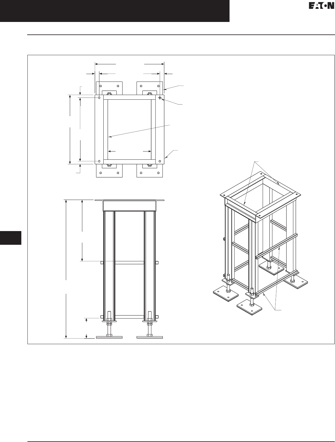
33.5-48
For more information, visit: www.eaton.com/consultants CA08104001E
September 2011
Uninterruptible Power Supplies
Sheet 33
22
23
24
25
26
27
28
29
30
31
32
33
34
35
36
37
38
39
40
41
42
43
Remote Power Panel
Layouts and Dimensions
144
RPP Floor Stand
Figure 33.5-44. RPP Floorstand, 48.00 Inch (1219.2)—Dimensions in Inches (mm)
See Dw
g
. LC48-AD
J
For Le
g
Detail
s
24.00
(
609.6
)
21.00
(
533.4
)
1.
50
(
38.1
)
1.
50
(
38.1
)
0
.
63
(
16.0
)
4X
Ø
Thr
u
0
.25
(
6.4
)
x
3.00
(
76.2
)
x
4.00
(
101.6
)
An
g
l
e
0.19
(
4.8
)
x
1.50
(
38.1
)
x
1.50
(
38.1
)
x
An
g
l
e
1.
00
(
25.4
)
24.
00
(
609.6
)
22.
00
(
558.8
)
1.
00
(
25.4
)
15.00
(
381.0
)
48.00
(
1219.2
)
±
3.00
(
76.2
)
C4 x 5.4
#
7.
00
(
177.8
)
21.2
5
(
539.8
)
1.00
(
25.4
)
Square Tubin
g

CA08104001E For more information, visit: www.eaton.com/consultants
33.6-1
September 2011
Uninterruptible Power Supplies
Sheet 33
22
23
24
25
26
27
28
29
30
31
32
33
34
35
36
37
38
39
40
41
42
43
Glossary of Power Terms
145
Glossary of Power Terms
Commonly Used Terms
ampere (A or Amp): The unit of mea-
sure for the “rate of flow” of electricity,
analogous to “gallons per minute.”
VA x 0.7 (power factor) = Watts
alternating current (AC): An electric
current that reverses its direction at
regularly recurring intervals.
blackout: A zero-voltage condition
lasting for more than two cycles.
brownout: A steady state of low
voltage, but not zero voltage.
direct current (DC): An electric current
in which the flow of electrons is in
one direction, such as supplied by
a battery.
double conversion: A UPS design in
which the primary power path consists
of a rectifier and inverter. Double
conversion isolates the output
power from all input anomalies
such as low voltage surges and
frequency variations.
electrical line noise: Radio frequency
interference (RFI), electromagnetic
interference (EMI) and other voltage
or frequency disturbances.
electromagnetic interference (EMI):
Electrical interference that can
cause equipment to work improperly.
EMI can be separated into conducted
EMI (interference conducted through
cables out of the UPS) and radiated
EMI (interference conducted through
the air).
Energy Saver System (ESS): Eaton’s
proprietary energy-saving technology
that allows large three-phase
UPSs to operate at greater than 99%
efficiency across load levels down to
20%, while maintaining maximum
protection for the load.
hertz (Hz): A unit of frequency equal to
one cycle per second.
high voltage spike: Rapid voltage peak
up to 6000V.
hot-swappable: The ability to change a
module without taking the critical load
off the UPS.
input voltage range: The voltage
range within which a UPS operates in
“normal” mode and does not require
battery power.
inverter: UPS assembly that converts
internal DC power to output AC power
to run user’s equipment. When the
inverter is supporting 100% of the load
at all times, as with an online UPS,
there is no break from utility power
to battery power.
line-interactive: An offline UPS
topology in which the system interacts
with the utility line in order to regulate
the power to the load.
load: The equipment connected to and
protected by a UPS.
maintenance bypass: An external
wiring path to which the load can
be transferred in order to upgrade or
perform service on the UPS without
powering down the load.
noise: (1) A disturbance that affects a
signal; it can distort the information
carried by the signal. (2) Random vari-
ations of one or more characteristics
of any entity such as voltage, current
or data. (3) Loosely, any disturbance
tending to interfere with normal opera-
tion of a device.
offline: Any UPS that does not fit the
definition of online. Line-interactive
and standby topologies are offline.
online: (1) A UPS that provides power
to the load from its inverter 100% of
the time, regulating BOTH voltage and
frequency, usually double conversion
topology.
plug and play: An electrical device that
does not require an electrician to install.
power factor (PF): The ratio of real power
to apparent power. Watts divided by VA.
Most power supplies used in communi-
cation and computer equipment have a
power factor of 0.7. (PF = 0.7)
VA x PF = W
W/PF = VA
power sag: Low voltage (below
nominal).
power surge: High voltage (above
nominal).
rack-mount: Ability to mount an electri-
cal assembly into a standardized rack.
rectifier: UPS component that converts
incoming AC power to DC power for
feeding the inverter and for charging
the battery.
redundancy: Duplication or repetition
of elements in electronic equipment to
provide alternative functional channels
in case of failure.
relay communication: Communica-
tion between a UPS and a computer
through the opening and closing
of solid state relays which are
pre-defined to indicate UPS status.
RS-232: The standard for serial
interfaces (serial refers to the eight
bits of each character successively
sent down one wire) used by most
computers, modems and printers;
a 25-pin physical interface.
run time: The amount of time the
battery in a UPS is designed to support
the load.
sine wave: A waveform that
represents periodic oscillations
of a pure frequency.
single-phase: Power system with one
primary waveform.
standby: UPS technology where
power is applied to the load directly
from the utility under normal opera-
tion, but switched to the inverter
and battery for emergency support
(offline topology).
three-phase: A power system with
three primary voltage waveforms
spaced equally 120° out of phase
with each other.
Total Harmonic Distortion (THD):
Describes how much the circuit
voltage deviates from a perfect sine
wave. A poor voltage THD is most
often manifested in a “flat topped”
waveform that comes from the
inability of a power source to
respond to the demands of highly
non-linear loads.
uninterruptible power system (UPS):
An electrical system designed to
provide instant, transient-free back
up power during power failure or fault.
Some UPSs also filter and/or regulate
utility power (line conditioning).
Variable Module Management System
(VMMS): Eaton’s efficiency maximizing
technology that allows the 9395 UPS
to achieve peak efficiency at low
load levels.
volt/voltage (V): Electrical pressure
that pushes current through a circuit.
High voltage in a computer circuit is
represented by 1; low (or zero) voltage
is represented by 0; volts direct current
(Vdc); volts alternating current (Vac).
VoltAmps (VA): Voltage x amps.
watts (W): The rate of doing
electrical work.

33.6-2
For more information, visit: www.eaton.com/consultants CA08104001E
September 2011
Uninterruptible Power Supplies
Sheet 33
22
23
24
25
26
27
28
29
30
31
32
33
34
35
36
37
38
39
40
41
42
43
146
This page intentionally left blank.
