Power Break II GET 8052C 1000486169 Catalog
2016-09-04
: Pdf 1000486169-Catalog 1000486169-Catalog B4 unilog
Open the PDF directly: View PDF ![]() .
.
Page Count: 117 [warning: Documents this large are best viewed by clicking the View PDF Link!]

GE Consumer & Industrial
Electrical Distribution
Power Break® II
Insulated Case Circuit Breakers
2
Table of Contents
Power Break® II Circuit Breakers .........................3
Basic Configuration .......................................3
Greater Convenience and Operator Safety. . . . . . . . . . . . . . . . . .3
Quick, Error-Free Installation of Universal Accessories . . . . . . .3
Three Choices of Advanced, Solid-State Trip Unites. . . . . . . . . .3
Key Features ..............................................4
Features and Characteristics .............................5
Basic Configurations ......................................5
Manual Operation .........................................5
Electrical Operation .......................................5
Drawout Construction ...................................6-7
Power+™ Trip Unit Systems ...............................8
Trip Target Module ........................................8
Operation of Power+™ Trip Unites . . . . . . . . . . . . . . . . . . . . . . . . . .9
Long-Time Protective Functions . . . . . . . . . . . . . . . . . . . . . . . . . . 10
Short-Time Functions .................................... 10
Normal Ground-Fault Protection . . . . . . . . . . . . . . . . . . . . . . . . . 12
Ratings Plugs ...........................................13
Current Sensors ......................................... 13
MicroVersaTrip Plus™ and PM™ Trip Units ..............14
Enhancements ......................................... 14
Operation .............................................. 15
Standard and Optional Protective Functions . . . . . . . . . . . . . . 15
Long-Time Protective Functions . . . . . . . . . . . . . . . . . . . . . . . . . . 16
Short-Time Functions .................................... 16
High-Range Instantaneous .............................. 18
Normal Ground-Fault Protection . . . . . . . . . . . . . . . . . . . . . . . . . 18
Defeatable Ground-Fault Protection . . . . . . . . . . . . . . . . . . . . . . 19
Programming Trip Units .................................22
Trip Targets – Overcurrent and Ground Fault . . . . . . . . . . . . . 22
Ratings Plugs ...........................................23
Current Sensors ......................................... 23
Accessories .............................................24
Stationary and Drawout Breakers . . . . . . . . . . . . . . . . . . . . . . . . 24
Test Kit ............................................... 24
Electrical Operator .................................... 24
Remote Close Solenoid ................................ 25
Shunt Trip ............................................26
Shunt Trip with Lockout ............................... 27
Bell Alarm ............................................ 27
Bell Alarm with Lockout ...............................28
Undervoltage Release Module . . . . . . . . . . . . . . . . . . . . . . . . . 28
Time Delay Module for UVR . . . . . . . . . . . . . . . . . . . . . . . . . . . . 28
Auxiliary Switch ....................................... 29
Limited Access “Pushbutton Cover” . . . . . . . . . . . . . . . . . . . . 30
Mechanical Operations Counter . . . . . . . . . . . . . . . . . . . . . . . 29
Padlock Device ....................................... 30
Key Interlock Provision ................................ 30
Door Interlock ........................................ 30
Neutral Current Sensors ...............................31
Additional Accessories - Stationary Breakers . . . . . . . . . . . . . 31
Lug Adapter Kits ...................................... 32
T-Studs ...............................................32
Mechanical Interlocks ................................. 33
Lug Kits. . . . . . . . . . . . . . . . . . . . . . . . . . . . . . . . . . . . . . . . . . . . . . . 33
Additional Accessory - Drawout Breakers . . . . . . . . . . . . . . . . . 33
Secondary Disconnects ...............................34
Shutters ..............................................34
Racking Padlock ...................................... 34
By-Pass Switch ....................................... 34
Racking Tool ..........................................34
Mechanical Interlocks ................................. 34
Lifting Bar ............................................ 34
Position Switch ....................................... 34
Catalog Numbers ....................................... 35
Circuit Breakers ......................................... 35
Accessories ............................................. 35
Power+™ Trip Units ...................................... 36
Rating Plugs ............................................ 36
MicroVersaTrip Plus™ and MicroVersaTrip PM™ . . . . . . . . . . . 37
Rating Plugs ............................................ 37
Application Data ....................................... 38
Standards and Testing ................................38-42
Power Break® II – 100 % - Rated Circuit Breakers . . . . . . . . . 42
Standard Rated Devices ............................... 42
100% Rated Devices .................................. 42
Factors Affecting the Current Ratings . . . . . . . . . . . . . . . . . . . . 42
Cable or Bus Size. . . . . . . . . . . . . . . . . . . . . . . . . . . . . . . . . . . 42-44
Ambient Temperature ................................. 44
Operating Frequency .................................. 44
Factor “C” – Operating Frequency . . . . . . . . . . . . . . . . . . . . . . 44
Altitude ............................................... 45
Load Class Rating Factor . . . . . . . . . . . . . . . . . . . . . . . . . . . . . . 45
Interrupting Ratings ..................................... 45
Basis of Interrupting Ratings . . . . . . . . . . . . . . . . . . . . . . . . 45-47
Miscellaneous Information and
Control Power Information ............................... 48
Humidity and Fungus ................................. 48
Wiring Diagram, Secondary Terminals . . . . . . . . . . . . . . . . . 48
Time Current Tripping Characteristics . . . . . . . . . . . . . . . . . . 48
Time Current Curves ...............................49-50
Physical Data
Outline Dimension Drawings . . . . . . . . . . . . . . . . . . . . . .51-107
Weight and Space Requirements . . . . . . . . . . . . . . . . . . . . . 107
Standards and References .............................108
Guide Form Specifications .........................109-112
Other Related Publications ............................113

3
Power Break® II Circuit Breakers
Basic Configuration
In 1965 GE pioneered the design of insulated case circuit
breakers when it introduced the original Power Break circuit
breaker. Now, GE introduces Power Break II insulated case
circuit breakers, the vanguard of a new age in reliable, flex-
ible and easy-to-use circuit protection.
Power Break II circuit breakers are UL Listed, CSA Certified
and IEC Certified* for up to 200,000 amps, at 240 volts, rms
symmetrical interrupting capacity without fuses or current
limiters. These new insulated case circuit breakers can be
applied on ac power systems through 600 volts. Featuring
an all-new 2000A compact design – up to 40% smaller than
before – Power Break II circuit breakers consist of three
envelope sizes from 800 to 4000 amps.
Greater Convenience And Operations Safety
The controls and status indicators you need most are read-
ily accessible. The flush-mounted handle, ON/OFF buttons,
rating plug test receptacle, bell alarm reset buttons– with
or without lockout – are easily reached; and all are double-
insulated from live components. And, for added security, a
standard padlock device lets you prevent accidental or
unauthorized closing of the breaker.
*See Performance chart page 46.
Quick, Error-Free Installation
of Universal Accessories
Drop-in bell alarm with manual reset lockout, shunt trip
(with or without lockout) and undervoltage release install in
seconds. No special tools. No breaker disassembly. Just slide
them into place. The modules are universal across all frame
sizes, and each is mechanically keyed to its compartment so
you make the right connection, every time. These accessories
are field installable and upgradeable.
Three Choices of Advanced, Solid-State Trip Units
Enhanced MicroVersaTrip™ Plus and MicroVersaTrip PM™
trip units give you two new ways to monitor and control the
Power Break II breaker with unprecedented ease. A simple
keypad lets you program and display a variety of functions
including tripping characteristics, remote communica-
tions, status information and protective relaying, and allows
integration with GE POWER LEADER™ Power Management
Systems. The trip unit display also allows viewing of many
standard metering parameters as well as pickup alarms,
trip target indications and fault status information. For less
demanding functionality, the Power+™ trip unit gives you
a third choice in Power Break II breaker control. Tripping
characteristics are easily adjusted by a set of simple-to-use
switches. The trip unit is upgradeable to ground fault by
simply inserting a ground fault rating plug. An optional target
module allows for target monitoring and also functions as a
trip unit health indicator.

4
Key Features
1) Compact, lightweight design
2) 36-point pre-wired, dedicated secondary
terminal block standard (see item 16)
3) Optional mechanical counter
4) Padlock device standard
5) Easy-to-reach ON/OFF buttons
6) Choice of Power+™, MicroVersaTrip Plus™ or
MicroVersaTrip PM™ trip units- field upgradeable,
UL Listed, CSA Certified. IEC 947-2 Certified*
7) Sealable door provides added security
8) Drop-in shunt trip, undervoltage release and bell alarm
(with and without manual lockout) modules
9) Flush-mounted pump handle
Power Break® II Circuit Breakers
Other
• Two-stage, stored energy mechanism provides charge-af-
ter-close capability
• Stationary and drawout versions (stationary shown)
• Manually and electrically operated versions in same enve-
lope
• Modular, field-installable motor operator and remote-close
solenoid with independent voltages available
• All frames upgradeable to POWER LEADER™ Power
Management Systems
• Configurable accessories activated through integrated
electronics provide new status information and allow new
flexibility in bell alarm and lockout control
• Modular auxiliary switches mounted beneath trip unit with
up to 12 NO/NC sets of contacts (Internal)
(Up to 36 terminals pre-wired to item 2, left side of breaker)
* See performance chart page 46.
2
3
8
7
54
9
1 6

5
Basis Configurations
All Power Break® II circuit breakers are available in two levels
of interrupting capacity – “standard break” and “Hi-Break®”
breakers. Each interrupting level is available in both station-
ary and drawout construction, with a full complement of
control and signaling accessories.
Standard break breakers are designed to meet the majority
of application requirements, calling for moderate levels of
available short-circuit current.
Hi-Break breakers, on the other hand, are specially designed
to withstand the stresses, and safely interrupt high levels of
short circuit current found in some applications (from 65 to
200 kA rms symmetrical amps – depending on voltage).
Manual Operation
The circuit breaker closing spring is energized by size opera-
tions of the retractable pump handle. Each handle move-
ment is a stage in the pre-charging of a spring-loaded,
quick-make, quick-break mechanism. To close the breaker
contacts, depress the “PUSH ON” button. With the breaker
in the “ON” position, it is now possible to recharge the main
closing springs by repeating the spring charging procedure.
The circuit breaker opening springs are automatically
charged when the breaker is closed. To open the breaker
and de-energize downstream circuits, manually depress the
“PUSH OFF” button.
Electrical Operation
The electrical operation fits under the cover of the manually
operated breaker. This assembly may be added to any Power
Break II breaker – in the factory or in the field – to provide
the electrical charge feature. All breaker controls inputs and
outputs are pre-wired to dedicated secondary terminals for
Table 5.1
Sequence Of Operation
ON/OFF
Indicator
Main Breaker
Contacts
Charging Spring
Indicator
Condition of
Charging Spring
Next Permissible
Operating Function
OFF Open Discharged Discharged Closing springs may be charged
OFF Open Charged Fully Charged Contacts may be closed
ON Closed Discharged Discharged Contacts may be opened, or
closing springs may be charged
ON Closed Charged Fully Charged Contacts may be opened
OFF Open Charged Fully Charged Closing spring may be discharged
without closing contacts by depressing
OFF button while pushing ON button
Features and Characteristics
Operation of circuit breaker pump handle
easy field installation. To complete the remote-operation
feature, a remote-close solenoid and either a shunt trip (with
or without lockout) or undervoltage release accessory is also
required. The electrical operator can be wired to automati-
cally re-charge the breaker after CLOSE or upon command.
Should motor control power be lost during the charging cycle
(3 seconds duration), spring charging may be completed
manually by using the pump handle. No special tools are
required. Any electrically operated breaker may be operated
manually.
For details of electrical control power requirements and wir-
ing diagrams, see pages 25-26.
Breaker Closing Speed
Three-cycle maximum closing speed, at nominal voltage, is
standard for all frame sizes. This speed exceeds the require-
ments for generator synchronizing.
6
Features and Characteristics
Drawout Construction
Type SSD (standard break) and SHD (Hi-Break®) Power Break
II drawout breakers are used in type SPSDOS and SPHDOS
substructures, providing the convenience and safety inherent
in drawout breaker construction. Drawout construction per-
mits activation of a new feeder, rapid circuit breaker replace-
ment, or inspection and maintenance of a breaker without
the inconvenience of de-energizing an entire switchboard.
Features (see photos, following page)
1) Primary disconnects: primary power is fed through mul-
tiple finger primary disconnect terminals when connected
to the primary stabs in the substructure.
2) Secondary disconnects: control signals are provided
through the 72 (36 maximum each side) secondary
disconnect terminals in the test and connected positions
only.
3) Wheels: the breaker has rollers which allow the unit to
ride on the substructure’s retractable rails for easy re-
moval and installation.
4) Wrench interlock: an interlock prevents engagement of
the racking wrench when the breaker contacts are closed.
This prevents disconnecting a closed breaker.
5) Drawout position indicator and switch: a drawout posi-
tion indicator displays whether the breaker is in the con-
nected, test or disconnected position.
6) Padlocking device: a padlocking provision accessory is
available to prevent access to the racking shaft, prevent-
ing movement of the breaker between the disconnected,
test and connected positions. (Not shown.)
7) Lifting bar: a lifting bar is available as an accessory, and
should be used to assist in safe handling of the drawout
breaker.
8) Manual motor cut-off switch: provided as standard
– prevents motor charge when racking breaker in from
disconnect to test position.
Other
• Drawout interlock: this interlock will trip a closed breaker
before the primary disconnects are engaged or disen-
gaged in the event that the wrench interlock is intention-
ally defeated.
• Drawout mechanism: a racking shaft powers a centrally
mounted power screw, through a chain drive, into a fixed
nut in the substructure. A special speed wrench is avail-
able with an integral ½” square drive socket. The wrench is
used for racking the breaker in and out of the substructure.
• Rejection feature: a built-in rejection feature prevents
insertion of a breaker into an incorrect substructure. This
prevents either: insertion of a standard break breaker into
a Hi-Break breaker substructure, or insertion of a higher
ampere rated breaker into a lower ampere rated substruc-
ture, or both.
• Shutters: shutters are available as an accessory to protect
personnel from inadvertently touching the primary stabs of
an energized switchboard when the drawout breaker unit
is removed.
• By-pass switch: a by-pass switch accessory has NO
and NC single-pole double-throw (SPDT) contacts, which
change state when the breaker is racked from the con-
nected to the test position. The switch is available in 2, 4,
and 6-contact modules.
• Substructure: the substructure is a self-contained frame-
work serving as a stationary receptacle for Power Break
II drawout breaker types SPSDOS and SPHDOS. It permits
easy activation of a new circuit in a spare compartment
(hole filler), rapid breaker replacement and simplifies
inspection and maintenance. The substructure is designed
for convenient mounting, with holes provided for bolting on
a shelf of supports. Holes are also provided in the primary
stabs for bolting to busbars or terminal lugs. The substruc-
ture also has retractable rails which aid in the installation
of the drawout breaker.

7
Features and Characteristics
2000-amp drawout breaker lifting bar and TDQLR
2000-amp drawout breaker
Drawout breaker rotated for inspection
1600-ampere substructure for standard break breaker
4
2
2
1
3
5
8
7
6

8
Power+™ Trip Unit Systems*
The Power+ trip unit system for Power Break®II insulated
case breakers consist of the trip unit, the trip actuator, cur-
rent sensors and rating plugs. The term “trip unit system”
applies to the combination of these four components which
form the solid-state circuit breaker tripping system.
Power+ trip units provide a complete range of standard and
optional overcurrent and ground-fault protective functions.
Components of Power+ trip unit system
True RMS Sensing
The Power+ trip unit continues to use GE’s proven technique
of measuring true rms currents of both sinusoidal and har-
monically distorted waveforms. The frequent sampling (48
times per cycle per phase) allows precise calculations of true
rms current. The sampling rate allows waveform measure-
ments up to the 11th harmonic. GE’s true rms sensing avoids
potential underprotection or overprotection problems associ-
ated with peak-sensing tripping systems.
Accessory Integration
Four accessories are integrated through the Power+ trip unit.
Drop-in shunt trip (with or without lockout), bell alarms (with
or without lockout) and the undervoltage release modules fit
into keyed pockets. They operate through the trip units, and
not through any external mechanisms. All accessory wiring
is pre-wired to secondary terminals, and no user wiring is
necessary. When activated, the shunt trip (with or without
lockout) and undervoltage release modules send a signal
to the trip unit to energize the trip actuator and open the
breaker.
* For availability on Power+ Trip units, contact your GE sales
engineer.
Trip Target Module (Optional)
Power+ trip target module (Target 02)
• View Button: Press the VIEW button to check the trip unit
status.
• Reset Button: Press the RESET button to clear any target
that is set.
• Battery Check: Target modules use two standard, 3V,
16mm x 1.6 mm, lithium batteries for viewing target
information. Battery life depends upon use, but may be
estimated at one year. When the batteries are energized,
depressing the VIEW button will illuminate either a set
target LED, i.e., LT or the BAT LED. Once target indica-
tors are cleared, battery status is indicated by the BAT
LED. Replacement batteries include Panasonic CR1616,
Eveready E-CR1616BP, or Duracell DL1616B, which may be
purchased commercially.
• Long-time pickup: The long-time pickup indicators moves
through two transitions. As the current in any phase
reaches 95% of its setpoint, the LTPU LED begins to flash.
As current increases, flashing frequency increases, until
100% of the pickup point is reached. At that moment, the
LTPU LED stays on continuously until the long-time delay
times out. Once the breaker has tripped on long-time, the
OVL target will be stored in memory. To view the trip, press
the VIEW button. To clear the target, press the RESET but-
ton.
• Short-time and instantaneous trips: Short–time and
instantaneous trips share the same trip target. The LTPU
LED is not illuminated, since the time intervals between
pickup and tripping are too short for either function. Once
the breaker has tripped on short-time or instantaneous,
the short target will be stored in memory. To view the trip,
press the VIEW button. To clear the target, press the RESET
button.
• Ground fault trip (Target02 only): The trip target for a
ground fault is the GF LED. To view the trip, press the VIEW
button. To clear the target, press the RESET button.
• Health monitor: Trip unit health status “okay” is illus-
trated by slow blinking of the LTPU LED. It may be seen by
depressing and holding the VIEW button. Sufficient power
must be supplied to the trip unit via external test kit, power
pack, or current transformers for the health monitor to be
operational.
Power+™Trip Units

9
Power+™ Trip Units
Operation Of Power+™ Trip Units
Block diagram of Power+ trip unit
Power+ trip units have a variety of standard and optional
functions. The block diagram shows a fully configured
Power+ trip unit with ground-fault protection. The current
sensors are special current transformers that provide the trip
unit with its operating power. Interchangeable rating plugs
act as scalars for the outputs of the current sensors, as well
as establish the current rating of individual breakers. When
a four-wire system is used and ground-fault protection is
called for, an external neutral sensor is necessary.
Analog current signals are converted to digital values, and
are measured and compared with established trip settings
in the microprocessor’s memory. Any overcurrent or ground
fault condition that exceeds pre-set conditions produce a trip
signal from the microprocessor to the trip actuator. The trip
actuator is a low-energy, positive-action tripping device. The
low-level trip signal counteracts the strength of the actua-
tor’s permanent magnet, and allows a spring to unseal the
magnet and trip the breaker.
Both the shunt trip and undervoltage release (UVR) acces-
sories also produce trip signals to the trip actuator when
energized. The two bell alarms operate only as a result of an
overcurrent trip condition.
Standard And Optional Protective Functions
Standard and optional protective functions for Power+
trip units are shown below. The breaker settings are pro-
grammed in multiples of “X” (rating plug amp values), “S”
(current sensor amp rating values), and “C” (the long-time
setting in amps–multiply long-time setting by rating plug
amp rating).
Standard
• Adjustable Long-Time (L) Pickup, 0.5 – 1.0X, with four delay
bands.
• Adjustable Instantaneous (l) Pickup, 1.5 – 15X.*
Options
• Overload, Short Circuit, and Short-Time local trip indicators
with overload pickup warning and health monitors.
• Adjustable Short-Time (S) Pickup, 1.5 -9.0C, and delay (3
bands) with l²t ON/OFF selection.
• Adjustable Ground Fault (G) Pickup, 02. 0 - 0.6S, and delay*
(3 bands) with l²t ON/OFF selection and trip indicator.
• Upgradeable Ground Fault function with use of appropri-
ate ground rating plug.
* Limited by breaker frame size above 2000A.

10
Long-Time Protective Functions
Long-Time Function / Current Setting (Standard)
The adjustable long-time setting is based on multiples of “X”,
the rating plug amp rating. There are 7 possible settings from
50% to 100% of rating plug amps. This setting establishes
the current setting of the breaker, which is the current the
breaker will carry continuously without tripping. Multiplying
the long-time setting by the rating plug value establishes the
value of “C”. For example, a breaker with a 95% long-time
setting and 500-amp rating plug (X), would have a 475-amp
current setting, or value of C.
(Long-time current setting (C) = (0.50 to 1.00) x rating plug (X))
Long-time function or current setting
Long-Time Delay (Standard)
Long-time delay varies the time it will take the breaker to trip
under sustained overload conditions. It permits the breaker
to ride through momentary predictable overloads (e.g., mo-
tor starting) without tripping. There are 4 time bands that
provide nominal delays from 3 to 25 seconds at 600% of the
breaker’s current setting, or value of C.
Long-time delay
Instantaneous Function (with Power+ Trip Units)
All Power Break® II breakers have the standard instanta-
neous trip function. The instantaneous trip point establishes
the value of current that will trip the breaker without inten-
tional time delay. Instantaneous trip times are 50 millisec-
onds, or less. Instantaneous trips are the result of severe
overcurrent or short-circuit conditions, and damage to the
power system is minimized by immediate tripping. Standard
settings are adjustable in multiples of the rating plug amp
value (X). See Table 11.1 for allowable values. The trip unit will
limit the instantaneous trip level so that the breaker with-
stand rating is not exceeded. Maximum setting is dependent
on breaker frame size.
Standard instantaneous function
Short-Time Functions (Optional)
Short-Time Pickup
The short-time pickup function controls the level of high cur-
rent the breaker will withstand for short periods of time to
allow downstream devices to clear faults without tripping the
breaker. Settings are adjustable in increments of the breaker
current setting (C). See Table 11.1 for allowable values. If the
instantaneous setting is set for lower values of current than
the short-time function, the instantaneous function prevails.
Short-time pickup function
Power+™ Trip Units

Tabe 11.1
Power+™ Trip Unit Characteristics
Envelope
Size
Frame Max.
Amp Rating
Sensor Rating (Amps)
(S)
Long-Time Short-time
Current Setting ©
(Pick-up) Multiple of
Rating Plug Amps (X)
Delay Seconds
(4 Bands)
Pick-up (Multiple of
Current Setting) (C)
Delay Seconds
(3 Bands)
2000
800 200, 400, 800
0.5, 0.6, 0.7, 0.8, 0.9,
0.95, and 1.0
2.4, 4.9, 9.8, 20
.5, 2.0, 2.5, 3.0,4.0, 5.0,
7.0 and 9.0
l²T in .10, .21, .35
1600 800, 1000, 1600 2.4, 4.9, 9.8, 20
2000 2000 2.4, 4.9, 9.8, 20
l²T out .10, .21, .35
3000 2500, 3000 1000, 2000, 2500, 3000 2.4, 4.9, 9.8, 20
4000 4000 4000 2.4, 4.9, 9.8, 20
Trip Unit Characteristics (continued)
Envelope Size Adjustable Instantaneous
Pick-Up without ST (Multiple
of Rating Plug Amps) (X)
Adjustable Instantaneous
Pick-Up with ST (Multiple of
Rating Plug Amps) (X)
Ground Fault
Pick-Up (Multiple of Sensor Amp Rating) Delay Seconds
(3 Bands)
2000
1.5 thru 10.0 1.5 thru 15.0 0.20 thru 0.60
l²T in .10 , .21, .35
1.5 thru 10.0 1.5 thru 15.0 0.20 thru 0.60
1.5 thru 10.0 1.5 thru 15.0 0.20 thru 0.60
3000 1.5 thru 10.0 1.5 thru 13.0 0.20 thru 0.37 l²T out .10, .21, .35
4000 1.5 thru 9.0 1.5 thru 9.0 0.20 thru 0.30
Time delay shown at 600% of current setting at lower limit of band. X= Rating plug amps
Time delay shown at lower limit of each band. All pick-up tolerances are ±10%. S= Sensor amp rating
Time delay shown at lower limit of each band. Ground fault pick-up not to exceed 1200 amps. C= Long-time current setting (pick-up)
Time delay shown at 200% of pick-up at lower limit of band.
11
Power+™ Trip Units

12
Power+™ Trip Units
Short-Time Delay
Short-time delay is always provided when short-time pickup
is ordered. Short-time delay provides additional refinement in
providing coordination between upstream and downstream
protective devices. There are three time delay bands that
provide delays from 100 ms to 350 ms of 1 (MIN), 2 (INT), 3
(MAX).
Short-time delay with l²t OUT
Selectable Short-time l²t Function
Selectable short-time l²t is always provided with the short-
time option. The l²t helps the solid-state trip unit coordinate
with downstream thermal magnetic devices or fuses. This
function impacts the shape of short-time and short-time
delay time current curves, and may be programmed either IN
or OUT.
Short-time delay with l²t IN
Normal Ground-Fault Protection (Optional)
Ground-Fault Protection
The ground-fault function in the Power+™ trip unit is field up-
gradeable. It is enabled and adjusted through the rating plug.
To upgrade to the ground-fault option, simply remove the
non-ground fault rating plug that does not have the ground-
fault option and install a ground-fault rating plug. A ground-
fault is an unintentional current flow from a circuit through
a conductive path to ground. Ground faults usually have
intermittent or very low values of current flow, as depicted in
Graph A, and are not detected by long-time overload protec-
tion.
Some ground-fault trip systems may not detect this type
of fault because the intermittent nature of the fault never
exceeds the trip threshold as illustrated in Graph B.
The Power+ trip unit detects and integrates (adds a series of
arcing and intermittent current pulses) the low-level cur-
rent of a ground fault. This integration function provides a
memory response for ground faults to achieve preferred
ground-fault protection as shown in Graph C.
Ground-fault memory circuit
The NEC requires that the maximum ground-fault setting not
exceed 1200 amps. Ground-fault protection includes pickup
setting, ground-fault delay settings and selectable l²t func-
tion.
Ground-fault pick-up settings are based on multiples of S,
the current sensor rating. The lowest setting is 20% of S, and
the highest setting is based on current sensor amp ratings,
such that the maximum setting does not exceed 1200 amps.
There are three ground-fault delay bands of 1 (MIN), 2 (INT), 3
(MAX) ranging from 100 ms to 350 ms. The l²t function adds
an l²t slope to the square corner of the ground-fault time
current curve transition, from pickup to the constant delay
bands, to improve coordination with downstream devices.
Ground-fault pickup and ground fault time delay

13
Power+™ Trip Units
Rating Plugs
Power+™ trip unit rating plug
A new interchangeable rating plug is used in the Power+™
trip unit across the entire Power Break® II breaker product
line. Rating plugs are the key devices that establish the cur-
rent rating of the breaker. They provide an essential scaling
function for the unit’s microprocessor, and ensure maximum
accuracy. They also provide an external jack for connection
to an external battery pack, or TVRMS2 test kit.
Rating plugs have rejection features that allow them to be
inserted only with breakers containing the correct current
sensors. Rating plugs for the Power+ trip unit cannot be used
with Spectra RMS™ molded case circuit breakers or with
MicroVersaTrip Plus™ and MicroVersaTrip PM™ trip units. See
Table 13.1 below.
Table 13.1
Rating Plug And Current Sensor Rating
Envelope
Size
Frame
Max
Rating
(Amps)
Sensor
Rating
(Amps) (S)
Sensor Rating
Plug Amps (X)
2000 800 200 100, 150, 200
400 200,225,250,300,400
800,1600 800 400, 450, 500, 600, 700, 800
1600 1000 600, 800, 1000
1600 800, 1000, 1100, 1200, 1600
2000 2000 1000, 1200, 1500, 1600, 2000
3000 2500 1000 600, 800, 1000
2000 1000, 1200, 1500, 1600, 2000
2500 1600, 2000, 2500
3000 3000 2000, 2500, 3000
4000 4000 4000 1600, 2000, 2500, 3000, 3600, 4000
S= Sensor amp rating X= Rating plug amp
Current Sensors
Typical toroidally wound sensor
Toroidally wound current sensors are furnished for all major
protective functions, and for use with Power+™ and Micro-
VersaTrip PM trip units. Current sensors are factory installed
and are not changeable in the field. There are 11 current
ratings for the Power Break II breaker line through 4000
amps. See Table 13.1 for current ratings. Rating plugs must
be coordinated with the current sensor rating (S) listed on the
face of the rating plug.

14
The Enhanced MicroVersaTrip Plus™ And
MicroVersaTrip PM™ Trip Unit Systems
The Enhanced MicroVersaTrip Plus and MicroVersaTrip PM
trip unit systems for Power Break® II insulated case breakers
consist of the trip unit, the trip actuator, current sensors and
rating plugs. The term “trip unit system” applies to the combi-
nation of these four components which form the solid-state
circuit breaker tripping system.
MicroVersaTrip Plus trip units provide a complete range of
standard and optional overcurrent and ground-fault pro-
tective functions. MicroVersaTrip PM units add advanced
metering, communications and protective relaying functions.
MicroVersaTrip PM trip units are designed to function as part
of the GE POWER LEADER™ Power Management System.
Components of MicroVersaTrip Plus trip unit system
True RMS Sensing
Enhanced MicroVersaTrip Plus and MicroVersaTrip PM trip
units continue to use GE’s proven technique of measuring
true rms currents (and voltages for MicroVersaTrip PM trip
units) of both sinusoidal and harmonically distorted wave-
forms. The frequent sampling (64 times per cycles per phase)
allows precise calculations of true rms current. The sampling
rate allows waveform measurement up to the 31st harmonic
to achieve accuracies of 99%. GE’s true rms sensing avoids
potential underprotection or overprotection problems associ-
ated with peak-sensing tripping systems.
Enhancements to MicroVersaTrip Plus
and MicroVersaTrip PM Trip Units
Enhancements include several new functions that simplify
programming and make fault displays easier to read and
interpret.
Batteries
Replaceable, long-life lithium batteries provide programming
and display power to the trip unit’s LCD on command. The
trip unit can be removed from the breaker, and all setpoints
can be defined at a technician’s desk. The integral conserva-
tion feature extends battery life. The batteries are automati-
cally shut off when no programming operation or display
request is called for within 30 seconds after the last key is
pressed. The batteries also enable the user to read fault
displays on an open breaker.
The battery is intended to power the Trip Unit when it is
otherwise unpowered. At low currents the Trip Unit Display is
not active. Pressing the BATTERY key under these conditions
will not activate the display. The MicroVersaTrip Plus trip unit
display is on as long as a small amount of current (mini-
mum 20% of current sensor rating) is flowing in the breaker
current sensors. The displays of installed MicroVersaTrip PM
units are visible at all times due to an external +24Vdc power
supply accessory.
The batteries are not required to maintain programmed
settings, or store trip information. They simply provide a
local power source to energize the programmer when no
other source of power is available. All setpoints, time delays
and other programming functions are stored in non-volatile
memory within the trip unit’s microprocessor.
Batteries have a two-year life under normal use. They are
user-replaceable.
LCD
The LCD – liquid crystal display – has increased contrast to
improve legibility in poor lighting conditions. New interna-
tional displays symbols are use for various programming
functions (e.g., “l>>” for short circuit and “l>” for overload).
Trip Operations Counter
The enhanced MicroVersaTrip Plus and MicroVersaTrip PM
Trip unit also store and display the total number of trips due
to long time overloads, short time and instantaneous short
circuits, and ground faults. Each display stores up to 256
operations per trip category before resetting to zero. Each
counter can be individually reset through the keypad.
Accessory Integration
Four accessories are integrated through the MicroVersaTrip
Plus and MicroVersaTrip PM trip units. Drop-in shunt trip (with
or without lockout), bell alarms (with or without lockout) and
the undervoltage release modules fit into keyed pockets.
They operate through the trip units, and not through any
external mechanism. All accessory wiring is pre-wired to
secondary terminals, and no user wiring is necessary. When
activated, the shunt trip (with our without lockout) and un-
dervoltage release modules send a signal to the trip unit to
energize the trip actuator and open the breaker.
MicroVersaTrip Plus™ and PM™ Trip Units

15
Operation of MicroVersaTrip Plus™
Trip Units
Block diagram of MicroVersaTrip Plus trip unit
MicroVersaTrip Plus units have a menu of standard and op-
tional functions. The block diagram shows a fully configured
MicroVersaTrip Plus trip unit with ground-fault protection.
The current sensors are special current transformers that
provide the trip unit with its operating power. Interchange-
able ratings plugs act as scalars for the outputs of the
current sensors, as well as establish the current rating of
individual breakers. When a four-wire system is used and a
ground-fault protection is called for, an external neutral sen-
sor is necessary.
Analog current signals are converted to digital values, and
are measured and compared with established trip settings
in the microprocessor’s memory. Any overcurrent or ground
fault condition that exceeds pre-set conditions produces a
trip signal from the microprocessor to the trip actuator. The
trip actuator is a low-energy, positive-action tripping device.
The low-level trip signal counteracts the strength of the
actuator’s permanent magnet, and allows a spring to unseal
the magnet and trip the breaker.
Both the shunt trip and undervoltage release (UVR) acces-
sories also produce trip signals to the trip actuator when en-
ergized. The user may program each of the two bell alarms,
independently, to operate as a result of any combination of
overcurrent (including ground fault), shunt trip and under-
voltage release.
Standard And Optional Protective Functions
Standard and optional protective functions for MicroVersa-
Trip Plus trip units are shown below. The breaker settings are
programmed in multiples of “X” (rating plug amp values), “S”
(current sensor amp rating values), “C” (the long-time setting
in amps – multiply long-time setting by rating plug amp rat-
ing), and “H” (the short-time withstand rating of the breaker).
Standard
• 3-phase Ammeter
• Adjustable Long-Time (L) pickup, 0.5 – 1.0X, with four
delay bands
• Adjustable instantaneous (l) pickup, 1.5 – 15X
• Overload, Short Circuit, and Short-Time local trip indicators
with overload pickup warning
• Test set initiated trip
Optional Functions
• Adjustable Short-Time (S) pickup, 1.0 -9.0C and delay
(3 bands) with l²t ON/OFF selection
• Adjustable Ground Fault (G) pickup, 0.2-0.6S and delay
(3 bands) with l²t On/Off selection and trip indicator
• High-range instantaneous fixed at 1.0H
• Zone selective interlocking for Ground Fault or Ground
Fault and Short-Time
• Defeatable Ground Fault function (non-UL)
MicroVersaTrip Plus™ and PM™ Trip Units

SETUP
LT
PICKUP
xln
SETUP
INST
PICKUP
xln
SETUP
ST
PICKUP
xLT
SETUP
LT
DELAY
16
MicroVersaTrip Plus™ and PM™ Trip Units
Long-Time Protective Functions
Long-Time Function/Current Setting (Standard)
The adjustable long-time setting is based on multiples of
“X”, the rating plug amp rating. There are 11 possible setting
from 50% to 100% of rating plug amps, in 5% steps. This
setting establishes the current setting of the breaker, which
is the current the breaker will carry continuously without
tripping. Multiplying the long-time setting by the rating plug
value establishes the value of “C”. For example, a breaker
with a 95% long-time setting and 500 amp rating plug (x)
would have a 475-amp current setting, or value of C.
(Long-time current setting (C) = (0.50 to1.00) X rating plug (X))
Long-time function or current setting
Long-Time Delay (Standard)
Long-time delay varies the time it will take the breaker to trip
under sustained overload conditions. It permits the breaker
to ride through momentary predictable overloads (e.g., mo-
tor starting) without tripping. There are 4 time bands that
provide nominal delays from 3 to 25 seconds at 600 % of the
breakers current setting, or value C.
Long-time delay
Instantaneous Function (Standard)
All Power Break® II breakers have either the standard in-
stantaneous trip function or the “high range” instantaneous
function. The instantaneous trip point establishes the value
of current that will trip the breaker without intentional time
delay. Instantaneous trip times are 50 milliseconds, or less.
Instantaneous trips are the result of severe overcurrent or
short-circuit conditions, and damage to the power systems is
minimized by immediate tripping. Standard settings are ad-
justable in increments of .5 of X of the rating plug amp value
(X). See Table 17.1 for allowable values. The trip unit will limit
the instantaneous trip level so that the breaker withstand
rating is not exceeded.
Standard instantaneous function
Short-Time Functions (Optional)
Short-Time Pickup
The short-time pickup functions controls the level of high
current the breaker will withstand for a short period of time
to allow downstream devices to clear faults without tripping
the breaker. Settings are adjustable in increments of 50% of
the breaker current setting (C). See Table 17.1 for allowable
values. If the instantaneous setting is set for lower values of
current than the short-time function, the instantaneous func-
tion prevails.
Short-time pickup function

17
MicroVersaTrip Plus™ and PM™ Trip Units
Table 17.1
MicroVersaTrip Plus™ And MicroVersaTrip PM Unit Characteristics
Envelope
Size
Frame
Max. Amp
Rating
Sensor Rating
(Amps)
(S)
Long - Time Short - Time
Current Setting (C)
(Pick-Up) Multiple of
Rating Plug Amps (X)
Delay
Seconds
(4 Bands)
Pick –up
(Multiple of Current
Setting) (C)
Delay
Seconds (3 Bands)
2000
800 200,400,800
0.5 thru 1.0 in
increments of 0.05
2.4, 4.9, 9.8, 2.0
1.5 thru 9.0 in
increments of 0.5
l²T in 0.40 for all
bands
1600 800,1000,1600 2.4, 4.9, 9.8, 2.0
2000 2000 2.4, 4.9, 9.8, 2.0
l²T out .10, .21, .35
3000 2500, 3000 1000,2000, 2500, 3000 2.4, 4.9, 9.8, 2.0
4000 4000 4000 2.4, 4.9, 9.8, 2.0
Trip Unit Characteristics (continued)
Envelope
Size
Adjustable Instantaneous
Pick-up without ST
(Multiple of Rating
Plug Amps)
(X)
Adjustable Instantaneous
Pick-up with ST
(Multiple of Rating
Plug Amps)
(X)
High Range
Instantaneous
(Multiple of Frame
Short-Time Rating)
(H)
Ground Fault
Pick-Up (Multiple of Sen-
sor Amp Rating)
Delay
Seconds (3 Bands)
2000
1.5 thru 10.0 in
0.5 increments
1.5 thru 15.0 in
0.5 increments
1.0
0.20 thru 0.60 in
increments of 0.01 l²T in 0.40 for all
bands
1.5 thru 10.0 in
0.5 increments
1.5 thru 15.0 in
0.5 increments
0.20 thru 0.60 in
increments of 0.01
1.5 thru 10.0 in
0.5 increments
1.5 thru 15.0 in
0.5 increments
0.20 thru 0.60 in
increments of 0.01
I²T out .10, .21, .35
3000 1.5 thru 10.0 in
0.5 increments
1.5 thru 13.0 in
0.5 increments
0.20 thru 0.37 in
increments of 0.01
4000 1.5 thru 9.0 in
0.5 increments
1.5 thru 9.0 in
0.5 increments
0.20 thru 0.30 in
increments of 0.01
Time delay shown at 600% of current setting at lower limit of band X = Rating plug amps
Time delay shown at lower limit of each band. All pick-up tolerances are ± S = Sensor amp rating
Time delay shown at lower limit of each band. Ground fault pick-up not to exceed 1200 amps C= Long-time current setting (pick-up)
Time delay shown at 200 % of pick-up at lower limit of band H= Short-time rating

xln
SETUP
I2T
DELAY
ST
xln
SETUP
I2T
DELAY
SETUP
GF
PICKUP
xCT
SETUP
GF I2T
DELAY
18
Short-Time Delay
Short-time delay is always provided when short-time pickup
is ordered. Short-time delay provides additional refinement in
providing coordination between upstream and downstream
protective devices. There are three time delays that provide
delays from 100 ms to 350 ms of 1 (MIN), 2 (INT), 3(MAX).
Short-time delay with I²t OUT
Selectable Short Time I²t Function
Selectable short-time I²t is always provided with the short-
time option. The I²t helps the solid-state trip unit coordinate
with downstream thermal magnetic devices or fuses. This
function impacts the shape of short-time and short-time
delay time current curves, and may be programmed either
IN or OUT.
Short-time delay with I²t IN
High-Range Instantaneous (Optional)
The high-range instantaneous function is for special applica-
tions where all coordination is based on adjustments of long
and short time. The instantaneous trip setting is fixed at “H”
– breaker’s short-time withstand rating.
Normal Ground-Fault Protection (Optional)
Ground-Fault Protection
A ground fault is an unintentional current flow from a circuit
through a conductive path to ground. Ground faults usu-
ally have intermittent or very low values of current flow,
as depicted in Graph A, and are not detected by long-time
overload protection.
Some ground-fault trip systems may not detect this type
of fault because the intermittent nature of the fault never
exceeds the trip threshold as illustrated in Graph B.
The MicroVersaTrip Plus™ and MicroVersaTrip PM™ trip units
detect and integrate (add a series of arcing and intermittent
current pulses) the low-level current of a ground fault. This
integration function provides a memory response for ground
faults to achieve preferred ground fault protection as shown
in Graph C.
The NEC requires that the maximum ground-fault setting not
exceed 1200 amps. Ground-fault protection includes pickup
setting, ground-fault delay settings and selectable l²t func-
tion.
Ground fault memory circuit
Ground fault pickup and ground fault time delay
Ground-fault pickup settings are based on multiples of S,
the current sensor rating. The lowest setting is 20% of S, and
the highest setting is based on current sensor amp ratings,
such that the maximum setting does not exceed 1200 amps.
There are three ground-fault delay bands of 1 (MIN), 2 (INT) 3
(MAX) ranging from 100 ms to 350 ms. The l²t function adds
an l²t slope to the square corner of the ground-fault time
current curve transition, from pickup to the constant delay
bands, to improve coordination with downstream devices.
MicroVersaTripPlus™ and PM™ Trip Units

19
Defeatable Ground-Fault Protection (Optional)–
Not UL Listed
A defeatable ground-fault protection is offered for users who
want the ability to enable or disable ground-fault protec-
tion depending on special circumstances. When this type of
ground-fault protection is ordered, in addition to the normal
ground-fault settings, the user can enable or disable ground-
fault protection during programming. To disable this kind of
ground-fault protection, set the delay to OFF.
Zone Selective Interlocking (Optional)
Traditional means of obtaining selectivity between main and
feeder breakers is to set the furthest downstream device
with the lowest time delays, and increase time delays of
upstream devices. The disadvantage of this is that upstream
portions of the system must endure high values of fault cur-
rent until time-out occurs.
Multi-zone selective interlocking
MicroVersaTrip Plus™ and MicroVersaTrip PM™ trip units
provide coordination between the first breaker and the im-
mediate upstream breaker. When the downstream breaker
detects a fault, it signals the upstream device to shift to its
preset time delay band, allowing the downstream device to
clear the fault. Without a signal from a downstream breaker,
an upstream breaker will respond on the minimum delay
band. For a fault between these two breakers, the upstream
would clear the fault on the minimum delay band since no
signal is being sent by the downstream breaker.
Zone Selective interlocking is available for either ground fault
only, or both ground-fault and short-time functions. The
zone selective interlocking feature requires a zone selective
interlock module (ZSIM) catalog number TIM1. The module is
an intermediate control device used between upstream and
downstream circuit breakers to communicate with the short-
time and ground-fault zone selective interlock functions of
the MicroVersaTrip Plus and MicroVersaTrip PM units. The
module requires 120/208/240 VAC, 15 VA maximum.
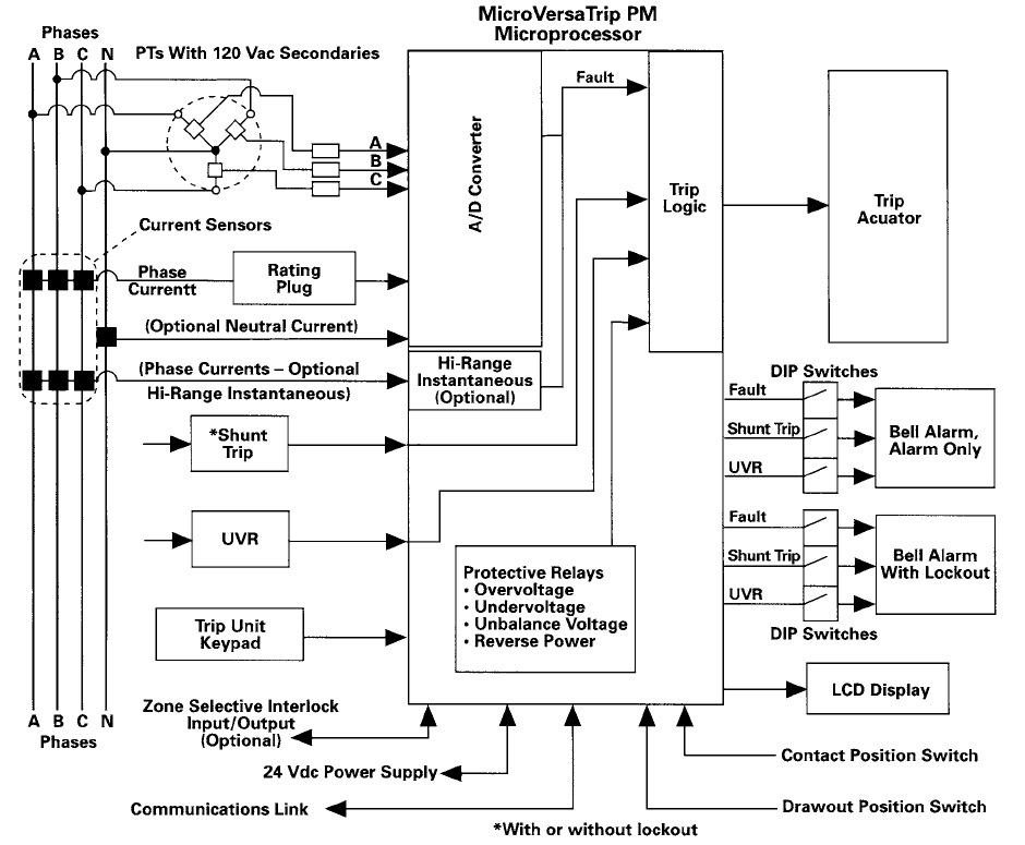
Operation of MicroVersaTrip PM Trip Units
MicroVersaTrip PM trip units add communications capability
with remote host computers and the GE POWER LEADER™
Power Management System. In addition, the user can choose
to add metering, protective relaying or both. In the block dia-
gram (page 20) of the MicroVersaTrip PM trip unit, note that
there are two additional sets of inputs – voltage inputs from
each phase and a +24 Vdc input from an external power
supply. Additionally, there is a communication input/output
link to the POWER LEADER system.
Voltage Inputs
Voltage inputs to the MicroVersaTrip PM trip unit are required
for both metering and protective relays. Voltage inputs
require three delta or wye-connected potential transformers
with 120 Vac secondaries, and an external voltage module
that further conditions the voltage signals for use by the trip
unit’s microprocessor. A single set of external voltage mod-
ules can serve the requirements of up to 20 trip units.
MicroVersaTripPlus ™ and PM™ Trip Units
20
+24 Vdc Input
MicroVersaTrip PM trip units require an external +24 Vdc
power supply to furnish power to the communication
network. In addition, this power supply energizes the LCD
display, so that low current values, voltage values and trip
targets are displayed without use of the internal batteries.
However, batteries are supplied with MicroVersaTrip PM trip
units for cold set-ups and viewing targets in the event the
+24 Vdc power supply is interrupted. A single +24 Vdc power
supply can supply the power requirements of up to 16 Micro-
VersaTrip PM trip units.
MicroVersaTrip Plus™ and PM™ Trip Units
Communications Output
The communications network uses a pair of shielded, twisted
wires to connect individual devices to the POWER LEADER™
system. Connection distances up to 1000 ft. can be made
without repeaters. All communication network wiring within
the breaker is pre-wired to dedicated secondary terminals.
Integration to Modbus RTU networks requires the use of a
POWER LEADER Modbus Concentrator.
MicroVersaTrip PM Microprocessor
Block diagram of MicroVersaTrip PM trip unit

21
Metering
When the metering function is selected, a number of
standard metering parameters can be viewed on the LCD
display. All of these values are communicated to the POWER
LEADER™ Power Management System. The accuracy of the
metering functions is constrained by the physical size of the
current sensors. Consequently, all metering functions are
designed for load management decisions, and are not a
substitute for utility revenue metering equipment.
• Current: All trip units, including MicroVersaTrip Plus™, pro-
vide metering of individual phase currents. The user can
select phases 1, 2, or 3. Current displays automatically shift
from amps to kiloamps above 999 amps. The minimum
current display resolution is in tenths of an amp (e.g., 512
A).
• Voltage: The metering display of four wire systems can
read both line-to-neutral and line-to-line voltage display
for each phase. The smallest resolution of the voltage
display is one volt (e.g. 277V, or 276V).
• Energy: The energy display indicates the amount of real
power that has passed through the breaker. The display
has three-digit resolution, and automatically scales the
display from kWh to MWh to GWh. Normal power flow can
be selected as either load-line or line-load in the setup
mode. Once normal flow is configures, energy values will
accumulate in the positive direction. For certain applica-
tions where power may flow in either direction, such as tie
breakers, energy may display a negative value.
• Real power: Real power in units of kW or MW can be
shown on command on the LCD display.
• Volt-amperes (or total power): “Total power” or volt-am-
peres in units of kVA or MVA can be viewed on command
on the LCD display.
MicroVersaTrip Plus™ and PM™ Trip Units
• Demand: Demand in units of kW or MW can be displayed.
The monitoring time period can be varied from 5 to 60
minutes, in increments of 5 minutes. The display provides a
rolling average of power over the scheduled time interval.
• Peak demand: Peak demands in units of kW or MW can be
displayed. This value indicates the highest power demand
reached since the start of demand measurements, or since
reset. The peak demand value can be reset to the present
demand via the keypad.
Protective Relaying
When protective relaying functions are selected, any combi-
nation of the following protective relays can be enabled. All
relay functions combine both an adjustable setpoint and an
adjustable discrete (not inverse) time delay. All time delays
are adjustable from 1 to 15 seconds in increments of 1 sec-
ond. All tripping is performed through the trip unit. The user
can configure the trip unit to activate the bell alarm only, the
bell alarm with lockout, or neither, in response to a protective
relay (or overcurrent/ground-fault) trip.
• Undervoltage: Undervoltage protection may be set from
50% to 90% of the true rms nominal voltage in increments
of 1%.
• Overvoltage: Overvoltage protection may be set from
110% to 150% of the true rms nominal voltage in incre-
ments of 1%.
• Voltage unbalance: Voltage-unbalance protection com-
pares the lowest or highest phase voltage with the other
two, and initiates a trip if the difference exceeds the
setpoint. True rms voltages are computed for each phase.
The range of trip settings varies from 10% to 50% in incre-
ments of 1%.
• Current unbalance: Current-unbalance protection com-
pares the true rms current in either the highest or lowest
phase with the true rms current in the other two phases. A
trip is initiated if the difference exceeds the setpoint. The
range of trip settings varies from 10% to 50% in incre-
ments of 1%.
• Power reversal: The Power Break® II breaker may be set
so that “positive” power flow can be in either direction (i.e.,
from line to load, or vice versa). Reverse power protection
is set in units of kW. Reverse power setpoints vary from
10kW to 990kW in increments of 10kW.
• Enable/disable relays: To disable any of the protective
relay functions, set the time delay for that function to OFF.
Setting the time delay to any discrete value enables the
relay.
Table 21.1 Trip Unit Metering Display Accuracy
Value Breaker Full Scale
Accuracy
System Full Scale
Accuracy
Current, rms –A, kA ±2.5% ±2.5%
Voltage, rms –V
Phase-Phase, Phase-Neutral
N/A ± 1.5%
Energy –kWh, MWh, GWh N/A ±4.0%
Demand – kW, MW N/A ±4.0%
Peak Demand- kW, MW N/A ±4.0%
Real Power – kW, MW N/A ±4.0%
Total Power – kVA, MVA N/A ±4.0%
Frequency N/A ±1 Hz
Time Delay N/A ±1 sec
Includes trip unit, breaker, current sensors and rating plug. Accuracy is based on
loading range of 20% to 100% of breaker current sensor rating.
Includes trip unit, breaker, current sensors, rating plug, plus Voltage Module (poten-
tial transformers, control power voltage conditioner). Accuracy is based on loading
range of 20 % to 100 % of breaker current sensor rating.

METER
PICKUP
kA
O1
STATUS
FAULT
kA
I>
LT
O2
2
I>>
STATUS
FAULT
I>>
INST
kA
xCT
STATUS
FAULT
GF
STATUS
GF OPS
22
Programming Trip Units
All MicroVersaTrip Plus and MicroVersaTrip PM trip units for
Power Break® II breakers use the same programming key-
pads. All functions ordered are selectable and displayed.
Programming display and keypad
• Function: Selects the mode of the display (Setup, Metering
or Status)
• Select: Chooses the next item for display. All modes have
a sequential menu that allows the user to step from one
function to the next.
• Battery: Energizes the internal battery circuit and the LCD.
• Value: Allows changing a setpoint, or changes a meter-
ing display from line-to-line or line-to-neutral, or select
between phases 1, 2 or 3.
• Enter: Stores setpoint in the trip unit’s non-volatile
memory.
Trip Targets – Overcurrent
and Ground Fault
Trip targets for protective functions use international sym-
bols, and are shown on the LCD when in the Status mode.
• Normal: When all protective circuits are within normal
limits, the term “OK” is visible in the LCD display.
• Long-time trip: The long-time trip display moves through
two transitions. As the current in any phase reaches 95%
of its setpoint, the word “PICKUP” begins to flash. As cur-
rent increases, flashing frequency increases, until 100%
of the pickup point is reached. At that moment, PICKUP
remains ON, continuously, until the long-time delay times
out. Once the breaker has tripped on long time, the symbol
“ |>” appears in the LCD display to indicate a breaker over-
load. In addition to this target, the display indicates the trip
status with the word, “FAULT.” The display shows the type
of trip “LT”, the phrase the fault occurred on, and the mag-
nitude of the fault current. The trip information is displayed
until cleared by the user.
Long-time trip imminent Breaker tripped on long time
• Short-time and instantaneous trips: Short-time and
instantaneous trips share the same trip target. The PICKUP
target is not illuminated, since the time interval between
pickup and tripping are so short for either function. In the
DISPLAY mode, the trip target for a short-time or instanta-
neous trip is “|>>.”
Breaker tripped Breaker tripped on
on short time instantaneous
• Ground Fault Trip: The trip target for a ground fault trip is
illumination of the letters “GF”.
Breaker tripped on ground fault
Trip Operations Counter
The trip unit stores the number of trip operations for long-
time, short-time, instantaneous and ground fault. Up to
256 counts of each trip operation are stored in memory.
Manual reset through the keypad is possible at any time. The
electronic trip operation counter does not store shunt trip,
undervoltage release or protective relay trips. An optional
mechanical operations counter is available that counts
each open-and-close operation of the main contacts for any
reason.
Breaker showing counter
Trip Targets – Protective Relays
Trip targets for the enabled protective relays appear in the
status screen when they occur. Symbols used are:
• Undervoltage trip V<
• Overvoltage trip V>
• Unbalanced voltage DV
• Unbalanced current DI
• Power reversal
Trip Targets - Accessories
UVR and ST targets are displayed when a trip is caused by an
undervoltage release or shunt trip accessory. The display will
indicate with a flashing target and the FAULT segment does
not display.
MicroVersaTrip Plus™ and PM ™Trip Units

23
MicroVersaTrip Plus™ and PM ™Trip Units
Rating Plugs
The same interchangeable rating plugs are used in all of the
MicroVersaTrip Plus™ and MicroVersaTrip PM™ trip units
across the entire Power Break® II breaker product line. Rating
plugs are the key devices that establish the current rating of
the breaker. They provide an essential scaling function for the
unit’s microprocessor, and ensure maximum accuracy. They
also provide an external jack for connection to an external
battery pack.
Rating plugs have rejection features that allow them to be
inserted only with breakers containing the correct current
sensors. Rating plugs for the enhanced MicroVersaTrip Plus
and MicrosVersaTrip PM trip units cannot be use with Spectra
RMS™ molded case circuit breakers, but are compatible with
Power Break and Type AKR breakers with MicroVersaTrip Plus
and MicroVersaTrip PM trip units. See Table 23.1
MicroVersaTrip rating plug
Table 23.1
Rating Plug And Current Sensor Rating
Envelope
Size
Frame Max.
Rating
(Amps)
Sensor
Rating
(Amps)
(S)
Sensor Rating
Plug Amps (X)
2000
800 200 100, 150, 200
400 150, 0, 225 ,250, 300, 400
800,1600 800 300,400,450,500,600,700,800
1600 1000 400,600,800,1000
1600 600,800,1000,1100,1200, 1600
2000 2000 800,1000,1200,1500,1600,2000
3000 2500
1000 400,600,800,1000
2000 800,1000,1200,1500,1600,2000
2500 1600,2000,2500
3000 3000 2000,2500,3000
4000 4000 4000 1600,2000,2500,3000, 3600,4000
S= Sensor amp rating
X= Rating plug amps
Current Sensors
Toroidally wound current sensors are furnished for all major
protective functions and for use with MicroVersaTrip PM trip
units. Toroidal sensors, including a second air-core winding,
are provided with the high-range instantaneous function.
Current sensors are factory installed and are not changeable
in the field. There are 11 current ratings for the Power Break
II breaker line through 4000 amps. See Table 23.1 for current
ratings. Rating plugs must be coordinated with the current
sensor rating (S) listed on the face of the rating plug.
Typical toroidally wound current sensor
Accessory Configuration
Activation of the Bell Alarm – Alarm Only and Bell Alarm with
Lockout are controlled by switch setting on the rear of the
trip unit. To change the conditions which activate these ac-
cessories, configure the trip unit switch setting as described
below.
Rear of trip unit
Table 23.2
Accessory Switch Setting
Switch Factory
Setting
Function
1 Disable Shunt trip activates Bell Alarm – Alarm Only
2 Disable UVR Trip activates Bell Alarm- Alarm Only
3 Enable Protection trip activates Bell Alarm – Alarm Only
4 Disable Shunt Trip Activates Bell Alarm/ Lockout
5 Disable UVR trip activates Bell Alarm/Lockout
6 Enable Protection trip activates Bell Alarm/ Lockout

24
Accessories – Stationary and
Drawout Breakers
The complete line of Power Break® II breaker accessories
may be either factory installed or field installed to meet user
needs. The electronic shunt trip (with or without lockout), the
bell alarm, the bell alarm with mechanical lockout, and the
undervoltage release modules drop in from the front of all
breakers. One of each of the above accessory modules can
be installed, and requires no field internal wiring or breaker
disassembly. The accessory modules are interchangeable
across all frame sizes.
Auxiliary switch modules are available in groups of 4, 8, or
12, NO/NC single-pole, double-throw (SPDT) switches. Their
installation simply involves removal of breaker cover, instal-
lation of the switch module, routing of wiring and installation
of the pre-wired terminal block and re-installation of the
cover. Auxiliary switches are also interchangeable across all
Power Break II breaker frames.
Test Kit
The test kit, catalog number TVRMS2 is a portable, battery-
powered, test kit which provides for trip unit health checks
and functional trip and no-trip test. It also provides defeat
of the ground-fault function and can be used in conjunction
with high-current test equipment. The test kit can be used to
provide +24V power to the trip unit for cold set-up and view
of trip targets. This test kit is for use with Power+™, MicroVer-
saTrip Plus™ and MicroVersaTrip PM ™ trip units.
Electrical Operator
The electrical operator mounts inside the front cover of the
manually operated breaker. This accessory can be added
to any Power Break II breaker in the factory or the field to
provide electrical spring charging. All breakers are pre-wired
to dedicated secondary terminals for easy field installation.
When electrical operation is used, a remote close solenoid
and either a shunt trip or an undervoltage release accessory
are required for remote closing and opening.
The electrical operator can be wired to charge automatically
following a CLOSE operation, or to charge on command. A
remote charge indicator switch is integral to the electrical
operator. If control power is lost during the charging cycle,
spring charging can be completed manually using the pump
handle – no special tools or separate handles are required.
However, if the charge cycle is begun manually, it must be
competed manually. Any electrically operated breaker can
be operated manually.
The control power required for each motor operator may be
determined from Table 25.2. If several motor operators are
fed from the same source, it should be sized to accommo-
date all operators simultaneously, especially if they are wired
for automatic charge.
The voltage drop in source supply from no-load to motor
full-load current should not exceed 7% of nominal voltage.
Acceptable dc power supplies are: three-phase, full-wave
rectified ac; battery; dc generator or any other dc source with
a peak-to-peak ripple voltage of not more than 15% at rated
full-load current. Operating range of electrical operator: 90%
-110% of nominal rating. See wiring diagram on page 26.
Table 24.1
Electrical Operators
Catalog
Number
Voltage Rating
(50-60Hz)
Peak Inrush
(Amps)
Operating Time
(Seconds)
SPE024 24 Vdc 30.0 3
SPE048 48 Vdc 18.0 3
SPE072 72 Vdc 10.0 3
SPE125 125 Vdc 7.5 3
SPE120 120 Vac 8.0 3
SPE240 240 Vac 6.0 3
Accessories
Power Break II breaker electrical operator

25
Accessories
Remote Close Solenoid
This accessory is an electrically operated solenoid which,
when energized, closes the breaker. It is suitable for control
interlock schemes in which manual closing capability would
not be convenient or would be too slow. It is an optional ac-
cessory for a manually operated breaker, but is required for
an electrically operated breaker. The remote close accessory
is continuously rated and has an anti-pump feature which
prevents a motor operated breaker from repeatedly closing
into a fault. Closing control voltage must be removed and
re-applied for each breaker closure.
This accessory consists of an integral electronic control mod-
ule and the closing solenoid. When control voltage is applied
to the accessory, the electronic control module applies a
single pulse of current to the solenoid for approximately 0.25
seconds to drive the solenoid before shutting the current off
to a level of approximately 10mA. Voltage must be removed
and re-applied to reclose the breaker, thereby providing the
anti-pump feature.
This pulse approach allows the accessory to be continuously
rated. Control voltage must be removed for 2.5 seconds and
then reapplied each time the solenoid is to be energized.
Removal of the voltage for significantly less than 2.5 sec-
onds will not reset the electronic control module and prevent
the solenoid from being energized. Applied control voltage
(closed circuit voltage at breaker terminals 34 and 16) must
be 85% to 110% of nominal. The solenoid will not energize if
voltage is ramped up to the acceptable range. Three-cycle
closing time, at nominal voltage, is standard and fulfills the
requirements of generator synchronizing.
Table 25.2
Control Power Requirements For Motor Operators
Rated Voltage
(50-60 Hz)
Operating
Voltage Range
Peak Inrush
(RMS Amps)
Peak Full
Load Amps
Average Amps Charge Time
(Sec)
Recommended
Fuse (Slo-blow)
24 Vdc 21 – 27 Vdc 30.0 14.0 11.0 3 12A, 125V
48 Vdc 41 - 53 Vdc 18.0 7.0 4.5 3 7A, 125V
72 Vdc 62 – 80 Vdc 10.0 4.5 3.0 3 5A, 125V
120 Vac 102 – 132 Vac 7.5 4.0 2.0 3 4A, 125V
125 Vdc 106 – 137 Vdc 8.0 2.5 1.8 3 2.5A, 125V
240 Vac 204 - 264 Vac 6.0 2.5 1.0 3 2.5A, 250V
Charging time apply to normal voltage only; times may vary at maximum and minimum voltage.
Table 25.1
Remote Close Solenoid
Catalog Number Voltage Ratings Peak Inrush Current
(Amps)
SPRCS024 24 Vdc 13.2
SPRCS048 48 Vdc 6.6
SPRCS072 72 Vdc 5.0
SPRCS125 125 Vdc 3.5
SPRCS120 120 Vac 3.0
SPRCS240 240 Vac 2.0
Remote close solenoid

26
Wiring Diagrams For Remote Operation
For proper operation, the electrical circuit should be wired as
shown in the diagram. All customer-supplied contacts should
be rated for the currents identified for both the electric op-
Accessories
Ac or dc power wiring diagram, remote operation
Shunt Trip
The shunt trip accessory is an electronic module which pro-
vides remote control capability to open the circuit breaker.
Breaker opening time is 50 milliseconds. When activated, the
shunt trip module sends a signal to the trip unit to open the
breaker. This allows the trip unit to record, display, distin-
guish and communicate (in MicroVersaTripPM™ trip units)
that the opening event was initiated by the shunt trip device.
The shunt trip is continuously rated and requires no cut-off
switch. When energized, the shunt trip supplies +24 Vdc
power to the trip unit to power the display.
Shunt trip modules are available in a wide range of voltages
(from 24 to 250 Vdc, and 24 to 240 Vac). They meet UL re-
quirements for operation at 55% of rated ac or 75% of rated
dc voltage, making this device suitable for use with Class 1
ground-fault protective devices. Shunt trip modules are also
available for 480 Vac and 600 Vac control power. A 50 VA
control power transformer, which mounts externally from
the breaker, is required and supplied with these accessories.
These transformers provide an output of 120 Vac, 50/60
Hz, to the supplied shunt trip ( with or without lockout). (See
outline drawing in the Physical Data section.)
Table 26.1
Shunt Trip Module
Catalog
Number
Voltage
Rating
(50-60 Hz)
Maximum
Operating
Voltage
(Volts)
Peak Inrush
Current
(AC Amps)
Nominal
Input
Current
(AC RMS mA)
SPST012 12 Vdc 13.2 3.0 200
SPST024 24 Vac/dc 26 1.5 140
SPST048 48 Vac/dc 53 1.5 110
SPST120 120Vac/125 Vdc 132 1.5 85
SPST208 208 Vac 228 1.5 50
SPST240 240Vac/250 Vdc 264 1.5 40
SPST 480 480 Vac 528 3.0 65
SPST 600 600 Vac 660 3.0 65
Shunt trip module
erator and the remote close solenoid. If momentary contact
switches are used, the minimum duration of contact closure
must be 83 milliseconds.

27
Accessories
Shunt Trip With Lockout
The shunt trip with lockout is similar to the regular shunt trip.
When energized, the shunt trip with lockout module sends a
signal to the trip unit to open the breaker. In addition, when
continuously energized with the breaker open, a plunger in
the module acts upon the mechanism, blocking manual and
electric closing by preventing mechanism spring discharge.
To close the breaker, de-energize the module for 250 ms. Be-
cause the breaker movable contacts are restrained and can-
not momentarily touch the stationary contacts, the mecha-
nism remains “kiss-free”. This feature is especially important
in main-tie-main schemes or generator circuits.
Table 27.1
Shunt Trip Module with Lockout
Catalog
Number
Voltage
Rating
(50-60 Hz)
Maximum
Operating
Voltage
(Volts)
Peak Inrush
Current
(AC Amps)
Nominal Input
Current
(AC RMS mA)
SPSTL012 12 Vdc 14 19 300
SPSTL024 24 Vac/dc 26 15 300
SPSTL048 48Vac/dc 53 7.5 200
SPSTL120 120Vac/125
Vdc
132 3 80
SPSTL208 208Vac 228 1.9 60
SPSTL240 240 Vac/250
Vdc
264 1.5 45
SPSTL480 480 Vac 528 3 65
SPSTL600 600Vac 660 3 65
Bell Alarm (Alarm Only)
The bell alarm module is used to signal breaker “tripped” sta-
tus to other accessories (e.g. external alarm devices, indicat-
ing lights, relays, or logic circuits) for remote indication and
interlocking functions. The switch is configurable by means
of rear-mounted DIP switches on the MicroVersaTrip Plus™
and PM™ trip units. The bell alarm can be made to oper-
ate in response to an overcurrent (including ground fault) or
protective relay trip and/or a shunt trip operation, and/or
operation of the undervoltage release module. It is not actu-
ated as a result of normal breaker “ON/OFF’ operation. For
the Power+™ trip unit, the bell alarm operates only when an
overcurrent (including ground fault) trip occurs.
This module provides a visual, mechanical pop-out target
which protrudes through the face of the circuit breaker door
when it operates. The bell alarm may be reset manually by
depressing the mechanical target, or automatically by clos-
ing the breaker.
The bell alarm is provided with one SPDT switch with control
power duty contacts as shown in Table 27.2.
Bell alarm
Table 27.2
Bell Alarm Module
Catalog Number AC Ratings DC Ratings
SPBAA240 6 A @ 240 Vac 0.5 A @ 125 Vdc
0.25 A @ 250 Vdc
SPBAA6006A @ 600 Vac 0.5 A @ 125 Vdc
0.25 A @ 250 Vdc
600 Vac module not UL listed

28
Bell Alarm With Lockout
The bell alarm with lockout module combines both the bell
alarm and a manual lockout function. The bell alarm switch
operates identically to the standard bell alarm module,
except that the mechanical pop-out target must be manually
reset before the breaker can be closed.
Operation of the bell alarm with lockout module can be in-
dependently set by means of setting the DIP switches at the
rear of the MicroVersaTrip Plus™ and PM™ trip units. For the
Power+™ trip unit, the bell alarm with lockout module oper-
ates only when an overcurrent (including ground fault) trip
occurs. Current ratings of the single SPDT switch are identical
to the bell alarm module.
Table 28.1
Bell Alarm with Lockout Module
Catalog Number AC Ratings DC Ratings
SPBAL240 6 A @ 240 Vac 0.5 A @ 125 Vdc
0.25 A@ 250 Vdc
SPBAL6006 A @ 600 Vac 0.5 A @ 125 Vdc
0.25 A @ 250 Vdc
600 Vac module not UL listed
Undervoltage Release Module
The undervoltage release is an electronic module used to
open the circuit breaker when the monitored voltage drops
below 35-60% of its rated value. The undervoltage release
“resets” when the monitored voltage is re-established allow-
ing the circuit breaker to reclose (the sealing voltage of the
UVR is 60-85% of its rated voltage).
Undervoltage release module
An undervoltage release trip operation is produced by the
Power+, MicroVersaTrip Plus or MicroVersaTrip PM trip unit in
response to a signal from the undervoltage release module.
This allows the trip unit to record, display, distinguish and
communicate (in MicroVersaTrip PM trip units) that the break-
er opening event was due to undervoltage release. Opera-
tion of the undervoltage release module will prevent breaker
contact closure, i.e. “kiss-free” operation. When energized,
the undervoltage release supplies +24 Vdc power to the Mi-
croVersaTrip Plus and PM trip units to power the display.
The undervoltage release module is available in a wide range
of control and power system voltages ranging from 12 Vdc
to 600 Vac. Undervoltage release modules used with 480
Vac and 600 Vac control power are supplied with a 50 VA
control power transformer which mounts externally from the
breaker. These transformers provide an output of 120 Vac,
50/60 Hz, to the UVR modules. (See outline drawings in Physi-
cal Data Section.)
Table 28.2
Undervoltage Release Module
Catalog
Number
Voltage Ratings
Current
(50-60 Hz)
Peak Inrush
Current
(Amps)
Nominal
Input
(mA)
SPUV012DC 12 Vdc 16 200
SPUV024DC 24 Vdc 15 140
SPUV048DC 48 Vdc 7.5 70
SPUV125DC 125 Vdc 3 30
SPUV250DC 250 Vdc 1.5 15
SPUV024AC 24 Vac 15 370
SPUV048AC 48 Vac 7.5 210
SPUV120AC 120 Vac 3 80
SPUV208AC 208 Vac 1.9 60
SPUV240AC 240 Vac 1.5 45
SPUV480AC 480 Vac 2 50
SPUV600AC 600 Vac 2 60
Time Delay Module for UVR
The time delay module prevents nuisance tripping due to
momentary loss of voltage. Cat. No. SPUVTD has 0.1 to 1.0
seconds delay. The module has 120 Vac input and 125 Vdc
output and must be used with the 125 Vdc UVR (Cat. No.
SPUV125DC).
Accessories
Bell alarm with mechanical reset lockout

29
Accessories
Auxiliary Switch
An auxiliary switch signals the circuit breaker’s primary con-
tact position (i.e. OPEN or CLOSED) to other devices, such as
indicating lights, relays or logic circuits. This enables the user
to provide remote indication, interlocking or control opera-
tions as a function of breaker primary contact position. The
auxiliary switch operation is independent of the method by
which the breaker is opened or closed. The auxiliary switch
does not distinguish between a “tripped” or “open” condi-
tion. The auxiliary switch contacts follow the main breaker
contacts on opening and precede them on closing.
Auxiliary switch with pre-wired secondary terminals (Drawout
shown)
Auxiliary switch modules are available with 4, 8,or 12 NO/NC
(SPDT) switches for control power duty ac/dc ratings. When
ordered for field installation, an auxiliary switch module
comes pre-wired to its own terminal board, which mounts
with one screw to the left side of the breaker. All secondary
terminals are dedicated, so there is no confusion in wiring to
a 4, 8, or 12-switch module. A separate accessory for draw-
out breakers come pre-wired to the secondary disconnect.
Table 29.1
Auxiliary Switch
Catalog NumberNumber of
Contacts
AC
Ratings
DC
Ratings
SPAS240AB4
SPAS240AB4D
4 6A@240 Vac
and120 Vac
0.5A@ 125 Vdc
0.25 @ 250 Vdc
SPAS240AB8
SPAS240AB8D
8 6A@ 240 Vac
and 120 Vac
0.5A@ 125 Vdc
0.25 @ 250 Vdc
SPAS240AB12
SPAS240AB12D
12 6A@240 Vac
and 120 Vac
0.5A@ 125 Vdc
0.25 @ 250 Vdc
SPAS600AB4
SPAS600AB4D4 6A@600 Vac 0.5A@ 125 Vdc
0.25 @ 250 Vdc
SPAS600AB8
SPAS600AB8D8 6A@600 Vac 0.5A@ 125 Vdc
0.25 @ 250 Vdc
“D” suffix for drawout breaker accessory.
600 Vac Modules not UL Listed
Limited Access “Pushbutton Cover”
This accessory limits access to “ON/OFF” control of a breaker
to authorized personnel. The pushbutton cover accessory
consists of transparent hinged covers that can be individu-
ally sealed to the limited access assembly. Both the “ON” and
“OFF” button covers can be pilot drilled to allow use of a 1/8”
rod to operate either one or both pushbuttons. The catalog
number of this accessory is: SPPBCOVER.
Limited access pushbutton cover assembly
Mechanical Operations Counter
The mechanical operations counter is mounted behind the
front cover of the breaker, and it is viewable through a rect-
angular knockout window opening in the breaker cover. It is
a five-digit non-resettable counter which is actuated each
time the breaker is opened by any means. Together with the
fault operations counters stored in MicroVersaTrip Plus™ and
MicroVersaTrip PM™ trip unit memory, a complete history
of breaker operations is available to the user. The catalog
number of this accessory is : SPCOUNTER.
Mechanical operations counter
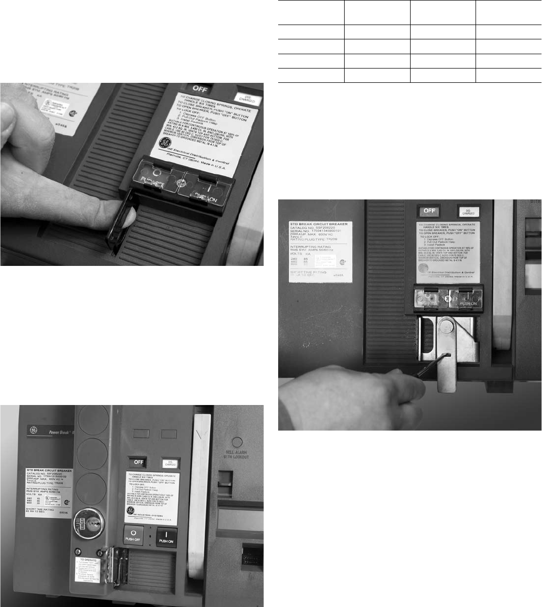
30
Padlock Device (Standard)
Padlocking devices are standard on all Power Break® II Cir-
cuit breakers. When the breaker is in the open position, and
the padlock device is raised at least ¼”, the breaker cannot
be closed mechanically or electrically. The device accepts
up to three padlocks with 1/4” to 3/8” diameter shanks. The
padlock device meets the EUSERC requirement for
padlocking.
Integral padlock device
Key Interlock Provisions
The key interlock provision enables the user to mount a
one-to four-cylinder, narrow-faced, Kirk-type FN customer-
supplied lock on the face of the breaker. The key interlock
provision works in conjunction with the padlock device. The
key interlock extends a lever through the padlock device
when the key is turned to the key removal or bolt extended
position.
Key interlock installed on front of the breaker
Table 30.1
Key Interlock Provisions
Catalog
Number
Number of
Locks
Kirk Key lock
Cat. Number
Superior Cat.
Number
SPK4 1 KFN00001-S105827Y
SPK4 2 KFN00002-S105828Y
SPK4 3 KFN00003-S105829Y
SPK4 4 KFN00004-S105827-4Y
Final digit may be 0, 1, 2, or 3 depending on number of key removal
positions.
Door Interlock
The door interlock provides interlocking of the circuit breaker
compartment’s hinged door so that the breaker must be in
the “OFF” position before the door can be opened. The door
interlock is defeatable with a small tool to allow authorized
access. The catalog number of the door interlock is: SPDIL.
Door interlock
Accessories

31
Neutral Current Sensors
When the ground-fault option is selected in a trip unit, and
a single phase 3-wire or a 3 phase four-wire power system
(e.g., 120/208 Vac or 277/480 Vac) is used, an external neu-
tral sensor must be inserted in the neutral lead of the power
system to complete the ground-fault protective circuit.
Neutral current sensor
Table 31.1
Neutral Current Sensors
Breaker Frame
(Amps)
Circuit Breaker
Sensor Rating
(Amps)
Neutral Sensor
Rating or Tap
Setting (Amps)
Catalog
Number
800 200
400
800
200
400/200
600/300
800/400
TSVG302
TSVG304A
TSVG306A
TSVG308A
1600
1000
1600
800/400
1000/500
1200/600
1600/1000
TSVG808A
TSVG810A
TSVG812A
TSVG816A
2000 2000 2000/1200 TSVG820A
3000
1000
2000
2500
3000
800/400
1000/500
1200/600
1600/1000
2000/1200
2500/1800
3000/2400
TSVG808A
TSVG810A
TSVG812A
TSVG816A
TSVG820A
TSVG825A
TSVG830A
4000 4000 4000/3000 TSVG940A
Match neutral current sensor rating (or tap setting) to circuit breaker sensor rating.
For use with multiple-source ground fault protection schemes. rating does not
match MicroVersaTrip® Trip Unit sensor.
Accessories
Additional Accessories – Stationary
Breakers General Purpose,
Wall Enclosures
General Purpose, NEMA 1 enclosures are available for Power
Break® II breakers with neutrals for 800-2000 amps. These
units are UL Listed for service entrance use for single phase
three-wire, or 3-phase four-wire power systems through 600
Vac. Enclosures are provided with breaker mounting studs
and lugs. Enclosures, breakers and neutrals are ordered and
shipped separately, unassembled. These units are suitable
for use in 65 kA (max.) rms symmetrical systems.
Table 31.2
Enclosures And Field Installed Neutrals
Catalog Number Frame Size Field Installed Neutral
Catalog Number
SPB08W 800 A TNT800
SPB16W 1600 A TNT1600
SPB20W 2000A TNT2000

32
Lug Adapter Kits
Pre-mount to bus structure allowing cabling or bussing to be
completed prior to breaker mounting. Accept either lugs or
crimp-type connector terminals. Catalog includes adapter
and hardware for either a three-pole line-side, or a three-
pole load-side connection. (Lugs not included)
Table 32.1
Lug Adapter Kits
Circuit Breaker
Frame Size (Amps)
Suitable For Use
With up to:
Catalog
Number
800 3 TPLUG108 Lugs or
3 Crimp Lugs Per Pole TPLUA08
1600 6 TPLUG108 Lugs or
6 Crimp Lugs Per Pole TPLUGA16
2000 6 TPLUG108 Lugs or
6 Crimp Lugs Per Pole SPLUGA20
Anderson VCEL-075-12H1 or equivalent.
T-Studs – SP20FCA – included with adapter.
T-Studs
T-Studs mount directly to the breaker, and can be rotated
for either vertical or horizontal busbar connection. Catalog
numbers cover one stud. Both copper and aluminum T-studs
are tin-plated.
800- amp, Cat. No. SP08FCA and 1600 – 2000-amp, Cat. No.
SP20FCA aluminum T- Studs
Table 32.2
T-Studs
Circuit
Breaker
Frame Size
(Amps)
Catalog Number
Max. Rating
(Amps)
For Front
Connected Breaker
For Back
Connected Breaker
800 800 SP08FCA
SP08FCC—
2000 1600-2000 SP20FCA
SP20FCC—
2500 2000
2500
SPS20FCA
SPS25FCCSPS20BCA
SPS25BCC
3000 3000 SPS30FCC
4000 4000
4000
SPS40FCC
SPS40LFCC —
—
Aluminum
Six T-studs supplied at no charge when ordered with breaker.
Copper
Supplied with integral T-Stud.
Extra long stud. Alternate with SPS40FCC for ease of installation.
Accessories

33
Mechanical Interlocks (“Walking Beam”)
For Stationary Breakers
Mechanical interlocks are mechanical devices used to
prevent two adjacent circuit breakers from both being in
the “ON” or closed position at the same time. The interlock
permits both breakers to be in the “OFF” position or open
position while allowing either or both to be charged.
Table 33.1
Mechanical Interlocks
Maximum Current Envelope
Size Rating (Amps)
Catalog Number
2000 SPWB20
3000 SPWB30
4000 SPWB40
Lug Kits
Lug kits accept copper and aluminum wire and are suitable
for direct mounting to the breaker, except in the case of
TSLUG kits, T-studs must also be used.
Table 33.2
Lug Kits
Circuit
Breaker
Frame Size
(Amps)
Max
Rating
(Amps)
Catalog
Number
Lugs
Per
Kit
Max.
Cables
Per
Pole
Wire
Range
(Footnote)
800
400 TPLUG106 1 1
600 TPLUG206 1 2
800 TPLUG308 1 3
800 TPLUG1081 3
1600 1600 TPLUG408 1 4
TPLUG1081 6
2000 2000 TPLUG1081 6
3000
800 TSLUG08 9 3
1200 TSLUG12 12 4
1600 TSLUG16 15 5
2000 TSLUG20 18 6
2500 TSLUG25 21 7
3000 TSLUG30 27 9
4000 4000 TSLUG40 33 11
For use with adapter kit only.
#2 AWG-600 kcmil Cu/Al.
300-750 kcmil Cu/Al.
#3/0 AWG – 800 kcmil Cu/Al.
500-800 Kcmil Cu/Al.
3/0- 800 kcmil Cu/Al.
For back connected 3000A: T-Stud integral with breaker.
Additional Accessories – Drawout
Breakers Substructures
Substructures are available for both standard and Hi-Break®
Power Break® II breakers. Holes are provided for bolting on
a shelf or supports. Holes are also provided in the primary
stabs for bolting to busbars or terminal lugs. A special speed
wrench-style racking tool is provided for racking a breaker in
and out of the substructure.
Table 33.3
Substructures
Circuit Breaker
Frame Size (Amps)
Standard Break
Catalog Number
Hi-Break
Catalog Number
800 SPSDOS08 SPHDOS08
1600 SPSDOS16 SPHDOS16
2000 SPSDOS20 SPHDOS20
2500 SPSDOS25 SPHDOS25
3000 SPSDOS30 SPHDOS30
4000 SPSDOS40 SPHDOS40
Accessories

Accessories
34
Secondary Disconnects
Control wiring is connected through drawout secondary
disconnects in the “TEST” and “CONNECTED” positions only.
Up to 72 control circuits are possible through (36) position
plug-style secondary disconnect blocks factory mounted to
each side of drawout breakers. One substructure disconnect
(SPD0SD36S) must be ordered for each breaker. An additional
block is required for auxiliary switches.
Table 34.1
Secondary Disconnects
Catalog Number Location
SPDOSD36S Substructure
SPDOSD36B Breaker
One must be ordered for each substructure when accessories or communications
are used. When auxiliary switches are used, along with any other electrical acces-
sory or communication, two disconnects must be ordered.
Order for replacement only. Included with drawout breaker.
Shutters
Shutters prevent unintentional contact with potentially live
primary disconnect stabs when a breaker is racked out of an
energized switchboard compartment.
Table 34.2
Shutters
Frame Size Catalog Number
800-2000A SPDSS20
3000A SPDSS30
4000A SPDSS49
Racking Padlock
The catalog number TDOPC racking padlock provides a
means for the user to prevent racking tool engagement,
thereby preventing movement of the breaker between the
Disconnected, Test and Connected positions.
By-Pass Switch
Provides control circuit continuity or downstream signal-
ing when drawout is engaged. The switch can be used as
an interlocking means to ensure the remote close solenoids
cannot be energized until the drawout breaker primaries are
fully engaged. The switch assembly mounts on the station-
ary frame, and the actuator to the carriage. Switch contacts
are rated at 10A at 600Vac, 0.75A at 125Vdc and 0.25A at
250Vdc.
Table 34.3
By-Pass Switch
Catalog Number Number of Switch Elements
TDOBP2L 2 NO/2 NC
TDOBP4L 4 NO/4 NC
TDOBP6L 6 NO/6 NC
Racking Tool
The racking tool is a drive wrench with a square ½” socket
that engages the racking mechanism of the drawout
breaker. The catalog number is TDORT. Note that one racking
tool is supplied with each group of five drawout breakers at
no charge.
Mechanical Interlocks for Drawout Breakers
Mechanical interlocks for drawout breakers provide the
same function as those for stationary breakers, except they
are used with two drawout breakers, mounted on a common
compartment centerline, in either the same vertical section
or adjacent vertical sections.
Table 34.4
Mechanical Interlocks
Envelope Size Catalog Number
800-2000 SPDOWB20
2500-4000 SPDOWB40
Lifting Bar
The lifting bar (TBOLB) provides a means of safely lifting a
drawout circuit breaker. A chain hook should be attached to
the central hole in the lifting bar.
Position Switch
Provides positive indication when the drawout breaker or
switch primary contact fingers have been fully disengaged
from the main bus connections. Switch contacts change
state only after the primary fingers are fully disconnected
when the breaker is being moved from the CONNECTED posi-
tion through the TEST position and into the DISCONNECTED
position.
May be used as part of a safety interlocking system in addi-
tion to the visual indicator on the drawout substructure. The
Position Switch accessory does not indicate either the TEST
or CONNECTED position. The switch assembly mounts on the
stationary frame and the actuator mounts to the carriage.
Switch contacts are rated at 10A at 600Vac, 0.75A at 125Vdc,
and 0.25A at 250Vdc.
Number of Switch
Elements
Product Number List Price
S NO/2NC SDOPS2L $177.00
4 NO/4 NC SDOPS4L $256.00
6 NO/6NC SDOPS6L $336.00

35
This section contains the nomenclature system for Power Break® II circuit breakers, Power+™, MicroVersaTrip Plus™ and
MicroVersaTrip PM™ trip units and the interchangeable rating plugs.
Power Break® II Circuit Breaker Catalog Numbers
S S D 08 * 02 H
Catalog Numbers
Accessory Catalog Numbers
SP AS 240 AB4D R
Power Break II breaker type
Current interrupting capacity
S = Standard break
H = HiBreak® breaker
Construction
D = Drawout
F = Stationary, front connected
B = Back connected, 2500-3000A only
Frame rating
08 = 800A 25 = 2500A
16 = 1600A 30 = 3000A
20 = 2000A 40 = 4000A
Auxiliary function
H = High-range instantaneous current sonsors
Blank = Standard current sensors
Current sensor rating
02 = 200A 20 = 2000A
04 = 400A 25 = 2500A
08 = 800A 30 = 3000A
10 = 1000A 40 = 4000A
16 = 1600A
Trip unit type and rating
B = Enhanced MicroVersaTrip Plus and
MicroVersaTrip PM trip unit;
D = Power+ trip unit
B2/D2 = 2000A maximum
B3/D3 = 2500, 3000A
B4/D4 = 4000A
Extender
R = Field installable kit
Blank = Factory installed
Auxiliary switch extender
AB4 = Auxiliary switch, type AB with 4 elements
AB8 = Auxiliary switch, type AB with 8 elements
AB12 = Auxiliary switch, tdype AB with 12 elements
(Add suffix “D” for Drawout construction
Voltage, unless otherwise stated
012 = 12 Vdc
024 = 24 Vdc
048 = 48 Vdc
120/125 = 120 Vac or 125 Vac
240/250 = 240 Vac and 250 Vac
250 = 250 Vdc
480 = 480 Vac
600 = 600 Vac
08 = 800A 25 = 2500A
16 = 1600A 30 = 3000A
20 = 2000A 40 = 4000A
BCA = Back connected aluminum
BCC = Back connected copper
FCA = Front connected aluminum terminal T-stud
LFCC = Front connected copper, long stud
36B = 36 secondary disconnects, breaker
36C = 36 secondary desconnects, substructure
High-range instantaneous sensors only available on
MicroVersaTrip Plus and MicroVersaTrip PM units. For
availability of Power+ Tip Untis, contact your ED&C sales
engineer.
Power Break II breaker
Device type
AS = Auxiliary switch*
BAA = Bell alarm, alarm only*
BAL = Bell alarm with lockout*
COUNTER = Mechanical counter*
DIL = Defeatable door interlock
DOSD = Drawout secondary disconnects
DOWB = Drawout mechanical interlock
DSS = Substructure shutter kit*
E = Electric operator*
HDOS = Hi-Break rated drawout sustructure*
K4 = Kirk Key lock (4 maximum)*
PBCOVER = Pushbutton cover*
RCS = Remote close solenoid*
SDOS = Standard rated drawout substructure*
ST = Shunt trip*
STL = Shunt trip with lockout
UV = Undervoltage release*
WB = Walking beam for stationary breakers
08 = 800A T-stud
20 = 1600 thru 2000A T-stud
S20 = 2000A T-stud (3000A frame)
S25 = 2500A T-stud
S30 = 3000A T-stud
S40 = 4000A T-stud
RAILS = Rail kit
LUGA = Lug adapter kit
B = Enclosure
* Device Cat. No. requires an extender “R” for field installable kit version only.

Target Module Catalog Numbers
TARGET00= Blank insert for Target Module
TARGET01= Target Module without ground fault target
TARGET02= Target Module with ground fault target
36
Power+™ Trip Unit Catalog Numbers
D2 20 LSI T1 R
Catalog Numbers
Rating Plug Catalog Numbers
TR 10 C 800 GF
Trip unit type and rating
TR = Trip unit rating plug
All Power+, MicroVersaTrip Plus™
and MicroVersaTrip PM™ rating plugs
Current sensor rating
2 = 200A
4 = 400A
8 = 800A
10 = 1000A
16 = 1600A
20 = 2000A
25 = 2500A
30 = 3000A
40 = 4000A
Trip unit type
C = Power+ trip unit rating plugs
Ground Fault Function
Blank = No ground fault
GF = Ground fault
Rating plug ampere rating
100 = 100A 800 = 800A
150 = 150A 1000 = 1000A
200 = 200A 1100 = 1100A
225 = 225A 1200 = 1200A
250 = 250A 1500 = 1500A
300 = 300A 1600 = 1600A
400 = 400A 2000 = 2000A
450 = 450A 2500 = 2500A
500 = 500A 3000 = 3000A
600 = 600A 3600 = 3600A
700 = 700A 4000 = 4000A
Trip unit type and rating
D2 = Power Break® II Power+ Trip Unit:
2000 A sensor maximum
D3 = Power Break II Power+ Trip Unti:
3000 A sensor maximum
D4 = Power Break II Power+ Trip Unit:
4000 A sensor maximum
Sensor rating
02 = 200A
04 = 400A
08 = 800A
10 = 1000A
16 = 1600A
20 = 2000A
25 = 2500A
30 = 3000A
40 = 4000A
Replacement or new
R= Replacement trip unit
(Blank) = New
Trip unit options
T1 = Target Module without
ground fault target
T2 = Target Module with
ground fault target
Blank = No Target Module
Auxiliary functions
LI = Long time and instantaneous
LSI = Long-time, short-time, instantaneous

37
MicroVersaTrip Plus™ and MicroVersaTrip PM™ Trip Unit Catalog Numbers
B2 20 LSI GZI PM R
Catalog Numbers
Rating Plug Catalog Numbers
TR 10 B 800
Trip unit type and rating
B2 = Power Break® II Enhanced MicroVersaTrip
Plus or PM Trip Unit: 2000A sensor maximum
B3 = Power Break II Enhanced MicroVersaTrip
Plus or PM Trip Unit: 3000A sensor maximum
B4 = Power Break II Enhanced MicroVersa Trip
Plus or PM Trip Unit: 4000A sensor maximum
Sensor rating
02 = 200A
04 = 400A
08 = 800A
10 = 1000A
16 = 1600A
20 = 2000A
25 = 2500A
30 = 3000A
40 = 4000A
Auxiliary functions
LI = Long time and instantaneous
LSI = Long-time, Short-time, instantaneous
LSH = Long-time, Short-time, high range instantane
Replacement or new
R = Replacement trip unit
(Blank) = New
Trip unit options
Options for MicroVersaTrip PM trip units only.
Must select one:
P = Protective relays and communications
M = Metering and communications
PM = Protective relays, metering,
and communications
(Blank) = MicroVersaTrip Plus trip unit
Ground fault funcitions
G = Ground fault
GD = Ground fault defeatable (not UL listed)
GZ1 = Ground fault; ground fault only zone
selective interlock
GZ2 = ground fault and short-time selective interlock
GDZ2 = Ground fault defeatable (not UL listed):
gound fault and short-time selective interlock
(Blank) = None
Device Type
TR = Trip unit rating plug
All MicroversaTrip Plus
and MicroVersaTrip PM rating plus
Current sensor rating
02 = 200A
04 = 400A
08 = 800A
10 = 1000A
16 = 1600A
20 = 2000A
25 = 2500A
30 = 3000A
40 = 4000A
Rating plug ampere rating
100 = 100A 1000 = 1000A
150 = 150A 1200 = 1200A
200 = 200A 1500 = 1500A
225 = 225A 1600 = 1600A
300 = 300A 2000 = 2000A
400 = 400A 2500 = 2500A
500 = 500A 3000 = 3000A
600 = 600A 3600 = 3600A
700 = 700A 4000 = 4000A
800 = 800A
Trip unit type
B = All Enhanced MicroVersaTrip
Plus & MicroVersaTrip PM
trip unit rating plugs

38
Standards And Testing
Power Break® II circuit breakers are UL Listed in accordance
with Standard UL 489. This standard requires the breaker to
meet or exceed endurance and interrupting criteria. Power
Break II breakers are designed and tested to exceed these
requirements.
UL 489 requirements for endurance capability without cur-
rent (mechanical endurance) vary with frame ratings. For
example, for an 800-amp frame, the UL requirement is 3000
operations; and for a 4000-amp frame, only 1100 opera-
tions. All Power Break II breakers are designed to exceed this
requirement by meeting a minimum of 10,000 mechanical
operations.
UL Test Procedures
Extracted from UL Standard 489, current edition.
The following information briefly describes the types of tests
Power Break II insulated case circuit breakers, rated 800
through 4000 amperes, must successfully pass.
1. Calibration: Tested at 200%, and 135% at 25° C. At
200%, an 800A breaker must trip in 2 to 30 minutes de-
pending on the current rating. At 135%, all sizes (larger
than 50 amperes) must trip within 2 hours.
2. Overload: 50 operations making and breaking six times
rated current at rated minimum voltage, 0.45-0.50
power factor for 800 and 1600A frame sizes; 2000 and
2500A frames, 25 operations at six time rated current;
and, 3000 and 4000A frames, 3 operations at six times
rated current plus 25 operations at two times rated cur-
rent. Tests are conducted at one operation per minute,
(make and break), but may be done in groups of five
operations with 15-minute delay between groups.
Overload test is conducted in a metal enclosure rep-
resenting the minimum size enclosure for which the
breaker is suitable. No electrical or mechanical break-
down is permitted and a 30-ampere fuse, connected
from the metal enclosure to the line lead least likely to
arc to the enclosure, must not rupture.
3. Repeat 200% calibration test.
4. Temperature Test: The circuit breaker after overload
is outfitted with 4 ft. minimum of rated copper cable
per pole, line and load end, and rated current is passed
through the breaker which is not in an enclosure. After
temperatures have stabilized, the temperature rise on
the cables at the connection to the breaker wiring ter-
minals must not exceed 50˚C rise, (75˚C total in a 25˚C
room ambient), and the breaker must not trip. Cables are
sized as shown in Table 43.1. When the copper bus bars
are used instead of cable for 1600-4000A breakers, they
are sized per Table 43.2.
5. Endurance: The breaker must complete an endurance
test (1) making and breaking rated current at rated volt-
age, .75-.80 lagging power factor and (2) additional no
load (mechanical) on-off operations per Table 38.1. The
ground-fault fuse described in item 2 above must not
rupture.
The rate of operation is one per minute except the 3000
and 4000A electrical test may be in groups of five with a
delay in between after conducting the first 10 operations
at one per minute.
Table 38.1
Number of Endurance Test Cycles
Frame
Size (Amps)
Number of Cycles of Operation
With Current Without Current Total
800 500 3000 3500
1600 500 2000 2500
2000 500 2000 2500
2500 500 2000 2500
3000 400 1100 1500
4000 400 1100 1500
6. Repeat 200% calibration test.
7. Interrupting ability (short-circuit) for devices rated 600
Vac (all Power Break II breakers): Each pole of the 3-pole
unit must complete an “opening” operation (O) and a
“close-open” operation (CO) of short-circuit current
(single-phase) in Table 38.2 at rated voltage. An “O” and
“CO” operation using all three poles (“common” 3-phase
tests) is also required on the same device used for previ-
ous the tests in items 1-6.
Short-circuit test are acceptable if:
a) there is no electrical or mechanical breakdown;
b) the ground fuse has not opened;
c) the conductor insulation is not damaged;
d) there is continuity in the closed position at rated
voltage; and,
e) a cotton pad covering any vent openings in the
enclosure has not ignited.
Short-circuit test are conducted with rated cable sizes (or bus
for 1600A and larger breakers) using a maximum of four feet
on the line side and a maximum of 10 inches on load side for
3-pole tests and four feet on load side for single-pole tests.
Table 38.2
Short-Circuit Levels
Frame Size
(Amps)
Power
Factor, Lagging
3-Pole Circuit Breaker –Available
Short-circuit Current Sym. Amp
1-Pole, 1-Phase 3-Pole, 3-Phase
800 .45-.50 8660 10000
1600 .25-.30 14000 20000
2000 .15-.20 1400025000
2500 .15-.20 2000030000
3000 .15-.20 25000 35000
4000 .15-.20 30000 45000
Circuit power factor may be .25-.30.
Application
39
Application
8. Repeat 200% calibration test.
9. Dielectric voltage withstand: The tested breaker must
withstand applied voltage of twice rated plus 1000 volts
(2200 volts for 600V rated breaker) for one minute be-
tween:
a) line and load terminals,
b) poles of opposite polarity, and
c) live parts and the metal enclosure.
Performance – High Available Fault Current
(Hi-Break® Power Break® II) Circuit Breakers – The UL
Standard 489 specifies additional, optional requirements for
evaluation of breakers on faults higher than the “standard”
values shown in item 5.
Test sequence is as follows:
1. Calibration: 200% of rated current.
2. Interrupting capacity: Short-circuit test are conducted
to evaluate (1) maximum IC rating, (2) IC at maximum
voltage, and (3) IC at maximum kVA. If one or more tests
are covered by another, for example, if maximum kVA
occurs at maximum voltage test, they may be omitted.
An “O” operation and a “CO” operation is required for
each evaluation. Acceptable high available fault current
ratings are, in RMS symmetrical kilo amperes: 7.5, 10, 14,
18, 22, 25, 30, 35, 42, 50, 65, 85, 100, 125,150, 200.
3. Trip-Out: Conducted at 250% of rated current. Breakers
must trip within same time limits as for 200% calibration.
4. Dielectric voltage withstand: Conducted at twice rated
(test) voltage.
The preceding is an abbreviated description. Refer to the
section Standards and References for specific standards.
GE Testing
GE has developed a qualification test plan for the Power+™,
MicroVersaTrip Plus™ and MicroVersaTrip PM™ trip units that
is in addition to the tests required by Standard UL 489. The
objective is to demonstrate performance and reliability under
severe operating conditions. Essential components of the
internal qualification test are:
GE Trip Unit Testing
1. Temperature Cycling. This test verifies that units are
not damaged when exposed to many extreme thermal
cycles. The test consists of ramping units from -20°C to
70°C a minimum of 10 times each. Units are soaked at
each extreme temperature for 1 hour minimum for each
cycle.
2. Storage Temperature. This test ensures that units will
operate properly following exposure to extreme storage
temperature for 72 hours. Units are stored in an un-
powered state at -55°C and +85° for 72 hours and then
subjected to functional testing to verify proper operation.
3. Voltage Surge. This test ensures that the circuit breaker
is not susceptible to direct and coupled surge voltages
on any primary line or any control input or output line.
The test is performed per the ANSI C37.90.1 Surge With-
stand Capability specification on all input and output
lines connected to the breaker. Both fast transient and
oscillatory surges are applied.
4. RF and EMI. These tests ensure that the breaker is not
susceptible to radiated electromagnetic fields. The test is
performed per the ANSI C37.90.2 Radiated Field Immuni-
ty specification. The breaker is subjected to a modulated
field of 30-50V/m from 20 MHz to1GHz with the field
polarization applied vertically and horizontally.
5. Walkie-Talkie Immunity. The breaker is subjected to
standard types of industrial walkie-talkies to ensure that
it is immune to nuisance trips or improper operation
when nearby walkie-talkies are used.
6. Wiggins Immunity. Test are performed to ensure the
breaker will not nuisance trip when exposed to a high in-
ductive load (Wiggy) voltage tester across the energized
phase lines.
7. Humidity. A number of units are exposed to high-humid-
ity environments of 95% relative humidity for a period of
one week to simulate severe environmental conditions.
8. Heat/Humidity Endurance. LCD display modules are
exposed to +80°C, 85% relative humidity for a minimum
of 1000 hours to ensure that the LCD seal and polar-
izers can withstand severe environments for prolonged
periods of time.
9. POWER LEADER™ Systems Tests. Tests are performed
to prove that the trip units can be integrated into existing
POWER LEADER networks. A large number of trip units
are configured into a large network of various POWER
LEADER devices to ensure that they can communicate
when subjected to large network conditions. Many types
of systems tests are performed including: communica-
tion over long distances, multiple simultaneous event
testing, communication protocol testing, integration
testing with other devices, and bus fault and bus loading
testing.
10. Dust. Units are subjected to severe atmospheric dust
environments per MIL-STD-810E, Method 510.3, Proc. I.
11. Salt Spray. Units are subjected to severe salt spray and
salt fog environments per ASTM B117.
12. Electro-Static Discharge. Units are subjected to Electro-
Static Discharge test of up to 8.0kV per IEC 801-2.
GE Breaker Testing
UL Vibration Testing:
GE Power Break II circuit breakers have been investigated in
accordance with UL 489 Supplement SB and vibration tested
in accordance with Supplement SB, Section SB2. This quali-
fies them as UL listed Naval circuit breakers intended for use
aboard non-combatant and auxiliary naval ships over
19.8 meters (65 feet) in length. Circuit breakers complying
with these requirements shall be marked “Naval”.

Frequency (Hz)
G force
1.400
1.200
1.000
0.800
0.600
0.400
0.200
0.000 5 7 9 11 13 15 17 19 21 23 25 27 29 31 33
Frequency (Hz)
Acceleration density
(G2/cps)
0.06
0.05
0.04
0.03
0.02
0.01
0
1 2 3 10 50 100 600 1000
40
Test breakers were subjected to a resonance frequency
search from 4 to 33 Hz, 2 hr. dwell at resonance, and a 2½
hr. variable frequency test in each of three rectilinear axes.
Tests were performed with the circuit breaker “closed” and
also “open.” Vibration input during testing is described by the
graph below. Resonance G-forces during testing exceeded
3Gs. Circuit breaker contacts were monitored during testing
to verify that contacts did not open when the circuit breaker
was “closed” and did not close when the circuit breaker was
“open”.
UL489 SB vibration
4G Vibration: In addition, 800-2000A Stationary mounted
Power Break® II circuit breakers have been tested to with-
stand 4G vibration.
Sine Sweep Vibration: Sinusoidal log sweep vibration in each
of 3 rectilinear axes with peak acceleration of 4 G from 10 Hz
to 500 Hz, followed by 30 minute resonance dwell at the 3
most severe frequencies in each axis.
Random Vibration: Random vibration from 2 Hz to 600 Hz
was run to the acceleration density shown below.
Random vibration test spectrum
IEC Test Qualification
Power Break II circuit breakers are tested to conform with
IEC Standard 947-2 for general purpose use with no spe-
cific enclosure. Power Break II circuit breakers are designed
for intentional time delay under short-circuit conditions as
described by IEC 947-2 use category B. In addition, Power
Break II circuit breakers are suitable for use in phase-earthed
systems and are tested in individual pole short circuits. All
Power Break II testing is performed in open air. During short-
circuit and endurance under load testing the circuit breakers
are surrounded by a perforated metal screen. The screen is
positioned over the top of the breaker and located 4.5 inches
above the arc chamber vents. The screen also covers a sur-
face located one inch away from the bottom and sides.
The metallic screen is made of 16-gauge steel with 3/16”
diameter holes punched on a ¼” stagger creating a 50%
metal-to-air ratio. During these tests, a 50 amp OPTS fuse is
used to connect the screen to the test supply neutral. Power
Break II circuit breakers are short-circuit tested in both the
line top and line bottom configuration making them suitable
for “reverse feed” applications. The conformance to IEC 947-
2 consists of the following test sequences all of which have
been third-party witnessed by UL:
I. General Performance Characteristics
1. Tripping Limits and Characteristics:
Power Break II circuit breaker tripping characteristics are
verified under short-circuit and overload conditions to
meet the relevant trip time curves. Various trip and no-
trip conditions are verified.
2. Dielectric Properties:
Power Break II circuit breakers are dielectric tested
through the main circuit and the control circuits to with-
stand 2500 volts for 1 minute without breaking down.
3. Mechanical Operation and Operational
Performance Capability:
Power Break II circuit breakers are endurance tested
to 10,000 operations without maintenance. 500 opera-
tions are performed under full load at rated voltage and
the remainder are performed under no-load conditions
with a minimum of 10 operations per hour. At least 10%
of the no-load operations are opened by a shunt trip
or undervoltage device. During the endurance testing
the circuit breaker is monitored to ensure the allowable
thermal rise limits are not exceeded. In addition to circuit
breaker endurance, drawout breakers are racked in and
out of their substructure 100 times.
4. Verification of Dielectric Withstand:
Following the endurance test, the circuit breaker’s main
circuit is verified to withstand a voltage equal to twice its
rated insulation voltage for 1 minute.
5. Verification of Temperature Rise:
Following the dielectric verification, a temperature-rise
test is made at the rated current at any convenient
voltage. The breaker is connected in open air to a power
supply through copper bus. Each main terminal is fed
by 3 each 3” x 0.25” x 3 meter long copper bus sections
hung vertically, painted flat black and spaced 0.25”
apart. The main terminals are verified to not rise more
than 80°C above ambient. The operating handle and
push-to-close button are verified to rise no more than 35
and 50°C respectively. Other areas are also verified.
Application
41
Application
II. Rated Service Short-Circuit Breaking Capacity (Ics)
1. Rated Service Short-Circuit Breaking Capacity:
Power Break® II circuit breakers are tested to complete
a series of short-circuit interruptions with a 3-minute
rest period between interruptions. The breakers must
complete an “open” operations followed by a “close-
open” operation and another “close-open” operation.
The circuit breakers are tested with an open circuit
voltage sufficient to enable a recovery voltage of the
rated voltage plus 5%. The 800-2000 amp Power Break II
circuit breakers are tested in a 56,000 amps rms sym-
metrical, 50 Hz, 20% power factor short circuit. (See
Table 46.1)
2. Verification of Dielectric Withstand:
Following the short-circuit interruptions, the breaker’s
main circuit is verified to withstand a voltage equal to
twice its rated insulation voltage for 1 minute.
3. Verification of Temperature Rise:
Following the dielectric verification, a temperature-rise
test is made at the rated current and the main terminals
are monitored as previously described in Sequence I test
5.
4. Verification of Overload Release:
Following the temperature-rise verification, the circuit
breaker overload protection is verified by applying 145%
of rated current through all three poles connected in
series. The breaker must trip within trip time curve.
III. Rated Ultimate Short-Circuit Breaking Capacity
(Icu)
1. Verification of Overload Release:
Prior to short-circuit testing, the circuit breaker overload
protection is verified by applying 200% of rated current
through each pole individually. The breaker must trip
within the trip time curve.
2. Rated Ultimate Short-Circuit Breaking Capacity:
Power Break II circuit breakers are tested to complete a
series of short-circuit interruptions with a 3 minute rest
period between interruptions. The breakers must com-
plete an “open” operation followed by a “close-open”
operation. The circuit breakers are tested with an open
circuit voltage sufficient to enable a recovery voltage of
the rated voltage plus 5%. The 800 – 2000 amp Power
Break II circuit breakers are tested in a 75,000 amp rms
symmetrical 50 Hz, 20% power factor short circuit.
3. Verification of Dielectric Withstand:
Following the short-circuit interruptions, the breaker’s
main circuit is verified to withstand a voltage equal to
twice its rated insulation voltage; however, not less than
1000V for 1 minute.
4. Verification of Overload Release:
Following the dielectric verification, the circuit breaker
overload protection is verified by applying 250% of rated
current through each pole individually. The breaker must
trip within the trip time curve.
IV. Rated Short-Time Withstand Current (Icw)
1. Verification of Overload Release:
Prior to short-circuit testing, the circuit breaker overload
protection is verified by applying 200% of rated current
through each pole individually. The breaker must trip
within the trip time curve.
2. Rated Short-Time Withstand Current:
Power Break II Circuit breakers are tested to carry a
short-time withstand current with the overcurrent and
instantaneous over-ride protection defeated. For the
800-2000 amp Power Break II circuit breakers, a short
circuit is calibrated to deliver the equivalent I²T of a
40,000 amp rms symmetrical short circuit for 1 second
or 1,600,000,000 I²T. Also, the test circuit is calibrated to
reach a peak current of at least 84,000 amps during its
first half cycle. Since momentary contact separation can
occur during this test, the test is made at rated voltage.
The test is performed at a frequency of 50 Hz with a plus
or minus 25% tolerance and a 25% power factor.
3. Verification of Temperature Rise:
Following the short-time withstand, a temperature-rise
test is made at the rated current and the main terminals
are monitored as previously described in Sequence I test
5.
4. Short-Circuit Breaking Capacity at the Maximum
Short-Time Withstand Current:
Following the temperature verification the breakers are
tested to complete a series of short-circuit interruptions
with a 3-minute rest period between interruptions. The
breakers must complete an “open” operation followed by
a “close-open” operation. The circuit breakers are tested
with an open circuit voltage sufficient to enable a recov-
ery voltage of the rated voltage plus 5%. The 800-2000
amp Power Break II circuit breaker is tested in a 40,000
amp rms symmetrical, 50 Hz, 25 % short circuit.
5. Verification of Dielectric Withstand:
Following the short-circuit interruptions, the breaker’s
main circuit is verified to withstand a voltage equal to
twice its rated insulation voltage for 1 minute.
6. Verification of Overload Release:
Following the dielectric verification, the circuit breaker
overload protection is verified by applying 250% of rated
current through each pole individually. The breaker must
trip within the trip time curve.

42
Application
V. Individual Pole Short-Circuit Test Sequence (Isu)
1. Individual Pole Short-Circuit Breaking Capacity:
Power Break® II Circuit breakers are tested to complete a
series of short-circuit interruptions with a 3-minute rest
period between interruptions. The breakers must com-
plete an “open” operation followed by a “close-open”
operation on each pole individually. The circuit breakers
are tested with an open circuit voltage sufficient to en-
able a recovery voltage of the rated voltage plus 5%. The
800-2000 amp Power Break II circuit breakers are tested
using two phases of a three-phase 25,000 amp rms
symmetrical, 50 Hz, 25% power factor short circuit.
2. Verification of Dielectric Withstand:
Following the short-circuit interruptions, the breakers
main circuit is verified to withstand a voltage equal to
twice its rated insulation voltage; however, not less than
1000 V for 1 minute.
3. Verification of Overload Release:
Following the dielectric verification, the circuit breaker
overload protection is verified by applying 250% of rated
current through each pole individually. The breaker must
trip within the trip time curve.
Table 42.1
Test Tolerance: Unless Otherwise Specified
All Tests No Load, Normal
Load or Over Load
Short Circuit
Current +5%-0% — 3500
Voltage +5%-0% — 2500
Frequency — ±5%(47.5-52.5 Hz) ±5%(47.5-52.5 Hz)
Power Factor — ±0.05 +0 -0.05
Power Break® II –
100 % Rated Circuit Breakers
Power Breaker II circuit breakers are UL Listed to carry 100%
of rating-plug nameplate current, continuously, when
installed in accordance with guideline printed on the breaker,
and as detailed in the following Current Rating Factors por-
tion of this section.
Standard Rated Devices
A “Standard rated” device is rated to carry 100% of its name-
plate current for short periods of time (up to 3 hours maxi-
mum) when enclosed in equipment, such as a switchboard.
The enclosed device has a continuous rating of 80% of rating
according to current versions of the National Electric Code
(Article 220-10).
100% Rated Devices
100% rated devices are designed to carry 100% of their
nameplate current rating when enclosed and tested in distri-
bution equipment.
4000 A stationary 80 %
Breakers with 100% rating are so marked on the front of
the devices. This marking includes minimum enclosure size,
minimum ventilation (if any) , minimum cable sizes and tem-
perature ratings to be used. Current versions of the National
Electric Code permit such use in the exceptions to Articles
210-22(c) and 220-10 (b).
Factors Affecting the Current Ratings
of Installed Devices
There are six application factors to consider in selecting cur-
rent rating on installed Power Break II insulated case circuit
breakers. These are: 1) the size of the cable or bus used in
the line and load connections, 2) the actual installed ambient
temperature, 3) the system operating frequency, 4) the alti-
tude of the installation, 5) the type of loading of the protected
circuit, and 6) the design safety factor.
The following simple relationship combines these six applica-
tion factors into a single equation:
ICB = IA x A x B x C x D x E x F
ICB = Installed circuit breaker current rating, amps
IA = Actual load current, amps
A = Cable of bus sizing factor
B = Ambient temperature rating factor
C = Frequency rating factor
D = Altitude rating factor
E = Load class rating factor
F = Safety factor
Cable or Bus Size
The thermal design of a circuit breaker takes into account
the ability of the line and load cables or buses to act as heat
sinks. Standard UL 489 has assigned specific cable or bus
sizes for each current rating. Generally, these assignments
are coordinated with specific conductor temperature ratings.
Increasing a conductor’s temperature rating decreases both
the cross-sectional area and its ability to conduct heat from
the circuit breaker. The chart below illustrates the effect of
changing cable areas on the current-carrying ability of the
circuit breaker.
Effects of changing load and line conductor sizes

43
Application
Table 43.1
Required Cable Size
Frame
Rating (Amps)
Sensor Rating or Rating Plug
Rating (Amps)
Cable Size and Quantity Cable Min Temp.
Rating Carrying 100%
Continuously (°C)
Copper Cables Aluminum Cables
Qty. Size (mcm) Qty. Size (mcm)
800
200
400
600
800
1
1
2
2 or 3
3/0
600
350
600 or 300
1
2
2
3
250
250
500
400
75
75
75
75
1600
800
1000
1200
1600
3
3
4
5
300
400
350
400
3
4
4
5
400
350
500
600
75
75
75
90
2000 2000 6 400 6 600 90
2500 2000
2500
6
7
400
500
6
8
600
600
75
90
3000 3000 8 or 9 400 or 500 9 or 10 500 or 600 90
4000 4000 10 or 11 500 or 600 12 or 13 500 or 600 90
100% Continuous load requires use of 90°C cable sized to 75°C ampacity. Lugs must be marked CU9AL or AL9CU or AL9 denoting suitability with 90°C cable.
Table 43.2
Required Bus Size – Bare Or Tinned Copper
Frame Rating
(Amps)
Bus Bars Per Terminal
Number Size in (Inches)
1600 2 ¼ X 3
2000 2 ¼ X 4
2500 2
4
¼ X 5
¼ X 2 ½
3000 4 ¼ X 4
4000 4 ¼ X 5
Table 43.3
Properties Of Conductors
Size
AWG/
KCMIL
Area Cir.
Mills
Conc.
Lay Or
Stranded
No. Wires
Conc. Lay
or Stranded
Diameter/
Wire (in.)
Bare
Conductors
Diameter
Area
Square
Inches
DC
Resistance*
Bare
Copper
DC
Resistance*
Tinned
Copper
DC
Resistance*
Aluminum
Equiv.
Cross Sect.
Area AWG/
KCMIL
ISO Metric
Cable Size
(mm)²
3/0 167,800 19 0.0940 0.470 0.173 0.0642 0.0668 0.105 85 95
250 250,000 37 0.0822 0.575 0.260 0.0431 0.0449 0.0708 127 120
300 300,000 37 0.0900 0.630 0.312 0.0308 0.0374 0.0590 152 150
350 350,000 37 0.0973 0.681 0.364 0.0320 0.0333 0.0505 177 185
400 400,000 37 0.1040 0.728 0.416 0.0270 0.0278 0.0442 202 —
500 500,000 37 0.1162 0.813 0.519 0.0216 0.0222 0.0354 253 240
600 600,000 61 0.0992 0.893 0.626 0.0180 0.0187 0.0295 304 300
750 750,000 61 0.1109 0.998 0.782 0.0144 0.0148 0.0236 380 —
* Note: DC resistance values are shown in ohms per 1000 feet at 25°C (77°F).

44
Application
Table 44.1
Factor “A” – Cable Or Bus Size Multiplying Factor
Percentage of Rated
(Required) Cross-Sectional Area
(%)
Factor A
50 1.40
60 1.25
70 1.15
80 1.07
90 1.02
100 1.00
125 0.99
150 0.97
200 0.97
Ambient Temperature
Ambient temperatures have an even wider effect on the
rating of the breaker-cable system. While the internal sens-
ing and tripping circuitry with the Power+™, MicroVersa-
Trip Plus™ and MicroVersaTrip PM™ trip units are ambient
insensitive, high-ambient temperatures may cause internal
components to exceed their operating temperature limits.
Low temperatures substantially increase the current-carry-
ing capabilities of the breaker-cable system until other limit-
ing factors occur (e.g., lubrication problems or mechanical
binding of internal parts due to differential contraction). The
ambient temperature of a Power Break® II breaker should not
be less than -20°C nor exceed +70°C.
Cable with insulation ratings above 75°C may be used,
providing it is sized to 75°C, per the NEC, or other applicable
codes.
The term “ambient” temperature always refers to the tem-
perature of the air immediately surrounding the breaker and
not the temperature of the air outside the breaker’s enclo-
sure. Room or outside air temperatures only establish the
thermal floor to which all other heating is added.
To convert breaker ambient from room ambient, it is nec-
essary to know the temperature rise within the equipment
housing the breaker. The temperature rise is a function of
several variables, including heating caused by other equip-
ment, ventilation, solar heating, factors relating to group
mounting and the free surface area of the breaker’s enclo-
sure.
Once the device’s ambient temperature is determined, select
Factor B from the table.
Table 44.2
Factor “B” – Ambient Temperature Rating Factor
Ambient Temperature
°C¹
Maximum Wire
Insulating Rating °C²
Factor B
25 75 1.00
40 90 1.00
50 105 1.00
60 125 1.10
70 125 1.15
Notes: 1) Average air temperature over a 24-hour period outside the break-
er’s insulated case, but inside the enclosure. 2) Cable (wire) must be based
on 75°C ampacities per Table 310-16, current National Electrical Code.
Operating Frequency
All Power Break II circuit breakers may be applied at their
published ratings on 50 Hz and 60 Hz power systems. At
nominal system frequencies less than 50 Hz but above direct
current, digital solid-state trip devices become inoperative
due to sensor saturation. On direct current systems, digital
solid-state trip units are completely inoperative. Power Break
II circuit breakers are, therefore, not suitable for direct cur-
rent applications.
System operating frequencies above 60 Hz may change the
performance and ratings of circuit breakers by heating me-
tallic parts and significantly reducing interrupting capacity.
Factor “C” – Operating Frequency
For operating frequencies of both 50 Hz and 60 Hz, the
operating frequency rating factor “C” = 1.00. For operating
frequencies other than 50 Hz and 60 Hz, derating factors “C”
are listed below.
Table 44.3
Factor “C” - Frequency Rating
Frequency * Factor C
dc —
50-60 Hz 1.00
150-180Hz 1.07
200-240 Hz 1.25
300-350 Hz 1.40
400-450 Hz 1.51
* Power+ trip units and the energy management functions in MicroVersaTrip
PM trip units are suitable for 50/60 Hz applications only.
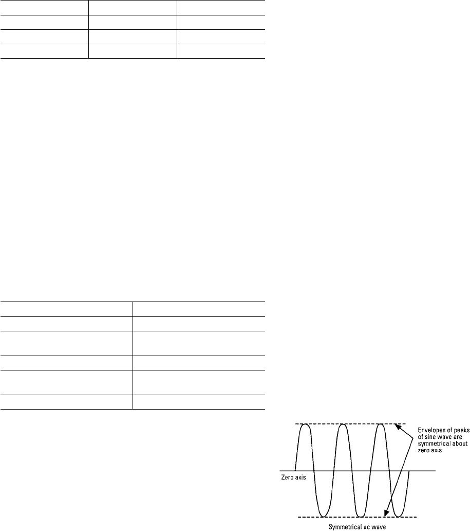
45
Application
Altitude
Power Break® II circuit breakers are designed for operation
at altitudes from sea level to 6000 ft. (1800 meters). Reduced
air densities at altitudes above 6000 ft. affects the ability of
the circuit breaker to both transfer heat and interrupt short
circuits.
Determine the altitude of the breaker’s installation, and se-
lect the altitude rating factor “D” from the following table.
Table 45.1
Factor “D” Altitude
Altitude (Feet) Altitude (Meters) Factor D
From 100 To 6,000 From 30 To 1,800 1.00
From 6,001 To 10,000 From 1,801 To 3,000 1.04
Above 10,001 Above 3,001 1.08
Load Class Rating Factor
The type of load and its duty cycle must be considered in the
application of Power Break II circuit breakers. Loads, such
as capacitors and electromagnets, require a substantial and
continuous derating factor if the breaker is normally used to
switch the load. With loads such as resistance welders, the
breaker’s continuous current rating must be no less than
125% of the welder’s 100% duty-cycle rating.
In general, insulated case circuit breakers are intended for
the protection of insulated cable. Where a circuit breaker is
intended to protect load equipment, prudent engineering
practices call for obtaining factory review and concurrence
with the selection of a specific protective device. Load class
selection factors “E” for typical application are listed in the
following table.
Table 45.2
Factor “E” – Load Class or Type
Load Type Factor E
Switching Electromagnets 1.50
Single Motor Branch Circuit Protec-
tion ( Normal Duty) 1.50
Switching Capacitors 1.50
Single Motor Branch Circuit Protec-
tion (Heavy Duty) 1.75
All other load Types (Normal Duty) 1.0
Use this factor to either plugging duty or starting more than 25 times per hour,
where the rms current cannot be easily calculated.
Safety Factor
A safety factor is used to provide a design margin between
the rating of a circuit breaker and the derived operating
current using all of the selection factors described in the
equation on page 42. A safety factor of 10% is often used to
prevent nuisance tripping.
Factor “F” – Safety Factor
A safety factor of 10% is equivalent to a Factor F of 1.10.
Interrupting Ratings
In addition to current rating considerations, Power Break II
circuit breakers must be able to automatically trip, or open,
the protected circuits under overload conditions. The breaker
must have sufficient interrupting capacity to interrupt the
maximum short-circuit that can flow under worst-case
conditions.
The following paragraphs describe the interrupting rating of
Power Break II circuit breakers.
Basis of Interrupting Ratings
Short-circuit current interrupting ratings depend on know-
ing the magnitude of short-circuit current that may flow
through the circuit breaker. Devices rated in accordance with
Standard UL 489 list their interrupting rating in terms of “rms
symmetrical amperes.”
Power factor or X/R ratio. Interrupting ratings are based on
a specific ratio of resistance – to reactance, or power factor
in the faulted circuit. Practical ac circuits contain some reac-
tance, so there is some displacement between current and
voltage wave-forms. Since a short circuit can occur at any
point of the voltage wave, the actual trace of short-circuit
current may display considerable initial displacement from
the zero current axis.
The magnitude of the momentary peak current to be inter-
rupted is a function of the maximum peak current displace-
ment from the zero current axis. That displacement is a
function of the X/R (ratio of reactance to resistance) or power
factor of the faulted circuit. The higher the X/R rating, the
lower the power factor and the greater the magnitude of
peak current displacement.
Symmetrical ac waveform

PF = x 100 And: Z = (R)2 + (X)2
Therefore PF = x 100
PF = Power factor, % Z = Impedance in ohms
R = Resistance in ohms X = Reactance in ohms
R
Z
R
(R)2 + (X)2
46
Application
Generally, electrical power system engineers calculate the
X/R ratios of circuit rather than power factor. The procedures
for calculating short-circuit current and X/R ratios are de-
scribed in Publication GET-3550.
Asymmetrical ac waveform
The figures below show the initial fault current displacement
of a pure circuit (symmetrical) and a reactive circuit with a
high X/R ratio. The actual current displacement of a reac-
tive circuit depends on the exact moment the short circuit is
applies. There is a simple relationship between power factor
and X/R of a faulted circuit:
Interrupting Ratings – Standard And Hi-Break® Breakers
Power Break® II breakers are available in two classifications
of interrupting ratings: Standard and Hi-Break breakers. All
ratings are without the need for external fuses or current
limiters. Hi-Break breakers’ interrupting ratings are for those
circuits with unusually high levels of available fault current.
Table 46.1
Interrupting Rating Breaker Performance In RMS Symmetrical kA
UL 489
50/60 Hz
Frame Size
800A
1600 -
2000A
2500 –
3000 4000A
Standard
240V
480V
600V
65
65
50
85
65
50
100
100
85
100
100
85
Hi-Break®
240V
480V
600V
100
100
65
125
100
65
200
150
100
200
150
100
Short Time
(0.5 sec.) 25 40 42 42
IEC 947 -2 Ratings
415V, 50/60 Hz
Icu
Ics
Icw (1 sec)
-
-
-
75
56
40
75
45
50
85
25
50
Requires 4000A construction
Table 46.2
Estimated 400 Hz Interrupting Ratings
RMS Symmetrical Amperes – Not UL Listed
Standard Break
Frame Size
(Amps)
Max. Rating Plug
Ampacity
120/240 277/480 346/600
800
1600
2000
2500
600
1000
1200
1600
6500
8500
8500
10000
5000
6500
6500
10000
4200
5000
5000
8500
Hi-Break
Frame Size
(Amps)
Max. Rating Plug
Ampacity
120/140 277/480 346/600
800
1600
2000
2500
600
1000
1200
1600
10000
12500
12500
20000
10000
10000
10000
15000
6500
6500
6500
10000
No additional thermal derating is required for above–maximum rating
plug ratings for frame sizes noted. Note: 400Hz interrupting ratings are
based on engineering judgment, taking into consideration the operating
characteristics of insulated case circuit breakers and the worldwide lack
of test facilities to verify performance. Power+™ trip units and the energy
management functions in MicroVersaTrip PM™ trip units are suitable for
50/60 Hz applications only.

47
Application
Table 47.1
Interrupting Rating Multipliers-
For High X/R Rations (Low Power Factors)
When the X/R ratio of a faulted circuit is higher than 4.899 (power factor of
0.20) the breaker’s interrupting rating must be derated. The multiplying fac-
tor is shown in the table below.
Power Factor X/R Ratio Interrupting Capacity
Derating Factor
0.20 4.899 1.000
0.19 5.167 0.98
0.18 5.465 0.97
0.17 5.797 0.96
0.16 6.169 0.95
0.15 6.169 0.94
0.14 7.072 0.93
0.13 7.627 0.91
0.12 8.273 0.90
0.11 9.036 0.89
0.10 9.950 0.88
0.09 11.066 0.87
0.08 12.460 0.85
0.07 14.251 0.84
0.06 16.637 0.83
0.05 19.974 0.82
0.04 24.980 0.81
Example Data
A Power Break® II stationary feeder breaker consisting of
770A of continuous loads @ 480Vac required. Available
short-circuit current at the breaker is 63kA rms symmetrical
with a power factor of 0.13 (X/R ratio of 7.627). Average tem-
perature of the room air could be as high as 45° C (air sur-
rounding the enclosed breaker will be 15° C higher.) Altitude
above sea level at the installation site is 6500 feet. The loads
are considered critical.
Selection
Since the Power Break II breakers are labeled as suitable to
carry 100% of their ampere rating continuously,* there is no
need to multiply the continuous load by 1.25 as would be
required when using a non 100% rated breaker.
Per UL 489, Power Break II breakers are short-circuit tested
with a power factor of 20% (X/R ratio of 4.889); the actual
faulted circuit power factor in this example, however, is 13%
(X/R ratio of 7.627) and this requires derating of the breaker’s
interrupting rating per Table 47.1. Multiplying the standard
break IC rating of 65kA by .91 gives 59.1kA rating when the
power factor is 13% and not 20% minimum.
The available short-circuit current is 63kA and thus the stan-
dard break breaker is not adequate and could not be used.
The Hi-Break® units are rated 100kA and are acceptable.
Further derating must be done for high ambient conditions.
Per Table 44.2 Factor “B”, 60°C breaker ambient tempera-
ture requires a derating factor of 1.10. Similarly, the 6500-ft.
altitude requires a 1.04 derating factor- see Table 45.1 Factor
“D”.
This feeder is a critical circuit and therefore a Safety Factor F
of 1.10 will be applied.
Next multiply the load, IA, by the several factors AxBxCxDx-
ExF to determine the minimum frame ampere rating:
ICB=IA x A x B x C x D x E x F = 770A x 1.00 x 1.1 x 1.00 x 1.04 x
1.00 x 1.1 = 770 A x 1.258 or 969A.
Select a 1600A Hi-Break frame with either a 1000A or a
1600A sensor rating with an 800A rating plug because the
rating plug is not affected by any of the load characteris-
tics. An 800A rating plug, however, may not permit the 10%
safety factor for additional current-carrying capacity above
the actual 770A. An alternate choice would be to select a
1000A rating plug and set the current setting (long time pick
up) to 0.9 and cable or bus for 900A ampacity. If the alter-
nate choice is used, some local inspecting authorities may
require sealing of the sealable trip unit and accessory door to
prevent upward adjustment of the 0.90 current setting.
Finally, if insulated conductors are to be used, the high –am-
bient temperature (60°C) will require using 125°C minimum
insulation rating with the conductors sized per the 75°C
ampacity tables.
Conductors may be sized to the 800A rating plug value,
if used, or to 900A current setting value if a 1000A rating
plug is used. Additional derating of the conductors may be
required for (1) more than three conductors in a raceway
and (2) ambient temperatures other than 30°C. Refer to the
National Electrical Code, Article 310.
Breaker Selection
User may select a front connected stationary, Hi-Break
breaker, 1600-amp frame, standard instantaneous with
1000-amp current sensor. Rating plug is 1000 amps. An
enhanced MicroVersaTrip Plus ™ trip unit with LT, ST, and I.
• Breaker: Cat. No. SHF16B210
• Rating Plug: Cat. No. TR10B1000
• Trip Unit: Cat. No. B210LSI
*4000A Stationary 80% rated.

48
Application
Humidity and Fungus
All ferrous parts are zinc plated with either a yellow dichro-
mate or phosphate finish. Zinc plating resists 96-hour salt
spray test. Alloy steel components made of inherently corro-
sion-resistant materials are not plated.
Current-carrying parts are either silver or tin plated for
corrosion protection and to assure reliable electrical joints.
Molded cases and covers, and all internal insulators, are
made from inorganic materials that are inherently fungus
proof.
Wiring Diagram, Secondary Terminals
All Power Break® II breakers use the same dedicated second-
ary terminals regardless of frame, rating, accessory or trip
unit combinations. The left side set of secondary terminals
are assigned to auxiliary switches. The right side set is as-
signed to all other accessories and breaker functions.
Terminals are suitable for (2) #18 -#12 solid or stranded
copper wire. Tightening torque is 9 lb-ins.
Left side secondary Right side secondary
terminals “A” Block terminals “B” Block
Time Current Tripping Characteristics
Power Break II insulated case circuit breaker time current
curves are the engineering documents that define the tech-
nical performance of the devices. Information provided on a
time current curve includes the following:
• Product family type (s)
• Specific device type (s)
• Ampere ratings covered on curve
• Overcurrent characteristics covered – long-time, short-
time, instantaneous, etc.
• Maximum total clearing time
• Maximum and minimum temperature limits
• Frequency ratings
• Voltage ratings
• Specific trip unit ratings
• Trip unit adjustment ranges
• Tolerance (band width)
Multiples of circuit breaker trip ratings, or other suitable
current value (e.g., current sensor rating) are shown on both
the top and bottom horizontal axes. The time in seconds
is shown on the vertical axes. Approximate minimum and
maximum clearing time is readily determined from the char-
acteristics curves. Tripping characteristics meet both NEMA
and UL standards for rating and calibration.
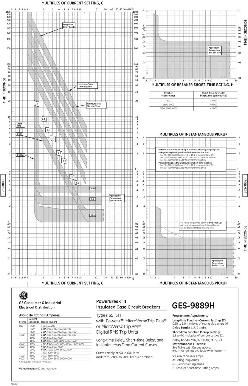
49
Application
Time Current Curves
Long-Time, Short-Time Delay and Instantaneous

50
Application
Time Current Curves
Ground Fault

51
Physical Data
Power Break® II 800- Amp Stationary
1. ¼ - 20 mounting bolts to be furnished by customer.
2. To prevent heating, do not mount breaker to magnetic steel back support.
3. All outline dimensions are the same for manually and electrically operated devices.
4. Dimensions in brackets are in [millimeters].
5. 4.50 [114.3] minimum distance above breaker to metal in an area 5.31 x 16.00 [134.9 x 406.4] due to arc chamber venting.

52
Physical Data
Power Break® II 800-Amp Stationary
1. ¼ - 20 mounting bolts to be furnished by customer.
2. To prevent heating, do not mount breaker to magnetic steel back support.
3. All outline dimensions are the same for manually and electrically operated devices.
4. Dimensions in brackets are in [millimeters].
5. 4.50 [114.3] minimum distance above breaker to metal in an area 5.31 x 16.00 [134.9 x 406.4] due to arc chamber venting.

53
Physical Data
Power Break® II 1600-2000- Amp Stationary
1. ¼ - 20 mounting bolts to be furnished by customer.
2. To prevent heating, do not mount breaker to magnetic steel back support.
3. All outline dimensions are the same for manually and electrically operated devices.
4. Dimensions in brackets are in [millimeters].
5. 4.50 [114.3] minimum distance above breaker to metal in an area 5.31 x 16.00 [134.9 x 406.4] due to arc chamber venting.

54
Physical Data
Power Break® II 1600-2000-Amp Stationary
1. ¼ - 20 mounting bolts to be furnished by customer.
2. To prevent heating, do not mount breaker to magnetic steel back support.
3. All outline dimensions are the same for manually and electrically operated devices.
4. Dimensions in brackets are in [millimeters].
5. 4.50 [114.3] minimum distance above breaker to metal in an area 5.31 x 16.00 [134.9 x 406.4] due to arc chamber venting.

55
Physical Data
1. All outline dimensions are the same for manually and electrically operated devices.
2. Dimensions in brackets are in [millimeters].
3. Any compartment metal in 6.50 X 14.00 [165.1 x 355.6] area below (and above at 1600A, minimum stacking height) must be removed. Reference
UL891 dead-front switchboards standard-electrical spacing requirements.
4. 3.74 [ 95] minimum distance above substructure to any metal in an are 5.31 x 16.00 [134.9 x 406.4] due to arc chamber venting.
5. Customer’s location for drilling hole for horizontally or vertically interconnected mechanical interlock. See bottom or side view.
Power Break® II 800-Amp Drawout

56
Physical Data
Power Break® II 800-Amp Drawout
1. All outline dimensions are the same for manually and electrically operated devices.
2. Dimensions in brackets are in [millimeters].
3. Any compartment metal in 6.50 X 14.00 [165.1 x 355.6] area below (and above at 1600A, minimum stacking height) must be removed. Reference
UL891 dead-front switchboards standard-electrical spacing requirements.
4. 3.74 [ 95] minimum distance above substructure to any metal in an are 5.31 x 16.00 [134.9 x 406.4] due to arc chamber venting.
5. Customer’s location for drilling hole for horizontally or vertically interconnected mechanical interlock. See bottom or side view.

57
Physical Data
Power Break® II 1600-2000-Amp Drawout
1. All outline dimensions are the same for manually and electrically operated devices.
2. Dimensions in brackets are in [millimeters].
3. Any compartment metal in 10.00 X 14.00 [254.0 x 355.6] are below (and above at 1600A, minimum stacking height) must be removed. Reference
UL891 dead-front switchboards standard-electrical spacing requirements.
4. 3.74 [95] minimum distance above substructure to any metal in an are 53.1 x 16.00 [134.9 x 406.4] due to arc chamber venting.
5. Customer’s location for drilling hole for horizontally or vertically interconnected mechanical interlock. See bottom or side view.

58
Physical Data
Power Break® II 1600-2000-Amp Drawout
1. All outline dimensions are the same for manually and electrically operated devices.
2. Dimensions in brackets are in [millimeters].
3. Any compartment metal in 10.00 x 14.00 [254.0 x 355.6] area below (and above at 1600A minimum stacking height) must be removed.
Reference UL891 dead-front switchboards standard-electrical spacing requirements.
4. 3.74 [95] minimum distance above substructure to any metal in an area 5.31 x 16.00 [134.9 x 406.4] due to arc chamber venting.
5. Customer’s location for drilling hole for horizontally or vertically interconnected mechanical interlock. See bottom or side view.

59
Physical Data
Power Break® II Information, 800-2000-Amp Frames
1. Dimensions in brackets are [metric].
2. Busbars or cables should be sized per UL891 dead-front switchboards standard.
* Screw terminal position relative to front of circuit breaker
Note: Wire range #18 thru #12 solid or stranded copper wire. Torque: 9lb-in.

60
Physical Data
Power Break® II Information, 800-2000-Amp Frames
1. Dimensions in brackets are [metric].
2. Busbars or cables should be sized per UL891 dead-front switchboards standard.
Frame
Rating
Breaker
Type
Weight Minimum
Compartment
Volume
Minimum Door
Ventilation
Standard Door Cut-Out Optional Door Cut- Out
Breaker Drawout
Substructure
A B C A B C
800A
Stationary
Mounted
71 lbs.*
[32,3 kg]
N/A 3447 cu. in.
[56486 cu. cm]
None 10
[254]
14
[356]
1.69
[42.9]
9.83
[249.7]
13.38
[339.9]
1.605
[40.8]
1600A
106 lbs.
[48,2 kg]
60.0 sq. in. [387,1 sq. cm] Total
30.0 sq. in. [193,5 sq. cm] Top
30.0 sq. in. [193,5 sq. cm] Bottom
2000A
86.4 sq. in. [557,4 sq. cm] Total
43.2 sq. in. [278,7 sq. cm] Top
43.2 sq. in. [278,7 sq. cm] Bottom
800A
Drawout
Mounted
106 lbs. *
[48,2 kg]
54 lbs
[24,5 kg] 3780 cu. in.
[61943 cu. cm]
None 10
[254]
14
[356]
N/A 9.83
[249.7]
13.38
[339.9]
N/A
1600A
125 lbs.*
[56,8 kg}
68 lbs.
[30,9 kg]
None
2000A 5670 cu. in.
[92915 cu. cm]
34.2 sq. in. [220,6 sq. cm] Total
29.5 sq. in. [190,3 sq. cm] Top
4.66 sq. in. [30,0 sq. cm] Bottom
N/A = Not Applicable
* Add 9 lbs. [4.1 kg] for electrical operator
Table 1
Trim Plate Required
Flush Front or Non-hinged
Door Construction - Trim Plate may
be omitted
Trim Plate Required
Flush Front or Non-hinged
Door Construction - Trim Plate may
be omitted

61
Physical Data
Power Break® II 2500-3000-Amp Front Connected
1. All outline dimensions are the same for manually and electrically operated devices.
2. Dimensions in brackets are in [millimeters].
3. 8.00 [ 203,2] minimum distance above breaker to metal due to arc chute venting.

62
Physical Data
Power Break® II 2500-3000-Amp Front Connected
1. All outline dimensions are the same for manually and electrically operated devices.
2. Dimensions in brackets are in [millimeters].
3. 8.00 [203,2] minimum distance above breaker to metal due to arc chute venting.

63
Physical Data
Power Break® II 2500-Amp Back Connected
1. All outline dimensions are the same for manually and electrically operated devices.
2. Dimensions in brackets are in [millimeters].
3. 8.00 [203,2] minimum distance above breaker to metal due to arc chute venting.

64
Physical Data
Power Break® II 2500-Amp Back Connected
1. All outline dimensions are the same for manually and electrically operated devices.
2. Dimensions in brackets are in [millimeters].
3. 8.00 [203,2] minimum distance above breaker to metal due to arc chute venting.

65
Physical Data
Power Break® II 3000-Amp Back Connected
1. All outline dimensions are the same for manually and electrically operated devices.
2. Dimensions in brackets are in [millimeters].
3. 8.00 [203,2] minimum distance above breaker to metal due to arc chute venting.

66
Physical Data
Power Break® II 3000-Amp Back Connected
1. All outline dimensions are the same for manually and electrically operated devices.
2. Demensions in brackets are in [millimeters].
3. 8.00 [203,2] minimum distance above breaker to metal due to arc chute venting.

67
Physical Data
1. All outline dimensions are the same for manually and electrically operated devices.
2. Dimensions in brackets are in [millimeters].
3. 8.00 [203,2] minimum distance above breaker to metal due to arc chute venting.
Power Break® II 4000-Amp Front Connected

68
Physical Data
Power Break® II 4000-Amp Front Connected
1. All outline dimensions are the same for manually and electrically operated devices.
2. Dimensions in brackets are in [millimeters].
3. 8.00 [ 203,2] minimum distance above breaker to metal due to arc chute venting.

69
Physical Data
1. All outline dimensions are the same for manually and electrically operated devices.
2. Dimensions in brackets are in [millimeters].
3. 4.25 [108] minimum distance above substructure (8.00 [203.2] from top of circuit breaker) to any metal in an area 9.00 x 16.00 [228,6 x 406,4] due
to arc chamber venting.
4. Customer’s location for drilling hole for horizontally or vertically interconnected mechanical interlock, See bottom or side view.
Power Break® II 2500-3000 Amp Drawout

70
Power Break® II 2500-3000 Amp Drawout
Physical Data
1. All outline dimensions are the same for manually and electrically operated devices.
2. Dimensions in brackets are in [millimeters].
3. 4.25 [108] minimum distance above substructure (8.00 [203.2] from top of circuit breaker) to any metal in an area 9.00 x 16.00 [228,6 x 406,4] due
to arc chamber venting.
4. Customer’s location for drilling hole for horizontally or vertically interconnected mechanical interlock, See bottom or side view.

71
Physical Data
Power Break® II 4000 Amp Drawout
1. All outline dimensions are the same for manually and electrically operated devices.
2. Dimensions in brackets are in [millimeters].
3. 4.25 [108] minimum distance above substructure (8.00 [203.2] from top of circuit breaker) to any metal in an area 9.00 x 16.00 [228,6 x 406,4] due
to arc chamber venting.
4. Customer’s location for drilling hole for horizontally or vertically interconnected mechanical interlock. See bottom or side view.

72
Power Break® II 4000 Amp Drawout
Physical Data
1. All outline dimensions are the same for manually and electrically operated devices.
2. Dimensions in brackets are in [millimeters].
3. 4.25 [108] minimum distance above substructure (8.00 [203.2] from top of circuit breaker) to any metal in an area 9.00 x 16.00 [228,6 x 406,4] due
to arc chamber venting.
4. Customer’s location for drilling hole for horizontally or vertically interconnected mechanical interlock. See bottom or side view.

73
Physical Data
Power Break® II 800-2000A Stationary Mechanical Interlock

74
Physical Data
Power Break® II 800-2000A Stationary Mechanical Interlock
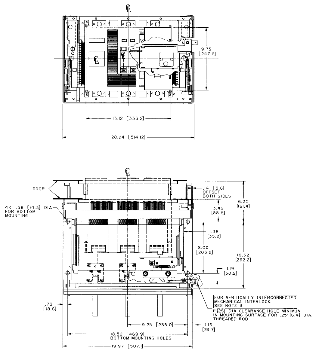
75
Physical Data
Power Break® II 800-2000A Drawout Mechanical Interlock
1. All outline dimensions are the same for manually and electrically operated devices.
2. Dimensions in brackets are in [millimeters].
3. Customer’s location for drilling hole for horizontally or vertically interconnected mechanical interlock. See bottom or side view.

76
Physical Data
Power Break® II 800-2000A Drawout Mechanical Interlock
1. All outline dimensions are the same for manually and electrically operated devices.
2. Dimensions in brackets are in [millimeters].
3. Customer’s location for drilling hole for horizontally or vertically interconnected mechanical interlock. See bottom or side view.

77
Physical Data
Power Break® II 2500-3000A Stationary Mechanical Interlock

78
Physical Data
Power Break® II 2500-3000A Stationary Mechanical Interlock

79
Physical Data
Power Break® II 2500-3000A Drawout Mechanical Interlock
1. All outline dimensions are the same for manually and electrically operated devices.
2. Dimensions in brackets are in [millimeters].
3. Customer’s location for drilling hole for horizontally or vertically interconnected mechanical interlock. See bottom or side view.

80
Physical Data
Power Break® II 2500-3000A Drawout Mechanical Interlock
1. All outline dimensions are the same for manually and electrically operated devices.
2. Dimensions in brackets are in [millimeters].
3. Customer’s location for drilling hole for hoizontally or vertically interconnected mechanical interlock. See bottom or side view.

81
Physical Data
Power Break® II 4000A Stationary Mechanical Interlock

82
Physical Data
Power Break® II 4000A Stationary Mechanical Interlock

83
Physical Data
Power Break® II 4000A Drawout Mechanical Interlock
1. All outline dimensions are the same for manually and electrically operated devices.
2. Dimensions in brackets are in [millimeters].
3. Customer’s location for drilling hole for horizontally or vertically interconnected mechanical interlock. See bottom or side view.

84
Physical Data
Power Break® II 4000A Drawout Mechanical Interlock
1. All outline dimensions are the same for manually and electrically operated devices.
2. Dimensions in brackets are in [millimeters].
3. Customer’s location for drilling hole for horizontally or vertically interconnected mechanical interlock. See bottom or side view.

85
Physical Data
Power Break® II Information, 2500A-4000A Frames
*Screw terminal position relative to front of circuit breaker
Note: Wire range #18 thru #12 solid or stranded copper wire. Torque: 9lb-in

86
Physical Data
Power Break® II Information, 2500A-4000A Frames
N/A = Not Applicable
* Add 9 lbs. [4.1 kg.] for electrical operator
1. Dimensions in brackets are [metric].
2. Busbars or cables should be sized per UL891 dead-front switchboards standard.
3. “D” Dia. = 4000 Amp front connected breaker mounting holes.
4. “E” Dia. = 2500A and 3000A front connected breaker mounting holes.
5. “F” Dia. = 2500A and 3000A back connected breaker mounting inserts.
Frame
Rating
Breaker
Type
Weight Minimum
Compartment
Volume
Minimum Door Ventilation Standard Door Cut-Out Optional Door Cut-Out
Breaker Drawout Substructure A B C A B C
2500A
Back Connected 167 lbs. [76 kg]*
N/A
13,950 cu. in.
[228,600 cu. cm]
160 sq. in. [1,032 sq. cm] Total
80 sq. in. [516 sq. cm] Top
80 sq. in. [516 sq. cm] Bottom
10
[254]
14
[356
.34
[8,6]
2.17
[55,1]
9.83
[249,7]
13.38
[339,9]
255
[6,4]
2.255
[57,28]
Front Connected 178 lbs. [81 kg]*
3000A
Back Connected 216 lbs. [98.3 kg]* 20,832 cu. in.
[341,375 cu. cm]
270 sq. in. [1,742 sq. cm] Total
135 sq. in. [871 sq. cm] Top
135 sq. in. [871 sq. cm] Bottom
Front Connected 179 lbs. 81.4 kg]*
4000A Front Connected 320 lbs. [145.6 kg] 25,143 cu. in.
[412,020 cu. cm]
270 sq. in. [1,742 sq. cm] Total
135 sq. in. [871 sq. cm] Top
135 sq. in. [871 sq. cm] Bottom
2500A
Drawout
Mounted
232 lbs. [105.6 kg]* 111 lbs. [50.5 kg]* 10.991 cu. in
[180.108 cu. cm.]
246 sq. in. [1,587 sq. cm] Total
123 sq. in. [793,5 sq. cm] Top
123 sq. in. [793,5 sq. cm] Bottom
10
[254]
14
[356]
3.84
[97.5]
9.83
[249.7]
13.38
[339.9]
3.755
[95.38]
3000A 233 lbs. [106 kg]* 111 lbs. [50.5 kg]* 10.991 cu. in
[180.108 cu. cm.]
246 sq. in. [1,587 sq. cm] Total
123 sq. in. [793,5 sq. cm] Top
123 sq. in. [793,5 sq. cm] Bottom
4000A 295 lbs. [134.2 kg]* 167 lbs. [76 kg]* 15.138 cu. in
[248,074 cu. cm.]
246 sq. in. [1,587 sq. cm] Total
123 sq. in. [793,5 sq. cm] Top
123 sq. in. [793,5 sq. cm] Bottom
Trim plate
Required
Flush Front or
Non-hinged Door
Construction Trim
Plate may
be omitted
Trim plate
Required
Table 1

87
Physical Data
Power Break® II 800-Amp T-Studs
Catalog No. Material Finish “A”
SP08FCA AL Tin 78 + .01 - .02
[19,8 + 0,3 -0,5]
SP08FCC AL Tin 375 + .005
[9,53 + 0,13]
1. T-studs may be mounted to either the line or load straps, and oriented horizontally or vertically as shown.
2. Dimensions in brackets are in [millimeters].

88
Physical Data
Power Break® II 1600-2000 Amp T-Studs
1. T-studs may be mounted to either the line or load straps, and oriented horizontally or vertically as shown.
2. Dimensions in brackets are in [millimeters].
Catalog No. Material Finish “A” Breaker Amps
SP20FCA AL Tin
78
1600A-2000A
SP20FCC CU Tin 750 + 005 [ 19.05 + 13] 1600A-2000A
+ .010
-.020
+ 0,25
-0,51
[19,8 ]

89
Physical Data
Power Break® II 2000, 2500, 3000-Amp T-Studs

90
Physical Data
Power Break® II 4000-Amp T-Studs
1. SPS40FCC may be used on all poles or alternated with SPS40LFCC as shown.

91
Physical Data
Power Break® II 2000-2500-Amp T-Studs, Back Connected

92
Physical Data
Power Break® II TPLUGA08 On 800 Amps
1. Dimensions in brackets are [metric].

93
Physical Data
Power Break® II TPLUGA16 On 1600 Amps
1. TPLUGA 16 kit fits on line or load side of all 1600A Power Break or Power Break II circuit breakers.
2. Dimensions in brackets are in [millimeters].

94
Physical Data
Power Break® II TPLUGA16 On 1600 Amps
1. TPLUGA 16 kit fits on line or load side of all 1600A Power Break or Power Break II circuit breakers.
2. Dimensions in brackets are in [millimeters].
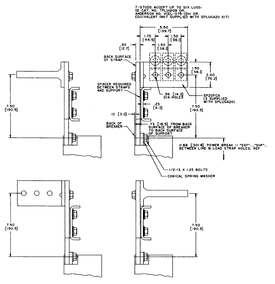
95
Physical Data
Power Break® II SPLUGA20 On 2000 Amps
1. SPLUGA20 kit fit on line or load side of all 2000A Power Break II circuit breakers. Does not fit on original Power Break 2000A circuit breaker.

96
Physical Data
Power Break® II SPLUGA20 On 2000 Amps
1. SPLUGA20 kit fit on line or load side of all 2000A Power Break II circuit breakers. Does not fit on original Power Break 2000A circuit breaker.

97
Physical Data
Power Break® II Lug Kits For 2500A Frame
1. Lug kit contains complete 3 pole line or load connection.
2. SPS20BCA and SPS25BCC back connected studs for use with back connected Power Break II circuit breakers.
3. SPS20FCA and SPS25FCC front connected studs for use with front connected Power Break II circuit breakers.

98
Physical Data
Power Break® II Lug Kits for 2500A Frame
Note A: Lug kit contains complete 3 pole line or load connection.
Note B: SPS20BCA and SPS25BCC back connected studs for use with back connected Power Break II circuit breakers.
Note C: SPS20FCA and SPS25FCC front connected studs for use with front connected Power Break II circuit breakers.
Catalog No. Amps “A” “B” “C” Use with Connector Catalog No.
TSLUG08 800 4.00 3 2
SPS20BCA (See Note: B) &
SPS20FCA (See Note: C)
TSLUG12 1200 4.00 4 2
TSLUG16 1600 4.50 5 3
TSLUG20 2000 4.50 6 3
TSLUG25 2500 6.25 7 4 SPS25BCC (See Note: B) &
SPS25FCC (See Note: C)

99
Physical Data
Power Break® II Lug Kits For 3000-4000A Frames
Note A: 3000 Amp back connected circuit breaker has non-removable integral connectors.
Note B: Lug kit contains complete 3 pole line or load connection as shown.
Note C: SPS30FCC and SPS40FCC front connected studs for use with front connected Power Break II circuit breakers.

100
Physical Data
Power Break® II Lug Kits for 3000-4000A Frames
Note A: 3000 Amp back connected circuit breaker has non-removable integral connectors.
Note B: Lug kit contains complete 3 pole line or load connection as shown.
Note C: SPS30FCC and SPS40FCC front connected studs for use with front connected Power Break II circuit breakers.
Catalog No. Amps “A” “B” “C” “D” “E” “F” Use with Connector Catalog No.
TSLUG30 3000 7.50 7.50 9 5 4.00 5.31 SPS30FCC (See Notes A & B)
TSLUG40 4000 7.94 9.00 11 4 6.00 6.75 SPS40FCC (See Note C)

101
Physical Data
Power Break® II UVR/ST Transformer For 480V And 600V Accessories
Part Ge Xfmr.
Cat. No.
Voltage Ref 60Hz
kVA
Approx.
Weight
(lbs.)
Maximum Envelope Mounting
Dept Width Height Depth Width Height
A B C D E F
P1 9T58K0042 480V .050 2.6 3.97 3.29 2.79 2.16 2.50 .219 x 7.50
P2 9T58K0062 600V .087 3.4 4.47 3.29 2.79 2.66 2.50 .219 x .750

102
Physical Data
Power Break® II Enclosure, 800A Frame

103
Physical Data
Power Break® II Enclosure, 800A Frame

104
Physical Data
Power Break® II Enclosure, 1600A And 2000A Frames

105
Physical Data
Power Break® II Enclosure, 1600A And 2000A Frames

106
Table 106.1
Outline Drawings – Circuit Breakers
Frame Rating (amps) Stationary Breaker
Outline Drawing GEM
3025
Drawout Breaker
Outline Drawing GEM
3025
800 SH1, 5, 6, 14 SH3, 5, 6, 15
1600 SH2, 5, 6, 14 SH4, 5, 6, 15
2000 SH2, 5, 6, 14 SH4, 5, 6, 15
2500 SH6, 7, 9, 13, 16 SH6, 11, 13, 19
3000 SH6, 7, 10,13, 16 SH6, 11, 13, 19
4000 SH6, 8, 13, 17 SH6, 12, 13, 18
Table 106.2
Outline Drawings – T-Studs For Stationary Breakers
Frame
Size
Max
Amp
Rating
T-Stud Catalog Number Outline
Draw-
ing GEM
3027
Front
Connected
Back
Connected
800 800 SP08FCA, SP08FCC — SH1
1600 1600 SP20FCA, SP20FCC — SH2
2000 2000 SP20FCA, SP20FCC — SH2
2500
2000 SPS20FCA — SH3
2000 SPS20BCA SH5
2500 SPS25FCC SH3
2500 SPS25BCC SH5
3000 3000 SPS30FCC
Supplied as
standard- not
removable
SH3
4000 4000 SPS40FCC,
SPS40LFCC — SH4
Table 106.3
Outline Drawings – Lug Kits for Stationary Breakers
Frame
Size
Maximum
Ampere Rating
Lug Kit
Catalog Number
Outline Drawing
GEM 3026
3000
800 TSLUG08 SH4
1200 TSLUG12 SH4
1600 TSLUG16 SH4
2000 TSLUG20 SH4
2500 TSLUG25 SH4
3000 TSLUG30 SH5
4000 4000 TSLUG40 SH5
Table 106.4
Outline Drawings – Neutral Sensors For Power+™, MicroVersa Trip Plus™
And MicroVersaTrip PM™ Units
Breaker
Frame Amps
Sensor Rating
(amps)
Catalog
Number
Outline Drawing
Number
800
200
400/200
600/300
800/400
TSVG302
TSVG304A
TSVG306A
TSVG308A
1600
800/400
1000/500
1200/600
1600/1000
TSVG808A
TSVG810A
TSVG812A
TSVG816A
2000 2000/1000 TSVG20A 139C5016SHI
2500/300
800/400
1000/500
1200/600
1600/1000
2000/1200
2500/1800
3000/2400
TSVG808A
TSVG810A
TSVG812A
TSVG816A
TSVG820A
TSVG825A
TSVG830A
4000 4000/3000 TSVG940A 139C5016SH2
Match neutral current sensor rating (or tap setting) to circuit breaker sensor rating.
For use with multiple-source ground-fault protection schemes. Rating does not
match MicroVersaTrip® Trip Unit frame sensor.
Table 106.5
Outline Drawings Lug Adapter Kits For Stationary Breakers
Maximum Ampere
Rating
Adapter Kit Catalog
Number
Outline Drawing
GEM 3026
800 A TPLUGA08 SH1
1600 A TPLUGA16 SH2
2000 A SPLUGA20 SH3
Physical Data

107
Physical Data
Table 107.1
Outline Drawings – Enclosures
Enclosure
Catalog
Number
Frame
Rating
Lugs
Per
Pole
Lugs Wire Range
(kcmil, CU/AL)
Outline
Drawing
GEM 3133
SPB08W 800 A 6 #2-600 or (2) #1/0-250 SH1
SPB16W 1600 A 12 #3/0-800 SH2
SPB20W 2000 A 14 #3/0-800 SH2
Table 107.2
Weight And Space Requirements
Frame
Rating
Breaker
Type
Weight Minimum
Compartment
Volume
Minimum
Door Ventilation
Breaker Drawout
Substructure
800A
Stationary
Mounted
71 Lbs. *
(32.3 Kg)
N/A 3447 Cu. In.
(56,486 Cu. Cm)
None
1600A
79 Lbs. *
(35.9 Kg)
60.0 Sq In. (387.1 Sq. Cm) Total
30.0 Sq In. (193.5 Sq Cm) Top
30.0 Sq In. (193.5 Sq Cm) Bottom
2000A
86.4 Sq. In. (557.4 Sq. Cm) Total
43.2 Sq. In. (278.7 Sq Cm) Top
43.2 Sq. In. (278.7 Sq Cm) Bottom
800A
Drawout Mounted
106 Lbs.*
(48.2 Kg)
54 Lbs
(24.5 Kg) 3780 Cu. In
(61,943 Cu. Cm)
None
1600A
125 Lbs. *
(56.8 Kg)
68 Lbs.
(30.9 Kg)
None
2000A 5670 Cu. In
(82,915 Cu. Cm)
34.2 Sq. In (220.6 Sq. Cm) Total
29.5 Sq. In. (190.3 Sq. Cm) Top
4.66 Sq. In. ( 30.0 Sq. Cm) Bottom
2500A
Back Connected 167 Lbs. (76 Kg)*
N/A
13,950 Cu. In.
(228,600 Cu. Cm)
160 Sq. In. (1032 Sq. Cm) Total
80 Sq In. ( 516 Sq. Cm) Top
80 Sq In. ( 516 Sq. Cm) Bottom
Front Connected 178 Lbs. (81 Kg) *
3000A
Back Connected 216 Lbs. ( 81.4 Kg) * 20,832 Cu. In.
(341,375 Cu. Cm)
270 Sq In. (1742 Sq. Cm) Total
135 Sq. In. ( 871 Sq. Cm) Top
135 Sq. In. ( 871 Sq. Cm) Top
Front Connected 179 Lbs. (81.40) *
4000A Front Connected 320 Lbs. (145.6 Kg)* 25,143 Cu. In
412,020 Cu. Cm)
270 Sq In. (1742 Sq. Cm) Total
135 Sq. In. ( 871 Sq. Cm) Top
135 Sq. In. ( 871 Sq. Cm) Top
2500A 232 Lbs. (105.6 Kg)* 111 Lbs. (50.5 Kg) 10,991 Cu. In.
(180,108 Cu. Cm)
246 Sq. In. (1587 Sq Cm) Total
123 Sq. In. ( 793.5 Sq Cm) Top
123 Sq. In. ( 793.5 Sq. Cm) Bottom
3000A Drawout Mounted 233 Lbs. (106 Kg) * 111 Lbs. (50.5 Kg) 10,991 Cu. In.
(180,108 Cu. Cm
246 Sq. In. (1587 Sq Cm) Total
123 Sq. In. ( 793.5 Sq Cm) Top
123 Sq. In. ( 793.5 Sq. Cm) Bottom
4000A 259 Lbs. (134.2 Kg)* 167 Lbs (76 Kg) 15,138 Cu. In.
(248,074 Cu. Cm)
246 Sq. In. (1587 Sq Cm) Total
123 Sq. In. ( 793.5 Sq Cm) Top
123 Sq. In. ( 793.5 Sq. Cm) Bottom
N/A = Not Applicable * Add 9 lbs. (4.1 Kg) for electrical operator
108
Underwriters Laboratories® (UL)
Publication Stock, 333 Pfingsten Road
Northbrook, Il 60062 USA
Standard UL 489 and UL 489-SB2 Molded Case Circuit Break-
ers and Circuit Breaker Enclosures
National Electrical Manufactures Association (NEMA)
NEMA Publication, 155 East 44th Street,
New York, NY 10017 USA
AB-1 Standards Publication, Molded Case Circuit Breakers
Institute of Electrical and Electronics Engineers (IEEE)
ICEE, 345 East 47th Street,
New York, NY 10017 USA
American National Standard Institute (ANSI)
ANSI, 11 West 42nd Street,
New York, NY 10036 USA
ANSI/IEEE C37.90.1 – 1989
IEEE Standard Surge Withstand Capability (SWC)
Tests for Protective Relays and Relay Systems
ANSI/IEEE C37.90.2 – 1993
Withstand Capability of Relay Systems to Radiated Electro-
magnetic Interference from Transceivers
Standards and References
International Electrotechnical Committee (IEC)
Bureau Central de la Commission
Electrotechnique Internationale
3 rue de Varamb’e
Geneve, SUISSE
IEC 801-2 2nd Edition 1991-04
Electromagnetic Compatibility for Industrial-Process
Measurement and Control Equipments
Part 2: Electrostatic Discharge Requirements
National Electrical Code®
Order from National Fire Association
Batterymarch Park
Quincy, MA 02269
American Society for Testing and Materials (ASTM)
1916 Race Street
Philadelphia, PA 19103 USA
ASTM B117-73 (Reapproved 1979)
Standard Method of Salt Spray (Fog) Testing
Military Standard (MIL-STD)
Defense Printing Service
700 Robbins Avenue, Bldg. 4D
Philadelphia, PA 19111-5094 USA
MIL-STD-810E
Environmental Test Methods and Engineering Guidelines
109
General Requirements
Circuit Breakers shall be of insulated case construction. They
shall be UL Listed under Standard UL 489, UL 489-SB2, CSA
Certified, and IEC 947-2 Certified and shall meet the require-
ments of NEMA Standard AB1.
Circuit breakers shall be (manually) (electrically) operated,
(drawout) (stationary) mounted with features and accessories
described in these requirements. Breakers shall have a mini-
mum voltage rating of 600 Vac, and shall be rated to carry
100% of the current rating of the breaker continuously.*
Breakers shall have minimum UL Listed interrupting ratings
as indicated on the drawings. All manually operated breakers
shall be field convertible to electrical operation by means of
the addition of an internally mounted electrical operator. Ad-
dition of an electrical operator shall not change the physical
dimensions of a breaker.
Circuit breakers shall be constructed of a high-strength,
glass-reinforced insulating case. Construction shall provide a
double level of insulation between primary current-carrying
parts and operating personnel. The interrupting mechanism
shall contain arc chutes with steel vent grids to suppress arcs
and cool vented gases. Interphase barriers shall be included
to completely isolate each pole. For each breaker, the close
and latch rating shall be equal to its short-time rating to help
assure selectivity with downstream devices when closing
into a fault.
Breakers shall contain a true two-step stored energy operat-
ing mechanism providing quick-make, quick-break operation
capable of charging-after-closing operation. It shall be pos-
sible to discharge the closing spring without closing the main
contacts. The maximum closing time shall be three cycles at
nominal voltage.
Attempting to close a circuit breaker while an accessory un-
dervoltage release is de-energized or, while a shunt trip with
lockout is energized, or while a bell alarm with lockout is ac-
tivated, shall result in a “kiss-free” operation of the contacts.
Common tripping of all poles shall be standard. Breakers
shall be capable of a minimum of 10,000 mechanical open
and close operations without any required service.
When drawout breakers are in the fully withdrawn position,
there shall be provisions for tilting the breakers for inspec-
tion, maintenance or removal. It shall be possible to replace
the primary disconnect fingers with the breakers in the
withdrawn position.
Each breaker shall include a retractable charging handle,
close pushbutton, open pushbutton, closing spring charge/
discharge indicator and breaker ON/OFF indicator mounted
on the front of the breaker. Each breaker shall have as stan-
dard, a padlocking provision to prevent closing the breaker
when padlocks are installed. Padlocking provisions shall ac-
cept up to three padlocks with 1/4” to 3/8” diameter shanks.
This provision shall meet OSHA and California Code (EUSERC)
requirements.
Each stationary and drawout breaker shall have provisions
for up to 72 dedicated secondary terminal points. All discon-
nected points shall be capable of being probed from the
front of the breaker. All breaker control and accessory wiring,
including wiring for future accessories, shall be pre-wired to
integral terminal blocks which shall be clearly identified by
number and function. Each terminal point shall have space
available for two AWG#18#12 wires per terminal and cus-
tomer circuit identification.
Each circuit breaker shall contain the following accessories
(shunt trip with or without lockout) (undervoltage release)
(bell alarm) (bell alarm with lockout) [ (4 or 8 or 12 stage) SPDT
auxiliary switches] (remote close solenoid) (remote “charged”
indicator). All accessories shall be field installable. Field instal-
lation of shunt trip (with or without lockout), undervoltage
release, bell alarms – with and without lockout shall require
no adjustments, no internal wiring and no removal of the
circuit breaker cover. The bell alarm and bell alarm with
lockout shall each contain a mechanical target, which shall
extend from the front cover when the device operates. The
bell alarm (alarm only) shall reset automatically when the
breaker is closed. The bell alarm with lockout must be reset
by depressing the mechanical pop-out target before the
breaker can be closed. The bell alarm and the bell alarm with
lockout shall be independently field-configurable to operate
in response to an overcurrent and/or protective relay opera-
tion, plus any combination of shunt trip and/or undervoltage
release operation – including no response to a protection
trip, shunt tripping or undervoltage release trip. Note: for the
Power+™ trip unit, the bell alarm and bell alarm with lock-
out respond to an overcurrent operation only. The shunt trip
(with or without lockout) shall be continuously rated with no
requirements for a cut-off switch.
Each circuit breaker shall contain the following mechanical
accessories (operation counter) (sealable limited access “ON”
and “OFF” pushbutton cover) [ (1, or 2 or 3 or 4) cylinder key
interlock provision ] (shutters to cover drawout/stationary
primary disconnects when the breaker is racked out) (racking
padlock provision to prevent operation of the breaker racking
mechanism) (door interlock with defeat mechanism to pre-
vent opening the hinged breaker compartment door when
the breaker is closed) (walking beam interlock for stationary
breakers to prevent two adjacent breakers from being on
the same time) (mechanical interlock for drawout breakers
to prevent two adjacent breakers from being on at the same
time). All mechanical accessories shall be capable of being
field installed.
* 4000A Stationary 80% rated.
Guide Form Specifications
110
Breaker Protective System (MicroVersaTrip Plus™ and
MicroVersaTrip PM™)
1. Each circuit breaker shall be equipped with a protec-
tive trip unit system to protect against overloads, short
circuits (and ground faults) as specified in the following
subparagraphs. The protective trip unit shall consist of a
solid-state, microprocessor-based, programmer; tripping
means; current sensors; power supply and other devices
as required for proper operation.
2. As a minimum, the trip unit shall have the following fea-
tures and functions:
a) The housing shall be a metallic enclosure to protect
against magnetic interference, dust and other con-
taminants.
b) The protective system shall have reliable program-
mable controls with repetitive accuracy and precise
unit settings.
c) All current sensing shall employ true rms technology
for detecting overloads, (short-time overcurrent con-
ditions), high-level instantaneous overcurrent condi-
tions, (and ground-fault conditions).
d) A high-contrast, liquid crystal display – LCD – unit
shall display settings, trip targets, and specified
metering displays. The trip unit shall be equipped with
long-life lithium batteries – with automatic time delay
shut-off features – to provide both programming and
observation of trip targets or other functions when
the breaker is de-energized.
e) A multi-button keypad to provide local set-up and
readout on the LCD of all trip settings.
f) UL Listed, CSA Certified, IEC 947-2 Certified, field-in-
stallable, interchangeable rating plugs. It shall not
be necessary to change or remove the trip unit to
change the trip rating. Rating plugs shall contain
rejection features to prevent installation of a plug with
an incorrect current sensor rating.
g) Integral test jack for connection of a battery pack or
test kit to the breaker.
h) (When specified) the ground-fault function shall
contain a memory circuit to integrate low-level arcing
fault currents with time to sum intermittent ground-
fault current spikes.
i) A mechanism with provisions for sealing the rating
plug, the trip unit, and the “ENTER” key on the protec-
tive trip unit to make the installation tamper-resistant.
j) The unit shall be dual-rated for both 50Hz and 60Hz
operation. Noise immunity shall meet the require-
ments of ANSI Standard C37.90.2
k) The trip unit shall have an integral, resettable trip
counter to record the number of long-time, short-
time, instantaneous and ground-fault trips.
l) The trip unit shall display trip targets for long-time,
short-time, instantaneous and ground-fault trips.
3. The trip units for the main and tie breakers shall include
the following protective functions:
a) Adjustable long-time current settings.
b) Adjustable long-time delay with four time delay
bands.
c) Long-time pickup warning indicator.
d) Trip targets for long-time, instantaneous (and short-
time, when specified), and ground fault (when speci-
fied).
e) SELECT ONE OF THE FOLLOWING
1) Adjustable instantaneous pickup.
2) Adjustable short-time pickup and delay, with three
delay bands, and switchable l²t ramp and
adjustable instantaneous pickup.
3) Fixed high-range instantaneous pickup.
f) OPTIONAL: Adjustable ground-fault pickup and time
delay, with three delay bands and switchable l²t
ramp.
g) OPTIONAL: Zone-selective interlocking [SELECT ONE]
(for ground-fault conditions) (for both ground-fault
and short-time conditions).
4. The trip units for feeder breakers shall include the follow-
ing protective functions:
a. Adjustable long-time current settings
b) Adjustable long-time delay with four time delay
bands.
c) Long-time pickup warning indicator.
d) Tip targets for long-time, instantaneous (and short-
time, when specified), and ground fault (when speci-
fied).
e) SELECT ONE OF THE FOLLOWING
1) Adjustable instantaneous pickup.
2) Adjustable short-time pickup and delay, with three
delay bands, and switchable l²t ramp and
adjustable instantaneous pickup.
3) Fixed high-range instantaneous pickup.
f.) OPTIONAL: Adjustable ground-fault pickup and time
delay, with three delay bands and switchable l²t
ramp.
g.) OPTIONAL: Zone-selective interlocking [SELECT ONE]
(for ground-fault conditions) (for both ground-fault
and short-time conditions).
Guide Form Specifications
111
5. The trip units shall include the following metering func-
tions, which shall be displayed on the LCD:
a. Current, rms (A of kA), each phase, ± 2.5% accuracy.
b. OPTIONAL: Note: If any of the following are included,
all will be included.
1) Voltage, rms, (V), line-to-line or line-to-neutral,
±1.5% accuracy.
2) Energy (kWh, MWh, GWh) total, ±4% accuracy,
user resettable.
3) Demand (kWh, MWH, GWh) over an adjustable
time period of 5 to 60 minutes, ±4% accuracy.
4) Peak demand (kW, MW), ± 4% accuracy, user
resettable.
5) Real power (kW, MW), line-to-line, line-to-neutral,
±4% accuracy.
6) Total (apparent) power (kVA, MVA), line-to-line, line-
to-neutral, ±4% accuracy.
6. OPTIONAL:
The trip unit shall include all of the following protec-
tive functions. However, it shall be possible to disable,
by user-programming, any combination of unwanted
protective functions.
a. Undervoltage, adjustable pickup – 50 to 90%, adjust-
able delay – 1 to 15 seconds.
b. Overvoltage, adjustable pickup – 110 to 150%, adjust-
able delay – 1 to 15 seconds.
c. Voltage unbalance, adjustable pickup – 10 to 50%,
adjustable delay – 1 to 15 seconds.
d. Current unbalance, adjustable pickup – 10 to 50%,
adjustable delay – 1 to 15 seconds.
e. Reverse power, selectable direction, adjustable
pickup-10kW to 990 kW, adjustable delay – 1 to 15
seconds.
7. OPTIONAL: The trip unit shall include communication
capability as follows:
a. The trip unit through dedicated secondary terminal on
the breaker shall provide a communication port for
communication with and access to a remote comput-
er via the breaker supplier’s standard communication
network and protocol.
b. All metering, setpoints, protective trip counts and
other event signaling shall be retrievable by the re-
mote computer.
Guide Form Specifications
8. Current sensors shall be mounted on the breaker frame
and shall use encapsulated construction to protect
against damage and moisture. (For ground-fault pro-
tection of a four-wire power system, a fourth–neutral
current– sensor shall be mounted in the cable compart-
ment, and shall be compatible with the phase overcur-
rent sensors.)
9. The trip unit’s LCD and programming functions shall be
operable at all times, even when the breaker is either
open or closed under a no-load condition. Metering
functions, other than current, protective relaying and
communication functions may require a separate power
supply within the equipment lineup. The external power
supply shall meet the breaker supplier’s standard rec-
ommendations for this type of application.
*With optional Target Module
112
Guide Form Specifications
Breaker Protective Systems (Power+™ Trip Units)
1. Each circuit breaker shall be equipped with a protec-
tive trip unit system to protect against overloads, short
circuits (and ground faults) as specified in the following
subparagraphs. The protective trip unit shall consist of a
solid-state, microprocessor-based, programmer; tripping
means; current sensors; power supply and other devices
as required for proper operation.
2. As a minimum, the trip unit shall have the following fea-
tures and functions:
a. The housing shall be a metallic enclosure to protect
against magnetic interference, dust and other con-
taminants.
b. The protective system shall have reliable program-
mable controls with repetitive accuracy and precise
unit settings.
c. All current sensing shall employ true rms technol-
ogy for detecting overloads, (short-time overcurrent
conditions and ground-fault conditions).
d. The trip unit shall be equipped with long-life lithium
batteries – with automatic time delay shut-off fea-
tures – to provide observation of trip targets.*
e. UL 489 and UL 489-SB2 Listed, CSA Certified, IEC 947-
2 Certified, field-installable, interchangeable rating
plugs. It shall not be necessary to change or remove
the trip unit to change the trip rating. Rating plugs
shall contain rejection features to prevent installation
of a plug with an incorrect current sensor rating.
f. Integral test jack for connection of a battery pack or
test kit to the breaker.
g. (When specified) the ground-fault function shall
contain a memory circuit to integrate low-level arcing
fault currents with time to sum intermittent ground-
fault current spikes.
h. A mechanism with provisions for sealing the rating
plug and trip unit to make the installation tamper-re-
sistant.
i. The unit shall be dual-rated for both 50Hz and 60Hz
operation. Noise immunity shall meet the require-
ments of ANSI Standard C37.90.2
j. The trip unit shall display trip targets for long-time,
short-time, instantaneous and ground fault*.
3. The trip units for the main and tie breakers shall include
the following protective functions:
a. Adjustable long-time current settings.
b. Adjustable long-time delay with four time delay
bands.
c. Long-time pickup warning indicator*
d. Trip targets for overload, short circuit (when specified),
and ground fault (when specified).*
e. SELECT ONE OF THE FOLLOWING:
1) Adjustable instantaneous pickup.
2) Adjustable short-time pickup and delay, with three
delay bands, and switchable l²t ramp and
adjustable instantaneous pickup.
f. OPTIONAL: Adjustable ground-fault pick-up and time
delay, with three delay bands, and switchable l²t
ramp.
4. The trip units for feeder breakers shall include the follow-
ing protective functions:
a. Adjustable long-time current settings.
b. Adjustable long-time delay with four time delay
bands.
c. Long-time pickup warning indicator.*
d. Trip targets for overload, short circuit (when specified),
and ground fault (when specified)
e. SELECT ONE OF THE FOLLOWING:
1) Adjustable instantaneous pickup.
2) Adjustable short-time pickup and delay, with three
delay bands, and switchable l²t ramp and
adjustable instantaneous pickup.
f. OPTIONAL: Adjustable ground-fault pickup and time
delay, with three delay bands, and switchable l²t
ramp.
5. Current sensors shall be mounted on the breaker frame
and shall use encapsulated construction to protect
against damage and moisture. (For ground-fault pro-
tection of a four-wire power system, a fourth – neutral
current – sensor shall be mounted in the cable compart-
ment, and shall be compatible with the phase overcur-
rent sensors.)
*With optional Target Module
113
Power Break® Insulated Case Circuit Breakers
Power Break II Circuit Breaker Installation, Operation and Maintenance . . . . . . . . . . . . . . . . . . . . . . . . . . . . . . . . . . . . . . . . . . . GEH-6270
Power+™ Trip Units ...............................................................................................DEH-049
MicroVersaTrip Plus™ and MicroVersaTrip PM™ Trip Units
MicroVersaTrip Plus and MicroVersaTrip PM Trip Units, Instructions . . . . . . . . . . . . . . . . . . . . . . . . . . . . . . . . . . . . . . . . . . . . . . . GEH-6273
Voltage Conditioners for MicroVersaTrip Plus and MicroVersaTrip PM Units, Instructions . . . . . . . . . . . . . . . . . . . . . . . . . . . GEH-6254
24Vdc Power Supply for MicroVersaTrip Plus and MicroVersaTrip PM Trip Units, Instructions . . . . . . . . . . . . . . . . . . . . . . . GEH-6253
Power Leader™ Power Management
POWER LEADER Power Management System ......................................................................DEA-018
POWER LEADER Display Meter .....................................................................................DE-326
POWER LEADER Monitor ...........................................................................................DE-334
POWER LEADER Repeater .........................................................................................DE-333
POWER LEADER Communication Network Interface (CNI) Card . . . . . . . . . . . . . . . . . . . . . . . . . . . . . . . . . . . . . . . . . . . . . . . . . . . . . DET-001
POWER LEADER Communication Junction Box .....................................................................DET-011
POWER LEADER Product Interface Module .........................................................................DET-025
POWER LEADER PCM/Gateway Module ............................................................................DET-013
POWER LEADER Distribution Software .............................................................................DET-002
POWER LEADER Distribution Software Packages ...................................................................DET-003
POWER LEADER Distribution Software – Computer Guide . . . . . . . . . . . . . . . . . . . . . . . . . . . . . . . . . . . . . . . . . . . . . . . . . . . . . . . . . . . DEE-001
Spectra Series™ Switchboards
Spectra Series Switchboards .....................................................................................GET-8032
Auto Throwover Equipment for Spectra Series and AV-Line Switchboards . . . . . . . . . . . . . . . . . . . . . . . . . . . . . . . . . . . . . . . . GEA-10261
Ground Break® Ground Fault Relay System
GROUND BREAK Ground Fault Relay System .......................................................................GE-2964
Other Related Publications
114
Notes
115

116
Information contained in this application guide is based on established industry stan-
dards and practices. It is published in the interest of assisting preparation of plans and
specifications for insulated case circuit breakers. Neither the General Electric Company
nor any person acting on its behalf assumes any liability with respect to the use of,
or for damages or injury resulting from the use of any information contained in this
application guide.
GE Consumer & Industrial
41 Woodford Avenue
Plainville, CT 06062
Power Break is a registered trademark of the General Electric Company
© 2007 General Electric Company
www.geelectrical.com
GET-8052C 0707

Power Break® II Insulated Case Circuit Breakers GET-8052C
