P NA 0000219 Brochure
2016-09-04
: Pdf 1000489856-Brochure 1000489856-Brochure B4 unilog
Open the PDF directly: View PDF ![]() .
.
Page Count: 26

3100513805
Quantum Unity CPUs
140 CPU 311 10,
140 CPU 434 12A,
140 CPU 534 14A, and
140 CPU 534 14B
June 2009 eng

231005138 05 June 2009

31005138 05 June 2009 3
Table of Contents
Safety Information . . . . . . . . . . . . . . . . . . . . . . . . . . . . . . . . . . . .5
About the Book . . . . . . . . . . . . . . . . . . . . . . . . . . . . . . . . . . . . . . .7
Chapter 1 Quantum Unity CPUs . . . . . . . . . . . . . . . . . . . . . . . . . . . . . . . . . .9
At a Glance . . . . . . . . . . . . . . . . . . . . . . . . . . . . . . . . . . . . . . . . . . . . . . . . . . . . . . 9
Specifications . . . . . . . . . . . . . . . . . . . . . . . . . . . . . . . . . . . . . . . . . . . . . . . . . . . 10
Front Panel Topology . . . . . . . . . . . . . . . . . . . . . . . . . . . . . . . . . . . . . . . . . . . . . 14
Rear Panel Topology. . . . . . . . . . . . . . . . . . . . . . . . . . . . . . . . . . . . . . . . . . . . . . 21
Option Module Interface Support . . . . . . . . . . . . . . . . . . . . . . . . . . . . . . . . . . . . 22
Index . . . . . . . . . . . . . . . . . . . . . . . . . . . . . . . . . . . . . . . . . . . . . . 27

431005138 05 June 2009
31005138 05 June 2009 5
§
Safety Information
Important Information
NOTICE Read these instructions carefully, and look at the equipment to become familiar with
the device before trying to install, operate, or maintain it. The following special
messages may appear throughout this documentation or on the equipment to warn
of potential hazards or to call attention to information that clarifies or simplifies a
procedure.
The addition of this symbol to a Danger or Warning safety label indicates
that an electrical hazard exists, which will result in personal injury if the
instructions are not followed.
This is the safety alert symbol. It is used to alert you to potential personal
injury hazards. Obey all safety messages that follow this symbol to avoid
possible injury or death.
DANGER indicates an imminently hazardous situation, which, if not avoided, will
result in death, serious injury, or equipment damage.
DANGER
WARNING
WARNING indicates a potentially hazardous situation, which, if not avoided, can result
in death, serious injury, or equipment damage.
CAUTION
CAUTION indicates a potentially hazardous situation, which, if not avoided, can result
in injury or equipment damage.

Safety Information
631005138 05 June 2009
PLEASE NOTE Electrical equipment should be serviced only by qualified personnel. No responsi-
bility is assumed by Schneider Electric for any consequences arising out of the use
of this material. This document is not intended as an instruction manual for untrained
persons.
© 2003 Schneider Electric All Rights Reserved.

31005138 05 June 2009 7
About the Book
At a Glance
Document Scope This instruction sheet provides information on the Quantum Unity CPUs: 140 CPU
311 00, 140 CPU 434 12A, 140 CPU 534 14A, and 140 CPU 534 14B.
Validity Note The data and illustrations found in this book are not binding. We reserve the right to
modify our products in line with our policy of continuous product development. The
information in this document is subject to change without notice and should not be
construed as a commitment by Schneider Electric.
This document applies to the installation and use of ProWORX 32 in Windows 98,
Windows Me, Windows XP, Windows NT 4.0, and Windows 2000 environments and
ProWORX Server in Windows XP, Windows NT 4.0, and Windows 2000
environments.
Related
Documents Title of Documentation Reference Number
Modicon Quantum Automation Series Hardware Reference Guide 840 USE 100 00
Quantum with Unity Pro Hardware Reference Manual UNYUSE10010V11X

About the Book
831005138 05 June 2009
Product Related
Warnings
Schneider Electric assumes no responsibility for any errors that may appear in this
document. If you have any suggestions for improvements or amendments or have
found errors in this publication, please notify us.
No part of this document may be reproduced in any form or by any means, electronic
or mechanical, including photocopying, without express written permission of
Schneider Electric. All rights reserved. Copyright 2003.
All pertinent state, regional, and local safety regulations must be observed when
installing and using this product. For reasons of safety and to ensure compliance
with documented system data, only the manufacturer should perform repairs to
components.
When controllers are used for applications with technical safety requirements,
please follow the relevant instructions.
Failure to use Schneider Electric software or approved software with our hardware
products may result in improper operating results.
Failure to observe this product related warning can result in injury or equipment
damage
User Comments We welcome your comments about this document. You can reach us by e-mail at
techpub@schneider-electric.com

31005138 05 June 200 9
1
Quantum Unity CPUs
At a Glance
Overview This chapter provides information on the specifications and topology of the Quantum
Unity CPUs 140 CPU 311 10, 140 CPU 434 12A, 140 CPU 534 14A, and
140 CPU 534 14B. In addition, information is provided on network modules that are
supported by these Quantum Unity CPUs.
What's in this
Chapter?
This chapter contains the following topics:
Topic Page
Specifications 10
Front Panel Topology 14
Rear Panel Topology 21
Option Module Interface Support 22
Quantum Unity CPUs
31005138 05 June 2009
Specifications
Overview The following provides information on the specifications of the 140 CPU 311 10, 140
CPU 434 12A, 140 CPU 534 14A, and 140 CPU 534 14B Quantum modules. The
140 CPU 311 10 module is supported only by Unity. The 140 CPU 434 12A, 140
CPU 534 14A, and 140 CPU 534 14B modules are supported by Concept and
ProWORX and, via an upgrade of their executive, by Unity.
Related
Documentation
For more information concerning these modules, see the Quantum with Unity Pro
Hardware Reference Manual, UNYUSE10010V11X or the Quantum Automation
Series Hardware Reference Guide, 840USE10000 (140 CPU 434 12 A, 140 CPU
534 14A, and 140 CPU 534 14B only).
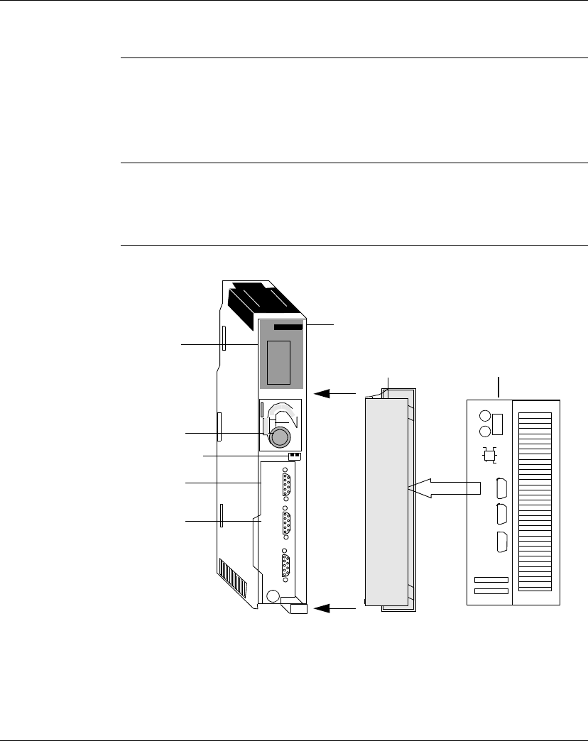
CPU Modules The following illustration shows the 140 CPU 311 10 module and its components.
Modbus
Date
Installed
off
not used
RTU
ASCII
mem
mem
prt
Modbus
Modbus
Plus
Network
Node
Customer Identification Label
(Fold label and place it inside
door)
Removable door
Model Number
Module Description
Color Code
LED Area
Battery
Memory Protect and
Comm parameter
Slide Switches
Modbus
Connector
Modbus Plus
Chan A
Modbus Plus
Connector
Chan A
140
CPU 311 10
CONTROLLER
X
Batt.
Modbus
Modbus
Connector
Modbus
Batt.
Spare
Quantum Unity CPUs
31005138 05June 20 11
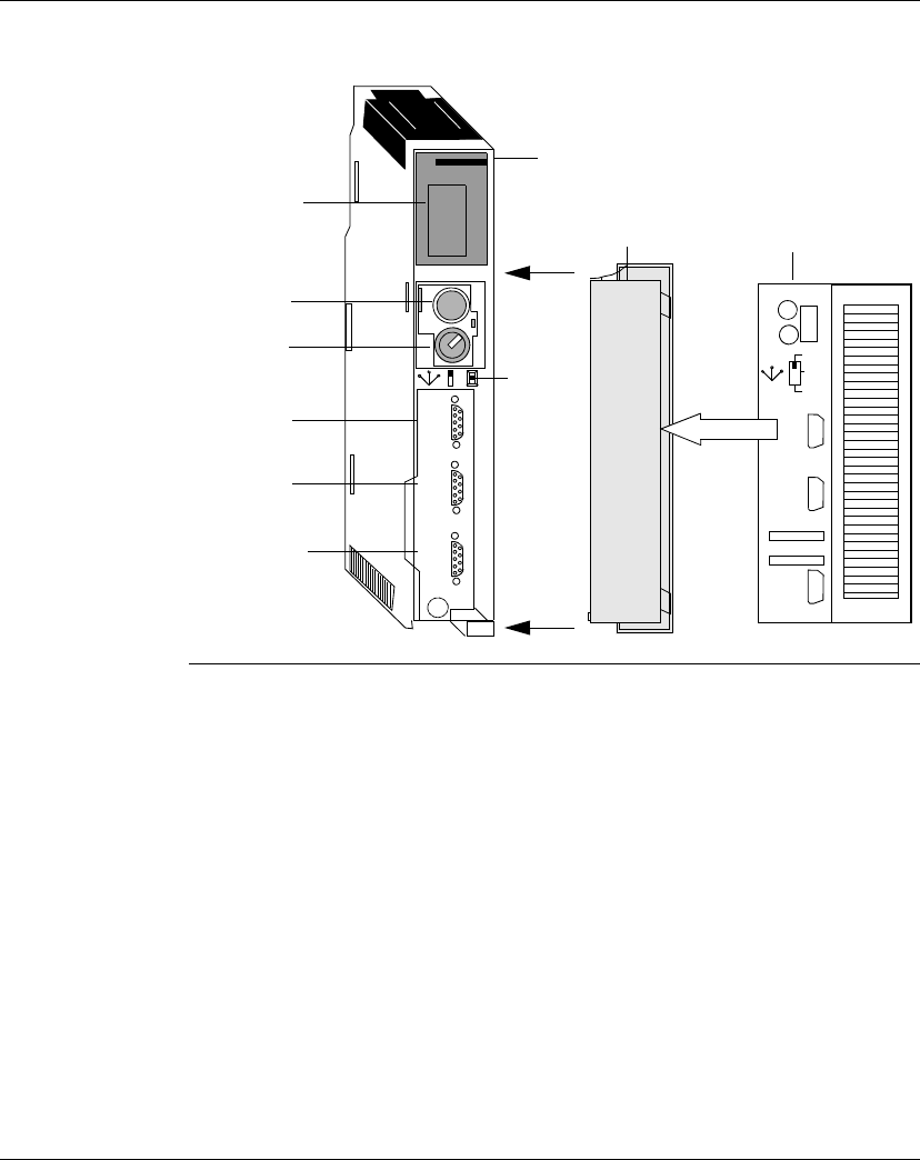
The following illustration shows the 140 CPU 434 12A module and its components.
The 140 CPU 534 14A and 140 CPU 534 14B modules have the same components.
Modbus
Comm 1
Network
Node
Customer Identification Label
(Fold label and place it inside
door) Part #31002249
Removable door
Part #043513804
Model Number
Module Description
Color Code
Battery
Key Switch
Modbus
Connector
140
CPU 434 12A
486 CONTROLLER
Modbus
Connector
Modbus Plus
Connector
Modbus
Comm 2
Modbus
Plus
Slide
Switch
ASCII
RTU
mem
X
LED
SW
stop
mem
prtstart
Modbus
Plus
For use with
140 CPU 434 12A
140 CPU 534 14A
Modbus
Modbus
Batt
Date
Installed

Quantum Unity CPUs
12 31005138 05 June 2009
Specifications The following table shows the specifications for the 140 CPU 311 10, 140 CPU 434
12A, 140 CPU 534 14A, and 140 CPU 534 14B modules.
Specifications
Model 140CPU31110 140CPU43412A 140CPU53414A 140CPU53414B
Processor 80486 80486 80586 80486
Math Coprocessor Yes Yes Yes Yes
Clock Speed 66 MHz 66 MHz 133 MHz 100 MHz
User Logic/Reference Capacity
Maximum IEC program (Concept/ProWorx)
IEC Application without PCMCIA (Unity)
Program and unlocated data (min)
Located data and config (max)
984 Ladder Logic (not in Unity)
Discrete
Register
Unity
Concept/ProWORX
N/A
400 k
148 k
N/A
51.7 k
10 k
N/A
846 k
800k
256 k
64 k
64 k
64 k
57 k
2.5 M
2.7 m
256 k
64 k
64 k
64 k
57 k
2.5 M
2.7 m
256 k
64 k
64 k
64 k
57 k
Local I/O
Maximum I/O Words
Unity
Concept/ProWORX
Maximum Number of I/O Racks
64 in and 64 out/module
64 in and 64 out/drop
2 (requires expander)
Remote I/O
Maximum I/O Words per Drop
Maximum Number of Remote Drops
Number of Networks
64 in and 64 out
31
1
Distributed I/O
Maximum Networks per System
Maximum Words per Network
Maximum Words per Node
3
500 in and 500 out
30 in and 32 out
Maximum Number of Network Module
Interfaces
26 6 6
Watchdog Timer 250 ms
(software
adjustable)
Logic Solve Time 0.1 ... 0.5 ms/k 0.1 ... 0.5 ms/k 0.9 ... 0.45 ms/k 0.9 ... 0.45 ms/k

Quantum Unity CPUs
31005138 05 June 20 13
Battery
Type
Service Life
Shelf Life
Load Current, Typical
Load Current, Max
3 V Lithium
1200 mAH
10 years
7 mA
210 mA
3 V Lithium
1200 mAH
10 years
7 mA
210 mA
3 V Lithium
1200 mAH
10 years
14 mA
210 mA
3 V Lithium
1200 mAH
10 years
14 mA
210 mA
Communication Ports
Modbus (RS-232)
Modbus Plus
2
1
2
1
2
1
2
1
Programming Software Capability Unity, version
1.0 minimum
Modsoft, version 2.6 or higher Concept, version 2.1 or
higher ProWORX NxT, version 2.0 or higher
ProWORX Plus, version 1.05 or higher ProWORX 32,
version 1.0 or higher Unity, version 1.0 or higher
Bus Current Required 1250 mA 1250 mA 1250 mA 1250 mA
Key Switch No Yes Yes Yes
TOD Clock Accuracy +/- 8.0 seconds/day 0 ... 60° C
Operating Temperature 0 ... 60° C
1CPUs 140 CPU 434 12 A/140 CPU 434 14A are shipped with Concept/ProWORX operating systems (exec)
preloaded. If you need Unity support, you need to load the Unity exec, available on the Web, into the CPU.
Specifications
Model 140CPU31110 140CPU43412A 140CPU53414A 140CPU53414B
Quantum Unity CPUs
14 31005138 05 June 2009
Front Panel Topology
Overview The following provides information on the front panel topology of the Quantum CPU
modules. There are two switches (a three-position slide switch and a three-position
key switch) located on the front of the 140 CPU 434 12A, 140 CPU 534 14A, and
140 CPU 534 14B modules. The 140 CPU 311 10 module has two slide switches
but does not have a key switch.
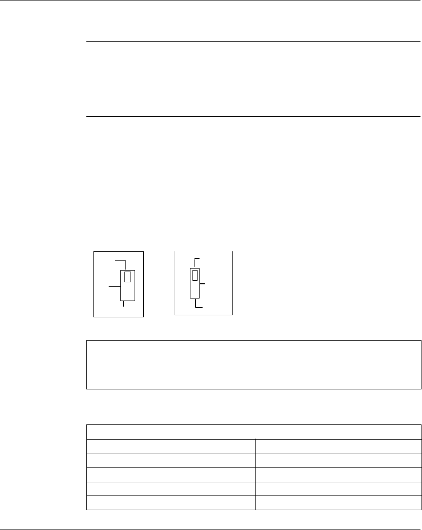
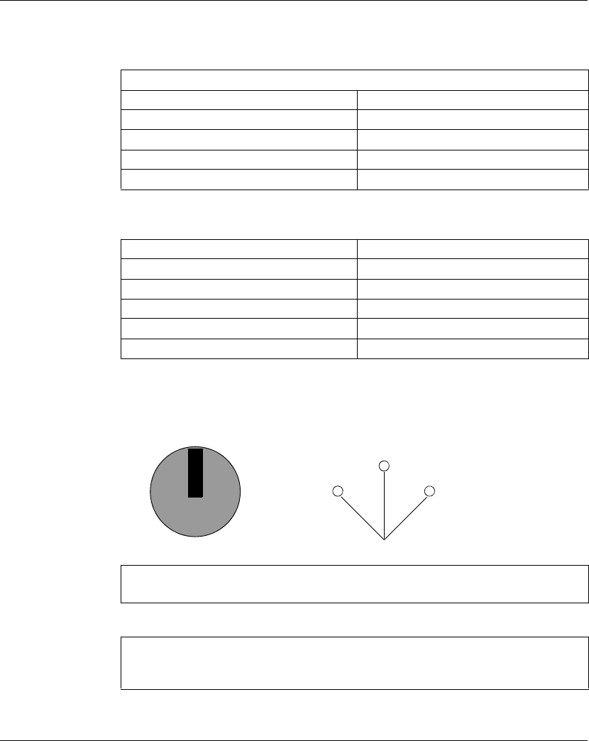
Front Panel Slide
Switches
The 140 CPU 311 10 module has two, three-position slide switches. The left switch
is used for memory protection when in the top position and no memory protection in
the bottom position. The three-position slide switch on the right is used to select the
communication parameter settings for the Modbus ports.
The 140 CPU 434 12A, 140 CPU 534 14A, and 140 CPU 534 14B modules have a
single slide switch that is used to select the comm parameter settings for the
Modbus (RS-232) ports.
The following illustration shows the slide switches for these two modules. The 140
CPU 311 10 uses both slide switches. The 140 CPU 434 12A, 140 CPU 534 14A,
and 140 CPU 534 14B modules use only the slide switch on the right.
Setting the slide switch to the top position assigns ASCII functionality to the port; the
following communication parameters are set and cannot be changed.
Note: The CPU hardware defaults to bridge mode when the front panel switch is
set to RTU or ASCII mode. When networking controllers, a panel device connected
to the CPU Modbus port can communicate with the controller to which it is
connected, as well as log into any nodes on the Modbus Plus network.
ASCII Comm Port Parameters
Baud 2,400
Parity Even
Data Bits 7
Stop Bits 1
Device Address Rear panel rotary switch setting
ASCII
RTU
mem
mem
prt
Not
used
Mem Prt off
Quantum Unity CPUs
31005138 05 June 2009 15
Setting the slide switch to the middle position assigns remote terminal unit (RTU)
functionality to the port; the following comm parameters are set and cannot be
changed.
Setting the slide switch to the bottom position gives you the ability to assign comm
parameters to the port in software; the following parameters are valid.
The key switch is used to protect memory from programming changes while the
controller is in operation. The following illustration shows the key switch that is used
with the 140CPU43412A, 140 CPU 534 14A, and 140 CPU 534 14B modules.
RTU Comm Port Parameters
Baud 9,600
Parity Even
Data Bits 8
Stop Bits 1
Device Address Rear panel rotary switch settings
Valid Com Port Parameters
Baud 50 ... 19,200
Data Bits 7/8
Stop Bits 1/2
Parity Enable/Disable Odd/Even
Device Address 1 ... 247
Note: The key switch positions shown next to the switch (above) are for reference
only and are marked on the module as indicated on the right.
Note: The 140 CPU 434 12A, 140 CPU 534 14A, and 140 CPU 534 14B
processors feature the key switch illustrated above, while the 140 CPU 311 10 has
a slide switch.
Stop
Mem
Prt
Start
Stop
Mem
Prt
Start

Quantum Unity CPUs
16 31005138 05 June 2009
The following table provides key/slider switch information for all three low end CPUs.
CPU Type Switch
Position
Behavior Protected? Accepts
Stop or
Start?
Key Switch Transition
Quantum
140 CPU 311 10
Mem Prt On The application in Flash
memory is not transferred to
internal RAM; a warm restart of
the application is triggered.
Y N From Mem Prt Off:
does not modify last
controller state and
rejects programmer
changes.
Not used Do not use this position,
because it may lead to
undefined operation
YNn/a
Mem Prt Off The application in Flash
memory is automatically
transferred to internal RAM
when the PLC is powered up. A
cold restart of the application is
triggered.
N Y From Mem Prt On :
enables programmer
changes and starts
controller if stopped.
Quantum
140 CPU 434 12A
140 CPU 534 14A
Stop The application in Flash
memory is not transferred to
internal RAM; a warm restart of
the application is triggered.
Y N From Start or Mem Prt:
stops controller, if
running, and voids
programmer changes.
Mem Prt The application in Flash
memory is not transferred to
internal RAM. A warm restart of
the application is triggered.
Y N From Stop or Start:
prevents program
changes, controller run
status is unchanged.
Start The application in Flash
memory is automatically
transferred to internal RAM
when the PLC is powered up. A
cold restart of the application is
triggered.
N Y From Stop: enables
programmer changes,
starts controller. From
Mem Prt: accepts
programmer changes,
starts controller if
stopped.
Quantum Unity CPUs
31005138 05 June 2009 17
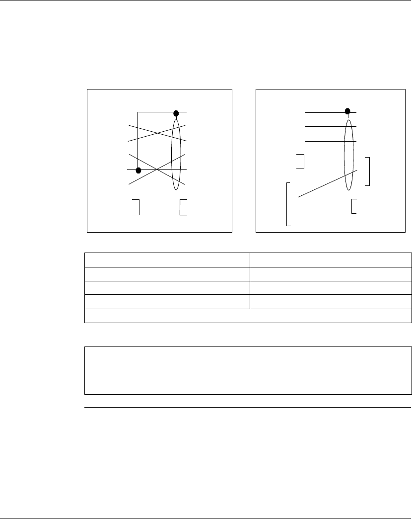
Front Panel
Modbus
Connector
The Quantum 140 CPU 434 12A, 140 CPU 534 14A, and 140 CPU 534 14B are
equipped with two nine-pin RS-232 connectors that support Modicon's proprietary
Modbus communication protocol. The 140 CPU 311 10 module has one nine-pin
RS-232 connector. The following is the Modbus port pinout connections for nine-pin
connections.
The following abbreviations are used in the figures above.
TX: Transmitted Data DTR: Data Terminal Ready
RX: Received Data CLS: Clear to Send
RTS: Request to Send N/C: No Connections
DSR: Data Set Ready CD: Carrier Detect
GND: Ground
Note: Although the Modbus ports electrically support existing Modbus cables, it is
recommended that a Modbus programming cable (Part # 990NAA26320) be used.
This cable has been designed to fit under the door of a Quantum CPU or NOM
module.
5
IBM-AT
9-Pin Female
Quantum
9-Pin Male
Quantum
9-Pin Male
IBM-XT
25-Pin Female
CD
RX
TX
DTR
GND
DSR
RTS
CTS
1
2
3
4
5
6
7
8
1
2
3
4
6
7
8
9
SHIELD
RX
TX
DTR
GND 5
DSR
RTS
CTS
NC
1
2
3
4
6
7
8
9
SHIELD
RX
TX
DTR
GND
DSR
RTS
CTS
NC
RX
RTS
CTS
DSR
GND
NC
1
2
3
4
5
6
7
8
SHIELD
TX
20DTR
Quantum Unity CPUs
18 31005138 05 June 2009
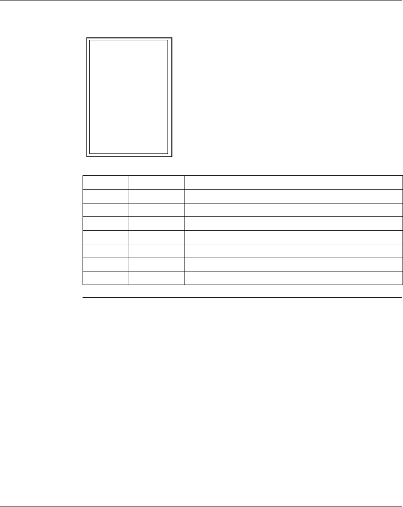
LED Indicators
and Descriptions
The following illustration shows the LED indicators for the 140CPU31110,
140CPU43412A, 140 CPU 534 14A, and 140 CPU 534 14B modules.
Table with three columns.
LEDs Color Indication When On
Ready Green The CPU has passed power-up diagnostics
Run Green The CPU has been started and is solving logic.
Bat Low Red The battery needs replacing or is not present.
Modbus Green Communications are active on the Modbus port 1 or 2.
Modbus + Green Communications are active on the Modbus Plus port.
Error A Red Indicates communications error on the Modbus Plus port.
Mem Prt Amber Memory is write-protected (the memory protect switch is on).
Ready
Bat Low
Error A
Run
Modbus
Modbus +
Mem Prt

Quantum Unity CPUs
31005138 05 June 2009 19
LED Error Codes Table with three columns.
LED Error Codes
Number of Blinks Code Error
Continuous 0000 requested kernel mode
2 80B ram error during sizing
80C run output active failed
82E MB command handler stack error
3 769 bus grant received
72A not master asic on cpu
72B master config write bad
72C quantum bus DPM write failure
72F plc asic loopback test
730 plc asic BAD_DATA
4 604 UPI timeout error
605 bad UPI response opcode
606 UPI bus diagnostic error
607 modbus cmd-buffer overflow
608 modbus cmd-length is zero
609 modbus abort command error
614 mbp bus interface error
615 bad mbp response opcode
616 timeout waiting for mbp
617 mbp out of synchronization
618 mbp invalid path
619 page 0 not paragraph aligned
61E bad external uart hardware
61F bad receive comm state
620 bad receive comm state
l621 bad transmit comm state
l622 bad comm state trn_asc
623 bad comm state trn_rtu
624 bad comm state rcv_rtu
l625 bad comm state rcv_asc
626 bad modbus state tmr0_evt
627 bad modbus state trn-int

Quantum Unity CPUs
20 31005138 05 June 2009
628 bad modbus state rcv-int
631 bad interrupt
5 503 ram address test error
52D P.O.S.T. BAD MPU ERROR
6 402 ram data test error
7 300 EXEC not loaded
301 EXEC checksum
8 8001 Kernal prom checksum error
8002 flash prog/erase error
8003 unexpected executive return
LED Error Codes
Number of Blinks Code Error
Quantum Unity CPUs
31005138 05 June 2009 21
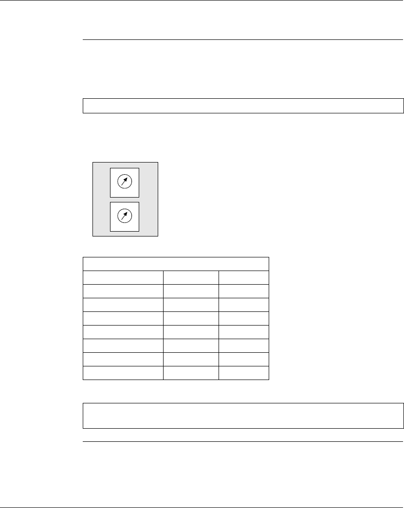
Rear Panel Topology
Overview The address switch, which is comprised of two rotary switches, is located on the rear
panel of the Quantum CPUs. The address switch is used for setting Modbus Plus
node and Modbus port addresses.
SW1 (the top switch) sets the upper digit (tens) of the address, SW2 (the bottom
switch) sets the lower digit (ones) of the address. The illustration below shows the
correct setting for an example address of 11.
Table with three columns.
Note: The highest address that may be set with the address switch is 64.
SW1 and SW2 Address Settings
Node Address SW1 SW2
1 ... 9 0 1 ... 9
10 ... 19 1 0 ... 9
20 ... 29 2 0 ... 9
30 ... 39 3 0 ... 9
40 ... 49 4 0 ... 9
50 ... 59 5 0 ... 9
60 ... 64 6 0 ... 4
Note: If "0" or an address greater than 64 is selected, the Modbus + LED will be
"ON" steady to indicate the selection of an invalid address.
1
3
0
9
2
6
4
5
8
7
1
3
0
9
2
6
4
5
8
7
SW1 (TENS)
SW2 (ONES)

Quantum Unity CPUs
22 31005138 05 June 2009
Option Module Interface Support
Overview The 140 CPU 434 12A, 140 CPU 534 14A, and 140 CPU 534 14B each support up
to six network modules (i.e., Modbus Plus, Ethernet, and Multi-Axis Motion option
modules) using the option module interface technique. However, only two Modbus
Plus modules can have full functionality, including Quantum DIO support. The 140
CPU 311 10 supports up to two network modules.
Quantum
Communications
and Network
Modules
The following table shows the network modules that are supported.
Model Number Description Module
Interface
Technique
Loadable
Required
(not in
Unity)
Backplane Support Bus
Power mA
Local RIO DIO
140CRP81100 Profibus Direct CPU
Driver
N Y N N 1200
140CRP93100 Remote I/O Head
interface, single
cable
Direct CPU
Driver
NYNN780
140CRP93200 Remote I/O Head
Interface, dual
cable
Direct CPU
Driver
NYNN780
140CHS21000
(not in Unity)
Hot Standby
Processor Kit
Direct CPU
Driver
YYNN700
140NOA61110
(not in Unity)
Interbus Master
(G3)
Direct CPU
Driver
YYNN700
140NOA62200 Interbus Master
(G4)
Direct CPU
Driver
YYNN700
140NOM21100 Modbus Plus
Options, single
cable
Option module N Y N N 780
140NOM21200 Modbus Plus
Option, dual cable
Option module N Y N N 780
140NOM25200 Modbus Plus
Option, single
channel fiber
Option module N Y N N 900
140NOE31100 Ethernet SY/MAX
Twisted Pair
Option module N Y N N 1000

Quantum Unity CPUs
31005138 05 June 2009 23
140NOE35100 Ethernet SY/MAX
Fiber Optic
Option Module N Y N N 1000
140NOE77101 Ethernet Option Module N Y N N 1000
140NOE77111 Ethernet Web
Server
Option Module N Y N N 1000
140MMS42500 Multi-Axis Motion
Controller w/
SERCOS
Option Module N Y N N 2500
140NOL91110
(not in Unity)
LonWorks
Interface, twisted
pair TPT/XF-78
I/O Map (16/16) Y Y Y N 950
Model Number Description Module
Interface
Technique
Loadable
Required
(not in
Unity)
Backplane Support Bus
Power mA
Local RIO DIO

Quantum Unity CPUs
24 31005138 05 June 2009
Quantum
Modbus and
Modbus Plus
Services
This table describes the types of services provided by Modbus and Modbus Plus.
Type Service Description Native CPU Ports NOM 1-2 Ports NOM 3-6 Ports1
Modbus Modbus
Plus
Modbus Modbus
Plus
Modbus Modbus
Plus
Modbus
Services
Default Modbus Port
Parameters
Y- Y- Y-
Configurable Modbus
Port Parameters
Y- Y- Y5-
Modbus to Modbus Plus
Bridging
Y2-Y3-Y3-
Local CPU Programming Y4-Y4-N-
Remote CPU
Programming over
Modbus Plus
Y4-Y4-Y2-
Modbus access to local
CPU
Y- Y- N
Modbus access to
remote CPU over
Modbus Plus
Y- Y- Y-
Modbus Network Slave
Support
Y- N- N-
Modbus Master support
with XMIT Loadable
Y- N- N-
Executive Firmware
Loading Support
Y- N- N-

Quantum Unity CPUs
31005138 05 June 2009 25
Modbus
Plus
Services
MSTR read/write register
messaging6
-Y-Y-Y
MSTR read/write Global
Data messaging
-Y-Y-Y
MSTR get/clear local/
remote statistics
-Y-Y-Y
Config Extension Global
Data Support
-Y-Y-N
Config Extension Peer
Cop Support
-Y-Y-N
Distributed I/O Support - Y - Y - N
CPU Programming - Y4-Y4-Y4
Executive Firmware
Loading Support
-Y-N-Y
1. Only supported on the 140 CPU 434 12A and 140 CPU 534 14A Quantum controllers.
2. The native CPU Modbus port can be disabled from bridge mode operation with the native Modbus Plus port.
3. Modbus ports on NOMs are always in bridge mode with their associated Modbus Plus port.
4. Only one programmer connection can be logged in at a time to any CPU, and only one program monitor can be
attached at a time to any CPU.
5. Modbus port parameters on NOMs 3-6 are defined by Modbus Port 3 in Concept and Modsoft when the comm
parameter selector switch is in mem.
6. Up to 4 MSTR read/write register instructions can be serviced per CPU scan per Modbus Plus port.
Type Service Description Native CPU Ports NOM 1-2 Ports NOM 3-6 Ports1
Modbus Modbus
Plus
Modbus Modbus
Plus
Modbus Modbus
Plus

Quantum Unity CPUs
26 31005138 05 June 2009
