8089cv0 Installation Directions
2016-08-17
: Pdf 1000496359-Installationsheet 1000496359-InstallationSheet B3 unilog
Open the PDF directly: View PDF ![]() .
.
Page Count: 154 [warning: Documents this large are best viewed by clicking the View PDF Link!]
- 2_Notes_Electricians and Programmer.pdf
- 3_8089_en_00toc.pdf
- 4_8089s01.pdf
- 5_8089s02.pdf
- 6_8089s03.pdf
- 5051.pdf
- Please observe the following notes
- Table of contents
- 1 Smart Managed Narrow switch
- 2 Mounting and installation
- 3 Startup and functions
- 4 Configuration and diagnostics
- 4.1 Making contact between the SMN and PC for initial configuration
- 4.2 Web-based management (WBM)
- 4.3 Simple Network Management Protocol (SNMP)
- 4.3.1 General function
- 4.3.2 Diagram of SNMP management
- 4.3.3 RFC 1213 MIB - MIB II
- 4.3.4 RMON MIB (1.3.6.1.2.1.16)
- 4.3.5 Bridge MIB (1.3.6.1.2.1.17)
- 4.3.6 pBridgeMIB (1.3.6.1.2.1.17.6)
- 4.3.7 qBridgeMIB (1.3.6.1.2.1.17.7)
- 4.3.8 rstp MIB (1.3.6.1.2.1.17.11)
- 4.3.9 IANAifType MIB (1.3.6.1.2.1.30)
- 4.3.10 IF MIB (1.3.6.1.2.1.31)
- 4.3.11 pnoRedundancy MIB 1.3.6.1.4.1.24686
- 4.3.12 Private MIBs
- 4.4 Management via local V.24 (RS-232) communication interface
- 5 (Rapid) Spanning Tree
- 6 Media Redundancy Protocol (MRP)
- 7 Multicast filtering
- 8 Virtual Local Area Network (VLAN)
- 9 Operation as a PROFINET device
- 10 LLDP (Link Layer Discovery Protocol)
- 11 Technical data and ordering data
User manual
Smart Managed Narrow Switch
Order No. —

2016-02-15
PHOENIX CONTACT 8089_en_03
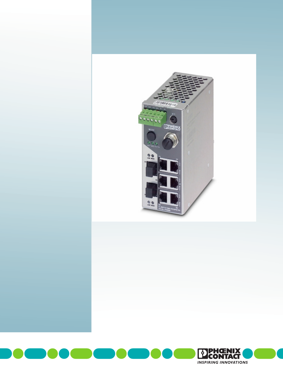
Smart Managed Narrow Switch
UM EN FL SWITCH SMN 6TX/2POF-PN
03
—
Designation Version Order No.
FL SWITCH SMN 6TX/2POF-PN 2700290
FL SWITCH SMN 8TX-PN 2989501
FL SWITCH SMN 6TX/2FX 2989543
FL SWITCH SMN 6TX/2FX-SM 2989556
User manual
Designation:
Revision:
Order No.:
This user manual is valid for:
PHOENIX CONTACT
Please observe the following notes
User group of this manual
The use of products described in this manual is oriented exclusively to:
– Qualified electricians or persons instructed by them, who are familiar with applicable
standards and other regulations regarding electrical engineering and, in particular, the
relevant safety concepts.
– Qualified application programmers and software engineers, who are familiar with the
safety concepts of automation technology and applicable standards.
Explanation of symbols used and signal words
How to contact us
Internet Up-to-date information on Phoenix Contact products and our Terms and Conditions can be
found on the Internet at:
phoenixcontact.com
Make sure you always use the latest documentation.
It can be downloaded at:
phoenixcontact.net/products
Subsidiaries If there are any problems that cannot be solved using the documentation, please contact
your Phoenix Contact subsidiary.
Subsidiary contact information is available at phoenixcontact.com.
Published by PHOENIX CONTACT GmbH & Co. KG
Flachsmarktstraße 8
32825 Blomberg
GERMANY
Should you have any suggestions or recommendations for improvement of the contents and
layout of our manuals, please send your comments to:
tecdoc@phoenixcontact.com
This is the safety alert symbol. It is used to alert you to potential personal injury
hazards. Obey all safety measures that follow this symbol to avoid possible
injury or death.
There are three different categories of personal injury that are indicated with a
signal word.
DANGER This indicates a hazardous situation which, if not avoided, will
result in death or serious injury.
WARNING This indicates a hazardous situation which, if not avoided, could
result in death or serious injury.
CAUTION This indicates a hazardous situation which, if not avoided, could
result in minor or moderate injury.
This symbol together with the signal word NOTE and the accompanying text
alert the reader to a situation which may cause damage or malfunction to the
device, hardware/software, or surrounding property.
This symbol and the accompanying text provide the reader with additional
information or refer to detailed sources of information.

Please observe the following notes
PHOENIX CONTACT
General terms and conditions of use for technical documentation
Phoenix Contact reserves the right to alter, correct, and/or improve the technical
documentation and the products described in the technical documentation at its own
discretion and without giving prior notice, insofar as this is reasonable for the user. The
same applies to any technical changes that serve the purpose of technical progress.
The receipt of technical documentation (in particular user documentation) does not
constitute any further duty on the part of Phoenix Contact to furnish information on
modifications to products and/or technical documentation. You are responsible to verify the
suitability and intended use of the products in your specific application, in particular with
regard to observing the applicable standards and regulations. All information made
available in the technical data is supplied without any accompanying guarantee, whether
expressly mentioned, implied or tacitly assumed.
In general, the provisions of the current standard Terms and Conditions of Phoenix Contact
apply exclusively, in particular as concerns any warranty liability.
This manual, including all illustrations contained herein, is copyright protected. Any
changes to the contents or the publication of extracts of this document is prohibited.
Phoenix Contact reserves the right to register its own intellectual property rights for the
product identifications of Phoenix Contact products that are used here. Registration of such
intellectual property rights by third parties is prohibited.
Other product identifications may be afforded legal protection, even where they may not be
indicated as such.

8089_en_03 PHOENIX CONTACT 3
Table of contents
1 Smart Managed Narrow Switch .................................................................................................9
1.1 Features ................................................................................................................9
1.1.1 Dimensions of the SMN .......................................................................11
1.2 Status and diagnostics indicators ........................................................................13
1.2.1 Firmware versions and their functions ..................................................14
2 Mounting and installation .........................................................................................................15
2.1 Mounting and removing the SMN ........................................................................15
2.2 Installing the Smart Managed Narrow Switch ......................................................16
2.2.1 Connecting the 24 V DC supply voltage ...............................................16
2.2.2 Signal contact ......................................................................................17
2.2.3 Assignment of the RJ45 Ethernet connectors ......................................17
2.2.4 RS-232 interface for external management ..........................................18
2.3 Grounding............................................................................................................18
3 Startup and functions ...............................................................................................................19
3.1 Basic settings ......................................................................................................19
3.1.1 Delivery state/default settings ..............................................................19
3.2 Using Smart mode...............................................................................................20
3.2.1 Activating Smart mode .........................................................................20
3.3 Frame switching ..................................................................................................22
3.3.1 Store and forward ................................................................................22
3.3.2 Multi-address function ..........................................................................22
3.3.3 Learning addresses .............................................................................22
3.3.4 Prioritization .........................................................................................23
4 Configuration and diagnostics ..................................................................................................25
4.1 Making contact between the SMN and PC for initial configuration.......................25
4.1.1 Operation with static IP addresses .......................................................25
4.2 Web-based management (WBM) ........................................................................27
4.2.1 General function ...................................................................................27
4.2.2 Requirements for the use of WBM .......................................................28
4.2.3 Functions/information in WBM .............................................................28
4.3 Simple Network Management Protocol (SNMP)..................................................47
4.3.1 General function ...................................................................................47
4.3.2 Schematic view of SNMP management ...............................................47
4.3.3 RFC 1213 MIB - MIB II .........................................................................51
4.3.4 RMON MIB (1.3.6.1.2.1.16) .................................................................58
4.3.5 Bridge MIB (1.3.6.1.2.1.17) ..................................................................64
4.3.6 pBridgeMIB (1.3.6.1.2.1.17.6) ..............................................................66
4.3.7 qBridgeMIB (1.3.6.1.2.1.17.7) ..............................................................67
4.3.8 rstp MIB (1.3.6.1.2.1.17.11) .................................................................70
4.3.9 IANAifType MIB (1.3.6.1.2.1.30) ..........................................................70

FL SWITCH SMN
4PHOENIX CONTACT 8089_en_03
4.3.10 IF MIB (1.3.6.1.2.1.31) .........................................................................70
4.3.11 pnoRedundancy MIB 1.3.6.1.4.1.24686 ..............................................73
4.3.12 Private MIBs .........................................................................................74
4.4 Management via local RS-232 communication interface ...................................103
4.4.1 General function .................................................................................103
4.4.2 User interface functions .....................................................................104
4.4.3 Starting with faulty software (firmware) ..............................................107
5 (Rapid) Spanning Tree ...........................................................................................................109
5.1 General function ................................................................................................109
5.2 (R)STP startup...................................................................................................110
5.2.1 Enabling (R)STP on all switches involved ..........................................110
5.2.2 Connection failure - Example .............................................................118
5.2.3 Mixed operation of RSTP and STP ....................................................119
5.2.4 Topology detection of a Rapid Spanning Tree network (RSTP) .........119
5.2.5 Configuration notes for Rapid Spanning Tree ....................................122
6 Media Redundancy Protocol (MRP) ......................................................................................133
6.1 General function ................................................................................................133
6.2 MRP manager ...................................................................................................133
6.2.1 Network examples .............................................................................134
6.3 Enabling web pages for using MRP in WBM......................................................135
6.4 Configuration of MRP ........................................................................................136
6.4.1 MRP general ......................................................................................136
6.4.2 MRP configuration .............................................................................137
7 Multicast filtering ...................................................................................................................139
7.1 Basics................................................................................................................139
7.2 Enabling the web pages for multicast filtering in WBM.......................................139
7.3 Static multicast groups.......................................................................................139
7.3.1 “Current Multicast Groups” web page ................................................140
7.3.2 Creating static multicast groups .........................................................140
7.3.3 Procedure for creating a multicast group ............................................142
7.4 Dynamic multicast groups..................................................................................144
7.4.1 Internet Group Management Protocol (IGMP) ....................................144
7.4.2 “General Multicast Configuration” web page ......................................146
8 Virtual Local Area Network (VLAN) ........................................................................................147
8.1 Basics................................................................................................................147
8.2 Enabling the VLAN web pages in web-based management ..............................147
8.2.1 Management VLAN ID .......................................................................147
8.2.2 Changing the management VLAN ID .................................................148

Table of contents
8089_en_03 PHOENIX CONTACT 5
8.3 General VLAN configuration ..............................................................................148
8.4 Current VLANs ..................................................................................................149
8.4.1 Static VLANs ......................................................................................150
8.4.2 VLAN port configuration .....................................................................151
8.4.3 VLAN port configuration table ............................................................151
8.5 Setting up static VLANs .....................................................................................152
8.6 VLAN and (R)STP .............................................................................................153
9 Operation as a PROFINET device .........................................................................................155
9.1 Preparing the switch for PROFINET mode ........................................................155
9.2 Switch as a PROFINET device ..........................................................................156
9.2.1 Configuration in the engineering tool ..................................................156
9.2.2 Configuring the switch as a PROFINET device ..................................157
9.2.3 Configuration via the engineering tool ................................................158
9.2.4 PROFINET flashing function ..............................................................159
9.2.5 Device naming ...................................................................................159
9.2.6 Operating in the PROFINET environment ..........................................159
9.3 PROFINET alarms.............................................................................................159
9.3.1 Alarms in WBM ..................................................................................160
9.4 Process data communication.............................................................................160
9.4.1 Control word .......................................................................................160
9.5 PDEV function description .................................................................................161
9.5.1 PROFINET stack and PDEV function .................................................162
10 Link Layer Discovery Protocol (LLDP) ...................................................................................163
10.1 Basics................................................................................................................163
10.2 Topology representation via an engineering tool ...............................................166
11 Technical data and ordering data ...........................................................................................167
11.1 Technical data ...................................................................................................167
11.2 Ordering data.....................................................................................................170
A Appendixes.............................................................................................................................173
A 1 List of figures .....................................................................................................173
B 2 List of tables ......................................................................................................177

FL SWITCH SMN
6PHOENIX CONTACT 8089_en_03
Smart Managed Narrow Switch
8089_en_03 PHOENIX CONTACT 9
1 Smart Managed Narrow Switch
1.1 Features
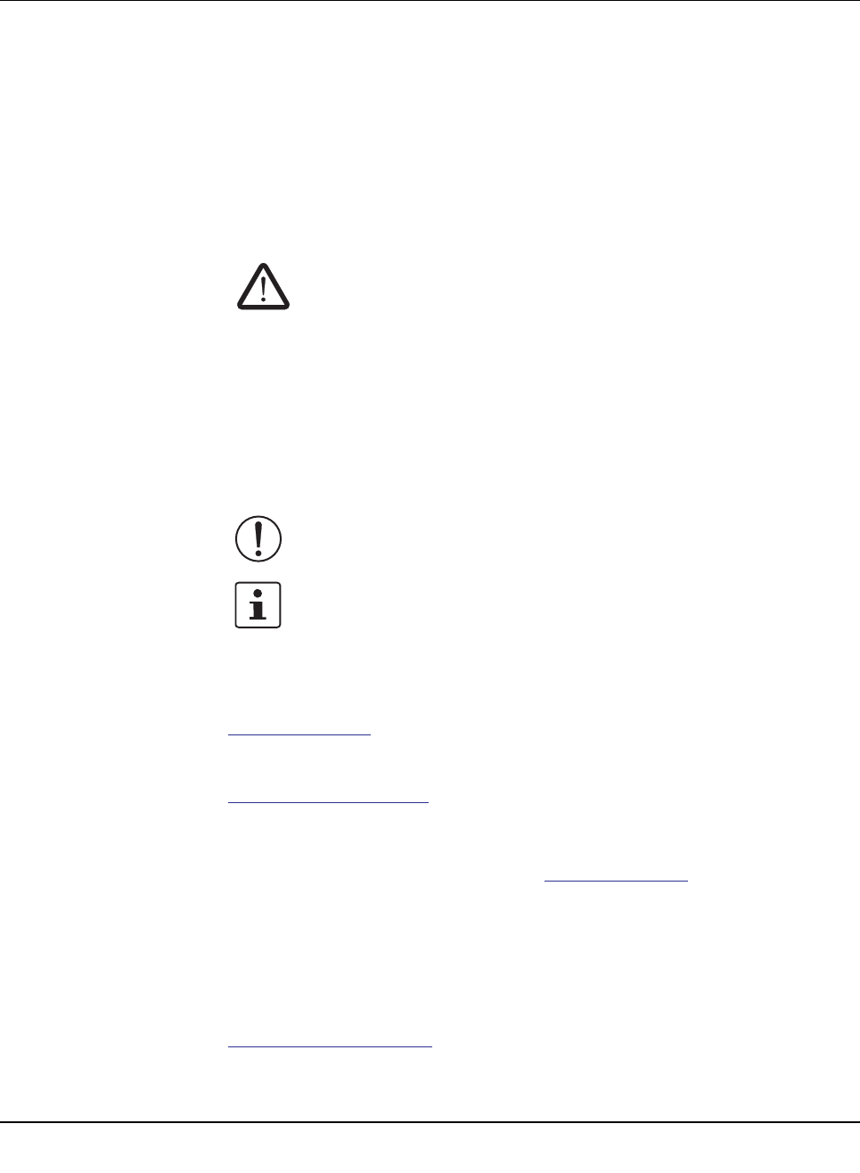
The Smart Managed Narrow Switch (Smart Managed Narrow Switch - SMN) is an indus-
trial Ethernet switch, which is available in the following versions:
– Six Fast Ethernet ports in RJ45 format and two fiber optic ports in POF format (FL
SWITCH SMN 6TX/2POF-PN)
– Eight Fast Ethernet ports in RJ45 format
(FL SWITCH SMN 8TX-PN)
– Six Fast Ethernet ports in RJ45 format and two fiber optic ports in SC multi-mode format
(FL SWITCH SMN 6TX/2FX)
– Six Fast Ethernet ports in RJ45 format and two fiber optic ports in SC single-mode for-
mat (FL SWITCH SMN 6TX/2FX-SM)
Figure 1-1 Smart Managed Compact Switch (versions)
Future-proof networks for the highest demands
Maximum performance 10/100 Mbps on each RJ45 port, 100 Mbps for fiber optic ports
Maximum availability Maximum network availability
A device design that does not use a fan, the redundant power supply, and conformance with
all relevant industrial standards in terms of EMC, climate, mechanical load, etc. ensure the
highest possible level of availability.
Quick media redundancy Redundancy can be created with standards: the (Rapid) Spanning Tree Protocol or MRP
(Media Redundancy Protocol) ensure safe operation of the entire network regardless of to-
pology, even in the event of a cable interrupt.
NOTE: By default upon delivery, the Smart Managed Compact Switch switch operates in
“PROFINET” mode.

Smart Managed Compact Switch
10 PHOENIX CONTACT 8089_en_03
All information Clear information
Two LEDs per port with switchable information ensure that you always have sufficient local
information. A web server and an SNMP agent are provided for diagnostics, maintenance,
and configuration via the network. A terminal access point can be used for on-site operation.
Port mirroring Port mirroring can be used to monitor data traffic on the network connections or as an im-
portant service function.
Features and fields of application of the Smart Managed Compact Switch
– Increased network performance by filtering data traffic:
- Local data traffic remains local.
- The data volume in network segments is reduced.
– Easy network expansion and network configuration.
– Coupling of copper segments with different transmission speeds.
Automatic detection of 10 Mbps or 100 Mbps data transmission speed with auto cross-
ing for the RJ45 ports.
– Flexible use of fiber optics in SCRJ format.
– Increased availability through the use of redundant transmission paths with the shortest
switch-over times using Rapid Spanning Tree and fast ring detection. Support of vari-
ous topologies and meshed structures as well as ring topologies with special ring de-
tection.
– Switch configuration using web-based management, SNMP or locally via an RS-232 in-
terface.
– Port mirroring.
– Topology detection using LLDP (Link Layer Discovery Protocol).
– Address assignment via BootP, DCP or statically.
– Media Redundancy Protocol (MRP) supported as a client or as the MRP master. The
MRP ring can thus be created using any SMN ports.
– Can be used in the PROFINET environment.
– Operating mode can be easily changed using Smart mode.
– POF port diagnostics.

Smart Managed Narrow Switch
8089_en_03 PHOENIX CONTACT 11
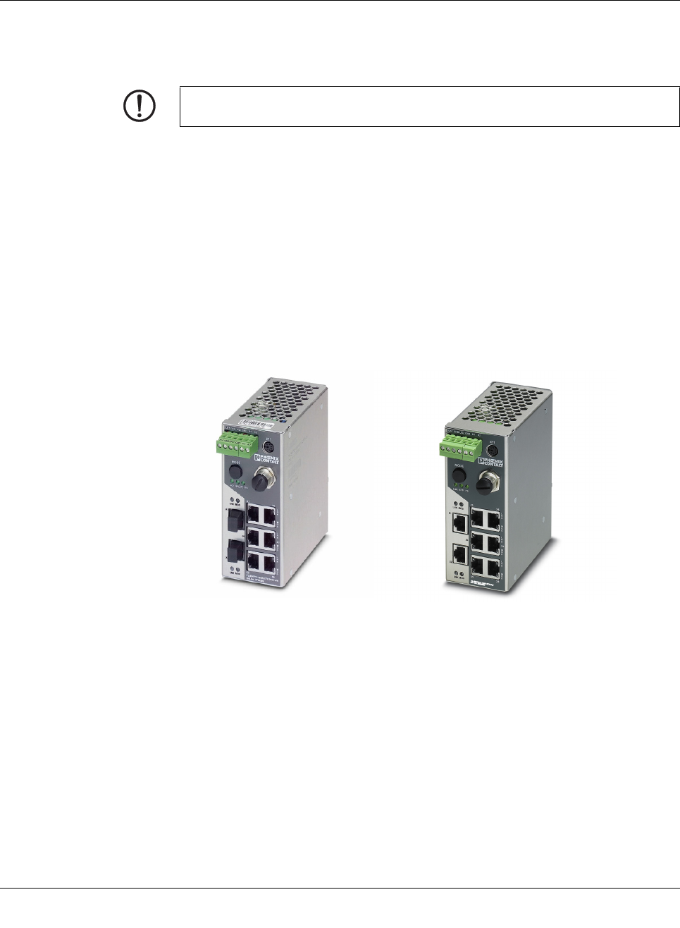
1.1.0.1 View of the SMN
Figure 1-2 View of the FL SWITCH SMN 6TX/2POF-PN
– Diagnostic/status indicators
Important information is displayed directly on the device. Each port has two LEDs. The
top LED always indicates the “LINK”, the display of the bottom LED is set with the func-
tion switch.
– MODE switch for LEDs and Smart mode
The MODE switch can be used to specify which information is displayed by the second
port-specific LED. The three LEDs below the switch indicate the selected mode. This
information is then displayed by all port-specific LEDs (see also example on page 14).
In addition, this button is used to set the switch to Smart mode (for details, see “Using
Smart mode” on page 20).
– Mini-DIN RS-232
RS-232 interface in Mini-DIN format for on-site configuration via the serial interface.
– Signal contact
The floating signal contact can be connected here via a 2-pos. COMBICON connector.
– Supply voltage connection
The supply voltage can be connected via the 4-pos. COMBICON connector (redundan-
cy is optional).
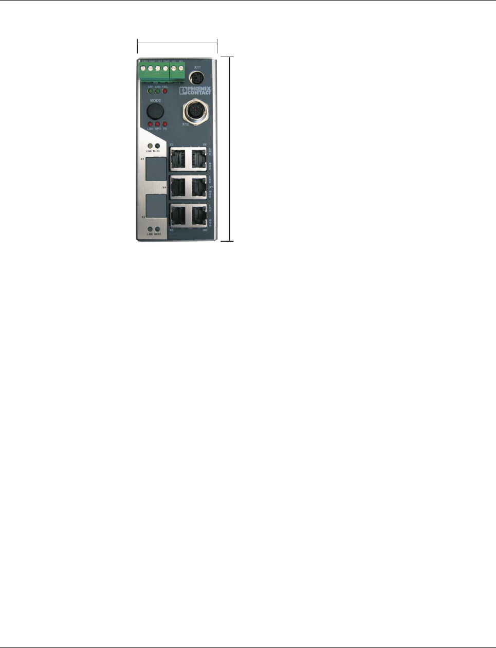
1.1.1 Dimensions of the SMN
Depth from top edge of DIN rail including MEM PLUG: 175 mm
Smart Managed Compact Switch
12 PHOENIX CONTACT 8089_en_03
Depth from top edge of DIN rail without MEM PLUG: 130 mm
Figure 1-3 Housing dimensions of the FL SWITCH SMN in millimeters
56 mm
133 mm
Smart Managed Narrow Switch
8089_en_03 PHOENIX CONTACT 13
1.2 Status and diagnostics indicators
Please note that the meaning of the LEDs differs in Smart mode (see “Using Smart mode”
on page 20).
Des. Color Status Meaning
US1 Green On Supply voltage 1 within the tolerance range
Off Supply voltage 1 too low
US2 Green On Supply voltage 2 within the tolerance range
Off Supply voltage 2 too low
FAIL Red On Signal contact open, i.e., an error has occurred
Off Signal contact closed, i.e., an error has not occurred
A Link LED is located on the front of the SMN for each port
LNK
(Link)
Green On Link active
Off Link not active
An additional LED is located on the front of the SMN for each port. The function of the second LED (MODE) for each port
can be set using the MODE switch (see also example below). There are three options (during the boot process the mode
and port LEDs are permanently on):
ACT
(Activity)
Green On Transmitting/receiving telegrams
Off Not transmitting/receiving telegrams
SPD
(Speed)
Green ON (green) 100 Mbps
Off 10 Mbps if Link LED is active (for RJ45 ports only)
FD
(Duplex)
Green On Full duplex
Off Half duplex
FO
(Fiber Optic)
Orange Off The system reserve of the optical path is >2 dB
Flashing
0.5 Hz
The system reserve of the optical path is between 2 dB and 0 dB
Flashing
2 Hz
The system reserve of the optical path is <0 dB
On Diagnostic alarm
ACT/SPD/FD Yellow Flashing Switch is in Smart mode (see “Using Smart mode” on page 20)
Smart Managed Compact Switch
14 PHOENIX CONTACT 8089_en_03
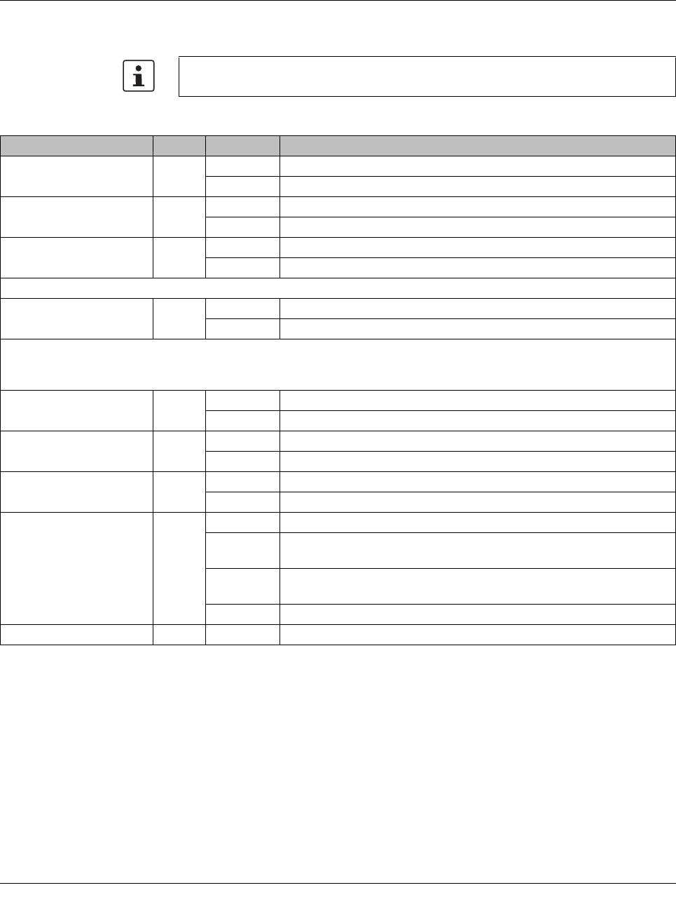
Example:
In Figure 1-4, the LED indicators have the following meaning:
A: The MODE switch has been used to select duplex mode (FD); the mode LEDs now indi-
cate that port 1 is in full duplex mode.
B: The switch has been used to select the data transmission speed (SPD); the mode LEDs
now indicate that port 1 is operating at 10 Mbps, port 2 is operating at 100 Mbps, port 3 is
operating at 100 Mbps, and port 4 is not operating at all.
Figure 1-4 Example of status indicators
1.2.1 Firmware versions and their functions
Firmware version 1.00 provides the standard switch functions.
MODE
ACT SPD FD
AB
Mounting and installation
8089_en_03 PHOENIX CONTACT 15
2 Mounting and installation
2.1 Mounting and removing the SMN
Mount the SMN on a clean DIN rail according to DIN EN 50022 (e.g., NS 35 ... from Phoenix
Contact). To avoid contact resistance, only use clean, corrosion-free DIN rails. End brack-
ets (E/NS 35N, Order No. 0800886) can be mounted to the right and left of the SMN to stop
the modules from slipping on the DIN rail.
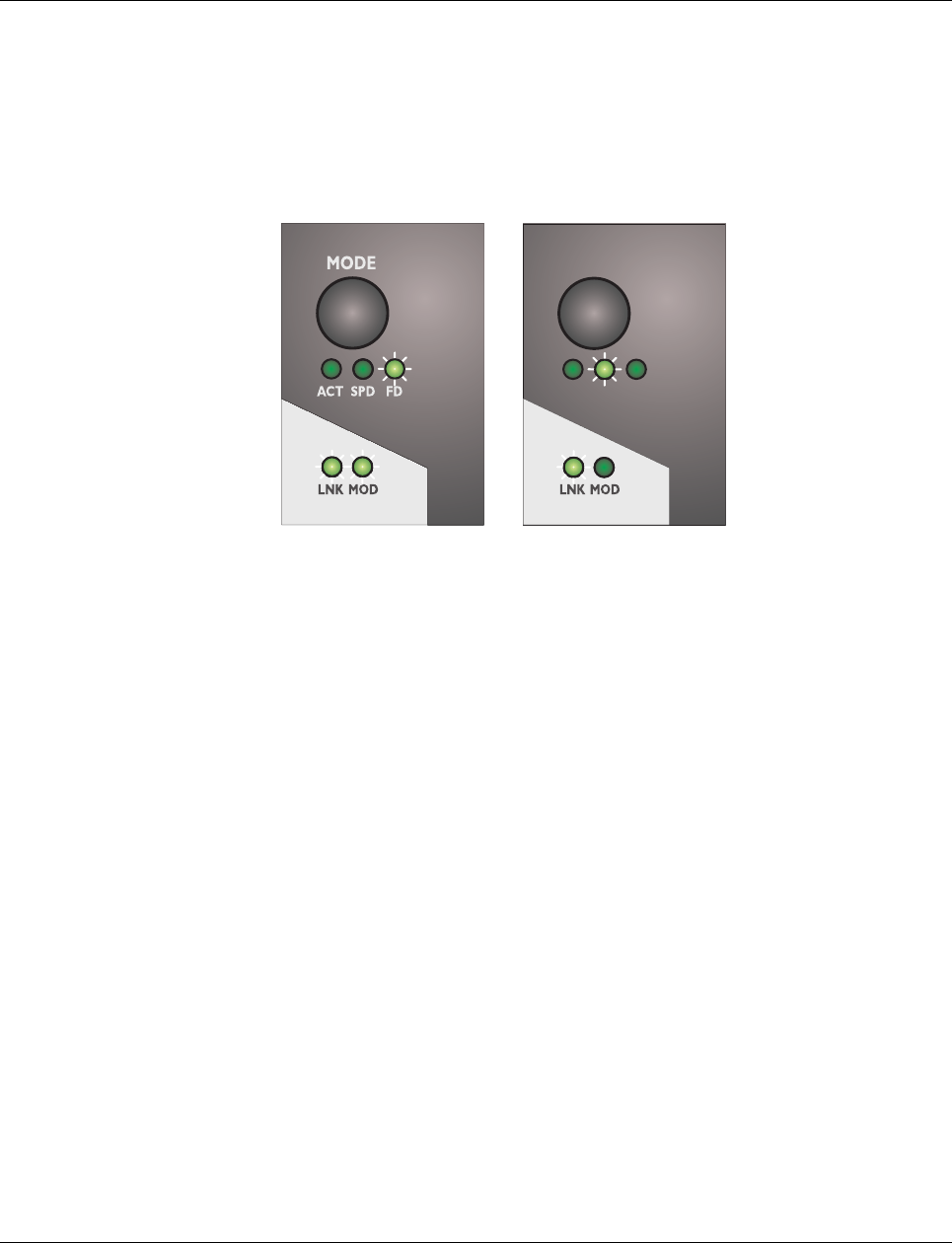
Mounting:
1Place the module onto the DIN rail from above (1). The upper holding keyway of the
module must be hooked onto the top edge of the DIN rail. Push the module from the
front towards the mounting surface (2).
Figure 2-1 Snapping the SMN onto the DIN rail
2Once the module has been snapped on properly, check that it is fixed securely on the
DIN rail. Check whether the positive latch is facing upwards, i.e., snapped on correctly.
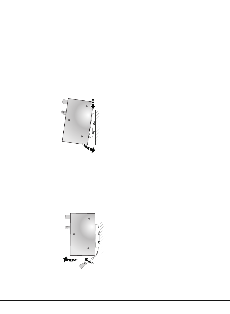
Removal:
1Pull down the positive latch using a suitable tool (e.g., screwdriver). Then swivel the
bottom of the module away from the DIN rail slightly (1). Next, lift the module upwards
away from the DIN rail (2).
Figure 2-2 Removing the SMN
1
2
A
1
2
Smart Managed Compact Switch
16 PHOENIX CONTACT 8089_en_03
2.2 Installing the Smart Managed Narrow Switch
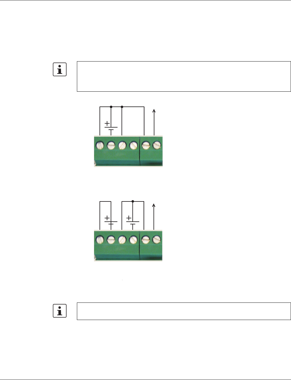
2.2.1 Connecting the 24 V DC supply voltage
The SMN is operated using a 24 V DC voltage, which is applied via COMBICON. If required,
the voltage can also be supplied redundantly (see Figure 2-4).
Figure 2-3 Supplying the SMN using one voltage source
Redundant 24 V DC supply
Figure 2-4 Supplying the SMN using two voltage sources
If redundant power supply monitoring is active (default setting), an error is indicated if only
one voltage is applied. A bridge between US1 and US2 prevents this error message.
However, it is also possible to deactivate monitoring in web-based management or via
SNMP.
OUT
24 V DC
US1
GND
US2
GND
R1
R2
In order to reset the SMN on power up, the power supply must be interrupted for at least
3 seconds.
OUT
24 V DC
US1
GND
US2
GND
R1
R2
Mounting and installation
8089_en_03 PHOENIX CONTACT 17
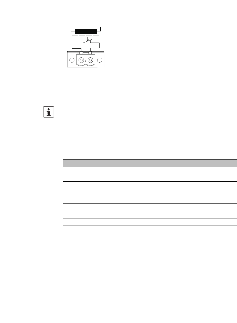
2.2.2 Signal contact
The switch has a floating signal contact. An error is indicated when the contact is opened.
Figure 2-5 Basic circuit diagram for the signal contact
The indicated error states are configured in web-based management or via SNMP. For a list
of error states that can be configured, please refer to Section ““Diagnostics, Alarm Contact”
Menu” on page 44.
2.2.3 Assignment of the RJ45 Ethernet connectors
In the event of a non-redundant voltage supply, the switch indicates the voltage supply
failure by opening the signal contact. This error message can be prevented by connecting
the supply voltage to both terminal blocks in parallel, as shown in Figure 2-3, or by deac-
tivating redundant power supply monitoring in web-based management or via SNMP.
Table 2-1 Pin assignment of RJ45 connectors
Pin number 10Base-T / 10 Mbps 100Base-T / 100 Mbps
1 TD+ (transmit) TD+ (transmit)
2 TD- (transmit) TD- (transmit)
3 RD+ (receive) RD+ (receive)
4- -
5- -
6 RD- (receive) RD- (receive)
7- -
8- -
R1 R2
67842015
Smart Managed Compact Switch
18 PHOENIX CONTACT 8089_en_03
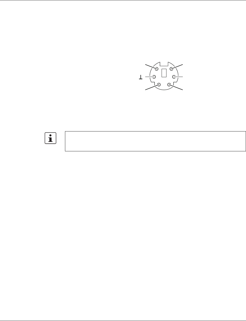
2.2.4 RS-232 interface for external management
The 6-pos. Mini-DIN socket provides a serial interface to connect a local management sta-
tion. It enables the connection to the management interface (for an appropriate cable,
please refer to page 170) via a VT100 terminal or a PC with corresponding terminal emula-
tion. Set the following transmission parameters:
Figure 2-6 Transmission parameters and assignment of the RS-232 interface
2.3 Grounding
All Factoryline devices must be grounded so that any possible interference is shielded from
the data telegram and discharged to ground potential.
A wire of at least 2.5 mm2 must be used for grounding. When mounting on a DIN rail, the
DIN rail must be connected to protective earth ground via grounding terminal blocks. The
module is connected to protective earth ground via the metal header.
Bits per second 38400
Data bits 8
Parity None
Stop bits 1
Flow control None
Grounding protects people and machines against hazardous voltages. To avoid these
dangers, as far as possible, correct grounding, taking the local conditions into account, is
vital.
12
34
56
TxD
RxD
res.
RTSCTS
RS-232 (V.24) interface
6151007
Startup and functions
8089_en_03 PHOENIX CONTACT 19
3 Startup and functions
3.1 Basic settings
3.1.1 Delivery state/default settings
By default upon delivery or after the system is reset to the default settings, the following
functions and properties are available:
– The password is: “private”
– All IP parameters are deleted. The switch has no valid IP parameters:
IP address: 0.0.0.0
Subnet mask: 0.0.0.0
Gateway: 0.0.0.0
– PROFINET is activated as the addressing mechanism.
– All available ports are activated with the following parameters:
- Autonegotiation
- Autocrossing
– All counters of the SNMP agent are deleted.
– The web server, SNMP agent, and RS-232 interface are active.
– Port mirroring, Rapid Spanning Tree, broadcast limiter, and MRP are deactivated.
– The alarm contact only opens in the event of non-redundant power supply.
– The transmission of SNMP traps is deactivated and the switch has no valid trap desti-
nation IP address.
– The aging time is set to 40 seconds.
– The WBM refresh interval is set to 30 seconds.
– The switch is in “PROFINET” mode.
– The transmission of SNMP traps is deactivated and the switch has no valid trap desti-
nation IP address.
The basic Ethernet functions do not have to be configured and are available when the
supply voltage is switched on.
The procedure for switching to the supported operating modes via Smart mode is de-
scribed in Section “Using Smart mode” on page 20.
The aging time is set using the “dot1dTpAgingTime” MIB object (OID 1.3.6.1.2.1.17.4.2).
The available setting range is 10 to 825 seconds. For static configuration, an aging time
of 300 seconds is recommended.

Smart Managed Compact Switch
20 PHOENIX CONTACT 8089_en_03
3.2 Using Smart mode
Smart mode enables the user to change the operating mode of the switch without having
access the management interface.
The FL SWITCH SMN offers the following setting options via Smart mode:
– Reset to the default settings
– Set PROFINET mode
– Exit Smart mode without changes
3.2.1 Activating Smart mode
The mode button is used to call/exit Smart mode and to select the desired setting. The three
mode LEDs indicate the mode that is currently set and the mode which will apply when ex-
iting Smart mode.
3.2.1.1 Calling Smart mode
•Following the switch boot phase, as soon as the three mode LEDs go out, press and
hold down the mode button for more than five seconds. If Smart mode is active, the
three LEDs will flash.
•When Smart mode is started, the switch is initially in the “Exit without changes” state.
3.2.1.2 Selecting the desired setting
•To select the various settings, press the mode button briefly and select the desired op-
erating mode.
3.2.1.3 Exiting Smart mode
•To exit, press and hold down the mode button for at least five seconds. The previously
selected operating mode is saved.
3.2.1.4 Possible operating modes in Smart mode
The FL SWITCH SMN supports the selection of the following operating modes in Smart
mode (see also example below):
Table 3-1 Operating modes in Smart mode
Mode ACT
LED 1
SPD
LED 2
FD
LED 3
Exit Smart mode without changes Off Off On
Reset to the default settings Off On Off
Set PROFINET mode Off On On
Startup and functions
8089_en_03 PHOENIX CONTACT 21
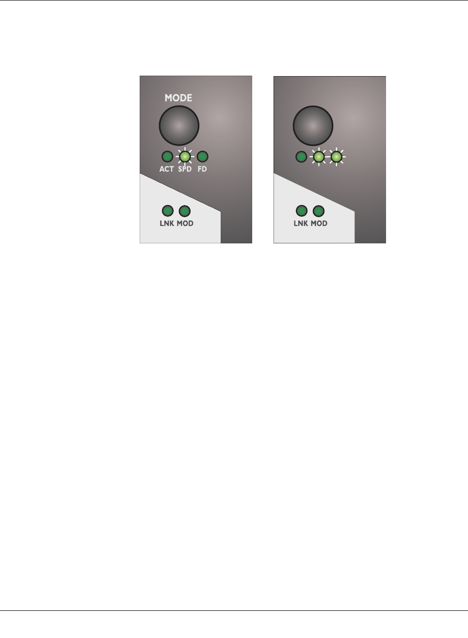
Example:
When the switch is in Smart mode, exiting Smart mode triggers the following action:
Example A: Resetting to the default settings
Example B: Setting PROFINET mode
Figure 3-1 Example of Smart mode
MODE
ACT SPD FD
AB
Smart Managed Compact Switch
22 PHOENIX CONTACT 8089_en_03
3.3 Frame switching
The FL SWITCH SMN operates in store-and-forward mode. When receiving a data packet,
the switch analyzes the source and destination addresses. The switch stores up to 4000
MAC addresses in its address table with an adjustable aging time of 10 to 825 seconds.
3.3.1 Store and forward
All data telegrams received by the switch are stored and checked for validity. Invalid or
faulty data packets (>1522 bytes or CRC errors) and fragments (<64 bytes) are rejected.
Valid data telegrams are forwarded by the switch.
3.3.2 Multi-address function
The switch learns all the source addresses for each port. Only packets with:
– Unknown source addresses
– A source address for this port or
– A multicast/broadcast address
in the destination address field are forwarded via the relevant port. The switch can learn up
to 4000 addresses. This is important if more than one termination device is connected to
one or more ports. Several independent subnetworks can be connected to one switch.
3.3.3 Learning addresses
The FL SWITCH SMN independently learns the addresses for termination devices, which
are connected via this port, by evaluating the source addresses in the data telegrams. When
the FL SWITCH SMN receives a data telegram, it forwards this data telegram to only that
port that connects to the specified device (if the address could be learned beforehand).
The FL SWITCH SMN can learn up to 4000 addresses and store them in its table. The
switch monitors the age of the learned addresses. The switch automatically deletes from its
address table address entries that exceed a specific age (default: 40 seconds, adjustable
from 10 to 825 seconds, aging time).
All learned entries are deleted on a restart.
A link down deletes all the entries of the affected port.
A list of detected MAC addresses can be found in the MAC address table (see Section
““Diagnostics, Mac Address Table” menu” on page 46). The MAC address table can be
deleted via the “Clear” button.
The aging time is set using the “dot1dTpAgingTime” MIB object (OID 1.3.6.1.2.1.17.4.2).
The available setting range is 10 to 825 seconds. For static configuration, an aging time
of 300 seconds is recommended.

Startup and functions
8089_en_03 PHOENIX CONTACT 23
3.3.4 Prioritization
The switch supports four priority queues for adjusting the internal packet processing se-
quence (traffic classes according to IEEE 802.1D). Data telegrams that are received are as-
signed to these classes according to the priority of the data packet, which is specified in the
VLAN/prioritization tag:
– Data packets with the value “0” or “1” in the priority field are transmitted with the lowest
priority (default).
– Data packets with the value “2” or “3” in the priority field are transmitted with the second
lowest priority.
– Data packets with values between “4” and “5” in the priority field are transmitted with the
second highest priority by the switch.
– Data packets with values between “6” and “7” in the priority field are transmitted with the
highest priority by the switch.
Processing rules
The switch controller in the FL SWITCH SMN forwards received packets to one of the re-
ceive queues according to the following decisions:
– BPDU packets are always assigned to the high-priority queue.
– Packets with VLAN/prioritization tag are forwarded according to the queues listed
above.
– All remaining data is assigned to the low-priority queue.
3.3.4.1 Class of Service (CoS)
Class of Service refers to a mechanism used to take into consideration the value of the pri-
ority field (values 1 to 7) in VLAN data packets with a tag. The switch assigns the data
streams in various processing queues, depending on what priority information is contained
in the CoS tag. The switch supports four internal processing queues.
3.3.4.2 Quality of Service (QoS)
Quality of Service affects the forwarding and handling of data streams and results in individ-
ual data streams being given differential treatment (usually preferential). QoS can be used,
e.g., to guarantee a transmission bandwidth for individual data streams. The switch uses
QoS in connection with prioritization (see CoS). The broadcast limiter can also be referred
to as a QoS function.
3.3.4.3 Flow control
Flow control can provide advantages during transmission in large network topologies in
which peak loads are to be expected. The switch supports flow control.

Smart Managed Compact Switch
24 PHOENIX CONTACT 8089_en_03
Configuration and diagnostics
8089_en_03 PHOENIX CONTACT 25
4 Configuration and diagnostics
The Smart Managed Narrow switch (SMN) offers several user interfaces for accessing con-
figuration and diagnostic data. The preferred interfaces are the web interface and SNMP in-
terface. These two interfaces can be used to make all necessary settings and request all in-
formation.
Access via the RS-232 interface only enables access to basic information and supports
basic configuration. However, the RS-232 interface also enables firmware update via TFTP
in the event of faulty firmware.
4.1 Making contact between the SMN and PC for initial
configuration
4.1.1 Operation with static IP addresses
To enable the SMN to be accessed using the desired IP address, make sure that the com-
puter and the SMN are in the same IP subnetwork. To do this, for initial contact your com-
puter must be configured so that contact is possible. The following screenshots were cre-
ated under Windows XP Professional.
Settings are not automatically saved permanently. The active configuration can be saved
permanently by selecting “Save current configuration” on the “Configuration Manage-
ment” web page. Additional saving options are also available via SNMP or RS-232.
Please note that the switch does not support supernetting or classless interdomain rout-
ing.
Smart Managed Compact Switch
26 PHOENIX CONTACT 8089_en_03
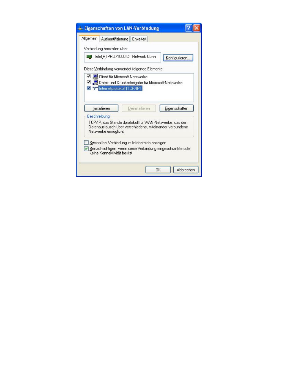
To set the IP parameters, open the Properties tab for your network adapter. Activate “Inter-
net Protocol (TCP/IP)” and then click on “Properties”.
Figure 4-1 Properties dialog box for the network card
Configuration and diagnostics
8089_en_03 PHOENIX CONTACT 27
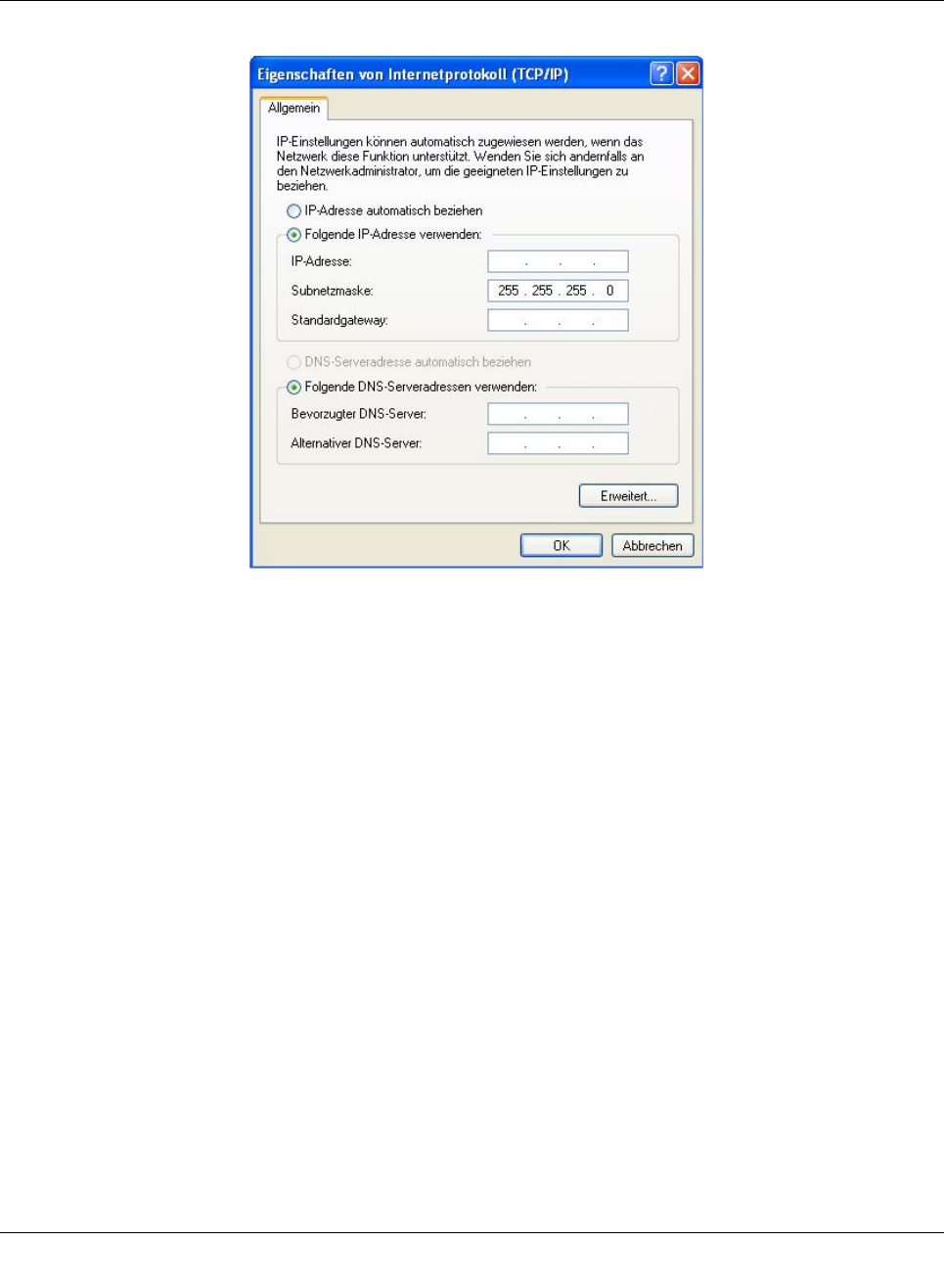
In the dialog box that opens, click the “Use the following IP address” radio button.
Figure4-2 “Internet Protocol (TCP/IP) Properties” dialog box
Enter the desired IP address of your computer (not that of the SMN) in the “IP address” field
and the corresponding subnet mask. Close the dialog box with “OK”.
The device can now be accessed via a web browser. In the address line of your browser,
enter the IP address of the SMN in the following format:
http://xxx.xxx.xxx.xxx
After entering the IP address in the browser, an overview page is displayed for the SMN
where no login is required.
After the correct user name and password have been entered, the device configuration
pages are loaded.
4.2 Web-based management (WBM)
4.2.1 General function
Online diagnostics The user-friendly web-based management interface can be used to manage the switch from
anywhere in the network using a standard browser. Comprehensive configuration and diag-
nostic functions are clearly displayed on a graphical user interface. Every user with a net-
Smart Managed Compact Switch
28 PHOENIX CONTACT 8089_en_03
work connection to the device has read access to that device via a browser. A wide range
of information about the device itself, set parameters, and the operating state can be
viewed.
4.2.2 Requirements for the use of WBM
As the web server operates using the Hyper Text Transfer Protocol, a standard browser can
be used. Access is via the URL “http://IP address of the device”.
Example: http://172.16.29.112
For full operation of the web pages, the browser must support JavaScript 1.2 and Cascad-
ing Style Sheets Level 1. We recommend the use of Microsoft Internet Explorer 6.0.
4.2.2.1 Structure of the web pages
The web pages are divided into four areas:
– Device type and device logo
– Device name (specified by the user) and loading time, to avoid mix-ups
– Navigation tree on the left-hand side
– Information tables on the right-hand side, which contain current device information
during runtime.
4.2.2.2 Password concept
After having entered the valid password, no further entry of the password is necessary for a
period of 300 s (default). After this period of time has elapsed or after clicking on “Logout”,
the password must be re-entered.
The concept is valid for the first ten users logged in simultaneously. All other users must
confirm each configuration modification by entering the password, until less than ten users
are logged in.
4.2.3 Functions/information in WBM
The navigation tree provides direct access to the following four areas:
–General Instructions
Basic information about WBM.
Modifications can only be made by entering the valid password. By default upon delivery,
the password is “private”.
For security reasons, we recommend changing the existing password to a new one
known only to you.
WBM can only be called using a valid IP address. By default upon delivery, the switch has
no valid IP address.
Settings are not automatically saved permanently. If the active configuration has not been
saved, a flashing floppy disk icon appears in the top-right corner in WBM. The icon is
linked to the “Configuration Management” web page. The active configuration can be
saved permanently by selecting “Save current configuration” on this web page.
If the connection is interrupted during the transmission of web pages, a waiting time of
several minutes is required before the web interface can be accessed again.
Configuration and diagnostics
8089_en_03 PHOENIX CONTACT 29
–Device Information
General device information.
–General Configuration
Device configuration/device as a network device.
–Switch Station
Device-specific configuration and diagnostics.
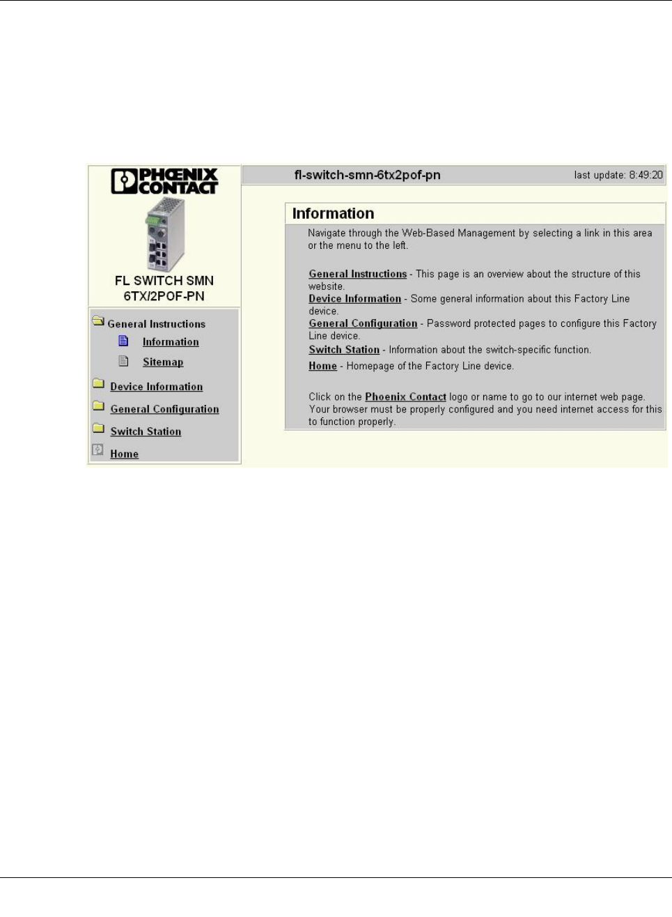
4.2.3.1 General instructions
Figure4-3 “Information” web page for the SMN
General instructions
Contains a brief description of WBM and a navigation tree (site map), which is linked to
every page of WBM.
Smart Managed Compact Switch
30 PHOENIX CONTACT 8089_en_03
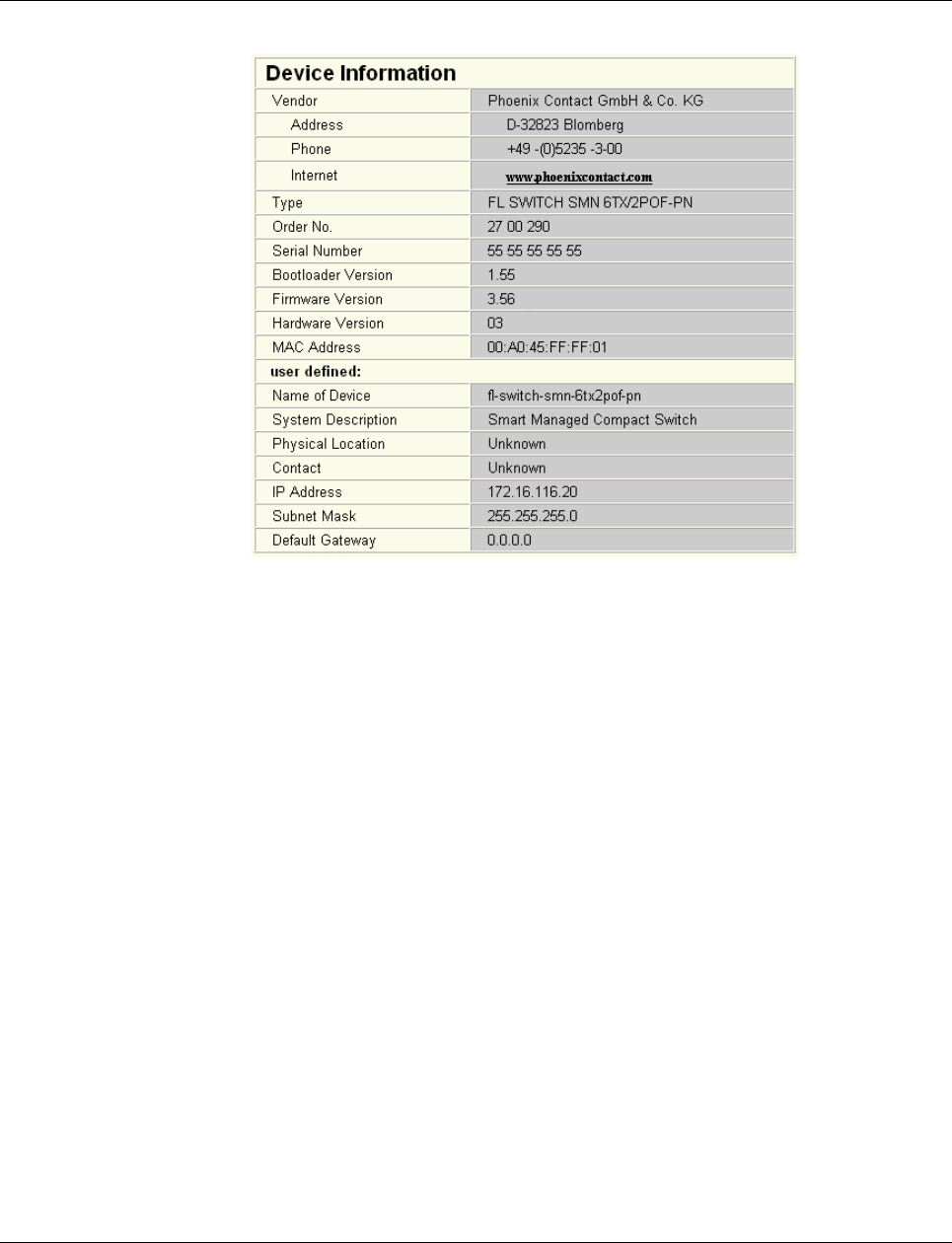
4.2.3.2 Device information
Figure 4-4 “Device Information” web page
“General” menu
Here, you will find a range of static information about the device and the manufacturer.
“Technical Data” menu
Here, you will find the most important technical data.
“Hardware Installation” menu
Here, you will find a connection diagram for connecting the redundant power supply and the
signal contact.
“Local Diagnostics” menu
Here, you will find a description of the meaning of the switchable diagnostics and status in-
dicators.
“Serial Port” menu
Here, you will find the transmission parameters for serial communication.
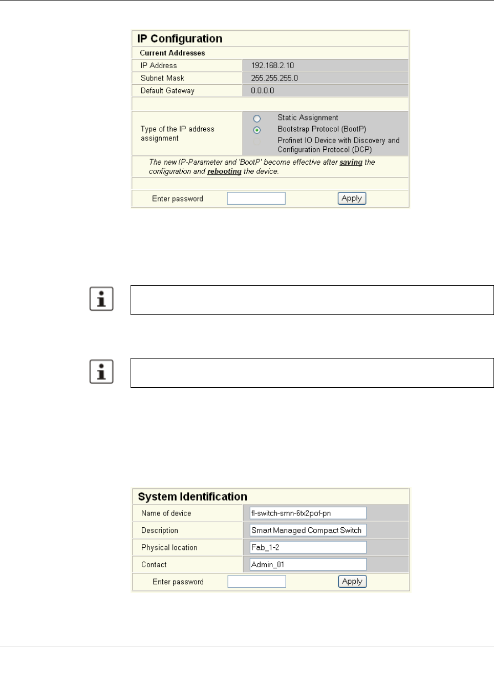
4.2.3.3 General configuration
“IP Configuration” menu
This page displays the set IP parameters and addressing mechanism.
Configuration and diagnostics
8089_en_03 PHOENIX CONTACT 31
To change the IP parameters via WBM, “Static” must be selected.
Figure4-5 “IP Configuration” web page
IP address assignment
“PROFINET” is activated by default upon delivery. The switch waits for startup by a PROF-
INET controller, which also assigns the IP addresses.
– Static Assignment
The switch can be accessed using the set IP address and does not send any kind of
requests for the receipt of IP parameters.
– Bootstrap Protocol (BootP)
The switch sends a maximum of three BootP requests after every restart and receives
a BootP reply with IP parameters. If there is no BootP reply, the switch starts after the
third request without IP configuration.
“System Identification” menu
This menu is used to display or modify user-specific device data, e.g., location, device
name or function. This device data is also available in SNMP.
Figure4-6 “System Identification” menu
While the switch waits for an IP address to be assigned (maximum of three BootP re-
quests) the mode LED which has been selected via the mode button will also flash.
Modifications to the IP parameters only take effect once the configuration is saved and a
restart is then performed.
Smart Managed Compact Switch
32 PHOENIX CONTACT 8089_en_03
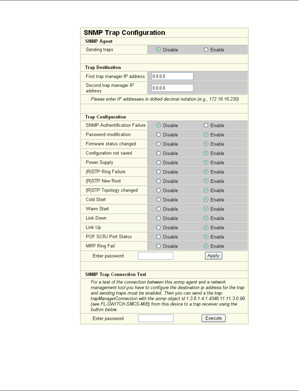
“SNMP Trap Configuration” menu
SNMP agent The “Sending traps” function can be globally enabled/disabled here.
Figure 4-7 “SNMP Trap Configuration” web page
Trap destination This part of the table is used to view or modify the IP addresses of the two trap receivers.
Trap configuration Sending of traps can be individually enabled/disabled here.
Configuration and diagnostics
8089_en_03 PHOENIX CONTACT 33
SNMP trap
Connection test
Once the “Sending traps” function has been activated and the trap managers have been de-
fined using the IP addresses, test traps can now be sent using “Execute” to test the commu-
nication path from the switch to the trap receiver.
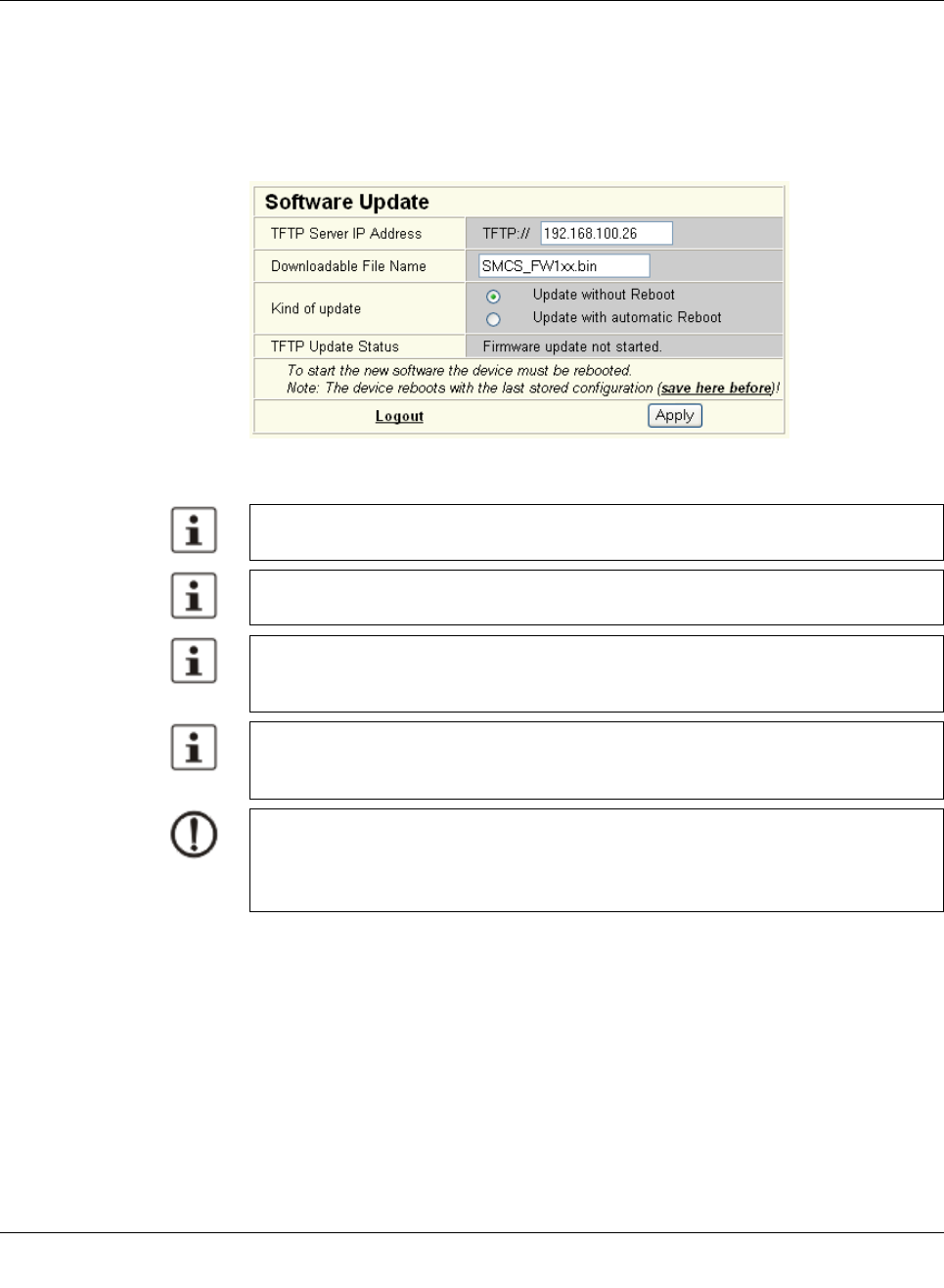
“Software Update” menu
This page is used to view or modify the parameters for a software update and to trigger the
update.
Figure4-8 “Software Update” web page
A reset is not carried out automatically following a firmware update. The desired option
can be selected in WBM.
Please make sure that the “TFTP Server” service program is activated in the Factory Man-
ager toolbar.
You can monitor the download in the Factory Manager message window (25%, 50%,
75%, 100%). Always wait until all the LEDs light up after approximately two minutes and
the device is available again after booting.
It is not ensured that all existing configuration data will be retained after a firmware up-
date/downgrade. Therefore, please check the configuration settings or reset the device to
the default delivery settings.
NOTE:
A voltage failure during a firmware update results in the destruction of the firmware on the
SMN. An update via TFTP is required, see “Starting with faulty software (firmware)” on
page 107.
Smart Managed Compact Switch
34 PHOENIX CONTACT 8089_en_03
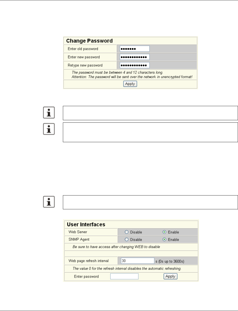
“Change Password” menu
Here, you can enter the existing password and then change it to a new one known only to
you. By default upon delivery, the password is “private” (please note that it is case-sensi-
tive). For security reasons, the input fields do not display your password, but instead
“*******” is displayed.
Figure 4-9 “Change Password” web page
“User Interfaces” menu
The following actions can be performed here:
– Activating/deactivating the web server.
– Activating/deactivating the SNMP agent.
– Setting the refresh interval for the automatic updating of the web pages. Here, you can
also set the refresh interval for automatic updating of different web pages. If the interval
is set to “0”, the pages will no longer be updated.
Figure 4-10 “User Interfaces” web page
The password must be between four and twelve characters long. Note that the password
is always transferred via the network in unencrypted format.
Forgotten your password?
Call the Phoenix Contact phone number listed in the Appendix, making sure you have the
device serial number and MAC address to hand.
Automatic updating of web pages is only possible when using Internet Explorer Version
5.5 or later.
Configuration and diagnostics
8089_en_03 PHOENIX CONTACT 35
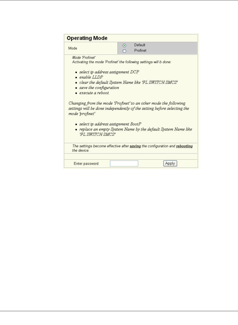
“Operating Mode” menu
Operation as a
PROFINET device
In this menu, select whether the switch is to operate as a PROFINET device. For additional
information about operation as a PROFINET device, see Section 9 “Operation as a PROF-
INET device”.
Figure4-11 “Operating Mode” web page
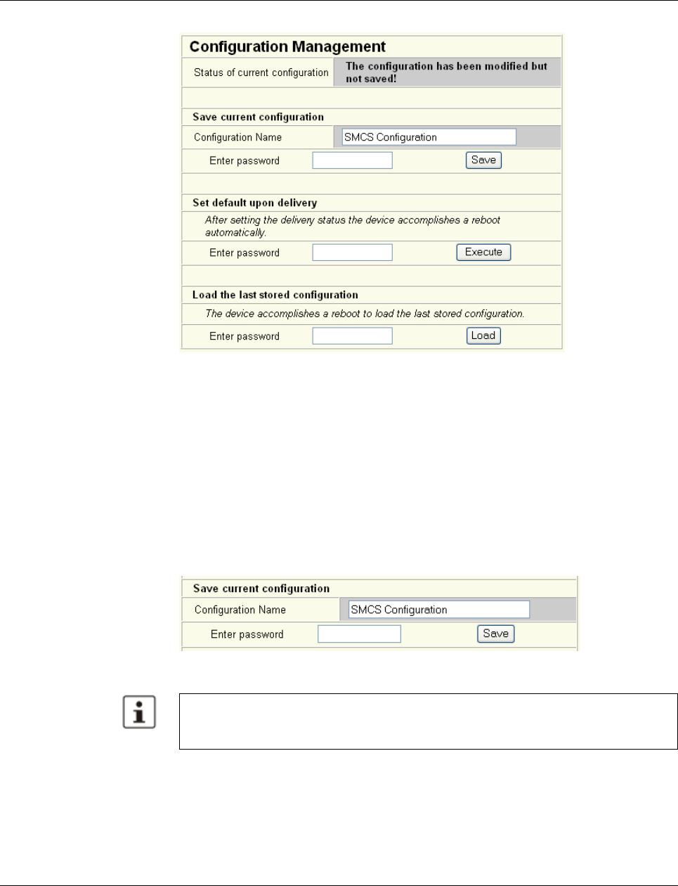
“Configuration Management, General” menu
This table is used to view all parameters that are required to save the active configuration or
load a new configuration, and to modify them (by entering a valid password). It can also be
used to restart the system with the relevant configuration or to reset the SMN to the default
state upon delivery.
Smart Managed Compact Switch
36 PHOENIX CONTACT 8089_en_03
Figure 4-12 “Configuration Management” web page
Possible states for “Status of current configuration”:
– The configuration has been modified but not saved (also indicated by the flashing flop-
py disk icon).
– Saving the current configuration.
– The current configuration is equal to the saved one in the non-volatile memory of the
switch.
– The current configuration was saved.
Save current
configuration
The active configuration together with the corresponding configuration name can be saved
here by entering a valid password.
Figure 4-13 “Save current configuration” web page
If the new configuration is not activated by a reset after a configuration download, the
“Save current configuration” command overwrites the previously loaded configuration
and instead saves the active configuration of the SMN.
Configuration and diagnostics
8089_en_03 PHOENIX CONTACT 37
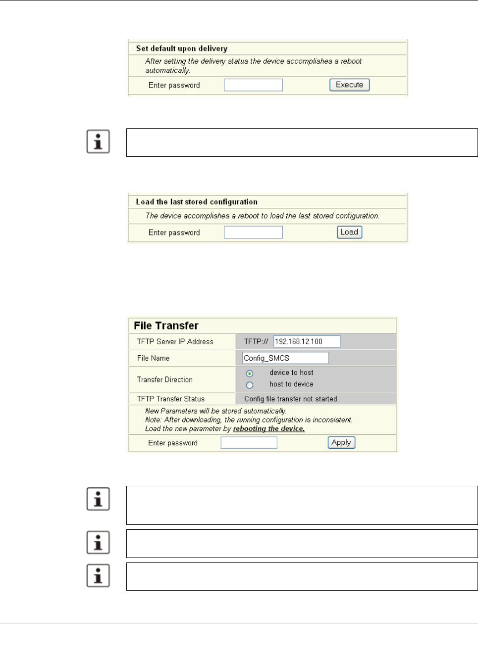
Set default upon delivery This option can be used to reset the switch to its default settings (default upon delivery) by
entering a valid password.
Figure4-14 “Set default upon delivery” web page
Load the last stored con-
figuration
This option can be used to reactivate the last configuration stored on the device. All modifi-
cations made to the configuration since it was last saved are lost.
Figure4-15 “Load the last stored configuration” web page
“Configuration Management, File Transfer” menu
Configuration file transfer This option can be used to save your device configuration on a PC or to operate the switch
using a stored configuration.
Figure4-16 “File Transfer” web page
WBM can only be called using a valid IP address. Once the switch has been reset to its
default settings, it has no valid IP address and the addressing mechanism is set to BootP.
When a configuration is uploaded from the SMN to a PC, the last saved version is trans-
mitted. Should you wish to transmit the active configuration, it is recommended that you
save it again beforehand (“Save current configuration” function).
When a configuration is downloaded from the PC to a SMN, the new configuration is only
activated once the switch has been reset.
The use of a configuration file does not affect an existing (“old”) password.
Smart Managed Compact Switch
38 PHOENIX CONTACT 8089_en_03
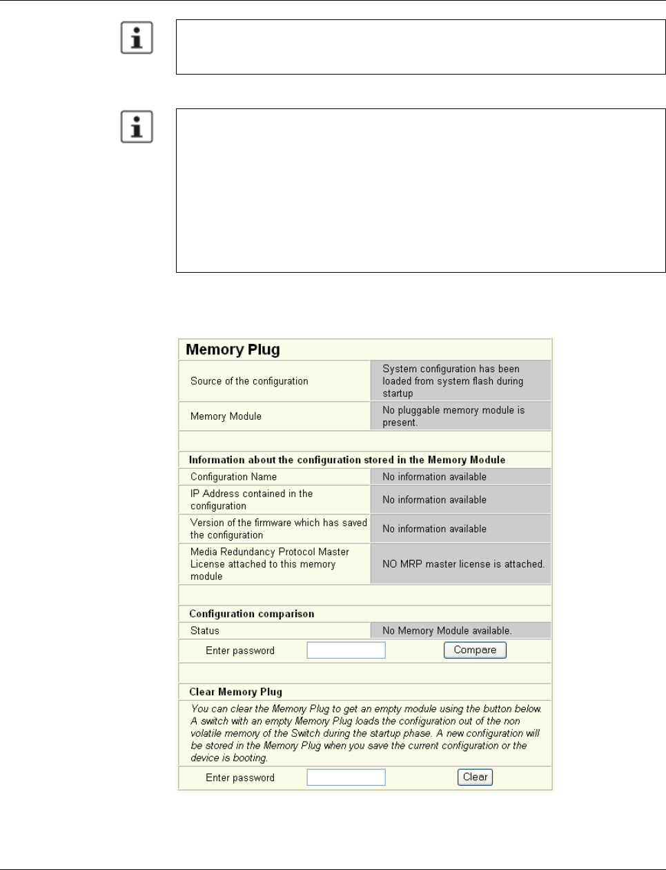
Device replacement
“Configuration Management, Memory Plug” menu
Memory plug
Figure 4-17 “Memory Plug” web page
Following a “host to device” file transfer, some configuration modifications will take effect
immediately, others will only take effect after a reset.
The SMN must be reset in order to ensure consistency.
Configuration using a configuration file is used when replacing devices. To duplicate de-
vices using a configuration file, observe the following:
– Create a point-to-point connection between an SMN and the management station.
– Load the configuration file on the SMN.
– Reset the SMN.
– Adjust the IP parameters.
– Save the configuration (“Save current configuration” function).
The duplicated switch can now be operated in the network using the adjusted IP param-
eters.
Configuration and diagnostics
8089_en_03 PHOENIX CONTACT 39
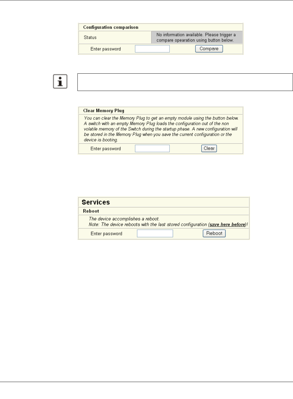
Configuration comparison Here you can compare the configuration on the memory plug with the configuration in the
SMN memory. The result is displayed in text format.
Figure4-18 “Configuration comparison” web page
Clear memory plug Here, you can delete the memory plug by entering a valid password.
Figure4-19 “Clear Memory Plug” web page
4.2.3.4 Switch station
“Services” menu
Figure4-20 “File Transfer” web page
Reboot To trigger a reboot via the web interface, enter a valid password. Save the configuration be-
forehand, so that configuration modifications are retained or can be activated via a restart.
If you replace a memory plug with another memory plug within a few seconds, the config-
uration comparison must be updated manually.
Smart Managed Compact Switch
40 PHOENIX CONTACT 8089_en_03
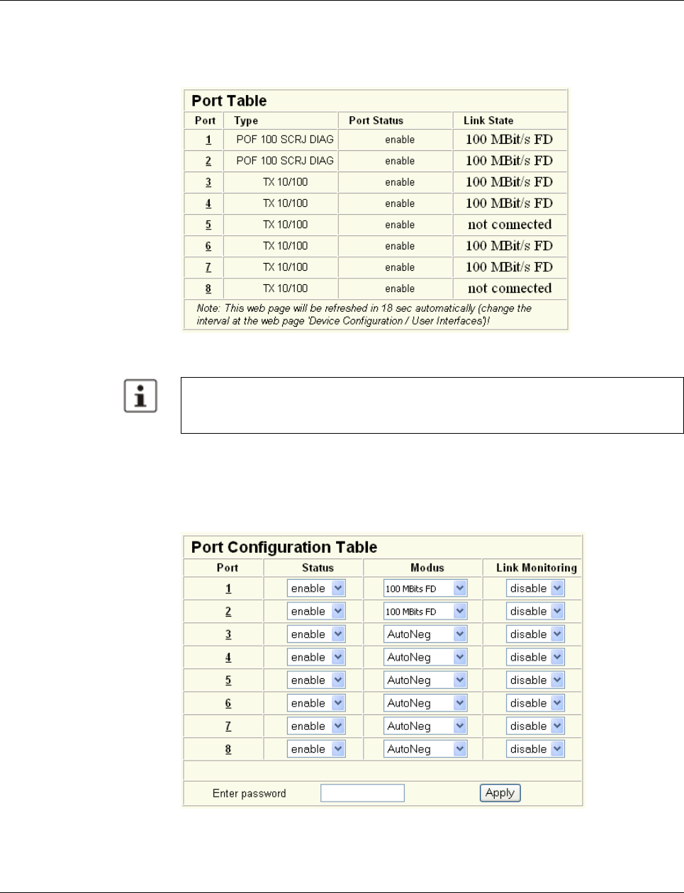
“Ports, Port Table” menu
Overview of all available ports. Clicking on the relevant port number opens a port-specific
page (“Port Configuration”).
Figure 4-21 “Port Table” web page
“Ports, Port Configuration Table” menu
This menu provides an overview of the important configuration settings for all ports and also
offers the option of setting the status, transmission mode, and link monitoring function for all
existing ports.
Figure 4-22 “Port Configuration Table” web page
When setting the transmission mode, make sure that the same settings have been made
at both ends of the connection. If the settings are not the same, this can result in increased
collisions or CRC errors and can adversely affect network performance.
Configuration and diagnostics
8089_en_03 PHOENIX CONTACT 41
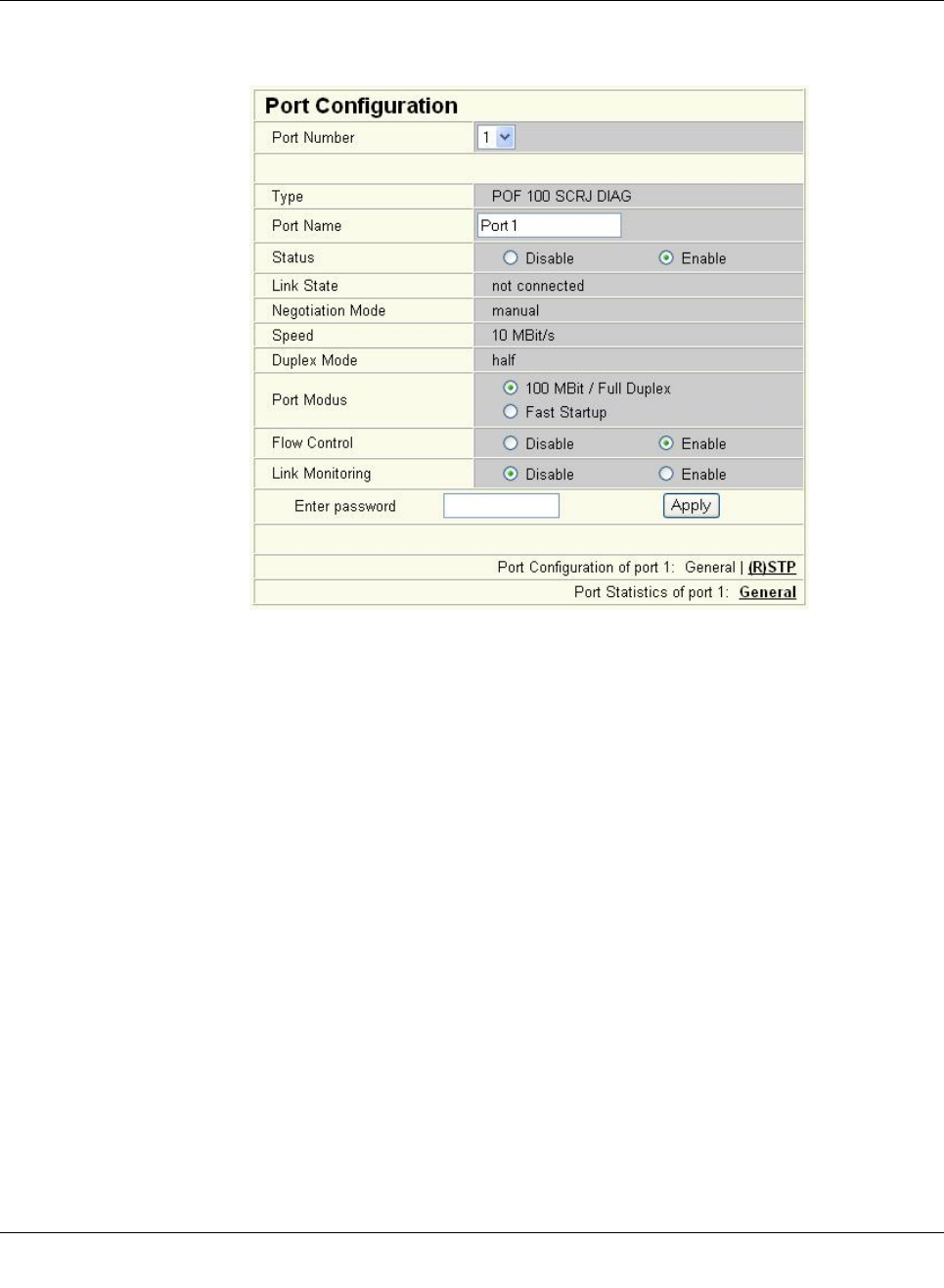
“Ports, Port Configuration” menu
Offers individual configuration options for each port.
Figure4-23 “Port Configuration” web page
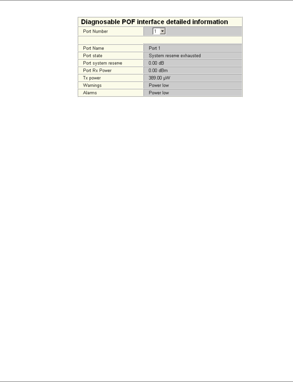
4.2.3.5 Using POF diagnostics
The following states can be displayed under “Transceiver status”:
– “POF-SCRJ Interface is OK” (The system reserve is greater than 2 dB and is displayed
under “RX system reserve”.)
– “POF-SCRJ Interface the system reserve is low” (The system reserve is less than 2 dB,
but greater than 0 dB.)
– “POF-SCRJ Interface the system reserve is exhausted” (No system reserve available -
the received optical power is below the required minimum value.)
Smart Managed Compact Switch
42 PHOENIX CONTACT 8089_en_03
Figure 4-24 “Diagnostics” web page
Configuration and diagnostics
8089_en_03 PHOENIX CONTACT 43
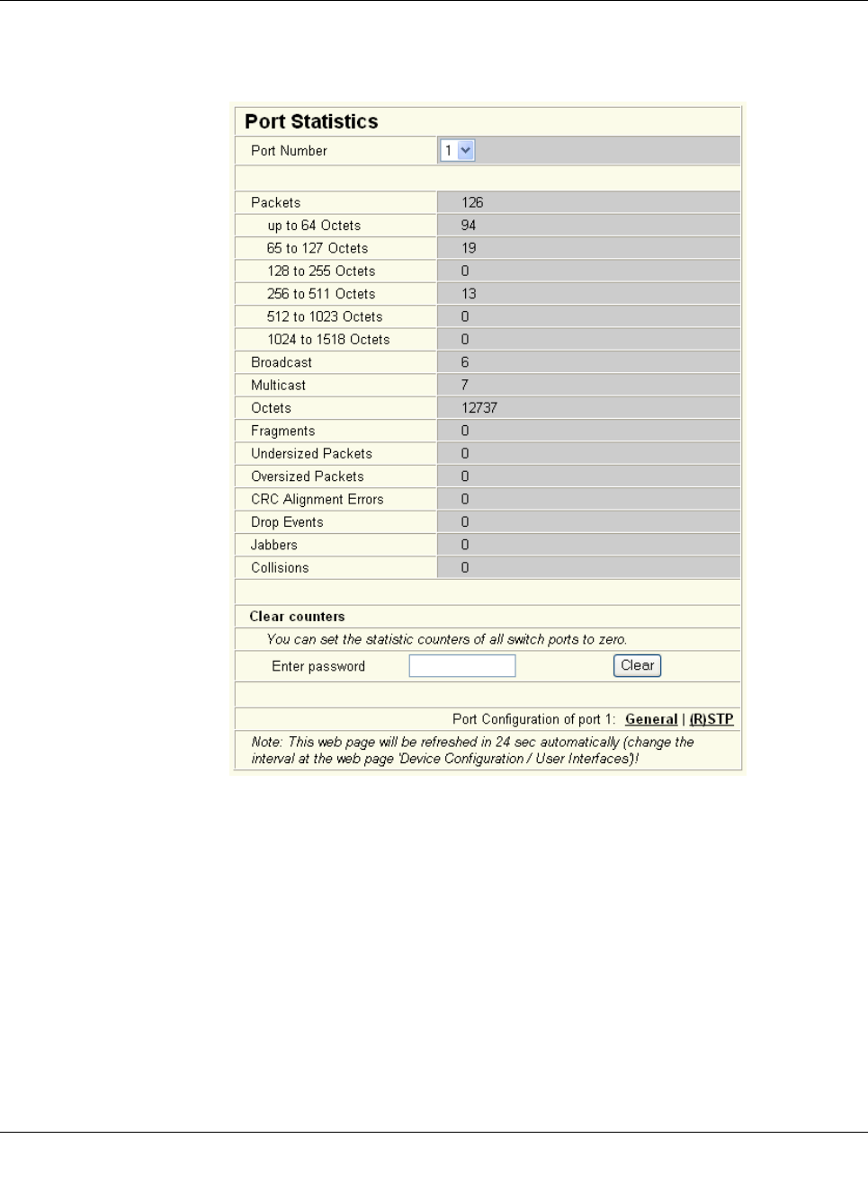
“Ports, Port Statistics” menu
This menu provides detailed statistical information about the volume of data for each indi-
vidual port. On this page, additional counter states can be set to zero for all ports.
Figure4-25 “Port Statistics” web page
Smart Managed Compact Switch
44 PHOENIX CONTACT 8089_en_03
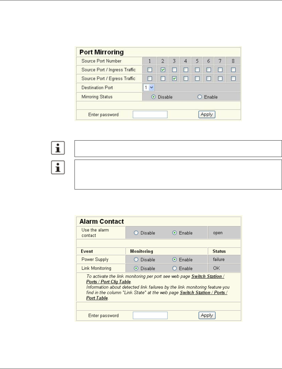
“Ports, Port Mirroring” menu
Activation/deactivation and setting of port mirroring. Port mirroring is used to passively read
input or output data that is being transmitted via a selected port. To do this, a measuring in-
strument (PC) is connected to the destination port, which records the data, yet must not it-
self be activated.
Figure 4-26 “Port Mirroring” web page
“Diagnostics, Alarm Contact” Menu
Here, you can set whether and for which events the signal contact (alarm contact) is used.
Figure 4-27 “Alarm Contact” web page
WBM prevents the same ports from being set, i.e., the source port and destination port
must differ.
The port capacity is calculated according to the set transmission parameters. Example: A
source port is operated at 100 Mbps and reaches a capacity of 5%. The destination port
is operated at 10 Mbps. Therefore, with the same volume of data, the destination port
reaches a capacity of 50%.
Configuration and diagnostics
8089_en_03 PHOENIX CONTACT 45
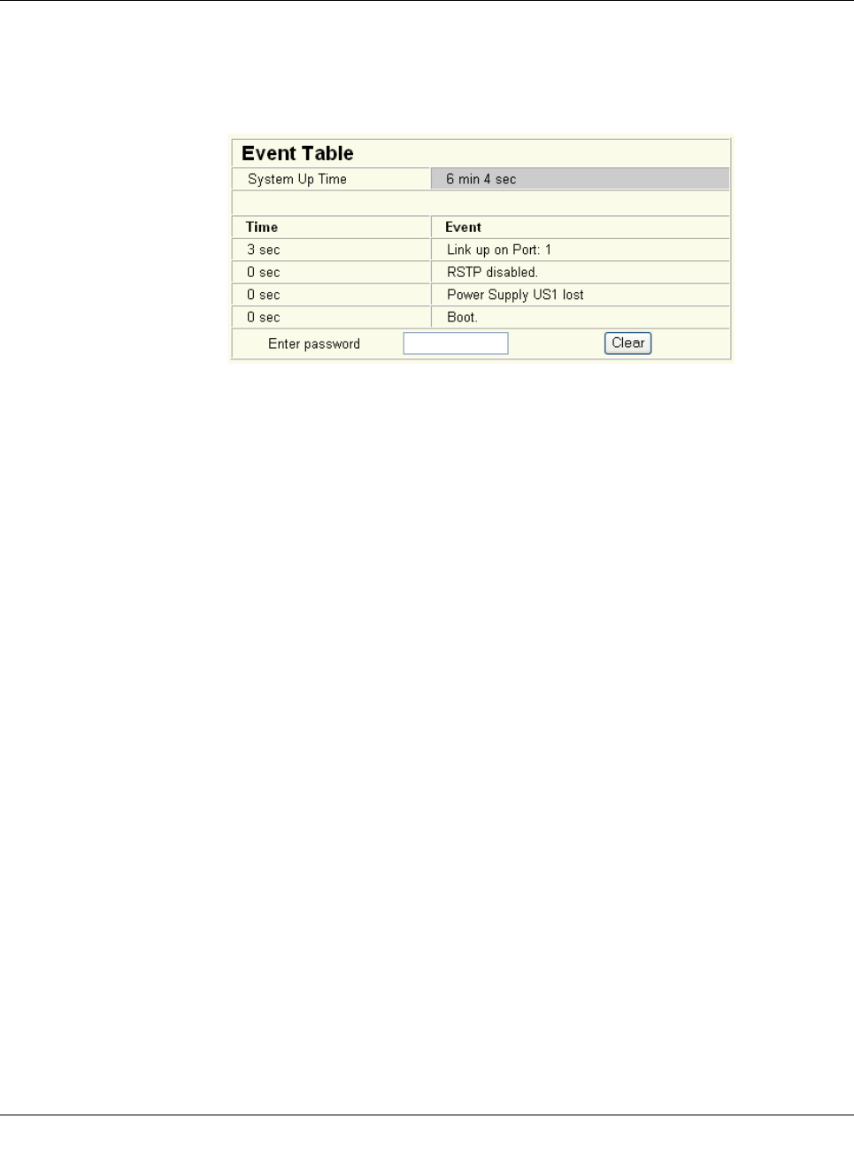
“Diagnostics, Event Table” menu
Here, you will find a list of the latest important events. The list contains up to 200 entries.
From the 200th entry onwards the oldest entries are overwritten (FIFO principle - first in, first
out). If old entries are overwritten by new entries, a corresponding note is displayed under
the event table.
Figure4-28 “Event Table” web page
The “Clear” button can be used to delete entries in the event table.
The following events are listed in the event table:
– Event Table cleared.
– Password has been changed.
– Password has not been changed successfully.
– Configuration has been saved.
– The configuration has been modified the first time after the last storing.
– Configuration File Transfer successfully executed.
– Configuration File Transfer was not successfully executed.
– Firmware Update was successfully executed.
– Firmware Update was not successfully executed.
– Link up at port xy.
– Link down at port xy.
– Enabling port xy.
– Disabling port xy.
– RSTP enabled.
– RSTP disabled.
– RSTP topology changed.
– RSTP elected this switch as new root.
– Power Supply US1 lost.
– Power Supply US2 lost.
– Power Supply US1 and US2 are connected now.
– LLDP Agent enabled.
– LLDP Agent disabled.
– LLDP recognized new neighbor at port xy.
– LLDP neighborhood information become obsolete at port xy.
– LLDP neighborhood information changed at port xy.
– MRP Client enabled/MRP disable.
Smart Managed Compact Switch
46 PHOENIX CONTACT 8089_en_03
– MRP Manager detects a loop failure enabled/MRP disable.
– MRP Ring failure detected/MRP Ring closed (OK).
– MRP Manager detects a closed loop.
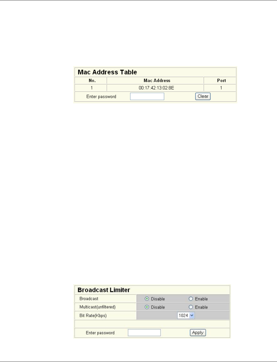
“Diagnostics, Mac Address Table” menu
Here, you will find a list of which MAC address has been detected at which switch port, and
its VLAN ID. If no packets are received at a port for a duration longer than the aging time,
the entry is deleted.
Figure 4-29 “Mac Address Table” web page
The “Clear” button can be used to delete entries in the MAC address table.
“LLDP General” menu
For information about LLDP, please refer to Section “Link Layer Discovery Protocol (LLDP)”
on page 163.
4.2.3.6 (Rapid) Spanning Tree
The Rapid/Spanning Tree Protocol (RSTP) is a standardized method (IEEE 802.1w/IEEE
802.1d). For information, please refer to Section 5 “(Rapid) Spanning Tree”.
4.2.3.7 Media Redundancy Protocol
The Media Redundancy Protocol is part of PROFINET standard IEC 61158 and is de-
scribed in Section 6 “Media Redundancy Protocol (MRP)”.
“Broadcast Limiter” menu
The “Broadcast Limiter” function can be used to limit broadcast and multicast traffic to an
adjustable level in order to prevent a loss in performance on termination devices.
If the configurable bandwidth limit is reached, further broadcast or multicast packets are re-
jected. The set bandwidth applies for the incoming data traffic of each individual port.
The following configuration options are provided via WEB and SNMP:
– Activation/deactivation of broadcast traffic limiting on all ports
– Activation/deactivation of multicast traffic limiting on all ports
The bandwidth is selected from a drop-down list and is specified in kbps or Mbps.
Figure 4-30 “Broadcast Limiter” menu
Configuration and diagnostics
8089_en_03 PHOENIX CONTACT 47
4.3 Simple Network Management Protocol (SNMP)
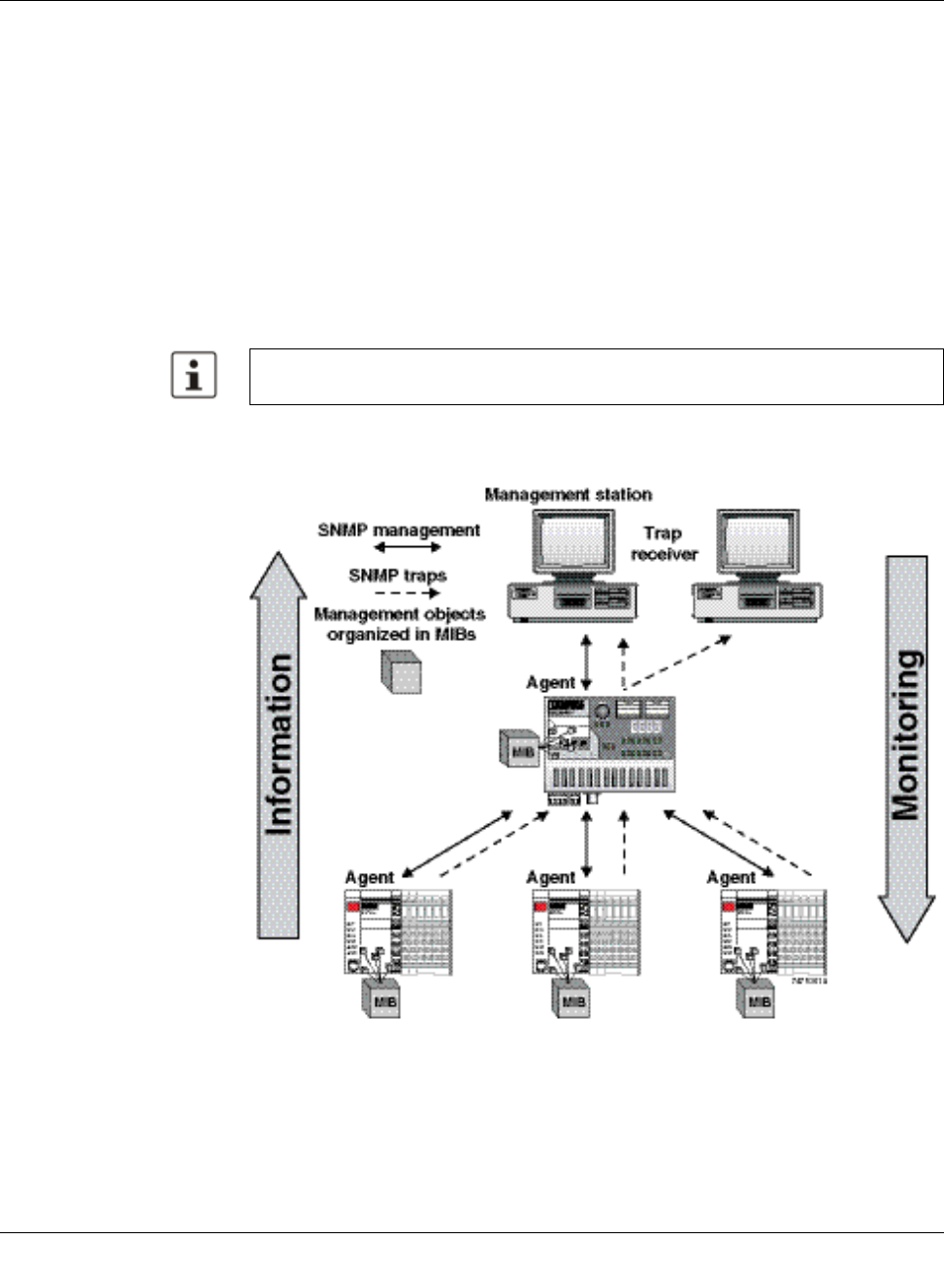
4.3.1 General function
SNMP is a manufacturer-independent standard for Ethernet management. It defines com-
mands for reading and writing information, and defines formats for error and status mes-
sages. SNMP is also a structured model that consists of agents, their relevant Management
Information Base (MIB) and a manager. The manager is a software tool that is executed on
a network management station. The agents are located inside switches, BK modules, rout-
ers, and other devices that support SNMP. The task of the agents is to collect and provide
data in the MIB. The manager regularly requests and displays this information. The devices
can be configured by writing data from the manager to the MIB. In the event of an emer-
gency, the agents can also send messages (traps) directly to the manager.
4.3.2 Schematic view of SNMP management
Figure4-31 Schematic view of SNMP
All configuration modifications, which are to take effect after a SMN restart, must be saved
permanently using the “flWorkFWCtrlConfSave” object.
Smart Managed Compact Switch
48 PHOENIX CONTACT 8089_en_03
SNMP interface
All managed Factoryline components have an SNMP agent. This agent of an
FL SWITCH SMN manages Management Information Base II (MIB 2) according to RFC
1213, RMON MIB, Bridge MIB, If MIB, Etherlike MIB, Iana-address-family MIB, IANAifType
MIB, SNMPv2 MIB, SNMP-FRAMEWORK MIB, P Bridge MIB, Q Bridge MIB, RSTP MIB,
LLDP MIB, and private SNMP objects from Phoenix Contact (FL-SWITCH-M MIB).
Network management stations, such as a PC with Factory Manager, can read and modify
configuration and diagnostic data from network devices via the Simple Network Manage-
ment Protocol. In addition, any SNMP tools or network management tools can be used to
access Factoryline products via SNMP. To do this, the MIBs supported by the relevant de-
vice must be made available to the SNMP management tools.
On the one hand, these are globally valid MIBs, which are specified and described in RFCs
(Request for Comments). This includes, for example, MIB2 according to RFC1213, which
is supported by all SNMP-compatible network devices. On the other hand, manufacturers
can specify their own SNMP objects, which are then assigned to a private manufacturer
area in the large SNMP object tree. Manufacturers are then responsible for their own private
(enterprise) areas, i.e., they must ensure that only one object is assigned to an object ID (ob-
ject name and parameters) and can be published. If an object is no longer needed, it can be
labeled as “expired”, but it cannot be reused with other parameters under any circum-
stances.
Phoenix Contact provides notification of ASN1 SNMP objects by publishing their descrip-
tions on the Internet.
Reading SNMP objects is not password-protected. However, a password is required for
read access in SNMP, but this is set to “public”, which is usual for network devices, and can-
not be modified. By default upon delivery, the password for write access is “private” and can
be changed by the user.
Another benefit for the user is the option of sending traps using the Simple Network Man-
agement Protocol.
Management Information Base (MIB)
Database which contains all the data (objects and variables) required for network manage-
ment.
Agent
An agent is a software tool which collects data from the network device on which it is in-
stalled and transmits this data on request. Agents reside in all managed network compo-
nents and transmit the values of specific settings and parameters to the management sta-
tion. On a request of a manager or on the occurrence of a specific event, the agent transmits
the collected information to the management station.
Traps
Traps are spontaneous SNMP alarm or information messages that are sent by an SNMP-
compatible device when specific events occur. Traps are transmitted with maximum priority
to various addresses, if required, and can then be displayed by the management station in
plain text. The IP addresses that are to receive these traps (trap targets/receivers) must be
set by the user on the relevant device.
SNMP, the web interface, and the serial terminal all use the same password, which can
be changed by the user.

Configuration and diagnostics
8089_en_03 PHOENIX CONTACT 49
trapPasswd
trapFWHealth
trapFWConf
trapPowerSupply
trapRstpRingFailure
trapManagerConnection
OID 1.3.6.1.4.1.4346.11.11.3.0.1
Description Sent to the defined trap receivers on each modification or attempted modification of the de-
vice password and contains information about the status of the last modification or at-
tempted modification.
OID 1.3.6.1.4.1.4346.11.11.3.0.2
Description Sent on each firmware-related modification and contains additional information about the
firmware status.
OID 1.3.6.1.4.1.4346.11.11.3.0.3
Description Sent each time the configuration is saved and informs the management station that the
configuration has been saved successfully.
This trap is sent in the event of configuration modifications (port name, port mode, device
name, IP address, trap receiver address, port mirroring, etc.), which are not yet saved per-
manently. The trap also provides a warning that, if not saved permanently, the changes will
be lost on a reset.
OID 1.3.6.1.4.1.4346.11.11.3.0.4
Description Sent each time the redundant power supply fails.
OID 1.3.6.1.4.1.4346.11.11.3.0.6
Description Sent in the event of a link interrupt in the redundant RSTP ring.
OID 1.3.6.1.4.1.4346.11.11.3.0.99
Description Trap to test the connection between the SNMP agent and the network management sta-
tion.
FL SWITCH SMN 6TX/2POF-PN / 8TX-PN
50PHOENIX CONTACT 8089_en_03
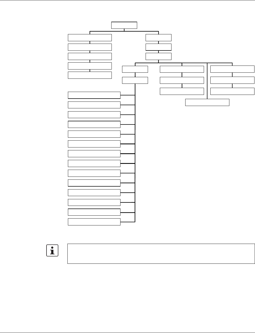
4.3.2.1 Tree structure of the MIB
Figure 4-32 Tree structure of the MIB
1system
2 interfaces
3 address translation
4 ip
5 icmp
6 tcp
7 udp
10 transmission
2 mgmt
1 mib-2
1 internet
1 iso
3 org
6 dod
4 private
1 enterprises
4346 phoenixContact
11 snmp
16 rmon
17 dot1dBridge
31 ifMib
8 egp
6 snmpV2
3 snmpModules
1 snmpMIB
30 ianaifType
5 security
0 std
8802 iso8802
1 ieee802dot1
1 ieee802dot1mibs
2 lldpMIB
6146b029
Not all devices support all object classes. If an unsupported object class is requested,
"not supported" is generated. If an attempt is made to modify an unsupported object class,
the message "badValue" is generated.

Configuration and diagnostics
8089_en_03PHOENIX CONTACT 51
4.3.3 RFC 1213 MIB - MIB II
4.3.3.1 System group (1.3.6.1.2.1.1)
The system group has mandatory characters for all systems. It contains system-specific
objects. If an agent does not have a value for a variable, the response is a string with
length 0.
(1) system
– (1) sysDescr
– (2) sysObjectID
– (3) sysUpTime
– (4) sysContact
– (5) sysName
– (6) sysLocation
– (7) sysServices
– (8) sysORLastChange
– (9) sysORTable
sysDescr
sysObjectID
sysUpTime
OID 1.3.6.1.2.1.1.1.0
Syntax Octet string (size: 0 - 255)
Access Read
Description A textual description of the entry. The value should contain the full name and version num-
ber of:
- Type of system hardware
- Operation system software
- Network software
The description may only consist of ASCII characters that can be printed.
OID 1.3.6.1.2.1.1.2.0
Syntax Object identifier
Access Read
Description The authorization identification for the manufacturer of the network management subsys-
tem, which is integrated in this device. This value is located in the SMI enterprises subtree
(1.3.6.1.4.1) and describes which type of device is being managed. For example, if the
manufacturer "Phoenix Contact GmbH" is assigned subtree 1.3.6.1.4.1.4346, it can then
assign its bridge the identifier 1.3.6.1.4.1.4346.2.1.
OID 1.3.6.1.2.1.1.3.0
Syntax TimeTicks
Access Read
Description The time in hundredths of seconds since the last network management unit reset.

Smart Managed Compact Switch
52 PHOENIX CONTACT 8089_en_03
sysContact
sysName
sysLocation
sysServices
sysORLastChange
OID 1.3.6.1.2.1.1.4.0
Syntax Octet string (size: 0 - 255)
Access Read and write
Description The textual identification of the contact person for these managed nodes and information
on how this person can be contacted.
OID 1.3.6.1.2.1.1.5.0
Syntax Octet string (size: 0 - 255)
Access Read and write
Description A name for this node assigned by the administrator. According to the agreement, this is
the fully qualifying name in the domain.
OID 1.3.6.1.2.1.1.6.0
Syntax Octet string (size: 0 - 255)
Access Read and write
Description The physical location of this node (e.g., “Hall 1, 3rd floor”).
OID 1.3.6.1.2.1.1.7.0
Syntax Integer (0 - 127)
Access Read
Description Indicates a number of services that this device offers. The value is the sum of several cal-
culations. For every layer of the OSI reference model, there is a calculation in the form of
(2 L-1), where L indicates the layer.
For example:
A node which primarily executes line routing functions has the value (2 3-1) = 4.
A node which is a host and provides application services has the value (2 4-1) + (2 7-1) = 72.
OID 1.3.6.1.2.1.1.8
Syntax TimeTicks
Access Read
Description Indicates the value of the sysUpTime during the last system modification.

Configuration and diagnostics
8089_en_03 PHOENIX CONTACT 53
sysORTable
4.3.3.2 Interface group (1.3.6.1.2.1.2)
The interface group contains information about device interfaces.
4.3.3.3 Address translation group (1.3.6.1.2.1.3)
The address translation group has mandatory characters for all systems. It contains infor-
mation about the address assignment.
OID 1.3.6.1.2.1.1.9
Syntax TimeTicks
Access Read
Description The table contains the following objects: sysORIndex, sysORID, sysORDescr, and sys-
ORUpTime.
(2) interfaces
-- (1) ifNumber
-- (2) ifTable
-- (1) if Entry
-- (1) ifIndex
-- (2) ifDescr
-- (3) ifType
-- (4) ifMtu
-- (5) ifSpeed
-- (6) ifPhysAddress
-- (7) ifAdminStatus
-- (8) ifOperStatus
-- (9) ifLastChange
-- (10) ifInOctets
-- (11) ifInUcastPkts
-- (12) ifInNUcastPkts
-- (13) ifInDiscards
-- (14) ifInErrors
-- (15) ifInUnknownProtos
-- (16) ifOutOctets
-- (17) ifOutUcastPkts
-- (18) ifOutNUcastPkts
-- (19) ifOutDiscards
-- (20) ifOutErrors
-- (21) ifOutQLen
-- (22) ifSpecific
(3) at-- (1) atTable
-- (1) atEntry
-- (1) atIfIndex
-- (2) atPhysAddress
-- (3) atNetAddress

Smart Managed Compact Switch
54 PHOENIX CONTACT 8089_en_03
4.3.3.4 Internet protocol group (1.3.6.1.2.1.4)
The Internet protocol group has mandatory characters for all systems. It contains informa-
tion concerning IP switching.
(4) ip
-- (1) ipForwarding
-- (2) ipDefaultTTL
-- (3) ipInReceives
-- (4) ipInHdrErrors
-- (5) ipInAddrErrors
-- (6) ipForwDatagrams
-- (7) ipInUnknownProtos
-- (8) ipInDiscards
-- (9) ipInDelivers
-- (10) ipOutRequests
-- (11) ipOutDiscards
-- (12) ipOutNoRoutes
-- (13) ipReasmTimeout
-- (14) ipReasmReqds
-- (15) ipReasmOKs
-- (16) ipReasmFails
-- (17) ipFragOKs
-- (18) ipFragFails
-- (19) ipFragCreates
-- (20) ipAddrTable
-- (1) ipAddrEntry
-- (1) ipAdEntAddr
-- (2) ipAdEntIfIndex
-- (3) ipAdEntNetMask
-- (4) ipAdEntBcastAddr
-- (5) ipAdEntReasmMaxSize
-- (21) ipRouteTable
-- (1) ipRouteEntry
-- (1) ipRouteDest
-- (2) ipRouteIfIndex
-- (3) ipRouteMetric1
-- (4) ipRouteMetric2
-- (5) ipRouteMetric3
-- (6) ipRouteMetric4
-- (7) ipRouteNextHop
-- (8) ipRouteType
-- (9) ipRouteProto
-- (10) ipRouteAge
-- (11) ipRouteMask
-- (12) ipRouteMetric5
-- (13) ipRouteInfo
-- (22) ipNetToMediaTable
-- (1) ipNetToMediaEntry

Configuration and diagnostics
8089_en_03 PHOENIX CONTACT 55
4.3.3.5 ICMP group (1.3.6.1.2.1.5)
The Internet Control Message Protocol group has mandatory characters for all systems. It
contains information about troubleshooting and control in Internet data traffic.
-- (1) ipNetToMediaIfIndex
-- (2) ipNetToMediaPhysAddress
-- (3) ipNetToMediaNetAddress
-- (4) ipNetToMediaType
-- (23) ipRoutingDiscards
(5) icmp
-- (1) icmpInMsgs
-- (2) icmpInErrors
-- (3) icmpInDestUnreachs
-- (4) icmpInTimeExcds
-- (5) icmpInParmProbs
-- (6) icmpInSrcQuenchs
-- (7) icmpInRedirects
-- (8) icmpInEchos
-- (9) icmpInEchoReps
-- (10) icmpInTimestamps
-- (11) icmpInTimestampReps
-- (12) icmpInAddrMasks
-- (13) icmpInAddrMaskReps
-- (14) icmpOutMsgs
-- (15) icmpOutErrors
-- (16) icmpOutDestUnreachs
-- (17) icmpOutTimeExcds
-- (18) icmpOutParmProbs
-- (19) icmpOutSrcQuenchs
-- (20) icmpOutRedirects
-- (21) icmpOutEchos
-- (22) icmpOutEchoReps
-- (23) icmpOutTimestamps
-- (24) icmpOutTimestampReps
-- (25) icmpOutAddrMasks
-- (26) icmpOutAddrMaskReps

Smart Managed Compact Switch
56 PHOENIX CONTACT 8089_en_03
4.3.3.6 Transfer Control Protocol group (1.3.6.1.2.1.6)
The Transfer Control Protocol group has mandatory characters for all systems that imple-
ment TCP. Instances of objects, which provide information about a specific TCP connec-
tion, are valid as long as the connection is established.
4.3.3.7 User Datagram Protocol group (1.3.6.1.2.1.7)
The User Datagram Protocol group has mandatory characters for all systems that imple-
ment UDP.
(6) tcp
-- (1) tcpRtoAlgorithm
-- (2) tcpRtoMin
-- (3) tcpRtoMax
-- (4) tcpMaxConn
-- (5) tcpActiveOpens
-- (6) tcpPassiveOpens
-- (7) tcpAttemptFails
-- (8) tcpEstabResets
-- (9) tcpCurrEstab
-- (10) tcpInSegs
-- (11) tcpOutSegs
-- (12) tcpRetransSegs
-- (13) tcpConnTable
-- (1) tcpConnEntry
-- (1) tcpConnState
-- (2) tcpConnLocalAddress
-- (3) tcpConnLocalPort
-- (4) tcpConnRemAddress
-- (5) tcpConnRemPort
-- (14) tcpInErrs
-- (15) tcpOutRsts
(7) udp
-- (1) udpInDatagrams
-- (2) udpNoPorts
-- (3) udpInErrors
-- (4) udpOutDatagrams
-- (5) udpTable
-- (1) udpEntry
-- (1) udpLocalAddress
-- (2) udpLocalPort

Configuration and diagnostics
8089_en_03 PHOENIX CONTACT 57
4.3.3.8 egp group (1.3.6.1.2.1.8)
4.3.3.9 Transmission group (1.3.6.1.2.1.10)
4.3.3.10 Simple Network Management Protocol group (1.3.6.1.2.1.11)
The Simple Network Management Protocol group has mandatory characters for all sys-
tems. In SNMP devices, which are optimized to support either a single agent or a single
management station, some of the listed objects will be written with the value “0”.
(8) egp
-- (1) egpInMsgs
-- (2) egpInErrors
-- (3) egpOutMsgs
-- (4) egpOutErrors
-- (5) egpNeighTable
-- (1) egpNeighEntry
-- (1) egpNeighState
-- (2) egpNeighAddr
-- (3) egpNeighAs
-- (4) egpNeighInMsgs
-- (5) egpNeighInErrs
-- (6) egpNeighOutMsgs
-- (7) egpNeighOutErrs
-- (8) egpNeighInErrMsgs
-- (9) egpNeighOutErrMsgs
-- (10) egpNeighStateUps
-- (11) egpNeighStateDowns
-- (12) egpNeighIntervalHello
-- (13) egpNeighIntervallPoll
-- (14) egpNeighMode
-- (15) egpNeighEventTrigger
-- (6) egpAs
(10) transmission
(11) snmp
-- (1) snmpInPkts
-- (2) snmpOutPkts
-- (3) snmpInBadVersions
-- (4) snmpInBadCommunityName
-- (5) snmpInBadCommunityUses
-- (6) snmpInASNParseErrs
-- (8) snmpInTooBigs
-- (9) snmpInNoSuchNames
-- (10) snmpInBadValues
-- (11) snmpInReadOnlys
-- (12) snmpInGenErrs
-- (13) snmpInTotalReqVars
-- (14) snmpInTotalSetVars
-- (15) snmpInGetRequests
-- (16) snmpInGetNexts

Smart Managed Compact Switch
58 PHOENIX CONTACT 8089_en_03
4.3.4 RMON MIB (1.3.6.1.2.1.16)
This part of the MIB continuously provides the network management with up-to-date and
historical network component data. The configuration of alarms and events controls the
evaluation of network component counters. Depending on the configuration, the result of
the evaluation is indicated to the management station by the agents using traps. The follow-
ing groups are supported:
– statistics
– history
– alarm
– hosts
– hostTopN
– matrix
– filter
– capture and event.
-- (17) snmpInSetRequests
-- (18) snmpInGetResponses
-- (19) snmpInTraps
-- (20) snmpOutTooBigs
-- (21) snmpOutNoSuchNames
-- (22) snmpOutBadValues
-- (24) snmpOutGenErrs
-- (25) snmpOutGetRequests
-- (26) snmpOutGetNexts
-- (27) snmpOutSetRequests
-- (28) snmpOutGetResponses
-- (29) snmpOutTraps
-- (30) snmpEnableAuthenTraps
-- (31) snmpSilentDrops
-- (32) snmpProxyDrops

Configuration and diagnostics
8089_en_03 PHOENIX CONTACT 59
4.3.4.1 statistics (1.3.6.1.2.1.16.1)
This MIB group contains information about, e.g., the number of unicast, multicast or broad-
cast telegrams, telegram rate and distribution or the number of faulty telegrams classed ac-
cording to the error type.
The statistics group contains information about the network load and quality.
4.3.4.2 history (1.3.6.1.2.1.16.2)
The history group contains statistical information, which can be read and represented, e.g.,
as a time curve.
(1) etherStatsTable
-- (1) etherStatsEntry
-- (1) etherStatsIndex
-- (2) etherStatsDataSource
-- (3) etherStatsDropEvents
-- (4) etherStatsOctets
-- (5) etherStatsPkts
-- (6) etherStatsBroadcastPkts
-- (7) etherStatsMulticastPkts
-- (8) etherStatsCRCAlignErrors
-- (9) etherStatsUndersizePkts
-- (10) etherStatsOversizePkts
-- (11) etherStatsFragments
-- (12) etherStatsJabbers
-- (13) etherStatsCollisions
-- (14) etherStatsPkts64Octets
-- (15) etherStatsPkts65to127Octets
-- (16) etherStatsPkts128to255Octets
-- (17) etherStatsPkts256to511Octets
-- (18) etherStatsPkts512to1023Octets
-- (19) etherStatsPkts1024to1518Octets
-- (20) etherStatsOwner
-- (21) etherStatsStatus
(1) historyControlTable
-- (1) historyControlEntry
-- (1) historyControlIndex
-- (2) historyControlDataSource
-- (3) historyControlBucketsRequested
-- (4) historyControlBucketsGranted
-- (5) historyControlInterval
-- (6) historyControlOwner
-- (7) historyControlStatus
(2) etherhistoryTable
-- (1) etherhistoryEntry
-- (1) etherHistoryIndex
-- (2) etherHistorySampleIndex
-- (3) etherHistoryIntervalStart
-- (4) etherHistoryDropEvents
-- (5) etherHistoryOctets

Smart Managed Compact Switch
60 PHOENIX CONTACT 8089_en_03
4.3.4.3 alarm (1.3.6.1.2.1.16.3)
The alarm group requests statistical values and compares them with the defined limit val-
ues. If a value is above or below the limit value, an alarm and a trap are generated.
4.3.4.4 hosts (1.3.6.1.2.1.16.4)
-- (6) etherHistoryPkts
-- (7) etherHistoryBroadcastPkts
-- (8) etherHistoryMulticastPkts
-- (9) etherHistoryCRCAlignErrors
-- (10) etherHistoryUndersizePkts
-- (11) etherHistoryOversizePkts
-- (12) etherHistoryFragments
-- (13) etherHistoryJabbers
-- (14) etherHistoryCollisions
-- (15) etherHistoryUtilization
(1) alarmTable
-- (1) alarmEntry
-- (1) alarmIndex
-- (2) alarmInterval
-- (3) alarmVariable
-- (4) alarmSampleType
-- (5) alarmValue
-- (6) alarmStartupAlarm
-- (7) alarmRisingThreshold
-- (8) alarmFallingThreshold
-- (9) alarmRisingEventIndex
-- (10) alarmFallingEventIndex
-- (11) alarmOwner
-- (12) alarmStatus
(1) hostControlTable
-- (1) hostControlEntry
-- (1) hostControlIndex
-- (2) hostControlDataSource
-- (3) hostControlTableSize
-- (4) hostControlLastDeleteTime
-- (5) hostControlOwner
-- (6) hostControlStatus
-- (2) hostTable
-- (1) hostEntry
-- (1) hostAddress
-- (2) hostCreationOrder
-- (3) hostIndex
-- (4) hostInPkts
-- (5) hostOutPkts
-- (6) hostInOctets
-- (7) hostOutOctets
-- (8) hostOutErrors

Configuration and diagnostics
8089_en_03 PHOENIX CONTACT 61
4.3.4.5 hostTopN (1.3.6.1.2.1.16.5)
4.3.4.6 matrix (1.3.6.1.2.1.16.6)
-- (9) hostOutBroadcastPkts
-- (10) hostOutMulticastPkts
-- (3) hostTimeTable
-- (1) hostTimeEntry
-- (1) hostTimeAddress
-- (2) hostTimeCreationOrder
-- (3) hostTimeIndex
-- (4) hostTimeInPkts
-- (5) hostTimeOutPkts
-- (6) hostTimeInOctets
-- (7) hostTimeOutOctets
-- (8) hostTimeOutErrors
-- (9) hostTimeOutBroadcastPkts
-- (10) hostTimeOutMulticastPkts
(1) hostTopNControlTable
-- (1) hostTopNControlEntry
-- (1) hostTopNControlIndex
-- (2) hostTopNHostINdex
-- (3) hostTopNRateBase
-- (4) hostTopNTimeRemaining
-- (5) hostTopNDuration
-- (6) hostTopNRequestedSize
-- (7) hostTopNGrantedSize
-- (8) hostTopNStartTime
-- (9) hostTopNOwner
-- (10) hostTopNStatus
-- (2) hostTopNTable
-- (1) hostTopNEntry
-- (1) hostTopNReport
-- (2) hostTopNIndex
-- (3) hostTopNAddress
-- (4) hostTopNRate
-- (1) martrixControlTable
-- (1) matrixControlEntry
-- (1) matrixControlIndex
-- (2) matrixControlDataSource
-- (3) matrixControlTableSize
-- (4) matrixControlLastDeleteTime
-- (5) matrixControlOwner
-- (6) matrixControlStatus
-- (2) matrixSDTable
-- (1) matrixSDEntry
-- (1) matrixSDSourceAddress
-- (2) matrixSDDestAddress

Smart Managed Compact Switch
62 PHOENIX CONTACT 8089_en_03
4.3.4.7 filter (1.3.6.1.2.1.16.7)
-- (3) matrixSDIndex
-- (4) matrixSDPkts
-- (5) matrixSDOctets
-- (6) matrixSDErrors
-- (3) matrixDSTable
-- (1) matrixDSEntry
-- (1) matrixDSSourceAddress
-- (2) matrixDSDestAddress
-- (3) matrixDSIndex
-- (4) matrixDSPkts
-- (5) matrixDSOctets
-- (6) matrixDSErrors
(1) filterTable
-- (1) filterEntry
-- (1) filterIndex
-- (2) filterChannelIndex
-- (3) filterPktDataOffset
-- (4) filterPktData
-- (5) filterPktDataMask
-- (6) filterPktDataNotMask
-- (7) filterPktStatus
-- (8) filterPktStatusMask
-- (9) filterPktStatusNotMask
-- (10) filterOwner
-- (11) filterStatus
(2) channelTable
-- (1) channelEntry
-- (1) channelIndex
-- (2) channelIfIndex
-- (3) channelAcceptTime
-- (4) channelDataControl
-- (5) channelTurnOnEventIndex
-- (6) channelTurnOffEventIndex
-- (7) channelEventIndex
-- (8) channelEventStatus
-- (9) channelMatches
-- (10) channelDescription
-- (11) channelOwner
-- (12) channelStatus

Configuration and diagnostics
8089_en_03 PHOENIX CONTACT 63
4.3.4.8 capture (1.3.6.1.2.1.16.8)
4.3.4.9 event (1.3.6.1.2.1.16.9)
The event group controls the generation of traps when the alarms described above occur.
(1) bufferControlTable
-- (1) bufferControlEntry
-- (1) bufferControlIndex
-- (2) bufferControlChannelIndex
-- (3) bufferControlFullStatus
-- (4) bufferControlFullAction
-- (5) bufferControlCaptureSliceSize
-- (6) bufferControlDownloadSliceSize
-- (7) bufferControlDownloadOffset
-- (8) bufferControlMaxOctetsRequested
-- (9) bufferControlMaxOctetsGranted
-- (10) bufferControlCapturedPackets
-- (11) bufferControlTurnOnTime
-- (12) bufferControlOwner
-- (13) bufferControlStatus
(2) captureBufferTable
-- (1)captureBufferEntry
-- (1)captureBufferControlIndex
-- (2)captureBufferIndex
-- (3) captureBufferPacketID
-- (4) captureBufferPacketData
-- (5) captureBufferPacketLength
-- (6) captureBufferPacketTime
-- (7) captureBufferPacketStatus
(1) eventTable
-- (1) eventEntry
-- (1) eventIndex
-- (2) eventDescription
-- (3) eventType
-- (4) eventCommunity
-- (5) eventLastTimeSent
-- (6) eventOwner
-- (7) eventStatus
(2) logTable
-- (1) logEntry
-- (1) logEventIndex
-- (2) logIndex
-- (3) logTime
-- (4) logDescription

Smart Managed Compact Switch
64 PHOENIX CONTACT 8089_en_03
4.3.5 Bridge MIB (1.3.6.1.2.1.17)
4.3.5.1 dot1dBase (1.3.6.1.2.1.17.1)
The dot1dBase group contains bridge-specific information.
4.3.5.2 dot1dStp (1.3.6.1.2.1.17.2)
(1) dot1dBaseBridgeAddress
(2) dot1dBaseNumPorts
(3) dot1dBasePortType
(4) dot1dBasePortTable
-- dot1dBasePortEntry
-- (1) dot1dBasePort
-- (2) dot1dBasePortIfIndex
-- (3) dot1dBasePortPortCircuit
-- (4) dot1dBasePortDelayExceededDiscards
-- (5) dot1dBasePortMtuExceededDiscards
-- (1) dot1dStpProtocolSpecification
-- (2) dot1dStpPriority
-- (3) dot1dStpTimeSinceTopologyChange
-- (4) dot1dStpTopChanges
-- (5) dot1dStpDesignateRoot
-- (6) dot1dStpRootCost
-- (7) dot1dStpRootPort
-- (8) dot1dStpMaxAge
-- (9) dot1dStpHelloTime
-- (10) dot1dStpHoldTime
-- (11) dot1dStpForwardDelay
-- (12) dot1dStpBridgeMaxAge
-- (13) dot1dStpBridgeHelloTime
-- (14) dot1dStpBridgeForwardDelay
-- (15) dot1dStpPortTable
-- (1) dot1dStpPortEntry
-- (1) dot1dStpPort
-- (2) dot1dStpPortPriority
-- (3) dot1dStpPortState
-- (4) dot1dStpPortEnable
-- (5) dot1dStpPortPathCost
-- (6) dot1dStpPortDesignatedRoot
-- (7) dot1dStpPortDesignatedCost
-- (8) dot1dStpPortDesignatedBridge
-- (9) dot1dStpPortDesignatedPort
-- (10) dot1dStpPortForwardTransitions
-- (11) dot1dStpPortPathCost32
-- (16) dot1dStpVersion
-- (17) dot1dStpTxHoldCount
-- (18) dot1dStpPathCostDefault
-- (19) dot1dStpExtPortTable

Configuration and diagnostics
8089_en_03 PHOENIX CONTACT 65
4.3.5.3 dot1dTp (1.3.6.1.2.1.17.4)
The dot1dTp group contains bridge-specific information.
4.3.5.4 dot1dStatic (1.3.6.1.2.1.17.5)
-- (1) dot1dStpExtPortEntry
-- (1) dot1dStpPortProtocolMigration
-- (2) dot1dStpPortAdminEdgePort
-- (3) dot1dStpPortOperEdgePort
-- (4) dot1dStpPortAdminPointToPoint
-- (5) dot1dStpPortOperPointToPoint
-- (6) dot1dStpPortAdminPathCost
(1) dot1dTpLearnedEntryDiscards
(2) dot1dTpAgingTime
(3) dot1dTpFdbTable
-- (1) dot1dTpFdbEntry
-- (1) dot1dTpFdbAddress
-- (2) dot1dTpFdbPort
-- (3) dot1dTpFdbStatus
(4) dot1dTpPortTable
-- dot1dTpPortEntry
-- (1) dot1dTpPort
-- (2) dot1dTpPortMaxInfo
-- (3) dot1dTpPortInFrames
-- (4) dot1dTpPortOutFrames
-- (5) dot1dTpPortInDiscards
(5) dot1dTpHCPortTable
-- dot1dTpHCPortEntry
-- (1) dot1dTpHCPortInFrames
-- (2) dot1dTpHCPortOutFrames
-- (3) dot1dTpHCPortInDiscards
(6) dot1dTpPortOverflowTable
-- dot1dTpPortOverflowEntry
-- (1) dot1dTpPortInOverflowFrames
-- (2) dot1dTpPortOutOverflowFrames
-- (3) dot1dTpPortInOverflowDiscards
-- (1) dot1dStaticTable
-- (1) dot1dStaticEntry
-- (1) dot1dStaticAddress
-- (2) dot1dStaticReceivePort
-- (3) dot1dStaticAllowedToGoTo

Smart Managed Compact Switch
66 PHOENIX CONTACT 8089_en_03
4.3.6 pBridgeMIB (1.3.6.1.2.1.17.6)
4.3.6.1 pBridgeMIBObjects (1.3.6.1.2.1.17.6.1)
4.3.6.2 pBridgeConformance (1.3.6.1.2.1.17.6.2)
-- (1) dot1dExtBase
-- (1) dot1dDeviceCapabilities
-- (2) dot1dTrafficClassesEnabled
-- (3) dot1dGmrpStatus
-- (4) dot1dCapabilitiesTable
-- (1) dot1dCapabilitiesEntry
-- (1) dot1dPortCapabilities
-- (2) dot1dPriority
-- (1) dot1dPortPriorityTable
-- (1) dot1dPortPriorityEntry
-- (1) dot1dPortDefaultUserPriority
-- (2) dot1dPortNumTrafficClasses
-- (2) dot1dUserPriorityRegenTable
-- (1) dot1dUserPriorityRegenTable
-- (1) dot1dUserPriority
-- (2) dot1dRegenUserPriority
-- (3) dot1dTrafficClassTable
-- (1) dot1dTrafficClassEntry
-- (1) dot1dTrafficClassPriority
-- (2) dot1dTrafficClass
-- (4) dot1dPortOutboundAccessPriorityTable
-- (1) dot1dPortOutboundAccessPriorityEntry
-- (1) dot1dPortOutboundAccessPriority
-- (3) dot1dGarp
-- (1) dot1dPortGarpTable
-- (1) dot1dPortGarpEntry
-- (1) dot1dPortGarpJoinTime
-- (2) dot1dPortGarpLeaveTime
-- (3) dot1dPortGarpLeaveAllTime
-- (4) dot1dGmrp
-- (1) dot1dPortGmrpTable
-- (1) dot1dPortGmrpEntry
-- (1) dot1dPortGmrpStatus
-- (2) dot1dPortGmrpFailedRegistrations
-- (3) dot1dPortGmrpLastPduOrigin
-- (1) pBridgeGroups
-- (1) pBridgeExtCapGroup
-- (2) pBridgeDeviceGmrpGroup
-- (3) pBridgeDevicePriorityGroup
-- (4) pBridgeDefaultPriorityGroup
-- (5) pBridgeRegentPriorityGroup
-- (6) pBridgePriorityGroup
-- (7) pBridgeAccessPriorityGroup

Configuration and diagnostics
8089_en_03 PHOENIX CONTACT 67
4.3.7 qBridgeMIB (1.3.6.1.2.1.17.7)
4.3.7.1 qBridgeMIBObjects (1.3.6.1.2.1.17.7.1)
-- (8) pBridgePortGarpGroup
-- (9) pBridgePortGmrpGroup
-- (10) pBridgeHCPortGroup
-- (11) pBridgePortOverflowGroup
-- (2) pBridgeCompliances
-- (1) pBridgeCompliance
-- (1) dot1qBase
-- (1) dot1qVLANVersionNumber
-- (2) dot1qMaxVLANId
-- (3) dot1qMaxSupportedVLANs
-- (4) dot1qNumVLANs
-- (5) dot1qGvrpStatus
-- (2) dot1qTp
-- (1) dot1qFdbTable
-- (1) dot1qFdbEntry
-- (1) dot1qFdbId
-- (2) dot1qFdbDynamicCount
-- (2) dot1qTpFdbTable
-- (1) dot1qTpFdbEntry
-- (1) dot1qTpFdbAddress
-- (2) dot1qTpFdbPort
-- (3) dot1qTpFdbStatus
-- (3) dot1qTpGroupTable
-- (1) dot1qTpGroupEntry
-- (1) dot1qTpGroupAddress
-- (2) dot1qTpGroupEgressPorts
-- (3) dot1qTpGroupLearnt
-- (4) dot1qForwardAllTable
-- (1) dot1qForwardAllEntry
-- (1) dot1qForwardAllPorts
-- (2) dot1qForwardAllStaticPorts
-- (3) dot1qForwardAllForbiddenPorts
-- (5) dot1qForwardUnregisteredTable
-- (1) dot1qForwardUnregisteredEntry
-- (1) dot1qForwardUnregisteredPorts
-- (2) dot1qForwardUnregisteredStaticPorts
-- (3) dot1qForwardUnregisteredForbiddenPorts
-- (3) dot1qStatic
-- (1) dot1qStaticUnicastTable
-- (1) dot1qStaticUnicastEntry
-- (1) dot1qStaticUnicastAddress
-- (2) dot1qStaticUnicastReceivePort
-- (3) dot1qStaticUnicastAllowedToGoTo
-- (4) dot1qStaticUnicastStatus

Smart Managed Compact Switch
68 PHOENIX CONTACT 8089_en_03
-- (2) dot1qStaticMulticastTable
-- (1) dot1qStaticMulticastEntry
-- (1) dot1qStaticMulticastAddress
-- (2) dot1qStaticMulticastReceivePort
-- (3) dot1qStaticMulticastStaticEgressPorts
-- (4) dot1qStaticMulticastForbiddenEgressPorts
-- (5) dot1qStaticMulticastStatus
-- (4) dot1qVLAN
-- (1) dot1qVLANNumDeletes
-- (2) dot1qVLANCurrentTable
-- (1) dot1qVLANCurrentEntry
-- (1) dot1qVLANTimeMark
-- (2) dot1qVLANIndex
-- (3) dot1qVLANFdbId
-- (4) dot1qVLANCurrentEgressPorts
-- (5) dot1qVLANCurrentUntaggedPorts
-- (6) dot1qVLANStatus
-- (7) dot1qVLANCreationTime
-- (3) dot1qVLANStaticTable
-- (1) dot1qVLANStaticEntry
-- (1) dot1qVLANStaticName
-- (2) dot1qVLANStaticEgressPorts
-- (3) dot1qVLANForbiddenEgressPorts
-- (4) dot1qVLANStaticUntaggedPorts
-- (5) dot1qVLANStaticRowStatus
-- (4) dot1qNextFreeLocalVLANIndex
-- (5) dot1qPortVLANTable
-- (1) dot1qPortVLANEntry
-- (1) dot1qPvid
-- (2) dot1qPortAcceptableFrameTypes
-- (3) dot1qPortIngressFiltering
-- (4) dot1qPortGvrpStatus
-- (5) dot1qPortGvrpFailedRegistrations
-- (6) dot1qPortGvrpLastPduOrigin
-- (6) dot1qPortVLANStatisticsTable
-- (1) dot1qPortVLANStatisticsEntry
-- (1) dot1qTpVLANPortInFrames
-- (2) dot1qTpVLANPortOutFrames
-- (3) dot1qTpVLANPortInDiscards
-- (4) dot1qTpVLANPortInOverflowFrames
-- (5) dot1qTpVLANPortOutOverflowFrames
-- (6) dot1qTpVLANPortInOverflowDiscards
-- (7) dot1qPortVLANHCStatisticsTable
-- (1) dot1qPortVLANHCStatisticsEntry
-- (1) dot1qPortVLANHCInFrames
-- (2) dot1qPortVLANHCOutFrames
-- (3) dot1qPortVLANHCIn Discards
-- (8) dot1qLearningConstraintsTable
-- (1) dot1qLearningConstraintsEntry
-- (1) dot1qConstraintVLAN

Configuration and diagnostics
8089_en_03 PHOENIX CONTACT 69
4.3.7.2 qBridgeConformance (1.3.6.1.2.1.17.7.2)
4.3.7.3 dot1dConformance (1.3.6.1.2.1.17.7.3)
-- (2) dot1qConstraintSet
-- (3) dot1qConstraintType
-- (4) dot1qConstraintStatus
-- (9) dot1qConstraintSetDefault
-- (10) dot1qConstraintTypeDefault
-- (1) qBridgeGroups
-- (1) qBridgeBaseGroup
-- (2) qBridgeFdbUnicastGroup
-- (3) qBridgeFdbMulticastGroup
-- (4) qBridgeServiceRequirementsGroup
-- (5) qBridgeFdbStaticGroup
-- (6) qBridgeVLANGroup
-- (7) qBridgeVLANStaticGroup
-- (8) qBridgePortGroup
-- (9) qBridgeVLANStatisticsGroup
-- (10) qBridgeVLANStatisticsOverflowGroup
-- (11) qBridgeVLANHCStatisticsGroup
-- (12) qBridgeLearningConstraintsGroup
-- (13) qBridgeLearningConstraintDefaultGroup
-- (2) qBridgeCompliances
-- (1) qBridgeCompliance
-- (1) dot1dGroups
-- (1) dot1dBaseBridgeGroup
-- (2) dot1BasePortGroup
-- (3) dot1dStpBridgeGroup
-- (4) dot1dStpPortGroup2
-- (5) dot1dStpPortGroup3
-- (6) dot1dTpBridgeGroup
-- (7) dot1dTpSdbGroup
-- (8) dot1dTpGroup
-- (9) dot1dStaticGroup
-- (10) dot1dNotificationGroup
-- (2) dot1dCompliances
-- (1) BridgeCompliances1493
-- (2) BridgeCompliances4188

Smart Managed Compact Switch
70 PHOENIX CONTACT 8089_en_03
4.3.8 rstp MIB (1.3.6.1.2.1.17.11)
4.3.8.1 rstp Conformance (1.3.6.1.2.1.17.11.1)
rstp Groups (1.3.6.1.2.1.17.11.1.1)
rstp Compliance Groups (1.3.6.1.2.1.17.11.1.2)
4.3.9 IANAifType MIB (1.3.6.1.2.1.30)
The IANAifType MIB defines the “ifTable” in MIB II. See “Interface group (1.3.6.1.2.1.2)” on
page 53.
4.3.10 IF MIB (1.3.6.1.2.1.31)
4.3.10.1 ifMIBObjects (1.3.6.1.2.1.31.1)
-- (1) rstpBridgeGroups
-- (2) rstpDefaultPathCostGroup
-- (3) rstpPortGroup
-- (1) rstpCompliance
-- (1) ifXTable
-- (1) ifXEntry
-- (1) ifName
-- (2) ifInMulticastPkts
-- (3) ifInBroadcastPkts
-- (4) ifOutMulticastPkts
-- (5) ifOutBroadcastPkts
-- (6) ifHCInOctets
-- (7) ifHCInUcastPkts
-- (8) ifHCInMulticastPkts
-- (9) ifHCInBroadcastPkts
-- (10) ifHCOutOctets
-- (11) ifHCOutUcastPkts
-- (12) ifHCOutMulticastPkts
-- (13) ifHCOutBroadcastPkts
-- (14) ifLinkUpDownTrapEnable
-- (15) ifHighSpeed
-- (16) ifPromiscuousMode
-- (17) ifConnectorPresent
-- (18) ifAlias
-- (19) ifCounterDiscontinuityTime
-- (2) ifStackTable
-- (1) ifStackEntry
-- (1) ifStackHigherLayer
-- (2) ifStackLowerLayer

Configuration and diagnostics
8089_en_03 PHOENIX CONTACT 71
4.3.10.2 ifConformance (1.3.6.1.2.1.31.2)
4.3.10.3 etherMIBObjects (1.3.6.1.2.1.32.1)
-- (3) ifStackStatus
-- (3) ifTestTable
-- (1) ifTestEntry
-- (1) ifTestID
-- (2) ifTestStatus
-- (3) ifTestType
-- (4) ifTestResult
-- (5) ifTestCode
-- (6) ifTestOwner
-- (4) ifRcvAddressTable
-- (1) ifRcvAddressEntry
-- (1) ifRcvAddressAddress
-- (2) ifRcvAddressStatus
-- (3) ifRcvAddressType
-- (5) ifTableLastChange
-- (6) ifStackLastChange
-- (1) ifGroups
-- (1) ifGeneralGroup
-- (2) ifFixedLengthGroup
-- (3) ifHCFixedLengthGroup
-- (4) ifPacketGroup
-- (5) ifHCPacketGroup
-- (6) ifVHCPacketGroup
-- (7) ifRcvAddressGroup
-- (8) ifTestGroup
-- (9) ifStackGroup
-- (10) ifGeneralInformationGroup
-- (11) ifStackGroup2
-- (12) ifOldObjectsGroup
-- (13) ifCounterDiscontinuityGroup
-- (2) ifCompliances
-- (1) ifCompliance
-- (2) ifCompliance2
-- (1) etherConformance
-- (1) etherGroups
-- (1) etherStatsGroup
-- (2) etherCollisionTableGroup
-- (3) etherStats100BbsGroup
-- (4) etherStatsBaseGroup
-- (5) etherStatsLowSpeedGroup
-- (6) etherStatsHighSpeedGroup
-- (7) etherDuplexGroup
-- (8) etherControlGroup

Smart Managed Compact Switch
72 PHOENIX CONTACT 8089_en_03
4.3.10.4 lldpMIB (1.0.8802.1.1.2)
-- (9) etherControlPauseGroup
-- (1) etherCompliances
-- (1) etherCompliances
-- (2) ether100MbsCompliance
-- (3) dot3Compliance
(1) lldpObjects
-- (1) lldpConfiguration
-- (1) lldpMessageTxInterval
-- (2) lldpMessageTxHoldMultiplier
-- (2) lldpStatistics
-- (3) lldpLocalSystemData
-- (1) lldpLocChassisIdSubType
-- (2) lldpLocChassisId
-- (3) lldpLocSysName
-- (4) lldpLocSysDesc
-- (5) lldpLocSysCapSupported
-- (6) lldpLocSysCapEnabled
-- (7) lldpLocPortTable
-- (1) lldpLocPortMum
-- (2) lldpLocPortIdSubtype
-- (3) lldpLocPortId
-- (4) lldpLocPortDesc
-- (8) lldpLocManAddrTable
-- (1) lldpLocManAddrSubtype
-- (2) lldpLocManAddr
-- (3) lldpLocManAddrLen
-- (4) lldpLocManAddrIfSubtype
-- (5) lldpLocManAddrIfId
-- (6) lldpLocManAddrOID
-- (4) lldpRemoteSystemsData
-- (1) lldpRemTable
-- (1) lldpRemTimeMark
-- (2) lldpRemLocalPortNum
-- (3) lldpRemIndex
-- (4) lldpRemChassisType
-- (5) lldpRemChassisId
-- (6) lldpRemPortIdSubtype
-- (7) lldpRemPortId
-- (8) lldpRemPortDesc
-- (9) lldpRemSysName
-- (10) lldpRemSysDesc
-- (11) lldpRemSysCapSupported
-- (12) lldpRemSysCapEnabled
-- (2) lldpRemManAddrTable
-- (1) lldpRemAddrSubSubtype

Configuration and diagnostics
8089_en_03 PHOENIX CONTACT 73
4.3.11 pnoRedundancy MIB 1.3.6.1.4.1.24686
-- (2) lldpRemManAddr
-- (3) lldpRemManAddrIfSubtype
-- (4) lldpRemManAddrIfId
-- (5) lldpRemManAddrOID
-- (5) lldpConformance
(1) pnoMRPDomainTable
-- (1) pnoMRPDomainEntry
-- (1) pnoMRPDomainIndex
-- (2) pnoMRPDomainUuid
-- (3) pnoMRPDomainName
-- (4) pnoMRPDomainAdminRole
-- (5) pnoMRPDomainOperRole
-- (6) pnoMRPDomainManagerPriority
-- (7) pnoMRPDomainRingPort1
-- (8) pnoMRPDomainRingPort1State
-- (9) pnoMRPDomainRingPort2
-- (10)pnoMRPDomainRingPort2State
-- (11) pnoMRPDomainState
-- (12) pnoMRPDomainError
-- (13) pnoMRPDomainRingOpenCount
-- (14) pnoMRPDomainLastRingOpenChange
-- (15) pnoMRPDomainRoundTripDelayMax
-- (16) pnoMRPDomainRoundTripDelayMin
-- (17) pnoMRPDomainResetRoundTripDelays
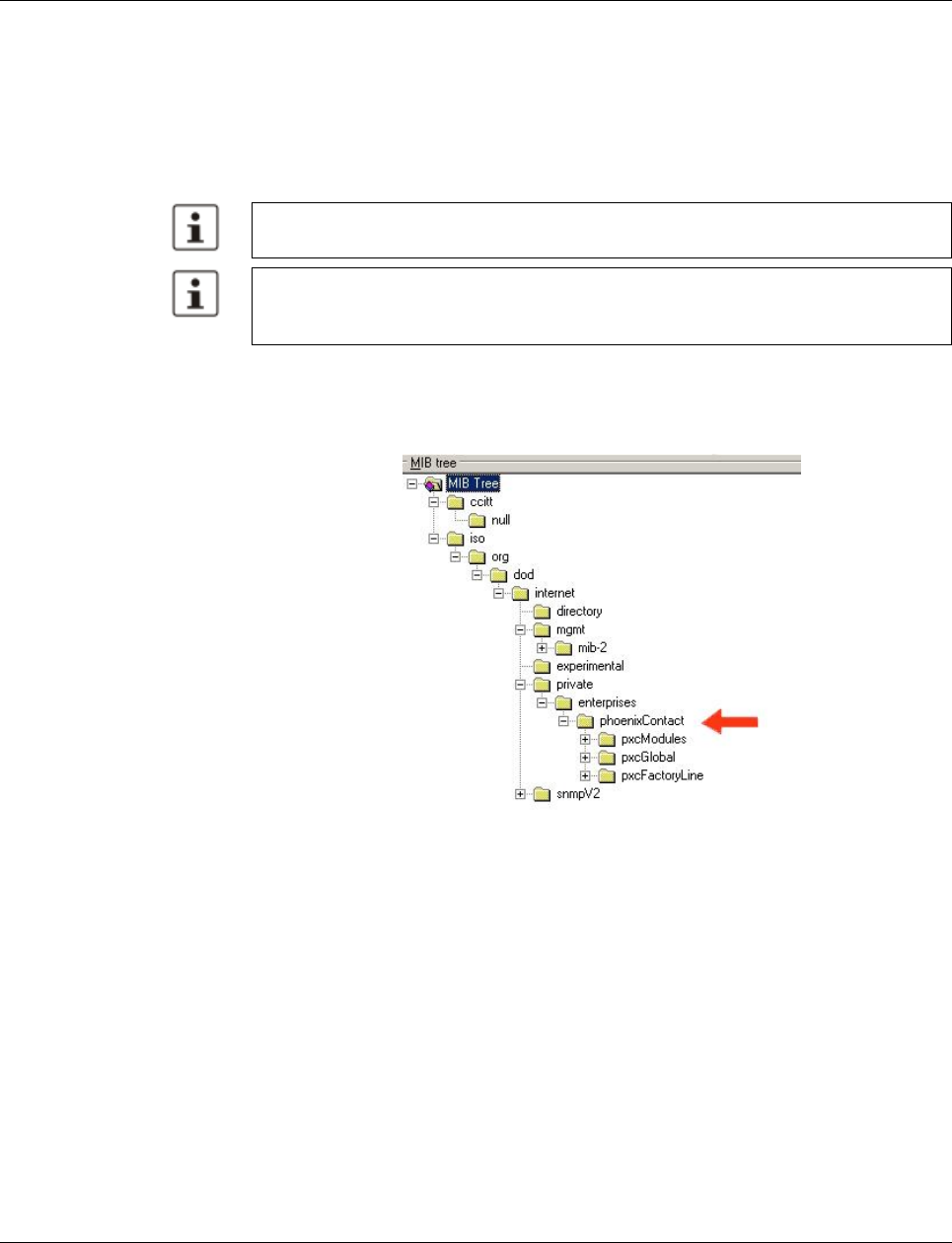
Smart Managed Compact Switch
74 PHOENIX CONTACT 8089_en_03
4.3.12 Private MIBs
The private MIBs for the SMN from Phoenix Contact can be found under object ID
1.3.6.1.4.1.4346. The SMN MIB contains the following groups:
– pxcModules (OID = 1.3.6.1.4.1.4346.1),
– pxcGlobal (OID = 1.3.6.1.4.1.4346.2)
– pxcFactoryLine (OID = 1.3.6.1.4.1.4346.11)
MIB tree
The private MIB from Phoenix Contact is integrated in the MIB tree as follows (see red ar-
row).
Figure 4-33 MIB tree
4.3.12.1 pxcModules OID = 1.3.6.1.4.1.4346.1
flMSwitchMModule
OID 1.3.6.1.4.1.4346.1.8
The object contains information about the manufacturer.
4.3.12.2 pxcGlobal OID = 1.3.6.1.4.1.4346.2
pxcBasic
OID 1.3.6.1.4.1.4346.2.1
All configuration modifications, which are to take effect after a SMN restart, must be saved
permanently using the “flWorkFWCtrlConfSave” object.
The aging time (default: 40 seconds) is not set using the private MIBs, instead it is set us-
ing the “dot1dTpAgingTime” MIB object (OID 1.3.6.1.2.1.17.4.2). The available setting
range is 10 to 825 seconds.

Configuration and diagnostics
8089_en_03 PHOENIX CONTACT 75
pxcBasicName
OID 1.3.6.1.4.1.4346.2.1.1
Syntax Display string
Access Read
Description Contains the manufacturer's name: Phoenix Contact GmbH & Co. KG.
pxcBasicDescr
OID 1.3.6.1.4.1.4346.2.1.2
Syntax Display string
Access Read
Description Contains the manufacturer's name and address:
Phoenix Contact GmbH & Co. KG, D-32823 Blomberg.
pxcBasicURL
OID 1.3.6.1.4.1.4346.2.1.3
Syntax Display string
Access Read
Description Contains the manufacturer's web address:
http://www.phoenixcontact.com.
4.3.12.3 pxcFactoryLine OID = 1.3.6.1.4.1.4346.11
flGlobal
OID 1.3.6.1.4.1.4346.11.1
flBasic
OID 1.3.6.1.4.1.4346.11.1.1
flBasicName
OID 1.3.6.1.4.1.4346.11.1.1.1
Syntax Display string
Access Read
Description Contains the name of the product group:
Factoryline.

Smart Managed Compact Switch
76 PHOENIX CONTACT 8089_en_03
flBasicDescr
OID 1.3.6.1.4.1.4346.11.1.1.2
Syntax Display string
Access Read
Description Contains a brief description of the product group:
Ethernet Installation System.
flBasicURL
OID 1.3.6.1.4.1.4346.11.1.1.3
Syntax Display string
Access Read
Description Contains a specific URL for the product group:
www.factoryline.de.
flBasicCompCapacity
OID 1.3.6.1.4.1.4346.11.1.1.4
Syntax Integer32 (1 ... 1024)
Access Read
Description Contains the number of different components that can be managed with this device.
flComponents
OID 1.3.6.1.4.1.4346.11.1.2
flComponentsTable
OID 1.3.6.1.4.1.4346.11.1.2.1
flComponentsTableEntry
OID 1.3.6.1.4.1.4346.11.1.2.1.1
Syntax
Access
Description Generates a table with descriptions for components in the “Factoryline” product group,
which can be managed by this management unit.
flComponentsIndex
OID 1.3.6.1.4.1.4346.11.1.2.1.1.1
Syntax Integer32 (1 ... 1024)
Access Read

Configuration and diagnostics
8089_en_03 PHOENIX CONTACT 77
flWorkDevice
OID 1.3.6.1.4.1.4346.11.11
flWorkBasic
OID 1.3.6.1.4.1.4346.11.11.1
flWorkBasicName
Description Identifies the components for which this entry contains information.
flComponentsName
OID 1.3.6.1.4.1.4346.11.1.2.1.1.2
Syntax Display string
Access Read
Description Contains the designation of the component.
flComponentsDescr
OID 1.3.6.1.4.1.4346.11.1.2.1.1.3
Syntax Display string
Access Read
Description Contains a brief description of the component.
flComponentsURL
OID 1.3.6.1.4.1.4346.11.1.2.1.1.4
Syntax Display string
Access Read
Description Contains the URL of a Phoenix Contact website with additional information about the com-
ponent.
flComponentsOrderNumber
OID 1.3.6.1.4.1.4346.11.1.2.1.1.5
Syntax Display string
Access Read
Description Contains the order number of the component.
OID 1.3.6.1.4.1.4346.11.11.1.1
Syntax Display string
Access Read and write
Description Contains the device name (corresponds to “sysName” from MIB2), which the user as-
signed to the device.
Check this entry following a firmware update, it may have been overwritten with
default values.

Smart Managed Compact Switch
78 PHOENIX CONTACT 8089_en_03
flWorkBasicDescr
flWorkBasicURL
flWorkBasicSerialNumber
flWorkBasicHWRevision
flWorkBasicPowerStat
OID 1.3.6.1.4.1.4346.11.11.1.2
Syntax Display string
Access Read and write
Description Contains a short description (corresponds to “sysDescr” from MIB2), which the user as-
signed to this component.
Check this entry following a firmware update, it may have been overwritten with
default values.
OID 1.3.6.1.4.1.4346.11.11.1.3
Syntax Display string
Access Read
Description Contains the URL of the device-specific web page for WBM in the form of the currently set
IP address.
OID 1.3.6.1.4.1.4346.11.11.1.4
Syntax Octet string (12)
Access Read
Description Contains the serial number of the device.
OID 1.3.6.1.4.1.4346.11.11.1.5
Syntax Octet string (4)
Access Read
Description Contains the hardware version of the device.
OID 1.3.6.1.4.1.4346.11.11.1.6
Syntax Integer32 (1 ... 1024)
Access Read
Description Contains status information about the connected supply voltages:
- Unknown1
- Supply voltage 1 OK3
- Supply voltage 2 OK4
- Supply voltage 1 and 2 OK5

Configuration and diagnostics
8089_en_03 PHOENIX CONTACT 79
flWorkBasicCompMaxCapacity
flWorkBasicCompCapacity
flWorkComponents
OID 1.3.6.1.4.1.4346.11.11.2
flWorkComponentsTable
OID 1.3.6.1.4.1.4346.11.11.2.1
flWorkComponentsEntry
OID 1.3.6.1.4.1.4346.11.11.1.11
Syntax Integer32 (1 ... 1024)
Access Read
Description Contains the maximum number of interfaces that can be connected in theory.
OID 1.3.6.1.4.1.4346.11.11.1.12
Syntax Integer32 (1 ... 1024)
Access Read
Description Contains the number of interfaces actually connected.
OID 1.3.6.1.4.1.4346.11.11.2.1.1
Description Generates a table with the available interface modules of this switch station.
flWorkComponentsIndex
OID 1.3.6.1.4.1.4346.11.11.2.1.1.1
Syntax Integer32 (1 ... 1024)
Access Read
Description Indicates the selected interface number, for which this entry contains information.
flWorkComponentsOID
OID 1.3.6.1.4.1.4346.11.11.2.1.1.2
Syntax OBJECT IDENTIFIER
Access Read
Description This OID indicates the corresponding entry in flWorkComponentsEntry.
flWorkComponentsURL
OID 1.3.6.1.4.1.4346.11.11.2.1.1.3
Syntax Display string
Access Read
Description Contains the IP address of the switch.
flWorkComponentsDevSign
OID 1.3.6.1.4.1.4346.11.11.2.1.1.4
Smart Managed Compact Switch
80 PHOENIX CONTACT 8089_en_03
flWorkTraps
OID 1.3.6.1.4.1.4346.11.11.3
flWorkTrapsDelemeter
OID 1.3.6.1.4.1.4346.11.11.3.0
trapPasswdAccess
trapFWHealth
trapFWConf
trapPowerSupply
trapRstpRingFailure
Syntax Integer (0 ... 24)
Access Read
Description Contains the designation of the interface module.
OID 1.3.6.1.4.1.4346.11.11.3.0.1
Description Sent to the defined trap receivers on each modification or attempted modification of the de-
vice password and contains information about the status of the last modification or at-
tempted modification.
OID 1.3.6.1.4.1.4346.11.11.3.0.2
Description Sent to the diagnostic display on each firmware-related modification and contains addi-
tional information about the firmware status.
OID 1.3.6.1.4.1.4346.11.11.3.0.3
Description Sent each time the configuration is saved and informs the management station that the
configuration has been saved successfully.
This trap is sent in the event of configuration modifications (port name, port mode, device
name, IP address, trap receiver address, port mirroring, etc.), which are not yet saved per-
manently. The trap therefore provides a warning that, if not saved permanently, the
changes will be lost on a reset.
The “flWorkNetIfParamAssignment” object must be set to static (1), otherwise
objects cannot be written.
OID 1.3.6.1.4.1.4346.11.11.3.0.4
Description Sent each time the redundant power supply fails.
OID 1.3.6.1.4.1.4346.11.11.3.0.6
Description Sent in the event of a link interrupt in the redundant RSTP ring.
Configuration and diagnostics
8089_en_03 PHOENIX CONTACT 81
trapManagerConnection
flWorkNet
OID 1.3.6.1.4.1.4346.11.11.4
flWorkNetlfParameter
OID 1.3.6.1.4.1.4346.11.11.4.1
flWorkNetIfParamPhyAddress
flWorkNetIfParamIPAddress
flWorkNetIfParamSubnetmask
flWorkNetIfParamGwIpAddress
OID 1.3.6.1.4.1.4346.11.11.3.0.99
Description This trap is used to test the connection between the device and trap manager.
OID 1.3.6.1.4.1.4346.11.11.4.1.1
Syntax MacAddress
Access Read
Description Contains the MAC address of the switch.
OID 1.3.6.1.4.1.4346.11.11.4.1.2
Syntax IpAddress
Access Read and write
Description Contains the current IP address of the SMN. Changes only take effect once the “flWor-
kNetIfParamSave” object has been executed.
The “flWorkNetIfParamAssignment” object must be set to static (1), otherwise
objects cannot be written.
OID 1.3.6.1.4.1.4346.11.11.4.1.3
Syntax IpAddress
Access Read and write
Description Contains the current subnet mask of the SMN. Changes only take effect once the “flWor-
kNetIfParamSave” object has been executed.
The “flWorkNetIfParamAssignment” object must be set to static (1), otherwise
objects cannot be written.
OID 1.3.6.1.4.1.4346.11.11.4.1.4
Smart Managed Compact Switch
82 PHOENIX CONTACT 8089_en_03
flWorkNetIfParamStatus
flWorkNetIfParamSave
Syntax IpAddress
Access Read and write
Description Contains the IP address of the current default gateway/router of the SMN. Changes only
take effect once the “flWorkNetIfParamSave” object has been executed.
The “flWorkNetIfParamAssignment” object must be set to static (1), otherwise
objects cannot be written.
OID 1.3.6.1.4.1.4346.11.11.4.1.5
Syntax Integer32 (1 ... 1024)
Access Read
Description Indicates whether IP parameters were modified but not saved:
No change 1
Address setting modified, but not yet activated2
Address settings must be saved permanently using the
“flWorkFWCtrlConfSave” object.
OID 1.3.6.1.4.1.4346.11.11.4.1.6
Syntax Integer
Access Read and write
Description Provides the option of saving modified IP parameters or undoing the modifications:
Undo modification1
Activate modification2
Address settings must be saved permanently using the
“flWorkFWCtrlConfSave” object.
Configuration and diagnostics
8089_en_03 PHOENIX CONTACT 83
flWorkNetIfParamAssignment
flWorkNetIfParamManagementVlanId
flWorkNetPort
OID 1.3.6.1.4.1.4346.11.11.4.2
flWorkNetPortCapacity
flWorkNetPortTable
OID 1.3.6.1.4.1.4346.11.11.4.2.2
flWorkNetPortEntry
OID 1.3.6.1.4.1.4346.11.11.4.1.7
Syntax Integer
Access Read and write
Description Provides the option of modifying the assignment mechanism for IP parameters.
Static IP address1
Assignment via BootP (default)2
Modifications to the assignment mechanism also affect the management func-
tions via the web interface and via RS-232.
Modifications to the assignment mechanism on BootP (2) or DCP (4) are only
activated after a restart of the SMN.
Address settings must be saved permanently using the
“flWorkFWCtrlConfSave” object.
OID 1.3.6.1.4.1.4346.11.11.4.1.8
Syntax Integer32 (1 ... 4094)
Access Read and write
Description If the switch is operated in “Tagging” VLAN mode, this object indicates in which VLAN
(VLAN ID) the management agent is located.
OID 1.3.6.1.4.1.4346.11.11.4.2.1
Syntax Integer32 (1 ... 1024)
Access Read
Description Contains the number of available ports depending on the configuration of the MMS.
OID 1.3.6.1.4.1.4346.11.11.4.2.2.1
Description Generates a table with a detailed description of the port configuration.
flWorkNetPortIndex
OID 1.3.6.1.4.1.4346.11.11.4.2.2.1.1
Syntax Integer32 (1 ... 1024)

Smart Managed Compact Switch
84 PHOENIX CONTACT 8089_en_03
Access Read
Description Specifies the port number of the selected port.
flWorkNetPortLinkState
OID 1.3.6.1.4.1.4346.11.11.4.2.2.1.2
Syntax Integer
Access Read
Description Indicates the port status:
Connected 1
Not connected2
farEndFault3
flWorkNetPortSpeed
OID 1.3.6.1.4.1.4346.11.11.4.2.2.1.3
Syntax Gauge32
Access Read
Description Contains the data transmission speed of the selected port in bps.
flWorkNetPortDuplexMode
OID 1.3.6.1.4.1.4346.11.11.4.2.2.1.4
Syntax Integer
Access Read
Description Contains the duplex mode of the selected port:
No link0
Full duplex1
Half duplex2
flWorkNetPortNegotiation
OID 1.3.6.1.4.1.4346.11.11.4.2.2.1.5
Syntax Integer
Access Read
Description Contains the duplex mode of the selected port:
Automatic1
Manual2
flWorkNetPortName
OID 1.3.6.1.4.1.4346.11.11.4.2.2.1.6
Syntax Octet string (0 ... 16)
Access Read and write
Description Contains the “name” of the port, e.g., “Robot 1”.
flWorkNetPortEnable
OID 1.3.6.1.4.1.4346.11.11.4.2.2.1.7
Syntax Integer
Access Read and write
Description Here you can disable the port:
Port disabled1
Port enabled2
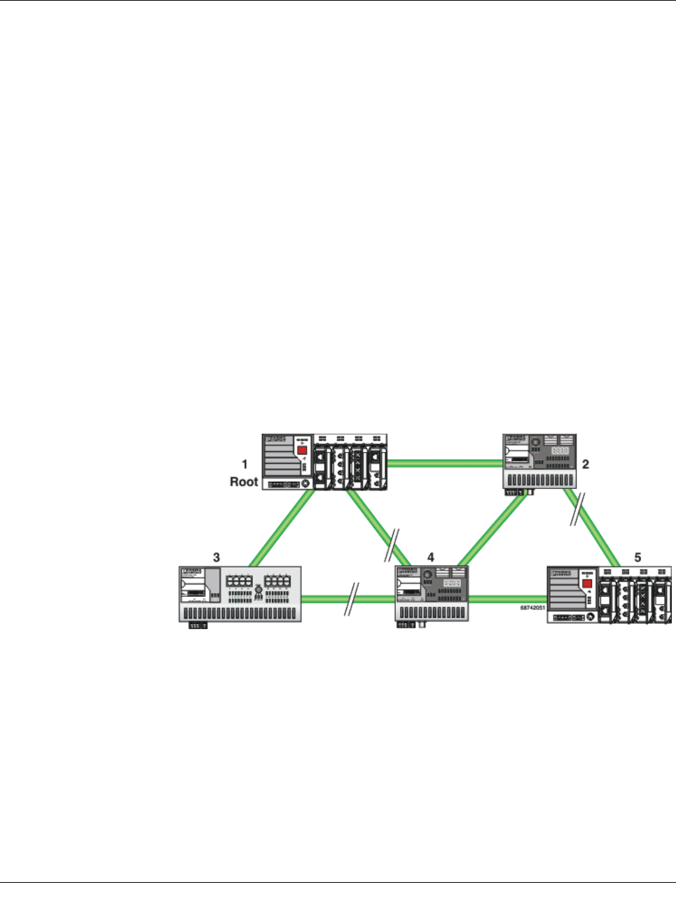
(Rapid) Spanning Tree
8089_en_03 PHOENIX CONTACT 109
5 (Rapid) Spanning Tree
5.1 General function
Loops The Rapid/Spanning Tree Protocol (RSTP) is a standardized method (IEEE 802.1w/IEEE
802.1d) that enables the use of Ethernet networks with redundant data paths. Ethernet net-
works with redundant data paths form a meshed topology with initially impermissible loops.
Due to these loops, data packets can circulate endlessly within the network and can also be
duplicated. As a consequence, the network is usually overloaded due to circulating data
packets, and communication is interrupted. The meshed structure is therefore replaced by
a logical, deterministic path with a tree structure without loops using the Spanning Tree al-
gorithm. In the event of data path failure, some of the previously disconnected connections
are reconnected to ensure uninterrupted network operation.
IEEE 802.1w RSTP prevents the long timer-controlled switch-over times of STP.
Example:
In the following network topology, (six) redundant paths have been created to ensure ac-
cess to all network devices in the event of a data path failure. These redundant paths are
impermissible loops. The Spanning Tree Protocol automatically transforms this topology
into a tree by disconnecting selected ports. In this context, one of the switches is assigned
the role of the root of the tree. From this root, all other switches can be accessed via a single
data path.
Figure5-1 Possible tree structure with Spanning Tree
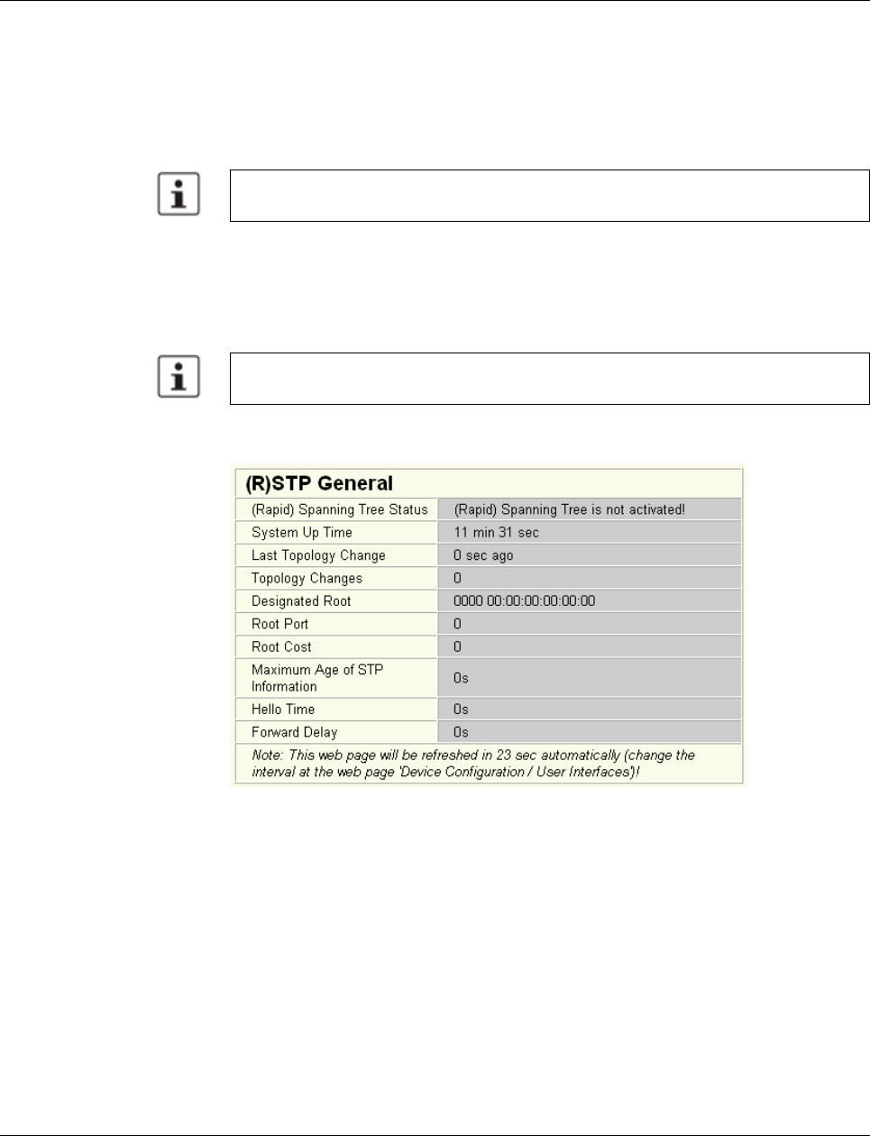
Smart Managed Compact Switch
110 PHOENIX CONTACT 8089_en_03
5.2 (R)STP startup
Startup consists of two parts that must be executed in the specified order:
1Enable (R)STP on all switches that are to be operated as active (R)STP components in
the network.
2Connect the switches to form a meshed topology.
5.2.1 Enabling (R)STP on all switches involved
(R)STP can be activated via web-based management, via the SNMP interface or via the se-
rial interface.
Now switch to the “Switch Station” menu on the “(R)STP General” page. Here, you will find
various information about the Spanning Tree configuration.
Figure 5-2 “(R)STP General” web page
The web page displays the parameters with which the switch is currently operating.
(R)STP configuration
It is sufficient to set the “Rapid Spanning Tree Status” to “Enable” in order to start (R)STP
using default settings. Priority values can be specified for the switch. The bridge and backup
root can be specified via these priority values.
Only multiples of 4096 are permitted. The desired value can be entered in the “Priority” field.
The value will be rounded automatically to the next multiple of 4096. Once you have con-
firmed the modification by entering your password, the initialization mechanism is started.
Redundant connections can now be created.
Only create the meshed topology after activating (R)STP.
While learning the network topology, the switch temporarily does not participate in net-
work communication.
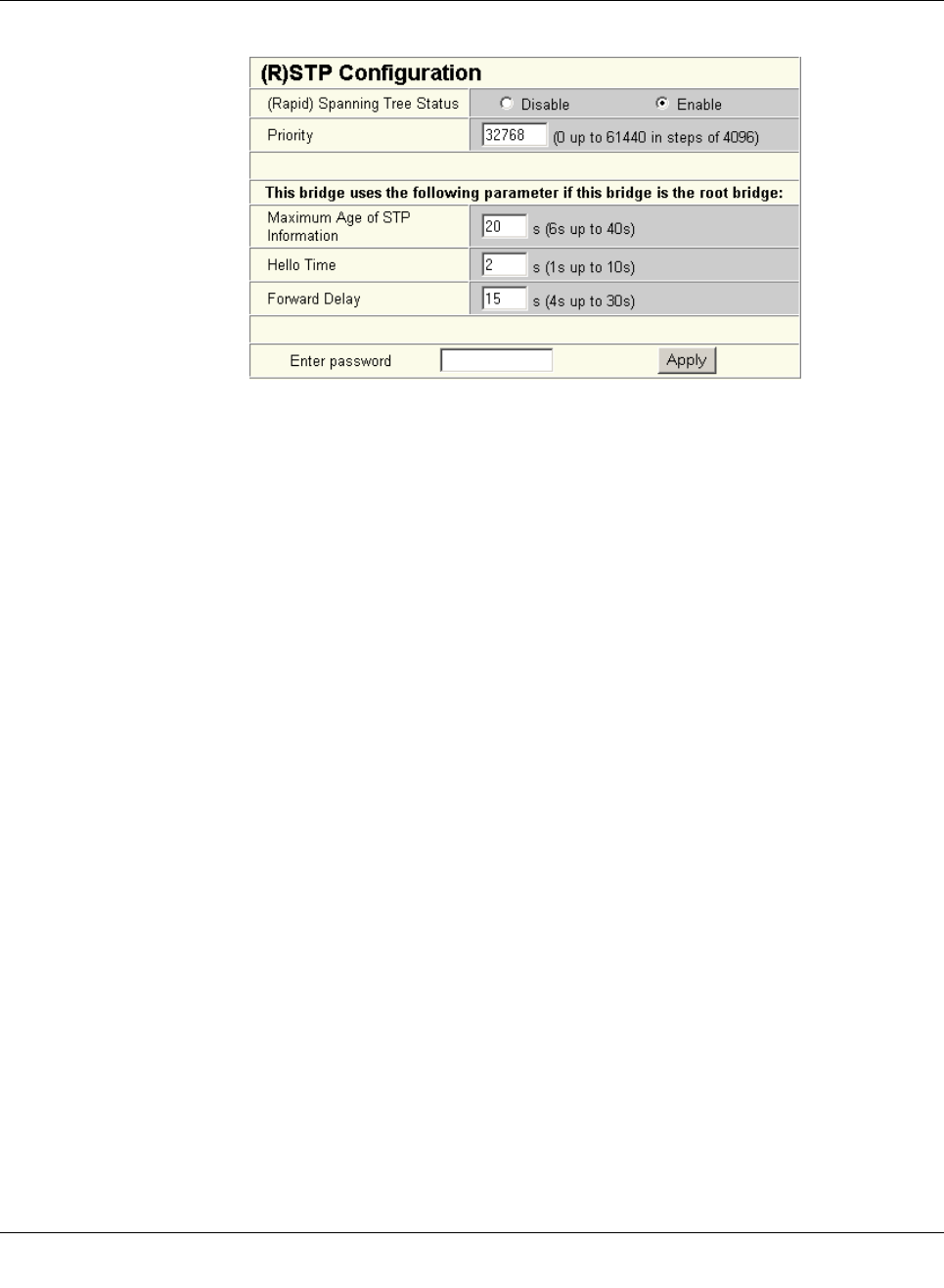
(Rapid) Spanning Tree
8089_en_03 PHOENIX CONTACT 111
Figure5-3 “(R)STP Configuration” web page
Large tree support
If RSTP is operated using the default values, it is suitable for up to seven switches along the
relevant path (see Figure 5-17 on page 130 and Figure 5-18 on page 131 as an example of
the relevant path). The RSTP protocol would therefore be possible in a ring topology for up
to 15 switches.
The “Large Tree Support” option makes the ring topology suitable for 28 switches along the
relevant path if RSTP is used. The “Large Tree Support” option could provide an RSTP ring
topology with up to 57 devices. When using “Large Tree Support”, please note the following:
– In the large tree support RSTP topology, do not use devices that do not support large
tree support.
– Enable the “Large Tree Support” option on all devices.
– If RSTP is to be activated as the redundancy mechanism in an existing network with
more than seven switches along the relevant path, then the “Large Tree Support” option
must first be enabled on all devices.
– It is recommended that “Large Tree Support” is not activated in networks with less than
seven switches along the relevant path.
Maximum age of STP information
The parameter is set by the root switch and used by all switches in the ring. The parameter
is sent to make sure that each switch in the network has a constant value, against which the
age of the saved configuration is tested.
The “Maximum Age of STP Information”, “Hello Time”, and “Forward Delay” fields have the
same meaning as for STP. These values are used when this switch becomes a root. The
values currently used can be found under “(R)STP General”.
Hello time
Specifies the time interval within which the root bridge regularly reports to the other bridges
via BPDU.
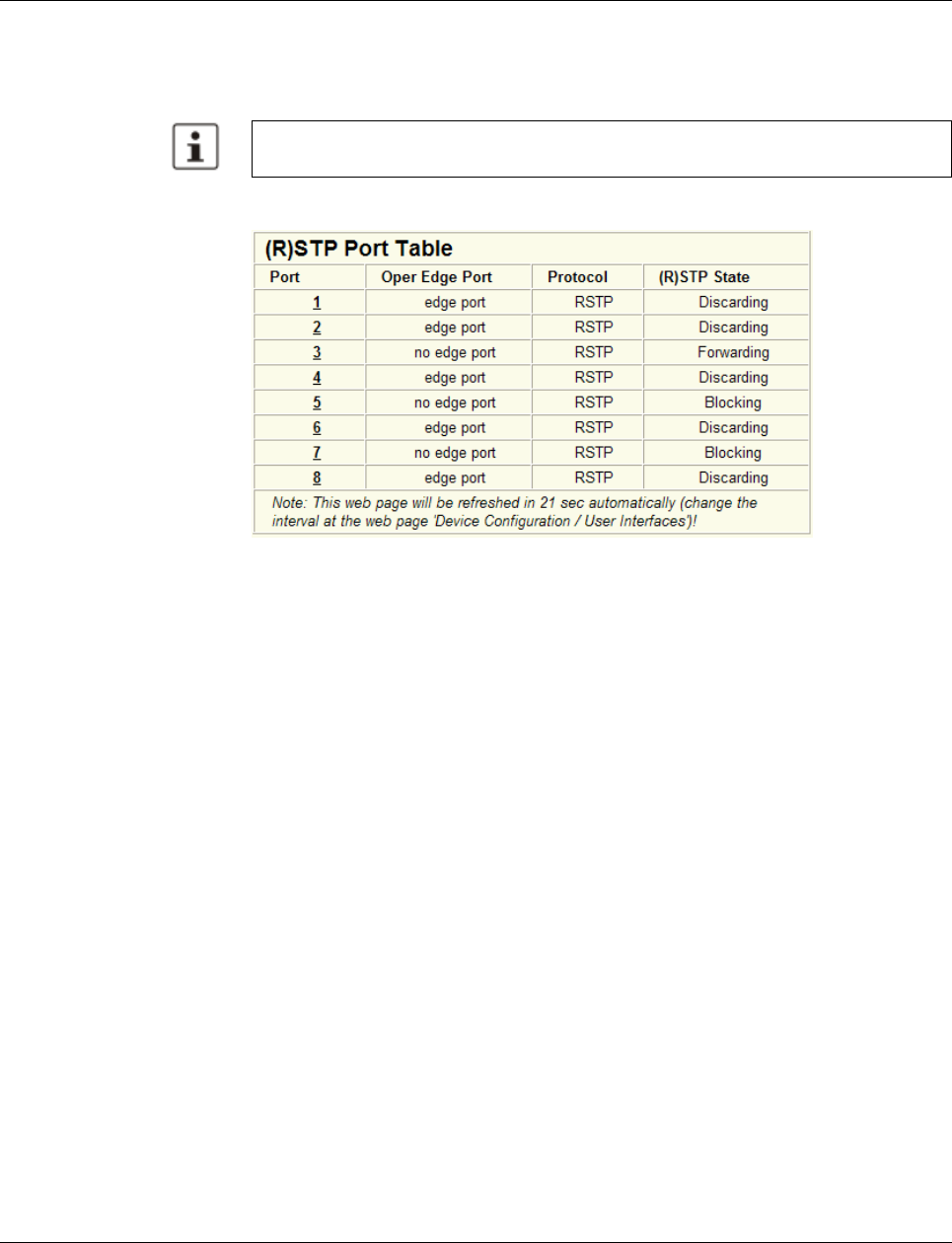
Smart Managed Compact Switch
112 PHOENIX CONTACT 8089_en_03
Forward delay
The forward delay value indicates how long the switches are to wait in order for the port state
in STP mode to change from “Discarding” to “Listening” and from “Listening” to “Learning”
(2 x forward delay).
(R)STP port table
Figure 5-4 “(R)STP Port Table” web page
Oper edge port
All ports that do not receive any (R)STP BPDUs (e.g., termination device ports) become
edge ports, i.e., ports that go to the “Forwarding” state immediately after restart. All ports
that do not receive any (R)STP BPDUs (e.g., termination device ports) become edge ports,
i.e., ports that go to the “Forwarding” state immediately after restart.
Protocol
Indicates the redundancy protocol used.
(R)STP state
Indicates the current (R)STP state of the relevant port.
Possible states:
– “Forwarding”
The port is integrated in the active topology and forwards data.
– “Discarding”
The port does not take part in data transmission.
– “Learning”
The port does not take part in data transmission of the active topology, however, MAC
addresses are learned.
– Blocking/Discarding
The port has a link, but has been set to the “Discarding” state by RSTP.
The “Max Age of STP”, “Hello Time”, and “Forward Delay” parameters are optimized by
default upon delivery. They should not be modified.
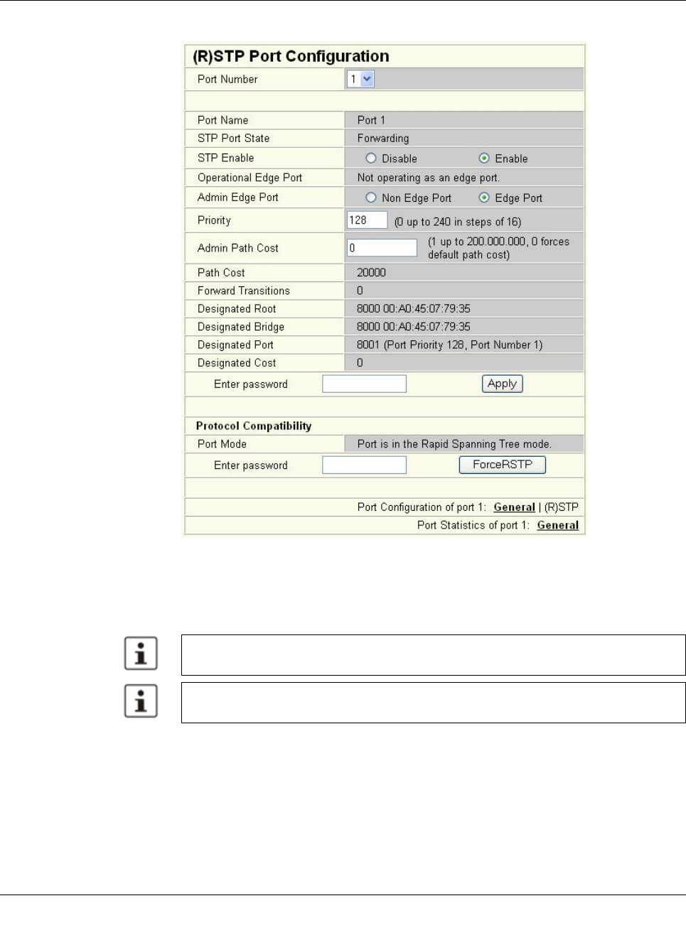
(Rapid) Spanning Tree
8089_en_03 PHOENIX CONTACT 113
(R)STP port configuration table
Figure5-5 “(R)STP Port Configuration Table” web page
An overview of the main settings for each port is provided here.
5.2.1.1 (R)STP port configuration
This page displays the valid (R)STP configuration settings for the selected port.
If termination devices or subnetworks are connected without RSTP or STP via a port, it is
recommended that the “Admin Edge Port” be set to “Edge Port”. In this way, a link modifica-
tion at this port does not result in a topology modification.
5.2.1.2 Switch/port ID
The validity of switches and ports is determined according to priority vectors.
Modifications of properties can result in complete reconfiguration of (Rapid) Spanning
Tree.
It is recommended that a suitable root switch and a backup root switch are specified using
corresponding priority assignment.
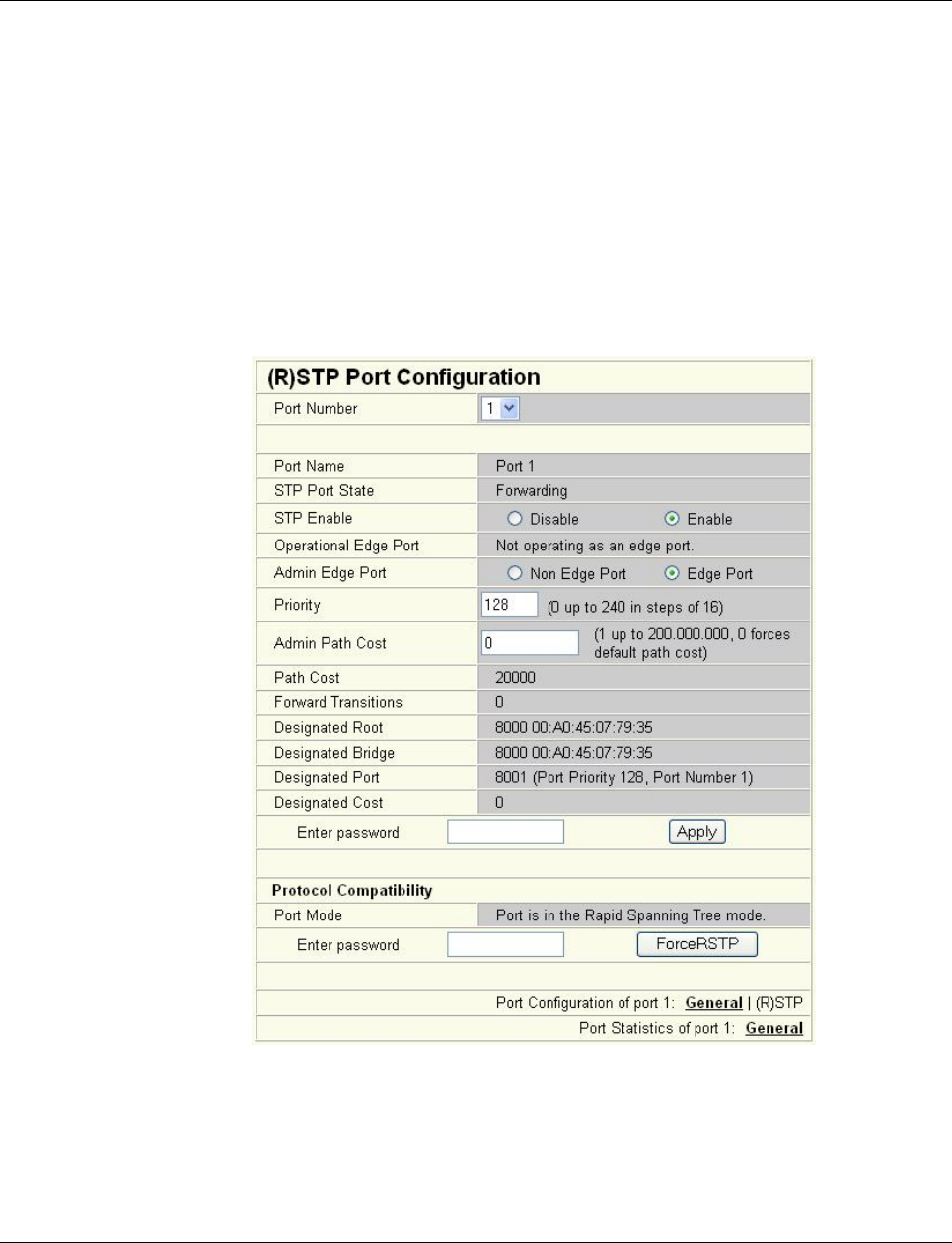
Smart Managed Compact Switch
114 PHOENIX CONTACT 8089_en_03
Bridge identifier
A switch ID consists of eight bytes as an unsigned integer value. When comparing two
switch IDs, the one with the lowest numeric value is of higher, i.e., “better”, priority.
The first two bytes contain the priority.
The last six bytes contain the MAC address and thus ensure the uniqueness of the switch
ID in the event of identical priority values.
The switch with the lowest numerical switch ID becomes the root. It is recommended that
the root port and alternate port are specified using the priority.
Port identifier
The port ID consists of four bits for the port priority and twelve bits for the port number. The
port ID is interpreted as an unsigned integer value. When comparing two port IDs, the one
with the lowest numeric value is of higher, i.e., “better”, priority.
Figure 5-6 “(R)STP Port Configuration” web page
Port number
Indicates the number of the port currently selected.

(Rapid) Spanning Tree
8089_en_03 PHOENIX CONTACT 115
Port name
Indicates the name of the port.
STP port state
Indicates the status in which this port takes part in STP.
Operational edge port
Indicates whether this port is operated as an edge port.
Admin edge port
Here, you can specify whether this port is to be operated as an edge port (default setting),
if possible.
Priority
Indicates the priority set for this port (default 128). Due to backward compatibility with STP,
priority values can be set that are not configurable in RSTP.
Admin path cost
Indicates the path cost set for this port. A path cost equal to “0” activates the cost calculation
according to the transmission speed (10 Mbps = 2000000; 100 Mbps = 200000; 1000 Mbps
= 20000).
Path cost
Indicates the path cost used for this port.
Forward transitions
Indicates how often the port switches from the “Discarding” state to the “Forwarding” state.
Additional parameters provide information about the network paths in a stable topology that
are used by the BPDU telegrams.
Designated root
Root bridge for this Spanning Tree.
Designated bridge
The switch from which the port receives the best BPDUs. The value is based on the priority
value in hex and the MAC address.
Designated port
Port via which the BPDUs are sent from the designated bridge. The value is based on the
port priority (2 digits) and the port number.
Designated cost
Indicates the path cost of this segment to the root switch.
Protocol compatibility
Figure5-7 Protocol compatibility

Smart Managed Compact Switch
116 PHOENIX CONTACT 8089_en_03
If a port receives STP BPDUs, it switches automatically to STP mode. Automatic switching
to (R)STP mode does not take place. Switching to (R)STP mode can only be forced via
“ForceRstp” or via a restart.
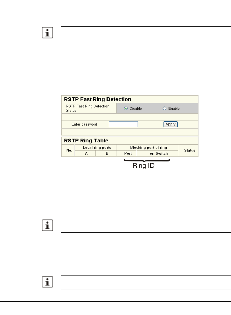
(Rapid) Spanning Tree
8089_en_03 PHOENIX CONTACT 117
RSTP fast ring detection
The “RSTP Fast Ring Detection” function can be activated on the “RSTP Configuration” web
page (see page 111).
This function speeds up the switch-over to a redundant path in the event of an error and pro-
vides easy diagnostics. RSTP fast ring detection provides each ring with an ID. This ID is
made known to each switch in the relevant ring. A switch can belong to several different
rings at the same time.
Structure of the ring ID The ring ID consists of the port number of the blocking port and the MAC address of the cor-
responding switch. Advantages of the ring ID:
– Easier to identify redundant paths and locate blocking ports.
– Possible to check whether the desired topology corresponds to the actual topology.
Figure5-8 RSTP ring table
Information in WBM The following information is displayed on the web page (and via SNMP):
Local ring ports
These two ports of this switch belong to the ring that is listed (ring ID).
Blocking port
This port deliberately breaks the loop.
Ring detection states The following states can occur for ring detection:
–Not Ready - Ring detection has not yet been completed.
–OK - Ring detection has been completed and quick switch-over is possible in the event
of an error.
–Broken - The ring is broken on this branch in the direction of the root switch.
– Failed on Port A - The ring was broken on this switch at port A.
The “Fast Ring Detection” function is only performed for connections with 10 Mbps or
100 Mbps.
A blocking port does not receive LLDP BPDUs, but does send LLDP BPDUs.
In the event of a link failure in the ring, the “trapRstpRingFailure” trap is sent.
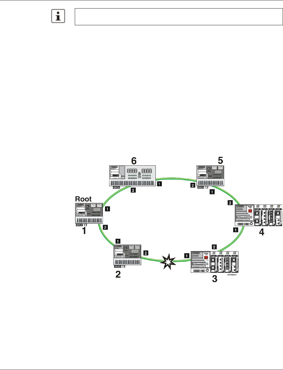
Smart Managed Compact Switch
118 PHOENIX CONTACT 8089_en_03
When using RSTP fast ring detection, please note the following:
– For RSTP fast ring detection, do not use devices that do not support this function.
– Enable RSTP fast ring detection on all devices.
– All data paths must be in full duplex mode.
5.2.2 Connection failure - Example
The following diagram illustrates an RSTP ring with six switches, where switch 1 is the root.
The ring extends over port 1 and port 2 for each switch. On switch 4, the loop is broken by
a blocking port.
If a cable interrupt occurs at the point indicated by the star, this produces the following en-
tries on the “RSTP Fast Ring Detection” web page:
Switch 3 - Failed on Port A
Switch 4 - Broken
In addition, switch 3 would also generate the “flWorkLinkFailure” trap, as long as the send-
ing of traps is not disabled.
Figure 5-9 Connection failure with RSTP ring detection
If the “Broken” or “Failed” status lasts for longer than 60 seconds, it is no longer displayed
after the next topology modification, since these rings no longer exist.

(Rapid) Spanning Tree
8089_en_03 PHOENIX CONTACT 119
5.2.3 Mixed operation of RSTP and STP
If a device with STP support is integrated into the network, only switch ports that receive
STP BPDUs are set to STP mode. All other ports that receive RSTP BPDUs remain in RSTP
mode.
5.2.4 Topology detection of a Rapid Spanning Tree network
(RSTP)
(Rapid) Spanning Tree switches continually exchange information about the network topol-
ogy using special messages (BPDUs - Bridge Protocol Data Units). In this way the switches
“learn” the current network topology and - based on this information - make the following de-
cisions:
– Which switch is selected as the root switch
– Which data paths are disabled
If a switch is started using the (Rapid) Spanning Tree Protocol, it first expects to be the root
switch. However, no data communication is possible during the startup phase until the cur-
rent network topology has been learned and until the decisions described above have been
made. Therefore loops in the network startup phase which could occur because no data
path is interrupted, are prevented.
5.2.4.1 Topology modification
A topology modification can be triggered by the following:
– Adding a data path
– Failure of a data path
– Adding a spanning tree switch, or
– Failure of a Spanning Tree switch
A topology modification is automatically detected and the network is reconfigured so that
another tree is created and all the devices in this tree can be accessed. During this process,
loops do not even occur temporarily.
If sending of traps was not deactivated, two traps are generated:
– newRoot (OID: 1.3.6.1.2.1.17.0.1)
– topologyChange (OID 1.3.6.1.2.1.17.0.2)
5.2.4.2 Interrupted data paths and port states
The described data path interruption by the Spanning Tree Protocol is created by discon-
necting individual ports that no longer forward any data packets. A port can have the follow-
ing states:
– Learning
– Forwarding
– Blocking/Discarding
– Disabled (link down or disconnected by the user)
The current port states are shown in the web interface.
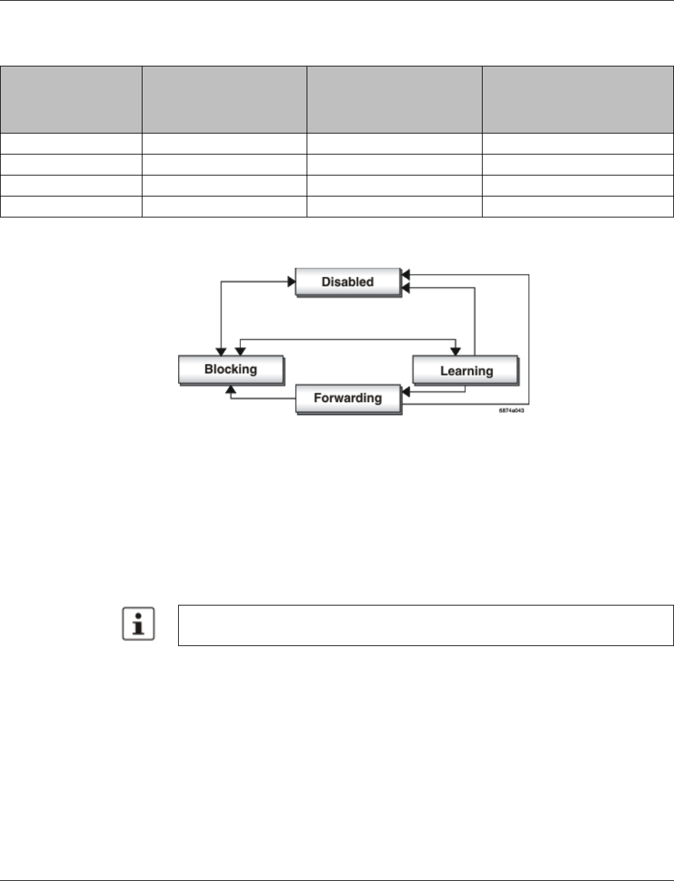
Smart Managed Compact Switch
120 PHOENIX CONTACT 8089_en_03
The properties of the various port states are shown in the table below.
The sequence of the five port states defined in the Spanning Tree Protocol cannot be as-
signed freely. The following diagram illustrates the possible sequence of the port states.
Figure 5-10 Sequence of the possible port states in STP
After device startup and, if necessary, also during topology modification, a port runs through
the states in the following order:
Learning ® Forwarding
or
Disabled ® Blocking/Discarding
Due to the edge property of ports, they switch to “Forwarding” immediately. In the second
case, the port generates a data path interruption in order to suppress loops accordingly.
5.2.4.3 Fast forwarding
If the Spanning Tree Protocol is deactivated at a port, the corresponding port is in “Fast For-
warding” mode.
A fast forwarding port
– Ignores all BPDUs that are received at this port.
– Does not send any BPDUs.
– Switches to the “Forwarding” state immediately after establishing the data link. Termi-
nation devices connected to this port can be accessed immediately.
“Port STP Status” in WBM on the “STP Port Configuration” page must be set to “Disabled”
to activate fast forwarding.
Table5-1 Properties of the port states
Receiving and evaluating
BPDUs (learning the
topology)
Learning the MAC
addresses of connected
devices and creating the
switching table
Forwarding data packets
(normal switching function)
Disabled
Blocking/Discarding X
Learning X X
Forwarding X X X
At least one port in the “Forwarding” state is at a data path between two spanning tree
switches so that the data path can be integrated into the network.
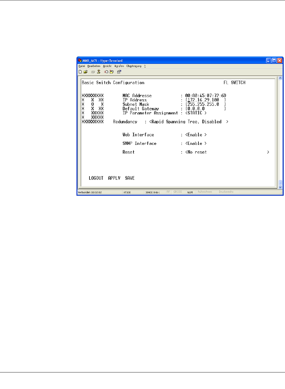
(Rapid) Spanning Tree
8089_en_03 PHOENIX CONTACT 121
Frame duplication Due to the fast switch-over times of RSTP, frames may be duplicated and the order of
frames may be changed.
5.2.4.4 Enabling via serial interface
Establish a connection to the switch. The procedure is described in Section “Management
via local RS-232 communication interface” on page 103. Set “Spanning Tree, Enabled” on
the following page in the “Redundancy” field and select “Save”.
Figure5-11 Activating Rapid Spanning Tree
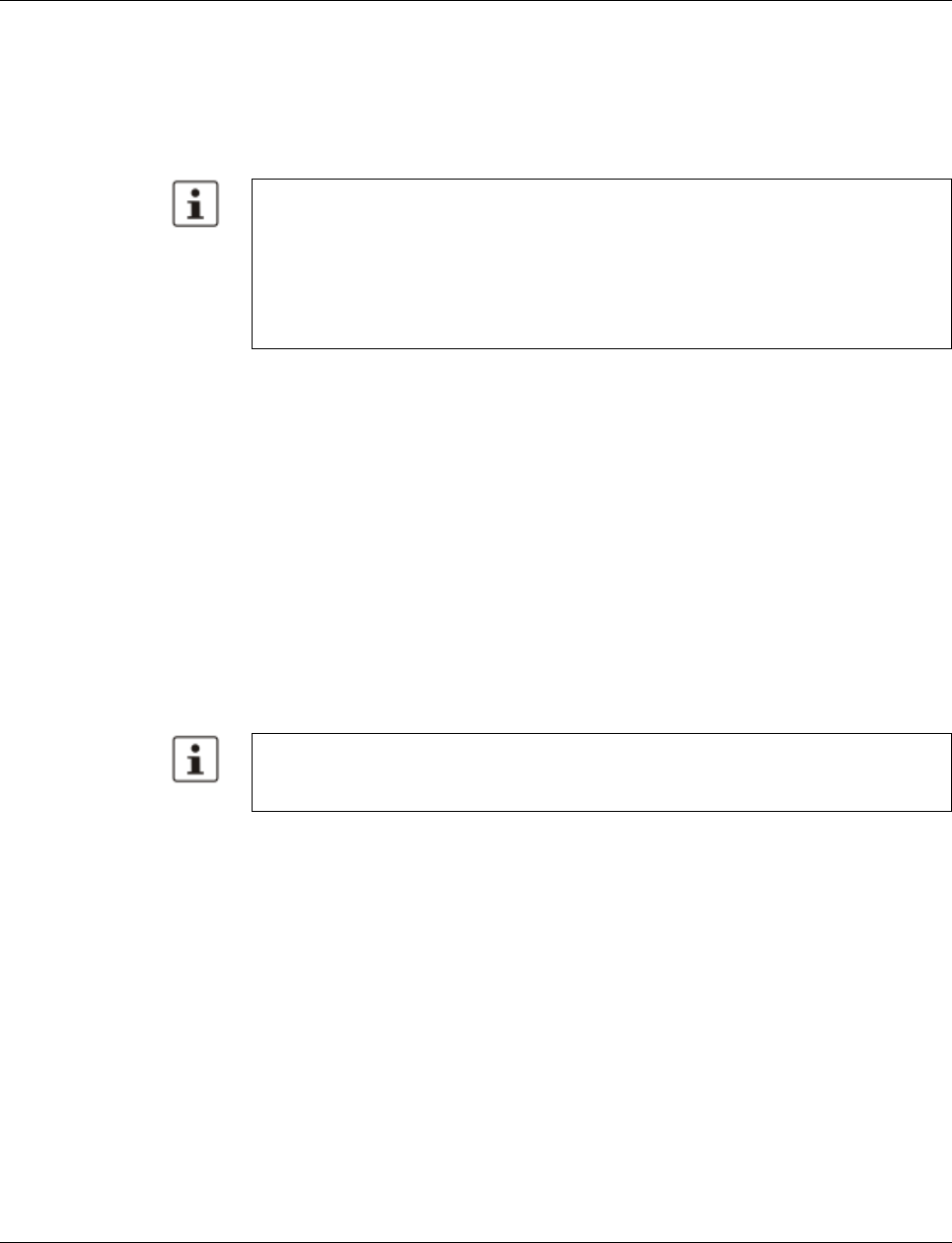
Smart Managed Compact Switch
122 PHOENIX CONTACT 8089_en_03
5.2.5 Configuration notes for Rapid Spanning Tree
In contrast to the Spanning Tree method, the Rapid Spanning Tree method supports event-
controlled actions that are no longer triggered based on a timer.
If one line fails (link down), the Rapid Spanning Tree method can respond more quickly to
this failure and thus the switch-over time can be kept low.
– For short switch-over times, structure your network in such a way that a maximum of
seven switches are located in a cascade up to the root switch. The switch-over times
can range from 100 ms to 2 s.
– Use priority assignment to specify a central switch as the root.
– It is also recommended to assign a switch as the backup root.
– For short switch-over times, all switches in the redundant topology should support the
Rapid Spanning Tree Protocol and no hubs should be used.
5.2.5.1 Connecting the switches to form a meshed topology
Having activated (Rapid) Spanning Tree for all switches, you can create a meshed topology
with redundant data paths. Any data links can now be created without taking loops into con-
sideration. Loops can even be added on purpose in order to create redundant links.
In this context, a data path between spanning tree switches can be
– A direct connection.
– A connection via one or more additional switches that do not support Spanning Tree.
– A connection via one or more hubs that do not support Spanning Tree.
Furthermore, a data path can consist of a connection of a spanning tree switch to
– A termination device.
– A network segment in which no loops may occur, which consists of several infrastruc-
ture components (hubs or switches) without Spanning Tree support.
For the last two data path options, no specific precautionary measures are necessary. If
necessary, you can use the “Fast Forwarding” option for the respective ports (see Section
“Fast forwarding” on page120).
For the first three cases, the following rules must be observed:
–Rule 1: Spanning Tree transparency for all infrastructure components
All infrastructure components used in your network that do not actively support Span-
ning Tree must be transparent for Spanning Tree messages (BPDUs) and must forward
all BPDUs to all ports without modifying them. When Spanning Tree is disabled, the
switch is transparent for BPDUs.
A link down or link up must be detected at the switch so that the RSTP switches can detect
a line failure and a restored line more quickly. Please take into consideration, in particular,
paths where media converters are used. It might be possible that media converters offer
setting options to transmit the link status of the fiber optic side to the twisted-pair side.
If a link down is not detected at the switch because the cable interrupt is between the me-
dia converters, and no link down is forced at the switch, timer-based detection is activat-
ed, which may result in longer switch-over times.
If Spanning Tree is not supported by all of the switches used, the reconfiguration time for
Spanning Tree is extended by the aging time of the switches without Spanning Tree sup-
port.
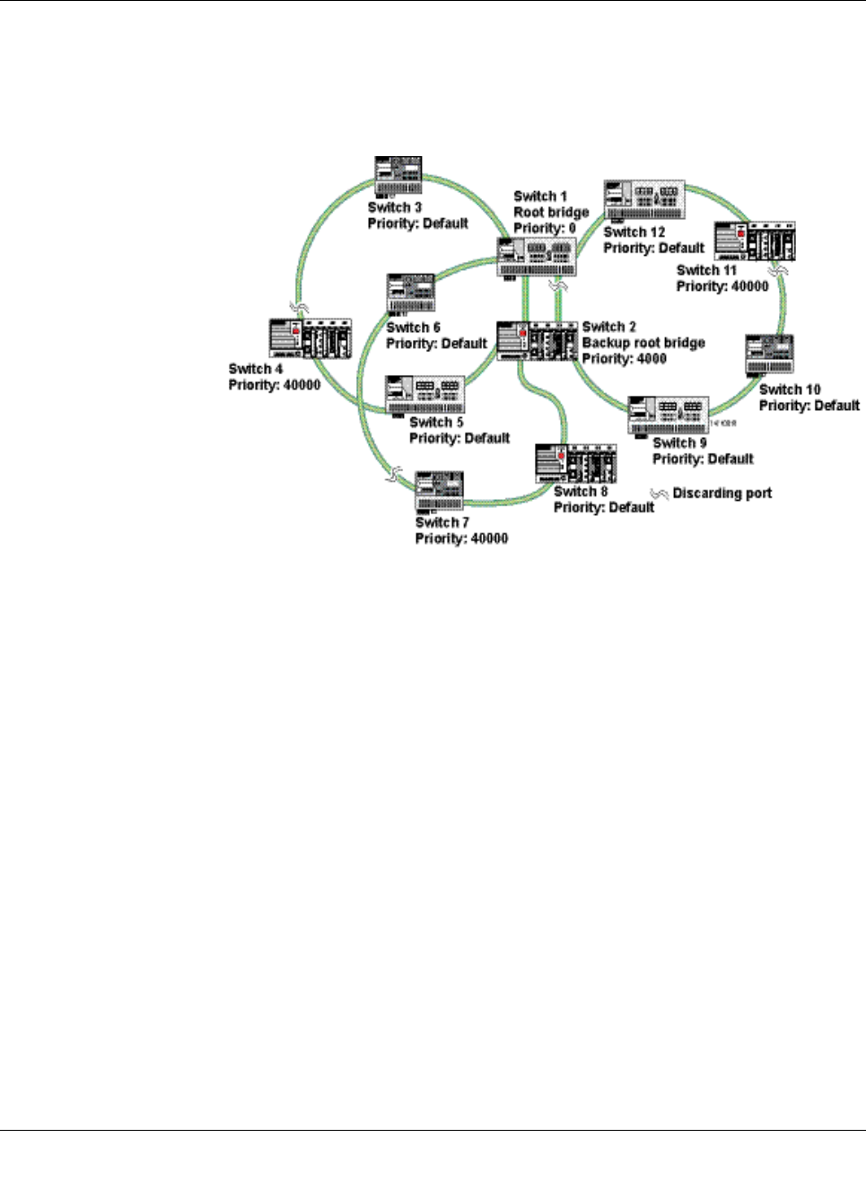
(Rapid) Spanning Tree
8089_en_03 PHOENIX CONTACT 123
–Rule 2: At least one active Spanning Tree component per loop
An active Spanning Tree component supports the Spanning Tree Protocol, sends/re-
ceives and evaluates BPDUs, and sets its ports to the relevant STP states.
Each loop in a network must have at least one active Spanning Tree component to dis-
integrate the loop.
Example:
Figure5-12 Example topology
The loops in the example topology illustrated are disabled by active RSTP components. The
example topology contains three rings; the root and the backup root are components in
each of the three rings. The three rings do not affect one another; a modification to the to-
pology in one ring does not affect the topology of the other two rings.
–Rule 3: No more than ten active Spanning Tree components in the topology
when using the Spanning Tree default setting
The ability to disintegrate any topology to form a tree without loops requires a complex
protocol that works with several variable timers. These variable timers are dimensioned
using the default values recommended by the IEEE standard so that a topology with a
maximum of ten active Spanning Tree components always results in a stable network.
When using large tree, please note the following (see also Section “Large tree support”
on page 111):
– In the large tree support RSTP topology, only use devices that support large tree.
– Enable the “Large Tree Support” option on all devices.
– If RSTP is to be activated as the redundancy mechanism in an existing network
with more than seven switches along the relevant path, then the “Large Tree Sup-
port” option must first be enabled on all devices.
– It is recommended that “Large Tree Support” is not activated in networks with less
than seven switches along the relevant path.
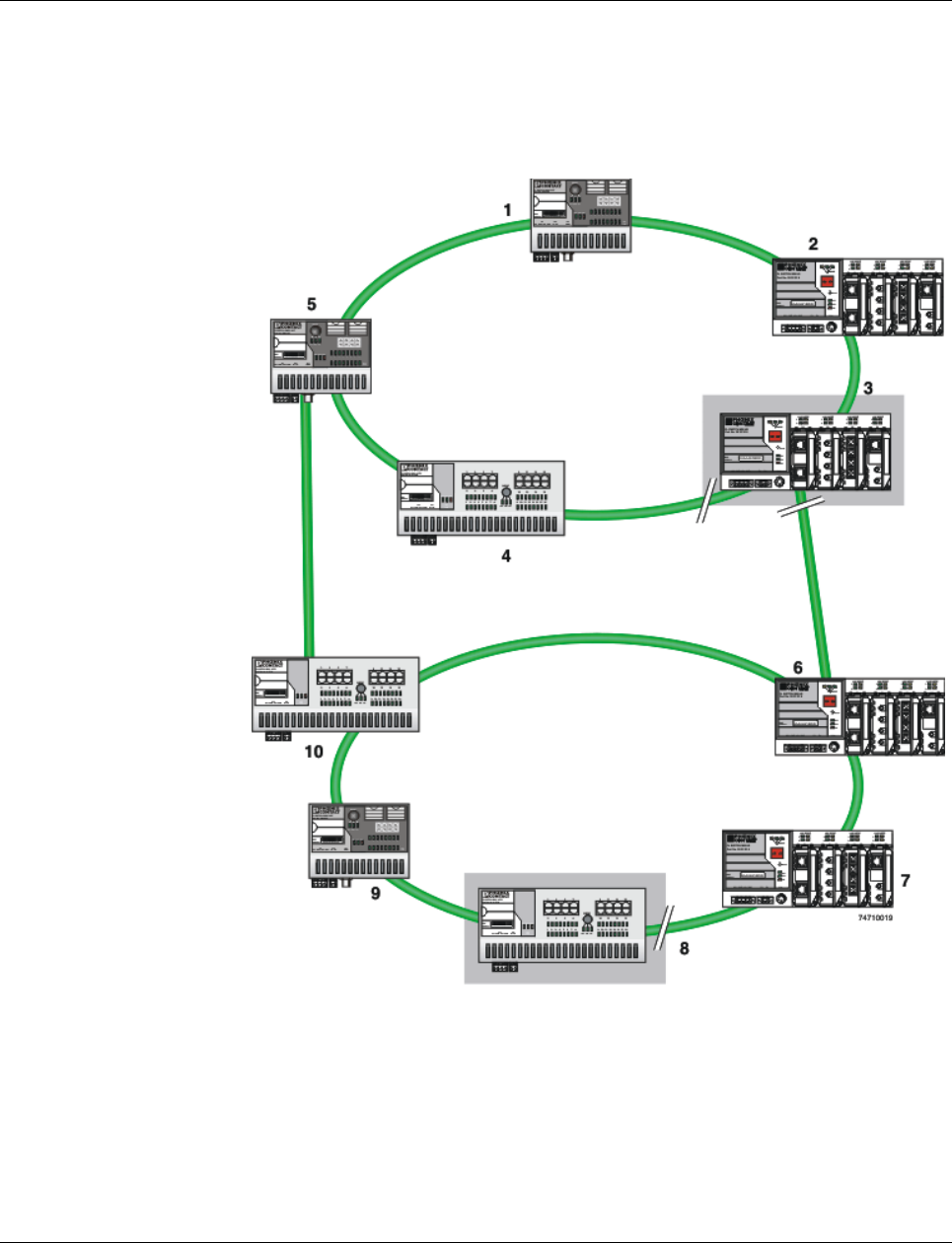
Smart Managed Compact Switch
124 PHOENIX CONTACT 8089_en_03
5.2.5.2 Example topologies
5.2.5.3 Redundant coupling of network segments
In this example, two network segments are connected via redundant data paths. Two RSTP
components have ports in the “Blocking/Discarding” state (highlighted in gray). This is suf-
ficient to operate the network.
Figure 5-13 Redundant coupling of network segments
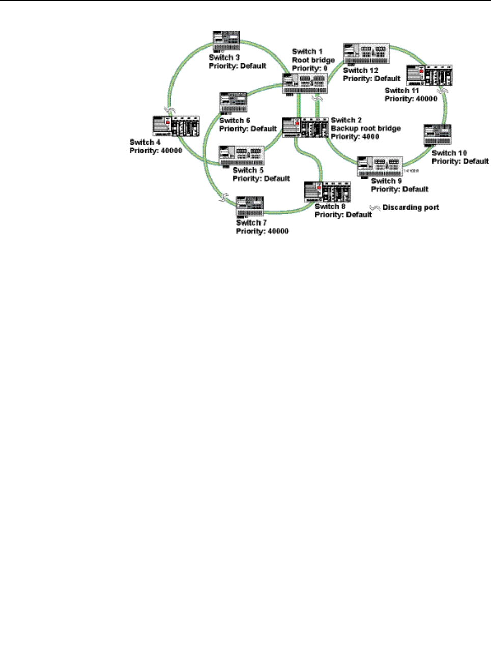
(Rapid) Spanning Tree
8089_en_03 PHOENIX CONTACT 125
Example with fast ring detection
Figure5-14 Example with fast ring detection
The switches in the illustrated example are arranged in such a way that two devices at the
central position are configured as the root bridge and as the backup root bridge (via the pri-
ority).
The root bridge has the lowest priority, the backup root bridge has the second lowest prior-
ity. The root bridge and the backup root bridge are connected together redundantly. The re-
maining switches are networked in several rings in a ring topology. The end points of the
rings are implemented on the root bridge and on the backup root bridge. The switch furthest
away from the root bridge has a lower priority than the default setting, e.g., 40000.
The advantage of this constellation is that the individual rings are not adversely affected in
the event of an error.
5.2.5.4 Method of operation of the Spanning Tree Protocol (STP)
Path costs
In a LAN segment, data is distributed with different speeds and methods, e.g., 100 Mbps full
duplex or 10Mbps half duplex. The interconnection of network devices involves different
transmission bandwidths and different performance characteristics - which means there are
also different “path costs”.
“High path costs” are associated with low-performance connections, e.g., 10 Mbps half du-
plex, while “low path costs” are associated with connections with a high total transmission
speed, e.g., 100 Mbps full duplex.

Smart Managed Compact Switch
126 PHOENIX CONTACT 8089_en_03
Components of a Spanning Tree domain
Designated switch
The switch that connects a specific LAN segment (with the lowest path costs) to the root
switch.
Root port
The other switches set the port with the lowest path costs (or with the highest total transmis-
sion speed) as the root switch in the forwarding state.
There is always just one root port per switch.
Exception: The switch supports several Spanning Tree domains.
Designated ports
Ports in the forwarding state of the designated switch.
These are the ports with the “best” path to the root switch.
Switch ID
Priority and
MAC address The switch with the lowest bridge identifier is the root switch. The bridge identifier consists
of the MAC address and the priority. Since the priority is placed before the MAC address,
assignment of the appropriate priority clearly identifies the root switch, independent of the
MAC address. The switch with the highest priority (lowest value) becomes the root switch.
For every switch port within the network, a unique cost calculation is created. These root
path costs are the sum of all path costs for one packet on the path between the root switch
and corresponding switch port. The port of a switch with the lowest root path costs is always
the active port. If the same root path costs have been calculated for two or more ports, the
switch priority followed by the port priority determine the priority of the path.
Port ID
The port identifier consists of the path costs and the priority. Since the priority is placed be-
fore the path costs, the assignment of the appropriate priority clearly identifies the root port,
independent of the path costs. The port with the highest priority (lowest value) becomes the
root port.
5.2.5.5 Processes in the Spanning Tree Protocol (STP)
Selecting the root switch
For every topology modification, every switch first assumes that it is the root switch and thus
sends its own switch ID (e.g., the MAC address) into the network. All switches receive these
messages (MAC multicast) and store the contents of the “best” message. The “best” mes-
sage contains the following topology information: The root ID information and the cost infor-
mation.
After having received the root ID information, the switch compares the following:
– The new root ID is saved if it has a higher priority than the IDs that are already stored
(including its own ID).
– The path costs are checked in case the root ID is identical to the one already saved. If
they are lower, the ID is saved.
– If the root ID and the costs are the same, the ID of the sender is checked. If the ID is
lower than the switch's own ID, it is saved.
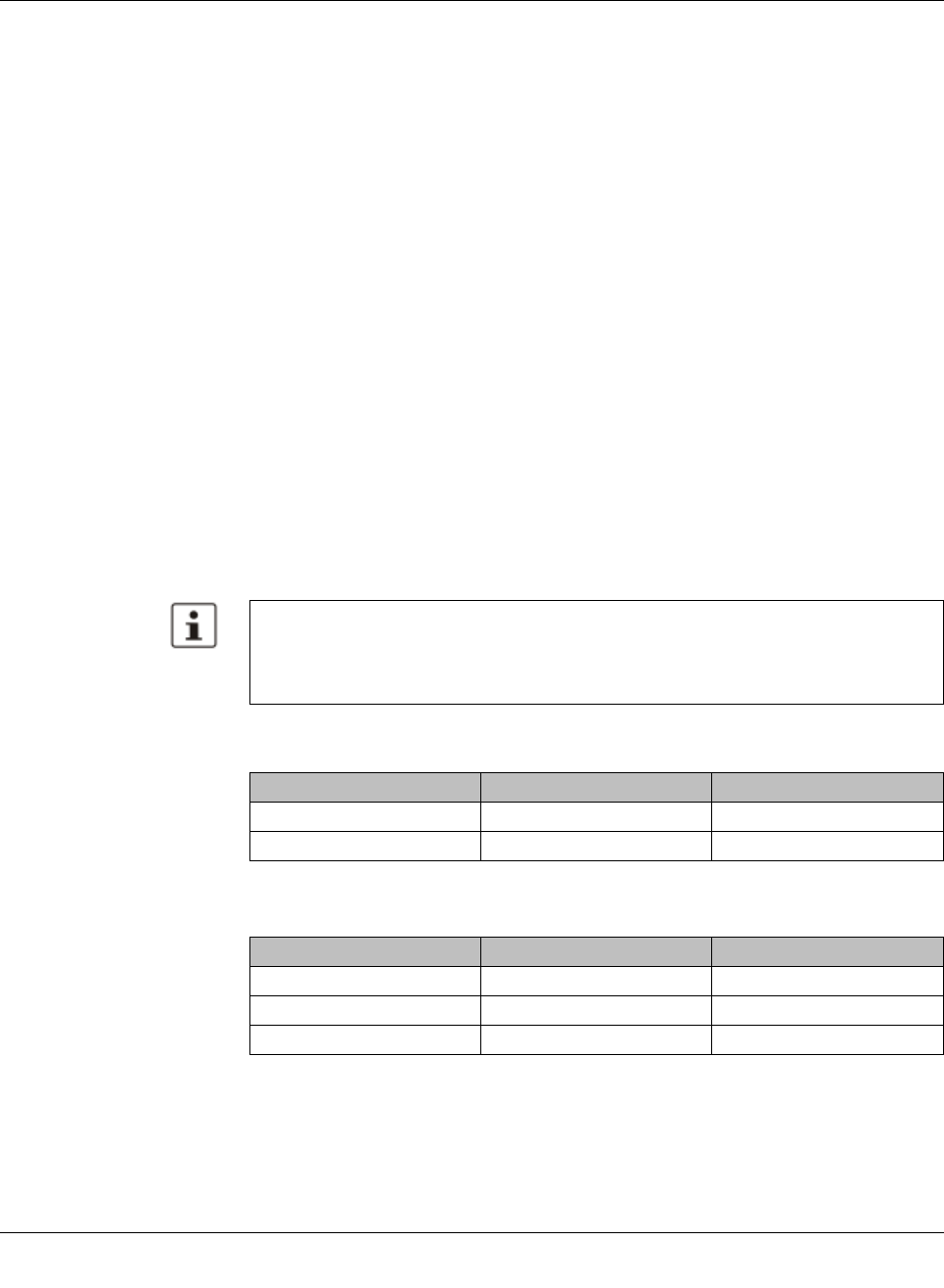
(Rapid) Spanning Tree
8089_en_03 PHOENIX CONTACT 127
– If the root ID, costs, and sender ID are the same, the priority of the sender port is the
decisive criterion.
Selecting a designated switch
For every network, the switch with the most favorable root connection is selected. This
switch is called the designated switch.
The root switch is the designated switch for all directly connected networks.
Selecting a root port
Once the root switch has been specified by processing the root IDs, the switches now spec-
ify the root ports.
The most favorable path is specified by minimizing all connection costs on the path to the
root switch. Transmission speeds can also serve as costs. For the switch, the path costs
added by each port for every HOP (the hop of a data packet from one point to the next) are
preset to a value of 19 (default setting/recommended for 100 Mbps) and can be modified at
any time by the user.
Selecting a designated port
At every “designated switch” the port with the most cost-effective data link in the direction of
the root switch is called the designated port.
Port costs
The port costs can be set according to two different standards, 802.1D (STP) or 801.1W
(RSTP).
If, in addition to Phoenix Contact devices, devices from other manufacturers are used, it
is recommended that the port costs are set according to a uniform standard.
The “dot1dstpPathCostDefault” SNMP object (OID 1.3.6.1.2.1.17.2.18) can be used to
change the standard that is used.
Table5-2 Port costs according to 802.D
Transmission speed Recommended value Recommended range
10 Mbps 100 50 - 600
100 Mbps 19 10 - 60
Table5-3 Port costs according to 802.W
Transmission speed Recommended value Recommended range
10 Mbps 2 000 000 200 000 - 20 000 000
100 Mbps 200 000 20 000 - 2 000 000
1000 Mbps 20 000 2 000 - 200 000

Smart Managed Compact Switch
128 PHOENIX CONTACT 8089_en_03
5.2.5.6 Flow chart for specifying the root path
Figure 5-15 Flowchart for specifying the root path
5.2.5.7 Extended configuration
It may be practical to actively specify the topology that forms from the Spanning Tree Pro-
tocol and not to leave it to the random MAC addresses of the switches involved.
Non-blocking/blocking data paths can thus be influenced and a load distribution specified.
It may also be practical to explicitly deactivate the Spanning Tree Protocol at those ports
that do not participate in Spanning Tree so as to benefit from the fast forwarding function.
The Spanning Tree protocol also must be deactivated at individual ports if two different net-
work segments - both using Spanning Tree - are to be coupled via these ports without the
two tree structures melting to a large Spanning Tree.
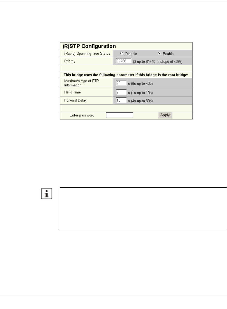
(Rapid) Spanning Tree
8089_en_03 PHOENIX CONTACT 129
Specifying the root switch
The root switch is assigned via the assignment of an appropriate priority for the Spanning
Tree segment. Set the highest priority (lowest value) in the “Priority” field on the “STP Bridge
Configuration” page in WBM for the switch selected as the root switch. Make sure that all
the other network switches have a lower priority (higher value). Here, the set path costs are
not evaluated.
Figure5-16 Specifying the root switch priority
Specifying the root port or designated port
The root port and designated port are always the ports with the lowest path costs. If the
costs are the same, the priority is the decisive criterion. If the priorities are also the same,
the port number is the decisive criterion. Specify an appropriate combination of costs and
priority on the “STP Port Configuration” page in WBM for the port specified as the root port
or designated port. Make sure that all the other network switches either have higher costs
or a lower priority (higher value).
5.2.5.8 Disabling the Spanning Tree Protocol/using the fast forwarding function
One of the following requirements must be met so that the Spanning Tree Protocol can be
disabled for a port:
– A termination device is connected to the port.
– Additional infrastructure components are connected to the port. The corresponding
network segment does not contain any loops.
Additional infrastructure components are connected to the port, forming a Spanning Tree
of their own. No additional redundant connections to this network segment are permitted.
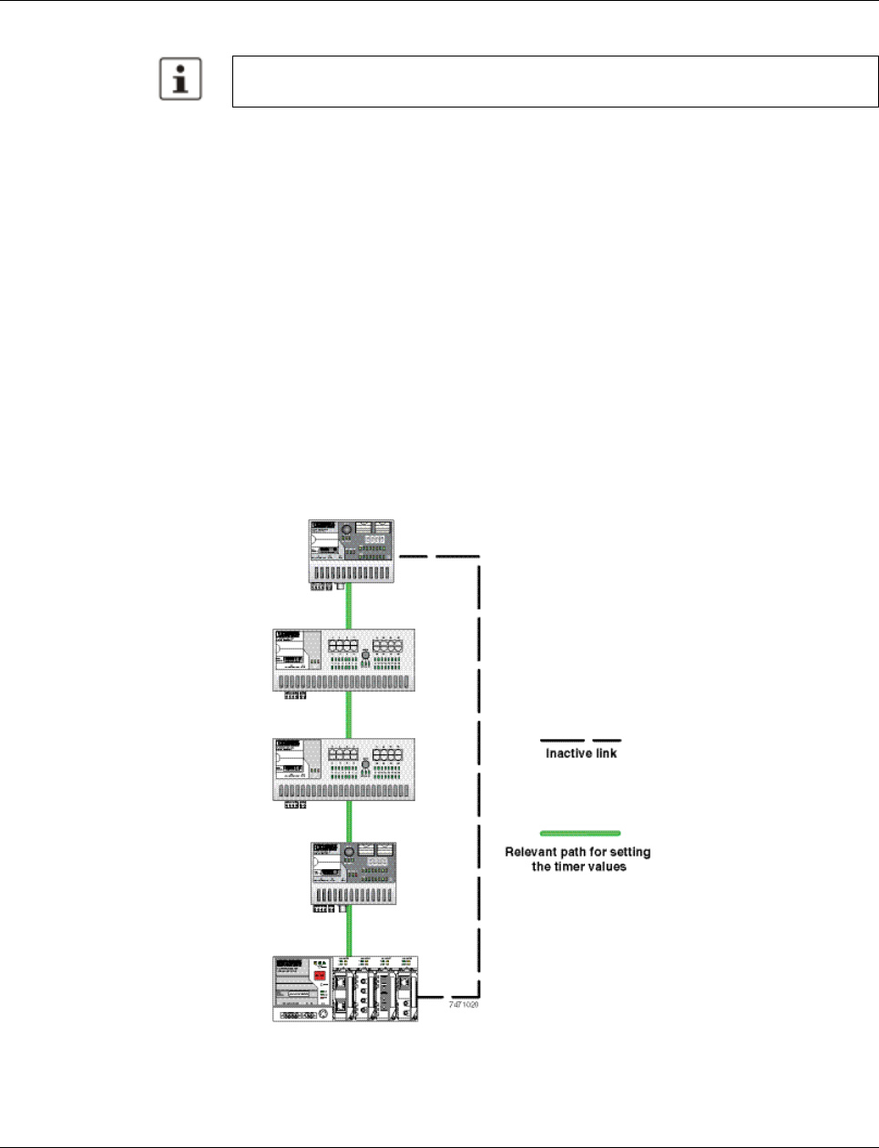
Smart Managed Compact Switch
130 PHOENIX CONTACT 8089_en_03
5.2.5.9 Modifying the protocol timers
It may be necessary to modify the protocol timers if, e.g., there are more than ten active
Spanning Tree components in a single network. You can also try to reduce the reconfigura-
tion times by modifying the timers. However, care should be taken in order to prevent unsta-
ble networks.
Please note that the protocol times are specified by the root switch and that they are distrib-
uted to all devices via BPDU. It is therefore necessary to modify the values in the root switch
at first. If a root switch fails, the timer values of another active STP switch (i.e., the new root
switch) will be valid for the entire network segment. Please remember this during compo-
nent configuration.
Specifying the timer values (STP and RSTP)
– Maximum number of active Spanning Tree components along the path beginning at the
root switch (please refer to the following two example illustrations):
= (MaxAge / 2) - Hello Time + 1
– 2 x (Forward Delay - 1 s) ³ MaxAge
– MaxAge ³ 2 × (HelloTime + 1 s)
The value ((MaxAge / 2) - Hello Time) for a ring topology corresponds to the maximum num -
ber of components with active Spanning Tree.
Figure 5-17 Example 1 of the “relevant path”
Modifying the protocol timers may result in unstable networks.
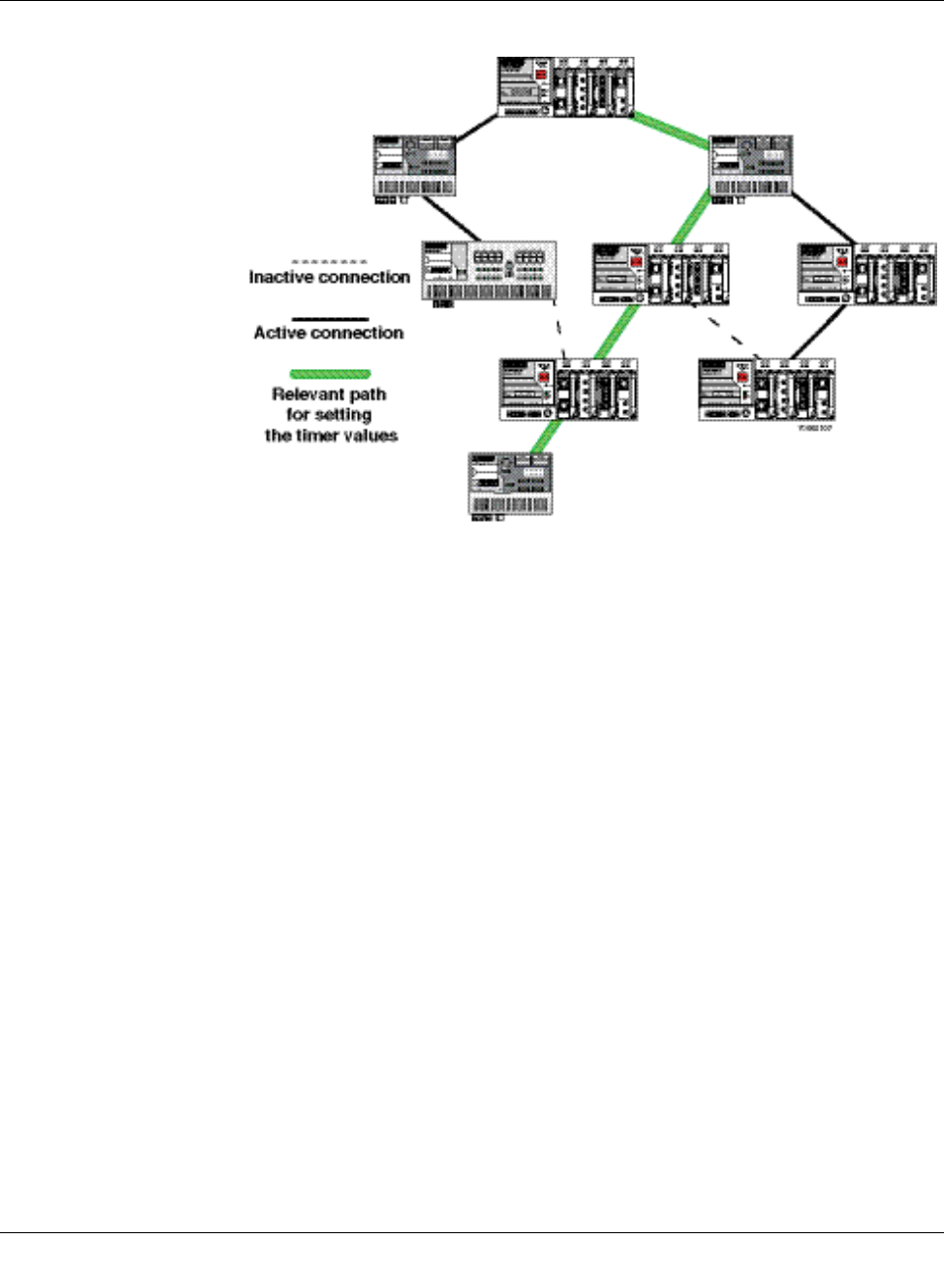
(Rapid) Spanning Tree
8089_en_03 PHOENIX CONTACT 131
Figure5-18 Example 2 of the “relevant path”
5.2.5.10 Reconfiguration times
The reconfiguration time for a Spanning Tree depends on the timer values for MaxAge and
Forward Delay.
The minimum reconfiguration time is: 2 × Forward Delay
The maximum reconfiguration time is: 2 × Forward Delay + MaxAge
For the values recommended by the IEEE standard, the value for ten active STP switches
along a path beginning with the root switch is between 30 s and 50 s.
Switch-over time response to be expected for RSTP and RSTP with activated ring
detection
When usingRSTP, expect switch-over times in the range from 100 ms to 2 s.
When using fast ring detection, expect switch-over times in the range from 100 ms to
500 ms.
The various roles of ports
The root port of a switch connects this switch to the root switch - either directly or via an-
other switch (designated switch).
Thedesignated port is the port at a designated switch that is connected to the root port of
the next switch.
No additional switches/bridges are connected to an edge port. Termination devices are
connected to an edge port.
An alternate port is a path to the root, which, however, did not become a root port. This
means that this port is not part of the active topology.

Smart Managed Compact Switch
132 PHOENIX CONTACT 8089_en_03
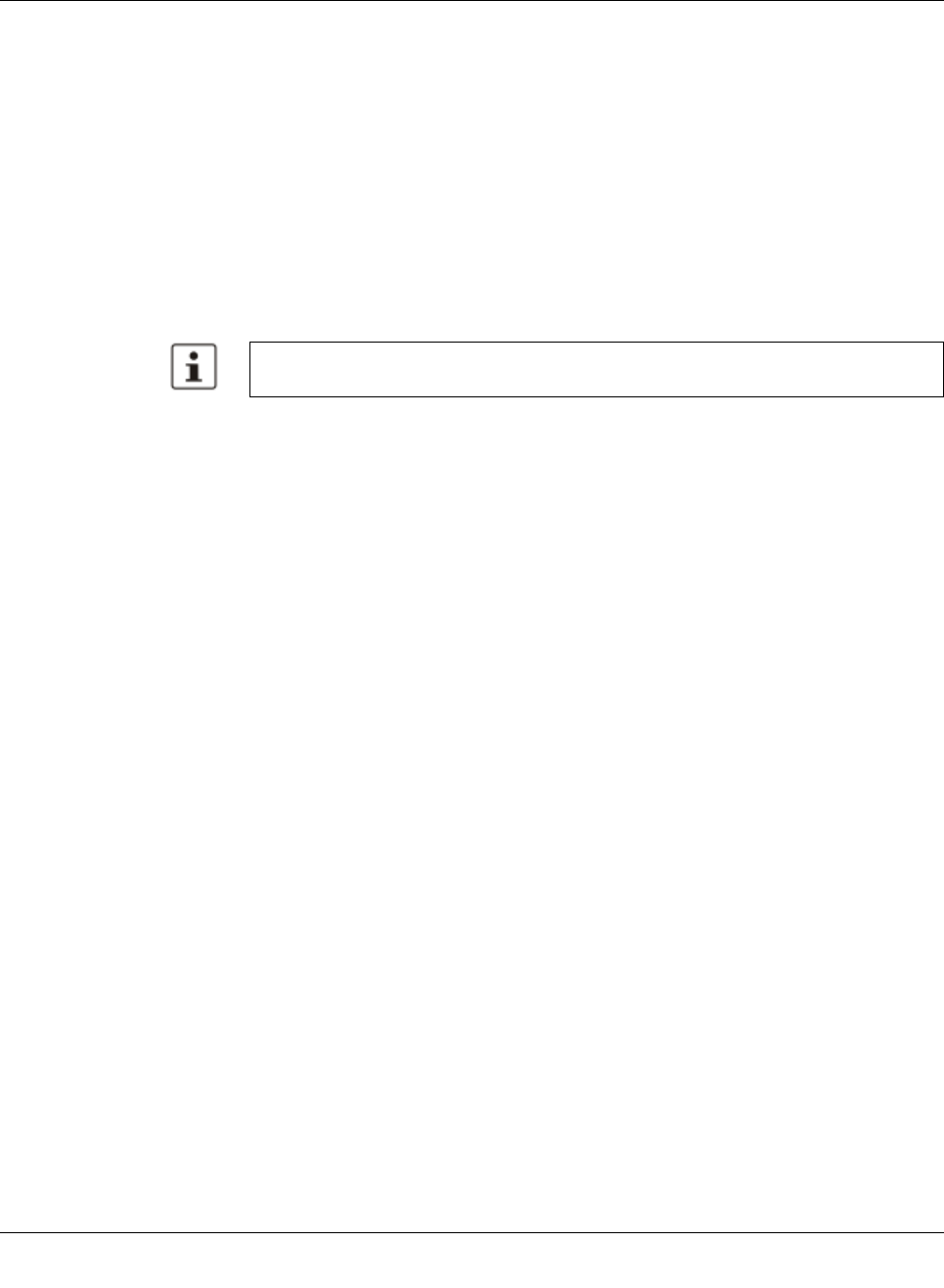
Media Redundancy Protocol (MRP)
8089_en_03 PHOENIX CONTACT 133
6 Media Redundancy Protocol (MRP)
6.1 General function
Loops A ring can be created in the network using MRP according to IEC 62439 and a redundant
connection provided. Each ring must contain an MRP manager, all other devices (in the
ring) must support the MRP client function. The ring is created using dedicated ports. The
MRP ports must be configured in the switch management. When configured correctly, MRP
offers a guaranteed maximum switch-over time of 200 ms.
For the MCS, the necessary MRP manager function can be implemented with the “FL MEM
Plug/MRM” configuration memory (Order No. 2891275).
6.2 MRP manager
For the MMS/MCS, the MRP manager function is provided by an interface module/MEM
plug. Since the manager function is linked to a replaceable module, the following options are
available:
– If no manager module is present, “MRP Manager” mode is not available or cannot be
selected.
– If a manager function module is inserted during runtime or if it is already present during
the boot process, “MRP Manager” mode is available or accepted in the user interfaces.
– If a manager function module is present during the boot process and “MRP Manager”
mode is activated in the saved configuration of the MMS/MCS, the MRP manager func-
tion is automatically enabled.
– If no manager function module is present during the boot process and the MRP manag-
er is enabled in the saved configuration, the device activates a “safe state”, in which one
of the ring ports is set to blocking mode to prevent loop generation. An error message
appears, which would also be displayed in the event of a ring error, informing the user
of this configuration error. After inserting the manager function module, the manager
can be re-enabled manually or a reboot executed.
– If a manager function module is removed during runtime, the MRP manager can no lon-
ger be selected.
– If a manager function module is removed while the MRP manager is active, the mode
remains active until the device is restarted or is switched to another mode (MRP client,
disabled).
Please note that MRP is disabled by default upon delivery.
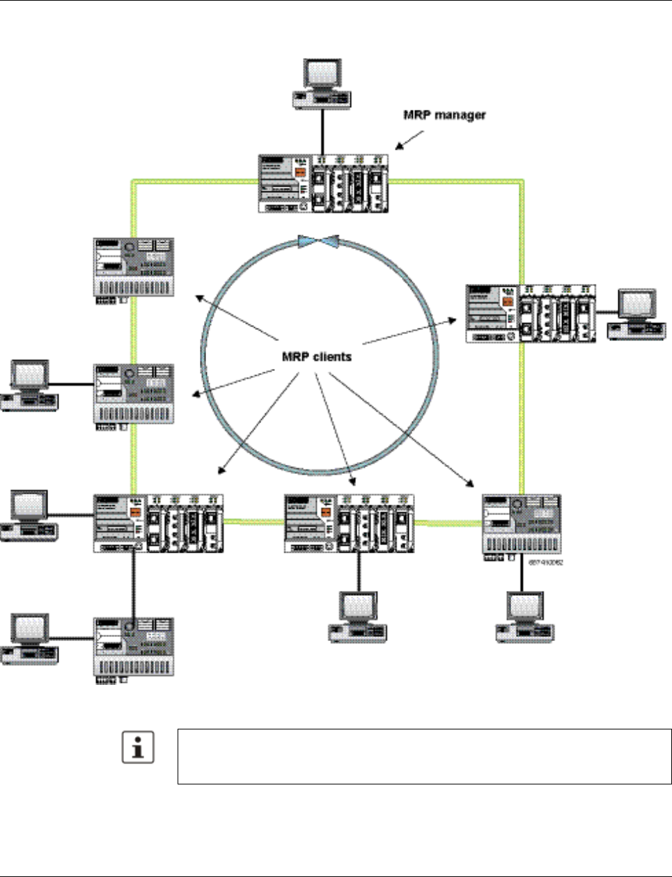
Smart Managed Compact Switch
134 PHOENIX CONTACT 8089_en_03
6.2.1 Network examples
Figure 6-1 Example of an MRP ring
Make sure that the topology used does not contain an invalid mixture of RSTP and MRP,
e.g., by additionally coupling two of the devices through an RSTP connection rendering
them redundant.
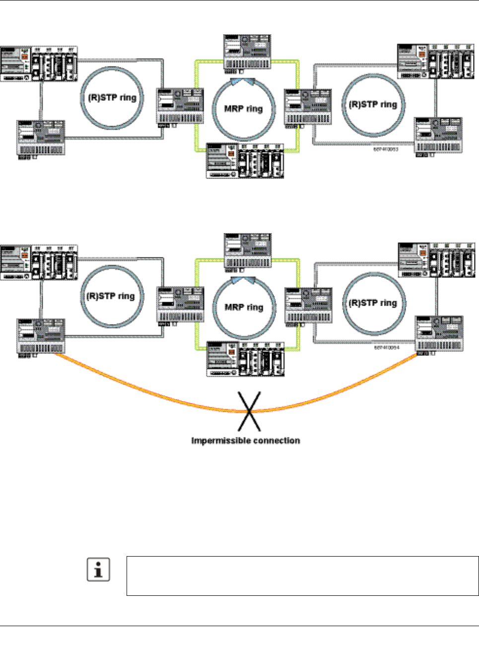
Media Redundancy Protocol (MRP)
8089_en_03 PHOENIX CONTACT 135
6.2.1.1 Example of a permissible network with MRP and (R)STP
Figure6-2 Permissible example of MRP with (R)STP
6.2.1.2 Example of an impermissible network with MRP and (R)STP
Figure6-3 Impermissible example
6.3 Enabling web pages for using MRP in WBM
Activate WBM for the switches, e.g., using Factory Manager. Switch to the “General Con-
figuration” menu, then select the “User Interfaces” page. Activate “Redundancy” and con-
firm by entering your password.
Activating “Redundancy” under “General Configuration, User Interfaces” does not acti-
vate a redundancy mechanism. In the WBM menu, the “Media Redundancy” page - under
which the function can be configured and activated - is enabled.
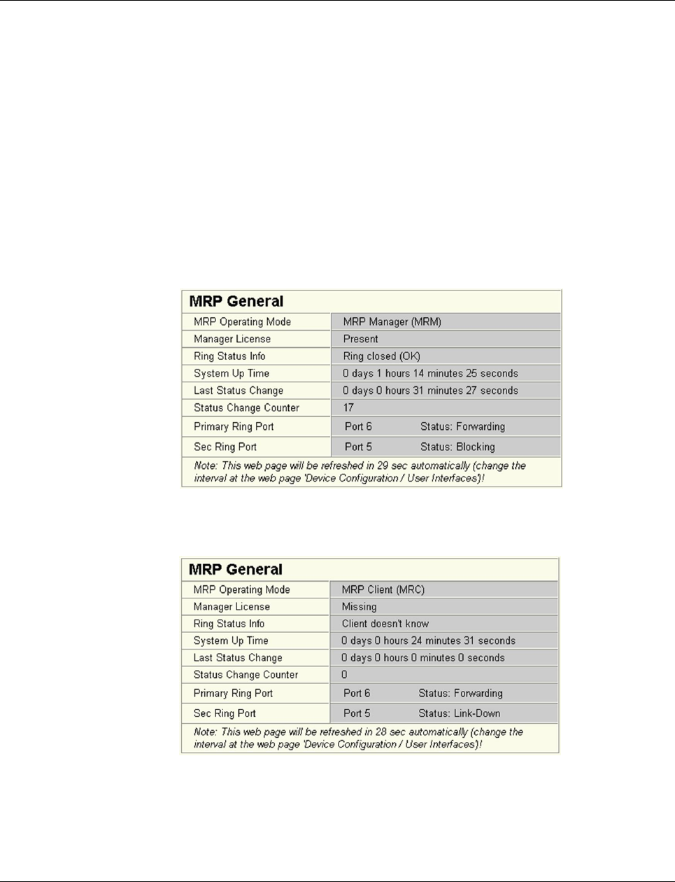
Smart Managed Compact Switch
136 PHOENIX CONTACT 8089_en_03
6.4 Configuration of MRP
6.4.1 MRP general
The “MRP General” web page shows the current parameters set for using the protocol. The
following information is displayed:
– Operating mode (disabled, MRP client or MRP manager)
– Manager function (present or missing)
– Ring status if the switch is operating as an MRP manager (OK (ring closed) or Fail (ring
open))
– Topology modification counter
– Time of last topology modification
– Ring port numbers and status of the ports (Forwarding or Blocking)
Figure 6-4 “MRP General” web page for an MRP manager
Figure 6-5 “MRP General” web page for an MRP client
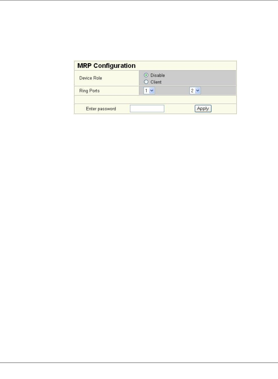
Media Redundancy Protocol (MRP)
8089_en_03 PHOENIX CONTACT 137
6.4.2 MRP configuration
The “MRP Configuration” web page is used to configure the protocol parameters. The fol-
lowing configuration parameters are displayed:
– Device role (disabled, MRP client or MRP manager)
– Selection of the ring ports that are integrated in the MRP ring
– Selection of the VLAN ID for tagging mode
Figure6-6 “MRP Configuration” web page
6.4.2.1 Using MRP in VLAN mode
When using VLANs, a standard tag with the highest priority is assigned to the MRP packets.
In addition, a VLAN ID can be specified in the MRP configuration. Only static VLAN entries,
which are listed in WBM under “Switch, VLAN, Static VLAN”, can be used. The tag is only
added to the MRP packet if the port to which the MRP packet is sent is operating in tagging
mode.

Smart Managed Compact Switch
138 PHOENIX CONTACT 8089_en_03
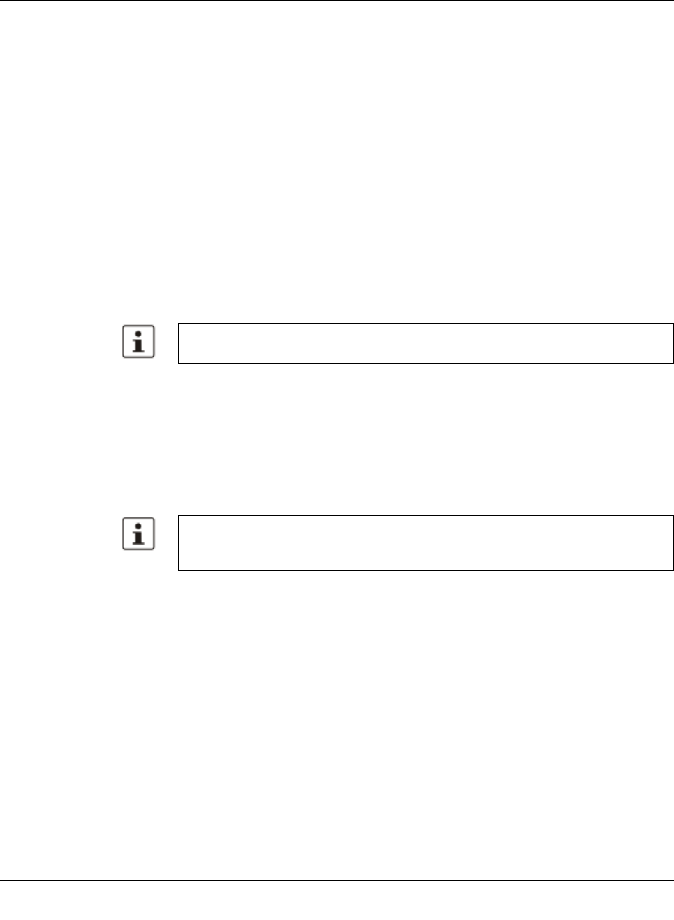
Multicast filtering
8089_en_03 PHOENIX CONTACT 139
7 Multicast filtering
7.1 Basics
Multicast Multicast applications, unlike unicast applications with point-to-point communication, do not
transmit their data with the MAC address of the destination, but with an independent multi-
cast group address. Always using wireless communication, a station transmitsone data
packet that is received by one or more receiving stations.
Advantages:
1If, for example, a data packet of a transmitter is to be transmitted to eight receivers, the
same packet does not have to be sent eight times to the addresses of all eight devices.
Instead it only needs to be sent once to the address of the multicast group that includes
the eight devices.
2When using multicast communication and filtering, the bandwidth requirement for data
transmission is reduced because each packet is only transmitted once.
7.2 Enabling the web pages for multicast filtering in
WBM
Activate WBM for the switches, e.g., using Factory Manager. Switch to the “General Con-
figuration” menu, then select the “User Interfaces” page. Activate “Multicast Filtering” and
confirm by entering your password.
7.3 Static multicast groups
Static multicast groups must be created manually on every switch, and all ports that are
used to contact group members need to be added. The advantages of static groups are:
1Easy specification of network paths on which the multicast data traffic of known groups
is limited.
2No querier required (see “Query” on page 145).
The following marginal conditions must be observed:
– Precise network documentation for path specification is required.
– Possible redundant paths due to Spanning Tree must be taken into account during port
assignment.
– For network modifications and, during servicing or expansion, the multicast data paths
must be restored.
A maximum of 128 multicast groups can be created automatically for IGMP snooping. In
addition, a maximum of 20 static groups can be created.
When activating “Multicast Filtering” under “General Configuration, User Interfaces”, the
multicast mechanism is not activated. In the WBM menu, the “Multicast” page - under
which the function can be configured and activated - is enabled.
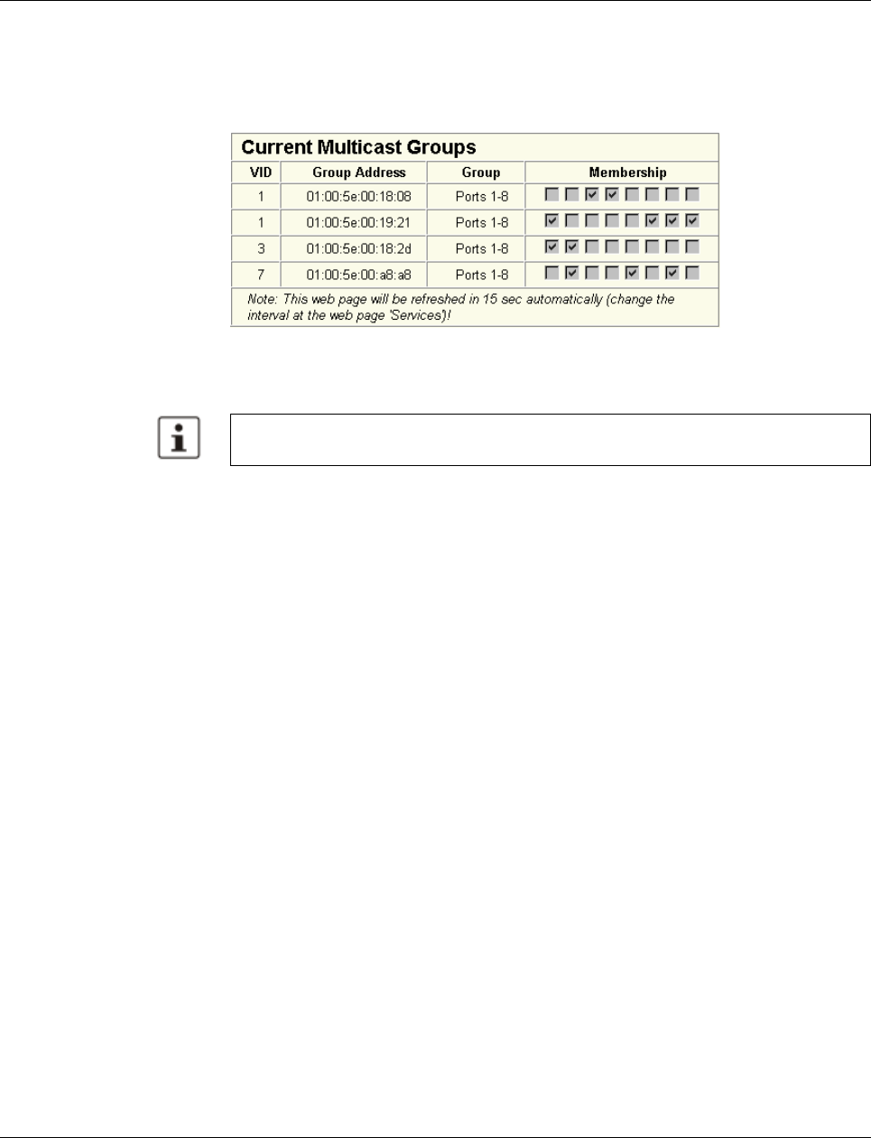
Smart Managed Compact Switch
140 PHOENIX CONTACT 8089_en_03
7.3.1 “Current Multicast Groups” web page
The table on this web page provides an overview of the current multicast groups created on
this MMS. These include multicast groups assigned as a result of IGMP snooping and
groups that are statically created.
Figure 7-1 “Current Multicast Groups” web page
The checkboxes indicate which port has been assigned to each individual group.
The overview for group membership is based on the “dot1qTpGroupTable” SNMP group.
This table contains all groups (static entries and IGMP) and their members.
7.3.2 Creating static multicast groups
This web page is used to create and manage statically configured multicast groups. In order
to create a multicast group, enter the MAC address provided (see “Multicast addresses” on
page 142) for the multicast group in the “Multicast Group Address” field, add the ports of the
data paths to the group members, and confirm these entries by entering a valid password.
If a group address is entered as an IP address, the IP address is converted into a multicast
MAC address according to the specifications of IEEE 802.1 D/p.
Overwriting a dynamic group with a static configuration means that a new port assignment
for this group cannot be created dynamically. Port assignment for this group can only be
started dynamically once the group has been deleted.
Conversion The guidelines for converting a multicast IP addresses into a multicast MAC address require
mapping of different IP groups to the same MAC group. Avoid the use of IP groups that
– Do not differ in the first and second byte from the right
– Differ by 128 in the third byte from the right
Please note that all multicast groups that are known to the switch, including the dynami-
cally detected groups that were not created manually, are shown on this web page.
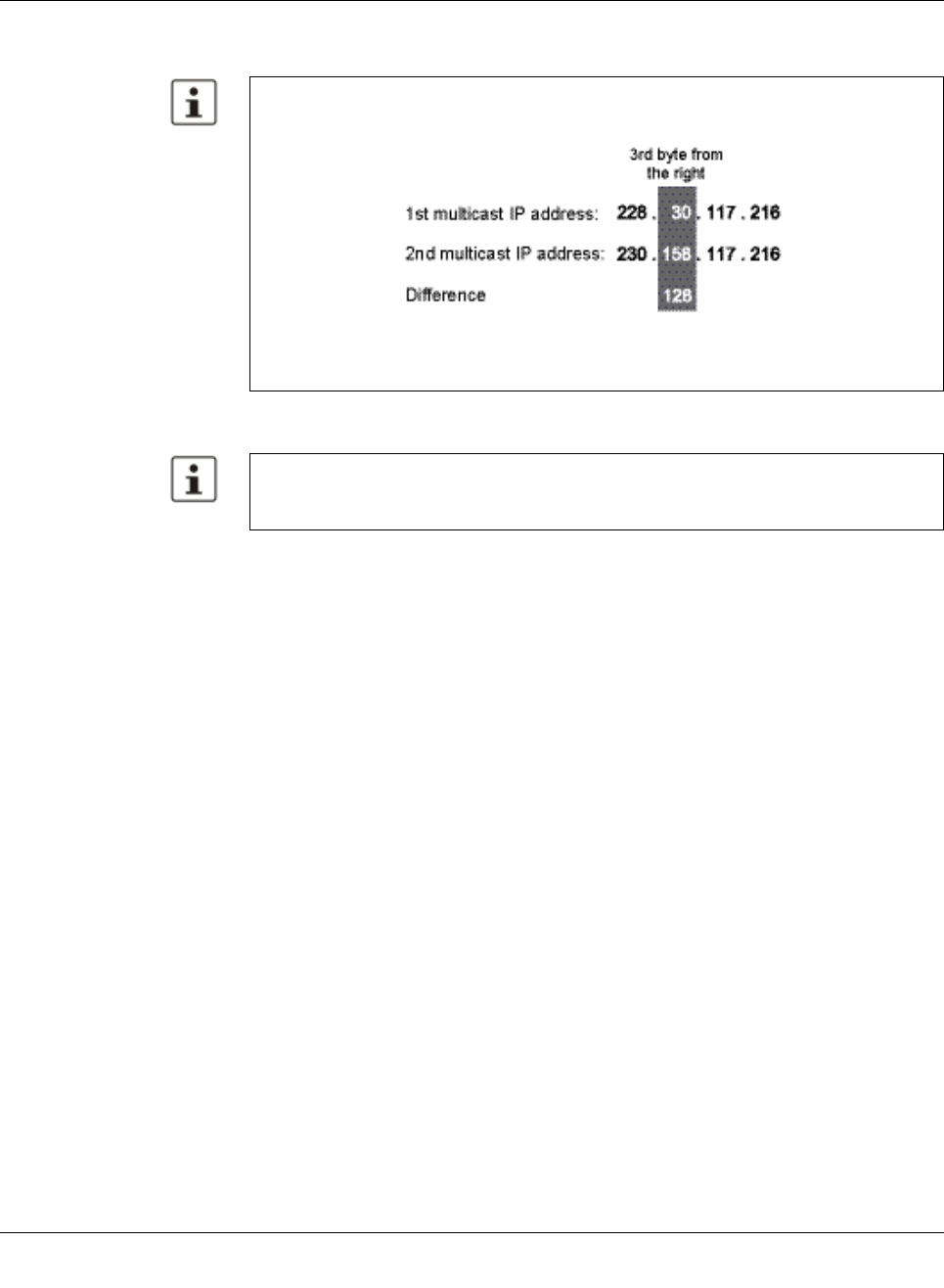
Multicast filtering
8089_en_03 PHOENIX CONTACT 141
The fourth byte from the right is always replaced by 01:00:5e during conversion. See ex-
ample below:
The group is added to the list of existing static multicast groups. This list, which is displayed
in a list box, is referred to as “dot1qStaticMulticastTable” in SNMP.
Port assignment After entering a new group in the “Multicast Group Address” field, add the ports of the group
members by selecting the corresponding checkboxes. Confirm by entering your password
and clicking on “Apply”.
Because of the conversion from IP to MAC addresses, you should avoid using IP address-
es that differ by 128 in the third byte from the right. Example:
Both multicast IP addresses are converted into multicast MAC address
01:00:5e:1e:75:d8.
Settings are not automatically saved permanently. The active configuration can be saved
permanently by selecting “Save current configuration” on the “Configuration Manage-
ment” web page.
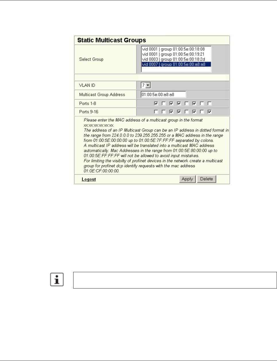
Smart Managed Compact Switch
142 PHOENIX CONTACT 8089_en_03
Modifying
assignment Select the corresponding group in the “Select Group” list box to modify or delete the port as-
signment. The group members are indicated by activated checkboxes and can be modified,
if required. An action is completed by entering a password and clicking on “Apply” or “De-
lete”.
Figure 7-2 “Static Multicast Groups” menu
Checking the group as-
signment In order to check which ports are assigned to which group, select one of the existing groups.
The corresponding MAC address is then displayed in the “Multicast Group Address” text
field. The members of the group are indicated by the activated checkboxes.
Multicast addresses
Do not use multicast MAC addresses that are in the range from 01:00:5e:80:00:00 to
01:00:5e:FF:FF:FF.
Incorrect format An incorrect MAC address format and the entry of “non-multicast addresses” is indicated,
and the entry is not permitted.
7.3.3 Procedure for creating a multicast group
Gain an overview of the multicast applications available within the network and the multicast
addresses used. Create a group for every multicast application or for the multicast address
used, and for each switch add the ports to which a device of the appropriate group is directly
connected or via which the device can be accessed.
Please note that in multicast MAC addresses the bytes are separated by a colon (:) and
in IP multicast addresses are separated by a full stop (.).
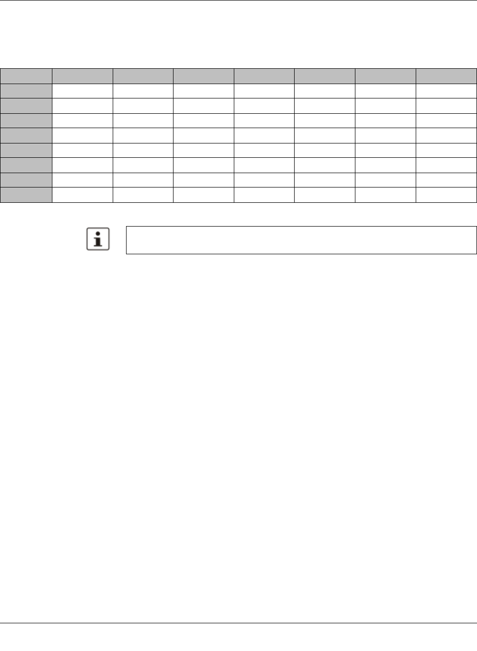
Multicast filtering
8089_en_03 PHOENIX CONTACT 143
Example In the following table, the ports (for each switch) to which the receivers of the multicast data
are connected are indicated with an “X”. See an example configuration in Figure 7-3 on
page 144
Table7-1 Multicast port assignment on the switches
Switch 1 Switch 2 Switch 3 Switch 4 Switch 5 Switch 6 Switch 7
Port 1
Port 2 X X X X X X X
Port 3
Port 4 X X
Port 5 X
Port 6 X
Port 7 X
Port 8 X X
Please note that possible redundant paths resulting from Rapid Spanning Tree must be
taken into consideration for multicast group creation.
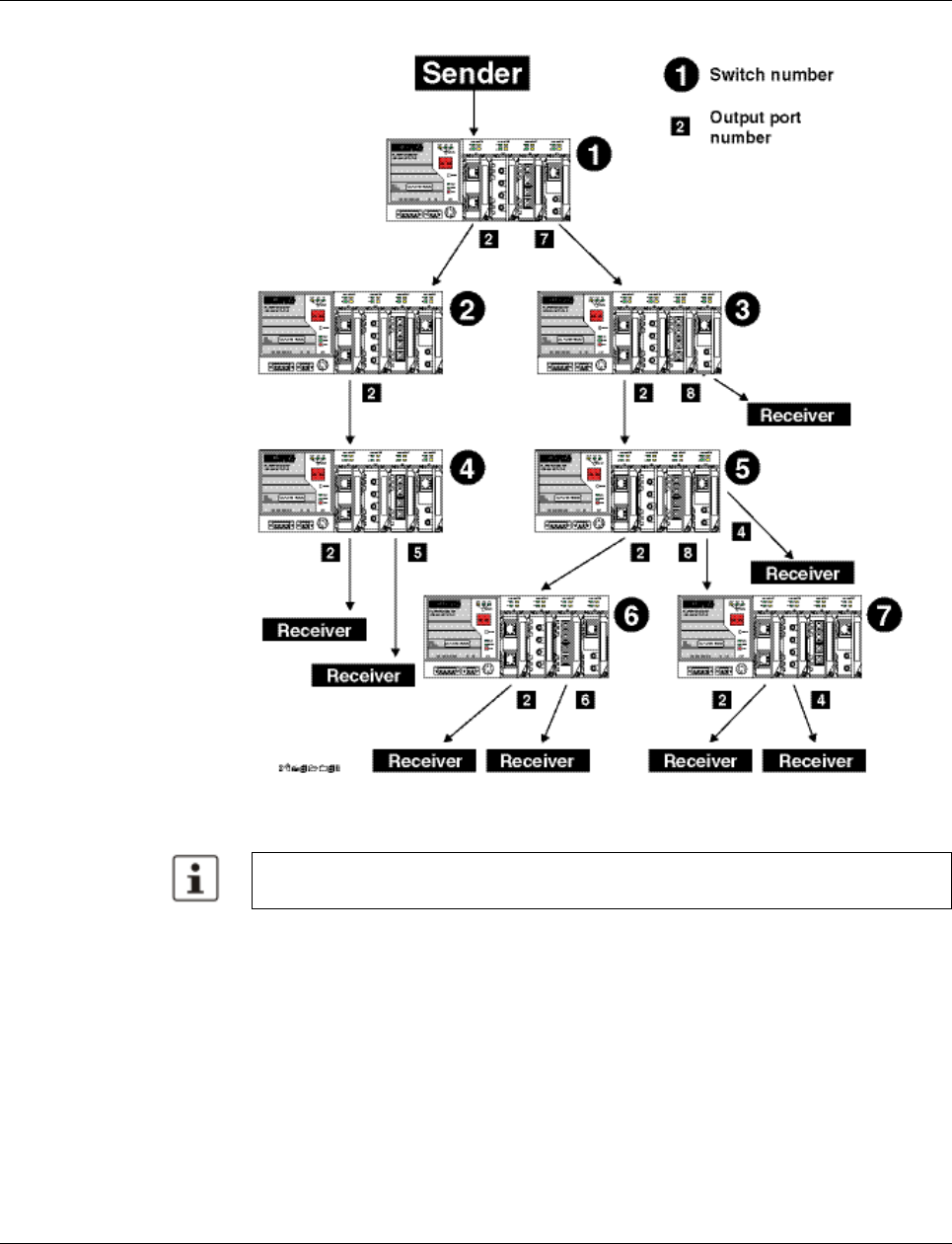
Smart Managed Compact Switch
144 PHOENIX CONTACT 8089_en_03
Figure 7-3 Configuration example
7.4 Dynamic multicast groups
7.4.1 Internet Group Management Protocol (IGMP)
IGMP on Layer 3 The Internet Group Management Protocol describes a method for distributing information
via multicast applications between routers and terminal devices at IP level (Layer 3).
Possible redundant paths resulting from Rapid Spanning Tree must be taken into consid-
eration for multicast group creation.

Multicast filtering
8089_en_03 PHOENIX CONTACT 145
When starting a multicast application, a network device transmits an IGMP membership re-
port and thus announces its membership of a specific multicast group. A router collects
these membership reports, maintaining in this way the multicast groups of its subnetwork.
Query At regular intervals, the router sends IGMP queries. This prompts the devices with multicast
receiver applications to send another membership report.
The router enters the IP multicast group address from the report message in its routing ta-
ble. This means that frames with this IP multicast group address in the destination address
field are only transferred according to the routing table. Devices that are no longer members
of a multicast group log out with a leave message (IGMP Version 2 or later) and no longer
send report messages.
The router also removes the routing table entry if it does not receive a report message within
a specific time (aging time). If several routers with active IGMP query function are connected
to the network, they determine among themselves which router performs the query function.
This depends on the IP addresses, as the router with the lowest IP address continues to op-
erate as the querier and all the other routers no longer send query messages. If these rout-
ers do not receive a new query telegram within a specific period of time, they themselves
become queriers again. If there are no routers in the network, a suitably equipped switch
can be used for the query function. Please note that the MMS/MCS only operates as the
IGMP querier in the management VLAN.
IGMP snooping A switch that connects a multicast receiver with a router can read and evaluate IGMP infor-
mation using the IGMP snooping method. IGMP snooping translates IP multicast group ad-
dresses into multicast MAC addresses, so that the IGMP function can also be detected by
Layer 2 switches. The switch enters the MAC addresses of the multicast receivers, which
were obtained from the IP addresses by IGMP snooping, in its own multicast filter table.
Thus the switch filters multicast packets of known multicast groups and only forwards pack-
ets to those ports to which corresponding multicast receivers are connected.
IGMP snooping can only be used on Layer 2 if all terminal devices send IGMP messages.
The IP stack of multicast-compatible terminal devices with applications linked to a multicast
address automatically sends the relevant membership reports.
IGMP snooping operates independently of the Internet Group Management Protocol
(IGMP).
The “IGMP Query” function only transmits in the management VLAN and only stops if
there is a better querier in the management VLAN.
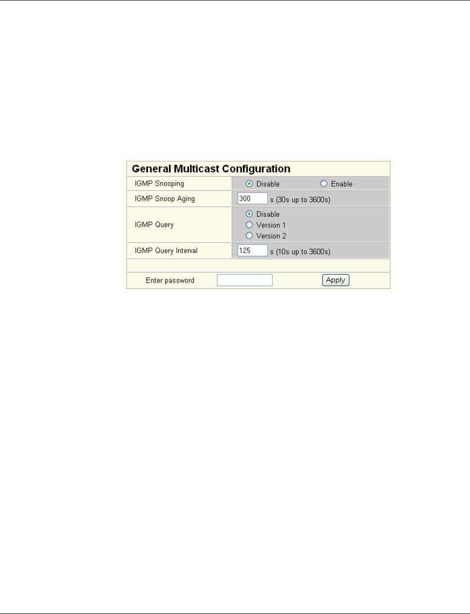
Smart Managed Compact Switch
146 PHOENIX CONTACT 8089_en_03
7.4.1.1 Extended multicast filtering
If IGMP snooping is active, multicast data streams for which no membership reports of pos-
sible recipients are registered are also detected. For these multicasts, groups are created
dynamically. These multicasts are forwarded to the querier, i.e., the querier port is entered
in the group.
If the switch itself is the querier, these multicasts are blocked.
7.4.2 “General Multicast Configuration” web page
This web page provides global settings for multicast support. Here, IGMP snooping can be
activated and an aging time specified for IGMP snooping information.
Figure 7-4 “General Multicast Configuration” web page
IGMP snooping
In IGMP snooping, the switch passively listens in on the IGMP messages that are sent over
the network and dynamically creates the appropriate groups. The groups are not saved and
will be lost during every power down or when the snooping function is switched off.
IGMP query
An MMS/MCS with activated query function actively sends queries at the “Query Interval”
and evaluates the received reports. The MMS/MCS only sends IGMP query reports if IGMP
snooping is enabled and only in the management VLAN.
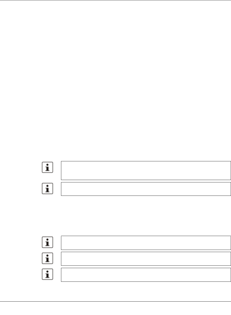
Virtual Local Area Network (VLAN)
8089_en_03 PHOENIX CONTACT 147
8 Virtual Local Area Network (VLAN)
8.1 Basics
VLAN A VLAN is a closed network, which is separated logically/functionally rather than physically
from the other networks. A VLAN creates its own broadcast and multicast domain, which is
defined by the user according to specified logical criteria. VLANs are used to separate the
physical and the logical network structure.
– Data packets are only forwarded within the relevant VLAN.
– The members of a VLAN can be distributed over a large area.
The reduced propagation of broadcasts and multicasts increases the available bandwidth
within a network segment. In addition, the strict separation of the data traffic increases sys-
tem security.
A router or similar Layer 3 device is required for data traffic between VLANs.
For the switch, the VLANs can be created statically.
8.2 Enabling the VLAN web pages in web-based man-
agement
Start web-based management for the switches, e.g., using Factory Manager, switch to the
“General Configuration” menu, then the “User Interfaces” page. Activate the “VLAN” func-
tion and confirm by entering your password.
8.2.1 Management VLAN ID
The management of the switch is assigned to VLAN 1 by default upon delivery. In addition,
all ports are assigned to VLAN 1 by default upon delivery. This ensures that the network-
supported management functions can be accessed via all ports.
When activating “VLAN” under “User Interfaces”, the VLAN mechanism is not activated.
In the WBM menu, the “VLAN” page - under which the function can be configured and ac-
tivated - is enabled.
When deactivating the VLAN configuration pages under “User Interfaces”, the VLAN
mechanism is not deactivated. The saved VLAN configuration is retained.
Make sure that the switch is always managed in a VLAN that you can also access.
VLAN ID 1 cannot be deleted and is thus always created on the switch.
If you delete the VLAN in which the switch is managed, management is automatically
switched to VLAN 1.
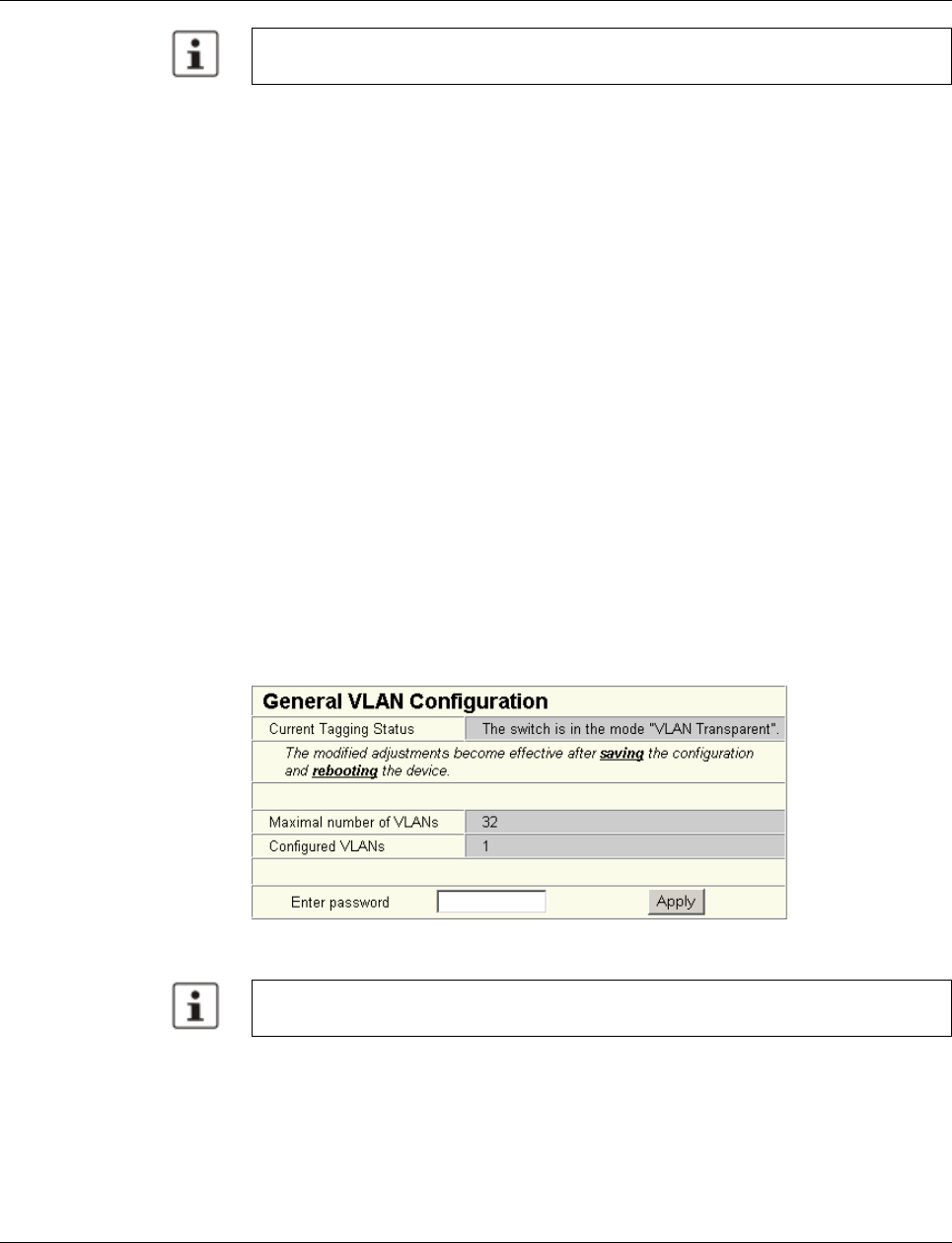
Smart Managed Compact Switch
148 PHOENIX CONTACT 8089_en_03
8.2.2 Changing the management VLAN ID
8.2.2.1 Configuration in transparent mode
1In WBM, enable the pages for VLAN configuration (WBM: User Interfaces, Virtual LAN).
2Create the required VLANs on the “Static VLANs” web page.
3On the “VLAN Port Configuration Table” web page, assign the ports for incoming pack-
ets to individual VLANs using the VLAN ID.
4On the “IP Configuration” web page, the desired management VLAN ID can now be set.
5On the “General VLAN Configuration” web page, set the switch to “Tagging” VLAN
mode.
6Save the configuration on the “General Configuration, Configuration Management” web
page and restart the switch.
8.3 General VLAN configuration
Basic settings for VLAN operation can be made on the “Switch Station, VLAN, General
VLAN Configuration” web page.
Transparent In “Transparent” mode, the switch processes the incoming data packets as described in
Section “Frame switching” (see Section 3.3 on page 22). Neither the structure nor the con-
tents of the data packets is changed. The information about VLAN assignment from a tag
that may be contained in the data packet is ignored.
Figure 8-1 “General VLAN Configuration” menu
The “IGMP Query” function only transmits in the management VLAN and only stops if
there is a better querier in the management VLAN.
The switch supports a maximum of 32 different VLANs.
Virtual Local Area Network (VLAN)
8089_en_03 PHOENIX CONTACT 149
8.4 Current VLANs
The “Current VLANs” web page provides an overview of the VLANs currently set up. In ad-
dition, refer to the table for the VLAN in which the switch is actually managed. All static
VLANs are listed here. A distinction is made between untagged (U) group members and
non-members (-) (see possible states on page 150).
Figure8-2 “Current VLANs” web page
When the maximum number of set up VLANs is reached, the following text appears below
the key for the member states: “The switch supports only 32 VLANs! Further VLANs will be
refused!”
VLAN 1 is always created statically and all ports are added to it as untagged members.
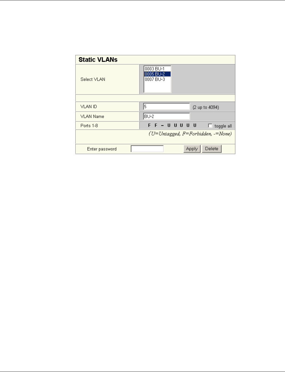
Smart Managed Compact Switch
150 PHOENIX CONTACT 8089_en_03
8.4.1 Static VLANs
Static VLANs can be created on this web page. Up to 31 new VLANs can be created
(VLAN 2 to VLAN 32). If more are created, a corresponding message will be displayed.
VLAN 1 is always created statically and all ports are added to it as untagged members. By
default upon delivery, network-based management interfaces (WBM, Telnet, and SNMP)
are available from VLAN 1.
Figure 8-3 “Static VLANs” menu
On this web page you can create static VLANs by assigning a VLAN ID and VLAN name.
The ports are then assigned to the individual VLANs by selecting the relevant VLAN and
clicking on the character in the “Ports 1-8” line that indicates the current port status. Various
options are selected by clicking on the status several times. By selecting “toggle all”, all
available ports in the relevant port group change their status.
The possible states are:
U = Untagged
Ports with “Untagged” status belong to the selected VLAN and packets are sent to this port
without VLAN tag. An “Untagged” port cannot belong to multiple VLANs - otherwise there is
no logical division (except VLAN 1)
F = Forbidden
Ports with the “Forbidden” status do not belong to the selected VLAN and cannot be added
dynamically to this VLAN via GVRP.
- = None
Ports with “None” status are not integrated into the VLAN.
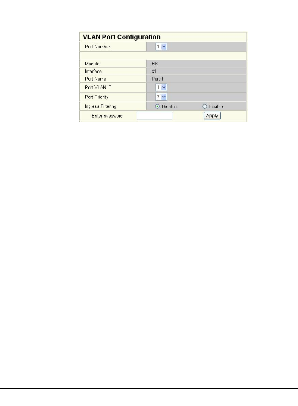
Virtual Local Area Network (VLAN)
8089_en_03 PHOENIX CONTACT 151
8.4.2 VLAN port configuration
Port-specific VLAN settings can be made on this web page.
Figure8-4 VLAN port configuration
If “Ingress Filtering” is set to “Enable”, the switch rejects data packets received at this port if
the port is not a “tagged member” or “untagged member” of the VLAN with the VLAN ID con-
tained in the tag of the packet.
Port priority
– A corresponding tag indicating the priority is added to packets without tags.
Port VLAN ID
– Assignment of received, untagged packets to a VLAN. The corresponding VLAN ID
must be set for the ports that are “untagged members” of a VLAN (see “Example: Com-
munication between termination devices via VLAN” on page 153).
Only IDs of existing VLANs can be set as the port VLAN ID. If a VLAN is deleted, all port
VLAN IDs that are set to this VLAN are reset to the default VLAN ID “1”.
8.4.3 VLAN port configuration table
This web page provides an overview of the main VLAN settings for the ports. Clicking on the
relevant port number opens the “VLAN Port Configuration” web page, where the settings
can be modified.
This table can be used to assign incoming packets to the created VLANs if the packets
reached the port without a VLAN tag.
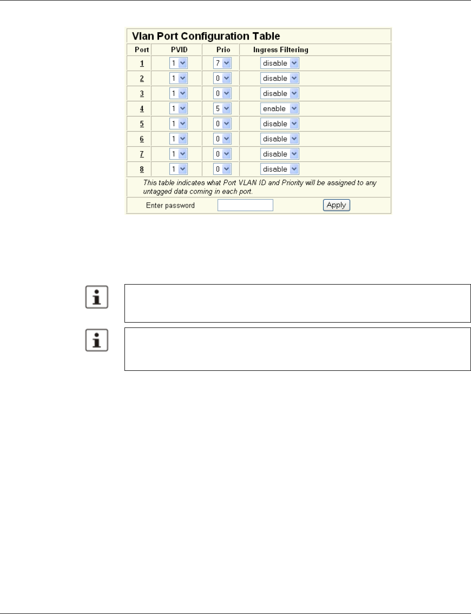
Smart Managed Compact Switch
152 PHOENIX CONTACT 8089_en_03
Figure 8-5 “Vlan Port Configuration Table” menu
8.5 Setting up static VLANs
In order to set up a VLAN, the switches involved must be configured accordingly. In the fol-
lowing example, data traffic is to be enabled in VLAN 5 between termination devices A
and B.
Security recommendation: Instead of using VLAN 1 for management, it is recommended
that a new separate VLAN is created for management. Ensure that the administrator has
access to this VLAN.
Warnings displayed when setting up/configuring VLANs indicate configuration errors:
– An “untagged” port belongs to multiple VLANs.
The port assignment (untagged) and PVID do not match.
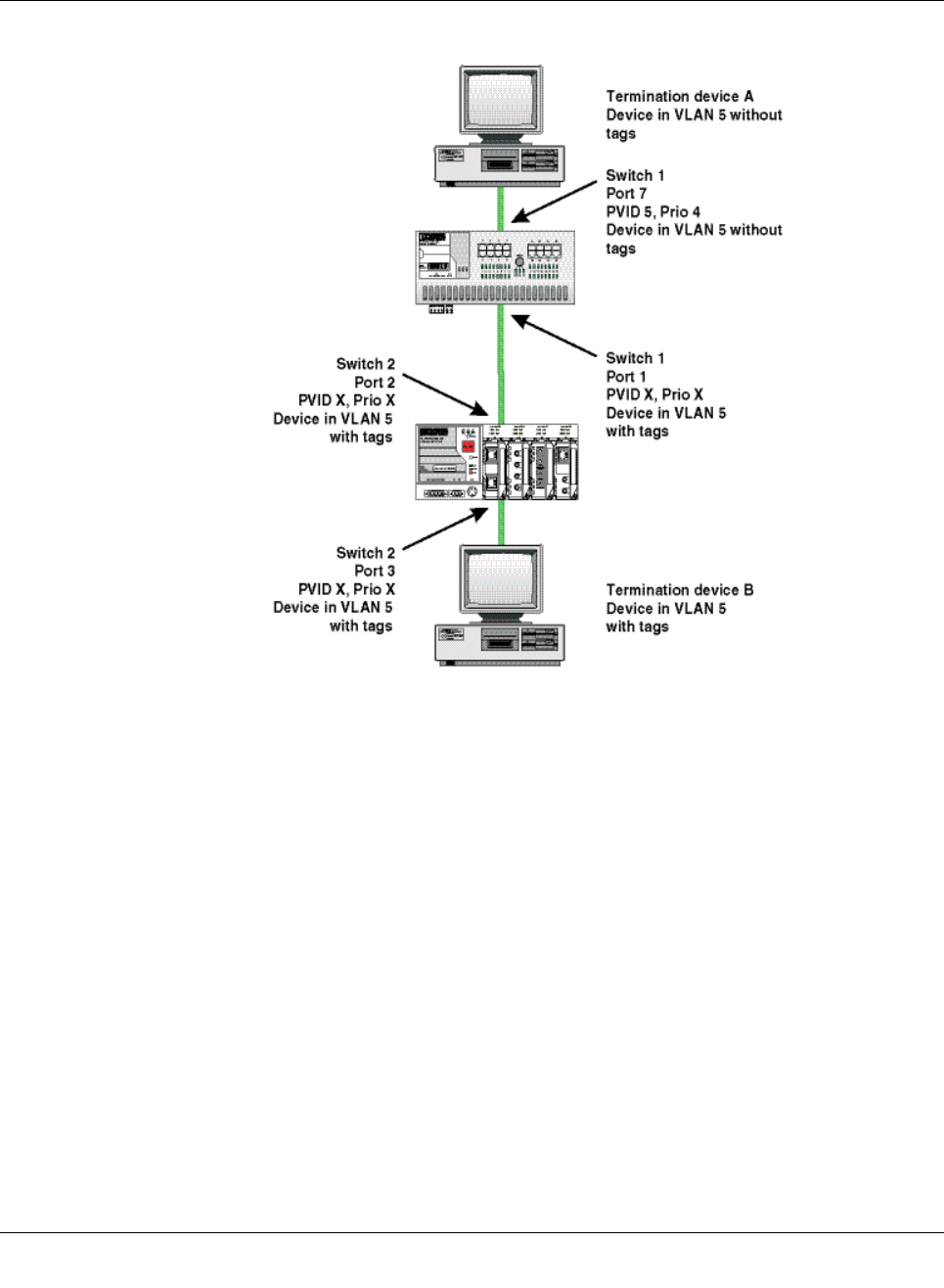
Virtual Local Area Network (VLAN)
8089_en_03 PHOENIX CONTACT 153
Figure8-6 Example: Communication between termination devices via VLAN
Switch configuration
1Set both switches to “VLAN Tagging” mode, save, and restart the devices.
2Create VLAN 5 on switch 1 and specify port 7 as an “untagged” member and port 1 as
a “tagged” member.
3For port 7 at switch 1, set the port VLAN ID to 5 and the port priority to any.
4On switch 2, set up port 2 and port 3 as “tagged” members of VLAN 5.
Both termination devices now communicate via the network path shown in the example
without other switch ports forwarding the broadcast packets for both termination devices, for
example.
8.6 VLAN and (R)STP
When using (R)STP and VLAN simultaneously, please note the following:
– (R)STP is not based on VLANs.
– (R)STP creates a loop-free topology in the form of a tree structure.
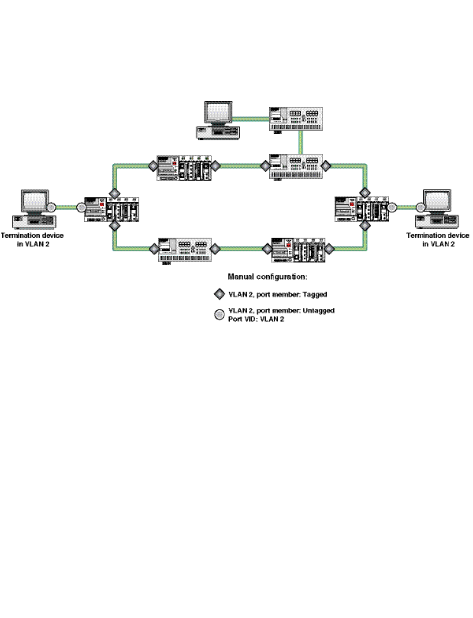
Smart Managed Compact Switch
154 PHOENIX CONTACT 8089_en_03
In the event of static VLAN configuration, all possible redundant data paths must be taken
into consideration during configuration. All possible backbone ports of the network (i.e., not
the termination device ports) must be inserted in all available VLANs as “tagged” members.
This ensures that for every possible tree structure that can be generated by (R)STP, every
VLAN can be accessed by every switch.
An example configuration is illustrated in the following diagram:
Figure 8-7 Typical configuration for VLAN and (R)STP

Operation as a PROFINET device
8089_en_03 PHOENIX CONTACT 155
9 Operation as a PROFINET device
The switch is supported as a PROFINET device in PC Worx Version 5.00.26 or later. The
PROFINET controller is then responsible for starting up the switch within a PROFINET ap-
plication. This includes assigning the IP parameters, comparing the desired/actual configu-
ration, and archiving alarms sent by the switch. In the event that a device is replaced, the
controller detects the replacement device and starts it up automatically. For the controller
program, the switch as a PROFINET device will make available the link states as a process
data item.
9.1 Preparing the switch for PROFINET mode
When activating PROFINET mode, the following default settings are made for operation:
– The Link Layer Discovery Protocol (LLDP) is activated with the following configuration
specifications for PROFINET components:
- Message transmit interval: 5 s
- Message transmit hold multiplier: 2
- TLV port ID with subtype locally assigned in the following format: port-xyz
- TLV chassis ID with subtype locally assigned transmits the station name
– The Discovery and Configuration Protocol (DCP) is activated as the mechanism for as-
signing IP parameters.
– The station name (system name) is deleted if the value for the “System Name” object
contains the device type (default upon delivery).
– The MRP protocol is not activated.
– The PDEV function is supported by firmware version 2.20 or later.
In addition, when switching to “PROFINET” mode, the configuration is saved automatically
and the device is restarted.
The switch then starts in “PROFINET” mode for the first time and waits for a name and a
PROFINET IP address to be assigned. At this point, the switch is already visible in the net-
work via LLDP with the default name “FL SWITCH SMN” and IP address “0.0.0.0”.
The switch indicates that it is waiting for a valid IP configuration via DCP when the LED for
the mode that is currently active flashes.
The switch cannot be accessed via other network services such as ping at this time.
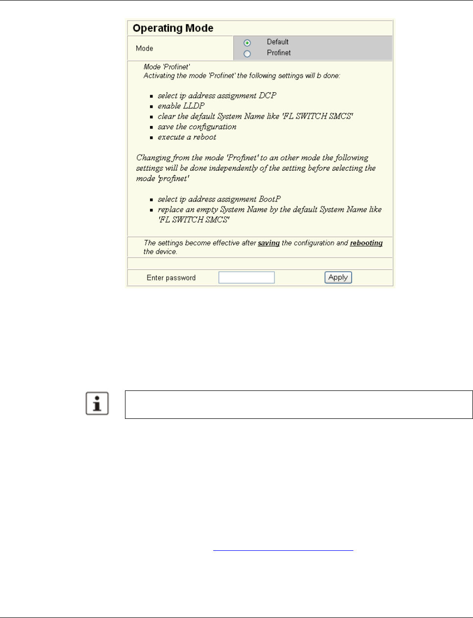
Smart Managed Compact Switch
156 PHOENIX CONTACT 8089_en_03
Figure 9-1 “Operating Mode” web page
Switching to “Default”
mode When the switch is reset to “Default” mode from “PROFINET” mode, the following settings
are made:
– LLDP remains active with the values set by default.
– IP address assignment is set to BootP.
– The station name for the switch does not change. If no station name has been specified,
the device type is entered.
9.2 Switch as a PROFINET device
9.2.1 Configuration in the engineering tool
9.2.1.1 Specifying the bus configuration
The switch can be operated as a PROFINET device if it is integrated under a controller in
the bus configuration in the engineering tool. A GSD file and an FDCML file for integration
can be downloaded at www.download.phoenixcontact.com.
It is recommended to save the new configuration after changing operating mode. Please
note that some configuration modifications only take effect after a restart.
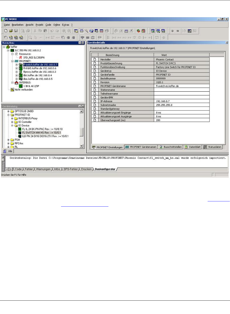
Operation as a PROFINET device
8089_en_03 PHOENIX CONTACT 157
Figure9-2 The switch in the bus configuration under PC Worx
If the switch is not listed in the device catalog, the device description provided by Phoenix
Contact must be imported. The latest device description can be downloaded at www.down-
load.phoenixcontact.com.
If the device description is available in the device catalog, the following options are available
for bus configuration:
– Manual - The components are transferred to the bus configuration from the device cat-
alog using drag & drop.
– Automatic - The devices are entered via the “Read PROFINET” function, which means
that they can be accessed in the network via DCP (Discovery and Configuration Proto-
col). For this, the devices must be supplied with power and the operating mode must be
set to “PROFINET”.
9.2.2 Configuring the switch as a PROFINET device
Once all switches have been added to the bus configuration, the following settings must be
made for the individual switches via the “Detail View” tab (device details):
– The PROFINET device name must be checked and modified if necessary.
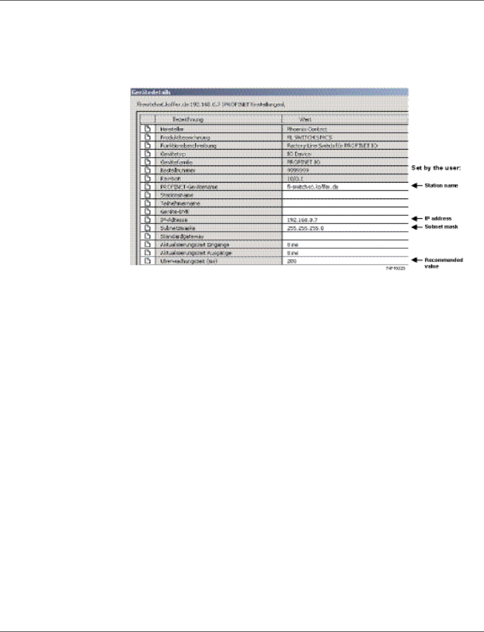
Smart Managed Compact Switch
158 PHOENIX CONTACT 8089_en_03
– The IP address and the subnet mask must be checked and modified if necessary.
– The update time for inputs should be set to “512 ms” (default).
– The update time for outputs should be set to “512 ms” (default).
– The monitoring time should be set to “2000 ms” (default).
– The interface modules must be selected from the module catalog and added to the sta-
tion.
Figure 9-3 Device details with modified settings
The PROFINET variables can then be created and used in the control program.
In addition to the “PNIO_DATA_STATE” standard variable, the switch provides the link sta-
tus as a process data byte for each port. If the “PNIO_DATA_VALID” bit for the “PNIO_-
DATA_STATE” variable declares the switch process data as valid, the process data item for
a port can have the following values (see Section “Additional process data” on page 161):
– Value = 1 - Active link
– Value = 2 - No active link
– Value = 3 - Link present, but partner cannot establish link (only for FX ports - Far End
Fault Detection)
– Value = 4 - Port is administratively disabled
– Value = 129 - Port is active, but in the “Blocking” state due to the redundancy protocol
(RSTP, MRP)
Process data can only be accessed if the parameterized desired configuration on device
startup corresponds to the actual configuration.
The “Status” word and the “Control” word of the management agent are not used.
9.2.3 Configuration via the engineering tool
The universal parameter editor (UPE) can be used to configure the switch via the engineer-
ing tool (PC Worx).
– Activation/deactivation of PROFINET alarms
– Configuration of port mode
– Configuration of port state
Operation as a PROFINET device
8089_en_03 PHOENIX CONTACT 159
9.2.4 PROFINET flashing function
If the switch is requested to flash in PROFINET mode by the engineering tool, the LEDs se-
lected by the mode button flash.
9.2.5 Device naming
In order to start up a switch in “PROFINET” mode, each switch must be assigned a name
once, i.e., each PROFINET device is assigned a unique device name. A device search
(“Read PROFINET” function in PC Worx) is performed via the engineering tool, where all the
devices that can be accessed in the network are listed. After identifying unknown devices
via the specified MAC address or the “Flashing” function, the device name configured in the
engineering tool is saved permanently on the switch with the “Assign Name” function.
9.2.6 Operating in the PROFINET environment
A switch that has already been assigned a name starts in “PROFINET” mode without an IP
address and waits for the assignment of an IP configuration (flashing of the LED for the cur-
rently active mode). Once the project has been translated and downloaded to the controller,
the controller implements startup and configuration. As soon as a communication relation-
ship has been successfully established between the switch and the controller, the switch
starts its management interfaces. The switch indicates that the PROFINET connection has
been established correctly by means of an entry in the event table.
9.3 PROFINET alarms
The SMN can send the following alarms:
– Redundant power supply missing (management agent alarm)
– MRP manager registered a ring interrupt (management agent alarm)
– Interface module removed (slot-specific alarm)
– Link monitoring (slot alarm for the relevant channel/port)
All the alarms are deactivated when the device is started.
The device name can also be assigned via WBM before switching to PROFINET mode.
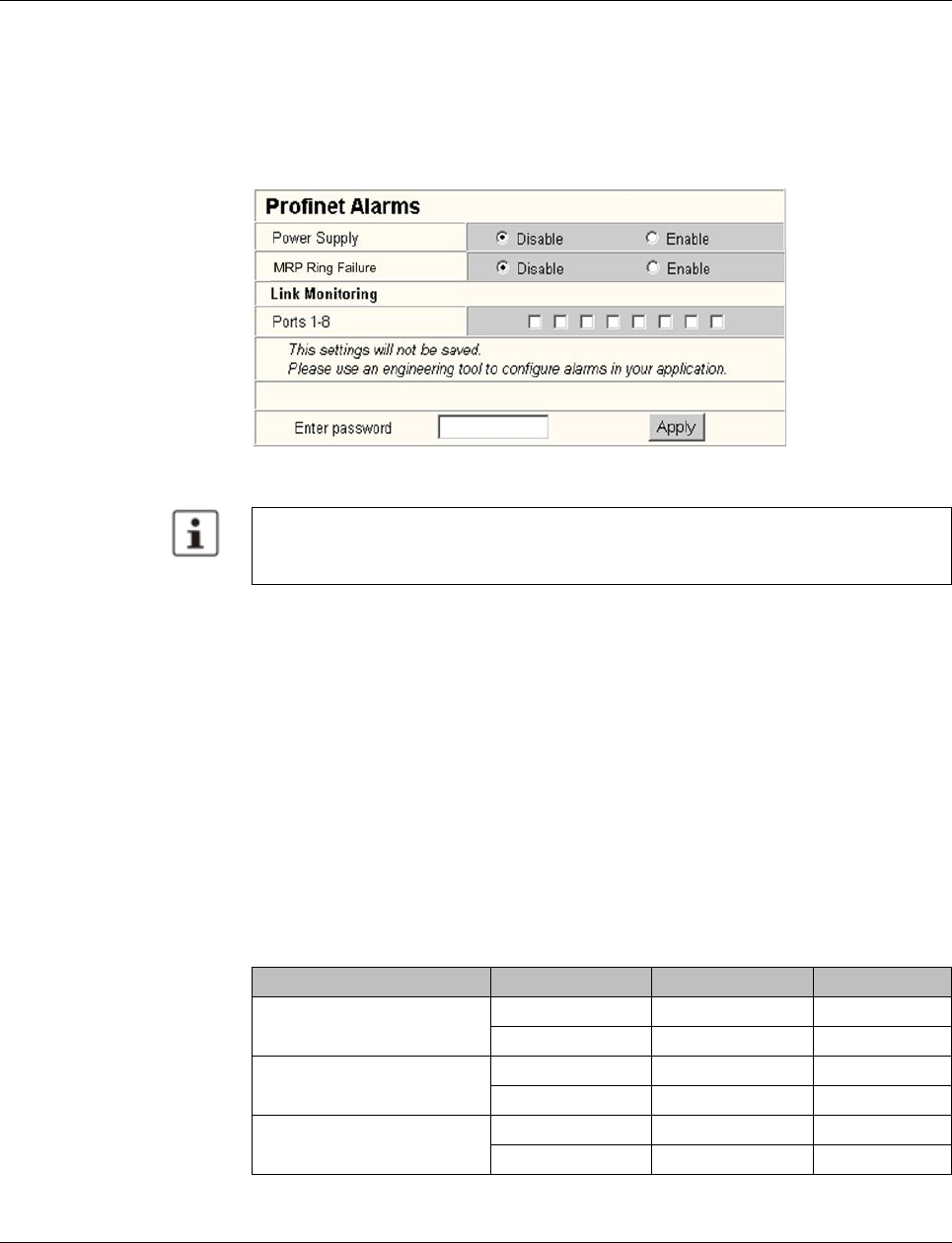
Smart Managed Compact Switch
160 PHOENIX CONTACT 8089_en_03
9.3.1 Alarms in WBM
In “PROFINET” mode, the “PROFINET Alarms” web page appears in the navigation bar
under “Switch Station, Diagnostics”. Here, all alarms supported by the IO device can be ac-
tivated. The PROFINET alarms are sent to the controller by the IO devices. From there they
can be read from the diagnostic archive using “Diag+” (version 2.0 is included in Service
Pack 1 for PC Worx 5.00.26).
Figure 9-4 PROFINET alarms in WBM
9.4 Process data communication
9.4.1 Control word
The control word is a special process data item used to make settings which are not to be
executed via a conventional process data item.
A command consisting of two bytes can be written to the control word of the management
agent. The device responds to this with the same command in the status word. Byte 0 spec-
ifies the action and the new status; byte 1 specifies the port number. If a command is to
apply to all the ports, the value 0xFF can be sent instead of the port number. A command
should only be sent once, but never in a process data communication cycle.
The settings made for the PROFINET alarms can be saved with the configuration. The
controller can transmit a different alarm configuration to the switch and therefore overwrite
the configuration settings.
Table9-1 Assignment of the control word
Action Status Byte 0 Byte 1
Link monitoring On 0x01 Port or 0xFF
Off 0x02 Port or 0xFF
POF SCRJ diagnostics On 0x03 Port or 0xFF
Off 0x04 Port or 0xFF
Power supply On 0x05 0x00
Off 0x06 0x00
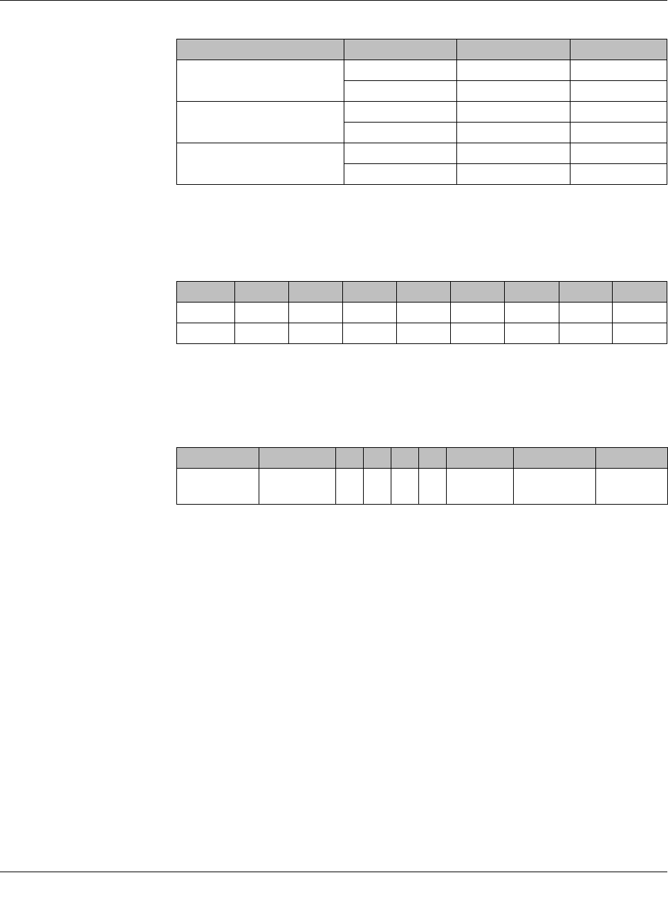
Operation as a PROFINET device
8089_en_03 PHOENIX CONTACT 161
9.4.1.1 Additional process data
The SMN can send the following process data:
– Summary of the link states of all ports (three bytes) - each port corresponds to one bit
(0 - Link down; 1 - Link up)
– The slots transmit link information for each port. This includes:
- Link status: (0 - Link down; 1 - Link up)
- Far end fault status: (0 - No fault; 1 - Fault)
- Port enable status: (0 - Enabled; 1 - Disabled)
- Link mode: (0 - Forwarding; 1 - Blocking)
9.5 PDEV function description
The PDEV function provides an extended scope of functions for switches in PROFINET
mode. This includes displaying neighbor and topology information in the engineering tool.
This information is determined using the Link Layer Discovery Protocol (LLDP) and can be
used, for example, to compare the desired and actual network.
In addition, the PDEV function is used to display the transmitted information via the respec-
tive Ethernet ports.
The PDEV function uses two new submodules:
– Interface submodule with port number 0x8X00 (X: from 0 to F)
– Port submodule with port number 0x8IXX (I: Interface ID; X: Port number)
These submodules are represented in the Step7 engineering tool. PROFINET communica-
tion enables information about the port speed, duplex mode, and the link status to be read.
An engineering tool reads and then displays the neighbor and topology information via
SNMP.
Interface removed On 0x07 0x00
Off 0x08 0x00
MRP ring failure On 0x09 0x00
Off 0x0a 0x00
Link enable status On 0x20 Port
Off 0x21 Port
Byte 1, 2, 3 1, 2, 3 1, 2, 3 1, 2, 3 1, 2, 3 1, 2, 3 1, 2, 3 1, 2, 3
Bit 7 6 5 4 3 2 1 0
Port 8/16/24 7/15/23 6/14/22 5/13/21 4/12/20 3/11/19 2/10/18 1/9/17
Bit 7 6 5 4 3 2 1 0
Meaning Link mode Port
enable Far end fault Link status
Table9-1 Assignment of the control word
Action Status Byte 0 Byte 1

Smart Managed Compact Switch
162 PHOENIX CONTACT 8089_en_03
9.5.1 PROFINET stack and PDEV function
The PDEV function is supported by PROFINET stack version 2.2. The following functions
are supported by PN stack 2.2:
– Link status, port mode, and port MAC address can be requested via the port
– Storing of PDEV data
– Reorganization of submodules for integrating interfaces and new ports
– Use of the PN stack LLDP in PN mode (used for neighbor and topology detection)
– Support for device replacement and application redundancy
9.5.1.1 PDEV in the firmware
The PDEV function can be used for the FL SWITCH SMN device range in firmware version
2.2 or later. In addition, the corresponding version of the GSDML file must be used (the
FDCML file does not support PDEV at present).
These files are used to describe the device function and can be imported into an engineer-
ing tool.
The PDEV function is only available in firmware version 2.2 or later.
Link Layer Discovery Protocol (LLDP)
8089_en_03 PHOENIX CONTACT 163
10 Link Layer Discovery Protocol (LLDP)
10.1 Basics
LLDP The switch supports LLDP according to IEEE 802.1ab and enables topology detection of
devices that also have LLDP activated.
Advantages of using LLDP:
– Improved error location detection
– Improved device replacement
– More efficient network configuration
The following information is received by or sent to neighbors, as long as LLDP is activated:
– The device transmits its own management and connection information to neighboring
devices.
– The device receives management and connection information from neighboring devic-
es.
Displaying LLDP informa-
tion The information that is collected is presented in a table in WBM. The table includes the two
port numbers that are used to connect both devices together, as well as the IP address, the
device name of neighboring devices, and the device type.
LLDP general The Link Layer Discovery Protocol (LLDP) according to 802.1ab is used by network devices
to understand and maintain individual neighbor relationships.
Function
A network infrastructure component transmits a port-specific BPDU (Bridge Protocol Data
Unit), which contains the individual device information, at the “Message Transmit Interval”
to each port in order to distribute topology information. The partner connected to the rele-
vant port learns the corresponding port-specific neighbors from these BPDUs.
The information learned from the BPDUs is saved for a defined period of time as the TTL
value (Time To Live). Subsequent receipt of the same BPDUs increases the TTL value
again and the information is still saved. If the TTL elapses, the neighbor information is de-
leted.
Please note that a blocking port using RSTP does not receive LLDP BPDUs, but does
send them.
An SMN manages a maximum of 50 items of neighbor information, all other information is
ignored.
If several neighbors are displayed on one switch port, then at least one other switch/hub,
which does not support or has not activated LLDP, is installed between this switch and
the neighbor indicated.
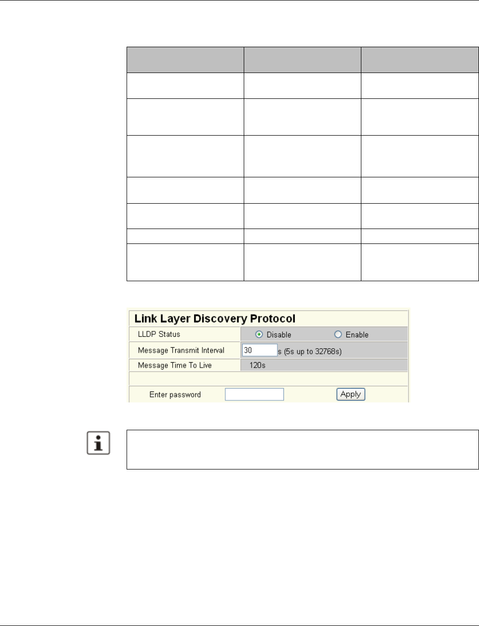
Smart Managed Compact Switch
164 PHOENIX CONTACT 8089_en_03
Link Layer Discovery Pro-
tocol
Figure 10-1 “Link Layer Discovery Protocol” web page
Table 10-1 Event table for LLDP
Event Activity of the individual
LLDP agent Response of the neigh-
boring LLDP agent
Activate LLDP agent or de-
vice startup Transmit LLDP BPDUs to all
ports Include sender in the list of
neighbors
Deactivate LLDP agent or
software reset Transmit LLDP BPDUs with
a TTL value of 0 seconds to
all ports
Delete sender from the list
of neighbors
Link up Transmit port-specific LLDP
BPDUs Include sender in the list of
neighbors
Link down Delete all neighbors for this
port -
Timer (Message Transmit
Interval) Cyclic transmission of
BPDUs to all ports Update information
Aging (Time To Live) Delete neighbor information -
Receiving a BPDU from a
new neighbor Extend list of neighbors and
respond with port-specific
BPDU
Include sender in the list of
neighbors
The “Message Time To Live” is determined by multiplying the “Message Transmit Inter-
val” with the “Message Transmit Hold Multiplier”. The “Message Transmit Hold Multiplier”
can only be modified via SNMP. The default value is four.

Link Layer Discovery Protocol (LLDP)
8089_en_03 PHOENIX CONTACT 165
LLDP topology
Figure10-2 “LLDP Topology” web page
A table is created for known neighbors and contains the following five columns:
– Local port
Contains the port number of the local switch that is used to connect a neighbor to this
switch. The port number is also a link to the local “Port Configuration” web page.
– Type
An icon is displayed here, which corresponds to the neighboring device type. “Ethernet
Device” is displayed in general for devices produced by other manufacturers.
– Address
Indicates the management IP address for the neighbor.
– Device
Indicates the system name of the neighbor.
– Indicates the port number of the neighboring switch that is used to connect the neighbor
to the local switch. If the neighbor is identified as a Phoenix Contact switch, the port
number is implemented as a link to the “Port Configuration” web page for the neighbor.
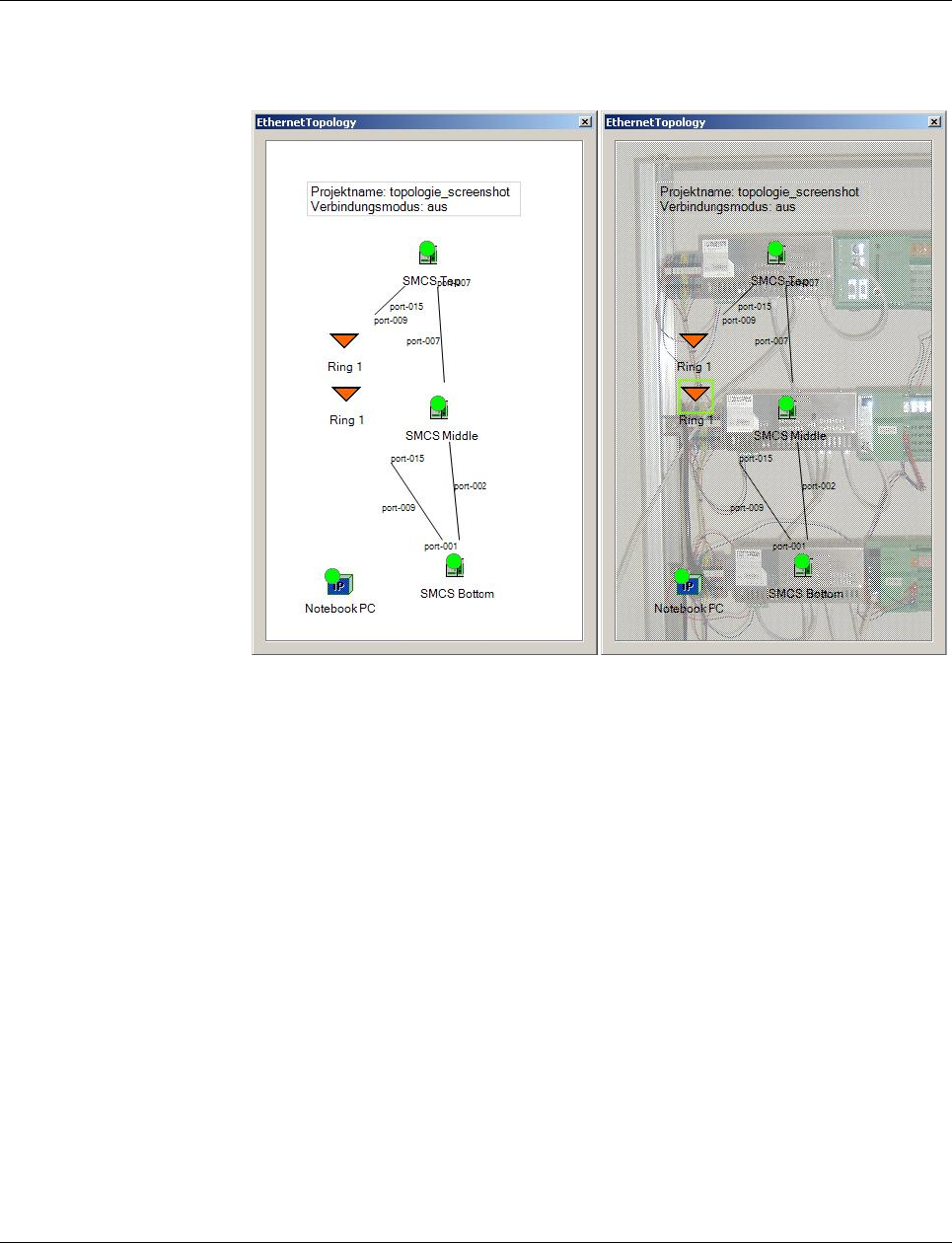
Smart Managed Compact Switch
166 PHOENIX CONTACT 8089_en_03
10.2 Topology representation via an engineering tool
The LLDP information can be represented as such or similarly in engineering tools.
Figure 10-3 Topology representation

Technical data and ordering data
8089_en_03 PHOENIX CONTACT 167
11 Technical data and ordering data
11.1 Technical data
General data
Function Smart Managed Narrow Switch, Ethernet/Fast Ethernet switch; conforms to
standard IEEE 802.3/802.3u/802.3ab
Switch principle Store and forward
Address table 4000 MAC addresses
SNMP Version 2c
Transmission capacity per port
64-byte packet size, half duplex At 10 Mbps: 14880 pps (packets per second)
At 100 Mbps: 148800 pps
Supported MIBs MIB II and private SNMP objects from Phoenix Contact
Housing dimensions (width x height x depth) in mm 56 x 133 x 130 (depth from top edge of DIN rail)
56 x 133 x 175 (depth from top edge of DIN rail)
with FL MEM PLUG (accessories)
Permissible operating temperature 0°C to 55°C
Permissible storage temperature -40°C to +85°C
Degree of protection IP20, IEC 60529
Protection class Class 3 VDE 0106; IEC 60536
Humidity
Operation 5% ... 95%, non-condensing
Storage 5% ... 95%, non-condensing
Air pressure
Operation 86 kPa to 108 kPa, 1500 m above sea level
Storage 66 kPa to 108 kPa, 3500 m above sea level
Ambient compatibility Free from substances that would hinder coating with paint or varnish accord-
ing to VW specification
Mounting position Perpendicular to a standard DIN rail
Connection to protective earth ground By snapping it onto a grounded DIN rail
Weight 650 g, typical
Supply voltage (US1/US2 redundant)
Connection Via COMBICON; maximum conductor cross section = 2.5 mm2
Nominal value 24 V DC
Permissible voltage range 18.0 V DC to 32.0 V DC
Permissible ripple (within the permissible voltage range) 3.6 VPP
Test voltage 500 V DC for 1 minute
Current consumption at US at 24 V DC, maximum 0.6 5A
Maximum power consumption 14.5 W
Interfaces on the SMN
Number of Ethernet ports 8
RS-232 communication interface
Connection format Mini-DIN socket

Smart Managed Compact Switch
168 PHOENIX CONTACT 8089_en_03
Floating signal contact
Voltage 24 V DC
Current carrying capacity 100 mA
Interfaces on the SMN
Ethernet interfaces
Properties of RJ45 ports
Number 6 or 8 with auto crossing and auto negotiation
Connection format 8-pos. RJ45 socket on the switch
Connection medium Twisted-pair cable with a conductor cross section of 0.14 mm2 to 0.22 mm2
Cable impedance 100 ohms
Transmission speed 10/100
Maximum network segment expansion 100 m
General properties of POF ports
Number 0 or 2
Connection format SC-RJ sockets on the device
Data transmission speed 100 Mbps according to PROFINET standard
Wavelength 660 nm
Laser protection Class 1 according to DIN EN 60825-1
Minimum cable length 1 m
Transmission length including 3 dB system reserve 50 m polymer fiber with F-K 980/1000 230 dB/km at 10/100 Mbps, maximum
100 m HCS fiber with F-S 200/230 8 dB/km at 100 Mbps, maximum
(Average) dynamic transmission power (fiber type) in link mode
Minimum -8.0 dBm (980/1000 µm)
(Average) dynamic receiver sensitivity (fiber type) in link mode
Minimum -23.0 dBm (980/1000 µm)
Optical overrange 1.0 dBm (980/1000 µm)
Properties of 100 Mbps multi-mode ports in SC format
Connection format SC-RJ sockets on the device
Data transmission speed 100 Mbps, full duplex
Wavelength 1310 nm
Maximum transmission length 7.1 km fiberglass with F-G 50/125 µm 0.7 dB/km F1200
3.1 km fiberglass with F-G 50/125 µm 1.6 dB/km F800
8.0 km fiberglass with F-G 62.5/125 µm 0.7 dB/km F1000
3.8 km fiberglass with F-G 62.5/125 µm 2.6 dB/km F600
Transmission power
Minimum -19 dBm 62.5/125 µm
-24 dBm 50/125 µm
Maximum -14 dBm
Receiver sensitivity
Minimum -32.0 dBm
Properties of 100 Mbps single-mode ports in SC format
Connection format SC-RJ sockets on the device
Data transmission speed 100 Mbps, full duplex
Wavelength 1310 nm
Maximum transmission length 39 km fiberglass with F-G 9/125 µm 0.36 dB/km
35 km fiberglass with F-G 9/125 µm 0.4 dB/km
28 km fiberglass with F-G 9/125 µm 0.5 dB/km 0

Technical data and ordering data
8089_en_03 PHOENIX CONTACT 169
Transmission power
Minimum -15 dBm 9/125 µm
Receiver sensitivity
Minimum -31.0 dBm
Ethernet interfaces [...]
Mechanical tests
Shock testing according to IEC 60068-2-27 Operation:25g,
Half-sine shock pulse
Storage/transport: 50g,
Half-sine shock pulse
Vibration resistance according to IEC 60068-2-6 Operation/storage/transport: 5g, 10 Hz ... 150 Hz
Free fall according to IEC 60068-2-32 1 m
Conformance with EMC directives
Developed according to IEC 61000-6-2
Noise emission according to EN 55022: 1998
+ A1: 2000 + A2: 2003 (interference voltage) Class B (residential)
Noise emission according to EN55011: 1998
+ A1: 1999 + A2: 2002 (electromagnetic interference) Class B (residential)
Noise immunity according to EN 61000-4-2 (IEC1000-4-2) (ESD)
Contact discharge:
Air discharge:
Indirect discharge:
Requirements according to DIN EN 61000-6-2
Test intensity 2, criterion B
Test intensity 3, criterion B
Test intensity 2, criterion B
Noise immunity according to EN 61000-4-3 (IEC 1000-4-3)
(electromagnetic fields) Requirements according to DIN EN 61000-6-2
Test intensity 3, criterion A
Noise immunity according to EN 61000-4-4 (IEC 1000-4-4) (burst)
Data cables:
Power supply:
Requirements according to DIN EN 61000-6-2
Test intensity 2, criterion B
Test intensity 3, criterion B
Noise immunity according to EN 61000-4-5 (IEC 1000-4-5) (surge)
Data cables:
Power supply:
Requirements according to DIN EN 61000-6-2
Test intensity 2, criterion B
Test intensity 1, criterion B
Noise immunity according to EN 61000-4-6 (IEC 1000-4-6) (conducted) Requirements according to DIN EN 61000-6-2
Test intensity 3, criterion A
Additional certification
RoHS EEE 2002/95/EC - WEEE 2002/96/EC
Differences between this version and previous versions
Rev. 00: First version
Rev. 01: Integration of FL SWITCH SMN 8TX-PN
Rev. 02: New firmware
Rev. 03: New devices added

Smart Managed Compact Switch
170 PHOENIX CONTACT 8089_en_03
11.2 Ordering data
Products
Accessories
Description Order designation Order No. Pcs./Pkt.
Smart Managed Narrow Switch with six Fast Ethernet ports in RJ45 format
and two SCRJ-POF ports, operating in “PROFINET” mode by default upon
delivery
FL SWITCH SMN 6TX/2POF-PN 2700290 1
Smart Managed Narrow Switch with eight Fast Ethernet ports in RJ45 format,
operating in “PROFINET” mode by default upon delivery FL SWITCH SMN 8TX-PN 2989501 1
Smart Managed Narrow Switch with six Fast Ethernet ports in RJ45 format
and two FO ports in SC multi-mode format FL SWITCH SMN 6TX/2FX 2989543 1
Smart Managed Narrow Switch with six Fast Ethernet ports in RJ45 format
and two FO ports in SC single-mode format FL SWITCH SMN 6TX/2FX-SM 2989556 1
Replaceable configuration memory FL MEM PLUG 2891259 1
Pluggable parameterization memory with MRP manager function FL MEM PLUG/MRM 2891275 1
Description Order designation Order No. Pcs./Pkt.
Configuration cable, for connecting the switch to a PC, RS-232 COM CAB MINI DIN 2400127 1
Universal end bracket E/NS 35 N 0800886 1
Network monitoring with HMI/SCADA systems FL SMNP OPC SERVER 2832166 1
Patch box 8 x RJ45 CAT5e, pre-assembled, can be retrofitted FL PBX 8TX 2832496 1
Patch box 6 x RJ45 CAT5e and 4 SC-RJ, glass, pre-assembled, can be ret-
rofitted FL PBX 6TX/4FX 2832506 1
Angled patch connector with two RJ45 CAT5e network connections including
Layer 1 security elements FL PF SEC 2TX 2832687 1
Angled patch connector with eight RJ45 CAT5e network connections includ-
ing Layer 1 security elements FL PF SEC 8TX 2832690 1
Angled patch connector with two RJ45 CAT5e network connections FL PF 2TX CAT5E 2891165 1
Angled patch connector with eight RJ45 CAT5e network connections FL PF 8TX CAT5E 2891178 1
Angled patch connector with two RJ45 CAT6 network connections FL PF 2TX CAT 6 2891068 1
Angled patch connector with eight RJ45 CAT6 network connections FL PF 8TX CAT 6 2891071 1
Patch cable, CAT6, pre-assembled, 0.3 m long FL CAT6 PATCH 0,3 2891181 10
Patch cable, CAT6, pre-assembled, 0.5 m long FL CAT6 PATCH 0,5 2891288 10
Patch cable, CAT6, pre-assembled, 1.0 m long FL CAT6 PATCH 1,0 2891385 10
Patch cable, CAT6, pre-assembled, 1.5 m long FL CAT6 PATCH 1,5 2891482 10
Patch cable, CAT6, pre-assembled, 2.0 m long FL CAT6 PATCH 2,0 2891589 10
Patch cable, CAT6, pre-assembled, 3.0 m long FL CAT6 PATCH 3,0 2891686 10
Patch cable, CAT6, pre-assembled, 5.0 m long FL CAT6 PATCH 5,0 2891783 10
Patch cable, CAT6, pre-assembled, 7.5 m long FL CAT6 PATCH 7,5 2891880 10
Patch cable, CAT6, pre-assembled, 10 m long FL CAT6 PATCH 10 2891887 10
Patch cable, CAT6, pre-assembled, 12.5 m long FL CAT6 PATCH 12,5 2891369 5
Patch cable, CAT6, pre-assembled, 15 m long FL CAT6 PATCH 15 2891372 5
Patch cable, CAT6, pre-assembled, 20 m long FL CAT6 PATCH 20 2891576 5
Patch cable, CAT5, pre-assembled, 0.3 m long FL CAT5 PATCH 0,3 2832250 10
Patch cable, CAT5, pre-assembled, 0.5 m long FL CAT5 PATCH 0,5 2832263 10
Patch cable, CAT5, pre-assembled, 1.0 m long FL CAT5 PATCH 1,0 2832276 10
Patch cable, CAT5, pre-assembled, 1.5 m long FL CAT5 PATCH 1,5 2832221 10
Patch cable, CAT5, pre-assembled, 2.0 m long FL CAT5 PATCH 2,0 2832289 10

Technical data and ordering data
8089_en_03 PHOENIX CONTACT 171
HOTLINE:
If there are any problems that cannot be solved using this documentation, please call our
hotline:
+ 49 - (0) 52 81 - 946 28 88
factoryline-service@phoenixcontact.com
Patch cable, CAT5, pre-assembled, 3.0 m long FL CAT5 PATCH 3,0 2832292 10
Patch cable, CAT5, pre-assembled, 5.0 m long FL CAT5 PATCH 5,0 2832580 10
Patch cable, CAT5, pre-assembled, 7.5 m long FL CAT5 PATCH 7,5 2832616 10
Patch cable, CAT5, pre-assembled, 10.0 m long FL CAT5 PATCH 10 2832629 10
Color coding for FL CAT5/6 PATCH ..., black FL PATCH CCODE BK 2891194 20
Color coding for FL CAT5/6 PATCH ..., brown FL PATCH CCODE BN 2891495 20
Color coding for FL CAT5/6 PATCH ..., blue FL PATCH CCODE BU 2891291 20
Color coding for FL CAT5/6 PATCH ..., green FL PATCH CCODE GN 2891796 20
Color coding for FL CAT5/6 PATCH ..., gray FL PATCH CCODE GY 2891699 20
Color coding for FL CAT5/6 PATCH ..., red FL PATCH CCODE RD 2891893 20
Color coding for FL CAT5/6 PATCH ..., violet FL PATCH CCODE VT 2891990 20
Color coding for FL CAT5/6 PATCH ..., yellow FL PATCH CCODE YE 2891592 20
Lockable security element for FL CAT5/6 PATCH ... FL PATCH GUARD 2891424 20
Color coding for FL PATCH GUARD, black FL PATCH GUARD CCODE BK 2891136 12
Color coding for FL PATCH GUARD, blue FL PATCH GUARD CCODE BU 2891233 12
Color coding for FL PATCH GUARD, green FL PATCH GUARD CCODE GN 2891631 12
Color coding for FL PATCH GUARD, orange FL PATCH GUARD CCODE OG 2891330 12
Color coding for FL PATCH GUARD, red FL PATCH GUARD CCODE RD 2891738 12
Color coding for FL PATCH GUARD, turquoise FL PATCH GUARD CCODE TQ 2891534 12
Color coding for FL PATCH GUARD, violet FL PATCH GUARD CCODE VT 2891835 12
Color coding for FL PATCH GUARD, yellow FL PATCH GUARD CCODE YE 2891437 12
Key for FL PATCH GUARD FL PATCH GUARD KEY 2891521 1
Security element for FL CAT5/6 PATCH ... FL PATCH SAFE CLIP 2891246 20
Polymer fiber connectors (two duplex connectors in the set) PSM-SET-SCRJ-DUP/2-POF 2708656 1
Polishing set for polymer fiber connectors (required to assemble polymer
fiber connectors) VS-SCRJ-POF-POLISH 1656673 1
Polymer fiber cable (fiber optic) for indoor installation PSM-LWL-KDHEAVY 2744319 1
HCS fiber connectors (two duplex connectors in the set) PSM-SET-SCRJ-DUP/2-HCS 2313070 1
Tool kit for HCS connectors (required to assemble HCS fiber connectors) PSM-HCS-KONFTOOL/SCRJ 2708876 1
HCS cable (fiber optic) for indoor installation PSM-LWL-HCS-RUGGED-200/230 2799885 1
HCS cable (fiber optic) for outdoor installation PSM-LWL-HCSO-200/230 2799445 1
HCS GI fiber cable, duplex 200/230 µm, for indoor installation, suitable for
use in drag chains, compliant with PROFINET installation guidelines, sold by
the meter without connectors
FL FOC PN-C-HCS-GI-200/230 2313410 1
HCS-GI cable, duplex, 200/230 µm, for indoor installation, suitable for use in
drag chains, compliant with PROFINET installation guidelines, pre-assem-
bled cable with connectors
FL FOC PN-C-HCS-GI 2313504 1
Description [...] Order designation Order No. Pcs./Pkt.

Smart Managed Compact Switch
172 PHOENIX CONTACT 8089_en_03

List of tables
8089_en_03 PHOENIX CONTACT 177
B 2 List of tables
Section 1
Section 2
Table2-1: Pin assignment of RJ45 connectors ....................................................17
Section 3
Table3-1: Operating modes in Smart mode.........................................................20
Section 4
Section 5
Table5-1: Properties of the port states...............................................................120
Table5-2: Port costs according to 802.D............................................................127
Table5-3: Port costs according to 802.W...........................................................127
Section 6
Section 7
Table7-1: Multicast port assignment on the switches ........................................143
Section 8
Section 9
Table9-1: Assignment of the control word..........................................................160
Section 10
Table10-1: Event table for LLDP..........................................................................164
Section 11
Appendix A

Smart Managed Compact Switch
178 PHOENIX CONTACT 8089_en_03

Appendixes
8089_en_03 PHOENIX CONTACT 173
A Appendixes
A 1 List of figures
Section 1
Figure1-1: Smart Managed Compact Switch (versions) .........................................9
Figure1-2: View of the FL SWITCH SMN 6TX/2POF-PN .....................................11
Figure1-3: Housing dimensions of the FL SWITCH SMN in millimeters ...............12
Figure1-4: Example of status indicators ...............................................................14
Section 2
Figure2-1: Snapping the SMN onto the DIN rail ...................................................15
Figure2-2: Removing the SMN .............................................................................15
Figure2-3: Supplying the SMN using one voltage source .....................................16
Figure2-4: Supplying the SMN using two voltage sources ...................................16
Figure2-5: Basic circuit diagram for the signal contact .........................................17
Figure2-6: Transmission parameters and assignment of the RS-232 interface ....18
Section 3
Figure3-1: Example of Smart mode .....................................................................21
Section 4
Figure4-1: Properties dialog box for the network card ..........................................26
Figure4-2: “Internet Protocol (TCP/IP) Properties” dialog box ..............................27
Figure4-3: “Information” web page for the SMN ...................................................29
Figure4-4: “Device Information” web page ...........................................................30
Figure4-5: “IP Configuration” web page ...............................................................31
Figure4-6: “System Identification” menu ..............................................................31
Figure4-7: “SNMP Trap Configuration” web page ................................................32
Figure4-8: “Software Update” web page ..............................................................33
Figure4-9: “Change Password” web page ............................................................34
Figure4-10: “User Interfaces” web page .................................................................34
Figure4-11: “Operating Mode” web page ...............................................................35
Figure4-12: “Configuration Management” web page ..............................................36
Figure4-13: “Save current configuration” web page ...............................................36

Smart Managed Compact Switch
174 PHOENIX CONTACT 8089_en_03
Figure 4-14: “Set default upon delivery” web page ..................................................37
Figure 4-15: “Load the last stored configuration” web page ....................................37
Figure 4-16: “File Transfer” web page .....................................................................37
Figure 4-17: “Memory Plug” web page ....................................................................38
Figure 4-18: “Configuration comparison” web page ................................................39
Figure 4-19: “Clear Memory Plug” web page ..........................................................39
Figure 4-20: “File Transfer” web page .....................................................................39
Figure 4-21: “Port Table” web page ........................................................................40
Figure 4-22: “Port Configuration Table” web page ..................................................40
Figure 4-23: “Port Configuration” web page ............................................................41
Figure 4-24: “Diagnostics” web page ......................................................................42
Figure 4-25: “Port Statistics” web page ...................................................................43
Figure 4-26: “Port Mirroring” web page ...................................................................44
Figure 4-27: “Alarm Contact” web page ..................................................................44
Figure 4-28: “Event Table” web page ......................................................................45
Figure 4-29: “Mac Address Table” web page ..........................................................46
Figure 4-30: “Broadcast Limiter” menu ...................................................................46
Figure 4-31: Schematic view of SNMP ....................................................................47
Figure 4-32: Tree structure of the MIB .................................................................... 50
Figure 4-33: MIB tree ..............................................................................................74
Figure 4-34: HyperTerminal configuration .............................................................103
Figure 4-35: User interface login screen ............................................................... 104
Figure 4-36: IP configuration in the user interface .................................................105
Figure 4-37: Resetting to the default settings ........................................................106
Figure 4-38: Screen displayed on HyperTerminal when booting ...........................107
Figure 4-39: Screen displayed for IP parameters on HyperTerminal .....................107
Figure 4-40: Selection menu for faulty firmware ....................................................108
Section 5
Figure 5-1: Possible tree structure with Spanning Tree ....................................... 109
Figure 5-2: “(R)STP General” web page ............................................................. 110
Figure 5-3: “(R)STP Configuration” web page .....................................................111
Figure 5-4: “(R)STP Port Table” web page ..........................................................112
Figure 5-5: “(R)STP Port Configuration Table” web page ...................................113
Figure 5-6: “(R)STP Port Configuration” web page .............................................114
Figure 5-7: Protocol compatibility ........................................................................115
Figure 5-8: RSTP ring table .................................................................................117

List of figures
8089_en_03 PHOENIX CONTACT 175
Figure5-9: Connection failure with RSTP ring detection .....................................118
Figure5-10: Sequence of the possible port states in STP .....................................120
Figure5-11: Activating Rapid Spanning Tree .......................................................121
Figure5-12: Example topology .............................................................................123
Figure5-13: Redundant coupling of network segments ........................................ 124
Figure5-14: Example with fast ring detection .......................................................125
Figure5-15: Flowchart for specifying the root path ...............................................128
Figure5-16: Specifying the root switch priority .....................................................129
Figure5-17: Example 1 of the “relevant path” ....................................................... 130
Figure5-18: Example 2 of the “relevant path” ....................................................... 131
Section 6
Figure6-1: Example of an MRP ring ...................................................................134
Figure6-2: Permissible example of MRP with (R)STP ........................................135
Figure6-3: Impermissible example .....................................................................135
Figure6-4: “MRP General” web page for an MRP manager ................................136
Figure6-5: “MRP General” web page for an MRP client ..................................... 136
Figure6-6: “MRP Configuration” web page .........................................................137
Section 7
Figure7-1: “Current Multicast Groups” web page ...............................................140
Figure7-2: “Static Multicast Groups” menu .........................................................142
Figure7-3: Configuration example ......................................................................144
Figure7-4: “General Multicast Configuration” web page .....................................146
Section 8
Figure8-1: “General VLAN Configuration” menu ................................................148
Figure8-2: “Current VLANs” web page ...............................................................149
Figure8-3: “Static VLANs” menu ........................................................................150
Figure8-4: VLAN port configuration ....................................................................151
Figure8-5: “Vlan Port Configuration Table” menu ...............................................152
Figure8-6: Example: Communication between termination devices via VLAN ...153
Figure8-7: Typical configuration for VLAN and (R)STP ......................................154
Section 9
Figure9-1: “Operating Mode” web page .............................................................156

Smart Managed Compact Switch
176 PHOENIX CONTACT 8089_en_03
Figure 9-2: The switch in the bus configuration under PC Worx ..........................157
Figure 9-3: Device details with modified settings ................................................158
Figure 9-4: PROFINET alarms in WBM ...............................................................160
Section 10
Figure 10-1: “Link Layer Discovery Protocol” web page ........................................164
Figure 10-2: “LLDP Topology” web page ..............................................................165
Figure 10-3: Topology representation ...................................................................166
Section 11
Appendix A
