Catalog Cablofil 2016 2017 1000497871
2016-09-04
: Pdf 1000497871-Catalog 1000497871-Catalog B4 unilog
Open the PDF directly: View PDF ![]() .
.
Page Count: 288 [warning: Documents this large are best viewed by clicking the View PDF Link!]
designed to be better.™
CATALOG
CABLOFIL® Cable Management
PW® Ladder Tray
TROUGH TRAYS Fiber Trough & V-Trough
FASTENERS J-Hooks, FAS Power® Brackets & CabloPort
2016
2017
CABLOFIL
®
L
L
Cable Management
b
a
C
®
L
I
F
O
L
B
B
A
C
n
e
m
m
e
g
a
n
n
a
M
e

LEGRAND Table of contents
Cablofil® Cable Management PW® Cable Tray
AB
CONTENTS
WWW.LEGRAND.US/CABLOFIL
CABLOFIL
CABLE MANAGEMENT
INTRODUCTION
PAGES A.1-A.9
WIRE CABLE TRAY
PAGES A.10-A.19
SPLICING
PAGES A.20-A.27
WALL MOUNTINGS
PAGES A.28-A.37
CEILING MOUNTINGS
PAGES A.38-A.47
UNDERFLOOR
PAGES A.48-A.59
FIBER OPTIC
PAGES A.60-A.65
OTHER MOUNTINGS
PAGES A.66-A.79
ACCESSORIES
PAGES A.80-A.81
INSTALLATIONS
PAGES A.86-A.105
I
NTR
O
DU
C
TI
ON
P
A
G
E
S
B.1-B.7
L
ADDER TRAY
,
TROUGH
&
S
O
LID B
O
TT
OM
P
AGES B.8-B.79
–
ITRAY PAGES B.10-B.25
–
METALLI
C
PAGES B.26-B.69
–
FIBER
G
LASS PAGES B.70-B.79
CHANNEL SYSTEM
S
P
AGES B.80-B.89
C
ABLE R
U
NWAY
P
AGES B.90-B.95
Trough Tray Legrand® Fasteners
C
CONTENTS
D
WWW.LEGRAND.US/CABLOFIL
I
CABLOFIL
CABLE MANAGEMENT
INTRODUCTION
PAGES C.1-C.5
TRAY, SPLICES & FITTINGS
PAGES C.6-C.15
SUPPORTS & ACCESSORIES
PAGES C.18-C.25
INSTALLATIONS
PAGES C.26-C.29
SPECIFICATIONS
PAGES C.30-C.31
CROSS REFERENCE
PAGES C.32-C.33
INTRODUCTION
PAGES D.1
JHOOKS
PAGES D.2-D.8
OTHER FASTENERS
PAGES D.9-D.11
FAS POWER
PAGES D.12-D.23
CABLOPORT
PAGES D.24-D.31
SEISMIC BRACING
PAGES D.32-D.38
FULL LINE PRODUCT INDEX
PAGES I.2-I.3

PW Ladder tray is the ultimate solution for heavy
power cables in industrial applications. Itray features
a modified aluminum I-beam design that’s suited for
industrial installations with large diameter cables.
The structural offset in the sidewall creates a strong,
mid-span splice that reduces the number of supports
required. PW Long Span Tray is available in aluminum
and steel for extremely heavy loads and longer spans
for roadway bridging. Our exclusive long span/heavy
duty cable tray is designed with I-beam side rails that
can span up to 50' and meet exacting industry and load
standards.
Cablofil Cable Management is the best choice data and
power cable pathways in commercial and industrial
projects. It can be installed quickly using smaller
crews to reduce overall installed costs by up to 50%.
Cablofil is constructed of precision engineered, high
quality, welded steel wire and can be adapted to fit any
installation on-site. A variety of offered finishes means
Cabolfil can be used for exposed indoor applications or
in the most demanding exterior environments.
LEGRAND The most complete line of
CABLOFIL®
Wire Mesh Cable Management
PW®
Ladder Tray
PRODUCT LINES
WWW.LEGRAND.US/CABLOFIL
II
CABLOFIL
CABLE MANAGEMENT

Cablofil Trough Tray is a cable management system
designed to maximize network reliability and minimize
lifecyle costs. Fiber Trough tray utilizes high strength
steel components to provide the strength and durability
required to manage fiber optic or copper cabling
in the most demanding data center environments.
V-Trough provides protection for power cables, keeping
them cool and accessible. Cablofil Trough tray gives
any installation a professional look and provides the
ultimate protection for your cables.
Our new Fasteners line is comprised of the products
that contractors use on a daily basis for cable
management. J-Hooks, FAS Power pre-fab electrical
products, CabloPort rooftop supports and cable tray
support hardware. Each product is designed for easy
installation and is constructed of quality materials that
make for a lasting installation.
cable management products
TROUGH TRAY
Fiber Trough & V-Trough
FASTENERS
J-Hooks, FAS Power®
, CabloPort & Seismic Bracing
V-TROUGH
TRAY & FITTINGS
PRODUCT LINES
WWW.LEGRAND.US/CABLOFIL
III
CABLOFIL
CABLE MANAGEMENT
A.62
A.61A.18
A.63
A.65
A.65
LEGRAND The newest innovations
COTFIL50 / COTFIL100
Snap-In Wire Dividers
Snap-In Wire
Dividers
are the
quick
and easy
way to
separate different
cabling types within the same
cable pathway. Available in
50mm and 100mm heights,
each divider snaps in place
without additional hardware or
tools.
EZT90RS / RADT90RS
Radius Shields
Radius
shields create
a smooth
corner around
junctions made
with EZT90
and RADT90
hardware.
They’re made
from durable,
black ABS plastic and include
slots for mounting with zip ties.
HXB / RHXB / HTB
Horizontal Cross Bridges
Junction
bridges
keep cables
separated
at tees and
crosses in
Cablofil cable
management
for optimum network signal
integrity. The unique design
creates smooth cable
transitions to keep cables from
kinking and bunching.
INSERTPP
Plastic Inserts
Plastic
inserts
create a
smooth
bottom for
sensitive
cable types in Cablofil cable
management. Available in
bottom only and bottom with
sides, each 200' polypropylene
roll can be easily cut to length
to fit any installation.
CABLOFIL
TOH
Fiber-Optic
Twist-On Horn
Fiber-Optic
Twist-On
Horn installs
to any series
Cablofil cable
management without tools or
additional hardware. Use as a
single or in multiple sets, on
the bottom or sides of the tray
to manage lengths of fiber optic
cabling.
CABLEXIT50
Cable Exit
Use this
cable exit
for smaller
groups of
cables that
are entering
and exiting
Cablofil through the bottom
of the tray. Its smooth, high-
density plastic construction
eliminates deformation and
damage to cable bundles.
j
NEW PRODUCTS
WWW.LEGRAND.US/CABLOFIL
IV
CABLOFIL
CABLE MANAGEMENT

B.24
B.24
A.64 C.17
A.64
in cable management products
PW TROUGH TRAY
OTDOFAS
Over-the-Top Drop Out
Use Over-
the-Top
Drop Out
for cables
that exit or
enter on the
side of the
tray and is designed to snap
in place without additional
hardware. Over-the-Top Drop
Out features hold-down slots to
secure cables in place.
OTDO
Over-the-Top Waterfall
Use Over-
the-Top
Waterfall for
cables that
exit or enter
the side
of the tray. It eliminates the
need to cut any side wires that
reduce tray integrity. Over-the-
Top Waterfall features steel,
powder coated construction
and hold-down slots to zip tie
cables in place.
IP34
Cable Tray Isolation Pad
Plastic pad
reduces
friction and
vibration
in PW cable tray and support
members. Also functions as
an electrical isolation barrier
between dissimilar metals. Red
poly construction adds visibility
and can be easily seen by
inspectors. IP34 is plenum rated
and UV resistant.
OHCB
Overhead Clamp Kit
OHCB clamps
makes trapeze
hanging PW Itray
simple. OHCB
keeps the integrity
of the side rails
intact without
the need to drill
holes and keeps the supports
well out of the cable pathway.
Supports can be easily
removed and reattached to add
additional cables if needed.
FTCHC
Center Hanger
Center
Hanging Fiber
Trough and
V-Trough tray
makes adding
cables easy
with the new FTCHC. The open
side allows greater access to
cable pathways up to 12" wide
and makes covers easier to
remove and replace. Designed
for medium duty loads.
NEW PRODUCTS
WWW.LEGRAND.US/CABLOFIL
V
CABLOFIL
CABLE MANAGEMENT
CJ
Attachment Mounting Hardware
Use these attachment options for custom
J-Hook combinations. Available in eight
styles.
D.4
D.7
D.6
D.7
LEGRAND The newest additions to
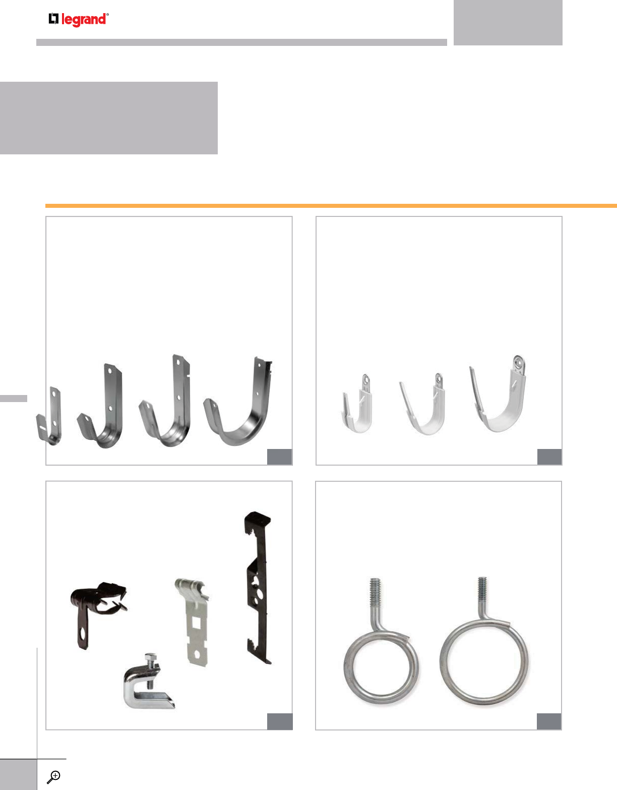
CJ Series
J-Hooks
Our CJ Series J-Hooks are engineered to provide
stress-free for multiple cable bundles and features
tapered edges to reduce cable sheath damage. They
can also be ordered with ten attachment options
for fast installation without the need for additional
hardware. Available in four sizes from ¾” to 4”.
CJHP Series
Plastic Coated J-Hooks
Our “Cable Cage” plastic coated J-Hook features a
built-in latch that allows you to lock the bendable
flap into place. Available in sizes 1”, 2" and 3” with
two different attachment options.
CJ4T
Bridle Rings
Bridle rings are a simple option for smaller cable
bundles. Available in two sizes.
FASTENERS
NEW PRODUCTS
WWW.LEGRAND.US/CABLOFIL
VI
CABLOFIL
CABLE MANAGEMENT
D.14
D.16 D.16
our fasteners product line
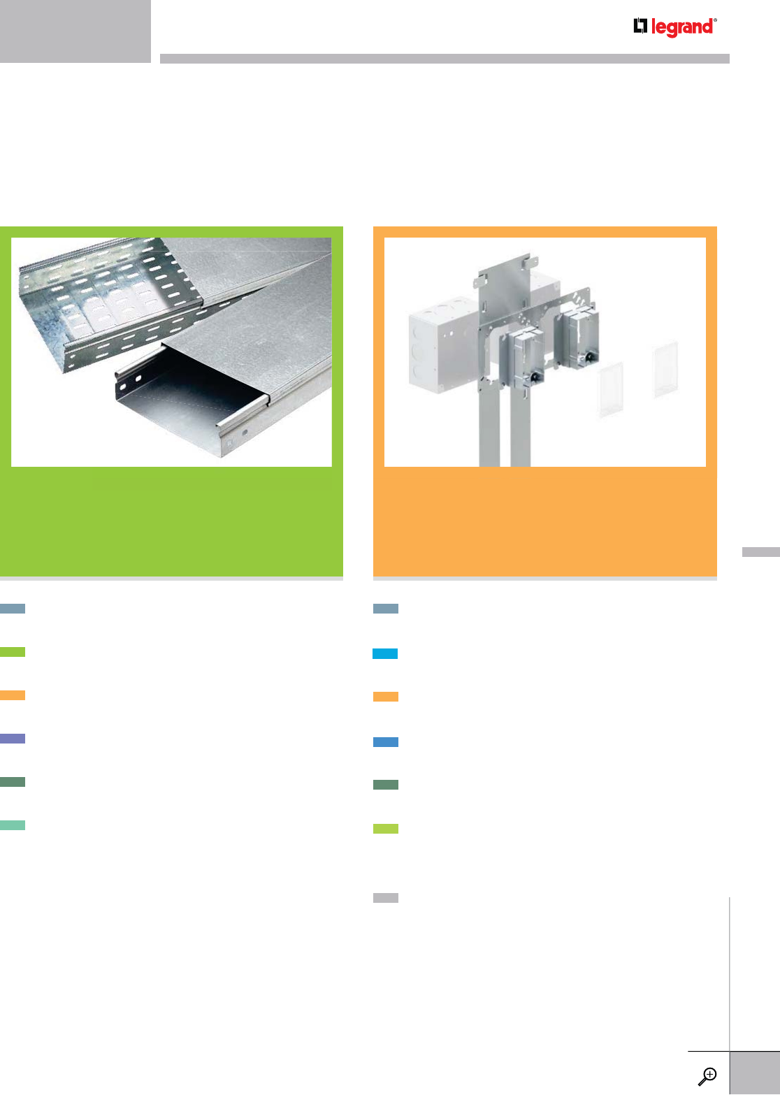
F Series
Redesigned Floor Bracket
Our FAS Power Floor Bracket
has been redesigned with
a built-in wire clamp. Just
remove from base, bend and
slip it into place. Pre-drilled
mounting holes make pre-
fabricated wiring assemblies
a snap.
CWTB
Telescoping Box Bracket
Available in two sizes, this bracket fits standard or
off-width studs without cutting. Use for box
or cable support.
CWTSB
Telescoping Box Support
For heavier boxes, this bracket fits any stud spacing
from 16” to 24”. Plaster ring secures box in
place. Fits 4-11/16” boxes.
Telescoping
Box
Bracket
A
vailable in two sizes
,
this bracket fits standard
off-width studs without cuttin
g
. Use for b
o
bl t
or ca
bl
e suppor
t
.
For
heavier
boxes
,
this
bracket
fits
any
stud
s
from 16” to 24”. Plaster rin
g
secures b
o
p
lace. Fits 4-11/16” boxes.
NEW PRODUCTS
WWW.LEGRAND.US/CABLOFIL
VII
CABLOFIL
CABLE MANAGEMENT

INTRODUCTION
PAGES A.1-A.9
WIRE CABLE TRAY
PAGES A.10-A.19
SPLICING
PAGES A.20-A.27
WALL MOUNTINGS
PAGES A.28-A.37
CEILING MOUNTINGS
PAGES A.38-A.47
UNDERFLOOR
PAGES A.48-A.59
FIBER OPTIC
PAGES A.60-A.65
OTHER MOUNTINGS
PAGES A.66-A.79
ACCESSORIES
PAGES A.80-A.81
INSTALLATIONS
PAGES A.86-A.105
CABLOFIL
TABLE OF CONTENTS

CABLOFIL, THE FIRST NAME IN CABLE MANAGEMENT
Over 35 years ago, Cablofil was introduced to the European
market. Since that time it has become the gold standard for cable
management around the world. Its success is the result of on-
going innovation and continued quality manufacturing practices
that are being embraced by engineers and contractors alike.
To date, more than 125,000 miles of Cablofil Cable Management
have been installed globally.
COMMITMENT TO THE NORTH AMERICAN MARKET
Fifteen years ago, Cablofil was one of the first cable management
manufacturers to market in the US, Mexico and Canada. Since
then, demand for Cablofil has expanded rapidly requiring
the establishment of a 78,000 sq. ft. manufacturing facility
in Mascoutah, Illinois in 2001. This is currently the largest plant of its kind in North America. With this
commitment, we have emerged as the US leader in product innovation, quality control and timely delivery.
THE INNOVATION CONTINUES
Legrand’s vision and leadership has moved the cable
management market forward with innovative ideas and
product enhancements. And as the market changes, so do
we. Each product within the Cablofil product line is constantly
evaluated for improving cable pathway construction and to
reduce installation times. We are constantly developing new
products to embrace new cabling types and methods. Look to
Legrand, the industry leader in cable management.
CABLOFIL CABLE MANAGEMENT
The Industry Leader
INTRODUCTION
WWW.LEGRAND.US/CABLOFIL
A.1
CABLOFIL
CABLE MANAGEMENT

Submittal Builder helps build submittals fast. Select the
Cablofil parts that suit your project and Submittal Builder
will assemble a cover sheet and all of the cut sheets
needed for the materials you specified-in a single pdf file.
Use this online tool for a quick estimate of the
Cablofil parts needed to complete your next project.
Take Off Wizard will give you a material list by run,
or a total bill of materials.
FAS Path Configurator helps you plan and create
prefabricated cable management supports. Prefabricated
or kitted supports are assembled by Legrand in advance
and are shipped to the jobsite to reduce costs. Choose from
three types of support systems – underfloor, wall or ceiling
hung supports. Then configure your support online and
print out a completed cut sheet.
Need a drawing or have a unique problem with your cable
pathway design? This drawing library has a variety of
product drawings and special application assemblies that
are downloadable and ready to use.
Mega Building
111 Mega Drive
Mega City, MO 63111
Mr Jones
122 Mega Drive
Mega City, MO 63111
111-111- 1111
Qty Part Number Part Name
21 CF 105/300 EZ Tray 4" deep and 12" wide. Finish: Electrozinc
59 CF 54/300 EZ Tray 2" deep and 12" wide. Finish: Electrozinc
358 CF 54/450 EZ Tray 2" deep and 18" wide. Finish: Electrozinc
257 FASC 450 PG Ceiling Mount:FAS C BRACKET Finish: Pre-Galvanized (1 per package)
73 FASP 300 PG Ceiling Mount:FAS P FAS PROFILE Finish: Pre-Galvanized (1 per package)
27 FASC 300 PG Wall Mount:FAS C BRACKET Finish: Pre-Galvanized (1 per package)
191 FASL 450 PG Wall Mount:FAS L BRACKET Finish: Pre-Galvanized (1 per package)
44 RADT 90 Kit EZ Tees & Elbows
20 EDRN EZ Splice EDRN Fast Splice Finish: Electrozinc (50 per package)
3 FASLOCK S PG Sweep Connector (25 per package)
8 FASLOCK XL PG Sweep Connector (25 per package)
1 EZ CN 1/4 EZ Accessory
1 EZHN 1/4 EZ Accessory
100 THRD 1/4 EZ Accessory
Project Build Out
Bill of Materials
Cablofil Cable Management has always been easy to install, and with these online tools, it’s now easy to
design your next project. They will guide you through the Cablofil product line and help you plan your next
project, quickly and easily. You can find links to all of these helpful programs at www.legrand.us/cablofil/tools.
CABLOFIL CABLE MANAGEMENT
Web-based Design Tools
INTRODUCTION
WWW.LEGRAND.US/CABLOFIL
A.2
CABLOFIL
CABLE MANAGEMENT

Download this Excel spreadsheet to determine what size
cable pathway you need for your application. It is loaded
with sizes and weights for most standard data and
power cable and will calculate volume and weight limits
for your cable pathway.
FAS Power pre-wired assemblies from Legrand are now
easier to order with an online configurator. Choose from
floor or wall brackets and any number of accessories and
our configurator will display an exploded drawing and a
corresponding item number in seconds.
A downloadable pdf cutsheet is instantly created that you
can use in specification or ordering.
This a great tool to quickly select the proper tray by
NEMA Class, size and material when planning your next
project. Configure straight sections or horizontal and
vertical fittings. A 2-D or 3-D drawing is created instantly
in Solidworks, CATIA V5, AutoCAD 3D, IGES, STEP, or
ParaSolid Binary formats and is available for download.
Data sheets are available for all parts that you configure.
This add-on allows you to bring the power AutoCAD to
your next Cablofil Cable Management project. Choose
from multiple tray sizes and add them as an overlay to
your plan. This add-on also allows you to generate a
BOM for easy ordering.
INTRODUCTION
WWW.LEGRAND.US/CABLOFIL
A.3
CABLOFIL
CABLE MANAGEMENT

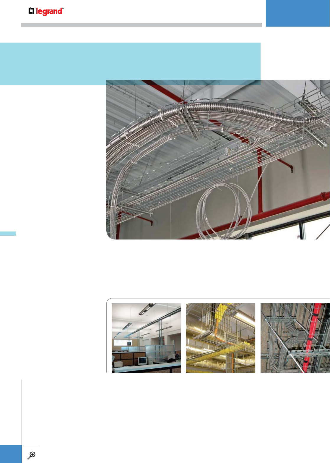
UNDERFLOOR
The UFS system was specifically designed for raised access floor cable
management. UFS can be installed before or after floor installation with
simple tools and is self-supporting, so it won’t void the manufacturer
warranty of raised access floors.
DATA CENTER
Cablofil Cable Management is especially suited for tight
spaces usually associated with communication closet
installations. All cable pathway turns, bends, and changes in
elevation can be fabricated on-site with simple tools to speed
installation time.
Cablofil is the right choice for cable management in all types of construction. Look to
the leader for specially engineered products that reduce installation time and create
cost-effective installations. For specific installation ideas and downloadable
drawings, go to our online Best Practices web site at: www.legrand.us/cablofil/tools.
CABLOFIL CABLE MANAGEMENT
Engineered Solutions for
Specific Applications
INTRODUCTION
WWW.LEGRAND.US/CABLOFIL
A.4
CABLOFIL
CABLE MANAGEMENT
COMMERCIAL
Cablofil Cable Management is as good-looking
as it is tough. All components are available in
Black or Custom Color power-coated finishes
for exposed installations in offices and public
buildings, or in a cost-effective electrozinc
finish for use above suspended ceilings.
INDUSTRIAL
Cablofil Cable Management is available in a
wide variety of finishes to meet the demands of the
harshest industrial environments. Choice of finishes include
two grades of stainless steel for food processing installations and
for use in salt/marine environments, as well as hot-dipped
galvanized finishes for exterior applications.
INTRODUCTION
WWW.LEGRAND.US/CABLOFIL
A.5
CABLOFIL
CABLE MANAGEMENT

Cablofil Cable Management is available in a variety of finishes to meet any industry need, from decorative to
extreme environments. Use this chart to help you determine the best finish for your application and its availability.
CABLOFIL CABLE MANAGEMENT
Finishes and Product Features
SYMBOL MATERIAL FINISH & STANDARD
INTERIOR
INSTALLATIONS
EXTERIOR
INSTALLATIONS
PETROLEUM PLANTS
CHEMICAL PLANTS
MARINE/SALT,
WEAK SULPHUROUS
ENVIRONMENTS
ACIDIC, ALKALINE
ENVIRONMENTS
FOOD PRODUCTION,
WASHDOWN,
CLEAN ROOMS
HALOGEN
ENVIRONMENTS
PG Carbon Steel
ASTM A653
Pre-Galvanized:
Continuous Galvanization
Before Fabrication
ASTM A 653
O
EZ Carbon Steel
ASTM A510
Grade 1020
Electrozinc:
Electrozinc plating
ASTM B 633
O
GC Carbon Steel
ASTM A510
Grade 1008
Hot Dipped Galvanized:
After Fabrication
ASTM A 123
OOOO
DC Carbon Steel
ASTM A510
Grade 1008
Geomet:
Zinc and Aluminum Protection
Equivalent to Hot Dip Galvanization
ASTM F 1136
OOOO
304L Stainless
Steel
AISI Type 304L
Stainless Steel 304L:
Cleaned and Passivated
ASTM A 380
OOOOOO
316L Stainless
Steel
AISI Type 316L
Stainless Steel 316L:
Cleaned and Passivated
ASTM A 380
OOOOOO
BL Carbon Steel
ASTM A510
Grade 1008
Black Painted:
Black Powder Coated
ASTM D 3451
O
PE Carbon Steel
ASTM A510
Grade 1008
Custom Painted:
Custom Color
Powder Coated
ASTM D 3451
O
For a more detailed explanation of finish standards and compatibility, visit www.legrand.us/cablofil.ORecommended OPossible
INTRODUCTION
WWW.LEGRAND.US/CABLOFIL
A.6
CABLOFIL
CABLE MANAGEMENT
Galvanic corrosion is the result of an electrochemical phenomenon due to the potential difference between different metals,
or between a metal and the impurities it contains, when they are in electrical contact. Be aware of this phenomenon when
selecting supports, splices and accessories. The results listed below are based on laboratory conditions and testing. However,
in actual installations other conditions need to be considered to determine if significant galvanic reactions will occur.
Galvanic Corrosion
™
ASSEMBLY
WITHOUT NUTS
AND BOLTS
ASSEMBLY WITH
NUTS AND BOLTS
PATENTED CABLOFIL
PRODUCTS
FAST ASSEMBLY
PATENTED FAST
ASSEMBLY SYSTEM™
NEW PRODUCT
INNOVATION
RECOMMENDED COMPATIBILITY
CABLE TRAY ACCESSORIES
PG / EZ PG / EZ
GC GC / DC
304L / 316L 316L
RECOMMENDED FOR TYPICAL CABLE TRAY
HARDWARE FINISH
TRAY MATERIAL & FINISH ZINC
PLATED GEOMET GC 316L
Steel/EZ (Electrozinc) OOOO
Steel/GC (HDGAF) OOO
Steel/BL (Painted) OOOO
Steel/PE (Painted) OOOO
Stainless-steel 304 (Passive) OOO
Stainless-steel 316 (Passive) OOO
Aluminum OOO
ORecommended OPossible
GALVANIC CORROSION TEXT RESULTS
PRIMARY MATERIAL TRAY
SECONDARY MATERIAL
HARDWARE
STAINLESSSTEEL 304L
NICKLE
COPPER
BRASS
CARBON STEEL
ALUMINUM
CHROMIUM
ZINC
Stainless-steel 304L 0
Nickle 180 0
Copper 320 140 0
Brass 400 220 80 0
Carbon Steel 750 570 430 350 0
Aluminum 840 660 520 440 90 0
Chromium 950 770 630 550 200 110 0
Zinc 1150 970 830 750 400 310 200 0
The potential differences are expressed in millivolts. Shaded secondary materials
in combination with primary materials listed above is not recommended.
Conditions
Lab Tests
• Submerged in seawater
• Equal mass materials
• Great connection
Typical Cable Tray Installation
• Wet/dry cycles not constant immersion
• Primary material may be 100 times greater
• Electrical current/connector
CABLOFIL PRODUCT CODE
Our part number makes it easy to identify part type, size and
finish. Please use this code whenever ordering or specifying
any Cablofil product.
SYMBOLS LEGEND
Use these symbols to guide you through our catalog of
innovative cable management products.
FOR TRAY
TYPE OF TRAY DEPTH IN MM WIDTH IN MM FINISH CODE
CF 54 100 EZ
FOR SUPPORT AND OTHER PRODUCTS
PRODUCT CODE SIZE IN MM FINISH CODE
FASC 300 PG
INTRODUCTION
WWW.LEGRAND.US/CABLOFIL
A.7
CABLOFIL
CABLE MANAGEMENT

Use this handy load guide to determine the capacity of your cable pathway. Always plan for extra space in cable pathways
during the initial installation to allow capacity for future cable additions. For information on other cable sizes, go to
www.legrand.us/cablofil/tools and use our online load calculator.
LOAD TABLE
LOADS IN LBS/FT PER SPAN
TRAY FILL AREA
(sq. in.) 5678
CF54/50(2x2) 4.03 32.0 15.1 11.1 9.1
CF54/100(2x4) 8.06 39.4 22.3 16.4 15.9
CF54/150(2x6) 12.09 46.5 27.6 20.3 19.1
CF54/200(2x8) 16.12 54.2 36.4 26.7 24.7
CF54/300(2x12) 24.18 71.6 47.1 34.6 31.7
CF54/450(2x18) 36.27 134.9 91.0 66.8 60.3
CF54/600(2x24) 48.36 119.4 95.4 70.1 62.8
CF105/100(4x4) 15.97 68.3 46.4 34.1 30.5
CF105/150(4x6) 23.95 98.4 60.2 44.3 40.9
CF105/200(4x8) 31.93 109.4 76.2 56.0 51.9
CF105/300(4x12) 47.90 142.0 126.8 93.1 89.2
CF105/450(4x18) 71.84 151.0 129.9 95.4 88.7
CF105/600(4x24) 95.79 151.0 129.9 95.4 88.7
CF150/150(6x6) 34.41 127.5 123.0 90.4 89.1
CF150/200(6x8) 45.88 127.5 123.0 90.4 89.1
CF150/300(6x12) 68.82 175.9 155.0 113.9 98.3
CF150/450(6x18) 103.23 175.9 155.0 113.9 98.3
CF150/600(6x24) 137.64 228.5 165.7 121.7 91.3
CABLOFIL CABLE MANAGEMENT
Quick Reference Load Table
INTRODUCTION
WWW.LEGRAND.US/CABLOFIL
A.8
CABLOFIL
CABLE MANAGEMENT

DATA CABLE FILL TABLE MC POWER CABLE FILL TABLE
MAX NUMBER OF CABLES PER CODE MAX NUMBER OF MC CABLES PER CODE
TRAY Cat 5e 4-pr
Plenum (.17”)
Cat 5e 4-pr
Non-Plenum (.19”)
Cat 6e 4-pr
Plenum (.22”)
Cat 6a 4-pr
Plenum (.35”)
2C (12 AWG)
THHN TypeMC
AlumArmor
3C (12 AWG)
THHN TypeMC
AlumArmor
3C (AWG 4/0)
THHN TypeMC
AlumArmor
3C (500 kcmil)
THHN TypeMC
AlumArmor
CF30/50(1x2) 47 cbls 38 cbls 28 cbls 11 cbls 11 cbls 10 cbls – –
CF30/100(1x4) 95 cbls 76 cbls 57 cbls 22 cbls 23 cbls 21 cbls – –
CF30/150(1x6) 43 cbls 114 cbls 85 cbls 33 cbls 35 cbls 31 cbls – –
CF30/200(1x8) 191 cbls 153 cbls 114 cbls 45 cbls 47 cbls 42 cbls – –
CF30/300(1x12) 286 cbls 229 cbls 171 cbls 67 cbls 71 cbls 63 cbls – –
CF54/50(2x2) 88 cbls 71 cbls 53 cbls 20 cbls 11 cbls 10 cbls – –
CF54/100(2x4) 177 cbls 142 cbls 106 cbls 41 cbls 23 cbls 21 cbls 2 cbls 1 cbl
CF54/150(2x6) 266 cbls 213 cbls 159 cbls 62 cbls 35 cbls 31 cbls 3 cbls 2 cbls
CF54/200(2x8) 355 cbls 284 cbls 212 cbls 83 cbls 47 cbls 42 cbls 5 cbls 3 cbls
CF54/300(2x12) 532 cbls 426 cbls 318 cbls 125 cbls 71 cbls 63 cbls 7 cbls 5 cbls
CF54/400(2x16) 710 cbls 568 cbls 424 cbls 167 cbls 95 cbls 84 cbls 10 cbls 7 cbls
CF54/450(2x18) 798 cbls 639 cbls 477 cbls 188 cbls 107 cbls 94 cbls 11 cbls 7 cbls
CF54/500(2x20) 887 cbls 710 cbls 530 cbls 209 cbls 119 cbls 105 cbls 12 cbls 8 cbls
CF54/600(2x24) 1065 cbls 852 cbls 636 cbls 251 cbls 143 cbls 126 cbls 15 cbls 10 cbls
CF105/100(4x4) 351 cbls 281 cbls 209 cbls 82 cbls 23 cbls 21 cbls 2 cbls 1 cbl
CF105/150(4x6) 527 cbls 422 cbls 314 cbls 124 cbls 35 cbls 31 cbls 3 cbls 2 cbls
CF105/200(4x8) 703 cbls 563 cbls 419 cbls 165 cbls 47 cbls 42 cbls 5 cbls 3 cbls
CF105/300(4x12) 1055 cbls 844 cbls 629 cbls 248 cbls 71 cbls 63 cbls 7 cbls 5 cbls
CF105/400(4x16) 1406 cbls 1126 cbls 839 cbls 331 cbls 95 cbls 84 cbls 10 cbls 7 cbls
CF105/450(4x18) 1582 cbls 1266 cbls 944 cbls 373 cbls 107 cbls 94 cbls 11 cbls 7 cbls
CF105/500(4x20) 1758 cbls 1407 cbls 1049 cbls 414 cbls 119 cbls 105 cbls 12 cbls 8 cbls
CF105/600(4x24) 2110 cbls 1689 cbls 1259 cbls 497 cbls 143 cbls 126 cbls 15 cbls 10 cbls
CF150/150(6x6) 788 cbls 631 cbls 469 cbls 186 cbls 23 cbls 21 cbls 3 cbls 2 cbls
CF150/200(6x8) 1010 cbls 809 cbls 603 cbls 238 cbls 47 cbls 42 cbls 5 cbls 3 cbls
CF150/300(6x12) 1515 cbls 1213 cbls 905 cbls 357 cbls 71 cbls 63 cbls 7 cbls 5 cbls
CF150/400(6x16) 2021 cbls 1618 cbls 1206 cbls 476 cbls 95 cbls 84 cbls 10 cbls 7 cbls
CF150/450(6x18) 2273 cbls 1820 cbls 1357 cbls 536 cbls 107 cbls 94 cbls 11 cbls 7 cbls
CF150/500(6x20) 2526 cbls 2022 cbls 1508 cbls 596 cbls 119 cbls 105 cbls 12 cbls 8 cbls
CF150/600(6x24) 3031 cbls 2427 cbls 1810 cbls 715 cbls 143 cbls 126 cbls 15 cbls 10 cbls
INTRODUCTION
WWW.LEGRAND.US/CABLOFIL
A.9
CABLOFIL
CABLE MANAGEMENT
CERTIFICATIONS
Cablofil Cable Managements have been independently evaluated by UL, CSA, ABS, DNV, ETL, and VDE to meet applicable standards
and requirements. Our products hold UL Classification to NEC requirements, cCSAus certification to NEMA & CSA requirements,
ABS Product Design Assessment certification, and E90 certification. Our products also meet the standards requirements of IEC,
EIA-TIA, and BICSI. For more information on Cablofil certifications, please visit www.legrand.us/cablofil.
MEMBERSHIPS:
NEMA, CTI, EIA-TIA, NFPA, IEC, BICSI
Designed to be Better
Cablofil Cable Management is constructed of precision engineered, high quality,
welded steel wire and is the result of decades of research gained from the installation
of 125,000 miles of tray across the globe. Our tray is subjected to testing at every stage
of the manufacturing process. In actual use, it has performed in a wide variety of
applications from heavy power cable pathways on oil drilling platforms in the
North Sea, to data installation above the ceiling in modern office buildings.
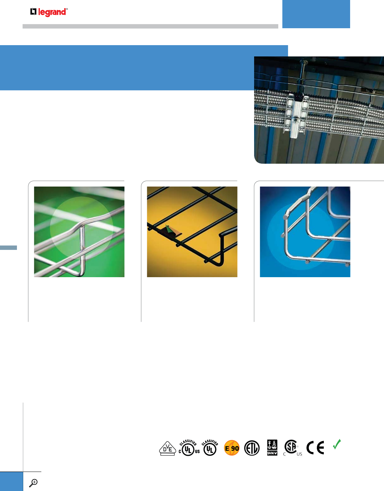
SAFETEDGE
Our unique Safe-T-Edge design
involves “T” welding the lateral
wires to the bottom edge of the top
wires, which eliminates sharp edges
and creates a smooth cable pathway
that’s safe for cables and installers.
This is most important when adding
or changing cables in your cable
pathway.
UL CLASSIFIED PAINTED
WIRE CABLE TRAY
Our UL Classified painted wire tray
meets NEC392 from the National
Electric Code that states, “all cable
tray systems must be properly
BONDED, per 250.96”. It is also UL
Classified as an EGC (Equipment
Grounding Conductor). Installation
requires a SWK splice on adjoining
tray bottoms that features a copper
strip.
PATENTED OPTIMIZED
WIRE DESIGN
The diameter of key wires in Cablofil
is optimized to the exact diameter
necessary, enabling the tray to
support the greatest working load.
While other manufacturers advocate
larger wire sizes for greater strength,
Legrand reviews product performance
using best-tested method for in-field
use. This optimized wire design is
patented in the US and around the
world.
®
REGISTERED TO
ISO
9001:2000
RoHS
COMPLIANT
CABLE MANAGEMENT
WIRE MESH CABLE TRAY
WWW.LEGRAND.US/CABLOFIL
A.10
CABLOFIL
CABLE MANAGEMENT

LOAD TESTING
Cablofil Cable Management has been engineered and tested per
NEMA VE1 to support loads that exceed its fill capacity. For exact
data on load capacity, testing methods and support placement,
please visit www.legrand.us/cablofil.
ELECTRICAL CONTINUITY
Cablofil Cable Management and our wide range of splices are tested and
comply with CSA, IEC, NEC, NEMA and UL requirements for low resistance.
Excellent electrical continuity and grounding is essential for safe installations
and reduces shock hazards.
STEEL GRADE QUALITY
Our tray is constructed of precision engineered, high quality steel wire. ISO 9000
certified, Cablofil Cable Management is subjected to rigorous quality control at
every stage of the manufacturing processes.
RESISTANCE TO FIRE
Cablofil Cable Management is certified E-30 to E-90. This German standard
is the only certification of its kind in the world and requires that the tray
and its supports withstand 1000˚ C or 1832˚ F heat for a period of 90
minutes. This is an important safety consideration when planning fire exit
routes from a burning building.
EXCELLENT EMC
Testing by independent laboratories show that Cablofil Cable Management, when
installed and earthed correctly, significantly reduces electromagnetic disturbances.
The steel structure of the tray absorbs EMI and drains the disturbance away
from cables causing minimal effect to the connected equipment. Cable pathways
constructed of aluminum alloys or plastics have no effect on EMI reduction.
CF 30 A.12
1” DEEP TRAY
CF 54 A.12
2” DEEP TRAY
CF 105 A.13
4” DEEP TRAY
CF 150 A.13
6” DEEP TRAY
UL CLASSIFIED PAINTED A.14
WIRE CABLE TRAY
PACKCF A.14
EASY PACK
CFG A.15
G-TRAY
G-MINI
CFL A.15
L-TRAY
TXF 35 A.16
TELEX RAIL
CTXF 35 A.16
TELEX RAIL COVER
UC 35 A.16
TELEX RAIL
STANDOFF SUPPORT
TRAY INSERT A.16
FCF 54 A.17
FASCLIC
CVN A.17
COVER
CLIP F02 A.17
COVER CLIP
COTFIL50/COTFIL100 A.18
SNAP-IN WIRE DIVIDERS
COT F A.18
FLEXIBLE DIVIDER
COT 30/COT54 A.19
DIVIDER STRIP
COT 105/COT 150 A.19
DIVIDER STRIP
COT J A.19
DIVIDER COUPLER
WIRE MESH CABLE TRAY
WWW.LEGRAND.US/CABLOFIL
A.11
CABLOFIL
CABLE MANAGEMENT

CF 54/400
CF 54/450
CF 54/500
CF 54/550
CF 54/600
CF 54/50
CF 54/100
CF 54/150
CF 54/200
CF 54/300
Cablofil’s Optimized Wire Size, Tray Patent Number – 6.138.961
Cablofil’s Optimized Wire Size, Tray Patent Number – 6.138.961
HEIGHT WIDTH LENGTH WEIGHT EZ
INCHES MM INCHES MM FEET M LBS KG
ZF 30/50* 1.0 30 2.0 50 10.0 3 3.3 1.5 –
CF 30/100 1.0 30 4.0 100 10.0 3 4.5 2.0 –
CF 30/150 1.0 30 6.0 150 10.0 3 5.7 2.6 –
CF 30/200 1.0 30 8.0 200 10.0 3 7.4 3.3 –
CF 30/300 1.0 30 12.0 300 10.0 3 9.4 4.3 –
*Products listed as “ZF” are only available in Straight Edge Tray.
– Contact manufacturer for availability.
ZF 30/50*
CF 30/100
CF 30/150
CF 30/200
CF 30/300
HEIGHT WIDTH LENGTH WEIGHT EZ GC 304L 316L BL PE
INCHES MM INCHES MM FEET M LBS KG
CF 54/50 2.0 54 2.0 50 10.0 3 5.3 2.4 000 061 – – – 941 101 934 056
CF 54/100 2.0 54 4.0 100 10.0 3 6.5 3.0 000 071 – – – 941 102 934 095
CF 54/150 2.0 54 6.0 150 10.0 3 7.8 3.5 000 081 – – – 941 103 934 130
CF 54/200 2.0 54 8.0 200 10.0 3 9.0 4.1 000 091 – – – 941 104 934 158
CF 54/300 2.0 54 12.0 300 10.0 3 13.4 6.1 000 101 – – – 941 105 933 901
CF 54/400 2.0 54 16.0 400 10.0 3 20.0 9.1 000 201 – – – 941 107 933 918
CF 54/450 2.0 54 18.0 450 10.0 3 22.8 10.3 000 251 – – 000 254 941 108 933 928
CF 54/500 2.0 54 20.0 500 10.0 3 24.4 11.0 000 301 – – – 941 109 933 932
CF 54/550 2.0 54 22.0 550 10.0 3 25.9 11.7 941 001 – – – 942 288 942 360
CF 54/600 2.0 54 24.0 600 10.0 3 27.5 12.5 000 401 – – – 941 110 933 944
– Contact manufacturer for availability.
Other sizes available. Contact Legrand.
CF 30 / ZF30
CABLOFIL CABLE TRAY
CF 54
CABLOFIL CABLE TRAY
WIRE MESH CABLE TRAY
WWW.LEGRAND.US/CABLOFIL
A.12
CABLOFIL
CABLE MANAGEMENT

Cablofil’s Optimized Wire Size, Tray Patent Number – 6.138.961
HEIGHT WIDTH LENGTH WEIGHT EZ GC 304L † 316L † BL PE
INCHES MM INCHES MM FEET M LBS KG
CF 150/150 6.0 150 6.0 150 10.0 3 18.9 8.6 000 981 – – – 941 124 934 178
CF 150/200 6.0 150 8.0 200 10.0 3 21.8 9.9 000 951 000 953 – – 941 121 934 172
CF 150/300 6.0 150 12.0 300 10.0 3 24.4 11.0 000 961 – – – 941 122 934 174
CF 150/400 6.0 150 16.0 400 10.0 3 25.8 11.7 000 971 – – – 941 123 934 176
CF 150/450 6.0 150 18.0 450 10.0 3 26.5 12.0 001 011 – – – 941 125 933 902
CF 150/500 6.0 150 20.0 500 10.0 3 27.8 12.6 001 021 – – – 941 126 933 903
ZF 150/550** 6.0 150 22.0 550 10.0 3 28.7 13.0 941 000 – – – 942 287 942 359
ZF 150/900** 6.0 150 36.0 900 10.0 3 34.6 15.7 943 161 – – – 943 783 –
– Contact manufacturer for availability.
**Products listed as “ZF” are only available in Straight Edge Tray.
†Available as “ZF” only.
CF 105/450
CF 105/500
CF 105/550
CF 105/600
CF 105/100
CF 105/150
CF 105/200
CF 105/300
CF 105/400
Other sizes available. Contact Legrand.
Other sizes available. Contact Legrand.
HEIGHT WIDTH LENGTH WEIGHT EZ GC 304L 316L BL PE
INCHES MM INCHES MM FEET M LBS KG
CF 105/100 4.0 105 4.0 100 10.0 3 9.0 4.1 000 891 – – – 941 114 934 146
CF 105/150 4.0 105 6.0 150 10.0 3 10.2 4.6 000 901 – – – 941 115 934 152
CF 105/200 4.0 105 8.0 200 10.0 3 13.4 6.1 000 911 000 913 000 918 000 914 941 116 934 160
CF 105/300 4.0 105 12.0 300 10.0 3 21.2 9.6 000 921 – – – 941 118 934 163
CF 105/400 4.0 105 16.0 400 10.0 3 23.0 10.4 000 931 – – – 941 119 934 167
CF 105/450 4.0 105 18.0 450 10.0 3 25.9 11.8 001 931 – – – 942 463 942 462
CF 105/500 4.0 105 20.0 500 10.0 3 27.5 12.5 000 941 – 000 948 – 941 120 934 170
CF 105/550 4.0 105 22.0 550 10.0 3 29.0 13.0 001 941 –––––
CF 105/600 4.0 105 24.0 600 10.0 3 30.4 13.8 001 031 – – 001 034 941 127 933 905
CF 105
CABLOFIL CABLE TRAY
CF 150 / ZF 150
CABLOFIL CABLE TRAY
– Contact manufacturer for availability.
CF 150/150
CF 150/200
CF 150/300
CF 150/400
CF 150/450
CF 150/500
ZF 150/550
ZF 150/900
WIRE MESH CABLE TRAY
WWW.LEGRAND.US/CABLOFIL
A.13
CABLOFIL
CABLE MANAGEMENT
• Industry’s only UL-Classified painted wire cable tray per NEC 392.
• Standard on all Cablofil BL or PE.
Directions for use:
1. Remove outer mask of folded copper strip (that has been painted over)
at the end of each section tray.
2. Splice tray section with SWK splice (page A.24) on copper strip of
adjoining trays to maintain proper bonding.
HEIGHT WIDTH LENGTH WEIGHT EZ
INCHES MM INCHES MM FEET M LBS KG
PACKCF 54/50 2.0 54 2.0 50 39.0 12 26.5 12.0 800 211
PACKCF 54/100 2.0 54 4.0 100 26.0 8 24.3 11.0 800 221
PACKCF 54/150 2.0 54 6.0 150 26.0 8 26.5 12.0 800 231
PACKCF 54/200 2.0 54 8.0 200 26.0 8 28.7 13.0 800 241
PACKCF 54/300 2.0 54 12.0 300 26.0 8 37.5 17.0 800 261
• Easy Pack is a conveniently packaged, all inclusive and ready to install
cable management system.
• Stop in at your local distributor showroom and get the products you
need right away.
• Great for small jobs and making additions to existing installations.
• I nstallation instructions and splicing hardware are included. Just cut,
bend and install—it’s that easy.
• Can be shipped via parcel service.
Each Easy Pack includes:
• 2" Easy Pack contains (6) 78" sections (39') of 2" deep Cablofil Tray and
12 Preclick splices.
• 4", 6" and 8" Easy Pack contains (4) 78" sections (26') of 2" deep
Cablofil Tray and 8 Preclick splices.
• 12" Easy Pack contains (4) 78" sections (26') of 2" deep Cablofil Tray,
8 Preclick splices and 4 SWK bolts.
• Easy installation instructions.
UL CLASSIFIED PAINTED
WIRE CABLE TRAY
PACKCF
CABLOFIL EASY PACK
WIRE MESH CABLE TRAY
WWW.LEGRAND.US/CABLOFIL
A.14
CABLOFIL
CABLE MANAGEMENT

• Unique curved top allows for direct
attachment to machinery, ceilings or walls.
• Use CE40 for CFG support attachment.
• 3" overhang on G-Tray allows for
direct-mounting in many configurations.
• Unique crosswire design easily bends and
lies flat when mounting.
• Use CE25 for G-Mini support attachment.
• G-Mini is a simple and secure routing for
small cable runs.
• Use SWK (page A.24) for splicing.
CFG
CABLOFIL G-TRAY AND G-MINI
HEIGHT WIDTH LENGTH WEIGHT EZ GC 304L 316L BL PE
INCHES MM INCHES MM FEET M LBS KG
CFG 50/100 2.0 50 4.0 100 10.0 3 7.0 3.2 ––––941 143 933 935
CFG 50/150 2.0 50 6.0 150 10.0 3 10.3 4.7 ––––943 114 –
CFG 50/200 2.0 50 8.0 200 10.0 3 10.3 4.7 ––––941 144 933 937
G–MINI 2.0 50 2.0 50 10.0 3 8.8 4.0 – – – 430 114 – –
– Contact manufacturer for availability.
HEIGHT WIDTH LENGTH WEIGHT EZ GC 304L 316L BL PE
INCHES MM INCHES MM FEET M LBS KG
CFL 54/100 2.0 54 4.0 100 10.0 3 5.3 2.4 942 769 – – – 942 772 942 773
– Contact manufacturer for availability.
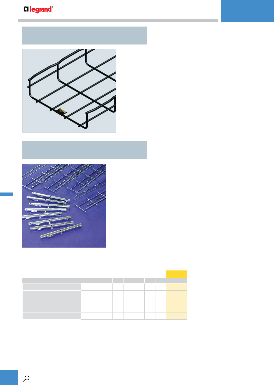
• Can be configured to any installation.
• For ETC Tray Beam Support see page D.10.
CFL
CABLOFIL L-TRAY
G-TRAY G-MINI
WIRE MESH CABLE TRAY
WWW.LEGRAND.US/CABLOFIL
A.15
CABLOFIL
CABLE MANAGEMENT

• Cover eliminates dirt and dust build-up on cable.
• Field fabricates on-site to fit changes in levels.
• Provides physical protection for cables.
• Use built-in tabs for permanent attachment to tray.
HEIGHT WIDTH LENGTH WEIGHT EZ GC 304L 316L BL PE
INCHES MM INCHES MM FEET M LBS KG
TXF 35 1.0 35 1.0 35 10.0 3 3.3 1.5 755 001 755 003 755 008 755 004 941 407 931 142
WIDTH LENGTH WEIGHT PG GC 316L BL PE
INCHES MM FEET M LBS KG
CTXF 35 1.0 35 10.0 3 2.7 1.2 755 100 – – 942 611 –
– Contact manufacturer for availability.
• Unique wire arrangement allows tray to lay flat
on cabinets or machinery without rocking.
• Use in applications where small runs of cable
are needed.
• Use SWK splice hardware.
• Use Tray Insert to protect cables in underside of tray.
• Bend over tabs to secure insert to tray.
PKG. QTY. WIDTH LENGTH WEIGHT PG
INCHES MM INCHES M LBS KG
Insert 100 2 3.39 86 58.75 1.5 2.5 1.1 942 420
Insert 150 2 5.39 137 58.75 1.5 4.47 2.0 942 421
Insert 200 2 7.36 187 58.75 1.5 5.0 2.3 942 422
Insert 300 2 11.34 288 58.75 1.5 8.6 3.9 942 426
Insert 450 2 17.36 441 58.75 1.5 12.5 5.7 942 427
Insert 500 2 19.33 491 58.75 1.5 13.75 6.2 942 428
Insert 600 2 23.39 594 58.75 1.5 15.0 6.8 942 430
Insert 900 2 35.20 894 58.75 1.5 52.5 23.8 943 367
TXF 35
TELEX RAIL
CTXF 35
TELEX RAIL COVER
UC 35
TELEX RAIL STANDOFF SUPPORT
WIDTH WEIGHT PG GC 316L BL PE
INCHES MM LBS KG
UC 35 1.5 40 1.1 0.5 586 160 – 586 164 942 754 942 755
• Specially designed to attach Telex rail to cabinet tops and channel framing.
• Fold over tabs secure tray without nuts and bolts. Just snap tray in place.
INSERT
TRAY INSERT
WIRE MESH CABLE TRAY
WWW.LEGRAND.US/CABLOFIL
A.16
CABLOFIL
CABLE MANAGEMENT
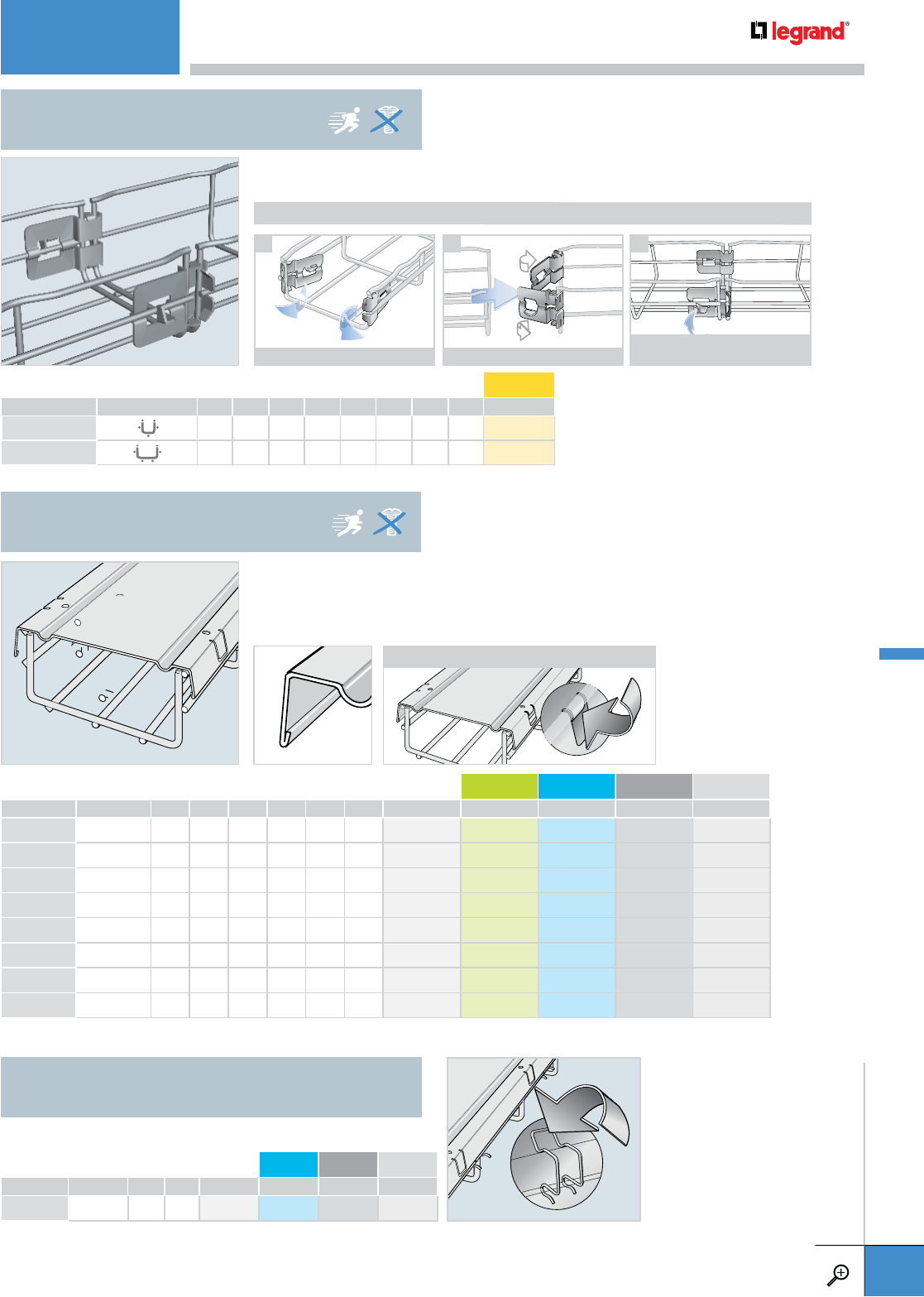
• FCF 54 includes pre-installed splices to speed install time.
• Locking tabs make for a secure splice.
ASSEMBLY
21
FOLD SPLICES OUT ALIGN TWO TRAY SECTIONS
USE PLIERS TO BEND LOCKING TABS
TO SECURE SPLICE
3
HEIGHT WIDTH LENGTH WEIGHT EZ
INCHES MM INCHES MM FEET M LBS KG
FCF 54/50 2.0 54 2.0 50 10.0 3 5.3 2.4 081 061
FCF 54/100 2.0 54 4.0 100 10.0 3 6.6 3.0 081 071
FCF 54
FASCLIC TRAY
PKG. QTY. WEIGHT PG 316L BL PE
LBS KG
CLIP F02 25 2.2 1.0 646 200 646 204 942 807 942 808
• Cover eliminates dirt and dust build-up on cable.
• Field fabricate on-site to fit changes in levels.
• Use built-in tabs for permanent attachment to tray.
• 3– 3.3’ covers are included in each package to cover 1-10’ section of Cablofil tray.
• Use for installations where cover (CVN) is removed frequently.
PKG. QTY. WIDTH LENGTH WEIGHT PG GC 316L BL PE
INCHES MM FEET M LBS KG
CVN 50 3 2.0 71 3.3 1 2.6 1.2 629 050 629 053 629 054 941 332 934 071
CVN 100 3 4.0 121 3.3 1 4.6 2.1 629 100 629 103 629 104 941 333 934 073
CVN 150 3 6.0 171 3.3 1 7.3 3.3 629 150 629 153 629 154 941 334 934 075
CVN 200 3 8.0 221 3.3 1 9.3 4.2 629 200 629 203 629 204 941 335 934 077
CVN 300 3 12.0 322 3.3 1 13.2 6.0 629 300 629 303 629 304 941 336 934 079
CVN 450 3 18.0 475 3.3 1 22.5 10.2 629 450 – – 941 338 934 083
CVN 500 3 20.0 525 3.3 1 28.4 12.9 629 500 – – 941 339 934 085
CVN 600 3 24.0 625 3.3 1 33.1 15.0 629 600 – – 941 340 934 087
– Contact manufacturer for availability.
CVN
CABLOFIL COVER
CLIP F02
COVER CLIP
ASSEMBLY
WIRE MESH CABLE TRAY
WWW.LEGRAND.US/CABLOFIL
A.17
CABLOFIL
CABLE MANAGEMENT
• Separates cables on sweeps and bends.
• Allows for installation of power cables and
data cables within the same pathway.
• Attaches to Cablofil tray using three sets of
EZ BN 1/4 and CE 25.
PKG. QTY. HEIGHT LENGTH WEIGHT PG GC 304L 316L BL PE
INCHES MM FEET METERS LBS KG
COTF54 KIT 1 2.0 54 6.0 2 1.07 0.49 943 423 – – – 943 426 943 427
COTF105 KIT 1 4.0 105 6.0 2 2.14 0.97 943 428 – – – 943 431 943 432
COTF150 KIT 1 6.0 150 6.0 2 3.21 1.46 943 433 – – – 943 436 943 437
– Contact manufacturer for availability.
COT F
FLEXIBLE DIVIDER
COTFIL50/COTFIL100
SNAP-IN WIRE DIVIDERS
• Keeps different cabling types separated in a single pathway
• Mount on straight sections, tees, crosses, junctions and sweeps
• Specific sizes available for CF54 and CF105 series
Cablofil Cable Management
• Snaps-in, requiring no additional hardware
• Patented
PKG. QTY. SIZE WEIGHT EZ
INCHES MM LBS KG
COTFIL50 12 2 50 .91 .412 586 721
COTFIL100 12 4 100 1.04 .471 586 728
WIRE MESH CABLE TRAY
WWW.LEGRAND.US/CABLOFIL
A.18
CABLOFIL
CABLE MANAGEMENT

HEIGHT LENGTH WEIGHT PG GC 316L BL PE
INCHES MM FEET M LBS KG
COT 30 1.0 30 10.0 3 2.0 0.9 923 010 – – 942 283 933 889
COT 54 2.0 54 10.0 3 2.8 1.3 923 020 923 023 923 024 942 284 933 891
– Contact manufacturer for availability.
HEIGHT LENGTH WEIGHT PG GC 316L BL PE
INCHES MM FEET M LBS KG
COT 105 KIT 4.0 105 10.0 3 4.7 2.1 943 413 943 414 943 415 943 416 943 417
COT 150 KIT 6.0 150 10.0 3 6.6 3.0 943 418 – – 943 421 943 422
– Contact manufacturer for availability.
PKG. QTY. WEIGHT AL PG 316L
LBS KG
COT J 25 0.026 0.012 943 390 923 050 923 054
• For cable separation within a single tray.
• Attach to tray with fold-over tabs or with
EZ BN 1/4 and CE 25 (sold separately –
see pg. A.81).
• Field fabricate with tin snips for changes
in levels.
• For cable separation within a single tray.
• Field fabricate with tin snips to fit
changes in levels.
• Requires EZ BN 1/4 and CE 25 to attach
to tray (included).
• COT 150 does not have tabs.
• Improves electrical continuity and strengthens dividers.
• Can be removed with a screwdriver and is reusable.
CF 30 CF 54
COT 30 COT 54
CF 105 CF 150
COT 105 COT 150
x1
EZ BN 1/4
x1
CE 25
COT 30/COT 54
DIVIDER STRIP
COT 105/COT 150
DIVIDER STRIP
COT J
DIVIDER COUPLER
WIRE MESH CABLE TRAY
WWW.LEGRAND.US/CABLOFIL
A.19
CABLOFIL
CABLE MANAGEMENT
A.21 EDRN
FAST SPLICE
A.21 EDRNTOOL
MOUNTING TOOL
A.21 PRECLICK
SPLICE
A.22 EXPANKIT
EXPANSION KIT
A.22 EDRSKIT
TRAY REDUCTION KIT
A.23 EDT
SPLICE PLATE
A.23 ED 275
UNIVERSAL SPLICE BAR
A.24 SWK
SPLICE WASHER KIT
A.24 CE 40
SQUARE SPLICE WASHER
A.25 CE 25/CE30
SQUARE SPLICE WASHER
A.25 CE 35
CLAMPING WASHER
A.26 FASLOCK
SPLICE
A.26 EAC KIT
ELEVATION CHANGE HINGE
A.26 EZT 90 KIT
90˚ AND TEE BEND KIT
A.27 RADT 90 KIT
RADIUS TEE 90˚ KIT
A.27 RADT 9012 KIT
12” RADIUS TEE 90˚ KIT
Cablofil has a splice for every need. Our EDRN is
the fastest splice we offer saving up to half the
installation time compared to bolted connections.
Other splices are available that help installers
give your installation additional strength or have
improved electrical continuity. The choice is yours.
For more information on splicing Cablofil Cable
Management, please go to www.legrand.us/cablofil.
SPLICING
SPLICING
WWW.LEGRAND.US/CABLOFIL
A.20
CABLOFIL
CABLE MANAGEMENT
• Fastest splice available from the Cablofil product
line. Saves up to half the install time compared to
bolted connections.
• Special assembly tool (EDRNTOOL) is included in
every bag of splices.
• UL Classified Splice.
• Additional mounting tool for use with EDRN splice.
• 7/16 hex in handle doubles as a SWK wrench.
SPLICING GUIDELINES
CF30 – CF54 – CF105 – CF150 2”
8” (50
200 MM)
12” (300
MM)
18”
24” (450
600 MM)
EDRN splices
needed on side wires 2x EDRN 2x EDRN 2x EDRN
EDRN splices needed
on bottom of tray –1x EDRN 2x EDRN
EDRN / EDRNTOOL
FAST SPLICE
PKG. QTY. WEIGHT EZ DC 316L BL PE
LBS KG
EDRN 25 3.9 1.75 ––
558 244 ––
50 8.8 4.0 558 241 558 247 –941 281 934 032
EDRNTOOL 1 0.2 0.09 – – – 943 408 –
– Contact manufacturer for availability.
EDRNTOOL
PKG. QTY. WEIGHT PG GC 316L BL PE
LBS KG
PRECLICK 8 1.7 0.8 942 735 – 942 739 942 738 942 737
– Contact manufacturer for availability.
• Installation is fast and easy – only a screwdriver is required to snap the splices in place.
• Square holes allows for bolted connections.
• SWK is sold separately. See p. A.81.
SWK
SPLICING GUIDELINES
CF54 – CF105 – CF150 2”
8” (50
200 MM)
12” (300
MM)
18”
24” (450
600 MM)
PRECLICK splices
needed on side wires 2x PRECLICK 2x PRECLICK 2x PRECLICK
SWK splices needed
on bottom of tray –1x SWK 2x SWK
PRECLICK
SPLICE
See installation instructions on page A.86.
See installation instructions on page A.86.
SPLICING
WWW.LEGRAND.US/CABLOFIL
A.21
CABLOFIL
CABLE MANAGEMENT
PLAY
PLAY
• Each kit includes two SWK, one ED 275
(or ED 1100), two EZ BN 1/4 and two
CE 25.
• ED 275 and ED 1100 can be trimmed
to any length with a shear or bolt
cutter if needed.
• Allows expansion between two pieces of tray
• Can be cut to fit with a bolt cutter.
• Can be bent by hand for use in tees, elbows, etc.
• UL Classified Splice.
• Slots (.22” x .28”) are on .98” centers.
PKG. QTY. WEIGHT EZ 316L
LBS KG
EXPANKIT 1 14.4 6.5 943 122 –
– Contact manufacturer for availability.
EDRSKIT
TRAY REDUCTION KIT
EXPANKIT
EXPANSION KIT
PKG. QTY. WEIGHT EZ 304L BL PE
LBS KG
ED275RSKIT* 1 0.3 0.15 943 202 – 943 441 944 590
ED1100RSKIT†1 1.2 0.6 943 221 – 944 396 –
– Contact manufacturer for availability.
*Use on tray differences up to 8”
†Use on tray differences over 8”
SPLICING
WWW.LEGRAND.US/CABLOFIL
A.22
CABLOFIL
CABLE MANAGEMENT

PKG. QTY. WEIGHT EZ 316L BL PE
LBS KG
EDT 50 6.6 3.0 558 251 558 254 941 282 934 034
PKG. QTY. WEIGHT EZ GC 316L BL PE
LBS KG
ED 275 50 14.4 6.5 558 221 - 558 224 941 279 930 621
• Splices are specially designed to join two sections of CF 30 Cablofil tray.
• EZ BN 1/4, CE 25 and SWK are sold separately. (see pg. A.81).
• UL Classified Splice.
SWK
SWK
CF30 – CF54 – CF105 – CF150 2” (50
MM)
4”
8”
(100
200
MM)
12”
24” (300
600 MM)
EDT splices needed
for side wires 2x CE 25, EZ BN 1/4, EDT 2x CE 25, EZ BN 1/4, EDT 2x CE 25, EZ BN 1/4, EDT
SWK splices needed
on bottom of tray –1x SWK 2x SWK
CF54 – CF105 – CF150 2” (50
MM)
4”
8”
(100
200
MM)
12”
24” (300
600 MM)
ED 275 splices
needed for side wires 2x CE 25, EZ BN 1/4, ED 275 2x CE 25, EZ BN 1/4, ED 275 2x CE 25, EZ BN 1/4, ED 275
SWK splices needed
on bottom of tray –1x SWK 2x SWK
EZ BN 1/4
CE 25
EDT
EZ BN 1/4
CE 25
ED 275
• Can be cut to fit with a bolt cutter.
• Can be bent by hand for use in tees, elbows, etc.
• EZ BN 1/4, CE 25 and SWK are sold separately. (see pg. A.81).
• UL Classified Splice.
• Slots (.22" x .28") are on .98" centers.
EDT
SPLICE PLATE
ED 275
UNIVERSAL SPLICE BAR
SPLICING
WWW.LEGRAND.US/CABLOFIL
A.23
CABLOFIL
CABLE MANAGEMENT
• SWK is designed with a 1/4" x 20* threaded bolt compatible with
standard US tools.
• Use SWK to splice any two sections of Cablofil tray.
• Swaged nut allows clamp to be stationary while nut is tightened.
• Consult chart below for correct number of SWK sets needed for
each width of tray.
• Also use for fabricating bends, turns and tees.
• UL Classified Splice .
PKG. QTY. WEIGHT EZ DC 316L BL
LBS KG
SWK 50 3.6 1.6 943 215 943 216 943 218 943 217
• Use for splicing Cablofil tray on bends and
adjustable turns.
• Two CE 40’s and one EZ BN 1/4 are required for
each connection.
• EZ BN 1/4 is sold separately. (see pg. A.81).
• UL Classified Splice.
APPLICATIONS
* Threads were previously M6
CF30 – CF54 – CF105 – CF150 – TXF35 – CFG 2” (50
MM)
4”
8” (100
200 MM)
12”
24” (300
600 MM)
SWK attachment sets
needed for side wires 2x SWK 2x SWK 2x SWK
SWK attachment sets
needed for bottom wires –1x SWK 2x SWK
SWK
SWK
SPLICE WASHER KIT
CE 40
SQUARE SPLICE WASHER
PKG. QTY. WEIGHT EZ GC DC 316L BL PE
LBS KG
CE 40 25 2.7 1.2 558 051 942 461 – 558 054 941 276 934 030
– Contact manufacturer for availability.
SPLICING
WWW.LEGRAND.US/CABLOFIL
A.24
CABLOFIL
CABLE MANAGEMENT
PLAY
• Use CE 25 and CE 30 with EZ BN 1/4 to splice any two sections of Cablofil tray.
• Consult chart below for correct number of Nut/Bolt/Clamp sets needed for
each width of tray.
• Also use for fabricating bends, turns and tees.
• UL Classified Splice.
• Useful for clamping cable dropouts or other
accessories to the top two side wires of Cablofil tray.
• Use with EZ BN 1/4 Bolt/Nut (sold separately –
see pg. A.81).
CF30 – CF54 – CF105 – CF150 2” (50
MM)
4”
8” (100
200 MM)
12”
24” (300
600 MM)
CE 25-CE30 attachment
sets needed for side wires 2x CE 25, CE 30, EZ BN 1/4 2x CE 25, CE 30, EZ BN 1/4 2x CE 25, CE 30, EZ BN 1/4
CE 25-CE30 attachment
sets needed for bottom wires –1x CE 25, CE 30, EZ BN 1/4 2x CE 25, CE 30, EZ BN 1/4
EZ BN 1/4
CE 30
CE 25
PKG. QTY. LENGTH WEIGHT 316L
INCHES MM LBS KG
CE 35 10 1.4 35 1.1 0.5 943 249
CE 25/CE 30
SQUARE SPLICE WASHER
CE 35
CLAMPING WASHER
PKG. QTY. WEIGHT EZ GC DC 316L BL PE
LBS KG
CE 25 50 1.0 0.45 558 011 942 459 558 013 558 014 941 274 934 022
CE 30 50 1.7 0.75 558 041 942 460 558 043 558 044 941 275 934 028
EZ BN 1/4 50 1.0 0.45 941 084 – 943 458 – 942 308 942 380
– Contact manufacturer for availability.
SPLICING
WWW.LEGRAND.US/CABLOFIL
A.25
CABLOFIL
CABLE MANAGEMENT

PKG. QTY. WEIGHT EZ DC 316L BL PE
LBS KG
FAS LOCK S 25 1.4 0.63 558 340 558 347 – 942 869 942 870
FAS LOCK XL 25 1.4 0.63 558 320 – – 942 821 942 822
– Contact manufacturer for availability.
FASLOCK S FASLOCK XL
x2
x4
CE 40
• One kit contains hardware for one
tee or two 90° bends.
• Slotted Design fits any size tray and
eliminates precise tray alignment.
• UL Classified Splice.
90˚ Braces
x8
x10
EZ BN 1/4
CE 25
PKG. QTY. WEIGHT EZ GC 316L BL PE
LBS KG
EZT 90 KIT 1 1.5 0.7 941 052 942 686 941 056 942 307 942 379
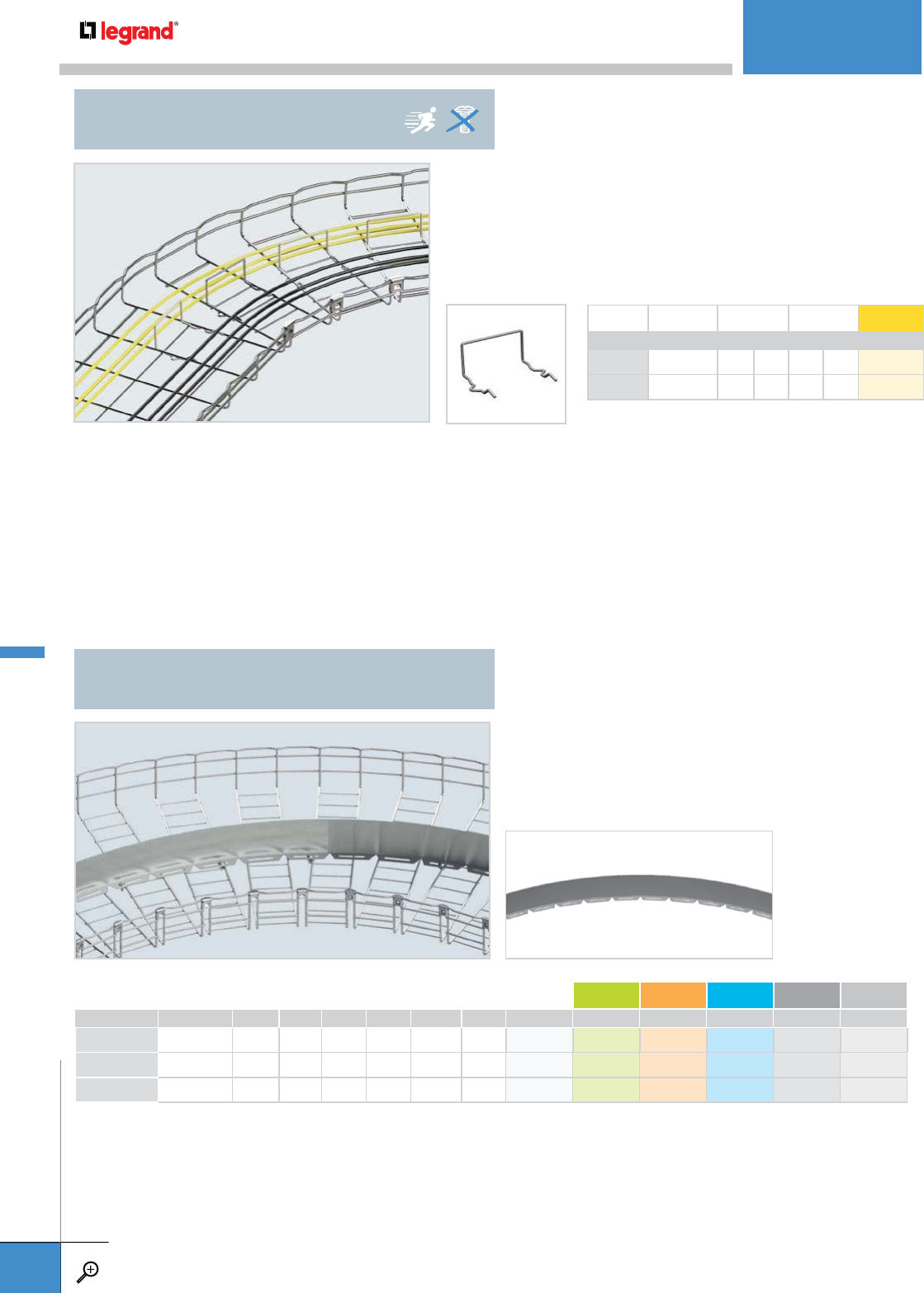
• Simple splicing method for bends and sweeps requires no tools.
• Use FASLOCK S for tray widths from 100 to 200mm and FASLOCK XL for tray
widths from 300 to 600mm.
• Unique design protects installers from cut edges.
x2
EAC
x8
x8
EZ BN 1/4
CE 25
• Reinforces changes in elevation.
• Strengthens installations that support heavy
power cables.
• Package contains hardware required for
elevation change as shown in photo.
• Pivot hardware pre installed.
• Works with 2” through 6” depth trays.
FASLOCK
SPLICE
EAC KIT
ELEVATION CHANGE HINGE
EZT 90 KIT
90˚ AND TEE BEND KIT
PKG. QTY. WEIGHT DC
LBS KG
EAC KIT 1 0.36 0.16 943 131
SPLICING
WWW.LEGRAND.US/CABLOFIL
A.26
CABLOFIL
CABLE MANAGEMENT
PLAY
PLAY
x2
RADIUS
SPLICE
x2
RADIUS
SPLICE
• One kit contains two Radius Splice, ten EZBN 1/4, eight CE 25 and four CE 40.
• Provides a sturdy radius tee that facilitates pulling MC or large power cables.
• Top wire loops help contain cable in tray while being pulled.
• One kit contains hardware for one tee or two 90˚ bends.
• UL Classified Splice.
• Patented design.
• One kit contains two Radius T 90 12 Splice, ten EZ BN 1/4, eight CE 25 and four CE 40.
• Provides a sturdy radius tee that facilitates pulling MC or large power cables.
• Top wire loops help contain cable in tray while being pulled.
• One kit contains hardware for one tee or two 90° bends.
• UL Classified Splice.
• Patented design.
x8
x10
EZ BN 1/4
CE 25
x8
x10
EZ BN 1/4
CE 25
PKG. QTY. HEIGHT WEIGHT EZ GC BL* PE
INCHES MM LBS KG
RAD T 90 KIT 2 1 2.0 54 2.0 0.90 942 911 943 209 943 027 943 121
RAD T 90 KIT 4 1 4.0 105 2.2 0.99 942 912 943 157 943 108 943 403
RAD T 90 KIT 6 1 6.0 150 2.4 1.08 942 942 943 160 943 387 944 411
* Other painted finishes available. Please contact Legrand Customer Service.
PKG. QTY. HEIGHT WEIGHT EZ GC BL PE
INCHES MM LBS KG
RAD T 90 12 KIT 2 1 2.0 54 3.2 1.45 943 474 – 943 475 943 476
RAD T 90 12 KIT 4 1 4.0 105 3.6 1.63 943 478 943 481 943 479 943 480
RAD T 90 12 KIT 6 1 6.0 150 3.8 1.72 943 482 – 943 483 943 484
– Contact manufacturer for availability.
x4
CE 40
x4
CE 40
RADT 90 KIT
5½” RADIUS TEE 90˚ KIT
RADT 9012 KIT
12” RADIUS TEE 90˚ KIT
SPLICING
WWW.LEGRAND.US/CABLOFIL
A.27
CABLOFIL
CABLE MANAGEMENT
PLAY

A.29 FAS P
FAS PROFILE
A.29 FV
VERTICAL BRACKET
A.30 FAS L
BRACKET
A.30 WTSB
WALL TOP SADDLE BRACKET
A.31 FAS C
BRACKET
A.32 FAS U
UNIVERSAL BRACKET
A.33 EDF
RAIL
A.34 CS
STANDARD L BRACKET
A.34 CSC
STANDARD C BRACKET
A.35 CRP
UNIVERSAL WALL BRACKET
A.35 C 50
WALL MOUNT ATTACHMENT
A.36 UC 50
CABLE TRAY STANDOFF
A.37 CAT 30/41
SNAP-IN WALL
HANGER SUPPORT
Many Cablofil wall supports utilize our unique Fast Assembly
System (FAS). This system utilizes simple one-step locking
tabs that require no additional hardware to secure tray
runs to its supports, reducing installation time and saving
money. Also available are standard wall supports that require
bolted connections to the tray. This comprehensive range of
wall supports in multiple finishes allows for every possible
installation you will need.
WALL MOUNTINGS
WALL MOUNTINGS
WWW.LEGRAND.US/CABLOFIL
A.28
CABLOFIL
CABLE MANAGEMENT

• Pre-drilled mounting holes make
installations easy.
• Patented FAS style attachment
secures tray without nuts and bolts.
• Will hold tray away from wall 0.66".
• Unique support keeps tray secure
vertically.
• Fold-over tabs secure tray; no
additional hardware needed.
• Uses 2 supports for tray widths of
18" or more.
• Use on 6“ and wider tray.
LENGTH WEIGHT PG GC 316L BL PE
INCHES MM LBS KG
FASP 150 6.0 150 0.4 0.2 014 150 014 153 014 154 941 153 930 012
FASP 200 8.0 200 0.7 0.3 014 200 014 203 014 204 941 154 930 014
FASP 300 12.0 300 0.9 0.4 014 300 014 303 014 304 941 155 930 016
FASP 400 16.0 400 1.1 0.5 014 400 014 403 014 404 941 156 930 018
FASP 450 18.0 450 1.2 0.6 014 450 – – 941 157 930 020
FASP 500 20.0 500 1.3 0.6 014 500 – – 941 158 930 022
FASP 550 22.0 550 1.3 0.6 014 550 014 553 – 941 159 930 024
FASP 600 24.0 600 1.5 0.7 014 600 014 603 014 604 941 160 930 026
FASP 700 28.0 700 1.8 0.8 014 700 – 014 704 941 162 930 028
FASP 1000 40.0 1000 2.6 1.2 014 010 – 014 014 941 149 930 006
FASP 2000 80.0 2000 5.3 2.4 014 020 – – 941 151 930 008
FASP 3000 120.0 3000 7.9 3.6 014 030 014 033 014 034 941 152 930 010
– Contact manufacturer for availability.
LENGTH WEIGHT PG GC 316L BL PE
INCHES MM LBS KG
FV 1 8.0 200 0.7 0.3 586 070 586 073 586 074 942 805 –
– Contact manufacturer for availability.
0.66"
16 MM
1.18"
30 MM
FAS P
FAS PROFILE
FV
VERTICAL BRACKET
WALL MOUNTINGS
WWW.LEGRAND.US/CABLOFIL
A.29
CABLOFIL
CABLE MANAGEMENT
PLAY
TRAY WIDTH LENGTH (L) WEIGHT PG GC 304L 316L BL PE
INCHES MM INCHES MM LBS KG
FASL 100 4.0 100 7.0 178.5 0.9 0.4 556 100 556 103 – 556 104 941 257 930 523
FASL 150 6.0 150 9.0 228.5 1.0 0.5 556 110 556 113 – 556 114 941 258 930 525
FASL 200 8.0 200 11.0 278.5 1.1 0.5 556 120 556 123 – 556 124 941 259 930 527
FASL 300 12.0 300 14.9 378.5 1.4 0.6 556 130 556 133 – 556 134 941 260 930 529
FASL 400 16.0 400 18.8 478.5 1.8 0.8 556 140 – – – 943 146 943 388
FASL 450 18.0 450 20.8 528.5 2.1 1.0 556 150 – – – 942 848 942 600
• For installation of Cablofil tray
onto walls.
• Reduce installation time—patented
FAS style attachment holds tray
secure without nuts and bolts.
• Order “width” to match tray.
• Installs Cablofil tray onto interior
block walls without drilling or
concrete anchors.
• Includes two EZBN 5/16 bolts
to attach FAS L or FAS C tray
supports (sold separately –
see pg. A.81).
– Contact manufacturer for availability.
L
PKG QTY WIDTH WEIGHT EZ
INCHES MM LBS KG
WTSB 46 10 4.0-6.0 102-152 1.9 0.86 943 347
WTSB 810 10 8.0-10.0 203-254 2.3 1.05 943 348
Patent Number – 20090289152
FAS L
BRACKET
WTSB
WALL TOP SADDLE BRACKET
WALL MOUNTINGS
WWW.LEGRAND.US/CABLOFIL
A.30
CABLOFIL
CABLE MANAGEMENT
TRAY WIDTH LENGTH (L1) LENGTH (L2) WEIGHT PG GC 304L 316L BL PE
INCHES MM INCHES MM INCHES MM LBS KG
FASC 100 4.0 100 6.7 170 7.0 178.5 1.4 0.6 556 300 – – – 941 261 930 531
FASC 150 6.0 150 6.7 170 8.9 228.5 1.5 0.7 556 310 – – – 941 262 930 533
FASC 200 8.0 200 6.7 170 10.9 278.5 1.7 0.8 556 320 – – – 941 263 930 535
FASC 300 12.0 300 11.3 288 14.9 378.5 1.9 0.9 556 330 – – – 941 264 930 537
FASC 400 16.0 400 11.3 288 18.8 478.5 2.4 1.1 556 340 – – – 943 096 –
FASC 450 18.0 450 11.3 288 20.8 528.5 2.75 1.25 556 350 – – – 942 596 –
– Contact manufacturer for availability.
• Use one or more FAS C brackets
to create multiple level tray
installations.
• Saves installation time – patented
FAS style attachment holds tray
secure without nuts and bolts.
• EZ BN 1/4 and CE 25 are
sold separately. (see pg. A.81).
8.6"
210 MM
L2
L1
x1
x1
EZ BN 1/4
CE 25
APPLICATIONS
FAS C
BRACKET
WALL MOUNTINGS
WWW.LEGRAND.US/CABLOFIL
A.31
CABLOFIL
CABLE MANAGEMENT
HEIGHT TRAY WIDTH LENGTH WEIGHT PG GC 316L BL PE
INCHES MM INCHES MM INCHES MM LBS KG
FASU 100 3.5 85 4.0 100 6.0 157 0.3 0.1 557 410 – 557 414 941 267 930 575
FASU 150 5.0 124 6.0 150 8.0 207 0.4 0.2 557 420 557 423 557 424 941 268 930 577
FASU 200 5.5 139 8.0 200 12.0 257 0.5 0.2 557 430 557 433 557 434 941 269 930 579
FASU 300 5.5 139 12.0 300 14.0 357 0.8 0.3 557 440 557 443 557 444 941 270 930 581
– Contact manufacturer for availability.
HEIGHT TRAY WIDTH LENGTH WEIGHT PG GC 316L BL PE
INCHES MM INCHES MM INCHES MM LBS KG
FASU 400 5.5 137.7 16.0 400 18.0 457 1.8 0.8 557 450 557 453 557 454 941 271 930 583
FASU 450 5.5 137.7 18.0 450 20.0 507 2.4 1.1 944 533 – – 944 536 944 937
FASU 500 5.5 137.7 20.0 500 22.0 557 2.9 1.3 557 460 557 463 – 941 272 930 585
FASU 600 5.5 137.7 24.0 600 26.0 657 6.4 2.9 557 470 – – 941 273 930 587
– Contact manufacturer for availability.
• For tray installation onto walls or
channel framing.
• Patented FAS style attachment
holds tray secure without nuts and
bolts.
• For wider tray and heavier loads.
• Snaps directly into EDF rail.
APPLICATIONS
APPLICATIONS
FAS U
UNIVERSAL BRACKET
WALL MOUNTINGS
WWW.LEGRAND.US/CABLOFIL
A.32
CABLOFIL
CABLE MANAGEMENT

LENGTH WEIGHT PG GC 316L BL PE
INCHES MM LBS KG
EDF 300 10.6 270 0.7 0.3 561 310 561 313 – 942 817 942 818
EDF 600 24.8 630 1.8 0.8 557 610 557 613 – 942 815 942 816
EDF 1000 39.0 990 2.6 1.2 561 090 561 093 – 942 813 942 814
EDF 2000 78.0 2000 5.5 2.5 561 010 561 013 – 941 288 930 641
EDF 3000 120.0 3000 9.1 4.1 561 020 561 023 – 941 289 930 643
– Contact manufacturer for availability.
• EDF Rail makes tiered tray runs
easier and faster to install.
• CA Pin (sold separately) is required
to install 4" to 12" FASU. Suggested
for 16" to 24" FASU.
• FASU sizes 16" to 24" will snap
directly onto EDF Rail.
CA
EDF
RAIL
WALL MOUNTINGS
WWW.LEGRAND.US/CABLOFIL
A.33
CABLOFIL
CABLE MANAGEMENT
WIDTH LENGTH (L1) LENGTH (L2) WEIGHT PG GC 316L BL PE
INCHES MM INCHES MM INCHES MM LBS KG
CSC 100 4.0 100 5.1 130 5.7 145 1.1 0.5 002 760 – – 941 136 930 082
CSC 200 8.0 200 7.0 180 9.6 245 1.4 0.7 002 770 – 002 774 941 137 930 084
CSC 300 12.0 300 9.0 230 13.6 345 1.8 0.8 002 780 – – 941 138 930 086
– Contact manufacturer for availability.
• Can be stacked for multilevel Cablofil
tray installations.
• ECLI clip prevents bracket compression.
• EZ BN 1/4, EZ BN 5/16, CE 25, CE 40
and ECLI are sold separately. (see
pg. A.81).
L2
L1
8"
200 MM
100 – 200 MM x1
300 MM x2 ECLI
EZ BN 5/16
CE 40
100 – 300 MM x1
EZ BN 1/4
CE 25
WIDTH LENGTH WEIGHT PG GC 316L BL PE
INCHES MM INCHES MM LBS KG
CS 100 4.0 100 5.7 145 0.4 0.2 002 700 – 002 704 941 130 930 070
CS 200 8.0 200 9.6 245 0.8 0.4 002 710 002 713 – 941 131 930 072
CS 300 12.0 300 13.6 345 1.2 0.5 002 720 – 002 724 941 132 930 074
– Contact manufacturer for availability.
• For cable tray installation onto walls.
• ECLI clip prevents bracket compression.
• EZ BN 1/4, CE 25 and ECLI are sold separately.
(see pg. A.81).
100 – 200 MM x1
300 – 450 MM x2
ECLI
EZ BN 1/4
CE 25
CS
STANDARD L BRACKET
CSC
STANDARD C BRACKET
WALL MOUNTINGS
WWW.LEGRAND.US/CABLOFIL
A.34
CABLOFIL
CABLE MANAGEMENT
WEIGHT PG GC 316L BL PE
LBS KG
C 50 0.2 0.1 586 130 586 133 – 941 308 930 694
– Contact manufacturer for availability.
HEIGHT WIDTH LENGTH WEIGHT GC
INCHES MM INCHES MM INCHES MM LBS KG
CRP 100 3.7 93 4.0 100 4.6 117 0.4 0.2 –
CRP 150 3.7 93 6.0 150 6.5 167 0.7 0.3 –
CRP 200 3.7 93 8.0 200 8.5 217 0.8 0.3 557 233
CRP 300 3.7 93 12.0 300 12.4 317 1.0 0.5 557 243
CRP 400 4.7 121 16.0 400 16.4 417 1.3 0.6 –
CRP 500 4.7 121 20.0 500 20.4 517 1.8 0.8 557 263
CRP 600 4.7 121 24.0 600 24.3 617 2.4 1.1 557 273
– Contact manufacturer for availability.
• Hot dipped galvanized after fabrication
for corrosion resistance.
• CE 25 and EZ BN 1/4 are sold
separately. (see pg. A.81).
• Attaches tray up to 4" wide to walls, cabinets or machinery.
• Fold-over tabs secures tray without additional hardware.
• Slotted mounting holes make for adjustable installations.
APPLICATIONS
100 – 200 MM x1
300 – 400 MM x2
500 – 600 MM x3
EZ BN 1/4
CE 25
• Secure tray in open front
configuration.
CRP
UNIVERSAL WALL BRACKET
C 50
WALL MOUNT ATTACHMENT
WALL MOUNTINGS
WWW.LEGRAND.US/CABLOFIL
A.35
CABLOFIL
CABLE MANAGEMENT
WEIGHT PG GC 316L BL PE
LBS KG
UC 50 0.1 0.06 586 040 586 043 586 044 941 304 930 681
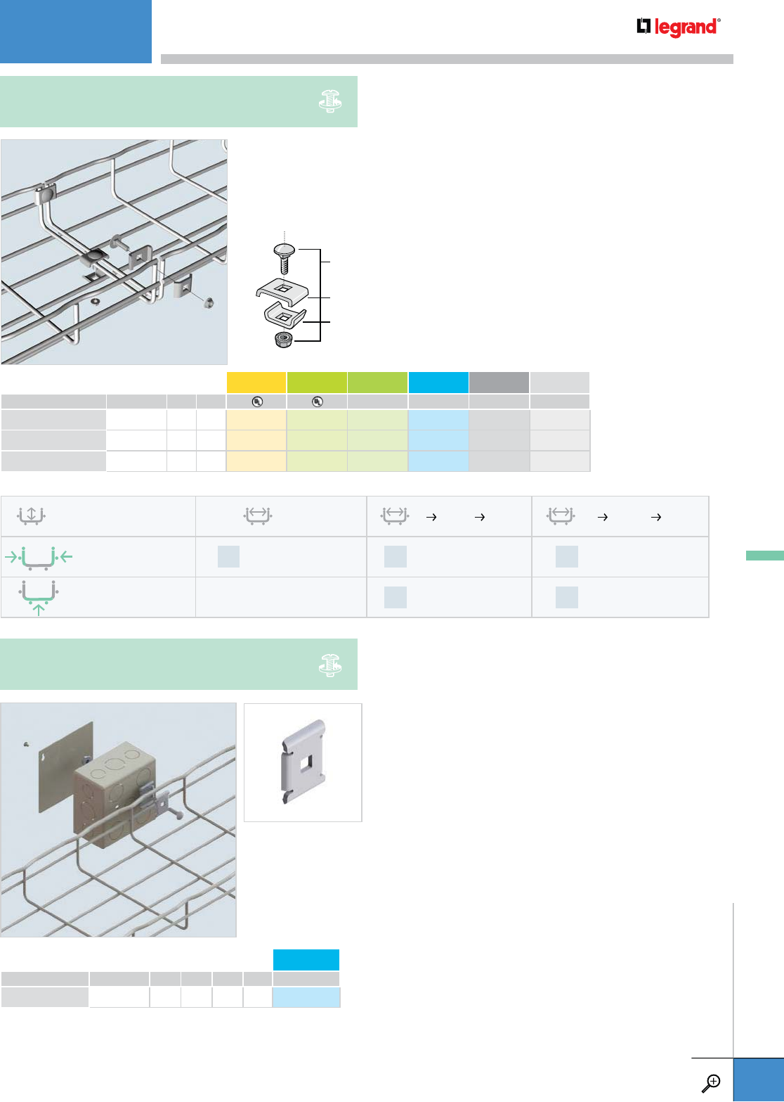
• Attaches 2" wide tray to cabinet tops
and channel framing.
• Fold over tabs secure tray
without fasteners.
Attaches 2" wide tray to CS
wall supports.
Can attach 2" wide tray directly to wall for horizontal and
vertical installations.
APPLICATIONS
CF30
CF54
UC 50
CABLE TRAY STANDOFF
WALL MOUNTINGS
WWW.LEGRAND.US/CABLOFIL
A.36
CABLOFIL
CABLE MANAGEMENT

WEIGHT PG GC 316L BL PE
LBS KG
CAT 30/41 0.1 0.03 942 720 – – 942 800 942 801
– Contact manufacturer for availability.
CAT 30/41 can attach 2" wide tray directly to
walls, cabinets or machinery.
Use EZ BN 1/4 to attach 2" wide tray to
channel framing or CS supports.
• Keeps 2" wide tray secure when
attaching to supports.
• No screws required for tray
attachment.
• Just snap in place.
APPLICATIONS
CF54
CF30
CAT 30/41
SNAP-IN WALL HANGER SUPPORT
WALL MOUNTINGS
WWW.LEGRAND.US/CABLOFIL
A.37
CABLOFIL
CABLE MANAGEMENT
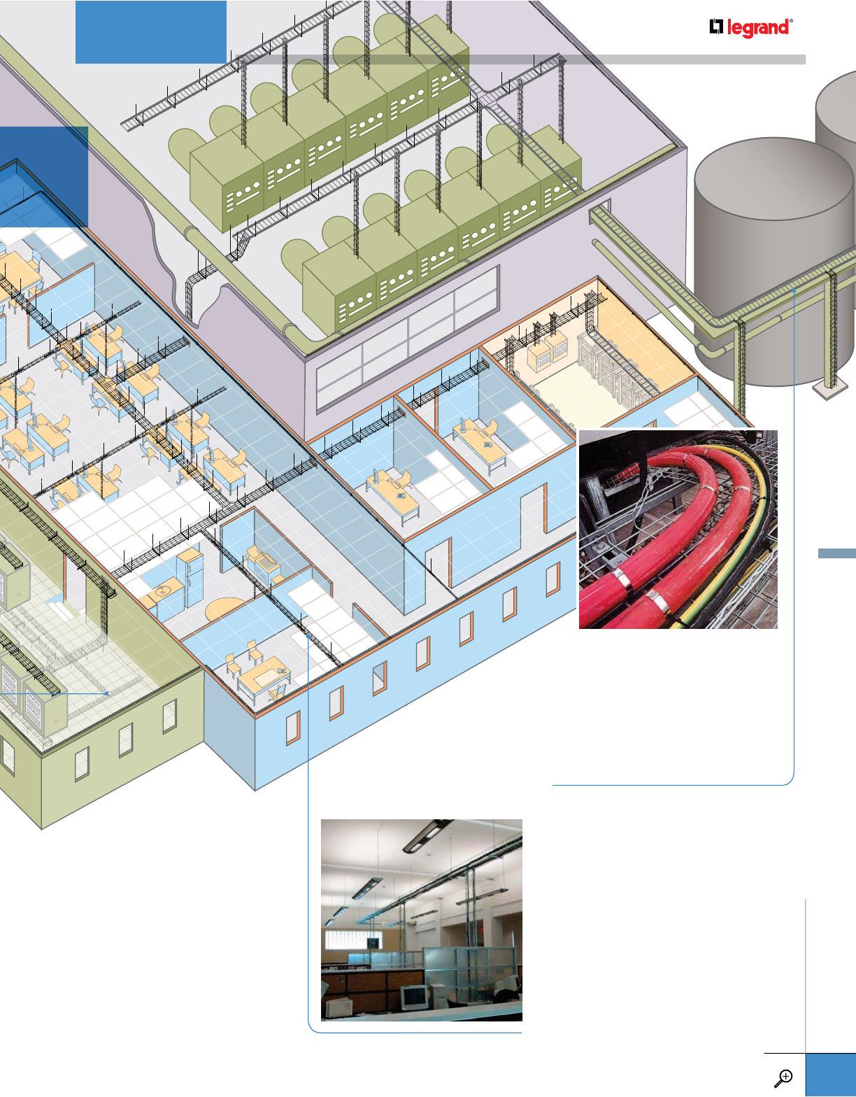
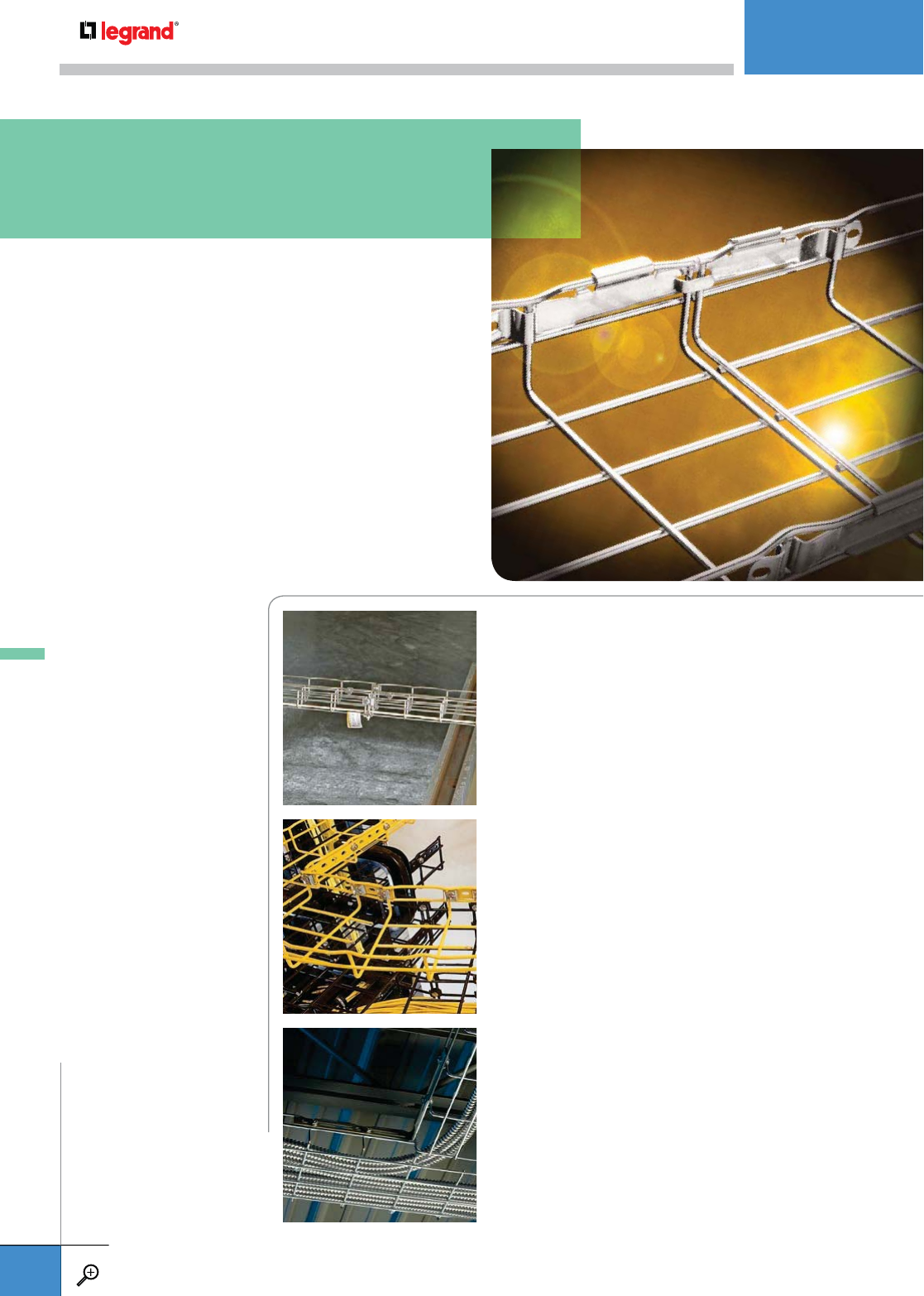
Legrand offers three styles of Cablofil ceiling hung supports, direct attachment to
the ceiling deck, suspended from threaded rods or pendant style supports. Many
hangers feature our unique FAS system of securing the tray to the supports without
additional hardware. All Cablofil ceiling supports are available in a variety of finishes
to compliment the type of tray you plan to install.
CEILING MOUNTINGS
A . 3 9 SF 50
CENTER HANGER
A.39 SF 100
CENTER HANGER
A.40 PAT 30
SUSPENSION SHOE
A.40 SAS
SINGLE HANGER
SUSPENSION BRACKET
A.41 FAS PCH
CENTER HANGER
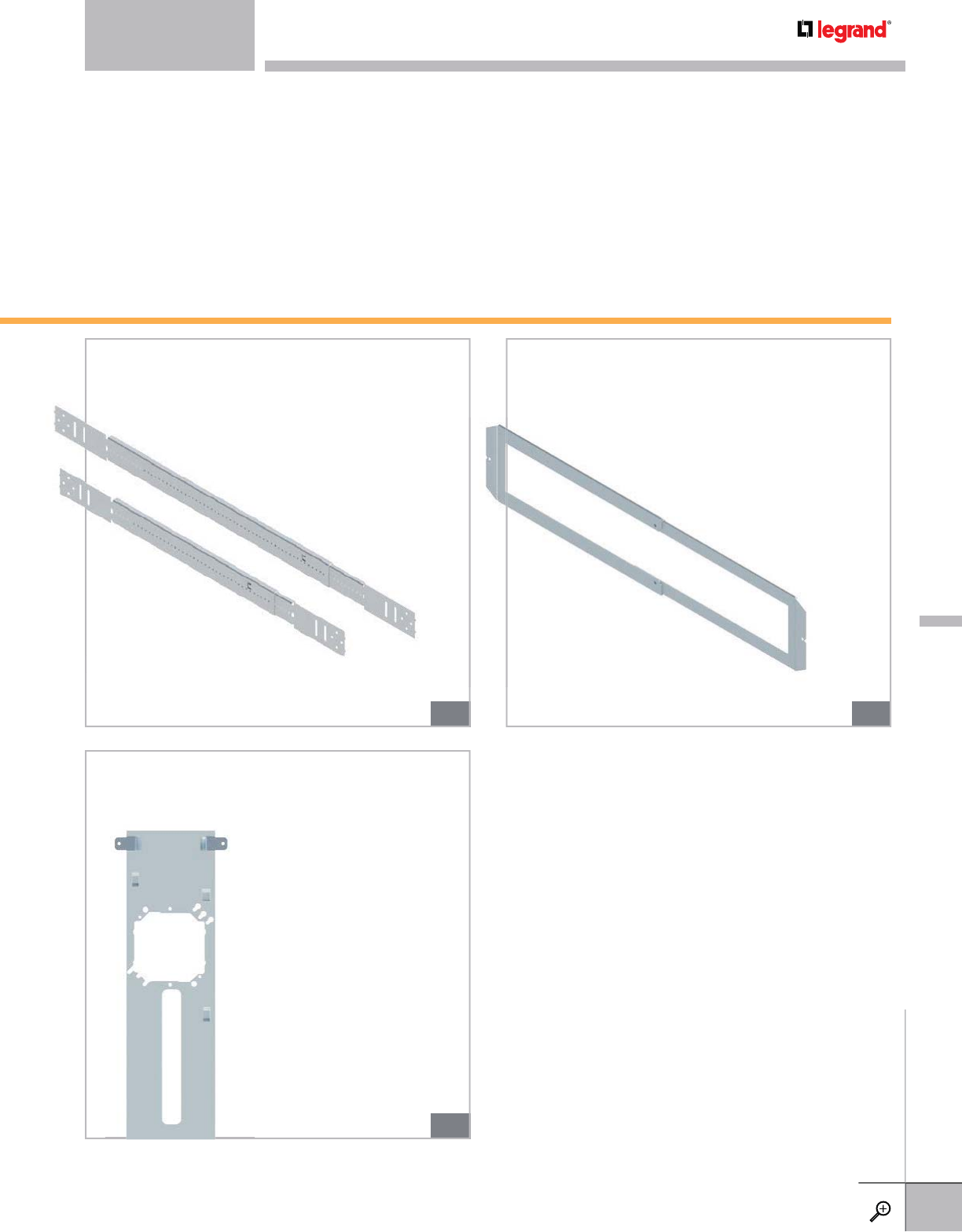
A.42 FAS P
FAS PROFILE
A.42 SON
SLIP-ON LOCK NUT®
A.43 AS
TRAPEZE HANGING CLIP
A.43 PROCS
STANDARD PROFILE
A.44 FAS C
BRACKET
A.44 CSC
STANDARD C BRACKET
A.45 CS / PS
PENDANT L BRACKETS
A.46 EDF
RAIL
A.47 PFREDF
MOUNTING BRACKET
A.47 DF
ANGLE MOUNTING BRACKET
A.47 ERD 10
BRACE PLATE
CEILING MOUNTINGS
WWW.LEGRAND.US/CABLOFIL
A.38
CABLOFIL
CABLE MANAGEMENT
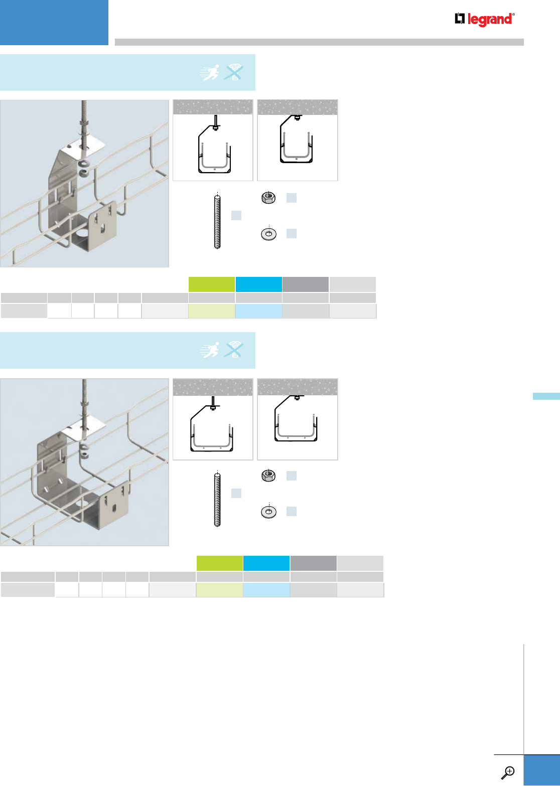
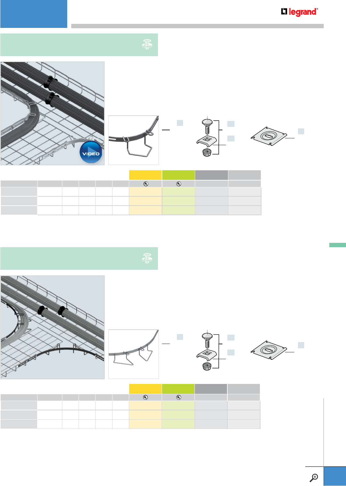
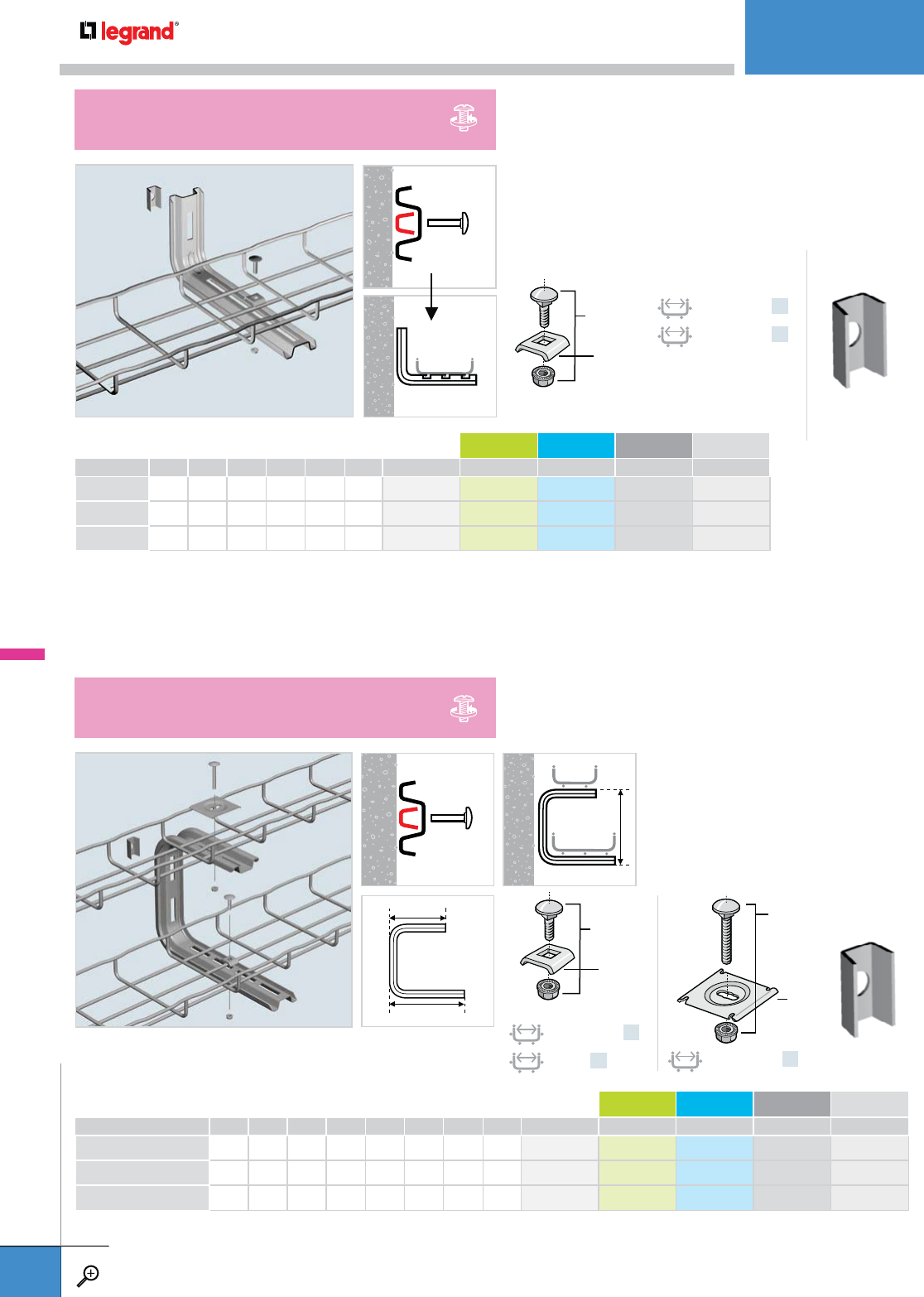
• For center hanging 2" wide tray.
• Fold-over tabs secure tray without
additional hardware.
• Threaded rod, nuts and washers
sold separately.
• Optional THRD: 5/16"
• Can be attached directly to ceiling
with power tools thru bottom
access hole.
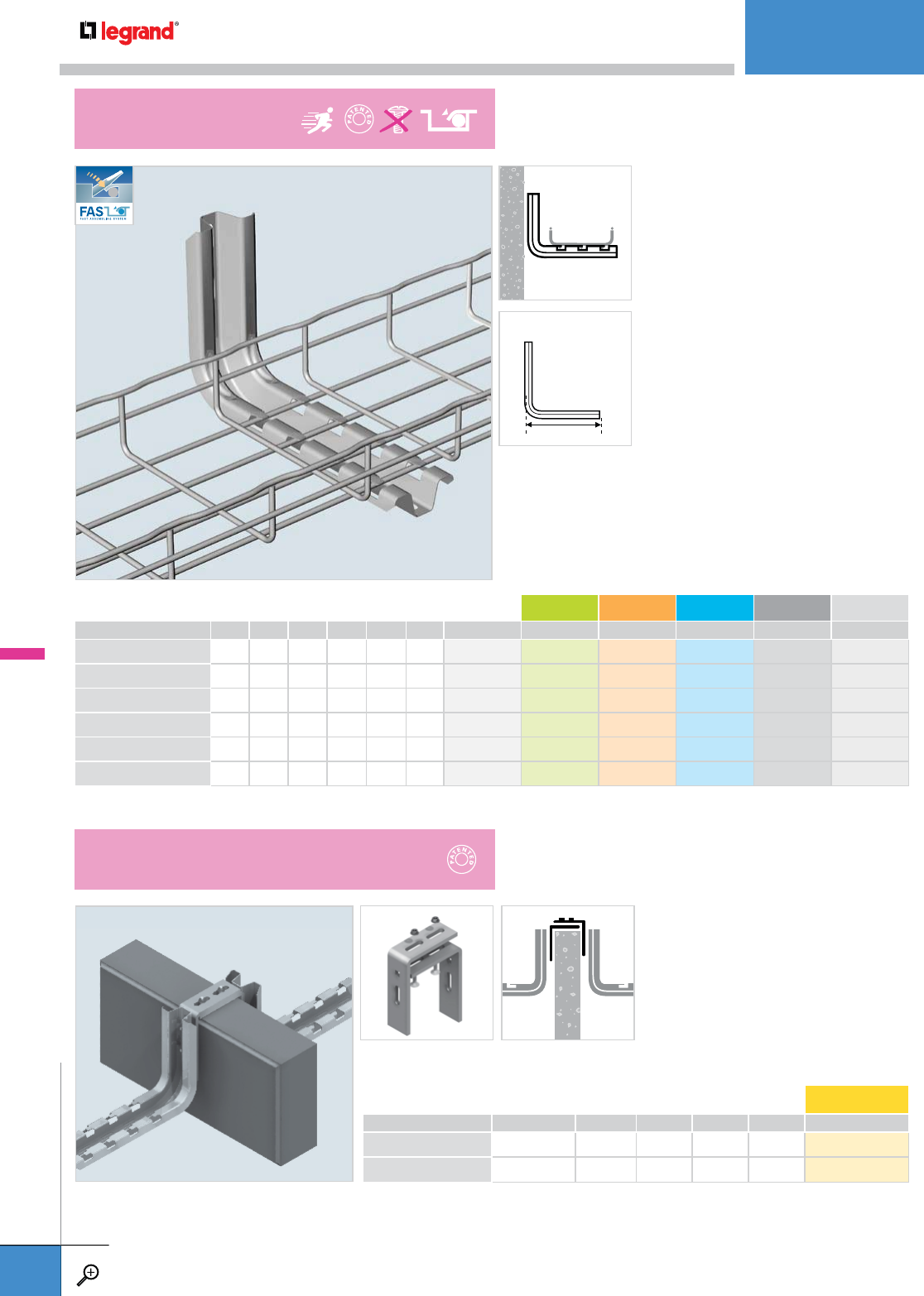
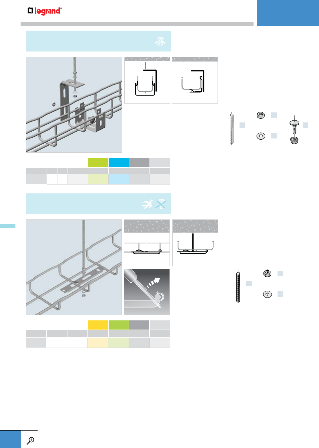
• For center hanging 4" wide tray.
• Fold-over tabs secure tray without
additional hardware.
• Threaded rod, nuts and washers
sold separately.
• Optional THRD: 5/16”
• Can be attached directly to ceiling
with power tools thru bottom
access hole.
WIDTH WEIGHT PG GC 316L BL PE
INCHES CM LBS KG
SF 50 2.0 50 0.4 0.2 586 140 586 143 586 144 942 593 942 594
WIDTH WEIGHT PG GC 316L BL PE
INCHES CM LBS KG
SF 100 4.0 100 0.9 0.4 586 100 586 103 586 104 942 840 942 606
x1
x2
x2
THRD 1/4
EZ HN 1/4
EZ FW 1/4
x1
x2
x2
THRD 1/4
EZ HN 1/4
EZ FW 1/4
SF 50
CENTER HANGER
SF 100
CENTER HANGER
CEILING MOUNTINGS
WWW.LEGRAND.US/CABLOFIL
A.39
CABLOFIL
CABLE MANAGEMENT
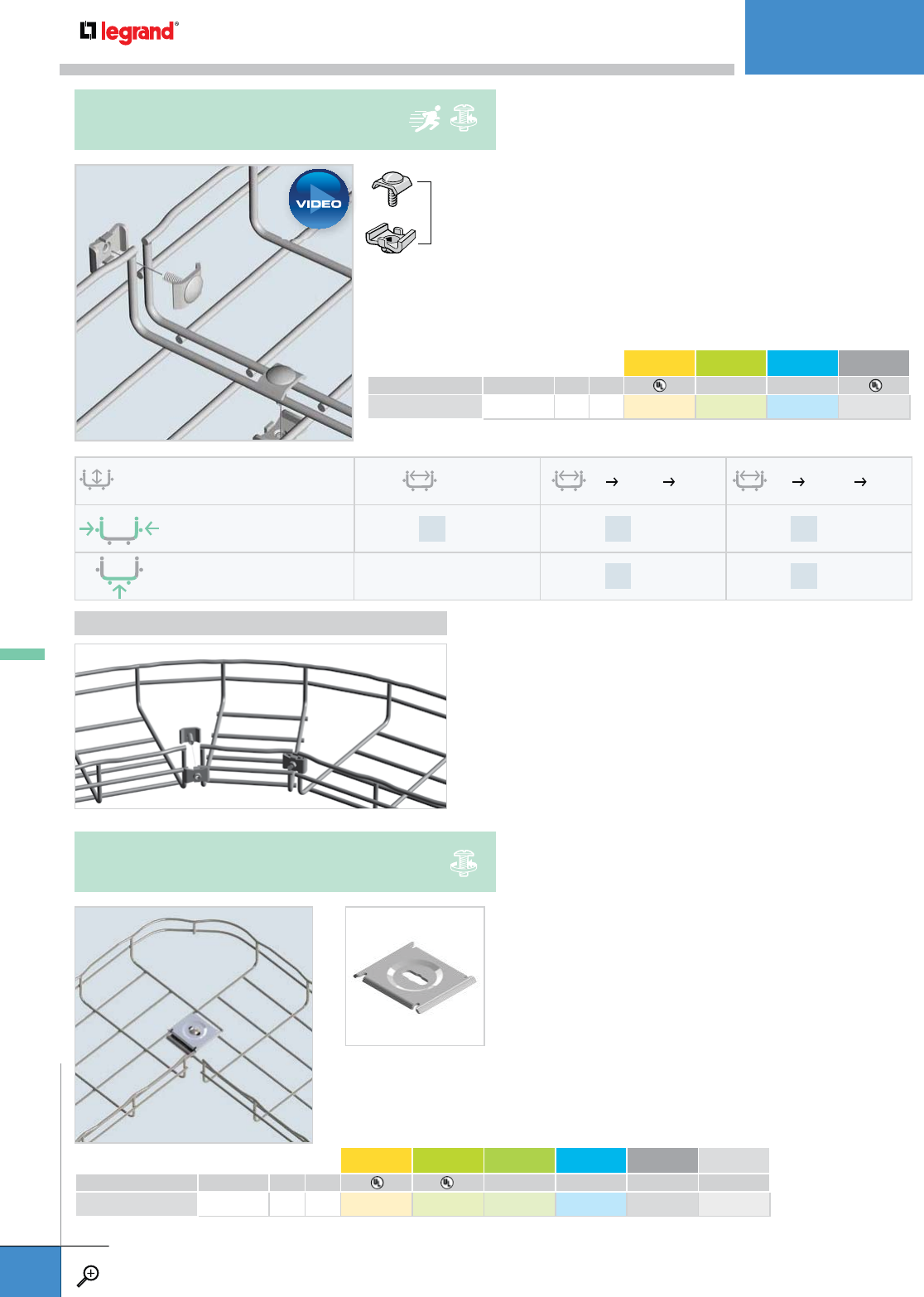
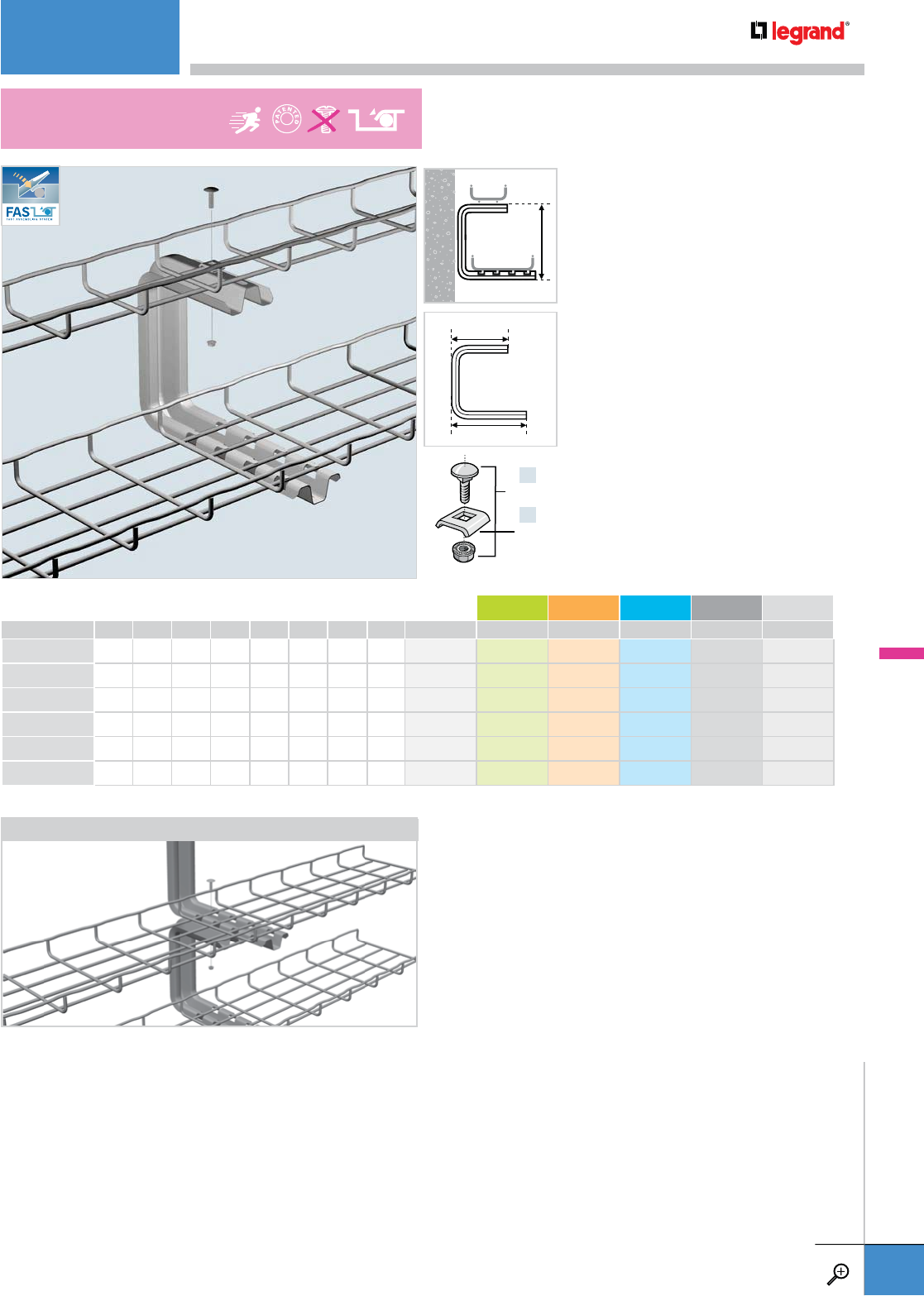
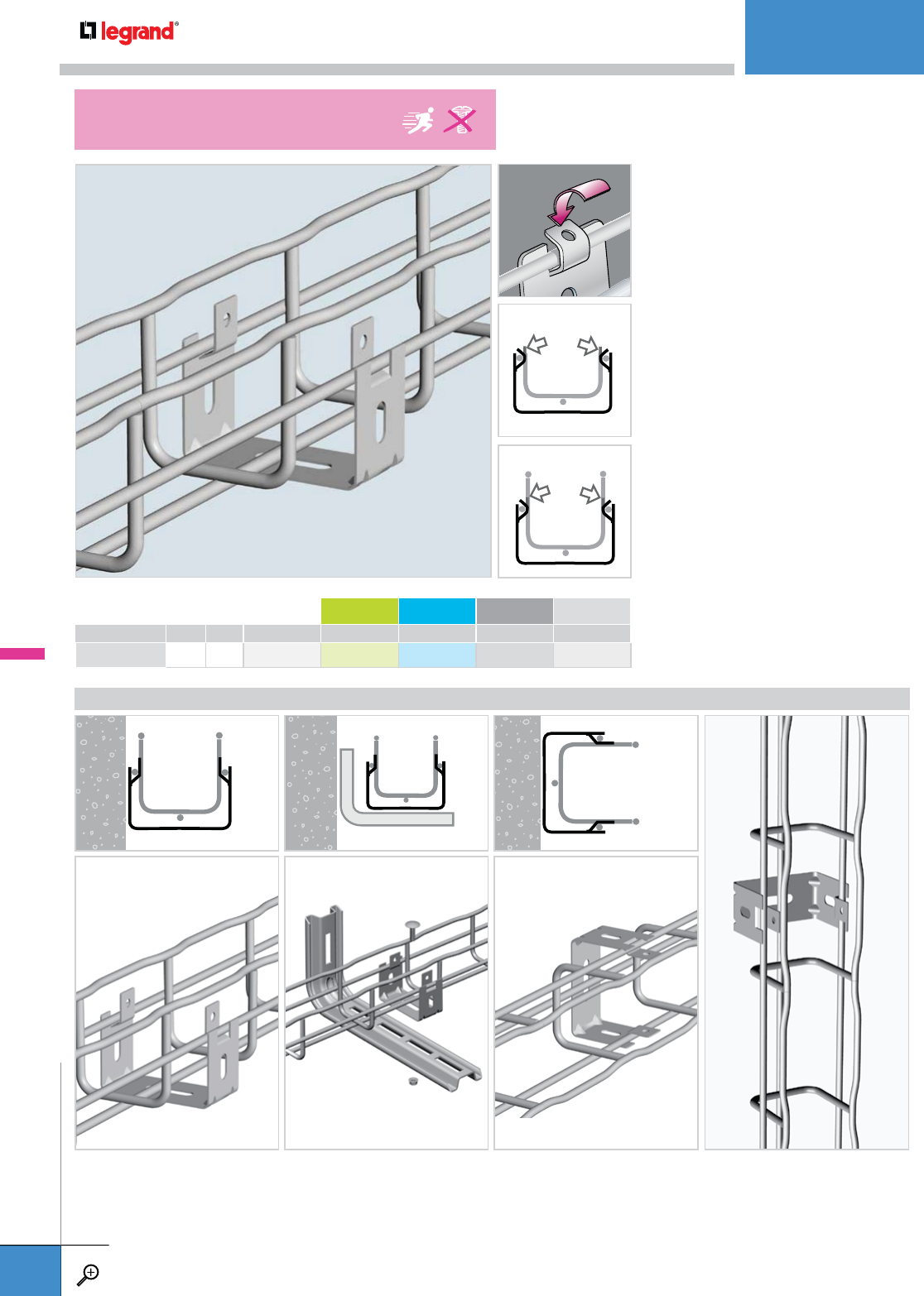
• Works with CAT 30/41 and UC 50
for trapeze hanging 2" wide tray.
• Use EZ BN 1/4 and CAT 30/41 for
attachment (sold separately).
• Threaded rod, nuts and washers
sold separately.
• Snap in attachment requires no
bolts, nuts, or tools to attach
Cablofil tray.
• Threaded rod, nuts and washers
sold separately.
• Limit to 6” or smaller tray
x1 x1
x2
x2
THRD 1/4 EZ BN 1/4
EZ HN 1/4
EZ FW 1/4
x1
x2
x2
THRD 1/4
EZ HN 1/4
EZ FW 1/4
WEIGHT PG GC 316L BL PE
LBS KG
PAT 30 0.2 0.1 557 300 557 303 557 304 941 265 930 569
PKG. QTY. WEIGHT EZ DC BL PE
LBS KG
SAS 50 3.3 1.5 586 031 586 037 941 303 930 679
100 150
CAT 30/41
UC50
PAT 30
SUSPENSION SHOE
SAS
SINGLE HANGER SUSPENSION BRACKET
CEILING MOUNTINGS
WWW.LEGRAND.US/CABLOFIL
A.40
CABLOFIL
CABLE MANAGEMENT
x1
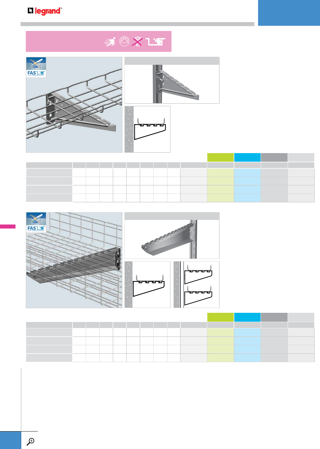
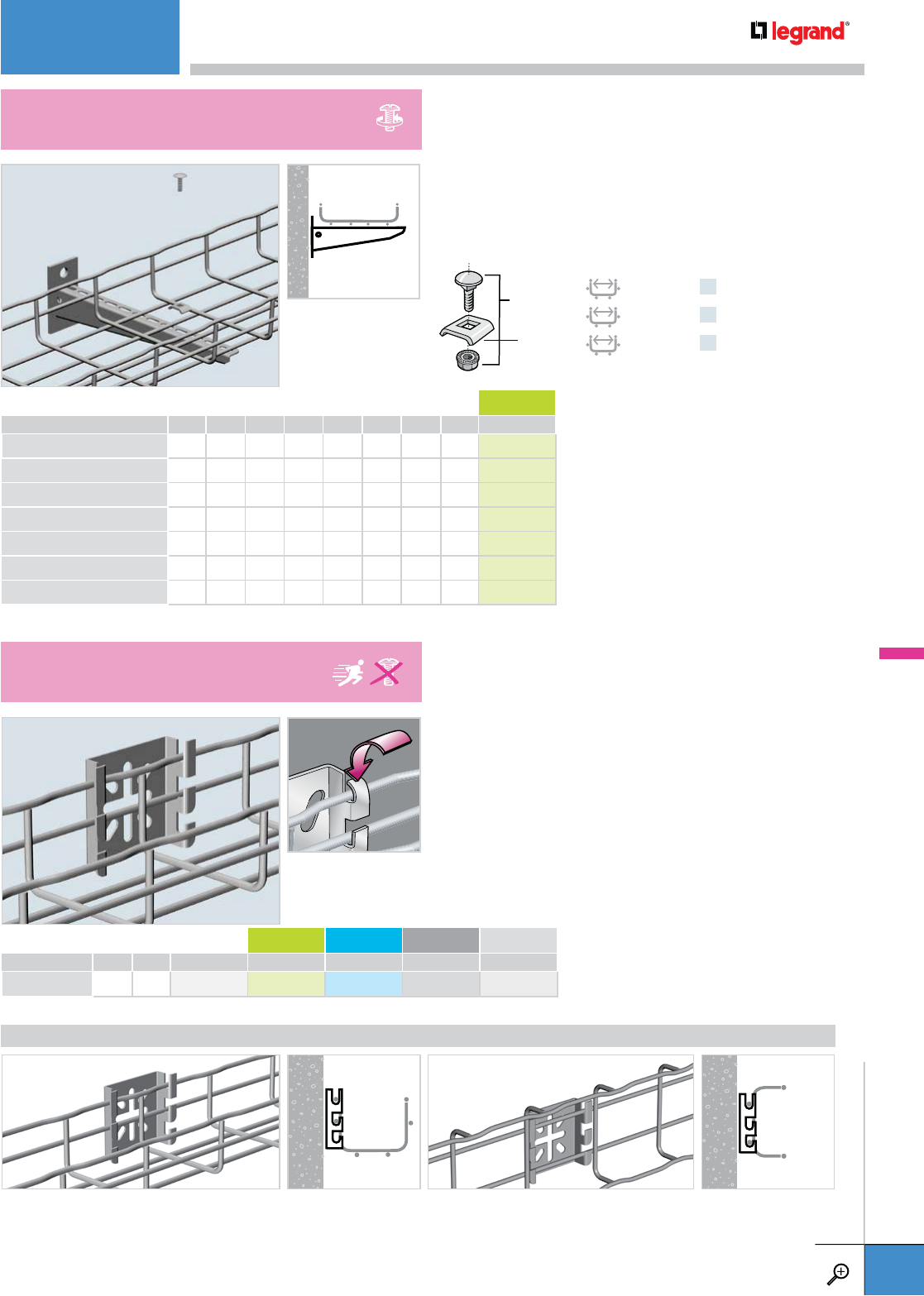
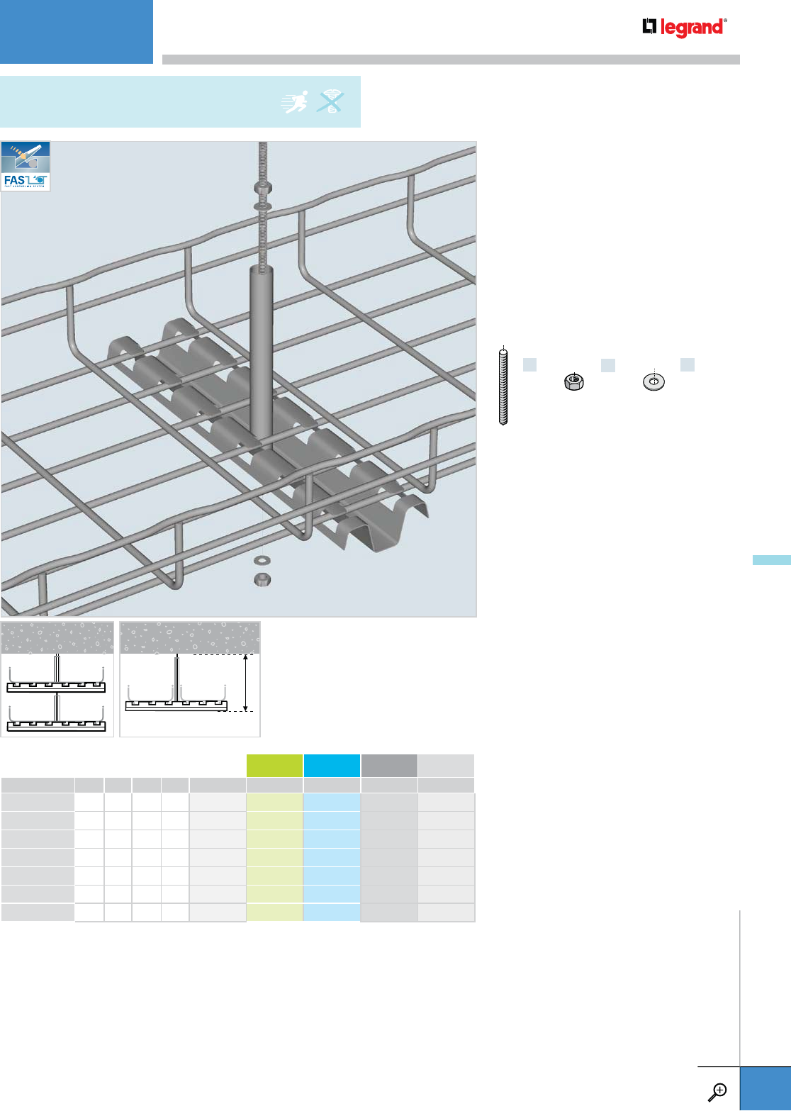
• Only one threaded rod is needed
to suspend tray.
• Suspension tube protects cables.
• 6" and 18" Center Hangers have
offset suspension tube to avoid
center wire.
• Threaded rod, nuts and washers
sold separately.
• Balanced loading recommended.
THRD 1/4
THRD 3/8
THRD 1/2
x2
EZ HN 1/4
EZ HN 3/8
EZ HN 1/2
x2
EZ FW 1/4
EZ FW 3/8
EZ FW 1/2
LENGTH WEIGHT PG GC 316L BL PE
INCHES MM LBS KG
FASPCH 150 6.0 144 0.6 0.2 942 357 – – 942 315 942 387
FASPCH 200 8.0 194 0.7 0.3 586 200 – – 941 310 934 049
FASPCH 300 12.0 294 0.9 0.4 586 300 – – 941 311 934 050
FASPCH 400 16.0 394 1.1 0.5 586 400 – – 941 312 934 051
FASPCH 450 18.0 444 1.3 0.6 586 450 – – 941 313 934 052
FASPCH 500* 20.0 494 1.3 0.6 586 500 – – 941 314 934 053
FASPCH 600* 24.0 594 1.5 0.7 586 600 – – 941 315 934 054
– Contact manufacturer for availability.
*1/2 threaded rod required for this size hanger.
6"
FAS PCH
CENTER HANGER
CEILING MOUNTINGS
WWW.LEGRAND.US/CABLOFIL
A.41
CABLOFIL
CABLE MANAGEMENT
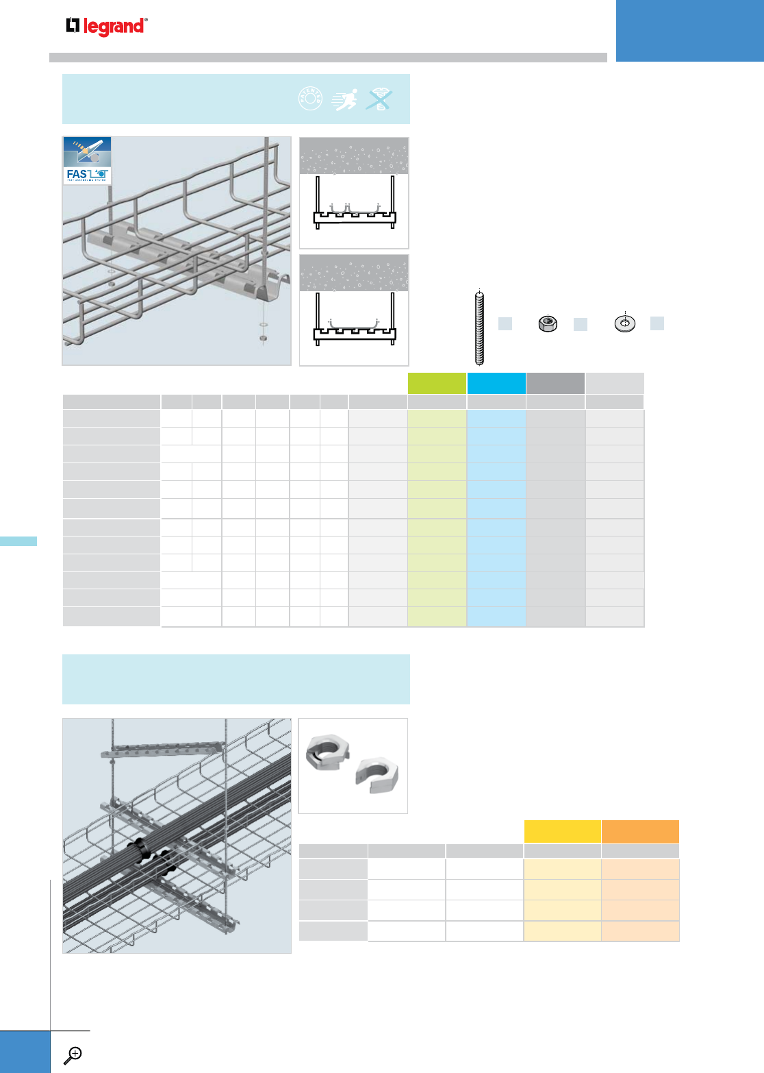
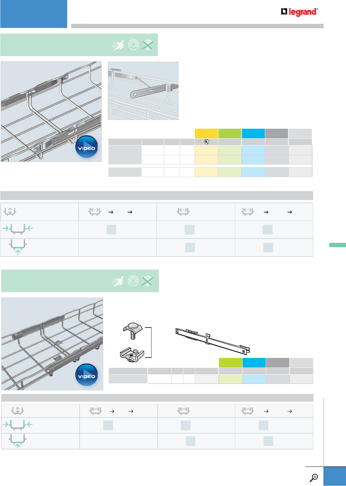
• For trapeze hung installations, use 4" longer profile
than tray width. Example: for CF 54/300 tray (12") use
FAS P400 (16").
• Maximum threaded rod size is 3/8". For use with larger
sizes of threaded rod, bracket holes must be drilled larger.
• Patented FAS style attachment secures tray without
nuts and bolts.
• Threaded rods, nuts and washers sold separately.
• Notify Customer Service when placing order.
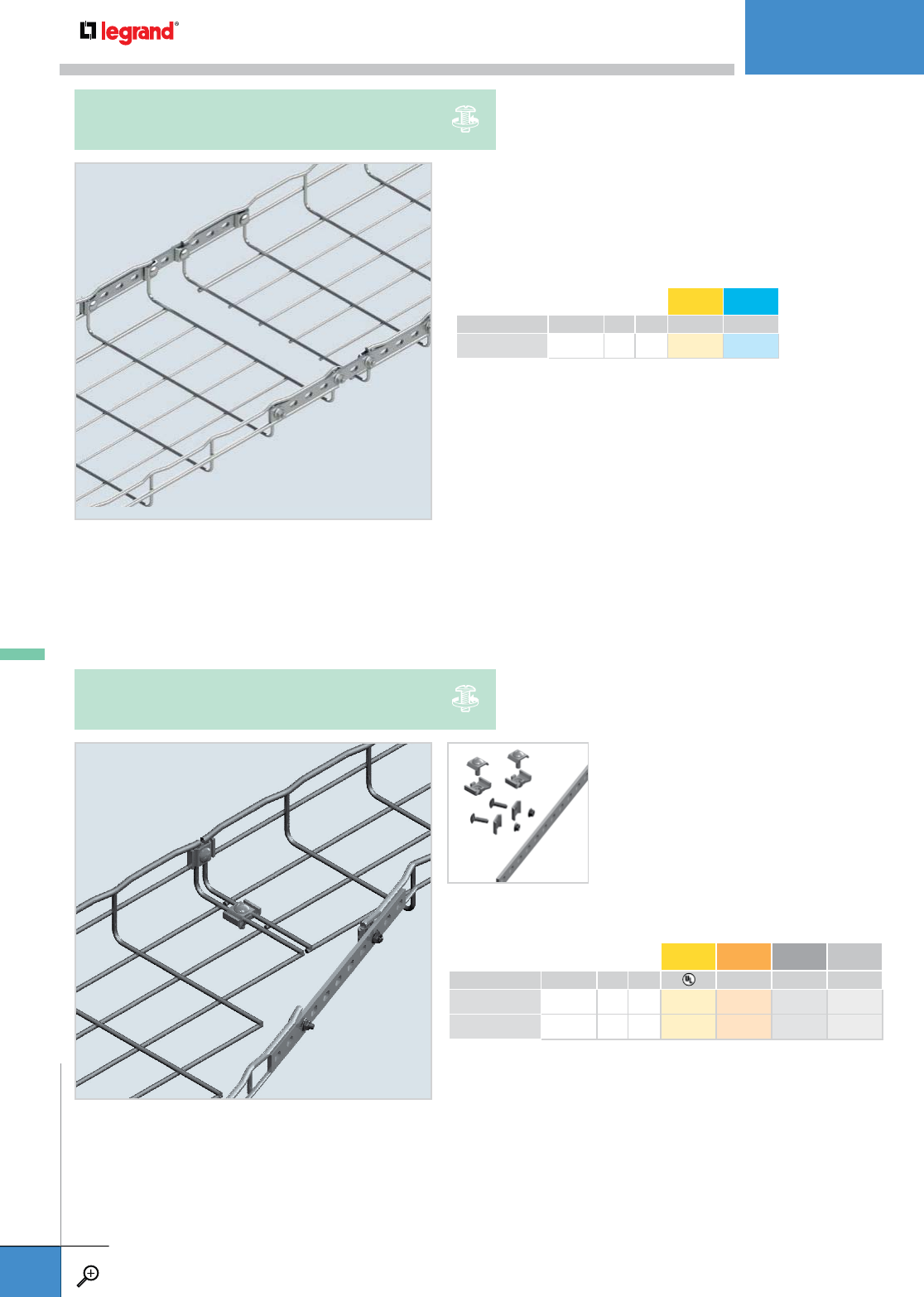
• Install additional tiers to existing trapeze hung cable
pathways with ease.
• To install, place slip-on nut onto threaded rod, rotate nut
halves, tighten halves to lock in place.
• FASP end slots require being “opened up” to install on
threaded rod(s).
x2
THRD 3/8
x4
EZ HN 3/8
x4
EZ FW 3/8
TRAY WIDTH LENGTH WEIGHT PG GC 316L BL PE
INCHES MM INCHES MM LBS KG
FASP 150 2.0 50 6.0 150 0.4 0.2 014 150 014 153 014 154 941 153 930 012
FASP 200 4.0 100 8.0 200 0.7 0.3 014 200 014 203 014 204 941 154 930 014
FASP 300 Multiple 12.0 300 0.9 0.4 014 300 014 303 014 304 941 155 930 016
FASP 400 12.0 300 16.0 400 1.1 0.5 014 400 014 403 014 404 941 156 930 018
FASP 450 14.0 350 18.0 450 1.2 0.5 014 450 – – 941 157 930 020
FASP 500 16.0 400 20.0 500 1.3 0.6 014 500 – – 941 158 930 022
FASP 550 18.0 450 22.0 550 1.3 0.6 014 550 014 553 – 941 159 930 024
FASP 600 20.0 500 24.0 600 1.5 0.7 014 600 014 603 014 604 941 160 930 026
FASP 700 24.0 600 28.0 700 1.8 0.8 014 700 – 014 704 941 162 930 028
FASP 1000 Multiple 40.0 1000 2.6 1.2 014 010 – 014 014 941 149 930 006
FASP 2000 Multiple 80.0 2000 5.3 2.4 014 020 – – 941 151 930 008
FASP 3000 Multiple 120.0 3000 7.9 3.6 014 030 014 033 014 034 941 152 930 010
– Contact manufacturer for availability.
PKG QTY THREAD SIZE EZ 304L
SON1/4 2 1/4 - 20 943 351 –
SON3/8 2 3/8 - 18 943 352 –
SON1/2 2 1/2 - 12 943 353 –
SON5/8 2 5/8 - 11 943 354 –
– Contact manufacturer for availability.
FAS P
FAS PROFILE
SON
SLIP-ON LOCK NUT®
CEILING MOUNTINGS
WWW.LEGRAND.US/CABLOFIL
A.42
CABLOFIL
CABLE MANAGEMENT
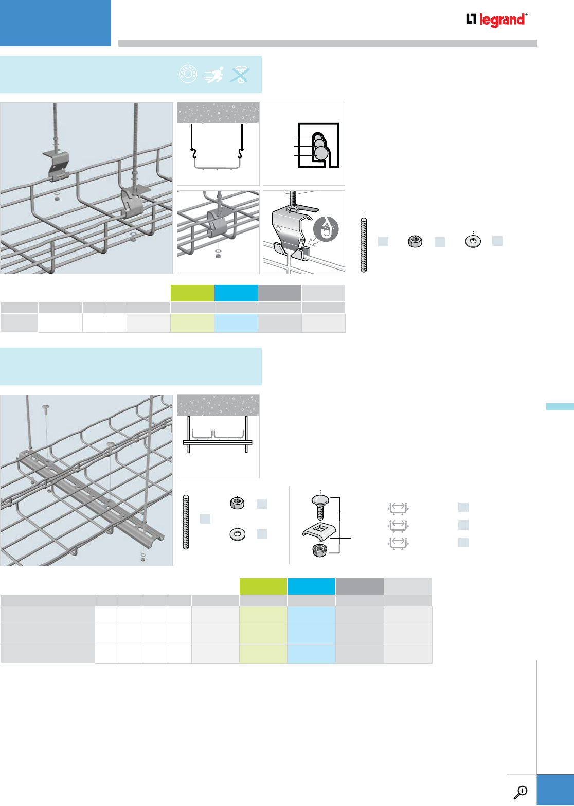
• Tray can be detached on one side to
add cables.
• Use pliers to lock tabs and secure
tray to threaded rod.
• Threaded rods, nuts, and washers
sold separately.
• Allows threaded rod to extend past
AS clip for multi-tier levels.
• Field cut to any length.
• Can support multiple tray runs.
• Threaded rods, nuts, and washers sold separately.
PKG. QTY. WEIGHT PG GC 316L BL PE
LBS KG
AS 50 6.6 3.0 586 020 – 586 024 941 301 930 675
– Contact manufacturer for availability.
LENGTH WEIGHT PG GC 316L BL PE
INCHES MM LBS KG
PROCS 1000 39.0 1000 2.6 1.2 002 920 – 002 924 941 140 930 088
PROCS 2000 79.0 2000 5.1 2.3 002 930 – – 941 141 930 090
PROCS 3000 118.0 3000 8.4 3.8 002 940 – – 941 142 930 092
– Contact manufacturer for availability.
x2
THRD 1/4
THRD 3/8
THRD 1/2
x4
EZ HN 1/4
EZ HN 3/8
EZ HN 1/2
x4
EZ FW 1/4
EZ FW 3/8
EZ FW 1/2
x2
THRD 1/4
x4
EZ HN 1/4
x4
EZ FW 1/4
100 – 200 MM x1
300 – 450 MM x2
500 – 600 MM x3
EZ BN 1/4
CE 25
THRD 1/4
THRD 3/8
THRD 1/2
OPTIONAL PLACEMENT
AS
TRAPEZE HANGING CLIP
PROCS
STANDARD PROFILE
CEILING MOUNTINGS
WWW.LEGRAND.US/CABLOFIL
A.43
CABLOFIL
CABLE MANAGEMENT
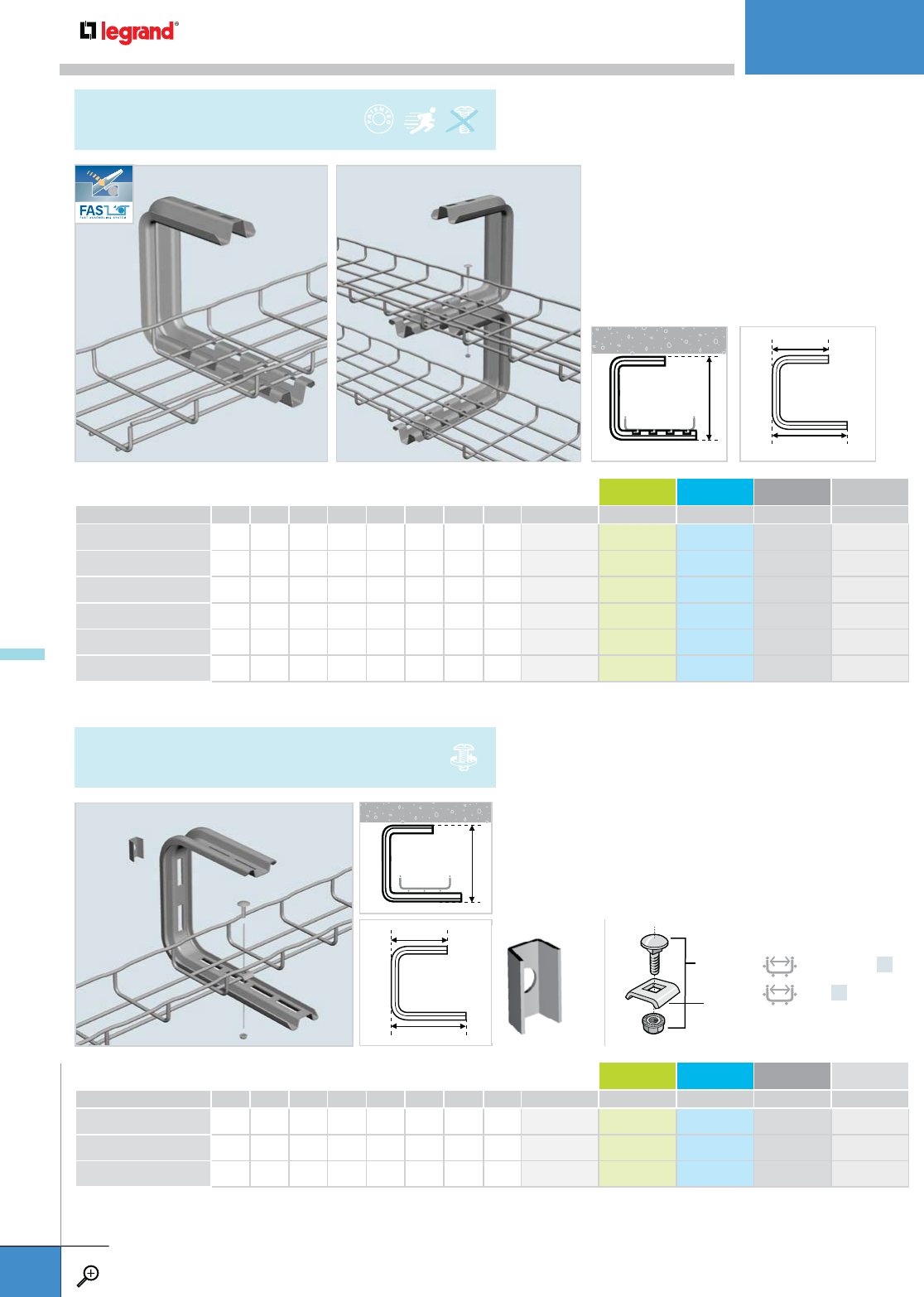
• For cable tray installation under ceilings
or overhangs.
• Can be stacked for multiple levels of tray.
• Saves installation time—patented FAS style
attachment holds cable tray secure without
nuts and bolts.
• EZ BN 1/4 and CE 25 are sold separately.
(see pg. A.81).
• For cable tray installations under ceiling or overhangs.
• Can be stacked for multilevel Cablofil tray installations.
• EZ BN 1/4 and CE 25 are sold separately. (see pg. A.81).
WIDTH LENGTH (L1) LENGTH (L2) WEIGHT PG GC 316L BL PE
INCHES MM INCHES MM INCHES MM LBS KG
FASC 100 4.0 100 6.7 170 7.0 178.5 1.4 0.6 556 300 – 556 304 941 261 930 531
FASC 150 6.0 150 6.7 170 8.9 228.5 1.5 0.7 556 310 – 556 314 941 262 930 533
FASC 200 8.0 200 6.7 170 10.9 278.5 1.7 0.8 556 320 – 556 324 941 263 930 535
FASC 300 12.0 300 11.3 288 14.9 378.5 1.9 0.9 556 330 556 333 – 941 264 930 537
FASC 400 16.0 400 11.3 288 18.8 478.5 2.4 1.1 556 340 – – 943 096 –
FASC 450 18.0 450 11.3 288 20.8 528.5 2.8 1.3 556 350 – – 942 596 –
– Contact manufacturer for availability.
WIDTH LENGTH (L1) LENGTH (L2) WEIGHT PG GC 316L BL PE
INCHES MM INCHES MM INCHES MM LBS KG
CSC 100 4.0 100 5.1 130 5.7 145 1.1 0.5 002 760 – – 941 136 930 082
CSC 200 8.0 200 7.1 180 9.6 245 1.4 0.7 002 770 – 002 774 941 137 930 084
CSC 300 12.0 300 9.1 230 13.6 345 1.8 0.8 002 780 – – 941 138 930 086
– Contact manufacturer for availability.
100 – 200 MM x1
300 x2
EZ BN 1/4
CE 25
ECLI
L2
L1
L2
L1
8.6"
210 MM
8"
200 MM
FAS C
BRACKET
CSC
STANDARD C BRACKET
CEILING MOUNTINGS
WWW.LEGRAND.US/CABLOFIL
A.44
CABLOFIL
CABLE MANAGEMENT
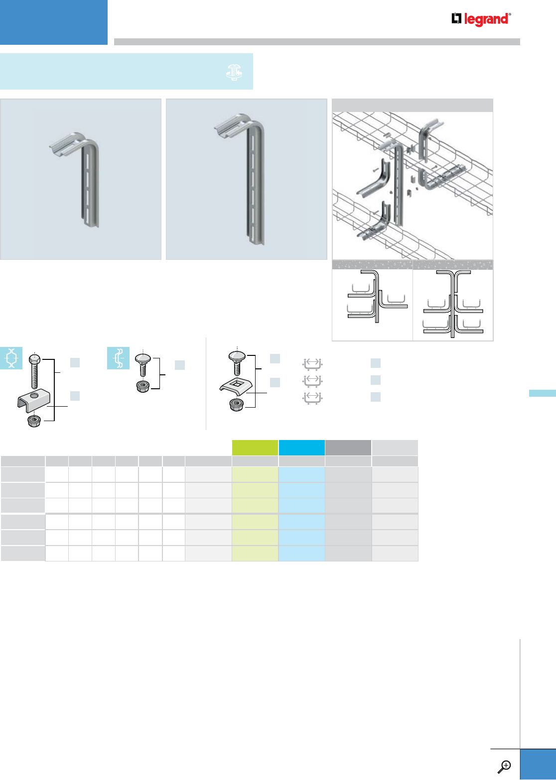
• Versatile brackets that can be configured to create numerous
ceiling-hung installations.
• Slotted holes allow for adjustments during installation.
• Tray attachment hardware sold separately. See p. A.81.
• Sold individually.
WIDTH LENGTH WEIGHT PG GC 316L BL PE
INCHES MM INCHES MM LBS KG
CS 100 4.0 100 5.7 145 0.4 0.2 002 700 – 002 704 941 130 930 070
CS 200 8.0 200 9.6 245 0.8 0.4 002 710 002 713 – 941 131 930 072
CS 300 12.0 300 13.6 345 1.2 0.5 002 720 – 002 724 941 132 930 074
PS 400 16.0 400 17.5 445 1.5 0.7 002 730 – – 941 133 930 076
PS 500 20.0 500 21.4 545 1.8 0.8 002 740 – – 941 134 930 078
PS 600 24.0 600 25.4 645 2.1 0.9 002 750 – – 941 135 930 080
– Contact manufacturer for availability.
100 – 200 MM x1
300 – 450 MM x2
500 – 600 MM x3
x1
x1
EZ BN 1/4
CE 25
x2
x1
EZ BN 5/16
ECLI
x1
EZ BN 1/4
CS / PS
PENDANT L BRACKETS
APPLICATIONS
CS PS
CEILING MOUNTINGS
WWW.LEGRAND.US/CABLOFIL
A.45
CABLOFIL
CABLE MANAGEMENT
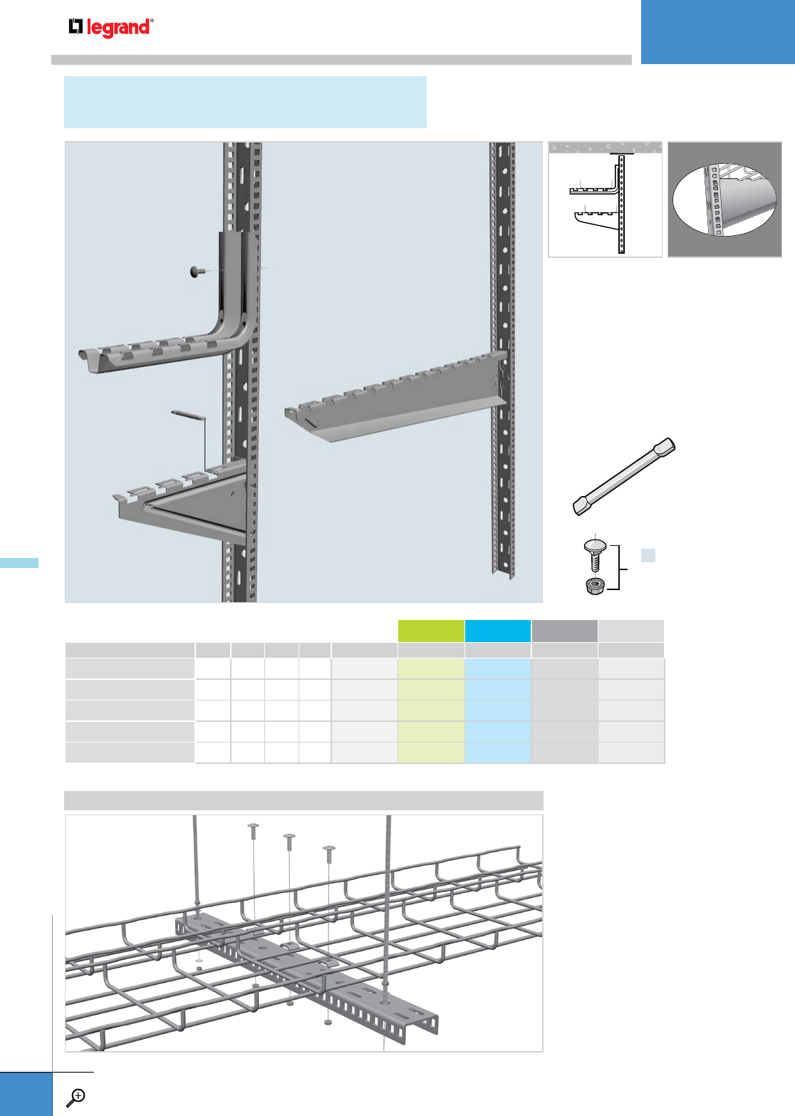
• EDF Rail makes tiered tray runs
easier and faster to install.
• CA Pin (sold separately) is required
to install 4” to 12” FASU. Suggested
for 16” to 24” FASU.
• FASU sizes 16" to 24" will snap
directly onto EDF Rail.
• Use EZ BN 1/4 (sold separately)
to attach any FAS L to EDF Rail.
LENGTH WEIGHT PG GC 316L BL PE
INCHES MM LBS KG
EDF 300 10.6 270 0.7 0.3 561 310 – – 942 817 942 818
EDF 600 24.8 630 1.8 0.8 557 610 – – 942 815 942 816
EDF 1000 39.0 990 2.6 1.2 561 090 – – 942 813 942 814
EDF 2000 78.0 2000 5.5 2.5 561 010 – – 941 288 930 641
EDF 3000 120.0 3000 9.1 4.1 561 020 – – 941 289 930 643
– Contact manufacturer for availability.
APPLICATIONS
x1
EZ BN 1/4
CA
EDF
RAIL
(see pg. A.81)
CEILING MOUNTINGS
WWW.LEGRAND.US/CABLOFIL
A.46
CABLOFIL
CABLE MANAGEMENT
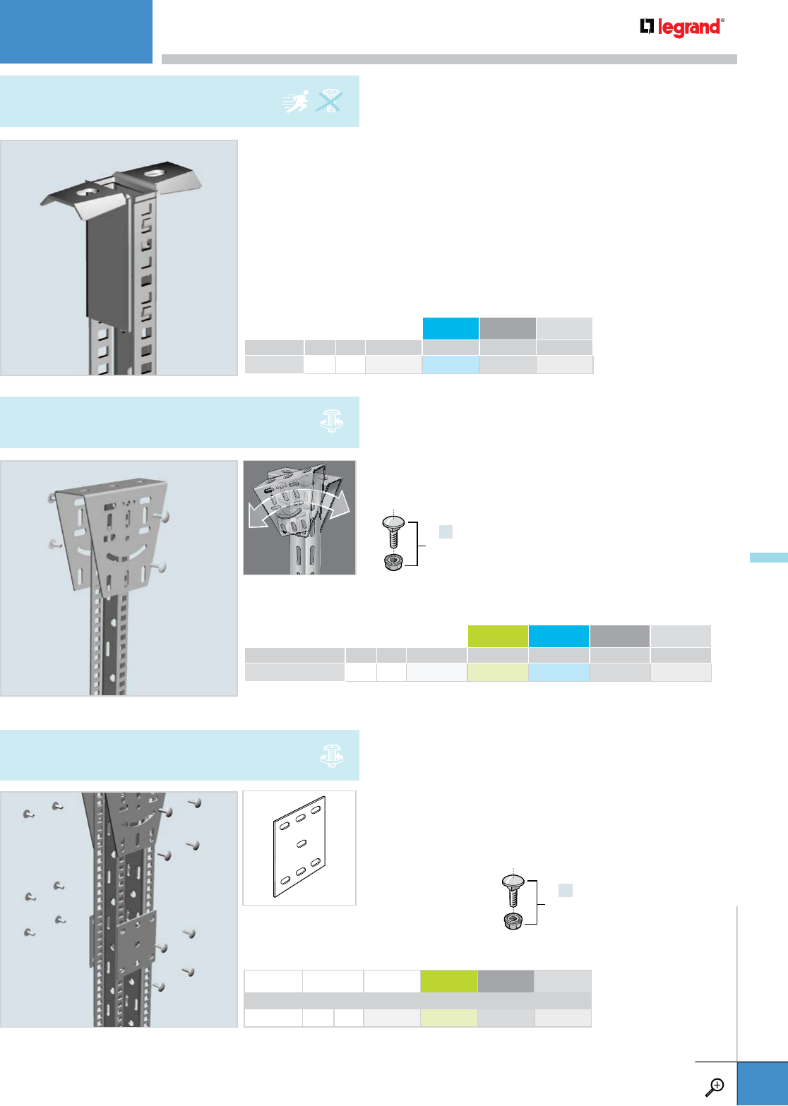
WEIGHT PG 316L BL PE
LBS KG
PFREDF 1.3 0.6 561 080 – 942 761 942 762
– Contact manufacturer for availability.
WEIGHT PG GC 316L BL PE
LBS KG
DF 1.3 0.6 561 060 – – 942 880 –
– Contact manufacturer for availability.
WEIGHT PG GC BL PE
LBS KG
ERD 10 0.4 0.5 561 050 – 942 759 942 760
– Contact manufacturer for availability.
• Use PFREDF to attach EDF Rail directly to ceiling.
• EDF Rail attaches to PFREDF without additional hardware.
• Use DF to attach EDF Rail to any angled ceiling.
• Attach EDF Rail to DF with EZ BN 5/16
(sold separately-see pg. A.81).
• Use ERD 10 to assemble double-sided ceiling hung tray runs.
• Attach EDF Rail to ERD 10 with EZ BN 5/16
(sold separately-see pg. A.81).
x4
EZ BN 5/16
x4
EZ BN 5/16
+50˚/-30˚
PFREDF
MOUNTING BRACKET
DF
ANGLE MOUNTING BRACKET
ERD 10
BRACE PLATE
CEILING MOUNTINGS
WWW.LEGRAND.US/CABLOFIL
A.47
CABLOFIL
CABLE MANAGEMENT
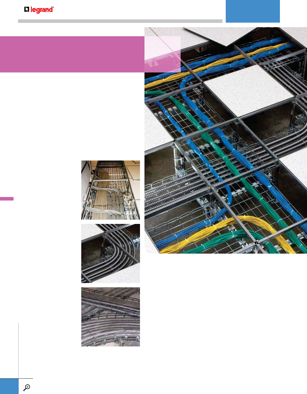
A . 4 9 UFC 550 KIT
UNDER FLOOR
SUPPORT CLAMP KIT
A.49 UFC
UNDER FLOOR
SUPPORT CLAMP
A.50 FAS P
FAS PROFILE
A.50 UFCN
UNDER FLOOR CLAMP
A.51 UC 50
CABLE TRAY STANDOFF
A.51 C 50
UNDER FLOOR
ATTACHMENT
A.52 FAS L
BRACKET
A.52 FAS U
UNIVERSAL BRACKET
A.53 EDF
RAIL
A.53 DF
ANGLE MOUNTING BRACKET
A.54 UFS
UNDER FLOOR SUPPORT
A.54 UFS
UNDER FLOOR
SUPPORT BRACKET
A.55 UFFS
UNDER FLOOR FIBERGLASS
SUPPORT STAND
A.56 UFS
UNDER FLOOR CABLE
MANAGEMENT SYSTEM
A.56 UFSUPKIT
UFS SUPPORT KIT
A.56 UFSCB 4/300PG
UFS CANTILEVER BRACKET
A.57 UFCF2
UFS WIRE TRAY SECTION
A.57 UFT 90° KIT
Legrand offers a wide variety of Cablofil options for
raised access floor installations, the newest being
the UFS Underfloor Cable management system.
UFS is independently supported so that it doesn't
void the warranty of the raised access floor and it is
engineered with 2ft. tray sections so that it can be
installed entirely through the floor openings.
UNDERFLOOR
UNDERFLOOR
WWW.LEGRAND.US/CABLOFIL
A.48
CABLOFIL
CABLE MANAGEMENT
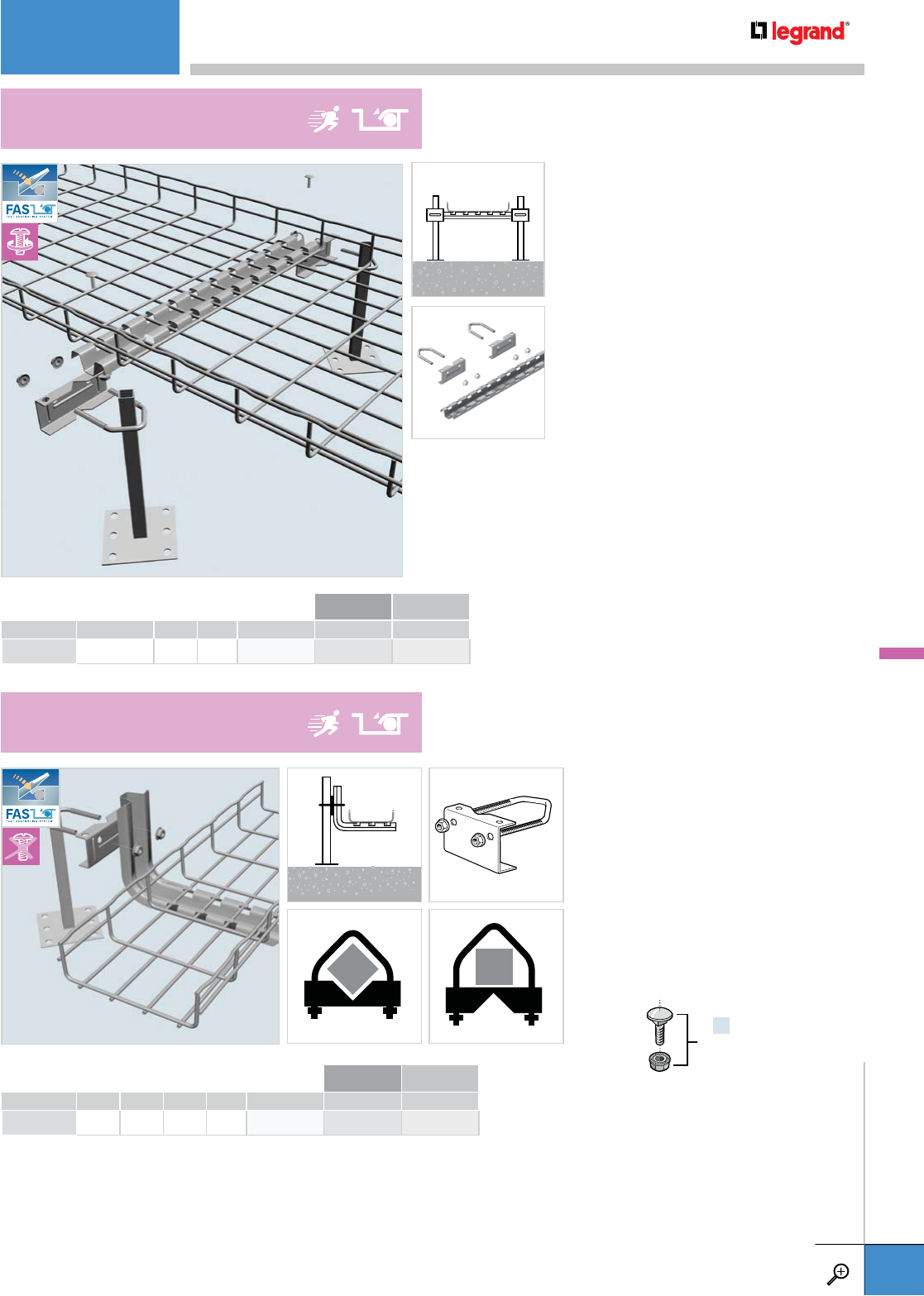
LENGTH WEIGHT PG BL PE
INCHES MM LBS KG
UFC 5.0 127 0.7 0.3 559 220 941 287 934 043
• Creates a tray support using
FAS L brackets in under floor
applications.
• To install, clamp FAS L Brackets
to raised floor support through
one side of U-bolt ONLY.
• UFC clamp works with round or
square post profiles.
• Turn UFC support plate around if
post faces are parallel with floor grid.
• Creates a tray support between two
floor supports for Cablofil tray runs.
• To install, clamp UFC to raised floor
supports then bolt FAS P 550 to
UFC clamps.
• Use patented locking tabs on FAS P
550 to secure tray without additional
hardware.
• Kit contains two UFC clamps, two
EZ BN 1/4 and one FAS P 550.
x2
EZ BN 1/4
PKG QTY WEIGHT PG BL PE
LBS KG
UFC550 KIT 1 0.7 0.3 943 179 943 180 943 181
UFC550 KIT
UNDER FLOOR SUPPORT CLAMP KIT
UFC
UNDER FLOOR SUPPORT CLAMP
UNDERFLOOR
WWW.LEGRAND.US/CABLOFIL
A.49
CABLOFIL
CABLE MANAGEMENT
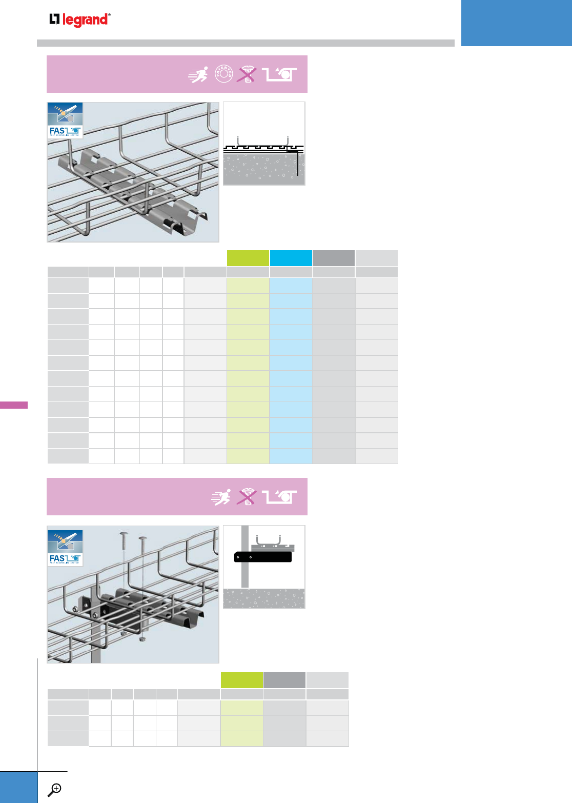
• Pre-drilled holes make installation easy.
• Will hold tray away from floor 0.66".
• Saves installation time – patented FAS style attachment
hold Cablofil tray secure without nuts and bolts.
• UFCN includes clamp, pre-assembled FAS Profile,
nuts and bolts.
• Clamp attaches to square or round support posts.
• FAS Profile secures tray without additional hardware.
• Adjusts to any height.
LENGTH WEIGHT PG GC 316L BL PE
INCHES MM LBS KG
FASP 150 6.0 150 0.4 0.2 014 150 014 153 014 154 941 153 930 012
FASP 200 8.0 200 0.7 0.3 014 200 014 203 014 204 941 154 930 014
FASP 300 12.0 300 0.9 0.4 014 300 014 303 014 304 941 155 930 016
FASP 400 16.0 400 1.1 0.5 014 400 014 403 014 404 941 156 930 018
FASP 450 18.0 450 1.2 0.6 014 450 – – 941 157 930 020
FASP 500 20.0 500 1.3 0.6 014 500 – – 941 158 930 022
FASP 550 22.0 550 1.3 0.6 014 550 014 553 – 941 159 930 024
FASP 600 24.0 600 1.5 0.7 014 600 014 603 014 604 941 160 930 026
FASP 700 28.0 700 1.8 0.8 014 700 – 014 704 941 162 930 028
FASP 1000 40.0 1000 2.6 1.2 014 010 – 014 014 941 149 930 006
FASP 2000 80.0 2000 5.3 2.4 014 020 – – 941 151 930 008
FASP 3000 120.0 3000 7.9 3.6 014 030 014 033 014 034 941 152 930 010
– Contact manufacturer for availability.
LENGTH WEIGHT PG GC BL PE
INCHES MM LBS KG
UFCN 150 6 150 2.5 1.0 942 839 – 943 149 942 838
UFCN 200 8 200 2.7 1.2 942 448 – 942 341 942 413
UFCN 300 12 300 3.0 1.4 942 449 – 942 342 942 414
– Contact manufacturer for availability.
0.66"
16 MM
FAS P
FAS PROFILE
UFCN
UNDER FLOOR CLAMP
UNDERFLOOR
WWW.LEGRAND.US/CABLOFIL
A.50
CABLOFIL
CABLE MANAGEMENT
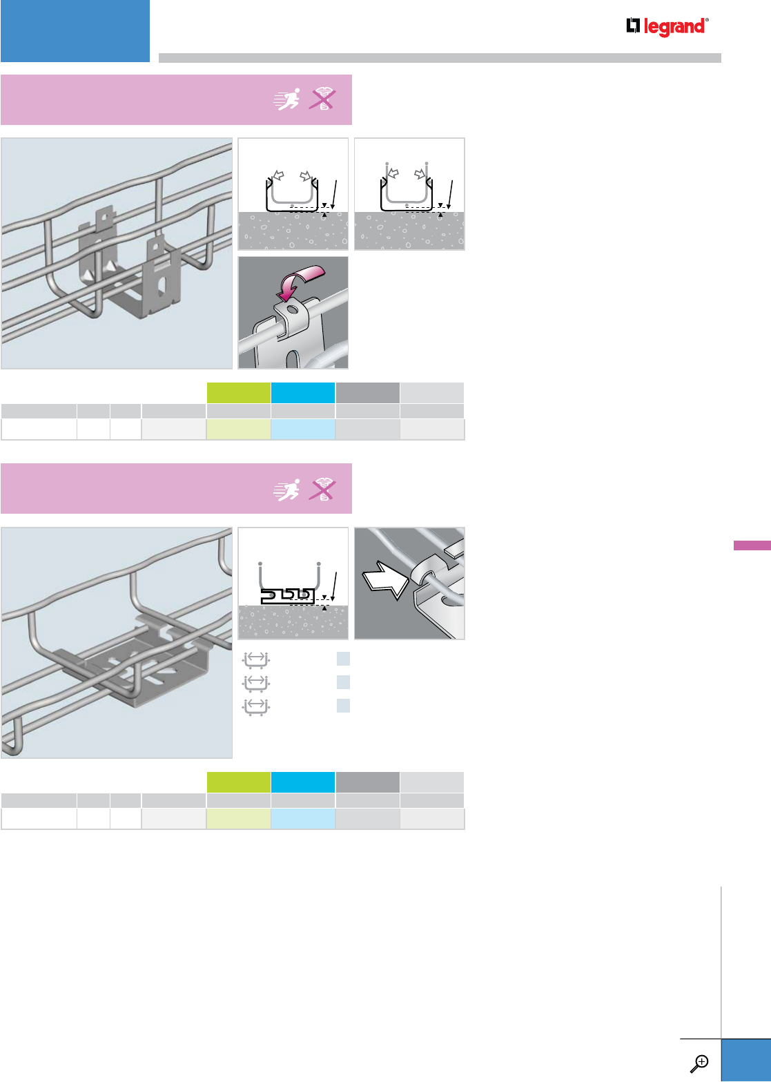
• Attaches 2" wide tray to floor and
channel framing.
• Fold over tabs secure tray without
fasteners.
• Stand-off height is 0.3" (8mm).
• Attaches tray to floor and channel
framing.
• Fold over tabs secure tray without
additional hardware.
• Slotted mounting holes make for
adjustable installations.
WEIGHT PG GC 316L BL PE
LBS KG
UC 50 0.1 0.06 586 040 – – 941 304 930 681
– Contact manufacturer for availability.
WEIGHT PG GC 316L BL PE
LBS KG
C 50 0.2 0.1 586 130 – – 941 308 930 694
– Contact manufacturer for availability.
CF30 CF54
0.3"
8 MM
0.5"
12 MM
0.3"
8 MM
100 – 200 MM x1
300 – 450 MM x2
500 – 600 MM x3
UC 50
CABLE TRAY STANDOFF
C 50
UNDER FLOOR ATTACHMENT
UNDERFLOOR
WWW.LEGRAND.US/CABLOFIL
A.51
CABLOFIL
CABLE MANAGEMENT
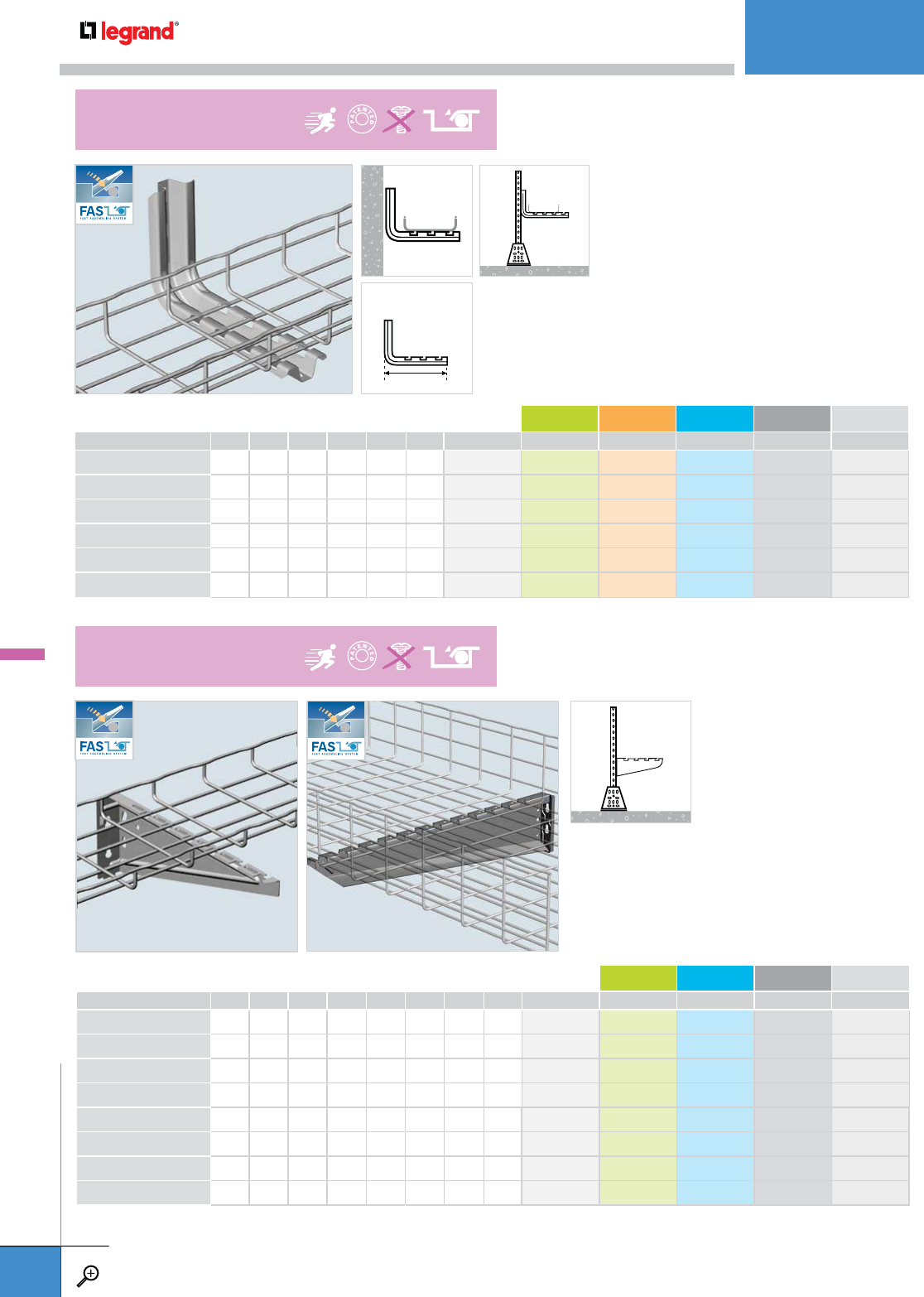
TRAY WIDTH LENGTH WEIGHT PG GC 304L 316L BL PE
INCHES MM INCHES MM LBS KG
FASL 100 4.0 100 7.0 178.5 0.9 0.4 556 100 556 103 – 556 104 941 257 930 523
FASL 150 6.0 150 9.0 228.5 1.0 0.5 556 110 556 113 – 556 114 941 258 930 525
FASL 200 8.0 200 11.0 278.5 1.1 0.5 556 120 556 123 – 556 124 941 259 930 527
FASL 300 12.0 300 14.9 378.5 1.4 0.6 556 130 556 133 – 556 134 941 260 930 529
FASL 400 16.0 400 18.8 478.5 1.8 0.8 556 140 – – – 943 146 943 388
FASL 450 18.0 450 20.8 528.5 2.1 1.0 556 150 – – – 942 848 942 600
– Contact manufacturer for availability.
• Use for tray support in under floor
applications in combination with UFC
Clamp or EDF Rail.
• Use patented locking tabs on FAS L
to secure tray without additional hardware.
• Order “width” to match tray.
L
HEIGHT TRAY WIDTH LENGTH WEIGHT PG GC 316L BL PE
INCHES MM INCHES MM INCHES MM LBS KG
FASU 100 3.5 85 4.0 100 6.0 157 0.3 0.1 557 410 – 557 414 941 267 930 575
FASU 150 5.0 124 6.0 150 8.0 207 0.4 0.2 557 420 557 423 557 424 941 268 930 577
FASU 200 5.5 139 8.0 200 12.0 257 0.5 0.2 557 430 557 433 557 434 941 269 930 579
FASU 300 5.5 139 12.0 300 14.0 357 0.8 0.3 557 440 557 443 557 444 941 270 930 581
FASU 400 5.5 137.7 16.0 400 18.0 457 1.8 0.8 557 450 557 453 557 454 941 271 930 583
FASU 450 5.5 137.7 18.0 450 20.0 507 2.4 1.1 944 533 – – 944 536 944 937
FASU 500 5.5 137.7 20.0 500 22.0 557 2.9 1.3 557 460 557 463 – 941 272 930 585
FASU 600 5.5 137.7 24.0 600 26.0 657 6.4 2.9 557 470 – – 941 273 930 587
– Contact manufacturer for availability.
• Use for tray support in under floor applications
in combination with EDF Rail.
• Use patented locking tabs on FAS U to secure
tray without additional hardware.
• Supports wider tray and heavier loads than FAS L.
• FAS U snaps directly into EDF rail.
FASU 100-300 FASU 400-600
FAS L
BRACKET
FAS U
UNIVERSAL BRACKET
UNDERFLOOR
WWW.LEGRAND.US/CABLOFIL
A.52
CABLOFIL
CABLE MANAGEMENT
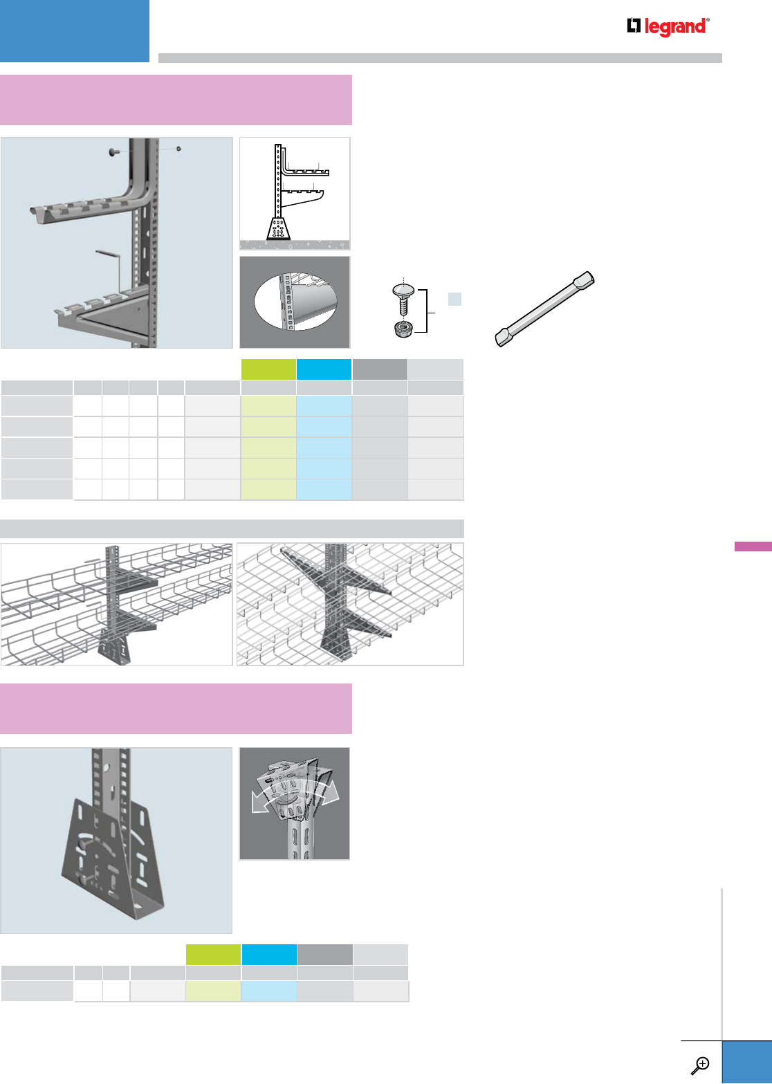
• EDF Rail makes multiple floor mounted cable tray runs
easier and faster to install.
• CA Pin (sold separately) is required to install 4" to 12"
FASU. Suggested for 16" to 24" FASU.
• FASU sizes 16" to 24" will snap directly onto EDF Rail.
• Use EZ BN 5/16 (sold separately) to attach any FAS L to
EDF Rail.
• Use DF to attach EDF Rail to any floor.
• Attach EDF Rail to DF with EZ BN 5/16 (sold separately).
• Use DF to attach EDF to a ceiling or deck that is on an
angle for a perfect pendant hanger.
LENGTH WEIGHT PG GC 316L BL PE
INCHES MM LBS KG
EDF 300 10.6 270 0.7 0.3 561 310 – – 942 817 942 818
EDF 600 24.8 630 1.8 0.8 557 610 – – 942 815 942 816
EDF 1000 39.0 990 2.6 1.2 561 090 – – 942 813 942 814
EDF 2000 78 2000 5.5 2.5 561 010 – – 941 288 930 641
EDF 3000 120 3000 9.1 4.1 561 020 – – 941 289 930 643
– Contact manufacturer for availability.
WEIGHT PG GC 316L BL PE
LBS KG
DF 1.3 0.6 561 060 – – 942 880 –
– Contact manufacturer for availability.
APPLICATIONS
x4
EZ BN 5/16 CA
EDF
RAIL
DF
ANGLE MOUNTING BRACKET
UNDERFLOOR
WWW.LEGRAND.US/CABLOFIL
A.53
CABLOFIL
CABLE MANAGEMENT
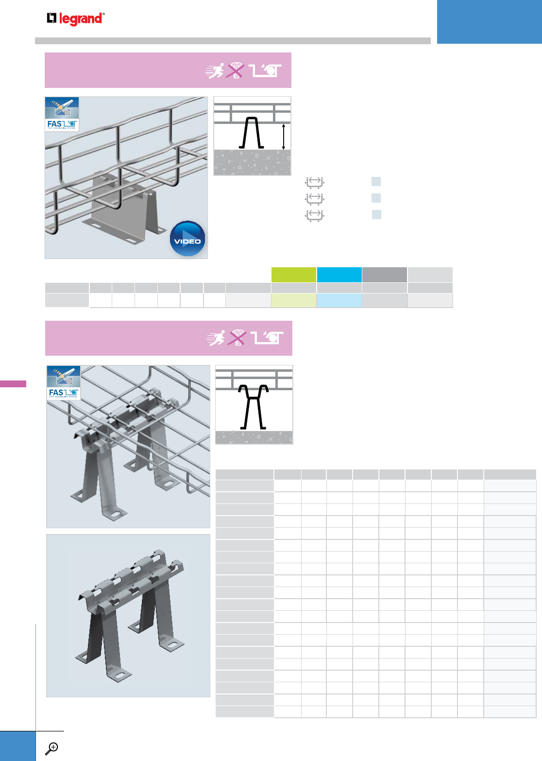
• Pre-drilled mounting holes make installations easy.
• UFS can be used as a stand off support on equipment
cabinets to avoid covering ventilation fans.
• Saves installation time—patented FAS style attachment
holds tray secure without nuts and bolts.
• Raises cable pathway within easy reach of floor openings.
• Slotted mounting holes allow for quick attachment to
floor deck.
• Installs quickly – patented FAS locking tabs require no
additional hardware to secure tray.
• Supports tray independently of raised floor systems.
WIDTH LENGTH WEIGHT PG GC 316L BL PE
INCHES MM INCHES MM LBS KG
UFS 60/100 2.4 60 4.0 100 0.2 0.1 586 080 – – 941 307 930 689
– Contact manufacturer for availability.
2.2"
55 MM
100 – 200 MM x1
300 – 450 MM x2
500 MM x3
HEIGHT LENGTH FOR TRAY SIZE WEIGHT PG
INCHES MM INCHES MM INCHES MM LBS KG
UFS 100/150 4.0 100 6.0 150 6.0 150 1.7 0.77 943 306
UFS 100/200 4.0 100 8.0 200 8.0 200 1.9 0.86 943 307
UFS 100/300 4.0 100 12.0 300 12.0 300 2.1 0.95 943 308
UFS 100/450 4.0 100 18.0 450 18.0 450 2.4 1.09 943 309
UFS 100/500 4.0 100 20.0 500 20.0 500 2.5 1.13 943 310
UFS 150/150 6.0 150 6.0 150 6.0 150 2.1 0.93 943 311
UFS 150/200 6.0 150 8.0 200 8.0 200 2.3 1.06 942 354
UFS 150/300 6.0 150 12.0 300 12.0 300 2.5 1.15 943 312
UFS 150/450 6.0 150 18.0 450 18.0 450 2.8 1.29 943 313
UFS 150/500 6.0 150 20.0 500 20.0 500 2.9 1.33 943 314
UFS 200/150 8.0 200 6.0 150 6.0 150 2.5 1.12 943 315
UFS 200/200 8.0 200 8.0 200 8.0 200 2.8 1.25 943 316
UFS 200/300 8.0 200 12.0 300 12.0 300 3.0 1.34 943 317
UFS 200/450 8.0 200 18.0 450 18.0 450 3.3 1.48 943 318
UFS 200/500 8.0 200 20.0 500 20.0 500 3.4 1.52 943 319
UFS 300/150 12.0 300 6.0 150 6.0 150 3.3 1.50 943 320
UFS 300/200 12.0 300 8.0 200 8.0 200 3.6 1.63 943 321
UFS 300/300 12.0 300 12.0 300 12.0 300 3.8 1.72 943 322
UFS 300/450 12.0 300 18.0 450 18.0 450 4.1 1.86 943 323
UFS 300/500 12.0 300 20.0 500 20.0 500 4.2 1.91 943 324
UFS
UNDER FLOOR SUPPORT
UFS
UNDER FLOOR SUPPORT BRACKET
UNDERFLOOR
WWW.LEGRAND.US/CABLOFIL
A.54
CABLOFIL
CABLE MANAGEMENT
PLAY
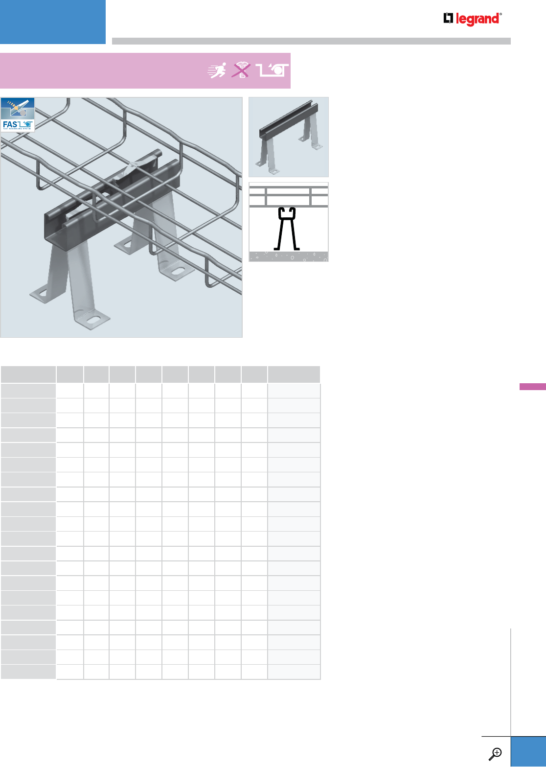
• Raises cable pathway within easy
reach of floor openings.
• Fiberglass strut design keeps cable
pathway insulated from floor deck.
• Slotted mounting holes allow for
quick attachment to floor deck.
• Use FS 41 Fastrut connectors to secure
tray to mounting bracket (not included).
• Supports tray independently of raised
floor systems.
HEIGHT LENGTH FOR TRAY SIZE WEIGHT PG
INCHES MM INCHES MM INCHES MM LBS KG Base Finish (Strut
Finish is Fiberglass)
UFFS100/200* 4.0 100 7,87 200 6.0 150 1.6 0.73 943 325
UFFS100/250** 4.0 100 9.84 250 8.0 200 1.7 0.77 943 326
UFFS100/300 4.0 100 11.81 300 12.0 300 1.8 0.82 943 327
UFFS100/450 4.0 100 17.71 450 18.0 450 2.1 0.95 943 328
UFFS100/500 4.0 100 19.68 500 20.0 500 2.2 1.0 943 329
UFFS150/200* 6.0 150 7,87 200 6.0 150 2.0 0.91 943 330
UFFS150/250** 6.0 150 9.84 250 8.0 200 2.1 0.95 943 331
UFFS150/300 6.0 150 11.81 300 12.0 300 2.2 1.0 943 332
UFFS150/450 6.0 150 17.71 450 18.0 450 2.5 1.13 943 333
UFFS150/500 6.0 150 19.68 500 20.0 500 2.6 1.18 943 334
UFFS200/200* 8.0 200 7.87 200 6.0 150 2.5 1.13 943 335
UFFS200/250** 8.0 200 9.84 250 8.0 200 2.6 1.18 943 336
UFFS200/300 8.0 200 11.81 300 12.0 300 2.7 1.22 943 337
UFFS200/450 8.0 200 17.71 450 18.0 450 3.0 1.36 943 338
UFFS200/500 8.0 200 19.68 500 20.0 500 3.1 1.41 943 339
UFFS300/200* 12.0 300 7.87 200 6.0 150 3.3 1.50 943 340
UFFS300/250** 12.0 300 9.84 250 8.0 200 3.4 1.54 943 341
UFFS300/300 12.0 300 11.81 300 12.0 300 3.5 1.59 943 342
UFFS300/450 12.0 300 17.71 450 18.0 450 3.8 1.72 943 343
UFFS300/500 12.0 300 19.68 500 20.0 500 3.9 1.77 943 344
* Use with 150 Series Wide Tray ** Use with 200 Series Wide Tray
UFFS
UNDER FLOOR FIBERGLASS SUPPORT STAND
UNDERFLOOR
WWW.LEGRAND.US/CABLOFIL
A.55
CABLOFIL
CABLE MANAGEMENT

• Designed to work with all standard raised access floors.
• Self supporting – won’t void the warranty of your floor.
• UFS 2’ tray sections allow for easy installation through the floor openings.
• UFS support kits can utilize standard 10’ tray sections.
• 18" (450mm) and 20" (500mm) for use on top tier only.
• UFS installs with simple tools – no hardware needed.
• Vertical leg can be cut to accommodate shorter elevations.
• Allow multiple tray levels without obstructing access to
lower level.
• No hardware required.
PKG. QTY. HEIGHT WIDTH PG
INCHES MM INCHES MM
UFS SUPPORT KITS
UFSUPKIT100* 1 3.5 90 22.0 550 942 918
UFSUPKIT200* 1 7.0 130 22.0 550 942 919
UFSUPKIT300* 1 10.6 270 22.0 550 942 920
UFSUPKIT400* 1 14.0 360 22.0 550 942 921
UFSUPKIT600* 1 24.8 630 22.0 550 942 922
* Each Support Kit includes 1 Crossbar, 2 Leg Supports and 2 Leg Attachment Clips.
Kit Components May Be Ordered Individually
CROSSBARS
UFCRSBAR 1 2.4 60 22.0 550 589 010
LEGS
EDF100 1 3.5 90 – – 561 320
EDF200 1 7.0 130 – – 561 330
EDF300 1 10.6 270 – – 561 310
EDF400 1 14.0 360 – – 561 340
EDF450 1 17.7 450 – – 561 350
EDF500 1 21.2 540 – – 557 360
EDF600 1 24.8 630 – – 557 610
LEG ATTACHMENT CLIPS
UFPSTCLPPG 2 ––––589 110
• Crossbars secure tray with FAS style
tabs – only a screwdriver is needed.
• Heavy-duty legs have multiple
mounting holes for almost infinite
height adjustment.
• Attachment clips secure installation
to raised access floor legs.
x1
x2
x2
UFCRSBAR
UFPSTCLP
EDF
PKG QTY WEIGHT PG
LBS KG
UFSCB 4/300PG 1 0.50 0.22 943 029
UFS
UNDER FLOOR CABLE MANAGEMENT SYSTEM
UFSUPKIT
UFS SUPPORT KIT
UFSCB
UFS CANTILEVER BRACKET
UNDERFLOOR
WWW.LEGRAND.US/CABLOFIL
A.56
CABLOFIL
CABLE MANAGEMENT

APPLICATIONS
• UFCF tray will accept all Cablofil
accessories without adjustment.
• Use UFT 90 Kit at tees and junctions.
PKG. QTY. HEIGHT WIDTH LENGTH EZ
INCHES MM INCHES MM INCHES MM
UFCF2/54/300 1 2.0 54 12.0 300 24.0 600 600 261
UFCF2/54/400 1 2.0 54 16.0 400 24.0 600 600 291
UFCF2/54/500* 1 2.0 54 20.0 500 24.0 600 600 301
UFCF2/105/150 1 4.0 105 6.0 150 24.0 600 942 945
UFCF2/105/300 1 4.0 105 12.0 300 24.0 600 600 661
UFCF2/105/400 1 4.0 105 16.0 400 24.0 600 600 691
UFCF2/105/500* 1 4.0 105 20.0 500 24.0 600 600 701
UFCF2/150/300 1 6.0 150 12.0 300 24.0 600 600 861
UFCF2/150/400 1 6.0 150 16.0 400 24.0 600 600 891
UFCF2/150/500* 1 6.0 150 20.0 500 24.0 600 600 901
* 18” and 20” for use in top tier only.
PKG. QTY. WIDTH LENGTH PG EZ GC
INCHES MM INCHES MM
UFT90KIT* 1 18.0 450 24.0 600 – 942 923 –
* Each 90° Kit includes 1 Flat Tray Section and 6 Securing Clips.
Kit Components May Be Ordered Individually
CORNER OR JUNCTION TRAY/CLIPS
UFFLAT 1 18.0 450 24.0 600 – 942 917 –
UFTXSPRCLP 1 - - - - 589 210 – –
– Contact manufacturer for availability.
x1
UFFLAT
x4
UFTXSPRCLP
UFCF2
UFS WIRE TRAY SECTION
UFT 90˚ KITS
UNDERFLOOR
WWW.LEGRAND.US/CABLOFIL
A.57
CABLOFIL
CABLE MANAGEMENT
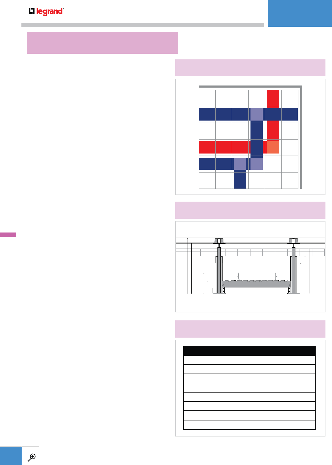
1.1" CLEARANCE
3.5" LEG HEIGHT
5.5" TOTAL HEIGHT
POWER CABLE PATHWAY
DATA CABLE PATHWAY
17" CLEARANCE
18" TOTAL HEIGHT
RAISED ACCESS FLOOR
8.2" CLEARANCE
10.6" LEG HEIGHT
13" TOTAL HEIGHT
Planning and ordering UFS for any raised access floor is
simple if you follow these steps.
PLANNING
1. Review a scale drawing of the installation defining the
planned cable pathways. Consider multiple levels of
cable trays within the installation, ie. all data cables on
the 12” level and all power cables on the 4” level
(see Diagram A.).
2. Determine the number of cables needed in the pathway.
It’s a good rule to allow for 50% additional capacity for
future moves, adds and changes.
3. Refer to the Cablofil Load/Fill calculator at
www.legrand.us/cablofil to determine tray size. Specify
the exact cable size(s) when making this calculation.
4. Determine the leg height for each level of tray. Add the
tray depth to the leg height to make sure your installation
clears the lowest part of the floor and other tray runs.
(see Diagram B).
5. Confirm the tray width you are planning is compatible
with your leg selection. The EDF legs in the UFS system
can support multiple levels of tray – however, 500mm tray
can only be used when the crossbar is installed at the top
of any leg.
ORDERING
1. Determine the amount of straight tray sections needed.
Consider tray length options. Save labor and use 10’ sections
when tray is installed before floor installation – use 2’ tray
for installation in an existing floor.
2. Determine the number of support kits needed for each
tray level. Support 2’ tray at every junction of the raised
access floor or every 2’. For 10’ tray, supports are used
every 8’. Additional supports will be needed at ends of
runs and at T’s and corners.
3. Count the number of 90° corners, T’s and junctions.
The UFT90KIT works with any size or depth of tray.
4. Send a completed bill of materials (and a copy of your
scale drawing) to your Legrand representative for re-
view and a price quotation (see Diagram C.).
DIAGRAM A.
EXAMPLE OF UFS IN 12’ X 12’ RAISED ACCESS FLOOR
2' x 2' Raised Access Floor
Data - 12" high level in 2" x 20" tray
Power - 4" high level in 2" x 12" tray
DIAGRAM B.
EXAMPLE OF INSTALLATION WITH MULTIPLE LEVELS
DIAGRAM C.
EXAMPLE OF BILL OF MATERIALS
QTY. PART OR KIT #
DATA CABLE PATHWAY
10 UFCF2/54/500
17 UFTUPKIT300
3 UFT90KIT
POWER CABLE PATHWAY
7 UFC2/54/300
10 UFTUPKIT100
1 UFT90KIT
UFS
HOW TO ORDER CABLOFIL UNDER FLOOR SYSTEMS
UNDERFLOOR
WWW.LEGRAND.US/CABLOFIL
A.58
CABLOFIL
CABLE MANAGEMENT

1
2
3
4
5
6
UFS Under Floor System is designed to reduce labor costs in raised access floor applications. All parts of the system assemble with little
or no attachment hardware and require only simple tools. For more information, please contact your local Legrand representative.
Assemble both leg sections to crossbars.
Using a screwdriver, secure assembly by
bending small tab on each leg. All leg support
sections can be assembled in advance or offsite
for greater efficiency.
Place assembly leg supports in position and
loosely secure to floor legs with serrated
attachment clips.
Place 2’ tray sections in position.
Bend FAS style tabs with screwdriver to secure
tray. Double rows of FAS tabs on UFS crossbars
act as tray splices.
Use a UFT90KIT for corners, tees, and
junctions. Secure with tray clips.
UFS
HOW TO INSTALL CABLOFIL UNDER FLOOR SYSTEMS
UNDERFLOOR
WWW.LEGRAND.US/CABLOFIL
A.59
CABLOFIL
CABLE MANAGEMENT
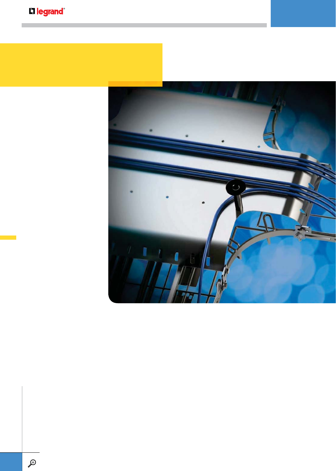
Cablofil is perfectly suited for fiber-optic cabling with accessories that create large radius
bends and dropouts that keep cables functioning at the highest specification. This accessory
line also includes new flexible tray inserts that keep cabling uniformly supported and a series
of junction bridges for tee and 4-way tray intersections.
A.61 EZT90RS
90˚ RADIUS SHIELDS
A.61 RADT90RS
90˚ RADIUS SHIELDS
A.62 HXB
HORIZONTAL CROSS BRIDGE
A.62 RHXB
REDUCING HORIZONTAL
CROSS BRIDGE
A.62 HTB
HORIZONTAL TEE BRIDGE
A.63 BH75KIT
BRIDGE HORN KIT
A.63 INSERTPP
PLASTIC INSERTS
A.64 OTDOFAS
OVER-THE-TOP DROP OUT
A.64 OTDO
OVER-THE-TOP WATERFALL
A.65 CABLEXIT50
CABLE EXIT
A.65 TOH
FIBER-OPTIC TWIST-ON HORN
FIBER OPTIC
FIBER-OPTIC
WWW.LEGRAND.US/CABLOFIL
A.60
CABLOFIL
CABLE MANAGEMENT
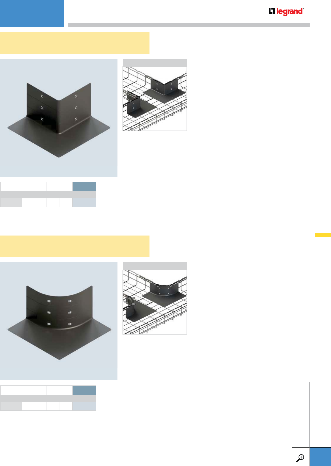
EZT90RS
90˚ RADIUS SHIELDS
RADT90RS
90˚ RADIUS SHIELDS
• Use in conjunction with EZT 90 KIT
• Protects cable from rough edges at cable
pathway junctions
• Slotted, ABS design installs with zip ties
(included)
• One size fits CF54, CF105 and CF150 tray
heights – just trim to fit
• Sold in pairs
• Use in conjunction with RADT 90 KIT
• Protects cable from rough edges at cable
pathway junctions
• Slotted, ABS design installs with zip ties
(included)
• One size fits CF54, CF105 and CF150 tray
heights – just trim to fit
• Sold in pairs
APPLICATION
APPLICATION
PKG. QTY. WEIGHT PL*
LBS KG
EZT90RS 1 .208 .094 944 768
* PL = Plastic
PKG. QTY. WEIGHT PL*
LBS KG
RADT90RS 1 .197 .089 944 770
* PL = Plastic
FIBER-OPTIC
WWW.LEGRAND.US/CABLOFIL
A.61
CABLOFIL
CABLE MANAGEMENT

HXB
HORIZONTAL CROSS BRIDGE
RHXB
REDUCING HORIZONTAL CROSS BRIDGE
HTB
HORIZONTAL TEE BRIDGE
• Keeps cabling separated in horizontal tray crossings
• Durable steel construction with Pre-galvanized and Black
powder coated finishes
• Mounts to tray with included BC1 Bridge Clip and self-tapping
screws
• Use cable ties in slotted holes to secure cables
• All mounting holes are pre-drilled
• Use on CF54, CF105 and CF150 tray
• Fits 12” (300 mm) tray widths
• Keeps cabling separated in horizontal tray crossings
• Durable steel construction with Pre-galvanized and Black
powder coated finishes
• Mounts to tray with included BC1 Bridge Clip and self-tapping
screws
• Use cable ties in slotted holes to secure cables
• All mounting holes are pre-drilled
• Use on CF54, CF105 and CF150 tray
• Fits tray intersections of 24” (600 mm) and 18” (450 mm) tray
widths
• Keeps cabling separated in horizontal tee junctions
• Durable steel construction with Pre-galvanized and Black
powder coated finishes
• Mounts to tray with included BC1 Bridge Clip and self-tapping
screws
• Use cable ties in slotted holes to secure cables
• All mounting holes are pre-drilled
• Use on CF54, CF105 and CF150 tray
• Fits 12” (300 mm) tray widths
• Available in a reducing option
TRAY WIDTH TRAY WIDTH 2 WEIGHT PG BL
INCHES MM INCHES MM LBS KG
RHXB600-450 24" 600 18" 450 14.21 6.44 944723 944725
TRAY WIDTH TRAY WIDTH 2 WEIGHT PG BL
INCHES MM INCHES MM LBS KG
HTB300 12" 300 12" 300 7.23 3.27 944736 944737
TRAY WIDTH TRAY WIDTH 2 WEIGHT PG BL
INCHES MM INCHES MM LBS KG
HXB300 12" 300 12" 300 8.74 3.96 944734 944735
APPLICATION
APPLICATION
APPLICATION
FIBER-OPTIC
WWW.LEGRAND.US/CABLOFIL
A.62
CABLOFIL
CABLE MANAGEMENT
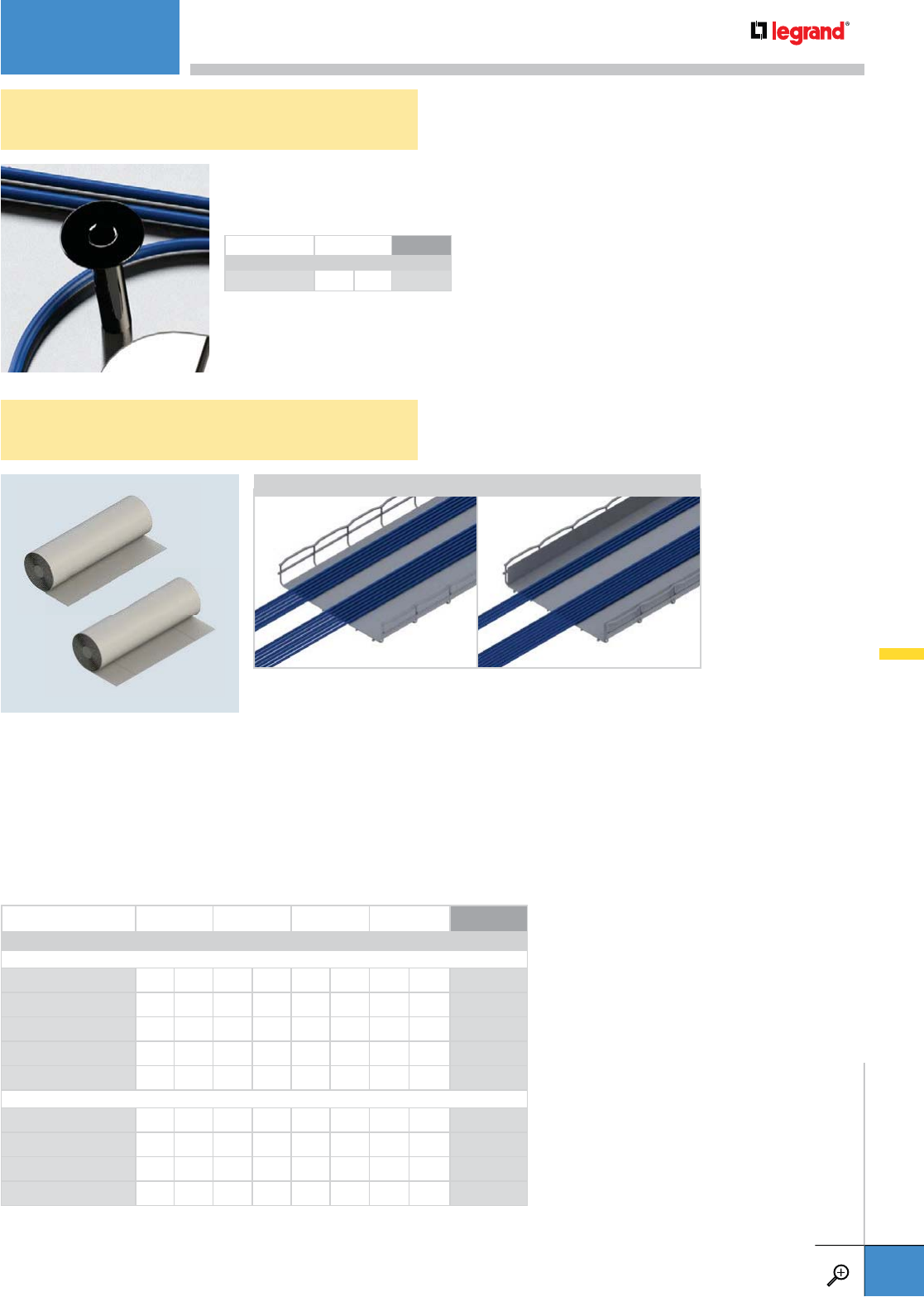
INSERTPP
PLASTIC INSERTS
BH75KIT
BRIDGE HORN KIT
• Mounts to any bridge with predrilled holes
• Keeps cables from leaving the cable pathway.
• Available in black plastic
• 17 mil thickness creates a smooth cable pathway in Cablofil cable management
• Bottom only insert fits 150 to 600 wide tray
• Bottom with sides insert fits CF54, CF105 and CF150 tray in widths from 100 to 600
• Bottom with sides insert is perforated to easily form sides
• Flame Class per UL 94 V-0
• RoHS Compliant
• UV Retardant
• Other sizes available upon request
TRAY WIDTH HEIGHT LENGTH WEIGHT BL
INCHES MM INCHES MM FEET M LBS KG
BOTTOM ONLY
INSERTPP150 6 150 - - 200 60 7.1 3.22 944695
INSERTPP300 12 300 - - 200 60 21.1 9.57 944696
INSERTPP450 18 450 - - 200 60 33 14.96 944697
INSERTPP500 20 500 - - 200 60 36.7 16.64 944691
INSERTPP600 24 600 - - 200 60 44.1 20 944698
BOTTOM w/ SIDES
INSERTPP105/150 6 150 4 105 165 50 21.2 9.61 944702
INSERTPP105/300 12 300 4 105 165 50 28.1 9.62 944703
INSERTPP105/450 18 450 4 105 165 50 45.5 20.63 944709
INSERTPP105/600 24 600 4 105 165 50 54.7 24.81 944700
APPLICATIONS
BOTTOM ONLY BOTTOM w/ SIDES
WEIGHT BL
LBS KG
BH75KIT 0.22 0.10 944722
FIBER-OPTIC
WWW.LEGRAND.US/CABLOFIL
A.63
CABLOFIL
CABLE MANAGEMENT
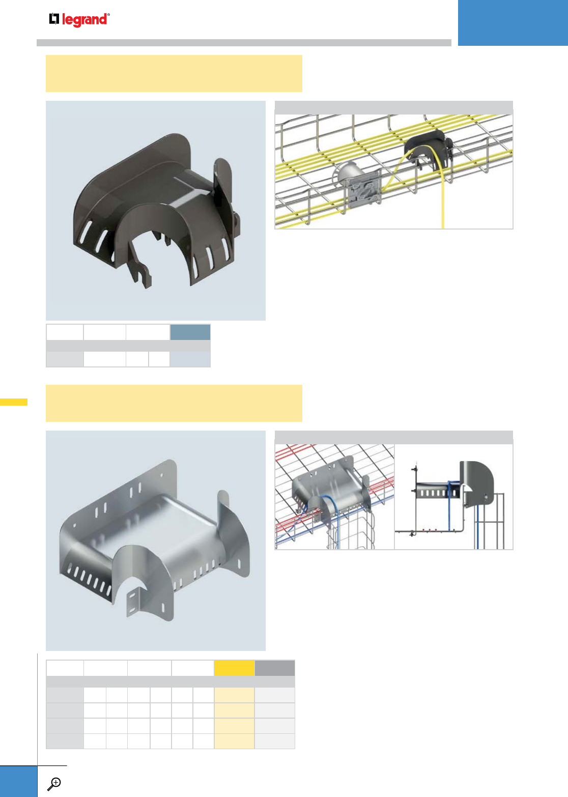
PKG. QTY. WEIGHT PL*
LBS KG
OTDOFAS 1 .066 .029 943 779
* PL = Plastic
OPENING 1 OPENING 2 WEIGHT EZ BL
INCHES MM INCHES MM LBS KG
OTDO44 4 100 4 100 4.02 1.82 944 681 944 793
OTDO46 4 100 6 150 4.72 2.14 944 791 944 795
OTDO68 6 150 8 200 5.34 2.42 944 684 944 727
OTDO810 8 200 10 250 6.12 2.77 944 715 944 719
OTDOFAS
OVER-THE-TOP DROP OUT
OTDO
OVER-THE-TOP WATERFALL
• Smooth, curved design keeps eliminates sharp bends for
fiber-optic cabling
• Durable polycarbonate material
• Use built-in hold down slots for securing cables
• Snaps in place without additional hardware
• Allows cable to exit side of cable pathway without cutting
tray wires
• Fits CF54/200-600 trays and CF105/150-600 trays
• Patent pending
• Recommended for larger bundles of fiber-optic cabling dropouts
• Allows cable to exit side of cable pathway without cutting tray wires
• Metal construction available in Electrozinc and Black powder coated finishes
• Available in four sizes
• Kit includes one OTDO and all necessary mounting hardware
• Fits series 54, 105 and 150 Cablofil cable management
• Patent pending
APPLICATION
APPLICATION
FIBER-OPTIC
WWW.LEGRAND.US/CABLOFIL
A.64
CABLOFIL
CABLE MANAGEMENT
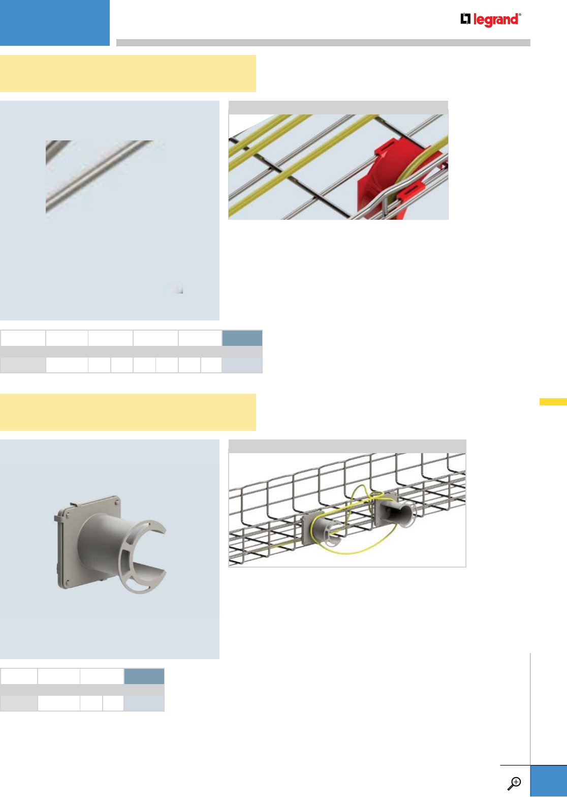
CABLEXIT50
CABLE EXIT
TOH
FIBER-OPTIC TWIST-ON HORN
• Recommended for electrical, telecommunication and fiber-optic cabling
• Keeps cables from deforming when entering and exiting tray
• Plastic construction is durable and corrosion resistant
• Snaps into place without attachment hardware
• CABLEXIT can be installed in a continuous row without modification
• Fits any Cablofil cable management tray
• UL 94VO Rated
PKG. QTY. WIDTH LENGTH WEIGHT PL*
INCHES MM INCHES MM LBS KG
CABLEXIT50 1 2 50 4 100 .024 .010 944 653
* PL = Plastic
APPLICATION
• Use to manage extra lengths of fiber-optic cabling
• Snaps onto side or bottom of any Cablofil cable pathway
• Use in singles, pairs or more
• ABS plastic construction is durable and corrosion resistant
• Kit includes one Plexo 80 Base and one Fiber-Optic Horn
• Requires no additional hardware for attachment
PKG. QTY. WEIGHT PL*
LBS KG
TOH 1 .13 .05 944 707
* PL = Plastic
APPLICATION
FIBER-OPTIC
WWW.LEGRAND.US/CABLOFIL
A.65
CABLOFIL
CABLE MANAGEMENT
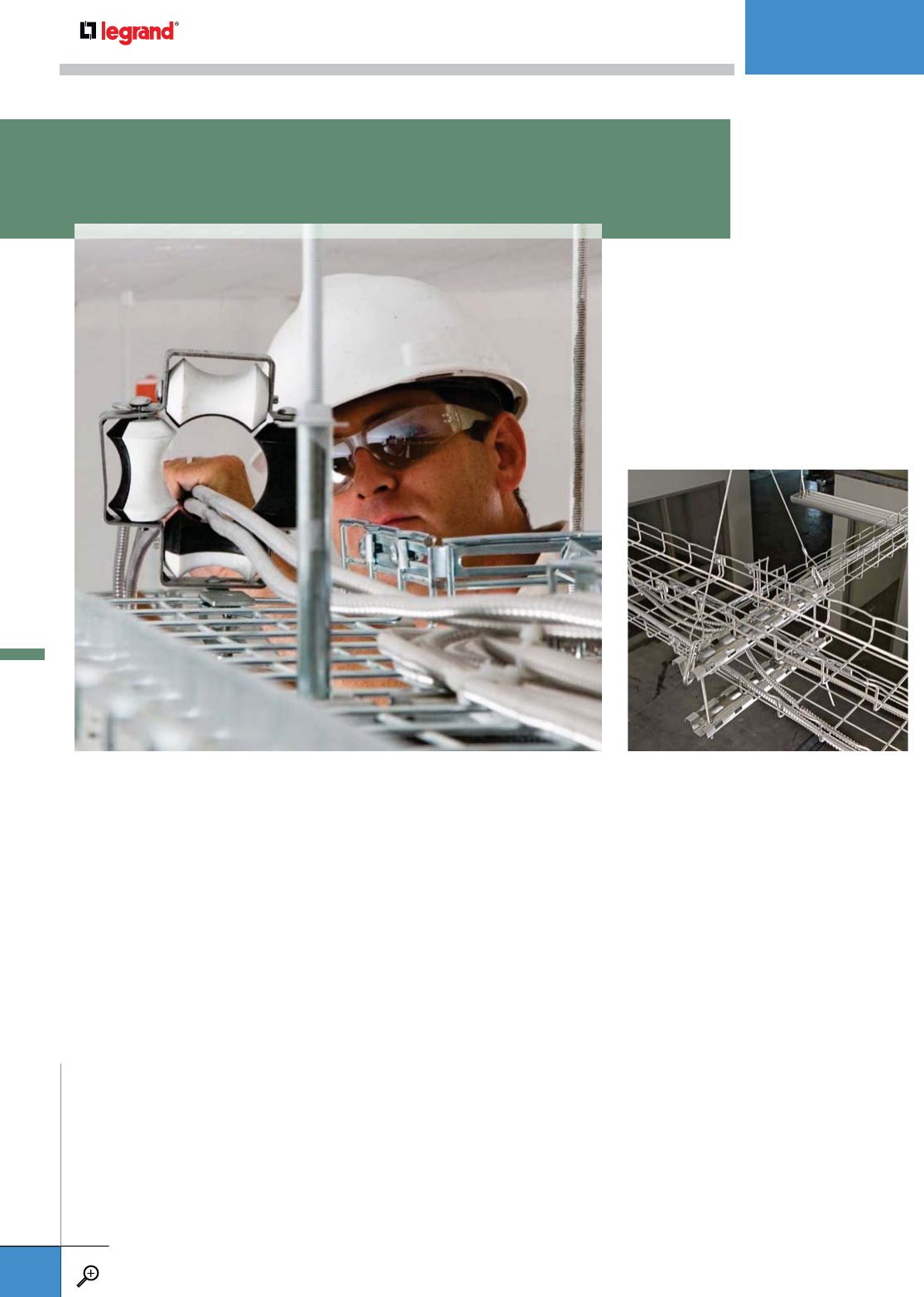
A.67 C50CC
CONDUIT CLAMP KIT
A.67 CC KIT
CONDUIT CLAMP KIT
A.68 CE40CC & CH
CONDUIT ATTACHMENT FITTINGS & CONDUIT
CLAMP KIT
A.68 TC4KIT/TC5KIT
TWIST-ON METALLIC
JUNCTION BOXES
A.69 C 50
ELECTRICAL BOX SUPPORT
A.69 SBDA
CONDUIT AND BOX SUPPORT
A.69 CM50I
INDUSTRIAL BOX
MOUNTING BRACKET
A.70 HB 2 KIT
WALL/FLOOR
TERMINATION BRACKET
A.70 AB225 KIT
ANGLE BRACKET
A.71 YCKIT
YOKE CLAMP KIT
A.71 WMC2LA
TRAY-TO-LADDER CLAMP
A.71 FS 41
FASTRUT CONNECTOR
A.72 DO
WATERFALL DROPOUT
A.72 CABLEXIT
DROP OUT KIT
CABLE DROP OUT
A.73 DROP OUT KIT
CABLE DROP OUT KIT
A.73 MFM
METALLIC MULTIFIX PLATE
A.74 CLIP
CABLE LABEL CLIP
A.74 EZVC
VELCRO ROLL
A.74 RB112KIT
RACK BRACKET KIT
A.75 EZJB 5/16
J-BOLT
A.75 GNDSB
GROUNDING LUG
A.75 GNDCL
GROUNDING LUG
A.76 FAS ROLLER
A.76 FAS ROLLER HD
HEAVY DUTY
A.78 FLAMESTOPPER
OTHER MOUNTINGS
A wide variety of mounting accessories
make Cablofil the easiest brand of Cable
Management to install on the market.
Every accessory has been designed to
keep cables safe and create a durable
installation.
OTHER MOUNTINGS
WWW.LEGRAND.US/CABLOFIL
A.66
CABLOFIL
CABLE MANAGEMENT
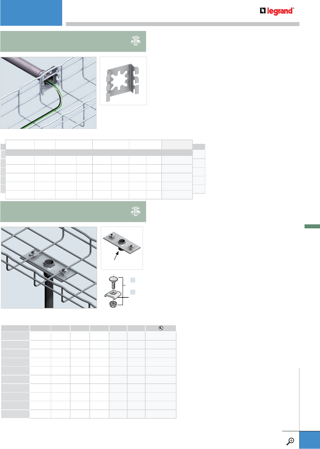
• Allows for easy connection to cable drops in EMT with
conduit connector (not included).
• Attaches 1/2” to 4” conduit to any size Cablofil tray.
• Kit includes: one connector plate, two CE 25 washers and
two EZ BN 1/4 Bolt/Nut.
• Remove one longitudinal wire (between adjacent cross
wires of WMCT) on CCKITs 112 and larger where necessary
on WMCT to accommodate conduit fittings clearance.
• Secures 1/2” to 1-1/2 “ conduit to any size Cablofil tray.
• Installs quickly – patented FAS locking tabs require no
additional hardware to secure to tray.
• Attach conduit to C50CC after attachment to tray with
conduit connector (not included).
Conduit connector
by others
EMT DIAMETER WEIGHT LOAD RATING PG
INCHES MM LBS KG LBS KG
CC12KIT 0.5 12.7 0.55 0.25 150.0 68.0 943 238
CC34KIT 0.75 19.0 0.55 0.25 150.0 68.0 943 239
CC1KIT 1.0 25.4 0.54 0.25 190.0 86.2 943 240
CC114KIT 1.25 31.7 0.53 0.24 225.0 102.1 943 241
CC112KIT 1.5 38.1 0.52 0.24 250.0 113.4 943 242
CC2KIT 2.0 50.8 0.51 0.23 300.0 136.1 943 243
CC212KIT 2 .5 63.5 0.75 0.34 375.0 170.1 943 244
CC3KIT 3.0 76.0 0.75 0.34 500.0 226.8 943 245
CC312KIT 3.5 88.9 0.89 0.40 600.0 272.6 943 246
CC4KIT 4.0 101.0 1.0 0.47 700.0 317.5 943 247
PKG. QTY. WIDTH CONDUIT DIAMETER WEIGHT PG
INCHES MM INCHES MM LBS KG
C50CC12 1 0.82 20.8 0.5 12.7 0.21 0.10 943 175
C50CC34 1 1.04 26.4 0.75 19.0 0.21 0.10 943 176
C50CC1 1 1.29 32.8 1.0 25.4 0.20 0.09 943 115
C50CC114 1 1.64 41.6 1.25 31.7 0.20 0.09 943 116
C50CC112 1 1.88 47.2 1.5 38.1 0.20 0.09 943 117
x2
x2
EZ BN 1/4
CE 25
C50CC
CONDUIT CLAMP KIT
CC KIT
CONDUIT CLAMP KIT
OTHER MOUNTINGS
WWW.LEGRAND.US/CABLOFIL
A.67
CABLOFIL
CABLE MANAGEMENT
PKG QTY WIDTH CONDUIT DIAMETER WEIGHT PG
INCHES MM LBS KG
C50CC12 1 0.82 20.8 0.5 12.7 0.21 0.10 943 175
C50CC34 1 1.04 26.4 0.75 19.0 0.21 0.10 943 176
C50CC1 1 1.29 32.8 1.0 25.4 0.20 0.09 943 115
C50CC114 1 1.64 41.6 1.25 31.7 0.20 0.09 943 116
C50CC112 1 1.88 47.2 1.5 38.1 0.20 0.09 943 117

• Secures conduit to Cablofil tray.
• For Bottom Mounting – works with all Cablofil tray. For Side Mounting –
works only with CF 105 and CF 150 tray series.
• CE 40 CC attaches 1/2” to 1-1/4” conduit diameters.
• CH Kit secures 1/2” to 4” conduit diameters.
• CH Kit includes: two CE 40 washers, one EZ BN 1/4 and one Conduit Hanger.
PKG. QTY. FOR CONDUIT SIZE WEIGHT EZ BL PE
INCHES LBS KG
CE40CC12 10 0.5 0.22 0.10 943 168 – –
CE40CC34 10 0.75 0.21 0.10 943 169 943 275 –
CE40CC1 10 1.0 0.20 0.09 943 170 943 276 –
CE40CC114 10 1.25 0.19 0.09 943 171 943 277 –
CH12 KIT 1 0.5 0.27 0.12 943 192 943 278 943 292
CH34 KIT 1 0.75 0.28 0.13 943 193 943 279 943 293
CH1 KIT 1 1.0 0.29 0.13 943 194 943 280 943 294
CH114 KIT 1 1.25 0.30 0.14 943 195 943 281 943 295
CH112 KIT 1 1.5 0.36 0.16 943 196 943 282 943 296
CH2 KIT 1 2.0 0.40 0.18 943 197 943 283 943 297
CH212 KIT 1 2.5 0.45 0.20 943 198 943 284 943 298
CH3 KIT 1 3.0 0.50 0.23 943 199 943 285 943 299
CH312 KIT 1 3.5 0.67 0.30 943 200 943 286 943 300
CH4 KIT 1 4.0 0.91 0.41 943 201 943 287 943 301
– Contact manufacturer for availability.
CH Kits
CE40CC / CH
CONDUIT ATTACHMENT FITTINGS AND CONDUIT CLAMP KIT
• Easy 45˚ twist-on attachment to any CF Series Cablofil tray.
• Available in 4” and 4-11/16” box sizes.
• Boxes feature standard knockouts on 4 sides.
• Flat covers, mounting screws, box and bonding hardware are included in kit.
• UL Classified.
• Designed to accept all NEMA standard face plates and plaster rings.
HEIGHT WIDTH DEPTH WEIGHT
PG
INCHES MM INCHES
MM
INCHES MM LBS KG
TC4KIT 4.0 102 4.8 122 2.0 50 1.2 0.5 944 478
TC5KIT 4.7 119 5.5 140 2.0 50 1.3 0.5 944 479
TC5KIT
TC4KIT
TC4KIT/TC5KIT
TWIST-ON METALLIC JUNCTION BOXES
CE40CC
OTHER MOUNTINGS
WWW.LEGRAND.US/CABLOFIL
A.68
CABLOFIL
CABLE MANAGEMENT
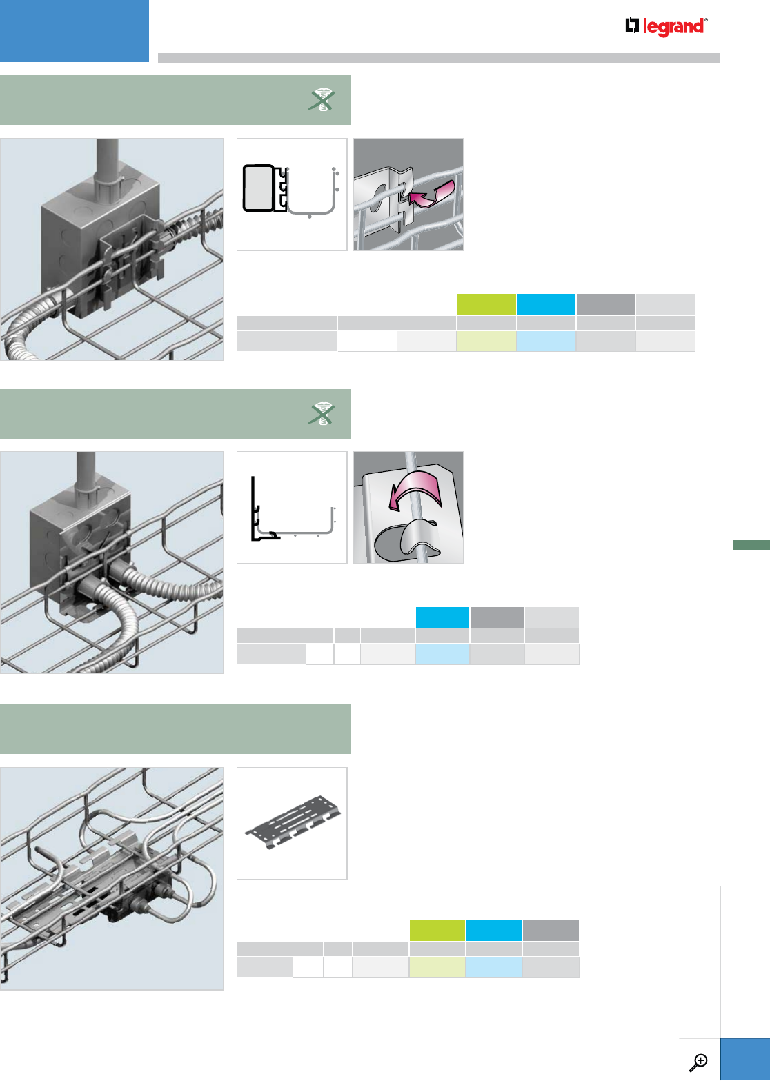
• Mount electrical boxes and lighting
fixtures directly to cable tray.
• Slotted mounting holes allow for
less-than-perfect hole alignment.
• Fold over tabs secure attachment
to tray.
• Mount electrical boxes and conduit
directly to Cablofil tray.
• Mounting holes accommodate 1/2”
and 3/4” conduit.
• Slotted mounting holes allow for
less-than-perfect hole alignment.
• Fold over tabs secure attachment
to tray.
• FAS style tabs secures bracket to tray without
additional hardware.
• Slotted mounting hole design allows for less-than-
perfect hole alignment.
WEIGHT PG GC 316L BL PE
LBS KG
C 50 0.2 0.1 586 130 – – 941 308 930 694
– Contact manufacturer for availability.
WEIGHT PG GC 316L BL
LBS KG
CM50I 0.33 0.15 586 260 – – 942 958
– Contact manufacturer for availability.
WEIGHT PG 316L BL PE
LBS KG
SBDA 0.2 0.1 585 210 – 942 950 942 951
– Contact manufacturer for availability.
C 50
ELECTRICAL BOX SUPPORT
SBDA
CONDUIT AND BOX SUPPORT
CM50I
INDUSTRIAL BOX MOUNTING BRACKET
OTHER MOUNTINGS
WWW.LEGRAND.US/CABLOFIL
A.69
CABLOFIL
CABLE MANAGEMENT
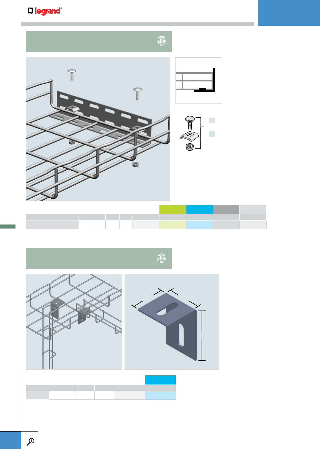
• Secures smaller tray runs to
larger tray runs at right angles.
• Kit contains two EZ BN 1/4
Bolt/Nut and two CE 25 washers
to secure tray.
• Wall Termination Bracket works in
a variety of ways to support Cablofil
tray in telecommunications closets,
equipment rooms, risers, etc. on
wall or floor.
• Slotted design adapts to any
configuration.
• Kit contains two EZ BN 1/4 and two
CE 25 with one HB2.
LENGTH WEIGHT PG GC 316L BL PE
INCHES MM LBS KG
HB 2 KIT 9.4 240 0.4 0.2 942 419 – – 942 319 942 391
– Contact manufacturer for availability.
x2
x2
EZ BN 1/4
CE 25
PKG. QTY. WEIGHT PG 316L
LBS KG
AB225KIT 10 1.07 0.48 943 223 –
– Contact manufacturer for availability.
1½" 1½"
2¼"
HB 2 KIT
WALL/FLOOR TERMINATION BRACKET
AB225 KIT
ANGLE BRACKET
OTHER MOUNTINGS
WWW.LEGRAND.US/CABLOFIL
A.70
CABLOFIL
CABLE MANAGEMENT
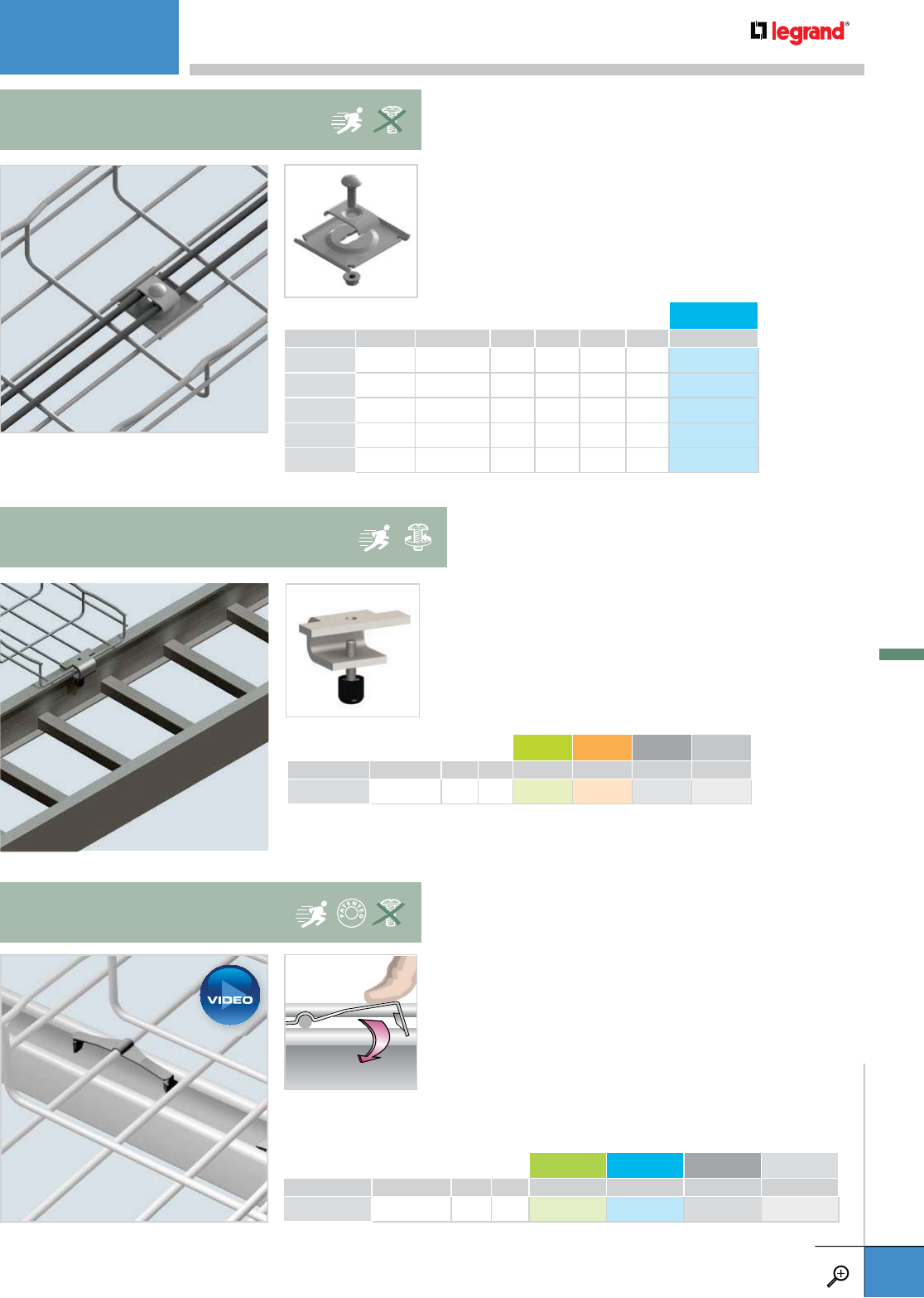
• This unique clamp allows tray to be attached to
the side rails of any ladder tray and a pre-installed
setscrew secures the junction for a secure installation.
• Bolt head protection cap included as shown
PKG. QTY. WEIGHT GC 304L BL PE
LBS KG
WMC2LA 1 0.37 0.17 – – 943 493 943 494
– Contact manufacturer for availability.
WMC2LA
WIRE MESH CABLE TRAY-TO-LADDER CLAMP
PKG. QTY. NO. OF TUBES TUBE DIAMETER WEIGHT 316L
INCHES MM LBS KG
YC214KIT 10 2 0.25 6.35 1.17 0.53 943 253
YC238KIT 10 2 0.375 9.52 1.20 0.54 943 254
YC212KIT 10 2 0.5 12.7 1.32 0.60 943 255
YC414KIT 10 4 0.25 6.35 1.34 0.61 943 256
YC438KIT 10 4 0.375 9.52 1.47 0.66 943 257
• Secures tubing to Cablofil tray to resist
vibration in industrial applications.
• Accommodates up to 1/2” tubing.
• Each kit includes: one YC Yoke Clamp, one
CE 40 Washer and one EZBN 1/4 Bolt/Nut.
YCKIT
YOKE CLAMP KIT
• FASTRUT attaches tray to strut without bolts and nuts
or tools.
• Reduces installation time.
• Install FASTRUT on outer wires of tray, and both sides
of the strut.
• 2 required for tray 12" or smaller.
• 3 required for tray 18" or larger.
PKG. QTY. WEIGHT DC 316L BL PE
LBS KG
FS 41 25 3.3 1.5 599 007 599 004 942 823 942 824
FS 41
FASTRUT CONNECTOR
OTHER MOUNTINGS
WWW.LEGRAND.US/CABLOFIL
A.71
CABLOFIL
CABLE MANAGEMENT
PLAY

• Protects cables when exiting and entering tray.
• Snap in mounting tabs eliminate the need for
attachment hardware and speeds install time.
WEIGHT PG 316L BL PE
LBS KG
CABLEXIT100 0.2 0.1 585 160 585 164 941 299 930 669
CABLEXIT
CABLE EXIT
TRAY DEPTH
WIDTH*
WEIGHT EZ BL PE
INCHES MM INCHES MM LBS KG
DO54/150 2.0 54 6.75 170 13.2 6.0 943 210 943 258 943 262
DO54/300 2.0 54 12.75 325 17.6 8.0 943 211 943 259 943 263
DO105/150 4.0 105 6.75 170 15.4 7.0 943 212 943 260 943 264
DO105/300 4.0 105 12.75 325 19.8 9.0 943 213 943 261 943 265
*Internal dimensions
• Smooth solid construction provides protection for cables entering
or exiting the cable pathway.
• Can be used as transition to other cable types.
• All attachment hardware is included.
• Upright flange support holes where required.
• Designed to fit 6” (150 mm) and wider trays.
DO
WATERFALL DROPOUT
6"
150 MM
OTHER MOUNTINGS
WWW.LEGRAND.US/CABLOFIL
A.72
CABLOFIL
CABLE MANAGEMENT
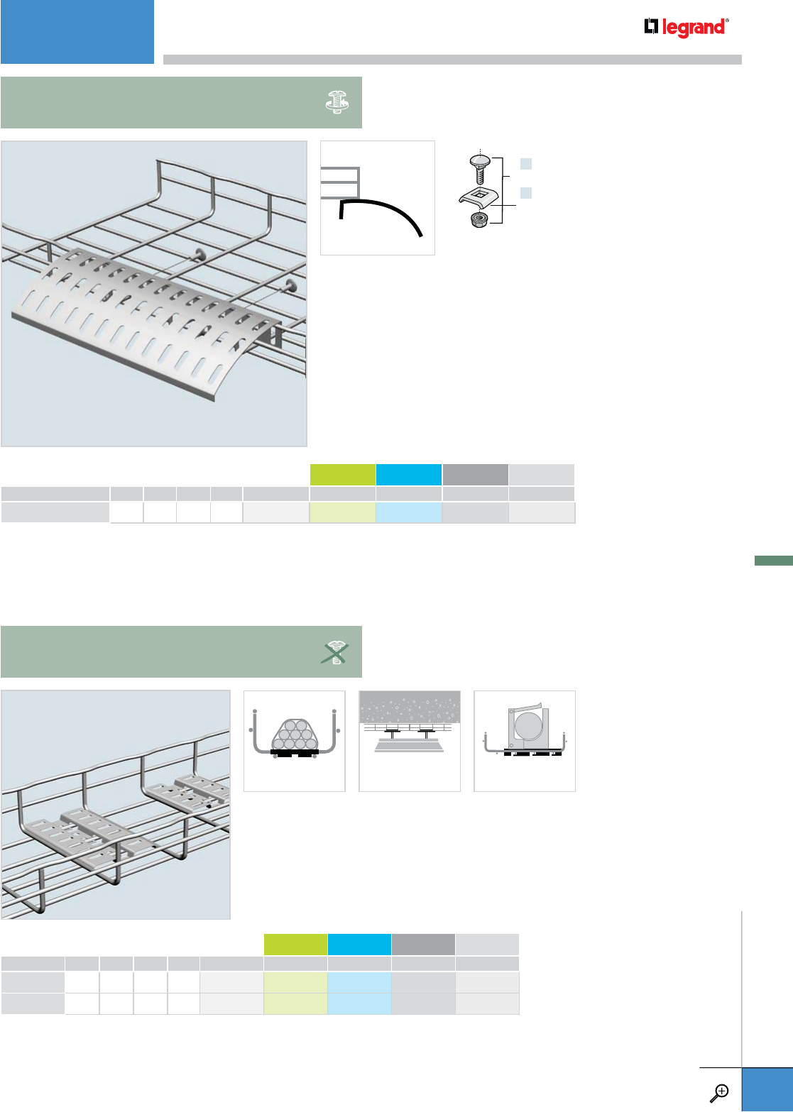
• Protects cables when exiting and entering tray. Slotted design
allows for cable tie or velcro tiewrap cable attachment.
• 7” radius bend eases strain on cables.
• Kit contains two EZ BN 1/4 and two CE 25 with one DROP OUT.
LENGTH WEIGHT PG GC 316L BL PE
INCHES MM LBS KG
DROP OUT KIT 12.25 311 0.9 0.4 942 895 – – 942 896 942 898
– Contact manufacturer for availability.
x2
x2
EZ BN 1/4
CE 25
DROP OUT KIT
CABLE DROP OUT KIT
• Allows installer to mount junction boxes, lighting, tubing,
cable bundles or other hardware directly to tray.
• Snap in mounting tabs eliminate the need for additional
hardware and speed install time.
• Tubing clamps can be attached to plate.
• Underside load limit: 75 lbs (S.F. 1.5)
LENGTH WEIGHT PG GC 316L BL PE
INCHES MM LBS KG
MFM 100 4.0 100 0.2 0.1 585 140 – 585 144 941 297 930 664
MFM 150 6.0 150 0.2 0.1 585 150 – – 941 298 930 667
– Contact manufacturer for availability.
CABLE BUNDLING LIGHT SUPPORT TUBING SUPPORT
MFM
METALLIC MULTIFIX PLATE
OTHER MOUNTINGS
WWW.LEGRAND.US/CABLOFIL
A.73
CABLOFIL
CABLE MANAGEMENT
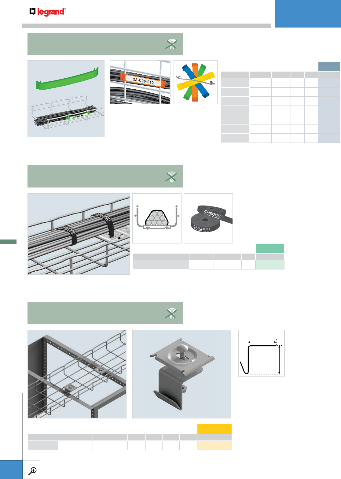
• 1/2” velcro can be cut to fit any size
cable bundle.
• Great for frequent cable changes.
• Secures Cablofil tray to angled frame
type rack tops.
• Tray can be attached parallel with the
rack front.
• 10 Kits to a package.
• Works with all tray sizes.
• Each Kit includes:
- (1) RB112 Bracket
- (1) CE 40 washer
- (1) EZ BN 1/4 Bolt/nut
LENGTH WEIGHT VC*
FEET MM LBS KG
EZVC 15 / ROLL 7 0.1 0.05 559 677
*VC= Velcro
PKG. QTY. WIDTH DEPTH WEIGHT EZ
INCHES MM INCHES MM LBS KG
RB112KIT 10 1.5 38 1.5 38 0.35 0.16 943 350
1.5"
38.1 MM
1.5"
38.1 MM
EZVC
VELCRO ROLL
RB112KIT
RACK BRACKET
• Use Cable Label Clips to identify cable runs.
• Color code makes identification easy.
• Durable poly material won’t fade.
PKG. QTY. COLOR WEIGHT PL*
LBS KG
CLIPBLACK 50 Black 0.009 0.004 559 127
CLIPWHITE 50 White 0.009 0.004 559 137
CLIPORANGE 50 Orange 0.009 0.004 559 147
CLIPYELLOW 50 Yellow 0.009 0.004 559 157
CLIPGREEN 50 Green 0.009 0.004 559 167
CLIPBLUE 50 Blue 0.009 0.004 559 177
CLIPGRAY 50 Gray 0.009 0.004 559 197
CLIP
CABLE LABEL CLIP
*PL= Plastic
OTHER MOUNTINGS
WWW.LEGRAND.US/CABLOFIL
A.74
CABLOFIL
CABLE MANAGEMENT
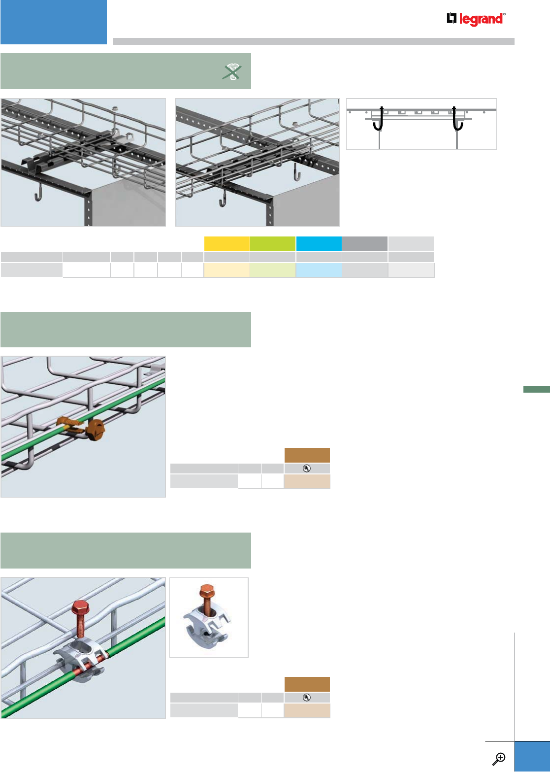
• Use this J-Bolt in conjunction
with a FAS P 200 or FAS P 300 for
attachment to a 19” or 23” rack.
• No drilling needed (see drawing).
• FAS Profile sold separately.
• Nut included.
PKG. QTY. LENGTH WEIGHT EZ GC 316L BL PE
INCHES MM LBS KG
EZJB 5/16 2 2.5 64 2.0 0.91 942 016 – – 942 311 942 383
– Contact manufacturer for availability.
EZJB 5/16
J-BOLT
• Accommodates AWG 3-14 grounding wires.
• Use one GNDSB every 60’ and/or at the end of each tray run. If tray is used as
an Equipment Grounding Conductor, use one on each section of tray for a code
compliant installation.
• Works with any size Cablofil tray.
• UL Listed, CSA Approved.
• Accommodates AWG 1/0 - #6 grounding wires.
• Use one GNDCL every 60’ and/or at the end of each
tray run. If tray is used as an Equipment Grounding
Conductor, use one on each section of tray for a code
compliant installation.
• Works with any size Cablofil tray.
• UL Listed, CSA approved.
• Tin-plated
GNDSB
GROUNDING LUG
GNDCL
GROUNDING LUG
WEIGHT CU*
LBS KG
GNDSB 0.07 0.03 942 616
*CU= Copper
WEIGHT CU*
LBS KG
GNDCL 0.2 0.1 942 866
*CU= Copper
OTHER MOUNTINGS
WWW.LEGRAND.US/CABLOFIL
A.75
CABLOFIL
CABLE MANAGEMENT
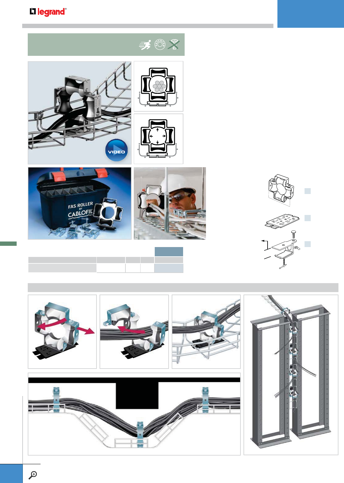
APPLICATIONS
PKG. QTY. WEIGHT PL*
LBS KG
FAS ROLLER 6 11.0 4.8 011 100
FOR CHANGES IN LEVELS FOR COMMUNICATION RACKS
*PL= Plastic
• Easy open gate allows full access to FAS Roller.
• Unique 4 roller design prevents cable snagging.
• Bi-color rollers show roller turn at a distance which
prevents burning the cable while being pulled.
• Multifix™ poly swivel base attaches directly to Cablofil
tray without tools.
• Can also be attached with bolts or handy clamp
provided in kit.
• Use FAS Roller as a permanent part of a tray installation
in horizontal and vertical pathways – for hard to reach
areas, i.e. access floors or plenums.
• Sold in sets of 6 – includes handy carrying case.
• Inside diameter is 2.688”.
x6
x6
x6
+
+
Accommodates up to
1" rung thickness
2.68”
FAS ROLLER
CABLE GUIDE
OTHER MOUNTINGS
WWW.LEGRAND.US/CABLOFIL
A.76
CABLOFIL
CABLE MANAGEMENT
PLAY
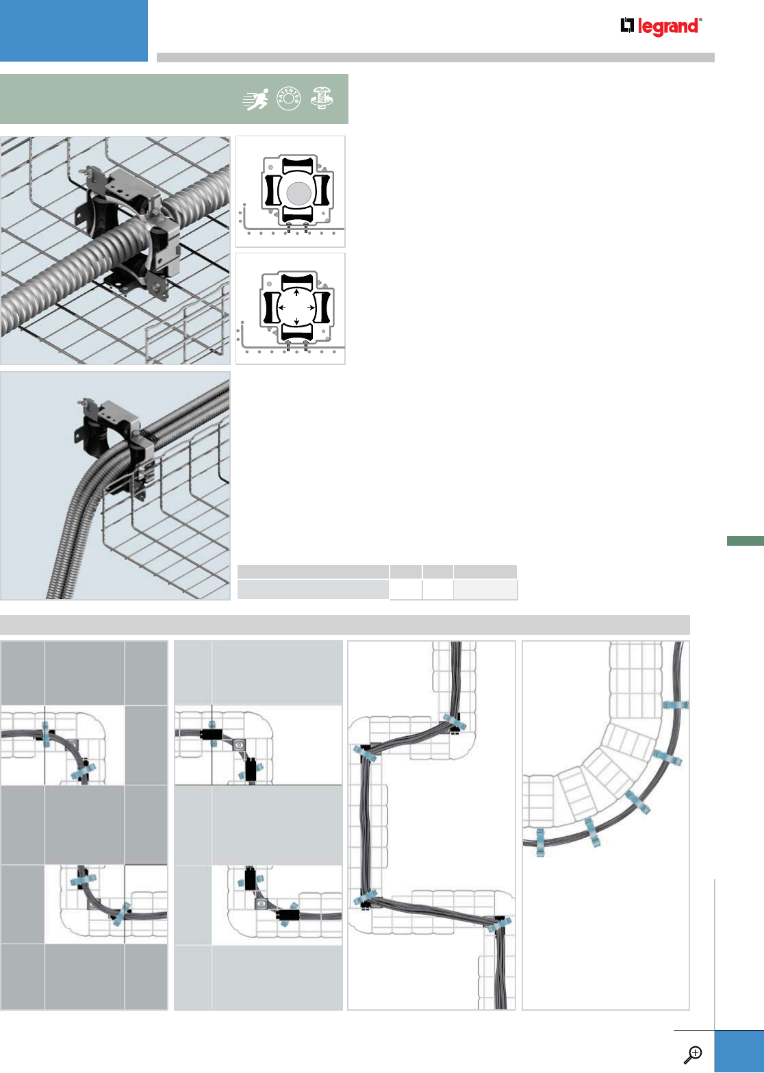
APPLICATIONS
WEIGHT PG
LBS KG
FAS ROLLER HD 3.5 1.59 942 879
FOR ACCESS FLOOR APPLICATIONS FOR SHARP ANGLESFOR ABOVE CEILING FOR WIDE BENDS
• Use HD FAS Roller to pull large power cables or MC cables.
• Heavy-duty frame attaches to any Cablofil tray with
EZ BN 1/4 and CE 30.
• Swing-open gate allows easy loading and unloading
of cables.
• 4-roller design allows cables to be pulled in any direction -
prevents cable snags.
• Bi-colored rollers show installer that roller is functioning
properly – prevents burned cable insulation.
• Sold individually.
• Always place hinge side to inside radius when used
on fittings.
• Inside diameter is 4”.
4”
FASROLLER HD
HEAVY DUTY
OTHER MOUNTINGS
WWW.LEGRAND.US/CABLOFIL
A.77
CABLOFIL
CABLE MANAGEMENT
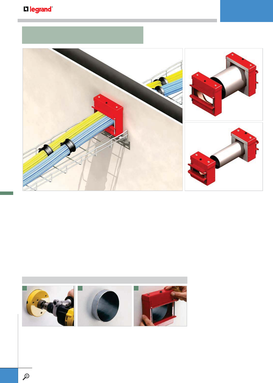
If you need the integrity of a firewall, without adding caulk or putty after the cables
have been installed, look to FlameStopper thru-wall fittings. Redesigned for both
new installations and retrofits, these fittings combine a built-in fire-stopping
intumescent material with an enclosed thru-wall penetration. They meet UL tests
for flame, temperature and smoke, as well as for use in air handling spaces (plenums).
Once installed, FlameStopper fittings allow you to add or remove cables easily, without
risking unseen and potentially dangerous gaps or voids that can occur with caulks or putty.
FlameStopper thru-wall fittings consist of two box assemblies, each with adjustable
steel doors. The boxes are fitted to EMT conduit and cable pass through a block of
intumescent material inside each assembly. At 375º the material expands, creating
a hard char that fills voids around the cables and stops flame from penetrating the
opening. FlameStopper thru-wall fittings are easy to install and inspect and work
seamlessly with Cablofil cable management.
Determine the location for the
fitting on the wall and cut a
hole to fit FlameStopper
EMT conduit.
Install FlameStopper box to one
side of the wall using
adhesive strips. Insert the
proper length of conduit thru
the opening and press in place.
Install the second FlameStopper
box to opposite side of the wall
and tighten all bolts.
• Available in 2” and 4” capacities.
• 4 hour rating for flame and
temperature when tested to UL 1479
standards.
• Highly effective smoke stop.
• Can be ganged for additional capacity.
• Bond both FlameStopper Fittings and
Cablofil Trays together by attaching
proper size wire to ground screw on
fitting tops, through FlameStopper
Sleeve, and to trays using either Cablofil
GNDSB or GNDCL ground clamp in
order to comply with NEC 250.96
1 2 3
TO INSTALL FLAMESTOPPER
For more information on FlameStopper go to www.legrand.us/wiremold or call 1-800-621-2062.
FLAMESTOPPER™
OTHER MOUNTINGS
WWW.LEGRAND.US/CABLOFIL
A.78
CABLOFIL
CABLE MANAGEMENT
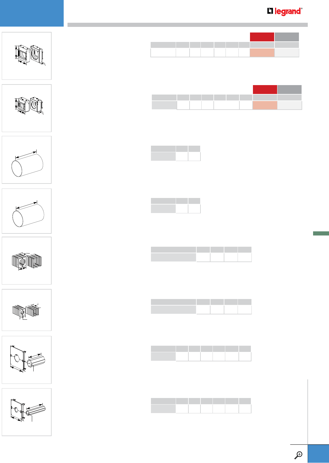
Firestop 4" Trade EMT Conduit Fitting –
For transitioning cable through fire
rated walls/floors for both new and
retrofit applications. Available in red
(RED), or G90 galvanized finish (GA).
UL System W-L-3264 and W-J-3137.
HEIGHT WIDTH DEPTH RED GA
INCHES MM INCHES MM INCHES MM
FS4R 6.25 159 6.0 153 1.75 44 FS4R-RED RS4R-GA
I
6 1/4"
[159mm]
6"
[153mm] 1 3/4"
[44mm]
Firestop 2" Trade EMT Conduit Fitting –
For transitioning cable through fire
rated walls/floors for both new and
retrofit applications. Available in red
(RED), or G90 galvanized finish (GA).
UL System W-L-3264 and W-J-3137.
HEIGHT WIDTH DEPTH RED GA
INCHES MM INCHES MM INCHES MM
FS2R 3.75 95 3.625 92 1.75 44 FS2R-RED RS2R-GA
I
3 3/4"
[95mm]
3 5/8"
[92mm] 1 3/4"
[44mm]
Precut Conduit 4" Trade Size EMT –
Precut to 7 5/8" [194mm] to fit
standard gypsum fire walls with a
two-hour fire rating (6" [152mm] wall
thickness).
LENGTH
INCHES MM
FSPCC4758 7.625 194
7 5/8"
[194mm]
Precut Conduit 2" Trade Size EMT –
Precut to 7 5/8" [194mm] to fit
standard gypsum fire walls with a
two-hour fire rating (6" [152mm] wall
thickness).
LENGTH
INCHES MM
FSPCC2758 7.625 194
7 5/8"
[194mm]
Heat Shield 4" Trade Size Conduit –
Used only when an existing installed
conduit extends 1" [25mm] to 6"
[152mm] beyond the wall surface.
WIDTH DEPTH
INCHES MM INCHES MM
FS4RHS 6.125 155 6.375 162
C
I
6 3/8"
[162mm]
6 1/8"
[155mm]
Heat Shield 2" Trade Size Conduit –
Used only when an existing installed
conduit extends 1" [25mm] to 6"
[152mm] beyond the wall surface.
WIDTH DEPTH
INCHES MM INCHES MM
FS2RHS 3.75 95 6.375 162
6 3/8"
[162mm]
3 3/4"
[95mm]
Retrofit Kit for Existing Installations –
Kit includes 4" trade size split conduit
sleeve to enclose existing cables, and
12" x 12" [305mm x 305mm] ceramic
heat protected wall plate to cover
irregular hole cuts. For use with FS4R
Series Firestop.
HEIGHT WIDTH DEPTH
INCHES MM INCHES MM INCHES MM
FS4RWP12 12.0 305 12.0 305 10.0 254
10"
[254mm]
12"
[305mm] 12"
[305mm]
Retrofit Kit for Existing Installations –
Kit includes 2" trade size split conduit
sleeve to enclose existing cables, and
8" x 8" [203mm x 203mm] ceramic
heat protected wall plate to cover
irregular hole cuts. For use with FS2R
Series Firestop.
HEIGHT WIDTH DEPTH
INCHES MM INCHES MM INCHES MM
FS4RWP8 8.0 203 8.0 203 10.0 254
10"
[254mm]
8"
[203mm] 8"
[203mm]
OTHER MOUNTINGS
WWW.LEGRAND.US/CABLOFIL
A.79
CABLOFIL
CABLE MANAGEMENT

ED 275 ED 250/90ED 1100
ACCESSORIES
PKG. QTY. LENGTH WEIGHT EZ 316L BL PE
INCHES MM LBS KG
ED 275 50 11.0 275 14.3 6.5 558 221 558 224 941 279 930 621
ED 1100 1 43.0 1100 1.1 0.5 558 201 – 941 277 930 616
ED 250/90 50 10.0 250 14.3 6.5 558 211 – 941 278 930 618
– Contact manufacturer for availability.
ACCESSORIES
WWW.LEGRAND.US/CABLOFIL
A.80
CABLOFIL
CABLE MANAGEMENT
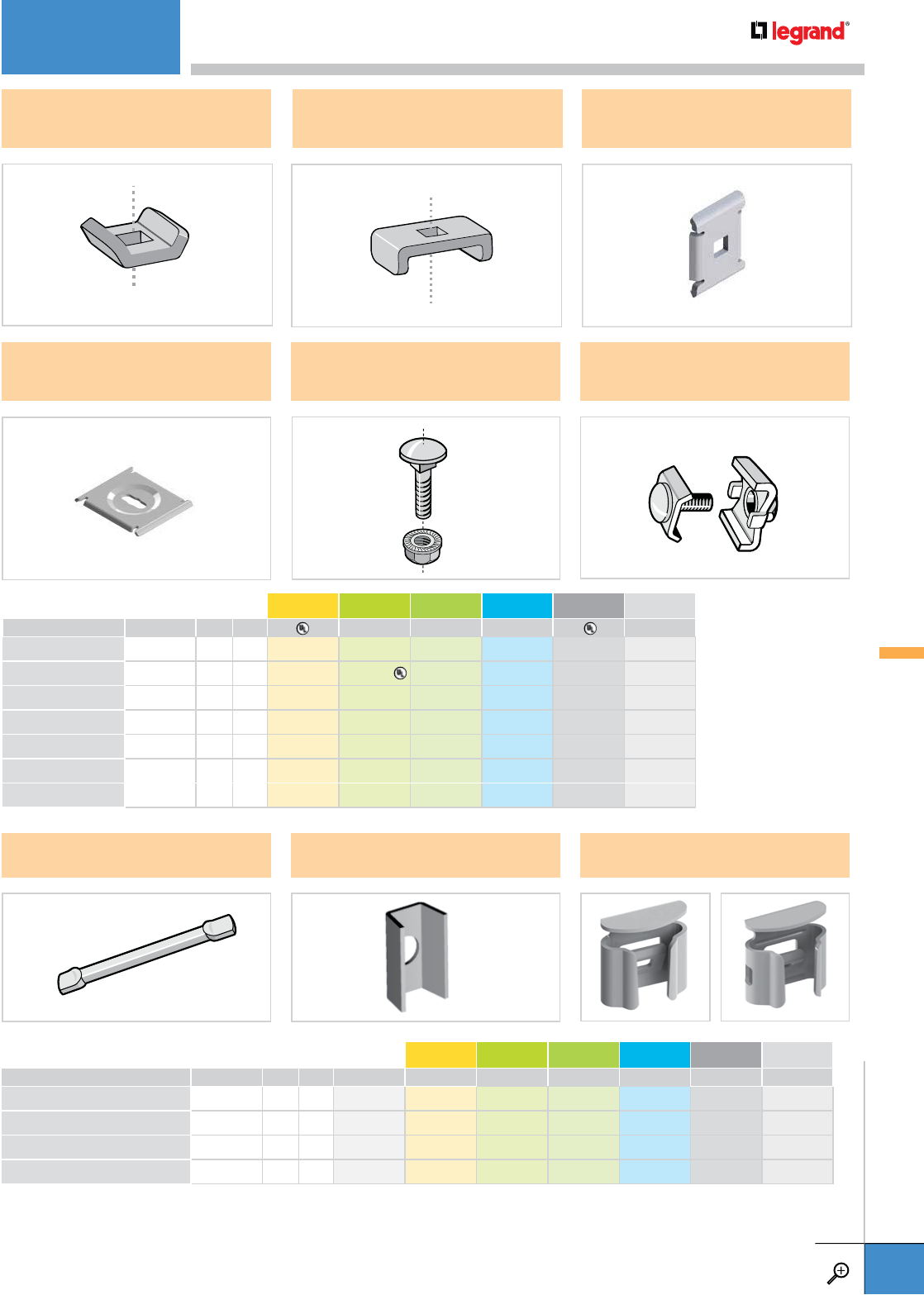
CA ECLI FASLOCK
PKG. QTY. WEIGHT PG EZ GC DC 316L BL PE
LBS KG
CA 50 2.2 1.0 – 801 051 – – – 942 881 –
ECLI 10 0.04 0.02 557 190 ––––942 797 –
FASLOCK S* 25 1.4 0.6 – 558 340 – – – 942 869 942 870
FASLOCK XL* 25 1.4 0.6 – 558 320 – – – 942 821 942 822
– Contact manufacturer for availability.
*Use FASLOCK S for 100mm - 200mm. Use FASLOCK XL for 300mm - 600mm.
EZ BN 1/4
EZ BN 5/16
CE 25
SWK
CE 30 CE 35
CE 40
FASLOCK S FASLOCK XL
PKG. QTY. WEIGHT EZ GC DC 316L BL PE
LBS KG
CE 25 50 1.0 0.4 558 011 – – – 941 274 934 022
CE 30 50 1.7 0.8 558 041 – – – 941 275 934 028
CE 35 251.10.5––––––
CE 40 25 2.7 1.2 558 051 – – – 941 276 934 030
EZ BN 1/4 50 1.3 0.6 941 084 – 943 458 – 942 308 942 380
EZ BN 5/16 50 2.0 0.9 942 778 – 943 500 – 942 780 –
SWK 50 3.6 1.6 943 215 – 943 216 943 218 943 217 –
– Contact manufacturer for availability.
ACCESSORIES
WWW.LEGRAND.US/CABLOFIL
A.81
CABLOFIL
CABLE MANAGEMENT

A.83 CUSTOM BENDS AND
JUNCTIONS
DIRECTIONAL CHANGE
HARDWARE
A.84 HOW TO CUT
CABLOFIL CABLE TRAY
COUPFIL
CUTYFIL
A.85 USING A POWER CUTTER
TO CUT CABLOFIL
A.86 EDRN
FAST SPLICE
A.86 PRECLICK
SPLICE
A.87 FAS TABS FOR
SUPPORTS
A.87 FAS TABS FOR
ACCESSORIES
A.88 T JUNCTIONS
RAD T 90 KIT
A.90 T JUNCTIONS
EZ T 90 KIT
A.92 Y JUNCTIONS
A.94 90˚ BENDS
RAD T 90 KIT
A.96 90˚ BENDS
EZ T 90 KIT
A.98 90˚ JUNCTIONS
EZ T 90 KIT
A.99 OTHER THAN
90˚ JUNCTIONS
A.100 SWEEPS
SWK
A.102 SWEEPS
FASLOCK
A.104 REDUCTIONS
A.107 CHANGING LEVELS
CUTTING AND BENDING
INSTALLATIONS
Use this guide to learn the most effective installation practices when installing
Cablofil tray. Each example of bends and tee’s clearly illustrate proper tray
cutting combined with recommended usage of Cablofil accessories.
INSTALLATIONS
WWW.LEGRAND.US/CABLOFIL
A.82
CABLOFIL
CABLE MANAGEMENT
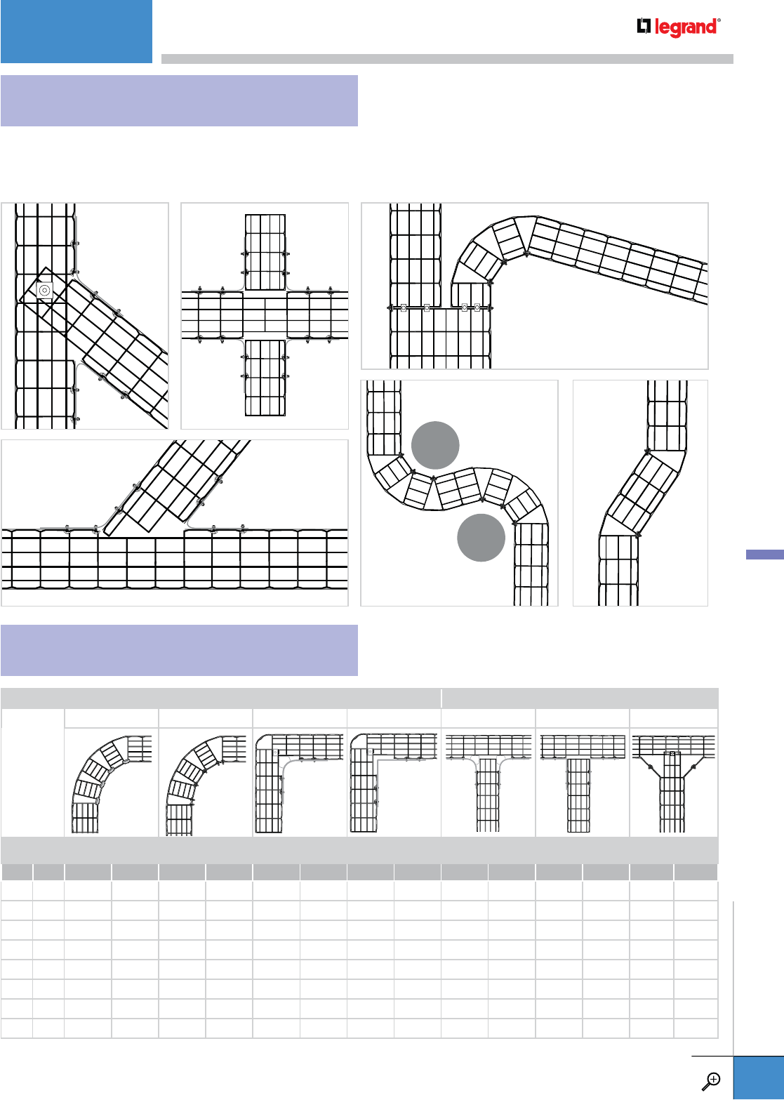
WITH CABLOFIL CABLE TRAY, ANY INSTALLATION CONFIGURATION IS POSSIBLE
Engineers and contractors in North America and around the world have found Cablofil to be the solution to any installation
problem. Any bend, sweep or level change can be fabricated on site. Let your imagination have no limits on your next project.
CUSTOM BENDS AND JUNCTIONS
DIRECTIONAL CHANGE HARDWARE
90˚ BENDS HORIZONTAL TEE
FASLOCK (SWEEP) SWK (SWEEP) RADT90 EZT90 RADT90 EZT90 Y JUNCTION
TRAY WIDTH QTY.
REQUIRED
CUT
INSTRUCTIONS
QTY.
REQUIRED
CUT
INSTRUCTIONS
QTY.
REQUIRED
CUT
INSTRUCTIONS
QTY.
REQUIRED
CUT
INSTRUCTIONS
QTY.
REQUIRED
CUT
INSTRUCTIONS
QTY.
REQUIRED
CUT
INSTRUCTIONS
HARDWARE
REQUIRED
CUT
INSTRUCTIONS
INCHES MM
2.0 50 - - 2 p. A.100 - - 1 kit p. A.96 - - 1 kit p. A.90 - -
4.0 100 2 p. A.102 2 p. A.100 1 kit p. A.88 1 kit p. A.96 1 kit p. A.94 1 kit p. A.90 p. A.80-81 p. A.92
6.0 150 3 p. A.102 4 p. A.100 1 kit p. A.88 1 kit p. A.96 1 kit p. A.94 1 kit p. A.90 p. A.80-81 p. A.92
8.0 200 4 p. A.102 4 p. A.100 1 kit p. A.88 1 kit p. A.96 1 kit p. A.94 1 kit p. A.90 p. A.80-81 p. A.92
12.0 300 6 p. A.103 6 p. A.101 1 kit p. A.89 1 kit p. A.97 1 kit p. A.94 1 kit p. A.91 p. A.80-81 p. A.93
18.0 400 9 p. A.103 8 p. A.101 1 kit p. A.89 1 kit p. A.97 1 kit p. A.95 1 kit p. A.91 p. A.80-81 p. A.93
20.0 450 10 p. A.103 9 p. A.101 1 kit p. A.89 1 kit p. A.97 1 kit p. A.95 1 kit p. A.91 - -
24.0 550 12 p. A.103 11 p. A.101 1 kit p. A.89 1 kit p. A.97 1 kit p. A.95 1 kit p. A.91 - -
INSTALLATIONS
WWW.LEGRAND.US/CABLOFIL
A.83
CABLOFIL
CABLE MANAGEMENT
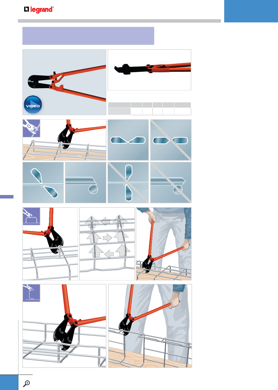
LENGTH WEIGHT
INCHES MM LBS KG/1
COUPFIL 24.8 630 6.0 2.7 559 507
• Angle all cuts away from the
new end.
• Cut each wire with one clean cut,
eliminating any grinding or touch-up.
• Always use side action angle
bolt cutters.
• Cut the bottom wires first, in order
as shown, from the underside of
the tray.
• Rest the lower jaw of the cutters
against the cradle wire and cut at
an angle away from the new end.
• Cut the side wires next, starting
with the top wire.
• Make sure the finished cut is safe
and ready for installation.
21
34
5
6
HOW TO CUT CABLOFIL CABLE TRAY
INSTALLATIONS
WWW.LEGRAND.US/CABLOFIL
A.84
CABLOFIL
CABLE MANAGEMENT
PLAY
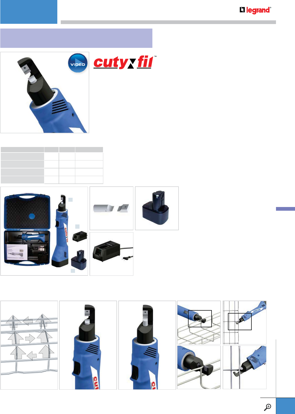
WEIGHT
LBS KG/1
CUTYFIL 9.5 4.3 559 548
REPLACEMENT BLADES 0.4 0.2 559 577
BATTERY 1.0 0.5 559 567
CHARGER 2.0 0.9 559 558
Cutyfil makes cutting Cablofil cable management easy. This lightweight power tool
features a 330˚ swivel cutting head to make cuts from any angle. One button control
engages and retracts blade for each cut. Cutyfil Kit comes in a padded carrying
case with 2 batteries and a charger.
Go to www.legrand.us/cablofil to view video demonstration.
Use the same cutting procedures as outlined on the previous page when using Cutyfil. Remember to always wear safety goggles
and follow safe procedures when using power equipment.
21
34
5
6
x1
x1
x2
USING A POWER CUTTER TO CUT CABLOFIL
INSTALLATIONS
WWW.LEGRAND.US/CABLOFIL
A.85
CABLOFIL
CABLE MANAGEMENT
PLAY
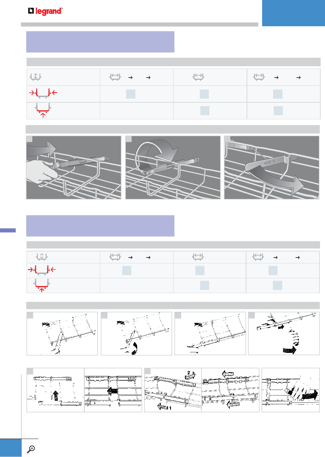
EDRN
FAST SPLICE
PRECLICK
SPLICE
21 3
INSTRUCTIONS
SPLICING GUIDELINES
CF30 – CF54 – CF105 – CF150 2”
8” (50
200 MM)
12” (300
MM)
18”
24” (450
600 MM)
EDRN splices
needed on side wires 2x EDRN 2x EDRN 2x EDRN
EDRN splices needed
on bottom of tray –1x EDRN 2x EDRN
Step 1-3: Snap a PRECLICK on each length of Cablofil tray to be joined.
Removing PRECLICK: Use a screw
driver to remove PRECLICK
Step 5: Join both lengths of Cablofil tray and snap in place. (two options)
1
5a
2 3
5b
4
INSTRUCTIONS
Step 4: Snap in place with a screw
driver or a simple “TAP” on the end.
SPLICING GUIDELINES
CF54 – CF105 – CF150 2”
8” (50
200 MM)
12” (300
MM)
18”
24” (450
600 MM)
PRECLICK splices
needed on side wires 2x PRECLICK 2x PRECLICK 2x PRECLICK
SWK splices needed
on bottom of tray –1x SWK 2x SWK
INSTALLATIONS
WWW.LEGRAND.US/CABLOFIL
A.86
CABLOFIL
CABLE MANAGEMENT
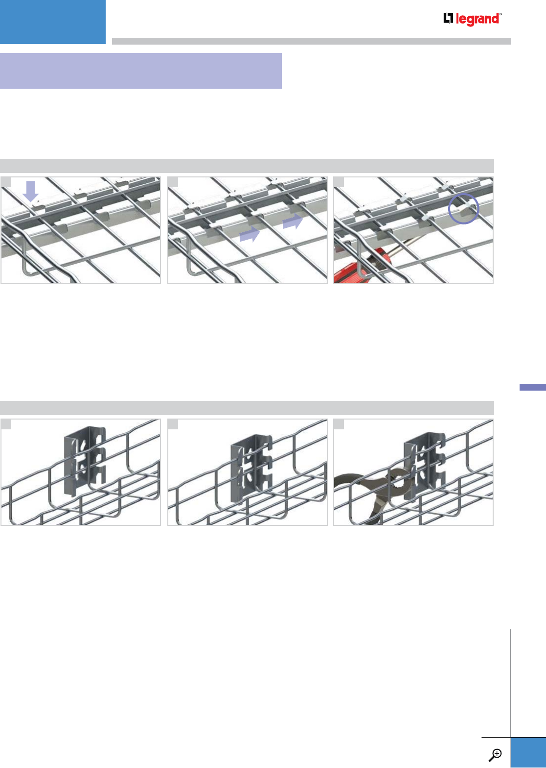
21 3
INSTRUCTIONS
21 3
INSTRUCTIONS
PROPER USE OF FAS TABS
Insert tray into slots Slide tray under tabs From the underside, depress several tabs
using a screwdriver or pliers to secure tray
Place accessory onto tray Slide accessory under tabs Depress all tabs using a screwdriver or
pliers to secure tray
FAS tabs speed up installation times and because no additional attachment hardware
is required, they also reduce costs. Follow these steps for proper installation:
FOR SUPPORTS
FOR ACCESSORIES
INSTALLATIONS
WWW.LEGRAND.US/CABLOFIL
A.87
CABLOFIL
CABLE MANAGEMENT
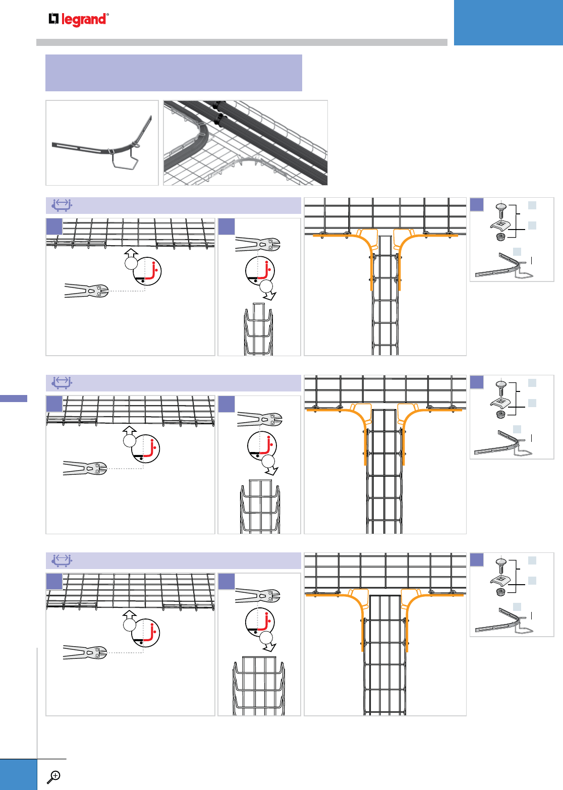
One RAD T 90 KIT will make one T Junction.
For complete kit description and depths offered
see page A.27.
4" (100 MM)
6" (150 MM)
8" (200 MM)
x3
x2
x4
x2
x4
x1
x4
x1
x4
EZ BN 1/4
CE 25
RAD T 9O
X2
x4
x1
x4
EZ BN 1/4
CE 25
RAD T 9O
X2
x4
x1
x4
EZ BN 1/4
CE 25
RAD T 9O
X2
x1
x1
x1
x1
1
1
1
2
2
2
T JUNCTIONS
RAD T 90 KIT
INSTALLATIONS
WWW.LEGRAND.US/CABLOFIL
A.88
CABLOFIL
CABLE MANAGEMENT

18-20" (450-500 MM)
24" (600 MM)
12" (300 MM)
x7
x8
x5
x1
x4
x1
x4
EZ BN 1/4
CE 25
RAD T 9O
X2
x4
x1
x4
EZ BN 1/4
CE 25
RAD T 9O
X2
x4
x1
x4
EZ BN 1/4
CE 25
RAD T 9O
X2
x1
x1
x1
x1
x1
x1
1
1
1
2
2
2
INSTALLATIONS
WWW.LEGRAND.US/CABLOFIL
A.89
CABLOFIL
CABLE MANAGEMENT
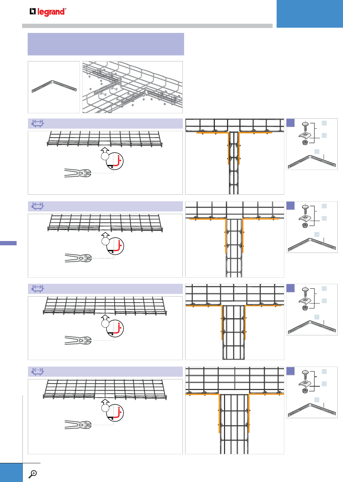
One EZ T 90 KIT will make one T Junction. For complete kit
description see page A.26.
2" (50 MM)
4" (100 MM)
6" (150 MM)
8" (200 MM)
x1
x1
x2
x2
x4
x1
x4
EZ BN 1/4
CE 25
EZ T 9O
X2
x4
x1
x4
EZ BN 1/4
CE 25
EZ T 9O
X2
x4
x1
x4
EZ BN 1/4
CE 25
EZ T 9O
X2
x4
x1
x4
EZ BN 1/4
CE 25
EZ T 9O
X2
T JUNCTIONS
EZ T 90 KIT
INSTALLATIONS
WWW.LEGRAND.US/CABLOFIL
A.90
CABLOFIL
CABLE MANAGEMENT

18-20" (450-500 MM)
24" (600 MM)
12" (300 MM)
x5
x6
x3
x4
x1
x4
EZ BN 1/4
CE 25
EZ T 9O
X2
x4
x1
x4
EZ BN 1/4
CE 25
EZ T 9O
X2
x4
x1
x4
EZ BN 1/4
CE 25
EZ T 9O
X2
INSTALLATIONS
WWW.LEGRAND.US/CABLOFIL
A.91
CABLOFIL
CABLE MANAGEMENT

x1 x2 x1
x1
x1
x1 x3 x1
x1
x1
x1 x3 x1
x1
x1
4" (100 MM)
6" (150 MM)
8" (200 MM)
1
1
1
2
2
2
x2
x1
x2
EZ BN 1/4
CE 25
ED 275*
X3
X3
X1
X2
*Use bolt cutters to
fabricate this part from
ED 275.
See pgs. A.80-A.81.
See pgs. A.80-A.81.
See pgs. A.80-A.81.
See pgs. A.80-A.81.
x1
SWK
x1
SWK
x1
SWK
Y JUNCTIONS
INSTALLATIONS
WWW.LEGRAND.US/CABLOFIL
A.92
CABLOFIL
CABLE MANAGEMENT
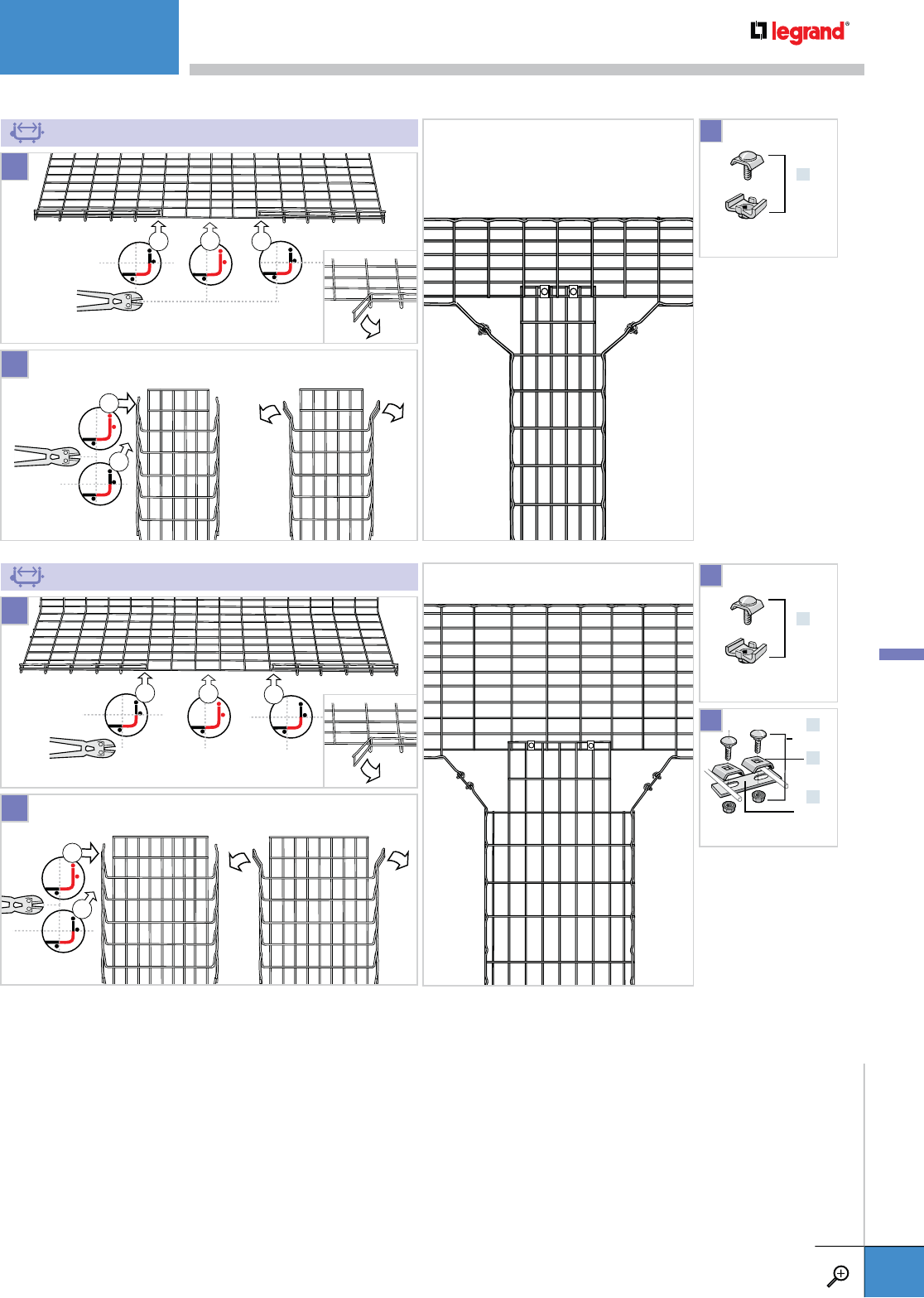
x1 x4 x1
x1
x1
x1 x5 x1
x1
x1
12" - 20” - 24” (300 - 500 - 600 MM)
18" (450 MM)
1
1
2
2
x2
x1
x2
EZ BN 1/4
CE 25
ED 275*
X4
X2
X2
*Use bolt cutters to
fabricate this part from
ED 275.
See pgs. A.80-A.81.
See pgs. A.80-A.81.
See pgs. A.80-A.81.
x1
SWK
x1
SWK
INSTALLATIONS
WWW.LEGRAND.US/CABLOFIL
A.93
CABLOFIL
CABLE MANAGEMENT
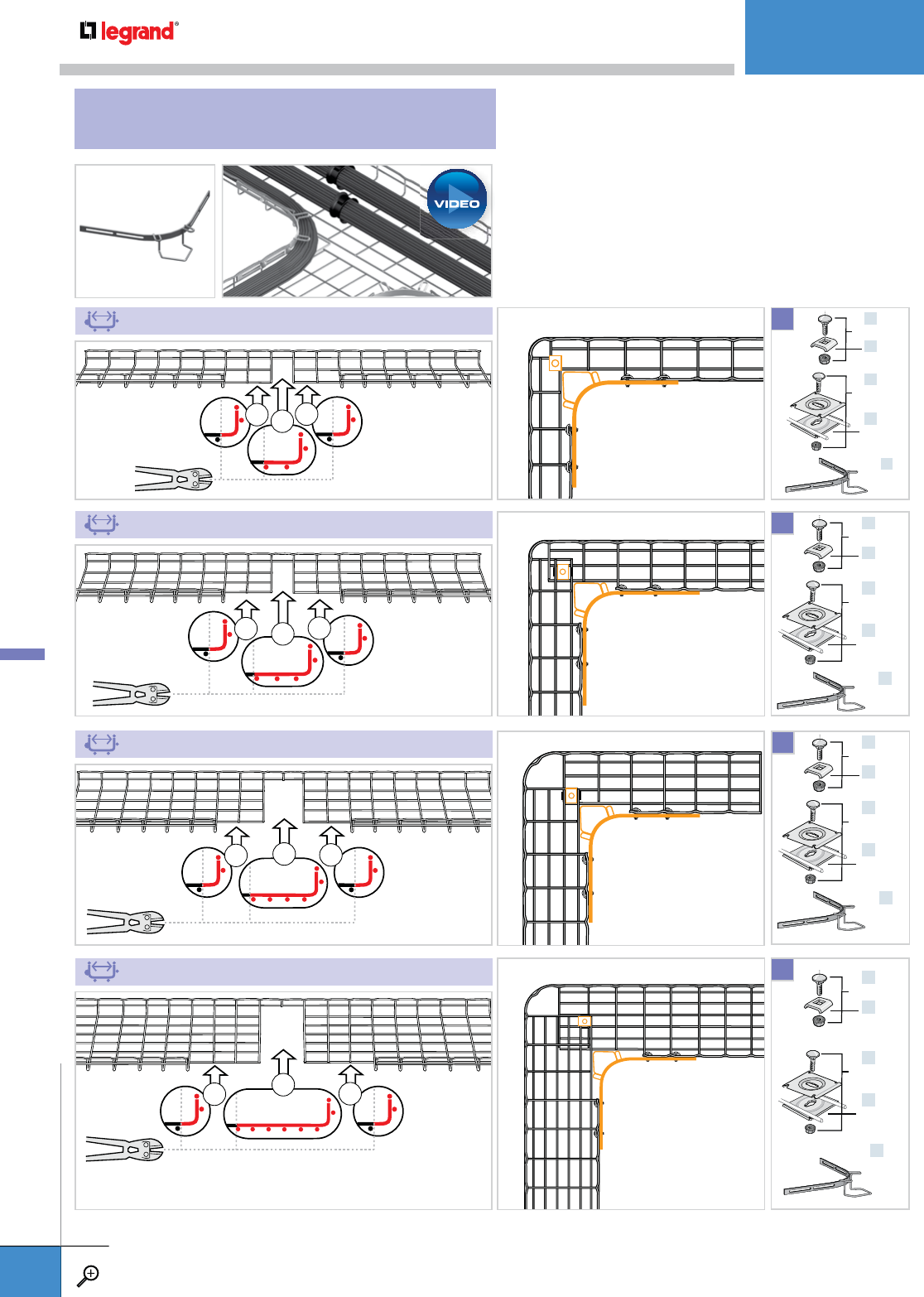
x2 x1 x2
x2 x2
x1
x2 x2 x2
One RAD T 90 KIT will make two 90˚ Bends. For complete
kit description and depths offered, see page A.27.
4" (100 MM)
6" (150 MM)
8" (200 MM)
x4
x4
EZ BN 1/4
CE 25
x1
x2
EZ BN 1/4
CE 40
X1
x1
RAD T 9O
x4
x4
EZ BN 1/4
CE 25
x1
x2
EZ BN 1/4
CE 40
X1
x1
RAD T 9O
x4
x4
EZ BN 1/4
CE 25
x1
x2
EZ BN 1/4
CE 40
X1
x1
RAD T 9O
90˚ BENDS
RAD T 90 KIT
x3 x2 x3
12" (300 MM)
x4
x4
EZ BN 1/4
CE 25
x1
x2
EZ BN 1/4
CE 40
X1
x1
RAD T 9O
INSTALLATIONS
WWW.LEGRAND.US/CABLOFIL
A.94
CABLOFIL
CABLE MANAGEMENT
PLAY
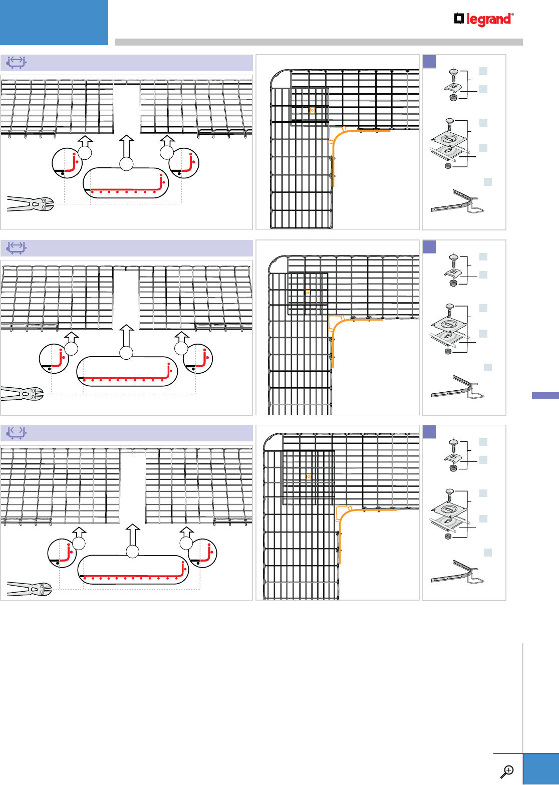
x4
x2
x4
x4 x4
x2
x5 x5
x2
18" (450 MM)
20" (500 MM)
24" (600 MM)
x4
x4
EZ BN 1/4
CE 25
x1
x2
EZ BN 1/4
CE 40
X1
x1
RAD T 9O
x4
x4
EZ BN 1/4
CE 25
x1
x2
EZ BN 1/4
CE 40
X1
x1
RAD T 9O
x4
x4
EZ BN 1/4
CE 25
x1
x2
EZ BN 1/4
CE 40
X1
x1
RAD T 9O
INSTALLATIONS
WWW.LEGRAND.US/CABLOFIL
A.95
CABLOFIL
CABLE MANAGEMENT
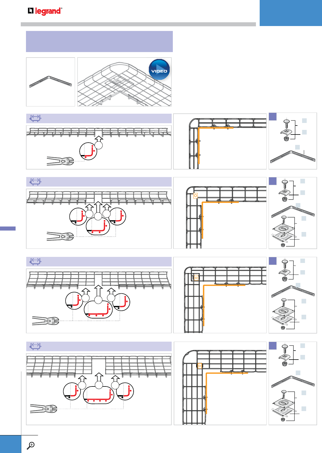
x1
x1 x1 x1
x2 x2
x1
x2 x2 x2
One EZ T 90 KIT will make two 90˚ Bends.
For complete kit description, see page 26.
2" (50 MM)
4" (100 MM)
6" (150 MM)
8" (200 MM)
x4
x4
EZ BN 1/4
CE 25
x1 EZ T 9O
x1
x2
EZ BN 1/4
CE 40
X1
x4
x4
EZ BN 1/4
CE 25
x1 EZ T 9O
x1
x2
EZ BN 1/4
CE 40
X1
x4
x4
EZ BN 1/4
CE 25
x1 EZ T 9O
x1
x2
EZ BN 1/4
CE 40
X1
x4
x1
x4
EZ BN 1/4
CE 25
EZ T 9O
X1
90˚ BENDS
EZ T 90 KIT
INSTALLATIONS
WWW.LEGRAND.US/CABLOFIL
A.96
CABLOFIL
CABLE MANAGEMENT
PLAY
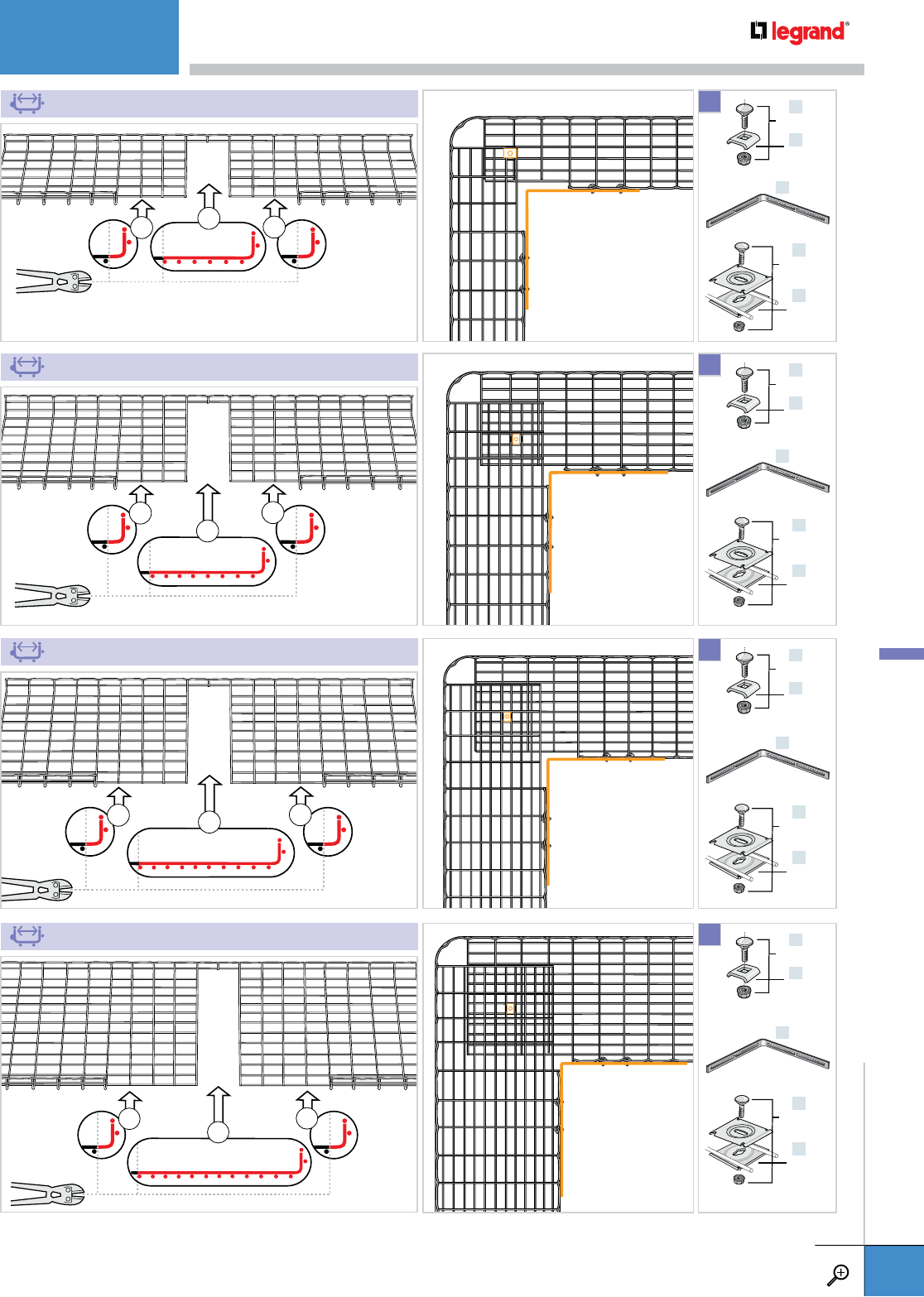
x3 x2 x3
x3
x2
x3
x4 x4
x2
x4 x4
x2
12" (300 MM)
18" (450 MM)
20" (500 MM)
24" (600 MM)
x4
x4
EZ BN 1/4
CE 25
x1 EZ T 9O
x1
x2
EZ BN 1/4
CE 40
X1
x4
x4
EZ BN 1/4
CE 25
x1 EZ T 9O
x1
x2
EZ BN 1/4
CE 40
X1
x4
x4
EZ BN 1/4
CE 25
x1 EZ T 9O
x1
x2
EZ BN 1/4
CE 40
X1
x4
x4
EZ BN 1/4
CE 25
x1 EZ T 9O
x1
x2
EZ BN 1/4
CE 40
X1
INSTALLATIONS
WWW.LEGRAND.US/CABLOFIL
A.97
CABLOFIL
CABLE MANAGEMENT
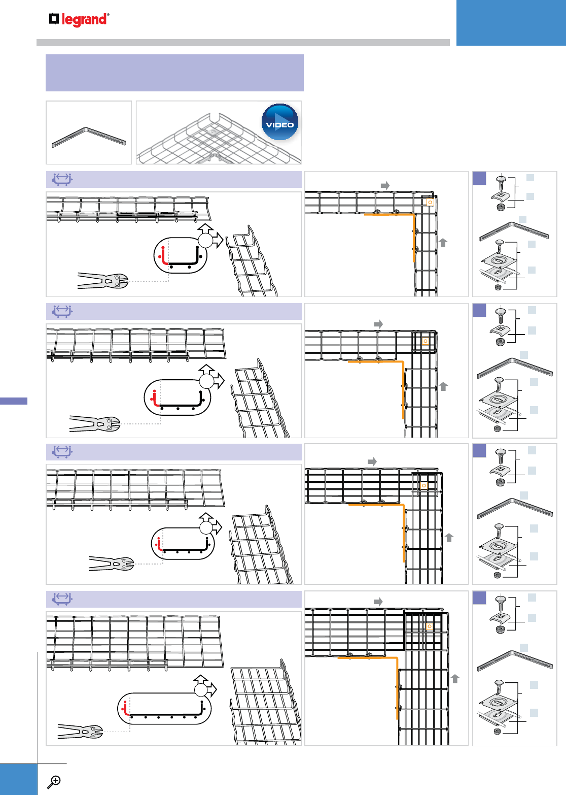
One EZ T 90 KIT will make two 90˚ Junctions.
For complete kit description, see page 26.
x1
x2
x2
x3
4" (100 MM)
8" (200 MM)
6" (150 MM)
12" (300 MM)
x4
x4
EZ BN 1/4
CE 25
x1 EZ T 9O
x1
x2
EZ BN 1/4
CE 40
X1
x4
x4
EZ BN 1/4
CE 25
x1 EZ T 9O
x1
x2
EZ BN 1/4
CE 40
X1
x4
x4
EZ BN 1/4
CE 25
x1 EZ T 9O
x1
x2
EZ BN 1/4
CE 40
X1
x4
x4
EZ BN 1/4
CE 25
x1 EZ T 9O
x1
x2
EZ BN 1/4
CE 40
X1
90˚ JUNCTIONS
EZ T 90 KIT
INSTALLATIONS
WWW.LEGRAND.US/CABLOFIL
A.98
CABLOFIL
CABLE MANAGEMENT
PLAY
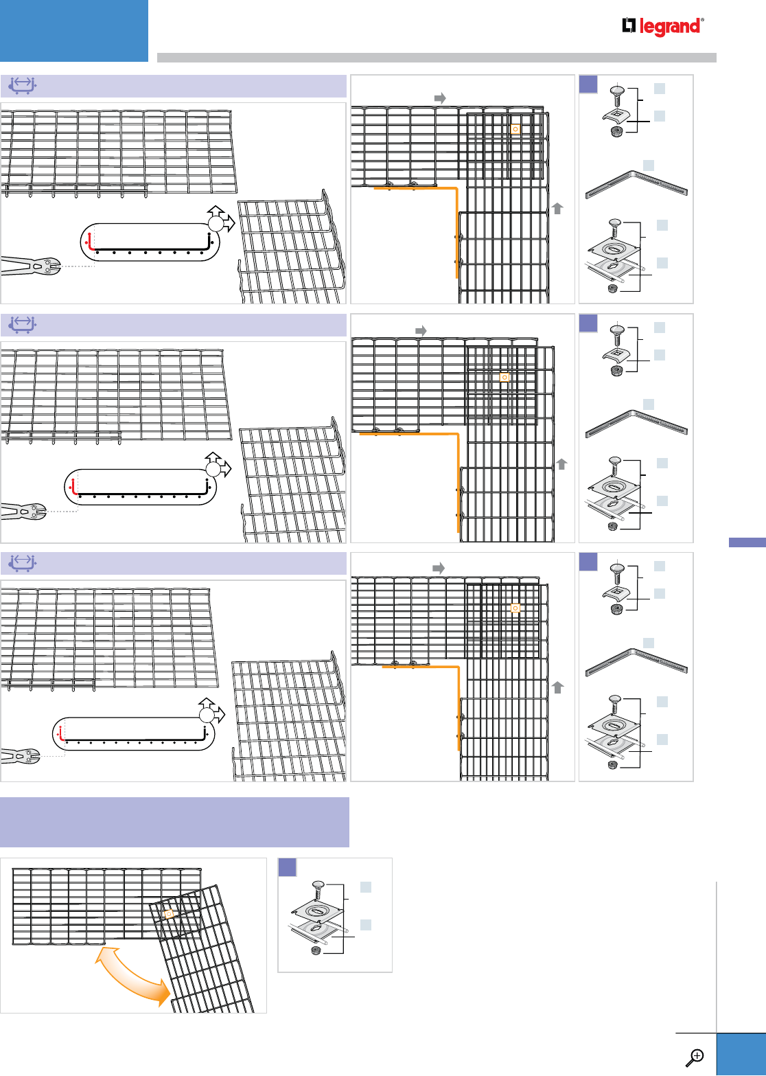
x4
x5
x6
18" (450 MM)
20" (500 MM)
24" (600 MM)
x4
x4
EZ BN 1/4
CE 25
x1 EZ T 9O
x1
x2
EZ BN 1/4
CE 40
X1
x4
x4
EZ BN 1/4
CE 25
x1 EZ T 9O
x1
x2
EZ BN 1/4
CE 40
X1
x4
x4
EZ BN 1/4
CE 25
x1 EZ T 9O
x1
x2
EZ BN 1/4
CE 40
X1
X1
x1
x2
EZ BN 1/4
CE 40
OTHER THAN 90˚ JUNCTIONS
INSTALLATIONS
WWW.LEGRAND.US/CABLOFIL
A.99
CABLOFIL
CABLE MANAGEMENT
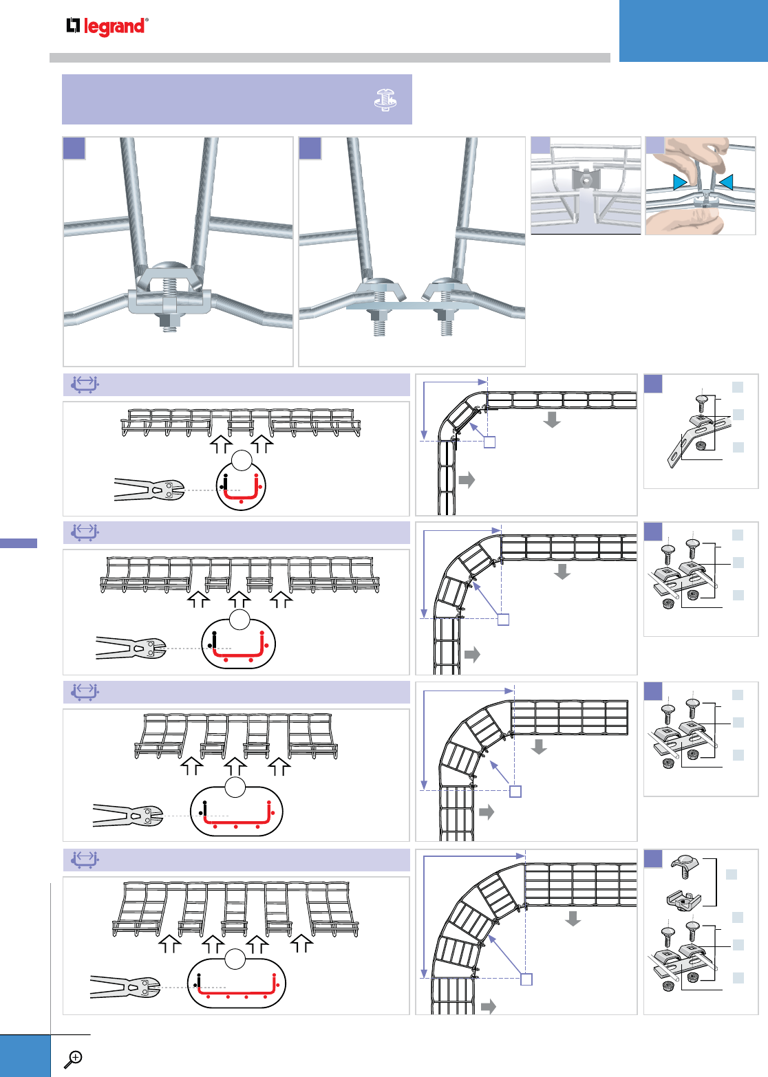
• Sweeps can be formed easily on
site by cutting some of the side and
bottom wires. Use the SWK method
to secure desired curve.
• Always place bolt heads to inside of
tray to prevent frayed wires.
• Use bolt cutters to fabricate this part
from ED275.
A B
x2
x3
x3
x4
2" (50 MM)
4" (100 MM)
6" (150 MM)
8" (200 MM)
x2
x1
x2
EZ BN 1/4
CE 25
ED 275*
X3
See pgs. A.80-A.81.
x2
x1
x2
EZ BN 1/4
CE 25
ED 275*
X3
See pgs. A.80-A.81.
x4
x1
x4
EZ BN 1/4
CE 25
ED 275*
X3
See pgs. A.80-A.81.
x2
x1
x2
EZ BN 1/4
CE 25
ED 275*
X2
See pgs. A.80-A.81.
x1
SWK
7.5"
190 MM
5.5"
140 MM
R
12.6"
320 MM
8.7"
220 MM
R
17.7"
450 MM
11.8"
300 MM
R
17.7"
450 MM
9.8"
250 MM
R
1 2
SWEEPS
SWK & EZ BN 1/4 / CE 25 / ED 275
INSTALLATIONS
WWW.LEGRAND.US/CABLOFIL
A.100
CABLOFIL
CABLE MANAGEMENT
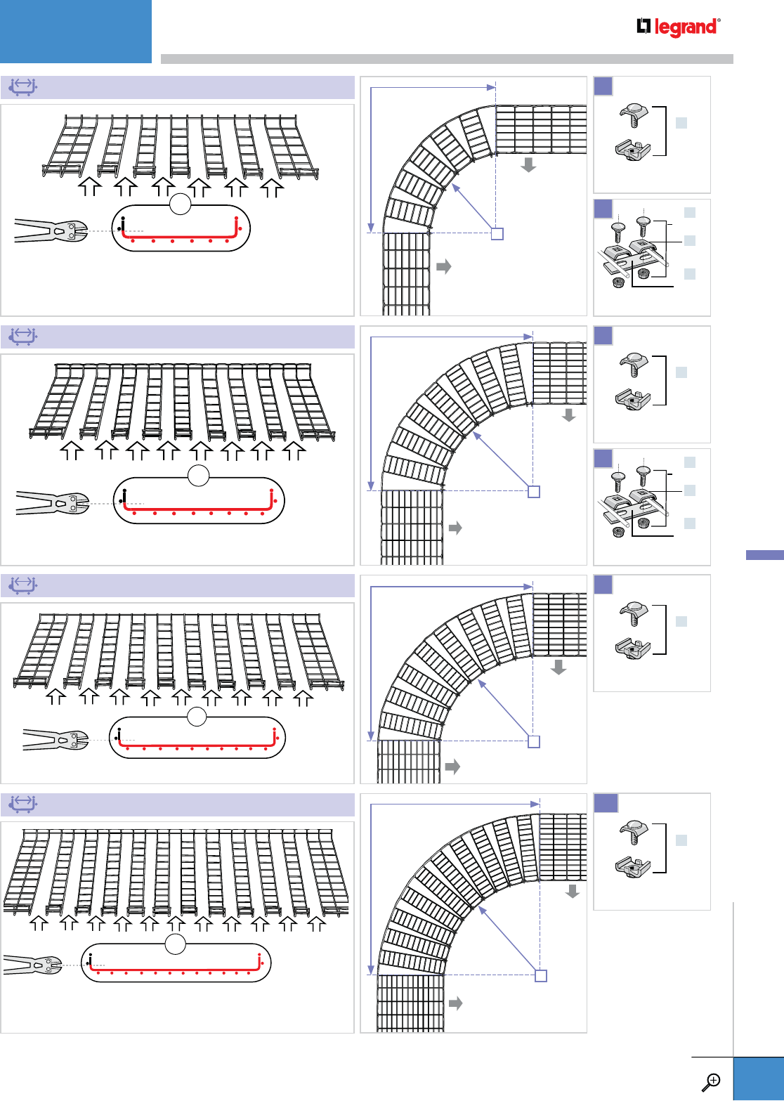
12" (300 MM)
20" (500 MM)
18" (450 MM)
24" (600 MM)
x2
x1
x2
EZ BN 1/4
CE 25
ED 275*
x2
x1
x2
EZ BN 1/4
CE 25
ED 275*
X4
X9
X6
X11
X2
X2
See pgs. A.80-A.81.
See pgs. A.80-A.81.
See pgs. A.80-A.81.
See pgs. A.80-A.81.
See pgs. A.80-A.81.
See pgs. A.80-A.81.
x1
SWK
x1
SWK
x1
SWK
x1
SWK
x6
x9
x8
x11
27.6"
700 MM
15.8"
400 MM
R
37.4"
950 MM
19.7"
500 MM
R
42.5"
1080 MM
22.8"
580 MM
R
52.8"
1340 MM
29.1"
740 MM
R
INSTALLATIONS
WWW.LEGRAND.US/CABLOFIL
A.101
CABLOFIL
CABLE MANAGEMENT
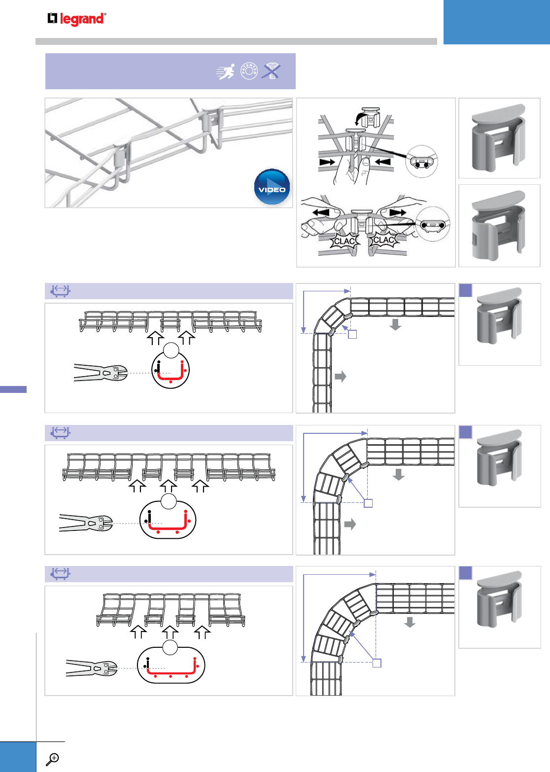
x2
x3
x3
Sweeps can be formed easily on site by cutting some of the side and
bottom wires. Use the FASLOCK method to secure desired curve.
See page 81.
4” (100 MM)
6” (150 MM)
8" (200 MM)
X2
FASLOCK S
See page A.81.
FASLOCK S
See page A.81.
X3
X4
11.9"
303 MM
5.6"
142 MM
R
17.0"
433 MM
8.7"
221 MM
R
21.9"
557 MM
11.8"
300 MM
R
FASLOCK S
FASLOCK XL
SWEEPS
FASLOCK
FASLOCK S
See page A.81.
INSTALLATIONS
WWW.LEGRAND.US/CABLOFIL
A.102
CABLOFIL
CABLE MANAGEMENT
PLAY

x6
x10
x9
x12
12" (300 MM)
20" (500 MM)
18" (450 MM)
24" (600 MM)
X6
X10
X8
X12
27.6"
700 MM
15.8"
400 MM
R
42.5"
1080 MM
24.8"
630 MM
R
47.6"
1210 MM
28"
710 MM
R
57.7"
1465 MM
34.1"
865 MM
R
*Use FASLOCK S for 100mm - 200mm widths. Use FASLOCK XL for 300mm - 600mm widths.
FASLOCK XL
See page A.81.
FASLOCK XL
See page A.81.
FASLOCK XL
See page A.81.
FASLOCK XL
See page A.81.
INSTALLATIONS
WWW.LEGRAND.US/CABLOFIL
A.103
CABLOFIL
CABLE MANAGEMENT

x1
x1 x1
x1
x1
x1 x2
x1
x1 x2
x1 x1
4" (100 MM)
8" (200 MM)
12" (300 MM)
See page A.22.
See page A.22.
ED275RSKIT
ED275RSKIT
ED1100RSKIT
X1
X1
X1
See page A.22.
REDUCTIONS
INSTALLATIONS
WWW.LEGRAND.US/CABLOFIL
A.104
CABLOFIL
CABLE MANAGEMENT
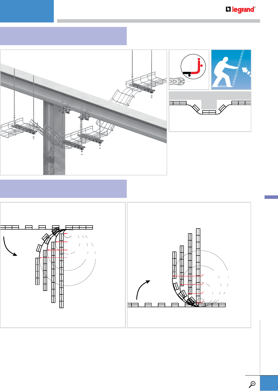
To avoid obstructions or change levels,
cut the side wires as shown and bend
Cablofil tray to the angles needed.
R = 2.5" 64 MM
R = 2.5" 64 MM
R = 7.5" 190 MM
R = 7.5" 190 MM
R = 13" 320 MM
R = 13" 320 MM
R = 18" 445 MM
R = 18" 445 MM
CHANGING LEVELS
CUTTING AND BENDING
INSTALLATIONS
WWW.LEGRAND.US/CABLOFIL
A.105
CABLOFIL
CABLE MANAGEMENT

PW
TABLE OF CONTENTS
INTR
O
D
UC
TI
ON
PA
PA
PA
PA
PA
PA
GE
GE
GE
GE
GE
GE
S
S
S
S
S
S
B
B
B
B
B
B.
1
1
1
1
1
1-
B
B
B
B.
7
7
7
7
7
7
7
7
7
7
LADDER TRAY
,
TROUGH
&
SOLID BOTTOM
PA
PA
PA
PA
PAPA
P
GE
GE
GE
GE
GE
GE
S
S
S
S
S
S
S
S
B
B
B.
B
B
B
8
8
8
8-
8-
B
B
B
B
B.
B
B
B
79
79
79
79
9
79
79
9
9
–
–
–
–
ITRAY
PA
PA
PAPA
A
PA
PA
GE
GE
GE
GE
G
GE
S
S
S
S
S
S
B.
B
B
B
B
B.
10
10
10
10
1
10
0
-B
B
B
B
B
B
2
2
2
2
2
.2
.2
5
5
5
5
5
5
5
–
–
–
METALLIC
PA
PA
PA
GE
GE
E
S
S
S
B.
B.
2626
-B
-B
.6
.6
6
6
99
9
–
–
–
–
FIBER
G
LASS
PA
PA
PA
GE
GE
GE
S
S
S
B.
B.
B
70
70
7
-B-B
-B
.7
.7
.
7
7
9
9
9
9
C
HANNEL SYSTEM
S
P
PA
P
PA
P
GE
GE
E
E
E
S
S
S
S
S
B.B.
B
B.
B
B.
80
80
0
8
-B
-B
.8
8
.8
9
9
9
C
ABLE R
U
NWAY
P
P
PA
GE
GE
E
E
E
GE
E
S
S
S
S
S
S
S
S
B.B.
B.
90
90
90
-B-B
-B
.9
9
.9
5
5
5

QUALITY AND INNOVATION
FOR OVER 60 YEARS.
Cable tray, introduced in the mid 1940's, has proved to be a very
efficient cable management solution. It provides system flexibility
and expandability with substantial savings in installation labor
and material costs. For more than six decades the PW brand
has played a leadership role in the cable tray industry, providing
advanced cable management solutions.
PW CABLE TRAY
Built to Handle the Load
Our latest innovation is Itray. It’s aluminum cable tray that been
redesigned with stronger side rails and faster splicing options to
streamline the engineering, purchasing and installation of cable
tray. And continue to look to PW cable management to support
extremely heavy cabling and bridge roadways, our exclusive long
span/heavy duty cable tray is designed with up to 10” I-beam side
rails that can span up to 50’ and meet exacting industry and load
standards.
Legrand continues to provide contractors and end users with the
specific products they need — from standard designs to custom-
built products. With our national distribution partnerships and
our manufacturing facilities in North America, we are perfectly
positioned to supply any sized project — offering excellent service
with the best lead times in the industry.
INTRODUCTION
WWW.LEGRAND.US/CABLOFIL
B.1
PW CABLE TRAY
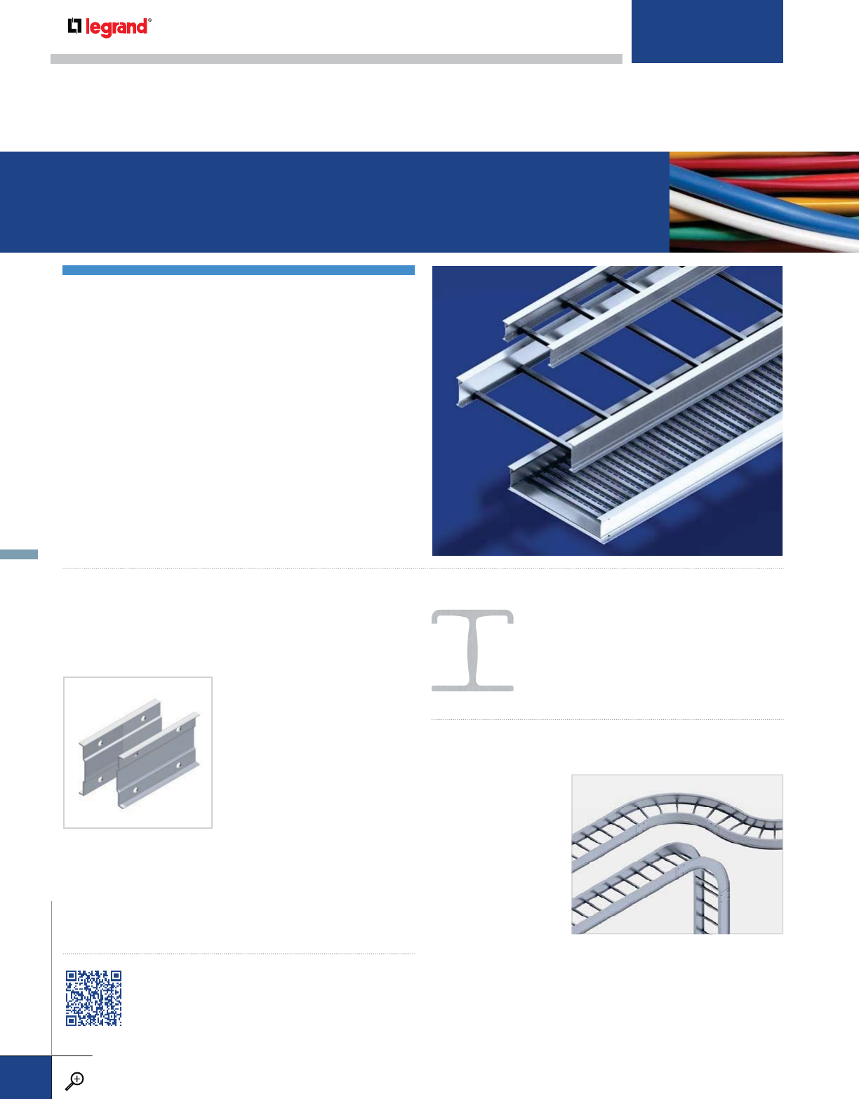
NEW ITRAY ALUMINUM LADDER,
TROUGH AND SOLID BOTTOM SYSTEMS
Itray is the newest addition to the PW Line of cable tray products.
It was designed to streamline the engineering, purchasing
and installation of cable tray. Itray replaces our current “C”
aluminum 4” to 7’ side rail height cable tray line.
Itray’s patent-pending, all-aluminum construction features
a space saving I-beam design, a side rail engineered with
structural offsets and a matching splice. The I-beam design
minimizes total tray width and creates a smooth transition
between straight sections and fittings. And Itray splices reduce
hardware needs by 50%. These features allow Itray to be
installed up to 30% faster than standard tray.
SPLICING MADE EASY
The structural offset side rail and splice design makes a splice
that is strong and easy to install. The stronger splice allows
mid-span splicing while maintaining full NEMA load class. This
simplifies the design process
and reduces the overall number
of spliced sections that require
jobsite fabrication. During
installation the splice simply snaps
in place and keeps tray sections
aligned while the installer inserts
and tightens 4 bolts.Itray’s all
aluminum construction features
a space saving I-beam design,
a side rail engineered with structural offsets and a matching
splice. The I-beam design minimizes total tray width and creates
a smooth transition between straight sections and fittings. And
Itray splices reduce hardware needs by 50%. These features
allow Itray to be installed up to 30% faster than standard tray.
STRONGER IBEAM RUNG DESIGN
Itray also features the strongest rungs in the
industry. It’s I-beam design reduces twist and
deflection under load and heavier I-beam
rungs are standard on wider tray without
special order.
SMOOTHER FINISHED INSTALLATIONS
Itray straight sections
and fittings match
perfectly creating a
smooth side rail edge
for a natural cable
pathway that makes
pulling cable easier
and with less chance
of damage to the cable
sheath. Itray features
a 3” tangent that follows industry standards and the symmetric
side rail design allows smooth ceiling to wall transitions without
the need for field fabrication. Transition splices are available for
older, existing installations.
PW CABLE TRAY SYSTEMS
VIEW THIS VIDEO FOR A COMPLETE
PRESENTATION ON ITRAY
INTRODUCTION
WWW.LEGRAND.US/CABLOFIL
B.2
PW CABLE TRAY

CHANNEL TRAY
Channel tray is a one-piece ventilated or solid-bottom cable
tray with sizes up to 6” wide. It is commonly used for small
runs of cable or for drops from main cable tray runs to
equipment or junction boxes. These products are available in
aluminum, mill galvanized steel and hot-dipped galvanized
steel. For extremely corrosive applications we have products
in 304 and 316 stainless steel or polyester and vinylester
fiberglass. A complete line of accessories is available,
including covers and fittings in 12" to 36" radius.
METALLIC AND FIBERGLASS LADDER,
TROUGH AND SOLID BOTTOM SYSTEMS
PW cable tray is a fabricated structure consisting of two side rails connected by
individual rungs or bottom. Side rails are 4" to 10" high. Widths are 6" to 36". Bottom
options include Ladder, Vented Corrugated Bottom, Solid Corrugated Bottom, and
Flat-Sheet Solid Bottom designs.
A wide range of load and span designations are available for every possible application,
from trays for commercial use where spans over 8’ are required, to trays for longer spans
required in industrial applications. Also available are trays built for extremely long spans
– up to 50’ – for special applications like roadway crossings and pipe bridges.
Our product line includes trays, fittings, covers, firewall penetration sleeves, and other accessories. These products are available
in hot-dipped galvanized steel. For extremely corrosive applications we have product lines in 304 and 316 stainless steel or
polyester and vinylester fiberglass.
CABLE RUNWAY
Cable Runway is available in a lightweight version with tubular
side rails and a solid bar side rail option for maximum support
strength. Both styles have tubular steel rungs. Commonly used
in telecommunication, voice, and data applications, runway
is typically mounted directly above or to computer racking
systems, enclosures, and relay rack cabinets. Cable Runway
is available in yellow-zinc dichromate as required for UL
Classified installations as an equipment ground conductor, and
a range of powder-coated finishes.
INTRODUCTION
WWW.LEGRAND.US/CABLOFIL
B.3
PW CABLE TRAY
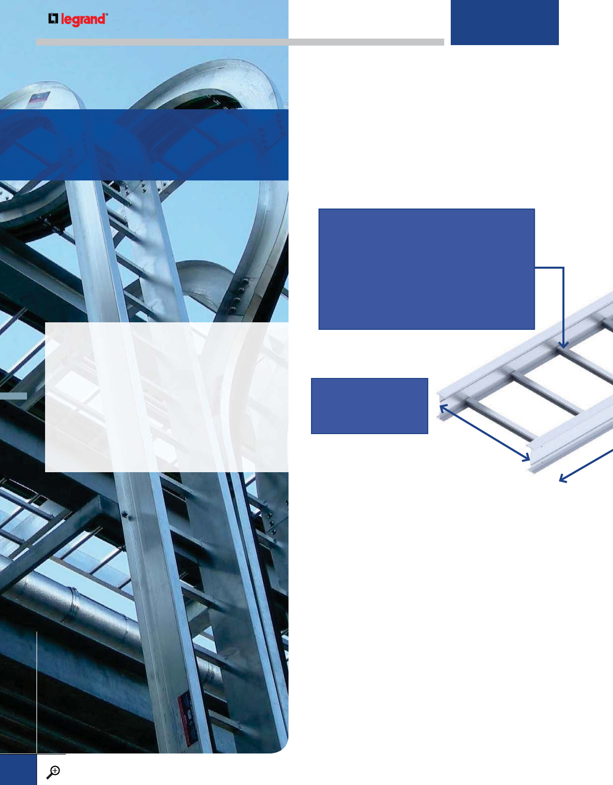
LOAD/SPAN CLASS DESIGNATION
THE LOAD/SPAN CLASSIFICATION describes the cable tray’s
load-carrying capability for a specific support span. A
classification should be selected that reflects the actual
working load and support span for each application. This
designation directly affects the cost of the tray, so the proper
selection is essential to determine the most economical cable
tray system necessary for each project. Please consult with
Legrand for working loads and support spans that fall outside
the boundaries of the Load/Span Classes shown.
CONCENTRATED STATIC LOAD: In addition to an evenly distributed
cable load, it is occasionally required that the cable tray system
be capable of supporting a concentrated static load.
A concentrated static load represents a static weight applied on
the centerline of the cable tray at midspan. The concentrated
static load in lbs. may be converted to an equivalent uniform
load (We) in lbs./ft., using the following formula, and added to
the static weight of cables in the tray. A NEMA Load Class can
then be selected that reflects the combination of the cable load
and converted static load.
PW CABLE TRAY
LOAD DEPTH: Interior depth of the cable tray that
is available for cable fill. Specifications for cable
trays should include a specific requirement for
the tray load depth. Due to design variations
between different manufacturers, it is important
to specify an exact load depth to ensure equal
performance. The load depth may differ slightly
based on choice of tray bottom.
TRAY OPTIONS
It is essential to consider the type and
quantity of cables to be installed in the
cable tray when planning your project.
Refer to Article 392 of the National
Electrical Code (NEC) for guidelines on
calculating the cable tray depth and width.
WIDTH: Interior width of
the tray or channel that
is available for cable fill.
Understanding
Our Products
WWW.LEGRAND.US/CABLOFIL
B.4
PW CABLE TRAY
WWW.LEGRAND.US/CABLOFIL
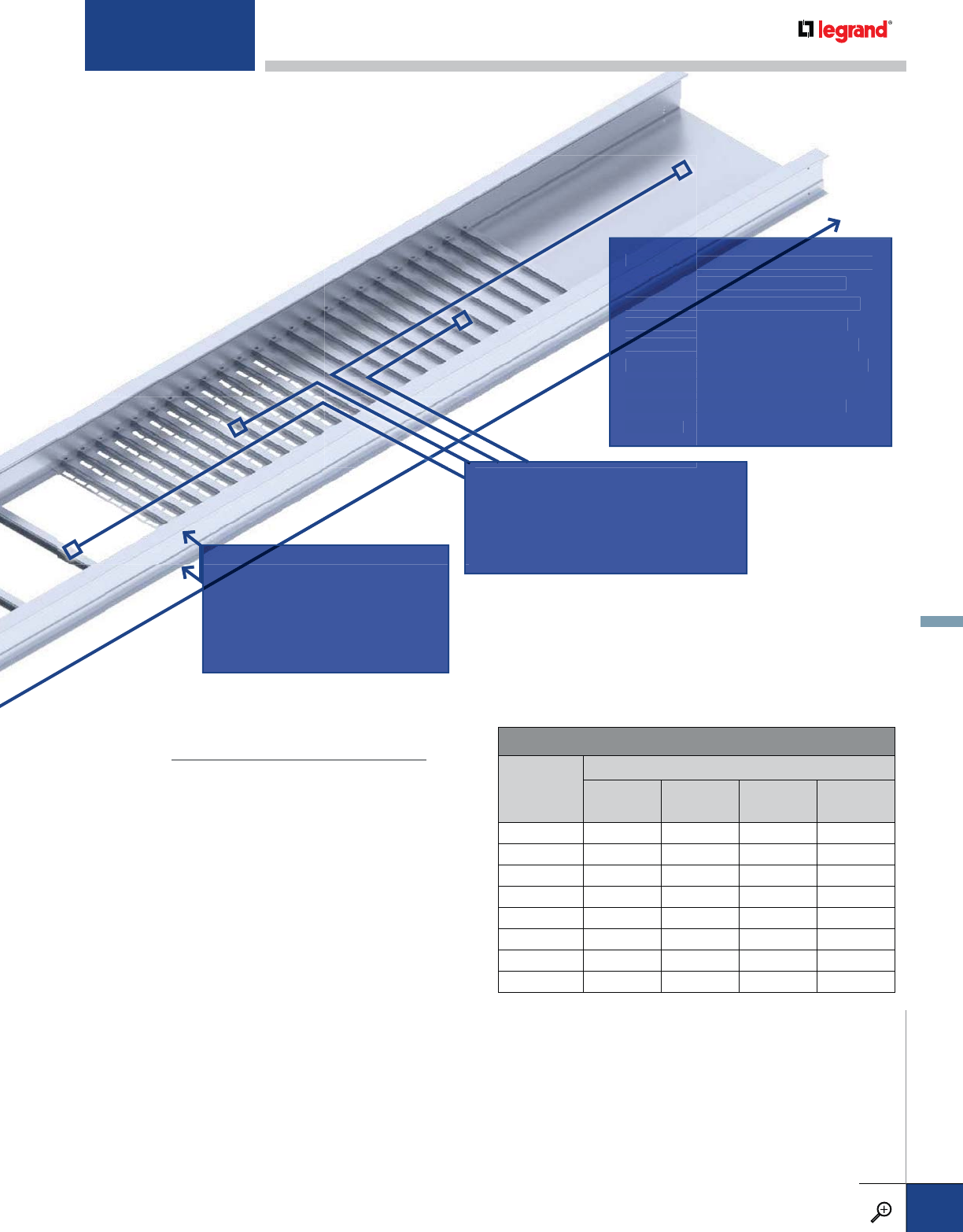
Example:
A 200 lb. concentrated load is to be applied to
a cable tray that is supported on a 12 ft. support span.
Using the formula above, the equivalent uniform load
We = 2 x 200 / 12 = 33 lbs. per linear foot. This should be
added to the anticipated cable load to determine the
appropriate Load/Span Class for the cable tray.
Note:
To accommodate concentrated loads, some circumstances
may require cable trays to have reinforced side rails or bottom
members. Therefore, it is recommended that you consult with
Legrand when considering concentrated loads or any other
special cable tray loading requirements.
We = 2 x (concentrated static load, lbs.)
support span length, ft.
LENGTH: The overall length of each cable
tray straight section. The spacing of
the cable tray supports will determine
the length requirements for straight
trays. The support span should not be
greater than the straight section length
to ensure that no more than one splice
plate connection is located between
supports.
LE
NG
TH
:
Th
e
tray stra
i
g
h
t
the cable tr
a
tr
a
the le
ng
th r
lengt
tr
ay
s. The s
tra
g
reater th
an
to ensure
th
p
late conn
e
su
pp
orts.
LOAD/SPAN CLASS DESIGNATIONS
WORKING
LOAD
lbs/ft (kg/m)
SUPPORT SPAN, ft. (m)
8 ft.
(2.4 m)
10 ft.
(3.0 m)
12 ft.
(3.7 m)
20 ft.
(6.0 m)
25 (37) — A — —
45 (67) — — — D
50 (74) 8A — 12A 20A
65 (97) — C — —
75 (112) 8B — 12B E or 20B
100 (149) 8C — 12C 20C
120 (179) — D — —
200 (299) — E — —
WORKING LOAD: Total load of cables installed and uniformly
distributed in the cable tray.
SUPPORT SPAN: Maximum distance between cable tray supports.
CLASSES 8, 12, 20 / A, B, C: NEMA designations, published by the
National Electrical Manufacturers Assoc. in Standard VE1.
CLASSES A, C, D, AND E: CSA designations, published by the
Canadian Standards Association in Standard C22.2, No. 126.
SIDE RAIL HEIGHT:
The overall height of the cable
tray side rail. In general, side rail
heights for PW cable trays are 1”
greater than the load depth.
BOTTOM TYPE: Legrand offers numerous
tray bottom types and options to
accommodate a wide variety of wire
management solutions.
INTRODUCTION
WWW.LEGRAND.US/CABLOFIL
B.5
PW CABLE TRAY
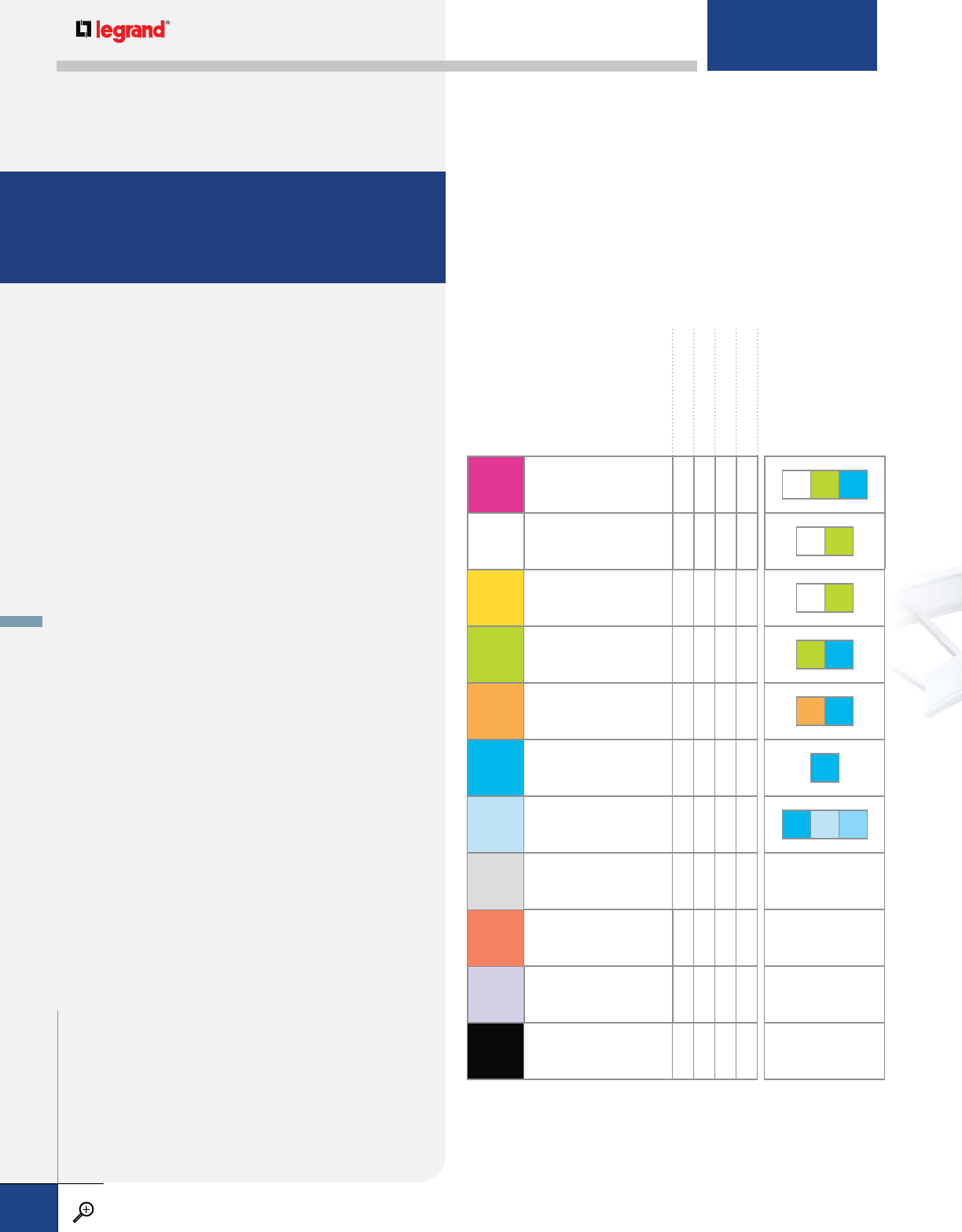
PW CABLE TRAY
FITTINGS, ACCESSORIES AND HARDWARE
A complete cable tray system includes
fittings, accessories, supports, and hardware.
Consider the following components when
designing a cable tray system:
FITTING RADIUS: The nominal bend radius for fittings
should not be less than the minimum allowable bending
radius for the cables to be installed in the tray. Cable
manufacturers typically publish the minimum bending
radius as a multiple of the cable diameter.
EXPANSION CONNECTORS AND SUPPORTS: It is important to
consider thermal expansion and contraction in the cable
tray system, especially for outdoor applications. NEMA
Standards Pub. VE2 addresses the proper installation and
spacing of expansion connectors, expansion guides, hold
down clamps, tray supports, and bonding jumpers.
COVERS: Cable tray covers are often needed to contain
and protect tray contents. Carefully select a specific cover
design and specify the proper attachment hardware
needed for indoor, outdoor, or vertical installations.
DIVIDERS: In some applications, the NEC requires the use
of tray dividers to separate cables. Multiple dividers can
also easily help manage complex wiring systems.
GROUNDING: All aluminum and galvanized steel cable
trays manufactured by Legrand are classified by UL as
equipment grounding conductors with specific ampere
ratings per NEC 392. To maintain electrical continuity,
bonding jumpers should be installed at mechanically
discontinuous locations and sized in accordance with the
rating of the cable tray system.
HARDWARE: Screws, nuts, bolts, etc. for assembling
cable tray connectors and accessories are normally
provided in zinc plated or geomet steel, adequate for
most applications. Some moist, outdoor, or corrosive
environments may require the use of stainless steel
hardware for better performance. All PW cable tray
connectors and most accessories are available with
optional Type 316 stainless steel hardware.
DRY INTERIORS
EXTERIORS
CORROSIVE
HIGHLY CORROSIVE
A
ALUMINUM; MARINE GRADE;
COPPER FREE ALLOYS
6063-T6, 5052-H32 & 3003
OO ZN GE S6
M
MILL GALVANIZED STEEL
(Before Fabrication)
ASTM A653 G90
OZN CD
ZELECTRO-GALVANIZED STEEL
ASTM B633 SC2 OZN CD
GHOT-DIP GALVANIZED STEEL
(After Fabrication) ASTM A123 OOCD S6
LSTAINLESS STEEL
AISI Type 304L OS4 S6
TSTAINLESS STEEL
AISI Type 316L OOS6
FFIBERGLASS
ASTM E-84 Class 1 OS6 FG FE
PE
SPECIAL FINISHES
ASTM D3451
(for powder paint only)
OOO
CCOPPER
NNYLON
VVINYL
ORecommended OPossible
MATERIALS
The selection of cable tray
material depends on many
factors including environmental
conditions, corrosion resistance,
aesthetics, and material
handling. FASTENER
FINISHES
Ordering
Our Products
INTRODUCTION
WWW.LEGRAND.US/CABLOFIL
B.6
PW CABLE TRAY

The numbering system for all other tray lines has not changed.
SPECIFYING YOUR ORDER
TRAY SYSTEM
NUMBER
This identifies the
specific tray design
and is used as a
catalog number prefix
for straight sections.
LENGTH
0010 – 10'-0"
0012* – 12'-0"
0020†– 20'-0"
0024 – 24'-0"
* Standard for
SERIES 1
† Standard for
SERIES 2
WIDTH
06 – 6"
09 – 9"
12 – 12"
18 – 18"
24 – 24"
30 – 30"
36 – 36"
BOTTOM TYPE
VENTED
06 – 6" Rung Spacing
09 – 9" Rung Spacing*
12 – 12" Rung Spacing
18 – 18" Rung Spacing
VC† – Vented Corrugated
NON-VENTED
SC† – Solid Corrugated
SF† – Solid Flat Bottom
* Standard rung spacing
† Not available for flange out tray
STRAIGHT SECTION CATALOG NUMBER
09-1F54-0020-12
RAIL HEIGHT
4 – 4”
5 – 5”
6 – 6”
7 – 7”
MATERIAL
A
NEMA
CLASS LENGTH
S120 – 120"
S144 – 144"
S240 – 240"
S288 – 280”
WIDTH
06 – 6"
09 – 9"
12 – 12"
18 – 18"
24 – 24"
30 – 30"
36 – 36"
BOTTOM TYPE
VENTED
06 – 6” Rung Spacing
09 – 9” Rung Spacing
12 – 12” Rung Spacing
VC – Vented Corrugated
NON-VENTED
SC – Solid Corrugated
SB – Solid Bottom
ITRAY STRAIGHT SECTION CATALOG NUMBERING EXAMPLE:
09-4 A 12B-S144-06
RAIL HEIGHT
4 – 4”
5 – 5”
6 – 6”
7 – 7”
MATERIAL
A
FITTING
DESCRIPTION
90º Horizontal
Elbow
RADIUS
12 – 12"
24 – 24”
36 – 36”
WIDTH
06 – 6"
09 – 9"
12 – 12"
18 – 18"
24 – 24"
30 – 30"
36 – 36"
BOTTOM TYPE
VENTED
LD – Ladder Rung
VC – Vented Corrugated
NON-VENTED
SC – Solid Corrugated
SB – Solid Bottom
ITRAY FITTING CATALOG NUMBERING EXAMPLE:
LD-4 A -90HB12-06
A
gated
tom
TYP
TA
A
The tray material is listed as well.
Currently Itray will only be offered in
Aluminum. Stronger I-beam construction
means no series choice is needed.
S28
The tray system number is
the same as the NEMA Class
– no cross-reference needed.
3
No complicated Fitting System Number or
Product Number. The Fitting Description is now
an abbreviated form of the product name.
Radius measurement
is now clearly shown.
Aluminum Tray
The numbering system for Itray
Aluminum 4” to 7” tray is new and
easier to use. Please review these
examples before specifying your order.
Overall rail height is clearly marked
with 4” to 7” heights available.
FITTING CATALOG NUMBER
LD-6G2O-9012-24
FITTING SERIES FLANGE
DIRECTION
I – Flange In
O – Flange Out
SIDE RAIL
HEIGHT
4 – 4"
5 – 5"
6 – 6"
7 – 7"
BOTTOM TYPE PRODUCT NO.
MATERIAL
G
L
T
FITTING
SYSTEM NO. WIDTH
1 - SERIES 1
2 - SERIES 2
Use 4-digit Fitting System No.
Look for the Itray Compatible designation
throughout the Ladder, Trough and Solid
Bottom section of this catalog for products
that also fit Itray specifications.
INTRODUCTION
WWW.LEGRAND.US/CABLOFIL
B.7
PW CABLE TRAY
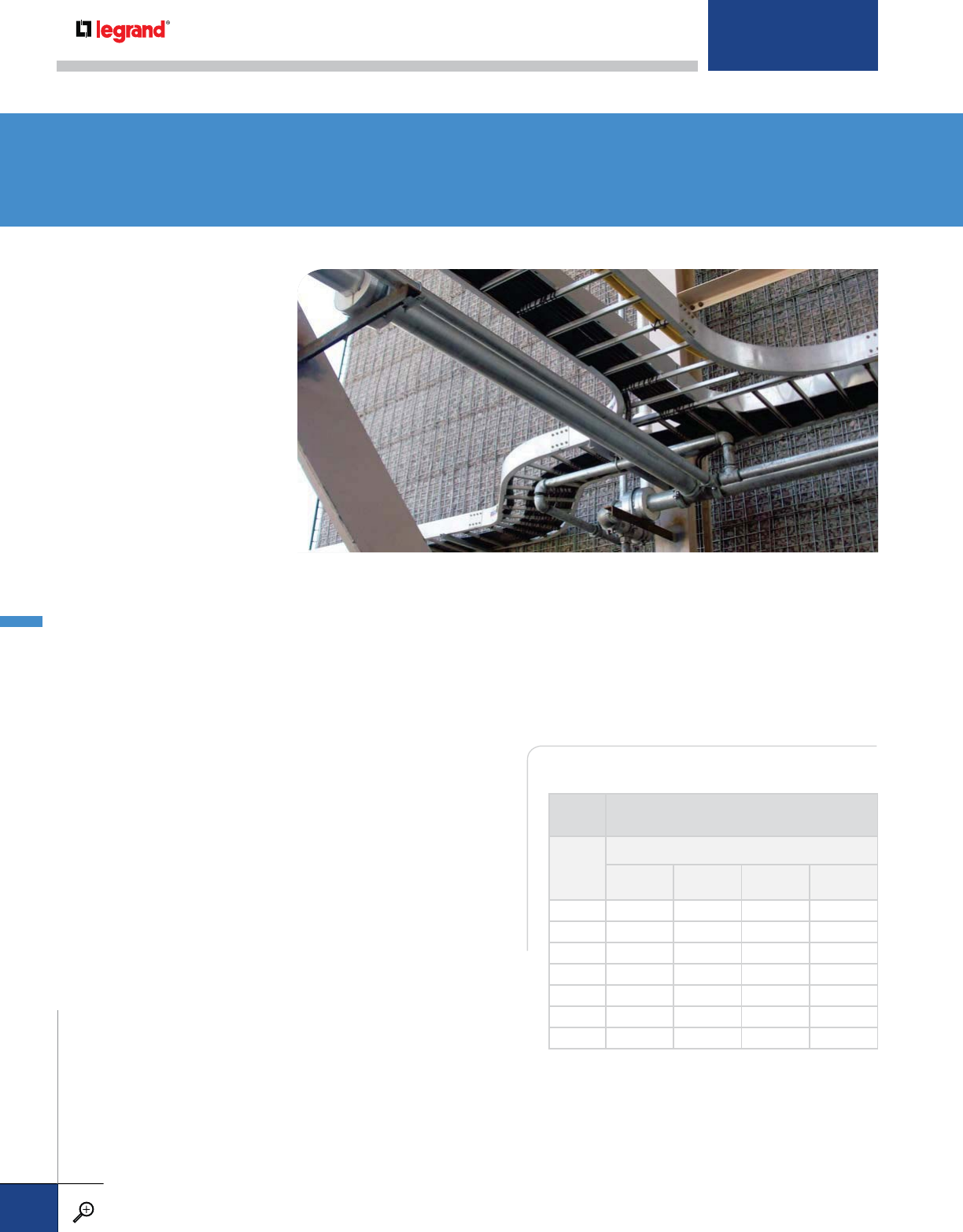
MC POWER CABLE FILL TABLE
LADDER
TRAY MAX NUMBER OF CABLES PER CODE*
WIDTH (IN.)
THHN TypeMC AlumArmor
2C
(12 AWG)
3C
(12 AWG)
3C
(AWG 4/0)
3C
(500 kcmil)
6 35 cbls 31 cbls 3 cbls 2 cbls
9 52 cbls 45 cbls 5 cbls 3 cbls
12 71 cbls 63 cbls 7 cbls 5 cbls
18 107 cbls 94 cbls 11 cbls 7 cbls
24 143 cbls 126 cbls 15 cbls 10 cbls
30 178 cbls 157 cbls 18 cbls 12 cbls
36 214 cbls 204 cbls 22 cbls 15 cbls
* Vented cable tray only.
ITRAY ALUMINUM TRAY
B.10 STRAIGHT SECTIONS
B.12 FITTINGS
B.20 COVERS
B.22 SPLICES & CONNECTORS
B.24 ACCESSORIES
METALLIC
B.26 LONGSPAN TRAY
B.28 STEEL TRAY
B.30 STAINLESS STEEL TRAY
B.32 FITTINGS
B.42 COVERS
B.45 SPLICES & CONNECTORS
B.49 ACCESSORIES
B.58 FIRESTOP SYSTEMS
B.60 REFERENCE
INFORMATION
B.63 RUNG OPTIONS
FIBERGLASS
B.70 STRAIGHT SECTIONS
B.72 FITTINGS
B.76 COVERS
B.77 SPLICES & CONNECTORS
B.78 ACCESSORIES
LADDER, TROUGH & SOLID BOTTOM
The PW Line of cable tray products is offered in a wide variety of sizes, designs and
finishes to meet exacting industry standards. Choose from our extensive selection of rail,
rung and bottom styles that are available in a variety of finishes. Also choose from fittings,
accessories, fire stop systems and fasteners that will complete your installation.
Legrand representatives have the experience to insure that your cable management
needs will be fulfilled on time and to your specifications.
METALLIC
PW CABLE TRAY
WWW.LEGRAND.US/CABLOFIL
B.8
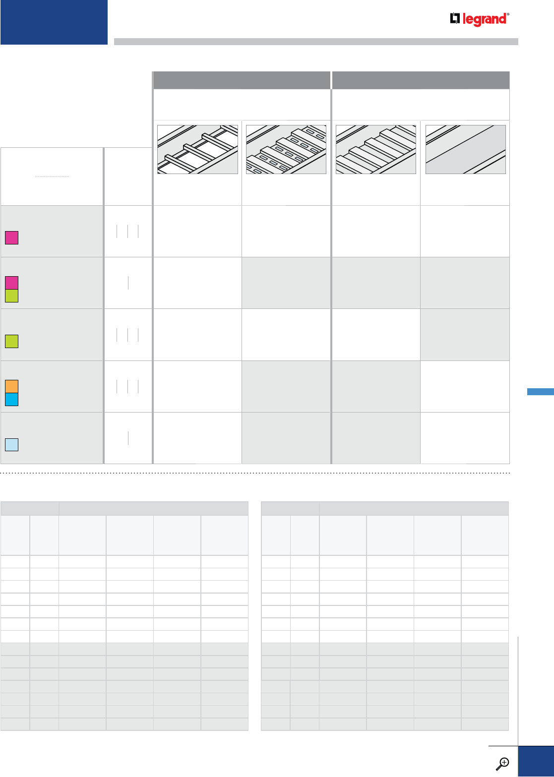
LADDER TRAY MAX NUMBER OF CABLES PER CODE
WIDTH
(IN.)
LOAD
DEPTH
(IN.)
Cat 5e
4-pr
Plenum
(.17 IN.)
Cat 5e
w4-pr
Non-Plenum
(.19 IN.)
Cat 6e
4-pr
Plenum
(.22 IN.)
Cat 6a
4-pr
Plenum
(.30 IN.)
6 3 396 cbls 317 cbls 236 cbls 127 cbls
9 3 594 cbls 476 cbls 355 cbls 190 cbls
12 3 793 cbls 634 cbls 473 cbls 254 cbls
18 3 1189 cbls 952 cbls 710 cbls 381 cbls
24 3 1586 cbls 1269 cbls 947 cbls 509 cbls
30 3 1982 cbls 1587 cbls 1183 cbls 636 cbls
36 3 2379 cbls 1904 cbls 1420 cbls 763 cbls
6 4 527 cbls 422 cbls 314 cbls 169 cbls
9 4 803 cbls 643 cbls 480 cbls 258 cbls
12 4 1055 cbls 844 cbls 629 cbls 338 cbls
18 4 1582 cbls 1266 cbls 944 cbls 508 cbls
24 4 2110 cbls 1689 cbls 1259 cbls 677 cbls
30 4 2679 cbls 2145 cbls 1600 cbls 860 cbls
36 4 3215 cbls 2574 cbls 1920 cbls 1032 cbls
LADDER TRAY MAX NUMBER OF CABLES PER CODE
WIDTH
(IN.)
LOAD
DEPTH
(IN.)
Cat 5e
4-pr
Plenum
(.17 IN.)
Cat 5e
w4-pr
Non-Plenum
(.19 IN.)
Cat 6e
4-pr
Plenum
(.22 IN.)
Cat 6a
4-pr
Plenum
(.30 IN.)
6 5 660 cbls 529 cbls 394 cbls 212 cbls
9 5 991 cbls 793 cbls 591 cbls 318 cbls
12 5 1321 cbls 1058 cbls 789 cbls 424 cbls
18 5 1982 cbls 1587 cbls 1183 cbls 636 cbls
24 5 2643 cbls 2116 cbls 1578 cbls 848 cbls
30 5 3304 cbls 2645 cbls 1972 cbls 1061 cbls
36 5 3965 cbls 3174 cbls 2367 cbls 1273 cbls
6 6 788 cbls 631 cbls 469 cbls 277 cbls
9 6 1189 cbls 952 cbls 710 cbls 381 cbls
12 6 1515 cbls 1213 cbls 905 cbls 486 cbls
18 6 2273 cbls 1820 cbls 1357 cbls 730 cbls
24 6 3031 cbls 2427 cbls 1810 cbls 973 cbls
30 6 3965 cbls 3174 cbls 2367 cbls 1273 cbls
36 6 4758 cbls 3809 cbls 2841 cbls 1527 cbls
VENTED NON-VENTED
Tray options that meet the NEMA standard for
vented tray – 25% of the cable bearing surface
must be ventilated.
TRAY
MATERIAL
SIDE RAIL
HEIGHTS
INCHES LADDER STANDARD
RUNG
VENTILATED TROUGH
CORRUGATED
SOLID BOTTOM
CORRUGATED
SOLID BOTTOM
FLAT SHEET
ITRAY
AALUMINUM 4567 6", 9" and 12"
rung spacing
7/8" wide ribs are
½" deep on 2" centers
with air vents
7/8" wide ribs are
½" deep on 2" centers
Flat sheet over
12" rung spacing
LONGSPAN
AALUMINUM
GHOT-DIP GALVANIZED STEEL
810 9", 12" and 18"
rung spacing N/A N/A N/A
STEEL
GHOT-DIP GALVANIZED STEEL 4567 6", 9" and 12"
rung spacing
7/8" wide ribs are
½" deep on 2" centers
with air vents
7/8" wide ribs are
½" deep on 2" centers N/A
STAINLESS STEEL
LSTAINLESS STEEL 304L
TSTAINLESS STEEL 316L
4567 6", 9" and 12"
rung spacing N/A N/A Flat sheet only
FIBERGLASS
FFIBERGLASS 46 6", 9" and 12"
rung spacing N/A N/A Flat sheet under
12" rung spacing
DATA CABLE FILL TABLE
For detailed material and finish descriptions, see page B.6.
METALLIC
PW CABLE TRAY
WWW.LEGRAND.US/CABLOFIL
B.9
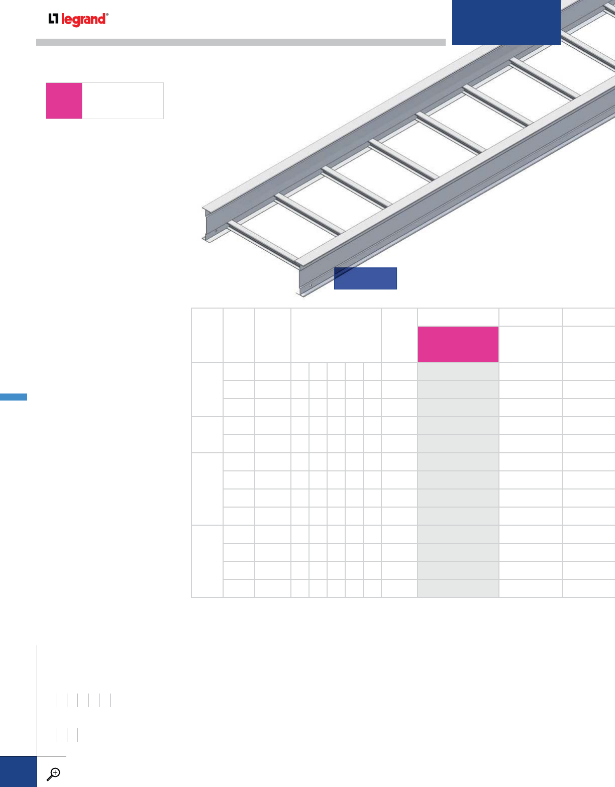
ITRAY
AALUMINUM
WIDTHS (W) INCHES
6 9 12 18 24 30 36
RAIL HEIGHTS (H) INCHES
4567
CONNECTORS & FITTINGS:
Necessary connectors and
fasteners are supplied with
all trays and fittings. Extra
connectors for field cuts
or spares must be ordered
separately.
SAFE LOAD:
Allowable cable load in
pounds per linear foot
uniformly distributed.
Based on tray with
standard rung on 9"
centers and supported on
simple beam with safety
factor of 1.5 per NEMA VE1.
CONCENTRATED LOAD:
All ladders with solid rungs
and trays with corrugated
bottoms will support a
200 lb. concentrated load
applied at the center of
the tray in addition to the
NEMA-rated cable load
without collapse.
RAIL HEIGHT (IN.)
LOAD DEPTH (IN.)
NEMA CLASS
AVAILABLE LENGTHS
(FT.)
WIDTHS (IN)
TRAY SYSTEM NUMBER AMP RATING
][
—
][
4
3 12B 10 12 - - - 6 – 36 4A12B 1200
3 12C 10 12 20 - - 6 – 36 4A12C 1200
3 20B - 12 20 24 - 6 – 36 4A20B 2000
5
4 12C 10 12 20 - - 6 – 36 5A12C 1200
4 20B - 12 20 24 - 6 – 36 5A20B 1600
6
5 12C 10 12 20 - - 6 – 36 6A12C 1200
5 20B - 12 20 24 - 6 – 36 6A20B 1600
5 20C - 12 20 24 - 6 – 36 6A20C 2000
5 24C - - 20 24 30 6 – 36 6A24C 2000
7
6 12C 10 12 20 - - 6 – 36 7A12C 1600
6 20B - 12 20 24 - 6 – 36 7A20B 2000
6 20C - 12 20 24 - 6 – 36 7A20C 2000
6 24C - - 20 24 30 6 – 36 7A24C 2000
LADDER
ITRAY – STRAIGHT SECTIONS
PW CABLE TRAY
WWW.LEGRAND.US/CABLOFIL
B.10

SUPPORT SPAN (FT.)
6 8 10 12 14 16 18 20 22 24 26 28 30
SAFE LOAD DATA (LBS./FT.) / DEFLECTION (IN.) / SAFETY FACTOR 1.5
300 0.46 169 0.81 108 1.27 75 1.83
400 0.49 225 0.86 144 1.35 100 1.94 71 2.64 52 3.45
469 0.92 300 1.43 208 2.06 153 2.80 117 3.66 93 4.63 75 5.72 61 6.92 50 8.24
400 0.28 225 0.50 144 0.78 100 1.12 71 1.52 52 1.99
469 0.60 300 0.95 208 1.36 153 1.85 117 2.42 93 3.06 75 3.78 61 4.57 50 5.44
400 0.24 225 0.42 144 0.66 100 0.95 71 1.29 52 1.69
469 0.43 300 0.67 208 0.96 153 1.31 117 1.71 93 2.16 75 2.67 61 3.23 50 3.84
400 0.78 278 1.12 204 1.53 156 2.00 123 2.53 100 3.12 81 3.78 66 4.49
400 1.04 294 1.41 225 1.84 178 2.33 144 2.88 119 3.48 100 4.14 84 4.86 71 5.64 61 6.47
400 0.15 225 0.27 144 0.42 100 0.61 71 0.83 52 1.08
469 0.32 300 0.50 208 0.72 153 0.98 117 1.29 93 1.63 75 2.01 61 2.43 50 2.89
400 0.55 278 0.78 204 1.07 156 1.40 123 1.77 100 2.18 81 2.64 66 3.14
400 0.90 294 1.23 225 1.60 178 2.03 144 2.50 119 3.03 100 3.60 84 4.23 71 4.90 61 5.63
RAIL HEIGHT
4 – 4”
5 – 5”
6 – 6”
7 – 7”
MATERIAL
A
NEMA
CLASS LENGTH*
S120 – 120"
S144 – 144"
S240 – 240"
S288 – 288”
WIDTH
06 – 6"
09 – 9"
12 – 12"
18 – 18"
24 – 24"
30 – 30"
36 – 36"
BOTTOM TYPE
VENTED
06 – 6" Rung Spacing
09 – 9" Rung Spacing
12 – 12" Rung Spacing
VC – Vented Corrugated
NON-VENTED
SC – Solid Corrugated
SB – Solid Bottom
ITRAY STRAIGHT SECTION CATALOG NUMBERING EXAMPLE:
09-4 A 12B-S144-06
* S144 and S240 are standard; S120 and S288 are available with extended lead time.
VENTED CORRUGATED SOLID CORRUGATED SOLID BOTTOM
(INSTALLED OVER RUNGS)
All Legrand aluminum
and steel cable trays
are Classified by
UL as equipment
grounding conductors
per NEC 392.60.
(UL File No. E60796)
For detailed material and finish descriptions, see page B.6.
ITRAY – STRAIGHT SECTIONS
PW CABLE TRAY
WWW.LEGRAND.US/CABLOFIL
B.11
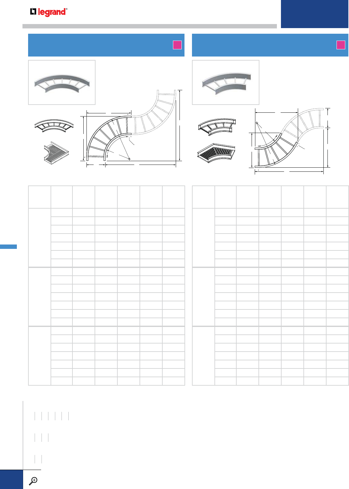
90HB
HORIZONTAL 90˚ ELBOW 60HB
HORIZONTAL 60˚ ELBOW
RADIUS
R
WIDTH
W
RADIUS 2
R2 ABCD
12
61821213636
92124243939
12 24 27 27 42 42
18 30 33 33 48 48
24 36 39 39 54 54
30 42 45 45 60 60
36 48 51 51 66 66
24
63033336060
93336366363
12 36 39 39 66 66
18 42 45 45 72 72
24 48 51 51 78 78
30 54 57 57 84 84
36 60 63 63 90 90
36
64245458484
94548488787
12 48 51 51 90 90
18 54 57 57 96 96
24 60 63 63 102 102
30 66 69 69 108 108
36 72 75 75 114 114
RADIUS
R
WIDTH
W
RADIUS 2
R2 ABCD
12
61820
1/8145/835 201/4
92122
5/8175/8375/8213/4
12 24 251/4205/8401/8231/4
18 30 301/2265/8453/8261/4
24 36 355/8325/8505/8291/4
30 42 407/8385/8553/4321/4
36 48 461/8445/861 351/4
24
63030
1/2205/8553/4321/4
93333
1/8235/8583/8333/4
12 36 355/8265/861 351/4
18 42 407/8325/8661/8381/4
24 48 461/8385/8713/8411/4
30 54 511/4445/8761/2441/4
36 60 561/2505/8813/4471/4
36
64240
7/8265/8761/2441/4
94543
1/2295/8791/8453/4
12 48 461/8325/8813/4471/4
18 54 511/4385/887 501/4
24 60 561/2445/8921/8531/4
30 66 615/8505/8973/8561/4
36 72 667/8565/81021/2591/4
A A
A
R2
B
W
C
D
R
60˚
3" tangent
WIDTHS (W) INCHES
6 9 12 18 24 30 36
RAIL HEIGHTS (H) INCHES
4567
RADIUS (R) INCHES
12 24 36
A
R2
B
W C
D
R90˚
3" tangent
BOTTOM TYPES
LD and SB
VC and SC
BOTTOM TYPES
LD and SB
VC and SC
ITRAY – FITTINGS
PW CABLE TRAY
WWW.LEGRAND.US/CABLOFIL
B.12
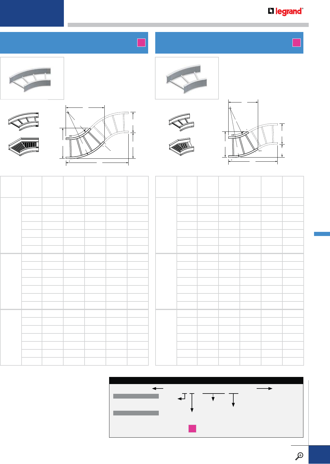
45HB
HORIZONTAL 45˚ ELBOW 30HB
HORIZONTAL 30˚ ELBOW
RADIUS
R
WIDTH
W
RADIUS 2
R2 ABCD
12
61817
7/8115/8311/213
9212014
5/8335/8137/8
12 24 221/8175/8353/4143/4
18 30 263/8235/840 161/2
24 36 305/8295/8441/8181/4
30 42 347/8355/8483/820
36 48 39 415/8525/8217/8
24
63026
3/8151/8483/820
93328
1/2181/8501/221
12 36 305/8211/8525/8217/8
18 42 347/8271/8567/8235/8
24 48 39 331/8611/8253/8
30 54 431/4391/8653/8271/8
36 60 471/2451/8695/8287/8
36
64234
7/8185/8653/8271/8
9453721
5/8671/228
12 48 39 245/8695/8287/8
18 54 431/4305/8737/8305/8
24 60 471/2365/8781/8323/8
30 66 513/4425/8823/8341/8
36 72 56 485/8865/8357/8
RADIUS
R
WIDTH
W
RADIUS 2
R2 ABCD
12
61814
1/291/8261/47
92116
1/8121/8273/473/8
12 24 175/8151/8291/477/8
18 30 205/8211/8321/485/8
24 36 235/8271/8351/493/8
30 42 265/8331/8381/4101/4
36 48 295/8391/8411/411
24
63020
5/8103/4381/4101/4
93322
1/8133/4393/4105/8
12 36 235/8163/4411/411
18 42 265/8223/4441/4117/8
24 48 295/8283/4471/4125/8
30 54 325/8343/4501/4131/2
36 60 355/8403/4531/4141/4
36
64226
5/8123/8501/4131/2
94528
1/8153/8513/4137/8
12 48 295/8183/8531/4141/4
18 54 325/8243/8561/415
24 60 355/8303/8591/4157/8
30 66 385/8363/8621/4165/8
36 72 415/8423/8651/4171/2
A A
A
R2
B
W
C
D
R
45˚
3" tangent
A
R2
B
W
C
D
R
30˚3" tangent
RAIL
HEIGHT
4 – 4"
5 – 5"
6 – 6"
7 – 7" MATERIAL
A
FITTING
CODE
90HB
60HB
45HB
30HB
RADIUS
12 – 12"
24 – 24"
36 – 36"
WIDTH
06 – 6"
09 – 9"
12 – 12"
18 – 18"
24 – 24"
30 – 30"
36 – 36"
BOTTOM TYPE
VENTED
LD – Ladder Rung
VC – Vented Corrugated
NON-VENTED
SC – Solid Corrugated
SB – Solid Bottom
ITRAY HORIZONTAL ELBOW CATALOG NUMBERING EXAMPLE:
LD-4A -90HB 12-06
BOTTOM TYPES
LD and SB
VC and SC
BOTTOM TYPES
LD and SB
VC and SC
For detailed material and finish descriptions, see page B.6.
ITRAY – FITTINGS
PW CABLE TRAY
WWW.LEGRAND.US/CABLOFIL
B.13

HT
HORIZONTAL STANDARD TEE
3" tangent
A
W
B
W
R
RADIUS
R
WIDTH
WAB
12
6 36 21 5/8
9 39 24 5/8
12 42 27 5/8
18 48 33 5/8
24 54 39 5/8
30 60 45 5/8
36 66 51 5/8
24
6 60 33 5/8
9 63 36 5/8
12 66 39 5/8
18 72 45 5/8
24 78 51 5/8
30 84 57 5/8
36 90 63 5/8
36
6 84 45 5/8
9 87 48 5/8
12 90 51 5/8
18 96 57 5/8
24 102 63 5/8
30 108 69 5/8
36 114 75 5/8
A
SR / LR / RR
HORIZONTAL REDUCERS
W1
W2
L
W1
W2
L
LEFT HAND
RIGHT HAND
LENGTH
MAIN
WIDTH
W1
AVAILABLE BRANCH WIDTHS
W2
18
96-----
1269----
18 6 9 12 - - -
24 6 9 12 18 - -
30 6 9 12 18 24 -
36 6 9 12 18 24 30
W1
W2
L
STRAIGHT
A
RAIL
HEIGHT
4 – 4"
5 – 5"
6 – 6"
7 – 7" MATERIAL
A
FITTING
CODE
SR
LR
RR
WIDTH 1
09 – 9"
12 – 12"
18 – 18"
24 – 24"
30 – 30"
36 – 36"
WIDTH 2
06 – 6"
09 – 9"
12 – 12"
18 – 18"
24 – 24"
30 – 30"
36 – 36"
BOTTOM TYPE
VENTED
LD – Ladder Rung
VC – Vented Corrugated
NON-VENTED
SC – Solid Corrugated
SB – Solid Bottom
ITRAY HORIZONTAL REDUCER CATALOG NUMBERING EXAMPLE:
LD-4A -SR09-06
PW CABLE TRAY
WWW.LEGRAND.US/CABLOFIL
B.14
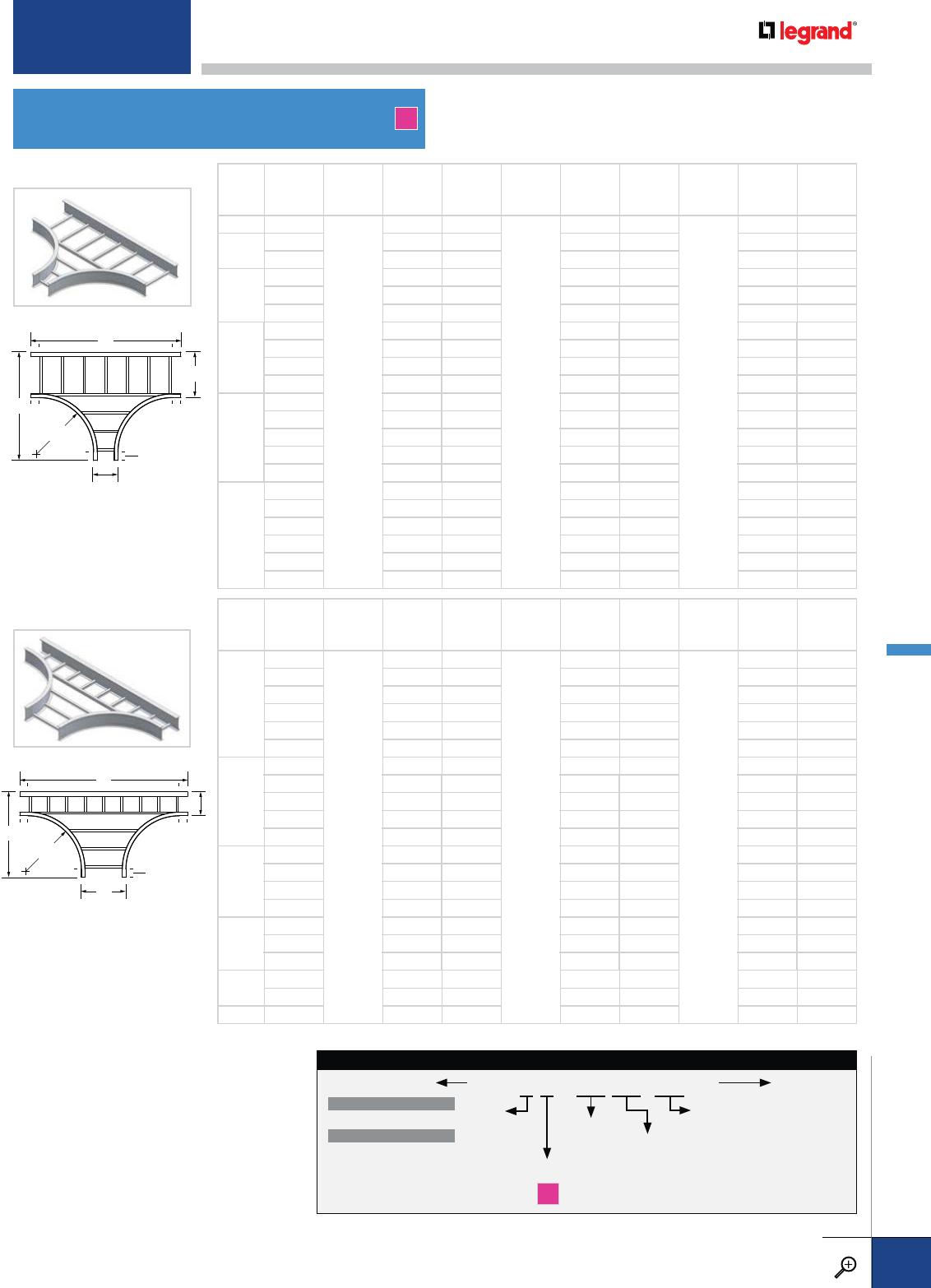
RT / ET
HORIZONTAL REDUCING/EXPANDING TEES
W1
A
B
R
W2
3" tangent
A
W1
B
W2
R
3" tangent
MAIN
WIDTH
W1
BRANCH
WIDTH
W2
RADIUS
RAB
RADIUS
RAB
RADIUS
RAB
96
12
36 24 5/8
24
60 36 5/8
36
84 48 5/8
12 6 36 27 5/860 39 5/884 51 5/8
9 39 27 5/863 39 5/887 51 5/8
18
6 36 33 5/860 45 5/884 57 5/8
9 39 33 5/863 45 5/887 57 5/8
12 42 33 5/866 45 5/890 57 5/8
24
6 36 39 5/860 51 5/884 63 5/8
9 39 39 5/863 51 5/887 63 5/8
12 42 39 5/866 51 5/890 63 5/8
18 48 39 5/872 51 5/896 63 5/8
30
6 36 45 5/860 57 5/884 69 5/8
9 39 45 5/863 57 5/887 69 5/8
12 42 45 5/866 57 5/890 69 5/8
18 48 45 5/872 57 5/896 69 5/8
24 54 45 5/878 57 5/8102 69 5/8
36
6 36 51 5/860 63 5/884 75 5/8
9 39 51 5/863 63 5/887 75 5/8
12 42 51 5/866 63 5/890 75 5/8
18 48 51 5/872 63 5/896 75 5/8
24 54 51 5/878 63 5/8102 75 5/8
30 60 51 5/884 63 5/8108 75 5/8
MAIN
WIDTH
W1
BRANCH
WIDTH
W2
RADIUS
RAB
RADIUS
RAB
RADIUS
RAB
6
9
12
39 21 5/8
24
63 33 5/8
36
87 45 5/8
12 42 21 5/866 33 5/890 45 5/8
18 48 21 5/872 33 5/896 45 5/8
24 54 21 5/878 33 5/8102 45 5/8
30 60 21 5/884 33 5/8108 45 5/8
36 66 21 5/890 33 5/8114 45 5/8
9
12 42 24 5/866 36 5/890 48 5/8
18 48 24 5/872 36 5/896 48 5/8
24 54 24 5/878 36 5/8102 48 5/8
30 60 24 5/884 36 5/8108 48 5/8
36 66 24 5/890 36 5/8114 48 5/8
12
18 48 27 5/872 39 5/896 51 5/8
24 54 27 5/878 39 5/8102 51 5/8
30 60 27 5/884 39 5/8108 51 5/8
36 66 27 5/890 39 5/8114 51 5/8
18
24 54 33 5/878 45 5/8102 57 5/8
30 60 33 5/884 45 5/8108 57 5/8
36 66 33 5/890 45 5/8114 57 5/8
24 30 60 39 5/884 51 5/8108 63 5/8
36 66 39 5/890 51 5/8114 63 5/8
30 36 66 45 5/890 57 5/8114 69 5/8
A
REDUCING TEE
EXPANDING TEE
RAIL
HEIGHT
4 – 4"
5 – 5"
6 – 6"
7 – 7" MATERIAL
A
FITTING
CODE
HT*
RT
ET
WIDTH 1
06 – 6"
09 – 9"
12 – 12"
18 – 18"
24 – 24"
30 – 30"
36 – 36"
WIDTH 2*
06 – 6"
09 – 9"
12 – 12"
18 – 18"
24 – 24"
30 – 30"
36 – 36"
BOTTOM TYPE
VENTED
LD – Ladder Rung
NON-VENTED
SB – Solid Bottom
ITRAY HORIZONTAL TEE CATALOG NUMBERING EXAMPLE:
LD-4A -RT12-1206
RADIUS
12 – 12"
24 – 24"
36 – 36"
* Width 2 does not apply to Horizontal Tee (HT).
* Reducing/expanding tees are not available
with the corrugated bottom type. Use reducer
fittings (see page 14) or reducer splice plates
(see page 23) in conjunction with horizontal
standard tee fittings which are available with
corrugated bottoms.
For detailed material and finish descriptions, see page B.6.
PW CABLE TRAY
WWW.LEGRAND.US/CABLOFIL
B.15
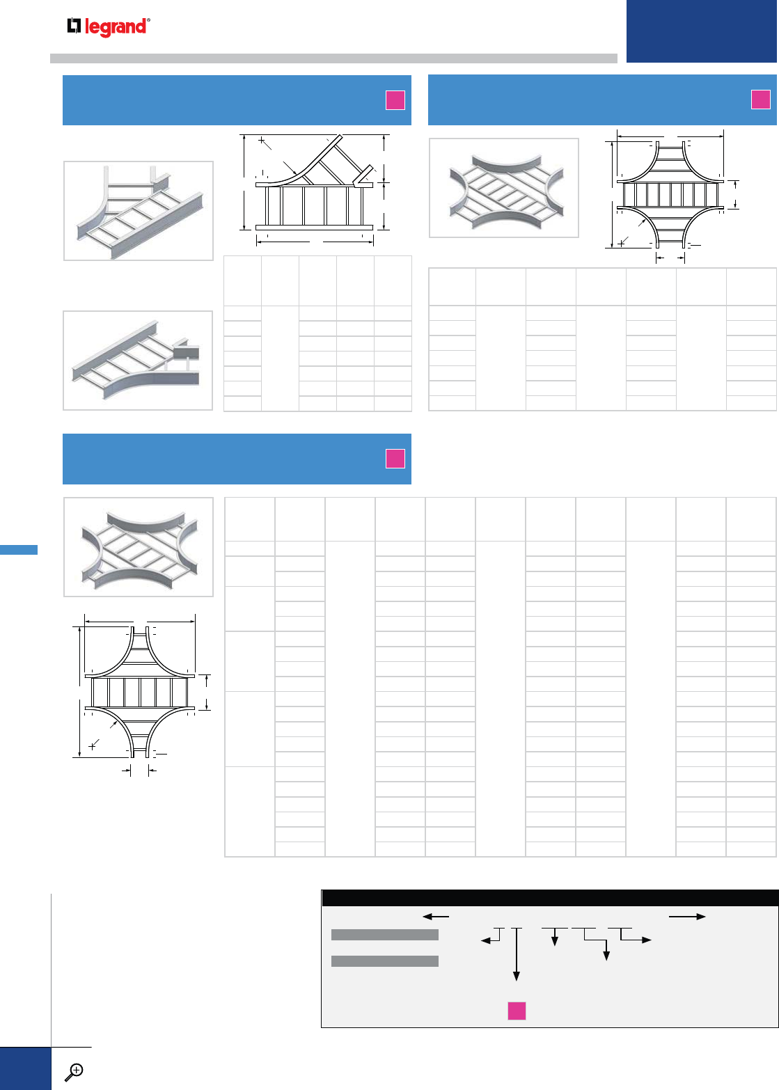
WIDTH
W
RADIUS
RABC
6
24
31 ¼ 12 18
9 35 ½ 14 1
/
823 1
/
8
12 39 5
/
816 ¼ 28 ¼
18 48 ¼ 20 ½ 38 ½
24 56 5
/
824 ¾ 48 ¾
30 65 ¼ 29 59
36 73 5
/
833 ¼ 69 ¼
C
A
W
B
R
3" tangent
YL / YR
HORIZONTAL WYE BRANCHES
LEFT HAND
RIGHT HAND
A
A
A
W
W
R
3" tangent
A
A
W1
W2
R
3" tangent
RX
HORIZONTAL REDUCING CROSS
HX
HORIZONTAL STANDARD CROSS
A
A
WIDTH
W
RADIUS
RARADIUS
RARADIUS
RA
6
12
36
24
60
36
84
9396387
12 42 66 90
18 48 72 96
24 54 78 102
30 60 84 108
36 66 90 114
RAIL
HEIGHT
4 – 4"
5 – 5"
6 – 6"
7 – 7" MATERIAL
A
FITTING
CODE
RX
WIDTH 1
06 – 6"
09 – 9"
12 – 12"
18 – 18"
24 – 24"
30 – 30"
36 – 36"
WIDTH 2
06 – 6"
09 – 9"
12 – 12"
18 – 18"
24 – 24"
30 – 30"
36 – 36"
BOTTOM TYPE
VENTED
LD – Ladder Rung
NON-VENTED
SB – Solid Bottom
ITRAY HORIZONTAL REDUCING CROSS CATALOG NUMBERING EXAMPLE:
LD-4A -RX12-0906
RADIUS
12 – 12"
24 – 24"
36 – 36"
MAIN
WIDTH
W1
BRANCH
WIDTH
W2
RADIUS
RAB
RADIUS
RAB
RADIUS
RAB
96
12
36 39
24
60 63
36
84 87
12 6 3642 6066 8490
9 3942 6366 8790
18
6 3648 6072 8496
9 3948 6372 8796
12 42 48 66 72 90 96
24
6 3654 6078 84102
9 3954 6378 87102
12 42 54 66 78 90 102
18 48 54 72 78 96 102
30
6 3660 6084 84108
9 3960 6384 87108
12 42 60 66 84 90 108
18 48 60 72 84 96 108
24 54 60 78 84 102 108
36
6 3666 6090 84114
9 3966 6390 87114
12 42 66 66 90 90 114
18 48 66 72 90 96 114
24 54 66 78 90 102 114
30 60 66 84 90 108 114
* Reducing crosses are not available with
the corrugated bottom type. Use reducer
fittings (see page 14) or reducer splice plates
(see page 23) in conjunction with horizontal
standard cross fittings which are available
with corrugated bottoms.
PW CABLE TRAY
WWW.LEGRAND.US/CABLOFIL
B.16
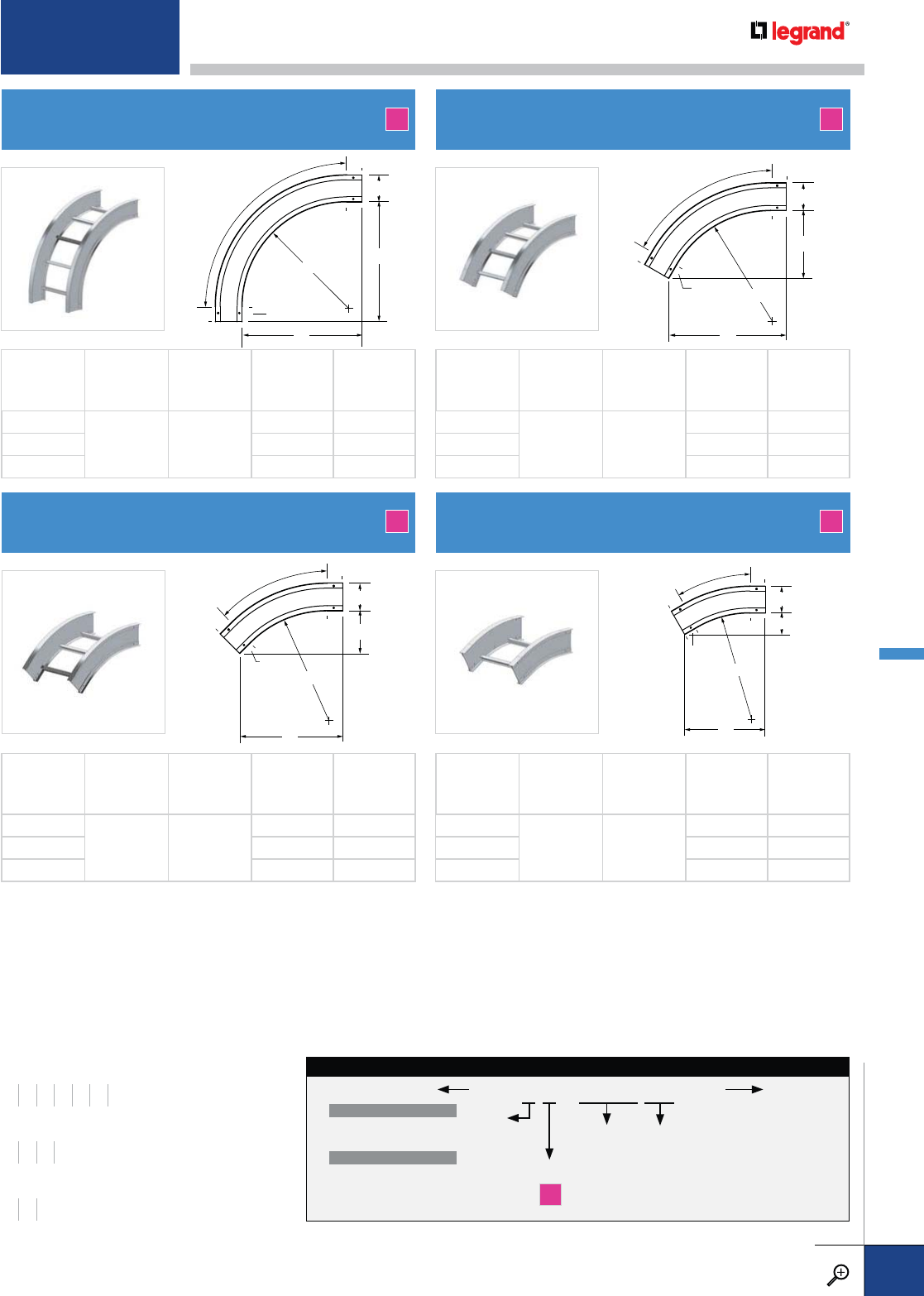
B
A
H
R
90˚
3" tangent
B
A
H
R
45˚
3" tangent
B
A
H
R
30˚
3" tangent
B
A
H
R
60˚
3" tangent
90VO
VERTICAL OUTSIDE 90º ELBOW
45VO
VERTICAL OUTSIDE 45º ELBOW
60VO
VERTICAL OUTSIDE 60º ELBOW
30VO
VERTICAL OUTSIDE 30º ELBOW
A
A
A
A
RADIUS
R
WIDTH
W
RAIL HEIGHT
HAB
12
6-36 4-7
15 15
24 27 27
36 39 39
RADIUS
R
WIDTH
W
RAIL HEIGHT
HAB
12
6-36 4-7
13*5/855/8
24 221/891/8
36 305/8125/8
RADIUS
R
WIDTH
W
RAIL HEIGHT
HAB
12
6-36 4-7
15 85/8
24 251/4145/8
36 355/8205/8
RADIUS
R
WIDTH
W
RAIL HEIGHT
HAB
12
6-36 4-7
115/831/8
24 175/843/4
36 235/863/8
RAIL
HEIGHT
4 – 4"
5 – 5"
6 – 6"
7 – 7"
MATERIAL
A
FITTING
CODE
90VO
60VO
45VO
30VO
WIDTH
06 – 6"
09 – 9"
12 – 12"
18 – 18"
24 – 24"
30 – 30"
36 – 36"
BOTTOM TYPE
VENTED
LD – Ladder Rung
VC – Vented Corrugated
NON-VENTED
SC – Solid Corrugated
SB – Solid Bottom
ITRAY VERTICAL INSIDE ELBOW CATALOG NUMBERING EXAMPLE:
LD-6A -90VO12-06
RADIUS
12 – 12"
24 – 24"
36 – 36"
WIDTHS (W) INCHES
6 9 12 18 24 30 36
RAIL HEIGHTS (H) INCHES
4567
RADIUS (R) INCHES
12 24 36
For detailed material and finish descriptions, see page B.6.
ITRAY – FITTINGS
PW CABLE TRAY
WWW.LEGRAND.US/CABLOFIL
B.17
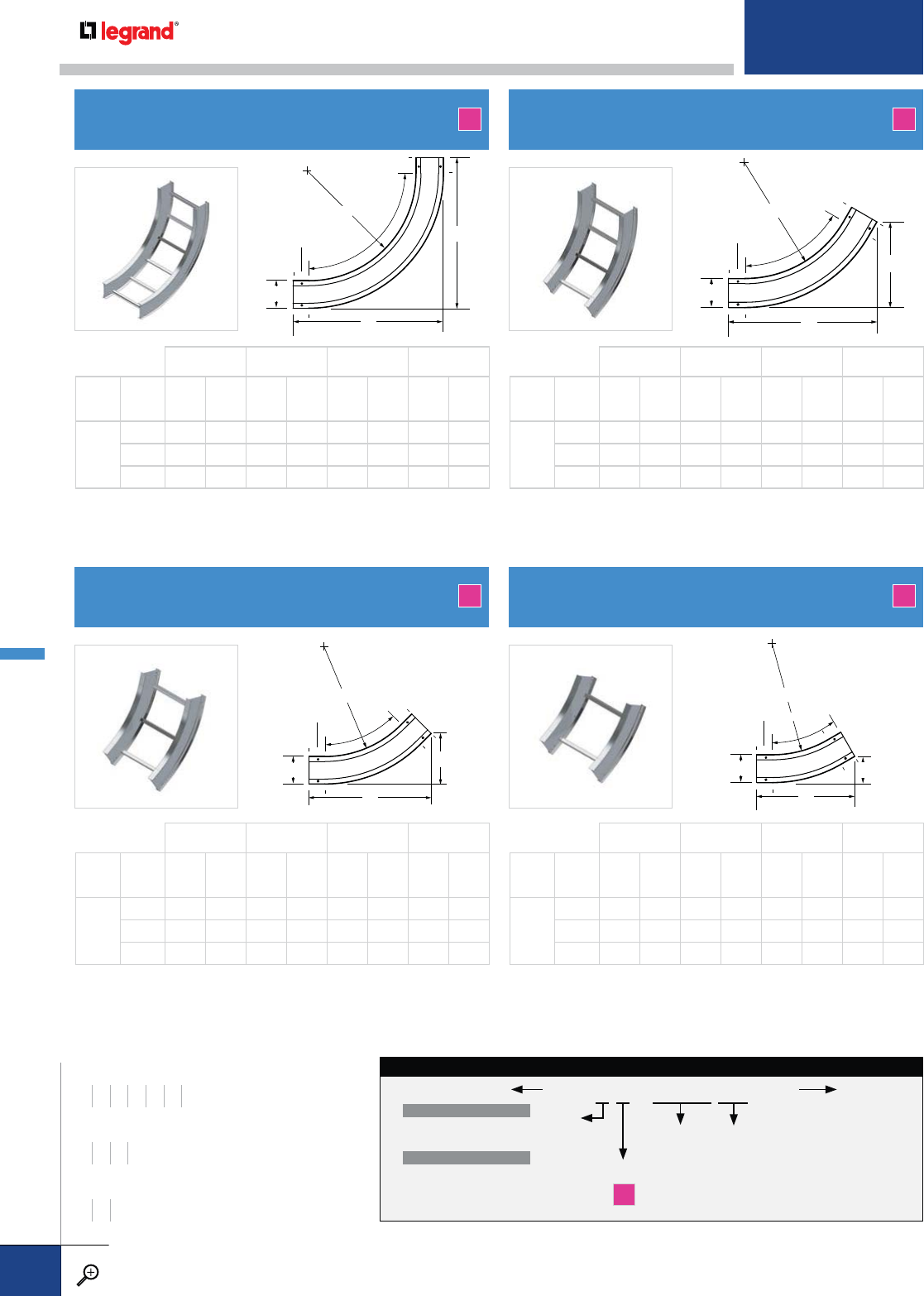
B
A
H
R
90˚
3" tangent
B
A
H
R
45˚
3" tangent
B
A
H
R
60˚
3" tangent
B
A
H
R
30˚
3" tangent
90VI
VERTICAL INSIDE 90º ELBOW
45VI
VERTICAL INSIDE 45º ELBOW
60VI
VERTICAL INSIDE 60º ELBOW
30VI
VERTICAL INSIDE 30º ELBOW
A
A
A
A
H = 4 H = 5 H = 6 H = 7
WIDTH
W
RADIUS
RABABABAB
ALL
12 163/863/4171/871/8177/873/8181/275/8
24 247/8103/8255/8105/8263/8107/827 111/4
36 333/8137/8341/8141/8347/8143/8351/2143/4
H = 4 H = 5 H = 6 H = 7
WIDTH
W
RADIUS
RABABABAB
ALL
12 19 19 20 20 21 21 22 22
24 31 31 32 32 33 33 34 34
36 43 43 44 44 45 45 46 46
H = 4 H = 5 H = 6 H = 7
WIDTH
W
RADIUS
RABABABAB
ALL
12 135/835/8141/833/4145/837/8151/84
24 195/851/4201/853/8205/851/2211/855/8
36 255/867/8261/8726
5/871/8271/871/4
H = 4 H = 5 H = 6 H = 7
WIDTH
W
RADIUS
RABABABAB
ALL
12 183/8105/8191/4111/8201/8115/821 121/8
24 283/4165/8295/8171/8301/2175/8313/8181/8
36 391/8225/840 231/8407/8235/8413/4241/8
90VI
45VI
60VI
30VI
RAIL
HEIGHT
4 – 4"
5 – 5"
6 – 6"
7 – 7"
MATERIAL
A
FITTING
CODE
90VI
60VI
45VI
30VI
WIDTH
06 – 6"
09 – 9"
12 – 12"
18 – 18"
24 – 24"
30 – 30"
36 – 36"
BOTTOM TYPE
VENTED
LD – Ladder Rung
VC – Vented Corrugated
NON-VENTED
SC – Solid Corrugated
SB – Solid Bottom
ITRAY VERTICAL INSIDE ELBOW CATALOG NUMBERING EXAMPLE:
LD-4 A -90VI 12-09
RADIUS
12 – 12"
24 – 24"
36 – 36"
WIDTHS (W) INCHES
6 9 12 18 24 30 36
RAIL HEIGHTS (H) INCHES
4567
RADIUS (R) INCHES
12 24 36
ITRAY – FITTINGS
PW CABLE TRAY
WWW.LEGRAND.US/CABLOFIL
B.18
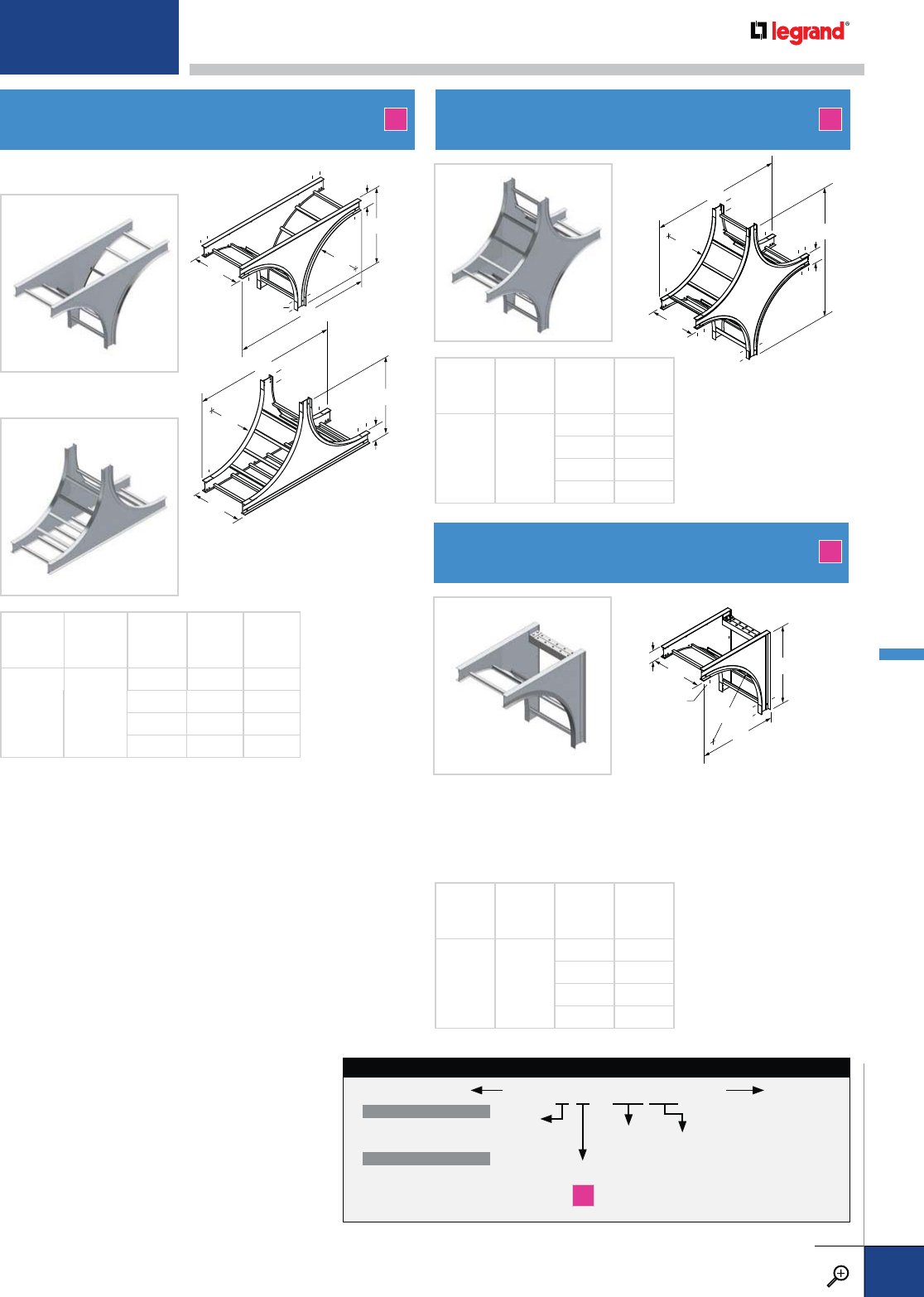
A
H
A
W
R
3" tangent
A
A
HW
R
3" tangent
A
H
H
H
B
W
R
3" tan
g
en
t
A
H
H
H
B
W
R
3
" tangent
TEE DOWN
TEE UP
TEE UP fittings have rungs or
bottom members for cable support
across the bottom of the fitting.
TD / TU
VERTICAL TEES VX
VERTICAL CROSS
Supports cables at the top of long vertical drops where the
weight of the vertical cable may be excessive. Hooks (sold
separately) attach to the brace in the elbow; when used with
cable grips (supplied by others), tension in the vertical cable
is relieved and transferred to the elbow.
CS
VERTICAL CABLE SUPPORT ELBOW
A A
A
WIDTH
W
RADIUS
R
RAIL
HEIGHT
H
AB
ALL 24
45831
55932
66033
76134
WIDTH
W
RADIUS
R
RAIL
HEIGHT
H
A
ALL 24
458
559
660
761
WIDTH
W
RADIUS
R
RAIL
HEIGHT
H
A
ALL 24
431
532
633
734
TD
VX
CS
TU
RAIL
HEIGHT
4 – 4"
5 – 5"
6 – 6"
7 – 7"
MATERIAL
A
FITTING
CODE
TU
TD
WIDTH
06 – 6"
09 – 9"
12 – 12"
18 – 18"
24 – 24"
30 – 30"
36 – 36"
BOTTOM TYPE
VENTED
LD – Ladder Rung
VC – Vented Corrugated
NON-VENTED
SC – Solid Corrugated
SB – Solid Bottom
ITRAY VERTICAL TEE CATALOG NUMBERING EXAMPLE:
LD-4 A -TU24-09
RADIUS
24 – 24"
For detailed material and finish descriptions, see page B.6.
ITRAY – FITTINGS
PW CABLE TRAY
WWW.LEGRAND.US/CABLOFIL
B.19
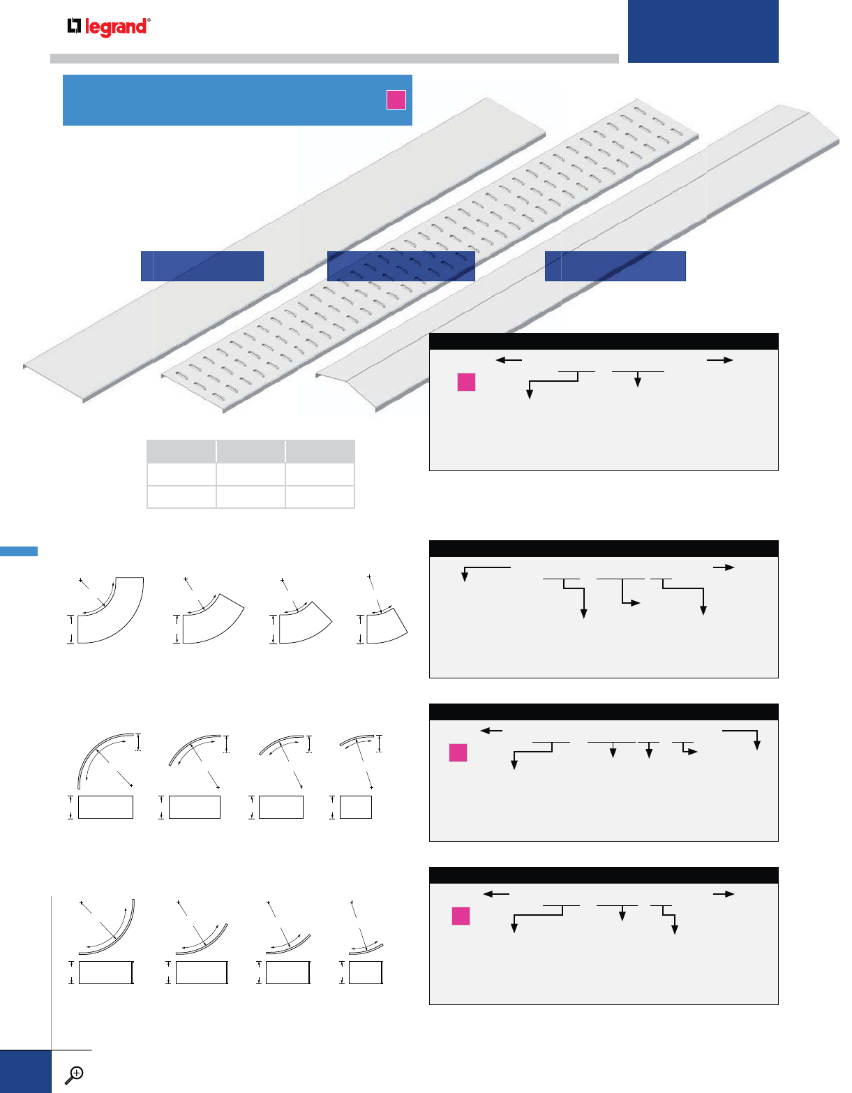
SFF / LFF / SPF
COVERS A
FOR HORIZONTAL ELBOWS ( 90HB/60HB/45HB/30HB)
FOR VERTICAL OUTSIDE ELBOWS ( 90VO/60VO/45V0/30VO)
FOR VERTICAL INSIDE ELBOWS (90VI /60VI /45VI/30VI)
COVER TYPE
SFF – Solid Flat Flanged
LFF – Louvered Flat Flanged
SPF – Solid Peaked Flanged
MATERIAL
A
LENGTH
S060 – 60"
S072 – 72"
S120 – 120"
S144 – 144”
WIDTH
06 – 6"
09 – 9"
12 – 12"
18 – 18"
24 – 24"
30 – 30"
36 – 36"
STRAIGHT SECTION COVER CATALOG NUMBERING EXAMPLE:
A -LFF-S060-06
R
90˚
WW
R
60˚
W
R
30˚
W
45˚
R
W
H
R
90˚
W
H
R
60˚
H
W
R
30˚
H
W
45˚
R
W
R
90˚
W
R
60˚
W
45˚
R
W
R
30˚
COVER TYPE
SFF – Solid Flat Flanged
LFF – Louvered Flat Flanged
SPF – Solid Peaked Flanged
A – Aluminum
for Ladder and
Solid Flat Bottoms
AC – Aluminum for
Corrugated
Bottoms
FITTING
CODE
90HB
60HB
45HB
30HB
WIDTH
06 – 6"
09 – 9"
12 – 12"
18 – 18"
24 – 24"
30 – 30"
36 – 36"
HORIZONTAL ELBOW COVER CATALOG NUMBERING EXAMPLE:
A-SFF-90HB12-06
RADIUS
12 – 12"
24 – 24"
36 – 36"
COVER TYPE
SFF – Solid Flat Flanged
LFF – Louvered Flat Flanged
MATERIAL
A
FITTING
CODE
90VI
60VI
45VI
30VI
WIDTH
06 – 6"
09 – 9"
12 – 12"
18 – 18"
24 – 24"
30 – 30"
36 – 36"
VERTICAL INSIDE ELBOW COVER CATALOG NUMBERING EXAMPLE:
A-SFF-90VI 24-12
RADIUS
12 – 12"
24 – 24"
36 – 36"
COVER TYPE
SFF – Solid Flat Flanged
LFF – Louvered Flat Flanged
MATERIAL
A
FITTING
CODE
90VO
60VO
45VO
30VO
WIDTH
06 – 6"
09 – 9"
12 – 12"
18 – 18"
24 – 24"
30 – 30"
36 – 36"
VERTICAL OUTSIDE ELBOW COVER CATALOG NUMBERING EXAMPLE:
A-S FF -90VO24-12 -4
RADIUS
12 – 12"
24 – 24"
36 – 36"
RAIL
HEIGHT
4 – 4"
5 – 5"
6 – 6"
7 – 7"
SOLID FLAT FLANGED LOUVERED FLAT FLANGED SOLID PEAKED FLANGED
COVER GAGE (6"-24") GAGE (30"-36")
SFF / LFF 0.040" 0.063"
SPF 0.040" 0.040"
ITRAY – COVERS
PW CABLE TRAY
WWW.LEGRAND.US/CABLOFIL
B.20
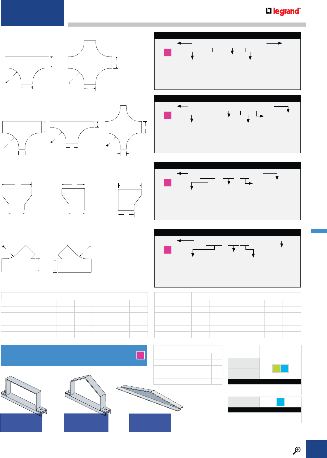
FCC / PCC / PCT
COVER CONNECTORS A
PRODUCT
CODE FASTENER OPTIONS
FCC
GE S6
PCC
CATALOG NUMBERING EXAMPLE:
H / Material Width Fasteners
4A - FCC -06-GE
PCT S6
CATALOG NUMBERING EXAMPLE:
Material Width Fasteners
A - PCT -06 - S6
FOR HORIZONTAL REDUCING TEE (RT), EXPANDING TEE (ET)
AND REDUCING CROSS (RX)
R
W1
W2
W1
R
W2
W2
R
W1
FOR HORIZONTAL STRAIGHT REDUCER (SR), LEFT HAND
REDUCER (LR) AND RIGHT HAND REDUCER (RR)
W2
W1
W2
W1
W2
W1
FOR HORIZONTAL LEFT HAND WYE (YL)
AND RIGHT HAND WYE (YR)
W
R
W
R
COVER TYPE
SFF – Solid Flat Flanged
LFF – Louvered Flat Flanged
SPF – Solid Peaked Flanged
MATERIAL
A
FITTING
CODE
RT
ET
RX
W1
06 – 6"
09 – 9"
12 – 12"
18 – 18"
24 – 24"
30 – 30"
36 – 36"
W2*
06 – 6"
09 – 9"
12 – 12"
18 – 18"
24 – 24"
30 – 30"
36 – 36"
HORIZONTAL REDUCING TEE COVER CATALOG NUMBERING EXAMPLE:
A-SFF-RT12-1206
RADIUS
12 – 12"
24 – 24"
36 – 36"
COVER TYPE
SFF – Solid Flat Flanged
LFF – Louvered Flat Flanged
SPF – Solid Peaked Flanged
MATERIAL
A
FITTING
CODE
SR
LR
RR
W1
06 – 6"
09 – 9"
12 – 12"
18 – 18"
24 – 24"
30 – 30"
36 – 36"
W2*
06 – 6"
09 – 9"
12 – 12"
18 – 18"
24 – 24"
30 – 30"
36 – 36"
HORIZONTAL STRAIGHT REDUCER COVER CATALOG NUMBERING EXAMPLE:
A-SFF-SR-1206
COVER TYPE
SFF – Solid Flat Flanged
LFF – Louvered Flat Flanged
SPF – Solid Peaked Flanged
MATERIAL
A
FITTING
CODE
YL
YR
WIDTH
06 – 6"
09 – 9"
12 – 12"
18 – 18"
24 – 24"
30 – 30"
36 – 36"
HORIZONTAL LEFT HAND WYE COVER CATALOG NUMBERING EXAMPLE:
A-SFF-YL24-12
RADIUS
24 – 24"
MAIN WIDTHS (W1) AVAILABLE REDUCING BRANCH WIDTHS (W2)
9 6-----
12 69----
18 6 9 12 - - -
24 6 9 12 18 - -
30 6 9 12 18 24 -
36 6 9 12 18 24 30
MAIN WIDTHS (W1) AVAILABLE EXPANDING BRANCH WIDTHS (W2)
6 9 12 18 24 30 36
9 1218243036 -
12 18 24 30 36 - -
18 24 30 36 - - -
24 3036----
30 36-----
QUANTITY OF COVER CLAMPS REQUIRED
STRAIGHT SECTION – 5' & 6' 2
STRAIGHT SECTION – 10' & 12' 3
HORIZONTAL/VERTICAL ELBOWS 2
TEES 3
CROSSES 4
* See tables below for available branch widths.
* See tables below for available branch widths.
FOR HORIZONTAL TEE (HT) AND CROSS (HX)
W
W
R
W
W
R
COVER TYPE
SFF – Solid Flat Flanged
LFF – Louvered Flat Flanged
SPF – Solid Peaked Flanged
MATERIAL
A
FITTING
CODE
HT
HX
WIDTH
06 – 6"
09 – 9"
12 – 12"
18 – 18"
24 – 24"
30 – 30"
36 – 36"
HORIZONTAL TEE COVER CATALOG NUMBERING EXAMPLE:
A-SFF-HT12-06
RADIUS
12 – 12"
24 – 24"
36 – 36"
FLAT COVER
CONNECTOR PEAKED COVER
CONNECTOR PEAKED COVER
TRANSITION
For detailed material and finish descriptions, see page B.6.
ITRAY – COVERS
PW CABLE TRAY
WWW.LEGRAND.US/CABLOFIL
B.21
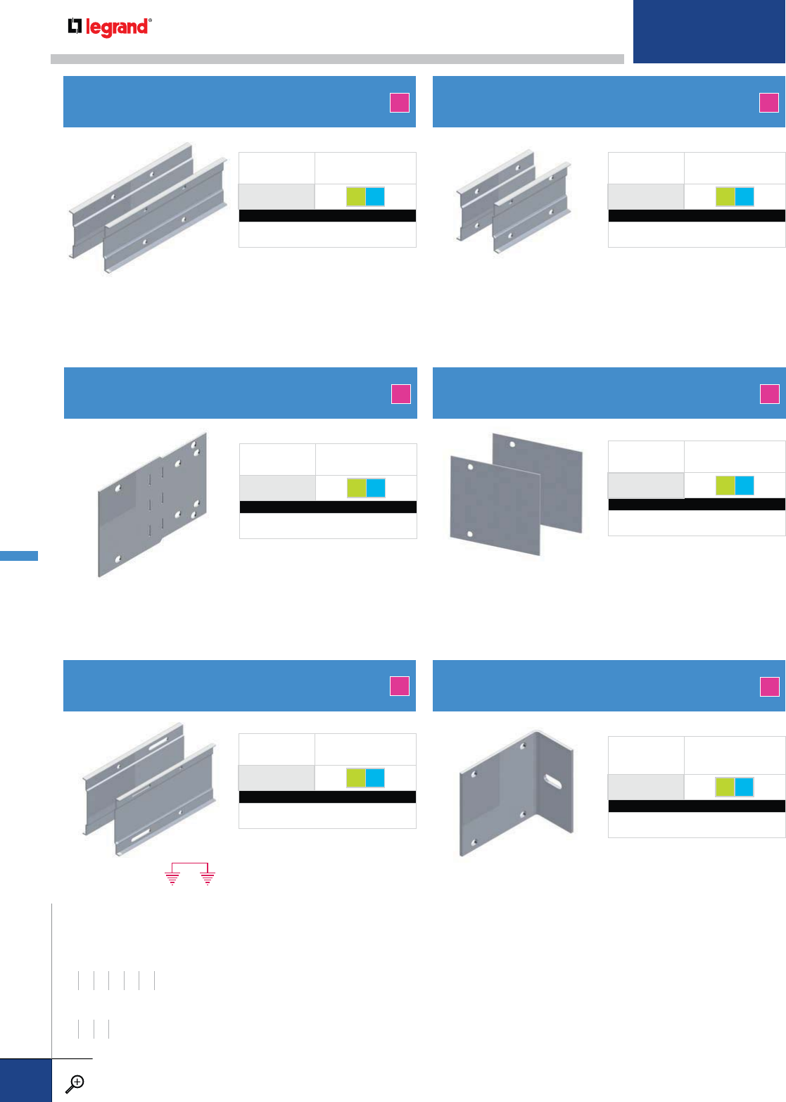
SSP
STRAIGHT SPLICE KIT
USP
UNIVERSAL SPLICE KIT
FSP
FITTING SPLICE KIT
USPB
UNIVERSAL BLANK SPLICE KIT
EXSP
EXPANSION SPLICE KIT
A
A
A
A
A
PRODUCT
CODE FASTENER OPTIONS
SSP GE S6
CATALOG NUMBERING EXAMPLE:
H / Material Fasteners
4A - SSP -S6
PRODUCT
CODE FASTENER OPTIONS
USP GE S6
CATALOG NUMBERING EXAMPLE:
H / Material Fasteners
4A - USP -GE
PRODUCT
CODE FASTENER OPTIONS
FSP GE S6
CATALOG NUMBERING EXAMPLE:
H / Material Fasteners
4A - FSP -GE
PRODUCT
CODE FASTENER OPTIONS
USPB GE S6
CATALOG NUMBERING EXAMPLE:
H / Material Fasteners
4A - USPB -S6
PRODUCT
CODE FASTENER OPTIONS
EXSP GE S6
CATALOG NUMBERING EXAMPLE:
H / Material Fasteners
4A - EXSP -S6
WIDTHS (W) INCHES
6 9 12 18 24 30 36
RAIL HEIGHTS (H) INCHES
4567
• 12" length
• Designed for splicing Itray
straight sections
• Includes splices and tray
connection hardware
• Patented design
• Designed to transition to
PW C-channel and other
I-beam systems
• Includes splices and tray
connection hardware
• Install as required P.xx or
NEMA VE-2 (see p. 61)
• Includes splices and tray
connection hardware
• Patented design
• Field drill for connection
to trays from other
manufacturers
• Includes splices and tray
connection hardware
• 6" length
• Designed for splicing Itray
fittings
• Includes splices and tray
connection hardware
• Patented design
VHSP
VERTICAL HANGER SPLICE KIT A
PRODUCT
CODE FASTENER OPTIONS
VHSP GE S6
CATALOG NUMBERING EXAMPLE:
H / Material Fasteners
4A - VHSP -GE
• For vertical tray support with
threaded rods
• Includes splices and tray
connection hardware
ITRAY – SPLICES & CONNECTORS
PW CABLE TRAY
WWW.LEGRAND.US/CABLOFIL
B.22
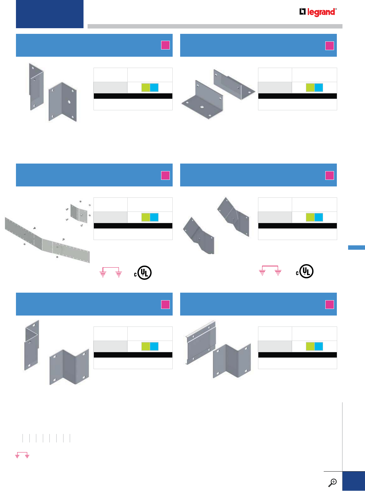
VASP
VERTICAL ADJUSTABLE SPLICE KIT
SRSP
STRAIGHT REDUCER SPLICE KIT ORSP
OFFSET REDUCER SPLICE KIT
90SP
90˚ CONNECTOR SPLICE KIT FFSP
FLOOR FLANGE SPLICE KIT
HASP
HORIZONTAL ADJUSTABLE SPLICE KIT A
A A
AA
A
PRODUCT
CODE FASTENER OPTIONS
VASP GE S6
CATALOG NUMBERING EXAMPLE:
H / Material Fasteners
4A - VASP -GE
PRODUCT
CODE FASTENER OPTIONS
SRSP GE S6
CATALOG NUMBERING EXAMPLE:
H / Material RN Fasteners
4A - SRSP - 06-GE
PRODUCT
CODE FASTENER OPTIONS
ORSP GE S6
CATALOG NUMBERING EXAMPLE:
H / Material RN Fasteners
4A - ORSP - 06 -S6
PRODUCT
CODE FASTENER OPTIONS
90SP GE S6
CATALOG NUMBERING EXAMPLE:
Rail Height / Material Fasteners
4A - 90SP -GE
PRODUCT
CODE FASTENER OPTIONS
FFSP GE S6
CATALOG NUMBERING EXAMPLE:
Rail Height / Material Fasteners
4A - FFSP -S6
PRODUCT
CODE FASTENER OPTIONS
HASP GE S6
CATALOG NUMBERING EXAMPLE:
Rail Height / Material Fasteners
4A - HASP -S6
TRAY WIDTH REDUCTION (RN) INCHES
3 6 9 121518212427
Each side
is RN/2.
• Includes 8 splice bolts for
connecting trays
• Includes splices and tray
connection hardware
• Includes splices and tray
connection hardware
• Field drill
outer splices
• Includes splices and
tray connection hardware
• Includes splices and tray
connection hardware
• Includes splices and tray
connection hardware
• Patented design
Bonding jumpers are required.
For detailed material and finish descriptions, see page B.6.
ITRAY – SPLICES & CONNECTORS
PW CABLE TRAY
WWW.LEGRAND.US/CABLOFIL
B.23
BE
BLIND END KIT
IP34
CABLE TRAY ISOLATION PAD
DIV
VERTICAL ELBOW DIVIDERS
DO
DROP OUT KIT
A
A
A
PRODUCT
CODE FASTENER OPTIONS
BE GE S6
CATALOG NUMBERING EXAMPLE:
H / Material W Fasteners
4A - BE -06-S6
PRODUCT
CODE FASTENER OPTIONS
DIV ZN S6
CATALOG NUMBERING EXAMPLE:
H / Material Elbow R Fasteners
6A - DIV -90VO-24-S6
PRODUCT
CODE FASTENER OPTIONS
DO S6
CATALOG NUMBERING EXAMPLE:
Material W Fasteners
A - DO -06-S6
PRODUCT CODE WIDTH LENGTH (FOLDED)
IP34 2.75 4
TBC
TRAY-TO-BOX CONNECTOR (FRAME TYPE) A
PRODUCT
CODE FASTENER OPTIONS
TBC GE S6
CATALOG NUMBERING EXAMPLE:
H / Material RN Fasteners
4A - TBC - 06 -S6
RHSP
REDUCING HEIGHT SPLICE KIT A
PRODUCT
CODE FASTENER OPTIONS
RHSP GE S6
CATALOG NUMBERING EXAMPLE:
H1 / H2 / Material Fasteners
5 4 A - RHSP -GE
H1 H2 OPTIONS
54--
645-
7456
WIDTHS (W) INCHES
6 9 12 18 24 30 36
RAIL HEIGHTS (H) INCHES
4567
• Includes one frame and
connection hardware
• Designed to support Itray
at connection to electrical
enclosures
• Includes one frame and
connection hardware
• Reduces vibration from industrial machinery
• Use an electrical isolation barrier or as a barrier between
dissimilar metals
• High-visibility red color is useful during inspections
• Made from durable HDPE (High-Density Polyethylene)
• Use with a hold-down clamp or as configured for an
expansion guide
• Each divider includes
two self-drilling screws
• Snaps in place over I-rung
OUTSIDE
ELBOW
INSIDE
ELBOW
RADIUS (R) INCHES
12 24 36
• Includes splices and tray
connection hardware
ITRAY – ACCESSORIES
PW CABLE TRAY
WWW.LEGRAND.US/CABLOFIL
B.24
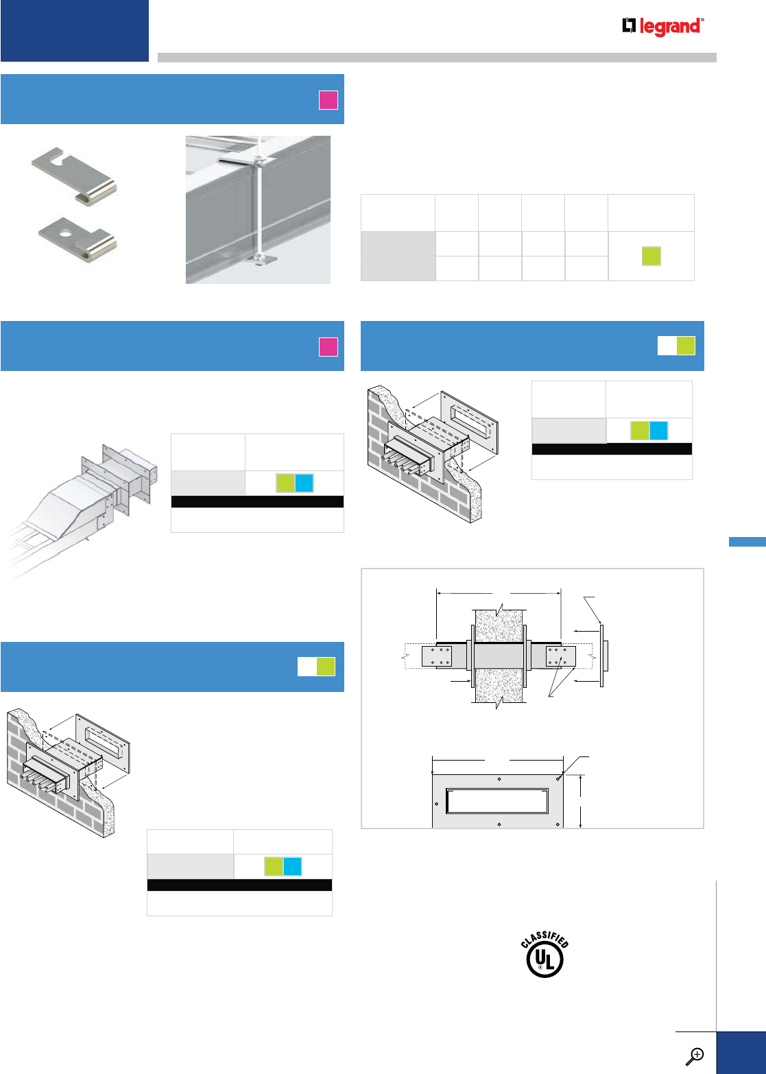
WPS
WALL PENETRATION SLEEVE
OCK
OUTDOOR CONVERSION KIT
OHCB
OVERHEAD CLAMP KIT
FWPS
FIRE WALL PENETRATION SLEEVE
A
A
PRODUCT CODE FASTENER OPTIONS
WPS GE S6
CATALOG NUMBERING EXAMPLE:
H / Material W Fasteners
4M - WPS -06-S6
PRODUCT
CODE FASTENER OPTIONS
OCK GE S6
CATALOG NUMBERING EXAMPLE:
H / Material W Fasteners
4A - OCK -06-S6
PRODUCT
CODE FASTENER OPTIONS
FWPS GE S6
CATALOG NUMBERING EXAMPLE:
H / Material W Fasteners
4G - FWPS -06-S6
PRODUCT
CODE HOLE SIZE WIDTH LENGTH
(TOP)
LENGTH
(BOTTOM) FASTENERS
OHCB38KIT .375 1.5 3.6 3
GE
OHCB12KIT .5 1.5 3.6 3
Provides a rigid support for cable
tray at wall penetrations. Overall
length of the sleeve is 20". Will
fit walls up to 8" thick. Bonding
jumpers are not required for use
with wall sleeves. Two pairs of
splice plates and fasteners are
included for tray attachment.
Each cable tray firestop sleeve includes:
• One penetration sleeve with flanges
• Hilti Fire Blocks
• One Hilti Firestop Putty Stick
• Hardware for cable tray connection to the wall sleeve
Fixed collar is
welded to sleeve
W*+6"
H*+6"
20"
7/16" diameter holes
for 3/8" hardware
(not included)
Cable trays are attached to both
ends of the sleeve using standard
splice plate connectors
Loose collar slides
over sleeve after it
is placed in the wall
SIDE VIEW
END VIEW
UL classified for use with:
2-hr concrete or block walls
2-hr concrete floors
1-hr gypsum walls
2-hr gypsum walls
Makes ladder tray wall penetrations weather resistant to
minimize water intrusions. Removable cover/shield fastens
to tray and wall penetration sleeve for the utmost in weather
protection.
MG
MG
• Wall Penetration Sleeve
(WPS or FWPS) not included
in kit, must be ordered
separately
• Steel only; aluminum not
available as it does not meet
fire rating requirements
• See pgs. B.58-59 for more
information
• Designed for trapeze hanging of Itray without drilling.
• Mounting kits available for 3/8" and ½" threaded rod
• Kit includes: eight SFHN (nuts with washers), two top
brackets, two bottom brackets. Threaded rod sold separately.
• Load rated at 1220 lbs/pair
• Can be used on fittings or straight sections of PW Itray
For detailed material and finish descriptions, see page B.6.
ITRAY – ACCESSORIES
PW CABLE TRAY
WWW.LEGRAND.US/CABLOFIL
B.25
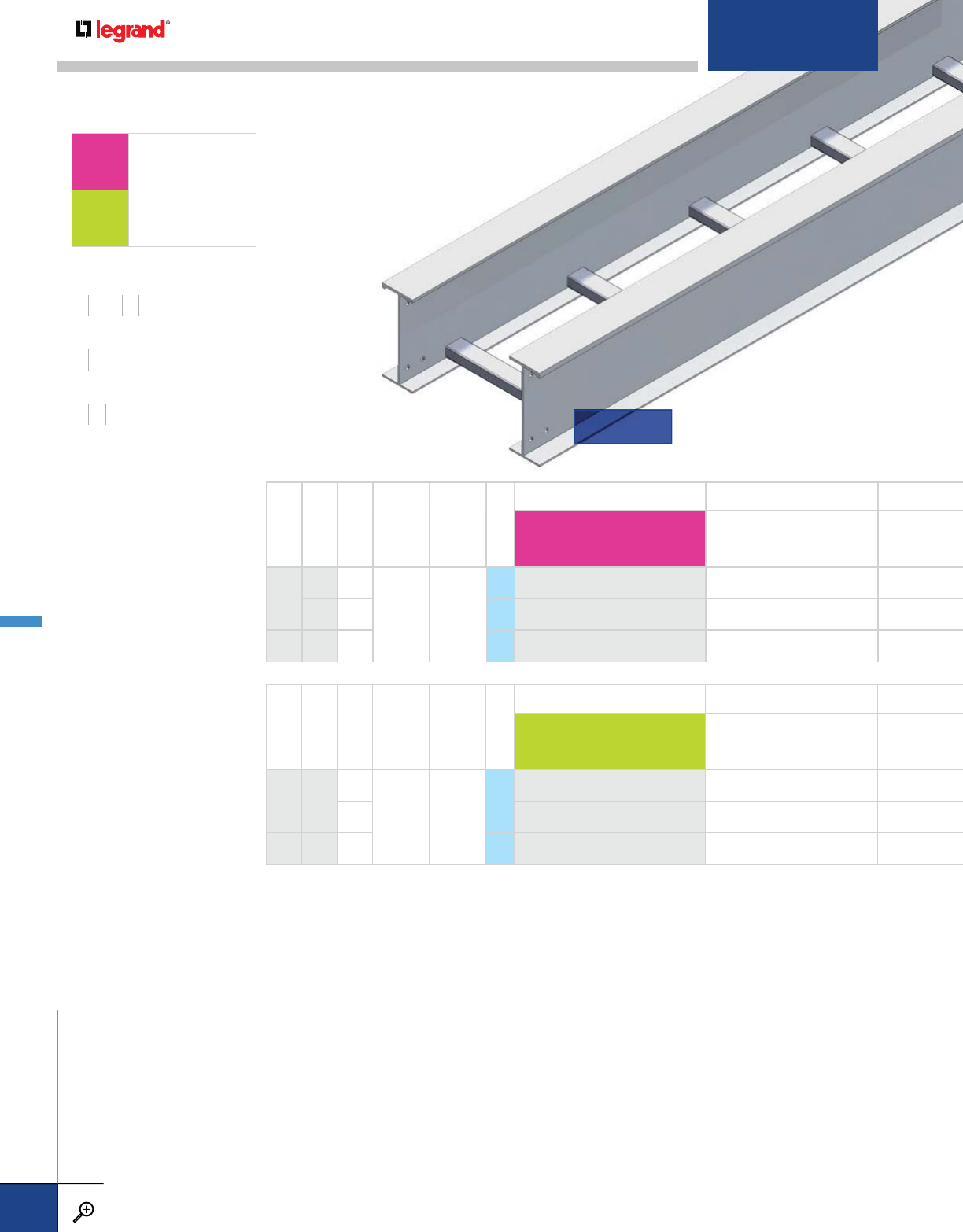
RAIL HEIGHT (IN.)
LOAD DEPTH (IN.)
RAIL FLANGE (IN.)
NEMA CLASS
CSA CLASS
SERIES
TRAY SYSTEM NUMBER AMP RATING
][
—
][
8
6* 3
20C+ E, 6M
S2 4823 2000
6* 21/2S2 4812 2000
10 6* 4 S2 4904 2000
Trays for extremely heavy loads and long spans have
I-beam side rails and are available in lengths up to 50'.
LONG-SPAN
AALUMINUM
GHOT-DIP
GALVANIZED STEEL
WIDTHS (W) INCHES
12 18 24 30 36
RAIL HEIGHTS (H) INCHES
810
LENGTHS (L) FEET
30 40 50
RAIL HEIGHT (IN.)
LOAD DEPTH (IN.)
RAIL FLANGE (IN.)
NEMA CLASS
CSA CLASS
SERIES
TRAY SYSTEM NUMBER AMP RATING
][
—
][
86*
21/4
20C+ –
S2 1952 600
4S2 1953 600
10 5 4 S2 1954†600
* 6" load depth is the maximum permissible by NEC; † Fittings not available
CONNECTORS:
Necessary connectors and
fasteners are supplied with
all tray. Extra connectors for
field cuts or spares must be
ordered separately.
SAFE LOAD:
Allowable cable load in
pounds per linear foot
uniformly distributed.
Based on tray with
standard rung on 9"
centers and supported on
simple beam with safety
factor of 1.5 per NEMA VE1.
CONCENTRATED LOAD:
All ladders will support a
200 lb. concentrated load
applied at the center of
the tray in addition to the
NEMA-rated cable load
without collapse.
E
(
IN.
)
ASS
S
S
S
T
RAY
S
Y
S
TEM N
U
MB
ER
A
MP RATIN
G
x
tremely heavy loads and long spans have
e
rails and are available in lengths up to 5
0
'.
LADDER
METALLIC STRAIGHT SECTIONS – LONG-SPAN
PW CABLE TRAY
WWW.LEGRAND.US/CABLOFIL
B.26
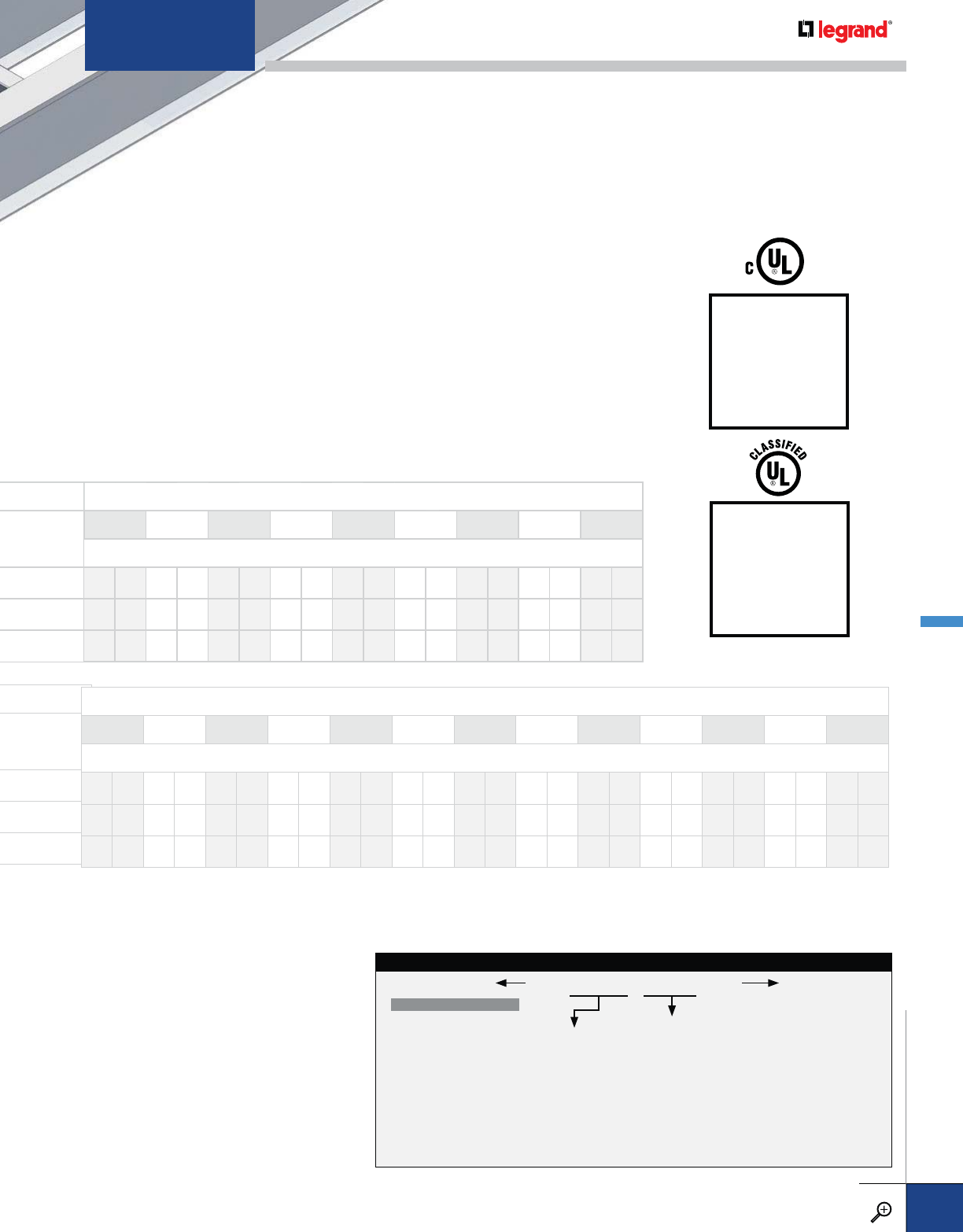
SUPPORT SPAN (FT.)
20 22 24 26 28 30 34 36 40
SAFE LOAD DATA (LBS./FT.) / DEFLECTION (IN.) / SAFETY FACTOR 1.5
270 1.88 218 2.22 179 2.58 150 2.98 127 3.39 108 3.81 76 4.44 64 4.70 48 5.31
292 2.00 236 2.37 194 2.75 162 3.17 137 3.60 117 4.05 82 4.69 69 4.97 52 5.70
400 1.15 331 1.39 278 1.66 237 1.94 204 2.25 178 2.59 138 3.32 123 3.73 100 4.60
TRAY SYSTEM
NUMBER
This identifies the
specific tray design
and is used as a
product number prefix
for straight sections.
LENGTH**
0030 – 30'-0"
0040 – 40'-0"
0050 – 50'-0"
WIDTH
12 – 12"
18 – 18"
24 – 24"
30 – 30"
36 – 36"
BOTTOM TYPE
VENTED
09 – 9" Rung Spacing*
12 – 12" Rung Spacing
18 – 18" Rung Spacing
* Standard rung spacing
** For spans shorter than 30' use 7A24C series. See page B.10.
LONG-SPAN STRAIGHT SECTION CATALOG NUMBERING EXAMPLE:
09-4823-0030-36
SUPPORT SPAN (FT.)
20 22 24 26 28 30 32 34 36 38 40 45 50
SAFE LOAD DATA (LBS./FT.) / DEFLECTION (IN.) / SAFETY FACTOR 1.5
203 0.88 167 1.06 141 1.27 120 1.49 103 1.72 90 1.98 81 2.22 68 2.47 60 2.72 54 3.06 48 3.31
360 0.98 298 1.18 250 1.41 213 1.65 184 1.92 160 2.20 139 2.47 121 2.74 107 3.05 95 3.35 85 3.69 66 4.00 51 5.37
900 1.04 744 1.26 625 1.50 533 1.77 459 2.05 400 2.35 347 2.64 304 2.95 268 3.26 238 3.60 212 3.94 164 4.87 124 5.62
SUPPORT SPAN (FT.
)
All Legrand aluminum
and steel cable trays
are Classified by
UL as equipment
grounding conductors
per NEC 392.60.
(UL File No. E60796)
Legrand trays
marked with CSA
load class have been
tested (loading, finish
and electrical) by UL
to CSA standard 126
22.2 .
For detailed material and finish descriptions, see page B.6.
METALLIC STRAIGHT SECTIONS – LONG-SPAN
PW CABLE TRAY
WWW.LEGRAND.US/CABLOFIL
B.27
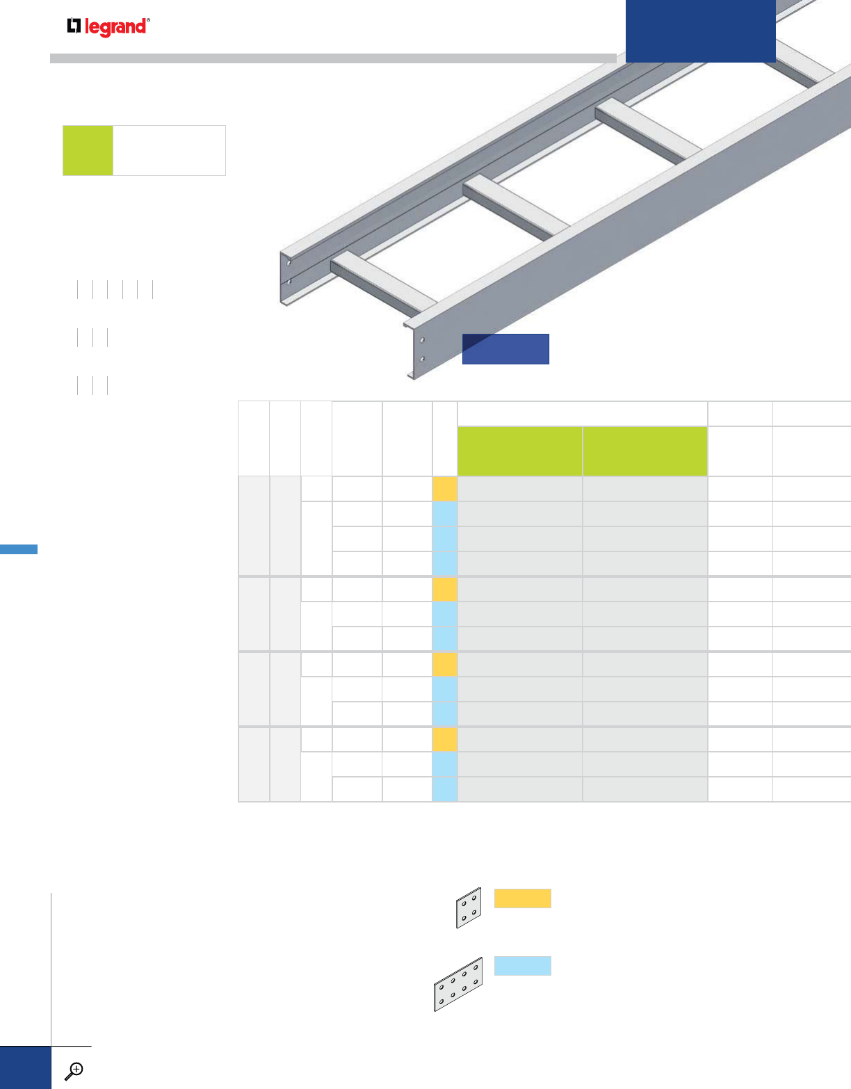
RAIL HEIGHT (IN.)
LOAD DEPTH (IN.)
RAIL FLANGE (IN.)
NEMA CLASS
CSA CLASS
SERIES
TRAY SYSTEM NUMBER AMP RATING
[
—
]]
—
[
43
112C, 16A D, 3M S1 A457 – 100
13/4
20A, 16B - S2 1D80 1D81 200
20B, 16C D, 6M S2 1D82 1D83 400
20C E, 6M S2 1D69* 1D70 400
54
1 12C, 16A D, 3M S1 1E72 – 100
13/4
20B, 16C - S2 1E45 1E46 400
20C D, 6M S2 1E53* 1E54 400
65
1 12C, 16A D, 3M S1 A639 – 100
13/4
20B, 16C E, 6M S2 1F45* 1F46 400
20C E, 6M S2 1F53* 1F54 400
76
1 12C, 16A D, 3M S1 1772 – 100
13/4
20B, 16C E, 6M S2 1755* 1756 400
20C E, 6M S2 1753 1754 400
WIDTHS (W) INCHES
6 9 12 18 24 30 36
RAIL HEIGHTS (H) INCHES
4567
LENGTHS (L) FEET
10 12 20 24
* 1D69, 1F45, and 1F53 corrugated bottom tray systems have a CSA load class D,6M rating.
1E53 and 1755 corrugated bottom tray systems do not have CSA load class ratings.
CONNECTORS & FITTINGS:
Necessary connectors and
fasteners are supplied with
all trays and fittings. Extra
connectors for field cuts
or spares must be ordered
separately.
SAFE LOAD:
Allowable cable load in
pounds per linear foot
uniformly distributed.
Based on tray with
standard rung on 9"
centers and supported on
simple beam with safety
factor of 1.5 per NEMA VE1.
CONCENTRATED LOAD:
All ladders with solid rungs
and trays with corrugated
bottoms will support a
200 lb. concentrated load
applied at the center of
the tray in addition to the
NEMA-rated cable load
without collapse.
STEEL
GHOT-DIP
GALVANIZED STEEL
SERIES1
Fitting side rails have 2" tangents (flat portion
beyond curvature) at the end of each fitting, to
accommodate splice plates with four holes.
SERIES2
Fitting side rails have 5" tangents at the end of
each fitting, to accommodate splice plates with
eight holes.
SPLICES Match above to determine the connectors you need.
LADDER
METALLIC STRAIGHT SECTIONS – STEEL
PW CABLE TRAY
WWW.LEGRAND.US/CABLOFIL
B.28
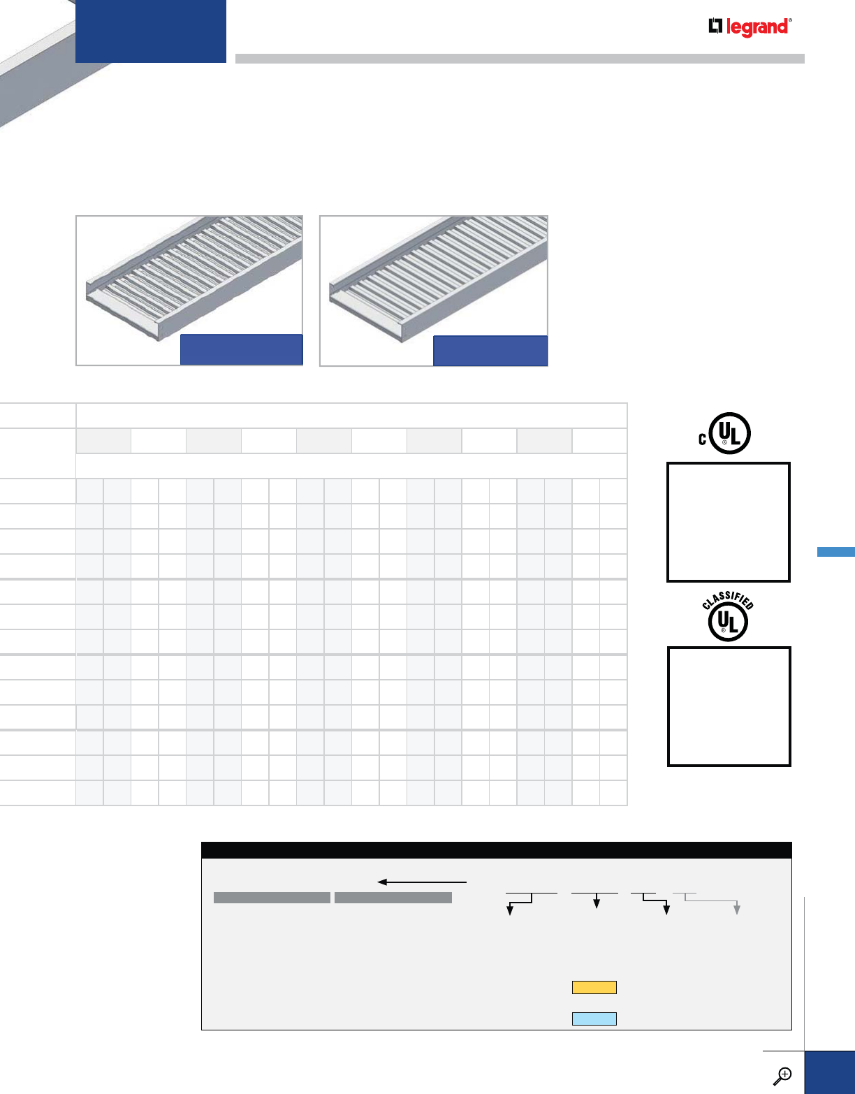
TRAY SYSTEM
NUMBER
This identifies the
specific tray design
and is used as a
product number prefix
for straight sections.
LENGTH
0010 – 10'-0"
0012* – 12'-0"
0020† – 20'-0"
0024 – 24'-0"
* Standard for
SERIES 1
† Standard for
SERIES 2
WIDTH
06 – 6"
09 – 9"
12 – 12"
18 – 18"
24 – 24"
30 – 30"
36 – 36"
RUNG OPTION
Add suffix for
non-standard rung.
See page B.63 for
details and other rung
options.
BOTTOM TYPE
STEEL STRAIGHT SECTION CATALOG NUMBERING EXAMPLE:
09-A457-0012-36-
PRODUCT NO.SYSTEM NO.
NON-VENTED
SC† – Solid Corrugated
* Standard rung spacing
† Not available for
flange out tray
VENTED
06 – 6" Rung Spacing
09 – 9" Rung Spacing*
12 – 12" Rung Spacing
18 – 18" Rung Spacing**
VC† – Vented Corrugated
SUPPORT SPAN (FT.)
6 8 10 12 14 16 18 20 22 24
SAFE LOAD DATA (LBS./FT.) / DEFLECTION (IN.) / SAFETY FACTOR 1.5
439 0.31 250 0.55 160 0.86 111 1.24 78 1.61 58 2.06
439 0.20 338 0.51 216 0.79 150 1.14 110 1.55 84 2.02 67 2.56 54 3.16 44 3.74 34 4.07
439 0.16 439 0.50 312 0.88 217 1.26 159 1.72 122 2.25 96 2.84 78 3.51 63 4.18 52 4.87
439 0.39 400 0.87 278 1.25 204 1.70 156 2.21 123 2.80 100 3.46 81 4.09 66 4.77
400 0.21 225 0.38 144 0.59 100 0.85 71 1.13 52 1.40
439 0.11 439 0.37 304 0.62 211 0.90 155 1.22 119 1.59 94 2.02 76 2.49 61 2.92 50 3.38
439 0.34 400 0.75 278 1.08 204 1.47 156 1.92 123 2.43 100 3.00 81 3.54 60 4.13
420 0.13 236 0.22 151 0.35 105 0.50 74 0.65 55 0.83
439 0.08 439 0.25 336 0.47 233 0.68 171 0.92 131 1.20 104 1.52 84 1.88 68 2.24 53 2.47
439 0.20 439 0.50 319 0.75 235 1.02 180 1.34 142 1.69 115 2.09 93 2.48 73 2.75
400 0.10 225 0.18 144 0.28 100 0.40 71 0.53 52 0.66
439 0.07 439 0.22 300 0.38 208 0.54 153 0.73 117 0.96 93 1.22 75 1.50 61 1.79 50 2.08
439 .017 439 0.42 319 0.63 235 0.86 180 1.12 142 1.42 115 1.75 93 2.11 76 2.52
All Legrand steel
cable trays are
Classified by UL as
equipment grounding
conductors per NEC
392.60. (UL File No.
E60796)
Legrand trays
marked with CSA
load class have been
tested (loading, finish
and electrical) by UL
to CSA standard 126
22.2 .
VENTED CORRUGATED SOLID CORRUGATED
For detailed material and finish descriptions, see page B.6.
METALLIC STRAIGHT SECTIONS – STEEL
PW CABLE TRAY
WWW.LEGRAND.US/CABLOFIL
B.29
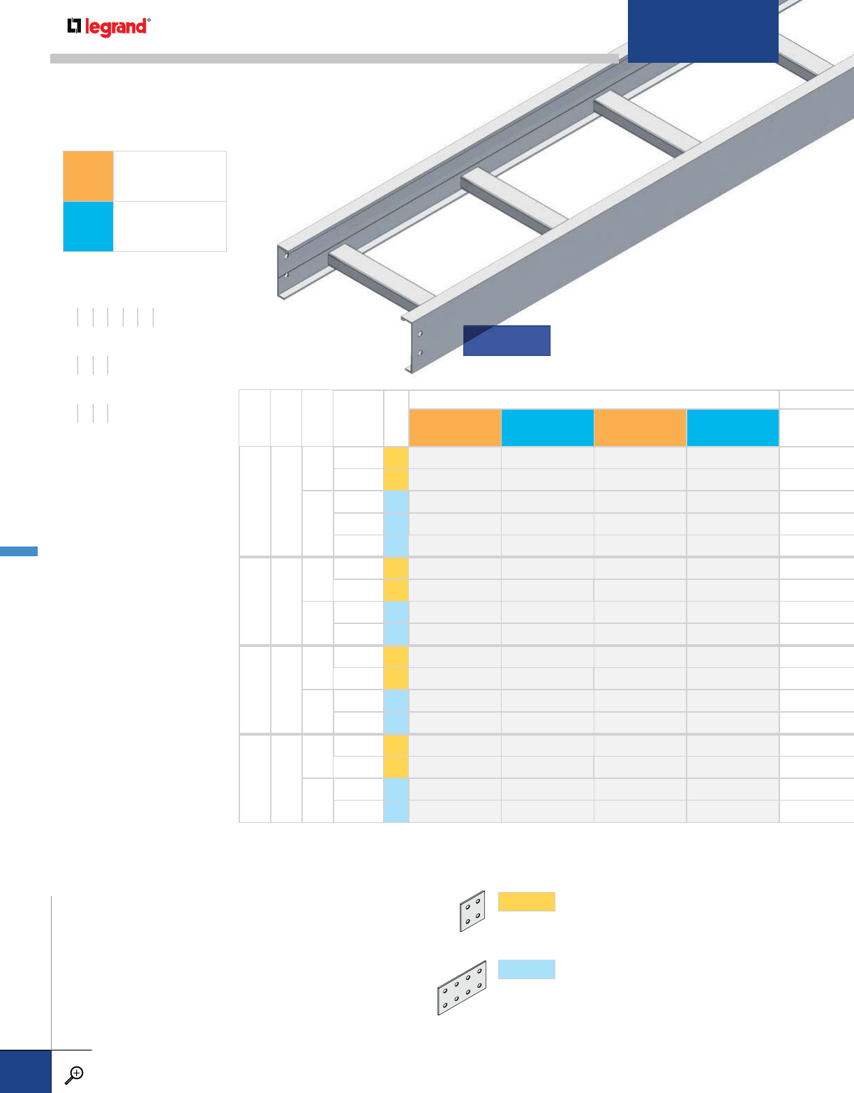
RAIL HEIGHT
(IN.)
LOAD DEPTH
(IN.)
RAIL FLANGE
(IN.)
NEMA CLASS
SERIES
TRAY SYSTEM NUMBER
[
—
][
—
]]
—
[ ]
—
[
43
112B S1 3408 3416 ––
12C, 16A S1 3409 3417 ––
13/4
20A, 16B S2 3476 3D85 3D63 3D82
20B, 16C S2 3456 3D92 3D93 3D58
20C S2 3406 3445 3407 3446
54
112B S1 3504 3514 ––
12C, 16A S1 3505 3515 ––
13/4
20B, 16C S2 3551 3594 3550 3582
20C S2 3587 3593 3592 3583
65
112B S1 3603 3620 ––
12C, 16A S1 3604 3621 ––
13/4
20B, 16C S2 3F67 3F85 3F68 3F66
20C S2 3645 3F35 3F58 3F61
76
112B S1 3734 3738 ––
12C, 16A S1 3735 3739 ––
13/4
20B, 16C S2 3701 3723 3754 3756
20C S2 3714 3724 3722 3760
WIDTHS (W) INCHES
6 9 12 18 24 30 36
RAIL HEIGHTS (H) INCHES
4567
LENGTHS (L) FEET
10 12 20 24
CONNECTORS & FITTINGS:
Necessary connectors and
fasteners are supplied with
all trays and fittings. Extra
connectors for field cuts
or spares must be ordered
separately.
SAFE LOAD:
Allowable cable load in
pounds per linear foot
uniformly distributed.
Based on tray with
standard rung on 9"
centers and supported on
simple beam with safety
factor of 1.5 per NEMA VE1.
CONCENTRATED LOAD:
All ladders with solid rungs
and trays with corrugated
bottoms will support a
200 lb. concentrated load
applied at the center of
the tray in addition to the
NEMA-rated cable load
without collapse.
STAINLESS
STEEL
LSTAINLESS STEEL
AISI Type 304L
TSTAINLESS STEEL
AISI Type 316L
SERIES1
Fitting side rails have 2" tangents (flat portion
beyond curvature) at the end of each fitting, to
accommodate splice plates with four holes.
SERIES2
Fitting side rails have 5" tangents at the end of
each fitting, to accommodate splice plates with
eight holes.
SPLICES Match above to determine the connectors you need.
LADDER
METALLIC STRAIGHT SECTIONS – STAINLESS STEEL
PW CABLE TRAY
WWW.LEGRAND.US/CABLOFIL
B.30
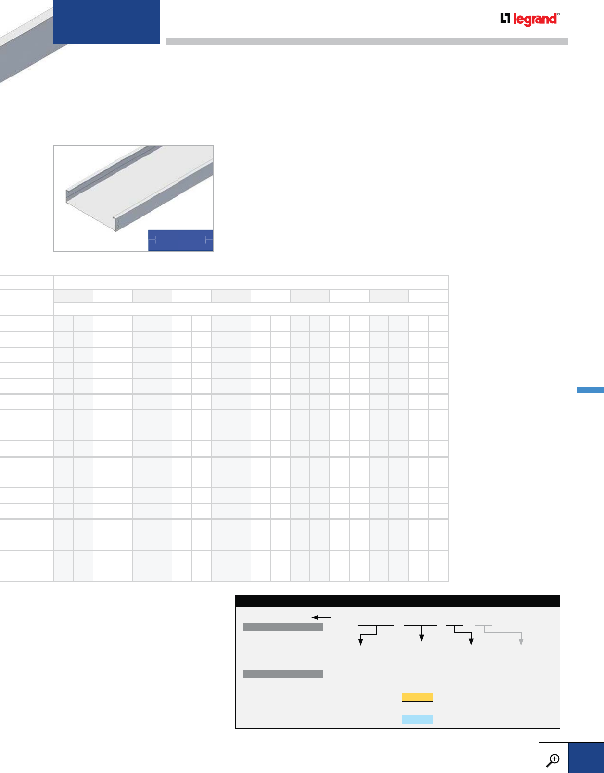
SUPPORT SPAN (FT.)
6 8 10 12 14 16 18 20 22 24
SAFE LOAD DATA (LBS./FT.) / DEFLECTION (IN.) / SAFETY FACTOR 1.5
300 0.30 169 0.54 108 0.85 75 1.22
400 0.32 225 0.57 144 0.90 100 1.29 71 1.71 52 2.13
556 0.31 313 0.55 200 0.86 139 1.24 102 1.69 78 2.20 62 2.79 50 3.44
564 0.24 469 0.62 300 0.97 208 1.39 153 1.89 117 2.47 93 3.13 75 3.70 86 4.60 48 5.13
564 0.54 400 0.94 278 1.36 204 1.85 156 2.41 123 3.05 100 3.77 81 4.45 63 4.96
300 0.20 169 0.35 108 0.55 75 0.79
400 0.23 225 0.41 144 0.64 100 0.93 71 1.23 52 1.53
564 0.16 469 0.42 300 0.66 208 0.95 153 1.29 117 1.69 93 2.14 75 2.64 61 3.14 48 3.51
564 0.46 400 0.80 278 1.16 204 1.57 156 2.05 123 2.60 100 3.21 81 3.79 63 4.22
300 0.11 169 0.20 108 0.31 75 0.45
400 0.14 225 0.24 144 0.38 100 0.54 71 0.71 52 0.89
564 0.12 469 0.32 300 0.51 208 0.73 153 0.99 117 1.30 93 1.64 75 2.03 61 2.42 48 2.70
564 0.31 400 0.54 278 0.77 204 1.05 156 1.38 123 1.74 100 2.15 81 2.54 63 2.83
300 0.10 169 0.17 108 0.27 75 0.39
400 0.11 225 0.19 144 0.30 100 0.43 71 0.57 52 0.71
564 0.10 469 0.26 300 0.41 208 0.58 153 0.79 117 1.04 93 1.31 75 1.62 61 1.93 48 2.15
564 0.28 400 0.48 278 0.69 204 0.93 156 1.22 123 1.55 100 1.91 81 2.05 63 2.28
TRAY SYSTEM
NUMBER
This identifies the
specific tray design
and is used as a
product number prefix
for straight sections.
LENGTH
0010 – 10'-0"
0012* – 12'-0"
0020† – 20'-0"
0024 – 24'-0"
* Standard for
SERIES 1
† Standard for
SERIES 2
WIDTH
06 – 6"
09 – 9"
12 – 12"
18 – 18"
24 – 24"
30 – 30"
36 – 36"
RUNG OPTION
Add suffix for
non-standard rung.
See page B.63 for
details and other rung
options.
BOTTOM TYPE
VENTED
06 – 6" Rung Spacing
09 – 9" Rung Spacing*
12 – 12" Rung Spacing
18 – 18" Rung Spacing
NON-VENTED
SF† – Solid Flat Bottom
* Standard rung spacing
† Not available with
flange out tray
STAINLESS STEEL STRAIGHT SECTION CATALOG NUMBERING EXAMPLE:
09-3620-0012-18-
SOLID BOTTOM
BO
TT
OM
SOLID
For detailed material and finish descriptions, see page B.6.
METALLIC STRAIGHT SECTIONS – STAINLESS STEEL
PW CABLE TRAY
WWW.LEGRAND.US/CABLOFIL
B.31
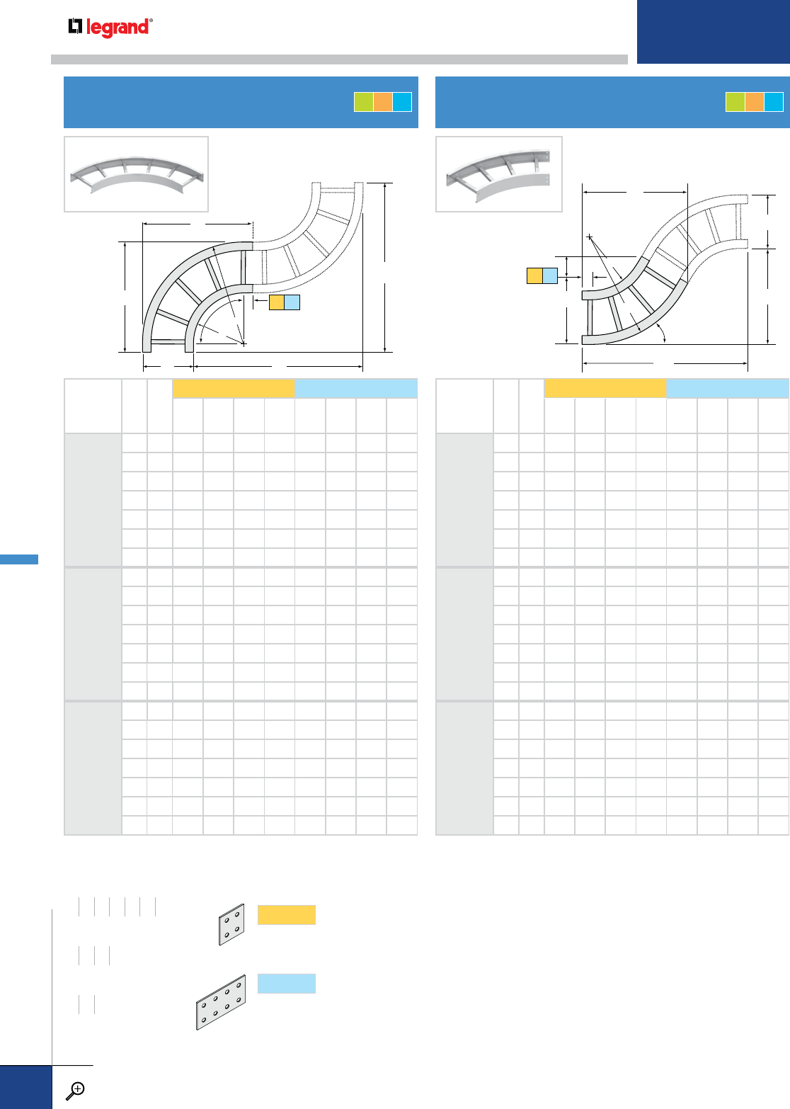
HORIZONTAL 90˚ ELBOW HORIZONTAL 60˚ ELBOW
A
C
B
D
W
R
R
90˚ 2
A
C
BD
W
R
60˚
R2
PRODUCT
NUMBER
RADIUS (IN.)
WR2
SERIES1 SERIES2
ABCDABCD
9012
12"
6182020343423234040
9212323373726264343
12 24 26 26 40 40 29 29 46 46
18 30 32 32 46 46 35 35 52 52
24 36 38 38 52 52 41 41 58 58
30 42 44 44 58 58 47 47 64 64
36 48 50 50 64 64 53 53 70 70
9024
24"
6303232585835356464
9333535616138386767
12 36 38 38 64 64 41 41 70 70
18 42 44 44 70 70 47 47 76 76
24 48 50 50 76 76 53 53 82 82
30 54 56 56 82 82 59 59 88 88
36 60 62 62 88 88 65 65 94 94
9036
36"
6424444828247478888
9454747858550509191
12 48 50 50 88 88 53 53 94 94
18 54 56 56 94 94 59 59 100 100
24 60 62 62 100 100 65 65 106 106
30 66 68 68 106 106 71 71 112 112
36 72 74 74 112 112 77 77 118 118
PRODUCT
NUMBER
RADIUS (IN.)
WR2
SERIES1 SERIES2
ABCDABCD
6012
12"
61818
5/8133/432 181/2231/8163/841 233/4
92121
1/4163/4345/820 255/8193/8431/2251/4
12 24 233/4193/4371/8211/2283/8223/8461/4263/4
18 30 29 253/4423/8241/2331/2283/8513/8293/4
24 36 341/8313/4471/2271/2385/8343/8561/2323/4
30 42 393/8373/4523/4301/2437/8403/8613/4353/4
36 48 441/2433/4577/8331/249 463/8667/8383/4
6024
24"
6302919
3/4523/4301/2331/2223/8613/4353/4
93331
5/8223/4553/832 361/8253/8643/8371/4
12 36 341/8253/4577/8331/2383/4283/867 383/4
18 42 393/8313/4631/8361/2437/8343/8721/8413/4
24 48 441/2373/4681/4391/2491/8403/8773/8443/4
30 54 493/4433/4731/2421/2541/8463/8825/8473/4
36 60 547/8493/4785/8451/2593/8523/8873/4503/4
6036
36"
64239
3/8253/4731/2421/2437/8283/8821/2473/4
9454228
3/4761/844 461/2313/8851/8491/4
12 48 441/2313/4785/8451/2491/8343/8873/4503/4
18 54 493/4373/4837/8481/2541/4403/8927/8533/4
24 60 547/8433/489 511/2591/2463/8981/8563/4
30 66 601/8493/4941/4541/2643/4523/81033/8593/4
36 72 651/4553/4993/8571/2697/8583/81081/2623/4
S1 S2
S1 S2
WIDTHS (W) INCHES
6 9 12 18 24 30 36
RAIL HEIGHTS (H) INCHES
4567
RADIUS (R) INCHES
12 24 36
SERIES1
Fitting side rails have 2" tangents (flat portion
beyond curvature) at the end of each fitting, to
accommodate splice plates with four holes.
SERIES2
Fitting side rails have 5" tangents at the end of
each fitting, to accommodate splice plates with
eight holes.
SPLICES Match above to determine the connectors you need.
GLT GLT
METALLIC FITTINGS
PW CABLE TRAY
WWW.LEGRAND.US/CABLOFIL
B.32
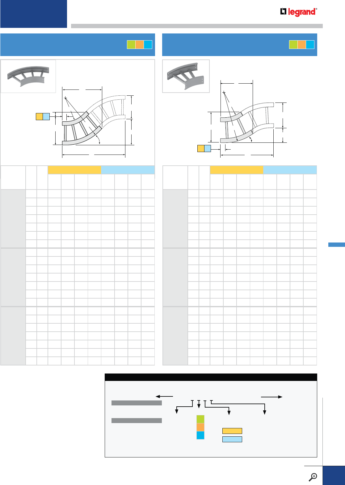
HORIZONTAL 45˚ ELBOW HORIZONTAL 30˚ ELBOW
A
C
BD
W
R
45˚
2
R
A
C
B
D
W
R
30˚
R2
PRODUCT
NUMBER
RADIUS (IN.)
WR2
SERIES1 SERIES2
ABCDABCD
4512
12"
61816
1/8107/828 115/8211/4131/8383/816
92118
1/4137/8301/8121/2233/8161/8401/2167/8
12 24 203/8167/8321/4133/8251/2191/8425/8173/4
18 30 245/8227/8361/2151/8293/4251/8467/8191/2
24 36 287/8287/8403/4163/434 311/8511/8211/4
30 42 331/8347/845 181/2381/4371/8553/823
36 48 373/8407/8491/4201/4421/2431/8595/8243/4
4524
24"
63024
5/8141/245 183/4293/4165/8551/423
93326
3/4171/2471/8195/8317/8195/8573/8233/4
12 36 287/8201/2491/4201/234 225/8591/2243/4
18 42 331/8261/2531/2221/4381/4285/8633/4263/8
24 48 373/8321/2573/4237/8421/2345/868 281/4
30 54 415/8381/262 255/8463/4405/8721/430
36 60 457/8441/2661/4273/851 465/8761/2313/4
4536
36"
64233
1/8181/862 257/8381/4201/8721/4297/8
94535
1/4211/8641/8263/4403/8231/8743/8303/4
12 48 373/8241/8661/4275/8421/2261/8761/2313/4
18 54 415/8301/8701/2293/8463/4321/8803/4333/8
24 60 457/8361/8743/431 51 381/885 351/4
30 66 501/8421/879 323/4551/4441/8891/437
36 72 543/8481/8831/4341/2591/2501/8931/2383/4
PRODUCT
NUMBER
RADIUS (IN.)
WR2
SERIES1 SERIES2
ABCDABCD
3012
12"
61812
3/485/8221/2618
3/8101/8333/49
92114
1/4115/824 63/8197/8131/8351/491/2
12 24 153/4145/8251/267/8213/8161/8363/497/8
18 30 183/4205/8281/275/8243/8221/8393/4105/8
24 36 213/4265/8311/283/8273/8281/8423/4111/2
30 42 243/4325/8341/291/4303/8341/8453/4123/8
36 48 273/4385/8371/210 333/8401/8483/4131/8
3024
24"
63018
3/4101/4341/291/4243/8113/4453/4121/4
93320
1/4131/436 95/8257/8143/4471/4125/8
12 36 213/4161/4371/2101/8273/8173/4483/413
18 42 243/4221/4401/2107/8303/8233/4513/4137/8
24 48 273/4281/4431/2115/8333/8293/4543/4145/8
30 54 303/4341/4461/2121/2363/8353/4573/4153/8
36 60 333/4401/4491/2131/4393/8413/4603/4161/4
3036
36"
64224
3/4117/8461/2121/2303/8133/8573/4151/2
94526
1/4147/848 127/8317/8163/8591/4157/8
12 48 273/4177/8491/2133/8333/8193/8603/4161/4
18 54 303/4237/8521/2141/8363/8253/8633/417
24 60 333/4297/8551/2147/8393/8313/8663/4177/8
30 66 363/4357/8581/2153/4423/8373/8693/4183/4
36 72 393/4417/8611/2161/2453/8433/8723/4191/2
S1 S2
S1 S2
HORIZONTAL ELBOW CATALOG NUMBERING EXAMPLE:
LD-6G2O-9012-24
FITTING
SERIES
1 - SERIES 1
2 - SERIES 2
FLANGE
DIRECTION
I – Flange In
O – Flange Out
SIDE RAIL
HEIGHT
4 – 4"
5 – 5"
6 – 6"
7 – 7"
MATERIAL
G
L
T
BOTTOM TYPE
VENTED
LD – Ladder
VC† – Vented Corrugated
NON-VENTED
SC† – Solid Corrugated
SF† – Solid Flat Bottom
† Not available for flange out tray
WIDTH
06 – 6"
09 – 9"
12 – 12"
18 – 18"
24 – 24"
30 – 30"
36 – 36"
PRODUCT NO.
FITTING
SYSTEM NO.
GLT GLT
For detailed material and finish descriptions, see page B.6.
METALLIC FITTINGS
PW CABLE TRAY
WWW.LEGRAND.US/CABLOFIL
B.33
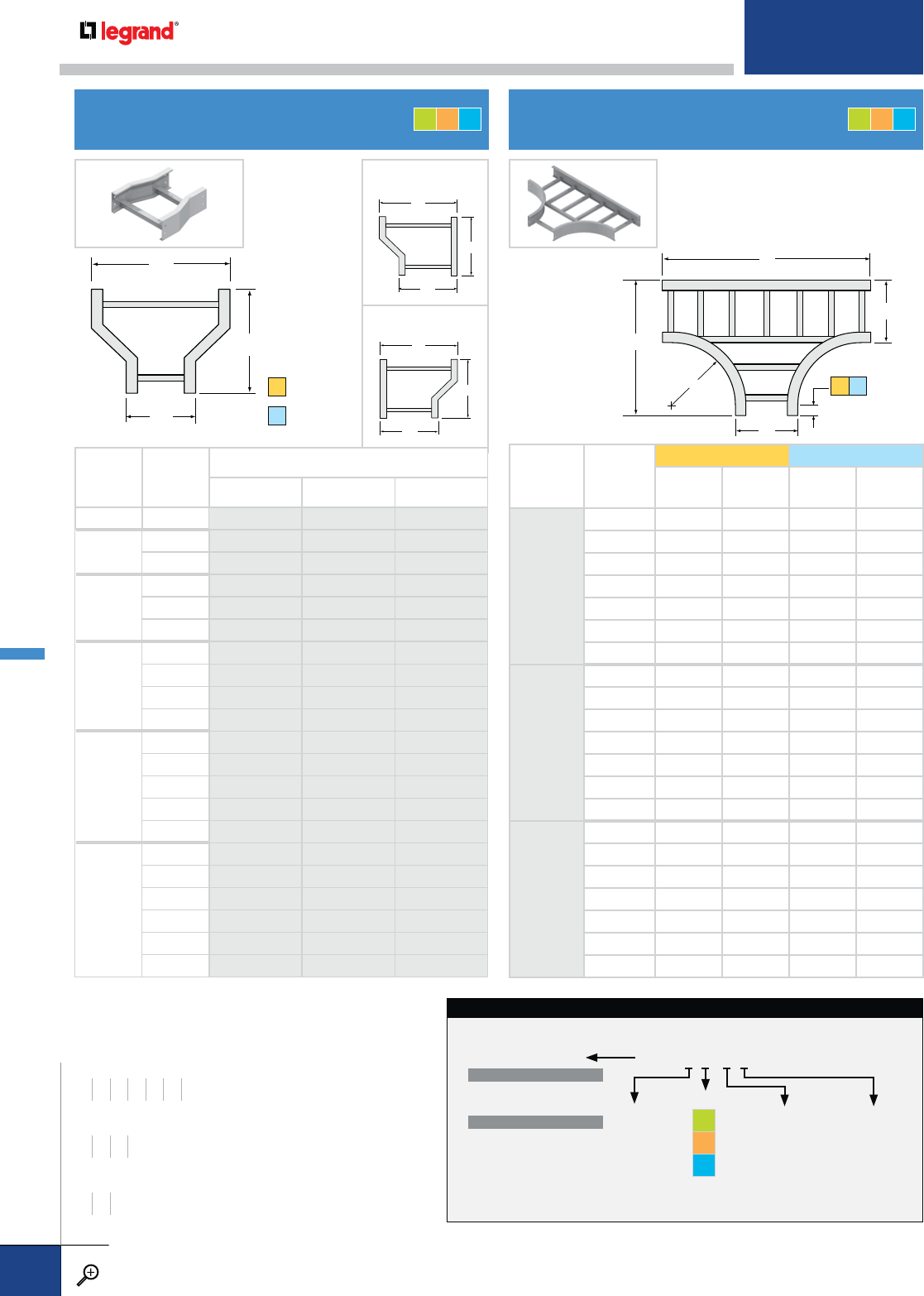
HORIZONTAL REDUCERS HORIZONTAL STANDARD TEE
L
W
W1
2
L
W
W1
2
A
B
W
R
W
LEFT HAND
RIGHT HAND
MAIN
WIDTH (IN.)
W1
BRANCH
WIDTH (IN.)
W2
PRODUCT NUMBER
STRAIGHT LEFT HAND RIGHT HAND
96 0109 0709 0809
12 60112 0712 0812
90112 0712 0812
18
60118 0718 0818
90118 0718 0818
12 0118 0718 0818
24
60124 0724 0824
90124 0724 0824
12 0124 0724 0824
18 0124 0724 0824
30
60130 0730 0830
90130 0730 0830
12 0130 0730 0830
18 0130 0730 0830
24 0130 0730 0830
36
60136 0736 0836
90136 0736 0836
12 0136 0736 0836
18 0136 0736 0836
24 0136 0736 0836
30 0136 0736 0836
W
W
L
1
2
HORIZONTAL REDUCERS CATALOG NUMBERING EXAMPLE:
LD-6G2O-0109-06
FITTING
SERIES
1 – Series 1
2 – Series 2
FLANGE
DIRECTION
I – Flange In
O – Flange Out
SIDE RAIL
HEIGHT
4 – 4"
5 – 5"
6 – 6"
7 – 7"
MATERIAL
G
L
T
BOTTOM TYPE
VENTED
LD – Ladder
VC† – Vented Corrugated
NON-VENTED
SC† – Solid Corrugated
SF† – Solid Flat Bottom
† Not available for flange out tray
BRANCH WIDTH
PRODUCT NO.
FITTING
SYSTEM NO.
LENGTH (L)
INCHES
S1 12
S2 18
STRAIGHT REDUCER
PRODUCT
NUMBER
RADIUS (IN.)
W
SERIES1 SERIES2
ABAB
2012
12"
6 34204023
9 37234326
12 40 26 46 29
18 46 32 52 35
24 52 38 58 41
30 58 44 64 47
36 64 50 70 53
2024
24"
6 58326435
9 61356738
12 64 38 70 41
18 70 44 76 47
24 76 50 82 53
30 82 56 88 59
36 88 62 94 65
2036
36"
6 82448847
9 85479150
12 88 50 94 53
18 94 56 100 59
24 100 62 106 65
30 106 68 112 71
36 112 74 118 77
S1 S2
WIDTHS (W) INCHES
6 9 12 18 24 30 36
RAIL HEIGHTS (H) INCHES
4567
RADIUS (R) INCHES
12 24 36
GLT GLT
METALLIC FITTINGS
PW CABLE TRAY
WWW.LEGRAND.US/CABLOFIL
B.34
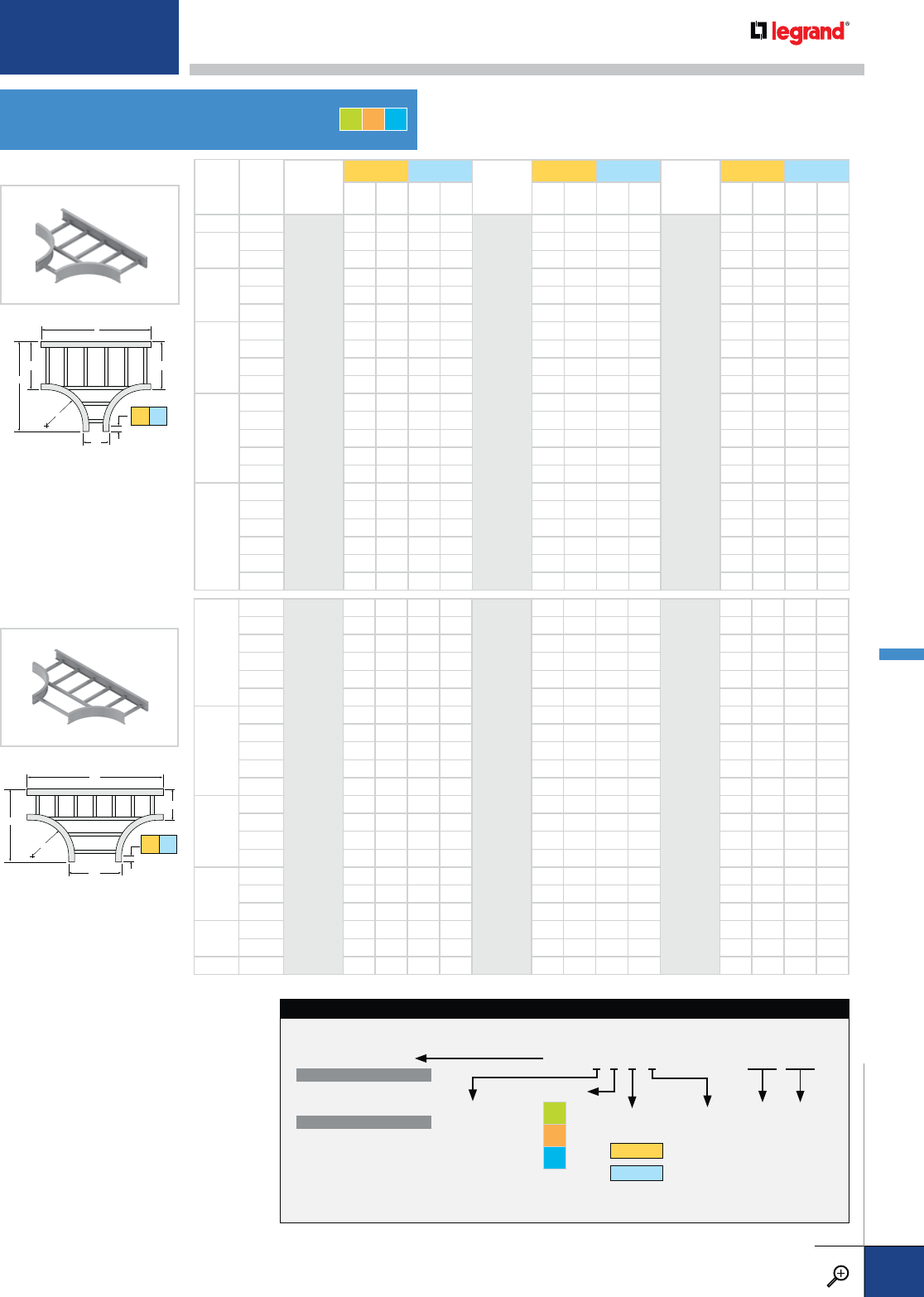
HORIZONTAL REDUCING/
EXPANDING TEES
REDUCING TEE
EXPANDING TEE
A
B
W
R
W1
2
A
B
W
R
W1
2
W1
6
9
2012
12"
37 20 43 23
2024
24"
61 32 67 35
2036
36"
85 44 91 47
12 40 20 46 23 64 32 70 35 88 44 94 47
18 46 20 52 23 70 32 76 35 94 44 100 47
24 52 20 58 23 76 32 82 35 100 44 106 47
30 58 20 64 23 82 32 88 35 106 44 112 47
36 64 20 70 23 88 32 94 35 112 44 118 47
9
12 40 23 46 26 64 35 70 38 88 47 94 50
18 46 23 52 26 70 35 76 38 94 47 100 50
24 52 23 58 26 76 35 82 38 100 47 106 50
30 58 23 64 26 82 35 88 38 106 47 112 50
36 64 23 70 26 88 35 94 38 112 47 118 50
12
18 46 26 52 29 70 38 76 41 94 50 100 53
24 52 26 58 29 76 38 82 41 100 50 106 53
30 58 26 64 29 82 38 88 41 106 50 112 53
36 64 26 70 29 88 38 94 41 112 50 118 53
18
24 52 32 58 35 76 44 82 47 100 56 106 59
30 58 32 64 35 82 44 88 47 106 56 112 59
36 64 32 70 35 88 44 94 47 112 56 118 59
24 30 58 38 64 41 82 50 88 53 106 62 112 65
36 64 38 70 41 88 50 94 53 112 62 118 65
30 36 64 44 70 47 88 56 94 59 112 68 118 71
MAIN
WIDTH
W1
BRANCH
WIDTH
W2
PRODUCT
NUMBER
RADIUS (IN.)
SERIES1 SERIES2 PRODUCT
NUMBER
RADIUS (IN.)
SERIES1 SERIES2 PRODUCT
NUMBER
RADIUS (IN.)
SERIES1 SERIES2
ABAB ABAB ABAB
96
2012
12"
34 23 40 26
2024
24"
58 35 64 38
2036
36"
82 47 88 50
12 6 34264029 58386441 82508853
9 37264329 61386741 85509153
18
6 34324035 58446447 82568859
9 37324335 61446747 85569159
12 40 32 46 35 64 44 70 47 88 56 94 59
24
6 34384041 58506453 82628865
9 37384341 61506753 85629165
12 40 38 46 41 64 50 70 53 88 62 94 65
18 46 38 52 41 70 50 76 53 94 62 100 65
30
6 34444047 58566459 82688871
9 37444347 61566759 85689171
12 40 44 46 47 64 56 70 59 88 68 94 71
18 46 44 52 47 70 56 76 59 94 68 100 71
24 52 44 58 47 76 56 82 59 100 68 106 71
36
6 34504053 58626465 82748877
9 37504353 61626765 85749177
12 40 50 46 53 64 62 70 65 88 74 94 77
18 46 50 52 53 70 62 76 65 94 74 100 77
24 52 50 58 53 76 62 82 65 100 74 106 77
30 58 50 64 53 82 62 88 65 106 74 112 77
REDUCING TEE CATALOG NUMBERING EXAMPLE:
LD-6G2O-2012-2412†
FITTING
SERIES
1 - SERIES 1
2 - SERIES 2
FLANGE
DIRECTION
I – Flange In
O – Flange Out
SIDE RAIL
HEIGHT
4 – 4"
5 – 5"
6 – 6"
7 – 7"
MATERIAL
G
L
T
W1 (W2)
06 – 6"
09 – 9"
12 – 12"
18 – 18"
24 – 24"
30 – 30"
36 – 36"
PRODUCT NO.
FITTING
SYSTEM NO.
† W2 applies only to reducing
and expanding tees.
BRANCH
WIDTH
MAIN
WIDTH
BOTTOM TYPE
VENTED
LD – Ladder
VC† – Vented Corrugated
NON-VENTED
SC† – Solid Corrugated
SF† – Solid Flat Bottom
† Not available for flange out tray
S1 S2
S1 S2
GLT
For detailed material and finish descriptions, see page B.6.
METALLIC FITTINGS
PW CABLE TRAY
WWW.LEGRAND.US/CABLOFIL
B.35
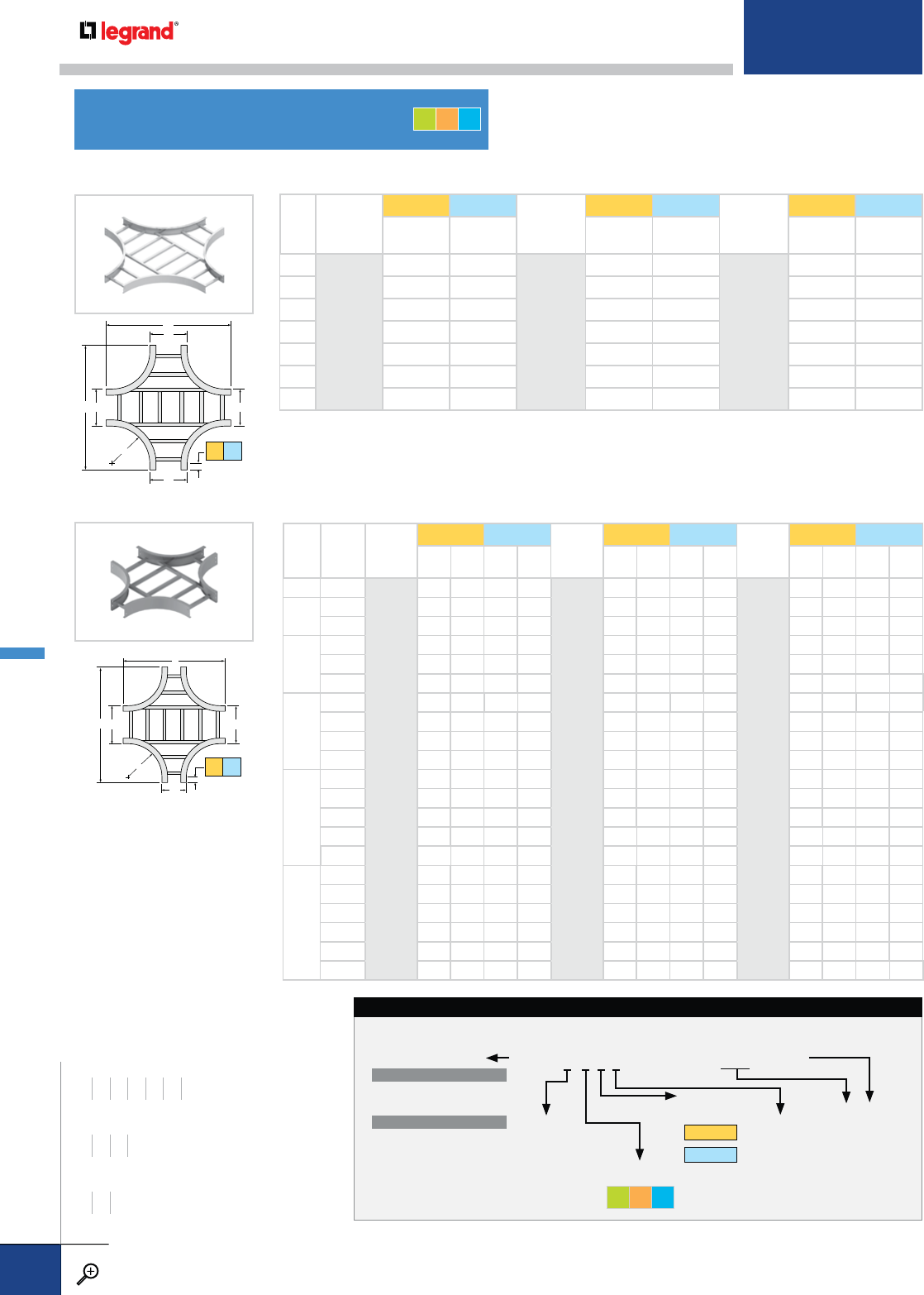
W
PRODUCT
NUMBER
RADIUS (IN.)
SERIES 1 SERIES 2 PRODUCT
NUMBER
RADIUS (IN.)
SERIES 1 SERIES 2 PRODUCT
NUMBER
RADIUS (IN.)
SERIES 1 SERIES 2
AA AA AA
6
1012
12"
34 40
1024
24"
58 64
1036
36"
82 88
9 3743 6167 8591
12 40 46 64 70 88 94
18 46 52 70 76 94 100
24 52 58 76 82 100 106
30 58 64 82 88 106 112
36 64 70 88 94 112 118
A
A
W
R
W
W
W
A
B
W
R
W1
2
W1
MAIN
WIDTH
W1
BRANCH
WIDTH
W2
PROD.
NUM.
RADIUS
SERIES 1 SERIES 2 PROD.
NUM.
RADIUS
SERIES 1 SERIES 2 PROD.
NUM.
RADIUS
SERIES 1 SERIES 2
ABAB ABAB ABAB
96
1012
12"
34 37 40 43
1024
24"
58 61 64 67
1036
36"
82 85 88 91
12 6 34404046 58646470 82888894
9 37404346 61646770 85889194
18
6 34464052 58706476 829488100
9 37464352 61706776 859491100
12 40 46 46 52 64 70 70 76 88 94 94 100
24
6 34524058 58766482 8210088106
9 37524358 61766782 8510091106
12 40 52 46 58 64 76 70 82 88 100 94 106
18 46 52 52 58 70 76 76 82 94 100 100 106
30
6 34584064 58826488 8210688112
9 37584364 61826788 8510691112
12 40 58 46 64 64 82 70 88 88 106 94 112
18 46 58 52 64 70 82 76 88 94 106 100 112
24 52 58 58 64 76 82 82 88 100 106 106 112
36
6 34644070 58886494 8211288118
9 37644370 61886794 8511291118
12 40 64 46 70 64 88 70 94 88 112 94 118
18 46 64 52 70 70 88 76 94 94 112 100 118
24 52 64 58 70 76 88 82 94 100 112 106 118
30 58 64 64 70 82 88 88 94 106 112 112 118
REDUCING CROSS CATALOG NUMBERING EXAMPLE:
LD-6G2I-1012- 24-06†
FITTING
SERIES
1 - SERIES 1
2 - SERIES 2
FLANGE
DIRECTION
I – Flange In
O – Flange Out
SIDE RAIL
HEIGHT
4 – 4"
5 – 5"
6 – 6"
7 – 7"
BOTTOM TYPE
VENTED
LD – Ladder
VC† – Vented Corrugated
NON-VENTED
SC† – Solid Corrugated
SF† – Solid Flat Bottom
† Not available for flange out tray
W1 (W2)
06 – 6"
09 – 9"
12 – 12"
18 – 18"
24 – 24"
30 – 30"
36 – 36"
PRODUCT NO.
FITTING
SYSTEM NO.
† W2 applies only
to reducing cross
MATERIAL
GLT
BRANCH
WIDTH
MAIN
WIDTH
HORIZONTAL CROSSES
STANDARD CROSS
REDUCING CROSS
S1 S2
S1 S2
WIDTHS (W) INCHES
6 9 12 18 24 30 36
RAIL HEIGHTS (H) INCHES
4567
RADIUS (R) INCHES
12 24 36
GLT
METALLIC FITTINGS
PW CABLE TRAY
WWW.LEGRAND.US/CABLOFIL
B.36
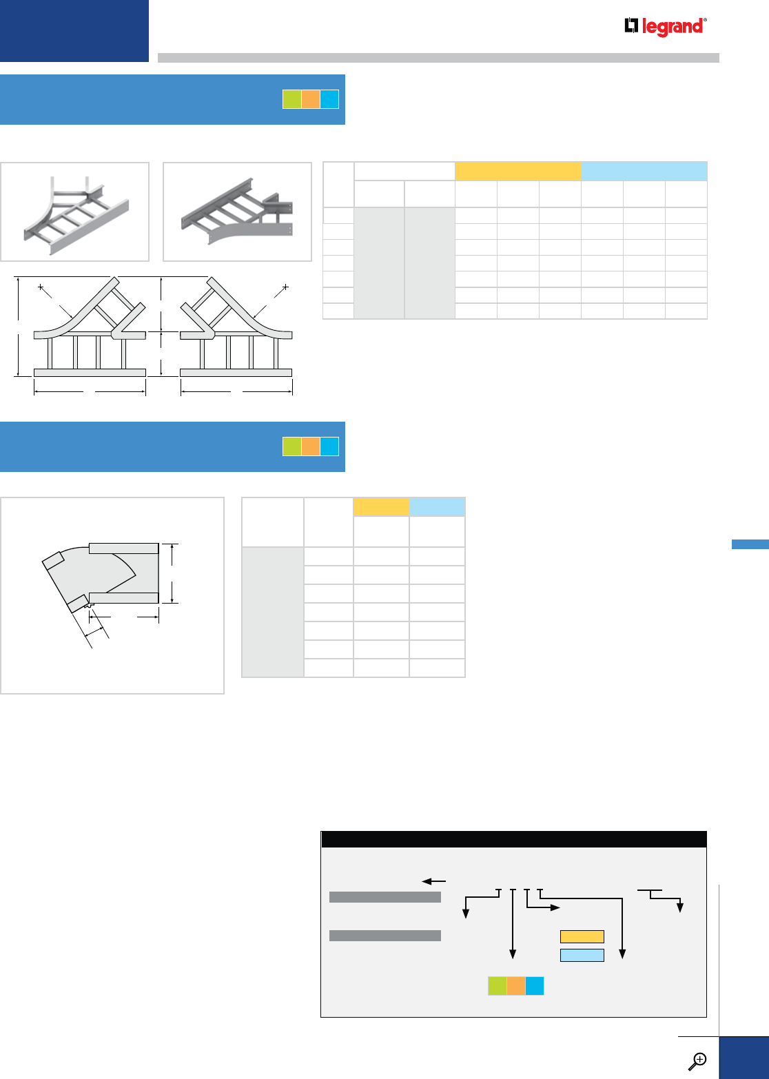
W
PRODUCT NUMBER SERIES 1 SERIES 2
LH
RADIUS (IN.)
RH
RADIUS (IN.) ABCABC
6
4024
24"
4124
24"
263/8101/4161/4293/8101/4161/4
930
5/8123/8213/8335/8123/8213/8
12 347/8141/2261/2377/8141/2261/2
18 433/8183/4363/4463/8183/4363/4
24 517/823 47 547/823 47
30 603/8271/4571/4633/8271/4571/4
36 687/8311/2671/2717/8311/2671/2
W+2
W
X
PRODUCT
NUMBER W
SERIES 1 SERIES 2
XX
0401
64 7
94 7
12 4 7
18 4 7
24 4 7
30 4 7
36 4 7
A
R
W
A
R
W
B
C
HORIZONTAL WYE BRANCH CATALOG NUMBERING EXAMPLE:
LD-6G2O-4024- 24
FITTING
SERIES
1 - SERIES 1
2 - SERIES 2
FLANGE
DIRECTION
I – Flange In
O – Flange Out
SIDE RAIL
HEIGHT
4 – 4"
5 – 5"
6 – 6"
7 – 7"
WIDTH
06 – 6"
09 – 9"
12 – 12"
18 – 18"
24 – 24"
30 – 30"
36 – 36"
PRODUCT NO.
FITTING
SYSTEM NO.
MATERIAL
GLT
BOTTOM TYPE
VENTED
LD – Ladder
VC† – Vented Corrugated
NON-VENTED
SC† – Solid Corrugated
SF† – Solid Flat Bottom
† Not available for flange out tray
HORIZONTAL WYE BRANCHES
HORIZONTAL ADJUSTABLE ELBOW
LEFT HAND RIGHT HAND
GLT
GLT
For detailed material and finish descriptions, see page B.6.
METALLIC FITTINGS
PW CABLE TRAY
WWW.LEGRAND.US/CABLOFIL
B.37
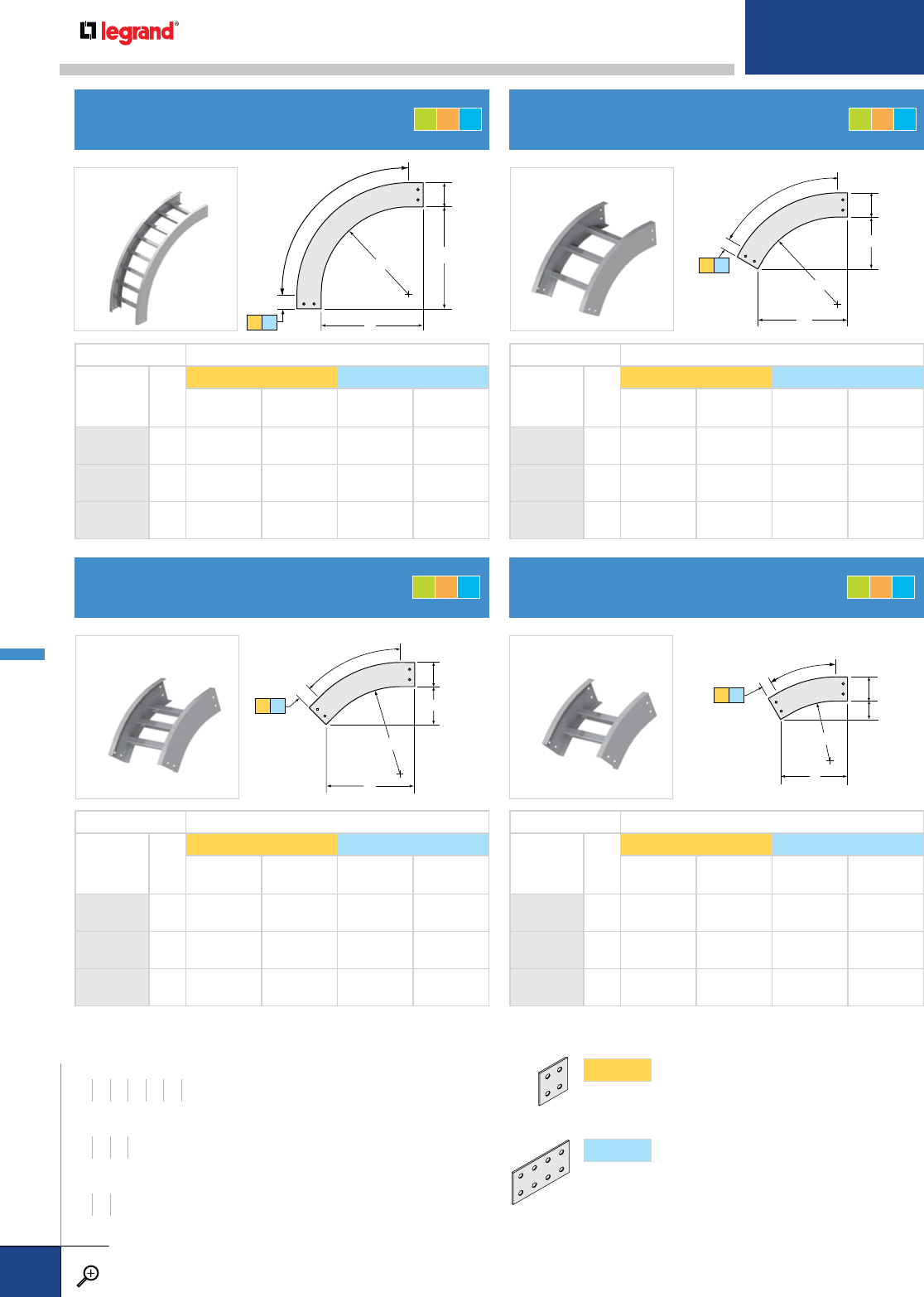
A
B
H
90˚
R
A
B
H
45˚
R
RAIL HEIGHT (IN.) > 4, 5, 6, 7
PRODUCT
NUMBER
RADIUS (IN.)
W*
SERIES 1 SERIES 2
ABAB
9212
12" ALL 14 14 17 17
9224
24" ALL 26 26 29 29
9236
36" ALL 38 38 41 41
RAIL HEIGHT (IN.) > 4, 5, 6, 7
PRODUCT
NUMBER
RADIUS (IN.)
W*
SERIES 1 SERIES 2
ABAB
4712
12" ALL 12 5 171/871/8
4724
24" ALL 201/281/2255/8105/8
4736
36" ALL 287/812 34 141/8
R
A
B
H
60˚
A
B
H
30˚
R
RAIL HEIGHT (IN.) > 4, 5, 6, 7
PRODUCT
NUMBER
RADIUS (IN.)
W*
SERIES 1 SERIES 2
ABAB
6212
12" ALL 131/273/418 13/8
6224
24" ALL 237/8133/4283/8163/8
6236
36" ALL 341/4193/4383/4223/8
RAIL HEIGHT (IN.) > 4, 5, 6, 7
PRODUCT
NUMBER
RADIUS (IN.)
W*
SERIES 1 SERIES 2
ABAB
3212
12" ALL 93/425/8153/841/8
3224
24" ALL 153/441/4213/853/4
3236
36" ALL 213/457/8273/873/8
VERTICAL OUTSIDE 90º ELBOW
VERTICAL OUTSIDE 45º ELBOW
VERTICAL OUTSIDE 60º ELBOW
VERTICAL OUTSIDE 30º ELBOW
S1 S2
S1 S2
S1 S2
S1 S2
WIDTHS (W) INCHES
6 9 12 18 24 30 36
RAIL HEIGHTS (H) INCHES
4567
RADIUS (R) INCHES
12 24 36
SERIES1
Fitting side rails have 2" tangents (flat portion beyond
curvature) at the end of each fitting, to accommodate
splice plates with four holes.
SERIES2
Fitting side rails have 5" tangents at the end of each
fitting, to accommodate splice plates with eight
holes.
SPLICES Match above to determine the connectors you need.
GLT
GLT
GLT
GLT
METALLIC FITTINGS
PW CABLE TRAY
WWW.LEGRAND.US/CABLOFIL
B.38
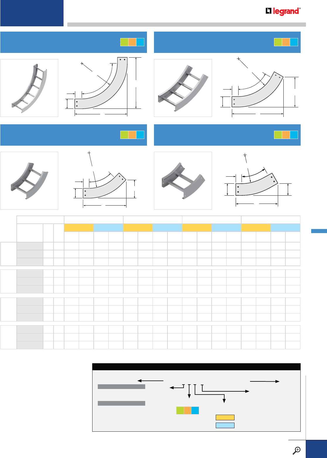
A
B
H
90˚
R
A
B
H
45˚
R
A
B
H
60˚
R
A
B
H
30˚
R
VERTICAL INSIDE 90º ELBOW
VERTICAL INSIDE 45º ELBOW
VERTICAL INSIDE 60º ELBOW
VERTICAL INSIDE 30º ELBOW
RAIL HEIGHT > 4567
PRODUCT
NUMBER
RADIUS (IN.)
RW
SERIES 1 SERIES 2 SERIES 1 SERIES 2 SERIES 1 SERIES 2 SERIES 1 SERIES 2
ABABABABABABABAB
90º
9112 12 ALL 18 18 21 21 19 19 22 22 20 20 23 23 21 21 24 24
9124 24 ALL 30 30 33 33 31 31 34 34 32 32 35 35 33 33 36 36
9136 36 ALL 42 42 45 45 43 43 46 46 44 44 47 47 45 45 48 48
60º
6112 12 ALL 167/893/4213/8123/8173/4101/4221/4127/8185/8103/4231/8133/8191/2111/424 137/8
6124 24 ALL 271/4153/4313/4183/8281/8161/4323/8187/829 163/4331/2193/8297/8171/4343/8197/8
6136 36 ALL 373/4213/4421/4243/8385/8221/4431/8247/8393/8223/4437/8253/8401/4231/4443/4257/8
45º
4612 12 ALL 143/461/8197/881/4151/261/2205/885/8161/463/4213/887/8167/87229
1/8
4624 24 ALL 231/495/8283/8113/424 10 291/8121/8245/8101/4293/4123/8253/8101/2301/2125/8
4636 36 ALL 313/4131/4367/8151/4321/2131/2375/8155/8331/8133/4381/4157/8337/814 39 161/4
30º
3112 12 ALL 113/431/4173/843/4121/431/4177/843/4123/433/8183/847/8131/435/8187/851/8
3124 24 ALL 173/443/4233/861/4181/447/8237/863/8183/4524
3/861/2191/451/4247/863/4
3136 36 ALL 233/463/8293/877/8241/461/2297/8824
3/465/8303/881/8251/467/8307/883/8
VERTICAL ELBOW CATALOG NUMBERING EXAMPLE:
LD-6G2 I-6124-24
FITTING
SERIES
1 - SERIES 1
2 - SERIES 2
FLANGE
DIRECTION
I – Flange In
O – Flange Out
SIDE RAIL
HEIGHT
4 – 4"
5 – 5"
6 – 6"
7 – 7"
WIDTH
06 – 6"
09 – 9"
12 – 12"
18 – 18"
24 – 24"
30 – 30"
36 – 36"
PRODUCT NO.FITTING SYSTEM NO.
BOTTOM TYPE
VENTED
LD – Ladder
VC† – Vented Corrugated
NON-VENTED
SC† – Solid Corrugated
SF† – Solid Flat Bottom
† Not available for flange out tray
MATERIAL
GLT
GLT
GLT
GLT
GLT
For detailed material and finish descriptions, see page B.6.
METALLIC FITTINGS
PW CABLE TRAY
WWW.LEGRAND.US/CABLOFIL
B.39
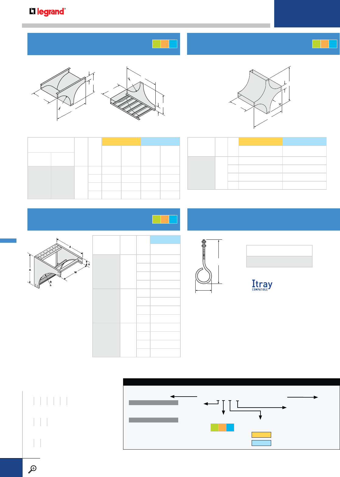
5.38"
1.38"
W
A
A
R
H
W
A
B
R
W
A
B
R
H
H
TEE DOWN TEE UP
PRODUCT NUMBER
RADIUS (IN.) WH
SERIES 1 SERIES 2
ABAB
TEE
DOWN
TEE
UP
2124
24"
2224
24" ALL
456306233
557316334
658326435
759336536
PRODUCT
NUMBER
RADIUS (IN.)
WH
SERIES 1 SERIES 2
AA
1124
24" ALL
456 62
557 63
658 64
759 65
PRODUCT
NUMBER
RADIUS
WH
SERIES 2
A
9312
12" ALL
421
522
623
724
9324
24" ALL
433
534
635
736
9336
36" ALL
445
546
647
748
COMPLETE CATALOG NO.
DS-1841-ZN
Supports cables at the
top of long vertical drops
where the weight of the
vertical cable may be
excessive. Hooks (sold
separately) attach to the
brace in the elbow; when
used with cable grips
(supplied by others),
tension in the vertical
cable is relieved and
transferred to the elbow.
TEE UP fittings have rungs or bottom members
for cable support across the bottom of the fitting.
VERTICAL TEES
VERTICAL 90º SUPPORT ELBOW CABLE SUPPORT HOOK
VERTICAL CROSS
VERTICAL TEE DOWN CATALOG NUMBERING EXAMPLE:
LD-6G2 I-2124-24
FITTING
SERIES
1 - SERIES 1
2 - SERIES 2
FLANGE
DIRECTION
I – Flange In
O – Flange Out
SIDE RAIL
HEIGHT
4 – 4"
5 – 5"
6 – 6"
7 – 7"
WIDTH
06 – 6"
09 – 9"
12 – 12"
18 – 18"
24 – 24"
30 – 30"
36 – 36"
PRODUCT NO.FITTING SYSTEM NO.
BOTTOM TYPE
VENTED
LD – Ladder
VC† – Vented Corrugated
NON-VENTED
SC† – Solid Corrugated
SF† – Solid Flat Bottom
† Not available for flange out tray
MATERIAL
GLT
WIDTHS (W) INCHES
6 9 12 18 24 30 36
RAIL HEIGHTS (H) INCHES
4567
RADIUS (R) INCHES
12 24 36
GLT
GLT
GLT
METALLIC FITTINGS
PW CABLE TRAY
WWW.LEGRAND.US/CABLOFIL
B.40
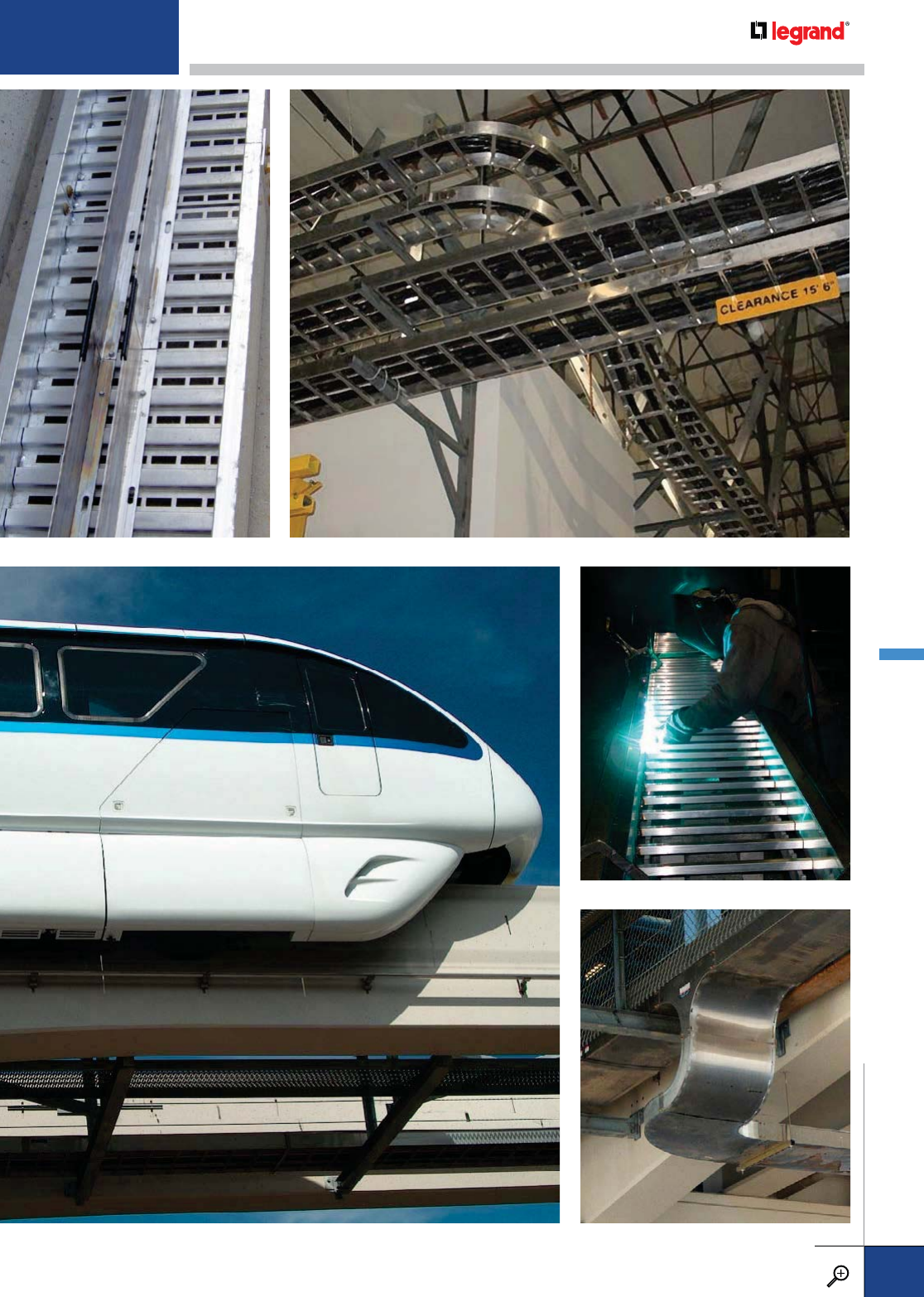
For detailed material and finish descriptions, see page B.6.
METALLIC
PW CABLE TRAY
WWW.LEGRAND.US/CABLOFIL
B.41
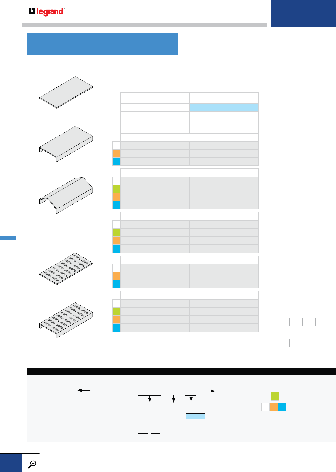
FLANGE IN 13/4" FLANGE OUT
SERIES 2
[
—
]]
—
[
SOLID, FLAT — NON-FLANGED PRODUCT NUMBER
M2002 2067
L3002 3038
T3042 3039
SOLID, FLAT — FLANGED* PRODUCT NUMBER
M2000 2066
G1000 1066
L3000 3036
T3005 3029
SOLID, PEAKED 15˚ — FLANGED† PRODUCT NUMBER
M2140 2114
G1140 1114
L3128 3131
T3017 3040
LOUVERED, FLAT — NON-FLANGED PRODUCT NUMBER
M2006 2112
L3050 3117
T3041 3112
LOUVERED, FLAT — FLANGED* PRODUCT NUMBER
M2007 2104
G1007 1104
L3070 3003
T3076 3113
SOLID COVERS
LOUVERED COVERS
FLAT, NON-FLANGED
FLAT, NON-FLANGED
FLAT, FLANGED
FLAT, FLANGED
PEAKED 15˚, FLANGED
Covers protect and contain cables. They are highly recommended
to avoid damage to the tray contents and to protect against the
elements. Some covers can also be attached to the tray with
hinges; please contact Legrand for more information.
* Flange is 3/8" wide.
† 15˚ is standard angle for peaked covers. Flange is 3/8" wide.
COVER CATALOG NUMBERING EXAMPLE:
60-2000 - 0012 -36 - 05-B
SIDE RAIL
HEIGHT*
40 – 4"
50 – 5"
60 – 6"
70 – 7"
COVER
SYSTEM NO.
LENGTH OR
FITTING PRODUCT NO.
WIDTH FITTING
TANGENT
05 - SERIES 2
(5" Tangents )
COVER THICKNESS
Letter suffixes are
used to indicate
alternate cover
thicknesses. Leave
blank for standard
thickness.
Standards:
G18 Ga.
MLT 20 Ga.
A – 18 Gage (0.048")
B – 16 Gage (0.060")
C – 14 Gage (0.075")
* Side rail height necessary for outside vertical fitting covers.
** Standard lengh for steel covers hot-dip galvanized after
fabrication per ASTMA-123 is 6'-0".
LENGTH
0006** – 6'
0010 – 10'
0012 – 12'
or
9224
FITTING PRODUCT NO.
TRAY COVERS
WIDTHS (W) INCHES
6 9 12 18 24 30 36
RAIL HEIGHTS (H) INCHES
4567
METALLIC COVERS
PW CABLE TRAY
WWW.LEGRAND.US/CABLOFIL
B.42
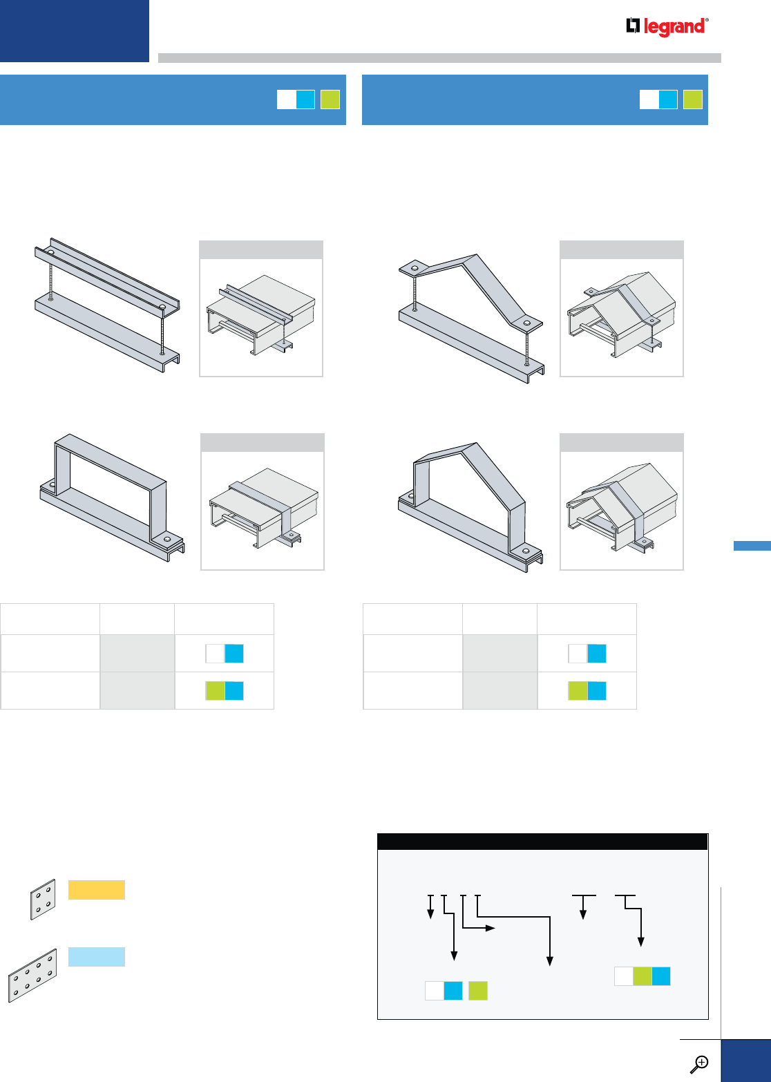
For use with indoor, outdoor, or vertical flat covers. Top and
bottom pieces are 1½" wide. Install one connector over each
cover joint and space additional connectors on 36"- 48" centers.
For use with indoor, outdoor, or vertical peaked covers. Top and
bottom pieces are 1½" wide. Install one connector over each
cover joint and space additional connectors on 36"- 48" centers.
DESCRIPTION PRODUCT
NUMBER FASTENERS
CHANNEL 1400 ZN S6
STRAP 1423 GE S6
DESCRIPTION PRODUCT
NUMBER FASTENERS
CHANNEL 1411 ZN S6
STRAP 1440 GE S6
CHANNEL-STYLE CHANNEL-STYLE
STRAP-STYLE STRAP-STYLE
COVER CONNECTOR CATALOG NUMBERING EXAMPLE:
6M2O-1411-24-S6
PRODUCT NO.
FITTING
SYSTEM NO.
MATERIAL
MT G*
*optional
SIDE
RAIL
HEIGHT
FITTING
SERIES
FLANGE
DIRECTION
WIDTH
FASTENERS
ZN GE S6
FLAT COVER CONNECTORS PEAKED COVER CONNECTORS
APPLICATION APPLICATION
APPLICATION APPLICATION
MT G
*MT G
*
SERIES1
Fitting side rails have 2" tangents (flat portion
beyond curvature) at the end of each fitting, to
accommodate splice plates with four holes.
SERIES2
Fitting side rails have 5" tangents at the end of
each fitting, to accommodate splice plates with
eight holes.
SPLICES Match above to determine the connectors you need.
For detailed material and finish descriptions, see page B.6.
METALLIC COVER CONNECTORS
PW CABLE TRAY
WWW.LEGRAND.US/CABLOFIL
B.43
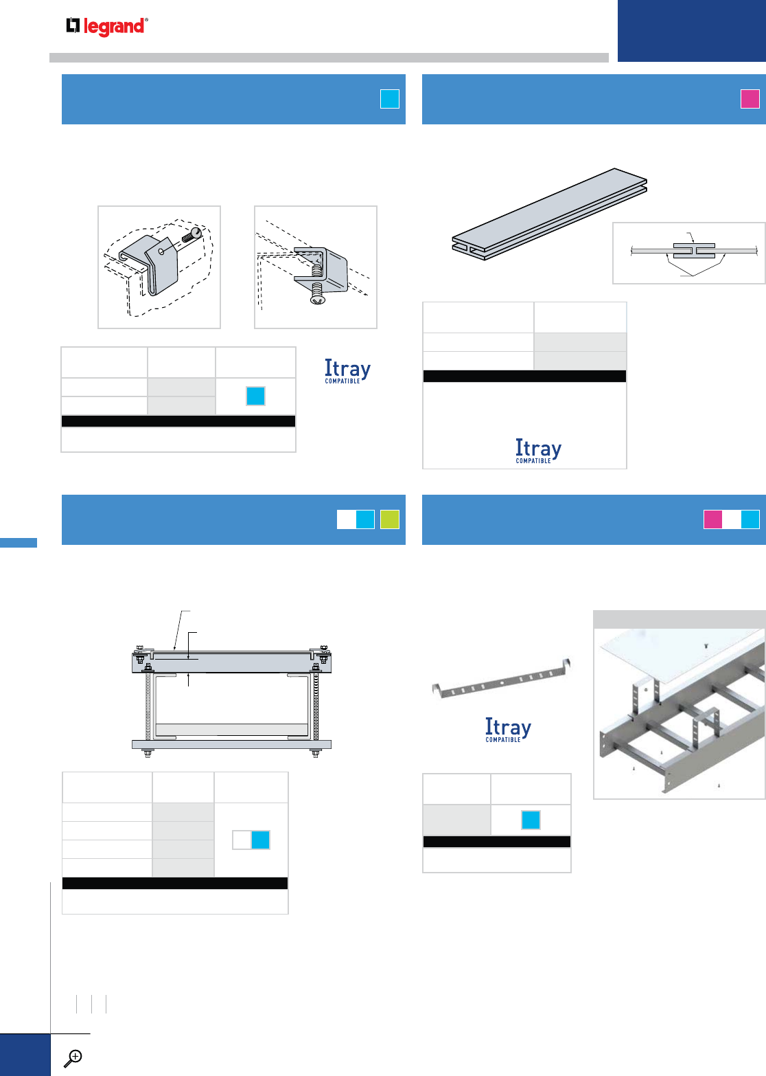
Gap
Flat or Peaked Cover with Flanges
FLANGE-OUT CLIPFLANGE-IN CLIP
DESCRIPTION PRODUCT
NUMBER
FASTENER
INCLUDED
FLANGE-IN 1410 S6
FLANGE-OUT 1853
CATALOG NUMBERING EXAMPLE (EA.):
Material Fasteners
T - 1410 -S6
PRODUCT
NUMBER
FASTENER
INCLUDED
1432 S6
CATALOG NUMBERING EXAMPLE (EA.):
Material Fasteners
M - 1432 -S6
Abutting Covers
H-Binder Strip
Closes gaps at cover joints. Notched for the tray side rail.
No fasteners required.
For use with indoor, horizontal covers. Flange-in clip requires
tray with 1" side rail flanges. Flange-out clip works with any
side rail flange width. Sold individually.
For use with all covers, indoors and outdoors. Covers are
attached to uprightmounted “C” channel on the top of the
cable tray. Install 36"-48" on center.
GAP DIMENSION
(IN.)
PRODUCT
NUMBER
FASTENER
OPTIONS
11441
ZN S6
21442
31443
41444
CATALOG NUMBERING EXAMPLE:
Fitting System No. Width Fasteners
6T2O - 1441 - 06 - S6
COVER CONNECTOR CLIPS
RAISED COVER CONNECTOR RAISED COVER CONNECTOR
H-BINDER COVER JOINT STRIP
T A
MT G
*AMT
RAIL HEIGHTS (H) INCHES
4567
APPLICATION
Raised cover connectors allow for ventilation of ladder tray
installations while protecting cables from possible falling objects.
Raised cover connectors allow a gap of 1”, 2”, 3” or 4”.
DESCRIPTION PRODUCT
NUMBER
FLAT COVER CLIP 0925
PEAKED COVER CLIP 0926
CATALOG NUMBERING EXAMPLE (EA.):
Connector System No.† Width
A2O - 0925 -06
†AI, A1O and A2O are the only three
Connector System No. possiblities for this part.
AI is
METALLIC COVER ACCESSORIES
PW CABLE TRAY
WWW.LEGRAND.US/CABLOFIL
B.44
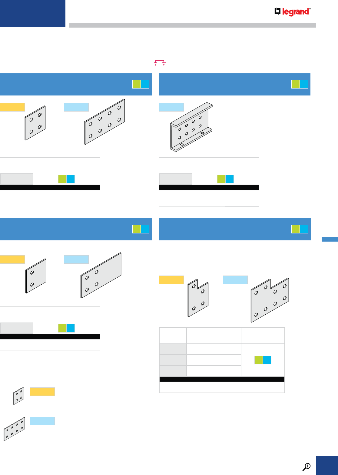
PRODUCT
NUMBER FASTENER OPTIONS
1302 GE S6
CATALOG NUMBERING EXAMPLE:
Connector System No. Fasteners
4G1 - 1302 -GE
PRODUCT
NUMBER FASTENER OPTIONS
1385 GE S6
CATALOG NUMBERING EXAMPLE:
Connector System No.† Fasteners
4G2 - 1385 -S6
†This item must be specified as Series 2 in the System No.
PRODUCT
NUMBER FASTENER OPTIONS
1335 GE S6
CATALOG NUMBERING EXAMPLE:
Connector System No.† Fasteners
4G1 - 1335 -GE
Cadmium-plated steel fasteners are standard for all splice plate connectors on aluminum and steel cable tray systems. All splices
are supplied in pairs. Type 316 stainless steel fasteners are standard on stainless steel systems, but are available as an option on
all aluminum and steel systems. Sufficient connector pairs with fasteners are automatically included with each shipment of straight
sections and fittings. Extras for field cuts or spares must be ordered separately. Bonding jumpers are required for all expansion
splice plates, adjustable connectors, and tray discontinuities. The symbol indicates that bonding jumpers are required.
These heavy-duty splice plates
are designed for random location,
including mid-span. Field-drilled
holes are required in the bottom
flanges of adjoining trays.
PRODUCT
NUMBER SIZE FASTENER OPTIONS
1386 REDUCES TO 4" HIGH TRAY
GE S6
1379 REDUCES TO 5" HIGH TRAY
1355 REDUCES TO 6" HIGH TRAY
CATALOG NUMBERING EXAMPLE:
Connector System No. Fasteners
6G2 - 1386 - GE
These splice plates are designed to connect cable tray side
rails with different heights. The connector system number
includes the larger side rail height. Choose the product
number depending on the reduced side rail height.
These splice plates are designed to connect to existing cable tray.
STANDARD SPLICE
UNIVERSAL SPLICE REDUCING HEIGHT SPLICE
MID-SPAN SPLICE
SERIES1
SERIES1
SERIES1
SERIES2 SERIES2
SERIES2
SERIES2
GT
GT
GT
GT
SERIES1
Fitting side rails have 2" tangents (flat portion
beyond curvature) at the end of each fitting, to
accommodate splice plates with four holes.
SERIES2
Fitting side rails have 5" tangents at the end of
each fitting, to accommodate splice plates with
eight holes.
SPLICES Match above to determine the connectors you need.
For detailed material and finish descriptions, see page B.6.
METALLIC SPLICES & CONNECTORS
PW CABLE TRAY
WWW.LEGRAND.US/CABLOFIL
B.45
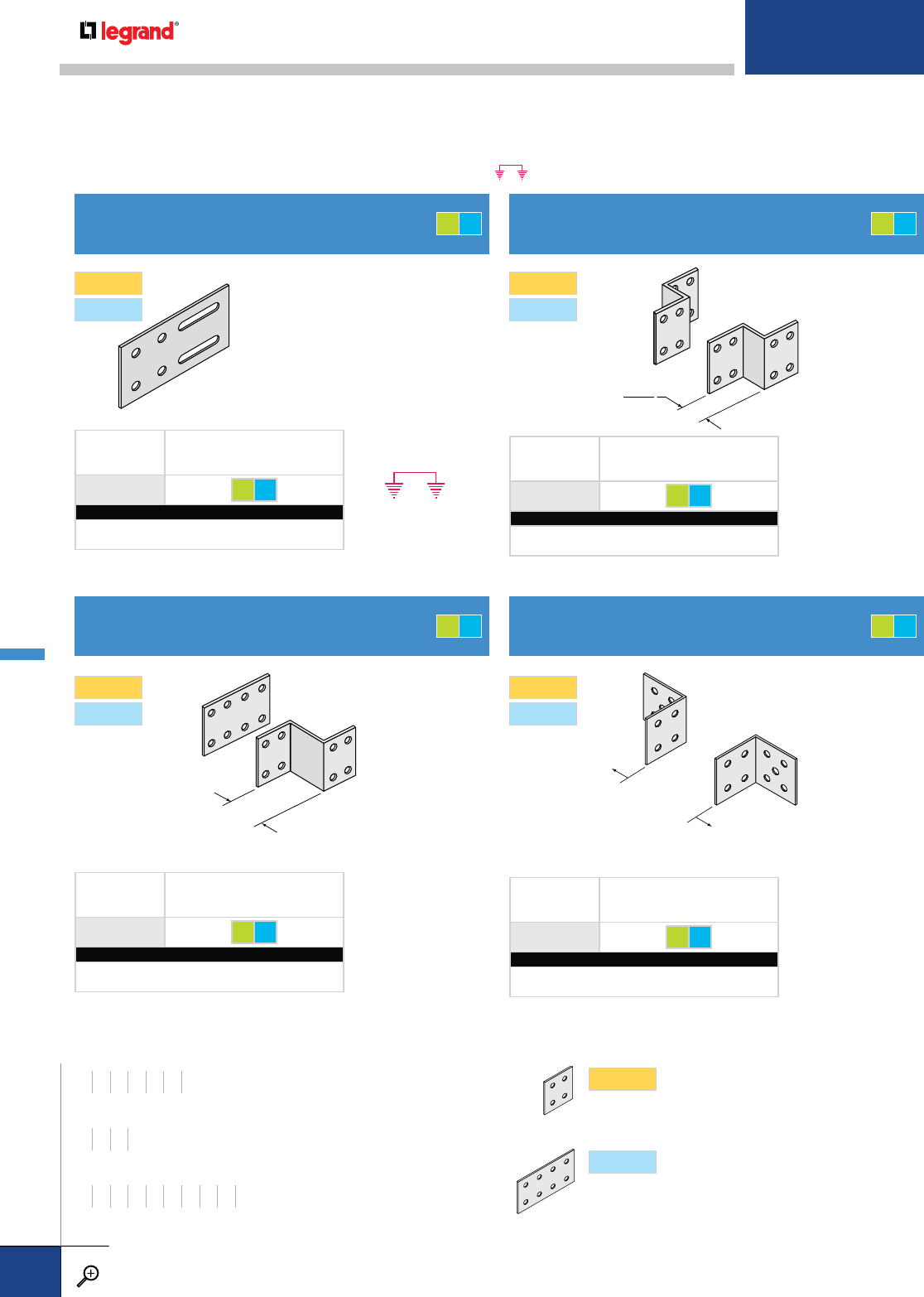
RN
ALL TRAY
WIDTHS
Permits thermal contraction
and expansion in a cable tray
installation. The length of the
straight cable tray run and the
temperature differential govern the
number and spacing of expansion
connectors. Expansion splice plates
permit 2" of movement.
PRODUCT
NUMBER FASTENER OPTIONS
1314 GE S6
CATALOG NUMBERING EXAMPLE:
Connector System No. Fasteners
4G2 - 1314 -GE
PRODUCT
NUMBER FASTENER OPTIONS
1320 GE S6
CATALOG NUMBERING EXAMPLE:
Connector System No. Fasteners
4G2 - 1320 -GE
RN
2
PRODUCT
NUMBER FASTENER OPTIONS
1303 GE S6
CATALOG NUMBERING EXAMPLE:
Connector System No. RN Fasteners
4G2 - 1303 -06-GE
PRODUCT
NUMBER FASTENER OPTIONS
1304 GE S6
CATALOG NUMBERING EXAMPLE:
Connector System No. RN Fasteners
4G2 - 1304 -12 - S6
EXPANSION SPLICE
OFFSET REDUCER SPLICE
STRAIGHT REDUCER SPLICE
90º CONNECTOR
Cadmium-plated steel fasteners are standard for all splice plate connectors on aluminum and steel cable tray systems. All splices
are supplied in pairs. Type 316 stainless steel fasteners are standard on stainless steel systems, but are available as an option on
all aluminum and steel systems. Sufficient connector pairs with fasteners are automatically included with each shipment of straight
sections and fittings. Extras for field cuts or spares must be ordered separately. Bonding jumpers are required for all expansion
splice plates, adjustable connectors, and tray discontinuities. The symbol indicates that bonding jumpers are required.
SERIES1
SERIES2
SERIES1
SERIES2
SERIES1
SERIES2
SERIES1
SERIES2
WIDTHS (W) INCHES
6 9 12 18 24 30 36
RAIL HEIGHTS (H) INCHES
4567
REDUCTION (RN) INCHES
3 6 9 12151821242730
SERIES1
Fitting side rails have 2" tangents (flat portion beyond
curvature) at the end of each fitting, to accommodate
splice plates with four holes.
SERIES2
Fitting side rails have 5" tangents at the end of each
fitting, to accommodate splice plates with eight holes.
SPLICES Match above to determine the connectors you need.
GT
GT
GT
GT
METALLIC SPLICES & CONNECTORS
PW CABLE TRAY
WWW.LEGRAND.US/CABLOFIL
B.46
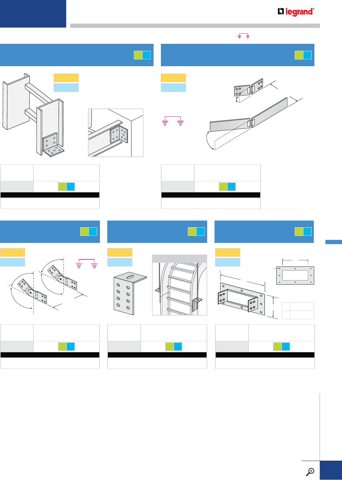
PRODUCT
NUMBER FASTENER OPTIONS
1864 GE S6
CATALOG NUMBERING EXAMPLE:
Connector System No. Fasteners
4G2 - 1864 -GE
PRODUCT
NUMBER FASTENER OPTIONS
1307 GE S6
CATALOG NUMBERING EXAMPLE:
Connector System No. Fasteners
4G2 - 1307 -GE
PRODUCT
NUMBER FASTENER OPTIONS
0356 GE S6
CATALOG NUMBERING EXAMPLE:
Connector System No. Fasteners
6G2 - 0356 -S6
PRODUCT
NUMBER FASTENER OPTIONS
0403 GE S6
CATALOG NUMBERING EXAMPLE:
Connector System No. Width Fasteners
4G2 - 0403 - 12 -GE
PRODUCT
NUMBER FASTENER OPTIONS
1305 GE S6
CATALOG NUMBERING EXAMPLE:
Connector System No. Fasteners
4G2 - 1305 -GE
For odd angle
bends up to 30˚
ALL
W
Fasteners for tray
attachment only
are included. Floor
connection leg has
9/16” diameter hole.
All splices are supplied in pairs. Bonding jumpers are required for use with all adjustable splices.
7/16” DIA
HOLES
W
ALL
W
B
A
Maximum bend angle is +
-90 Sold individually.
DIMENSIONS
A H + 3-3/4
B W + 4
FLOOR FLANGE / TRAY-TO-BOX
CONNECTOR
VERTICAL
ADJUSTABLE SPLICE VERTICAL HANGER
SPLICE TRAY-TO-BOX
FRAME CONNECTOR
HORIZONTAL ADJUSTABLE SPLICE
SERIES1
SERIES2
SERIES1
SERIES2
SERIES1
SERIES2
SERIES1
SERIES2
SERIES1
SERIES2
APPLICATION
GT GT
GTGTGT
All connectors on these pages are designed to fit Series 1 and 2 systems. When ordering, however, they should be specified as Series 2.
For detailed material and finish descriptions, see page B.6.
METALLIC SPLICES & CONNECTORS
PW CABLE TRAY
WWW.LEGRAND.US/CABLOFIL
B.47
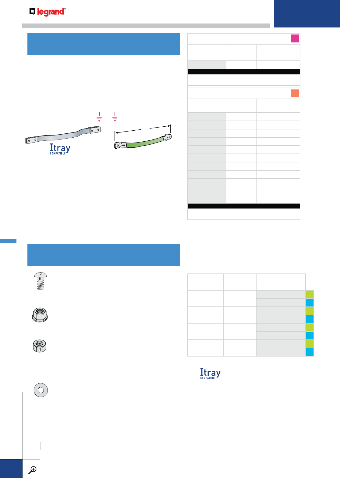
DESCRIPTION SIZE COMPLETE
CATALOG NUMBER
KNURLED
BOLT 3/8"-16 x ¾"DS-8530-01-GE GE
DS-8926-01-S6 S6
FLANGED
HEX NUT 3/8" DIA. DS-8524-01-GE GE
DS-8927-01-S6 S6
LOCKING
HEX NUT 3/8" DIA. DS-8575-02-GE GE
DS-8576-01-S6 S6
FLAT
WASHER 3/8" DIA. DS-8596-01-GE GE
DS-8600-01-S6 S6
Knurled Bolt: Specially designed for cable tray
connectors, the ribbed neck firmly grips the tray side
rail to prevent screw rotation while tightening. Bolt
can also be tightened with a Phillips screwdriver.
Flanged Hex Nut: “Free spinning” lock-type nut with
a serrated face, eliminating the need for a washer.
Nuts require a 9/16" wrench. Tighten to approximately
19-25 ft-lbs of torque.
Locking Hex Nut: For use with expansion
connectors. Deformed threads cause this nut to
lock on to the bolt after just a few turns, allowing
movement of the bolt in the expansion slot without
possibility of the nut backing off. Typically identified
by a rectangular indentation on the side of the nut.
Flat Washer: For use with expansion connectors.
Install under the locking hex nut in the expansion
slots. Prevents binding in the expansion slot during
movement of the tray due to thermal expansion.
LAMINATED ALUMINUM
PRODUCT
NUMBER LRATED AMPS
(N.E.C. 250-122)
BJ 21¼" 2000
CATALOG NUMBERING EXAMPLE (EA:):
Material Fasteners
A - BJ - 2000 - GE
INSULATED COPPER
PRODUCT
NUMBER COPPER
CABLE SIZE RATED AMPS
(N.E.C. 250-122)
A806 #6 200
A807 #4 300
A804 #2 500
A803 #1 600
A808 1/O 800
A809 2/O 1000
A805 3/O 1200
A810 4/O 1600
A814*
4/O WELDING
CABLE 2107
STRANDS
1800
CATALOG NUMBERING EXAMPLE (EA.):
Material
C - A806
* Length is 30" to the center of the lug holes. One-hole
tin-plated copper lugs are sized for ½" bolt. A814 is
the only insulated copper bonding jumper that is
compatible with Itray, as the other sizes are 15".
15"
LAMINATED ALUMINUM (BJ ONLY) INSULATED COPPER
Use across all discontinuities, expansion joints, and adjustable
connectors to maintain electrical continuity in the cable tray
system. Also use to bond the cable tray system to the building
ground. Bonding jumpers are not required at standard or rigid
splice locations. Fasteners for laminated bonding jumpers are
included; fasteners for insulated jumpers must be ordered
separately.
Laminated Aluminum: (4) 3/8" x 1¼" bolts per bonding jumper
(included).
Insulated Copper: Made with flame-retardant, moisture- and
heat-resistant, insulated copper cable. Tin plated copper lugs
have one hole, sized for 3/8" x ¾" bolt. Length is 15" to the
center of the lug holes. Special lengths, lugs, and cables are
also available.
A
C
BONDING JUMPERS
SPLICE FASTENERS
RAIL HEIGHTS (H) INCHES
4567
METALLIC SPLICES & CONNECTORS
PW CABLE TRAY
WWW.LEGRAND.US/CABLOFIL
B.48
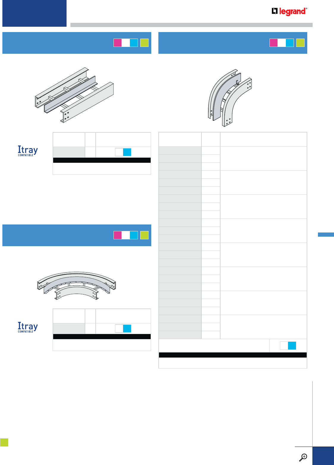
PRODUCT
NUMBER R DIVIDER TYPE
9112-99 12
90° INSIDE ELBOW
9124-99 24
9136-99 36
9212-99 12
90° OUTSIDE ELBOW
9224-99 24
9236-99 36
6112-99 12
60° INSIDE ELBOW
6124-99 24
6136-99 36
6212-99 12
60° OUTSIDE ELBOW
6224-99 24
6236-99 36
4612-99 12
45° INSIDE ELBOW
4624-99 24
4636-99 36
4712-99 12
45° OUTSIDE ELBOW
4724-99 24
4736-99 36
3112-99 12
30° INSIDE ELBOW
3124-99 24
3136-99 36
3212-99 12
30° OUTSIDE ELBOW
3224-99 24
3236-99 36
FASTENER OPTIONS ZN S6
CATALOG NUMBERING EXAMPLE:
Accessory System No. Fasteners
4A - 9212-99 -ZN
PRODUCT
NUMBER LFASTENER OPTIONS
0012-99 12 ZN S6
CATALOG NUMBERING EXAMPLE:
Accessory System No. Fasteners
4A - 0012-99 - ZN
PRODUCT
NUMBER LFASTENER OPTIONS
0606-99 6' ZN S6
CATALOG NUMBERING EXAMPLE:
Accessory System No. Fasteners
4T - 0606-99 - S6
For use with all straight tray. Furnished with four #10
self-drilling screws.
For use with all horizontal fittings of any radius.
Furnished with three #10 self-drilling screws.
Furnished with two #10 self-drilling screws.
STRAIGHT HORIZONTAL DIVIDER VERTICAL FITTING DIVIDER
FLEXIBLE HORIZONTAL DIVIDER
AMT G
*
AMT G
*
AMT G
*
G* = optional
For detailed material and finish descriptions, see page B.6.
METALLIC ACCESSORIES
PW CABLE TRAY
WWW.LEGRAND.US/CABLOFIL
B.49
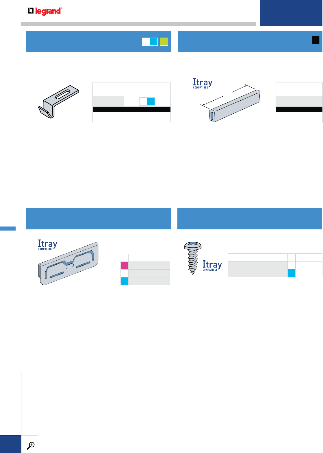
Splices joints of abutting divider strips. Vinyl edge strip is also
available in bulk lengths.
Purchased separately. Supplied with carriage bolt and flanged
hex nut. Designed for use with ladders with box-shaped rungs
(Types BX & BH–see pages B.66-B.67).
5"
COMPLETE CATALOG NO. SIZE
DS-8930-01-ZN ZN #10 X 3/4"
DS-8930-01-S6 S6 #10 X 3/4"
Provided with all dividers, but extras
can be ordered separately.
COMPLETE CAT. NO.
ACOTJ-AL
MCOTJ-PG
TCOTJ-316
Sold in bags of 25.
DIVIDER HOLD DOWN CLIP
DIVIDER SPLICE
5" VINYL DIVIDER SPLICE
SELF-DRILLING SCREW
PRODUCT
NUMBER FASTENER OPTIONS
1852 ZN S6
CATALOG NUMBERING EXAMPLE:
Material Fasteners
M - 1852 - ZN
PRODUCT
NUMBER
0930
CATALOG NUMBERING EXAMPLE:
Material
V - 0930
MT G
*V
METALLIC ACCESSORIES
PW CABLE TRAY
WWW.LEGRAND.US/CABLOFIL
B.50
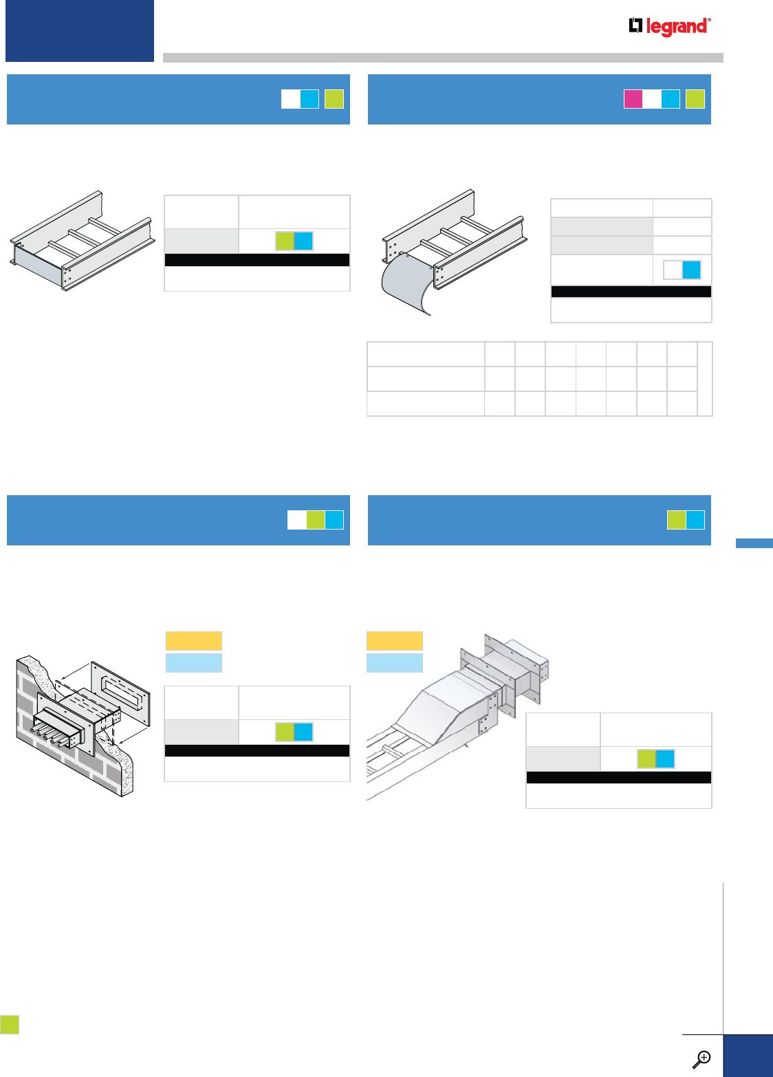
PRODUCT NUMBER R
0253 3/4
0254 5
FASTENER
OPTIONS ZN S6
CATALOG NUMBERING EXAMPLE:
Material -Flange Width Fasteners
AI-0253-06 -S6
Provides a rigid support for cable tray at wall penetrations.
Overall length of the sleeve is 20". Will fit walls up to 8" thick.
Bonding jumpers are not required for use with wall sleeves.
Two pairs of splice plates and fasteners are included for tray
attachment.
Seals off the open end of a cable tray. Attaches to the tray using
standard 3/8" dia. connector fasteners.
Provides a smooth, rounded surface for cables dropping out
of the bottom of the cable tray.
TRAY WIDTH (NOMINAL) 6 9 12 18 24 30 36
INDROPOUT WIDTH (FLG IN) 21/451/481/4141/4201/4261/4321/4
DROPOUT WIDTH (FLG OUT) 51/481/4113/4173/4233/4293/4353/4
• Fits Standard Hot-Dip
Galvanized or Stainless
"0424" or "0440" wall
penetrations (see page B.58.)
• Sized to fit flange-in or
flange-out trays
Makes ladder tray wall penetrations weather resistant to
minimize water intrusions. Removable cover/shield fastens
to tray and wall penetration sleeve for the utmost in weather
protection.
SERIES1
SERIES2
SERIES1
SERIES2
BLIND END PLATE
WALL PENETRATION SLEEVE
CABLE DROPOUT
OUTDOOR CONVERSION FOR
WALL PENETRATION
PRODUCT
NUMBER FASTENER OPTIONS
0402 GE S6
CATALOG NUMBERING EXAMPLE:
Height/Material Width Fasteners
4T - 0402 - 12 - GE
PRODUCT
NUMBER FASTENER OPTIONS
0424 GE S6
CATALOG NUMBERING EXAMPLE:
Connector System No Width Fasteners
4T2 - 0424 -12- S6
PRODUCT
NUMBER FASTENER OPTIONS
0434 GE S6
CATALOG NUMBERING EXAMPLE:
Connector System No Width Fasteners
4G2 - 0434 -06- GE
MT G
*AMT G
*
MGT GT
G* = optional
The wall penetration sleeve and outdoor conversion kit are designed to fit Series 1 and 2 systems.
When ordering, however, they should be specified as Series 2.
For detailed material and finish descriptions, see page B.6.
METALLIC ACCESSORIES
PW CABLE TRAY
WWW.LEGRAND.US/CABLOFIL
B.51
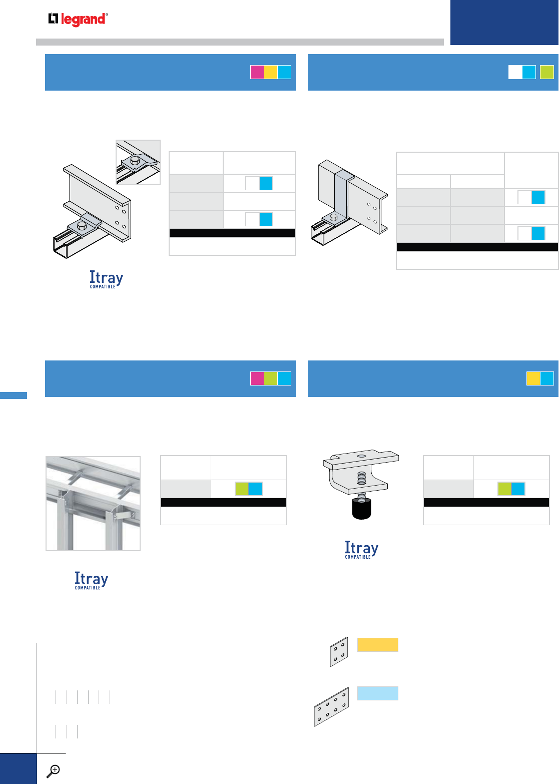
PRODUCT
NUMBER
FASTENER
OPTIONS
1893-01*ZN S6
1893-02 NONE
1893-03†ZN S6
CATALOG NUMBERING EXAMPLE:
Material Fasteners
A - 1893-01 -ZN
* Includes 3/8" x 1½" hex bolt, 3/8"
flanged nut.
† Includes 3/8" x 1½" hex bolt, 3/8"
spring nut.
Designed for use with all trays. 3/8" diameter hardware
for tray attachment only is included. Holes for structure
attachment are sized for 1/2" diameter fasteners. Ideal for
vertical tray support. Sold in pairs.
This unique clamp allows wire mesh cable tray to be attached
to the side rails of any ladder tray and a pre-installed setscrew
secures the junction for a permanent installation.
Wraps around the tray side rail for use with all solid bottom
trays. Can also be used with any flange-in tray system.
Expansion guide is slightly taller to permit longitudinal tray
movement caused by thermal expansion. Sold individually.
PRODUCT NUMBER FASTENER
OPTIONS
Z-HOLD DOWN EXPANSION
1866-01*1867-01 ZN S6
1866-02 1867-02 NONE
1866-03†1867-03 ZN S6
CATALOG NUMBERING EXAMPLE:
Accessory System No. Fasteners
4M - 1866-01 -ZN
* Includes ¼" x ¾" carriage bolt, ¼" flanged nut.
† Includes ¼" x 1½" screw, ¼" spring nut.
HOLD DOWN/EXPANSION CLAMP
HEAVY-DUTY HOLD DOWN BRACKETS
Z-HOLD DOWN/EXPANSION GUIDE
WIRE MESH-TO-LADDER CLAMP
Works as an expansion guide and flips over for use as a hold down
clamp for use with all ladder trays. Sold in packs of 10.
PRODUCT
NUMBER FASTENER OPTIONS
A845 GE S6
CATALOG NUMBERING EXAMPLE:
Material Fasteners
T - A845 -S6
PRODUCT
NUMBER FASTENER OPTIONS
WMC 2LA GE S6
CATALOG NUMBERING EXAMPLE:
Material Fasteners
T - WMC 2LA -S6
AZT MT G
*
AGT ZT
WIDTHS (W) INCHES
6 9 12 18 24 30 36
RAIL HEIGHTS (H) INCHES
4567
SERIES1
Fitting side rails have 2" tangents (flat portion
beyond curvature) at the end of each fitting, to
accommodate splice plates with four holes.
SERIES2
Fitting side rails have 5" tangents at the end of
each fitting, to accommodate splice plates with
eight holes.
SPLICES Match above to determine the connectors you need.
METALLIC ACCESSORIES
PW CABLE TRAY
WWW.LEGRAND.US/CABLOFIL
B.52
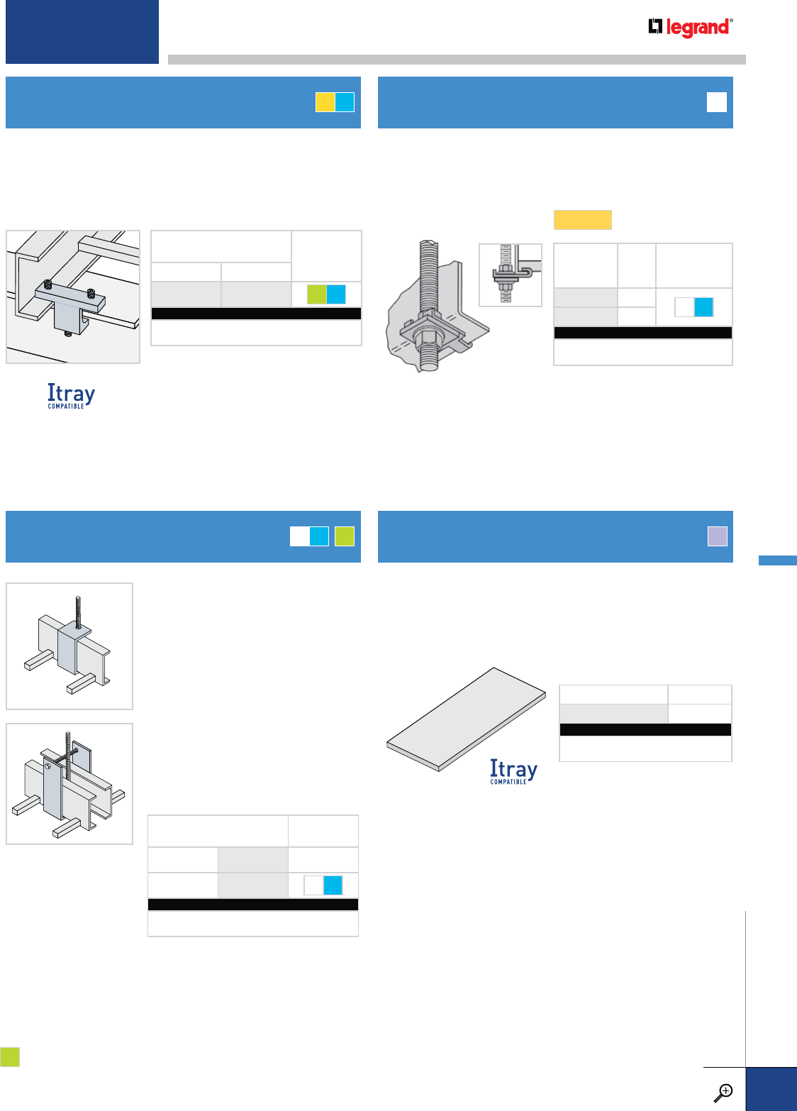
PRODUCT NUMBER DIMENSIONS
8945 1/8" X 3" X 6"
CATALOG NUMBERING EXAMPLE:
Material
N - 8945
PRODUCT
NUMBER ROD
DIA. FASTENERS
INCLUDED
1899-01 1/2"ZN S6
1899-02 3/8"
CATALOG NUMBERING EXAMPLE:
Material Fasteners
M - 1899-01 -S6
Attaches to the tray bottom flange and supports the cable tray
directly from a threaded rod without the need for an additional
support member. Threaded rod purchased separately.
SINGLE: Supports a single tray side rail
from a ½" threaded rod. For use with
all flange-out ladder tray systems.
Safe load = 300 lbs. per bracket.
Made of extruded black nylon. Can be installed between the
cable tray and support member to provide electrical isolation
of the tray system. Can also be used to facilitate cable tray
movement caused by thermal contraction and expansion.
No fasteners required.
PRODUCT NUMBER FASTENER
OPTIONS
HOLD DOWN EXPANSION
A802-01*A802-02†GE S6
CATALOG NUMBERING EXAMPLE:
Accessory System No. Fasteners
Z - A802-01 -S6
*Includes (2) ½" x 5/8" screws and
(1) ½" x 1 ½"screw.
†Includes (1) ½" x 1½"screw.
No drilling is required for either installation.
PRODUCT NUMBER FASTENER
OPTIONS
SINGLE A836 NONE
DOUBLE A837* ZN S6
CATALOG NUMBERING EXAMPLE:
Accessory System No. Fasteners
4M2- A837 - ZN
*Includes ¼" x 5" hex head bolt and ¼"
flanged nut.
Hold Down Clamp firmly attaches the cable tray to the flange
of an I-beam type support.
Expansion Guide attaches the clamp to the flange of an
I-beam type support, allowing movement of the tray side rail
due to thermal contraction and expansion.
I-BEAM HOLD DOWN CLAMP/
EXPANSION GUIDE
HANGER BRACKETS
SINGLE OVERHEAD HANGER CLAMP
NYLON ISOLATION PAD
SERIES1
DOUBLE: Supports two tray side rails
that are installed side-by-side from a
single ½" threaded rod. For use with
all flange-out ladder tray systems.
Safe load = 300 lbs. per bracket.
MT G
*
ZT M
N
G* = optional
For detailed material and finish descriptions, see page B.6.
METALLIC ACCESSORIES
PW CABLE TRAY
WWW.LEGRAND.US/CABLOFIL
B.53
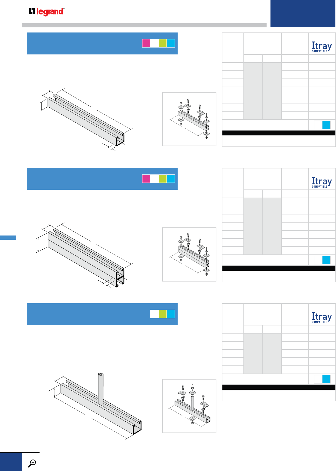
L
1
5
/
8
"
1
5
/
8
"
13
/
16
"
13
/
16
" DIA.
L
1
5
/
8
"
3
1
/
4
"
13
/
16
"
9
/
16
"
DIA.
1
5
/
8
"
1
5
/
8
"
L
L
L
L
SINGLE HANGER
CHANNEL KIT*
DOUBLE HANGER
CHANNEL KIT*
CENTER HANGER
CHANNEL KIT*
Made from 12-gage strut. Hangers have 9/16" diameter holes 13/16" from each
end to accept 1/2" threaded rod. Kit includes fasteners. When used with Z-type
hold-down clamps, select hanger with flange out dimensions.
Made from 12-gage struts welded back-to-back. Hangers have 9/16" dia.
holes 13/16" from each end to accept 1/2" threaded rod. When used with Z-type
hold-down clamps, select hanger with flange out dimensions.
Mounts with one 1/2" threaded rod to allow cable installation from both sides. Cable
should be loaded evenly on both sides of the center support to remain level. 12-gage
strut accepts channel nuts for hold down clamps with no drilling required. Not
recommended for trays over 24" wide. When used with Z-type hold-down clamps,
select hanger with flange out dimensions.
TRAY
WIDTH
PRODUCT NUMBER FLANGE IN
FLANGE OUT
HANGER KIT L (W+4) L (W+10)
6
0373 0393
10 16
91319
12 16 22
18 22 28
24 28 34
30 34 40
36 40 46
FASTENERS INCLUDED WITH KIT ONLY* ZN S6
CATALOG NUMBERING EXAMPLE:
Material Length Fasteners
M- 0393-10 - S6*
TRAY
WIDTH
PRODUCT NUMBER FLANGE IN
FLANGE OUT
HANGER KIT L (W+4) L (W+10)
6
0371 0394
10 16
91319
12 16 22
18 22 28
24 28 34
30 34 40
36 40 46
FASTENERS INCLUDED WITH KIT ONLY* ZN S6
CATALOG NUMBERING EXAMPLE:
Material Length Fasteners
M- 0394-16 - S6*
TRAY
WIDTH
PRODUCT NUMBER FLANGE IN
FLANGE OUT
HANGER KIT L (W+2) L (W+6)
6
0369 0395
812
91115
12 14 18
18 20 24
24 26 30
FASTENERS INCLUDED WITH KIT ONLY* ZN S6
CATALOG NUMBERING EXAMPLE:
Material Length Fasteners
M- 0395-10 - S6*
*Kits include hardware for ladder trays. Contact Legrand for other design options.
SINGLE HANGER CHANNEL
DOUBLE HANGER CHANNEL
CENTER HANGER CHANNEL
AMGT
AMGT
MGT
METALLIC ACCESSORIES
PW CABLE TRAY
WWW.LEGRAND.US/CABLOFIL
B.54
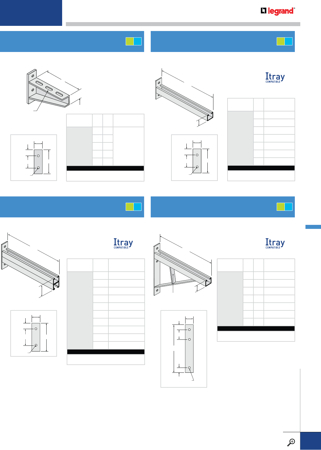
1
1
/
2
"
3/8" x 1" SLOTS
ON 2" CENTERS
L
PRODUCT
NUMBER LH
DESIGN LOAD -
UNIFORM (LBS.)
0353
76
900
10 6
13 6
19 7½
25 7½
CATALOG NUMBERING EXAMPLE:
Material Length
G-0353-13
L
15/8"
L
3
1/4
"
L
15/8"
STIFFENER BAR ON
31" LONG AND GREATER
PRODUCT
NUMBER LDESIGN LOAD -
UNIFORM (LBS.)
0215
7 1000
10 720
13 550
16 450
19 380
22 320
25 290
CATALOG NUMBERING EXAMPLE:
Material Length
G-0215-13
Recommended for use with flange-in cable trays. Made with 15/8" x 15/8" x 12 gage steel struts.
Made with 15/8" x 15/8" x 12 gage steel struts. Made with 15/8" x 15/8" x 12 gage steel struts.
2"
H
9/16" DIA.
23/4"
7/8"
2"
43/4"
9/16” DIA.
31/8"
13/16"
2"
6"
9/16" DIA.
43/8"
13/16"
PRODUCT
NUMBER LDESIGN LOAD -
UNIFORM (LBS.)
0216
7 3000
10 2400
13 1850
16 1500
19 1250
22 1100
25 960
31 770
37 650
43 560
CATALOG NUMBERING EXAMPLE:
Material Length
T-0216-13
2"
9/16" DIA.
31/8"
13/16"
13/16"
H
PRODUCT
NUMBER LH
DESIGN LOAD -
UNIFORM (LBS.)
0392
13 10 1600
19 15 1200
25 18 900
31 22 750
37 25 675
43 29 580
49 32 500
CATALOG NUMBERING EXAMPLE:
Material Length
G-0392-13
WALL BRACKET
DOUBLE STRUT BRACKET
SINGLE STRUT BRACKET
HEAVY-DUTY STRUT BRACKET
GT
GT
GT
GT
For detailed material and finish descriptions, see page B.6.
METALLIC ACCESSORIES
PW CABLE TRAY
WWW.LEGRAND.US/CABLOFIL
B.55
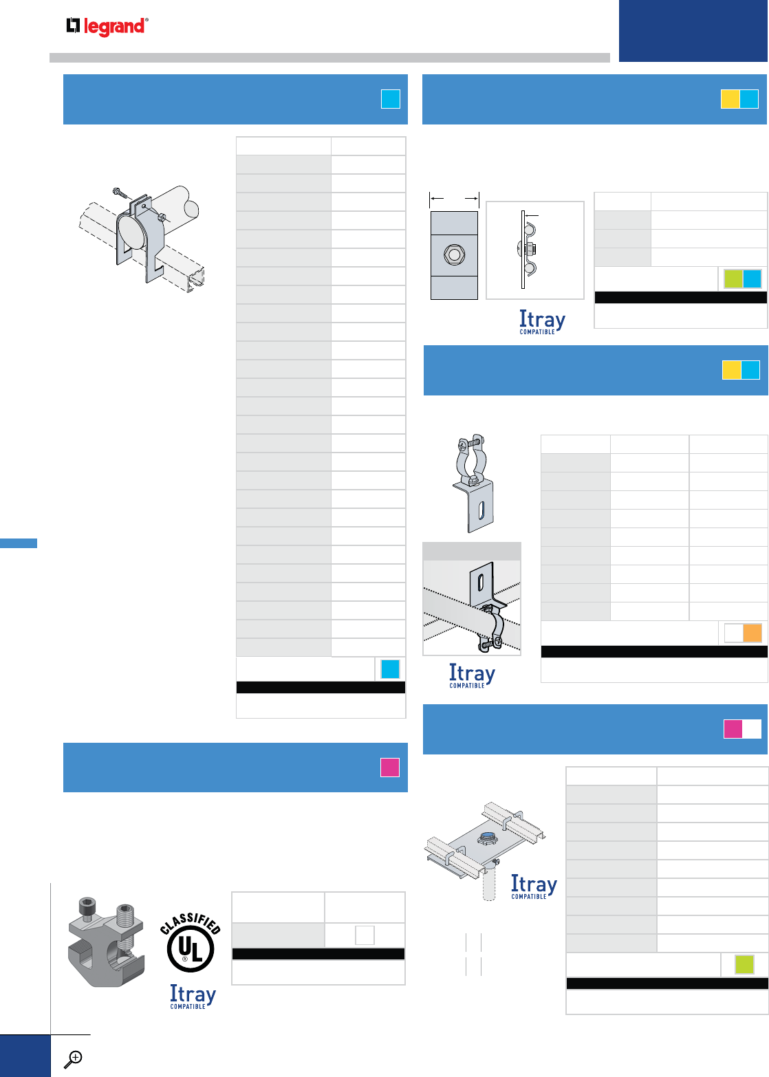
CABLE TRAY GROUNDING CLAMP
PRODUCT NUMBER CABLE SIZE
1916-06 3/4"
1916-07 7/8"
1916-08 1"
1916-09 11/8"
1916-10 11/4"
1916-11 13/8"
1916-12 11/2"
1916-13 15/8"
1916-14 13/4"
1916-15 17/8"
1916-16 2"
1916-17 21/8"
1916-18 21/4"
1916-19 23/8"
1916-20 21/2"
1916-21 25/8"
1916-22 23/4"
1916-23 27/8"
1916-24 3"
1916-25 31/8"
1916-26 31/4"
1916-27 33/8"
1916-28 31/2"
1916-29 35/8"
1916-30 33/4"
1916-31 37/8"
1916-32 4"
FASTENERS INCLUDED S6
CATALOG NUMBERING EXAMPLE:
Material Fasteners
T - 1916-06 -S6
PRODUCT
NUMBER
FASTENERS
INCLUDED
A840-01 ZN
CATALOG NUMBERING EXAMPLE:
Material Fasteners
A - A840-01 -ZN
11/4”PROD. NO. CONDUCTOR SIZE
1873-02 #2, #1 AND 1/0
1873-03 #6 TO #4
1873-04 2/0, 3/0 AND 4/0
FASTENER OPTIONS GE S6
CATALOG NUMBERING EXAMPLE:
Material Fasteners
Z - 1873-02 - S6
TRAY
SIDE
RAIL
PROD. NO. CONDUIT DIA. EMT DIA.
0228-05 3/8"-½" ½"
0228-06 ¾" ¾"
0228-10 1" 1"
0228-11 1¼" 1¼"
0228-12 1½" 1½"
0228-20 2" 2"
0228-25 2½" 2½"
0228-30 3" 3"
0228-40 4" 4"
FASTENER OPTIONS ZN S4
CATALOG NUMBERING EXAMPLE:
Material Fasteners
T - 0228-05 - S4
For use with all ladder cable
trays with box-shaped rungs.
A
Holds one or two bare copper or aluminum ground wires against
the cable tray side rail using included 3/8” diameter fasteners.
This clamp does not bond the ground wire to the tray.
Provides an excellent ground for copper or aluminum ground wires
to the cable tray. A 1/4” hex wrench is used to tighten both tray and
conductor set screws. Clamps are tin-plated, extruded aluminum.
Conductor Range: #6AWG to 250 MCM.
Attaches conduit to the cable tray side rail.
PRODUCT NUMBER EMT DIA.
0226-05 1/2"
0226-06 3/4"
0226-10 1"
0226-11 11/4"
0226-12 11/2"
0226-20 2"
0226-25* 21/2"
0226-30* 3"
0226-40* 4"
FASTENERS INCLUDED GE
CATALOG NUMBERING EXAMPLE:
Rung Spacing Material Fasteners
09 - M - 0226-11 - GE
Attaches conduit to
the ladder tray rungs.
GROUND WIRE ATTACHMENT CLAMPCABLE CLAMP
CONDUIT BRACKET CLAMP
CONDUIT PLATE CLAMP
APPLICATION
* Can also be used with
medium-wall (IMC) and
thick-wall (rigid) conduit.
RUNG SPACING INCHES
9" PLATE 69
18" PLATE 12 18
TZT
ZT
AM
METALLIC
PW CABLE TRAY
WWW.LEGRAND.US/CABLOFIL
B.56
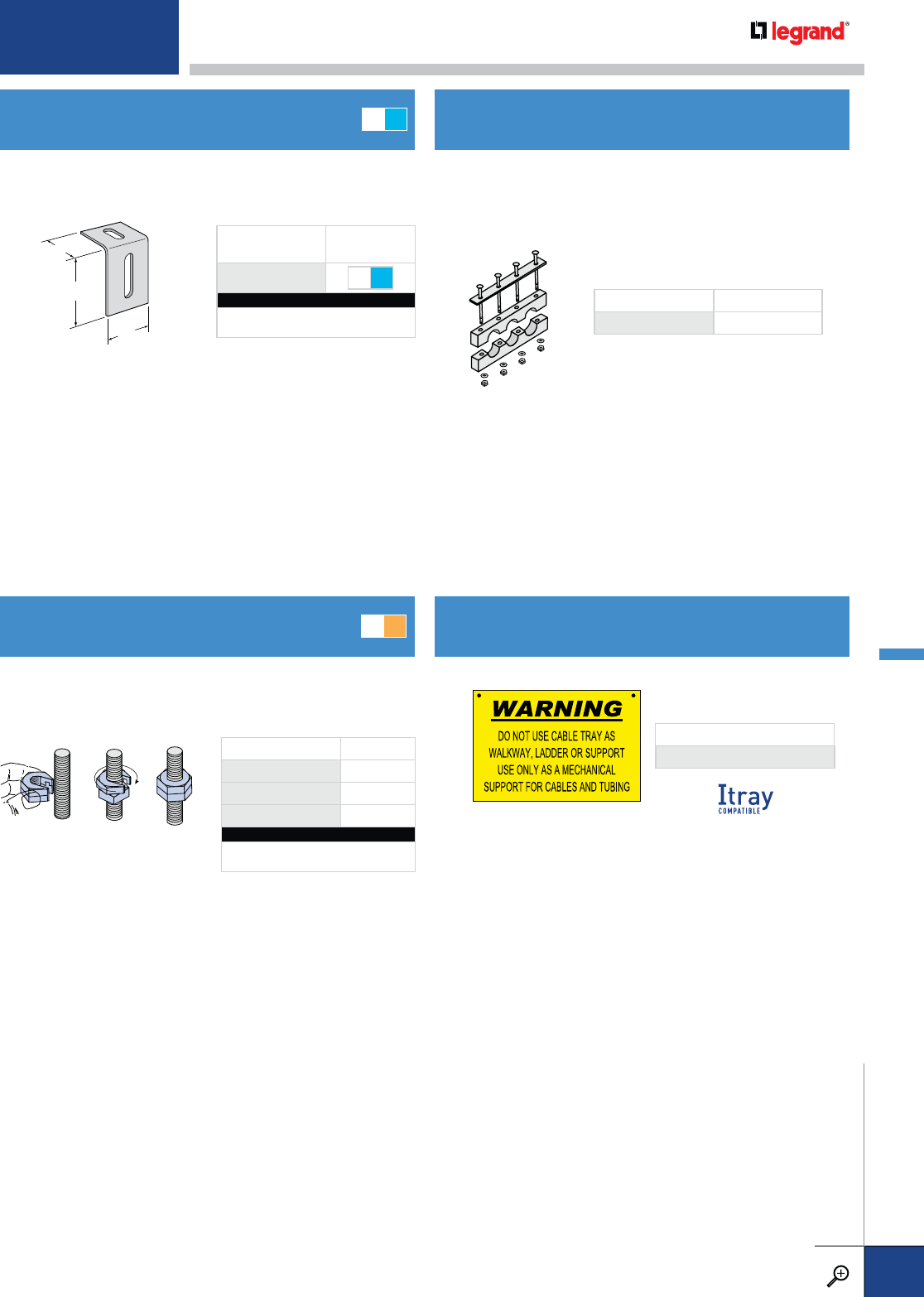
11
/
2”
2”
11
/
2”
PRODUCT NUMBER FASTENERS INCLUDED
0950 AS SPECIFIED
Permits attachment of clamps or other components to the cable
tray side rail. Conduit clamps are purchased separately.
Paraffin impregnated and furnished with 1/4" dia. fasteners.
Contact Legrand with quantities, cable dimensions, cable
spacing, and cable tray system information. Can be custom
designed for a wide variety of applications.
PRODUCT
NUMBER
FASTENER
OPTIONS
1818 ZN S6
CATALOG NUMBERING EXAMPLE:
Material Fasteners
T - 1818 -S6
Allows the user to slip the nut onto a rod, without actually
threading it. Ideal for when nuts must be added to a rod, but
cannot be threaded due to previously-installed equipment. Sign measures 8"x12".
PRODUCT NUMBER SIZE
SON 1/4 1/4"-20
SON 3/8 3/8"-16
SON 1/2 1/2"-13
CATALOG NUMBERING EXAMPLE:
Fasteners
SON 3/8-ZN
COMPLETE CATALOG NUMBER
P-0949-01
CLAMP BRACKET MAPLE CABLE BLOCKS
SLIP-ON LOCK NUT®PLASTIC SAFETY SIGN
ZN S4
MT
For detailed material and finish descriptions, see page B.6.
METALLIC ACCESSORIES
PW CABLE TRAY
WWW.LEGRAND.US/CABLOFIL
B.57
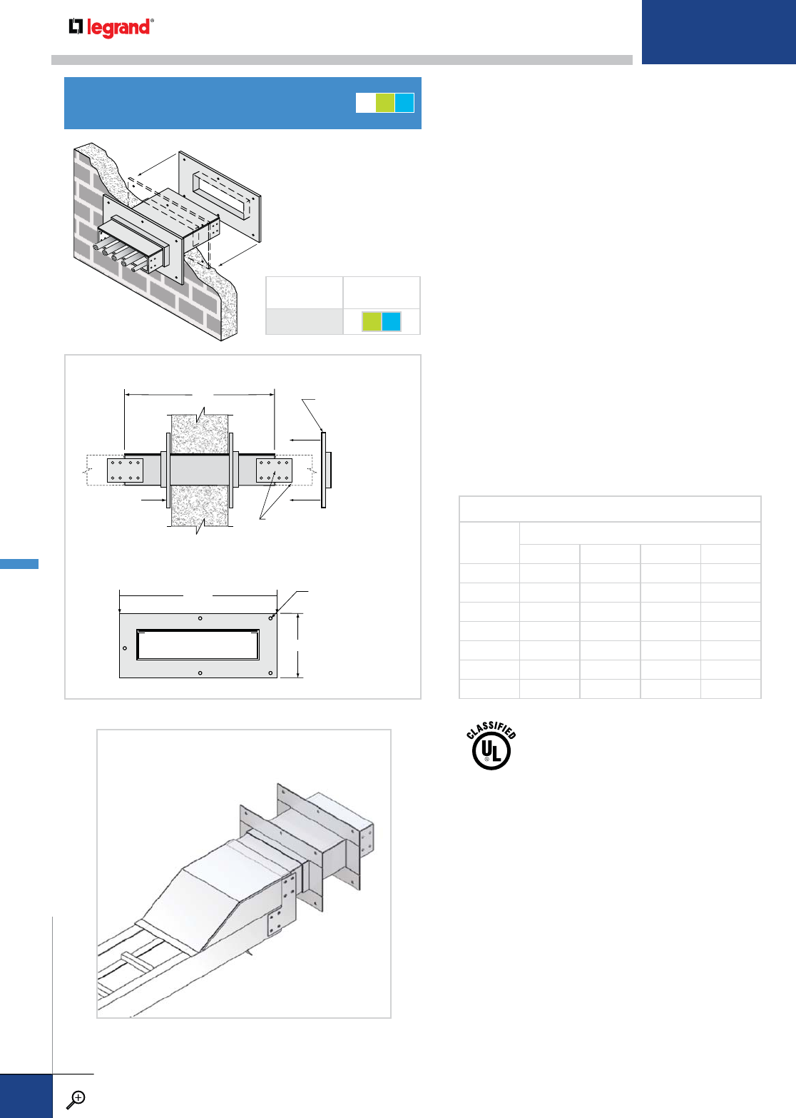
Fabricated cable tray fire stop sleeves from Legrand, combined
with Hilti Firestop products, are an economical alternative
to the high cost of fabricating protective fire wall and floor
penetration sleeves in the field.
This firestop system provides a rigid support for cable tray
in a UL classified system approved for fire wall and floor
penetrations. After the sleeve is placed in the wall or floor,
the loose collar slides over it. Hardware for the tray connection
only is included. Hardware required to mount sleeves to the
wall or floor is not included.
The Hilti Fire Block is a compressible fire stop brick, well-suited
for installations where frequent cable changes may be required.
Blocks are easily cut to fit any space, and can be removed and
reinstalled when cable configurations change. When exposed to
fire, the blocks expand to lock the seal in place.
Each cable tray firestop sleeve includes:
• One penetration sleeve with flanges
• Hilti Fire Blocks
• One Hilti Firestop Putty Stick
• Hardware for cable tray connection to the wall sleeve:
- Metallic and fiberglass cable trays with two side rails.
The Firestop kit includes two pairs of splice plates with
nuts & bolts; 316 stainless steel is recommended for use
with fiberglass systems.
Fixed collar is
welded to sleeve
W*+6"
H*+6"
20"
7/16" diameter holes
for 3/8" hardware
(not included)
Cable trays are attached to both
ends of the sleeve using standard
splice plate connectors
Loose collar slides
over sleeve after it
is placed in the wall
SIDE VIEW
END VIEW
NUMBER OF HILTI FIRE BLOCKS INCLUDED WITH EACH SLEEVE
SLEEVE
WIDTH
SIDE RAIL HEIGHT (IN.)
4567
62233
93344
123456
185678
24 6 8 9 11
30 8 101214
36 9 121416
UL classified for use with:
2-hr concrete or block walls
2-hr concrete floors
1-hr gypsum walls
2-hr gypsum walls
OUTDOOR CONVERSION FOR WALL PENETRATION (0434)
See page 51.
FIRE WALL PENETRATION SLEEVE
PRODUCT
NUMBER FASTENER
OPTIONS
0440 GE S6
MGT
• Wall Penetration Sleeve
(WPS or FWPS) not
included in kit, must be
ordered seperately
METALLIC FIRESTOP SYSTEMS
PW CABLE TRAY
WWW.LEGRAND.US/CABLOFIL
B.58
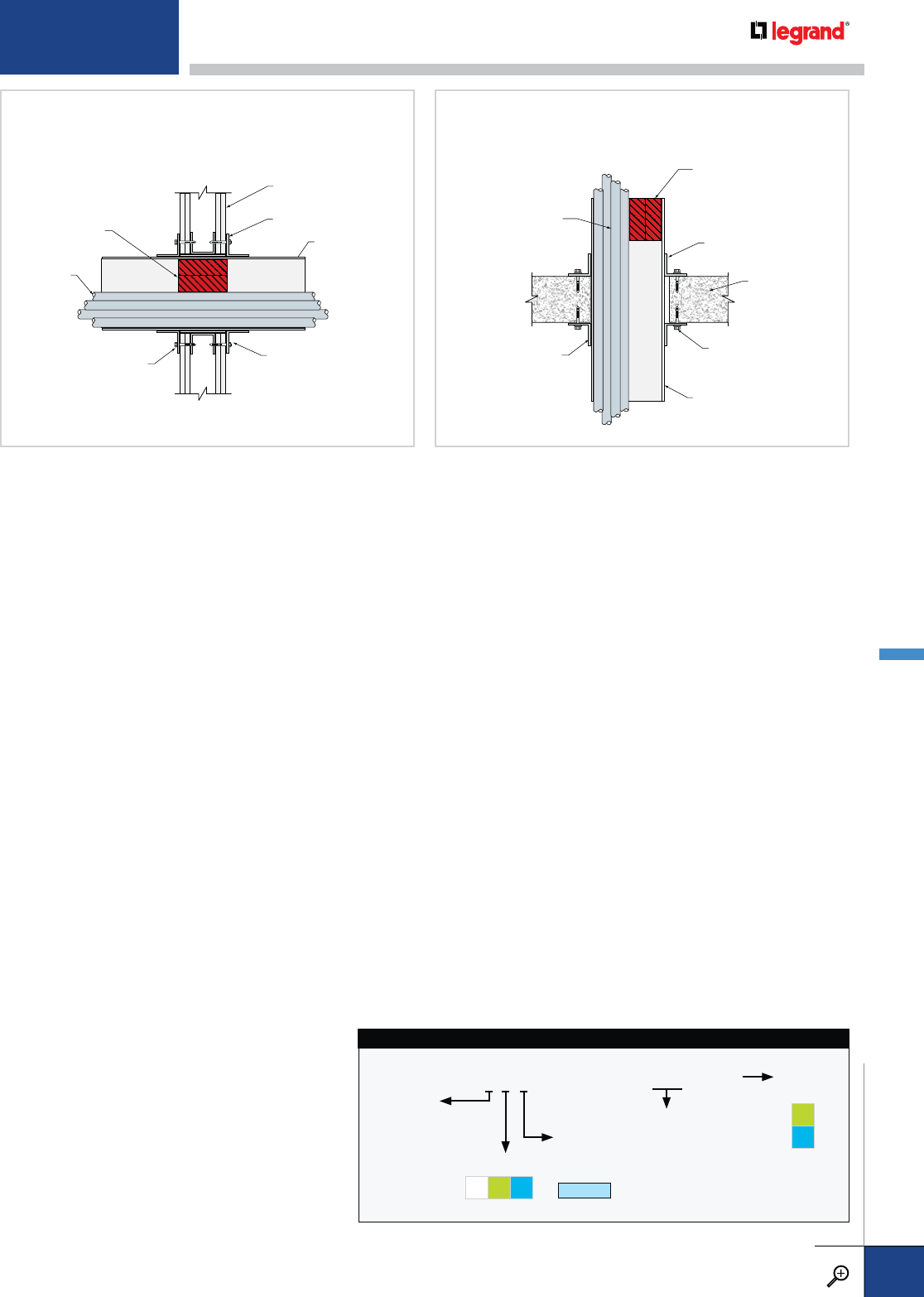
Hilti Fire Blocks
Fixed Collar
Wall Assembly
(Gypsum Wall Shown)
Penetration Sleeve
AdjustableCollar
Cables
Wall Anchors
(Not Included)
Hilti Fire Blocks
Fixed Collar
Floor Assembly
Penetration Sleeve
A
djustable Collar
Cables
Masonry Anchors
(Not Included)
Floor Firestop Sleeve Example
0440 product used as a floor sleeve per UL assembly
W-L-3226 and C-AJ-3232
Floor Firestop Sleeve Example
0440 product used as a floor sleeve per UL assembly
F-A-3022
WALL/FLOOR SLEEVE DESCRIPTION
Designed for single runs of cable tray, having a height and
width to match the tray system specified. One end of the 20 inch
sleeve has a flange attached 6 inches from the end, while the
flange for the other end is “floating” and is free to slide directly
against the face of the wall as needed. The 20 inch length of the
sleeve will accommodate a wall thickness of up to 8 inches. A
wall thickness of 8 inches will result in the sleeve protruding 6
inches from each side of the wall. Both ends of the sleeve are
punched with holes for attaching cable tray splice plates or
hardware needed for the tray system specified.
INSTALLATION
The opening in the wall should be within 1 inch of the nominal
height and width of the cable tray. The flanges of the sleeve
have 7/16" diameter mounting holes for attachment to the wall
using 3/8" diameter hardware. Hardware for wall attachment is
not included. After the sleeve is mounted in the wall or floor,
the cable trays on either side of the sleeve can be connected
using the hardware supplied with the sleeve. When the trays
are in place, the cables should be pulled through the wall and
sleeve as needed. After all of the cables are installed in the
tray, install the Fire Blocks as described. Any voids between
cables should be filled with the Firestop Putty Stick.
TECHNICAL DATA
Construction ............ Arc Welded
Sleeve
Dimensions .............. 20" x Tray Width x Tray Height
Flange
Dimensions .............. (Tray Width + 6") x (Tray Height + 6")
UL Classification ...... Qualifies for use as an equipment grounding
conductor per N.E.C. 392.7. Cross-sectional area
and amperage ratings are based on the cable tray
system attached to the sleeve.
HILTI FIRE BLOCKS INSTALLATION
Walls: Hilti Fire Blocks shall be installed with 5" dimension
projecting through and centered within wall assembly.
Floors: Hilti Fire Blocks shall be installed with 5" dimension
projecting through opening, flush with the top surface of
sleeve or recessed within sleeve at any level above the top
surface of floor.
Fire blocks fill the annular space between the cables and the
sleeve. Fire Blocks may be cut to match the profile of cables
or to fit opening. Any voids should be filled with 0618 Firestop
Putty Stick.
6M2-0440-36-GE
PRODUCT NO.
WALL PENETRATION SLEEVE CATALOG NUMBERING EXAMPLE:
CONNECTOR SYSTEM NO.
WIDTH
06 – 6"
09 – 9"
12 – 12"
18 – 18"
24 – 24"
30 – 30"
36 – 36"
FASTENER
OPTIONS
GE
S6
MATERIAL
MGT
SIDE RAIL
HEIGHT
4 – 4"
5 – 5"
6 – 6"
7 – 7"
FITTING SERIES
This item must
be specified as
SERIES 2
For detailed material and finish descriptions, see page B.6.
METALLIC FIRESTOP SYSTEMS
PW CABLE TRAY
WWW.LEGRAND.US/CABLOFIL
B.59

METALS
PW from Legrand, a pioneer in the development of cable trays, first
made a complete study of the metals available in order to create those
systems that would be unmatched in economy and strength. Inherent
are the problems connected with the environment and its effect on the
life of metals, including weathering and corrosion by electro-chemical
and chemical attack.
Steel – Hot-Dip Galvanized After All Fabrication and Welding
Commercial quality steel is used for this type of coating, which is
described below. This steel is either hot rolled, pickled and oiled, or
cold rolled, mild carbon steel.
Steel – Mill Galvanized (Pre-Galvanized)
Where heavy zinc coating is not necessary, steel with a continuous hot
rolled zinc coating conforming to ASTM specification A653 designation
G90 is used. Products made with mill galvanized steel are generally
lower in cost than the same products that are hot dip galvanized after
fabrication. However, see the limitations under “Finishes” later on
this page.
Stainless Steel
18-8 stainless steel type 304 and marine-grade type 316 is available
for most PW products. Certain products such as raceway push clips,
Stack-A-Tube yoke clamps, and some hardware items are made only
from 18-8 stainless steel. Stainless steel components are compatible
for use with hot dip galvanized, mill galvanized, and aluminum products.
Complete cable tray systems can be furnished in stainless steel.
Aluminum Alloys
The principal aluminum used for tray side rails, rungs, and channels is
extruded, copper-free alloy 6063-T6. This alloy is used for structural
members where extreme stiffness and high tensile strength are
mechanically required to resist high unit stresses. This is called a
“magnesium alloy”.
Alloy 5052-H32 is used for components fabricated from sheet
(except covers) such as connectors, blind ends, dropouts, etc. This is a
“magnesium alloy”, copper free, and very compatible with alloy 6063-T6.
This alloy possesses excellent characteristics for stamped and formed
components.
Alloys 3003 and 3105 are used for aluminum covers. These alloys are
very compatible with alloys 6063-T6 and 5052-H32.
FINISHES
Steel – Hot-Dip Galvanized After All Fabrication and Welding:
This high-quality coating is created in a multi-step process and applied
to the completed product after all fabrication and welding. First the
steel is cleaned by immersing it in a caustic dip tank, then pickled,
and finally washed. The article is then dipped into a molten zinc
bath. All surfaces are thoroughly coated. Hot dip galvanizing after all
fabrication and welding is done on PW products in accordance with
ASTM Specification A123. This coating, applied to steel trays, provides
greatest protection at lower cost.
Due to the high temperatures associated with the hot dip process,
some warping of the metal is common. This occurs most frequently
with products having large, flat surfaces such as covers. To minimize
warping, PW uses thicker sheet metal for covers. This does reduce
warping, but does not eliminate it.
Mill Galvanized (Pre-Galvanized)
This coating is applied onto steel sheets at the mill in accordance
with ASTM Specification A653 and results in a coating thickness of
0.90 ounces per square foot total for both sides. This coating adheres
tightly to the base metal at bends and compound curves. Being a hot
dip coating prior to tray fabrication, and of a controlled thickness about
one-third that of hot dip galvanized after fabrication, it is not generally
used outdoors. It is not recommended for areas where there is a
concentration of moisture and/or chemical deposits. This material
gives excellent service in dry, normal, or controlled atmospheres.
Some Helpful Hints On Which Zinc Coating To Select
1. Protection of the base metal is directly proportional to the zinc
coating thickness. Hence, thicker coating means longer life. At
sheared or punched locations, zinc on mill galvanized steel is wiped
down over approximately 1/3 of the metal thickness giving some
sacrificial protection in the presence of an electrolyte. On hot dip
galvanized after fabrication, all edges are coated but the original cost
is higher.
2. The edges of holes in mill galvanized steel will have no coating;
however, a small sacrificial protection is afforded by the top and
bottom surfaces of the sheet. The hot dip galvanized comment above
applies here.
3. If moisture and drippings accumulate, consider hot dip galvanized
after fabrication to avoid premature deterioration at those locations.
4. Covers are typically made from mill galvanized steel in order to avoid
the poor appearance caused by severe warping of such large flat
surfaces when hot dip galvanized after fabrication.
Other Coatings
Occasionally, other highly special coatings are required such as powder
coating, epoxy painting, standard painting, primer paint, and others.
Legrand engineers are available for consultation on these coatings and
their application to PW trays.
TECHNICAL DATA
PW CABLE TRAY
WWW.LEGRAND.US/CABLOFIL
B.60
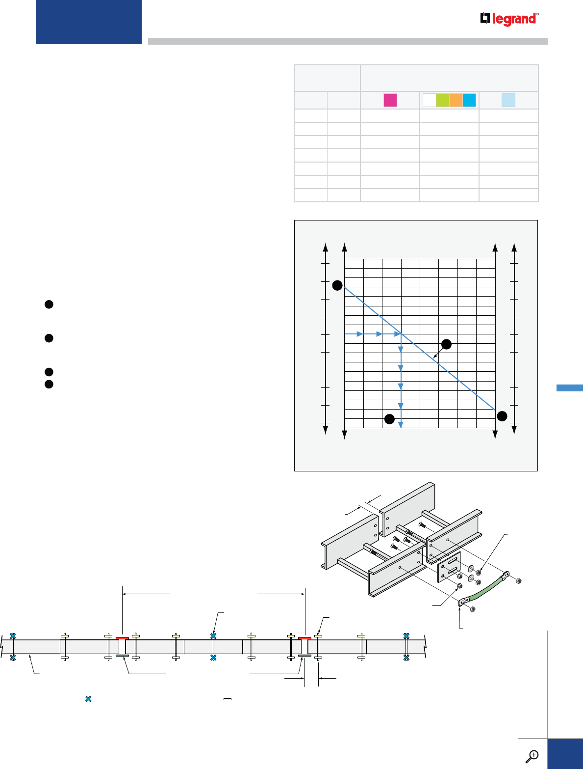
Figure 2
Expansion Connector Installation Locations
Expansion Splice Plates
(Bonding Jumpers Required) Place cable tray supports
within 24” of each side of
Expansion Splice Plates
Cable Tray Section
See Table 1 for Spacing
of Expansion Splice Plates
Cable Tray Support
with Hold Down Clamp Cable Tray Support with
Expansion Guide Clamp
Hold Down Clamp Locations
Anchor the tray with hold down clamps
at the one support point that is nearest
the midpoint between expansion gaps.
Expansion Guide Locations
Install expansion guide clamps at all tray
support points other than the midpoint.
Locking hex
nuts and flat
washers in
slotted holes
Flanged hex nuts
in round holes
Figure 3
Install bonding jumpers
across expansion plates
Gap Setting
130
110
90
70
50
30
10
-10
-30
50
40
30
20
10
0
-10
-20
-30
-40
Minimum
Temperature
Maximum
Temperature
130
110
90
70
50
30
10
-10
-30
50
40
30
20
10
0
-10
-20
-30
-40
Metal Temperature At Time Of Installation
o
C
o
F
o
C
o
F
01
1/8 1/4 3/8 1/2 5/8 3/4 7/8
Figure 1
Gap Setting of Expansion Splice Plate
Gap Setting
(in)
A
B
C
D
Table 1
TEMPERATURE
DIFFERENTIAL
MAXIMUM SPACING BETWEEN
EXPANSION JOINTS FOR 1" MOVEMENT (FT.)
˚F ˚C AMG L T F
25 14 260 512 667
50 28 130 256 333
75 42 87 171 222
100 56 65 128 167
125 70 52 102 133
150 83 43 85 111
175 97 37 73 95
Expansion splice plates should be placed on the outside of the cable tray
on both side rails. The screw heads should be on the inside and nuts on the
outside of the cable tray. Tighten the lock nuts on the screws in the slotted
holes just a few turns, allowing the bolt to move freely in the slot.
THERMAL CONTRACTION AND EXPANSION
Expansion Splice Plate Installation
It is important that thermal contraction and expansion be considered
when installing cable tray systems. The length of the straight cable trays
runs and the temperature differential govern the number of expansion
splice plates required (see Table 1).
Proper operation of the expansion splice plates depends upon correct
placement of the tray supports, hold down clamps and expansion guides
as shown.
Hold Down Clamps should be used at the support point nearest to the
midpoint between expansion gaps.
Expansion Guide Clamps should be used at all support points other
than the midpoint. These clamps should be installed in such a way to
allow the tray to slide freely under the clamp when thermal contraction
and expansion takes place.
Supports with expansion guide clamps should be located within 24” of
each side of expansion splice plates.
Accurate gap settings between trays at the expansion joint at the time
of installation are necessary for the proper operation of the expansion
splice plates. Use the following procedure to determine the correct gap
setting:
A
Determine what the maximum temperature will be at the
installation location and plot this point on the graph on the max.
temp line. (Example value = 100)
B
Determine what the minimum temperature will be at the
installation location and plot this point on the graph on the min.
temp line. (Example value = -30).
C
Draw a line between the maximum and minimum points.
D
At the time of installation, determine the air temperature.
(Example = 50). Plot this point on the line drawn between the
maximum and minimum temperatures to determine the correct
gap setting at the expansion plate. (Example = 3/8”).
For detailed material and finish descriptions, see page B.6.
TECHNICAL DATA
PW CABLE TRAY
WWW.LEGRAND.US/CABLOFIL
B.61
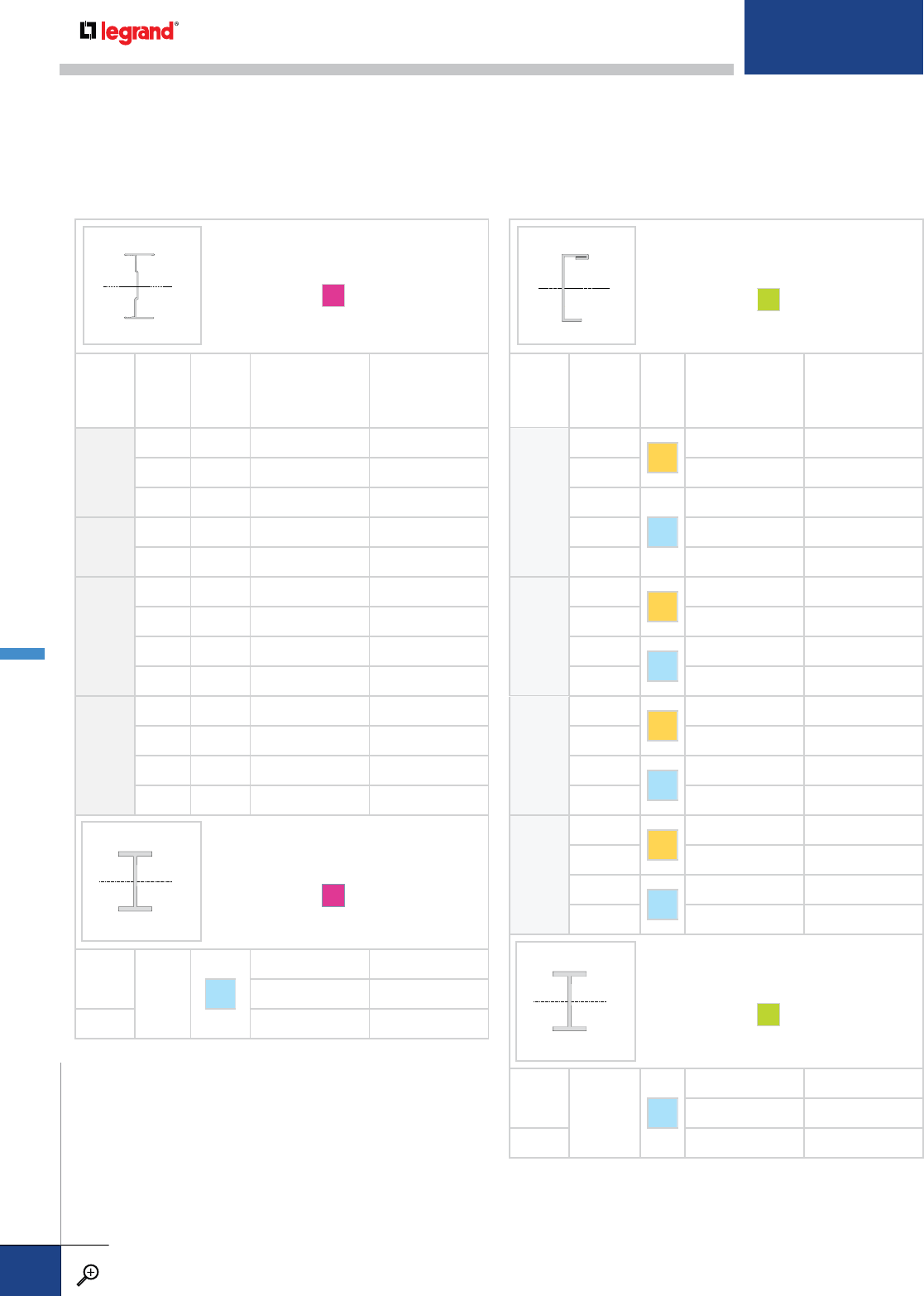
ITRAY IBEAM
A
RAIL
HEIGHT
(IN.)
NEMA
CLASS
PRODUCT
NUMBER
Ix
MOMENT OF INERTIA
(IN.4)
Sx
SECTION MODULUS
(IN.3)
4
12B 4A12B 1.343 0.626
12C 4A12C 1.418 0.646
20B 4A20B 2.717 1.103
5
12C 5A12C 2.288 0.859
20B 5A20B 3.344 1.146
6
12C 6A12C 3.993 1.182
20B 6A20B 5.441 1.549
20C 6A20C 6.380 1.836
24C 6A24C 8.128 2.349
7
12C 7A12C 5.403 1.106
20B 7A20B 7.675 1.896
20C 7A20C 9.803 2.471
24C 7A24C 12.092 3.005
IBEAM
A
8
20C+ S2
25.8053 7.1067
26.3140 7.3722
10 70.3837 15.2789
xx
CABLE TRAY SIDE RAILS
The mechanical properties of cable tray side rails for straight tray sections are shown for all standard systems. Side rails used for fittings
may have slightly different dimensions since they must be suitable for bending into curved sections. Fitting side rails are designed to meet or
exceed the loading requirements of the straight tray sections with which they are used when supported per NEMA VE2 installation guidelines.
Although the cross-sectional dimensions of the fitting side rails may be slightly different than the straight section side rails, all aspects of
fitting design are in accordance with NEMA VE1 requirements. Please contact Legrand for detailed information on fitting side rails.
xx
CCHANNEL
G
RAIL
HEIGHT
NEMA
CLASS
SERIES
Ix
MOMENT OF INERTIA
(IN.4)
Sx
SECTION MODULUS
(IN.3)
4
12B
S1
0.6214 0.3517
12C, 16A 0.7417 0.4110
20A, 16B
S2
1.0593 0.5860
20B, 16C 1.3781 0.7984
20C 1.7934 1.0044
5
12B
S1
1.0785 0.4796
12C, 16A 1.2925 0.5645
20B, 16C
S2
2.3334 1.0632
20C 3.1670 1.4398
6
12B
S1
1.7047 0.6234
12C, 16A 1.7873 0.6733
20B, 16C
S2
2.7718 1.0001
20C 3.4185 1.2324
7
12B
S1
2.5243 0.7830
12C, 16A 2.6403 0.8411
20B, 16C
S2
4.0298 1.2366
20C 4.9763 1.5260
IBEAM
G
8"
20C+ S2
18.5 4.62
30.8 7.81
10" 68.9 13.8
xx
xx
METALLIC RUNGS
PW CABLE TRAY
WWW.LEGRAND.US/CABLOFIL
B.62
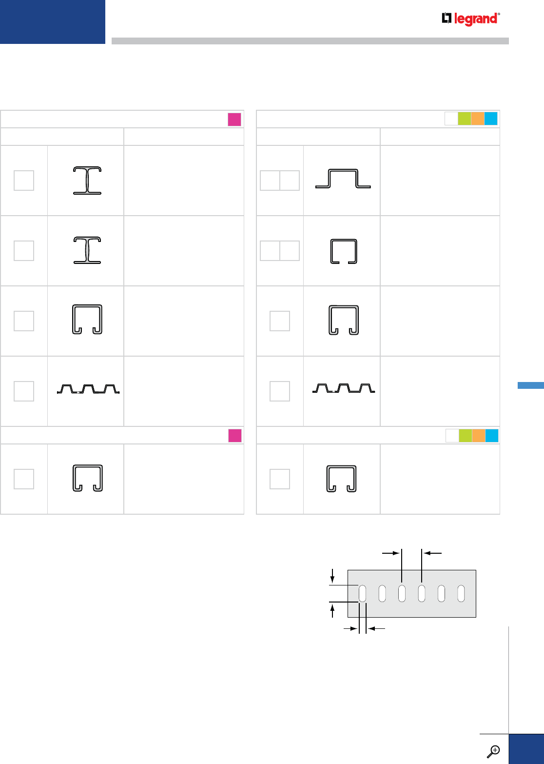
RUNG DESIGNS
PW offers a wide range of rung design options for special load applications. Extremely heavy cable loads, concentrated static loads, and heavy snow or
ice loads may require rungs with greater load capacities than standard designs. Rung substitutions are designated by suffixes added to the tray catalog
numbers .
STANDARD RUNGS AND BOTTOMS - ALUMINUM
TYPE USE
AL I-BEAM RUNG, 1" DEEP
STANDARD FOR MOST LADDERS
UP TO 24" WIDE
AH HEAVY I-BEAM RUNG, 1" DEEP
STANDARD FOR MOST LADDERS
30" AND WIDER
SR
SLOTTED STRUT RUNG, 15/8" DEEP
STANDARD FOR LONG-SPAN
LADDER TRAY WITH SIDERAIL OF
8" OR LARGER
CA CORRUGATED SHEET BOTTOM
SOLID TROUGH
UPGRADE RUNG - ALUMINUM
ST SLOTTED STRUT RUNG, 1" DEEP
UPGRADE OPTION FOR LADDERS
SEE BELOW FOR SLOT DETAIL
STANDARD RUNGS AND BOTTOMS - STEEL
TYPE USE
HL HH HAT RUNGS, SOLID
STANDARD FOR LADDER TRAYS
BX BH BOX RUNG, 1" DEEP
STANDARD FOR LADDER TRAYS
RS
SLOTTED STRUT RUNG, 15/8" DEEP
STANDARD FOR LONG-SPAN
LADDER TRAY WITH SIDERAIL OF
8" OR LARGER
CS CORRUGATED SHEET BOTTOM
SOLID TROUGH
NOT AVAILABLE IN STAINLESS STEEL
UPGRADE RUNG - STEEL
SU SLOTTED STRUT RUNG, 1" DEEP
UPGRADE OPTION FOR LADDERS
SEE BELOW FOR SLOT DETAIL
A
A
MGL T
MGL T
RUNG OPTIONS
SLOTTED RUNGS
All PW cable tray metallic ladder systems are available with slotted strut rungs for cable ties.
Slots are 0.75" long to accommodate stainless steel banding used in marine applications or
any location where extra cable support requires the use of cable ties. Slotted strut rungs are
provided with alternating slots up and down to allow for strut accessories to be used both
inside the tray and below the cable area. Slotted rungs are designated by the suffix
ST (aluminum) or SU (steel) added to the straight sections and fittings catalog numbers.
0.75"
0.31"
1.00" Spacing
For detailed material and finish descriptions, see page B.6.
METALLIC RUNGS
PW CABLE TRAY
WWW.LEGRAND.US/CABLOFIL
B.63
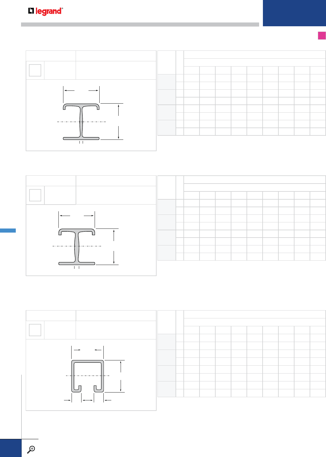
STANDARD RUNGS A
This is the standard rung for all 6"-24" wide aluminum ladder trays.
RUNG TYPE MECHANICAL PROPERTIES
AL I-BEAM
MINIMUM THICKNESS = 0.050"
MOMENT OF INERTIA: IX = 0.044 IN4
SECTION MODULUS: SX = 0.0869 IN3
1.00"
.081"
1.00"
xx
RUNG
SPACING
LOAD TYPE
SAFE LOAD LIMITS (LBS/FT)
TRAY WIDTH (IN.)
6 9 12 18 24 30 36 42 48
6Q
15330 3553 2665 1777 1332 AH AH AH AH
Q
26814 4276 3007 1738 1104 AH AH AH AH
9Q
13553 2369 1777 1184 888 AH AH AH AH
Q
24543 2851 2005 1159 736 AH AH AH AH
12* Q
12665 1777 1332 888 667 AH AH AH AH
Q
23407 2138 1504 869 552 AH AH AH AH
18 Q
11777 1184 888 592 444 AH AH AH AH
Q
22271 1425 1002 579 368 AH AH AH AH
Standard rung for 8" and larger siderail cable trays. Designed for extremely heavy load applications. This profile will accept strut hardware and
accessories. Trays which use this rung will have a load depth equal to the side rail height minus 15/8". SR rungs are installed alternating slot up
and slot down.
RUNG TYPE MECHANICAL PROPERTIES
SR SLOTTED†
MINIMUM THICKNESS = 0.102"
MOMENT OF INERTIA: IX = 0.1848 IN4
SECTION MODULUS: SX = 0.2039 IN3
1.63"
0.38"0.38"
xx
1.63"
RUNG
SPACING
LOAD TYPE
SAFE LOAD LIMITS (LBS/FT)
TRAY WIDTH (IN.)
6 9 12 18 24 30 36 42 48
6Q
19999 8700 6525 4350 3262 2610 2175 1864 1631
Q
29999 8700 6525 4350 3262 2610 2175 1864 1576
9Q
18700 5800 4350 2900 2175 1740 1450 1243 1087
Q
28700 5800 4350 2900 2175 1740 1450 1243 1050
12* Q
16525 4350 3262 2175 1631 1305 1087 932 816
Q
26525 4350 3262 2175 1631 1305 1087 932 788
18 Q
14350 2900 2175 1450 1087 870 725 621 544
Q
24350 2900 2175 1450 1087 870 725 621 525
RUNG TYPE MECHANICAL PROPERTIES
AH I-BEAM
MINIMUM THICKNESS = 0.070"
MOMENT OF INERTIA: IX = 0.0510 IN4
SECTION MODULUS: SX = 0.0981 IN3
1.00"
1.00"
xx
.126"
This is the standard rung for all aluminum ladder trays 30" and wider.
RUNG
SPACING
LOAD TYPE
SAFE LOAD LIMITS (LBS/FT)
TRAY WIDTH (IN.)
6 9 12 18 24 30 36 42 48
6Q
1AL AL AL AL AL 1360 1134 972 850
Q
2AL AL AL AL AL 1143 819 588 415
9Q
1AL AL AL AL AL 907 756 648 567
Q
2AL AL AL AL AL 762 546 392 276
12* Q
1AL AL AL AL AL 680 567 486 425
Q
2AL AL AL AL AL 572 410 294 207
18 Q
1AL AL AL AL AL 453 378 324 283
Q
2AL AL AL AL AL 381 273 196 138
METALLIC RUNGS
PW CABLE TRAY
WWW.LEGRAND.US/CABLOFIL
B.64
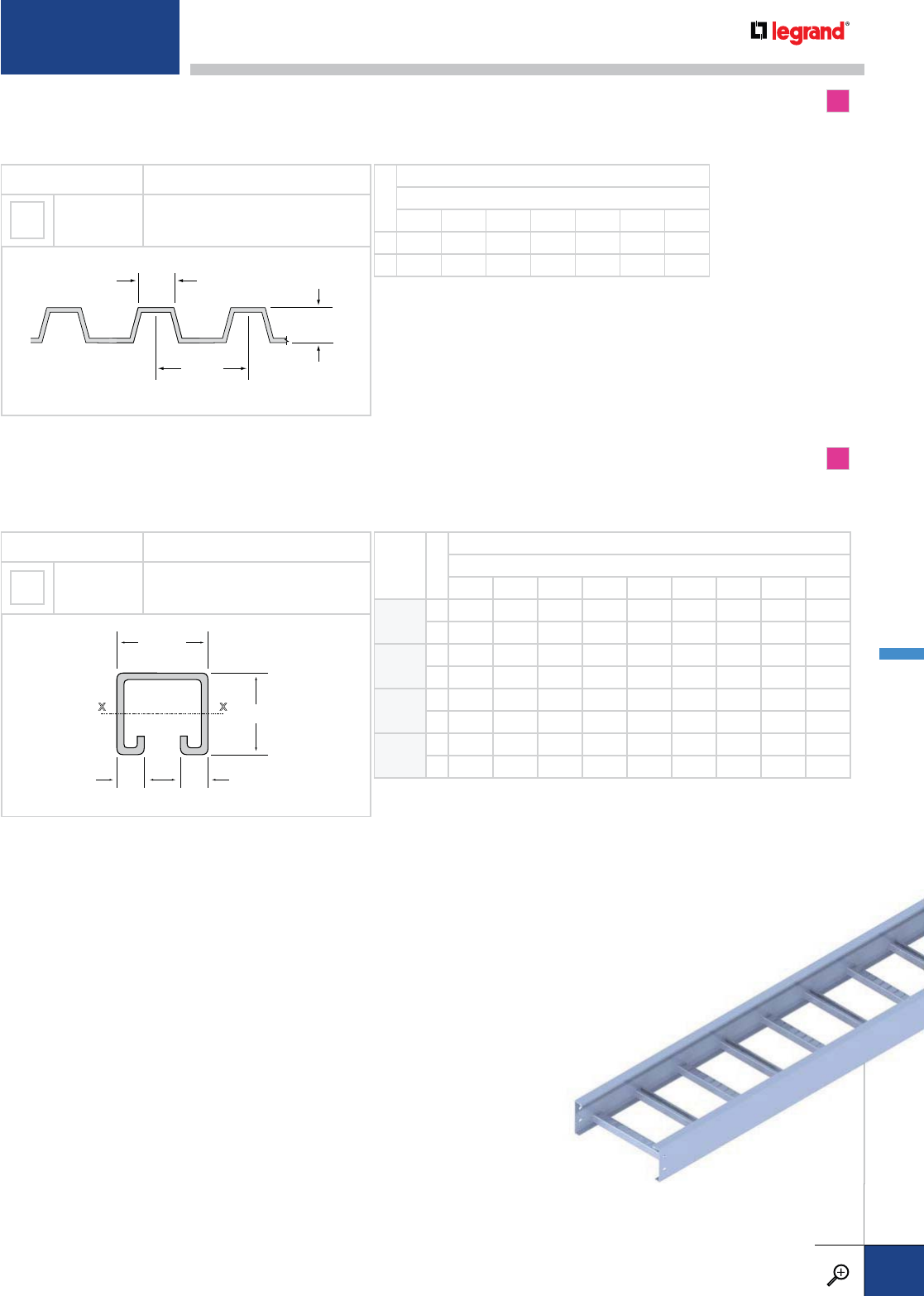
RUNG TYPE MECHANICAL PROPERTIES
ST SLOTTED†
MINIMUM THICKNESS = 0.105"
MOMENT OF INERTIA: IX = 0.0531 IN4
SECTION MODULUS: SX = 0.0917 IN3
1.63"
1.00"
0.38"
0.38"
xx
This is the upgrade slotted rung for all aluminum ladder cable tray. This rung is also available for all aluminum ladders for extremely heavy load
applications. ST rungs are installed alternating slot up and slot down.
RUNG
SPACING
LOAD TYPE
SAFE LOAD LIMITS (LBS/FT)
TRAY WIDTH (IN.)
6 9 12 18 24 30 36 42 48
6Q
16602 4402 3301 2201 1651 1320 1100 943 825
Q
26602 4402 3301 2201 1604 1123 803 574 402
9Q
14402 2934 2201 1467 1100 880 734 629 550
Q
24402 2934 2201 1467 1069 749 535 382 268
12* Q
13301 2201 1651 1100 825 660 550 472 413
Q
23301 2201 1651 1100 802 562 401 287 201
18 Q
12201 1467 1100 734 550 440 367 314 275
Q
22201 1467 1100 734 535 374 268 191 134
Q
1 SAFE LOAD/CABLE LOAD
ONLY: Allowable uniformly-
distributed cable load expressed
in lbs/linear foot of tray length,
based on the load carrying
capability of the rung with a
safety factor of 1.5. To convert
Safe Load/Cable Load Only to
reflect a safety factor of 2.0,
multiply the safe loads shown
by 0.75.
Q
2 SAFE LOAD / CABLE LOAD
+200 LBS: Allowable uniformly-
distributed cable load expressed
in lbs/linear foot of tray length,
based on the load carrying
capability of the rung with a
200 lb. concentrated static load
applied at the center of the
rung, without collapse.
Q
3 Will not support a 200 lb.
concentrated static load applied
at the center of the rung.
[XX] Two digit code in the
safe load limit tables indicates
recommended rung option for
specified width.
* Single rung load capacity: The data shown for 12" rung
spacing is equivalent to the load capacity of the single rung.
STANDARD CORRUGATED BOTTOM A
UPGRADE BOTTOM A
This is the standard corrugated bottom used for all aluminum, solid-bottom tray systems up to and including NEMA Class 20C.
Corrugated bottoms are not available in widths greater than 36". For extremely heavy load applications. Ladder type tray is recommended.
RUNG TYPE MECHANICAL PROPERTIES
CA SOLID OR
VENTILATED MINIMUM THICKNESS = 0.032"
2.19"
0.50"
0.88"
LOAD TYPE
SAFE LOAD LIMITS (LBS/FT)
TRAY WIDTH (IN.)
6 9 12 18 24 30 36
Q
12000 1333 1000 667 500 400 333
Q
22000 1333 1000 600 350 200 100
† Slotted rungs are
installed alternating
slot up and slot down.
For detailed material and finish descriptions, see page B.6.
METALLIC RUNGS
PW CABLE TRAY
WWW.LEGRAND.US/CABLOFIL
B.65
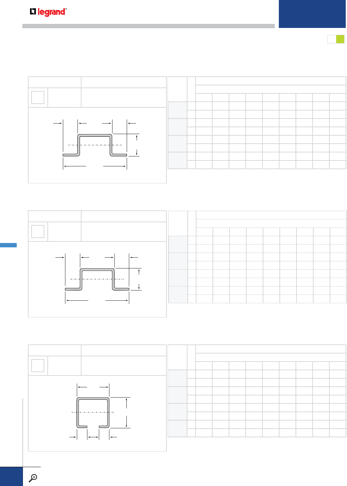
STANDARD RUNGS MG
RUNG TYPE MECHANICAL PROPERTIES
BX SOLID
MINIMUM THICKNESS = 0.048"
MOMENT OF INERTIA: IX = 0.0188 IN4
SECTION MODULUS: SX = 0.0343 IN3
0.97"
0.28"0.28"
xx
1.00"
This is the standard rung for all flange-out steel ladders and all flange-in, NEMA Class 20A, 20B, and 20C, hot-dip galvanized steel ladders
6"-24" wide. Please contact Legrand for catalog numbers if this rung is desired for other tray systems.
RUNG
SPACING
LOAD TYPE
SAFE LOAD LIMITS (LBS/FT)
TRAY WIDTH (IN.)
6 9 12 18 24 30 36 42 48
6Q
13243 2162 1621 1081 811 BH BH BH BH
Q
23243 2162 1561 774 381 BH BH BH BH
9Q
12162 1441 1081 721 540 BH BH BH BH
Q
22162 1441 1041 516 254 BH BH BH BH
12* Q
11621 1081 811 540 405 BH BH BH BH
Q
21621 1081 781 387 190 BH BH BH BH
18 Q
11081 721 540 360 270 BH BH BH BH
Q
21081 721 520 258 127 BH BH BH BH
This is the standard solid rung for the following steel cable trays, up to 24" wide: NEMA Class 12B and 12C ladder with flange-in side rails.
NEMA Class 20A, 20B and 20C, mill galvanized, and ladder.
RUNG TYPE MECHANICAL PROPERTIES
HL SOLID
THICKNESS = 0.038"
MOMENT OF INERTIA: IX = 0.0143 IN4
SECTION MODULUS: SX = 0.0374 IN3
1.25"
0.75"
xx
2.50"
0.63" 0.63"
RUNG TYPE MECHANICAL PROPERTIES
HH SOLID
THICKNESS = 0.048"
MOMENT OF INERTIA: IX = 0.0175 IN4
SECTION MODULUS: SX = 0.0456 IN3
1.25"
0.75"
xx
2.50"
0.63" 0.63"
This is the standard solid rung for the following steel cable trays, 30" and 36" wide: NEMA Class 12B and 12C ladder trays with flange-in side rails.
NEMA Class 20A, 20B and 20C, mill galvanized, ladder trays.
RUNG
SPACING
LOAD TYPE
SAFE LOAD LIMITS (LBS/FT)
TRAY WIDTH (IN.)
6 9 12 18 24 30 36 42 48
5Q
1HL HL HL HL HL 948 790 SU SU
Q
2HL HL HL HL HL 481 241 SU SU
6Q
1HL HL HL HL HL 790 659 SU SU
Q
2HL HL HL HL HL 401 201 SU SU
9Q
1HL HL HL HL HL 527 439 SU SU
Q
2HL HL HL HL HL 267 134 SU SU
12* Q
1HL HL HL HL HL 395 329 SU SU
Q
2HL HL HL HL HL 201 101 SU SU
RUNG
SPACING
LOAD TYPE
SAFE LOAD LIMITS (LBS/FT)
TRAY WIDTH (IN.)
6 9 12 18 24 30 36 42 48
5Q
13351 2234 1676 1117 838 HH HH SU SU
Q
23351 2234 1480 667 260 HH HH SU SU
6Q
12793 1862 1396 931 698 HH HH SU SU
Q
22793 1862 1233 556 217 HH HH SU SU
9Q
11862 1241 931 621 465 HH HH SU SU
Q
21862 1241 822 370 144 HH HH SU SU
12* Q
11396 931 698 465 349 HH HH SU SU
Q
21396 931 617 278 108 HH HH SU SU
METALLIC RUNGS
PW CABLE TRAY
WWW.LEGRAND.US/CABLOFIL
B.66
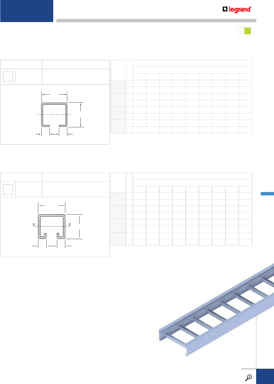
STANDARD RUNGS
UPGRADE RUNG
MG
This is the standard rung for all flange-out steel ladders and all flange-in, NEMA Class 20A, 20B, and 20C, hot-dipped galvanized steel ladders
30" and 36" wide. Please contact Legrand for catalog numbers if this rung is desired for other tray systems.
RUNG TYPE MECHANICAL PROPERTIES
BH SOLID
THICKNESS = 0.060"
MOMENT OF INERTIA: IX = 0.0227 IN4
SECTION MODULUS: SX = 0.0414 IN3
0.97"
0.28"0.28"
xx
1.00"
This is the upgrade slotted rung for all steel ladder cable trays. SU rungs are installed alternating slot up and slot down.
RUNG TYPE MECHANICAL PROPERTIES
SU SLOTTED†
THICKNESS = 0.120"
MOMENT OF INERTIA: IX = 0.0531 IN4
SECTION MODULUS: SX = 0.0921 IN3
1.63"
1.00"
0.38"
0.38"
xx
RUNG
SPACING
LOAD TYPE
SAFE LOAD LIMITS (LBS/FT)
TRAY WIDTH (IN.)
6 9 12 18 24 30 36 42 48
6Q
13999 3999 3066 2044 1533 1226 1022 876 766
Q
23999 3999 3066 2044 1499 1040 733 514 350
9Q
13999 2725 2044 1363 1022 818 681 584 511
Q
23999 2725 2044 1363 1000 693 489 343 233
12* Q
13066 2044 1533 1022 766 613 511 438 383
Q
23066 2044 1533 1022 750 520 366 257 175
18 Q
12044 1363 1022 681 511 409 341 292 255
Q
22044 1363 1022 681 500 347 244 171 117
Q
1 SAFE LOAD/CABLE LOAD
ONLY: Allowable uniformly-
distributed cable load expressed
in lbs/linear foot of tray length,
based on the load carrying
capability of the rung with a
safety factor of 1.5. To convert
Safe Load/Cable Load Only to
reflect a safety factor of 2.0,
multiply the safe loads shown
by 0.75.
Q
2 SAFE LOAD / CABLE LOAD
+200 LBS: Allowable uniformly-
distributed cable load expressed
in lbs/linear foot of tray length,
based on the load carrying
capability of the rung with a
200 lb. concentrated static load
applied at the center of the
rung, without collapse.
Q
3 Will not support a 200 lb.
concentrated static load applied
at the center of the rung.
[XX] Two digit code in the
safe load limit tables indicates
recommended rung option for
specified width.
* Single rung load capacity: The data shown for 12" rung
spacing is equivalent to the load capacity of the single rung. † Slotted rungs are
installed alternating
slot up and slot down.
RUNG
SPACING
LOAD TYPE
SAFE LOAD LIMITS (LBS/FT)
TRAY WIDTH (IN.)
6 9 12 18 24 30 36 42 48
6Q
1BX BX BX BX BX 816 680 583 510
Q
2BX BX BX BX BX 388 190 49 Q
3
9Q
1BX BX BX BX BX 544 453 389 340
Q
2BX BX BX BX BX 259 127 33 Q
3
12 Q
1BX BX BX BX BX 408 340 291 255
Q
2BX BX BX BX BX 194 95 24 Q
3
18 Q
1BX BX BX BX BX 272 227 194 170
Q
2BX BX BX BX BX 129 63 16 Q
3
For detailed material and finish descriptions, see page B.6.
METALLIC RUNGS
PW CABLE TRAY
WWW.LEGRAND.US/CABLOFIL
B.67
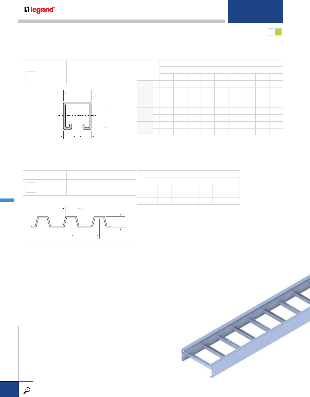
RUNG TYPE MECHANICAL PROPERTIES
CS SOLID OR
VENTILATED MINIMUM THICKNESS = 0.032"
2.19"
0.50"
0.88"
This is the standard corrugated bottom used for all steel, solid-bottom tray systems up to and including NEMA Class 20C. Corrugated bottoms are not
available in widths greater than 36". Please contact Legrand when considering solid bottom trays for extreme load applications.
LOAD TYPE
SAFE LOAD LIMITS (LBS/FT)
TRAY WIDTH (IN.)
6 9 12 18 24 30 36
Q
12007 1338 1003 669 502 401 334
Q
22007 1338 1003 599 350 200 100
RUNG TYPE MECHANICAL PROPERTIES
RS SLOTTED†
THICKNESS = 0.120"
MOMENT OF INERTIA: IX = 0.1848 IN4
SECTION MODULUS: SX = 0.2040 IN3
1.63"
0.38"0.38"
xx
1.63"
This rung is available for steel ladder tray systems for extremely heavy load applications. This profile will accept strut fasteners and accessories. RS
rungs are installed alternating slot up and slot down.
RUNG
SPACING
LOAD TYPE
SAFE LOAD LIMITS (LBS/FT)
TRAY WIDTH (IN.)
6 9 12 18 24 30 36 42 48
6Q
19999 9991 7494 4996 3747 2997 2498 2141 1873
Q
29999 9991 7494 4996 3747 2997 2498 2141 1873
9Q
19991 6661 4996 3330 2498 1998 1665 1427 1249
Q
29991 6661 4996 3330 2498 1998 1665 1427 1249
12* Q
17494 4996 3747 2498 1873 1499 1249 1071 937
Q
27494 4996 3747 2498 1873 1499 1249 1071 937
18 Q
14996 3330 2498 1665 1249 999 833 714 624
Q
24996 3330 2498 1665 1249 999 833 714 624
Q
1 SAFE LOAD/CABLE LOAD
ONLY: Allowable uniformly-
distributed cable load expressed
in lbs/linear foot of tray length,
based on the load carrying
capability of the rung with a
safety factor of 1.5. To convert
Safe Load/Cable Load Only to
reflect a safety factor of 2.0,
multiply the safe loads shown
by 0.75.
Q
2 SAFE LOAD / CABLE LOAD
+200 LBS: Allowable uniformly-
distributed cable load expressed
in lbs/linear foot of tray length,
based on the load carrying
capability of the rung with a
200 lb. concentrated static load
applied at the center of the
rung, without collapse.
Q
3 Will not support a 200 lb.
concentrated static load applied
at the center of the rung.
[XX] Two digit code in the
safe load limit tables indicates
recommended rung option for
specified width.
* Single rung load capacity: The data shown for 12" rung spacing is equivalent
to the load capacity of the single rung. † Slotted rungs are
installed alternating
slot up and slot down.
MG
STANDARD RUNGS
METALLIC RUNGS
PW CABLE TRAY
WWW.LEGRAND.US/CABLOFIL
B.68
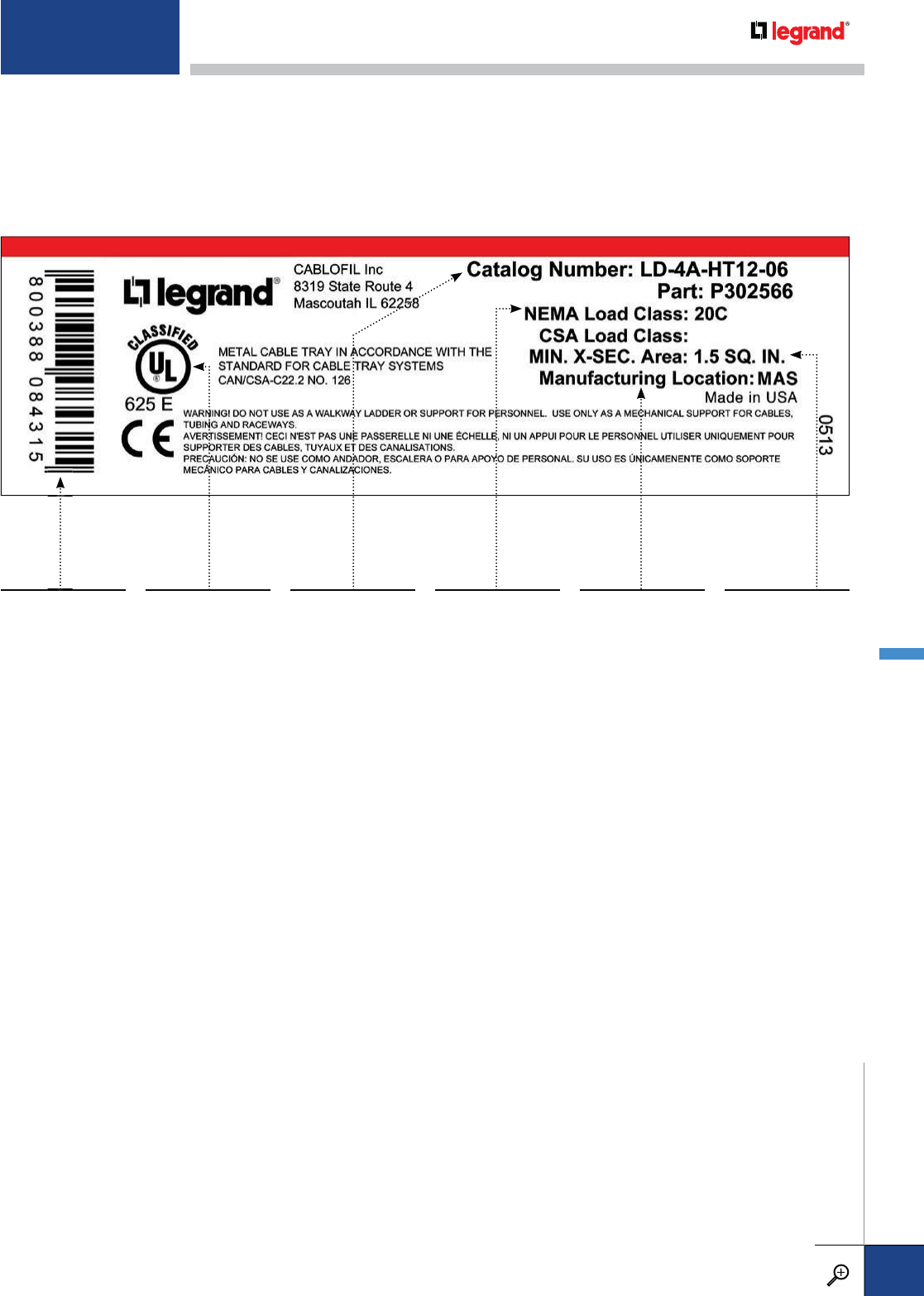
TRAY LABELS
This is a typical label attached to all PW cable tray straight sections and fittings. It presents
important information about the cable tray component and is in accordance with NEMA VE1
guidelines. Labels for fiberglass and stainless steel tray systems are similar. Because these trays
are not classified by UL as equipment grounding conductors, they do not have the UL logo or the
UL classification text.
The UPC code is used
for inventory control.
UL Classification
details and the UL
logo express the
product's grounding
qualifications,
including the area of
metal in the tray side
rails.
Catalog Number
indicates bottom type,
depth, material type
and part description
per NEMA VE1.
NEMA Load Class is
clearly marked.
Manufacturing
Location indicates
the Legrand
manufacturing
location from which
this product was
shipped.
Min. X-Sec. Area
Cross sectional areal
of both tray side rails
per NEC Table SB
392.60 (A).
FABRICATION OPTIONS AND
ENGINEERING SERVICES
No matter which product you choose, Legrand offers its customers a wide variety of fabrication
options and engineering services. We pride ourselves in providing you with the products you need,
built to your exact specifications. To help do so, take advantage of our wide range of ancillary
services including:
• Take-off and estimating assistance
• Marking special identification numbers on tray labels
• Special identification labels and warning signs
• Custom drawing and design services
• Special packaging and shipment options
• Staging per customer-defined areas
We are pleased to provide customized cable tray to fit your specific needs. Examples of the types
of modifications that can be made include but are not limited to:
• Factory-installed divider strips
• Pre-attached connector plates on trays and fittings
• Holes added to tray components for accessory attachments
Contact Legrand at 1-800-658-4641 so that we may discuss your exact job requirements.
For detailed material and finish descriptions, see page B.6.
TECHNICAL SPECIFICATIONS
PW CABLE TRAY
WWW.LEGRAND.US/CABLOFIL
B.69
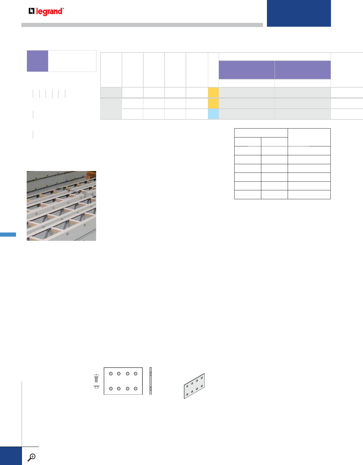
CONNECTOR
CONNECTORS & FITTINGS:
Necessary connectors are
supplied with all trays.
Extra connectors for
field cuts or spares must
be ordered separately.
Supplied in pairs with 316
stainless steel hardware.
Fiberglass and fiberglass
encapsulated hardware is
also available.
RAIL HEIGHT
(IN.)
LOAD DEPTH
(IN.)
RAIL FLANGE
(IN.)
NEMA CLASS
CSA CLASS
SERIES
TRAY SYSTEM NUMBER
[
—
][
—
]
LADDER SOLID BOTTOM
42
7/811/412B C S1 7400 7D20
6
47/82 12C, 16A D, 3M S1 7615 7F20
43/415/820C E, 6M S2 7625 7F24
MATERIAL:
Manufactured from polyester isopthalic resin conforming
with ASTM E-84 Class 1. This material displays good
corrosion resistance, including self extinguishing fire
retardant properties that comply: UL94 VO, ASTM D-635,
ASTM E-662, and FTMS 406-2023.
MECHANICAL PROPERTIES:
Tensile Strength: 20-30.6 kgf/mm2
28.4-43.5 ksi
Compression Strength: 20-30.6 kgf/mm2
28.4-43.5 ksi
Flexural Strength: 20-33.6 kfg/mm2
28.4-43.5 ksi
Shear Strength: 6.1 kgf/mm2
8.7 ksi
Density: 1.7-1.9 g/cm3
0.061-0.069lb/in3
THERMAL PROPERTIES:
Thermal Conductivity: 0.2-0.3 kcal/(mh˚C)
Oxygen Index: 42%
OperatingTemperature: -140 to +120˚ C
-220 to 248˚ F
TEMPERATURE Polyester resin
% of strength
F˚ C˚
75 25 100%
100 38 90%
125 50 78%
150 68 68%
175 79 60%
200 90 52%
WEATHER RESISTANCE:
Water Absorption: 24 h = 0.15%
4 days = 0.25%
Weight Increase: After 500 h = 0.7%
ELECTRICAL PROPERTIES:
Dielectric Strength: 7-15 kV/mm
Insulation Resistance: 1013 -1016 ohm
Pultruded profiles display excellent resistance
to the effects of UV and weathering.
All fiberglass fittings have 5" tangents and splices
with 8 predrilled holes. The vertical height of the
splice is based upon the tray series.
SPLICING
FIBERGLASS
FFIBERGLASS
WIDTHS (W) INCHES
6 9 12 18 24 30 36
RAIL HEIGHTS (H) INCHES
46
LENGTHS (L) FEET
10 20
FIBERGLASS STRAIGHT SECTIONS
PW CABLE TRAY
WWW.LEGRAND.US/CABLOFIL
B.70
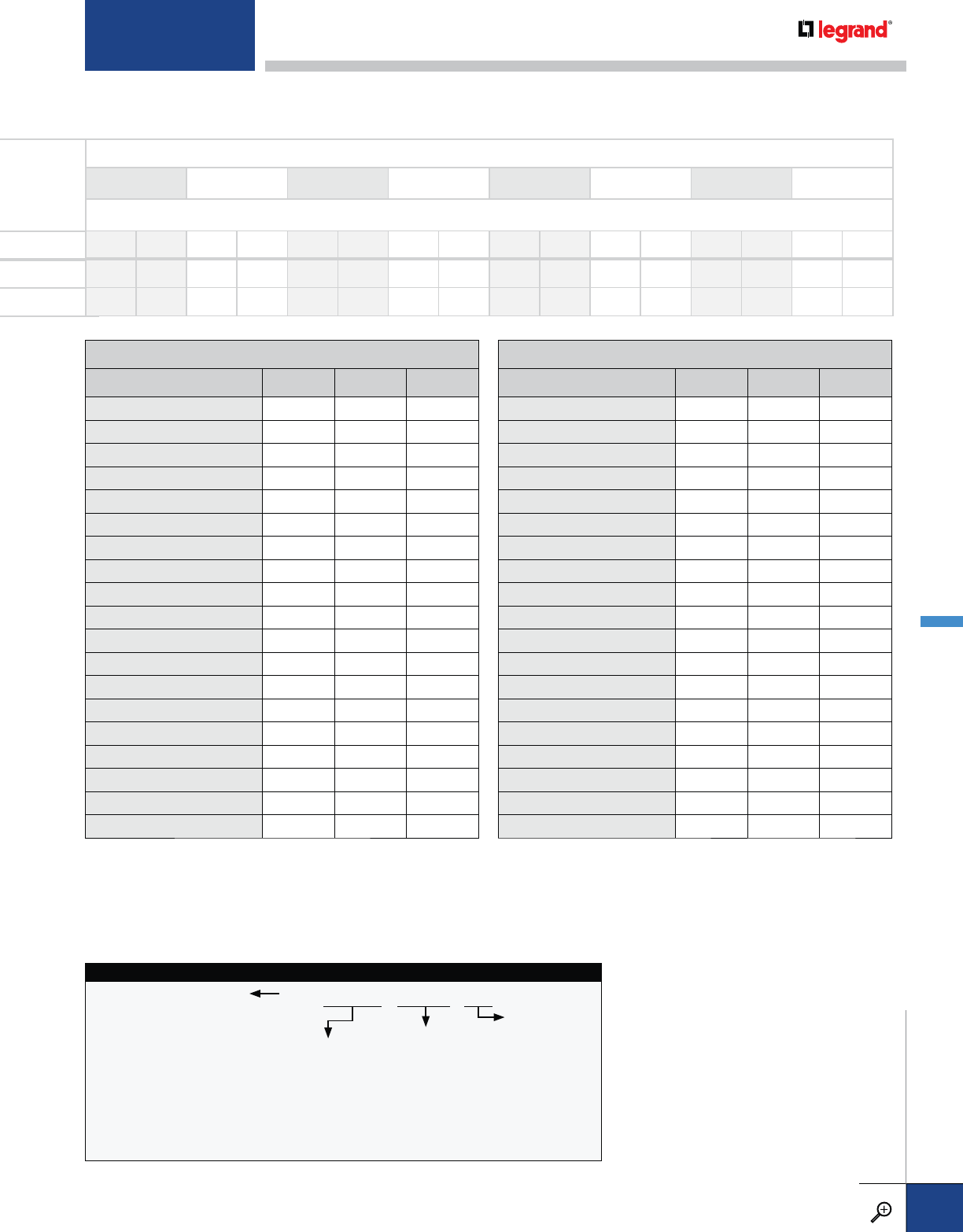
SUPPORT SPAN (FT.)
6 8 10 12 14 16 18 20
SAFE LOAD DATA (LBS./FT.) / DEFLECTION (IN.) / SAFETY FACTOR 1.5
196 0.38 164 0.85 138 1.61 80 2.08 56 2.57 41 3.04
174 0.53 159 0.88 128 1.24 105 1.59 82 1.95 50 2.45
278 1.25 246 2.03 215 2.79 183 3.56 152 4.31 120 5.09
RESISTANCE TO VARIOUS CHEMICAL AGENTS
CHEMICAL AGENT CONC. TEMP C˚ TEMP F˚
Acetic Acid 5% 65 149
Aluminum Sulphate 95 203
Ammonium Nitrate 100% 95 203
Beer 20 68
Benzene 20 68
Calcium Chloride 95 203
Chlorine Gas/Water 20 68
Chromic Acid 5% 95 203
Copper Sulphate 95 203
Ethylene Chlorohydrin 65 149
Ethylene Glycol 95 203
Ferrous Sulphate 95 203
Fatty Acids 100% 95 203
Hydrochloric Acid 1% 95 203
Hydrochloric Acid 10% 65 149
Hydrochloric Acid 37% 25 77
Kerosene 95 203
Magnesium Chloride 95 203
Napthaline 95 203
RESISTANCE TO VARIOUS CHEMICAL AGENTS
CHEMICAL AGENT CONC. TEMP C˚ TEMP F˚
Nitric Acid 30% 20 68
Phosphoric Acid 10% 95 203
Phosphoric Acid 85% 65 149
Salt Water 65 149
Sodium Bicarbonate 65 149
Sodium Bisulphate 25 77
Sodium Carbonate 25 77
Sodium Chloride 95 203
Sodium Hypochlorite 5% 65 149
Sodium Nitrate 100% 95 203
Sodium Silicate 25 77
Sodium Sulphate 95 203
Sulphuric Acid 1% 95 203
Sulphuric Acid 5% 65 149
Sulphuric Acid 10% 76 169
Sulphuric Acid 30% 25 77
Trisodium Phosphate 25 77
Water Sea/Tap 100% 50 122
Zinc Sulphate 65 149
TRAY SYSTEM
NUMBER
This identifies the
specific tray design
and is used as a
product number prefix
for straight sections.
LENGTH
0010 – 10'-0"
0020† – 20'-0"
WIDTH
06 – 6"
09 – 9"
12 – 12"
18 – 18"
24 – 24"
30 – 30"
36 – 36"
BOTTOM TYPE
06 – 6" Rung Spacing
09 – 9" Rung Spacing
12 – 12" Rung Spacing
SB – Solid Bottom
FIBERGLASS STRAIGHT SECTION CATALOG NUMBERING EXAMPLE:
06-7615-0010-36
For detailed material and finish descriptions, see page B.6.
FIBERGLASS STRAIGHT SECTIONS
PW CABLE TRAY
WWW.LEGRAND.US/CABLOFIL
B.71
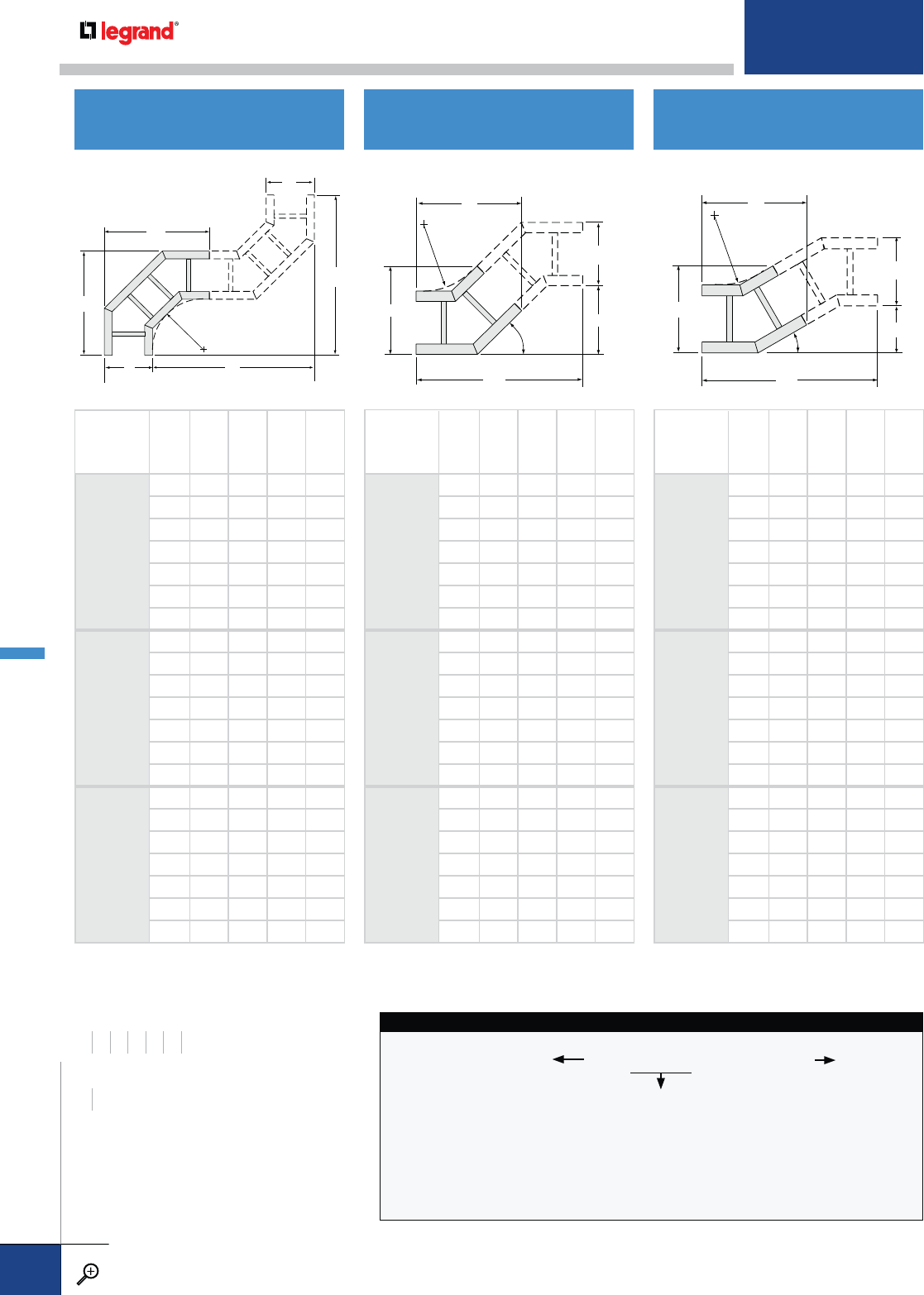
A
C
B
D
W
R
30˚
PRODUCT
NUMBER
RADIUS (IN.) WABCD
3012
12
612
3/483/4223/86
914
1/4113/4237/863/8
12 153/4143/4253/863/4
18 183/4203/4283/875/8
24 213/4263/4313/883/8
30 243/4323/4343/891/4
36 273/4383/4373/810
3024
24
618
3/4103/8343/891/4
920
1/4133/8357/895/8
12 213/4163/8373/810
18 243/4223/8403/8103/4
24 273/4283/8433/8115/8
30 303/4343/8463/8123/8
36 333/4403/8493/8131/4
3036
36
624
3/412 463/8123/8
926
1/415 477/8127/8
12 273/418 493/8131/4
18 303/424 523/814
24 333/430 553/8147/8
30 363/436 583/8155/8
36 393/442 613/8161/2
A
C
B
D
W
W
R
PRODUCT
NUMBER
RADIUS (IN.)
WABCD
9012
12
6 20203434
9 23233737
12 26 26 40 40
18 32 32 46 46
24 38 38 52 52
30 44 44 58 58
36 50 50 64 64
9024
24
6 32325858
9 35356161
12 38 38 64 64
18 44 44 70 70
24 50 50 76 76
30 56 56 82 82
36 62 62 88 88
9036
36
6 44448282
9 47478585
12 50 50 88 88
18 56 56 94 94
24 62 62 100 100
30 68 68 106 106
36 74 74 112 112
A
C
BD
W
R
45˚
PRODUCT
NUMBER
RADIUS (IN.) WABCD
4512
12
616
1/811 277/8111/2
918
1/414 30 121/2
12 203/817 321/8133/8
18 245/823 363/8151/8
24 283/429 403/4167/8
30 331/835 447/8185/8
36 373/841 491/8203/8
4524
24
624
5/8141/2447/8185/8
926
3/4171/247 191/2
12 287/8201/2491/8203/8
18 331/8261/2533/8221/8
24 373/8321/2575/8237/8
30 415/8381/2617/8255/8
36 457/8441/2661/8273/8
4536
36
633
1/818 617/8255/8
935
1/421 64 261/2
12 373/824 661/8273/8
18 415/830 703/8291/8
24 457/836 745/8307/8
30 501/842 787/8325/8
36 541/448 831/8343/8
HORIZONTAL 90˚ELBOW HORIZONTAL 60˚ELBOW HORIZONTAL 30˚ELBOW
WIDTHS (W) INCHES
6 9 12 18 24 30 36
RAIL HEIGHTS (H) INCHES
46 TRAY SYSTEM
NUMBER
This identifies the
specific tray design
and is used as a
product number prefix
for straight sections.
WIDTH
06 – 6"
09 – 9"
12 – 12"
18 – 18"
24 – 24"
30 – 30"
36 – 36"
BOTTOM TYPE
LD – Ladder
SB – Solid Bottom
FIBERGLASS HORIZONTAL ELBOW CATALOG NUMBERING EXAMPLE:
LD-7615-4512-36
PRODUCT NO.
FIBERGLASS FITTINGS
PW CABLE TRAY
WWW.LEGRAND.US/CABLOFIL
B.72
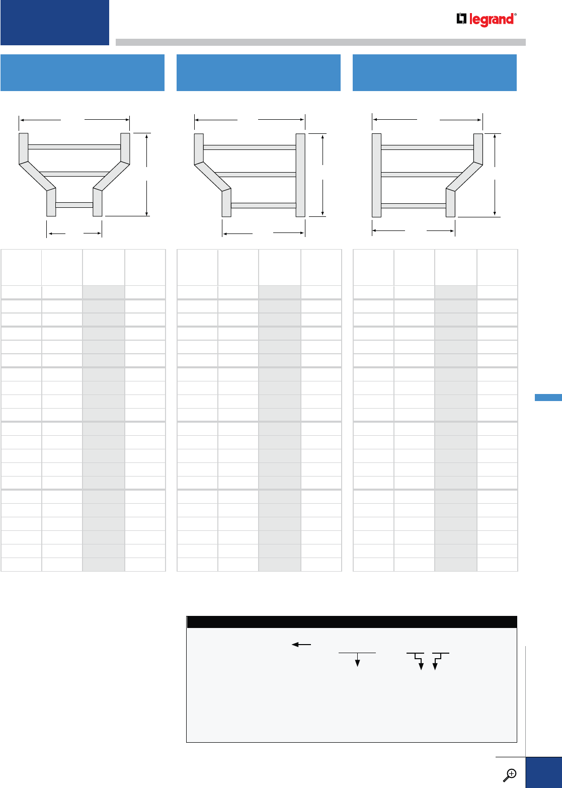
W
W
L
1
2W
W
L
2
1
L
W2
W1
MAIN WIDTH
W1
BRANCH
WIDTH
W2
PRODUCT
NUMBER L
96
0109 181/4
12 6 0112 175/8
12 9 0112 181/4
18 6 0118 205/8
18 9 0118 191/8
18 12 0118 175/8
24 6 0124 235/8
24 9 0124 221/8
24 12 0124 205/8
24 18 0124 175/8
30 6 0130 265/8
30 9 0130 251/8
30 12 0130 235/8
30 18 0130 205/8
30 24 0130 175/8
36 6 0136 295/8
36 9 0136 281/8
36 12 0136 265/8
36 18 0136 235/8
36 24 0136 205/8
36 30 0136 175/8
MAIN WIDTH
W1
BRANCH
WIDTH
W2
PRODUCT
NUMBER L
96
0709 175/8
12 6 0712 205/8
12 9 0712 175/8
18 6 0718 265/8
18 9 0718 235/8
18 12 0718 205/8
24 6 0724 325/8
24 9 0724 295/8
24 12 0724 265/8
24 18 0724 205/8
30 6 0730 385/8
30 9 0730 355/8
30 12 0730 325/8
30 18 0730 265/8
30 24 0730 205/8
36 6 0736 445/8
36 9 0736 415/8
36 12 0736 385/8
36 18 0736 325/8
36 24 0736 265/8
36 30 0736 205/8
MAIN WIDTH
W1
BRANCH
WIDTH
W2
PRODUCT
NUMBER L
96
0809 175/8
12 6 0812 205/8
12 9 0812 175/8
18 6 0818 265/8
18 9 0818 235/8
18 12 0818 205/8
24 6 0824 325/8
24 9 0824 295/8
24 12 0824 265/8
24 18 0824 205/8
30 6 0830 385/8
30 9 0830 355/8
30 12 0830 325/8
30 18 0830 265/8
30 24 0830 205/8
36 6 0836 445/8
36 9 0836 415/8
36 12 0836 385/8
36 18 0836 325/8
36 24 0836 265/8
36 30 0836 205/8
HORIZONTAL STRAIGHT
REDUCER HORIZONTAL LEFT HAND
REDUCER HORIZONTAL RIGHT HAND
REDUCER
W1 W2
06 – 6"
09 – 9"
12 – 12"
18 – 18"
24 – 24"
30 – 30"
36 – 36"
TRAY SYSTEM
NUMBER
This identifies the
specific tray design
and is used as a
product number prefix
for straight sections.
BOTTOM TYPE
LD – Ladder
SB – Solid Bottom
FIBERGLASS HORIZONTAL REDUCER CATALOG NUMBERING EXAMPLE:
SB-7F20-0118-12
PRODUCT NO.
For detailed material and finish descriptions, see page B.6.
FIBERGLASS FITTINGS
PW CABLE TRAY
WWW.LEGRAND.US/CABLOFIL
B.73
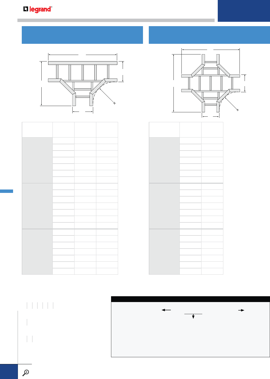
PRODUCT
NUMBER
RADIUS (IN.)
WAB
2012
12
63420
93723
12 40 26
18 46 32
24 52 38
30 58 44
36 64 50
2024
24
65832
96135
12 64 38
18 70 44
24 76 50
30 82 56
36 88 62
2036
36
68244
98547
12 88 50
18 94 56
24 100 62
30 106 68
36 112 74
PRODUCT
NUMBER
RADIUS (IN.)
WA
1012
12
634
937
12 40
18 46
24 52
30 58
36 64
1024
24
658
961
12 64
18 70
24 76
30 82
36 88
1036
36
682
985
12 88
18 94
24 100
30 106
36 112
HORIZONTAL TEE HORIZONTAL CROSS
TRAY SYSTEM
NUMBER
This identifies the
specific tray design
and is used as a
product number prefix
for straight sections.
WIDTH
06 – 6"
09 – 9"
12 – 12"
18 – 18"
24 – 24"
30 – 30"
36 – 36"
BOTTOM TYPE
LD – Ladder
SB – Solid Bottom
FIBERGLASS HORIZONTAL TEE CATALOG NUMBERING EXAMPLE:
LD-7615-4512-12
PRODUCT NO.
A
B
W
R
W
A
A
W
R
W
WIDTHS (W) INCHES
6 9 12 18 24 30 36
RAIL HEIGHTS (H) INCHES
46
RADIUS (R) INCHES
12 24 36
FIBERGLASS FITTINGS
PW CABLE TRAY
WWW.LEGRAND.US/CABLOFIL
B.74
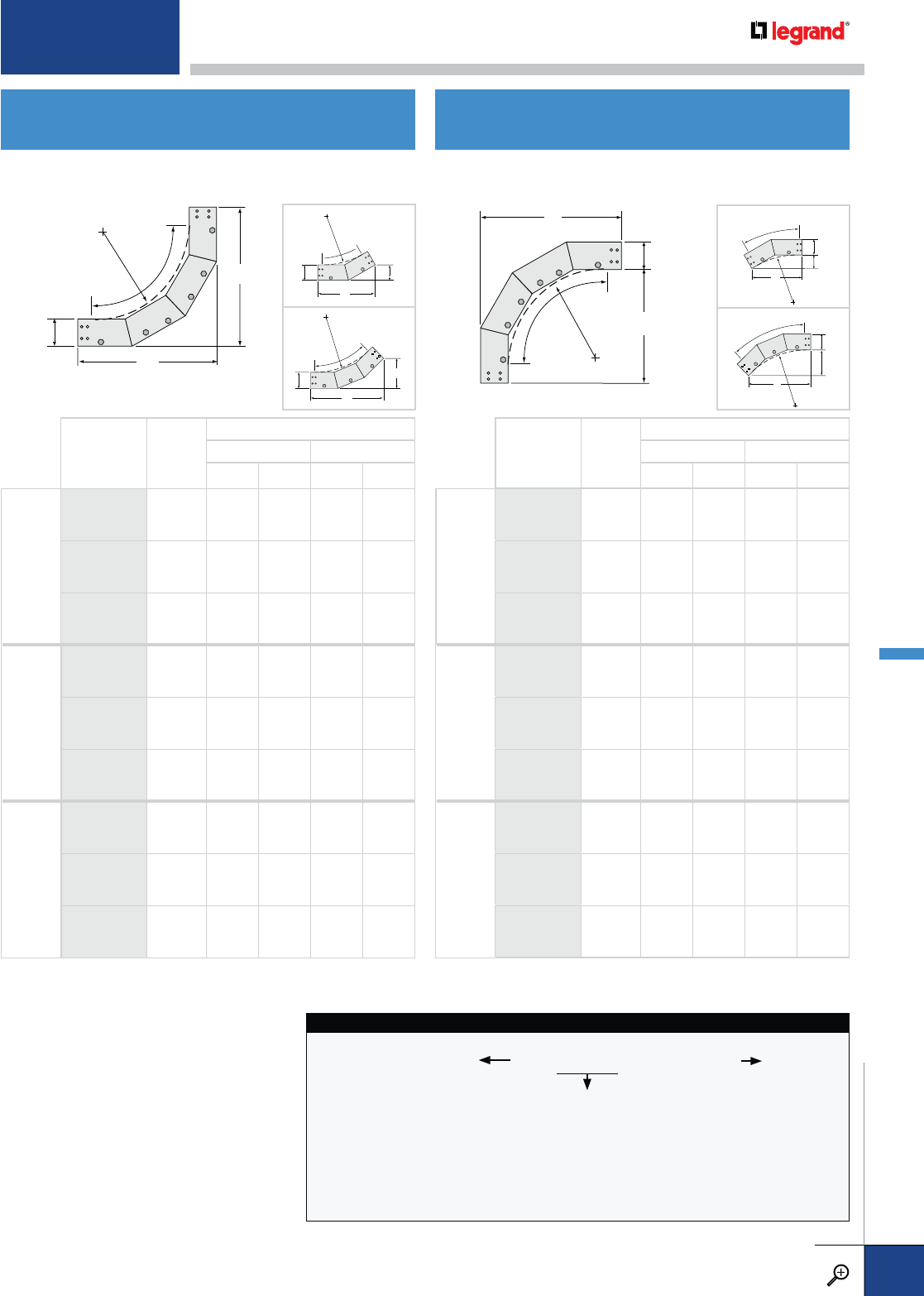
VERTICAL INSIDE ELBOWS VERTICAL OUTSIDE ELBOWS
TRAY SYSTEM
NUMBER
This identifies the
specific tray design
and is used as a
product number prefix
for straight sections.
WIDTH
06 – 6"
09 – 9"
12 – 12"
18 – 18"
24 – 24"
30 – 30"
36 – 36"
BOTTOM TYPE
LD – Ladder
SB – Solid Bottom
FIBERGLASS INSIDE ELBOW CATALOG NUMBERING EXAMPLE:
LD-7615-9112-24
PRODUCT NO.
A
B
H
90˚
R
A
B
90˚ R
H
A
B
H
45˚
R
45º
A
B
H
45˚
R
45º
A
B
H
30˚
R
30º
A
B
H
30˚
R
30º
90º 90º
PRODUCT
NUMBER
RADIUS
(IN.)
W
RAIL HEIGHT (IN.)
46
ABAB
90º
9112
12 ALL 18 18 20 20
9124
24 ALL 30 30 32 32
9136
36 ALL 42 42 44 44
45º
4612
12 ALL 143/461/8161/865/8
4624
24 ALL 231/495/8245/8101/4
4636
36 ALL 313/4131/8331/8133/4
30º
3112
12 ALL 113/431/8123/433/8
3124
24 ALL 173/443/4183/45
3136
36 ALL 233/463/8243/465/8
PRODUCT
NUMBER
RADIUS
(IN.)
W
RAIL HEIGHT (IN.)
46
ABAB
90º
9212
12 ALL 18 14 20 14
9224
24 ALL 30 26 32 26
9236
36 ALL 42 38 44 38
45º
4712
12 ALL 117/847/8117/847/8
4724
24 ALL 203/881/2203/881/2
4736
36 ALL 287/812 287/812
30º
3212
12 ALL 93/425/893/425/8
3224
24 ALL 153/441/4153/441/4
3236
36 ALL 213/457/8213/457/8
For detailed material and finish descriptions, see page B.6.
FIBERGLASS FITTINGS
PW CABLE TRAY
WWW.LEGRAND.US/CABLOFIL
B.75
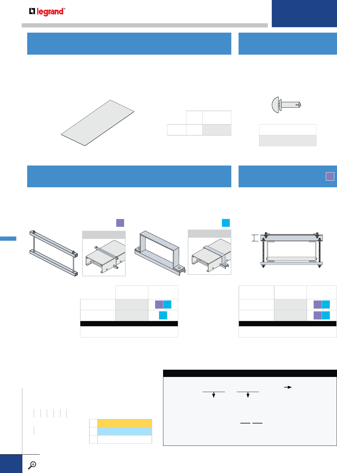
Only for use with indoor, horizontal
covers. Drive rivets are the most
economical method of cover
attachment. Requires field drilling.
Install on 24" centers.
Covers are highly recommended to avoid damage to the tray contents and to protect
against the elements. Flat covers are available for both straight sections and fittings.
Covers are made from fire-retardant polyester resin per ASTM E84 Class 1, light
gray color. Standard cover thickness is 1/8" and length is 10'-0". Side rail height
is necessary for outside vertical fitting covers. Please contact Legrand for more
information.
LENGTH
(FT.)
SYSTEM
NUMBER
COVER 10 7130
For use with indoor, outdoor, or vertical flat covers. The 1400 cover connector is 1"
wide fiberglass. The 1423 cover connector is 1½" wide stainless steel. Install one
connector over each cover joint and 36"-48" spacing between joints.
FLAT COVER
FLAT COVER CONNECTORS RAISED COVER CONNECTOR
DRIVE RIVET
F
CHANNEL-STYLE
APPLICATION
T
STRAP-STYLE
APPLICATION GAP
For use with all covers, indoors and
outdoors. Covers are attached to upright-
mounted “C” channel on the top of the
cable tray. Install 36"-48" on center.
PRODUCT
NUMBER
FASTENERS
INCLUDED
CHANNEL 1400 FG S6
STRAP 1423 S6
CATALOG NUMBERING EXAMPLE:
System No. Width Fasteners
6FI- 1400 -24-S6
GAP
DIMENSION (IN.)
PRODUCT
NUMBER
FASTENERS
INCLUDED
11441 FG S6
21442 FG S6
CATALOG NUMBERING EXAMPLE:
System No. Width Fasteners
6FI- 1441 -24-S6
COMPLETE CATALOG NUMBER
DS-8935-PL
F
WIDTHS (W) INCHES
6 9 12 18 24 30 36
RAIL HEIGHTS (H) INCHES
46
LENGTH (L) FEET
10
TRAY SYSTEM
NUMBER
This identifies the
specific tray design
and is used as a
product number prefix
for straight sections.
LENGTH
0010 – 10'
or
9112
FITTING PRODUCT NO.
This identifies
fitting type and radius
WIDTH
06 – 6"
09 – 9"
12 – 12"
18 – 18"
24 – 24"
30 – 30"
36 – 36"
FIBERGLASS FLAT COVER CATALOG NUMBERING EXAMPLE:
7130 - 0010 - 36
LENGTH OR PRODUCT FITTING NO..
F1 SERIES1
F2 SERIES2
FI Flange In
FIBERGLASS PREFIX OPTIONS
FIBERGLASS COVER & ACCESSORIES
PW CABLE TRAY
WWW.LEGRAND.US/CABLOFIL
B.76
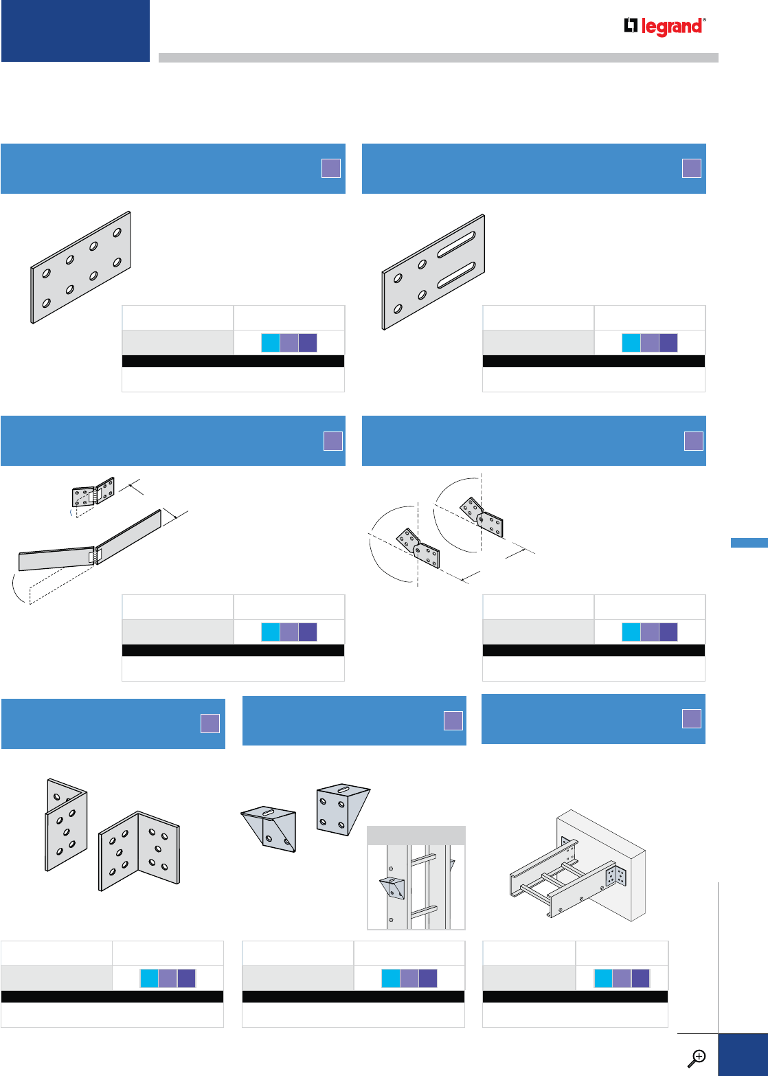
ALL
W
VERTICAL HANGER SPLICE
APPLICATION
PRODUCT NUMBER FASTENERS
0356 S6 FG FE
CATALOG NUMBERING EXAMPLE:
System No. Fasteners
F1- 0356 -S6
F
Provides vertical support point for trays.
TRAY-TO-BOX CONNECTOR
PRODUCT NUMBER FASTENERS
1864 S6 FG FE
CATALOG NUMBERING EXAMPLE:
System No. Fasteners
F1- 1864 -S6
F
Connects tray to the wall or a vertical
upright. Hardware for tray attachment
only is included.
HORIZONTAL ADJUSTABLE SPLICE F
ALL
W
Joins trays at adjustable
bend angles up to 30˚.
PRODUCT NUMBER FASTENERS
1305 S6 FG FE
CATALOG NUMBERING EXAMPLE:
System No. Fasteners
F1- 1305 -S6
STANDARD SPLICE
PRODUCT NUMBER FASTENERS
1302 S6 FG FE
CATALOG NUMBERING EXAMPLE:
System No. Fasteners
F1- 1302 -S6
FEXPANSION SPLICE
PRODUCT NUMBER FASTENERS
1314 S6 FG FE
CATALOG NUMBERING EXAMPLE:
System No. Fasteners
F1- 1314 -S6
Allows thermal contraction and
expansion of tray of up to 1".
Tray length and temperature
differential govern the spacing
and quantity needed.
F
90º CONNECTOR F
PRODUCT NUMBER FASTENERS
1320 S6 FG FE
CATALOG NUMBERING EXAMPLE:
System No. Fasteners
F1- 1320 -S6
Splice plates and connectors are fire-retardant polyester resin per ASTM E84 Class 1. Sufficient connector pairs with fasteners are
automatically included with each shipment of straight sections and fittings. Extras must be ordered separately. Type 316 stainless
steel fasteners are included standard, but fiberglass and fiberglass-encapsluated fasteners are options. Tighten flanged hex nut to
approximately 10-14 ft.-lbs. of torque.
VERTICAL ADJUSTABLE SPLICE F
Joins trays at adjustable
bend angles up to 90˚.
PRODUCT NUMBER FASTENERS
1307 S6 FG FE
CATALOG NUMBERING EXAMPLE:
System No. Fasteners
F1- 1307 -S6
For detailed material and finish descriptions, see page B.6.
FIBERGLASS SPLICES & CONNECTORS
PW CABLE TRAY
WWW.LEGRAND.US/CABLOFIL
B.77
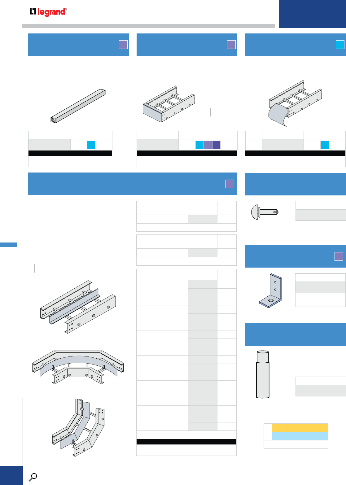
SealantSEALANT
Add or replace a tray rung using the
hardware provided. Field drilling may be
required. Rungs include factory-installed
threaded collets.
Seals off the open end of a cable tray.
Attaches to the tray using standard
3/8" dia. connector hardware.
Provides a smooth, rounded surface
for cables dropping out of the bottom
of the cable tray.
ADDITIONAL RUNG
DIVIDER STRIPS
BLIND END PLATE CABLE DROPOUT
HOLD DOWN CLIP
THERMOPLASTIC DRIVE RIVET
FIELD CUTTING SEALANT
PRODUCT NUMBER FASTENERS
8200 S6
CATALOG NUMBERING EXAMPLE:
Material Width Fasteners
F- 8200 -12-S6
PRODUCT NUMBER FASTENERS
0402 S6 FG FE
CATALOG NUMBERING EXAMPLE:
System No. Width Fasteners
6FI- 0402 -12-S6
RADIUS PRODUCT NUMBER FASTENERS
50254 S6
CATALOG NUMBERING EXAMPLE:
System No. Width Fasteners
TI- 0254 -24-S6
RAIL HEIGHTS (H)
INCHES
46
F F T
TYPE PRODUCT
NUMBER RADIUS
VERTICAL 90°
INSIDE ELBOW
9112-99 12
9124-99 24
9136-99 36
VERTICAL 90°
OUTSIDE ELBOW
9212-99 12
9224-99 24
9236-99 36
VERTICAL 45°
INSIDE ELBOW
4612-99 12
4624-99 24
4636-99 36
VERTICAL 45°
OUTSIDE ELBOW
4712-99 12
4724-99 24
4736-99 36
VERTICAL 30°
INSIDE ELBOW
3112-99 12
3124-99 24
3136-99 36
VERTICAL 30°
OUTSIDE ELBOW
3212-99 12
3224-99 24
3236-99 36
(2) HOLD DOWN CLIPS INCLUDED
CATALOG NUMBERING EXAMPLE:
System No.
6F- 0010-99-PL
TYPE PRODUCT
NUMBER LENGTH
(FT)
STRAIGHT HORIZONTAL 0010-99 10
(5) THERMOPLASTIC DRIVE RIVETS INCLUDED
TYPE PRODUCT
NUMBER LENGTH
(FT)
FLEXIBLE HORIZONTAL 0606-99 6
(4) HOLD DOWN CLIPS INCLUDED
Straight strips are for use with all straight
ladder tray; flexible strips are for use with
all horizontal fittings of any radius.
Field-drilled holes are required
for installation of all divider strips.
Clips should be attached to rungs on
alternating sides of the divider strip.
Used to reseal fiberglass after
field modifications. Can is one
pint. Includes two brushes.
COMPLETE CATALOG NO.
DS-8935-PL
COMPLETE CATALOG NO.
0941
F
F
STRAIGHT HORIZONTAL DIVIDER
FLEXIBLE HORIZONTAL DIVIDER
VERTICAL FITTING DIVIDER
RAIL HEIGHTS (H)
INCHES
46
COMPLETE CATALOG NO.
F-1852-PL
(3) THERMOPLASTIC
DRIVE RIVETS INCLUDED
F1 SERIES1
F2 SERIES2
FI Flange In
FIBERGLASS PREFIX OPTIONS
FIBERGLASS ACCESSORIES
PW CABLE TRAY
WWW.LEGRAND.US/CABLOFIL
B.78
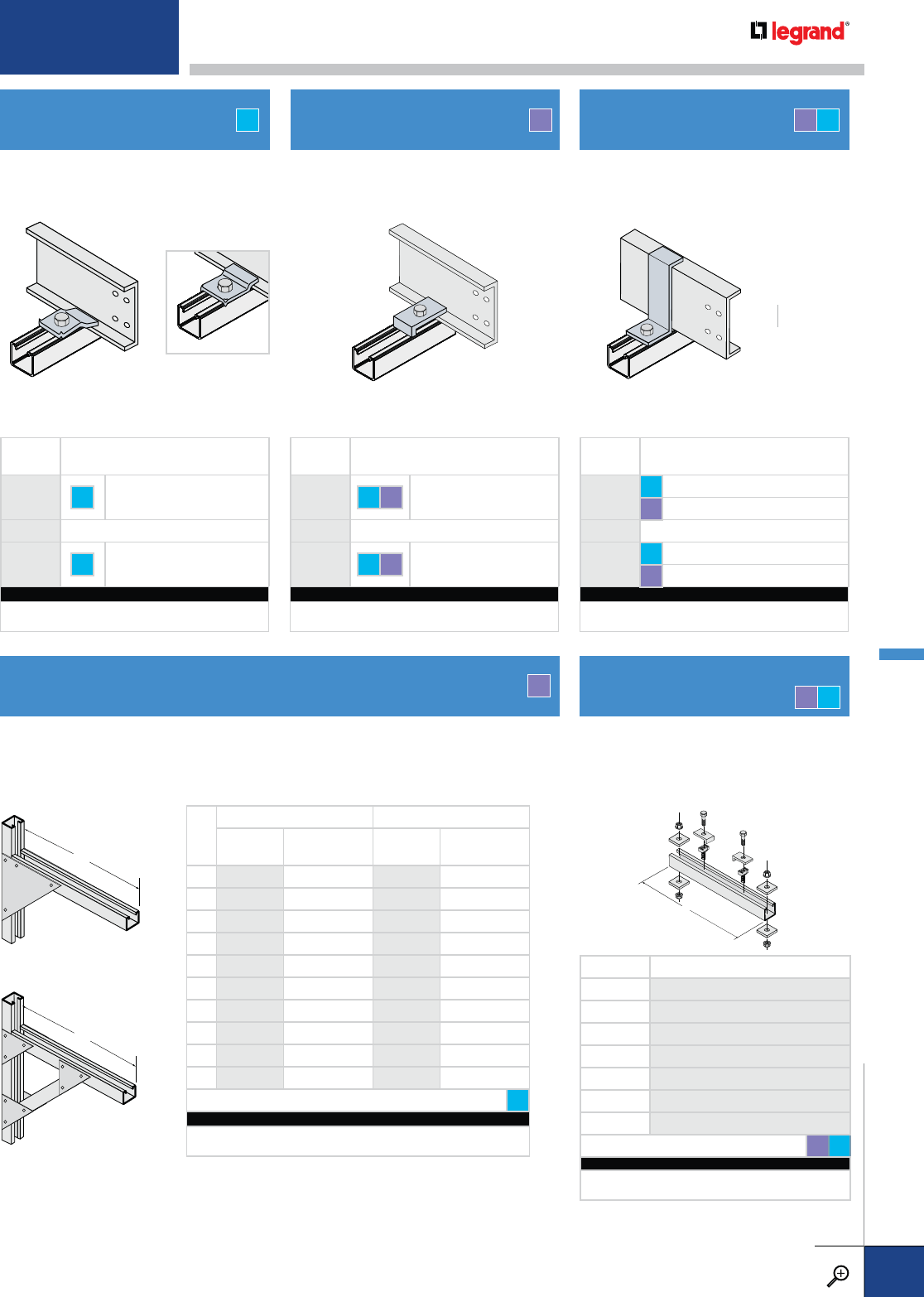
EXPANSION GUIDE CLAMP
SUPPORT BRACKETS
HOLD DOWN CLAMP Z-HOLD DOWN CLAMP
TRAPEZE HANGER SUPPORT
KIT (STANDARD DUTY)
RAIL HEIGHTS (H)
INCHES
46
Securely fastens the tray to the support
member. For use with all ladder tray
systems.
PRODUCT
NUMBER FASTENERS INCLUDED
1866-01 S6
¼"x1
½
" hex bolt, ¼" flanged nut
FG 3/8
"x1
½
" hex bolt,
3/8
" flanged nut
1866-02 NONE
1866-03 S6
¼" x 1
½
" hex bolt, ¼" spring nut
FG 3/8
" x 1
½
" hex bolt,
3/8
" spring nut
CATALOG NUMBERING EXAMPLE:
System No. Fasteners
6T- 1866-01 -S6
Securely fastens the tray to the support
member and prevents lateral movement.
For use with all flange-in tray systems.
Works as an expansion guide and flips
over as a hold down clamp. For use with
all ladder tray systems.
TF F T
Support brackets use 15/8” x 15/8” struts. Uniform Design Load is based on a safety
factor of 2.0. When selecting “L”, allow extra for flanges when supporting a solid
bottom tray system.
L
STANDARD
PRODUCT
NUMBER FASTENERS INCLUDED
1893-01 S6 3/8" x 1½" hex bolt,
3/8" flanged nut
1893-02 NONE
1893-03 S6 3/8" x 1½" hex bolt,
3/8" spring nut
CATALOG NUMBERING EXAMPLE:
Material Fasteners
T- 1893-01 -S6
L
STANDARD HEAVY-DUTY
PRODUCT
NUMBER
DESIGN
LOAD (LBS.)
PRODUCT
NUMBER
DESIGN
LOAD (LBS.)
70386 245 - -
10 0386 237 - -
13 0386 230 - -
16 0386 217 - -
19 0386 205 0387 610
22 0386 192 - -
25 0386 180 0387 590
31 - - 0387 700
37 - - 0387 700
43 - - 0387 700
ASSEMBLY HARDWARE S6
CATALOG NUMBERING EXAMPLE:
Material Length
F- 0386 - 10
L
HEAVY-DUTY
FT
TRAY WIDTH PRODUCT NUMBER
60385-10
90385-13
12 0385-16
18 0385-22
24 0385-28
30 0385-34
36 0385-40
FASTENERS INCLUDED FG S6
CATALOG NUMBERING EXAMPLE:
Material Length Fasteners
F- 0385-10 - S6
PRODUCT
NUMBER FASTENERS INCLUDED
1811-01 S6 FG
3/8" x 1½" hex bolt,
3/8" flanged nut
1811-02 NONE
1811-03 S6 FG 3/8" x 1½" hex bolt,
3/8" channel nut
CATALOG NUMBERING EXAMPLE:
Material Fasteners
F- 1811-01 -S6
F
L
Made with 15/8” x 15/8” fiberglass strut,
designed to accept ½" threaded rod
(sold separately). Includes hardware for
ladder trays. For other designs contact
Legrand.
For detailed material and finish descriptions, see page B.6.
FIBERGLASS ACCESSORIES
PW CABLE TRAY
WWW.LEGRAND.US/CABLOFIL
B.79
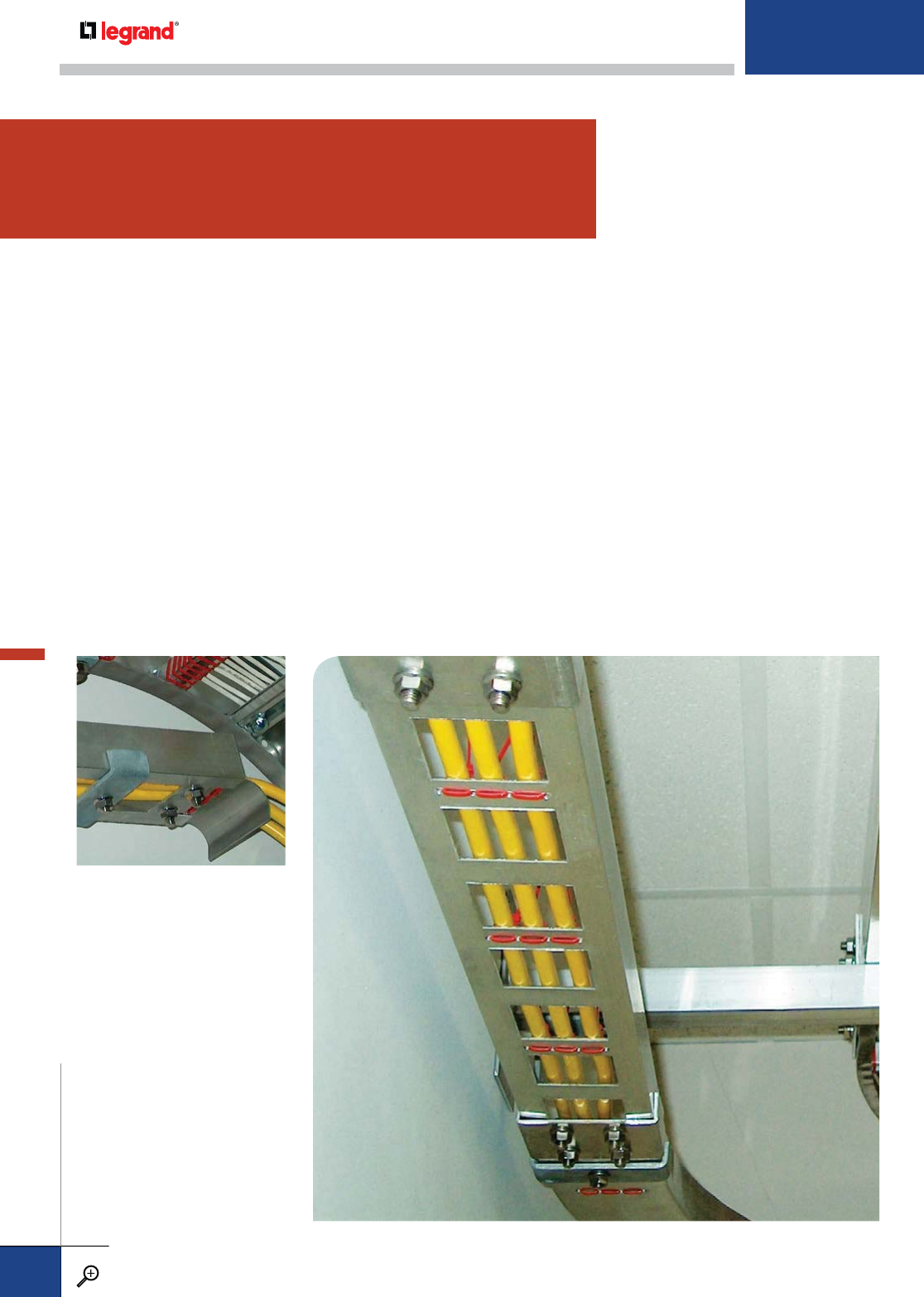
Channel tray is a fabricated metal tray constructed with a one-piece ventilated bottom or
solid-bottom channel section. It is commonly used for small runs of cable and for drops
from the main cable tray run to equipment or junction boxes.
We offer channel tray in a complete range of materials including aluminum, mill
galvanized steel, and steel that is hot-dip galvanized after fabrication. For extremely
corrosive applications we offer a wide range of designs in types 304 and 316 stainless
steels, polyester and vinylester fiberglass.
Additionally, our product line includes a complete line of accessories including covers
and fittings designed to support large-diameter cables.
• Horizontal and vertical fittings are available in 12", 24", and 36" radius
• 4" and 6" widths
• Available in solid and ventilated designs
METALLIC
B.81 STRAIGHT SECTIONS
& COVER
B.82 FITTINGS
B.85 SPLICES & CONNECTORS
FIBERGLASS
B.88 STRAIGHT SECTIONS
& COVERS
B.89 FITTINGS
CHANNEL SYSTEMS
CHANNEL SYSTEMS
PW CABLE TRAY
WWW.LEGRAND.US/CABLOFIL
B.80
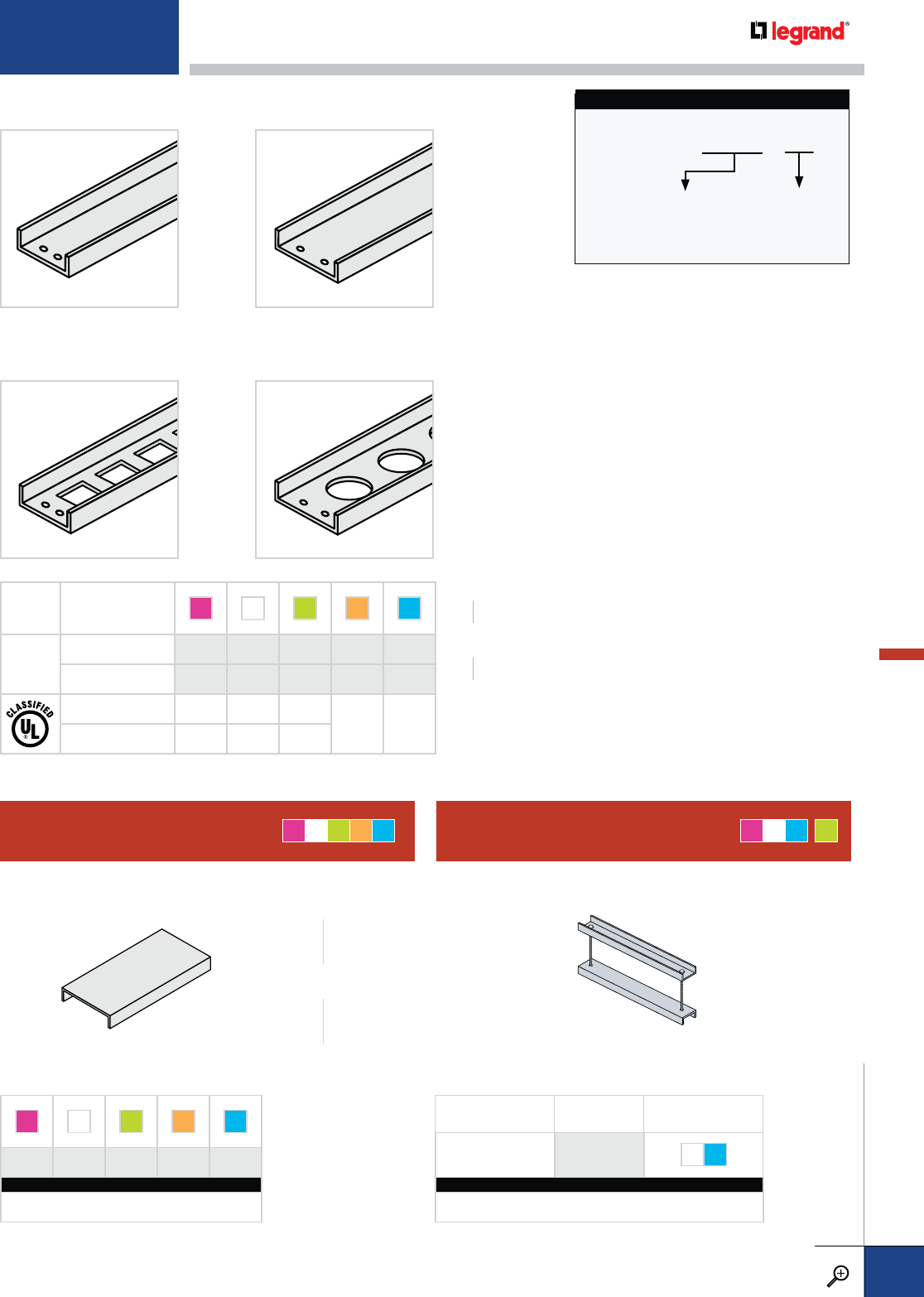
4"
4"
6"
6"
TRAY
DEPTH CHANNEL STYLE A M G L T
13/4"
SOLID 5509 2509 1509 3538 3529
VENTILATED* 5508 2508 1508 3532 3528
U.L. AREA 0.20 IN20.20 IN20.20 IN2
N/A N/A
AMPS 200 200 200
*Available in straight sections only. All fittings have solid bottom.
A M G L T
5088 2085 1085* 3014 3095
CATALOG NUMBERING EXAMPLE (EA.):
System Number Length Width
5088 - 0010 - 04
*Available in 6' length only.
STRAIGHT SECTION CATALOG NUMBERING EXAMPLE:
3538-0010-04
SYSTEM NO.
WIDTH
4 – 4"
6 – 6"
LENGTH
0010 – 10'
0012 – 12'
CHANNEL TRAY DESIGN OPTIONS SOLID BOTTOM
CHANNEL TRAY DESIGN OPTIONS VENTILATED BOTTOM
WIDTHS (W) INCHES
46
LENGTHS (L) FEET
10 12
LENGTH (L) FEET
0010 10
0012 12
WIDTH (W) INCHES
04 4
06 6
COVER CONNECTORCHANNEL COVER AMT G
*
AM GL T
CHANNEL-STYLEFLAT FLANGED
DESCRIPTION PRODUCT
NUMBER FASTENERS
CHANNEL 1400 ZN S6
CATALOG NUMBERING EXAMPLE (EA.):
Material Width Fasteners
A - 1400 - 04 - S6
For detailed material and finish descriptions, see page B.6.
CHANNEL STRAIGHT SECTIONS
PW CABLE TRAY
WWW.LEGRAND.US/CABLOFIL
B.81
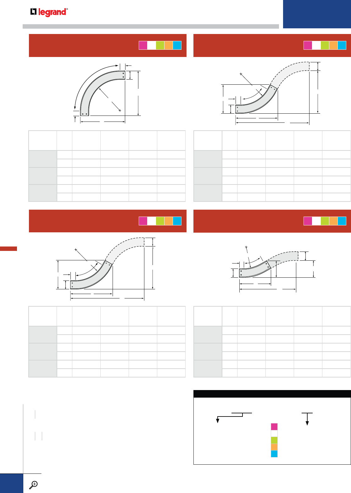
A
A
W
90˚
R
5"
5"
W
C
D
A
B
W
60˚
R
5"
W
C
D
A
B
W
45˚
R
5"
A
W
30˚
R
C
D
W
B
5”
HORIZONTAL 90˚ ELBOW
HORIZONTAL 45˚ ELBOW
HORIZONTAL 60˚ ELBOW
HORIZONTAL 30˚ ELBOW
PRODUCT
NUMBER
RADIUS (IN.)
WABCD
9012
12
421---
623---
9024
24
433---
635---
9036
36
445---
647---
PRODUCT
NUMBER
RADIUS (IN.)
WABCD
4512
12
419
7
/
8111
/
8367
/
815¼
6 21¼ 131
/
838¼ 157
/
8
4524
24
428
3
/
8145
/
8537
/
8223
/
8
629¾ 16
5
/
855¼ 227
/
8
4536
36
436
7
/
8181
/
870¾ 293
/
8
638¼ 20
1
/
872¼ 30
PRODUCT
NUMBER
RADIUS (IN.)
WA B C D
6012
12
421
3
/
8143
/
839¼ 22¾
623
1
/
8163
/
841 23¾
6024
24
4 31¾ 203
/
860 345
/
8
633½ 22
3
/
861¾ 355
/
8
6036
36
442
1
/
8263
/
880¾ 46¾
643
7
/
8283
/
8825
/
847¾
PRODUCT
NUMBER
RADIUS (IN.)
WA B C D
3012
12
417
3
/
881
/
832¾ 8¼
618
3
/
8101
/
833¾ 9
3024
24
423
3
/
89¾ 44¾ 12
624
3
/
811¾ 45¾ 12¼
3036
36
429
3
/
8113
/
856¾ 14½
630
3
/
8133
/
857¾ 15½
AMGL T
AMGL T
AMGL T
AMGL T
HORIZONTAL ELBOW CATALOG NUMBERING EXAMPLE:
5509 - 9012 - 06
04 – 4"
06 – 6"
SYSTEM NO. PRODUCT NO. WIDTH
5509 - A
2509 - M
1509 - G
3538 - L
3529 - T
This identifies the solid bottom
straight section tray to be used
as a catalog number prefix for
all fittings. All fittings are solid
bottom only and can be used
with ventilated bottom tray.
WIDTHS (W) INCHES
46
RADIUS (R) INCHES
12 24 36
CHANNEL METALLIC FITTINGS
PW CABLE TRAY
WWW.LEGRAND.US/CABLOFIL
B.82
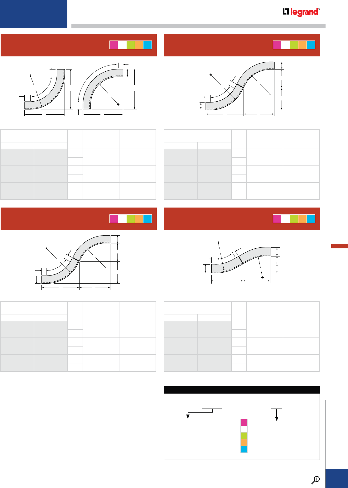
B
B
H
90˚
R
5"
5"
A
A
90˚
5"
5"
R
INSIDE ELBOW OUTSIDE ELBOW
H
B
A
B
H
60˚
R
R
5"
A
5"
INSIDE ELBOW OUTSIDE ELBOW
H
B
A
B
H
R
R
5"
A
INSIDE ELBOW OUTSIDE ELBOW
5"
A
H
30˚
RH
B
A
B
R
5"
5"
INSIDE ELBOW OUTSIDE ELBOW
VERTICAL 90˚ ELBOW
VERTICAL 45˚ ELBOW
VERTICAL 60˚ ELBOW
VERTICAL 30˚ ELBOW
PRODUCT NUMBER
RADIUS (IN.) WA B
INSIDE OUTSIDE
9112
12
9212
12
417 18¾
6
9124
24
9224
24
429 30¾
6
9136
36
9236
36
441 42¾
6
PRODUCT NUMBER
RADIUS (IN.) WA B
INSIDE OUTSIDE
4612
12
4712
12
417 7
6
4624
24
4724
24
425½ 105
/
8
6
4636
36
4736
36
434 141
/
8
6
PRODUCT NUMBER
RADIUS (IN.) WA B
INSIDE OUTSIDE
6112
12
6212
12
4177
/
8103
/
8
6
6124
24
6224
24
428¼ 163
/
8
6
6136
36
6236
36
4385
/
8223
/
8
6
PRODUCT NUMBER
RADIUS (IN.) WA B
INSIDE OUTSIDE
3112
12
3212
12
4153
/
841
/
8
6
3124
24
3224
24
4213
/
85¾
6
3136
36
3236
36
4273
/
873
/
8
6
AMGL T
AMGL T
AMGL T
AMGL T
VERTICAL ELBOW CATALOG NUMBERING EXAMPLE:
3529 - 9212 - 04
04 – 4"
06 – 6"
SYSTEM NO. PRODUCT NO. WIDTH
5509 - A
2509 - M
1509 - G
3538 - L
3529 - T
This identifies the solid bottom
straight section tray to be used
as a catalog number prefix for
all fittings. All fittings are solid
bottom only and can be used
with ventilated bottom tray.
For detailed material and finish descriptions, see page B.6.
CHANNEL METALLIC FITTINGS
PW CABLE TRAY
WWW.LEGRAND.US/CABLOFIL
B.83
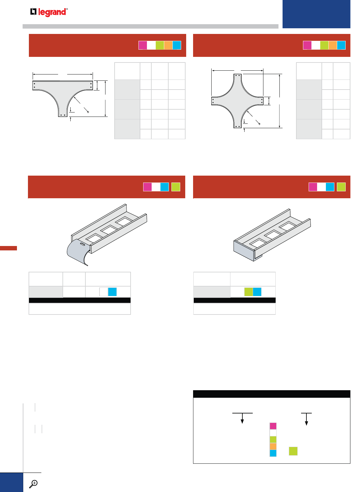
WIDTHS (W) INCHES
46
RADIUS (R) INCHES
12 24 36
CABLE DROPOUT BLIND END PLATE
PRODUCT
NUMBER
RADIUS (IN.)
WA B
2012
12
438 21
640 23
2024
24
462 33
664 35
2036
36
486 45
688 47
PRODUCT
NUMBER
RADIUS (IN.)
WA
1012
12
438
640
1024
24
462
664
1036
36
486
688
PRODUCT
NUMBER RADIUS FASTENERS
INCLUDED
0253 ¾" ZN S6
CATALOG NUMBERING EXAMPLE:
Material Width Fasteners
A - 0253 - 04 - ZN
PRODUCT
NUMBER FASTENERS
INCLUDED
0402 GE S6
CATALOG NUMBERING EXAMPLE:
Material Width Fasteners
A - 0402 - 06 - S6
AMT G
*AMT G
*
HORIZONTAL TEE HORIZONTAL CROSS
AMGL T AMGL T
A
B
W
R
5" (TYP.)
A
A
W
R
5" (TYP.)
5509 - 2012 - 06
04 – 4"
06 – 6"
SYSTEM NO. PRODUCT NO. WIDTH
5509 - A
2509 - M
1509 - G
3538 - L
3529 - T
This identifies the specific solid
bottom straight section tray
design and is used as a catalog
number prefix for all fittings.
HORIZONTAL TEE CATALOG NUMBERING EXAMPLE:
G* = optional
CHANNEL METALLIC FITTINGS
PW CABLE TRAY
WWW.LEGRAND.US/CABLOFIL
B.84
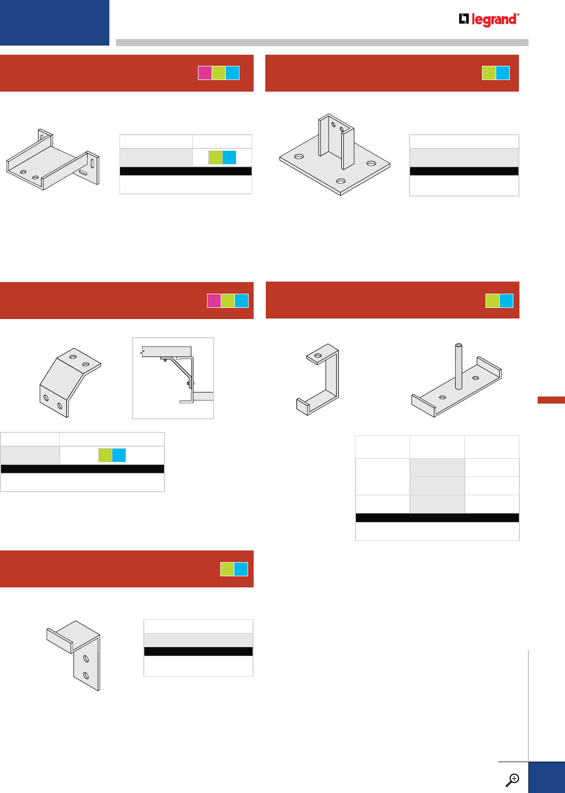
PRODUCT NO. FASTENERS INCLUDED
1338 GE S6
CATALOG NUMBERING EXAMPLE:
Material Width Fasteners
A - 1338 -04 - GE
CHANNEL-TO-TRAY CONNECTOR AGT
CHANNEL-TO-BOX CONNECTOR CHANNEL-TO-FLOOR BASE PLATE
AGT GT
PRODUCT NUMBER FASTENERS
0403 GE S6
CATALOG NUMBERING EXAMPLE:
Material Width Fasteners
A - 0403 - 04 - GE
PRODUCT NUMBER
1812
CATALOG NUMBERING EXAMPLE:
Material Width
G - 1812 - 04
OVERHEAD HANGER BRACKET GT
SINGLE DOUBLE
DESCRIPTION PRODUCT
NUMBER ROD SIZE
SINGLE 0333 ½"
0341 3
/
8"
DOUBLE 0334 ½"
CATALOG NUMBERING EXAMPLE (EA.):
Material Width
G - 0333 - 04
WALL BRACKET GT
PRODUCT NUMBER
1803
CATALOG NUMBERING EXAMPLE:
Material Width
G - 1803 - 04
For detailed material and finish descriptions, see page B.6.
CHANNEL METALLIC FITTINGS
PW CABLE TRAY
WWW.LEGRAND.US/CABLOFIL
B.85
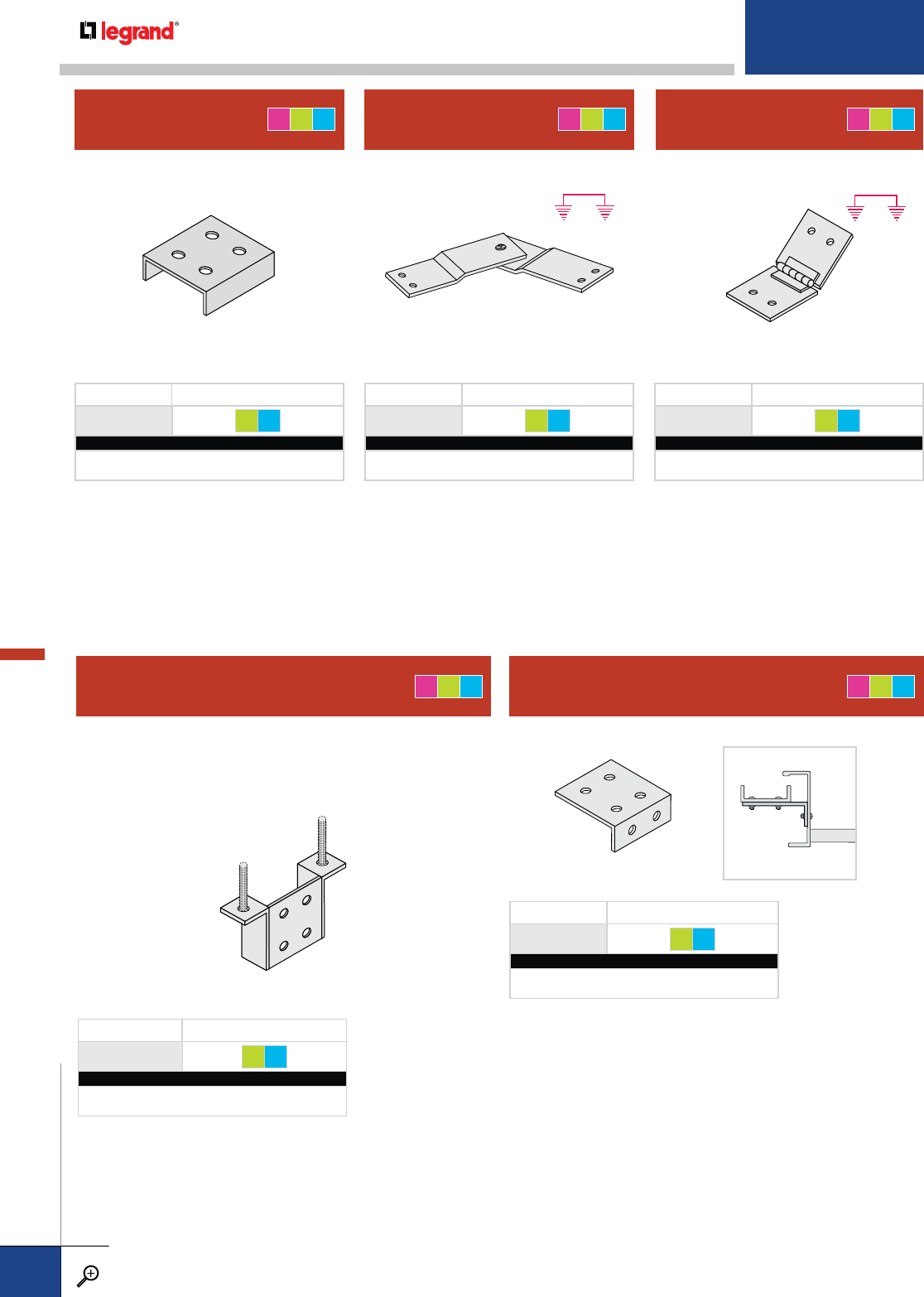
VERTICAL HANGER SPLICE AGT
Functions as a splice plate while offering a means of
supporting the channel vertically from two ½" threaded rods
(purchased separately). Fasteners for channel connection only
is included.
PRODUCT NUMBER FASTENERS
0357 GE S6
CATALOG NUMBERING EXAMPLE:
Material Width Fasteners
A - 0357 - 04 - GE
PRODUCT NO. FASTENERS INCLUDED
1301 GE S6
CATALOG NUMBERING EXAMPLE:
Material Width Fasteners
T - 1301 -04 - S6
PRODUCT NO. FASTENERS INCLUDED
1307 GE S6
CATALOG NUMBERING EXAMPLE:
Material Width Fasteners
T - 1307 -06 - S6
PRODUCT NO. FASTENERS INCLUDED
1305 GE S6
CATALOG NUMBERING EXAMPLE:
Material Width Fasteners
A - 1305 -06 - GE
Bonding jumpers
are required.
Bonding jumpers
are required.
STANDARD SPLICE HORIZONTAL
ADJUSTABLE SPLICE VERTICAL
ADJUSTABLE SPLICE
AGT AGT AGT
PRODUCT NO. FASTENERS INCLUDED
1357 GE S6
CATALOG NUMBERING EXAMPLE:
Material Width Fasteners
A - 1357 -04 - S6
MOUNTING BRACKET AGT
CHANNEL METALLIC SPLICES & CONNECTORS
PW CABLE TRAY
WWW.LEGRAND.US/CABLOFIL
B.86
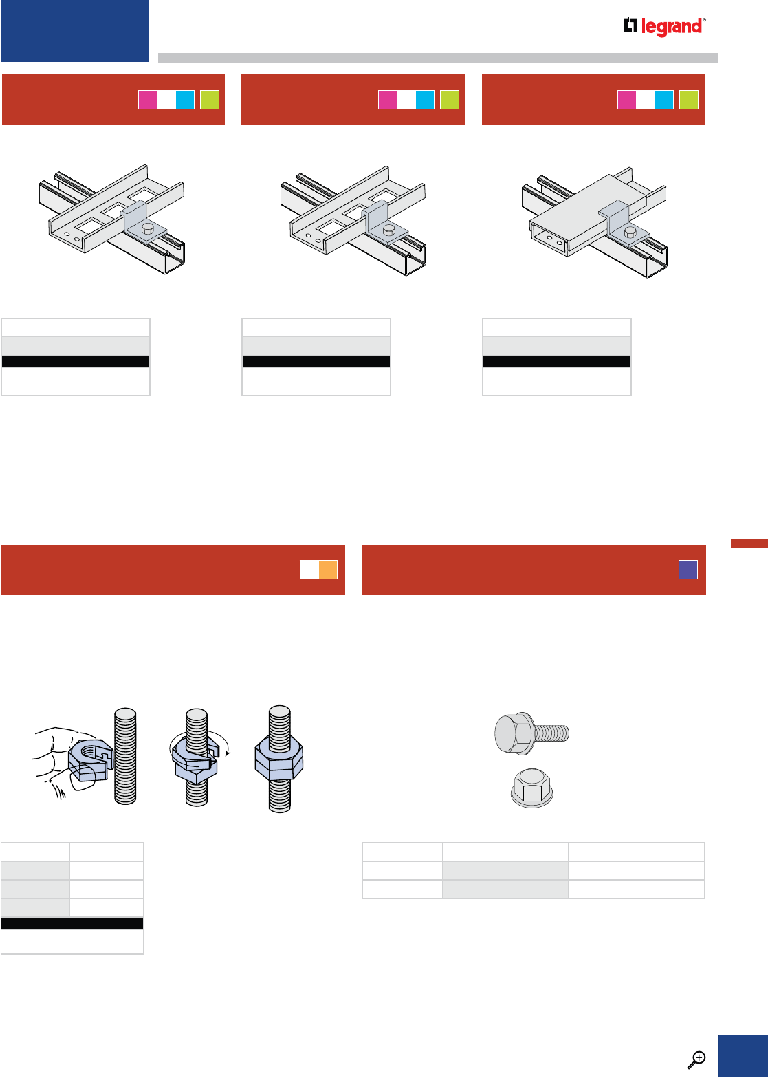
HOLD DOWN
CLAMP EXPANSION
GUIDE CLAMP HOLD DOWN/
COVER CLAMP
SLIP-ON LOCK NUT®FIBERGLASS ENCAPSULATED
STAINLESS STEEL HEX BOLT/NUT
PRODUCT NUMBER
1870
CATALOG NUMBERING EXAMPLE:
Material
T - 1870
PRODUCT NUMBER
1871
CATALOG NUMBERING EXAMPLE:
Material
A - 1871
PRODUCT NUMBER
1872
CATALOG NUMBERING EXAMPLE:
Material
T - 1872
ZN S4
Allows the user to slip the nut onto a rod, without actually
threading it. Ideal for when nuts must be added to a rod, but
cannot be threaded due to previously-installed equipment.
PRODUCT NO. SIZE
SON 1/4 ¼"-20
SON 3/8 3
/
8"-16
SON 1/2 ½"-13
CATALOG NUMBERING EXAMPLE:
Fasteners
SON 3/8 -ZN
To obtain the strength of stainless steel as well as the corrosion
resistance of fiberglass, use PW's 316 stainless steel hex nut and
hex bolt encapsulated in fire retardant fiberglass.
Designed for use with all PW fiberglass cable trays shown in this
catalog.
FE
DESCRIPTION COMPLETE CATALOG NO. SIZE GRIP RANGE
BOLT DS-8953-05-FE 3
/
8"-16 x 1" 0.35" TO 0.50"
NUT DS-8954-01-FE 3
/
8" N/A
AMT G
*AMT G
*AMT G
*
For detailed material and finish descriptions, see page B.6.
CHANNEL METALLIC SPLICES & CONNECTORS
PW CABLE TRAY
WWW.LEGRAND.US/CABLOFIL
B.87
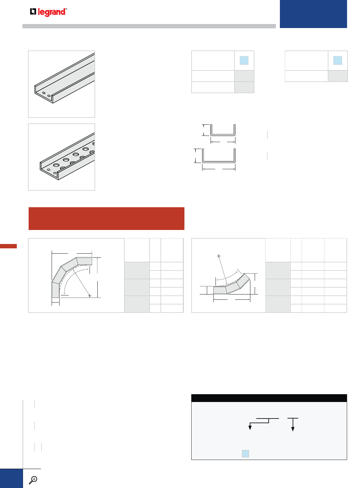
HORIZONTAL ELBOWS
A
A
W
90˚ R
90˚ PRODUCT
NUMBER
RADIUS (IN.)
WA
9012
12
418
620
9024
24
430
632
9036
36
442
644
A
B
W
45˚
R
45˚ PRODUCT
NUMBER
RADIUS (IN.)
WA B
4512
12
4 14¾ 87
/
8
616
1
/
8107
/
8
4524
24
4 23¼ 12½
624
5
/
814½
4536
36
4 31¾ 16
633
1
/
818
6"
2"
4"
1.20"
SOLID BOTTOM
VENTILATED BOTTOM
CHANNEL STYLE F
SOLID 7509
VENTILATED* 7508
*Available in straight sections only. All fittings have solid bottom.
COVER
(NOT SHOWN) F
FLAT, SOLID 7134
HORIZONTAL ELBOW CATALOG NUMBERING EXAMPLE:
7509-9012-06
SYSTEM NO. PRODUCT NO. WIDTH
WIDTH
4 – 4"
6 – 6"
Solid bottom straight section
tray design is used as a catalog
number prefix for all fittings.
7509 - F
FIBERGLASS CHANNEL TRAY
WIDTHS (W) INCHES
46
LENGTHS (H) FEET
10 20
WIDTHS (W) INCHES
46
LENGTHS (H) FEET
10 20
RADIUS (W) INCHES
12 24 36
CHANNEL FIBERGLASS STRAIGHT SECTIONS & FITTINGS
PW CABLE TRAY
WWW.LEGRAND.US/CABLOFIL
B.88
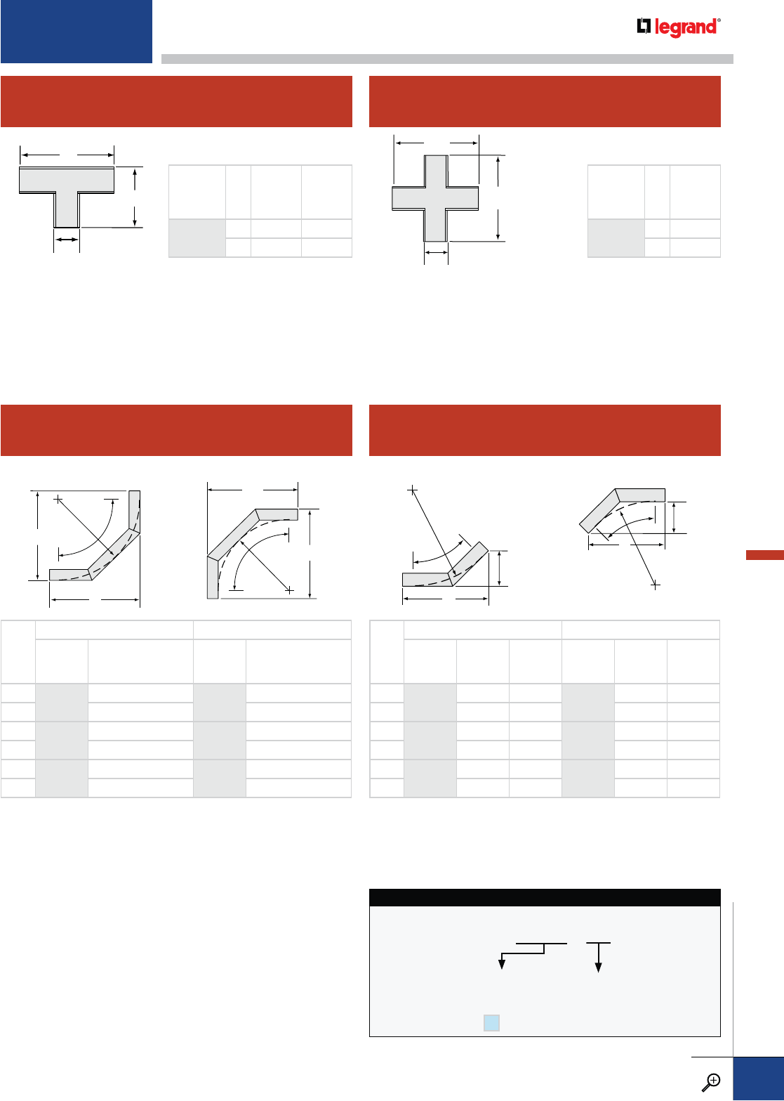
HORIZONTAL TEE
90º VERTICAL ELBOWS
HORIZONTAL CROSS
45º VERTICAL ELBOWS
PRODUCT
NUMBER WA B
2000 414 9
616 11
PRODUCT
NUMBER WA
1000 414
616
INSIDE
A
R
A
90˚
OUTSIDE
A
RA
90˚
INSIDE
A
R
B
45˚
OUTSIDE
A
R
B
45˚
W
INSIDE OUTSIDE
PRODUCT
NUMBER
RADIUS (IN.)
AB
PRODUCT
NUMBER
RADIUS (IN.)
AB
44612
12
12 5 4712
12
11¾ 47
/
8
6 12 5 11¾ 47
/
8
44624
24
203
/
88½ 4724
24
20¼ 83
/
8
620
3
/
88½ 20¼ 83
/
8
44636
36
287
/
812 4736
36
28¾ 117
/
8
628
7
/
812 28¾ 117
/
8
W
INSIDE OUTSIDE
PRODUCT
NUMBER
RADIUS (IN.)
A
PRODUCT
NUMBER
RADIUS (IN.)
A
49112
12
14 9212
12
15
614 15
7
/
8
49124
24
26 9224
24
27
626 27
7
/
8
49136
36
38 9236
36
39
638 39
7
/
8
HORIZONTAL TEE CATALOG NUMBERING EXAMPLE:
7509-2000-06
SYSTEM NO. PRODUCT NO. WIDTH
WIDTH
4 – 4"
6 – 6"
Solid bottom straight section
tray design is used as a catalog
number prefix for all fittings.
7509 - F
A
B
W
A
A
W
For detailed material and finish descriptions, see page B.6.
CHANNEL FIBERGLASS FITTINGS
PW CABLE TRAY
WWW.LEGRAND.US/CABLOFIL
B.89

Cable Runway is available in two styles, tubular side rails that are lightweight yet strong
and solid-bar side rails that offer maximum support strength. Both styles utilize rungs
made of tubular steel.
Cable runway is commonly used in telecommunications and voice and data applications.
Specific application examples include, computer data centers, server farms, 911 call
centers, network control centers, telephone/wireless communication centers, and
phone/data closets in commercial office buildings.
Available finishes include Yellow-zinc dichromate that is ideally used where the runway
needs to be UL Classified for use as an equipment ground conductor. Powder-coated
finishes are available in standard black and optional light gray.
• Available in 6”, 9", 12", 18", and 24” widths
• Available in Solid and Tubular side rail designs
• All rails are 10’ in length
B.91 STRAIGHT SECTIONS
B.92 FITTINGS
B.93 SPLICES,
CONNECTORS &
ACCESSORIES
CABLE RUNWAY
CABLE RUNWAY
PW CABLE TRAY
WWW.LEGRAND.US/CABLOFIL
B.90
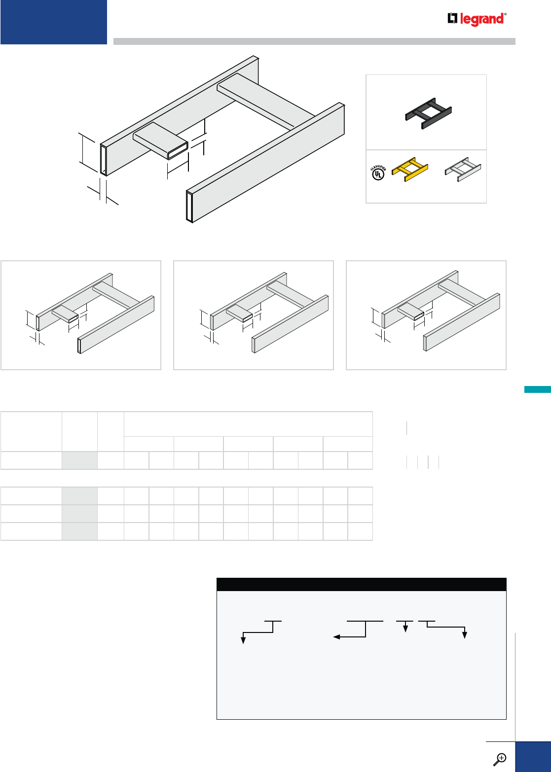
1.00"
(25.4mm)
0.50"
(12.7mm)
1.50"
(38.1mm)
0.375"
(9.5mm)
1.00"
(25.4mm)
0.50"
(12.7mm)
1.50"
(38.1mm)
0.375"
(9.5mm)
1.00"
(25.4mm)
0.375"
(9.5mm)
0.50"
(12.7mm)
2.00"
(50.8mm)
1.00"
(25.4mm)
0.375"
(9.5mm)
0.50"
(12.7mm)
2.00"
(50.8mm)
1½" TUBULAR SIDE RAIL
1½" SOLID SIDE RAIL
2" TUBULAR SIDE RAIL 2" SOLID SIDE RAIL
STANDARD DESIGN
TYPE PRODUCT
NUMBER
RAIL
HEIGHT*
SUPPORT SPAN (FT.)
SAFE LOAD (LBS./FT.) / DEFLECTION (IN.)
45678
TUBULAR 8104 1½ 248 0.41 159 0.63 110 1.19 81 1.24 62 1.62
OPTIONAL DESIGNS
TUBULAR 8204 2 300* 0.29 274 0.65 190 0.93 140 1.27 107 1.66
SOLID 8106 1½ 300* 0.26 300* 0.62 251 1.08 184 1.47 141 1.92
SOLID 8206 2 300* 0.11 300* 0.26 300* 0.54 246 0.82 188 1.07
* 1½ tubular rail height is standard; 1½ solid rail and 2" tubular and solid rail is optional and available by special order only.
SAFE LOAD: Allowable uniformly distributed load based on
simple beam type supports with a safety factor of 1.5. Safe
load data is based on the performance of the cable runway
side rails. An asterisk (*) denotes rung limitation.
DEFLECTION: Side rail deflection measured at the midspan
of the runway, based on simple beam type supports and
uniformly distributed loads. When trays are erected in a
continuous system, the midspan deflection decreases by as
much as 40%.
MATERIAL: Rectangular Steel Tube per ASTMA-513 and
Rectangular Steel Solid Bar per ASTMA-36.
CONSTRUCTION: Tubular rungs are attached to side rails
by arc welding.
STRAIGHT SECTION CATALOG NUMBERING EXAMPLE:
09-8104-0010-12BK
RUNG
SPACING
09 – 9"
PRODUCT NO.
TRAY
LENGTH
10'
Actual runway
length is 116½"
without connectors
WIDTH
06 – 6"
09 – 9"
12 – 12"
18 – 18"
24 – 24"
COATING COLOR
See chart above.
Standard:
Black(BK)
Optional:
Light Gray
(GY)
Yellow Zinc
Dichromate (YZ)
COLOR COATING
CHART
CABLE RUNWAY OPTIONAL DESIGNS
CABLE RUNWAY STANDARD DESIGN
RAIL HEIGHTS (H) INCHES
1.5 2
WIDTH (W) INCHES
6 9 12 18 24
LENGTH (L) FEET
10
For detailed material and finish descriptions, see page B.6.
CABLE RUNWAY STRAIGHT SECTIONS
PW CABLE TRAY
WWW.LEGRAND.US/CABLOFIL
B.91
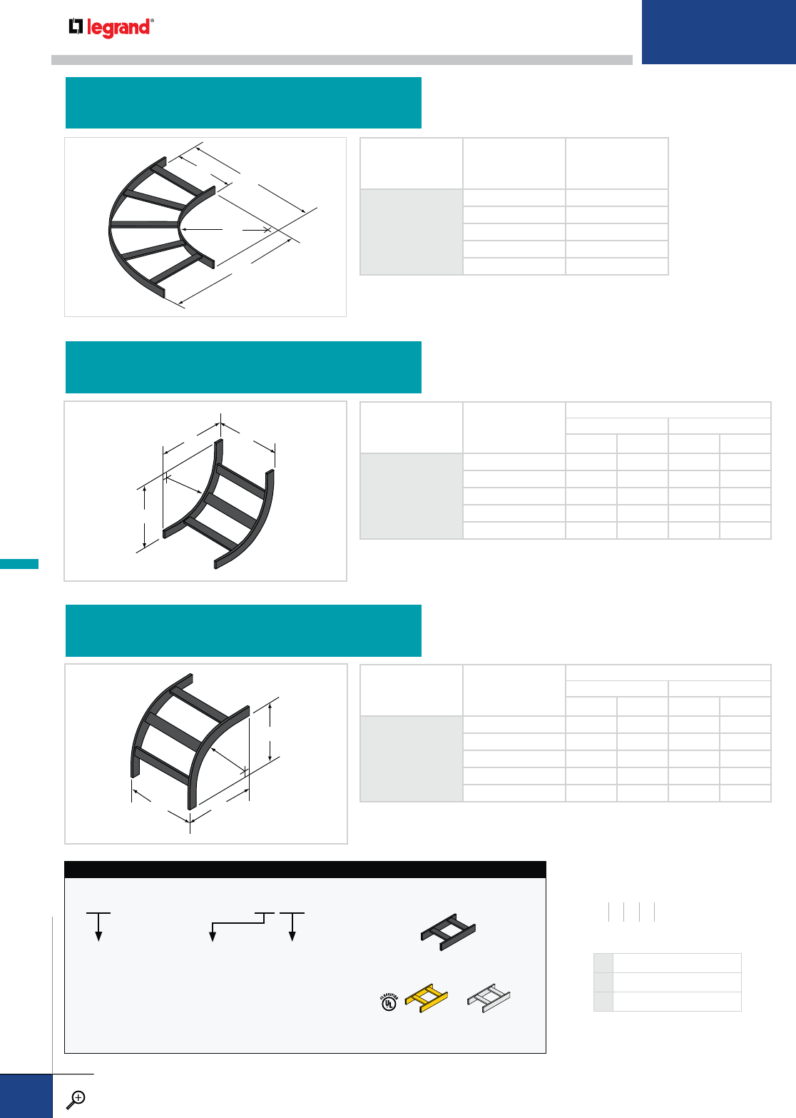
A
A
R
W
CATALOG NUMBER
RADIUS WA
9012
12"
621
924
12 27
18 33
24 39
W
B
A
R
CATALOG NUMBER
RADIUS W
SIDE RAIL HEIGHT
1½ 2
ABAB
9112
12"
6 16½ 16½ 17 17
9 16½ 16½ 17 17
12 16½ 16½ 17 17
18 16½ 16½ 17 17
24 16½ 16½ 17 17
W
D
C
R
CATALOG NUMBER
RADIUS W
SIDE RAIL HEIGHT
1½ 2
CDCD
9212
12"
6 16½ 15 17 15
9 16½ 15 17 15
12 16½ 15 17 15
18 16½ 15 17 15
24 16½ 15 17 15
HORIZONTAL ELBOW CATALOG NUMBERING EXAMPLE:
09-8104-9012-24 BK
RUNG
SPACING
09 – 9"
WIDTH
06 – 6"
09 – 9"
12 – 12"
18 – 18"
24 – 24"
PRODUCT NO.SYSTEM NO.
COATING
COLOR
Standard:
Black(BK)
Optional:
Light Gray
(GY)
Yellow Zinc
Dichromate (YZ)
COLOR COATING
CHART
90˚ HORIZONTAL ELBOW
90˚ VERTICAL INSIDE ELBOW
90˚ VERTICAL OUTSIDE ELBOW
WIDTHS (W) INCHES
6 9 12 18 24
RUNWAY PREFIX OPTIONS
R ALL SIZES
1R 1½" SIDERAIL (8104, 8106)
2R 2" SIDERAIL (8204, 8206)
CABLE RUNWAY FITTINGS
PW CABLE TRAY
WWW.LEGRAND.US/CABLOFIL
B.92
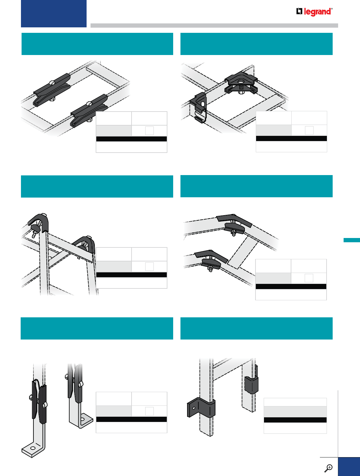
PRODUCT
NUMBER
FASTENERS
INCLUDED
1302 ZN
CATALOG NUMBERING EXAMPLE:
System No. Fasteners Coating
1R - 1302-ZN-BK
Connects runway sections. Sold in pairs. Joins runway sections at a 90˚ horizontal angle. Sold in pairs.
Joins runway sections at a 90˚ vertical angle. Sold in pairs.
PRODUCT
NUMBER
FASTENERS
INCLUDED
1320 ZN
CATALOG NUMBERING EXAMPLE:
System No. Fasteners Coating
1R - 132O -ZN-BK
PRODUCT
NUMBER
FASTENERS
INCLUDED
1331-90 ZN
CATALOG NUMBERING EXAMPLE:
System No. Fasteners Coating
1R- 1331-90-ZN-BK
Joins runway sections at a 45˚ vertical angle. Sold in pairs.
PRODUCT
NUMBER
FASTENERS
INCLUDED
1331-45 ZN
CATALOG NUMBERING EXAMPLE:
System No. Fasteners Coating
1R- 1331-45 -ZN-BK
PRODUCT
NUMBER
FASTENERS
INCLUDED
0339 ZN
CATALOG NUMBERING EXAMPLE:
System No. Fasteners Coating
1R- 0339 -ZN-BK
45˚ VERTICAL CONNECTOR
SPLICE
FLOOR/WALL SUPPORT BRACKET KIT
90˚ HORIZONTAL CONNECTOR
90˚ VERTICAL CONNECTOR
Secures runway to the wall or floor. Sized for 3/8"
hardware (not included). Sold in pairs.
PRODUCT NUMBER
0426
CATALOG NUMBERING EXAMPLE:
System No. Coating
1R - 0426 -BK
VERTICAL WALL BRACKET
Connects runway to the floor or wall and acts as a support
point. Includes the splice connector and foot support.
Attachment hardware is not included. Sold in pairs.
For detailed material and finish descriptions, see page B.6.
CABLE RUNWAY SPLICES, CONNECTORS & ACCESSORIES
PW CABLE TRAY
WWW.LEGRAND.US/CABLOFIL
B.93
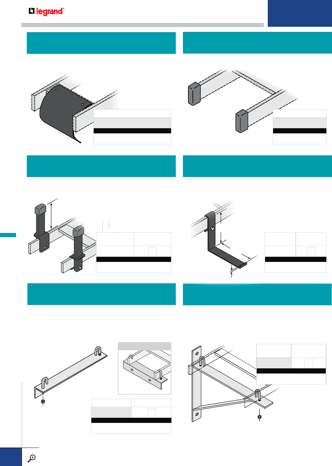
Protects the exposed ends of runway side rails.
Plastic material. Sold in pairs.
PROTECTIVE END CAP
Provides a smooth surface for cables to drop out of runway
with a 3" radius bend. Attaches to both rungs and siderails.
PRODUCT NUMBER
0254
CATALOG NUMBERING EXAMPLE:
System No. W Fasteners Coating
R- 0254 - 06-ZN-BK
CABLE DROPOUT
PRODUCT NUMBER
0410
CATALOG NUMBERING EXAMPLE:
System No.
1R - 0410
Supports cable runway against the wall or an upright vertical
surface. Hardware for runway attachment is included.
Standard finish is black epoxy powder coat.
PRODUCT NUMBER FASTENERS INCLUDED
0403 ZN
CATALOG NUMBERING EXAMPLE:
System No. W Fasteners Coating
R-0403-06-ZN-BK
PRODUCT
NUMBER FASTENERS
INCLUDED
0349 ZN
CATALOG NUMBERING EXAMPLE:
System No. W Fasteners Coating
R- 0349-09-ZN-BK
WALL ANGLE SUPPORT KIT WALL BRACKET
APPLICATION
H
*
Posts add load depth to cable runway. Includes one post, one
bracket, and one end cap. Posts are typically installed on 12"
centers.
4.24
4
.
75
0
.
25
Bracket provides a separate facility for running power
conductors or other cables that should be physically separated
from main cables.
PRODUCT
NUMBER FASTENERS
INCLUDED
A330 ZN
CATALOG NUMBERING EXAMPLE:
System No. H Fasteners Coating
1R- A330-08-ZN-BK
PRODUCT
NUMBER FASTENERS
INCLUDED
A834 ZN
CATALOG NUMBERING EXAMPLE:
System No. Fasteners Coating
1R - A834-ZN-BK
CABLE RETAINING POSTS L-BRACKET
HEIGHTS (H) INCHES
468
Supports cable runway against wall or upright vertical surface.
Angle length and hole spacing is based on the specified width.
Kit includes hardware for tray attachment, but wall attachment
hardware is not included. Standard finish is black epoxy
powder coat.
CABLE RUNWAY SPLICES, CONNECTORS & ACCESSORIES
PW CABLE TRAY
WWW.LEGRAND.US/CABLOFIL
B.94
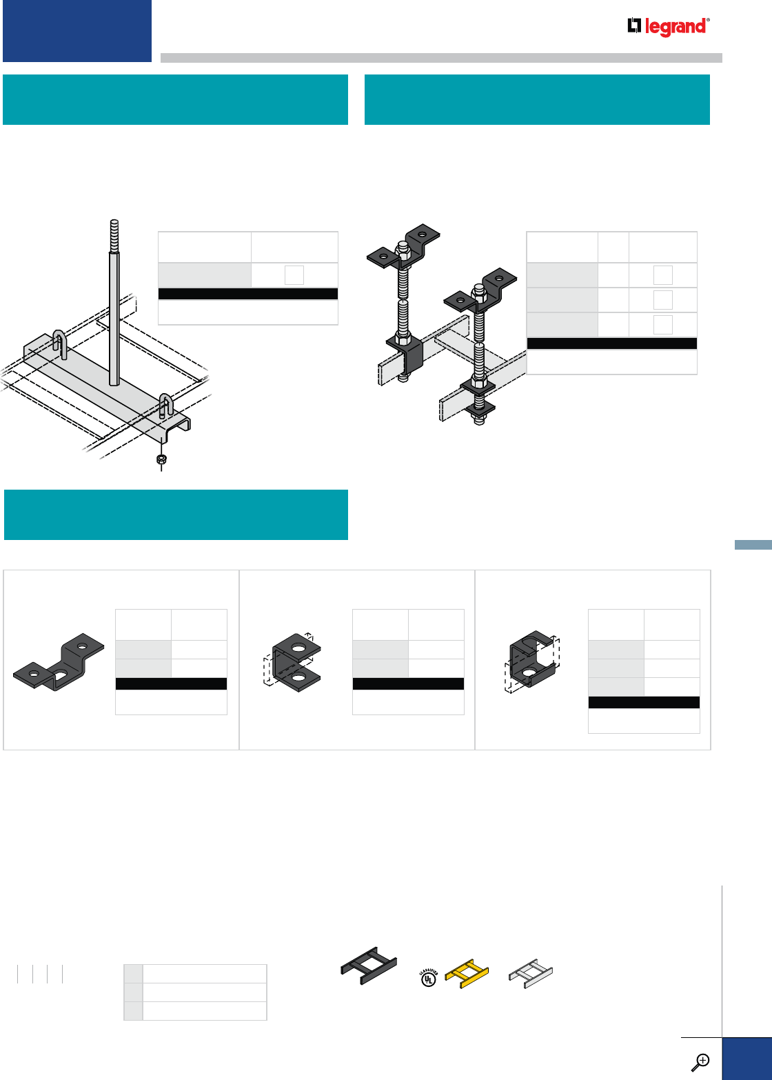
Supports cable runway from the ceiling using a single
threaded rod. Kit includes one support bracket and hardware
for tray attachment. Standard finish is black epoxy powder
coat. Threaded rod is purchased separately.
Supports cable runway from the ceiling with threaded rods. Kit
includes one ceiling support bracket, one runway side rail support
bracket and hex nuts. Threaded rod is purchased separately.
PRODUCT
NUMBER
USE WITH
FASTENERS
A823-01 3/8
A824-01 ½ or 5
/
8
CATALOG NUMBERING EXAMPLE:
System No. Coating
R-A823-01-BK
Used in conjunction with threaded rod to support cable runway from ceiling. Sold individually. Hardware is purchased separately.
PRODUCT
NUMBER
USE WITH
FASTENERS
A838-01 3/8
A839-01 1/2 or 5
/
8
CATALOG NUMBERING EXAMPLE:
System No. Coating
1R-A839-01-BK
PRODUCT
NUMBER
USE WITH
FASTENERS
A842-01 3
/
8
A843-01 ½
A844-01 5
/
8
CATALOG NUMBERING EXAMPLE:
System No. Coating
1R-A842-01-BK
PRODUCT
NUMBER
FASTENERS
INCLUDED
0345 ZN
CATALOG NUMBERING EXAMPLE:
System No. W Fasteners Coating
1R - 0345- 12 - ZN -BK
PRODUCT
NUMBER ROD
SIZE
FASTENERS
INCLUDED
0327 3
/
8ZN
0328 ½ZN
0331 5
/
8ZN
CATALOG NUMBERING EXAMPLE:
System No. Fasteners Coating
1R-0327-ZN-BK
RUNWAY SUPPORT BRACKETS
CENTER HUNG SUPPORT KIT TRAPEZE SUPPORT KIT
WIDTHS (W) INCHES
6 9 12 18 24
RUNWAY PREFIX OPTIONS
R ALL SIZES
1R 11/2" SIDERAIL (8104, 8106)
2R 2" SIDERAIL (8204, 8206)
Standard:
Black(BK)
Optional:
Light Gray
(GY)
Yellow Zinc
Dichromate (YZ)
COLOR COATING CHART
Wall Angle Support, Center
Hung Support and Wall
Bracket are also available in
black and grey colors.
CEILING SUPPORT BRACKET SIDE RAIL SUPPORT BRACKET SLOTTED SUPPORT BRACKET
CABLE RUNWAY SPLICES, CONNECTORS & ACCESSORIES
WWW.LEGRAND.US/CABLOFIL
B.95
PW CABLE TRAY

INTRODUCTION
PAGES C.1-C.5
TRAY, SPLICING & FITTINGS
PAGES C.6-C.15
SUPPORTS & ACCESSORIES
PAGES C.16-C.25
INSTALLATIONS
PAGES C.26-C.29
SPECIFICATIONS
PAGES C.30-C.31
CROSS REFERENCE
PAGES C.32-C.33
TT
T
RR
R
OO
O
U
U
U
U
U
G
G
G
G
H
H
H
T
T
T
RR
R
R
R
AA
A
A
A
A
YY
Y
Y
Y
TABLE OF CONTENT
S
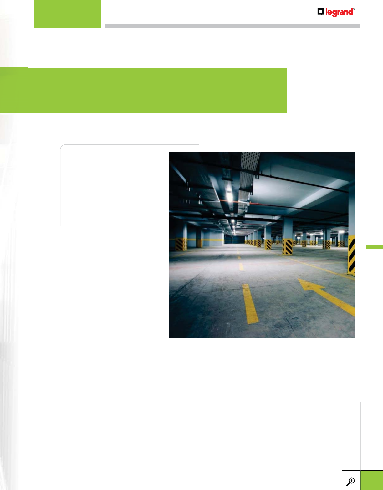
Legrand continues to be an
innovator in cable management
solutions and is proud to
introduce Cablofil Trough Tray,
a cable management system
designed to maximize network
reliability and minimize lifecyle
costs. Our Fiber Trough
design utilizes high strength
steel components to provide
the strength and durability
required to manage fiber
optic or copper cabling in the
most demanding data center
environments. V-Trough
provides protection for power
cables, keeping them cool and
accessible.
Cablofil trough trays are
manufactured to exacting
standards so that all
components fit together perfectly and install with ease. The design includes rolled top
edges to add strength and allows the covers to snap in place. It eliminates sharp top
edges to keep installers and cables safe. Patented fast splices, bends and turns are
available as stocked items. Jobsite fabrication is kept to a minimum and requires little
training for most installers, moving on and off the project quickly.
Cablofil trough tray gives any installation a professional look with finishes and colors to
match the environment. It is the ultimate protection for your cables.
CABLOFIL TROUGH TRAY
Quality Makes the Difference
INTRODUCTION
WWW.LEGRAND.US/CABLOFIL
C.1
CABLOFIL
TROUGH TRAY
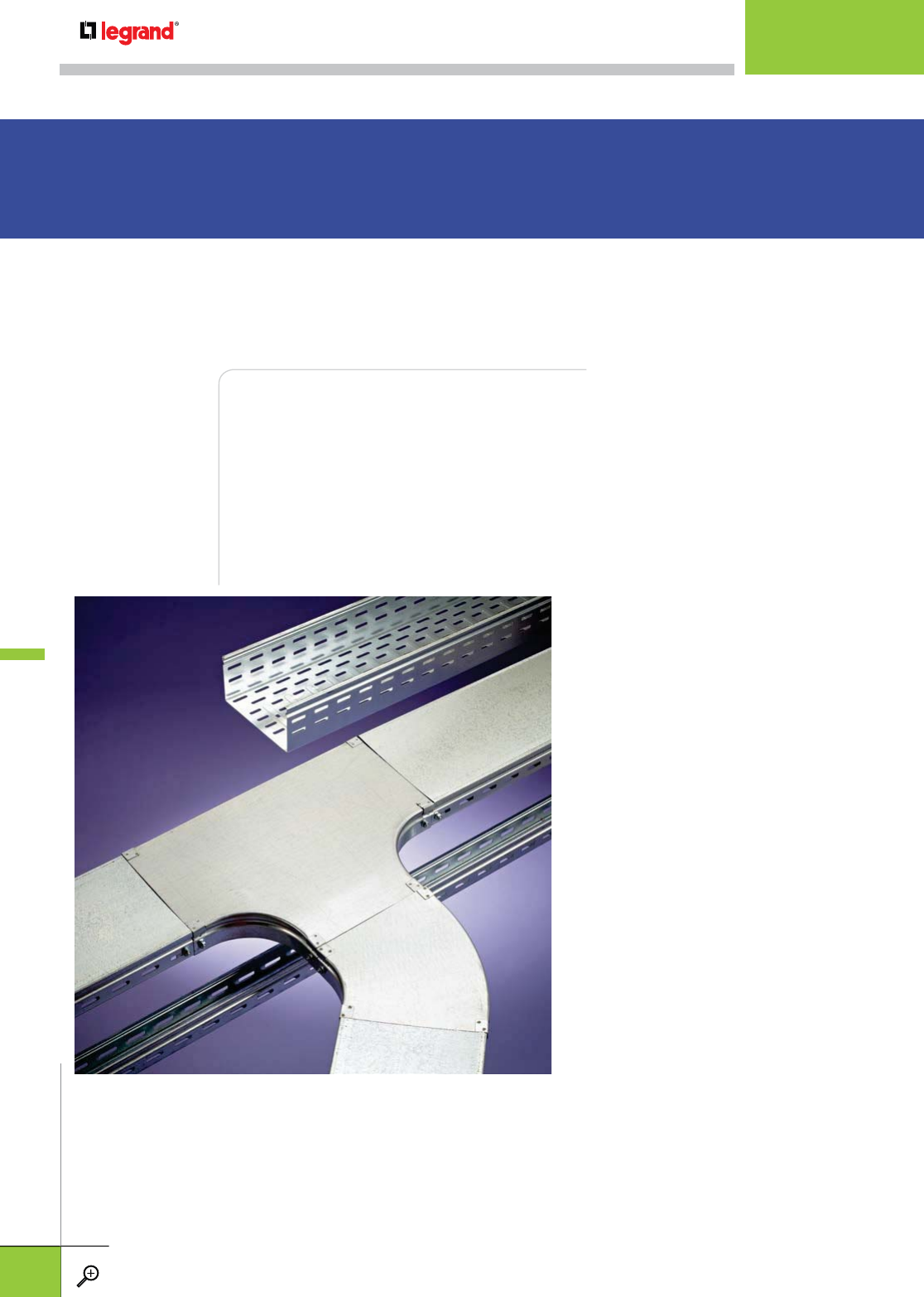
V-Trough cable tray keeps cabling cool, protected and easy to manage. Its high-strength
steel construction matches many European OEM specifications and is available in
smaller sizes for control and instrumentation cabling. The open tray design allows ready
access to cables and additional cabling can be added with ease. Covers are available
for complete security. V-Trough is manufactured to exacting standards so that all
components fit together perfectly, making installation a snap.
Ventilated Design All V-Trough straight
sections are ventilated to reduce cable
bundle heating, and to keep mold and
moisture from building up within the cable
pathway.
Safe and Strong All steel construction
provide the ultimate protection to cable
bundles. All edges are rounded and eased
in the fabrication process to keep cable
insulation undamaged during installation.
Access and Security The V-Trough line
includes solid covers for all straight and
curved sections. Tool-less cover removal
allows easy cable access for future cable
additions and maintenance. They can also
be bolted in place for security.
VTROUGH VENTILATED TRAY
Keep Your Cables
Out of Sight and Secure
INTRODUCTION
WWW.LEGRAND.US/CABLOFIL
C.2
CABLOFIL
TROUGH TRAY
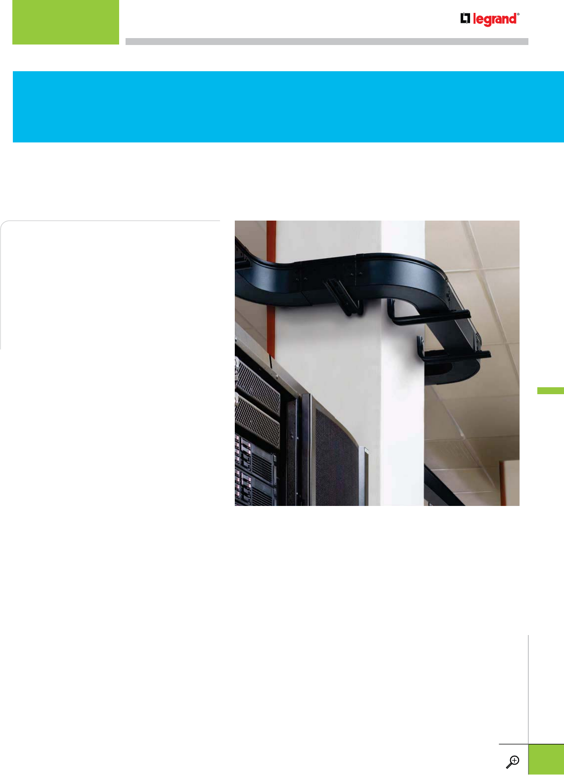
Fiber Trough is designed to maximize network
reliability and minimize lifecyle costs. It
utilizes high strength steel components to
provide the strength and durability required to
manage fiber cabling in the most demanding
data center environments. It provides the
ultimate in protection and is manufactured to
exacting standards so that all components fit
perfectly and install with ease.
STEEL vs. PLASTIC
Steel Lasts Most cable routing systems
manufactured from molded plastic can sag,
lose their shape, discolor and even degrade
due to exposure to UV light and other
environmental conditions. Steel retains its
color and shape over time regardless of the application or environment.
Steel tray requires fewer supports Plastic is generally heavier and requires
more supports on longer runs. Steel is lighter and more rigid reducing deflection.
On longer runs Fiber Trough requires one-half as many supports, reducing
installation time overall.
Protection from EMI EMI from transformers or high voltage cables can cause
signal interference for copper data cables. Fiber Trough’s steel construction can be
properly earthed to eliminate EMI and reduce noise and attenuation.
The Steel
Alternative
FIBER TROUGH CABLE TRAY
INTRODUCTION
WWW.LEGRAND.US/CABLOFIL
C.3
CABLOFIL
TROUGH TRAY
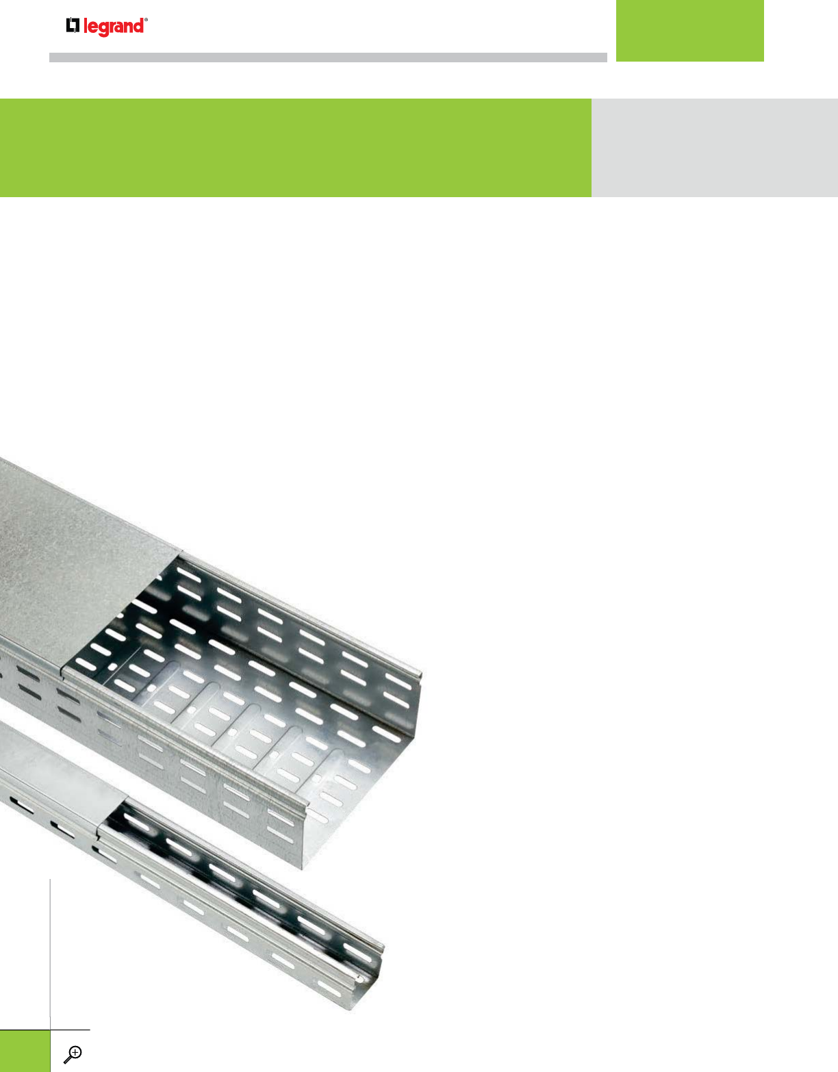
Fluid Design The built-in radius of Cablofil Trough tray effectively eliminates any
sharp angles and bends in the cable pathway that cause pinching and micro crack
stresses in fiber optic cabling. Its one-piece design integrates the side rails and
bottom for a cable pathway that eliminates cable snagging. The end result is a
simple and elegant finished installation.
Precision Fit Trough tray’s all steel construction allows it to be manufactured to
precise standards so that tray sections easily fit together and covers slide in place with
ease during the installation process. Cablofil trough tray includes all bends and turns
needed for any installation application.
Cable Protection All steel construction provides the ultimate protection for fragile
fiber optic and copper cables. It keeps cables safe from cuts, crushing problems and
improper bend radius issues. All edges are rounded and eased in the fabrication
process to ensure the cable insulation and installer is kept safe during
installation.
Splicing Made Simple Patented fast splice accessories
are available with pre-fitted screws to speed
installation time. The bolts are held in place
by the splice, just tighten the nuts to
secure tray sections. Simplify your BOM by
eliminating the need to plan/order/install
fittings. All you need is number of tray,
number of FTUS and you are done!
Designed for Installation Ease Easy
installation means lower costs. Cablofil Trough
Tray installs with few parts and it is easily installed
using standard construction practices and common
tools.
Complete Line of Accessories All bends and turns
necessary for any installation are available as
stocked items. No jobsite fabrication will
be needed. Other accessories include cable
drops, size reductions, cabinet connections and
supports.
simple
and
elegant
finished
installation
.
Prec
i
s
i
on F
i
t
Trough tray’s all steel constructio
precise standards so that tray sections easily fit t
o
ease during the installation process. Cablofil trou
nee
d
e
d
f
or any
i
nsta
ll
at
i
on a
ppli
cat
i
on.
C
a
b
l
e
Pr
o
t
ec
ti
o
n All steel construction provid
fib
er opt
i
c an
d
copper ca
bl
es.
I
t
k
eeps ca
bl
es s
a
i
mproper
b
en
d
ra
di
us
i
ssues.
All
e
dg
es are r
o
process to ensure the cable insulation
a
i
nsta
ll
at
i
on.
S
plicin
g
Made
S
impl
e
are available wit
h
i
nsta
ll
at
i
on
b
y t
h
e
s
secure
e
limin
a
f
ittin
g
s.
number
Designed
f
installation m
T
ray
i
nsta
ll
s w
i
t
h
u
s
i
n
g
stan
d
ar
d
co
n
t
oo
l
s.
C
omplete Line o
f
A
c
necessary for an
s
toc
k
e
d
i
te
m
be
n
eeded
.
O
d
ro
p
s, s
i
ze r
e
suppor
t
s.
The Simple Difference
CABLOFIL TROUGH TRAY
INTRODUCTION
WWW.LEGRAND.US/CABLOFIL
C.4
CABLOFIL
TROUGH TRAY
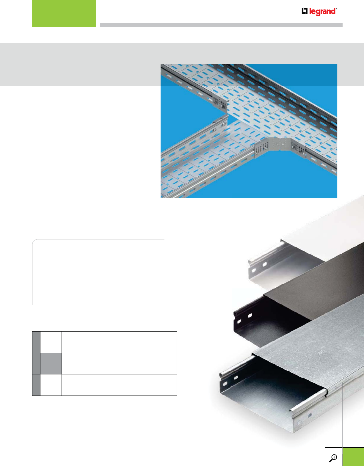
Cablofil trough tray is stocked in durable pre-galvanized and
textured flat black powder coat finishes that resist corrosion
over the lifetime of the installation. A white powder coat
finish is optional (contact Cablofil for availability.)
Our new splice design is more adaptable
than anything on the market – angles,
bends, tees and reductions – this splice
does it all. The FTUS eliminates the need
to plan, order and install special fittings
and simplifies your bill of materials.
And field modifications are simple
when installing Cablofil Trough Tray.
It’s available in two sizes to fit your tray
depth.
STANDARD
PG Carbon Steel
ASTM A510
Grade 1008
Pre-Galvanized: Continuous
Galvanization Before Fabrication
ASTM A 653
BL Carbon Steel
ASTM A510
Grade 1008
Black Painted:
Black Powder Coated
ASTM D 3451
OPTIONAL
WH Carbon Steel
ASTM A510
Grade 1008
White Painted:
White Powder Coated
ASTM D 3451
FINISHES
Finishes that Last
Easy Splicing
sion
INTRODUCTION
WWW.LEGRAND.US/CABLOFIL
C.5
CABLOFIL
TROUGH TRAY
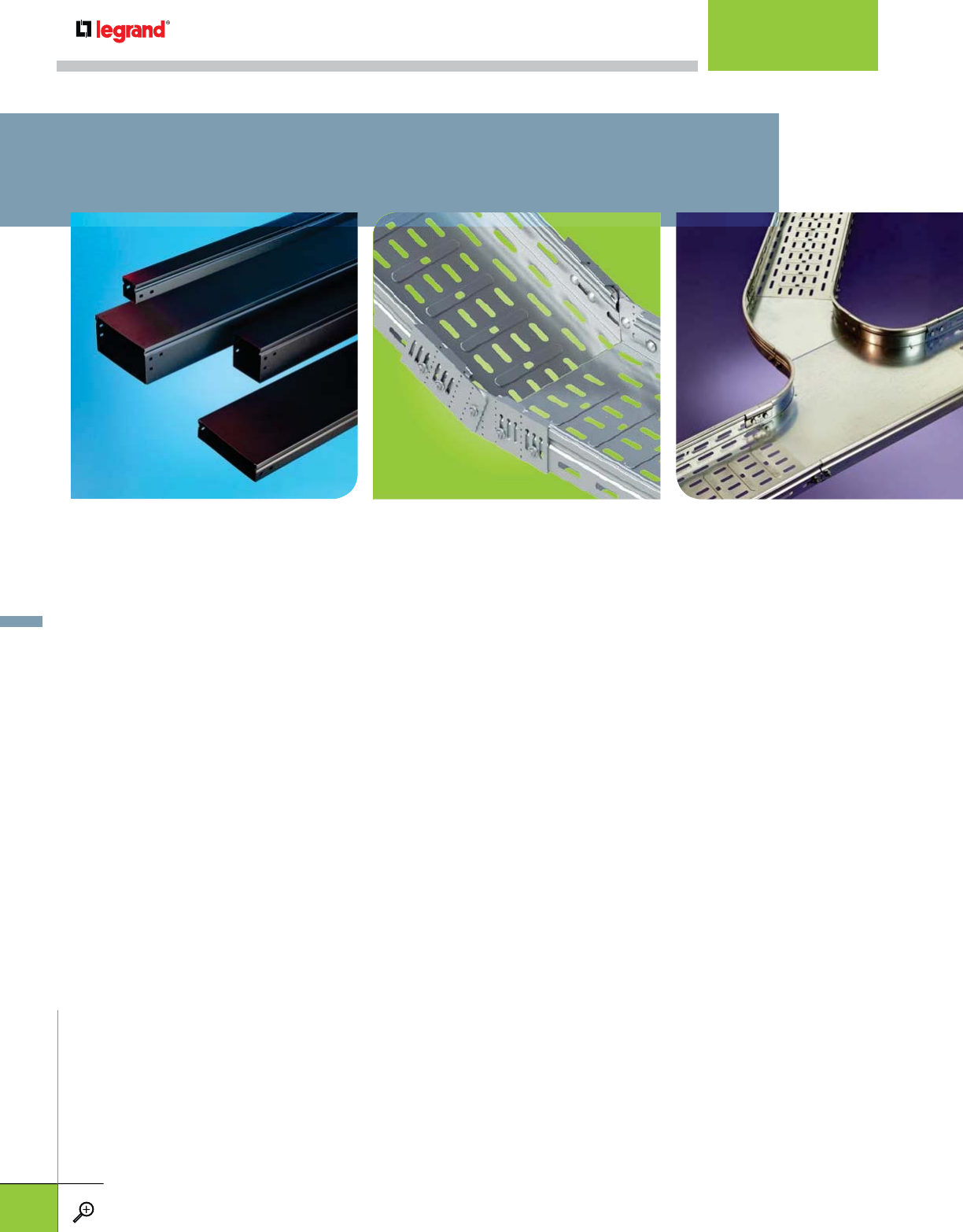
C.8 FT
STRAIGHT SECTION TRAY
C.9 VT
VENTILATED STRAIGHT
SECTION TRAY
C.8, 9 FTC
STRAIGHT TRAY COVERS
C.10 FTUS
UNIVERSAL ADJUSTABLE
SPLICE
C.11 FTRHR
RIGHT-HAND REDUCER
C.11 FTLHR
LEFT-HAND REDUCER
C.11 FTEF
FAS SPLICE
C.12 FTFB90
HORIZONTAL 90° ELBOW
C.12 FTCFB90
HORIZONTAL 90° ELBOW
COVER
C.12 FTFB45
HORIZONTAL 45° ELBOW
C.12 FTCFB45
HORIZONTAL 45° ELBOW
COVER
TRAY, SPLICING & FITTINGS
• Strong corrosion-resistant steel
construction
• Ventilated tray reduces cable heating,
mold and moisture buildup
• Rolled edge for cable protection
• 18-22 gage steel (t)
• Unique design allows covers to snap on
• Covers work with both solid and
ventilated tray
• Universal splicing system reduces need
for formed fittings.
C.13 FTVI90
VERTICAL 90° INSIDE ELBOW
C.13 FTCVI90
VERTICAL 90° INSIDE ELBOW COVER
C.13 FTVO90
VERTICAL 90° OUTSIDE ELBOW
C.13 FTCVO90
VERTICAL 90° OUTSIDE ELBOW COVER
C.14 FTT
HORIZONTAL TEE
C.14 FTTC
HORIZONTAL TEE COVER
C.14 FTB
HORIZONTAL BRANCH
C.14 FTBC
HORIZONTAL BRANCH COVER
C.15 FTX
HORIZONTAL CROSS
C.15 FTXC
HORIZONTAL CROSS COVER
C.15 FTVT
UPRIGHT DROPOUT TEE (COVER INCLUDED)
INTRODUCTION
WWW.LEGRAND.US/CABLOFIL
C.6
CABLOFIL
TROUGH TRAY
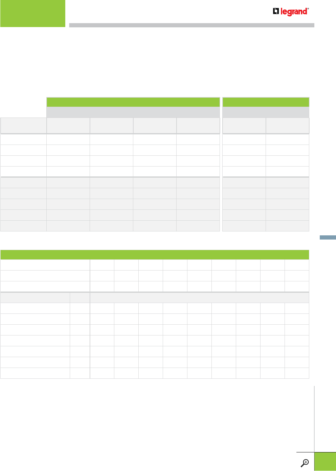
DATA CABLE FILL TABLE MC POWER CABLE FILL TABLE
MAX NUMBER OF CABLES PER CODE MAX NUMBER OF CABLES PER CODE
TRAY Cat 5e 4-pr
Plenum (.17”)
Cat 5e 4-pr
Non-Plenum (.19”)
Cat 6e 4-pr
Plenum (.22”) Cat 6a 4-pr
Plenum (.35”) 2C (12 AWG) THHN
TypeMC AlumArmor 3C (12 AWG) THHN
TypeMC AlumArmor
50/50 (2x2) 88 71 53 20 11 10
50/100 (2x4) 177 142 106 41 23 21
50/200 (2x8) 355 284 212 83 47 42
50/300 (2x12) 532 426 318 125 71 63
100/100 (4x4) 351 281 209 82 23 21
100/200 (4x8) 703 563 419 165 47 42
100/300 (4x12) 1055 844 629 248 71 63
100/500 (4x20) 1758 1407 1049 414 119 105
100/600 (4x24) 2110 1689 1259 497 143 126
CABLE CAPACITY (BASED ON 40% FILL*)
TROUGH TRAY SERIES 50/50 50/100 50/200 50/300 100/100 100/200 100/300 100/500 100/600
TRAY SIZE (HxW-IN) 2x2 2x4 2x8 2x12 4x4 4x8 4x12 4x20 4x24
CABLE FILL AREA (IN2) 3.875 7.75 15.5 23.25 15.5 31 46.5 77.5 93
CABLE TYPE†AREA NUMBER OF CABLES
Fiber - 0.063" (1.6mm) 0.003 517 1033 2067 3100 2067 4133 6200 10333 12400
Fiber - 0.079" (2.0mm) 0.005 310 620 1240 1860 1240 2480 3720 6200 7440
Fiber - 0.118" (3.0mm) 0.011 141 282 564 845 564 1127 1691 2818 3382
Ribbon - 0.205" (5.2mm) 0.033 47 94 188 282 188 376 564 939 1127
Category 5E - 0.17" (4.32mm) 0.023 67 135 270 404 270 539 809 1348 1617
Category 6- 0.24" (6.1mm) 0.045 34 69 138 207 138 276 413 689 827
Category 6A - 0.30" (7.6mm) 0.071 22 44 87 131 87 175 262 437 524
* 40% fill represents the maximum number of cables that can be practically installed (tray is piled to top of siderails with cable due to cable
straightness and gaps between cables). Tray dimensions are nominal.
†Typical cable diameters - for exact results, use the installed cable diameter provided by manufacturer)
Use these cable fill tables to determine the tray size(s) needed for your installation.
CABLE FILL TABLES
WWW.LEGRAND.US/CABLOFIL
C.7
CABLOFIL
TROUGH TRAY
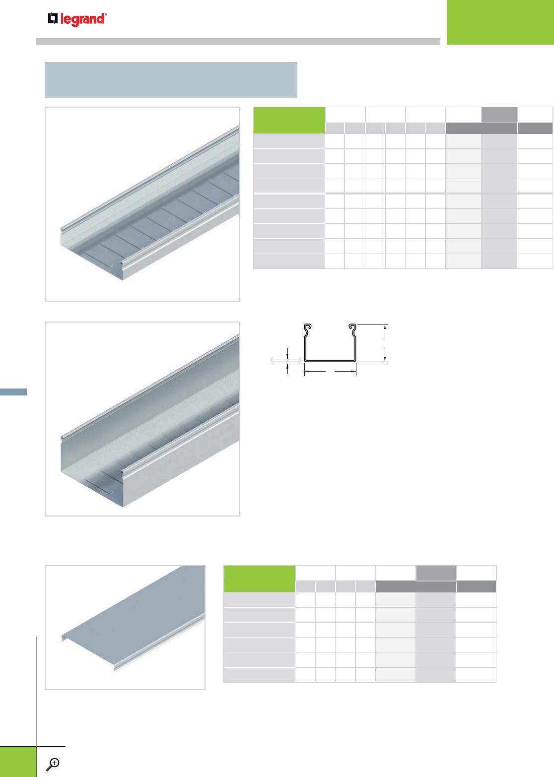
COVER WIDTH (W) LENGTH PG BL WH
IN MM FT M STANDARD
FTC 50 2 50 10 3 340 189 960 009 –
FTC 100 4 100 10 3 340 191 960 010 –
FTC 200 8 200 10 3 340 193 960 011 –
FTC 300 12 300 10 3 340 194 960 012 –
FTC 500 20 500 10 3 340 196 960 013 –
FTC 600 24 600 10 3 340 197 960 014 –
– Contact manufacturer for availability.
FTC
• 18 gage steel
• All covers are solid. Ventilated covers are not available.
• Splicing sold separately.
FT 50
FT 100
t
W
H
BASE HEIGHT (H) WIDTH (W) LENGTH PG BL WH
IN MM IN MM FT M STANDARD
FT 50/50 2 50 2 50 10 3 340 020 960 000 –
FT 50/100 2 50 4 100 10 3 340 021 960 001 –
FT 50/200†2 50 8 200 10 3 340 023 960 002 –
FT 50/300†2 50 12 300 10 3 340 024 960 003 –
FT 100/100 4 100 4 100 10 3 340 030 960 004 –
FT 100/200 4 100 8 200 10 3 340 032 960 005 –
FT 100/300 4 100 12 300 10 3 340 033 960 006 –
FT 100/500†4 100 20 500 10 3 340 093 960 007 –
FT 100/600†4 100 24 600 10 3 340 107 960 008 –
– Contact manufacturer for availability.
†
Ribbed bottom for additional rigidity
FT
STRAIGHT SECTION TRAY
STRAIGHT TRAY
WWW.LEGRAND.US/CABLOFIL
C.8
CABLOFIL
TROUGH TRAY
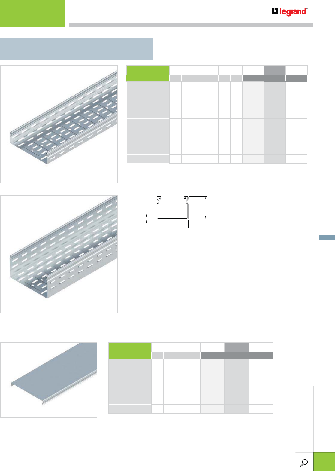
COVER WIDTH (W) LENGTH PG BL WH
IN MM FT M STANDARD
FTC 50 2 50 10 3 340 189 960 009 –
FTC 100 4 100 10 3 340 191 960 010 –
FTC 200 8 200 10 3 340 193 960 011 –
FTC 300 12 300 10 3 340 194 960 012 –
FTC 500 20 500 10 3 340 196 960 013 –
FTC 600 24 600 10 3 340 197 960 014 –
– Contact manufacturer for availability.
FTC
• 18 gage steel
• All covers are solid. Ventilated covers are not available.
• Splicing sold separately.
VT 50
VT 100
t
W
H
BASE HEIGHT (H) WIDTH (W) LENGTH PG BL WH
IN MM IN MM FT M STANDARD
VT 50/50 2 50 2 50 10 3 340 052 – –
VT 50/100 2 50 4 100 10 3 340 053 – –
VT 50/200†2 50 8 200 10 3 340 055 – –
VT 50/300†2 50 12 300 10 3 340 056 – –
VT 100/100 4 100 4 100 10 3 340 069 – –
VT 100/200 4 100 8 200 10 3 340 070 – –
VT 100/300 4 100 12 300 10 3 340 071 – –
VT 100/500†4 100 20 500 10 3 340 073 – –
VT 100/600†4 100 24 600 10 3 340 106 – –
– Contact manufacturer for availability.
†
Ribbed bottom for additional rigidity
VT
VENTILATED STRAIGHT SECTION TRAY
STRAIGHT TRAY
For finish descriptions, see page C.3. For detailed dimensions, see pages C.30-C.31. WWW.LEGRAND.US/CABLOFIL
C.9
CABLOFIL
TROUGH TRAY
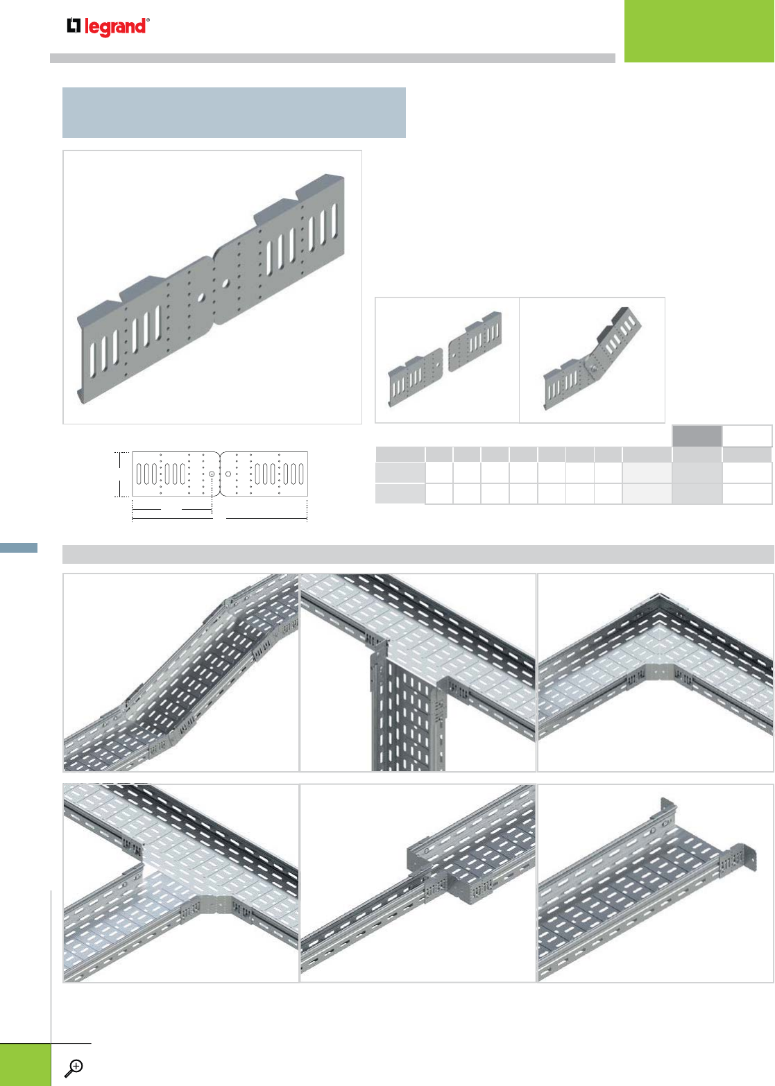
FTUS
UNIVERSAL ADJUSTABLE SPLICE
• Eliminates the need for specialized fittings
• One splice performs many functions
• Fabricates tees, reductions and level changes on-site
• Field bend to create one-sided reduction/expansion of
2", 4", 6", or 8"
• Field snap apart to make vertical adjustment splice plate
• ¼” hardware included for adjustable splice plate
H
L
140mm
VERTICAL ADJUSTABLE VERTICAL TEE DOWN MITERED 90º HORIZONTAL BEND
MITERED TEE REDUCER FLOOR/BOX CONNECTOR
APPLICATIONS
PACK HEIGHT (H) LENGTH (L) WEIGHT PG BL WH
PCS IN MM IN MM LBS KG
FTUS 50 1 2.1 52 11.8 300 2 50 341 224 960 020 –
FTUS 100 1 4.1 104 11.8 300 4 100 341 226 900 021 –
– Contact manufacturer for availability.
SPLCING
WWW.LEGRAND.US/CABLOFIL
C.10
CABLOFIL
TROUGH TRAY
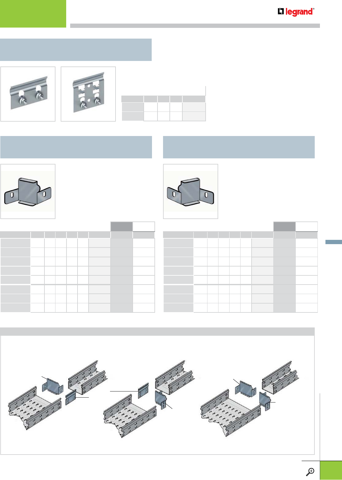
FTRHR
RIGHT-HAND REDUCER
FTLHR
LEFT-HAND REDUCER
PACK HEIGHT REDUCTION PG BL WH
PCS IN MM IN MM
FTRHR 50/25 1 2.0 50 1.0 25 341 550 960 148 –
FTRHR 50/50 1 2.0 50 2.0 50 341 551 341 551 –
FTRHR 50/100 1 2.0 50 4.0 100 341 552 960 150 –
FTRHR 50/150 1 2.0 50 6.0 150 341 553 960 151 –
FTRHR 50/200 1 2.0 50 8.0 200 341 554 960 152 –
FTRHR 100/50 1 4.0 100 2.0 50 341 669 960 164 –
FTRHR 100/100 1 4.0 100 4.0 100 341 670 960 165 –
FTRHR 100/150 1 4.0 100 6.0 150 341 671 960 166 –
– Contact manufacturer for availability.
PACK HEIGHT REDUCTION PG BL WH
PCS IN MM IN MM
FTLHR 50/25 1 2.0 50 1.0 25 341 577 960 153 *
FTLHR 50/50 1 2.0 50 2.0 50 341 578 960 154 *
FTLHR 50/100 1 2.0 50 4.0 100 341 579 960 155 *
FTLHR 50/150 1 2.0 50 6.0 150 341 580 960 156 *
FTLHR 50/200 1 2.0 50 8.0 200 341 581 960 157 *
FTLHR 100/50 1 4.0 100 2.0 50 341 691 960 167 *
FTLHR 100/100 1 4.0 100 4.0 100 341 692 960 168 *
FTLHR 100/150 1 4.0 100 6.0 150 341 693 960 169 *
– Contact manufacturer for availability.
• Rigid steel construction
• Connects straight sections and
fittings of different widths
• Hardware included
• Rigid steel construction
• Connects straight sections and
fittings of different widths
• Hardware included
Example of assembly for a right-hand , left-hand and concentric reduction.
LEFT-HAND
REDUCER
LEFT-HAND
REDUCER
RIGHT-HAND
REDUCER
RIGHT-HAND
REDUCER
FAS
SPLICES
FTEF
FAS SPLICE
PACK HEIGHT PG
PCS IN MM
FTEF 50 1 2.0 50 341 563
FTEF 100 1 4.0 100 341 622
• Connects straight sections and fittings
• Captive hardware makes installation simple (included)
FTEF 50 FTEF 100
APPLICATIONS
SPLICING
WWW.LEGRAND.US/CABLOFIL
C.11
CABLOFIL
TROUGH TRAY
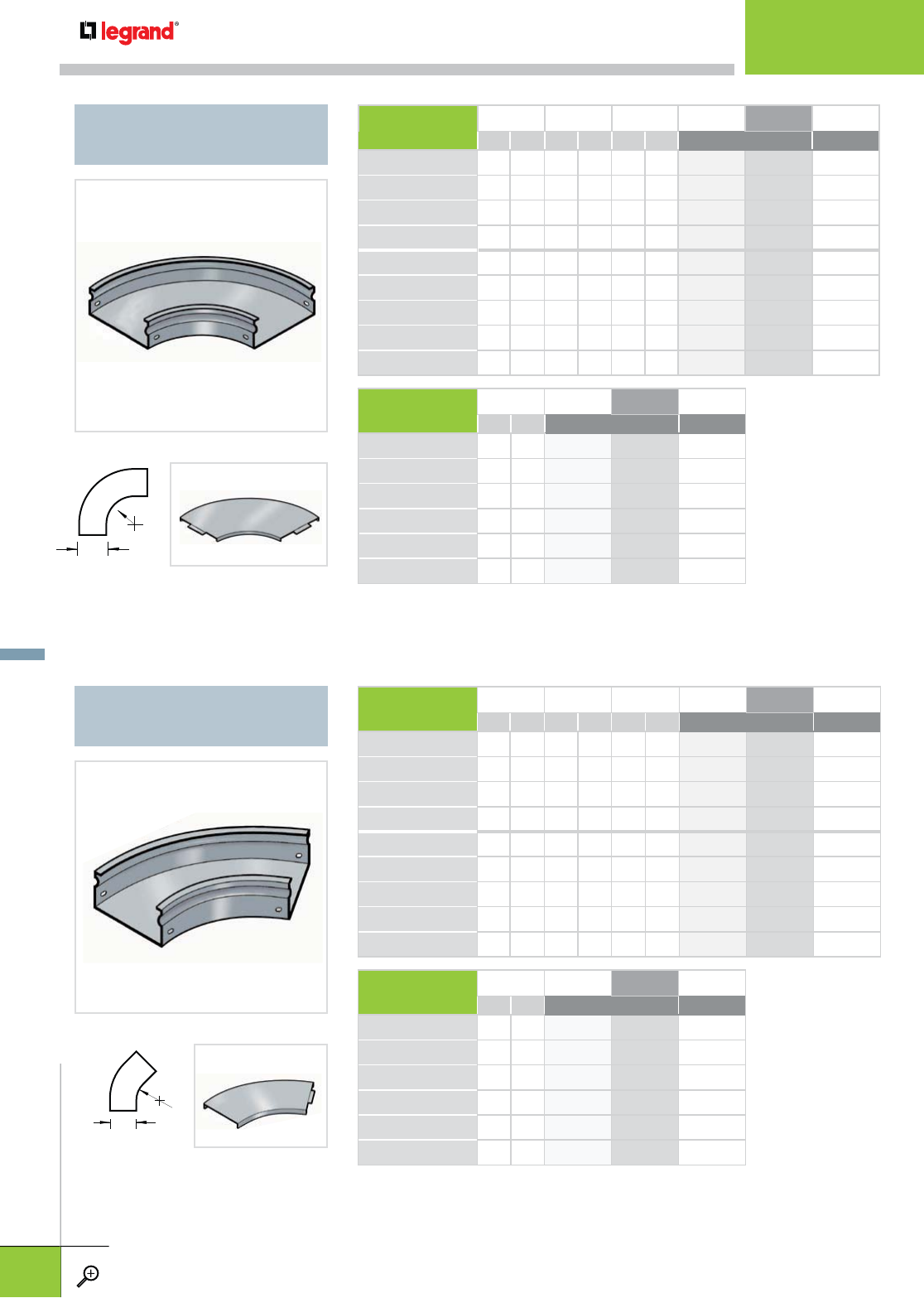
W
R
W
R
FTFB90
HORIZONTAL 90º ELBOW
FTFB45
HORIZONTAL 45° ELBOW
FTCFB90
FTCFB45
• All fittings and covers are solid.
• Cover sold separately.
• All fittings and covers are solid.
• Cover sold separately.
BASE HEIGHT WIDTH (W) RADIUS (R) PG BL WH
IN MM IN MM IN MM STANDARD
FTFB90 50/50 2 50 2 50 4 100 340 914 960 022 –
FTFB90 50/100 2 50 4 100 4 100 340 915 960 023 –
FTFB90 50/200 2 50 8 200 4 100 340 917 960 024 –
FTFB90 50/300 2 50 12 300 4 100 340 918 960 025 –
FTFB90 100/100 4 100 4 100 9.6 244 340 930 960 026 –
FTFB90 100/200 4 100 8 200 9.6 244 340 932 960 027 –
FTFB90 100/300 4 100 12 300 9.6 244 340 933 960 028 –
FTFB90 100/500 4 100 20 500 9.6 244 340 935 960 029 –
FTFB90 100/600 4 100 24 600 9.6 244 341 936 960 030 –
COVER WIDTH PG BL WH
IN MM STANDARD
FTCFB90 50 2 50 340 861 960 094 –
FTCFB90 100 4 100 340 863 960 095 –
FTCFB90 200 8 200 340 865 960 096 –
FTCFB90 300 12 300 340 866 960 097 –
FTCFB90 500 20 500 340 868 960 098 –
FTCFB90 600 24 600 340 869 960 099 –
– Contact manufacturer for availability.
BASE HEIGHT WIDTH (W) RADIUS PG BL WH
IN MM IN MM IN MM STANDARD
FTFB45 50/50 2 50 2 50 0.8 20 340 944 960 031 –
FTFB45 50/100 2 50 4 100 4 100 340 945 960 032 –
FTFB45 50/200 2 50 8 200 4 100 340 947 960 033 –
FTFB45 50/300 2 50 12 300 4 100 340 948 960 034 –
FTFB45 100/100 4 100 4 100 4 100 340 960 960 035 –
FTFB45 100/200 4 100 8 200 4 100 340 962 960 036 –
FTFB45 100/300 4 100 12 300 4 100 340 963 960 037 –
FTFB45 100/500 4 100 20 500 6 150 340 965 960 038 –
FTFB45 100/600 4 100 24 600 6 150 350 512 960 039 –
COVER WIDTH PG BL WH
IN MM STANDARD
FTCFB45 50 2 50 340 870 960 100 –
FTCFB45 100 4 100 340 872 960 101 –
FTCFB45 200 8 200 340 874 960 102 –
FTCFB45 300 12 300 340 875 960 103 –
FTCFB45 500 20 500 340 877 960 104 –
FTCFB45 600 24 600 340 878 960 105 –
– Contact manufacturer for availability.
FITTINGS
WWW.LEGRAND.US/CABLOFIL
C.12
CABLOFIL
TROUGH TRAY
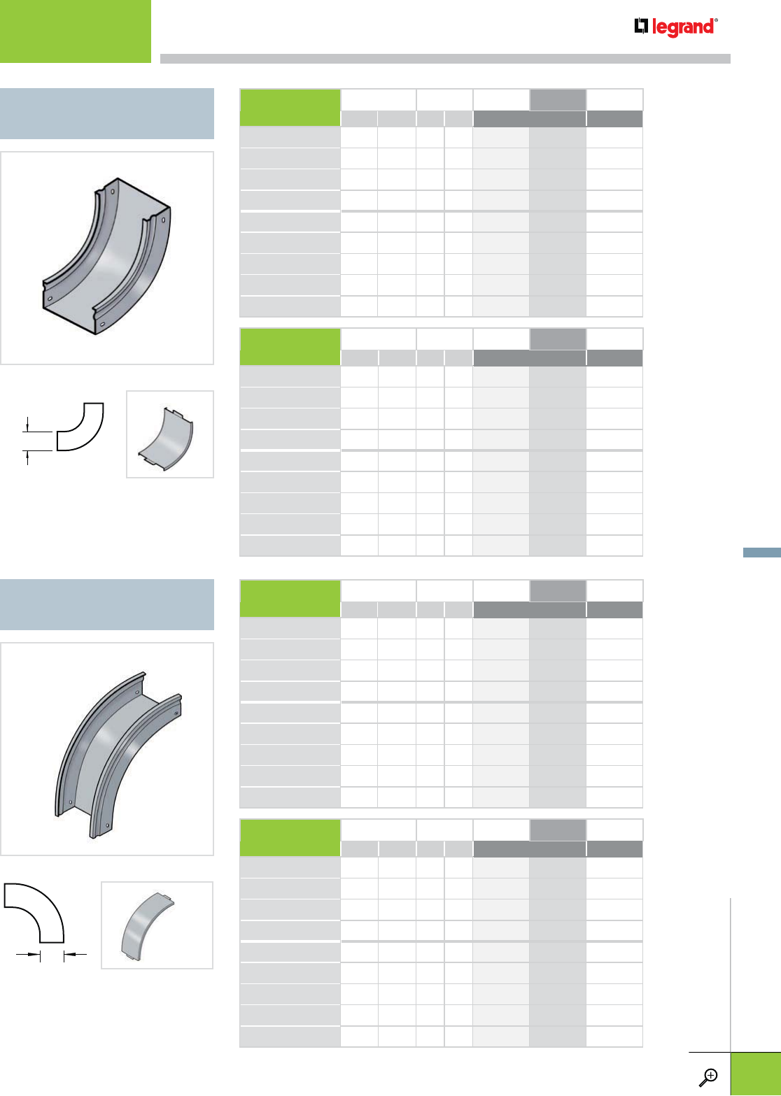
FTVI90
VERTICAL 90° INSIDE ELBOW
FTVO90
VERTICAL 90° OUTSIDE ELBOW
H
FTCVI90
H
FTCVO90
• All fittings and covers are solid.
• Cover sold separately.
• All fittings and covers are solid.
• Cover sold separately.
BASE HEIGHT (H) WIDTH PG BL WH
IN MM IN MM STANDARD
FTVI90 50/50 2 50 2 50 340 979 960 040 –
FTVI90 50/100 2 50 4 100 340 980 960 041 –
FTVI90 50/200 2 50 8 200 340 982 960 042 –
FTVI90 50/300 2 50 12 300 340 983 960 043 –
FTVI90 100/100 4 100 4 100 340 995 960 044 –
FTVI90 100/200 4 100 8 200 340 997 960 045 –
FTVI90 100/300 4 100 12 300 340 998 960 046 –
FTVI90 100/500 4 100 20 500 341 000 960 047 –
FTVI90 100/600 4 100 24 600 341 101 960 048 –
COVER FITS TRAY HEIGHT WIDTH PG BL WH
IN MM IN MM STANDARD
FTCVI90 50/50 2 50 2 50 340 888 960 112 –
FTCVI90 50/100 2 50 4 100 340 890 960 113 –
FTCVI90 50/200 2 50 8 200 340 892 960 114 –
FTCVI90 50/300 2 50 12 300 340 893 960 115 –
FTCVI90 100/100 4 100 4 100 341 175 960 116 –
FTCVI90 100/200 4 100 8 200 340 894 960 117 –
FTCVI90 100/300 4 100 12 300 340 895 960 118 –
FTCVI90 100/500 4 100 20 500 340 897 960 119 –
FTCVI90 100/600 4 100 24 600 340 898 960 120 –
– Contact manufacturer for availability.
BASE HEIGHT (H) WIDTH PG BL WH
IN MM IN MM STANDARD
FTVO90 50/50 2 50 2 50 341 038 960 049 –
FTVO90 50/100 2 50 4 100 341 039 960 050 –
FTVO90 50/200 2 50 8 200 341 041 960 051 –
FTVO90 50/300 2 50 12 300 341 042 960 052 –
FTVO90 100/100 4 100 4 100 341 054 960 053 –
FTVO90 100/200 4 100 8 200 341 056 960 054 –
FTVO90 100/300 4 100 12 300 341 057 960 055 –
FTVO90 100/500 4 100 20 500 341 059 960 056 –
FTVO90 100/600 4 100 24 600 341 007 960 057 –
COVER FITS TRAY HEIGHT WIDTH PG BL WH
IN MM IN MM STANDARD
FTCVO90 50/50 2 50 2 50 340 798 960 133 –
FTCVO90 50/100 2 50 4 100 340 808 960 134 –
FTCVO90 50/200 2 50 8 200 340 818 960 135 –
FTCVO90 50/300 2 50 12 300 340 819 960 136 –
FTCVO90 100/100 4 100 4 100 340 181 960 137 –
FTCVO90 100/200 4 100 8 200 340 825 960 138 –
FTCVO90 100/300 4 100 12 300 340 826 960 139 –
FTCVO90 100/400 4 100 20 500 340 828 960 140 –
FTCVO90 100/500 4 100 24 600 340 829 960 141 –
– Contact manufacturer for availability.
FITTINGS
For finish descriptions, see page C.3. For detailed dimensions, see pages C.30-C.31. WWW.LEGRAND.US/CABLOFIL
C.13
CABLOFIL
TROUGH TRAY
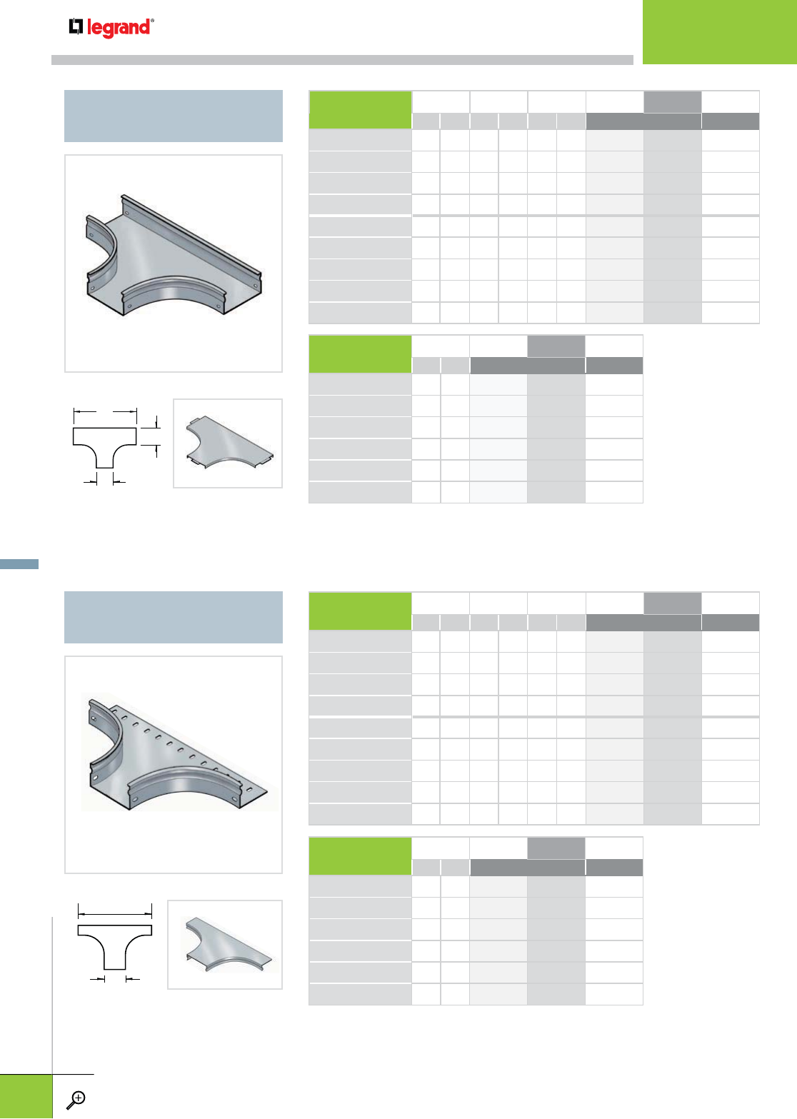
FTT
HORIZONTAL TEE
FTB
HORIZONTAL BRANCH
W
L1
W
FTTC
L2
W
FTBC
• All fittings and covers are solid.
• Cover sold separately.
• All fittings and covers are solid.
• Cover sold separately.
BASE HEIGHT WIDTH (W) LENGTH (L1) PG BL WH
IN MM IN MM IN MM STANDARD
FTT 50/50 2 50 2 50 6 150 341 103 960 058 –
FTT 50/100 2 50 4 100 14 360 341 104 960 059 –
FTT 50/200 2 50 8 200 18 460 341 106 960 060 –
FTT 50/300 2 50 12 300 22 560 341 107 960 061 –
FTT 100/100 4 100 4 100 14 360 341 119 960 062 –
FTT 100/200 4 100 8 200 18 460 341 121 960 063 –
FTT 100/300 4 100 12 300 22 560 341 122 960 064 –
FTT 100/400 4 100 20 500 36 900 341 124 960 065 –
FTT 100/500 4 100 24 600 40 1000 341 008 960 066 –
COVER WIDTH PG BL WH
IN MM STANDARD
FTTC 50 2 50 340 879 960 106 –
FTTC 100 4 100 340 881 960 107 –
FTTC 200 8 200 340 883 960 108 –
FTTC 300 12 300 340 884 960 109 –
FTTC 500 20 500 340 886 960 110 –
FTTC 600 24 600 340 887 960 111 –
– Contact manufacturer for availability.
BASE HEIGHT WIDTH (W) LENGTH (L2) PG BL WH
IN MM IN MM IN MM STANDARD
FTB 50/50 2 50 2 50 6 150 340 129 960 067 –
FTB 50/100 2 50 4 100 14 360 340 131 960 068 –
FTB 50/200 2 50 8 200 18 460 340 133 960 069 –
FTB 50/300 2 50 12 300 22 560 340 134 960 070 –
FTB 100/100 4 100 4 100 14 360 340 439 960 071 –
FTB 100/200 4 100 8 200 18 460 340 445 960 072 –
FTB 100/300 4 100 12 300 22 560 340 446 960 073 –
FTB 100/500 4 100 20 500 36 900 340 499 960 074 –
FTB 100/600 4 100 24 600 40 1000 340 500 960 075 –
COVER WIDTH PG BL WH
IN MM STANDARD
FTBC 50 2 50 340 501 960 121 –
FTBC 100 4 100 340 503 960 122 –
FTBC 200 8 200 340 505 960 123 –
FTBC 300 12 300 340 728 960 124 –
FTBC 500 20 500 340 746 960 125 –
FTBC 600 24 600 340 747 960 126 –
– Contact manufacturer for availability.
FITTINGS
WWW.LEGRAND.US/CABLOFIL
C.14
CABLOFIL
TROUGH TRAY
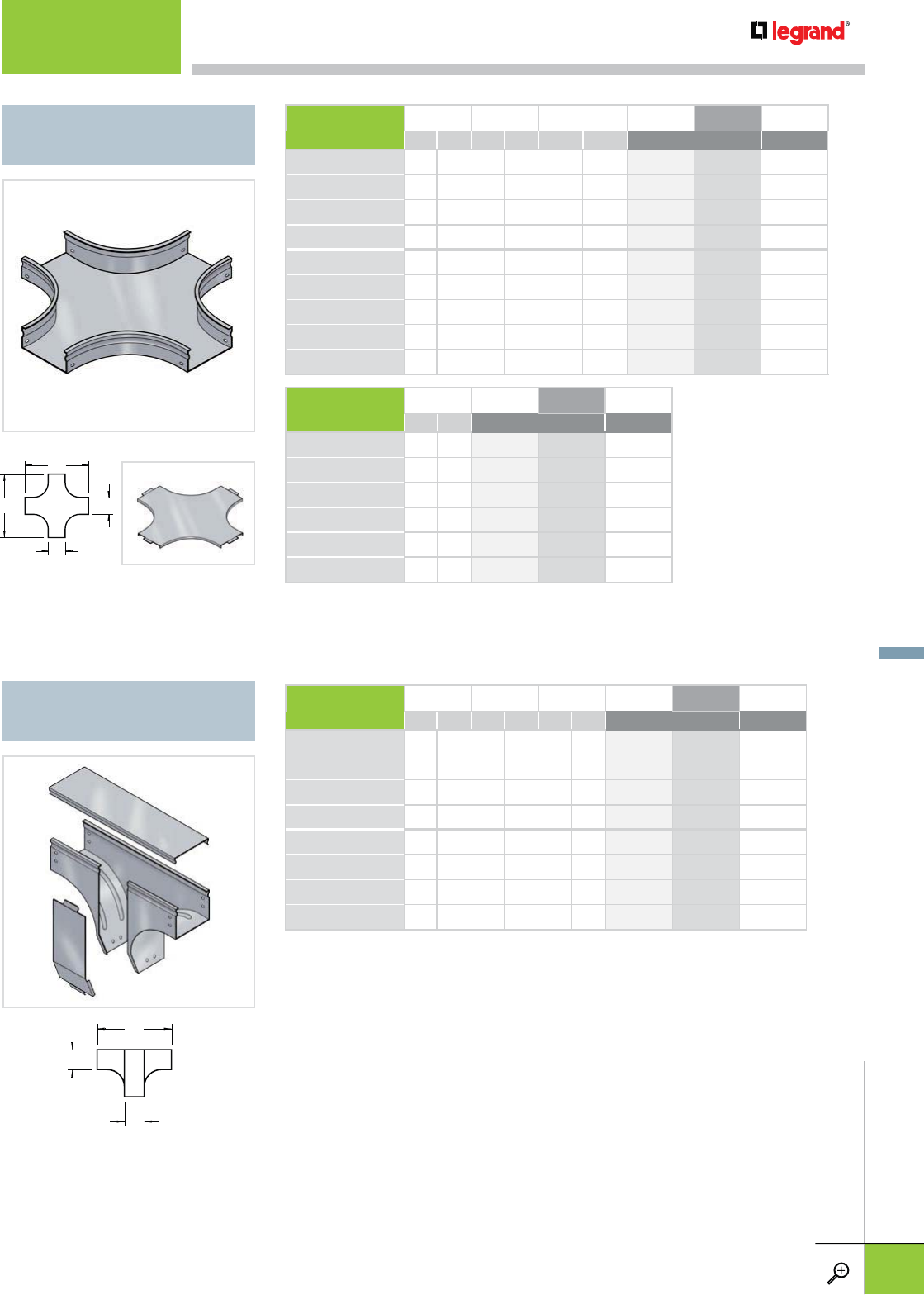
FTX
HORIZONTAL CROSS
L2
L1
W
W
FTXC
L1
H
W
FTVT
UPRIGHT DROPOUT TEE
• All fittings and covers are solid.
• Cover sold separately.
• All fittings and covers are solid.
• Full access allows cable lay-in.
• Covers included.
BASE HEIGHT WIDTH (W) LENGTH (L1/L2) PG BL WH
IN MM IN MM IN MM STANDARD
FTX 50/50 2 50 2 50 6 150 341 133 960 076 –
FTX 50/100 2 50 4 100 14 360 341 134 960 077 –
FTX 50/200 2 50 8 200 18 460 341 136 960 078 –
FTX 50/300 2 50 12 300 22 560 341 137 960 079 –
FTX 100/100 4 100 4 100 14 360 341 149 960 080 –
FTX 100/200 4 100 8 200 18 460 341 151 960 081 –
FTX 100/300 4 100 12 300 22 560 341 152 960 082 –
FTX 100/500 4 100 20 500 36 900 341 154 960 083 –
FTX 100/600 4 100 24 600 40 1000 341 067 960 084 –
COVER WIDTH PG BL WH
IN MM STANDARD
FTXC 50 2 50 340 748 960 127 –
FTXC 100 4 100 340 758 960 128 –
FTXC 200 8 200 340 768 960 129 –
FTXC 300 12 300 340 769 960 130 –
FTXC 500 20 500 340 779 960 131 –
FTXC 600 24 600 340 788 960 132 –
– Contact manufacturer for availability.
BASE + COVER HEIGHT (H) WIDTH (W) LENGTH (L1) PG BL WH
IN MM IN MM IN MM STANDARD
FTVT 50/50 2 50 2 50 6 150 340 662 960 085 –
FTVT 50/100 2 50 4 100 14 360 340 663 960 086 –
FTVT 50/200 2 50 8 200 18 460 340 665 960 087 –
FTVT 50/300 2 50 12 300 22 560 340 666 960 088 –
FTVT 100/100 4 100 4 100 14 360 340 678 960 089 –
FTVT 100/200 4 100 8 200 18 460 340 680 960 090 –
FTVT 100/300 4 100 12 300 22 560 340 681 960 091 –
FTVT 100/500 4 100 20 500 36 900 340 683 960 092 –
– Contact manufacturer for availability.
FITTINGS
For finish descriptions, see page C.3. For detailed dimensions, see pages C.30-C.31. WWW.LEGRAND.US/CABLOFIL
C.15
CABLOFIL
TROUGH TRAY
C.17 FTCH
CENTER HANGER
C.17 FTCHC
CENTER HANGER
C.17 FTAS
TRAPEZE HANGING CLIP
C.18 CS
STANDARD L BRACKET
C.18 CSC
STANDARD C BRACKET
C.18 PROCS
STANDARD PROFILE
C.18 A838/A839
SIDE RAIL SUPPORT BRACKETS
C.18 FTRB
ROD BRACKET KIT
C.19 FAS U
UNIVERSAL BRACKET
C.19 EDF
RAIL
C.20 PFREDF
CEILING MOUNTING BRACKET
C.20 ERD 10
BRACE PLATE
C.20 DF
FLOOR SUPPORT BRACKET
C.21 FTCFCL
COVER FASTENING CLIP
C.21 FTFCL
FASTENING CLIP
C.21 FTHDCL
TRAY HOLD DOWN CLIP
C.22 FTUMP
UNIVERSAL ACCESSORY
MOUNTING PLATE
C.22 FTCC
CABINET CONNECTION
C.22 FTCF
CABINET CONNECTION FLANGE
C.23 COT 54/105
DIVIDER STRIP
C.23 COT J
DIVIDER COUPLER
C.24 JP
EDGE PROTECTION STRIP
C.24 FTBP
BOTTOM ALIGNMENT PLATE
C.24 FTP31CL
P31 MARKING CLIP
C.24 FTBE
BLIND END
C.25 BTRCC6X12
C.25 CA
C.25 ECLI
C.25 EZ BN
C.25 EZ CN
C.25 EZ FW
C.25 EZ HN
C.25 THRD
C.25 THRDPT
SUPPORTS & ACCESSORIES
SUPPORTS & ACCESSORIES
WWW.LEGRAND.US/CABLOFIL
C.16
CABLOFIL
TROUGH TRAY
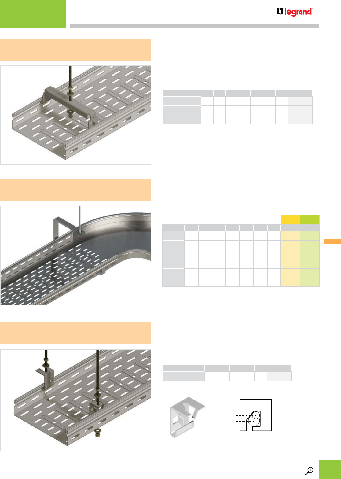
• Secure to tray by bending tabs outward
• Use with tray runs without covers
• Order to fit width of tray
• Designed for 3/8" threaded rod
• Open side allows cables to added to pathway easily
• Works with Fiber Trough or V-Trough Tray up to 16" wide
• Use with 3/8" threaded rod
• Steel construction is available in two finishes (EZ and GC)
• Secure to tray by bending tabs
• Use with tray runs without covers
• Use for multi-level tray runs
• Use with 1/4" and 3/8" threaded rods
PACK WIDTH WEIGHT MAX LOAD PG
PCS IN MM LBS KG LBS N
FTCH 100 1 4.0 100 - - 337 1500 341 164
FTCH 200 1 8.0 200 - - 337 1500 341 166
FTCH 300 1 12.0 300 - - 337 1500 341 167*
PACK WEIGHT MAX LOAD PG
PCS LBS KG LBS N
FTAS 1 - - 562 2500 341 170
FTCH
CENTER HANGER
FTCHC
CENTER HANGER
FTAS
TRAPEZE HANGING CLIP
THRD 1/4
THRD 3/8
*Coming Soon
PACK TRAY WIDTH HEIGHT WEIGHT EZ GC
PCS IN MM IN MM LBS KG
FTCHC75 1 3 75 2.5 63.5 .623 .282 – 343279
FTCHC100 1 4 100 3 76 .694 .314 347280 343280
FTCHC150 1 6 150 4 102 1.38 .629 347281 343281
FTCHC200 1 8 200 5 127 1.63 .739 347282 343282
FTCHC300 1 12 300 7 177 2.65 1.20 347283 343283
FTCHC400 1 16 400 9 230 4.77 2.16 347284 343284
– Contact manufacturer for availability.
SUPPORTS & ACCESSORIES
For finish descriptions, see page C.3. For detailed dimensions, see pages C.30-C.31. WWW.LEGRAND.US/CABLOFIL
C.17
CABLOFIL
TROUGH TRAY
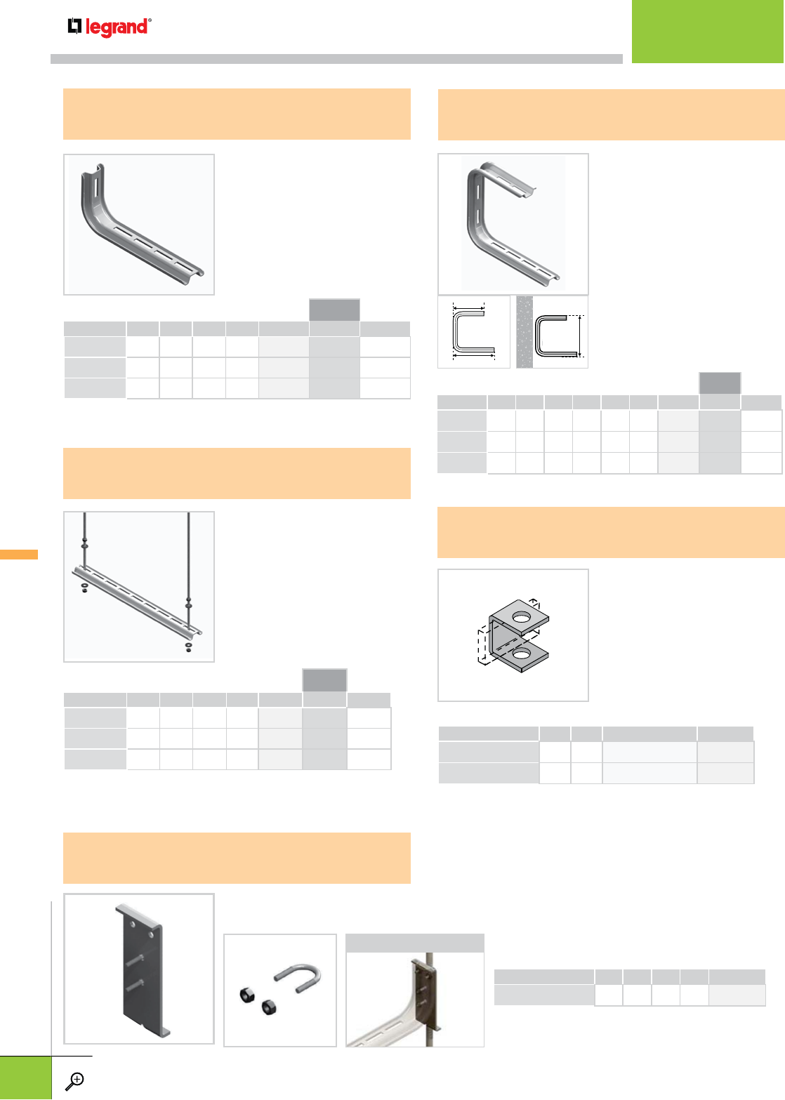
• Can be stacked for multi-level
Cablofil tray installations
• ECLI clip prevents bracket
compression
• EZ BN 1/4, EZ BN 5/16, CE
25, CE 40 and ECLI are sold
separately
• Designed for 1/4" hardware
(sold separately)
• Field cut to any length
• Can support multiple tray
runs
• Threaded rods, nuts, and
washers sold separately
• Used in conjunction with
threaded rod to support fiber
trough from cable runway.
Sold individually.
• Hardware sold separately
• 2" version available upon
request
WIDTH LENGTH PG
IN MM IN MM
FTRB 2 50 4 100 960 178
HEIGHT USE WITH HARDWARE PG
IN MM IN
1R-A838-01 1.0 25.4 3/8 P250 474
1R-A839-01 1.0 25.4 1/2 or 5/8 P250 475
PROCS
STANDARD PROFILE
A838/A839
SIDE RAIL SUPPORT BRACKETS
CSC
STANDARD C BRACKET
• For cable tray installation
onto walls
• ECLI clip prevents bracket
compression
• EZ BN 1/4, CE 25 and ECLI
are sold separately
• Designed for 1/4" hardware
(sold separately)
• Quickly and securely attaches to 3/8", 1/2" and 5/8"
threaded rods
• Works with existing or new installations
• Allows quick attachment of bracket
CS
STANDARD L BRACKET
FTRB
ROD BRACKET KIT
APPLICATION
L2
L1
8"
200 MM
WIDTH LENGTH PG BL WH
IN MM IN MM
CS 100 4.0 100 5.7 145 002 700 941 130 –
CS 200 8.0 200 9.6 245 002 710 941 131 –
CS 300 12.0 300 13.6 345 002 720 941 132 –
– Contact manufacturer for availability.
WIDTH LENGTH (L1) LENGTH (L2) PG BL WH
IN MM IN MM IN MM
CSC 100 4.0 100 5.1 130 5.7 145 002 760 941 136 –
CSC 200 8.0 200 7.0 180 9.6 245 002 770 941 137 –
CSC 300 12.0 300 9.0 230 13.6 345 002 780 941 138 –
– Contact manufacturer for availability.
LENGTH WEIGHT PG BL WH
IN MM LBS KG
PROCS 1000 39.0 1000 2.6 1.2 002 920 941 140 –
PROCS 2000 79.0 2000 5.1 2.3 002 930 941 141 –
PROCS 3000 118.0 3000 8.4 3.8 002 940 941 142 –
– Contact manufacturer for availability.
V-TROUGH
SUPPORTS &
ACCESSORIES
SUPPORTS & ACCESSORIES
WWW.LEGRAND.US/CABLOFIL
C.18
CABLOFIL
TROUGH TRAY
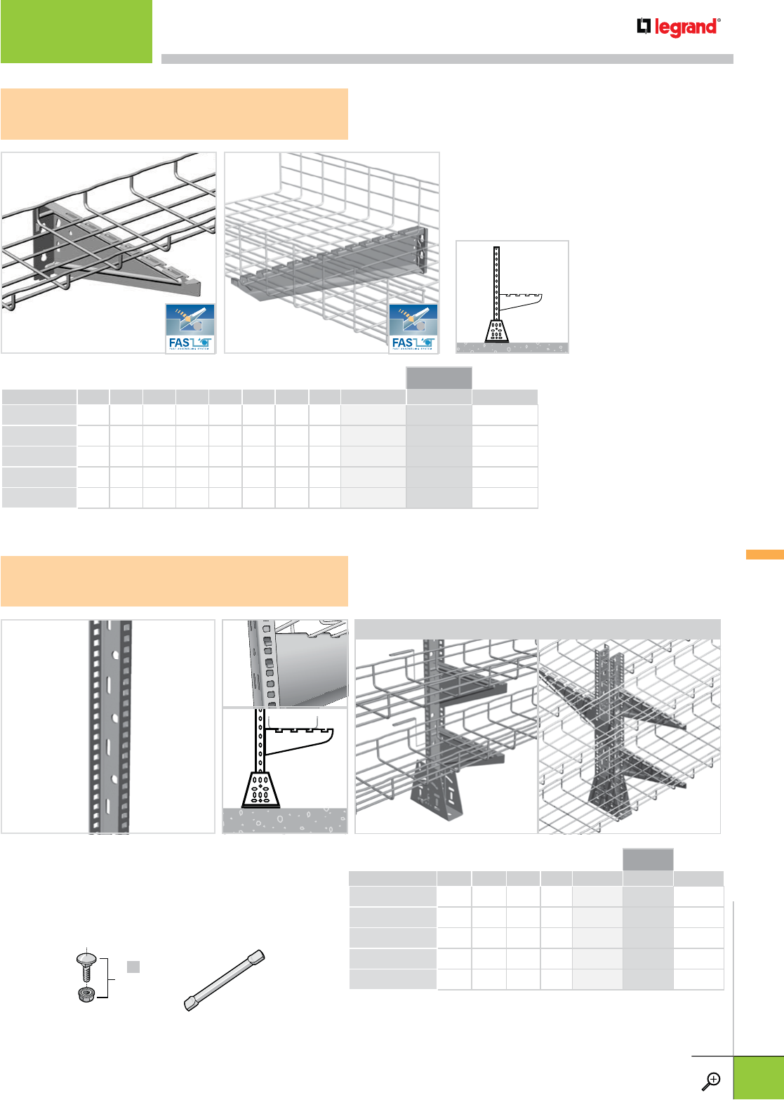
• EDF Rail makes multiple floor mounted cable tray runs
easier and faster to install
• CA Pin (sold separately) is required to install 4" to 12"
FAS U. Suggested for 16" to 24" FAS U.
• FAS U sizes 16" to 24" will snap directly onto EDF Rail
APPLICATIONS
CA
• Use for tray support on walls or under floor
applications.
• FAS U snaps directly into EDF rail
• Key holes in back of bracket for simple wall
mounting with 1/4" hardware
EDF
RAIL
FAS U
UNIVERSAL BRACKET
FASU 100-300 FASU 400-600
x4
EZ BN 5/16
HEIGHT TRAY WIDTH LENGTH WEIGHT PG BL WH
IN MM IN MM IN MM LBS KG
FASU 100 3.5 85 4.0 100 6.0 157 0.3 0.1 557 410 941 267 –
FASU 200 5.5 139 8.0 200 12.0 257 0.5 0.2 557 430 941 269 –
FASU 300 5.5 139 12.0 300 14.0 357 0.8 0.3 557 440 941 270 –
FASU 500 5.5 137.7 20.0 500 22.0 557 2.9 1.3 557 460 941 272 –
FASU 600 5.5 137.7 24.0 600 26.0 657 6.4 2.9 557 470 941 273 –
– Contact manufacturer for availability.
LENGTH WEIGHT PG BL WH
IN MM LBS KG
EDF 300 10.6 270 0.7 0.3 561 310 942 817 –
EDF 600 24.8 630 1.8 0.8 557 610 942 815 –
EDF 1000 39.0 990 2.6 1.2 561 090 942 813 –
EDF 2000 78.0 2000 5.5 2.5 561 010 941 288 –
EDF 3000 120.0 3000 9.1 4.1 561 020 941 289 –
– Contact manufacturer for availability.
V-TROUGH
SUPPORTS &
ACCESSORIES
SUPPORTS & ACCESSORIES
For finish descriptions, see page C.3. For detailed dimensions, see pages C.30-C.31. WWW.LEGRAND.US/CABLOFIL
C.19
CABLOFIL
TROUGH TRAY
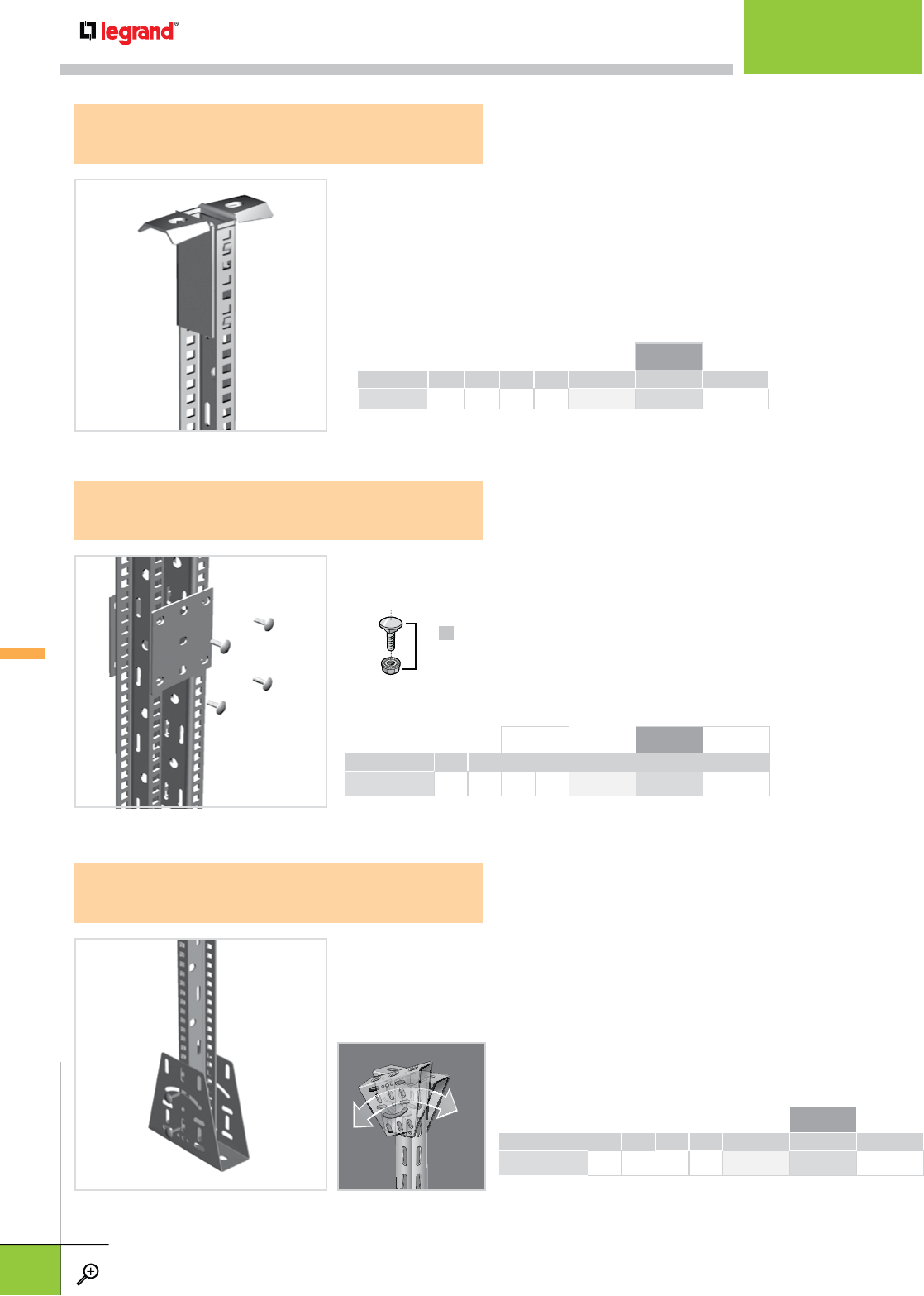
• Use DF to attach EDF Rail to any floor
• Attach EDF Rail to DF with EZBN 5/16 (sold separately)
• Also use DF to attach EDF to a ceiling or deck that is on an
angle for a perfect pendant hanger
x4
EZ BN 5/16
LENGTH WEIGHT PG BL WH
IN MM LBS KG
DF 1.3 0.6 1.3 0.6 561 060 942 880 –
– Contact manufacturer for availability.
LENGTH WEIGHT PG BL WH
IN MM LBS KG
ERD 10 0.4 0.5 0.4 0.5 561 050 942 759 –
– Contact manufacturer for availability.
DF
FLOOR SUPPORT BRACKET
ERD 10
BRACE PLATE
PFREDF
CEILING MOUNTING BRACKET
• Use ERD 10 to assemble double-sided ceiling hung tray runs.
• Attach EDF Rail to ERD 10 with EZ BN 5/16 (sold separately).
• Use PFREDF to attach EDF Rail directly to ceiling
• EDF Rail attaches to PFREDF without additional hardware
WEIGHT LENGTH PG BL WH
LBS KG IN MM
PFREDF 1.3 0.6 1.3 0.6 561 080 942 761 –
– Contact manufacturer for availability.
V-TROUGH
SUPPORTS &
ACCESSORIES
SUPPORTS & ACCESSORIES
WWW.LEGRAND.US/CABLOFIL
C.20
CABLOFIL
TROUGH TRAY
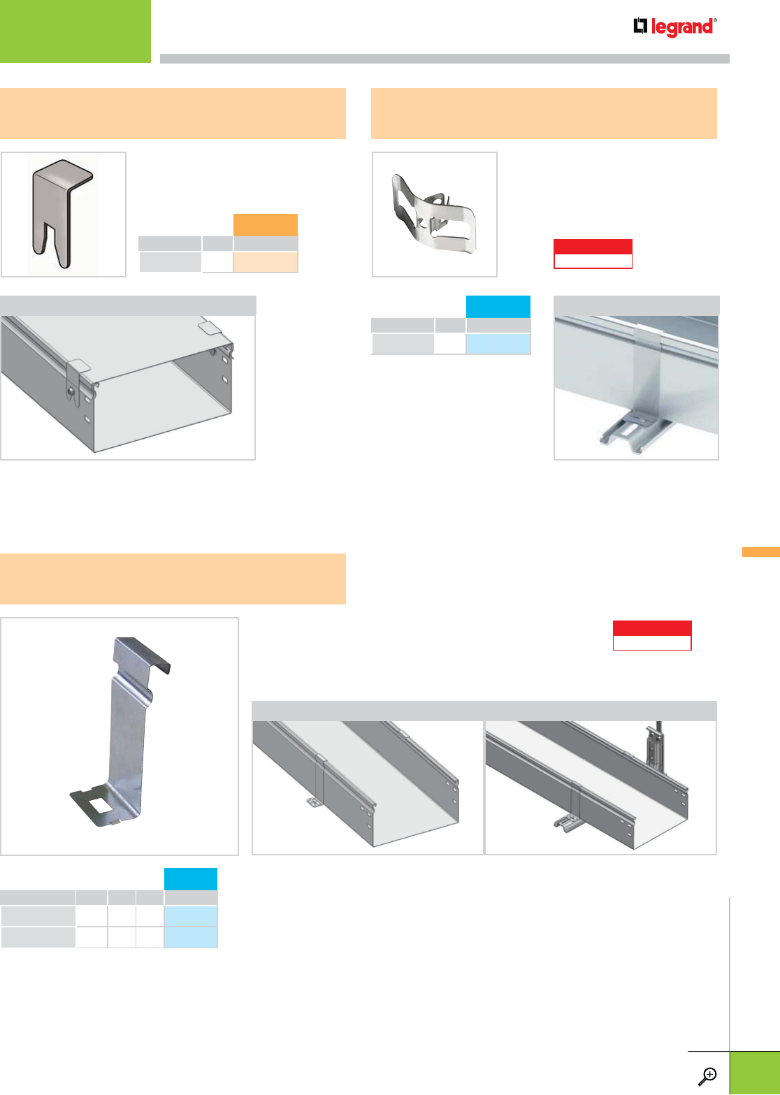
LEGRAND
PATENTED
PACK 316L
PCS
FTFCL 1 349 252
• Strong stainless steel construction
• Snaps on standard C bracket
• Use to secure tray without hardware
• Two required per support
FTFCL
FASTENING CLIP
• Provides added cover security
• Utilizes existing splice hardware
• Strong stainless steel construction
PACK 304L
PCS
FTCFCL 50 341 709
FTCFCL
COVER FASTENING CLIP
APPLICATION APPLICATION
LEGRAND
PATENTED
PACK FOR HEIGHT 316L
PCS IN MM
FTHDCL 50 1 2.0 50 349 253
FTHDCL 100 1 4.0 100 349 255
• Strong stainless steel construction
• Allows easy cover removal without removing tray hold down
• Two required per support
• Recommended for solid (non-perforated) trays. (FT series tray and all fittings]
FTHDCL
TRAY HOLD DOWN CLIP
APPLICATIONS
V-TROUGH
SUPPORTS &
ACCESSORIES
SUPPORTS & ACCESSORIES
For finish descriptions, see page C.3. For detailed dimensions, see pages C.30-C.31. WWW.LEGRAND.US/CABLOFIL
C.21
CABLOFIL
TROUGH TRAY
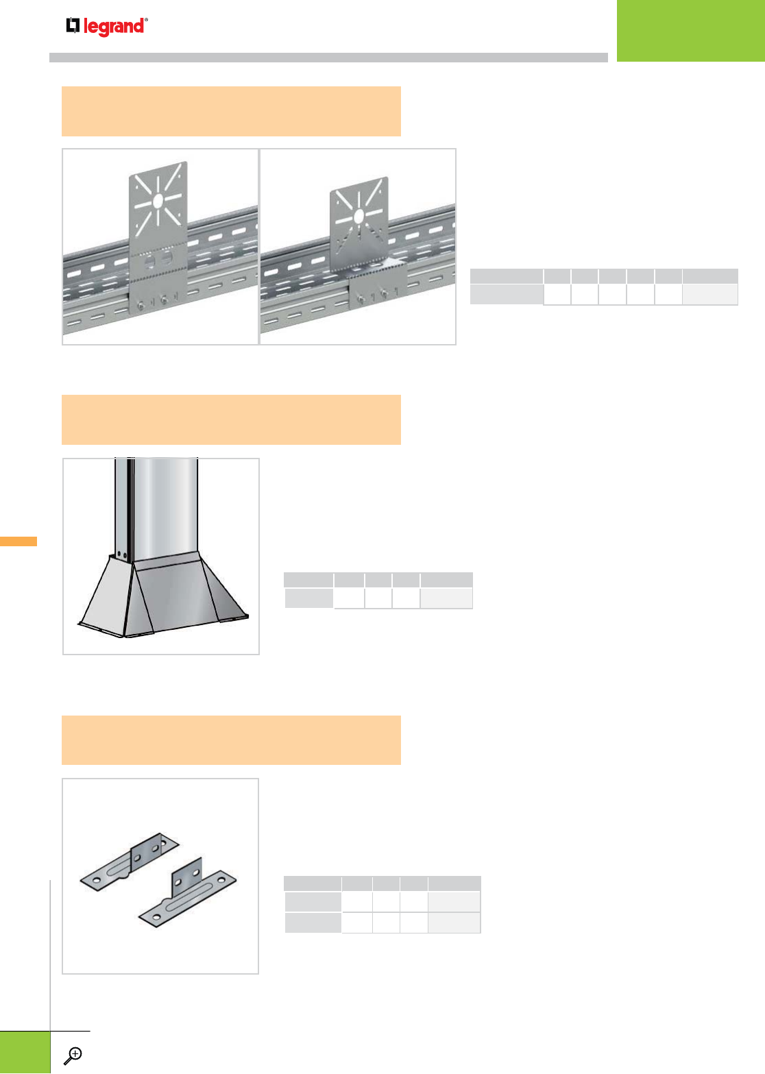
PACK HEIGHT PG
PCS IN MM
FTCF 50 1 2.0 50 341 576
FTCF 100 1 4.0 100 341 690
• Rigid steel construction
• Provides secure attachment at tray termination points
• Two connection brackets per package
• Hardware included
• Quick, clean connection to data cabinet
• Unique steel/plastic combination fits tray widths from 2" to 12" (50-300mm)
• Allows up to 4" flexibility of tray length at termination point
• Flared design allows tray connection when opening is larger than tray width
• Pack contains all pieces for one connection pair
PACK HEIGHT PG
PCS IN MM
FTCC 1 2.0 50 349 849
FTCC
CABINET CONNECTION
FTCF
CABINET CONNECTION FLANGE
• Attaches to tray side rail with two M6x10 bolts.
(Not included)
• Use vertically or bend for horizontal applications
• Use on 2
"
or 4
"
deep tray
• Fits all standard steel box sizes
FTUMP
UNIVERSAL ACCESSORY MOUNTING PLATE
PACK HEIGHT WEIGHT PG
PCS IN MM LBS KG
FTUMP 1 - - - - 350 155*
*Coming Soon
V-TROUGH
SUPPORTS &
ACCESSORIES
SUPPORTS & ACCESSORIES
WWW.LEGRAND.US/CABLOFIL
C.22
CABLOFIL
TROUGH TRAY
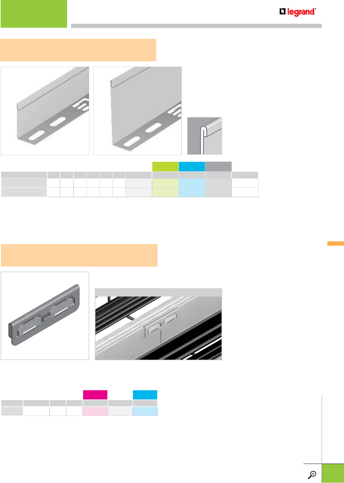
APPLICATION
• For cable separation within a single tray.
• Attach to tray with EZBN 1/4.
• Hardware optional and sold separately for COT 54
(see pg. C.25); required and included with COT 105
(as part of kit).
• Field modify with tin snips for changes in levels
• Rolled top edge provides rigidity as
well as protection for cables
HEIGHT LENGTH WEIGHT PG GC 316L BL WH
IN MM FT M LBS KG
COT 54 2.0 54 10.0 3 2.8 1.3 923 020 923 023 923 024 942 284 –
COT 105 KIT 4.0 105 10.0 3 4.7 2.1 943 413 943 414 943 415 943 416 –
– Contact manufacturer for availability.
PKG. QTY. WEIGHT AL PG 316L
PCS LBS KG
COT J 1 0.026 0.012 943 390 923 050 923 054
• Improves electrical continuity and strengthens dividers.
• Can be removed with a screwdriver and is reusable.
COT 54/105
DIVIDER STRIP
COT J
DIVIDER COUPLER
COT 54 COT 105
V-TROUGH
SUPPORTS &
ACCESSORIES
SUPPORTS & ACCESSORIES
For finish descriptions, see page C.3. For detailed dimensions, see pages C.30-C.31. WWW.LEGRAND.US/CABLOFIL
C.23
CABLOFIL
TROUGH TRAY
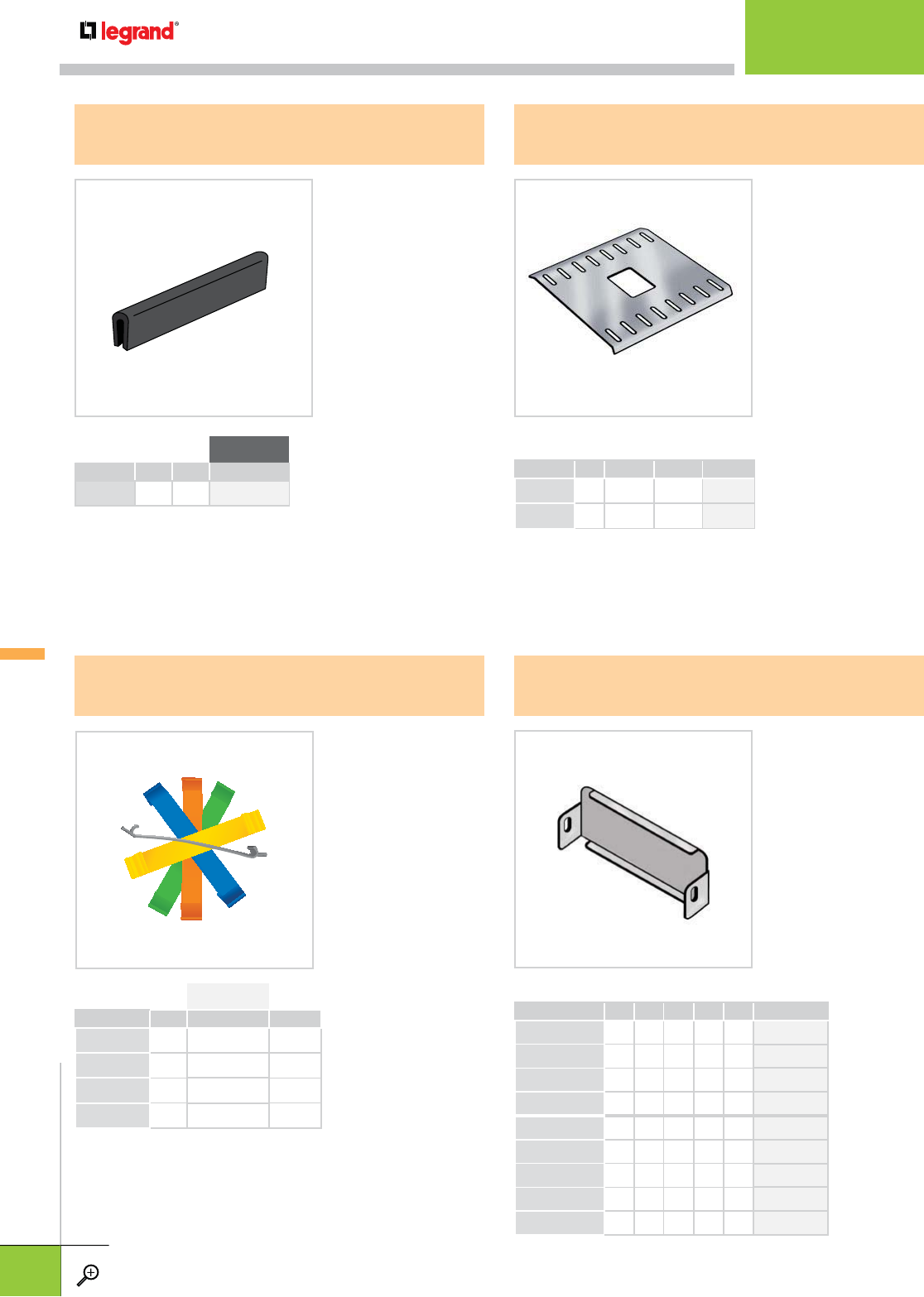
LENGTH VINYL
FT M
JP 15.0 1.5 522 354
PACK FITS TRAY WIDTHS PG
PCS IN MM
FTBP 300 1 4.0-12.0 100-300 341 500
FTBP 600 1 20.0-24.0 500-600 341 503
• Helps maintain
trough bottom
alignment with heavy
cable loads
• Includes hardware
• Slip on edge
protection
• Black vinyl
• 15' roll cut to fit
FTBP
BOTTOM ALIGNMENT PLATE
JP
EDGE PROTECTION STRIP
PACK PLASTIC COLOR
PCS
FTP31CLOR 1 340 184 ORANGE
FTP31CLBL 1 340 185 BLUE
FTP31CLYL 1 340 186 YELLOW
FTP31CLGN 1 340 187 GREEN
• Snap-in plastic clip
• Writable surface
allows easy
marking/
identification
• PVC construction
FTP31CL
P31 MARKING CLIP
PACK HEIGHT WIDTH PG
PCS IN MM IN MM
FTBE 50/50 1 2.0 50 2.0 50 341 537
FTBE 50/100 1 2.0 50 4.0 100 341 538
FTBE 50/200 1 2.0 50 8.0 200 341 540
FTBE 50/300 1 2.0 50 12.0 300 341 541
FTBE 100/100 1 4.0 100 4.0 100 341 659
FTBE 100/200 1 4.0 100 8.0 200 341 661
FTBE 100/300 1 4.0 100 12.0 300 341 662
FTBE 100/500 1 4.0 100 20.0 500 341 664
FTBE 100/600 1 4.0 100 24.0 600 340 737
• Can be field
punched for conduit
attachment
• Rigid steel
construction
• Includes hardware
FTBE
BLIND END
V-TROUGH
SUPPORTS &
ACCESSORIES
SUPPORTS & ACCESSORIES
WWW.LEGRAND.US/CABLOFIL
C.24
CABLOFIL
TROUGH TRAY
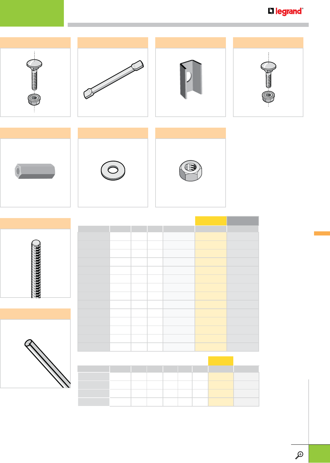
PACK LENGTH WEIGHT PITCH EZ PL
PCS FT M LBS KG
THRDPT 10 6.0 0.15 0.16 0.07 – – 942 947
THRD 1/4* 1 6.0 1.8 0.7 0.3 20 942 351 –
THRD 3/8* 1 6.0 1.8 1.8 0.8 16 942 353 –
THRD 1/2* 1 6.0 1.8 3.1 1.4 12 942 465 –
– Contact manufacturer for availability.
*Thread Pitch: 1/4” - 20; 3/8” - 16; 1/2” - 13
EZ FW
THRD
EZ HN
THRDPT
EZ BNBTRCC6X12 ECLICA
PACK WEIGHT PG EZ BL
PCS LBS KG
BTRCC6X12 100 2.6 1.2 – 801 001 –
CA 50 2.2 1.0 – 801 051 942 881
ECLI 10 0.04 0.02 557 190 – 942 797
EZ BN 1/4 50 2.0 0.9 – 941 084 –
EZ BN 5/16 50 1.3 0.6 – 942 778 –
EZ CN 1/4 100 3.0 1.4 – 941 094 –
EZ CN 3/8 100 4.0 1.8 – 941 205 –
EZ CN 1/2 100 5.0 2.3 – 942 790 –
EZ FW 1/4 100 0.5 0.2 – 941 511 –
EZ FW 3/8 100 0.6 0.3 – 941 612 –
EZ FW 1/2 100 0.5 0.2 – 942 464 –
EZ HN 1/4 100 0.6 0.3 – 941 713 –
EZ HN 3/8 100 0.7 0.3 – 941 915 –
EZ HN 1/2 100 2.0 0.9 – 941 814 –
EZ CN
V-TROUGH
SUPPORTS &
ACCESSORIES
SUPPORTS & ACCESSORIES
For finish descriptions, see page C.3. For detailed dimensions, see pages C.30-C.31. WWW.LEGRAND.US/CABLOFIL
C.25
CABLOFIL
TROUGH TRAY
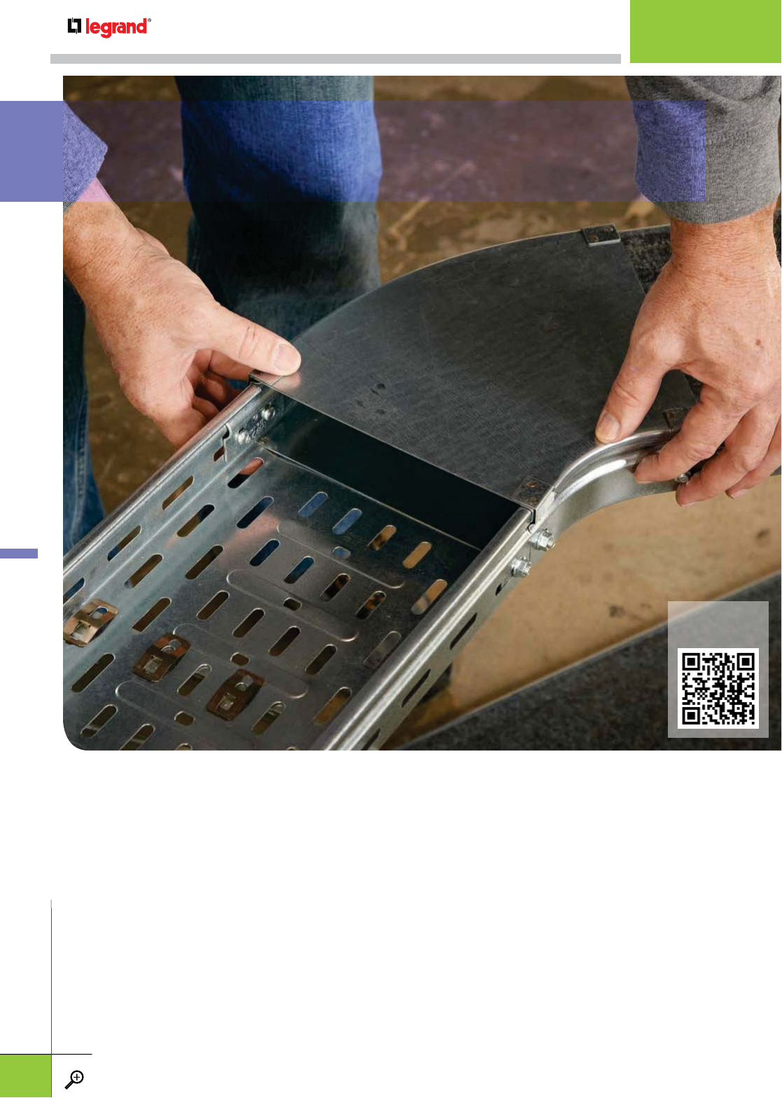
View
Installation Video
WWW.LEGRAND.US
/
CABLOFI
L
INSTALLATION GUIDELINES
INSTALLATION GUIDELINES
WWW.LEGRAND.US/CABLOFIL
C.26
CABLOFIL
TROUGH TRAY
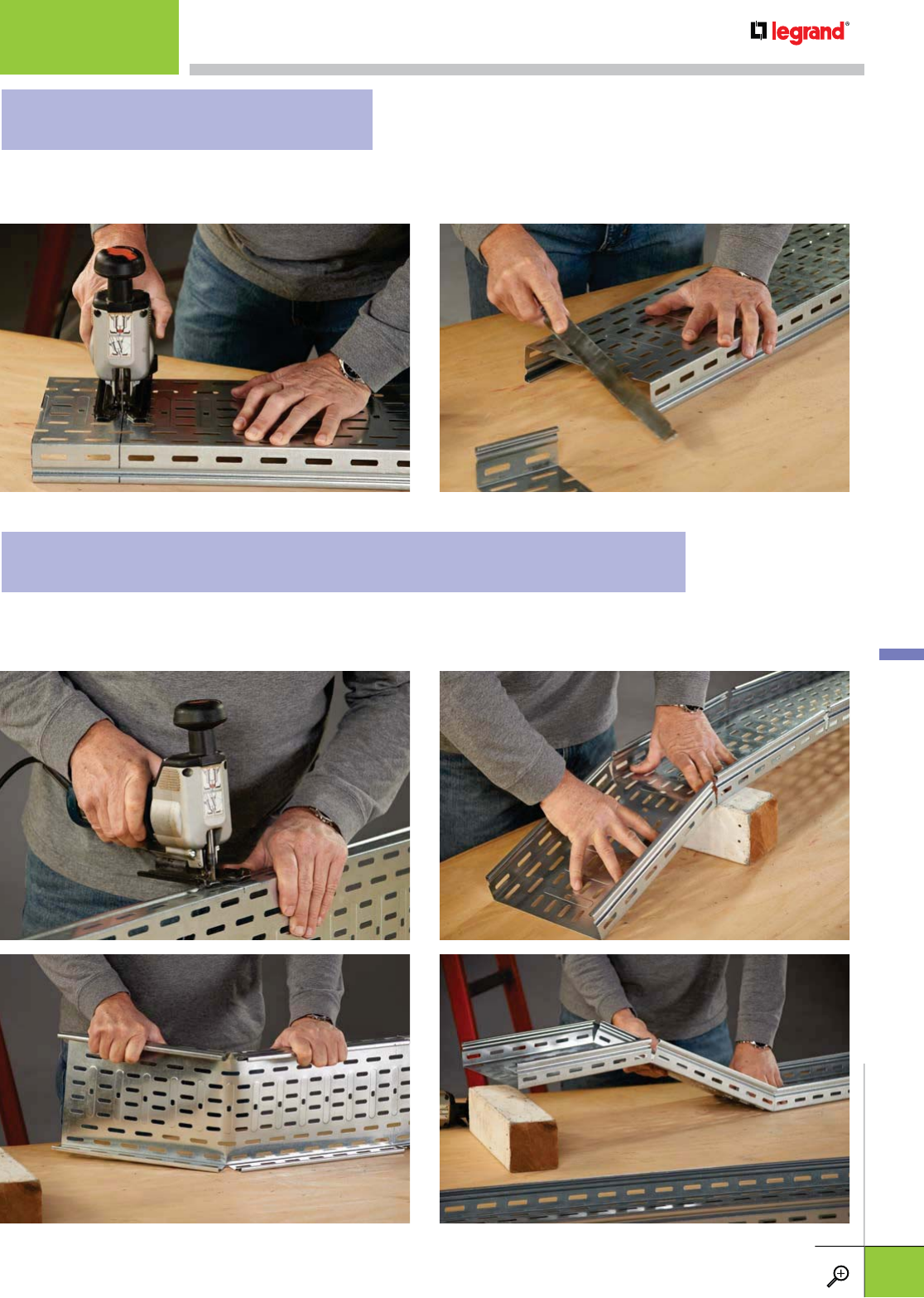
Cut only the sides of the tray for changes in cable pathway elevations. Make a 90 degree cut in both sides of
the tray for a downward bend. For an upward bend, make a double cut to form a notch. The notch should be
sized to fit the tray angle needed. Then, using a straight edge, form the tray to the proper angles.
V-TROUGH
INSTALLATIONS
Trough tray can be cut to length with a reciprocating saw fitted with a fine metal cutting blade. Mark three sides of the tray
using a square and make allowances to keep mounting hole slots in position for splicing to other straight sections or fittings.
Use a flat file to remove all rough edges. Cover sections can be modified in the same way.
CUTTING STRAIGHT SECTIONS
CUTTING STRAIGHT SECTIONS FOR ELEVATION CHANGES
INSTALLATION GUIDELINES
WWW.LEGRAND.US/CABLOFIL
C.27
CABLOFIL
TROUGH TRAY
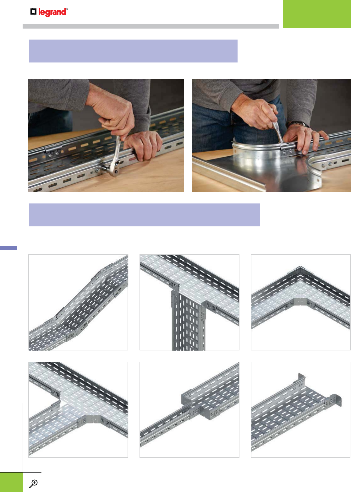
To splice straight sections of trough tray use the FTEF. The FTEF has attachment
hardware included and should be used when splicing straight sections or fittings.
The FTUS is a versatile splice that can be used to construct tees, reductions and elevation changes, thus reducing the need for
formed fittings. Use with EZ BN 1/4 bolt/nut or BTRCC6x12.
V-TROUGH
INSTALLATIONS
SPLICING STRAIGHT SECTIONS AND FITTINGS
SPLICING TEES, REDUCTIONS AND LEVEL CHANGES
INSTALLATION GUIDELINES
WWW.LEGRAND.US/CABLOFIL
C.28
CABLOFIL
TROUGH TRAY
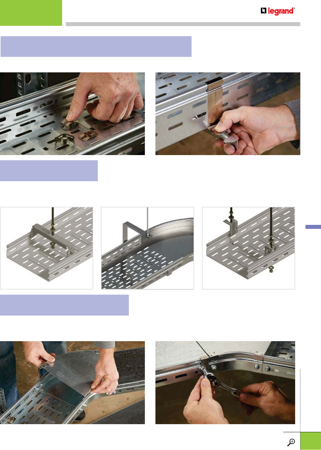
FTCH CENTER HANGER FTAS TRAPEZE HANGING CLIP FTAS TRAPEZE HANGING CLIP
Securing ventilated tray to supports is easy. For attachment to the FAS U or CS series support, use the FTFCL.
It simply snaps in place. For securing solid tray use the FTHDCL Tray Hold Down Clip. Both allow a cover to be used.
For trapeze mounting, three options are available: The FTCH and FTCHC Center Hangers both require only a
single threaded rod. The FTAS Trapeze Hanging Clip requires two 3/8" threaded rods, but allows cables to be
side loaded. Folding tabs secure tray to supports. Covers can be used with FTCHC but not FTCH or FTAS.
Complete the security of your cables with covers. These cover sections can be cut to fit with a
reciprocating saw and simply snap on. For additional security, use the FTCFCL Cover Fastening Clip.
This clip can be used in conjunction with splicing hardware to keep covers secure.
FTCHC CENTER HANGER
V-TROUGH
INSTALLATIONS
ATTACHING TO WALL OR FLOOR SUPPORTS
TRAPEZE SUPPORTS
COVER ATTACHMENT OPTIONS
INSTALLATION GUIDELINES
WWW.LEGRAND.US/CABLOFIL
C.29
CABLOFIL
TROUGH TRAY
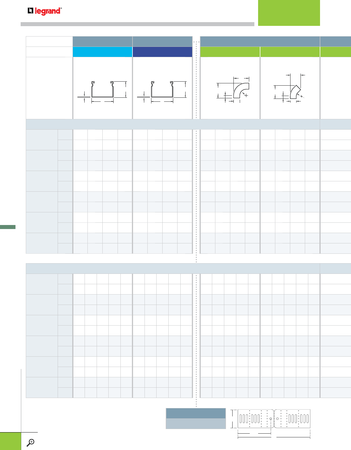
DESCRIPTION >STRAIGHT SOLID SECTION STRAIGHT VENTILATED SECTION FITTINGS
ITEM >FT VT FTFB90 FTFB45
TRAY HEIGHT (H) = 2.0 in / 50mm
TRAY WIDTH (W)
IN 2.0 3.9 7.9 11.8 2.0 3.9 7.9 11.8 2.0 3.9 7.9 11.8 2.0 3.9 7.9 11.8
MM 50 100 200 300 50 100 200 300 50 100 200 300 50 100 200 300
RADIUS (R)
IN - - - - - - - - 0.8 3.9 3.9 3.9 0.8 3.9 3.9 3.9
MM - - - - - - - - 20 100 100 100 20 100 100 100
LENGTH 1 (L1)
IN - - - - - - - - - 9.1 13.0 16.9 4.7 7.6 10.4 13.1
MM - - - - - - - - - 230 330 430 120 194 264 334
LENGTH 2 (L2)
IN - - - - - - - - 3.9 9.1 13.0 16.9 3.4 5.9 9.9 9.9
MM - - - - - - - - 100 230 330 430 85 151 251 251
TANGENT (C)
IN - - - - - - - - 1.2 1.2 1.2 1.2 1.2 1.2 1.2 1.2
MM - - - - - - - - 30 30 30 30 30 30 30 30
WEIGHT
LBS 4.9 6.9 11.7 19.6 4.9 6.9 11.7 19.6 0.6 1.6 3.7 6.5 0.4 0.6 1.1 1.8
KG 2.43 3.14 5.30 8.90 2.43 3.14 5.30 8.90 0.26 0.74 1.67 2.94 0.19 0.29 0.51 0.81
TRAY HEIGHT (H) = 3.9 in / 100mm
TRAY WIDTH (W)
IN 3.9 7.8 11.8 19.7 23.6 3.9 7.8 11.8 19.7 23.6 3.9 7.8 11.8 19.7 23.6 3.9 7.8 11.8 19.7 23.6
MM 100 200 300 500 600 100 200 300 500 600 100 200 300 500 600 100 200 300 500 600
RADIUS (R)
IN - - - - - - - - - - 3.9 3.9 3.9 5.9 5.9 3.9 3.9 3.9 5.9 5.9
MM - - - - - - - - - - 100 100 100 150 150 100 100 100 150 150
LENGTH 1 (L1)
IN - - - - - - - - - - 9.1 13.0 16.9 27.6 31.5 7.6 10.4 13.1 21.5 24.3
MM - - - - - - - - - - 230 330 430 700 800 193 263 334 545 616
LENGTH 2 (L2)
IN - - - - - - - - - - 9.1 13.0 16.9 27.6 31.5 5.9 9.9 13.8 22.8 26.7
MM - - - - - - - - - - 230 330 430 700 800 151 251 351 579 679
TANGENT (C)
IN - - - - - - - - - - 1.2 1.2 1.2 2.0 2.0 1.2 1.2 1.2 2.0 2.0
MM - - - - - - - - - - 30303050503030305050
WEIGHT
LBS 11.7 19.7 29.8 43.1 45.1 11.7 19.7 29.8 43.1 45.1 2.1 4.5 7.3 17.9 22.5 1.3 2.4 3.5 8.7 9.7
KG 5.31 8.94 13.52 19.55 20.46 5.31 8.94 13.52 19.55 20.46 0.97 2.03 3.29 8.14 10.20 0.61 1.08 1.66 3.95 4.40
t
W
H
t
W
H
L2
L1
W
R
C
L1
W
R
C
L2
H
L
140mm
UNIVERSAL ADJUSTABLE SPLICE
FTUS
See pages C.10, C.28
SPECIFICATIONS
WWW.LEGRAND.US/CABLOFIL
C.30
CABLOFIL
TROUGH TRAY
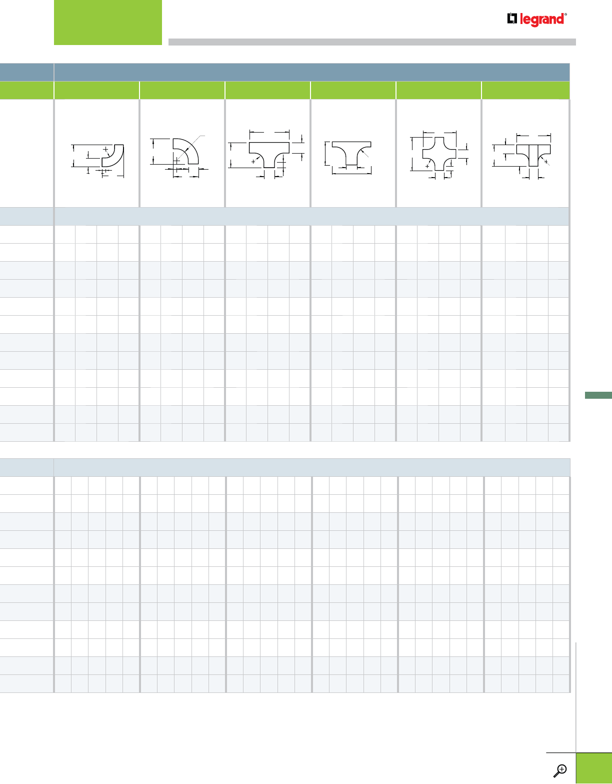
FITTINGS
FTVI90 FTVO90 FTT FTB FTX FTVT
TRAY HEIGHT (H) = 2.0 in / 50mm
2.0 3.9 7.9 11.8 2.0 3.9 7.9 11.8 2.0 3.9 7.9 11.8 2.0 3.9 7.9 11.8 2.0 3.9 7.9 11.8 2.0 3.9 7.9 11.8
50 100 200 300 50 100 200 300 50 100 200 300 50 100 200 300 50 100 200 300 50 100 200 300
0.8 3.9 3.9 3.9 0.8 5.0 5.0 5.0 0.8 3.9 3.9 3.9 0.8 3.9 3.9 3.9 0.8 3.9 3.9 3.9 - 3.9 3.9 3.9
20 100 100 100 20 127 127 127 20 100 100 100 20 100 100 100 20 100 100 100 - 100 100 100
3.9 7.1 7.1 7.1 3.9 8.3 8.3 8.3 5.9 14.2 18.1 22.0 3.8 7.1 7.1 7.1 5.9 14.2 18.1 22.0 5.9 14.2 18.1 22.0
100 180 180 180 100 210 210 210 150 360 460 560 96 180 180 180 150 360 460 560 150 360 460 560
3.9 7.1 7.1 7.1 3.9 8.3 8.3 8.3 3.9 9.1 13.0 16.9 5.9 14.1 18.0 22.0 5.9 14.2 18.1 22.0 3.9 8.3 9.4 11.8
100 180 180 180 100 210 210 210 100 230 330 430 150 358 458 558 150 360 460 560 100 210 240 300
1.2 1.2 1.2 1.2 1.2 1.2 1.2 1.2 1.2 1.2 1.2 1.2 - - - - 1.2 1.2 1.2 1.2 - - - -
30 30 30 30 30 30 30 30 30 30 30 30 - - - - 30 30 30 30 - - - -
0.5 1.1 1.6 2.1 0.4 1.1 1.6 2.0 0.6 1.7 3.0 4.7 0.7 1.6 2.2 2.8 0.7 2.4 4.1 6.2 0.7 2.9 5.3 8.7
0.21 0.49 0.72 0.95 0.17 0.51 0.71 0.91 0.26 0.79 1.37 2.11 0.30 0.74 0.99 1.25 0.31 1.09 1.86 2.81 0.31 1.30 2.42 3.95
TRAY HEIGHT (H) = 3.9 in / 100mm
3.9 7.8 11.8 19.7 23.6 3.9 7.8 11.8 19.7 23.6 3.9 7.8 11.8 19.7 23.6 3.9 7.8 11.8 19.7 23.6 3.9 7.8 11.8 19.7 23.6 3.9 7.8 11.8 19.7 -
100 200 300 500 600 100 200 300 500 600 100 200 300 500 600 100 200 300 500 600 100 200 300 500 600 100 200 300 500 -
5.9 5.9 5.9 5.9 5.9 5.9 5.9 5.9 5.9 5.9 3.9 3.9 3.9 5.9 5.9 3.9 3.9 3.9 5.9 5.9 3.9 3.9 3.9 5.9 5.9 3.9 3.9 3.9 3.9 -
150 150 150 150 150 150 150 150 150 150 100 100 100 150 150 100 100 100 150 150 100 100 100 150 150 100 100 100 100 -
11.8 11.8 11.8 11.8 11.8 11.9 11.9 11.9 11.9 11.9 14.2 18.1 22.0 35.4 39.4 7.1 7.1 7.1 9.8 9.8 14.2 18.1 22.0 35.4 39.4 14.2 18.1 22.0 35.4 -
300 300 300 300 300 301 301 301 301 301 360 460 560 900 1000 180 180 180 250 250 360 460 560 900 1000 360 460 560 900 -
11.8 11.8 11.8 11.8 11.8 11.9 11.9 11.9 11.9 11.9 9.1 13.0 16.9 27.6 31.5 14.1 18.0 22.8 35.4 39.3 14.2 18.1 22.0 35.4 39.4 9.1 11.4 13.8 17.7 -
300 300 300 300 300 301 301 301 301 301 230 330 430 700 800 358 458 558 898 998 360 460 560 900 1000 230 290 350 450 -
2.0 2.0 2.0 2.0 2.0 2.0 2.0 2.0 2.0 2.0 1.2 1.2 1.2 2.0 2.0 - - - - - 1.2 1.2 1.2 2.0 2.0 - - - - -
50 50 50 50 50 50 50 50 50 50 30 30 30 50 50 - - - - - 30 30 30 50 50 - - - - -
3.2 4.5 5.8 8.4 9.5 3.3 4.5 5.8 8.4 10.1 3.7 6.2 9.8 20.8 26.0 2.2 2.6 3.3 6.2 7.1 4.5 7.6 11.4 23.8 30.2 3.5 5.7 9.9 23.1 -
1.47 2.06 2.62 3.83 4.30 1.50 2.06 2.64 3.80 4.60 1.69 2.83 4.43 9.44 11.80 1.00 1.20 1.50 2.80 3.20 2.04 3.44 5.19 10.81 13.70 1.66 2.60 4.50 10.50 -
L1
C
L2
R
H
C
L2
H
R
L1 W
L1
L2
C
W
R
L2
L1
W
RL2
L1
C
W
R
W
L2
L1
H
W
R
SPECIFICATIONS
WWW.LEGRAND.US/CABLOFIL
C.31
CABLOFIL
TROUGH TRAY
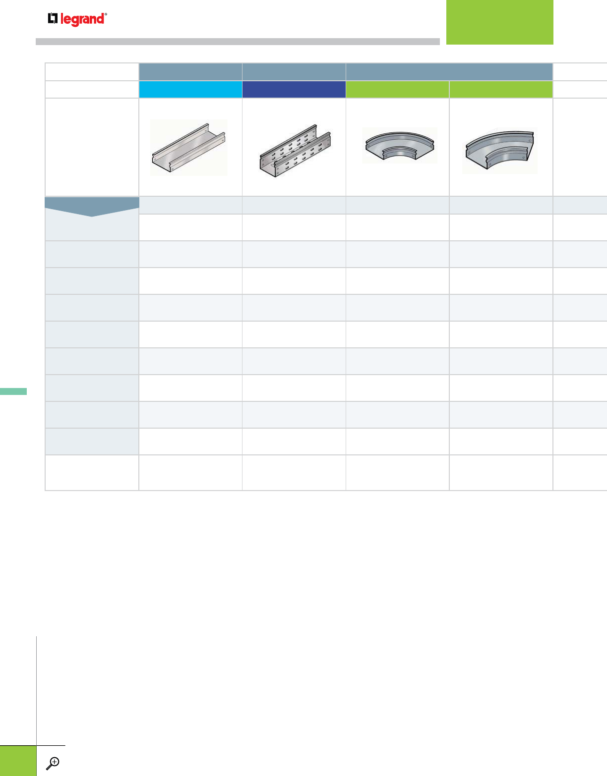
DESCRIPTION >STRAIGHT SECTION STRAIGHT VENTILATED SECTION FITTINGS
ITEM >FT VT FTFB90 FTFB45
C.8 C.8 C.12 C.12
2" x 2"
50 x 50 mm FT 50/50 VT 50/50 FTFB90 50/50 FTFB45 50/50
2" x 4"
50 x 100 mm FT 50/100 VT 50/100 FTFB90 50/100 FTFB45 50/100
2" x 8"
50 x 200 mm FT 50/200 VT 50/200 FTFB90 50/200 FTFB45 50/200
2" x 12"
50 x 300 mm FT 50/300 VT 50/300 FTFB90 50/300 FTFB45 50/300
4" x 4"
100 x 100 mm FT 100/100 VT 100/100 FTFB90 100/100 FTFB45 100/100
4" x 8"
100 x 200 mm FT 100/200 VT 100/200 FTFB90 100/200 FTFB45 100/200
4" x 12"
100 x 300 mm FT 100/300 VT 100/300 FTFB90 100/300 FTFB45 100/300
4" x 20"
100 x 500 mm FT 100/500 VT 100/500 FTFB90 100/500 FTFB45 100/500
4" x 24"
100 x 600 mm FT 100/600 VT 100/600 FTFB90 100/600 FTFB45 100/600
CORRESPONDING
COVER FTC FTC FTCFB90 FTCFB45
TRAY DIMENSIONS (HxW)
CROSS REFERENCE
WWW.LEGRAND.US/CABLOFIL
C.32
CABLOFIL
TROUGH TRAY
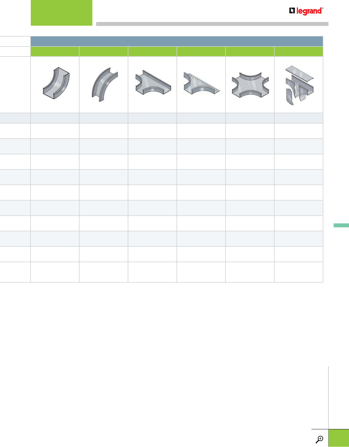
FITTINGS
FTVI90 FTVO90 FTT FTB FTX FTVT
C.13 C.13 C.14 C.14 C.15 C.15
FTVI90 50/50 FTVO90 50/50 FTT 50/50 FTB 50/50 FTX 50/50 FTVT 50/50
FTVI90 50/100 FTVO90 50/100 FTT 50/100 FTB 50/100 FTX 50/100 FTVT 50/100
FTVI90 50/200 FTVO90 50/200 FTT 50/200 FTB 50/200 FTX 50/200 FTVT 50/200
FTVI90 50/300 FTVO90 50/300 FTT 50/300 FTB 50/300 FTX 50/300 FTVT 50/300
FTVI90 100/100 FTVO90 100/100 FTT 100/100 FTB 100/100 FTX 100/100 FTVT 100/100
FTVI90 100/200 FTVO90 100/200 FTT 100/200 FTB 100/200 FTX 100/200 FTVT 100/200
FTVI90 100/300 FTVO90 100/300 FTT 100/300 FTB 100/300 FTX 100/300 FTVT 100/300
FTVI90 100/500 FTVO90 100/500 FTT 100/500 FTB 100/500 FTX 100/500 FTVT 100/500
FTVI90 100/600 FTVO90 100/600 FTT 100/600 FTB 100/600 FTX 100/600 —
FTCVI90 FTCVO90 FTTC FTBC FTXC INCLUDED
CROSS REFERENCE
WWW.LEGRAND.US/CABLOFIL
C.33
CABLOFIL
TROUGH TRAY
INTRODUCTION
PAGES D.1
JHOOKS
PAGES D.2-D.8
OTHER FASTENERS
PAGES D.9-D.11
FAS POWER
PAGES D.12-D.23
CABLOPORT
PAGES D.24-D.31
SEISMIC BRACING
PAGES D.32-D.38
FASTENERS
TABLE OF CONTENTS
Our electrical fasteners and components are designed to get you on and
off of the job-site in record time. Hammer-on J-Hooks, FAS Power pre-fab
components and CabloPort rooftop supports are just a few examples of
products that reduce labor, increasing your bottom line.
Cablofil fasteners and components are perfect
for branch wiring in these project types:
• Hotels
• Office Complexes
• Condominiums
• Hospitals
• Government Buildings
Also included in this catalog is a full line of seismic brace systems and
attachment hardware. Each product is designed with quality materials for
optimum performance in any installation.
Fasteners and prefab components
for everyday applications.
LEGRAND FASTENERS
INTRODUCTION
WWW.LEGRAND.US/CABLOFIL
D.1
LEGRAND
FASTENERS

Cable management that’s
fast and secure
LEGRAND JHOOKS
WWW.LEGRAND.US/CABLOFIL
D.2
LEGRAND
FASTENERS
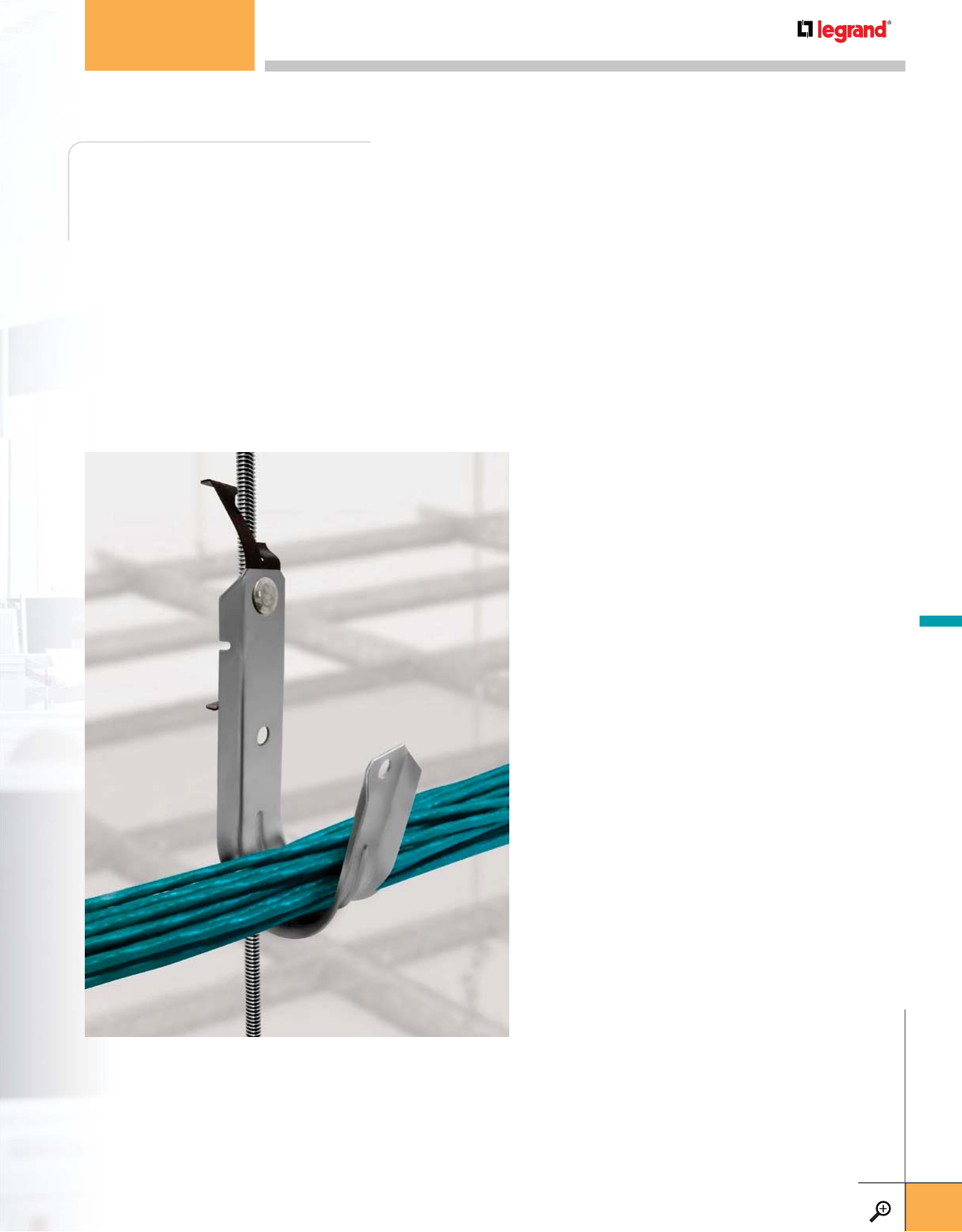
Cablofil J-Hooks provides an easy-to-install, non-continuous cable support for all
types of telecommunication, data and power cabling. They also are perfect for low
voltage building management and fire protection cabling.
Our CJ Series is engineered to provide stress-free cable support for multiple
cables and features a structural design for optimal strength and tapered edges to
reduce cable sheath damage. Multiple pre-drilled holes reduce on-site modification
at installation. Cablofil J-Hooks can be attached to a variety of structures and
are available with multiple attachment options that allow quick and easy cable
installation virtually anywhere.
CJ12 D.4
3/4" J-HOOK
CJ21 D.4
1-5/16" J-HOOK
CJ32 D.4
2" J-HOOK
CJ64 D.4
4" J-HOOK
CJHP16 D.6
1" J-HOOK
CJHP32 D.6
2" J-HOOK
CJHP48 D.6
3" J-HOOK
CJ4T125 D.7
1-1/4" BRIDLE
RING
CJ4T2 D.7
2" BRIDLE RING
CJ TREE D.8
J-HOOK TREE
CJHP TREE D.8
PLASTIC COATED
J-HOOK TREE
JHOOKS FEATURES:
• From ¾” to 4” sizes available
with multiple attachment
options
• Ready to use out of the box,
reducing installation time
and labor costs
• Requires no special
attachment hardware or
tools for assembly
• Provides superior fill capacity
and load rating
• Tree configurations provide
multiple J-Hooks with one
structural attachment
• Meets ISO®/IEC 14763-2,
TIA 568-C and TIA 569-C
• Complies with EN 50174-2
• Available in Red or Blue
(other colors are also
available)
• Marking mylar tabs available
for post installation needs.
(Contact manufacturer for
availability)
• cULus® Listed
J-HOOKS
WWW.LEGRAND.US/CABLOFIL
D.3
LEGRAND
FASTENERS
WWW.LEGRAND.US/CABLOFIL
D.3
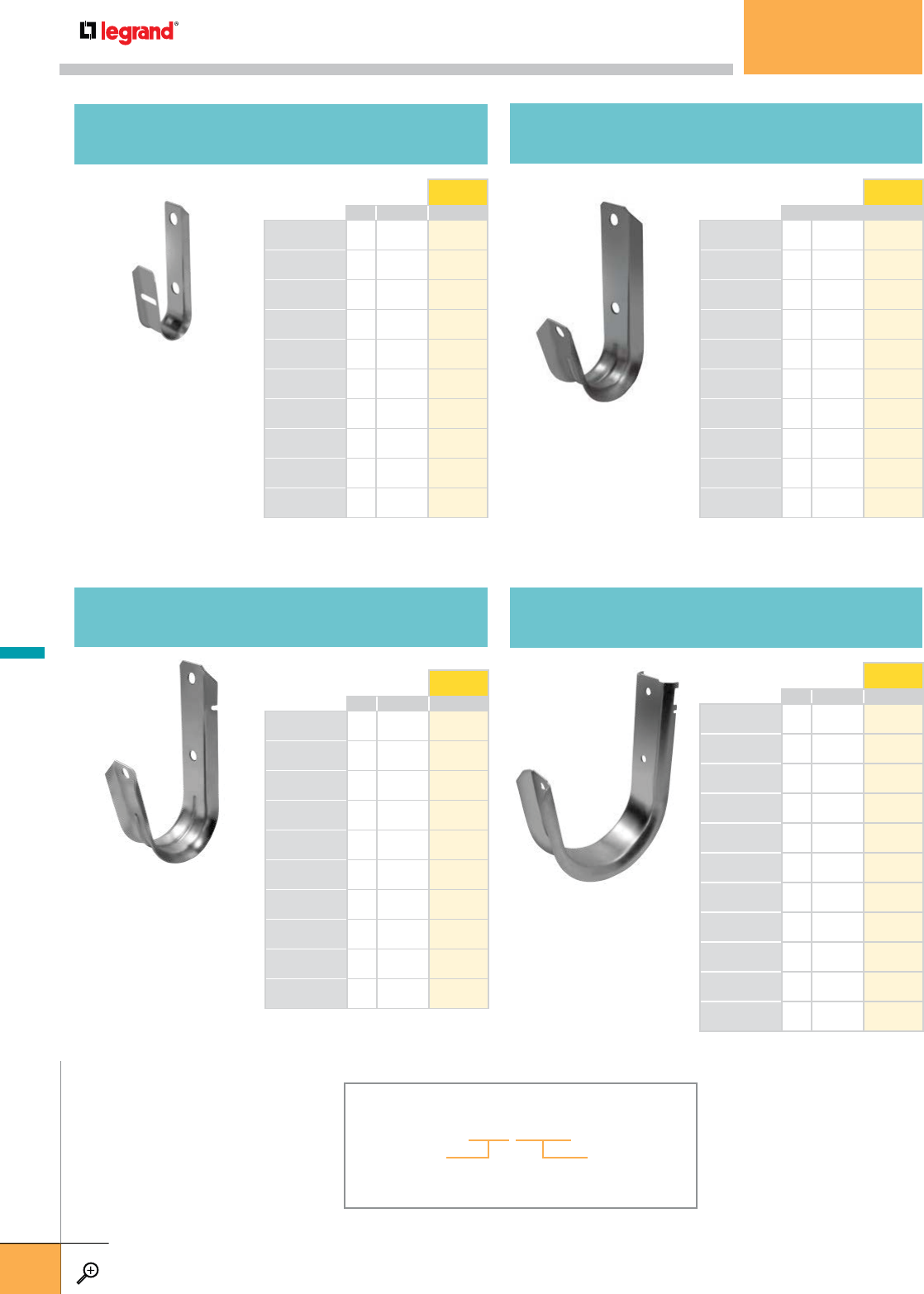
WEIGHT EZ
PCS LBS
CJ12 50 2.5 F000001
CJ12W 50 3.5 F000002
CJ12AC 50 4 F000003
CJ12HOK24 50 5 F000004
CJ12HOK58 50 5 F000005
CJ12PBC 50 8.5 F000006
CJ12ACPBC 50 10 F000007
CJ12SSBC 50 5.5 F000008
CJ12ACSSB 50 7 F000009
CJ12ACHOK24 50 6.5 F000010
WEIGHT EZ
PCS LBS
CJ32 50 7.5 F000021
CJ32W 50 8.5 F000022
CJ32AC 50 9.5 F000023
CJ32HOK24 50 10 F000024
CJ32HOK58 50 13.5 F000025
CJ32PBC 50 15 F000026
CJ32ACPBC 50 10 F000027
CJ32SSBC 50 10.5 F000028
CJ32ACSSB 50 12.5 F000029
CJ32ACHOK24 50 12.5 F000030
WEIGHT EZ
PCS LBS
CJ64 25 7.5 F000031
CJ64W 25 8.5 F000032
CJ64AC 25 12.5 F000039
CJ64HOK24 25 9.5 F000033
CJ64HOK58 25 10 F000034
CJ64PBC 25 13.5 F000035
CJ64ACPBC 25 15 F000036
CJ64SSBC 25 10.5 F000037
CJ64ACSSB 25 12.5 F000038
CJ64AC6 25 12.5 F000040
CJ64ACHOK24 25 12.5 F000041
WEIGHT EZ
PCS LBS
CJ21 50 6.5 F000011
CJ21W 50 7.5 F000012
CJ21AC 50 8.5 F000013
CJ21HOK24 50 9 F000014
CJ21HOK58 50 9 F000015
CJ21PBC 50 12.5 F000016
CJ21ACPBC 50 14 F000017
CJ21SSBC 50 9.5 F000018
CJ21ACSSB 50 11.5 F000019
CJ21ACHOK24 50 11.5 F000020
CJ12
¾" J-HOOK
CJ32
2" J-HOOK
CJ64
4" J-HOOK
CJ21
15
/
16" J-HOOK
PART NUMBERING EXAMPLE
CJ12 HOK24
ATTACHMENT
See options on D.5
JHOOK
Choose between
CJ12, CJ21, CJ32 & CJ64
J-HOOKS
WWW.LEGRAND.US/CABLOFIL
D.4
LEGRAND
FASTENERS
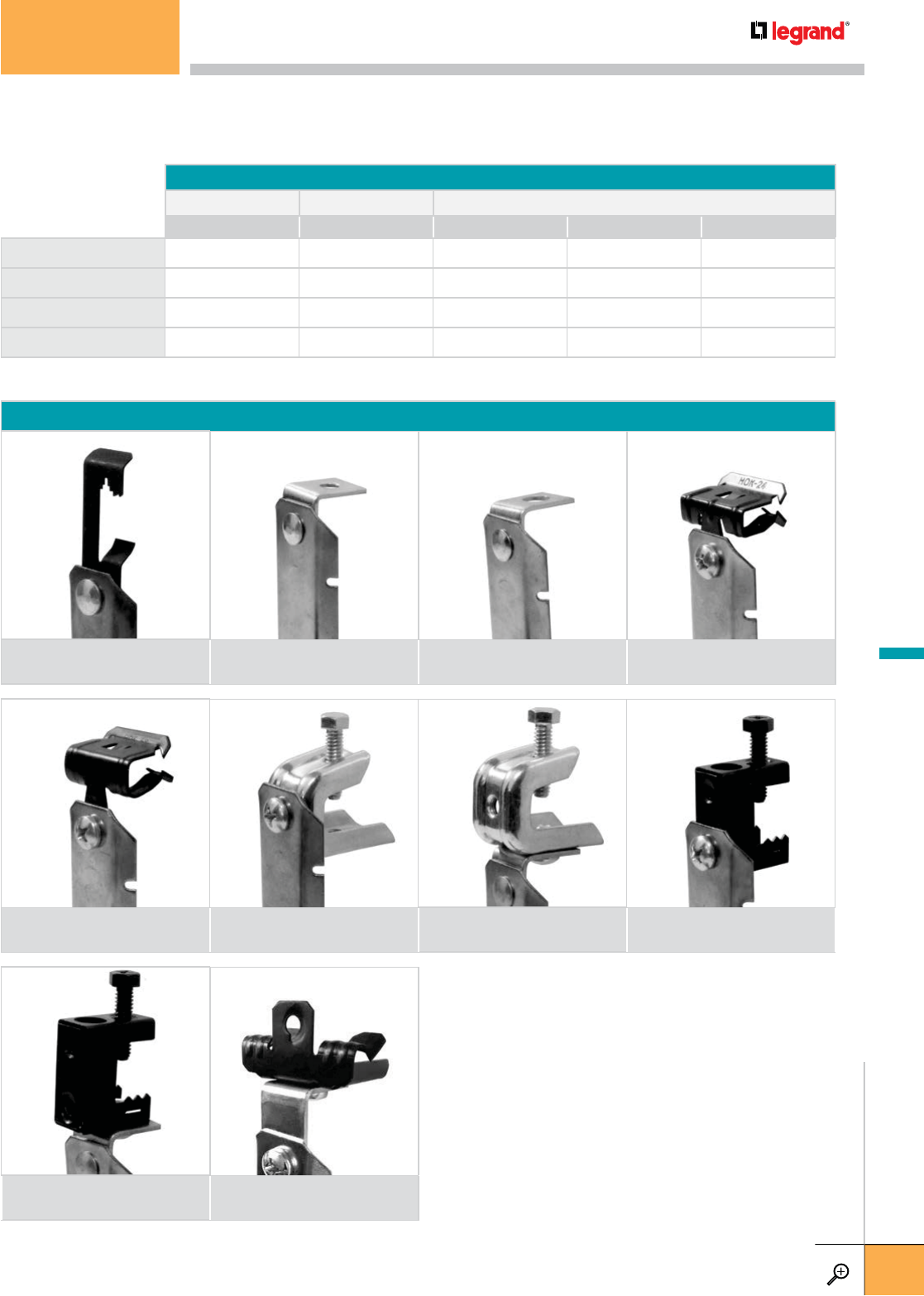
LOAD CAPACITY TABLE
HOOK SIZE LOAD CAPACITY CABLE CAPACITY
IN LBS 4-PAIR UTP CAT 5E CAT 6 2 STRAND FIBER OPTIC
CJ12 ¾17161016
CJ21 15
/
16 17 50 32 50
CJ32 2 17805080
CJ64 4 50 300 220 300
W AC AC6
CPBC
ACHOK24
HOK24
PBCHOK58
ATTACHMENT OPTIONS
Bat wing
12 gage – ¼" ATR
90˚ angled clip –
¼" hole
90˚ angled clip –
3
/
8" hole
Knock-on steel beam clamp –
1
/
8" to ¼"
Knock-on steel beam clamp –
5
/
16" to ½"
Pressed beam clamp –
up to ½"
Angled clip and
pressed beam clamp – up to ½"
Assembled to SSBC –
1
/
8" to ½"
Angled clip and SSBC –
swivels 360˚
Knock-on clamp and
angled clip – swivels 360˚
ACSSB
SSBC
J-HOOKS
WWW.LEGRAND.US/CABLOFIL
D.5
LEGRAND
FASTENERS

The ‘Cable Cage’ J-Hook features a built in latch that allows you to lock the bendable flap into place – up to 50 times with no signs
of metal fatigue. CJP J-Hooks combine the best features of both metal and plastic, providing strength and a slick, no-bur surface
for easy cable pulling. They will support all types of data communication and low-voltage cabling and are available with a number
of ready-made accessories for attachment to a wide variety of structures and surfaces. All CJP Hooks are plenum-safe.
WEIGHT EZ
PCS LBS
CJ16HP 50 2.5 F000051
CJ16HPW 50 4 F000059
CJ16HPAC 50 5 F000060
CJ32HP 50 5 F000052
CJ32HPW 50 6.5 F000061
CJ32HPAC 50 6.5 F000062
CJ48HP 25 15.5 F000053
CJ48HPW 25 18 F000063
CJ48HPAC 25 17.5 F000064
CJ16HP
1" J-HOOK
CJ32HP
2" J-HOOK
CJ48HP
3" J-HOOK
CJHP LOAD CAPACITY TABLE
HOOK SIZE LOAD CAPACITY CABLE CAPACITY
IN LBS 4-PAIR UTP CAT 5E CAT 6 2 STRAND FIBER OPTIC
CJ16HP 1 17201520
CJ32HP 2 17906090
CJ48HP 3 50 200 150 200
W
CJHP ATTACHMENT OPTIONS
Bat wing 90˚ angled clip
AC
PART NUMBERING EXAMPLE
CJ16HPW
ATTACHMENT
See options below
JHOOK
Choose between
CJ16HP, CJ32HP & CH48HP
J-HOOKS
WWW.LEGRAND.US/CABLOFIL
D.6
LEGRAND
FASTENERS
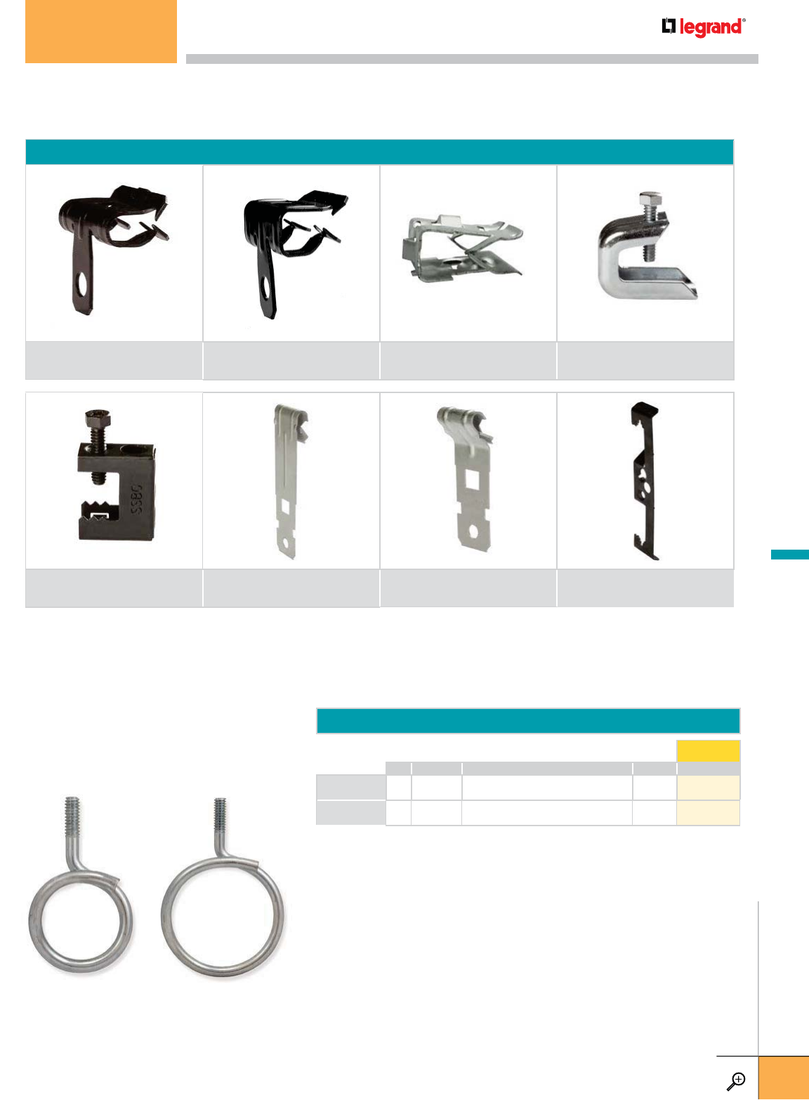
CJ ATTACHMENT MOUNTING HARDWARE
Knock-on steel beam clamp –
1
/
8" to ¼"
Knock-on steel beam clamp –
5
/
16" to ½"
Knock-on spring steel
beam clamp – 1
/
8" to ½"
Pressed beam clamp –
up to ½"
Spring steel beam clamp
1
/
8" – ½" 1
/
8" – ¼" Z Purlin 1
/
8" – ¼" C Purlin Bat wing
12 gage – ¼" ATR
J-HOOK BRIDLE RING OPTIONS
RING DIA. WEIGHT EZ
PCS IN DESCRIPTION LBS
CJ4T125 100 1¼ Bridle Ring ¼ x20 threads 6 F000042
CJ4T2 100 2 Bridle Ring ¼ x 20 threads 9 F000043
ATTACHMENTS
Use these attachment options to create your own custom J-Hook combinations. Sold in quantities of 100.
BRIDLE RINGS
Bridle rings are a simple option for smaller
bundles of communication or data cabling.
CJ24 CJ58 CJFMP
CJC14 CJBW
CJBC
CJZ14CJSSBC
J-HOOKS
WWW.LEGRAND.US/CABLOFIL
D.7
LEGRAND
FASTENERS
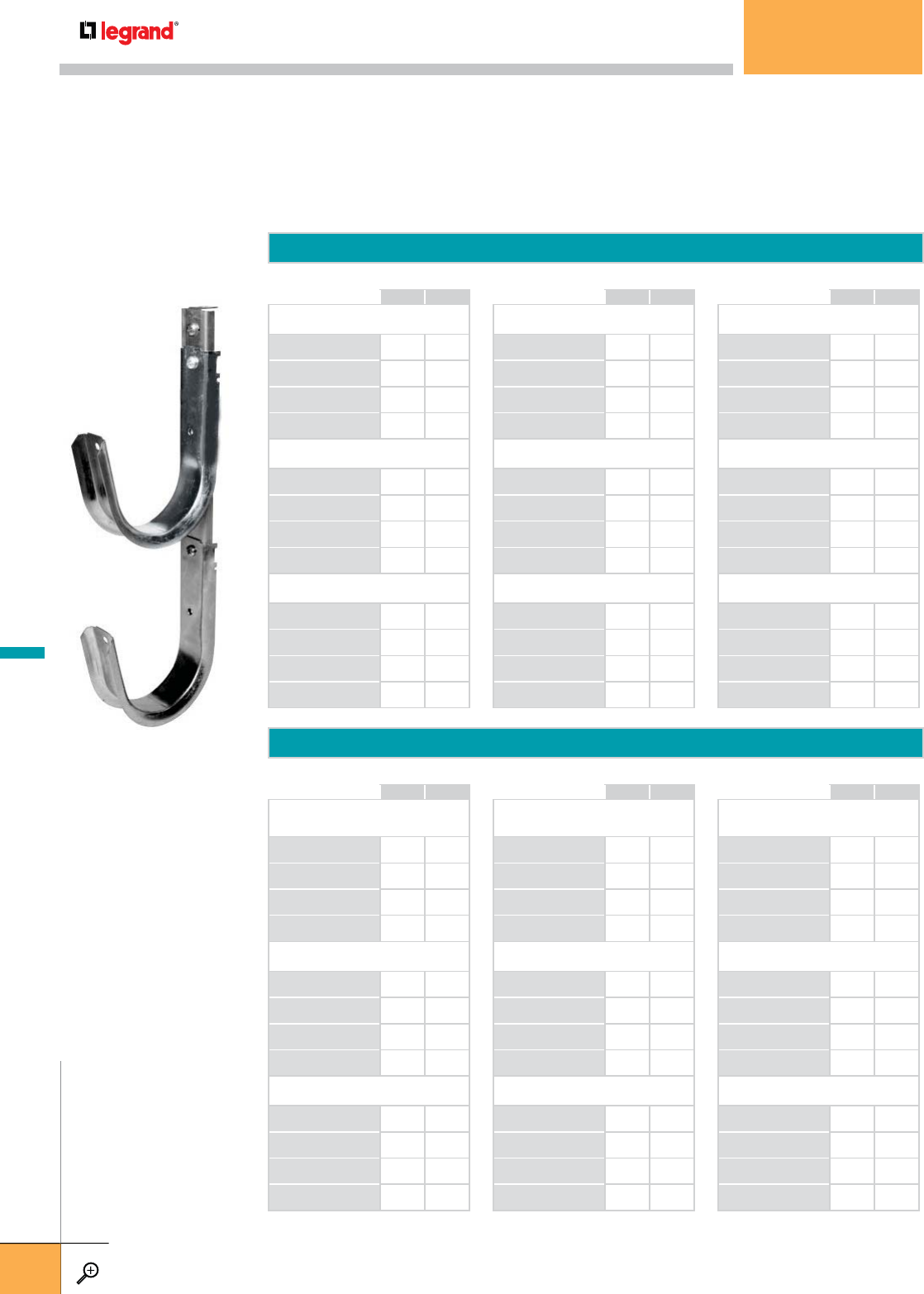
WEIGHT
HOOK COUNT LBS
1" VERTICAL TREE SUPPORTS WITH
PLASTIC COATED HOOKS
CJ16HP-SB-2 2 1.4
CJ16HP-SB-3 3 2.4
CJ16HP-SB-4 4 3.4
CJ16HP-SB-5 5 3.9
w/ ANGLE CLIP
CJ16HP-AC-SB-2 2 1.4
CJ16HP-AC-SB-3 3 2.4
CJ16HP-AC-SB-4 4 3.4
CJ16HP-AC-SB-5 5 3.9
w/ BEAM CLAMP
CJ16HP-PBC-SB-2 2 1.9
CJ16HP-PBC-SB-3 3 2.4
CJ16HP-PBC-SB-4 4 3.4
CJ16HP-PBC-SB-5 5 4.4
WEIGHT
HOOK COUNT LBS
2" VERTICAL TREE SUPPORTS WITH
PLASTIC COATED HOOKS
CJ32HP-SB-2 2 1.6
CJ32HP-SB-3 3 2.6
CJ32HP-SB-4 4 3.6
CJ32HP-SB-5 5 4.1
w/ ANGLE CLIP
CJ32HP-AC-SB-2 2 1.6
CJ32HP-AC-SB-3 3 2.6
CJ32HP-AC-SB-4 4 3.6
CJ32HP-AC-SB-5 5 4.1
w/ BEAM CLAMP
CJ32HP-PBC-SB-2 2 2.1
CJ32HP-PBC-SB-3 3 2.6
CJ32HP-PBC-SB-4 4 3.6
CJ32HP-PBC-SB-5 5 4.6
WEIGHT
HOOK COUNT LBS
3" VERTICAL TREE SUPPORTS WITH
PLASTIC COATED HOOKS
CJ48HP-SB-2 22
CJ48HP-SB-3 32
CJ48HP-SB-4 44
CJ48HP-SB-5 54
w/ ANGLE CLIP
CJ48HP-AC-SB-2 22
CJ48HP-AC-SB-3 33
CJ48HP-AC-SB-4 44
CJ48HP-AC-SB-5 54
w/ BEAM CLAMP
CJ48HP-PBC-SB-2 22
CJ48HP-PBC-SB-3 33
CJ48HP-PBC-SB-4 44
CJ48HP-PBC-SB-5 54
WEIGHT
HOOK COUNT LBS
15
/
16" VERTICAL TREE SUPPORTS
CJ21-SB-2 2 1.4
CJ21-SB-3 3 2.4
CJ21-SB-4 4 3.4
CJ21-SB-5 5 3.9
w/ ANGLE CLIP
CJ21-AC-SB-2 2 1.4
CJ21-AC-SB-3 3 2.4
CJ21-AC-SB-4 4 3.4
CJ21-AC-SB-5 5 3.9
w/ BEAM CLAMP
CJ21-PBC-SB-2 2 1.9
CJ21-PBC-SB-3 3 2.4
CJ21-PBC-SB-4 4 3.4
CJ21-PBC-SB-5 5 4.4
WEIGHT
HOOK COUNT LBS
2" VERTICAL TREE SUPPORTS
CJ32-SB-2 2 1.6
CJ32-SB-3 3 2.6
CJ32-SB-4 4 3.6
CJ32-SB-5 5 4.1
w/ ANGLE CLIP
CJ32-AC-SB-2 2 1.6
CJ32-AC-SB-3 3 2.6
CJ32-AC-SB-4 4 3.6
CJ32-AC-SB-5 5 4.1
w/ BEAM CLAMP
CJ32-PBC-SB-2 2 2.1
CJ32-PBC-SB-3 3 2.6
CJ32-PBC-SB-4 4 3.6
CJ32-PBC-SB-5 5 4.6
WEIGHT
HOOK COUNT LBS
4" VERTICAL TREE SUPPORTS
CJ64-SB-2 2 1.5
CJ64-SB-3 3 2.2
CJ64-SB-4 4-
CJ64-SB-5 5 3.6
w/ ANGLE CLIP
CJ64-AC-SB-2 22
CJ64-AC-SB-3 33
CJ64-AC-SB-4 44
CJ64-AC-SB-5 5 4.5
w/ BEAM CLAMP
CJ64-PBC-SB-2 2 2.5
CJ64-PBC-SB-3 33
CJ64-PBC-SB-4 44
CJ64-PBC-SB-5 55
CJ64-SB-2
CJ TREES
JHOOK TREES
J-Hook Trees are the ideal solution for segregating up to five runs of cable following the same cable pathway.
They are ready to use with no assembly required in multiple sizes and attachment methods.
These items are not stocked in our inventory. Please contact the manufacturer for shipping information,
pricing and other configurations.
CJHP TREES
J-HOOKS
WWW.LEGRAND.US/CABLOFIL
D.8
LEGRAND
FASTENERS
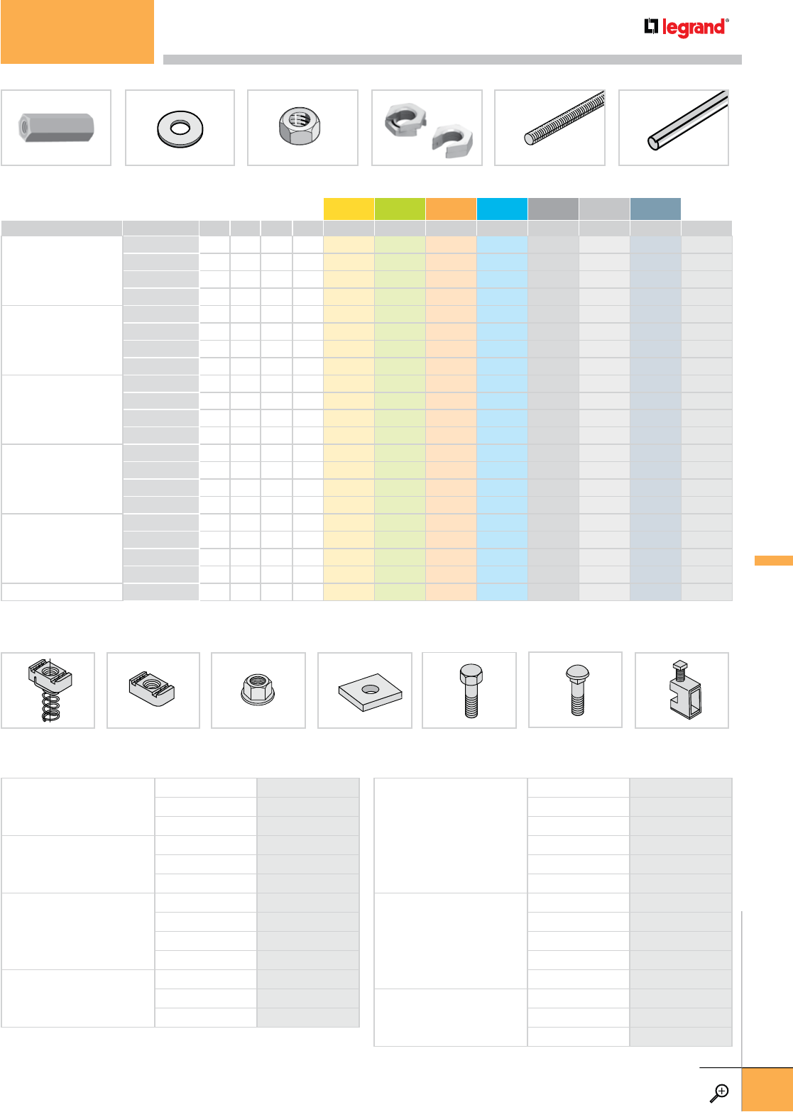
CHANNEL NUT
w/ SPRING
CHANNEL NUT
w/o SPRING
FLANGED HEX NUT SQUARE CHANNEL
WASHER
HEX HEAD BOLT CARRIAGE BOLT BEAM CLAMP
ROD COUPLING NUT FLAT, ROUND WASHER HEX NUT SLIP-ON
LOCK NUT
THREADED ROD THREADED ROD
PROTECTOR
DESCRIPTION SIZE ZN
CHANNEL NUT w/ SPRING
3
/
8"-16 DS-0102-05-ZN
½"-13 DS-0102-07-ZN
5
/
8"-11 DS-0102-08-ZN
CHANNEL NUT w/o SPRING
3
/
8"-16 DS-0103-05-ZN
½"-13 DS-0103-07-ZN
5
/
8"-11 DS-0103-08-ZN
FLANGED HEX NUT
¼"-20 DS-8845-01-ZN
3
/
8"-16 DS-8524-01-ZN
½"-13 DS-8644-01-ZN
5
/
8"-11 DS-8938-01-ZN
SQUARE CHANNEL WASHER
1½" w/ 3
/
8" HOLE DS-0113-02-ZN
1½" w/ ½" HOLE DS-0113-03-ZN
1½" w/ 5
/
8" HOLE DS-0113-04-ZN
DESCRIPTION SIZE ZN
HEX HEAD BOLT
¼"-20 x ¾" DS-8502-01-ZN
¼"-20 x 1" DS-8502-06-ZN
¼"-20 x 1¼" DS-8502-08-ZN
¼"-20 x 1½" DS-8502-10-ZN
3
/
8"-16 x 1½" DS-8520-05-ZN
½"-13 x 1½" DS-8515-15-ZN
CARRIAGE BOLT
3
/
8"-16 x 1½" DS-8510-04-ZN
3
/
8"-16 x 2½" DS-8510-08-ZN
3
/
8"-16 x 3" DS-8510-10-ZN
3
/
8"-16 x 3½" DS-8510-11-ZN
3
/
8"-16 x 4" DS-8510-12-ZN
BEAM CLAMP
FOR ¼" ROD DS-0221-01-ZN*
FOR 3
/
8" ROD DS-0221-04-ZN†
FOR ½" ROD DS-0221-06-ZN‡
Safe Load: *750 lbs.; †1100 lbs.; ‡1600 lbs.
DESCRIPTION PRODUCT NUM. QTY. DIA. LENGTH PITCH EZ GC 304L 316L BL PE PL ZN
IN FEET
ROD COUPLING NUT
EZ CN 1/4 100 1/4 – 20 941 094 – – 941 060 – – –
EZ CN 3/8 100 3/8 – 16 941 205 – – 941 061 – – –
EZ CN 1/2 100 1/2 – 13 942 790 942 791 – 942 792 942 793 942 794 –
DS-0237-06-ZN 5/8 – –––––––*
FLAT, ROUND WASHER
EZ FW 1/4 100 1/4 – 20 941 511 942 687 – 941 065 942 309 942 381 –
EZ FW 3/8 100 3/8 – 16 941 612 942 688 – 941 066 942 310 942 382 –
EZ FW 1/2 100 1/2 – 13 942 464 942 784 – 942 785 942 786 942 787 –
DS-8594-01-ZN 5/8 – –––––––*
HEX NUT
EZ HN 1/4 100 1/4 – 20 941 713 – – 941 067 – – –
EZ HN 3/8 100 3/8 – 16 941 915 – – 941 069 – – –
EZ HN 1/2 100 1/2 – 13 941 814 – – 941 068 – – –
DS-8594-01-ZN 5/8 – –––––––*
SLIP-ON
LOCK NUT
SON1/4 2 1/4 – 20 943 351 ––––––
SON3/8 2 3/8 – 18 943 352 – 943 355 ––––
SON1/2 2 1/2 – 12 943 353 – 943 356 ––––
SON5/8 2 5/8 – 11 943 354 ––––––
THREADED ROD
THRD 1/4 1 1/4 6.0 20 942 351 – – 942 471 – – –
THRD 3/8 1 3/8 6.0 16 942 353 – – 942 472 – – –
THRD 1/2 1 1/2 6.0 13 942 465 – – 942 789 – – –
DS-8594-01-ZN 10 5/8 6.0 –––––––*
THREADED ROD PROTECTOR THRDPT 10 0.5 – ––––––942 947
– Contact manufacturer for availability.
* In stock. Contact manufacturer.
OTHER FASTENERS
WWW.LEGRAND.US/CABLOFIL
D.9
LEGRAND
FASTENERS
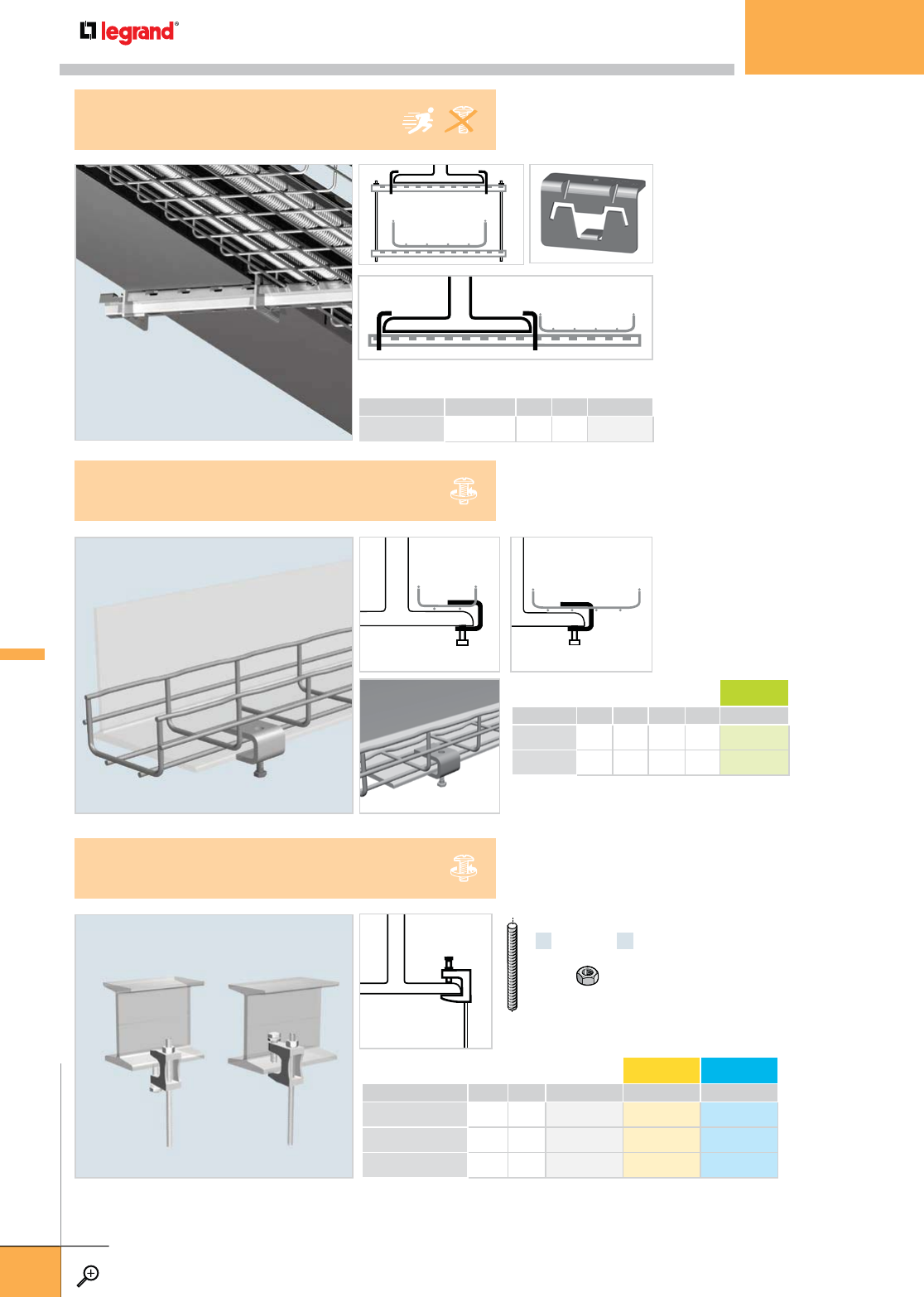
• FAS Clamps attach FAS Profile to
I-beams to speed installation time.
• 2 FAS Clamps are included in kit.
• VHM 8 x 20 set screws included.
• No threaded rod required.
• Saves ceiling space.
• Clamps tray directly to I-beam.
• No additional attachment
hardware needed.
• Set screw included.
• Attaches threaded rod directly to
I-beam.
• Threaded rod and nut are sold
separately.
• Set screw and jam nut included.
HEIGHT WEIGHT GC
INCHES MM LBS KG
ETC 20 0.8 20 0.2 0.1 942 819
ETC 30 1.0 30 0.4 0.2 –
– Contact manufacturer for availability.
WEIGHT PG EZ 316L
LBS KG
EZ BC 1/4 0.8 0.36 – 941 063 –
EZ BC 3/8 0.8 0.36 – 941 074 –
EZ BC 1/2 0.8 0.36 – 942 847 –
– Contact manufacturer for availability.
x1
THRD 1/4
THRD 3/8
THRD 1/2
x1
THRD 1/4
THRD 3/8
THRD 1/2
PKG. QTY. WEIGHT PG
LBS KG
FASCLM KIT 2 0.2 0.15 942 930
FASCLM KIT
BEAM CLAMP
ETC
TRAY BEAM SUPPORT
EZBC
BEAM CLAMP
OTHER FASTENERS
WWW.LEGRAND.US/CABLOFIL
D.10
LEGRAND
FASTENERS
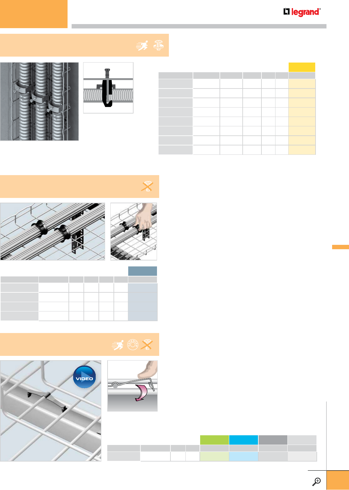
• CCLMP secures MC Cable to tray in vertical installations.
• One-piece design installs quickly using one hand.
• Combo bolt/phillips head requires no special tools to install.
PKG. QTY. CABLE SIZE WEIGHT EZ
INCHES MM LBS KG
CCLMP21 10 0.25-0.84 6-21 0.9 0.41 942 871
CCLMP35 10 0.85-1.35 22-35 1.4 0.64 942 872
CCLMP45 10 1.25-1.75 32-45 2.1 0.95 942 873
CCLMP52 10 1.55-2.05 40-52 3.0 1.36 942 874
CCLMP64 10 2.00-2.50 51-64 3.5 1.59 942 875
CCLMP76 10 2.50-3.00 64-76 3.9 1.77 942 876
CCLMP95 10 3.25-3.75 83-95 4.7 2.45 942 877
CCLMP108 10 3.75-4.25 95-108 5.4 2.45 942 878
CCLMP
CABLE CLAMP
• Protects signal by eliminating over-tightened cable ties
• Add new cables at any time – Cablo Snap is re-useable
• UL Listed, Meets EIA/TIA requirements.
• Plenum Rated
Applying Cablo Snap
1. Position Cablo Snap opening over cable bundle,
rotate slightly.
2. Snap Close - squeeze to lock teeth to desired pressure.
Removing Cable Snap
1. Squeeze Cablo Snap to unlock teeth.
2. Rotate Cablo Snap to remove cables.
PKG. QTY. WIDTH WEIGHT PL*
INCHES MM LBS KG
CABLO SNAP 12 25 0.5 12 0.1 0.1 942 952
CABLO SNAP 25 25 1.0 25 0.2 0.1 942 953
CABLO SNAP 37 25 1.5 37 0.6 0.3 942 954
CABLO SNAP 50 25 2.0 50 1.0 0.5 942 955
*PL= Plastic
CABLO SNAP
CABLE BUNDLER
• FASTRUT attaches tray to strut without bolts and nuts
or tools.
• Reduces installation time.
• Install FASTRUT on outer wires of tray, and both sides
of the strut.
• 2 required for tray 12" or smaller.
• 3 required for tray 18" or larger.
PKG. QTY. WEIGHT DC 316L BL PE
LBS KG
FS 41 25 3.3 1.5 599 007 599 004 942 823 942 824
FS 41
FASTRUT CONNECTOR
PLAY
OTHER FASTENERS
WWW.LEGRAND.US/CABLOFIL
D.11
LEGRAND
FASTENERS
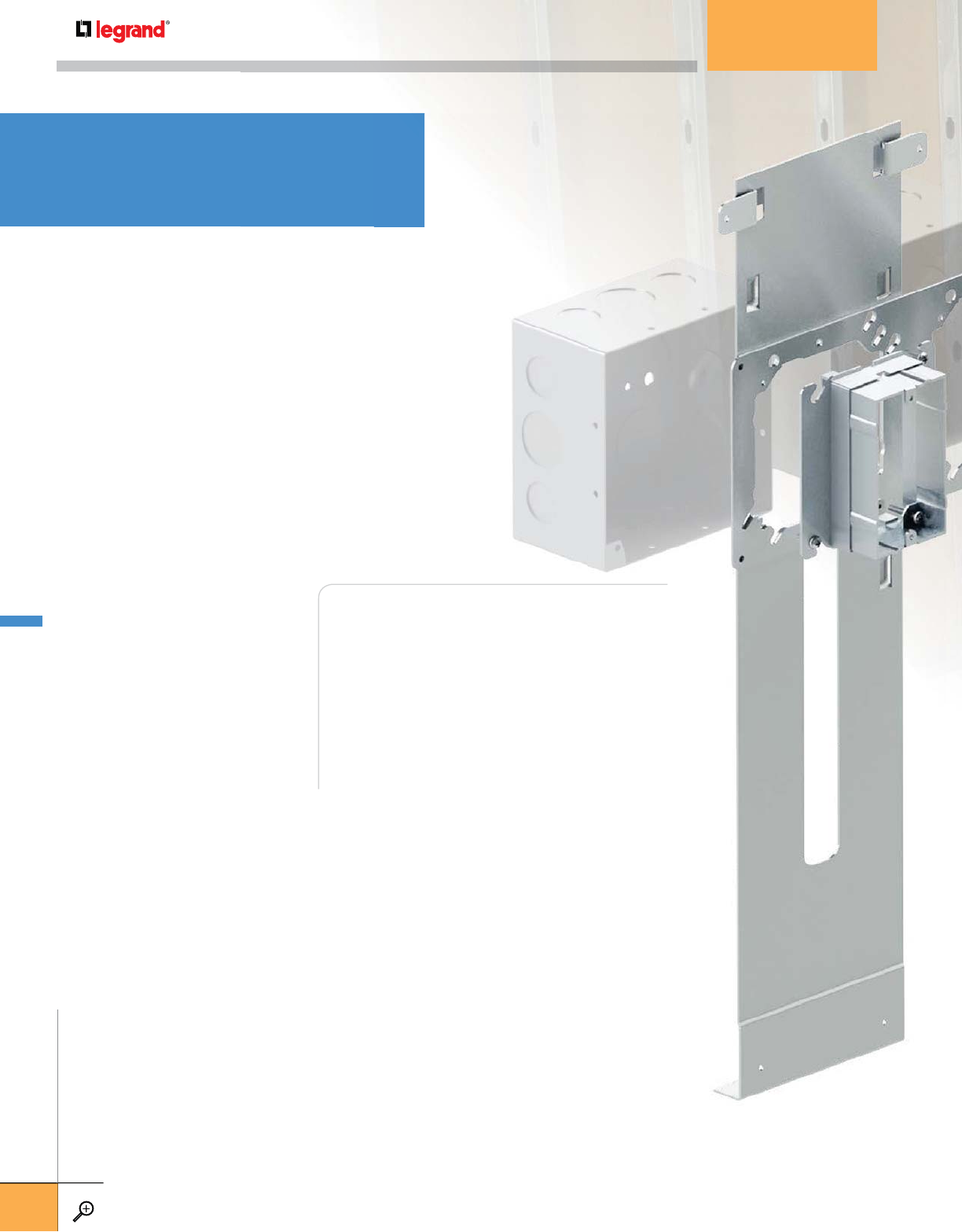
D.14 F SERIES
FLOOR BRACKETS
D.16 CW SERIES
SLIDER WALL BRACKETS
D.17 W SERIES
WALL BRACKETS
D.18 FB816
WALL BRACKET FOR
CONCRETE BLOCKS
D.21 DCP SERIES
PLASTIC DEVICE COVERS
D.21 APR SERIES
ADJUSTABLE PLASTER RINGS
D.22 AR SERIES
SUPPORT ARMS
D.22 T SERIES
WALL BRACES
FAS Power components are available for wall and
floor assemblies and for concrete block walls.
All our components are designed to fit together
easily to install quickly. And with FAS Power,
the number of components you need to stock
is limited as many parts are adjustable to fit
multiple wall thicknesses and depths keeping
inventoried parts low. FAS Power is the perfect
choice for projects with tight schedules.
FAS POWER®
Prefab components
that make a
difference.
FAS POWER
WWW.LEGRAND.US/CABLOFIL
D.12
LEGRAND
FASTENERS
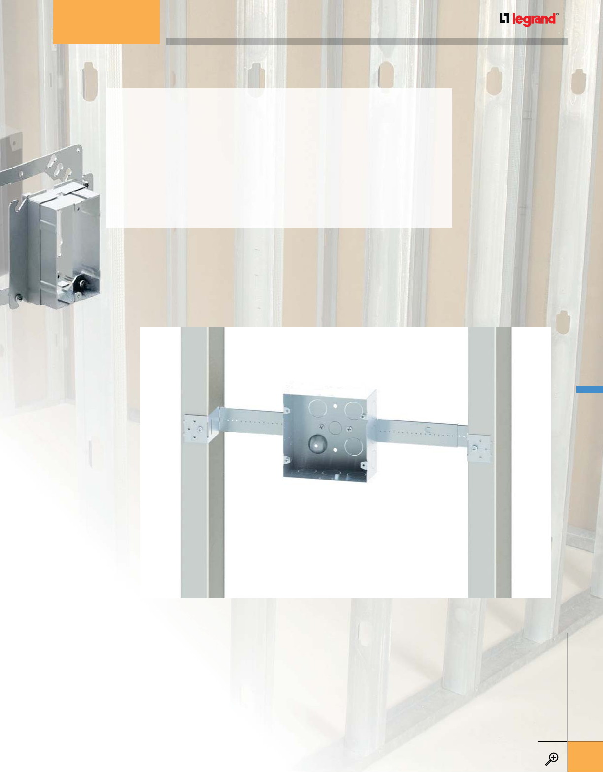
TELESCOPING BOX BRACKET FEATURES:
• Sizes for 12” to 24” stud spacing
• Fits off-width stud spacing without field modification
• Openings for attachment screws
• Fits multiple box depths
• Offsets designed to keep walls smooth
PREFAB COMPONENT FEATURES:
• Wire manager installs easily and fits most MC wire sizes
• Support Arms adjust to any wall thickness
• Predrilled mounting holes at plate
• 4” and 4-11/16” boxes mount independently from Plaster Ring
• Plaster Rings adjust to fit multiple wall thicknesses
• One to four box position brackets are available
• Clear Debris Covers keeps box interior clean during construction
FAS POWER
WWW.LEGRAND.US/CABLOFIL
D.13
LEGRAND
FASTENERS
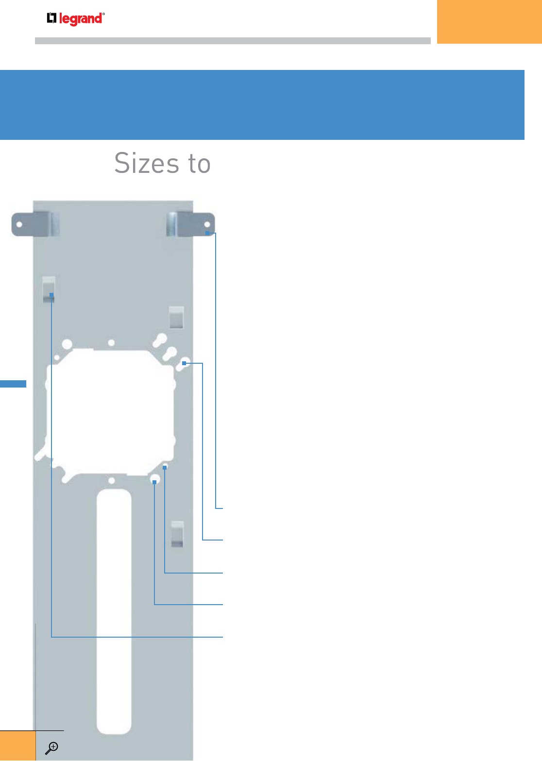
FAS Power Floor Brackets make it easy to prefabricate
electrical assemblies for branch circuit wiring. It features an
innovative built-in wire manager – just remove from base, bend
and slip it into place. It manages multiple-sized MC cable types
so no attachment to the stud needed. The design permits fast
installation anywhere between studs and ensures correct device
mounting height without measuring. Other design features
include predrilled mounting holes in the base and slots to
accept far side supports (sold separately).
Construction: 18 gauge pre-galvanized steel. UL Listed.
Prefabrication: The design accepts 4” and 5” plaster rings and 4”
and 4-11/16” square boxes mounted horizontally or vertically. A wire
manager is built into the design of the base. Just detach, make a few
bends with a pliers and slide in place.
Installation: The Floor Bracket is installed by kicking the lower flange
under the wall plate. Two holes are provided for attachment screws
if needed. Far Side Support Arms attach to the back of the bracket
to support the assembly against the wall behind. No attachment
hardware is needed.
Support Arms attach to the back of the bracket using
the two slots provided.
Keyhole Openings allow 4" or 4-11/16" x 2-1/8" boxes
to remain attached
Attachment Holes for 4" rings allow 4-11/16" x 2-1/8"
boxes to be mounted independently.
Attachment Holes for 4-11/16" x 2-1/8" boxes allow 4"
rings to be mounted independently
Multiple Box Heights are available from 12" to 24"
Sizes to fit any project.
FAS POWER® FLOOR BRACKETS
F112
FAS POWER – FLOOR BRACKETS
WWW.LEGRAND.US/CABLOFIL
D.14
LEGRAND
FASTENERS
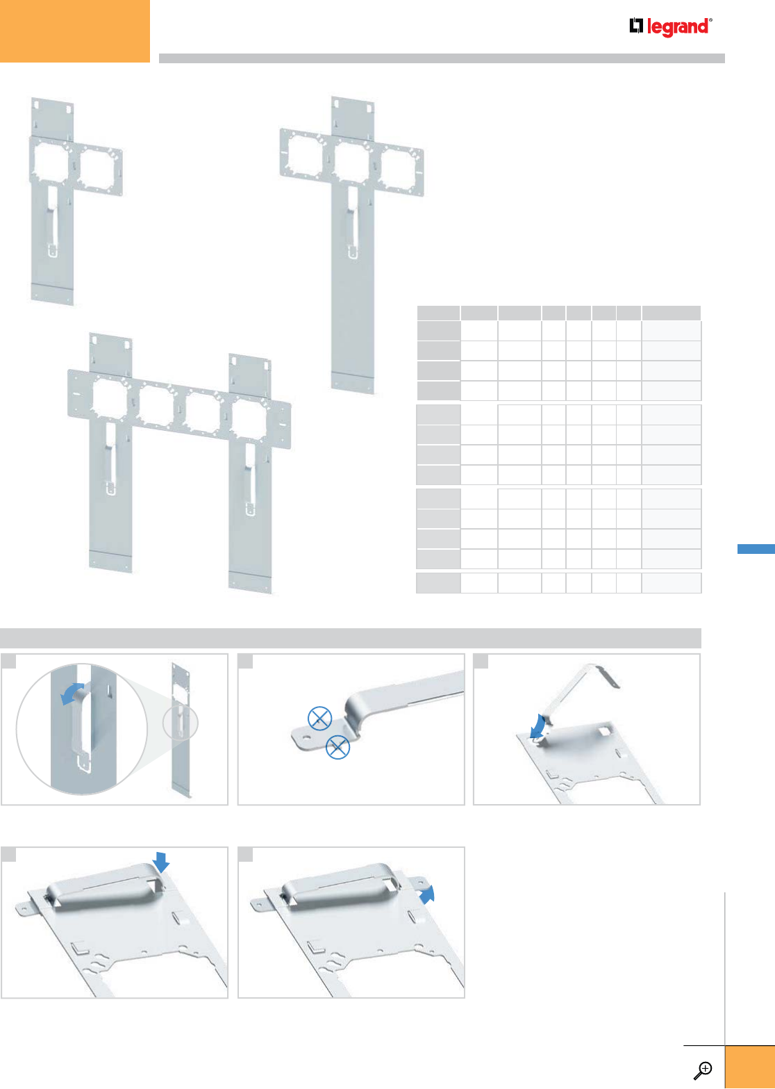
PKG.
QTY. OPENINGS
CENTER
HEIGHT
OVERALL
HEIGHT PG
IN MM IN MM
F112 25 1 12 300 5 125 FP981552
F115 25 1 15 380 5 125 FP981553
F118 25 1 18 450 5 125 FP981555
F124 25 1 24 600 5 125 FP981556
F212 25 2 12 300 5 125 FP981557
F215 25 2 15 380 5 125 FP981558
F218 25 2 18 450 5 125 FP981560
F224 25 2 24 600 5 125 FP981561
F312 25 3 12 300 5 125 FP981562
F315 25 3 15 380 5 125 FP981563
F318 25 3 18 450 5 125 FP981565
F324 25 3 24 600 5 125 FP981566
F418 25 4 18 450 5 125 FP981593
5
WIRE CLAMP INSTRUCTIONS
Remove clamp from floor bracket by
twisting.
Remove attachment tabs – twist off using
pliers.
Insert formed part of clamp into the back
of the bracket into provided slots.
Insert straight end of clamp into adjoining
clamp slot.
Manually bend straight tabs.
1 2 3
4
F215 F324
F418
FAS POWER – FLOOR BRACKETS
WWW.LEGRAND.US/CABLOFIL
D.15
LEGRAND
FASTENERS
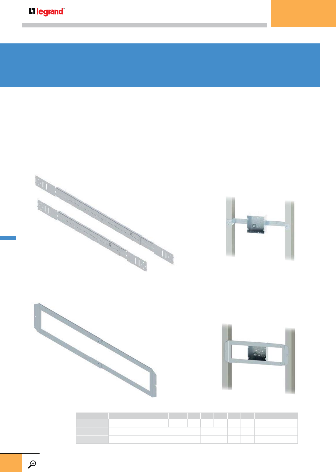
Versatility for any location.
FAS POWER® WALL BRACKETS
FAS Power Telescoping Brackets make box mounting quick and easy. Design for wall
mounting with standard or off-width stud spacing from 11" to 24" without cutting or
field fabrication.
TELESCOPING BOX BRACKETS
Available in two sizes, this sturdy bracket can be used for mounting boxes or for cable support.
Openings allow for easy box mounting and mounting to the stud. End tabs easily fold to fit
multiple box depths. The length is locked into place when the box is mounted using two screws
(not supplied). These brackets offer offsets of 1-1/2" and 2-1/8".
PKG. QTY. MIN. LENGTH MAX. LENGTH PKG. WEIGHT PG
DESCRIPTION INCHES MM INCHES MM LBS KG
CWTBB16 Telescoping Box Bracket 50 11 270 18 450 25 55 F000065
CWTBB24 Telescoping Box Bracket 50 17 430 26 660 33 73 F000066
CWTSB Telescoping Support Bracket 25 16 400 27 685 20 44 F000067
TELESCOPING BOX SUPPORT
For heavier loads or multiple box placements, this support is the answer. Fits 16" to 24" stud
placements and anything in between – no cutting or field fabrication is needed. Any 4-11/16"
box mounts from the back and is secured when the plaster ring is attached from the front side.
Side-to-side adjustment is easy after mounting.
Openin
g
s allow for easy box mountin
g
a
mu
l
t
i
p
l
e
b
ox
d
ept
h
s.
Th
e
l
engt
h
i
s
l
oc
k
e
(
not su
pp
lied
)
. These brackets offer offs
e
TE
LE
SC
OP
IN
G
BO
X
SU
PP
OR
T
CWTBB24
CWTBB16
pl
acements
and
anything
in
betwe
box mounts from the back and is
S
ide-to-side adjustment is easy a
CWTSB
FAS POWER – WALL BRACKETS
WWW.LEGRAND.US/CABLOFIL
D.16
LEGRAND
FASTENERS
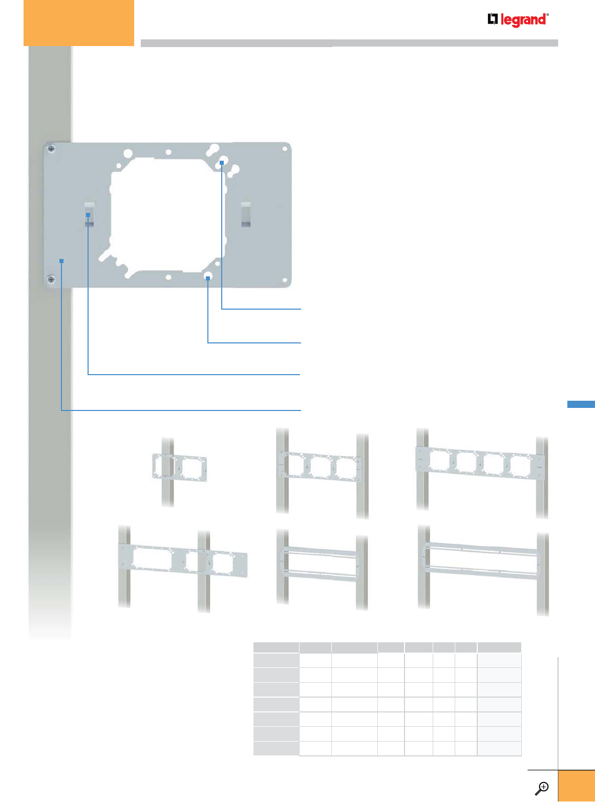
PKG. QTY. OPENINGS HEIGHT WIDTH PG
INCHES MM INCHES MM
W1 50 1 5 125 8.5 215 FP211097
W2 50 2 5 125 11 280 FP211101
W3 25 3 5 125 16.75 425 FP211103
W4 25 4 5 125 26 660 FP211105
W34 25 3 5 125 26 660 FP211104
W16SSL 25 16" Slider 6 150 16.75 425 FP211100
W24SSL 25 24" Slider 6 150 26 660 FP211102
Keyhole Openings allow 4", 4-11/16" and 5" x 2-1/8"
boxes to remain attached
Attachment Holes for 4-11/16" x 2-1/8" boxes allow
4" rings to be mounted independently
Support Arms are attached to the back of the bracket
using the two slots provided.
Wall Bracket attachment holes
Construction: 18 gage pre-galvanized steel. UL Listed.
Prefabrication: The design accepts 4" and 5" plaster
rings and 4", 4-11/16" and 5" square boxes mounted
horizontally or vertically.
Installation: Pre-drilled holes are provided for
attachment screws to the studs. Far Side Support
Arms attach to the back of the bracket to support
the assembly against the wall behind. No attachment
hardware is needed. (Not required for W16SSL and
W24SSL.)
W3W2 W4
W34
W1
* 16" and 24" slider brackets allow
electrical boxes to be adjusted horizontally
W16SSL* W24SSL*
FAS Power Wall Brackets make prefabricating switch and outlet assemblies easy. The
design includes mounting holes and slots to accept far side supports (sold separately).
FAS POWER – WALL BRACKETS
WWW.LEGRAND.US/CABLOFIL
D.17
LEGRAND
FASTENERS
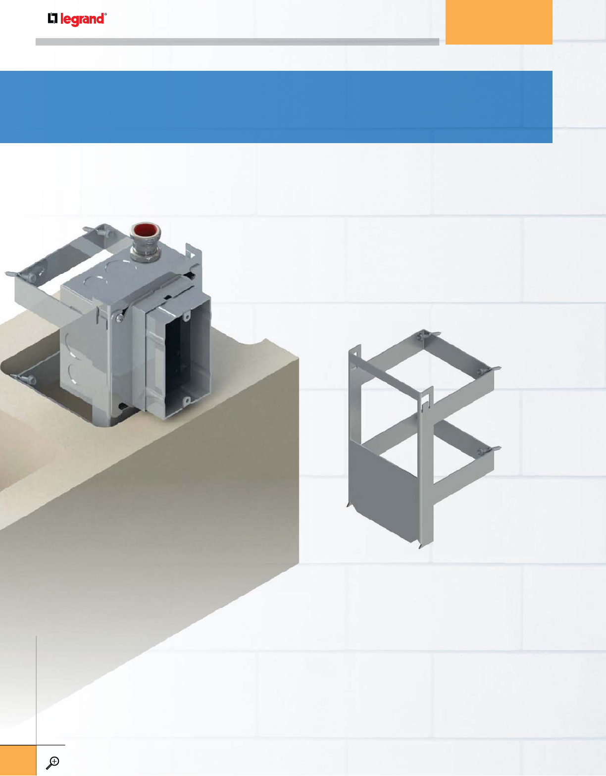
Box placement can be difficult when building concrete block walls,
but the FB816 bracket keeps all wall boxes correctly placed during
construction. The FB816 is a special bracket that can be securely
mounted into the block cavity keeping the box in place while the mortar
dries. Pre-assemble the bracket, box, plaster ring and conduit at rough
in, and the assembly will stay perfectly in place.
B
ox p
l
acement c
but the FB816 b
r
c
onstruction. Th
e
mounted into th
e
d
r
i
es.
P
re-asse
m
i
n, an
d
t
h
e asse
m
Designed for the challenges
of concrete block walls.
Construction: 18 gage pre-galvanized steel.
ETL Listed. Patented design.
Prefabrication: Designed to hold a
4” x 2-1/8” metallic box.
Installation: Pre-drilled holes are provided
for mounting box and plaster ring attachment.
After cutting the proper sized opening in the
concrete block, position the assembly and
tighten mounting screws within the block cavity
to keep assembly in place during joint hardening
process. All mounting hardware is included.
FAS POWER® WALL BRACKETS
FAS POWER – WALL BRACKETS
WWW.LEGRAND.US/CABLOFIL
D.18
LEGRAND
FASTENERS
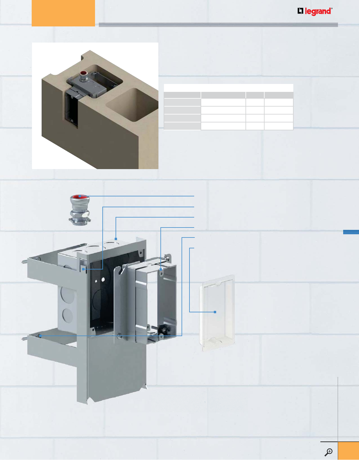
½” EMT Compression Connector (sold separately)
Bend-out stop tabs for 2 gang
4S Metallic Box – 4” x 2-1/8” (sold separately)
Adjustable Plaster Ring (sold separately)
Mounting screws
Plastic Device Cover (sold separately)
PKG. QTY. PG
DESCRIPTION
FB816 Concrete Wall Bracket 25 FP271884
FB816-D-12CONN ½" EMT Connector 1 FP003697
FB816-D-34CONN ¾" EMT Connector 1 FP003698
FB816-D-1CONN 1" EMT Connector 1 FP003699
FAS POWER – WALL BRACKETS
WWW.LEGRAND.US/CABLOFIL
D.19
LEGRAND
FASTENERS
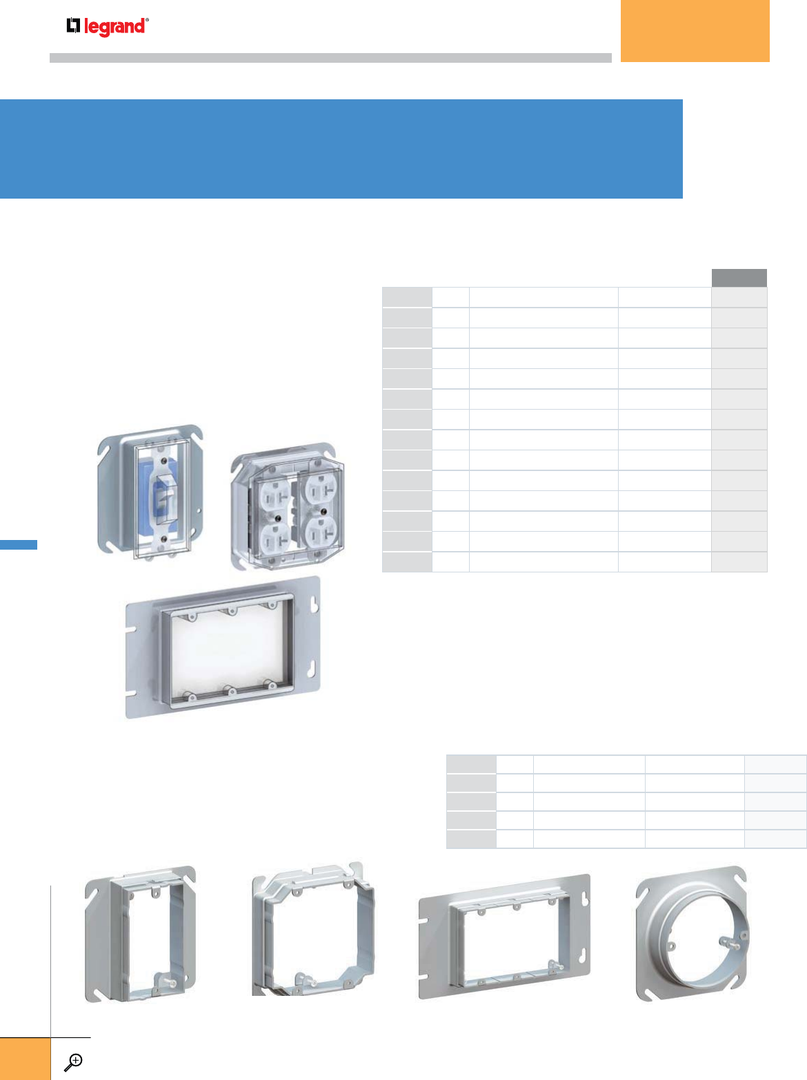
ADJUSTABLE RINGS
Useful in installation where wall thicknesses are
unknown at the time of order or electrical rough in.
Construction: Galvanized steel
APR-2APR-1 APR-RAPR-3
PKG. QTY. BOX SIZE / DEVICE TYPE FASTENERS INCLUDED PG
APR-1-5/8 25 SINGLE GANG 5
/
8" TO 1¼" FP211051
APR-1 25 SINGLE GANG ¾" TO 1½"FP211050
APR-2 25 TWO GANG ¾" TO 1½"FP211052
APR-3 25 THREE GANG ¾" TO 1½"FP211053
APR-R 25 3-0 ROUND ¾" TO 1½"FP211054
DCP-1T
DCP-2
DCP-3R
COVERS AND ADJUSTABLE RINGS
PKG. QTY. BOX SIZE / DEVICE TYPE FASTENERS INCLUDED PL
DCP-1 50 SINGLE GANG RECEPTACLE (2) #8-32 SCREWS FP003414
DCP-2 50 DOUBLE GANG RECEPTACLE (2) #8-32 SCREWS FP003416
DCP-3 50 THREE GANG RECEPTACLE (2) #8-32 SCREWS FP003418
DCP-4 50 FOUR GANG RECEPTACLE (2) #8-32 SCREWS FP003420
DCP-1T 50 SINGLE GANG TOGGLE SWITCH (2) #8-32 SCREWS FP003415
DCP-2T 50 DOUBLE GANG TOGGLE SWITCH (2) #8-32 SCREWS FP003417
DCP-3T 50 THREE GANG TOGGLE SWITCH (2) #8-32 SCREWS FP003419
DCP-4T 50 FOUR GANG TOGGLE SWITCH (2) #8-32 SCREWS FP003421
DCP-DT 50 DBL. GANG TOGGLE SWITCH & DEVICE (2) #8-32 SCREWS FP003422
DCP-1R 50 SINGLE GANG PLASTER RING ONLY NONE FP231068
DCP-2R 50 DOUBLE GANG PLASTER RING ONLY NONE FP231071
DCP-3R 50 THREE GANG PLASTER RING ONLY NONE FP231074
DCP-4R 50 FOUR GANG PLASTER RING ONLY NONE FP231077
DCP-R 50 3" ROUND PLASTER RING ONLY NONE FP231080
PLASTIC DEVICE COVERS
Attach to the front of receptacles, switches or
can be snapped onto empty mud rings to keep
them clean, dust free and finish ready during
the taping and painting process. The covers are
replaced later with faceplates at the trim out
phase of construction.
FAS POWER® ACCESSORIES
FAS POWER – ACCESSORIES
WWW.LEGRAND.US/CABLOFIL
D.20
LEGRAND
FASTENERS
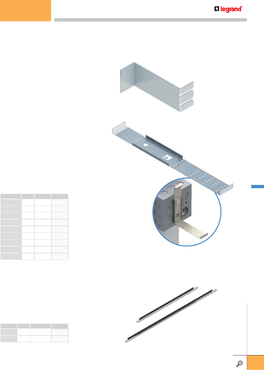
FIXED DEPTH SUPPORT ARMS
The FAS Power line includes 8 far side
support arms for 3" depth to 6½" walls.
Each snap easily onto any of our floor or
wall brackets.
Construction: 18 gage pre-galvanized steel AR350
AR250/600
SUPPORT ARMS FOR FLOOR AND WALL BRACKETS
PKG. QTY. STUD SPACING PG
INCHES
T16 50 16 FP211108
T24 50 24 FP211112
WALL BRACES FOR FLOOR BRACKETS
Wall braces stabilize FAS Power floor brackets where support
arms are not an option. Available for 16" and 24" stud spacing.
Construction
: Zinc-plated steel.
ort
i
ng.
T24
T16
ADJUSTABLE SUPPORT ARM
The Adjustable Far Side Support Arm is
perforated to make it easy to fit any sized
wall depth to stabilize FAS Power Floor
and Wall brackets. Just use a pliers to
adjust. The AR250/600 fits wall depths
from 2½" to 6" and reduces engineering
time for job sites with varied stud sizes
and wall depths. AR250/600 works with
21/8" boxes only.
Construction: 18 gage pre-galvanized steel
PKG. QTY. WALL DEPTH PG
INCHES
AR250 50 2.5 FP211040
AR300 50 3 FP211041
AR350 50 3.5 FP211042
AR400 50 4 FP211043
AR450 50 4.5 FP211044
AR500 50 5 FP211045
AR600 50 6 FP211048
AR650 50 6.5 FP211049
AR250/600 50 2.5-6 FP211055
AR
2
5
0/
6
00
FAS POWER ACCESSORIES
WWW.LEGRAND.US/CABLOFIL
D.21
LEGRAND
FASTENERS
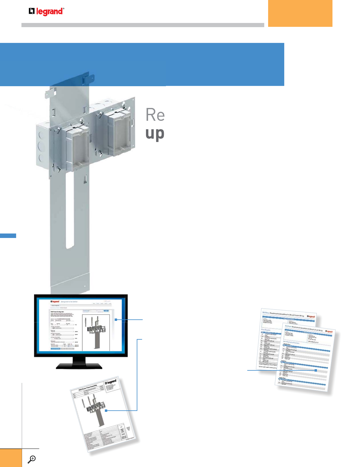
If you are looking to reduce your labor costs even more,
consider pre-assembled FAS Power. Our plant will manufacture
each assembly to your specifications for floor, wall or concrete
block applications. FAS Power offers a wide variety of outlets,
switches and wiring options, including precut lengths of MC
cabling that arrive at the jobsite stripped and ready to install.
At Rough-in – simply install the electrical assembly. You can choose to
have everything wired with a dust cover in place. All you do is make the
connections with push-wire connectors.
At Finish – P&S Plugtail® offers contractors the flexibility allowing
device and color choices to be made at the last minute due to changing
color schemes.
Reduce your labor costs
up to 50%
1. Plan an assembly with a
unique number
2. Create a submittal sheet for
each assembly
3. Build a Bill of Material for
ordering and inventory control
You can create a single assembly or the assemblies
for an entire building. For more information visit:
www.legrand.us/cablofil/fas-power and find out
how FAS Power Manufactured Assemblies can
benefit your bottom line!
If
you a
c
onsid
e
e
ac
h
a
s
block
a
s
witch
e
c
a
bli
n
g
At Rou
g
h
ave ev
e
connect
At
F
in
is
d
ev
i
ce
a
colo
r
sc
1.
Plan
To order FAS Power manufactured assemblies, use our online
configurator to choose from over thousands of floor and wall
options and hundreds of wiring options. It helps you:
FAS POWER® ASSEMBLIES
FAS POWER – ASSEMBLIES
WWW.LEGRAND.US/CABLOFIL
D.22
LEGRAND
FASTENERS
AND US/CABLOFIL
bli
es
P&S PlugTail® Wiring Devices –
For profitable commercial installations.
PlugTail is the perfect compliment to FAS Power Manufactured Assemblies.
It allows you to choose devices at the best time – at the end of the project.
At Rough-in – your productivity gains begin. Instead of making pigtails,
simply connect the pre-striped PlugTail connector leads. In one step, you’re
ready for device installation.
At Finish – Install devices in less than a minute. Just plug the connector
into a PlugTail device. No preparing, stripping or looping conductors. No
damaged devices or costly callbacks. P&S PlugTail installs three times faster
than conventional devices.
P&S PlugTail devices are available in standard or decorator styles and in up
to seven colors for any application.
• Specification Grade Receptacles and GFCI’s
• Hospital Grade Receptacles and GFCI’s
• Surge Protection Devices
• Single Pole and Three Way Toggle Switches
• Ratings for 15A and 20A
• Heavy Duty
• Tamper Resistant
• Isolated Ground
FAS POWER – WIRING DEVICES
WWW.LEGRAND.US/CABLOFIL
D.23
LEGRAND
FASTENERS
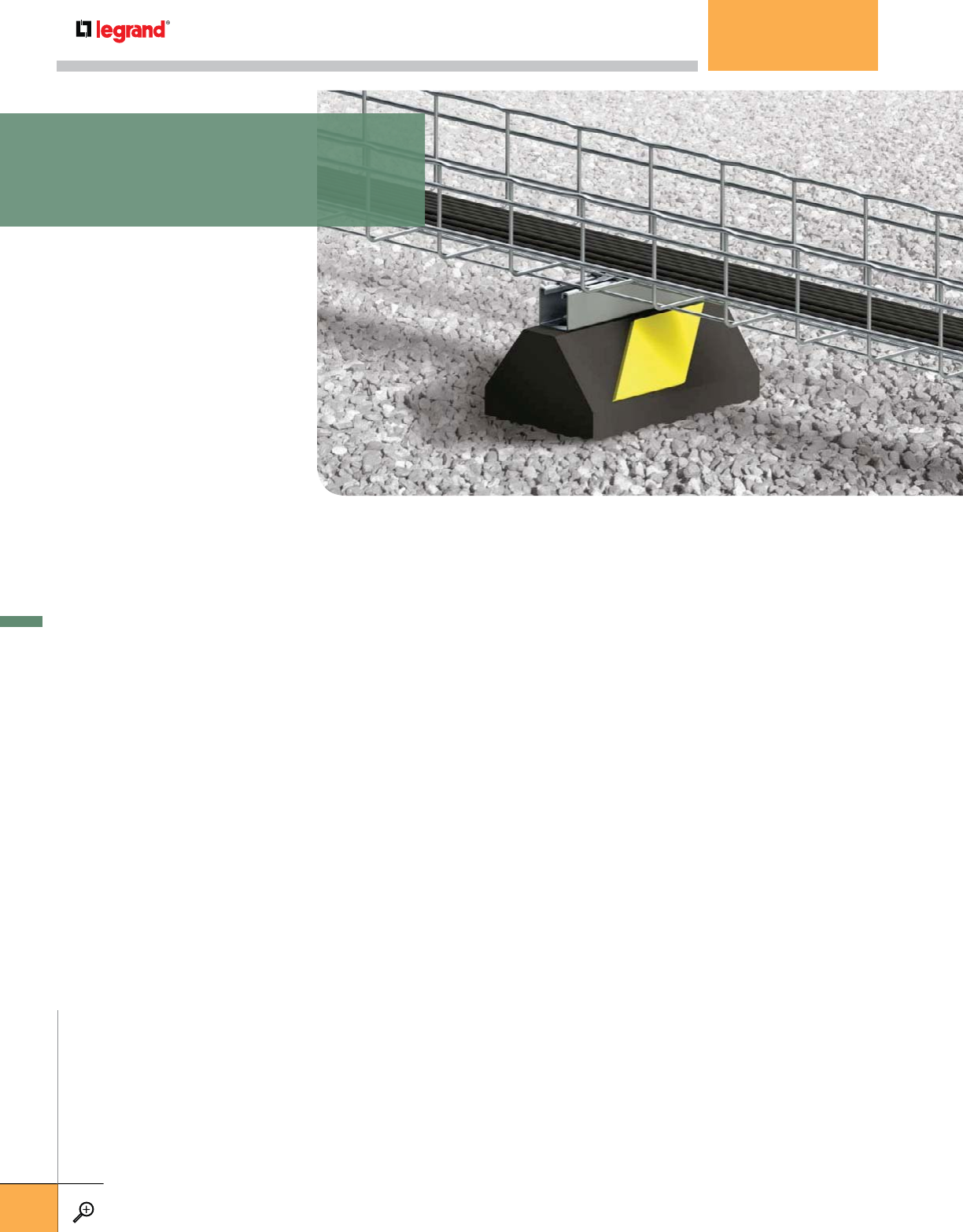
CABLOPORT®
CabloPort is a UV and weather resistant rubber base that creates a
cushion between rooftop mounted equipment and sensitive roofing
materials. Available in two styles: Standard is perfect for smaller loads
and tight spaces, and Widebody, with a broader base minimizing roof
pressure and more area for glue application. CabloPort is available with
pre-installed FAS P and Channel options for a variety of uses.
Non-Penetrating Weather Resistant Bases
• UV resistant rubber bases will not deteriorate over time
• Rubber base design supports up to 1000lb/ft
• Composite material accepts screws or other mechanical fasteners
• Made from 100% recycled rubber for green building certification
Preinstalled Metal Supports
• FAS P allows for easy installation of Cablofil cable management
• Slotted Channel supports PW ladder tray and tubing
• Supports are available in three finishes for exterior applications
• Options for sloped roofs and elevated pathways
Extends life of roof and improves safety
• Rubber base reduces pressure points on sensitive roofing materials
• Dampens vibrations from rooftop mounted equipment
• Reflective Safety Strip makes roof installations safer
Innovative solutions
for rooftop support.
D.25 CP/CPW
CABLOPORT
BASE ONLY
D.26 CPP/CPS/CPWP/CPWS
CABLOPORT BASE
w/ FAS P OR STRUT SUPPORT
D.27 CPPE/CPSE/
CPWE/CPWSE
CABLOPORT EXTENSION SERIES
w/ FAS P OR CHANNEL SUPPORT
D.28 CPSMEP/CPWSME
CABLOPORT MEDIUM LOAD
SERIES w/ CHANNEL SUPPORT
D.29 CPPB/CPSB/
CPWPB/CPWSB
CABLOPORT BRIDGE SERIES
w/ FAS P OR CHANNEL SUPPORT
D.29 CPSA
CABLOPORT VARI-ANGLE SERIES
w/ CHANNEL SUPPORT
D.30 CPWGT/CPWGP
CABLOPORT WIDEBODY BASE
w/ MEMBRANE
D.30 CPWGTP/CPWGPP/
CPWGTS/CPWGPS
CABLOPORT WIDEBODY BASE
w/ MEMBRANE AND FAS P OR
CHANNEL SUPPORT
D.31 CPPZ/CPSZ
CABLOPORT SEISMIC SERIES
CABLOPORT
WWW.LEGRAND.US/CABLOFIL
D.24
LEGRAND
FASTENERS
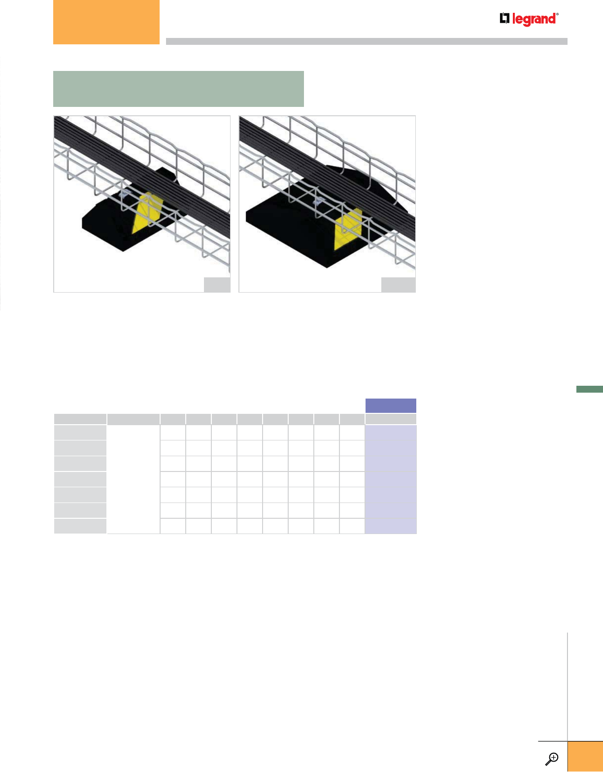
SUPPORT HEIGHT WIDTH BASE LENGTH WEIGHT RBR*
INCHES MM INCHES MM INCHES MM LBS KG
CP5
NONE
4.0 100 6.0 150 5.0 125 2.6 1.2 943 523
CP10 4.0 100 6.0 150 9.6 240 4.6 2.0 943 524
CP20 4.0 100 6.0 150 22.0 550 10.5 4.8 943 525
CP30 4.0 100 6.0 150 28.8 730 16.0 7.3 943 526
CPW12 3.0 75 12.0 300 12.0 300 9.5 4.3 943 714
CPW24 3.0 75 12.0 300 24.0 600 14.2 6.4 943 715
CPW36 3.0 75 12.0 300 36.0 900 18.9 8.6 943 716
*RBR= Rubber
• Cable pathway or other products mounted to base with clamps and screws.
• Install on any roofing material or other flat surface.
• Maximum Load 600 lbs.
• Widebody design has 1,000 lbs/ft maximum load and provides 5 times the surface to
minimize roof material pressure, increase load capacity and provide over 120 square in/ft
for glue application.
• Composite material allows through bolts or lag type screws (through bolts recommended)
Standard Base (Curb Style) Widebody Base
(Low Roof Pressure Style)
CP10 CPW12
CP/CPW
CABLOPORT BASE ONLY
CABLOPORT
WWW.LEGRAND.US/CABLOFIL
D.25
LEGRAND
FASTENERS
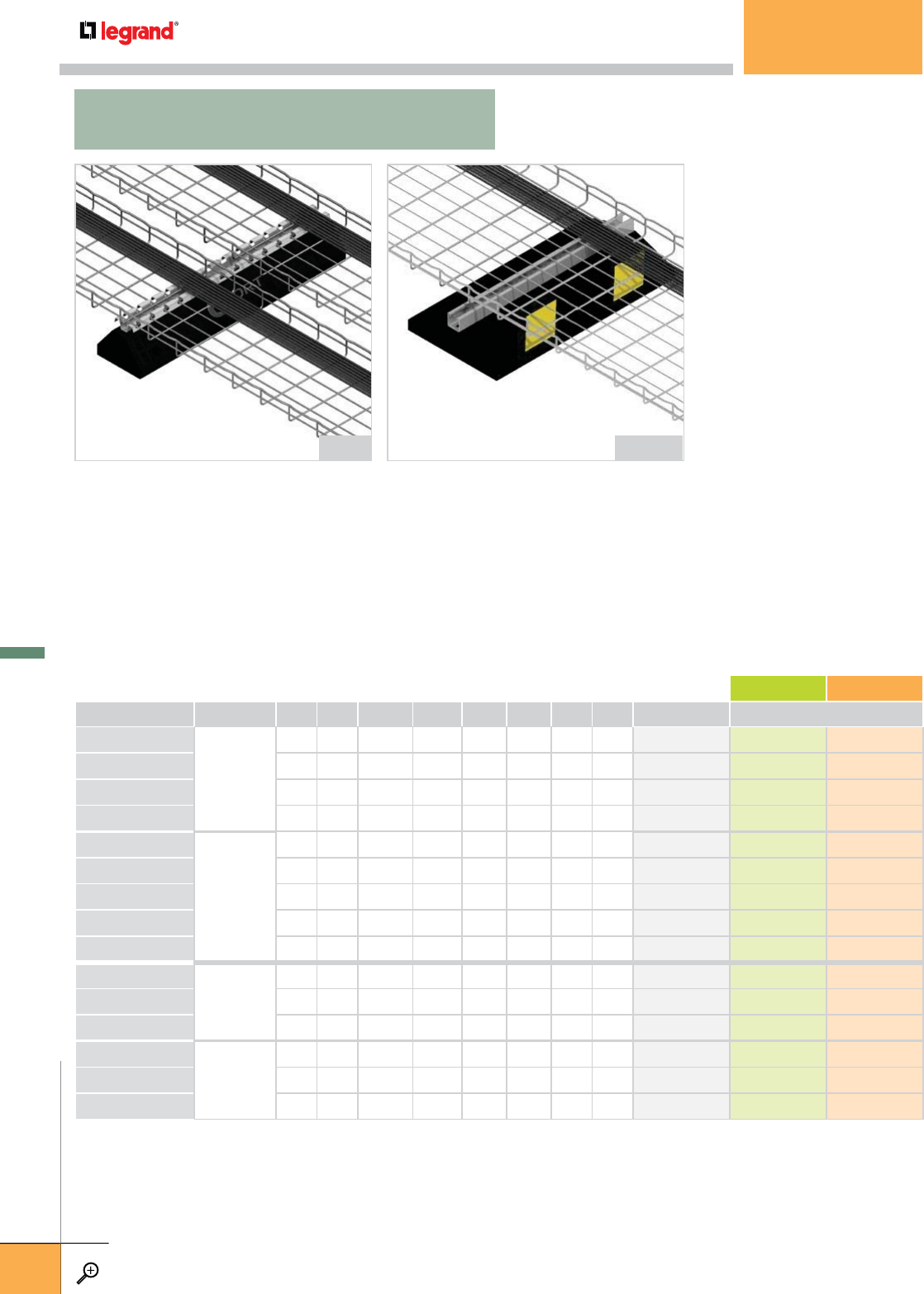
• For support of tray, piping or other items on flat roofs.
• Two support styles: FAS Profile for Cablofil trays or 13/16” galvanized channel (14 ga.) for
ladder tray, piping or other material support.
• Install on any roofing material or other flat surface.
• Supports are available in one standard finish and two optional finishes.
• Two rubber base designs: Standard Curb and Widebody style
• Widebody design has 1,000 lbs/ft maximum load and provides 5 times the surface area to
minimize roof material pressure, increase load capacity and provide over 120 square in/ft
for glue application.
SUPPORT HEIGHT SUPPORT LENGTH BASE LENGTH WEIGHT PG GC 304L
INCHES MM INCHES MM INCHES MM LBS KG
STANDARD FINISH OPTIONAL FINISHES
CPP5
FAS P
5.0
125
6.0 105 5.0 125 3.0 1.4
943 529
943 553
–
CPP10 5.0
125
12.0 300 9.6 240 5.0 2.3
943 530
943 554
–
CPP20 5.0
125
24.0 600 22.0 550 11.0 5.0
943 531
943 555
–
CPP30 5.0
125
30.0 750 28.8 730 18.5 8.4
943 532
943 556
–
CPS5
STRUT
5.0
125
6.0 105 5.0 125 3.0 1.4
943 534 – –
CPS10 4.9 120 10.0 250 9.6 240 5.3 2.4
943 535 943 559 –
CPS15 4.9 120 16.0 400 14.6 370 8.6 3.9
943 536 943 560 –
CPS20 4.9 120 22.0 550 22.0 550 11.2 5.1
943 537 943 561 –
CPS30 4.9 120 28.0 710 28.8 730 16.3 7.4
943 538 943 562 –
CPWP12
FAS P
4.0 100 12.0 300 12.0 300
9.4
4.3
943 720 943 732 –
CPWP24
4.0 100 24.0 600 24.0 600 14.6 6.6
943 721 943 733 –
CPWP36
4.0 100 36.0 900 36.0 900 19.3 8.8
943 722 – –
CPWS12
STRUT
3.75 95 12.0 300 12.0 300
10.0
4.5
943 738 943 750 –
CPWS24
3.75 95 24.0 600 24.0 600 14.7 6.7
943 739 943 751 –
CPWS36
3.75 95 36.0 900 36.0 900 19.5 8.8
943 740 943 752 –
– Contact manufacturer for availability.
Standard Base (Curb Style)
and FAS P Support
Widebody Base (Low
Roof Pressure Style)
with Channel Support
CPP30 CPWS24
CPP/CPS/CPWP/CPWS
CABLOPORT BASE WITH FAS P OR STRUT SUPPORT
CABLOPORT
WWW.LEGRAND.US/CABLOFIL
D.26
LEGRAND
FASTENERS
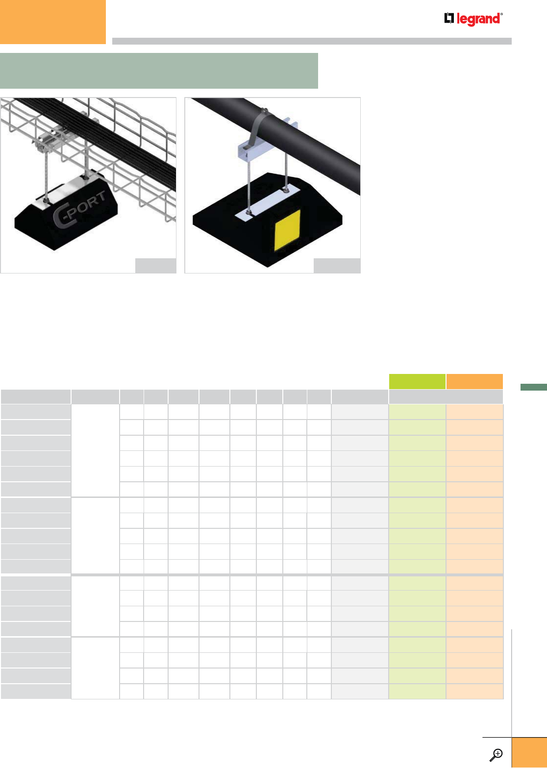
• Height adjustable.
• For support of cable pathways with varying heights .
• Base includes two (2) 1/2” Electrozinc threaded rod risers
and FAS Profile or channel.
• Supports are available in one standard finish and two
optional finishes.
• Install on any roofing material.
• Standard series maximum load 150 lbs.
• Widebody design has maximum load of 500 lbs.
• Provides 5 times the surface area to minimize roof material
pressure, increase load capacity and provide over 120
square in/ft for glue application.
SUPPORT HEIGHT SUPPORT LENGTH BASE LENGTH WEIGHT PG GC 304L
INCHES MM INCHES MM INCHES MM LBS KG
STANDARD FINISH OPTIONAL FINISHES
CPPE10-88
FAS P
8.0 200 8.0 200 9.6 240
6.2 2.8 943 565 943 589 –
CPPE20-818
8.0 200 18.0 450 22.0 550 13.4
6.1 943 567 943 591 –
CPPE20-824
8.0 200 24.0 600 22.0 550 13.6
6.2 943 568 943 592 –
CPPE10-128
12.0
300
8.0
200
9.6
240 6.5
2.9 943 569 943 593 –
CPPE20-1218
12.0
300
18.0
450
22.0
550 13.9
6.3 943 571 943 595 –
CPPE20-1224
12.0
300
24.0
600
22.0
550 14.5
6.6 943 572 943 596 –
CPSE10-810
STRUT
8.0 200 10.0 250 9.6 240 6.2
2.8 943 601 943 625 –
CPSE20-822
8.0 200 22.0 550 22.0 550 13.7
6.2 943 603 943 627 –
CPSE30-828
8.0 200 28.0 710 28.8 730 19.4
8.8 943 604 943 628 –
CPSE10-1210
12.0
300
10.0
250
9.6
240 6.5
2.9 943 605 943 629 –
CPSE30-1228
12.0
300
28.0
710
28.8
730 19.6
8.9 943 608 943 632 –
CPWPE12-128
FAS P
12.0
300
8.0
200
12.0
300
10.4 4.7 943 756 – –
CPWPE12-1212 12.0
300
12.0
300
12.0
300
10.6 4.8 943 757 – –
CPWPE24-1218 12.0
300
18.0
450
24.0
600
17.5 8.0 943 758 – –
CPWPE24-1224 12.0
300
24.0
600
24.0
600
17.8 8.1 943 759 – –
CPWSE12-1210
STRUT
12.0 300 10.0 250 12.0 300
10.5 4.8 943 768 943 776 –
CPWSE12-1216
12.0 300 16.0 400 12.0 300 10.7
4.9 943 769 943 777 –
CPWSE24-1222
12.0 300 22.0 550 24.0 600 17.8
8.1 943 770 943 778 –
CPWSE24-1228
16.0 400 24.0 600 24.0 600 18.2
8.3 943 771 943 779 –
– Contact manufacturer for availability.
Shown with
CFEP (Cablofil Extension Plate)
increases load capacity to 500 lbs. CPPE-88 CPWEPE12
CPPE/CPSE/CPWPE/CPWSE
CABLOPORT EXTENSION SERIES WITH FAS P OR CHANNEL SUPPORT
CABLOPORT
WWW.LEGRAND.US/CABLOFIL
D.27
LEGRAND
FASTENERS
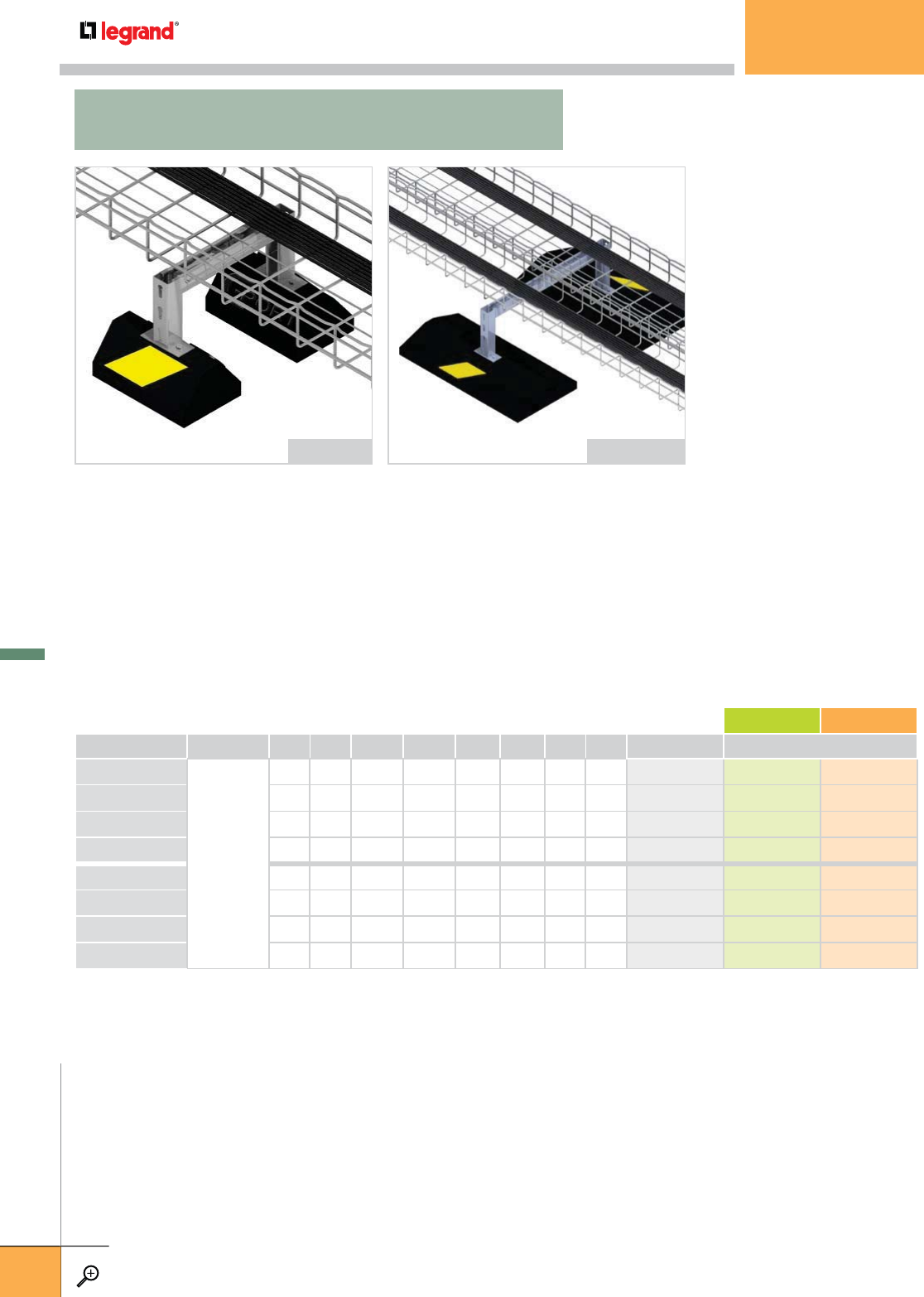
SUPPORT HEIGHT SUPPORT LENGTH BASE LENGTH WEIGHT PG GC 304L
INCHES MM INCHES MM INCHES MM LBS KG
STANDARD FINISH OPTIONAL FINISHES
CPSME1020
STRUT
10.0 250 20.0 500 10.0 250 14.2 6.4
943 669 943 677 –
CPSME1620
16.0 400 20.0 500 10.0 250 15.6 7.1
943 670 943 678 –
CPSME1030 10.0
250
30.0
750
22.0
550 45.0 20.4
943 671 943 679 –
CPSME1630 16.0
400
30.0
750
22.0
550 45.5 20.6
943 672 943 680 –
CPWSME1224
12.0 300 24.0 600 12.0 300 23.2 10.5
943 813 943 821 –
CPWSME2424
24.0 600 24.0 600 12.0 300 25.7 11.5
943 814 943 822 –
CPWSME1236 12.0
300
36.0
900
24.0
600 58.2 26.4
943 815 943 823 –
CPWSME2436 24.0
600
36.0
900
24.0
600 60.4 27.4
943 816 943 824 –
– Contact manufacturer for availability.
• Ideal for mounting medium load elevated cable pathways.
• Base includes two channel risers and channel crossbar.
• Install on any roofing material or other flat surfaces.
• Supports are available in one standard finish and two optional finishes.
• Channel can be used to support Cablofil tray (secure with FS41 (SS) Spring Clips).
• Standard series maximum load 150/500 lbs.
• Widebody design has 1,000 lbs/ft maximum load and provides 5 times the surface area to
minimize roof material pressure, increase load capacity and provide over 120 square in/ft
for glue application.
Standard Base (Curb Style)
with Channel Support
Widebody Base
(Low Roof Pressure Style)
with Channel Support
CPSME1020 CPWSME1224
CPSME/CPWSME
CABLOPORT MEDIUM LOAD SERIES WITH CHANNEL SUPPORT
CABLOPORT
WWW.LEGRAND.US/CABLOFIL
D.28
LEGRAND
FASTENERS
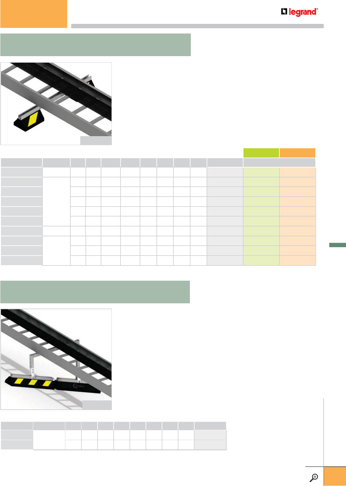
• Designed as sleeper for HVAC units, cable pathways, roof walkways or
other applications.
• Two (2) bases bridged with 1 5/8” galvanized channel (12 ga.) or FAS P.
• Install on any roofing material or other flat surfaces.
• Supports are available in one standard finish and two optional finishes.
• Channel can be used to support Cablofil tray (secure with FS41 Spring Clips).
• Standard series maximum load 500 lbs.
• Widebody design has 1,000 lbs/ft maximum load and provides five times the
surface area to minimize roof material pressure, increase load capacity and
provide over 120 square in/ft for glue application.
SUPPORT HEIGHT SUPPORT LENGTH BASE LENGTH WEIGHT PG GC 304L
INCHES MM INCHES MM INCHES MM LBS KG
STANDARD FINISH OPTIONAL FINISHES
CPPB10-28
FAS P 5.0 125 28.0 710 9.6
240 13.4
6.1
943 637 – –
CPSB10-28
STRUT
5.6
140
28.0 710 9.6
240
13.6 6.2
943 642 – –
CPSB10-36
5.6
140
36.0 900 9.6
240
14.9 6.8
943 643 – –
CPSB10-42
5.6
140
42.0
1050
9.6
240 – – 943 644 – –
CPSB10-50
5.6
140 50.0 1270 9.6 240 – – 943 645 – –
CPSB10-60
5.6
140 60.0 1524 9.6 240 – – 943 646 – –
CPWPB12-28
FAS P 5.0 125
28.0
710
12.0
300
22.2 10.1 944 434 – –
CPWSB12-28
STRUT
5.6
140 28.0
710
12.0
300
22.5 10.2 944 431 944 580 –
CPWSB12-36
5.6
140 36.0
900
12.0
300
23.6 10.7 944 432 – –
CPWSB12-42
5.6
140 42.0 1050 12.0
300
– – 944 433 – –
– Contact manufacturer for availability.
• Designed to adapt to any roof pitch or uneven surface.
• Install on any roofing material.
• Easily adjusted onsite.
• Leg adaptor will accommodate 1 5/8” x 1 5/8” channel framing.
• U-shaped 1 7/8” x 1 7/8” leg adaptor pre-drilled with 9/16”
mounting holes is pre-mounted to base.
• Maximum load 500 lbs.
SUPPORT BASE HEIGHT BASE WIDTH BASE LENGTH WEIGHT PG
INCHES MM INCHES MM INCHES MM LBS KG
CPSA10 STRUT 5.6 140 6.0 150 9.6 240 8.0 3.6 943 667
CPSA20 5.6 140 6.0 150 22.0 550 15.1 6.8 943 668
Vertical 1 5/8” x 1 5/8” strut and horizontal crossbar not provided.
Standard Base (Curb Style)
with Channel Support
Standard Base (Curb Style)
with Channel Support
CPSB10-28
CPSA20PG
CPPB/CPSB/CPWPB/CPWSB
CABLOPORT BRIDGE SERIES WITH FAS P OR CHANNEL SUPPORT
CPSA
CABLOPORT VARI-ANGLE SERIES WITH CHANNEL SUPPORT
CABLOPORT
WWW.LEGRAND.US/CABLOFIL
D.29
LEGRAND
FASTENERS
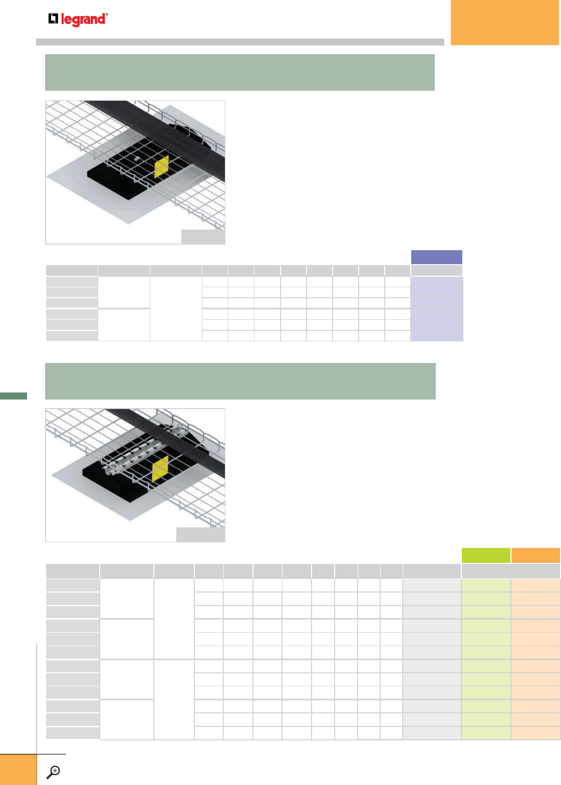
MEMBRANE MTRL SUPPORT HEIGHT WIDTH BASE LENGTH WEIGHT RBR*
INCHES MM INCHES MM INCHES MM LBS KG
CPWGT12
TPO
NONE
3.0 75 12.0 300 12.0 300 9.8 4.5 943 977
CPWGT24 3.0 75 12.0 300 24.0 600 14.5 6.6 943 978
CPWGT36 3.0 75 12.0 300 36.0 900 19.4 8.8 943 979
CPWGP12
PVC
3.0 75 12.0 300 12.0 300 9.8 4.5 943 989
CPWGP24 3.0 75 12.0 300 24.0 600 14.5 6.6 943 990
CPWGP36 3.0 75 12.0 300 36.0 900 19.4 8.8 943 991
• For rooftop support of cable pathways or other products mounted to base
with clamps or screws.
• Cable pathway is mounted to base with clamps and screws.
• Adhere membrane to TPO or PVC roofing material to reduce wind lift.
• Widebody design has no maximum load and provides 5 times the surface
area on the roof to minimize roof material pressure, increase load capacity
and provide over 120 square in/ft for glue application.
MEMBRANE MTRL SUPPORT
OVERALL HEIGHT
SUPPORT LENGTH BASE LENGTH WEIGHT*
PG GC 304L
INCHES MM INCHES MM INCHES MM LBS KG
STANDARD FINISH OPTIONAL FINISHES
CPWGTP12
TPO
FAS P
4.0 100 12.0 300 12.0 300 10.2 4.6 944 001 944 013 –
CPWGTP24 4.0 100 23.6 595 24.0 600 14.4 6.5 944 002 944 014 –
CPWGTP36 4.0 100 38.5 975 36.0 900 19.6 8.9 944 003 944 015 –
CPWGPP12
PVC
4.0 100 12.0 300 12.0 300 10.2 4.6 944 037 944 049 –
CPWGPP24 4.0 100 23.6 595 24.0 600 14.9 6.8 944 038 944 050 –
CPWGPP36 4.0 100 38.5 975 36.0 900 19.6 8.9 944 039 944 051 –
CPWGTS12
TPO
STRUT
3.75 95 12.0 300 12.0 300 10.3 4.7 944 073 944 085 –
CPWGTS24 3.75 95 24.0 600 24.0 600 15.0 6.8 944 074 944 086 –
CPWGTS36 3.75 95 36.0 900 36.0 900 19.6 8.9 944 075 944 087 –
CPWGPS12
PVC
3.75 95 12.0 300 12.0 300 10.3 4.7 944 109 944 121 –
CPWGPS24 3.75 95 24.0 600 24.0 600 15.0 6.8 944 110 944 122 –
CPWGPS36 3.75 95 36.0 900 36.0 900 19.6 8.9 944 111 944 123 –
– Contact manufacturer for availability.
• For rooftop support of cable pathways.
• Base includes FAS Profile or 13/16” galvanized channel (14 ga.).
• Adhere membrane to TPO or PVC roofing material to reduce wind lift.
• Supports are available in one standard finish and two optional finishes.
• Widebody design has no maximum load and provides 5 times the surface
area on the roof to minimize roof material pressure, increase load capacity
and provide over 120 square in/ft for glue application.
Widebody Base
(Low roof pressure Style)
with Membrane
Widebody Base
(Low roof pressure Style)
with Membrane and FAS P Support CPWGTP24
CPW6T24
CPWGT/CPWGP
CABLOPORT WIDEBODY BASE WITH MEMBRANE
CPWGTP/CPWGPP/CPWGTS/CPWGPS
CABLOPORT WIDEBODY BASE WITH MEMBRANE AND FAS P OR CHANNEL SUPPORT
*RBR= Rubber
CABLOPORT
WWW.LEGRAND.US/CABLOFIL
D.30
LEGRAND
FASTENERS
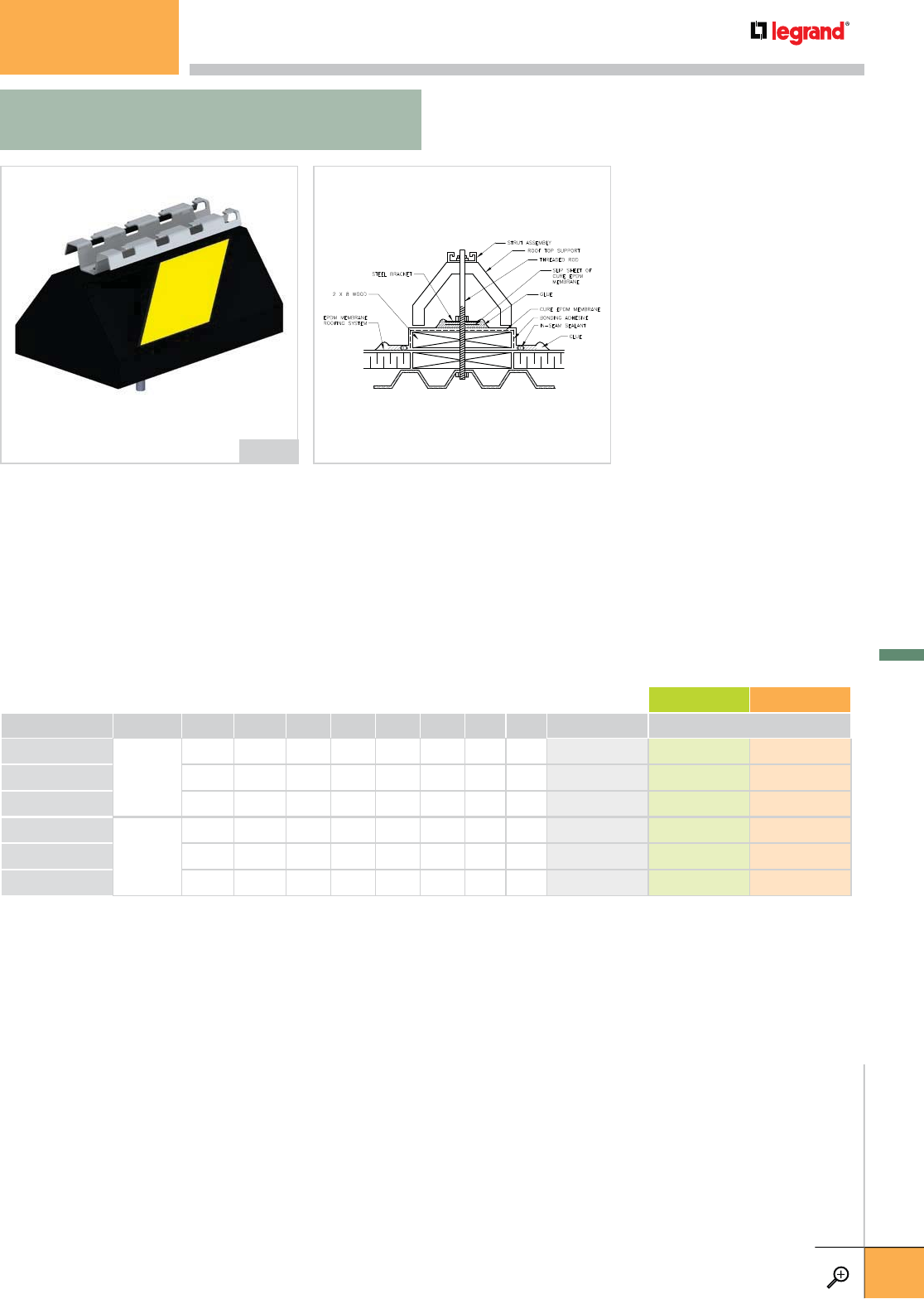
• Base includes FAS Profile or 13/16” galvanized channel (14 ga.).
• Designed for support of cable pathways and other rooftop equipment subject to
seismic codes.
• This base includes a bolt that penetrates the roofing membrane and fastens to the
underlining structure.
• Install on any roofing material or other flat surface.
• This product is approved by Carlisle SynTec Inc.
• Maximum load 750 lbs.
• Supports are available in one standard finish and two optional finishes.
SUPPORT OVERALL HEIGHT BRKT WIDTH BASE LENGTH WEIGHT PG GC 304L
INCHES MM INCHES MM INCHES MM LBS KG
STANDARD FINISH OPTIONAL FINISHES
CPPZ10
FAS P
5.0
125
12.0
300
9.6
240 5.8 2.6 943 681 943 701 –
CPPZ20
5.0
125
24.0
600
22.0
550
11.7
5.3 943 682 943 702 –
CPPZ30
5.0
125
30.0
750
28.8
730
16.8
7.6 943 683 943 703 –
CPSZ10
STRUT
4.9
120
12.0
300
9.6
240
5.9
2.7 943 686 943 706 –
CPSZ20
4.9
120
24.0
600
22.0
550
11.8
5.4 943 687 943 707 –
CPSZ30
4.9
120
30.0
750
28.8
730
16.9
7.7 943 688 943 708 –
– Contact manufacturer for availability.
Standard Seismic Base (Curb Style)
with FAS P Support CPPZ10
CPPZ/CPSZ
CABLOPORT SEISMIC SERIES
CABLOPORT
WWW.LEGRAND.US/CABLOFIL
D.31
LEGRAND
FASTENERS
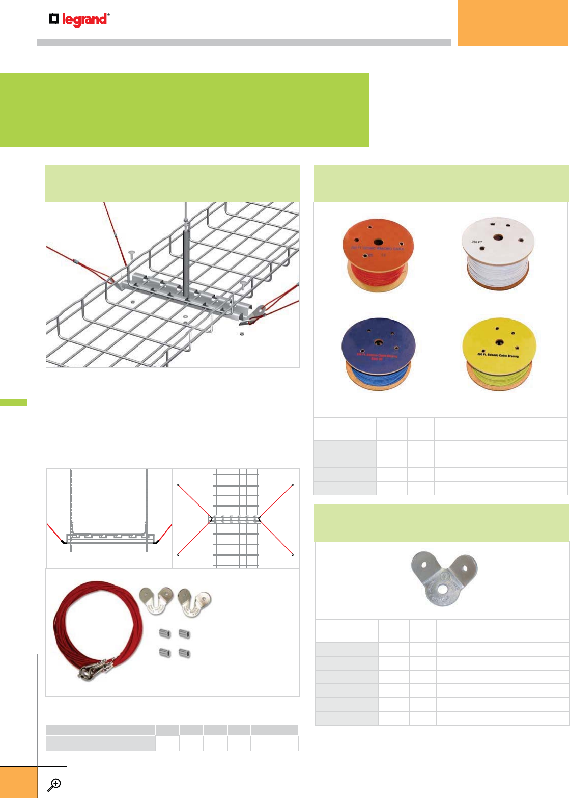
COMPLETE
CATALOG NO.
CABLE
SIZE
HOLE
DIA. DESCRIPTION
PW-URC-1/4P ALL ¼" URC FOR ¼" FASTENERS
PW-URC-3/8P ALL 3
/
8" URC FOR 3
/
8" FASTENERS
PW-URC-1/2P ALL ½" URC FOR ½" FASTENERS
PW-URC-5/8P ALL 5
/
8" URC FOR 5
/
8" FASTENERS
PW-URC-3/4P ALL ¾" URC FOR ¾" FASTENERS
PW-URC-7/8P ALL 7
/
8" URC FOR 7
7
/
8" FASTENERS
COMPLETE
CATALOG NO.
CABLE
SIZE
BOX
QTY. DESCRIPTION
PW-12-CBL 12 250 (1) 250' SPOOL OF RED #12 CABLE
PW-18-CBL 18 250 (1) 250' SPOOL OF WHITE #18 CABLE
PW-36-CBL 36 250 (1) 250' SPOOL OF BLUE #36 CABLE
PW-48-CBL 48 250 (1) 250' SPOOL OF YELLOW #48 CABLE
PW-12-CBL
PW-36-CBL
PW-18-CBL
PW-48-CBL
• Connect cables directly to 3/8” threaded rod in trapeze
installations for seismic bracing.
• Use two EZ BN 3/8 (sold separately) to attach cables to
FAS PCH for sway bracing.
• Pre-drilled tabs allow attachment directly to concrete deck.
• Spacing must be at least every 30’. For installation
recommendations contact Cablofil Technical Services.
LENGTH WEIGHT
FT M LBS KG
SZMCKIT 10.0 3 0.2 0.1 942 445
Each kit contains:
• (4) 11’ cables with
mounting eyelets
• (2) Metal brackets
for attachment to
support members
• (4) Cable clamp
collars
• (4) 3/8” x 3” wedge
anchors
BULK WIRE ROPE/CABLESEISMIC BRACING KIT FOR LONG TRAY RUNS
UNIVERSAL RESTRAINT CLIPS
SEISMIC BRACING
SEISMIC BRACING
WWW.LEGRAND.US/CABLOFIL
D.32
LEGRAND
FASTENERS
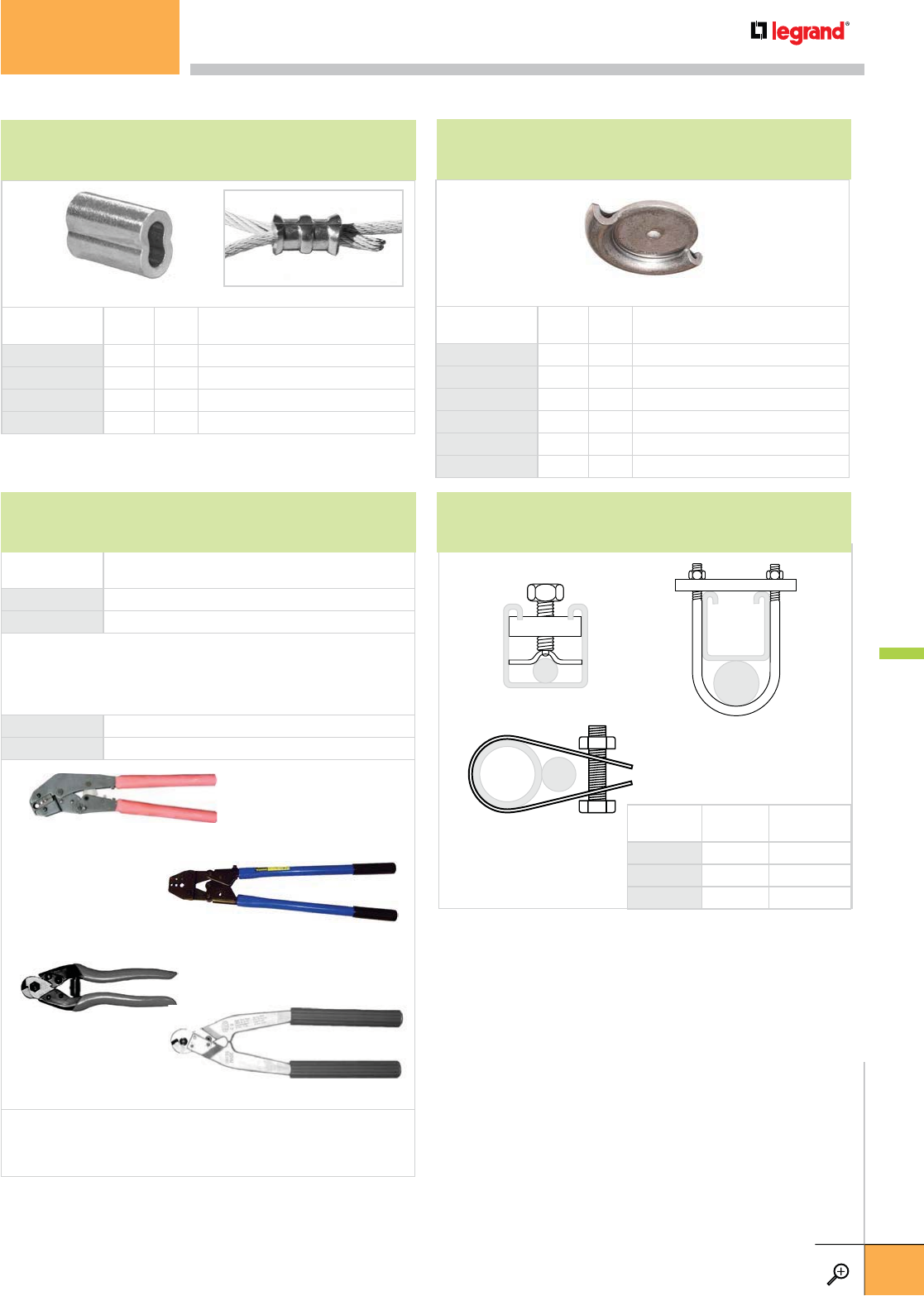
COMPLETE
CATALOG NO. DESCRIPTION
PW-0-12-SBHS (1) LOCOLOC HAND SWAGER FOR CRIMPING OVAL SLEEVES
PW-3-346-SBHS (1) LOCOLOC LARGE SWAGER FOR CRIMPING OVAL SLEEVES
The Locoloc® Hand Swager IS THE CORRECT TOOL FOR THE JOB. It is capable of crimping all
three sizes of oval sleeves for the braces in this manual. These tools are factory calibrated and
are furnished with gauges and instructions to insure the proper crimping of oval sleeves. The
Locoloc® Hand Swager is 26 inches long and weighs 6.5 pounds.
PW-C7 (1) FELCO CABLE CUTTER FOR #12 AND #18 CABLES
PW-C9 (1) FELCO CABLE CUTTER FOR #12 , #18 AND #36 CABLES
The Felco type C-7 and type C-9 Precision Cable Cutters are ideal for cutting
and trimming excess cable. The C-7 cutter is 8 inches long, weighs 10 ounces
and is used to cut size 12 and 18 cables with one hand. The type C-9 cutter is a
two-handed tool that cuts all three cable sizes with ease.
COMPLETE
CATALOG NO.
CABLE
SIZE
BOX
QTY. DESCRIPTION
PW-12-SLV 12 100 (1) BOX OF 100 #12 OVAL SLEEVES
PW-18-SLV 18 100 (1) BOX OF 100 #18 OVAL SLEEVES
PW-36-SLV 36 100 (1) BOX OF 100 #36 OVAL SLEEVES
PW-48-SLV 48 50 (1) BOX OF 50 #48 OVAL SLEEVES
PW-C7
PW-C9
PW-0-12-SBHS
PW-3-346-SBHS
PRODUCT
NUMBER TYPE ROD SIZE
0602 STRUT 3
/
8"-5
/
8"
0603 STRUT ¾"-1"
RS-1 PIPE ½"-1"
0603
0602
RS-1
COMPLETE
CATALOG NO.
CABLE
SIZE
HOLE
DIA. DESCRIPTION
PW-NPC-1/4P ALL ¼" NPC FOR ¼" FASTENERS
PW-NPC-3/8P ALL 3
/
8" NPC FOR 3
/
8" FASTENERS
PW-NPC-1/2P ALL ½" NPC FOR ½" FASTENERS
PW-NPC-5/8P ALL 5
/
8" NPC FOR 5
/
8" FASTENERS
PW-NPC-3/4P ALL ¾" NPC FOR ¾" FASTENERS
PW-NPC-7/8P ALL 7
/
8" NPC FOR 7
/
8" FASTENERS
See page D.38 for product
details and requirements.
OVAL SLEEVES
SUPPORT ROD STIFFENER CLIPS
NO PRY CLIP
ASSEMBLY TOOLS
SEISMIC BRACING
WWW.LEGRAND.US/CABLOFIL
D.33
LEGRAND
FASTENERS
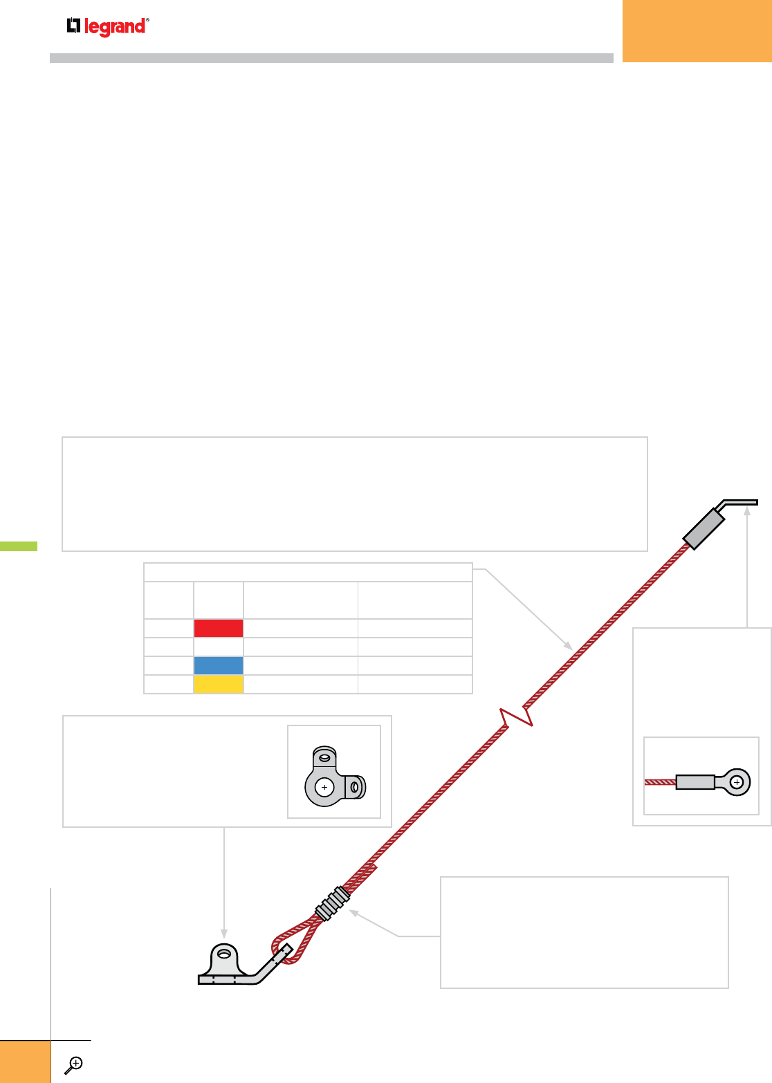
EARTHQUAKE SWAY BRACE SYSTEMS FOR CABLE TRAYS
Legrand has joined with Loos and Company, the industry’s top manufacturer of Seismic Wire Rope/Cable™ Bracing, to provide a comprehensive and
unique line of seismic protection products specifically designed for electrical cable tray applications. All our seismic Wire Rope/Cable™ bracing,
complies with model building codes, and installs in just one-third the time needed for more conventional pipe, angle, and strut bracing systems.
Our exclusive systems have no length limitation and are UL listed.
For more information go to www.legrand.us/cablofil and download our complete Seismic Bracing Catalog.
QUALITY CONSTRUCTION
Our standard braces are constructed of a splayed assembly of either
49 or 133 high strength, zinc coated, steel wires, configured into
Wire Rope/Cable™.
PRE-STRETCHED ASSEMBLY DAMPENS SEISMIC LOADS
Our Wire Rope/Cable™ is pre-stretched to its maximum recommended
working load. Pre-stretching allows our cable to act in its elastic range;
in essence, it behaves like a shock absorber.
SPECIAL DESIGN & INSTALLATION FEATURES
Every brace is designed to resist earthquake loads in tension and they
are not restricted in length as are compression braces. Standard braces
are extremely flexible, lightweight and are offered in precut lengths,
with or without fixed end fastener fittings.
FOUR STANDARD COLOR-CODED SIZES
Our standard braces are offered in three basic sizes, with minimum
breaking strengths of 900, 1650, 4000 and 6600 Lbs. Each is color-coded
in red, white, blue or yellow that insures proper designation on plans
and for installation in the field.
QUALITY ASSURANCE & CERTIFIED BREAK STRENGTH
The manufacturer conducts a rigorous in-plant program of inspection,
testing, and retesting of all its seismic Wire Rope/Cable™ products to
meet code and industry standards. Loos & Co.’s Certificate of Minimum
Breaking Strength is included with each shipment.
THE SEISMIC BRACING SYSTEM
Our seismic brace consists of four basic components: the Wire Rope/Cable™, a factory-attached stake eye end
treatment, an oval sleeve used to secure the cable loop, and a universal restraint clip (URC). The seismic braces are
pre-packaged with all of the parts needed to make a single 4-way sway brace. Hardware required to connect the
cable tray to the braced component and to the building structure are not included in the brace packages.
UNIVERSAL RESTRAINT CLIP (UCR)
The “URC” Clip connects the Wire
Rope/Cable™ brace to the cable tray
support member. It will accommodate all
three brace sizes and has hole diameters
to fit hardware sizes from ¼" to 1¼".
STAKE EYE
The stake eye attaches
the seismic brace to the
building structure and
is available to fit 3
/
8" or ½"
diameter hardware.
OVAL SLEEVE
The oval sleeve secures the cable loop through
the URC clip. There are three sizes of oval sleeves,
corresponding to the three brace sizes. The LOCOLOC®
hand swager tool is used to crimp the oval sleeves and
is required to maintain brace strengths.
TOP VIEW
TOP VIEW
THE WIRE ROPE/CABLE™
BRACE
SIZE
CABLE
COLOR
CERTIFIED MINIMUM
BREAK STRENGTH (LBS.)
ALLOWABLE LOAD
(SAFETY FACTOR = 1.5)
12 RED 900 600
18 WHITE 1650 1100
36 BLUE 4000 2667
48 YELLOW 6600 4400
SEISMIC BRACING
WWW.LEGRAND.US/CABLOFIL
D.34
LEGRAND
FASTENERS

CABLE TRAY
TOTAL LINEAR WEIGHT
(LBS./FT.)†
HORIZONTAL EARTHQUAKE LOAD (LBS.) AND BRACE SIZE* BASED ON A HORIZONTAL LOAD FACTOR (HLF) OF
ACCORDING TO BRACE SPACING AND CABLE TRAY TOTAL LINEAR WEIGHT 0.50
BRACE SPACING (FT.)
10 12 16 20 24 30 32 36 40
LOAD A B C LOAD A B C LOAD A B C LOAD A B C LOAD A B C LOAD A B C LOAD A B C LOAD A B C LOAD A B C
10 50 12 3
/
8"3
/
8"6012
3
/
8"3
/
8"8012
3
/
8"3
/
8" 100 12 3
/
8"3
/
8" 120 12 3
/
8"3
/
8" 150 12 3
/
8"3
/
8" 160 12 3
/
8"3
/
8" 180 12 3
/
8"3
/
8" 200 12 3
/
8"3
/
8"
20 100 12 3
/
8"3
/
8" 120 12 3
/
8"3
/
8" 160 12 3
/
8"3
/
8" 200 12 3
/
8"3
/
8" 240 12 3
/
8"3
/
8" 300 12 3
/
8"3
/
8" 320 12 3
/
8"3
/
8" 360 12 3
/
8"3
/
8" 400 12 3
/
8"3
/
8"
30 150 12 3
/
8"3
/
8" 180 12 3
/
8"3
/
8" 240 12 3
/
8"3
/
8" 300 12 3
/
8"3
/
8" 360 12 3
/
8"3
/
8" 450 18 3
/
8"3
/
8" 480 18 3
/
8"3
/
8" 540 18 3
/
8"3
/
8" 600 18 3
/
8"3
/
8"
40 200 12 3
/
8"3
/
8" 240 12 3
/
8"3
/
8" 320 12 3
/
8"3
/
8" 400 12 3
/
8"3
/
8" 480 18 3
/
8"3
/
8" 600 18 3
/
8"3
/
8" 640 18 3
/
8"3
/
8" 720 18 3
/
8" ½" 800 18 3
/
8"½"
50 250 12 3
/
8"3
/
8" 300 12 3
/
8"3
/
8" 400 12 3
/
8"3
/
8" 500 18 3
/
8"3
/
8" 600 18 3
/
8"3
/
8" 750 18 3
/
8" ½" 800 36 3
/
8" ½" 900 36 3
/
8" ½" 1000 36 3
/
8"½"
60 300 12 3
/
8"3
/
8" 360 12 3
/
8"3
/
8" 480 18 3
/
8"3
/
8" 600 18 3
/
8"3
/
8" 720 18 3
/
8"½900 36 3
/
8" ½" 960 36 3
/
8" ½" 1080 36 3
/
8" ½" 1200 36 3
/
8"½"
70 350 12 3
/
8"3
/
8" 420 12 3
/
8"3
/
8" 560 18 3
/
8"3
/
8" 700 18 3
/
8"3
/
8" 840 36 3
/
8" ½" 1050 36 3
/
8" ½" 1120 36 3
/
8" ½" 1260 36 ½" ½" 1400 36 ½" ½"
80 400 12 3
/
8"3
/
8" 480 18 3
/
8"3
/
8" 640 18 3
/
8"3
/
8" 800 36 3
/
8" ½" 960 36 3
/
8" ½" 1200 36 3
/
8" ½" 1280 36 ½" ½" 1440 36 ½" ½" 1600 36 ½" ½"
90 450 18 3
/
8"3
/
8" 540 18 3
/
8"3
/
8" 720 18 3
/
8" ½" 900 36 3
/
8" ½" 1080 36 3
/
8" ½" 1350 36 ½" ½" 1440 36 ½" ½" 1620 36 ½" ½" 1800 36 ½" 5
/
8"
100 500 18 3
/
8"3
/
8" 600 18 3
/
8"3
/
8" 800 36 3
/
8" ½" 1000 36 3
/
8" ½" 1200 36 3
/
8" ½" 1500 36 ½" ½" 1600 36 ½" ½" 1800 36 ½" 5
/
8" 2000 X ½" 5
/
8"
110 550 18 3
/
8"3
/
8" 660 18 3
/
8"3
/
8" 880 36 3
/
8" ½" 1100 36 3
/
8" ½" 1320 36 ½" ½" 1650 36 ½" ½" 1760 36 ½" ½" 1980 X X 5
/
8" 2200 X X 5
/
8"
120 600 18 3
/
8"3
/
8" 720 18 3
/
8" ½" 960 36 3
/
8" ½" 1200 36 3
/
8" ½" 1440 36 ½" ½" 1800 36 ½" 5
/
8" 1920 X ½" 5
/
8" 2160 X X 5
/
8" 2400 X X 5
/
8"
130 650 18 3
/
8"3
/
8" 780 36 3
/
8" ½" 1040 36 3
/
8" ½" 1300 36 ½" ½" 1560 36 ½" ½" 1950 X ½" 5
/
8" 2080 X X 5
/
8" 2340 X X 5
/
8" 2600 X X 5
/
8"
140 700 18 3
/
8" ½" 840 36 3
/
8" ½" 1120 36 3
/
8" ½" 1400 36 ½" ½" 1680 36 ½" ½" 2100 X X 5
/
8" 2240 X X 5
/
8" 2520 X X 5
/
8" 2800 X X 5
/
8"
150 750 18 3
/
8" ½" 900 36 3
/
8" ½" 1200 36 3
/
8" ½" 1500 36 ½" ½" 1800 36 ½" 5
/
8" 2250 X X 5
/
8" 2400 X X 5
/
8" 2700 X X 5
/
8" 3000 X X X
† Cable tray total linear weight is the combined weight of the cable tray and the installed cables.
* Sway brace and fastener sizes ( A, B, C ) are based on a minimum brace angle from vertical of 45 degrees.
A = V.S.T. UL Listed seismic Wire Rope/Cable™ brace size.
B = Minimum bolt or hanger rod diameter for brace-to-tray connection and brace-to-structure connection.
C = Minimum expansion shield diameter for brace anchorage to concrete structural element.
X = Loads are too high for the brace assembly and/or fastener at this sway brace spacing.
DESIGNING A SEISMIC BRACING SYSTEM
The following guidelines have been developed to aid in the process of designing seismic bracing systems for cable tray installations. This
information is intended to serve as a recommendation only and users are cautioned to modify each installation as required to meet all federal,
state, and local laws and regulations, which may supercede these recommendations. The design professional responsible for each project on
which these braces are used must approve the bracing layout, the capability of the structural elements to which the braces are attached, and the
use of the braces themselves along with their fasteners.
1. CALCULATE THE HORIZONTAL LOAD FACTOR (HLF) FOR
THE INSTALLATION.
Each earthquake sway brace must be designed to resist the horizontal
earthquake load/force within the brace zone of influence. The Horizontal
Load Factor is the minimum portion or percentage of the cable tray
system’s total weight within the brace zone of influence, which must be
resisted by the brace as applied in any horizontal direction.
The specific formula used to calculate the HLF, will be based upon
the governing building code or standard for the installation. All codes
and standards have somewhat different formulas for determining the
horizontal load factor. Current codes and standards use a variety of
factors, including the seismic zone for the region coefficients assigned
to the building or component/system importance and/or performance
level and anticipated responses to earthquake loads.
An Av activity level map and other information is available at:
www.legrand.us/cablofil.
2. CALCULATE THE CABLE TRAY TOTAL LINEAR WEIGHT.
The loads that must be resisted by the seismic brace include the weight
of the cable tray system and its contents. To do this, the total tray weight
must be calculated and expressed in total pounds per linear foot. For
multi-tier tray installations where only the bottom level of the tray is
braced, the total weight of all tiers should be included in the calculation.
3. USE THE BRACING TABLES TO DETERMINE THE BRACE
SIZES AND SPACING.
We have developed a series of bracing tables to simplify the selection
of the correct brace size, brace spacing, and minimum fastener sizes.
These tables tabulate this information according to the cable tray total
linear weight versus the brace spacing for a given horizontal load factor
and a minimum brace angle of 45 degrees from vertical. There are
four bracing tables, each based on horizontal load factors of 0.25, 0.50
(shown at the bottom of this page), 0.75, and 1.00 respectively. Go to
www.legrand.us/cablofil to find the bracing table that contains an HLF
that meets or exceeds the HLF required for your application. Contact
Legrand for a more precise calculation of your bracing needs.
4. SPECIFY COMPONENTS AND CATALOG NUMBERS
Refer to the Seismic Bracing Systems catalog on our website to generate
component specifications, material lists and part numbers specific for the
project. There are many important installation-specific factors to consider
which include, but are not limited to, the following conditions:
1. The distance between the cable tray support and the various building
structure components.
2. The type of cable tray to be installed
3. The type of cable tray supports to be installed.
4. Fastener types and attachment methods for making seismic
brace-to-structure connections.
5. Whether or not the installation of the seismic braces will be
concurrent with the installation of the cable tray supports, or
retrofitted at a later time.
For more information relating to the conditions of your specific
application go to: www.legrand.us/cablofil and download the
Seismic Bracing Systems brochure.
SEISMIC BRACING
WWW.LEGRAND.US/CABLOFIL
D.35
LEGRAND
FASTENERS
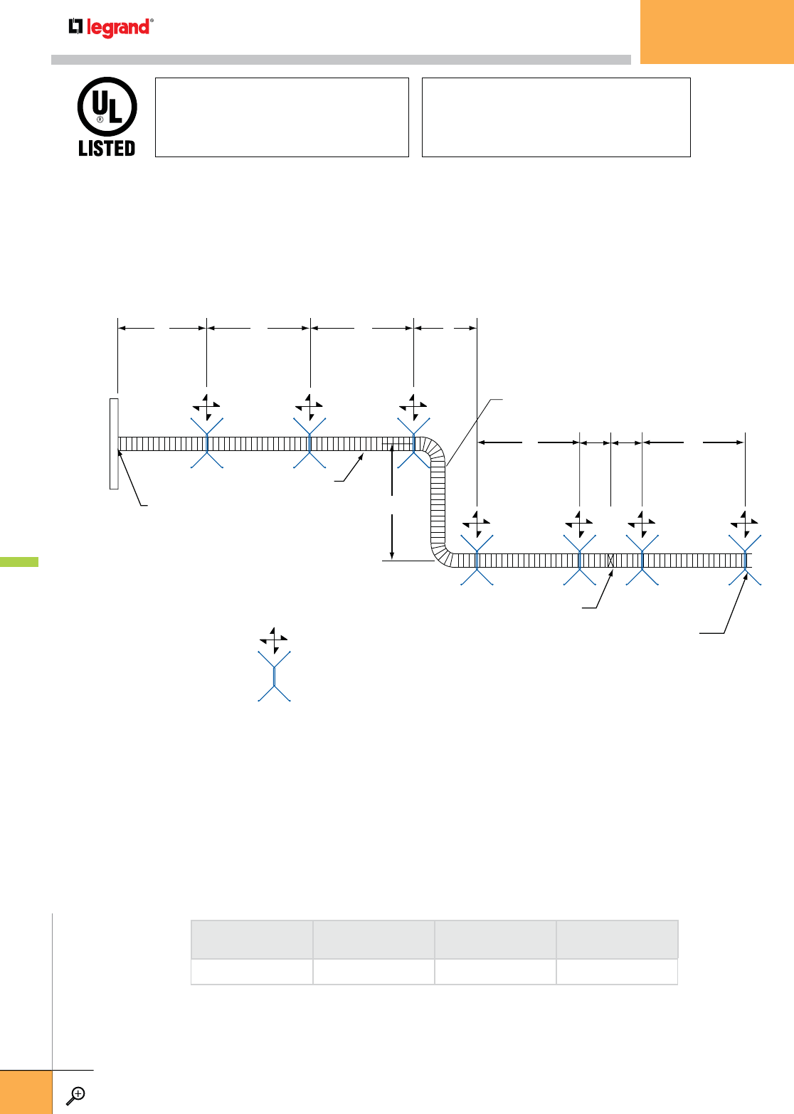
= 4-WAY (TRANSVERSE & LONGITUDINAL) SWAY BRACE
S S S X
SS ZZ
Y
FIXED TRAY END
STRAIGHT RUNS
*HORIZONTAL OFFSETS
*VERTICAL OFFSETS
FIRST SUPPORT NEAREST
TO NON-FIXED TRAY END
Approved Fixed Equipment Anchorage
California Office of Statewide Health Planning
and Development (OSHPD)
Based on CBC 2001 OPA-0619
City of Los Angeles Tested and Approved
For all mechanical, plumbing and electrical
piping, conduit, equipment and systems–
including fire sprinklers
SEISMIC Wire Rope/Cable™ BRACING
Break Strength Certified - Color Coded - Prestretched
NOTES:
(1) For horizontal offsets, a sway brace should be located at the cable tray support
nearest to one end of the offset.
(2) It is recommended that the max. Vertical offset without a sway brace be 30 feet and
that the max. Spacing for sway braces on vertical trays should be 40 feet.
BRACED COMPONENT
DESCRIPTION MAXIMUM "S" MAXIMUM "X" + "Y" MAXIMUM "Z"
CABLE TRAY 40 FT. 40 FT. 5 FT.
SWAY BRACE LOCATIONS AND SPACING
Refer to specifications, V.S.T. manual and tables for brace spacing, required brace locations, load calculations procedures, sizing,
and allowable loads on brace assemblies and fasteners.
SEISMIC BRACING
WWW.LEGRAND.US/CABLOFIL
D.36
LEGRAND
FASTENERS
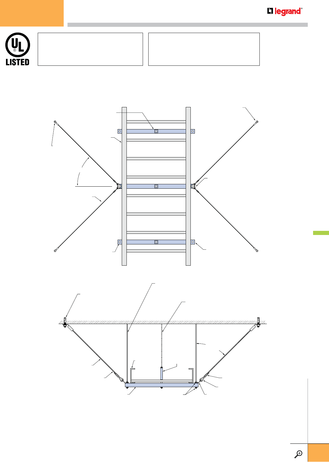
BRACE ANCHORAGE TO
BUILDING STRUCTURE
USING STAKE EYE
OR URC CLIP (TYP.)
(SEE DETAILS AT
WWW.CABLOFIL.COM)
BRACE CONNECTION TO
CABLE TRAY SUPPORT
USING URC CLIP (TYP.)
(SEE DETAILS AT
WWW.CABLOFIL.COM)
CABLE TRAY SUPPORT ROD
FOR CENTER-HUNG TYPE
TRAY SUPPORTS (TYP.)
(ONE ROD PER SUPPORT)
CABLE TRAY
SIDE RAIL
CABLE TRAY SUPPORT ROD
FOR TRAPEZE TYPE CABLE
TRAY SUPPORTS (TYP.)
(2 RODS PER SUPPORT)
WIRE ROPE/CABLE™
ASSEMBLY (TYP.)
45° (TYP.)
STAKE EYE
END OF WIRE
ROPE/CABLE™
(TYP.)
CABLE TRAY
SUPPORT MEMBER
(TYP.)
CABLE TRAY SUPPORT ROD (TYP.)
FOR CENTER-HUNG TYPE CABLE TRAY
SUPPORTS (SEE ROD STIFFENER
REQUIREMENTS AT
WWW.CABLOFIL.COM)
CABLE TRAY SUPPORT ROD (TYP.) FOR
TRAPEZE TYPE CABLE TRAY SUPPORTS
(SEE ROD STIFFENER REQUIREMENTS
AT WWW.CABLOFIL.COM)
TIGHTEN CABLES
ONLY TO REMOVE
EXCESSIVE SLACK
CABLE TRAY SUPPORT MEMBER
TWO WIRE ROPE/CABLE
ASSEMBLIES (ASSEMBLY
IN FOREGROUND SHOWN)
CABLE TRAY
1/2" INSIDE DIA.
SCH. 40 PIPE
(CENTER-HUNG
SUPPORTS)
45°
BRACE
ANGLE
(TYP.)
15/8" SQUARE WASHERS
AND HEX NUTS, TOP
AND BOTTOM (TYP.)
CABLE LOOP
OVAL SLEEVE
BRACE ANCHORAGE TO
BUILDING STRUCTURE
USING STAKE EYE (SHOWN)
OR URC CLIP (TYP.)
(SEE DETAILS AT
WWW.CABLOFIL.COM)
BRACE CONNECTION TO
CABLE TRAY SUPPORT
USING URC CLIP (TYP.)
(SEE DETAILS AT
WWW.CABLOFIL.COM)
Approved Fixed Equipment Anchorage
California Office of Statewide Health Planning
and Development (OSHPD)
Based on CBC 2001 OPA-0619
City of Los Angeles Tested and Approved
For all mechanical, plumbing and electrical
piping, conduit, equipment and systems–
including fire sprinklers
SEISMIC Wire Rope/Cable™ BRACING
Break Strength Certified - Color Coded - Prestretched
COMBINATION TRANSVERSE / LONGITUDINAL EARTHQUAKE SWAY BRACE
FOR PW INDUSTRIES (DOUBLE RAIL) CABLE TRAY
Refer to specifications, V.S.T. manual and tables for brace spacing, required brace locations, load calculations procedures, sizing, and
allowable loads on brace assemblies and fasteners.
SEISMIC BRACING
WWW.LEGRAND.US/CABLOFIL
D.37
LEGRAND
FASTENERS
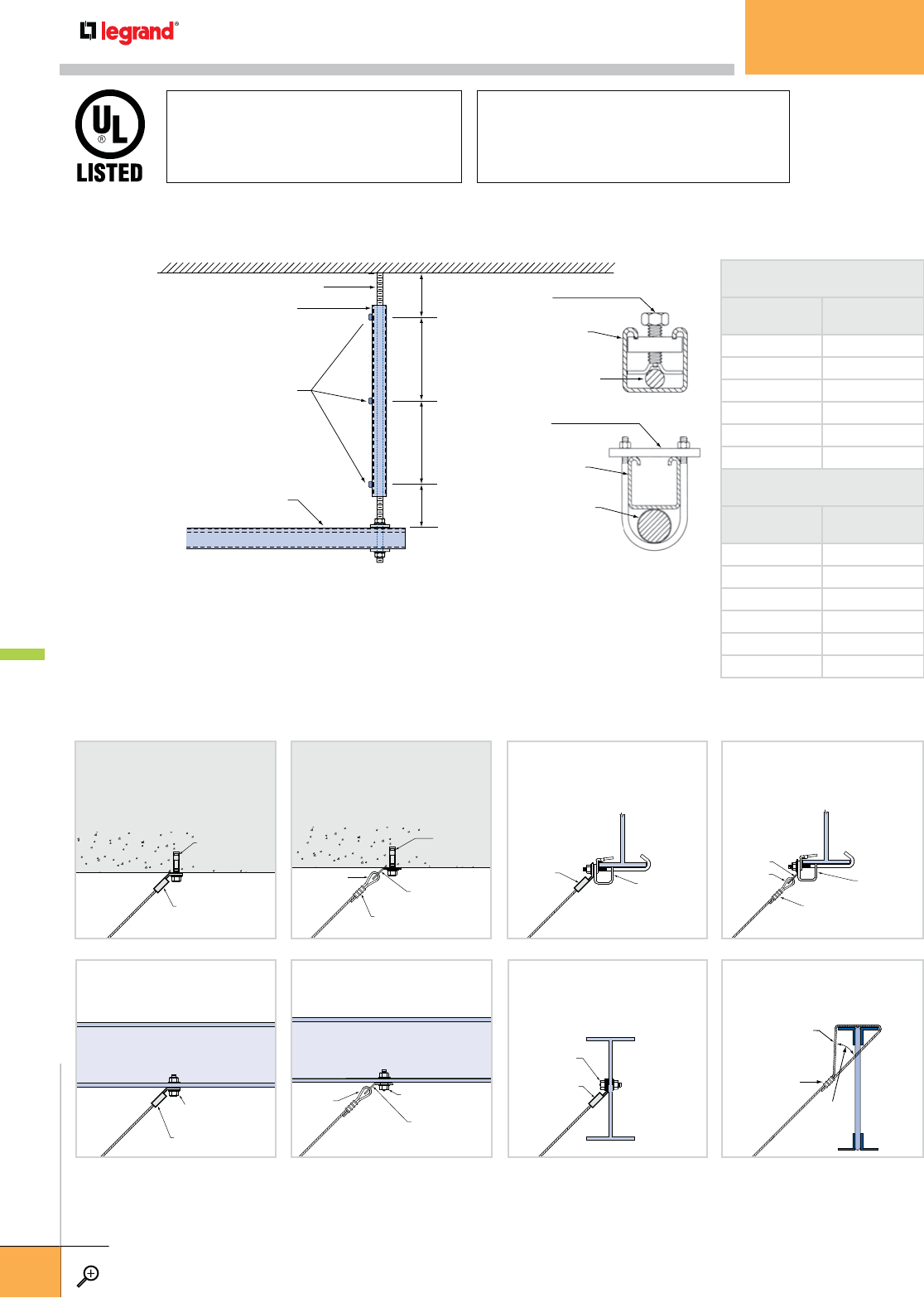
1. Maximum allowable length of 15/8" x 15/8" x 12 ga. steel strut for rod stiffener is 9'-0".
2. For support rods 9'-1" to 13'-1", sleeve the support rod with 2" schedule 40 pipe.
3. For multi-tier support systems, the steel strut rod stiffener shall be installed such that it be
secured to the side of the bottom support member, in contact with the structure, and held in
position by securing to the side of one other horizontal support member, using the rod stiffener
clips shown above.
ROD STIFFENER CLIPS
PART #0602 (UP TO 5/8" RODS)
OR #0603 (3/4" & ABOVE RODS)
15/8" x 15/8" x 12 GA. STEEL STRUT
FOR ROD STIFFENER*
6" MAXIMUM
6" MAXIMUM
SEE TABLE FOR
MAX. SPACING
SEE TABLE FOR
MAX. SPACING
THREADED SUPPORT ROD TO STRUCTURE
CABLE TRAY SUPPORT MEMBER
(TYPICALLY 15/8" x 12 GA. STEEL STRUT)
*2" SCH. 40 PIPE MAY BE SUBSTITUTED
FOR 15/8" STEEL STRUT
CLIP #0602
CLIP #0603
SUPPORT
ROD
STRUT
STRUT
SUPPORT
ROD
Approved Fixed Equipment Anchorage
California Office of Statewide Health Planning
and Development (OSHPD)
Based on CBC 2001 OPA-0619
City of Los Angeles Tested and Approved
For all mechanical, plumbing and electrical
piping, conduit, equipment and systems–
including fire sprinklers
SEISMIC Wire Rope/Cable™ BRACING
Break Strength Certified - Color Coded - Prestretched
SUPPORT ROD STIFFENER DETAILS AND REQUIREMENTS (AT SWAY BRACE LOCATIONS ONLY)
MAXIMUM ROD LENGTH
WITHOUT STIFFENER
ROD DIA. MAXIMUM LENGTH
3
/
8"16
½" 22
5
/
8"28
¾" 34
7
/
8"40
1" 46
MAXIMUM SPACING OF
ROD STIFFENER CLIPS
ROD DIA. MAXIMUM SPACING
3
/
8"13
½" 18
5
/
8"23
¾" 28
7
/
8"33
1" 38
STAKE EYE END
CONCRETE
EXPANSION ANCHOR
(3/8" OR 1/2" DIA. ONLY)
CABLE BRACE WITH CABLE LOOP
ANCHORED TO CONCRETE DECK
USING URC CLIP
DOUBLE SIDED
BEAM CLAMP*
(3/8" OR 1/2" ROD
DIA. ONLY)
STAKE
EYE END
WHEN DRILLING
OR WELDING
IS NOT PERMITTED
CABLE BRACE WITH STAKE EYE
ANCHORED TO DOUBLE SIDED
BEAM CLAMP*
OVAL SLEEVE
CABLE LOOP
CONCRETE
EXPANSION
ANCHOR
URC CLIP
CABLE BRACE WITH CABLE LOOP
ANCHORED TO CONCRETE DECK
USING URC CLIP
DOUBLE SIDED
BEAM CLAMP*
OVAL SLEEVE
CABLE LOOP
URC CLIP
WHEN DRILLING
OR WELDING
IS NOT PERMITTED
CABLE BRACE WITH CABLE LOOP
ANCHORED TO DOUBLE SIDED
BEAM CLAMP USING URC CLIP*
STAKE EYE END
A307 BOLT OR WELD
STUD (3/8" OR 1/2" DIA. ONLY)
CABLE BRACE WITH STAKE EYE
ANCHORED TO STEEL BEAM
OR JOIST
CABLE LOOP A307 BOLT OR WELD STUD
URC CLIP
CABLE BRACE WITH CABLE LOOP
ANCHORED TO STEEL BEAM
OR JOIST USING URC CLIP
A307 BOLT OR WELD
STUD (3/8" OR 1/2"
DIA. ONLY)
STAKE EYE END OF
CABLE ASSEMBLY
CABLE BRACE WITH STAKE EYE
ANCHORED TO STEEL BEAM
MAX. 45˚
LOOPED CABLE AROUND
TOP CHORD OF BAR JOIST
AT PANEL POINT
OVAL SLEEVE
CABLE BRACE LOOPED
CONNECTION AROUND
TOP CHORD OF BAR JOIST
AT PANEL POINT
(*MIN. CLAMP ROD DIA. PER COL. 'B' OF BRACING TABLES)
SAMPLE DETAILS OF CABLE BRACE ANCHORAGE TO STRUCTURE FOR CABLOFIL CABLE TRAY
NOTE: Refer to specifications, V.S.T. manual and tables for brace spacing, required brace locations,
load calculations procedures, sizing, and allowable loads on brace assemblies and fasteners.
SEISMIC BRACING
WWW.LEGRAND.US/CABLOFIL
D.38
LEGRAND
FASTENERS

LEGRAND PRODUCT NUMBER INDEX
Q
AWIRE MESH
AB225 KIT.............................70
AS.........................................43
BH75KI T ................................63
C 50 ...........................35 ,51, 69
C50CC ...................................67
CABLEXIT ..............................72
CABLEXIT50 ..........................65
CAT 30 ..................................37
CAT 41 ..................................37
CC KIT ...................................67
CE 25 ....................................25
CE 30 ....................................25
CE 35 ....................................25
CE 40 ....................................24
CE40CC ................................. 68
CF 105 ..................................13
CF 150 ..................................13
CF 30 ....................................12
CF 54 ....................................12
CFG .......................................15
CFL ....................................... 15
CH ........................................68
CLIP ......................................74
CLIP F02 ...............................17
CM50I ................................... 69
COT 105 ................................19
COT 150 ................................19
COT 30 ..................................19
COT 54 ..................................19
COT F ....................................18
COT J ....................................19
COTFIL50 ..............................18
COTFIL100.............................18
COUPFIL ...............................84
CUTYFIL ................................85
CRP ......................................35
CS .................................. 34, 45
CSC ................................ 34, 44
CTXF 35 ................................16
CVN ......................................17
DF................................... 47, 53
DO ........................................72
DROP OUT KIT .......................73
EAC KIT .................................26
ED 275 ..................................23
EDF ............................33, 46, 53
EDRN .............................. 21, 86
EDRNTOOL ............................21
EDRSKIT ...............................22
EDT ....................................... 23
ERD 10 ..................................47
EXPANKIT ..............................22
EZJB 5/16 .............................75
EZT 90 KIT .............................26
EZT90RS ...............................61
EZVC .....................................74
FAS C .............................. 31, 44
Q
BLADDER TRAY
001099................................78
001299 ................................49
0109 ............................... 34, 73
0112 ............................... 34, 73
0118 ............................... 34, 73
0124 ............................... 34, 73
0130 ............................... 34, 73
0136 ............................... 34, 73
0215 .....................................55
0216 .....................................55
0226 .....................................56
0228 .....................................56
0253 ............................... 51, 84
0254 ..........................51, 78, 94
0327 .....................................95
0328 .....................................95
0331 .....................................95
0333 .....................................85
0334 .....................................85
0339 .....................................93
0341 .....................................85
0345 .....................................95
0349 .....................................94
0353 .....................................55
0356 ............................... 47, 77
0357 .....................................86
0369 .....................................54
0371 .....................................54
0373 .....................................54
0385 .....................................79
0386 .....................................79
0387 .....................................79
0392 .....................................55
0393 .....................................54
0394 .....................................54
0395 .....................................54
0401 .....................................37
0402 ..........................51, 78, 84
0403 ..........................47, 85, 94
0410 .....................................94
0424 .....................................51
0426 .....................................93
0434 .....................................51
0440 .....................................58
0606 ............................... 49, 78
0709 ............................... 34, 73
0712 ............................... 34, 73
0718 ............................... 34, 73
0724 ............................... 34, 73
0730 ............................... 34, 73
0736 ............................... 34, 73
0809 ............................... 34, 73
0812 ............................... 34, 73
0818 ............................... 34, 73
0824 ............................... 34, 73
0830 ............................... 34, 73
0836 .....................................34
FAS L ..............................30, 52
FAS P .........................29, 42, 50
FAS PCH................................41
FAS ROLLER ..........................76
FAS U .............................. 32, 52
FASLOCK ............................... 26
FASROLLER HD......................77
FCF 54 ..................................17
FLAMESTOPPER .................... 78
FS 41 ....................................71
FV ......................................... 29
GNDCL ..................................75
GNDSB ..................................75
HB 2 KIT................................70
HTB ......................................62
HXB ......................................62
INSERT .................................16
INSERTPP .............................63
MFM ..................................... 73
OTDO ....................................64
OTDOFAS ...............................64
PACKCF.................................14
PAT 30 ..................................40
PFREDF ................................47
PRECLICK .............................21
PROCS ..................................43
PS ........................................45
RADT 90 KIT ..........................27
RADT 9012 KIT ......................27
RADT90RS .............................61
RB112KI T .............................. 74
RHXB ....................................62
SAS ......................................40
SBDA ....................................69
SF 100 ..................................39
SF 50 ....................................39
SON ...................................... 42
SWK .....................................24
TC4KIT .................................. 68
TC5KIT .................................. 68
TOH ......................................65
TXF 35 ..................................16
UC 35 ....................................16
UC 50 .............................. 36, 51
UFC .......................................49
UFC550 KIT ...........................49
UFCF2 ................................... 57
UFCN ....................................50
UFFS .....................................55
UFS...................... 54, 56, 58, 59
UFSCB ..................................56
UFSUPKIT .............................56
UFT 90˚ KITS ........................57
WMC2L A ...............................71
WTSB ...................................30
YCKIT ....................................71
ZF 150 ...................................13
ZF 30 ....................................12
0836 ............................... 34, 73
0925 .....................................44
0926 .....................................44
0930 .....................................50
0941 .....................................78
0950 .....................................57
1000 ............................... 42, 89
1007 .....................................42
1012 ..........................36, 74, 84
1024 ..........................36, 74, 84
1036 ..........................36, 74, 84
1066 .....................................42
1085 .....................................81
1104 .....................................42
1114 .....................................42
1124 .....................................40
1140 .....................................42
1301 .....................................86
1302 ..........................45, 77, 93
1303 .....................................46
1304 .....................................46
1305 ..........................47, 77, 86
1307 ..........................47, 77, 86
1314 ............................... 46, 77
1320 ..........................46, 77, 93
1331 .....................................93
1335 .....................................45
1338 .....................................85
1355 .....................................45
1357 .....................................86
1379 .....................................45
1385 .....................................45
1386 .....................................45
1400 ..........................43, 76, 81
1410 .....................................44
1411 .....................................43
1423 .....................................43
1423 .....................................76
1432 .....................................44
1440 .....................................43
1441 ............................... 44, 76
1442 ............................... 44, 76
1443 .....................................44
1444 .....................................44
1508 .....................................81
1509 .....................................81
1753 .....................................28
1754 .....................................28
1755 .....................................28
1756 .....................................28
1772 .....................................28
1803 .....................................85
1811 .....................................79
1812 .....................................85
1818 .....................................57
1852 .....................................50
1853 .....................................44
1864 .....................................47
1864 .....................................77
1866 ............................... 52, 79
1867 .....................................52
1870 .....................................87
1871 .....................................87
1872 .....................................87
1873 .....................................56
1893 ............................... 52, 79
1899 .....................................53
1916 .....................................56
1952 .....................................26
1953 .....................................26
1954 .....................................26
1D69 ..................................... 28
1D70 ..................................... 28
1D80 ..................................... 28
1D81 ..................................... 28
1D82 ..................................... 28
1D83 ..................................... 28
1E45 .....................................28
1E46 .....................................28
1E53 .....................................28
1E54 .....................................28
1E72 .....................................28
1F45 .....................................28
1F46 .....................................28
1F53 .....................................28
1F54 .....................................28
2000 ............................... 42, 89
2002 .....................................42
2006 .....................................42
2007 .....................................42
2012 .................... 34, 35, 74, 84
2024 .................... 34, 35, 74, 84
2036 .................... 34, 35, 74, 84
2066 .....................................42
2067 .....................................42
2085 .....................................81
2104 .....................................42
2112 .....................................42
2114 .....................................42
2124 .....................................40
2140 .....................................42
2224 .....................................40
2508 .....................................81
2509 .....................................81
3000 .....................................42
3002 .....................................42
3003 .....................................42
3005 .....................................42
3012 ..........................33, 72, 82
3014 .....................................81
3017 .....................................42
3024 ..........................33, 72, 82
3029 .....................................42
3036 .................... 33, 42, 72, 82
3038 .....................................42
3039 .....................................42
3040 .....................................42
3041 .....................................42
3042 .....................................42
3050 .....................................42
3070 .....................................42
3076 .....................................42
3095 .....................................81
30HB .....................................13
30VI ...................................... 18
30VO ..................................... 17
3112 .................... 39, 42, 75, 83
311299 .......................... 49, 78
3113 .....................................42
3117 .....................................42
3124 ..........................39, 75, 83
312499 .......................... 49, 78
3128 .....................................42
3131 .....................................42
3136 ..........................39, 75, 83
313699 .......................... 49, 78
3212 ..........................38, 75, 83
321299 .......................... 49, 78
3224 ..........................38, 75, 83
322499 .......................... 49, 78
3236 ..........................38, 75, 83
323699 .......................... 49, 78
3406 .....................................30
3407 .....................................30
3408 .....................................30
3409 .....................................30
3416 .....................................30
3417 .....................................30
3445 .....................................30
3446 .....................................30
3456 .....................................30
3476 .....................................30
3504 .....................................30
3505 .....................................30
3514 .....................................30
3515 .....................................30
3528 .....................................81
3529 .....................................81
3532 .....................................81
3538 .....................................81
3550 .....................................30
3551 .....................................30
3582 .....................................30
3583 .....................................30
3587 .....................................30
3592 .....................................30
3593 .....................................30
3594 .....................................30
3603 .....................................30
3604 .....................................30
3620 .....................................30
3621 .....................................30
3645 .....................................30
3701 .....................................30
FULL LINE PRODUCT INDEX
WWW.LEGRAND.US/CABLOFIL
I.2
CABLOFIL
CABLE MANAGEMENT

3714 .....................................30
3722 .....................................30
3723 .....................................30
3724 .....................................30
3734 .....................................30
3735 .....................................30
3738 .....................................30
3739 .....................................30
3754 .....................................30
3756 .....................................30
3760 .....................................30
3D58 ..................................... 30
3D63 ..................................... 30
3D82 ..................................... 30
3D85 ..................................... 30
3D92 ..................................... 30
3D93 ..................................... 30
3F35 .....................................30
3F58 .....................................30
3F61 .....................................30
3F66 .....................................30
3F67 .....................................30
3F68 .....................................30
3F85 .....................................30
4024 .....................................37
4124 .....................................37
4512 .................... 33, 72, 82, 88
4524 .................... 33, 72, 82, 88
4536 .................... 33, 72, 82, 88
45HB .....................................13
45VI ...................................... 18
45VO ..................................... 17
4612 .................... 39, 75, 83, 89
461299 .......................... 49, 78
4624 .................... 39, 75, 83, 89
462499 .......................... 49, 78
4636 .................... 39, 75, 83, 89
463699 .......................... 49, 78
4712 .................... 38, 75, 83, 89
471299 .......................... 49, 78
4724 .................... 38, 75, 83, 89
472499 .......................... 49, 78
4736 .................... 38, 75, 83, 89
473699 .......................... 49, 78
4812 .....................................26
4823 .....................................26
4904 .....................................26
4A12B ...................................10
4A12C ...................................10
4A20B ...................................10
5088 .....................................81
5508 .....................................81
5509 .....................................81
5A12C ...................................10
5A20B ...................................10
6012 ............................... 32, 82
6024 ............................... 32, 82
6036 ............................... 32, 82
60HB .....................................12
60VI ...................................... 18
60VO ..................................... 17
6112 ............................... 39, 83
611299 ................................49
6124 ............................... 39, 83
612499 ................................49
6136 ............................... 39, 83
613699 ................................49
6212 ............................... 38, 83
621299 ................................49
6224 ............................... 38, 83
622499 ................................49
6236 ............................... 38, 83
623699 ................................49
6A12C ...................................10
6A20B ...................................10
6A20C ...................................10
6A24C ...................................10
7130 .....................................76
7134 .....................................88
7400 .....................................70
7508 .....................................88
7509 .....................................88
7615 .....................................70
7625 .....................................70
7A12C ...................................10
7A20B ...................................10
7A20C ...................................10
7A24C ...................................10
7D20 ..................................... 70
7F20 .....................................70
7F24 .....................................70
8104 .....................................91
8106 .....................................91
8200 .....................................78
8204 .....................................91
8206 .....................................91
8945 .....................................53
9012 ...............32, 72, 82, 88, 92
9024 .................... 32, 72, 82, 88
9036 .................... 32, 72, 82, 88
90HB .....................................12
90SP ..................................... 23
90SP ..................................... 23
90VI ...................................... 18
90VO ..................................... 17
9112 ...............39, 75, 83, 89, 92
911299 .......................... 49, 78
9124 .................... 39, 75, 83, 89
912499 .......................... 49, 78
9136 .................... 39, 75, 83, 89
913699 .......................... 49, 78
9212 ...............38, 75, 83, 89, 92
921299 .......................... 49, 78
9224 .................... 38, 75, 83, 89
922499 .......................... 49, 78
9236 .................... 38, 75, 83, 89
923699 .......................... 49, 78
9312 .....................................40
9324 .....................................40
9336 .....................................40
A457 .....................................28
A639 .....................................28
A802 .....................................53
A803 .....................................48
A804 .....................................48
A805 .....................................48
A806 .....................................48
A807 .....................................48
A808 .....................................48
A809 .....................................48
A810 .....................................48
A814 .....................................48
A823 .....................................95
A824.....................................95
A836 .....................................53
A837 .....................................53
A83801 ................................95
A83901 ................................95
A84001 ................................56
A84201 ................................95
A84301 ................................95
A84401 ................................95
A845 .....................................52
BE.........................................24
BJ .........................................48
COTJ .....................................50
CS ........................................19
DIV .......................................24
DO ........................................24
DS1841 ................................40
DS8524 ................................48
DS8530 ................................48
DS8575 ................................48
DS8576 ................................48
DS8596 ................................48
DS8600 ................................48
DS8926 ................................48
DS8927 ................................48
DS8930 ................................50
DS8935 .....................76, 78, 87
DS8954 ................................87
ET ......................................... 15
EXSP .....................................22
F1852 .................................. 78
FCC ....................................... 21
FFSP .....................................23
FSP.......................................22
FWPS....................................25
HASP ....................................23
HT .........................................14
HX ........................................16
IP34 ...................................... 24
LFF ....................................... 20
LR .........................................14
OCK ......................................25
OHCB ....................................25
ORSP ....................................23
P094901.............................57
PCC ......................................21
PCT .......................................21
RHSP ....................................24
RR ........................................14
RT .........................................15
RX ........................................16
SFF ....................................... 20
SON 1/2 .......................... 57, 87
SON 1/4 .......................... 57, 87
SON 3/8 .......................... 57, 87
SPF.......................................20
SR ........................................14
SRSP ....................................23
SSP ......................................22
TBC .......................................24
TD .........................................19
TU .........................................19
USP ......................................22
USPB ....................................22
VASP .....................................23
VHSP ....................................22
VX .........................................19
WMC 2LA ..............................52
WPS .....................................25
YL .........................................16
YR ........................................16
Q
CTROUGH TRAY
A838.....................................18
A839 .....................................18
BTRCC6X12 ........................... 25
CA.........................................25
COT 54 ..................................23
COT 105 ................................23
COT J ....................................23
CS ........................................18
CSC ......................................18
DF.........................................20
ECLI ......................................25
EDF .......................................19
ERD 10 ..................................20
EZ BN....................................25
EZ CN ....................................25
EZ FW ...................................25
EZ HN ...................................25
FAS U ....................................19
FT ...........................................8
FTC .........................................8
FTAS .....................................17
FTB ....................................... 14
FTBC .....................................14
FTBE .....................................24
FTBP .....................................24
FTCC ..................................... 22
FTCF ..................................... 22
FTCFCL .................................21
FTCH .....................................17
FTCHC ...................................17
FTEF .....................................11
FTFB45 ................................12
FTCFB45 ..............................12
FTFB90 .................................12
FTCFB90 ...............................12
FTFCL ...................................21
FTHDCL .................................21
FTLHR ...................................11
FTP31CL ...............................24
FTRB .....................................18
FTRHR ..................................11
FTT .......................................14
FTTC .....................................14
FTUMP ..................................22
FTUS .....................................10
FTVI90 .................................13
FTCVI90 ...............................13
FTVO90 ................................13
FTCVO90 ..............................13
FT VT ..................................... 15
FTX ....................................... 15
FTXC ..................................... 15
JP .........................................24
PFREDF ................................20
PROCS ..................................18
THRD ....................................25
THRDPT ................................25
V T ...........................................9
Q
D FASTENERS
0602 .....................................33
0603 .....................................33
APR ......................................20
AR ........................................21
CABLO SNAP .........................11
CCLMP ..................................11
CJ TREES ................................8
CJ12 .......................................4
CJ21 .......................................4
CJ32 .......................................4
CJ64 .......................................4
CJ16HP ................................... 6
CJ32HP ................................... 6
CJ48HP ................................... 6
CJ4T125 ..................................7
CJ4T2 .....................................7
CJHP TREES ............................8
CP ........................................25
CPW .....................................25
CPP ......................................26
CPPB ....................................29
CPPE ....................................27
CPPZ .....................................31
CPS ......................................26
CPSA ....................................29
CPSB ....................................29
CPSE ....................................27
CPSME ..................................28
CPSZ .....................................31
CPW .....................................25
CPWP ...................................26
CPWGP .................................30
CPW GPP ............................... 30
CPWGPS ............................... 30
CPWGT .................................30
CPWGTP ...............................30
CPWGTS ...............................30
CPWPB .................................29
CPWPE .................................27
CPWS ...................................26
CPWSB .................................29
CPWSE .................................27
CPWSME...............................28
CWTBB .................................16
CWTSB .................................16
DCP ......................................20
DS0102 .................................. 9
DS0103 .................................. 9
DS0113 .................................. 9
DS0113 .................................. 9
DS0113 .................................. 9
DS0221 .................................. 9
DS0237 .................................. 9
DS0255 .................................. 9
DS0256 .................................. 9
DS0257 .................................. 9
DS8502 .................................. 9
DS8510 .................................. 9
DS8515 .................................. 9
DS8520 .................................. 9
DS8524 .................................. 9
DS8532 .................................. 9
DS8570 .................................. 9
DS8575 .................................. 9
DS8594 .................................. 9
DS8595 .................................. 9
DS8596 .................................. 9
DS8598 .................................. 9
DS8644 .................................. 9
DS8845 .................................. 9
DS8938 .................................. 9
ETC ....................................... 10
EZBC ..................................... 10
EZ CN ......................................9
EZ FW .....................................9
EZ HN .....................................9
F112 .....................................15
F115 .....................................15
F118 .....................................15
F124 .....................................15
F212 .....................................15
F215 .....................................15
F218 .....................................15
F224 .....................................15
F312 .....................................15
F315 .....................................15
F318 .....................................15
F324 .....................................15
F418 .....................................15
FASCLM KIT ..........................10
FB816 ...................................19
FB816D12CONN .................19
FB816D34CONN .................19
FB816D1CONN ...................19
FS 41 ....................................11
PWC7 ..................................33
PWC9 ..................................33
PWCBL ................................32
PWNPC ...............................33
PWSBHS..............................33
PWSLV ................................33
PWURC................................32
RS1 ..................................... 33
SON ........................................9
SZMCKIT ...............................32
T16 .......................................21
T24 .......................................21
THRD ......................................9
THRDPT ..................................9
W1 ........................................ 17
W16SSL ................................ 17
W2 ........................................ 17
W24SSL ................................ 17
W3 ........................................ 17
W34 ...................................... 17
W4 ........................................ 17
PRODUCT INDEX
WWW.LEGRAND.US/CABLOFIL
I.4
CABLOFIL
CABLE MANAGEMENT

designed to be better.™
FOLLOW US
Electrical Wiring Systems
8319 State Route 4
Mascoutah, IL 62258
800.658.4641
www.legrand.us/cablofil
570 Applewood Crescent
Vaughan, Ontario L4K 4B4
905.738.9195
www.legrand.ca
©2016 Legrand All Rights Reserved CAB_CAT_0116
