1000498556 Catalog
2016-07-04
: Pdf 1000498556-Catalog 1000498556-Catalog B1 unilog
Open the PDF directly: View PDF ![]() .
.
Page Count: 156 [warning: Documents this large are best viewed by clicking the View PDF Link!]

Lighting Control
Schneider Electric USA
320 Tech Park Drive, Suite 100
La Vergne, TN, 37086
1-888-778-2733
www.schneider-electric.us
Document Number 1200CT0701R11/12 April 2013
Make the most of your energySM
©2013 Schneider Electric. All Rights Reserved. Schneider Electric, Square D, Powerlink, C-Bus, Saturn, Dynamic Labeling Technology, and Wiser are
trademarks owned by Schneider Electric Industries SAS or its affiliated companies. All other trademarks are property of their respective owners.
Products Guide

Contents
Occupancy Sensors
•Introduction....................................................2
•WallSwitchOccupancySensors....................3
•SensorAccessories........................................8
•CeilingMountedOccupancySensors.............9
•WallMountedOccupancySensors...............11
•PowerPackandAuxiliaryRelays..................12
•CeilingMountedLineVoltageSensors..........13
•HighBayOccupancySensor........................14
•OccupancyController...................................16
•LowVoltageSwitches..................................17
•TechnicalSection.........................................18
Emergency Lighting Control Devices
•Introduction..................................................28
•Devices........................................................29
•TechnicalSection.........................................32
Emergency Lighting Control Panels
•Introduction.................................................. 36
•EmergencyLightingPanels.......................... 37
•EmergencyLightingPanelboards................. 38
•TechnicalSection......................................... 39
Current-Limiting Panels
•Introduction..................................................42
•Current-limitingPanels.................................43
Relay Panels
•Introduction.................................................. 46
•LPSRelayPanels......................................... 47
•RelaySwitches............................................. 48
•LPBRelayPanels......................................... 49
•LPLRelayPanels......................................... 50
•TechnicalSection......................................... 51
Architectural Dimming
•Introduction..................................................58
•inTouchControlStations...............................59
•Wall-MountedDimmingSystems..................60
•Rack-MountedDimmingSystems................61
•TechnicalSection.........................................63

Measurement & Verification
Panels (MVP)
•Introduction..................................................66
•NFMVPPanel..............................................67
•NQMVPPanel.............................................67
•PowerlinkMVPPanel...................................68
•TechnicalSection.........................................69
Powerlink Lighting Control
•Introduction..................................................72
•G3Panelboards...........................................73
•NFPanelboards...........................................74
•G3Remotely-operatedCircuitBreakers.......75
•G3ControlBus............................................77
•PowerSupply...............................................78
•Controllers....................................................79
•RemoteSourceController............................81
•RemoteMountController.............................82
•LCSAdvancedandLCSBasicsoftware.......83
•Accessories..................................................85
•DevicePowerSupply...................................86
•DeviceRouter...............................................87
•TechnicalSection.........................................88
C-Bus Lighting Control
•Introduction..................................................94
•Keypads.......................................................95
•TouchScreens.............................................98
•WiserHomeController...............................100
•SystemUnits..............................................101
•InputUnits..................................................108
•Sensors......................................................112
•OutputUnits...............................................118
•OccupancyController.................................127
•AreaLightingPanels...................................128
•C-BusEnclosures......................................129
•RemoteControls........................................133
•IRAccessories...........................................134
•SchedulePlusSoftware..............................135
•TechnicalSection.......................................137
Occupancy Sensors

OCCUPANCY SENSORS
SchneiderElectrichelpsbuildingowners
achieveenergysavingsandenergycode
compliancewithsensorsthatareeasytoselect,
installandcommission.Employingpassive
infrared(PIR),ultrasonicanddualtechnology
toaccuratelydetectoccupancyandcontrol
lightingloads,occupancysensorsautomatically
shut-offlightinginunoccupiedareas—
eliminatingwaste,reducingenergycosts
andmeetingcoderequirements.Schneider
Electricinnovationshelpbuildingownersnot
onlycomplywithenergycodes,buttheyalso
maximizeenergysavings.
•AdaptiveTechnology:Thistechnology
employsadvancedalgorithmstoachieve
convenientenergysavingsandreduced
lampandballastmaintenance.
•Integrallightlevelsensorsmaximizeenergy
savingsinday-litareasbyholdingoff
articiallightingwhenadequatenaturallight
isavailable.
•Walk-throughmodedetectsbriefperiods
ofoccupancyinprivateofces,allowingthe
sensortoshut-offlightingwithlesstimedelay.
•LampsavermodealternatestheA-and
B-loadsinroomsusing50/50bi-levellighting
controltomaximizelamplifeandreduce
maintenance.
•Isolatedrelaysmaybeusedtocommunicate
withothercontrolsystems,suchasbuilding
automationandenergymanagementsystems
thatcontrolotherbuildingsystems,like
HVACandlighting,tofurthermaximize
energysavings.
SchneiderElectricmakeslightingcontroleasy
withafulllineofversatileoccupancysensors.
Occupancy Sensors
2

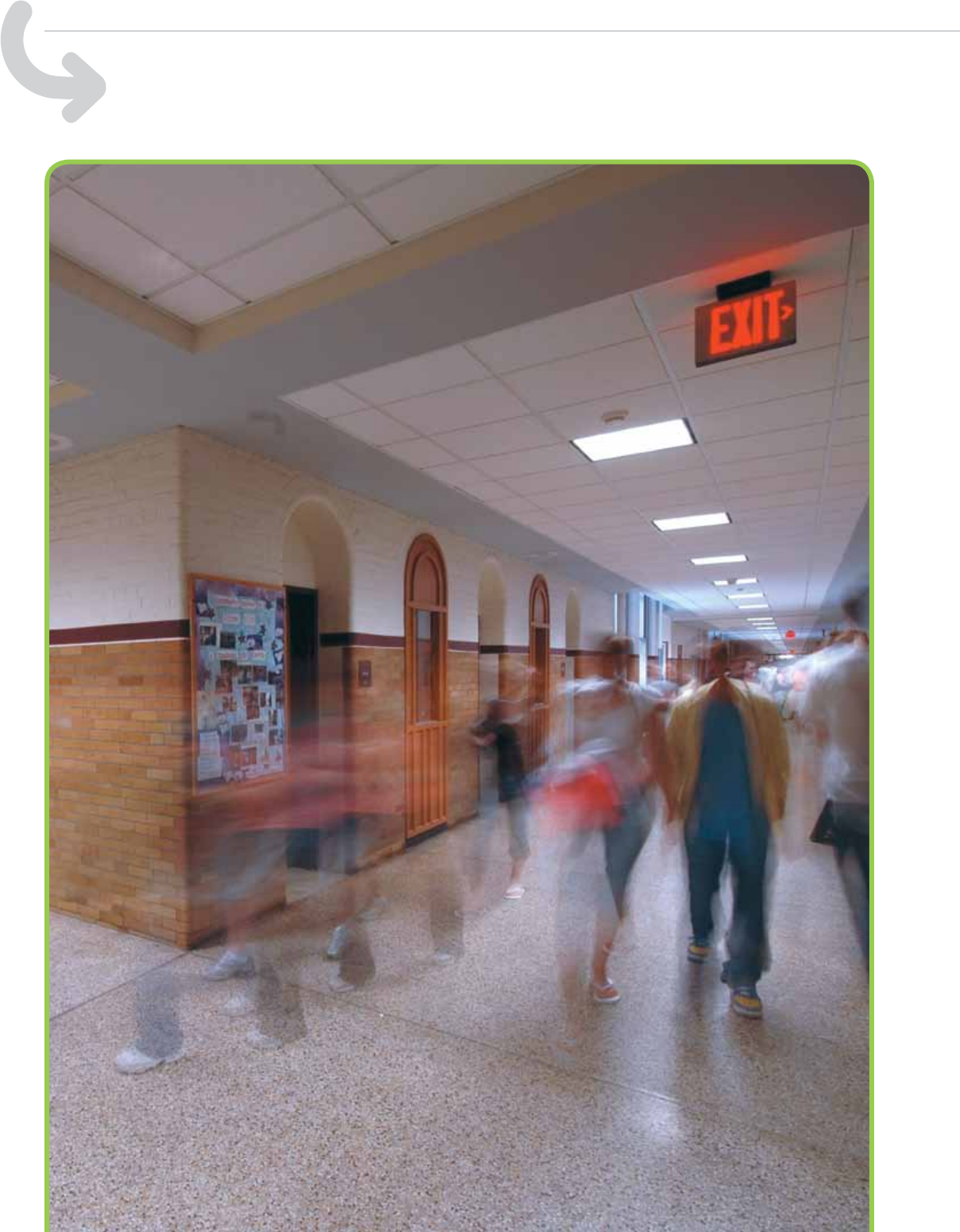
OCCUPANCY SENSORS WALL SWITCH OCCUPANCY SENSORS
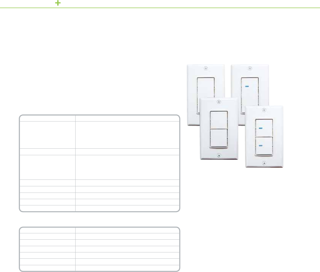
SchneiderElectricWallSwitchOccupancySensorsemploythelatestpassiveinfrared(PIR)technologyto
automaticallycontrollightinginofces,privaterestroomsandemployeebreakrooms.
EachSensoremploysaspecial180°multi-segmentedlensandPIRmotiondetectorcircuittodetectmotion.
Thisunitwillautomaticallyswitchthelightsoffafterapresetdelayifnomotionisdetected.
SchneiderElectricWallSwitchOccupancySensortsinplaceofexistingwallswitches,connectingtoexisting
activelineandgroundwiringsimilartoatypicalwallswitch.Noneutralorminimumloadisrequired.
Toassurelongrelaylife,SchneiderElectrichasdevelopedalowenergyswitchcircuittoassuremaximumcontact
life.Thesesensorsarecompatiblewithelectronicandmagneticballastloads,andrequirenominimumload.
Formaximumenergysavings,theSchneiderElectricWallSwitchOccupancySensorwithManual-Onrequiresthe
usertoswitchonlightingmanuallybypressingthebuttononthefront.Employingaspecial180°multi-segmented
lensandPIRmotionsensor,thesensorreliablydetectsoccupancytokeeplightsonwhiletheroomisoccupied.
Technical Information
Input 120or277Vac60Hz
Output 120Vac
1000Wmax.incandescentload
1000VAmax.ballastload
¼hpmax.motorload
277Vac
1800VAmax.ballastload
Operating Temperature 32°F–122°F(0°C–50°C)
Humidity 0–90%max.relativehumiditynon-condensing
Standard ULandcULListed
FCCPart15HomeandOfceUse(ClassB)
Title24Certied
*For Diagram see technical section page 18
Catalog Number Description
SLSPWS1277AI WallSwitchOccupancySensor(ivory)
SLSPWS1277AW WallSwitchOccupancySensor(white)
SLSPWS1277AL WallSwitchOccupancySensor(lightAlmond)
SLSPWS1277MW WallSwitchOccupancySensorWithManualOn(white)
SLSPWS1277MI WallSwitchOccupancySensorWithManualOn(ivory)
SLSPWS1277ML WallSwitchOccupancySensorwithManualOn(lightAlmond)
Product Features
•Availableinwhite,ivory
andlightalmondwith
matchingdecoratorwall
platecover
•AutoOn/AutoOff
•Manualbypass
•120or277Vacinput
(noneutralrequired)
•Nopowerpackrequired
•Nominimumload
•180°eldofview
(Upto1000sq.ft.)
•Useradjustabletime
delayfrom15second–
30minutes
•RedLEDmotionindicator
blinkstoindicatemotion
detection
•Suitableforuseonall
electronicandmagnetic
ballasts
•Furnishedwith(3)x6inch
externalwires(pigtails)
•UL®andcULListed
•Five-yearwarranty
Wall Switch
Occupancy Sensor Auto/Manual On
WallSwitchOccupancySensor
3
OCCUPANCY SENSORS WALL SWITCH OCCUPANCY SENSORSOCCUPANCY SENSORS WALL SWITCH OCCUPANCY SENSORS
Product Features
•Nousertimedelayand
sensitivityadjustments
necessary
•Availableinwhite,ivory,
andlightalmond
•Furnishedwithcover
plate
•ManualOn/ManualOffor
AutomaticOffoperation
•Noneutralorminimum
loadrequired
•Ratedforboth120V
incandescentand
uorescentlighting
•Title242005Residential
Lightingrequirements,
Sec.150(k)
•Nooverrideon
•Manual-ononly
(noauto-onmode)
•30minutetimedelay
•180°motiondetection
upto300sq.ft.(minor
motion)
•30secondgraceperiod
TheSchneiderElectricResidentialWallSwitchVacancySensordirectlyreplacesstandardlightswitches
inbathrooms,garages,laundryroomsandutilityroomsinaccordancewithTitle24requirementsfor
residentiallighting.
TheVacancySensoroperatesjustlikeastandardlightswitch,requiringabuttonpresstoturnlightson.
Lightsmaybeturnedoffwithabuttonpressorthesensorwillturnofflightingautomaticallywhentheareais
unoccupiedEmployingpassiveinfrared(PIR)technology,thesensorreliablydetectswhentheareahasbeen
vacatedthenturnsoffthelightingautomaticallyafteraxedtimedelayof30minutes.
TheVacancySensorfeaturesa‘graceperiod’.Ifthesensorshouldhappentoturnofflightingwhiletheareais
occupied,thesensorwillmonitorthearea,andturnlightingbackonautomaticallyifmotionisdetectedwithin
30secondsoftheinitialshutoff.Greatforretrots,theVacancySensortsinexistingwallboxesusingexisting
wiringandrequiresnoadjustment.
Technical Information
Input 120Vac±10%60Hz
Output 120Vac
• 1000Wmax.incandescentload
• 1000VAmax.ballastload
• ¼hpmax.motorload
Operating Environment 32°F–122°F(0°C–50°C)
Humidity 0–90%max.relativehumiditynon-condensing
Standards ULandcULListed
FCCPart15,HomeandOfceUse(ClassB)
Title24Certied
*For Diagram see technical section page 18
Catalog Number Description
SLSPWS120VW White
SLSPWS120VI Ivory
SLSPWS120VL LightAlmond
Wall Switch
Residential Wall Switch Vacancy Sensor
ResidentialWallSwitch
VacancySensor,LightAlmond
4

OCCUPANCY SENSORS WALL SWITCH OCCUPANCY SENSORS
Thedualcircuitsensoreasilyreplacestwowallswitchesusingexistingwiringwithnowiringmodications
required.Optional2-gangwallswitchcoverplatesavailableinmatchingcolors.Thesesensorsdonotrequire
aneutralconnectionorminimumload,makingitgreatforretrots.Easilyreplacesanexistingwallswitchusing
existingwiring–nowiring
modicationsrequired.Matchingwallswitchcoverplatemakesretrotscleanandsimple.
Technical Information
Input 120–277Vac±10%50/60Hz
Output 120Vac 277Vac
1000Wmax.tungsten
incandescentload
¼hpmax.motorload277Vac
1000VAmax.ballastload 1800VAmax.ballastload
Operating Temperature 32°F–122°F(0°C–50°C)
Humidity 0–90%max.relativehumiditynon-condensing
Time Delay Adjustment
Normal
Walk Through Mode
Test Mode
0.5–30minutes
2minutesifnoactivityisdetectedafter30seconds
15seconds
Light Level adjustment 0.5–250FC
Detection 180°passiveinfrared(PIR)
Audible Alert Selectable
Service Switch OFF/Auto/ON
Manual Operation Push-buttonON/OFF
Lens ImpactResistant
Relay Switching 0°±500uS
Standard ULandcULListed,FCCPart15/HomeandOfceUse(ClassB),Title24Certied
*For Diagram see technical section page 18
Catalog Number Description
SLSPWS1277UW White
SLSPWS1277UI Ivory
SLSPWS1277UG Gray
SLSPWS1277UL LightAlmond
SLSPWS1277UB Black
Catalog Number Description Blank Catalog Number Toggle Catalog Number Description
SLSPWD1277UW White SLSWP2DBW SLSWP2DTW White
SLSPWD1277UI Ivory SLSWP2DBI SLSWP2DTI Ivory
SLSPWD1277UG Gray SLSWP2DBG SLSWP2DTG Gray
SLSPWD1277UL LightAlmond SLSWP2DBL SLSWP2DTL LightAlmond
SLSPWD1277UB Black SLSWP2DBB SLSWP2DTB Black
Product Features
•Availableinwhite,ivory,
gray,lightalmondand
blackwithmatchingwall
switchcoverplate
•Colormatchingmulti-
segmentedlens
•Selectableauto-onand
manual-onmodes
•120–277Vac50/60Hz
input
•180°eldofview
•1000sq.ft.majormotion
and300sq.ft.minor
motioncoveragearea
•Lightlevelsensor
•Walk-throughmode
•Adjustablelightlevel,time
delayandsensitivity
•RedLEDmotionindicator
•Forusewithelectronic
andmagneticballasts
•Noneutralconnection,
minimumloadorpower
packrequired
•ULandcULListed
forUnitedStatesand
Canada
•Five-yearwarranty
SchneiderElectricSingleCircuitPIRWallSwitchOccupancySensorwithLight
Levelfeaturespassiveinfrared(PIR)technologytoconvenientlycontrollightingin
ofces,privatebathrooms,utilityroomsandemployeebreakrooms.Lowprole
sensoravailableinwhite,ivory,gray,lightalmondandblackwithcolor-matched
segmentedlenstomeetanydécorneed.
Adaptive Technology:Newtechnologyemploysadvancedalgorithmstoachieve
convenientenergysavingsandreducedlampandballastmaintenance.
Walk-Through Mode:Tomaximizeenergysavings,thesensordetectswhen
areasarebrieyoccupiedasaresultofapersonwalkingthroughandturnsoff
lightingbasedonashortertimedelay.
Light Level Sensor Mode:Eachsensorincludesanadjustablelightlevelsensor
toholdoffarticiallightingwhenadequatenaturallightispresent.Whennatural
lightlevelsdropbelowthethreshold,thesensorwillturnonarticiallightingin
occupiedspaces.
Lamp Saver Mode:(DualCircuitWallSwitch)Whenthelampsaverfeatureis
enabled,thesensorautomaticallyalternateswhichcircuitrespondstomotion.
Theresultismorepredictablelamplifeandreducedmaintenance.
Commercial Grade Occupancy Sensor
PIR Single and Dual Circuit Wall Switch
SingleCircuitWallSwitch
OccupancySensor
DualCircuitWallSwitch
OccupancySensor
5

OCCUPANCY SENSORS WALL SWITCH OCCUPANCY SENSORS
Product Features
•Availableinwhite,ivory,
gray,lightalmondand
blackwithmatchingwall
switchcoverplate
•Colormatchingmulti-
segmentedlens
•Selectableauto-onand
manual-onmodes
•120–277Vac
50/60Hzinput
•180°eldofview
•1000sq.ft.majormotion
and300sq.ft.minor
motioncoveragearea
•Lightlevelsensor
•Adjustablelightlevel,time
delayandsensitivity
•RedLEDmotionindicator
•Forusewithelectronic
andmagneticballasts
•Noneutralconnection,
minimumloadorpower
packrequired
•ULandcULListed
forUnitedStatesand
Canada
•Five-yearwarranty
SchneiderElectricSingleCircuitPIRWallSwitchOccupancySensorwithLightLevel
featurespassiveinfrared(PIR)technologytoconvenientlycontrollighting.
DualCircuitWallSwitchOccupancySensorsindependentlycontroltwolighting
circuitswithbi-levelswitchingtoreducelightingby50%whichmayberequired
byenergycodes.Thedualcircuitwallswitchoccupancysensoremployspassive
infrared(PIR)technologyanda180degreesegmentedlenstoachieveminormotion
coverageupto300squarefeet(27.87sq.meters).
Adaptive Technology: Newpatentpendingtechnologyemploysadvancedalgorithms
toachieveconvenientenergysavingsandreducedlampandballastmaintenance
Walk-Through Mode:Tomaximizeenergysavingsandreducewaste,thesensor
detectswhenareasarebrieyoccupiedasaresultofanoccupantwalkingthrough
andturnsofflightingbasedonashortertimedelay.
Light Level Sensor Mode:Eachsensorincludesanadjustablelightlevelsensorto
holdoffarticiallightingwhenadequatenaturallightispresent.Whennaturallightlevels
dropbelowthethreshold,thesensorwillturnonarticiallightinginoccupiedspaces.
Commercial Grade Occupancy Sensor
Ultrasonic Single and Dual Circuit Wall Switch
SingleCircuitWallSwitch
OccupancySensor
DualCircuitWallSwitch
OccupancySensor
Lamp Saver Mode:(DualCircuitwallswitch)whenthelampsaverfeatureisenabled,thesensorautomatically
alternateswhichcircuitrespondstomotion.Theresultismorepredictablelamplifeandreducedmaintenance.
Thesesensorsdonotrequireaneutralconnectionorminimumload,makingitgreatforretrots.Easilyreplaces
anexistingwallswitchusingexistingwiring–nowiring
modicationsrequired.Matchingwallswitchcoverplate
makesretrotscleanandsimple.
Technical Information
Input 120–277Vac±10%50/60Hz
Output 120Vac 277Vac
1000Wmax.tungsten
incandescentload
¼hpmax.motorload277Vac
1000VAmax.ballastload 1800VAmax.ballastload
Operating Temperature 32°F–122°F(0°C–50°C)
Humidity 0–90%max.relativehumiditynon-condensing
Time Delay Adjustment
Normal
Walk Through Mode
Test Mode
0.5–30minutes
2minutesifnoactivityisdetectedafter30seconds
15seconds
Light Level adjustment 0.5–250FC
Detection 180°passiveinfrared(PIR)
Audible Alert Selectable
Service Switch OFF/Auto/ON
Manual Operation Push-buttonON/OFF
Lens ImpactResistant
Relay Switching 0°±500uS
Standard ULandcULListed,FCCPart15/HomeandOfceUse(ClassB),Title24Certied
*For Diagram see technical section page 19
Catalog Number Description
SLSUWS1277UW White
SLSUWS1277UI Ivory
SLSUWS1277UG Gray
SLSUWS1277UL LightAlmond
SLSUWS1277UB Black
Catalog Number Description Blank Catalog
Number
Toggle Catalog
Number Description
SLSUWD1277UW White SLSWP2DBW SLSWP2DTW White
SLSUWD1277UI Ivory SLSWP2DBI SLSWP2DTI Ivory
SLSUWD1277UG Gray SLSWP2DBG SLSWP2DTG Gray
SLSUWD1277UL LightAlmond SLSWP2DBL SLSWP2DTL LightAlmond
SLSUWD1277UB Black SLSWP2DBB SLSWP2DTB Black
6

OCCUPANCY SENSORS WALL SWITCH OCCUPANCY SENSORS
Product Features
•Availableinwhite,ivory,
gray,lightalmondand
blackwithmatchingwall
switchcoverplate
•Colormatchingmulti-
segmentedlens
•Selectableauto-onand
manual-onmodes
•120–277Vac50/60Hz
input
•180°eldofview
•1000sq.ft.majormotion
and300sq.ft.minor
motioncoveragearea
•Lightlevelsensor
•Walk-throughmode
•Adjustablelightlevel,time
delayandsensitivity
•RedLEDmotionindicator
•Forusewithelectronic
andmagneticballasts
•Noneutralconnection,
minimumloadorpower
packrequired
•ULandcULListed
forUnitedStatesand
Canada
•Five-yearwarranty
SchneiderElectricSingleCircuitPIRWallSwitchOccupancySensorwithLightLevel
featurespassiveinfrared(PIR)technologytoconvenientlycontrollighting.
DualCircuitWallSwitchOccupancySensorsindependentlycontroltwolightingcircuits
withbi-levelswitchingtoreducelightingby50%whichmayberequiredbyenergy
codes.Thedualcircuitwallswitchoccupancysensoremployspassiveinfrared(PIR)
technologyanda180degreesegmentedlenstoachieveminormotioncoverageupto
300squarefeet(27.87sq.meters).
Adaptive Technology:Newpatentpendingtechnologyemploysadvanced
algorithmstoachieveconvenientenergysavingsandreducedlampand
ballastmaintenance.
Walk-Through Mode:Tomaximizeenergysavings,thesensordetectswhenareas
arebrieyoccupiedasaresultofapersonwalkingthroughandturnsofflightingbased
onashortertimedelay.
Light Level Sensor Mode:Eachsensorincludesanadjustablelightlevelsensorto
holdoffarticiallightingwhenadequatenaturallightispresent.Whennaturallightlevels
dropbelowthethreshold,thesensorwillturnonarticiallightinginoccupiedspaces.
Commercial Grade Occupancy Sensor
Dual Technology Single and Dual Circuit Wall Switch
SingleCircuitWallSwitch
OccupancySensor
Lamp Saver Mode:(DualCircuitsensor)Whenthelampsaverfeatureisenabled,thesensorautomatically
alternateswhichcircuitrespondstomotion.Theresultismorepredictablelamplifeandreducedmaintenance.
Thesensordoesnotrequireaneutralconnectionorminimumload,makingitgreatforretrots.Easilyreplaces
anexistingwallswitchusingexistingwiring–nowiringmodicationsrequired.Matchingwallswitchcoverplate
makesretrotscleanandsimple.
Technical Information
Input 120–277Vac±10%50/60Hz
Output 120Vac 277Vac
1000Wmax.tungsten
incandescentload
¼hpmax.motorload277Vac
1000VAmax.ballastload 1800VAmax.ballastload
Operating Temperature 32°F–122°F(0°C–50°C)
Humidity 0–90%max.relativehumiditynon-condensing
Time Delay Adjustment
Normal
Walk Through Mode
Test Mode
0.5–30minutes
2minutesifnoactivityisdetectedafter30seconds
15seconds
Light Level adjustment 0.5–250FC
Detection 180°passiveinfrared(PIR)
Audible Alert Selectable
Service Switch OFF/Auto/ON
Manual Operation Push-buttonON/OFF
Lens ImpactResistant
Relay Switching 0°±500uS
Standards ULandcULListed,FCCPart15/HomeandOfceUse(ClassB),Title24Certied
*For Diagram see technical section page 19
Catalog Number Description
SLSDWS1277UW White
SLSDWS1277UI Ivory
SLSDWS1277UG Gray
SLSDWS1277UL LightAlmond
SLSDWS1277UB Black
Catalog Number Description Blank Catalog
Number
Toggle Catalog
Number Description
SLSDWD1277UW White SLSWP2DBW SLSWP2DTW White
SLSDWD1277UI Ivory SLSWP2DBI SLSWP2DTI Ivory
SLSDWD1277UG Gray SLSWP2DBG SLSWP2DTG Gray
SLSDWD1277UL LightAlmond SLSWP2DBL SLSWP2DTL LightAlmond
SLSDWD1277UB Black SLSWP2DBB SLSWP2DTB Black
DualCircuitWallSwitch
OccupancySensor
7

OCCUPANCY SENSORS ACCESSORIES
ButtonCovers
(SLSBCB,SLSBCG,SLSBCI,
SLSBCL,andSLSBCW)
2GangWallplate
(SLSWP2DBB)
2GangWallplate
(SLSWP2DBG)
2GangWallplate
(SLSWP2DBI)
2GangWallplate
(SLSWP2DBL)
2GangWallplate
(SLSWP2DBW)
2GangWallplate
(SLSWP2DTB)
Button Covers for Commercial grade Single Circuit Sensors
Catalog Number Description
SLSBCB ButtonCoverBlack
SLSBCG ButtonCoverGray
SLSBCI ButtonCoverIvory
SLSBCL ButtonCoverLightAlmond
SLSBCW ButtonCoverWhite
2 Gang Wall plate, One Decorator opening and One Blank side.
Catalog Number Description
SLSWP2DBB 2GangCover,withOneDecoratoropeningBlack
SLSWP2DBG 2GangCover,withOneDecoratoropeningGray
SLSWP2DBI 2GangCover,withOneDecoratoropeningIvory
SLSWP2DBL 2GangCover,withOneDecoratoropeningLightAlmond
SLSWP2DBW 2GangCover,withOneDecoratoropeningWhite
2 Gang Wall plate, One Toggle Switch opening and One Blank side.
Catalog Number Description
SLSWP2DTB 2GangCover,withOneToggleswitchopeningBlack
SLSWP2DTG 2GangCover,withOneToggleswitchopeningGray
SLSWP2DTI 2GangCover,withOneToggleswitchopeningIvory
SLSWP2DTL 2GangCover,withOneToggleswitchopeningLightAlmond
SLSWP2DTW 2GangCover,withOneToggleswitchopeningWhite
Replacement Kits
Catalog Number Description
SLSCRK CeilingSensorReplacementPartsKit
Sensor Accessories
Blank Button Covers, Wall Plate toggle opening
and
Wall Plate Decorator and Ceiling sensor
replacement kit
8

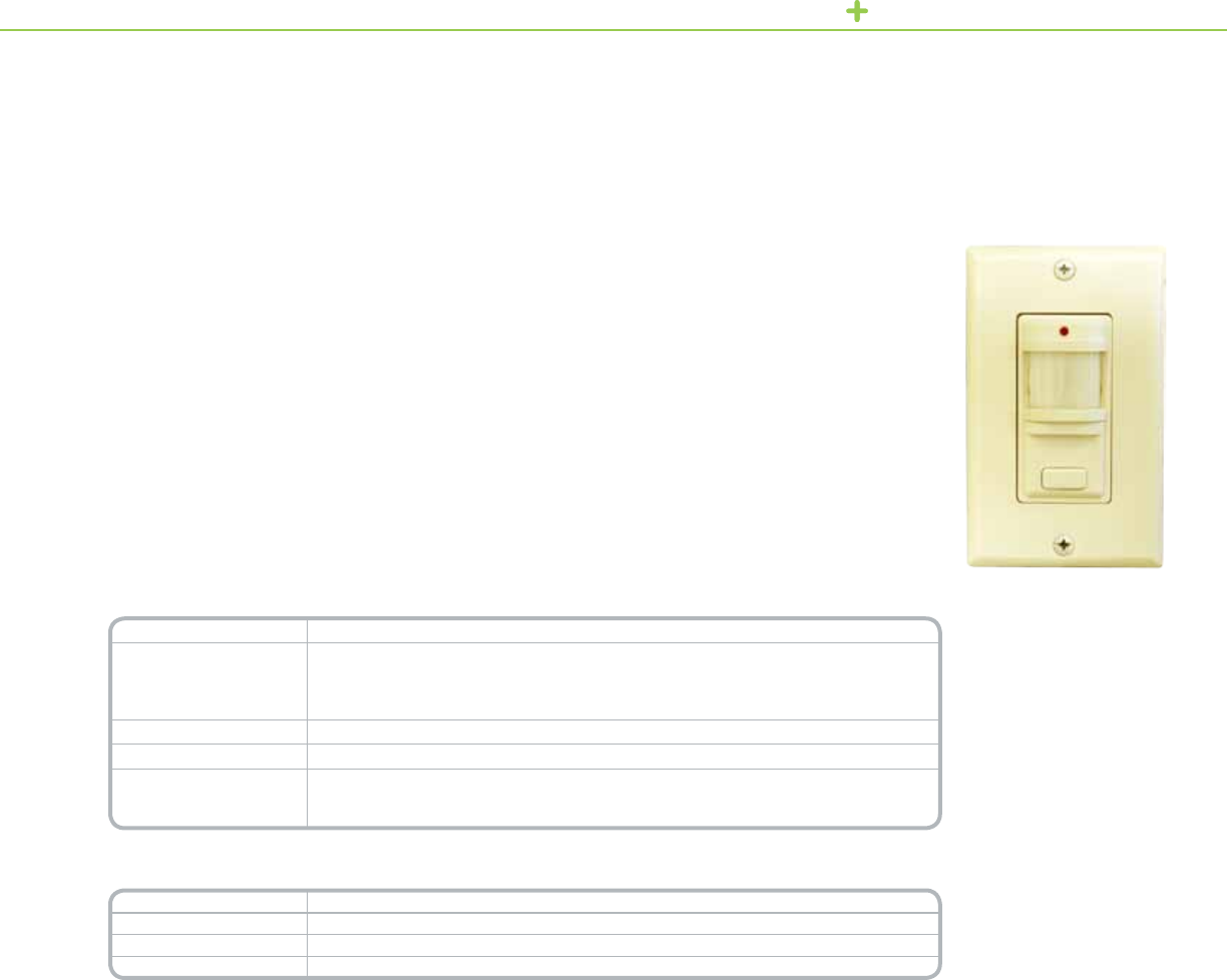
OCCUPANCY SENSORS CEILING MOUNTED OCCUPANCY SENSORS
CeilingMountedPassiveInfrared(PIR),UltrasonicandDualTechologyOccupancy
Sensorsaccuratelydetectoccupancyandautomaticallyswitcheslightingonandoff
asneeded.Thislowprolesensorisceilingmountedforsuperiormotiondetection.
PIR:360degreeeldofviewandupto1000squarefeet(92.90sq.meters)of
coveragearea.
Ultrasonic:360degreeeldofviewandupto2000squarefeet(185.8sq.meters)
ofcoveragearea.
Dual Technology:IncorporatesbothPassiveInfraredandUltrasonictechnology
witha360degreeeldofviewandupto2000squarefeet(185.8sq.meters)of
coveragearea.
Ceilingmountsensorsalsoincorporateanintegrallightlevelsensortoprevent
lightingfromswitchingOnwhensufcientambientlightispresent,suchasis
commonlyfoundinwindowedareas.
Installationandcongurationissimple.Thesensorreadilymountstodropceilings
andfeaturesfrontlocatedadjustmentsforsettingsensitivityandtimedelay.Features
anisolatedrelayforusewithbuildingautomation,securityandHVACsystems.
Technical Information
Current Consumption
@ 24 Vdc
21mANominal(PIR),34mANominal(Ultrasonic),37mANominal(DualTechnology)
Supply Voltage 24Vdc
Isolated Relay 1A@24VdcResistive
Operating Temperature 32°F–122°F(0°C–50°C)
Max. Humidity 0–90%max.relativehumiditynon-condensing
Standards ULandcULListed,FCCPart15/HomeandOfceUse(ClassB),Title24Certied
*For Diagram see technical section page 19 and 20
Catalog Number Description
SLSCPS1000 CeilingMountedPIROccupancySensor
SLSCUS2000 CeilingMountedUltrasonicOccupancySensor
SLSCDS2000 CeilingMountedDualTechnologyOccupancySensor
SLSPP1277 PowerPack(required)
SLSSP24 AuxiliaryRelay(optional)
Product Features
•24VacforusewithBAS
systems
•360degreeeldofview
•LightLevelSensing(from
0.5to250foot-candles)
•AdjustableTimeDelay
(pre-settimedelays
from15seconds(test)
to30minutes)
•AdjustableSensitivity
(from60to100%)
•IsolatedRelay(1Aat
24VdcNOandNC
FormCRelay)
•RedLEDMotionIndicator
•Adjustmentcompartment
coverequippedwith
retentionclip
•UL/cULListed
•ManualBypass
•Five-yearwarranty
Ceiling Mounted Occupancy Sensor
PIR/Ultrasonic/Dual Technology
CeilingMountedOccupancy
SensorPIR
CeilingMountedOccupancy
SensorUltrasonic
DualCircuitWallSwitch
OccupancySensor
9
OCCUPANCY SENSORS CEILING MOUNTED OCCUPANCY SENSORS
The180DegreeCeiling-MountedOccupancySensorsareidealforuseinbusiness
andofcesettingstoaccuratelydetectoccupancyandautomaticallycontrollighting.
Theceiling-mountdesignoftheselow-prolesensorsallowsthegreatestpossible
motionsensitivity.Anadjustmentpanelisconvenientlylocatedonthefrontofthe
sensor,providingreadyaccesstosettingcontrolsafterthesensorisinstalled.These
occupancysensorsareavailableintheultrasonicanddualtechnologymodels.The
dualtechnologymodelemployspassiveinfrared(PIR)andultrasonictechnology.
Technical Information
Ultrasonic Dual
Current Consumption
@ 24 Vdc** Active:30mA Active:33mA
Isolated relay Contactrating:1A@24VdcResistive
Operating Temperature 32°Fto122°F(0°Cto50°C)
Humidity 0–90%max.relativehumiditynon-condensing
Standards
ULandcULListed
FCCPart15
HomeandOfceUse(ClassB)
CaliforniaTitle24Certied
*For Diagram see technical section page 20 and 21
**Control power must be provided by the Power Pack SLSPP1277 or an approved equivalent.
Catalog Number Description
SLSCUS800 180DegreeUltrasonicsensor
SLSCDS800 180DegreeDualTechnologySensor
SLSPP1277 PowerPack(required)
SLSSP24 AuxiliaryRelay(optional)
Product Features
•1000sq.ft.
coveragearea
•180°eldofview
•Newpatentpending
adaptivetechnology
employsadvanced
algorithmstoachieve
convenientenergy
savingsandreducelamp
andballastmaintenance.
•Ambientlightlevel
sensingfrom0.5to
250foot-candles
•Adjustabletimedelay
from15sec.to30min.
•Adjustablesensitivity
from600to1000sq.ft.
(10-100%ofmaximum
coverage)
•Isolatedrelay(FormC
contactsforClass2
signalling)
•LEDmotionindicators
(ultrasonic=1red,
dualtechnology=1red,
1green)
180DegreeUltrasonic
OccupancySensor
180DegreeDualTechnology
OccupancySensor
180 Degree Ceiling-Mounted Occupancy Sensor
Ultrasonic/Dual Technology
10

OCCUPANCY SENSORS WALL MOUNTED OCCUPANCY SENSORS
SchneiderElectricWallMountedSensorsaccuratelydetectsoccupancyand
automaticallyswitcheslightingonandoffasneeded.Thissensoriswallorceiling
mountedforsuperiormotiondetection.
ThePIROccupancySensorincludes3interchangeablelensesforcustomcoverage
patterns.TheWideAnglelenshasa2500squarefootcoverageareawhenthe
sensorismounted8feethigh,theLongRangelenshasa102linearfootcoverage
area@10ft.highandtheHighBaylenshasa54linearfootcoveragearea@30ft.
high.Witha110degreeeldofview.
With1000squarefeetofcoveragearea,theSchneiderElectricPIRWallMounted
UltrasonicOccupancySensorisidealforstoragerooms,hallways,bathrooms,
conferencerooms,classroomsandopenofceareas.
Toreducetheoccurrenceoffalseonevents,theDualTechnologySensoremploys
PIRtechnologytodetectmajormotion.Oncelightinghasbeenturnedon,itemploys
highlysensitivePIRandultrasonictechnologytodetectminormotionandkeeplighting
Product Features
•Interchangeablelenses
forcustomcoverage
pattern(PIR)
•110degreeeldofview
•LightLevelSensing(from
0.5to250foot-candles)
•AdjustableTimeDelay
(pre-settimedelaysfrom
15secondsto30minutes)
•AdjustableSensitivity
(from60to100%)
•IsolatedRelay
•RedLEDMotionIndicator
(PIR/Ultrasonic)
•RedandGreenLED
Motionindicator
(DualTechnology)
•Frontlocatedadjustment
accesscover
•UL/cULListed
WallMountedOccupancy
SensorPIR
Wall Mounted Occupancy Sensor
PIR/Ultrasonic/Dual Technology
WallMountedOccupancy
SensorUltrasonic
onwhileareasremainoccupied.Whentheroomorareaisnolongeroccupied,thesensorturnsofflightingafter
apre-settimedelay.Thelowprolesensoriswallmountedforgreatestsensitivitytomotioninlargeareaswith
obstructions.Witha110degreeeldofviewandupto2500squarefeetofcoverageareawhenmountedat8ft.
offtheground,theWallMountedDualTechnologyOccupancySensorisidealforconferencerooms,classrooms,
bathrooms,andlargeofceareas.
WallmountsensorsalsoincorporateanintegrallightlevelsensortopreventlightingfromswitchingOnwhen
sufcientambientlightispresent,suchasiscommonlyfoundinwindowedareas.
Installationandcongurationissimple.Thesensorreadilymountstowallsaswellas
dropceilingsandfeatures
frontlocatedadjustmentsforsettingsensitivityandtimedelay.
Featuresanisolatedrelayforusewithbuilding
automation,securityandHVACsystems.
Technical Information
Current Consumption
@ 24 Vdc
21mANominal(PIR),34mANominal(Ultrasonic),37mANominal(DualTechnology)
Supply Voltage 24Vdc
Isolated Relay 1A@24VdcResistive
Operating Temperature 32°F–122°F(0°C–50°C)
Max. Humidity 0–90%max.relativehumiditynon-condensing
Standards ULandcULListed,FCCPart15/HomeandOfceUse(ClassB),Title24Certied
*For Diagram see technical section page 21 and 22
Catalog Number Description
SLSWPS1500 WallMountedOccupancySensorPIR
SLSWUS1500 WallMountedOccupancySensorUltrasonic
SLSWDS1500 WallMountedOccupancySensorDualTechnology
SLSPP1277 PowerPack(required)
SLSSP24 AuxiliaryRelay
WallMountedOccupancy
SensorDualTechnology
11
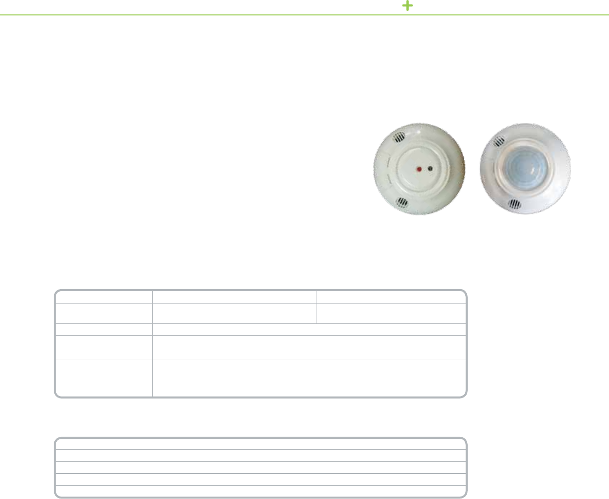
OCCUPANCY SENSORS POWER PACK AND AUXILIARY RELAY
ThePowerPacksupplieslowvoltagepowertoSchneiderElectricceilingandwall
mountedoccupancysensors,andemploysaheavyduty20Arelaytoswitchlighting
andHVACloadsbasedonacontrolsignalreceivedfromtheoccupancysensor.
Thepowerpackemploysamicro-controllerthatswitchesloadsatminimum
voltage,protectingrelaycontactsfromhighin-rushcurrentcommonwhenswitching
electronicballasts.Thisswitchingmethodreducesthestressacrosstherelay
contacts,preventingarc-overandassuringlongreliablecontactlife.
Similartothepowerpack,theauxiliaryrelaydoesnotsupplypower,butswitches
lightingandHVACloadsbasedonacontrolsignalfromtheoccupancysensor.
Boththepowerpackandauxiliaryrelayarehousedinaruggedplenumrated
enclosure.Flexiblemountingschemeallowsforinstallationinsideoroutsidea
standard4x4inchjunctionbox.
Technical Information (120V, 277V)
Power Pack Auxiliary Relay
Storage Temp -20°Fto150°F(-29°Cto65°C) -20°Fto150°F(-29°Cto65°C)
Operating Temperature 32°Fto104°F(0°Cto40°C) 32°Fto104°F(0°Cto40°C)
Max. Humidity 0–90%max.relativehumiditynon-condensing 0–90%max.relativehumiditynon-condensing
Input 120or277Vac/60Hz 24Vdc/36mA
Output 24Vdc/100mANominal NoPowerSupply
Max Load Ratings 120Vac/60Hz 277Vac/60Hz 120Vac/60Hz 277Vac/60Hz
Tungsten 15A/1800W 15A/1800W 15A/1800W 15A/1800W
Ballast 20A 20A 20A 20A
AC Motor 1HPat120Vac/NoHPratingat277Vac
Dimensions 3in.(76mm)tallx2.25in.(57mm)widex1.75in.(44mm)deep
*For Diagram see technical section page 22
Technical Information (347V)
Power Pack Auxiliary Relay
Storage Temp -20°Fto150°F(-29°Cto65°C) -20°Fto150°F(-29°Cto65°C)
Operating Temperature 32°Fto104°F(0°Cto40°C) 32°Fto104°F(0°Cto40°C)
Max. Humidity 0–90%max.relativehumiditynon-condensing 0–90%max.relativehumiditynon-condensing
Input 347Vac/60Hz 347Vac/60Hz
Output 24Vdc/150mAMax. NoPowerSupply
Max Load Ratings 347Vac/60Hz 347Vac/60Hz 347Vac/60Hz 347Vac/60Hz
Ballast 15Aballast,5200Watts
Dimensions 3in.tallX2.25in.wideX1.75in.deep[76mmtallX57mmwideX44mmdeep]
Standards ULandcULListed
FCC:Part15,HomeandOfceUseClassB
*For Diagram see technical section page 22
Catalog Number Description
SLSPP1277 OccupancySensorPowerPack120–277Vac
SLSSP24 OccupancySensorAuxiliaryRelay120–277Vac
SLSPP1347 OccupancySensorPowerPack347Vac
SLSSP24347 OccupancySensorAuxiliaryRelay347Vac
Power Pack and Auxiliary Relay
120V, 277V and 347V
PowerPack
Product Features
•120V,277Vand
347VInput
•PlenumRated
•FlexibleMountingOptions
•ULandcULListed
•FCCPart15,ClassB
•Heavydutyrelayrated
toswitchelectronic
ballastloads
•Externalcolorcoded
leadsforquickinstallation
•Mountstoastandard
4in.(101mm)x4in.
(101mm)junctionbox
usinga½in.(12.7mm)
threadedEMTnipple
•UL/cULListed
12

OCCUPANCY SENSORS CEILING MOUNTED OCCUPANCY SENSORS
TheCeilingMounted360°LineVoltageOccupancySensorlinefromSchneiderElectric,
areClass1devicesdesignedtooperatewithindoorlightingxturesperformingthe
switchingofelectricalloadsinresponsetoacontrolsignalfromthedetectioncircuitry
ofthedevice.Theoccupancysensorseasilymounttoastandard3.5in.(89mm)
octagonalelectricalboxaswellasa4in.(10.2cm)square(1900type)electrical
boxwithmudring.Thepowersectionofthesensortsintotheelectricalbox.The
occupancysensorsoperatefrom120Vacto347Vacat60HZ.
Technical Information
Operating Range VAC 120Vac:1000WMaxballastload,or1000WTungsten,
or¼Hpmotor
230Vac:1500WMaxballastload
277Vac:1800WMaxballastload
347Vac:1500WMaxballastload
Frequency 120Vac:60Hz
230Vac,277Vac,347Vac:50Hzor60Hz
Operating Temperature 32°Fto122°F(0°Cto50°C)
Humidity 0–90%max.relativehumiditynon-condensing
Standards ULandcULListed
FCCPart15,HomeandOfceUse(ClassB)
CaliforniaTitle24Certied
*For Diagram see technical section page 23 and 24
Catalog Number Description
SLSCLP1000 PassiveInfrared(PIR)OccupancySensors
SLSCLU2000 Ultrasonic(US)OccupancySensors
SLSCLD2000 DualTechnology(DT)OccupancySensors
Ceiling Mounted Line Voltage Occupancy Sensors
PIR/Ultrasonic/Dual Technology
CeilingMountedLineVoltage
OccupancySensorPIR
CeilingMountedLineVoltage
OccupancySensorUltrasonic
DualCircuitCeilingMounted
LineVoltageOccupancySensor
Product Features
All Models:
•Adjustablesensitivity
•ManualorAutomaticLightlevelfeaturefor
daylightharvesting
•Delay-offtimersettingcontrol—factorysetto18min.
formaxenergyvslamplife
•“AdaptiveTiming”modiestime-outvaluebasedon
occupancyactivities
•TimedelayTestmodeforsensorplacementtesting
•Lowcurrentconsumptioncircuitdesign
•“Walkthroughmode”forsensorsusedinhallways
andcorridors
PIR/Dual Technology:
•Interchangeable500or1000sq.ft.lenses
•“AdaptivePIR”movessensitivityofthesensorbased
onoccupancydetection
•DualTechLogicEngine—(ModesofOperation)
(DualTechmodelonly)
13

OCCUPANCY SENSORS HIGH BAY OCCUPANCY SENSORS
Sensorandoptional
counterweightmounted
onluminaire
SchneiderElectricHighBayHIDBasic,SingleandDualOutputOccupancySensors
workwithasingleHID(highintensitydischarge)luminairetoreducethelamp
wattagebyapproximately50%andthenreturnthelampwattageto100%when
occupancyisdetectedinanaisleorroom.Motionisdetectedusingpassiveinfrared
(PIR)technology.
BasicHIDSensorsareusedinsensor-per-xtureconguration,whilesingleoutput
sensorsincludeaconnectortosendandreceiveberopticsignals.Singleoutput
sensorsarecommonlyusedindaisychaincongurations.Dualoutputsensorshave
twoconnectorsthatsendberopticsignals,andarecommonlyusedincongurations
thatinterleaveswitchpacksandsensors.AllSensorsarecompatiblewithsingle
magneticHIDluminaires.
Technical Information
Fixture Compatibility HIDwithconstantwattageauto-transformerballast
Dimming Method Relay-switcheddual-sectioncapacitor
Switching Congurations Parallel(preferred)orseriescapacitors
Relay Current Rating 4amperesRMSmaximum
Maximum Fixture Wattage 1000wattsparallelmode/250wattsseriesmode
AC Line Voltage 120/208/240/277/347/480Vac
Power Consumption 3wattsmaximum
Maximum Fiber Spacing
Between Nodes 200ft.
Ambient Temperature
Range 32˚Fto122˚F(0˚Cto50˚C)non-condensing
Observed Motion ON Time 0to15minutes(user-adjustable)
Lamp Warm Up Interval 15minutes
Wire Harness 4conductor18AWGstrandedcopperwire
Wire Harness Length 36inches(91.44cm)
Dimensions
(including mounting nipple)
3.25in.(L)x3.25in.(W)x3.25in.(H)
[82.56mm(L)x82.56mm(W)x82.56mm(H)]
Standards ULListed916EnergyManagementEquipment,cULListed
*For Diagram see technical section page 25
Catalog Number Description
SLSPIP210 HIDOccupancySensor
SLSPIP211 HIDSingleOpticalOutputOccupancySensor
SLSPIP212 HIDDualOpticalOutputOccupancySensor
SLSPCW001 OptionalCounterweight
SLSPIP210EB HIDOccupancySensorElectronicBallast
SLSPIP210CT HIDOccupancySensorMagneticBallastColdTemperature
SLSPIP210EBCT HIDOccupancySensorElectronicBallastColdTemperature
SLSPSP101 HIDSwitchPackwithopticalcontrolports(1input/1output)
SLSPSP102 HIDSwitchpackwithopticalcontrolports(2inputs)
Product Features
•CompatiblewithHID
luminairesratedbetween
208and480Vac/60Hz,
withoutaddingtapsor
jumpers
•Upto40'mountingheight
•User-adjustable1to
15minuteactivitytimer
•User-adjustablerange
dialtocustomizePIR
sensitivity
•Availablewith
interchangeableaisle
andarealenses
•Lampalwaysstartson
hightoprovidefullrated
HIDlamplife,evenafter
ACpowerbumpsorloss
ofberopticsignals
•Includesamanualtest
switchforselfdiagnostics
thatassistwithinstallation
anddebuggingnetworks
High Bay Occupancy Sensor
HID
HighBayOccupancySensor
14

OCCUPANCY SENSORS HIGH BAY OCCUPANCY SENSORS
TheFluorescentHighBayPIRSensors(SLSFPS1347orSLSFPS1480)bySchneiderElectric
aredesignedforusewithT5andT8uorescentxturesinhighorlowbay,areaorisle
applications.ThesensorssaveenergybyusingPassiveInfrared(PIR)technologytodetect
motionandturningofflightsinunoccupiedareas.TheSLSFPS1347usesautomaticvoltage
sensingallowingthesamedevicetobeinstalledindifferentvoltagesystemsrangingfrom
120—347V.TheSLSFPS1480isdesignedspecicallyfor480Vapplications.Installationis
simplebecausedrop-downbracketsarenotrequired.
Technical Information
SLSFPS1480 SLSFPS1347
Fixture Compatibility T5andT8FluorescentFixtures
AC Line Voltage Black/Blackwires
480Vac±10%,60Hz
White/Blackwires
120/277/347Vac±10%,60Hz
Output Contact Rating 2000WMaxBallastLoad 1000/1800/1500WMaxBallastLoad
Ambient Temperature
Range 32°Fto158°F(0°Cto70°C)non-condensing
Observed Motion ON time 15secondsto30minutes
Dimensions (including
mounting nipple) (HxWxD) 4.96in.x3.25in.x3.25in.(126mmx82.56mmx82.56mm)
Standards ULandcULListed
*For Diagram see technical section page 25
Catalog Number Description
SLSFPS1347 OccupancySensor(120–347V)FluorescentHighBayPIR
SLSFPS1480 OccupancySensor(480V)FluorescentHighBayPIR
Product Features
•Includesauser-adjustable
timedialtosetthelength
oftimetheluminairesstay
onfrom15secondsto
30minutes.
•Includesauser-adjustable
rangedialtocustomize
PIRsensitivity.
•90degreerotatinglens
foravarietyofaisle-way
applications.
•Highbayarea,lowbay
area,andhighbayaisle
lensesprovided.
•18minutestime-out
presetformaximum
energytolamplife
savings.
High Bay PIR Occupancy Sensor
Fluorescent
FluorescentHighBayPIR
OccupancySensor
15

OCCUPANCY SENSORS OCCUPANCY CONTROLLER
TheOccupancyControllerfromSchneiderElectrichastwolightingcontrolrelays,anoccupancysensor
powersupply,twoauxiliaryinputswitches,twotimers(oneperrelay),andtworelaydefaultmode
switchesassociatedwitheachrelay.Theoccupancycontrollerprovidesasimpleall-in-onesolutionfor
dimming,on-offoperation,andpoweringofsensors.Itoperatesoverawiderangeofinputvoltages
(100–277Vac)andisdesignedforabove-ceilinginstallation.Theoccupancycontrollerisidealfor
in-roomoccupancycontrolapplicationssuchasclassrooms,open-ofcespace,executiveofcesand
conferencerooms.
Technical Information
Power Supply Voltage 100–277Vac
Power Supply Frequency 50–60Hz
Motion Sensor Power Supply Poweroutput280mA(140mAperdetectorconnection)
Power Supply Rating 24VdcSELV/Class2
Relay Rating Resistive:16Aat277Vac,Incandescent/Tungsten:12Aat277Vac
Fluorescent(UL)Standardballast:10Aat277Vac(inductive0.4–0.5pf)
Connections
(Screw-type Phoenix-style Connectors)
Input:14–12AWG(2.5–4mm²)
Relayoutput:14–12AWG(2.5–4mm²)
Motiondetector:3-pin,1perrelaypresent
Auxiliaryinput:2-pin,1perrelaypresent
Maximum Operating Temp. 122°F(50°C)approvedforuseinaplenum
Operating Humidity 10–90%max.relativehumiditynon-condensing
Dimensions (H x W x D) 8.0x7.87x2.36in.(203x200x60mm)
Standards (Title) CSAC22.2No.205(SignalEquipment),UL916(EnergyManagementEquipment)
FCCPart15(ClassBDigitalDeviceforHomeorOfceUse)
*For Diagram see technical section page 26
Catalog Number Description
5752PP/2R OccupancyControllerwith2relays,withC-Busconnection
5752PP/2R/2D OccupancyControllerwith2relaysand20-10Vdimmers,withC-Busconnection
752PP/2R OccupancyControllerwith2relays,nonetworkconnection
Compatible Sensors
Sensor Description
SLSCPS1000 CeilingmountPIRmotionsensor,360°detectionpattern,isolatedrelay
SLSCUS2000 CeilingmountUltrasonicmotionsensor,360°detectionpattern,isolatedrelay
SLSCDS2000 CeilingmountDual-technology(PIRandUltrasonic)motionsensor,
360°detectionpattern,isolatedrelay
SLSCUS800 CeilingmountUltrasonicmotionsensor,180°detectionpattern,isolatedrelay
SLSCDS800 CeilingmountDual-technology(PIRandUltrasonicmotionsensor,
180°detectionpattern,isolatedrelay
SLSWPS1500 WallmountPIRmotionsensor,110°detectionpattern,isolatedrelay
SLSWUS1500 WallmountUltrasonicmotionsensor,isolatedrelay
SLSWDS1500 WallmountDual-technology;PIRandultrasonicmotion
Product Features
•Inputvoltagerange:
100–277Vac50/60Hz
•Oneoccupancysensor
inputterminalfor
eachrelay
•24Vdcpowersupplyfor
themotiondetectors
•Oneauxiliaryinputswitch
terminalforoverridesand
anonboardtimerfor
eachrelay
•Onerelayfail-safemode
switchforeachrelay
•Remoteoverrideon/off
capability
•Class1andClass2
voltageisolation
Occupancy Controller
OccupancyController
16
WIRING DEVICES LOW VOLTAGE SWITCHES
Low Voltage Switches
TheSchneiderElectricLowVoltageSwitchesareaseriesofaestheticallypleasing
pushbuttonwallswitchesthatcanbemountedinvariousapplications.Thelow
voltageswitchesaredesignedtooperatewithSchneiderElectricOccupancy
Controllers,Powerlink,C-Bus,andrelaypanels.Allswitchmodelsareavailable
inwhite,almond,andivory.
Technical Information
Connection type ExternalwiresGauge:#22AWGstranded
Number of conductors/switch
SLSLVS1:2
SLSLVS1L:4
SLSLVS2:3
SLSLVS2L:7
SLSLVS1R:2
SLSLVS2R:3
Switch Operating Range 5–36VdcMaxcurrentof50mA@36Vdc
LED Operating Range
5–36Vdc
Minoperatingcurrent.150ma@5Vdc
Minoperatingcurrent.275ma@12Vdc
Minoperatingcurrent.385ma@24Vdc
Minoperatingcurrent.470ma@36Vdc
Conductor temperature rating Notspecied,selecttomeetULClass2requirements
Conductor voltage rating 5to36Vdc
Conductor length 6inchesfromhousing
Temperature 0–122°F(50°C)
Humidity 0–90%max.relativehumiditynon-condensing
*For Diagram see technical section page 26
Catalog Number Description
SLSLVS1x 1-button,lowvoltageswitch
SLSLVS1Lx 1-button,lowvoltageswitchwithLED
SLSLVS2x 2-button,lowvoltageswitch
SLSLVS2Lx 2-button,lowvoltageswitchwithLED
SLSLVS1Rx 1-buttonSchneiderElectricrelaypanelswitchwithLED
SLSLVS2Rx 2-buttonSchneiderElectricrelaypanelswitchwithLED
'X' – Designates color: W: White, I: Ivory, G: Gray, L: Light Almond, B: Black
LowVoltageSwitches
Product Features
•Providesimplemomentarypushbuttoncontrol.
•LEDmodelsprovidepilotlightsorstatusoutputs.
•Operateonvoltagerangesfrom5–36Vdc.
•CertainmodelsaredesignedforusewithSchneider
Electricrelaypanels.
•SwitcheststandardNEMAwallboxes.
•Decorator-styleenclosure;wallplateincluded.
17
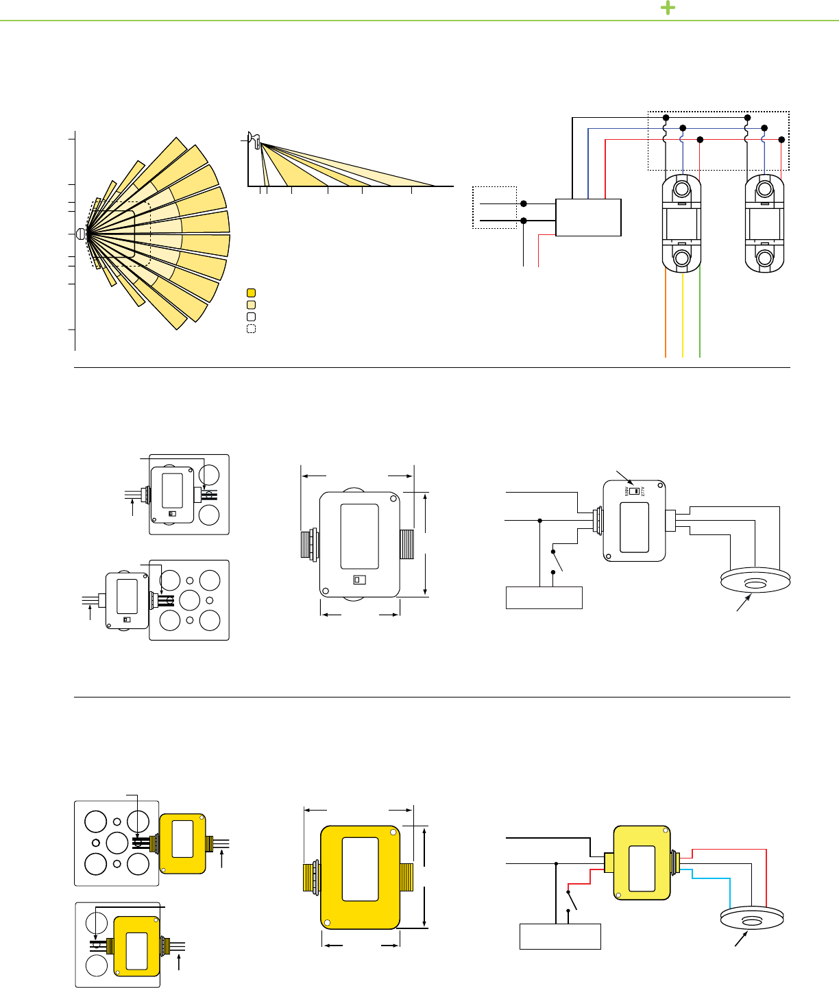
OCCUPANCY SENSORS TECHNICAL SECTION
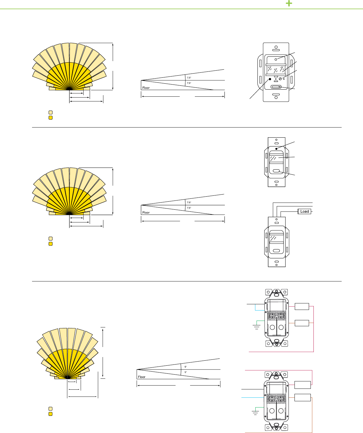
Wall Switch Occupancy Sensor
Residential Wall Switch Vacancy Sensor
Commercial Grade Occupancy Sensors
PIR Wall Switch
Sensor features
Vacancy Sensor Features
Vacancy Sensor Wiring Diagram
Sensor Wiring, Dual Circuit
Sensor Wiring, Bi-level
LED
PIR Motion Sensor Lens
Time-delay Setting:
15 sec. min. (Fully CCW)
30 min. max. (fully CW)
Auto/OFF Button
LED
PIR Motion Sensor Lens
Manual ON/OFF Button
(Push ON/Push OFF)
Hot (BLK)
Ground (GRN)
Neutral
(RED)
Bypass button
(In = Always ON, OUT = Normal Operation)
Sensor field of view
35 ft.
(10.7 m)
4 ft.
(1.2 m)
Sensor field of view, Side
35 ft.
(10.7 m)
4 ft.
(1.2 m)
Side view of sensor field of view
35 ft.
(10.7 m)
4 ft.
(1.2 m)
Major Motion
Minor Motion
35 ft.
(10.7 m)
10 ft. (3.1 m)
15 ft. (4.6 m)
25 ft. (7.6 m)
Major Motion
Minor Motion
Major Motion
Minor Motion
35 ft.
(10.7 m)
10 ft. (3.1 m)
15 ft. (4.6 m)
25 ft. (7.6 m)
35 ft.
(10.7 m)
6 ft. (1.83 m)
9 ft. (2.74 m)
21 ft. (6.4 m)
Line
Ground
Ground
Neutral
Neutral
Neutral
BK
BK
R
R
Primary
Load
Primary
Load
Secondary
Load
Secondary
Load
BR
BR
BL
BL
GN
GN
Line 1
Line 2
18
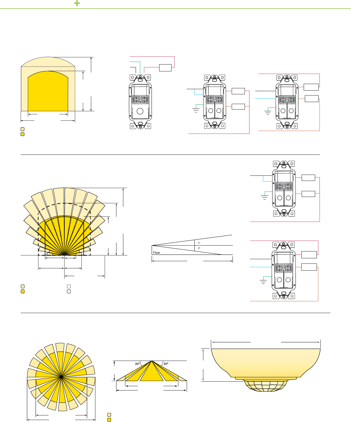
OCCUPANCY SENSORS TECHNICAL SECTION
Single and Dual Technology Sensor Field of View, Top
Commercial Grade Occupancy Sensors
Dual Technology Wall Switch
Commercial Grade Occupancy Sensors
Ultrasonic Wall Switch
Side view of sensor field of view
Ceiling Mounted Occupancy Sensor
PIR
25 ft. (7.62 m)
32 ft. (9.75 m)
4.5 in. (115 mm)
1.75 in.
(44 mm)
9 ft.
(2.74 m)
Sensor Wiring, Dual Circuit
Sensor Wiring, Dual Circuit
Sensor Wiring, Bi-level
Sensor Wiring, Bi-level
Dual Technology Sensor Field of View, Side
35 ft.
(10.7 m)
4 ft.
(1.2 m)
Line
Ground
Ground
Neutral
Neutral
Neutral
BK
BK
R
R
Primary
Load
Primary
Load
Secondary
Load
Secondary
Load
BR
BR
BL
BL
GN
Line
Ground
Neutral
Neutral (WHHT)
Single-level Lighting
Ground (GRN)
Hot(BLK)
BK RPrimary
Load
Secondary
Load
BR
BL
GN
GN
Line 1
Line 2
Ground
Neutral
Neutral
BK
RPrimary
Load
Secondary
Load
BR
BL
GN
Line 1
Line 2
Major Motion
Minor Motion
Major Motion PIR
Minor Motion PIR
Major Motion
Minor Motion
Major Motion Ultrasonic
Minor Motion Ultrasonic
Ultrasonic Sensor Field of View, Top Sensor Wiring
Load
(RED)
Note: Observe
Wiring Polarity
10 ft.
(3.05 m)
13.5 ft.
(4.11 m)
6 ft.
(1.83 m) 9 ft.
(2.74 m)
21 ft. (6.4 m)
20 ft. (6.1 m)
27 ft. (8.23 m)
35 ft. (10.67 m)
25 ft. (7.62 m)
32 ft. (9.75 m)
20 ft. (6.1 m)
27 ft. (8.23 m)
20 ft. (6.1 m)
27 ft. (8.23 m)
19

OCCUPANCY SENSORS TECHNICAL SECTION
Ceiling Mounted Occupancy Sensor
Dual Technology
180 Degree Ceiling-Mounted Occupancy Sensor
Ultrasonic
Ceiling Mounted Occupancy Sensor
Ultrasonic
Area of Detection
Area of Detection
Side view of ceiling mounted sensor
Major Motion
Minor Motion
Ultrasonic Major Motion
Ultrasonic Minor Motion
PIR Major Motion
PIR Minor Motion
Ultrasonic Major Motion
Ultrasonic Minor Motion
42 ft.
30 ft.
24 ft. 1.25 in.
(31 mm)
1.75 in.
(44 mm)
1.75 in.
(44 mm)
Side view of ceiling mounted sensor
Side view of ceiling mounted sensor
32 ft.
32 ft.
25 ft.
48 ft.
4.5 in. (115 mm)
48 ft.
30 ft.
42 ft.
24 ft.
25 ft.
32 ft.
4.5 in. (115 mm)
25 ft.
4.5 in. (115 mm)
20
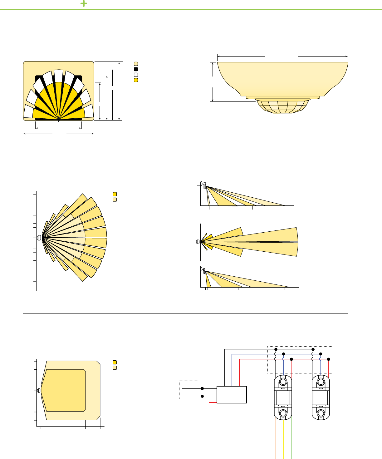
OCCUPANCY SENSORS TECHNICAL SECTION
180 Degree Ceiling-Mounted Occupancy Sensor
Dual Technology
Wall Mounted Occupancy Sensor
PIR
Wall Mounted Occupancy Sensor
Ultrasonic
ft.
Ultrasonic Major Motion
Ultrasonic Minor Motion
PIR Major Motion
PIR Minor Motion 1.75 in.
(44 mm)
Side view of ceiling mounted sensor
Class 1
Class 2
32 ft.
28 ft.
32 ft.
25 ft.
25 ft.
22 ft.
25
48
ft.
16
11
11
16
48
25
0
Major Motion
Minor Motion
Major Motion
Minor Motion
ft.
0
03 15 30 48 72
8
0
03 ft.
(0.9 m)
42 ft.
(12.8 m)
102 ft.
(31.1 m)
18 ft.
(5.49 m)
10 ft.
(3.1 m)
30 ft.
(9.14 m)
11.5
11.5
0
16
16
023 32
Neutral
Line Black
Black
Black
Black
Orange (N.O.)
White
Blue
Blue
Blue
Yellow (Common)
Red
Red
Red
Red
Green (N.C.)
Load
Power Pack
SLSPP1277
Additional Sensor (s)
(Optional)
4.5 in. (115 mm)
21
OCCUPANCY SENSORS TECHNICAL SECTION
System Diagram
Wiring Diagram
Front View Dimensions
Front View Dimensions
Flexible Mounting
Power Pack and Auxiliary Relay
120 Volt and 277 Volt
Power Pack and Auxiliary Relay
347 Volt
Wall Mounted Occupancy Sensor
Dual Technology
25
48
16
11
11
16
48
25
0
Major Motion
Minor Motion
Major Motion Ultrasonic
Minor Motion Ultrasonic
ft.
0
03 15 23 32 48 72
8
Inside
Outside
3 in.
(76 mm)
3 in.
(76 mm)
3 in. (76 mm)
3 in. (76 mm)
2.25 in.
(57 mm)
2.25 in.
(57 mm)
Inside
Outside
To Sensor
To Sensor
Line Voltage
Line Voltage
Class 1
Class 2
Neutral
Line Black
Black
Black
Black
Orange (N.O.)
White
Blue
Blue
Blue
Yellow (Common)
Red
Red
Red
Red
Green (N.C.)
Load
Power Pack
SLSPP1277
Additional
Sensor (s)
(Optional)
To Sensor
To Sensor
Line Voltage
Line Voltage
Voltage selector
Hot
Hot
Neutral
Neutral
Black
Black
Blue
Blue
Red
Red
Blk
Blk
+24 Vdc
+24 Vdc
Sensor
Sensor
Common
Common
Control Input
Control Input
White
White
Line Voltage
120/277 Vac
Line Voltage
347 Vac
Red
Red
Override OFF
Override OFF
Load
Load
Flexible Mounting 22

OCCUPANCY SENSORS TECHNICAL SECTION
Ceiling Mounted Line Voltage Occupancy Sensor
PIR
A
B
2
A
B
1
A
B
A
B
25 ft.
25 ft.
9 ft.
32 ft.
32 ft.
16 ft.
16 ft.
23 ft.
23 ft.
4.76 in.
0.99 in.
1.78 in.
4.76 in.
Key:
1. Top view
2. Side view
A. 1,000 Sq. ft. lens
B. 500 Sq. ft. lens
Major motion
Minor motion
Key:
A. Power source
(Refer to the operating
range described in the
specications table.)
B. Line/Hot (+)
C. Neutral (-)
D. Load
E. Override (Off)
F. Sensor (PIR shown)
Single Sensor
A
C
B
D
E
F
Multiple Sensors
A
C
B
D
E
F F
Ceiling Mounted Line Voltage Occupancy Sensors Wiring Diagram
23

OCCUPANCY SENSORS TECHNICAL SECTION
Ceiling Mounted Line Voltage Occupancy Sensor
Ultrasonic
Ceiling Mounted Line Voltage Occupancy Sensor
Dual Technology
A
B
A
B
30 ft.
48 ft.
42 ft.
90 ft. (27.4 m)
90˚
24 ft.
4.76 in.
0.99 in.
1.42 in.
4.76 in.
Key:
Major motion
Minor motion
15 ft.
(4.5 m)
Hallway Coverage
Top View Area Coverage (based on 9ft. mounting height)
C
D
E
F
30 ft.
48 ft.
42 ft.
24 ft.
25 ft.
32 ft.
16 ft.
23 ft.
Key:
A. 1,000 Sq. ft. lens
B. 500 Sq. ft. lens
C. PIR Major motion
D. PIR Minor motion
E. Ultrasonic major motion
F. Ultrasonic minor motion
(Based on 9 ft.
mounting height)
4.76 in.
4.76 in.
0.99 in.
1.78 in.
24

OCCUPANCY SENSORS TECHNICAL SECTION
Top View from area lens at 40’
Top View at 40’
Top View from area lens at 20’
High Bay Occupancy Sensors
HID
High Bay PIR Occupancy Sensor
Fluorescent
40 ft. 30 20 10 0 10 20 30 40
20’
30’
40’
40 ft. 30 20 10 0 10 20 30 40
20’
30’
40’
40 ft. 30 20 10 0 10 20 30 40
Coverage pattern for area/aisle lense (side view)
Coverage pattern for aisle lens (top view) Coverage pattern for area lens (top view)
Side View
Side View
Distance from sensor
Top View at 40 ft.
Top View at 40 ft.Sensor Height
Sensor Height
Above Floor
40 ft. 30 20 10 0 10 20 30 40
20’
Side View
Distance from sensor
Sensor Height
Above Floor
40 ft. 30 20 10 0 10 20 30 40
40 ft. 30 20 10 0 10 20 30 40
40’
Side View
Distance from sensor
Sensor Height
Above Floor
40 ft. 30 20 10 0 10 20 30 40
30
20
10
0’
30’
30’
20’
20’
20’20’
10’
10’
10’10’ 30’30’
0’
30’
30’
20’
20’
20’20’
10’
10’
10’10’ 30’30’
25

OCCUPANCY SENSORS TECHNICAL SECTION
Front viewSide view
Occupancy Controller
Low Voltage Switch One Switch
Low Voltage Relay Panel
Switch — One Switch
Low Voltage Relay Panel
Switch — Two Switches
One Switch with LED
Two Switches with LEDs
1.7 in.
(43.2 mm)
0.24 in.
(6.09 mm)
2.77 in.
(70.36 mm)
4.5 in.
(114.6 mm)
2.77 in.
(70.36 mm)
1.34 in.
(34.04 mm)
SLSLVS1
SW1
V OUT
V IN
SLSLVS1R
Reverse
Polarity
Switch
V OUT
V IN
Two Switches
SLSLVS2
SW1
SW2
V OUT SW1
V OUT SW2
V IN
SLSLVS2R
Reverse
Polarity
Switch
Reverse
Polarity
Switch
V OUT SW1
V OUT SW2
V IN
SLSLVS2L
SW1
SW2
(+) Anode LED1
(+) Anode LED2
(-) Cathode LED1
(-) Cathode LED2
V OUT SW1
V OUT SW2
V IN
T
SLSLVS1L
SW1
(+) Anode
(-) Cathode
V OUT
V IN
* Third-party devices
Low voltage
wall switch
Occupancy sensors
Dry contact
switches*
Occupancy
Controller
Occupancy signals
24 Vdc
Lighting load*
Power input
6.42 in.
(163 mm)
6.53 in.
(166 mm)
2.36 in.
(60 mm) 0.71 in. (18 mm)
0.83 in.
(21 mm)
0.63 in. (16 mm)
0.75 in.
(19 mm)
26

Emergency Lighting
Control Devices

AutomaticLoadControlRelay,emergency
lightingisonlyturnedonwhennecessary.
Duringnormalnon-operatinghours,the
emergencylightingisOff,providingfurther
energysavingsandextendedlamplife.
SchneiderElectricprovidesawideselection
ofEmergencyLightingControlDevicesthat
workwithoccupancyanddimming-based
lightingcontrols.
SchneiderELectricULlistedautomaticload
controlrelays(ALCR)enabledesignerstouse
standardlightingxturesfortheemergency
lightingsystemfedbyanemergencybackup
supply.Undernormaloperatingpower,the
devicesturnonandoffemergencylighting
alongwithstandardlightinginanarea.Inthe
eventofnormalpowerloss,theALCRdetects
thepowerloss,andwillautomaticallyswitch
onemergencypowertothextures.Withan
EMERGENCY LIGHTING CONTROL DEVICES
Emergency Egress Lighting
Control Devices
28

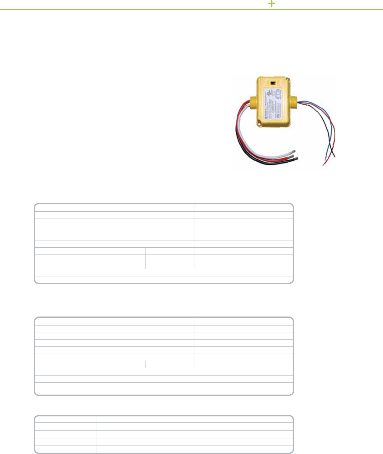
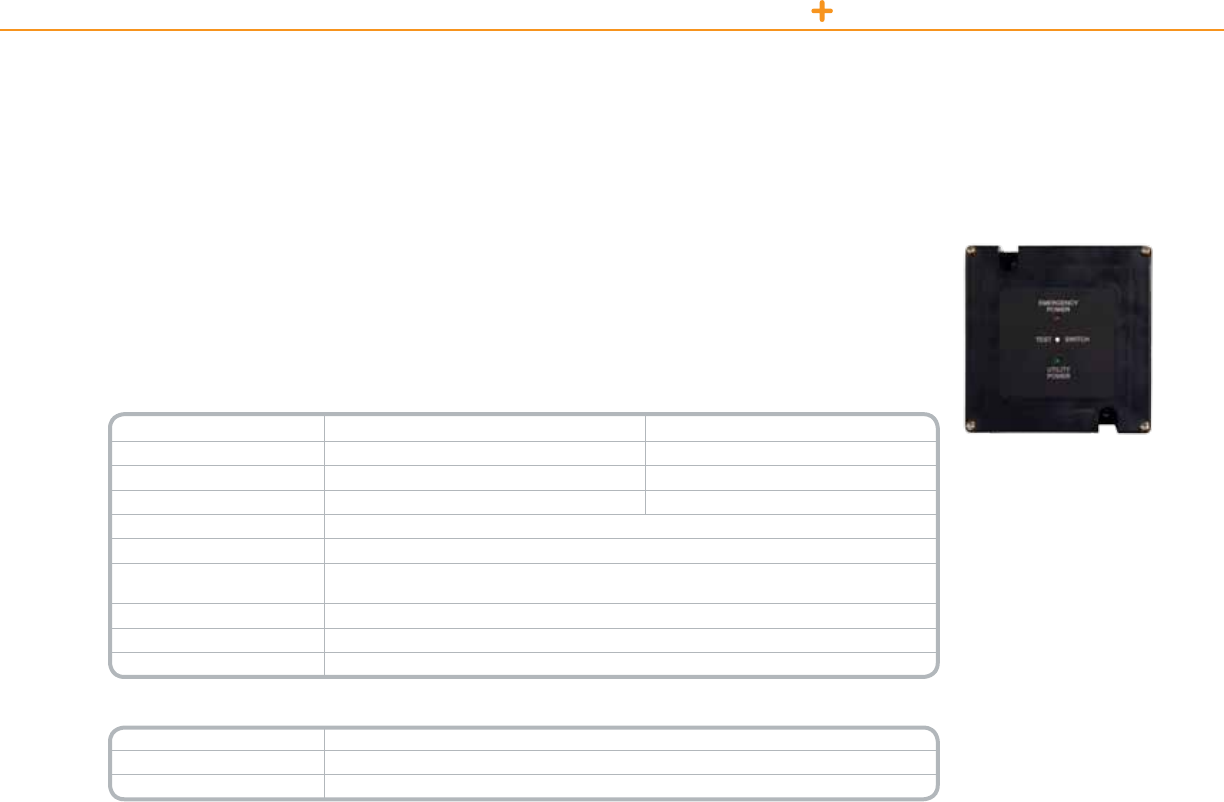
EMERGENCY LIGHTING CONTROL DEVICES EMERGENCY LIGHTING CONTROL RELAY
TheAutomaticLoadControlRelayisaUL924ListedEmergencyLightingControlDevice.
Itprovidesameansofturningonandoffemergencylightingalongwithregularlighting.TheAutomaticLoad
ControlRelayisdesignedtosensewhenapoweroutageoccurs,thenswitchesontheconnectedemergency
lightingload.
Technical Information
Sensing Input 120Vor277V
Load 120Vor277V
Load Rating 20A
Contact NC
Wiring:
Input Control
Emergency Control
18AWG(wireslabeled1,2,3,4)
14AWG(wireslabeled5,6)
Standards UL/cULlisted;UL924,UL94V-0FlameRating
Mounting Mountinajunctionboxwithablankcoverinthesamelocationasthecontrolledlighting.
Weight 8oz.(227g)
Temperature 32°Fto140°F(0°Cto60°C)
Dimensions (LxWxH) 3.75in.x1.75in.x1.5in.(95.25mmx44.45mmx38.10mm)
*For Diagram see technical section page 32
Catalog Number Description
SLSERC1277 AutomaticLoadControlRelay120Vand277V
AutomaticLoad
ControlRelay
Automatic Load Control Relays
SLSERC1277
Product Features
•120Vor277V.
•MeetsNEC2011
Article700
•Patentedself-testfeature
thatshowsemergency
powerisoperatingevery
timethelightswitchis
turnedOFF.
•VisibleLEDsforeasy
diagnostics.
•Noprogrammingrequired
andeasytoinstall.
•Usewithneworexisting
lightingxtures.
•UsewithSchneider
Electricoccupancy
sensors.
•Allmodelsare
constructedwithUL94
V-0ratedplastics.
•UL/cULlisted.
29
EMERGENCY LIGHTING CONTROL DEVICES EMERGENCY LIGHTING DIMMER CONTROL
Itprovidesameansofturningon/offanddimmingcontrolofemergency.TheDALCRisdesignedtodetectpower
outageeventsandswitchontheconnectedemergencylightingloadtomaximumlightlevel.TheDALCRsends
phaseangle,0–10V,andthree-wireballastloadstofullbrightinaemergencyegresslightingevent.Whenutility
powerisrestored,theunitswillrevertbacktotheirpreviouscontrolledstate.
Technical Information
Model SLSEDC120 SLSEDC277
Ballast 120Vac,20A 277Vac,20A
Tungsten 120Vac,1800W 277Vac,1500W
General Use 20A 20A
Wiring 14AWG
Standards UL/cULlisted;UL924,UL94V-0FlameRating
Mounting 4in.squareelectricalenclosure.Mountineitherthesamelocationofthecontrolledlighting,orina
remotelocationawayfromthecontrolledlighting.
Weight 16oz.(453.6g)
Temperature 32°Fto140°F(0°Cto60°C)
Dimensions (LxWxH) 5.125in.x5.125in.x2.25in.(130.175mmx130.175mmx57.15mm)
*For Diagram see technical section page 32
Catalog Number Description
SLSEDMC120 DimmingAutomaticLoadControlRelay120V
SLSEDMC277 DimmingAutomaticLoadControlRelay277V
DimmingAutomaticLoad
ControlRelay
Dimming Automatic Load Control Relay
SLSEDC120 and SLSEDC277
Product Features
•120Vor277V.
•MeetsNEC2011Article7
•Patentedself-testfeature
thatshowsemergency
powerisoperatingevery
timethelightswitchis
turnedOFF.
•VisibleLEDsandtest
switchesforeasy
diagnostics.
•Noprogrammingrequired
andeasytoinstall.
•Usewithneworexisting
lightingxtures.
•UsewithC-Busand
otherdimmingsolutions,
0–10V,phaseangle,
andDALI.
•Allmodelsare
constructedwithUL94
V-0ratedplastics.
•UL/cULlisted.
30

Panel Mount Automatic Load Control Relay
SLSEPMC120 and SLSEPMC277
PanelMountAutomatic
LoadControlRelay
Product Features
•120Vor277V.
•MeetsNEC2011
Article700
•Patentedself-testfeature
thatshowsemergency
powerisoperatingevery
timethelightswitchis
turnedOFF.
•VisibleLEDsandtest
switchesforeasy
diagnostics.
•Noprogrammingrequired
andeasytoinstall.
•Usewithneworexisting
lightingxtures.
•Suitableforusewith
SchneiderElectricrelay
panelsorPowerlink
LightingControlSystems.
•Allmodelsare
constructedwithUL94
V-0ratedplastics.
•UL/cULlisted.
EMERGENCY LIGHTING CONTROL DEVICES EMERGENCY LIGHTING CONTROL RELAY
ThePanelMountAutomaticLoadControlRelayisaUL924Listedemergencylightingcontroldevice.
Itprovidesameansofturningonandoffemergencylightingalongwithregularlighting.ThePanelMount
AutomaticLoadControlRelayisdesignedtosensewhenapoweroutageoccurs,thenswitchesonthe
connectedemergencylightingload.
Technical Information
Model SLSEPMC120 SLSEPMC277
Ballast 120Vac,20A 277Vac,20A
Tungsten 120Vac,1800W 277Vac,1500W
General Use 20A,1HP 20A,1HP
Terminal 12to14AWG
Maximum Terminal Torque 1.15lb/ft.(16kg/cm)
Standards UL/cULlisted;UL924,UL94V-0FlameRating
Mounting Electricalenclosure.Mountinaremotelocationawayfromthecontrolledlighting.
Weight 7oz.(198.45g)
Temperature 32°Fto140°F(0°Cto60°C)
Dimensions (LxWxH) 3.5in.x3in.x3in.(88.9mmx76.2mmx76.2mm)
*For Diagram see technical section page 33
Catalog Number Description
SLSEPMC120 PanelMountAutomaticLoadControlRelay120V
SLSEPMC277 PanelMountAutomaticLoadControlRelay277V
31

Emergency Lighting Control Relay
EMERGENCY LIGHTING CONTROL DEVICES TECHNICAL SECTION
Emergency Lighting Dimmer Control
Note:
UnderRegularPower
relay5isclosedand
relay3isopenallowing
thelightingcontrolpanel
powertoowbetween
input5andoutput8.
UnderRegularPower
relay6isclosedallowing
0-10dimmingsignalto
owbetweeninput6
andoutput9.
UnderEmergency
Powerrelay5isopen
andrelay3isclosed
allowingconstantpower
betweeninput3and
output8.
UnderEmergency
powerrelay6isopen
sendingthe0-10
dimmingsignalto
fullbright.
32

EMERGENCY LIGHTING CONTROL DEVICES TECHNICAL SECTION
Emergency Lighting Control Relay
Panel Mount
Typicalsystemconguration
utilizingtheG3Powerlink
Panelboard.TheEmergency
lightingcontrolpanelboard
isalsocompatiblewithother
systemandrelaycongurations.
33

34
Emergency
Lighting Control
Panelboards

Operationalprocesses,codecompliance,cost
reduction,sustainabilitysolutions,architectural
aesthetics—thelistofcommercialfacility
needsislonganddifculttobalance.
Akeyfactorinalloftheabove,lighting
contributestofacilitycostsandoperations.
Withlightingcontrolenhancementsyou
cangainenergyefciency,costsavings,
sustainability,alongwithpersonalcomfort
andconvenience.Emergencyegress
lightingrequirementscanbeacomplicating
factorineffectivelightingdesignand
energymanagement.
Simplifies Design Process
•Allowsstandardlightingxturestobeused
foremergencylighting
•Providesabilitytosharelightingcontrols
suchastimers,switches,andoccupancy
sensorswithemergencyegresslighting
Speeds Installation
•Factoryassembledandinstallsquicklyand
easilyreducinglabortimeandcosts
•Spacesavingdesignwithlesswiringand
easyaccess
Supports Sustainability
• Normaluseofschedule,switch,and
occupancy-sensordevicecontrolstobe
sharedonemergencylightingcircuits
reducesenergywaste
•Reducedwiringandlightingxturesneeded
•Easilysupportscentralizedpowersource
(Generatororinverter)foremergencylighting
eliminatingdistributedemergencybatteries
Streamlines Maintenance Testing
•Patented“switchtest”—testbuttons
atpanels/panelboardsforeachALCR
[NEC(NFPA70)andUL924]
•VisibleLEDsforutilityandemergency
powerdiagnostics
•Centralizedlocationforfacility-wide
emergencylightingmaintenanceandtesting
EMERGENCY LIGHTING CONTROL PANELBOARDS
Emergency Lighting Control
Panels/Panelboards
36
UL924 PANELS EMERGENCY LIGHTING CONTROL PANEL
Emergency Lighting Control Panel
EmergencyLightingControlPanel
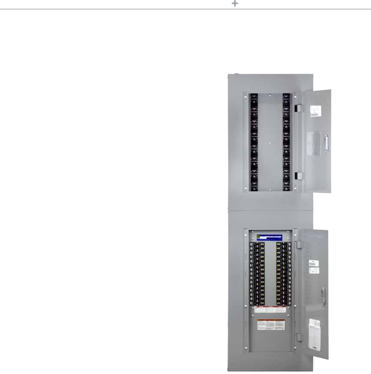
WiththeEmergencyLightingControlPanelsbySchneiderElectric,design,
installation,inspection,andongoingtestingrequirementsforemergencylighting
arestreamlined.Energyefciencyisgainedbyallowingthenormaluseofschedule,
switch,andoccupancy-sensordevicecontrolstobesharedonemergencylighting
circuits.Thisinnovative,centralized,controlsolutionforemergencylightingisafail
safeapproachinsupportofimprovedsustainability.
Ordering Information
ELCPsareorderedbasedontheenclosuremountinglocation(surfaceorush),
thenumberofALCRs,andthevoltageusedbythepanelmounteddevices
(120Vor277V).
SLSEPXS1
DC
B
A
Panel Number Explanation (Key)
A Emergencypanel
B X = Thenumberofpanelmounteddevices
C S= Surfacemount,
F = Flushmount
D 1 = 120V
2 = 277V
Eachshipmentcontainoneenclosurewith6to24panelmounteddevices
(SLSEPMC120orSLSEPMC277)andthisinstructionbulletin.
Note: ELCPs are avaliable for order with an even number of ALCRs, ranging from 6 to 24 ALCRs.
For Diagram see technical section page 39
Product Features
• Designedtobemountedbetweenemergencyand
regularcircuitbreakerpanelboards
• Isolatedpowerchanneldesignensuresemergency
andregularpowerneversharethesamespacein
accordancewithNEC
• Supportsfrom6to2420AAutomaticLoad
ControlRelays(ALCR)
• Availablein277Vacand120Vac
• ShortCircuitCurrentRating65kA@120Vac,
18kA@277Vac
• UL924andUL50Listed
• NEMA®Type1enclosure
• Availableinushandsurfacemount
• Equippedwithlockablecovers
• Acceptsupto10AWGwireforlongwireruns
• Onboardtestswitchforeachrelaysimplies
ongoingmaintenancerequirements
• Integrateswithlightingcontrolproducts
37
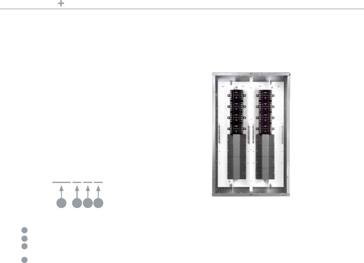
UL924 PANELS EMERGENCY LIGHTING CONTROL PANELBOARDS
Emergency Lighting Control Panelboard
SchneiderElectricintroducestherstcentralized,all-in-onepanelboardwith
onboardautomaticloadcontrolrelays(NEC(NFPA70)andUL924).Thisunique
combinationofbreakerandALCR(NEC(NFPA70)andUL924)panelboardallows
facilitiestostreamlineoperationalprocesses,reducecosts,improvesustainability,
anduseadvancedlightingcontroltechnologies.Italsoeasilysupportsacentralized
emergencypowersource(generatororinverter)foremergencylighting.
This elegant solution simplifies:
• IntegratesmultipleALCR[NEC(NFPA70)andUL924]andemergencylighting
breakersintoacentralized,selfcontainedpanelboard
• Consolidatesstandardlightingxtureswithemergencylighting
• Providesabilitytosharelightingcontrolssuchastimers,switches,and
occupancysensorswithemergencyegresslighting
Product Features
• EmergencyLightingControlPanelboard(2–16AutomaticLoadControl
RelayswithaoptionofNForNQbreakers)
• Availableinboth120Vand277Vmodelsaswellas125and250Amp
• SuitableforusewithSchneiderElectricRelayPanelsorPowerlinkLighting
ControlSystems
• ULlisted
For Diagram see technical section page 40
EmergencyLightingControlPanelboard
38

UL924 PANELS TECHNICAL SECTION
Emergency Lighting Control Panel
Panel Installation
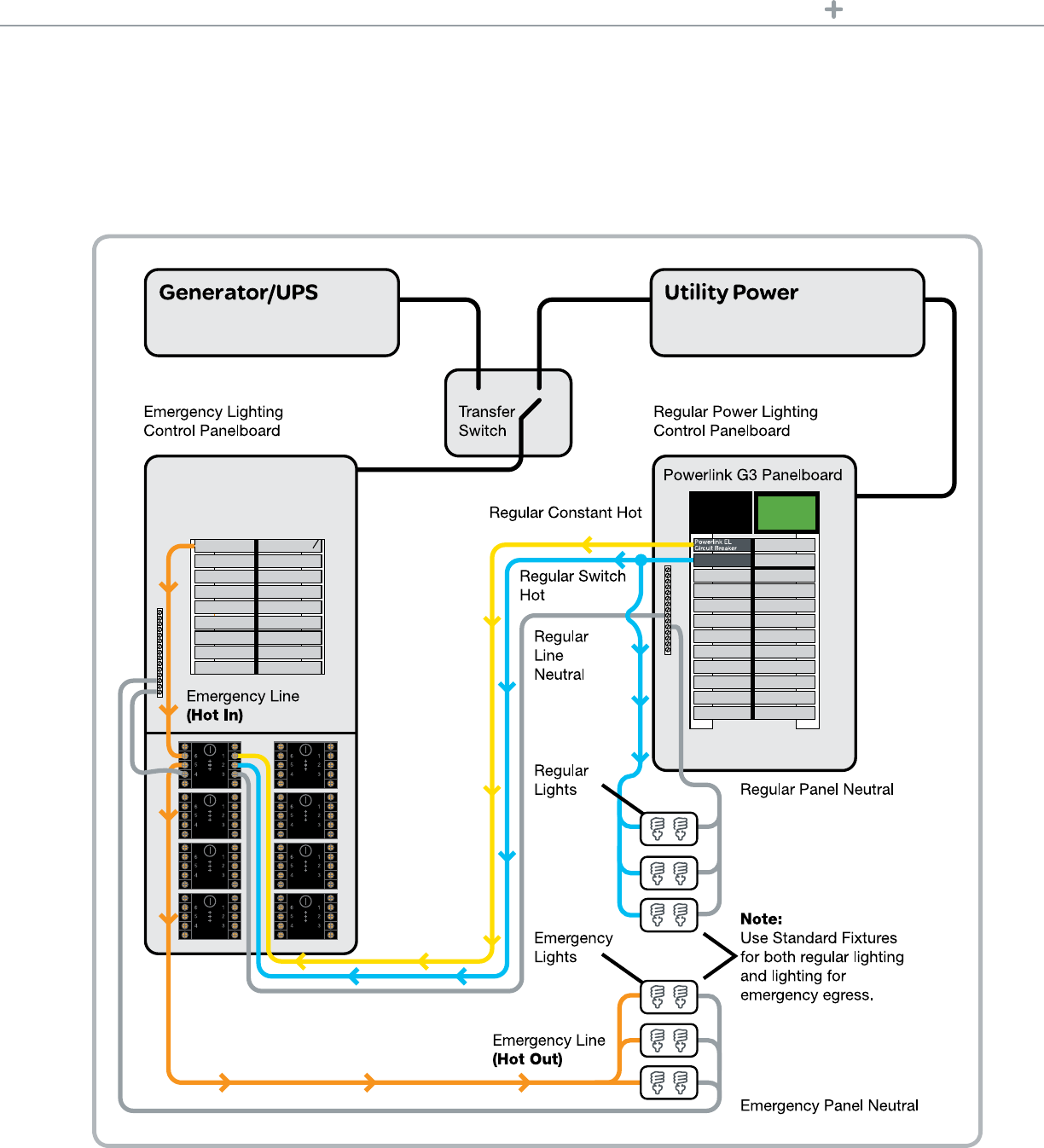
Emergency Panelboard Regular Panelboard
Schneider Electric
Relay Panel
Relay Controller Neutral
Relay Controller Power
Emergency Line
HOT into ALCR
Regular Constant Hot
Regular
Switch Hot
Regular
Line Neutral
Emergency Line
HOT into ALCR
Emergency
Lights Note:
Use standard
xtures for both
regular and
emergency
egress lighting.
Regular
Lights
Regular
Panel
Neutral
Emergency
Panel Neutral
Emergency Panel Neutral
TypicalsystemcongurationutilizingtheG3PowerlinkPanelboard.TheEmergencylightingcontrolpanelboardis
alsocompatiblewithothersystemandrelaycongurations.
39
UL924 PANELS TECHNICAL SECTION
Emergency Lighting Control Panelboard
Panelboard Installation
TypicalsystemcongurationutilizingtheG3PowerlinkPanelboard.TheEmergencylightingcontrolpanelboardis
alsocompatiblewithothersystemandrelaycongurations.
40

Current Limiting
Panels for Track
Lighting

Energycodestypicallyrequirelightingpower
densitycalculationsfortracklightingtobe
basedonthelinearfeetofinstalledtrack.Some
codesstipulatemultipliersaslowas30Wper
footoftrack,whileothersuseamultiplieras
highas70Wperfootoftrack.Whenenergy
efcientlightingisused,theconnectedloadis
typicallymuchlessthantheper-footmultipliers
givenintheenergycodes.Thispenalizeslighting
designsthatemploytracklightingandmay
threatenretailenvironmentswherehigherlight
levelsareneeded.
Current Limiting Panels
SCHNEIDER ELECTRIC CURRENT LIMITING PANELS
42

SCHNEIDER ELECTRICCURRENT LIMITING PANELS CURRENT LIMITING PANELS
Current Limiting Panels
CurrentLimitingPanel
CurrentLimitingPanelseasestheburdenofmeetingtoday’sstringentenergycodes
likeCaliforniaTitle24.Typicallyusedfortracklightingapplications,thesepanels
limitthepoweravailabletoalightingbranchcircuitbyincorporatingaspecialcircuit
breakerintothebranchcircuit.
BecausetheCurrentLimitingpanellimitstheavailablepowertoaspeciedlevel,
designerscanbetterreecttheactualpowerrequirementsintotheirloaddensity
calculations.Powerlevelwillbesubstantiallylowerthanbyusingthestandard
multipliersgivenfortracklighting.
Panelsarereadilyaccessibleprovidingeasyaccessforinspectionandmaintenance.
Thesepanelsalsoincorporatecircuitbreakersratedforthehigheravailablefault
currentsfoundonmany120Vsystems.Inaddition,theuseofsupplementary
protectorsprovidesaconvenientmeansforisolatingindividualtrackcircuits.
Product Features
•Readilyaccessiblepanel
mountedenclosures
•Flushorsurfacemounting
•Hingeddoorwithkey-
lockinglatch
•Upto42circuitbreakers
perenclosure
•Circuitbreakersrated
0.5A–16A
•Factoryassembled,
tested,andlabeled
•CATitle24compliant
Technical Information
Item Track-LimitingPanel
Type NEMA1Indoor
Box Galvanizedsteel
Finish ANSI49Gray
Voltage Rating 120VAC@10kAor277VAC@5kA
Short Circuit Current Rating 10,000A
Branch Circuit
Ampere Ratings 0.5A,1A,2A,3A,4A,5A,6A,7A,8A,10A,15A,16A
Branch Circuit Terminals Boxlugs:#18–4AWG(1–25mm2)
Operating Environment 77°F(25°C)
Standards UL1077,UL508A
Listings/Certications/
Compliance CaliforniaTitle24,ASHRAE90.1compliant
Enclosuresareavailableformountingupto21or42circuits.Bothenclosuresareavailableforushor
surfacemounting.
Enclosure Enclosure Cabinet Dimensions (H x W x D)
12M 14.25in.x9in.x3.75in.(362mmx229mmx95mm)
21M 14.25in.x3.75in.x17.92in.(362mmx95mmx455mm)
42M 14.25in.x3.75in.x33.78in.(362mmx95mmx858mm)
43
SCHNEIDER ELECTRIC CURRENT LIMITING PANELS CURRENT LIMITING PANELS
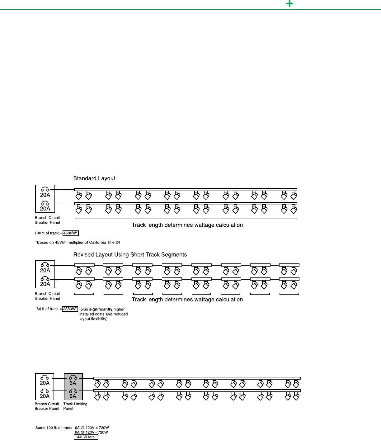
Energycodestypicallycalculatetracklightingloadsbasedonlinearfeetofinstalledtrack.Somecodesuseamultiplieraslowas30watts/foot
whileothersuseamultiplierashighas70watts/foot.Whenusingtheenergyefcientlightingtechnologiesavailabletoday,theconnectedload
istypicallymuchlessthantheper-footmultipliersusedbymostenergycodes.Thispenalizeslightingdesignsthatemploytracklightingand
wastesavailablelightingwattsthatcouldbeusedmoreeffectively.
Belowisatypicaltracklightingexample.TheStandardLayoutconsistsoftwo50’runsofsinglecircuittrack,eachwithsixteen39Wtrack
headsforatotalconnectedloadof1376W.TheRevisedLayoutUsingShortTrackSegmentshasthesame1376Wconnectedloadbutuses
sixteenshort4’tracksegments(64’),eachfedseparately,tohelpminimizetheimpactofthewattsperfootmultiplier.Thescenariowiththe
Track-LimitingPanelusestheoriginaltwo50’runsofsinglecircuittrack,witheachmonitoredbya6Ampcurrentlimitingcircuitbreakerthatis
closelymatchedtotheactualconnectedloadof1376W.Thisresultsintheminimumcalculatedwattspertheenergycodes.
Without the Current Limiting Panel
With the Current Limiting Panel
TheCurrentLimitingPanelinstallsbetweenthebranchcircuitbreakerandthetracklighting,solvingtheenergycodecalculationdiscrepancy,
makingthewattagecalculationindependentoftracklength.
44

Relay Panels

RELAY PANELS
Fully scalable solution
Whetheryou’recreatingalightingcontrol
systemforasingleroomorawholefacility,
theSchneiderElectriclineofrelaypanelsoffer
scalablesystemstotyourneedsnow.And,
asyourbuildingneedschange,thesystem
caneasilygrowtomeetthosedemands.
Oursolutionsaredesignedaroundthesize
andrequirementsofyourapplication.Allthis
withacommonplatformandeasyinstallation
practices.Talkaboutexibility
Building automation integration
WehavedesignedtheLPBBACnetandLPL
LonWorkspanelstointegrateeasilywith
otherfacilityoperations.HVAC,security,re,
younameit.We’veteamedupwith
othercontrolmanufacturerstoensurefull
compatibilityandcommunicationbetween
systems.Justwhatyou’dexpectfromaglobal
electricalindustryleader.
Theresult:seamlesssolutionsthatdeliverthe
energysavingsandconnectivityyoudemand
—meetingyourhighestperformanceand
budgetexpectations.Whatcouldbesimpler?
Heavy-duty design
Thelightingcontrolrelaypanelsofferamore
robustsolutionwiththeinclusionofaremovable
hingeddoorwithkeylock.Theheavy-duty
designisidealforplacementinelectricalrooms
orexposedareas.Individuallyreplaceable,
all-enclosedrelaysalsoprovideamorecost-
effectivereplacementsolution.
Energy savings
Lightingcontrolholdsincrediblepotentialfor
energysavings.Infact,evenwithnewerenergy-
efcientlightinglampandballastcombinations,
lightingisstillthenumberonesourceofenergy
consumptioninanybuilding.
Automated occupant control
There’snoreasontolightaroomwhen
nobody’sinit.Turningofflightsinareassuch
asmeetingrooms,corridors,andofcescan
reduceenergycostssignicantly.
Relay Panels
LightingcontrolrelaypanelsfromSchneiderElectricwillputyouincontrolofyourlighting,your
comfortandyourenergycosts.Regardlessofyourneed,ourrelaypanelsgiveyouareliable
solutionatanaffordablecost.
46

RELAY PANELS LPS RELAY PANELS
LPSpanelsreduceenergyusebyautomaticallyshuttingofflightsinresponsetoa
scheduledtimeeventfromitsintegraltimeschedulerorinresponsetoanexternal
controldevice,suchasakeypadswitch,occupancysensororphotocell.These
panelsareidealforuseinsmallercommercialapplications,suchassmallstripretail,
ofcespacesandparkinglotswhereacentralizedbuildingmanagementsystemis
notpractical.Itssimple,menu-driveninterfaceisdesignedforeasyprogramming
andintuitiveuseforelectricians,contractorsandend-users.
For Diagram see technical section page 51
LPS panels
LPS standalone. Easy control for low-voltage
switching applications.
LPSpanel
Robust,individuallyreplaceable,molded-caserelaysareindustry-leading
inreliability.
Thetimecontrollerfeaturesa365-day,7-dayrepeatingclockwithfull24hour
schedulingfunctionsandeventpriorities.
Relaycontrolsthatprovideindividualcontrolofeachrelay,andfeatureeasyto
usepushbuttonmembranes.
Technical Information
Catalog Number Description
SERP8HSNC SchneiderElectricseriesrelaypanel8HIDrelayswithoutcontroller
SERP16HSNC SchneiderElectricseriesrelaypanel16HIDrelayswithoutcontrollers
SERP32HSNC SchneiderElectricseriesrelaypanel32HIDrelayswithoutcontrollers
SERP48HSNC SchneiderElectricseriesrelaypanel48HIDrelayswithoutcontrollers
SERP64HSNC SchneiderElectricseriesrelaypanel64HIDrelayswithoutcontrollers
SERP4HS SchneiderElectricseriesrelaypanel4HIDrelays
SERP8HS SchneiderElectricseriesrelaypanel8HIDrelays
SERP16HS SchneiderElectricseriesrelaypanel16HIDrelays
SERP24HS SchneiderElectricseriesrelaypanel24HIDrelays
SERP32HS SchneiderElectricseriesrelaypanel32HIDrelays
47
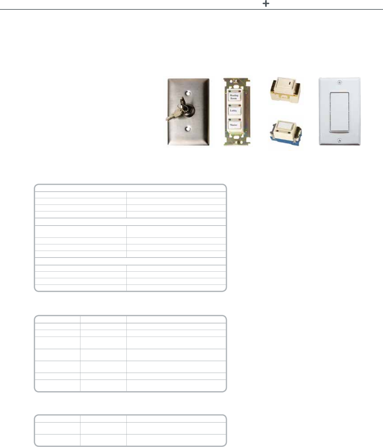
RELAY PANELS LIGHTING CONTROL RELAY SWITCHES
Lighting Control Relay Switches
Features
Key Switch (SERPKWS)
•Wallmountabletoanystandardwallbox
•Keyoperated(ON–turnright;OFF–turnleft)
•Operatesupto8relaysperswitch
•6switchesperrelay
Push Button Switch (SERPWSxGyB*)
•FactoryAssembled
•Includesmountingbracket,switch(es),coverplate
•LEDON/OFFindication
•Clearplasticlabelingcap
•Operatesupto4relaysperswitch
•6LEDswitchesperrelay
Rocker Switch (SERPRWS)
•Wallmountabletoanystandardwallbox
(1-gangrequiresmountingbracket(SERPWSMB)
•Operatesupto8relaysperswitch
•6switchesperrelay
•Optionalllerplate(SERPWSFP)
Push Button Switch (SERPPBWS)
•Wallmountabletoanystandardwallbox
(1-gangrequiresmountingbracket
•LEDON/OFFindication
•Clearplasticlabelingcap
•Operatesupto4relaysperswitch
•6LEDswitchesperrelay
•Optionalllerplate(SERPWSFP)
Decorator Switch (SLSVS1RX)(SLSVS2RX)
•Providesimplemomentarypushbuttoncontrol
•LEDmodelsprovidepilotlightsorstatusoutputs
•DesignedforusewithSchneiderElectricrelaypanels
•SwitcheststandardNEMAwallboxes
•Decorator-styleenclosure;wallplateincluded
* x = the number of ganged switch locations.
y = the number of button/switches.
***Finished assembly; mounting bracket and cover plate included.
Technical Information
Key Switch (SERPKWS)
Input/Output 3Amp,24Vdc,ReversiblepolarityImpulse
Relays per switch 8
Switches per Relay 6Switches
Operation (Turn key) Right/ON,Left/OFF
Push button Switch (SERPWSxGyB*)
Input/Output 1.5Amp,24Vdc,ReversiblepolarityImpulse
Switchinputfromcommonterminal
Relays per switch 4
Switches per Relay 6LEDSwitches
Operation (Turn key) Press/ON,Pressagain/OFF
Rocker Switch (SERPRWS)
Input/Output 3Amp,24Vdc,ReversiblepolarityImpulse
Relays per switch 8
Switches per Relay 6Switches
Operation PressonesideON;pressothersideOFF
*x = the number of ganged switch locations. y = the number of button/switches.
Note: All switches: use 18-24 AWG solid or stranded wire for Class 2 wiring connections.
For Diagram see technical section page 52 and 53
Catalog Number Switch type Description
SERKWS Keyswitch
Wallmountedmomentarycontactrelaykeyswitch
SERPRWS Rockerswitch Wallmountedrocker-typerelayswitch
SERPPBWS Pushbuttonswitch** Singleallmounted,LED-indicating,pushbutton
relayswitch.
SERPWSxGyB* Pushbutton
switch***
Singleormulti-gang,singleormulti-devicewall
mountedpushbuttonrelayswitcheswithLEDs.
SERPWSMB Mountingbracket Usedtomountsinglepushbuttonor
rockerswitches
SERPWSFP Fillerplate Usedtollblankpositionsinawallbracket
SERPWPxGyB* Coverplate Brushedmetal;forusewithpushbuttonand
rocker-typeswitchesonly.
*x = the number of ganged switch locations. y = the number of button/switches.
**Requires mounting and cover plates. May require ller plates.
***Finished assembly; mounting bracket and cover plate included.
Catalog Number Switch type Description
SLSLVS1Rx Decorator
1buttonswitch
1-buttonSchneiderElectricrelaypanelswitch
withLED
SLSLVS2Rx Decorator
2buttonswitch
2-buttonSchneiderElectricrelaypanelswitch
withLED
'X' = Designates color: W: White, I: Ivory, G: Gray, L: Light Almond, B: Black
For Diagram see technical section page 52 and 53
KeySwitch
(SERPKWS)
PushButtonSwitch
(SERPWSxGyB*)
Switch(SLSLVS1Rx)PushButtonSwitch
(SERPPBWS)
RockerSwitch
(SERPRWS)
TheSchneiderElectricLightingControlRelaySwitches
providemanualON/OFFoperationoflightinginzones.
Theswitchesareequippedwithaswitchbased
deviceusingreversiblepolaritypulsetechnology.The
switchesarefullycompatiblewithLightingControl
RelayPanelsbySchneiderElectric.
ManualON/OFFisthemostcommonoverride
operation.EachswitchprovidesON/OFFactionfor
individualrelaysorgroupsofrelays(zones).
48
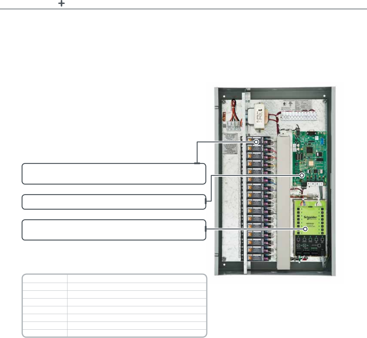
RELAY PANELS LPB PANELS
LPBrelaypanelsaredesignedtooperateonaBACnetnetworkwherecontrol
intelligenceisprovidedthroughaBACnetbuildingautomationsystem.Thesepanels
areidealformediumtolargefacilitieswithabuildingmanagementsystemutilizing
BACnetwherealow-costmeanstoachieveautomaticshut-offisrequired.These
panelsaresimpletoinstallandcommission,andofferseamlessintegrationwitha
full-featureschedulerthroughabuildingmanagementsystem.Switchoverridesand
photocellsareeasilyaddedforcompletecontrol.
For Diagram see technical section page 53 and 54
LPB relay panels
LPB BACnet. Combines complete
control with BACnet.
LPBpanel
Robust,individuallyreplaceable,molded-caserelaysareindustry-leading
inreliability.
TheBACnetcontrollerintegratesseamlesslywithopenprotocolnativeBACnet.
Relaycontrolsthatprovideindividualcontrolofeachrelay,andfeatureeasyto
usepushbuttonmembranes.
Technical Information
Catalog Number Description
SERPB8HSNC SchneiderElectricseriesrelaypanel8HIDrelayswithoutcontrollers
SERPB8HS SchneiderElectricseriesBACnetrelaypanel8HIDrelays
SERPB16HS SchneiderElectricseriesBACnetrelaypanel16HIDrelays
SERPB24HS SchneiderElectricseriesBACnetrelaypanel24HIDrelays
SERPB32HS SchneiderElectricseriesBACnetrelaypanel32HIDrelays
SERPB48HS SchneiderElectricseriesBACnetrelaypanel48HIDrelays
SERPB64HS SchneiderElectricseriesBACnetrelaypanel64HIDrelays
49

RELAY PANELS LPL PANELS
TheLPLpanelsofferengineersandfacilitiesmanagersalltheexibilitytheyneed
tomeettheirrequirementswhendealingwithlightingcontrolinsidetheirbuilding,
fromastand-alonesystem,toasoft-wirednetworkedpanelssystemorafully-
programmablenetworksystem.
LPLpanelsoftwareschedulingandeventprogrammingcapabilitieswilleasily
supportallcommonsequencesencounteredinlightingcontrol,andstackable,
optionalinput/outputcardsprogrameachinputforyourindividualneeds.
For Diagram see technical section page 55 and 56
LPL panels
LPL LonWorks. An integrated solution with native
LonWorks protocol.
LPLpanel
Robust,individuallyreplaceable,molded-caserelaysareindustryleading
inreliability.
Stackableoptionalinput/outputcontrollersuseLonWorksnetwork
communicationtointeroperateinhighlyfunctional,exibleandopen
buildingsystems.
Technical Information
Catalog Number Description
SERPL8HS SchneiderElectricseriesLonWorksrelaypanel8HIDrelays
SERPL16HS SchneiderElectricseriesLonWorksrelaypanel16HIDrelays
SERPL24HS SchneiderElectricseriesLonWorksrelaypanel24HIDrelays
SERPL32HS SchneiderElectricseriesLonWorksrelaypanel32HIDrelays
SERPL48HS SchneiderElectricseriesLonWorksrelaypanel48HIDrelays
SERPL64HS SchneiderElectricseriesLonWorksrelaypanel64HIDrelays
50
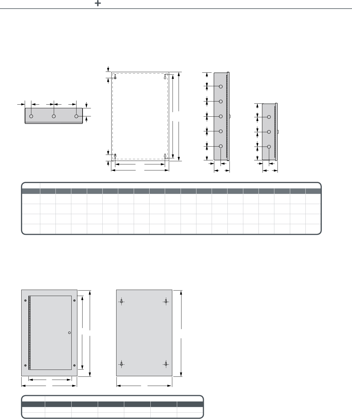
POWERLINK LIGHTING CONTROL TECHNICAL SECTION
LPS Lighting Control Relay Panel
Mounted Enclosure Dimensions (Without Doors)
Flush-Mounted Door Dimensions
Measurements — mm (in.)
Relays A B C D E F G H I J K L M N O P Q R
4or8* 42
(1.7)
149
(5.1)
149
(5.1)
46
(1.8) N/A N/A 330
(13)
381
(15)
345
(13.6)
381
(15)
90
(3.5)
101
(4)
101
(4)
90
(3.5) N/A N/A 46
(1.8)
101.6
(4)
4or8** 42
(1.7)
149
(5.1)
149
(5.1)
46
(1.8) N/A N/A 279.4
(11)
305
(12)
228.6
(9)
305
(12)
90
(3.5)
101
(4)
101
(4)
90
(3.5) N/A N/A 46
(1.8)
101.6
(4)
16 42
(1.7)
149
(5.1)
149
(5.1)
46
(1.8) N/A N/A 330
(13)
381
(15)
556
(21.9)
592
(23.3)
94
(3.7)
101
(4)
101
(4)
101
(4)
101
(4)
94
(3.7)
46
(1.8)
101.6
(4)
24or32 60
(2.4)
194
(7.6)
194
(7.6)
60
(2.4)
27.87
(1.10)
27.05
(1.08)
406.8
(16)
508
(20) N/A 850
(33.5)
55
(2.2)
190
(7.5) N/A N/A 190
(7.5)
55
(2.2)
55
(2.2)
101.6
(4)
Measurements — mm (in.)
Relays A B C D E F
16 349(13.7) 493(19.4) 582(22.9) 704(27.7) 493(19.4) 704(27.7)
24or32 478(18.8) 620(24.4) 838(33) 962(37.9) 620(24.4) 962(37.9)
* SERPB
** SERP4HS or SERP8HS
A B C
D
E
F
G
IJ
K
K
L
L
M
M
N
N
O
P
Q Q
R R
H
Top View
Front View (Without door
or interior assembly)
Side View for
16, 24, and 32 relay
capacity panels
Side View for
4 and 8 relay
capacity panels
FD
C
EB
A
Flush – Door Flush – Plate
51

POWERLINK LIGHTING CONTROL TECHNICAL SECTION
Rocker Switch
1.73 in.
44 mm
1.42 in.
36 mm
1.42 in.
36 mm
Lighting Control Relay Switches
Push button
4.5 in.
115 mm
2.8 in.
70 mm
2.72 in.
69 mm
1.10 in.
28 mm
4.0 in.
102 mm
4.4 in.
112 mm
1.46 in.
37 mm
Front View
Side View Front View
Side View
Bottom View
Side View
Top View
Side View Front View
Low Voltage Switch Key Switch
1.7 in.
(43.2 mm)
0.24 in.
(6.09 mm)
2.77 in.
(70.36 mm)
4.5 in.
(114.6 mm) 2.77 in.
(70.36 mm)
1.34 in.
(34.04 mm)
52

POWERLINK LIGHTING CONTROL TECHNICAL SECTION
Lighting Control Relay Switches (cont.)
Pushbutton (Individual)
LPB Lighting Control Relay Panel
Wiring
Dashed line to be used by
authorized electrical personnel.
Low voltage switch if used
To other
SERPRC401
SERPBC601
BACnet
Controller
SERPRC401
16 RELAY
CONTROLLER
TRANSFORMER T1
347, 120/24 V
Local switch
if used
BACnet
R9
R10
R11
R12
R13
R14
R15
R16
R8
R7
R6
R5
R4
R3
R2
R1
Gray
Purple
Blue
Green
Yellow
Orange
Red
Brown
Black
Black
White
White
Red
Black
White
Black
White + Black
White + Brown
White + Red
White + Orange
White + Yellow
White + Green
White
1.73 in.
44 mm
0.91 in.
23 mm
1.18 in.
30 mm
Top View
Side View Front View
53
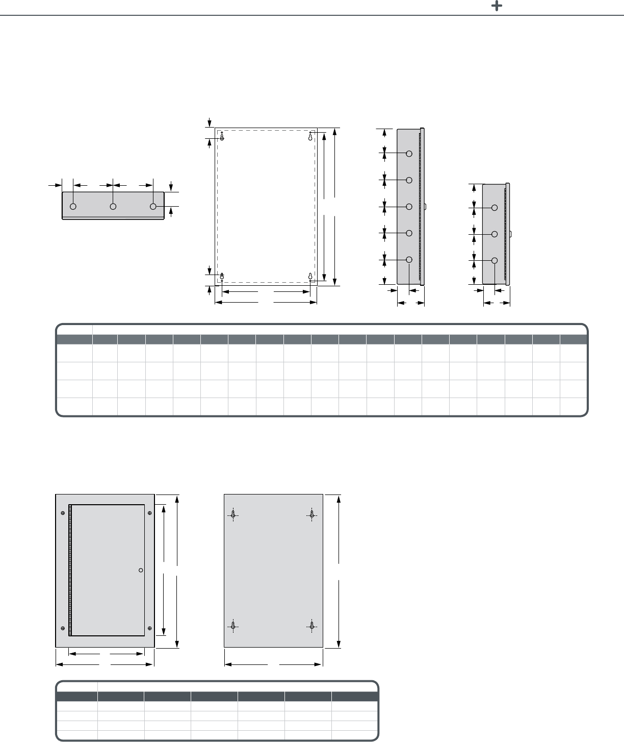
POWERLINK LIGHTING CONTROL TECHNICAL SECTION
LPB Lighting Control Relay Panel (cont.)
Mounted Enclosure Dimensions (Without Doors)
Measurements — mm (in.)
Relays A B C D E F G H I J K L M N O P Q R
842
(1.7)
149
(5.1)
149
(5.1)
46
(1.8) N/A N/A 330
(13)
381
(15)
345
(13.6)
381
(15)
90
(3.5)
101
(4)
101
(4)
90
(3.5) N/A N/A 46
(1.8)
101.6
(4)
16 42
(1.7)
149
(5.1)
149
(5.1)
46
(1.8) N/A N/A 330
(13)
381
(15)
556
(21.9)
592
(23.3)
94
(3.7)
101
(4)
101
(4)
101
(4)
101
(4)
94
(3.7)
46
(1.8)
101.6
(4)
32 60
(2.4)
194
(7.6)
194
(7.6)
60
(2.4)
27.87
(1.10)
27.05
(1.08)
406.8
(16)
508
(20) N/A 850
(33.5)
55
(2.2)
190
(7.5) N/A N/A 190
(7.5)
55
(2.2)
55
(2.2)
101.6
(4)
48or64 60
(2.4)
194
(7.6)
194
(7.6)
60
(2.4)
27.87
(1.10)
27.05
(1.08)
406.8
(16)
508
(20) N/A 1250
(49.2)
55
(2.2)
380
(15) N/A N/A 380
(15)
55
(2.2)
55
(2.2)
101.6
(4)
Flush-Mounted Door Dimensions
Measurements — mm (in.)
Relays A B C D E F
8349(13.7) 493(19.4) 371(14.6) 493(19.4) 493(19.4) 493(19.4)
16 349(13.7) 493(19.4) 582(22.9) 704(27.7) 493(19.4) 704(27.7)
32 478(18.8) 620(24.4) 838(33) 962(37.9) 620(24.4) 962(37.9)
48or64 478(18.8) 620(24.4) 1238(48.7) 1362(53.6) 620(24.4) 1362(53.6)
A B C
D
E
F
G
IJ
K
K
L
L
M
M
N
N
O
P
Q Q
R R
H
FD
C
EB
A
Flush – Door Flush – Plate
Top View
Front View (Without door
or interior assembly)
Side View for
16, 32, 48, and 64 relay
capacity panels
Side View for
8 relay capacity panels
54

POWERLINK LIGHTING CONTROL TECHNICAL SECTION
LPL Lighting Control Relay Panel
Input Wiring (Optional)
Output Wiring
SERVICE
RESET
0
1
2
3
4
5
6
7
8
9
10
11
12
13
14
15
SER Rx Tx INI
Neuron
Chip
+5v
SERVICE
RESET
SER Rx Tx INI
Neuron
Chip
+5v
OFFO FF OFF OFFO FF OFFO FF OFF OFFO FF OFF OFFO FF OFFO FF OFF
0
1
2
3
4
5
6
7
0
1
2
3
4
5
6
7
B
C
D
E
F
G
H
To other CCE cards
or CHR cards
To other CCE cards
or CHR cards
Transformer T1
120 V, 277 V, 347 V
Transformer T1
120 V, 277 V, 347 V
SER = Service Pin
RX = Receive Data
TX = Send Data
+5V = 5V power
INI = Initialization
SER = Service Pin
RX = Receive Data
TX = Send Data
+5V = 5V power
INI = Initialization
A = Low voltage switch ON/OFF
B = Maintained contact ON/OFF
C = Maintained contact OFF
D = Maintained contact ON
Wire Colors
(Controller to relays)
R1 = Brown
R2 = Red
R3 = Orange
R4 = Yellow
R5 = Green
R6 = Blue
R7 = Purple
R8 = Gray
R9 = White
R10 = Black
R11 = White + Black
R12 = White + Brown
R13 = White + Red
R14 = White + Orange
R15 = White + Yellow
R16 = White + Green
A
R1
R2
R3
R4
R5
R6
R7
R8
R9
R10
R11
R12
R13
R14
R15
R16
E = Maintained contact OFF
F = Maintained contact ON
G = Contact from timeclock ON/OFF
H = Contact from photocell ON/OFF
Input Controller
Output Controller
Pilot Lights
Pilot Lights
LonWork Network
LonWork Network
To Common Terminal
Local switch
if used
Local switch
if used
55

POWERLINK LIGHTING CONTROL TECHNICAL SECTION
LPL Lighting Control Relay Panel (cont.)
Wall- and Surface-Mounted Enclosure Dimensions (Without Doors)
A B C
D
E
F
G
IJ
K
K
L
L
M
M
N
N
O
P
Q Q
R R
H
Measurements — mm (in.)
Relays A B C D E F G H I J K L M N O P Q R
842
(1.7)
149
(5.1)
149
(5.1)
46
(1.8) N/A N/A 330
(13)
381
(15)
345
(13.6)
381
(15)
90
(3.5)
101
(4)
101
(4)
90
(3.5) N/A N/A 46
(1.8)
101.6
(4)
16 42
(1.7)
149
(5.1)
149
(5.1)
46
(1.8) N/A N/A 330
(13)
381
(15)
556
(21.9)
592
(23.3)
94
(3.7)
101
(4)
101
(4)
101
(4)
101
(4)
94
(3.7)
46
(1.8)
101.6
(4)
32 60
(2.4)
194
(7.6)
194
(7.6)
60
(2.4)
27.87
(1.10)
27.05
(1.08)
406.8
(16)
508
(20) N/A 850
(33.5)
55
(2.2)
190
(7.5) N/A N/A 190
(7.5)
55
(2.2)
55
(2.2)
101.6
(4)
48or64 60
(2.4)
194
(7.6)
194
(7.6)
60
(2.4)
27.87
(1.10)
27.05
(1.08)
406.8
(16)
508
(20) N/A 1250
(49.2)
55
(2.2)
380
(15) N/A N/A 380
(15)
55
(2.2)
55
(2.2)
101.6
(4)
Surface-Mounted Door Dimensions
Measurements — mm (in.)
Relays A B C D E F
8349(13.7) 493(19.4) 371(14.6) 493(19.4) 493(19.4) 493(19.4)
16 349(13.7) 493(19.4) 582(22.9) 704(27.7) 493(19.4) 704(27.7)
32 478(18.8) 620(24.4) 838(33) 962(37.9) 620(24.4) 962(37.9)
48or64 478(18.8) 620(24.4) 1238(48.7) 1362(53.6) 620(24.4) 1362(53.6)
Top View
Front View (Without door
or interior assembly)
Side View for
16, 32, 48, and 64 relay
capacity panels
Side View for
8 relay capacity panels
FD
C
EB
A
Flush – Door Flush – Plate
56

Architectural
Dimming

ARCHITECTURAL DIMMING
ofarchitecturaldimmingsolutions.From
conventioncenterstolibrariesorrestaurants
toballroomsourdimmingsystemsare
capableofprovidingthemostdemanding
precisecontroltailoredfortheapplication.
Architecturaldimmingprovidesanopportunity
totransformaspace,managemoods,
conserveenergy,andimprovethequalityoflife.
Tomakethebuildingenvironmentas
responsive,productiveandattractiveas
possible,SchneiderElectricoffersawiderange
Architectural Dimming
58

ARCHITECTURAL DIMMING INTOUCH CONTROL STATIONS
inTouch control stations
for Use with Architectural Dimming Systems
by Schneider Electric™
TheinTouchControlStationsbySchneiderElectricofferapowerfulandelegant
interfacetotheArchitecturalDimmingSystemsbySchneiderElectric.
TheinTouchfamilyofproductsoffersanextensivelineofuserinterfacesincluding
6and12channelmasterstationsaswellasawidevarietyofentrystations.
TheinTouchstationsusecapacitivetouchtechnologyprovidingtouchsensitivity
andimmediateresponse.Thesestationsprovideadurableuserinterfacewith
nomechanicalpartsmakingthemperfectforrestaurants,conferencerooms,
conventioncenters,andauditoriums.
InconjunctionwiththeWall-MountedArchitecturalDimmingPanels,theinTouch
masterstationsprovidecontroloftwoareaswithupto18presetsperarea.In
conjunctionwiththeArchitecturalDimmingRacks,thestationsproviderecallof
24presetsand16areasaswellasotherfunctionalityincluding;macros,room
partitioncontrol,alternateactions,on/offpairs.
Product Features
•Capacitivetouch
technology
•Commercialgrade
constructionwithno
mechanicalbuttons
orpotentiometers
•6or12channelsliders
withLEDlevelindicators
(MasterStations)
•Graphiclevel
LCDdisplay
•Multiplechannelpages
(ADSM612with
DimmerRack)
•HandheldInfrared
remotecontrol—
(optional)
Benefits
• Aestheticdesign/stateoftheartinterface
• Durabledesignforruggedenvironments
• Easeofprogramming
Technical Information
Master Stations Programmablepresetswithindividualchannelcontrol.
Mechanical Frame RuggedABSframewithaLexanoverlaycoveringthecontrolsection.
Mounting Mountsinastandardmulti-gangmasonrystylebackbox(furnishedbyothers)withnovisiblefasteners.
Display AgraphiclevelbacklitLCDdisplayingtheactivepresetname,fadetime,areaname,channelpage
number(ADSM612only),preset(scroll)names,andmenufunctions.
Controls Capacitivetouchsensingbuttonsandchannelcontrollerswithnomovingparts.*
Master Station Backlit
Control Buttons Full,Off,Scroll,Select,Store,Menu
IR Control IntegralinfraredreceiverforwirelesspresetselectionusingaCWChandheldtransmitter.
Network Wiring Stationsrequiretwoshieldedpair(Belden#9729)plus3#14AWGwires.
*Stations with mechanical buttons or potentiometers are not considered equal.
Ordering information: ContactyourlocalSchneiderElectricsalesrepresentativeformoreinformation.
For Diagram see technical section page 63
inTouchControlStations
59

ARCHITECTURAL DIMMING WALL-MOUNTED DIMMING SYSTEMS
Wall-Mounted Dimming Systems
Architectural Dimming Panels
TheWall-MountedArchitecturalDimmingPanelbySchneiderElectricprovidesasimpleandeasytoinstall
dimmingsystemforenvironmentslookingtoenhancethearchitecturaldesign,setmoodlighting,setfocalpoints
inthespace,andsaveenergy.
Thesedimmingpanelsarecompactintheirdesign.Theyincorporate6,9,and12circuitcongurations.
Thepanelsareavailablein120VACand277VACoptions.Thedimmingmodulesareavailablein2400watts
universal,3-wire,uorescent,andnon-dimlightingloads.
ThesepanelssupportmultipledigitalcontrolinputsincludingtheinTouchControlStationsbySchneiderElectric
andDMX512basedcontrollers.Severallifesafetyfeaturesarealsoincludedinthedesignofthedimmingpanels
includingrealarmbypassandphaselosscontrol.
Benefits
• Simple,CostCompetitiveDesignformostdimmingapplications
• EasytoInstallandProgram
• Flexibilityofcontrolfrommultiplesystems
Technical Information
Dimming Panel Specications
Enclosure Modular,weldedsteelcabinetwithatexturedblackpowdercoatnishandaremovablefrontpanel.
Wallmounteddesignforsurfaceorrecessedmounting.
Dimensions 17in.(W)x39in.(H)x4in.(D),43.2cm(W)x99.1cm(H)x10.2cm(D)
Main and Neutral Lugs Ratedto100ampsperphasefor120/208V,60Hz,3phase,4wireinput.
Mainlugssuitableforupto#1/0Gawire.(Optional277Vlugsavailableasrequired).
Operating Temperatures 104°Fambient(40°C)Thermostaticallycontrolledfans
Load wire terminals #8AWGmax.
Standard Universal Dimmer Specications
Dimmer Rating 2400wattscontinuousduty(1200wattswhenusedwithelectroniclow-voltagetransformers).
Overload Protection 20amp,fullymagnetic,switchdutyratedcircuitbreakersperdimmerthatisULlistedunderUL489as
abranchcircuitprotectorwithaminimum10,000AICrating.
Filtering Toroidalchoketolimitthecurrentrisetimetoaminimumof350micro-secondsasmeasuredfrom
10%to90%oftheoutputwaveformatmaximumlevel.
Load Control Compatibility
Universaldimmertocontrolincandescent,low-voltage(electronicormagnetic),neon/cold-cathode,
quartz,2-wirephasecontroldimmableuorescentballasts,andnon-dimmed(switched)loads.
(Optional)Providedimmerstocontrol0-10vand3-wiredimmableuorescentballastsasscheduled.
Dimmer Performance
Temperature Range 0°to104°Fambient(0°to40°C)
Line Voltage Range 90to140volts
Dimming Curve Squarelaw
Voltage Regulation Within3.5voltsoftheinputvoltage
Efciency Exceeds95%
Output Symmetricalalternatingcurrent(eliminatesanyDCcomponenttotheload)
Certications ULandcULListed
Ordering information: ContactyourlocalSchneiderElectricsalesrepresentativeformoreinformation.
For Diagram see technical section page 64
Product Features
•MagneticCircuit
BreakerforOverCurrent
Protection
•6,9,&12Circuit
Congurations
•2400wattsofUniversal
Dimming
•SupportIncandescent,
Quartz,Neon/Cold
Cathode,LowVoltage,
Fluorescent,andNon-
DimLoads
•FireAlarmBypass
•PhaseLossControl
•SupportsinTouch
ControlStationsby
SchneiderElectricand
DMX512digitalcontrols
•ProgrammableDimmer
toChannelPatch
Wall-MountedArchitectural
DimmingPanels
60

ARCHITECTURAL DIMMING RACK-MOUNTED DIMMING SYSTEMS
Rack-Mounted Dimming Systems
TheRack-MountedArchitecturalDimmingPanelsbySchneiderElectricareideal
forsmalltolargeprojectsincludingprofessionalandeducationaltheaters,television
studios,hotels,churches,andconventioncenters.Theuniversaldimmersinclude
dual2.4kWandsingle6KWmodules(120V)or5.4kW(277V)withthestandard
risetimesare350uSwith500uSand800uSoptions.Othermodulesincludenon-
dim,constantcircuits,anddimmableuorescentballastcontrol,and3-Wireballast.
TheRack-MountedDimmingPanelsarecompatiblewiththeinTouchControl
StationsbySchneiderElectricandprovideaseamlessinterfacebetweenatheater’s
stageandhouselightcontrols.Forarchitecturalapplications,thebasicrack
mountedsystemprovides24presetsineachof16independentareaswith
128systemcontrolchannelswhiletheadvancedoptionexpandsthesystemto
512channelsover64areas.AnEthernetoptionprovidestheconnectionforremote
systemmonitoring,programming,andsubsystemnetworking.AllEthernetbased
controlandmonitoringcanbeprovidedusingacompatibleconsoleorPC.
Architecturalapplicationscanbedesignedassmallersubsystemsandnetworked
forsinglepointcontrol,idealforconventioncenterandlargehotelprojects.
Product Features
•30,60,or120dimming
circuitsperrack
•Dual2.4KWorsingle
6KWdimmersper
modulefor120V
applications.Dual5.4KW
dimmerspermodulefor
277Vapplications
•350uSrisetimeis
standard.500uS
and800uSrisetimes
areoptional
•Fullymagneticdimmer
circuitbreakers
•Dimmerfeedbackand
statusreportingoption
•Advancedconguration
programming
•99backupcues
•Opto-isolateddualDMX
connections
•Ethernet-based
networkingoption
•Off-lineprogramming
Benefits
• Simple,CostCompetitiveDesignformostdimmingapplications
• EasytoInstallandProgram
• Flexibilityofcontrolfrommultiplesystems
Technical Information
Dimmer Cabinet Specications
Enclosure Modular,freestandingcabinetwithaweldedsteelframeandlockingdooroverthedimmers.
Dimensions • ADSR3016.5in.(W)x43.6in(H)x11.6in.(D)
• ADSR60/ADSR12019.2in.(W)x80.2in(H)x20.5in.(D)
Main and Neutral Lugs 120/208V,60Hz,3-Phase,4-Wireoperation
277/480V,60Hz,3-Phase,4-Wireoperation
Operating Temperatures 104°Fambient(40°C)Thermostaticallycontrolledfans
Dimmer Mounting RemovableSteeltraysw/dimmeralignmentguides
Load Wire Lugs upto#6AWG(Optional#2AWG)
Certications ULandcULListed
Weight Empty 96lbs.(43.5kg) 275lbs.(124.7kg) 310lbs.(140.6kg)
Full 176lbs.(79.8kg) 446lbs.(202.3kg) 655lbs.(301.6kg)
Rack-MountedArchitecturalDimmingPanels
61

ARCHITECTURAL DIMMING WALL-MOUNTED DIMMING SYSTEMS
Technical Information (cont.)
Standard Universal Dimming Module Specications
Dimmer Rating 120/208V:2.4kW*dualor6.0kWsinglemodule2400wattscontinuousdutyor277/480V:5.4kW
Overload Protection 20amp,fullymagnetic,switchduty-ratedcircuitbreakers/dimmer–ULlistedunderUL489asa
branchcircuitprotectorw/amin.10kAICrating.
Filtering Toroidalchokelimitingthecurrentrisetimetoamin.of350uSasmeasuredfrom10%to90%ofthe
outputwaveformatmax.level.
Load Control Compatibility
Universaldimmercontrollingincandescent,low-voltage(electronicormagnetic),neon/cold-cathode,
quartz,2-wirephasecontroldimmableuorescentballasts,&non-dimmed(switched)loads.(Optional)
Providedimmerstocontrol0-10vand3-wiredimmableuorescentballastsasscheduled.
Dimmer Performance
Temperature Range 0°to104°Fambient(0°to40°C)
Line voltage Range 90to140volts
Dimming Curve Squarelaw
Voltage Regulation Within3.5voltsoftheinputvoltage
Efciency Exceeds95%
Output Symmetricalalternatingcurrent(eliminatesanyDCcomponenttotheload)
*1200 watts when used w/ electronic low-voltage transformers
Ordering information
Catalog Number Description
120/208 V Rack Standard Dimming Modules
ADSRD22 Dual2.4kWdimmermodulewith350uSchokes
ADSRD22S Dual2.4kWdimmermodulewith350uSchokes,sensing
ADSRD22HR Dual2.4kWdimmermodulewith500uSchokes
ADSRD22HRS Dual2.4kWdimmermodulewith500uSchokes,sensing
ADSRD22EHR Single2.4kWdimmermodulewith800uSchokes
ADSRD22EHRS Single2.4kWdimmermodulewith800uSchokes,sensing
ADSRD16 Single6.0kWdimmermodulewith350uSchokes(nooutputcircuitbreaker)
ADSRD22CB Dual20Aconstantcircuitbreakermodule
ADSRD12FPC Single2.4kWuorescentdimmermoduleforphasecontroldimmableuorescentballasts(2or3wire)
ADSRD12FDC Dual2.4kWuorescentdimmermodulefordimmableuorescentballasts(0–10VDCcontrol)
ADSRD22ND Dual20Anon-dimmodule
ADSRDFM Fillermodule
120/208V Rack Dual Width Dimming Modules
ADSRD16HR Single6.0kWdimmermodulew/500uSchokes&4–20Abranchcircuitbreakers
ADSRD16HRS Single6.0kWdimmermodulew/500uSchokesw/sensing&4–20Abranchcircuitbreakers
277/480V Rack Standard Dimming Modules
ADSR2H22 Dual5.4kWdimmermodulew/350uSchokes
ADSR2H22FL Single5.4kWuorescentdimmermoduleforphasecontroldimmableuorescentballasts(2or3wire)
ADSR2H22FDC Dual5.4kWuorescentdimmermodulefordimmableuorescentballasts(0–10VDCcontrol)
ADSR2H22ND Dual20Anon-dimmodule
ADSR2H22CB Dual20Aconstantcircuitbreakermodule
Contact your local Schneider Electric sales representative for more information.
62
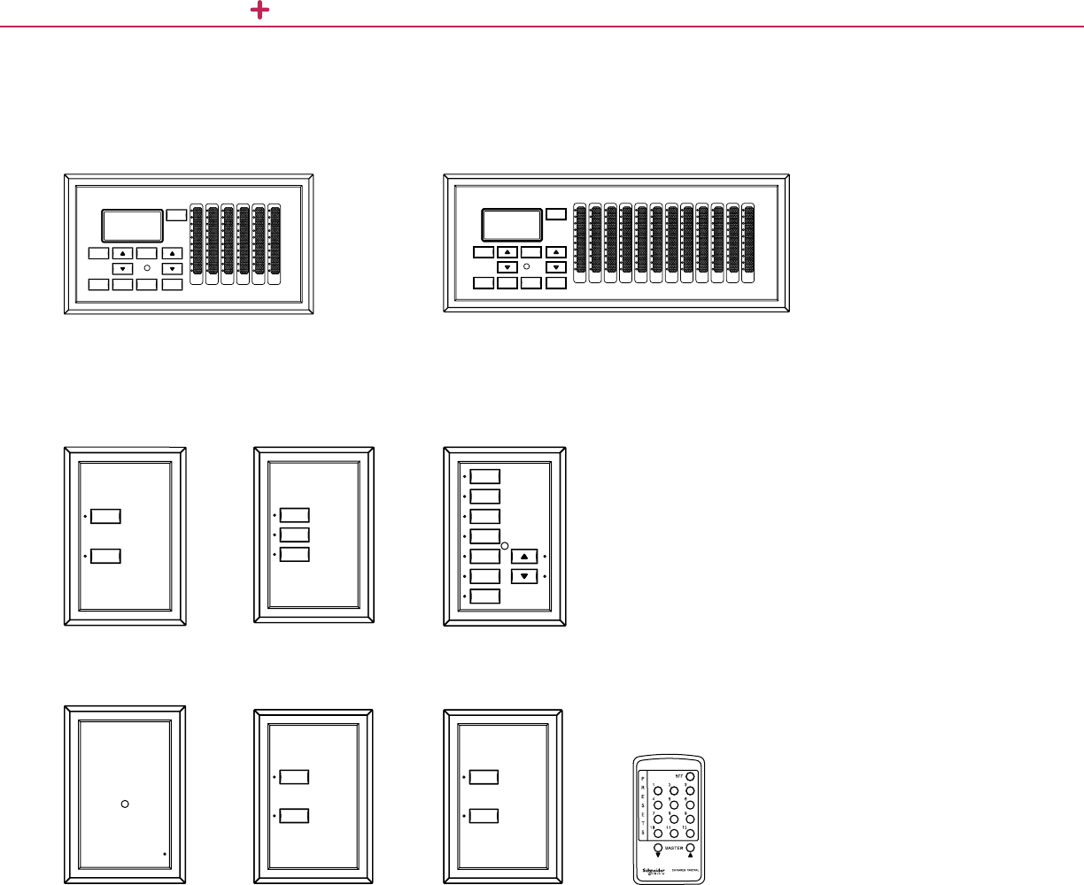
ARCHITECTURAL DIMMING TECHNICAL SECTION
inTouch control stations
Master Stations
6-Channel Master Station (ADSM606)
2-Button Remote Entry
Station (ADSE602)
3-Button Remote Entry
Station (ADSE603)
6-Button Remote Entry
Station (ADSE606RL)
Infrared Remote Entry
Station (ASEIR)
Combine Closure Entry
Station (ADSECC)
Touch Lock/Unlock Entry
Stations (ADSEL/UL)
Infrared Remote Control
(Optional) (ADSPWC)
12-Channel Master Station (ADSM612)
Remote Entry Stations
CLOSE
OPEN
FULL
OF F SELECTG RO UP
STORE
MASTERSCROLL
MENU
PAGE
1 23456789 10 11 12
OFF
DIM
FULL
OF F
6
5
4
3
2
1
OF F
FULL
UNLOCK
LOCK
12345 6
FULL
OF FS ELECTG ROUP
STORE
MASTERSCROLL
MENU
PAGE
63

ARCHITECTURAL DIMMING TECHNICAL SECTION
Front View Back View
Front View
(ADSR120)
Front View
(ADSR30)
Front View
(ADSR60)
Bottom View
Top View
Side View
Side View Side View
Top View
Top View
Wall-Mounted Dimming Systems
Dimming Panel Dimensions and Conduit Stub Locations
Rack-Mounted Dimming Systems
17 in.
(431.8 mm)
19.2 in.
(487.7 mm)
16.5 in.
(419 mm)
11.5 in.
(294.6 mm)
19.2 in.
(487.7 mm)
20.5 in.
(520.7 mm)
17 in.
(431.8 mm)
6 in.
(152.4 mm)
4 in.
(101.6 mm)
4 in.
(101.6 mm) 1.5 in.
(38 mm)
8 in.
(203.2 mm)
6 in.
(152.4 mm)
5.57 in.
(146 mm)
39 in.
(990.6 mm)
32.25 in.
(819 mm)
80.2 in.
(2037.1 mm)
43.6 in.
(1107.4 mm)
14 in.
(355.6 mm)
Power and control
conduit entry
Control only
conduit entry
Conduit Entry
Conduit Entry
(See legend)
64

Measurement &
Verification
Panels (MVP)

MEASUREMENT & VERIFICATION PANELS (MVP)
Understandingthecostoflighting—how
much,whenandwhereisessentialtogaining
agrasponyourstainabilitymeasures.The
MVPPanelboardsmeasureenergyuseall
thewaytotheindividualcircuitlevel,allowing
youtoisolateandmanageenergyusemore
preciselyforgreaterenergyefciencyand
savings.Havingtheabilitytoindependently
controlandmonitorindividualbranchcircuit
loadsopensawiderangeofoptionstobetter
understandthedynamicsofabuilding’s
performanceandmakeinformeddecisions
onsustainabilitysolutions.
Untilnow,energyusehasbeenmonitoredat
thepanellevelpreventingfacilitymanagersfrom
pin-pointingenergywaste.Improvingefciency
andreducingenergyusecostsrequireda
certainamountofguesswork.WithMVP,
buildingmanagersarenowabletoidentifytrue
“energywastingculprits”andmakeadjustments
accordingly.MVPwillrevealifenergywasteis
duetoelectronicsinaspecicbuildingzoneor
oorthatareleftonduringunoccupiedtimes,or
iflightingloadadjustmentsshouldbemade.The
precisepowerloadandenergyusedataMVP
provides,coupledwithitslightingcontrols,allows
energymanagerstosavemoneywhileworking
towardsmeetingtheirsustainabilitygoals.
Measurement & Verification
Panels (MVP)
66
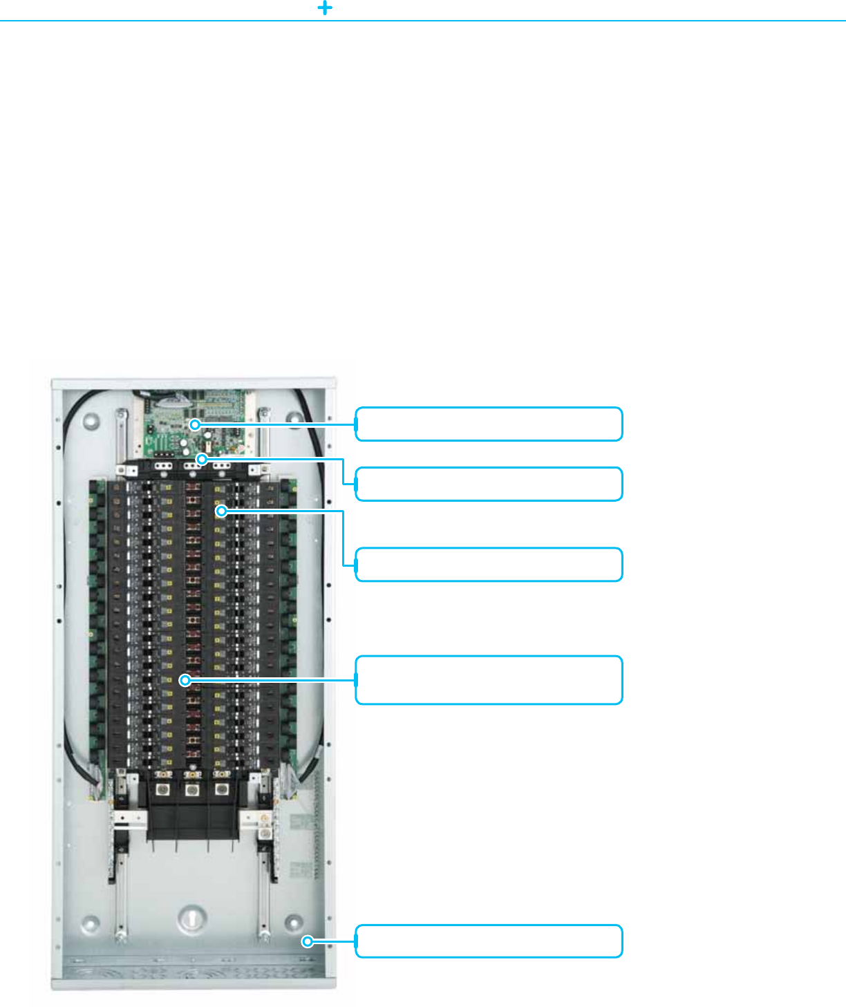
MEASUREMENT AND VERIFICATION PANELBOARDS NF AND NQ PANELBOARDS
NFandNQMeasurementandVericationLightingPanelboardsareacriticalcomponenttoanybuilding’s
sustainabilitysolutions.Inadditiontothestandardbranchovercurrentprotection,NFpanelboardsalso
incorporateindividualbranchcircuitpowermetering.Crucialtoenergymanagement,thisfeatureallowsyouto
monitortheenergyperformanceofelectricalsystemsatthebranchcircuitlevelforimprovedbuilding-wideenergy
efciency.Thiscapabilityalsoallowsyoutoverifythatsustainableenergyconservationmeasuresareperforming
theirintendedfunctions,andprovidesdataforestablishingbaselineperformancestudies.
For Diagram see technical section page 69
Measurement and Verification
Panelboards (MVP)
NF and NQ Panelboards
Branchcurrentandpowermetercontroller
StandardNForNQpanelboardinterior
StandardNForNQbreakers
42and84circuitcongurationavailable
dependingonpaneloptions
Standardpanelboardbox(20inchminimum)
Features
• Factoryassembledin
astandardNForNQ
panelboard.
• Industry-leading
monitoringcapabilities
formaximumpower
reliability.
• Branchcircuitpower
metersupportsupto
84individualbranch
circuitmonitoringpoints
throughboardmounted
individualCTs.
• Mainmeteringcapability
throughoptionally
providedCTs.
• Network
communicationsvia
Modbus®RTU.
• Availablein20inchor
24inchstandardbox
widths.
• Compatiblewith
PowerLogicION
Enterprise,PowerLogic
SystemManager,and
PowerLogicSCADA
software,givingyou
reliable,end-to-end
powermonitoringand
control,oravailable
asastandalone
panelboardsolution
withourcustomized
MVPSoftware.
67

MEASUREMENT AND VERIFICATION PANELBOARDS POWERLINK MVP
PowerlinkMVPIntelligentlightingpanelboardsprovideasimple,costeffective,andenergycodecompliantway
tometerandcontrolbranchcircuitsfromastandardpanelboard.Powerfulmicroprocessorbasedcontrollers
providelightingcontrolandpowermetering.IntegralmeteringisaccomplishedusingthePowerLogicbranch
circuitpowermeter(BCPM),ahighlyaccurate,full-featured,multi-branchcircuitpowermeterthatprovides
unrivalledlow-currentmonitoring.
For Diagram see technical section page 69
Measurement and Verification
Panelboards (MVP)
Powerlink MVP
Mainandbranchmeteringcontroller
Self-containedpowersupply
Web-basedcontroller
Remotelyoperatedcircuitbreakers
Standardpanelboardbox(20inchminimum)
Standardpanelboardinterior
Features
• Verifyenergysavings
bycircuit,zone,space,
orcompletelighting
system*
• Monitorperformance
toassuresystemis
workingasintended*
• Reviewdatafor
planningand
subsequentenergy
savingsopportunities*
• Implementcost
accordingtoactual
energyused*
• Measureoccupancy
andusagepatterns
• Scheduleevents,view
branchcircuitstatus,
andexaminesystem
eventlogs
• Reportsforplanning
andenergysavings
opportunities
• Alarmnotications
whenoperationfalls
outsideofdened
parameters
• Embeddedwebserver
• Automaticsunrise/
sunsettrackingwith
offsets
• Offersthewidest
dynamicmonitoring
rangewithinitsclass
• Attainagranularvision
ofpowerandenergy
usetopinpointareas
foroptimizationor
areasinneedof
additionalcapacity
* Requires BMS or Metering UI to
utilize these features
68

POWERLINK LIGHTING CONTROL TECHNICAL SECTION
Powerlink Measurement and Verification Lighting
Panelboard (MVP)
Current Sensor Strips
2.0 in.
(50 mm)
2.0 in.
(50 mm)
1.1 in.
(28 mm)
1.2 in.
(31 mm)
0.8 in.
(20 mm)
0.4 in. (10 mm)
opening
0.75 in. (19 mm)
on center
1.0 in. (26 mm)
on center
0.4 in. (10 mm)
opening
Slot: 0.25 x 0.5 in.
(7 x 13 mm)
Slot: 0.25 x 0.5 in.
(7 x 13 mm)
1.3 in.
(33 mm)
1.2 in.
(30 mm)
3.9 in.
(100 mm)
Ø = 0.2 in.
(5 mm)
8.9 in.
(288 mm)
7.3 in.
(184 mm)
1.75 in.
(45 mm)
4.8 in.
(122 mm)
5.8 in.
(146 mm)
8.3 in.
(211 mm)
7.9 in.
(200 mm)
1.0 in. option
0.75 in. option
25.0 in. (635 mm)
20.3 in. (516 mm)
Circuit Board with Mounting Bracket
69

70
Powerlink
Lighting Control

Formanydesigners,theengineeringofa
suitablelightingcontrolsystemhasbecome
adauntingtask.Thedesignermustbalance
spaceconstraints,equipment/installation
costs,maintenanceandoperationalconcerns,
whileensuringacode-compliantinstallation.
Fortunately,thePowerlinkG3lightingcontrol
systemaddressesconcernsby:
• Using standard lighting
panelboards
AllPowerlinkG3componentsmountinthe
paneljustlikeastandardcircuitbreaker.
Documentingyourcontrolsystemlayout
isassimpleasindicatingwhichbranch
circuitsaretobecontrolled.
• Saving space
Sincethelightingcontrolsystemis
locatedinsidethelightingpanelboard,
valuablewallandoorspaceisavailable
formoreproductiveuses.Schneider
Electricalsooffersspace-saving,column-
widthpanelboardsandexiblemodular
panelboardsystems.
• Complying with codes
Withtoday’shighavailablefaultcurrents,
it’sextremelyimportantthatyoursystem
meetscoderequirements.ThePowerlink
G3systemisfullyULlistedandmeets
NEC®requirements.
• Building Integration & Control
Todaymorethanever,buildingownersand
facilitymanagerswanttogetthemostout
ofeverydollarinvestedintheirbuilding
infrastructure.Powerlinklightingcontrol
systemsintegrateeasilywithotherbuilding
systemsaspartofanenergymanagement
systemorbuildingautomationsystem,
supportingcommonopenprotocolssuchas
BACnetandModbus.Comparedtostandard
lightingpanelboards,Powerlinklighting
controlsystemstypicallyachieveenough
energysavingstopayforthepanelboard
manytimesover.
Powerlink Lighting Control
POWERLINK LIGHTING CONTROL
72

POWERLINK LIGHTING CONTROL PANEL BOARDS
Powerlink
G3 Panel Mounted Components
Uptoeightpanelscanbeoperated
fromasinglecontroller.
Aself-containedpowersupplyfurnishesthepowerforremotelyoperatedcircuit
breakerswitchingandforthesystem’selectronics.
TheintelligenceofthePowerlinkG3systemcomesfromitsmicroprocessor-
basedcontroller.Itprocessesmanysignalsthatoriginateexternallyfrom
controldevices,suchasswitchesorsensors,orfromitspowerfulinternaltime
schedulerthatswitchesbreakersaccordingtopredeneddailyschedules.
ConventionalEDBcircuitbreakerscanbereadilyincorporatedintoaG3panel.
InnovativeSchneiderElectricremote-operatedcircuitbreakerscombinethe
protectivefeaturesofconventionalcircuitbreakerswiththeswitchingfunctions
ofacontactor.
Plug-oncontrolbusstripsactasthebridgebetweenthecircuitbreakersand
theelectroniccontrolcomponentsofaPowerlinkG3system.
73
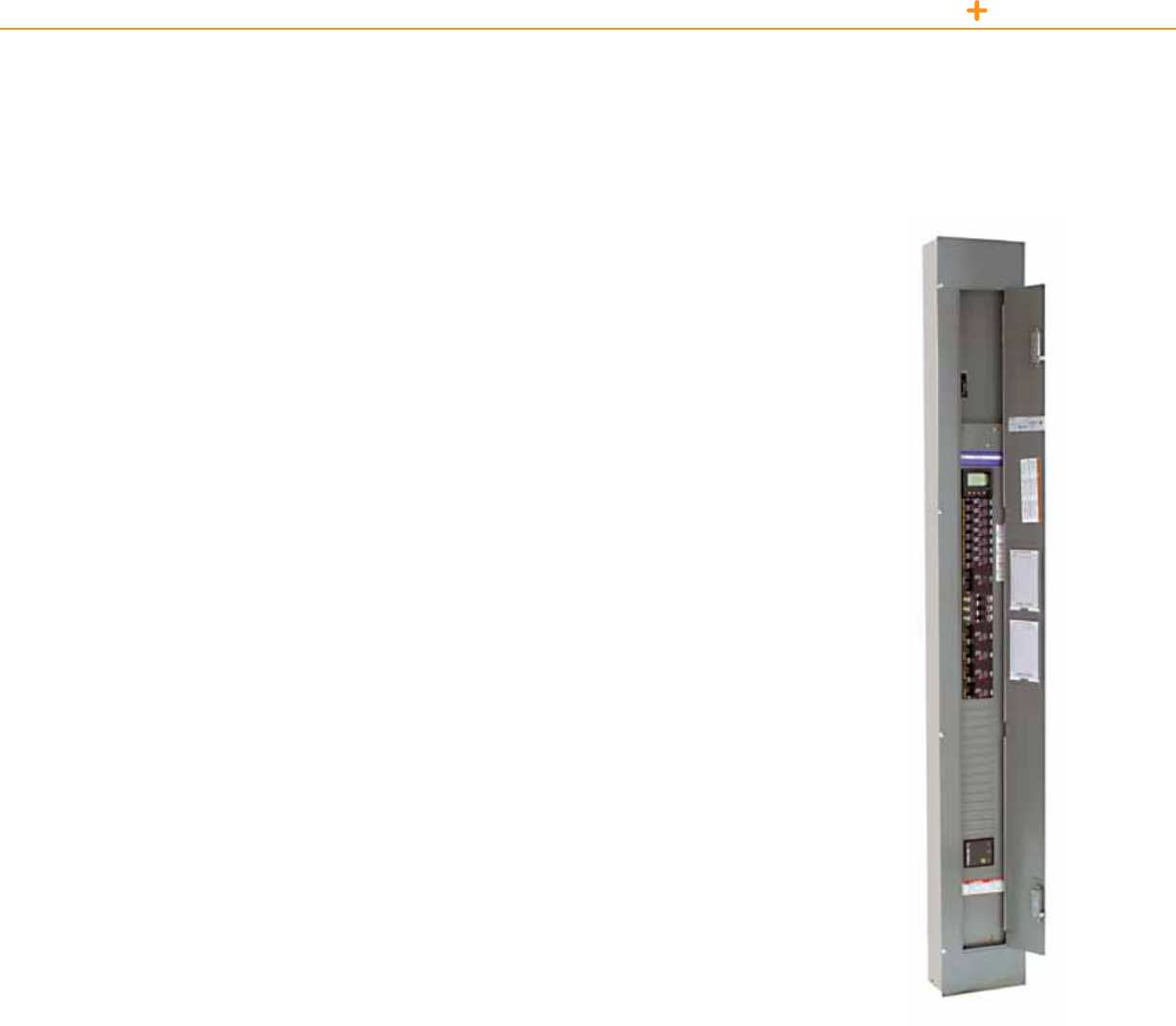
POWERLINK LIGHTING CONTROL PANEL BOARDS
TheNFPanelboardofferssuperiorperformanceandapplicationexibilityforcommercialandindustrialelectrical
systemsupto480Y/277V.SchneiderElectricistheonlylightingcontrolsupplierthatoffersafullrangeof
enclosureoptionsincludingNEMAType3R,5and12.Thefollowingdesignsareavailabletosuityourneeds:
• Standard–TheNFPanelboardofferssuperiorperformanceandapplicationexibilityforcommercialand
industrialelectricalsystemsupto480Y/277V.Thisversatilelightingandpowerdistributionpanelboardfeatures
awideselectionofcircuitbreakers,accessories,andready-to-installkits,aswellas200%ratedneutralsfor
non-linearloads.
• Column-width–TheseinnovativepanelsaredesignedtotintoastandardsizeW,H,orI-beamsupport
columnscommonlyfoundindistributionandindustrialfacilities.Column-widthpanelboardscanalsobewall
mounted,savingvaluableoorandwallspacewheretightequipmentspaceisaconcern.
• Modular Panelboard Systems (MPS)–Thispanelsystembundleselectricaldistributionequipmentinto
asingle,factoryassembledandwiredintegratedsystem.Thisapproachreplacesthetraditionalmethod
ofindependentlymountingeachpanelboardandlightingcontrolsystem,whichsavesspaceandreduces
installationtime.Modularpanelboardsystemsaretailoredtospecicationsandareavailablewithamixof
SchneiderElectricNQOD,NF,NFColumn-widthandSchneiderElectricPowerlinkinteriors,aswellasoptional
powerandcontrolwiring,drytypetransformers,lightingcontactors,transientvoltagesurgesuppression
(TVSS)units,andenclosurespaceforeldinstalledequipment.AllMPSpanelboardsareUnderwriters
Laboratories(UL)ListedunderFileE33139(PanelboardUL67).
• Integrated Power Center (IPC)–Thisintegratedsystemoffersthewiderangeoffactoryassembledand
wiredpanelboardsinteriors,drytypetransformers,andlightingcontrolasofferedwiththeMPSline.Inaddition,
theIPCoffersfactoryinstalledandprogrammedbuildingmanagementsystems,automatictransferswitches,
andmotorstarters.Regardlessofyoursystemcomplexity,SchneiderElectrichastheexpertisetointegrate
yourrequirementsintooneoptimized,costeffective,spacesavingsolution.IPCsareUnderwritersLaboratories
(UL)ListedunderleE83877(Dead-FrontSwitchboardUL891).
For Diagram see technical section page 88
NFColumnWidthPanelboard
NF Panelboards, Column Width
& Custom Panel Boards
74

POWERLINK LIGHTING CONTROL CIRCUIT BREAKERS
PowerlinkG3remotelyoperatedcircuitbreakersaredesignedforinstallationin
SchneiderElectricNFLightingPanelboardsaspartoftheSchneiderElectricPowerlink
G3LightingControlSystem.Thesecircuitbreakersprovidethesameovercurrent
protectionasfoundinstandardcircuitbreakers.
The Best in Remote Operation
• Robust24Vdcmotorandhighlyeffectivetripmechanismprovideunequaledremote
operationcapabilityintermsofcompactsize,electricalratings,andmechanicallife.
• Motoranddrivetraincanopenandclosethecontactswhenthecircuitbreaker
handleisintheONposition.
• ContactscannotbeclosedremotelywhenthehandleisintheOFFpositionorthe
circuitbreakeristripped.
• Manualoverrideselectorlocatedonthefrontofthebreakerprovidesby-passof
automatedcontrolcommand.
Product Features
•200,000cycles(ON/OFF)
loadendurance
•Remoteandlocalstatus
•Manualoverride
•Extralargeloadterminal
ECB-G3SeriesRemotelyOperatedCircuitBreakers
Powerlink
Remotely Operated ECB-G3 Circuit Breakers
• Inmanualmode,themotordrivetrainisdisconnectedfromthecontact,allowingthecircuitbreakerhandle
tooperatethecontactslikeaconventionalcircuitbreaker.
• Remotecontactstatusindication–determinesthepresenceorabsenceofvoltageontheloadsideterminal
ofthecircuitbreaker.
Tripping System with True RMS Sensing
• SchneiderElectricPowerlinkECB-G3circuitbreakershaveapermanenttripunitthatcontainsafactory
presetthermal(overload)tripelementandamagnetic(shortcircuit)tripelementineachpole.
• Thethermaltripelement–trueRMSsensingandiscalibratedtocarrythecontinuouscurrentratingofthe
circuitbreakerat140°F(40°C)freeairambienttemperature.
Technical Information
Voltage 120Vac 240Vac 480/277Vac
Interrupting capacity 65kAIR 65kAIR 14kAIR
Terminals (1)#14–8ALor(1)#14–8CU
Standards ULListed489,NEMAStandardAB-1-1986,CSAStandard22.5
*For series connector ratings, see page 89
Catalog Number One-Pole Catalog Number Two-Pole Catalog Number Three-Pole
ECB14015G3* 15Amp ECB24015G3* 15Amp ECB34015G3* 15Amp
ECB14020G3* 20Amp ECB24020G3* 20Amp ECB34020G3* 20Amp
ECB14030G3 30Amp ECB24030G3 30Amp ECB32030G3 30Amp**
*Switch Duty Rated
**Not available in 480 V
75
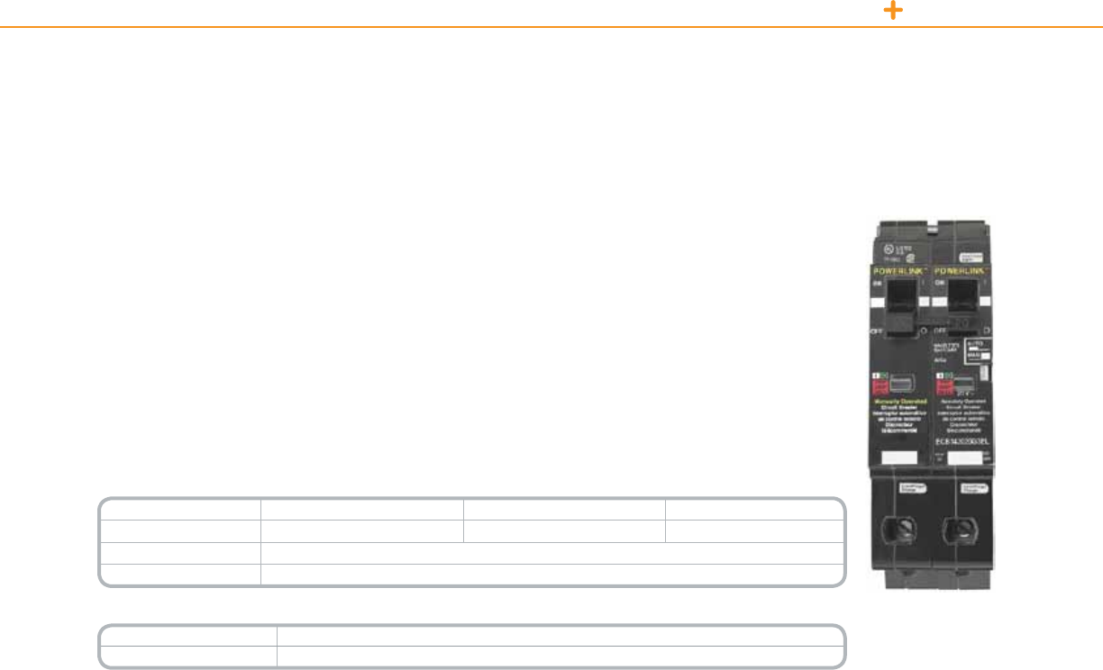
POWERLINK LIGHTING CONTROL CIRCUIT BREAKERS
PowerlinkECB-G3ELcircuitbreakersprovideameanstocomplywiththerequirementsoftheNEC,700.12.
Thecircuitbreakercontainsbotharemotelyoperatedswitchedcircuitforcontrollingtheluminaires,anda
manuallyoperatedunswitchedcircuit,whichprovidespowertotheunitemergencyequipment’schargingand
detectioncircuit.Bothcircuitsareelectricallytiedtothesamesourceviaasinglecommonbolt-onconnection
thatreceivesitssupplyfromthepanelboardbus.
BothcircuitsoftheECB-G3ELbreakercontainathermal-magnetictripmechanismthatprotectstheirassociated
conductorsfromovercurrent.Thecircuitbreakerprovidesacommontripfunctionensuringthatbothcircuitswill
openwheneverafaultoccursoneitherofthecircuits.Italsoprovidesacommonhandletietoensurethatboth
circuitsaremanuallyswitchedtogether.
Technical Information
Voltage 120Vac 240Vac 480/277Vac
Interrupting capacity 65kAIR 65kAIR 14kAIR
Terminals (1)#14–8ALor(1)#14–8CU
Standards ULListed489,NEMAStandardAB-1-1986,CSAStandard22.5
Catalog Number Description
ECB142020G3EL 20Amp
Product Features
•200,000cyclesload
endurance
•Remoteandlocalstatus
•Manualoverride
• Extralargeloadterminal
ECB-G3ELRemotelyOperated
CircuitBreakersforEmergency
LightingCircuits
ECB-G3EL Remotely Operated Circuit Breakers
for Emergency Lighting Circuits
76

POWERLINK LIGHTING CONTROL CONTROL BUS
PowerlinkG3ControlBusesprovidetheinterfacebetweenthesystemcontrollerandremotelyoperatedcircuit
breakers.Specically,theydistribute24Vdcswitchingpowerandcontrolsignalstoswitchremotelyoperated
circuitbreakersandreportcircuitbreakerstatusbacktothesystemcontroller.
Onetofourcontrolbusstripscanbemountedinasinglepanelboard.Ifonlyonecontrolbusisrequired,itis
alwaysmountedontheleft-handsideofastandardpanelboardoratthetopofacolumn-widthpanelboard.
Technical Information
Operating Temperature
(external panelboard ambient) 23°Fto104°F(-5°Cto40°C)
Storage Temperature -4°Fto185°F(–20°Cto85°C)
Operating Humidity 5%to95%(non-condensing)
ESD Immunity IEC1000,Level4
RF Susceptibility IEC1000,Level3
Electrical Fast Transient
Susceptibility IEC1000,Level3
Electrical Surge Susceptibility,
power line IEC1000,Level4
Electrical Surge Susceptibility,
interconnection lines IEC1000,Level3
Standards FCCPart15,ClassA;ULListed916EnergyManagementEquipment
Catalog Number Max. Control Circuits Orientation
NF12SBLG3 12 Left
NF12SBRG3 12 Right
NF18SBLG3 18 Left
NF18SBRG3 18 Right
NF21SBLG3 21 Left
NF21SBRG3 21 Right
Product Features
•AttachestoNF
Panelboardinterior
mountingrail.
•Modularconnectors
providesecureplug-in
connectionsforremotely
operatedcircuitbreakers
andcontrolelectronics.
•Noopenelectronics.
CeilingMountedOccupancy
SensorUltrasonic
Powerlink
G3 Control Bus
77
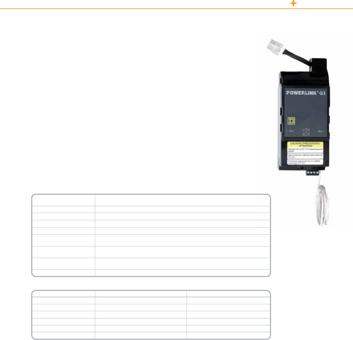
POWERLINK LIGHTING CONTROL POWER SUPPLY
PowerlinkG3PowerSupplyprovidespowertooperatethecontroller,controlbusesandremotelyoperated
circuitbreakers.ThepowersupplyattachestoanNFPanelboardinteriorinthesamemannerasastandard
3-polecircuitbreaker.
Thepowersupplyderivesitspowerfromthepanelboardinteriorbusandconvertsthelinevoltageintotwo
separatesupplies:onesupplyfurnishesthecontrollerwitha24Vdc,
Class2source;theothersupplyfurnishesthecontrolbusandsubnetwitha24Vdc,Class1source.
Anoptionaltypeofpowersupply,furnishedwithprimaryleads,isavailableforusewithaseparatelyderived
primarypowersource.Thisoptionisoftenusedinapplicationswherethesystemmustremainoperationalduring
poweroutages.Insuchapplications,theexternalleadsareconnectedtoanuninterruptiblepowersupply(UPS)
oralternatepowersource.
In20-inch(508mm)widepanels,thepowersupplyisalwayslocatedintheupperleft-handcorneroftheinterior.
Thecontrollerismountedadjacenttothepowersupplyontheright-handside.
Technical Information
Operating Temperature
(external panelboard ambient) 23°Fto104°F(-5°Cto40°C)
Storage Temperature -4°Fto185°F(–20°Cto85°C)
Operating Humidity 5%to95%(non-condensing)
ESD Immunity IEC1000,Level4
RF Susceptibility IEC1000,Level3
Electrical Fast Transient
Susceptibility IEC1000,Level3
Electrical Surge Susceptibility,
power line IEC1000,Level4
Electrical Surge Susceptibility,
interconnection lines IEC1000,Level3
Standards FCCPart15,ClassA;ULListed916EnergyManagementEquipment
Catalog Number Voltage Primary Source
NF120PSG3 120V PanelBus
NF240PSG3 240V PanelBus
NF277PSG3 277V PanelBus
NF120PSG3L 120V ExternalLeads
NF240PSG3L 240V ExternalLeads
NF277PSG3L 277V ExternalLeads
Product Features
•Attachestopanelboard
interior,occupiesthree
adjacentpolespaces.
•Externalleadfor
connectiontopanel
neutral.
•Modularconnectors
providesecureplug-
inconnectionsfor
connectiontoleft-hand
sidecontrolbusand
controller.
•LEDindicationofClass
1andClass2voltage
sourcesoperationalstatus.
•Removable
communicationterminal
blockformakingsubnet
connections.
•Internallyself-protected
againstshortcircuitsand
electricalsurges.
•Lowcontinuouspower
draw,lessthan20VA.
•Optionalexternalleadsfor
connectiontoremote
powersource.
•Noopenelectronics.
PowerSupply
Powerlink
Power Supply
78
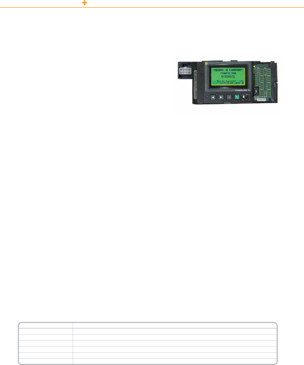
POWERLINK LIGHTING CONTROL CONTROLLERS
PowerlinkG3productlineoffersasimple,cost-effectivemeansforcontrolling
branchlightingcircuits.Fivedistinctsystemsprovideavarietyofcapabilitiesto
meetvirtuallyanyneed.
500 Level System
• Designedtobeusedinconjunctionwithothercontroldevicessuchas:External
timeclocks,accessreaders,occupancysensors,orotherbuildingsystems.
• Controldevicesprovideeitherdry-contactclosuresordigitalserial
communications.
• Incorporatesinternalprogrammabletimers.
• Controllerrespondstocommandsfromcontroldevicesbyautomatically
switchingaprogrammedgroupoflightingcircuits.
1000 Level System
• Includesallthefeaturesofthe500levelsystem,Plus:
• Incorporatesaexibletimeschedulerthateliminatestheneedforexternaltime
clocks.Includesmanycontrolfeaturesnotfoundintraditional,mechanical
timeclocksorenergymanagementsystems.
• Ideallysuitedforstand-alonesystemsinretail,ofce,institutional,and
industrialfacilities.
2000 Level System
• Includesallthefeaturesofthe1000levelsystem,Plus:
• Combinesthecontrol,input,andschedulingfeaturesoftheNF1000withthe
addedbenetofembeddedEthernetconnectivity.
• Peer-to-peer(P2P)controlnetworkconnectivityallowsdifferentcontrollersto
shareinputsignals,schedules,andlightingzonestates.
• Ethernetconnectivityreducesnetworkinstallationcostsbyeliminatingtheneed
foradedicatedlightingcontrolnetwork.
3000 Level System
• Combinescontrol,input,andschedulingfeaturesofthe2000levelcontroller,Plus:
• Embeddedwebserverforremoteaccesswithoutdedicatedsoftware
• Automatedalarmsnotifyusersviaemailwhenpre-denedeventsoccur
(eg:tripbreakers)
Powerlink
Controllers
3000C Level System
• 3000Ccontrolleraddsallthefeaturesofthe3000
levelcontroller,plustheabilitytointegratewithC-Bus
devicesontheC-Busnetwork
BacNet Capability
• TheBuildingAutomationandControlnetwork(BACnet)
communicationprotocolisbeingincorporatedinto
theexistingPowerlinkG3controllerdesign.The
BACnetprotocolallowsPowerlinkpanelstobeeasily
integratedintoaBuildingAutomationSystem(BAS)
employingthisopencommunicationstandardwithout
theneedforcommunicationbridgesorgateways.
Controller Models
ThefollowingPowerlinkG3controllermodelssupport
‘native’BACnetcommunications,BACnetIP,and
BACnetMS/TPonRS-485:
• NF2000G3—Ethernetcommunications,shared
remoteinputs,networktimesynchronization
• NF3000G3—Emailuponalarm,onboardwebpages
forstatus/control/conguration
• NF3000G3C—C-Buscommunications(abilityto
interfacewithaC-Buslightingcontrolnetwork)
* NF3000G3C does not have RS485 capabilities (BACnet MS/TP)
Controller
Catalog Number Controller Type
NF500G3 500LevelPowerlinkG3Controller
NF1000G3 1000LevelPowerlinkG3Controller
NF1000G3N2 1000LevelPowerlinkG3Controllerw/N2Protocol
NF2000G3 2000LevelPowerlinkG3Controller
NF3000G3 3000LevelPowerlinkG3Controller
NF3000G3C 3000LevelPowerlinkG3Controllerw/C-BusCapabilities
79
POWERLINK LIGHTING CONTROL CONTROLLERS
Controller Feature Comparison
Feature System Level
500 1000 2000 3000
Input Terminals
2-wire 8 16 16 16
2-wirewithstatusfeedback8888
3-wire 8888
Input Types
2-wirenormallyopen(NO)ornormallyclosed(NC) X X X X
2-wireNOorNC,withautomaticblinknotication X®XXX
2-wiremaintainedtoggle X®XXX
2-wiremomentarytoggle X®XXX
2-wiremomentaryONormomentaryOFF X®XXX
3-wiremomentary X®XXX
Inputtimers(1sec.upto18hours) X®XXX
Inputsynchronization — X X X
Sentry®Switchsupport X®XXX
ONdelay/OFFdelay X®XXX
Time Scheduler
Independentschedules — 16 16 16
ON-OFFperiods/schedule — 24 24 24
7-day24-hourrepeatingschedule — X X X
32specialevent/holidayperiods — X X X
Automaticdaylightsavings — X X X
Sunrise/sunsetwithoffsets — X X X
Networktimesynchronization(requiresTCPconnection) — — X X
Network Variables
Communicationsinputs(networkaccessible) 64 64 64 64
Remotesources(percontroller) — — 32 32
Maximumsubscriptions — — 256 256
Zones
Maximumnumber 64 64 64 64
Maximumsourcesperzone 1244
Congurablesourcelogic(OR,AND,XOR,XNOR,NOR,NAND,LASTEVENT) — ^X X
Maximumremotelyoperatedcircuitbreakers(persubnet) 168 168 168 168
Blinknotice(single,double,delaynoblink) X®XXX
ON-time X®XXX
Networking
RS-232port/RS-485port X X X X
Ethernet(10BaseTport) — — X X
Protocols
BACnet — — X X
C-Bus — — — X†
ModbusASCI/RTU X X X X
ModbusTCP — — X X
JohnsonControlsN2 — Xê— —
DMX512 — X X X
Front Panel
LEDdisplaywithcover X — — —
BacklitLCDdisplay — X X X
Passwordorfrontpaneldisable X®XXX
Memory
Non-volatilememoryforprogramsandconguration X X X X
On-boardcapacitortopowerclockchipduringpoweroutage — X X X
Flashmemoryforrmwareupgrade X X X X
Viewing Options
EventLog — +X X
StrikeCounter X®XXX
AlarmviewingviaEventLog — +X X
Alarmviewingviae-mail — — — X
Web-basedsetup,controlandstatusmonitoring — — — X
Terminals accept 24-18 AWG conductors êOrder NF1000G3N2 controller for use with Johnson Controls. † 3000G3C controller ^ And/or last event
®Requires conguration software for setup. 7.5mA maximum load per input terminal. + Not available with NF1000G3N2 controllers.
80

POWERLINK LIGHTING CONTROL CONTROLLERS
ThePowerlinkRemoteSourceController(RSC)providesadditionalschedulingand
dry-contactinputsviahighspeedEthernetconnectivitythatlinksawidevarietyof
inputdevicestoa2000or3000levelSquareDPowerlinksystem.
Product Features
• HighSpeedConnectivity
• Ethernetcommunicationeliminatesbottleneckstypicallyassociatedwith
serialdevices.
• UsesexistingLANinfrastructuretoreduceinputwiringcost.
• Usesconvenientradialfeedstoindependentinputdevices;thisavoidspitfalls
thataretypicallyassociatedwithdaisy-chainednetworkdigitalswitches.
Product Features
•NEMAType1enclosure
w/knockouts
•ULListed
RemoteSourceController
Powerlink
Remote Source Controller
Powerful Control Capability
• Supports(16)2-wireinputs,(8)2-wireinputswithstatusoutput,or(8)3-wireinputs.
• FullycongurablefromLCDdisplay/keypadorviaLCS/PCSsoftware.
• Specicallydesignedtooperateinconjunctionwith2000and3000levelcontrollers.
• AnyRSCinputcanbesetuptocontrolanyremotelyoperatedcircuitbreakerconnectedtothesystem.
• Assignableinputtimers,inputsynchronization,andprogrammablebehavioraccordingtospeciedtimeperiod.
• Providesanadditional(16)independenttimeschedulesthatcanbeconguredtooperateanycircuitbreaker
orzoneconguredonthesystem.
Technical Information
Dimensions 12in.x12in.x6in.(304.8mmx304.8mmx152.4mm)
Mounting Wallmount
Ethernet Port (1)10BaseTport
Inputs (16)dedicated2-wireinputsor(8)3-wireinputs
Outputs (8)outputs(maxof60mAtotalforalloutputscombined)
Auxiliary Power 24Vdc(100mAmax)
Terminal Wire Range #24–18AWG
Input Voltage 120/240/277Vac
Input Power Requirements 20VAmax
Standards ULListed916EnergyManagementEquipment
Catalog Number Description
RSC16G3120 120V
RSC16G3240 240V
RSC16G3277 277V
81

WiththenewRemoteMountController(RMC),Powerlinkelectronicscanbemounted
externallytothepanelboard,freeingupvaluablecircuitspaces.RMCsarealsouseful
inapplicationswhereaccesstopanelboardsisnotpermitted.
Benefits
• Savesvaluablecircuitspace:mountsonwallspacenexttoanyexistingpanelboard.
• SavesTimeandMoney:RMCsareeasytoinstallforretrotapplications.They
mountquicklyandeasilytoreducecostlyinstallationanddowntime.
• PowerandFlexibility:addLightingControltoanyneworexistingpanelboard
application.RMCsareavailablewithanyPOWERLINKG3controller—it’sthe
perfectt.
Catalog Number Controller Type Voltage
RMC500G3120 500 120Vac
RMC500G3240 500 240Vac
RMC500G3277 500 277Vac
RMC1000G3120 1000 120Vac
RMC1000G3240 1000 240Vac
RMC1000G3277 1000 277Vac
RMC1000N2G3120 1000N2 120Vac
RMC1000N2G3240 1000N2 240Vac
RMC1000N2G3277 1000N2 277Vac
RMC2000G3120 2000 120Vac
RMC2000G3240 2000 240Vac
RMC2000G3277 2000 277Vac
RMC3000G3120 3000 120Vac
RMC3000G3240 3000 240Vac
RMC3000G3277 3000 277Vac
For Diagram see technical section page 92
Product Features
•NEMA1enclosure
withhingeddoorfor
accesstocontrollerand
connections.
•Compactdimensions–
12in.x12in.x6in.
(305mmx305mmx
152mm)
•Integralpowersupplyfor
connectionto120V,
240V,and277V
systems.
•FullrangeofPowerlink
G3controlleroptions
•ULListed916Energy
ManagementEquipment
•Lowpowerconsumption
–20VAmax.
POWERLINK LIGHTING CONTROL CONTROLLERS
Powerlink
Remote Mount Controller
RemoteMountController
82

POWERLINK LIGHTING CONTROL ADVANCED AND BASIC SOFTWARE
Powerlink
LCS Advanced and LCS Basic software
Convenient Desktop Access
UnlockthepotentialofthePowerlinkG3lightingcontrolsystemwithLCSBasicand
AdvancedsoftwarefromSchneiderElectric.Scheduleevents,overridelighting,and
checkthestatusofbreakerwiththeclickofabutton.Easy-to-navigatesoftwaregives
awholenewmeaningtolightingcontrol.
• Reducecostlydowntimebyusingapersonalcomputertoaccessinformation
andprogramming.
• Createschedulesthateasilyapplytoallcontrollerswithinasystem,ratherthan
programingeachcontrollerindividually.
• Quicklyviewbranchcircuitstatus.(on,off,tripped,ornon-responding)
• Examinesystemeventlogs,makecongurationmodications,createormodify
schedules,initiateoverrides,andupgradermware.
Multi-Device Support (LCS Advanced)
Imaginehavingtheabilitytocongure,monitor,orcontrolahundredormorepanels
atonetime.LCSmakesitareality.Fromalargeofcebuilding,collegecampus,
militarybase,andmanufacturingfacility,toasmallretailsite,usersofLCSAdvanced
havetheabilitytoconguretheentiresystemfromonelocation,greatlyreducing
commissioning,monitoring,andcontroltime.Userscanquicklyviewbranchcircuit
status(on,off,tripped,ornon-responding)fortheentiresystematonetime.Examine
systemeventlogs,makecongurationmodications,createormodifytimeschedules,
initiateoverrides,andupgradermwaresimultaneously.
Firmware & Software Updates
EasytousermwareupgradefeaturesarebuiltdirectlyintotheLCSsoftware.Thisnot
onlyallowstheusertoaccessthelatestandgreatestreleases,butnowLCSgivesthe
usertheabilitytoupgradetheirsoftwareonlineaswell.
Templates
LCSimplementsanewapproachtoprogrammingPowerlinkG3controllersbyusing
globaltemplates.Globaltemplatesallowtheusertosend“like”congurationdatato
multipledevicesatonetime.Forinstance,asingleschedulecanbesetuponetime
andappliedtomultipledevices.
Device Discovery (LCS Advanced)
LCSAdvancedsoftwareallowsdiscoveryofcontrollerdevices,takingtheguesswork
outofcommunicationsetup.Don’thavetheIPaddressofthecontrollersthatare
neededtoprogram,monitor,orcontrol?Devicediscoveryallowsuserstoeasilysetup
asystembysearchingthenetworkanddetectingsupporteddevices.Finddevicesthat
areconnectedtoanetworkusingaserial,TCP,orgatewayconnection.Discovered
devicescanbeaddedtothecurrentsystemwiththeclickofabutton.
File Archiving
LCSisnottiedtoanyproprietarydatabases.LCSusesstandardle/folderarchiving.
Needtoemailacongurationtoafacilitymanager?Noproblem,justattachthele,
clicksend,andawayitgoes.Nomoreimportingandexportingfromadatabase.
Security
LCSallowsdifferentlevelsofaccesstoalighting
controlsystem.Time,dateanduseraccessis
recordedinthesystemlog,anduserchangesand
accessneedscanberestricted.
Reporting
LCSaddsreportingfunctionalitywithcustomizable
lteringandlogging.Forgotwhenthelastlamping
projecthappened?Withaclickofabuttonauser
canaccessbreakeron-timesandresetcounters.
Printandexportreportstocompilesystemtrends.
Compare
LCSbringsanewcapabilityofcomparing
congurationsstoredonacomputertothe
congurationinthePowerlinkG3controllerand
notiestheuserofthedifferences.
Restore
LCScanrestorecongurationstoanearlierversion,
withtheclickofabutton,abackupoftheoriginal
congurationisreadilyavailable.
Network File Sharing Repository
LCSallowsuserstosaveandretrieveconguration
lesonremoteserverscreatinglessconfusion
whenmultipleusersareaccessingand
programmingthesystem.
83
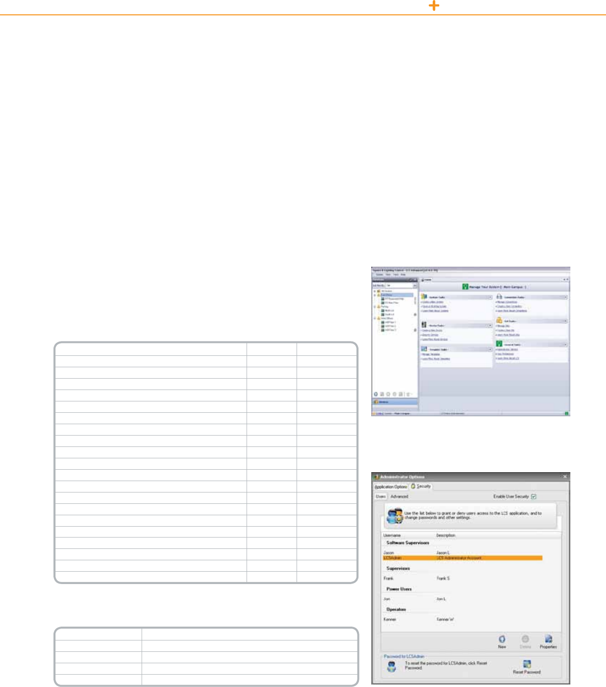
POWERLINK LIGHTING CONTROL ADVANCED AND BASIC SOFTWARE
Thequicklinksandeye-catchingiconsofLCSsoftwareoffers
usersaconvenientandeasytouseinterfacetothePowerlinkG3
lightingcontrolsystem.
Minimum Hardware Requirements
ThissoftwareisdesignedtooperateonaPCmeetingthefollowingrequirements:
• Processor:800MHz,RAM:512MB
• HardDrive:500MBavailable,Video1024x768minimumresolution
• Media:CD-ROM
• Inputs:KeyboardandMouse
Recommended Hardware Requirements
• Processor:1.6GHz
• RAM:1GB
• HardDrive:500MBavailable,Video1280x1024minimumresolution
• Media:CD-ROM
• Inputs:KeyboardandMouse
Technical Information
Features LCS Basic LCS Advanced
Support for NFG3 Devices X X
NFG3 Setup X X
NFG3 Status XX
NFG3 Control X X
Controller Notes X X
Firmware Downloads X X
Device Clear Memory X X
Device Soft Reset X X
Device Conguration Comparison X X
Schedule/Special Day Templates X X
Restore to Previous Conguration (limited to 1 back-up) X X
Reports X X
Controller Out-of-sync Status (online only) X X
Device Discovery — X
Security X®X®
On-line Health Checks X X
Group Devices by Logical Set (multiple devices) — X
User Dened Location for Storing Data X X
Support for Future Devices X X
Online Updates X X
LCS supports list of available autopoll periods for status screens of user’s choice
®LCS allows a user to dene as many accounts as needed based on 4 levels of ability
(Software Supervisors, Supervisors, Power Users and Operators)
Catalog Number Description
LCSBASIC LCSBasic(CD)
LCSBASICUP FullupgradefromPCStoLCSBasic(CD)
LCSADVANCED LCSAdvanced(CD)
LCSADVANCEDUP FullupgradefromPCStoLCSAdvanced(CD)
Supported Operating Systems
WindowsXP®ServicePack2,WindowsVista®,
Windows7®.
Required Software
ThesoftwarerequiresthefollowingMicrosoftsoftware
applicationstobeinstalled:.NETFrameworkv2.0,
WindowsInstallerv3.1orlater,InternetExplorerv6.0
orlater.
WithLCS,enjoythecomfortoftieredsecurityaccesslevels,ensuring
thatsensitivedataandinformationisalwayswellprotected.
84

Powerlink
Accessories
Slave Address Selector
TheSlaveAddressSelectorisrequiredforeachslavepanelconnectedtoasubnet.Theslaveaddressselectorestablishesa
uniquesystemaddressforthepanelthatisbothessentialforsystemoperationandusefulwhenthesystemisaccessedfroma
remotelocation.Theslaveaddressselectorplugsdirectlyontocontrolbuses.
• Rotaryoperatedswitchlabeled0–7foraddressingpanels
• Removableterminalblockforconnectingsubnetcable
• ModularplugforconnectingtheSlaveAddressSelectortosmartbususingtheSlaveBusConnectHarness
Slave Bus Connect Harness Assembly
TheSlaveBusConnectHarnessassembliesarerequiredinslavepanelsfurnishedwithtwocontrolbuses.Theharness
containsmodularplugsoneachend.
Column-width Controller Cable
AColumn-widthControllerCableisrequiredtoconnectthepowersupplytothecontrollerwhenusedinanNF
Column-widthPanelboard.
Remote Mounting Adapter
TheRemoteMountingAdapterprovidesameansformountingaPowerlinkcontrollerandpowersupplyinaseparateenclosure.
Thisbracketisidealforretrotapplicationswhereall42circuitspacesinthepanelboardarerequiredforbranchcircuitbreakers.
Controller Front Panel Serial Cable
TheControllerFrontPanelSerialCableisusedtomakedirectRS-232connectionsfromthecontrollertoaPCorlaptopcomputer.
Custom Barrier Kit
Thecustombarrierkitprovidesaheavy-dutybarrierforseparatingclassIIcontrolcircuitsfrompowerwiring.
Modem Kit
Thiskit,whichisdesignedspecicallyforSchneiderElectricPowerlinkG3controllers,containsallthenecessarycomponents
forusewiththecontroller.
RS-485/RS-232 Converter Kit
TheRS-485/RS-232converterkitallowsconnectionfromtheRS-485portofthecontrollertotheserialportofa
personalcomputer.
Subnet Cable
Fourwirecableforconnectingpanelstogetherinasubnetconguration.
POWERLINK LIGHTING CONTROL ACCESSORIES
Catalog Number Description
NFSELG3 Slaveaddressselector
NF2HG3 Slavebusconnectharness
NFCW3G Columnwidthcontrollercable
NFADAPTERG3 Remotemountingadaptor
NFFPC3G Controllerfrontpanelserialcable
NFASBKG3 Custombarrierkit
6382G3MODEM Modemkit
6382RS485G3KIT RS-485converterkit
SLSLVS1Rx 1-buttonSchneiderElectricrelaypanelswitchwithLED
SLSLVS2Rx 2-buttonSchneiderElectricrelaypanelswitchwithLED
Catalog Number Description
Subnet Cable
NFSN06 6'(1.83m)sub-netcable
NFSN10 10'(3.05m)sub-netcable
NFSN25 25'(7.62m)sub-netcable
NFSN50 50'(15.24m)sub-netcable
Demo Cases
63249-401-117 PowerlinkDemoKit—StandardCase
63249-401-118 PowerlinkDemoKit—PelicanCase
85

POWERLINK LIGHTING CONTROL POWER SUPPLY
ThePowerlinkDevicePowerSupplyisusedtodistributepoweronaC-Busnetwork.
Placedonthenetwork,devicepowersupplieswillprovidethecurrentnecessaryfor
operatingavarietyofpassiveSchneiderElectricC-Busdevices.
ADevicePowerSupplyconsistsofa8MenclosurecontainingoneortwoPower
Supplies(120or277Vac).
Technical Information
Nominal Line
Voltage
Operatesat120or277Vac,±10%,withafrequencyrangefrom
50–60Hz
Maximum Line
Current 9.9mAfor120Vpowersupply4.3mAfor277Vpowersupply
Electrical Isolation 3.75kVRMSfromC-Bustotheline
Current Output 350mA(singlepowersupplyunit)700mA(dualpowersupplyunit)
Dimensions
12.57in.(L)x8.88in.(W)x3.8in.(D)[319mm(L)x226mm(W)x97mm(D)]
Weight Onepowersupply:8.84lb(4.01kg)Twopowersupplies:9.28lb(4.21kg)
Operating
Environment
Temp.:32°Fto113°F(0°Cto45°C)RH:95%,noncondensing
Standards
UL:Listed508AIndustrialControlEquipment
CSA22.2Spec205SignalEquipment
FCC:Part15.101,ClassBDigitalDevice
EN61000-4-2ImmunitytoESD
*For Diagram see technical section page 89
Catalog Number Description
NFDP1120G3C 120VPowerlinkSinglePowerSupply
NFDP2120G3C 120VPowerlinkDualPowerSupply
NFDP1277G3C 277VPowerlinkSinglePowerSupply
NFDP2277G3C 277VPowerlinkDualPowerSupply
Product Features
•Surface-mountNEMA
Type1enclosure
withcover
•UnitandC-BusLEDs
indicatethestatusof
thelinevoltageand
thenetwork
•Sourcesupto700mA
(dualpowersupplies)to
theC-Busnetwork
•120or277Vacmodels
available
PowerlinkDevicePowerSupply
Powerlink
Device Power Supply
86
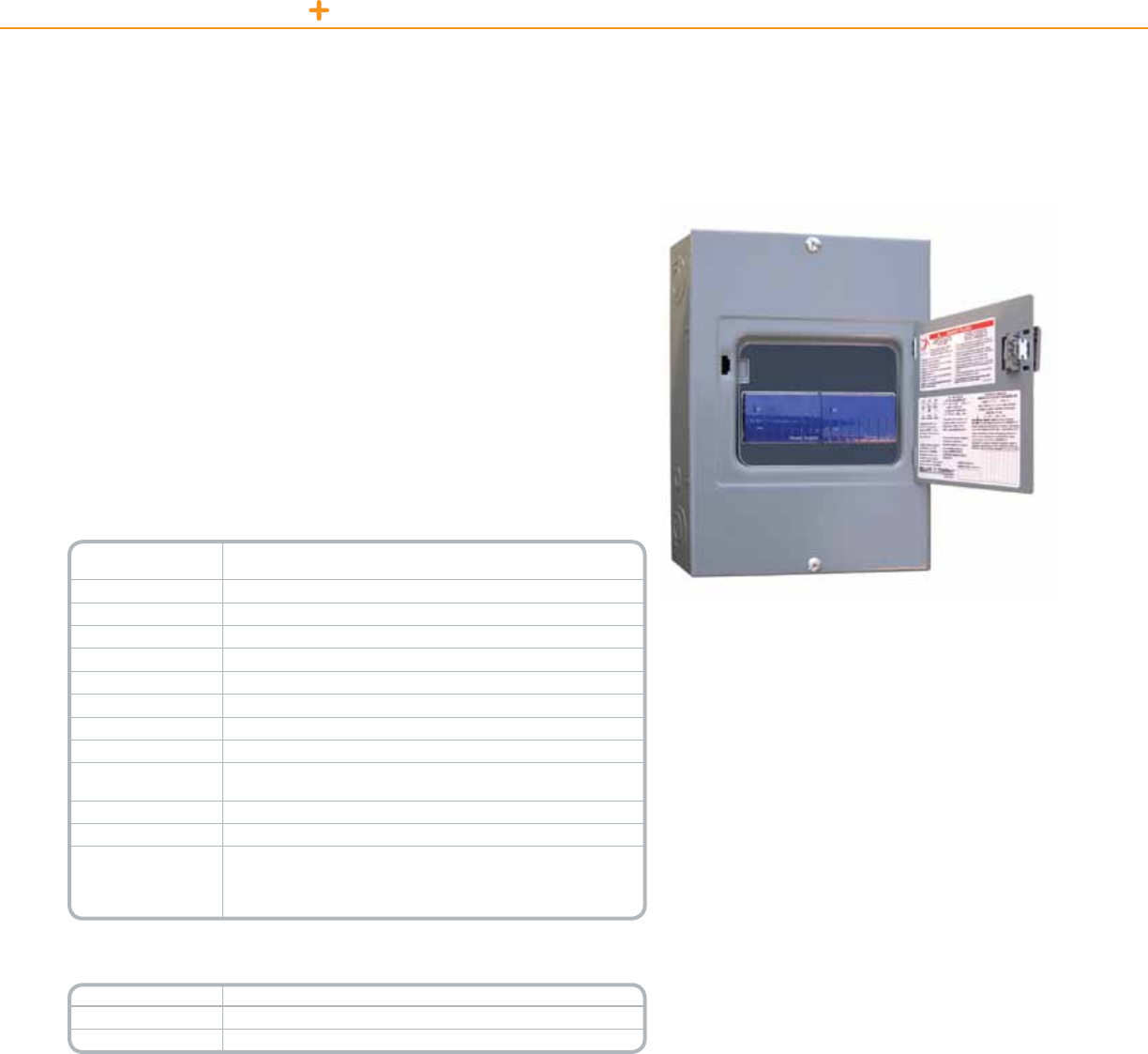
POWERLINK LIGHTING CONTROL DEVICE ROUTER
ThePowerlinkDeviceRouterallowstheexchangeofdatabetweenaPowerlink
NF3000G3CcontrollerandSchneiderElectricC-Busdevices.
ThebidirectionaldeviceroutercanreceivedatafromtheC-Businputdevices
andsendthedatatothePowerlinkpanel/network.Itcanalsoreceivedatasuch
asacontactclosurefromthePowerlinkinputandsendthatdatatoaC-Bus
output/network.
ThedevicerouterconsistsofaC-Bus8MenclosurecontainingaPCInterfaceand
aPowerSupply(120Vacor277Vac).Communicationbetweenthedevicerouter
andtheNF3000G3Ccontrollerismadewiththeincluded50-footserialcable.
Technical Information
Nominal Line Voltage Operatesat120or277Vac,±10%,withafrequencyrange
from50–60Hz
Maximum Line Current 9.9mAfor120Vdevicerouter4.3mAfor277Vdevicerouter
Electrical Isolation 3.75kVRMSfromC-Bustotheline
Current Output 350mAtotheC-Busnetwork
Status Indicators
UnitandUnit/Comms:Linevoltage,unitpower,anddatatransmission
C-Bus:PowerlevelsandpresenceofC-Busclock
Serial Connection
(1)9-pinRS-232D-typeserialconnector;(2)RS-232RJ-45connectors
C-Bus Connection (2)RJ-45socketsforconnectiontotheC-Busnetwork
Data Cable 50ftserial
Dimensions
12.57in.(L)x8.88in.(W)x3.8in.(D)
[319mm(L)x226mm(W)x97mm(D)]
Weight 9.1lbs(4.13kg)
Operating Environment Temp.:32°Fto113°F(0°Cto45°C)RH:95%,noncondensing
Standards
UL:Listed508AIndustrialControlEquipment
CSA22.2Spec205SignalEquipment
FCC:Part15.101,ClassBDigitalDevice
EN61000-4-2ImmunitytoESD
*For Diagram see technical section page 89
Catalog Number Description
NFDR120G3C 120VPowerlinkDeviceRouter
NFDR277G3C 277VPowerlinkDeviceRouter
PowerlinkDeviceRouter
Powerlink
Device Router
Product Features
•Surface-mountNEMA1enclosure,withcover
•Unit,Unit/Comms,andC-BusLEDsindicatethe
statusofdata
transmissionandpowertotheunitand
thenetwork
•Systemnetworkclockforsynchronizing
communicationsdata
•Networkpowersource,supplyingupto350mA
•120or277Vacmodelsavailable
87

5.75 in.
(146 mm)
9.69 in.
(246 mm)
5.60 in.
(142 mm)
H
H
Typical Enclosure
Front View
Typical Enclosure
Front View
Typical Enclosure
Side View
Typical Enclosure
Side View
Flush Mounting W + 1.50 (38 mm)
Surface Mounting W + 0.12 (3 mm)
Flush Mounting W + 1.50 (38 mm)
Surface Mounting W + 0.12 (3 mm)
Note:
These dimensions are standard. Please consult factory
for special requirements. * 34W only **800A Panelboards are 8¾ in. deep
Column Width Panelboard
Dimensional Drawings
NF Panelboard (indoor enclosure)
Max. Main Lug
Ampere Rating
Max.
Number
of Circuits
Enclosure
Height (H) Max. Main Lug
Ampere Rating
Max.
Number
of Circuits
Enclosure
Height (H)
In. mm In. mm
125A
12 26 660 125A
(EDB,EGB,EJB)
18 32 813
18 26 660 30 38 965
30* 32 813 42 44 1118
250A
30 38 965 100A(HDL,
HGL,HJL,HLL)
12 38 965
42 44 1118 18 38 965
54 50 1270 30* 44 1118
100A(FIL)
12 38 965
400A
30 50 1270
18 38 965 42 56 1422
30* 44 1118 54 62 1575
250A
(JDL,JGL,
JJL,JLL)
30 50 1270
600A
30 50 1270
42 56 1422 42 56 1422
54 62 1575 54 62 1575
800A**
30 50 1270 400/600A
(LCL,LIL)
30 68 1727
42 56 1422 42 74 1880
54 62 1575 54 80 2032
400A(LAL,LHL)
30 62 1575
–42 68 1727
54 74 1880
Max. Number of Circuits Max. Main Lug Ampere Rating Enclosure Height (H)
In. mm
Ready-to-Assemble (Also Available Factory Assembled)
Column Width — Main Lugs Only
30 125A 59 1499
42 225A 71 1803
Column Width — Main Circuit Breaker
30 125A 59 1499
42 225A 71 1803
POWERLINK LIGHTING CONTROL TECHNICAL SECTION
88
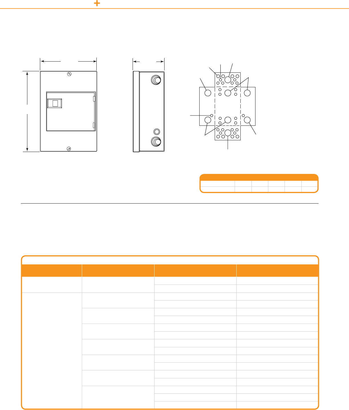
POWERLINK LIGHTING CONTROL TECHNICAL SECTION
ThistableliststheULshort-circuitcurrentratingsforNFpanelboardsincludingECB-G3circuitbreakers.Theratingsapplytoanintegralmain
locatedinthesameenclosureoraremotemainlocatedinaseparateenclosure.
NF Panelboard SCCR Table
Max. System Voltage Max. Short Circuit Current Rating Integral or Remote Main Circuit Breaker Schneider Electric Branch Circuit Breaker
Catalog Designation
120120/240240 65,000
EG,FH,FG,KH,LH,MH,MX,HG,JG EDB,EDB-EPD
EG ECB-G3
277
480Y/277
100,000 EJ,FC,FJ,KC,LC,LX,HJ,JJ EDB,EDB-EPD,EGB
EJ,FC,KC,HJ,JJ ECB-G3
125,000 HL,JL EDB,EDB-EPD,EGB,ECB-G3
FI,KI,LI,LXI EDB,EDB-EPD,EGB,EJB
200,000 FI,KI ECB-G3
ClassJorT(600V)200Amax.fuses EDB,EDB-EPD
35,000 EG,FG,HG,JG,KH,LH ECB-G3
EG,HG,JG EDB,EDB-EPD,EGB
65,000 EJ,FC,FJ,KC,LC,LX,HJ,JJ ECB-G3
EJ,FC,KC,HJ,JJ EDB,EDB-EPD,EGB,EJB
100,000 HL,JL EDB,EDB-EPD,EGB,EJB
400Amax.fuses ECB-G3
200,000
FI,KI,LI,LXI EDB,EDB-EPD,EGB,EJB,ECB-G3
FI,KI —
200Amax.fuses —
RMS Symmetrical Amperes
Short Circuit Current Rating Table
Side view showing depthFront view showing height and width
Powerlink
Device Power Supply/Device Router
C-Bus 8M Enclosure Knockouts
Symbol A B C D E
Conduit Size ½¾ 1 1¼ 1½
12.57 in.
(319 mm)
8.9 in.
(226 mm)
3.8 in.
(97 mm)
Conduit knockouts for
the 8M enclosure
A, B
B, C, D, E
B, C, D, E B, C, D, E
B, C, D, E
B, C, D, E
B, C, D, E
A
A
89
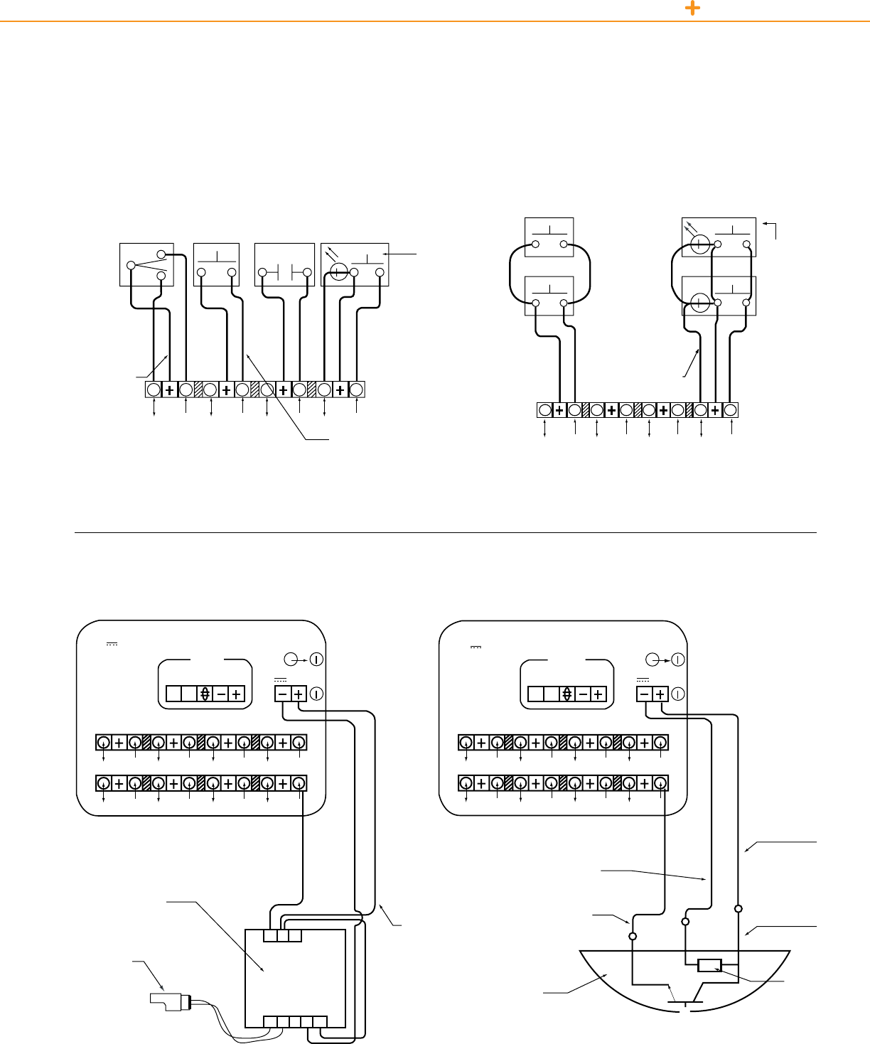
POWERLINK LIGHTING CONTROL TECHNICAL SECTION
Typical Controller
Typical Sensor
ThissectioncontainswiringdiagramsfortheSchneiderElectricPowerlinkG3systems.
Wiring Diagrams
Typical Switch Types Wired in Parallel
Various Low Voltage Switch TypesTypical Low Voltage Input Connections
Typical Photo Controller Wiring Diagram
Dual
Momentary
4
4
(12) (11) (10) (9)
3
3
2
2
1
1
Toggle
Momentary
NO or NC
Maintained
Pushbutton
Momentary
Pilot Switch
Control Wiring
Class 2, #18-22 AWG
1,000 ft. (305 m) Max.
Control Wiring
Class 2, #18-22 AWG
1,000 ft. (305 m) Max.
Control Wiring
Class 2, #18-22 AWG
1,000 ft. (305 m) Max.
Control Wiring
Class 2,
#18-22 AWG
1,000 ft.
(305 m) Max.
Power 24Vdc
24Vdc, 33 mA
Common
Control
Power
Class 2
24V Max.
AL-CU
Class 2
24V Max.
AL-CU COM 1
Controller (Typical)
RX RX
RS232 RS232
RS485 RS485
TX TX
Inputs may share
the common (+)
Pilot Device
24Vdc
7.5mA Max
Pilot Device
24Vdc,
7.5mA Max
Per Input
SW1 SW1
SW2 SW2
24V 24V
4 4
8 8
3 3
7 7
2 2
6 6
1 1
5 5
4
8
3
7
2
6
1 5
COM 1
90

POWERLINK LIGHTING CONTROL TECHNICAL SECTION
Threelevelsofcommunicationsareprovidedthatcanbeeasilytailoredtoindividualapplicationrequirements.
System Architecture
Ethernet Connectivity
SchneiderElectricPowerlinkG32000and3000
levelcontrollershaveintegratedonboardEthernet
capability.Inadditiontoprovidinghigh-speedEthernet
access,thesecontrollersallowfastpeer-to-peer(P2P)
connectivitybetweenpanels.With2000and3000level
systems,masterpanelscanshareinputs,schedules,
andzonestatus.
• BACnetIPopenprotocolin2000and3000level
controllers
• ModbusTCP/IPopenprotocolin2000and3000
levelcontrollers
Power Supply
Controllers
Ethernet Port
Ethernet
Cable
Ethernet
Cables
10 Base-T Network
Hub or Router
Master
Panel A Master
Panel B
Master Master
Slave Slave
Slave Slave
Subnet Communications
• EachSchneiderElectricPowerlinkG3Controllercandirectlyoperateupto
eightcontrolbuses.
• Controllersignalsthecontrolbusestoswitchtheassociatedbranchcircuits
andpollseachSchneiderElectricPowerlinkG3CircuitBreakertodetermineits
actualstatus.
• Communicationsbetweenthecontrollerandthecontrolbusesaremadewith
a4-wire,Class1communicationscable(Belden27326orequivalent).
• Slavepanels(thosecontainingcontrolbusesandremotelyoperatedcircuit
breakers,butnocontroller)maybemountedupto400feetawayfromthe
masterpanelthatcontainsthecontroller.
Subnetcommunicationsallowonecontrollertooperateupto168remotelyoperatedbranchcircuits.
Automation Network
• EachcontrollerprovidesbothRS-485andRS-232serialports.Providesaccessup
to247controllersusinganRS-485multi-dropconguration.
• Anautomationlevelnetworkcanalsobeusedtocommunicatewithotherbuilding
systemssuchasenergymanagementsystemsandcardaccesscontrollers.
Theautomationnetworkuseswidelyacceptedandsupportedindustrial-proven
protocolsusedbymanybuildingautomationmanufacturersandsystemsintegrators
»ModbusASCII/RTUopenprotocolinallSchneiderElectricPowerlink
G3Controllers
»DMX512protocolinautomationlevelnetworkfortheatricallightingapplications
in1000,2000,and3000levelcontrollers
»OptionalJCI-N2protocolfor1000levelcontrollers
»OptionalC-BusNetworkcapabilitywithNF3000G3Ccontrolleranddevicerouter
»BACnetMS/TPopenprotocolin2000and3000levelcontrollers
Personal Computer
or Modem
RS-232 to
RS-485
Converter
Master
Slave Slave Slave
Slave Slave Slave
Master Master
RS-485 Daisy Chain, 2-Wire, Twisted
Pair Belden 9841 or equivalent
AutomationnetworksprovideremoteaccesstothelightingcontrolsystemoveranRS-485network.An
RS-485networkconsistsoflowcost,2-wire,Class2communicationscable,Belden9841orequivalent.
91
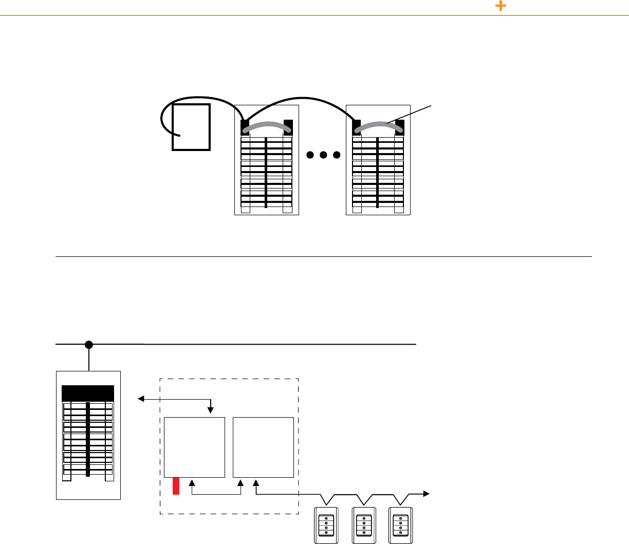
POWERLINK LIGHTING CONTROL TECHNICAL SECTION
Powerlink
Remote Mount Controller
4-wire, 18 AWG, Class 1
cable, subnet cable (general
cable 236100, Belden
Cable 27326 or equivalent)
Controller
Remote Mount Controller
Slave Panel Slave Panel
Slave bus
interconnect cable
C-Bus Network
Belowisatypicalone-linediagramforcreatingalocalareanetworkusingtheC-BusNetworkcapabilityoflevel3000G3Ccontrollers.
AllcablesshownbelowareCAT-5.
Ethernet
Powerlink G3
Powerlink Device Router
PC Interface
Hardware Burden
C-Bus Device Network
Power Supply
92

C-Bus Lighting
Control

• Fully-scalable solution
Whetheryou’recreatingalightingcontrol
systemforasingleroomorawhole
facility,SchniederElectriclightingcontrol
offersscalablesystemstotyourexact
needs.OurC-Bussolutionsaredesigned
aroundthesizeandrequirementsof
yourapplication.Allthiswithacommon
platformandeasyinstallationpractices.
Talkaboutexibility.
• C-Bus touch screens
Ouruniedwall-mountedpanelsallowyou
tocontrollightingsystemsandaccessories
withthetouchofanger.Designedwith
versatilityinmind,thesesleektouchscreens
areeasytoinstall,customizeanduse.
They’recompactyetpowerful.Simpleto
operateyethighlyexible.Adesktopmodel
isavailablewhenwallspaceislimitedorfor
addedconvenience.
Theavailabilityoflow-cost,powerful
microprocessorsforbuildingcontrol
andmanagementsystemshascreated
unprecedentedcustomerexpectationsfor
increasedcontrol,connectivityandintegration
ofelectricalandlow-voltagesystems.
• Lower installation cost
Withitsuniquedistributedcontrolsystem,
youcanplacerelaysanddimmersinvarious
locationsandconnectthemdirectlytothe
network–eliminatingtheneedtoruncable
backtoaseparateenclosurenearcentrally
locatedprocessors.
• C-Bus keypads
Theseaestheticallypleasingfaceplates
lendasophisticatedlooktovirtuallyany
space.They’reaselegantastheyare
well-engineered.
• Simple cabling/any topology
SincetheC-BussystemusesstandardCat-5
cabling,usinganytopology,there’snospecial
cabletoorderorkeepinsupply.Soit’smuch
easiertoaddresslast-minutechangeorders
ortocompleteajobwithoutwonderingifyou
havetherightmaterialsonhand.
C-Bus Lighting Control
C-BUS LIGHTING CONTROL
94
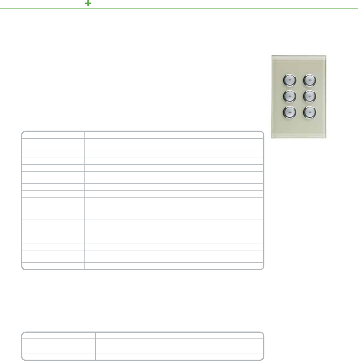
C-BUS LIGHTI NG CONTROL KEYPADS
SaturnStyle6ButtonKeypad
Technical Information
Voltage Requirements 15–36Vdc@22mArequiredfornormaloperation,drawnfromtheC-Busnetwork
Number of Units on a Network DeterminedwiththeC-BusCalculator,asoftwareutilityusedtoevaluatethetotalnetwork
currentload
Electrical Isolation 3.75kVRMSfromC-Bustopower(providedexternally)
Control Functions Loadswitching,dimming,timing,scenecontrol
Status Indicators Two-color(orangeandblue)user-congurableLEDs
Locator Option User-congurable,adjustableLEDtohelplocatetheunitindarkness,has
“ignorerstbuttonpress”option
Scene Control Uptofourscenesperkeypad,tenaddressesperscene
Timers 1sec–18hr,1secintervals
Response Time 200msecorless
C-Bus Connection Oneterminalblocktoaccommodate24-16AWG(0.2–1.31mm2),CAT5UTPcablerequired
Dimensions 4.57in.(L)x2.95in.(W)x1.1in.(D)[116mm(L)x75mm(W)x28mm(D)]
Mounting
Plastermudring(Raco8771orequal)w/minimuminternalwidth2.05in.(52mm)(notprovided)
Singlegangbox(CarlonA58381DCARorequal)w/minimuminternalwidth2.05in.(52mm)
(notprovided)
Weight 4.66oz(132g)
Operating Environment Temp.:32°Fto113°F(0°Cto45°C)RH:95%,noncondensing
Standards UL:Listed916EnergyManagement,CSA22.2Spec205SignalEquipment
FCC:Part15.101,ClassBDigitalDevice,EN61000-4-2ImmunitytoESD
Color Options Cream,black,mocha,white,purewhiteandstainlesssteel
*For Diagram see technical section page 145
OrdernumbersfortheSaturnkeypadassembliesindicatethenumberofbuttonsdesiredonthekeypad(x)and
thecolorofthecoverplate(y).ColorCodes:White(WE),Black(BK),Mocha(BR),Cream(CM),PureWhite(PW)
andStainlessSteel(SS).
Forexample,SLC5086NLBKrepresentsanorderforaSaturnkeypadwithsixbuttonsandablackcoverplate.
Theordernumberforatwo-buttonkeypadinmochawouldbeSLC5082NLBR.
Catalog Number Description
SLC508(X)NL(Y)* SaturnKeypadAssemblies,2,4or6buttons
SLC5080LC8 Pre-labeledbuttoncaps(1ea.of66frequentlyusedlabelssuchas:Meeting,Scene1,etc.)
SLC508(X)NLF(Y)* Stand-alonefaceplates
*When ordering: “x” equals button conguration 2, 4, or 6 and “y” equals color selection WE, BK, BR. CM, SS, PW
TheC-BusSaturn™Keypadsofferlocalizednger-tipcontroloflightingandelectricalservices.Theseelegant
keypadsincorporateauniqueglasscoverplatethatiseasytoinstall,customize,anduse.
Byvirtueofthevarietyofbuttoncongurationsavailable,onecompactSaturnkeypadcantaketheplaceofmany
singleoperationswitches,ON/OFFtoggles,dimmers,andtimers.
Availableinatwo-,four-,orsix-buttonkeypad,Saturn’smodernstyleiscomplementedbyorangeandblueLEDs
thatcaninstantlyshowthestatusofcontrolleddevices.
Product Features
•Buttoncongurations
includemulti-point
switchinganddimming,
masterON/OFFswitching,
andscenesettings
•Scenecontrolincludesup
totengroupaddressesper
sceneandfourscenesper
keypad
•Independenttimers
availableforeachbutton
•Dual-colorLEDwindows
oneachbuttoncanglow
incoolblue,orange,or
combinationsofboth,
indicatingwhenacontrolled
deviceisONorOFF
•Auto“fallback”candim
buttonLEDsatasettime
afterthelastbuttonpress
•LocatorLEDcanilluminate
thekeypad,helpingauser
nditindimlight
Functional
Aesthetics
•Distinctivelydesigned
transparentimpact-
resistantglasscoverplate
withsilverbuttonsthatcan
glowblueororange
•Clean-linedkeypadsare
wallmountedwithout
externalttings
•Low-prolekeypad
extendsonly0.5in.out
fromthewall
•Colorsareeasilymodied
tosuitpersonaltasteor
thedécor
•Optionalbuttoncovers
withlabels,enabling
quickidenticationof
lightingscenesor
controlleddevices
Saturn Keypads
95

C-BUS LIGHTING CONTROL KEYPADS
C-BusDynamicLabelingTechnology™(DLT)keypadscombineprogrammablekeypadbuttons,andeasily
customizedlabelsonabacklitLCDscreenthateliminatestheneedforcustomlabels.
Thesekeypadsaredesignedtobeeasytoinstall,customize,anduse.Byvirtueofthevarietyofbutton
congurationsavailable,onecompactDLTkeypadcantaketheplaceofmanysingleoperationswitches,
ON/OFFtoggles,dimmers,andtimers.
CoolblueLEDslightthevekeypadbuttons,complementingthekeypad’ssleeklinesandinstantlyshowingthe
statusofcontrolleddevices.
Saturn Dynamic Labeling Technology Keypads
SaturnStyleDLTKeypad
Technical Information
Voltage Requirements 15–36Vdc@22mArequiredfornormaloperation,drawnfromtheC-Busnetwork
Number of Units on a Network UsetheC-BusCalculator,asoftwareutility,todeterminethetotalnetworkcurrentload
Electrical Isolation 3.75kVRMSfromC-Bustopower(providedexternally)
Control Functions Loadswitching,dimming,timing,scenecontrol
Status Indicators Blue,onedimmableLEDperbutton
Backlight White,dimmable,usercongurable
Locator Option User-congurable,adjustableblueLEDforlocatingtheunitindarkness,with
“ignorerstbuttonpress”option
Scene Control 4scenesperkeypad,10addressesperscene
Timers 1sec–18hr,1secondintervals
Screen 64x128pixelsLCD
Response Time 200msecorless
C-Bus Connection Oneterminalblocktoaccommodate24–16AWG(0.2–1.31mm2),CAT5UTPcablerequired
Dimensions 4.57in.(L)x2.95in.(W)x1.20in.(D)[116mm(L)x76mm(W)x32mm(D)]
Mounting
Standardplaster(mud)ringorwallbox(notprovided),minimuminternalwidth2.05in.(52mm)
Centers:3.31in.(84mm)
Weight 3.35oz(95g)
Operating Environment Temp.:32°Fto113°F(0°Cto45°C)RH:95%,noncondensing
Standards UL:Listed916EnergyManagementEquipmentCSA22.2Spec205Signal
FCC:Part15.101,ClassBDigitalDeviceEN61000-4-2ImmunitytoESD
Color Plate Colors SaturnStyle:PureWhite,White,Cream,Black,Mocha,StainlessSteel
**For Diagram see technical section page 145
OrdernumbersfortheSaturnDLTkeypadsincludethestocknumber(SLC5085DL)andthecodeforthecolorof
thecoverplate:Black(BK),Mocha(BR),White(WE)andCream(CM).Forexample,SLC5085DLBRrepresentsa
completecatalognumberforaSaturnDLTkeypadwithamochacoverplate.
Catalog Number Description
SLC5085DL( ) SaturnKeypadwithDLTinWhite(WE),Cream(CM),Black(BK),Mocha(BR),
PureWhite(PW)andStainlessSteel(SS)
Product Features
•Buttoncongurations
includemulti-point
switchinganddimming,
masterON/OFFswitching,
andscenesettings
•Keypadshavevephysical
buttons–fourcontrol
buttonsandonescroll/
pagebutton–combined
withtwoscreensoflabels,
foratotalofeightcontrol
buttonsandtwoscroll/
pagebuttons
•Scenecontrolincludes
tengroupaddressesper
scene,fourscenesper
keypad
•Independenttimers
availableforeachbutton
•ButtonLEDscanbeused
aslocatorlightsinthedark
•Timeclockcanbe
displayedatthebottomof
thescreen
•Displaysupto8languages
fromasetofmorethan65
Functional
Aesthetics
•64x128pixelLCDscreen
withawhitebacklight
•EditableLCDlabels,
availableforeachbuttonor
controlgroup,candisplay
text,symbols,andgraphics
•Dynamicgraphicdisplays,
suchasbargraphs,canbe
enabledordisabled
•Bitmapscanbe
downloadedforeachgroup
addressorscene
96
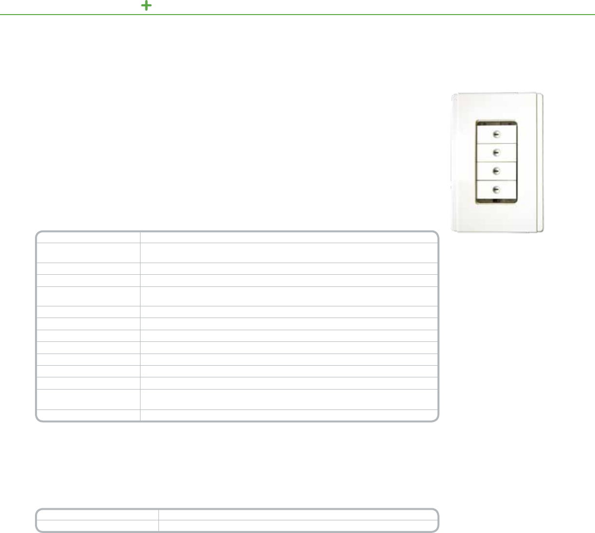
C-BUS LIGHTI NG CONTROL KEYPADS
Neo Decorator Keypads
Technical Information
Voltage Requirements 15–36Vdc@22mArequiredfornormaloperation,drawnfromtheC-Busnetwork
Number of Units on a Network DeterminedwiththeC-BusCalculator,asoftwareutilityusedtoevaluatethetotalnetwork
currentload
Electrical Isolation 3.75kVRMSfromC-Bustopower(providedexternally)
Control Functions Loadswitching,dimming,timing,scenecontrol
Locator Option User-congurable,adjustableLEDtohelplocatetheunitindarkness,has
“ignorerstbuttonpress”option
Scene Control Upto4scenesperkeypad,10addressesperscene
Timers 1sec–18hr,1secondintervals
Response Time 200msecorless
C-Bus Connection Oneterminalblocktoaccommodate24–16AWG(0.2–1.31mm2),CAT5UTPcablerequired
Dimensions 4.57in.(L)x3.0in.(W)x.91in.(D)[116mm(L)x76mm(W)x23mm(D)]
Weight 2.9oz(82g)
Operating Environment Temp.:32°Fto113°F(0°Cto45°C)RH:95%,noncondensing
Standards UL:Listed916EnergyManagementEquipmentCSA22.2Spec205Signal
FCC:Part15.101,ClassBDigitalDevice
Color Options NeoStyle:Slate,White,Cream,Brown,Black,SoftGrey,DesertSand
**For Diagram see technical section page 145
OrdernumbersfortheNeoDecoratorkeypadsincludethestocknumber,thenumberofbuttons(1thru4)and
thecodeforthebuttoncolor:Black(BK),Brown(BR),White(WE),Cream(CM),Slate(GB),SoftGrey(SG)
DesertSand(DS),Ivory(VY)andLightAlmond(LA).
Forexample,SLC505(4)NLM(WE)representsaNeoDecoratorstylekeypadwith4buttonsinwhite.
Catalog Number Description
SLC505(X)NLM(Y)* NeoDecoratorStyleKeypad
*when ordering: “x” equals button conguration 1, 2, 3, or 4 and “y” equals color selection BK, BR, WE, CM, GB, SG, DS, VY, or LA
SchneiderElectricC-BusNeoDecoratorStyleKeypadsofferlocalizednger-tipcontroloflightingandelectrical
services.Theseelegantkeypadsincorporateauniquecoverplate(orderedseparately)thatiseasytoinstall,
customize,anduse.
Byvirtueofthevarietyofbuttoncongurationsavailable,onecompactDecoratorstylekeypadcantaketheplace
ofmanysingleoperationswitches,ON/OFFtoggles,dimmers,andtimers.
Availableinaone-,two-,three-orfour-buttonkeypad,thesemodernstylekeypadsarecomplementedbyblue
LEDsthatcaninstantlyshowthestatusofcontrolleddevices.
Neo4ButtonDecorator
StyleKeypad
Multi-Functional
Capabilities
•Buttoncongurations
includemulti-point
switchinganddimming,
masterON/OFFswitching,
andscenesettings
•Scenecontrolincludesup
totengroupaddressesper
sceneandfourscenesper
keypad
•Independenttimers
availableforeachbutton
•LEDwindowsoneach
buttoncanglowincool
blueororange,indicating
whenacontrolleddeviceis
ONorOFF
•Auto“fallback”candim
buttonLEDsatasettime
afterthelastbuttonpress
•LocatorLEDcanilluminate
thekeypad,helpingauser
nditindimlight
•Hasinfraredremote
capabilitieswithSchneider
ElectricC-Busremotes
97
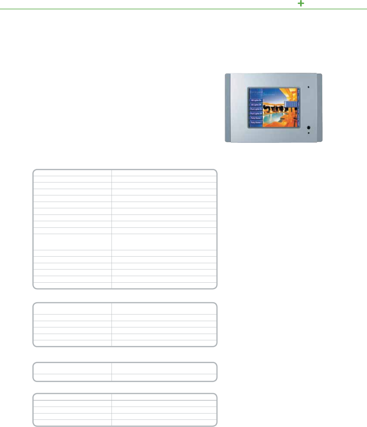
C-BUS LIGHTI NG CONTROL TOUCH SCREENS
TheC-BusSpectrumColorTouchScreensbySchneiderElectricareauniedwall-
mountedordesktoppanelforcontrollinglightingsystemsandaccessorieswiththe
touchofanger.
Designedwithversatilityinmind,thesesleektouchscreensareeasytoinstall,
customize,anduse.Compactyetpowerful,thetouchscreenhasnumerous
congurationsavailable,makingitanattractivealternativetomultiplesingleoperation
switches,ON/OFFtoggles,dimmers,andtimerswhichcanclutterupeventhenicest
wall.TheC-BusSpectrumColorTouchScreensareavailableintheSaturnandNeo
stylecoverplateswithawideassortmentofcolorstochoosefrom.
Product Features
•Multiplecontrolscreenscanincludemulti-pointswitching
anddimming,masterON/OFFswitching,schedules,and
scenesfromamenudriveninterface
•Includesa“wakefeature”proximitysensorthatturns
onthebacklightwhenactivatedbymotionwithinthe
proximityrange.
•Astronomicalclockwithfullschedulingandholidays
•Fullfeaturelogicengineprovidesabilitytocreatecustom
controlsandintegrate3rdpartydevices
•Locatoroptiontohelpusersndthescreenindimlight
•Built-ininfraredreceiverwithremotecontrol
•RS-232portforthirdpartydeviceintegration
•USBprogrammingportaccessiblefromthefrontof
theunit
Functional Aesthetics
•Clean-linedlow-proletouchscreencanbewall-mounted
withoutexternalttings
•Displayandcontrolscanbeconguredwithsymbols,
images,clocksandtime,andtextinmultiplelanguages
•Areaplansandotherscenescanbegraphicallydepicted
Color
Spectrum Color Touch Screens
Wall-mountedSpectrumTouchScreen
Technical Information
AC input impedance 13Kohms@1kHz
Display type 4.7in.(119mm)activeblackandwhiteorcolorLCD
Display resolution 320x240pixels
Display luminance 120cd/m²
Viewing angle Left,right:45°;up:50°;down:30°
Backlight type WhiteLED
Touch surface durability 1millionpresses(typical)
Maximum number of controlled loads 255groupaddressesoneachofthe10applications
Third party interface RS-232port
Programming port USBtypeB(frontofunit,behindcoverplate)
C-Bus supply voltage (required for
normal operation. Does not provide
current to the C-Bus network.)
Spectrum:15to36Vdc@72mA
Network clock Softwareselectable
Network burden Softwareselectable
Processor ARM7TDMI,40MHz
Warm up time
<10seconds
Operating temperature 32°Fto113°F(0°Cto45°C)
Operating humidity 10%to95%RH
*For Diagram see technical section page 146
Spectrum Touch Screen-Wall
Mounted Catalog Number
Description
SLC5000CTCL2xx Spectrumw/non-stylizedplasticCoverPlate
SLC5050CTCL2xx Spectrumw/NeoStyleCoverPlate
SLC5080CTCL2xx Spectrumw/SaturnStyleCoverPlate
SLCBS5000CTCL2 Spectrumw/StainlessSteelCoverPlate
SLCBB5000CTCL2 Spectrumw/BrassCoverPlate
Note: xx = color code (GB – Brushed Aluminum and Slate*, WE – White, BK – Black, CM – Cream,
BR – Mocha**, PW – Pure White**) *Neo only **Saturn only
Spectrum Desktop Model
Catalog Number
Description
SLC5000CTCD2xx SpectrumDesktopTouchScreen
Note: xx = color code/WE–White, BK–Black
Accessories Description
SLC5000CT2WB WallboxforSpectrumTouchScreen
SLC5080CT2Fxx ReplacementCoverPlate,Saturnstyle
SLC5000CT2FSS ReplacementCoverPlate,StainlessSteel
SLC5050CT2Fxx ReplacementCoverPlate,Neostyle
Note: xx = color code (GB – Brushed Aluminum and Slate*, WE – White, BK – Black, CM – Cream,
BR – Mocha**, PW – Pure White**) *Neo only **Saturn only
98
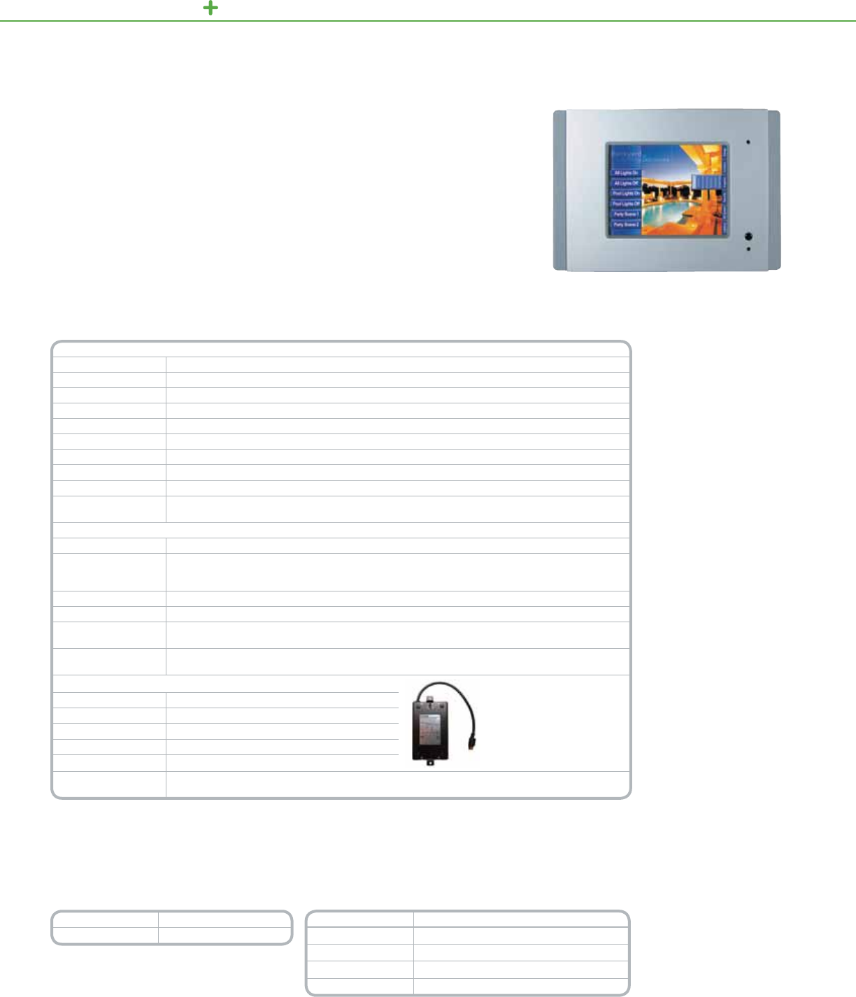
C-BUS LIGHTI NG CONTROL TOUCH SCREENS
Powersupplyforcolortouch
screen(soldseparately)
TheC-BusColorTouchScreenisauniedpanelforcontrollinglightingsystemsand
accessorieswiththetouchofanger.
Thetouchscreen'ssophisticatedappearancereectstheunderlyingcraftsmanshipofits
design.Amongitsmanycapabilities,thispowerfulPC-basedsystemsupportsgraphical
depictionofareaplans,monitoringofvariousC-Busdevices,schedulingoflightingand
otherloads,nger-tipcontrolofpresetscenes,andoperationfromthetouchscreenorby
remotecontroller.
Product Features
•Abilitytocongure
controlsincluding
scenes,schedules,state
changesandgraphic
animation
•Abilitytocustomize
buttons,sliders,photos
anddrawings
•Audiotoolssupportuse
ofcustomWAVlesfor
audiblefeedbackand
voiceprompts
•Internalamplied
speakerhasvolume
controlandexternal
speakerterminal
•Built-inRJ-45Ethernet
andC-Busnetwork,RS-
232,andUSBterminals
•Infraredreceiverfor
remotecontroland
infraredinputfor
accessories
•Controlscanbe
passwordprotected
atmultiplelevels
•Astronomicalandreal
timeclocks
Functional
Aesthetics
•Touchsensitive6.4inch
(640x480)colorLCD
panel
•Lightsensorfor
automaticbacklight
control
•Flushwall-mountdesign
•Coverplatesavailablein
NeoandSaturnstyles
•Fivecolorschemes
available,complementing
anydécor
Color
Touch Screen
ColorTouchScreen
Technical Information
Screen
Type LCDactivematrix
Size 6.4in.(diagonal)
Resolution VGA,640x480pixels
Pixel Pitch 0.01in.(H)x0.01in.(V)[0.204mm(H)x0.202mm(V)]
Viewing Area 5.14in.(H)x3.82in.(V)[130.6mm(H)x97.0mm(V)]
Touch Overlay Type Resistivemembrane
Viewing Angle Typicalhorizontal:70°leftandright/Typicalvertical:40°up,70°down
Luminance 300cd/m2
Backlight Coldcathodewithlightsensorforautomaticbacklightlevelcontrol
Memory 256MBcompactFlashmemory,pre-programmedwithpanelrmware,Backup:Lithiumbatteryretains
currentdateandtimefor5years.
Components and Connectors
Front Ethernet10/100/RJ-45terminal(hidden),Speaker(hidden),Infraredreceiver,RS-232viaDB9terminal
Rear
C-BusRJ-45terminals(2)•Ethernet10/100/RJ-45terminalCompositevideooutputviaRCAterminal(75
ohm)•RS-232viaDB9terminalUSBtypeAterminals(2)forfuturesoftwaresupportRemoteinfrared(IR)
terminal(hardwiredviaa3.5mmmini-jack)Externalspeaker/headphoneterminal(3.5mmmini-jack)
Overall Dimensions
9.8in.(W)x6.9in.(H)x2.9in.(D)[246mm(W)x173mm(H)x72.5mm(D)]
Weight 3.02lbs.(1375g)(excludingcoverplate)
Operating
Environment Temp.:50°Fto86°F(10°Cto30°C)/RH:95%noncondensing
Standards ULListed916EnergyManagementEquipmentCSA22.2Spec.205SignalEquipment,FCC:Part15.101,
ClassBDigitalDevice•EN61000-4-2ImmunitytoESD
Required Accessories: Power Supply (Sold Separately)
Power Supply 6.9in.(L)x3.1in.(W)x1.8in.(H)
Dimensions 175mm(L)x80mm(W)x45mm(H)
Adaptor Box 5.2in.(L)x2in.(W)x.4in.(H)
Dimensions 113mm(L)x50mm(W)x11mm(H)
Weight 4.2lb(1.925kg)
Standards UL:Listed60950InformationTechnologyEquipment-Safety:GeneralRequirements•CSA22.2Spec.
205SignalEquipmentFCC:Part15.101,ClassBDigitalDevice•EN61000-4-2ImmunitytoESD
*For Diagram see technical section page 146
OrdernumbersfortheNeoandSaturnstyletouchscreensincludethestocknumber,andthecodeforthecover
color.SaturnColors:Black(BK),Mocha(BR),White(WE),Cream(CM)andPureWhite(PW).NeoColors:Brushed
Aluminum
andSlate(GB),White(WE)andBlack(BK).Forexample,SLC5050CTC(WE)representsaNeoStyleTouch
Screeninwhite.
Catalog Number Description
SLC5080CTC2( ) SaturnStyleTouchScreen
Accessories Description
SLC5000CTCPS* ColorTouchScreenPowerSupply
SLC5000CTCWB** ColorTouchScreenWallBox
SLC5000CTCNA** ColorTouchScreenWallNailBracket
SLC5000CTCRM** ColorTouchScreenWallPlasterBoardBracket
* Required for every color touch screen installation.
** Color touch screen must be mounted with one of these options
99

C-BUS LIGHTING CONTROL HOME CONTROLLER
TheWiser™HomeControlleristhemissingpieceofthesmarthomepuzzle,enhancingthecapabilities
andconnectivityoftheC-Busnetwork.Itseasy-to-usegraphicaluserinterface(GUI)providesaccess
tothehomeC-Busnetworkandallofyourelectrical,multimedia,andtelecommunicationneeds.This
sameGUIcanbeinstalledacrossmultiplecontroldevices,suchasmobilephones,TVswithMicrosoft®
WindowsMedia®Center,personalcomputers,andwebtablets,inadditiontotheC-Busrangeoftouch
screensandkeypads.Nomatterwhereyouare,theWiserHomeControllerallowsyoutomonitorand
controlyourhomeenvironmentlocallyorremotelyovertheInternet.
Product Features
•EthernetandWi-Fibased
controllerforyourC-Bus
system
•Built-inEthernetrouter
•Built-inWi-Fiaccesspoint
•Supportforlighting,air-
conditioning,multi-room
audio,alarms,cameras,
andotherequipment
•Easytounderstand
wizard-baseduser
interfacegraphics
•Built-inscene,scheduling,
andlogicprogramming
modules
•Allowsremote
reprogrammingfrom
outsidethehome/building
byinstallers
•Common,intuitive
interfaceforalldevices
•OperatesusingC-Bus
TAGdescriptions,
Locations,andFunction
Groups
•Conguredand
commissionedusing
C-BusToolkitandPICED
software
•Controlviayourmobile
phoneorotherweb-
enableddevices
•Displaysup-to-the-minute
news,weather,andmore
WiserHomeController
Wiser
Home Controller
Technical Information
Power Source
• HomeController’srouter:ACpowerpack
• InlineC-BusNetworkInterface:
»ACpowerpackthroughbusbarforEthernet
»C-BussideispoweredbytheC-Busnetwork
Mounting location • Wallmountedwithtwokeyholeopenings
• Mustbeinstalledindoors
Minimum distance to operator 7.9in.(20cm)fromnearestantenna
Mounting screw spacing 3.8in.(95.5mm)betweencentres
Operating ambient
temperature 32°F–113°F(0°C–45°C)
Operating relative humidity 10%to90%,non-condensing
Types of electrical connection
(Suitable for copper or
aluminium conductors)
• DisconnectableDCpowersupplyjackonthebusbar-0.04x0.12in.(1x3mm)centerpositive
• DisconnectableWANconnectoronbusbar–1xRJ-45plug
• DisconnectableLANconnectorsonrouter–3xRJ-45plug
• Fixedaux(C-Bus)terminalfor2x2.5mm;fortwistedpairs;withstrainreliefpost
Ethernet WAN protocol TCP/IP
Recommended
Internet browsers Microsoft®InternetExplorer®orMozilla®Firefox®
*For Diagram see technical section page 147
Catalog Number Description
WHC5918 WiserHomeController
100

C-BUS LIGHTING CONTROL SYSTEM UNITS
TheSchneiderElectricC-BusEthernetNetworkInterfaceunitisaC-Bussystem
supportdevicedesignedtoprovideanisolatedcommunicationspathbetweenan
EthernetNetworkandaC-BusNetwork.
Thefollowingfunctionscanbeachievedthroughthisinterface:programmingC-Bus
Units,issuingcommandstoaC-BusNetworkincludingscheduledactivitiesaswell
asmonitoringanddataloggingofactivitiesonaC-BusNetwork.
TheC-BusEthernetNetworkInterfacemayalsogeneratethesystemclockfor
communicationsdatasynchronizationontheC-BusNetworkandprovidea
softwareselectableNetworkBurden.
Product Features
•Programming
C-BusUnits
•Issuingcommandstoa
C-BusNetwork,including
scheduledactivities
•MonitoringandData
Loggingofactivitieson
aC-BusNetwork
•Softwareselectable
C-BusSystemClock
EthernetNetworkInterface
C-Bus
Ethernet Network Interface
Technical Information
C-Bus Voltage Requirements 15–36Vdc
Supply Current 12Vacordc@300mA
C-Bus Input Voltage 15to36Vdc
External Power Supply
(provided) 12Vdc@500mA
Electrical Isolation 500VRMScontinuousC-Bus/RS-232
Status Indicators EthernetLED/CommsLED
C-Bus System Clock Softwareselectable
C-Bus Network Burden Softwareselectable
Ethernet Connection RJ-45socketforconnectiontoEthernet
Dimensions 3.35in.(H)x2.83in.(W)x2.56in.(D)[85mm(H)x72mm(W)x65mm(D)]
Weight 4.59oz(130g)
Operating Temp.:32°Fto113°F(0°Cto45°C)
Environment RH:95%,noncondensing
Storage Environment Temp.:14°Fto140°F(-10°Cto60°C),RH:95%,noncondensing
Standards UL:Listed916EnergyManagementEquipment
CSA22.2Spec205SignalEquipment
*For Diagram see technical section page 147
Catalog Number Description
SLC5500CN2 EthernetNetworkInterface
101
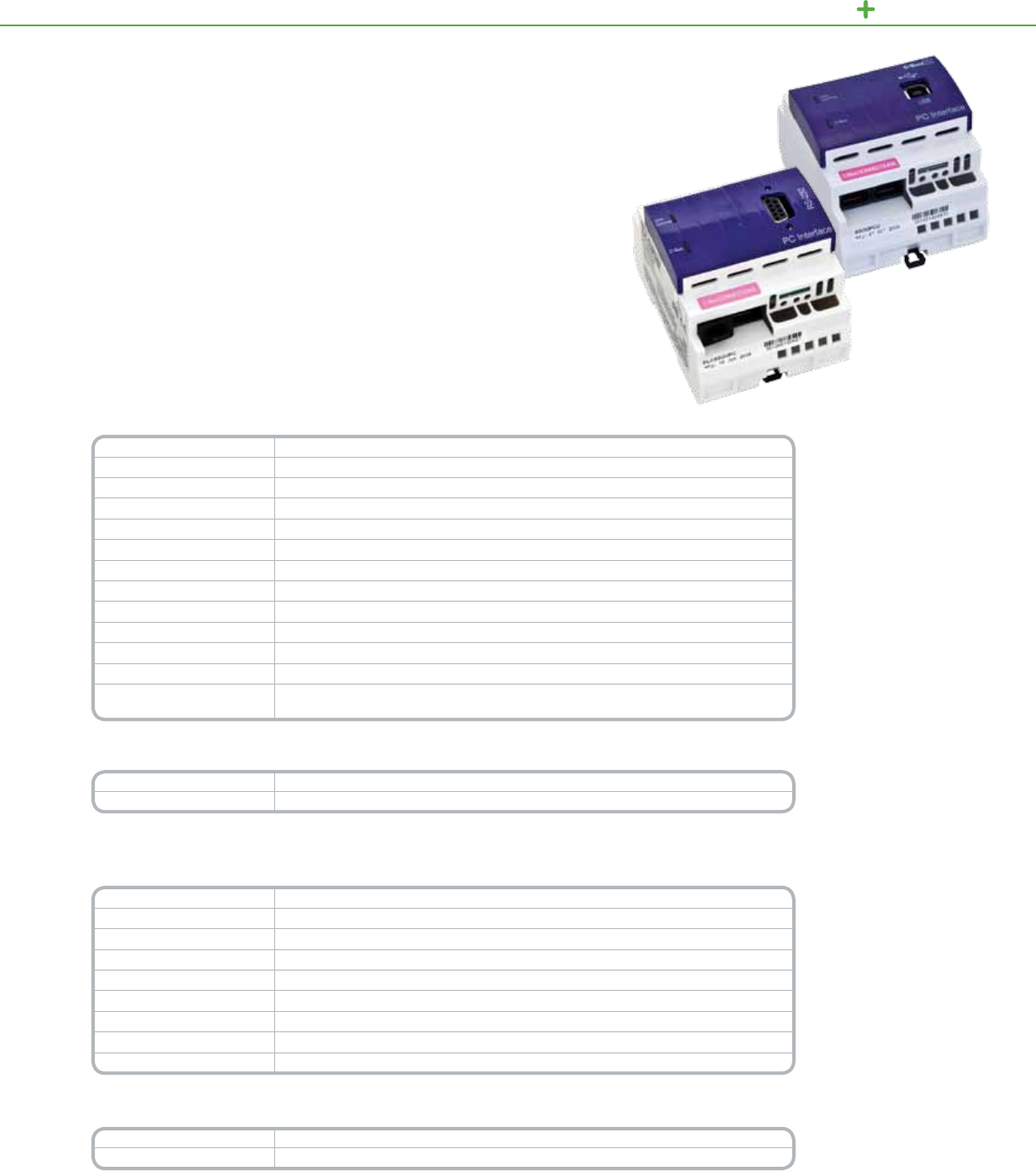
C-BUS LIGHTING CONTROL SYSTEM UNITS
TheC-BusPCInterface(PCI)expandsoptionsforconguring,controlling,and
monitoringC-Busnetworksbyprovidinganinterfacebetweenthenetworkand
apersonalcomputer(PC)orotherexternaldevice.
TheC-BusPCImoduleeasilymountstoaDINrailandconnectstoexternal
devicesthroughitsbuilt-inconnectorports.Powertotheunitisprovidedthrough
theC-Busnetwork.
C-Bus
PC Interface/PC Interface USB
Product Features
•Unit/CommsLEDshows
thestatusoftheunit’s
powerandofanydata
transmissions
•C-BusLEDshowsthe
statusofthenetworkat
theunit,includingthelevel
ofnetworkpowerandthe
presenceoftheC-Bus
clock
•Systemnetworkclock
forsynchronizing
communicationsdata
•PCInterface:ThreeRS-
232serialconnectorsfor
connectingtoaPCorto
externaldevices:(1)9-pin
D-typeserialconnector
(female)and(2)8-pinRJ-45
connectors.
•USBModel:USB(B-Type)
Connector
•TwoC-Busnetwork
connectorports:RJ-45
sockets
•Datacableforconnecting
PCIandpersonalcomputer,
includingDB9connectors
PCInterfaceandPC
InterfaceUSB
PC Interface Technical Information
Voltage Requirements 15–36Vdc@32mArequiredfornormaloperation,drawnfromtheC-Busnetwork
Electrical Isolation 500VRMScontinuousC-Bus/RS-232
Status Unit/Comms:Unitpoweranddatatransmission
Indicators C-Bus:PowerlevelsandpresenceofC-Busclock
Serial (1)9-pinRS-232D-typeserialconnector
Port (2)RS-232RJ-45connectors
Cable 6.6ft.(2m),withDB9connectors
C-Bus Connection (2)RJ-45socketsforconnectiontoaC-Busnetwork
Dimensions 2.84in.(H)x3.35in.(W)x2.60in.(D)[72mm(H)x85mm(W)x66mm(D)]
Mounting DINrail,4Mwide
Serial Termination Temp.:32°Fto113°F(0°Cto45°C),RH:95%,noncondensing
Storage Environment Temp.:14°Fto140°F(-10°Cto60°C),RH:95%,noncondensing
Standards UL:Listed916EnergyManagementEquipment,CSA22.2Spec205SignalEquipment
FCC:Part15.101,ClassBDigitalDevice,EN61000-4-2ImmunitytoESD
*For Diagram see technical section page 147
Catalog Number Description
SLC5500PC PCInterface
PC Interface USB Technical Information
C-bus input voltage 15–36Vdc
Current drawn 22mA
Electrical isolation rating 500VrmscontinuousC-Bus/RS232
Communications USBTypeAtoB
Operating temperature 32°F–113°F(0°C–45°C)
Operating humidity range 95%RH;non-condensing
Terminals C-Bus,RJ45connectors(2),USBtoPC
Dimensions 2.84in.(L)x3.35in.(W)x2.60in.(D)[72mm(L)x85mm(W)x66mm(D)]
Weight 0.23lbs(104g)
*For Diagram see technical section page 148
Catalog Number Description
SLC5500PCU PCInterface,USBModel
102
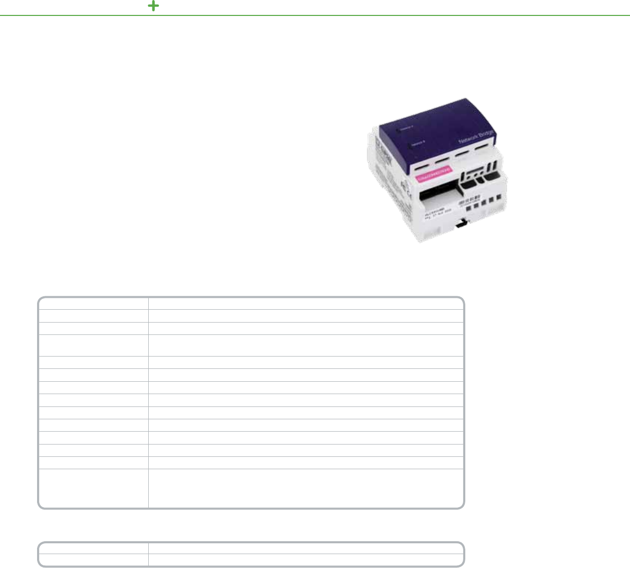
C-BUS LIGHTING CONTROL SYSTEM UNITS
Technical Information
Voltage Requirements 15–36Vdc@18mArequiredfornormaloperation,drawnfromeachconnectedC-Busnetwork
Electrical Isolation 3.5kVRMSfor1min(betweennetworks)
Status NetworkA,NetworkB
Indicators PowerON,Communicationsinprogress
PowerOFF,Notconnected/insufcientpower
Propagation Delay 250ms(delayformessagetransferbetweentwoadjacentC-BusNetworks)
Interconnect Inparallel:51networks(50networkbridges)
Capacity Inseries:7networks(6networkbridges)
C-Bus System Clock Softwareselectable
C-Bus Network Burden Softwareselectable
C-Bus Connection (2)pairofRJ-45socketsforconnectiontoC-Busnetworks
Dimensions 2.84in.(H)x3.35in.(W)x2.60in.(D)[72mm(H)x85mm(W)x66mm(D)]
Weight 3.35oz(95g)
Operating Environment Temp.:32°Fto113°F(0°Cto45°C)RH:95%,noncondensing
Standards
UL:Listed916EnergyManagementEquipment
CSA22.2Spec205SignalEquipment
FCC:Part15.101,ClassBDigitalDevice
EN61000-4-2ImmunitytoESD
*For Diagram see technical section page 148
Catalog Number Description
SLC5500NB NetworkBridge
TheC-BusNetworkBridgeprovidesacommunicationchannelbetweenC-Busunits
onseparatenetworks,expandingthetotalnumberofunitsthatcanbecongured,
controlled,andmonitored.
NetworkBridge
Product Features
•Increasestransmission
distancesbyactingasa
repeaterstationfordata
transmission
•Expandsthetotalnumber
ofC-Busdevicesthatcan
operateonthesystem
byisolatingdevicesto
individualnetworks
[Inparallel:50networks
(50networkbridges)
Inseries:7networks
(6networkbridges)]
•Indicateseachnetwork’s
statuslevel
•Storesoperatingstatus
innon-volatilememory
forrecoveryfroma
poweroutage
•Usesbuilt-inconnectors
toconnecttoaC-Bus
network
C-Bus
Network Bridge
103

C-BUS LIGHTING CONTROL SYSTEM UNITS
TheC-BusPowerSupplyisspecicallydesignedtooperatewiththeC-Busnetwork
asapowersourceforpassiveC-Busdevices.
ThepowersupplymountstoaDINrailandconnectstotheC-Busnetworkthrough
built-inRJ-45connectors.
ThesedevicesareULlistedasClass2powersuppliesandaresuitableforparallel
operation.UptovepowersuppliescanbeconnectedtoasingleC-Busnetwork.
PowerSupply
Product Features
•Availablein120and
277Vacmodels
•Regulatingpowersupply
compensatesforline
voltageandfrequency
variations,sothereis
constantoutput
•Sourcesupto350mAto
theC-Busnetwork
•ULlistedtooperatein
parallelwithotherC-Bus
powersupplies,uptove
onasingleC-Busnetwork
•Incorporatesshortcircuit
andreversepolarity
protection
•Indicatesthelinevoltage
statuswithaUnitLED
•Indicatesthenetwork
status,includingthe
networkpowerandthe
presenceoftheC-Bus
clock,withaC-BusLED
•Standardbuilt-inC-Bus
networkconnectors:
(2)RJ-45
C-Bus
Power Supply
Technical Information
Nominal Line Voltage Operatesat120or277Vac,±10%,withafrequencyrangefrom50–60Hz
Electrical Isolation 3.75kVRMSfromC-Bustotheline
Current Output 350mAtotheC-Busnetwork
Status Indicators Unit:Unitpower
C-Bus:Networkvoltagelevelandpresenceofsystemclock
Power Supplies per Network UptovepowersuppliesonasingleC-Busnetwork
C-Bus Connection (2)RJ-45socketsforconnectiontotheC-Busnetwork
Cable (1)15.75in.(400mm)patchleadincluded
Dimensions 3.35in.(H)x2.84in.(W)x2.60in.(D)[85mm(H)x72mm(W)x66mm(D)]
Mounting DINrail,4Mwide
Weight 7oz(200g)
Operating Environment Temp.:32°Fto104°F(0°Cto40°C)
EnvironmentRH:95%,noncondensing
Storage Environment Temp.:14°Fto140°F(-10°Cto60°C)
EnvironmentRH:95%,noncondensing
Standards
UL:Listed916EnergyManagementEquipment
CSA22.2Spec205SignalEquipment
FCC:Part15.101,ClassBDigitalDevice
EN61000-4-2ImmunitytoESD
*For Diagram see technical section page 148
Catalog Number Description
SLC5500TPS 120VacPowerSupply
SLC5500HPS 277VacPowerSupply
104

C-BUS LIGHTING CONTROL SYSTEM UNITS
Technical Information
Nominal Line Voltage Operatesat120or277Vac,±10%,withafrequencyrangefrom50–60Hz
Maximum Line Current 9.9mAfor120Vpowersupply4.3mAfor277Vpowersupply
Electrical Isolation 3.75kVRMSfromC-Bustotheline
Current Output 350mA(singlepowersupplyunit)700mA(dualpowersupplyunit)
Dimensions 12.57in.(L)x8.88in.(W)x3.8in.(D)[319mm(L)x226mm(W)x97mm(D)]
Weight Onepowersupply:8.84lb(4.01kg)Twopowersupplies:9.28lb(4.21kg)
Operating Environment Temp.:32°Fto113°F(0°Cto45°C)RH:95%,noncondensing
Standards
UL:Listed508AIndustrialControlEquipment
CSA22.2Spec205SignalEquipment
FCC:Part15.101,ClassBDigitalDevice
EN61000-4-2ImmunitytoESD
*For Diagram see technical section page 89
Catalog Number Description
NFDP1120G3C 120VPowerlinkSinglePowerSupply
NFDP2120G3C 120VPowerlinkDualPowerSupply
NFDP1277G3C 277VPowerlinkSinglePowerSupply
NFDP2277G3C 277VPowerlinkDualPowerSupply
ThePowerlinkDevicePowerSupplyisusedtodistributepoweronaC-Bus
network.Placedatcriticalpointsonthenetwork,devicepowersupplieswill
providethecurrentnecessaryforoperatingavarietyofpassiveSchneiderElectric
C-Busdevices.
APowerlinkDevicePowerSupplyconsistsofaC-Bus8Menclosurecontaining
oneortwo4MPowerSupplies.
Product Features
•Surface-mountNEMA1
enclosurewithtrim
assembly
•UnitandC-BusLEDs
indicatethestatusof
thelinevoltageandthe
network
•Sourcesupto700mA
(dualpowersupplies)tothe
C-Busnetwork
•120or277Vac
modelsavailable
•UTPconnectionjumper
includedfordualsupply
PowerlinkDevicePowerSupply
Powerlink
Device Power Supply
105
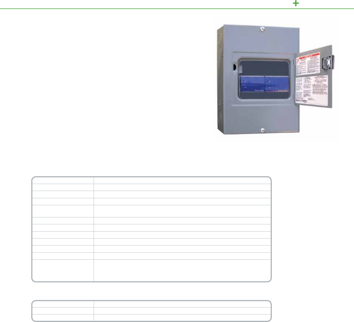
C-BUS LIGHTING CONTROL SYSTEM UNITS
Technical Information
Nominal Line Voltage Operatesat120or277Vac,±10%,withafrequencyrangefrom50–60Hz
Maximum Line Current 9.9mAfor120Vdevicerouter4.3mAfor277Vdevicerouter
Electrical Isolation 3.75kVRMSfromC-Bustotheline
Current Output 350mAtotheC-Busnetwork
Status Indicators UnitandUnit/Comms:Linevoltage,unitpower,anddatatransmission
C-Bus:PowerlevelsandpresenceofC-Busclock
Serial Connection (1)9-pinRS-232D-typeserialconnector(2)RS-232RJ-45connectors
C-Bus Connection (2)RJ-45socketsforconnectiontotheC-Busnetwork
Data Cable 50ft.serial
Dimensions 12.57in.(L)x8.88in.(W)x3.8in.(D)[319mm(L)x226mm(W)x97mm(D)]
Weight 9.1lbs(4.13kg)
Operating Environment Temp.:32°Fto113°F(0°Cto45°C)RH:95%,noncondensing
Standards
UL:Listed508AIndustrialControlEquipment
CSA22.2Spec205SignalEquipment
FCC:Part15.101,ClassBDigitalDevice
EN61000-4-2ImmunitytoESD
*For Diagram see technical section page 89
Catalog Number Description
NFDR120G3C 120VPowerlinkDeviceRouter
NFDR277G3C 277VPowerlinkDeviceRouter
ThePowerlinkDeviceRouterallowstheexchangeofdatabetweenaPowerlink
NF3000G3CcontrollerandSchneiderElectricC-Busdevices.
ThebidirectionaldeviceroutercanreceivedatafromC-Businputdevicesandsend
thedatatothePowerlinkpanel/network.Itcanalsoreceivedatasuchasacontact
closurefromthePowerlinkinputandsendthatdatatoaC-Busoutput/network.
Thedevicerouterconsistsofa8MenclosurecontainingaPCInterfaceandaPower
Supply.CommunicationbetweenthedevicerouterandtheNF3000G3Ccontrolleris
madewiththeincluded50-footserialcable.
PowerlinkDeviceRouter
Powerlink
Device Router
Product Features
•Surface-mountNEMA1
enclosurewithtrim
assembly
•Unit,Unit/Comms,and
C-BusLEDsindicatethe
statusofdatatransmission
andpowertotheunitand
thenetwork
•Systemnetworkclock
forsynchronizing
communicationsdata
•Networkpowersource,
supplyingupto350mA
•120or277Vac
modelsavailable
106

C-BUS LIGHTING CONTROL SYSTEM UNITS
Technical Information
C-Bus Supply Voltage 15–36Vdc@32mADrawnfromtheC-Busnetwork
RS-232 Supply Voltage 24Vac@20mA(powersourcenotprovided)
Battery Backup
Supply Voltage 12Vdc@30mA(powersourcenotprovided)
Connections 2C-BusRJ-45sockets(inparallel),2RS-232RJ-45sockets,1USBtypeBsocket,screw
terminalsfor12Vdcbatteryand24Vacpower
C-Bus System Clock Softwareselectable
Network Burden Softwareselectable
Status Indicators Unit/Comms,C-Bus,StatusandUser
Dimensions 2.83x3.62x2.48inches(72x92x63mm)
Weight 5.29oz(150g)
Mounting DIN4Mwide
Operating Environment 32°Fto113°F(0°Cto45°C)10%–95%RH,noncondensing
Standards CSA22.2Spec205SignalEquipment
*For Diagram see technical section page 149
Catalog Number Description
SLC5500PACA PascalAutomationController
TheC-BusPascalAutomationController(PAC)providesextendedconditionaland
real-timeeventprogrammingtoC-Bussystems.ThePACsupportsafullrangeof
programmingcommandsincludingconditionallogic,owcontrol,variablesand
scheduling.
Systemsintegratorswillappreciatethebuilt-inschedulingtools,scenetools,
andwizardsforcreatingbasiclogicprograms.Fullprogrammingcapabilities
canbeachievedutilizingthefree-formscripteditorbasedoffthePASCAL
programminglanguage.
ThePACdirectlyconnectstoawiredC-Bussystem.Programsaredownloaded
fromapersonalcomputerthroughaUSBconnection.
Product Features
•Conditionalandreal-time
eventsprogramming
forC-Bus
•ConnectsdirectlytoC-Bus
network
•PoweredfromtheC-Bus
network
•USBportforconnection
topersonalcomputer
•(2)RS-232portsforthird
partydevicecontrol
•Realtime,astronomical
andC-Bussystemclock
includedwith24hour
internalcapacitorbackup
andexternal12Vdc
batteryterminals
Programming
capabilities
including:
•Conditionallogic
(if,then,and,or,not,etc.)
•FlowControl
(for,repeat,while)
•Variables(integer,real,
Boolean,character,string)
•Controlandmonitoringof
groupaddresses
•Controlandmonitoring
ofscenes
PascalAutomationController
C-Bus
Pascal Automation Controller
107
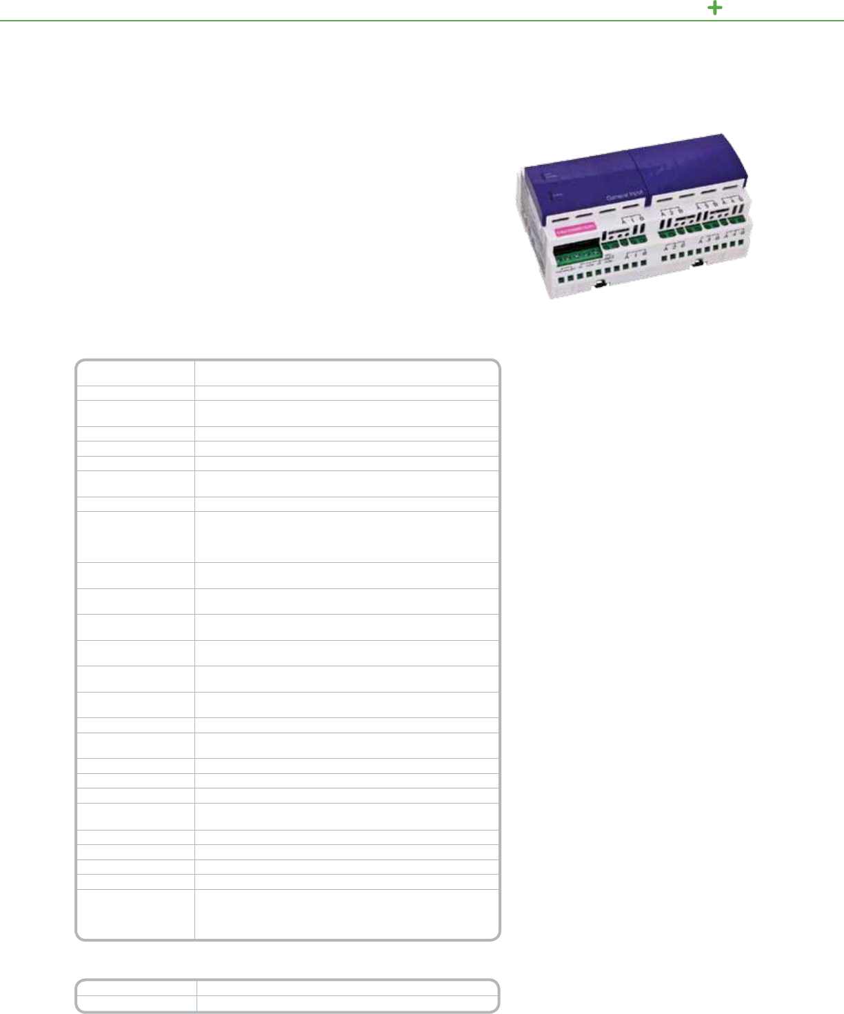
C-BUS LIGHTING CONTROL INPUT UNITS
TheC-BusFour-ChannelGeneralInputUnitsareDIN-railmounteddevicesthat
measureTTLdigitalandreal-worldanalogquantitiesandgeneratemessagesabout
themeasurementstotheC-Busnetwork.Byactingasaninterfacewithvarious
externalsensors,thegeneralinputunitenablesintegrationoftheC-Busnetwork
withavarietyofsystemtypes,suchasthoseforHVACandforpowermonitoring.
Congurationoptionsincludeselectableinputtypes,eightadjustabledecision
thresholdsperchannel,denableactions,selectableltering,broadcastrates,anda
separatehysteresisvalueperchannel.
GeneralInputUnit
Product Features
•MeasuresTTLdigitalquantitiesincludingvoltage,current,or
resistancefromexternalsensorssuchaslightlevel,pressure,
andtemperature
•Fourchannelsofinput,eachwithanadjustablehysteresis
value,eightdecisionthresholds,andasoftware-selectable
inputvaluetransformationintheformy=ax+b
•Inputchannelsarecompatiblewitharangeofthird-party
sensors
•Look-uptablewithinterpolation
•Capableofthresholdswitchingorbroadcastingvaluesonto
thenetwork
•Controlfunctionsincludeloadswitching,dimming,trigger
applications,enablecontrolapplications,andmeasurement
applications
•Measuresinputsignalsupto10Hzandhasanadjustable
input-signalltertoreducesusceptibilitytoimpulseandnoise
•Supplies250mAtoexternalsensors
•LEDsindicatethestatusofthenetworkattheunitandthe
unit’spoweranddatatransmissions
•Software-selectablenetworkburdenandC-Bussystemclock
•Standardbuilt-inC-Busnetworkconnectors:(2)RJ-45
•Non-volatilememorystoresoperatingstatusforrecovery
fromapoweroutage
•Includes120V/24Vacpowerpack
C-Bus
General Input Unit
Technical Information
Nominal Voltage
Requirements 15–36volts@18mAfromtheC-Busnetwork
Nominal 120Vac
Nominal Supply Voltage 16–27Vac/dc,±10%,50–60Hz,providedbyanexternalpower
supply(included)
AC Input Impedance 100kOhm@1kHz
External Power Supply 24Vac@500mA
Electrical Isolation 500VRMSperinput
Nominal 24 Vdc
Output Voltage 24Vdc@250mA,±10%GeneralInput
Digital Sensor Input TTL,5Vfromexternalsource
Analog Sensor Inputs:
Voltage Ranges
Input Current Ranges
Resistance Ranges
0–1,0–5,0–10,0–20Vdc
0–20mADC,4–20mADC
0–500ohm,0–1000ohm,0–3000ohm,0–10000ohm
Maximum Input
Voltages -20Vto60Vdc
Input Voltage Range
Impedance Atleast100kOhm
Current Sense
Impedance 249ohm
Resistance Range
Injection Current 500μA
Basic Accuracy after
Calibration 0.5%offullscale
Maximum Input
Frequency 10Hz
Broadcast Rates 2–1024sec
Number of Units
per Network 10
C-Bus Connections (2)RJ-45connectors,CAT5UTPcablerequired
Cable 15.75in.(400mm)patchleadincluded
Terminals Accommodate16–12AWGcable(2x1.31mm2or1x3.31mm2)
Status Indicators Unit/Comms:Unitpoweranddatatransmission
C-Bus:PowerlevelsandpresenceofC-Busclock
Dimensions
5.7in.(L)x3.4in.(W)x2.6in.(H)[144mm(L)x85mm(W)x65mm(H)]
Weight 7oz(190g)
Mounting DINrail,8Mwide
Operating Environment 32°Fto113°F(0°Cto45°C)RH:95%,noncondensing
Standards
CSA22.2Spec205SignalEquipment
FCC:Part15.101,ClassBDigital
EN61000-4-2ImmunitytoESD
ULListed916EnergyManagementEquipment
*For Diagram see technical section page 149
Catalog Number Description
SLCE5504TGI 4ChannelGeneralInputUnit
108

C-BUS LIGHTING CONTROL INPUT UNITS
Technical Information
Nominal Voltage
Requirements 15–36Vdc@18mA,drawnfromtheC-Busnetwork
Electrical Isolation None
Voltage Across Input ExternalSwitchOpens:5Vdc
ExternalSwitchCloses:0Vdc
Current–Switch Closed Lessthan50μA
Distance Between 2-ChannelCoupler:Upto1ft.(0.3m)each
Switch and Bus
Coupler 4-ChannelCoupler:Upto3ft.(1m)each
LED Drive Output 2-ChannelCoupleronly:2mA@12V
Maximum Input
Voltages -20to60Vdc
Number of Units per
Network
UsetheC-BusCalculator,asoftwareutility,todeterminethetotal
networkcurrentload
C-Bus Connections Two-wayremovablescrew-typeterminalsaccommodating
24–16AWGcable(0.2–1.31mm2)
Channel Input Spring-loadedterminalblockaccommodating
Connections 24–12AWGcable(0.2–3.31mm2)
Status Indicators Channel(2or4)
Timers 1sec–18hr,1secintervals
Dimensions
2.2in.(L)x1.9in.(W)x0.7in.(H))[55mm(L)x49mm(W)x18mm(H)]
Weight 1.1oz(32g)
Operating Environment 32°Fto113°F(0°Cto45°C)RH:95%,noncondensing
Standards
UL:Listed916EnergyManagementEquipment
CSA22.2Spec205SignalEquipment
FCC:Part15.101,ClassBDigital,
EN61000-4-2ImmunitytoESD
*For Diagram see technical section page 149
Catalog Number Description
SLC5102BCLEDL Two-ChannelBusCoupler
SLC5104BCL Four-ChannelBusCoupler
TheC-BusBusCouplersarenon-isolatedinputdevicesthatprovideaninterface
betweendry-contactmechanicalswitchesandaC-Busnetwork.Thebuscoupler
increasestheversatilityoftheC-Busnetworkbyfacilitatingremoteaccesswithany
dry-contactswitchmechanismofferedbySchneiderElectricandothermanufacturers.
Asystem’sexibilitycanbefurtherenhancedbyusingthebuscouplerwithvarious
otherswitchtypes,includingreed,pressure,ormicroswitches.
Availableintwo-andfour-channelmodels,thebuscouplerissmallenoughtobe
usedinrestrictedspaces.Congurationoptionsincludestandardcontrolfunctions
suchasON/OFF,toggle,dimmers,andtimers.
Product Features
•Providestwoorfournon-isolatedinputsforexternal
voltage-freemechanicalswitches.Two-channelunitsfeature
independentremoteLEDoutputs
•ControloptionsincludeON/OFF,toggle,dimmer,ortimer
•OrangeLEDforeachchanneltoindicateoperationalstatus
•Two-wayremovableterminalblockfortheC-Busconnection
•Terminalblockallowsconnectionofuptofourexternal
switches(four-channelcoupler)ortwoexternalswitchesand
twoexternalLEDs(two-channelcoupler)
•Smallsizeforadaptationtorestrictedspaces
•Non-volatilememorystoresoperatingstatusforrecovery
fromapoweroutage
•Receivesdataandpoweroveranetwork,soitdoesnot
requirepowerpacksorlinevoltageconnections
Four-ChannelBusCoupler
C-Bus
Bus Coupler
109

C-BUS LIGHTING CONTROL INPUT UNITS
TheC-BusFour-ChannelAuxiliaryInputsareisolatedfour-channelinputunitsthat
provideaninterfacebetweenvoltage-freemechanicalswitchesandaC-Busnetwork.
AnauxiliaryunitincreasestheversatilityoftheC-Busnetworkbyfacilitatingremote
accesswithanydry-contactswitchmechanismofferedbySchneiderElectricorother
manufacturers.
DIN-railmountedforquickinstallation,theauxiliaryunitcanbeconguredwith
standardC-Buscontrolfunctionssuchasremotescenetriggering,ON/OFF,toggle,
dimmer,ortimer.
Product Features
•Providesfourisolatedinputsforexternalvoltage-free
mechanicalswitches
•Controloptionsincluderemotescenetriggering,
ON/OFF,toggle,dimmer,ortimeroperations
•OrangeLEDsindicateoperationalstatus,onefor
eachchannel
•Standardbuilt-inC-Busnetworkconnectors:(2)RJ-45
•Non-volatilememorystoresoperatingstatusforrecovery
fromapoweroutage
Four-ChannelAuxiliaryInputUnit
C-Bus
Four-Channel Auxiliary Input
Technical Information
Nominal Voltage
Requirements 15–36Vdc@18mA,drawnfromtheC-Busnetwork
Electrical Isolation C-Bus/RemoteInput:500VRMS
RemoteInput:500VRMS
Voltage Across Input ExternalSwitchOpens:5VdcExternalSwitchCloses:0Vdc
Current–Switch
Closed 0.4mA
Switch Resistance Upto1000ohm,includingcableresistance(26.5ohmsperkm
resistancefor#18copperwirecoatedDCcurrentresistance)
Number of Units
per Network
UsetheC-BusCalculator,asoftwareutility,todeterminethetotal
networkcurrentload
C-Bus Connections (2)RJ-45connectors,CAT5UTPcablerequired
Cable 15.75in.(400mm)patchleadincluded
Terminals Accommodateone12ortwo14-22AWGcables
(1x3.1mm2)or2x2.0-0.3mm2)]
Status Indicators Channel:(4)orangeLEDstoindicatetheloadstatusforeachchannel
Timers 1sec–18hr,1secintervals
Dimensions 3.4in.(L)x2.8in.(W)x2.6in.(H))[85mm(L)x72mm(W)x65mm(H)]
Weight 4.6oz(130g)
Mounting DINrail,4Mwide
Operating
Environment
32°Fto113°F(0°Cto45°C)RH:95%,noncondensing
Standards
UL:Listed916EnergyManagementEquipment
CSA22.2Spec205SignalEquipment
FCC:Part15.101,ClassBDigitalDevice
EN61000-4-2ImmunitytoESD
*For Diagram see technical section page 150
Catalog Number Description
SLCLE5504AUX 4ChannelAuxiliaryInputUnit
110
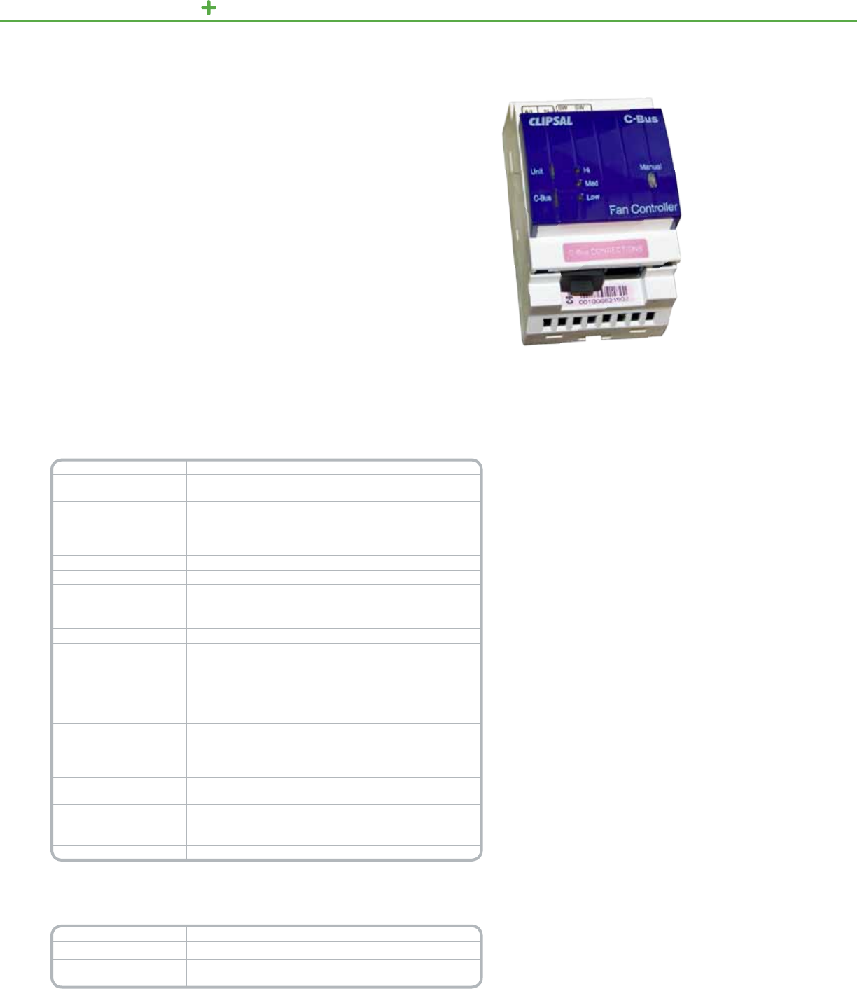
C-BUS LIGHTING CONTROL INPUT UNITS
TheSLC5501RFCPC-BusDINFanControllerunitisaDINrailmountedC-Bus
outputdevicethatprovidessingle-buttonspeedcontrolforasingleceilingfan.
TheFanControllercanbeinstalledinastandardC-Busenclosure,orinanoptional
enclosure,suchasSLC5501FREplasticenclosure,onawallorinaceilingspace.
TheSLC5501RFCPFanControllerprovidesC-Buscontrolofaceilingfanforupto
threespeeds(Low,MediumandHigh)andoffandcanbedisplayedinC-BusDLT
keypads.Controlcanbeincludedinscenesandschedules.Fancontrollersare
Master/slavecongurable,somultiplefanscanbecontrolledfromasingleswitch
usingmultiplecontrollers.
Theunitisforindooruseonly.Thefancontrollermustbemountedinanenclosure
thatisproperly-ratedfortheapplication.Aqualiedpersonmustinstallthe
electricalconnections.
Technical Information
C-Bus input voltage 15–36Vdc
C-Bus current requirement 18mA,poweredfromC-Busnetwork,doesnotprovidepower
fortheC-Busnetwork
Maximum units
per network 100
Network clock Softwareselectable
Network burden SoftwareselectablewhenUnitAddressis001
AC input impedance 100kΩ@1kHz
Warm-up time 10seconds
Electrical isolation 3.75kVfromC-Bustomains
Input voltage for fan motor 120Vac;inputcircuitmusthaveasuitablecircuitbreaker
Fan load rating 1.5AFLA
Motor load rating 1.5FLA,9LRA
Switch duty type (S1) Continuousduty.Lineandneutralareswitched.Fanmotorand
neutralareswitched.
Speed control ThreeuniquefanspeedsLow,Med,andHiandOff.
Connectors
C-Bus:2xRJ-45
Fan:2xscrewtypeforone16AWG(1.5mm²)wire
InputPower:2xscrewtypeforuptotwo16AWG(1.5mm²)
Indicators Unit,C-Bus,3xFanspeed
Control Localoverridepushbutton,notilluminated
Rated impulse
withstand voltage 4kV
Mounting type DINrail,orwallorceilingspacemountingintheoptionalplastic
enclosure;Forindooruseonly
Weight FanControllerRelayUnit:5.11oz(145g)
Optionalplasticenclosure:7.76oz(220g)
Operating temperature 32°Fto149°F(0°Cto65°C)
Humidity 10%to95%RH,noncondensing
*For Diagram see technical section page 150
Note: There are no user-serviceable parts. The unit draws no power from mains and requires no line
connection to operate.
Catalog Number Description
SLC5501RFCP C-Busoutputunitforcontrollingaceilingfan
SLC5501FRE* EnclosuretoaccommodateaC-Busceilingfancontroller
outputunit
*The SLC5501FRE is optional equipment and not UL certied or rated for plenum use. Use an enclosure that
is properly-rated for your application.
C-Bus
DIN Fan Controller
111

C-BUS LIGHTI NG CONTROL SENSORS
Product Features
•Indooruse,wallorceiling-mountedunitwitha90°eld
ofviewandadetectionareaof400squarefeet
•LEDcanbeconguredtoindicatemotiondetection
•Light-levelsensorhasSunrise/Sunsetsettings,clock
overrides,andadjustablesensitivityrangingfrom0.1foot
candletofullsunlight
•Advancedcircuitrytohelppreventfalsetriggering,including
electrostaticandelectromagneticshields,dualelement
detectors,pyroelectricceramicsensors,andanoptical
bandpasslter
•ControlsuptofourC-Busgroupaddressesthatcanbe
individuallyscheduled
•Non-volatilememorystoresoperatingstatusforrecovery
fromapoweroutage
•Receivesdataandpoweroveranetwork,sothesensor
doesnotrequirepowerpacksorlinevoltageconnections
IndoorPIROccupancySensor
TheC-BusIndoorPIROccupancySensorprovidesreliablethermal-radiation-based
controloflightingandotherC-Busoutputdevices.
Suitableforwallorceilingmounting,thissensoroffersacontinuousdetectioneld
of400squarefeetanda90°eldofview.Theentiredetectioneldhasuniform
sensitivityandnodeadzones,makingitanideallighting-controlsolutionforofces,
corridors,andconferencerooms.
Congurationoptionsincludeanadjustablelight-levelsensorthatcanbesetto
automaticallyturnofflightswhenambientlightlevelsaresufcientorturnonlights
whenambientlightlevelsareinsufcient.
C-Bus
Indoor PIR Occupancy Sensor
Technical Information
Nominal Voltage
Requirements 15–36Vdc@18mA,drawnfromtheC-Busnetwork
Field of View 90°
PIR Detection Field Typically400sqft.(37sqm)
Light-Level inhibit
Threshold 0.1footcandle(1lux)tofullsunlight
Timer Delay Range 0sec–18hr,1secinterval
Number of Units per
Network
UsetheC-BusCalculator,asoftwareutility,todeterminethetotal
networkcurrentload
C-Bus Connection Screw-typeterminals,inputterminalsaccommodate24–16AWGcable
(0.2–1.31mm2)
Status Indicators LEDcanbeconguredtoturnonwhenmovementisdetected
Dimensions 3.9in.(W)x2.2in.(H)[100mm(W)x57mm(H)]
Weight 4.4oz(125g)
Mounting Surface:Ceilingorwall
Ht:8ft.(2.4m)aboveoor
Operating
Environment Indoor32°Fto122°F(0°Cto50°C)
Standards
UL:Listed916EnergyManagementEquipment
CSA22.2Spec205SignalEquipment
FCC:Part15.101,ClassBDigitalDevice
EN61000-4-2ImmunitytoESD
*For Diagram see technical section page 150
Catalog Number Description
SLC5751L 90°IndoorPIROccupancySensor
112

C-BUS LIGHTI NG CONTROL SENSORS
Product Features
•360°detectionpattern,indooruse
•Effectivecoverageareaismorethan800squarefeet
whenunitismounted8feetabovetheoor
•Dualelementdetectorsminimizefalsetriggering
•LEDsindicatemovementdetectionandstatusoftheIR
receiver,andthelight-levelsensor
•Cancontroluptofourscenesorgroupaddressesthat
canbeindividuallyscheduled
•Adjustablelight-levelsensorwithSunrise/Sunsetand
clockoverrides
•Attractive,lowproleunitcanbeushmountedonceiling
orsuspendedfromwalltileswhereitisunobtrusive,with
afacediameterofonly2.8inches
•Non-volatilememorystoresoperatingstatusforrecovery
fromapoweroutage
•Receivesdataandpoweroveranetwork.Nopower
packsorlinevoltageconnectionsrequired
TheC-Bus360°IndoorPIROccupancySensorcombinesapassiveinfraredreceiver
(PIR)foroccupancysensingandalight-levelsensorintoasmall,highlyversatileunit.
Themulti-sensor’s2.8inchfacediametermakesitunobtrusiveandideallysuitedfor
ushmountingontheceiling.
Thissensorhasa360degreeeldofviewwithaneffectivecoveragepatternof
morethan800feet,soitisideallysuitedforofces,copierrooms,closets,and
restrooms.MultiplesensorscanbeconnectedtothesameC-Busnetworkto
providelargercoveragepatterns.
Congurationoptionsincludeadjustabletimedelaysforautomaticshut-offfollowing
apresettimeperiodwithoutdetectedmotionandanadjustablelight-levelsensor
thatcanbesettoautomaticallyturnofflightswhenambientlightlevelsaresufcient
orturnonlightswhenambientlightlevelsareinsufcient. 360°PIROccupancySensor
C-Bus
360° PIR Occupancy Sensor
Technical Information
Nominal Voltage
Requirements 15–36Vdc@18mA,drawnfromtheC-Busnetwork
Field of View 360°
PIR Rated
Detection Field
Typically800sqft.(74sqm)whensensorismounted8ft.(2.4m)
aboveoor
Light-Level inhibit
Threshold 0.1footcandle(1lux)tofullsunlight
Timer Delay 0secto18hr
Number of Units per
Network
UsetheC-BusCalculator,asoftwareutility,todeterminethetotal
networkcurrentload
C-Bus Connection Tworemovableterminalblocks,requiresCAT5datacable
Status Indicators LEDcanbeconguredtoturnonwhenmovementisdetected
Dimensions 4.1in.(L)x2.8in.(W)[103mm(L)x72mm(W)]
Weight 4.4oz(125g)
Mounting
Surface:Ceiling
Ht:8ft.(2.4m)aboveoor
Max.Ht:12ft.(3.7m)aboveoor
Min.CeilingThickness:0.4–0.75in.(10–19.1mm)
Operating Indooronly
Environment 32°Fto113°F(0°Cto45°C)
RH:95%,noncondensing
Standards
UL:Listed916EnergyManagementEquipment
CSA22.2Spec205SignalEquipment
FCC:Part15.101,ClassBDigitalDevice
EN61000-4-2ImmunitytoESD
*For Diagram see technical section page 151
Catalog Number Description
SLC5753L 360°PIROccupancySensor
113

C-BUS LIGHTING CONTROL SENSORS
Product Features
•360°detectionpattern,indooruse
•Effectivedetectionareaofoccupancysensorismorethan
800squarefeetwhenunitismounted8feetabovetheoor.
EffectiveIRcoverageis800squarefeet.
•Dualelementdetectorsminimizefalsetriggering
•LEDsindicatemovementdetectionandstatusoftheIR
receiver,theoccupancysensor,andthelight-levelsensor
•CancontroluptoeightC-Busscenesordirectlycontrol
uptoeightC-Busgroupaddressesthatcanbeindividually
scheduled
•Adjustablelight-levelsensorhasSunrise/Sunsetandclock
overrides
•Attractive,lowproleunitcanbeushmountedonceilingor
suspendedfromwalltileswhereitisunobtrusive,withaface
diameterofonly2.8inches
•Optionalhandheldremotecontroller(SLC5084TX,
SLC5088TX)
•Non-volatilememorystoresoperatingstatusforrecoveryfrom
apoweroutage
•Receivesdataandpoweroveranetwork,sothesensordoes
notrequirepowerpacksorlinevoltageconnections
TheC-Bus360°PIRMulti-Sensorcombinesapassiveinfraredreceiver(PIR)for
occupancysensing,alight-levelsensor,andaninfraredremotereceiverintoasmall,
highlyversatileunit.Thesensor’s2.8inchfacediametermakesitunobtrusiveand
ideallysuitedforushmountingontheceiling.
Congurationoptionsfortheoccupancysensorincludeadjustabletimedelays
forautomaticshut-offfollowingapresettimeperiodwithoutdetectedmotionand
anadjustablelight-levelsensortoturnonlightsautomaticallywhenambientlight
levelsareloworturnofflightswhenambientlightlevelsaresufcient.Thebuilt-inIR
receiveracceptscommandsfromanoptionalhandheldremotecontroller,making
thesensoridealforclassroomsandconferenceroomareas.
360°PIRMulti-Sensor
C-Bus
360° PIR Multi-Sensor
Technical Information
Nominal Voltage
Requirements 15–36Vdc@18mA,drawnfromtheC-Busnetwork
Field of View 360°
PIR Rated
Detection Field
Typically800sqft.(74sqm)whensensorismounted8ft.(2.4m)
aboveoor
IR Receiver Rated
Detection Field
Typically800sqft.(74sqm)whensensorismounted8ft.(2.4m)
aboveoor
Light-Level inhibit
Threshold 0.1footcandle(1lux)tofullsunlight
Timer Delay 0secto18hr
Number of Units per
Network
UsetheC-BusCalculator,asoftwareutility,todeterminethetotal
networkcurrentload
C-Bus Connection Tworemovableterminalblocks,requiresCAT5datacable
Status Indicators
PIRSensororIRReceiver(activity)
PIRSensor(enabled/disabled)
LightLevelMaint.(enabled/disabled)
Dimensions 4.1in.(L)x2.8in.(W)[103mm(L)x72mm(W)]
Weight 4.4oz(125g)
Mounting
Surface:Ceiling
Ht:8ft.(2.4m)aboveoor
Max.Ht:12ft.(3.7m)aboveoor
Min.CeilingThickness:0.4–0.75in.(10–19.1mm)
Operating Indooronly
Environment 32°Fto113°F(0°Cto45°C)
RH:95%,noncondensing
Standards
UL:Listed916EnergyManagementEquipment
CSA22.2Spec205SignalEquipment
FCC:Part15.101,ClassBDigitalDevice
EN61000-4-2ImmunitytoESD
*For Diagram see technical section page 151
Catalog Number Description
SLC5753PEIRL 360°PIRMulti-Sensor
Accessories Description
SLC5084TX IR4-ButtonRemoteController(orderedseparately)
SLC5088TX IR8-ButtonRemoteController(orderedseparately)
114
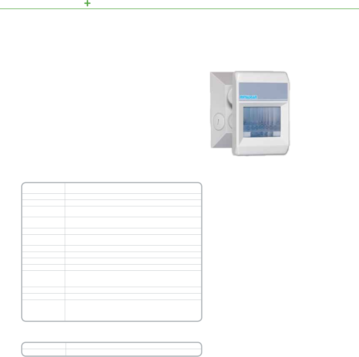
C-BUS LIGHTING CONTROL SENSORS
TheC-BusOutdoorPIRMotionSensorcombinesreliablethermal-radiation-based
controloflightingwithruggedconstructionsuitableforoutdoorrequirements.The
unit’sadvancedcircuitsandatmulti-segmentedlensprovidecoverageofupto
3000squarefeetina110°eldofview.
Thedetectionareaincorporatesamulti-facetedlens,whichensuresfastresponse
tomotionandfewdeadzones.Electrostaticandelectromagneticshields,dual
elementdetectors,anopticalbandpasslter,andpyroelectricceramicsensorsare
usedtoreducetheincidenceoffalsetriggering.
Congurationoptionsincludeanadjustablelight-levelsensorthatcanbesetto
automaticallyturnofflightswhenambientlightlevelsaresufcientorturnonlights
whenambientlightlevelsareinsufcient.
Product Features
•Outdooruse,wallorceiling-mountedunitwitha110°eldof
viewandadetectionareaupto3000squarefeetindiameter
•Lenshas12overlappingzonesoneachof4levels,forminga
continuousdetectioneld
•Ruggedconstructionandpre-wiredexiblecord
•LEDindicatesmotiondetection
•Light-levelsensorhasSunrise/Sunsetsettings,clock
overrides,andadjustablesensitivityrangingfrom
0.1footcandletofullsunlight
•ControlsuptofourC-Busgroupaddressesthatcanbe
individuallyscheduled
•Non-volatilememorystoresoperatingstatusforrecoveryfrom
apoweroutage
•Receivesdataandpoweroveranetwork,sothesensordoes
notrequirepowerpacksorlinevoltageconnections
OutdoorPIRMotionSensor
C-Bus
Outdoor Motion Sensor
Technical Information
Nominal Voltage
Requirements 15–36Vdc@18mA,drawnfromtheC-Busnetwork
Field of View 110°
PIR Detection Field Typically3000sqft.(279sqm)
Light-Level inhibit
Threshold 0.1footcandle(1lux)tofullsunlight
Number of
Detection Zones 18LongRange,16IntermediateRange,10ShortRange,4ultraShort
Timer Delay Range 0secto18hr
Number of Units
per Network
UsetheC-BusCalculator,asoftwareutility,todeterminethetotalnetwork
currentload
C-Bus Connection Oneterminalblock
Status Indicators LEDcanbeconguredtoturnonwhenmovementisdetected
Dimensions 4.5in.(L)x2.9in.(W)x5.5in.(D)[114mm(L)x74mm(W)x140mm(D)]
Weight 8oz(227g)
Mounting
Standardplate/boxwith3.3in.(84mm)mountingcenters
Surface:Ceilingorwall
Ht:8ft.(2.4m)aboveoor
Operating Outdooronly
Environment 32°Fto+122°F(0°Cto+50°C)
Standards
UL:Listed916EnergyManagementEquipment
CSA22.2Spec205SignalEquipment
FCC:Part15.101,ClassBDigitalDevice
EN61000-4-2ImmunitytoESD
*For Diagram see technical section page 151
Catalog Number Description
SLC5750WPL 110°OutdoorPIRMotionSensor
115
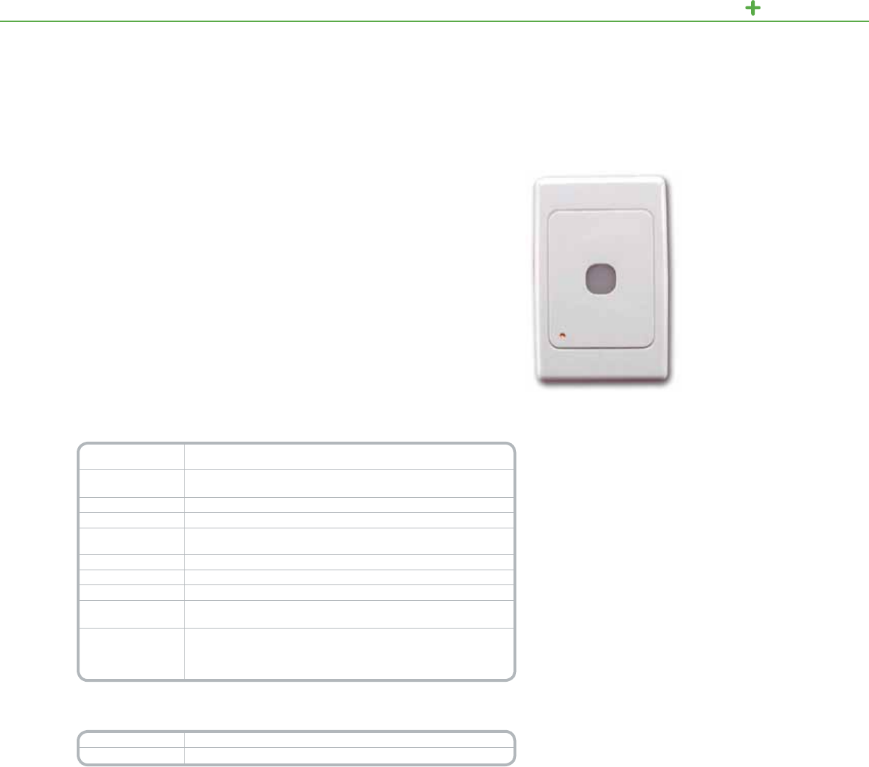
C-BUS LIGHTING CONTROL SENSORS
Product Features
•Canmaintainconstantilluminationlevelsof5-150footcandles
•ControlsuptotwoC-Busgroupaddresses,onesetfor
ON/OFFoperationsandonesetforrampingoperations
•180°eldofview
•CanbeenabledordisabledovertheC-Busnetwork
•Storesoperatingstatusinnon-volatilememoryforrecovery
fromapoweroutage
•ReceivesdataandpoweroverasingleC-Bustwisted
paircable
•VeriesstatusofinputandoutputdevicesonsameC-Bus
applicationaddress,updatinginputstatusifnecessary
•LEDcanbeconguredtoindicatecurrentstatusofanyC-Bus
groupaddress
•Attractive,wall-mounted,low-proleunit
TheC-BusLight-LevelSensormeasuresambientlightlevelsandautomaticallyissues
ON,OFF,orrampcommandsoveraC-Busnetwork.Thelight-levelsensorcan
controlrelays,dimmers,orremotelyoperatedcircuitbreakers,changingtheirstatus
accordingtopre-setambientlightinglevels.
TheC-Buslight-levelsensorhasadynamicrangebetween5-150footcandles,
andcompensatesfornoiseandrapidlightintensityuctuationsbyusingltering
andhysteresis.
Thelight-levelsensorcancontroluptotwoC-Busgroupaddresses:oneaddress
controlstheswitchingON/OFFofalampcircuitaccordingtotheamountofambient
light,whiletheotherisusedtocontinuouslyregulatethelight-leveloutputofany
numberoflamps.
LightLevelSensor
C-Bus
Light-Level Sensor
Technical Information
Nominal Voltage
Requirements 15–36Vdc@18mA,drawnfromtheC-Busnetwork
Light Level Reads:2–278footcandles(20–3000lux)
Controls:5–148footcandles(40–1600lux)
Field of View 180°
C-Bus Connection Accommodates6x24AWGcable(6x0.2mm2)
Status Indicators Canbeconguredtoreportstateofanyoneofthreegroupaddresses:
Enabled,ON/OFF,orRamp
Dimensions
4.57in.(L)x2.99in.(W)x1.93in.(D)[116mm(L)x76mm(W)x49mm(D)]
Weight 3oz(85g)
Operating Indooronly
Environment 32°Fto122°F(0°Cto50°C)
RH:95%,noncondensing
Standards
UL:Listed916EnergyManagementEquipment
CSA22.2Spec205SignalEquipment
FCC:Part15.101,ClassBDigitalDevice
EN61000-4-2ImmunitytoESD
*For Diagram see technical section page 151
Catalog Number Description
SLC5031PE Light-LevelSensor
116
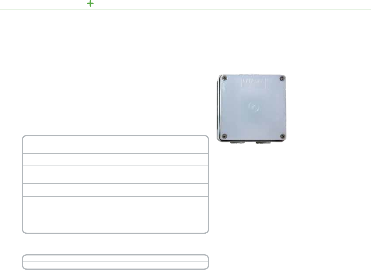
C-BUS LIGHTING CONTROL SENSORS
TheC-Buslight-levelsensormeasuresambientlightlevelsandautomaticallyissues
ON/OFForrampcommandsoveraC-Busnetworktomaintainoutdoorlighting
levels.Primarilydesignedforoutdooruse,thislight-levelsensorisalsosuitablefor
indoorsettingsinwhichawaterresistantcasingisdesirable.
Product Features
•Outdooruse,wall-andceiling-mountedlow-proleunit
•Canmaintainaconstantilluminationlevelof
5–150footcandles
•ControlofuptotwoC-Busgroupaddresses
•SensorsreceivedataandpoweroverasingleC-Bus
twisted-paircable,sotheydonotrequirepowerpacks
orline-voltageconnections
•180°eldofview
OutdoorLightLevelSensor
C-Bus
Outdoor Light-Level Sensor
Technical Information
Nominal Voltage
Requirements 15–36Vdc@18mA,drawnfromtheC-Busnetwork
Field of View 180°
Light-Level Range Reads:2–278footcandles(20–3000lux)
Controls:5–148footcandles(40–1600lux)
C-Bus Connection Screw-typeinputterminalsaccommodate6x24AWGcable(6x0.2mm²)
ConnectionrequiresCAT5datacable
Max. Units/Network Basedonthetotalnetworkcurrentloadandavailablepower
Conduit Openings Sizedfor20mmand25mmconduitttings
Dimensions 4in.(L)x4in.(W)x2.5in.(D)[102mm(L)x102mm(W)x65mm(D)]
Weight 10.8oz(305g)
Mounting Indoororoutdoor,wallorceiling
IndoorHeight:Atleast6.5ft.(1.9m)aboveoor
Operating
Environment
Outdoororindoor-22°Fto122°F(-30°Cto50°C)
RH:95%,noncondensing
Standards FCC:Part15.101,ClassBDigitalDevice
*For Diagram see technical section page 152
Catalog Number Description
SLC5031PEWP OutdoorLight-LevelSensor
117
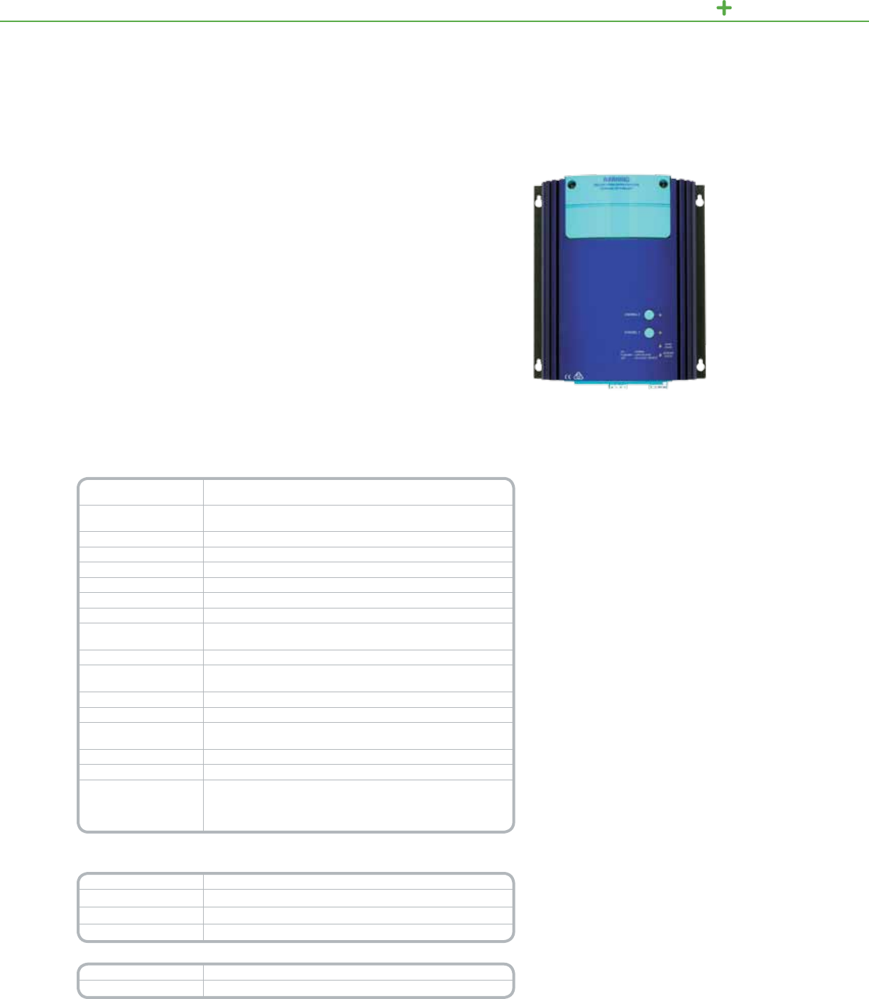
C-BUS LIGHTING CONTROL OUTPUT UNITS
TheC-BusProfessionalDimmersaredesignedtocontrolincandescentand
compatiblelow-voltagelighting.Thesedimmersareidealfortightspaceapplications
wheretraditionalrackmountedassembliesarenotpractical.
Professionaldimmerunitsareavailablein5A(4channels),10A(twochannels),
and20A(onechannel)models.Eachchannelprovidesindependentdimming
andincorporatesthermaloverloadandover-currentprotection.Thesedimmer
unitsautomaticallycompensateforvoltageandfrequencyuctuationsandemploy
advancedphase-controltechniquestoreduceickerandincreaselamplife.
Thealuminumenclosureactsasaheatsinkandisdesignedforeasywall
mounting,includingkeyholemountsandremovableterminalsfortheC-Busand
overrideconnections.Anoptionalterminalboxisavailableforconduitconnections.
Congurationoptionsincludenetworkmonitoringofthechannelloadandnetwork
voltages,adjustabledelaysfordimminglevels,andmasteroverride.
Product Features
•Suitableforusewithresistiveandinductiveloadsandlow-
voltagelampsutilizingironcoreorelectronictransformers
•Quick-mountingdesign,includingkeyholemounts,front
andrearcableaccess,andremovableterminalsforC-Bus
connections
•Specializeddimmingmodes–softturnon/offandlinearized
brightnesscontrol
•Built-inpowersupplysources60mAtotheC-Busnetwork
•Compensatesfoructuationsinfrequencyandvoltageof
powersource
•Monitorsloadcurrentbychannel
•Integralthermaloverloadprotectiononeachchannel
•IndividualchannelscanbeturnedOn/Offattheunitorvia
C-Buscommands
•LEDsindicatethestatusofthenetworkattheunitandthe
statusoftheunit’sloadandpower
•Optionalterminalboxforconnectingconduit
•Non-volatilememorystoresoperatingstatusforrecoveryfrom
apoweroutage
10A,2-ChannelProfessionalDimmerUnit
C-Bus
Professional Series Dimmer
Technical Information
Nominal Voltage
Requirements C-Busvoltage15–36Vdc
Nominal Line Supply
Voltage and Frequency 110–120Vac,±10%,50/60Hz
Useable Output Current 60mA
Frequency Drift 3Hzperminute,maximum
Frequency Step Change 0.1Hz(maximum)
Minimum Load 100Wperchannel
Current Sensing 5–100%offull-ratedload,5%accuracy
Efciency 98%
Number of Units
per Network
UsetheC-BusCalculator,asoftwareutility,todeterminethetotal
networkcurrentload
C-Bus Connections Four-wayremovablescrewterminals,CAT5UTPcablerequired
Load Terminals Accommodatesone#12oruptotwo#14AWGcable
[(3.31mm2–1.3mm2)]
Auxiliary Contacts 2.5A@120Vac,normallyopen,voltagefree,resistive
Status Indicators Channel,UnitandC-Bus
Dimensions 9.45in.(L)x7.95in.(W)x2.95in.(H))
[240mm(L)x202mm(W)x75mm(H)]
Weight 4.85lb(2.2kg)
Operating Environment 32°Fto113°F(0°Cto45°C)RH:95%,noncondensing
Standards
UL508IndustrialControlEquipment
CSA22.2Spec205SignalEquipment
FCC:Part15.101,ClassBDigitalDevice
EN61000-4-2ImmunitytoESD
*For Diagram see technical section page 152
Catalog Number Description
SLC5104TD5 ProfessionalDimmer5A,4Channel,120Vac
SLC5102TD10 ProfessionalDimmer10A,2Channel,120Vac
SLC5101TD20 ProfessionalDimmer20A,1Channel120Vac
Accessories Description
SLCU5100TB TerminalBox
118
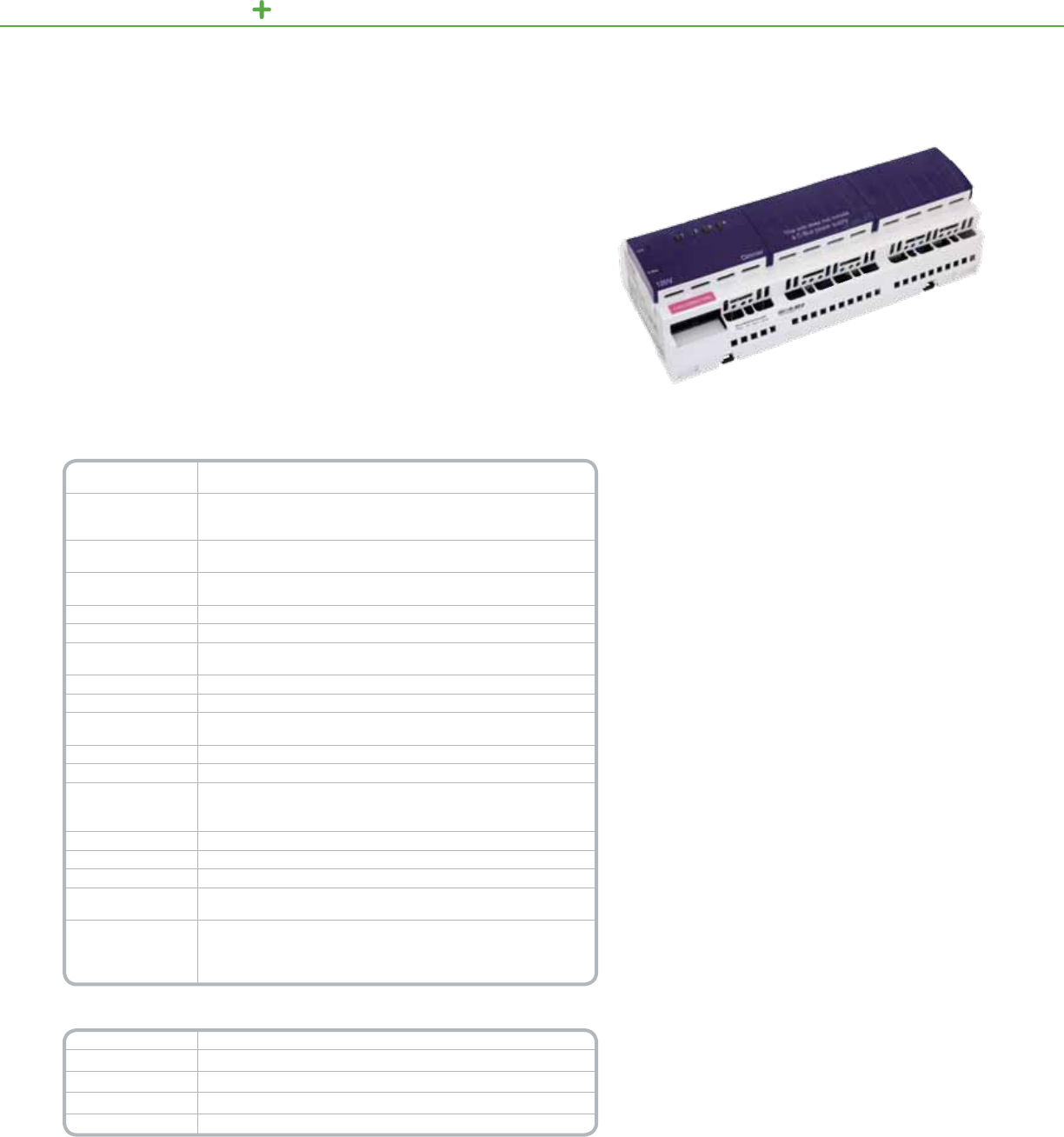
TheC-BusPhaseAngleDimmersareC-Buscontrolledoutputunitssuitablefor
incandescentandcompatiblelow-voltagelighting.Theseunitsaredesignedtobe
rackmountedinsuitableDINstyleenclosures.
Eachoftheunit’schannelscanindependentlycontrolloadstocreatedynamic
lightingscenes.Thesedimmerunitsautomaticallycompensateforvoltageand
frequencyuctuationsandemployadvancedphase-controltechniquestoreduce
ickerandincreaselamplife.
Product Features
•Suitableforusewithincandescentlampsandlow-voltage
lampsutilizingironcoreorelectronictransformers
•Specializeddimmingmodes—softturnOn/Offandlinearized
brightnesscontrol
•Cansupplyupto200mAtotheC-Busnetwork
(modelsSLC5504TD4AandSLC5508TD2Awithbuilt-in
powersupply)
•Integralthermaloverloadprotectiononeachchannel
•IndividualchannelscanbeturnedON/OFFatunitorvia
C-Buscommands
•LEDsindicatethestatusofthenetworkattheunit,thestatus
oftheunit’sloadandpower,andthestatusofeachchannel
•Non-volatilememorystoresoperatingstatusforrecovery
fromapoweroutage
PhaseAngleDimmerUnitwithPowerSupply
C-Bus
Phase Angle Dimmers
Technical Information
Nominal Voltage
Requirements
15–36Vdc@18mAfromtheC-Busnetworkwhenthereisnoexternal
powersource
Nominal Line
Supply Voltage and
Frequency
110–120Vac,±10%,50–60Hz
C-Bus Source
Current 200mA(Models:SLC5508TD2A,SLC5504TD4A)
Load Rating per
Channel 2A(SLC5508TD2A),4A(SLC5504TD4A)
Minimum Load 15Wperchannel
Efciency 98%
Number of Units
per Network
UsetheC-BusCalculator,asoftwareutility,todeterminethetotal
networkcurrentload
C-Bus Connections (2)RJ-45connectors,CAT5UTPcablerequired
Cable 15.75in.(400mm)patchleadincluded
Remote Override
Connection RJ-45connector
Power Terminals Accommodate16–12AWGcable
Load Terminals 2x#14–16gaugeor1x#12gauge
Status Indicators
Channel:(1)perchannel
Unit(1):Unitpower
C-Bus(1):PowerlevelsandpresenceofC-Busclock
Dimensions 8.5in.(L)x3.6in.(W)x2.5in.(H))[216mm(L)x92mm(W)x63mm(H)]
Weight 23oz(647g)
Mounting DINrail,12Mwide
Operating
Environment 32°Fto113°F(0°Cto45°C)RH:95%,noncondensing
Standards
UL508IndustrialControlEquipment
CSA22.2Spec205SignalEquipment
FCC:Part15.101,ClassBDigitalDevice
EN61000-4-2ImmunitytoESD
*For Diagram see technical section page 153
Catalog Number Description
SLC5504TD4A Four-Channel4ADimmer,withpowersupply
SLC5504TD4AP Four-Channel4ADimmer,withoutpowersupply
SLC5508TD2A Eight-Channel2ADimmer,withpowersupply
SLC5508TD2AP Eight-Channel2ADimmer,withoutpowersupply
C-BUS LIGHTI NG CONTROL OUTPUT UNITS
119

C-BUS LIGHTING CONTROL OUTPUT UNITS
TheC-BusDigitalAddressableLightingInterface(DALI)Gatewayprovidesan
isolatedtwo-waycommunicationspathbetweenaC-BusnetworkandtwoDALI
networks,makingitpossibletousetheC-Busnetworktocontrolandmonitor
DALIballasts.
TheDALIgatewayconstantlymonitorsbothDALInetworksandcandetectand
reportfaultylampsinuorescentballastsornon-functionalDALIballasts.
Product Features
•Providestwo-waycommunicationsbetweenC-BusandDALI
networks,routingselectedmessagesfromonetotheother
•UnitistransparentandinvisibletoDALIballasts
•Pre-programmedC-BustoDALIandDALItoC-Bus
addressingstructure
•Unit/CommsandC-BusLEDsshowthestatusofdata
transmissions,theunit’spower,theC-Busnetwork’spower,
andthepresenceoftheC-Busclock
•Software-selectablenetworkburdenandnetworkclock
•Standardbuilt-inC-Busnetworkconnectors:(2)RJ-45
•Non-volatilememorytostoreoperatingstatusforrecovery
fromapoweroutage
•Receivesdataandpoweroverthenetwork,sotheunitdoes
notrequirepowerpacksorline-voltageconnections
DALIGateway
C-Bus
2 Channel DALI Gateway
Technical Information
Nominal Voltage
Requirements 15–36Vdc@32mA,drawnfromtheC-Busnetwork
Electrical Isolation 3.75kVRMS,frominterfacetoC-Busnetwork
Number of Units
per Network
UsetheC-BusCalculator,asoftwareutility,todeterminethetotal
networkcurrentload
C-Bus Connections Built-inRJ-45sockets(2)forconnectiontotheC-Busnetwork
DALI Connections Twoscrew-typeterminalblocksaccommodating16–12AWGcable
(2x1.31mm2or1x2.5mm2)
Cable (1)15.75in.(400mm)patchleadincluded
Status Indicators Unit/Comms:Unitpoweranddatatransmission
C-Bus:PowerlevelsandpresenceofC-Busclock
Dimensions 3.4in.(L)x2.8in.(W)x2.6in.(H)[85mm(L)x72mm(W)x65mm(H)]
Weight 4.6oz(130g)
Mounting DINrail,4Mwide
Operating
Environment 32°Fto113°F(0°Cto45°C)RH:95%,noncondensing
Standards
UL:Listed916EnergyManagementEquipment
CSA22.2Spec205SignalEquipment
FCC:Part15.101,ClassBDigitalDevice
EN61000-4-2ImmunitytoESD
*For Diagram see technical section page 153
Catalog Number Description
SLC5502DAL Two-ChannelDALIGateway
120
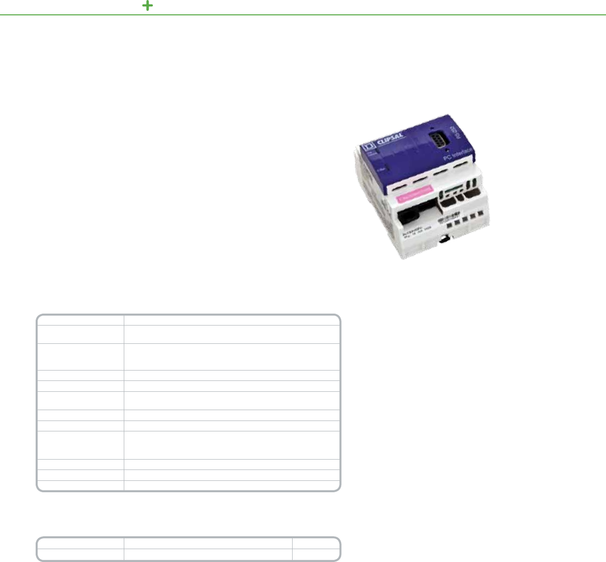
C-BUS LIGHTING CONTROL OUTPUT UNITS
TheC-BustoDMXOneWayGatewayconvertsuptotwelvereceivedlightinggroup
address/levelstoDMX-512-Adata,andthentransmitsthedatatoaconnected
DMX-512-Anetwork.
UsingtheDMXGateway,C-BuscancontrolthefollowingDMX-512-A
baseddevices:
• LEDlightingcontrollersthatincludecontrolinputsfordimmingandcolormixing
• Strobes
• Fiberopticlighting
• Fogmachines
• Animatedcharacters
• Motorizedxtures
Product Features
•EnablesonewaycommunicationbetweenC-Busand
DMX-512-Anetworks
•Custom-congurableaddressmapping.(OneC-Busaddress
cancontrolmultipleDMX512slots)
•DrawspowerfromtheC-Busnetwork
•LEDsdisplaythestatusofthepower,communications,and
theC-Busnetwork
•RemoteOverride(ONandOFF)options
•Software-selectablenetworkburdenandnetworkclock
•Twostandardbuilt-inC-BusRJ-45networkconnectors
•Non-volatilememoryprotectsunitagainstpoweroutages
•ConguredbyusingtheC-BusToolkitsoftware
DMXGateway(SLC5500DMX)
C-Bus
DMX Gateway
Technical Information
DMX protocol DMX512-A
Maximum length of
DMX cable in network 1493ft.(455meters)
Maximum number
of units on a C-Bus
network
30
C-Bus input power 15–36Vdc,65mA,class2
DMX output 6.4Vpp,12mA,class2
C-Bus AC input
impedance 40kΩat1kHz
Electrical isolation 2500VbetweenC-BusandDMX
Mounting type DINrail,4Mwide
Connectors
2RJ-45forC-Busnetwork
1ScrewterminalblockforDMX**
1XLR5-pinfemalepanelconnectorontheDMXcableassembly
Weight 0.27lbs(121grams)
Operating temperature 32°Fto113°F(0°Cto45°C)
Humidity 10%to95%noncondensing
*For Diagram see technical section page 153
** Do not connect the DMX Gateway between other devices. The DMX Gateway must be at the Position 1 on the
DMX network. Use a daisy-chain conguration.
Catalog Number Description Quantity
5500DMX C-BustoDMXOneWayGateway 1
121
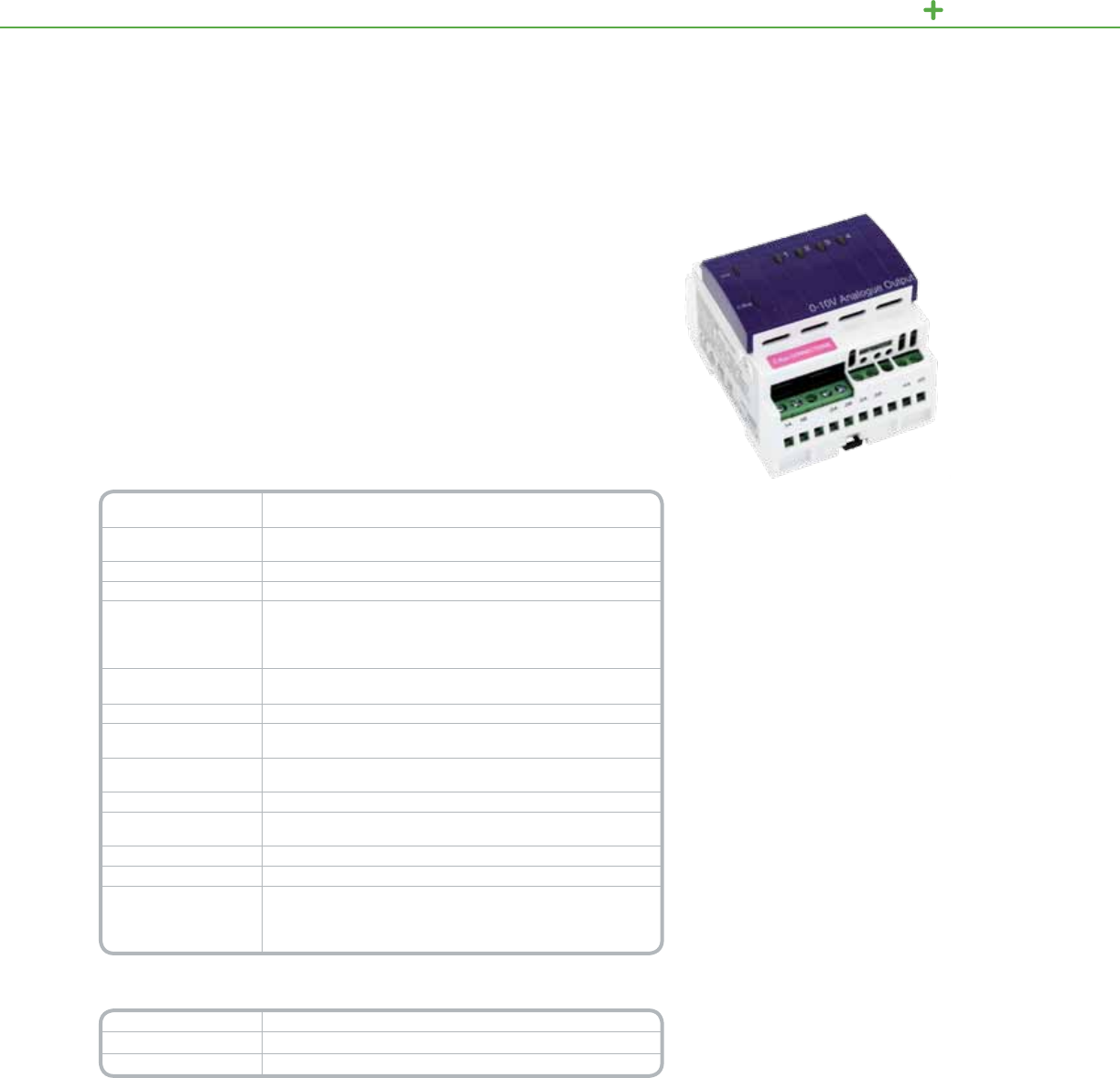
C-BUS LIGHTING CONTROL OUTPUT UNITS
TheC-Bus4Channel0-10VDimmerprovidesfourchannelsofanalog0-10Vdcthat
canbeusedasthecontrolsignalsforvariousperipheraldevices,includingcertain
LEDdriversandelectronicallydimmableuorescentlightingballasts.
Thisanalogoutputunitcansinkorsourcecurrentasappropriatefortheconnected
load,andproduces0–10VinresponsetocommandsfromtheC-Busnetwork.
Eachchannelcanbeindividuallyadjustedfrom0to100%attheunit,byC-Bus
commandsorremotely,andeachcandrivemultipleloads.
Product Features
•Producesfourindependentlycontrollablechannelsof
0-10Vdcforcontrollingdimmablelightingballastsor
otherloads
•Eachchannelcansinkorsourcecurrentanddrive
multipleloads
•TwoRJ-45connectorsfacilitatequickconnectionstothe
C-Busnetworkandbetweensimilarunits
•UnitandC-BusLEDsshowthestatusoftheunitand
thenetwork
•Non-volatilememorystoresoperatingstatusforrecovery
fromapoweroutage
•120or277Vacmodelsavailable
4channel0-10VFluorescentBallastDimmer
C-Bus
4 Channel 0 – 10V Dimmer
Technical Information
Power Requirements C-Bus:15–36Vdc@22mArequiredfornormaloperation.
Power:120Vor277Vacconnection,10W
Number of Units
per Network
UsetheC-BusCalculator,asoftwareutility,todeterminethetotal
networkcurrentload
Electrical Isolation 3.5kVRMSfromC-Bustotheline
Output Voltage Range 0–10Vdc(±0.5)
Output Rating
Sourcing:2.5mA(minimumof4kohm)
Sinking:15mAatVout=0V
8mAatVout=10V
[i.e.,I=15-(0.7xVout)mA]
Status Indicators Unit:Unitpower
C-Bus:Networkvoltagelevelandpresenceofsystemclock
C-Bus Connection (2)RJ-45terminals
Cable (1)15.75in.(400mm)CAT5patchleadwithpre-terminated
RJ-45connectors
Output Terminals Accommodates2X16AWGor1X12AWGcable
(2x1.3mm2or1x3.3mm2)
Mounting DINrail,4Mwide
Dimensions 3.35in.(L)x2.83in.(W)x2.56in.(D)
[85mm(L)x72mm(W)x65mm(D)]
Weight 8.64oz(245g)
Operating Environment 32°Fto122°F(0°Cto50°C)RH:95%,noncondensing
Standards
UL:Listed916EnergyManagementEquipment
CSA22.2Spec205SignalEquipment
FCC:Part15.101,ClassBDigitalDevice
EN61000-4-2ImmunitytoESD
*For Diagram see technical section page 154
Catalog Number Description
SLCLE5504TAMP AnalogOutputUnit,0–10V,120V
SLCLE5504HAMP AnalogOutputUnit,0–10V,277V
122
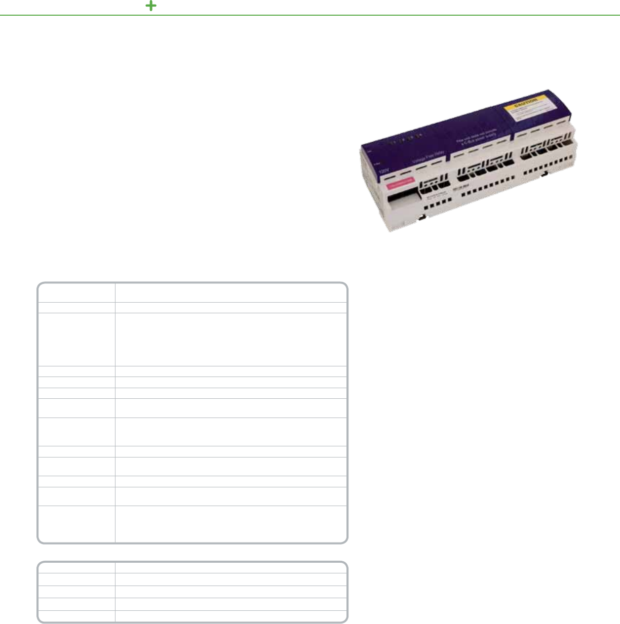
C-BUS LIGHTING CONTROL OUTPUT UNITS
TheC-BusRelaysareDIN-railmountedunitswithtwelveindependent,voltage
free,relaycontactsforgeneralswitchingapplications.Theyaresuitableforuse
withresistive,inductive,incandescentanduorescentloads.
Eachchannelisindependentlycongurableandfeaturesazerocrossing
magneticallylatchingrelaydesignedforswitchingtheharshelectricalloads
associatedwithtoday’shighefciencylightingsystems.Localtogglebuttonsare
providedoneachunittoallowindividualchannelstobetoggledateachunitorvia
C-Busnetworkcommands.RemoteONandOFFfacilitiesareavailable,permitting
allchannelstobeturnedONorOFFwithoutC-BusNetworkcommunications.
Product Features
• Fourortwelveindependentlyoperatingvoltage
freerelaycontacts
• Twoconvenientbuilt-inC-Busnetworkconnectors
(RJ-45)
• Unitsavailablebothwithandwithouta200mA
powersupply
• Non-volatilememorystoresoperatingstatusfor
recoveryfrompoweroutage
• LEDIndicatorsshowthestatusofthenetwork
andtheunit
• LoadRating
»Resistive-10A
»Inductive-10A
»Fluorescent-10A
»Motor-2A
10AmpRelay
C-Bus
10 Amp Relay Unit
Technical Information
Nominal Supply
Voltage
110–120V(SLC5512TRVFandSLC5512TRVFP)
277V(SLC5512HRVFandSLC5512HRVFP)
Frequency Range(s) 50–60Hz
C-Bus Supply
Voltage
15–36Vdc@18mArequiredforprogrammingwhenelectricalpower
sourceisnotconnected
Sources200mAtotheC-BusNetworkwithelectricalpowersource
connected(non-powersupplyversions)
15–36Vdc@0mAisrequiredforprogrammingwhenelectricalpower
sourceisconnected
Electrical isolation 3.75kVRMSfromC-Bustopowersource
Contact Type VoltageFree,magneticallylatched
C-Bus Connections 2RJ-45connectors,CAT5UTPcablereq.
Electrical Terminals Accommodates(1)#12orupto(2)#14–16AWG
(3.31mm2-(2)x2.08-1.31mm2)
Status Indicators
C-BusIndicator
UnitStatusIndicator
LoadIndicator
Dimensions 12Channel—8.46x3.35x2.56inches(215x85x65mm)
Weight 12Channel—21oz(600g)(w/oPowerSupply)28oz(800g)
(w/PowerSupply)
Mounting DINrail,12Channel—12Mwide
Operating
Environment 32°Fto113°F(0°Cto45°C)RH:95%,noncondensing
Standards
UL:Listed508IndustrialControlEquipment
CSA22.2No.14IndustrialControlEquipment
FCC:Part15,ClassBDigitalDevice
EN61000-4-2ImmunitytoESD
Catalog Number Description
SLC5512TRVF 12Channel,120V,10Aw/powersupply
SLC5512TRVFP 12Channel,120V,10Aw/opowersupply
SLC5512HRVF 12Channel,277V,10Aw/powersupply
SLC5512HRVFP 12Channel,277V,10Aw/opowersupply
123
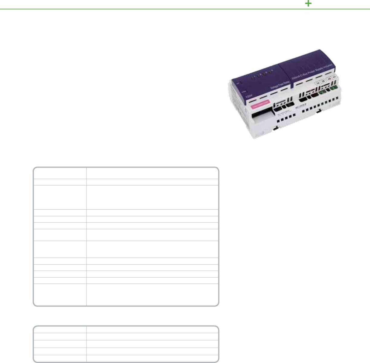
C-BUS LIGHTING CONTROL OUTPUT UNITS
Product Features
• Fourindependentlyoperatingvoltagefree
relaycontacts
• Twoconvenientbuilt-inC-Busnetwork
connectors(RJ-45)
• Unitsavailablebothwithandwithouta
200mApowersupply
• Non-volatilememorystoresoperatingstatus
forrecoveryfrompoweroutage
• LEDIndicatorsshowthestatusofthe
networkandtheunit
• RemoteON/OFFoverridecapabilities
• LoadRating(4channel20Ampratedrelay)
»Resistive20A
»Inductive20A
»Fluorescent20A
»Motor4A
4Channel20ARelay
TheC-Bus20AmpRelaysareDIN-railmountedunitswithfourindependent,voltage
free,relaycontacts.Theyaresuitableforusewithresistive,inductive,incandescent
anduorescentloads.
Eachchannelisindependentlycongurableandfeaturesazerocrossingmagnetically
latchingrelaydesignedforswitchingtheharshelectricalloadsassociatedwith
today’shighefciencylightingsystems.Localtogglebuttonsareprovidedoneach
unittoallowindividualchannelstobetoggledateachunitorviaC-Busnetwork
commands.RemoteONandOFFfacilitiesareavailable,permittingallchannelstobe
turnedONorOFFwithoutC-BusNetworkcommunications.
C-Bus
20 Amp Relay Units
Technical Information
Nominal Supply Voltage 110–120V(SLC5512TRVFandSLC5512TRVFP)
277V(SLC5512HRVFandSLC5512HRVFP)
Frequency Range(s) 50–60Hz
C-Bus Supply Voltage
15–36Vdc@18mArequiredforprogrammingwhenelectrical
powersourceisnotconnected.
Sources200mAtotheC-BusNetworkwithelectricalpower
sourceconnected.
Electrical isolation 3.75kVRMSfromC-Bustopowersource
Contact Type VoltageFree,magneticallylatched
C-Bus Connections 2RJ-45connectors,CAT5UTPcablereq.
Electrical Terminals Accommodates(1)#12orupto(2)#14–16AWG
(2x1.3mm2or1x3.3mm2)
Status Indicators
C-BusIndicator
UnitStatusIndicator
LoadIndicator
Dimensions 8.46x3.35x2.56inches(215x85x65mm)
Weight 20.46oz(580g)
Mounting DINrail,12Mwide
Operating Environment 32°Fto113°F(0°Cto45°C)RH:95%,noncondensing
Standards
UL508IndustrialControlEquipment
CSA22.2Spec205SignalEquipment
FCC:Part15.101,ClassBDigitalDevice
EN61000-3-2LowFrequencyEmissions
*For Diagram see technical section page 154
Catalog Number Description
SLC5504TRVF20 4Channel,120V,20Awithpowersupply
SLC5504TRVF20P 4Channel,120V,20Awithoutpowersupply
SLC5504HRVF20 4Channel,277V,20Awithpowersupply
SLC5504HRVF20P 4Channel,277V,20Awithoutpowersupply
124

C-BUS LIGHTING CONTROL OUTPUT UNITS
TheC-BusChangeoverRelaysareDIN-railmounteddeviceswithfourindependent,
voltagefree,changeoverrelaycontacts.
SchneiderElectricC-BusChangeoverRelaysaredesignedtooperatethree-
speedmotorsandtwo-waymotorcontroldevices.Someoftheirmostcommon
applicationsincludeoperatingmotorizedblinds,shutters,curtainsandskylights
(open/closed)wheretheyprovideamuchsimpleralternativetotraditionaland
obtrusiverelayinterlockingsystems.
Product Features
• Four(4)isolatedindependentlyoperating
relaychannels
• Two(2)convenientbuilt-inC-Busnetwork
connectors(RJ-45)
• Non-volatilememorystoresoperatingstatusfor
recoveryfrompoweroutage
• LEDIndicatorsshowthestatusofthenetworkand
theunit
• ChangeoverRelaysratings:(120VacMax)
• 2AExhaustfans(shadedpoleinductionmotors)
• 2ACeilingfans(split-phaseinductionmotors)
ChangeoverRelayUnit
C-Bus
Changeover Relay Units
Technical Information
Nominal Supply Voltage 110–120V(SLC5504TRVFCandSLC5504TRVFCP)
250–277V(SLC5504HRVFCandSLC5504HRVFCP)
Frequency Range(s) 50–60Hz
C-Bus Supply Voltage
15–36Vdc@18mArequiredforprogrammingwhenelectrical
powersourceisnotconnected.
Sources200mAtotheC-BusNetworkwithelectricalpowersource
connected.
Electrical isolation 3.75kVRMSfromC-Bustopowersource
Contact Type Changeover,Non-latching
C-Bus Connections 2RJ-45connectors,CAT5UTPcablereq.
Electrical Terminals Accommodates(1)#12orupto(2)#14–16AWG
(2x1.3mm2or1x3.3mm2)
Status Indicators
C-BusIndicator
UnitStatusIndicator
LoadIndicator
Dimensions 5.67x3.35x2.60inches(144x85x65mm)
Weight 13oz(370g)(WithPowerSupply)
17oz(490g)(WithoutPowerSupply)
Mounting DINrail,8Mwide
Operating Environment 32°Fto113°F(0°Cto45°C)RH:95%,noncondensing
Standards
UL:Listed508IndustrialControlEquipment
CSA22.2No.14IndustrialControlEquipment
FCC:Part15,ClassBDigitalDevice
*For Diagram see technical section page 154
Catalog Number Description
SLC5504TRVFC 4Channelchangeoverrelayunit120Vac,withpowersupply
SLC5504HRVFC 4Channelchangeoverrelayunit277Vac,withpowersupply
125

C-BUS LIGHTING CONTROL OUTPUT UNITS
TheC-Bus8ChannelLowVoltageRelayisusedforswitchingloadssuchas
irrigationsolenoids,andLVairconditioningdampers.TheRelaymayalsobeused
forswitchingLVpulsesignalcontrolloadsintothirdpartyproducts.
TheC-Bus8ChannelLowVoltageRelayisaC-Busoutputdevicethatcontrols
eightlowvoltagerelaychannels.TheunitispoweredfromtheC-Busnetworkand
requiresnootherpowersource.Theunitcanbedaisychainedorplacedattheend
ofaC-Busnetwork.
Product Features
• Software-selectableC-Bussystemclock
• Synchronizedatacommunicationonthe
C-Busnetwork
• SwitchLowVoltageLoads
• Controlthirdpartyproducts
• 2StatusIndicatorLights
LowVoltageRelay
C-Bus
Low Voltage Relay
Technical Information
C-Bus network
supply voltage 15to36Vdc@32mArequiredforprogrammingandoperation
Maximum units per
C-Bus network 50
C-Bus connections 2wire,twistedpair
Warm up time 5seconds
Load rating per relay
channel
2Aat30Vdcmaximumor30VacRMSsuitableforresistiveand
inductiveloads
Contact type Voltagefree,SPDT(changeover)
Relay terminal
connections Ccommon,N/Onormallyopen,N/Cnormallyclosed
Types of electrical
connection
Fixedloadterminalfor:1x1.0mm²wirepertunnel(13AWG),
Fixedaux(C-Bus)connectorsfor:2x1.5mm²
Dimensions (W x H x D) 8.66x3.15x1.50in.(220x80x38mm)
Weight 11.64oz(330g)
Mounting mode Surface:4mountingscrewholesandkeyholemount
EMC environment EnvironmentA
Operating ambient
temperature 32°Fto122°F(0°Cto50°C)
Storage temperature 32°Fto140°F(0°Cto60°C)
Operating humidity 10to90%noncondensing
Standards:
CSAC22.2No.205—SignalEquipment
UL916—EnergyManagementEquipment,FCCPart
15—ClassBDigitalDeviceforHomeorOfceUse
*For Diagram see technical section page 155
Catalog Number Description
SLC5108RELVP 8ChannelLowVoltageRelay
126

C-BUS LIGHTING CONTROL OCCUPANCY CONTROLLER
TheOccupancyControllerfromSchneiderElectrichastwolightingcontrolrelays,amotionsensor
powersupply,twoauxiliaryinputswitches,twotimers(oneperrelay),andtworelaydefaultmode
switchesassociatedwitheachrelay.TheoccupancycontrollerincludesaC-Businterfaceallowingfor
seamlessintegrationintoanyC-Busnetwork.Theoccupancycontrollerprovidesasimpleall-in-one
solutionfordimming,on-offoperation,andpoweringofsensors.Itoperatesoverawiderangeof
inputvoltages(100–277Vac)andisdesignedforabove-ceilinginstallation.Theoccupancycontroller
isidealforin-roomoccupancycontrolapplicationssuchasclassrooms,open-ofcespace,executive
ofcesandconferencerooms.ThecontrollermaybeconguredforC-Busconnectivityorina
standaloneoperationmodeusingthestandalonejumper.
Technical Information
Power supply voltage 100–277Vac
Power supply frequency 50–60Hz
Motion sensor power supply Poweroutput280mA(140mAperdetectorconnection)
Power supply rating 24VdcSELV/Class2
Nominal C-Bus Voltage Requirements
(if connected to C-Bus network)
Draws15–36VdcSELV/Class2@25mAfromtheC-Busnetwork,
enablingconguration.
Max units per network 80
C-Bus AC Impedance 80KΩ@1KHz
Relay rating Resistive:16Aat277Vac,Incandescent/Tungsten:12Aat277Vac
Fluorescent(UL)Standardballast:10Aat277Vac(inductive0.4–0.5pf)
Ballast control power supply
(5752PP/2R/2D) Analog:1–10Vdc200mA,DSI:0–12Vdc200mA,DALI:0–12Vdc250mA
Maximum ballasts per control
(57PP/2R/2D) 100forDALIorDSI.50for0–10Vanalog
Connections
(Screw-type Phoenix-style connectors)
Input:14–12AWG(2.5–4mm²),Relayoutput:14–12AWG(2.5–4mm²)
Motiondetector:3-pin,1perrelaypresent,Auxiliaryinput:2-pin,1perrelaypresent,
C-Bus:4-pin
Maximum operating temp. 122°F(50°C)approvedforuseinaplenum
Operating humidity 10to90%RH(non-condensing)
Dimensions (H x W x D) 8.0x7.87x2.36in.(203x200x60mm)
Standards (Title) CSAC22.2No.205(SignalEquipment),UL916(EnergyManagementEquipment)
FCCPart15(ClassBDigitalDeviceforHomeorOfceUse)
*For Diagram see technical section page 26
Catalog
Number
Description
5752PP/2R OccupancyControllerwith2relaysratedat16ampseach
5752PP/2R/2D
OccupancyControllerwith2relaysratedat16ampseachand2ballastcontroloutputs:DSI,DALI,or0-10V*
*Check with your local C-Bus or Schneider Electric sales representative for availability of units that can control electronic ballasts.
Compatible Sensors
Sensor Description
SLSCPS1000 CeilingmountPIRmotionsensor,
360°detectionpattern,isolatedrelay
SLSCUS2000 CeilingmountUltrasonicmotionsensor,
360°detectionpattern,isolatedrelay
SLSCDS2000
CeilingmountDual-technology
(PIRandUltrasonic)motionsensor,
360°detectionpattern,isolatedrelay
SLSCDU800 CeilingmountUltrasonicmotionsensor,
180°detectionpattern,isolatedrelay
Product Features
•Inputvoltagerange:
100–277Vac50/60Hz
•Onemotiondetectorinput
terminalforeachrelay
•24Vdcpowersupplyfor
themotiondetectors
•Oneauxiliaryinputswitch
terminalandtimerfor
eachrelay
•Onerelayfail-safemode
switchforeachrelay
•Remoteoverrideon/off
capability
•Class1andClass2
voltageisolation
•C-Busconnectivityoption
Occupancy Controller with
C-Bus Connection Option
The5752PPSeries
OccupancyController
Sensor Description
SLSCDS800
CeilingmountDual-technology
(PIRandUltrasonicmotionsensor,
180°detectionpattern,isolatedrelay
SLSWPS1500 WallmountPIRmotionsensor,
110°detectionpattern,isolatedrelay
SLSWUS1500 WallmountUltrasonicmotionsensor,
isolatedrelay
SLSWDS1500 WallmountDual-technology;PIRand
ultrasonicmotion
127
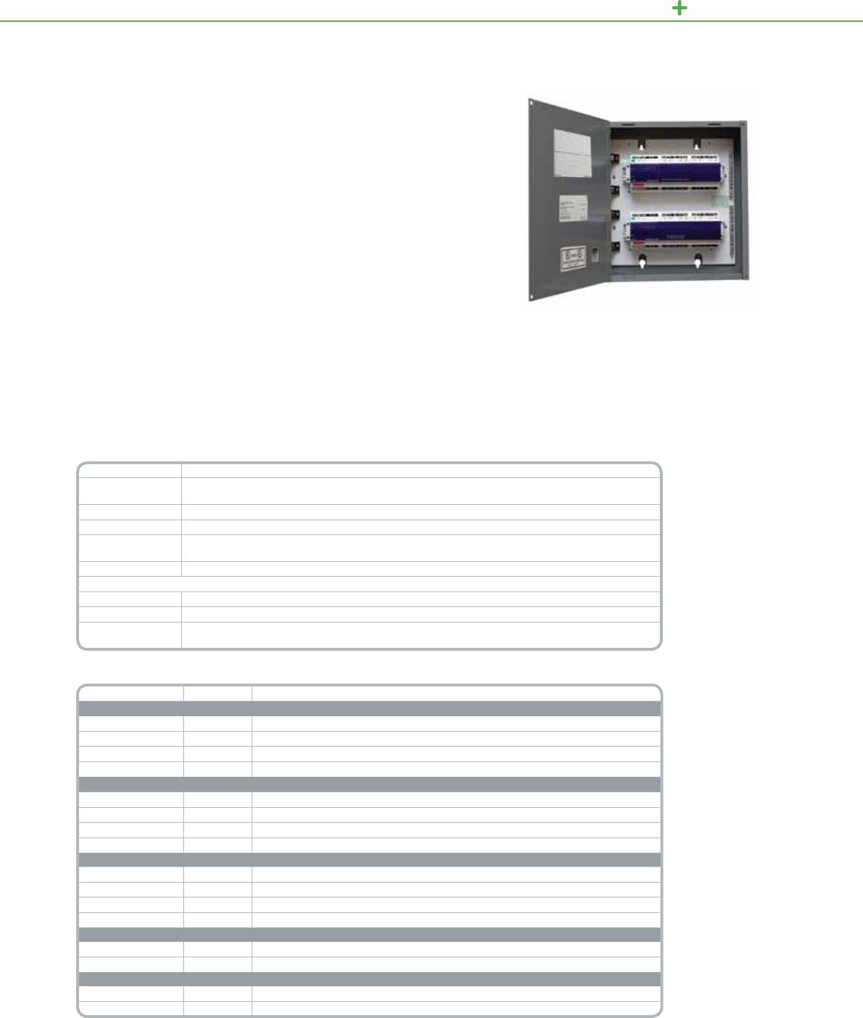
C-BUS LIGHTI NG CONTROL AREA LIGHTING PANEL
TheC-BusAreaLightingPanelsareideallysuitedtomeetlightingcontrolenergy
coderequirementsinclassrooms,ofcesandothersmallspaces.Thesedevices
providetheabilitytointegratekeypads,occupancysensing,lightleveldetection,
andswitchingwithoutthemessofcomplexcontrolwiring.AsimpleCAT-5cableis
allthatisrequiredtoconnectsensorsandkeypads.
AreaLightingPanelscanoperateasindependentstand-aloneislandsoraspart
ofanentirefacilitywidelightingcontrolsystem.Enclosurescaneasilybemounted
inelectricalclosetsorinceilingspaces.Theyincludeallnecessaryconnections
andareULListed.AreaLightingPanelscanalsobeusedinconjunctionwith
Powerlinkpanels.
Product Features
• Relaymodels:Fouror
eightrelayoutputs,
rated20A
• 0–10Voutputsfor
controlof0–10V
dimmableuorescent
ballast(suitableforuse
withMARK7®,Sylvania
Quicktronic®,and
UniversalSuperDim®)
• Integralneutraland
groundbarterminalstrips
• Plenum-ratedforceiling
applications
• Bypassmodetofacilitate
quickstartup
• MeetsNECArticle409
• ULListed508A,SCCR
currentratings:65kA
(120V),14kA(277V)
• SurfaceMountNEMA1
Enclosure
8channel20ARelayAreaLightingPanel
C-Bus
Area Lighting Panels
Technical Information
Rated Voltage 120Vand277V50/60Hz
Number of Units
per Network UsetheC-Buscalculator,asoftwareutilitytodeterminetotalnetworkcurrentloadorToolkitsoftware
Electrical isolation 3.5kVRMSfromC-Bustotheline
Relays 20A
Short Circuit
Current Rating 65kA(120V),14kA(277V)
C-Bus Connections RJ45
Dimensions
12M Enclosure 12.78in.x9.09in.x4.0in.
24M Enclosure 14.50in.x14.94in.x4.0in.
Standards UL:Listed508A,FCCpart15.101,ClassBDevice
EN61000-4-2ImmunitytoESD
Catalog Number Enclosure Description
4 Channel 20A Relay Models
SLCZ042000T 12M 4Channel20ARelay@120Vwithpowersupply*
SLCZ042000H 12M 4Channel20ARelay@277Vwithpowersupply*
SLCZ042000TP 12M 4Channel20ARelay@120Vwithoutpowersupply
SLCZ042000HP 12M 4Channel20ARelay@277Vwithoutpowersupply
8 Channel 20A Relay Models
SLCZ082000T 24M 8Channel20ARelay@120Vwithpowersupply*
SLCZ082000H 24M 8Channel20ARelay@277Vwithpowersupply*
SLCZ082000TP 24M 8Channel20ARelay@120Vwithoutpowersupply
SLCZ082000HP 24M 8Channel20ARelay@277Vwithoutpowersupply
4 Channel 20A Relay Models with 0-10V Output Units
SLCZ04204AT 24M 4Channel20ARelay@120Vwithpowersupplyand4Channel0–10VOutputUnit*
SLCZ04204AH 24M 4Channel20ARelay@277Vwithpowersupplyand4Channel0–10VOutputUnit*
SLCZ04204ATP 24M 4Channel20ARelay@120Vwithoutpowersupplyand4Channel0–10VOutputUnit
SLCZ04204AHP 24M 4Channel20ARelay@277Vwithoutpowersupplyand4Channel0–10VOutputUnit
4 Channel Phase Angle Dimmer Models
SLCZ00004DT 12M 4ChannelPhaseAngleDimmer@120Vwithpowersupply
SLCZ00004DTP 12M 4ChannelPhaseAngleDimmer@120Vwithoutpowersupply
4 Channel 20A Relay Models with Phase Angle Dimmer Units
SLCZ04204DT 24M 4Channel20ARelay@120Vwithpowersupplyand4channelphaseangledimmerunit
SLCZ04204DTP 24M 4Channel20ARelay@120Vwithoutpowersupplyand4channelphaseangledimmerunit
*For stand-alone applications order unit with power supply
AreaLightingPanelscanbeusedforon/offswitching,steppeddimmingorcontinuousdimmingapplications.
Allrelaysfeaturerugged20Aratedcontactsforswitchingelectronicballastloads.Modelswithcontinuous
dimmingcapabilitiesareratedforeitherNECClass1orClass2wiring.
128
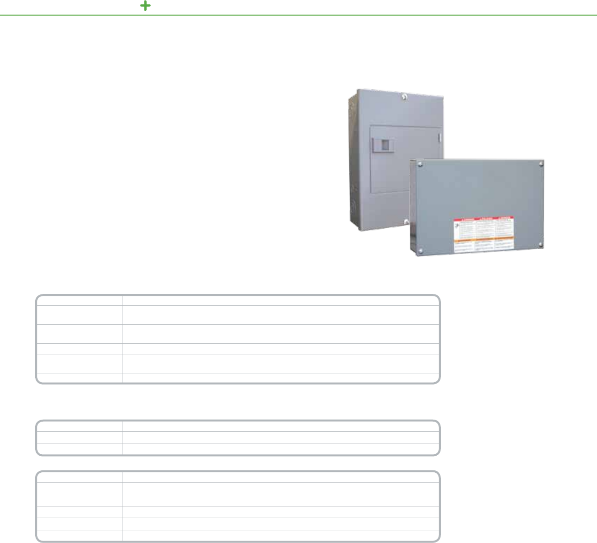
C-BUS LIGHTING CONTROL ENCLOSURES
TheC-BusEnclosuresprovideahousingforvariousC-BusDIN-mounteddevices.
The8Mand12Menclosuresarespecicallydesignedfordistributedapplications
thatrequirephysicalproximitybetweenDINunitsandkeypads,sensorsor
controlledloads.
The8MenclosureconsistsofaboxwithacoverandaDINrailformountingone
8Mortwo4Munits.Theenclosurealsohasprovisionsformountingneutraland
groundbars.
The12MenclosureconsistsofaboxwithacoverandaDINrailformountingthree
4MC-Busunits,one8Munitplusone4Munitorone12Munit.Theenclosurealso
hasfactorymountedneutralandgroundbars.
Product Features
• Surface-mountNEMA1
enclosure
• Weldedsheetsteelwith
knockouts
• Graybakedenamel,
electrodeposited
overcleaned,
phosphatizedsteel
• Triple-leadcover
screwsforfast
installationofcover
• DINrail,suitablefor
mountingDINmodules
• ULListed
8MEnclosure
C-Bus
8M/12M Enclosures
Technical Information
Type NEMA1
DIN Module Capacity 8M:One8Mortwo4MC-Busunits
12M:One12M,one8M+one4Morthree4MC-Busunits
Dimensions 8M:12.57in.(L)x8.88in.(W)x3.8in.(D)[319mm(L)x226mm(W)x97mm(D)]
12M:12.78in.(W)x9.09in.(T)x4.0in.(D)[325mm(L)x231mm(W)x102mm(D)]
Mounting DINrail
Weight 8M:8.4lb(3.81kg)
12M:11.7lb(5.3kg)
Standards ULStandard50Enclosuresforelectricalequipment
*For Diagram see technical section page 155
Catalog Number Description
SLC8M 8MDINEnclosure
SLC12MSG 12MDINEnclosureê
Accessories Description
PK7GTA Ground/NeutralBar®
PKGTAB NeutralInsulatorKit®
SLC4CSF8 FillerPlate,4M
PK7GTA Ground/NeutralBar
PKGTAB NeutralInsulatorKit
Includes one ground bar, one ller plate, cable ties and mounts for wire management.
êIncludes one DIN rail, one ground bar, and one insulated neutral terminal bar pre installed on the mounting pan.
Also included are 2 ft. of exible, Class 2 barrier, four pan mounting screws, four cover mounting screws, and two DIN rail stops.
®Additional terminal bar and insulator for devices that require neutral connection points for loads, such as a relay unit.
Note: The C-Bus 8M Enclosure will accept one additional terminator bar (PK7GTA) intended for load neutral connections. This is to be used when
the C-Bus unit mounted inside requires neutral connection points for loads, i.e. a relay unit. Use in conjunction with a Neutral Insulator Kit (PKGTAB)
12MEnclosure
129
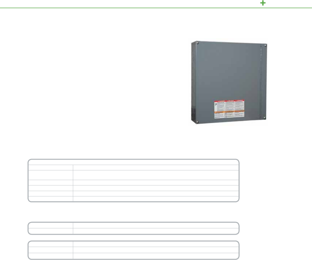
C-BUS LIGHTING CONTROL ENCLOSURES
TheC-BusEnclosuresprovideahousingforvariousC-BusDIN-mounteddevices.The
24Menclosureisspecicallydesignedfordistributedapplicationsthatrequirephysical
proximitybetweenDINunitsandkeypads,sensorsorcontrolledloads.
Suitableforsurfacemounting,the24Menclosureconsistsofaboxwithahinged
doorandtworowsformountingC-BusDIN-mountedunits.Eachrowcanholdone
12Munit,one8Munitplusone4Munit,orthree4Munits.Theenclosurealsohas
provisionsforadditionalneutralandgroundbars.
Product Features
• Surface-mount
NEMA1enclosure
• Weldedsheetsteel
withknockouts
• Graybakedenamel,
electrodeposited
overcleaned,
phosphatizedsteel
• Triple-leadcover
screwsforfast
installationofcover
• Hingedtrimfor
easyaccess
• DINrail,suitablefor
mountingC-Bus
DIN-mountedC-Bus
units.Eachrowcan
holdone12Munit,one
8Munitplusone4M
unit,orthree4Munits.
• ULListed
24MEnclosure
C-Bus
24M Enclosure
Technical Information
24M Enclosure
Type NEMA1
DIN Module Capacity TworowsformountingC-BusDIN-mountedunits.Eachrowcanholdone12Munit,one8Munitplus
one4Munit,orthree4Munits
Dimensions 14.50in.(W)x14.94in.(T)x4.0in.(D)[368mm(L)x379mm(W)x102mm(D)]
Mounting DINrail
Standard ULStandard50Enclosuresforelectricalequipment
Weight 18.9lb(8.6kg)
*For Diagram see technical section page 156
Catalog Number Description
SLC24MSG 24MDINEnclosureê
Accessories Description
PK7GTA Ground/NeutralBar®
PKGTAB NeutralInsulatorKit®
êThe enclosure comes with two DIN rails, two ground bars, and two insulated neutral terminal bars pre-installed on the mounting pan. Also included
are 2 ft. of exible, Class 2 barrier, four pan mounting screws, and four door mounting screws, and four DIN rail stops.
®Additional terminal bar and insulator for devices that require neutral connection points for loads, such as a relay unit.
Note: The C-Bus 24M Enclosure will accept one additional terminator bar (PK7GTA) intended for load neutral connections. This is to be used when
the C-Bus unit mounted inside requires neutral connection points for loads, i.e. a relay unit. Use in conjunction with a Neutral Insulator Kit (PKGTAB)
130
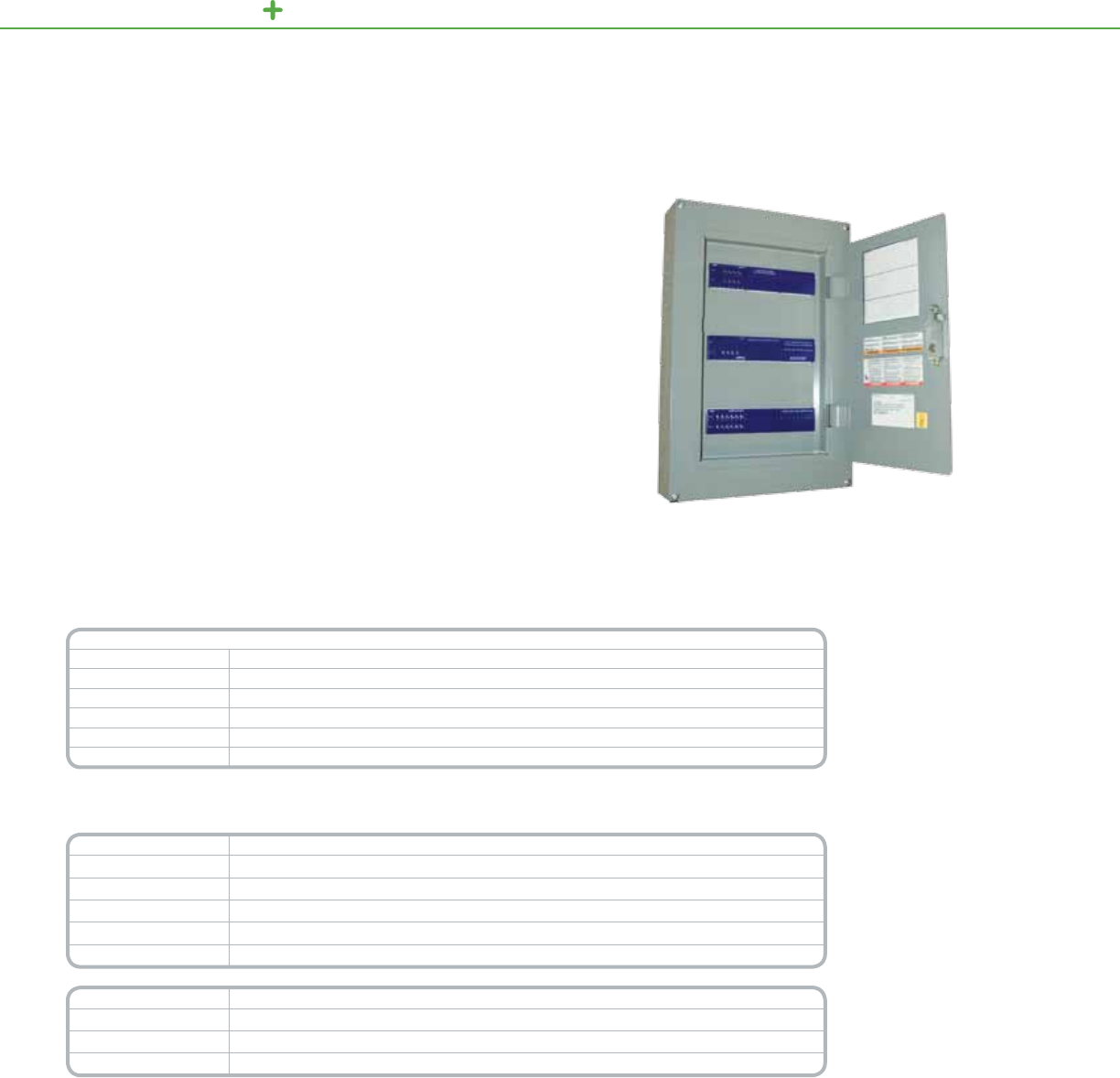
C-BUS LIGHTING CONTROL ENCLOSURES
TheC-BusEnclosuresprovideamulti-purposemeansforhousingvariousC-Bus
DIN-mounteddevices.Suitableforushorsurfacemounting,theenclosureconsists
ofamounting,panassembly,andacoverassembly.Thecabinetcanbeordered
separately,allowingforitsinstallationwiththerough-inofeldwiring.Optional
accessoriesareavailabletomeettheneedsofparticularinstallations.
The36MSenclosureprovidesthreerowsformountingDIN-mountedC-Busunits.
Eachrowhasthecapacitytoholdone12Munit,one8Munitwithone4Munit,or
three4Munits.
36MSEnclosuresarespecicallydesignedforconventionalinstallationnearthe
mainbreakerpanel.TheyprovideasimplemeansofinstallingDIN-mountedunits
withallofthenecessarywiring,neutralbars,groundbarsandothercomponents
included.Onceinstalled,theenclosuresystemallowsforeasysystemmaintenance
withtheC-Busunitsaccessible.
Product Features
• NEMA1enclosure
suitableforushor
surfacemounting
• Weldedsheetsteelwith
knockouts
• Graybakedenamel
paint,electrodeposited
overcleaned,
phosphatizedsteel
• Triple-leadcover
screwsforfast
installationofcover
• Three(3)DINrails,each
suitableformounting
C-BusDINunitsin
oneofthefollowing
congurations:
»One(1)12Munit
»One(1)8Mmodule
withone(1)4Munit
»Three(3)4Munits
36MSEnclosure
C-Bus
36MS Enclosures
Technical Information
36M Enclosure
Type NEMA1
DIN Module Capacity ThreeDINrails,eachwiththecapacityforone12M,one8Mwithone4M,orthree4MC-BusDINunits
Dimensions with Cover 40.6in.(L)x15.4in.(W)x3.9in.(D)[1031mm(L)x392mm(W)x99mm(D)]
Standard ULStandard50Enclosuresforelectricalequipment
Module Mounting DINrail
Total Weight 57.7lb(26.17kg)
*For Diagram see technical section page 156
Catalog Number Description
SLC36SC EnclosureCabinet
SLCMSFG FlushMountGray
SLCMSSG SurfaceMountGray
SLCMSFW FlushMountWhite
SLC2REC DualReceptacleBracket
Accessories Description
PK7GTA Grnd/Neutral
PKGTAB NeutralIsolatorKit
SLC4CSF8 FillerPlate
131
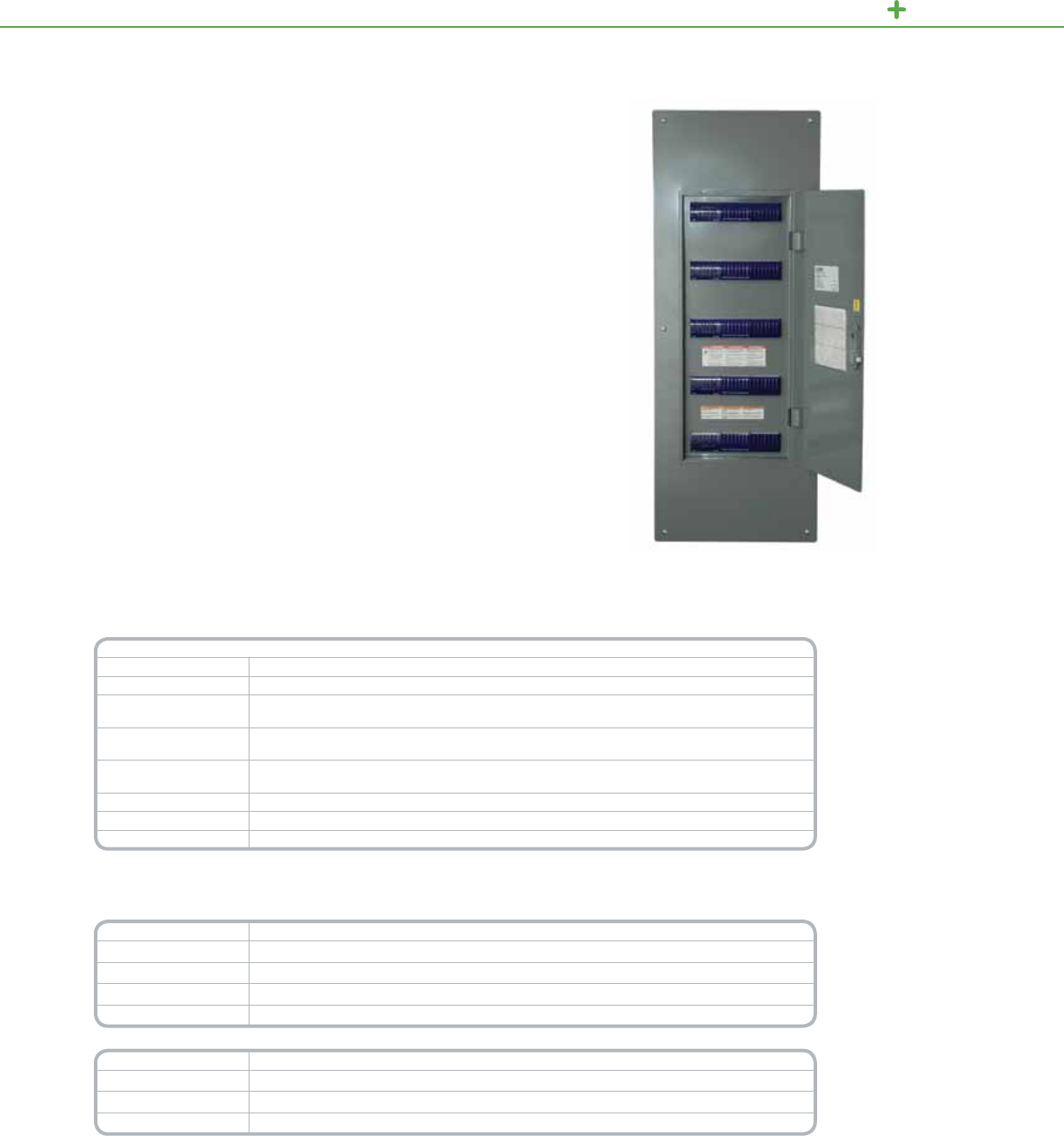
C-BUS LIGHTING CONTROL ENCLOSURES
TheC-BusEnclosuresprovideamulti-purposemeansforhousingvariousC-Bus
DIN-mounteddevices.Suitableforushorsurfacemounting,theenclosureconsists
ofacabinet,amountingpanassembly,andacoverassembly.Thecabinetcanbe
orderedseparately,allowingforitsinstallationwiththerough-inofeldwiring.Options
areavailabletomeettheneedsofparticularinstallations.
The60MenclosureprovidesverowsformountingDIN-mountedC-Busunits.
Eachrowhasthecapacitytoholdone12Munit,one8Munitwithone4Munitor
three4Munits.
SchneiderElectric60MEnclosuresarespecicallydesignedforconventional
installationnearthemainbreakerpanel.Theyprovideasimplemeansofinstalling
DIN-mountedunitswithallofthenecessarywiring,neutralbar,barriersandother
componentsincluded.Onceinstalled,theenclosuresystemallowsforeasysystem
maintenancewiththeC-Busunitsaccessible.
Product Features
• NEMAType1enclosure
suitableforushor
surfacemounting
• Weldedsheetsteel
withknockouts
• ANSIGray#49
bakedenamelpaint,
electrodeposited
overcleaned,
phosphatizedsteel
• Triple-leadcover
screwsforfast
installationofcover
• ULlisted,600Vrated
Class2barrier
included
• (3)pre-installed23
positiongroundbars
and(5)12position
isolatedneutral
assembliesincluded
• FiveDINrails,each
suitableformounting
C-BusDINunitsin
oneofthefollowing
congurations:
»One12Munit
»One8Munitwithone
(1)4Munit
»Three4Munits
• ULListed
60MEnclosure
C-Bus
60M Enclosures
Technical Information
60M Enclosure
Type NEMAType1
DIN Module Capacity FiveDINrails,eachwiththecapacityforone12M,one8Mwithone4M,orthree4MC-BusDINunits
Dimensions with Cover
(ush mount) 40.6in.(L)x15.4in.(W)x3.9in.(D)[1031mm(L)x392mm(W)x99mm(D)]
Dimensions with Cover
(surface mount) 39.4in.(L)x14.2in.(W)x3.9in.(D)[1000mm(L)x360mm(W)x99mm(D)]
Dimensions of
Enclosure Cabinet 39.4in.(L)x14.2in.(W)x3.69in.(D)[1000mm(L)x360mm(W)x99.8mm(D)]
Standard ULStandard50Enclosuresforelectricalequipment
Module Mounting DINrail
Total Weight 57.7lb(26.17kg)
*For Diagram see technical section page 157
Catalog Number Description
SLC36C EnclosureCabinet,40in.
SLC60MFG Mountingpanwithgrayush-mountcover
SLC60MSG Mountingpanwithgraysurface-mountcover
SLC60MFW Mountingpanwithwhiteush-mountcover
Accessories Description
SDM4AC Twoduplexpowerreceptacles
PK4FL Doorlatch,locking
SLC4CSF8 Fillerplate,4M
132
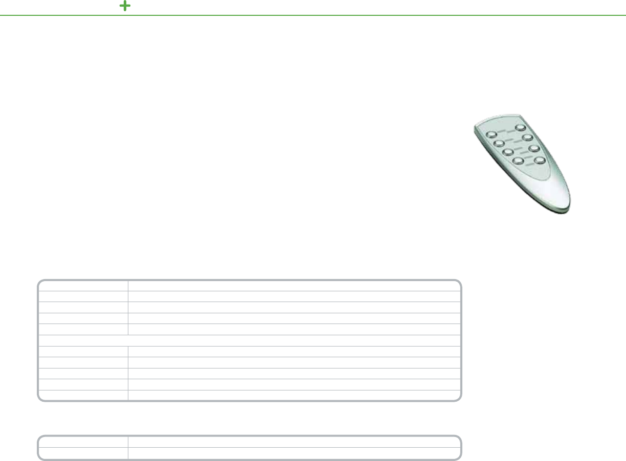
C-BUS MULTI-ROOM REMOTE CONTROLLERS
8ButtonRemoteControls
Product Features
• Eight-buttonoptions
• Wallmountstorage
holderincludedwith
eachremotecontrol
• Removeablefrontcover
forlabelinsertion
(labelsincluded)
• (2)AAAbatteries
included
Distributed
Intelligence
• CompatiblewithC-Bus
IRInputdevices
TheC-BusEight-buttonInfrared(IR)RemoteControlprovideshandheldremotecontroloperationoflightingand
otherloads.DesignedtoworkinconjunctionwithC-BusdevicescontainingIRreceivers,thisconvenientremote
controlcanswitch,dimandcontrollightingscenes.
C-BusEight-buttonRemoteControllercontrolsmultipleinputunitsaswellasseparatelyconguredunits.
Thisversatileremotecontrolhasarangeofupto49feet(15meters)andiseasilyconguredbyprogrammingtheIR
receivingdeviceintheC-BusToolkitsoftware.
C-Bus
Eight Button Remote Controllers
Technical Information
Supply Voltage 3Vdcrequiredfornormaloperation
Battery Type (2)xAAAalkalineSpeakerDiameter
IR Transmission Range Upto49ft.(15m)
Dimensions 5.9in.(L)x2.1in.(W)x1.0in.(D)[149mm(L)x52mm(W)x25mm(D)]
Weight (w/o batteries) 2oz(61g)
Remote Control Holder
Dimensions 4.3in.(L)x2.2in.(W)x1.3in.(D)[108mm(L)x55mm(W)x32mm(D)
Mounting Centers 2.2–2.4in.(55–60mm)
Mounting Screw Size #6(7/8in.)atheadwoodscrew(3.5mmx20mm)
Wall Anchor Size ¼in.(7mmx25mm)
Weight 1oz(28g)
*For Diagram see technical section page 158
Catalog Number Description
SLC5088TX EightButtonIRRemoteController
133
8ButtonRemoteControls
C-BUS MULTI-ROOM IR ACCESSORIES
IR TUBE TARGET
Infra-redIRtargetdesignedtoreceiveIRcommandsfromInfra-redremotecontrols.Simplein-ceilingmounting.
Includesphoenixconnectorand2metersofwire.Comeswithoptionalclearlens.
IR Shelf Mount Target
Infra-redIRtargetdesignedtoreceiveIRcommandsfromInfra-redremotecontrols.Simplysetunitonshelfforeasy
IRcommandaccess.Includesphoenixconnectorand2metersofwire.
IR Flat Target
Infra-redIRtargetdesignedtoreceiveIRcommandsfromInfra-redremotecontrols.Designedtomountindiffusers
andsmallareastomaskappearance.Includesphoenixconnectorand2metersofwire.
IR Emitter Leads
IRLeadsplugintotheC-BusMultiroomaudiomatrixswitcherorC-BusNirts,andemitIRcodestothethirdparty
devices.Singleanddualemitterleadsavailable.Includestransparentadhesivestickerforapplication.
NIRT
TheC-BusNIRTisawallmountedIRtransmitter,thatisdesignedtoworkwiththeC-Buscontrolsystem.TheNIRT
transmitsupto2channelsofIRcommandstocontrolthirdpartycomponents,ie:DVDplayers,TV’s,etc.
IR Reader
TheC-BusIRReaderisaprogrammingtoolthatisusedtolearn3rdpartyremotecontrolIRcommands.UsingCirca
software(freedownload)plugIRReaderintoaPCviaUSBportandsendremotecontrolsignalcaptureIRCode.
IR Accessories
Catalog Number Description
SLC8050TT IRTubeTarget
SLC8050ST IRShelfMountTarget
SLC8050FT IRFlatTarget
SLC8050LD IREmitterLeads-Single
SLC80502LD IREmitterLeads-Dual
SLC5034NIRT NIRT
SLC5100RP IRReader
134
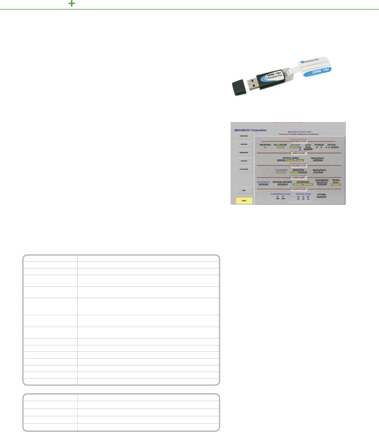
C-BUS SOFTWARE SOFTWARE
TheC-BusSchedulePlusSoftwareprovidesapowerfulandsimpletouseinterface
toaC-Buscontrolsystem.SchedulePlusprovidescontrolandmonitoringofa
commercialorindustrialC-BussystemfromaPCrunningtheMicrosoftWindows
operatingsystem.AccessisobtainedfromalocalPCorremotelyviaanInternet
connectionwithastandardWebBrowser.
SchedulePlusdisplaysgraphicalitemsonuserpageswithsimpleMenuandTab
basedoptions.GraphicitemscanbeprogrammedtoperformC-Busfunctionswhen
pressed.ExamplesofthetypeofitemsthatcanappearonSchedulePluspages
includebuttons,sliders,indicators,real-timeclocksJPEGImagesandBitmapImages.
Thesecanbeplacedandsizedasauserrequiresandcanbedisplayedinfullcolor.
SchedulePlusalsoreportsthestateoftheC-Busgroupaddressesonanetworkin
real-time,withgroupaddressesrepresentedbytextoriconsthatchangecondition
dependingonstatus.Customiconscanbegeneratedtorepresentthevariouscontrol
states;alternativelyiconsfromtheiconlibraryprovidedwiththepackagecanbeused.
AswellasmanualcontrolandmonitoringofaC-Bussystem,SchedulePluscan
alsobeusedtocreateandeditcompleteC-Busscenesandinitiatereal-timebased
schedulesofevents.Thesoftwaresupportsaprojecteditingmodeforcustomizing
theuserinterfaceandanoperationmode,whereclickingcomponentsonthescreen
willexecutetheprogrammedactions.Enhancedschedulingincludessupportfor
monitoringloadruntimes,loadpowerandenergyconsumed.
ExampleofaSchedulePlusSoftwareDisplayScreen
Product Features
• SupportsMicrosoftPlatforms(Vistacompatible)
• Supports128bitencryptedinternetconnectivity
• Automaticprojecterrorcheckingandreporting
• ConnectiontoC-BusviaEthernetorRS-232
• Two,tenandunlimitednetworksoftwarelicence
keyoptions
• Fullyfunctionallogicengine
• Graphicalcomponentsusedtoillustrateactions
• Scheduledeventscanbecreated,displayed,
edited,printedandscheduleddaily,weekly,
weekdays,weekendsandmonthly
• Monitoringofloadruntimes,loadpowerand
energyconsumed
• Pagetemplatesandimagelibrary
• Eventlog
• Twomodes,NormalOperationorProject
EditingModes
• Individualpagescanbepasswordprotected
• ApplicationsupportforHVACandSecurity
SchedulePlusApplicationSoftwareUSB
C-Bus Software
Schedule Plus
Technical Information
Platform Windows95,98,2000,NT,ME,VistaandXP
Server Technology C-BusC-Gate
Connections Ethernet,RS-232
Graphical Objects Text,buttons,sliders,shapes,images,realtimeclock,C-Bustimer,
percentageindicator,lightlevel,temperature,C-Busnetworkvoltage
Component Properties C-Busnetworkparameters,position,size,fontstyleandcolor,textand
imagealignments,borders,stroke,backgroundcolor/shading
Graphical Associations
C-Buscommand(on/off/ramp),sceneactivation,sceneactivationvia
C-Busscenecontrollers,pagelinks,backonepage,operationover
remoteapplications,exitsimulationpage
Scheduled Events Create,displayeditandprint.Daily,weekly,weekdays,weekends,
monthlyandonceoff
Event Properties SendC-Buscommand(on/off/ramp&ramprate),sendpulsedC-Bus
commands,setscenes,timeofevent,cycleofevent
Password Protection Yes
Modes (2)Normal/ProjectEditing
Project Summary Yes
Event Log Yes
Page Templates Yes(included)
Image Library Yes(included)
Sound .WAVlecapable
Catalog Number Description
SLC5000SDSP24 SchedulePluslicensekeyfor2networks
SLC5000SDSP104 SchedulePluslicensekeyfor10networks
SLC5000SDSPU4 SchedulePluslicensekeyforunlimitednetworks
SLC5000SDSP24 SchedulePlusinstallerKey*
* Installer key allows installers to create/commission projects using SchedulePlus software. This code key is time
restricted and allows the software to operate in ‘normal’ mode for anywhere between 48 to 72 hours per use
(the software then returns to evaluation/demo mode).
Note: The installer code key will also be compatible with future software releases
135

136
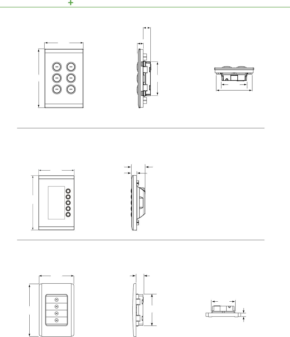
C-BUS LIGHTING CONTROL TECHNICAL SECTION
2.05 in.
52 mm
2.7 in.
69 mm
0.51 in.
13 mm
0.6 in.
15 mm
Top view of keypad showing width
Front view of keypad, including external
height and width measurements of case
Side view of keypad, including height and
depth requirements for insertion into wall
Saturn
Keypads
3.0 in.
76 mm
4.57 in.
116 mm
2.6 in.
66 mm
Front and side views of the Saturn DLT keypad
illustrate its length and width and the depth the
case extends into and out of a wall
.43 in.
10.8 mm
1.13 in.
28.8 mm
Saturn Keypads
with Dynamic Labelling Technology
Neo Decorator
Keypads
3.0 in.
76 mm
4.57 in.
116 mm
Front view of keypad, including external height
and width measurements of Faceplate
Side view of keypad, including height and
depth requirements for insertion into wall
Top view of keypad, including
depth of face plate
3.0 in.
76 mm
4.57 in.
116 mm
.63 in.
16 mm
2.76 in.
70 mm
.28 in.
7 mm
1.69 in.
43 mm
137
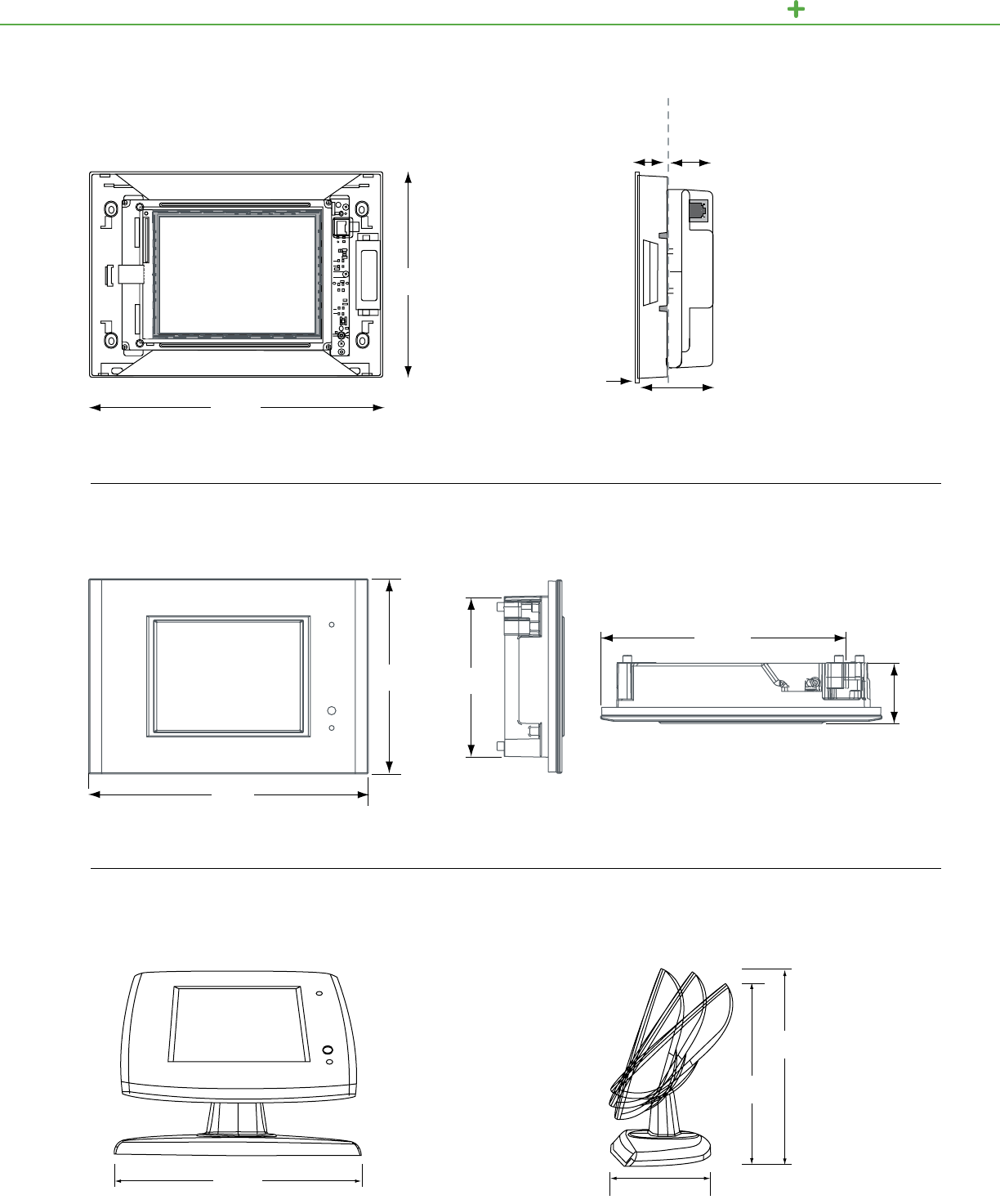
C-BUS LIGHTI NG CONTROL TECHNICAL SECTION
Protrusion from wall:
Cover plate
Mounting depth into wall:
Excluding cover plate
0.9 in. (23.5 mm) 2.2 in. (54 mm)
2.9 in. (72.5 mm)
Side view of Color Touch Screen
Side view of Spectrum
Touch Screen
Side view of Spectrum
Touch Screen
Top view of Spectrum Touch Screen
Front view of Color Touch Screen
Front view of Spectrum Touch Screen
Front view of Spectrum
Touch Screen
Color
Touch Screen
9.8 in.
246 mm
6.9 in.
173 mm
Spectrum
Touch Screen
Spectrum
Desktop Touch Screen
3.75 in.
95 mm
5.5 in.
140 mm
6 in.
152 mm
7.5 in.
191 mm
1.65 in.
42 mm
7.56 in.
192 mm
5.39 in.
137 mm 4.5 in.
135 mm
6.8 in.
172.5 mm
138
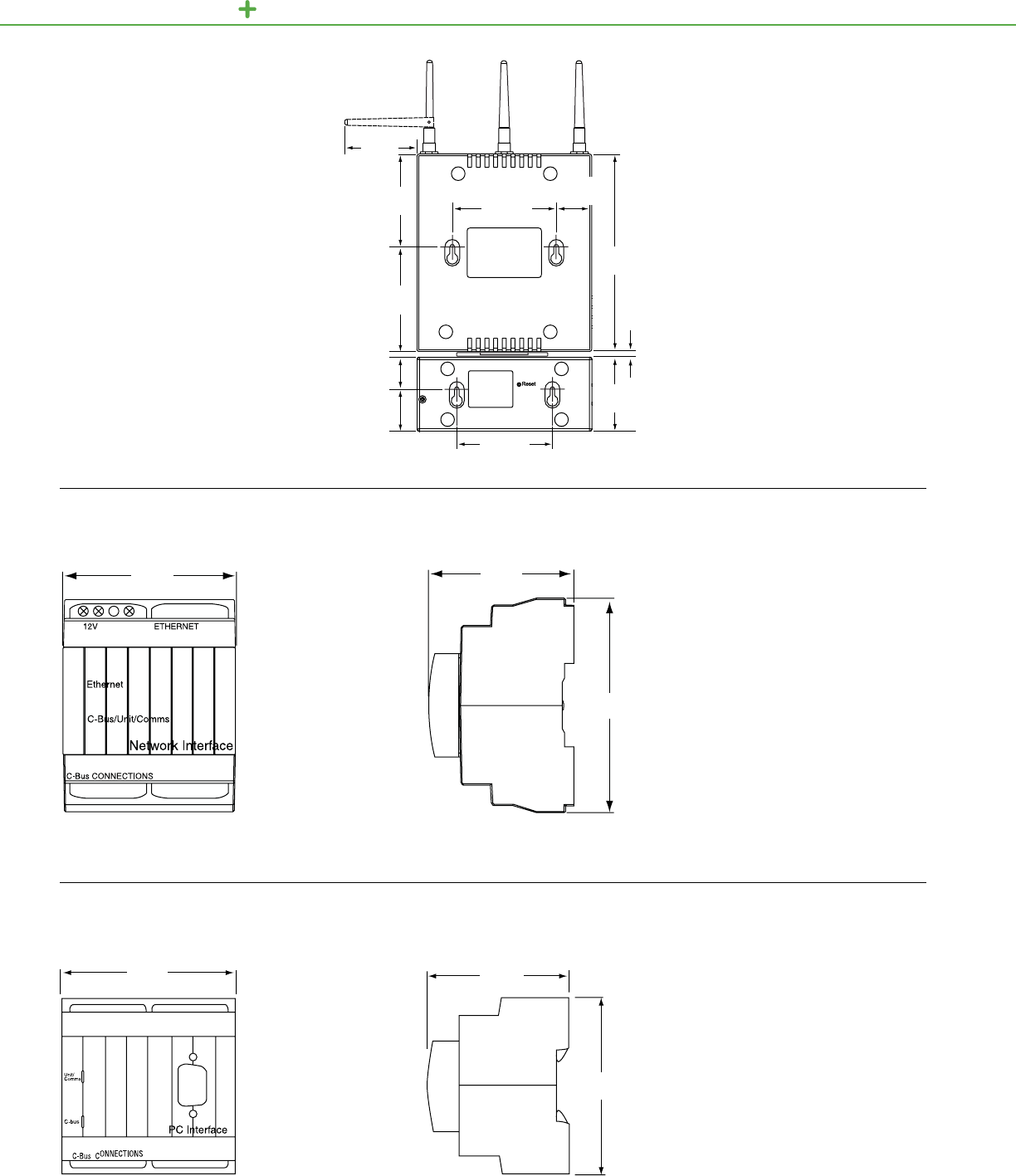
C-BUS LIGHTING CONTROL TECHNICAL SECTION
Wiser
Home Controller
6.25 in.
159 mm
2.9 in.
74 mm 3.75 in.
95.5 mm
0.9 in.
23 mm
2.75 in.
70 mm
3.3 in.
85 mm
2.4 in.
60 mm
3.75 in.
95.5 mm
1.4 in.
35 mm
0.9 in.
25 mm
0.2 in.
6 mm
View of the Ethernet Network
Interface showing width
Front view of the PC
Interface showing width
Side view of the PC Interface
showing height and depth
3.35 in.
85 mm
View of the Ethernet Network Interface
showing height and depth
Ethernet Network Interface
PC Interface
2.84 in.
72 mm 2.56 in.
65 mm
2.83 in.
72 mm
2.56 in.
65 mm
3.35 in.
85 mm
139

Side view of the PC Interface
showing height and depth
USB Interface
Front view of the PC Interface
showing width
2.84 in.
72 mm 2.60 in.
66 mm
3.35 in.
85 mm
C-BUS LIGHTI NG CONTROL TECHNICAL SECTION
Front view of a Power Supply
showing width
Side view of a Power Supply
showing depth and height
2.56 in.
65 mm
Front view of the Network
Bridge showing width
Side view of Network Bridge
showing height and depth
3.35 in.
85 mm
Power Supply
Network Bridge
2.83 in.
72 mm
2.56 in.
65 mm
2.83 in.
72 mm
3.35 in.
85 mm
140
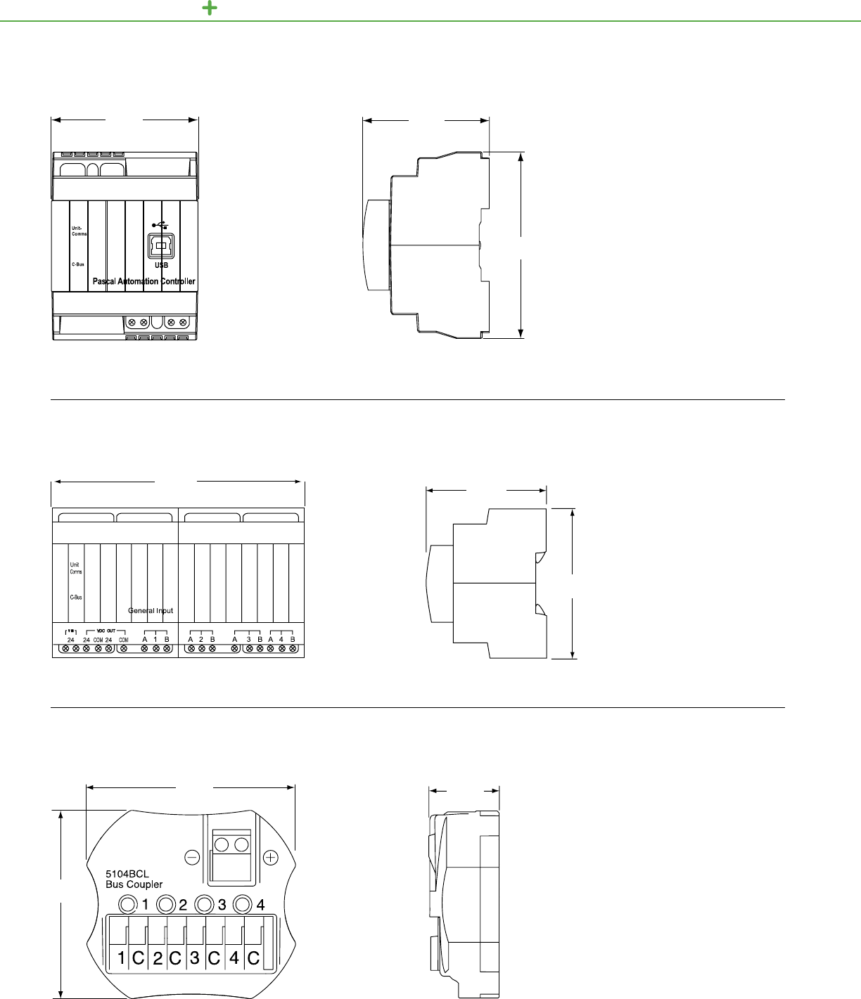
C-BUS LIGHTING CONTROL TECHNICAL SECTION
Front view of the Pascal
Automation Controller Side view of the Pascal
Automation Controller
Pascal Automation Controller
2.48 in.
63 mm
3.62 in.
92 mm
2.83 in.
72 mm
5.7 in.
144 mm
Top view of General Input Unit Side view of General Input Unit
Top view of Four-Channel Bus Coupler Side view of the Four-Channel Bus Coupler
Bus Coupler
General Input Unit
2.60 in.
65 mm
3.4 in.
85 mm
1.9 in.
49 mm
2.2 in.
55 mm
0.71 in.
18 mm
141
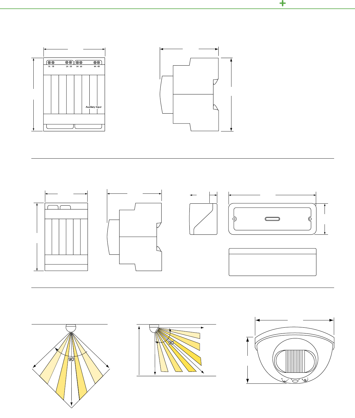
Top view of Four-Channel
Auxiliary Input Unit
Front view of DIN Fan Controller
Side view of Four-Channel
Auxiliary Input Unit
Side view of DIN Fan Controller Side view of Fan Controller Enclosure
Front view of Fan Controller Enclosure
Four-Channel Auxiliary Input Unit
2.8 in.
72 mm
3.4 in.
85 mm
2.60 in.
65 mm
3.4 in.
85 mm
C-BUS LIGHTI NG CONTROL TECHNICAL SECTION
DIN Fan Controller
2.1 in.
53 mm 2.6 in.
66 mm
3 in.
75.5 mm
8.3 in.
210 mm
2.6 in.
65 mm
3.4 in.
85 mm
20 ft.
6 m
28 ft.
8.5 m
20 ft
6 m
8 ft.
2.4 m 28 ft.
8.5 m
28 ft.
8.5 m
Field of view from side of indoor occupancy sensor
Front view of indoor occupancy sensor
Field of view from top of indoor occupancy sensor
Indoor PIR Occupancy Sensor
Wall Ceiling
Sensor
3.9 in.
100 mm
2.2 in.
57 mm
Fan Controller Enclosure
142
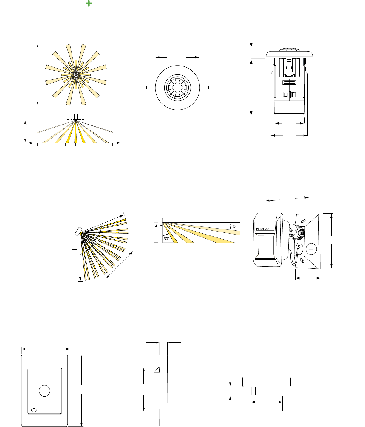
C-BUS LIGHTING CONTROL TECHNICAL SECTION
.59 in.
15 mm
3.46 in.
88 mm
26 ft.
8 m
8 ft.
2.4 m
13 ft.
4 m
13 ft.
4 m
7 ft.
2 m
7 ft.
2 m
0Side view of C-Bus 360° PIR
Occupancy Sensor
Front view of C-Bus 360° PIR
Occupancy Sensor
Field of view from top and side for 360 PIR
Occupancy Sensor mounted 8 ft. above floor
360° PIR Occupancy and Multi-Sensor
2.83 in.
72 mm
1.85 in.
47 mm
1.97 in.
50 mm
Ultra short – 4 ft.
1.2 m
Short – 13 ft.
4 m
Intermediate – 26 ft.
8 m
Long – 59 ft.
18 m
ZONES and
NOMINAL RANGES
Sensor
Sensor
Optimum
“Approach Path”
59 ft.
18 m
Field of view from side of Outdoor
Motion Sensor
Field of view from top of Outdoor Motion Sensor Side view of Outdoor Motion Sensor
5.5 in.
140 mm
4.5 in.
114 mm
2.9 in.
74 mm
8 ft.
2.4 m
Outdoor Motion Sensor
Top view of light-level sensor
0.49 in.
12.5 mm
1.93 in.
49 mm
0.52 in.
13 mm
2.83 in.
72 mm
Side view of Light-Level Sensor Front view of Light-Level Sensor
Light-Level Sensor
2.99 in.
76 mm
4.57 in.
116 mm
143
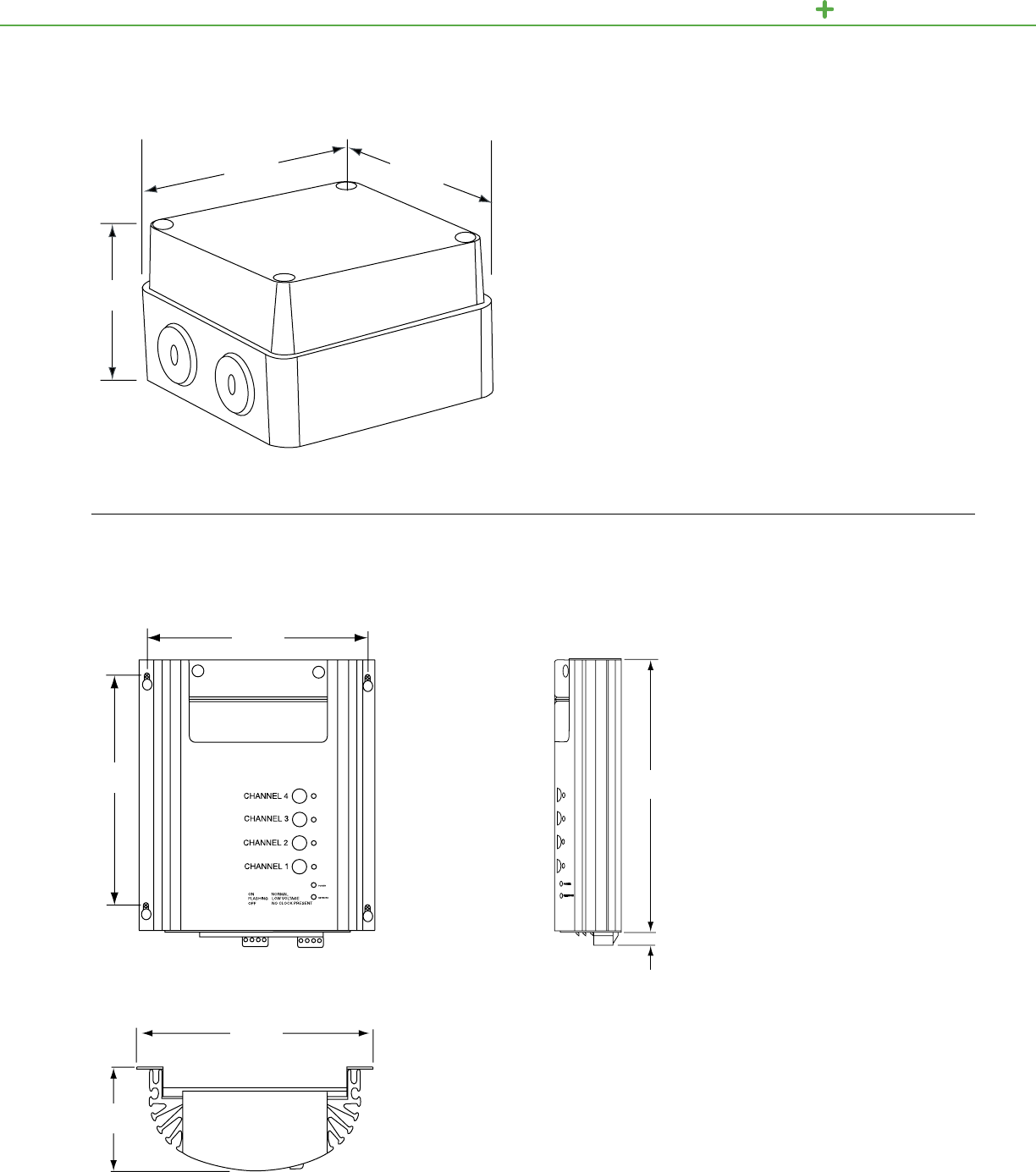
View including height, width and depth dimensions
Outdoor Light-Level Sensor
2.5 in.
65 mm
4 in.
102 mm 4 in.
102 mm
C-BUS LIGHTI NG CONTROL TECHNICAL SECTION
0.4 in.
10 mm
3 in.
75 mm
Front view including mounting centers Side view
Top view
Professional Series Dimmer
7.5 in.
190 mm
7.7 in.
195 mm
POWER
NETWORK
9 in.
230 mm
8 in.
202 mm
144
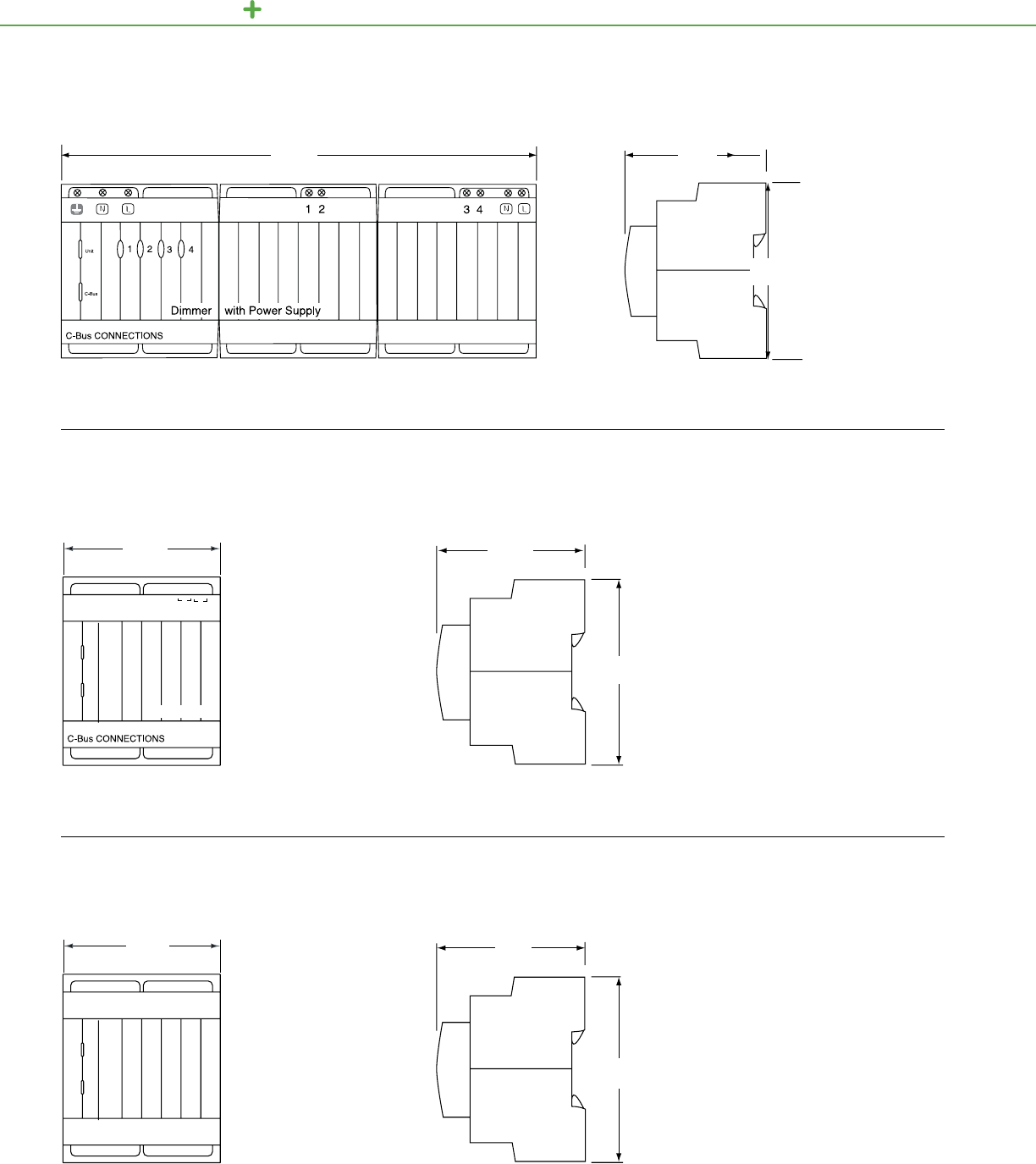
C-BUS LIGHTING CONTROL TECHNICAL SECTION
8.5 in.
215 mm
Front view of the Phase Angle Dimmer Unit Side view of the Phase Angle Dimmer Unit
Phase Angle Dimmer Unit
2.6 in.
65 mm
3.4 in.
85 mm
Front view of DALI Gateway
Front view
Side view of DALI Gateway
Side view
2 Channel DALI Gateway
DMX One Way Gateway
2.6 in.
65 mm
Unit/
Comms
C-Bus
DALI
1DALI
2
2.83 in.
72 mm
2.84 in.
72 mm
3.4 in.
85 mm
3.35 in.
85 mm
2.6 in.
66 mm
DALI Gateway
145
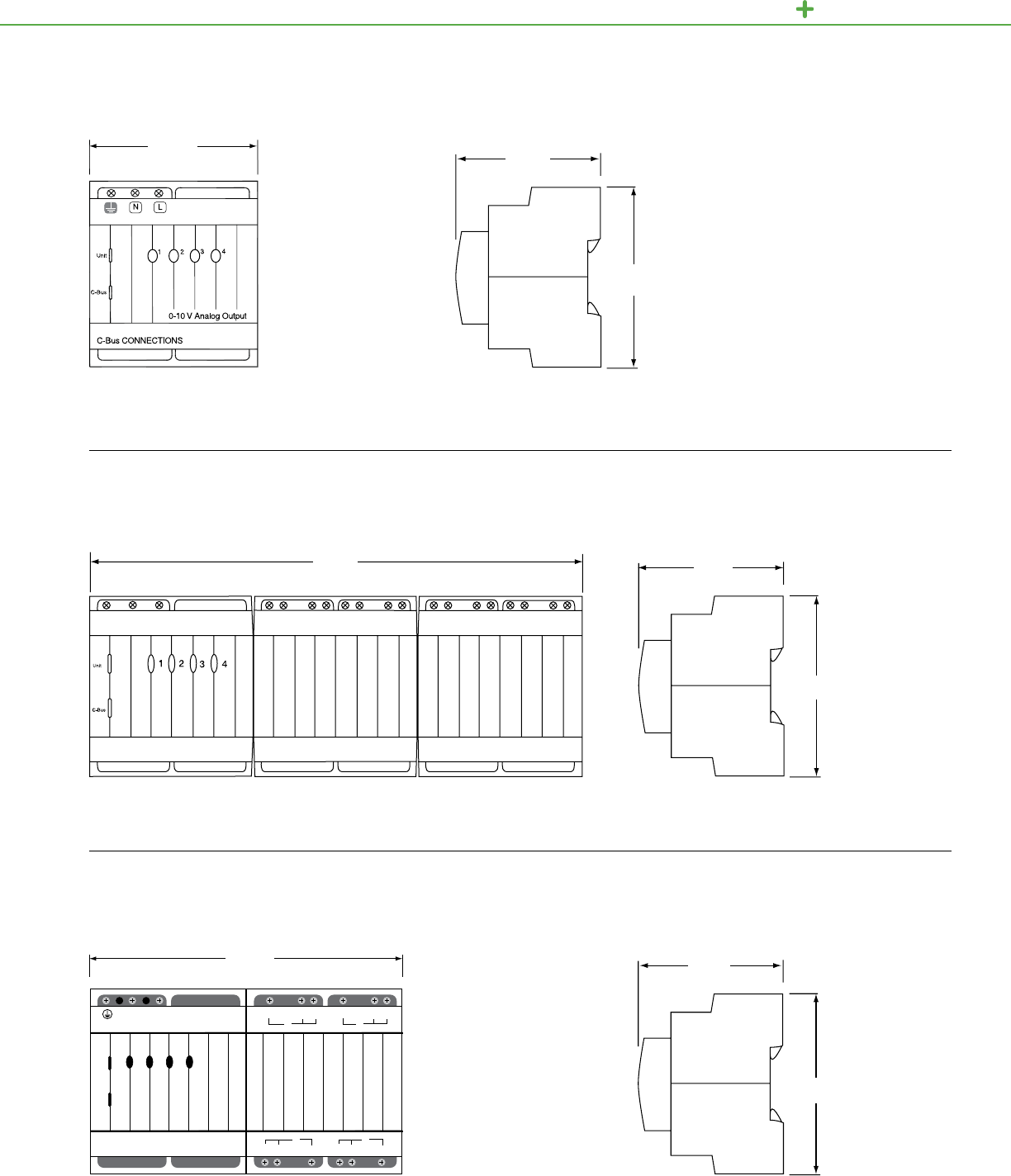
2.56 in.
65 mm
Front view of the 0-10V
Fluorescent Ballast Dimmer
Side view of the 0-10V Fluorescent
Ballast Dimmer
4 Channel 0-10V Fluorescent Ballast Dimmer
2.83 in.
72 mm
3.35 in.
85 mm
C-BUS LIGHTI NG CONTROL TECHNICAL SECTION
Front view of a C-Bus 4 Channel 20 Amp Relay with Power Supply Side view of a C-Bus 4 Channel 20 Amp Relay
20 Amp Relay Units
Front view of a C-Bus Changeover Relay Side view of a C-Bus Changeover Relay
Changeover Relay Units
2.56 in.
65 mm
3.35 in.
85 mm
Changeover Relay
23 41
C-Bus CONNECTIONS
Unit
C-Bus
N
USE COPPER WIRE ONLY
LNO NCC NO NCC
NC NONC NO CC
34
12
5.67 in.
144 mm
8.46 in.
215 mm 2.56 in.
65 mm
3.35 in.
85 mm
146
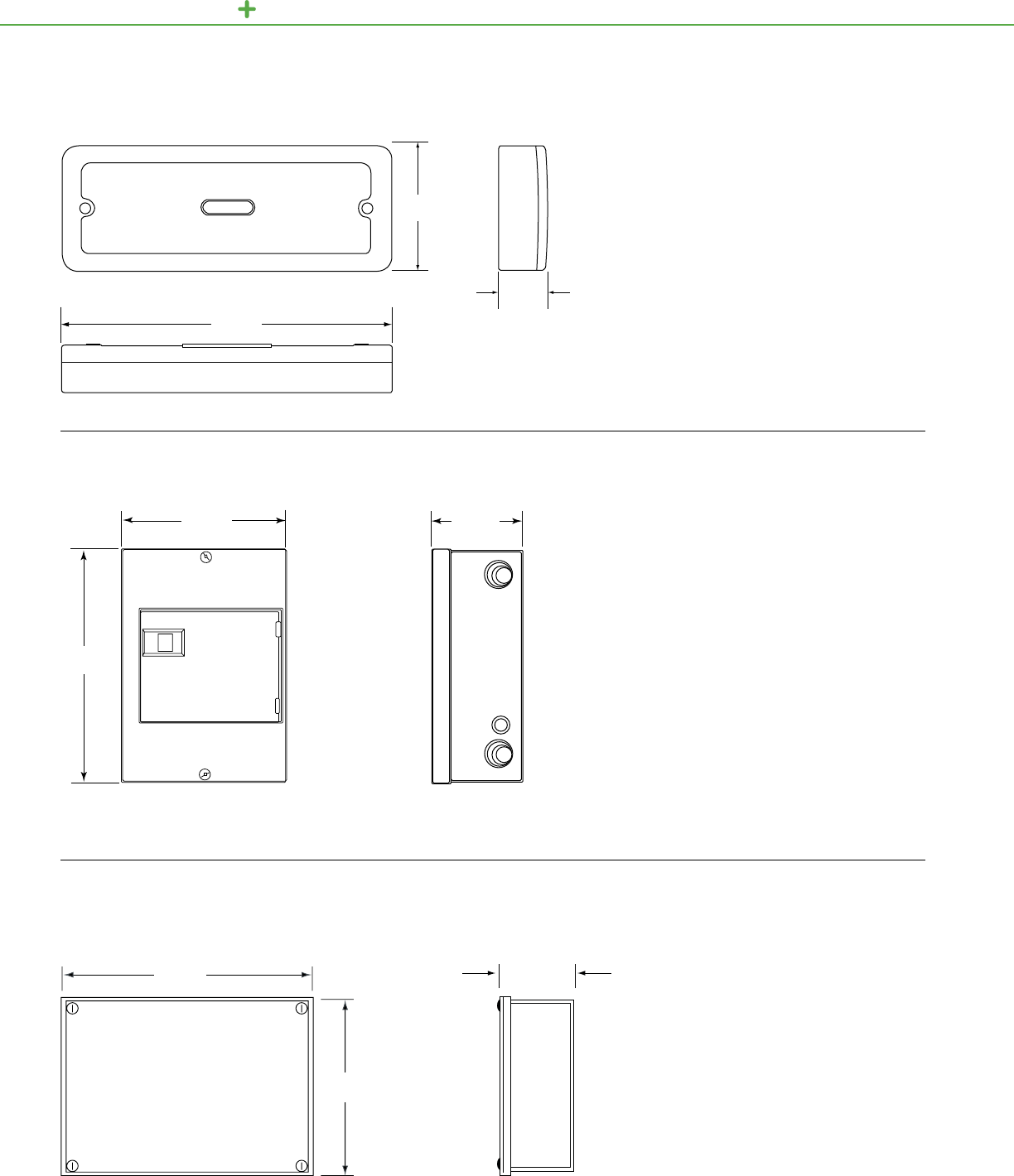
C-BUS LIGHTING CONTROL TECHNICAL SECTION
1.50 in.
(38 mm)
Front view of 8M Enclosure box showing
height and width
Top view of Low Voltage Relay 8 Channel
Front view of Low Voltage Relay 8 Channel
Side view of 8M Enclosure box showing depth
Side view of Low Voltage
Relay 8 Channel
8M Enclosure
Low Voltage Relay 8 Channel
3.15 in.
(80 mm)
8.66 in.
(220 mm)
12.57 in.
(319 mm)
8.9 in.
(226 mm)
3.8 in.
(97 mm)
Front view of 12M Enclosure box showing height and width Side view of 12M Enclosure box showing depth
4.0 in.
102 mm
12M Enclosure
12.78 in.
325 mm
9.09 in.
231 mm
147
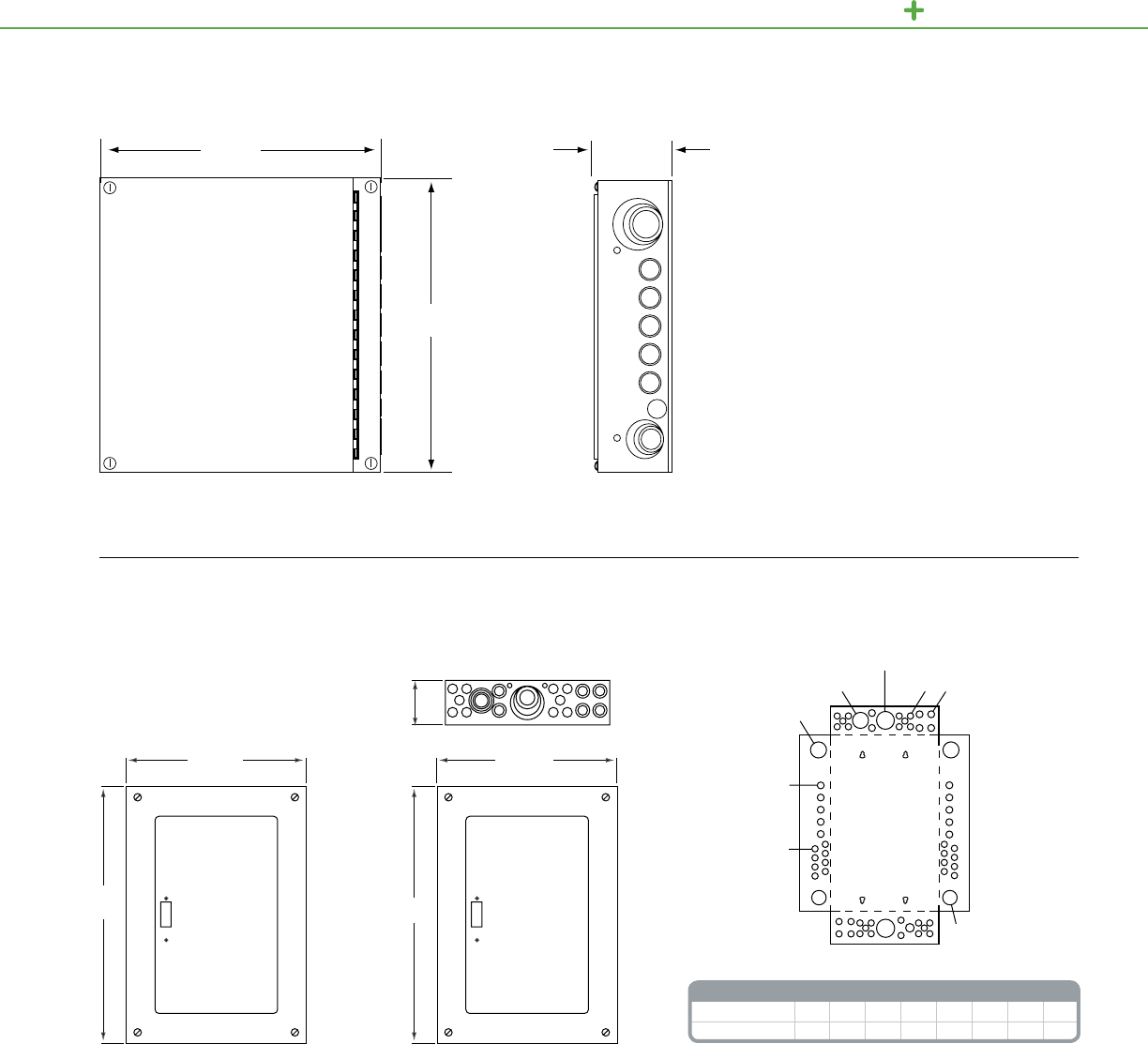
Front view of 24M Enclosure box showing height and width Side view of 24M Enclosure box showing depth
4.0 in.
102 mm
24M Enclosure
3.81 in.
(97 mm)
Dimensions for the 36MS
Enclosure Flush Mounted
Dimensions for the 36MS
Enclosure Surface Mounted
36MS Enclosure
14.50 in.
368 mm
14.94 in.
379 mm
36MS Knockouts
Symbol A B C D E F G H
Conduit Size ½¾ 1 1¼ 1½ 22½ 3
14.24 in.
(362 mm)
20.93 in.
(532mm)
15.44 in.
(392 mm)
22.12 in.
(562 mm)
C, D, E, F, G
A, B, C, D
B, C, D, E
C, D, E, F
A, B
A
AA, B
C-BUS LIGHTI NG CONTROL TECHNICAL SECTION
148
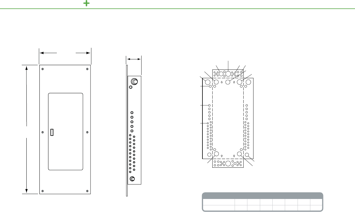
3.9 in.
99 mm
Front and side view (flush mount)
60M Enclosure
36M Knockouts
Symbol A B C D E F G
Conduit Size ½¾ 1 1¼ 1½ 22½
knockouts
C, D, E, F, G
B, C, D, E
A, B, C, D
B, C, D, E
B, C, D, E
D, E, F, G
B, C
A, B
A
C, D, E, F
A, B
C, D, E, F
D, E, F, G
A
15.4 in.
392 mm
40.6 in.
1031 mm
C-BUS LIGHTING CONTROL TECHNICAL SECTION
149
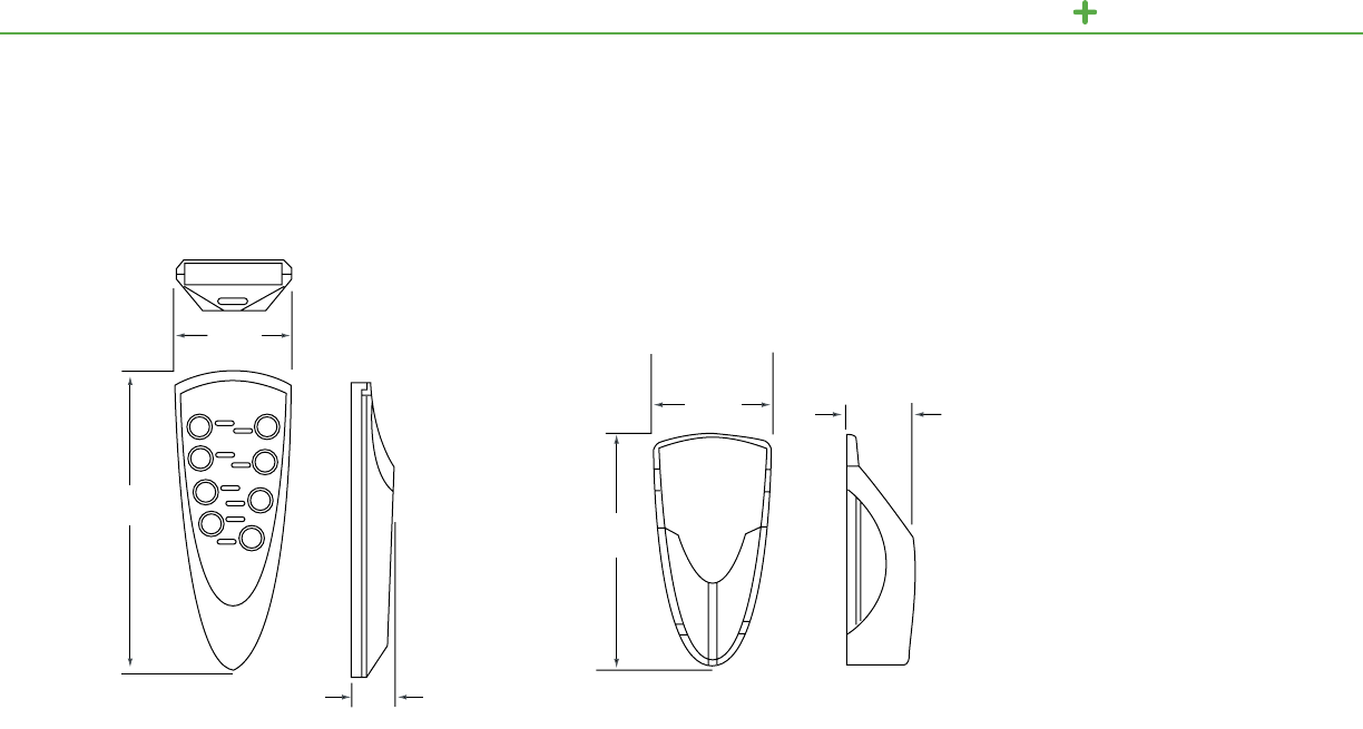
C-BUS MULTI-ROOM TECHNICAL SECTION
C-Bus 4 and 8 Button Remote Control HolderC-Bus 8 Button Remote Control
5.9 in.
149 mm
2.1 in.
52 mm
1 in.
25 mm
4.3 in.
108 mm
1.3 in.
32 mm
2.2 in.
55 mm
C-Bus
Eight Button Remote Controllers
150

Lighting Control
Schneider Electric USA
320 Tech Park Drive, Suite 100
La Vergne, TN, 37086
1-888-778-2733
www.schneider-electric.us
Document Number 1200CT0701R11/12 April 2013
Make the most of your energySM
©2013 Schneider Electric. All Rights Reserved. Schneider Electric, Square D, Powerlink, C-Bus, Saturn, Dynamic Labeling Technology, and Wiser are
trademarks owned by Schneider Electric Industries SAS or its affiliated companies. All other trademarks are property of their respective owners.
Products Guide
