TB04000002E 1000498846 Catalog
2016-10-06
: Pdf 1000498846-Catalog 1000498846-Catalog B5 unilog
Open the PDF directly: View PDF ![]() .
.
Page Count: 134 [warning: Documents this large are best viewed by clicking the View PDF Link!]
- Blank Page
- Blank Page
- Blank Page
- Blank Page
- Blank Page
- Blank Page
- Blank Page
- Blank Page
- Blank Page
- Blank Page
- Blank Page
- Blank Page
- Blank Page
- Blank Page
- Blank Page
- Blank Page
- Blank Page
- Blank Page
- Blank Page
- Blank Page
- Blank Page
- Blank Page
- Blank Page
- Blank Page
- Blank Page
- Blank Page
- Blank Page
- Blank Page
- Blank Page
- Blank Page
- Blank Page
- Blank Page
- Blank Page
- Blank Page
- Blank Page
- Blank Page
- Blank Page
- Blank Page
- Blank Page
- Blank Page
CA08104001E For more information, visit: www.eaton.com/consultants
February 2016
Contents
Adjustable Frequency Drives—Low Voltage 31.0-1
Sheet 31
22
23
24
25
26
27
28
29
30
31
32
33
34
35
36
37
38
39
40
41
42
4 3
001
Adjustable Frequency
Drives—Low Voltage
Adjustable Frequency Drives—Low Voltage
Application Guide
Motor Application and Performance . . . . . . . . . . . . . . . . . . . . . . . . . . . . . . . 31.0-2
AC Drive Application . . . . . . . . . . . . . . . . . . . . . . . . . . . . . . . . . . . . . . . . . 31.0-2
AC Drive Performance . . . . . . . . . . . . . . . . . . . . . . . . . . . . . . . . . . . . . . . . 31.0-3
Motor Load Types and Characteristics . . . . . . . . . . . . . . . . . . . . . . . . . . . . . 31.0-5
Motor Load Types. . . . . . . . . . . . . . . . . . . . . . . . . . . . . . . . . . . . . . . . . . . . 31.0-5
Drive Selection . . . . . . . . . . . . . . . . . . . . . . . . . . . . . . . . . . . . . . . . . . . . . . . . 31.0-6
Selections Considerations . . . . . . . . . . . . . . . . . . . . . . . . . . . . . . . . . . . . . 31.0-6
Harmonics . . . . . . . . . . . . . . . . . . . . . . . . . . . . . . . . . . . . . . . . . . . . . . . . . . . . 31.0-7
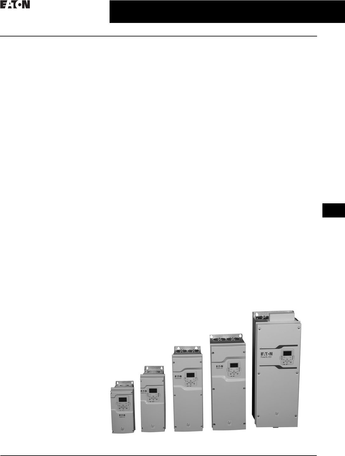
PowerXL Series Drives
PowerXL DE1 . . . . . . . . . . . . . . . . . . . . . . . . . . . . . . . . . . . . . . . . . . . . . . . . . 31.1-1
PowerXL DC1 . . . . . . . . . . . . . . . . . . . . . . . . . . . . . . . . . . . . . . . . . . . . . . . . . 31.1-6
PowerXL DG1 . . . . . . . . . . . . . . . . . . . . . . . . . . . . . . . . . . . . . . . . . . . . . . . . . 31.1-16
EGS Enclosed DG1 . . . . . . . . . . . . . . . . . . . . . . . . . . . . . . . . . . . . . . . . . . . 31.1-28
EGF Passive Filtered DG1 . . . . . . . . . . . . . . . . . . . . . . . . . . . . . . . . . . . . . 31.1-37
9000X Series Drives
SVX Drives . . . . . . . . . . . . . . . . . . . . . . . . . . . . . . . . . . . . . . . . . . . . . . . . . . . . 31.2-1
Enclosed SVX . . . . . . . . . . . . . . . . . . . . . . . . . . . . . . . . . . . . . . . . . . . . . . . 31.2-24
CFX Passive Filtered SVX . . . . . . . . . . . . . . . . . . . . . . . . . . . . . . . . . . . . . 31.2-41
CPX 18-Pulse SVX . . . . . . . . . . . . . . . . . . . . . . . . . . . . . . . . . . . . . . . . . . . 31.2-53
H-Max Drives
H-Max Drives . . . . . . . . . . . . . . . . . . . . . . . . . . . . . . . . . . . . . . . . . . . . . . . . . . 31.3-1
H-Max IntelliPass and IntelliDisconnect . . . . . . . . . . . . . . . . . . . . . . . . . 31.3-10
Specifications
See Eaton’s Product Specification Guide, available on CD or on the Web.
CSI Format: . . . . . . . . . . . . . . . . . . . . . . . 1995 2010
Sections 16483A, Sections 26 29 23.11,
16483B, 26 29 23.13,
16483C, 26 29 23.16,
16483D 26 29 23.19
Adjustable Frequency Drives

31.0-2
For more information, visit: www.eaton.com/consultants CA08104001E
February 2016
Adjustable Frequency Drives—Low Voltage
Sheet 31
22
23
24
25
26
27
28
29
30
31
32
33
34
35
36
37
38
39
40
41
42
4 3
Application Guide
002
Motor Application and
Performance
AFD Output Harmonics
For the purpose of performance
evaluation, the non-sinusoidal output
waveforms produced by AFDs are
represented by their mathematically
equivalent component parts. All
such waveforms consist of an infinite
number of sinusoidal components of
different amplitudes and frequencies.
The fundamental component is the
“good” part of the waveform, which
provides power to the motor at the
desired operating frequencies.
The harmonics are unwanted
components, which provide unusable
voltages and currents to the motor
at frequencies that are multiples of
the fundamental.
State-of-the-art designs for pulse
width modulated AFDs provide a sine
weighted modulation strategy with a
high switching frequency, and reduced
output harmonic content as compared
to other types of drives. A motor
operating on a PWM drive will have
an additional heat loss due to the
harmonic content as compared
to utility line operation.
PWM drives that are comprised of
IGBT (insulated gate bipolar transistor)
power devices are also capable of rapid
voltage rise times, which can stress the
insulation system of the AC motor.
For this reason, motors designed for
operation on IGBT PWM inverter power
incorporating insulation systems
rated for rapid voltage rise times and
higher operating temperatures are
recommended for use with the drives.
Standard motors with a 1.15 service fac-
tor or energy efficient motors can
be used provided that additional drive
output filtering is incorporated to limit
voltage rise times and to reduce the
output harmonic content.
Multiple Motor Operation
Any number of motors can be
connected in parallel and controlled
on an open loop (frequency control)
configuration by a single AFD as long
as the total connected load does not
exceed the rating of the drive. A closed
loop vector controlled drive cannot be
used with multiple motors. Although
the basic principles of multiple
motor operation are not difficult to
understand, Application Engineering
assistance should be requested to
make certain that the application
is successful.
Because the frequency of the power
supplied by the AFD is the same for
all motors, the motors will always
operate at relatively the same speed.
With NEMA design B motors, the
speeds will be matched within 3% or
less, depending on the load variation
among the motors and their rated slip.
Exact speed matching between motors
is not possible. If an adjustable speed
ratio is required between motors, each
motor must be connected to its own
individual AFD.
AC Drive Application
Matching the AFD to the Motor
Voltage source AFDs are designed
for use with any standard three-phase
induction motor. AFD sizing and motor
matching are often simply a matter
of matching the AFD output voltage,
frequency and current ratings to the
requirements of the motor. If the load
torque exceeds 150% for Constant
Torque (CT) drives or 110% for Variable
Torque (VT) drives during starting or
intermittently while running the drive,
oversizing may be required.
Output Voltage and Frequency
For AFDs rated at 480 V, motors
are connected for 460 V at 60 Hz.
380 V/50 Hz motors can also be used
because the V/Hz ratio, 380/50, is
7.6V/Hz, the same as a 460 V/60 Hz
motor. 415 V motors can be operated if
the AFD V/Hz adjustment is reset. With
proper V/Hz adjustment, 575 V motors
can be operated at constant V/Hz up to
80% speed and at constant voltage
from 80% to 100% speed. Maximum
motor
torque and hp for this mode of
operation
is limited above 80% speed
because of the reduced V/Hz levels. For
AFDs rated at 240 V, the motor will be
connected for 230 V.
Output Current
The full load current ratings of typical
AFDs are matched to typical full load
motor current ratings as listed in
National Electrical Code® Table 430.150.
Generally, an AFD of a given horse-
power rating will be adequate for a
motor of the same rating, but the
actual motor current required under
operating conditions is the determin-
ing factor for AFD sizing. If the motor
will be run at full load, the AFD output
current rating must be equal to or
greater than the motor nameplate
current. If the motor is oversized to
provide a wide speed range, the AFD
should be sized to provide the current
required by the motor at the maximum
operating torque. Motor oversizing
should generally be limited to one
horsepower size increase.
Motor Protection
Motor overload protection must be
provided as required by applicable
codes. Direct motor protection is not
automatically provided as part of the
AC drive.
AFDs are equipped with electronic
protection circuits with an inverse
time or I2t characteristic equivalent
to a conventional overload relay.
Conventional overload relays are also
used with AFDs equipped with bypass.
If these current sensing protective
devices are used with motors driving
constant torque loads, the minimum
speed should be adjusted to prevent
the motor from running at speeds at
which overheating could occur, unless
the I2t circuit provides a speed and
load calibrated trip. The best means
of AC drive motor protection is direct
winding overtemperature sensing,
such as an overtemperature switch
or thermistor imbedded in the motor
windings. Overtemperature switches
are more convenient because they can
normally be connected directly to the
AC drive control circuit. Thermistors
generally require a special sensing
relay. Direct overtemperature protection
is preferred over overcurrent sensing
protective devices because motor
overheating can occur with normal
operating current at low operating
speeds.
CA08104001E For more information, visit: www.eaton.com/consultants
31.0-3
February 2016
Adjustable Frequency Drives—Low Voltage
Sheet 31
22
23
24
25
26
27
28
29
30
31
32
33
34
35
36
37
38
39
40
41
42
4 3
Application Guide
003
Motor short-circuit protection is not
required because the AC drive protec-
tion circuits nearly always adequately
protect the motor in this respect.
When a single AFD provides power to
multiple motors connected in parallel,
special considerations must be given
to motor protection. Individual over-
load protection must be provided for
each motor. Short-circuit protection
may be required for some applications.
Bearing and DV/DT Protection
The rapid voltage rise times present
in today’s IGBT PWM drives may
cause current to flow in the motor
bearings due to shaft voltage caused
by capacitive coupling. This current
flow can result in minute electrical
discharges within the bearing,
potentially damaging the bearing
over time. Therefore a DV/DT filter
should be used where the drive and
motor are separated by 100 feet or
more. Using an insulated motor
shaft bearing and/or setting the
inverter carrier frequency to the lowest
acceptable level can help minimize the
potential for this phenomenon as well.
AC Drive Performance
Operator Control and Interface
Operator controls are often via the
drive keypad. In other situations, an
operator station or remote control
may be desired. If these requirements
cannot be achieved by remotely
mounting the keypad, terminal
blocks with digital and analog
interface capability are provided.
Acceleration and Deceleration
AFDs are always equipped with adjust-
able acceleration and deceleration
control. Acceleration and deceleration
rates must be adjusted to suit the
characteristics of the load to prevent
shutdown due to overcurrent or over-
voltage. Increasing acceleration or
deceleration times will proportionally
decrease the torque requirement.
Speed Range
The characteristics of the motor
usually determine the speed range
of an AC drive. The AFD output
frequency range is usually wider
than the range that can be effectively
used by the motor.
Speed Regulation
The open loop speed regulation of an
AC drive is determined by the motor
slip. Because NEMA design B motors
usually have 3% slip or less, at 60 Hz
and rated load the speed regulation of
the drive is 3%.
AFDs equipped with slip compensa-
tion or flux or vector control can
provide speed regulation, which is
better than the open loop regulation
of the motor. Slip compensation and
flux or vector control improves speed
regulation by increasing and decreas-
ing the operating frequency by a
small amount as the load increases
and decreases.
Further improvement in steady-state
speed regulation can be obtained by
using a tachometer generator to
provide speed feedback to a closed
loop speed regulator option, or
an external device such as the
Durant® Strider.
Service Deviation
Speed regulation specifies only
that portion of the drive speed
change that is directly caused by
a change in load. Several other factors
can cause unintended changes in the
drive operating speed. These factors
contribute to the drive’s service
deviation. Table 31.0-1 lists some
of these factors and the typical effect
that they have on drive speed.
Table 31.0-1. Factors Affecting
Service Deviation
Current Limit
If an AC drive was not equipped with
current limit, the overcurrent trip circuits
would shut down the drive should the
motor draw excessive current due to
an overload or too rapid an acceleration
rate. Current limit provides a means of
maintaining control of the drive under
these conditions.
If the output current reaches the current
limit setting while the drive is running
at set speed, the drive will decelerate
to a lower speed. If possible, the speed
will decrease to whatever operating
speed is required to prevent exceeding
the current limit setting.
If the output current reaches the current
limit setting while the drive is acceler-
ating, the drive will deviate from the
programmed acceleration ramp and
accelerate at a rate that will prevent the
current from exceeding the set limit.
If the drive reaches the negative
current limit setting (if applicable)
while the drive is decelerating,
the drive will deviate from the
programmed deceleration ramp,
and decelerate at a rate that will
try to prevent the current from
exceeding the limit.
Regeneration Limit and Braking
Regeneration limit prevents the motor
from developing braking torque above
a limit that corresponds to the normal
losses that are inherent in the motor
and controller.
When the drive is equipped with
dynamic braking, the motor is allowed
to develop a higher level of braking
torque. The regenerated braking
energy is dissipated in the dynamic
braking resistors. A fully regenerative
drive includes circuitry that returns the
regenerated braking energy to the
power lines.
IR Compensation
A V/Hz AC drive can provide improved
starting torque and low speed overload
capability if the lower speed voltage
boost is changed automatically to
compensate for changing load
conditions. This feature is called IR
compensation. Without IR compensa-
tion, it is difficult to achieve the
maximum possible motor torque
because the voltage boost required
for maximum torque can cause the
motor to saturate and draw excessive
current when it is lightly loaded. The IR
compensation circuit senses the motor
load and reduces the voltage boost
when the motor is lightly loaded.
A flux control AC drive provides a similar
result by modifying its instantaneous
voltage and frequency to allow the
motor to develop the required torque
for the load.
Influencing
Factor
Typical Speed
Change
Line voltage variations
within rated tolerance.
0.0%
Ambient temperature
variations of controller within
rated tolerance after warmup.
0.25%
Motor temperature variations.
Cold to maximum operating
temperature.
0.5%

31.0-4
For more information, visit: www.eaton.com/consultants CA08104001E
February 2016
Adjustable Frequency Drives—Low Voltage
Sheet 31
22
23
24
25
26
27
28
29
30
31
32
33
34
35
36
37
38
39
40
41
42
4 3
Application Guide
004
Installation Compatibility
The successful application of an
AC drive requires the assurance
that the drive will be compatible with
the environment in which it will be
installed. The following are some
of the aspects of compatibility that
should be considered.
Cooling Air
Even though AFDs are very efficient,
the heat produced in the controller
cabinet can be substantial. The
electronic circuitry is subject to
immediate failure if its operating
temperature limits are exceeded.
Junction temperatures of transistors,
SCRs and IGBTs typically can only
increase 20–25 °C from full load to
failure. It is important to remove heat
through the usual mechanisms of
radiation, conduction (heat sinks) or
convection (fans). The enclosure must
be located away from direct sunlight
and hot surfaces. The room tempera-
ture must be kept within the specified
limits and adequate cooling air must be
allowed to flow around the enclosure.
Excessively moist, corrosive or dirty
air must be prevented from entering
the enclosure.
Isolation Transformers
Drive isolation transformers are
sometimes recommended or
specified by others for various
reasons. Eaton does not require
the use of isolation transformers
because Eaton drives are designed
to operate directly from plant power
distribution systems without using
isolation transformers.
Eaton AFDs are designed to withstand
line voltage transients and noise
generated by other equipment in a
typical installation environment when
applied to systems with the required
minimum impedance levels. They are
also designed to prevent nuisance levels
of noise from being reflected back to
the power lines. Electronic protection
circuits fully protect the drives from
output short circuits and ground faults
regardless of available fault current
without requiring isolation or external
impedance. Isolation transformers
are generally not recommended as a
preventative or curative measure for
suspected difficulties of these types.
Example:
Suppose you wish to estimate AC
drive efficiency for a 50 hp drive on a
centrifugal pump. Efficiency is to be
estimated for operation at full speed and
70% speed. The motor is nameplated
94.5% NEMA nominal efficiency.
From the variable torque columns in
Table 31.0-2, the adjustment factors for
full speed operation range from 0.93 to
0.95 and the adjustment factors for
70% speed range from 0.874 to 0.895.
For 100% speed:
■Eff. = 94.5 x 0.93 = 87.9%
(low estimate)
■Eff. = 94.5 x 0.95 = 89.8%
(high estimate)
For 70% speed:
■Eff. = 94.5 x 0.874 = 82.6%
(low estimate)
■Eff. = 94.5 x 0.895 = 84.6%
(high estimate)
Power Factor
The power factor typically specified
for AFDs is displacement power factor,
which is defined as the cosine of the
angle between the fundamental voltage
and current. Many instruments used
for utility billing purposes give readings
equivalent to displacement power factor.
Another definition and measurement
method combines the effects of power
and harmonic content to define total
power factor. Newer utility instrumen-
tation is capable of recording total
power factor, resulting in potential
power factor penalty billing.
Displacement power factor for a PWM
drive is approximately 0.95 at all oper-
ating points. The displacement power
factor is not significantly affected by
the motor speed, the motor load or the
motor power factor. Total power factor
will vary with line voltage, utility feeder
size and total system and drive load.
Power factor correction capacitors
should not be connected at the AC
drive power input. Correction should
be done on a plantwide basis. If capac-
itors are located too close to the drive,
or if drives represent a high percentage
of the total plant electrical load, there
may be an undesirable interaction
between the capacitors and the drives,
leading to a failure of either or both.
Capacitor Banks
If the capacitors must be located near
the drive, a line reactor should be used
on the drive input to reduce the possi-
bility of interaction. Note that adding
this reactor does not eliminate the
potential for harmonic resonance.
To be assured of a solution that will
improve power factor and avoid
resonance, a system study must
be performed to determine the
optimum selection of capacitance
and inductive reactance.
Power factor correction capacitors
must never, under any circumstances,
be connected at the AC drive controller
output. They would serve no useful
purpose, and they may damage
the drive.
AC Drive Input Harmonics
AFDs use a rectifier to convert AC
line voltage to the DC levels required
by the inverter section. Rectifiers are
nonlinear devices that cause a current
to be drawn from the line, which
includes many harmonics. These
harmonic currents will cause harmonic
voltages to be created in the line, which
may affect sensitive devices on the
same line. IEEE 519-1992 provides
recommendations for the harmonic
current levels reflected to the utility
by any user, where the feeder ties into
the utility grid. For difficult installations
where the levels of IEEE 519 cannot be
met, or those using on-site generated
power, a “Clean Power” rectifier can
be used. The “Clean Power” rectifier
uses phase shifted semiconductors to
significantly reduce harmonics to levels
well within the IEEE guidelines. For
more specific information, see CPX
section on Page 31.2-53.

CA08104001E For more information, visit: www.eaton.com/consultants
31.0-5
February 2016
Adjustable Frequency Drives—Low Voltage
Sheet 31
22
23
24
25
26
27
28
29
30
31
32
33
34
35
36
37
38
39
40
41
42
4 3
Application Guide
005
Motor Load Types and
Characteristics
Introduction
This section of your Application Guide
discusses the following topics on
motor load types and characteristics:
■Motor load types
■Other functional considerations
The process of selecting an electrical
adjustable speed drive is one where
the load is of primary consideration. It
is important to understand the speed
and torque characteristics as well as
horsepower requirements of the type
of load to be considered.
When considering load characteris-
tics, the following should be evalu-
ated:
■What type of load is associated
with the application?
■Does the load have a shock
component?
■What is the size of the load?
■Are large inertial loads involved?
■What are the motor considerations?
■Over what speed range are heavy
loads encountered?
■How fast is the load to be accelerated
or decelerated?
Motor loads are classified into three
main groups, depending on how
their torque and horsepower vary
with operating speed. The following
paragraphs deal with the various
motor load types usually found in
process, manufacturing, machining
and commercial applications.
Motor Load Types
Constant Torque Load
This type of load is frequently
encountered. In this group, the torque
demanded by the load is constant
throughout the speed range. The load
requires the same amount of torque at
low speeds as at high speeds. Loads of
this type are essentially friction loads.
In other words, the constant torque
characteristic is needed to overcome
friction. Figure 31.0-1 shows the
constant torque and variable
horsepower demanded by the load.
As seen in Figure 31.0-1, torque
remains constant while horsepower is
directly proportional to speed. A look
at the basic horsepower equation also
verifies this fact:
Torque x Speed
hp = –––––––––––––––––
5252
Where:
Torque is measured in lb-ft.
Speed is measured in rpm.
5252 is proportionality constant.
Figure 31.0-1. Constant Torque Load
Examples of this type of load are
conveyors, extruders and surface
winders. Constant torque capability
may also be used when shock loads,
overloads or high inertia loads require
special drive sizing.
Constant Horsepower Load
In this type of load, the horsepower
demanded by the load is constant over
the speed range. The load requires
high torque at low speeds. From the
previous formula, you can see that
with the horsepower held constant,
the torque will decrease as the speed
increases. Put another way, the speed
and torque are inversely proportional
to each other. Figure 31.0-2 shows the
constant horsepower and variable
torque demanded by the load.
Examples of this type of load are
center-driven winders and machine
tool spindles. A specific example of
this application would be a lathe that
requires slow speeds for rough cuts
where large amounts of material are
removed, and high speeds for fine cuts
where little material is removed. Usually
very high starting torques are required
for quick acceleration. Constant
horsepower range is usually limited
on an AC drive from base speed to 1.5–
2 times base speed.
Figure 31.0-2. Constant Horsepower Load

31.0-6
For more information, visit: www.eaton.com/consultants CA08104001E
February 2016
Adjustable Frequency Drives—Low Voltage
Sheet 31
22
23
24
25
26
27
28
29
30
31
32
33
34
35
36
37
38
39
40
41
42
4 3
Application Guide
006
Variable Torque Load
With this type of load, the torque is
directly proportional to some mathe-
matical power of speed, usually speed
squared (Speed2). Mathematically:
Horsepower is typically proportional to
speed cubed (speed3). Figure 31.0-3
shows the variable torque and variable
horsepower demanded by the load.
Examples of loads that exhibit variable
load torque characteristics are centrifu-
gal fans, pumps and blowers. This type
of load requires much lower torque at
low speeds than at high speeds.
Figure 31.0-3. Variable Torque Load
Torque Constant
Operating
Speed
Nameplate
Speed
------------------------
2
=
Drive Selection
Introduction
This section discusses the following
topics on selecting the appropriate
drive:
■Selection considerations
■Selecting a drive for a machine
■Drive application questions
Selection Considerations
When selecting a drive and associated
equipment for an application, the
following points should be considered:
Environment
The environment in which the motor
and power conversion equipment
operates is of prime concern. Condi-
tions such as ambient temperature,
cooling air supply and the presence of
gas, moisture and dust should all be
considered when choosing a drive, its
enclosures and protective features.
Speed Range
The minimum and maximum motor
speeds for the application will
determine the drive’s base speed.
Speed Regulation
The allowable amount of speed
variation should be considered.
Does the application require
unvarying speed at all torque
values or will variations be tolerated?
Torque Requirements
The starting, peak and running torques
should be considered when selecting a
drive. Starting torque requirements
can vary from a small percentage of
the full load to a value several times
full load torque. The peak torque
varies because of a change in load
conditions or mechanical nature of the
machine. The motor torque available
to the driven machine must be more
than that required by the machine
from start to full speed. The greater the
excess torque, the more rapid the
acceleration potential.
Acceleration
The necessary acceleration time
should be considered. Acceleration
time is directly proportional to the total
inertia and inversely proportional to
the torque available.
Duty Cycle
Selecting the proper drive depends
on whether the load is steady, varies,
follows a repetitive cycle of variation
or has pulsating torques. The duty
cycle, which is defined as a fixed
repetitive load pattern over a given
period of time, is expressed as the
ratio of on-time to the cycle period.
When the operating cycle is such that
the drive operates at idle, or a reduced
load for more than 25% of the time, the
duty cycle becomes a factor in select-
ing the proper drive.
Heating
The temperature of a motor or
controller is a function of ventilation
and losses. Operating self-ventilated
motors at reduced speeds may cause
above normal temperature rises.
Derating or forced ventilation may be
necessary to achieve the rated motor
torque output at reduced speeds.
Drive Type
Does the application require perfor-
mance elements such as quick speed
response or torque control? These
may require the use of a flux vector
or closed loop vector drive, instead
of a volts per hertz drive.
Table 31.0-2. Drive Specifications
Description hp Range Current Harmonic
Distortion
Applications
M-Max
H-Max
SVX
1/4–10
10–600
3/4–800
35–40%
35–40%
35–40%
Micro drive
HVAC specific—6 pulse
General use—6 pulse
CFX
CPX
3/4–400
25–800
7–10%
3%
General use with passive filters
18 pulse clean power
CA08104001E For more information, visit: www.eaton.com/consultants
31.0-7
February 2016
Adjustable Frequency Drives—Low Voltage
Sheet 31
22
23
24
25
26
27
28
29
30
31
32
33
34
35
36
37
38
39
40
41
42
4 3
Application Guide
007
Harmonics
Clean Power Drives Overview
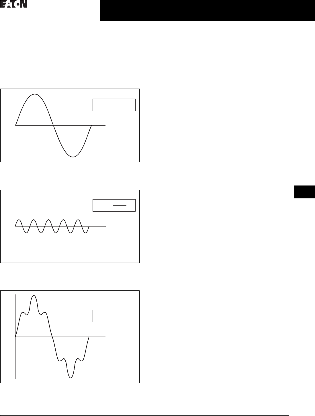
What are Harmonics?
Take a perfect wave with a fundamental frequency of 60 Hz,
which is close to what is supplied by the power company.
Figure 31.0-4. Perfect Wave
Add a second wave that is five times the fundamental frequency—
300 Hz (typical of frequency added to the line by a fluorescent light).
Figure 31.0-5. Second Wave
Combine the two waves. The result is a 60 Hz supply rich in
fifth harmonics.
Figure 31.0-6. Resulting Supply
What Causes Harmonics?
Harmonics are the result of non-linear loads that convert
AC line voltage to DC. Examples of equipment that are
non-linear loads are listed below:
■AC variable frequency drives
■DC drives
■Fluorescence lighting, computers, UPS systems
■Industrial washing machines, punch presses, welders, etc.
How Can Harmonics Due to VFDs Be Diminished?
By applying drives from the Eaton Clean Power drives family:
EGF and CFX passive filtered drives, HCX 12-pulse drives,
EGP and CPX 18-pulse drives, and RGX regenerative drives.
What are Linear Loads?
Linear loads are primarily devices that run across the line
and do not add harmonics. Motors are prime examples. The
downside to having large motor linear loads is that they
draw more energy than a VFD, because of their inability to
control motor speed. In most applications there is a turn
down valve used with the motor which will reduce the flow
of the material, without significantly reducing the load to the
motor. While this provides some measure of speed control,
it is extremely inefficient.
Why be Concerned About Harmonics?
1. Installation and utility costs increase. Harmonics
cause damage to transformers and lower efficiencies
due to the voltage drop. These losses can become
significant (from 16.6–21.6%) which can have a dramatic
effect on the HVAC systems that are controlling the
temperatures of the building where the transformer
and drive equipment reside.
2. Downtime and loss of productivity. Telephones and
data transmissions links may not be guaranteed to work
on the same power grids polluted with harmonics.
3. Downtime and nuisance trips of drives and other
equipment. Emergency generators have up to three
times the impedance that is found in a conventional
utility source. Thus the harmonic voltage can be up to
three times as large, causing risk of operation problems.
4. Larger motors must be used. Motors running
across the line that are connected on polluted power
distribution grids can overheat or operate at lower
efficiency due to harmonics.
5. Higher installation costs. Transformers and power
equipment must be oversized to accommodate the loss
of efficiencies. This is due to the harmonic currents
circulating through the distribution without performing
useful work.
f(x) = sin(x)
Volts
(v)
Time
(t)
f(x) = sin(5x)
5
Volts
(v)
Time
(t)
f(x) = sin(x) +
Volts
(v)
Time
(t)
sin(5x)
5
31.0-8
For more information, visit: www.eaton.com/consultants CA08104001E
February 2016
Adjustable Frequency Drives—Low Voltage
Sheet 31
22
23
24
25
26
27
28
29
30
31
32
33
34
35
36
37
38
39
40
41
42
4 3
Application Guide
008
How Does a VFD Convert Three-Phase AC to a
Variable Output Voltage and Frequency?
The six-pulse VFD: The majority of all conventional drives
that are built consist of a six-pulse configuration. The figure
below
represents a six-diode rectifier design that converts
three-phase utility power to DC. The inverter section uses
IGBTs to convert
DC power to a simulated AC sine wave that
can vary in frequency from 0–400 Hz.
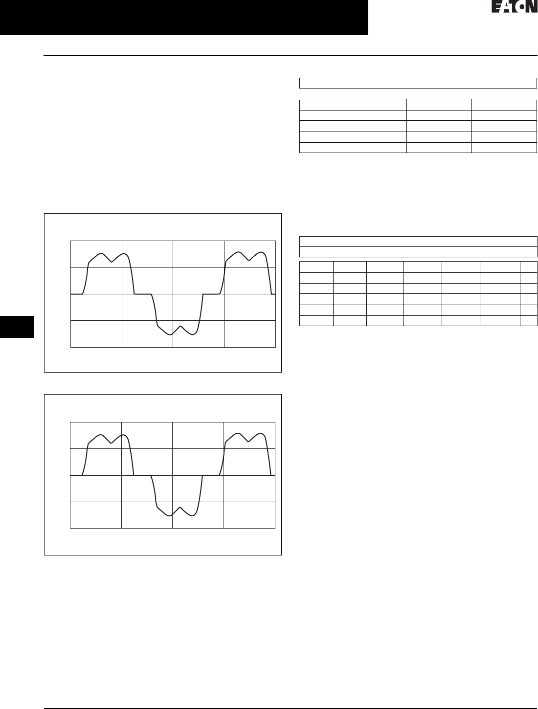
The six-pulse VFD drive creates harmonic current distortion.
The harmonic current that is created is energy that can not
be used by customers and causes external heat and losses
to all components including other drives that are on the
same power distribution. The figure is a 100 hp drive with
45 A of damaging harmonic current.
Figure 31.0-7. 100 hp Six-Diode Rectifier Design
Figure 31.0-8. 100 hp Six-Pulse Nonproductive Harmonic Current
Table 31.0-3. Six-Pulse Nonproductive Harmonic Current
Guidelines of Meeting IEEE Std. 519-2014
Harmonic Distortion Limits
The IEEE 519-2014 Specification is a standard that provides
guidelines for commercial and industrial users that are
implementing medium and low voltage equipment.
Table 31.0-4. Current Distortion Limits for Systems Rated
120 V through 69 kV
1Even harmonics are limited to 25% of the odd harmonic limits shown
in table above.
2Current distortions that result in a DC offset, e.g., half-wave converters,
are not allowed.
3All power generation equipment is limited to these values of current
distortion, regardless of actual Isc /IL.
where
Isc = maximum short-circuit current at PCC.
IL = maximum demand load current (fundamental frequency
component) at the PCC under normal load operating conditions.
1000
Current
Amps
500
0
–500
–1000
0.100 0.10625 0.1125
Time in Seconds
0.11875 0.125
1000
Current
Amps
500
0
–500
–1000
0.100 0.10625 0.1125
Time in Seconds
0.11875 0.125
Six-Pulse Circuit
Current Harmonics
I1 = 100% I11 = 6.10% I19 = 1.77%
I5 = 22.5% I13 = 4.06% I23 = 1.12%
I7 = 9.38% I17 = 2.26% I25 = 0.86%
Power = 100 hp
Harmonic current = 45 amps
Maximum Harmonic Current Distortion in percent of IL
Individual Harmonic Order (Odd Harmonics) 12
I
sc
/I
L
3
m
h < 11 11
m
h < 17 17
m
h < 23 23
m
h < 35 35
m
h
m
50 TDD
<20
3
4.0 2.0 1.5 0.6 0.3 5.0
20 <50 7.0 3.5 2.5 1.0 0.5 8.0
50 <100 10.0 4.5 4.0 1.5 0.7 12.0
100 <1000 12.0 5.5 5.0 2.0 1.0 15.0
>1000 15.0 7.0 6.0 2.5 1.4 20.0
CA08104001E For more information, visit: www.eaton.com/consultants
31.0-9
February 2016
Adjustable Frequency Drives—Low Voltage
Sheet 31
22
23
24
25
26
27
28
29
30
31
32
33
34
35
36
37
38
39
40
41
42
4 3
Application Guide
009
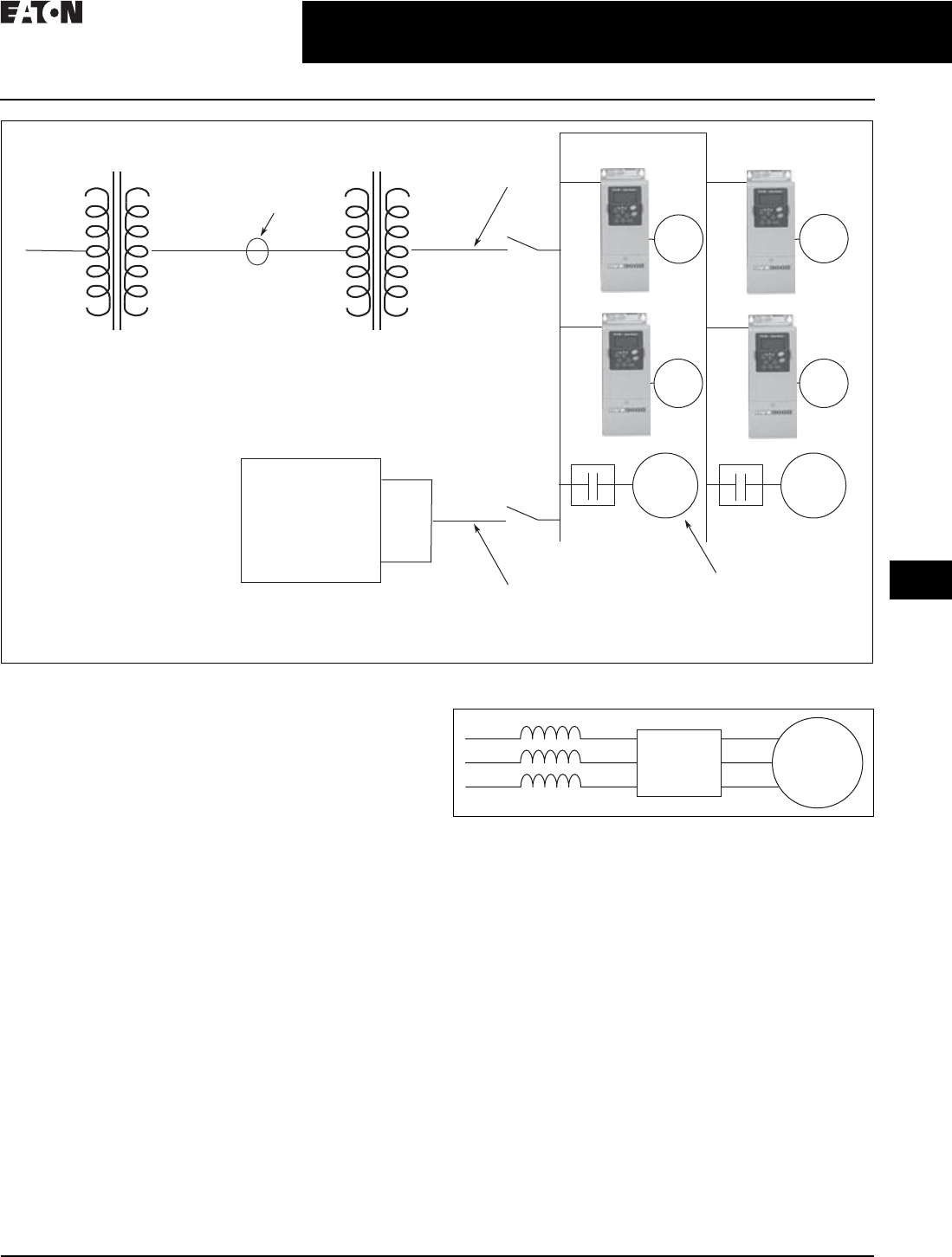
Figure 31.0-9. One-Line Diagram for Harmonic Analysis
Terms
■PCC (Point of Common Coupling) is defined as the
electrical connecting point between the utility and
multiple customers per the specifications in IEEE 519
■POA (Point of Analysis) is defined as where the harmonic
calculations are taken
An oscilloscope can make all measurements at the PCC or
POA to do an on-site harmonic evaluation.
Harmonic Reduction Methods to Meet IEEE 519
1. Line Reactor
A line reactor is a three-phase series inductance on the line
side of an AFD. If a line reactor is applied on all AFDs, it is
possible to meet IEEE guidelines where 10–25% of system
loads are AFDs, depending on the stiffness of the line and
the value of line reactance. Line reactors are available in
various values of percent impedance, most typically 1–1.5%,
3% and 5%.
Note: The SVX/SPX drives come standard with a nominal 3% input
impedance.
Figure 31.0-10. Line Reactor
Advantages
■Low cost
■Can provide moderate reduction in voltage and
current harmonics
■Available in various values of percent impedance
■Provides increased input protection for AFD and its
semiconductors from line transients
Disadvantages
■May not reduce harmonic levels to below
IEEE 519-2014 guidelines
■Voltage drop due to IR loss
____Volts ____Volts
____Volts
____kVA
____Isc
____Impedance
PCC
Utility Side
Utility Side
Transformer
____Volts ____Volts
____Volts
____kVA
____Isc
____Impedance
Customer
Transformer
Customer
Generator
____Volts
____kVA
____Isc
____Impedance
Source A
Source B
Generator
Set
AC
Motor
AC
Motor
AC
Motor
Total Linear Motor Loads
Total Non-Linear Drive Loads
____AMPS
____AMPS
AC
Motor
AC
Motor
AC
Motor
The best way to estimate AFD harmonic contribution to an electrical system is to perform a harmonic analysis based on known
system characteristics. The one line in this figure would provide the data to complete the calculations.
AFD Motor
31.0-10
For more information, visit: www.eaton.com/consultants CA08104001E
February 2016
Adjustable Frequency Drives—Low Voltage
Sheet 31
22
23
24
25
26
27
28
29
30
31
32
33
34
35
36
37
38
39
40
41
42
4 3
Application Guide
010
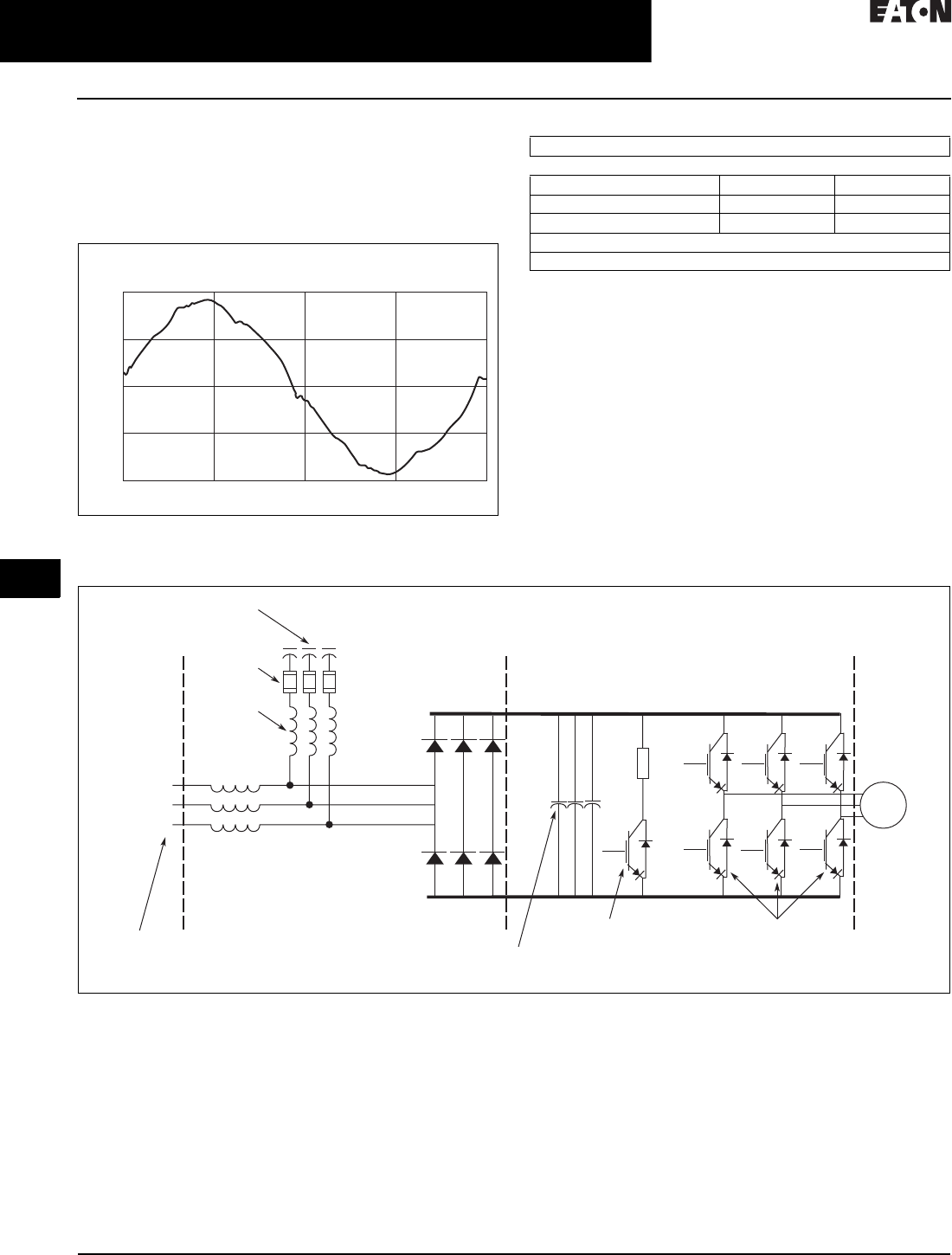
2. Passive Filters
Tuned harmonic filters involve the series connection of an
inductor with the shunt connection of an inductor and capac-
itor to form a low impedance path to ground for a specific
range of frequencies. This path presents an alternative to the
flow of harmonic currents back into the utility source.
Figure 31.0-11. 100 hp Enclosed 480 V Drive with Integrated
Passive Filter
Table 31.0-5. 100 hp Enclosed 480 V Drive with Integrated Passive Filter
Advantages
■Low cost for smaller horsepower applications
■More effective harmonic attenuation than
12-pulse drives
■Provides increased input protection for AFD from
line transients
Disadvantages
■Capacitors age over time, unlike magnetics
■Not as effective as 18-pulse drives
■Challenging to retrofit with bypass applications
Figure 31.0-12. Enclosed Drive with Integrated Passive Filter
200
Current
Amps
100
0
–100
–200
Time
Passive Filter
Current Harmonics
I1 = 100% I11 = 0.24% I19 = 0.50%
I5 = 3.76% I13 = 1.1% I23 = 0.55%
I7 = 1.65% I17 = 0.80% I25 = 0.80%
Power = 100 hp
Hc = 8.6 amps
Three-Phase
Input
AC Input
Reactor
L1A
L2A
L3A
1
2
3
Output Transistors
IGBT Section
Dynamic Braking
Transistor
6-Pulse Diode
Bridge Rectier
Converter Section
Shunt
Fusing
Tuned
Shunt
Reactor
Tuned
Harmonic
Capacitor
Inverter Section
(–) DC
(+) DC
Bus
Capacitors
AC
Motor
CA08104001E For more information, visit: www.eaton.com/consultants
31.0-11
February 2016
Adjustable Frequency Drives—Low Voltage
Sheet 31
22
23
24
25
26
27
28
29
30
31
32
33
34
35
36
37
38
39
40
41
42
4 3
Application Guide
011
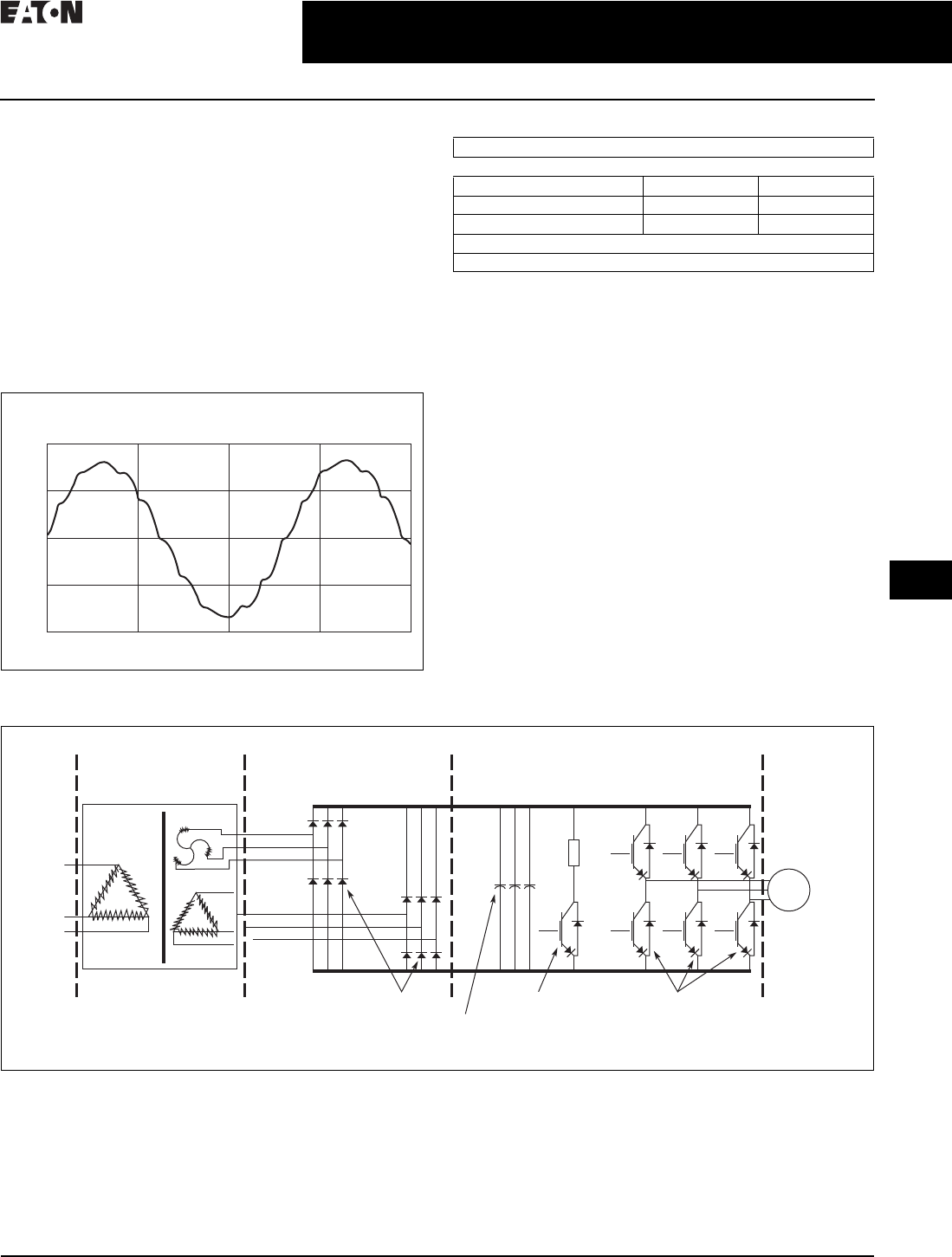
3. 12-Pulse Converters
A 12-pulse converter incorporates two separate AFD input
semiconductor bridges, which are fed from 30º phase shifted
power sources with identical impedance. The sources may
be two isolation transformers, where one is a delta/wye
design (which provides the phase shift) and the second a
delta/delta design (which does not phase shift). The 12-pulse
arrangement allows the harmonics from the first converter
to cancel the harmonics of the second. Up to approximately
85% reduction of harmonic current and voltage distortion
may be achieved (over standard six-pulse converter). This
permits a facility to use a larger percentage of AFD loads
under IEEE 519-2014 guidelines than allowable using line
reactors or DC chokes. A harmonic analysis is required to
guarantee compliance with guidelines.
Figure 31.0-13. 100 hp 480 V Drive with 12-Pulse Rectifier
Table 31.0-6. 100 hp 480 V Drive with 12-Pulse Rectifier
Advantages
■Reasonable cost, although significantly more than
reactors or chokes
■Substantial reduction (up to approx. 85%) in voltage
and current harmonics
■Provides increased input protection for AFD and its
semiconductors from line transients
Disadvantages
■Impedance matching of phase shifted sources is critical
to performance
■Transformers often require separate mounting or larger
AFD enclosures
■May not reduce distribution harmonic levels to below
IEEE 519-2014 guidelines
■Cannot retrofit for most AFDs
Figure 31.0-14. Basic 12-Pulse Rectifier with “Phase-Shifting” Transformer
200
Current
Amps
100
0
–100
–200
Time
12-Pulse Circuit
Current Harmonics
I1 = 100% I11 = 4.19% I19 = 0.06%
I5 = 1.25% I13 = 2.95% I23 = 0.87%
I7 = 0.48% I17 = 0.21% I25 = 0.73%
Power = 100 hp
Hc = 20 amps
12-Pulse Diode
Bridge Rectier
Converter Section
Inverter Section
(+) DC
L1A
L2A
L3A
L1B
L2B
L3B
(-) DC
Dynamic Braking
Transistor
Output Transistors
IGBT Section
AC
Motor
12-Pulse Diode
Bridge Rectier
Converter Section
12-Pulse
Phase-Shifting
Transformer
Bus
Capacitors
31.0-12
For more information, visit: www.eaton.com/consultants CA08104001E
February 2016
Adjustable Frequency Drives—Low Voltage
Sheet 31
22
23
24
25
26
27
28
29
30
31
32
33
34
35
36
37
38
39
40
41
42
4 3
Application Guide
012
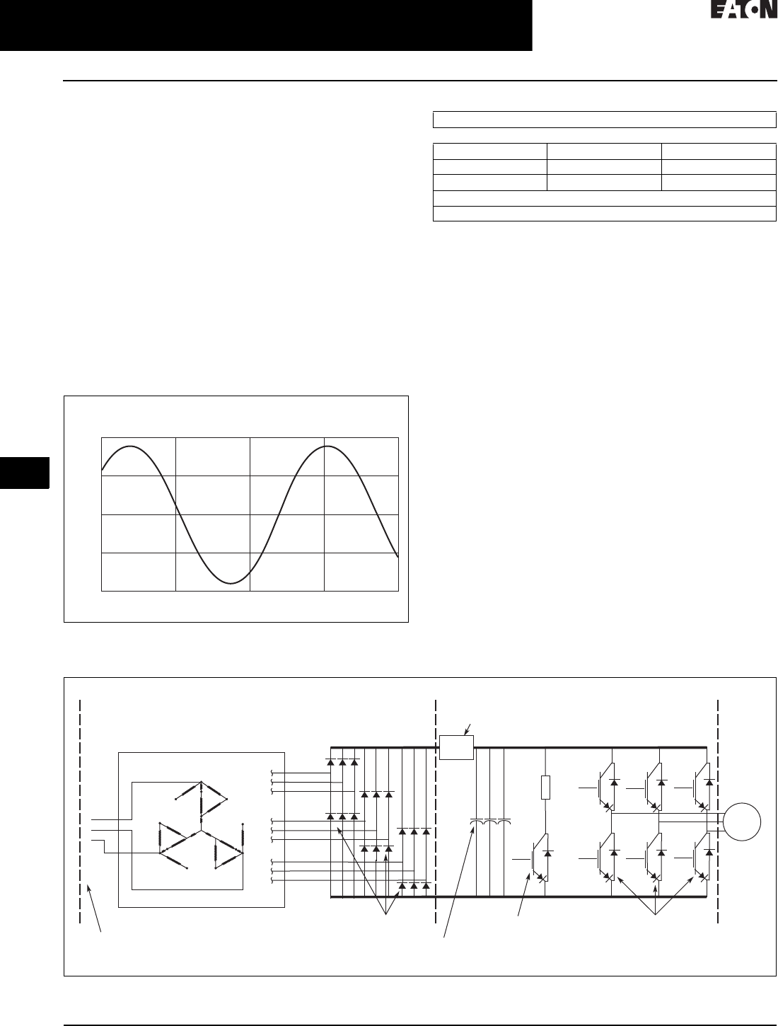
4. 18-Pulse Converters
When the total load is comprised of non-linear load such
as drives, and the ratio is lsc/IL, the greatest harmonic
mitigation is required. Under these conditions, the currents
drawn from the supply need to be sinusoidal and “clean”
such that system interference and additional losses are
negligible. Eaton’s enclosed 18-pulse drive uses a phase-
shifting auto-transformer with delta-connected winding that
carries only the ampere-turns caused by the difference in
load currents. This results in nine separate phases. In this
type of configuration, the total kVA rating of the transformer
magnetic system was only 48% that of the motor load. A
traditional isolated transformer system, with multipulse
windings, would require the full kVA rating to be supported,
which is more common in an MV step-down transformer.
The integrated 18-pulse drive, with near sine wave input
current and low harmonics will meet the requirements of
IEEE 519-2014 under all practical operating conditions. The
comparisons with six-pulse passive filter and 12-pulse
systems are shown on Pages 31.0-8, 31.0-11 and below.
Figure 31.0-15. 100 hp 480 V Drive with 18-Pulse Rectifier
Table 31.0-7. 100 hp 480 V Drive with 18-Pulse Rectifier
Advantages
■Effectively guarantees compliance with IEEE 519-2014
■Provides increased input protection for AFD and its
semiconductors from line transients
■Up to 4 times the harmonic reduction of 12-pulse methods
■Smaller transformer than isolation transformer used in
12-pulse converter
■Minimizes ripple current in capacitors, doubling expected
capacitor life
Disadvantages
■Not as cost-effective as some other methods at small
(<50) horsepower
Figure 31.0-16. Basic 18-Pulse Rectifier with Phase-Shifting Auto-Transformer
200
Current
Amps
100
0
–100
–200
Time
18-Pulse Clean Power
Current Harmonics
I1 = 100% I11 = 0.24% I19 = 1.00%
I5 = 0.16% I13 = 0.10% I23 = 0.01%
I7 = 0.33% I17 = 0.86% I25 = 0.01%
Power = 100 hp
Hc = 5.9 amps
1
12
23
34
4
5
5
6
67
7
8
8
9
9
A
C
N
Output Transistors
IGBT Section
Dynamic Braking
Transistor
Pre-charge
Circuit
18-Pulse SCR
Bridge Rectier
Converter Section
18-Pulse
Phase-Shifting
Auto-Transformer
Inverter Section
(–) DC
(+) DC
Diode Rectiers
Bus
Capacitors
3-Phase
AC Input
1
2
3
AC
Motor

CA08104001E For more information, visit: www.eaton.com/consultants
31.1-1
February 2016
Adjustable Frequency Drives—Low Voltage
Sheet 31
22
23
24
25
26
27
28
29
30
31
32
33
34
35
36
37
38
39
40
41
42
4 3
PowerXL Series Drives
General Information
013
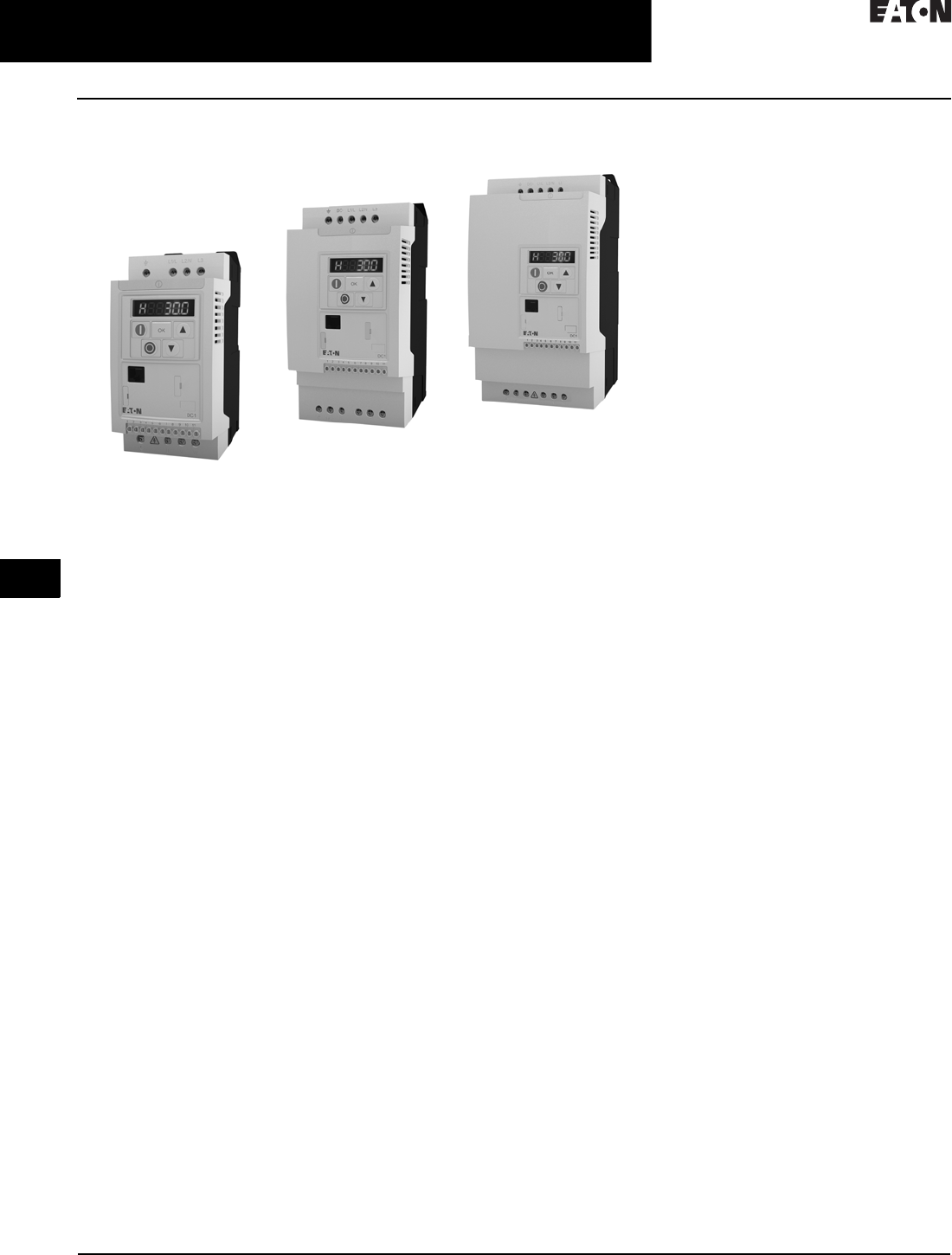
PowerXL DE1 Series
PowerXL DE1 Series
Product Description
Eaton’s PowerXL
®
DE1
variable speed
starter offers the advantages of both a
motor starter and a variable frequency
drive in a single device. The DE1 is a
compact and easy-to-use device with
the ability to change the speed of the
motor with the simplicity of a contactor
starter. With 14 basic parameters,
SmartWire-DT® connectivity and an
intuitive configuration module, the
DE1
setup and commissioning
is easy for
any panel builder and MOEM. The DE1
was designed for customers who have
concerns of the complexity of a VFD but
still
require variable frequency and
advanced motor protection.
Models rated at 480 V, three-phase,
50/60 Hz are available in sizes ranging
from 0.5 to 10 hp. Models rated at
230 V, single-phase in/three-phase out,
50/60 Hz are available in sizes ranging
from 0.33 to 3 hp.
The DE1 VSS is designed without a
keypad to provide a simplistic, cost
effective solution. Units are shipped
without a keypad. In order to change
parameters, there are accessories
such as the configuration module
that can change up to 5 parameters
or connectivity products to connect to
the drivesConnect PC Tool.
Features
■Compact, space-saving design
■Rugged design rated up to 60 °C
without derating
■DIN rail and screw mountable
■Narrow footprint for true side-by-
side installation
■Rated for group motor applications
■Low capacitor design for
low harmonics
■Control terminal blocks
■Three digital inputs
■One digital/analog (programmable)
input
■One relay output
■Contactor style power wiring
■RS-485/Modbus as standard
■Efficient, simple design without a
keypad
■Three indicating LEDs for fault and
condition status
■Reliable design—
150% for 60 s
175% for 2 s
■Smartwire-DT ready for expanding
communication gateways
Standards and Certifications
Product
■Complies with EN 61800-3
Safety
■IEC 61800-5-1
■CE
■UL
■CSA/cUL
■cTick
■UKRSekpro
■GOST R
■RoHS compliant

31.1-2
For more information, visit: www.eaton.com/consultants CA08104001E
February 2016
Adjustable Frequency Drives—Low Voltage
Sheet 31
22
23
24
25
26
27
28
29
30
31
32
33
34
35
36
37
38
39
40
41
42
4 3
PowerXL Series Drives
Product Selection
014
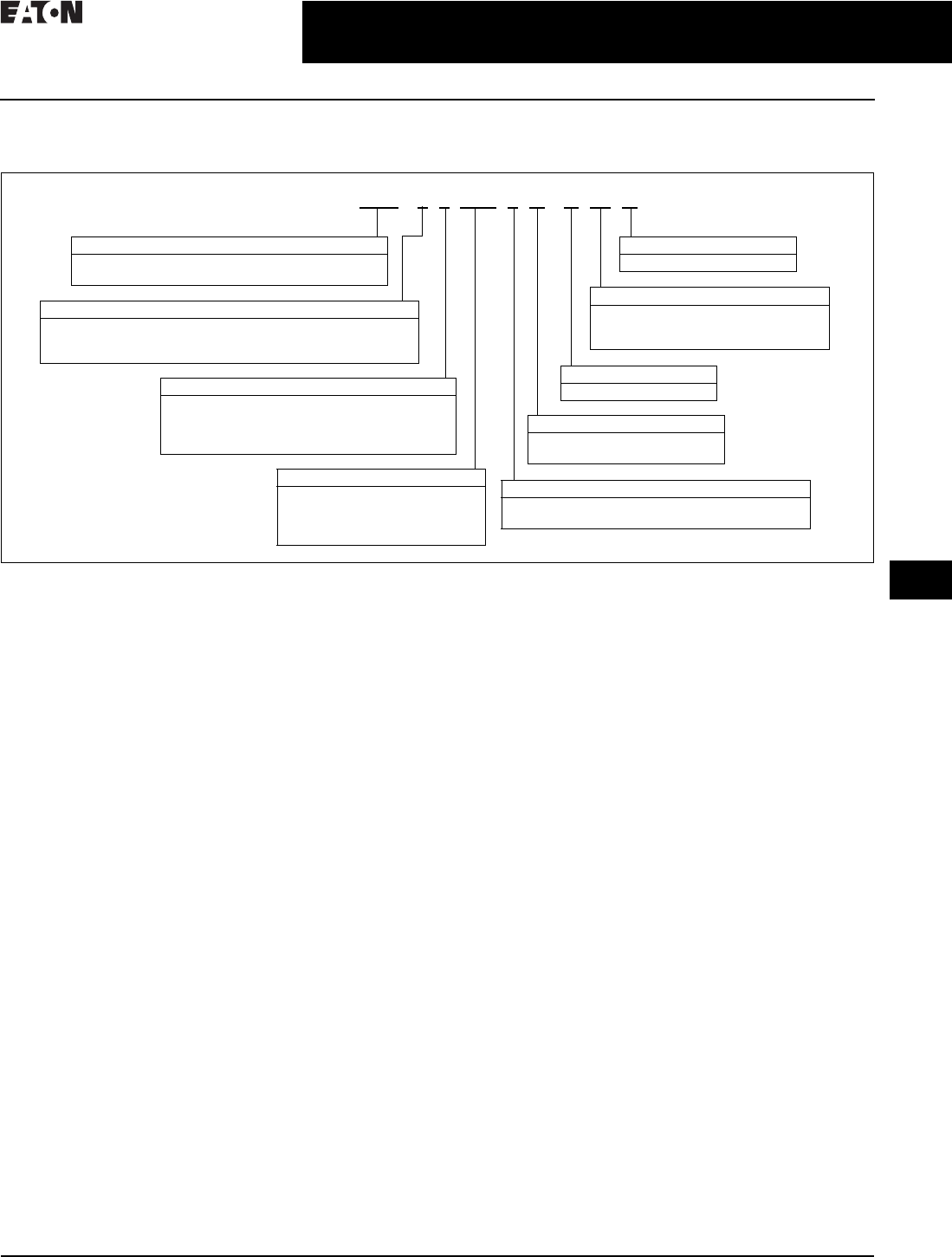
Catalog Number Selection
Table 31.1-1. DE1 Series Variable Speed Starter
Product Selection
IP20
DE1 -1 24D3 N N -N 20 N
Conformation Coated Option
N= Not conformal coated boards
Device Series
E1 = Economy
Basic Naming
D=Drive
Current Rating
230 V 460 V
1D4 = 1.4 A, 0.33 hp, 0.25
kW
2D3 = 2.3 A, 0.5 hp,
0.37 kW
2D7 = 2.7 A, 0.75 hp, 0.55
kW
4D3 = 4.3 A, 1.0 hp,
0.75 kW
7D0 = 7.0 A, 2.0 hp,
1.5 kW
9D6 = 9.6 A, 3.0 hp,
2.2 kW
1D3 = 1.3 A, 0.5 hp,
0.37 kW
2D1 = 2.1 A, 1.0 hp,
0.75 kW
3D6 = 3.6 A, 2.0 hp,
1.5 kW
5D0 = 5.0 A, 3.0 hp,
2.2 kW
6D6 = 6.6 A, 4.0 hp,
3.0 kW
8D5 = 8.5 A, 5.0 hp,
4.0 kW
011 = 11 A, 7.5 hp,
5.5 kW
016 = 16 A, 10 hp,
7.5 kW
Number of Phases
1= Single-phase main connection/
three-phase motor connection
3= Three-phase main connection/
three-phase motor connection
Input/Output Voltage
2=230 V
4=480 V
Environment Rating
20 = IP20, NEMA 0
Display Option
N= No display
Brake Chopper Option
N= No brake chopper
Filter Option
N=No filter
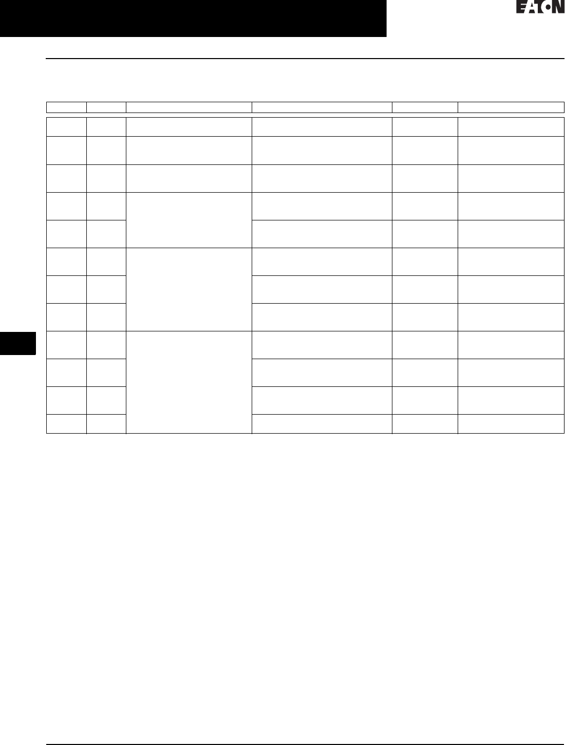
Table 31.1-2. DE1 Series IP20 Enclosure Drives
1For all applications, select the unit such that the motor current is less than or equal to the rated
continuous output current.
2These are constant torque/high overload rated drives.
hp 1kW Volts 100%
Continuous
Current In (A)
Frame
Size
Catalog Number 2
0.33 0.25 200–240 V single-phase in/
230 V three-phase out
1.4 1 DE1-121D4NN-N20N
0.5 0.37 2.3 1 DE1-122D3NN-N20N
0.75 0.55 2.7 1 DE1-122D7NN-N20N
1 0.75 4.3 1 DE1-124D3NN-N20N
21.5 7 1 DE1-127D0NN-N20N
32.2 9.6 2 DE1-129D6NN-N20N
0.5 0.37 380–480 V three-phase in/
480 V three-phase out
1.3 1 DE1-341D3NN-N20N
1 0.75 2.1 1 DE1-342D1NN-N20N
21.5 3.6 1 DE1-343D6NN-N20N
32.2 5 2 DE1-345D0NN-N20N
43 6.6 2 DE1-346D6NN-N20N
54 8.5 2 DE1-348D5NN-N20N
7. 5 5 . 5 11. 3 2 DE1-34011NN-N20N
10 7.5 16 2 DE1-34016NN-N20N

CA08104001E For more information, visit: www.eaton.com/consultants
31.1-3
February 2016
Adjustable Frequency Drives—Low Voltage
Sheet 31
22
23
24
25
26
27
28
29
30
31
32
33
34
35
36
37
38
39
40
41
42
4 3
PowerXL Series Drives
Technical Data
015
Accessories
Table 31.1-3. PC Communication Kit and Copy/Paste Module
Table 31.1-4. Keypad Options
1Includes 1 m RS-485 data cable.
Table 31.1-5. Extension Cables and Data Cable Splitter
Table 31.1-6. SmartWire Modules
Table 31.1-7. Commoning Links 2
2Commoning links can be used to connect multiple line side 460 V DE1
units for use in group motor applications.
3These combinations may result in the total of the individual input
currents exceeding the three-phase commoning link’s and incoming
connection block’s ampacity (35 A).
4Required for group motor applications when using the 460 V
commoning links.
Technical Data and Specifications
Ratings
Table 31.1-8. PowerXL DE1 Basic Controller Standard Ratings
Table 31.1-9. Programmable Parameters
Specifications
Table 31.1-10. PowerXL DE1 Series
5All units do not require derating except for the 10 hp 460 V unit which
may require derating depending on the switching frequency used.
Description Catalog Number
Bluetooth copy/paste communication stick DX-COM-STICK
USB to RJ45 panel mount kit DX-COM-PCKIT
USB to RJ45 PC Tool cable DX-CBL-PC-3M0
Description Catalog Number
LED remote keypad—7-segment display, IP54 rated DX-KEY-LED 1
Configuration module—plug-in unit, DIP switch
and dial control
DXE-EXT-SET
Description Catalog Number
RJ45 communication cable w/terminating resistor EASY-NT-R
RS-485 data cable, RJ45, 0.5 m DX-CBL-RJ45-0M5
RS-485 data cable, RJ45, 1.0 m DX-CBL-RJ45-1M0
RS-485 data cable, RJ45, 3.0 m DX-CBL-RJ45-3M0
RS-485 three-way data cable splitter, RJ45 DX-SPL-RJ45-3SL
RS-485 data cable splitter, RJ45, (1 connector
to 2 socket)
DX-SPL-RJ45-2SL1PL
Description Catalog Number
SmartWire-DT interface for DE1 and DC1 IP20 DX-NET-SWD3
Description Max. Devices Used Catalog Number
460 V, three-phase link 3xFS1 XTCEXCLK3B
2xFS1 + 1xFS2
2xFS2
4xFS1 XTCEXCLK4B
3xFS1 + 1xFS2
1xFS1 + 2xFS2 3
5xFS1 XTCEXCLK5B
4xFS1 + 1xFS2
2xFS1 + 2xFS2 3
3xFS2 3
460 V, incoming terminal — XTCEXITB 4
Description Specification
Protections
Overload protection 150% for 60s for every 600 seconds
Overvoltage protection Yes
Undervoltage protection Yes
Ground fault protection Yes
Overtemperature protection Yes
Motor overload protection Yes
Motor stall protection Yes
Short-circuit protection 100 kAIC with fuses, 65 kAIC with PKZM,
10 kAIC with FAZ
Description
14 Standard operation parameters
Programmable start function
DC-brake at start and stop
Adjustable switching frequency
Autorestart function after fault
Protections and supervisions
Power section fault indication
External fault
Fieldbus communication
Analog input range selection, signal scaling and filtering
Four preset speed reference
Description Specification
Input Ratings
Input voltage (Vin)±10%
Input frequency (fin) 50/60 Hz (variation up to 48–62 Hz)
Connection to power Maximum of one time every 30 seconds
Output Ratings
Output voltage 0 to Vin
Continuous output current Continuous rated current IN at ambient
temperature max. 140 °F (60 °C), 150% for
60 seconds, 175% for 2 seconds
Output frequency 0 to 500 Hz
Frequency resolution 0.1 Hz
Initial output current (IH) 175% for 2s for every 20 seconds
Torque depends on motor
Control Characteristics
Operation mode U/f control, slip compensation
Switching frequency 4 to 32 kHz
Voltage reference 10 Vdc (max. 10 mA)
Field weakening point 0 to 500 Hz
Acceleration time 0.1 to 600 seconds
Deceleration time 0.1 to 600 seconds
Ambient Conditions
Ambient operating
temperature
–10 °C to +50 °C, for 60 °C there is no
derating required 5
Storage temperature –40 °C to +70 °C
Relative humidity 0 to 95% RH, noncondensing,
non-corrosive, no dripping water
Enclosure class IP20 (FS1–FS3)

31.1-4
For more information, visit: www.eaton.com/consultants CA08104001E
February 2016
Adjustable Frequency Drives—Low Voltage
Sheet 31
22
23
24
25
26
27
28
29
30
31
32
33
34
35
36
37
38
39
40
41
42
4 3
PowerXL Series Drives
Technical Data
016
Standards—DE1 Series
Variable Speed Starter
I/O Specifications
■Digital inputs DI1–DI4 are program-
mable
■Relay output is programmable
■DI3 and DI4 can be programmed to
be digital, thermistor or analog
Includes:
■Four inputs (three digital and one
digital/analog)
■Analog input
❑4–20 mA
❑0–10 V
■One relay output
■RS-485 interface
Reliability
■Pretested components
■Computerized testing
■Robust design rated to 60 °C
Table 31.1-11. DE1 Series I/O Interface
Terminal Signal Factory Preset Description
0 V 0 V Reference potential — 0 V connection
+0 V +24 Vdc Control voltage for DI1-DI4 — Maximum load 100 mA
Reference potential V
1 DI1 Digital Input 1 FWD +10 to 24 V
2 DI2 Digital Input 2 REV +10 to 24 V
3 DI3 Digital Input 3 Fixed frequency FF1 +10 to 24 V
Ther. Thermistor Fixed frequency FF1 External fault: [Need info]
Trip at 3600 ?
Reset at 1600 ?
4 DI4 Digital Input 4 Frequency reference value +10 to 24 V
AI1 Analog Input Frequency reference value 0 to 10 V 0/4–20 mA
Can be switched with parameter P16
13 K13 Relay 1, normally open contact Active = RUN Maximum switching load: 250 Vac/6 A or 30 Vdc/5 A
14 K14 Relay 1, normally open contact Active = RUN Maximum switching load: 250 Vac/6 A or 30 Vdc/5 A

CA08104001E For more information, visit: www.eaton.com/consultants
31.1-5
February 2016
Adjustable Frequency Drives—Low Voltage
Sheet 31
22
23
24
25
26
27
28
29
30
31
32
33
34
35
36
37
38
39
40
41
42
4 3
PowerXL Series Drives
Dimensions
017
Dimensions—Approximate Dimensions in Inches (mm)
Figure 31.1-1. DE1, Sizes FS1 and FS2, Degree of Protection IP20/NEMA 0
B
C
Ø2
Ø1
A
A1 C1
B1
B2
0 V +10 V 1 2 3 4 1 3 14
UVW
B3
B4
Ø
L1/LL2/NL3
Frame
Size
A A1 B B1 B2 B3 B4 C C1 Ø1Ø2Weight
Lb (kg)
FS1 1.77
(45.0)
0.98
(25.0)
9.09
(231.0)
8.66
(220.0)
0.20
(5.1)
2.52
(64.0)
6.54
(166.1)
6.65
(169.0)
0.26
(6.6)
0.20
(5.1)
0.39
(10.0)
2.29
(1.04)
FS2 3.54
(90.0)
1.97
(50.0)
9.09
(231.0)
8.66
(220.0)
0.20
(5.1)
2.52
(64.0)
6.54
(166.1)
6.65
(169.0)
0.26
(6.6)
0.20
(5.1)
0.39
(10.0)
3.70
(1.68)
31.1-6
For more information, visit: www.eaton.com/consultants CA08104001E
February 2016
Adjustable Frequency Drives—Low Voltage
Sheet 31
22
23
24
25
26
27
28
29
30
31
32
33
34
35
36
37
38
39
40
41
42
4 3
PowerXL Series Drives
General Information
018
PowerXL DC1 Series Drives
DG1 General Purpose Drive
Product Description
Eaton’s PowerXL® DC1 variable
frequency drives are the next
generation of drives specifically
engineered for today’s machinery
applications.
The DC1 is compact with only 14
basic parameters, SmartWire-DT®
connectivity, and outstanding ease of
mounting and installation. The DC1 is
perfect for quick commissioning and
is ideal for panel builders. This drive
supports single-phase motor applica-
tions, and detachable terminal blocks
make control wiring much easier.
Models rated at 480 volts, three-phase,
50/60 Hz are available in sizes ranging
from 1 to 30 hp. Models rated at
240 volts, single- or three-phase,
50/60 Hz are available in sizes ranging
from 0.5 to 15 hp. Models rated at
115 volts, single-phase, 50/60 Hz are
available in the 0.5 to 3 hp size range.
Features
■Compact, space-saving design
■
Rugged and reliable—
175% for 2 s,
50 °C rated
■DIN rail and screw mountable
(FS1 and FS2)
■Side-by-side installation
■Industry-leading efficiency delivers
energy savings to the customer
■Optional integrated EMC filters
make the unit suitable for
commercial and industrial networks
■Brake chopper as standard in frames
2 and higher
■Temperature-controlled fan
■RS-485/Modbus® and CANopen™
as standard
■PI controller as standard
■SmartWire capability
■Removable I/O terminal blocks
■Contactor style power wiring
■Designed for shaded-pole, single-
phase motors and permanent split
capacitor single-phase motors
■Designed to run surface mounted
(SPM) and rotor in-built (IPM)
permanent magnet motors
Standards and Certifications
Product
■Complies with EN61800-3 (2004)
EMC (At Default Settings)
■EMC Category C1, C2 and C3 at
default settings (1 m, 5 m, 25 m)
Safety 1
■61800-5-1
■EN 60529
■CE
■UL
■cUL
■UkrSepro
■c-Tick
■RoHS compliant
1See unit nameplate for more detailed
approvals.
CA08104001E For more information, visit: www.eaton.com/consultants
31.1-7
February 2016
Adjustable Frequency Drives—Low Voltage
Sheet 31
22
23
24
25
26
27
28
29
30
31
32
33
34
35
36
37
38
39
40
41
42
4 3
PowerXL Series Drives
Enclosed Drives
019
Catalog Number Selection
Table 31.1-12. DC1 Series Adjustable Frequency AC Drives
DC1 -1 24D1 F N -A 20 N
Type
N
= Standard basic device
Device Series
DC1= Variable frequency drive, compact, Series 1
=(D = Drives, C = Compact, 1 = Series 1)
Degree of Protection
20 = IP20/NEMA 0
66 = IP66/NEMA 4/4X
6S = IP66 with disconnect/NEMA 4/4X
Display Unit (Display)
A
= LED display
Brake Chopper
N= No internal brake chopper
B= Brake chopper
EMC (Radio Interference Suppression Filter)
N= No internal RFI filter
F= Internal RFI filter
Connection in Power Section
1= Single-phase mains connection/three-phase motor connection
3= Three-phase mains connection/three-phase motor connection
S= Single-phase mains connection/single-phase motor connection
Mains Voltage Category
1= 110 V (110–115 V ±10%)
2= 230 V (200–240 V ±10%)
4= 480 V (380–480 V ±10%)
D= 110 V input/230 V output (voltage doubler)
Rated Operational Current
Examples—
2D2 = 2.2 A
4D1 = 4.1 A
024 = 24 A
31.1-8
For more information, visit: www.eaton.com/consultants CA08104001E
February 2016
Adjustable Frequency Drives—Low Voltage
Sheet 31
22
23
24
25
26
27
28
29
30
31
32
33
34
35
36
37
38
39
40
41
42
4 3
PowerXL Series Drives
Enclosed Drives
020
Product Selection
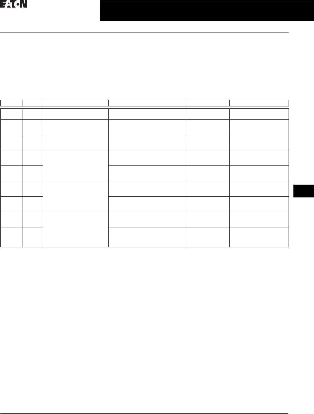
Table 31.1-13. DC1 Series IP20 Enclosure Drives 1
1These are constant torque/high overload rated drives.
2For all applications, select the unit such that the motor current is less than or equal to the rated continuous output current.
3Brake chopper circuit available as standard in frames 2 and 3.
4Only for use with shaded pole or split capacitor single-phase motors.
5RFI version available. Substitute with DC1-*****F*-**** for this option.
hp 2kW Volts 100% Continuous Current In (A) Frame Size 3Catalog Number
0.5
0.75
0.37
0.55
115 V single-phase in/ 4
115 V single-phase out
7
10.5
1
2
DC1-S17D0NN-A20N
DC1-S1011NB-A20N
0.5
1
1.5
0.37
0.75
1.1
200–240 V single-phase in/ 4
200–240 V single-phase out
4.3
7
10
1
1
2
DC1-S24D3NN-A20N 5
DC1-S27D0NN-A20N 5
DC1-S2011NB-A20N 5
0.5
1
1.5
0.37
0.75
1.1
115 V single-phase in/
230 V three-phase out
2.3
4.3
5.8
1
1
2
DC1-1D2D3NN-A20N
DC1-1D4D3NN-A20N
DC1-1D5D8NB-A20N
0.5
1
2
0.37
0.75
1.5
200–240 V single-phase in/
230 V three-phase out
2.3
4.3
7
1
1
1
DC1-122D3NN-A20N 5
DC1-124D3NN-A20N 5
DC1-127D0NN-A20N 5
2
3
5
1.5
2.2
4
7
10.5
15
2
2
3
DC1-127D0NB-A20N 5
DC1-12011NB-A20N 5
DC1-12015NB-A20N
0.5
1
2
0.37
0.75
1.5
200–240 V three-phase in/
230 V three-phase out
2.3
4.3
7
1
1
1
DC1-322D3NN-A20N
DC1-324D3NN-A20N
DC1-327D0NN-A20N
2
3
5
1.5
2.2
4
7
10.5
18
2
2
3
DC1-327D0NB-A20N 5
DC1-32011NB-A20N 5
DC1-32018NB-A20N 5
7. 5
10
15
5.5
7. 5
11
24
30
46
4
4
4
DC1-32024NB-A20N 5
DC1-32030NB-A20N 5
DC1-32046NB-A20N 5
1
2
2
0.75
1.5
1.5
380–480 V three-phase in/
480 V three-phase out
2.2
4.1
4.1
1
1
2
DC1-342D2NN-A20N 5
DC1-344D1NN-A20N 5
DC1-344D1NB-A20N 5
3
5
7. 5
2.2
4
5.5
5.8
9.5
14
2
2
3
DC1-345D8NB-A20N 5
DC1-349D5NB-A20N 5
DC1-34014NB-A20N 5
10
15
20
7. 5
11
15
18
24
30
3
3
4
DC1-34018NB-A20N 5
DC1-34024NB-A20N 5
DC1-34030NB-A20N 5
25
30
18.5
22
39
46
4
4
DC1-34039NB-A20N 5
DC1-34046NB-A20N 5
CA08104001E For more information, visit: www.eaton.com/consultants
31.1-9
February 2016
Adjustable Frequency Drives—Low Voltage
Sheet 31
22
23
24
25
26
27
28
29
30
31
32
33
34
35
36
37
38
39
40
41
42
4 3
PowerXL Series Drives
Enclosed Drives
021
IP66 NEMA 4/4X Interior DC1 Drive
The IP66 version of the DC1 is a unique
solution to allow for mounting the
drive outside of a control panel or next
to a motor for distributed control.
“-A66N” Option
This version comes with the keypad
that is similar to that of IP20 version.
There are no additional cover controls
to address security concerns.
“-A6SN” Option
This version has an integrated
potentiometer, a forward/off/reverse
switch and a disconnect switch with
lock-off capability with the standard
keypad. This allows for reduced labor
and materials when compared to a
IP20 solution in separate enclosure.
Table 31.1-14. DC1 Series IP66 Enclosure Drives 1
1These are constant torque/high overload rated drives.
2For all applications, select the unit such that the motor current is less than or equal to the rated continuous output current.
3Brake chopper circuit available as standard in frames 2 and 3.
4Non-disconnect version available. Substitute with -A66N.
5RFI version available. Substitute with DC1-*****F*-**** for this option.
hp 2kW Volts 100% Continuous Current In (A) Frame Size 3Catalog Number
0.5
0.75
0.37
0.55
115 V single-phase in/
115 V single-phase out
7
10.5
1
2
DC1-S17D0NN-A6SN 4
DC1-S1011NB-A6SN 4
0.5
1
1.5
0.37
0.75
1.1
200–240 V single-phase in/
200–240 V single-phase out
4.3
7
10
1
1
2
DC1-S24D3NN-A6SN 45
DC1-S27D0NN-A6SN 45
DC1-S2011NB-A6SN 45
0.5
1
1.5
0.37
0.75
1.1
115 V single-phase in/
230 V three-phase out
2.3
4.3
5.8
1
1
2
DC1-1D2D3NN-A6SN 4
DC1-1D4D3NN-A6SN 4
DC1-1D5D8NB-A6SN 4
0.5
1
2
0.37
0.75
1.5
200–240 V single-phase in/
230 V three-phase out
2.3
4.3
7
1
1
1
DC1-122D3NN-A6SN 45
DC1-124D3NN-A6SN 45
DC1-127D0NN-A6SN 45
2
3
5
1.5
2.2
4
7
10.5
15
2
2
3
DC1-127D0NB-A6SN 45
DC1-12011NB-A6SN 45
DC1-12015NB-A6SN 4
0.5
1
2
0.37
0.75
1.5
200–240 V three-phase in/
230 V three-phase out
2.3
4.3
7
1
1
1
DC1-322D3NN-A6SN 4
DC1-324D3NN-A6SN 4
DC1-327D0NN-A6SN 4
2
3
5
1.5
2.2
4
7
10.5
18
2
2
3
DC1-327D0NB-A6SN 45
DC1-32011NB-A6SN 45
DC1-32018NB-A6SN 45
1
2
2
0.75
1.5
1.5
380–480 V three-phase in/
460 V three-phase out
2.2
4.1
4.1
1
1
2
DC1-342D2NN-A6SN 45
DC1-344D1NN-A6SN 45
DC1-344D1NB-A6SN 45
3
5
7. 5
10
2.2
4
5.5
7. 5
5.8
9.5
14
18
2
2
3
3
DC1-345D8NB-A6SN 45
DC1-349D5NB-A6SN 45
DC1-34014NB-A6SN 45
DC1-34018NB-A6SN 45

31.1-10
For more information, visit: www.eaton.com/consultants CA08104001E
February 2016
Adjustable Frequency Drives—Low Voltage
Sheet 31
22
23
24
25
26
27
28
29
30
31
32
33
34
35
36
37
38
39
40
41
42
4 3
PowerXL Series Drives
Enclosed Drives
022
Accessories
DC1 Series
Table 31.1-15. PC Communication Kit and Copy/Paste Module
Table 31.1-16. Encoder Feedback Plug-In Option Module
and Miscellaneous Cards
Table 31.1-17. Remote Keypad
1Includes 1 m RS-485 data cable.
Table 31.1-18. Brake Resistor (FR2 and FR3)
Table 31.1-19. Extension Cables and Data Cable Splitter
Table 31.1-20. SmartWire Modules
Description Catalog Number
Bluetooth copy/paste communication stick DX-COM-STICK
USB to RJ45 panel mount kit DX-COM-PCKIT
USB to RJ45 converter cable DX-COM-PCCABLE
USB to RJ45 PC Tool cable DX-CBL-PC-3MO
Description Catalog Number
Local control/test option card DXC-EXT-LOCSIM
HVACO drive running and tripped relay
output card
DXC-EXT-2RO1 AO
Dual relay output card DXC-EXT-2RO
110 V logic input card DXC-EXT-IO110
230 V logic input card DXC-EXT-IO230
Description Catalog Number
LED remote keypad—7-segment display,
IP54 rated
DX-KEY-LED 1
OLED remote keypad—full text display, multi-line
text, multi-language, IP54 hand/auto buttons
DX-KEY-OLED 1
Description Catalog Number
DC1, DA1 internal mount 200 W, 100 R DX-BR3-100
Description Catalog Number
RJ45 communication cable
with terminating resistor
EASY-NT-R
RS-485 data cable, RJ45, 0.5 m DX-CBL-RJ45-0M5
RS-485 data cable, RJ45, 1.0 m DX-CBL-RJ45-1M0
RS-485 data cable, RJ45, 3.0 m DX-CBL-RJ45-3M0
RS-485 three-way data cable splitter, RJ45 DX-SPL-RJ45-3SL
RS-485 data cable splitter, RJ45,
(1 connector to 2 socket)
DX-SPL-RJ45-2SL1PL
Description Catalog Number
SmartWire-DT interface for DC1 IP20 DX-NET-SWD3

CA08104001E For more information, visit: www.eaton.com/consultants
31.1-11
February 2016
Adjustable Frequency Drives—Low Voltage
Sheet 31
22
23
24
25
26
27
28
29
30
31
32
33
34
35
36
37
38
39
40
41
42
4 3
PowerXL Series Drives
Enclosed Drives
023
Technical Data and Specifications
DC1 Series
Ratings
Table 31.1-21. PowerXL DC1 Basic Controller IP20 Standard Ratings
Table 31.1-22. Programmable Parameters
Specifications
Table 31.1-23. PowerXL DC1 Series Drives
1Exception: 115 V single-phase in, 230 V three-phase out.
2Only FS2, FS3 and FS4 drives are equipped with brake chopper circuit.
Description Specification
Protections
Overload protection 150% for 60s for every 600 seconds
Overvoltage protection Yes
Undervoltage protection Yes
Ground fault protection Yes
Overtemperature protection Yes
Motor overload protection Yes
Motor stall protection Yes
Short-circuit withstand rating 100 kAIC with Type 1 fuses
Description
Built-in Help card
14 Standard operation parameters
Reference scaling
Programmable start and stop functions
DC-brake at start and stop
Programmable V/Hz curve
Adjustable switching frequency
Autorestart function after fault
Protections and supervisions
Power section fault indication
External fault
Fieldbus communication
Second deceleration time
Analog input range selection, signal scaling and filtering
PI controller
Skip frequencies
Description Specification
Input Ratings
Input voltage (Vin)±10%
Input frequency (fin) 50/60 Hz (variation up to 48–62 Hz)
Connection to power Maximum of one time every 30 seconds
Output Ratings
Output voltage 0 to Vin 1
Continuous
output current
Continuous rated current IN at
ambient temperature max.
122 °F (50 °C), 150% for 60 seconds,
175% for 2 seconds
Output frequency 0 to 500 Hz
Frequency resolution 0.1 Hz
Initial output current (IH) 175% for 2s for every 20 seconds
Torque depends on motor
Control Characteristics
Operation mode U/f control, slip compensation
Switching frequency 4 to 32 kHz
Voltage reference 10 Vdc (max. 10 mA)
Field weakening point 0 to 500 Hz
Acceleration time 0.1 to 600 seconds
Deceleration time 0.1 to 600 seconds
Brake Resistor (Minimum Values) 2
230 V Series FS2 and FS3 47 ohms
400 V Series FS2 100 ohms, FS3 47 ohms
Ambient Conditions
Ambient operating
temperature
+14 °F (–10 °C), no frost to +122 °F (+50 °C):
Rated loadability IN
IP20—NEMA 0
Storage temperature –40 °F (–40 °C) to +140 °F (+60 °C)
Relative humidity 0 to 95% RH, noncondensing, non-corrosive,
no dripping water
Enclosure class IP20 (FS1–FS4)

31.1-12
For more information, visit: www.eaton.com/consultants CA08104001E
February 2016
Adjustable Frequency Drives—Low Voltage
Sheet 31
22
23
24
25
26
27
28
29
30
31
32
33
34
35
36
37
38
39
40
41
42
4 3
PowerXL Series Drives
Enclosed Drives
024
Standards—DC1 Series
I/O Specifications
■Digital inputs DI1–DI4 are
programmable
■Digital, relay and analog outputs
are programmable
Includes:
■Four inputs (two digital and two
digital/analog)
■Analog inputs
❑4–20 mA
❑0–10 V
■One output (analog or digital)
■One relay output
■RS-485 interface
Reliability
■Pretested components
■Computerized testing
■Final test with full load
■Conformal-coated boards
■
Eaton’s Electrical Services &
Systems: national network
of AF drive specialists
Table 31.1-24. DC1 Series I/O Interface
1Programmable function.
Terminal Signal Factory Preset Description
1 +24 Vdc Control voltage for DI1–DI4 — Maximum load 100 mA
Reference potential V
2 DI1 Digital Input 1 Start Enable FWD 8 to +30 V (High, R1 > 6 k h)
3 DI2 Digital Input 2 Start Enable REV 8 to +30 V (High, R1 > 6 k h)
4 DI3 Digital Input 3 Fixed frequency FF1 Digital: 8–30 V (high)
AI2 Analog Input 2 Fixed frequency FF1 Analog: 0 to +10 V (Ri >72 k h)
0/4–20 mA (Rß = 500 h)
Can be switched with parameter P16
5 +10 Vdc Reference voltage, Output (+10 V) — Maximum load 10 mA
Reference potential 0 V
6 AI1 Analog Input 1 Frequency reference value 1
(fixed frequency)
Analog: 0 to +10 V (Ri >72 k h)
0/4–20 mA (Rß = 500 h)
Can be switched with parameter P16
DI4 Digital Input 5 Frequency reference value 1
(fixed frequency)
Digital: 8–30 V (high)
7 0 V Reference potential — 0 V = connection terminal 9
8 AO1 Analog Output 1 Output frequency Analog: 0 to +10 V, maximum 4–20 mA
Can be switched with parameter P-25
DO1 Digital Output 1 Output frequency Digital: 8 to +24 V
9 0 V Reference potential — 0 V connection terminal 7
10 K13 Relay 1, normally open contact Active = RUN Maximum switching load: 250 Vac/6 A or 30 Vdc/5 A
11 K14 Relay 1, normally open contact Active = RUN Maximum switching load: 250 Vac/6 A or 30 Vdc/5 A
2
DI1 FWD
24V
3
DI2 REV
4
DI3
(AI2)
FF1
6
AI1
(DI4)
f-Soll
1
+24V Out
< 100 mA
8
AO
(DO)
f-Out
CPU
0 to +10V/20 mA
0 to +10V/20 mA
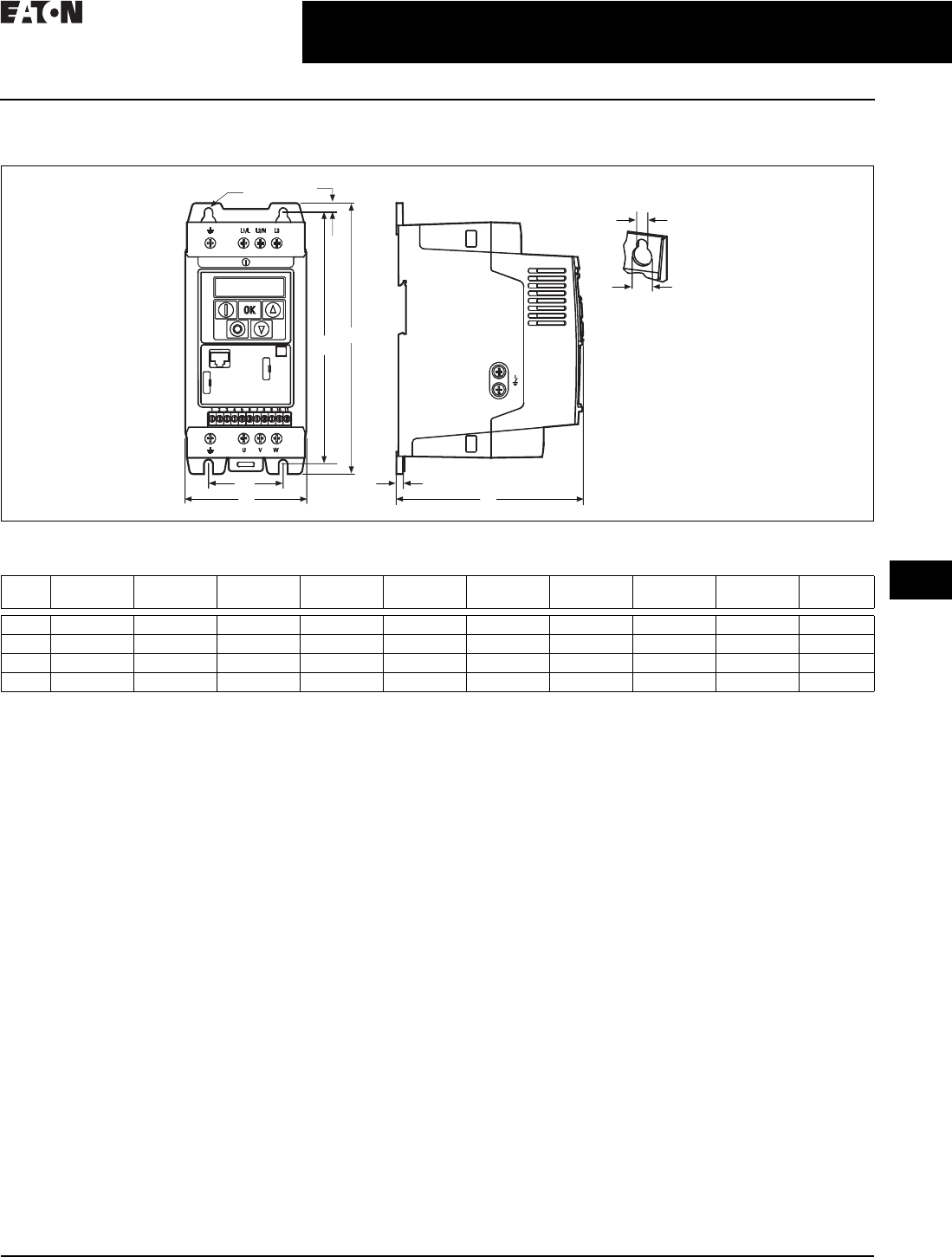
CA08104001E For more information, visit: www.eaton.com/consultants
31.1-13
February 2016
Adjustable Frequency Drives—Low Voltage
Sheet 31
22
23
24
25
26
27
28
29
30
31
32
33
34
35
36
37
38
39
40
41
42
4 3
PowerXL Series Drives
Enclosed Drives
025
Dimensions—Approximate Dimensions in Inches (mm)
Figure 31.1-2. DC1, Sizes FS1–FS4, Degree of Protection IP20/NEMA 0
B1
A
B
Ø2
Ø1
Ø
C1
C
A1
B2
Frame
Size
A A1 B B1 B2 C C1 Ø1Ø2 Weight
Lb (kg)
FS1 3.19 (81.0) 1.97 (50.0) 7.24 (184.0) 6.69 (170.0) 0.28 (7.0) 4.88 (124.0) 0.16 (4.0) 0.24 (6.0) 0.47 (12.0) 2.43 (1.1)
FS2 4.21 (107.0) 2.95 (75.0) 9.09 (231.0) 8.46 (215.0) 0.31 (8.0) 5.98 (152.0) 0.20 (5.0) 0.24 (6.0) 0.47 (12.0) 5.73 (2.6)
FS3 5.16 (131.0) 3.94 (100.0) 10.75 (273.0) 10.04 (255.0) 0.33 (8.5) 6.89 (175.0) 0.20 (5.0) 0.24 (6.0) 0.47 (12.0) 8.82 (4.0)
FS4 6.30 (160.0) — 16.54 (420.0) — — 8.35 (212.0) — — — —
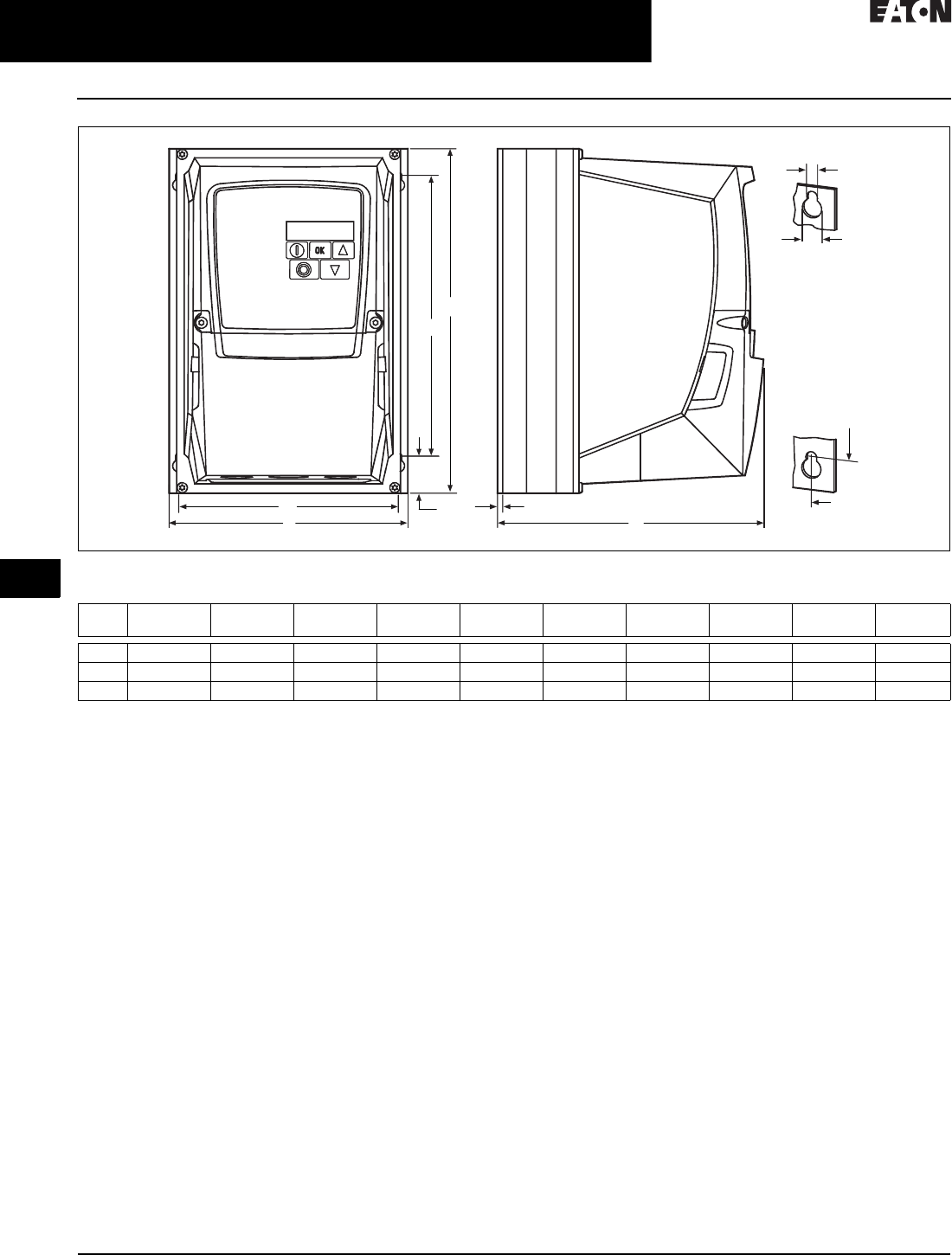
31.1-14
For more information, visit: www.eaton.com/consultants CA08104001E
February 2016
Adjustable Frequency Drives—Low Voltage
Sheet 31
22
23
24
25
26
27
28
29
30
31
32
33
34
35
36
37
38
39
40
41
42
4 3
PowerXL Series Drives
Enclosed Drives
026
Figure 31.1-3. DC1, Sizes FS1–FS3, Degree of Protection IP66/NEMA 4
B
C
A1
B1
Ø2
Ø1
A
A1 C1
B1
B2
Frame
Size
A A1 B B1 B2 C C1 Ø1Ø2Weight
Lb (kg)
FS1 6.34 (161.0) 5.85 (148.5) 9.13 (232.0) 7.44 (189.0) 0.98 (25.0) 7.24 (184.0) 0.14 (3.5) 0.15 (4.0) 0.31 (8.0) 5.51 (2.5)
FS2 7.40 (188.0) 6.93 (176.0) 10.12 (257.0) 7.87 (200.0) 1.12 (28.5) 7.58 (192.0) 0.14 (3.5) 0.16 (4.2) 0.33 (8.5) 10.36 (4.7)
FS3 8.29 (210.5) 7.78 (197.5) 12.20 (310.0) 9.90 (251.5) 1.31 (33.4) 9.21 (234.0) 0.14 (3.5) 0.16 (4.2) 0.33 (8.5) 17.42 (7.9)
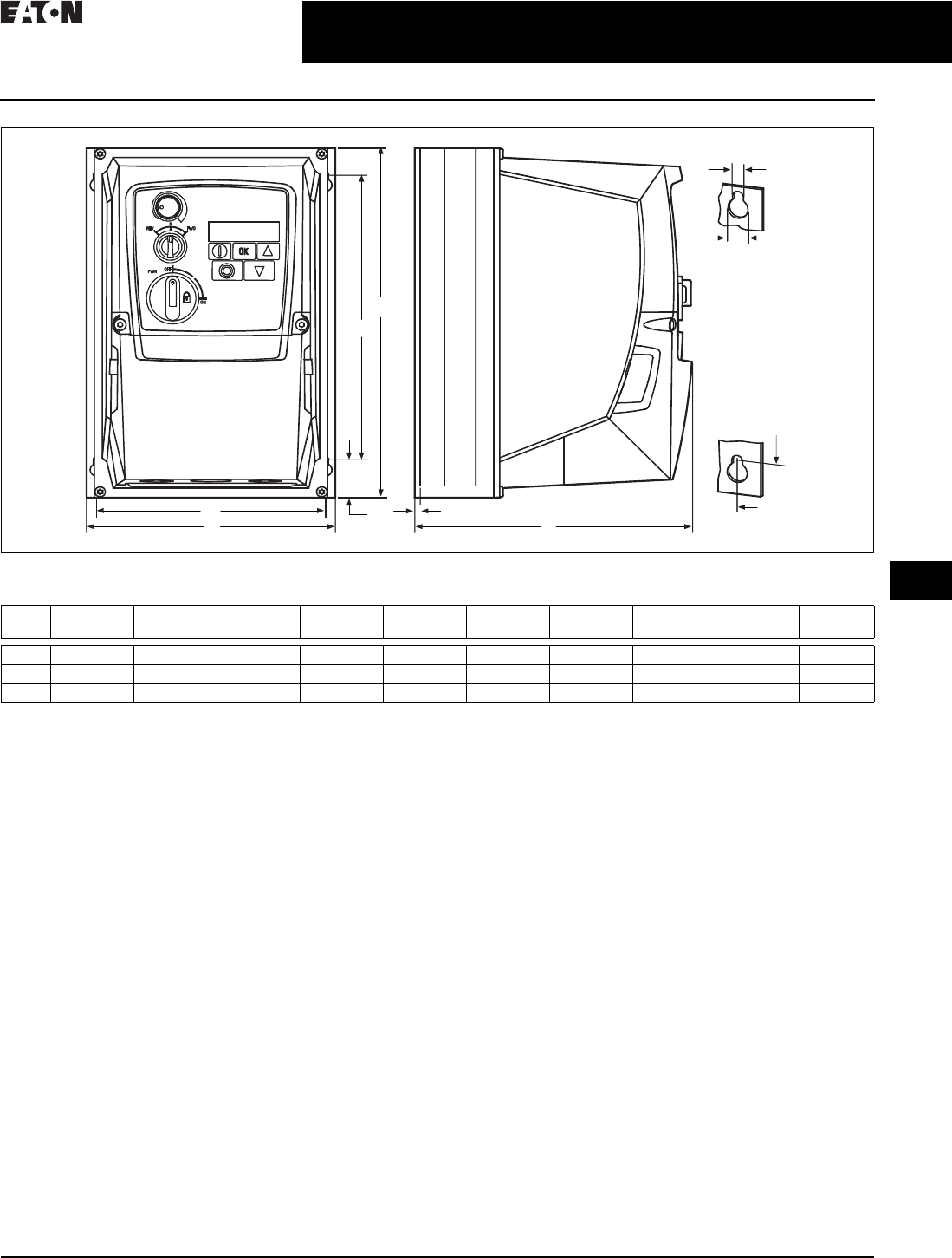
CA08104001E For more information, visit: www.eaton.com/consultants
31.1-15
February 2016
Adjustable Frequency Drives—Low Voltage
Sheet 31
22
23
24
25
26
27
28
29
30
31
32
33
34
35
36
37
38
39
40
41
42
4 3
PowerXL Series Drives
Enclosed Drives
027
Figure 31.1-4. DC1, Sizes FS1–FS3, Degree of Protection IP66/NEMA 4, with Local Controls
Ø2
A1
C1
A1
A C
B1
B
B1
B2
Ø1
Frame
Size
A A1 B B1 B2 C C1 Ø1Ø2 Weight
Lb (kg)
FS1 6.34 (161.0) 5.85 (148.5) 9.13 (232.0) 7.44 (189.0) 0.98 (25.0) 7.24 (184.0) 0.14 (3.5) 0.15 (4.0) 0.31 (8.0) 6.17 (2.8)
FS2 7.40 (188.0) 6.93 (176.0) 10.12 (257.0) 7.87 (200.0) 1.12 (28.5) 7.58 (192.0) 0.14 (3.5) 0.16 (4.2) 0.33 (8.5) 11.02 (5.0)
FS3 8.29 (210.5) 7.78 (197.5) 12.20 (310.0) 9.90 (251.5) 1.31 (33.4) 9.21 (234.0) 0.14 (3.5) 0.16 (4.2) 0.33 (8.5) 18.08 (8.2)
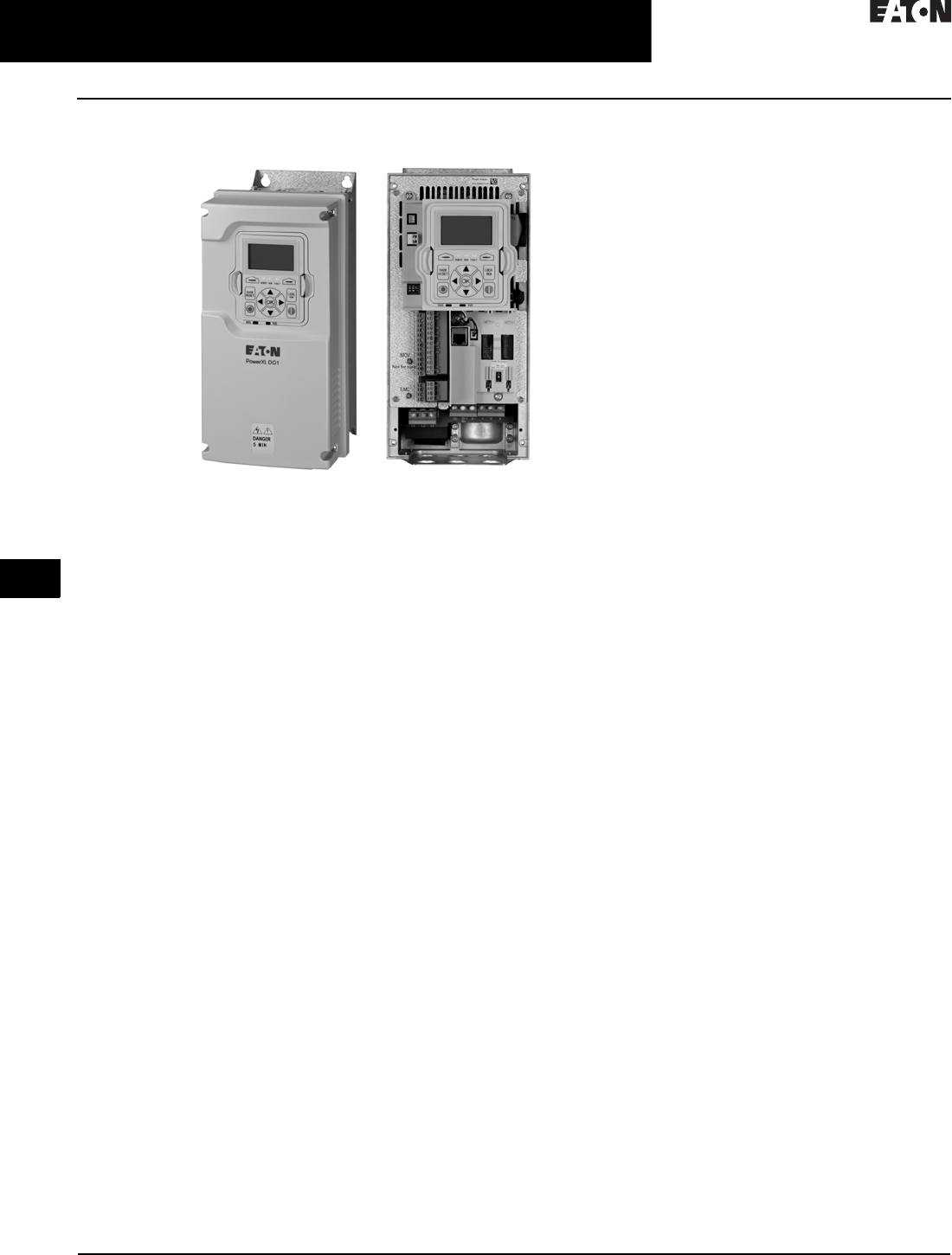
31.1-16
For more information, visit: www.eaton.com/consultants CA08104001E
February 2016
Adjustable Frequency Drives—Low Voltage
Sheet 31
22
23
24
25
26
27
28
29
30
31
32
33
34
35
36
37
38
39
40
41
42
4 3
PowerXL Series Drives
Enclosed Drives
028
PowerXL DG1 Series Drives
DG1 General Purpose Drive
Product Description
The DG1 general purpose drives are
part of Eaton’s next generation PowerXL
Series of adjustable frequency drives
specifically engineered for today’s more
demanding commercial and industrial
applications. The power unit makes
use of the most sophisticated semi-
conductor technology and a highly
modular construction that can be
flexibly adapted to meet the
customer’s needs.
The control module was designed
to include today’s standard
communication protocols and I/O
while still having the modularity
to add additional option cards.
Eaton’s patented Active Energy Control
is also a standard feature on DG1
drives, offering customers increased
efficiency, safety and reliability.
These drives continue the tradition
of robust performance and raise the
bar on features and functionality,
ensuring the best solution at the
right price.
Product Range
■230 V to 125 hp, 312 A, 90 kW
■480 V to 250 hp, 310 A, 160 kW
■575 V to 250 hp, 250 A, 160 kW
Features and Benefits
Harmonic Reduction
■All DG-1 Drives have a DC choke
as standard
■Line and load reactors are
available as an option, consult
factory for sizing
Hardware
■Brake chopper standard on
Frames 1, 2, 3
■Dual overload ratings
❑110% variable torque (IL)
❑150% constant torque (IH)
■Type 1/IP21 and Type 12/IP54
enclosures available
■Integrated common mode reduc-
tion 5% DC link choke with input
surge protection
■EMI/RFI filters standard on all
drives—meets EMC Category C2
■Real-time clock—supports
calendaring and PLC functionality
■Graphic LCD display and keypad—
supports simple menu navigation as
well as on-screen diagnostics and
troubleshooting
■LOCAL/REMOTE operation from
keypad and two configurable
soft keys
■Conformal coated control and
power boards standard
■Control logic can be powered from
an external auxiliary control panel—
internal drive functions and fieldbus
if necessary
■Standard I/O:
❑8DI, 1DO
❑2AI, 2AO
❑2FC, 1FA relays
■Standard communications:
❑EtherNet/IP,
Modbus TCP
❑RS-485: Modbus RTU,
BACnet MS/TP
■Seamless integration into EtherNet/
IP networks via EIP-Assist I/O
tag-generation tool
■Two expansion slots—intended to
support additional I/O or communi-
cation protocols as necessary
■Quick disconnect terminals for I/O
connections—supports fast easy
installation
■Safe Torque Off (STO) built-in with
functional safety SIL1 certification
Dynamic Braking
■Available on all DG-1 drives
■Consult factory for sizing and
options
Software
■Active Energy Control®—minimizes
energy losses in your motor,
resulting in industry-leading energy
efficiency for your application
■Quick Start Wizard upon initial
power-up supports fast, easy
installation
■Standard applications:
❑Standard
❑Multi-pump and fan Control
❑Multi-PID
❑Multi-purpose
■Copy/paste functionality on drive
keypad—allows for fast setup of
multiple drives
■Pre-programmed I/O—supports
fast, easy installation for most
applications
■Dynamic motor regenerative
energy management
■Advanced PC Tool with diagnostic
capabilities
■Two keypad software keys for easy
menu navigation and shortcuts

CA08104001E For more information, visit: www.eaton.com/consultants
31.1-17
February 2016
Adjustable Frequency Drives—Low Voltage
Sheet 31
22
23
24
25
26
27
28
29
30
31
32
33
34
35
36
37
38
39
40
41
42
4 3
PowerXL Series Drives
Enclosed Drives
029
Standards and Certifications
Product
■IEC/EN 61800-5-1
■IEC/EN 61800-5-2
■UL 508C
■IEC 61508
■EN 62061
■EN ISO 13849-1
EMC
■Immunity: IEC/EN 61800-3
■Category C2
Certification
■UL
■cUL
■CE
■C-Tick
■RoHS
■EAC
■Plenum rated
Catalog Number Selection
Catalog Number Selection is for illustrative purposes only and not to be used to create new catalog numbers.
Table 31.1-25. PowerXL Series—DG1 General Purpose Drive
Internal Brake Chopper
N = No brake chopper
B = Brake chopper
Series Power Part Options
DG1 –344D3 F B –C21 C
Basic Naming
D = Drive
Series
G1 = General purpose
Phase Reference
3 = 3~ INPUT/3~ OUTPUT
Coating of Boards
C = Coated
Enclosure (IP Rating)
21 = IP21/Type 1
54 = IP54/Type 12
Display Option
C = LCD (graphical)
N = No display
Output Current Rating (CT)
208–240 V 380–500 V 525–600 V
3D7 = 3.7 A, 0.55 kW, 0.75 hp
4D8 = 4.8 A, 0.75 kW, 1 hp
6D6 = 6.6 A, 1.1 kW, 1.5 hp
7D8 = 7.8 A, 1.5 kW, 2 hp
011 = 11 A, 2.2 kW, 3 hp
012 = 12.5 A, 3 kW, 5 hp (VT)
017 = 17.5 A, 3.7 kW, 5 hp
025 = 25 A, 5.5 kW, 7.5 hp
031 = 31 A, 7.5 kW, 10 hp
048 = 48 A, 11 kW, 15 hp
061 = 61 A, 15 kW, 20 hp
075 = 75 A, 18.5 kW, 25 hp
088 = 88 A, 22 kW, 30 hp
114 = 114 A, 30 kW, 40 hp
143 = 143 A, 37 kW, 50 hp
170 = 170 A, 45 kW, 60 hp
211 = 211 A, 55 kW, 75 hp
248 = 248 A, 75 kW, 100 hp
2D2 = 2.2 A, 0.75 kW, 1 hp
3D3 = 3.3 A, 1.1 kW, 1.5 hp
4D3 = 4.3 A, 1.5 kW, 2 hp
5D6 = 5.6 A, 2.2 kW, 3 hp
7D6 = 7.6 A, 3 kW, 5 hp
9D0 = 9 A, 4 kW, 7.5 hp (VT)
012 = 12 A, 5.5 kW, 7.5 hp
016 = 16 A, 7.5 kW, 10 hp
023 = 23 A, 11 kW, 15 hp
031 = 31 A, 15 kW, 20 hp
038 = 38 A, 18 kW, 25 hp
046 = 46 A, 22 kW, 30 hp
061 = 61 A, 30 kW, 40 hp
072 = 72 A, 37 kW, 50 hp
087 = 87 A, 45 kW, 60 hp
105 = 105 A, 55 kW, 75 hp
140 = 140 A, 75 kW, 100 hp
170 = 170 A, 90 kW, 125 hp
205 = 205 A, 110 kW, 150 hp
245 = 245 A, 150 kW, 200 hp
3D3 =3.3 A, 1.5 kW, 2 hp
4D5 =4.5 A, 2.2 kW, 3 hp
7D5 =7.5 A, 3.7 kW, 5 hp
010 = 10 A, 5.5 kW, 7.5 hp
013 = 13.5 A, 7.5 kW, 10 hp
018 = 18 A, 11 kW, 15 hp
022 = 22 A, 15 kW, 20 hp
027 = 27 A, 18 kW, 25 hp
034 = 34 A, 22 kW, 30 hp
041 = 41 A, 30 kW, 40 hp
052 = 52 A, 37 kW, 50 hp
062 = 62 A, 45 kW, 60 hp
080 = 80 A, 55 kW, 75 hp
100 = 100 A, 75 kW, 100 hp
125 = 125 A, 90 kW, 125 hp
144 = 144 A, 110 kW, 150 hp
208 = 208 A, 160 kW, 200 hp
Input/Output Voltage Rating
2 = 230 V (208–240 V, –15%, +10%)
4 = 400 V (380–500 V, –15%, +10%)
5 = 575 V (525–600 V, –15%, +10%)
Internal EMC Filter
D =DC choke only
E = EMC filter only
F = Internal EMC filter and DC choke
N = No EMC filter, no DC choke

31.1-18
For more information, visit: www.eaton.com/consultants CA08104001E
February 2016
Adjustable Frequency Drives—Low Voltage
Sheet 31
22
23
24
25
26
27
28
29
30
31
32
33
34
35
36
37
38
39
40
41
42
4 3
PowerXL Series Drives
Enclosed Drives
030
Table 31.1-26. PowerXL Series—DG1 General Purpose Option Boards
Product Selection
Table 31.1-27. DG1 Series Drives—208–240 V
1FR6 available in 2016.
Frame
Size
Constant Torque (CT) / High Overload (IH) Variable Torque (VT) / Low Overload (IL) Catalog
Number
230 V, 50 Hz
kW Rating
230 V, 60 Hz
hp
Current
A
230 V, 50 Hz
kW Rating
230 V, 60 Hz
hp
Current
A
Type 1/IP21
FR1 0.55
0.75
1.1
0.75
1
1.5
3.7
4.8
6.6
0.75
1.1
1.5
1
1.5
2
4.8
6.6
7. 8
DG1-323D7FB-C21C
DG1-324D8FB-C21C
DG1-326D6FB-C21C
1.5
2.2
2
3
7. 8
11
2.2
3
3
—
11
12.5
DG1-327D8FB-C21C
DG1-32011FB-C21C
FR2 3
3.7
5.5
—
5
7. 5
12.5
17.5
25
3.7
5.5
7. 5
5
7. 5
10
17.5
25
31
DG1-32012FB-C21C
DG1-32017FB-C21C
DG1-32025FB-C21C
FR3 7.5
11
10
15
31
48
11
15
15
20
48
61
DG1-32031FB-C21C
DG1-32048FB-C21C
FR4 15
18.5
22
20
25
30
61
75
88
18.5
22
30
25
30
40
75
88
114
DG1-32061FN-C21C
DG1-32075FN-C21C
DG1-32088FN-C21C
FR5 30
37
45
40
50
60
114
143
170
37
45
55
50
60
75
143
170
211
DG1-32114FN-C21C
DG1-32143FN-C21C
DG1-32170FN-C21C
FR6 155
75
75
100
211
248
75
90
100
125
261
312
DG1-32211FN-C21C
DG1-32248FN-C21C
Type 12/IP54
FR1 0.55
0.75
1.1
0.75
1
1.5
3.7
4.8
6.6
0.75
1.1
1.5
1
1.5
2
4.8
6.6
7. 8
DG1-323D7FB-C54C
DG1-324D8FB-C54C
DG1-326D6FB-C54C
1.5
2.2
2
3
7. 8
11
2.2
3
3
—
11
12.5
DG1-327D8FB-C54C
DG1-32011FB-C54C
FR2 3
3.7
5.5
—
5
7. 5
12.5
17.5
25
3.7
5.5
7. 5
5
7. 5
10
17.5
25
31
DG1-32012FB-C54C
DG1-32017FB-C54C
DG1-32025FB-C54C
FR3 7.5
11
10
15
31
48
11
15
15
20
48
61
DG1-32031FB-C54C
DG1-32048FB-C54C
FR4 15
18.5
22
20
25
30
61
75
88
18.5
22
30
25
30
40
75
88
114
DG1-32061FN-C54C
DG1-32075FN-C54C
DG1-32088FN-C54C
FR5 30
37
45
40
50
60
114
143
170
37
45
55
50
60
75
143
170
211
DG1-32114FN-C54C
DG1-32143FN-C54C
DG1-32170FN-C54C
FR6 155
75
75
100
211
248
75
90
100
125
261
312
DG1-32211FN-C54C
DG1-32248FN-C54C
DX G–NET–PROFIBUS
Function
PROFIBUS = PROFIBUS
DEVICENET= DeviceNet
CANOPEN = CANopen
SWD = SmartWire
See Accessories on Page 31.1-10
for full offering
Type
NET = Communication card
EXT = I/O card
ACC = Accessory
SPR = Spare part
KEY = Keypad
CBL = Cable
Basic Naming
DX = PowerXL Drive Series
G = General purpose

CA08104001E For more information, visit: www.eaton.com/consultants
31.1-19
February 2016
Adjustable Frequency Drives—Low Voltage
Sheet 31
22
23
24
25
26
27
28
29
30
31
32
33
34
35
36
37
38
39
40
41
42
4 3
PowerXL Series Drives
Enclosed Drives
031
Table 31.1-28. DG1 Series Drives—380–500 V
1FR6 available in 2016.
Frame
Size
Constant Torque (CT) / High Overload (IH) Variable Torque (VT) / Low Overload (IL) Catalog
Number
400 V, 50 Hz
kW Rating
460 V, 60 Hz
hp
Current
A
400 V, 50 Hz
kW Rating
460 V, 60 Hz
hp
Current
A
Type 1/IP24
FR1 0.75
1.1
1.5
1
1.5
2
2.2
3.3
4.3
1.1
1.5
2.2
1.5
2
3
3.3
4.3
5.6
DG1-342D2FB-C21C
DG1-343D3FB-C21C
DG1-344D3FB-C21C
2.2
3
4
3
5
—
5.6
7. 6
9
3
4
5.5
5
—
7. 5
7. 6
9
12
DG1-345D6FB-C21C
DG1-347D6FB-C21C
DG1-349D0FB-C21C
FR2 5.5
7. 5
11
7. 5
10
15
12
16
23
7. 5
11
15
10
15
20
16
23
31
DG1-34012FB-C21C
DG1-34016FB-C21C
DG1-34023FB-C21C
FR3 15
18.5
22
20
25
30
31
38
46
18.5
22
30
25
30
40
38
46
61
DG1-34031FB-C21C
DG1-34038FB-C21C
DG1-34046FB-C21C
FR4 30
37
45
40
50
60
61
72
87
37
45
55
50
60
75
72
87
105
DG1-34061FN-C21C
DG1-34072FN-C21C
DG1-34087FN-C21C
FR5 55
75
90
75
100
125
105
140
170
75
90
110
100
125
150
140
170
205
DG1-34105FN-C21C
DG1-34140FN-C21C
DG1-34170FN-C21C
FR6 1110
150
150
200
205
245
132
160
200
250
261
310
DG1-34205FN-C21C
DG1-34245FN-C21C
Type 12/IP54
FR1 0.75
1.1
1.5
1
1.5
2
2.2
3.3
4.3
1.1
1.5
2.2
1.5
2
3
3.3
4.3
5.6
DG1-342D2FB-C54C
DG1-343D3FB-C54C
DG1-344D3FB-C54C
2.2
3
4
3
5
—
5.6
7. 6
9
3
4
5.5
5
—
7. 5
7. 6
9
12
DG1-345D6FB-C54C
DG1-347D6FB-C54C
DG1-349D0FB-C54C
FR2 5.5
7. 5
11
7. 5
10
15
12
16
23
7. 5
11
15
10
15
20
16
23
31
DG1-34012FB-C54C
DG1-34016FB-C54C
DG1-34023FB-C54C
FR3 15
18.5
22
20
25
30
31
38
46
18.5
22
30
25
30
40
38
46
61
DG1-34031FB-C54C
DG1-34038FB-C54C
DG1-34046FB-C54C
FR4 30
37
45
40
50
60
61
72
87
37
45
55
50
60
75
72
87
105
DG1-34061FN-C54C
DG1-34072FN-C54C
DG1-34087FN-C54C
FR5 55
75
90
75
100
125
105
140
170
75
90
110
100
125
150
140
170
205
DG1-34105FN-C54C
DG1-34140FN-C54C
DG1-34170FN-C54C
FR6 1110
150
150
200
205
245
132
160
200
250
261
310
DG1-34205FN-C54C
DG1-34245FN-C54C
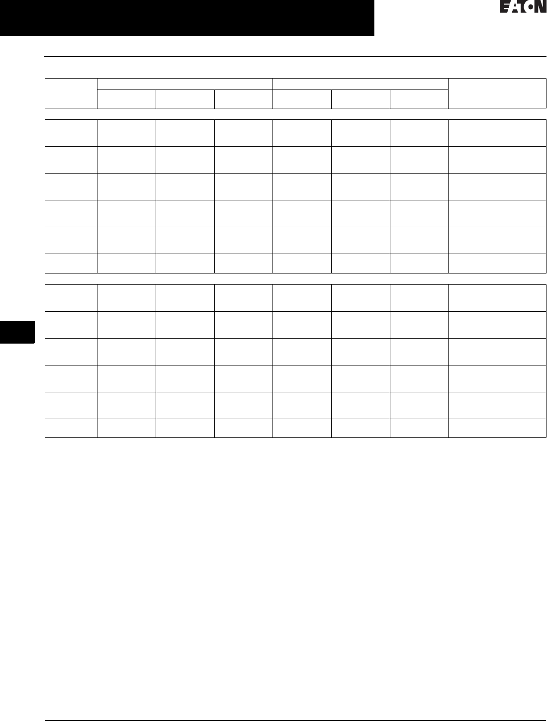
31.1-20
For more information, visit: www.eaton.com/consultants CA08104001E
February 2016
Adjustable Frequency Drives—Low Voltage
Sheet 31
22
23
24
25
26
27
28
29
30
31
32
33
34
35
36
37
38
39
40
41
42
4 3
PowerXL Series Drives
Enclosed Drives
032
Table 31.1-29. DG1 Series Drives—575 V
1FR6 available in 2016.
Frame
Size
Constant Torque (CT) / High Overload (IH) Variable Torque (VT) / Low Overload (IL) Catalog
Number
575 V, 60 Hz
kW Rating
575 V, 60 Hz
hp
Current
A
575 V, 60 Hz
kW Rating
575 V, 60 Hz
hp
Current
A
Type 1/IP21
FR1 1.5
2.2
3.7
2
3
5
3.3
4.5
7. 5
2.2
3.7
5.5
3
5
7. 5
4.5
7. 5
10
DG1-353D3FB-C21C
DG1-354D5FB-C21C
DG1-357D5FB-C21C
FR2 5.5
7. 5
11
7. 5
10
15
10
13.5
18
7. 5
11
15
10
15
20
13.5
18
22
DG1-35010FB-C21C
DG1-35013FB-C21C
DG1-35018FB-C21C
FR3 15
18.5
22
20
25
30
22
27
34
18.5
22
30
25
30
40
27
34
41
DG1-35022FB-C21C
DG1-35027FB-C21C
DG1-35034FB-C21C
FR4 30
37
45
40
50
60
41
52
62
37
45
55
50
60
75
52
62
80
DG1-35041FN-C21C
DG1-35052FN-C21C
DG1-35062FN-C21C
FR5 55
75
90
75
100
125
80
100
125
75
90
110
100
125
150
100
125
144
DG1-35080FN-C21C
DG1-35100FN-C21C
DG1-35125FN-C21C
FR6 1110
150
150
200
144
208
150
187
200
250
208
250
DG1-35144FN-C21C
DG1-35208FN-C21C
Type 12/IP54
FR1 1.5
2.2
3.7
2
3
5
3.3
4.5
7. 5
2.2
3.7
5.5
3
5
7. 5
4.5
7. 5
10
DG1-353D3FB-C54C
DG1-354D5FB-C54C
DG1-357D5FB-C54C
FR2 5.5
7. 5
11
7. 5
10
15
10
13.5
18
7. 5
11
15
10
15
20
13.5
18
22
DG1-35010FB-C54C
DG1-35013FB-C54C
DG1-35018FB-C54C
FR3 15
18.5
22
20
25
30
22
27
34
18.5
22
30
25
30
40
27
34
41
DG1-35022FB-C54C
DG1-35027FB-C54C
DG1-35034FB-C54C
FR4 30
37
45
40
50
60
41
52
62
37
45
55
50
60
75
52
62
80
DG1-35041FN-C54C
DG1-35052FN-C54C
DG1-35062FN-C54C
FR5 55
75
90
75
100
125
80
100
125
75
90
110
100
125
150
100
125
144
DG1-35080FN-C54C
DG1-35100FN-C54C
DG1-35125FN-C54C
FR6 1110
150
150
200
144
208
150
187
200
250
208
250
DG1-35144FN-C54C
DG1-35208FN-C54C
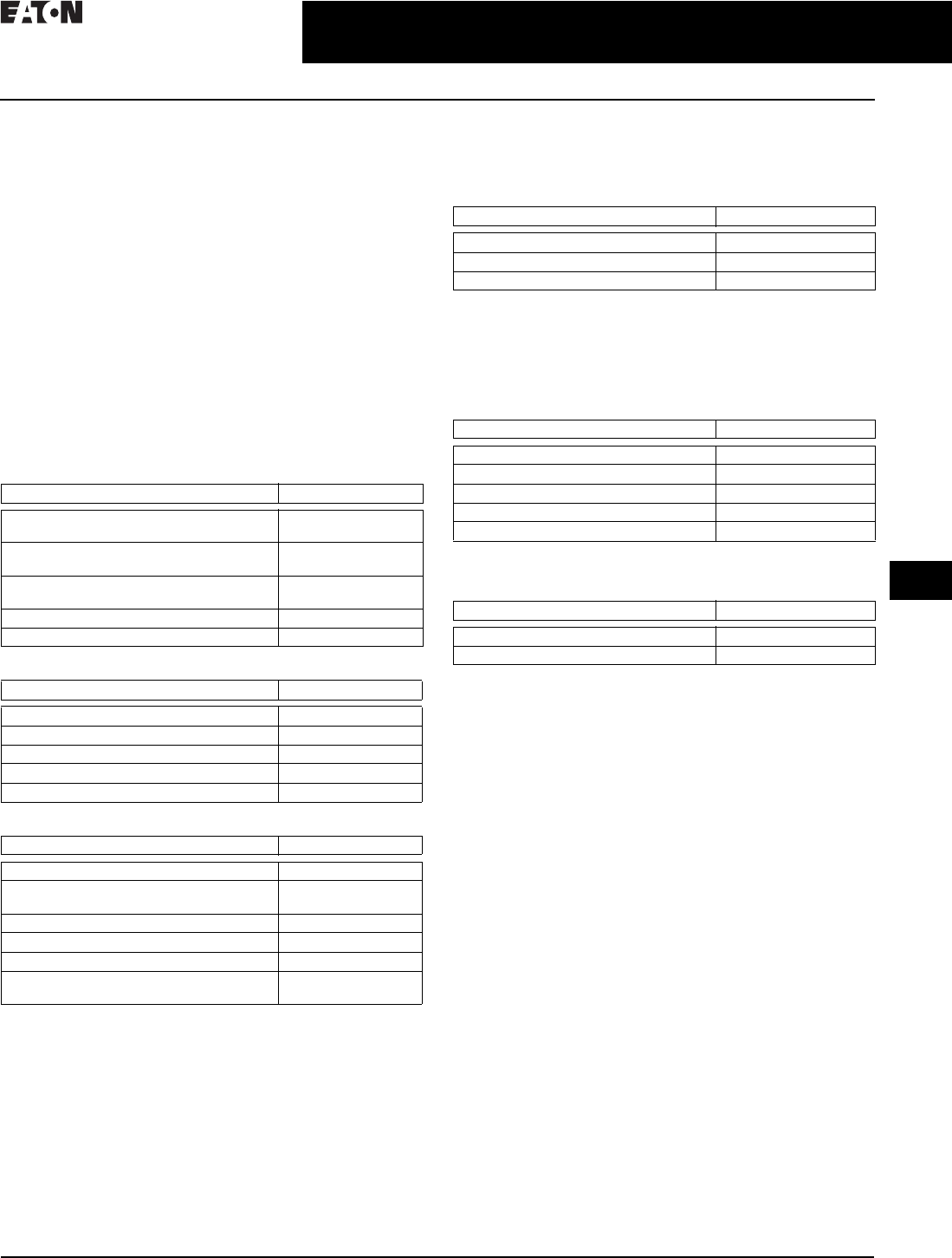
CA08104001E For more information, visit: www.eaton.com/consultants
31.1-21
February 2016
Adjustable Frequency Drives—Low Voltage
Sheet 31
22
23
24
25
26
27
28
29
30
31
32
33
34
35
36
37
38
39
40
41
42
4 3
PowerXL Series Drives
Enclosed Drives
033
Accessories
The PowerXL Series—DG1 drives can accommodate a
wide selection of expander and adapter option boards to
customize the drive for your application needs. The drive’s
control unit is designed to accept a total of two additional
option boards.
The PowerXL Series—DG1 drives come with a factory-
installed standard board configuration including the
following:
■Standard I/O:
❑8DI, 1DO
❑2AI, 2AO
❑2FC, 1FA relays
■Standard communications:
❑EtherNet/IP, Modbus TCP
❑RS-485: Modbus RTU, BACnet MS/TP
Table 31.1-30. PowerXL Series—DG1 I/O Card Kits
Table 31.1-31. PowerXL Series—DG1 Communication Card Kits
Table 31.1-32. PowerXL Series—DG1 Keypad Kits
PowerXL Series—DG1 Conversion and Flange Kits
The Type 12/IP54 option kit is used to convert a Type 1/IP21 to a
Type 12/IP54 drive. The kit includes cover, fan and grommets.
Table 31.1-33. Type 12/IP54 Conversion Kits 1
1For Frame 3 and above, consult factory.
The flange kit is used when the power section heat sink is
mounted through the back panel of an enclosure. The kit
includes hardware, top flange plate, bottom flange plate and
two side flange plates.
Table 31.1-34. Flange Kits
PowerXL Series—DG1 Demo Units
Table 31.1-35. Demo Units
Description Catalog Number
3 x DI, 3 x DO, 1 x thermistor,
24 Vdc/EXT option card
DXG-EXT-3DI3DO1T
1 x AI, 2 x AO (isolated to control board)
option card
DXG-EXT-1AI2AO
3 x relay dry contact (2NO + 1NO/NC)
option card
DXG-EXT-3RO
3 x PT100 RTD thermistor input option card DXG-EXT-THER1
6 x DI 240 Vac input option card DXG-EXT-6DI
Description Catalog Number
PROFIBUS-DP communication card DXG-NET-PROFIBUS
CANopen communication card DXG-NET-CANOPEN
DeviceNet communication card DXG-NET-DEVICENET
PROFIBUS DB9 to 5-pin adapter card DXG-MNT-PROFIBUS
SmartWire communication card and module DXG-NET-SWD
Description Catalog Number
Standard keypad DXG-KEY-LCD
Remote keypad kit (IP 54 rated keypad
holder and 3 m cable)
DXG-KEY-RMTKIT
1 m remote keypad cable DXG-CBL-1M0
3 m remote keypad cable DXG-CBL-3M0
Remote keypad mounting holder only DXG-KEY-HOLDER
Type 12/IP54 keypad hole plug
(maintain rating without keypad)
DXG-KEY-N12PLUG
Description Catalog Number
Frame 1 230 V Type 12/IP54 kit DXG-ACC-2FR1N12KIT
Frame 1 480 V Type 12/IP54 kit DXG-ACC-4FR1N12KIT
Frame 2 Type 12/IP54 kit DXG-ACC-FR2N12KIT
Description Catalog Number
Frame 1 flange kit Type 12/IP54 DXG-ACC-FR1N12FK
Frame 2 flange kit Type 12/IP54 DXG-ACC-FR2N12FK
Frame 3 flange kit Type 12/IP54 DXG-ACC-FR3N12FK
Frame 4 flange kit Type 12/IP54 DXG-ACC-FR4N12FK
Frame 5 flange kit Type 12/IP54 DXG-ACC-FR5N12FK
Description Catalog Number
DG1 control module demo stand DG1-DEMO1
DG1 full drive demo case DG1-DEMO2
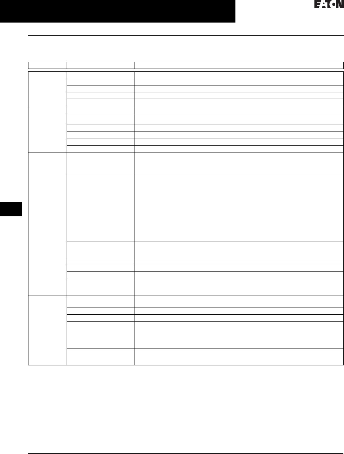
31.1-22
For more information, visit: www.eaton.com/consultants CA08104001E
February 2016
Adjustable Frequency Drives—Low Voltage
Sheet 31
22
23
24
25
26
27
28
29
30
31
32
33
34
35
36
37
38
39
40
41
42
4 3
PowerXL Series Drives
Enclosed Drives
034
Technical Data and Specifications
Table 31.1-36. PowerXL Series—DG1 Technical Data and Specifications
Attribute Description Specification
Input ratings Input voltage Uin 208 V to 240 V, 380 V to 500 V, 525 V to 600 V, –15 to 10%
Input frequency 50 Hz to 60 Hz (variation up to 45 Hz to 66 Hz)
Connection to power Once per minute or less
Starting delay 3 s (FR1 to FR2), 4 s (FR3), 5 s (FR4), 6 s (FR5 and FR6)
Short-circuit withstand rating 100 kAIC (fuses and circuit breakers)
Output ratings Output voltage 0 to Uin
Continuous output current IL: ambient temperature maximum 40 °C, up to 60 °C with derating, overload 1.1 x IL (1 min./10 min.)
IH: ambient temperature maximum 50 °C, up to 60 °C with derating, overload 1.5 x IH (1 min./10 min.)
Overload current 150% respectively 110% (1 min./10 min.)
Initial output current 200% (2 s / 20 s)
Output frequency 0–400 Hz (standard)
Frequency resolution 0.01 Hz
Control
characteristics
Control methods Frequency control
Speed control
Open-loop speed control
Open-loop torque control
Switching frequency 230 V / 480 V range:
FR1–3: 1 kHz to 12 kHz
FR4–6: 1 kHz to 10 kHz
230 V / 480 V defaults:
FR1–3: 4 kHz
FR4–5: 3.6 kHz
FR6: 2 kHz
575 V range:
FR1–6: 1 kHz to 6 kHz
575 V defaults:
FR1–4: 3 kHz
FR5–6: 2 kHz
Automatic switching frequency derating in case of overload.
Frequency reference Analog input: resolution 0.1% (10-bit), accuracy +1%
Analog output: resolution 0.1% (10-bit), accuracy +1%
Panel reference: resolution 0.01 Hz
Field weakening point 20 Hz to 400 Hz
Acceleration time 0.1 s to 3000 s
Deceleration time 0.1 s to 3000 s
Braking torque DC brake: 30% x Motor Rated Torque (Tn) (without brake chopper)
Dynamic braking (with optional brake chopper using an external brake resistor):
100% continuous maximum rating
Ambient
conditions
Ambient operating temperature –10 °C (no frost) to +50 °C, up to +60 °C with derating (CT)
–10 °C (no frost) to +40 °C, up to +60 °C with derating (VT)
Storage temperature –40 °C to +70 °C
Relative humidity 0–95% RH, noncondensing, non-corrosive
Air quality:
●Chemical vapors
●Mechanical particles
Tested according to IEC 60068-2-60 Test Key:
Flowing mixed gas corrosion test, Method 1 (H2S [hydrogen sulfide] and SO2 [sulfur dioxide])
Designed according to:
IEC 60721-3-3, unit in operation, class 3C2
IEC 60721-3-3, unit in operation, class 3S2
Altitude 100% load capacity (no derating) up to 3280 ft (1000 m); 1% derating for each 328 ft (100 m) above 3280
ft (1000 m); max. 9842 ft (3000 m) (2000 m for corner grounded earth main systems)
For 575 V product, maximum altitude is 6561 ft (2000 m) regardless of main system

CA08104001E For more information, visit: www.eaton.com/consultants
31.1-23
February 2016
Adjustable Frequency Drives—Low Voltage
Sheet 31
22
23
24
25
26
27
28
29
30
31
32
33
34
35
36
37
38
39
40
41
42
4 3
PowerXL Series Drives
Enclosed Drives
035
Table 31.1-36. PowerXL Series—DG1 Technical Data and Specifications (Continued)
Attribute Description Specification
Ambient conditions
(continued)
Vibration:
●EN 61800-5-1
●EN 60668-2-6
5–150 Hz
Displacement amplitude: 1 mm (peak) at 5 Hz to 15.8 Hz (FR1–FR6)
Maximum acceleration amplitude: 1g at 15.8 Hz to 150 Hz (FR1–FR6)
Shock:
●ISTA 1 A
●EN 60068-2-27
Storage and shipping: maximum 15 g, 11 ms (in package)
Overvoltage Overvoltage Category III
Pollution degree Pollution Degree 2
Enclosure class IP21/Type 1 standard in entire kW/hp range
IP54/Type 12 option
Note: Keypad or keypad hole plug required to be mounted in drive for IP54/Type 12 rating
Immunity Fulfills EN 61800-3 (2004), first and second environment
MTBF FR1: 165,457 hours
FR2: 134,833 hours
FR3: 102,515 hours
FR4: 121,567 hours
FR5: 108,189 hours
FR6: Available in 2016
Noise FR1: 51.2 dB
FR2: 58.6 dB
FR3: 61.0 dB
FR4: 68.0 dB
FR5: 69.1 dB
FR6: Available in 2016
Standards Safety UL 508C, CSA C22.2 No. 274-13 and EN 61800-5-1
EMC +EMC2: EN 61800-3 (2004), Category C2
The drive can be modified for IT networks and corner grounding TN system
Electrostatic discharge Second environment, IEC 61000-4-2, 4 kV CD or 8 kV AD, Criterion B
Fast transient burst Second environment, IEC 61000-4-4, 2 kV/5 kHz, Criterion B
Dielectrical strength Primary to secondary: 3600 Vac/5100 Vdc
Primary to earth: 2000 Vac/2828 Vdc
Approvals EAC, RCM (C-Tick), RoHS, CE, UL and cUL (see nameplate for more detailed approvals)
Fieldbus connections Onboard: EtherNet/IP, Modbus® TCP, Modbus RTU, BACnet

31.1-24
For more information, visit: www.eaton.com/consultants CA08104001E
February 2016
Adjustable Frequency Drives—Low Voltage
Sheet 31
22
23
24
25
26
27
28
29
30
31
32
33
34
35
36
37
38
39
40
41
42
4 3
PowerXL Series Drives
Enclosed Drives
036
Table 31.1-36. PowerXL Series—DG1 Technical Data and Specifications (Continued)
Attribute Description Specification
Safety/protections Overvoltage protection Yes
Overvoltage trip limit 230 V drives: 456 V
480 V drives: 911 V
575 V drives: 1100 V
Undervoltage protection Yes
Undervoltage trip limit 230 V drives: 211 V
480 V drives: 370 V
575 V drives: 550 V
Earth fault protection Yes
Default: 15% motor FLA
Minimum: 0% motor FLA
Maximum: 30% motor FLA
Input phase supervision Yes
Motor phase supervision Yes
Overcurrent protection Trip limit 4.0 x IH instantaneously
Unit overtemperature
protection
Yes
Motor overload protection Yes
Motor stall protection Yes
Motor underload protection Yes
DC bus overvoltage control Yes
Short-circuit protection of 24 V
reference voltages
Yes
Surge protection Yes (differential mode 2 kV; common mode 4 kV
230 V drives: 275 Vac, 10,000 A
480 V drives: 320 Vac, 8000 A
575 V drives: 385 Vac, 10,000 A
Common coated boards Yes (prevents corrosion)
Efficiency Drive efficiency ratings 480 V: FR1 = 97.7%
480 V: FR2 = 97.9%
480 V: FR3 = 97.7%
480 V: FR4 = 98.0%
480 V: FR5 = 98.2%
230 V: FR1 = 96.7%
230 V: FR2 = 97.4%
230 V: FR3 = 97.2%
230 V: FR4 = 97.4%
230 V: FR5 = 97.7%
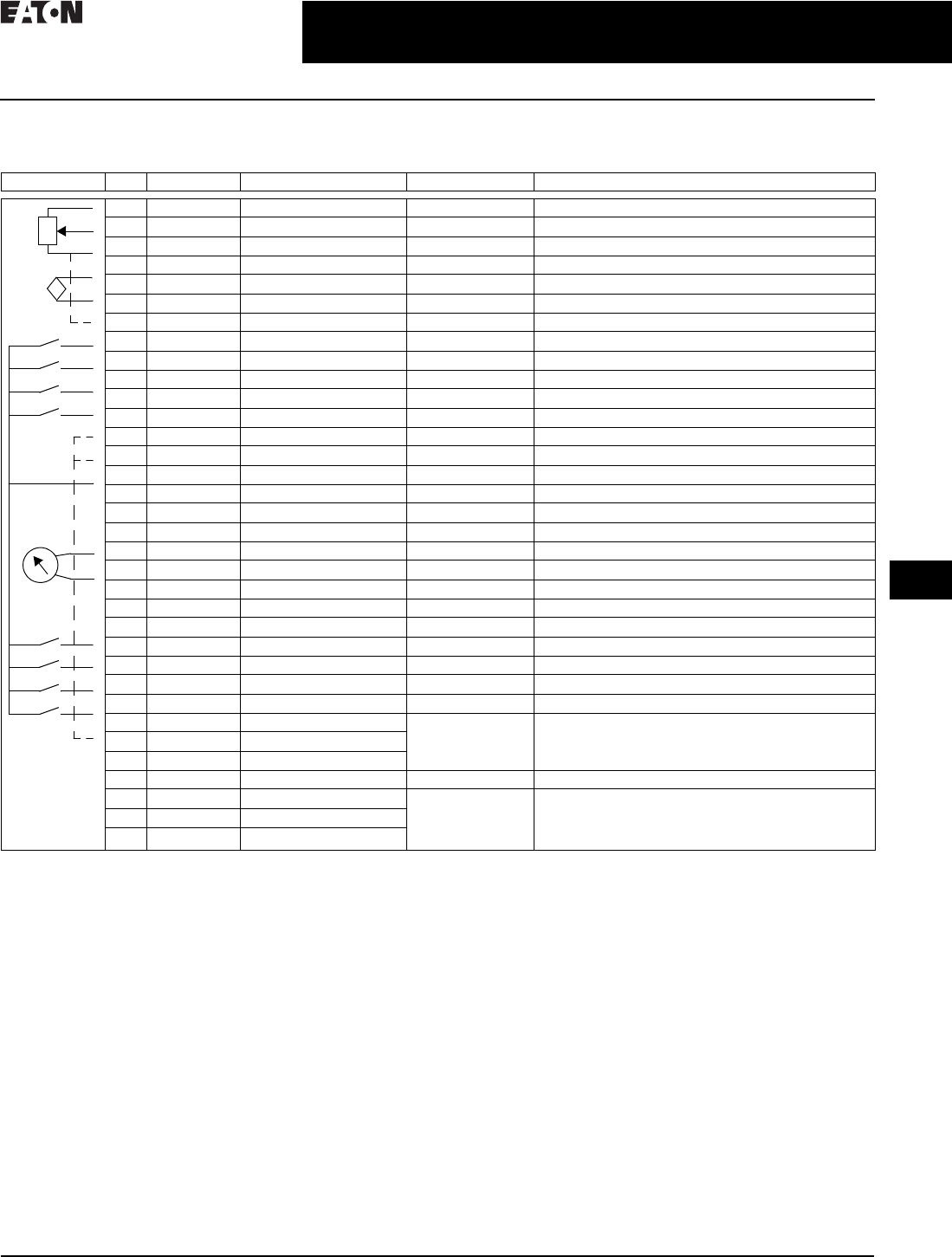
CA08104001E For more information, visit: www.eaton.com/consultants
31.1-25
February 2016
Adjustable Frequency Drives—Low Voltage
Sheet 31
22
23
24
25
26
27
28
29
30
31
32
33
34
35
36
37
38
39
40
41
42
4 3
PowerXL Series Drives
Enclosed Drives
037
Wiring Diagram
Table 31.1-37. PowerXL Series—DG1 Control Wiring Diagram
Note: The above wiring demonstrates a SINK configuration. It is important that CMA and CMB are wired to ground (as shown by dashed line).
If a SOURCE configuration is desired, wire 24 V to CMA and CMB and close the inputs to ground. When using the +10 V for AI1, it is important
to wire AI1– to ground (as shown by dashed line). If using +10 V for AI1 or AI2, terminals 3, 5 and 6 need to be jumpered together.
External Wiring Pin Signal Name Signal Default Setting Description
1 +10 V Ref. Output Voltage — 10 Vdc Supply Source
2 AI1+ Analog Input 1 0–10 V Voltage Speed Reference (Programmable to 4 mA to 20 mA)
3 AI1– Analog Input 1 Ground — Analog Input 1 Common (Ground)
4 AI2+ Analog Input 2 4 mA to 20 mA Current Speed Reference (Programmable to 0–10 V)
5 AI2– Analog Input 2 Ground — Analog Input 2 Common (Ground)
6 GND I/O Signal Ground — I/O Ground for Reference and Control
7 DIN5 Digital Input 5 Preset Speed B0 Sets frequency output to Preset Speed 1
8 DIN6 Digital Input 6 Preset Speed B1 Sets frequency output to Preset Speed 2
9 DIN7 Digital Input 7 — —
10 DIN8 Digital Input 8 Force Remote (TI+) Input takes VFD from Local to Remote
11 CMB DI5 to DI8 Common Grounded Allows source input
12 GND I/O Signal Ground — I/O Ground for Reference and Control
13 24 V +24 Vdc Output — Control voltage output (100 mA max.)
14 DO1 Digital Output 1 Ready Shows the drive is ready to run
15 24 Vo +24 Vdc Output — Control voltage output (100 mA max.)
16 GND I/O Signal Ground — I/O Ground for Reference and Control
17 AO1+ Analog Output 1 Output Frequency Shows Output frequency to motor 0–60 Hz (4 mA to 20 mA)
18 AO2+ Analog Output 2 Motor Current Shows Motor current of motor 0–FLA (4 mA to 20 mA)
19 24 Vi +24 Vdc Input — External control voltage input
20 DIN1 Digital Input 1 Run Forward Input starts drive in forward direction (start enable)
21 DIN2 Digital Input 2 Run Reverse Input starts drive in reverse direction (start enable)
22 DIN3 Digital Input 3 External Fault Input causes drive to fault
23 DIN4 Digital Input 4 Fault Reset Input resets active faults
24 CMA DI1 to DI4 Common Grounded Allows source input
25 A RS-485 Signal A — Fieldbus Communication (Modbus, BACnet)
26 B RS-485 Signal B — Fieldbus Communication (Modbus, BACnet)
27 R3NO Relay 3 Normally Open At Speed Relay output 3 shows VFD is at Ref. Frequency
28 R1NC Relay 1 Normally Closed Run Relay output 1 shows VFD is in a run state
29 R1CM Relay 1 Common
30 R1NO Relay 1 Normally Open
31 R3CM Relay 3 Common At Speed Relay output 3 shows VFD is at Ref. Frequency
32 R2NC Relay 2 Normally Closed Fault Relay output 2 shows VFD is in a fault state
33 R2CM Relay 2 Common
34 R2NO Relay 2 Normally Open
Res
i
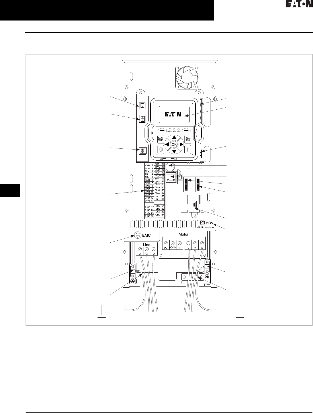
31.1-26
For more information, visit: www.eaton.com/consultants CA08104001E
February 2016
Adjustable Frequency Drives—Low Voltage
Sheet 31
22
23
24
25
26
27
28
29
30
31
32
33
34
35
36
37
38
39
40
41
42
4 3
PowerXL Series Drives
Enclosed Drives
038
Control Board Layout
Figure 31.1-5. PowerXL Series—DG1 Control Board Layout
DSP Connection
to Power Board
Keypad
MCU Connection
to Power Board
RTC Battery (Standard)
RJ45 EtherNet/IP,
Modbus TCP
Optional Card Slot A
Optional Card Slot B
RS-485 Terminating
Resistor
MOV Screw
Motor Ground
Clamp Location
Grounding
Strap Location
Grounding
Strap Location
Line Ground
Clamp Location
Removable
EMC Screw
Control I/O
Terminals
AI Mode Selection
Safe Torque Off (STO)
Fan Power Wire
Line Side Motor
ON
123
ON
1
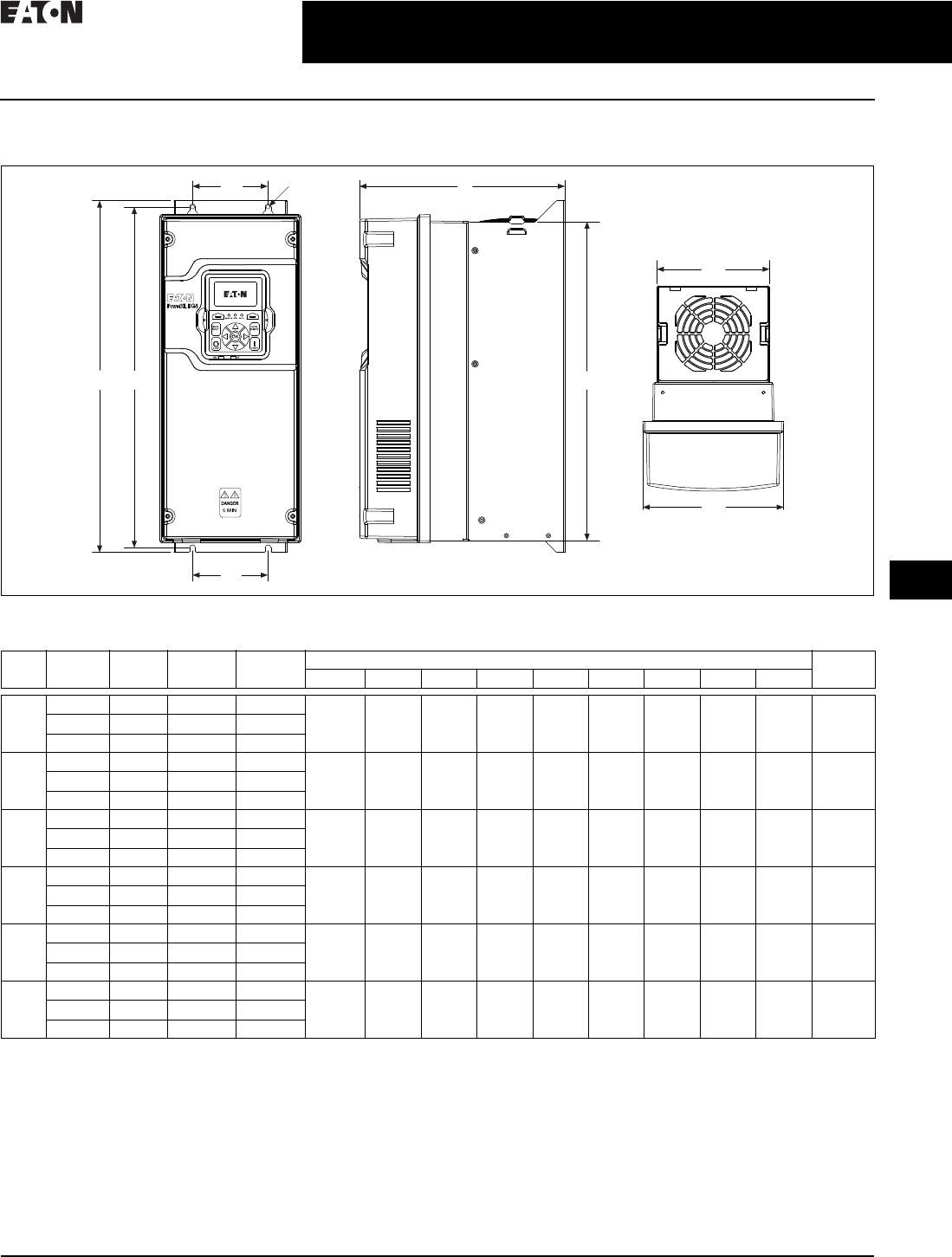
CA08104001E For more information, visit: www.eaton.com/consultants
31.1-27
February 2016
Adjustable Frequency Drives—Low Voltage
Sheet 31
22
23
24
25
26
27
28
29
30
31
32
33
34
35
36
37
38
39
40
41
42
4 3
PowerXL Series Drives
Enclosed Drives
039
Dimensions—Approximate Dimensions in Inches (mm)
Figure 31.1-6. PowerXL Series—DG1 Dimensions
1FR6 available in 2016.
W3
H2
W4
W1
W2
H1
D
H3
Ø
Frame
Size
Volta ge hp
(CT/IH)
kW Amperes
(VT/L)
Approximate Dimensions in Inches (mm) Weight
Lb (kg)
D H1 H2 H3 W1W2W3W4Ø
FR1 230 Vac 0.75–3 0.55–2.2 3.5–11 7.91
(200.9)
12.87
(326.9)
12.28
(311.9)
11. 5 0
(292.1)
6.02
(153.0)
4.80
(121.9)
3.94
(100.1)
3.94
(100.1)
0.28
(7.0)
14.33
(6.5)
480 Vac 1–5 0.75–3.7 2.3–7.6
575 Vac 2–5 1.5–3.7 3.3–7.5
FR2 230 Vac 5–7.5 3–5.5 12.5–25 9.63
(244.7)
16.50
(419.1)
15.98
(405.9)
14.96
(380.0)
6.61
(167.8)
5.28
(134.1)
3.54
(90.0)
3.54
(90.0)
0.28
(7.0)
23.37
(10.6)
480 Vac 7.5–15 5.5–11 12–23
575 Vac 7.5–15 5.5–11 10–18
FR3 230 Vac 10–15 7.5–11 31–48 10.44
(265.1)
21.97
(558.0)
21.46
(545.0)
20.41
(518.5)
8.06
(204.6)
7. 2 4
(183.9)
4.92
(125.0)
4.92
(125.0)
0.35
(9.0)
49.82
(22.6)
480 Vac 20–30 15–22 31–46
575 Vac 20–30 15–22 22–34
FR4 230 Vac 20–30 15–22 61–88 11.57
(294.0)
24.80
(629.9)
24.31
(617.5)
23.27
(591.1)
9.36
(237.7)
9.13
(231.9)
8.07
(205.0)
8.07
(205.0)
0.35
(9.0)
77.60
(35.2)
480 Vac 40–60 30–45 61–87
575 Vac 40–60 30–45 41–62
FR5 230 Vac 40–60 30–45 114–170 13.41
(340.7)
34.98
(888.5)
29.65
(753.1)
27.83
(706.9)
11. 3 4
(288.0)
11. 1 0
(281.9)
8.66
(220.0)
8.66
(220.0)
0.35
(9.0)
154.32
(70.0)
480 Vac 75–125 55–90 105–170
575 Vac 75–125 55–90 80–125
FR6 1230 Vac 75–100 55–75 211–248 1 111111111
480 Vac 150–200 110–150 205–261
575 Vac 150–200 110–160 144–208
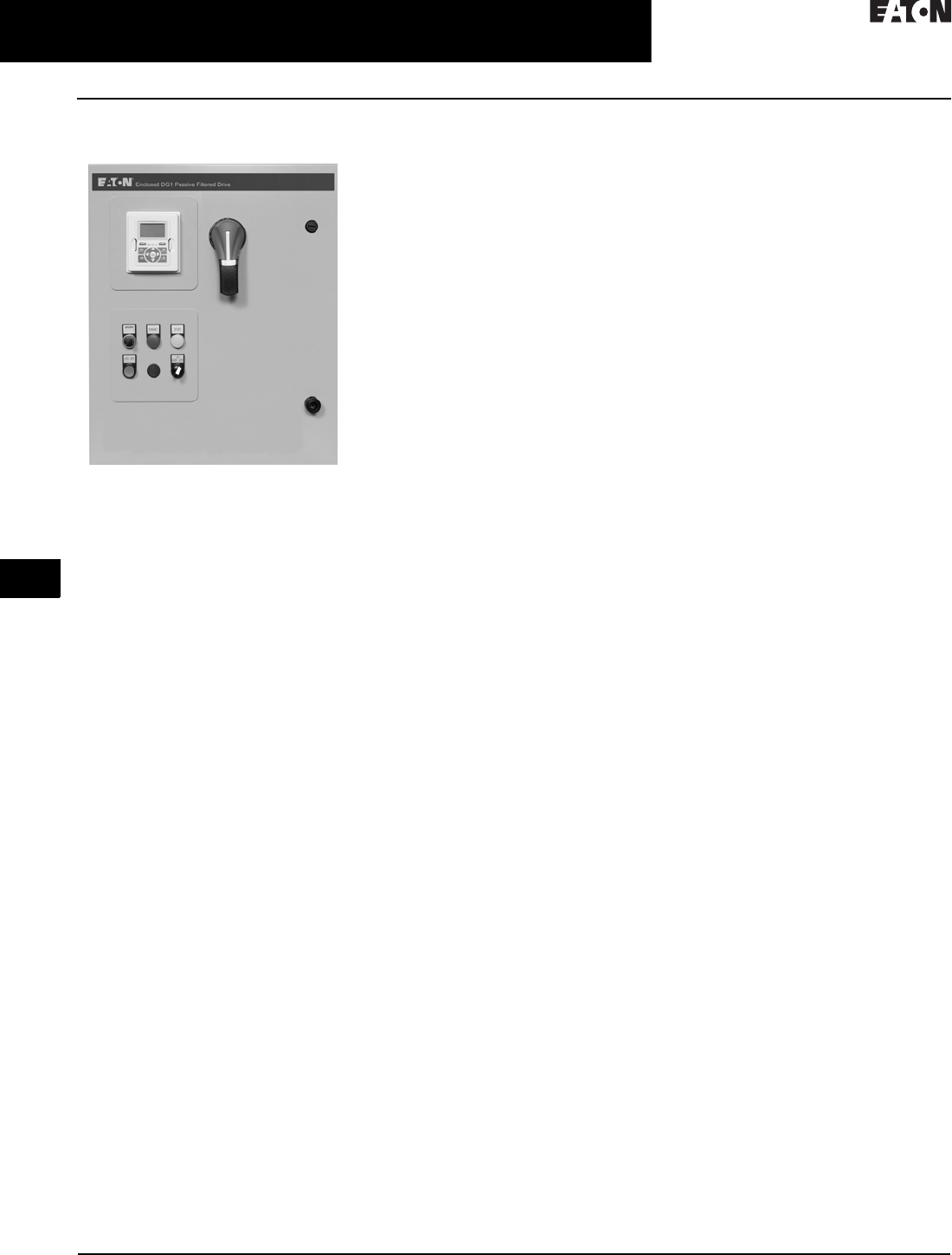
31.1-28
For more information, visit: www.eaton.com/consultants CA08104001E
February 2016
Adjustable Frequency Drives—Low Voltage
Sheet 31
22
23
24
25
26
27
28
29
30
31
32
33
34
35
36
37
38
39
40
41
42
4 3
PowerXL Series Drives
EGS Enclosed DG1
040
EGS Enclosed DG1
DG1 General Purpose Drive
Enclosed Drive
Product Description
The DG1 Enclosed Drive family
incorporates the latest Eaton drive
technology into pre-engineered
enclosed solutions covering the
industry’s most common applications.
Using the benefits of the PowerXL
DG1, the enclosed family provides
enhanced user safety with the Safe
Torque feature as well as industry-
leading energy efficiency from the
patented Active Energy Control
algorithm. Eaton further raises the
bar by providing customers with
industry best lead times with the
Rapid Response System. This system
allows customers to select from
9 million standard configurations that
have been pre-engineered with each
configuration having a set lead time.
The Rapid Response System delivers
an improved quotation process and a
faster delivery.
Features and Benefits
■Dual rated for both constant
torque (CT) / high overload (IH)
and variable torque (VT) / low
overload applications
■Optional Brake Chopper for external
braking applications
■Available circuit breaker, motor
circuit protector, fused disconnect,
isolation fusing and surge protec-
tion device options to provide input
power protection
■Optional 3% input and output
reactors provide a reduction in
voltage and current harmonics on
both line and load side
■Bypass options include a standard
three-contactor design and a
reduced voltage soft starter design
■Output contactor option provides
a means for positive disconnection
of the drive output from the motor
terminals
■MotoRX and dV/dt filter options are
used to reduce transients voltages
at the motor terminals
■Customizable cover control options
■Padlockable disconnect
■The PowerXL DG1 comes standard
with the following communication
protocols:
❑EtherNet/IP
❑Modbus/TCP
❑Modbus RTU
❑BACnet MS/TP
Communication Options
■PROFIBUS-DP
■LonWorks
■CANopen
■DeviceNet
Enclosure Ratings
■NEMA Type 1
■NEMA Type 12
■NEMA Type 3R
Mounting
■Wall mount
■Floor mount: 12-inch legs
■Floor mount: 22-inch legs
Product Range
■208 V: 0.75–100 hp
■230 V: 0.75–125 hp
■480 V: 1–250 hp
■230 V single-phase: 1–60 hp
■480 V single-phase: 1.5–125 hp
Standards and Certifications
■UL 508C tested, listed and approved
■OSHPD
Technical Specifications
■See PowerXL DG1 open drive
for technical specifications
(Table 31.1-36)
■See PowerXL DG1 open drive
(Table 31.1-37) for control wiring

CA08104001E For more information, visit: www.eaton.com/consultants
31.1-29
February 2016
Adjustable Frequency Drives—Low Voltage
Sheet 31
22
23
24
25
26
27
28
29
30
31
32
33
34
35
36
37
38
39
40
41
42
4 3
PowerXL Series Drives
EGS Enclosed DG1
041
Catalog Number Selection
Catalog Number Selection is for illustrative purposes only and not to be used to create new catalog numbers.
Table 31.1-38. DG1 Enclosed—Base Catalog Number
1Brake chopper is a factory-installed option only. Braking resistors sold separately. See DG1 drives starting on Page 31.1-31 for selection.
2Additional enclosure options including NEMA 4, 4X, 7 and 9 are available. Please contact the factory for configuration and pricing.
3Part number configuration continued on the following page.
EGS 3D5 1 D 1
Product Family
EGS = Enclosed DG1 drives—standard
Output Ampere Rating
208 V 230 V 480 V
3D5 = 3.5 A, 0.75 hp
4D6 = 4.6 A, 1 hp
6D6 = 6.6 A, 1.5 hp
7D5 = 7.5 A, 2 hp
010 = 10.6 A, 3 hp
016 = 16.7 A, 5 hp
024 = 24.2 A, 7.5 hp
030 = 30.8 A, 10 hp
046 = 46.2 A, 15 hp
059 = 59.4 A, 20 hp
074 = 74.8 A, 25 hp
088 = 88 A, 30 hp
114 = 114 A, 40 hp
143 = 143 A, 50 hp
169 = 169 A, 60 hp
211 = 211 A, 75 hp
273 = 273 A, 100 hp
3D2 = 3.2 A, 0.75 hp
4D2 = 4.2 A, 1 hp
6D0 = 6.0 A, 1.5 hp
6D8 = 6.8 A, 2 hp
9D6 = 9.6 A, 3 hp
015 = 15.2, 5 hp
022 = 22 A, 7.5 hp
028 = 28 A, 10 hp
042 = 42 A, 15 hp
054 = 54 A, 20 hp
068 = 68 A, 25 hp
080 = 80 A, 30 hp
104 = 104 A, 40 hp
130 = 130 A, 50 hp
154 = 154 A, 60 hp
192 = 192 A, 75 hp
248 = 248 A, 100 hp
312 = 312 A, 125 hp
2D1 = 2.1 A, 1 hp
3D0 = 3.0 A, 1.5 hp
3D4 = 3.4 A, 2 hp
4D8 = 4.8 A, 3 hp
7D6 = 7.6 A, 5 hp
011 = 11 A, 7.5 hp
014 = 14 A, 10 hp
021 = 21 A, 15 hp
027 = 27 A, 20 hp
034 = 34 A, 25 hp
040 = 40 A, 30 hp
052 = 52 A, 40 hp
065 = 65 A, 50 hp
077 = 77 A, 60 hp
096 = 96 A, 75 hp
124 = 124 A, 100 hp
156 = 156 A, 125 hp
180 = 180 A, 150 hp
240 = 240 A, 200 hp
302 = 302 A, 250 hp
Phasing, Voltage
1 = Input: Three-phase, 208 V
Output: Three-phase
2 = Input: Three-phase, 230 V
Output: Three-phase
4 = Input: Three-phase, 480 V
Output: Three-phase
5 = Input: Three-phase, 575 V
Output: Three-phase
J = Input: Single-phase, 230 V
Output: Three-phase
K = Input: Single-phase, 480 V
Output: Three-phase
Braking Application 1
A = No brake chopper, low overload
B = Brake chopper, low overload
C = No brake chopper, high overload
D = Brake chopper, high overload
Enclosure Rating 2
1 = NEMA Type 1
2 = NEMA Type 12
3 = NEMA Type 3R
6 = NEMA Type 1 Filtered and gasketed
• = Custom option
______
Options 3
See Page 31.1-30 for catalog
number option selection.

31.1-30
For more information, visit: www.eaton.com/consultants CA08104001E
February 2016
Adjustable Frequency Drives—Low Voltage
Sheet 31
22
23
24
25
26
27
28
29
30
31
32
33
34
35
36
37
38
39
40
41
42
4 3
PowerXL Series Drives
EGS Enclosed DG1
042
Table 31.1-39. DG1 Enclosed—Base Catalog Number
1HMCP disconnect option required and only available when bypass is selected.
2More options are available as Engineered to Order through the Bid Manager tool.
3All bypass options include third contactor for drive isolation when in bypass mode.
4Output contactor not available with bypass. Bypass comes standard with output contactor.
5Pilot devices are 22 mm standard. 30 mm options are available as engineered to order through the Bid Manager tool
EGS 3D5 1 D 1 2 0 0 B 1 0 0 0 0
Power Disconnect Options
0 = None
1 = MCP disconnect 1
2 = Circuit breaker
3 = Circuit breaker/isolation fusing
4 = Circuit breaker/isolation fusing/3% input reactor
5 = Circuit breaker/isolation fusing/SPD
6 = Circuit breaker/isolation fusing/SPD/3% input reactor
7 = Circuit breaker/3% input reactor
8 = Circuit breaker/SPD
9 = Circuit breaker/SPD/3% input reactor
A = Fused disconnect
B = Fused disconnect/SPD
C = Fused disconnect/SPD/3% input reactor
D = Fused disconnect/3% input reactor
E = Isolation fuses
F = Isolation fuses/3% input reactor
G = Isolation fuses/SPD
H = Isolation fuses/SPD/3% input reactor
• = Custom option 2
Base Catalog Number Example
See Page 31.1-29 for base catalog
number selection.
Output Power Options 4
0 =None
A = Output contactor
B = 3% Output reactor
C = MotoRX filter
D =dV/dt filter
E = 3% Output Reactor/
= output contactor
F = MotoRX/output contactor
G = dV/dt/output contactor
• = Custom option 2
Option Boards 2
Same options and codes as Option Boards 1
Communication Options
0 = No option
1 = PROFIBUS-DP
2 = LonWorks (SVX only)
3 = CANopen (slave)
4 = DeviceNet
5 = PROFIBUS-DP (D9 connector)
6 = Modbus (SVX only)
7 = Modbus (D9 connector) (SVX only)
8 = Johnson Controls N2 (SVX only)
9 = Modbus TCP (SVX only)
A = BACnet (SVX only)
B = EtherNet/IP (SVX only)
C = RS-232 with D9 connector (SVX only)
D = SmartWire-DT (DG1 only)
• = Custom option 2
Light Options 5
0 =None
1 = Non-bypass light kit—Power On, Run, Fault
2 = Bypass light kit—On, VFD Run, Fault, Bypass Run
• = Custom option 2
Option Boards 1
0 = No option
1 = 3 x DI, 3 x DO, 1 Thermistor, 24 Vdc/EXT
(DG1 only)
2 = 1 x AI, 2 x AO (isolated to control board)
(DG1 only)
3 = 3 x relay dry contact (2NO + 1NO/NC) (DG1 only)
4 = 3 x PT100 RTD thermistor input (DG1 only)
5 = 6 DI 240 Vac input (DG1 only)
6 = 6 DI, 1 ext +24 Vdc/EXT +24 Vdc (SVX only)
7 = 1 RO (NC-NO), 1 RO (NO), 1 therm (SVX only)
8 = 1 AI (mA isolated), 2 AO (mA isolated),
1 ext +24 Vdc/EXT +24 Vdc (SVX only)
9 = 3 RO (NO) (SVX only)
A = 1 ext +24 Vdc/EXT +24 Vdc, 3 Pt100 (SVX only)
B = 1 RO (NO), 5 DI 42–240 Vac input (SVX only)
C = Encoder low volt +5 V / 15 V / 24 V
(high-performance drive only)
D = Encoder high volt +15 V / 24 V
(high-performance drive only)
E = Double encoder (high-performance drive only)
• = Custom option 2
Bypass Options 3
0 = None
1 = Manual HOA bypass
2 = Manual HOA bypass/isolation fusing
3 = Manual HOA bypass/isolation fusing/3% input reactor
4 = Manual HOA bypass/isolation fusing/SPD
5 = Manual HOA bypass/isolation fusing/SPD/3% input reactor
6 = Manual HOA bypass/3% input reactor
7 = Manual HOA bypass/SPD
8 = Manual HOA bypass/SPD/3% input reactor
H = Manual HOA RVSS bypass
J = Manual HOA RVSS bypass/isolation fusing
K = Manual HOA RVSS bypass/isolation fusing/3% input reactor
L = Manual HOA RVSS bypass/isolation fusing/SPD
M = Manual HOA RVSS bypass/isolation fusing/
SPD/3% input reactor
N = Manual HOA RVSS bypass/3% input reactor
P = Manual HOA RVSS bypass/SPD
R = Manual HOA RVSS bypass/SPD/3% input reactor
• = Custom option 2
Enclosure Options
0 = None
1 = Floor stand—12 inches
2 = Floor stand—22 inches
A = Space heater
B = Space heater and 12-inch floor stands
C = Space heater and 22-inch floor stands
• = Custom option 2
Control Options 5
0 = None
1 = Speed pot
2 = Start-stop pushbutton
3 = Start-stop pushbutton
with speed pot
A = HOA switch
B = Start-stop pushbutton with
speed pot and HOA switch
C = Start-stop pushbutton
with HOA switch
D = HOA switch with speed pot
• = Custom option 2

CA08104001E For more information, visit: www.eaton.com/consultants
31.1-31
February 2016
Adjustable Frequency Drives—Low Voltage
Sheet 31
22
23
24
25
26
27
28
29
30
31
32
33
34
35
36
37
38
39
40
41
42
4 3
PowerXL Series Drives
EGS Enclosed DG1
043
Production Selection
Table 31.1-40. 208 V Drives—Constant Torque (CT)/High Overload (IH) Enclosed Drives
1Table is for base catalog number reference only. For complete catalog number selection, see Page 31.1-30.
2These units are current rated. They do not meet NEC ampere rating at this horsepower.
Table 31.1-41. 208 V Drives—Variable Torque (VT)/Low Overload (IL) Enclosed Drives
3Table is for base catalog number reference only. For complete catalog number selection, see Page 31.1-30.
hp Current (A) Drive
Frame Size
NEMA Type 1 NEMA Type 12 NEMA Type 3R
Base
Catalog Number 1
Base
Catalog Number 1
Base
Catalog Number 1
0.75
1
1.5
3.5
4.6
6.6
1
1
1
EGS3D51D1
EGS4D61D1
EGS6D61D1
EGS3D51D2
EGS4D61D2
EGS6D61D2
EGS3D51D3
EGS4D61D3
EGS6D61D3
2
3
5
7. 5
10.6
16.7
1
1
2
EGS7D51D1
EGS0101D1
EGS0161D1
EGS7D51D2
EGS0101D2
EGS0161D2
EGS7D51D3
EGS0101D3
EGS0161D3
7. 5
10
15
24.2
30.8
46.2
2
3
3
EGS0241D1
EGS0301D1
EGS0461D1
EGS0241D2
EGS0301D2
EGS0461D2
EGS0241D3
EGS0301D3
EGS0461D3
20
25
30
59.4
74.8
88
4
4
4
EGS0591C1
EGS0741C1
EGS0881C1
EGS0591C2
EGS0741C2
EGS0881C2
EGS0591C3
EGS0741C3
EGS0881C3
40
50
60
114
143
169
5
5
5
EGS1141C1
EGS1431C1
EGS1691C1
EGS1141C2
EGS1431C2
EGS1691C2
EGS1141C3
EGS1431C3
EGS1691C3
75
100 2
211
261 2
6
6
EGS2111C1
EGS2611C1
EGS2111C2
EGS2611C2
EGS2 111C3
EGS2611C3
hp Current (A) Drive
Frame Size
NEMA Type 1 NEMA Type 12 NEMA Type 3R
Base
Catalog Number 3
Base
Catalog Number 3
Base
Catalog Number 3
1
1.5
2
4.6
6.6
7. 5
1
1
1
EGS4D61B1
EGS6D61B1
EGS7D51B1
EGS4D61B2
EGS6D61B2
EGS7D51B2
EGS4D61B3
EGS6D61B3
EGS7D51B3
3
5
7. 5
10.6
16.7
24.2
1
2
2
EGS0101B1
EGS0161B1
EGS0241B1
EGS0101B2
EGS0161B2
EGS0241B2
EGS0101B3
EGS0161B3
EGS0241B3
10
15
20
30.8
46.2
59.4
2
3
3
EGS0301B1
EGS0461B1
EGS0591B1
EGS0301B2
EGS0461B2
EGS0591B2
EGS0301B3
EGS0461B3
EGS0591B3
25
30
40
74.8
88
114
4
4
4
EGS0741A1
EGS0881A1
EGS1141A1
EGS0741A2
EGS0881A2
EGS1141A2
EGS0741A3
EGS0881A3
EGS1141A3
50
60
75
100
143
169
211
273
5
5
5
6
EGS1431A1
EGS1691A1
EGS2 111A1
EGS2731A1
EGS1431A2
EGS1691A2
EGS2 111A2
EGS2731A2
EGS1431A3
EGS1691A3
EGS2 111A3
EGS2731A3

31.1-32
For more information, visit: www.eaton.com/consultants CA08104001E
February 2016
Adjustable Frequency Drives—Low Voltage
Sheet 31
22
23
24
25
26
27
28
29
30
31
32
33
34
35
36
37
38
39
40
41
42
4 3
PowerXL Series Drives
EGS Enclosed DG1
044
Table 31.1-42. 230 V Drives—Constant Torque (CT)/High Overload (IH) Enclosed Drives
1Table is for base catalog number reference only. For complete catalog number selection, see Page 31.1-30.
Table 31.1-43. 230 V Drives—Variable Torque (VT)/Low Overload (IL) Enclosed Drives
2Table is for base catalog number reference only. For complete catalog number selection, see Page 31.1-30.
hp Current (A) Drive
Frame Size
NEMA Type 1 NEMA Type 12 NEMA Type 3R
Base
Catalog Number 1
Base
Catalog Number 1
Base
Catalog Number 1
0.75
1
1.5
3.2
4.2
6
1
1
1
EGS3D22D1
EGS4D22D1
EGS6D02D1
EGS3D22D2
EGS4D22D2
EGS6D02D2
EGS3D22D3
EGS4D22D3
EGS6D02D3
2
3
5
6.8
9.6
15.2
1
1
2
EGS6D82D1
EGS9D62D1
EGS0152D1
EGS6D82D2
EGS9D62D2
EGS0152D2
EGS6D82D3
EGS9D62D3
EGS0152D3
7. 5
10
15
22
28
42
2
3
3
EGS0222D1
EGS0282D1
EGS0422D1
EGS0222D2
EGS0282D2
EGS0422D2
EGS0222D3
EGS0282D3
EGS0422D3
20
25
30
54
68
80
4
4
4
EGS0542C1
EGS0682C1
EGS0802C1
EGS0542C2
EGS0682C2
EGS0802C2
EGS0542C3
EGS0682C3
EGS0802C3
40
50
60
104
130
154
5
5
5
EGS1042C1
EGS1302C1
EGS1542C1
EGS1042C2
EGS1302C2
EGS1542C2
EGS1042C3
EGS1302C3
EGS1542C3
75
100
192
248
6
6
EGS1922C1
EGS2482C1
EGS1922C2
EGS2482C2
EGS1922C3
EGS2482C3
hp Current (A) Drive
Frame Size
NEMA Type 1 NEMA Type 12 NEMA Type 3R
Base
Catalog Number 2
Base
Catalog Number 2
Base
Catalog Number 2
1
1.5
2
4.2
6
6.8
1
1
1
EGS4D22B1
EGS6D02B1
EGS6D82B1
EGS4D22B2
EGS6D02B2
EGS6D82B2
EGS4D22B3
EGS6D02B3
EGS6D82B3
3
5
7. 5
9.6
15.2
22
1
2
2
EGS9D62B1
EGS0152B1
EGS0222B1
EGS9D62B2
EGS0152B2
EGS0222B2
EGS9D62B3
EGS0152B3
EGS0222B3
10
15
20
28
42
54
2
3
3
EGS0282B1
EGS0422B1
EGS0542B1
EGS0282B2
EGS0422B2
EGS0542B2
EGS0282B3
EGS0422B3
EGS0542B3
25
30
40
68
80
104
4
4
4
EGS0682A1
EGS0802A1
EGS1042A1
EGS0682A2
EGS0802A2
EGS1042A2
EGS0682A3
EGS0802A3
EGS1042A3
50
60
75
130
154
192
5
5
5
EGS1302A1
EGS1542A1
EGS1922A1
EGS1302A2
EGS1542A2
EGS1922A2
EGS1302A3
EGS1542A3
EGS1922A3
100
125
248
312
6
6
EGS2482A1
EGS3122A1
EGS2482A2
EGS3122A2
EGS2482A3
EGS3122A3

CA08104001E For more information, visit: www.eaton.com/consultants
31.1-33
February 2016
Adjustable Frequency Drives—Low Voltage
Sheet 31
22
23
24
25
26
27
28
29
30
31
32
33
34
35
36
37
38
39
40
41
42
4 3
PowerXL Series Drives
EGS Enclosed DG1
045
Table 31.1-44. 480 V Drives—Constant Torque (CT)/High Overload (IH) Enclosed Drives
1Table is for base catalog number reference only. For complete catalog number selection, see Page 31.1-30.
Table 31.1-45. 480 V Drives—Variable Torque (VT)/Low Overload (IL) Enclosed Drives
2Table is for base catalog number reference only. For complete catalog number selection, see Page 31.1-30.
hp Current (A) Drive
Frame Size
NEMA Type 1 NEMA Type 12 NEMA Type 3R
Base
Catalog Number 1
Base
Catalog Number 1
Base
Catalog Number 1
1
1.5
2
2.1
3
3.4
1
1
1
EGS2D14D1
EGS3D04D1
EGS3D44D1
EGS2D14D2
EGS3D04D2
EGS3D44D2
EGS2D14D3
EGS3D04D3
EGS3D44D3
3
5
7. 5
4.8
7. 6
11
1
1
2
EGS4D84D1
EGS7D64D1
EGS0114D1
EGS4D84D2
EGS7D64D2
EGS0114D2
EGS4D84D3
EGS7D64D3
EGS0114D3
10
15
20
14
21
27
2
2
3
EGS0144D1
EGS0214D1
EGS0274D1
EGS0144D2
EGS0214D2
EGS0274D2
EGS0144D3
EGS0214D3
EGS0274D3
25
30
40
34
40
52
3
3
4
EGS0344D1
EGS0404D1
EGS0524C1
EGS0344D2
EGS0404D2
EGS0524C2
EGS0344D3
EGS0404D3
EGS0524C3
50
60
75
65
77
96
4
4
5
EGS0654C1
EGS0774C1
EGS0964C1
EGS0654C2
EGS0774C2
EGS0964C2
EGS0654C3
EGS0774C3
EGS0964C3
100
125
150
200
124
156
180
240
5
5
6
6
EGS1244C1
EGS1564C1
EGS1804C1
EGS2404C1
EGS1244C2
EGS1564C2
EGS1804C2
EGS2404C2
EGS1244C3
EGS1564C3
EGS1804C3
EGS2404C3
hp Current (A) Drive
Frame Size
NEMA Type 1 NEMA Type 12 NEMA Type 3R
Base
Catalog Number 2
Base
Catalog Number 2
Base
Catalog Number 2
1.5
2
3
3
3.4
4.8
1
1
1
EGS3D04B1
EGS3D44B1
EGS4D84B1
EGS3D04B2
EGS3D44B2
EGS4D84B2
EGS3D04B3
EGS3D44B3
EGS4D84B3
5
7. 5
10
7. 6
11
14
1
1
2
EGS7D64B1
EGS0114B1
EGS0144B1
EGS7D64B2
EGS0114B2
EGS0144B2
EGS7D64B3
EGS0114B3
EGS0144B3
15
20
25
21
27
34
2
2
3
EGS0214B1
EGS0274B1
EGS0344B1
EGS0214B2
EGS0274B2
EGS0344B2
EGS0214B3
EGS0274B3
EGS0344B3
EGS0404B3
EGS0524B3
EGS0654A3
30
40
50
40
52
65
3
3
4
EGS0404B1
EGS0524B1
EGS0654A1
EGS0404B2
EGS0524B2
EGS0654A2
60
75
100
77
96
124
4
4
5
EGS0774A1
EGS0964A1
EGS1244A1
EGS0774A2
EGS0964A2
EGS1244A2
EGS0774A3
EGS0964A3
EGS1244A3
125
150
200
250
156
180
240
302
5
5
6
6
EGS1564A1
EGS1804A1
EGS2404A1
EGS3024A1
EGS1564A2
EGS1804A2
EGS2404A2
EGS3024A2
EGS1564A3
EGS1804A3
EGS2404A3
EGS3024A3

31.1-34
For more information, visit: www.eaton.com/consultants CA08104001E
February 2016
Adjustable Frequency Drives—Low Voltage
Sheet 31
22
23
24
25
26
27
28
29
30
31
32
33
34
35
36
37
38
39
40
41
42
4 3
PowerXL Series Drives
EGS Enclosed DG1
046
Table 31.1-46. 230 V Single-Phase Drives—Variable Torque (VT)/Low Overload (IL) Enclosed Drives
1Table is for base catalog number reference only. For complete catalog number selection, see Page 31.1-30.
Table 31.1-47. 480 V Single-Phase Drives—Variable Torque (VT)/Low Overload (IL) Enclosed Drives
2Table is for base catalog number reference only. For complete catalog number selection, see Page 31.1-30.
hp Current (A) Drive
Frame Size
NEMA Type 1 NEMA Type 12 NEMA Type 3R
Base
Catalog Number 1
Base
Catalog Number 1
Base
Catalog Number 1
1
1.5
2
4.2
6
6.8
1
1
1
EGS4D2JB1
EGS6D0JB1
EGS6D8JB1
EGS4D2JB2
EGS6D0JB2
EGS6D8JB2
EGS4D2JB3
EGS6D0JB3
EGS6D8JB3
3
5
7. 5
9.6
15.2
22
1
2
2
EGS9D6JB1
EGS015JB1
EGS022JB1
EGS9D6JB2
EGS015JB2
EGS022JB2
EGS9D6JB3
EGS015JB3
EGS022JB3
10
15
20
28
42
54
2
3
3
EGS028JB1
EGS042JB1
EGS054JB1
EGS028JB2
EGS042JB2
EGS054JB2
EGS028JB3
EGS042JB3
EGS054JB3
25
30
40
68
80
104
4
4
4
EGS068JA1
EGS080JA1
EGS104JA1
EGS068JA2
EGS080JA2
EGS104JA2
EGS068JA3
EGS080JA3
EGS104JA3
50
60
130
154
5
5
EGS130JA1
EGS154JA1
EGS130JA2
EGS154JA2
EGS130JA3
EGS154JA3
hp Current (A) Drive
Frame Size
N E M A Ty p e 1 N E M A Ty p e 1 2 N E M A Ty p e 3 R
Base
Catalog Number 2
Base
Catalog Number 2
Base
Catalog Number 2
1.5
2
3
3
3.4
4.8
1
1
1
EGS3D0KB1
EGS3D4KB1
EGS4D8KB1
EGS3D0KB2
EGS3D4KB2
EGS4D8KB2
EGS3D0KB3
EGS3D4KB3
EGS4D8KB3
5
7. 5
10
7. 6
11
14
1
1
2
EGS7D6KB1
EGS011KB1
EGS014KB1
EGS7D6KB2
EGS011KB2
EGS014KB2
EGS7D6KB3
EGS011KB3
EGS014KB3
15
20
25
21
27
34
2
2
3
EGS021KB1
EGS027KB1
EGS034KB1
EGS021KB2
EGS027KB2
EGS034KB2
EGS021KB3
EGS027KB3
EGS034KB3
30
40
50
40
52
65
3
3
4
EGS040KB1
EGS052KB1
EGS065KA1
EGS040KB2
EGS052KB2
EGS065KA2
EGS040KB3
EGS052KB3
EGS065KA3
60
75
100
125
77
96
124
156
4
4
5
5
EGS077KA1
EGS096KA1
EGS124KA1
EGS156KA1
EGS077KA2
EGS096KA2
EGS124KA2
EGS156KA2
EGS077KA3
EGS096KA3
EGS124KA3
EGS156KA3

CA08104001E For more information, visit: www.eaton.com/consultants
31.1-35
February 2016
Adjustable Frequency Drives—Low Voltage
Sheet 31
22
23
24
25
26
27
28
29
30
31
32
33
34
35
36
37
38
39
40
41
42
4 3
PowerXL Series Drives
EGS Enclosed DG1
047
Options
Table 31.1-48. Input Power Options
Table 31.1-49. Bypass Options
Option Description
HMCP Disconnect The HMCP motor protection circuit breaker uses an electronic trip unit to provide typical motor overload relay
functionality and short-circuit protection against potential phase-to-phase or phase-to-ground faults.
Circuit Breaker Utilizes a circuit breaker to provide a means of short-circuit protection for the power cables between it
and the drive, and protection from high-level ground faults on the power cable. Allows a convenient means
of disconnecting the drive from the line, and the operating mechanism can be padlocked in the OFF position.
This is factory mounted in the enclosure.
Isolation Fusing Provides high-level fault protection of the drive input power circuit from the load side of the fuses to the
input side of the power transistors. This option consists of three 200 kA fuses that are factory mounted in
the enclosure.
3% Input Reactor The input reactor is a three-phase series inductance on the line side of an AFD. It is used to provide a reduction
in voltage and current harmonics. It also provides increased input protection for AFD and its semiconductors
from line transients.
SPD Provides a surge protection device (SPD) connected to the line side terminals and is designed to clip line side
transients.
Fused Disconnect Utilizes fusing to provide a means of short-circuit protection for the power cables between it and the drive, and
protection from high-level ground faults on the power cable. Allows a convenient means of disconnecting the
drive from the line, and the operating mechanism can be padlocked in the OFF position. This is factory mounted
in the enclosure.
Option Description
Manual HOA Bypass Provides a three-position selector switch that allows the user to select either a HAND or AUTO mode of
operation. HAND mode is defaulted keypad operation, and AUTO mode is defaulted to control from an
external terminal source. These modes of operation can be configured via programming to allow for
alternate combinations of start and speed sources. Start and speed sources include keypad, I/O and fieldbus.
Manual HOA RVSS Bypass This option adds a reduced voltage soft starter to bypass assembly for soft starting in bypass mode.

31.1-36
For more information, visit: www.eaton.com/consultants CA08104001E
February 2016
Adjustable Frequency Drives—Low Voltage
Sheet 31
22
23
24
25
26
27
28
29
30
31
32
33
34
35
36
37
38
39
40
41
42
4 3
PowerXL Series Drives
EGS Enclosed DG1
048
Table 31.1-50. Output Power Options
Table 31.1-51. Control Options
Table 31.1-52. Light Options
Table 31.1-53. Enclosure Options
Option Description
Output Contactor Provides a means for positive disconnection of the drive output from the motor terminals. The contactor coil
is controlled by the drive’s run or permissive logic. NC and NO auxiliary contacts rated at 10 A, 600 Vac are
provided for customer use. This option includes a low VA 115 Vac fused control power transformer and is
factory mounted in the enclosure.
3% Output Reactor The output reactor is a three-phase series inductance on the load side of an AFD. It is used to provide a reduction
in voltage and current harmonics.
MotoRX Filter Used to reduce transient voltage (dV/dt) and peak voltages at the motor terminals. This option is comprised of a
0.5% line reactor, followed by capacitive filtering and an energy recovery/clamping circuit. Unlike the traditional
dV/dt filter, the MotoRx recovers most of the energy from the voltage peaks, resulting in a lower voltage drop
to the motor, therefore conserving power. This option is used when the distance between a single motor and
the drive is 300–600 ft (91–183 m). This option can not be used with the brake chopper circuit. in this case, the
traditional dV/dt filter should be investigated as an alternative.
dV/dt Filter Used to reduce the transient voltage (dV/dt) at the motor terminals. The traditional dV/dt filter is recommended
for cable lengths exceeding 100 ft (30 m) with a drive of 3 hp and above, for cable lengths of 33 ft (10 m) with a
drive of 2 hp and below, or for a drive rated at 525–690 V. This option is mounted in the enclosure and may be
used in conjunction with a brake chopper circuit. This option is mounted in the enclosure.
Option Description
Speed Pot Provides the ability to adjust the frequency reference using a door-mounted potentiometer. This option uses the
10 Vdc reference to generate a 0–10 V signal at the analog voltage input signal terminal. When the HOA bypass
option is added, the speed is controlled when the HOA switch is in the HAND position. Without the HOA bypass
option, a two-position switch (labeled local/remote) is provided on the keypad to select speed reference from
the speed potentiometer or a remote speed signal.
HOA Switch Provides a three-position selector switch that allows the user to select either a HAND or AUTO mode of
peration. HAND mode is defaulted to keypad operation, and AUTO mode is defaulted to control from an
external terminal source. These modes of operation can be configured via drive programming to allow for
alternate combinations of start and speed sources. Start and speed sources include Keypad, I/O and fieldbus.
Start-Stop Pushbutton Provides door-mounted START and STOP pushbuttons for either bypass or non-bypass configurations.
Option Description
Non-Bypass Light Kit—Power On,
Run, Fault
Provides a white POWER ON light that indicates power to the enclosed cabinet, a green RUN light that indicates
the drive is running and a red FAULT light that indicates a drive fault has occurred.
Bypass Light Kit—On, VFD Run, Fault,
Bypass Run
Provides a white POWER ON light that indicates power to the enclosed cabinet, a green RUN light that indicates
the drive is running, a red FAULT light that indicates a drive fault has occurred and an amber light that indicates
when the motor is running in Bypass mode.
Option Description
Floor Stand 12 in Converts a normally wall-mounted enclosure to a floor-standing enclosure with a height of 12 in (304.8 mm).
Floor Stand 22 in Converts a normally wall-mounted enclosure to a floor-standing enclosure with a height of 22 in (558.8 mm).
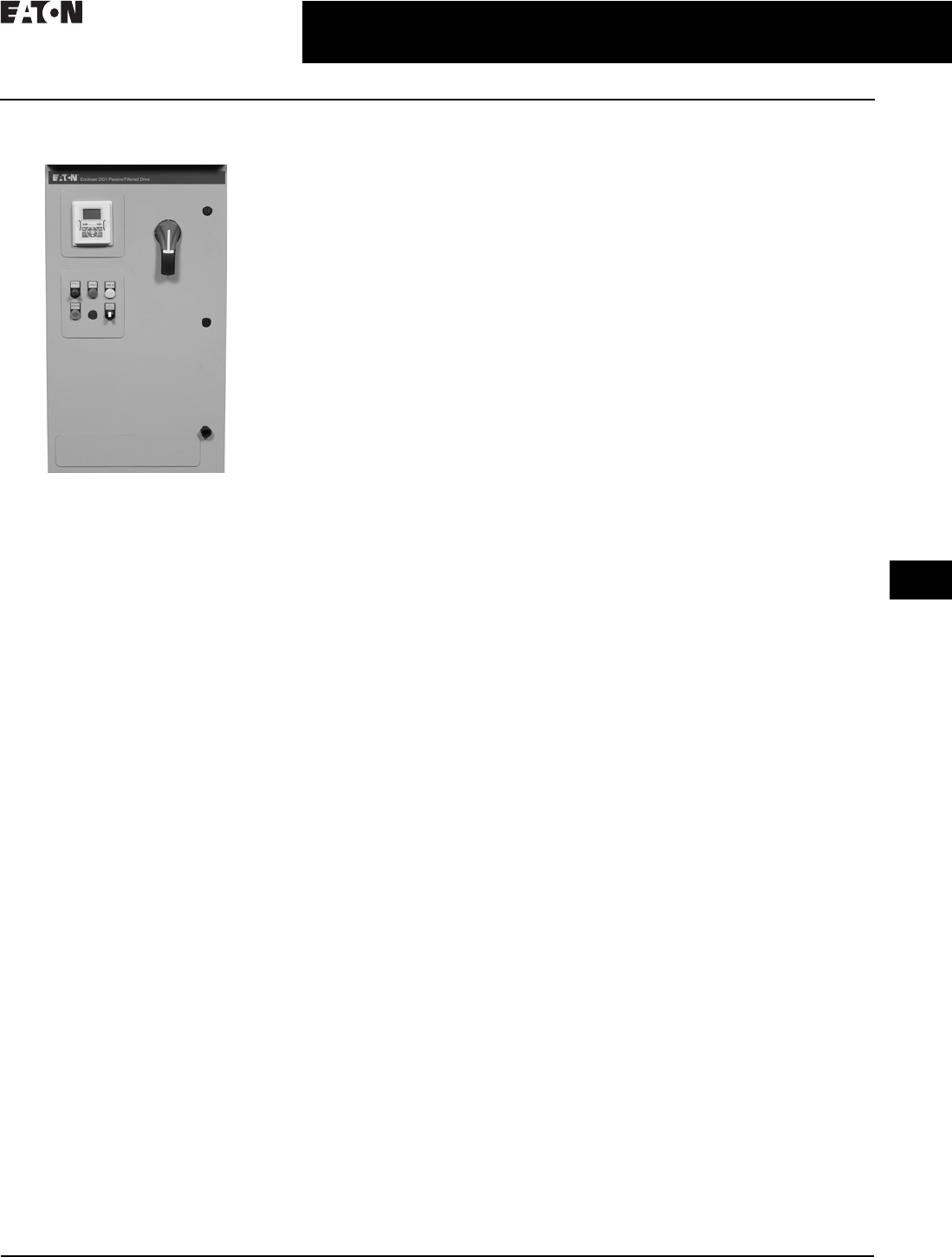
CA08104001E For more information, visit: www.eaton.com/consultants
31.1-37
February 2016
Adjustable Frequency Drives—Low Voltage
Sheet 31
22
23
24
25
26
27
28
29
30
31
32
33
34
35
36
37
38
39
40
41
42
4 3
PowerXL Series Drives
EGF Passive Filtered DG1
049
EGF Passive Filtered DG1
EGF Enclosed Drives
Product Description
Eaton’s Enclosed EGF Drives combine
harmonic distortion reduction and true
power factor performance with the
latest in Eaton adjustable frequency
drive technology to deliver an
industry-leading solution. This pre-
engineered passive filtered solution
prevents transformer overheating
and overloading of breakers and
feeders, which enables the application
of adjustable frequency drives on
generators and other high impedance
power systems.
Features and Benefits
■Tuned passive filter
■Delivers 5–8% THD
■Generator compatible
■Uses the same DG1, SVX or
SPX drive that is stocked in
the warehouse
■Simple to retrofit
■Provides a low-impedance path to
ground for the harmonic frequencies
■Meets IEEE 519-2014
■Excellent cost for performance
■Small footprint, compact
enclosure design
■Insensitive to voltage imbalance
■Customizable cover control options
■Padlockable disconnect
■The PowerXL DG1 comes standard
with the following communication
protocols:
❑EtherNet/IP
❑Modbus/TCP
❑Modbus RTU
❑BACnet MS/TP
Communication Options
■PROFIBUS-DP
■LonWorks
■CANopen
■DeviceNet
Enclosure Ratings
■NEMA Type 1
■NEMA Type 12
■NEMA Type 3R
Mounting
■Wall mount
■Floor mount: 12-inch legs
■Floor mount: 22-inch legs
Product Range
■208 V: 0.75–100 hp
■230 V: 0.75–125 hp
■480 V: 1–250 hp
Standards and Certifications
■UL 508C tested, listed and approved
■OSHPD
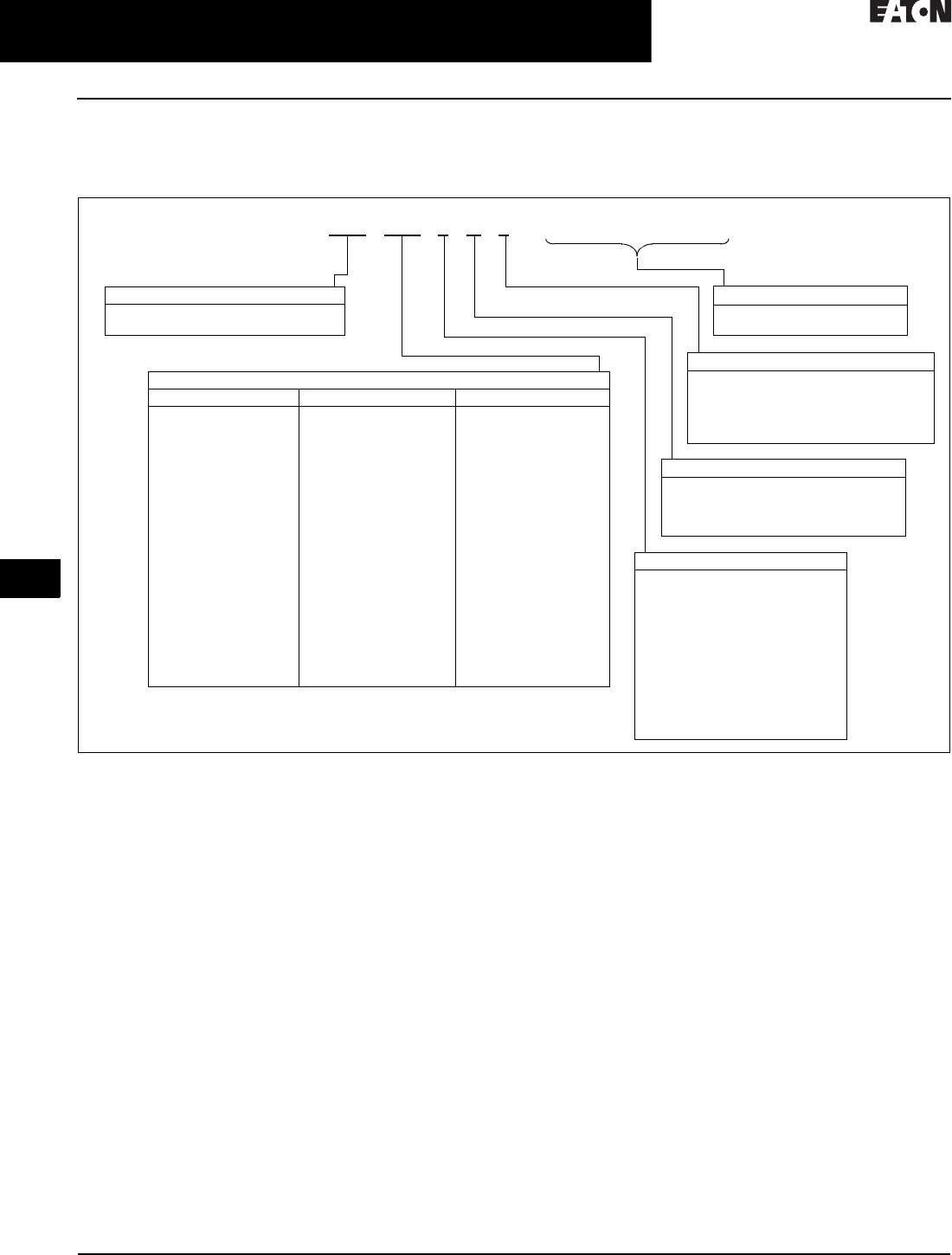
31.1-38
For more information, visit: www.eaton.com/consultants CA08104001E
February 2016
Adjustable Frequency Drives—Low Voltage
Sheet 31
22
23
24
25
26
27
28
29
30
31
32
33
34
35
36
37
38
39
40
41
42
4 3
PowerXL Series Drives
EGF Passive Filtered DG1
050
Catalog Number Selection
Catalog Number Selection is for illustrative purposes only and not to be used to create new catalog numbers.
Table 31.1-54. EGF Enclosed—Base Catalog Number
1Brake chopper is a factory-installed option only. Braking resistors sold separately. See DG1 drives starting on Page 31.1-31 for selection.
2Additional enclosure options including NEMA 4, 4X, 7 and 9 are available. Please contact the factory for configuration and pricing.
3Part number configuration continued on the following page.
EGF 3D5 1 D 1
Product Family
EGF = Enclosed DG1 drives—
passive filtered
Output Ampere Rating
208 V 230 V 480 V
3D5 = 3.5 A, 0.75 hp
4D6 = 4.6 A, 1 hp
6D6 = 6.6 A, 1.5 hp
7D5 = 7.5 A, 2 hp
010 = 10.6 A, 3 hp
016 = 16.7 A, 5 hp
024 = 24.2 A, 7.5 hp
030 = 30.8 A, 10 hp
046 = 46.2 A, 15 hp
059 = 59.4 A, 20 hp
074 = 74.8 A, 25 hp
088 = 88 A, 30 hp
114 = 114 A, 40 hp
143 = 143 A, 50 hp
169 = 169 A, 60 hp
211 = 211 A, 75 hp
273 = 273 A, 100 hp
3D2 = 3.2 A, 0.75 hp
4D2 = 4.2 A, 1 hp
6D0 = 6.0 A, 1.5 hp
6D8 = 6.8 A, 2 hp
9D6 = 9.6 A, 3 hp
015 = 15.2, 5 hp
022 = 22 A, 7.5 hp
028 = 28 A, 10 hp
042 = 42 A, 15 hp
054 = 54 A, 20 hp
068 = 68 A, 25 hp
080 = 80 A, 30 hp
104 = 104 A, 40 hp
130 = 130 A, 50 hp
154 = 154 A, 60 hp
192 = 192 A, 75 hp
248 = 248 A, 100 hp
312 = 312 A, 125 hp
2D1 = 2.1 A, 1 hp
3D0 = 3.0 A, 1.5 hp
3D4 = 3.4 A, 2 hp
4D8 = 4.8 A, 3 hp
7D6 = 7.6 A, 5 hp
011 = 11 A, 7.5 hp
014 = 14 A, 10 hp
021 = 21 A, 15 hp
027 = 27 A, 20 hp
034 = 34 A, 25 hp
040 = 40 A, 30 hp
052 = 52 A, 40 hp
065 = 65 A, 50 hp
077 = 77 A, 60 hp
096 = 96 A, 75 hp
124 = 124 A, 100 hp
156 = 156 A, 125 hp
180 = 180 A, 150 hp
240 = 240 A, 200 hp
302 = 302 A, 250 hp
Phasing, Voltage
1 = Input: Three-phase, 208 V
Output: Three-phase
2 = Input: Three-phase, 230 V
Output: Three-phase
4 = Input: Three-phase, 480 V
Output: Three-phase
5 = Input: Three-phase, 575 V
Output: Three-phase
J = Input: Single-phase, 230 V
Output: Three-phase
K = Input: Single-phase, 480 V
Output: Three-phase
Braking Application 1
A = No brake chopper, low overload
B = Brake chopper, low overload
C = No brake chopper, high overload
D = Brake chopper, high overload
Enclosure Rating 2
1 = NEMA Type 1
2 = NEMA Type 12
3 = NEMA Type 3R
6 = NEMA Type 1 Filtered
• = Custom option
______
Options 3
See Page 31.1-39 for catalog
number option selection.
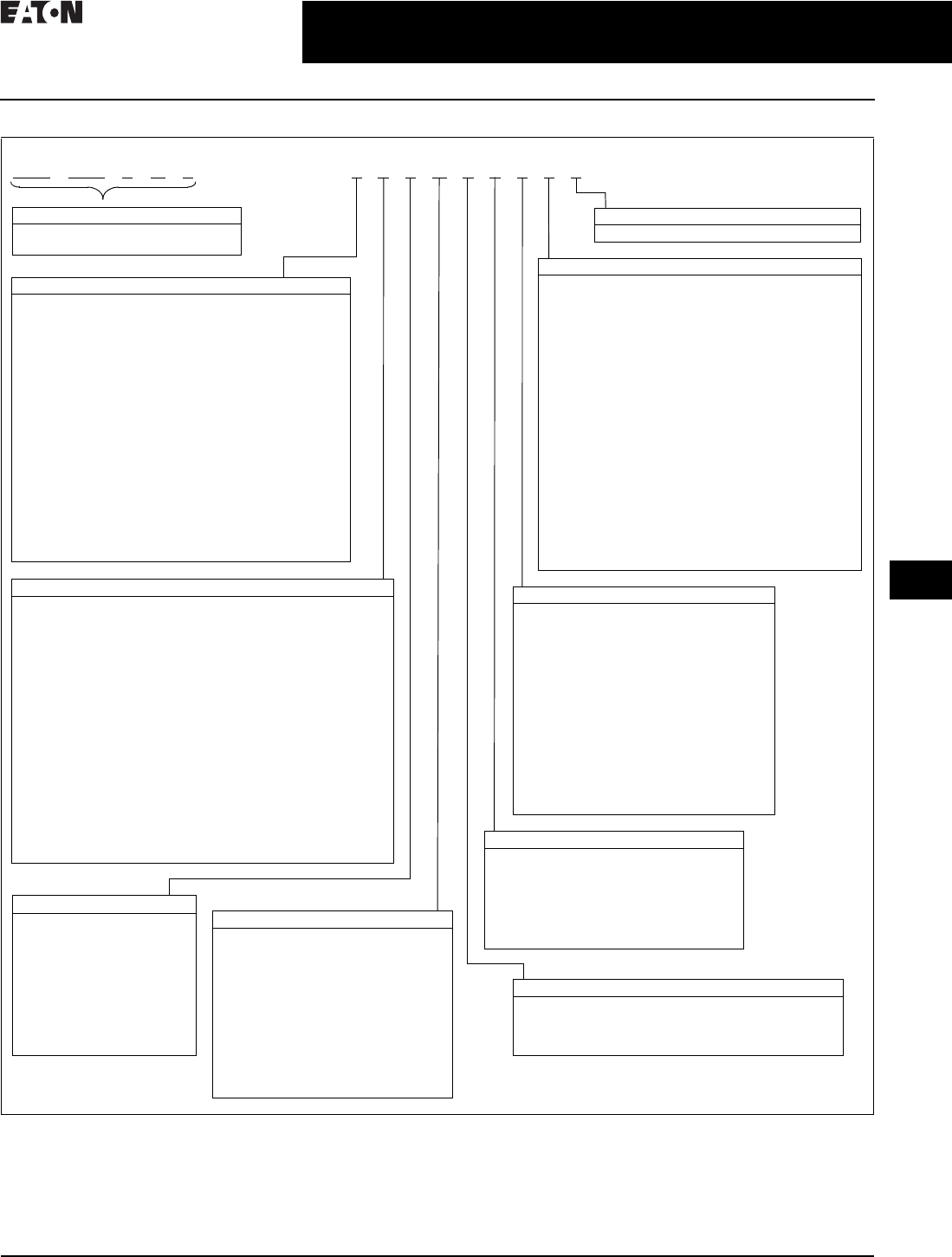
CA08104001E For more information, visit: www.eaton.com/consultants
31.1-39
February 2016
Adjustable Frequency Drives—Low Voltage
Sheet 31
22
23
24
25
26
27
28
29
30
31
32
33
34
35
36
37
38
39
40
41
42
4 3
PowerXL Series Drives
EGF Passive Filtered DG1
051
Table 31.1-55. EGF Enclosed—Catalog Number Options
1HMCP disconnect option required and only available when bypass is selected.
2More options are available as Engineered to Order through the Bid Manager tool.
3All bypass options include third contactor for drive isolation when in bypass mode.
4Output contactor not available with bypass. Bypass comes standard with output contactor.
5Pilot devices are 22 mm standard. 30 mm options are available as engineered to order through the Bid Manager tool.
EGF 3D5 1 D 1 2 0 0 B 1 0 0 0 0
Power Disconnect Options
0 = None
1 = MCP disconnect 1
2 = Circuit breaker
3 = Circuit breaker/isolation fusing
4 = Circuit breaker/isolation fusing/3% input reactor
5 = Circuit breaker/isolation fusing/SPD
6 = Circuit breaker/isolation fusing/SPD/3% input reactor
7 = Circuit breaker/3% input reactor
8 = Circuit breaker/SPD
9 = Circuit breaker/SPD/3% input reactor
A = Fused disconnect
B = Fused disconnect/SPD
C = Fused disconnect/SPD/3% input reactor
D = Fused disconnect/3% input reactor
E = Isolation fuses
F = Isolation fuses/3% input reactor
G = Isolation fuses/SPD
H = Isolation fuses/SPD/3% input reactor
• = Custom option 2
Base Catalog Number Example
See Page 31.1-38 for base catalog
number selection.
Output Power Options 4
0 =None
A = Output contactor
B = 3% Output reactor
C = MotoRX filter
D =dV/dt filter
E = 3% Output Reactor/
= output contactor
F = MotoRX/output contactor
G = dV/dt/output contactor
• = Custom option 2
Option Boards 2
Same options and codes as Option Boards 1
Communication Options
0 = No option
1 = PROFIBUS-DP
2 = LonWorks (SVX only)
3 = CANopen (slave)
4 = DeviceNet
5 = PROFIBUS-DP (D9 connector)
6 = Modbus (SVX only)
7 = Modbus (D9 connector) (SVX only)
8 = Johnson Controls N2 (SVX only)
9 = Modbus TCP (SVX only)
A = BACnet (SVX only)
B = EtherNet/IP (SVX only)
C = RS-232 with D9 connector (SVX only)
D = SmartWire-DT (DG1 only)
• = Custom option 2
Light Options 5
0 =None
1 = Non-bypass light kit—Power On, Run, Fault
2 = Bypass light kit—On, VFD Run, Fault, Bypass Run
• = Custom option 2
Option Boards 1
0 = No option
1 = 3 x DI, 3 x DO, 1 Thermistor, 24 Vdc/EXT
(DG1 only)
2 = 1 x AI, 2 x AO (isolated to control board)
(DG1 only)
3 = 3 x relay dry contact (2NO + 1NO/NC) (DG1 only)
4 = 3 x PT100 RTD thermistor input (DG1 only)
5 = 6 DI 240 Vac input (DG1 only)
6 = 6 DI, 1 ext +24 Vdc/EXT +24 Vdc (SVX only)
7 = 1 RO (NC-NO), 1 RO (NO), 1 therm (SVX only)
8 = 1 AI (mA isolated), 2 AO (mA isolated),
1 ext +24 Vdc/EXT +24 Vdc (SVX only)
9 = 3 RO (NO) (SVX only)
A = 1 ext +24 Vdc/EXT +24 Vdc, 3 Pt100 (SVX only)
B = 1 RO (NO), 5 DI 42–240 Vac input (SVX only)
C = Encoder low volt +5 V / 15 V / 24 V
(high-performance drive only)
D = Encoder high volt +15 V / 24 V
(high-performance drive only)
E = Double encoder (high-performance drive only)
• = Custom option 2
Bypass Options 3
0 = None
1 = Manual HOA bypass
2 = Manual HOA bypass/isolation fusing
3 = Manual HOA bypass/isolation fusing/3% input reactor
4 = Manual HOA bypass/isolation fusing/SPD
5 = Manual HOA bypass/isolation fusing/SPD/3% input reactor
6 = Manual HOA bypass/3% input reactor
7 = Manual HOA bypass/SPD
8 = Manual HOA bypass/SPD/3% input reactor
H = Manual HOA RVSS bypass
J = Manual HOA RVSS bypass/isolation fusing
K = Manual HOA RVSS bypass/isolation fusing/3% input reactor
L = Manual HOA RVSS bypass/isolation fusing/SPD
M = Manual HOA RVSS bypass/isolation fusing/
SPD/3% input reactor
N = Manual HOA RVSS bypass/3% input reactor
P = Manual HOA RVSS bypass/SPD
R = Manual HOA RVSS bypass/SPD/3% input reactor
• = Custom option 2
Enclosure Options
0 = None
1 = Floor stand—12 inches
2 = Floor stand—22 inches
A = Space heater
B = Space heater and 12-inch floor stands
C = Space heater and 22-inch floor stands
• = Custom option 2
Control Options 5
0 = None
1 = Speed pot
2 = Start-stop pushbutton
3 = Start-stop pushbutton
with speed pot
A = HOA switch
B = Start-stop pushbutton with
speed pot and HOA switch
C = Start-stop pushbutton
with HOA switch
D = HOA switch with speed pot
• = Custom option 2

31.1-40
For more information, visit: www.eaton.com/consultants CA08104001E
February 2016
Adjustable Frequency Drives—Low Voltage
Sheet 31
22
23
24
25
26
27
28
29
30
31
32
33
34
35
36
37
38
39
40
41
42
4 3
PowerXL Series Drives
EGF Passive Filtered DG1
052
Production Selection
Table 31.1-56. 208 V Drives—Constant Torque (CT)/High Overload (IH) Enclosed Drives
1Table is for base catalog number reference only. For complete catalog number selection, see Page 31.1-38.
2These units are current rated. They do not meet NEC ampere rating at this horsepower.
Table 31.1-57. 208 V Drives—Variable Torque (VT)/Low Overload (IL) Enclosed Drives
3Table is for base catalog number reference only. For complete catalog number selection, see Page 31.1-38.
hp Current (A) Drive
Frame Size
NEMA Type 1 NEMA Type 12 NEMA Type 3R
Base
Catalog Number 1
Base
Catalog Number 1
Base
Catalog Number 1
0.75
1
1.5
3.5
4.6
6.6
1
1
1
EGF3D51D1
EGF4D61D1
EGF6D61D1
EGF3D51D2
EGF4D61D2
EGF6D61D2
EGF3D51D3
EGF4D61D3
EGF6D61D3
2
3
5
7. 5
10.6
16.7
1
1
2
EGF7D51D1
EGF0101D1
EGF0161D1
EGF7D51D2
EGF0101D2
EGF0161D2
EGF7D51D3
EGF0101D3
EGF0161D3
7. 5
10
15
24.2
30.8
46.2
2
3
3
EGF0241D1
EGF0301D1
EGF0461D1
EGF0241D2
EGF0301D2
EGF0461D2
EGF0241D3
EGF0301D3
EGF0461D3
20
25
30
59.4
74.8
88
4
4
4
EGF0591C1
EGF0741C1
EGF0881C1
EGF0591C2
EGF0741C2
EGF0881C2
EGF0591C3
EGF0741C3
EGF0881C3
40
50
60
114
143
169
5
5
5
EGF1141C1
EGF1431C1
EGF1691C1
EGF1141C2
EGF1431C2
EGF1691C2
EGF1141C3
EGF1431C3
EGF1691C3
75
100 2
211
261 2
6
6
EGF2 111C1
EGF2611C1
EGF2 111C2
EGF2611C2
EGF2 111C3
EGF2611C3
hp Current (A) Drive
Frame Size
NEMA Type 1 NEMA Type 12 NEMA Type 3R
Base
Catalog Number 3
Base
Catalog Number 3
Base
Catalog Number 3
1
1.5
2
4.6
6.6
7. 5
1
1
1
EGF4D61B1
EGF6D61B1
EGF7D51B1
EGF4D61B2
EGF6D61B2
EGF7D51B2
EGF4D61B3
EGF6D61B3
EGF7D51B3
3
5
7. 5
10.6
16.7
24.2
1
2
2
EGF0101B1
EGF0161B1
EGF0241B1
EGF0101B2
EGF0161B2
EGF0241B2
EGF0101B3
EGF0161B3
EGF0241B3
10
15
20
30.8
46.2
59.4
2
3
3
EGF0301B1
EGF0461B1
EGF0591B1
EGF0301B2
EGF0461B2
EGF0591B2
EGF0301B3
EGF0461B3
EGF0591B3
25
30
40
74.8
88
114
4
4
4
EGF0741A1
EGF0881A1
EGF1141A1
EGF0741A2
EGF0881A2
EGF1141A2
EGF0741A3
EGF0881A3
EGF1141A3
50
60
75
100
143
169
211
273
5
5
5
6
EGF1431A1
EGF1691A1
EGF2 111A1
EGF2731A1
EGF1431A2
EGF1691A2
EGF2 111A2
EGF2731A2
EGF1431A3
EGF1691A3
EGF2 111A3
EGF2731A3

CA08104001E For more information, visit: www.eaton.com/consultants
31.1-41
February 2016
Adjustable Frequency Drives—Low Voltage
Sheet 31
22
23
24
25
26
27
28
29
30
31
32
33
34
35
36
37
38
39
40
41
42
4 3
PowerXL Series Drives
EGF Passive Filtered DG1
053
Table 31.1-58. 230 V Drives—Constant Torque (CT)/High Overload (IH) Enclosed Drives
1Table is for base catalog number reference only. For complete catalog number selection, see Page 31.1-38.
Table 31.1-59. 230 V Drives—Variable Torque (VT)/Low Overload (IL) Enclosed Drives
2Table is for base catalog number reference only. For complete catalog number selection, see Page 31.1-38.
hp Current (A) Drive
Frame Size
NEMA Type 1 NEMA Type 12 NEMA Type 3R
Base
Catalog Number 1
Base
Catalog Number 1
Base
Catalog Number 1
0.75
1
1.5
3.2
4.2
6
1
1
1
EGF3D22D1
EGF4D22D1
EGF6D02D1
EGF3D22D2
EGF4D22D2
EGF6D02D2
EGF3D22D3
EGF4D22D3
EGF6D02D3
2
3
5
6.8
9.6
15.2
1
1
2
EGF6D82D1
EGF9D62D1
EGF0152D1
EGF6D82D2
EGF9D62D2
EGF0152D2
EGF6D82D3
EGF9D62D3
EGF0152D3
7. 5
10
15
22
28
42
2
3
3
EGF0222D1
EGF0282D1
EGF0422D1
EGF0222D2
EGF0282D2
EGF0422D2
EGF0222D3
EGF0282D3
EGF0422D3
20
25
30
54
68
80
4
4
4
EGF0542C1
EGF0682C1
EGF0802C1
EGF0542C2
EGF0682C2
EGF0802C2
EGF0542C3
EGF0682C3
EGF0802C3
40
50
60
104
130
154
5
5
5
EGF1042C1
EGF1302C1
EGF1542C1
EGF1042C2
EGF1302C2
EGF1542C2
EGF1042C3
EGF1302C3
EGF1542C3
75
100
192
248
6
6
EGF1922C1
EGF2482C1
EGF1922C2
EGF2482C2
EGF1922C3
EGF2482C3
hp Current (A) Drive
Frame Size
NEMA Type 1 NEMA Type 12 NEMA Type 3R
Base
Catalog Number 2
Base
Catalog Number 2
Base
Catalog Number 2
1
1.5
2
4.2
6
6.8
1
1
1
EGF4D22B1
EGF6D02B1
EGF6D82B1
EGF4D22B2
EGF6D02B2
EGF6D82B2
EGF4D22B3
EGF6D02B3
EGF6D82B3
3
5
7. 5
9.6
15.2
22
1
2
2
EGF9D62B1
EGF0152B1
EGF0222B1
EGF9D62B2
EGF0152B2
EGF0222B2
EGF9D62B3
EGF0152B3
EGF0222B3
10
15
20
28
42
54
2
3
3
EGF0282B1
EGF0422B1
EGF0542B1
EGF0282B2
EGF0422B2
EGF0542B2
EGF0282B3
EGF0422B3
EGF0542B3
25
30
40
68
80
104
4
4
4
EGF0682A1
EGF0802A1
EGF1042A1
EGF0682A2
EGF0802A2
EGF1042A2
EGF0682A3
EGF0802A3
EGF1042A3
50
60
75
130
154
192
5
5
5
EGF1302A1
EGF1542A1
EGF1922A1
EGF1302A2
EGF1542A2
EGF1922A2
EGF1302A3
EGF1542A3
EGF1922A3
100
125
248
312
6
6
EGF2482A1
EGF3122A1
EGF2482A2
EGF3122A2
EGF2482A3
EGF3122A3

31.1-42
For more information, visit: www.eaton.com/consultants CA08104001E
February 2016
Adjustable Frequency Drives—Low Voltage
Sheet 31
22
23
24
25
26
27
28
29
30
31
32
33
34
35
36
37
38
39
40
41
42
4 3
PowerXL Series Drives
EGF Passive Filtered DG1
054
Table 31.1-60. 480 V Drives—Constant Torque (CT)/High Overload (IH) Enclosed Drives
1Table is for base catalog number reference only. For complete catalog number selection, see Page 31.1-38.
Table 31.1-61. 480 V Drives—Variable Torque (VT)/Low Overload (IL) Enclosed Drives
2Table is for base catalog number reference only. For complete catalog number selection, see Page 31.1-38.
hp Current (A) Drive
Frame Size
NEMA Type 1 NEMA Type 12 NEMA Type 3R
Base
Catalog Number 1
Base
Catalog Number 1
Base
Catalog Number 1
1
1.5
2
2.1
3
3.4
1
1
1
EGF2D14D1
EGF3D04D1
EGF3D44D1
EGF2D14D2
EGF3D04D2
EGF3D44D2
EGF2D14D3
EGF3D04D3
EGF3D44D3
3
5
7. 5
4.8
7. 6
11
1
1
2
EGF4D84D1
EGF7D64D1
EGF0114D1
EGF4D84D2
EGF7D64D2
EGF0114D2
EGF4D84D3
EGF7D64D3
EGF0114D3
10
15
20
14
21
27
2
2
3
EGF0144D1
EGF0214D1
EGF0274D1
EGF0144D2
EGF0214D2
EGF0274D2
EGF0144D3
EGF0214D3
EGF0274D3
25
30
40
34
40
52
3
3
4
EGF0344D1
EGF0404D1
EGF0524C1
EGF0344D2
EGF0404D2
EGF0524C2
EGF0344D3
EGF0404D3
EGF0524C3
50
60
75
65
77
96
4
4
5
EGF0654C1
EGF0774C1
EGF0964C1
EGF0654C2
EGF0774C2
EGF0964C2
EGF0654C3
EGF0774C3
EGF0964C3
100
125
150
200
124
156
180
240
5
5
6
6
EGF1244C1
EGF1564C1
EGF1804C1
EGF2404C1
EGF1244C2
EGF1564C2
EGF1804C2
EGF2404C2
EGF1244C3
EGF1564C3
EGF1804C3
EGF2404C3
hp Current (A) Drive
Frame Size
N E M A Ty p e 1 N E M A Ty p e 1 2 N E M A Ty p e 3 R
Base
Catalog Number 2
Base
Catalog Number 2
Base
Catalog Number 2
1.5
2
3
3
3.4
4.8
1
1
1
EGF3D04B1
EGF3D44B1
EGF4D84B1
EGF3D04B2
EGF3D44B2
EGF4D84B2
EGF3D04B3
EGF3D44B3
EGF4D84B3
5
7. 5
10
7. 6
11
14
1
1
2
EGF7D64B1
EGF0114B1
EGF0144B1
EGF7D64B2
EGF0114B2
EGF0144B2
EGF7D64B3
EGF0114B3
EGF0144B3
15
20
25
21
27
34
2
2
3
EGF0214B1
EGF0274B1
EGF0344B1
EGF0214B2
EGF0274B2
EGF0344B2
EGF0214B3
EGF0274B3
EGF0344B3
30
40
50
40
52
65
3
3
4
EGF0404B1
EGF0524B1
EGF0654A1
EGF0404B2
EGF0524B2
EGF0654A2
EGF0404B3
EGF0524B3
EGF0654A3
60
75
100
77
96
124
4
4
5
EGF0774A1
EGF0964A1
EGF1244A1
EGF0774A2
EGF0964A2
EGF1244A2
EGF0774A3
EGF0964A3
EGF1244A3
125
150
200
250
156
180
240
302
5
5
6
6
EGF1564A1
EGF1804A1
EGF2404A1
EGF3024A1
EGF1564A2
EGF1804A2
EGF2404A2
EGF3024A2
EGF1564A3
EGF1804A3
EGF2404A3
EGF3024A3

CA08104001E For more information, visit: www.eaton.com/consultants
31.1-43
February 2016
Adjustable Frequency Drives—Low Voltage
Sheet 31
22
23
24
25
26
27
28
29
30
31
32
33
34
35
36
37
38
39
40
41
42
4 3
PowerXL Series Drives
EGF Passive Filtered DG1
055
Options
Table 31.1-62. Input Power Options
Table 31.1-63. Bypass Options
Table 31.1-64. Output Power Options
Option Description
HMCP Disconnect The HMCP motor protection circuit breaker uses an electronic trip unit to provide typical motor overload relay
functionality and short-circuit protection against potential phase-to-phase or phase-to-ground faults.
Circuit Breaker Utilizes a circuit breaker to provide a means of short-circuit protection for the power cables between it and
the drive, and protection from high-level ground faults on the power cable. Allows a convenient means of
disconnecting the drive from the line, and the operating mechanism can be padlocked in the OFF position.
This is factory mounted in the enclosure.
Isolation Fusing Provides high-level fault protection of the drive input power circuit from the load side of the fuses to the
input side of the power transistors. This option consists of three 200 kA fuses that are factory mounted in
the enclosure.
3% Input Reactor The input reactor is a three-phase series inductance on the line side of an AFD. It is used to provide a reduction
in voltage and current harmonics. It also provides increased input protection for AFD and its semiconductors
from line transients.
SPD Provides a surge protection device (SPD) connected to the line side terminals and is designed to clip line
side transients.
Fused Disconnect Utilizes fusing to provide a means of short-circuit protection for the power cables between it and the drive, and
protection from high-level ground faults on the power cable. Allows a convenient means of disconnecting the
drive from the line, and the operating mechanism can be padlocked in the OFF position. This is factory mounted
in the enclosure.
Option Description
Manual HOA Bypass Provides a three-position selector switch that allows the user to select either a HAND or AUTO mode of
operation. HAND mode is defaulted keypad operation, and AUTO mode is defaulted to control from an
external terminal source. These modes of operation can be configured via programming to allow for alternate
combinations of start and speed sources. Start and speed sources include keypad, I/O and fieldbus.
Manual HOA RVSS Bypass This option adds a reduced voltage soft starter to bypass assembly for soft starting in bypass mode.
Option Description
Output Contactor Provides a means for positive disconnection of the drive output from the motor terminals. The contactor coil
is controlled by the drive’s run or permissive logic. NC and NO auxiliary contacts rated at 10 A, 600 Vac are
provided for customer use. This option includes a low VA 115 Vac fused control power transformer and is factory
mounted in the enclosure.
3% Output Reactor The output reactor is a three-phase series inductance on the load side of an AFD. It is used to provide a reduction
in voltage and current harmonics.
MotoRX Filter Used to reduce transient voltage () and peak voltages at the motor terminals. This option is comprised of a
0.5% line reactor, followed by capacitive filtering and an energy recovery/clamping circuit. Unlike the traditional
filter, the MotoRx recovers most of the energy from the voltage peaks, resulting in a lower voltage drop to the
motor, therefore conserving power. This option is used when the distance between a single motor and the drive
is 300–600 ft (91–183 m). This option can not be used with the brake chopper circuit. in this case, the traditional
filter should be investigated as an alternative.
dV/dt Filter Used to reduce the transient voltage () at the motor terminals. The traditional filter is recommended for cable
lengths exceeding 100 ft (30 m) with a drive of 3 hp and above, for cable lengths of 33 ft (10 m) with a drive of
2 hp and below, or for a drive rated at 525–690 V. This option is mounted in the enclosure and may be used in
conjunction with a brake chopper circuit. This option is mounted in the enclosure.

31.1-44
For more information, visit: www.eaton.com/consultants CA08104001E
February 2016
Adjustable Frequency Drives—Low Voltage
Sheet 31
22
23
24
25
26
27
28
29
30
31
32
33
34
35
36
37
38
39
40
41
42
4 3
PowerXL Series Drives
EGF Passive Filtered DG1
056
Table 31.1-65. Control Options
Table 31.1-66. Light Options
Table 31.1-67. Enclosure Options
Option Description
Speed Pot Provides the ability to adjust the frequency reference using a door-mounted potentiometer. This option uses the
10 Vdc reference to generate a 0–10 V signal at the analog voltage input signal terminal. When the HOA bypass
option is added, the speed is controlled when the HOA switch is in the HAND position. Without the HOA bypass
option, a two-position switch (labeled local/remote) is provided on the keypad to select speed reference from
the speed potentiometer or a remote speed signal.
HOA Switch Provides a three-position selector switch that allows the user to select either a HAND or AUTO mode of
operation. HAND mode is defaulted to keypad operation, and AUTO mode is defaulted to control from an
external terminal source. These modes of operation can be configured via drive programming to allow for
alternate combinations of start and speed sources. Start and speed sources include Keypad, I/O and fieldbus.
Start-Stop Pushbutton Provides door-mounted START and STOP pushbuttons for either bypass or non-bypass configurations.
Option Description
Non-Bypass Light Kit—Power On, Run,
Fault
Provides a white POWER ON light that indicates power to the enclosed cabinet, a green RUN light that indicates
the drive is running and a red FAULT light that indicates a drive fault has occurred.
Bypass Light Kit—On, VFD Run, Fault,
Bypass Run
Provides a white POWER ON light that indicates power to the enclosed cabinet, a green RUN light that indicates
the drive is running, a red FAULT light that indicates a drive fault has occurred and an amber light that indicates
when the motor is running in Bypass mode.
Option Description
Floor Stand 12 in Converts a normally wall-mounted enclosure to a floor-standing enclosure with a height of 12 in (304.8 mm).
Floor Stand 22 in Converts a normally wall-mounted enclosure to a floor-standing enclosure with a height of 22 in (558.8 mm).
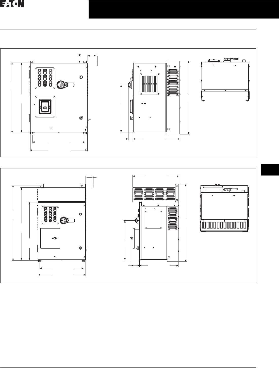
CA08104001E For more information, visit: www.eaton.com/consultants
31.1-45
February 2016
Adjustable Frequency Drives—Low Voltage
Sheet 31
22
23
24
25
26
27
28
29
30
31
32
33
34
35
36
37
38
39
40
41
42
4 3
PowerXL Series Drives
EGF Passive Filtered DG1
057
Dimensions—Approximate Dimensions in Inches (mm)
Figure 31.1-7. AX Box, NEMA 1/12
Figure 31.1-8. AX Box, NEMA 3R
25.80
(655.3)
3.00 (76.2)
Minimum
Air Space
Required
Both Sides
4.00 (101.6) Minimum
Free Air Space Required
25.35
(643.9)
19.30 (490.2)
20.92 (531.4)
17.02 (432.2)
1.76
(44.8)
26.74
(679.2)
17.31
(439.7)
Ø 0.44 (11.2)
Mounting
Holes
(4 Places)
20.18 (512.5)
3.00 (76.2)
Minimum
Air Space
Required
Both Sides
33.09
(840.4)
31.76
(806.6)
25.35
(643.9)
19.30 (490.2)
20.92 (531.4)
3.64
(92.5) 17.02 (432.2)
17.28
(438.9)
33.97
(862.8)
Ø 0.44 (11.2)
Mounting
Holes
(4 Places)
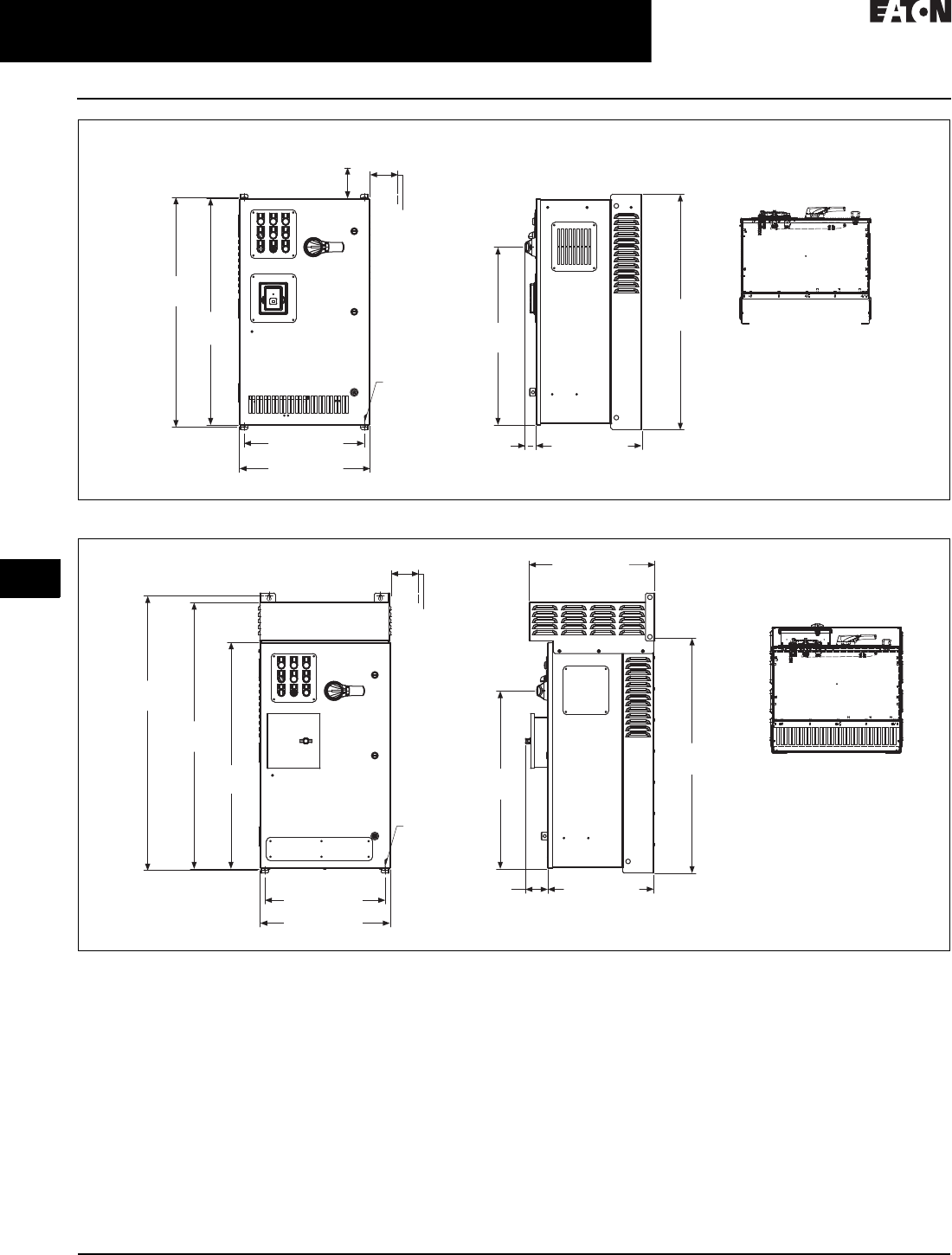
31.1-46
For more information, visit: www.eaton.com/consultants CA08104001E
February 2016
Adjustable Frequency Drives—Low Voltage
Sheet 31
22
23
24
25
26
27
28
29
30
31
32
33
34
35
36
37
38
39
40
41
42
4 3
PowerXL Series Drives
EGF Passive Filtered DG1
058
Figure 31.1-9. BX Box, NEMA 1/12
Figure 31.1-10. BX Box, NEMA 3R
4.00 (101.6)
Minimum
Free Air Space
Required
28.55
(725.1)
36.80
(934.7)
36.35
(923.3)
19.30 (490.2)
20.92 (531.4)
17.01 (432.2)
1.76
(44.8)
37.74
(958.6)
3.00 (76.2)
Minimum
Air Space
Required
Both Sides
Ø 0.44 (11.2)
Mounting
Holes
(4 Places)
28.56
(725.3)
44.09
(1119.8)
36.35
(923.3)
42.69
(1084.3)
19.30 (490.2)
20.92 (531.4)
37.74
(958.6)
3.00 (76.2)
Minimum
Air Space
Required
Both Sides
Ø 0.44 (11.2)
Mounting
Holes
(4 Places)
17.01 (432.2)
3.51
(89.1)
20.18 (512.5)

CA08104001E For more information, visit: www.eaton.com/consultants
31.1-47
February 2016
Adjustable Frequency Drives—Low Voltage
Sheet 31
22
23
24
25
26
27
28
29
30
31
32
33
34
35
36
37
38
39
40
41
42
4 3
PowerXL Series Drives
EGF Passive Filtered DG1
059
Figure 31.1-11. CX Box, NEMA 1/12
Figure 31.1-12. CX Box, NEMA 3R
49.74
(1263.4)
48.80
(1239.5)
48.35
(1228.1)
29.30 (744.2)
30.92 (785.4)
1.74
(44.2) 17.76 (451.2)
35.85
(910.6)
3.00 (76.2)
Minimum
Air Space
Required
Both Sides
4.00 (101.6) Minimum
Free Air Space Required
Ø 0.44 (11.2)
Mounting
Holes
(4 Places)
30.88 (784.4)
56.08
(1424.5)
54.77
(1391.2)
48.35
(1228.1)
29.30 (744.2)
30.92 (785.4) 17.76 (451.2)
3.72
(94.4)
56.96
(1446.9)
35.85
(910.6)
21.00 (533.3)
3.00 (76.2)
Minimum
Air Space
Required
Both Sides
Ø 0.44 (11.2)
Mounting
Holes
(4 Places)
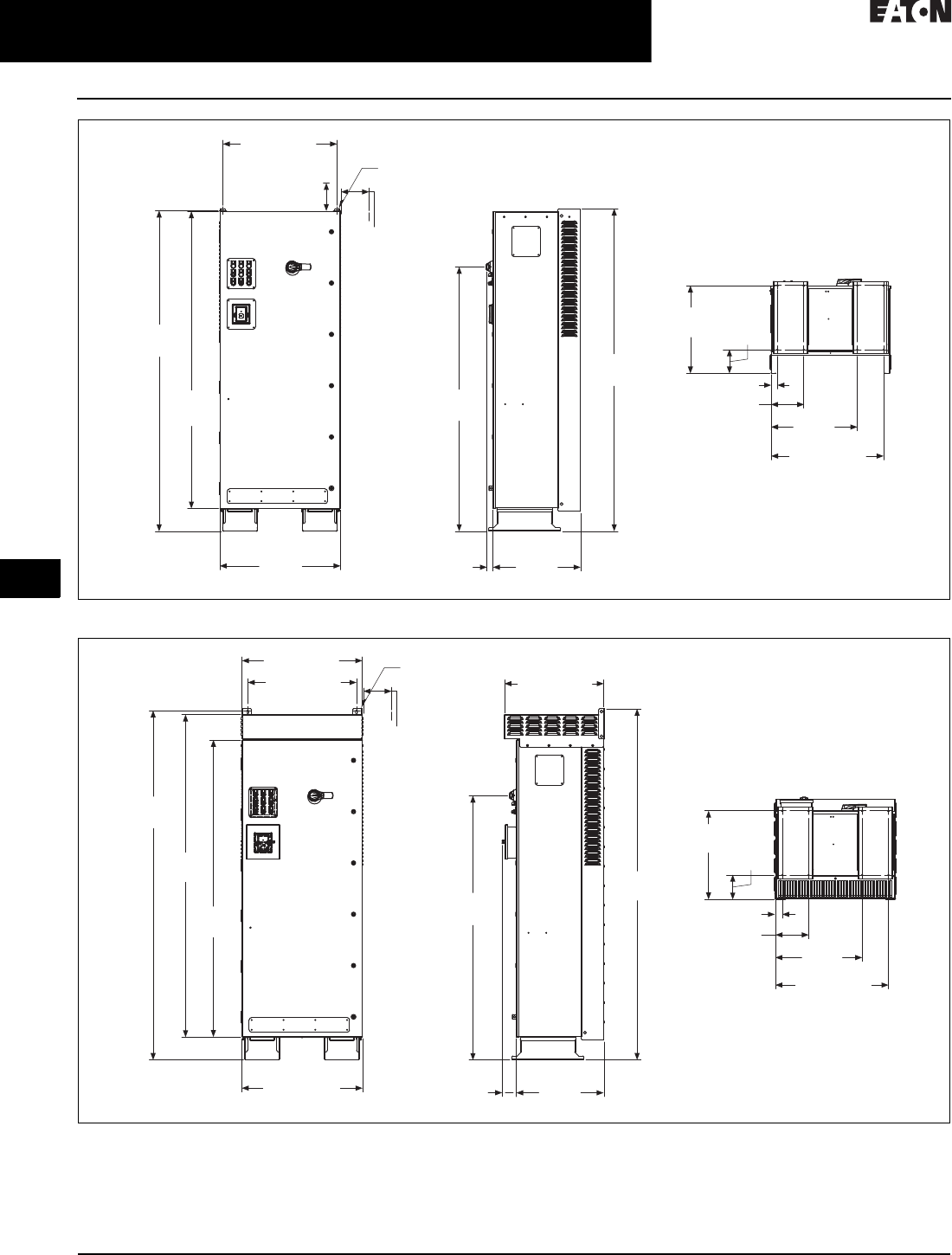
31.1-48
For more information, visit: www.eaton.com/consultants CA08104001E
February 2016
Adjustable Frequency Drives—Low Voltage
Sheet 31
22
23
24
25
26
27
28
29
30
31
32
33
34
35
36
37
38
39
40
41
42
4 3
PowerXL Series Drives
EGF Passive Filtered DG1
060
Figure 31.1-13. DX Box, NEMA 1/12
Figure 31.1-14. DX Box, NEMA 3R
82.35
(2091.7)
76.35
(1939.3)
30.92
(785.4)
22.48
(571.1)
1.55
(39.4)
82.85
(2104.4)
67.89
(1724.4)
28.88 (733.6)
22.56
(573.0) 6.13
(155.6)
8.38 (212.9)
1.62 (41.1)
22.12
(561.8)
29.30 (744.2)
Ø 0.44 (11.2)
Mounting
Holes
(2 Places)
3.00 (76.2)
Minimum
Air Space
Required
Both Sides
4.00 (101.6)
Minimum
Free Air Space
Required
22.81
(579.2)
29.06 (738.1)
30.88 (784.4)
27.88 (708.2)
89.70
(2278.3)
82.84
(2104.1)
76.35
(1939.3)
30.92 (785.4) 3.64
(92.5)
22.48
(571.1)
67.89
(1724.4)
90.14
(2289.5)
25.51 (647.8)
1.80 (45.7)
8.56 (217.4)
22.30
(566.4)
Ø 0.44 (11.2)
Mounting
Holes
(2 Places)
3.00 (76.2)
Minimum
Air Space
Required
Both Sides
6.31
(160.3)
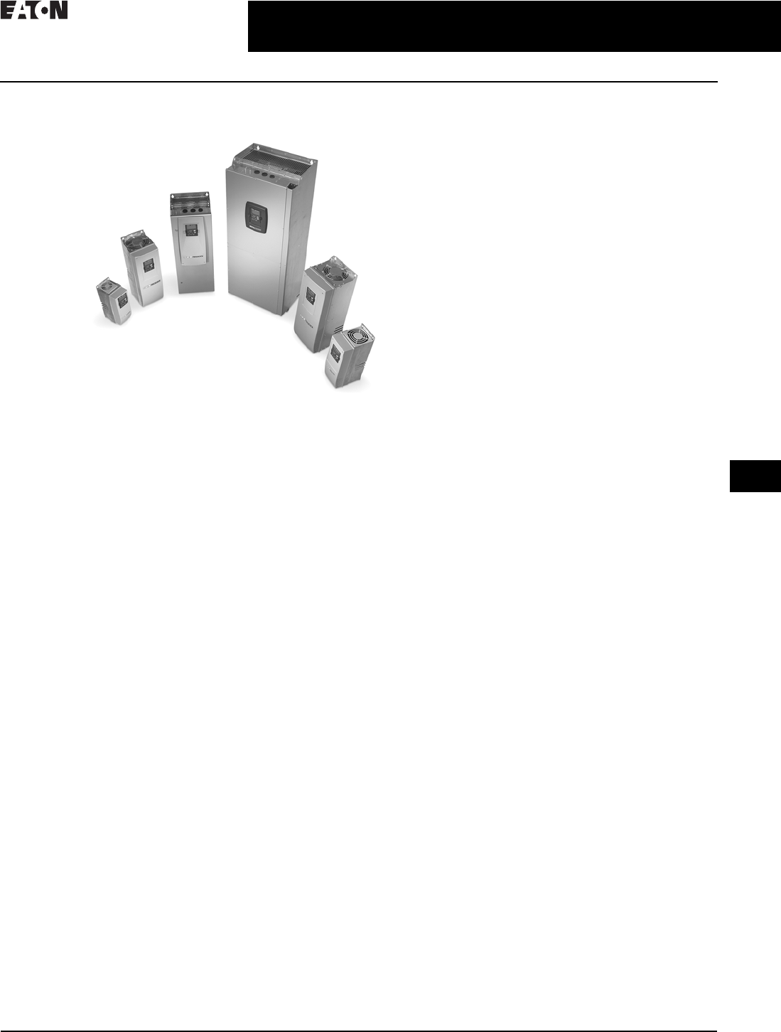
CA08104001E For more information, visit: www.eaton.com/consultants
31.2-1
February 2016
Adjustable Frequency Drives—Low Voltage
Sheet 31
22
23
24
25
26
27
28
29
30
31
32
33
34
35
36
37
38
39
40
41
42
4 3
9000X Series Drives
General Information
061
SVX Drives
SVX Drives
Product Description
SVX Series Adjustable Frequency
Drives from Eaton’s Electrical Sector
are the next generation of drives
specifically engineered for today’s
commercial and industrial applica-
tions. The power unit makes use of
the most sophisticated semiconductor
technology and a highly modular
construction that can be flexibly
adapted to the customer’s needs.
The input and output configuration
(I/O) is designed with modularity in
mind. The I/O is compromised of
option cards, each with its own input
and output configuration. The control
module is designed to accept a total of
five of these cards. The cards contain
not only normal analog and digital
inputs but also fieldbus cards.
These drives continue the tradition
of robust performance, and raise
the bar on features and functionality,
ensuring the best solution at the
right price.
Features
■Robust design—proven 500,000
hours MTBF
■Integrated 3% line reactors standard
on drives from FR4 through FR9
■EMI/RFI Filters H standard up to
200 hp IH 480 V, 100 hp IH 230 V
■Simplified operating menu allows
for typical programming changes,
while programming mode provides
control of everything
■Quick Start Wizard built into the
programming of the drive ensures
a smooth start-up
■Keypad can display up to three mon-
itored parameters simultaneously
■LOCAL/REMOTE operation from
keypad
■Copy/paste function allows transfer
of parameter settings from one
drive to the next
■Standard NEMA Type 12/IP54
keypad on all drives
■The SVX can be flexibly adapted
to a variety of needs using our pre-
installed “Seven in One” precision
application programs consisting of:
❑Basic
❑Standard
❑Local/remote
❑Multi step speed control
❑PID control
❑Multi-purpose control
❑Pump and fan control with auto
change
■Additional I/O and communication
cards provide plug and play
functionality
■I/O connections with simple quick
connection terminals
■Hand-held auxiliary 24 V power
supply allows programming/
monitoring of control module
without applying full power to
the drive
■Control logic can be powered from
an external auxiliary control panel,
internal drive functions and fieldbus
if necessary
■Brake chopper standard from:
1–30 hp/380–500 V
3/4–15 hp/208–230 V
■NEMA Type 1/IP21 and NEMA
Type 12/IP54 enclosures available,
Frame Sizes FR4–FR9
■Open chassis FR10 and greater
■Standard option board configura-
tion includes an A9 I/O board and an
A2 relay output board installed in
slots A and B
Standards and Certifications
Product
■IEC 61800-2
EMC (at Default Settings)
■Immunity: Fulfills all EMC immunity
requirements; Emissions:
EN 61800-3, LEVEL H
Safety
■UL 508C
■CE

31.2-2
For more information, visit: www.eaton.com/consultants CA08104001E
February 2016
Adjustable Frequency Drives—Low Voltage
Sheet 31
22
23
24
25
26
27
28
29
30
31
32
33
34
35
36
37
38
39
40
41
42
4 3
9000X Series Drives
General Information
062
Catalog Number Selection
Table 31.2-1. SVX Adjustable Frequency Drives
1All 230 V drives and 480 V drives up to 200 hp (IH) are only available with input option 1 (EMC Level H). 480 V drives 250 hp (IH) or larger are available
with input option 2 (EMC Level N). 480 V drives are available with input option 4 (EMC Level L). 575 V drives 200 hp (IH) or larger are only available
with input option 2. 575 V drives up to 150 hp (IH) are only available with input option 4 (EMC Level L).
2480 V drives up to 30 hp (IH) are only available with brake chopper option B. 480 V drives 40 hp (IH) or larger come standard with brake chopper
option N. 230 V drives up to 15 hp (IH) are only available with brake chopper option B. 230 V drives 20 hp or larger come standard with brake chopper
option N. All 575 V drives come standard without brake chopper option (N). N = No brake chopper.
3480 V drives 250 hp (IH) and larger are available with enclosure style 0 (chassis); 690 V drives 200 hp (IH) and larger are available with enclosure
style 0 (chassis).
4Factory promise delivery. Consult sales office for availability.
SVX 010 A 1 –4A 1 B 1 ______
Options
Options appear in alphabetical order.
Extended I/O Card Options
B1 = 6 DI, 1 ext +24 Vdc/EXT +24 Vdc
B2 = 1 RO (NC-NO), 1 RO (NO), 1 therm
B4 = 1 AI (mA isolated),
2 AO (mA isolated),
1 ext +24 Vdc/EXT + 24 Vdc
B5 = 3 RO (NO)
B8 = 1 ext +24 Vdc/EXT +24 Vdc, 3 Pt100
B9 = RO (NO), 5 DI 42–240 Vac input
Communication Cards
CA = Johnson Controls N2
CI = Modbus TCP
CJ = BACnet
CQ = EtherNet/IP
C2 = Modbus
C3 = PROFIBUS DP
C4 = LonWorks
C5 = PROFIBUS DP (D9 connector)
C6 = CANopen (slave)
C7 = DeviceNet
C8 = Modbus (D9 Type connector)
D3 = RS-232 with D9 connection
Board Modifications
1 = Standard boards
2 = Conformal (varnished) coating 4
Brake Chopper Options 2
N
= No brake chopper circuit
B
= Internal brake chopper circuit
Input Options 1
1 = Three-phase, EMC H
2 = Three-phase, EMC N
4 = Three-phase, EMC L
AFD Software Series
A = Standard software
Enclosure 3
0 = Chassis
1 = NEMA
Type 1/IP21
2 = NEMA
Type 12/IP54
Keypad
A = Alphanumeric
Product Family
SVX= Open drives
SPX = Open drives FR10
and greater
Horsepower Rating
F07 = 3/4 hp
F15 = 1-1/2 hp
007 = 7-1/2 hp
010 = 10 hp
050 = 50 hp
125 = 125 hp
350 = 350 hp
700 = 700 hp
800 = 800 hp
900 = 900 hp
H10 = 1000 hp
H12 = 1200 hp
H13 = 1350 hp
H15 = 1500 hp
H16 = 1600 hp
H20 = 2000 hp
Voltage Rating
2 = 230 V (208–240)
4 = 480 V (380–500)
5 = 575 V (525–690)

CA08104001E For more information, visit: www.eaton.com/consultants
31.2-3
February 2016
Adjustable Frequency Drives—Low Voltage
Sheet 31
22
23
24
25
26
27
28
29
30
31
32
33
34
35
36
37
38
39
40
41
42
4 3
9000X Series Drives
General Information
063
Product Selection
Table 31.2-2. SVX Drives—230 V
Frame Size hp (IH) Current (IH)hp (I
L) Current (IL) Catalog Number
208–240 V, NEMA Type 1/IP21 Drives
FR4 3/4
1
1-1/2
2
3
3.7
4.8
6.6
7. 8
11
1
1-1/2
2
3
—
4.8
6.6
7. 8
11
12.5
SVXF07A1-2A1B1
SVX001A1-2A1B1
SVXF15A1-2A1B1
SVX002A1-2A1B1
SVX003A1-2A1B1
FR5 —
5
7-1/2
12.5
17.5
25
5
7-1/2
10
17.5
25
31
SVX004A1-2A1B1
SVX005A1-2A1B1
SVX007A1-2A1B1
FR6 10
15
31
48
15
20
48
61
SVX010A1-2A1B1
SVX015A1-2A1B1
FR7 20
25
30
61
75
88
25
30
40
75
88
114
SVX020A1-2A1N1
SVX025A1-2A1N1
SVX030A1-2A1N1
FR8 40
50
60
114
140
170
50
60
75
140
170
205
SVX040A1-2A1N1
SVX050A1-2A1N1
SVX060A1-2A1N1
FR9 75
100
205
261
100
125
261
300
SVX075A1-2A1N1
SVX100A1-2A1N1
208–240 V, NEMA Type 12/IP54 Drives
FR4 3/4
1
1-1/2
2
3
3.7
4.8
6.6
7. 8
11
1
1-1/2
2
3
—
4.8
6.6
7. 8
11
12.5
SVXF07A2-2A1B1
SVX001A2-2A1B1
SVXF15A2-2A1B1
SVX002A2-2A1B1
SVX003A2-2A1B1
FR5 —
5
7-1/2
12.5
17.5
25
5
7-1/2
10
17.5
25
31
SVX004A2-2A1B1
SVX005A2-2A1B1
SVX007A2-2A1B1
FR6 10
15
31
48
15
20
48
61
SVX010A2-2A1B1
SVX015A2-2A1B1
FR7 20
25
30
61
75
88
25
30
40
75
88
114
SVX020A2-2A1N1
SVX025A2-2A1N1
SVX030A2-2A1N1
FR8 40
50
60
114
140
170
50
60
75
140
170
205
SVX040A2-2A1N1
SVX050A2-2A1N1
SVX060A2-2A1N1
FR9 75
100
205
261
100
125
261
300
SVX075A2-2A1N1
SVX100A2-2A1N1

31.2-4
For more information, visit: www.eaton.com/consultants CA08104001E
February 2016
Adjustable Frequency Drives—Low Voltage
Sheet 31
22
23
24
25
26
27
28
29
30
31
32
33
34
35
36
37
38
39
40
41
42
4 3
9000X Series Drives
General Information
064
Table 31.2-3. 480 V SVX Drives
1FR10–FR14 includes 3% line reactor, but it is not integral to chassis.
Frame Size hp (IH) Current (IH)hp (I
L)Current (I
L) Catalog Number
380–500 V, NEMA Type 1/IP21 Drives
FR4 1
1-1/2
2
3
5
—
2.2
3.3
4.3
5.6
7. 6
9
1-1/2
2
3
5
—
7-1/2
3.3
4.3
5.6
7. 6
9
12
SVX001A1-4A1B1
SVXF15A1-4A1B1
SVX002A1-4A1B1
SVX003A1-4A1B1
SVX005A1-4A1B1
SVX006A1-4A1B1
FR5 7-1/2
10
15
12
16
23
10
15
20
16
23
31
SVX007A1-4A1B1
SVX010A1-4A1B1
SVX015A1-4A1B1
FR6 20
25
30
31
38
46
25
30
40
38
46
61
SVX020A1-4A1B1
SVX025A1-4A1B1
SVX030A1-4A1B1
FR7 40
50
60
61
72
87
50
60
75
72
87
105
SVX040A1-4A1N1
SVX050A1-4A1N1
SVX060A1-4A1N1
FR8 75
100
125
105
140
170
100
125
150
140
170
205
SVX075A1-4A1N1
SVX100A1-4A1N1
SVX125A1-4A1N1
FR9 150
200
205
245
200
250
261
300
SVX150A1-4A1N1
SVX200A1-4A1N1
380–500 V, NEMA Type 12/IP54 Drives
FR4 1
1-1/2
2
3
5
—
2.2
3.3
4.3
5.6
7. 6
9
1-1/2
2
3
5
—
7-1/2
3.3
4.3
5.6
7. 6
9
12
SVX001A2-4A1B1
SVXF15A2-4A1B1
SVX002A2-4A1B1
SVX003A2-4A1B1
SVX005A2-4A1B1
SVX006A2-4A1B1
FR5 7-1/2
10
15
12
16
23
10
15
20
16
23
31
SVX007A2-4A1B1
SVX010A2-4A1B1
SVX015A2-4A1B1
FR6 20
25
30
31
38
46
25
30
40
38
46
61
SVX020A2-4A1B1
SVX025A2-4A1B1
SVX030A2-4A1B1
FR7 40
50
60
61
72
87
50
60
75
72
87
105
SVX040A2-4A1N1
SVX050A2-4A1N1
SVX060A2-4A1N1
FR8 75
100
125
105
140
170
100
125
150
140
170
205
SVX075A2-4A1N1
SVX100A2-4A1N1
SVX125A2-4A1N1
FR9 150
200
205
245
200
250
261
300
SVX150A2-4A1N1
SVX200A2-4A1N1
380–500 V, Open Chassis Drives
FR10 1250
300
350
330
385
460
300
350
400
385
460
520
SPX250A0-4A2N1
SPX300A0-4A2N1
SPX350A0-4A2N1
FR11 400
500
—
520
590
650
500
—
600
590
650
730
SPX400A0-4A2N1
SPX500A0-4A2N1
SPX550A0-4A2N1
FR12 600
—
700
730
820
920
—
700
800
820
920
1030
SPX600A0-4A2N1
SPX650A0-4A2N1
SPX700A0-4A2N1
FR13 800
900
1000
1030
11 5 0
1300
900
1000
1200
11 5 0
1300
1450
SPX800A0-4A2N1
SPX900A0-4A2N1
SPXH10A0-4A2N1
FR14 1200
1600
190 0
1600
1940
2300
1500
1800
2200
1770
2150
2700
SPXH12A0-4A2N1
SPXH16A0-4A2N1
SPXH19A0-4A2N1

CA08104001E For more information, visit: www.eaton.com/consultants
31.2-5
February 2016
Adjustable Frequency Drives—Low Voltage
Sheet 31
22
23
24
25
26
27
28
29
30
31
32
33
34
35
36
37
38
39
40
41
42
4 3
9000X Series Drives
General Information
065
Table 31.2-4. 575 V SVX Drives
Frame Size hp (IH) Current (IH)hp (I
L) Current (IL) Catalog Number
525–690 V, NEMA Type 1/IP21 Drives
FR6 2
3
—
5
7-1/2
3.3
4.5
5.5
7. 5
10
3
—
5
7-1/2
10
4.5
5.5
7. 5
10
13.5
SVX002A1-5A4N1
SVX003A1-5A4N1
SVX004A1-5A4N1
SVX005A1-5A4N1
SVX007A1-5A4N1
10
15
20
25
13.5
18
22
27
15
20
25
30
18
22
27
34
SVX010A1-5A4N1
SVX015A1-5A4N1
SVX020A1-5A4N1
SVX025A1-5A4N1
FR7 30
40
34
41
40
50
41
52
SVX030A1-5A4N1
SVX040A1-5A4N1
FR8 50
60
75
52
62
80
60
75
100
62
80
100
SVX050A1-5A4N1
SVX060A1-5A4N1
SVX075A1-5A4N1
FR9 100
125
150
—
100
125
144
170
125
150
—
200
125
144
170
208
SVX100A1-5A4N1
SVX125A1-5A4N1
SVX150A1-5A4N1
SVX175A1-5A4N1
525–690 V, NEMA Type 12/IP54 Drives
FR6 2
3
—
5
7-1/2
3.3
4.5
5.5
7. 5
10
3
—
5
7-1/2
10
4.5
5.5
7. 5
10
13.5
SVX002A2-5A4N1
SVX003A2-5A4N1
SVX004A2-5A4N1
SVX005A2-5A4N1
SVX007A2-5A4N1
10
15
20
25
13.5
18
22
27
15
20
25
30
18
22
27
34
SVX010A2-5A4N1
SVX015A2-5A4N1
SVX020A2-5A4N1
SVX025A2-5A4N1
FR7 30
40
34
41
40
50
41
52
SVX030A2-5A4N1
SVX040A2-5A4N1
FR8 50
60
75
52
62
80
60
75
100
62
80
100
SVX050A2-5A4N1
SVX060A2-5A4N1
SVX075A2-5A4N1
FR9 100
125
150
—
100
125
144
170
125
150
—
200
125
144
170
208
SVX100A2-5A4N1
SVX125A2-5A4N1
SVX150A2-5A4N1
SVX175A2-5A4N1
525–690 V, Open Chassis Drives
FR10 200
250
300
208
261
325
250
300
400
261
325
385
SPX200A0-5A2N1
SPX250A0-5A2N1
SPX300A0-5A2N1
FR11 400
450
500
385
460
502
450
500
—
460
502
590
SPX400A0-5A2N1
SPX450A0-5A2N1
SPX500A0-5A2N1
FR12 —
600
700
590
650
750
600
700
800
650
750
820
SPX550A0-5A2N1
SPX600A0-5A2N1
SPX700A0-5A2N1
FR13 800
900
1000
820
920
1030
900
1000
1250
920
1030
11 8 0
SPX800A0-5A2N1
SPX900A0-5A2N1
SPXH10A0-5A2N1
FR14 1350
1500
2000
1300
1500
1900
1500
2000
2300
1500
190 0
2250
SPXH13A0-5A2N1
SPXH15A0-5A2N1
SPXH20A0-5A2N1
31.2-6
For more information, visit: www.eaton.com/consultants CA08104001E
February 2016
Adjustable Frequency Drives—Low Voltage
Sheet 31
22
23
24
25
26
27
28
29
30
31
32
33
34
35
36
37
38
39
40
41
42
4 3
9000X Series Drives
General Information
066
Options
SVX Series Option Board Kits
The SVX Series drives can accommo-
date a wide selection of expander and
adapter option boards to customize
the drive for your application needs.
The drive’s control unit is designed to
accept a total of five option boards.
The SVX Series factory installed
standard board configuration includes
an A9 I/O board and an A2 relay output
board, which are installed in slots
A and B.
Figure 31.2-1. Option Boards
Table 31.2-5. Option Board Kits
1AI = Analog Input; AO = Analog Output, DI = Digital Input, DO = Digital Output, RO = Relay Output
2Option card must be installed in one of the slots listed for that card. Slot indicated in bold is the preferred location.
3OPTC2 is a multi-protocol option card.
ABCDE
Option Kit Description 1Allowed Slot
Locations 2
Field
Installed
Factory
Installed
SVX Ready Programs
Catalog
Number
Option
Designator
Basic Local/
Remote
Standard MSS PID Multi-P. PFC
Standard I/O Cards
6 DI, 1 DO, 2 AI, 1 AO, 1 +10 Vdc ref,
2 ext +24 Vdc/EXT +24 Vdc
AOPTA9 —■ ■ ■ ■■■ ■
2 RO (NC-NO) B OPTA2 —■ ■ ■ ■■■ ■
Extended I/O Cards
2 RO, therm B OPTA3 A3 —■ ■ ■■■ ■
Encoder low volt +5 V/15 V/24 V—SPX only C OPTA4 A4 —■ ■ ■■■ ■
Encoder high volt +15 V/24 V—SPX only C OPTA5 A5 —■ ■ ■■■ ■
Double encoder—SPX only C OPTA7 A7 ■ ■ ■ ■■■ ■
6 DI, 1 DO, 2 AI, 1 AO A OPTA8 A8 —■ ■ ■■■ ■
3 DI (encoder 10–24 V), out +15 V/+24 V,
2 DO (pulse+direction)—SPX only
COPTAE AE ■ ■ ■ ■■■ ■
6 DI, 1 ext +24 Vdc/EXT +24 Vdc B, C, D, E OPTB1 B1 —— — ——
■■
1 RO (NC-NO), 1 RO (NO), 1 therm B, C, D, E OPTB2 B2 —— — ——
■■
1 AI (mA isolated), 2 AO (mA isolated),
1 ext +24 Vdc/EXT +24 Vdc
B, C, D, E OPTB4 B4 ■ ■ ■ ■■■ ■
3 RO (NO) B, C, D, E OPTB5 B5 —— — ——
■■
1 ext +24 Vdc/EXT +24 Vdc, 3 Pt100 B, C, D, E OPTB8 B8 — — — ——— —
1 RO (NO), 5 DI 42–240 Vac input B, C, D, E OPTB9 B9 —— — ——
■■
Communication Cards
Modbus 3D, EOPTC2 C2 ■ ■ ■ ■■■ ■
Johnson Controls N2 3D, EOPTC2 CA — — — ——— —
Modbus TCP D, EOPTCI CI ■ ■ ■ ■■■ ■
BACnet D, EOPTCJ CJ ■ ■ ■ ■■■ ■
EtherNet/IP D, EOPTCQ CQ ■ ■ ■ ■■■ ■
PROFIBUS DP D, EOPTC3 C3 ■ ■ ■ ■■■ ■
LonWorks D, EOPTC4 C4 ■ ■ ■ ■■■ ■
PROFIBUS DP (D9 connector) D, EOPTC5 C5 ■ ■ ■ ■■■ ■
CANopen (slave) D, EOPTC6 C6 ■ ■ ■ ■■■ ■
DeviceNet D, EOPTC7 C7 ■ ■ ■ ■■■ ■
Modbus (D9 type connector) D, EOPTC8 C8 ■ ■ ■ ■■■ ■
Adapter—SPX only D, EOPTD1 D1 ■ ■ ■ ■■■ ■
Adapter—SPX only D, EOPTD2 D2 ■ ■ ■ ■■■ ■
RS-232 with D9 connection D, EOPTD3 D3 ■ ■ ■ ■■■ ■

CA08104001E For more information, visit: www.eaton.com/consultants
31.2-7
February 2016
Adjustable Frequency Drives—Low Voltage
Sheet 31
22
23
24
25
26
27
28
29
30
31
32
33
34
35
36
37
38
39
40
41
42
4 3
9000X Series Drives
General Information
067
Technical Data and Specifications
Table 31.2-6. SVX Drives Table 31.2-6. SVX Drives (Continued)
Table 31.2-7. Standard I/O Specifications
Description Specification
Input Ratings
Input voltage (Vin)+10%/–15%
Input frequency (fin) 50/60 Hz (variation up to 45–66 Hz)
Connection to power Once per minute or less (typical operation)
High withstand rating 100 kAIC
Output Ratings
Output voltage 0 to Vin
Continuous
output current
IH rated 100% at 122 °F (50 °C), FR9 and below
IL rated 100% at 104 °F (40 °C), FR9 and below
IH/IL 100% at 104 °F (40 °C), FR10 and above
Overload current (IH/IL) 150% IH, 110% IL for 1 min.
Output frequency 0 to 320 Hz
Frequency resolution 0.01 Hz
Initial output current (IH) 250% for 2 seconds
Efficiency >96%
Control Characteristics
Control method Frequency control (V/f)
Open loop: Sensorless vector control
Closed loop: SPX drives only
Switching frequency
Frame 4–6
Frame 7–12
Adjustable with parameter 2.6.9
1–16 kHz; default 10 kHz
1–10 kHz; default 3.6 kHz
Frequency reference Analog input: Resolution 0.1% (10-bit),
accuracy ±1% V/Hz
Panel reference: Resolution 0.01 Hz
Field weakening point 30–320 Hz
Acceleration time 0–3000 sec.
Deceleration time 0–3000 sec.
Braking torque DC brake: 30% x Tn (without brake option)
Ambient Conditions
Ambient operating
temperature
14 °F (–10 °C), no frost to 122 °F (50 °C)
IH (FR4–FR9)
14 °F (–10 °C), no frost to 104 °F (40 °C)
IH (FR10 and up)
14 °F (–10 °C), no frost to 104 °F (40 °C)
IL (all frames)
Storage temperature –40° to 158 °F (–40° to 70 °C)
Relative humidity 0 to 95% RH, noncondensing, non-corrosive,
no dripping water
Air quality Chemical vapors: IEC 721-3-3, unit in operation,
class 3C2; Mechanical particles: IEC 721-3-3, unit
in operation, class 3S2
Altitude 100% load capacity (no derating)
up to 3280 ft (1000 m);
1% derating for each 328 ft (100 m)
above 3280 ft (1000 m); max. 9842 ft (3000 m)
Vibration EN 50178, EN 60068-2-6; 5 to 50 Hz,
displacement amplitude 1 mm (peak)
at 3 to 15.8 Hz, max. acceleration amplitude
1G at 15.8 to 150 Hz
Shock EN 50178, EN 60068-2-27 UPS Drop test (for
applicable UPS weights) Storage and shipping:
max. 15 g, 11 ms (in package)
Enclosure class NEMA 1/IP21 or NEMA 12/IP54,
open chassis/IP20
Description Specification
Control Connections
Analog input voltage 0 to 10 V, R = 200 kohms (–10 to 10 V joystick
control) resolution 0.1%; accuracy ±1%
Analog input current 0(4) to 20 mA; Ri—250 ohms differential
Digital inputs (6) Positive or negative logic; 18 to 30 Vdc
Auxiliary voltage +24 V ±15%, max. 250 mA
Output reference
voltage
+10 V +3%, max. load 10 mA
Analog output 0(4) to 20 mA; RL max. 500 ohms;
resolution 10 bit; accuracy ±2%
Digital outputs Open collector output, 50 mA/48 V
Relay outputs Two programmable Form C relay outputs
switching capacity: 24 Vdc/8 A, 250 Vac/8 A,
125 Vdc/0.4 A
Protections
Overcurrent protection Trip limit 4.0 x IH instantaneously
Overvoltage protection Yes
Undervoltage protection Yes
Earth fault protection In case of earth fault in motor or motor cable,
only the frequency converter is protected
Input phase supervision Trips if any of the input phases are missing
Motor phase
supervision
Trips if any of the output phases are missing
Overtemperature
protection
Yes
Motor overload
protection
Yes
Motor stall protection Yes
Motor underload
protection
Yes
Short-circuit protection Yes (+24 V and +10 V reference voltages)
Description Specification
Six–digital input
programmable
24 V: “0” <10 V, “1” >18V,Ri >5 kohms
Two–analog input
configurable w/jumpers
Voltage: 0–±10 V, Ri >200 kohms
Current: 0 (4)–20 mA, Ri = 250 ohms
Two–digital output
programmable
Form C relays 250 Vac
30 Vdc 2 amp resistive
One–analog output
programmable
configurable w/jumper
0–20 mA, RL max. 500 ohms 10 bits ±2%
One digital output
programmable
Open collector 48 Vdc 50 mA
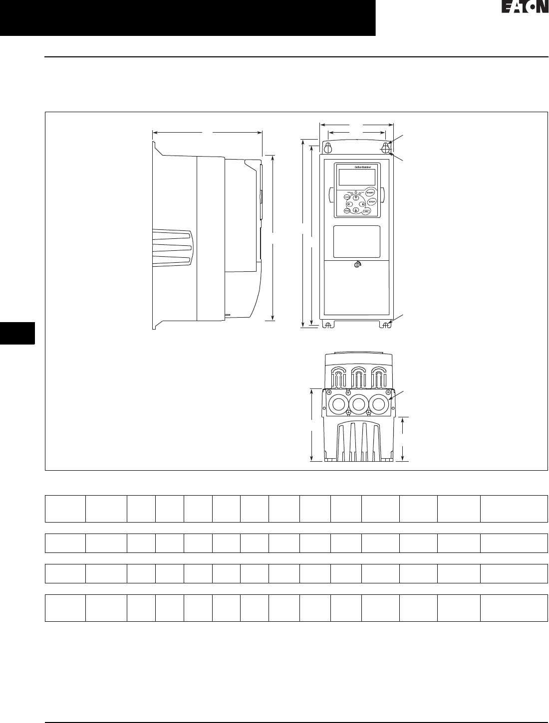
31.2-8
For more information, visit: www.eaton.com/consultants CA08104001E
February 2016
Adjustable Frequency Drives—Low Voltage
Sheet 31
22
23
24
25
26
27
28
29
30
31
32
33
34
35
36
37
38
39
40
41
42
4 3
9000X Series Drives
General Information
068
Dimensions—Approximate Dimensions in Inches (mm)
9000X Open Drives
Figure 31.2-2. NEMA Type 1/IP21 and NEMA Type 12/IP54, FR4, FR5 and FR6
EATON
D1 W2
W1
R2
R1
R2
H3 H2
H1
D2
D3
Knockouts
Volta ge hp ( IH) H1 H2 H3 D1 D2 D3 W1 W2 R1 Dia. R2 Dia. Weight
Lb (kg)
Knockouts in
Inches (mm)
N1 (O.D.)
FR4
230 V
480 V
3/4–3
1–5
12.9
(327)
12.3
(313)
11. 5
(292)
7. 5
(190)
3.0
(77)
4.9
(126)
5.0
(128)
3.9
(100)
0.5 (13) 0.3 (7) 11.0 (5) 3 at 1.1 (28)
FR5
230 V
480 V
5–7-1/2
7-1/2–15
16.5
(419)
16.0
(406)
15.3
(389)
8.4
(214)
3.9
(100)
5.8
(148)
5.6
(143)
3.9
(100)
0.5 (13) 0.3 (7) 17.9 (8) 2 at 1.5 (37)
1 at 1.1 (28)
FR6
230 V
480 V
575 V
10–15
20–30
2–25
22.0
(558)
21.3
(541)
20.4
(519)
9.3 (
237)
4.2
(105)
6.5
(165)
7. 6
(195)
5.8
(148)
0.6 (15.5) 0.4 (9) 40.8 (19) 3 at 1.5 (37)
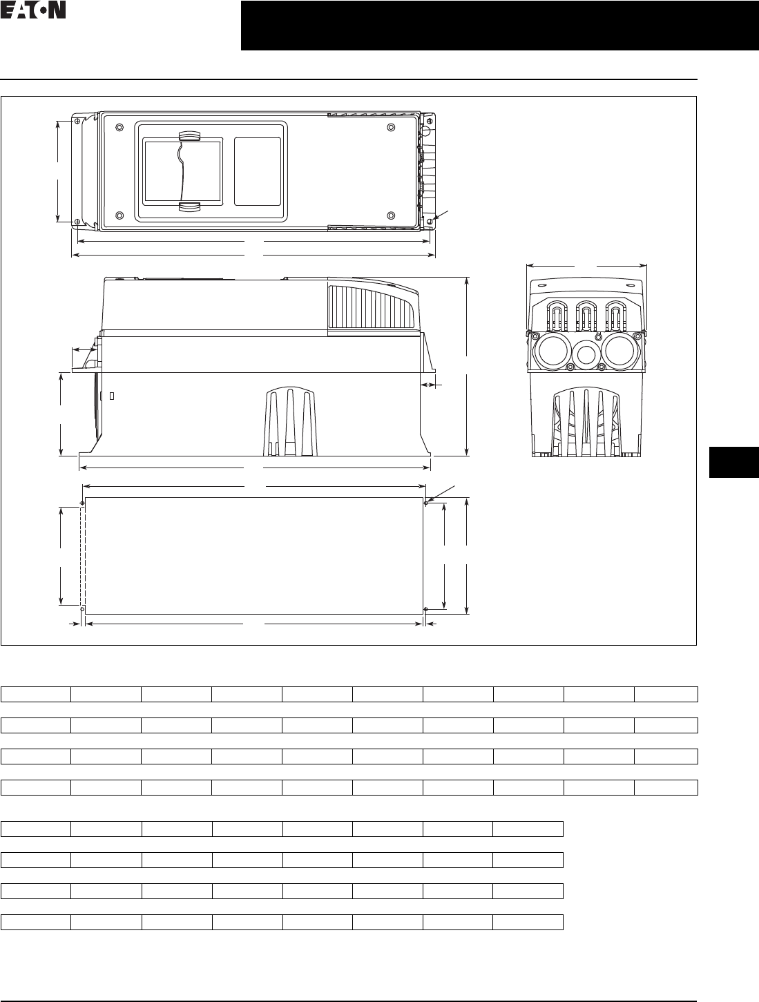
CA08104001E For more information, visit: www.eaton.com/consultants
31.2-9
February 2016
Adjustable Frequency Drives—Low Voltage
Sheet 31
22
23
24
25
26
27
28
29
30
31
32
33
34
35
36
37
38
39
40
41
42
4 3
9000X Series Drives
General Information
069
Figure 31.2-3. NEMA Type 1/IP21 and NEMA Type 12/IP54 with Flange Kit, FR4, FR5 and FR6
Table 31.2-8. FR4, FR5 and FR6 with Flange Kit
Table 31.2-9. Flange Opening, FR4 to FR6
W1 W2 H1 H2 H3 H4 H5 D1 D2 Dia. A
FR4
5.0 (128) 4.5 (113) 13.3 (337) 12.8 (325) 12.9 (327) 1.2 (30) 0.9 (22) 7.5 (190) 3.0 (77) 0.3 (7)
FR5
5.6 (143) 4.7 (120) 17.0 (434) 16.5 (420) 16.5 (419) 1.4 (36) 0.7 (18) 8.4 (214) 3.9 (100) 0.3 (7)
FR6
7.7 (195) 6.7 (170) 22.0 (560) 21.6 (549) 22.0 (558) 1.2 (30) 0.8 (20) 9.3 (237) 4.2 (106) 0.3 (7)
W2
H1
H2
D2
Flange Opening
FR4 to FR6
H4
H5
H3
W1
Dia. A
D1
W3W4
W5
Dia. B
H7
H6 H9H8
W3 W4 W5 H6 H7 H8 H9 Dia. B
FR4
4.8 (123) 4.5 (113) — 12.4 (315) 12.8 (325) — 0.2 (5) 0.3 (7)
FR5
5.3 (135) 4.7 (120) — 16.2 (410) 16.5 (420) — 0.2 (5) 0.3 (7)
FR6
7.3 (185) 6.7 (170) 6.2 (157) 21.2 (539) 21.6 (549) 0.3 (7) 0.2 (5) 0.3 (7)
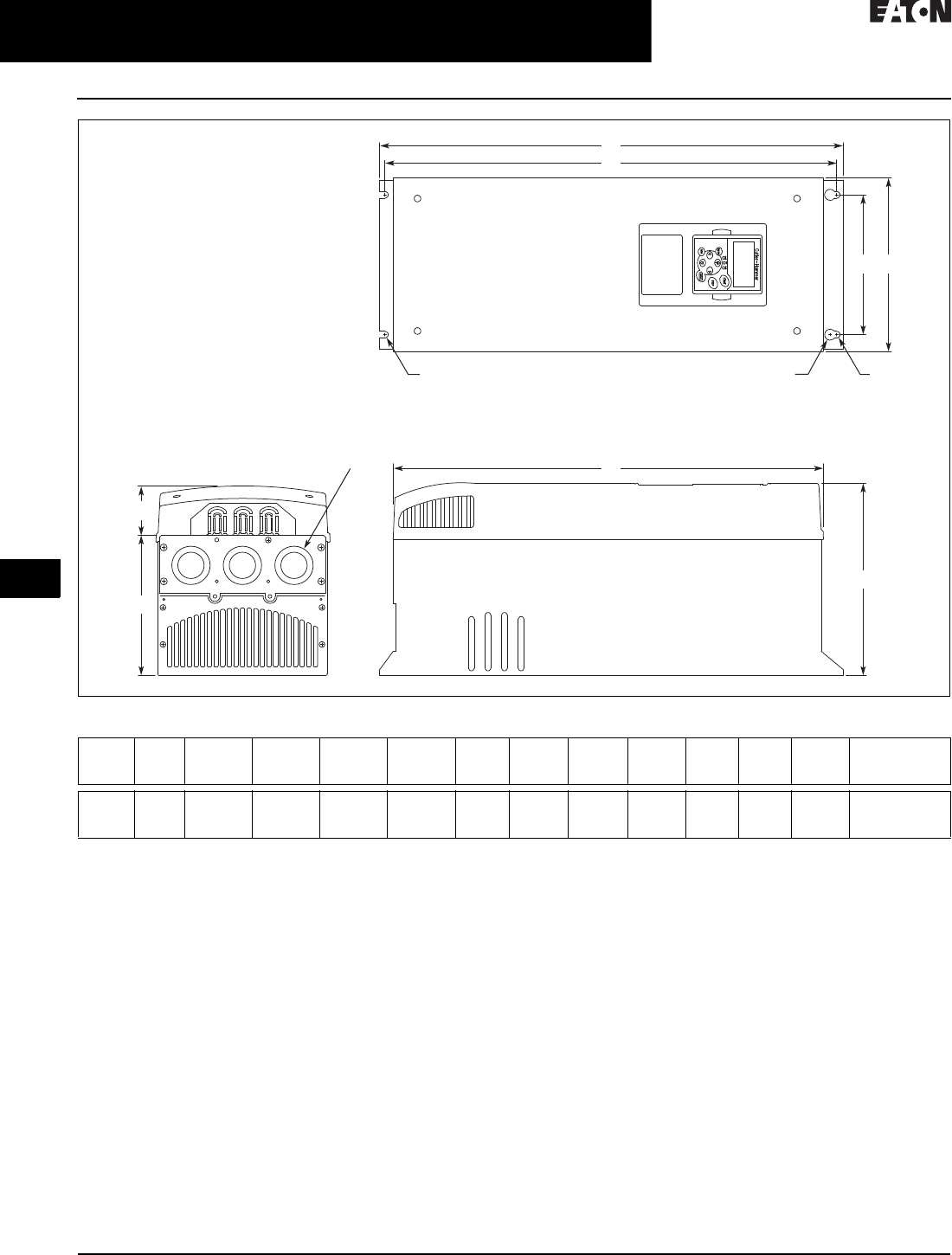
31.2-10
For more information, visit: www.eaton.com/consultants CA08104001E
February 2016
Adjustable Frequency Drives—Low Voltage
Sheet 31
22
23
24
25
26
27
28
29
30
31
32
33
34
35
36
37
38
39
40
41
42
4 3
9000X Series Drives
General Information
070
Figure 31.2-4. NEMA Type 1/IP21 and NEMA Type 12/IP54, FR7
Volta ge h p (IH)H1H2H3D1D2D3W1W2R1 Dia.R2 Dia.Weight
Lb (kg)
Knockouts
in Inches (mm)
N1 (O.D.)
230 V
480 V
575 V
20–30
40–60
30–40
24.8 (630) 24.2 (614) 23.2 (590) 10.1 (257) 3.0 (77) 7.3 (184) 9.3 (237) 7.5 (190) 0.7 (18) 0.4 (9) 77.2 (35) 3 at 1.5 (37)
W2
H1
D1
D2
Knockouts
R2 R2R1
D3
H2
H3
W1

CA08104001E For more information, visit: www.eaton.com/consultants
31.2-11
February 2016
Adjustable Frequency Drives—Low Voltage
Sheet 31
22
23
24
25
26
27
28
29
30
31
32
33
34
35
36
37
38
39
40
41
42
4 3
9000X Series Drives
General Information
071
Figure 31.2-5. NEMA Type 1/IP21 and NEMA Type 12/IP54, FR8
D1
H2
H1
W2W1
H3
R2
R1
Volta ge hp (I H)D1H1H2H3W1W2R1 Dia.R2 Dia.Weight
Lb (kg)
230 V
480 V
575 V
40–60
75–125
50–75
13.5 (344) 30.1 (764) 28.8 (732) 28.4 (721) 11.5 (291) 10 (255) 0.7 (18) 0.4 (9) 127 (58)
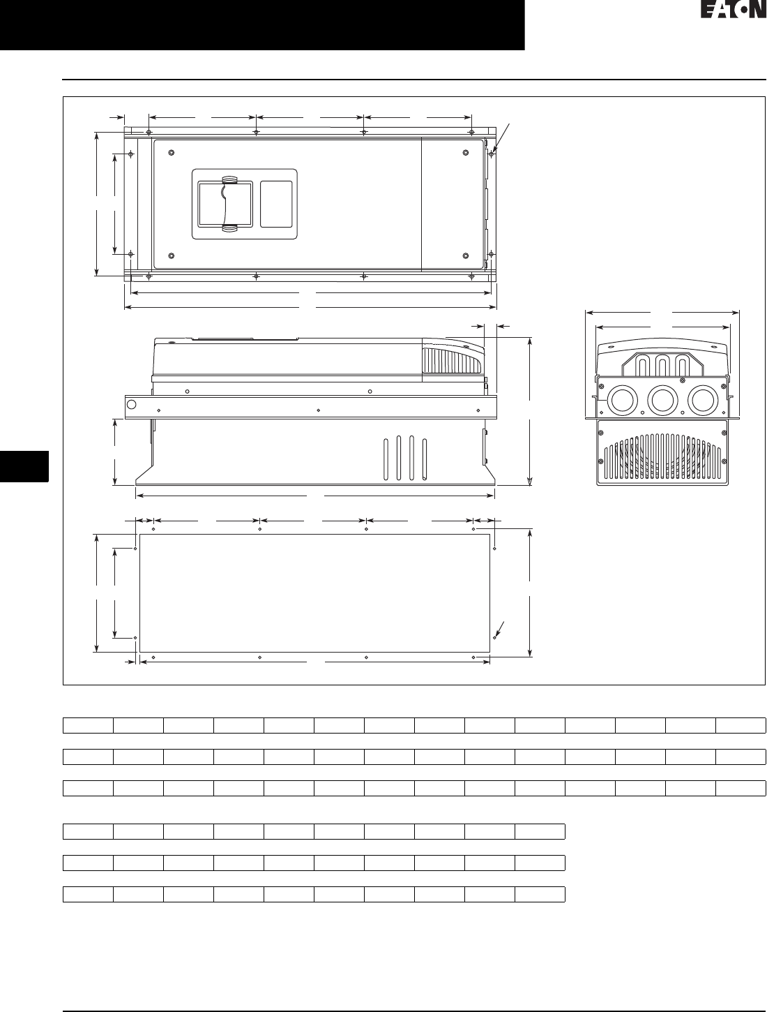
31.2-12
For more information, visit: www.eaton.com/consultants CA08104001E
February 2016
Adjustable Frequency Drives—Low Voltage
Sheet 31
22
23
24
25
26
27
28
29
30
31
32
33
34
35
36
37
38
39
40
41
42
4 3
9000X Series Drives
General Information
072
Figure 31.2-6. NEMA Type 1/IP21 and NEMA Type 12/IP54, with Flange Kit, FR7 and FR8
Table 31.2-10. Flange Opening, FR7 and FR8
W1 W2 W3 W4 H1 H2 H3 H4 H5 H6 H7 D1 D2 Dia. A
FR7
9.3 (237) 6.8 (175) 10.6 (270) 10.0 (253) 24.9 (652) 24.8 (632) 24.8 (630) 7.4 (189) 7.4 (189) 0.9 (23) 0.8 (20) 10.1 (257) 4.6 (117) 0.3 (6)
FR8
11.2 (285) — 14.0 (355) 13.0 (330) 32.8 (832) — 29.3 (745) 10.2 (258) 10.4 (265) 1.7 (43) 2.2 (57) 13.5 (344) 4.3 (110) 0.4 (9)
W5 W6 W7 H8 H9 H10 H11 H12 H13 Dia. B
FR7
9.2 (233) 6.9 (175) 10.0 (253) 24.4 (619) 7.4 (189) 7.4 (189) 1.4 (35) 1.3 (32) 1.0 (25) 0.3 (6)
FR8
11.9 (301) — 13.0 (330) 31.9 (810) 10.2 (258) 10.4 (265) — — 1.3 (33) 0.4 (9)
H7
W3
H9
D1
W1
H9H12
H13
H11H10
H1
H2
H5 Dia. A
Dia. B
H4H4H6
W2W4
D2
W6W5 W7
H3
H8
Flange Opening
FR7/FR8
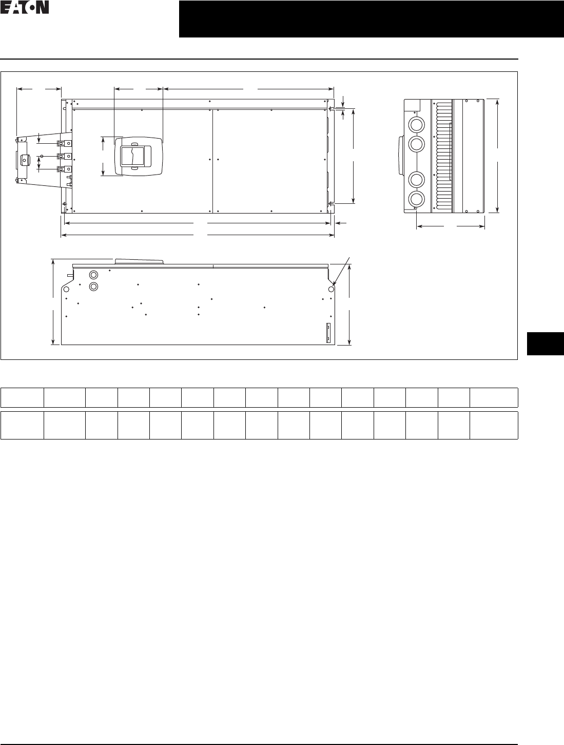
CA08104001E For more information, visit: www.eaton.com/consultants
31.2-13
February 2016
Adjustable Frequency Drives—Low Voltage
Sheet 31
22
23
24
25
26
27
28
29
30
31
32
33
34
35
36
37
38
39
40
41
42
4 3
9000X Series Drives
General Information
073
Figure 31.2-7. NEMA Type 1/IP21 and NEMA Type 12/IP54 FR9
1Brake resistor terminal box (H6) included when brake chopper ordered.
Volta ge h p (IH)W1W2W3W4H1 H2 H3 H4
1D1 D2 D3 Dia. Weight
Lb (kg)
230 V
480 V
575 V
75–100
150–200
100–175
18.9
(480)
15.7
(400)
0.4
(9)
2.1
(54)
45.3
(1150)
44.1
(1120)
0.6
(16)
7. 4
(188)
14.2
(361.5)
13.4
(340)
11. 2
(285)
0.8
(21)
321.9 (146)
D2
Dia.
D1
H5
W2
W4
H3H4
H2
H1
H6
W3
W5
PE
B- B+ /R+ R-
W5 W1
D3

31.2-14
For more information, visit: www.eaton.com/consultants CA08104001E
February 2016
Adjustable Frequency Drives—Low Voltage
Sheet 31
22
23
24
25
26
27
28
29
30
31
32
33
34
35
36
37
38
39
40
41
42
4 3
9000X Series Drives
General Information
074
Figure 31.2-8. NEMA Type 1/IP21 and NEMA Type 12/IP54, FR9 with Flange Kit
W1 W2 W3 W4 W5 H1 H2 H3 H4 H5 H6 H7 D1 D2 D3 Dia.
20.9
(530)
20.0
(510)
19.1
(485)
7. 9
(200)
0.2
(5.5)
51.7
(1312)
45.3
(1150)
16.5
(420)
3.9
(100)
1.4
(35)
0.4
(9)
0.1
(2)
24.9
(362)
13.4
(340)
4.3
(109)
0.8
(21)
.20 (5)
Dia.
H4
H2
D2
Dia.
D1
D3
H4
W1
H7
W5
W3
W4
H3 H3 H3 H5H5
H6 H1
W4
W2
Flange Opening
FR9
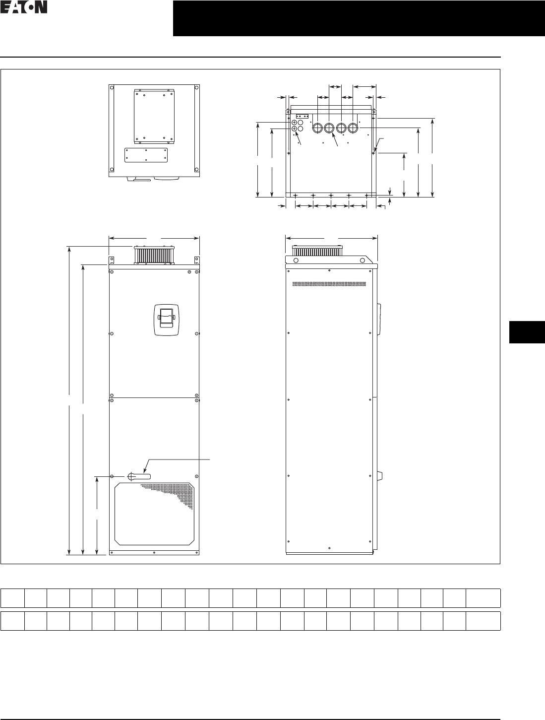
CA08104001E For more information, visit: www.eaton.com/consultants
31.2-15
February 2016
Adjustable Frequency Drives—Low Voltage
Sheet 31
22
23
24
25
26
27
28
29
30
31
32
33
34
35
36
37
38
39
40
41
42
4 3
9000X Series Drives
General Information
075
Figure 31.2-9. NEMA Type 1/IP21 and NEMA Type 12/IP54, FR10 Freestanding
Dia. 3
Dia. 2
Dia. 1
W5
W6
W4 W4
D4
D2
W2
W2
D5
D3 D6 D7
W3 W3 W3 W3
H1
H2
H3
W1 D1
Operator
(Shown with
Optional
Disconnect)
W6
W7
W1 W2 W3 W4 W5 W6 W7 H1 H2 H3 D1 D2 D3 D4 D5 D6 D7 Dia. 1 Dia. 2 Dia. 3 Weight
Lb (kg)
23.43
(595)
2.46
(62.5)
4.53
(115)
0.79
(20)
5.95
(151)
2.95
(75)
30.11
(79)
79.45
(2018)
74.80
(1900)
20.18
(512.5)
23.70
(602)
17.44
(443)
19.02
(483)
0.47
(12)
11. 2 2
(285)
17.60
(447)
20.08
(510)
0.83
(21)
1.89
(48)
0.43
(11)
857
(389)
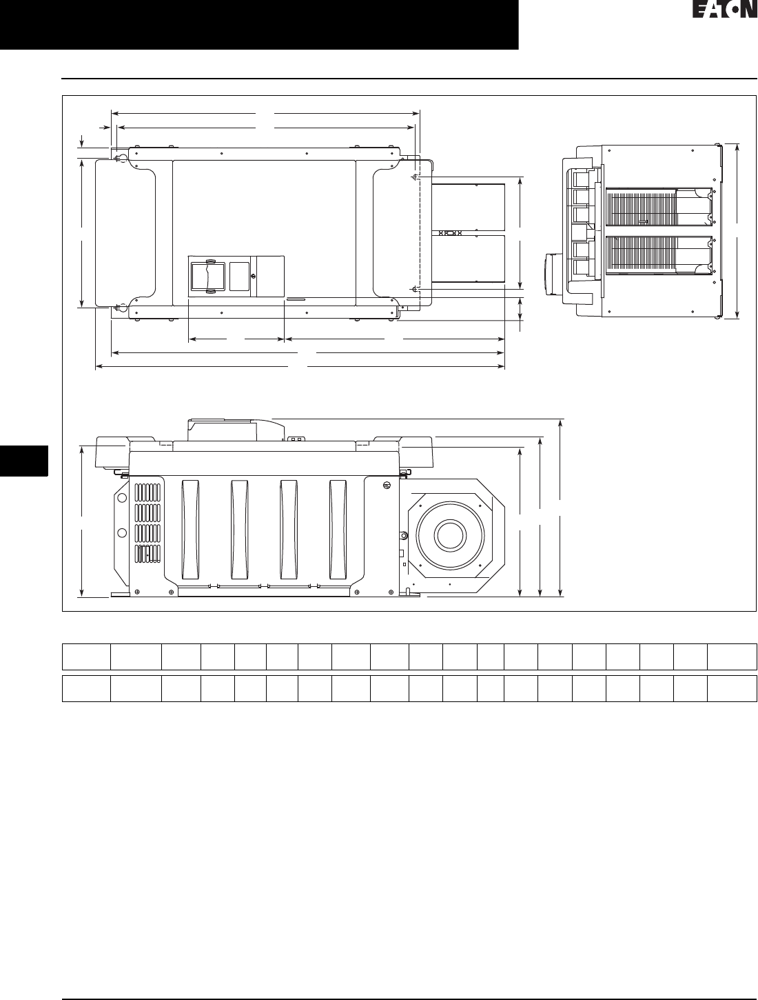
31.2-16
For more information, visit: www.eaton.com/consultants CA08104001E
February 2016
Adjustable Frequency Drives—Low Voltage
Sheet 31
22
23
24
25
26
27
28
29
30
31
32
33
34
35
36
37
38
39
40
41
42
4 3
9000X Series Drives
General Information
076
Figure 31.2-10. FR10 Open Chassis 1
19000X FR12 is built of two FR10 modules. Please refer to SPX installation manual for mounting instructions.
Volta ge hp (IH)W1 W2W3W4W5H1 H2 H3H4H5H6H7D1D2D3D4Weight
Lb (kg)
480 V
575 V
250–350
200–300
19.7
(500)
16.7
(425)
1.2
(30)
2.6
(67)
12.8
(325)
45.9
(1165)
44.1
(1121)
34.6
(879)
33.5
(850)
0.7
(17)
24.7
(627)
10.8
(275)
19.9
(506)
17.9
(455)
16.7
(423)
16.6
(421)
518
(235)
H2
W1
H7 H6
H4H5
H3
H1
W2
W3
W5
W4
D4 D2 D1
D3

CA08104001E For more information, visit: www.eaton.com/consultants
31.2-17
February 2016
Adjustable Frequency Drives—Low Voltage
Sheet 31
22
23
24
25
26
27
28
29
30
31
32
33
34
35
36
37
38
39
40
41
42
4 3
9000X Series Drives
General Information
077
Figure 31.2-11. NEMA Type 1/IP21, FR11 Freestanding Drive
H1
H2
W1 D1
H3
D2
D3
Dia. 3
D4
D5
Dia. 1 Dia. 2
W2
W2 W3 W3 W3 W3
W8
W6
W4
W6
W5
W7W7 W6W6W6W6
Operator
(Shown with
Optional
Disconnect)
Voltage hp (I
H
) W1 W2W3 W4W5W6W7W8H1 H2 H3 D1 D2 D3 D4 D5 Dia. 1Dia. 2Dia. 3 Weight
Lb (kg)
480 400–550 31.26
(794)
2.40
(61)
6.50
(165)
0.79
(20)
3.43
(87)
2.95
(75)
2.52
(64)
1.18
(30)
79.45
(2018)
74.80
(1900)
20.18
(512.5)
23.70
(602)
11. 2 2
(285)
19.09
(485)
0.47
(12)
17.60
(447)
0.83
(21)
1.89
(48)
0.35 x 0.43
(9 x 11)
526
(239)

31.2-18
For more information, visit: www.eaton.com/consultants CA08104001E
February 2016
Adjustable Frequency Drives—Low Voltage
Sheet 31
22
23
24
25
26
27
28
29
30
31
32
33
34
35
36
37
38
39
40
41
42
4 3
9000X Series Drives
General Information
078
Figure 31.2-12. FR11 Open Chassis
Volta ge hp (I H)W1W2W3H1 H2D1D2Weight
Lb (kg)
480 V
575 V
400–550
400–500
27.9 (709) 8.86 (225) 2.6 (67) 45.5 (1155) 33.5 (850) 19.8 (503) 18.4 (468) 833 (378)
H1
H2
D1
W2
W2
W3
W2
W2
W3
W1
Shown without
terminal cover
D2

CA08104001E For more information, visit: www.eaton.com/consultants
31.2-19
February 2016
Adjustable Frequency Drives—Low Voltage
Sheet 31
22
23
24
25
26
27
28
29
30
31
32
33
34
35
36
37
38
39
40
41
42
4 3
9000X Series Drives
General Information
079
Figure 31.2-13. FR13, Open Chassis Inverter
Note: 9000X FR14 is built of two FR13 modules. Please refer to SPX installation manual for mounting instructions.
FR13 is built from an inverter module and a converter module. Please refer to SPX installation manual for mounting instructions.
W1 W2 W3 W4 W5 H1 H2 H3 H4 H5 D1 D2 D3 D4 D5 D6 D7 D8 Dia.
1
Dia.
2
Dia.
3
Dia.
4
Weight
Lb (kg)
27.87
(708)
5.91
(150)
26.65
(677)
4.57
(116)
3.35
(85)
41.54
(1055)
2.46
(62.5)
39.86
(1012.5)
41.34
(1050)
0.79
(20)
21.77
(553)
0.51
(13)
0.63
(16)
1.9 7
(50)
1.06
(27)
1.5 7
(40)
5.91
(150)
9.64
(244.8)
0.35x0.59
(9x15)
0.18
(4.6)
0.51
(13)
0.37
(9.5)
683
(310)
W4 W4 W4 W4 W4
H3
Dia. 1 D1 D2 W1
W2W2W2W2
H2
W5 W5 W5
D3
Dia. 3
Dia. 3 D4
D4
H5
H4H1
D5 D6
D7
D8
D6
W3
Dia. 2
Dia. 4
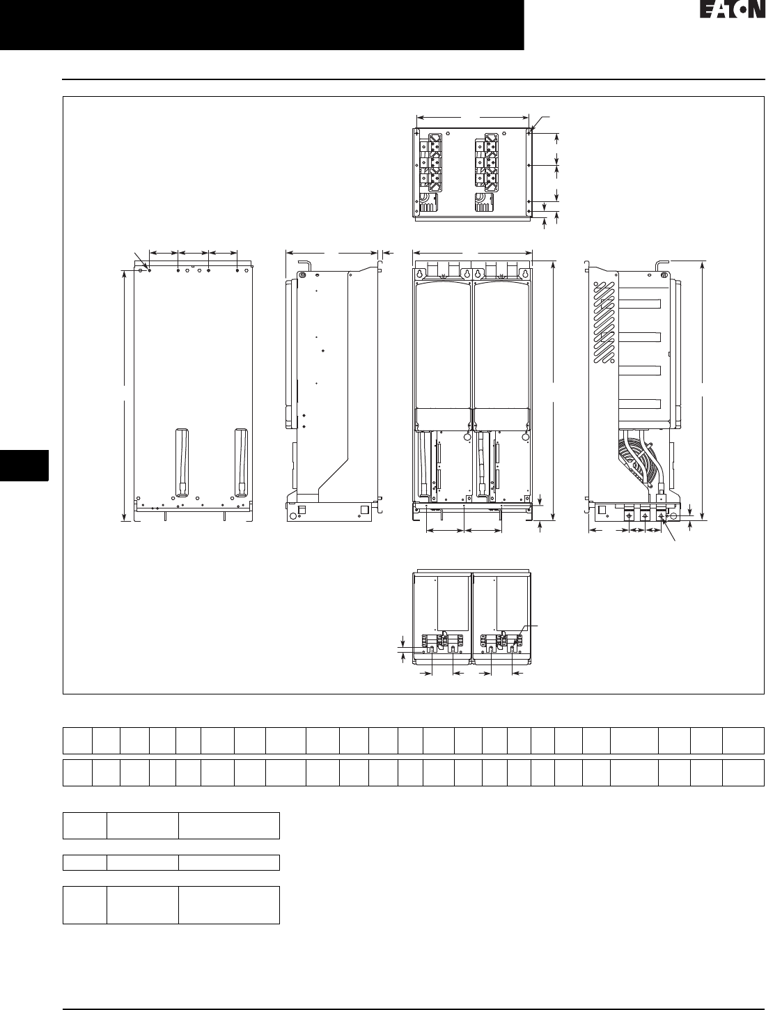
31.2-20
For more information, visit: www.eaton.com/consultants CA08104001E
February 2016
Adjustable Frequency Drives—Low Voltage
Sheet 31
22
23
24
25
26
27
28
29
30
31
32
33
34
35
36
37
38
39
40
41
42
4 3
9000X Series Drives
General Information
080
Figure 31.2-14. FR13, Open Chassis Converter
Table 31.2-11. Number of Input Units
W1 W2 W3 W4 W5 H1 H2 H3 H4 H5 D1 D2 D3 D4 D5 D6 D7 D8 D9 Dia. 1 Dia. 2 Dia. 3 Weight
Lb (kg)
18.74
(476)
5.91
(150)
17.52
(445)
4.57
(116)
3.35
(85)
41.54
(1055)
2.46
(62.5)
39.86
(1012.5)
41.34
(1050)
0.69
(17.5)
14.69
(373)
0.51
(13)
0.73
(18.5)
6.42
(163)
2.56
(65)
1.0 6
(27)
1.5 7
(40)
5.91
(150)
5.24
(133)
0.35x0.59
(9x15)
0.51
(13)
0.37
(9.5)
295
(134)
H3
H2
H5
H4
Dia. 1 W4 W4 W4
W5
D3 W5
D5
D4 D5
W2
W2
D1 D2
Dia. 2
Dia. 2
H1
W3 Dia. 3
D9
D8
D7
D6
W1
hp Input
Modules
Catalog
Number
480 V
800 2 SPX800A0-4A2N1
690 V
800
900
1000
2
2
2
SPX800A0-5A2N1
SPX900A0-5A2N1
SPXH10A0-5A2N1
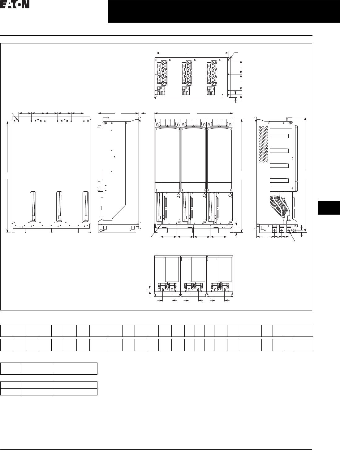
CA08104001E For more information, visit: www.eaton.com/consultants
31.2-21
February 2016
Adjustable Frequency Drives—Low Voltage
Sheet 31
22
23
24
25
26
27
28
29
30
31
32
33
34
35
36
37
38
39
40
41
42
4 3
9000X Series Drives
General Information
081
Figure 31.2-15. FR13, Open Chassis Converter—900/1000 hp 480 V
Table 31.2-12. Number of Input Units
W1 W2 W3 W4 W5 H1 H2 H3 H4 H5 D1 D2 D3 D4 D5 D6 D7 D8 D9 Dia.
1
Dia.
2
Dia.
3
Dia.
4
Weight
Lb (kg)
27.87
(708)
5.91
(150)
26.65
(677)
4.57
(116)
3.35
(85)
41.54
(1055)
2.46
(62.5)
39.86
(1012.5)
41.34
(1050)
0.69
(17.5)
14.69
(373)
0.51
(13)
0.73
(18.5)
6.42
(163)
2.56
(65)
1.06
(27)
1.5 7
(40)
5.91
(150)
5.24
(133)
0.35x0.59
(9x15)
0.18
(4.6)
0.51
(13)
0.37
(9.5)
443
(201)
H3
H2
H5
Dia. 1 W4 W4 W4 W4 W4
W5
D3 W5 W5
D5
D4 D5
W2
W2
W2 W2
D1 D2
Dia. 2
Dia. 3
H1 H4
W3 Dia. 4
D9
D8
D7
D6
W1
hp Input
Modules
Catalog
Number
480 V
900 3 SPX900A0-4A2N1
1000 3 SPXH10A0-4A2N1
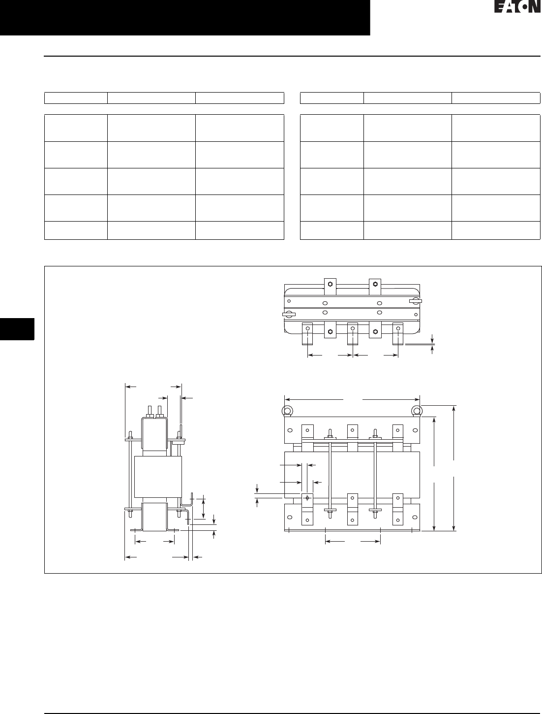
31.2-22
For more information, visit: www.eaton.com/consultants CA08104001E
February 2016
Adjustable Frequency Drives—Low Voltage
Sheet 31
22
23
24
25
26
27
28
29
30
31
32
33
34
35
36
37
38
39
40
41
42
4 3
9000X Series Drives
General Information
082
AC Choke Dimensions
Table 31.2-13. Choke Types
1Chokes are provided with all FR10–FR14 drives.
Figure 31.2-16. CHK0520
Frame Size Choke Type 1Catalog Number Frame Size Choke Type 1Catalog Number
Voltage Range 380–500 V Voltage Range 525–690 V
FR10 CHK0400
CHK0520
CHK0520
SPX2504
SPX3004
SPX3504
FR10 CHK0261
CHK0400
CHK0400
SPX2005
SPX2505
SPX3005
FR11 2 x CHK0400
2 x CHK0400
2 x CHK0400
SPX4004
SPX5004
SPX5504
FR11 CHK0520
CHK0520
2 x CHK0400
SPX4005
SPX4505
SPX5005
FR12 2 x CHK0520
2 x CHK0520
2 x CHK0520
SPX6004
SPX6504
SPX7004
FR12 2 x CHK0400
2 x CHK0400
2 x CHK0400
SPX5505
SPX6005
SPX7005
FR13 2 x CHK0400
3 x CHK0520
3 x CHK0520
SPX8004
SPX9004
SPXH104
FR13 2 x CHK0400
2 x CHK0400
2 x CHK0400
SPX8005
SPX9005
SPXH105
FR14 4 x CHK0520
6 x CHK0400
SPXH124
SPXH164
FR14 4 x CHK0400
6 x CHK0400
SPXH135
SPXH155
11
33
2
1
3
22
1.58
(40)
7.88
(200)
6.50
(165) 6.50
(165)
19.57
(497)
.79
(20) 15.71
(399)
17.57
(446)
.79
(20)
.24
(6)
3.03
(77)
.83
(21)
.55 (14)9.61 (244)
8.03 (204)
1.69
(43)
5.70
(145)
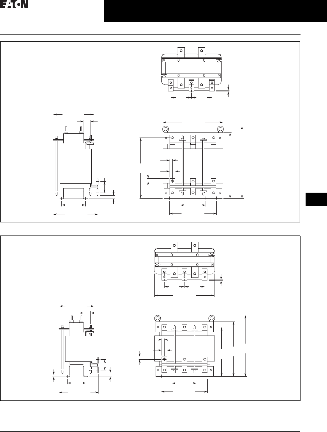
CA08104001E For more information, visit: www.eaton.com/consultants
31.2-23
February 2016
Adjustable Frequency Drives—Low Voltage
Sheet 31
22
23
24
25
26
27
28
29
30
31
32
33
34
35
36
37
38
39
40
41
42
4 3
9000X Series Drives
General Information
083
Figure 31.2-17. CHK0400
Figure 31.2-18. CHK0261
111
33
22
3
2
10.30 (262)
9.37 (238)
1.54
(39)
1.18
(30)
5.90
(150)
13.79 (350)
4.72
(120) 4.72
(120)
10.83 (275)
.59
(15)
5.51
(140)
13.94
(354)
15.08
(383)
16.58
(421)
2.64
(67)
.75
(19)
.24
(6)
.59
(15)
13.79 (350)
4.72
(120) 4.72
(120)
.24
(6)
11
33
2
1
3
22
1.18
(30)
5.90
(150)
10.83 (275)
.59
(15)
11.30
(287)
12.56
(319)
14.06
(357)
.59
(15)
.39
(10)
.87
(22)
.75 (19)
Min.
9.06 (230)
8.11 (206)
1.54
(39)
4.25
(108)
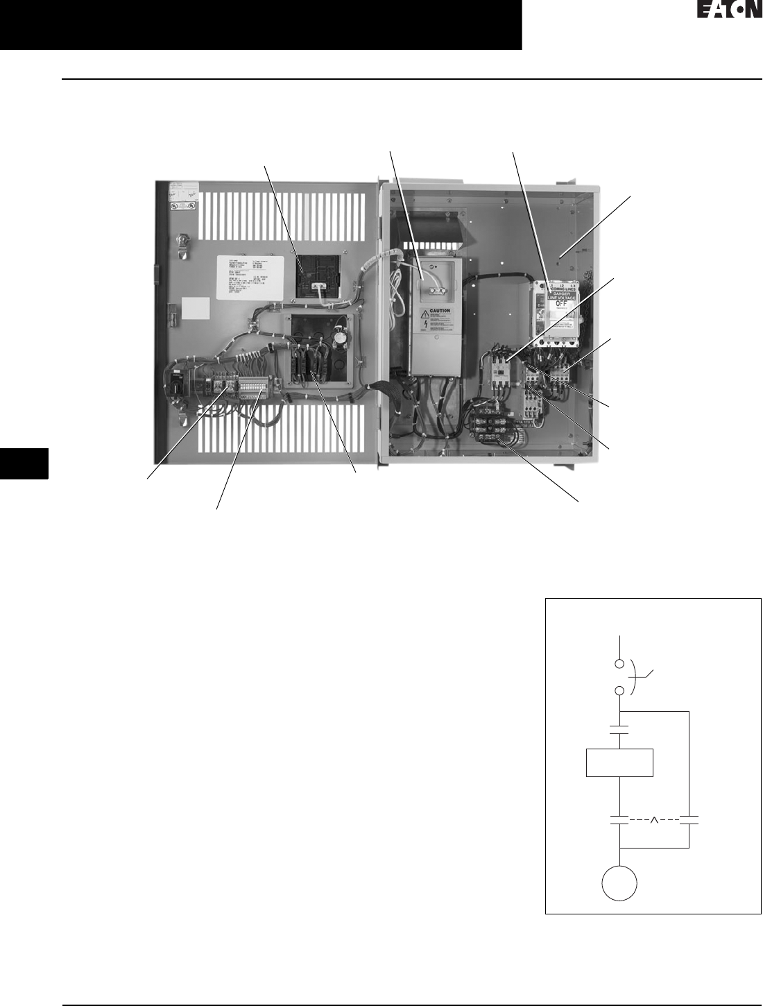
31.2-24
For more information, visit: www.eaton.com/consultants CA08104001E
February 2016
Adjustable Frequency Drives—Low Voltage
Sheet 31
22
23
24
25
26
27
28
29
30
31
32
33
34
35
36
37
38
39
40
41
42
4 3
9000X Series Drives
Enclosed SVX
084
Enclosed SVX
General Description
■Standard enclosed—covers a wide
range of the most commonly ordered
options. Pre-engineering eliminates
the lead time normally associated
with customer specific options
■Modified standard enclosed—
applies to specific customer require-
ments that vary from the Standard
Enclosed offering, such as the need
for an additional indicating light or
minor modifications to drawings.
Consult your Eaton representative for
assistance in pricing and lead time
■Custom engineered—for those
applications with more unique or
complex requirements, these are
individually engineered to the
customer’s needs. Consult your
Eaton representative for assistance
in pricing and lead time
Features
■NEMA Type 1 or Type 12 enclosures
■Input voltage: 208 V, 230 V, 480 V
and 575 V
■Complete range of control, network
and power options
■Horsepower range:
❑208 V—3/4 to 100 hp IH;
1 to 100 hp IL
❑230 V—3/4 to 100 hp IH;
1 to 100 hp IL
❑480 V—1 to 700 hp IH;
1-1/2 to 800 hp IL
■HMCP padlockable
Standards and Certifications
■UL listed
■cUL listed
Figure 31.2-19. Power Diagram for Bypass
Options RB and RA
Bypass Pilot Lights and
Selector Switches
• Option RB
• Option RA
• Option L2
• Option KF
Customer Control and Signal
Connection Terminal Block
Control Relay
Input Contactor
(Included as Standard
with Bypass Option)
115 V Control
Transformer
• Option KB
Overload Relay
• Option PH
• Option PI
Bypass Contactor
• Option RB
• Option RA
Output Contactor
• Option PE
(Included as Standard
with Bypass Option)
Input Line Fuses
• Option P3
Door-Mounted Keypad
(Included as Standard
with Bypass Option)
SVX9000 Variable
Frequency Drive
Input Disconnect (HMCP)
• Option P1
Enclosed 9000X Series Drive
SVX9000
Drive
HMCP
Input
Power
Output
Contactor Bypass
Contactor
Mechanical
Interlock
Motor
M
L
Inverter
Input
Contactor
I

CA08104001E For more information, visit: www.eaton.com/consultants
31.2-25
February 2016
Adjustable Frequency Drives—Low Voltage
Sheet 31
22
23
24
25
26
27
28
29
30
31
32
33
34
35
36
37
38
39
40
41
42
4 3
9000X Series Drives
Enclosed SVX
085
Catalog Number Selection
Table 31.2-14. SVX9000 Enclosed NEMA Type 1/12 Drive Catalog Numbering System
1Local/remote keypad is included as the
standard control panel.
2Brake chopper is a factory installed
option only, see drive option tables on
Pages 31.2-27–31.2-29. Note: External
dynamic braking resistors not included.
Consult factory.
3Includes local/remote speed reference switch.
4Some options are voltage and/or
horsepower specific. Consult your
Eaton representative for details.
5See Pages 31.2-30 and 31.2-31
for descriptions.
6Applicable only with FR10 and FR11
Freestanding designs.
7Consult Eaton for pricing and availability.
Communication Options
C2 = Modbus
C3 = PROFIBUS DP
C4 = LonWorks
C5 = PROFIBUS DP (D9
connector)
C6 = CANopen (slave)
C7 = DeviceNet
C8 = Modbus (D9 Type
connector)
CA = Johnson Controls N2
CI = Modbus TCP
CJ =BACnet
D3 = RS-232 with D9 connection
S V X F 0 7 14AA
Enclosed Options 145 Type
K1
K2
K3
K4
K5
K6
KB
KF
KO
Door-mounted speed potentiometer 3
Door-mounted speed potentiometer with
HOA selector switch 3
3–15 psig Follower
HAND/OFF/AUTO switch (22 mm)
MANUAL/AUTO ref switch (22 mm)
START/STOP pushbuttons (22 mm)
115 V control transformer–550 VA
Bypass test switch for RA and RB
Standard elapsed time meter
Control
Control
Control
Control
Control
Control
Control
Addl. bypass
Control
L1
L2
LE
Power on and fault pilot lights
Bypass pilot lights for RA, RB bypass options
Red RUN light
Light
Addl. bypass
Light
P1
P2
P3
P7
PE
PF
PG
PH
PI
PN
Input disconnect (HMCP) 100 kAIC
Disconnect switch 6
Input line fuses (200 kAIC)
Input power surge protection
Output contactor
Output filter
MotoRx (up to 600 ft) 1000 V/µS DV/DT filter
Single overload relay
Dual overload relays
Dual overloads for bypass
Input
Input
Input
Input
Output
Output
Output
Output
Output
Addl. bypass
RA
RB
RC
RD
Manual HOA bypass controller
Manual IOB bypass controller
Auto transfer HOA bypass controller
Auto transfer IOB bypass controller
Bypass
Bypass
Bypass
Bypass
S5
S6
S7
S8
S9
Floor stand 22 inches
Floor stand 12 inches
10 inch expansion
20 inch expansion
Space heater
Enclosure
Enclosure
Enclosure
Enclosure
Enclosure
Voltage Rating
1 = 208 V
2 = 230 V
4 = 480 V
Product Family
SVX = Enclosed drives
Horsepower Rating
F07 = 3/4 hp
001 = 1 hp
F15 = 1-1/2 hp
002 = 2 hp
003 = 3 hp
005 = 5 hp
007 = 7-1/2 hp
010 = 10 hp
015 = 15 hp
020 = 20 hp
025 = 25 hp
030 = 30 hp
040 = 40 hp
050 = 50 hp
060 = 60 hp
075 = 75 hp
100 = 100 hp
125 = 125 hp
150 = 150 hp
200 = 200 hp
250 = 250 hp
300 = 300 hp
350 = 350 hp
400 = 400 hp
500 = 500 hp
550 = 550 hp
600 = 600 hp
650 = 650 hp
700 = 700 hp
Enclosure Rating
1 = NEMA Type 1
2 = NEMA Type 12
6 = NEMA 12 filtered
Application—Torque/Braking 2
A= IL/no brake chopper
B= IL/internal brake chopper
D= IH/no brake chopper
E= IH/internal brake chopper
Enclosed Style
A = Enclosed drive
Control Options
B1 = 6 DI, 1 ext +24 Vdc/EXT +24 Vdc
B2 = 1 RO (NC/NO), 1 RO (NO), 1 Therm
B4 = 1 AI (mA isolated), 2 AO (mA isolated),
1 ext +24 Vdc/EXT +24 Vdc
B5 = 3 RO (NO)
B8 = 1 ext +24 Vdc/EXT +24 Vdc, 3 Pt100
B9 = 1 RO (NO), 5 DI 42–240 Vac input
Build Alphabetically and Numerically
Engineered Options
HT = High Temperature rating for 50°C
(FR10 and above) 7
VB = Varnished Boards

31.2-26
For more information, visit: www.eaton.com/consultants CA08104001E
February 2016
Adjustable Frequency Drives—Low Voltage
Sheet 31
22
23
24
25
26
27
28
29
30
31
32
33
34
35
36
37
38
39
40
41
42
4 3
9000X Series Drives
Enclosed SVX
086
Table 31.2-15. Input Molded-Case Breaker Sizes—230 V Ratings
Note: Based on a maximum of 104 ºF (40 ºC). A UL listed breaker
must be used.
Table 31.2-16. Input Molded-Case Breaker Sizes—480 V Ratings
Note: Based on a maximum of 104 ºF (40 ºC). A UL listed breaker
must be used.
Table 31.2-17. Input Fuse Sizes—230 V Ratings
Note: UL recognized type JJS preferred but RK acceptable.
Table 31.2-18. Input Fuse Sizes—480 V Ratings
Note: UL recognized type JJS preferred but RK acceptable.
hp Frame
Size
FLA Breaker
Current
1
1-1/2
2
3
FR4
FR4
FR4
FR4
4.8
6.6
7. 8
11
15
15
15
15
5
7-1/2
FR5
FR5
17.5
25
20
30
10
15
FR6
FR6
31
48
40
60
20
25
30
FR7
FR7
FR7
61
72
87
80
100
100
hp Frame
Size
FLA Breaker
Current
1-1/2
2
3
5
FR4
FR4
FR4
FR4
3.3
4.3
5.6
7. 6
15
15
15
15
7-1/2
10
15
FR5
FR5
FR5
12
16
23
20
30
30
20
25
30
FR6
FR6
FR6
31
38
46
40
50
60
40
50
60
FR7
FR7
FR7
61
72
87
80
100
100
75
100
125
FR8
FR8
FR8
105
140
170
125
150
200
150
200
FR9
FR9
205
261
250
300
250
300
350
FR10
FR10
FR10
300
385
460
400
500
600
400
500
550
FR11
FR11
FR11
520
590
650
700
800
900
600
650
700
FR12
FR12
FR12
750
820
920
1000
1000
1200
VT hp Frame
Size
NEC I
(A)
I
(A)
Fuse
Quantity
Fuse
(A)
1
1-1/2
2
3
FR4
FR4
FR4
FR4
4.2
6
6.8
9.6
4.8
6.6
7. 8
11
3
3
3
3
10
10
10
15
5
7-1/2
10
FR5
FR5
FR5
15.2
22
28
17.5
25
31
3
3
3
20
30
40
15
20
FR6
FR6
42
54
48
61
3
3
60
80
25
30
40
FR7
FR7
FR7
68
80
104
72
87
114
3
3
3
100
110
125
50
60
75
FR8
FR8
FR8
130
154
192
140
170
205
3
3
3
175
200
250
100 FR9 248 261 3 300
VT hp Frame
Size
NEC I
(A)
I
(A)
Fuse
Quantity
Fuse
(A)
1-1/2
2
3
5
7-1/2
FR4
FR4
FR4
FR4
FR4
3
3.4
4.8
7. 6
11
3.3
4.3
5.6
7. 6
12
3
3
3
3
3
10
10
10
10
15
10
15
20
FR5
FR5
FR5
14
21
27
16
23
31
3
3
3
20
30
35
25
30
40
FR6
FR6
FR6
34
40
52
38
46
61
3
3
3
50
60
80
50
60
75
FR7
FR7
FR7
65
77
96
72
87
105
3
3
3
100
110
125
100
125
150
FR8
FR8
FR8
124
156
180
140
170
205
3
3
3
175
200
250
200
250
FR9
FR9
240
302
261
300
3
3
350
400
300
350
400
FR10
FR10
FR10
361
414
477
385
460
520
3
3
3
450
500
600
500
550
600
FR11
FR11
FR11
590
NS
NS
590
650
730
6
6
6
350
400
450
650
700
800
FR12
FR12
FR12
NS
NS
NS
820
920
1030
6
6
6
500
500
600

CA08104001E For more information, visit: www.eaton.com/consultants
31.2-27
February 2016
Adjustable Frequency Drives—Low Voltage
Sheet 31
22
23
24
25
26
27
28
29
30
31
32
33
34
35
36
37
38
39
40
41
42
4 3
9000X Series Drives
Enclosed SVX
087
Product Selection
When Ordering
■Select a base catalog number
that meets the application require-
ments—nominal horsepower,
voltage and enclosure rating (the
enclosed drive’s continuous output
amp rating should be equal to or
greater than the motor’s full load
amp rating). The base enclosed
package includes a standard drive,
door mounted Local/Remote
Keypad and enclosure
■If dynamic brake chopper or
Control/Communication option is
desired, change the appropriate
code in the base catalog number
■Select enclosed options. Add
the codes as suffixes to the base
catalog number in alphabetical
and numeric order
■Read all footnotes
208 V Drives
Table 31.2-19. 208 Vac Input Base Drive
1Enclosure dimensions listed on Pages 31.2-32–31.2-40.
2Includes drive, Local/Remote keypad and enclosure.
Note: Drive heat dissipation calculations listed on Page 31.2-29.
Enclosure
Size 1
hp Current
(A)
NEMA Type 1 NEMA Type 12 Drawing
Number
Frame Size Frame Size
208 V High Overload Drive and Enclosure—IH = Constant Torque
0
0
0
0
3/4
1
1-1/2
2
3.7
4.8
6.6
7. 8
4
4 FR4
4
4
4
4
4
4
9
9
9
9
0
0
0
1
3
5
7-1/2
10
11
17.5
25
31
4
5
5
6
4
5
5
6
9
9
9
10
1
2
2
2
15
20
25
30
48
61
75
88
6
7
7
7
6
7
7
7
10
11
11
11
3
4
5
40
50
60
114
143
170
8
8
8
8
8
8
12
13
14
5
5
75
100
211
273
9
9
9
9
14
14
208 V Low Overload Drive and Enclosure—IL = Variable Torque
0
0
0
0
1
1-1/2
2
3
4.8
6.6
7. 8
11
4
4
4
4
4
4
4
4
9
9
9
9
0
0
0
1
5
7-1/2
10
15
17.5
25
31
48
5
5
5
6
5
5
5
6
9
9
9
10
1
2
2
2
20
25
30
40
61
75
88
114
6
7
7
7
6
7
7
7
10
11
11
11
3
4
5
50
60
75
—
170
—
8
8
8
8
8
8
12
13
14
5100—99 14
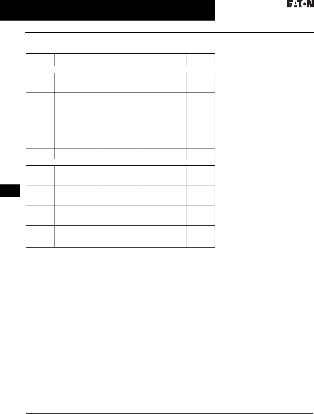
31.2-28
For more information, visit: www.eaton.com/consultants CA08104001E
February 2016
Adjustable Frequency Drives—Low Voltage
Sheet 31
22
23
24
25
26
27
28
29
30
31
32
33
34
35
36
37
38
39
40
41
42
4 3
9000X Series Drives
Enclosed SVX
088
230 V Drives
Table 31.2-20. 230 Vac Input Base Drive
1Enclosure dimensions listed on Pages 31.2-32–31.2-40.
2Includes drive, Local/Remote keypad and enclosure.
Enclosure
Size 1
hp Current
(A)
NEMA Type 1 NEMA Type 12 Drawing
Number
Frame Size Frame Size
230 V High Overload Drive and Enclosure—IH = Constant Torque
0
0
0
0
3/4
1
1-1/2
2
3.7
4.8
6.6
7. 8
4
4
4 FR
4
4
4
4 FR
4
9
9
9
9
0
0
0
1
3
5
7-1/2
10
11
17.5
25
31
4
5
5
6
4
5
5
6
9
9
9
10
1
2
2
2
15
20
25
30
48
61
75
88
6
7
7
7
6
7
7
7
10
11
11
11
3
4
5
40
50
60
114
140
170
8
8
8
8
8
8
12
13
14
5
5
75
100
205
261
9
9
9
9
14
14
230 V Low Overload Drive and Enclosure—IL = Variable Torque
0
0
0
0
1
1-1/2
2
3
4.8
6.6
7. 8
11
4
4
4
4
4
4
4
4
9
9
9
9
0
0
0
1
5
7-1/2
10
15
17.5
25
31
48
5
5
5
6
5
5
5
6
9
9
9
10
1
2
2
2
20
25
30
40
61
75
88
114
6
7
7
7
6
7
7
7
10
11
11
11
3
4
5
50
60
75
140
170
205
8
8
8
8
8
8
12
13
14
5 100 261 9 9 14

CA08104001E For more information, visit: www.eaton.com/consultants
31.2-29
February 2016
Adjustable Frequency Drives—Low Voltage
Sheet 31
22
23
24
25
26
27
28
29
30
31
32
33
34
35
36
37
38
39
40
41
42
4 3
9000X Series Drives
Enclosed SVX
089
480 V Drives
Table 31.2-21. 480 Vac Input Base Drive
1Enclosure dimensions listed on Pages 31.2-32–31.2-40.
2Includes drive, Local/Remote keypad and enclosure.
3Consult Eaton.
4The smaller enclosure Size 6 accommodates only power options, input disconnect (P1) and
input line fuses (P3). Bypass and other options require Size 8. Adding any standard control
option will not require the larger enclosure.
5The smaller enclosure Size 8 accommodates only power options, input disconnect (P1) and
input line fuses (P3). Bypass and other options require Size 9. Adding any standard control
option will not require the larger enclosure.
6For other options, consult factory.
Enclosure
Size 1
hp Current
(A)
NEMA Type 1 NEMA Type 12 Drawing
Number
Frame Size Frame Size
High Overload Drive and Enclosure—IH = Constant Torque
0
0
0
0
1
1-1/2
2
3
2.2
3.3
4.3
5.6
4
4
4 FR
4
4
4
4 FR
4
9
9
9
9
0
0
0
0
5
7-1/2
10
15
7. 6
12
16
23
4
5
5
5
4
5
5
5
9
9
9
9
1
1
1
2
20
25
30
40
31
38
46
61
6
6
6
7
6
6
6
7
10
10
10
11
2
2
3
3
4
50
60
75
100
125
72
87
105
140
170
7
7
8
8
8
7
7
8
8
8
11
11
12
12
13
5
5
150
200
205
245
9
9
9
9
14
14
6, 8 46
6, 8 46
6, 8 46
250
300
350
300
385
460
10
10
10
10
10
10
15 4, 16 6
15 4, 16 6
15 4, 16 6
8, 9 56
8, 9 56
8, 9 56
400
500
550
520
590
650
11
11
11
11
11
11
16 5, 17 6
16 5, 17 6
16 5, 17 6
3
3
3
600
650
700
730
820
920
12
12
12
12
12
12
3
3
3
Low Overload Drive and Enclosure—IL = Variable Torque
0
0
0
0
1-1/2
2
3
5
3.3
4.3
5.6
7. 6
4
4
4
4
4
4
4
4
9
9
9
9
0
0
0
0
7-1/2
10
15
20
12
16
23
31
4
5
5
5
4
5
5
5
9
9
9
9
1
1
1
2
25
30
40
50
38
46
61
72
6
6
6
7
6
6
6
7
10
10
10
11
2
2
3
4
4
60
75
100
125
150
87
105
140
170
205
7
7
8
8
8
7
7
8
8
8
11
11
12
13
13
5
5
200
250
261
300
9
9
9
9
14
14
6, 8 46
6, 8 46
6, 8 46
300
350
400
385
460
520
10
10
10
10
10
10
15 4, 16 6
15 4, 16 6
15 4, 16 6
8, 9 56
8, 9 56
8, 9 56
500
550
600
590
650
730
11
11
11
11
11
11
16 5, 17 6
16 5, 17 6
16 5, 17 6
3
3
3
650
700
800
820
920
1030
12
12
12
12
12
12
3
3
3
Drive Heat Dissipation
Calculations
The Eaton 9000X drive is a highly
efficient electric power converter
releasing minimal amounts of waste
heat energy into the ambient air. The
amount of heat loss from the drive in
operation is directly proportional to
the load of the connected motor,
the drive switching frequency and
operating frequency. Based on
the drive operating load, the heat
dissipation can be calculated at a
given operating point. For most cases,
the following general formula can be
used to estimate the heat dissipation
of the power module:
Pmotor [kW] x 0.025 = Ploss [kW]
Where Pmotor is the operating power
of the motor and Ploss is the heat
dissipated from the 9000X drive.
For example, a 20 hp [15 kW] motor
is applied with a 9000X inverter on a
pump application. The application
has been designed so that maximum
motor load will be 95% or 14.3 kW.
Using the formula above, the
calculated heat dissipation of the
drive will be approximately 356 watts/
hour or 1215 BTU/hour at the designed
maximum load.
15 kW x 0.95 = 14.3 kW
14.3 kW x 0.025 = 0.356 kW/hour or
356 watts/hour
356 watts/hour x 3.412 = 1215 BTU/hour
Note: This example assumes the default
switching frequency has been used.
Additional conversion formulas:
hp x 0.7457 = kW
hp x 745.7 = watts
kW x 1000 = watts
Watts/hour x 3.412 = BTU/hour
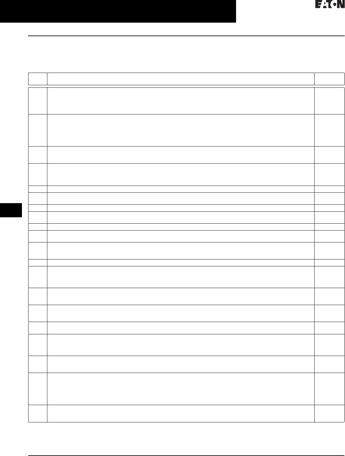
31.2-30
For more information, visit: www.eaton.com/consultants CA08104001E
February 2016
Adjustable Frequency Drives—Low Voltage
Sheet 31
22
23
24
25
26
27
28
29
30
31
32
33
34
35
36
37
38
39
40
41
42
4 3
9000X Series Drives
Enclosed SVX
090
SVX9000 Drives
Control/Communication Option Descriptions
Table 31.2-22. Available Control/Communications Options
Option Description Option
Ty p e
K1 Door-Mounted Speed Potentiometer—Provides the SVX9000 with the ability to adjust the frequency reference using a door-
mounted potentiometer. This option uses the 10 Vdc reference to generate a 0–10 V signal at the analog voltage input signal
terminal. When the HOA bypass option is added, the speed is controlled when the HOA switch is in the hand position. Without
the HOA bypass option, a 2-position switch (labeled local/remote) is provided on the keypad to select speed reference from the Speed
Potentiometer or a remote speed signal.
Control
K2 Door-Mounted Speed Potentiometer with HOA Selector Switch—Provides the SVX9000 with the ability to start/stop and adjust
the speed reference from door-mounted control devices or remotely from customer supplied inputs. In HAND position, the drive
will start and the speed is controlled by the door-mounted speed potentiometer. The drive will be disabled in the OFF position.
When AUTO is selected, the run enable and speed reference are controlled from remote inputs. Speed reference can be either 0–10 Vdc
or 4–20 mA. The drive default is 4–20 mA, parameter is field programmable. Run enable is controlled by a dry contact
closure. This option requires a customer supplied 115 V power source.
Control
K3 3–15 psig Follower—Provides a pneumatic transducer that converts a 3–15 psig pneumatic signal to either 0–8 Vdc or a
1–9 Vdc signal interface with the SVX9000. The circuit board is mounted on the inside of the front enclosure panel and connects
to the user’s pneumatic control system via 6 ft (1.8 m) of flexible tubing and a 1/4-inch (6.4 mm) brass tube union.
Control
K4 HAND/OFF/AUTO Switch for Non-bypass Configurations—Provides a three-position selector switch that allows the user to select
either a Hand or Auto mode of operation. Hand mode is defaulted to keypad operation, and Auto mode is defaulted to
control from an external terminal source. These modes of operation can be configured via programming to allow for alternate
combinations of start and speed sources. Start and speed sources include keypad, I/O and FieldBus.
Control
K5 MANUAL/AUTO Speed Reference Switch—Provides a door-mounted selector switch for Manual/Auto speed reference. Control
K6 START/STOP Pushbuttons—Provides door-mounted START and STOP pushbuttons for either bypass or non-bypass
configurations.
Control
KB 115 V Control Transformer–550 VA—Provides a fused control power transformer with additional 550 VA at 115 V for customer use. Control
KF Bypass Test Switch for RB and RA—Allows the user to energize the AF drive for testing while operating the motor on the bypass
controller. The Test Switch is mounted on the inside of the enclosure door.
Addl. bypass
KO Standard Elapsed Time Meter—Provides a door-mounted elapsed run time meter. Control
L1 Power On and Fault Pilot Lights—Provides a white power on light that indicates power to the enclosed cabinet and a red fault
light indicates a drive fault has occurred.
Light
L2 Bypass Pilot Lights for RB, RA Bypass Options—A green light indicates when the motor is running in inverter mode and an
amber light indicates when the motor is running in bypass mode. The lights are mounted on the enclosure door, above the
switches.
Addl. bypass
LE RUN Pilot Light—Provides a green run light that indicates the drive has been commanded to start. Light
P1 Input Disconnect Assembly Rated to 100 kAIC—High Interrupting Motor Circuit Protector (HMCP) that provides a means of short-
circuit protection for the power cables between it and the SVX9000, and protection from high-level ground faults on the power
cable. Allows a convenient means of disconnecting the SVX9000 from the line and the operating mechanism can be padlocked in the
OFF position. This is factory mounted in the enclosure.
Input
P2 Disconnect Switch—Disconnect switch option is applicable only with NEMA Type 1 and NEMA Type 12 Freestanding drives.
Allows a convenient means of disconnecting the SVX9000 from the line, and the operating mechanism can be padlocked in the
OFF position. This is factory-mounted in the enclosure.
Input
P3 Input Line Fuses Rated to 200 kAIC—Provides high-level fault protection of the SVX9000 input power circuit from the load side of
the fuses to the input side of the power transistors. This option consists of three 200 kA fuses, which are factory mounted in the
enclosure.
Input
P7 MOV Surge Suppressor—Provides a metal oxide varistor (MOV) connected to the line side terminals and is designed to clip line
side transients.
Input
PE Output Contactor—Provides a means for positive disconnection of the drive output from the motor terminals. The contactor coil
is controlled by the drive’s run or permissive logic. NC and NO auxiliary contacts rated at 10 A, 600 Vac are provided for
customer use. Bypass Options RB and RA include an Output Contactor as standard. This option includes a low VA 115 Vac
fused Control Power Transformer and is factory mounted in the enclosure.
Output
PF Output Filter—Used to reduce the transient voltage (DV/DT) at the motor terminals. The Output Filter is recommended for cable
lengths exceeding 100 ft (30 m) with a drive of 3 hp and above, for cable lengths of 33 ft (10 m) with a drive of 2 hp and below, or
for a drive rated at 525–690 V. This option is mounted in the enclosure, and may be used in conjunction with a brake chopper circuit.
Output
PG MotoRx (300–600 ft) 1000 V/µS DV/DT Filter—Used to reduce transient voltage (DV/DT) and peak voltages at the motor
terminals. This option is comprised of a 0.5% line reactor, followed by capacitive filtering and an energy recovery/clamping circuit.
Unlike the Output Filter (See option PF), the MotoRx recovers most of the energy from the voltage peaks, resulting in a lower volt-
age drop to the motor, and therefore conserving power. This option is used when the distance between a single motor and the
drive is 300–600 ft (91–183 m). This option can not be used with the Brake Chopper Circuit. The Output Filter (option PF) should
be investigated as an alternative.
Output
PH Single Overload Relay—Uses a bimetallic overload relay to provide additional overload current protection to the motor on con-
figurations without bypass options. It is included with the Bypass Configurations for overload current protection in the bypass
mode. The Overload Relay is mounted within the enclosure, and is manually resettable. Heater pack included.
Output

CA08104001E For more information, visit: www.eaton.com/consultants
31.2-31
February 2016
Adjustable Frequency Drives—Low Voltage
Sheet 31
22
23
24
25
26
27
28
29
30
31
32
33
34
35
36
37
38
39
40
41
42
4 3
9000X Series Drives
Enclosed SVX
091
Table 31.2-22. Available Control/Communications Options (Continued)
Note: For availability, see base drive voltage required.
Option Description Option Type
PI Dual Overload Relays—This option is recommended when a single drive is operating two motors and overload current protec-
tion is needed for each of the motors. The standard configuration includes two bimetallic overload relays, each sized to protect a
motor with 50% of the drive hp rating. For example, a 100 hp drive would include two overload relays sized to protect two 50 hp
motors. The relays are mounted within the enclosure, and are manually resettable. Heater packs not included.
Output
PN Dual Overloads for Bypass—This option is recommended when a single drive is operating two motors in the bypass mode and
overload current protection is needed for each of the motors. The standard configuration includes two bimetallic overload relays,
each sized to protect a motor with 50% of the drive hp rating. For example, a 100 hp drive would include two overload relays
sized to protect two 50 hp motors. The relays are mounted within the enclosure, and are manually resettable.
Addl. bypass
RA Manual HOA Bypass Controller—The Manual HAND/OFF/AUTO (HOA)—three-contactor—bypass option provides a means of
bypassing the SVX9000, allowing the AC motor to be operated at full speed directly from the AC supply line. This option consists
of an input disconnect, a fused control power transformer, and a full voltage bypass starter with a door-mounted HOA selector
switch and an INVERTER/BYPASS switch. The HOA switch provides the ability to start and stop the drive in the inverter mode. The
Bypass includes an input contactor, an output contactor, and a bypass starter with an electronic overload relay. The contactors
are mechanically and electrically interlocked.
Bypass
RB Manual IOB Bypass Controller—The Manual INVERTER/OFF/BYPASS (IOB)—three-contactor—bypass option provides a means
of bypassing the SVX9000, allowing the AC motor to be operated at full speed directly from the AC supply line. This option
consists of an input disconnect, a fused control power transformer, and a full voltage bypass starter with a door-mounted IOB
selector switch. The Bypass includes an input contactor, an output contactor, and a bypass starter with an electronic overload
relay. The contactors are mechanically and electrically interlocked.
Bypass
RC Auto Transfer HOA Bypass Controller–The Manual HAND/OFF/AUTO (HOA)—three-contactor—bypass option provides a means
of bypassing the SVX9000, allowing the AC motor to be operated at full speed directly from the AC supply line. The circuitry
provides an automatic transfer of the load to “across the line” operation after a drive trip. This option consists of an input
disconnect, a fused control power transformer, and a full voltage bypass starter with a door-mounted HOA selector switch and an
INVERTER/BYPASS switch. The HOA switch provides the ability to start and stop the drive in either mode. The Bypass includes an
input contactor, an output contactor, and a bypass starter with an electronic overload relay. The contactors are mechanically and
electrically interlocked. Door-mounted pilot lights are provided that indicate bypass or inverter operation. A green light indicates
when the motor is running in inverter mode and an amber light indicates when the motor is running in bypass mode.
Warning: The motor may restart when the overcurrent relay is reset when operating in bypass, unless the IOB selector switch
is turned to the OFF position.
Bypass
RD Auto Transfer IOB Bypass Controller—The Auto INVERTER/OFF/BYPASS (IOB)—three-contactor—bypass option provides a means
of bypassing the SVX9000, allowing the AC motor to be operated at full speed directly from the AC supply line. The circuitry pro-
vides an automatic transfer of the load to “across the line” operation after a drive trip. This option consists of an input discon-
nect, a fused control power transformer, and a full voltage bypass starter with a door mounted IOB selector switch. The Bypass
includes an input contactor, an output contactor, and a bypass starter with an electronic overload relay. The contactors are
mechanically and electrically interlocked. Door-mounted pilot lights are provided which indicate bypass or inverter operation. A
green light indicates when the motor is running in inverter mode and an amber light indicates when the motor is running in
bypass mode.
Warning: The motor may restart when the overcurrent relay is reset when operating in bypass, unless the IOB selector switch
is turned to the OFF position.
Bypass
S5 Floor Stand 22 Inches—Converts a Size 1 or 2, normally wall mounted enclosure to a floor standing enclosure with a height of
22 inches (558.8 mm).
Enclosure
S6 Floor Stand 12 Inches—Converts a Size 2, normally wall mounted enclosure to a floor standing enclosure with a height of 12 inches
(304.8 mm).
Enclosure
S7 10-Inch Expansion—In a Size 5 enclosure, the extension allows for bottom cable entry and additional space for customer
mounted components.
Note: Enclosure expansion rated NEMA Type 1 only.
Enclosure
S8 20-Inch Expansion—In a Size 5 enclosure, the extension allows for bottom cable entry and additional space for customer
mounted components. When the Output Filter (option PF) is selected for a drive using a Size 5 enclosure, this expansion box is
required and included in the option pricing.
Note: Enclosure expansion rated NEMA Type 1 only.
Enclosure
S9 Space Heater—Prevents condensation from forming in the enclosure when the drive is inactive or in storage. Includes a
thermostat for variable temperature control. A 200W heater is installed in enclosures 0 and 1, and a 400W heater is installed in
enclosures 2–5. Requires a customer supplied 115 V remote supply source.
Enclosure
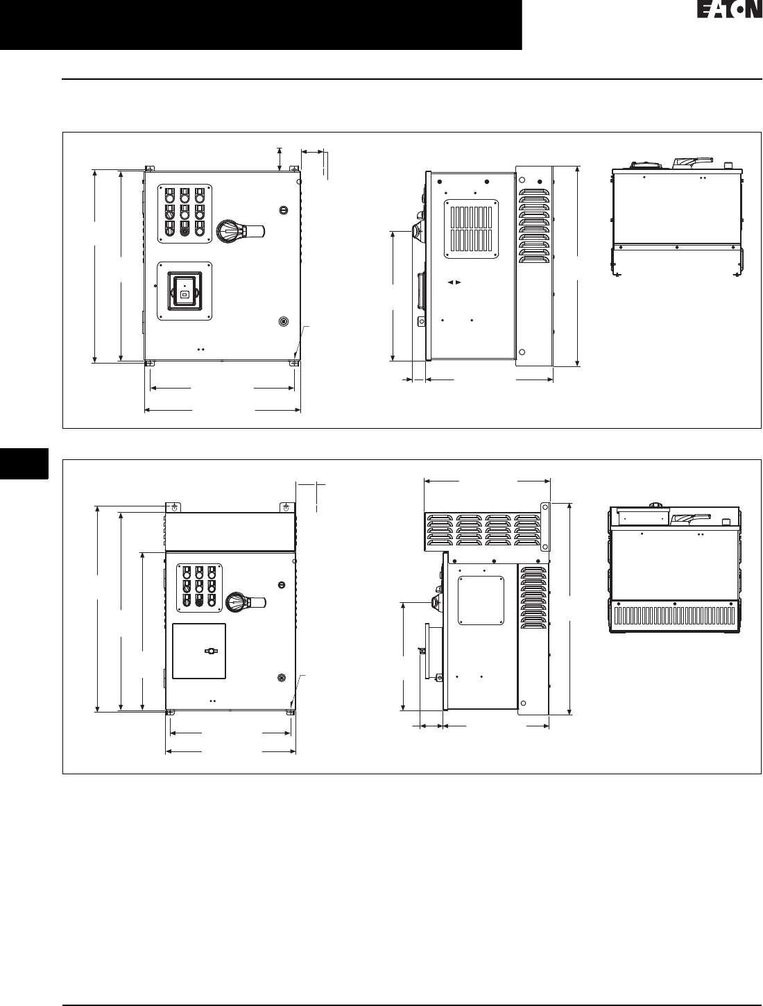
31.2-32
For more information, visit: www.eaton.com/consultants CA08104001E
February 2016
Adjustable Frequency Drives—Low Voltage
Sheet 31
22
23
24
25
26
27
28
29
30
31
32
33
34
35
36
37
38
39
40
41
42
4 3
9000X Series Drives
Enclosed SVX
092
Dimensions—Approximate Dimensions in Inches (mm)
Figure 31.2-20. AX Box, NEMA 1/12
Figure 31.2-21. AX Box, NEMA 3R
25.80
(655.3)
3.00 (76.2)
Minimum
Air Space
Required
Both Sides
4.00 (101.6) Minimum
Free Air Space Required
25.35
(643.9)
19.30 (490.2)
20.92 (531.4)
17.02 (432.2)
1.76
(44.8)
26.74
(679.2)
17.31
(439.7)
Ø 0.44 (11.2)
Mounting
Holes
(4 Places)
20.18 (512.5)
3.00 (76.2)
Minimum
Air Space
Required
Both Sides
33.09
(840.4)
31.76
(806.6)
25.35
(643.9)
19.30 (490.2)
20.92 (531.4)
3.64
(92.5) 17.02 (432.2)
17.28
(438.9)
33.97
(862.8)
Ø 0.44 (11.2)
Mounting
Holes
(4 Places)
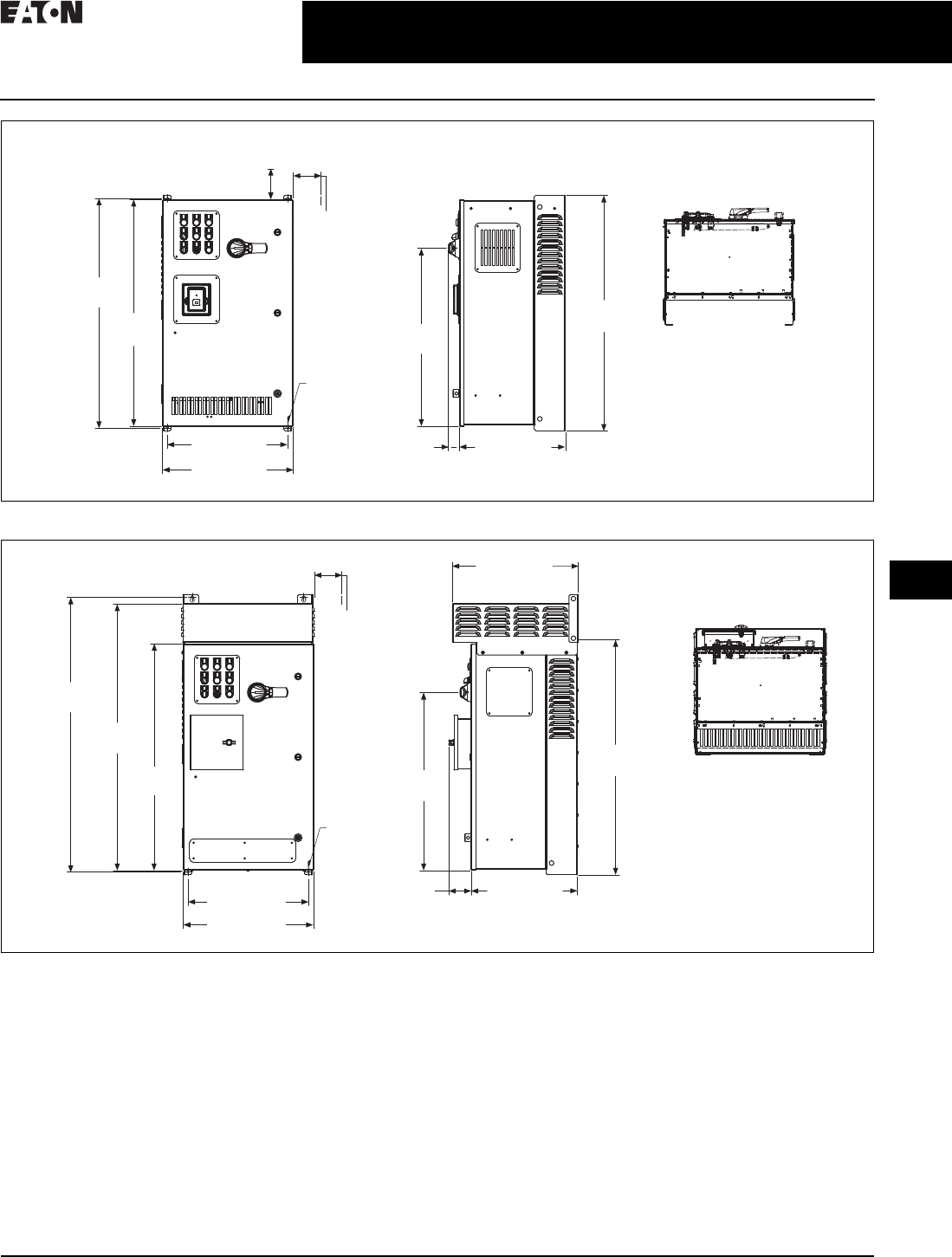
CA08104001E For more information, visit: www.eaton.com/consultants
31.2-33
February 2016
Adjustable Frequency Drives—Low Voltage
Sheet 31
22
23
24
25
26
27
28
29
30
31
32
33
34
35
36
37
38
39
40
41
42
4 3
9000X Series Drives
Enclosed SVX
093
Figure 31.2-22. BX Box, NEMA 1/12
Figure 31.2-23. BX Box, NEMA 3R
4.00 (101.6)
Minimum
Free Air Space
Required
28.55
(725.1)
36.80
(934.7)
36.35
(923.3)
19.30 (490.2)
20.92 (531.4)
17.01 (432.2)
1.76
(44.8)
37.74
(958.6)
3.00 (76.2)
Minimum
Air Space
Required
Both Sides
Ø 0.44 (11.2)
Mounting
Holes
(4 Places)
28.56
(725.3)
44.09
(1119.8)
36.35
(923.3)
42.69
(1084.3)
19.30 (490.2)
20.92 (531.4)
37.74
(958.6)
3.00 (76.2)
Minimum
Air Space
Required
Both Sides
Ø 0.44 (11.2)
Mounting
Holes
(4 Places)
17.01 (432.2)
3.51
(89.1)
20.18 (512.5)
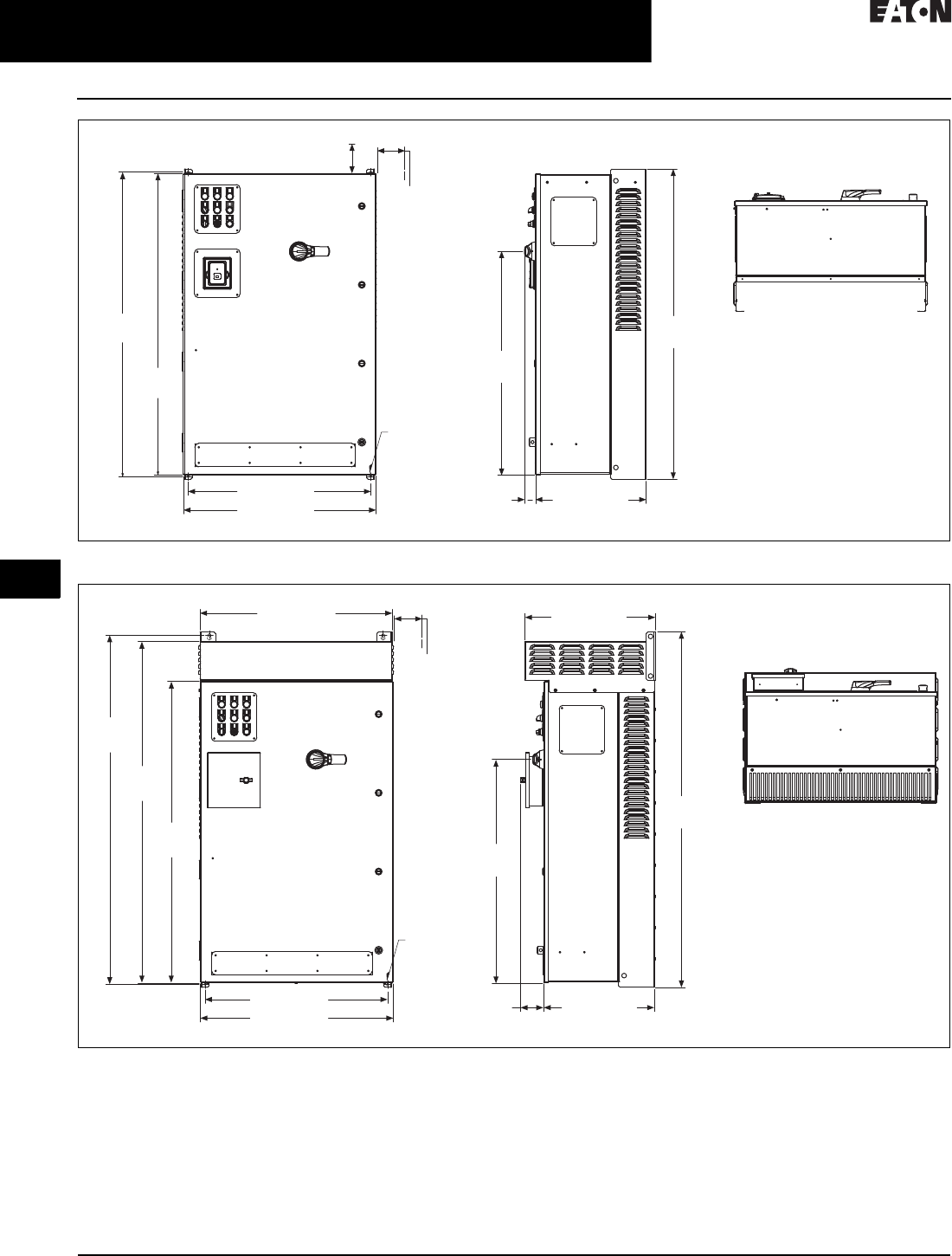
31.2-34
For more information, visit: www.eaton.com/consultants CA08104001E
February 2016
Adjustable Frequency Drives—Low Voltage
Sheet 31
22
23
24
25
26
27
28
29
30
31
32
33
34
35
36
37
38
39
40
41
42
4 3
9000X Series Drives
Enclosed SVX
094
Figure 31.2-24. CX Box, NEMA 1/12
Figure 31.2-25. CX Box, NEMA 3R
49.74
(1263.4)
48.80
(1239.5)
48.35
(1228.1)
29.30 (744.2)
30.92 (785.4)
1.74
(44.2) 17.76 (451.2)
35.85
(910.6)
3.00 (76.2)
Minimum
Air Space
Required
Both Sides
4.00 (101.6) Minimum
Free Air Space Required
Ø 0.44 (11.2)
Mounting
Holes
(4 Places)
30.88 (784.4)
56.08
(1424.5)
54.77
(1391.2)
48.35
(1228.1)
29.30 (744.2)
30.92 (785.4) 17.76 (451.2)
3.72
(94.4)
56.96
(1446.9)
35.85
(910.6)
21.00 (533.3)
3.00 (76.2)
Minimum
Air Space
Required
Both Sides
Ø 0.44 (11.2)
Mounting
Holes
(4 Places)
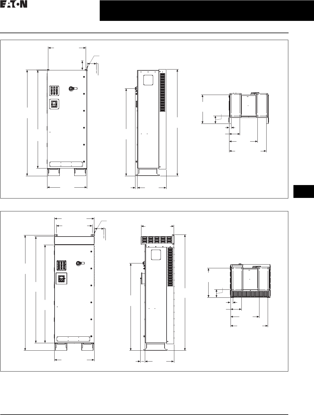
CA08104001E For more information, visit: www.eaton.com/consultants
31.2-35
February 2016
Adjustable Frequency Drives—Low Voltage
Sheet 31
22
23
24
25
26
27
28
29
30
31
32
33
34
35
36
37
38
39
40
41
42
4 3
9000X Series Drives
Enclosed SVX
095
Figure 31.2-26. DX Box, NEMA 1/12
Figure 31.2-27. DX Box, NEMA 3R
82.35
(2091.7)
76.35
(1939.3)
30.92
(785.4)
22.48
(571.1)
1.55
(39.4)
82.85
(2104.4)
67.89
(1724.4)
28.88 (733.6)
22.56
(573.0) 6.13
(155.6)
8.38 (212.9)
1.62 (41.1)
22.12
(561.8)
29.30 (744.2)
Ø 0.44 (11.2)
Mounting
Holes
(2 Places)
3.00 (76.2)
Minimum
Air Space
Required
Both Sides
4.00 (101.6)
Minimum
Free Air Space
Required
22.81
(579.2)
29.06 (738.1)
30.88 (784.4)
27.88 (708.2)
89.70
(2278.3)
82.84
(2104.1)
76.35
(1939.3)
30.92 (785.4) 3.64
(92.5)
22.48
(571.1)
67.89
(1724.4)
90.14
(2289.5)
25.51 (647.8)
1.80 (45.7)
8.56 (217.4)
22.30
(566.4)
Ø 0.44 (11.2)
Mounting
Holes
(2 Places)
3.00 (76.2)
Minimum
Air Space
Required
Both Sides
6.31
(160.3)
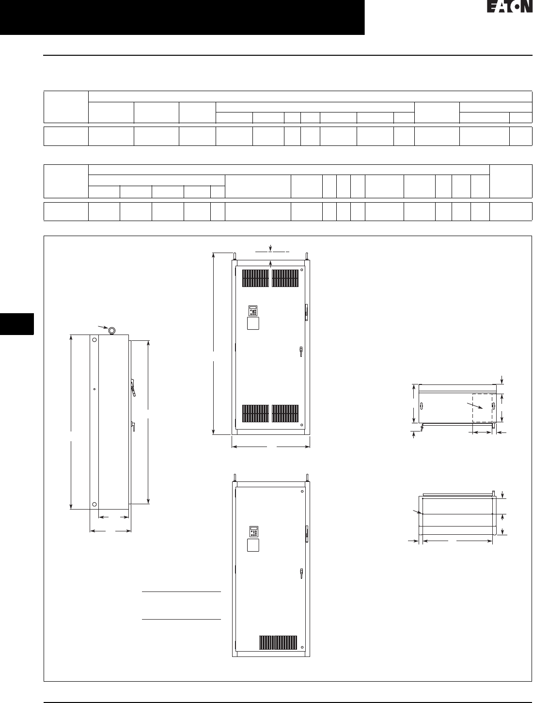
31.2-36
For more information, visit: www.eaton.com/consultants CA08104001E
February 2016
Adjustable Frequency Drives—Low Voltage
Sheet 31
22
23
24
25
26
27
28
29
30
31
32
33
34
35
36
37
38
39
40
41
42
4 3
9000X Series Drives
Enclosed SVX
096
SVX Drawing 14—Enclosure Size 5
Table 31.2-23. Approximate Dimensions and Shipping Weight—Enclosed Products
Table 31.2-23. Approximate Dimensions and Shipping Weight—Enclosed Products (Continued)
Figure 31.2-28. Approximate Dimensions
Enclosure
Size
Dimensions in Inches (mm)
Wide
A
High
B
Deep
C
Mounting H Minimum Air Space
DD1EE1F GG1 J K
5 40.00
(1016)
90.00
(2286)
21.30
(541)
36.00
(914)
2.00
(51)
—— 8.00
(203)
10.80
(273)
—84.40
(2143)
4.00
(102)
—
Enclosure
Size
Dimensions in Inches (mm) Max.
Approx.
Ship. Wt.
Lb (kg)
Cable Entry Door Clearance
S
T U V W RR SS TT UU VV
LMNPR
515.00
(381)
10.00
(254)
4.80
(122)
2.00
(51)
— 36.30
(921)
20.00
(508)
———94.00
(2387)
15.50
(394)
— — — 1275 (579)
M
Lifting Eyes
(2 Places)
B
H
C
SS
Side View
RR
J
A
Front View
NEMA Type 1
Front View
NEMA Type 12
S
T
0.56 (14.2) Dia.
Mounting
Holes
(4 Places)
D1 D
G
F
N
L
For Cable
Entry
P
Top View
Bottom View
For Reference Only,
Dimensions Subject to Change.
IL hp
††75
100
—
200
250
IH hp
††60
††75
100
150
200
208/230V
480V
Note: No bottom entry/exit.
S7 option required.
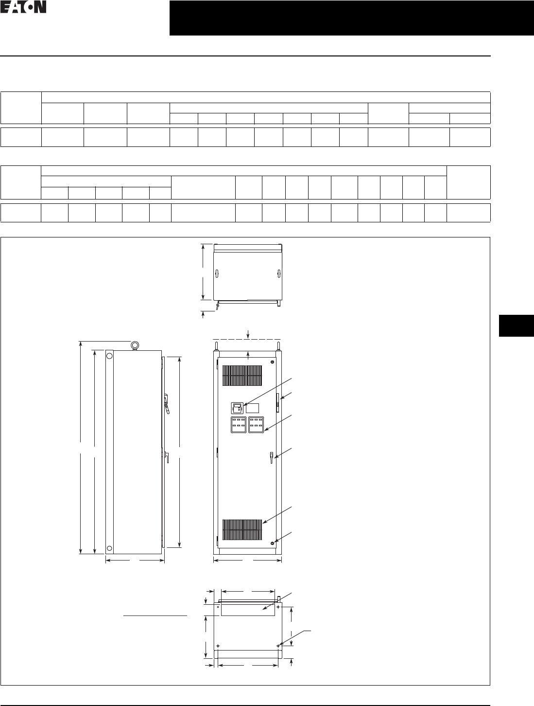
CA08104001E For more information, visit: www.eaton.com/consultants
31.2-37
February 2016
Adjustable Frequency Drives—Low Voltage
Sheet 31
22
23
24
25
26
27
28
29
30
31
32
33
34
35
36
37
38
39
40
41
42
4 3
9000X Series Drives
Enclosed SVX
097
SVX Drawing 15—Enclosure Size 6
Table 31.2-24. Approximate Dimensions and Shipping Weight—Enclosed Products
Table 31.2-24. Approximate Dimensions and Shipping Weight—Enclosed Products (Continued)
Figure 31.2-29. Approximate Dimensions
Enclosure
Size
Dimensions in Inches (mm)
Wide
A
High
B
Deep
C
Mounting H Minimum Air Space
D D1D2E F G G1 J K
630.00
(762)
90.00
(2286)
26.00
(660)
26.50
(673)
1.80
(46)
——17.30
(438)
5.50
(140)
— 84.40
(2143)
4.00
(102)
—
Enclosure
Size
Dimensions in Inches (mm) Max.
Approx.
Ship. Wt.
Lb (kg)
Cable Entry Door Clearance
S
T U V W RR SS TT UU VV
LMNPR
6 23.5
(597)
03.30
(84)
4.50
(114)
19.30
(490)
— 26.20
(667)
24.80
(629)
———93.90
(2386)
————1500 (681)
Keypad
Operator Elements When Specified,
Mounted on These Panels
Ventilating Slots
Key-Locking Handle
Quarter Turn Latch
(2 Places)
Flanged Disconnect Supplied
with Circuit Breaker When Specified
A
C
Side View
Bottom View
S
J
H
B
T
Top View
Door Clearance
RR
L
DD1
G
F
N
P
For Cable Entry
M
0.56 (14.2) Dia.
Mounting Hole –
(4 Places)
Front View
IL hp
300
350
400
IH hp
250
300
350
480V
Note: See Page 31.2-29 notes 4
and 5 for enclosure and option
selection.
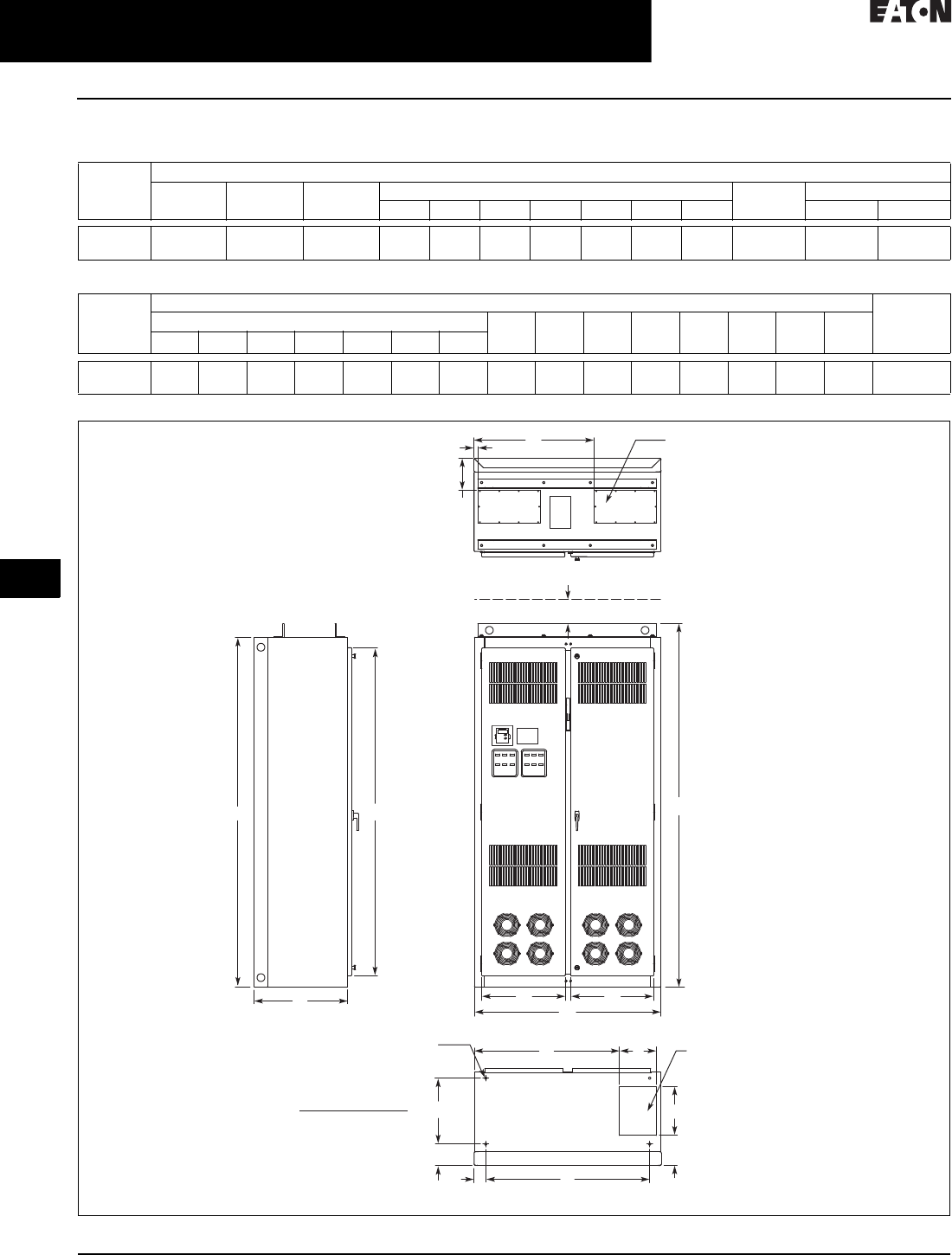
31.2-38
For more information, visit: www.eaton.com/consultants CA08104001E
February 2016
Adjustable Frequency Drives—Low Voltage
Sheet 31
22
23
24
25
26
27
28
29
30
31
32
33
34
35
36
37
38
39
40
41
42
4 3
9000X Series Drives
Enclosed SVX
098
SVX Drawing 16—Enclosure Size 8
Table 31.2-25. Approximate Dimensions and Shipping Weight—Enclosed Products
Table 31.2-25. Approximate Dimensions and Shipping Weight—Enclosed Products (Continued)
Figure 31.2-30. Approximate Dimensions
Enclosure
Size
Dimensions in Inches (mm)
Wide
A
High
B
Deep
C
Mounting H Minimum Air Space
D D1D2E F G G1 J K
848.00
(1219)
90.00
(2286)
24.00
(610)
42.20
(1072)
3.00
(77)
———5.50
(139)
— 84.40
(2143)
4.00
(102)
—
Enclosure
Size
Dimensions in Inches (mm) Max.
Approx.
Ship. Wt.
Lb (kg)
Cable Entry U V W RR SS TT UU VV
LMNPRST
89.50
(241)
37.50
(952)
12.50
(318)
7. 7 0
(196)
8.30
(210)
1.30
(32)
31.00
(787)
21.50
(545)
21.30
(541)
— 93.50
(2375)
————2000 (908)
T
S
LM
0.56 (14.2) Dia.
Mounting Hole –
(4 Places)
R
RR
H
B
UV
C
A
For Top Cable Entry –
(2 Places)
Bottom View
Top View
Front View
Side View
For Bottom
Cable Entry
N
P
F
G
J
D
D1
IL hp
300
350
400
500
550
600
IH hp
250
300
350
400
500
550
480V
Note: See Page 31.2-29
notes 4 and 5 for enclosure
and option selection.
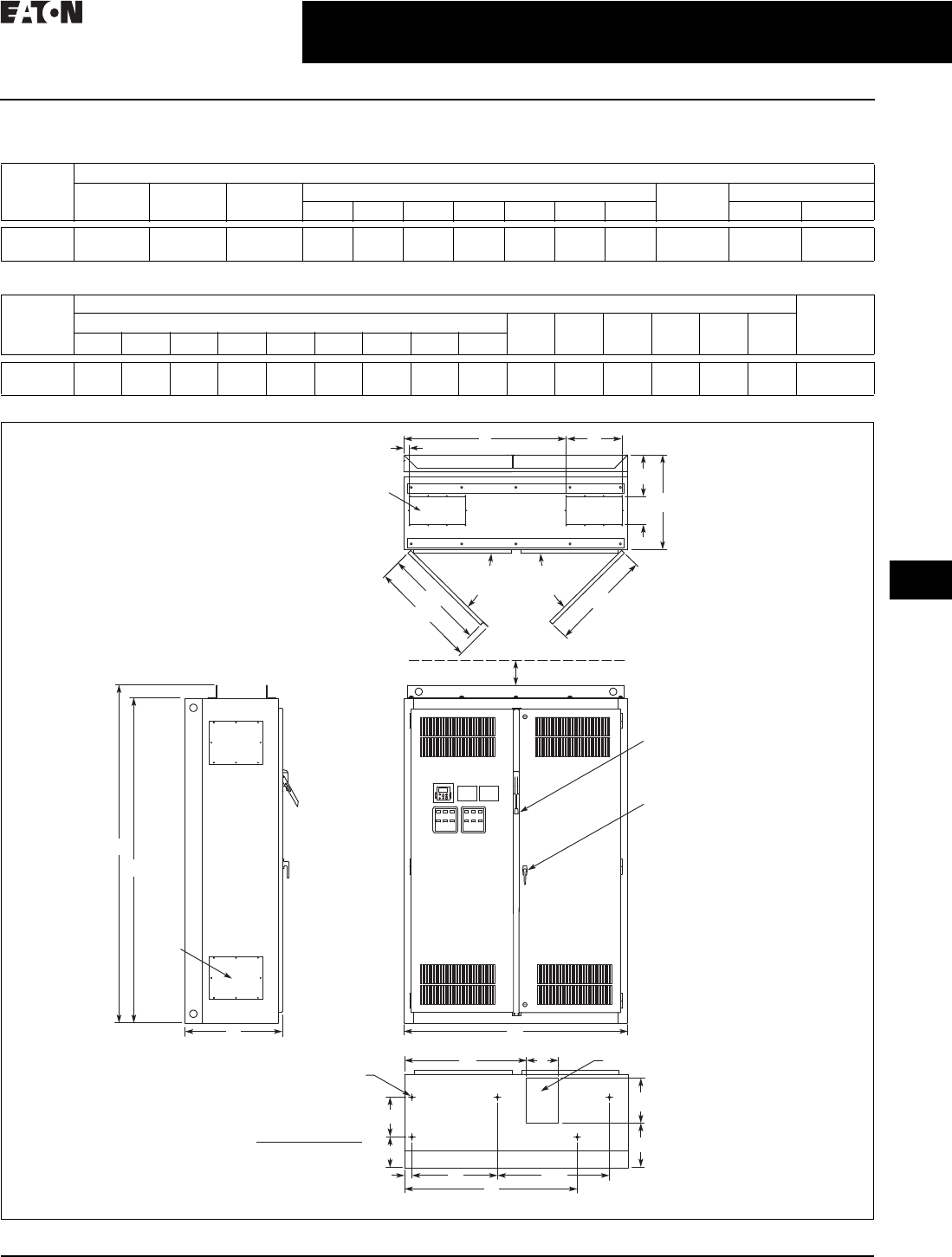
CA08104001E For more information, visit: www.eaton.com/consultants
31.2-39
February 2016
Adjustable Frequency Drives—Low Voltage
Sheet 31
22
23
24
25
26
27
28
29
30
31
32
33
34
35
36
37
38
39
40
41
42
4 3
9000X Series Drives
Enclosed SVX
100
SVX Drawing 17—Enclosure Size 9
Table 31.2-26. Approximate Dimensions and Shipping Weight—Enclosed Products
Table 31.2-26. Approximate Dimensions and Shipping Weight—Enclosed Products (Continued)
Figure 31.2-31. Approximate Dimensions
Enclosure
Size
Dimensions in Inches (mm)
Wide
A
High
B
Deep
C
Mounting H Minimum Air Space
D D1D2E F G G1 J K
960.00
(1524)
90.00
(2286)
26.10
(664)
22.90
(582)
2.00
(51)
30.00
(762)
44.30
(1125)
10.60
(270)
10.60
(270)
8.20
(208)
—4.00
(102)
—
Enclosure
Size
Dimensions in Inches (mm) Max.
Approx.
Ship. Wt.
Lb (kg)
Cable Entry W RR SS TT UU VV
LMNPRSTUV
98.50
(216)
32.70
(831)
12.00
(305)
11. 9 0
(303)
9.80
(249)
1.50
(38)
43.50
(1105)
15.00
(381)
7. 5 0
(191)
25.00
(635)
93.50
(2375)
27.40
(696)
29.10
(738)
27.10
(687)
— 2500 (1135)
R
W
V
UU
J
SS
TT
Top View
STU
B
RR
AC Front View
Bottom View
Side View
Access in Top –
(2 Places)
Bottom Access
0.56 (14.2) Dia.
Mounting Hole –
(5 Places)
90º Max.
Door
Opening
P
N
D1 D
G1
G
D2
ML
E
Key-Locking Handle
Access
Plate –
4 Places
90º Max.
Door
Opening
Drive Circuit Breaker
IL hp
500
550
600
IH hp
400
500
550
480V
Note: See Page 31.2-29
notes 4 and 5 for enclosure
and option selection.

31.2-40
For more information, visit: www.eaton.com/consultants CA08104001E
February 2016
Adjustable Frequency Drives—Low Voltage
Sheet 31
22
23
24
25
26
27
28
29
30
31
32
33
34
35
36
37
38
39
40
41
42
4 3
9000X Series Drives
Enclosed SVX
100
CFX9000—Drawing 6
Figure 31.2-32. Enclosure Size F—Approximate Dimensions in Inches (mm)
Table 31.2-27. CFX9000 Drive Dimensions
H H1 W W1 D D1 Approximate
Weight Lb (kg)
Approximate
Shipping Weight
Lb (kg)
93.58 (2376.9) 69.51 (1765.60) 60.00 (1524.0) 48.00 (1219.2) 37.50 (952.5) 26.00 (660.4) 1700 (771) 1850 (839)
D
D1
HH1
W
W1
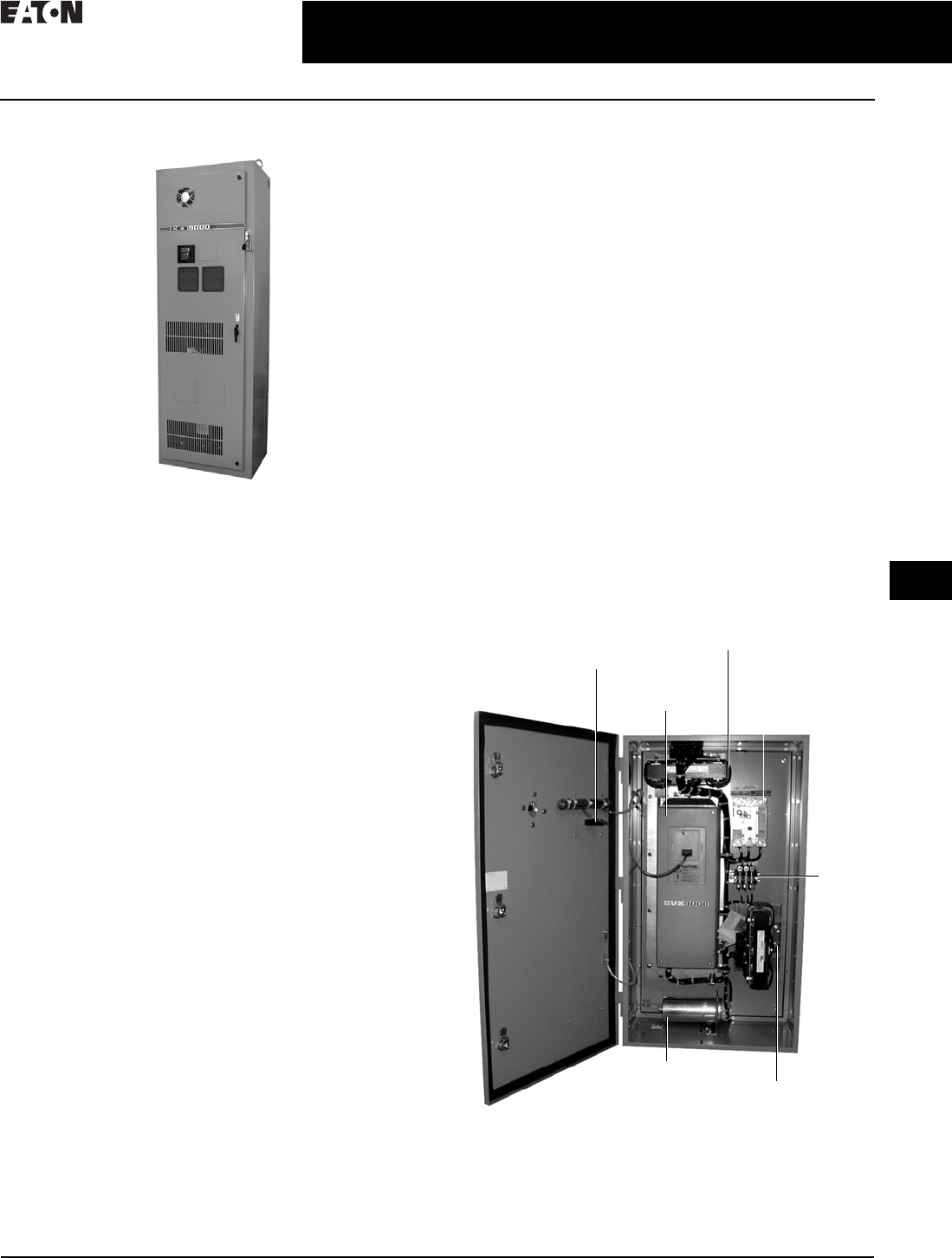
CA08104001E For more information, visit: www.eaton.com/consultants
31.2-41
February 2016
Adjustable Frequency Drives—Low Voltage
Sheet 31
22
23
24
25
26
27
28
29
30
31
32
33
34
35
36
37
38
39
40
41
42
4 3
9000X Series Drives
CFX Passive Filtered SVX
101
CFX Passive Filtered SVX
CFX9000 Enclosed Drives
General Description
Eaton’s CFX9000 Clean Power Drives use tuned passive
filters to significantly reduce line harmonics at the drive
input terminals.
The CFX9000 drive also delivers true power factor—in
addition to reducing harmonic distortion, the CFX9000
drive prevents transformer overheating and overloading
of breakers and feeders, which enables the application of
adjustable frequency drives on generators and other high
impedance power systems.
CFX9000 Enclosed Products
■Standard enclosed—covers a wide range of the most
commonly ordered options. Pre-engineering eliminates
the lead time normally associated with customer
specific options. Available configurations are listed
on Pages 31.3-3–31.3-9
■Modified standard enclosed—applies to specific customer
requirements that vary from the Standard Enclosed offer-
ing, such as the need for an additional indicating light or
minor modifications to drawings. Contact your local sales
office for assistance in pricing and lead time
■Custom engineered—for those applications with more
unique or complex requirements, these are individually
engineered to the customer’s needs. Contact your local
sales office for assistance in pricing and lead time
Application Description
Terms
■PCC (point of common coupling) is defined as the
electrical connecting point between the utility and
multiple customers per the specifications in IEEE 519
■POA (point of analysis) is defined as where the harmonic
calculations are taken
An oscilloscope can make all measurements at the PCC or
POA to do an on-site harmonic evaluation.
Features and Benefits
CFX9000 Integrated Filter Clean Power Drive features include
(at 480 V):
■UL Type 1, UL Type 12, UL Type 3R
and NEMA 12 with
gaskets and filters
■Input voltage: 480 V, 230 V, 575 V
■Complete range of control, network and power options
■Horsepower range:
❑480 V, 7-1/2–400 hp IL
❑230 V, 7-1/2–100 hp IL; consult factory for details
❑575 V, 15–400 hp IL; consult factory for details
■Single enclosure for both drive and filter reduces field
wiring and enables convenient bypass installation
■Packaged solution ensures optimal coordination of drive
and filter
Standards and Certifications
■UL
■cUL
■508C
Product Identification
CFX9000 Drive—UL Type 12, 40 hp
Input
Reactor
Optional
Breaker
Disconnect
(P1)
Shunt
Fusing
Tuned
Shunt
Reactor
SVX9000
Drive
Tuned
Harmonic
Capacitor
Door-Mounted
Keypad
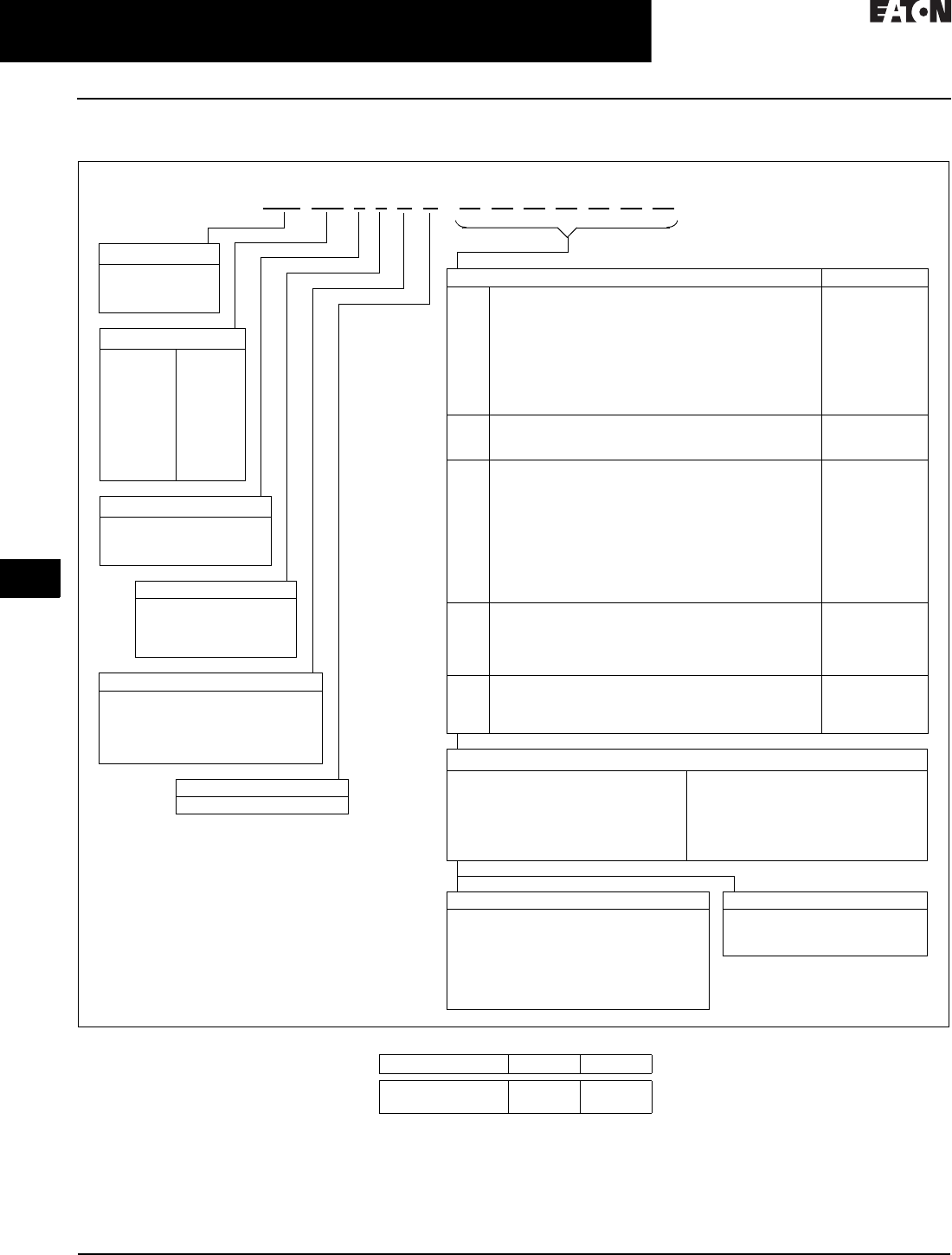
31.2-42
For more information, visit: www.eaton.com/consultants CA08104001E
February 2016
Adjustable Frequency Drives—Low Voltage
Sheet 31
22
23
24
25
26
27
28
29
30
31
32
33
34
35
36
37
38
39
40
41
42
4 3
9000X Series Drives
CFX Passive Filtered SVX
102
Catalog Number Selection
Table 31.2-28. CFX9000 Enclosed Drives Catalog Numbering System
1Brake chopper is standard in 208 V, 230 V
and 480 V drives up to FR6; optional in all
other drives.
2Local/remote keypad is included as the
standard control panel.
3Some options are voltage and/or
horsepower specific. Consult your
Eaton representative for details.
4See Pages 31.2-30 and 31.2-31 for complete
descriptions.
5Includes local/remote speed reference switch.
6See Page 31.2-6 for complete descriptions.
7Consult Eaton for availability.
Table 31.2-29. Ambient Temperature Ratings
1For high temperature rating, select HT
option code and contact factory.
■If dynamic brake chopper or control/
communication option is desired,
change the appropriate code in the
base catalog number
■All of the programming is
exactly the same as the standard
SVX9000 drive
■Select enclosed options. Add
the codes as suffixes to the base
catalog number in alphabetical and
numeric order
Enclosed Options 234 Type
K1
K2
K3
K4
K5
K6
KF
KO
Door-mounted speed potentiometer 5
Door-mounted speed potentiometer with
HOA selector switch 5
3–15 psig follower
HAND/OFF/AUTO switch (22 mm)
MANUAL/AUTO reference switch (22 mm)
START/STOP pushbuttons (22 mm)
Bypass test switch for RA and RB
Standard elapsed time meter
Control
Control
Control
Control
Control
Control
Addl. bypass
Control
L1
L2
LE
Power, RUN and fault pilot lights
Bypass pilot lights for RA, RB, bypass options
Red RUN light
Light
Addl. bypass
Light
P1
P3
P7
P8
PE
PF
PG
PH
PI
PN
Input circuit breaker
Input line fuses (200 kAIC)
Input power surge protection
SPD surge protective device
Output contactor
Output filter
MotoRx (up to 600 ft) 1000 V/µS DV/DT filter
Single overload relay
Dual overload relays
Dual overloads for bypass
Input
Input
Input
Input
Output
Output
Output
Output
Output
Addl. bypass
RA
RB
RC
RD
RG
Manual HOA bypass controller
Manual IOB bypass controller
Auto transfer HOA bypass controller
Auto transfer IOB bypass controller
Reduced voltage starter for bypass
Bypass
Bypass
Bypass
Bypass
Bypass
S4
S5
S6
S9
Floor stand 6.00 inches
Floor stand 22.00 inches
Floor stand 12.00 inches
Space heater
Enclosure
Enclosure
Enclosure
Enclosure
Enclosure Rating
1 = UL Type 1
2 = UL Type 12
3 = UL Type 3R
CFX 050 1 4 A A
Product Family
CFX =Integrated
filter clean
power drive
Horsepower Rating
007 = 7-1/2
010 = 10
015 = 15
020 = 20
025 = 25
030 = 30
040 = 40
050 = 50
060 = 60
075 = 75
100 = 100
125 = 125
150 = 150
200 = 200
250 = 250
300 = 300
350 = 350
400 = 400
Build Alphabetically and Numerically
Voltage Rating
1= 208 V
2= 230 V
4= 480 V
5= 575 V (575–600 V)
Application—Torque/Braking 1
A = IL/no brake chopper
B = IL/internal brake chopper
D = IH/no brake chopper
E = IH/internal brake chopper
Enclosed Style
A = Enclosed drive
Communication Options 6
C2 = Modbus
C3 = PROFIBUS DP
C4 = LonWorks
C5 = PROFIBUS DP (D9 connector)
C6 = CANopen (slave)
C7 = DeviceNet
C8 = Modbus (D9 type connector)
CA = Johnson Controls N2
CI = Modbus TCP/EtherNet/IP
CJ =BACnet
D3 = RS-232 with D9 connection
Control Options
B1 = 6 DI, 1 ext +24 Vdc/EXT +24 Vdc
B = 1 RO (NC-NO), 1 RO (NO), 1 therm
B4 = 1 AI (mA isolated), 2 AO (mA isolated),
1 ext +24 Vdc/EXT +24 Vdc
B5 = 3 RO (NO)
B8 = 1 ext +24 Vdc/EXT +24 Vdc, 3 Pt100
B9 = 1 RO (NO), 5 DI 42–240 Vac input
Engineered Options
HT = High temperature rating
for 50°C 7
VB = Varnished boards
Enclosure Size IHIL
B, C, 9 1
7, 8
40 °C
50 °C
40 °C
50 °C

CA08104001E For more information, visit: www.eaton.com/consultants
31.2-43
February 2016
Adjustable Frequency Drives—Low Voltage
Sheet 31
22
23
24
25
26
27
28
29
30
31
32
33
34
35
36
37
38
39
40
41
42
4 3
9000X Series Drives
CFX Passive Filtered SVX
103
Technical Data and Specifications
Table 31.2-30. 208 Vac
Table 31.2-31. 230 Vac
hp NEC
Current
Chassis
Frame
NEMA 1 NEMA 12 NEMA 3R
Disconnect
Only
Power
Options
Disconnect
Only
Power
Options
Disconnect
Only
Power
Options
Low Overload Drive (Variable Torque)
7-1/2
10
15
24.2
30.8
46.2
FR5
FR5
FR6
DWG-1
DRW-1
DRW-1
DRW-3
DRW-3
DRW-3
DWG-1
DRW-1
DRW-1
DRW-3
DRW-3
DRW-3
DRW-2
DRW-2
DRW-2
DRW-4
DRW-4
DRW-4
20
25
30
59.4
74.8
88.0
FR6
FR7
FR7
DRW-1
DRW-3
DRW-3
DRW-3
DRW-7
DRW-7
DRW-1
DRW-3
DRW-3
DRW-3
DRW-7
DRW-7
DRW-2
DRW-4
DRW-4
DRW-4
DRW-5
DRW-5
40
50
60
11 4 . 0
143.0
169.0
FR7
FR8
FR8
DRW-3
DRW-7
DRW-7
DRW-7
DRW-7
DRW-7
DRW-3
DRW-7
DRW-7
DRW-7
DRW-7
DRW-7
DRW-4
DRW-6
DRW-6
DRW-5
DRW-6
DRW-6
75
100
211.0
273.0
FR8
FR9
DRW-7
DRW-8
DRW-7
DRW-8
DRW-7
DRW-8
DRW-7
DRW-8
DRW-6
DRW-6
DRW-6
DRW-6
High Overload Drive (Constant Torque)
7-1/2
10
15
24.2
30.8
46.2
FR5
FR6
FR6
DWG-1
DRW-1
DRW-1
DRW-3
DRW-3
DRW-3
DWG-1
DRW-1
DRW-1
DRW-3
DRW-3
DRW-3
DRW-2
DRW-2
DRW-2
DRW-4
DRW-4
DRW-4
20
25
30
59.4
74.8
88.0
FR7
FR7
FR7
DRW-3
DRW-3
DRW-3
DRW-7
DRW-7
DRW-7
DRW-3
DRW-3
DRW-3
DRW-7
DRW-7
DRW-7
DRW-4
DRW-4
DRW-4
DRW-5
DRW-5
DRW-5
40
50
60
11 4 . 0
143.0
169.0
FR8
FR8
FR8
DRW-7
DRW-7
DRW-7
DRW-7
DRW-7
DRW-7
DRW-7
DRW-7
DRW-7
DRW-7
DRW-7
DRW-7
DRW-6
DRW-6
DRW-6
DRW-6
DRW-6
DRW-6
75
100
211.0
273.0
FR9
FR9
DRW-8
DRW-8
DRW-8
DRW-8
DRW-8
DRW-8
DRW-8
DRW-8
DRW-6
DRW-6
DRW-6
DRW-6
hp NEC
Current
Chassis
Frame
NEMA 1 NEMA 12 NEMA 3R
Disconnect
Only
Power
Options
Disconnect
Only
Power
Options
Disconnect
Only
Power
Options
Low Overload Drive (Variable Torque)
7-1/2
10
15
22.0
28.0
42.0
FR5
FR5
FR6
DWG-1
DRW-1
DRW-1
DRW-3
DRW-3
DRW-3
DWG-1
DRW-1
DRW-1
DRW-3
DRW-3
DRW-3
DRW-2
DRW-2
DRW-2
DRW-4
DRW-4
DRW-4
20
25
30
54.0
68.0
80.0
FR6
FR7
FR7
DRW-1
DRW-3
DRW-3
DRW-3
DRW-7
DRW-7
DRW-1
DRW-3
DRW-3
DRW-3
DRW-7
DRW-7
DRW-2
DRW-4
DRW-4
DRW-4
DRW-5
DRW-5
40
50
60
104.0
130.0
154.0
FR7
FR8
FR8
DRW-3
DRW-7
DRW-7
DRW-7
DRW-7
DRW-7
DRW-3
DRW-7
DRW-7
DRW-7
DRW-7
DRW-7
DRW-4
DRW-6
DRW-6
DRW-5
DRW-5
DRW-6
75
100
192.0
248.0
FR8
FR9
DRW-7
DRW-8
DRW-7
DRW-8
DRW-7
DRW-8
DRW-7
DRW-8
DRW-6
DRW-6
DRW-6
DRW-6
High Overload Drive (Constant Torque)
7-1/2
10
15
22.0
28.0
42.0
FR5
FR6
FR6
DWG-1
DRW-1
DRW-1
DRW-3
DRW-3
DRW-3
DWG-1
DRW-1
DRW-1
DRW-3
DRW-3
DRW-3
DRW-2
DRW-2
DRW-2
DRW-4
DRW-4
DRW-4
20
25
30
54.0
68.0
80.0
FR7
FR7
FR7
DRW-1
DRW-3
DRW-3
DRW-3
DRW-7
DRW-7
DRW-1
DRW-3
DRW-3
DRW-3
DRW-7
DRW-7
DRW-2
DRW-4
DRW-4
DRW-4
DRW-5
DRW-5
40
50
60
104.0
130.0
154.0
FR8
FR8
FR8
DRW-3
DRW-7
DRW-7
DRW-7
DRW-7
DRW-7
DRW-3
DRW-7
DRW-7
DRW-7
DRW-7
DRW-7
DRW-4
DRW-6
DRW-6
DRW-5
DRW-6
DRW-6
75
100
192.0
248.0
FR9
FR9
DRW-8
DRW-8
DRW-8
DRW-8
DRW-8
DRW-8
DRW-8
DRW-8
DRW-6
DRW-6
DRW-6
DRW-6

31.2-44
For more information, visit: www.eaton.com/consultants CA08104001E
February 2016
Adjustable Frequency Drives—Low Voltage
Sheet 31
22
23
24
25
26
27
28
29
30
31
32
33
34
35
36
37
38
39
40
41
42
4 3
9000X Series Drives
CFX Passive Filtered SVX
104
Table 31.2-32. 480 Vac
1Consult factory.
hp NEC
Current
Chassis
Frame
NEMA 1 NEMA 12 NEMA 3R
Disconnect
Only
Power
Options
Disconnect
Only
Power
Options
Disconnect
Only
Power
Options
Low Overload Drive (Variable Torque)
7-1/2
10
15
11. 0
14.0
21.0
FR4
FR5
FR5
DWG-1
DRW-1
DRW-1
DRW-3
DRW-3
DRW-3
DWG-1
DRW-1
DRW-1
DRW-3
DRW-3
DRW-3
DRW-2
DRW-2
DRW-2
DRW-4
DRW-4
DRW-4
20
25
30
27.0
34.0
40.0
FR5
FR6
FR6
DRW-1
DRW-1
DRW-1
DRW-3
DRW-3
DRW-3
DRW-1
DRW-1
DRW-1
DRW-3
DRW-3
DRW-3
DRW-2
DRW-2
DRW-2
DRW-4
DRW-4
DRW-4
40
50
60
52.0
65.0
77.0
FR7
FR8
FR8
DRW-1
DRW-3
DRW-3
DRW-3
DRW-7
DRW-7
DRW-1
DRW-3
DRW-3
DRW-3
DRW-7
DRW-7
DRW-2
DRW-4
DRW-4
DRW-4
DRW-5
DRW-5
75
100
125
96.0
124.0
156.0
FR8
FR9
FR8
DRW-3
DRW-3
DRW-3
DRW-7
DRW-7
DRW-7
DRW-3
DRW-3
DRW-3
DRW-7
DRW-7
DRW-7
DRW-4
DRW-4
DRW-4
DRW-5
DRW-5
DRW-5
150
200
250
180.0
240.0
302.0
FR8
FR9
FR9
DRW-3
DRW-8
DRW-8
DRW-7
DRW-8
DRW-8
DRW-3
DRW-8
DRW-8
DRW-7
DRW-8
DRW-8
DRW-4
DRW-6
DRW-6
DRW-5
DRW-6
DRW-6
300
350
400
361.0
414.0
477.0
FR10
FR10
FR10
DRW-9
DRW-9
DRW-9
DRW-9
DRW-9
DRW-9
DRW-9
DRW-9
DRW-9
DRW-9
DRW-9
DRW-9
1
1
1
1
1
1
High Overload Drive (Constant Torque)
7-1/2
10
15
11. 0
14.0
21.0
FR4
FR5
FR5
DRW-1
DRW-1
DRW-1
DRW-3
DRW-3
DRW-3
DRW-1
DRW-1
DRW-1
DRW-3
DRW-3
DRW-3
DRW-2
DRW-2
DRW-2
DRW-4
DRW-4
DRW-4
20
25
30
27.0
34.0
40.0
FR5
FR6
FR6
DRW-1
DRW-1
DRW-1
DRW-3
DRW-3
DRW-3
DRW-1
DRW-1
DRW-1
DRW-3
DRW-3
DRW-3
DRW-2
DRW-2
DRW-2
DRW-4
DRW-4
DRW-4
40
50
60
52.0
65.0
77.0
FR6
FR7
FR7
DRW-1
DRW-3
DRW-3
DRW-3
DRW-7
DRW-7
DRW-1
DRW-3
DRW-3
DRW-3
DRW-7
DRW-7
DRW-2
DRW-4
DRW-4
DRW-4
DRW-5
DRW-5
75
100
125
96.0
124.0
156.0
FR7
FR8
FR8
DRW-3
DRW-7
DRW-7
DRW-7
DRW-7
DRW-7
DRW-3
DRW-7
DRW-7
DRW-7
DRW-7
DRW-7
DRW-4
DRW-6
DRW-6
DRW-5
DRW-6
DRW-6
150
200
250
180.0
240.0
302.0
FR8
FR9
FR9
DRW-7
DRW-8
DRW-8
DRW-7
DRW-8
DRW-8
DRW-7
DRW-8
DRW-8
DRW-7
DRW-8
DRW-8
DRW-6
DRW-6
DRW-6
DRW-6
DRW-6
DRW-6
300
350
361.0
414.0
FR10
FR10
DRW-9
DRW-9
DRW-9
DRW-9
DRW-9
DRW-9
DRW-9
DRW-9
1
1
1
1

CA08104001E For more information, visit: www.eaton.com/consultants
31.2-45
February 2016
Adjustable Frequency Drives—Low Voltage
Sheet 31
22
23
24
25
26
27
28
29
30
31
32
33
34
35
36
37
38
39
40
41
42
4 3
9000X Series Drives
CFX Passive Filtered SVX
105
Table 31.2-33. 575 Vac
1Consult factory.
hp NEC
Current
Chassis
Frame
NEMA 1 NEMA 12 NEMA 3R
Disconnect
Only
Power
Options
Disconnect
Only
Power
Options
Disconnect
Only
Power
Options
Low Overload Drive (Variable Torque)
15
20
25
17.0
22.0
27.0
FR6
FR6
FR6
DWG-1
DRW-1
DRW-1
DRW-3
DRW-3
DRW-3
DWG-1
DRW-1
DRW-1
DRW-3
DRW-3
DRW-3
DRW-2
DRW-2
DRW-2
DRW-4
DRW-4
DRW-4
30
40
50
32.0
41.0
52.0
FR6
FR7
FR7
DRW-1
DRW-3
DRW-3
DRW-3
DRW-7
DRW-7
DRW-1
DRW-3
DRW-3
DRW-3
DRW-7
DRW-7
DRW-2
DRW-4
DRW-4
DRW-4
DRW-5
DRW-5
60
75
100
62.0
77.0
99.0
FR8
FR8
FR8
DRW-7
DRW-7
DRW-7
DRW-7
DRW-7
DRW-7
DRW-7
DRW-7
DRW-7
DRW-7
DRW-7
DRW-7
DRW-6
DRW-6
DRW-6
DRW-6
DRW-6
DRW-6
125
150
200
125.0
144.0
192.0
FR9
FR9
FR9
DRW-8
DRW-8
DRW-8
DRW-8
DRW-8
DRW-8
DRW-8
DRW-8
DRW-8
DRW-8
DRW-8
DRW-8
DRW-6
DRW-6
DRW-6
DRW-6
DRW-6
DRW-6
250
300
400
242.0
289.0
382.0
FR10
FR10
FR10
DRW-9
DRW-9
DRW-9
DRW-9
DRW-9
DRW-9
DRW-9
DRW-9
DRW-9
DRW-9
DRW-9
DRW-9
1
1
1
1
1
1
High Overload Drive (Constant Torque)
10
15
20
14.0
17.0
22.0
FR6
FR6
FR6
DWG-1
DWG-1
DWG-1
DRW-3
DRW-3
DRW-3
DWG-1
DWG-1
DWG-1
DRW-3
DRW-3
DRW-3
DRW-2
DRW-2
DRW-2
DRW-4
DRW-4
DRW-4
25
30
40
27.0
32.0
41.0
FR6
FR7
FR7
DWG-1
DRW-3
DRW-3
DRW-3
DRW-7
DRW-7
DWG-1
DRW-3
DRW-3
DRW-3
DRW-7
DRW-7
DRW-2
DRW-4
DRW-4
DRW-4
DRW-5
DRW-5
50
60
75
52.0
62.0
77.0
FR8
FR8
FR8
DRW-7
DRW-7
DRW-7
DRW-7
DRW-7
DRW-7
DRW-7
DRW-7
DRW-7
DRW-7
DRW-7
DRW-7
DRW-6
DRW-6
DRW-6
DRW-6
DRW-6
DRW-6
100
125
150
99.0
125.0
144.0
FR9
FR9
FR9
DRW-8
DRW-8
DRW-8
DRW-8
DRW-8
DRW-8
DRW-8
DRW-8
DRW-8
DRW-8
DRW-8
DRW-8
DRW-6
DRW-6
DRW-6
DRW-6
DRW-6
DRW-6
200
250
300
192.0
242.0
289.0
FR10
FR10
FR10
DRW-9
DRW-9
DRW-9
DRW-9
DRW-9
DRW-9
DRW-9
DRW-9
DRW-9
DRW-9
DRW-9
DRW-9
1
1
1
1
1
1

31.2-46
For more information, visit: www.eaton.com/consultants CA08104001E
February 2016
Adjustable Frequency Drives—Low Voltage
Sheet 31
22
23
24
25
26
27
28
29
30
31
32
33
34
35
36
37
38
39
40
41
42
4 3
9000X Series Drives
CFX Passive Filtered SVX
106
Figure 31.2-33. BX Box, NEMA 1/12
Figure 31.2-34. BX Box, NEMA 3R
4.00 (101.6)
Minimum
Free Air Space
Required
28.55
(725.1)
36.80
(934.7)
36.35
(923.3)
19.30 (490.2)
20.92 (531.4)
17.01 (432.2)
1.76
(44.8)
37.74
(958.6)
3.00 (76.2)
Minimum
Air Space
Required
Both Sides
Ø 0.44 (11.2)
Mounting
Holes
(4 Places)
28.56
(725.3)
44.09
(1119.8)
36.35
(923.3)
42.69
(1084.3)
19.30 (490.2)
20.92 (531.4)
37.74
(958.6)
3.00 (76.2)
Minimum
Air Space
Required
Both Sides
Ø 0.44 (11.2)
Mounting
Holes
(4 Places)
17.01 (432.2)
3.51
(89.1)
20.18 (512.5)
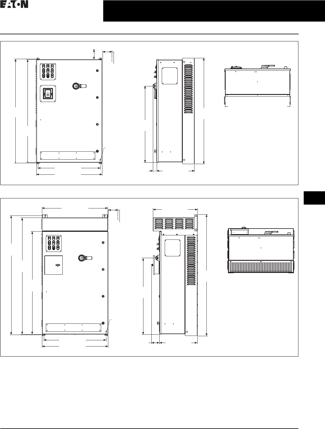
CA08104001E For more information, visit: www.eaton.com/consultants
31.2-47
February 2016
Adjustable Frequency Drives—Low Voltage
Sheet 31
22
23
24
25
26
27
28
29
30
31
32
33
34
35
36
37
38
39
40
41
42
4 3
9000X Series Drives
CFX Passive Filtered SVX
107
Figure 31.2-35. CX Box, NEMA 1/12
Figure 31.2-36. CX Box, NEMA 3R
49.74
(1263.4)
48.80
(1239.5)
48.35
(1228.1)
29.30 (744.2)
30.92 (785.4)
1.74
(44.2) 17.76 (451.2)
35.85
(910.6)
3.00 (76.2)
Minimum
Air Space
Required
Both Sides
4.00 (101.6) Minimum
Free Air Space Required
Ø 0.44 (11.2)
Mounting
Holes
(4 Places)
30.88 (784.4)
56.08
(1424.5)
54.77
(1391.2)
48.35
(1228.1)
29.30 (744.2)
30.92 (785.4) 17.76 (451.2)
3.72
(94.4)
56.96
(1446.9)
35.85
(910.6)
21.00 (533.3)
3.00 (76.2)
Minimum
Air Space
Required
Both Sides
Ø 0.44 (11.2)
Mounting
Holes
(4 Places)

31.2-48
For more information, visit: www.eaton.com/consultants CA08104001E
February 2016
Adjustable Frequency Drives—Low Voltage
Sheet 31
22
23
24
25
26
27
28
29
30
31
32
33
34
35
36
37
38
39
40
41
42
4 3
9000X Series Drives
CFX Passive Filtered SVX
108
Figure 31.2-37. DX Box, NEMA 1/12
Figure 31.2-38. DX Box, NEMA 3R
82.35
(2091.7)
76.35
(1939.3)
30.92
(785.4)
22.48
(571.1)
1.55
(39.4)
82.85
(2104.4)
67.89
(1724.4)
28.88 (733.6)
22.56
(573.0) 6.13
(155.6)
8.38 (212.9)
1.62 (41.1)
22.12
(561.8)
29.30 (744.2)
Ø 0.44 (11.2)
Mounting
Holes
(2 Places)
3.00 (76.2)
Minimum
Air Space
Required
Both Sides
4.00 (101.6)
Minimum
Free Air Space
Required
22.81
(579.2)
29.06 (738.1)
30.88 (784.4)
27.88 (708.2)
89.70
(2278.3)
82.84
(2104.1)
76.35
(1939.3)
30.92 (785.4) 3.64
(92.5)
22.48
(571.1)
67.89
(1724.4)
90.14
(2289.5)
25.51 (647.8)
1.80 (45.7)
8.56 (217.4)
22.30
(566.4)
Ø 0.44 (11.2)
Mounting
Holes
(2 Places)
3.00 (76.2)
Minimum
Air Space
Required
Both Sides
6.31
(160.3)

CA08104001E For more information, visit: www.eaton.com/consultants
31.2-49
February 2016
Adjustable Frequency Drives—Low Voltage
Sheet 31
22
23
24
25
26
27
28
29
30
31
32
33
34
35
36
37
38
39
40
41
42
4 3
9000X Series Drives
CFX Passive Filtered SVX
109
CFX9000—Drawing 6
Figure 31.2-39. Enclosure Size F—Approximate Dimensions in Inches (mm)
Table 31.2-34. CFX9000 Drive Dimensions
H H1 W W1 D D1 Approximate
Weight Lb (kg)
Approximate
Shipping Weight
Lb (kg)
93.58 (2376.9) 69.51 (1765.60) 60.00 (1524.0) 48.00 (1219.2) 37.50 (952.5) 26.00 (660.4) 1700 (771) 1850 (839)
D
D1
HH1
W
W1

31.2-50
For more information, visit: www.eaton.com/consultants CA08104001E
February 2016
Adjustable Frequency Drives—Low Voltage
Sheet 31
22
23
24
25
26
27
28
29
30
31
32
33
34
35
36
37
38
39
40
41
42
4 3
9000X Series Drives
CFX Passive Filtered SVX
110
CFX9000—Drawing 7
Figure 31.2-40. Enclosure Size 7—Approximate Dimensions in Inches (mm)
Construction: NEMA Type 1 Oversize
Finish: Enclosure–ANSI 61 Gray (Light)
30.00
(762.0)
15.50
(393.7)
21.50
(546.1)
Side View
15.00
(381.0)
8.00
(203.2)
8.50
(215.9)
18.75
(476.3)
5.75
(146.1)
1.75 (44.5) Typ.
24.45 (621.0)
28.05 (712.5)
20.00
(508.0)
26.25
(666.8)
4.79
(121.7)
Top View
Bottom View
10.00
(254.0)
Hinged Side
Door Clearance
at 90∞
2.00
(50.8)
3.50
(88.9)
90.00
(2286.0)
93.92
(2385.6) 84.37
(2143.0)
4.00 (101.6) Minimum
Free Air Space Required
Keypad
Exhaust
Air
For
Cable Entry
Operator Elements When Specified,
Mounted on These Panels
Intake Ventilating Slots
(Filtered on NEMA 12)
Key-Locking Handle
Quarter Turn Latch
(2 Places)
Opening for
Bottom Cable Entry
0.56 (14.2) Dia.
Mounting Holes
(4 Places)
Flanged Disconnect Supplied
with Circuit Breaker When Specified
Front View
Approximate
Shipping Weight
Lb (kg)
1000 (454)

CA08104001E For more information, visit: www.eaton.com/consultants
31.2-51
February 2016
Adjustable Frequency Drives—Low Voltage
Sheet 31
22
23
24
25
26
27
28
29
30
31
32
33
34
35
36
37
38
39
40
41
42
4 3
9000X Series Drives
CFX Passive Filtered SVX
111
CFX9000—Drawing 8
Figure 31.2-41. Enclosure Size 8—Approximate Dimensions in Inches (mm)
Construction: NEMA Type 1 Oversize
Finish: Enclosure–ANSI 61 Gray (Light)
24.00 (609.6)
25.14 (639)
Side View 9.50
(241.3)
22.47
(570.74)
5.48
(139.19)
7.73
(196.34)
12.50
(317.5)
45.22 (1148.59)
37.47 (951.74)
3.01 (76.45)
8.25
(209.6)
1.25
(31.8)
31.00
(787.4)
21.45 (544.8) 21.31 (541.3)
48.00 (1219.2)
Front View
Top View
90.00
(2286.0)
93.50
(2374.9)84.37
(2143.0)
Opening for Top Cable Entry
(2 Places)
Keypad
Operator Elements When Specified,
Mounted on These Panels
Intake Ventilating Slots
(Filtered on NEMA 12)
Key-Locking Handle
Quarter Turn Latch
(2 Places)
Bottom View
0.56 (14.2) Dia.
Mounting Holes
(4 Places) Opening for
Bottom Cable Entry
Flanged Disconnect Supplied
with Circuit Breaker When Specified
4.00 (101.6) Minimum
Free Air Space Required
Approximate
Shipping Weight
Lb (kg)
1400 (636)
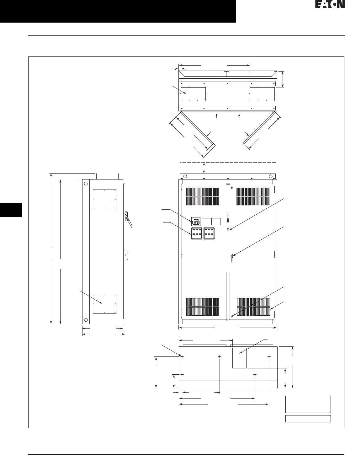
31.2-52
For more information, visit: www.eaton.com/consultants CA08104001E
February 2016
Adjustable Frequency Drives—Low Voltage
Sheet 31
22
23
24
25
26
27
28
29
30
31
32
33
34
35
36
37
38
39
40
41
42
4 3
9000X Series Drives
CFX Passive Filtered SVX
112
CFX9000—Drawing 9
Figure 31.2-42. Enclosure Size 9—Approximate Dimensions in Inches (mm)
25.00 (635.0)
26.14 (664.0)
9.75
(247.7)
Top View
1.5 (38.1) 43.5 (1104.9)
90.00
(2286.0)
93.50
(2374.9)
4.00 (101.6) Minimum
Free Air Space Required
60.00 (1524)
Front View
Bottom View
Side View
7.46 x 15.00
(189.5 x 381.0)
Access in Top –
2 Places
8.50 x 12.00 (215.9 x 304.8)
Bottom Access
0.56 (14.2) Dia.
Mounting Hole –
5 Places
27.06
(687.3)
27.36
(694.9)
90 Max.
Door
Opening
29.05
(737.9)
11. 93
(303.0)
25.00
(635.0)
18.84
(478.5)
8.20
(208.3)
2.00 (50.8) 22.90 (581.7)
32.72 (831.1)
46.30 (1176.0)
54.90 (1394.5)
Key-Locking Handle
Access
Plate –
4 Places
90 Max.
Door
Opening
Finish: Enclosure – ANSI 61 Gray (Light)
Material: Enclosure and Backplate – 12 ga.
= .1046 Cold Rolled Steel
Operator
Elements
When Specified,
Mounted on
These Panels
Keypad
Intake Ventilating Slots
(Filtered on NEMA 12)
Quarter Turn Latch
(2 Places)
Flanged Disconnect
Supplied with
Circuit Breaker
When Specified
Approximate
Shipping Weight
Lb (kg)
1800 (817)
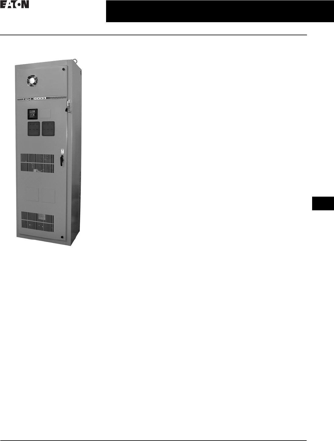
CA08104001E For more information, visit: www.eaton.com/consultants
31.2-53
February 2016
Adjustable Frequency Drives—Low Voltage
Sheet 31
22
23
24
25
26
27
28
29
30
31
32
33
34
35
36
37
38
39
40
41
42
4 3
9000X Series Drives
CPX 18-Pulse SVX
113
CPX 18-Pulse SVX
CPX9000—150 hp IL
General Description
Eaton’s CPX9000 Clean Power Drives
use advanced 18-pulse, clean power
technology that significantly reduces
line harmonics at the drive input
terminals, resulting in one of the
purest sinusoidal waveforms available.
Enhancements to the CPX9000
Clean Power Drives include smaller
enclosures and higher temperature
ratings than CP9000 for selected drives.
The CPX9000 drive also delivers true
power factor—in addition to reducing
harmonic distortion, the CPX9000 drive
prevents transformer overheating and
overloading of breakers and feeders,
which enables the application of
adjustable frequency drives on
generators and other high impedance
power systems.
CPX9000 Enclosed Products
■Standard enclosed—covers a
wide range of the most commonly
ordered options. Pre-engineering
eliminates the lead time normally
associated with customer specific
options
■Modified standard enclosed—
applies to specific customer require-
ments that vary from the Standard
Enclosed offering, such as the need
for an additional indicating light or
minor modifications to drawings.
Contact your local sales office for
assistance in pricing and lead time
■Custom engineered—for those
applications with more unique
or complex requirements, these
are individually engineered to the
customer’s needs. Contact your
local sales office for pricing and
lead time
Features and Benefits
CPX9000 Clean Power Drive
features include:
■25–150 hp IL drives available in
30-inch enclosure
■200 and 250 hp IL drives available in
48-inch enclosure
■300–400 hp IL drives available in
60-inch enclosure
■500–600 hp IL drives available in
80-inch enclosure
■NEMA Type 1, NEMA 12 with
gaskets and filters
■Input voltage: 480 V, 208/230 V
■Complete range of control, network
and power options
■Horsepower range:
❑480 V, 25–700 hp IH;
25–800 hp IL
❑208/230 V, 25–100 hp IL;
consult factory for details
■Over 10 years of 18-pulse clean
power experience
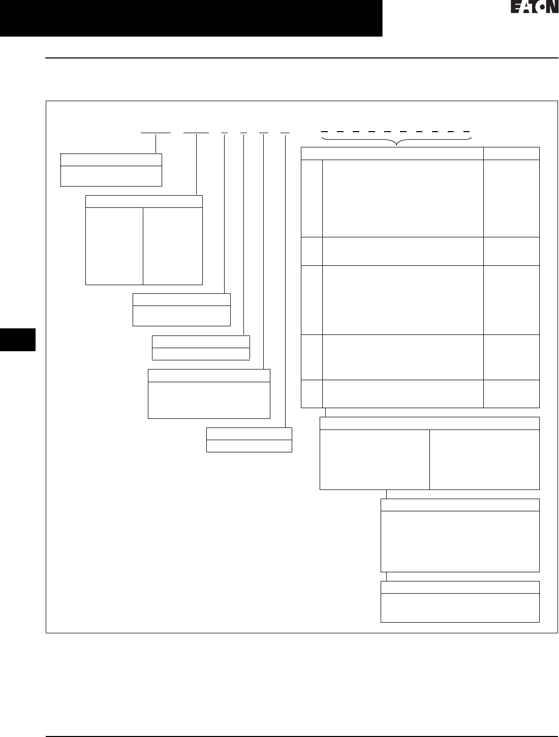
31.2-54
For more information, visit: www.eaton.com/consultants CA08104001E
February 2016
Adjustable Frequency Drives—Low Voltage
Sheet 31
22
23
24
25
26
27
28
29
30
31
32
33
34
35
36
37
38
39
40
41
42
4 3
9000X Series Drives
CPX 18-Pulse SVX
114
Catalog Number Selection
Table 31.2-35. CPX9000 Enclosed NEMA Type 1 Drive Catalog Numbering System
1Brake chopper is standard in drives up to 30 hp IH or 40 hp IL. It is optional in larger drives.
2Local/remote keypad is included as the standard control panel and as a digital HOA switch.
3Some options are voltage and/or horsepower specific. Consult your Eaton representative for details.
4See Pages 31.2-30 and 31.2-31 for descriptions.
5Includes local/remote speed reference switch.
6See Page 31.2-6 for complete descriptions.
7Consult Eaton for pricing and availability.
Communication Options 6
C2 = Modbus
C3 = PROFIBUS DP
C4 = LonWorks
C5 = PROFIBUS DP (D9
connector)
C6 = CANopen (slave)
C7 = DeviceNet
C8 = Modbus (D9 Type
connector)
CA = Johnson Controls N2
CI = Modbus TCP
CJ =BACnet
D3 = RS-232 with D9 connection
C P X 1 0 0 1 4 A A
Voltage Rating
4 = 480 V
Product Family
CPX = Clean power 18-pulse
enclosed drives
Horsepower Rating
025 = 25 hp
030 = 30 hp
040 = 40 hp
050 = 50 hp
060 = 60 hp
075 = 75 hp
100 = 100 hp
125 = 125 hp
150 = 150 hp
200 = 200 hp
250 = 250 hp
300 = 300 hp
350 = 350 hp
400 = 400 hp
500 = 500 hp
600 = 600 hp
700 = 700 hp
800 = 800 hp
Enclosure Rating
1 = NEMA Type 1
6 = NEMA 12 filtered
Application—Torque/Braking 2
A = IL/no brake chopper
B = IL/internal brake chopper
D = IH/no brake chopper
E = IH/internal brake chopper
Enclosed Style
A = Enclosed drive
Enclosed Options 135 Type
K1
K2
K3
K4
K5
K6
KF
KO
Door-mounted speed potentiometer 5
Door-mounted speed potentiometer with HOA
selector switch 5
3–15 psig follower
HAND/OFF/AUTO switch (22 mm)
MANUAL/AUTO reference switch (22 mm)
START/STOP pushbuttons (22 mm)
Bypass test switch for RA and RB
Standard elapsed time meter
Control
Control
Control
Control
Control
Control
Addl. bypass
Control
L1
L2
LE
Power on and fault pilot lights
Bypass pilot lights for RA, RB, bypass options
Red RUN light
Light
Addl. bypass
Light
P1
PE
PF
PG
PH
PI
PN
Input disconnect
Output contactor
Output filter
MotoRx (up to 600 ft) 1000 V/µS
DV/DT filter
Single overload relay
Dual overload relays
Dual overloads for bypass
Input
Output
Output
Output
Output
Output
Addl. bypass
RA
RB
RC
RD
RG
Manual HOA bypass controller
Manual IOB bypass controller
Auto transfer HOA bypass controller
Auto transfer IOB bypass controller
Reduced voltage starter for bypass
Bypass
Bypass
Bypass
Bypass
Bypass
S7
S8
S9
10-inch expansion
20-inch expansion
Space heater
Enclosure
Enclosure
Enclosure
Build options alphabetically and numerically.
Engineered Options
HT = High temperature rating for 50 °C
(FR10 and above) 7
VB = Varnished boards
Control Options
B1 = 6 DI, 1 ext +24 Vdc/EXT +24 Vdc
B2 = 1 RO (NC/NO), 1 RO (NO), 1 Therm
B4 = 1 AI (mA isolated), 2 AO (mA isolated),
1 ext +24 Vdc/EXT +24 Vdc
B5 = 3 RO (NO)
B8 = 1 ext +24 Vdc/EXT +24 Vdc, 3 Pt100
B9 = 1 RO (NO), 5 DI 42–240 Vac Input
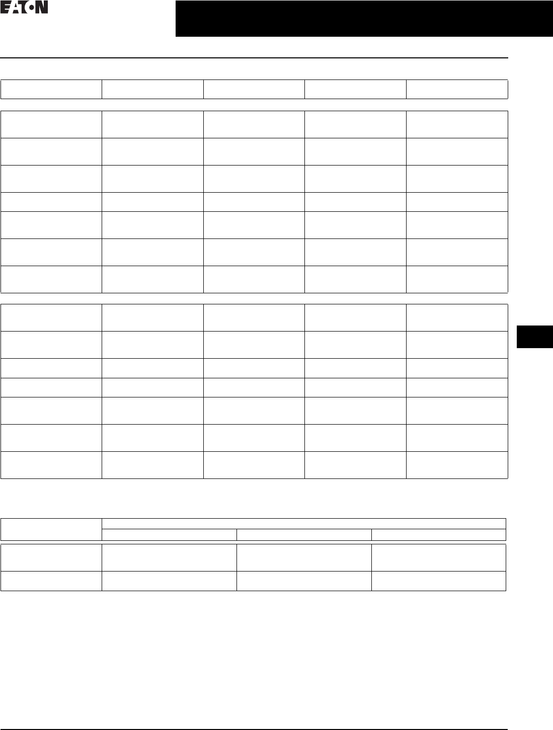
CA08104001E For more information, visit: www.eaton.com/consultants
31.2-55
February 2016
Adjustable Frequency Drives—Low Voltage
Sheet 31
22
23
24
25
26
27
28
29
30
31
32
33
34
35
36
37
38
39
40
41
42
4 3
9000X Series Drives
CPX 18-Pulse SVX
115
Table 31.2-36. 480 Vac CPX9000 Base Drive Product Selection
1See enclosure dimensions in Ta b l e 3 1. 2 -3 7 .
2Consult factory.
Table 31.2-37. CPX9000 Enclosure Dimensions
3Enclosure sizes accommodate drive and options, including bypass and disconnect.
For other power options, consult your Eaton representative.
4Consult factory.
Enclosure
Size 1
hp Current
(A)
Chassis
Frame
Drawing
Number
Low Overload Drive—IL = Variable Torque
725
30
40
38
46
61
FR6
FR6
FR6
1
1
1
750
60
75
72
87
105
FR7
FR7
FR7
1
1
1
7100
125
150
140
170
205
FR8
FR8
FR8
1
1
1
8200
250
261
300
FR9
FR9
2
2
9300
350
400
385
460
520
FR10
FR10
FR10
3
3
3
10 500
550
600
590
650
730
FR11
FR11
FR11
4
4
4
11 6 5 0
700
800
820
920
1030
FR12
FR12
FR12
2
2
2
High Overload Drive—IH = Constant Torque
725
30
40
38
46
61
FR6
FR6
FR7
1
1
1
750
60
75
72
87
105
FR7
FR7
FR8
1
1
1
7100
125
140
170
FR8
FR8
1
1
8150
200
205
245
FR9
FR9
2
2
9250
300
350
300
385
460
FR10
FR10
FR10
3
3
3
10 400
500
550
520
590
650
FR11
FR11
FR11
4
4
4
11 6 0 0
650
700
720
820
840
FR12
FR12
FR12
2
2
2
Enclosure
Size 3
Approximate Dimensions in Inches (mm)
Width Height Depth
7
8
9
30.00 (762.0)
48.00 (1219.2)
60.00 (1524.0)
90.00 (2286.0)
90.00 (2286.0)
90.00 (2286.0)
21.50 (546.1)
26.14 (664.0)
25.74 (653.8)
10
11 4
80.00 (2032.0)
—
90.00 (2286.0)
—
31.75 (806.5)
—
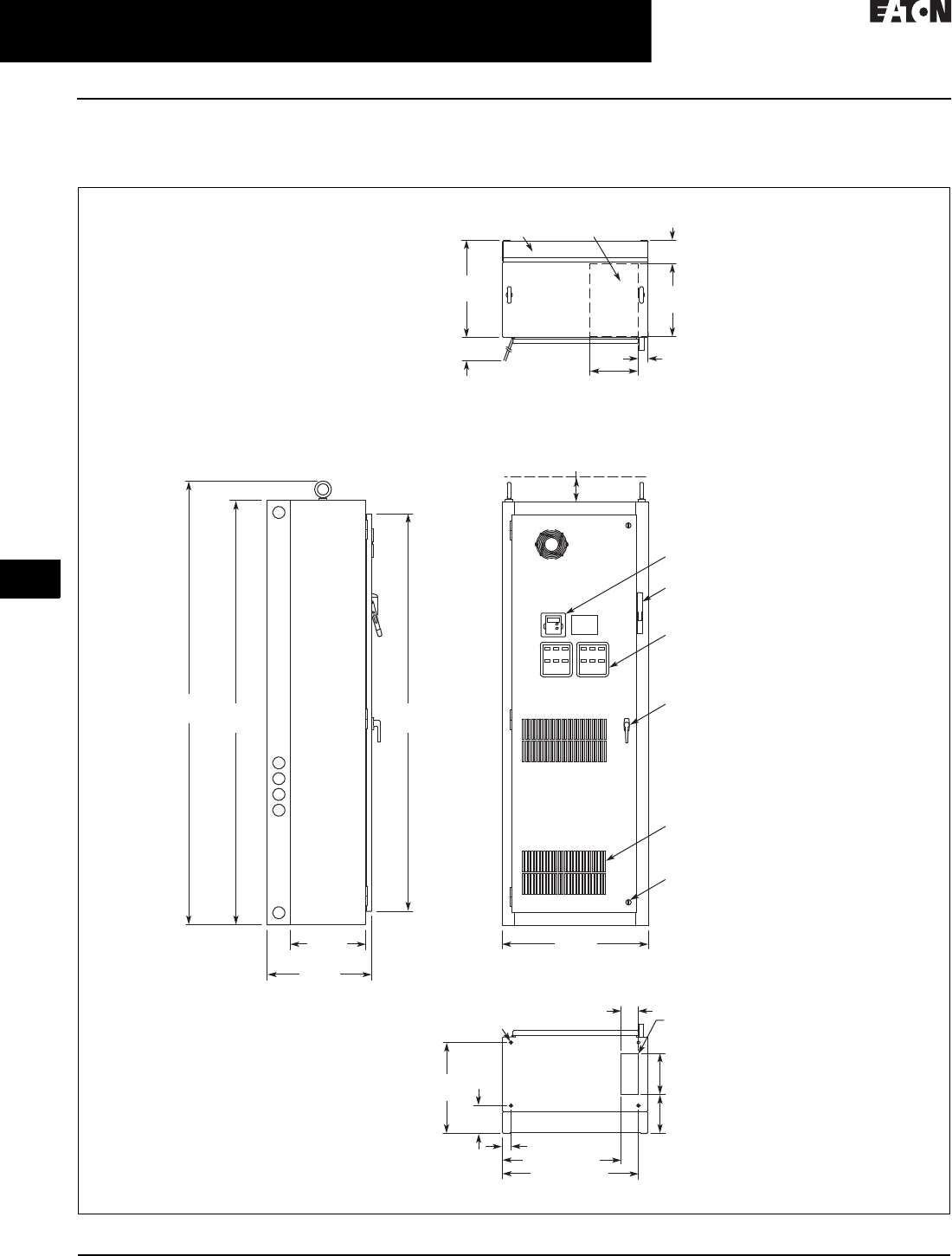
31.2-56
For more information, visit: www.eaton.com/consultants CA08104001E
February 2016
Adjustable Frequency Drives—Low Voltage
Sheet 31
22
23
24
25
26
27
28
29
30
31
32
33
34
35
36
37
38
39
40
41
42
4 3
9000X Series Drives
CPX 18-Pulse SVX
116
Dimensions
CPX Drawing 1—Enclosure Size 7
Figure 31.2-43. 25–150 hp IL and 25–125 hp IH—Approximate Dimensions in Inches (mm)
Construction: NEMA Type 1 Oversize
Finish: Enclosure–ANSI 61 Gray (Light)
30.00
(762.0)
15.50
(393.7)
21.50
(546.1)
Side View
15.00
(381.0)
8.00
(203.2)
8.50
(215.9)
18.75
(476.3)
5.75
(146.1)
1.75 (44.5) Typ.
24.45 (621.0)
28.05 (712.5)
20.00
(508.0)
26.25
(666.8)
4.79
(121.7)
Top View
Bottom View
10.00
(254.0)
Hinged Side
Door Clearance
at 90∞
2.00
(50.8)
3.50
(88.9)
90.00
(2286.0)
93.92
(2385.6) 84.37
(2143.0)
4.00 (101.6) Minimum
Free Air Space Required
Keypad
Exhaust
Air
For
Cable Entry
Operator Elements When Specified,
Mounted on These Panels
Intake Ventilating Slots
(Filtered on NEMA 12)
Key-Locking Handle
Quarter Turn Latch
(2 Places)
Opening for
Bottom Cable Entry
0.56 (14.2) Dia.
Mounting Holes
(4 Places)
Flanged Disconnect Supplied
with Circuit Breaker When Specified
Front View
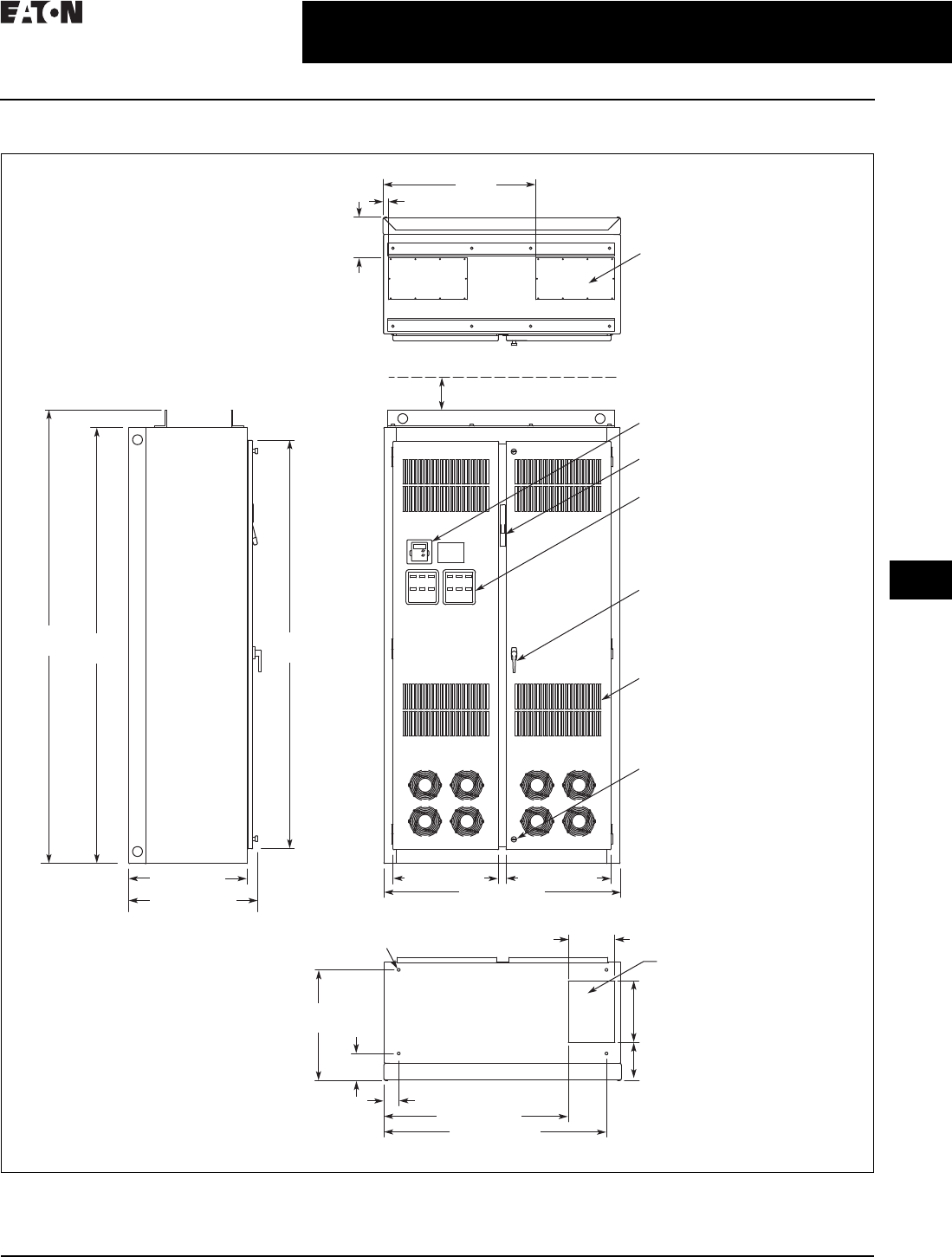
CA08104001E For more information, visit: www.eaton.com/consultants
31.2-57
February 2016
Adjustable Frequency Drives—Low Voltage
Sheet 31
22
23
24
25
26
27
28
29
30
31
32
33
34
35
36
37
38
39
40
41
42
4 3
9000X Series Drives
CPX 18-Pulse SVX
117
CPX Drawing 2—Enclosure Size 8
Figure 31.2-44. 200–250 hp IL and 150–200 hp IH—Approximate Dimensions in Inches (mm)
Construction: NEMA Type 1 Oversize
Finish: Enclosure–ANSI 61 Gray (Light)
24.00 (609.6)
25.14 (639)
Side View 9.50
(241.3)
22.47
(570.74)
5.48
(139.19)
7.73
(196.34)
12.50
(317.5)
45.22 (1148.59)
37.47 (951.74)
3.01 (76.45)
8.25
(209.6)
1.25
(31.8)
31.00
(787.4)
21.45 (544.8) 21.31 (541.3)
48.00 (1219.2)
Front View
Top View
90.00
(2286.0)
93.50
(2374.9)84.37
(2143.0)
Opening for Top Cable Entry
(2 Places)
Keypad
Operator Elements When Specified,
Mounted on These Panels
Intake Ventilating Slots
(Filtered on NEMA 12)
Key-Locking Handle
Quarter Turn Latch
(2 Places)
Bottom View
0.56 (14.2) Dia.
Mounting Holes
(4 Places) Opening for
Bottom Cable Entry
Flanged Disconnect Supplied
with Circuit Breaker When Specified
4.00 (101.6) Minimum
Free Air Space Required
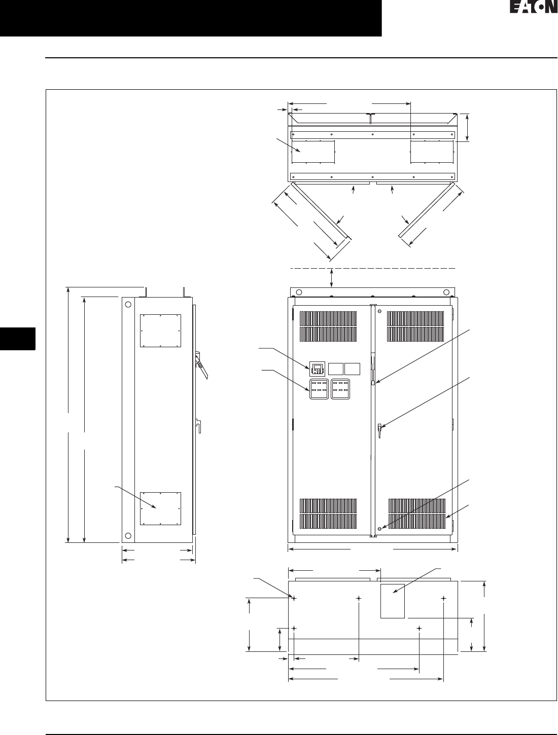
31.2-58
For more information, visit: www.eaton.com/consultants CA08104001E
February 2016
Adjustable Frequency Drives—Low Voltage
Sheet 31
22
23
24
25
26
27
28
29
30
31
32
33
34
35
36
37
38
39
40
41
42
4 3
9000X Series Drives
CPX 18-Pulse SVX
118
CPX Drawing 3—Enclosure Size 9
Figure 31.2-45. 300–400 hp IL and 250–350 hp IH—Approximate Dimensions in Inches (mm)
25.00 (635.0)
26.14 (664.0)
9.75
(247.7)
Top View
1.5 (38.1) 43.5 (1104.9)
90.00
(2286.0)
93.50
(2374.9)
4.00 (101.6) Minimum
Free Air Space Required
60.00 (1524)
Front View
Bottom View
Side View
7.46 x 15.00
(189.5 x 381.0)
Access in Top –
2 Places
8.50 x 12.00 (215.9 x 304.8)
Bottom Access
0.56 (14.2) Dia.
Mounting Hole –
5 Places
27.06
(687.3)
27.36
(694.9)
90 Max.
Door
Opening
29.05
(737.9)
11. 93
(303.0)
25.00
(635.0)
18.84
(478.5)
8.20
(208.3)
2.00 (50.8) 22.90 (581.7)
32.72 (831.1)
46.30 (1176.0)
54.90 (1394.5)
Key-Locking Handle
Access
Plate –
4 Places
90 Max.
Door
Opening
Finish: Enclosure – ANSI 61 Gray (Light)
Material: Enclosure and Backplate – 12 ga.
= .1046 Cold Rolled Steel
Operator
Elements
When Specified,
Mounted on
These Panels
Keypad
Intake Ventilating Slots
(Filtered on NEMA 12)
Quarter Turn Latch
(2 Places)
Flanged Disconnect
Supplied with
Circuit Breaker
When Specified
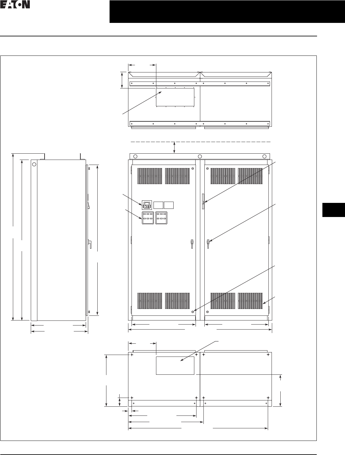
CA08104001E For more information, visit: www.eaton.com/consultants
31.2-59
February 2016
Adjustable Frequency Drives—Low Voltage
Sheet 31
22
23
24
25
26
27
28
29
30
31
32
33
34
35
36
37
38
39
40
41
42
4 3
9000X Series Drives
CPX 18-Pulse SVX
119
CPX Drawing 4—Enclosure Size 10
Figure 31.2-46. 500–600 hp IL and 400–500 hp IH—Approximate Dimensions in Inches (mm)
30.50 (774.7)
31.75 (806.5)
9.03
(229.4)
Top View
15.63
(397.0)
90.00
(2286.0)
84.37
(2143.0)
93.50
(2374.9)
4.00 (101.6) Minimum
Free Air Space Required
35.75 (908.1) 35.75 (908.1)
80.00 (2032.0)
Front View
Side View
21.00 x 10.00
(533.4 x 254.0)
Access in Top
21.00 x 10.00 (533.4 x 254.0)
Bottom Access
17.79
(451.9)
29.04
(737.6)
4.87
(123.7)
2.00 (50.8)
15.64
(397.3)
38.00 (965.2)
42.02 (1067.3)
Bottom View
78.02 (1981.7)
Finish: Enclosure – ANSI 61 Gray (Light)
Material: Enclosure and Backplate–12 ga.
= 0.1046 Cold Rolled Steel
Operator
Elements
When
Specified,
Mounted
on These
Panels
Keypad
Key-Locking
Handle
Intake Ventilating
Slots (Filtered on
NEMA 12)
Quarter Turn
Latch (4 Places)
Flanged
Disconnect
Supplied with
Circuit Breaker
When Specified

31.2-60
For more information, visit: www.eaton.com/consultants CA08104001E
February 2016
Adjustable Frequency Drives—Low Voltage
Sheet 31
22
23
24
25
26
27
28
29
30
31
32
33
34
35
36
37
38
39
40
41
42
4 3
9000X Series Drives
CPX 18-Pulse SVX
120
Wiring Diagrams
Figure 31.2-47. Power Diagram 25–250 hp IL and 25–200 hp IH
Figure 31.2-48. Power Diagram 300+ hp IL and 250+ hp IH
Figure 31.2-49. Power Diagram 25–250 hp IL and 25–200 hp IH with Bypass
Figure 31.2-50. Power Diagram 300+ hp IL/250+ hp IH with Bypass
18-Pulse
Transformer
18-Pulse
Diode Bridge
9000X
Drive
Circuit
Breaker
Motor
Input
Fusing
IInverter Input
Contactor
18-Pulse
Transformer
6-Pulse
Diode Bridge
9000X
12-Pulse Drive
Circuit
Breaker
Motor
Input
Fusing
Pre-charge
Complete
Contactor
18-Pulse
Transformer
Optional
Reduced
Voltage Starter
18-Pulse
Diode Bridge
9000X
Drive
HMCP
Output
Contactor
Mechanical
Interlock
Motor
M
Inverter Input
Contactor I
Bypass
Contactor
L
(IT.)
Input
Fusing
Overload
18-Pulse
Tr ansformer
Optional
Reduced
Voltage Starter
9000X
12-Pulse Drive
HMCP
Output
Contactor
Mechanical
Interlock
Motor
M
Inverter Input
Contactor I
Bypass
Contactor
L
Input
Fusing
Overload
6-Pulse
Diode Bridge
Pre-charge
Complete
Contactor
(IT.)
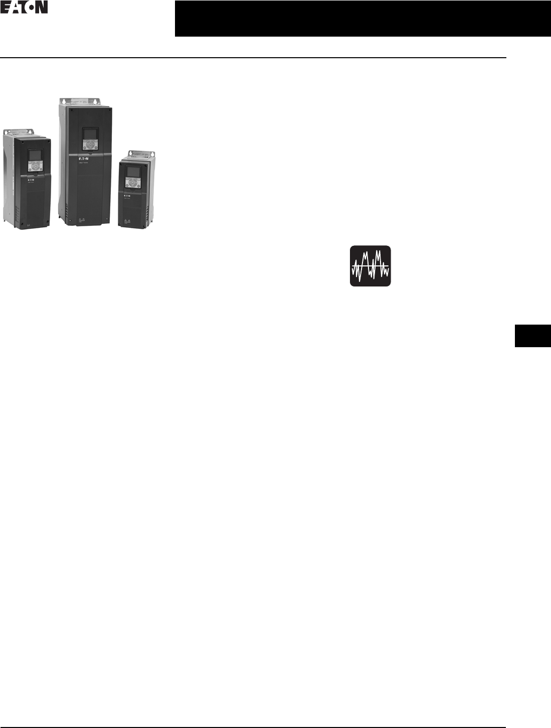
CA08104001E For more information, visit: www.eaton.com/consultants
31.3-1
February 2016
Adjustable Frequency Drives—Low Voltage
Sheet 31
22
23
24
25
26
27
28
29
30
31
32
33
34
35
36
37
38
39
40
41
42
4 3
31.3-9H-Max Drives
H-Max Drives
121
H-Max Drives
H-Max Drives
General Description
Eaton’s H-Max Series VFD has
software and hardware designed
specifically for the HVAC, pump
industry. The ultra-efficient DC
capacitor and power structure allows
the drive to consume less energy,
lowering greenhouse gases.
The I/O configuration is designed
with
wiring ergonomics in mind by includ-
ing removable terminal blocks. The
main, easily removable, control board
used for all drive frames with six
digital IN,
two analog IN, one analog
OUT, three relay OUT
accepts two
additional I/O or communication
board. In addition, the control board
has built-in RS-485 and Ethernet
communication.
These drives continue the tradition of
robust performance, and raise the bar
on features and functionality, ensur-
ing the best solution at the right price.
Features and Benefits
■Integrated DC link choke standard
on drives from FS4 through FS9
■DC bus regulation anti-trip
■Input surge protection against
voltage spikes varistor input
■EMI/RFI filters standard on all drives
from FS4 through FS9 to meet EMC
Category 2
■HAND/OFF/AUTO and DRIVE/
BYPASS selector on keypad
simplifies control
■Additional I/O and communication
cards provide plug-and-play
functionality
■Copy/paste function allows transfer
of parameter settings from one
drive to the next
■Keypad can display up to nine moni-
tored parameters simultaneously
■Remote mount keypad kit available
■NEMA Type 1 and NEMA Type 12
available
■Real-time clock with PLC functionality
■Two independent PID functions
■On-screen troubleshooting
diagnostics with embedded
manual assistance
■Onboard RS-485 (Modbus, N2,
FLN, BACnet)
■Onboard Ethernet-based communi-
cations (BACnet/IP, Modbus/TCP
■Standard NEMA Type 12 keypad
on all drives
■Quickstart wizard built into
programming of drive ensures
a smooth startup
■I/O connections with simple
quick connection terminals
■Control logic can be powered from
an external 24 V power supply to
simulate internal drive functions
and fieldbus, if necessary, used for
testing and software downloads
■Standard I/O,6DI, 2AI, 1AO 2 Form C
RO (NO/NC), 1 Form A RO (NO)
■Hard wired external/damper interlock
Standards and Certifications
Product
■IEC 61800-5-1
■CE
■cUL
Safety
■UL 508C
■EN 61800-5-1
■CE
■cUL
Seismic Qualification
Refer to
Ta b 1
for information on
seismic qualification for this and
other Eaton products.
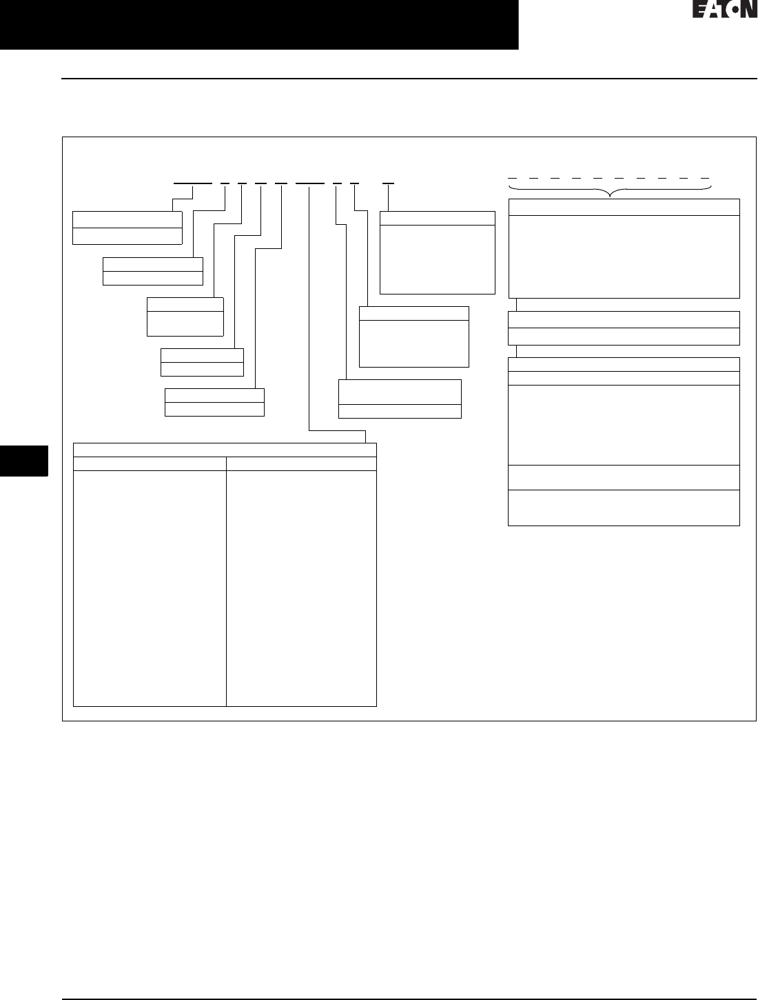
31.3-2
For more information, visit: www.eaton.com/consultants CA08104001E
February 2016
Adjustable Frequency Drives—Low Voltage
Sheet 31
22
23
24
25
26
27
28
29
30
31
32
33
34
35
36
37
38
39
40
41
42
4 3
H-Max Drives
H-Max Drives
122
Catalog Number Selection
Table 31.3-1. H-Max Series Drives Catalog Numbering System
1DB chopper standard frames FS4–FS6. 1.5–40 hp, 3.4–61 A, 480 Vac; 0.75–20 hp, 3.7–62 A, 200–240 Vac.
Notes:
■All boards are varnished (conformed coated). Corrosion resistant.
■Battery included in all drives for real-time clock.
■Keypad kit includes HOA bypass.
■Keypad kit includes HOA, back reset for Europe application.
■EMI/RFI filters included.
■DC link choke included.
Amperes
200–240 V 380–480 V
3D7 = 3.7 A—0.75 hp, 0.55 kW 1
4D8 = 4.8 A—1 hp, 0.75 kW 1
6D6 = 6.6 A—1.5 hp, 1.1 kW 1
8D0 = 8 A—2 hp, 1.5 kW 1
011 = 11 A—3 hp, 2.2 kW 1
012 = 12 A—4 hp, 3 kW 1
018 = 18 A—5 hp, 4 kW 1
024 = 24 A—7.5 hp, 5.5 kW 1
031 = 31 A—10 hp, 7.5 kW 1
048 = 48 A—15 hp, 11 kW 1
062 = 62A—20 hp, 15 kW 1
075 = 75 A—25 hp, 18.5 kW
088 = 88 A—30 hp, 22 kW
105 = 105 A—40 hp, 30 kW
140 = 140 A—50 hp, 37 kW
170 = 170 A—60 hp, 45 kW
205 = 205 A—75 hp, 55 kW
261 = 261 A—100 hp, 75 kW
310 = 310 A—125 hp, 90 kW
3D4 = 3.4 A—1.5 hp, 1.1 kW 1
4D8 = 4.8 A—2 hp, 1.5 kW 1
5D6 = 5.6 A—3 hp, 2.2 kW 1
8D0 = 8 A—4 hp, 3 kW 1
9D6 = 9.6 A—5 hp, 4 kW 1
012 = 12 A—7.5 hp, 5.5 kW 1
016 = 16 A—10 hp, 7.5 kW 1
023 = 23 A—15 hp, 11 kW 1
031 = 31 A—20 hp, 15 kW 1
038 = 38 A—25 hp, 18.5 kW 1
046 = 46 A—30 hp, 22 kW 1
061 = 61 A—40 hp, 30 kW 1
072 = 72 A—50 hp, 37 kW
087 = 87 A—60 hp, 45 kW
105 = 105 A—75 hp, 55 kW
140 = 140 A—100 hp, 75 kW
170 = 170 A—125 hp, 90 kW
205 = 205 A—150 hp, 110 kW
261 = 261 A—200 hp, 132 kW
310 = 310 A—250 hp, 160 kW
HMX 3 4 A G 3D4 21-B
Product
HMX = HVAC drive
Extended I/O Options in Slot D and E
B1 = 6 x DI /DO, Each digital input can be
individually programmed as digital output
B2 = 1RO (NC/NO), 1RO (NO), 1 Thermistor
B4 = 1 x AI, 2 x AO (isolated)
B5 =3 x RO
B8 = 1 ext +24 Vdc/ext +24 Vdc, 3 Pt100
B9 = 1RO (NO), 5 DI 42–240 Vac input
Build options alphabetically and numerically.
Optional Communications in Slot D and E
C4 = LonWorks®
Standard Onboard Communications
RS-485 Communications
BACnet MS/TP = Master slave/token protocol
(Universal BACnet) RS-485
Modbus RTU RS-485, ASCII or RTU, remote
terminal unit 32 nodes
FLN Siemens APOGEE FLN (P1) ASCII or RTU,
remote terminal unit 32 nodes
N2 = Johnson Controls Metasys N2 network
Onboard Ethernet-Based Communications
(port left side of keypad)
BACnet/IP Ethernet industrial protocol
Modbus/TCP Transmission control protocol
(Ethernet-based)
Phase
3 =Three-phase
Voltage
2= 200–240 V
4= 380–480 V
Software Series
A–Z
Keypad
G = Graphical panel
Enclosure
1 = Open NEMA
Type 1 IP21
2 = Open NEMA
Type 12 IP54
Input Options Frame
and Voltage Specific
2 = EMC C2
Braking/Application
N= No brake chopper
(low overload)
B= Internal brake
chopper
(low overload
FS4–FS6 included)

CA08104001E For more information, visit: www.eaton.com/consultants
31.3-3
February 2016
Adjustable Frequency Drives—Low Voltage
Sheet 31
22
23
24
25
26
27
28
29
30
31
32
33
34
35
36
37
38
39
40
41
42
4 3
H-Max Drives
H-Max Drives
123
Product Selection
Table 31.3-2. H-Max Series Drives—230 Vac
1For sizing reference.
FS
Frame
Size
Drive Output Current Assigned Motor Ratings 230 Vac
NEC Amperes 1
Low Overload
Full Load Amperes
at 50 °C
Low Overload Full
Load Amperes at 40 °C
Horsepower Drive kW
230 Vac/50 Hz
NEMA Type 1/IP21
43.7
4.8
6.6
0.75
1.0
1.5
0.55
0.75
1.1
3.2
4.2
6.6
2.6
3.7
4.8
8.0
11. 0
12.5
2.0
3.0
4.0
1.5
2.2
3.0
6.8
9.6
N/A
6.6
8.0
11. 0
5 18.0
24.0
31.0
5.0
7. 5
10.0
4.0
5.5
7. 5
15.2
22.0
28.0
12.5
18.0
24.0
6 48.0
62.0
15.0
20.0
11. 0
15.0
42.0
54.0
31.0
48.0
7 75.0
88.0
105.0
25.0
30.0
40.0
18.5
22.0
30.0
68.0
80.0
104.0
62.0
75.0
88.0
8 140.0
170.0
205.0
50.0
60.0
75.0
37.0
45.0
55.0
130.0
154.0
192.0
105.0
140.0
170.0
9 261.0
310.0
100.0
125.0
75.0
90.0
248.0
N/A
205.0
261.0
NEMA Type 12/IP54
43.7
4.8
6.6
0.75
1.0
1.5
0.55
0.75
1.1
3.2
4.2
6.6
2.6
3.7
4.8
8.0
11. 0
12.5
2.0
3.0
4.0
1.5
2.2
3.0
6.8
9.6
N/A
6.6
8.0
11. 0
5 18.0
24.0
31.0
5.0
7. 5
10.0
4.0
5.5
7. 5
15.2
22.0
28.0
12.0
18.0
24.0
6 48.0
62.0
15.0
20.0
11. 0
15.0
42.0
54.0
31.0
48.0
7 75.0
88.0
105.0
25.0
30.0
40.0
18.5
22.0
30.0
68.0
80.0
104.0
62.0
75.0
88.0
8 140.0
170.0
205.0
50.0
60.0
75.0
37.0
45.0
55.0
130.0
154.0
192.0
105.0
140.0
170.0
9 261.0
310.0
100.0
125.0
75.0
90.0
248.0
N/A
205.0
261.0
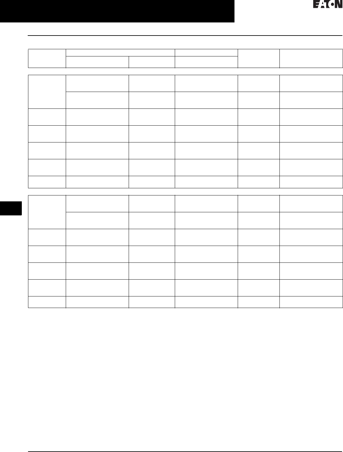
31.3-4
For more information, visit: www.eaton.com/consultants CA08104001E
February 2016
Adjustable Frequency Drives—Low Voltage
Sheet 31
22
23
24
25
26
27
28
29
30
31
32
33
34
35
36
37
38
39
40
41
42
4 3
H-Max Drives
H-Max Drives
124
Table 31.3-3. H-Max Series Drives—480 Vac
1For sizing reference.
FS
Frame
Size
Drive Output Current Assigned Motor Ratings 480 Vac
NEC Amperes 1
Low Overload
Full Load Amperes
at 50 °C
Low Overload Full
Load Amperes at 40 °C
Horsepower Drive kW
400 Vac/50 Hz
NEMA Type 1/IP21
43.4
4.8
5.6
1.5
2.0
3.0
1.1
1.5
2.2
2.1
3.4
5.6
2.6
3.4
4.8
8.0
9.6
12.0
4.0
5.0
7. 5
3.0
4.0
5.5
N/A
7. 6
11. 0
5.6
8.0
9.6
5 16.0
23.0
31.0
10.0
15.0
20.0
7. 5
11. 0
15.0
14.0
21.0
27.0
12.0
16.0
23.0
6 38.0
46.0
61.0
25.0
30.0
40.0
18.5
22.0
30.0
34.0
40.0
52.0
31.0
38.0
46.0
7 72.0
87.0
105.0
50.0
60.0
75.0
37.0
45.0
55.0
65.0
77.0
96.0
61.0
72.0
87.0
8 140.0
170.0
205.0
100.0
125.0
150.0
75.0
90.0
110 . 0
124.0
156.0
180.0
105.0
140.0
170.0
9 261.0
310.0
200.0
250.0
132.0
160.0
240.0
302.0
205.0
261.0
NEMA Type 12/IP54
43.4
4.8
5.6
1.5
2.0
3.0
1.1
1.5
2.2
2.1
3.4
5.6
2.6
3.4
4.8
8.0
9.6
12.0
4.0
5.0
7. 5
3.0
4.0
5.5
N/A
7. 6
11. 0
5.6
8.0
9.6
516.0
23.0
31.0
10.0
15.0
20.0
7. 5
11. 0
15.0
14.0
21.0
27.0
12.0
16.0
23.0
6 38.0
46.0
61.0
25.0
30.0
40.0
18.5
22.0
30.0
34.0
40.0
52.0
31.0
38.0
46.0
7 72.0
87.0
105.0
50.0
60.0
75.0
37.0
45.0
55.0
65.0
77.0
96.0
61.0
72.0
87.0
8 140.0
170.0
205.0
100.0
125.0
150.0
75.0
90.0
110 . 0
124.0
156.0
180.0
105.0
140.0
170.0
9 261.0
310.0
200.0
250.0
132.0
160.0
240.0
302.0
205.0
261.0

CA08104001E For more information, visit: www.eaton.com/consultants
31.3-5
February 2016
Adjustable Frequency Drives—Low Voltage
Sheet 31
22
23
24
25
26
27
28
29
30
31
32
33
34
35
36
37
38
39
40
41
42
4 3
H-Max Drives
H-Max Drives
125
Onboard Network Communications
Johnson Controls Metasys N2
H-Max Series provides communication
between the drive and a Johnson
Controls Metasys N2 network.
With this connection, the drive
can be controlled, monitored and
programmed from the Metasys
system. N2 can be selected and
programmed by the drive keypad.
BACnet
H-Max Series provides communication
to BACnet networks. Data transfer
is master-slave/token passing
(MS/TP) RS-485.
BACnet IP
100Base-T interface.
Modbus TCP
Ethernet based protocol.
Modbus RTU
H-Max Series provides communication
to Modbus RTU RS-485 as a slave on a
Modbus network. Other communica-
tion parameters include an address
range from 1 to 247; a parity of None,
Odd or Even; and the stop bit is 1.
FLN
H-Max Series provides communication
to Siemens APOGEE™ FLN (P1) RTU
RS-485 as a slave on an FLN network.
Other communication parameters
include an address range from 1 to 247,
a parity of None, Odd or Even
and option boards.
H-Max Series Option Board Kits
Available for Slots D and E
The H-Max Series drives can
accommodate a wide selection of
expander and adapter option boards
to customize the drive for your
application needs. The drive’s control
unit is designed to accept a total of two
option boards.
The H-Max Series factory-installed
standard board configuration includes
an I/O board and a relay output board.
Table 31.3-4. Option Boards
Mounted in Slots D and E
NEMA Type 1 to NEMA Type 12/
IP54 Conversion Kit
The NEMA Type 12/IP54 option kit is
used to convert a NEMA Type 1 to a
NEMA Type 12 drive.
Kit consists of a drive cover, a fan kit
and plugs.
Table 31.3-5. NEMA Type 12/IP54 Cover
Flange Kits
The flange kit is used when the power
section heat sink is mounted through
the back panel of an enclosure.
Option Kit
Description
Option Kit
Catalog
Number
6 x DI /DO, each digital
input can be individually
programmed as digital
output
XMX-IO-B1-A
1RO Form C (NO/NC), 1RO
Form A (NO), 1 thermistor
XMX-IO-B2-A
1 x AI, 2 x AO (isolated) XMX-IO-B4-A
3 x RO Form A (NO) XMX-IO-B5-A
1 ext +24 Vdc/ext +24 Vdc,
3 Pt100
XMX-IO-B8-A
1RO Form A (NO),
5DI 42–240 Vac input
XMX-IO-B9-A
LonWorks XMX-COM-C4-A
Option Kit
Description
Option Kit
Catalog
Number
FS4-branded N12/IP54 cover
with gasket, plastic plug, fans,
Eaton logos
FS4-N12KIT
FS5-branded N12/IP54 cover
with gasket, plastic plug, fans,
Eaton logos
FS5-N12KIT
FS6-branded N12/IP54 cover
with gasket, plastic plug, fans,
Eaton logos
FS6-N12KIT

31.3-6
For more information, visit: www.eaton.com/consultants CA08104001E
February 2016
Adjustable Frequency Drives—Low Voltage
Sheet 31
22
23
24
25
26
27
28
29
30
31
32
33
34
35
36
37
38
39
40
41
42
4 3
H-Max Drives
H-Max Drives
126
Technical Data and Specifications
Table 31.3-6. H-Max Series Drives
Description Specification
Input Ratings
Input voltage (Vin) 200–240 Vac, 380–480 Vac, –10%/+10%
Input frequency (fin) 50/60 Hz (variation up to 47–66 Hz)
Connection to power Once per minute or less (typical operation)
Short-circuit withstand rating 100 kAIC
Output Ratings
Output voltage 0 to Vin/Uin line voltage in
Continuous output current Ambient temperature max. 104 °F (40 °C)
IL overload 1.1 x IL (1 min./10 min.)
Overload current 110% (1 min./10 min.)
Initial output current 150% for 2 seconds
Output frequency 0 to 320 Hz
Frequency resolution 0.01 Hz
Control Characteristics
Control method Frequency control (V/f) open loop sensorless vector control
Switching frequency 1–310 A FS4–9: default 6 kHz
Frequency reference Analog input: Resolution 0.1% (10-bit), accuracy ±1%
Panel reference: Resolution 0.01 Hz
Field weakening point 8 to 320 Hz
Acceleration time 0.1 to 3000 seconds
Deceleration time 0.1 to 3000 seconds
Braking torque DC brake: 30% x Tn (without brake option)
Ambient Conditions
Ambient operating temperature FS4–FS9: 14 °F (–10 °C), no frost to 104 °F (40 °C)
(Drive can operate at 122 °F (50 °C), see Pages 31.3-3 and 31.3-4)
Storage temperature –40 °F to +158 °F (–40 °C to +70 °C)
Relative humidity 0 to 95% RH, noncondensing, non-corrosive, no dripping water
Air quality Chemical vapors: IEC 60721-3-3, unit in operation, Class 3C2; Mechanical particles: IEC 60721-3-3,
unit in operation, Class 3S2
Altitude 100% load capacity (no derating) up to 3280 ft (1000 m);
1% derating for each 328 ft (100 m) above 3280 ft (1000 m);
max. 9842 ft (3000 m); 380–480 V
Vibration FS4–FS9: EN 61800-5-1, EN 60068-2-6; 5 to 150 Hz, displacement amplitude 1 mm (peak) at 5 to 15.8 Hz,
max. acceleration amplitude 1G at 15.8 to 150 Hz
Shock EN 61800-5-1, EN 60068-2-27 UPS Drop test (for applicable UPS weights)
Storage and shipping: max. 15G, 11 ms (in package)
Enclosure class NEMA Type 1/IP21 or NEMA Type 12/IP54 (keypad required for IP54/Type 12)
Standards
EMC Immunity: Fulfills all EMC immunity requirements;
Emissions: EN 61800-3, LEVEL H (EMC C2)
Emissions EMC level dependent—+EMC 2: EN61800-3 (2004) Category C2
Delivered with Class C2 EMC filtering as default.

CA08104001E For more information, visit: www.eaton.com/consultants
31.3-7
February 2016
Adjustable Frequency Drives—Low Voltage
Sheet 31
22
23
24
25
26
27
28
29
30
31
32
33
34
35
36
37
38
39
40
41
42
4 3
H-Max Series Drives
H-Max Drives
127
Table 31.3-6. H-Max Series Drives (Continued)
Description Specification
Control Connections
Analog input voltage 0 to 10 V, R = 200 kohms differential
Resolution 0.1%; Accuracy ±1%
DIP switch selection (voltage/current)
Analog input current 0(4) to 20 mA; Ri –250 ohms differential
Digital inputs (6) Positive or negative logic; 18 to 30 Vdc
Auxiliary voltage +24 V ±10%, max. 250 mA
Output reference voltage +10 V +3%, max. load 10 mA
Analog output 0–10 V, 0(4) to 20 mA; RL max. 500 ohms;
Resolution 10 bit; Accuracy ±2%
DIP switch selection (voltage/current)
Relay outputs 3 programmable, 2 Form C, 1 Form A relay outputs
Switching capacity: 24 Vdc/8 A, 250 Vac/8 A, 125 Vdc/0.4 A
Hard wire jumper Between terminal 6 and 10 factory default
DIP switch setting default RS-485 = off
A01 = current
A12 = current
A11 = voltage
Protections
Overcurrent protection Trip limit 4.0 x IH instantaneously
Overvoltage protection Yes
DC bus regulation anti-trip Yes (accelerates or decelerates the load)
Undervoltage protection Yes
Earth fault protection Yes (in case of earth fault in motor or motor cable, only the frequency converter is protected)
Input phase supervision Yes (trips if any of the input phases are missing)
Motor phase supervision Yes (trips if any of the output phases are missing)
Overtemperature protection Yes
Motor overload protection Yes
Motor stall protection Yes
Motor underload protection Yes
Short-circuit protection Yes
Surge protection Yes (varistor input)
Conformed coated (varnished) boards Yes (prevents corrosion)
Seismic
OHSPD Special Seismic Certification Pre-Approved
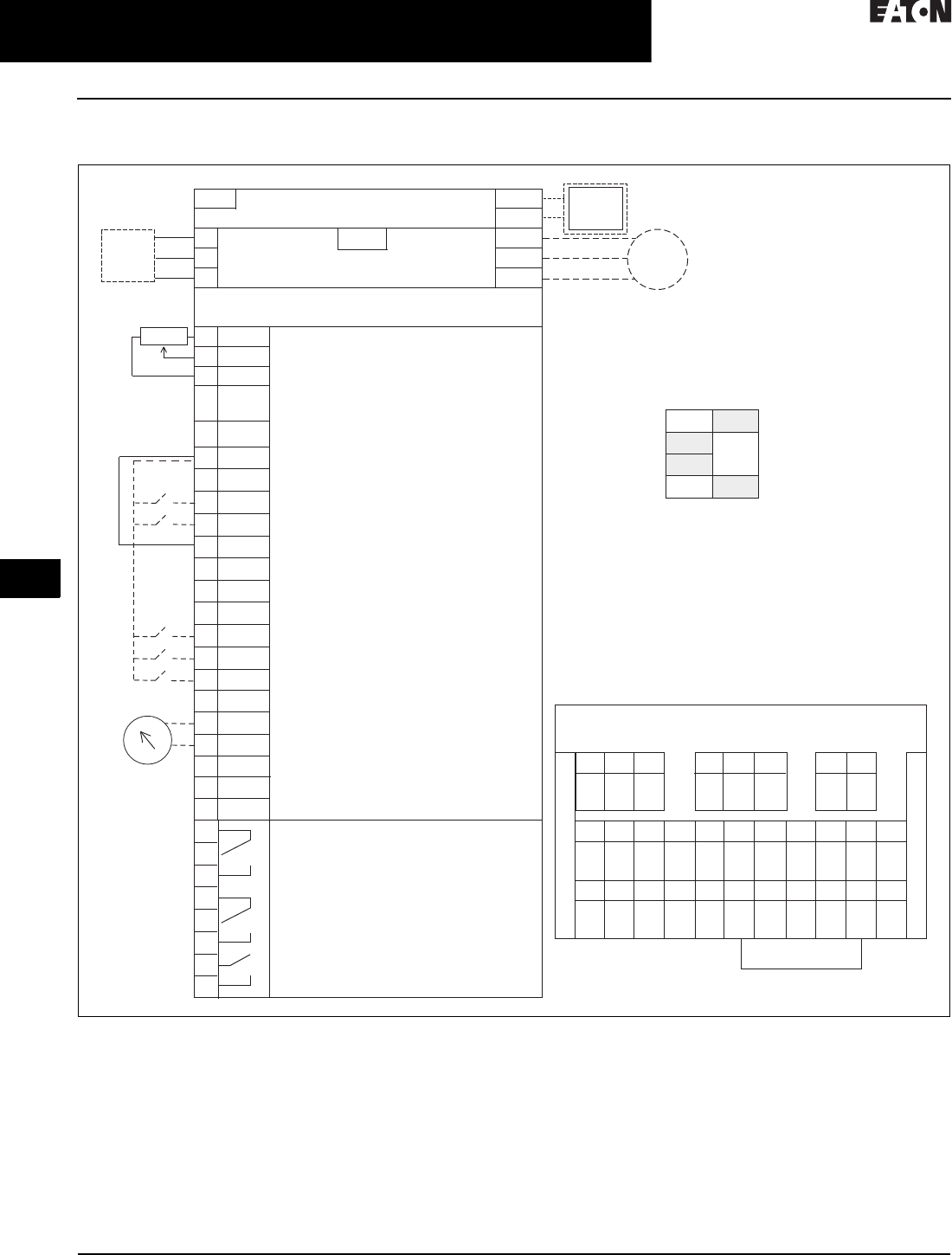
31.3-8
For more information, visit: www.eaton.com/consultants CA08104001E
February 2016
Adjustable Frequency Drives—Low Voltage
Sheet 31
22
23
24
25
26
27
28
29
30
31
32
33
34
35
36
37
38
39
40
41
42
4 3
H-Max Drives
H-Max Drives
128
Wiring Diagram
Figure 31.3-1. Control Input/Output, PID Application
Standards
■Digital inputs D1–D6, relay out,
analog in/out are freely programmed
■The user can assign a single input to
multiple functions
Includes
■Six digital input
■Two analog input
■One analog output
■Three relay output
■RS-485
■Ethernet (BACnet and Modbus)
Reliability
■Pretested components
■Conformal coated (varnished) boards
■40°C rated
■110% overload for one minute
■Eaton’s Electrical Services &
Systems national network of
AF drive specialists
Slot A
1
2
3
4
5
6
7
8
9
10
11
12
13
14
15
16
17
18
19
A
+10V
AI–1+
V
in
AI–2+
AI–2–
24V
out
GND
DIN1
DIN2
DIN3
24V
out
GND
DIN4
DIN5
DIN6
AO–1+
AO–1–
DATA-
Reference Output
Analog Input Voltage (Range 0–10 Vdc)
(can be programmed to current 4–20 mA)
Analog Output Common (Ground)
Analog Input Common
PI Setpoint or Feedback
Control Voltage Output (0.1A max.)
I/O Ground
START/STOP (Contact closed = start)
External Fault (Closed = fault)
Run Interlock Permissive IP Interlock
(Closed = OK)
DIN1–DIN6 Common
Control Voltage Output (0.1A max.)
I/O Ground
Fire Mode (Contact closed = fire mode)
Force Bypass (Contact closed = bypass)
DIN1–DIN6 Common
Output Frequency (0–20 mA)
Analog Output Common (Ground)
RS-485 DATA-
Speed Select 0–100% (Preset speed)
U (T1)
V (T2)
W (T3)
R+
R-
L1
L2
L3
Three-Phase Input
Input
(Single-Phase not available)
Three-Phase
Output
DB
Chopper
Optional
Resistor
TerminalFactory Default Signal
Resistor
Analog Input Current (Range 4–20 mA)
(can be programmed to voltage 0–10 Vdc)
PI Setpoint or Feedback
BDATA+
RO1 Bypass Run
RO2 Drive Run
RO3 Fault
24 Vdc/8A
250 Vac/8A
125 Vdc/0.4A
Relay Board 1
Default Signal
21
22
23
24
25
26
32
33
Slot B
Analog
RS-485 DATA+
AI1
OFFON
Current
Current
Current
Voltage
Voltage
Voltage
Factory
Jumper
COM
CMB
30
24 Vdc
in
Auxiliary Input Voltage
123456 78 910 11
12 13 14 15 16 17 18 1930 A B
RS-485
Data–
RS-485
Data+
24 Vdc
in
AO1–AO1+COM
DI1–6
DI6DI5DI4GND24 Vdc
out
DI2DI1GND24 Vdc
out
AI2–AI2+AI1–AI1++10
Vdc
COM
DI1–6
DI3
21
RO1
22 23 24 25 26 32 33
NC
RO1
COM
RO1
NO
RO2
NC
RO2
COM
RO2
NO
RO3
COM
RO3
NO
Slot D __________________
Slot E __________________
Terminal Block Layout
Factory Jumper
External Interlock
Circuit
Breaker
Optional
Motor
RJ-45
BACnet/IP Ethernet Industrial Protocol
Modbus/TCP Transmission Control Protocol (Ethernet Based)
5% DC Link
Reactor
RS-485
AO1
AI2
Programmable BACnet,
Modbus, FLN, N2

CA08104001E For more information, visit: www.eaton.com/consultants
31.3-9
February 2016
Adjustable Frequency Drives—Low Voltage
Sheet 31
22
23
24
25
26
27
28
29
30
31
32
33
34
35
36
37
38
39
40
41
42
4 3
H-Max Drives
H-Max Drives
129
Dimensions—Approximate Dimensions in Inches (mm)
Figure 31.3-2. H-Max Series Frames FS4–FS7
Table 31.3-7. FS4–FS7 Dimensions and Weights
Figure 31.3-3. H-Max Series Frames FS8 and FS9
Table 31.3-8. FS8 and FS9 Dimensions and Weights
Note: For flange dimension, please reference User Manual.
Voltage hp kW Amperes D H1 Hole
Center-to-Center
H2
H3 W1 W2 W3 Weight in
Lb (kg)
FS4
230 Vac
480 Vac
0.75–4
1.5 – 7. 5
0.55–3.0
1.1–5.5
3.7–12.5
3.4–12
7.77 (197.3)
7.77 (197.3)
12.89 (327.5)
12.89 (327.5)
12.32 (313.0)
12.32 (313.0)
11.22 (285.0)
11.22 (285.0)
5.04 (128.0)
5.04 (128.0)
3.94 (100.0)
3.94 (100.0)
3.94 (100.0)
3.94 (100.0)
13.2 (6)
13.2 (6)
FS5
230 Vac
480 Vac
5–10
10–20
4–7.5
7. 5 – 1 5
18–31
16–31
8.73 (221.6)
8.73 (221.6)
16.50 (419.0)
16.50 (419.0)
15.98 (406.0)
15.98 (406.0)
15.04 (382.0)
15.04 (382.0)
5.67 (144.0)
5.67 (144.0)
4.53 (115.0)
4.53 (115.0)
3.94 (100.0)
3.94 (100.0)
22.0 (10)
22.0 (10)
FS6
230 Vac
480 Vac
15–20
25–40
11 – 1 5
18.5–30
48–62
38–61
9.29 (236.0)
9.29 (236.0)
21.93 (557.0)
21.93 (557.0)
21.28 (540.5)
21.28 (540.5)
20.24 (514.0)
20.24 (514.0)
7.68 (195.0)
7.68 (195.0)
5.83 (148.0)
5.83 (148.0)
5.83 (148.0)
5.83 (148.0)
44.1 (20)
44.1 (20)
FS7
230 Vac
480 Vac
25–30
50–75
18.5–30
37–55
75–105
72–105
10.49 (266.5)
10.49 (266.5)
25.98 (660.0)
25.98 (660.0)
25.39 (645.0)
25.39 (645.0)
24.29 (617.0)
24.29 (617.0)
9.06 (230.0)
9.06 (230.0)
7.48 (190.0)
7.48 (190.0)
7.48 (190.0)
7.48 (190.0)
82.6 (37.5)
82.6 (37.5)
Voltage hp kW Amperes D H1 Hole
Center-to-Center
H2
H3 W1 W2 W3 Weight in
Lb (kg)
FS8
230 Vac
480 Vac
50–75
100–150
37–55
75–110
140–205
140–205
13.76 (349.6)
13.76 (349.6)
38.02 (965.7)
38.02 (965.7)
37.26 (946.4)
37.26 (946.4)
37.26 (946.4)
37.26 (946.4)
11.42 (290.1)
11.42 (290.1)
9.29 (236.0)
9.29 (236.0)
1.42 (36.0)
1.42 (36.0)
154.3 (70)
154.3 (70)
FS9
230 Vac
480 Vac
100–120
200–250
75–90
132–160
261–310
261–310
14.63 (371.6)
14.63 (371.6)
33.09 (890.4)
33.09 (890.4)
31.89 (810.0)
31.89 (810.0)
31.89 (810.0)
31.89 (810.0)
18.90 (480.0)
18.90 (480.0)
15.75 (400.0)
15.75 (400.0)
1.57 (40.0)
1.57 (40.0)
238.1 (108)
238.1 (108)
W1
H3 H1 H2
W2
W3
D
H3 H1
W1 W2
W3
H2
D
31.3-10
For more information, visit: www.eaton.com/consultants CA08104001E
February 2016
Adjustable Frequency Drives—Low Voltage
Sheet 31
22
23
24
25
26
27
28
29
30
31
32
33
34
35
36
37
38
39
40
41
42
4 3
H-Max Drives
H-Max IntelliPass and IntelliDisconnect
130
H-Max IntelliPass and
IntelliDisconnect
H-Max IntelliPass and
IntelliDisconnect Drives
General Description
The IntelliPass electronic bypass is a
two or optional three contactor design
using a 24 Vdc XT Series contactor
with an optional manual override
switch that allows the unit to run in
bypass without the H-Max Series drive.
The IntelliPass software parameters
use engineering units common to the
HVAC industry. Onboard startup wizard
guarantees flawless commissioning
with plug-and-play screen entry.
Available in NEMA Type 1 and 12
with optional pre-engineered operator
devices to meet all customized
specification requirements.
The IntelliPass construction features
allow for easy installation, reliable
operation and serviceability with
additional onboard wire space
and removable conduit plates
with knockouts.
Features and Benefits
IntelliPass/IntelliDisconnect
■Circuit breaker provides flexible
drive isolation configurations to
meet customers’ needs
■Communication interface enables
control of the motor operated by the
drive or bypass
■Plenum rated
■Designed and tested to UL 508C
specifications
■Standard DC link choke for
enhanced transient and harmonic
distortion protection
■DC bus regulation anti-trip
■Input surge protection against
voltage spikes varistor input
■EMI/RFI filters standard on all drives
to meet EMC Category 2
■Top and bottom conduit entry for
installation ease
■Pass-through I/O capability
■Additional I/O and communication
cards provide plug and play
functionality
■Copy/paste keypad function allows
transfer of parameter settings from
one drive to the next. Also allows for
redundant storage of drive
settings in keypad as well as drive
for backup
■Optional fusing—fuse rating 200 kAIC
■Keypad can display up to nine moni-
tored parameters simultaneously
■OHSPD Special Seismic Certification
Pre-Approved
■Standard NEMA Type 12 keypad on
all drives
■Simplified operating menu allows
for typical programming changes
■Accommodates a wide selection of
expander boards and adapter
boards
■Control logic can be powered from
an external auxiliary control panel
■Standard I/O, 6 DI, 2 AI, 1 AO,
2 Form C RO, 1 Form A RO
■Onboard RS-485 (Modbus, N2,
FLN, BACnet)
■Built-in Ethernet communication
(BACnet/IP, Modbus/TCP)
■DB chopper standard frames
FS4–FS6 for USA application
❑1.5–40 hp, 2.1–52 A, 480 Vac
❑1–20 hp, 4.2–54 A, 230 Vac
❑1–20 hp, 4.6–60 A, 208 Vac
■Hard wired external/damper interlock
IntelliPass
■Fully rated, mechanically
interlocked contacts
■HAND/OFF/AUTO and DRIVE/
BYPASS selector on keypad
simplifies control
■Two power sources for control
ensure redundancy and provide
additional ride-through capability
■Self-healing power supplies
■Bypass circuit current interrupting
rating up to 65 kAIC without fusing
■Fully featured mechanically
interlocked bypass featuring
Eaton’s XT contactors
■Pre-engineered options to
allow custom configurations
(see option P150)
■Robust steel enclosure for simple
installation
■Programmable auto restart and
auto bypass while allowing critical
damper interlock functionality
Standards and Certifications
Product
■IEC 61800-5-1
■CE
■cUL
Safety
■UL 508C
■EN 61800-5-1
■CE
■cUL
■OHSPD Special Seismic Certification
Pre-Approved
Note: For specifications and options,
see H-Max (Pages 31.3-1 through 31.3-9).

CA08104001E For more information, visit: www.eaton.com/consultants
31.3-11
February 2016
Adjustable Frequency Drives—Low Voltage
Sheet 31
22
23
24
25
26
27
28
29
30
31
32
33
34
35
36
37
38
39
40
41
42
4 3
H-Max Drives
HH-Max IntelliPass and IntelliDisconnect
131
Catalog Number Selection
Table 31.3-9. H-Max Series IntelliPass and IntelliDisconnect Drives Catalog Numbering System
1DB chopper standard frames FS4–FS6 for USA application. 1.5–40 hp, 2.1–52 A, 480 Vac; 1–20 hp, 4.2–54 A, 230 Vac; 1–20 hp, 4.6–60 A, 208 Vac.
Notes:
■IntelliPass—two contactor electronic bypass standard.
■All boards are varnished. Corrosion resistant.
■Battery included in all drives for real-time clock. Three year lifetime.
■Keypad kit includes HOA bypass.
■EMI/RFI filters included.
■DC link choke included.
Product
HMX = HVAC drive (VT)
(low overload)
Extended I/O Options in Slot D and E
B1 = 6 x DI /DO, Each digital input can be
individually programmed as digital output
B2 = 1RO (NC/NO), 1RO (NO), 1 Thermistor
B4 = 1 x AI, 2 x AO (isolated)
B5 =3 x RO
B8 = 1 ext +24 Vdc/ext +24 Vdc, 3 Pt100
B9 = 1RO (NO), 5 DI 42–240 Vac input
NEC Ampere Ratings
208 V
4D6 = 4.6 A—1 hp 1
7D5 = 7.5 A—2 hp 1
011 = 11 A—3 hp 1
017 = 17 A—5 hp 1
025 = 25 A—7.5 hp 1
031 = 31 A—10 hp 1
047 = 47 A—15 hp 1
060 = 60 A—20 hp 1
075 = 75 A—25 hp
088 = 88 A—30 hp
230 V
4D2 = 4.2 A—1 hp 1
6D8 = 6.8 A—2 hp 1
9D6 = 9.6 A—3 hp 1
016 = 16 A—5 hp 1
022 = 22 A—7.5 hp 1
028 = 28 A—10 hp 1
042 = 42 A—15 hp 1
054 = 54 A—20 hp 1
068 = 68 A—25 hp
080 = 80 A—30 hp
480 V
2D1 = 2.1 A—1 hp 1
3D4 = 3.4 A—2 hp 1
5D6 = 5.6 A—3 hp 1
7D6 = 7.6 A—5 hp 1
011 = 11 A—7.5 hp 1
014 = 14 A—10 hp 1
021 = 21 A—15 hp 1
027 = 27 A—20 hp 1
034 = 34 A—25 hp 1
040 = 40 A—30 hp 1
052 = 52 A—40 hp 1
065 = 65 A—50 hp
077 = 77 A—60 hp
096 = 96 A—75 hp
Enclosure Style
3= IntelliPass
NEMA Type 1
A= IntelliDisconnect
NEMA Type 1
Braking/Application
N= No brake chopper
(low overload)
B= Internal brake; chopper
(low overload
FS4–FS6 included)
Voltage
1=208 V
2=230 V
4=480 V
Software Series
A–Z
Keypad Options
None available
EMC Upgrade Option
EMC C2 Standard
IntelliDisconnect Options
P3 = Fused drive isolation
PE = Output contactor
SA = Space heater w/transformer (Type 3R only)
Optional Communications in Slot D and E
C4 = LonWorks
IntelliPass Bypass Options
P3 = Fused drive isolation (can not be used with P6)
P6 = Third contactor drive isolation
PE = Output contactor (used for IntelliDisconnect)
M1 = Manual bypass switch located on front door
SA = Space heater w/transformer (Type 3R only)
KF = Drive test switch (used only with P6 option)
L1 = Power on and fault light (two separate lights)
L2 = Bypass pilot light (red)
L3 = Manual bypass light (amber)
LE = Drive run light
K9 = Auxiliary contacts
IS = Isolation switch
Standard Onboard Communications
RS-485 Communications
BACnet MS/TP = Master slave/token protocol (Universal BACnet) RS-485
Modbus RTU RS-485, ASCII or RTU, remote terminal unit 32 nodes
FLN Siemens APOGEE FLN (P1) ASCII or RTU, remote terminal unit 32 nodes
N2 = Johnson Controls Metasys N2 network
Onboard Ethernet-Based Communications
(port left side of keypad)
BACnet/IP Ethernet industrial protocol
Modbus/TCP Transmission control protocol (Ethernet-based)
HMX 011 3 4 B A
Build options alphabetically and numerically.

31.3-12
For more information, visit: www.eaton.com/consultants CA08104001E
February 2016
Adjustable Frequency Drives—Low Voltage
Sheet 31
22
23
24
25
26
27
28
29
30
31
32
33
34
35
36
37
38
39
40
41
42
4 3
H-Max Drives
H-Max IntelliPass and IntelliDisconnect
132
Product Selection
Table 31.3-10. H-Max Series IntelliPass NEMA Type 1—
Two Contactor Bypass Standard
Table 31.3-11. H-Max Series IntelliDisconnect NEMA Type 1—
Main Disconnect Standard
Note: For Wiring Diagrams, see Page 31.3-13.
FS Frame Size Horsepower Drive Rated
NEC Amperes
208 Vac
41.0
2.0
3.0
4.6
7. 5
10.6
55.0
7. 5
10.0
16.7
24.2
30.8
615.0
20.0
46.2
59.4
7 25.0
30.0
74.9
88.0
230 Vac
41.0
2.0
3.0
4.2
6.8
9.6
55.0
7. 5
10.0
15.2
22.0
28.0
615.0
20.0
42.0
54.0
7 25.0
30.0
68.0
80.0
480 Vac
41.0
2.0
3.0
2.1
3.4
5.6
5.0
7. 5
9.6
11. 0
510.0
15.0
20.0
14.0
21.0
27.0
6 25.0
30.0
40.0
34.0
40.0
52.0
7 50.0
60.0
75.0
65.0
77.0
96.0
FS Frame Size Horsepower Drive Rated
NEC Amperes
208 Vac
41.0
2.0
3.0
4.6
7. 5
11. 0
55.0
7. 5
10.0
17.0
25.0
31.0
615.0
20.0
47.0
60.0
7 25.0
30.0
75.0
88.0
230 Vac
41.0
2.0
3.0
4.2
6.8
9.6
55.0
7. 5
10.0
15.2
22.0
28.0
615.0
20.0
42.0
54.0
7 25.0
30.0
68.0
80.0
480 Vac
41.0
2.0
3.0
2.1
3.4
5.6
5.0
7. 5
9.6
11. 0
510.0
15.0
20.0
14.0
21.0
27.0
6 25.0
30.0
40.0
34.0
40.0
52.0
7 50.0
60.0
75.0
65.0
77.0
96.0

CA08104001E For more information, visit: www.eaton.com/consultants
31.3-13
February 2016
Adjustable Frequency Drives—Low Voltage
Sheet 31
22
23
24
25
26
27
28
29
30
31
32
33
34
35
36
37
38
39
40
41
42
4 3
H-Max Drives
H-Max IntelliPass and IntelliDisconnect
133
Figure 31.3-4. H-Max Series IntelliPass
Figure 31.3-5. H-Max Series IntelliDisconnect Power Wiring
Bypass
Incoming Power
L1 L2 L3
Circuit
Breaker
L1
To Drive Input
To Drive Output
U(T1)
L2 L3
Output
Contactor
V(T2)W(T3)
Motor
Bypass
Contactor
Overload
Relay
U(T1)
V(T2)
W(T3)
Optional Fuse
or
Drive Input
Contactor
Incoming Power
L1 L2 L3
Circuit
Breaker
Optional Fuse
To Drive Input
To Drive Output
Motor
U(T1)
V(T2)
W(T3)
U(T1)
Optional
Output
Contactor
V(T2)W(T3)
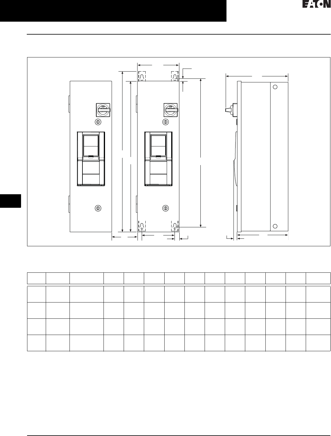
31.3-14
For more information, visit: www.eaton.com/consultants CA08104001E
February 2016
Adjustable Frequency Drives—Low Voltage
Sheet 31
22
23
24
25
26
27
28
29
30
31
32
33
34
35
36
37
38
39
40
41
42
4 3
H-Max Drives
H-Max IntelliPass and IntelliDisconnect
134
Dimensions—Approximate Dimensions in Inches (mm)
Figure 31.3-6. H-Max Series IntelliPass and IntelliDisconnect Drives
Note: Consult factory or use manual for final dimensions.
Table 31.3-12. IntelliPass and IntelliDisconnect Drive Dimensions and Weights
Note: C distance is spacing required to mount multiple drives.
Frame
Size
Volta ge H orse powe r
(IL)
H1 H2 H3 H4 C W1 W2 W3 D1 D2 Weight in
Lb (kg)
FS4 208
230
480
1–3
1–3
1–7.5
29.69
(754.1)
37.12
(942.9)
0.25
(6.35)
31.00
(914.4)
3.00
(76.2)
7. 8 8
(200.2)
6.33
(160.8)
0.75
(19.1)
11. 4 0
(289.6)
9.27
(235.5)
45.0
(20.41)
FS5 208
230
480
5–10
5–10
10–20
37.00
(939.8)
34.47
(875.5)
0.25
(6.35)
38.31
(973.0)
3.00
(76.2)
9.40
(238.8)
7. 7 5
(196.9)
0.75
(19.1)
15.30
(388.6)
13.17
(334.6)
57.5 (26.10)
FS6 208
230
480
15–20
15–20
25–40
45.08
(1145.0)
40.28
(1023.1)
0.25
(6.35)
46.4
(1178.6)
4.00
(101.6)
10.90
(276.9)
9.35
(327.5)
0.75
(19.1)
15.75
(400.0)
13.62
(346.0)
98.0
(44.45)
FS7 208
230
480
25–30
25–30
50–75
58.32
(1481.3)
56.30
(1430.0)
0.25
(6.35)
59.46
(1510.3)
5.00
(127.0)
13.98
(355.1)
12.35
(313.7)
0.75
(19.1)
15.50
(393.7)
13.55
(244.2)
165.0
(74.84)
C
H1
W2 W3
H2
W1 H3
D1
D3 D2
H4
