T991A Remote Bulb Temperature Controller Installation Directions
2016-10-06
: Pdf 1000507601-Installationsheet 1000507601-InstallationSheet B5 unilog
Open the PDF directly: View PDF ![]() .
.
Page Count: 3
I
T991A REMOTE BULB
TEMPERATURE CONTROLLER
APPLICATION
The T991A Remote
Bulb Temperature Controller is
used to sense water and air temperatures, and pro-
vides proportional control of a Series 90 (Modutrol*)
motor. Typically, Series SO motors are used with
linkages to operate valves or dampers in air cmdi-
timing systems.
The TSSlA cm be used to replace the controliers
listed below:
TSSIA temperature settings sa,me
See
Table
1 for corresponding T9SlA
-
INSTALLATION
NOTE:
Installation and service should be made only
by a quaiiCied service mm. Follov instruciions lu-
nished by heating or cooling system manufacturer, if
available.
(ion on a blat surface where the ambient temper&e
does not exceed 125 F. When mounting on a hoi or
cold surface. mount the case on a wood board or
other insulating material. The 5-fool capillary tube
provides for remote mounting.
Proceed lo Ihe FORK NEW INSTALLATION section
or FOR REPLACEMENT section.
FOR NEW INSTALLATION:
MOUNTTHE CONTHOLLER CASE-
1. Remove cover. Using the case as a templa.te,
mark three screw hole locations on mountinz surface,
then punch or drill holes.
2. Fasten TSSlAsecurely lo mounting surfacewith
the mounting screws furnished.
TO INSTALL SENSING BULB IN AIR DUCT:
Locale
the sensing bulb where duct air of average
temperature can circulate freely around ii. Avoid
mounting the bulb close to hot pipes, cooling coils,
and other places where air temperatures are not
representative.
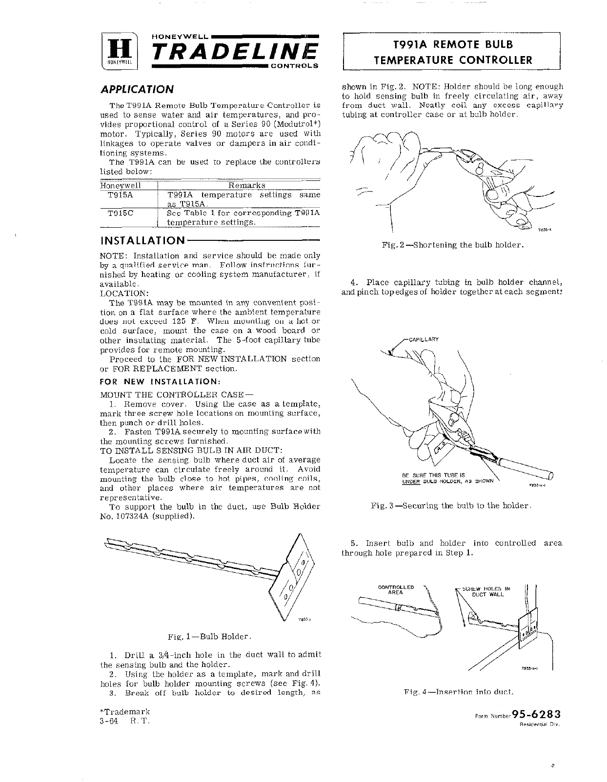
To support the bulb in Lhe duct, use Bulb Hoider
No. 107324A (supplied).
Fig. l-Bulb Holder,
1. Drill a 3/4-inch hole in the duct wall to admit
the sensing bulb and the holder.
2.
Using
the holder as a template, mark and drill
holes for bulb holder mounting screws (see Fig. 4).
3.
Break off bulb holder to desired length, as
*Trademark
3-64 R.T.
shown in Fig. 2.
NOTE:
Holder should be long enough
to hold sensing bulb in freely circulaiing air, away
from duck wail. Neatly coil any excess capillary
tubing at controller case or at bulb holder.
Fig. 2Shortening Ihe bulb holder.
4. Place capillary tubing in bulb holder channel,
and pinch topedges of holder together aleach segment:
Fig. 3--Securing the bulb to the holder
5. Insert bulb and holder into controlled area
through hole prepared in Step 1.
Fig. 4-Insertion into duct.
3
6. Fasten bulb holder to duct wall with screws 4. Fit bulb retaining clamp over immersion well
furnished. flange and capillary tubing, and tighten screw, as
slhown in Fie. 7.
Neatly coil excess capillary tubing at T991A case.
8”s RETAlNlNG CLAMP pMERSI”N WELL
\
FOR REPLACEMENT:
Remove old controller. Moluit T991A in same lo-
cation if ihis meek the requirements in LOCATION,
FigI 5-Fastening bulb holder to duck wail above.
Use old sensing bulb hole, bulb holder, immersion
TO INSTALL SENSING BULB IN TANKS OR BOIL- well, or compression iitting if these are suitable;
ERS -otherwise, follow applicable instructions for new in-
The T991A sensing bulb may be inserted directly stallaiion, above.
into a tank or boiler tapping by “si”g a No. 7617M See Table 1 in SETTINGS AND ADJUSTMENTS.
(M-inch NPT) or 76172 (3kinch NPT) Compression
Fitting (order separately); or the element may be
WIRING
inscried into a No. 112622AA (&‘-inch NPT) or
112G30AA (3/4-inch NPT) Immersion Well (order All wiring must comply with local electrical codes.
separately) which is screwed into ihe ianlr or boiler. CAUTION: Disconnect power supply.
Two knockouts are provided ai top and boliom of
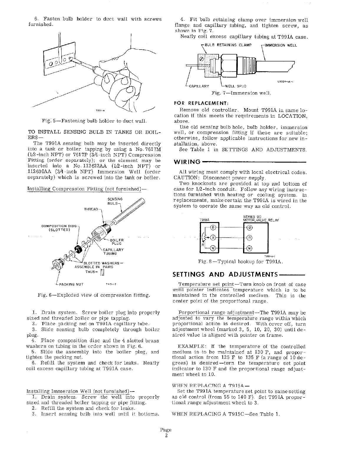
Installing Compression Fitiing (not i”rnished)- ca.se for U-inch conduit. Follow any wiring instruc-
iions furnished with heaiing or cooling system. In
replacemenis, make certain the T991A is wired in the
system to operate the same way as old control.
Fig. 8-Typical hookup for T991A
SEtTTINGS AND ADJUSTMENTS
LPPiCKlNGNUT ,OiS~,~i
Temperaiure sel point-Turn knob on front of case
until pokier indicates temperaiure which is io be
Fig. B-Exploded view of compression fitting, maintained in the controlled medium This is the
center point Of the proportional range.
1. Drain system. Screw boiler plug into properly Porportional range adjustmen-The T991A may be
sized and threaded boiler or pipe tapping. adjusted to vary the iemperaturc range within which
2. Place packing nut 011 T99iA capillary lube. proporlionai
action
is desired. With cover off, lurn
3. Slide sensing bulb compieieiy tko”gh boiler adjustment wheel (marked 3, 5, 10, 20, 30) until de-
p,i,g. sired value is aligned wiih p~inier on frame.
4. Place composilion disc and the 4 slotted brass
washers
on
tubing in the order shown in Fig. 6. EXAMPLE: If the temperature of the controlled
5. Slide the assembly into the boiler plug, and medium is to be maintained ai 130 F, and propor-
tighte” the packing nul. tional action from 125 F to 135 F (a range of 10 de-
6. ReIill the sysiem and check for leaks. Neatly grees) is desired-turn ihe iemperature set point
coil cxccss capillary tubing at T991A case. inclicaior to 130 F and the proportional range adjust-
ment wheel to 10.
WHEN REPLACBIG A T915A-
Inslalling Immersion Well (not furnished)- Set the T991A temperature set point to same seiiing
1. Drain system. Screw the well into properly as Oid control (from 55 io 140 F). Set T991A propor-
sized and threaded boiler tappiq or pipe Eiiiing. tional range adjustmeni wheel to 3.
2. Refill the syShn and check for leaks.
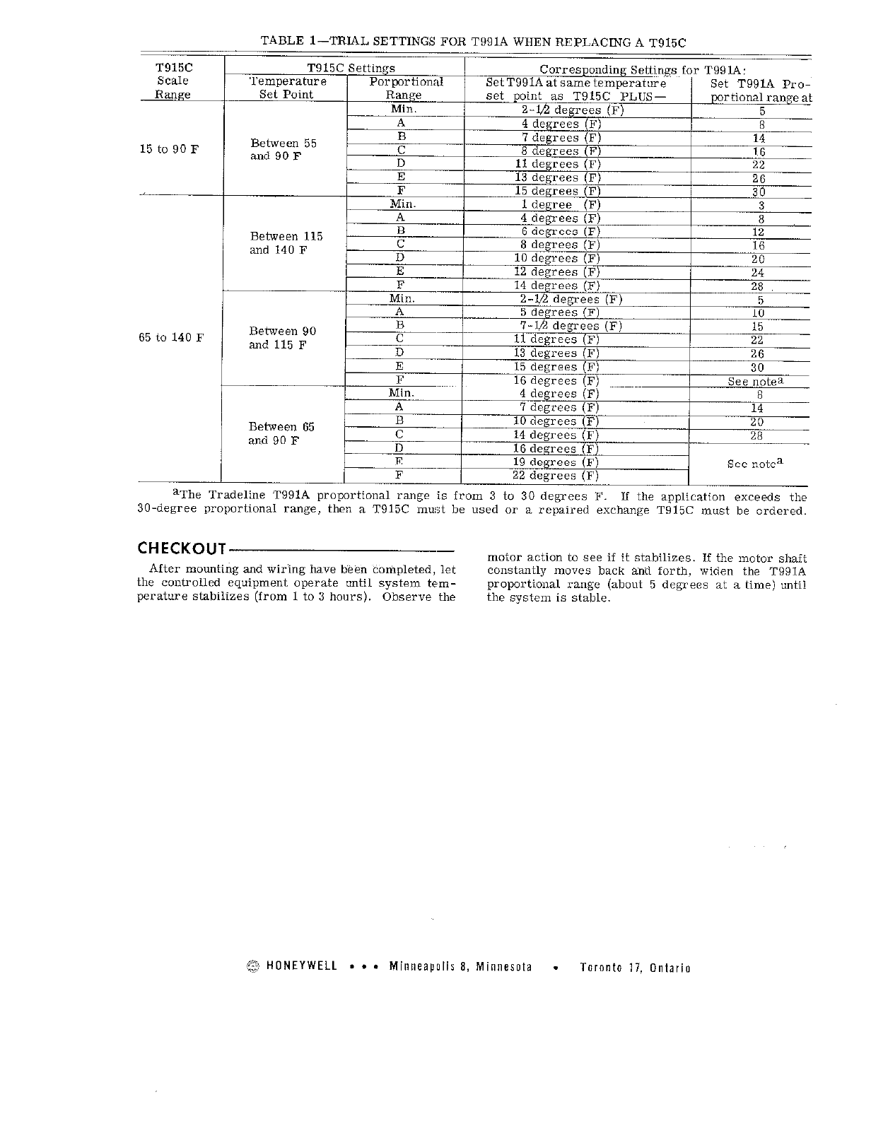
3. Insert sensing b”ib into well wlil it bottoms. WHEN REPLACING A T915C-See Table 1.
Page
2
I
-
TABLE l-TRIAL SETTINGS FOR T991A WHEN REPLACING A T915C
T915C T915C Settings Corresponding Settings for T99lA:
Scale Temperature Porportional Set T991A at same temperature Set T991A Pro-
F
Range set Point Range set point as T915C PLUS- portional range at
Min. Z-lb degrees (F) 5
Between 55
15 to 90 F and90F
t
Between 115
and 140 F
Between 90
65 to 140 F and 115 F
E /
F
in.
A
B
Between 65 C
and 90 F
=I
n
IY oegrees ,j?) see note”
I
G / 22 degrees (F)
aThe Tradeline T991A proportional range is from 3 to 30 degrees F. If ihe application exceeds the
30.degree proportional range, then a T915C must be used or a repaired exchange T915C musi be ordered.
-
CHECKOUT
motor action to see if ii stabilizes. If the motor shaft
After mounting and wiring have been conipleted, let Constantly mo”es back and forth, widen the T991A
the controlled equipment operate until system tem- proportional range (about 5 degrees ai a time) until
perature stabilizes (from 1 to 3 hours). Observe the the system is stable.
@, HONEYWELL . a . Minneapolis 8, Minnesota . Toronto 17. Ontario
By using this Honeywell literature, you agree that Honeywell will have no liability for any damages arising out of your use or modification to, the
literature. You will defend and indemnify Honeywell, its affiliates and subsidiaries, from and against any liability, cost, or damages, including
attorneys’ fees, arising out of, or resulting from, any modification to the literature by you.
